Книги
W.Green, G.Swanborough
The Complete Book of Fighters
559
W.Green, G.Swanborough - The Complete Book of Fighters
AVIATIK (BERG) 30.14 Austria-Hungary
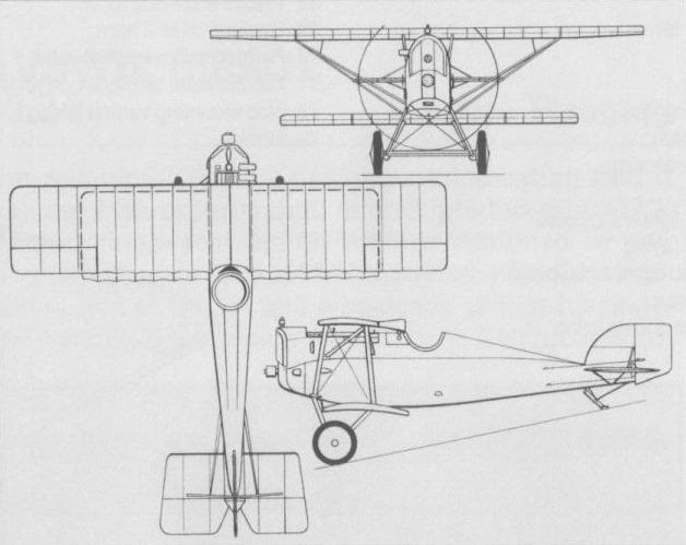
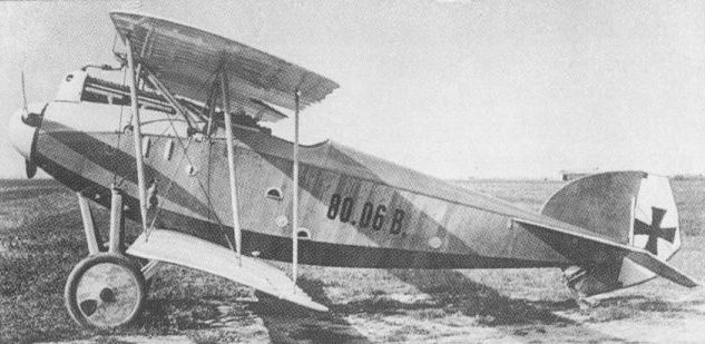
The first single-seat fighter to be built by the Osterreichisch-Ungarische Flugzeugfabrik Aviatik to the designs of Dipl Ing Julius von Berg, the Aviatik 30.14 (the designation indicating the 14th experimental aircraft produced by O-UF Aviatik) was powered by a 185 hp Austro-Daimler six-cylinder inline water-cooled engine. Armament consisted of a single 8-mm Schwarzlose synchronised machine gun. Of wooden construction with ply and fabric skinning, the Aviatik 30.14 crashed at Aspern on its first flight on 16 October 1916, the test pilot, Ferdinand Konschel, losing his life. However, the programme had revealed sufficient promise to warrant further development of the basic design, The wing gap was drastically reduced, wing stagger was introduced, the vertical tail surfaces were enlarged and, with more minor changes, three further prototypes were built, the 30.19, 30.20 and 30.21, which led to the DI.
Max speed, 109 mph (175 km/h).
Span, 26 ft 3 in (8,00 m).
Length, 22 ft 6 in (6,86 m).
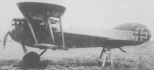
Julius von Berg's first fighter, the 30.14.
AVIATIK (BERG) 30.24
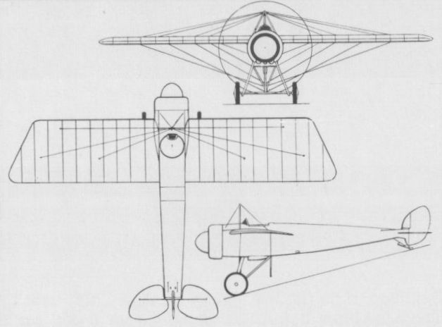
The Aviatik 30.24 (this designation indicating that it was the 24th experimental aircraft produced by O-UF Aviatik) single-seat fighter triplane designed by von Berg appeared in May 1917. Employing a similar structure to that of the DI and a basically similar fuselage, the Aviatik 30.24 was powered by a 200 hp Austro-Daimler engine and carried an armament of two synchronised 8-mm Schwarzlose 07/12 machine guns. Performance was marginally inferior to that of the similarly-powered DI, and only one prototype of the triplane was therefore completed.
Max speed, 108 mph (174 km/h).
Time to 3,280 ft (1000 m), 2.66 min, to 6,560 ft (2 000 m), 4.15 min.
Empty weight, 1,367 lb (620 kg).
Loaded weight, 1,900 lb (862 kg).
Span, 23 ft 8 1/4 in (7,22 m).
Length, 22 ft 6 in (6,86 m).
Height, 9 ft 0 in (2,75 m).
Wing area, 242.19 sq ft (22,50 m2).
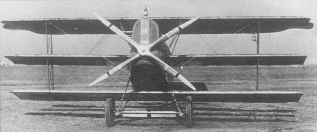
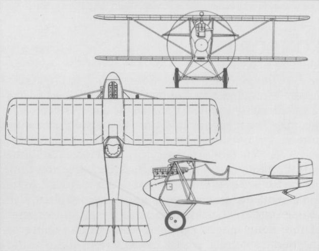
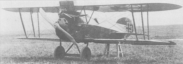
The Aviatik (Berg) 30.24 was a triplane derivative of the DI with a 200 hp Austro-Daimler. Only one triplane prototype was completed.
AVIATIK (BERG) D I Austria-Hungary
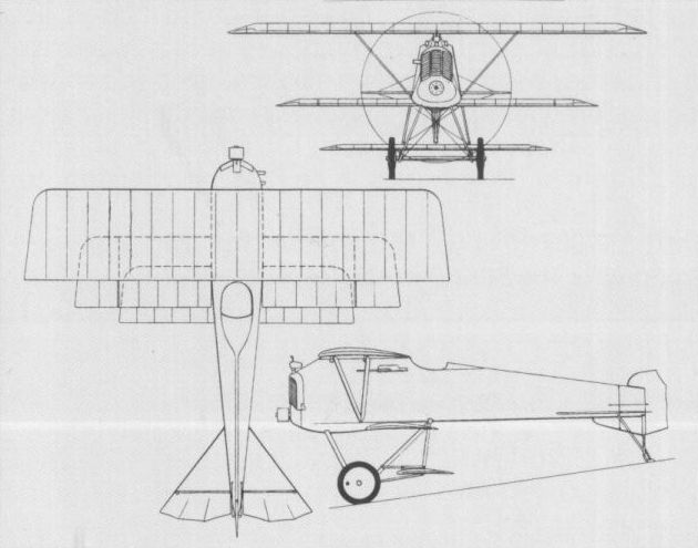
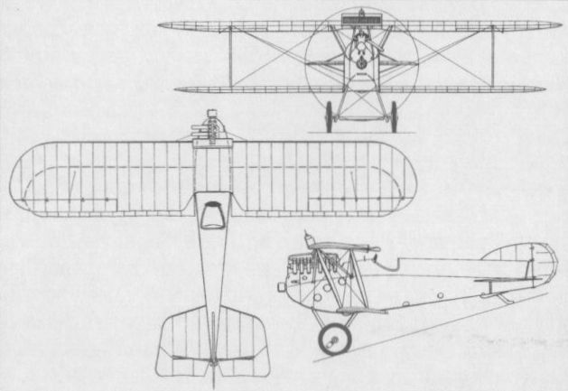
Designed by Dipl Ing Julius von Berg and frequently referred to as the Berg Scout, the DI was the first single-seat fighter of indigenous design to be manufactured in quantity by the Osterreichisch-Ungarische Flugzeugfabrik Aviatik of Vienna. The prototypes of the DI were the Av 30.19, 30.20 and 30.21, and the first of these was flown on 24 January 1917, differing from the subsequent production model primarily in lacking armament. Of wooden construction with ply fuselage skinning and fabric wing skinning, the DI entered service with the Austro-Hungarian Luftfahrttruppe in the autumn of 1917, by which time armament had standardised on two synchronised 8-mm Schwarzlose machine guns. Initial D Is had the 185 hp Austro-Daimler six-cylinder inline engine, some 140 were built with the 160 hp Austro-Daimler, and 200 and 225 hp Austro-Daimlers were progressively introduced. Some 700 fighters of this Berg type were manufactured by the parent concern and under licence by Lohner, Lloyd, Thone und Fiala, MAG and WKF. The following specification relates to the model powered by the 200 hp Austro-Daimler engine.
Max speed, 115mph (185km/h).
Time to 3,280 ft (1000 m), 2.23 min, to 6,560 ft (2 000 m), 7.63 min.
Endurance, 2.5 hrs.
Empty weight, 1,345 lb (610 kg).
Loaded weight, 1,878 lb (852 kg).
Span, 26 ft 3 in (8,00 m).
Length, 22 ft 6 in (6,86 m).
Height, 8 ft 2 in (2,48 m).
Wing area, 234.66 sq ft (21,80 m2).
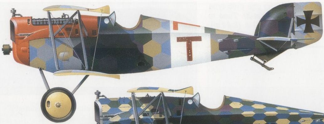
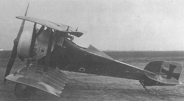
A DI Series 138 forced down at Treviso on 23 June 1918
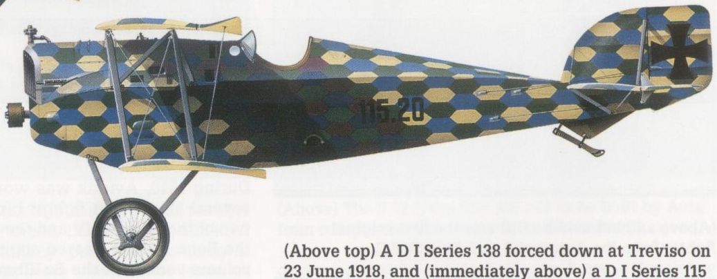
A D I Series 115 (Lohner-built) operated by Flik 60J in 1918.
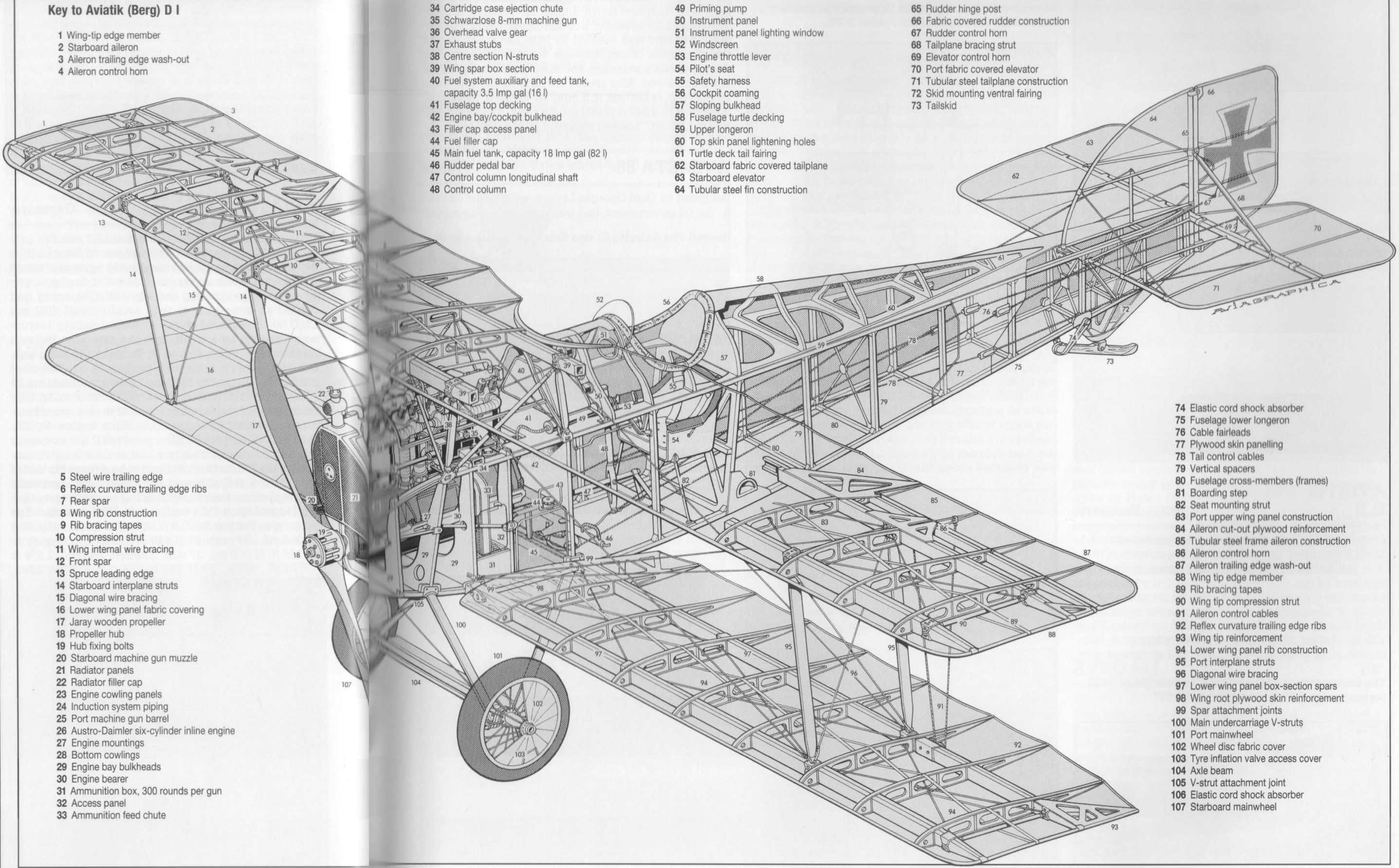
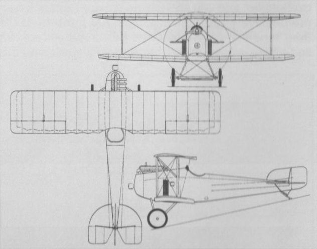
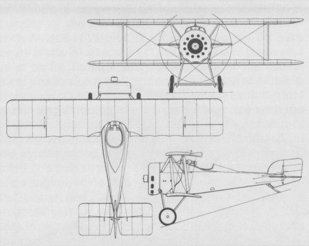
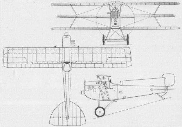
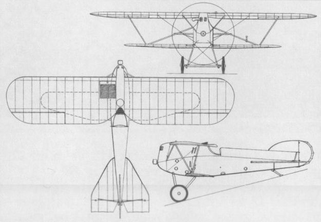
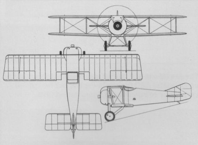
Aviatik (Berg) D I
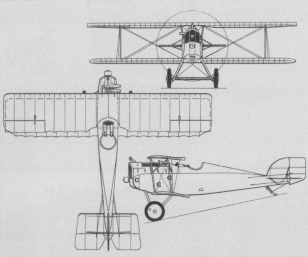
A general arrangement drawing of the 200 hp Austro-Daimler-engined D I in standard form.
AVIATIK (BERG) D II Austria-Hungary
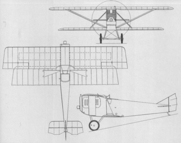
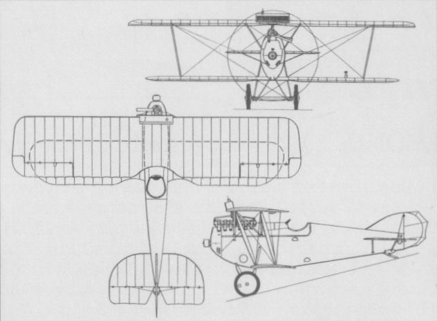
Featuring a fuselage virtually identical to that of the D I, the DII was flown as a prototype in the summer of 1917, this, the Aviatik 30.22, actually employing much of the structure of the 30.21 (see D I). The DII was characterised by a short-span cantilever lower wing, and a series of 19 aircraft was built for frontline evaluation, these being powered by either the 200 hp (Series 39) or 225 hp (Series 339) Austro-Daimler engine. A four-bladed Jaray propeller was fitted, and armament consisted of the usual paired Schwarzlose 8-mm guns. The first three series aircraft were tested in November 1917, and seven were evaluated at the front, but the decision that O-UF Aviatik should licence-manufacture the Fokker D VII terminated any plans to build the DII in quantity. One DII airframe was experimentally fitted with a 200 hp Hiero engine as the Aviatik 30.38, and participated in the July 1918 D-Contest. With the 225 hp Austro-Daimler engine the D II attained 137 mph (220 km/h). The following details relate to the 200 hp version.
Max speed, 130 mph (210 km/h).
Time to 3,280 ft (1 000 m), 2.6 min, to 6,560 ft (2 000 m), 6.6 min.
Empty weight, 1,294 lb (587 kg).
Loaded weight, 1,786 lb (810 kg).
Span, 24 ft 7 1/4 in (7.50 m).
Length, 22 ft 10 3/4 in (6,98 m).
The DII series aircraft was tested in November 1917, but plans for large-scale production ended with the choice of the Fokker D VII.
AVIATIK (BERG) 30.25 Austria-Hungary
The requirement of the Austro-Hungarian Army Command for a long-range single-seat reconnaissance fighter led Dipl Ing Julius von Berg to develop the Aviatik 30.25. Completed in March 1918, this was basically a single-seat version of the two-seat Aviatik (Berg) CI reconnaissance aircraft, with similar fuel tankage, and provision for the installation of an automatic camera and two synchronised 8-mm Schwarzlose 07/12 machine guns. It was also proposed to install radio equipment. Power was provided by a 200 hp Austro-Daimler six-cylinder engine, and speed performance was comparable with that of the Aviatik 30.30 fighter then under test, but no production was undertaken.
The requirement of the Austro-Hungarian Army Command for a long-range single-seat reconnaissance fighter led Dipl Ing Julius von Berg to develop the Aviatik 30.25. Completed in March 1918, this was basically a single-seat version of the two-seat Aviatik (Berg) CI reconnaissance aircraft, with similar fuel tankage, and provision for the installation of an automatic camera and two synchronised 8-mm Schwarzlose 07/12 machine guns. It was also proposed to install radio equipment. Power was provided by a 200 hp Austro-Daimler six-cylinder engine, and speed performance was comparable with that of the Aviatik 30.30 fighter then under test, but no production was undertaken.

The Aviatik 30.25 experimental single-seat reconnaissance fighter, evolved from the Aviatik (Berg) С I reconnaissance two-seater, had provision for an automatic camera.
AVIATIK (BERG) 30.27 & 29 Austria-Hungary
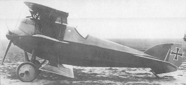
Whereas all previous single-seat fighters designed by von Berg had utilised Austro-Daimler inline engines, the Aviatik 30.27 and the similar 30.29, which appeared early in 1918, were powered by the 160 hp Steyr Le Rhone 11-cylinder rotary. Of wooden construction with plywood fuselage skinning, apart from the forward section which was covered by light metal panels, and fabric-covered wings, the Aviatik 30.27 and 30.29 each carried the standard twin-Schwarzlose gun armament, and were initially flown with two-bladed propellers. Subsequently, the original engine cowling (which left the lowest three cylinders exposed) was replaced by a full ring cowling, and the four-bladed Jaray propeller was adopted. Both participated in the July 1918 D-Contest, 30.29 crashing when the upper wing leading-edge collapsed as its pilot initiated a loop. The following details apply to the 30.27 in its final form.
Max speed, 115 mph (185 km/h) at 2,625 ft (800 m).
Time to 3,280 ft (1000 m), 1.42 min, to 6,560 ft (2 000 m), 3.75 min.
Empty weight, 851 lb (386 kg).
Loaded weight, 1,336 lb (606 kg).
Span, 22 ft 4 1/2 in (6,82 m).
Length, 16 ft 4 3/4 in (5,00 m).
Height, 8 ft 6 3/4 in (2,61 m).
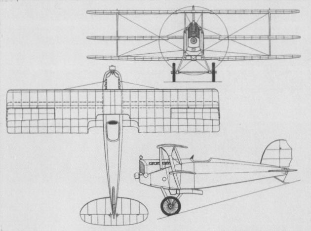
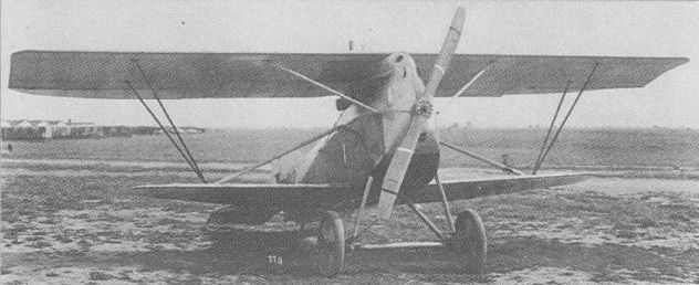
The Aviatik (Berg) 30.27 appeared early in 1918 with a Steyr Le Rhone rotary engine.
The Aviatik 30.27 which, together with the similar 30.29, participated in the D-type contest of July 1918
The Aviatik 30.27 which, together with the similar 30.29, participated in the D-type contest of July 1918
AVIATIK (BERG) 30.30 Austria-Hungary
Developed specifically for high altitude combat over the Italian front, the Aviatik 30.30 (which has sometimes been referred to as the D III although no evidence exists to support the application of this designation) had wings similar to those of the D I, married to a new fuselage, redesigned vertical tail surfaces and a 230 hp Hiero six-cylinder inline engine, the radiator for which was mounted above the upper wing centre section.
Time to 3,280 ft (1 000 m), 2.17 min, to 6,560 ft (2 000 m), 5.1 min, to 9,840 ft (3 000 m), 9.1 min.
Empty weight, 1,506 lb (683 kg).
Loaded weight, 2,079 lb (943 kg).
AVIATIK (BERG) 30.40 Austria-Hungary
A parasol monoplane derivative of the Aviatik 30.27, the Aviatik 30.40 was powered by a similar 160 hp Steyr Le Rhone 11-cylinder rotary engine, and only one prototype was built and flown during the summer of 1918. The Aviatik 30.40 was of wooden construction. The forward fuselage was covered by light metal panels and the remainder of the fuselage was ply covered. The wing had fabric skinning, and steel-tube bracing struts were employed.
Max speed, 119 mph (192 km/h).
Time to 3,280ft (1000m), 1.5min, to 6,560ft (2 000m), 2.83 min., to 9,840 ft (3 000 m), 6.83 min.
Empty weight, 807 lb (366 kg).
Loaded weight, 1,292 lb (586 kg).
KNOLLER 70.01 Austria-Hungary
The K.u.k.Fliegerarsenal Fischamend began construction during 1917 of two single-seat fighter prototypes, the 70.01 and 70.02, to the designs of Prof Richard Knoller. A single-bay unstaggered biplane of wooden construction powered by a 230 hp Hiero water-cooled six-cylinder inline engine, the Knoller fighter featured a flexible wing section intended to reduce drag by flattening with increased speed. Intended armament comprised two synchronised 8-mm Schwarzlose machine guns. Initially fitted with wing warping, the 70.01 flew for the first time on 23 November 1917, but suffered damage during a ground manoeuvre within a few days. During repairs at the Fliegerarsenal, the prototype was fitted with ailerons on the upper wing. From March until 20 June 1918, when it was damaged in a landing accident, it underwent official testing at Aspern. Having higher priority activities, the Fliegerarsenal transferred the tasks of repairing the 70.01 and completing the 70.02 to the Flugzeug Reparatur und Bau Anstalt (Fruba) in Vienna. The 70.01 was subjected to load testing in August 1918, and the 70.02, completed in September, was intended to continue the flight test programme, which, if successful, was to have resulted in an order (to be fulfilled by Fruba) for 10 pre-series aircraft. The end of hostilities was accompanied by discontinuation of the fighter development programme.
Max speed (estimated), 149 mph (240 km/h).
Span, 26 ft 3 in (8,00 m).
Length, 20 ft 10 in (6,35 m).
Height, 9 ft 4 1/5 in (2,85 m).
LLOYD 40.15 Austria-Hungary
In the late summer of 1917, the Magyar "Lloyd" Repulogep es Motogyar (Ungarische Flugzeug- und Motorenfabrik "Lloyd") initiated design of a single-seat fighter triplane. The centre and lower wings of this fighter were fully cantilevered, the upper wing being supported by Vee-type struts. Another unusual feature was the adoption of rotating ailerons on the centre wing. The Lloyd 40.15, as the fighter was designated, was powered by a 185 hp Daimler (MAG) six-cylinder water-cooled engine. It reportedly made its debut in December 1917 (although, according to a report dated 1 March 1918, the prototype was in process of assembly at that time). No information regarding subsequent flight testing has survived.
Loaded weight, 1,984 lb (900 kg).
Span, 24 ft 11 1/4 in (7,60 m).
Length, 23 ft 3 1/2 in (7,10 m).
Height, 9 ft 3 in (2,82 m).
Wing area, 238.96 sq ft (22,20 m2).
LLOYD 40.16 Austria-Hungary
Evolved in parallel with the Lloyd 40.15 and designed by Ing Hanns Wizina and Ing von Melczer, the Lloyd 40.16 single-seat fighter biplane was completed in December 1917. It offered an unconventional solution to the problem of providing the pilot with the best possible forward and downward view. The wings were given extreme stagger and were mounted independently, the upper wing being supported by a massive aerofoil-section strut which contributed some lift, a smaller triangular strut supporting the semi-cantilevered lower wing. The Lloyd 40.16 was originally intended to be powered by a 200 hp Benz (Mar) engine and to have rotating wingtip ailerons. In the event, the 220 hp engine was supplanted by a 185 hp Daimler (MAG) engine for demonstration during the fighter evaluation of July 1918, and conventional ailerons were fitted to the upper wing. No record of the results of flight testing has survived.
Loaded weight, 2,216 lb (1005 kg).
Span, 28 ft 1 7/8 in (8,58 m).
Length, 22 ft 8 2/5 in (6,92 m).
Height, 8 ft 5 1/2 in (2,58 m).
Wing area, 264.05 sq ft (24,53 m2).
The Lloyd 40.15 fighter triplane.
The unconventional Lloyd 40.16 biplane.
LOHNER Typ AA (10.20A) Austria-Hungary
During 1916, the Lohnerwerke of Vienna received a contract from the K.u.K.Luftfahrttruppen (Imperial and Royal Air Service of the Austro-Hungarian Army) for four single-seat fighter prototypes powered by the 185 hp Austro-Daimler six-cylinder inline engine. The first of these, the Lohner 10.20, or Typ AA, appeared at Aspern on 5 September 1916. A single-bay biplane with an armament of twin synchronised Schwarzlose machine guns, the Lohner 10.20 was characterised by a singularly abbreviated and deep, slab-sided fuselage. This was suspended between the wings by a short, inverted-Vee cabane and the faired struts supported the undercarriage. The wing cellule had broad, aerofoil-section I-type struts, and the vertical tail possessed no fixed surface. Taxying trials revealed insufficient control. The rudder area was increased several times and the fuselage lengthened before the aircraft flew on 29 December 1916. The fighter demonstrated poor stability, and, after suffering severe damage in February 1917, was returned to the Lohnerwerke for repair and extensive modification. The aircraft re-emerged in the following month as the Lohner 10.20A, the lower wing having been raised to the base of the fuselage, the cabane being eliminated, a twin-strutted wing cellule being adopted, the fuselage being lengthened and the redesigned tail surfaces embodying a fixed fin. The Lohner 10.20A was destroyed in a crash on 6 June 1917, and no data relating to this type are recorded.
LOHNER TYP AA (10.20B) Austria-Hungary
The second fighter prototype from the Lohnerwerke, the 10.20B (later redesignated 111.02), possessed essentially similar wing and tail surfaces to those of the 10.20A. It had a "wireless” wing cabane, however, which reverted to aerofoil-section I-struts supplemented by inclined Vee-struts. It also introduced a deep dorsal fin. Powered by a similar 185 hp Austro-Daimler engine to that of its predecessor and carrying a twin-Schwarzlose gun armament, the Lohner 10.20B made its initial flight at Aspern on 2 June 1917. The prototype was taken over by the K.u.K.Luftfahrttruppen in August 1917, and official trials continued through October when further development was halted. No data relating to this type are available.
LOHNER TYP AA (111.03) Austria-Hungary
The third Typ AA series prototype produced by the Lohnerwerke, the 111.03 differed from its immediate predecessor, the 10.20B alias 111.02, in having a conventional wire-braced wing cellule, a redesigned rudder and unfaired undercarriage strutting. Retaining the 185 hp Austro-Daimler engine, the Lohner 111.03 was flown for the first time on 28 June 1917, and flight testing continued through October. At this stage, the Lohnerwerke was assigned a manufacturing licence for the Aviatik D I, and further development of the Typ AA series was ended.
Max speed, 120 mph (193 km/h).
Time to 3,280 ft (1 000 m), 2.66 min.
Range, 240 mis (386 km).
Empty weight, 1,373 lb (623 kg).
Loaded weight, 2,085 lb (946 kg).
Span, 24 ft 11 1/4 in (7,60 m).
Length, 20 ft 10 in (6,35m).
Height, 9 ft 10 1/8 in (3,00 m).
Wing area, 215.28 sq ft (20,00 m2).

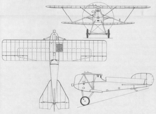
The original Typ AA featured a very deep, but short, slab-sided fuselage.

The Lohner 10.20B combined a new fuselage with wings and tail of the 10.20A.
Extensive revision of the Lohner 10.20 resulted in a single 10.20A prototype.
The Lohner 10.20B combined a new fuselage with wings and tail of the 10.20A.
LOHNER TYP A (111.04) Austria-Hungary
Possessing fundamentally similar fuselage and tail surfaces to the final Typ AA biplane, the Typ A (111.04) triplane was completed on 23 June 1917. Similarly powered and armed to the preceding Lohner fighters, the Typ A had comparatively high aspect ratio wings braced by a unique canted strut arrangement. Official trials were conducted on 7 July 1917 with mediocre results, and the prototype was returned to the Lohnerwerke for modification. It reappeared in September 1917, and subsequent performance trials proved satisfactory, but the handling characteristics were poor and view from the cockpit was deemed inadequate, with the result that the programme was terminated.
Max speed, 111 mph (178 km/h).
Time to 3,280 ft (1 000 m), 2.8 min.
Range, 221 mis (356 km).
Empty weight, 1,527 lb (692,5 kg).
Loaded weight, 2,041 lb (926 kg).
Span, 28 ft 10 1/2 in (8,80 m).
Length, 20 ft 10 in (6,35 m).
Height, 9 ft 10 1/8 in (3,00 m).
Wing area, 226.05 sqft (21,00 m2).
The Lohner Typ A (111.04) fighter triplane.
OEFFAG TYPE CF (50.14) Austria-Hungary
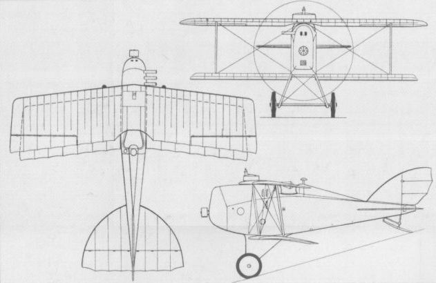
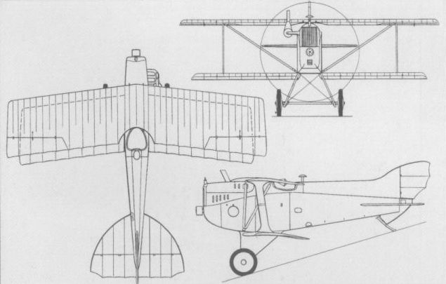
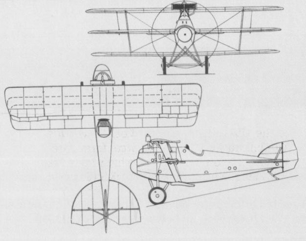
Late in 1917, the Oesterreichische Flugzeugfabrik (Oeffag) of Wiener Neustadt initiated the design of its first and, in the event, only single-seat fighter, the Type CF. An equi-span triplane of wooden construction with I-type interplane struts, the Type CF was powered by a 225 hp Austro-Daimler six-cylinder water-cooled engine, intended armament comprising two synchronised 8-mm Schwarzlose machine guns. Flight testing began in May 1918, but the triplane was already outmoded by contemporary biplane development, the Type CF being viewed by the K.u.K.Luftfahrttruppen as retrogressive. Nevertheless, the prototype appeared in the Fighter Evaluation held at Aspern in July 1918. In the meantime, the two-piece upper wing had given place to a one-piece wing with ailerons of increased area, a 200 hp Austro-Daimler engine having supplanted the more powerful unit. Too heavy and unwieldy, the Type CF aroused no enthusiasm, having neither performance nor manoeuvrability to commend it, and further development was abandoned.
Loaded weight, 2,138 lb (970 kg).
Span, 27 ft 6 2/3 in (8,40 m).
Length, 20 ft 11 9/10 in (6,40 m).
Height, 9 ft 9 1/3 in (2,98 m).
Wing area, 256.19 sq ft (23,80 m2).

The Type CF appeared in the July 1918 Fighter Evaluation held at Aspern.
PHONIX 20.14 Austria-Hungary
Shortly after commencing licence manufacture of the Brandenburg D I, the Phonix-Flugzeugwerke initiated work on an "improved fighter with a Nieuport (ie, sesquiplane] cellule” under the design leadership of Dipl-Ing Kirste. The prototype, completed early in December 1916, utilised the fuselage of Brandenburg D I 28.48 (48th 28-Series fighter) to which was applied a deepened forward portion eliminating the centre-section cabane of bracing struts. This was mated with an enlarged-area upper wing and shorter-span narrow-chord lower wing to provide the desired sesquiplane cellule. Crashed during flight testing on 16 January 1917, the prototype was rebuilt, redesignated 20.14 (ie, 14th experimental aircraft produced by Phonix), and fitted with modified ailerons and a new, lengthened fuselage. Retaining the 185 hp Austro-Daimler six-cylinder water-cooled engine, the 20.14 entered flight test in June 1917, proving to possess an inferior climb rate to the parallel 20.15. The sole 20.14 was eventually sold to the Navy and flown from Trieste.
Empty weight (approx), 1,466 lb (665 kg).
Loaded weight (approx), 2,028 lb (920 kg).
Span, 28 ft 2 3/5 in (8,60 m).
Length, 20 ft 8 in (6,30 m).
Height, 8 ft 11 1/2 in (2,73 m).
Wing area, 209.9 sq ft (19,50 m 2).
PHONIX 20.16 Austria-Hungary
Destined to be Dipl-Ing Kirste’s final attempt to produce a successful single-seat fighter of sesquiplane configuration, the 20.16 mated a Brandenburg D I (ex 28.73) fuselage with a new wing cellule (as did the 20.14). The wings featured rounded tips and the upper wing, which utilised a new high-lift profile, was set lower on the fuselage to improve forward view for the pilot. The 20.16 was fitted with a 200 hp Austro-Daimler engine and was flight tested in the late spring of 1917, but, having failed to demonstrate desirable characteristics, by June of that year it was undergoing reconstruction with a Sparmann-designed biplane cellule similar to that of the 20.15. In this form it was to become the true prototype of the Phonix D I. No data are available apart from the wing span of 31 ft 6 in (9,60 m).
The sole example of the Phonix 20.14 which was completed in December 1916.

After tests in June 1917, the Phonix 20.16 was rebuilt with an entirely new wing cellule.
The sole example of the Phonix 20.14 which was completed in December 1916.
The Phonix 20.16 is illustrated here in its original sesquiplane configuration.
PHONIX 20.15 Austria-Hungary
While the 20.14 sesquiplane prototype was being rebuilt from the 28.48, Phonix completed a further fighter prototype, the 20.15, with a Sparmann-designed single-bay biplane wing cellule. The fuselage of Brandenburg D I 28.50 was used and the 185 hp Austro-Daimler engine was retained. Of fabric-covered wooden construction, the 20.15 was first flown in June 1917, and demonstrated handling characteristics far superior to those of the Brandenburg D I, but a barely improved performance. However, the 20.15 was to be considered as a lineal predecessor of the production Phonix D I, and, later assigned the training role, this prototype survived World War I, being offered for sale to Czechoslovakia in April 1920. No data are available.
PHONIX D I (TYPE 8) Austria-Hungary
Having proved the superiority of the Sparmann-designed biplane cellule over the sesquiplane cellule, Phonix began in June 1917 to prepare engineering drawings for a series production fighter based on the 20.15 and the rebuilt 20.16 prototypes, and powered by a 200 hp Hiero six-cylinder water-cooled engine. Of wooden construction with plywood and fabric skinning, the new fighter, designated D I, carried an armament of two synchronised Schwarzlose 8-mm machine guns, and the first 11 aircraft were accepted by the K.u.k.Luftfahrttruppen in October 1917. Production for this service totalled 120 aircraft, deliveries being completed in the late spring of 1918, and 20 were also supplied to the Austro-Hungarian Navy. The D I remained at the Front until the end of hostilities (72 being at the Front on 1 August 1918) and was noteworthy for its sturdiness and excellent handling characteristics, although most pilots considered climb rate and level speed to be inadequate.
Max speed, 111 mph (178 km/h).
Time to 3,280 ft (1000 m), 3.05 min.
Empty weight, 1,578 lb (716 kg).
Loaded weight, 2,096 lb (951 kg).
Span, 32 ft 1 4/5 in (9,80 m).
Length, 22 ft 1 3/4 in (6,75 m).
Height, 8 ft 8 1/3 in (2,65 m).
Wing area, 269.1 sqft (25,00 m2).
PHONIX D II (TYPE 9) Austria-Hungary
Testing of the D I in October 1917 had elicited such responses from pilots as "superb flight characteristics, but only average performance." Phonix responded rapidly with a new prototype, the 20.18, which weighed some 176 lb (80 kg) less than the D I, flight trials commencing in November 1917. This was ordered into production as the D II. Similarly powered to the D I, the D II had a one-piece upper wing, higher aspect ratio ailerons and dihedral eliminated. Balanced ailerons were fitted and tailplane chord was reduced. During trials, the D II attained 16,405 ft (5 000 m) within 20 min as compared with 28 min required by the D I. Acceptances of the first of 48 D II fighters began in March 1918, these being followed by 48 of the D IIa version which differed in having a 230 hp Hiero engine in place of the 200 hp unit, although shortages of the uprated power plant resulted in some 20 per cent of the D IIa fighters being delivered to the K.u.k.Luftfahrttruppen with the lower-powered engine. The first D Ila fighters were despatched to the Front in late May 1918. Ten D Ila fighters were transferred to the Austro-Hungarian Navy in August 1918. The following performance data relate specifically to the D Ila.
Max speed, 115 mph (185 km/h).
Time to 3,280 ft (1000 m), 3.0 min.
Span, 32 ft 1 4/5 in (9,80 m).
Length, 22 ft 1 3/4 in (6,75 m).
Height, 8 ft 8 1/3 in (2,65 m).
Wing area, 269. lsq ft (25,00 m2).
PHONIX D III Austria-Hungary
Among D II derivatives participating in the July 1918 Fighter Evaluation held at Aspern was one D Ila (422.23) with ailerons on both upper and lower wings. After flying all participating fighters, Oblt Benno von Fiala and Oblt Frank Linke-Crawford expressed a preference for the four-aileron D IIa derivative on the basis of handling and manoeuvrability. Phonix immediately initiated work on a production version with a new four-aileron wing cellule of improved planform and the aileron interconnecting struts (which tended to vibrate) replaced by cables. Formal permission to proceed with series production of this aircraft (which had been tentatively designated "D II Series 222-neu) as the D III was received on 18 September 1918, with delivery of 100 aircraft to the K.u.k.Luftfahrttruppen scheduled to start in the following month. A contract had earlier been placed by the Austro-Hungarian Navy for 50 similar fighters powered by the 230 hp Hiero engine, and two or three of these had been accepted by November 1918. However, none was accepted by the K.u.k.Luftfahrttruppen, and when hostilities terminated 60 D III airframes were complete but without engines, 14 were 98 per cent complete and the remaining 26 were 75 per cent complete. On 6 July 1919, Dipl-Ing Edmund Sparmann and Max Perini demonstrated one of the naval D IIIs in Stockholm. This was purchased by the Thulin company from which, in April 1920, it was procured by Flygkompaniet of the Swedish Army, 20 more D IIIs being purchased via Germany for Flygkompaniet. These, referred to as Phonix 222s, were powered by the 200 hp Hiero engine and delivered in August 1920. Subsequently, in 1925, the Army Aircraft Factory at Malmen (CMF) built a further 10 Phonix 222s, these having the 185 hp BMW IIIa engine and additional fuel tanks faired into the upper wing. The first Swedish-built aircraft was delivered on 16 September 1925, and, like the original aircraft built by the parent company, carried two 6.5-mm Schwarzlose M17 guns. When Flygvapnet was established on 1 July 1926, the new service absorbed 12 ex-Army Phonix 222s (including three of the original fighters) which were assigned the designation J1, these being relegated to the training role from 1928 and the last being withdrawn in 1933. The following data relate to the 230 hp Hiero-powered D III.
Max speed, 117 mph (188 km/h).
Time to 3,280 ft (1 000 m), 2.0 min.
Range, 217 mis (350 km).
Empty weight, 1,510 lb (685 kg).
Loaded weight, 2,097 lb (951 kg).
Span, 32 ft 1 4/5 in (9,80 m).
Length, 21 ft 8 2/3 in (6,62 m).
Height, 9 ft 10 1/2 in (3,01m).
Wing area, 269.1 sq ft (25,00 m2).
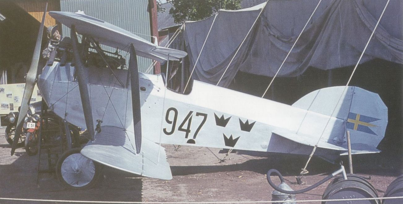
A preserved example of the Phonix D III, or Phonix 222, acquired by the Swedish Army in August 1920.

Based on the 20.16 prototype, the Phonix D I was built in series during 1917-18.
A modified D IIa (422.23) with ailerons on both upper and lower wings for D III development.
The D IIa was essentially a more powerful version of the basic D II, appearing in May 1918.

A Phonix 222 alias D III in Swedish service in 1936 when employed for weather reconnaissance.

The D I, the first Phonix series fighter.
The Phonix D II illustrated by the general arrangement drawing entered service in March 1918.

A general arrangement drawing of the D III.
PHONIX 20.22 TO 20.25 Austria-Hungary
During the Fighter Evaluation held at Aspern in July 1918, Phonix submitted (in addition to the previously-mentioned D IIa 422.23) two modified D Ila fighters, the 230 hp Hiero-powered 20.22 and the 225 hp Austro-Daimler-powered 20.23. These differed from the standard D IIa fundamentally in having ailerons on both upper and lower wings. In addition, the upper wing was marginally raised, that of the 20.22 being increased slightly in area and combined with a reduced-span lower wing. Whereas 20.22 had struts interconnecting the ailerons, 20.23 had aileron cables running through the lower wing. Neither type was pursued further, but two additional Phonix prototypes participated in the evaluation. These, the 20.24 and 20.25, were representative of an entirely new design, whereas the 20.22 and 20.23 had, like all preceding Phonix fighters, stemmed from the Brandenburg D I. The 20.24 and 20.25 differed one from the other in engine type, the former having a 230 hp Hiero and the latter a 225 hp Austro-Daimler. Single-bay staggered biplanes with oval-section plywood-skinned fuselages, they were designed by Dipl-Ing Kirste assisted by Ing Zwerina and were flown only on the last day of the Fighter Evaluation (13 July). Demonstrating outstanding qualities, they were recipients of an order for two pre-series prototypes (20.28 and 20.29) in anticipation of series production as the Phonix D IV. Hostilities terminated, however, before these could be completed. The following data relate to the Hiero-powered 20.24.
Max speed, 115 mph (185 km/h).
Time to 3,280 ft (1 000m), 2.0 min.
Empty weight, 1,466 lb (665 kg).
Loaded weight, 2,094 lb (950 kg).
Span, 27 ft 10 2/3 in (8,50 m).
Length, 21ft 7 4/5 in (6,60 m).
Height, 9 ft 6 1/8 in (2,90 m).
Wing area, 252.96 sq ft (23,50 m2).
The Phonix 20.24 was ordered in anticipation of series production as the D IV.
W.K.F. 80.05 Austria-Hungary
The first fighter of original design to be produced by W.K.F. (Wiener Karosserie- und Flugzeugfabrik Dr W v Gutmann), the W.K.F. 80.05 single-bay staggered triplane designed by Ing Alfred Gassner was completed in November 1917. Of wooden construction, it utilised a so-called Fischrumpf, or ‘‘Fish[-shaped] Fuselage”, of hexagonal cross section with plywood skinning, and the wings, which had I-type, aerofoil-section interplane struts, had ailerons on the upper and centre planes only. The W.K.F. 80.05 was powered by a 200 hp Austro-Daimler six-cylinder inline water-cooled engine and provision was made for an armament of twin synchronised Schwarzlose machine guns. Forward view from the cockpit was extremely limited by the very shallow cabane and the radiator bracing, and only limited flight testing of the sole W.K.F. 80.05 prototype was undertaken.
Max speed, 124 mph (200 km/h).
Endurance, 1.5 hrs.
Max range, 155 mis (250 km).
Empty weight, 1,477 lb (670 kg).
Loaded weight, 2,061 lb (935 kg).
Span, 26 ft 2 7/8 in (8,00 m).
Length, 19 ft 9 in (6,02 m).
Height, 9 ft 8 1/8 in (2,95 m).
Wing area, 242.9 sq ft (22,49 m2).
The W.K.F. 80.05 saw only limited testing owing to restricted view from its cockpit.
W.K.F. 80.06 Austria-Hungary
A single-bay staggered biplane following closely on the W.K.F. 80.05 triplane and possessing a number of common features, such as the Fischrumpf, the W.K.F. 80.06 was similarly powered with a 200 hp Austro-Daimler engine and was also of wooden construction with plywood skinning. First flown early in 1918, the W.K.F. 80.06 was fitted with its twin synchronised Schwarzlose gun armament during February, and, in March, it demonstrated the ability to attain an altitude of 16,405 ft (5 000 m) within 22 min, matching the climb of such fighters as the Albatros D III (Oef) and Phonix D II. Re-engined with a 230 hp Hiero, the prototype arrived at Aspern for official testing on 30 April 1918, but was written off as a result of a crash. A second, modified prototype, the W.K.F. 80.06B powered by a 225 hp Austro-Daimler engine, was delivered to Aspern. Ing Alfred Gassner had elected to reduce the wing gap and fit ailerons to both wings of the 80.06B, and, as a weight-saving measure, had replaced the plywood skinning of the wings with fabric. The prototype was flown at Aspern in July 1918 during the Fighter Evaluation along side two fundamentally similar prototypes, the W.K.F. 80.10 and 80.12, these differing from the 80.06B essentially in having the 230 hp Hiero engine. As a result of the excellent performance demonstrated by these prototypes, W.K.F. was awarded a production contract for the fighter as the D I, flight testing of the W.K.F. 80.06B continuing through August 1918. The end of hostilities terminated the W.K.F. D I programme. The 230 hp Hiero-engined fighter achieved an altitude of 16,405 ft (5 000 m) within 18 min and a maximum speed of 121 mph (195 km/h), no further data being available.
A single-bay staggered biplane following closely on the W.K.F. 80.05 triplane and possessing a number of common features, such as the Fischrumpf, the W.K.F. 80.06 was similarly powered with a 200 hp Austro-Daimler engine and was also of wooden construction with plywood skinning. First flown early in 1918, the W.K.F. 80.06 was fitted with its twin synchronised Schwarzlose gun armament during February, and, in March, it demonstrated the ability to attain an altitude of 16,405 ft (5 000 m) within 22 min, matching the climb of such fighters as the Albatros D III (Oef) and Phonix D II. Re-engined with a 230 hp Hiero, the prototype arrived at Aspern for official testing on 30 April 1918, but was written off as a result of a crash. A second, modified prototype, the W.K.F. 80.06B powered by a 225 hp Austro-Daimler engine, was delivered to Aspern. Ing Alfred Gassner had elected to reduce the wing gap and fit ailerons to both wings of the 80.06B, and, as a weight-saving measure, had replaced the plywood skinning of the wings with fabric. The prototype was flown at Aspern in July 1918 during the Fighter Evaluation along side two fundamentally similar prototypes, the W.K.F. 80.10 and 80.12, these differing from the 80.06B essentially in having the 230 hp Hiero engine. As a result of the excellent performance demonstrated by these prototypes, W.K.F. was awarded a production contract for the fighter as the D I, flight testing of the W.K.F. 80.06B continuing through August 1918. The end of hostilities terminated the W.K.F. D I programme. The 230 hp Hiero-engined fighter achieved an altitude of 16,405 ft (5 000 m) within 18 min and a maximum speed of 121 mph (195 km/h), no further data being available.
The W.K.F. 80.06 was officially tested at Aspern, but crashed and was written off.
A.D. SCOUT (SPARROW) UK
Designed by Harris Booth of the Air Department of the Admiralty as a single-seat anti-airship fighter, the A.D. Scout - later to become known unofficially as the "Sparrow” - was an extraordinary single-bay staggered biplane intended to carry a Davis two-pounder recoilless gun. The rudders and outsize tailplane were carried by four parallel tailbooms, and the unusual appearance of the A.D. Scout resulted primarily from the fact that the large mainplane gap was below rather than above the nacelle accommodating the pilot. The gun was intended to be mounted in the bottom of the nacelle, to the tail of which was attached a 100 hp nine-cylinder Gnome Monosoupape rotary engine driving a pusher propeller. Construction was of wood with fabric covering, and four prototypes were ordered and built (two by Hewlett & Blondeau and two by Blackburn) in 1915. Delivered to the RNAS, the A.D. Scouts proved seriously overweight and difficult to handle in the air. In consequence, all four aircraft were scrapped.
Max speed, 84 mph (135 km/h).
Endurance, 2.5 hrs.
Span, 33 ft 5 in (10,18 m).
Length, 22 ft 9 in (6,93 m).
Height, 10 ft 3 in (3,12 m).

An anti-airship fighter, the A.D. Scout proved overweight and handled badly.
ALCOCK A.1 UK
Evolved at the RNAS base at Mudros, in the Aegean, by Lt John Alcock during the summer of 1917, the A.l employed modified components of the Sopwith Triplane (forward fuselage and lower wings), Sopwith Pup (upper wings), and Sopwith Camel (tailplane and elevators) which were married to a rear fuselage and vertical tail surfaces of original design. Powered by a 110 hp Clerget 9Z nine-cylinder rotary engine and carrying a 0.303-in (7,7-mm) Vickers machine gun, the A.l (which was also referred to by its designers as the "Sopwith Mouse” in recognition of its part parentage) flew at Mudros in October 1917, but was written off after crashing early in 1918.
Approx span, 24 ft 3 in (7,39 m).
Approx length, 19 ft lin (5,82 m).
Approx height, 7 ft 9 in (2,36 m).
ARMSTRONG WHITWORTH F.K.6 UK
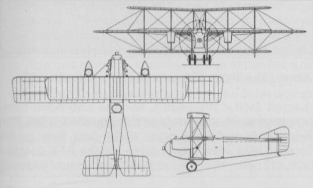
In 1915, Frederick Koolhoven, the chief designer of sir W G Armstrong Whitworth & Co Ltd, initiated work on a highly unorthodox three-seat triplane powered by a 250 hp Rolls-Royce 12-cylinder water-cooled engine. It was intended to accommodate two gunners each with a 0.303-in (7,7-mm) machine gun in shallow nacelles, mounted above the centre wing on each side of the fuselage, the gunners being seated ahead of the propeller plane of the tractor engine. Although a prototype was completed and allegedly designated F.K.5, this was never flown, being extensively damaged as a result of a ground loop during it first take-off attempt. The design was extensively revised early in 1916 to meet an RFC requirement for an airship interceptor and long-range escort fighter. The revised design is believed to have been designated F.K.6 (and certainly not F.K.12 as has sometimes been stated) and four examples were ordered, two of these being intended for the RNAS. In the event, only one F.K.6 was built. The gunners' nacelles were underslung on the central mainplane, armament remained two 0.303-in (7,7-mm) Lewis guns and the 250 hp Rolls-Royce engine was retained. It is believed that relatively limited flight testing was undertaken.
Span, 63 ft 0 in (18,89 m).
Length, 37 ft 0 3/4 in (11,29 m).
Height, 17ft 0 in (5.18 m).
ARMSTRONG WHITWORTH F.K.10 UK
Derived from the F.K.9, but embodying considerable redesign, the F.K.10 two-seat fighter-reconnaissance quadruplane retained virtually no more than the basic wing structure of its immediate predecessor. A production contract for 50 F.K.10s was given to Angus Sanderson & Company of Newcastle-on-Tyne on 30 December 1916 on behalf of the RFC, but only five aircraft were destined to be completed before the contract was cancelled. Three were ordered for the RNAS, two of these from the Phoenix Dynamo Manufacturing Company and one from Armstrong Whitworth, these eventually being completed and tested. The F.K.10 was normally powered by a 130 hp Clerget 9B rotary, but at least one was flown with a 110 hp Le Rhone, and armament comprised one fixed 0.303-in (7,7-mm) Vickers gun and one free 0.303-in (7,7-mm) Lewis.
Max speed, 84 mph (135 km/h) at 6,500 ft (1980 m), 74 mph (119 km/h) at 10,000 ft (3 050m).
Time to 6,500 ft (1980 m), 15.85 min.
Endurance, 2.5 hrs. Empty weight, 1,236 lb (560 kg).
Loaded weight, 2,019 lb (916 kg).
Span, 27 ft 10 in (8,48 m).
Length, 22 ft 3 in (6,78 m).
Height, 11 ft 6 in (3,50 m).
Wing area, 390.4 sq ft (36,27 m2).
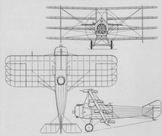
ARMSTRONG WHITWORTH F.K.9 UK
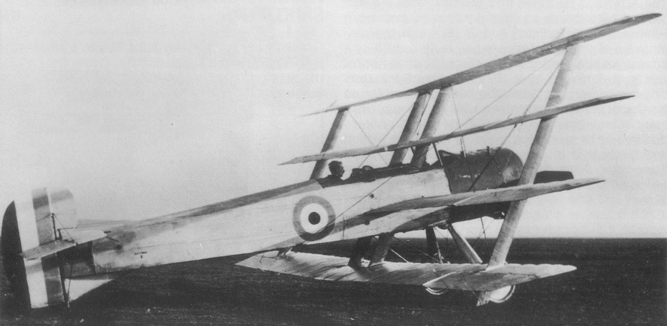
The F.K.9 two-seat fighter-reconnaissance quadruplane was built by Sir W G Armstrong Whitworth & Co Ltd as a private venture, and was initially flown in the summer of 1916. Initial trials dictated a number of modifications, including new wings with enlarged ailerons, an enlarged fin, a redesigned engine cowling and increased undercarriage track. In this form, powered by a 110 hp Clerget 9Z rotary engine, and with a designated armament of one fixed 0.303-in (7,7-mm) Vickers gun and one free 0.303-in (7,7-mm) Lewis gun, the F.K.9 was officially tested in November-December 1916 at the Central Flying School. A production contract for 50 examples of an improved version, the F.K.10, was awarded.
Max speed, 94 mph (151 km/h) at 6,500 ft (1980 m), 87mph (140 km/h) at 10,000 ft (3 050 m).
Time to 6,500 ft (1 980 m), 14.33 min.
Endurance, 3 hrs.
Empty weight, 1,226 lb (556 kg).
Loaded weight, 2,038 lb (924 kg).
No dimensions available.
Built as a private venture, the F.K.9 quadruplane entered flight test in the summer of 1916.
The F.K.9 quadriplane in its modified form, photographed at the Central Flying School, Upavon, late in 1916.
The F.K.9 quadriplane in its modified form, photographed at the Central Flying School, Upavon, late in 1916.
ARMSTRONG WHITWORTH F.M.4 ARMADILLO UK
The Armadillo, designed by F Murphy, who had succeeded F Koolhoven as chief designer to Armstrong Whitworth, was initiated late in 1917, and the construction of two prototypes began early in 1918 as a private venture, the first of these being flown in April of that year. Powered by a 230 hp Bentley B.R.2 nine-cylinder rotary, the Armadillo had provision for an armament of two synchronised 0.303-in (7,7-mm) Vickers machine guns, but flying characteristics were declared to be most unsatisfactory and flight testing was terminated in June 1918, the second prototype never being flown.
Max speed, 125 mph (201 km/h) at sea level, 113 mph (182 km/h) at 10,000 ft (3 050 m).
Time to 10,000 ft (3 050 m), 6.5 min.
Endurance, 2.75 hrs.
Empty weight, 1,250 lb (567 kg).
Loaded weight, 1,860 lb (844 kg).
Span, 27 ft 9 in (8,46 m).
Length, 18 ft 10 in (5,74 m).
Height, 7 ft 10 in (2,38 m).
Wing area, 232 sq ft (21,55 m2).
The Armadillo after modification of the undercarriage and the introduction of glazed panels forward of the cockpit for improved view.
ARMSTRONG WHITWORTH ARA UK
The Ara was designed in 1918 to use the extremely promising ABC Dragonfly nine-cylinder air-cooled radial of 320 hp and three prototypes were ordered. However, delays in delivery of the Dragonfly engine led, in October 1918, to the decision to abandon all plans to produce a Dragonfly-powered fighter in quantity, and those companies with such warplanes under development were each allocated one Dragonfly engine in December 1918 in order to enable them to complete and test one prototype of each of their designs. In the event, the ABC engine proved extremely unreliable when the Ara commenced trials early in 1919. Nevertheless, a second prototype was completed and flown before, late in 1919, Sir W G Armstrong Whitworth & Co Ltd closed its aircraft department. The planned armament of the Ara comprised two 0.303-in (7,7-mm) Vickers guns.
Max speed, 150 mph (241 km/h) at sea level, 145 mph (233 km/h) at 10,000 ft (3 050 m).
Time to 10,000 ft (3 050 m), 4.5 min.
Endurance, 3.25 hrs.
Empty weight, 1,320 lb (599 kg).
Loaded weight, 1,930 lb (875 kg).
Span, 27 ft 5 in (8,35m).
Length, 20 ft 3 in (6,17 m).
Height, 7 ft 10 in (2,39 m).
Wing area, 257 sq ft (23,87 m2).

The Ara was designed around the unsuccessful ABC Dragonfly engine, but two prototypes were completed and flown during 1919.
The second Ara, F4972, differed from the first in having an increased gap between the wings.
The second Ara, F4972, differed from the first in having an increased gap between the wings.

SIDDELEY S.R.2. SISKIN UK
When, in January 1917, Capt F M Green became chief aeronautical engineer of the Siddeley-Deasy Motor Car Company, he began the design of a single-seat fighter, the S.R.2. A compact single-bay sesquiplane predominantly of wooden construction with fabric skinning, the S.R.2 was powered by a 320 hp A.B.C. Dragonfly nine-cylinder radial engine. Armament comprised two synchronised 0.303-in (7,7-mm) machine guns. A contract for six prototypes was reduced to three in mid 1918, the first of these flying in April 1919, by which time the fighter had been officially named Siskin. The first prototype Siskin was subsequently re-engined with an Armstrong Siddeley Jaguar, development in this form continuing after Siddeley Deasy acquired in 1921 the name and goodwill of Sir W G Armstrong Whitworth & Co Ltd, and the Armstrong Whitworth Siskin II emerging in 1922.
Max speed, 145 mph (233 km/h) at 6,500 ft (1980 m).
Time to 6,500 ft (1980 m), 4.5 min.
Service ceiling, 23,800 ft (7255 m).
Empty weight, 1,463 lb (664 kg).
Loaded weight, 2,181 lb (989 kg).
Span, 27 ft 6 in (8,38 m).
Length, 21ft 3 in (6,48 m).
Height, 9 ft 9 in (2,97 m).
Wing area, 247 sqft (22,95 m2).

The S.R.2, together with many of its contemporaries, was rendered ineffective by the failure of the Dragonfly engine.
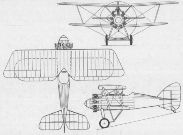
The Siddeley Siskin in its initial form with the A.B.C. Dragonfly engine.
AUSTIN A.F.B.1 UK
Frequently referred to as the "Austin Ball Scout" because the Austin Motor Company incorporated some of the ideas of Capt Albert Ball, VC, DSO, MC, in this fighter’s design, the A.E.B.1 was designed by C H Brooks and was flown for the first time in July 1917. It was of wooden construction with fabric covering, and was powered by a 200 hp Hispano-Suiza eight-cylinder liquid-cooled engine. Armament comprised a single 0.303-in (7,7-mm) Lewis machine gun firing through the hollow propeller shaft, and a similar weapon on a Foster mounting above the upper wing centre section. As originally built, the sole prototype of the A.E.B.1 had slightly sweptback wing surfaces and conventional single-bay bracing, but during the course of development new unswept surfaces accompanied by revised interplane bracing of two-bay form were introduced. The aircraft flew for the first time after these modifications on 17 September 1917. The following data relate to the A.E.B.1 in its original form.
Max speed, 138 mph (222 km/h) at sea level, 120 mph (193 km/h) at 15, 000 ft (4 570 m).
Time to 10,000 ft (3 050 m), 8.9 min.
Endurance, 2.25 hrs.
Empty weight, 1,525 lb (692 kg).
Loaded weight, 2,077 lb (942 kg).
Span, 30ft 0 in (9,14 m).
Length, 21 ft 6 in (6,55 m).
Height, 9 ft 3 in (2,82 m).
Wing area, 290 sq ft (26,94 m2).

The Austin A.F.B.1 in its revised and definitive configuration as flown autumn 1917.
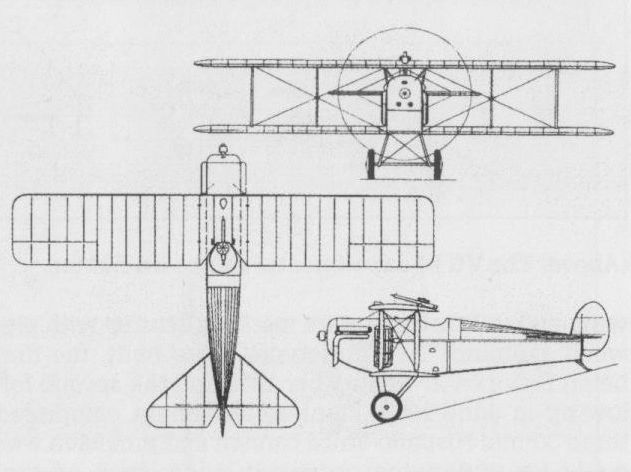
The A.F.B.1 in its final form without wing sweep and SPAD-style interplane bracing.
AUSTIN A.F.T.3 OSPREY
A private venture intended to compete with the Sopwith Snipe, the Osprey was of wooden construction with fabric skinning and was powered by a 230 hp Bentley B.R.2 nine-cylinder rotary engine. Armament comprised two fixed and synchronised 0.303-in (7,7-mm) Vickers machine guns and one semi-free Lewis gun of similar calibre on the rear spanwise member of the middle-wing centre section. The Osprey was flown for the first time in February 1918, but performance proved to be inferior to that of the Snipe, and construction of second and third prototypes was abandoned.
Max speed, 118mph (190 km/h) at 10,000ft (3 050 m), 110 mph (177 km/h) at 15,000 ft (4 570 m).
Time to 10,000 ft (3 050 m), 10.35 min.
Endurance, 3 hrs. Empty weight, 1,106 lb (502 kg).
Loaded weight, 1,888 lb (856 kg).
Span, 23 ft 0 in (7,01m).
Length, 17 ft 7 in (5,36 m).
Height, 10 ft 8 in (3,25 m).
Wing area, 233 sq ft (21,64 m2).
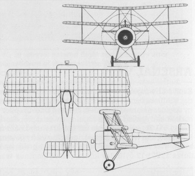
AUSTIN GREYHOUND UK
The Greyhound tandem two-seat fighter-reconnaissance aircraft was designed by J Kenworthy as a potential successor to the Bristol Fighter, but the first prototype was not completed until after the Armistice of 1918 owing to difficulties with its 320 hp ABC Dragonfly I nine-cylinder radial engine. Flight testing eventually commenced in May 1919, and three prototypes were built and flown, but no further development was undertaken. Armament comprised two fixed synchronised 0.303-in (7,7-mm) Vickers guns and a single 0.303-in (7,7-mm). Lewis gun on a Scarff ring in the rear cockpit.
Max speed, 129 mph (207 km/h) at 6,500 ft (1 980 m), 126 mph (203 km/h) at 10,000 ft (3 050 m).
Time to 10,000 ft (3 050 m), 10.83 min.
Endurance, 3 hrs.
Empty weight, 1,838 lb (834 kg).
Loaded weight, 3,032 lb (1375 kg).
Span, 39 ft 0 in (11,89 m).
Length, 26 ft 8 1/2 in (8,14 m).
Height, 10 ft 4 in (3,15 m).
Wing area, 400 sqft (36,16 m2).
AVRO 504 UK
Although the Avro 504 saw most widespread use as a two-seater for reconnaissance, bombing and training, it also saw some service as a single-seat fighter, initially with the Royal Naval Air Service for airship interception. The first variant intended specifically for this role was the Avro 504C which, powered by the 80 hp Gnome seven-cylinder rotary, was essentially similar to the two-seat Avro 504B apart from having a fuel tank occupying the space normally taken up by the forward cockpit, and a gap in the top centre section through which a 0.303-in (7,7-mm) Lewis gun could be fired upward at an angle of 45 deg. Eighty Avro 504Cs were ordered for the RNAS, 50 of these being built by Brush Electrical Engineering, and these were operated on home defence duties from various RNAS stations. One was modified in 1916 to take a 75 hp Rolls-Royce Hawk inline engine, and 30 were ordered for the RNAS as the Avro 504F, but, in the event, these were completed with the standard Gnome rotary. The Royal Flying Corps equivalent of the Avro 504C was the Avro 504D, but only six were produced, these being delivered in August 1915. Early in 1918, a number of singleseat fighter conversions of the 110 hp Le Rhone 9J nine-cylinder rotary-powered Avro 504K was produced for issue to Home Defence squadrons, these having a single Lewis gun on a Foster mounting above the upper wing centre section. Several of these were later fitted with a V-type undercarriage similar to that of the Avro 521. The following data relate to the Avro 504C.
Max speed, 83 mph (134 km/h) at sea level.
Time to 3,500 ft (1065 m), 7.2 min.
Endurance, 8 hrs.
Empty weight, 930 lb (422 kg).
Loaded weight, 1,592 lb (722 kg).
Span, 36 ft 0 in (10,97m).
Length, 29 ft 5 in (8,96m).
Height, 10 ft 5 in (3,17 m).
Wing area, 330 sq ft (30,66 m2).
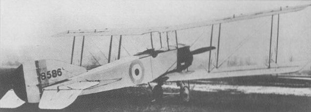
The Avro 504C was the first variant of the basic design to be intended specifically for the interception of airships and the most important single-seat fighter variant of the basic Avro 504 and was employed in some numbers by the RNAS
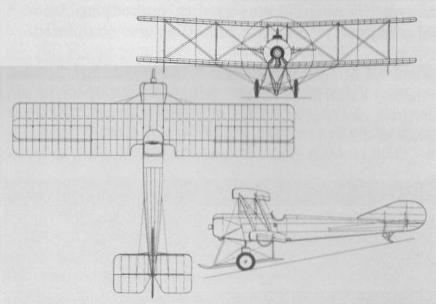
The Avro 504C was the first variant of the basic design to be intended specifically for the interception of airships.
AVRO 521 UK
The Avro 521 two-seat fighter, which was flown late in 1915, was something of a hybrid in that it embodied a number of Avro 504 components. Powered by a 110 hp Clerget 9Z nine-cylinder rotary, the prototype had provision for a free-mounted 0.303-in (7,7-mm) Lewis gun fired from the rear cockpit. The prototype underwent official trials early in 1916, and 25 aircraft were ordered for the RFC, but this contract was subsequently cancelled, and there is no evidence that any Avro 521 other than the prototype (which crashed at Upavon on 21 September 1916) was built.
Max speed, 90 mph (145 km/h) at sea level.
Time to 6,000 ft (1830 m), 14 min.
Endurance, 4.5 hrs.
Empty weight, 1,150 lb (522 kg).
Loaded weight, 1,995 lb (905 kg).
Span, 30 ft 0 in (9,14m).
Length, 28 ft 2 in (8,58 m).
Wing area, 266 sq ft (24,71 m2).
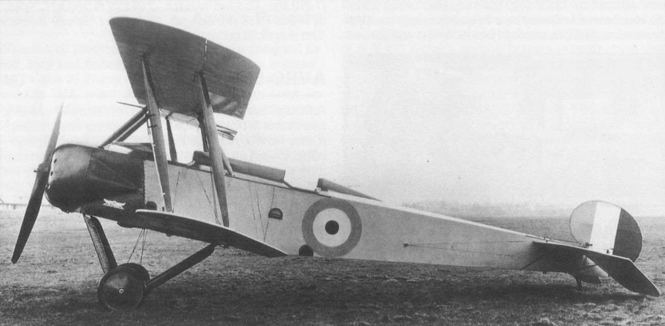
The Avro 521 two-seater was intended for the long-range and escort fighter tasks
AVRO 527
The final two-seat fighter derivative of the basic Avro 504 design, the Avro 527 was built for the RFC and flown for the first time early in 1916 with a 150 hp Sunbeam Nubian eight-cylinder water-cooled engine. The mainplanes, undercarriage and tail assembly were basically similar to those of the Avro 504, but the fuselage differed markedly from that of the earlier aircraft. Proposed armament consisted of a single free-mounted 0.303-in (7,7-mm) Lewis gun in the rear cockpit. The Avro 527 displayed a poor climb rate and the pilot’s forward view was seriously impaired by the twin exhaust stacks of the Nubian engine. Only one prototype was completed, and development was discontinued during the course of 1916, a version with a longer-span wing, the 527A, being discarded at the same time.
Max speed, 103 mph (166 km/h) at sea level.
Span, 36 ft 0 in (10,97 m).
AVRO 523 PIKE UK
Flown for the first time in May 1916, the Pike three-seat twin-engined biplane was designed primarily to meet an Admiralty requirement for a long-range escort and anti-airship fighter. The pilot was seated just ahead of the mainplanes with gunners’ cockpits, each with a free-mounted 0.303-in (7,7-mm) Lewis, fore and aft. Of wooden construction with fabric skinning, the first prototype Pike had two 150 hp Sunbeam eight-cylinder liquid-cooled engines mounted as pushers driving two-bladed propellers via extension shafts. A second Pike, the Avro 523A, differed primarily in having two 150 hp Green six-cylinder liquid-cooled engines driving tractor propellers and a Scarff-type ring mounting for the forward Lewis gun. No production of the Pike was ordered following completion of official trials. The following data relate to the Avro 523.
Max speed, 97 mph (156 km/h) at sea level, 88 mph (142 km/h) at 10,000 ft (3 050 m).
Time to 5,000 ft (1525 m), 9.5 min, to 10,000 ft (3 050 m), 27 min.
Endurance, 7hrs.
Empty weight, 4,000 lb (1814 kg).
Loaded weight, 6,0641b (2 751kg).
Span, 60 ft 0 in (18,29 m).
Length, 39 ft 1 in (11,91m).
Height, 11 ft 8 in (3,55m).
Wing area, 815 sqft (75,71m2).
AVRO 530 UK
Of relatively clean aerodynamic design by contemporary standards and featuring a ducted propeller spinner, the Avro 530 two-seat fighter was designed in 1916 to compete with the Bristol F.2A, but the first prototype was not flown until July 1917. Powered by a 200 hp Hispano-Suiza 8Bd eight-cylinder water-cooled engine, the Avro 530 was of wooden construction with fabric skinning, and mounted an armament of a single fixed and synchronised 0.303-in (7,7-mm) Vickers gun, a Lewis gun of similar calibre being mounted on a Scarff ring in the rear cockpit. Although performance of the Avro 530 proved to be good, it did not improve sufficiently on that of the Bristol F.2A to warrant production orders. Furthermore, priority in the supply of the Hispano-Suiza engine was being given to the S.E.5a. During 1918, one of the two Avro 530 prototypes was flown with a 200 hp Sunbeam Arab engine, revised undercarriage, an extended tail fin and flapless wings of new section with long-span ailerons, but development was subsequently abandoned.
Max speed, 114 mph (183 km/h) at sea level, 102 mph (164 km/h) at 10,0 ft (3 050 m).
Time to 10,000 ft (3 050 m), 15min.
Endurance, 4hrs.
Empty weight, 1,695 lb (769 kg).
Loaded weight, 2,680 lb (1216 kg).
Span, 36 ft 0 in (10,97 m).
Length, 28 ft 6 in (8,69 m).
Height, 9 ft 7 in (2,92 m).
Wing area, 325.5 sqft (30,23 m2).

The Avro 530 was designed in 1916 as a competitor for the Bristol F.2A, but, when flown, did not afford a sufficient advance.
AVRO 531 SPIDER UK
An unsponsored private-venture single-seat fighter designed by Roy Chadwick and flown for the first time in April 1918, the Spider made use of a number of Avro 504 components and had a fabric-covered wooden structure with a system of Warren-girder steel-tube interplane struts. The upper wing was mounted close to the fuselage and directly above the cockpit. In its original form, the Spider was powered by a 110 hp Le Rhone 9J nine-cylinder rotary engine, and proved to possess exceptional manoeuvrability, but overall performance was not sufficiently in advance of the contemporary Sopwith Camel to warrant quantity production. Armament comprised one fixed synchronised 0.303-in (7,7- mm) Vickers machine gun, and a 130 hp Clerget 9B rotary was later fitted, the following details relating to the Spider fitted with this power plant.
Max speed, 120 mph (193 km/h) at sea level, 110 mph (177 km/h) at 10,0 ft (3 050 m).
Time to 10,000 ft (3 050 m), 9.5 min.
Empty weight, 963 lb (437 kg).
Loaded weight, 1,517 lb (688 kg).
Span, 28 ft 6 in (8,68m).
Length, 20 ft 6 in (6,25 m).
Height, 7 ft 10 in (2,38 m).
Wing area, 189 sqft (17,55 m2).
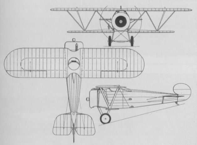
The Spider sesquiplane fighter of 1918.
B.A.T. F.K.22 (BANTAM II) UK
The first design by Frederick (Frits) Koolhoven after joining the British Aerial Transport Company (B.A.T.), the private-venture F.K.22 single-seat fighter flown in September 1917 was of wooden construction with a monocoque fuselage. Powered by a 120 hp A.B.C. Mosquito six-cylinder radial engine, it displayed sufficient promise to win an official contract for a batch of six development aircraft. The first and third of these were powered by the 170 hp A.B.C. Wasp seven-cylinder radial (F.K.22/1) and the second by a 100 hp Gnome Monosoupape nine-cylinder rotary (F.K.22/2), the remaining three eventually being completed as prototypes for the F.K.23. The F.K.22/2, retroactively named Bantam II, was the first to fly, commencing its trials in December 1917 and being delivered to Martlesham for official trials on 19 January 1918. Armament comprised two synchronised 0.303-in (7,7-mm) Vickers guns, and this prototype, later re-engined with a 110 hp Le Rhone 9J nine-cylinder rotary, was eventually assigned to the Central Flying School at Upavon. The fate of the two F.K.22/Is is unknown and the following details relate to the F.K.22/2 in Monosoupape-engined form.
Max speed, 100 mph (161 km/h) at 10,000 ft (3 050 m).
Time to 10,000 ft (3 050 m), 16.8 min.
Service ceiling, 14,500 ft (4 420 m).
Empty weight, 866 lb (393 kg).
Loaded weight, 1,260 lb (571 kg).
Span, 24 ft 8 in (7,52 m).
Length, 20 ft 8 in (6,30 m).
Height, 7 ft 5 in (2.26 m).
Wing area, 230 sq ft (21,37 m2).
B.A.T. F.K.23 (BANTAM I) UK
The first prototype F.K.23 was originally ordered as the fourth of a batch of six development F.K.22s, and while retaining the wooden structure with monocoque fuselage, it embodied extensive redesign. Overall span and wing area were reduced to 20 ft (6,09 m) and 160 sq ft (14,86 m2) respectively, and the tail surfaces were redesigned. Armament comprised two synchronised 0.303-in (7,7-mm) Vickers guns and power was provided by a 170 hp A.B.C. Wasp I, flight testing being initiated in May 1918. Two further prototypes (originally ordered as the fifth and sixth F.K.22s) were similarly powered, but dimensionally larger, and after further redesign resulting from initial flight trials, a batch of 12 F.K.23 Bantam Is was ordered, the first of these being delivered to the RAE at Farnborough on 26 July 1918. At least nine Bantam Is were completed, one of these being sent to France and evaluated at Villacoublay in the late summer of 1918. One example was sent to the USA for evaluation at Wright Field, but this fighter's principal shortcoming was the poor reliability of its Wasp I engine.
Max speed, 128 mph (206 km/h) at 6,500 ft (1 980 m).
Time to 10,000 ft (3050 m), 9.0 min.
Endurance, 2.25 hrs.
Empty weight, 833 lb (378 kg).
Loaded weight, 1,321 lb (599 kg).
Span, 25 ft 0 in (7,62 m).
Length, 18 ft 5 in (5,61m).
Height, 6 ft 9 in (2,06 m).
Wing area, 185 sq ft (17,18 m2).
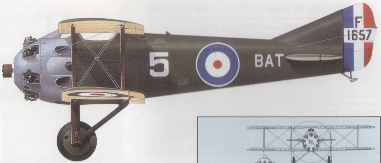
The fifth aircraft from the production batch of Bantam Is built in 1918, in racing trim.
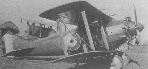
The original BAT F.K.22 with A.B.C. Mosquito engine, in late 1917

The first production F.K.23 Bantam Mk I with 170hp ABC Wasp engine; the port Vickers gun port is just visible in the lower segment of the engine cowling. F1653 first flew in March 1918 and was taken on charge by the RAE on 13 August 1920, but crashed near Aldershot on 10 January 1922.
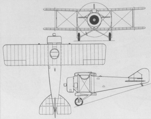
The Koolhoven-designed BAT F.K.22/2 Bantam II.
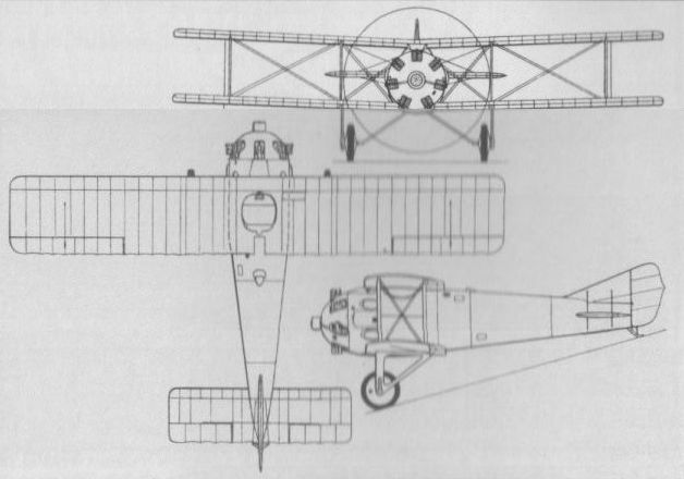
The A.B.C. Wasp-engined B.A.T. F.K.23 Bantam I.
B.A.T. F.K.25 BASILISK UK
The last single-seat fighter of Koolhoven design built by the British Aerial Transport Company, the F.K.25 Basilisk was designed around the 350 hp A.B.C. Dragonfly I nine-cylinder radial engine and carried the usual armament of twin synchronised 0.303-in (7,7- mm) Vickers guns. Of wooden construction with a monocoque fuselage, the Basilisk featured a hood-like fairing, ahead of the cockpit, which enclosed the guns and shielded the pilot. Three prototypes were ordered, the first of these flying during the summer of 1918. The second prototype, completed in 1919, differed from its predecessor primarily in having a deeper fairing ahead of the cockpit. Further work on the Basilisk was abandoned at the end of 1919.
Max speed, 142 mph (228 km/h) at 6,500 ft (1 980 m).
Time to 10,000 ft (3 050 m), 8.4 min.
Endurance, 3.25 hrs.
Empty weight, 1,454 lb (659 kg).
Loaded weight, 2,182 lb (990 kg).
Span, 25 ft 4 in (7,72m).
Length, 20 ft 5 in (6,22m).
Height, 8 ft 2 in (2,49 m).
Wing area, 212 sq ft (19,69 m2).
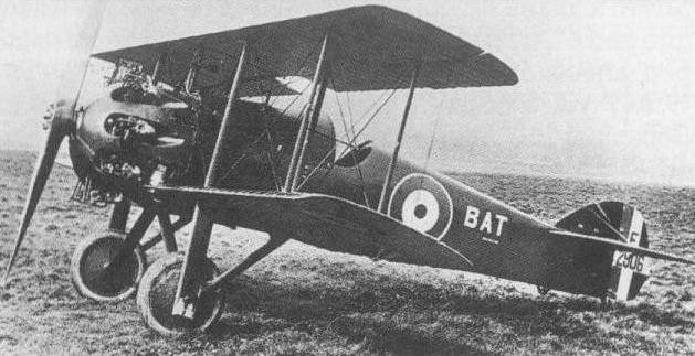
First of the three F.K.25 Basilisk fighters built by B.A.T. in 1918/1919 to Koolhoven design.
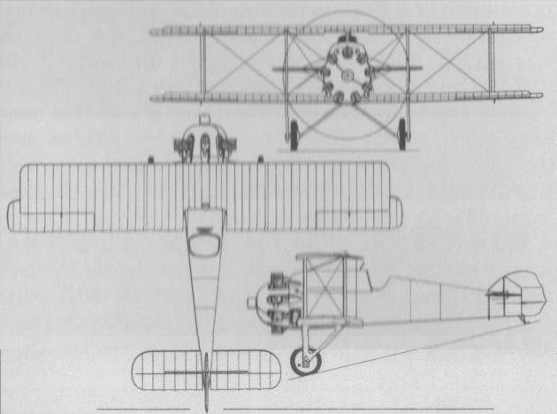
The Basilisk was the last of the B.A.T. fighters.
BEARDMORE W.B.II UK
A two-seat fighter built as a private venture and based on the design of the B.E.2c by G Tilghman-Richards of William Beardmore & Co, the W.B.II was powered by a 200 hp Hispano-Suiza 8Bd eight-cylinder water-cooled engine. It carried an armament of two fixed synchronised 0.303-in (7,7-mm) Vickers guns and a single 0.303-in (7,7-mm) Lewis gun on a swivelling Beardmore-Richards mounting. The W.B.II was first flown on 30 August 1917, and performance proved good, but the Hispano-Suiza engine was in short supply and was required for the S.E.5a single-seater. No production of the W.B.II was therefore undertaken, although two civil examples were built in 1920 as the W.B.IIB.
Max speed, 120 mph (193 km/h) at sea level, 111 mph (179 km/h) at 10,000 ft (3 050 m).
Time to 5,000 ft (1524 m), 10 min.
Endurance, 2.8 hrs.
Empty weight, 1,765 lb (800 kg).
Loaded weight, 2,650 lb (1202 kg).
Span, 34 ft 10 in (10,62 m).
Length, 26 ft 10 in (8,18 m).
Height, 10 ft 0 in (3,05 m).
Wing area, 354 sq ft (32,88 m 2).
BEARDMORE W.B.III UK
The W.B.III single-seat shipboard fighter was an extensively modified variant of the Sopwith Pup with manually-folding mainplanes and folding main undercarriage members. The prototype (a modified Pup) was officially accepted on 7 February 1917, and 100 production W.B.IIIs were ordered under the official designation S.B.3. Armament comprised a single 0.303-in (7,7-mm) Lewis gun which fired upwards through a cut-out in the upper wing centre section, and the W.B.III could be fitted with either the seven-cylinder Clerget or nine-cylinder Le Rhone 9C rotary, both of 80 hp. The first 13 production W.B.IIIs had folding undercarriages similar to the prototype and were known as S.B.3Fs, but subsequent W.B.IIIs had jettisonable undercarriages (S.B.3D) and flotation equipment. The S.B.3D version saw some service aboard British carriers, one was used in an unsuccessful attempt to fly from the forecastle of the battle cruiser HMS Renown and several were supplied to Japan.
Max speed, 103 mph (166 km/h) at sea level, 98 mph (158 km/h) at 6,500 ft (1980 m).
Time to 6,500 ft (1 980 m), 12.15 min.
Endurance, 2.75 hrs.
Empty weight, 890 lb (404 kg).
Loaded weight, 1,289 lb (585 kg).
Span, 25ft 0 in (7,62m).
Length, 20 ft 2 1/2 in (6,16 m).
Height, 8 ft 1 1/4 in (2,46 m).
Wing area, 243 sqft (22,57 m2).
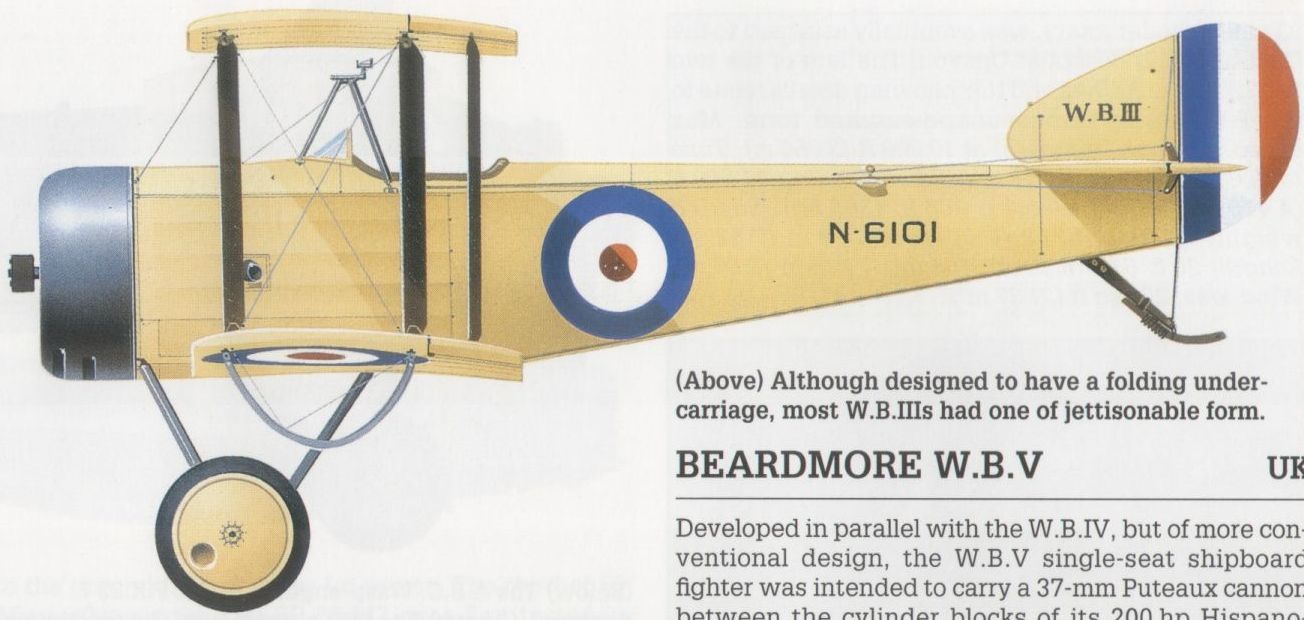
Although designed to have a folding undercarriage, most W.B.IIIs had one of jettisonable form.
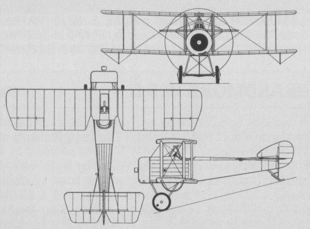
S.B.3D version for naval use.
BEARDMORE W.B.IV UK
The W.B.IV single-seat shipboard fighter was the first entirely original fighter to be developed by William Beardmore & Company and embodied several interesting features. To provide the best possible view for the pilot, the 200 hp Hispano-Suiza eight-cylinder water-cooled engine was mounted aft of the cockpit and drove the propeller via an extension shaft which passed between the pilot's legs. The cockpit was water-tight, a large flotation chamber was provided in the forward fuselage, wingtip floats were incorporated to stabilise the aircraft in the event of it alighting on the water in an emergency, and the undercarriage was jettisonable. The mainplanes could be folded, and armament comprised a single synchronised 0.303-in (7,7-mm) Vickers gun and a Lewis gun of similar calibre mounted on a tripod ahead of the cockpit. Three prototypes of the W.B.IV were ordered, the first of these flying on 12 December 1917. Performance proved creditable, but the other prototypes were not completed.
Max speed, 110 mph (177 km/h) at sea level, 102 mph (164 km/h) at 10,000 ft (3050 m).
Time to 5,000 ft (1 525 m), 7.0 min.
Endurance, 2.5 hrs.
Empty weight, 2,055 lb (932 kg).
Loaded weight, 2,595 lb (1177 kg).
Span, 35 ft 10 in (10,92 m).
Length, 26 ft 6 in (8,08 m).
Height, 9 ft 10 1/2 in (3,00 m).
Wing area, 350 sq ft (32,52 m2).
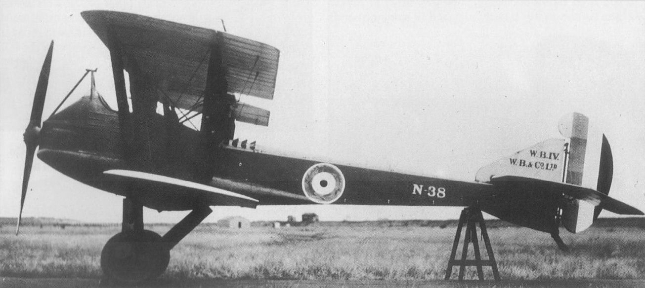
Tested at Martlesham Heath, the Beardmore W.B.IV had the original underwing tip floats removed.
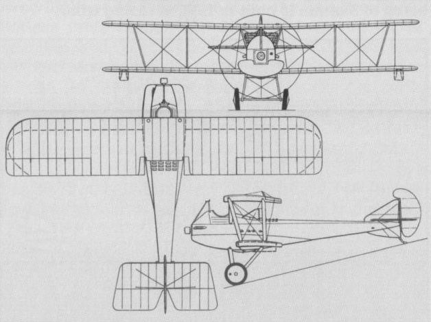
The Beardmore W.B.IV was designed for shipboard use.
BEARDMORE W.B.V UK
Developed in parallel with the W.B.IV, but of more conventional design, the W.B.V single-seat shipboard fighter was intended to carry a 37-mm Puteaux cannon between the cylinder blocks of its 200 hp Hispano-Suiza eight-cylinder water-cooled engine. It featured folding wings, a jettisonable undercarriage and inflatable flotation bags beneath the underside of the leading edge of the lower wing. Three prototypes of the W.B.V were ordered, the first of these flying on 3 December 1917, but the engine-mounted cannon was quickly removed and a more conventional armament mounted, this comprising a synchronised 0.303-in (7,7- mm) Vickers gun and a 0.303-in (7,7-mm) Lewis gun on a tripod ahead of the cockpit. The second prototype W.B.V was completed and flown in 1918, but further development was abandoned before the end of World War I.
Max speed, 112 mph (180 km/h) at sea level, 103 mph (166 km/h) at 10,000 ft (3 050 m).
Time to 5,000 ft (1525 m), 6.0 min.
Endurance, 2.5 hrs.
Empty weight, 1,860 lb (844 kg).
Loaded weight, 2,500 lb (1134 kg).
Span, 35 ft 10 in (10,92 m).
Length, 26 ft 7 in (8,10 m).
Height, 11 ft 10 in (3,61 m).
Wing area, 394 sqft (36,60 m2).
BLACKBURN TRIPLANE UK
Designed by Harris Booth, who was also responsible for the A.D. Scout, the Blackburn single-seat fighter triplane was intended to carry a single Davis two-pounder quick-fire recoilless gun firing from the nose of the nacelle and was conceived for the anti-Zeppelin role. Possessing a fabric-covered airframe, the triplane was initially flown early in 1917 with a 100 hp Clerget 9Z nine-cylinder rotary engine driving a four-bladed propeller. The Clerget was soon replaced by a Gnome Monosoupape nine-cylinder rotary of 100 hp driving a two-blade propeller and the triplane was accepted by the Admiralty on 20 February 1917, but was struck off charge as unsatisfactory four weeks later, on 19 March.
Approx max speed, 90 mph (145 km/h).
Endurance, 3 hrs.
Empty weight, 1,011 lb (458,5 kg).
Loaded weight, 1,500 lb (680 kg).
Span, 24 ft 0 in (7,31m).
Length, 21ft 5 1/4 in (6,53 m).
Height, 8 ft 6 in (2,59 m).
Wing area, 221 sq ft (20,53 m2).
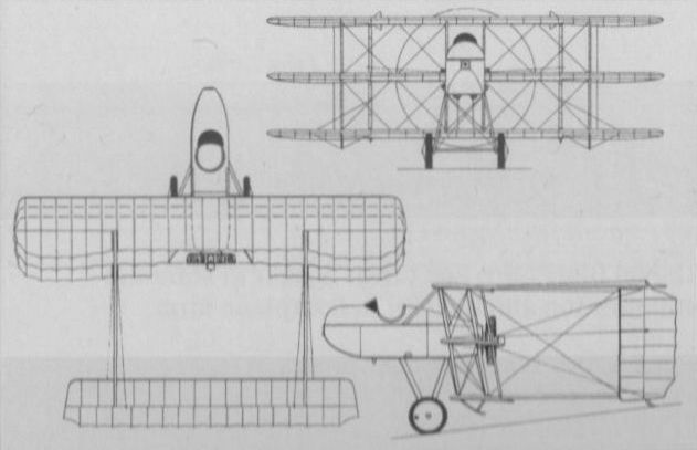
Blackburn's extraordinary Triplane fighter of 1917.
BOULTON & PAUL P.3 BOBOLINK UK
Designed by J D North, the P.3 Bobolink single-seat fighter was the first original aircraft to bear the Boulton & Paul appellation. Intended as a successor for the Sopwith Camel, the Bobolink was a two-bay biplane of wooden construction powered by a 230 hp Bentley B.R.2 nine-cylinder rotary engine and carrying an armament of two synchronised 0.303-in (7,7-mm) Vickers machine guns. The sole example of the Bobolink completed was flown for the first time in January 1918, initially with ailerons on the upper wing only, ailerons being added to the lower wing by the time official trials began at Martlesham Heath in February. Official evaluation pronounced the Bobolink as having insufficient manoeuvrability, and although tests were continued by the manufacturer no further development was undertaken.
Max speed, 125 mph (201 km/h) at 10,000 ft (3060 m).
Time to 10,000 ft (3 050 m), 9.33 min.
Endurance, 3.25 hrs.
Empty weight, 1,226 lb (556 kg).
Loaded weight, 1,992 lb (904 kg).
Span, 29 ft 0 in (8,84 m)
Length, 20 ft 0 in (6,10m).
Height, 8 ft 4 in (2,54 m).
Wing area, 266 sq ft (24,71 m2).
BRISTOL SCOUT D UK
Derived from a single-seat sports biplane designed by Frank Barnwell, first flown in February 1914 and retrospectively known as the Scout A, the Scout D was a revised design which, completed in November 1915, had provision for a fixed synchronised 0.303-in (7,7-mm) Vickers gun. The Scout D had been preceded by two Scout Bs, which, intended for reconnaissance, were officially unarmed, but one of which was fitted with a rifle on each side of the fuselage and angled outward to avoid hitting the propeller when fired. These had been followed by 161 Scout Cs (74 for the RN and 87 for the RFC) which, again, were officially unarmed, although much ingenuity was displayed in the field in fitting pistols, rifles and carbines, while some RN Scouts carried 24-round canisters of Ranken darts which it was intended to use against Zeppelins. The Scout D was thus the first model for which armament was officially intended, though relatively few of these had the synchronised Vickers gun and the armament of others varied considerably, some having a 0.303-in (7,7-mm) fixed Lewis gun firing straight ahead without synchronising equipment and others having a movable Lewis above the upper wing. Of the 210 examples built, 80 went to the RN, of which 50 had 100 hp Gnome Monosoupape engines and the remainder the 80 hp Gnome. Most of those delivered to the RFC ultimately had the 80 hp Le Rhone engines and the following data relate to the Scout D with this engine.
Max speed, 100 mph (161 km/h) at sea level, 86 mph (138 km/h) at 10,000 ft (3050 m).
Time to 10,000 ft (3050 m), 18.5 min.
Endurance, 2.5 hrs.
Empty weight, 760 lb (345 kg).
Loaded weight, 1,250 lb (567 kg).
Span, 24 ft 7 in (7,49 m).
Length, 20 ft 8 in (6,30 m).
Height, 8 ft 6 in (2,59 m).
Wing area, 198 sq ft (18,39 m2).
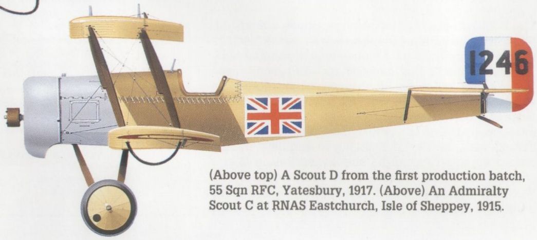
An Admiralty Scout C at RNAS Eastchurch, Isle of Sheppey, 1915.

A Scout D from the first production batch, 55 Sqn RFC, Yatesbury, 1917.
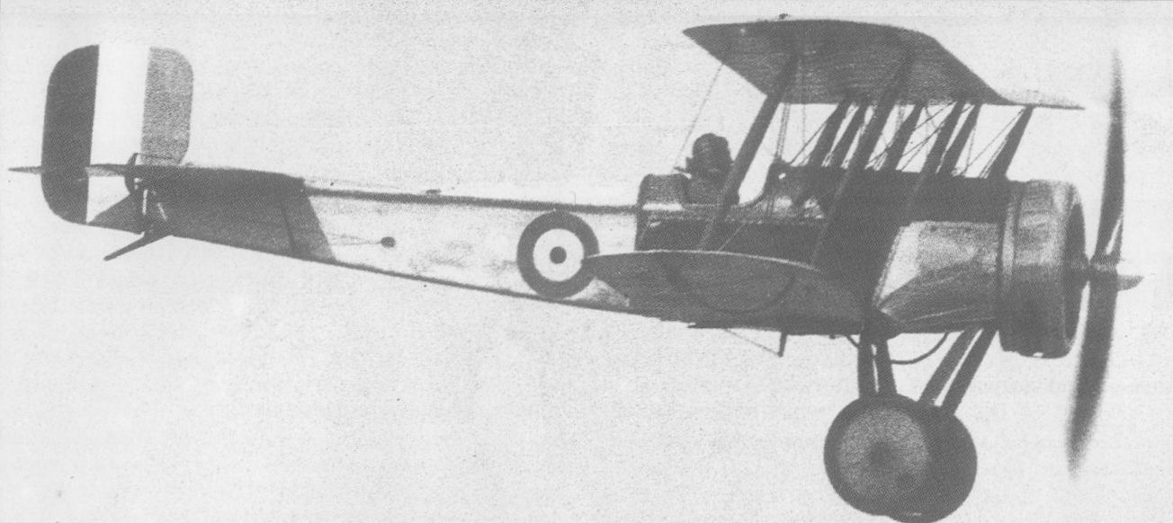
The Scout D was the first fully armed version of the Bristol biplane, but many flew unarmed such as that in Australia in 1919.
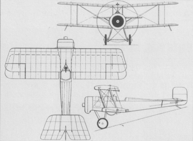
Bristol Scout D
BRISTOL F.2A (FIGHTER) UK
Known by the appellation of "Fighter" almost from its birth, the F.2 series of two-seat fighter-reconnaissance aircraft designed by Frank Barnwell was to join the ranks of the true immortals of World War I. Designed around the new 190 hp Rolls-Royce 12-cylinder water-cooled engine, but with provision for the alternative installation of the 150 hp eight-cylinder Hispano-Suiza, the F.2A had a single forward-firing synchronised 0.303-in (7,7-mm) Vickers gun and a Lewis gun of the same calibre on a Scarff ring in the rear cockpit. The first of two prototypes was flown on 9 September 1916, a production contract for 50 aircraft having been placed 12 days earlier, on 28 August. Deliveries began early in 1917, but initial operational experience in April 1917 was disappointing, thanks to the use of incorrect combat techniques. Confidence in the type was restored when newly-evolved methods were proved successful. Meanwhile, the improved F.2B had been evolved, the 51st and subsequent production aircraft being of this standard, and delivery of the F.2B resulting in the withdrawal from frontline use of the F.2A.
Max speed, 110.mph (177 km/h) at sea level, 106 mph (171 km/h) at 5,0 ft (1 525m).
Time to 5,000 ft (1 525m), 5.45 min.
Endurance, 3 hrs.
Empty weight, 1,727 lb (783 kg).
Loaded weight, 2,667 lb (1210 kg).
Span, 39 ft 3 in (11,96 m).
Length, 25 ft 10 in (7,87 m).
Height, 9 ft 6 in (2,89 m).
Wing area, 389 sq ft (36,14 m2).
BRISTOL F.2B (FIGHTER) UK
The F.2B two-seat fighter-reconnaissance aircraft differed from the F.2A in having a revised centre fuselage to provide improved pilot view, an enlarged fuel tank, increased ammunition capacity for the synchronised Vickers gun and a modified lower wing affording a small increase in gross area. New horizontal tail surfaces of greater span and increased aspect ratio were introduced, and after the first 150 F.2Bs had been delivered with the 190 hp Rolls-Royce engine - by this time designated Falcon I - the 220 hp Falcon II was adopted, this being succeeded in turn by the 275 hp Falcon III which powered the majority of the F.2Bs built. F.2B deliveries began on 13 April 1917, and the success of this type led to the decision to re-equip all RFC fighter-reconnaissance squadrons with F.2Bs. Production continued, in the event, until September 1919, by which time a total number of 4,747 had been completed, 3,126 of these by the parent company. Of the final batch, 153 were delivered with the 200 hp Sunbeam Arab engine and 18 with the 230 hp Siddeley Puma. When the RAF was re-established on a peacetime footing, the F.2B was adopted as standard for the army co-operation role and reinstated in production for this task as the Mk II, others being refurbished to similar standards. Fifty structurally revised aircraft delivered in 1926 were designated as Mk IIIs, all surviving aircraft of this mark being converted in 1928 as Mk IVs. The following data relate to the Falcon III-powered F.2B of 1918.
Max speed, 123 mph (198 km/h) at 5,000 ft (1525 m), 113 mph (182 km/h) at 10,000 ft (3 050 m).
Time to 10,000 ft (3050 m), 11.85 min.
Empty weight, 1,930 lb (875 kg).
Loaded weight, 2,848 lb (1292 kg).
Span, 39 ft 3 in (11,96 m).
Length, 25 ft 10 in (7,87 m).
Height, 9 ft 9 in (2,97 m).
Wing area, 405.6 sq ft (37,68 m2).

A Bristol-built, Falcon-engined F.2B Fighter on the strength of No 139 Sqn in Italy, August 1918.
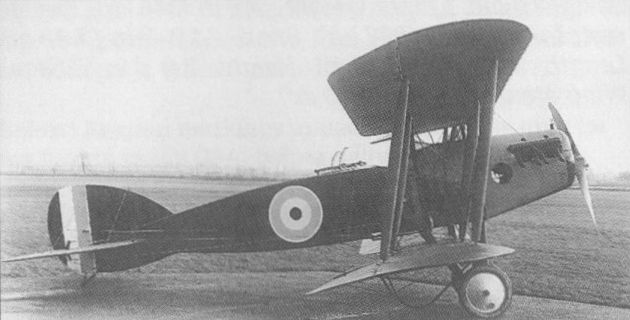
Second prototype of the Bristol F.2A which was powered by a 150 hp Hispano Suiza engine, only 50 aircraft of this type being built.
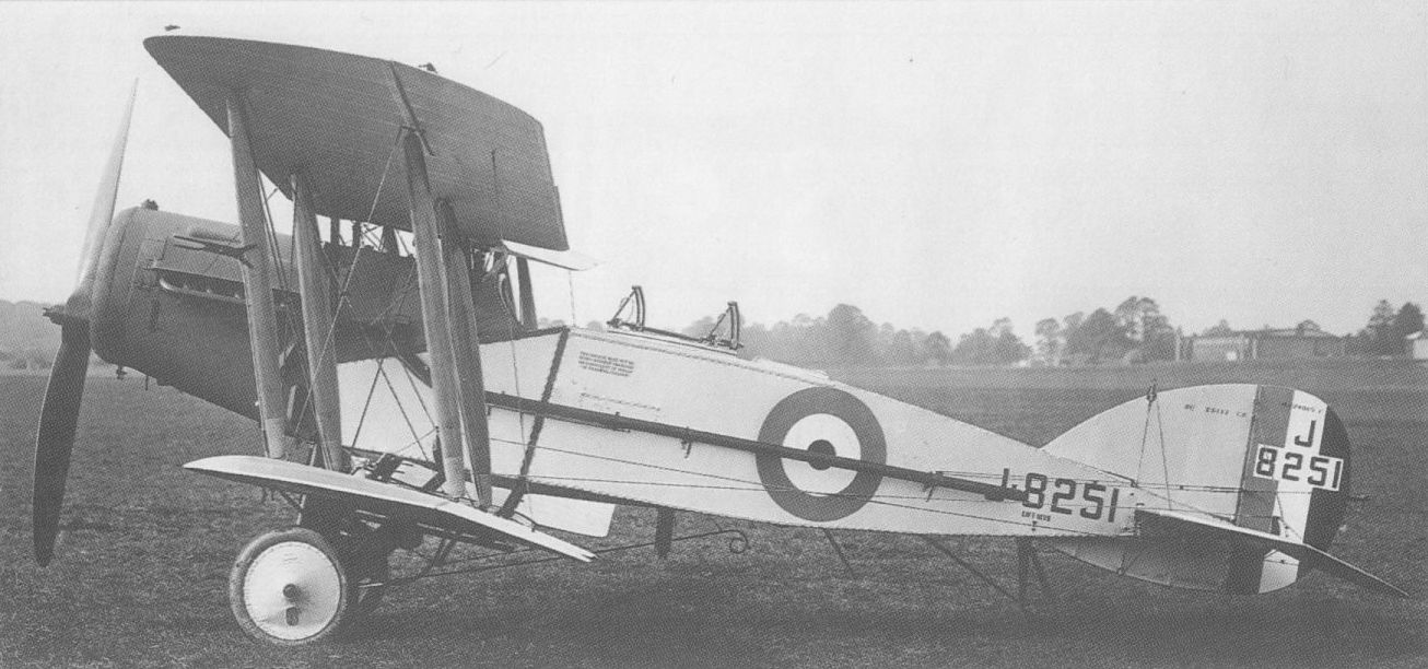
An example of the Fighter Mk III from the 1926 production batch, with structural revisions.
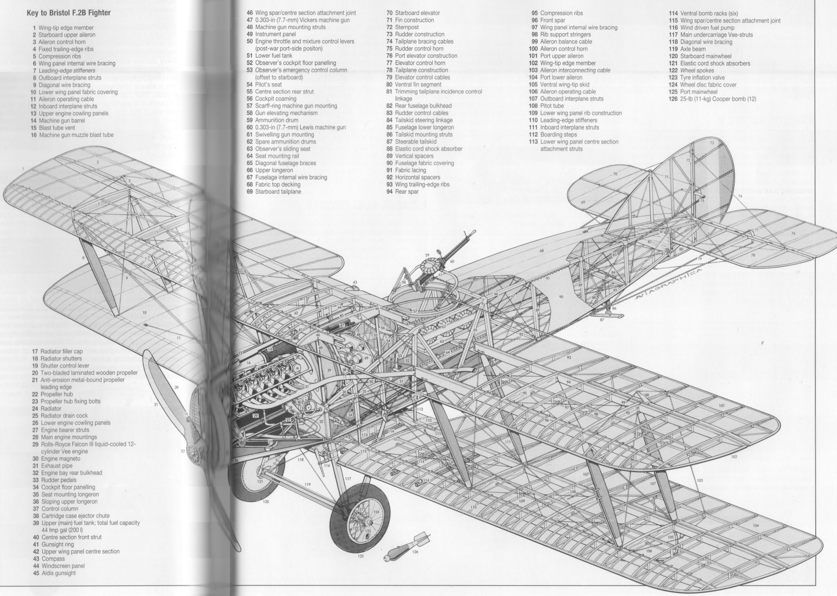
Bristol F.2B Fighter
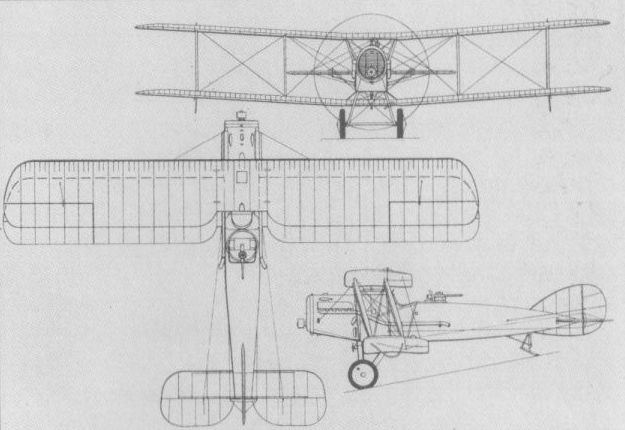
Bristol F.2B with Rolls-Royce Falcon engine.
BRISTOL M.1C UK
The M.1C was the production derivative of the private-venture M.1A which, designed by Frank Barnwell, had flown for the first time on 14 July 1916. It was of innovatory design in being a shoulder-wing monoplane with a fully faired fuselage of good streamline form and a drag-reducing hemispherical spinner. Four similar aircraft were ordered by the War Office, these each having a single 0.303-in (7,7-mm) Vickers gun mounted on the port wing root and a clear-view cut-out panel in the starboard wing root to afford the pilot a measure of downward visibility. This version received the designation M.1B and a production order for 125 aircraft was placed on 3 August 1917 as M.1Cs. Powered by a 110 hp Le Rhone 9J nine-cylinder rotary engine, the M.1C had a centrally-mounted Vickers gun, but its subsequent operational career was largely confined to the Middle East where 33 M.1Cs were sent during 1917-18. No aircraft of this type were issued to RFC squadrons based in France, most being used by UK-based training units, the 49 mph (97 km/h) landing speed being considered too high for small Western Front airfields.
Max speed, 130 mph (209 km/h) at sea level, 127 mph (204 km/h) at 5,0 ft (1 525 m).
Time to 10,000 ft (3 050 m), 10.45 min.
Endurance, 1.75 hrs.
Empty weight, 896 lb (406 kg).
Loaded weight, 1,348 lb (611 kg).
Span, 30 ft 9 in (9,37 m).
Length, 20 ft 5 1/2 in (6,23 m).
Height, 7 ft 9 1/2 in (2,37 m).
Wing area, 145 sq ft (13,47 m2).
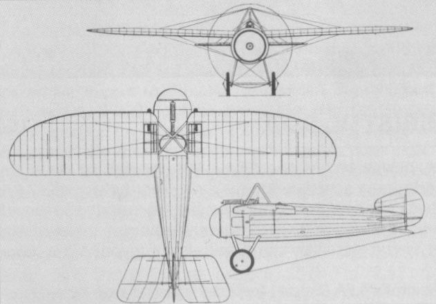
The Bristol M.1C
BRISTOL S.2A UK
A derivative of the Scout D intended to meet an Admiralty specification for a two-seat fighter, the S.2A had side-by-side seating and was intended to be armed with a single 0.303-in (7,7-mm) Lewis gun. In the event, it was rejected by the Admiralty in favour of the Sopwith 1 1/2 Strutter, but work continued on the two prototypes at the behest of the War Office which envisaged the type primarily as a potential advanced trainer for the RFC. The two prototypes were completed in May and June 1916 respectively, being powered by the 110 hp Clerget engine (although one was later re-engined with a 100 hp Gnome Monosoupape), and were delivered to the Central Flying School at Upavon. They were found to be manoeuvrable and quite fast, but no further development was undertaken.
Max speed, 95mph (153 km/h).
Endurance, 3.0 hrs.
Loaded weight, 1,400 lb (635 kg). Span, 28 ft 2 in (8,58m).
Length, 21 ft 3 in (6,48 m).
Height, 10 ft 0 in (3.05 m).
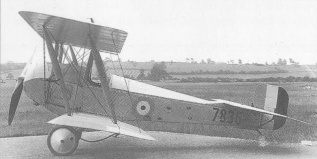
Bristol's S.2A featured unusual side-by-side seating, but only a single Lewis gun armament.
The Bristol S.2A, actually 7836, which differed from the 7837 (which was the only other one) by the shape of the cockpit cut-out as well as the engine. It was a 2-seater with side-by-side seating, and was sometimes referred to as the "sociable"; also as the "tubby". Intended as a fighter, it got a little use as a trainer.
The Bristol S.2A, actually 7836, which differed from the 7837 (which was the only other one) by the shape of the cockpit cut-out as well as the engine. It was a 2-seater with side-by-side seating, and was sometimes referred to as the "sociable"; also as the "tubby". Intended as a fighter, it got a little use as a trainer.
BRISTOL T.T.A. UK
Designed by Frank Barnwell assisted by Leslie G Frise, the T.T.A. (Twin Tractor Model A) was intended to meet a requirement for a two-seat twin-engined local defence fighter, the gunner in the nose having an unobstructed field of fire for two free-mounted 0.303-in (7,7-mm) Lewis guns. Dual controls were fitted and the intended power plant comprised two 150 hp R.A.F.4a engines. In the event, non-availability of these engines resulted in the installation of two 120 hp six-cylinder Beardmore water-cooled engines in the two prototypes ordered. The first T.T.A. was flown in April 1916, but displayed poor lateral control and was adversely criticised on the grounds of poor pilot view. As by this time synchronising mechanisms for guns were becoming available, no further development of this category of aircraft was pursued.
Max speed, 87 mph (140 km/h) at sea level.
Time to 6,000 ft (1830 m), 21 min.
Empty weight, 3,820 lb (1 733 kg).
Loaded weight, 5,100 lb (2 313 kg).
Span, 53 ft 6 in (16,30 m).
Length, 39 ft 2 in (11,94 m).
Height, 12 ft 6 in (3,81 m).
Wing area, 817 sq ft (75,90 m ).
BRISTOL SCOUT F UK
Originally intended for a 200 hp Hispano-Suiza engine, the Scout F was initiated by Frank Barnwell in June 1917, subsequently being redesigned to take a 200 hp Sunbeam Arab II eight-cylinder water-cooled engine. This power plant had been ordered into large-scale production in January 1917, before adequate testing had been undertaken. Six prototypes of the Scout F were ordered, the first of these flying in March 1918, by which time it had been decided to complete only the first two aircraft with Arab engines. The Scout F possessed excellent flying qualities, but its Arab engine proved totally unreliable. Nevertheless, the second prototype was completed and flown, flight testing continuing into 1919. Armament comprised two synchronised 0.303-in (7,7-mm) Vickers guns.
Max speed, 138 mph (222 km/h) at sea level, 128 mph (206 km/h) at 10,000 ft (3 050 m).
Time to 10,000 ft (3 050 m), 9.35 min.
Empty weight, 1,436 lb (651 kg).
Loaded weight, 2,210 lb (1002 kg).
Span, 29 ft 7 1/2 in (9,03 m).
Length, 20 ft 10 in (6,35m).
Height, 8 ft 4 in (2,54 m).
Wing area, 260 sqft (24,15 m2).
BRISTOL SCOUT F.1 UK
The shortcomings of the Arab engine led, at an early stage in the development of the Scout F, to an investigation of possible alternative power plants, and it was decided to adapt the third prototype airframe to take a new 14-cylinder two-row Brazil-Straker (later Cosmos Engineering) Mercury radial of 347 hp. Designated Scout F.1, the aircraft was first flown on 6 September 1918, and proved to possess an excellent performance, establishing new unofficial climb records in April 1919. By that time, further development of the Mercury engine had been abandoned and no more work on the Scout F.1 was undertaken.
Max speed, 145 mph (233 km/h) at sea level.
Time to 10,000 ft (3 050 m), 5.45 min.
Loaded weight, 2,260 lb (1 025 kg).
Span, 29 ft 7 1/2 in (9,03m).
Length, 20 ft 0 in (6,09m).
Height, 8 ft 4 in (2,54 m).
Wing area, 260 sq ft (24,15 m2).
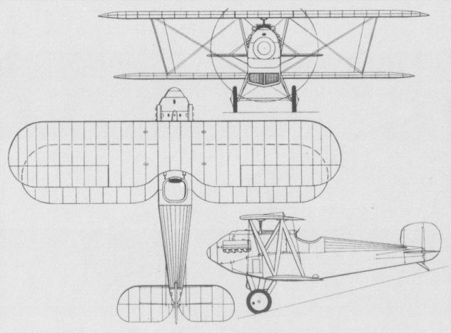
The Bristol Scout F of 1918 was powered by the unreliable Sunbeam Arab and only two prototypes were built.
BRISTOL F.2C BADGER UK
Intended as a successor to the F.2B two-seat fighter-reconnaissance aircraft, the F.2C Badger was designed for the 320 hp ABC Dragonfly I nine-cylinder radial, three prototypes being ordered. Armament comprised two fixed 0.303-in (7,7-mm) Vickers machine guns and a 0.303-in (7,7-mm) Lewis gun mounted on a Scarff ring in the rear cockpit. The first prototype suffered a crash landing as a result of an engine failure during its first take-off on 4 February 1919, but was subsequently rebuilt and flown. The second prototype was completed with a nine-cylinder Cosmos Jupiter of 450 hp and flew on 24 May 1919, but later had a Dragonfly substituted for the Jupiter. A third aircraft was completed as the Badger II with a Cosmos Jupiter engine and redesigned wings, this being re-engined in 1921 with a 385 hp Jupiter II (this power plant having meanwhile been taken over by Bristol) and subsequently being used primarily for engine development purposes. The following data relate to the Dragonfly-engined Badger.
Max speed, 135 mph (217 km/h) at sea level, 129 mph (207 km/h) at 10,000 ft (3 050m).
Time to 10,000 ft (3 050 m), 11 min.
Empty weight, 1,948 lb (884 kg).
Loaded weight, 3,152 lb (1430 kg).
Span, 36 ft 9 in (11,20 m).
Length, 23 ft 8 in (7,21m).
Height, 9 ft 1 in (2,76 m).
Wing area, 357.2 sq ft (33,18 m2)).
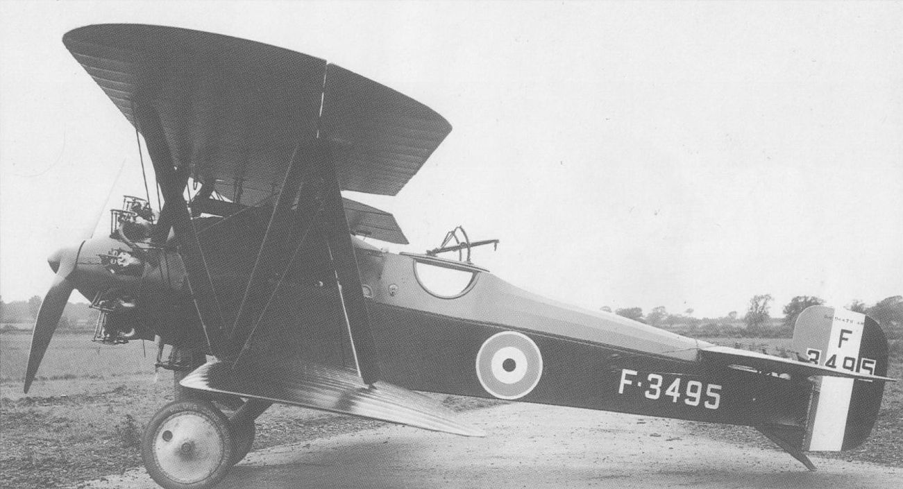
Badger I F3495 as rebuilt after suffering a crash landing on its first flight, with improved Dragonfly installation and larger rudder; Filton, February 1919.
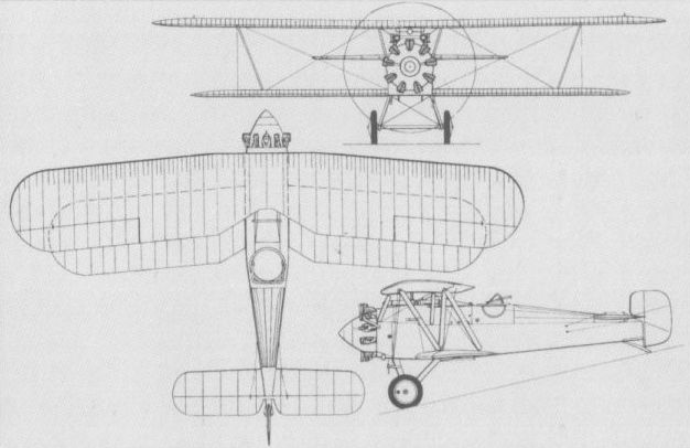
First Bristol F.2C Badger in its definitive form.
AIRCO D.H.2 UK
Designed by Geoffrey de Havilland of the Aircraft Manufacturing Company (Airco), the D.H.2 single-seat fighter was an unstaggered two-bay biplane of fabric-covered wooden construction with tubular steel booms carrying the tail surfaces. The prototype was first flown on 1 June 1915, but, having been sent to France for evaluation under operational conditions, fell into German hands substantially intact on 15 August. A few series D.H.2s were to be fitted with the 100 hp Le Rhone nine-cylinder rotary, but the standard engine was the 100 hp Gnome Monosoupape rotary mounted as a pusher. Armament comprised a free-mounted 0.303-in (7,7-mm) Lewis machine gun, and the D.H.2 proved an extremely sturdy aircraft and fully aerobatic with delightful handling qualities. A total of 266 served with the British Expeditionary Force in France from 400 delivered. The following data relate to the Gnome-engined version.
Max speed, 93 mph (150 km/h) at sea level, 77 mph (124 km/h) at 10.000 ft (3 050 m).
Time to 5,0 ft (1 525 m), 8.45 min.
Empty weight, 943 lb (428 kg).
Loaded weight, 1,441 lb (654 kg).
Span, 28 ft 3 in (8,61 m).
Length, 25 ft 2 1/2 in (7,68 m).
Height, 9 ft 6 1/2 in (2,91 m).
Wing area, 249 sq ft (23,13 m3).
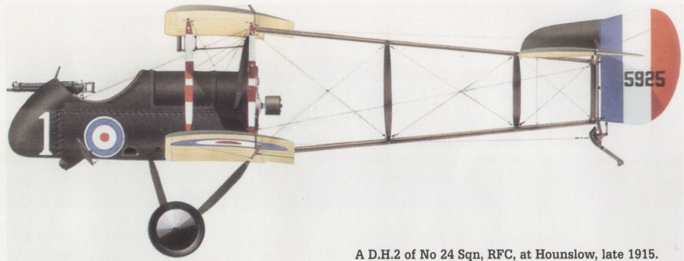
A D.H.2 of No 24 Sqn, RFC, at Hounslow, late 1915.
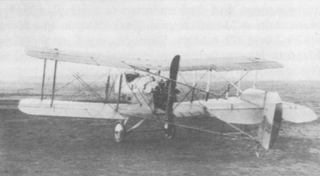
A D.H.2 of the first Airco production batch.
AIRCO D.H.5 UK
Characterised by the pronounced negative stagger of its mainplanes, which resulted from an attempt on the part of Geoffrey de Havilland to combine the performance of the tractor biplane with the cockpit visibility of pusher aircraft, the D.H.5 was flown late in 1916, and entered service in May 1917. Immensely strong and possessing docile handling qualities, but easily outflown by contemporary fighters at altitudes above 10,000 ft (3 050 m), the D.H.5 was of wooden construction with plywood and fabric skinning. Power was provided by a 100 hp Le Rhone 9J nine-cylinder rotary and armament consisted of a single 0.303-in (7,7-mm) Vickers gun. Some 550 were built by the parent company; Darracq Motor Engineering; March, Jones and Cribb, and British Caudron, but the D.H.5 was deemed to be of limited success and had been withdrawn from operations by the end of January 1918.
Max speed, 102 mph (164 km/h) at 10,000 ft (3 050 m), 89 mph (143 km/h) at 15,000 ft (4 570 m).
Initial climb, 1,200 ft/min (6,1 m/sec).
Endurance, 2.75 hrs.
Empty weight, 1,101 lb (458 kg).
Loaded weight, 1,492 lb (677 kg).
Span, 25 ft 8in (7,82m).
Length, 22 ft 0in (6,71 m).
Height, 9ft 1 1/2 in (2,78 m).
Wing area, 212.1 sq ft (19,70 m2).
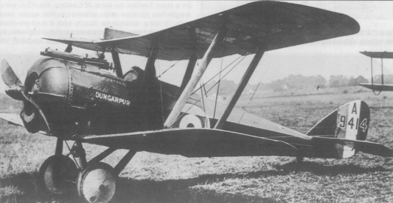
A D.H.5 of the batch of 200 fighters of this type built in 1917 by the Darracq Motor Engineering Co.
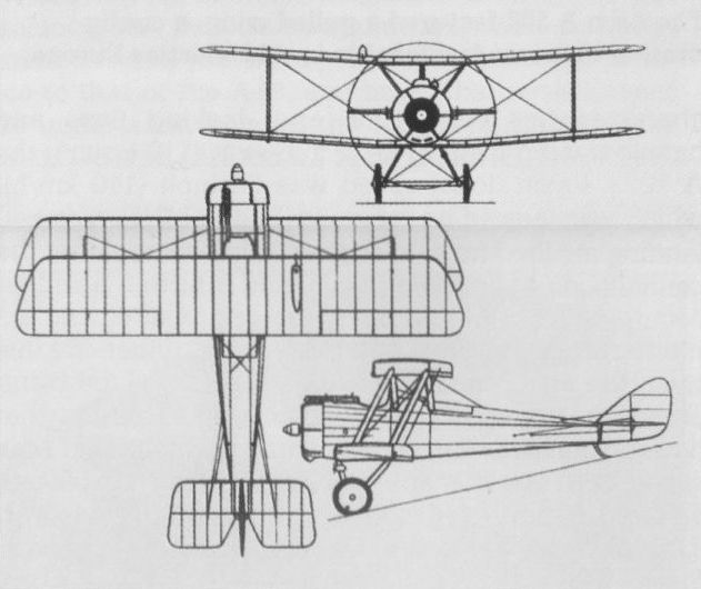
Negative stagger characterised the D.H.5.
FAIREY F.2 UK
The first aircraft to be designed entirely by Fairey Aviation, the F2 was a massive twin-engined, three-seat, long-range fighter ordered by the Admiralty. Powered by two 190 hp Rolls-Royce Falcon 12-cylinder water-cooled engines, the F2 was a three-bay biplane with a four-wheel "bedstead" main undercarriage, the wings folding aft from a point outboard of the engines. Armament consisted of a 0.303-in (7,7-mm) Lewis machine gun on a Scarff ring in the extreme nose and a similar installation immediately aft of the wings. The sole prototype made its official first flight on 17 May 1917, but Admiralty interest in the F.2 had waned by then, and no further development was undertaken as no use had been found for the large, relatively slow, multi-engined, multi-seat fighter.
Max speed, 93 mph (150 km/h) at sea level.
Time to 5,000 ft (1 525 m), 6.0 min.
Endurance, 3.5 hrs.
Loaded weight, 4,880 lb (2213 kg).
Span, 77 ft 0 in (23,47m).
Length, 40 ft 6 in (12,34 m).
Height, 13 ft 6 in (4,11 m).
Wing area, 814 sq ft (75.62 m2).
FAIREY HAMBLE BABY UK
The Hamble Baby represented an attempt on the part of the Fairey Aviation Company to improve the performance of the Sopwith Baby single-seat fighter float seaplane, but, in the event, emerged as virtually a new type. The Hamble Baby used, for the first time, the Fairey Patent Camber Gear, a form of trailing-edge flap attached to each mainplane of the redesigned wing to act as ailerons in normal flight, but capable of being deflected as lift-increasing devices for take-off and landing. The tail assembly was redesigned and Fairey designed floats were fitted. Armament consisted of a single synchronised 0.303-in (7,7-mm) machine gun with provision for two 65-lb (29,5-kg) bombs. The first 50 aircraft were powered by the 110 hp Clerget nine-cylinder rotary engine and the remaining 130 (built by Parnall and Sons) had the 130 hp Clerget. The last 74 Babies built by Parnall were fitted with wheel-and-skid undercarriages and known as Hamble Baby Converts. The Hamble Babies were operated by the RNAS in the UK, the Mediterranean and the Aegean, entering service in the summer of 1917. The data relate to the 110 hp Baby.
Max speed, 90 mph (145 km/h) at 2,000 ft (610 m).
Time to 2,000 ft (610 m), 5.5 min
Endurance, 2.0 hrs.
Empty weight, 1,386 lb (629 kg)
Loaded weight, 1,946 lb (883 kg).
Span, 27 ft 9 1/4 in (8,46 m).
Length, 23 ft 4 in (7,11 m).
Height, 9 ft 6 in (2,89 m)
Wing area, 246 sq ft (22,85 m2).
MANN EGERTON Type H UK
The first original design produced by Mann Egerton and Company, which had previously manufactured various aircraft types under licence, the Type H single-seat shipboard fighter was designed by J W Carr to Specification N.la. Powered by a 200 hp Hispano-Suiza 8Bd eight-cylinder water-cooled engine, the Type H was an equi-span unstaggered two-bay biplane armed with a single fixed 0.303-in (7,7-mm) Vickers gun mounted to port on the fuselage and a Lewis gun of similar calibre mounted above the wing centre section. The wings could be folded manually and the first prototype had a large, flush-fitting float attached to the underside of the fuselage. In addition, flotation chambers were included in the fuselage, and the undercarriage, which was attached to the underside of the float, could be jettisoned in the event that the aircraft was forced to alight on water. Flight testing of the first prototype commenced in the autumn of 1917, but the aircraft failed flotation testing and was therefore considered unacceptable. The second prototype differed in having inflatable flotation bags in place of the fixed float, a more conventional undercarriage and a horn-balanced rudder. This aircraft underwent official testing during December 1917, but the Type H was not accepted for service use and further development was discontinued. The following data relate specifically to the second prototype.
Max speed, 113 mph (182 km/h) at 6,500 ft (1 980 m).
Time to 6,500 ft (1 980 m), 6.45 min.
Endurance, 3.25 hrs.
Empty weight, 1,760 lb (798 kg).
Loaded weight, 2,326 lb (1055 kg).
Span, 30 ft 9 in (9,37 m).
Length, 21 ft 11 in (6,68 m).
Height, 8 ft 11 1/2 in (2,73 m).
Wing area, 310 sq ft (28,80 m2).
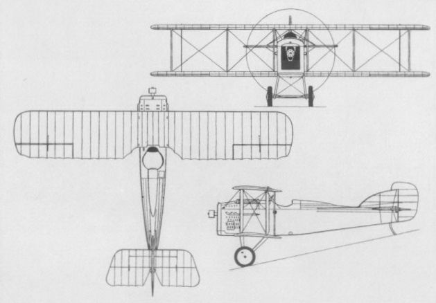
Flush-fitting floats on the first Type H were discarded for the second aircraft (shown).
MANN & GRIMMER M.1 UK
Designed by R F Mann and R P Grimmer, the M.1 two-seat fighter represented an attempt to combine the superior performance offered by a tractor configuration with the clear forward field of fire provided by a pusher arrangement. The conventionally-mounted Anzani 10-cylinder air-cooled radial engine drove two pusher propellers by means of an extended shaft via a gearbox and chains. The gunner was seated immediately aft of the engine, the pilot's cockpit being just behind the plane of the propellers. The M.1 was first flown on 19 February 1915, but difficulties were experienced with the chain transmission and with handling. Various modifications were made and the 100 hp Anzani engine was replaced by one rated at 125 hp, but after some 18 hours of flight testing, the M.1 was wrecked on 16 November 1915 before it could be evaluated by the RFC, and although work on the prototype of an improved version, the M.2, was begun, no further aircraft was completed.
Max speed, 85 mph (137 km/h).
Time to 3,000 ft (915 m), 8 min.
Endurance, 4.5 his.
Approx empty weight, 2,100 lb (953 kg).
Approx loaded weight, 2,800 lb (1270 kg).
Span, 34 ft 9 in (10,59 m).
Length, 26 ft 5 in (8.05 m).
Wing area, 322 sq ft (29,91 m2).
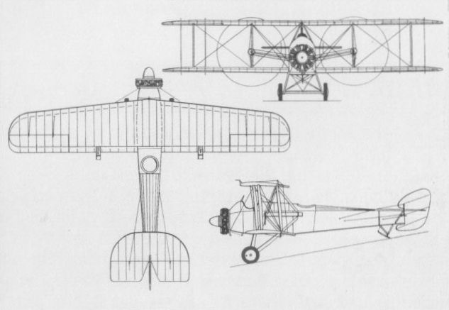
MARTINSYDE ELEPHANT UK
An unusually large aircraft by contemporary standards for a single-seater, the Elephant two-bay equi-span staggered biplane was designed by A A Fletcher of the Martinsyde Company, a prototype powered by a 120 hp Austro-Daimler engine entering test in the autumn of 1915. The initial production version, the G.100, was powered by a 120 hp six-cylinder Beardmore engine and was armed with a single 0.303-in (7,7-mm) Lewis gun mounted above the centre section (this later being augmented by a similar weapon bracket-mounted to port behind the cockpit), deliveries to the RFC commencing in 1916. The G.100 was succeeded by the G.102 version which differed in having a 160 hp Beardmore engine and replaced the lower-powered model progressively. The G.100 and G.102 Elephants were used in France and the Middle East, although only one RFC squadron was completely equipped with this type, a total of 270 being manufactured. While not particularly successful as a fighter owing to its poor agility by comparison with its smaller contemporaries, the Elephant performed a useful service as a bomber, carrying up to 230 lb (104 kg). The following data relate to the G.102.
Max speed, 103 mph (166 km/h) at sea level.
Time to 3,000 ft (915 m), 3.5 min.
Endurance, 4.5 hrs.
Empty weight, 1,793 lb (813 kg).
Loaded weight, 2,458 lb (1115 kg).
Span, 38 ft 0 in (11,58 m).
Length, 26 ft 6 1/2 in (8,08 m).
Height, 9 ft 8 in (2,95 m).
Wing area, 410 sqft (38,09 m2).
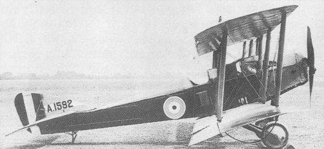
In its G.102 form (shown) the Elephant had a more powerful engine than was used in the G.100.

In its G.102 form the Elephant had a more powerful engine than was used in the G.100 (shown).
MARTINSYDE R.G. UK
Derived from the Elephant via a single-bay experimental variant of the earlier design by A A Fletcher, the R.G. bore a close resemblance to its predecessor and was initially flown late in 1916 with a 190 hp Rolls-Royce Falcon 12-cylinder water-cooled engine. Armament comprised a fixed 0.303-in (7,7-mm) Vickers gun on the port upper longeron, outside the cabane struts, and a Lewis gun on the starboard side of the cockpit. After official trials in February 1917, the R.G. was revised in a number of respects. The cockpit was moved aft and the centre section cut-out was enlarged. The span of the lower wing was reduced and the rear top decking was raised. Armament was changed and consisted of two 0.303-in (7,7-mm) Vickers guns immediately in front of the cockpit, and a 275 hp Falcon III engine was fitted. In this form, the R.G. had, according to the official report, a ‘‘performance ... far and away better than any other machine manufactured”. However, development was discontinued in favour of the superior F.3. The following data relate to the definitive R.G.
Max speed, 132 mph (212 km/h) at 6,500 ft (1 980 m).
Time to 10,000 ft (3 050 m), 7.33 min.
Endurance, 2 hrs.
Empty weight, 1,740 lb (789 kg).
Loaded weight, 2,261 lb (1 026 kg).
Span, 32 ft 0 in (9,75 m).
Length, 25 ft 10 in (7,87 m).
Height, 9 ft 10 in (2,30 m).
Wing area, 310 sqft (28,80 m2).
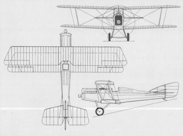
Owing much to the Elephant, the R.G. was discontinued in favour of the Buzzard.
MARTINSYDE F.1 UK
The F.1 two-seat fighter was conceived late in 1915 as a tractor biplane in which the gunner occupied the forward cockpit and stood upright to fire a 0.303-in (7,7- mm) Lewis gun on a mount built into the upper wing centre section. Powered by a 250 hp Rolls-Royce Mk III engine (later to become known as the Eagle III), the F.1 suffered a somewhat protracted development and, by the time that it was officially tested in July 1917, it was already obsolete. Obviously not acceptable for operational use, the F.1 was not further developed.
Max speed, 109 mph (175 km/h) at 6,500 ft (1 980 m).
Time to 10,000 ft (3 050 m), 13.66 min.
Endurance, 3.75 hrs.
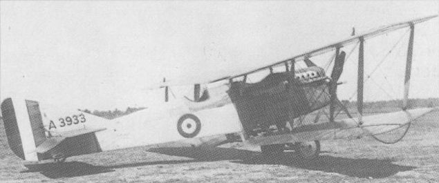
The sole prototype of the F.1 two-seat fighter was tested with little success in 1917.
MARTINSYDE F.2 UK
Of more modern concept that the F.1, the F.2 two-seat fighter was, like its predecessors, of wooden construction with fabric skinning, apart from the sides and top decking of the fuselage which were plywood covered. Designed and built while the F.1 was under construction, the F.2 underwent official testing two months prior to its predecessor, in May 1917. The F.2 was powered by a 200 hp Hispano-Suiza 8Bd eight-cylinder water-cooled engine and carried an armament of one fixed and synchronised 0.303-in (7,7-mm) Vickers gun and one Lewis gun on a Scarff ring. Shortcomings revealed during official trials ruled out a production order, and the prototype was utilised as a test-bed for the then-new Sunbeam Arab engine.
Max speed, 120 mph (193 km/h) at sea level.
Time to 10,000 ft (3 050 m), 13.5 min.
Endurance, 2.5 hrs.
Empty weight, 1,547 lb (702 kg).
Loaded weight, 2,355 lb (1 068 kg).
Span, 32 ft 0 in (9,75 m).
Length, 25 ft 0 in (7,62 m).
Height, 8 ft 2 in (2,49 m).
Wing area, 334 sq ft (31,03 m2).
MARTINSYDE BUZZARD UK
Widely considered to have been one of the best single-seat fighters to emerge during World War I, the Buzzard began life as a private venture design by G H Handasyde designated F.3. A single-bay staggered biplane of conventional wooden construction with fabric skinning and powered by a Rolls-Royce Falcon engine of 285 hp, the F.3 appeared in the autumn of 1917. It underwent its first official trials on 3 October, six further prototypes being ordered and a decision to manufacture the F.3 in quantity being taken before the end of 1917. The F.3 was powered by the 275 hp Falcon III engine, but priorities in Falcon engine supplies enjoyed by the Bristol Fighter led to the reworking of the F.3 for the 300 hp Hispano-Suiza 8Fb. With this it was redesignated F.4 and (from September 1918) officially named Buzzard. It is uncertain just how many of the original batch of 150 aircraft were completed as Falcon-engined F.3s, but most were certainly finished as HS 8Fb-engined F.4s, the first of the latter being tested at Martlesham Heath in June 1918. Additional contracts for the F.4 were placed with the parent company (300), Boulton & Paul (500), Hooper (200) and Standard Motor (300). Armed with two synchronised 0.303-in (7,7-mm) Vickers guns, the F.4 differed from the F.3, apart from power plant, in having revised fuselage decking contours and more extensive plywood skinning. Belated engine deliveries and other factors delayed production, only seven having been handed over by November 1918, and, in the event, no RAF squadron was to be equipped with the type. Production of the F.4 by the parent company continued for a time after the Armistice (no other contractor apparently producing any complete Buzzards) and more than 370 airframes were built, some being fitted with Falcon engines. A number of F.4 Buzzards was sold abroad by the Aircraft Disposal Company, the principal recipients being Finland (15), Portugal (4), Spain (20) and the USSR, the last-mentioned procuring 100 aircraft of this type. A two-seat variant, the F.4A, was produced in 1920, a much-modified derivative with two-bay wings of increased span appearing in the following year. This had a Lewis gun in the rear cockpit and several were supplied to Spain in June 1921, both single- and two-seat Buzzards being referred to as F.4As in Spanish service. The following data relate to the standard F.4 Buzzard.
Max speed, 132 mph (212 km/h) at 15,000 ft (4 570 m).
Time to 10,000 ft (3 050 m), 7.9 min.
Empty weight, 1,811 lb (821 kg).
Loaded weight, 2,398 lb (1088 kg).
Span, 32 ft 9 1/2 in (9,99 m).
Length, 25 ft 5 1/2in (7,76 m).
Height, 8 ft 10 in (2,69 m).
Wing area, 320 sq ft (29,73 m2).
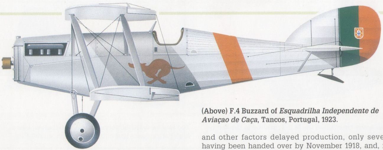
F.4 Buzzard of Esquadrilha Independente de Aviacao de Caca, Tancos, Portugal, 1923.
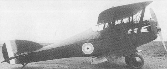
The F.3 version of the Buzzard used the Falcon engine

The HS 8Fb was used in the definitive F.4 version seen in Portuguese service.
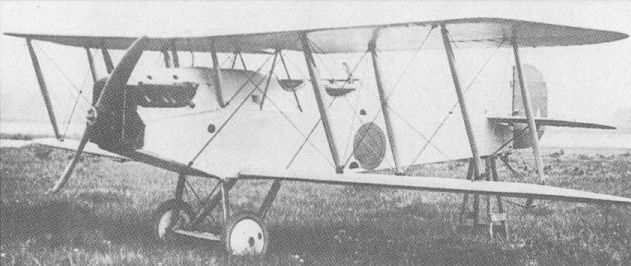
The two-bay two-seat version of the Buzzard supplied to Spain
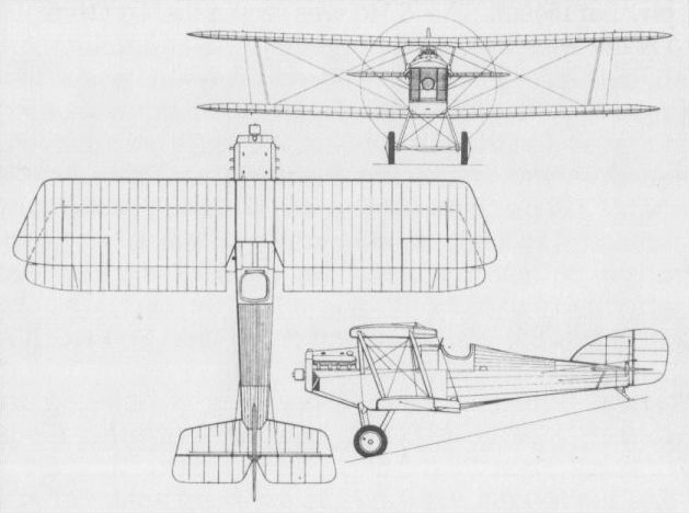
The standard F.4.
NESTLER SCOUT UK
In 1916, F C Nestler Limited established it own design office under E Boudot and embarked on the design of a single-seat fighting scout as a private venture. Of conventional wire-braced, fabric-covered wooden construction, this was a single-bay staggered biplane powered by a 100 hp Gnome Monosoupape nine-cylinder rotary engine. Of compact design, the Nestler fighting scout proved very manoeuvrable, but crashed on 26 March 1917, the damage being too extensive for the aircraft to be rebuilt. No data concerning this aircraft have apparently survived and the intended armament is unknown.
In 1916, F C Nestler Limited established it own design office under E Boudot and embarked on the design of a single-seat fighting scout as a private venture. Of conventional wire-braced, fabric-covered wooden construction, this was a single-bay staggered biplane powered by a 100 hp Gnome Monosoupape nine-cylinder rotary engine. Of compact design, the Nestler fighting scout proved very manoeuvrable, but crashed on 26 March 1917, the damage being too extensive for the aircraft to be rebuilt. No data concerning this aircraft have apparently survived and the intended armament is unknown.
NIEUPORT (& GENERAL) B.N.1 UK
The Nieuport & General Aircraft Company was established in November 1916 for the purpose of manufacturing Nieuport designs in the UK. When H P Folland joined the company following dispersal of the Royal Aircraft Factory design office, work began on an original single-seat fighter. Designated B.N.1 (the initials signifying ‘‘British Nieuport”), the new fighter was not related to any French Nieuport design and was an equi-span, two-bay, unstaggered biplane powered by a Bentley B.R.2 nine-cylinder rotary engine. Of fabric-covered wooden construction, the B.N.l carried an armament of two synchronised 0.303-in (7,7-mm) guns and a gun of similar calibre above the wing centre section. Three prototypes were ordered and the first of these was flown early in March 1918. After destruction of the prototype in a crash on the 10th of that month, development was discontinued and the remaining two prototypes were scrapped before completion.
Max speed, 127 mph (204 km/h) at 15,000 ft (4 570 m).
Time to 15,000 ft (4 570 m), 16 min.
Endurance, 3.0 hrs.
Loaded weight, 2,030 lb (921 kg).
Span, 28 ft 0 in (8,53m).
Length, 18 ft 6 in (5,64m).
Height, 9 ft 0 in (2,74 m).
Wing area, 260 sq ft (24,15 m2).
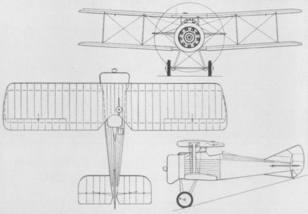
NIEUPORT (& GENERAL) NIGHTHAWK UK
Work on the Nighthawk single-seat fighter was initiated by H P Folland in May 1918, the aircraft being designed to accept the new A.B.C. Dragonfly nine-cylinder radial engine. Three prototypes were ordered and the decision to proceed with quantity production was taken by the Air Ministry before the first of these had flown. Orders were placed with both the parent company and Gloucestershire Aircraft, but defects with the Dragonfly engine created delays in the programme and a prototype was not flown until after the Armistice. Production Nighthawks from both contractors appeared late in 1919, these being powered by the 320 hp Dragonfly, but none saw service with the RAF. When, in August 1920, Nieuport & General closed down, the rights to the Nighthawk, together with the services of its designer, were acquired by Gloucestershire Aircraft which continued development.
Max speed, 151 mph (243 km/h) at sea level.
Time to 10,000 ft (3050 m), 7.16 min.
Endurance, 3.0 hrs.
Empty weight, 1,500 lb (680 kg).
Loaded weight, 2,218 lb (1006 kg).
Span, 28 ft 0 in (8,53m).
Length, 18 ft 6 in (5,64 m).
Height, 9 ft 6 in (2,90 m).
Wing area, 276 sq ft (25,64 m2).
PARNALL SCOUT UK
Parnall and Sons of Bristol initiated work on the company’s first original aircraft, a single-seat anti-airship fighter to the designs of A Camden Pratt, in 1916. Intended to meet a requirement formulated by the Admiralty, this aircraft, unofficially known as the Zeppelin Chaser, was a large, two-bay staggered biplane of wooden construction. It was powered by a 260 hp Sunbeam Maori 12-cylinder water-cooled engine and armed with a single 0.303-in (7,7-mm) gun offset to starboard and firing upward at an angle of 45 deg. Two prototypes were ordered, but the first of these proved appreciably overweight. Although the Scout reportedly flew twice, it was considered to possess unacceptably low safety factors and was returned to the manufacturer, development being abandoned. The following data are manufacturer’s estimates.
Max speed, 113 mph (182 km/h) at sea level.
Span, 44 ft 0 in (13,41 m).
Wing area, 516 sq ft (47,94 m2).
PEMBERTON-BILLING P.B.23E UK
Designed in 1915 by Noel Pemberton-Billing, and built by the company bearing his name, the P.B.23E single-seat pusher fighting scout biplane was of wooden construction, but the nacelle mounted between the wings and accommodating the pilot was unusual for its time in being covered with light alloy sheet metal. Armament consisted of a single 0.303-in (7,7-mm) machine gun mounted in the nose of the nacelle and power was provided by an 80 hp Le Rhone rotary. The P.B.23E was first flown in September 1915, but was not adopted in its original form, being further developed as the P.B.25. No data relating to the P.B.23 appear to have survived.
PEMBERTON-BILLING P.B.25 SCOUT UK
Known officially as the Scout, the P.B.25 was a development of the P.B.23. The most obvious differences were in the design of the nacelle, which was fabric covered, and in the wing cellule, the mainplanes featuring 11 deg of sweepback and inversely-tapered ailerons. Twenty P.B.25s were ordered by the Admiralty, all but one of these being powered by the 100 hp Gnome Monosoupape, the exception having a 110 hp Clerget rotary. Armament comprised a single 0.303-in (7,7-mm) machine gun mounted on the nacelle. The last P.B.25 was delivered to the RNAS in February 1917, by which time this type had acquired an unenviable reputation, the take-off and landing characteristics being particularly hazardous. Apart from poor flying qualities, its performance was inadequate and, being viewed as something of an anachronism, the Scout was quickly discarded.
Max speed, 89 mph (143 km/h) at sea level.
Time to 6,000 ft (1 830 m), 11 min.
Endurance, 2.5 hrs.
Empty weight, 1,080 lb (490 kg).
Loaded weight, 1,541 lb (699 kg).
Span, 32 ft 11 1/2 in (10,04 m).
Length, 24 ft 1 in (7,34 m).
Height, 10 ft 5 in (3,17 m).
Wing area, 277 sq ft (25,73 m2).
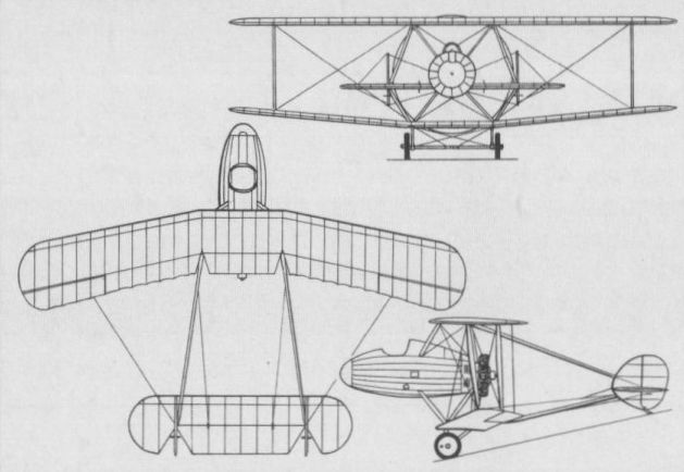
The P.B.25 was ordered for the RNAS, but proved to be unsuited for operational use.
PEMBERTON-BILLING P.B.29E UK
One of the most extraordinary interceptor fighters flown during World War I, the P.B.29E twin-engined quadruplane was conceived as an anti-airship aircraft. Intended to be capable of prolonged cruise at low speeds during the nocturnal hours, the P.B.29E featured high aspect ratio wings with a pair of 90 hp Austro-Daimler six-cylinder water-cooled engines underslung from the second mainplane and driving pusher propellers. The entire wing cellule was braced as a two-bay structure, the fuselage being attached to the second wing and accommodating two crew members, and a gunner with a single 0.303-in (7,7-mm) machine gun occupying a nacelle that filled the gap between the centre sections of the upper mainplanes. The P.B.29E was flown in the winter of 1915-16, and was destroyed comparatively early in its flight test programme, but aroused sufficient interest to warrant development of the P.B.31E of similar concept. No data relating to the P.B.29E are available.
One of the most extraordinary interceptor fighters flown during World War I, the P.B.29E twin-engined quadruplane was conceived as an anti-airship aircraft. Intended to be capable of prolonged cruise at low speeds during the nocturnal hours, the P.B.29E featured high aspect ratio wings with a pair of 90 hp Austro-Daimler six-cylinder water-cooled engines underslung from the second mainplane and driving pusher propellers. The entire wing cellule was braced as a two-bay structure, the fuselage being attached to the second wing and accommodating two crew members, and a gunner with a single 0.303-in (7,7-mm) machine gun occupying a nacelle that filled the gap between the centre sections of the upper mainplanes. The P.B.29E was flown in the winter of 1915-16, and was destroyed comparatively early in its flight test programme, but aroused sufficient interest to warrant development of the P.B.31E of similar concept. No data relating to the P.B.29E are available.
PEMBERTON-BILLING (SUPERMARINE) P.B.31E UK
When Pemberton-Billing Ltd changed its name to Supermarine Aviation in December 1916, work on a further airship fighter, the P.B.31E, had reached an advanced stage and the first prototype of this quadruplane was to fly shortly afterwards, in February 1917. Fundamentally an extrapolation of the P.B.29E, and unofficially known as Night Hawk, the P.B.31E was designed to have a maximum endurance in excess of 18 hours to enable it to lie in wait for intruding airships. The entire concept was fallacious as, in the unlikely event that the P.B.31E found itself fortuitously in the same area of sky as its prey, it would have been totally incapable of pursuing the airship which could have risen out of range before any guns could have been brought to bear. A three-bay quadruplane powered by two 100 hp Anzani nine-cylinder radials, the P.B.31E carried a searchlight in the extreme nose. The intended armament comprised a one-and-a-half pounder Davis gun on a traversing mounting in a forward position level with the top wing, a 0.303-in (7,7-mm) machine gun being located in a second position immediately aft and a similar weapon occupying a forward fuselage position. Shortly after the start of flight trials, the shortcomings of the concept were finally appreciated, and, on 23 July 1917, the first prototype was scrapped and the second incomplete prototype abandoned.
Max speed, 75 mph (121 km/h).
Time to 10,000 ft (3050 m), 1 hr.
Normal endurance, 9 hrs.
Empty weight. 3,677 lb (1668 kg).
Loaded weight, 6,146 lb (2 788 kg).
Span, 60 ft 0 in (18,29 m).
Length, 36 ft 10 1/2 in (11,24 m).
Height, 17 ft 8 1/2 in (5,40 m).
Wing area, 962 sqft (89,37 m2).
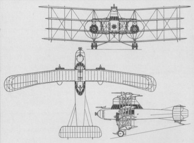
The P.B.31E anti-airship fighter quadruplane.
PORT VICTORIA P.V.2. UK
The Royal Naval Aeroplane Repair Depot was commissioned at the Isle of Grain early in 1915, and to distinguish it from the seaplane station already established there it was named Port Victoria. Ultimately it became known as the Marine Experimental Aircraft Depot and undertook original design work. Its first entirely original design was the P.V.2 single-seat anti-Zeppelin seaplane. Of wooden construction and powered by a 100 hp Gnome Monosoupape rotary, the P.V.2 was an exceptionally clean sesquiplane, the wing cellule being almost devoid of bracing wires with the upper wing attached to the upper fuselage longerons and the lower wing passing beneath the fuselage. The intended armament was a two-pounder Davis gun, although this was never fitted. The P.V.2 was first flown in June 1916 with floats of the pontoon type, these later being replaced by Linton Hope floats. Trials showed considerable promise and it was decided to develop the design further as the P.V.2bis (which see).
Max speed, 95 mph (153 km/h) at sea level.
Time to 3,0 ft (915 m), 5.0 min.
Empty weight, 1,087 lb (493 kg).
Loaded weight, 1,590 lb (721 kg).
Span, 27 ft 0 in (8,23 m).
Length, 22 ft 0 in (6,70 m).
Height, 8 ft 4 in (2,54 m).
Wing area, 168 sqft (15,60 m2).
PORT VICTORIA P.V.2bis UK
The decision to develop the P.V.2 as the P.V.2bis single-seat fighter seaplane resulted in major changes to the original prototype, the most significant being the raising of the upper wing by 1 ft (30 cm) to improve the pilot’s view for alighting and the insertion of centre-section struts. The span and area of the upper wing were increased by introduction of a 2-ft (61-cm) centre section, and the planned armament was two 0.303-in (7,7-mm) machine guns to fire forward and upward above the propeller, although, in the event, only one such gun was apparently fitted. The P.V.2bis was flown early in 1917, providing data for later Port Victoria types.
Max speed, 93 mph (150 km/h) at sea level.
Time to 3,000 ft (915 m), 6.0 min.
Empty weight, 1,211 lb (549 kg).
Loaded weight, 1,702 lb (772 kg).
Span, 29ft 0 in (8,84 m).
Length, 22 ft 0 in (6,70 m).
Height, 9 ft 4 in (2,84 m).
Wing area, 180 sq ft (16,72 m2).
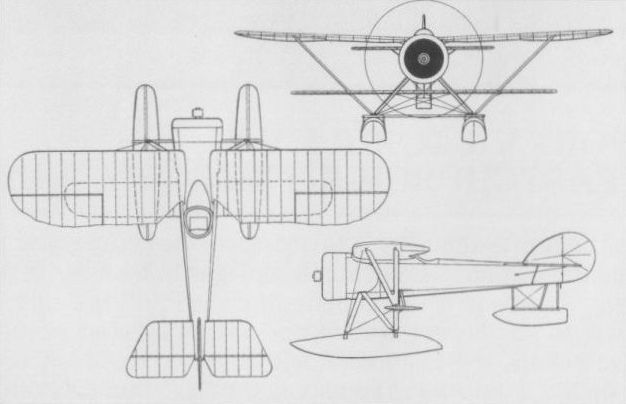
The P.V.2 anti-Zeppelin aircraft which was intended to carry a two-pounder Davis gun.
PORT VICTORIA P.V.4 UK
Early in 1916, the Marine Experimental Aircraft Depot initiated the design of a land-based two-seat fighter, the P.V.3. Although this was never built, the Depot was officially requested to develop a float seaplane version carrying radio equipment and a single 0.303-in (7,7- mm) machine gun. This, the P.V.4, was a small and compact sesquiplane with a central nacelle for the two crew members and a pusher engine, and the tail assembly carried by four slim booms. The gunner occupied the forward cockpit, which was equipped with a Scarff ring for the gun. The intention was to fit the P.V.4 with a 150 hp Smith "Static” radial engine but, as this was unavailable, a 110 hp Clerget rotary was installed for flight testing in mid-1917. This created CG problems, resolution of which would have involved considerable redesign, and, as the P.V.4 was considered to possess insufficient promise to warrant this work, development was discontinued.
Max speed, 81 mph (130 km/h).
Loaded weight 2,400 lb (1 089 kg).
Span, 32 ft 0 in (9,75 m).
Wing area, 220 sq ft (20,44 m2).
PORT VICTORIA P.V.5 UK
Shortly after the Depot initiated work on the P.V.4, it was asked to develop a single-seat fighter seaplane also capable of performing light bombing tasks with two internally-stowed 65-lb (29,5-kg) bombs. To meet this requirement, two different aircraft were designed and built, the P.V.5 and the P.V.5a. The former was developed from the P.V.2bis and employed a similar sesquiplane wing cellule devoid of flying wires and braced by struts to the float undercarriage. The wings employed a high-lift aerofoil section, the armament comprised a single synchronised 0.303-in (7,7-mm) machine gun plus the two 65-lb (29,5-kg) bombs specified and power was provided by a 150 hp Hispano-Suiza engine. Fitted with pontoon-type floats rather than the Linton Hope floats for which it had been designed, the P.V.5 was flight tested in mid-1917 with promising results, but the original requirement had been overtaken and development was discontinued.
Max speed, 94 mph (151 km/h) at 2,000 ft (610 m).
Time to 2,000 ft (610 m), 4.83 min.
Empty weight, 1,788 lb (811 kg).
Loaded weight, 2,456 lb (1114 kg).
Span, 32 ft 0 in (9,75 m).
Length, 25 ft 6 in (7,77 m).
Height, 9 ft 9 in (2,97 m).
Wing area, 245 sq ft (22,76 m2).
PORT VICTORIA P.V.5a UK
Designed along more conventional lines than the P.V.5, the P.V.5a was an equi-span single-bay biplane with cable bracing, sharing with the former type only the fuselage, tail surfaces and armament. The pontoon-type floats were supplanted by Linton Hope floats, the internal accommodation for a bomb load was eliminated and a 200 hp Hispano-Suiza engine was fitted. Work on the P.V.5 and 5a was initiated in parallel, but work on the latter was discontinued early in 1917, and only reinstated after the P.V.5 had flown, the P.V.5a commencing flight test in the spring of 1918. It proved inferior to the P.V.5 in terms of manoeuvrability and pilot’s view, but was satisfactory in most other respects. Development was discontinued after completion of flight testing as no service requirement for this category of aircraft existed.
Max speed, 102 mph (164 km/h) at 2,000 ft (610 m).
Time to 2,000 ft (610 m), 2.33 min.
Endurance, 2.5 hrs.
Empty weight, 1,972 lb (894 kg).
Loaded weight, 2,518 lb (1142 kg).
Span, 33 ft 1 in (10,08 m).
Length, 26 ft 9 in (8,15 m).
Height, 13 ft 1 in (3,99 m).
Wing area, 309 sq ft (28,71 m2).
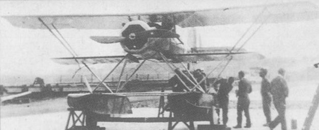
The P.V.5 was fitted with pontoon-type floats and was flight tested in mid-1917.
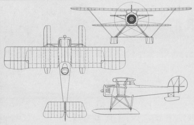
The P.V.5 was fitted with pontoon-type floats and was flight tested in mid-1917.
PORT VICTORIA P.V.7 (GRAIN KITTEN) UK
To meet a requirement for a diminutive lightweight single-seat airship interceptor suitable for operation from platforms on relatively small seagoing vessels, the Depot produced the P.V.7 to the designs of W H Sayers. To become known as the Grain Kitten to distinguish it from a competitive design created by the RNAS Experimental Flight at Eastchurch (which accordingly became known as the Eastchurch Kitten), the P.V.7 was an extremely small sesquiplane intended to be powered by a 45 hp geared ABC Gnat two-cylinder air-cooled engine. Armament consisted of a single 0.303-in (7,7-mm) machine gun mounted above the wing centre section. Unavailability of the geared Gnat engine led to installation of a 35 hp direct-drive Gnat with which the P.V.7 was completed in the summer of 1917. Difficulties were experienced with the engine from the start of flight testing in June, the aircraft being tail-heavy and performance disappointing. A series of modifications was introduced, but the P.V.7 was not flown subsequently.
Max speed, 89 mph (143 km/h) at 2,000 ft (610 m).
Time to 6,500 ft (1980 m), 10.8 min.
Empty weight, 272 lb (123 kg).
Loaded weight, 491 lb (223 kg).
Span, 18 ft 0 in (5,49 m).
Length, 14 ft 11 in (4,55 m).
Height, 5 ft 3 in (1,60 m).
Wing area, 85 sq ft (7,90 m2).
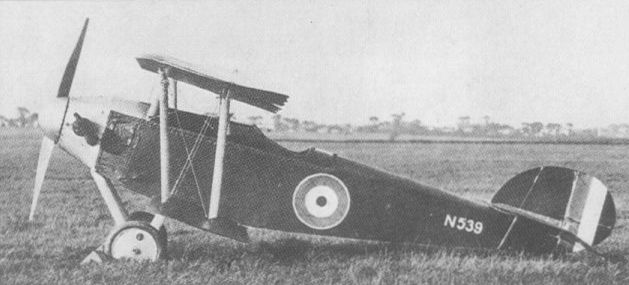
The P.V.7 single-seat lightweight anti-Zeppelin fighter flew in June 1917.

PORT VICTORIA P.V.8 (EASTCHURCH KITTEN) UK
Although designed by Lt G H Millar of the RNAS Experimental Flight at Eastchurch and partly built by that establishment, this competitor for the P.V.7 as a lightweight single-seat interceptor was completed in the workshops at Port Victoria and assigned the designation P.V.8. Becoming known as the Eastchurch Kitten, the P.V.8 was an angular single-bay staggered biplane intended, like the P.V.7, to be powered by the geared ABC Gnat engine, but of necessity fitted with the 35 hp ungeared version of this two-cylinder power plant. When initially flown on 1 September 1917, the P.V.8 possessed no fixed tailplane, but the horizontal tail surfaces were redesigned to incorporate a small tailplane prior to the second flight. Proving itself superior to the P.V.7 in every way, the P.V.8 suffered similar problems with its engine. On 13 March 1918, the Eastchurch Kitten was packed for despatch to the USA, where it was to be evaluated, but there is no record that it ever reached its destination.
Max speed, 94 mph (151 km/h) at 2,000 ft (610 m).
Time to 6,500 ft (1 980 m), 11.0 min.
Empty weight, 340 lb (154 kg).
Loaded weight, 586 lb (266 kg).
Span, 18 ft 11 1/2 in (5,78 m).
Length, 15 ft 7 1/2 in (4,76 m).
Height, 5 ft 2 in (1,57 m).
Wing area, 106 sqft (9,85 m2).

Intended to compete with the P.V.7, the P.V.8 was dubbed Eastchurch Kitten.
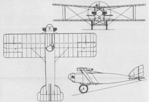
PORT VICTORIA P.V.9 UK
Owing much to the P.V.2, the P.V.9 single-seat fighter seaplane, first flown in December 1917, was a sesquiplane braced entirely by faired steel tubes. With a fuselage mounted between the wings, an armament of one synchronised 0.303-in (7,7-mm) machine gun and a similar-calibre weapon mounted on top of the fuselage, the P.V.9 had single-step pontoon-type floats and a 150 hp Bentley B.R.I rotary engine. Protracted engine problems delayed the initiation of full-scale trials until May 1918, at which time it was alleged to be the best float-equipped single-seat fighter extant. However, lack of a suitable propeller prevented full exploitation of its performance potential and, no longer fulfilling a service requirement, its development was discontinued.
Max speed, 110 mph(177 km/h) at 2,000 ft (610 m).
Time to 6,500 ft (1980 m), 13.33 min.
Endurance. 2.5 hrs.
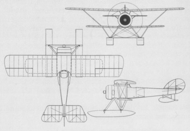
ROYAL AIRCRAFT FACTORY F.E.3 UK
Located at Farnborough and engaged primarily in aeronautical research, the Royal Aircraft Factory (so named in April 1912) was responsible for the design and development of a number of warplanes during World War I. In accordance with the factory’s purpose they received designations combining a prefix letter (at first indicating the general configuration, but later the role) with E for experimental (although several, such as the B.E.2, F.E.2, R.E.8 and S.E.5, were to be built in large numbers). Built in 1913, the F.E.3 was thus the third design in the “Farman Experimental” series of pusher biplanes, and was designed to carry a COW one-pounder quick-firing gun. Alternatively known as the A.E.I (“Armoured Experimental”), the two-seat F.E.3 was a two-bay biplane with overhanging upper wing, and a four-bladed pusher propeller driven by a shaft and chain from the 100 hp Chenu eight-cylinder water-cooled inline engine mounted in the front of the fuselage. The large cruciform tail unit was carried on a single central boom secured through the hollow propeller shaft and braced by wires to the upper wing and the undercarriage. Flight tests showed that the tail attachment was not sufficiently rigid and the gun, fitted in front of the fuselage, was fired only in static tests at Farnborough after flight testing was abandoned. The F.E.3 used fabric-covered wooden construction for the wings and tail unit, but the fuselage nacelle was of steel tube construction with aluminium and plywood skinning. A large central orifice in the nose took in air for the engine radiators, which were inside the nacelle.
Max speed, 75 mph (121 km/h) at sea level.
Initial climb, 350 ft/min (1,78 m/sec).
Service ceiling, 5,000 ft (1525 m).
Empty weight, 1,400 lb (635 kg).
Loaded weight, 2,080 lb (943 kg).
Span, 40 ft 0 in (12,19m).
Length, 29 ft 3 in (8,91m).
Height, 11 ft 3 in (3,43 m).
Wing area, 436.5 sq ft (40,55 m2).
ROYAL AIRCRAFT FACTORY F.E.6 UK
Of similar construction to the F.E.3, the F.E.6 was built in 1914 and was powered by a 120 hp Austro-Daimler six-cylinder water-cooled engine. Standard R.E.5 components were used for the wings, which were of equi-span, and the tail unit was carried on a cantilever boom, without bracing wires. The F.E.6 was flown at Farnborough on 14 November 1914 but this may have been its only flight, and, if fitted, the COW gun that it was designed to carry was not fired.
Empty weight, 2,000 lb (907 kg).
Loaded weight, 2,630 lb (1193 kg).
Span, 49 ft 4 in (15,03 m).
Length, 29 ft 6 in (8,99 m).
Height, 15 ft 0 in (4,57 m).
Wing area, 542 sq ft (50,35 m2).
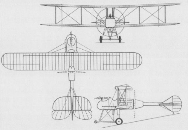
The F.E.6 was a derivative of the F.E.3.
ROYAL AIRCRAFT FACTORY S.E.2 UK
The S.E.2 was a rebuild of the unarmed B.S.l, which was designed at Farnborough by Geoffrey de Havilland assisted by H P Folland and S J Waters, and flown in early 1913. Designated as a ‘‘Bleriot Scout”, the B.S.l was an attractive single-bay equi-span biplane with a circular-section fuselage which was of monocoque construction aft of the single-seat cockpit. Power was provided by a partially-cowled 100 hp Gnome rotary engine. The B.S.l achieved 92 mph (148 km/h) and a climb rate of 900 ft/min (4,6 m/sec) in early tests, but was badly damaged on 27 March 1913. It was then rebuilt with a redesigned tail unit that included a semicircular tailplane with a lifting profile, divided elevators, a small fin and large rudder. With a fully-cowled 80 hp Gnome nine-cylinder rotary engine, the aircraft flew again in October 1913, being redesignated S.E.2 as a Scouting Experimental (although the S.E. series had earlier been intended for ‘‘Santos Experimental”, of canard configuration). RFC handling trials took place (with No 5 Squadron) early in 1914, after which the S.E.2 was again rebuilt, with a more conventional rear fuselage of wooden construction and fabric covering, larger fin and rudder, constant-chord tailplane and other smaller changes. Taken to France (by No 3 Squadron) later in 1914, the S.E.2 was fitted with two Army rifles firing at outward angles to clear the propeller, and other (revolver) armament was also tried during the several months it remained with the squadron.
Max speed, 85 mph (137 km/h) at sea level.
Empty weight, 720 lb (327 kg).
Loaded weight, 1,132 lb (513 kg).
Span, 27 ft 6 in (8,38 m).
Length, 20 ft 5 in (6,22 m).
Height, 9 ft 316 in (2,83 m).
Wing area, 188 sq ft (17,47 m2).
ROYAL AIRCRAFT FACTORY B.E.2c UK
Second of the Farnborough designs to bear a “Bleriot Experimental” designation as a general-purpose tractor biplane, the B.E.2 appeared in 1912 and provided the basis for a family of variants produced in large quantity for use by the RFC, principally as an unarmed two-seat scout. With modifications to enhance the inherent stability of the basic design, the B.E.2c was developed in 1914 and many of the 1,216 of this variant built were to serve with various ad hoc armament installations. The B.E.2c was a two-bay biplane with unstaggered equi-span wings, a conventional tail unit with separate fin, rudder, tailplane and elevators, and an undercarriage incorporating skids to help prevent nose-overs. The 70 hp Renault eight-cylinder Vee-type engine powered early production aircraft, but the 90 hp RAF Ia eight-cylinder Vee-type soon became standard. Construction of the B.E.2c was of wood throughout, with fabric covering. A variety of mounts was evolved for a single 0.303-in (7,7-mm) Lewis machine gun in the observer’s (front) cockpit, primarily for self-defence. More specifically to serve as a fighter with Home Defence squadrons of the RFC and the RNAS, numerous B.E.2c’s were modified as single-seaters, armament comprising a single Lewis gun mounted to fire upwards behind the wing centre section or, in some cases, on the side of the fuselage alongside the cockpit, angled outwards to clear the propeller disc. Flying by night, despite a lack of nocturnal flight aids, B.E.2c’s shot down five raiding Zeppelins over the UK during 1916. B.E.2c’s were also used for a number of armament experiments. The following data are for the B.E.2c with RAF Ia engine.
Max speed, 72 mph (116 km/h) at 6,500 ft (1 980 m).
Time to 6,500 ft (1980 m), 20 min.
Service ceiling, 10,000 ft (3 050 m).
Endurance, 3.25 hrs.
Empty weight, 1,370 lb (621kg).
Loaded weight, 2,142 lb (972 kg).
Span, 36 ft 10 in (11,23 m).
Length, 27 ft 3 in (8,30 m).
Height, 11 ft 4 in (3,45 m).
Wing area, 396 sq ft (36,79 m2).
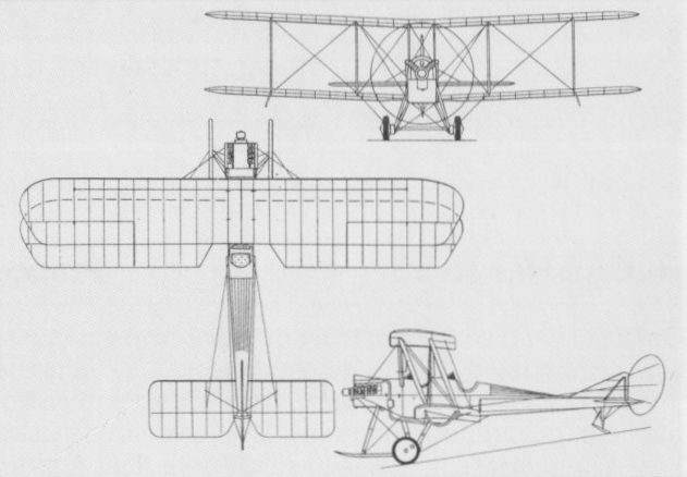
The B.E.2c in its early standard form.
ROYAL AIRCRAFT FACTORY F.E.2A & F.E.2B UK
Sharing little more than its configuration with the F.E.2 flown at Farnborough in 1913, the F.E.2a appeared early in 1915 and was designed to provide the RFC with an armed reconnaissance aircraft. It was a large three-bay biplane, using a flat centre section and outer panels that were identical with those of the B.E.2c (which see), and incorporating dihedral. A short nacelle carried the observer/gunner in the nose ahead of the pilot, and the pusher engine. The tail unit was carried by four booms extending aft from the wings and comprised a large tailplane with elevators, a kidney-shaped rudder and small triangular fin above the tailplane. A small nose-wheel was provided ahead of the oleo-strutted main wheels to help prevent nosing over, and the whole of the upper wing centre section trailing-edge aft of the rear spar was hinged for use as a flap-cum-airbrake. Armament normally comprised a 0.303-in (7,7-mm) Lewis machine gun in the front cockpit on one of several alternative mounts. The first F.E.2a flew on 26 January 1915 with a 100 hp Green six-cylinder inline water-cooled engine but proved underpowered and the 120 hp Austro-Daimler built under licence by Beardmore became the standard for 11 more F.E.2a’s and early production examples of the F.E.2b. The latter was the ”productionised” version with the Beardmore engine, trailing-edge flap deleted, simplified fuel system and other changes to facilitate large-scale production by inexperienced companies. These comprised, apart from the RAF itself (which built only 47 F.E.2b's): Boulton & Paul (250); Barclay Curie (100); Garrett & Sons (60); Ransome, Sims & Jefferies (350); Alex Stephen and Sons (150) and G & J Weir (600). A 160 hp Beardmore engine was adopted later, and the oleo u/c with nosewheel gave way to a simplified form without the nosewheel or, later, a non-oleo V-strut arrangement. All 12 F.E.2a’s and almost a thousand F.E.2b's went to RFC squadrons in France, where they engaged in offensive patrols over the enemy lines in the role of fighter escort for unarmed reconnaissance aircraft. Over 200 were issued to Home Defence units, some of these flying as single-seaters, and service use of the F.E.2b continued until the Armistice in November 1918. The following data are for the version with 160 hp Beardmore engine.
Max speed, 91.5 mph (147km/h) at sea level, 76mph (122 km/h) at 10,000 ft (3 050 m).
Time to 4,000 ft (1220 m), 9.85 min.
Service ceiling, 11,000 ft (3353 m).
Empty weight, 2,061 lb (935kg).
Loaded weight, 3,037lb (1378kg).
Span, 47 ft 9 in (14,56 m).
Length, 32 ft 3 in (9,83 m).
Height, 12 ft 7 1/2 in (3,84 m).
Wing area, 494 sqft (45,89 m2).
ROYAL AIRCRAFT FACTORY F.E.2c UK
Among the 12 F.E.2a's sent to France in 1915, where they were flown by No 6 Squadron RFC and sometimes known by the alternative official designation of Fighter Mark I, one had its seating arrangement reversed. Thus, the pilot occupied the front cockpit - located a little farther aft than in the F.E.2a and 2b - and the gunner was in an elevated aft position. An additional Lewis gun was fitted in the nose, remotely controlled by the pilot. In this form, the aircraft was designated F.E.2c. Conversion of a small number of F.E.2b's to 2c configuration was put in hand at the RAF, Farnborough, but only two are thought to have been completed as the F.E.2c was found to offer no advantage over the F.E.2b. Six more 2b’s were converted to 2c’s in late 1917, however, to serve as night bombers with No 100 Squadron, for which role the improved view for the pilot outweighed the difficulties posed for the gunner. Data for the F.E.2c were as for the F.E.2b.
ROYAL AIRCRAFT FACTORY F.E.2D UK
On 7 April 1916, a version of the F.E.2b was flown at the RAF Farnborough, fitted with a 250 hp Rolls-Royce Mk I (later, Eagle I) 12-cylinder water-cooled V-type engine, becoming thus the prototype F.E.2d. Compared with the 160 hp F.E.2b, the Rolls-Royce-engined version had better rate of climb and ceiling and slightly improved speed performance, and although the heavier engine adversely affected manoeuvrability and field performance, the F.E.2d was ordered into production as an interim supplement for the F.E.2b. Eighty-five were built at Farnborough and 270 by Boulton & Paul, although many of these were completed, in the event, with Beardmore engines as F.E.2b’s. In those F.E.2d’s completed, several versions of the Rolls-Royce engine were fitted; as well as the Mk I these comprised the 250 hp Marks III and IV (later, 284 hp Eagle III and IV) and the 275 hp Marks I and II (later, 322 hp Eagle V and VI). The first few F.E.2d’s had the oleo undercarriage with nosewheel extension, but the modified oleo type without the nosewheel was soon adopted. The F.E.2d was in service in France by July 1916, and the type also served with Home Defence units, although its low speed performance made it an ineffective Zeppelin-chaser. Most F.E.2d’s were armed with two Lewis guns, one on a flexible mounting in the nose and another fixed forward-firing for the pilot; in some cases a third gun, on a telescopic pillar mounting, was also provided between the two cockpits. The following data apply to the F.E.2d with 250 hp Rolls-Royce Mark I engine.
Max speed, 94 mph (151 km/h) at 5,000 ft (1525 m), 88 mph (142 km/h) at 10,000 ft (3050 m).
Time to 5,000 ft (1525 m), 7.15 min.
Service ceiling, 17,500 ft (5334 m).
Endurance, 3.5 hrs.
Empty weight, 2,509 lb (1138 kg).
Loaded weight, 3,470 lb (1 574 kg).
Span, 47 ft 9 in (14,55 m).
Length, 32 ft 3 in (10,13 m).
Height, 12 ft 7 1/2 in (3,85 m).
Wing area, 494 sqft (45,89 m2).
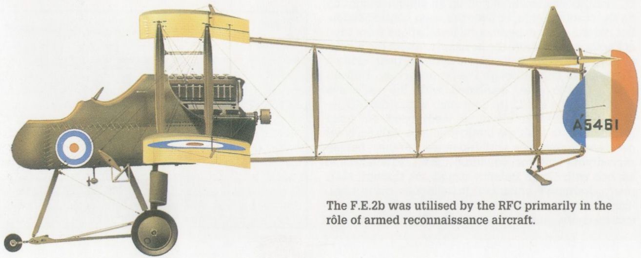
The F.E.2b was utilised by the RFC primarily in the role of armed reconnaissance aircraft.

A Green-engined F.E.2a
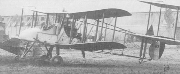
In the few F.E.2c’s built, the positions of the pilot and gunner were reversed.

An early series F.E.2d built at Farnborough, showing the low-sided pilot’s cockpit.

The more numerous Beardmore-engined F.E.2b.
ROYAL AIRCRAFT FACTORY S.E.4A UK
Designed at Farnborough by H P Folland at the end of 1914, the S.E.4a was one of a series of “Scouting Experimentals" used to study the interplay of stability and manoeuvrability. Unrelated, except in configuration and design authorship, to the high performance S.E.4 of mid-1914, the S.E.4a was a sturdy little single-bay biplane with equi-span wings incorporating 3.5 deg of dihedral and having no centre section. The square-section fuselage was of conventional spruce construction with steel tubes to accept the loads from the lower wings, and, like the wooden wings and tail unit, was fabric-covered. Full-span ailerons were fitted to both sets of wings, and power was provided by an 80 hp Gnome seven-cylinder rotary in a fully circular short - chord cowling. The first of four S.E.4a's built at the RAF flew there on 25 June 1915, and differed from its successors in having faired fuselage sides and an outsize spinner. The fourth and last S.E.4a flew on 13 August that year. The third, flown on 27 July, was at first fitted with an 80 hp Le Rhone engine, the Gnome being substituted later, and in October 1916 this same S.E.4a was provided with an 80 hp Clerget. In the hands of the RFC, at least one of the S.E.4a’s was armed with a 0.303-in (7,7-mm) Lewis gun mounted on the centre line above the upper wing to clear the propeller disc.
Span, 27 ft 6 in (8,38 m).
Length, 20 ft 10 1/2 in (6,37 m).
Height, 9 ft 5 in (2,87 m).
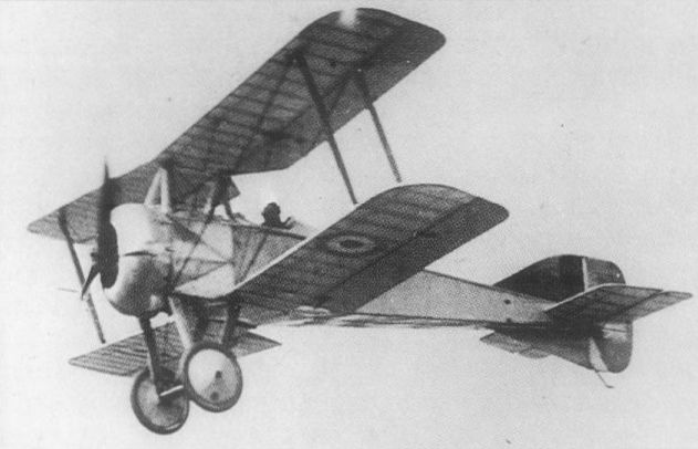
S.E.4a 5611 in flight with Lewis guns on the center section, showing the flat-sided fuselage which distinguished it from the slightly more streamlined prototype.

The S.E.4a with Le Rhone engine.
ROYAL AIRCRAFT FACTORY F.E.8 UK
Designed under the direction of John Kenworthy, the F.E.8 was the first single-seat fighter evolved as such at Farnborough, where the first of two prototypes was flown on 15 October 1915. Of pusher configuration to allow an uninterrupted forward field of fire for the 0.303-in (7,7-mm) Lewis gun, the F.E.8 was a two-bay equi-span biplane with a short fuselage nacelle to accommodate the gun, the pilot and a 100 hp Gnome Monosoupape nine-cylinder rotary engine, and four slender booms to carry the cruciform tail unit. Construction of the nacelle was of welded steel-tube with aluminium sheet covering; the wings and tail unit used conventional wooden spars and ribs with fabric covering. Trials with the second prototype in France in late 1915 led to a change in the gun installation, which was mounted within the nacelle nose and could be moved through a limited range by means of a control in the cockpit. Production F.E.8s, which began to appear in May and June 1916 from the factories of Darracq Motor Engineering at Fulham and Vickers at Weybridge, had a more practical gun mounting on the nose immediately ahead of the cockpit. Production totalled 220 by Darracq and 50 by Vickers. Service use by RFC squadrons in France began in August 1916, and, although soon obsolescent, the F.E.8 remained in service for a year, becoming the last single-seater of pusher configuration in general use. Trial installations of the 110 hp Le Rhone and 110 hp Clerget engines were made, but the Monosoupape remained the standard fit and the following data apply to this version.
Max speed, 94 mph (151 km/h) at sea level, 70 mph (113 km/h) at 10,000 ft (3050 m).
Service ceiling, 15,210 ft (4 636 m).
Endurance, 2.5 hrs.
Empty weight, 895 lb (406 kg).
Loaded weight, 1,346 lb (611 kg).
Span, 31ft 6 in (9,60 m).
Length, 23 ft 8 in (7,21m).
Height, 9 ft 2 in (2,79 m).
Wing area, 218 sq ft (20,25 m2).

A 41 Squadron F.E.8, 7616, photographed in flight. The streamers denote that it is piloted by a flight leader.
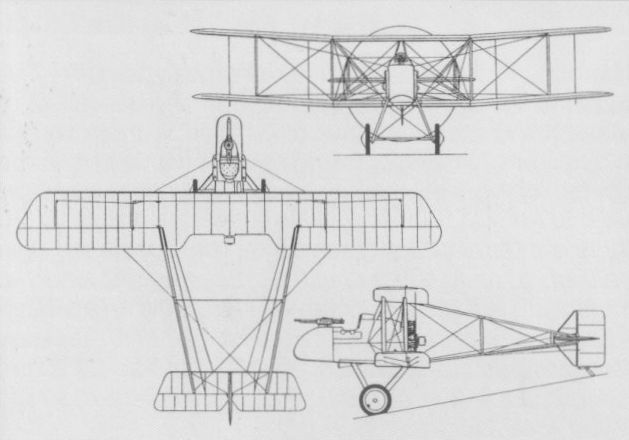
The F.E.8 with Gnome Monosoupape engine.
ROYAL AIRCRAFT FACTORY B.E.12 UK
Evolved at Farnborough during 1915 as a marriage of the B.E.2c airframe with the then-new R.A.F.4 air-cooled 12-cylinder Vee-type engine of 140 hp, the B.E.12 prototype began test flying at the end of July that year. Although flown from the start as a single-seater, it was at first unarmed and was intended for such roles as bombing and photography rather than as a fighter. The prototype was tested in France in September 1915 and its generally satisfactory performance encouraged the War Office to order production of the B.E.12 in that same month. Delivered from March 1916 onwards, production aircraft had the R.A.F.4a engine (with increased stroke), twin upright exhaust stacks, an auxiliary gravity fuel tank under the port upper wing and, after the first few, an enlarged rudder with curved leading edge. At first serving with RFC squadrons in France for general duties, the B.E.12 was fitted with a 0.303-in (7,7-mm) Lewis machine gun on an oblique mounting on the fuselage side, or over the wing centre section, but several other experimental installations were tried at Farnborough before the decision to adopt the newly-available Vickers-Challenger interrupter gear, using a Vickers gun firing through the propeller disc. Difficulties with the gear, combined with the excessive stability of the B.E.12 (to overcome which the B.E.2e-type tailplane and elevators were used on some B.E.12s), made the type ineffectual as a fighter, however, and it was soon withdrawn from France, having served with only two squadrons. B.E.12s remained in service with Home Defence squadrons through 1917, many alternative armament installations being tried, including a quartet of Lewis guns, and sets of Le Prieur rockets on the interplane struts. One Zeppelin was shot down by a B.E.12, in June 1917. At Farnborough, one was tested with a Davis six-pounder recoilless gun, firing upwards at 45 deg for anti-Zeppelin use, but this was not adopted for production. Contracts were placed with two companies for B.E.12 production, Daimler building 200 and Standard Motor Co, 50, against the original orders placed in 1915, and Daimler receiving a contract for 200 more in August 1917. Many of the latter, however, were completed as B.E.12b's (which see).
Max speed, 102 mph (164 km/h) at sea level, 91 mph (146 km/h) at 10,000 ft (3 050 m).
Time to 10,000 ft (3050 m), 33 min.
Service ceiling, 12,500 ft (3810 m).
Endurance, 3 hrs.
Empty weight, 1,635 lb (742 kg).
Loaded weight, 2,352 lb (1067 kg).
Span, 37ft 0 in (11,3 m).
Length, 27 ft 3 in (8,31 m).
Height, 11 ft 1 1/2 in (3,39 m).
Wing area, 371 sq ft (34,47 m2).
ROYAL AIRCRAFT FACTORY B.E.12A UK
With the B.E.12 established in production in 1916, based on the B.E.2c airframe with its equi-span two-bay wing and massive horizontal tail surfaces, a further marriage was arranged to combine the R.A.F.4a engine with the newer B.E.2e airframe. This introduced the single-bay cellule with overhanging upper wing and a smaller tailplane/elevator combination, together with the larger, rounded fin of the B.E.12. Designated B.E.12a in this form, the type was ordered from Coventry Ordnance Works and Daimler, each of which received contracts for 50 during 1916 (some of the Daimler batch being completed as B.E.12s). The B.E.12a’s served briefly with Home Defence units and more extensively in Palestine, with the Australian-manned No 67 Squadron.
Max speed, 105 mph (169 km/h) at sea level, 80.5 mph (129.5 km/h) at 10,000 ft (3 050 m).
Time to 10,0 ft (3 050 m), 24.25 min.
Empty weight, 1,610 lb (730 kg).
Loaded weight, 2,327 lb (1056 kg).
Span, 40 ft 0 in (12,19 m).
Length, 27 ft 3 in (8,30 m).
Height, 12 ft 0 in (3,66 m).
Wing area, 360 sq ft (33,44 m2).
ROYAL AIRCRAFT FACTORY B.E.12B UK
In an attempt to improve the performance of the B.E.12, primarily for the benefit of Home Defence squadrons, a 200 hp Hispano-Suiza water-cooled eight-cylinder Vee-type engine was substituted for the 150 hp R.A.F.4a. The first such installation was completed in September 1917 by the Southern Aircraft Repair Depot at Farnborough and demonstrated a dramatic improvement in speed and climb performance. Consequently, it was decided that 150 of the 200 B.E.12s ordered from Daimler in August 1917 should be completed with the Hispano engines as B.E.12b’s. Airframes built by Daimler were fitted with these engines at the Northern Aircraft Repair Depot at Aston, near Sheffield, and deliveries began late in 1917. As Zeppelin raids on the UK had by this time virtually come to an end, many B.E.12b’s went straight into store, their urgently-needed engines being removed for use in other aircraft types, such as the S.E.5a. It is believed that production of B.E.12b’s ended some 12-20 short of the intended total. The standard armament of the B.E.12b comprised a 0.303-in (7,7-mm) Lewis gun above the centre section, firing over the propeller disc. Performance and weight data for the B.E.12b are not recorded. Dimensions similar to those of the B.E.12.

A drawing of the standard B.E.12a, without armament.
ROYAL AIRCRAFT FACTORY B.E.2E
First flown in February 1916 and destined to be built in larger numbers than the B.E.2c, the B.E.2e differed from the former in having single bay wings of unequal span and a new tailplane. Provision was made for extra fuel in a tank under the port upper wing and for dual controls, but the former was seldom fitted. The large upper wing overhang was braced from inverted-Vee kingposts above the interplane struts, and the standard engine remained the 90 hp RAF la, as the 105 hp RAF lb that was intended to be used in the B.E.2e did not reach production. From production totalling 1,320 aircraft (plus some B.E.2c and 2d conversions), B.E.2e’s were issued to 11 Home Defence squadrons of the RFC (as well as many units on the Western Front and elsewhere). Like the B.E.2c, the 2e often carried a single Lewis gun in the front cockpit, for which assorted mountings were available. An alternative armament tried by some of the Home Defence aircraft for anti-Zeppelin patrols comprised a quartet of Le Prieur rockets, the launching rails for which were attached to the interplane struts, two each side and angled upwards. Little success was achieved by the B.E.2e as a fighter, its performance being inadequate for aerial combat by 1916, and heavy losses were suffered by the RFC squadrons flying the type in France. Retroactively, the designations B.E.2f and B.E.2g were applied to distinguish, respectively, between those B.E.2e’s converted from 2c’s and those built as 2e’s or converted from 2d’s, as their fuel systems and capacities were significantly different.
Max speed, 90 mph (145 km/h) at sea level, 75 mph (121 km/h) at 10,000 ft (3050 m).
Time to 10,000 ft (3 050 m), 53 min.
Service ceiling, 9,000 ft (2 743 m).
Endurance, 4 hrs.
Empty weight, 1,431 lb (649 kg).
Loaded weight, 2,100 lb (953 kg).
Span, 40 ft 9 in (12,42 m).
Length, 27 ft 3 in (8,31 m).
Height, 12 ft 0 in (3,66 m).
Wing area, 360 sqft (33,44 m2).
ROYAL AIRCRAFT FACTORY S.E.5 UK
Second only to the Sopwith Camel in reputation as the RFC's outstanding fighter of World War I, the S.E.5 was designed under the direction of H.P. Folland. Of classic tractor biplane configuration, the S.E.5 was initiated to take advantage of the new Hispano-Suiza engine that began test-running in Spain in February 1915 and was in production in France a few weeks later. Two versions of the engine became available during 1916, the basic direct-drive 150 hp unit and a geared version producing 200 hp. Examples of both were included in the British orders placed in France and, subsequently, with Wolseley for licence-built examples (as the 150 hp Python and 200 hp Adder respectively). The S.E.5 was intended, from the outset, to be powered by the 200 hp geared engine and to be armed with a 0.303-in (7,7-mm) Lewis machine gun firing through a hollow propeller shaft, but, in the event, early aircraft had to use the 150 hp Hispano 8Aa, and had an armament of one Vickers gun in the front fuselage, offset to port, with interrupter gear, and a Lewis on a Foster mount above the centre section. Unarmed, the first of three prototypes of the S.E.5 flew on 22 November 1916. It was a compact single-bay biplane with equi-span wings featuring raked tips, a similarly-raked tailplane, triangular fin and almost rectangular rudder, with a small ventral fin and a V-strut undercarriage. A large windscreen was provided over the front of the cockpit. All major components were of conventional wood construction, with fabric covering. Of two further prototypes, one was similarly powered and first flew on 4 December 1916, whereas the other introduced the 200 hp engine and became, effectively, the prototype for the S.E.5a (which see). Production of the S.E.5 was ordered "off the drawing board” with a first batch of 24 built by the RAF at Farnborough, where the first was completed in March 1917. A second batch of 50 followed on, but at least 15 of these were to emerge as S.E.5a’s, and some S.E.5s in service were also modified to have 200 hp engines. In service with the RFC in France by early 1917, production S.E.5s were modified in various ways, particularly by removal of the windscreen. Other changes tried out on S.E.5s to improve the lateral control were consolidated in the S.E.5a.
Max speed, 122 mph (196 km/h) at 3,000 ft (915 m), 98 mph (158 km/h) at 15,000 ft (4 570 m).
Time to 6,500 ft (1980 m), 8 min.
Service ceiling, 19,000 ft (5 790 m).
Endurance, 2.5 hrs.
Empty weight, 1,399 lb (635 kg).
Loaded weight, 1,935 lb (878 kg).
Span, 27 ft 11 in (8,51 m).
Length, 20 ft 11 in (6,38 m).
Height, 9 ft 5 in (2,87 m).
Wing area, 249.8 sq ft (23,20 m2).
ROYAL AIRCRAFT FACTORY S.E.5a UK
The third prototype of the S.E.5 flew at Farnborough on 12 January 1917 powered by a 200 hp geared Hispano-Suiza 8B water-cooled eight-cylinder V-type engine, but otherwise similar to the 150 hp-engined earlier prototypes. While production deliveries of the 200 hp engine were awaited, airframe modifications were introduced in the light of early experience with the first production batch of S.E.5s. In particular, the wing rear spars were shortened at the tips to provide greater strength, this serving to blunt the previously raked tips and reduce overall span by 15 1/2 in (39,4 cm). At the same time, lateral control was improved by shortening the levers on the ailerons. With a small Avro-type windscreen in place of the S.E.5's voluminous structure, a small fabric-covered head fairing behind the cockpit, the blunt wings and the standard Vickers + Lewis gun armament, the version with 200 hp engine became the subject of large-scale production as the S.E.5a, starting with part of the second batch S.E.5s already ordered from the RAF. Two hundred more were built at Farnborough itself and, in addition, by the time the war came to an end in November 1918, some 5,125 S.E.5a’s had been built by five companies in less than 18 months: Austin (1,550), Bleriot & Spad (560), Martinsyde (400), Vickers (2,215) and Wolseley (400). Production of the 200 hp Hispano (in several sub-variants, and including licence-production by Wolseley as the W.4B Adder I, II and III) failed to keep pace with this prodigious output, and numerous operational difficulties with the engine enhanced the problem. Consequently, many S.E.5a's were fitted (without change of designation) with the 200 hp direct-drive Wolseley W.4A Viper, a derivative of the French engine. At least six S.E.5a's were flown with the 200 hp Sunbeam Arab I (geared) or Arab II (direct drive) water-cooled eight-cylinder engine in trials at Farnborough, and some production aircraft received high-compression versions of the French-built Hispano-Suiza engine, increasing maximum output to 220 hp. Twenty-two squadrons of the RFC and the US Air Service were flying the S.E.5a by the time of the Armistice, but this brought an end to planned large-scale production by Curtiss in the US when only one of 1,000 on order had been completed (in addition to 56 assembled from British components). Service use continued on a small scale for only a short time after the end of the war, in Australia, Canada and South Africa as well as with the RAF. The following data refer to the S.E.5a with the 200 hp Hispano-Suiza engine.
Max speed, 126 mph (203 km/h) at 10,000 ft (3 050 m), 116 mph (187 km/h) at 15,000 ft (4 570 m).
Time to 10,000 ft (3 050 m), 13.25 min.
Service ceiling, 17,000 ft (5180 m).
Endurance, 2.25 hrs.
Empty weight, 1,531 lb (694 kg).
Loaded weight, 2,048 lb (929 kg).
Span, 26 ft 7 1/2 in (8,11 m).
Length, 20 ft 11 in (6,37 m).
Height, 9 ft 6 in (2,89 m).
Wing area, 245.8 sq ft (22,83 m2).
ROYAL AIRCRAFT FACTORY S.E.5B UK
The final aircraft built at Farnborough against contracts for 74 S.E.5s placed in 1917 was used early the following year for an experimental programme aimed at improving the performance and fighting ability of the type. Fitted with a 200 hp Hispano-Suiza 8B engine and armed with the Lewis and Vickers gun combination of the standard S.E.5a, it had new single-bay wings of unequal span and chord. In addition, a retractable radiator was provided in the forward fuselage, and a large, shallow, propeller spinner was fitted, to combine with a re-profiled cowling and give better streamlining of the fuselage. The head-fairing behind the cockpit was also improved. Tests in 1918 revealed little performance gain or handling benefit, with the extra drag of the big upper wing offsetting gains from the more streamlined fuselage. Standard S.E.5a wings were fitted to the S.E.5b in 1919, as well as a modified horizontal tail, for comparative testing at Martlesham Heath, and this aircraft made an appearance at the RAF Pageant at Hendon in 1920.
Loaded weight, 1,950 lb (885 kg).
Span, 30 ft 7 in (9,32 m).
Length, 20 ft 10 in (6,35 m).
Height, 9 ft 6 in (2,89 m).
Wing area, 278 sqft (25,83 m2).
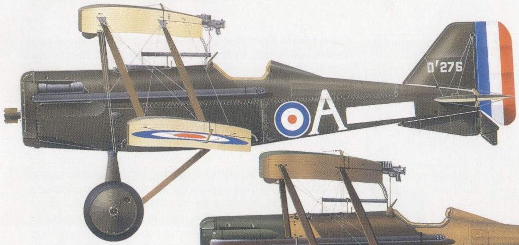
S.E.5a, No 74 Sqn, RAF, at Teteghem, France, April 1919, as flown by "Mick” Mannock.

S.E.5a in Polish service.
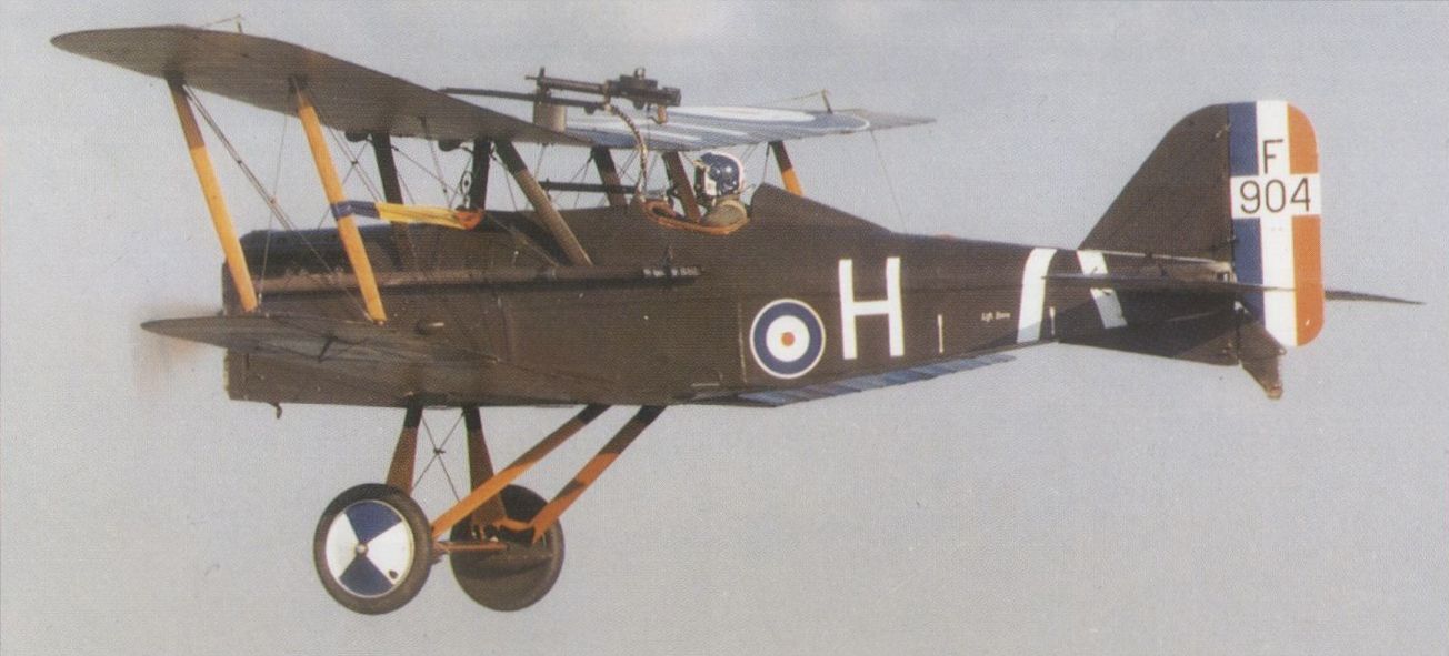
Built by Wolseley, this S.E.5a once used for "skywriting” was restored at the RAE in 1972.
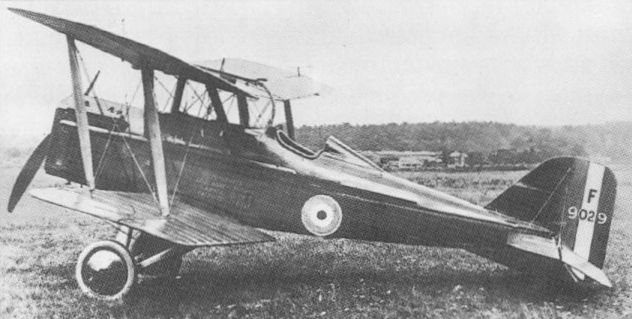
A "presentation” S.E.5a from Addis Ababa, showing the fighter’s standard armament.
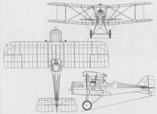
A drawing, showing the S.E.5a’s standard armament.
ROYAL AIRCRAFT FACTORY F.E.9 UK
Conceived as a replacement for the F.E.2b in the fighter-reconnaissance role, the F.E.9 was of similar pusher configuration and therefore already obsolescent by the time it appeared in 1917. Emphasis was placed in the design upon providing the gunner with a good field of fire and the pilot a good all-round view. To this end, the nacelle was located close beneath the upper wing and was carried on struts above the shorter-span lower wing. The large overhang of the upper wing brought the F.E.9 almost into the sesquiplane category, and called for bracing wires from triangular kingposts above the interplane struts of the single-bay cellule. A cruciform tail unit was carried on four slender booms, as on the F.E.2, and the Vee-strutted undercarriage incorporated oleo legs. Construction was largely of wood, but pairs of steel tube N-struts linked the nacelle to the upper and lower wings. Power was provided by a 200 hp Hispano-Suiza eight-cylinder V-type water-cooled engine and the planned armament comprised two 0.303-in (7,7-mm) Lewis guns on pillar mounts, ahead of and behind the front cockpit, and both fired by the observer - the latter rearwards over the pilot’s head and the top wing. Installation of a third gun, on the side of the fuselage for use by the pilot, was planned. Authority was given by the War Office for construction of three prototypes and a production batch of 24 in October 1916, and testing began in April 1917. Handling and performance of the prototypes were disappointing, however, and production was cancelled, to allow the Hispano engines to be used in more worthwhile types. Testing of the prototypes continued, in the course of which two-bay wings were tried on the second aircraft, which was also flown for a time by No 78 Home Defence Squadron, RFC.
Max speed, 105 mph (169 km/h) at 10,000 ft (3 050 m), 88 mph (142 km/h) at 15,000 ft (4 570 m).
Time to 10,000 ft (3050 m), 21.35 min.
Service ceiling, 15,500 ft (4 725 m).
Loaded weight, 2,480 lb (1125 kg).
Span, 40 ft 1 in (12,22 m).
Length, 28 ft 3 in (8,61m).
Height, 9 ft 9 in (2,97 m).
Wing area, 365 sqft (33,91 m2).
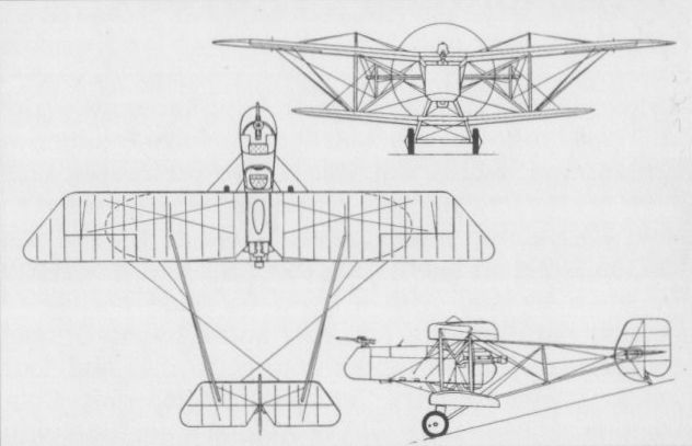
The F.E.9 is seen with the original single-bay wings.
ROYAL AIRCRAFT FACTORY N.E.1 UK
As a derivative of the F.E.9 (which see), the RAF planned to develop a dedicated night fighter as the F.E.12. This was to have used the same 200 hp Hispano-Suiza eight-cylinder Vee-type water-cooled engine, the same undercarriage, tailbooms, tail unit and wing centre section as the F.E.9, and basically the same nacelle, but with the crew positions reversed. New equi-span, three-bay wings were planned, with plain unbalanced ailerons. The pilot, in the front cockpit for the best possible view during unaided nocturnal operations, was to have a forward-firing 0.303-in (7,7- mm) Lewis gun, whereas the observer was to be armed with a Vickers rocket gun for which two mounts were to be provided for firing forwards or aft. Provision was to be made for a searchlight in the nose, and another on the forward mount for the rocket gun, with a wind-driven generator under the nacelle. Six prototypes were planned, but before construction began the designation was changed to N.E.1 (for ‘‘Night-flying Experimental”) and some changes were made. These eliminated the second searchlight, increased the span of the wing centre section, changed the tail unit design, moved the boom attachment points on the tailplane outwards, and introduced a wide-track undercarriage with a divided axle arrangement. Flown early in September 1917, the first N.E.1 was almost immediately damaged and was then modified, before resuming flying on 4 October, to accommodate the observer in the front cockpit with the rocket gun and the pilot behind with a fixed Lewis gun. In this form, the N.E.1 was submitted to official trials at Martlesham Heath in November 1917, but was not thought to have adequate performance to serve as a night fighter. The other five prototypes were all completed by January 1918, but one was used only for static testing, another probably remained unflown and only one was issued to an RFC squadron for home defence.
Max speed, 95mph (153 km/h) at 10,000 ft (3050 m), 85mph (137 km/h) at 16,500 ft (5 030 m).
Time to 1,000 ft (305 m), 1.6 min.
Service ceiling, 17,500 ft (5335 m).
Endurance, 2.75 hrs.
Empty weight, 2,071 lb (939 kg).
Loaded weight, 2,946 lb (1336 kg).
Span, 47 ft 10 in (14,57m).
Length, 30 ft 2 in (9,19 m).
Height, 9 ft 8 in (2,94 m).
Wing area, 555.1 sq ft (51,57 m2).
ROYAL AIRCRAFT FACTORY A.E.3 RAM UK
The last aircraft type to emerge from the Royal Aircraft Factory at Farnborough, before its change of name in June 1918 to Royal Aircraft Establishment, the A.E.3 was itself an extrapolation from the N.E.1 (which see). Designated as an "Armoured Experimental" type, the A.E.1 was intended as a specialised ground-attack fighter, for which purpose it was to mount a pair of 0.303-in (7,7-mm) Lewis guns in the nose, with a limited degree of movement in azimuth and depression. A third Lewis was to be pillar-mounted in the front, observer’s, cockpit for self-defence. Like the N.E.1, the A.E.3 was a large three-bay equi-span biplane, differing principally in the construction and shape of the nacelle, which was armoured with steel plate and provided stowage for 32 ammunition drums. Intended to be powered by the 200 hp Hispano engine as used in the N.E.1, the A.E.3 prototype emerged at the end of March 1918 with a 200 hp Sunbeam Arab, whilst the second, eight weeks later, had a 230 hp Bentley B.R.2 rotary. Flight testing of the latter began on 4 June, and larger ailerons and rudders were fitted before this A.E.3 went to France for service trials, which aroused little enthusiasm. The third aircraft, also completed in June 1918, had an Arab engine like the first and in this form the A.E.3 was named the Ram I, whilst the B.R.2 version became the Ram II. A proposed derivative, the Ram III, was not built and no production ensued, other, better, types having become available . The following speed is estimated with a 200 hp Hispano engine.
Max speed, 95 mph (153 km/h).
Span, 47 ft 10 1/2 in (14,59m).
Length, 27 ft 8 1/2 in (8,44 m).
Height, 10 ft 0 in (3,05 m).
Wing area, 560 sq ft (52,02 m2).
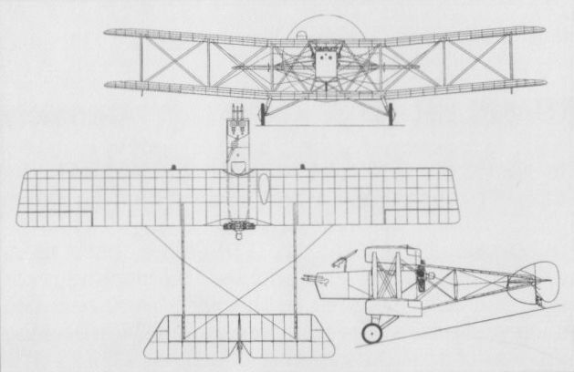
The A.E.3 Ram II with B.R.2 engine.
ROBEY PETERS R.R.F.25 UK
Tests conducted in the USA led the British Admiralty to adopt the Davis recoilless gun for the RNAS, several types of aircraft being designed around this immense weapon, essentially for the anti-Zeppelin role. Among these was the Robey Peters R.R.F.25, designed by J A Peters for Robey & Company. Powered by a 250 hp Rolls-Royce 12-cylinder Vee-type water-cooled engine (later to be named Eagle), the R.R.F.25 was an unequal-span two-bay biplane with a crew of three comprising a pilot and two gunners. The pilot was accommodated far aft, immediately ahead of the vertical tail, and the gunners occupied nacelles suspended beneath the upper wing. The port nacelle accommodated a 0.303-in (7,7-mm) Lewis gun and the starboard nacelle housed a two-pounder version of the Davis gun which exceeded 7 ft (2,13 m) in length. Eight shells for the gun were fitted into the nacelle and two more in the adjacent wing. Two prototypes were ordered, the first of these flying in September 1916. It suffered minor damage as a result of turning over during the take-off run for what was to have been its second flight, and when it did succeed in getting airborne once more a fire at low altitude resulted in a crash in which it was destroyed. The second prototype, referred to as the Mk II, featured a new equi-span three-bay wing cellule, introduced a fixed tail fin, and side windows were added for the pilot. Overall span was reduced by 2 ft (61 cm) and wing area was increased by 63.5 sq ft (5,89 m2). It was intended that a Davis gun be carried in each nacelle. This aircraft was, in fact, cancelled by the Admiralty, but was completed nonetheless in January 1917 and flown during the course of the month. It stalled on take-off, however, and crashed, further work on the aircraft being finally abandoned. The following data relate to the first prototype.
Loaded weight, 3,700 lb (1678 kg).
Span, 54 ft 6 in (16,61m).
Length, 29 ft 4 1/2 in (8,95 m).
Wing area, 483.5 sq ft (44,92 m2).
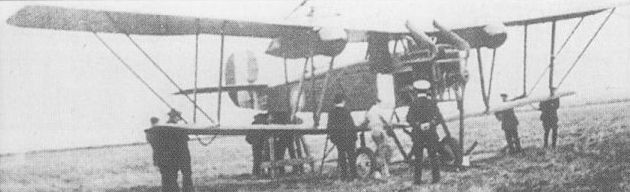
The first prototype R.R.F.25 anti-Zeppelin aircraft with two-pounder Davis gun in the port nacelle.
This is the only known photo of the first machine, the F 25 MK 1 serial 9498 before its test flight. The second machine 9499 has a revised wing structure and is the one usually pictured.
This is the only known photo of the first machine, the F 25 MK 1 serial 9498 before its test flight. The second machine 9499 has a revised wing structure and is the one usually pictured.

The equal-span second prototype of the R.R.F.25
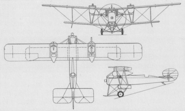
The unequal-span first prototype of the R.R.F.25
SAGE TYPE 2 UK
Designed by Clifford W Tinson for Frederick Sage & Company, the Type 2 two-seat fighting scout was of original concept. Considerable care was taken to reduce aerodynamic drag, the 100 hp Gnome Monosoupape nine-cylinder rotary engine being fully cowled, a large propeller spinner being provided and the crew being accommodated in a fully-glazed cabin. Of conventional wire-braced wooden construction, the Type 2 was a single-bay biplane with considerable gap, the upper wing being supported by the cabin structure and having an aperture above the observer’s seat. When standing to fire his 0.303-in (7,7-mm) machine gun, the observer had a wide and clear field of fire. Remarkably small, the Type 2 had rod-activated ailerons in the upper wing only. First flown on 10 August 1916, it proved to possess a very good performance, but gun synchronization had meanwhile become available, and after the sole prototype had been wrecked in a forced landing on 20 September 1916, no attempt was made to rebuild the aircraft or develop it.
Max speed, 112 mph (180 km/h) at sea level.
Time to 10,000 ft (3 050 m), 14.75 min.
Endurance, 2.5 hrs.
Empty weight, 890 lb (404 kg).
Loaded weight, 1,546 lb (701 kg).
Span, 22 ft 2 1/2 in (6,77 m).
Length, 21 ft 1 5/8 in (6,45 m).
Height, 9 ft 6 in (2,89 m).
Wing area, 168 sq ft (15,61 m2).
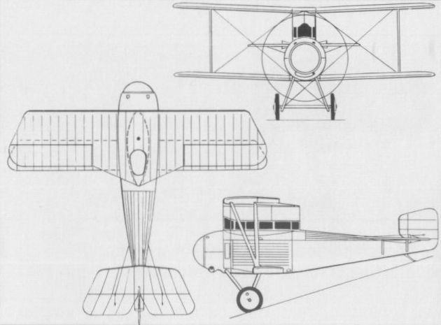
SOPWITH GUN BUS UK
The Gun Bus was essentially a landplane derivative of the S.P.Gn (Sopwith Pusher, gun), a gun-carrying two-seat pusher biplane with twin floats. Six of these floatplanes were ordered from the recently-founded Sopwith Aviation Company by the Greek government in March 1914, but immediately commandeered by the Admiralty when war was declared in August that year, subsequently serving with the RNAS. The Gun Bus, intended for the fighting role, carried a 0.303-in (7,7-mm) machine gun on a flexible mount in the forward cockpit and was powered by a 100 hp Gnome Monosoupape rotary engine. A more powerful version, with a 150 hp Sunbeam eight-cylinder water-cooled engine, was developed specifically for the RNAS, this having a redesigned nacelle and a revised undercarriage. Six of the Sunbeam-powered Gun Buses were built for the RNAS by Sopwith, a further 30 being ordered for the service from Robey & Company, these last being intended for bombing (and possibly anti-submarine) duties as distinct from fighting. The pilot was moved forward to the front cockpit, a bombing panel being let into the floor and four bomb carriers being fitted beneath the lower wing. The following data relate to the Sunbeam-powered two-seat fighter Gun Bus.
Max speed, 80 mph (129 km/h).
Span, 50 ft 0 in (15,24 m).
Length, 32 ft 6 in (9,90 m).
Height, 11 ft 4 in (3,45 m).
Wing area, 474 sqft (44,03 m2).
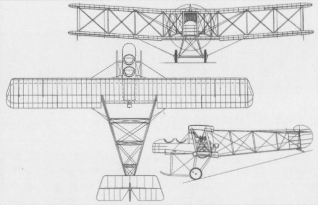
The Sunbeam-powered Gun Bus which was developed specifically for the RNAS.
SOPWITH SCHNEIDER UK
Derived from the Tabloid float seaplane which won the Schneider Trophy contest in April 1914, and named, appropriately enough, the Schneider, the single-seat twin-float seaplane ordered into production in November 1914 for the RNAS resembled closely the aircraft that had gained the Trophy at Monaco. Retaining the same 100 hp Gnome Monosoupape nine-cylinder rotary - the upper half of which was enclosed by a ‘bull-nose’ cowling - and wing-warping lateral control, the Schneider had a larger fin and rudder, reinforced float bracing and an aperture in the centre section for an upward-angled 0.303-in (7,7-mm) machine gun. Used for patrol duties against enemy airships from seaplane stations around the British coast, the Schneiders were provided with incendiary ammunition and operated against Zeppelins from early 1915. Schneiders were also carried aboard light cruisers of the North Sea Patrol for anti-Zeppelin operations, and served at the Dardanelles, in the Aegean and in the Eastern Mediterranean. Two Schneiders operated from the carrier Ark Royal in April 1915 at Mudros, and the type was still serving in the Aegean as late as November 1916, one shooting down an enemy aircraft which had attacked the airship shed at Mudros on the 21st of that month. A total of 136 Schneiders is believed to have been built, progressive development resulting in the Baby.
Max speed, 89 mph (143 km/h) at sea level.
Time to 8,500 ft (2 500 m), 33.8 min.
Endurance, 2.5 hrs.
Loaded weight, 1,530 lb (694 kg).
Span, 25 ft 8 in (7,82 m).
Length, 22 ft 8 in (6,90 m).
Height, 9 ft 9 in (2,97 m).
Wing area, 240 sq ft (22,30 m2).
SOPWITH BABY UK
Derived from the Schneider single-seat fighter seaplane, the Baby first appeared in September 1915, and differed from its predecessor primarily in having a 110 hp Clerget nine-cylinder rotary in place of the Monosoupape, this being accommodated by a horseshoe-shaped open-fronted cowling. As on late production Schneiders, ailerons replaced wing warping for lateral control, and armament usually consisted of a single 0.303-in (7,7-mm) machine gun synchronised to fire through the propeller, although a few Babies retained the arrangement of the Schneider with the gun attached to the centre section and firing upward to clear the propeller. Several Babies were fitted with two 0.303-in (7,7-mm) guns side by side over the wing; one batch of Blackburn-built Babies was fitted with Ranken explosive darts as anti-airship weapons, and at least one was fitted with Le Prieur rockets, 10 of these devices being attached to the interplane bracing struts. Two 65-lb (29,5-kg) bombs could also be carried. The Baby was widely used by the RNAS to provide fighter , aircraft for use with patrol ships, as escorts for two-seaters and for operation from early aircraft carriers. A total of 286 Babies was built of which 195 were produced by Blackburn - and sometimes known as Blackburn Babies - 105 of the latter being fitted with the 130 hp Clerget engine, and, of these, 40 were fitted (initially) to carry the Ranken dart and no gun armament. A more extensive modification of the Sopwith float fighter was the Fairey Hamble Baby (which see). The following data relate to the 130 hp Blackburn-built Baby.
Max speed, 100 mph (161 km/h) at sea level.
Time to 10,000 ft (3 050 m), 35 min.
Endurance, 2.25 hrs.
Empty weight, 1,226 lb (556 kg).
Loaded weight, 1,715 lb (778 kg).
Span, 25 ft 8 in (6,90 m).
Length, 23 ft 0 in (7,01 m).
Height, 10 ft 0 in (3,05 m).
Wing area, 240 sq ft (22,30 m2).

By 1920, Norway's Marinens Flyvevaesen had received 17 ex-RNAS Baby floatplanes.
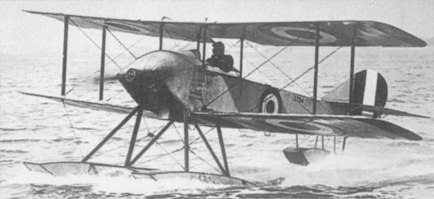
Schneider (No.3734) with wing warping, a series example serving with the RNAS in 1915.
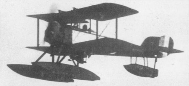
A Blackburn-built Baby with overwing guns

A three-view drawing of the Baby.
SOPWITH 1 1/2-STRUTTER UK
Deriving its extraordinary appellation from a characteristic arrangement of cabane struts - a name that was initially unofficial, but came to be accepted as a result of common usage - the 1 1/2-Strutter was both the first British aircraft to be built with a synchronised gun as standard equipment and the first true two-seat fighter to see RFC service. Designed and built for the Admiralty, the unarmed prototype was completed in December 1915, and series deliveries to the RNAS followed from February 1916. A single-bay biplane of wooden construction with fabric skinning, the 1 1/2-Strutter featured air brakes in the lower wing and an adjustable-incidence tailplane. At an early production stage, armament was standardised on a synchronised 0.303-in (7,7-mm) gun with a second weapon of similar calibre on a Scarff ring mounting in the rear cockpit. The 1 1/2-Strutter was used by the RNAS in both escort and (without observer) bombing roles, and 77 of the first 150 aircraft ordered by the Admiralty were transferred to the RFC owing to the exigencies of the times. A single-seat bomber version of the 1 1/2-Strutter was built in parallel, some examples of this variant being converted as two-seat fighters. Initial production aircraft were powered by the 110 hp Clerget 9Z nine-cylinder rotary engine, but, in the autumn of 1916, this gave place to a 130 hp Clerget 9B. At least 1,513 1 1/2-Strutters were built in the UK (by the parent company, Fairey Aviation, Hooper & Co, Mann, Egerton & Co, Ruston, Proctor & Co, Vickers Ltd, Wells Aviation and Westland Aircraft). The 1 1/2-Strutter was licence-built in France as a single- and two-seat bomber (SOP 1B1 and 1B2) and two-seat reconnaissance aircraft (SOP 1A2), primarily with the 110 hp and 135 hp Le Rhone 9J and 9Jby nine-cylinder rotaries, 4,500 allegedly being produced by Liore et Olivier, Hanriot, Amiot, Bessoneau, Darracq, REP and Sarazin Freres. The US government procured 514 from France, and others were supplied to Belgium and Imperial Russia. The following data apply to the 130 hp Clerget-engined model.
Max speed, 100 mph (161 km/h) at 6,500 ft (1 980 m).
Time to 6,500 ft (1 980 m), 9.15 min.
Endurance, 3.75 hrs.
Empty weight, 1,305 lb (592 kg).
Loaded weight, 2,150 lb (975 kg).
Span, 33 ft 6 in (10,21 m).
Length, 25 ft 3 in (7,69 m).
Height, 10 ft 3 in (3,12 m).
Wing area, 346 sqft (32,14 m2).
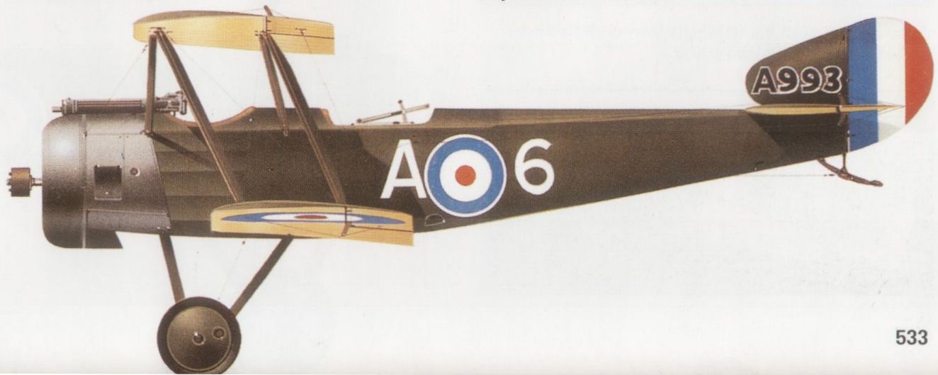
Sopwith 1 1/2-Strutter in service in France late 1916 with No 70 Sqn, RFC.
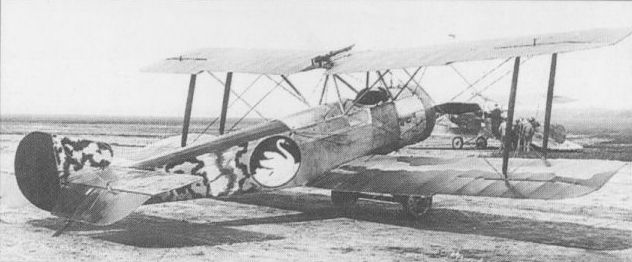
A Sopwith 1 1/2-Strutter in RNAS service

A three-view drawing of the 1 1/2-Strutter.
SOPWITH F.1 CAMEL UK
Evolved from the Pup, to which it bore a close family resemblance, the F.1 design - rapidly nicknamed Camel because of its hump-backed appearance, an epithet eventually to be recognised officially - was passed by the Sopwith experimental department on 22 December 1916. Possessing conventionally wire-braced and fabric-covered wooden wings, and a wire-braced wooden box girder fuselage covered by light alloy panels forward, plywood to aft of the cockpit and fabric, the Camel had an armament of twin synchronised 0.303-in (7,7-mm) guns. It was produced in series powered with the 130 hp Clerget 9B, the 150 hp Bentley B.R.1 or the 110 hp Le Rhone nine-cylinder rotaries. The Camel (F.1 and 2F.1, the latter listed separately) was to be ordered in large numbers from various contractors (Boulton & Paul, British Caudron, Clayton & Shuttleworth, Hooper, March, Jones & Cribb, Nieuport & General, Portholme Aerodrome and Ruston, Proctor) for both the RFC and RNAS, deliveries commencing in May 1917. A total of 5,597 (F.1 and 2F.1) was ordered, of which 5,490 were apparently delivered. The F.1 Camel was adapted for the nocturnal intercept role as a replacement for the 1 1/2-Strutter on Home Defence duties. Mostly Le Rhone-powered, Camel night fighters were armed with twin 0.303-in (7,7-mm) guns above the wing centre section and firing upwards at an angle of 45 deg, the cockpit being moved one bay farther aft and the centre section cut-out being enlarged. A total of 2,519 F.1 Camels (plus 129 2F.1 Camels) was on RAF charge on 31 October 1918, but these did not survive long after the Armistice, giving place to the Sopwith Snipe. The following data relate to the 130 hp Clerget 9B-powered F.1 Camel.
Max speed, 115 mph (185 km/h) at 6,500 ft (1 980 m).
Time to 6,500 ft (1 980 m), 6.0 min.
Endurance, 2.5 hrs.
Empty weight, 929 lb (421 kg).
Loaded weight, 1,453 lb (659 kg).
Span, 28 ft 0 in (8,53 m).
Length, 18 ft 9 in (5,71 m).
Height, 8 ft 6 in (2,59 m).
Wing area, 231 sqft (21,46 m2).
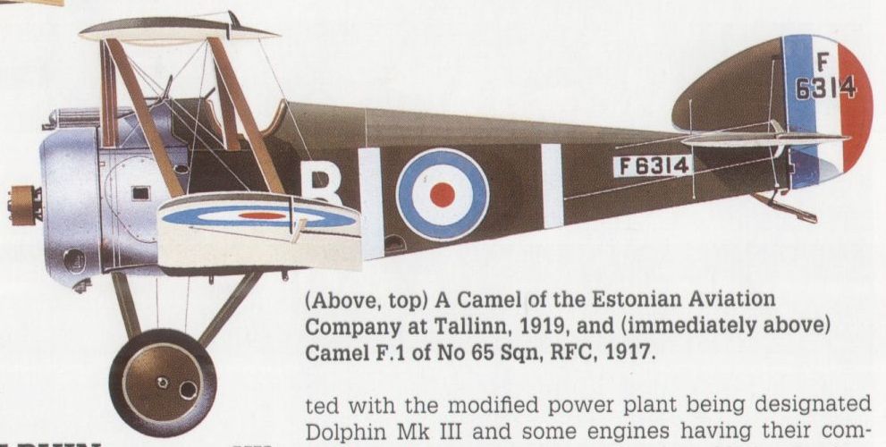
Camel F.1 of No 65 Sqn, RFC, 1917.

A Camel of the Estonian Aviation Company at Tallinn, 1919
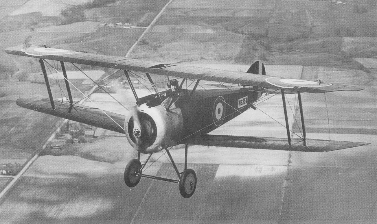
One of the few surviving Camels, this 2F.1 is now preserved in the US Marine Corps Museum.
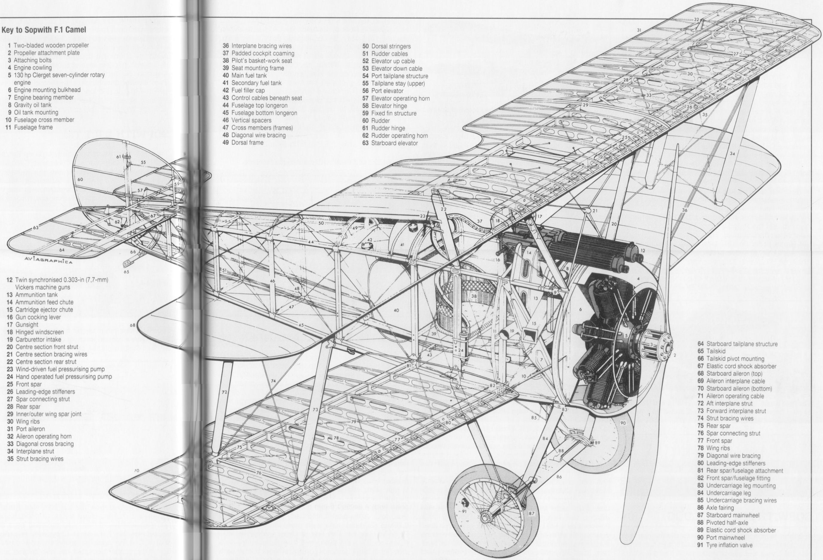
Sopwith F.1 Camel
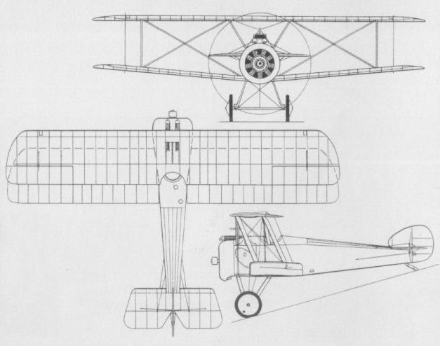
A three-view drawing of the standard Camel fighter.
SOPWITH L.R.T.TR. UK
The L.R.T.Tr., presumably signifying Long-Range Tractor Triplane, was designed to meet an RFC requirement for a combined escort fighter and airship interceptor. Other contenders were the Armstrong Whitworth F.K.6, also of triplane arrangement, and the Vickers F.B.11, which was of more conventional biplane layout. Of bizarre appearance, the L.R.T.Tr. was a three-bay triplane with narrow-chord wings, all of which were fitted with ailerons. Power was provided by a 250 hp Rolls-Royce Mk I (Eagle I) 12-cylinder water-cooled engine, and the crew comprised a pilot and two gunners. One gunner occupied the rear cockpit and the other a streamlined nacelle built around the upper wing centre section, both having a single 0.303-in (7,7- mm) machine gun. By the time flight test commenced in 1916, it was appreciated that the concept of the L.R.T.Tr. had been rendered outdated by the advent of practical gun synchronisation equipment and the success against airships enjoyed by more conventional aircraft. This clumsy aeroplane, meanwhile assigned the epithet of Egg Box, was duly abandoned.
Span, 52 ft 9 in (16,08 m).
Length, 35 ft 3 in (10,74 m).
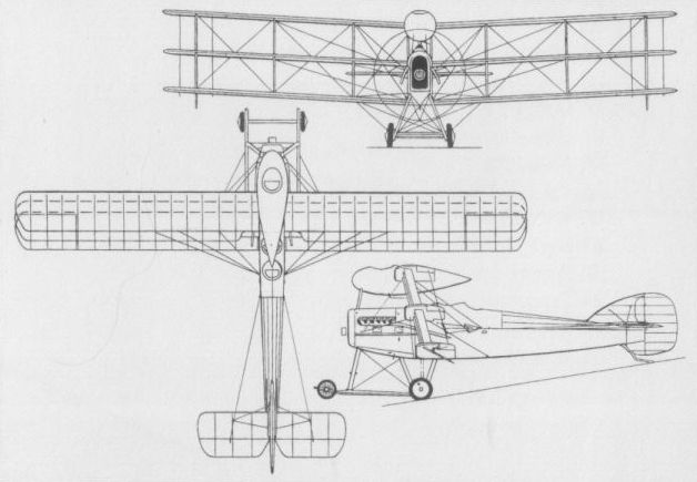
Sopwith's long-range tractor triplane was a contemporary of the Clerget and Hispano-Suiza triplanes, but was not a success.
SOPWITH PUP UK
Possessing an obvious resemblance to the 1 1/2-Strutter, the Pup - again an unofficial appellation which was to become inseparable from the aircraft to which it was affectionately applied - flew in the early spring of 1916 as the Sopwith Scout. A conventional single-bay equi-span staggered biplane primarily of wooden construction with fabric skinning, the Pup had a single 0.303-in (7,7-mm) synchronised machine gun, and all six prototypes and the initial 11 Beardmore-built aircraft had the 80 hp Clerget nine-cylinder rotary engine. Subsequently, the 80 hp Le Rhone rotary was standardised. The Pup was ordered by the Admiralty from Sopwith and Beardmore, and by the War Office from Standard Motor and Whitehead Aircraft, the first production examples appearing in September 1916. Obsolescent as a frontline fighter by the late summer of 1917 - although production continued in 1918, 733 being delivered in that year to bring the grand total to 1,770 - the Pup was assigned to Home Defence units. To improve combat capability against the Gotha bombers then attacking the UK, the Pup was fitted with a 100 hp Gnome Monosoupape, the installation being characterised by a horseshoe-shaped cowling. Many RNAS Pups were armed with a 0.303-in (7,7-mm) gun on a tripod mount in front of the cockpit and some 20 were equipped to carry eight Le Prieur rockets, four each on the interplane struts. Early in 1917, the Pup came into use as a shipboard fighter and was used on the carriers Campania, Furious and Manxman. The following data relate to the standard Le Rhone 9C-powered Pup.
Max speed, 111 mph (179 km/h) at sea level.
Time to 5,000 ft (1 525 m), 5.33 min.
Endurance, 3.0 hrs.
Empty weight, 787 lb (357 kg).
Loaded weight, 1,225 lb (556 kg).
Span, 26 ft 6 in (8,08 m).
Length, 19 ft 3 3/4 in (5,89 m).
Height, 9 ft 5 in (2,87 m).
Wing area, 254 sq ft (23,60 m2).
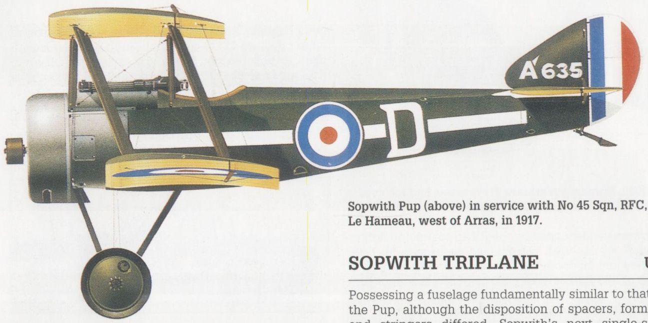
Sopwith Pup in service with No 45 Sqn, RFC, at Le Hameau, west of Arras, in 1917.
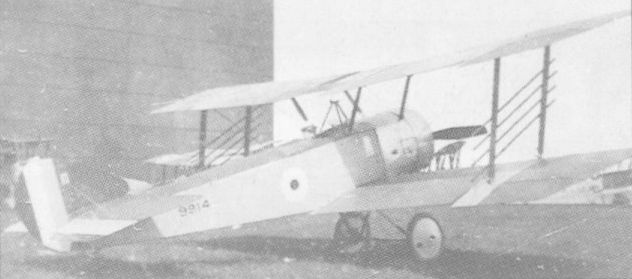
A Beardmore-built RNAS Pup with Le Prieur rockets on the interplane struts.
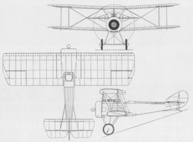
The Sopwith Pup
SOPWITH TRIPLANE UK
Possessing a fuselage fundamentally similar to that of the Pup, although the disposition of spacers, formers and stringers differed, Sopwith’s next single-seat fighter - designed, like the Pup, by Herbert Smith - initiated a vogue: that of the fighting triplane. The first prototype of what was to be referred to simply as the Triplane was completed in May 1916, its radical wing arrangement of triple narrow-chord mainplanes, with ailerons on all three wings and single broad-chord interplane and centre section struts, resulted in exemplary manoeuvrability and, for its day, a phenomenal climb rate. A measure of the success of the Sopwith Triplane after making its combat debut with the RNAS was provided by the extraordinary variety of single-seat fighters of similar configuration hurriedly developed by German and Austro-Hungarian companies. Initially powered by the 110 hp Clerget 9Z nine-cylinder rotary, but more usually being fitted with the 130 hp Clerget 9B, the Triplane began to appear in production form late in 1916, joining combat in the following February. Armament normally comprised one synchronised 0.303-in (7,7-mm) gun, but a few were fitted with twin weapons of this calibre. At least one aircraft was tested with a 110 hp Le Rhone engine. Although the Tri¬plane was ordered for both the RNAS and RFC, it was, in fact, used operationally by the former service only, an agreement having been reached in February 1917 under which the RNAS exchanged all its SPAD S.VIIs for all the Triplanes then on order for the RFC. As a result, contracts were reduced and only some 150 were completed, the Triplane’s operational career being brief, and its replacement by the Camel in Naval squadrons commencing as early as July 1917. The following data relate to the 130 hp Clerget-engined Triplane.
Max speed, 116 mph (187 km/h) at 6,000 ft (1 830 m).
Time to 6,500 ft (1 980 m), 6.33 min.
Endurance, 2.75 hrs.
Empty weight, 993 lb (450 kg).
Loaded weight, 1,415 lb (642 kg).
Span, 26 ft 6 in (8,08 m).
Length, 19 ft 6 in (5,94 m).
Height, 10 ft 6 in (3,20 m).
Wing area, 231 sq ft (21,46 m2).
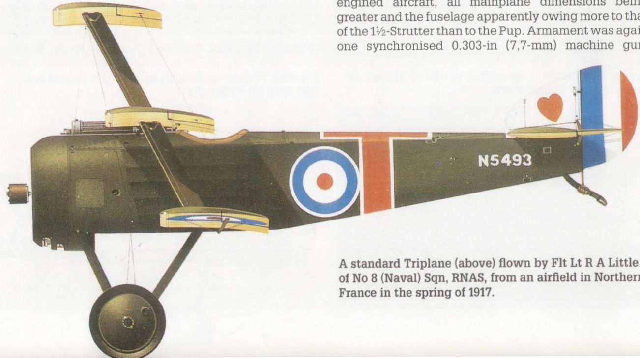
A standard Triplane flown by Flt Lt R A Little of No 8 (Naval) Sqn, RNAS, from an airfield in Northern France in the spring of 1917.

A Sopwith-built Triplane for the RNAS, with standard armament of a single Vickers gun.
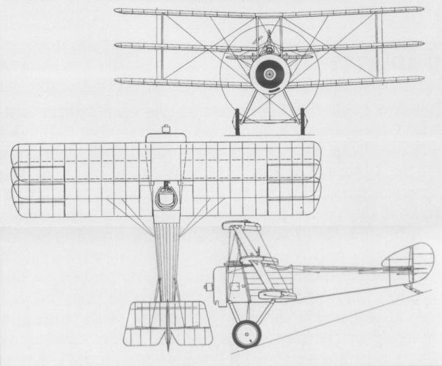
Three-view drawing of the Sopwith Triplane.
SOPWITH HISPANO-SUIZA TRIPLANE
Although Sopwith’s Hispano-Suiza-engined triplane fighter was almost contemporary with the Clerget-engined Triplane, it was a completely different aeroplane, common design features being confined to the wing configuration and the style of interplane struts. Designed around the new Hispano-Suiza eight-cylinder water-cooled engine, two prototypes were completed, one with the 150 hp direct-drive version of the engine and the other with a 200 hp geared version. The Hispano-Suiza Triplane featured a circular nose radiator and was generally larger than the Clerget-engined aircraft, all mainplane dimensions being greater and the fuselage apparently owing more to that of the 1 1/2-Strutter than to the Pup. Armament was again one synchronised 0.303-in (7,7-mm) machine gun. Engine availability delayed the completion of the two prototypes until the late autumn of 1916. The 200 hp second prototype was lost on 20 October 1916 as the result of a flutter-induced tail failure, and the 150 hp first prototype continued flying until the autumn of 1917, during which it flew several home defence sorties from Manston. No further development was undertaken. The following data relate to the second prototype.
Max speed, 120 mph (193 km/h).
Time to 10,000 ft (3 050 m), 9.0 min.
Span, 28 ft 6 in (8,69 m).
Length, 23 ft 2 in (7,06 m).
Wing area, 340 sq ft (31,59 m2).
SOPWITH 2F.1 CAMEL UK
A shipboard version of the F.1 Camel single-seat fighter, the 2F.1 differed essentially in having an abbreviated upper wing centre section and correspondingly shorter lower wing; narrower, steel-tube cabane struts; external elevator cables, and a detachable rear fuselage to facilitate stowage aboard ship. The standard engine was the 150 hp Bentley B.R.1, but the 130 hp Clerget 9B was regarded as an alternative, and armament comprised one synchronised 0.303-in (7,7-mm) machine gun and a second weapon of similar calibre above the wing centre section. Deliveries of the 2F.1 to the RNAS began in the autumn of 1917 against an initial order for 50 fighters placed with the parent company. William Beardmore & Co subsequently became the major contractor for this version of the Camel, building a further 150 of which the first flew on 20 February 1918. The 2F.1 Camels were employed by the RNAS and (after the amalgamation of that service with the RFC on 1 April 1918) RAF from shore bases, towed lighters, battle cruisers, large light cruisers and from the carriers Argus, Furious, Pegasus and Eagle. On 31 October 1918, 129 were on charge with the RAF, of which 112 were with units of the Grand Fleet. The 2F.1 Camel remained in service as a carrier-borne fighter for some years after World War I, a number was supplied to Latvia and Estonia, and others supplied to Canada continued in use until the late ’twenties. The following data relate to the B.R.1-powered 2F.1 Camel.
Max speed, 122 mph (196 km/h) at 10,000 ft (3 050 m).
Time to 10,000 ft (3 050 m), 11.5 min.
Empty weight, 1,036 lb (470 kg).
Loaded weight, 1,530 lb (694 kg).
Span, 26 ft 11 in (8,20 m).
Length, 18 ft 8 in (5,69 m).
Height, 9ft 1 in (2,77 m).
Wing area, 221 sq ft (20,53 m2).
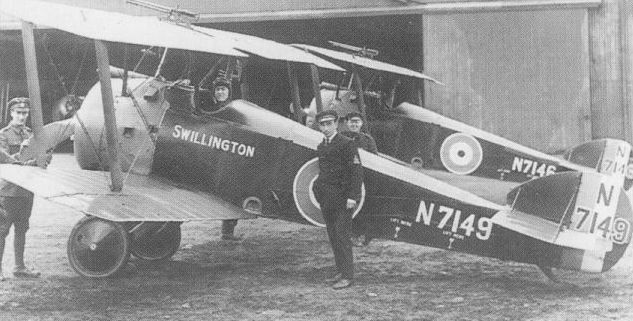
A pair of the 2F.1 shipboard versions of the Camel serving at Turnhouse in 1918.
SOPWITH 5F.1 DOLPHIN
Designed to provide the pilot with the best possible view in tactically important directions, the 5F.1 Dolphin was unusual in being a two-bay equi-span biplane with negative stagger. The pilot was seated with his head in the open framework connecting the upper mainplanes. Primarily of fabric-covered wire-braced wooden construction with an upper centre section of steel tube, the Dolphin was powered by a 200 hp Hispano-Suiza geared eight-cylinder water-cooled engine in its initial production form. Armament consisted of two fixed and synchronised 0.303-in (7,7-mm) guns and either one or two guns of similar calibre mounted over the wing centre section and movable, but usually firing forwards and upwards. The prototype was flown in late May 1917, the first production contract was placed in the following month, on 29 June, and quantity deliveries to the RFC began late in the year. The first Dolphin squadron was deployed to France in February 1918, and the decision was taken to licence-build a version for the US Air Service in France. This, the Dolphin Mk II powered by a 300 hp Hispano-Suiza engine, was to be manufactured by the SACA (Societe Anonyme des Constructions Aeronautiques) and the Air Service anticipated taking delivery of 2,194 by mid 1919. In the event, only a few Dolphin Mk IIs were completed before the Armistice prompted cancellation of all contracts. Difficulties with the reduction gear of the original 200 hp engine led to the conversion of many to direct drive, aircraft fitted with the modified power plant being designated Dolphin Mk III and some engines having their compression ratio raised to boost output to 220 hp. Production of the Dolphin totalled 1,532 aircraft, of which all but 121 were built during 1918. Both Dolphin Mks I and III were finally withdrawn from RAF service mid 1919. The following data relate to the Dolphin Mk III.
Max speed, 128 mph (206 km/h) at 6,500 ft(1 980 m).
Time to 6,500 ft (1980 m), 6.33 min.
Empty weight, 1,466 lb (665 kg).
Loaded weight, 2,000 lb (907 kg).
Span, 32 ft 6 in (9,90 m).
Length, 22 ft 3 in (6,78 m).
Height, 8 ft 6 in (2,59 m).
Wing area, 263.25 sq ft (24,46 m2).
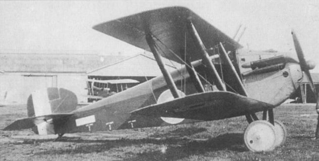
The Sopwith Dolphin, a service example showing upward-firing guns.
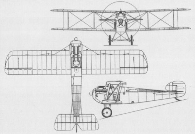
The Sopwith Dolphin with two guns
SOPWITH 3F.2 HIPPO UK
Built as a private venture, the Hippo two-seat fighter featured negative wing stagger, the gap between the wings being completely filled by the deep fuselage, and the first of two prototypes was flown on 13 September 1917. A two-bay biplane powered by a 200 hp Clerget 11Eb 11-cylinder rotary, the Hippo had an armament of two fixed synchronised 0.303-in (7,7-mm) and (initially) two free-mounted guns of similar calibre, or (later) one 0.303-in (7,7-mm) gun on a Scarff mount in the rear cockpit. Official trials were performed at Martlesham Heath in January 1918, these having been delayed by engine problems. The performance of the Hippo was considered inferior to that of the Bristol F.2B and lateral control was criticised, and, on 2 February 1918, the aircraft was returned to Sopwith. Despite official rejection, the manufacturer fitted new wings, plain ailerons and an enlarged fin. Wing dihedral was increased and stagger was reduced, and with these modifications the Hippo re-emerged in April 1918, with a second prototype following in June. By that time, the F.2B was giving satisfaction in service and it became apparent to Sopwith that the Hippo was too late, further development being discontinued. The following data relate to the Hippo in its original form.
Max speed, 115 mph (185 km/h) at 10,000 ft (3050 m).
Time to 10,000 ft (3 050 m), 13.25 min.
Empty weight, 1,481 lb (672 kg).
Loaded weight, 2,590 lb (1175 kg).
Span, 38 ft 9 in (11,81 m).
Length, 24 ft 6 in (7,47 m).
Height, 9 ft 4 in (2,84 m).
Wing area, 340 sq ft (31,59 m2).

The first Hippo in its original form
SOPWITH 2FR.2 BULLDOG UK
A fighter-reconnaissance two-seater, the Bulldog was a compact aircraft which, in its initial form as first flown late 1917, was a single-bay staggered biplane with a 200 hp Clerget 11Eb 11-cylinder rotary engine and an armament of two synchronised and two pillar-mounted 0.303-in (7,7-mm) machine guns. The Bulldog proved heavier than projected and difficult to control, and in an attempt to improve handling qualities it was fitted with two-bay wings with balanced ailerons, flight test being resumed in March 1918. With the balanced ailerons replaced by plain surfaces, the Bulldog was submitted to Martlesham Heath for official trials on 22 April 1918. There it was found to handle well, but to possess disappointing performance. It was eventually to be re- engined with a Bentley B.R.2. The second prototype was completed with an A.B.C. Dragonfly nine-cylinder radial of 320 hp, being delivered to the RAE at Farnborough on 25 June 1918 as the Bulldog Mk II and serving as an engine test bed. Work began on a third prototype, but the Bulldog’s failure to win official approval led to discontinuation of the programme before this aircraft could be completed. The following data relate to the Clerget-engined Bulldog with two-bay wings and plain ailerons.
Max speed, 109 mph (175 km/h) at 10,000 ft (3 050 m).
Time to 8,000 ft (2 440 m), 8.4 min.
Endurance, 2.0 hrs.
Empty weight, 1,441 lb (654 kg).
Loaded weight, 2,495 lb (1132 kg).
Span, 33 ft 9 in (10,29 m).
Length, 23 ft 0 in (7,00 m).
Height, 8 ft 9 in (2,67m).
Wing area, 335 sq ft (31,12 m2).
SOPWITH DRAGON UK
The sixth and last prototype of the Snipe was fitted with the 320 hp A.B.C. Dragonfly nine-cylinder radial engine as the Snipe Mk II. Despite the shortcomings of this engine, it endowed the Snipe with an outstanding performance when it could be persuaded to function efficiently, and, with the Dragonfly’s faults still to be recognised as incurable, 30 Snipes were ordered with the A.B.C. engine on 3 May 1918. Assigned the name Dragon, these were delivered in June and July 1919, the production prototype having appeared in the previous January. The Dragonfly-engined Snipes were produced in parallel with aircraft built from the ground up as Dragons, these having horn-balanced upper ailerons and the 360 hp Dragonfly la engine, armament comprising the standard pair of synchronised 0.303-in (7,7- mm) guns. About 200 of a 300-aircraft contract were completed and efforts to cure the engine’s troubles continued until the autumn of 1921, the Dragon, officially adopted at that time as a standard RAF single-seat fighter, never being issued to a squadron and being officially declared obsolete in April 1923.
Max speed, 105 mph (241 km/h).
Time to 10,000 ft (3050 m), 7.5 min.
Loaded weight, 2,132 lb (967 kg).
Span, 31ft 1 in (9,47 m).
Length, 21 ft 9 in (6,63 m).
Height, 9 ft 6 in (2,90 m).
Wing area, 271 sq ft (25,18 m2).
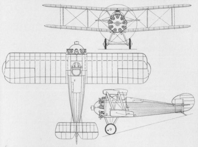
Dragon three-view drawing.
SOPWITH T.F.2 SALAMANDER UK
A requirement for an armoured single-seat ground attack fighter was issued to the Sopwith company in January 1918, a standard F.1 Camel being rapidly fitted with armour protection and triple-gun armament, and flying as the T.F.1 in the following month (T.F. indicating Trench Fighter). The T.F.1 was a stop-gap type that could be made available rapidly by modifying existing aircraft, but the requirement had specified the use of a 230 hp Bentley B.R.2 nine-cylinder rotary engine and Sopwith discarded the T.F.1 in favour of a modified Snipe design as the T.F.2 Salamander. Despite many similarities to the Snipe, the Salamander differed extensively and there was little or no interchangeability between the two aircraft. The forward portion of the fuselage was a simple armoured box, the bottom being 11-mm plate, the sides 6-mm plate, the front - the engine backplate - 8-mm plate and the rear 10-mm plate with a second 6-mm plate separated by 3.75 in (9,50 cm). Armament comprised two synchronised 0.303-in (7,7-mm) guns with provision for four 25-lb (11,34-kg) bombs. The first of three prototypes was flown on 27 April 1918, and the Salamander was ordered in large numbers (contracts were placed with the parent company, Air Navigation Co, Glendower Aircraft, National Aircraft, Palladium Autocars and Wolseley Motors), 37 being on RAF charge by 31 October. When hostilities ceased, production of the Salamander continued with a view to its use by the postwar RAF, and by mid 1919, when manufacture eventually terminated, Sopwith had delivered 334 and other contractors had contributed a further 85. However, no squadron was ever equipped with this type which was abandoned in favour of the Snipe.
Max speed, 125 mph (201 km/h) at 3,000 ft (915 m).
Time to 5,000 ft (1525 m), 6.5 min.
Endurance, 1.5 hrs.
Empty weight, 1,844 lb (836 kg).
Loaded weight, 2,512 lb (1139 kg).
Span (balanced upper ailerons), 31ft 2 6/8 in (9,52 m).
Length, 19 ft 6 in (5,94 m).
Height, 9 ft 4 in (2,84 m).
Wing area, 272 sqft (25,27 m2).

View, showing the first Salamander E5429 in Sopwith photograph S.362 at Brooklands. The panel showing between the unstaggered guns of E5429 bears the word 'Petrol' and a figure for 'gallons' ending in '3/4'.
SOPWITH SWALLOW UK
Utilising an F.1 Camel fuselage mated with a parasol wing, the Swallow single-seat fighter monoplane was powered by a 110 hp Le Rhone 9J nine-cylinder rotary engine and carried the standard armament of twin synchronised 0.303-in (7,7-mm) machine guns. Flown for the first time in September 1918, the Swallow was delivered to Martlesham Heath for official trials on 29 October 1918, remaining there until May 1919, the trials having been delayed by fuel system problems. The performance of the Swallow as revealed at Martlesham did not warrant further development, and the prototype was scrapped.
Max speed, 113 mph (182 km/h) at 10,000 ft (3050 m).
Time to 6,500 ft (1 980 m), 5.6 min.
Empty weight, 889 lb (403 kg).
Loaded weight, 1,420 lb (644 kg).
Span, 28 ft 10 in (8,79 m).
Length, 18 ft 9 in (5,72 m).
Height, 10 ft 2 in (3,10 m).
Wing area, 160 sqft (14,86 m2).
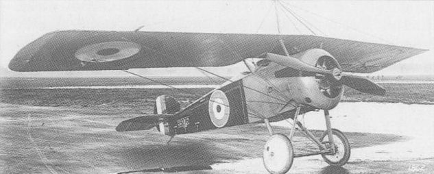
The sole Swallow used the fuselage of a series Camel, with a new monoplane wing.
SOPWITH 8F.1 SNAIL UK
In October 1917, the A.B.C. Wasp seven-cylinder radial air-cooled engine was considered to offer much promise, and on the 31st of that month Sopwith was invited by the Air Board to tender designs for a single-seat fighter utilising that power plant. Four prototypes were ordered, these being of conventional construction, and, on 23 November, the company was asked to build two additional prototypes with plywood monocoque fuselages. In view of its intended function adoption of the name Snail for the new single-seater was bizarre, this being approved on 16 February 1918. Powered by a 170 hp Wasp I, the first prototype Snail was completed in April 1918, this having negative wing stagger and fabric skinning for its circular-section fuselage. Intended armament comprised two synchronised 0.303-in (7,7-mm) machine guns, a third weapon of similar calibre being mounted above the wing centre section, to starboard of the cut-out. The remaining three prototypes of conventional construction were not completed, the next Snail to fly being the first of the two with plywood monocoque fuselages and positive wing stagger. On 9 May, the monocoque Snail was sent to Martlesham Heath for official trials, the reports being less than complimentary about its manoeuvrability and low-speed control. When, in October 1918, it was decided to abandon the Wasp engine, further work on the Snail was terminated, the second monocoque prototype being discontinued before completion. The following data relate to the monocoque Snail.
Max speed, 115 mph (185 km/h) at sea level.
Time to 6,000 ft (1830 m), 6.25 min.
Empty weight, 1,390 lb (630 kg).
Loaded weight, 1,920 lb (871 kg).
Span, 25 ft 4 in (7,72 m).
Length, 19 ft 0 in (5,79 m).
Height, 7 ft 10 in (2,39 m).
Wing area, 228.6 sqft (21,24 m2).
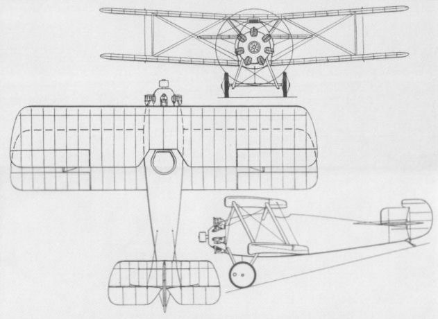
The 8F.1 Snail with monocoque fuselage
SOPWITH SNARK UK
Despite the fact that, by 1918, the triplane configuration was widely considered as passe for the fighter, on 14 May of that year, Sopwith was awarded a contract for three prototypes of a new single-seat fighting triplane, conforming to the RAF Type I specification and named the Snark. Powered by a 320 hp A.B.C. Dragonfly I nine-cylinder radial and featuring a plywood monocoque fuselage, the Snark was an equi-span staggered triplane and its designed armament was somewhat radical in the weight of fire that it offered, consisting of two synchronised 0.303-in (7,7-mm) guns on the fuselage and four weapons of similar calibre mounted two per side under the bottom wing. The first Snark was passed for flight test in September 1918, but unavailability of a Dragonfly engine and the decision to make various minor modifications delayed manufacturer’s trials until September of the following year, the aircraft arriving at Martlesham Heath for official trials on 12 November 1919. The second prototype reached Martlesham on 17 March 1920, and the third prototype, with a 360 hp Dragonfly Ia engine, late in the year. Apart from engine problems, the Snark triplanes suffered fuselage deterioration and all three were written off in 1921.
Max speed, 130 mph (209 km/h) at 3,000 ft (915 m).
Loaded weight, 2,283 lb (1036 kg).
Span, 26 ft 6 in (8,08 m).
Length, 20 ft 6 in (6,25 m).
Height, 10 ft 10 in (3,30 m).
Wing area, 322 sq ft (29,91 m2).
SOPWITH 7F.1 SNIPE
Conceived in the summer of 1917 as a successor to the Camel, the Sopwith 7F.1 single-seat fighter, later to be named the Snipe, was intended to utilise the new and more powerful Bentley B.R.2 nine-cylinder rotary engine (which was to commence bench running in October 1917) rated at 234 hp, and to afford a superior view for the pilot. Six prototypes were ordered, and, being adjudged superior to its competitors, (the Boulton & Paul Bobolink and the Nieuport B.N.1), the Snipe was ordered into large-scale production. The first prototype (with a B.R.1 engine) entered flight test in the early autumn of 1917, and production Snipes began to appear in the summer of 1918, contracts having been placed with the parent company, Boulton & Paul, the Coventry Ordnance Works, Napier, Nieuport & General, Portholme Aerodrome and Ruston, Proctor. Armament consisted of the standard pair of synchronised 0.303-in (7,7-mm) machine guns, and the Snipe was employed operationally for the first time on 23 September 1918. For long-range escort duties, the 7F.1a Snipe Mk 1a was developed, increased fuel tankage extending endurance to 4.5 hours, and deliveries of this version commenced early in 1919. The last prototype, referred to as the Snipe Mk II, was fitted with the 320 hp A.B.C. Dragonfly nine-cylinder radial engine, this being completed in April 1918, and entering production six months later as the Dragon. Of 4,500 Snipes ordered, 497 had been built by the end of December 1918, production continuing, despite heavy cancellations after the Armistice, into the early 'twenties, with at least 1,100 eventually being delivered. The Snipe remained with RAF squadrons as late as 1926.
Max speed, 121 mph (195 km/h) at 10,000 ft (3,050 m).
Time to 6,500 ft (1980 m), 5.15 min.
Endurance, 3.0 hrs.
Empty weight, 1.312 lb (595 kg).
Loaded weight. 2,020 lb (916 kg).
Span, 31 ft 1 in (9,47 m).
Length, 19 ft 10 in (6,04 m).
Height, 8 ft 3 in (2,51 m).
Wing area, 271 sq ft (25,17 m2).
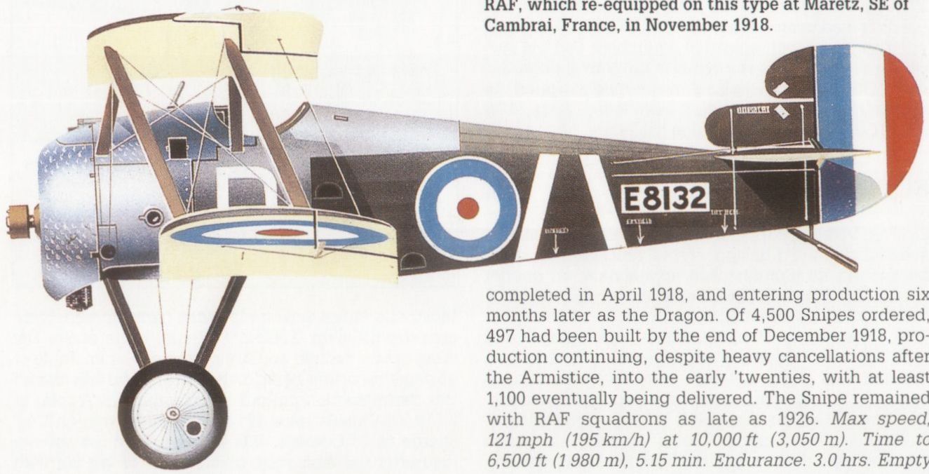
A Sopwith-built Snipe flown by No 208 Sqn RAF, which re-equipped on this type at Maretz, SE of Cambrai, France, in November 1918.

A series aircraft with No 5 FTS, Sealand, early 1920.

Snipe three-view drawing
SOPWITH SNAPPER UK
Designed in parallel with the Snark triplane and similarly intended to meet the requirements of the RAF’s Type I specification, the Snapper single-bay staggered equi-span biplane was destined to be the last fighter to bear the Sopwith name before the company went into liquidation in September 1920. Three prototypes of the Snapper were ordered on 6 June 1918, and, although originally designed with a plywood monocoque fuselage, all three aircraft were completed with conventional fabric-covered fuselages. Powered by a 320 hp A.B.C. Dragonfly I nine-cylinder radial engine and carrying the standard pair of synchronised 0.303-in (7,7-mm) machine guns, the first Snapper performed manufacturer's trials in the second half of July 1919, being delivered to Martlesham Heath for official trials on 1 August. Flight test was somewhat spasmodic owing to recurring difficulties with the engine, but all three Snappers were at the RAE, Farnborough, in mid-1920. It is presumed that trials continued until the decision was taken to discontinue further attempts to rectify the engine’s problems.
Max speed, 140 mph (225 km/h) at 3,000 ft (915 m).
Time to 3,000 ft (915 m), 1.93 min.
Empty weight, 1,462 lb (663 kg).
Loaded weight, 2,190 lb (993 kg).
Span, 28 ft 0 in (8,53 m).
Length, 20 ft 7 in (6,27 m).
Height, 10 ft 0 in (3,05 m).
Wing area, 292 sq ft (27,13 m2).

Designed in parallel with the Snark, the Snapper appeared in April 1919.
VICKERS E.F.B.1 UK
On 19 November 1912, Vickers received a contract from the Admiralty for an experimental fighting biplane armed with a machine gun. Various configurations were investigated before the desirability of placing the gunner in the extreme nose of the aircraft, in order to achieve a clear field of fire, led to choice of a fuselage nacelle carrying at its rear an engine driving a pusher propeller. This nacelle was mated with an unequal-span heavily-staggered biplane configuration, the tail surfaces being carried by paired and vertically dis¬posed booms attaching to the upper and lower rear wing spars on each side of the engine. Designated E.F.B. (Experimental Fighting Biplane) 1 and dubbed “Destroyer", the Vickers aircraft was, if not the very first, then one of the earliest dedicated fighter aircraft, and was armed with a single 0.303-in (7,7-mm) Maxim machine gun on a mount affording 60 deg elevation and traverse. The airframe of the E.F.B.1 was primarily of metal construction, the nacelle accommodating the pilot and gunner, and carrying an 80 hp Wolseley eight-cylinder Vee-type engine, being of steel tube with duralumin skinning. Wing warping was employed for lateral control. Prior to its first flight, the E.F.B.1 was displayed at the Aero Show held at Olympia, London, in February 1913. The gun was fitted for the first flight test, made at Joyce Green, but this rendered the aircraft so nose-heavy that it briefly left the ground, then nosed down, struck the ground and turned over. The following performance data are estimated.
Max speed, 70 mph (113 km/h) at sea level.
Initial climb, 450 ft/min (2,3 m/sec).
Endurance, 4.5 hrs.
Empty weight, 1,760 lb (798 kg).
Loaded weight, 2,660 lb (1207 kg).
Span, 40 ft 0 in (12,19 m).
Length, 27 ft 6 in (8,38 m).
Height, 11ft 11 in (3,63 m).
Wing area, 385 sq ft (35,77 m2)
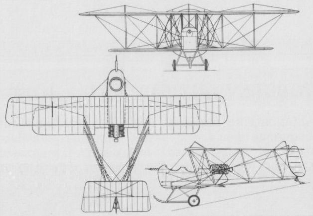
Vickers’ E.F.B.1, one of the earliest dedicated fighter aircraft.
VICKERS E.F.B.2 UK
Following the loss of the E.F.B.1, Vickers undertook major redesign of its gun carrier while retaining the basic configuration to result in the E.F.B.2, again against an Admiralty contract. The E.F.B.2 eliminated the wing stagger of the previous aircraft and increased the span of the lower wing while retaining warping for lateral control. The fuselage nacelle was redesigned and large celluloid windows were inserted in its sides; the angular horizontal tail surfaces gave place to surfaces of elliptical form and a 100 hp Gnome Monosoupape nine-cylinder rotary engine was fitted. The 0.303-in (7,7-mm) machine gun on a ball-and-socket mounting in the forward cockpit was retained, and the E.F.B.2 entered flight test at Bognor in the autumn of 1913, but crashed there during the course of October.
Max speed, 60 mph (97 km/h) at sea level.
Initial climb, 200 ft/min (1,02 m/sec).
Range, 150 mis (241 km).
Empty weight, 1.050 lb (476 kg).
Loaded weight, 1,760 lb (798 kg).
Span, 38 ft 7 in (11,76 m).
Length, 29 ft 2 in (8,89 m).
Height, 9 ft 7 in (2,92 m).
Wing area, 380 sqft (35,30 m2)
VICKERS E.F.B.3 UK
In December 1913, a third Vickers Experimental Fighting Biplane, the E.F.B.3, made its debut. The slight overhang of the top wing was eliminated to result in an equi-span biplane, the fuselage nacelle underwent further redesign, the celluloid windows being eliminated, and, most important, ailerons on both upper and lower wings supplanted the wing-warping control of its predecessors. The 100 hp Gnome Monosoupape rotary was retained as was also the 0.303-in (7,7-mm) Vickers gun. Displayed at the Aero Show held at Olympia in 1914, the E.F.B.3. was the subject of an order from the Admiralty for six aircraft placed in December 1913. This contract was subsequently taken over by the War Office, the six aircraft embodying a number of modifications - at least one was fitted with an eight-cylinder Vee-type 80 hp Wolseley engine - and being referred to as the Vickers No (or Type) 30. These were to lead in turn to the E.F.B.5 and F.B.5 Gunbus. The following data relate to the early E.F.B.3 with Gnome engine.
Max speed, 60 mph (97 km/h) at sea level.
Initial climb, 300 ft/min (1,52 m/sec).
Range, 300 mis (483 km).
Empty weight, 1,050 lb (476 kg).
Loaded weight, 1,680 lb (762 kg).
Span. 37 ft 4 in (11,38 m).
Length, 27 ft 6 in (8,38 m).
Height, 9 ft 9 in (2,97 m).
Wing area, 385 sq ft (35,77 m2).

The short-lived E.F.B.2 was a revision of the original E.F.B.1 design.

The short-lived E.F.B.2 was a revision of the original E.F.B.1 design.
VICKERS F.B.5 GUNBUS UK
Progressive changes introduced by successive E.F.B.3s led to the E.F.B.5 - the E.F.B.4 being a project with a more streamlined nacelle centred between the wings and only two tailbooms - which was flown from Joyce Green to Brooklands on 17 July 1914. In parallel, Vickers developed the E.F.B.6, which, basically similar to the E.F.B.5, had longer-span upper wings. It lacked top decking between the two crew seats and had ailerons in the upper wings only. At Brooklands on 14 July 1914, the E.F.B.6 was taken on strength by the Royal Flying Corps when World War I began, but was not developed. The E.F.B.5, on the contrary, was ordered into production for both the RFC and the RNAS on 14 August 1914, the first series aircraft being completed in the following October. At this time, the aircraft became simply F.B. (Fighting Biplane) 5 and was dubbed Gunbus. The E.F.B.5 had retained the semi-circular tailplane of the E.F.B.2 and early E.F.B.3, but the series F.B.5 had an enlarged tailplane of rectangular planform and a larger rudder. A Lewis gun on a more practical mount supplanted the similar-calibre Vickers in the nose and the standard power plant was the 100 hp Gnome Monosoupape nine-cylinder rotary. The first F.B.5 reached the Western Front early February 1915, and, on the following 25 July, the first squadron of any air service formed specifically for fighting duties and equipped throughout with a single aircraft type arrived in France, this being the RFC’s No 11 Sqn with F.B.5s. The RNAS made little use of the F.B.5, and, after the delivery of four to that service, the large majority of subsequent deliveries went to the RFC, although the RNAS did receive two further F.B.5s which, ordered in May 1915, were fitted with the 150 hp Smith Static radial engine, its large diameter propeller necessitating the raising of the fuselage nacelle several inches above the lower wing. Two hundred and forty-one F.B.5s were delivered to the RFC, of which 109 were sent to the British Expeditionary Force in France (60 in 1915 and 49 in 1916). Licence production of the F.B.5 was undertaken in France by the Societe Anonym Darracq (which built a total of 99 of these and the later F.B.9) between May 1915 and June 1916. Twelve were also built under licence in Denmark in 1917-18 by the Tojhusvseiksted. At least four F.B.5As were built with armour-plated fuselage nacelles and these were powered by 110 hp Clerget 9Z nine-cylinder rotary engines and had oleo undercarriages. Suffering an unreliable engine and a marginal performance throughout its operational career, the F.B.5 was finally withdrawn from the Western Front in the autumn of 1916, being subsequently confined to RFC instructional units.
Max speed, 70 mph (113 km/h) at 5.000 ft (1525 m).
Time to 5,000 ft (1525 m), 16.0 min.
Service ceiling, 9.000 ft (2 745 m).
Endurance, 4.5 hrs.
Empty weight. 1,220 lb (553 kg).
Loaded weight, 2,050 lb (930 kg).
Span, 36 ft 6 in (11,13 m).
Length. 27 ft 2 in (8,28 m).
Height, 11 ft 1 in (3.38 m).
Wing area, 382 sq ft (35.49 m2).
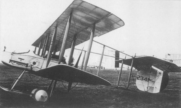
The F.B.5 in its series form with enlarged rudder and tailplane.
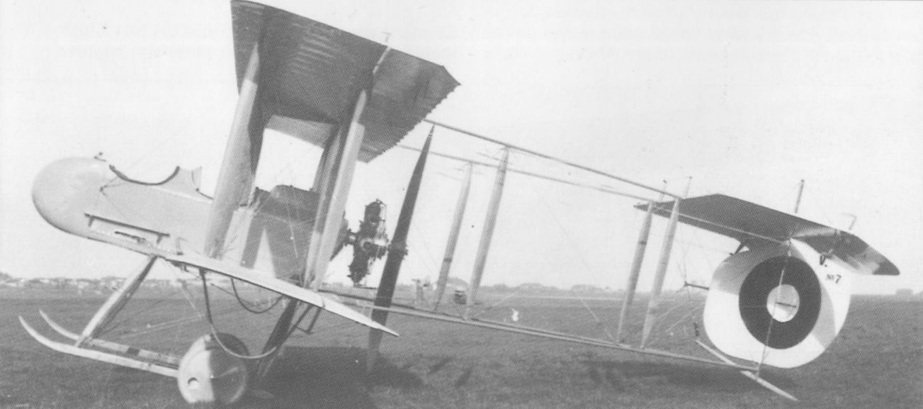
A dozen examples of the Vickers F.B.5 were built in Denmark; illustrated is No 7.
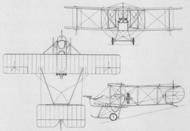
The F.B.5 in its series form with enlarged rudder and tailplane.
VICKERS F.B.7 UK
On the outbreak of World War I, Vickers engaged R L Howard-Flanders to design a twin-engined fighting aeroplane capable of carrying a Vickers one-pounder quick-firing gun with armour protection for the gunner. Powered by two 100 hp Gnome Monosoupape nine-cylinder rotaries mounted overhung between the mainplanes and suspended on simple steel-tube open framework, the prototype was designated E.F.B.7 and was flown for the first time in August 1915. An ungainly unequal-span biplane with two bays of struts, the E.F.B.7 accommodated the pilot aft of the mainplanes, several feet from the gunner in the extreme nose. The substantial gun mount was bolted to the centre of the forward cockpit floor, the gunner’s seat being attached to the mount with which it traversed - sufficient room was provided in the cockpit to permit gun and gunner to turn through a full 360 deg. The E.F.B.7 was one of the first twin-engined military aircraft to fly successfully, and an order for 12 production F.B.7s was placed on 20 August 1915, immediately after the initial flight tests of the E.F.B.7, but, in the event, the series model was to differ in a number of major respects. The distance separating the two-man crew was found unacceptable and the pilot was brought forward of the wings in sensible proximity to the gunner, the structure of the upper wing was completely redesigned and the fuselage was revised in cross section, becoming rectangular throughout rather than having an inverted triangular cross section aft. Owing to a shortage of Gnome rotaries, the first production aircraft was fitted with 80 hp Renault eight-cylinder air-cooled engines as the F.B.7A, the engine change resulting in a major loss of performance. As the F.B.7A obviously possessed no operational usefulness, Vickers persuaded the War Office to cancel the contract for the remaining aircraft (which were being built by A Darracq & Company at Fulham under subcontract). The following data relate to the Gnome-engined E.F.B.7.
Max speed, 75 mph (121 km/h) at 5,000 ft (1525 m).
Time to 5,000 ft (1525 m), 18.0 min.
Ceiling, 9,000 ft (2 745 m).
Endurance, 2.5 hrs.
Empty weight, 2,136 lb (969 kg).
Loaded weight, 3,196 lb (1450 kg).
Span, 59 ft 6 in (18,17 m).
Length, 36 ft 0 in (10,97 m).
Wing area, 640 sqft (59.46 m2).
VICKERS F.B.8 UK
Although possessing a superficial resemblance to the F.B.7, the F.B.8. designed in the autumn of 1915 by Rex K Pierson, was a very much smaller, lightly-armed two-seat fighter carrying only a single 0.303-in (7,7-mm) Lewis gun as armament. Powered by two 100 hp Gnome Monosoupape rotaries, the F.B.8 began flight testing in November 1915, and performance proved to be good. The gunner was accommodated in the extreme nose and the pilot was seated beneath the trailing edge of the upper wing. From the outset, it was obvious that the armament carried by the F.B.8 could equally well be accommodated by a smaller, single-engined aircraft, but it had been hoped that an appreciably higher performance could be obtained by doubling the power available. Insufficient attention had been paid to the drag of such an aircraft, however, and performance proved lower than had been anticipated. Furthermore, the aircraft was insufficiently manoeuvrable for fighting duties and was discontinued.
Max speed, 98 mph (158 km/h) at 5,000 ft (1 525 m).
Time to 5,000 ft (1525 m), 10 min.
Service ceiling, 14,000 ft (4 270 m).
Endurance. 3.0 hrs.
Empty weight, 1.840 lb (835 kg).
Loaded weight, 2,700 lb (1225 kg).
Span. 38 ft 4 in (11,68 m).
Length, 28 ft 2 in (8,58 m).
Height, 9 ft 10 in (3.00 m).
Wing area, 468 sq ft (43,48 m2).
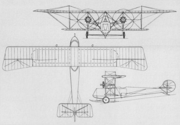
The E.F.B.7 with engine cowlings removed.
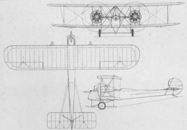
Only a single example was built of the F.B.8, developed from the F.B.7.
VICKERS E.S.1 UK
Early in 1915, Rex K Pierson was tasked with the redesign of the so-called Barnwell Bullet, an unarmed single-seat biplane designed as a private venture by Vickers' then chief test pilot, Harold Barnwell. Assigned the designation E.S. (Experimental Scout) 1 and completed in August 1915, the redesigned aircraft was powered by a 100 hp Gnome Monosoupape rotary and carried no armament. An equi-span single-bay unstaggered biplane, the E.S.1 was aerodynamically clean and possessed an excellent performance, but view for the pilot was extremely poor. An improved version was then developed, powered by the 110 hp Clerget nine-cylinder rotary engine. This was assigned the official designation E.S.1 Mk II. although it was known to Vickers as the E.S.2. Two E.S.1 Mk IIs were built, one of these being fitted with a 0.303-in (7,7-mm) Vickers machine gun with Vickers-Challenger synchronising gear and sent to France in the summer of 1916 for operational trials with No 11 Sqn. RFC. The other E.S.1 Mk II was eventually similarly armed and tested with a 110 hp Le Rhone rotary, while the original E.S.1, too, was fitted with the gun and synchronization gear, and was at one time included on the strength of an RFC Home Defence squadron (No 50). The official evaluation of the E.S.1 in both versions pronounced the aircraft tiring to fly and difficult to land, and no production was ordered. The E.S.1 did, however, serve as a basis for the design of the later F.B.19. The following data relate to the Clerget-engined E.S.1 Mk II.
Max speed. 112 mph (180 km/h) at sea level, 106 mph (170 km/h) at 8,000ft (2 440 m).
Time to 8.000 ft (2 440 m), 12.65 min.
Endurance, 2.0 his.
Empty weight, 981 lb (445 kg).
Loaded weight, 1,502 lb (681 kg).
Span, 24 ft 4 1/2 in (7,43 m).
Length, 20 ft 3 in (6,17 m).
Height, 7 ft 8 in (2,34 m).
Wing area, 215 sq ft (19.97 m2).
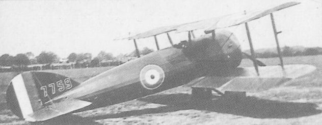
Two examples of the E.S.1 Mk II were built and, also known as E.S.2s, were briefly tested by the RFC.
VICKERS F.B.9 UK
Dubbed unofficially the Streamline Gunbus, the F.B.9, which emerged towards the end of 1915, introduced numerous refinements over its predecessor, the F.B.5. The fuselage nacelle was of improved aerodynamic form; the wings and tailplane sported rounded tips; streamlined Rafwires replaced stranded steel cables and turnbuckles for interplane bracing, and a plain, Vee-type undercarriage supplanted the twin skids previously used. The standard power plant remained the 100 hp Gnome Monosoupape rotary. Vickers built a total of 95 F.B.9s, and a further 20-30 were built by Darracq in France, some of which were issued to the RFC (No 11 Sqn) and were used during the Battle of the Somme which began on 1 July 1916. The manufacture of the F.B.9 in Italy by Vickers-Terni fell through owing to political reasons. A version designated F.B.10 powered by an Isotta-Fraschini engine was proposed but not built. Outclassed by more advanced fighting aeroplanes, the F.B.9s saw only brief first-line service, the great majority being assigned tuitional tasks on delivery to the RFC, for which some were retrofitted with dual controls. For gunnery training, some F.B.9s were fitted with a Scarff ring on the front cockpit, but none remained on charge at the time of the Armistice.
Max speed, 83 mph (134 km/h) at sea level, 75 mph (121 km/h) at 6,500 ft (1980 m).
Time to 6,500 ft (1 980 m), 19 min.
Service ceiling, 11,000 ft (3 355 m).
Endurance, 4.5 hrs.
Empty weight. 1,029 lb (467 kg).
Loaded weight. 1,892 lb (858 kg).
Span, 33 ft 9 in (10,29 m).
Length, 28 ft 5 1/2 in (8,67m).
Height, 11 ft 6 in (3.50 m).
Wing area, 340 sq ft (31.59 m2).
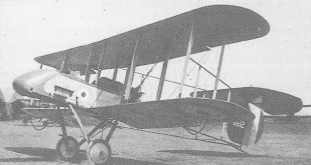
One of 95 examples of the F.B.9 built by Vickers. Others were licence-built in France.
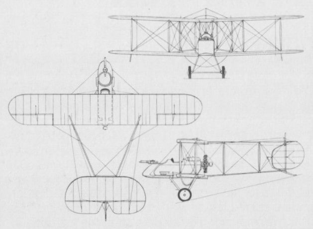
A derivative of the F.B.5, the F.B.9 saw service in the Battle of the Somme.
VICKERS F.B.11 UK
Designed by Howard Flanders as an airship destroyer, for which purpose it had an elevated gunner’s station, or "fighting top”, mounted on the centre section of the upper wing, the F.B.11 flew in late November 1916. Carrying a crew of three, including two gunners each provided with a 0.303-in (7,7-mm) Lewis gun, the F.B.11 was powered by a 250 hp Rolls-Royce Mk III 12-cylinder water-cooled engine - later to be named Eagle. The F.B.11 proved to be deficient in lateral control and the first prototype eventually crashed and was written off, a second example never being completed as, in the meantime, it had been realised that the entire concept of the large airship destroyer was fundamentally unsound.
Max speed, 96 mph (154 km/h) at 5,000 ft (1525 m), 81 mph (130 km/h) at 10,000 ft (3 050 m).
Time to 5,000 ft (1525 m), 16.5 min.
Ceiling, 11,000 ft (3355 m).
Endurance, 7.5 his.
Empty weight, 3,340 lb (1515 kg).
Loaded weight, 4,934 lb (2238 kg).
Span, 51 ft 0 in (15,54 m).
Length, 43 ft 0 in (13,10 m).
Height, 13 ft 8 in (4,16 m).
Wing area, 845 sq ft (78,50 m2).
VICKERS F.B.12 UK
A compact two-bay biplane of pusher type, the F.B.12 was designed for the 150 hp Hart static radial engine, in the development of which the Hart Engine Company was being assisted by Vickers. With a single-seat nacelle faired out to a circular cross section and mounted in mid wing-gap, and tailbooms converging in side elevation to meet at the rear spar of the tailplane. the F.B.12 had a basic structure primarily of steel tube. Unavailability of an airworthy Hart engine led to the first F.B.12 being fitted with an 80 hp Le Rhone rotary, with which it flew in June 1916. Although underpowered, it demonstrated a creditable performance when tested at the Central Flying School in the following August. The Le Rhone was then replaced by a 100 hp Gnome Monosoupape, and, subsequently, new wings of greater span were fitted - overall span being extended by 3 ft 7 in (1,09 m) - with straight raked rather than elliptical tips. Redesignated F.B.12A, this aircraft was sent to France for operational evaluation in December 1916. A further aircraft was built - by Wells Aviation of Chelsea - with the Hart engine as the F.B.12B. This was flown early in 1917, but promptly crashed, helping to seal the fate of the Hart radial. A contract for 50 aircraft powered by the Hart had, on 10 November 1916, been awarded Vickers, the intention being to fit the series aircraft with a new, wooden nacelle and enlarged vertical tail surfaces as the F.B.12C. Production of the F.B.12C was sub-contracted to Wells Aviation, but with the loss of the F.B.12B, the Hart engine was abandoned. In the event, only 18 F.B.12C airframes were completed and these were fitted with a variety of engines, including the 110 hp Le Rhone nine-cylinder rotary and the 100 hp Anzani 10-cylinder radial. Testing at Martlesham Heath in May 1917 revealed insufficient elevator control at low speeds, heavy lateral control and other problems. Furthermore, the gun (a 0.303-in/7,7-mm Lewis) was considered to be badly positioned for changing ammunition drums. By this time, tractor fighters of superior performance were in RFC service and further development of the F.B.12 was therefore discontinued. The following data relate to the Le Rhone-powered F.B.12C.
Max speed, 87 mph (140 km/h) at 6,500 ft (1980 m), 81 mph (130 km/h) at 10,000 ft (3 050 m).
Time to 6,500 ft (1980 m), 9.7 min.
Service ceiling, 14,500 ft (4 420 m).
Endurance, 3.25 hrs.
Empty weight, 927 lb (420 kg).
Loaded weight, 1,447 lb (656 kg).
Span. 29 ft 7 in (9,02 m).
Length, 21ft 10 in (6,65 m).
Height, 8 ft 7 in (2,62 m).
Wing area, 237 sq ft (22,02 m2).
VICKERS F.B.16 UK
Conceived, like the F.B.12, to utilise the 150 hp Hart engine, the F.B.16 was designed by Rex K Pierson. Completed and flown in the summer of 1916, it was a single-bay staggered biplane with a fuselage faired out fully to an elliptical cross section, the Hart engine being partly cowled, and armament consisting of a single centrally-mounted synchronised 0.303-in (7,7-mm) Vickers gun. During the course of testing, the part-cowling was removed from the engine to improve cooling, the decking aft of the cockpit was cut down and new vertical tail surfaces were fitted. With the ending of Hart engine development, the basic F.B.16 underwent very considerable redesign, reappearing as the F.B.16A with a 150 hp Hispano-Suiza water-cooled Vee-eight engine. This aircraft was destroyed in a crash on 20 December 1916, but a second identical aircraft was completed in the following month. The F.B.16A had flat fuselage sides and the single synchronised Vickers gun was supplemented by a Lewis mounted above the centre section. After receiving favourable reports during Martlesham Heath trials, it was re-engined with a 200 hp Hispano-Suiza engine as the F.B.16D, a wider-chord wing being fitted, with both gap and stagger increased, and a larger vertical tail fitted. The synchronised Vickers gun was replaced by a Lewis firing through the hollow propeller shaft. Because large contracts had been placed for the contemporary S.E.5a, particularly with Vickers, and because Martlesham Heath evaluation contained numerous design criticisms of which rectification would have been time consuming, the F.B.16D was not ordered into production. Nonetheless, work on a further development, the F.B.16E allegedly returned performance figures unsurpassed by any of its contemporaries, but no production order was placed, and on 29 July 1918, the prototype crashed after its propeller disintegrated. The following data relate to the F.B.16D.
Max speed, 135 mph (217 km/h) at 10,000 ft (3050 m), 126 mph (203 km/h) at 15,000 ft (4 570 m).
Time to 10,000 ft (3 050 m), 10.45 min.
Service ceiling, 18,500 ft (5 640 m).
Endurance, 2.25 hrs.
Empty weight, 1,376 lb (624 kg).
Loaded weight, 1,875 lb (850 kg).
Span, 25 ft 0 in (7,62 m).
Length, 19 ft 6 in (5,94 m).
Height, 8 ft 9 in (2,67 m).
Wing area, 207 sqft (19,23 m2).
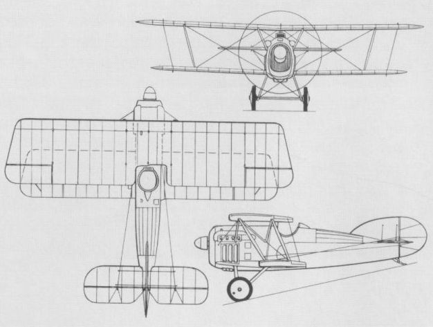
Increased wing chord and more vertical tail area distinguished the F.B.16D.
VICKERS F.B.19 UK
Designed in 1916 by G H Challenger and flown for the first time in August of that year, the F.B.19 was a single-bay unstaggered equi-span biplane with a single 0.303-in (7,7-mm) Vickers gun mounted on the port side of the fuselage and a 100 hp Gnome Monosoupape engine. Ordered by the War Office for the RFC, the series version was powered by either the Gnome or the 110 hp Le Rhone. Some 50 F.B.19s were built, and, late in 1916, a batch of six was sent to France where, after operational evaluation, the fighter was deemed unsuited for the fighting conditions then evolving. At this time, some of the F.B.19s were delivered to the Russian government following demonstrations in Petrograd, Moscow, Kiev and Tiflis, but several were still in their crates on the docks at Archangel at the commencement of the Bolshevik revolution. These aircraft were destroyed by the Royal Navy, but a few others assembled prior to the Navy's action were flown in Bolshevik service. A modified version, the F.B.19 Mk II, was developed with wing stagger and either the Le Rhone or Clerget 110 hp rotary. Only 12 Mk IIs were built and several of these were included in a batch of 12 F.B.19s sent to the Middle Eastern theatres of war. These were flown in Palestine and Macedonia from June 1917, but no squadron used the type exclusively and it was not well liked. The following data relate to the Le Rhone-powered F.B.19.
Max speed, 98 mph (158 km/h) at 10.000 ft (3 050 m), 90 mph (145 km/h) at 15,000 ft (4 570 m).
Time to 5,000 ft (1525 m), 5.6 min.
Ceiling, 17.000 ft (5180 m).
Endurance, 3.25 hrs.
Empty weight, 892 lb (405 kg).
Loaded weight, 1,478 lb (670 kg).
Span, 24 ft 0 in (7,31 m).
Length, 18 ft 2 in (5,54 m).
Height, 8 ft 3 in (2,51m).
Wing area, 215 sq ft (19,97 m2).
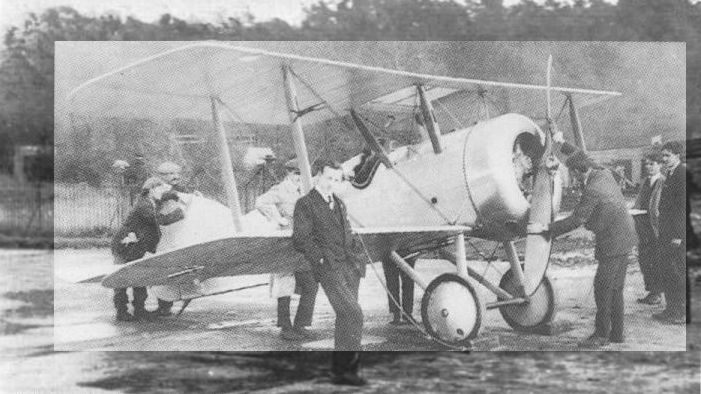
An F.B.19 Mk I being started up at Brooklands with Harold Barnwell in the cockpit and Stan Cockerell leaning against the starboard wing.
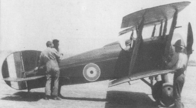
In its Mk II form, the F.B.19 was produced in small numbers for RFC service.
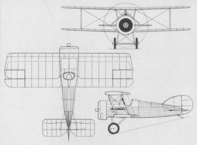
VICKERS F.B.24 UK
A two-seat fighter-reconnaissance aircraft, the F.B.24 was yet another Vickers aircraft originally designed for the ill-fated and Vickers-sponsored Hart radial engine. The prototype was completed in December 1916, but unavailability of the Hart engine resulted in its modification to accept the 150 hp Hispano-Suiza water-cooled engine as the F.B.24A, and the second airframe, the F.B.24B, being similarly powered. An unequal-span two-bay biplane, the F.B.24 had an armament of one fixed synchronised Vickers gun and one Lewis on a Scarff ring mounting. Both F.B.24A and 24B were re- engined with the 200 hp Hispano-Suiza with which they were redesignated as F.B.24Ds. Similar in general configuration was the F.B.24C, which was powered by a 275 hp Lorraine-Dietrich 8Bd water-cooled eight-cylinder Vee-type engine and armed with two synchronised Vickers guns, provision being made for emergency dual control in the gunner’s cockpit. The F.B.24C and D both possessed good performance, but the limited view offered from the pilot’s cockpit was considered unacceptable. Consequently, the Vickers team revised the basic design by lowering the upper wing so that it was attached directly to the upper longerons, the front cockpit being situated between the wing spars. With this change, the aircraft was designated F.B.24E and power was provided by a 200 hp Hispano-Suiza. This same configuration was adopted for yet a further version of the design, the F.B.24G, which was a larger aircraft than its predecessors, with two-bay wings of equal span and chord and a 375 hp Lorraine-Dietrich 12-cylinder Vee-type engine. The F.B.24G was built in France by the Darracq concern, but it did not fly until 26 May 1919, and its performance and fate have gone unrecorded. The following data relate to the F.B.24D.
Max speed, 118 mph (190 km/h) at 10,000 ft (3 050 m).
Time to 10,000 ft (3 050 m), 15 min.
Endurance, 3.0 hrs.
Empty weight, 1,630 lb (739 kg).
Loaded weight, 2,610 lb (1184 kg).
Span, 35 ft 6 in (10,82 m).
Length, 26 ft 0 in (7,92 m).
Wing area, 340 sqft (31,59 m2).
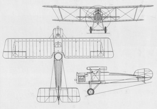
The F.B.24C in its version with a frontal radiator for the Lorraine-Dietrich engine.
VICKERS F.B.25 UK
Derived from the abortive F.B.23 design intended as a successor to the F.B.9, the F.B.25 two-seat night fighter was conceived to fulfil the same requirement as the Royal Aircraft Factory’s N.E.1. Completed in the early spring of 1917, the F.B.25 carried its two crew members in staggered side-by-side seats, the gunner being positioned ahead and to starboard. Like the N.E.1, the F.B.25 was intended to carry the Vickers-built Crayford rocket gun with which it was supposed to attack hostile airships, and a small searchlight was originally to have been mounted in the extreme nose of the nacelle. The intention was to power the F.B.25 with the 200 hp Hispano-Suiza eight-cylinder water-cooled engine, and in order to minimise the risk of the aircraft turning over during a nocturnal landing, it was proposed to provide a nosewheel. In the event, non-availability of a 200 hp unit dictated installation of a 150 hp Hispano-Suiza, and neither searchlight nor nosewheel was fitted. A two- bay unstaggered equi-span biplane with tailbooms converging in elevation to meet at the rear spar of the tailplane, the F.B.25 carried its unusually wide nacelle at mid wing-gap. As well as the Crayford rocket gun, an interesting feature was the oleo-pneumatic undercarriage. Flight testing revealed poor characteristics, and when sent to Martlesham Heath in May 1917 (where it was eventually to crash), the official reports were singularly unflattering, dismissing the F.B.25 as wholly unsuited for night fighting. The following performance data were established at Martlesham Heath.
Max speed, 86 mph (138 km/h) at 5,000 ft (1 525 m), 77 mph (124 km/h) at 10,000ft (3,050 m).
Time to 6,000 ft (1 830 m), 11.9 min.
Service ceiling, 11,000 ft (3 355 m).
Endurance, 4.5 hrs.
Empty weight, 1,608 lb (729 kg).
Loaded weight, 2,454 lb (1113 kg).
Span, 41 ft 6 in (12,65 m).
Length, 28 ft 1 in (8,56 m).
Height, 10 ft 10 in (3,30 m).
Wing area, 500 sq ft (46,45 m2).
VICKERS F.B.26 VAMPIRE UK
Curiously retrogressive in design when built in May 1917, the pusher fighter with boom-carried empennage being decidedly passe at that stage in World War I, the F.B.26 single-seat fighter had its nacelle attached directly to the upper wing. The original concept provided for a single 0.303-in (7,7-mm) Lewis gun, but an additional Lewis had been introduced by the time that the F.B.26 reached Martlesham Heath for official testing in July 1917. Power was provided by a 200 hp Hispano-Suiza engine, but inadequate cooling led to the original single flat radiator being replaced by two separate radiator blocks. On 25 August 1917, the prototype was spun into the ground by Vickers' test pilot Harold Barnwell. Nonetheless, a month later, on 19 September, a contract was placed for six examples of a modified version of the F.B.26. The wing structure was completely revised, radiator blocks were attached to the nacelle sides and a larger vertical tail was introduced. Interest in the F.B.26 centred on its potential as a Home Defence fighter, and it was proposed that armament would consist of two Lewis guns coupled with an Aldis sight and capable of several degrees of elevation and depression. However, in order to obtain greater firepower, the nacelle of the F.B.26 was modified to permit installation of an Eeman three-gun universal mounting. The first two F.B.26s had the trio of Lewis guns fixed to fire horizontally, but it was intended that the next four aircraft would have a modified Eeman mounting capable of 45 deg of elevation. The first of the modified F.B.26s was flown in December 1917 with a 200 hp Hispano-Suiza engine. After testing at Martlesham Heath, this aircraft was assigned to No 141 Sqn in February 1918 for service evaluation. It was concluded that the F.B.26 was unsuited for Home Defence duties and work on the incomplete machines was halted, although the second and third examples had been completed and flown meanwhile. As the basic design was considered to possess potential in the close air support role, the second of the modified F.B.26s was fitted with a redesigned nacelle incorporating armour protection for the pilot and a 230 hp Bentley B.R.2 nine-cylinder rotary. This armoured "trench-strafer” was assigned the designation F.B.26A, and, under the official nomenclature scheme introduced in the spring of 1918, became the Vampire II, the F.B.26 being the Vampire I. In the event, the Vampire II had still to be completed by the end of June 1918, and thus came too late on the wartime scene. The following data are applicable to the Hispano-Suiza-engined modified F.B.26.
Max speed, 121 mph (195 km/h) at 5,000 ft (1525 m), 117 mph (188 km/h) at 10,000ft (3 050 m).
Time to 5,000 ft (1525 m), 4.33 min.
Service ceiling, 22,500 ft (6 860 m).
Endurance, 3,0 hrs.
Empty weight, 1,470 lb (667 kg).
Loaded weight, 2,030 lb (921 kg).
Span, 31 ft 6 in (9,63 m).
Length, 23 ft 5 in (7,14 m).
Height, 9 ft 5 in (2,87 m).
Wing area, 267 sqft (24,80 m2).
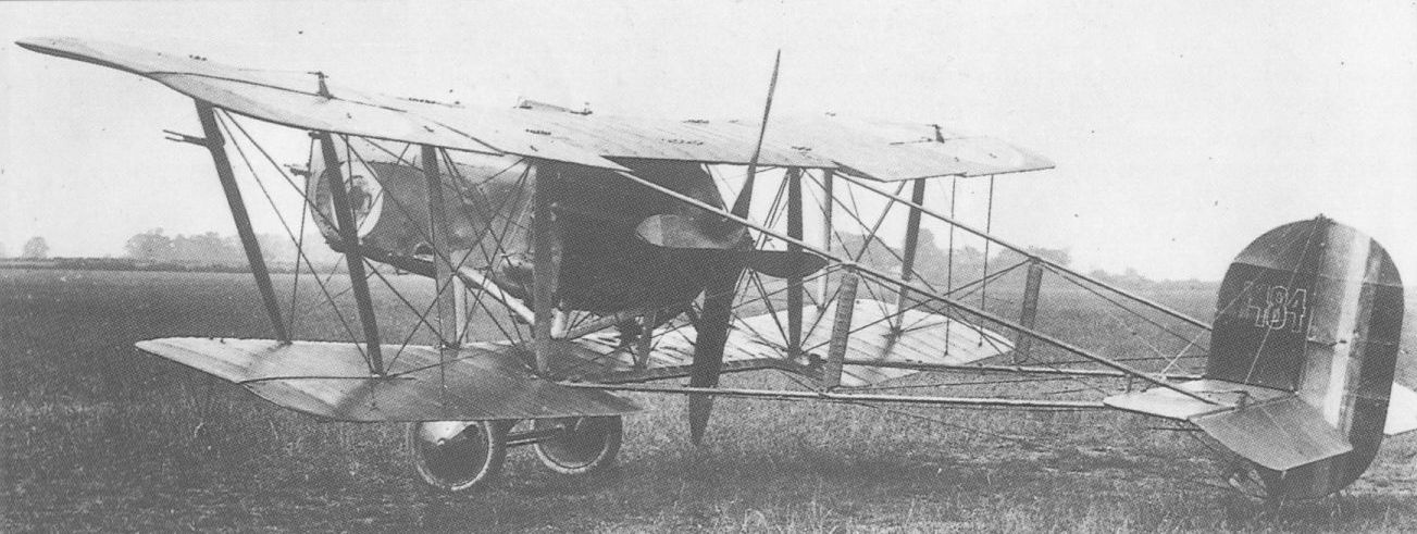
Alone among Vickers' World War I fighters, the F.B.26 received a name, being dubbed Vampire.

The F.B.26 fitted with Eeman triple-gun mounting in the nose and the definitive wings.
WESTLAND N.1B UK
Westland Aircraft began design of its first aircraft in 1917, in response to an Admiralty requirement for a single-seat fighting scout seaplane. In the Admiralty's N.1B category, the aircraft was designed by Robert Bruce and Arthur Davenport, and was a compact two-bay equi-span biplane of conventional wooden structure and fabric covering. First flown in August 1917, it was powered by a 150 hp Bentley BR1 rotary engine. Inboard of the ailerons, on both upper and lower wings, the trailing-edge camber could be varied to obtain the effect of plain flaps. The wings could be folded backwards for shipboard stowage. Armament comprised one synchronised 0.303-in (7,7-mm) Vickers gun and a flexibly-mounted Lewis of the same calibre above the upper wing centre section. Two prototypes were built and sometimes referred to as the Westland N16 and N17 from their RNAS serial numbers. The first was flown with short Sopwith floats and a large strut-mounted tail-float whereas the second was used to evaluate long Westland floats that eliminated the need for a tail float. This second aircraft, which lacked the camber-changing mechanism on the wings, also flew with the Sopwith floats and a tail float directly attached to the underside of the rear fuselage. By the time the N.1Bs were on test at the Isle of Grain, the RNAS was experimenting successfully with the shipboard operation of wheeled aircraft and the requirement for a floatplane fighting scout faded away. The following data refer to the second prototype with Sopwith floats.
Max speed, 108 mph (175 km/h) at 3,750 ft (1 145 m).
Time to 2,000 ft (610 m), 3.8 min, to 10,000 ft (3 050 m), 28.65 min.
Service ceiling, 12,700 ft (3 870 m).
Endurance, 2.75 hrs. Empty weight, 1,504 lb (682 kg).
Loaded weight, 1,978 lb (897 kg).
Span, 31 ft 3 1/2 in (9,53 m).
Length, 25 ft 5 1/2 in (7,76 m).
Height, 11 ft 2 in (3,40 m).
Wing area, 278 sq ft (25,83 m2).
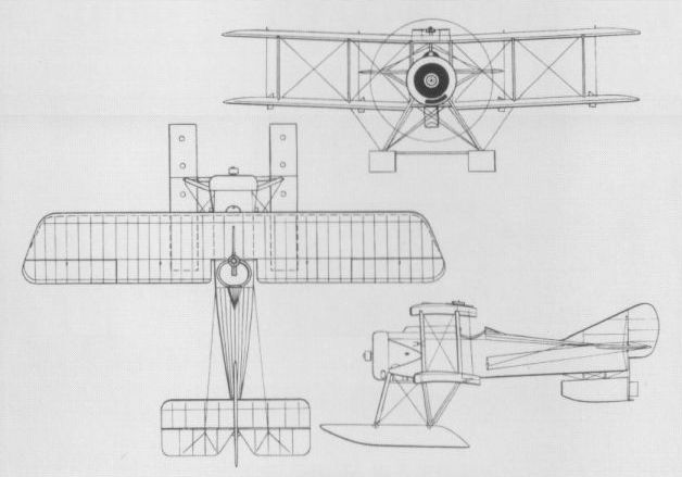
The Westland N16, as originally flown, with short floats of Sopwith design.
WESTLAND WAGTAIL UK
A contemporary of the Sopwith Snail and the BAT Bantam, the Wagtail was similarly designed to comply with the A.1(a) Specification drawn up by the Air Board in 1917 to define its requirements for a single-seat fighter. Emphasis was to be placed upon manoeuvrability and climb, with the ability to achieve 135 mph (217 km/h) at 15,0 ft (4 570 m) when carrying oxygen equipment and three machine guns. Like its competitors, the Wagtail was powered by the 170 hp ABC Wasp I seven-cylinder radial, an engine that eventually thwarted further development of all three A.1(a) types. A well-proportioned, diminutive single-bay biplane, the Wagtail gained a contract for three prototypes late in 1917, and the first was flown in April 1918. Construction was of fabric-covered wood, with metal-framed rudder and elevators, and two synchronised 0.303-in (7,7-mm) Vickers guns were fitted. An overwing Lewis gun was planned, but not fitted to the prototypes. Whereas the first Wagtail to fly had equal dihedral (2 deg 30 min) on upper and lower wings, the second and third were completed (and the first later modified) to have a larger cutout in the upper wing centre section with 5 deg of dihedral on the outer panels of the upper wing and a flat lower wing. Destroyed in a fire at Yeovil soon after its first flight on 29 April 1918, the second Wagtail had to be replaced later that year; the third went to Martlesham Heath on 8 May, but problems with the Wasp limited flying. In October 1918, the engine was officially abandoned, and with it any plans to produce Wasp-engined aircraft. Two more Wagtails were ordered from Westland in 1919, to serve as test-beds for the 160 hp Armstrong-Siddeley Lynx seven-cylinder radial engine. Unarmed, these two aircraft were delivered to the RAE in September/October 1921. The following data for the Wasp-engined Wagtail include performance estimates.
Max speed, 125 mph (201 km/h) at 10,000 ft (3 050 m).
Time to 5,000 ft (1 525 m), 3.5 min.
Endurance, 2.5 hrs.
Empty weight, 746 lb (338 kg).
Loaded weight, 1,330 lb (603 kg).
Span, 23 ft 2 in (7,06 m).
Length, 18 ft 11 in (5,77 m).
Height, 8 ft 0 in (2,44 m).
Wing area, 190 sq ft (17,65 m2).
WESTLAND WEASEL UK
In April 1918, Westland gained a three-prototype contract for a two-seat fighter-reconnaissance aircraft that was designed to provide a successor to the Bristol F.2b fighter. In configuration, the new fighter, to which the name Weasel was given, closely resembled a scaled-up Wagtail. The pilot was located beneath the trailing edge of the upper wing, with the observer/ gunner close behind, with a single 0.303-in (7,7-mm) Lewis gun on a Scarff ring. Two fixed and synchronised forward-firing Vickers guns of the same calibre were provided for the pilot. The Weasel had a two-spar wooden wing and a wire-braced wooden fuselage, with fabric covering for all but the ply-covered front fuselage. In common with the competing Austin Greyhound and Bristol Badger, the Weasel was powered by the 320 hp ABC Dragonfly nine-cylinder air-cooled radial engine, which (like the ABC Wasp in the Wagtail) proved so unsatisfactory as to rule out any possibility of production, even if the ending of World War I had not removed the urgency from the requirement. Flight testing did not begin until November 1918 and a Weasel went to Martlesham Heath in April the following year, followed by the third prototype in November. Subsequently, two of the Weasels were used for engine development at the RAE Farnborough, one being re- engined with a 385 hp Cosmos Jupiter II nine-cylinder radial and the other with a 350 hp Armstrong Siddeley Jaguar II 14-cylinder radial. A Jupiter II was also used to power a fourth Weasel, which was ordered in August 1919 and delivered in 1920 with full armament, although also used primarily for engine development. The following data refer to the Dragonfly-powered Weasel.
Max speed, 130 mph (210 km/h) at 6,500 ft (1980 m).
Time to 10,000 ft (3 050 m), 10 min.
Service ceiling, 20,700 ft (6310 m).
Empty weight, 1,867 lb (847 kg).
Loaded weight, 3,071 lb (1393 kg).
Span, 35 ft 6 in (10,82 m).
Length, 24 ft 10 in (7,56 m).
Height, 10 ft 1 in (3,07 m).
Wing area, 368 sq ft (34,19 m2).
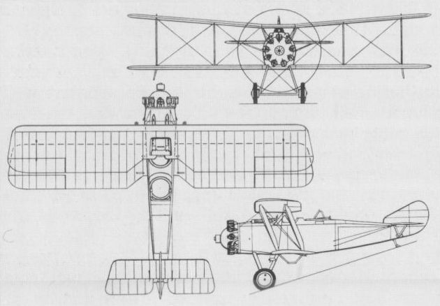
Designed to succeed the Bristol F.2B, the Weasel failed to attain production.
WHITEHEAD COMET UK
At the end of 1916, the Whitehead Aircraft Company completed, at its Richmond, Surrey, works, a small single-seat fighting scout. Not unlike the Camel in general appearance - and perhaps inspired by the Sopwith type, for the production of which Whitehead was a major contractor - the aircraft was a compact single-bay biplane, with ailerons on all four wings. The fuselage was faired to a near-circular cross section and the engine was an 80 hp Le Rhone nine-cylinder rotary. The name Comet was bestowed upon the fighter by its manufacturer, although it was also known within the works as the Boyle Scout, in an allusion to its principal designer, Edwin Boyle. No details of the planned armament appear to have survived, nor of any flight testing, although the Comet was reported to have flown. No data are available.
At the end of 1916, the Whitehead Aircraft Company completed, at its Richmond, Surrey, works, a small single-seat fighting scout. Not unlike the Camel in general appearance - and perhaps inspired by the Sopwith type, for the production of which Whitehead was a major contractor - the aircraft was a compact single-bay biplane, with ailerons on all four wings. The fuselage was faired to a near-circular cross section and the engine was an 80 hp Le Rhone nine-cylinder rotary. The name Comet was bestowed upon the fighter by its manufacturer, although it was also known within the works as the Boyle Scout, in an allusion to its principal designer, Edwin Boyle. No details of the planned armament appear to have survived, nor of any flight testing, although the Comet was reported to have flown. No data are available.

Probably inspired by Sopwith practice, the Whitehead Comet was designed by Edwin Boyle.
WIGHT QUADRUPLANE UK
Confusingly, aircraft of original design produced by the J S White company bore the appellation Wight, to link them with the location of the works at Cowes on the Isle of Wight. The last of some eight types developed under the direction of Howard T Wright as chief designer was the only Wight aircraft in the fighter category. This was a quadruplane of most unusual layout, in which the fuselage filled the gap between the two middle wings, with the upper and lower mainplanes carried above and below it on struts. At first, single wide-chord struts were used for the cabane and for the single wing bays between the upper, mid-upper and mid-lower wings, all of which had ailerons. The bottom wing, of shorter span, was carried on pairs of struts under the fuselage, and from the mid lower wing. The main wheels were carried on single struts each side and were notched into the bottom wing, with which the axle was in line. Construction was of wood, with mixed fabric and plywood covering. The engine was a 110 hp Clerget 9Z nine-cylinder rotary, but there is no record of the planned armament. Early flight testing, in mid-1916, led to a complete redesign and rebuild, by Howard T Wright and his team, with a fuselage of increased cross-section area and changed profile in side elevation, an enlarged tail unit and a new set of wings of varying chord. The original broad-chord struts gave way to pairs of narrow struts throughout and the undercarriage was lengthened. Possibly first tested at Martlesham Heath in February 1917, the Quadruplane acquired a third set of wings, with span progressively decreasing from top to bottom and ailerons on the two upper sets only. Further tests in July 1917 were unsatisfactory and the Quadruplane was written off in February 1918. No data have survived other than the dimensions.
Span 19 ft 0 in (5,79 m).
Length (final form), 20 ft 6 in (6,25 m).
Height, 10 ft 6 in (3,20 m).
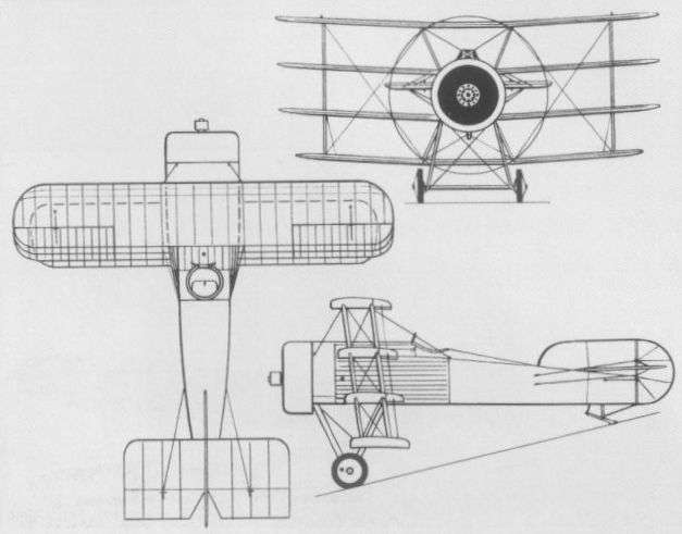
The extraordinary short-span Wight Quadruplane was tested at Martlesham in 1917.
A.E.G. D I Germany
The first fighter produced by A.E.G. (Allgemeine Elektrizitats Gesellschaft), the DI single-bay biplane was primarily of steel tube construction with single-spar wings and fabric skinning, power being provided by a 160 hp Daimler D IIIa six-cylinder water-cooled engine and armament comprising twin 7,92-mm LMG 08/15 synchronised guns. The first of three prototypes appeared in May 1917, type testing being conducted during August-September after the fuselage was lengthened by 15 3/4 in (40 cm), the second and third prototypes differing in having cheek-type radiators. Difficult to fly, one prototype crashing during type testing, the DI was nevertheless ordered as a pre-series of 20 for frontline evaluation. This contract was cancelled, however, after a second prototype crashed on 5 September 1917.
Max speed, 127 mph (205 km/h).
Time to 3,280 ft (1000m), 2.2 min.
Empty weight, 1,510 lb (685 kg).
Loaded weight, 2,072 lb (940 kg).
Span, 27 ft 10 5/8 in (8,50 m).
Length, 20 ft 0 1/8 in (6,10 m).
Height, 8 ft 8 1/3 in (2,65 m).
Wing area, 173.73 sq ft (16,14 m2).
A.E.G. Dr I Germany
Essentially a Dreidecker, or triplane, derivative of the D I, the Dr I was inspired by a circular of 27 July 1917 inviting inspection of a Sopwith Triplane that had been captured intact and proposals for fighters possessing at least comparable characteristics. A.E.G.’s contribution to the programme appeared in October 1917, this mating a triple-wing cellule with the fuselage, tail surfaces, 160 hp Daimler D IIIa engine and twin-gun armament of the D I. The Dr I revealed poor performance and unpleasant handling characteristics, development being quickly abandoned.
Max speed, 106 mph (170 km/h).
Empty weight, 1,565 lb (710 kg).
Loaded weight, 2,138 lb (970 kg).
Span, 30 ft 10 in (9,40m).
Length 20 ft 0 1/8 in (6,10 m).

The first A.E.G. DI which appeared in May 1917.
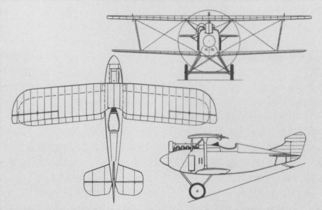
The second prototype of the A.E.G. D I.
A.E.G. DJ I Germany
Pursuing the concept of the single-seat armoured ground attack fighter, A.E.G. had begun the development of an aerodynamically advanced biplane as a Panzer-Einsitzer before the initiation of flight testing of the PE triplane, and this, the DJ I, was to be flown in July 1918. Two prototypes of the DJ I were completed with the 195 hp Benz Bz IIIb engine and a third prototype with the 240 hp Maybach Mb IVa engine, armament standardising on twin synchronised 7,92-mm LMG 08/15 guns with provision for anti-personnel bombs. An equi-span two-bay biplane, the DJ I wing cellule dispensed with flying wires, interplane bracing being provided by I-section struts. The wings were of dural construction with fabric covering, and the fuselage, which embodied some armour protection for the engine, fuel tank and pilot, had sheet aluminium skinning. Hostilities terminated while flight testing of the DJ I was still in progress. The following data relate to the Benz-engined version.
Max speed, 112 mph (180 km/h).
Empty weight, 2,606 lb (1182 kg).
Loaded weight. 3.031 lb (1375 kg).
Span, 32 ft 9 3/4 in (10,00 m).
Length, 21ft 11 1/3 in (6,69 m).
Height, 9 ft 10 1/8 in (3,00 m).
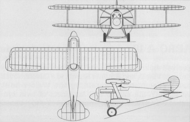
The A.E.G. DJ I armoured ground attack fighter.
A.E.G. PE Germany
The PE (Panzer-Einsitzer) was a single-seat armoured ground attack fighter and proved to be unique among aircraft designed for this task in being of triplane configuration. Featuring an armoured light alloy-covered fuselage and fabric-covered dural wings, the PE was powered by a 195 hp Benz Bz IIIb eight-cylinder water-cooled engine and was first flown in March 1918. Armament consisted of two synchronised 7,92-mm LMG 08/15 machine guns supplemented by racks for small bombs. The PE proved easy to fly but was found to have poor stability and was considered by the Idflieg (Inspektion der Fliegertruppe) to possess inadequate performance for fighter-versus-fighter combat, a dedicated ground attack aircraft being considered unacceptable. Nonetheless, A.E.G. was to persist with the concept with the DJ.
Max speed, 103 mph (166 km/h).
Time to 3,280 ft (1000 m), 5.8 min.
Empty weight, 2,606 lb (1182 kg).
Loaded weight, 3.113 lb (1412 kg).
Span, 36 ft 8 7/8 in (11,20 m).
Length, 21ft 7 7/8 in (6,60 m).
ALBATROS D I Germany
Designed by Herren Thelen, Schubert and Gnadig in a successful endeavour to wrest from the Allies the aerial superiority gained over the Fokker monoplanes by the Nieuport 11 Bebe and the Airco D.H.2, DI was the first fighter to be developed by the Albatros-Werke. Introduced in August 1916 were 12 pre-series aircraft ordered in the previous June after April Typen-Prufung by the Idflieg. Aerodynamically clean for its time, the D I had a semi-monocoque wooden fuselage which differed radically from the fabric-skinned, braced box-girder type fuselages then in almost universal use. The wings were conventional fabric-covered wooden structures, the power plant was either the 150 hp Benz Bz III or 160 hp Mercedes D III six-cylinder inline water-cooled engine, and armament consisted of paired 7,92-mm LMG 08/15 synchronised machine guns. Fifty series D Is were ordered in July 1916, and these were delivered to the Front (where 50 pre-series and series D Is were in service in November), but no further production of this fighter was undertaken as the DI had been overtaken by the D II which, in fact, arrived at the Front at the same time as the earlier type.
Max speed, 109mph (175km/h).
Time to 3,280 ft (1000m), 6.0 min.
Endurance, 1.5 hrs.
Empty weight, 1,422 lb (645 kg).
Loaded weight, 1,809 lb (898 kg).
Span, 27ft 10 2/3 in (8,50 m). Length, 24 ft 3 1/3 in (7,40 m).
Height, 9 ft 6 3/8 in (2,95 m).
Wing area, 246.50 sq ft (22,90 m2).
ALBATROS D II
One of the most serious design faults of the DI was the poor forward and upward fields of vision provided for the pilot, and to rectify this deficiency the upper wing was lowered and the wing cellule was staggered, reducing overall height by 14 in (36 cm). With this and other more minor changes, the fighter was redesignated D II, and an initial production batch of 100 was ordered in August 1916, arrangements being made for the DII to be licence-built by LVG (Luft-Verkehrs-Gesellschaft). It was also to be built by Oeffag (Oesterreichische Flugzeugfabrik) for the Austro-Hungarian K.u.K. Luftfahrttruppen with a 185 hp Austro-Daimler engine. The standard D II had the 160 hp Daimler D III and armament remained a pair of LMG 08/15 guns. Twenty-eight D IIs were at the Front in November 1916, and the strength of this type peaked in January 1917, when 214 were recorded at the Front.
Max speed, 109 mph (175 km/h).
Time to 3,280 ft (1 000 m), 5.5 min.
Endurance, 1.5 hrs.
Empty weight, 1,404 lb (637 kg).
Loaded weight, 1,958 lb (888 kg).
Span, 27 ft 10 2/3 in (8,50 m).
Length, 24 ft 3 1/3 in (7,40 m).
Height, 8 ft 6 in (2,59 m).
Wing area, 263.72 sq ft (24,50 m2).

The series DI which appeared at the Front in autumn 1916.
ALBATROS D III Germany
Dipl-Ing Robert Thelen and Dipl-Ing Schubert, at the behest of the Idflieg, endeavoured to adapt the sesquiplane wing cellule utilised by Nieuport fighters to the semi-monocoque fuselage and tail surfaces of the DII to produce the D III. Featuring the single-spar lower wing and Vee-strutted cellule a la Nieuport, the D III was powered by the 180 hp Mercedes D IIIa six-cylinder inline water-cooled engine and had twin synchronised LMG 08/15 7,92-mm guns. The prototype flown in August 1916, was, in fact, one of a batch of 12 D IIIs ordered during the previous June, 400 more being ordered by Idflieg from Albatros during October. The D III was issued to the Jastas from December 1916, and began to suffer recurrent wing failures, these resulting from the torsional flexibility of the lower wing (although this was not appreciated at the time). Albatros' OAW (Ostdeutsche Albatros-Werke) at Schneidemuhl received orders for 840 D IIIs during April-August 1917, these featuring reinforced wings. The D III was also licence-built by Oeffag and fitted progressively with Austro-Daimler engines of 185, 200 and 225 hp, the first production examples with the highest-powered of these engines being accepted in May 1918, and some 220 being delivered to the Austro-Hungarian K.u.K. Luftfahrttruppen to the end of October 1918. After World War I, Poland procured 60 of the 200 hp Oeffag-built D IIIs, some being flown with 7.Eskadra Kosciuszkowska between August 1920 and May 1921 by US volunteer pilots. The following data relate to the standard D III with the D IIIa engine boosted to 180 hp by means of an increase in compression ratio.
Max speed, 103 mph (165 km/h).
Time to 3,280 ft (1000m), 3.75 min.
Empty weight, 1,457 lb (661 kg).
Loaded weight, 1,953 lb (886 kg).
Span, 29 ft 8 in (9,04 m).
Length, 24 ft 0 5/8 in (7,33 m).
Height, 9 ft 9 1/4 in (2,98 m).
Wing area, 220.66 sqft (20,50 m2).

An early ex-works Albatros D III with the original centrally-located radiator.
By November 1917 there were well over 400 Albatros DIIIs in front-line service, although by the summer the types had been technologically superseded by the DV.
By November 1917 there were well over 400 Albatros DIIIs in front-line service, although by the summer the types had been technologically superseded by the DV.
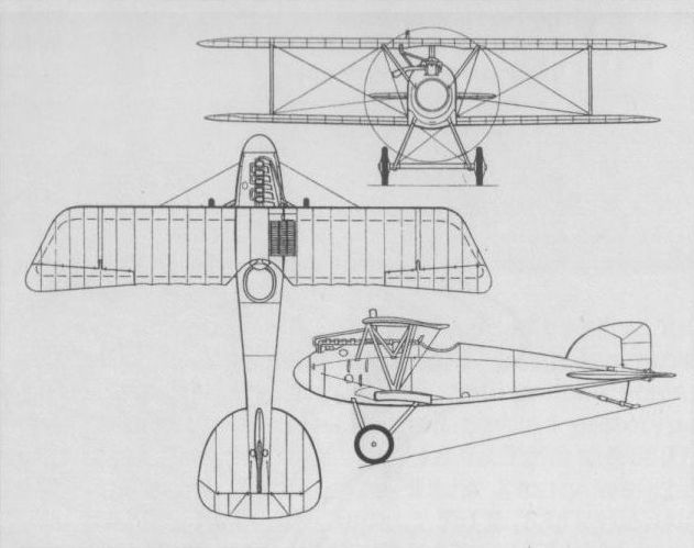
The D III with Vee-strutted wing cellule.
ALBATROS W 4
Ordered as a prototype in June 1916 and tested at Warnemunde in the following September, the W 4 single-seat fighter floatplane mated a D II fuselage with new wings and tail surfaces, the 160 hp Daimler D III engine being retained. The twin floats had to be redesigned and reinforced, and the transparent Cellon wing centre section panel featured by early production W 4s became brittle and tore in flight, necessitating replacement by fabric. From June 1917, the side radiators - which tended to boil over in hot weather - were replaced, and, with the sixth production batch commencing with the 68th series aircraft, ailerons were introduced also in the lower wing. With an armament of either one or two 7,92-mm guns, the W 4 operated over both the North Sea and the Baltic, and 128 (including the prototype) were built, the last of eight batches being ordered in August 1917 with deliveries being completed in the following December. As late as June 1918, 65 W 4s were still listed as active (24 more being with various seaplane stations as practice machines).
Max speed, 99 mph (160 km/h).
Time to 3,280 ft (1000 m), 6.5 min.
Empty weight, 1,742 lb (790 kg).
Loaded weight, 2,359 lb (1070 kg).
Span, 31ft 2 in (9,50m).
Length, 27ft 1 1/4 in (8,26m).
Height, 11 ft 11 3/4 in (3,65 m).
Wing area, 340.15 sq ft (31,60 m2).

A late production W 4 with wing-mounted radiator.
ALBATROS D IV Germany
The DIV was developed essentially to test the geared version of the 160 hp Mercedes engine (this having reduced the 1,400 rpm of the engine crankshaft to 900 rpm at the propeller). It was based on the D II cellule, but substantially enlarged, and three D IVs were ordered in November 1916. It is believed that only one of these was completed and flown. It was tested with two-, three- and four-bladed propellers until April 1918, but excessive vibration led to the discontinuation of the programme.
Max speed, 103 mph (165 km/h).
Endurance, 2.2 hrs.
Span, 29 ft 8 in (9,04 m).
Length, 24 ft 0 5/8 in (7,33 m).
Wing area, 220.66 sq ft (20,50 m2).
ALBATROS D V Germany
At the same time as the OAW received its first contract for the D III in April 1917, Albatros received an order from Idflieg for 200 DVs, referred to as "lightened D IIIs". The DV retained the wings of the DIII (although the aileron cables were led through the upper wing), was powered by the high-compression Mercedes D IIIa with oversize cylinders and offering 180 hp, and mounted twin 7,92-mm synchronised LMG 08/15 machine guns. The D V experienced a recurrence of the wing failures (previously suffered by the D III) as early as May 1917. Four hundred more D Vs were ordered, nevertheless, in May 1917 and 300 in July, after which the Idflieg terminated production in favour of the D Va which reverted to the D III-type aileron control cable arrangement and was reinforced throughout. The last Albatros fighter to see operational use in World War I, the D Va arrived at the Front in October 1917, by which time 1,612 fighters of this version had been ordered. Service of the D Va peaked in May 1918 when there were 928 (plus 131 D Vs) in operational use.
Max speed, 115 mph (185 km/h).
Time to 3,280 ft (1000 m), 4.35 min.
Endurance, 2.0 hrs.
Empty weight, 1,515 lb (687 kg).
Loaded weight, 2,066 lb (937 kg).
Span, 29 ft 8 in (9,04 m).
Length, 24 ft 0 5/8 in (7,33m).
Height, 8ft 10 1/4 in (2,70m).
Wing area, 228.19 sq ft (21,20 m2).
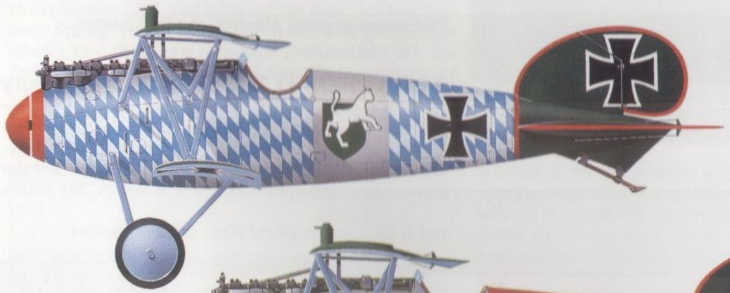
An Albatros D V of Jasta 5 with a Bavarian Lion motif
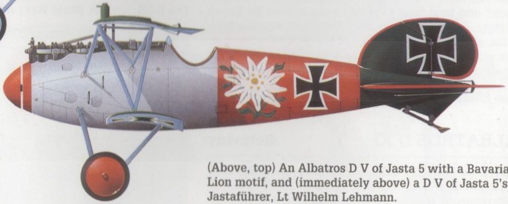
A D V of Jasta 5's Jastafuhrer, Lt Wilhelm Lehmann.

The Albatros D V was flown by Vzfw Barth of Jasta 10 in the late autumn of 1917.
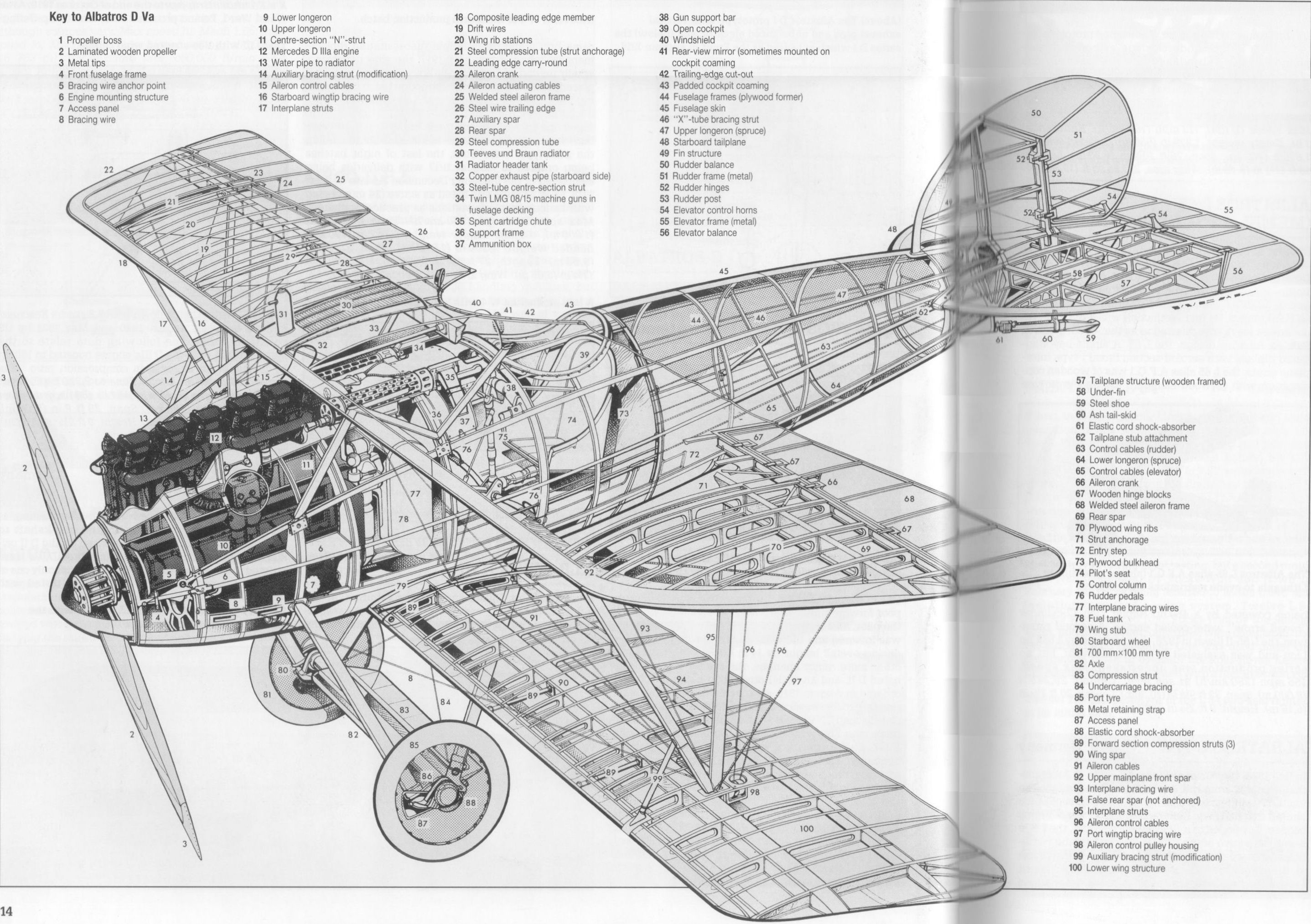
Albatros D Va
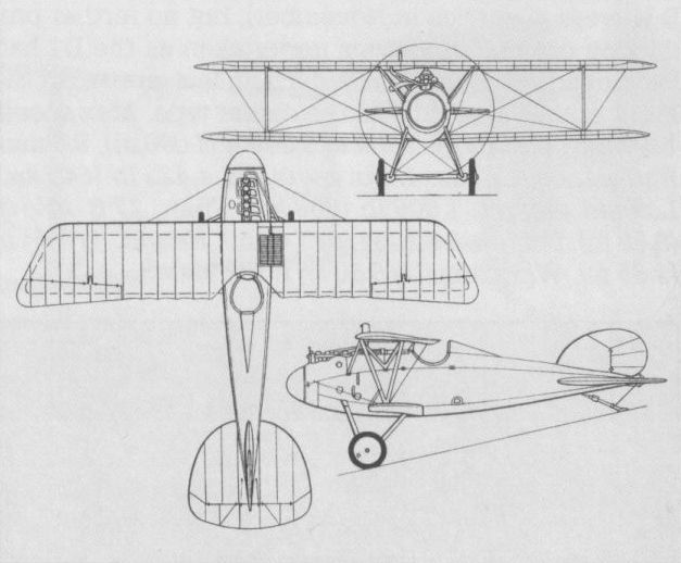
The D V reached the Front in September 1917.
ALBATROS D VII Germany
Flown in August 1917, the D VII was powered by a 195 hp Benz Bz IIIb eight-cylinder water-cooled Vee engine. Strut-linked ailerons were carried by all wings and armament comprised two 7,92-mm machine guns. The characteristics of the D VII offered an insufficient advance to warrant development beyond prototype status.
Max speed, 127 mph (204 km/h).
Time to 6,560 ft (2 000 m), 7 min.
Endurance, 2 hrs.
Empty weight, 1,389 lb (630kg).
Loaded weight, 1,951 lb (885 kg).
Span, 30 ft 6 7/8 in (9,32 m).
Length, 21 ft 8 1/4 in (6,61 m).
ALBATROS DR I Germany
The Dr I was essentially a D V fuselage, tail surfaces and undercarriage married to three pairs of wings, and flown in the summer of 1917 for comparison trials with the standard biplane. Powered by a Daimler D IIIa engine, the Dr I proved to offer no advantage over the D V, and progressed no further than prototype evaluation. Armament consisted of the usual pair of 7,92-mm machine guns.
Span, 28 ft 6 1/2 in (8,70m).
Length, 24 ft 0 5/8 in (7,33 m).
ALBATROS D IX Germany
Unlike previous Albatros fighters, the DIX featured a slab-sided, flat-bottomed fuselage. The wings were similar to those of the D VII, as were also the tail surfaces, power was provided by a 180 hp Daimler D IIIa engine, and armament consisted of the usual twin synchronised 7,92-mm LMG 08/15 machine guns. The sole prototype appeared early in 1918, but performance proved disappointing and development was discontinued.
Max speed, 96 mph (155 km/h).
Time to 3,280 ft (1000 m), 4 min.
Endurance, 1.5 hrs.
Empty weight, 1,492 lb (677 kg).
Loaded weight, 1,977 lb (897 kg).
Span 34 ft 1 1/2 in (10,40 m).
Length, 21 ft 9 7/8 in (6,65 m).
ALBATROS D X
Developed in parallel with the DIX and possessing a similar slab-sided fuselage, the D X was powered by a 195 hp Benz Bz IIIbo eight-cylinder water-cooled engine, and participated in the second D-type Contest held at Adlershof in June 1918. Armament comprised the usual pair of machine guns. Development progressed no further than prototype trials.
Max speed, 106 mph (170 km/h).
Endurance, 1.5 hrs.
Empty weight, 1,468 lb (666 kg).
Loaded weight, 1,995 lb (905 kg).
Span, 32 ft 3 1/3 in (9,84 m).
Length, 20 ft 3 1/3 in (6,18m).
ALBATROS D VI Germany
The D VI twin-boom single-seat pusher biplane powered by a 180 hp Daimler D IIIa engine was built during 1917, and was flown for the first time in February 1918. The undercarriage was damaged during the initial landing and had still to be repaired in May when further work on the D VI was suspended due to higher priority allocated to other projects. The engine was then removed for another application. Armament comprised a fixed forward-firing 20-mm Becker cannon and a 7,92-mm LMG 08/15 machine gun.
Empty weight, 1,406 lb (638 kg).
Loaded weight, 1,940 lb (880 kg).
Span, 32ft 1 7/8 in (9,80m).
Length, 25 ft 5 1/8 in (7,75m).
ALBATROS D XI Germany
Flown for the first time in February 1918, the DXI departed from the traditional Albatros formula in certain respects. Like its predecessors, it was of wooden construction with fabric-covered wings and plywood-covered fuselage, but the unequal-span staggered wings had inclined aerofoil-section I-struts braced from their bases by pairs of diagonal struts which eliminated the need for wire bracing. For the first time in an Albatros fighter a rotary engine was employed, this being a 160 hp Siemens-Halske Sh III, and the unusually large propeller necessitated an exceptionally tall undercarriage. Armament comprised the usual twin 7,92-mm machine guns, and two prototypes were built, the first having a four-blade propeller and balanced parallel-chord ailerons, and the second having a two-blade propeller and unbalanced ailerons of inverse taper.
Max speed, 118 mph (190 km/h).
Time to 6,560 ft (2 000 m), 4.65 min.
Endurance, 1.5 hrs.
Empty weight, 1,089 lb (494 kg).
Loaded weight. 1,519 - 1,594 lb (689 - 723 kg).
Span, 26ft 3in (8,00m).
Length, 18ft 3 1/2 in (5,58m).
Wing area, 199.13 sqft (18,5 m2).

First rotary-engined Albatros, the D XI.
ALBATROS D XII Germany
The last Albatros fighter of World War I actually completed and flown, the D XII featured the slab-sided plywood-covered fuselage introduced by the D X, and the first of two prototypes was flown in March 1918 with a 180 hp Daimler D IIIa engine. The second prototype, fitted with a Bohme undercarriage embodying compressed-air shock absorbers, and unbalanced ailerons of inverse taper in place of the balanced parallel-chord ailerons of the first prototype, followed in April 1918, and was later fitted with a 185 hp BMW IIIa engine for participation in the third D-type contest of October.
Max speed (D IIIa), 112 mph (180 km/h).
Endurance, 1 hr.
Empty weight, 1,279 lb (580 kg).
Loaded weight, 1,675 lb (760 kg).
Span, 26 ft 10 3/4 in (8,20 m).
Length. 18 ft 11 1/2 in (5,78 m).
Wing area, 213.55 sq ft (19,84 m2).
ALBATROS Dr II Germany
The Dr II was, in effect, a triplane variant of the D X biplane with a similar 195 hp Benz Bz IIIbo engine. Ailerons were fitted to all wings, and these, of parallel chord and heavily staggered, were braced by broad I-struts. Armament consisted of two 7,92-mm machine guns, and the sole prototype of the Dr II was flown in the spring of 1918.
Empty weight, 1,490 lb (676 kg).
Loaded weight, 2,017 lb (915 kg).
Span, 32 ft 92/3 in (10,00 m).
Length, 20 ft 3 1/3 in (6,18 m).
Wing area, 286.32 sq ft (26,6 m2).
ALTER A.l Germany
Conceptually adhering closely to the Nie 11 Bebe if not an outright copy of the French design, the A.l single-seat fighter, designed by Kallweit and Ketterer and built by the Ludwig Alter-Werke of Darmstadt, was first flown in February 1917 by Georg Sell. A single-bay sesquiplane with I-type interplane struts, the A.l was of wooden construction with fabric and plywood covering. Armament consisted of two synchronised 7,92-mm LMG 08/15 machine guns and power was provided by a 110 hp Goebel Goe II seven-cylinder rotary engine. The A.l was demonstrated to the Idflieg (Inspektion der Fliegertruppe), but the type was rejected, performance being considered inadequate and the structure being viewed as insufficiently robust, further development being discontinued.
Max speed, 110 mph (177km/h).
Time to 9,840 ft (3000m), 12.8min.
Loaded weight, 1,124 lb (510 kg).
AVIATIK D II
The Automobil und Aviatik AG of Leipzig-Heiterblick licence-built the Halberstadt DII as the Aviatik DI - later known as the Halberstadt D II(Av) - before, in late 1916, developing and building an original single-seat fighter as the DII. Powered by the 160 hp Daimler D III six-cylinder water-cooled engine and carrying an armament of two synchronised 7,92-mm LMG 08/15 machine guns, the DII was a staggered single-bay biplane with wooden, fabric-covered wings and a steel-tube (forward) and wood (aft) fuselage largely ply covered. The Aviatik fighter did not find favour with the Idflieg as a result of the Typen-Prufung and further development was discontinued, only the one prototype being built.
Max speed, 93 mph (150 km/h).
Time to 3,280 ft (1000 m), 7.2 min.
Span, 29 ft 0 in (8,84 m).
Length, 22 ft 4 1/2 in (6,82 m).
Height, 9 ft 5 in (2,87 m).
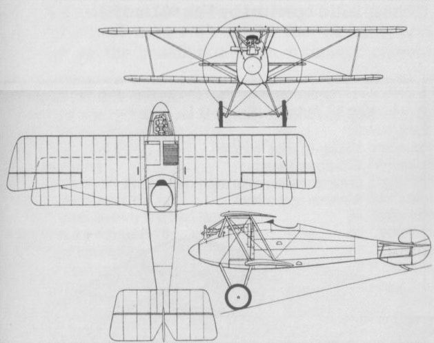
AVIATIK D III Germany
Flown for the first time in November 1917, the first prototype D III was powered by an ungeared Benz Bz IIIbo eight-cylinder Vee engine rated at 195 hp, was of mixed construction with a steel-tube forward fuselage, plywood fuselage skinning and fabric wing skinning, and carried an armament of twin synchronised 7,92-mm LMG 08/15 machine guns. A distinguishing feature was provided by a small, keel-like extension beneath the fuselage which served to increase the wing gap. Initial Typen-Prufung was performed at Adlershof during 9-12 February 1918, and after modifications by Aviatik, the D III was returned to Adlershof in April for resumption of type testing, together with a second prototype powered by a geared Bz IIIbm engine. By this time a small series of Bz IIIbo-powered D IIIs was under construction for service test and evaluation. Performance of the D III was considered to be superior to that of the Albatros D V although no details have apparently survived other than those relating to climb tests conducted in March 1918 with the Bz IIIbo-powered first prototype.
Time to 3,280 ft (1 000m), 2.5min, to 6,560ft (2 000 m), 5.7 min, to 9,840 ft (3 000 m), 11 min, to 13,125 ft (4 000 m), 17 min.
Loaded weight, 1,905 lb (864 kg).
Span, 29 ft 6 3/8 in ((9,0 m).
Wing area, 226.5 sq ft (21,0 m2).
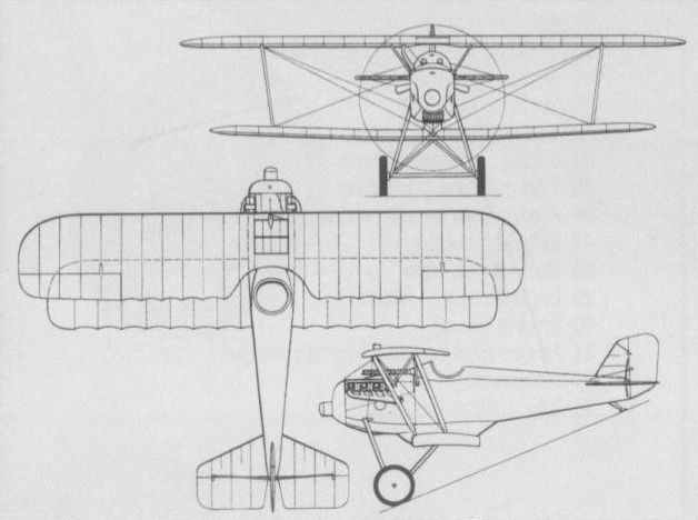
The Aviatik D III, initial type testing of which at Adlershof was performed in February 1918
AVIATIK D VII Germany
The D VII, which was intended to participate in the third D-type Contest of October 1918, was essentially similar to the D VI apart from having completely redesigned vertical and horizontal tail surfaces. Like its predecessor, it was powered by a geared Benz Bz IIIbm eight-cylinder Vee engine driving a four-bladed propeller. Armament comprised the standard twin 7,92-mm synchronised machine guns, and only one prototype was completed.
Max speed,119 mph (192 km/h).
Time to 19,685 ft (6000 m), 24 min.
Empty weight, 1,642 lb (745 kg).
Loaded weight, 2,083 lb (945 kg).
Span, 31 ft 8 1/3 in (9,66 m).
Length, 20 ft 0 1/8 in (6,10 m).
Height, 8 ft 2 1/2 in (2,50 m).
AVIATIK D.VI
During 1918, Aviatik was working on prototypes of several single-seat fighter biplanes simultaneously, two of these, the DIV and the D V, being powered by the Benz Bz IIIbv geared engine which was a larger-volume version of the Bz IIIbm. Apart from its power plant and a redesigned and enlarged rudder, the DIV was essentially similar to the D III, while the D V was a new fighter design which discarded flying wires. Prototypes of both types were built, but protracted engine teething troubles delayed the programmes, and there is no evidence that either was flown. The D VI, the sole prototype of which was flown in August 1918, bore little relationship to earlier Aviatik single-seat fighters, and was a two-bay biplane of wooden construction with ply-covered fuselage and fabric-covered wings and tail surfaces. Armament comprised two synchronised 7,92-mm LMG 08/15 machine guns and power was provided by a geared Benz Bz IIIbm. The D VI was intended to participate in the second D-type Contest held at Adlershof in June 1918. Owing to problems provided by the reduction gear of the Bz IIIbm, it was too late to participate in this contest, and by the time type-testing had revealed excellent flight characteristics, the D VI had already been overtaken by the D VII.
Max speed, 117 mph (188 km/h).
Time to 16,405 ft (5 000 m), 17.8 min.
Empty weight, 1,653 lb (750 kg).
Loaded weight, 2,072 lb (940 kg).
Span, 31ft 8 1/3 in (9,66 m).
Length, 20 ft 0 1/8 in (6,10 m).
Height, 8 ft 2 1/2 ft (2,50 m).
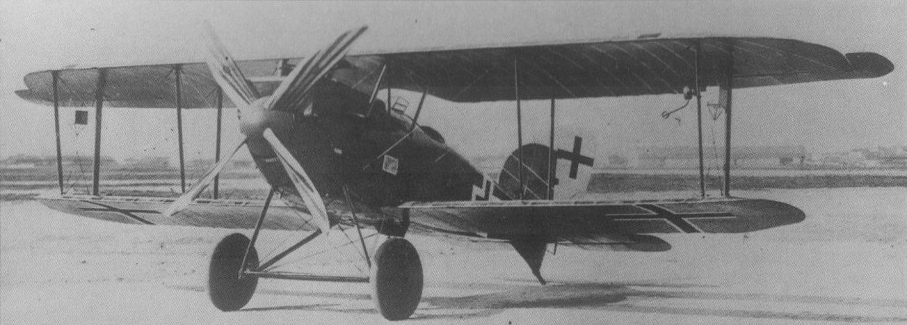
The Aviatik D VII was the last Aviatik single-seat fighter to be flight tested, and was fundamentally similar to the D VI apart from its tail surfaces.
Another of the 1918 designs to find little favour was the compact Aviatik DVIII. Although its performance was reasonable it had an endurance of little more than one hour.
Another of the 1918 designs to find little favour was the compact Aviatik DVIII. Although its performance was reasonable it had an endurance of little more than one hour.

BFW CL I (TYPE 17) Germany
In late 1917, the Bayerische Flugzeugwerke (BFW) of Munich, which had been organised around the former Otto Werke in the previous year, was awarded a contract to build two prototypes of the Cl I two-seat reconnaissance fighter of original design. At the time, BFW was negotiating a contract to build 100 Halberstadt Cl II reconnaissance fighters and the company’s Cl I was specifically designed to require 20 per cent less manufacturing manhours than the Halberstadt aircraft. The first prototype, known by BFW as the Type 17, was completed in April 1918 with a 160 hp Mercedes D III engine. A single-bay unequal span biplane with an intended armament of one fixed LMG 08/15 machine gun and an LMG 14 on a ring mounting, the Cl I was sent to the Adlershof test centre for Typprufung in July 1918, but the Idflieg reported that it was ‘‘in no way equal” to the Hannover Cl V, requesting that improvements be made and the aircraft resubmitted for further evaluation. Accordingly, a lighter fuselage was fitted and, as the Cl Ia, the aircraft underwent static load testing between 30 August and 14 September 1918. Results were unsatisfactory and BFW agreed to redesign the Cl Ia in accordance with ‘‘new design principles” (see Cl III).
Time to 3,280 ft(1 000 m), 2.0 min, to 13,125 ft (4 000 m), 6.5 min.
Empty weight (Cl Ia), 1,587 lb (720 kg).
Loaded weight (Cl Ia), 2,337 lb (1060 kg).
Span, 34 ft 10 1/8 in (10,62 m).
Length, 25 ft 7 1/2 in (7,81 m).
BFW CL II (TYPE 18) Germany
The second prototype of the Cl I two-seat reconnaissance fighter was completed with a 175 hp MAN (Maschinenfabrik Augsburg-Nurnberg) Mana III six-cylinder inline engine as the Cl II, or Type 18, in May 1918. In all other respects the Cl II was similar to the Cl I, but no details of its testing are available.
Time to 13,125 ft (4 000 m), 5.0 min.
Dimensions as for Cl I.
BFW CL III Germany
Redesign of the Cl Ia by BFW in accordance with the ‘‘new design principles” as requested by Idflieg resulted in the Cl III, a single prototype of which was completed at the close of hostilities but was not apparently subjected to Idflieg testing. Adhering closely to the concept of the Cl Ia, the Cl III was powered by a 200 hp Benz Bz IV engine and featured longer-span, more angular wings. A further development, the Cl IV, remained on the BFW drawing boards. No performance data or weights are recorded.
Span, 37 ft 10 1/3 in (11,54 m).
Length, 25 ft 7 1/2 in (7,81 m).
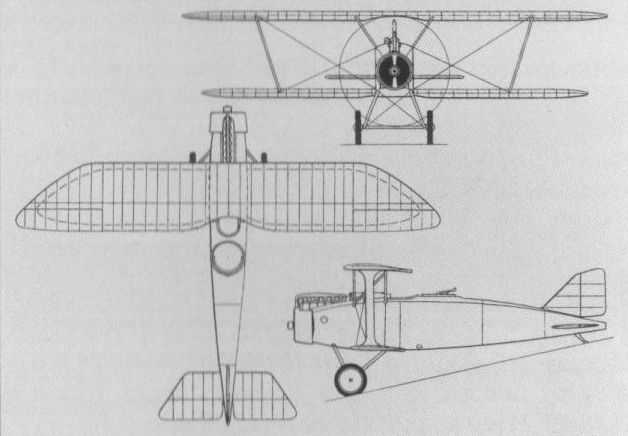
The second prototype of the BFW Cl I became the Cl II with a MAN III engine.
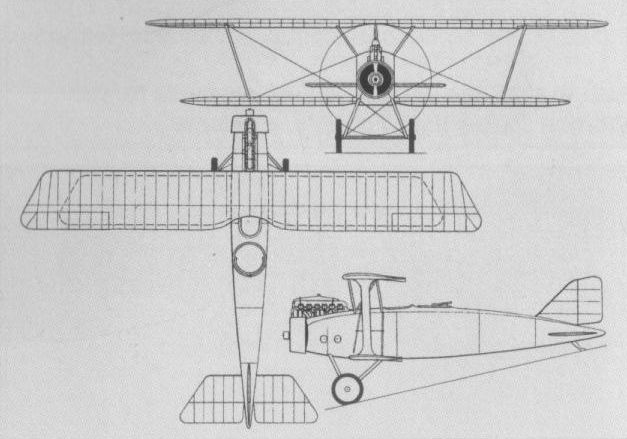
The BFW Cl III was too late for wartime service.
DAIMLER L 6 (D I) Germany
During the summer of 1915, the Daimler Motoren-Gesellschaft established an aircraft division at the request of the Inspektion der Fliegertruppen (Idflieg). In 1917, this Flugzeug Abteilung initiated work on an original single-seat fighter to the design of Ing Karl Schopper and powered by the company’s new D IIIb eight-cylinder water-cooled engine. Flight testing of this, the L 6 (or D I) equi-span single-bay biplane, was delayed until late November 1917 by engine bearing problems. Tail heaviness was rectified by modification of the wing cellule arrangement, flight testing was completed in March 1918, and the L 6 was sent to Adlershof for Typprufung in July, concurrently participating in the second D-Type Competition. Performance suffered owing to the fact that the D nib engine, which was rated at 185 hp, lost power at altitude, but a contract for 20 examples of the Daimler fighter was awarded on 23 July 1918. These aircraft, which were armed with synchronised 7,92-mm LMG 08/15 machine guns, were delivered during December 1918.
Max speed, 114 mph (183 km/h).
Time to 19,685 ft (6 000 m), 30 min.
Endurance, 2 hrs.
Empty weight, 1,653 lb (750 kg).
Loaded weight, 2,039 lb (925 kg).
Span, 32 ft 5 3/4 in (9,90 m).
Length, 23 ft 11 2/5 in (7,30 m).
Height, 9 ft 0 2/3 in (2,76 m).
Wing area, 243.27 sq ft (22,60 m2).
DAIMLER L 9 (D II) Germany
Essentially a refined development of the L 6, dispensing with interplane bracing wires and having staggered wings and new vertical tail surfaces, the L 9 single-seat fighter employed a similar 186 hp Daimler D IIIb engine. It was intended to carry an armament of twin synchronised 7,92-mm LMG 08/15 machine guns. Flown initially with fully cantilevered wings in July 1918, the L 9 was modified during August by the addition of aerofoil-section I-type interplane bracing struts. Hanns Klemm had joined Daimler's Flugzeug Abteilung as chief designer on 1 April 1918, and the L 9 apparently embodied some of his ideas. Only one prototype was completed and no production contract was awarded. Daimler offered the L 9 in modified form for use on postal services in 1920, but failed to obtain a purchaser.
Max speed, 118 mph (190 km/h).
Initial climb, 905 ft/min (4,60 m/sec).
Range, 273 mis (440 km).
Empty weight, 1,636 lb (742 kg).
Loaded weight, 2,182 lb (990 kg).
Span, 29 ft 6 1/3 in (9,00 m).
Length, 23 ft 7 1/2 in (7,20 m).
Height, 8 ft 6 1/3 in (2,60 m).
Wing area, 240.25 sqft (22,32 m2).

Daimler’s first fighter design, the L 6 of 1917.
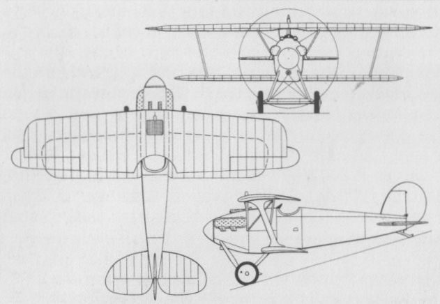
First flown with cantilever wings, the L 9 was later fitted with interplane struts.
DAIMLER L 11 Germany
The L11 single-seat parasol monoplane fighter was the first aircraft built from the outset by Daimler's Flugzeug Abteilung to the designs of Hanns Klemm. Of exceptionally clean aerodynamic form, powered by a 185 hp D IIIb eight-cylinder water-cooled engine, and featuring swivelling wingtips which served as servos and balanced the ailerons, the L 11 was flown for the first time on 8 November 1918. During trials in the following February, it attained an altitude of 19,685 ft (6 000 m) in 17 min and achieved an absolute ceiling of 27,560 ft (8 400 m). Only one prototype of the L 11 fighter was completed.
Max speed, 124 mph (200 km/h).
Time to 3,280 ft (1000 m), 3.2 min.
Span, 39 ft 4 1/2 in (12,00 m).
Length, 26 ft 8 9/10 in (8.15 m).
Wing area, 310 sqft (28,80 m2).
DAIMLER L 14 Germany
Owing much to Hanns Klemm's single-seat L11, but embodying further aerodynamic refinement and featuring an exceptionally clean oval-section semi-monocoque fuselage, the L 14 tandem two-seat parasol monoplane fighter retained the 185 hp Daimler D IIIb eight-cylinder water-cooled engine and swivelling wingtips of the preceding fighter. Intended armament comprised a single forward-firing 7,92-mm LMG 08/15 machine gun and one Parabellum of similar calibre in the rear cockpit. The sole prototype of the L14 was completed in the autumn of 1919, and, together with the L 8, was offered for sale to the Chilean government, a mail-carrying version being proposed as the L14V. In the event, no further example was completed.
Max speed, 128 mph (206 km/h).
Range, 435 mis (700 km).
Time to 3,280 ft (1 000 m), 3.1 min.
Empty weight, 1,918 lb (870 kg).
Loaded weight, 2,800 lb (1270 kg).
Span, 40 ft 4 1/5 in (12,30 m).
Wing area, 322.93 sq ft (30,00 m2).
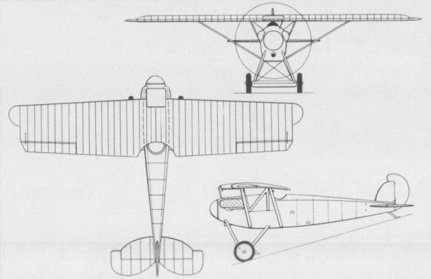
The sole Daimler L11 which was the first aircraft wholly designed by Hanns Klemm.
DAIMLER L 8 (CL I) Germany
A tandem two-seat single-bay staggered biplane, the Daimler L 8 (Cl I) was intended primarily as a light escort fighter, a single prototype being built late in 1917. Powered by a 185 hp Daimler D IIIb eight-cylinder water-cooled engine, the L 8 carried an armament of one forward-firing synchronised LMG 08/15 7,92-mm machine gun and a Parabellum machine gun in the rear cockpit. No further prototypes were completed, and although, in July 1919, Daimler offered to build the L 8 for the Chilean government, no contract was signed. The following specification relates to the L 8 as offered to Chile.
Max speed, 93 mph (150 km/h) at 4,920 ft (1500 m).
Time to 16,405 ft (5 000m), 33.5 min.
Endurance, 4 hrs.
Empty weight, 1,808 lb (820 kg).
Loaded weight, 2,711 lb (1230 kg).
Span, 38 ft 9 1/3 in (11,82 m).
Length, 24 ft 5 1/3 in (7,45 m).
Height, 9 ft 8 1/8 in (2,95 m).
Wing area, 339.07 sq ft (31,50 m2).
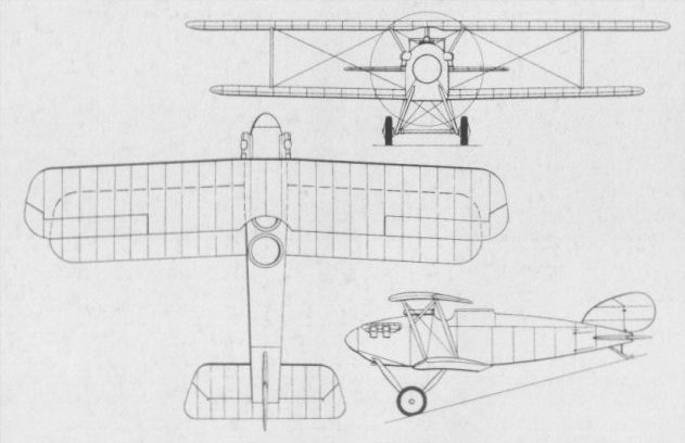
DFW T 28 FLOH Germany
Designed in late 1915 by Dipl Ing Hermann Dorner, newly appointed as chief engineer of the Deutsche Flugzeugwerke GmbH (DFW) of Leipzig-Lindenthal, the T 28 Floh (Flea) was, in appearance, one of the most extraordinary single-seat biplane fighter prototypes tested during World War I. Built under the supervision of Ing Theo Rockenfeller at DFW’s Lubeck-Travemunde subsidiary, the T 28 featured an inordinately deep fuselage in which the 100 hp Mercedes D I six-cylinder water-cooled engine was completely buried. Of wooden construction with fabric-covered wings and wood veneer skinning for the fuselage, the T 28 carried a single machine gun in the forward fuselage above the engine. During the maiden flight a speed of 112 mph (180 km/h) was attained - a noteworthy accomplishment at the time - but minor damage resulted during the landing. Some modifications were made, including the introduction of aerodynamically-balanced elevators, but the authorities evinced no interest in the aircraft and further development of the T 28 was abandoned in consequence.
Max speed, (approx) 112 mph (180 km/h).
Empty weight, 926 lb (420 kg).
Loaded weight,1,433 lb (650 kg).
Span, 20 ft 4 in (6,20 m).
Length 14 ft 9 in (4,50 m).
Height, 7 ft 6 1/2 in (2,30 m).
Wing area, 161.46 sq ft (15,00 m2).

DFW D I Germany
The DFW D I (which was subsequently to be referred to on occasions erroneously as the D II and by the unconfirmed and almost certainly incorrect designation of F 34) was a single-bay biplane powered by a 160 hp Mercedes D IIIa engine and mounting the usual pair of synchronised 7,92-mm LMG 08/15 machine guns. Entered in the second D-type contest held in May-June 1918, the DFW DI was rejected out of hand "for any frontline utilisation" and did not participate in the subsequent flight evaluation. During July 1918, however, the D I was rebuilt and flight test results were considered sufficiently promising for full static load tests to be conducted at Adlershof during late July and early August. However, these tests revealed that the fuselage and tail demanded strengthening, and the type was not approved for service use in consequence.
Max speed, 110 mph (177 km/h).
Time to 13,125 ft (4 000 m), 10 min.
Empty weight, 1,409 lb (639 kg).
Loaded weight, 1,806 lb (819 kg).
Span, 29 ft 9 1/2 in (9,08 m).
Length, 18 ft 16 in (5,50 m).
Wing area, 247.58 sqft (23,00 m2).
DFW T 34-I Germany
A conventional single-bay biplane of wooden construction powered by a 160 hp Mercedes D III engine and mounting twin synchronised 7,92-mm machine guns, the T 34-I (frequently referred to erroneously as the D I) was developed in mid-1917, first appearing in official Idflieg progress reports in October of that year when the cooling system was being modified and the control surfaces enlarged. In November, new wings with a more efficient rib profile were under construction and, in January 1918, the T 34-I attained an altitude of 16,405 ft (5 000 m) in 22 min, a climb capability possessed by the Pfalz D IIIa already in operational service. By this time, the ailerons had been removed from the lower wing and the vertical tail surfaces had undergone further redesign, and in this form the T 34-I was entered in the first D-type contest at Adlershof in February 1918. It was rejected on the score of poor cockpit visibility prior to the flight evaluation and thus did not appear in the official statistical tabulations. No data on the T 34-I are available.
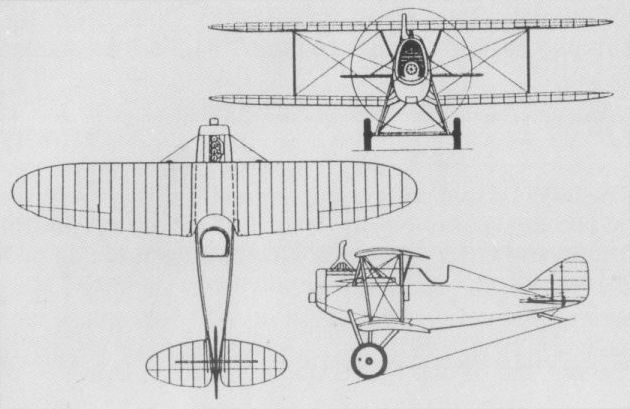
Contrasting with the T 28, the DFW T 34-I was a conventional single-bay biplane.

The DFW DI with Mercedes D IIIa engine.
DFW T 34-II Germany
Evolved in parallel with the T 34-I biplane, the T 34-II (sometimes referred to erroneously as the Dr I) single-seat triplane employed a similar fuselage, power plant (Mercedes D III), armament (twin synchronised LMG 08/15s) and undercarriage to those of the biplane fighter. Both top and bottom wings were one-piece units mounted well clear of the fuselage and sufficiently staggered to obviate the need for a pilot-vision cut-out. The central wing carried generous ailerons and possessed broad tips, and the tail surfaces were similar to those of the definitive T 34-I, but incorporating a somewhat larger rudder. Together with the T 34-I, the T 34-II triplane was submitted for evaluation in the first D-type contest, but was excluded from the competition flight testing for reasons of poor pilot visibility and "unsuitable design”. No data on the T 34-II are available.
Evolved in parallel with the T 34-I biplane, the T 34-II (sometimes referred to erroneously as the Dr I) single-seat triplane employed a similar fuselage, power plant (Mercedes D III), armament (twin synchronised LMG 08/15s) and undercarriage to those of the biplane fighter. Both top and bottom wings were one-piece units mounted well clear of the fuselage and sufficiently staggered to obviate the need for a pilot-vision cut-out. The central wing carried generous ailerons and possessed broad tips, and the tail surfaces were similar to those of the definitive T 34-I, but incorporating a somewhat larger rudder. Together with the T 34-I, the T 34-II triplane was submitted for evaluation in the first D-type contest, but was excluded from the competition flight testing for reasons of poor pilot visibility and "unsuitable design”. No data on the T 34-II are available.
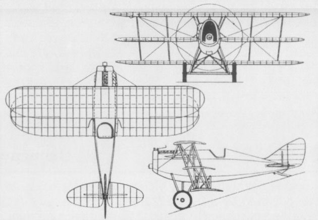
EULER "GELBER HUND” Germany
August Euler, proprietor of the Euler-Werke, near Frankfurt am Main, obtained a patent in 1912 for a fixed forward-firing machine gun aimed by steering the aircraft on which it was mounted in the direction of the target. This development was demonstrated to the German military authorities on 10 May 1912, the gun being mounted on a two-seat pusher biplane named "Gelber Hund" (Yellow Dog). In 1915, the Euler-Werke produced a single-seat fighter, which, also known as the "Gelber Hund", mounted a single fixed forward-firing 7,92-mm Maxim MG 08/15 machine gun in the nose of a short fuselage nacelle, power being provided by a 120 hp Mercedes D III engine mounted at the rear of the nacelle. The propeller rotated between twin wire-braced steel-frame booms carrying the tail assembly. The "Gelber Hund" failed to attract a production order and no specification has apparently survived.
EULER (VERSUCHSZWEISITZER) Germany
In parallel with the single-seat "Gelber Hund", the Euler-Werke built, as a private venture, a two-seat fighter of generally similar configuration referred to simply as a versuchszweisitzer (experimental two-seater). Intended primarily for anti-airship and escort tasks, and powered by a 160 hp Mercedes D III engine, the versuchszweisitzer appeared in the late autumn of 1915, and, in its initial form, featured a rotating turret for a gunner in the extreme nose of the fuselage nacelle, the pilot being accommodated aft. The turret was provided with a single Bergmann MG 15n/A machine gun. After initial trials, the fuselage nacelle was rebuilt, the pilot being moved forward in the nose and provided with a fixed forward-firing Bergmann gun, and the gunner being accommodated in a pulpit-like open-frame turret providing a 360-deg field of fire and mounting a single Parabellum MG 14 machine gun. In an attempt to reduce drag, the frame supporting the turret ring-mounting was subsequently faired in and the forward decking of the fuselage nacelle was raised to partially enclose the fixed gun, but further development was abandoned shortly afterwards.
Time to 9,840 ft (3000 m), 44 min.
Endurance, 4 hrs.
Span, 48 ft 6 3/4 in (14,80 m).
Length, 30 ft 6 1/8 in (9,30 m).
Height, 10 ft 6 in (3,20 m).
Wing area, 566.20 sq ft (52,60 m2).

The Euler "Gelber Hund" of 1915 which featured a fixed forward-firing machine gun in the extreme nose of the fuselage pod.
An experimental single-seat pusher design powered with 160 h.p. Mercedes D III engine. No details available.
Known as the "Gelber Hund", this single-seat pusher was the first Euler-Werke fighting scout.
An experimental single-seat pusher design powered with 160 h.p. Mercedes D III engine. No details available.
Known as the "Gelber Hund", this single-seat pusher was the first Euler-Werke fighting scout.
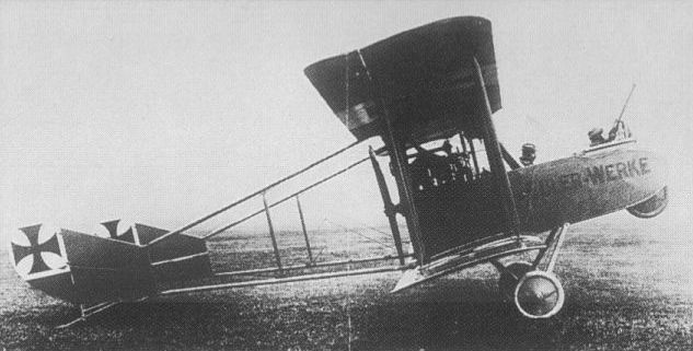
The initial form with nose turret of the Euler two-seat fighter of 1915 intended primarily for anti-airship and escort missions.
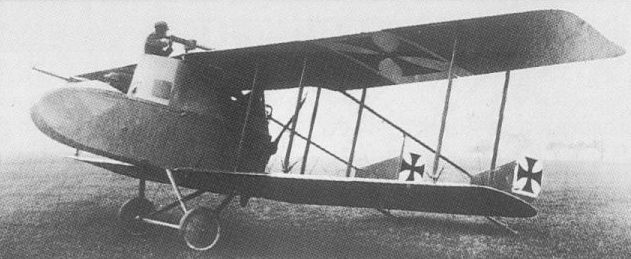
The final form of the Euler two-seat fighter of 1915 with faired, pulpit-like gun position, intended primarily for anti-airship and escort missions.
EULER D I Germany
The success at the front of the Nieuport 11 prompted the German authorities to request several manufacturers to design aircraft based on the French fighter, that produced by the Euler-Werke as the company’s D I probably adhering most closely to the original. Powered by an 80 hp Oberursel U O seven-cylinder rotary and mounting a single 7,92-mm machine gun, the DI prototype was flown in the autumn of 1916, and an initial series of 50 was ordered in October of that year, despite the fact that type testing at Adlershof was not to be completed until January 1917. Two Euler D Is (presumably prototypes) were recorded as being at the front at the end of October 1916, but the production aircraft was to be employed primarily as a fighter trainer. A further 50 were ordered with the completion of the Adlershof trials, but part of this order was later transferred to the D II (which see).
Max speed, 87 mph (140 km/h).
Time to 6,560 ft (2 000 m), 12.5 min.
Empty weight, 838 lb (380 kg).
Loaded weight, 1,323 lb (600 kg).
Span, 26 ft 6 7/8 in (8,10 m).
Length, 19 ft 0 1/4 in (5,80 m).
Height, 8 ft 8 3/4 in (2,66 m).
Wing area, 139.93 sq ft (13,00 m2).
EULER D II Germany
The Euler D II was essentially a re-engined D I, the airframe being virtually unchanged and the power plant being a 100 hp Oberursel U I seven-cylinder rotary. A batch of 30 DII fighters was ordered in March 1917, but owing to tardiness on the part of the Euler-Werke in producing these, deliveries did not commence until the following December and, in consequence, the DII was relegated to the Jagdstaffelschulen with which it served until the end of hostilities.
Max speed 90 mph (145 km/h).
Time to 6,560 ft (2 000 m), 9.5 min.
Endurance, 1.5 hrs.
Empty weight, 838 lb (380 kg).
Loaded weight, 1,356 lb (615 kg).
Span, 24 ft 6 in (7,47m).
Length, 19 ft 5 7/8 in (5,94 m).
Height, 9 ft 0 in (2,75m).
EULER DOPPELDECKER (TYPE 1) Germany
In April 1918, the Inspektion dei Fliegertruppen (Idflieg) reported that the Mercedes D III-powered triplane fighter (Type 3) had been rebuilt as a biplane and that altitude test flying was imminent. Official evaluation continued throughout May, during the course of which the I-type interplane struts were replaced by V-type struts and the inverted V-type struts of the cabane gave place to paired individual struts on each side. Testing appears to have been inconclusive, the prototype eventually being returned to the Euler-Werke. No specification is available.
EULER DOPPELDECKER (TYPE 2) Germany
An extremely compact fighter biplane powered by the 160 hp Siemens und Halske Sh III counter-rotating engine driving a four-bladed propeller was flown for the first time in April 1918 by the Euler-Werke. This aircraft (which has been confused with the Euler DII) was a parallel-chord equi-span single-bay biplane and was reputed to possess an exceptional performance. It was scheduled to participate in the second D-type contest in May, but did not appear, and its subsequent testing was reportedly restricted. No specification is available.
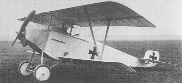
The Euler D I was a copy of the successful French Nieuport 11 fighter but was eventually assigned primarily to the fighter training role after trials at the front.

Seen in its initial form, the Type 1 Euler biplane was, in fact, the Type 3 triplane rebuilt.
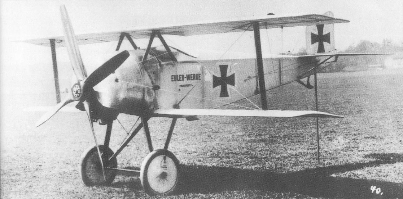
Confused erroneously with the DII, the Euler Type 2 biplane appeared in April 1918.
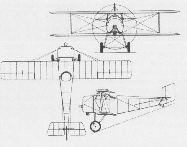
The compact Type 2 Euler fighting biplane.
EULER DREIDECKER (TYPE 2) Germany
In 1917, the Austro-Hungarian engineer Julius Hromadnik joined forces with August Euler, the result of this partnership being a series of private venture biplane, triplane and quadruplane fighters comprising approximately half of the 22 experimental aircraft produced by the Euler-Werke during World War I. The first-known Euler experimental fighter triplane developed in collaboration with Hromadnik was first reported in July 1917, this being Euler’s second wartime triplane as, in August of the previous year, the company had flown a side-by-side two-seat training triplane powered by a 220 hp eight-cylinder Mercedes DIV engine. The fighter triplane was powered by a 14-cylinder two-row Oberursel U III engine of 160 hp and featured I-type struts between the centre and lower wing, and V-type struts between the centre and upper wing. Disappointing performance led to the modification of this experimental fighter to biplane configuration and in this form it was still under test in April 1918. No specification is available.
EULER DREIDECKER (TYPE 3) Germany
An entirely new single-seat fighter triplane produced by the Euler-Werke with the assistance of Julius Hromadnik was flown for the first time in November 1917. Built, like its predecessor, as a private venture, it had parallel-chord equi-span wings with I-type interplane struts and a 160 hp Mercedes D III engine. This type evidently fell short of requirements as, like the earlier fighter triplane, it was rebuilt in biplane form (see Doppeldecker Type 1) for further trials. No specification is available.
EULER DREIDECKER (TYPE 4) Germany
The most successful of the Euler-Hromadnik fighter triplanes was powered by the newly-perfected Goebel Goe III nine-cylinder rotary engine of 180 hp. By virtue of having achieved an altitude of 16,405 ft (5 000 m) in 13.5 min, the Goe III-powered triplane was demonstrated during the second D-type contest at Adlershof in May 1918. However, service pilots were unimpressed by the fighter, the tailplane of which was severely damaged during taxying, and the aircraft was returned to the Euler-Werke in consequence, remaining there until removed from the factory in December 1918. No specification is available.
EULER DREIDECKER (TYPE 5) Germany
Some doubts concerning the efficacy of the full-span ailerons acting as a controllable wing, as utilised by the Euler-Vierdecker (which see), resulted in the development of a more orthodox triplane version of the same basic design with normal ailerons fitted. Initially powered by a similar 100 hp Oberursel U I seven-cylinder rotary, it was reportedly later re-engined with the more efficient 110 hp nine-cylinder Siemens und Halske Sh I counter-rotating power plant. At the same time, equal wing gap replaced the unequal gap with which initial flight testing was conducted, the centre wing being raised on the fuselage and the cabane struts being lengthened. No specification is available.
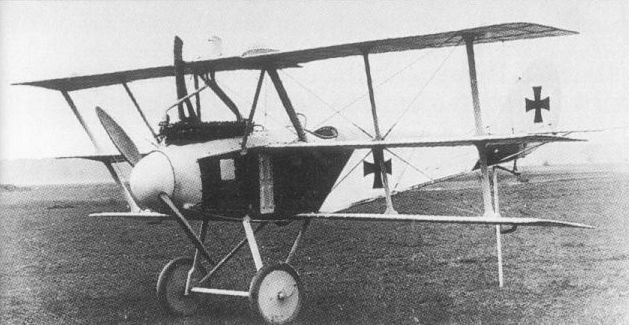
The private-venture Type 3 triplane was the second Euler-Werke fighter of this configuration.
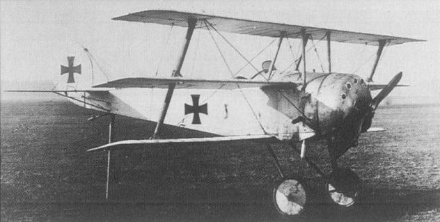
The most successful of the Euler-Hromadnik triplanes was the extremely neat Type 4 illustrated here.
The only prototype Euler Dr 7 was powered by a 110 hp Gobel Goe.II rotary.
The only prototype Euler Dr 7 was powered by a 110 hp Gobel Goe.II rotary.
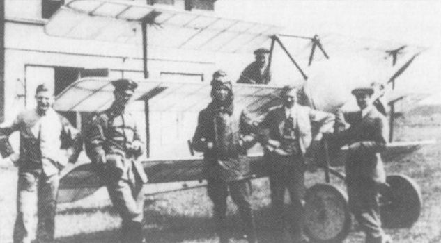
The final Euler fighting triplane (Type 5) after the application of increased gap and deeper cabane.
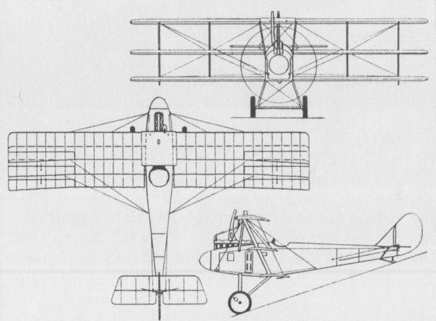
The Euler-Werke triplane fighter (Type 3).
EULER VIERDECKER Germany
Although referred to as a vierdecker (quadruplane), this Euler fighter powered by a 100 hp Oberursel U I seven-cylinder rotary, which commenced its flight test programme in December 1917, was technically a triplane in that the top surfaces were, in fact, full-span ailerons acting as a controllable fourth wing surface. The poor performance demonstrated during evaluation at Adlershof, which was continuing in May 1918, precluded further military interest in the design, although a second prototype was completed with a 110 hp Goebel Goe II seven-cylinder rotary. Both prototypes were transported out of the Allied zone of occupation in December 1918.
Empty weight, 1,948 lb (883,5 kg).
Loaded weight, 3,054 lb (1385,5 kg).
Wing area, 497 sq ft (46,17 m2).

FOKKER E I (M 5K/MG) Germany
Flown in the late spring of 1914, the M 5 (the prefix letter signifying Militar) was a single-seat monoplane of mixed construction, with a welded steel-tube fuselage, wooden wings and fabric skinning. It was built in two versions, the M 5L (assigned the military designation A II) with long-(lang) and the M 5K (A III) with short-(kurz) span wings. Several were supplied privately to Prussian officers and two (A IIs) to the Austro-Hungarian Luftfahrttruppen. One M 5K was fitted with a DWM Parabellum MG 14 with Fokker’s so-called Stangensteuerung (push-rod control) synchronising the weapon with the propeller. This was successfully demonstrated to the Idflieg (Inspectorate of Flying Troops) as the M 5K/MG and was ordered in series by the Heeresverwaltung as the E I. The more reliable air-cooled version of the Maxim LMG 08/15 gun was standardised and the E I was powered by an 80 hp Oberursel U O (Gnome copy) seven-cylinder rotary engine. Production deliveries commenced in June 1915, a total of 54 aircraft being built, of which the majority were assigned to the Kampf-Einsitzer-Kommando (Single-seat Battle Command). Some E Is went to various Feldflieger-Abteilungen, six were ordered by the Marine-Landflieger and nine were assigned to the Austro-Hungarian Luftfahrttruppen. Deliveries of the E I were completed in June 1916.
Max speed, 81 mph (130 km/h).
Range, 124 mis (200 km) at 68 mph (110 km/h).
Service ceiling, 9,840 ft (3 000 m).
Empty weight, 789 lb (358 kg).
Loaded weight, 1,241 lb (563 kg).
Span, 29 ft 4 1/3 in (8,95 m).
Length, 22 ft 1 3/4 in (6,75 m).
Height, 7 ft 10 1/2 in (2,40 m).
Wing area, 155 sq ft (14,40 m2).
FOKKER E II & III (M 14) Germany
Derived from the M 5K fighting scout, the M 14 was, in its initial form at least, an unarmed tuitional aircraft with 10.76 sq ft (1,00 m2) more wing area and a marginally longer fuselage. Some local structural reinforcement and minor changes were introduced in the forward fuselage decking, the upper wing bracing pylon and the undercarriage, and the 80 hp Oberursel engine of the E I was retained. Twelve were ordered by the Heeresverwaltung under the designation E II. In the event, 47 additional E IIs were also to be built, with a similar armament to that of the E I, the first three of these being delivered in July 1915 and 13 more following in August before the first unarmed examples (six delivered in each of September and October) were taken into the inventory. The armed E IIs were re-engined with the 100 hp Oberursel U I nine-cylinder rotary during repair or overhaul, reappearing in Fokker’s delivery lists as E IIIs when redelivered to the Fliegertruppen. The designation E III was, in fact, that applied to new-build M 14 airframes fitted with the U I rotary from the outset, improved synchronising gear being provided for the LMG 08/15 gun. Of 258 aircraft built from the outset as E IIIs, 221 were delivered to the Fliegertruppen, 19 were supplied to Marine-Landflieger, 12 were received by the Austro-Hungarian Luftfahrttruppen and the remaining six went to the Austro-Hungarian Navy. The following data relate to the E III.
Max speed, 87 mph (140 km/h).
Range, 149 mis (240 km) at 74 mph (120 km/h).
Service ceiling, 11,810 ft (3 600 m).
Empty weight, 880 lb (399 kg).
Loaded weight, 1,345 lb (610 kg).
Span, 31ft 2 4/5 in (9,52 m).
Length, 23 ft 7 1/2 in (7,20 m).
Height, 7 ft 10 1/2 in (2,40 m).
Wing area, 165.77 sq ft (15,40 m2).

A Fokker E I of the Kampf-Einsitzer-Kommando over the Western Front late summer 1915.
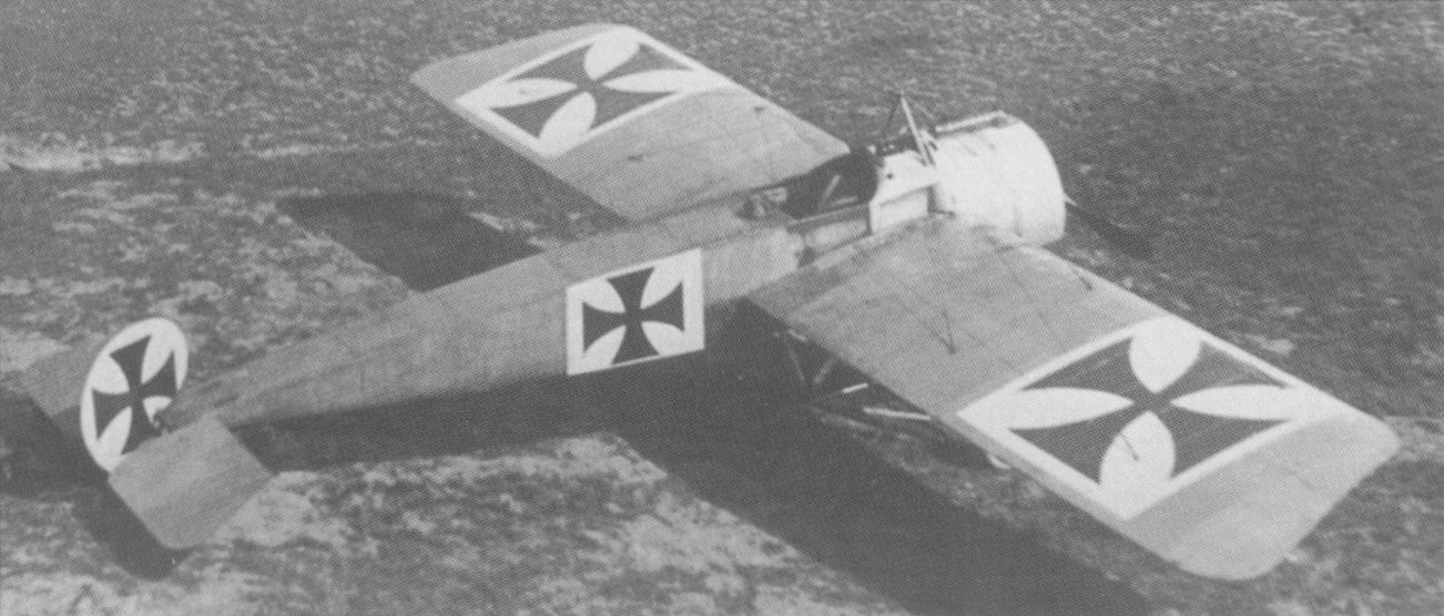
The E III was essentially similar to the E II apart from its engine, most E IIs being converted.
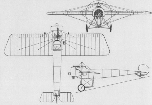
A general arrangement drawing of the production E I.
FOKKER E IV (M 15) Germany
Several of the most successful Fokker Eindecker pilots, including Max Immelmann and Oswald Boelcke, asked Anthony Fokker to develop a more powerful and more heavily armed version of his fighting scout. As a consequence, the M 15 was evolved, the first example of which was delivered in September 1915 as the E IV. Embodying modest increases in overall dimensions, the E IV was powered by the 160 hp Oberursel U III two-row 14-cylinder rotary engine, and, in standard form, was fitted with paired synchronised LMG 08/15 machine guns. At least one example of the E IV was completed (for Immelmann) with the then unprecedented fixed-gun armament of three LMG 08/15s. The success of the E IV at the Front was limited and production was restricted to 49 examples, of which the last was delivered in July 1916.
Max speed, 99 mph (160 km/h).
Range, 149 mis (240 km) at 81 mph (130 km/h).
Service ceiling, 14,765 ft (4 500 m).
Empty weight, 1,014 lb (460 kg).
Loaded weight, 1,596 lb (724 kg).
Span, 32 ft 9 1/2 in (10,00 m).
Length, 24 ft 7 1/4 in (7,50 m).
Height, 9 ft 1 in (2,77m).
Wing area, 175.46 sqft (16,30 m2).
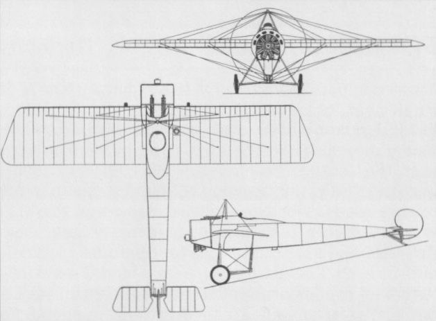
FOKKER K I (M 9) Germany
Original in concept in having a push-pull engine configuration and twin fuselage booms, the M 9 was developed without official encouragement as an offensive fighter, the sole prototype being completed in April I 1915. Also known by the designation K I (the "K” prefix indicating Kampfflugzeug, or ‘‘Battle Aircraft”), the M 9 utilised two fuselages, complete with tail assemblies from conventional M 7 two-seat sesquiplanes. These I were married by means of a biplane structure to a central nacelle which carried single 80 hp seven-cylinder rotary Oberursel U O engines fore and aft, with the pilot seated between. The nose of each M 7 fuselage accommodated a cockpit for a gunner. No rigid structure connected the two fuselages aft of the nacelle and, in consequence, the booms tended to twist when the wings warped. The M 9 was perfunctorily flight tested by Anthony Fokker. He complained of the flexing of the tailbooms and the marked tail heaviness which rendered control difficult. As Fokker was by then preoccupied with testing the M 5K/MG (E I) monoplane, further development of the M 9 was abandoned. No data relating to this short-lived experimental fighter have apparently survived.
Original in concept in having a push-pull engine configuration and twin fuselage booms, the M 9 was developed without official encouragement as an offensive fighter, the sole prototype being completed in April I 1915. Also known by the designation K I (the "K” prefix indicating Kampfflugzeug, or ‘‘Battle Aircraft”), the M 9 utilised two fuselages, complete with tail assemblies from conventional M 7 two-seat sesquiplanes. These I were married by means of a biplane structure to a central nacelle which carried single 80 hp seven-cylinder rotary Oberursel U O engines fore and aft, with the pilot seated between. The nose of each M 7 fuselage accommodated a cockpit for a gunner. No rigid structure connected the two fuselages aft of the nacelle and, in consequence, the booms tended to twist when the wings warped. The M 9 was perfunctorily flight tested by Anthony Fokker. He complained of the flexing of the tailbooms and the marked tail heaviness which rendered control difficult. As Fokker was by then preoccupied with testing the M 5K/MG (E I) monoplane, further development of the M 9 was abandoned. No data relating to this short-lived experimental fighter have apparently survived.

FOKKER M 16 Germany
A tandem two-seat fighter designed by Martin Kreutzer primarily for the Austro-Hungarian Luftfahrttruppen, the M 16 was an angular two-bay equi-span unstaggered biplane with a welded steel-tube fuselage, wooden wings and fabric skinning. It was initially powered by a 160 hp Mercedes D III six-cylinder water-cooled engine and utilised wing warping for lateral control. It was subsequently fitted with a 200 hp Austro-Daimler six-cylinder water-cooled engine, the means of lateral control being changed from wing warping to large ailerons with overhanging horn balances on the upper wing. The M 16 was shipped to the Luftfahrttruppen for evaluation in April 1916, and was fitted with a single synchronised Schwarzlose machine gun offset to port and another Schwarzlose machine gun on a flexible mount in the rear cockpit. Although an order for 26 aircraft was placed by the Austro-Hungarian service, no production of the M 16 was undertaken. The designations ‘‘M 16E", "M 16Z”
and ‘‘M 16ZK” were subsequently ascribed to this aircraft to signify Einstielig (single-strutted or single-bay), Zweistielig (two-bay) and Klappenverwindung (flap control - ailerons as opposed to wing warping) but were not assigned contemporaneously, being of post-World War I origin. No specification for the M 16 two- seat fighter has apparently survived.
FOKKER D I (M 18) Germany
A development of the M17, the M18 single-seat fighter was, in initial prototype form, frequently referred to erroneously by works of reference as the "M 16E". It was a similar unstaggered single-bay equi-span biplane with the upper fuselage contour parallel with the upper wing, but differing essentially in having a 100 hp Mercedes D I six-cylinder water-cooled engine. Unofficially dubbed the Karausche (Crucian Carp), the M 18 prototype underwent modifications similar to those applied to the M 17 (ie, cut-down fuselage decking and wing stagger), and was also flown in twin-bay configuration. It was ordered into production in twin-bay form as the D I with a 120 hp Mercedes D II engine and an armament of a single synchronised LMG 08/15 machine gun. Like the D II, the D I began to arrive at the Front in July-August 1916, 90 being built for the German Fliegertruppen, six for the Marine-Landflieger and 16 for the Austro-Hungarian Luftfahrttruppen by which the fighter was designated B III. In addition, MAG (Magyar Altalanos Gepgyar) in Hungary built eight. One of those supplied to the Austro-Hungarians was experimentally fitted with a 160 hp Mercedes D III engine and had ailerons in place of wing warping for lateral control. Another experimental model had sweptback long-span wings.
Max speed, 93 mph (105 km/h).
Time to 3,280 ft (1000 m), 5.0 min.
Endurance, 1.5 hrs.
Empty weight, 1,020 lb (463 kg).
Loaded weight, 1,477 lb (670 kg).
Span 29 ft 8 1/4 in (9,05 m).
Length, 20 ft 7 9/10 in (6,30 m).
Height, 8 ft 4 1/3 in (2,55 m).
Wing area, 215.28 sqft (20,00 m2).
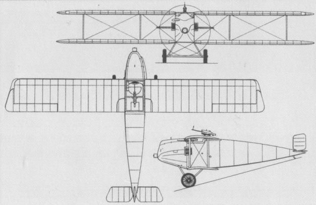
The M16 in the definitive form in which it was evaluated by the Luftfahrttruppen of Austria-Hungary in the spring of 1916.
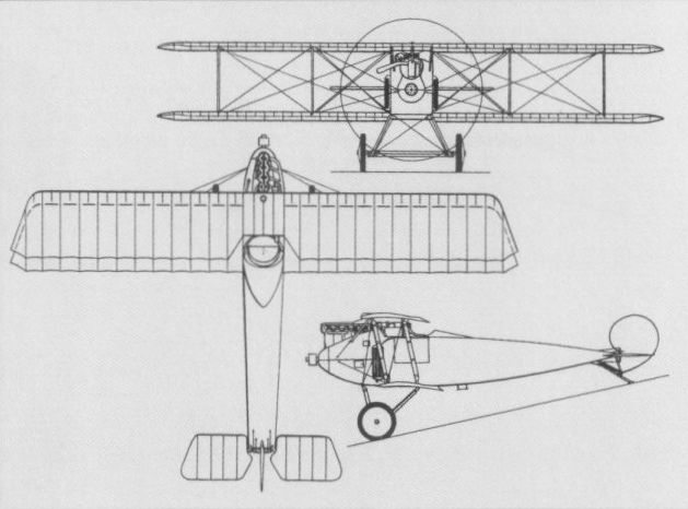
A general arrangement drawing of the standard production two-bay DI issued to the Fliegertruppen.
FOKKER D II (M 17) Germany
Evolved in parallel with the M16 by Kreutzer, the M17 single-seat fighter was, in its original form, an unstaggered single-bay equi-span biplane with an inordinately deep fuselage affording extremely limited view from the cockpit. The fuselage decking was subsequently cut down to improve all-round vision from the cockpit and stagger was applied to the wings. The M17 was flown with both the 80 hp seven-cylinder Oberursel U O and 100 hp nine-cylinder Oberursel I rotaries, and in both Einstielig (single-bay) and Zweistielig (two-bay) configurations. Twenty of the 80 hp single-bay M 17s were supplied to the Austro-Hungarian Luftfahrttruppen and assigned the designation B II, a further 42 being built by the MAG (Magyar Altalanos Gepgyar). Some of these were fitted with a single unsynchronised Schwarzlose machine gun above the upper wing, but most were unarmed and assigned to the training role. Austro-Hungarian acceptances commenced in April 1916. The two-bay M 17 with the higher-powered U I engine was adopted by Germany's Fliegertruppen as the D II, this type having a single synchronised Maxim LMG 08/15 machine gun. It began arriving at the Front in July-August 1916, 181 being delivered. One example was supplied for evaluation to the Marine-Landflieger. The designations "M 17Z" and "M 17E" were purely post-World War I attributions. The following data relate to the D II.
Max speed, 93 mph (150km/h).
Time to 3,280 ft (1 000m), 4.0 min.
Range, 124 mis (200 km).
Empty weight, 846 lb (384 kg).
Loaded weight, 1,268 lb (575 kg).
Span, 28 ft 8 1/2 in (8,75 m).
Length, 20 ft 11 7/8 in (6,40 m).
Height, 8 ft 4 1/3 in (2,55 m).
Wing area, 193.76 sq ft (18,00 m2).
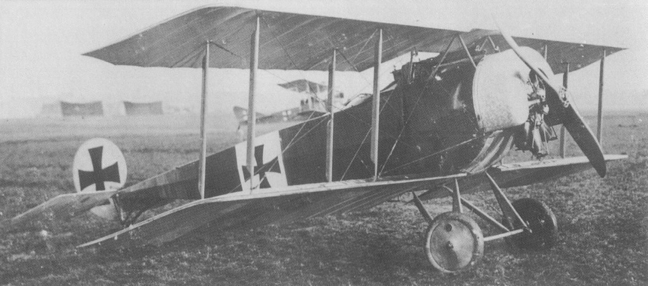
The two-bay D II of the Fliegertruppen that arrived at the Front during the late summer of 1916.
An unidentified D.II displaying the fuselage camouflage scheme which left cowling in "turned" metal finish. The unit and location are not identified.
An unidentified D.II displaying the fuselage camouflage scheme which left cowling in "turned" metal finish. The unit and location are not identified.
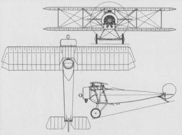
The standard two-bay production D II.
FOKKER D III (M 19) Germany
The capabilities of the D I and D II were by consensus indifferent, and, in an attempt to provide a single-seat fighter of higher performance and heavier firepower, Martin Kreutzer adapted the M18 to take the 160 hp 14-cylinder two-row rotary Oberursel U III engine and an armament of two synchronised LMG 08/15 machine guns. The new fighter was assigned the Fokker designation M 19 and when ordered by the Idflieg (Inspektion der Fliegertruppen) became the D III. A total of 210 was delivered to the German Fliegertruppen, late production examples supplanting wing warping with ailerons for lateral control, and 10 aileron-equipped D IIIs (including the prototype) were supplied to the Netherlands where they arrived in October 1917. The D III reached the Front in August 1916, but primarily as a result of the unreliability of its U III engine was rapidly relegated to home defence duties. One experimental example was fitted with a 110 hp Siemens-Halske Sh II engine enclosed by a full cowling, the propeller being fitted with a large spinner.
Max speed, 99 mph (160km/h).
Time to 3,280 ft (1000 m), 3.0 min.
Range, 137 mis (220 km) at 87 mph (140 km/h).
Empty weight, 948 lb (430 kg).
Loaded weight, 1,565 lb (710 kg).
Span, 29 ft 8 1/4 in (9,05 m).
Length, 20 ft 7 9/10 in (6,30 m).
Height, 8 ft 4 1/3 in (2,55 m).
Wing area, 215.28 sqft (20,00 m2).
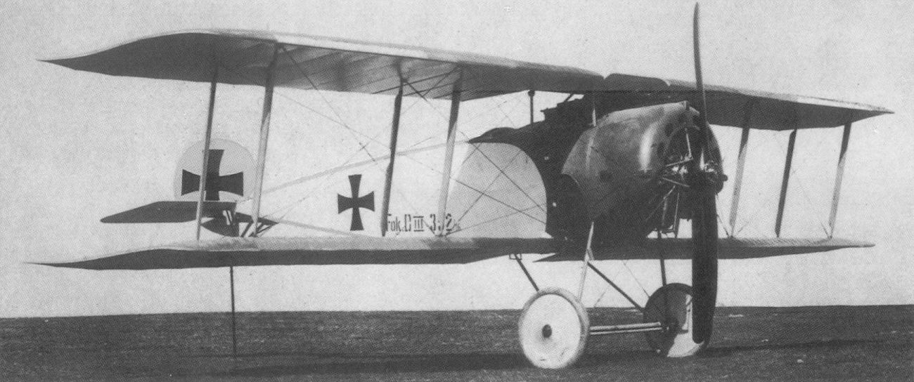
A standard production D III, seen here with warping control, reached the Front in August 1916.
Fokker D.III 352/16 in which Boelcke scored victories number 20 through 26, the first seven victories for Jasta 2 between 2 September and 17 September 1916. The Kaiser presented this aircraft to the armory museum in the Berlin Zeughaus for exhibition. It was destroyed by the bombings in World War II.
Fokker D.III 352/16 in which Boelcke scored victories number 20 through 26, the first seven victories for Jasta 2 between 2 September and 17 September 1916. The Kaiser presented this aircraft to the armory museum in the Berlin Zeughaus for exhibition. It was destroyed by the bombings in World War II.
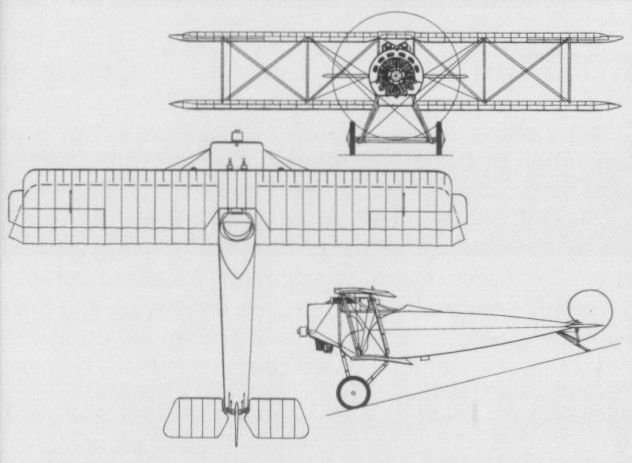
The D III in its definitive production form in which ailerons replaced wing warping for lateral control.
FOKKER D IV (M 21) Germany
A contemporary of the M 19 and the last of the Fokker fighters to be ascribed solely to Martin Kreutzer, the M 21 was, to all intents and purposes, the D I (M18) with twin-gun armament and the 160 hp Mercedes D III six-cylinder water-cooled engine. The M 21 was assigned the service designation D IV and two were at the Front on 31 August 1916, but saw no combat service. The performance of the D IV proved disappointing by comparison with contemporary types and the Idflieg considered that supplies of the 160 hp Mercedes should be assigned to other types. Production was, in consequence, restricted to 40 aircraft for the Fliegertruppen, one being experimentally fitted with a refined engine cowling and large propeller spinner. In addition, four D IVs were built for Sweden where they arrived in March 1918.
Max speed, 99 mph (160 km/h).
Time to 3,280 ft (1 000 m), 3.0 min.
Range, 137 mis (220 km).
Empty weight, 1,336 lb (606 kg).
Loaded weight, 1,852 lb (840 kg).
Span, 31 ft 9 1/10 in (9,70 m).
Length, 20 ft 7 8/10 in (6,30 m).
Height, 9 ft 0 1/4 in (2,75 m).
Wing area, 226.05 sqft (21,00 m2).
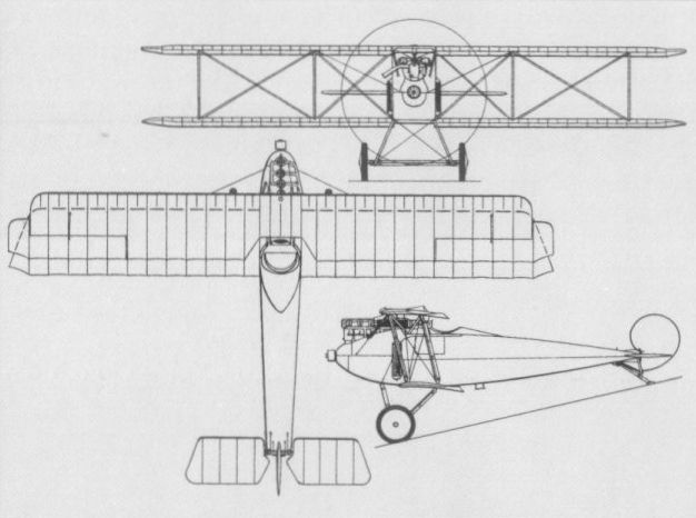
The D IV in standard production form.
FOKKER D V (M 22) Germany
The last single-seat fighter to be initiated by Martin Kreutzer before his death on 27 June 1916, but productionised by his successor, Reinhold Platz, the M 22 was, from several aspects, more refined than its predecessors. The most noteworthy departure from previous practice was the pronounced sweepback and increased forward stagger applied to the upper wing. Wing warping was finally discarded for lateral control, large, overhung, balanced ailerons being fitted to the upper wing, and a single-bay configuration was standardised. Illustrations purporting to depict two-bay versions with unswept upper wing as the "M 22ZF" - a designation of purely post-WWI origin - in fact show an M 17 with fully-cowled engine and spinner, and an M19 with an Sh II experimental installation. The 110 hp Oberursel UI nine-cylinder rotary engine of the M 22 was fully cowled, a large propeller spinner was fitted and standard armament comprised a single synchronised LMG 08/15 machine gun offset to starboard. The M 22 was assigned the official designation D V, the production model making its debut in September 1916. The D V was, in fact, ordered as a trainer, but was, fortuitously, to be issued to some home-based defence squadrons of both Fliegertruppen and the Marine-Landflieger as an interceptor. Although it appeared at the Front in February 1917, and offered good flying qualities, its performance was eclipsed by more powerful contemporaries, and most of the 300 D Vs built were utilised for their originally intended training role.
Max speed, 106 mph (170 km/h).
Time to 9,840 ft (3000 m), 19 min.
Range, 149 mis (240 km).
Empty weight, 800 lb (363 kg).
Loaded weight, 1,248 lb (566 kg).
Span, 28 ft 8 1/2 in (8,75 m).
Length, 19 ft 10 in (6,05 m).
Height, 7 ft 6 in (2,30 m).
Wing area, 166.85 sqft (15,50 m2).
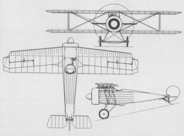
The D V, which made its debut in autumn 1916.
FOKKER V 1 Germany
The first Fokker fighter design to be ascribed solely to Reinhold Platz was a radical single-seat cantilever sesquiplane powered by a 110 hp Le Rhone nine-cylinder rotary engine. It was also the first of the Schwerin-built Versuchsmaschinen (experimental machines) to be assigned a V-series designation as the V 1. Flown in December 1916, and known unofficially as the Floh (Flea), the V 1 possessed wings of unusually thick aerofoil section, and consisting of wooden boxspars and ribs with plywood skinning. The incidence of the upper wing could be changed in flight and conventional trailing-edge ailerons gave place to rotatable wing tips. The vertical and horizontal tail surfaces were of what were later to become known as "all-moving” type and were aerodynamically balanced. The steel-tube fuselage was faired to circular section by means of wooden hoops and stringers. Provision was made for the installation of two synchronised LMG 08/15 machine guns. Quite extensively flown, this highly innovatory fighter prototype, referred to as of Verspannungslos (literally ‘‘without bracing”, or cantilever) type, was inspected by the Idflieg, but considered too radical.
Max speed, 111 mph (178 km/h).
Span, 25 ft 9 7/8 in (7,87 m).
Length, 16 ft 4 1/2 in (4,99 m).
Height, 9 ft 0 in (2,74 m).
Wing area, 161.46 sq ft (15,00 m2).
FOKKER V 2 Germany
Developed in parallel with the V1, the V 2 - which was also referred to contemporaneously as the D IV by Fokker despite Idflieg application of this designation to Kreutzer’s M 21 - differed essentially in having a 160 hp Mercedes D III six-cylinder water-cooled engine. The shift in cg resulting from introduction of the D III engine led Reinhold Platz to adopt modest sweepback on the outer upper wing panels attached to an abbreviated, unswept centre section. The vertical tail was modified to compensate for the increased side area forward provided by the D III engine, the fixed portion being increased in depth and faired into the aft fuselage. There was virtually no cabane between the engine cowling and the wing centre section, which was supported by splayed steel-tube tripods attached to the front spar. Like the V 1, the V 2 had a variable-incidence upper wing and rotatable wing tips. Although the V 2 allegedly proved ‘‘fast and sensitive” during flight test, there is no record of the V 2 having been inspected by the Idflieg.
Max speed, 118 mph (190 km/h) at 1,640 ft (500 m).
Time to 3,280 ft (1 000 m), 2.8 min.
Span, 25 ft 6 1/2 in (7,82 m).
Length, 17 ft 0 3/4 in (5,21 m).
Height, 8 ft 4 3/4 in (2,56 m).
Wing area, 165.77 sq ft (15,40 m2).
FOKKER V 3 Germany
Difficulties experienced with the V1 and V 2 led to the construction of yet a third fighter prototype of Verspannungslos configuration. This, the V 3, retained the 160 hp Mercedes D III engine, but both wings were increased in area by a total of 38.75 sqft (3,60 m2), a deeper, more orthodox cabane was introduced to improve view from the cockpit and orthodox vertical tail surfaces were provided. The manually-variable wing incidence was discarded in favour of fixed incidence and a radiator for the D III was let into the leading edge of the wing centre section. The V 3 allegedly offered a rate of climb superior to that of the V 2, but handling characteristics were considered ‘‘too difficult” for the frontline pilot and this line of development was discarded. No data for the V 3 appear to have survived.
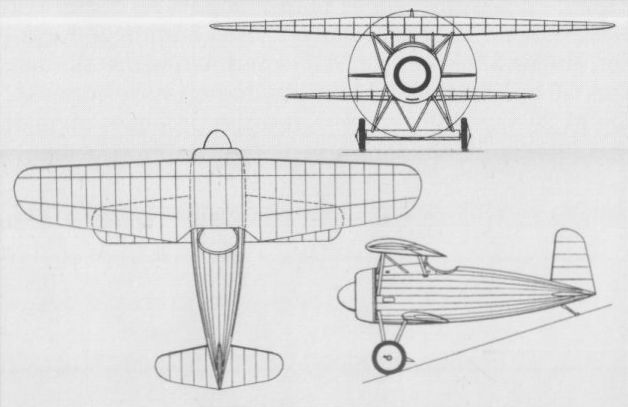
The V 1 was a radical cantilever sesquiplane, designed by Reinhold Platz, which began its flight test programme in December 1916.
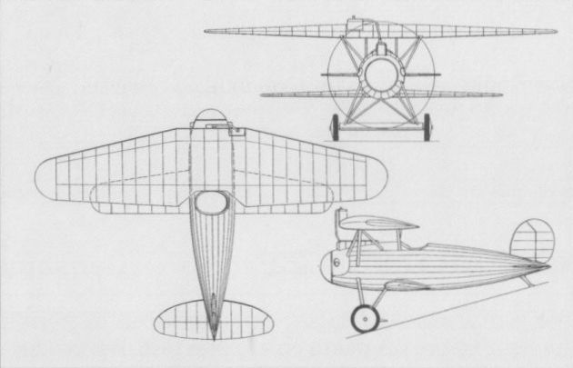
Utilising experience gained with the V 1 and V 2, the V 3 allegedly possessed handling characteristics "too difficult" for frontline pilots.
FOKKER D VI Germany
One of the single-seat fighter types evolved by Fokker for participation in the first D-type competition (the so-called D-Flugzeug-Wettbewerbe) that was to be held at Adlershof in January 1918 was the V 9 ordered on 24 August 1917 with a 110 hp Oberursel Ur II rotary. An unequal-span, single-bay, staggered biplane with fuselage, engine installation, undercarriage and tail assembly virtually identical with those of the Dr I, the V 9 was followed by five further prototypes, these being the similarly-powered V 12 and V 16, the 160 hp Steyr-built Le Rhone-engined V14, and two 160 hp Siemens-Halske Sh III-engined V 13s. The V 13s participated in the D-type competition, and, despite the fact that the Sh III engine was unavailable, this type was ordered into production by the Idflieg as the D VI. It was necessary to install the 100 hp Ur II engine in the series model, which, although manoeuvrable and offering a relatively good performance for the power available, was eclipsed in every respect by the parallel D VII. Orders were, in fact, placed for 270 D VIs, but these were cut back to 60 of which seven, plus the V12, were delivered to the Austro-Hungarian Luftfahrttruppe. The armament of the D VI consisted of paired synchronised 7,92-mm LMG 08/15 guns and the type was confined by the Fliegertruppen to home defence tasks.
Max speed, 122 mph (196 km/h).
Time to 3,280 ft (1000 m), 2.5 min.
Range 186 mis (300 km).
Empty weight, 866 lb (393 kg).
Loaded weight, 1,290 lb (585 kg).
Span, 25 ft 1 in (7,65 m).
Length, 20 ft 5 1/4in (6,23 m).
Height, 8 ft 4 1/3 in (2,55 m).
Wing area, 190.53 sq ft (17,70 m2).
FOKKER V 33 Germany
The V 33 was the ultimate development of the line of rotary-engined fighter biplanes stemming from the V 9. Smaller and lighter than preceding fighters in the series, the V 33 was apparently intended as a contender in the final D-type competition, although, in the event, it did not compete. It was initially flown with a 110 hp Oberursel Ur II nine-cylinder rotary, this eventually being replaced by a 145 hp Ur III 11-cylinder rotary. The single example of the V 33 was taken to the Netherlands after the Armistice and used by Anthony Fokker as his personal aircraft until 1922. The following data are applicable to the V 33 after application of the Ur III engine.
Time to 9,840 ft (3 000 m), 7.4 min.
Empty weight, 875 lb (397 kg).
Loaded weight, 1,358 lb (616 kg).
Span, 23 ft 9 in (7,24 m).
Length, 17 ft 10 4/5 in (5,46m).
Height, 7 ft 7 in (2,31m).
Wing area, 147.47 sq ft (13,70 m2).
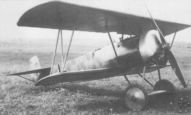
The V 33 was the last wartime Fokker fighter to employ a rotary engine.
FOKKER D VII Germany
Ordered on 20 September 1917 as a parallel development to the rotary-engined V 9 (from which was to be derived the D VI), the V 11, powered by a 160 hp Mercedes D III six-cylinder water-cooled engine, was the progenitor of the D VII, the most famous of all German World War I fighters. Of mixed construction like preceding Fokker fighters, the V11 flew in December 1917, but revealed some directional instability and other shortcomings. These were rectified by lengthening the fuselage, reducing the wing gap and stagger, etc, and the V 11 competed at Adlershof, together with the essentially similar V18, in the January 1918 D-type contest. Pronounced winning contenders by the Idflieg, these prototypes provided the basis for a fighter to which the designation D VII was assigned, contracts being placed with Fokker at Schwerin and the Albatros factories at Johannisthal and Schneidemuhl (OAW). Other prototypes comprised V 21, the 200 hp Austro-Daimler-engined V 22 - which was to be evaluated at Aspem in July 1918 - and the 185 hp BMW IIIa-engined V 24. This last served as the prototype of the similarly-powered D VIIF. Armed with two 7,92-mm LMG 08/15 guns, the D III-powered D VII began to reach the Front in April 1918, followed closely by the BMW IIIa-powered D VIIF, and licence production of the D VII with the Austro-Daimler engine was undertaken by MAG (Magyar Altalanos Gepgyar) in Hungary. In the event, MAG completed only 12 D VIIs, and these postwar. Fokker produced 877 series D VIIs (of which six were supplied to MAG as pattern aircraft together with the V 22), and 923 and 826 were built respectively by the Johannisthal and Schneidemuhl facilities of Albatros. Ninety-eight D VIIs were smuggled from Germany to the Netherlands after the Armistice, of which 22 went to the LVA (Luchtvaartafdeling), 20 to the MLD (Marine Luchtvaartdienst), six to the KNIL (Koninklijk Nederlands Indisch Leger) and the remaining 50 were sold to the Soviet Union. Eight D VIIs and two D VIIFs were acquired from the Allied Control Commission by the Swiss Fliegertruppe - one of these later being fitted with an Hispano-Suiza 8Fb engine as the D VIIS - which obtained a further six overhauled D VIIs in 1925 from the Swiss Alfred Comte concern, which went on to build eight D VIIs during 1928-29. A total of 142 D VIIs was shipped to the USA in 1919 for evaluation and use by the US Army’s Air Service, at least a dozen of these being used at McCook Field for experimental work with various engines, including the 230 and 290 hp Liberty, 200 hp Hall-Scott L-6 and 375 hp Packard 1A-1237. Several more D VIIs were purchased in 1920 for the Air Service from Fokker, and other countries to adopt the D VII post-World War I included Belgium, which received 75 from March 1919. Of these, 35 were delivered to the Army’s Aviation Militaire, remaining in service until 1931. The following data relate to the standard D III-powered D VII.
Max speed, 115 mph (185 km/h) at sea level, 116 mph (187 km/h) at 3,280 ft (1000 m).
Time to 3,280 ft (1000m), 5.8min.
Empty weight, 1,508 lb (684 kg).
Loaded weight, 2,006 lb (910 kg).
Span, 29 ft 2 1/3 in (8,90 m).
Length, 22 ft 9 3/4 in (6,95 m).
Height, 9 ft 0 in (2,75 m).
Wing area, 217.44 sq ft (20,20 m2).
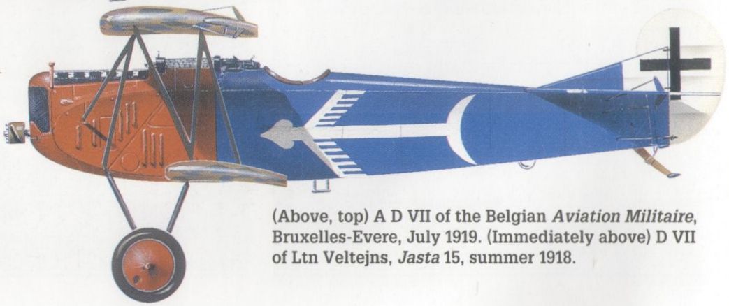
D VII of Ltn Veltejns, Jasta 15, summer 1918.
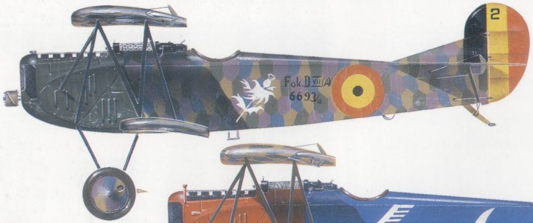
A D VII of the Belgian Aviation Militaire, Bruxelles-Evere, July 1919.
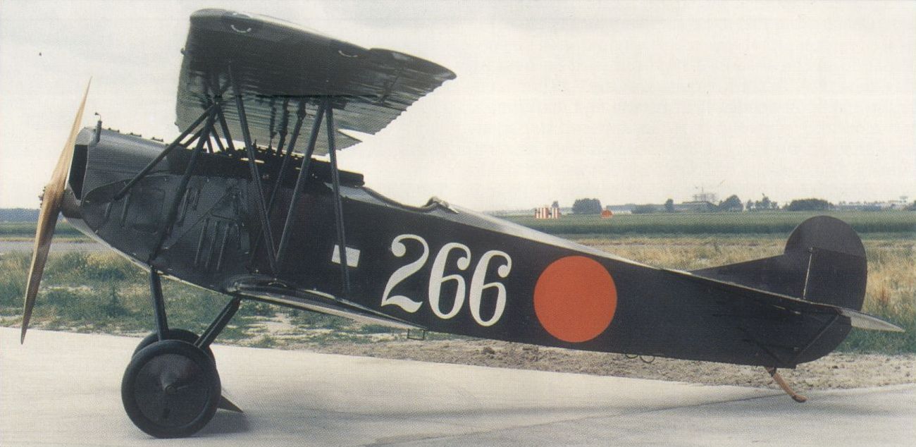
A restored Albatros-built D VII in early Luchtvaartafdeling markings and originally one of 142 shipped to the USA in 1919.
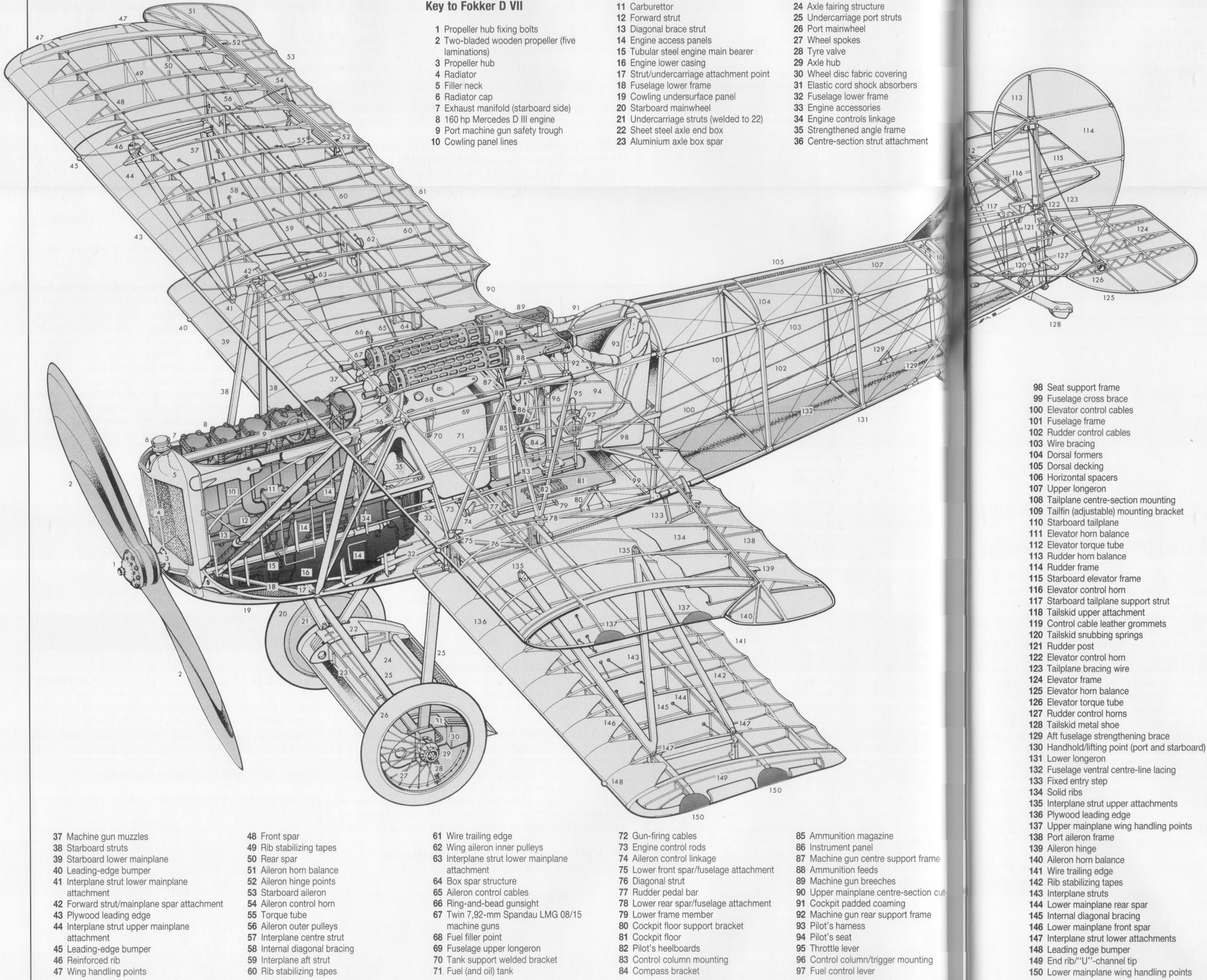
Fokker D VII
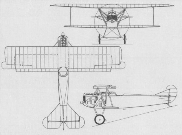
The D VII.
FOKKER V 4 Germany
The V 4, also referred to contemporaneously as the D VI - although possessing no relationship other than a common design origin to the fighter subsequently to be officially assigned that designation - was originally designed as a single-seat fighter biplane ordered on 13 May 1917 for the Austro-Hungarian Luftfahrttruppe. As a result of the service debut of the Sopwith Triplane, however, this aircraft was completed by Reinhold Platz - at the behest of Anthony Fokker - as a triplane. The V 4 (a prototype frequently to be erroneously referred to as the V 3) was an extremely compact aircraft powered by a 120 hp Le Rhone nine-cylinder rotary engine, having a slab-sided, rectangular-section, fabric-covered fuselage and three staggered cantilever wings. All three wings were of the same chord and section, but the top wing was of greater span than the equi-span middle and bottom wings. The V 4 was flown at Schwerin for the first time in May 1917, and, unlike preceding Platz fighter designs, had orthodox unbalanced ailerons on the top wing and unbalanced elevators. Aerodynamically balanced ailerons and elevators were introduced after initial flight testing, together with I-type interplane struts to reduce wing flexing. Two synchronised LMG 08/15 machine guns were fitted, and, in late August 1917, the V 4 was shipped to Austria-Hungary. Prior to this, on 5 July, a second and similar V 4 (alias D VI) had been ordered, and, six days later, a contract had been placed for two more as V 5s to be powered by the 110 hp Le Rhone, a copy of which, the Oberursel Ur II, was to power the series Dr I fighter. Performance, weights and dimensions of the V 5s were generally similar to those of the Dr I (which see).
FOKKER V 6 Germany
Developed in parallel with the V 5 (the true prototype of the series Dr I) the V 6, ordered on 7 July 1917, represented an attempt by Platz to mate the 160 hp Mercedes D III six-cylinder water-cooled engine with a triplane airframe. In order to achieve a wing loading similar to that of the rotary-engined V 5 despite the substantially heavier D III engine, the wing span and area were increased, overall span being extended by 35.4 in (90 cm) and mainplane chord being increased, this last change dictating increased interplane gap. The lower position of the bottom wing led to deepening of the forward fuselage and cg considerations necessitated positioning of the cockpit well aft. The V 6, also referred to as the D VII, lacked the manoeuvrability demonstrated by the parallel V 5 (see Dr I) and development was discontinued. No data are available for this prototype.
FOKKER DR I (V 5) Germany
The series version of the V 5, which, with a 110 hp Le Rhone, differed from the V 4 (which see) primarily in having an intermediate-span centre wing, the Dr I single-seat fighter triplane began to reach the Front in October 1917. In fact the second and third series aircraft had been evaluated from the latter part of August from Courtrai by Manfred von Richthofen's Jasta. Armed with two synchronised 7,92-mm LMG 08/15 machine guns, the Dr I was powered by the 110 hp Oberursel Ur II copy of the nine-cylinder Le Rhone rotary. The Dr I enjoyed some success in combat, being extraordinarily manoeuvrable, but deliveries to the Fliegertruppen were inhibited by engine shortages and the need to replace the wings of all early production aircraft, manufacturing standards of which were considered unacceptable by the Idflieg. The original V 5 was brought up to production standards and delivered as a Dr I, and 320 series Dr Is were delivered to the Fliegertruppen. One was supplied to the Austro-Hungarian MAG concern. Four prototypes with more powerful engines were completed as V 7s. One of these, with an 11-cylinder Oberursel Ur III rotary of 145 hp, participated in the first D-type contest at Adlershof, attaining an altitude of 16,405 ft (5 000 m) in 15.5 min. Two V 7s were delivered to Austria-Hungary, one with a 160 hp Siemens-Halske Sh III rotary and the other with a 145 hp Steyr-built Le Rhone, and the fourth was fitted with a 170 hp Goebel Goe III rotary.
Max speed, 115 mph (185 km/h) at sea level, 102 mph (165 km/h) at 13,125 ft (4 000 m).
Time to 3,280 ft (1000 m), 2.9 min.
Range, 186 mis (300 km).
Empty weight, 895 lb (406 kg).
Loaded weight, 1,292 lb (586 kg).
Span, 23 ft 7 in (7,19 m).
Length, 18 ft 11 in (5,77 m).
Height, 9 ft 8 in (2,95 m).
Wing area, 200.9 sq ft (18,66 m2).
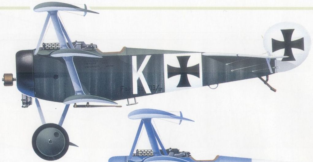
(A Dr I flown by Ltn Fritz Kempf of Jasta Boelcke
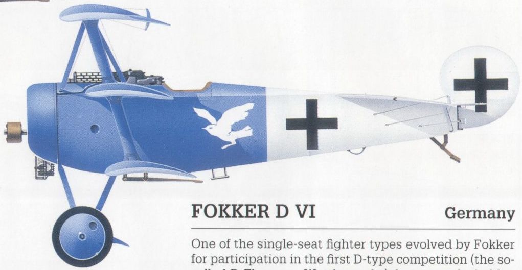
A Dr I originally operated by Jasta 18 and subsequently acquired by the French.
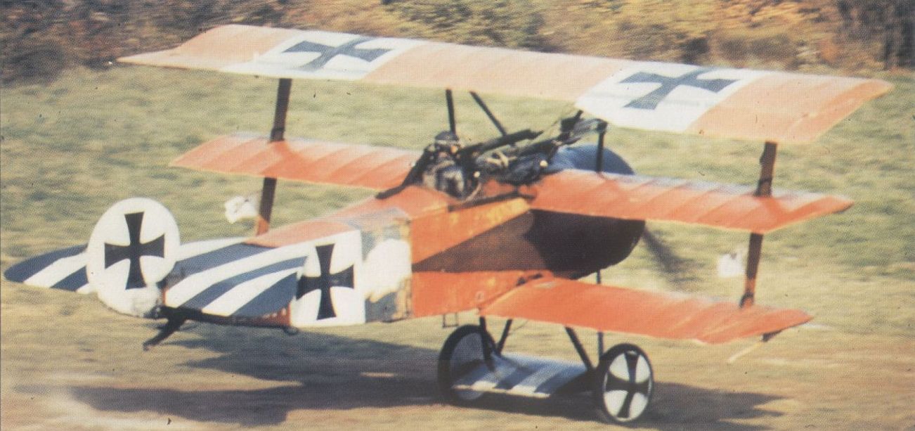
A US-built Gnome-engined Dr I replica.
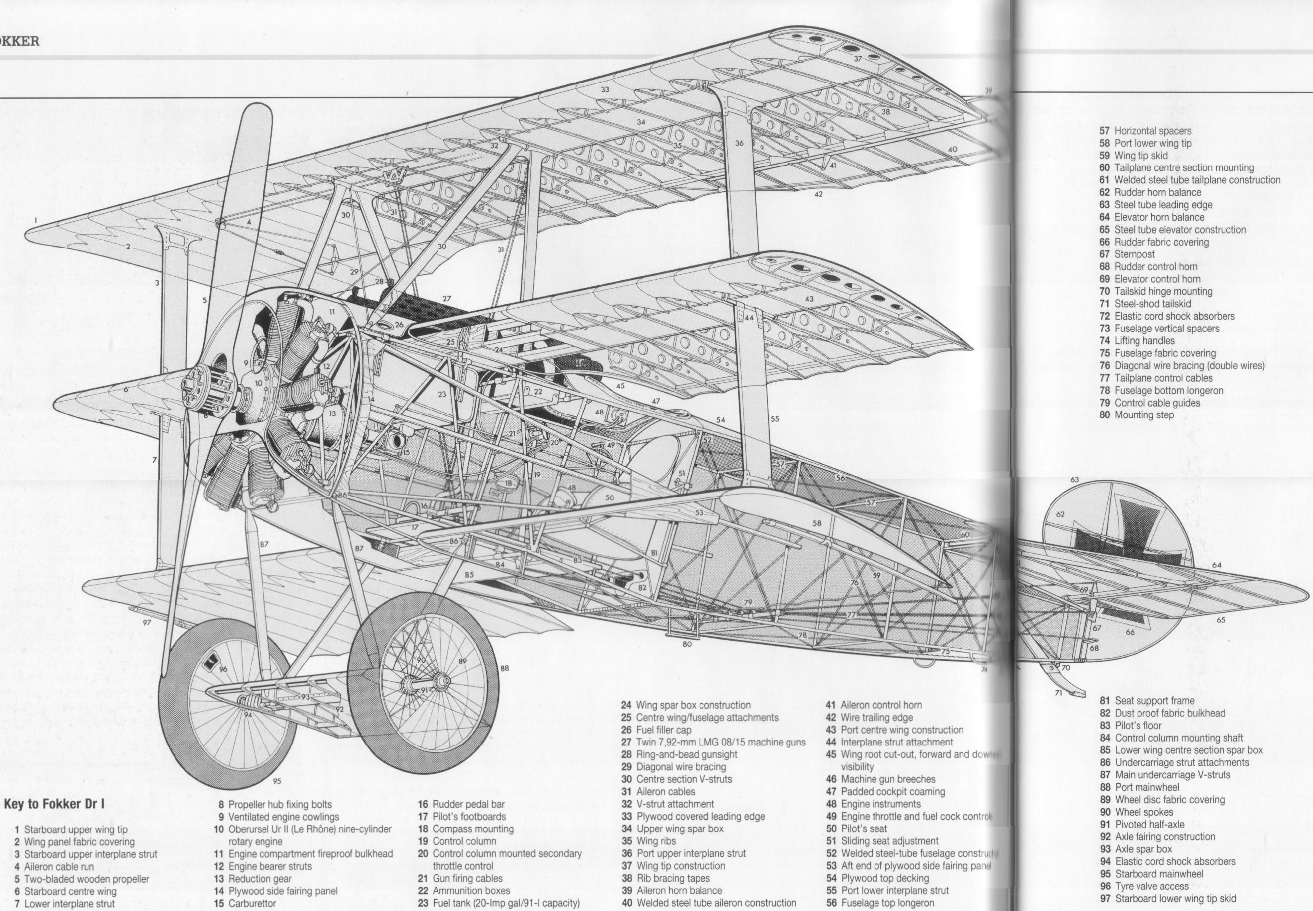
Fokker Dr I
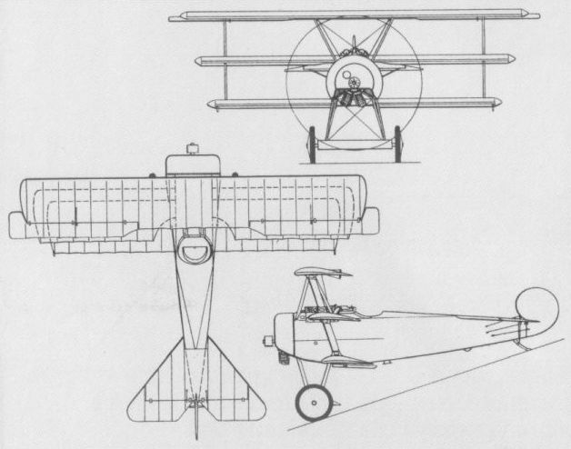
The Dr I, illustrated by the general arrangement drawing, enjoyed notoriety out of all proportion to its success in combat.
FOKKER V 17 Germany
The first single-seat fighter monoplane to be designed by Reinhold Platz, the V 17 was ordered on 28 December 1917, and was demonstrated during the following month at Adlershof in the first D-type competition. Powered by a 110 hp Oberursel Ur II nine-cylinder rotary engine and armed with two synchronised 7,92-mm LMG 08/15 machine guns, the V 17 employed plywood skinning for both wings and fuselage. The wing, mounted in high-mid position, was manufactured in one piece and built up on two wooden box spars, and the rectangular-section fuselage was of welded steel-tube construction. Demonstrated at Adlershof by Anthony Fokker, the V17 failed to attract the interest of the Idflieg.
Time to 3,280 ft (1 000 m), 3.25 min.
Empty weight, 840 lb (381 kg).
Loaded weight, 1,237 lb (461 kg).
Length, 18 ft 11 1.8 in (5,77m).
FOKKER V 20 Germany
The V 20 single-seat fighter monoplane was claimed to have been designed and built within the course of six-and-a-half days. Its development was prompted by the demonstration of the V 17 at Adlershof during the first D-type competition, Anthony Fokker believing that a more powerful aircraft of essentially similar design stood a good chance of attracting a production contract. Accordingly, Reinhold Platz designed the V 20 around the 160 hp Mercedes D III six-cylinder water-cooled engine. Although of similar configuration to the V 17 and of the same structural concept, apart from utilising fabric skinning aft of the rear spar, the V 20 had no design commonality with the earlier monoplane prototype. It reach Adlershof before conclusion of the D-type competition, but evidently did not achieve the success for which Fokker had hoped as no further development was undertaken.
FOKKER V 23 Germany
Despite the lack of success attending the V17 and V 20 single-seat fighter monoplanes during the first D-type competition, Reinhold Platz - who, by this time, had established quite extraordinary design prolificity - was reluctant to relinquish the cantilever monoplane concept. Considering this to be aerodynamically ideal, he created further prototypes of this configuration for participation in the second D-type competition held in May-June 1918. The first of these was the V 23 powered by the 160 hp Mercedes D in engine and featuring a mid-mounted, plywood-covered, tapered two-spar wooden wing with inset ailerons which were also ply skinned. The fuselage was a rectangular welded steel-tube structure and the standard armament of paired and synchronised LMG 08/15 guns was intended. The V 23 was demonstrated at Adlershof during the contest, but was criticised for the view that was offered from the cockpit which was considered inadequate for combat. It was consequently rejected by the Idflieg without type testing, Fokker discontinuing development.
Max speed, 124 mph (200 km/h) at 6,560 ft (2 000 m).
Time to 3,280 ft (1000 m), 3.0 min.
Empty weight, 1,484 lb (673 kg).
Loaded weight, 1,880 lb (853 kg).
Span, 28 ft 8 in (8,73 m).
Length, 19 ft 0 1/3 in (5,80 m).
Height, 8 ft 8 in (2,65 m).
Wing area, 119.7 sqft (11,12 m2).
FOKKER V 25 Germany
Built in parallel with the V 23 for participation in the second D-type competition, the V 25 employed a similar structure but was of low- rather than mid-wing configuration, and was powered by a 110 hp Oberursel Ur II nine-cylinder rotary engine. Appreciably smaller and lighter than the mid-wing monoplane prototype, the V 25 offered superior manoeuvrability and better initial climb, but owing to its low-powered engine had little chance of success and its development, like that of the V 23, was abandoned after the competition.
Max speed, 124 mph (200 km/h) at sea level.
Time to 3,280 ft (1 000m), 1.7min.
Empty weight, 847 lb (384 kg).
Loaded weight, 1,243 lb (564 kg).
Span, 28 ft 7 3/4 in (8,73 m).
Length, 19 ft 5 1/2 in (5,93 m).
Height, 8 ft 7 1/2 in (2,63 m).
Wing area, 119.7 sq ft (11,12 m2).
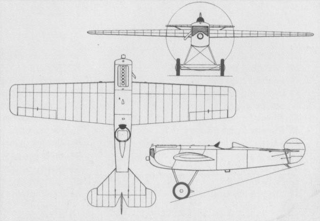
The Fokker V 23 fighter monoplane.

The V 25 participated in the 2nd D-type competition at Adlershof in May-June 1918.

Developed in parallel with the V 5, the V 6 had a larger wing span and area, and a water-cooled Mercedes D III engine.
FOKKER V 8 Germany
A decidedly bizarre single-seat fighter, the V 8 could be described both as a quintuplane and a tandem-wing aircraft. Powered by a 160 hp Mercedes D III engine, the V 8 had an unstaggered equi-span triplane wing arrangement mounted at the extreme nose and a biplane wing arrangement immediately aft of the pilot’s cockpit and approximately two-and-a-half times the wing chord behind the triplane structure. The top plane of each set of wings incorporated balanced ailerons, and a conventional tail assembly was provided at the end of an inordinately long fuselage, the CG being located between the two wing systems. Anthony Fokker made an abbreviated flight - barely more than a hop - in the V 8 in October 1917, some modifications subsequently being made before a further brief flight was made two weeks later, development then being abandoned. No data for this type were recorded.
A decidedly bizarre single-seat fighter, the V 8 could be described both as a quintuplane and a tandem-wing aircraft. Powered by a 160 hp Mercedes D III engine, the V 8 had an unstaggered equi-span triplane wing arrangement mounted at the extreme nose and a biplane wing arrangement immediately aft of the pilot’s cockpit and approximately two-and-a-half times the wing chord behind the triplane structure. The top plane of each set of wings incorporated balanced ailerons, and a conventional tail assembly was provided at the end of an inordinately long fuselage, the CG being located between the two wing systems. Anthony Fokker made an abbreviated flight - barely more than a hop - in the V 8 in October 1917, some modifications subsequently being made before a further brief flight was made two weeks later, development then being abandoned. No data for this type were recorded.
FOKKER D VIII (E V) Germany
Apart from his extraordinary prolificity, Reinhold Platz also demonstrated outstanding versatility: virtually simultaneously with his series of mid- and low-wing fighter monoplane prototypes, he was engaged in developing a parasol monoplane fighter. Contrary to popular belief, this fighter was ordered into production by the Idflieg prior to the second D-type competition, the first production examples being accepted some two weeks before the contest ended! This fighter, initially officially designated E V by the Idflieg in the Eindecker (monoplane) series, was the production development of the V 28. This, initially flown with a 110 hp Oberursel Ur II, was also tested with the 145 hp Ur III and 160 hp Goebel Goe in 11-cylinder rotaries. Similar airframes with different engines were the 110 hp Le Rhone-powered V 26, the V 27 and V 30 with the 195 hp Benz Bz IIIb and IIIa six-cylinder water-cooled engines respectively, and the V 29 with the 160 hp Mercedes D III. The E V was manufactured with the Ur II rotary pending availability of the more powerful Ur III and Goe III, and armament consisted of the standard pair of synchronised LMG 08/15 guns. Initial contracts called for 210 aircraft, with deliveries to the Fliegertruppe commencing in July 1918, in which month 59 were accepted (including one for evaluation by the Austro-Hungarian Luftfahrttruppe). Eighty E Vs were accepted during the following month, the last of these on 23 August when further acceptances terminated owing to wing failures. When acceptances were resumed on 8 October, a new wing was fitted, and, for some inexplicable reason, the designation was changed to D VIII (although externally it was impossible to distinguish between the E V and the D VIII). Eighty E Vs were listed at the Front on 31 August 1918 and 85 D VIIIs on 31 October. Of contracts for 335 E V/D VIII fighters placed with Fokker, a total of 289 was delivered (139 E Vs and 150 D VIIIs), 53 of the D VIIIs being delivered after 28 November 1918 without engines. All were powered by the Ur II engine, apart from 26 that received the Ur III. Operational usage of the E V/D VIII was strictly limited because of poor engine serviceability and the need to replace the wings of the E V.
Max speed, 115 mph (185 km/h) at sea level, 107 mph (173 km/h) at 14,765 ft (4 500m).
Time to 6,560 ft (2 000m), 5.08 min.
Range, 186 mis (300 km).
Empty weight, 847 lb (384 kg).
Loaded weight, 1,265 lb (574 kg).
Span, 27 ft 4 1/3 in (8,34 m).
Length, 19 ft 5 in (5,92 m).
Height, 8 ft 6 1/3 in (2,60 m).
Wing area, 115.18 sqft (10,70 m2).
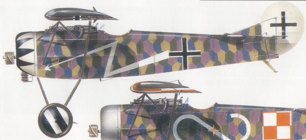
D VIII of Jasta 6 at Busigny-Escaufort, August 1918
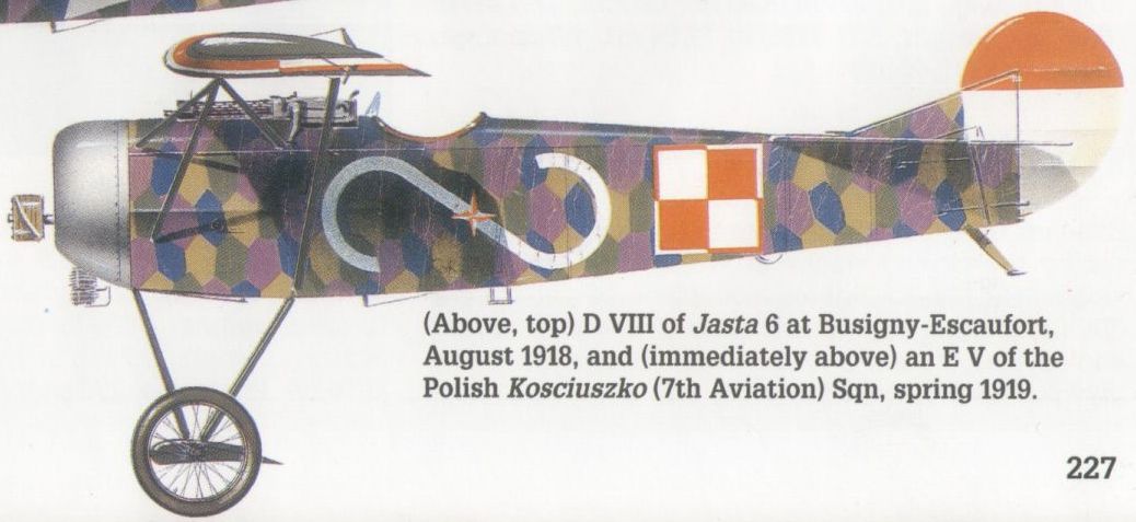
An E V of the Polish Kosciuszko (7th Aviation) Sqn, spring 1919.

A Warner-powered full-scale D VIII replica built in the USA and first flown in September 1968.
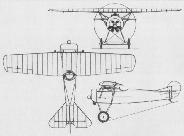
A general arrangement drawing of the definitive production D VIII parasol monoplane.
FOKKER V 34 & V 36 Germany
The V 34 and V 36 single-seat fighters were the final developments of the basic D VII undertaken during World War I, and differed essentially in their vertical tail surfaces. Both were powered by the 185 hp BMW IIIa six-cylinder water-cooled engine, both featured an oval frontal radiator and both were sent to Adlershof on 10 October 1918 to participate in the third D-type competition. Apart from the vertical tail (which was essentially similar to that of the D VII), the V 36 differed from the V 34 in having one major innovation: the main fuel tank was transferred from the fuselage to the undercarriage axle fairing. Further development of these D VII derivatives terminated with the end of World War I. The following data are specifically applicable to the V 36 armed with two synchronised LMG 08/15 machine guns.
Time to 3,280 ft (1 000 m), 1.75 min.
Empty weight, 1,404 lb (637 kg).
Loaded weight, 1,920 lb (871 kg).
Span, 29 ft 3 3/5 in (8,93 m).
Length, 21 ft 2 3/4 in (6,46 m).
Height, 9 ft 11 9/10 in (3,04 m).
Wing area, 189.45 sq ft (17,60 m2).
FRIEDRICHSHAFEN FF 43 Germany
In September 1916, the Flugzeugbau Friedrichshafen presented the Idflieg (Inspektion der Fliegertruppen - Inspectorate of Flying Troops) with a proposal for a single-seat, land-based fighter based on the FF 43 floatplane. This, the FF 46, received an order for three prototypes, which, like the FF 43, were to be powered by the 160 hp Mercedes D III, but were to be armed with twin synchronised 7,92-mm MG 08/15 machine guns. The FF 46, or D I, was a single-bay staggered biplane, the first prototype having vertical cabane strutting, but the second having splayed struts to improve forward vision. The Idflieg testing of the FF 46 was not completed until 28 April 1917, when it was concluded that the type was not acceptable for series production as its flight characteristics and performance were inferior to those of its contemporaries. There is no record of the third prototype being completed.
Empty weight, 1,512 lb (686 kg).
Loaded weight, 1,986 lb (901 kg).
Span, 29 ft 6 1/3 in (9,00 m).
Length, 23 ft 3 1/2 in (7,10 m).
Height, 8 ft 10 1/3 in (2,70m).
Wing area, 277.72 sqft (25,80 m2).
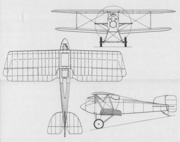
The FF 46 was based broadly on the FF 43, but, in fact, had no commonality with the float fighter other than design origin.
FRIEDRICHSHAFEN FF 46 (D I) Germany
In the summer of 1916, the German Navy ordered a variety of waterborne single-seat fighters for evaluation, one of these being the FF 43 twin-float single-bay biplane from the Manzell factory of the Flugzeugbau Friedrichshafen on 8 June 1916. Powered by a 160 hp Mercedes D III engine and armed with one synchronised 7,92-mm machine gun, the FF 43 was completed on 29 August 1916, and delivered to the Seeflugzeug Versuchs Kommando (Seaplane Testing Command) at Warnemunde for acceptance testing on 8 September. Sent to the Zeebrugge naval air station on 6 October for evaluation under operational conditions in the North Sea, the FF 43 was not accepted for production, being officially struck-off on 13 April 1917.
Max speed, 101 mph (163 km/h).
Time to 3,280 ft (1 000 m), 6.0 min, to 6,560 ft (2 000 m), 12.0 min.
Empty weight, 1,759 lb (798 kg).
Loaded weight, 2,377 lb (1078 kg).
Span, 32 ft 6 1/2 in (9,92 m).
Length, 28 ft 0 3/5 in (8,55 m).
Height, 10 ft 11 9/10 in (3,35 m).
Wing area, 333.69 sq ft (31,00 m2).
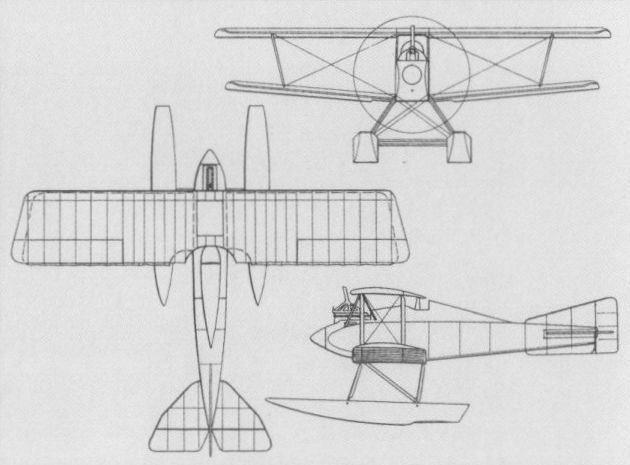
The FF 43 float fighter evaluated under operational conditions in the North Sea from October 1916 by the Seeflugzeug Versuchs Kommando.
FRIEDRICHSHAFEN FF 54 Germany
The Flugzeugbau Friedrichshafen specialised in the design of robust seaplanes and sturdy bombers, proving unsuccessful in attempting to produce lightweight structures needed for small single-seat fighters. The FF 54, designed by Dipl-Ing van Gries, proved no more successful than preceding warplanes of this type from the Manzell factory, albeit less conventional in design approach. The FF 54 was conceived as a single-seat quadruplane powered by a 160 hp Mercedes D IIIa water-cooled engine and armed with two synchronised 7,92-mm MG 08/15 machine guns. The two narrow-chord middle wings were mounted on the centreline and baseline of the fuselage with little gap, interconnected between themselves and the bottom wing by broad, aerofoil-section interplane struts. On 31 October 1917, the FF 54 was in final assembly with flight testing anticipated within 3-4 weeks. When this began, however, the quadruplane arrangement proved unsuccessful and, in April 1918, the prototype was rebuilt as a triplane, changes being restricted to removal of the lower middle wing and redesign of the vertical tail surfaces. Flight testing of the FF 54 in its revised form began in May 1918, and continued until the following September, when a crash resulted in abandonment of further work on the aircraft. No data are available for the FF 54 in either quadruplane or triplane form.
The Flugzeugbau Friedrichshafen specialised in the design of robust seaplanes and sturdy bombers, proving unsuccessful in attempting to produce lightweight structures needed for small single-seat fighters. The FF 54, designed by Dipl-Ing van Gries, proved no more successful than preceding warplanes of this type from the Manzell factory, albeit less conventional in design approach. The FF 54 was conceived as a single-seat quadruplane powered by a 160 hp Mercedes D IIIa water-cooled engine and armed with two synchronised 7,92-mm MG 08/15 machine guns. The two narrow-chord middle wings were mounted on the centreline and baseline of the fuselage with little gap, interconnected between themselves and the bottom wing by broad, aerofoil-section interplane struts. On 31 October 1917, the FF 54 was in final assembly with flight testing anticipated within 3-4 weeks. When this began, however, the quadruplane arrangement proved unsuccessful and, in April 1918, the prototype was rebuilt as a triplane, changes being restricted to removal of the lower middle wing and redesign of the vertical tail surfaces. Flight testing of the FF 54 in its revised form began in May 1918, and continued until the following September, when a crash resulted in abandonment of further work on the aircraft. No data are available for the FF 54 in either quadruplane or triplane form.

The FF 54 in its original quadruplane form as tested late 1917
GEEST Germany
In 1916, Dr Waldemar Geest designed a single-seat fighter which, built by Automobil und Aviatik AG of Leipzig-Heiterblick, utilised his patented Mowe (Seagull) type wing. The Mowe wing featured varying incidence angle and dihedral over its planform to compensate for forward and lateral gusts, and the excellent stability that it offered had been demonstrated by six Mowe monoplanes built prior to World War I. The Mowe wing concept was adapted by Dr Geest for a fighter of staggered single-bay biplane configuration powered by a 160 hp Mercedes D III six-cylinder water-cooled engine. During military trials, performed in 1917, the Geest fighter attained an altitude of 11,485 ft (3 500 m) in 17.5 min and a maximum speed of 99 mph (160 km/h), but development was discontinued and no further aircraft employed the Mowe wing.
In 1916, Dr Waldemar Geest designed a single-seat fighter which, built by Automobil und Aviatik AG of Leipzig-Heiterblick, utilised his patented Mowe (Seagull) type wing. The Mowe wing featured varying incidence angle and dihedral over its planform to compensate for forward and lateral gusts, and the excellent stability that it offered had been demonstrated by six Mowe monoplanes built prior to World War I. The Mowe wing concept was adapted by Dr Geest for a fighter of staggered single-bay biplane configuration powered by a 160 hp Mercedes D III six-cylinder water-cooled engine. During military trials, performed in 1917, the Geest fighter attained an altitude of 11,485 ft (3 500 m) in 17.5 min and a maximum speed of 99 mph (160 km/h), but development was discontinued and no further aircraft employed the Mowe wing.
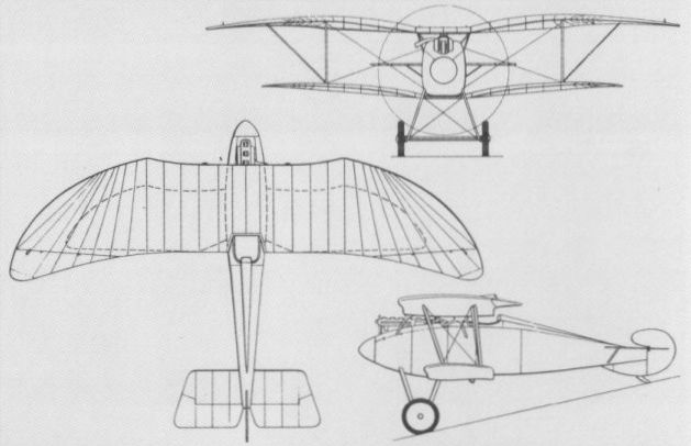
GERMANIA DB Germany
Built by the Germania-Flugzeugwerke GmbH of Leipzig, the DB two-seat fighter utilised the efficient Walfisch (Whale) fuselage configuration which endowed the gunner, seated ahead of the pilot, with a broad forward field of fire. A two-bay biplane, the DB was powered by a 180 hp Argus As III water-cooled engine, carried a single machine gun on a ring mounting in the forward cockpit and was undergoing trials in September 1915. No production of the fighter was undertaken and no data relating to this type are available.
Built by the Germania-Flugzeugwerke GmbH of Leipzig, the DB two-seat fighter utilised the efficient Walfisch (Whale) fuselage configuration which endowed the gunner, seated ahead of the pilot, with a broad forward field of fire. A two-bay biplane, the DB was powered by a 180 hp Argus As III water-cooled engine, carried a single machine gun on a ring mounting in the forward cockpit and was undergoing trials in September 1915. No production of the fighter was undertaken and no data relating to this type are available.
GERMANIA JM Germany
The Germania JM (Jagdmaschine) experimental single-seat fighter was based on the promising results of wind tunnel testing with the Walfisch (Whale) fuselage configuration at Gottingen. Designed by J Egwin Leiber, the JM was a single-bay biplane powered by a 100 hp Argus As I water-cooled engine and made its debut in the summer of 1916. While under test on 16 August 1916, the JM attained altitudes of 3,280 ft (1 000 m) in 4 min, 6,560 ft (2 000 m) in 11 min, 9,840 ft (3 000 m) in 19 min and 10,825 ft (3 300 m) in 20 min. No further development was undertaken and no data are available.
The Germania JM (Jagdmaschine) experimental single-seat fighter was based on the promising results of wind tunnel testing with the Walfisch (Whale) fuselage configuration at Gottingen. Designed by J Egwin Leiber, the JM was a single-bay biplane powered by a 100 hp Argus As I water-cooled engine and made its debut in the summer of 1916. While under test on 16 August 1916, the JM attained altitudes of 3,280 ft (1 000 m) in 4 min, 6,560 ft (2 000 m) in 11 min, 9,840 ft (3 000 m) in 19 min and 10,825 ft (3 300 m) in 20 min. No further development was undertaken and no data are available.
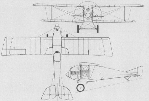
A general arrangement drawing of the JM.
HALBERSTADT DI Germany
In the late autumn of 1915, the Halberstadter Flugzeugwerke initiated flight testing of a single-seat fighter evolved by Dipl-Ing Karl Theis from the Halberstadt B II trainer. Apart from some structural reinforcement and the mounting of a single synchronised LMG 08/15 machine gun, the Halberstadt fighter differed from its progenitor primarily in having shorter-span, staggered wings. Two prototypes were built, one powered by a 120 hp Argus As II and the other by a 100 hp Mercedes D I. Both featured a neat, car-type frontal radiator which, it transpired, was to prove ineffectual in summer temperatures and was not to be perfected until 1918. These prototypes were at Adlershof in February 1916, the Mercedes-engined prototype undergoing static load testing, and, at this time, they were designated Halberstadt D I. An order for an initial batch of 12 D I fighters "powered by a 120 hp engine” was placed on 21 March 1916. In the event, the production model of the D I embodied a number of design refinements, and, with a 120 hp Mercedes D II engine, became the Halberstadt D II (which see). The following data relate to the 100 hp Mercedes-engined D I prototype.
Time to 3,280 ft (1 000 m), 4.5 min.
Empty weight, 1,215 lb (551 kg).
Loaded weight, 1,630 lb (739 kg).
Wing area, 258.34 sq ft (24, 00 m2).
HALBERSTADT D II & D III German
The production derivative of the D I, which entered service with the Fliegertruppe from June 1916 as the D II, differed from its progenitor in a number of respects apart from its 120 hp Mercedes D II six-cylinder water-cooled engine. The car-type radiator was discarded in favour of an exposed cylinder block and wing-mounted radiator, with an inordinately massive exhaust stack to starboard, and the pilot’s cockpit was raised and faired by means of a turtle deck. Early production D IIs retained the balanced ailerons of the D I, but later examples adopted wide-chord, unbalanced ailerons. The armament of one LMG 08/15 machine gun on the starboard side of the forward fuselage was retained, and the D II, which possessed an exceptionally robust structure, was licence-built by the Automobil und Aviatik AG and the Hannoversche Waggonfabrik AG. Each produced 30, which, somewhat confusingly, were initially designated Aviatik D I and Hannover D I respectively. After completing an initial batch of 12 D IIs, the parent company continued with a batch of 24 D IIs and D IIIs, there being no fundamental difference between the two models apart from engine, the latter having a 120 hp Argus As II. During manufacture of a follow-on batch of 30 D IIIs by the Halberstadter Flugzeugwerke production was switched to the improved D V and - apart from licence manufacture of the D II - total production of the D II and D III was 50 aircraft. The following data relate to the D II.
Max speed, 93 mph (150 km/h) at sea level.
Time to 3,280 ft (1 000 m), 3.5 min.
Range, 155 mis (250 km).
Empty weight 1,147 lb (520 kg).
Loaded weight, 1,610 lb (730 kg).
Span 28 ft 10 3/8 in (8,80 m).
Length, 23 ft 11 3/8 in (7,30 m).
Wing area, 254 sqft (23,60 m2).
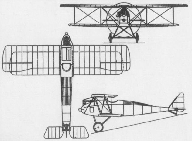
The D III with an Argus As II was otherwise similar to the Mercedes-powered D II (shown).
HALBERSTADT D IV
On 9 March 1916, the Halberstadter Flugzeugwerke was awarded a contract to develop a twin-gun fighter powered by a 150-160 hp engine. Designated D IV and powered by a 150 hp Benz Bz III engine, the new fighter was an elegant single-bay biplane with a neatly-cowled power plant. Three prototypes were ordered, of which one was for static load testing. Submitted at Adlershof in October 1916, the D IV was rejected by the Idflieg because of "unsatisfactory cabane design", but served as a basis for the highly successful Cl II two-seat fighter.
Loaded weight, 1,819 lb (825 kg).
Span, 27 ft 63/4 in (8,40 m).
Wing area, 258.34 sq ft (24,00 m2).
HALBERSTADT CL II Germany
In the autumn of 1916, the German Air Staff conceived a requirement for a two-seat "defensive patrol and pursuit aircraft”; an amalgam of features of the two-seat C-type and single-seat D-type. Accordingly, in November 1916, the Halberstadter Flugzeugwerke, among other companies, received a three-prototype contract for an aircraft fulfilling a specification prepared by the Idflieg. Designed by Dipl-Ing Karl Theis and based on his unsuccessful D IV single-seat fighter, this aircraft, initially designated C II but redesignated CL II in the summer of 1917, was powered by a 160 hp Mercedes D III water-cooled engine. It was armed with a fixed LMG 08/15 machine gun for the pilot and a flexible LMG 14 on a raised ring mounting for the gunner. Within days of passing its official type test, on 7 May 1917, the first CL II production order was placed. This two-seater reached the Front in August 1917, achieving immediate acclaim. Its excellent manoeuvrability, good climb rate and the wide field of view provided for the rear gunner enabled it to engage enemy single-seaters on equal terms. The CL II rapidly became the mainstay of the Schutzstaffeln (units formed to provide protection for reconnaissance aircraft). With the later formation of the Schlachtstaffeln, the CL II enjoyed auspicious success in the close air support fighter role. For front-line evaluation, a few CL IIs were fitted with the BMW IIIa engine with which they were designated CL IIa. A total of 700 CL IIs was built under five production contracts by the Halberstadter Flugzeugwerke through mid-1918, and a further 200 were built in 1918 by the Bayerische Flugzeugwerke (BFW).
Max speed, 102 mph (165 km/h) at 16,405 ft (5 000 m).
Time to 3,280 ft (1 000 m), 5.0 min.
Endurance, 3.0 hrs.
Empty weight, 1,701 lb (773 kg).
Loaded weight, 2,498 lb (1133 kg).
Span, 35 ft 4 in (10,76 m).
Length, 23 ft 11 1/2 in (7,30 m).
Height, 9 ft 0 1/2 in (2,75 m).
Wing area, 305.7 sq ft (28,40 m2).
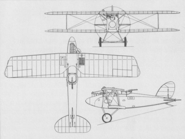
The CL II in standard configuration.
HALBERSTADT D V Germany
The D V, which reverted to the two-bay formula, was based on the earlier D III and was similarly powered with a 120 hp Argus As II engine. It differed in featuring aerodynamically-balanced inset ailerons and a redesigned centre section, which, with a simplified cabane structure and a large semi-circular cut-out in the upper wing, offered an improved field of view for the pilot. A single LMG 08/15 machine gun was mounted on the port side of the forward fuselage, but the last D Vs produced were armed with twin synchronised guns. The D V appeared at the Front in the autumn of 1916, some 50-55 being produced by the Halberstadter Flugzeugwerke during the course of that year. A further 37 were manufactured in 1917, these being mostly for use by Turkey where the first D Vs arrived in March 1917. Operating in high temperatures, the D Vs were fitted with additional radiators on their fuselage sides, resulting in some loss of performance. On the Western Front, the D Vs were replaced in the operational role in the summer of 1917, but others remained in first-line service in Palestine well into 1918.
Max speed, 99 mph (160 km/h).
Time to 3,280 ft (1 000 m), 4.0 min.
Range, 124 mis (200 km).
Empty weight, 1,323 lb (600 kg).
Loaded weight, 1,790 lb (812 kg).
Span, 28 ft 6 1/2 in (8,70 m).
Length, 23 ft 11 3/8 in (7,30 m).
Wing area, 258.34 sq ft (24,00 m2).
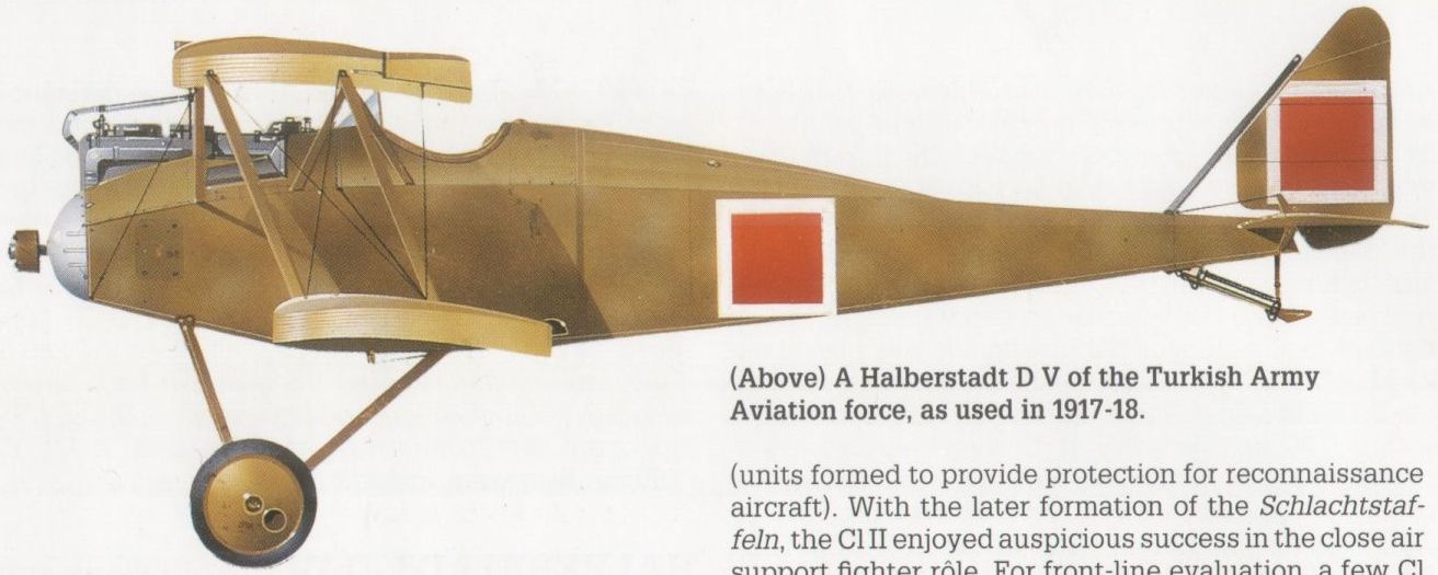
A Halberstadt D V of the Turkish Army Aviation force, as used in 1917-18.
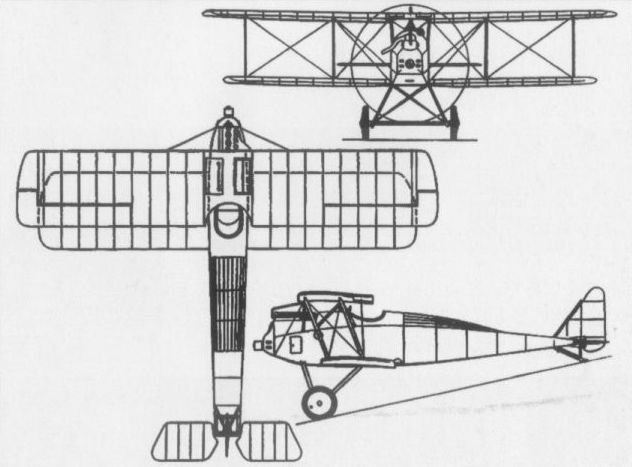
The Halberstadt D V with Argus As II engine.
HALBERSTADT CL IV Germany
Early in 1918, the Halberstadter Flugzeugwerke began work on a higher-performance and more manoeuvrable derivative of the CL II. By February the prototype of this CL IV had arrived at Adlershof for its official type test. Lighter than its predecessor as a result of some structural refinement, the CL IV possessed a similar armament and a 160 hp Mercedes D IIIa engine. It passed its type test during March-April 1918, the official report referring to its ‘‘very favourable climb rate and superlative handling qualities”. Commencing in May 1918, a total of 450 CL IVs was ordered from Halberstadt and a further 250 were ordered from the Luftfahrzeug Gesellschaft (Roland). The CL IV supplemented the CL II in the Schlachtstaffeln, and a total of 136 was recorded at the Front on 31 August 1918, deliveries still being under way when hostilities terminated.
Max speed, 104 mph (168 km/h) at 16,405 ft (5 000 m).
Time to 16,405 ft (5 000 m), 32 min.
Endurance, 325 hrs.
Empty weight, 1,605 lb (728 kg).
Loaded weight, 2,354 lb (1 068 kg).
Span, 35 ft 2 3/4 in (10,74 m).
Length, 21 ft 5 1/2 in (6,54 m).
Height, 8 ft 9 in (2,67m).
Wing area, 311.7 sqft (28,96 m2).
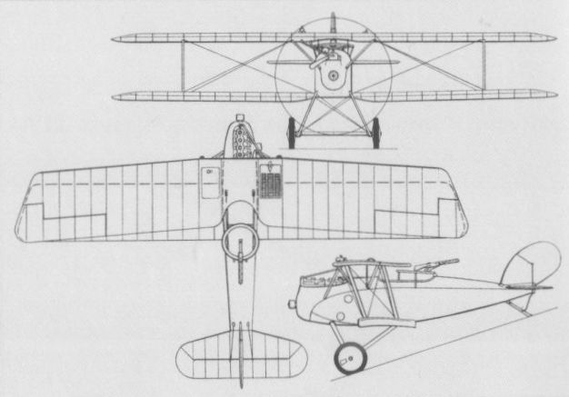
HALBERSTADT CLS I Germany
A requirement was formulated in September 1918 for a two-seat fighter optimised for the close air support role. Climb rate was considered of secondary importance, emphasis being placed on speed, manoeuvrability and dive capability. The Halberstadter Flugzeugwerke responded with a design based on the C VIII reconnaissance biplane, but having reduced wing span and a 160 hp Mercedes D IIIa engine, and designated Cls I. The requirement resulting in the Cls I had specified an increase in useful load (by comparison with the CL IV) from 750 lb (340 kg) to 926 lb (420 kg), apparently to cater for a twin fixed-gun armament and a larger load of anti-personnel bombs, but the provision of a 20-mm Becker cannon for the gunner was also proposed. The Cls I was type tested in October 1918, but when the static testing of components terminated on 6 December, some strengthening of the tail surfaces was called for. Only three or four prototype Cls I close air support fighters were completed.
Max speed, 115 mph (185 km/h).
Empty weight, 1,504 lb (682 kg).
Loaded weight, 2,430 lb (1102 kg).
Span, 31ft 9 7/8 in (9,70 m).
Length, 22 ft 9 5/8 in (6,95 m).
Height, 10 ft 0 in (3,05 m).
Wing area, 284.18 sq ft (26,40 m2).
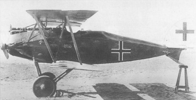
Based on the C VIII reconnaissance biplane, the two- seat Cls I did not enter production.
HANNOVER CL II Germany
The concept of the comparatively light and manoeuvrable two-seat "defensive patrol and pursuit” aircraft realised by the German Air Staff in the autumn of 1916 led to the issue of three-prototype contracts to several manufacturers, including the Hannoversche Waggonfabrik AG. Initially designated C II, but redesignated CL II in the summer of 1917, the company’s contender, designed by Dipl-Ing Hermann Dorner, successfully completed its Typenprufung on 21 July 1917. Powered by a 180 hp Argus As III water-cooled engine, the Hannover CL II was armed with a single fixed LMG 08/15 machine gun and an LMG 14 machine gun on a flexible mounting. Within two months of the type test, the Idflieg placed orders for 500 CL IIs and these were introduced into service from October 1917. The CL II proved exceptionally versatile, and, in addition to its fighter roles, it was utilised for low-altitude tactical reconnaissance. Its manoeuvrability was such that its crews were able to engage enemy single-seat fighters with confidence. The maximum frontline complement of 295 aircraft was attained in February 1918, after which the CL II was progressively phased out in favour of the CL III and IIIa. The Hannoversche Waggonfabrik built 439 CL IIs, the remainder of the contract being completed as CL IIIa’s, and Roland licence-built 200 CL II(Rol) aircraft in 1918 for use as advanced trainers.
Max speed, 102 mph (165 km/h).
Climb to 3,280 ft (1000 m), 6.1 min.
Empty weight, 1,653 lb (750 kg).
Loaded weight, 2,447 lb (1110 kg).
Span, 39 ft 2 1/2 in (11,95 m).
Length, 25 ft 7 in (7,80 m).
Height, 9 ft 0 1/4 in (2,75 m).
Wing area, 363.8 sq ft (33,8 m2).
HANNOVER CL III Germany
A progressive development of the CL II designed by Hermann Dorner, the CL III was intended to offer improved altitude capability with the 160 hp Mercedes D III water-cooled engine. Despite some airframe strengthening, the CL III had a slightly reduced structural weight and marginally smaller overall dimensions. The Typenprufung was successfully passed on 23 February 1918, and an order placed for 200 aircraft with deliveries to commence in the following month. In the event, as a result of shortages of the Mercedes engine, only 80 CL IIIs were delivered, the remainder of the order being completed with the 180 hp Argus As III(O) licence-built by Opel as the CL IIIa. This version was to remain in production until the end of hostilities, 573 being delivered. The designation CL IIIb was allocated to the version that was to have been powered by the 185 hp NAG C III engine, and the CL IIIc was a twin-bay version built specifically as a test-bed for the NAG engine. The CL III and IIIa entered service in April 1918, serving primarily with the Schlachtstaffeln operating in the ground attack fighter role. Oddly, the Hannoversche Waggonfabrik completed a further 100 CL IIIs and 38 CL IIIa's after the Armistice. The following data relate to the CL IIIa.
Max speed, 103 mph (165 km/h) at 16,405 ft (5000 m).
Time to 3,280 ft (1 000 m), 5.3 min.
Endurance, 3 hrs.
Empty weight, 1,653 lb (750 kg).
Loaded weight, 2,447 lb (1110 kg).
Span, 38 ft 4 1/2 in (11,70 m).
Length, 24 ft 10 1/4 in (7,58 m).
Height, 9 ft 2 1/4 in (2,80 m).
Wing area, 351.97 sqft (32,70 m2).
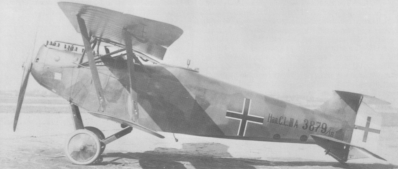
A further engine change led to the CL IIIa.

With an engine change and small improvements, the CL III evolved from the CL II.
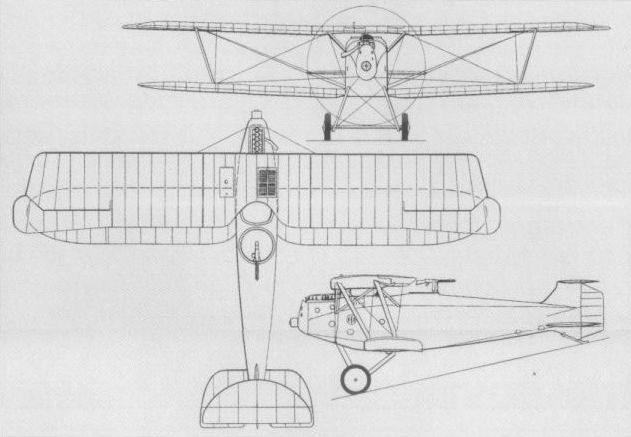
The two-seat Hannover Cl II proved highly manoeuvrable and versatile.
HANNOVER CL V Germany
In mid-1918, the Idflieg prepared a specification calling for a Jagdzweisitzer - a two-seat fighter intended to engage the newer Allied single-seaters on even terms. It was to emphasise high speed, diving capability and manoeuvrability, and carry a fixed forward-firing armament of twin synchronised machine guns plus a third gun in the rear cockpit. To meet this requirement, which called for the aircraft to be tested to single-seat fighter load requirements, Hermann Dorner produced an extremely rugged and compact airframe. Designated CL V, the prototype was powered by a 186 hp BMW IIIa engine. Tested against a similarly-powered Fokker D VII, it demonstrated comparable speed and climb. With the original biplane tail replaced by one of monoplane configuration, the CL V was ordered into production, a contract for 100 aircraft being placed in September 1918, although it is doubtful if any of the 46 completed before the end of hostilities reached the Front. A further 62 were completed after the Armistice. A stripped down example of the CL V was used to establish a world altitude record of 27,362 ft (8 340 m) on 22 November 1919. During 1923-24, the Kjeller Flyvemaskinsfabrik at Halden, Norway, built 14 CL Vs under licence for the Norwegian Army as the F.F.7 Hauk(Hawk), these remaining in service until 1929.
Max speed, 109 mph (175 km/h) at 6,560 ft (2 000 m).
Time to 9,840 ft (3 000 m), 12 min.
Range, 211 mis (340 km).
Empty weight, 1,587 lb (720 kg).
Loaded weight, 2,381 lb (1080 kg).
Span, 34 ft 5 in (10,49 m).
Length, 22 ft 11 1/2 in (7,00 m).
Height, 9 ft 3 1/4 in (2,84 m).
Wing area, 306.78 sq ft (28,50 m2).
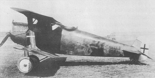
Last of the Hannover fighters, the CL V was too late for service in World War I.
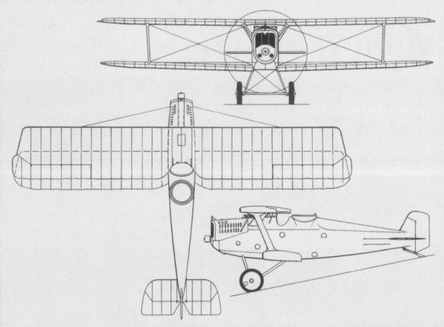
Last of the Hannover fighters, the CL V was too late for service in World War I.
BRANDENBURG CC Germany
Intended primarily for use by the Austro-Hungarian Navy, the CC single-seat fighter flying boat (the designation was derived from the initials of Camillo Castiglioni, the financier of the Hansa- und Brandenburgische Flugzeug-Werke) was a single-bay biplane of wooden construction which appeared in prototype form in mid-1916. Retaining the "star” interplane bracing strut arrangement introduced by the KD (D I), the CC was supplied to the Austro-Hungarian Navy with both the 160 hp Austro-Daimler and 180 hp Hiero six-cylinder water-cooled engines, armament consisting of a single 8-mm Schwarzlose machine gun projecting through the windscreen. A total of 37 fighter flying boats of this type was delivered to the service. The CC was also adopted by the German Navy, which received a total of 36, with deliveries commencing in February 1917. These were powered by the 150 hp Benz Bz III, the engines of some examples being semi-cowled. The CC initially carried an armament of one 7,92-mm LMG 08/15 machine gun, but late production examples had two such weapons fixed to fire forward in the upper decking of the hull nose, and the hull was lengthened to improve flying characteristics. In July 1917, the German Navy grounded the CC until all aircraft were provided with extra (Vee-type) interplane bracing struts to dampen severe wing vibration. The CC was employed extensively and with considerable success over the Adriatic by the Austro-Hungarian Navy. One example was completed experimentally as a triplane, the extra wing being placed at the intersection of the "star-struts”. It was delivered to the Austro-Hungarian Navy for evaluation on 11 May 1917, but was written-off in a landing accident on the following 19 September. One CC was modified and tested in the summer of 1918 as the W 22, with broad sponsons replacing the outrigger stabilising floats. This experimental model, which crashed during testing, was intended solely to evaluate the sponson concept as part of the Staaken Rs IV development programme.
Max speed, 109 mph (175 km/h).
Time to 3,280 ft (1 000 m), 4.8 min.
Range, 310 mis (500 km).
Empty weight, 1,764 lb (800 kg).
Loaded weight, 2,381 lb (1080 kg).
Span, 30 ft 6 1/8 in (9,30 m).
Length, 25 ft 2 3/4 in (7,69 m).
Height, 11 ft 8 1/2 in (3,57 m).
Wing area, 285.46 sqft (26,52 m2).

The CC as originally built.
BRANDENBURG KD (D I) Germany
Designed by Ernst Heinkel specifically for the Austro-Hungarian K.u.k. Luftfahrttruppen in 1916, the KD (Kampf Doppeldecker) single-seat fighter featured a novel system of wing interplane bracing in the form of four Vee struts joined in the centre of the wing bay by their apices to result in a "star” arrangement, which led to the KD being dubbed a "star strutter”. Flown as a prototype with the 160 hp Mercedes D III six-cylinder water-cooled engine, the KD was manufactured in series as the D I with the 150 hp and 160 hp Austro-Daimler engines by the Hansa- und Brandenburgische Flugzeug-Werke, and with the 185 hp Austro-Daimler by the Phonix Flugzeugwerke of Vienna. Of wooden construction with fabric wing skinning, plywood fuselage skinning and having steel-tube interplane strutting, the D I was armed with a single unsynchronised 8-mm Schwarzlose machine gun which was enclosed by a fairing on top of the cabane and fired over the propeller. The D I was reputedly difficult to fly, suffered inadequate directional stability owing to the rudder being blanketed by the deep fuselage, and had poor spin recovery characteristics. A number of Phonix-built Brandenburg D Is survived World War I to serve briefly with the Deutschosterreichische Fliegertruppe.
Max speed, 116 mph (187 km/h) at sea level.
Time to 3,280 ft (1000 m), 3.0 min.
Empty weight, 1,481 lb (672 kg).
Loaded weight, 2,028 lb (920 kg).
Span, 27ft 10 2/3 in (8,50 m).
Length, 20 ft 10 in (6,35m).
Wing area, 257.80 sq ft (23,95 m2).

The KD "star strutter" without the overwing gun fairing.

The KD "star strutter" in its 160 hp Austro-Daimler-engined DI production form.
BRANDENBURG KDW Germany
The KDW twin-float single-seat fighter seaplane was essentially a conversion of the land-based KD (D I) to provide an interim aircraft for floatplane station defence. The only major change introduced on the prototype apart from provision of a twin-float chassis was some slight extension of the wings, but the fin area was later increased to compensate for the increased keel area resulting from the addition of the floats. The prototypes were fitted with the 150 hp Benz Bz III six-cylinder water-cooled engine, but apart from a pre-production batch of 10 similarly-powered aircraft, all subsequent examples of the KDW had the 160 hp Maybach Mb III six-cylinder water-cooled engine. The first production series was armed with a single synchronised 7,92-mm LMG 08/15 machine gun mounted on the starboard side of the nose, but the final batch of 20 delivered between October 1917 and February 1918 had a gun mounted on each side of the cockpit and additional Vee-type interplane bracing struts. A total of 58 KDW float fighters was delivered.
Max speed, 106 mph (170 km/h).
Time to 3,280 ft (1000 m), 5.9 min, to 6,560 ft (2 000 m), 14 min.
Range, 310 mis (500 km).
Empty weight, 1,673 lb (759 kg).
Loaded weight, 2,290 lb (1 039 kg).
Span, 30 ft 6 1/8 in (9,30 m).
Length, 25 ft 9 1/2 in (7,86m).
Height, 10 ft 11 7/8 in (3,35m).
Wing area, 313.77 sq ft (29,15 m2).
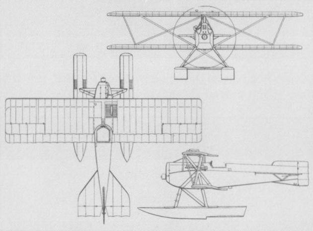
The KDW was essentially a float-equipped conversion of the KD "star strutter".
BRANDENBURG KF Germany
The first fighter to be designed by Ernst Heinkel as chief designer for the Hansa- und Brandenburgische Flugzeug-Werke, the KF two-seater appeared early in 1916, and was a two-bay, twin-boom biplane powered by a 150 hp Benz Bz III six-cylinder water-cooled engine installed as a pusher and driving a two-bladed propeller between the tailbooms. The KF was of wooden construction with plywood-covered fuselage nacelle and tailbooms, and armament was intended to consist of a single 7,92-mm Parabellum machine gun on a flexible mounting in the forward cockpit. Work on the KF was discontinued as it offered no advance in performance over the similarly-configured Ago C I which served in the reconnaissance role.
Max speed, 87 mph (140 km/h) at 3,280 ft (1000 m).
Empty weight, 1,675 lb (760 kg).
Loaded weight, 2,844 lb (1290 kg).
Span, 38 ft 0 2/3 in (11,60 m).
Length, 27 ft 7 3/4 in (8,48 m).
Wing area, 414.50 sq ft (38,6 m2).
BRANDENBURG W 11 Germany
A heavier and more powerful derivative of the KDW, the W 11 single-seat twin-float fighter biplane was powered by a 220 hp Benz Bz IVa water-cooled engine and retained the "star” interplane bracing arrangement of its predecessor. Armament consisted of two synchronised LMG 08/15 machine guns, and two prototypes were completed during February-March 1917. No series production was undertaken.
Max speed, 109 mph (176 km/h).
Time to 3,280 ft (1 000 m), 4.0 min.
Range, 217 mis (350 km).
Empty weight, 2,061 lb (935 kg).
Loaded weight, 2,718 lb (1233 kg).
Span, 33 ft 1 2/3 in (10,10 m).
Length, 26 ft 6 7/8 in (8,10 m).
Height, 10 ft 10 3/4 in (3,32 m).
Wing area, 338.2 sq ft (31,42 m2).
BRANDENBURG W 16 Germany
Intended primarily as a successor to the KDW in the station defence fighter role, but also to investigate the potentialities of the application of rotary engines to seaplanes, the W 16 was designed by Ernst Heinkel in 1916, and was a conventional twin-float single-seat fighter floatplane of wood and fabric construction with ply-skinned fuselage and floats. Like Heinkel’s earlier ‘‘star strutter” fighters, the W16 lacked bracing wires, these being rendered unnecessary by single struts extending from the base of the inclined Vee-type interplane struts to the top of the forward fuselage mainframe. Power was provided by a 160 hp Oberursel U III rotary engine and armament comprised two synchronised LMG 08/15 machine guns. Three prototypes were ordered, the first of these being tested in February 1917, and the third example was sent to Adlershof for static tests. No further development was undertaken as the German Navy had lost interest in single-seat fighter floatplanes.
Max speed, 106 mph (170 km/h).
Time to 3,280 ft (1 000 m), 5.0 min, to 9,840 ft (3 000 m), 27 min.
Approx endurance, 2.0 hrs.
Empty weight, 1,402 lb (636 kg).
Loaded weight, 1,975 lb (896 kg).
Span, 30 ft 4 1/8 in (9,25 m).
Length, 24 ft 1 1/3in (7,35m).
Height, 9 ft 7 in (2,92 m).
Wing area, 229.81 sq ft (21,35 m2).
BRANDENBURG L 14 Germany
A derivative of the KD (D I) with larger overall dimensions, simplified interplane bracing and a 200 hp Hiero six-cylinder water-cooled engine, the L 14 single-seat fighter was evaluated by the Austro-Hungarian air arm in 1917, but was not accepted for series production. Two prototypes were built and flown, these differing primarily in the arrangement of the interplane bracing struts employed, and intended armament was twin 8-mm Schwarzlose synchronised machine guns.
Max speed, 112 mph (180 km/h).
Time to 3,280 ft (1 000 m), 4.0 min.
Empty weight, 1,631 lb (740 kg).
Loaded weight, 2,072 lb (940 kg).
Span, 33 ft 5 1/2 in (10,20 m).
Length, 23 ft 1 1/2in (7,05m).
Wing area, 272.12 sqft (25,28 m2).
BRANDENBURG L 16 German
A single-seat equi-span fighter triplane, developed for the Austro-Hungarian K.u.k. Luftfahrttruppen, with aerofoil-section I-type interplane bracing struts, the L 16 was powered by a 185 hp Austro-Daimler six-cylinder water-cooled engine and was intended to carry an armament of two synchronised machine guns. Various coolant radiator arrangements were evaluated on the single prototype built, but the fighter offered insufficient promise to warrant series production and development was abandoned.
Max speed, 118 mph (190 km/h).
Empty weight, 1,631 lb (740 kg).
Loaded weight, 2,061 lb (935 kg).
Span, 29 ft 6 1/3 in (9,00 m).
Length, 23 ft 7 7/8 in (7,21 m).
Height, 12 ft 1 2/3 in (3,70 m).
Wing area, 360.59 sq ft (33,5 m2).
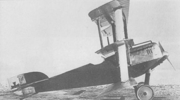
Evaluated by the Austro-Hungarian air arm in 1917, the L16 triplane lacked promise.
BRANDENBURG W 12 Germany
A single-bay twin-float two-seat fighter biplane, the W 12 was flown for the first time in January 1917 with a 160 hp Mercedes D III six-cylinder water-cooled engine. Of wooden construction with plywood fuselage skinning, the W12 was produced for the German Navy with both the 160 hp Mercedes D IIIa engine and the 150 hp Benz Bz III, and proved outstandingly manoeuvrable. Its first operations were conducted from the seaplane station at Zeebrugge, from where it quickly distinguished itself in service. Standard armament comprised one forward-firing synchronised 7,92-mm LMG 08/15 machine gun and a Parabellum of similar calibre on a flexible mount in the rear cockpit, but of the 146 W 12s that had been built when production terminated in June 1918, one batch of 30 Benz-engined fighters had been delivered with a forward-firing armament of two LMGs.
Max speed, 99 mph (160 km/h).
Time to 3,280 ft (1000 m), 7.0 min, to 6,560 ft (2 000 m), 18.9 min.
Endurance, 3.5 hrs.
Empty weight, 2,198 lb (997 kg).
Loaded weight, 3,205 lb (1454 kg).
Span, 36 ft 8 7/8 in (11,2 m).
Length, 31 ft 6 in (9,60 m).
Height, 10 ft 10 in (3,30 in).
Wing area, 389.66 sq ft (36,2 m2).
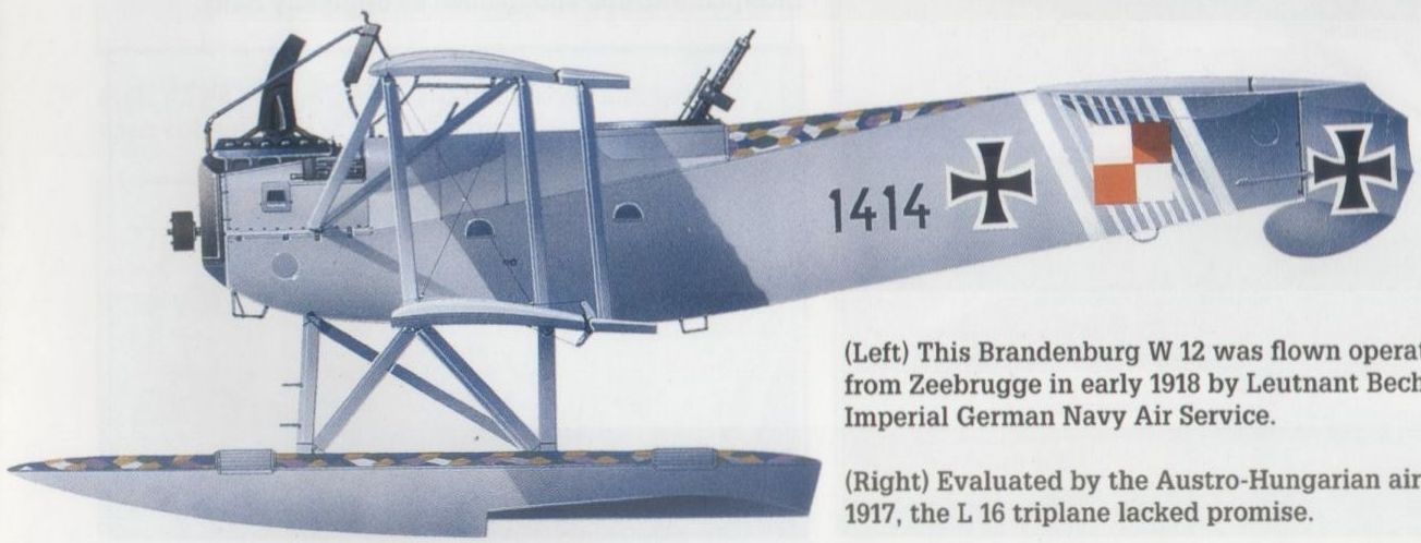
This Brandenburg W12 was flown operationally from Zeebrugge in early 1918 by Leutnant Becht of the Imperial German Navy Air Service.
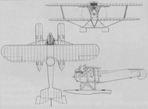
BRANDENBURG W 17 (A 49) Germany
A single-seat fighter flying boat developed for the Austro-Hungarian Navy, the prototype of the W 17 (also designated A 49/1) was a biplane with a cantilever lower wing and was tested at Pola in July 1917. K.u.k. Linienschiffsleutnant Gottfried Banfield, responsible for the evaluation of the W 17, felt that the cantilever lower wing was unsuited for marine use and that the flying boat possessed inadequate manoeuvrability. Armament of the W 17 comprised two 8-mm Schwarzlose machine guns and the initial aircraft was allegedly lost when the upper wing broke away in flight. A second aircraft (the A 49/11) was completed as an equi-span triplane with interplane bracing struts. This is believed to have been submitted to the Austro-Hungarian Navy for evaluation in July 1917, but no details of these tests, or aircraft data, appear to have survived.
A single-seat fighter flying boat developed for the Austro-Hungarian Navy, the prototype of the W 17 (also designated A 49/1) was a biplane with a cantilever lower wing and was tested at Pola in July 1917. K.u.k. Linienschiffsleutnant Gottfried Banfield, responsible for the evaluation of the W 17, felt that the cantilever lower wing was unsuited for marine use and that the flying boat possessed inadequate manoeuvrability. Armament of the W 17 comprised two 8-mm Schwarzlose machine guns and the initial aircraft was allegedly lost when the upper wing broke away in flight. A second aircraft (the A 49/11) was completed as an equi-span triplane with interplane bracing struts. This is believed to have been submitted to the Austro-Hungarian Navy for evaluation in July 1917, but no details of these tests, or aircraft data, appear to have survived.
BRANDENBURG W 18
The W18 single-seat fighter flying boat was, like the CC that it supplanted, intended primarily for the Austro-Hungarian Navy. The prototype was flown early in 1917 with a 150 hp Benz Bz III six-cylinder water-cooled engine, and production with a 200 hp Hiero engine was undertaken on behalf of the Austro-Hungarian Navy, a total of 47 being delivered between September 1917 and May 1918. Armament normally comprised two fixed forward-firing 8-mm Schwarzlose machine guns, and the W 18 was employed for both station defence and fighter patrol tasks. One Benz-engined example was delivered to the German Navy in December 1917.
Max speed, 106 mph (170 km/h).
Time to 3,280 ft (1 000 m), 5.0 min, to 9,840 ft (3 000 m), 23.0 min.
Empty weight, 1,929 lb (875 kg).
Loaded weight, 2,524 lb (1145 kg).
Span, 35 ft 1 1/4 in (10,70 m).
Length, 26 ft 8 7/8 in (8,15 m).
Height, 11 ft 3 7/8 in (3,45 m).
Wing area, 370.07 sqft (34,38 m2).
BRANDENBURG W 23
Employing single-bay biplane wings similar to those of the W 18 coupled with a lengthened, aero- and hydrodynamically refined hull, the W 23 single-seat fighter flying boat was designed to mount a single fixed forward-firing 20-mm Becker cannon. This was mounted in the starboard side of the upper decking of the hull nose with a 7,92-mm LMG 08/15 machine gun mounted to port. Power was provided by a 160 hp Mercedes six-cylinder water-cooled engine driving a two-bladed pusher propeller. The structure was wooden with fabric and plywood skinning. Three prototypes were ordered in June 1917, these being delivered for evaluation in January 1918. The W 23 proved to possess such poor flight characteristics that no further development was undertaken.
Max speed, 102 mph (165 km/h).
Empty weight, 2,024 lb (918 kg).
Loaded weight, 2,780 lb (1261 kg).
Span, 35 ft 1 1/4 min (10,70 m).
Length, 29 ft 11 7/8 in (9,14 m).
Height, 10 ft 11 7.8 in (3,35 m).
Wing area, 373.52 sq ft (34,7 m2).

The W18 in production form with Hiero engine.
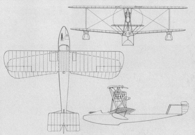
The single prototype of the Brandenburg W 23.
BRANDENBURG W 25 Germany
The last of the Heinkel-designed single-seat fighter float seaplanes built by the Hansa- und Brandenburgische Flugzeug-Werke, the W 25, produced as a single prototype late in 1917, was the final development of the KDW. Reverting to the 150 hp Benz Bz III engine used by the prototype and pre-production KDWs, the W 25 possessed an essentially similar fuselage, but discarded the "star" interplane strut arrangement in favour of normal strut bracing. Initially the prototype flew with ailerons on the upper wing only, but these were subsequently added to the lower wing, each pair being joined at the wingtip by link struts. Armament comprised two synchronised 7,92-mm LMG 08/15 machine guns. Having by this time lost interest in single-seat fighter floatplanes, the German Navy did not foster further development of the W 25.
Max speed, 99 mph (160 km/h).
Time to 3,280 ft (1 000 m), 6.5 min.
Empty weight, 2,024 lb (918 kg).
Loaded weight, 2,606 lb (1182 kg).
Span, 34 ft 1 1/2 in (10,40 m).
Length, 28 ft 10 1/2 in (8,80 m).
Height, 11 ft 3 7/8 in (3,45 m).
Wing area, 393.22 sq ft (36,53 m2).
BRANDENBURG W 19 Germany
An enlarged W 12 developed to meet a demand for a two-seat fighter seaplane with greater endurance, the W19 was first committed to operations in January 1918. Appreciably larger than the W12, the W19 was of similar construction with fabric-covered wings and plywood-covered fuselage and floats, and was powered by a 260 hp Maybach Mb IVa six-cylinder water-cooled engine. The substantial increase in span necessitated the adoption of a two-bay arrangement, and, apart from the three prototypes, all W 19s carried an armament of two 7,92-mm LMG 08/15 synchronised machine guns and a single Parabellum of similar calibre on a flexible mount in the rear cockpit. One W19 was experimentally fitted with a 20-mm Becker cannon for trials. A total of 53 production W 19s was completed (one being retained for static tests).
Max speed, 93 mph (150 km/h).
Time to 3,280 ft (1 000 m), 6.4 min, to 6,560 ft (2 000 m), 18.9 min.
Empty weight, 3,164 lb (1435 kg).
Loaded weight, 4,420 lb (2 005 kg). Span, 45 ft 3 1/3 in (13,80 m).
Length, 34 ft 11 1/4 in (10,65 m).
Height, 13 ft 5 3/8 in (4,10 m).
Wing area, 622.17 sq ft (57,8 m2).
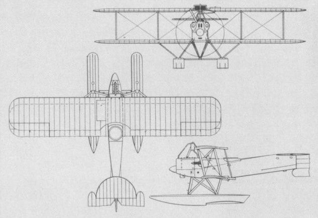
BRANDENBURG W 27 & W 32 Germany
Early in 1918, it was suggested to Ernst Heinkel that a successor to the W 12 two-seat fighter would soon be required if the German Navy was to maintain its superiority over Allied types being encountered over the North Sea. To conserve valuable time, Heinkel installed the new 195 hp Benz Bz IIIbo eight-cylinder Vee engine in a modified W 12 airframe and a 160 hp Mercedes D IIIa in a second W12. Wing span and gap were reduced, stagger was increased to improve visibility, and aerofoil-section I-type interplane struts were adopted. Armament comprised two synchronised 7,92-mm LMG 08/15 machine guns and one 7,92-mm Parabellum on a flexible mount in the rear cockpit. The Benz-engined prototype received the designation W 27 while that powered by the Mercedes engine became the W 32, but both were found inferior to the W 29 monoplane and no further development was undertaken. The following data relate to the W 27.
Max speed, 106 mph (170 km/h).
Empty weight, 2,445 lb (1109 kg).
Loaded weight, 3,569 lb (1 619 kg).
Span, 36 ft 8 7/8 in (11,20 m).
Length, 30 ft 3 1/3 in (9,23 m).
Height, 10 ft 0 1/2 in (3,06 m).
Wing area, 388.16 sqft (36,06 m2).
BRANDENBURG W 29 Germany
Evolved from the W12 two-seat patrol fighter biplane in parallel with the W 27, the W 29 was essentially a monoplane derivative of the former powered, in prototype form, by the 195 hp Benz Bz IIIbo eight-cylinder Vee engine. The span and chord of the monoplane wing approximated in area to the biplane wings of the W12, and the wing itself was a two-spar wooden structure with fabric skinning. The 150 hp Benz Bz III six-cylinder inline water-cooled engine was standardised for the production model of the W 29, which began operations with the German Navy in April 1918. Over 150 W 29s are known to have been delivered to that service in two basic versions, one equipped with radio and fitted with a single synchronised 7,92-mm LMG 08/15 machine gun plus a Parabellum on a flexible mount in the rear cockpit, and the other having two forward-firing LMGs and lacking radio equipment. The W 29, operating from Zeebrugge, Borkum and Norderney, achieved considerable operational success during the closing stages of World War I. In 1921, licence production of the W 29 was initiated by the Danish naval dockyard, 15 being built and these continuing in Danish Navy service until 1931.
Max speed, 109 mph (175 km/h).
Time to 3,280 ft (1000 m), 6.0 min, to 6,560 ft (2 000m), 13.0 min.
Endurance, 4 hrs.
Empty weight, 2,205 lb (1000 kg).
Loaded weight, 3,294 lb (1494 kg).
Span, 44 ft 3 1/2 in (13,50 m).
Length, 30 ft 8 1/2 in (9,36 m).
Height, 9 ft 10 1/8 in (3,00 m).
Wing area, 346.6 sqft (32,2 m2).
m2).
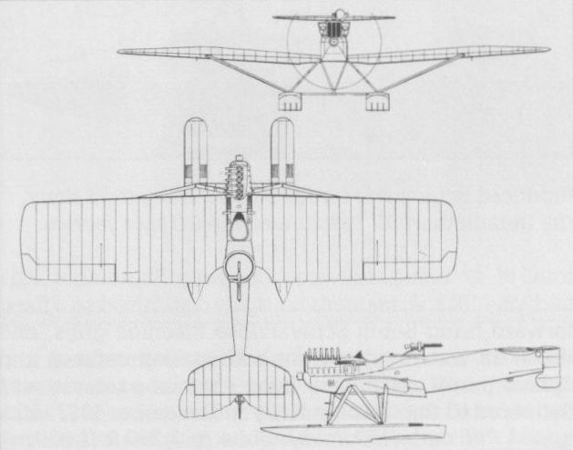
Essentially a monoplane derivative of the W 12 biplane, the W 29 was produced in time to serve with the German Navy from 1918.
BRANDENBURG W 34 Germany
Continuing the line of two-seat patrol fighter monoplanes initiated with the W 29, the W 34 was the final WWI development of the series of float seaplanes designed for the Hansa- und Brandenburgische Flugzeug-Werke by Ernst Heinkel and Hans Klemm. Essentially a scaled-up W 33 intended for the 300 hp Basse und Selve BuS IVa six-cylinder water-cooled engine, only one prototype of the W 34 had been completed by the end of the War. Additional examples powered by the 300 hp Fiat A 12bis engine were built after the termination of hostilities.
Max speed, 109 mph (175 km/h).
Empty weight, 3,382 lb (1 534 kg).
Loaded weight, 5,004 lb (2 270 kg).
Span, 55 ft 5 1/2 in (16,60 m).
Length, 36 ft 5 in (11,10 m).
Wing area, 527.45 sq ft (49.0 m2).

Skis could replace the regular floats of the W 33, as seen on this Finnish-built example flown by No 1 Detached Maritime Flying Squadron.

Developed from the smaller W 29, the W 33 was built in Norway and Finland after production in Germany was halted by the Armistice.

Developed from the smaller W 29, the W 33 was built in Norway and Finland after production in Germany was halted by the Armistice.
JUNKERS J 2 Germany
Following the successful demonstration in December 1915 of the Junkers J 1 all-steel two-seat experimental aircraft, Junkers und Compagnie of Dessau was awarded a contract by the Inspektion der Fliegertruppen (Idflieg) on 31 January 1916 for six examples of a single-seat fighter derivative, the J 2. The first example, powered by a 120 hp Mercedes D II water-cooled engine and carrying an armament of one LMG 08/15 machine gun, was flown at Doberitz on 11 July 1916. As a result of flight trials, a number of changes were introduced on the subsequent five aircraft which were powered by the 160 hp Mercedes D III engine. Overall length was increased marginally, wing span was extended by 27 1/2 in (70 cm), wing area reduced by 9 sq ft (84 cm2), long-span, shorter-chord ailerons were fitted and the forward fuselage contours revised. In its definitive form, the J 2 was 9 mph (15 km/h) faster than the best contemporary fighter and its handling characteristics were good, but because of the weight of its all-steel construction, climb rate was below the then current combat requirements. View from the cockpit was considered inadequate, and Idflieg coolness towards the fighter increased still further when a J 2 crashed on 23 September 1916, killing test pilot Max Schade. No further examples were ordered in consequence. The following data relate to the definitive model.
Max speed, 124 mph (200 km/h).
Time to 9,840 ft (3 000 m), 21 min.
Empty weight, 2,244 lb (1018 kg).
Loaded weight, 2,568 lb (1165 kg).
Span, 38 ft 4 2/3 in (11,70 m).
Length, 24 ft 4 1/2 in (7,43 m).
Height, 10 ft 3 1/4 in (3,13 m).
Wing area, 204.52 sqft (19,00 m2).
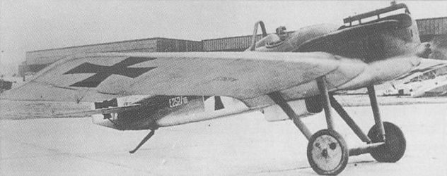
The first all-metal fighter monoplane, the J 2 began flight test in July 1916.
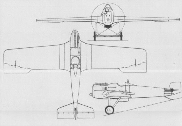
The first all-metal fighter monoplane, the J 2 began flight test in July 1916.
JUNKERS J 8 Germany
On 26 December 1916, Junkers received an Idflieg contract to build three prototypes of the J 8 all-metal two-seat monoplane in the CL-type category - a ‘‘defensive patrol and pursuit aircraft”. Thanks to the priority accorded production of the J I ground attack biplane, however, the J 8 was not completed until 4 December 1917, being flown for the first time a few days later. Of dural construction and powered by a 160 hp Mercedes D III engine, the J 8 was demonstrated during the first D-type contest in February 1918, and in the following month the Junkers-Fokker Werke AG (established on 20 October 1917) received a contract for a pre-series of a modified version, the J 10.
Max speed, 100 mph (161 km/h).
Endurance, 1.5 hrs.
Empty weight, 1,565 lb (710 kg).
Loaded weight, 2,315 lb (1 050 kg).
Span, 39 ft 6 in (12,04 m).
Length, 25 ft 11 in (7,90 m).
Height, 8 ft 8 3/4 in (2,66 m).
Wing area, 251.88 sq ft (23,40 m2).
JUNKERS CL I (J 10) Germany
The CL I (J10) was an improved derivative of the J 8 intended for offensive patrol and close air support roles. Powered by a Mercedes D III engine of 160 hp and armed with two fixed LMG 08/15 machine guns and a Parabellum in the rear cockpit, the CL I was the subject of an order placed with the Junkers-Fokker Werke AG in March 1918 for 10 pre-series aircraft. Subsequent contracts raised the total ordered to 63 machines, of which 44 were delivered through March 1919. Together with the D I, the CL I was used by the Geschwader Sachsenberg during the post-World War I fighting against Bolshevik forces in the Baltic.
Max speed, 118 mph (190 km/h).
Time to 3,280 ft (1000 m), 3.9 min.
Endurance, 2.0 hrs.
Empty weight, 1,620 lb (735 kg).
Loaded weight, 2,546 lb (1155 kg).
Span, 40 ft 0 1/4 in (12,20 m).
Length, 25 ft 11 in (7,90 m).
Height, 10 ft 2 in (3,10 m).
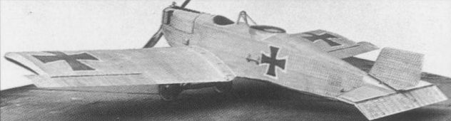
Image showing the prototype Junkers J.8 two seat close-support fighter. Work on the sole J.8 started in October 1917, aimed at providing a successor to the armoured Junkers J I. As it transpired, the J.8, with its 160hp Mercedes D III, had a top level speed of 116mph and impressed those that flew it at the first of the 1918 fighter trials. Not only did the J.8 lead directly to the CL I production contract, but its development contributed greatly to solving many of the single seat J.7's ongoing problems. Too late to have any effect in the air war, the 41 Junkers CL Is completed stood up well, alongside their single seat Junkers D I when operated in the 1919 Baltic War. Powered by a 185hp Benz Bz IIIa, the CL I had a top level speed of 118mph and a ceiling of 17,000 feet. Armament on later machines comprised two 7.92 Spandaus for the pilot, along with the flexibly-mounted 7.92mm Parabellum in the rear.
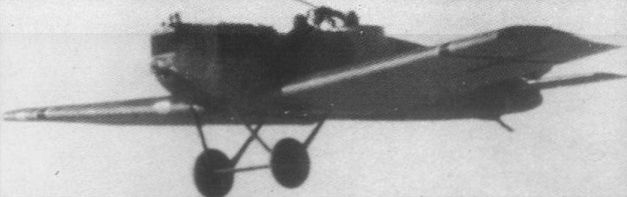
The CL I served post-World War I in the Baltic with the Geschwader Sachsenberg.
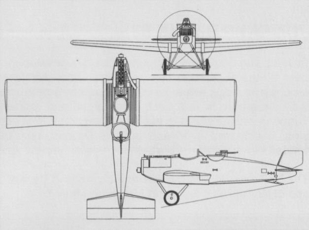
The CL I was the ultimate wartime development of the line of Junkers monoplanes.
JUNKERS J 7 Germany
During the summer of 1916, Junkers switched attention from all-steel to dural construction in an effort to reduce aircraft weight. The J 3 all-duralumin single-seat fighter was discarded when partially built, because of the disinterest of the Idflieg. Nevertheless, Junkers proceeded, as a private venture, with the J 7 single-seat fighter, using the corrugated sheet skinning and duralumin tube construction techniques developed for the J I armoured ground attack biplane. Designed by Dipl-Ing Otto Reuter and powered by a 160 hp Mercedes D III engine, the J 7 flew for the first time on 17 September 1917. Rotating wingtip ailerons were initially fitted, these being replaced by conventional ailerons at an early stage. During the test programme a frontal radiator was introduced, together with a new wing embodying longer-span ailerons. Although not formally permitted to compete in the first D-type contest held at Adlershof in February 1918 because of its monoplane configuration, the J 7 proved faster than all official contenders, and, in February 1918, was finally accepted for testing by the Idflieg. Discussions were held concerning procurement of a small operational evaluation series of J 7s, but this fighter had meanwhile been overtaken by the J 9.
Max speed, 127 mph (205 km/h).
Time to 16,405 ft (5000 m), 24 min.
Empty weight, 1,446 lb (656 kg).
Loaded weight, 1,775 lb (805 kg).
Span, 30 ft 2 1/4 in (9,20 m).
Length, 21 ft 11 3/4 in (6,70 m).
Height, 8 ft 6 1/3 in (2,60 m).
Wing area, 125.94 sq ft (11,70 m2).
JUNKERS D I (J 9) Germany
Hard on the heels of the J 7, construction of the improved J 9 single-seat fighter was begun by Junkers. Powered by a similar 160 hp Mercedes D III engine, the J 9 flew for the first time in late April 1918. Concurrently, the Idflieg awarded Junkers und Compagnie and the Junkers-Fokker Werke AG each a contract for 10 pre-series J 9s as D Is. The first D I prototype was entered in the 2nd D-type contest held at Adlershof in May-June 1918, but combat pilots adjudged it totally unsuited for fighter tactics then current. It was suggested that, in view of the comparative invulnerability of its metal structure, it should be produced as a specialised ‘‘balloon attack" aircraft. Accordingly, further contracts were issued for the D I for this role between May and November 1918, bringing the total ordered to 60 machines. Of these, Junkers delivered about 27 and Junkers-Fokker delivered 13 through February 1919. There is no record of the D I having been used in combat during World War I, but a few were active with the Geschwader Sachsenberg in Kurland against Bolshevik insurgents. One D I was test flown with a 185 hp Benz Bz IIIb eight-cylinder Vee engine, and another, powered by a 185 hp BMW IIIa engine, participated in the 3rd D-type contest in October 1918.
Max speed, 140 mph (225 km/h).
Time to 16,405 ft (5 000 m), 24 min.
Endurance, 1.5 hrs.
Empty weight, 1,442 lb (654 kg).
Loaded weight, 1,839 lb (834 kg).
Span, 29 ft 6 1/3 in (9,00 m).
Length, 23 ft 9 3/8 in (7,25 m).
Height, 8 ft 6 1/3 in (2,60 m).
Wing area, 159.31 sq ft (14,80 m2).
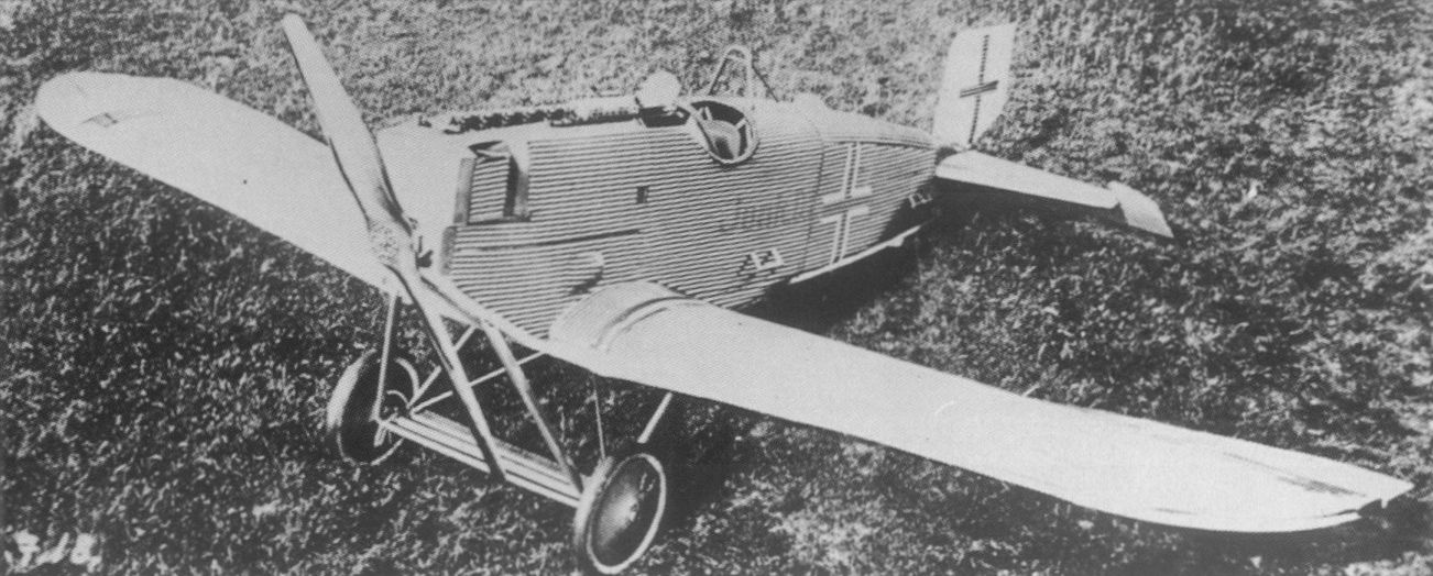
The short-fuselage version of the J 9 (D I) photographed fully armed on 8 July 1918.
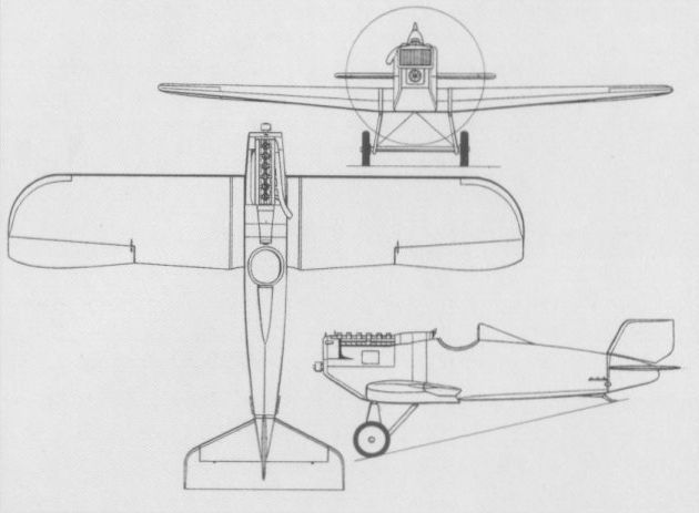
The Junkers J 7 in its definitive form.
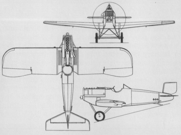
The early-production short-fuselage J 9, found unsuited for contemporary fighter tactics.
KONDOR DREIDECKER Germany
In the summer of 1917, the Kondor Flugzeugwerke of Essen was joined by Walter Rethel and Paul G Ehrhardt, formerly with LVG, to initiate a series of original designs. The company had previously been concerned primarily with licence manufacture of the Albatros B II and B IIa. The first original design produced by Rethel and Ehrhardt was a single-seat fighter triplane (dreidecker) which entered flight test in October 1917. Initial trials with an unrecorded engine type evidently revealed performance shortcomings as an Idflieg report of the same month refers to the aircraft being re-engined by Kondor with a geared six-cylinder water-cooled Mercedes D III of 160 hp. Testing of the triplane fighter was terminated as a result of severe vibration problems, the fuselage, lower wing assembly and tail subsequently being utilised by the D 7 biplane. No illustrations or data relating to the Kondor triplane have survived.
In the summer of 1917, the Kondor Flugzeugwerke of Essen was joined by Walter Rethel and Paul G Ehrhardt, formerly with LVG, to initiate a series of original designs. The company had previously been concerned primarily with licence manufacture of the Albatros B II and B IIa. The first original design produced by Rethel and Ehrhardt was a single-seat fighter triplane (dreidecker) which entered flight test in October 1917. Initial trials with an unrecorded engine type evidently revealed performance shortcomings as an Idflieg report of the same month refers to the aircraft being re-engined by Kondor with a geared six-cylinder water-cooled Mercedes D III of 160 hp. Testing of the triplane fighter was terminated as a result of severe vibration problems, the fuselage, lower wing assembly and tail subsequently being utilised by the D 7 biplane. No illustrations or data relating to the Kondor triplane have survived.
KONDOR D 1 Germany
Designed by Rethel and Ehrhardt in parallel with the triplane,the D 1 single-seat fighter was an unequal-span single-bay staggered biplane powered by a 100 hp Gnome-Monosoupape rotary engine. Following Albatros practice in having a single-spar lower wing with V-type interplane strutting, the D 1 was dubbed unofficially and somewhat scathingly as the Kondorlaus and was extensively test flown by Ehrhardt. Intended armament comprised two synchronised LMG 08/15 machine guns with 500 rounds. Flight testing was initiated in the late autumn of 1917, but performance proved disappointing, this possibly being the cause of the prototype's unofficial appellation. In the spring of 1918, when Ehrhardt left the Kondor Flugzeugwerke for health reasons, redesign of the aircraft was undertaken by Walter Rethel as the D 2.
Empty weight, 855 lb (388 kg).
Loaded weight, 1,252 lb (568 kg).
Span, 24 ft 11 1/4 in (7,60 m).
Length, 15 ft 10 7/8 in (4,85 m).
Height, 7 ft 10 1/2 in (2,40 m).
Wing area, 143.7 sq ft (13,35 m2).
KONDOR D 2 Germany
The D 2 single-seat fighter was essentially similar to the D 1, but changes included a two-spar lower wing with parallel interplane bracing struts. Power was provided by a 110 hp Oberursel Ur II rotary engine and armament comprised two synchronised LMG 08/15 machine guns. The D 2 was first flown in May 1918, and two examples participated in the second D-type contest held at Adlershof in June 1918. These were temporarily referred to for convenience as the D I (w/n 200) and D II (w/n 201), one having ailerons on all four wings and one apparently having ailerons on the upper wings only. Oblt Herman Goring, in his report on the potential of these Kondor fighters, gave his opinion that they were "very fine in regard to flight characteristics, but not worthy of further consideration owing to their poor performance". No further development of the D 2 was undertaken.
Max speed, 109 mph (175 km/h).
Time to 9,840 ft (3 000 m), 10.4 min.
Endurance, 1.5 hrs.
Empty weight, 838 lb (380 kg).
Loaded weight, 1,235 lb (560 kg).
Span, 24 ft 10 4/5 in (7,59 m).
Length, 15 ft 11 3/4 in (4,87 m).
Height, 7 ft 10 9/10 in (2,41m).
Wing area, 143.59 sq ft (13,34 m2).
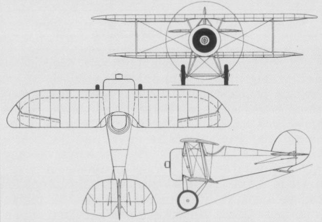
The Kondor D 2 participated in the second D-type contest at Adlershof in June 1918.
KONDOR D 6 Germany
Developed by Walter Rethel in the summer of 1918, and powered by a 145 hp Oberursel Ur III rotary engine, the D 6 represented an attempt to provide maximum forward and upward visibility for the pilot. Like preceding Kondor fighters, the D 6 had a steel-tube fuselage, but this was fabric- rather than plywood-covered. The normal upper wing centre section was completely deleted, a tripod of struts, each strut of differing length, bracing the upper wing halves to the fuselage. Armament consisted of the usual pair of synchronised LMG 08/15 machine guns of 7,9-mm calibre. Although some flight testing was conducted during the summer of 1918, the curious upper wing arrangement had its shortcomings, including dubious structural integrity. The induced tip drag was twice that of a normal wing, and the D 6 never appeared in the monthly Idflieg reports, development apparently being discontinued at an early stage.
Max speed, 106 mph (170 km/h).
Endurance, 1.5 hrs.
Empty weight, 926 lb (420 kg).
Loaded weight, 1,422 lb (645 kg).
Span, 27 ft 0 4/5 in (8,25 m).
Length, 19 ft 0 1/3 in (5,80 m).
Height, 8 ft 3 1/2 in (2,53 m).
Wing area, 148.54 sq ft (13,80 m2).

The D 6 was innovative in its approach to improving forward and upward visibility.
KONDOR D 7 Germany
The D 7 single-seat fighter was essentially a re-work of the original Kondor triplane fighter as a biplane, retaining the plywood-covered steel tube fuselage, tail and lower wing. The bracing of the wing cellule was novel, the interplane struts taking the form of inverted tripods, and the fuselage was mounted between the wings, the lower wing being braced to the robust undercarriage rather than directly to the fuselage. The initial flight tests of the D 7 are unrecorded, but an Idflieg report stated that the D 7 had now been fitted with a standard 160 hp Mercedes D III engine with which it was expected to resume flight testing in early May 1918. The D 7 did not make an appearance at the second D-type contest in June 1918, development having apparently been discontinued meanwhile.
Max speed, 112 mph (180 km/h).
Endurance, 1.45 hrs.
Empty weight, 1,300 lb (590 kg).
Loaded weight, 1,731 lb (785 kg).
Span, 27 ft 10 2/3 in (8,50 m).
Length, 20 ft 4 in (6,20 m).
Height, 7 ft 6 1/2 in (2,30 m).
Wing area, 169 sq ft (15,70 m2).
KONDOR E 3 (D I) Germany
In July 1918, Walter Rethel initiated design of a single-seat parasol-wing fighter monoplane patterned on the Fokker E V (D VIII) and designated E 3 by the Kondor Flugzeugwerke. A unique cantilever wing construction was devised for the new fighter and patented by Kondor. This consisted of thin veneer sheets laid chordwise across the wing between protruding ribs to which the veneer was attached with opposing L-shaped strips. This wing structure was exceptionally robust and, according to Kondor, the protruding ribs resulted in improved aerodynamic characteristics. Powered by a 160 hp Oberursel Ur III rotary, the E 3 was sent to Adlershof for type test in September 1918, and participated in the Third D-type contest held in the following month. The E 3 was reported as having excellent flying characteristics only marginally inferior to those of the Siemens-Schuckert D IV, and its wing did not oscillate at high speeds as did that of the Fokker D VIII. Hptm Eduard Ritter von Schleich, CO of Jagdgeschwader 4, regarded the E 3 as the best fighter of the competition. A second E 3 (referred to by Kondor as the E 3a) was built with a new 160 hp Goebel Goe III rotary engine, this having a full cowling rather than the cutaway horseshoe-type cowling partly enclosing the Ur III rotary. This version had a max speed of 124 mph (200 km/h) and attained an altitude of 16,405 ft (5 000 m) in 11 min. The Kondor parasol was assigned the official designation of D I, but it is not known with certainty how many were built, although it is believed that 100 fighters of this type were ordered and some 8-10 completed. After World War I, a single E 3a was acquired by the Swiss Comte, Mittelholzer concern for aerobatic displays, two others being procured by the Dutch NAVO firm early in 1920.
Max speed, 118 mph (190 km/h).
Time to 16,405 ft (5000 m), 16.0 min.
Ceiling, 20,275 ft (6180 m).
Empty weight, 1,014 lb (460 kg).
Loaded weight, 1,411 lb (640 kg).
Span, 29 ft 6 1/3 in (9,00 m).
Length, 18 ft 0 1/2 in (5,50 m).
Height, 9 ft 0 1/4 in (2,75 m).
Wing area, 137.24 sq ft (12,75 m2).
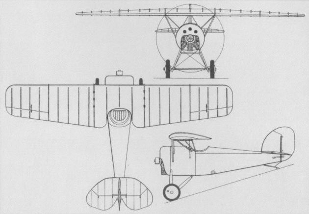
Ur III-powered E 3.
LFG ROLAND D I Germany
Shortly before World War I, the Luft-Fahrzeug Gesellschaft (LFG) adopted the corporate tradename "Roland” to avoid confusion with the Luft-Verkehrs-Gesellschaft (LVG). In 1916, the company initiated the design of a single-seat fighter under the direction of Dipl-Ing Tantzen. It was proposed that the new fighter should embody the innovative structural techniques adopted for the highly successful C II Walfisch (Whale) which utilised the so-called Wickelrumpf, or "wrapped fuselage”, a moulded two-piece shell composed of thin bands of spruce veneer reinforced with fabric. Three prototypes of the new D I fighter were ordered in April 1916, and with the completion of Idflieg (Inspektion der Fliegertruppen) testing in August, LFG was awarded a contract for 60 aircraft. Concurrently, the Pfalz Flugzeugwerke received a contract for a further 20 aircraft. The D I was powered by a 160 hp Mercedes D III water-cooled engine and carried an armament of two synchronised LMG 08/15 machine guns. Although the D I made its appearance at the Front in October 1916, a severe fire at the LFG factory in the previous month had reduced deliveries to little more than a token quantity. The D I inventory at the Front attained a peak of 12 aircraft in February 1917, and the type had disappeared from front-line units in the following June, a few continuing to serve as fighter trainers through 1918. The D I was unofficially known as the Haifisch (Shark).
Max speed, 112 mph (180 km/h) at sea level.
Time to 3,280 ft (1 000 m), 7 min.
Empty weight, 1,541 lb (699 kg).
Loaded weight, 2,055 lb (932 kg).
Span, 29 ft 2 1/3 in (8,90 m).
Length, 22 ft 3 2/3 in (6,80 m).
Height, 9 ft 6 in (2,90 m).
Wing area, 247.58 sq ft (23,00 m2).
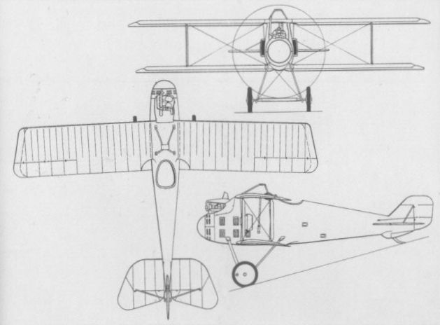
LFG ROLAND D II Germany
While the pilot of the D I enjoyed an excellent upward view, the view downwards, impeded by the somewhat rotund fuselage and twin ear radiators, left much to be desired and was the subject of much criticism. Dipl-Ing Tantzen and his team therefore undertook some redesign, which resulted in the D II. Whereas the upper decking of the D I fuselage was faired into the upper wing, that of the D II was cut down and a narrow pylon faired into the wing, the lateral radiators being discarded in favour of a radiator in the upper wing. The D II proved more difficult to fly and somewhat less manoeuvrable than the Albatros D I, and had a tendency to enter a spin from a steep bank. Nonetheless, in October 1916, LFG received a contract for 30 D II fighters powered by the 160 hp Mercedes D III and armed with two 7,9-mm LMG 08/15 guns. A contract for an additional 100 aircraft was awarded to the Pfalz Flugzeugwerke in the following month. With the availability of the new 180 hp Argus As III water-cooled engine, this power plant was mated with the D II airframe and production continued as the D IIa, of which 40 were ordered in November 1916, 100 in January 1917 and a final 50 in the following March. Performances of the DII and Ha were essentially similar, but the Argus engine of the latter unexpectedly demonstrated a severe power loss at higher altitudes, seriously restricting the fighter’s usefulness. The D II reached the Front in February 1917, strength peaking at 97 aircraft in April and tapering off until the type disappeared from the first line inventory in October. The D IIa reached the Front in June 1917, in which month the inventory reached 128 aircraft, and it was withdrawn from first line service in December 1917. Data relate to the D II.
Max speed, 103 mph (165 km/h).
Time to 16,405 ft (5 000 m), 23 min.
Empty weight, 1,400 lb (635 kg).
Loaded weight, 1,797 lb (815 kg).
Span, 29 ft 3 7/8 in (8,94 m).
Length, 22 ft 8 3/4 in (6,93 m).
Height, 10 ft 2 1/2 in (3,11 m).
Wing area, 245.21 sqft (22,78 m2).
LFG ROLAND D III Germany
In a further attempt to improve visibility for the pilot, LFG evolved the D III. Using a fuselage essentially similar to that of the D II, this introduced staggered, unequal-span and unequal-chord wings, and a cabane of broad aerofoil-section struts. Retaining the 180 hp Argus As III engine of the D IIa and the paired 7,9-mm LMG 08/15 armament, the D III received type test approval in May 1917. LFG and Pfalz respectively received contracts for 150 and 200 aircraft. In the event, Pfalz did not build the LFG fighter, switching instead to the Pfalz D III, and as the former was powered by the marginally-performing Argus engine, very few Roland D IIIs were assigned to the Front, a maximum of nine being with first line units in February 1918 and the last being withdrawn in the following April.
Max speed, 109 mph (175 km/h) at sea level.
Empty weight, 1,581 lb (717 kg).
Loaded weight, 2,119 lb (961 kg).
Wing area, 213.45 sq ft (19,83 m2).
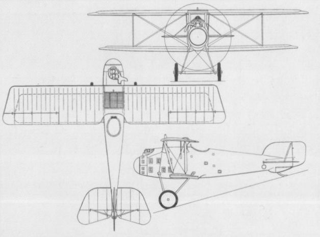
A raised top wing and a conventional cabane distinguished the Roland D III from the earlier Roland fighter biplanes.
LFG ROLAND D IV (DR I) Germany
The DIV single-seat fighter triplane of mid-1917 marked a noteworthy departure from previous LFG structural methods in that the Wickelrumpf that had characterised all previous aircraft gave place to the so-called Klinkerrumpf - clinker-built or lapstrake construction utilising the planking methods commonly employed in the construction of small boat hulls. Strips of spruce overlapped one another by some two-thirds over a light framework of stringers and formers. This method of construction was less time-consuming than the Wickelrumpf and comparably robust. The D IV - later to be redesignated Dr I when the "Dr” prefix was adopted for triplanes - was powered by a 160 hp Mercedes D III water-cooled engine and carried the usual armament of twin synchronised 7,9-mm LMG 08/15 machine guns. A single prototype was ordered by the Idflieg for evaluation, but this crashed at the end of September 1917. It was promptly rebuilt utilising a D VI fuselage, but subsequent testing revealed no particularly outstanding characteristics and further development was discontinued.
Max speed, 96 mph (155 km/h).
Service ceiling, 19,685 ft (6 000 m).
Empty weight, 2,050 lb (930 kg).
Loaded weight, 2,665 lb (1208 kg).
Span, 31ft 0 in (9,45 m).
Length, 24 ft 0 in (7,32 m).

The D IV was the first Roland fighter to adopt the Klinkerrumpf construction method.
LFG ROLAND D V Germany
During the autumn of 1917, three prototypes of the D V were built in an attempt to eradicate the shortcomings revealed by the D III. Retaining the moulded two-piece shell-type fuselage construction of the earlier fighter, and being, in fact, the last LFG type to utilise this so-called Wickelrumpf, the D V employed the complete wing cellule of the D III. The fuselage cross section was reduced and the decking lowered to improve vision from the cockpit. Armament remained two 7,9-mm LMG 08/15 machine guns, and while one prototype retained the 180 hp Argus As III engine of the earlier D II and D III, the other two were powered by the 160 hp Mercedes D III. Testing revealed little advance over the D III and development was discontinued in favour of the D VI. No data relating to the D V are available.
During the autumn of 1917, three prototypes of the D V were built in an attempt to eradicate the shortcomings revealed by the D III. Retaining the moulded two-piece shell-type fuselage construction of the earlier fighter, and being, in fact, the last LFG type to utilise this so-called Wickelrumpf, the D V employed the complete wing cellule of the D III. The fuselage cross section was reduced and the decking lowered to improve vision from the cockpit. Armament remained two 7,9-mm LMG 08/15 machine guns, and while one prototype retained the 180 hp Argus As III engine of the earlier D II and D III, the other two were powered by the 160 hp Mercedes D III. Testing revealed little advance over the D III and development was discontinued in favour of the D VI. No data relating to the D V are available.

The Roland DV was one of a number of designs for which only a single prototype was built in 1917, a period when the Germans were searching for new fighter designs to develop to counter the growing numbers and capabilities of Allied designs.
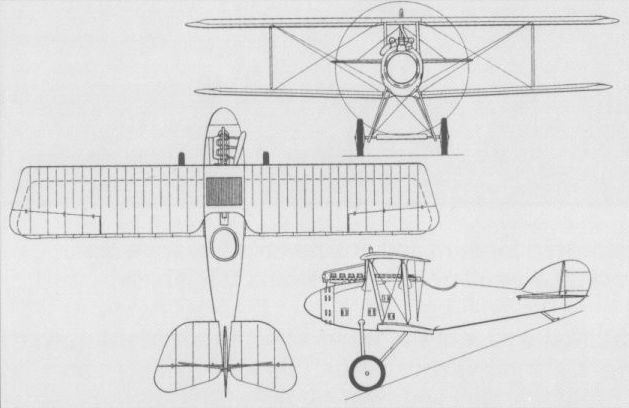
The D V was derived from the D III, the shortcomings of which were not overcome.
LFG ROLAND W Germany
The Roland W twin-float fighter seaplane was an adaptation of the D I. Flown for the first time on 29 June 1917, and powered by a 160 hp Mercedes D III engine, it arrived for evaluation at the base of the Seeflugzeug-Versuchs-Kommando (SVK) at Warnemunde in the following month. It was promptly returned to LFG for modifications aimed at improving the flying characteristics and the view from the cockpit. It was returned to the SVK in September 1917, modified once more and then flight tested, but the poor visibility it offered the pilot led to its prompt rejection. The sole prototype, after further modification to the fuselage, was assigned to the marine single-seat fighter school in November 1917.
Time to 3,280 ft (1 000 m), 5.4 min.
Empty weight, 2,531 lb (1148 kg).
Span, 33 ft 1 2/3 in (10,10 m).
Length, 29 ft 4 1/3 in (8,95 m).
Height, 10 ft 5 7/8 in (3,20 m).
LFG ROLAND D IX Germany
With the advent of more powerful rotary engines in the spring of 1918, Idflieg supported the development of compatible fighters, one such being the D IX powered by the new 160 hp Siemens-Halske Sh III rotary. The first D IX prototype demonstrated excellent performance at the 1st D-type contest in January 1918, before being destroyed as a result of a freak accident. While the D IX was in flight, the pilot’s seat collapsed, its occupant inadvertently pulling the aircraft into a tight loop in which the resultant g forces propelled him through the bottom of the fuselage before the aircraft broke up. At the time, two more prototypes were in assembly, the first of these being successfully load-tested in April prior to resumption of flight testing. The second D IX differed in having enlarged tail surfaces and unbalanced ailerons. Armament comprised twin synchronised 7,9-mm LMG 08/15 machine guns. It appeared in the 2nd D-type contest in May, but, according to the debriefing minutes, was considered unsuited for series production. The third D IX had been completed meanwhile with overhung, unbalanced ailerons and a larger horn-balanced rudder.
Max speed, 115 mph (185 km/h).
Time to 16,405 ft (5 000 m), 16.4 min.
Endurance, 1.5 hrs.
Empty weight, 1,177 lb (534 kg).
Loaded weight, 1,596 lb (724 kg).
Span, 29 ft 3 1/4 in (8,92m).
Length, 19 ft 4 1/4 in (5,90m).
Height, 9 ft 0 in (2,75 m).
Wing area, 198.92 sq ft (18,48 m2).
LFG ROLAND D XIV Germany
Essentially similar to the D XIII, the D XIV was ordered by Idflieg in April 1918 to evaluate the new Goebel Goe III 11-cylinder rotary engine of 160 hp. Fitted with the standard twin 7,9-mm LMG 08/15 gun armament, the prototype D XIV was completed in time to participate in the 2nd D-type contest in May 1918. Flying was strictly limited by the recalcitrant engine, and this, in accordance with competition protocol, eliminated the D XIV from further consideration as a production type. No data relating to the D XIV are available.
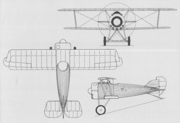
The second D IX with enlarged, horn-balanced rudder.
LFG ROLAND D VI Germany
On 17 October 1917, the first of three prototypes of the D VI fighter was rolled out as the 1,000th aircraft manufactured by LFG. Whereas the D V had been essentially an attempt to enhance the capabilities of the D III design, the D VI was an entirely new design. Utilising the Klinkerrumpf fuselage constructional method first employed by the abortive D IV (Dr I), the D VI entered flight test in November 1917, initially with a 160 hp Mercedes D III engine. As supplies of this engine were restricted, the 185 hp Benz Bz IIIa was installed in at least one of the three prototypes. Testing continued through January 1918, being hampered by inclement weather and difficulties in achieving a suitable propeller match with the engine-airframe combination. After participating in the 1st D-type contest at Adlershof, the D VI passed its type test on 9 February 1918, an initial order being placed for 50 aircraft. By the time World War I came to an end, orders had been placed for 350 D VIa (Mercedes D IIIa) and D VIb (Benz Bz IIIa) fighters. Both the D VIa and D VIb began to reach combat units in May-June 1918, 58 of the former and 12 of the latter being included in the frontline inventory of 31 August. Pilots did not consider the D VI to be anything more than a marginal improvement over the Albatros D Va and Pfalz D IIIa that it was intended to replace - it was slightly faster and more manoeuvrable, but had a lower climb rate - yet it remained in limited production until the end of the conflict. Of the 350 built, 200 were of the D VIb version to which the following data relate.
Max speed, 124 mph (199 km/h).
Time to 16,405 ft (5 000 m), 19 min.
Endurance, 2 hrs.
Empty weight, 1,446 lb (656 kg).
Loaded weight, 1,865 lb (846 kg).
Span, 30 ft 10 7/8 in (9,42 m).
Length, 20 ft 8 7/8 in (6,32 m).
Height, 9 ft 2 1/4 in (2,80 m).
Wing area, 238.1 sq ft (22,12 m2).
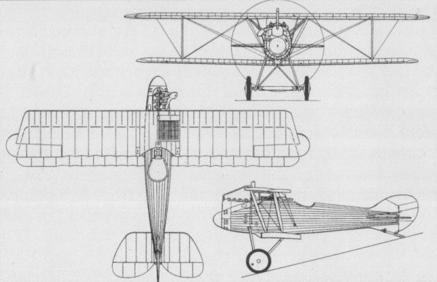
The Mercedes-engined D VIa was, in other respects, similar to the Benz-engined D VIb (on scheme) .
LFG ROLAND D VII Germany
Evolved in parallel with the D VI and also participating in the 1st D-type contest at Adlershof, the D VII was of similar construction and carried an identical armament of two 7,9-mm LMG 08/15 machine guns. It was powered, however, by the still-experimental 185 hp Benz Bz IIIbo eight-cylinder direct-drive engine. Although pilots considered forward view from the cockpit to be outstanding, thanks to the Vee-type arrangement of the engine, the Bz IIIbo was still suffering teething troubles. In the course of further development, the ailerons were revised and D VI-type vertical tail surfaces introduced. The aircraft again participated in a D-type contest, the 2nd, in May 1918. The engine was still insufficiently developed, however, and its recurrent problems dictated termination of the D VII test programme.
Max speed, 118 mph (190 km/h).
Time to 16,405 ft (5 000 m), 16.2 min.
Endurance, 1.5 hrs.
Empty weight, 1,468 lb (666 kg).
Loaded weight, 1,892 lb (858 kg).
Span, 29 ft 0 in (8,84 m).
Length, 20 ft 0 in (6,10 m).
Height, 9 ft 2 1/4 in (2,80 m).
Wing area, 224.22 sq ft (20,83 m2).
LFG ROLAND D VIII Germany
Built by LFG concurrently with the D VII, the D VIII differed essentially in having a geared Benz Bz IIIbm eight-cylinder Vee-type engine of 185 hp in place of the direct-drive Bz IIIbo. According to Idfliegreports, the D VIII was scheduled to make its appearance on 5 May 1918, in time to participate in the 2nd D-type contest. Although records concerning the D VIII are sparse, the debriefing minutes of the contest stated that ‘‘due to the results obtained during the trials, the Roland D VIII cannot be considered for series production”. It is known that the reduction gearing of the Bz IIIbm engine suffered severe vibration and recurrent mechanical faults, and it may be assumed that further development was discontinued after the Competition. No data or illustrations of the D VIII are available.
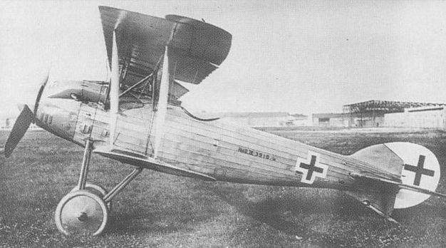
Revised ailerons and tail unit were applied to the D VII before it was finally abandoned.
LFG ROLAND D XIII Germany
In March 1918, after the experimental 195 hp Korting Kg III eight-cylinder water-cooled Vee-type engine had completed a 24-hour duration test, an example of this power plant fitted with reduction gear was delivered to the Luft-Fahrzeug Gesellschaft for installation in the prototype of a new single-seat fighter, the D XIII. Based on the D VII and ordered in April 1918, the D XIII entered flight test in May 1918, but crankshaft cooling proved inadequate and difficulties were experienced with the oil system. In July, the Kg III engine was removed from the prototype and returned to the manufacturer for modification. It was destined not to be re-installed, however, as the D XIII was one of 10 prototypes destroyed in a hangar fire on 25 July 1918. The D XIII was fitted with two synchronised LMG 08/15 machine guns. No performance data were recorded.
Span, 29 ft 6 1/3 in (9,00 m).
Wing area, 247.58 sq ft (23,00 m2).
LFG ROLAND D XV Germany
Three prototypes of the D XV were ordered in April 1918, the original intention being to fit each aircraft with a different engine for comparison purposes. The D XV perpetuated the use of the Klinkerrumpf (clinker-built) fuselage first used on the D IV. The wing cellule was of the "wireless” type, having no bracing cables, and featured appreciably more stagger than that of any preceding LFG fighter. The first D XV was powered by a 160 hp Mercedes D IIIa engine and was completed before the end of April, but flight testing was interrupted in May by the decision to return the prototype to the factory for modifications. A second, similarly-powered, D XV appeared in June 1918, the principal changes being replacement of the paired interplane struts by single I-type struts and the introduction of overhanging ailerons on the upper wing. This prototype was flight tested with both the Mercedes engine and a 185 hp BMW IIIa, demonstrating a good turn of speed, but proving deficient in climb rate. In September 1918, Idflieg demanded further modifications in the light of the trials conducted with the first two prototypes. Instead, the LFG designed a completely new fighter which retained the D XV designation. The following data relate to the initial version of the D XV with the Mercedes D IIIa engine.
Empty weight, 1,609 lb (730 kg).
Loaded weight, 2,006 lb (910 kg).
Span, 28 ft 4 1/8 in (8,64 m).
Wing area, 256.19 sqft (23,80 m2).
LFG ROLAND D XV (II) Germany
Rather than introduce the modifications in the D XV demanded by Idflieg, LFG produced an entirely new fighter bearing no relationship to its predecessor, but, nevertheless, retaining the D XV designation. Bearing a strong similarity to the Fokker D VII and claimed by some to be no more than an unauthorised copy of that fighter, the new D XV was of different construction. The clinker-built fuselage gave place to one of rectangular cross section with plywood skinning, tubular steel N-type interplane bracing struts were employed and two prototypes were built. The first of these appeared late in October 1918 with a 185 hp BMW IIIa engine, and the second was rolled out shortly afterwards with a 200 hp Benz Bz nia. Neither prototype participated in the 3rd D-type contest, and further development was halted by the Armistice. No data relating to the second D XV design are available.
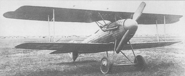
Based on the D VII, the single D XIII had the experimental Korting Vee-type engine.
LFG ROLAND D XVI Germany
Two versions of the D XVI parasol monoplane fighter - initially designated E I - were completed in September-October 1918, one powered by a 160 hp Goebel Goe III rotary and the other by a similarly-rated Siemens-Halske Sh III rotary. The D XVI had a fully-cantilevered fabric-covered parasol wing and a slab-sided plywood-covered fuselage, armament comprising twin synchronised 7,9-mm LMG 08/15 machine guns. Although the 3rd D-type contest was officially restricted to types powered by the BMW engine, Idflieg permitted participation of the Sh III-engined D XVI as it was considered "an interesting type". The D XVI proved faster than the Siemens-Schuckert D IV and Fokker D VII up to an altitude of 13,125 ft (4 000 m), but was slower above that height.
Span 31 ft 0 1/2 in (9,46 m).
Length, 19 ft 4 in (5,90 m).
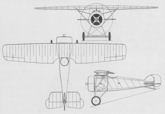
Second prototype of the D XVI fighter.
LFG ROLAND D XVII Germany
The last single-seat fighter to be developed by LFG was the D XVII parasol monoplane powered by a 185 hp BMW IIIa engine. Rolled out on 18 October 1918, the D XVII was in time to be included in the 3rd D-type contest held at Adlershof that month, but was considered markedly inferior to the similarly-powered Fokker V 29 parasol monoplane. During turns the wing of the D XVII oscillated alarmingly and landing was difficult because of a tendency to stall suddenly during the approach if speed was not maintained. No further details are available.
The last single-seat fighter to be developed by LFG was the D XVII parasol monoplane powered by a 185 hp BMW IIIa engine. Rolled out on 18 October 1918, the D XVII was in time to be included in the 3rd D-type contest held at Adlershof that month, but was considered markedly inferior to the similarly-powered Fokker V 29 parasol monoplane. During turns the wing of the D XVII oscillated alarmingly and landing was difficult because of a tendency to stall suddenly during the approach if speed was not maintained. No further details are available.
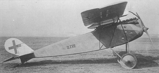
Last of the Roland single-seat fighters, the D XVII was flown just before the end of World War I.
LTG FD 1 Germany
The Luft Torpedo Gesellschaft (LTG) was established in March 1915, primarily for the development of an aerial torpedo. It expanded into aircraft sub-contract, and, on 8 February 1917, received a contract for three prototypes of an original single-seat twin-float fighter, the FD 1. A single-bay staggered equi-span biplane, the FD 1 was powered by a 150 hp Benz Bz III driving the propeller via a Loeb reduction gearbox. The first FD 1 was delivered in May 1917, in which month a further contract was placed for three additional prototypes embodying improvements. The three FD Is ordered under the initial contract were tested through September 1917, after overcoming engine and gearbox mounting deficiencies, but demonstrated poor manoeuvrability. The aircraft built against the second contract differed primarily in having extended dorsal and ventral fins, the first of these being delivered in late October 1917. The FD 1 was finally approved for service in March 1918, five aircraft being added to the Marine seaplane inventory, the first prototype having been destroyed during static load testing. The FD Is were not flown in combat, being placed in storage at Hage where they were discovered by the Allies in December 1918. One example of a landplane version of the FD 1 was flight tested at Johannisthal during 1917.
Max speed, 90 mph (145 km/h).
Time to 3,280 ft (1 000 m), 4.5 min.
Empty weight, 1,973 lb (895 kg).
Loaded weight, 2,568 lb (1165 kg).
Span, 32 ft 9 3/4 in (10,00m).
Length, 29 ft 6 1/3 in (9,00 m).
Height, 11 ft 7 3/4 in (3,55 m).
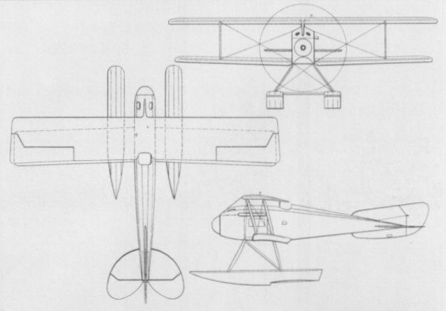
LVG E I Germany
The first fighter of original design produced by the Luft-Verkehrs-Gesellschaft (LVG) of Berlin-Johannisthal was a two-seat monoplane designed by Franz Schneider. This, the E I powered by a 120 hp Mercedes D II engine and flown in 1915, was fitted with both a synchronised machine gun for the pilot and a machine gun on a ring mounting for the second crew member. The LVG E I was unusual in that, unlike most contemporaries, it featured ailerons, most monoplanes at the time employing wing warping for control. Although a promising design, the sole prototype was lost while being ferried to the Front for operational evaluation. It was subsequently ascertained that the screws of the wing bracing struts had worked loose with the result that the wings had collapsed. No data relating to the LVG E I are available.
The first fighter of original design produced by the Luft-Verkehrs-Gesellschaft (LVG) of Berlin-Johannisthal was a two-seat monoplane designed by Franz Schneider. This, the E I powered by a 120 hp Mercedes D II engine and flown in 1915, was fitted with both a synchronised machine gun for the pilot and a machine gun on a ring mounting for the second crew member. The LVG E I was unusual in that, unlike most contemporaries, it featured ailerons, most monoplanes at the time employing wing warping for control. Although a promising design, the sole prototype was lost while being ferried to the Front for operational evaluation. It was subsequently ascertained that the screws of the wing bracing struts had worked loose with the result that the wings had collapsed. No data relating to the LVG E I are available.
LVG D 10 Germany
The Luft-Verkehrs-Gesellschaft (LVG), which had initiated licence manufacture of 75 Albatros D II fighters in August 1916, began work during the course of that year on an original single-seat, single-bay fighter biplane. Of unusual appearance to the designs of engineers Ehrhardt and Rethel, it was designated D10. Powered by a 120 hp Mercedes D II engine, the LVG fighter was noteworthy for its extraordinarily deep fuselage which completely filled the wide wing gap. This Walfisch-type fuselage was of wrapped plywood strip semi-monocoque form, and the wing cellule featured exceptionally broad aerofoil-section interplane struts. The D 10 is known to have demonstrated unsatisfactory characteristics in flight, but no data are available.
The Luft-Verkehrs-Gesellschaft (LVG), which had initiated licence manufacture of 75 Albatros D II fighters in August 1916, began work during the course of that year on an original single-seat, single-bay fighter biplane. Of unusual appearance to the designs of engineers Ehrhardt and Rethel, it was designated D10. Powered by a 120 hp Mercedes D II engine, the LVG fighter was noteworthy for its extraordinarily deep fuselage which completely filled the wide wing gap. This Walfisch-type fuselage was of wrapped plywood strip semi-monocoque form, and the wing cellule featured exceptionally broad aerofoil-section interplane struts. The D 10 is known to have demonstrated unsatisfactory characteristics in flight, but no data are available.
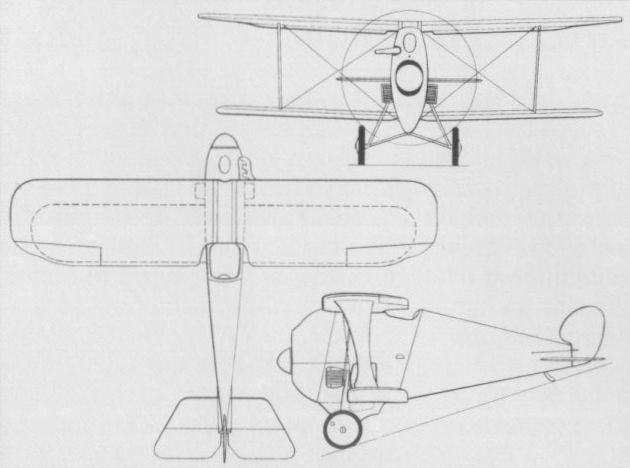
The D10 possessed an unusually deep fuselage which filled the entire wing gap.
LVG D 12 (D II) Germany
At the end of 1916, the LVG produced the prototype of an elegant and more orthodox single-seat fighter biplane, the D 12, also known as the D II (the LVG D I being the licence-built Albatros D II). An unequal-span single-bay biplane with an Albatros-style wooden semi-monocoque fuselage which filled the gap between the wings, the D 12 was powered by a 160 hp Mercedes D III engine and allegedly attained 124 mph (200 km/h) during the course of prototype trials. After suffering accidental damage the type was not further developed. No data relating to the D 12 are available.
At the end of 1916, the LVG produced the prototype of an elegant and more orthodox single-seat fighter biplane, the D 12, also known as the D II (the LVG D I being the licence-built Albatros D II). An unequal-span single-bay biplane with an Albatros-style wooden semi-monocoque fuselage which filled the gap between the wings, the D 12 was powered by a 160 hp Mercedes D III engine and allegedly attained 124 mph (200 km/h) during the course of prototype trials. After suffering accidental damage the type was not further developed. No data relating to the D 12 are available.
LVG D III Germany
Retaining the plywood-covering and semi-monocoque type construction of the D 10 and D 12, the LVG D III made its appearance in the summer of 1917. It was a competitor of the very successful Albatros D III and differed in virtually every respect from its predecessors. The gap-filling fuselage configuration was discarded and an attempt was made to utilise semi-rigid bracing in that the landing wires were replaced by struts, although flying wires were retained. The D III was powered by a 185 hp NAG C III six-cylinder inline engine and carried an armament of two LMG 08/15 machine guns. Official type testing was completed on 2 June 1917, but the D III was adjudged too heavy and too large, and was therefore discounted as a potential production aircraft.
Max speed, 109 mph (175 km/h).
Time to 3,280 ft (1000 m), 3.0 min.
Empty weight, 1,704 lb (773 kg).
Loaded weight 2,266 lb (1 028 kg).
Span, 32 ft 9 3/4 in (10,00 m).
Length, 24 ft 8 1/2 in (7,53 m).
Height, 9 ft 7 in (2,92 m).
Wing area, 282.02 sq ft (26,20 m2).
LVG D IV Germany
Retaining the aerodynamically clean, plywood-covered semi-monocoque fuselage style of the D III and a generally similar wing cellule, with single-spar lower wing and Vee-type interplane struts, the LVG D IV was in the final stages of assembly in September 1917, according to an Idflieg report. Serving as a test-bed for the new 185 hp Benz Bz IIIbo eight-cylinder Vee-type direct-drive engine, the D IV was flight tested intermittently until, on 5 January 1918, the crankshaft broke in flight. The aircraft caught fire and was destroyed. A second D IV prototype was completed in late January, but suffered recurrent engine problems. Nevertheless, it was entered in the 1st D-type contest at Adlershof, but on 29 January, the first day of the competition, the engine caught fire and the aircraft was destroyed, further development being discontinued.
Time to 16,405 ft (5 000 m), 28 min.
Empty weight, 1,499 lb (680 kg).
Loaded weight, 2,061 lb (935 kg).
Span, 27 ft 10 2/3 in (8,50 m).
Length, 20 ft 7 1/4 in (6,28 m).
Height, 8 ft 10 1/4 in (2,70 m).
Wing area, 194.4 sqft (18,06 m2).

The D IV had the misfortune to suffer recurrent engine problems which resulted in the destruction of both prototypes of this fighter.
LVG D V Germany
Designed by Paul Ehrhardt and flown for the first time in June 1918, the LVG D V was unusual in that the lower wing was of much broader chord than the upper. The narrow-chord upper wing panels outboard of the centre section pivoted differentially to act as "ailerons” for lateral manoeuvres. The fuselage was slab-sided and plywood covered, armament comprised two 7,9-mm LMG 08/15 machine guns and power was provided by a geared Vee-eight Benz Bz IIIbm engine affording 185 hp. The D V proved fast, but it was unstable at full speed and its controllability was poor. During a test flight with Ehrhardt at the controls in July 1918, the sole D V prototype made a crash landing and turned turtle, further development being halted. No data are available on this type.
LVG D VI Germany
The last single-seat fighter to emerge from LVG, the D VI single-bay biplane was in final assembly in September 1918, flight testing being initiated shortly before hostilities terminated. Like the preceding D V, it featured a slab-sided plywood-covered fuselage, a twin-LMG 08/15 gun armament and a 185 hp Benz Bz IIIbm geared Vee-eight engine with a chin-type air intake. However, the wing configuration was totally different, the lower wing being sweptback and the I-type interplane struts being supplemented by metal strap cross bracing. No data relating to the D VI are available.
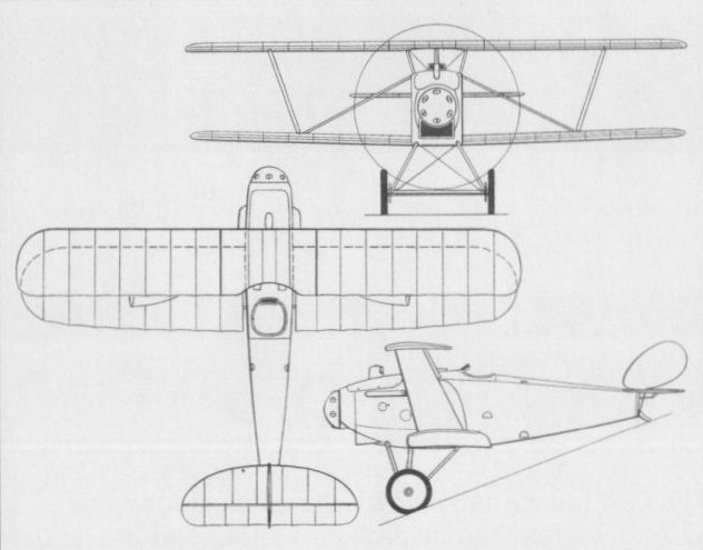
Differentially pivoting upper wing tips were an unusual feature of the D V.
MARK D I Germany
The Markische Flugzeugwerke of Golm in der Mark was established in 1916 for aircraft repair, the training of military pilots and the eventual licence manufacture of training biplanes. In 1918, Ing Wilhelm Hillman left the Schutte-Lanz organisation to join the Markische Flugzeugwerke, for which he designed a single-seat fighter, the Mark D I, powered by a 195 hp Benz Bz IIIb water-cooled eight-cylinder Vee engine. The D I was scheduled to participate in the second fighter competition at Adlershof in May 1918, but the first prototype was destroyed in a crash prior to the contest. A second prototype, on which the warping of the lower wing surfaces was allegedly to have been replaced by conventional ailerons, was under construction in September 1918, but work was apparently terminated with the end of hostilities. No data are available apart from a time of 14 min to climb to 16,405 ft (5 000 m).
The Markische Flugzeugwerke of Golm in der Mark was established in 1916 for aircraft repair, the training of military pilots and the eventual licence manufacture of training biplanes. In 1918, Ing Wilhelm Hillman left the Schutte-Lanz organisation to join the Markische Flugzeugwerke, for which he designed a single-seat fighter, the Mark D I, powered by a 195 hp Benz Bz IIIb water-cooled eight-cylinder Vee engine. The D I was scheduled to participate in the second fighter competition at Adlershof in May 1918, but the first prototype was destroyed in a crash prior to the contest. A second prototype, on which the warping of the lower wing surfaces was allegedly to have been replaced by conventional ailerons, was under construction in September 1918, but work was apparently terminated with the end of hostilities. No data are available apart from a time of 14 min to climb to 16,405 ft (5 000 m).
NAGLO D II
The D II quadruplane built by the Naglo Werft of Pichelsdorf, near Berlin, was designed by Ing Gnadig, who was, at the time, still in the employ of the Albatros Werke. It participated in the second D-type contest at Adlershof in the summer of 1918, the debriefing minutes of which indicated that it was to appear for further testing after modification. Powered by a 160 hp Mercedes six-cylinder water-cooled engine and intended to carry an armament of two LMG 08/15 machine guns, the Naglo D II appears to have been based on an Albatros D V-type fuselage. The bottom wing, completely independent of the three main lifting surfaces, was attached to an extruded keel and braced with splayed struts. Official type testing was undertaken on 24 May 1918, and during the D-type contest evaluation pilots praised the excellence of the construction and workmanship of the D II while calling for an improvement in the flight characteristics. No details of the performance of this quadruplane fighter have survived.
Empty weight, 1,596 lb (724 kg).
Loaded weight, 2,015 lb (914 kg).
Span, 29 ft 6 1/3 in (9,00 m).
Wing area, 241.12 sq ft (22,40 m2).
NFW E I Germany
In the spring of 1916, the National-Flugzeug-Werke built at Johannisthal a single-seat monoplane to the designs of Dipl Ing Hergt. Referred to as the EI (although this is unlikely to have been an official designation) and apparently intended for the fighting role, it was a shoulder wing monoplane of wooden construction. It had a plywood-covered, single-piece, two-spar wing, and the pilot’s cockpit was situated between the spars. The E I was powered by an 80 hp Oberursel U 0 (Gnome) seven-cylinder rotary engine, but no details of its flight testing have survived, development apparently being discontinued in favour of a larger and more powerful monoplane (E II).
Max speed, 97 mph (156 km/h).
Time to 4,265 ft (1300 m), 6.0 min.
Empty weight, 944 lb (428 kg).
Loaded weight, 1,367 lb (620 kg).
Span, 32 ft 9 7/10 in (10,00 m).
Length, 21ft 3 9/10 in (6,50 m).
Wing area, 169.21 sq ft (15,72 m2).
NFW E II Germany
Although the National-Flugzeug-Werke was largely preoccupied with aircraft repair and flying school operation, in 1917 this concern again built an original single-seat monoplane. To the designs of Dipl Ing Heinrich and completed at Leipzig, this aircraft was of wooden construction and was powered by a 160 hp Daimler D IIIa six-cylinder water-cooled engine. Referred to as the E II, although, again, this is unlikely to have been an official designation, this aircraft progressed no further than a single prototype.
Max speed, 116 mph (186 km/h).
Time to 9,515 ft (2 900 m), 6.3 min.
Empty weight, 1,230 lb (558 kg).
Loaded weight, 1,693 lb (768 kg).
Span, 39 ft 4 1/2 in (12,00 m).
Wing area, 182.99 sq ft (17,00 m2).
PFALZ E III Germany
The Morane-Saulnier Type L parasol monoplane two-seater, for which the Pfalz Flugzeug-Werke acquired a manufacturing licence in 1914, was built primarily for the reconnaissance and training roles as the A I and A II with the 80 hp Oberursel U 0 and 100 hp Oberursel U I rotaries respectively, 60 being delivered during 1914-15. In 1915, the rear seat and gun mounting were removed, a single synchronised LMG 08/15 machine gun was mounted ahead of the cockpit, and, with the 100 hp U I engine, the modified aircraft was produced in small numbers as the E III fighter. Although having a rate of climb superior to that of the E II, the E III was considered as essentially an interim type and the largest number of these fighters at the Front at any one time was eight (June 1916).
Max speed, 95mph (153 km/h).
Time to 3,280 ft (1000 m), 3.0 min.
Endurance, 2.0 hrs.
Empty weight, 981 lb (445 kg).
Loaded weight, 1,554 lb (705 kg).
Span, 36 ft 9 in (11,20 m).
Length, 22 ft 5 3/4 in (6,85m).
Height, 11 ft 1 7/8 in (3,40 m).
Wing area, 193.76 sq ft (18,00 m2).
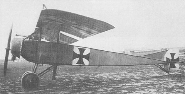
The E III was considered an interim type and was evolved from the Morane-Saulnier Type L.
PFALZ E I Germany
Early in 1914, the Pfalz Flugzeug-Werke, which had been established in the previous year specifically to manufacture aircraft for the Bavarian Flying Service, acquired a licence to manufacture the Morane-Saulnier Types H and L. In 1915, Pfalz produced its first aircraft to carry a machine gun, this, the E I, being broadly based on the Type H and powered by an 80 hp Oberursel U 0 (Gnome) rotary engine. This shoulder-wing monoplane of wooden construction passed its Typen-Prufung in September 1915. Two were at the Front by the end of the following month and the number of E Is at the Front peaked at 27 aircraft by the end of April 1916. Their principal role was as armed escorts for observation flights, armament comprising a single synchronised LMG 08/15 machine gun. Some E Is saw action in Palestine during the 1916 Sinai desert campaign, and others were flown by Bavarian units as unarmed high-speed reconnaissance aircraft.
Max speed, 87 mph (140 km/h).
Time to 2,625 ft (800 m), 3.0 min.
Endurance, 1.5 hrs. Empty weight, 760 lb (345 kg).
Loaded weight, 1,179 lb (535 kg).
Span, 30 ft 4 1/2 in (9,26 m).
Length, 20 ft 8 in (6,30 m).
Height, 8 ft 4 2/5 in (2,55 m).
Wing area, 150.7 sq ft (14,00 m2).
PFALZ E II Germany
Fundamentally an improved E I, the E II completed its Typen-Prufung in July 1916, but by that time 30 were already at the Front with various Bavarian squadrons. Following manufacture of some 60 E Is, Pfalz introduced a 100 hp Oberursel U I rotary, increased overall span by 3 ft 1 in (94 cm) and continued production as the E II. Armament remained a single synchronised LMG 08/15 machine gun, and the E II served alongside the lower-powered E I in twos and threes with two-seat reconnaissance aircraft units to undertake escort tasks. Like the E I, the E II was entirely of wooden construction and, apart from having a fabric-skinned rear fuselage, was plywood covered. The E II had disappeared from the Western Front by the end of 1916, some having served in Macedonia, Palestine and Syria.
Max speed, 93 mph (150 km/h).
Time to 2,625 ft (800 m), 2.75 min.
Endurance, 1.5 hrs.
Empty weight, 904 lb (410 kg).
Loaded weight, 1,261 lb (572 kg).
Span, 33 ft 5 1/2 in (10,20 m).
Length, 21 ft 1 9/10 in (6,45 m).
Height, 8 ft 4 2/5 in (2,55 m).
Wing area, 172.23 sq ft (16,00 m2).
PFALZ E IV Germany
Retaining the ply- and fabric-covered wooden airframe of the E II, the E IV differed primarily in having a two-row Oberursel U III rotary engine of 160 hp and an armament of two synchronised LMG 08/15 machine guns. Type-tested in January 1916, the E IV was found to be a poor gun platform and its U III engine proved unreliable. A series of 24 aircraft was built, but the E IV saw little frontline use owing to its shortcomings, and the maximum number at the Front at any one time was five aircraft (April 1916).
Max speed, 99 mph (160 km/h).
Time to 9,840 ft (3 000 m), 10 min.
Endurance, 1 hr.
Empty weight, 1,038 lb (471 kg).
Loaded weight, 1,530 lb (694 kg).
Dimensions as for E II apart from length of 21 ft 7 7/8 in (6,60 m).
PFALZ E VI Germany
Although, by early 1916, the more rugged and manoeuvrable biplane configuration was demonstrating a clear superiority over the monoplane in the fighting role, the Pfalz Flugzeug-Werke persisted with the latter and developed the E V and E VI. The E VI differed primarily in having the 100 hp Oberursel U I rotary engine, and some redesign of the vertical tail surface, but this type saw no combat, the 20 built being assigned to the instructional role.

The Pfalz E I was broadly based on the Morane-Saulnier Type H and began to arrive at the Front from late October 1915.
PFALZ D.4 Germany
Designated D.4 by its manufacturer, the Pfalz Flugzeug-Werke’s first essay in the single-seat fighting biplane category, flown in the summer of 1916, was powered by a 105 hp Daimler D I six-cylinder water-cooled engine with a car-type radiator. An unequal-span, slightly-staggered single-bay biplane, the D.4 featured an exceptionally deep fuselage eliminating the normal cabane structure and afforded an extremely poor forward view for the pilot who was unable to see the horizon in level flight and was virtually blind for take-off and landing. Flight testing revealed poor handling characteristics, the rudder being blanketed by the deep fuselage and directional stability being totally inadequate. A fixed vertical fin was added at an early stage, but this failed to ameliorate the more serious shortcomings, development being discontinued and Pfalz building the LFG Roland D I (and subsequently the D II). No data relating to the D.4 have survived.
Designated D.4 by its manufacturer, the Pfalz Flugzeug-Werke’s first essay in the single-seat fighting biplane category, flown in the summer of 1916, was powered by a 105 hp Daimler D I six-cylinder water-cooled engine with a car-type radiator. An unequal-span, slightly-staggered single-bay biplane, the D.4 featured an exceptionally deep fuselage eliminating the normal cabane structure and afforded an extremely poor forward view for the pilot who was unable to see the horizon in level flight and was virtually blind for take-off and landing. Flight testing revealed poor handling characteristics, the rudder being blanketed by the deep fuselage and directional stability being totally inadequate. A fixed vertical fin was added at an early stage, but this failed to ameliorate the more serious shortcomings, development being discontinued and Pfalz building the LFG Roland D I (and subsequently the D II). No data relating to the D.4 have survived.
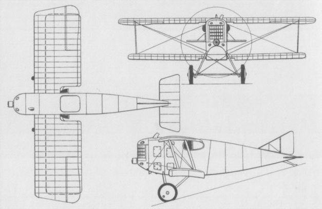
PFALZ E V Germany
Although, by early 1916, the more rugged and manoeuvrable biplane configuration was demonstrating a clear superiority over the monoplane in the fighting role, the Pfalz Flugzeug-Werke persisted with the latter and developed the E V and E VI. The E V, which completed its Typen-Prufung in July 1916, employed an essentially similar airframe to that of the E IV, this being mated with a 105 hp Daimler D I six-cylinder water-cooled engine, armament reverting to a single LMG 08/15 machine gun. Twenty E Vs were built, but the advent of more efficient and more powerful biplanes rendered the E V obsolescent prior to delivery and only three saw frontline service.
Max speed, 102 mph (165 km/h).
Endurance, 2.0 hrs.
Empty weight, 1,124 lb (510 kg).
Loaded weight, 1,534 lb (696 kg).
Dimensions as for E IV.
PFALZ D III Germany
Designed by Ing Geringer assisted by Ing Paulus and Ing Geldmacher, the D III owed much to experience gained in manufacture of the LFG Roland D I and II, and was an unequal-span single-bay biplane of wooden construction with a semi-monocoque fuselage. Powered by a 160 hp Daimler D III six-cylinder water-cooled engine and carrying an armament of twin LMG 08/15 machine guns, the D III completed Typen-Prufung at Adlershof in June 1917. By October 1917, 145 D IIIs were already in squadron service, the number at the Front attaining a peak of 276 by the year's end. The D IIIa, which embodied relatively minor changes including a redesigned, longer-span tailplane, repositioned guns and modified lower-wing tips, reached the Front in December 1917. The D IIIa attained its peak service usage in April 1918 when 433 were at the Front. Similarly powered and armed to the D III, the D IIIa, which remained in first-line use until the end of hostilities, had a basically similar specification, the following data relating to the earlier model.
Max speed, 102 mph (165 km/h) at 9,840 ft (3 000 m).
Time to 4,920 ft (1500 m), 6.9 min.
Endurance, 2.2 hrs.
Empty weight, 1,521 lb (690 kg).
Loaded weight, 2,039 lb (925 kg).
Span, 30 ft 10 in (9,40 m).
Length, 22 ft 9 2/3 in (6,95 m).
Height, 9 ft 9 1/8 in (2,67 m).
Wing area, 238.32 sqft (22,14 m2).
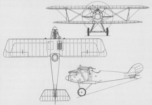
The D III which saw service from autumn 1917.
PFALZ D IV Germany
No details of the D IV single-seat single-bay biplane fighter are available apart from the fact that it was powered by a 110 hp Oberursel U II rotary engine and was built in parallel with the D VI (there being no record of a D V). The D IV is believed to have been flown early in 1917.
PFALZ D VI Germany
Submitted for inclusion in the first D-type Competition at Adlershof in January 1918 (together with the D VII and D VIII), the D VI was an elegant single-bay biplane in which careful attention had been paid to aerodynamic cleanliness. Flown early in 1917, and employing the semi-monocoque wrapped plywood fuselage construction of the D III, the D VI was powered by a 110 hp Oberursel U II rotary. Armament comprised the standard twin LMG 08/15 arrangement and acceptance testing was completed satisfactorily in September 1917, but a comparatively poor rate of climb seems to have militated against a production order.
Time to 16,405 ft (5 000 m), 24 min.
Empty weight, 882 lb (400 kg).
Loaded weight, 1,336 lb (606 kg).
Span, 23 ft 2 3/4 in (7,08 m).
Wing area, 143.16 sqft (13,30 m2).
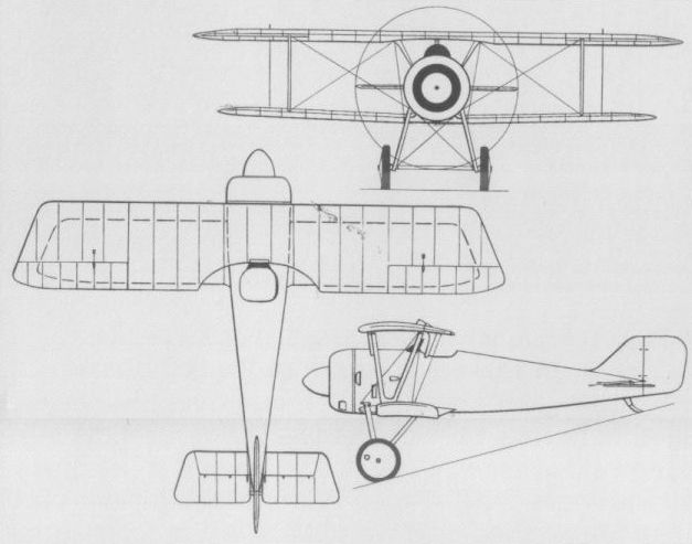
The D VI which was flown early in 1917.
PFALZ D VII Germany
A further Pfalz contender in the first D-type Competition, the D VII single-bay staggered biplane passed its Typen-Prufung in February 1918, but was not the recipient of a production contract. The D VII was tested with both balanced and unbalanced ailerons, with two-bladed and four-bladed propellers, and with at least three engines: the 160 hp Siemens Halske Sh III, the 160 hp Goebel Goe III and the 145 hp Oberursel U III. Armament consisted of the standard twin LMG 08/15 machine guns. The following data relate to the Sh III-powered model.
Max speed, 118 mph (190 km/h) at 13,125 ft (4 000 m).
Time to 19,685 ft (6 000 m), 25.25 min.
Endurance, 1.5 hrs.
Empty weight, 1,146 lb (520 kg).
Loaded weight, 1,576 lb (715 kg).
Span, 24 ft 8 in (7,52 m).
Length, 18 ft 6 1/2 in (5,65m).
Height, 9 ft 4 1/4 in (2,85 m).
Wing area, 185.14 sqft (17,20 m2).
PFALZ D VIII Germany
A contender in the second D-type Competition at Adlershof in May 1918, the D VIII was in all respects similar to the D VII apart from having two-bay wing bracing. The slightly raked wings were of equal parallel chord with slightly splayed interplane struts, and a standard Pfalz-type wooden structure was employed, with a semi-monocoque fuselage. The Typen-Prufung was performed in January 1918, with a D VIII powered by a 160 hp Siemens Halske Sh III 11-cylinder rotary, but one of two D VIIIs participating in the D-type Competition had N-type interplane struts, horn-balanced ailerons and a 160 hp Goebel Goe III engine. Limited production of the Sh III-powered D VIII was undertaken, this being introduced to squadron service in June 1918, but by the end of August only 19 fighters of this type were at the Front, a total of 40 having been built. A D VIII was tested with a 145 hp Oberursel U III engine and another with a Rhemag R II driving counter-rotating propellers, but only the Sh III version saw service. Armed with two LMG 08/15 machine guns, the D VIII possessed pleasant handling characteristics and offered a good standard of manoeuvrability and a high climb rate, but it suffered a weak undercarriage. Data relate to the Sh III-powered D VIII.
Max speed, 118 mph (190 km/h).
Time to 9,840 ft (3 000 m), 3.1 min.
Endurance, 1.5 hrs.
Empty weight, 1,197 lb (543 kg).
Loaded weight, 1,627 lb (738 kg).
Dimensions as for D VII.
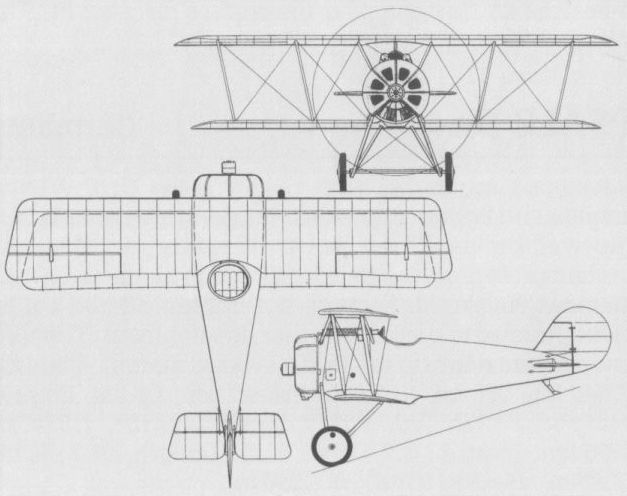
The D VIII saw limited production and was tested at the Front in the summer of 1918.
PFALZ DR I Germany
Official interest in the potential of the triplane configuration for single-seat fighters prompted Pfalz to develop the Dr I. Powered by a 160 hp Siemens Halske Sh III 11-cylinder geared rotary engine, this underwent Typen-Prufung in October 1917. Armed with twin synchronised LMG 08/15 guns, the Dr I was of sufficient promise to warrant a pre-series evaluation batch of 10 aircraft, all of which arrived at the Front by the end of April 1918. Service pilots considered the Dr I too slow and its Sh III engine insufficiently reliable for frontline use, and no further examples were produced.
Max speed, 118 mph (190 km/h) at 13,125 ft (4 000 m).
Time to 16,405 ft (5 000 m), 13.5 min.
Endurance, 1.5 hrs.
Empty weight, 1,124 lb (510 kg).
Loaded weight, 1,554 lb (705 kg).
Span, 28 ft 0 2/3 in (8,55 m).
Length, 18 ft 0 1/2 in (5,50 m).
Height, 9 ft 0 2/3 in (2,76 m).
Wing area, 185.14 sqft (17,20 m2).
PFALZ DR II Germany
Developed in parallel with the Dr I, the Dr II was a smaller and lighter single-seat fighter triplane utilising the well-proven Oberursel Ur II rotary of 110 hp. A second prototype, the Dr IId, differed in having a 110 hp Siemens Halske Sh I rotary, but neither offered sufficient promise to warrant further development. The following data relate to the Ur II-powered aircraft.
Time to 9,840 ft (3 000 m), 10.2 min.
Endurance, 1.5 hrs.
Empty weight, 882 lb (400 kg).
Loaded weight, 1,314 lb (596 kg).
Span, 23 ft 7 1/2 in (7,20 m).
Length, 19 ft 6 1/4 in (5,95 m).
Height, 9 ft 6 1/8 in (2,90 m).
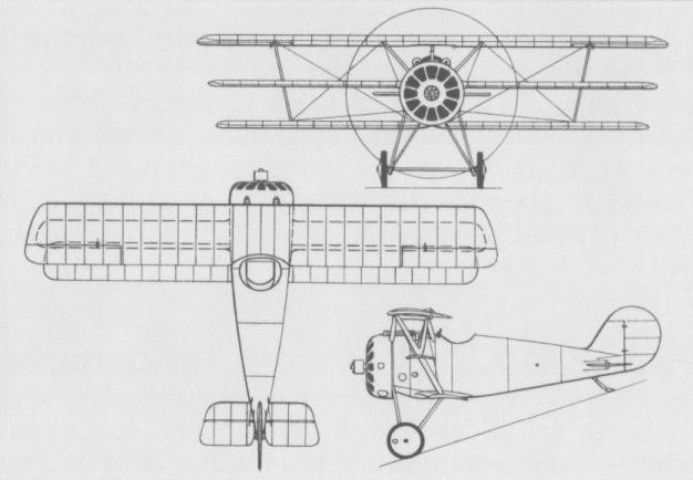
The Dr I was tested at the Front in pre-production form during the spring of 1918.
PFALZ DR-TYP Germany
In the late autumn of 1917, the Pfalz Flugzeug-Werke completed and flew a triplane derivative of the standard D III biplane. Retaining the 160 hp Daimler D III engine, this experimental model (for which no designation is recorded) featured ailerons on both upper and lower wings. It would seem that manufacturer’s trials were unsuccessful, however, as this triplane was never demonstrated to the military authorities at Adlershof.
In the late autumn of 1917, the Pfalz Flugzeug-Werke completed and flew a triplane derivative of the standard D III biplane. Retaining the 160 hp Daimler D III engine, this experimental model (for which no designation is recorded) featured ailerons on both upper and lower wings. It would seem that manufacturer’s trials were unsuccessful, however, as this triplane was never demonstrated to the military authorities at Adlershof.
PFALZ D XII Germany
Participating in the second D-type Competition alongside the D VIII, the D XII was adjudged one of the winning contenders and Pfalz was awarded a contract for 500 aircraft of this type. The four examples participating in the competition each had a different engine, one having a 180 hp Daimler D IIIau, one having a 185 hp BMW IIIa, one having a 195 hp Benz Bz IIIbou and another having a 170 hp Daimler D IIIa. The last mentioned six-cylinder water-cooled engine was adopted for the series D XII, Typen-Prufung taking place on 19 June 1918. Armed with twin LMG 08/15 machine guns, the D XII began to reach the Front in quantity in August 1918, but it was reputedly unpopular with its pilots owing to poor control response. By October 1918, 180 D XIIs were at the Front, but although sturdy aircraft, they did not compare favourably with the contemporary Fokker D VII.
Max speed, 106 mph (170 km/h).
Time to 3,280 ft (1 000 m), 3.4 min.
Endurance, 1.5 hrs.
Empty weight, 1,578 lb (716 kg).
Loaded weight, 1,977 lb (897 kg).
Span, 29 ft 6 1/3 in (9,00 m).
Length, 20 ft 10 in (6,35 m).
Height, 8 ft 10 1/4 in (2,70m).
Wing area, 233.58 sq ft (21,70 m2).
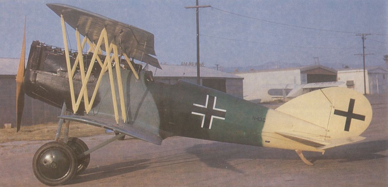
A Pfalz D XII photographed at Riverside, California, in 1959 when owned by Frank Tallman.
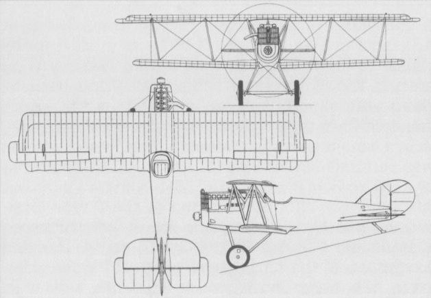
The D XII began to reach the Front in quantity in August 1918, but proved unpopular.
PFALZ D XIV Germany
The D XIV, which underwent Typen-Prufung on 15 May 1918, was very similar to its immediate predecessor, but featured wings of greater span and area, a deeper fuselage, an enlarged vertical fin and a high-compression Benz Bz IVu six-cylinder water-cooled engine. Structurally similar to preceding Pfalz fighters and carrying the standard twin-gun armament, the D XIV participated in the second D-type Competition, but did not demonstrate any appreciable advance over the D XII, development being discontinued.
Max speed, 112 mph (180 km/h) at 13,125 ft (4 000 m).
Time to 3,280 ft (1000 m), 3.0 min.
Endurance, 1.5 hrs.
Empty weight, 1,836 lb (833 kg).
Loaded weight, 2,275 lb (1032 kg).
Span, 32 ft 9 2/3 in (10,00 m).
Length, 20 ft 8 4/5 in (6,32 m).
Height, 8 ft 10 1/4 in (2,70 m).
Wing area, 273.73 sq ft (25,43 m2).
PFALZ D XV Germany
Certainly one of the last, if not the last, single-seat fighter to be accepted for production in Germany during World War I - having completed its Typen-Prufung on 4 November 1918, a few days before the Armistice - the D XV participated in the third D-type Competition in October 1918. Departing from previous Pfalz practice in having the fuselage suspended between the single-bay wings and all flying and landing wires deleted, the D XV was developed during the summer of 1918, and flew in D XVf and D XV(Spezial) versions in the competition. The former had unbalanced ailerons and the latter had balanced ailerons which were adopted for the series version, both having the 185 hp BMW IIIa engine, although the Daimler D IIIa of 180 hp could also be fitted. The D XV was highly manoeuvrable and possessed a good performance, but was allegedly tail heavy and difficult to land. Too late to see operational service, several series D XVs were completed and Allied inspection teams found 74 finished D XV fuselages at the Pfalz Flugzeug-Werke in September 1919.
Max speed, 126 mph (203 km/h).
Time to 3,280 ft (1000 m), 2.0 min.
Endurance, 1.5 hrs.
Empty weight, 1,627 lb (738 kg).
Loaded weight, 2,024 lb (918 kg).
Span, 28 ft 2 2/3 in (8,60 m).
Length, 21 ft 3 9/10 in (6,50 m).
Height, 8 ft 10 1/3 in (2,70 m).
Wing area, 215.28 sqft (20,00 m2).
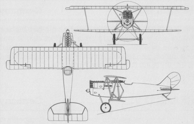
REX D 6 Germany
Early in 1916, the Flugmaschine Rex Gesellschaft of Koln-Bickendorf produced its first single-seat fighter to the designs of Dipl-Ing Friedrich Hansen, the D 6, which allegedly owed its inspiration to the Bristol Scout. A thoroughly conventional equi-span single-bay biplane, the D 6 was of wooden construction with fabric skinning and was powered by an 80 hp Oberursel (Gnome) U 0 seven-cylinder rotary engine. The first prototype D 6 crashed on its first flight while being flown by its designer from Cologne airfield, but a second example was built, this differing in only minor respects, such as omission of the nose-over structure projecting ahead of the undercarriage. No further details of the D 6 have been recorded, but it may be assumed that performance was insufficient to justify an Idflieg contract.
Early in 1916, the Flugmaschine Rex Gesellschaft of Koln-Bickendorf produced its first single-seat fighter to the designs of Dipl-Ing Friedrich Hansen, the D 6, which allegedly owed its inspiration to the Bristol Scout. A thoroughly conventional equi-span single-bay biplane, the D 6 was of wooden construction with fabric skinning and was powered by an 80 hp Oberursel (Gnome) U 0 seven-cylinder rotary engine. The first prototype D 6 crashed on its first flight while being flown by its designer from Cologne airfield, but a second example was built, this differing in only minor respects, such as omission of the nose-over structure projecting ahead of the undercarriage. No further details of the D 6 have been recorded, but it may be assumed that performance was insufficient to justify an Idflieg contract.
REX D 7
Designed by Dipl-Ing Friedrich Hansen and built as a private venture in the summer of 1917, allegedly to the specific requirements of Lt Werner Voss, the D 7 was a small sesquiplane of wooden construction and powered by a 100 hp Hansen seven-cylinder single-valve rotary engine. Featuring a slab-sided, plywood-skinned fuselage with fabric-covered wings and horizontal tail surfaces, the D 7 was novel in that the lower wing halves pivoted about the bases of the V-type interplane struts, either collectively or differentially, thus serving as flaps or ailerons, a scheme that was the subject of a patent. No record of the flight testing of the D 7 has survived, but the arrangement would seem to have been of dubious practicality as the prototype appears to have been abandoned after the death of Voss, on 23 September 1917.
Designed by Dipl-Ing Friedrich Hansen and built as a private venture in the summer of 1917, allegedly to the specific requirements of Lt Werner Voss, the D 7 was a small sesquiplane of wooden construction and powered by a 100 hp Hansen seven-cylinder single-valve rotary engine. Featuring a slab-sided, plywood-skinned fuselage with fabric-covered wings and horizontal tail surfaces, the D 7 was novel in that the lower wing halves pivoted about the bases of the V-type interplane struts, either collectively or differentially, thus serving as flaps or ailerons, a scheme that was the subject of a patent. No record of the flight testing of the D 7 has survived, but the arrangement would seem to have been of dubious practicality as the prototype appears to have been abandoned after the death of Voss, on 23 September 1917.
RUMPLER 6A 2 Germany
In May 1916, the Rumpler Flugzeug-Werke initiated flight test of a tandem two-seat reconnaissance fighter referred to by the company designation 6A 2 (the first digit indicating the year, the letter indicating the aircraft category and the second digit signifying the design sequence in that category and year). Whereas all preceding Rumpler biplanes had featured two-bay wing cellules, the 6A 2 broke new ground in being of single-bay configuration with Y-type interplane struts. Of mixed construction with plywood and fabric skinning, it was initially powered by a 160 hp Mercedes D III six-cylinder water-cooled engine with Stimkuhler radiator beneath the wing centre section and a ‘‘rhino horn” exhaust pipe. Proposed armament comprised a synchronised 7,9-mm LMG 08/15 machine gun and a swivelling Parabellum in the rear cockpit. At an early phase in flight development some strengthening of the wings was undertaken and more orthodox paired struts substituted, and, subsequently, the 6A 2 was fitted with a geared eight-cylinder Mercedes D IV engine of 220 hp. Excessive vibration led to discontinuation of the flight test programme, the type being overtaken by the more innovative 7C 1.
Loaded weight, 2,778 lb (1260 kg).
Span, 33 ft 5 1/2 in (10,20 m).
RUMPLER 6B 1 Germany
The first essay in the single-seat fighter category by Rumpler was a twin-float seaplane intended for both offensive patrol and seaplane station defence. Assigned the company designation 6B 1, the fighter was a derivative of the highly successful 5A 2 (C I) two-seat general-purpose biplane, possessing a fundamentally similar structure and retaining the 160 hp Mercedes D III engine. The two-bay wing cellule was also retained, but a modest stagger was applied, the rear cockpit was discarded and armament comprised a single synchronised 7,9-mm LMG 08/15 machine gun. The largest of five single-seat float fighter prototypes ordered in June 1916 for evaluation by the Marine-Flieger, the 6B1 entered production after acceptance of three prototypes during July-August 1916. Forty series aircraft followed between November and May 1917, production continuing with the 6B 2 of which 50 had been delivered when the programme terminated in January 1918. The 6B 2 differed in comparatively minor respects, the most visible modification being use of the tailplane of ‘‘wing-nut” form of the C IV. The following data relate to the 6B 1 in standard form.
Max speed, 84 mph (135 km/h) at sea level.
Time to 9,840 ft (3000 m), 25 min.
Range, 342 mis (550 km).
Empty weight, 1,742 lb (790 kg).
Loaded weight, 2,513 lb (1140 kg).
Span, 39 ft 10 1/3 in (12,15 m).
Length, 29 ft 8 1/3 in (9,05 m).
Height, 11 ft 5 3/4 in (3,50 m).
Wing area, 384.28 sq ft (35,70 m2).
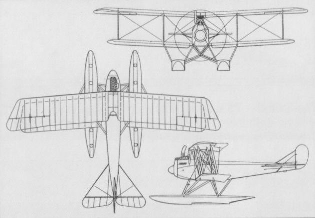
The Rumpler 6B 1 (shown) and similar 6B 2 were ordered in quantity after prototype test.
RUMPLER 7C 1 Germany
Late in 1916, the Rumpler team headed by Edmund Rumpler initiated design of both a two-seat and a single-seat fighter embodying a novel, if complex, method of fuselage construction. This, protected by a patent filed early in 1915, sought to combine minimum weight with maximum strength. The fuselage was built up from plywood frames with numerous thin stringers, the whole being covered by two layers of doped fabric strips applied diagonally in opposite directions and intended to provide the necessary torsional stiffness. A close-cowled 160 hp Mercedes D III engine was attached to a fuselage extrusion supporting the upper wing, which embodied an offset flush radiator. The upper wing was of parallel chord, the lower wing being of so-called Libelle (Dragonfly) form featuring a curved trailing edge, the wing cellule being braced by single broad-chord I-section struts with cables running to two fuselage points. This formula, which resulted in what was, aerodynamically, an outstandingly clean aeroplane, was applied to the 7C1 two-seat fighter and the 7D 1 single-seat fighter. The 7C 1 entered flight test in the spring of 1917, initially with vertical tail surfaces confined to a pivoting rudder. The tail was subsequently redesigned to embody a fixed fin, but development was discontinued at a comparatively early stage, presumably as a result of difficulties similar to those experienced with the parallel single-seat 7D 1. No specification for the 7C 1 appears to have survived.
Late in 1916, the Rumpler team headed by Edmund Rumpler initiated design of both a two-seat and a single-seat fighter embodying a novel, if complex, method of fuselage construction. This, protected by a patent filed early in 1915, sought to combine minimum weight with maximum strength. The fuselage was built up from plywood frames with numerous thin stringers, the whole being covered by two layers of doped fabric strips applied diagonally in opposite directions and intended to provide the necessary torsional stiffness. A close-cowled 160 hp Mercedes D III engine was attached to a fuselage extrusion supporting the upper wing, which embodied an offset flush radiator. The upper wing was of parallel chord, the lower wing being of so-called Libelle (Dragonfly) form featuring a curved trailing edge, the wing cellule being braced by single broad-chord I-section struts with cables running to two fuselage points. This formula, which resulted in what was, aerodynamically, an outstandingly clean aeroplane, was applied to the 7C1 two-seat fighter and the 7D 1 single-seat fighter. The 7C 1 entered flight test in the spring of 1917, initially with vertical tail surfaces confined to a pivoting rudder. The tail was subsequently redesigned to embody a fixed fin, but development was discontinued at a comparatively early stage, presumably as a result of difficulties similar to those experienced with the parallel single-seat 7D 1. No specification for the 7C 1 appears to have survived.
RUMPLER 7D 1 Germany
Evolved in parallel with the two-seat 7C 1 and embodying similar aerodynamic and structural features, the 7D 1 single-seat fighter was the recipient of an Idflieg (Inspectorate of Flying Troops) contract for three prototypes, flight testing commencing in the spring of 1917. The Idflieg requirement called for a speed of 103 mph (165 km/h) at 16,405 ft (5 000 m), that altitude being attained in 31.5 minutes, and an endurance of 1.5 hrs. An armament of two synchronised 7,9-mm LMG 08/15 machine guns was specified and provision for oxygen breathing apparatus requested. A second identical prototype was designated 7D 2. Flight testing revealed that the pilot’s field of vision was seriously impaired by the broad-chord interplane struts and there were aerodynamic problems associated with the upper wing/fuselage junction. Furthermore, there were servicing difficulties related to the engine installation. In consequence, the 7D1 and 2 were abandoned in favour of a more conventional fighter, the 7D 3.
Max speed, 109 mph (175 km/h).
Service ceiling, 22,965 ft (7 000 m).
Span, 26 ft 10 3/4 in (8,20 m).
Length, 19 ft 4 1/4 in (5,90 m).
Height, 8 ft 6 1/3 in (2,60 m).
RUMPLER 7D 3 Germany
The shortcomings displayed by the 7D 1 and 2 led the Rumpler team to evolve a more conventional derivative fighter retaining the same structural precepts. This, the 7D 3, retained the Mercedes D III engine, but a more orthodox installation was adopted, the flush radiator being centrally mounted in the wing centre section which was raised above the forward fuselage decking by means of a cabane structure. The broad-chord I-type interplane struts were discarded in favour of more conventional twin struts. The 7D 3 was tested during the summer of 1917, but it may be presumed that results were not entirely satisfactory, as, by the late autumn, work had begun on an entirely new aircraft, the 7D 4, intended to participate in the first D-type contest that was to take place at Adlershof early in the following year. No further details of the 7D 3 are available.
RUMPLER 7D 4 Germany
To compete in the first D-type contest (20 January - 12 February 1918), intended to select single-seat fighters for service introduction in mid-1918, Rumpler built two prototypes of the 7D 4. One prototype was completed with a conventional twin-strut cellule and the other with a cellule employing "reverse-C” interplane struts braced by fabric-wrapped triple cables. The fuselage structure remained unchanged, but in an attempt to eradicate some torsional problems experienced earlier with this type of construction, a thin plywood veneer skinning was applied to the nose and tail sections to increase rigidity. Again, the Mercedes D III engine was retained and specified armament was two 7,9-mm LMG 08/15 synchronised guns. Flight testing of the 7D 4 had commenced by October 1917, and during the D-type contest the example fitted with "reverse-C” interplane struts attained an altitude of 16,405 ft (5 000 m) within 23.8 min. This prototype was considered to afford excellent visibility from the cockpit, but was, by consensus, somewhat temperamental in handling and difficult to land. Nevertheless, it appeared to possess sufficient promise to warrant an order for a pre-series of 50 examples of a developed version (7D 7) for further investigation and possible operational evaluation. Another prototype was completed as the 7D 5, this differing essentially in having an automobile-style frontal radiator. No specification for the 7D 4 is available.
RUMPLER 7D 7 Germany
Too late to participate officially in the first D-type contest, the 7D 7 was an improved derivative of the 7D 4 with the "reverse-C” type interplane struts. A new Gottingen aerofoil was employed for the wing, which had control surfaces of marginally reduced area, the cockpit was smaller and was moved forward 13 4/5 in (35 cm), and the buried wing radiator gave place to ear-type radiators mounted immediately above the lower wing roots. Flight testing proved the 7D 7 faster than the 7D 4, and an unofficial climb to 16,405 ft (5 000 m) within 18 min was reported. The 7D 7 was powered by the 160 hp Mercedes D III engine and possessed an armament of two synchronised 7,9-mm LMG 08/15 machine guns, static load testing and flight evaluation occupying the period 22 February to 1 May 1918. Some disconcerting twisting of the tail was encountered during certain manoeuvres, calling for structural reinforcement, the Idflieg reporting in May 1918 that the 7D 7 was "unacceptable for the Front and would be rebuilt.”
RUMPLER 8D 1 (D I) Germany
To overcome the lack of rear fuselage rigidity experienced during testing of the 7D 7, the fabric-wrapped, multi-stringered fuselage structure first featured by the 7C 1 and 7D 1 was finally and reluctantly abandoned in favour of a stronger, more conventional semi-monocoque of diagonally-wrapped strips of glued plywood. The wing cellule was reinforced, balanced ailerons were fitted, and the fin and rudder were redesigned and enlarged. Designated 8D 1, this revised fighter provided the standard for the 50 pre-series aircraft previously ordered from Rumpler as D Is. Three pre-series D Is powered by the 160 hp Mercedes D IIIa engine and one powered by the 180 hp D IIIau high-compression engine participated in the second D-type contest (27 May - 28 June 1918), the last-mentioned attaining an altitude of 16,405 ft (5 000 m) in 18.7 min compared with 27 min required by the D IIIa-engined D I. Excellent climb and altitude capabilities notwithstanding, the evaluation pilots’ consensus of the D I was unfavourable, particularly criticised being aileron response - which was considered slow and erratic - the gliding and landing characteristics, and the level of vibration. One D I powered by a 185 hp BMW ma engine participated in the third D-type contest (10-22 October 1918), being the only contender to attain an altitude of 26,900 ft (8 200 m), but the fighter was deemed of ‘‘limited usefulness” in close-in combat. Military acceptance testing of the Rumpler fighter had still to be completed at the time the conflict terminated when 22 had been built. Another 27 were completed after the Armistice. The following data relate to the standard D IIIa-powered D I.
Max speed, 112 mph (180 km/h) at 16,405 ft (5000 m).
Time to 16,405 ft (5000 m), 23.75 min.
Endurance, 1.5 hrs.
Empty weight, 1,356 lb (615 kg).
Loaded weight, 1,775 lb (805 kg).
Span, 27 ft 7 1/2 in (8,42 m).
Length, 18 ft 10 2/5 in (5,75 m).
Height, 8 ft 4 3/4 in (2,56 m).
Wing area, 179.33 sq ft (16,66 m2).
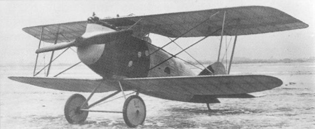
The Rumpler 7D 4 with a twin-strut cellule which entered flight test in October 1917.
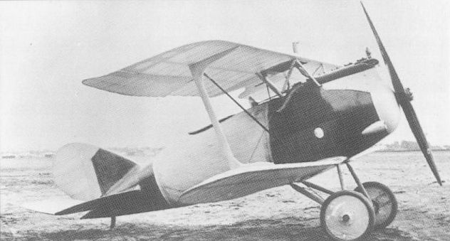
The Rumpler 7D 4 in its original form with a cellule employing "reverse-C" interplane struts.
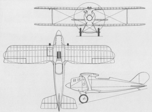
The Rumpler 7D 1 single-seat fighter.

The Rumpler 7D 4 with a twin-strut cellule which entered flight test in October 1917.
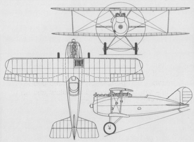
The Rumpler 7D 7 with new Gottingen aerofoil.
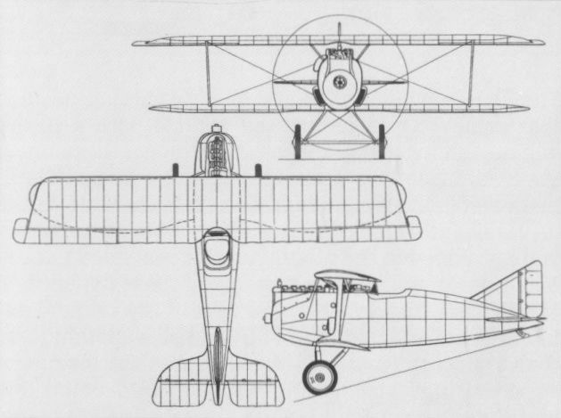
The pre-series D I, the Rumpler 8D 1, which participated in two D-type contests.
SABLATNIG SF 3 Germany
Designed by the Sablatnig-Flugzeugbau of Berlin to meet a requirement for a two-seat fighter for escort and offensive patrols, the SF 3 was a large twin-float, two- bay biplane, a single prototype of which was flown in 1916. Powered by a 200 hp Benz Bz IV six-cylinder water-cooled engine with a "rhino horn” type exhaust pipe and lateral ear-type radiators, the SF 3 had a ply-covered fuselage and an armament of one fixed forward-firing 7,9-mm LMG 08/15 machine gun and a swivelling Parabellum in the rear cockpit. The SF 3 displayed unsatisfactory characteristics and development was discontinued. No further details are recorded.
SABLATNIG SF 7 Germany
When the Marineflieger formulated a requirement for a longer-range two-seat waterborne fighter, the Sablatnig-Flugzeugbau developed the SF 7 in competition with the Friedrichshafen FF 48 and the Brandenburg W 19, three prototypes of each being ordered in April 1917. The SF 7 was a two-bay twin-float biplane with I-type interplane struts and rigid diagonal struts bracing the inboard wireless bay. Power was provided by a six-cylinder water-cooled Maybach Mb IV engine of 240 hp and armament consisted of a single fixed 7,9-mm LMG 08/15 machine gun and a Parabellum on a flexible mounting in the rear cockpit. The SF 7s were accepted by the Navy in September 1917, but comparative trials with the W 19 proved the superiority of the Brandenburg design, which was selected to fulfil the requirement.
Max speed, 101 mph (164 km/h) at sea level.
Ceiling, 14,765 ft (4 500 m).
Range, 466 mis (750 km).
Empty weight, 3,433 lb (1557 kg).
Loaded weight, 4,665 lb (2116 kg).
Span, 51 ft 0 1/2 in (15,58 m).
Length, 30 ft 2 1/4 in (9,20 m).
Height, 12 ft 1 2/3 in (3,70 m).
Wing area, 571.9 sq ft (53,13 m2).
SABLATNIG SF 4
A Marineflieger demand for a single-seat waterborne fighter for offensive patrol and seaplane station defence resulted in the design of the SF 4, one of five such types ordered for prototype evaluation in June 1916. The SF 4, of which two examples were ordered, was powered by a 150 hp Benz Bz III six-cylinder inline water-cooled engine. The first prototype, delivered on 17 February 1917, was an unequal-span staggered single-bay biplane with twin floats. The X-type interplane struts and the small inverted V-type struts (the latter providing anchorage points above the upper wing for bracing) were faired by fabric. The first prototype proved to possess poor manoeuvrability and the Sablatnig-Flugzeugbau elected to undertake major redesign and to complete the second SF 4 as a triplane (which see). The SF 4 had an armament of one synchronised 7,9-mm LMG 08/15 machine gun.
Max speed, 98 mph (158 km/h) at sea level.
Time to 3,280 ft (1,000 m), 5.5 min.
Empty weight, 1,742 lb (790 kg).
Loaded weight, 2,359 lb (1 070 kg).
Span, 39 ft 4 3/8 in (12,00 m).
Length, 27 ft 4 in (8,33 m).
Height, 12 ft 2 7/8 in (3,73 m).
Wing area, 304.2 sq ft (28,26 m2).
SABLATNIG SF 4DR Germany
The poor manoeuvrability demonstrated by the first prototype of the SF 4 biplane led to major redesign, the second prototype being completed as an equi-span triplane. This, the SF 4Dr, retained the Bz III engine and single-gun armament of the first prototype, together with the fuselage structure and floats. The interplane and cabane struts were of broad-chord I-type and the tail surfaces were entirely redesigned. No details of the results achieved during flight testing of the SF 4Dr have survived and no further examples were built.
Span, 30 ft 4 1/8 in (9,25 m).
Length, 27 ft 4 in (8,33 m).
Wing area, 305.49 sq ft (28,38 m2).
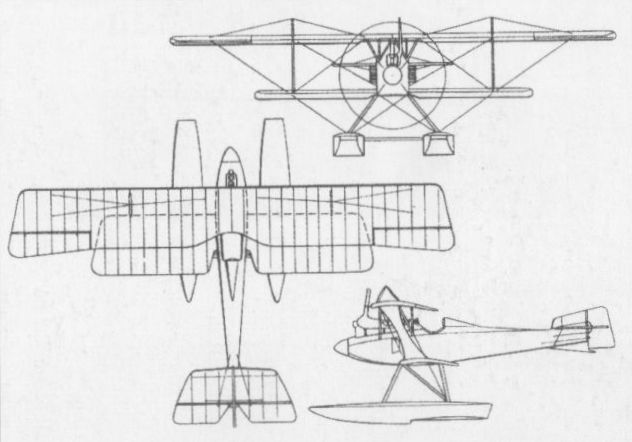
Only one prototype of the SF 4 was completed in biplane configuration.
SCHNEIDER D-TYP Germany
The Franz Schneider Flugmaschinen-Werke was established in January 1917 by Franz Schneider for aircraft repair and servicing. Schneider had been associated with Edouard Nieuport prior to World War I and was subsequently responsible for the design of a number of LVG types. In 1918, Schneider designed and built a single-seat fighter powered by a 200 hp Goebel Goe III nine-cylinder rotary engine and carrying an armament of two 7,9-mm LMG 08/15 machine guns. Of conventional appearance, this fighter was unusual in having a patented arrangement of variable-incidence wings. A single-bay equi-span biplane with ailerons on the lower wings, the Schneider fighter allegedly demonstrated good climb and manoeuvrability, and was reportedly to have been fitted with an innovative arrangement whereby the engine could be tilted several degrees in flight, although there is no record of such an installation having been made. No specification for the Schneider fighter has survived.
The Franz Schneider Flugmaschinen-Werke was established in January 1917 by Franz Schneider for aircraft repair and servicing. Schneider had been associated with Edouard Nieuport prior to World War I and was subsequently responsible for the design of a number of LVG types. In 1918, Schneider designed and built a single-seat fighter powered by a 200 hp Goebel Goe III nine-cylinder rotary engine and carrying an armament of two 7,9-mm LMG 08/15 machine guns. Of conventional appearance, this fighter was unusual in having a patented arrangement of variable-incidence wings. A single-bay equi-span biplane with ailerons on the lower wings, the Schneider fighter allegedly demonstrated good climb and manoeuvrability, and was reportedly to have been fitted with an innovative arrangement whereby the engine could be tilted several degrees in flight, although there is no record of such an installation having been made. No specification for the Schneider fighter has survived.
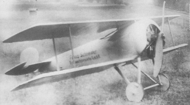
Few records have survived of the diminutive Schneider fighter, tested in 1918.
SCHUTTE-LANZ D I Germany
The Luftfahrzeugbau Schutte-Lanz produced, in 1915, what was subsequently claimed to be the first German single-seat biplane fighter. Designed by Dipl-Ing W Hillmann and Walter Stein, this, the D I, was a lightweight single-bay staggered biplane which had apparently found its inspiration in the Sopwith Tabloid. Of wooden construction throughout with fabric skinning, it was powered by an 80 hp Oberursel (Gnome) seven-cylinder rotary engine, but was rejected by the Idflieg on the grounds that the biplane afforded inferior pilot vision to the monoplane and was therefore unsuited for the single-seat fighter role. Hillmann and Stein introduced some redesign and installed a 100 hp Mercedes six-cylinder water-cooled engine to result in the D II, which, in the event, was never flown.
Max speed, 84 mph (135 km/h) at sea level
Span, 24 ft 7 1/4 in (7,50 m).
Length, 17 ft 8 2/3 in (5.40 m).
SCHUTTE-LANZ D III Germany
Designed to participate in the first D-type contest organised by the Idflieg at Adlershof, which took place between 20 January and 12 February 1918, the D III was a conventional single-bay staggered biplane with N-type interplane struts. Armament comprised two 7,9-mm LMG 08/15 machine guns and power was provided by a 160 hp Mercedes D III six-cylinder inline water-cooled engine, an unusual feature being the use of an individual exhaust pipe for each cylinder, an aerofoil-shaped radiator being offset to port in the upper wing centre section. Of wooden construction with fabric skinning, the D III revealed an unspectacular performance, and, during the D-type contest, on 25 January, recorded climbing times of 3.0 min to 3,280 ft (1 000 m) and 31.9 min to 16,405 ft (5 000 m).
Max speed, 121 mph (195 km/h).
Loaded weight, 1,896 lb (860 kg).
Span, 26 ft 3 in (8,00 m).
Length, 21 ft 39/w in (6,50 m).
Schutte-Lanz Fighter Specifications
D.III D.IV D.VI D.VII
Engine 160 hp Mercedes D.III 195 hp Benz B.IIIbo V-8 160 hp Mercedes D.III 180 hp Mercedes D.IIIau
Span, m 8.0 9.0 10.8 9.0
Chord, upper, m 1.5 1.5 1.6 1.5
Chord, lower, m 1.2 1.2 1.3 1.2
Wing area, m2 20.0 23.3 23.7 24.3
Length, m 6.5 5.8 6.65 6.0
Height, m 3.1 2.963 2.64 3.1
Wt, empty, kg 645 710 800 630
Wt, loaded, kg 860 900 980 810
Max. speed, kmh 195 180
Climb, 1000 m 3.0 min 2.8 min
Climb, 2000 m 5.8 min
Climb, 3000 m 9.7 min
Climb, 4000 m 14.8 min
Climb, 5000 m 31.9 min 14 min 21.3 min
Climb, 6000 m 29.6 min
Climb, 7000 m 29.6 min
Climb, 8000 m 45.5 min
Ceiling, m 8000
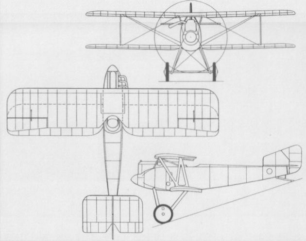
SCHUTTE-LANZ D IV Germany
Built in parallel with the D III, but possessing no commonality, the D IV was powered by a 220 hp Benz Bz IIIbo eight-cylinder Vee-type water-cooled engine and carried an armament of two 7,9-mm LMG 08/15 machine guns. Of wooden construction, it was a single-bay staggered biplane with N-type interplane struts and ailerons on both upper and lower mainplanes. Flown late in 1917, the D IV was found to posses a performance inferior to that of the D III and was therefore withdrawn as a contender in the D-type contest. A second prototype, the D IVa, differed in having a frontal radiator for the Benz engine, shallower underside fuselage contours which did not project below the lower wing, a redesigned undercarriage and revised cabane struts. A further development of the basic design, the D V, was intended to be powered by the 160 hp Mercedes D III engine fitted with a Brown Boveri compressor. Difficulties with this compressor resulted in work on the D V being discontinued by May 1918.
Time to 16,405 ft (5 000 m), 14.0 min.
Empty weight, 1,532 lb (695 kg).
Loaded weight, 1,951 lb (885 kg).
Span, 29 ft 6 1/3 in (9,00 m).
Length, 19 ft 0 1/4 in (5,80 m).
Wing area, 247.15 sqft (22,96 m2).
SCHUTTE-LANZ D VII Germany
A progressive development of the basic D III design, the D VII was completed in time to compete in the second D-type contest (27 May - 28 June 1918). Powered by a Mercedes D IIIavu six-cylinder water-cooled engine of 180 hp with a frontal, automobile-type radiator, the D VII was of wooden construction with a plywood-covered fuselage, the wing cellule being essentially similar to that of the earlier fighter, but having ailerons also on the lower wing for improved lateral control. Armament comprised twin 7,9-mm LMG 08/15 machine guns. Three prototypes of the D VII were ordered, the first of these entering flight test in May 1918. This type did not display a particularly outstanding performance during the D-type contest, but flight testing was continuing at the time of the Armistice.
Max speed, 112 mph (180 km/h).
Time to 3,280 ft (1000 m), 2.4 min, to 16,405 ft (5 000 m), 31.6 min.
Endurance, 1.5 hrs.
Empty weight, 1,631 lb (740 kg).
Loaded weight, 2,028 lb (920 kg).
Span, 29 ft 6 1/3 in (9,00 m).
Length, 19 ft 8 1/4in (6,00 m).
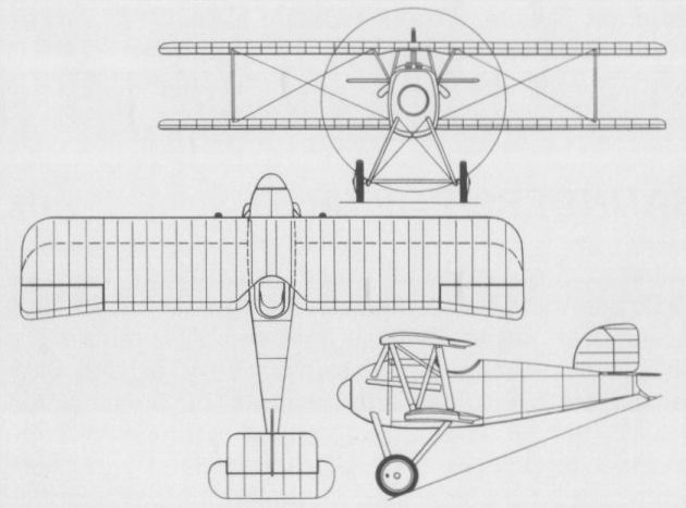
The D IV with Benz Bz IIIbo engine.
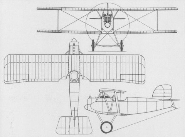
The Schutte-Lanz D VII of mid 1918.
SCHUTTE-LANZ Dr I Germany
The operational debut of the Sopwith triplane on the Western Front in the spring of 1917 aroused considerable interest in this configuration within the Idflieg which immediately encouraged the development of conceptually similar fighters by the German industry. Among single-seat fighter triplanes submitted as a result was the Dr I proffered by the Luftfahrzeugbau Schutte-Lanz. Powered by a 160 hp Mercedes D III six-cylinder inline water-cooled engine and carrying the then standard armament of twin 7,9-mm LMG 08/15 machine guns, the Dr I mated the fuselage and vertical tail surfaces of the D III biplane with a triplane wing cellule. The arrangement of the wings was unusual in that forward stagger was applied to the centre plane, presumably in an attempt to improve view. The Dr I participated in the second D-type contest (27 May - 28 June 1918).
Loaded weight, 1,984 lb (900 kg).
Span, 26 ft 3 in (8,00 m).
Length, 20 ft 6 1/2 in (6,26 m).
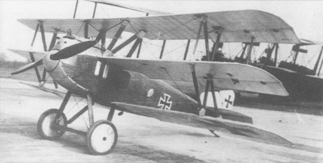
The only prototype Schutte-Lanz triplane was powered by a 160 hp Mercedes D.III. lt was derived from the Schutte-Lanz D.III biplane with the same engine; the D.III biplane had better speed and climb than the Dr.I triplane.
Schutte-Lanz developed the Dr I in 1918 after studying the Sopwith Triplane.
Schutte-Lanz developed the Dr I in 1918 after studying the Sopwith Triplane.
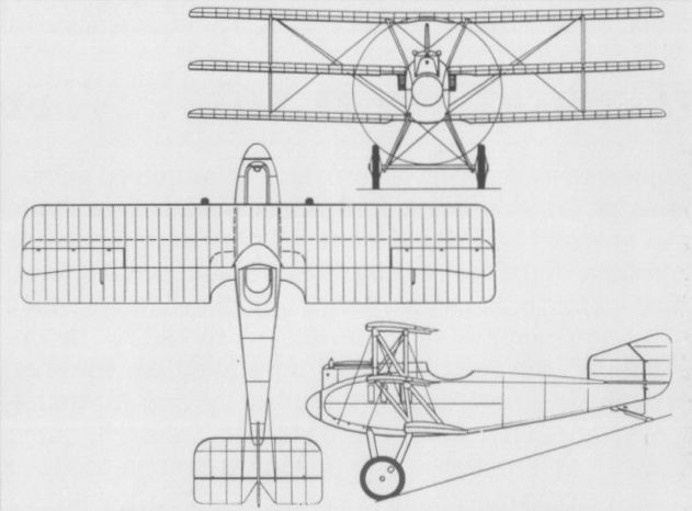
SCHUTTE-LANZ D VI Germany
A unique single-seat fighter created by the Luftfahrzeugbau Schutte-Lanz in the spring of 1918 was the D VI, which was fundamentally a parasol monoplane, but featured additional lifting surface in the form of an aerofoil-section fairing between the parallel struts bracing the outer wing panels to the base of the fuselage. Powered by a 160 hp Mercedes D III engine, the D VI was flown for the first time on 29 May 1918, but crashed and was not rebuilt.
Span, 35 ft 5 1/5 in (10,80 m).
Length, 21 ft 4 1/3 in (6,51 m).

SCHWADE KAMPFEINSITZER Nr 1 Germany
In 1914, the Otto Schwade concern of Erfurt initiated the flight test of a small single-seater powered by an 80 hp Schwade Stahlherz seven-cylinder rotary engine installed as a pusher behind an abbreviated circular section nacelle. A single-bay biplane with tubular outriggers supporting the tail surfaces, the Schwade single-seater, known as the Nr 1, was fitted with a Bergmann LMG 15 7,9-mm machine gun on a flexible mounting during the course of flight trials, but no details of these are recorded and development is believed to have been abandoned at an early stage in favour of a more advanced design, the Nr 2.
SCHWADE KAMPFEINSITZER NR 2 Germany
Late in 1915, Otto Schwade produced a single-seat two-bay biplane twin-boom pusher fighter, the Nr 2, which appears to have been developed in the light of experience gained with the company's first Kampfeinsitzer. A somewhat ungainly aircraft with the pilot accommodated in a circular-section nacelle suspended between the wings by a profusion of struts, and twin vertical tail surfaces carried by ply-covered booms of narrow oval section, this aircraft was powered by a Schwade Stahlherz seven-cylinder rotary engine of 80 hp. No further details of this aircraft have been recorded.
SIEMENS-SCHUCKERT (SSW) DD 5 Germany
The first single-seat fighter biplane to be designed by Franz Steffen (who was subsequently to lose his life while demonstrating the E II monoplane), the DD 5 featured sharply tapered wings built up around steel tube spars, steel I-type interplane struts and a similar fuselage and tail to those of the E I monoplane. Powered by a 100 hp Siemens-Halske Sh I nine-cylinder rotary engine, the DD 5 was tested by the Idflieg in August 1916, but was rejected owing to its poor aerodynamic qualities and the restricted field of view provided by the cockpit. Armament comprised a single 7,9-mm LMG 08/15 machine gun. Only one prototype of the DD 5 was built and tested, development being discontinued in favour of an almost identical copy of the Nieuport 11 that was being developed (as the D I) in parallel. No specification for the DD 5 is available.
The first single-seat fighter biplane to be designed by Franz Steffen (who was subsequently to lose his life while demonstrating the E II monoplane), the DD 5 featured sharply tapered wings built up around steel tube spars, steel I-type interplane struts and a similar fuselage and tail to those of the E I monoplane. Powered by a 100 hp Siemens-Halske Sh I nine-cylinder rotary engine, the DD 5 was tested by the Idflieg in August 1916, but was rejected owing to its poor aerodynamic qualities and the restricted field of view provided by the cockpit. Armament comprised a single 7,9-mm LMG 08/15 machine gun. Only one prototype of the DD 5 was built and tested, development being discontinued in favour of an almost identical copy of the Nieuport 11 that was being developed (as the D I) in parallel. No specification for the DD 5 is available.

The single prototype of the DD 5 was rejected owing to poor aerodynamic qualities.
SIEMENS-SCHUCKERT (SSW) E I Germany
The first single-seat fighter to be produced by the Siemens-Schuckert-Werke (SSW), the E I monoplane was designed by Franz Steffen and completed in October 1915. Of conventional shoulder-wing arrangement with warp control rather than ailerons, the E I had steel-tube wing spars, fabric-covered wings and plywood-covered fuselage, power being provided by a Siemens-Halske Sh I nine-cylinder rotary engine of 100 hp and armament comprising a single synchronised 7,9-mm LMG 08/15 machine gun. After completion of flight testing on 17 March 1916, the E I was recommended for service, and the Idflieg placed a contract for 20 aircraft with the SSW Nurnberg facility. Only five E Is were listed as being at the Front on 31 October 1916, by which time the type had been rendered obsolescent by the appearance during the Battle of the Somme of the Nieuport 11.
Max speed, 87 mph (140 km/h) at sea level.
Range, 130 mis (210 km).
Empty weight, 1,043 lb (473 kg).
Loaded weight, 1,484 lb (673 kg).
Span, 32 ft 9 2/3 in (10,00 m).
Length, 23 ft 3 1/2 in (7,10 m).
Height, 9 ft 2 1/4 in (2,80 m).
Wing area, 172.23 sqft (16,00 m2).
SIEMENS-SCHUCKERT (SSW) E II Germany
Completed early in 1916, the E II was essentially similar to the E I apart from its power plant, the Sh I rotary being replaced by a six-cylinder inline Argus As II engine rated at 120 hp. Armament remained a single 7,9-mm LMG 08/15 machine gun. The sole prototype of the E II was destroyed on 26 June 1916 during a demonstration at Doberitz, its designer, Franz Steffen, who was flying the aircraft, losing his life. No details of the E II are available.
SIEMENS-SCHUCKERT (SSW) E III Germany
Following the small production batch of E I monoplanes, the Siemens-Schuckert-Werke received an Idflieg contract for six additional aircraft designated E III. These differed from the E I only in power plant type. Powered by a 100 hp Oberursel UI nine-cylinder rotary engine, the E III retained the airframe and armament of the E I, a proposed development, the E IV, being similar apart from a circular-section fuselage. The dimensions and performance of the E III were similar to those of the E I.
Empty weight, 1,054 lb (478 kg).
Loaded weight, 1,495 lb (678 kg).
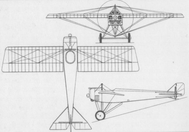
The E I which achieved operational service in small numbers in the summer of 1916.
SIEMENS-SCHUCKERT (SSW) D I Germany
The debut of the Nieuport 11 on the Western Front came as a serious blow to Germany, and, with no immediate prospect of a superior fighter forthcoming from the German aircraft industry, the Idflieg requested Albatros, Euler and SSW to produce improved copies of the Nie 11 with the utmost urgency. The SSW version, designed by Franz Steffen shortly before his death in the E II, was powered by a 110 hp Siemens-Halske Sh I rotary and armed with a single synchronised 7,9-mm LMG 08/15 machine gun, but was in most other respects virtually identical to the French fighter. In October 1916, Bruno Steffen, brother of the designer, made a noteworthy climb to 16,405 ft (5 000 m) in 45 min in the prototype of the SSW version of the Nie 11, and, on 25 November, a contract was placed for 150 aircraft under the designation D I. In the event, production tempo was slowed by delays in deliveries of the geared rotary engine, and as, by mid 1917, the SSW D I had been overtaken in performance by other types, only 95 were completed (the remaining 55 airframes being delivered uncovered to Adlershof). An order for a further 100 placed on 21 March 1917 had meanwhile been cancelled. Only small numbers of SSW D Is appeared on the Western Front, most being assigned to flying schools. Attempts to improve the basic fighter resulted in a single D Ia and two D Ib aircraft. The D Ia featured a twin-gun armament and a 14-sq ft (1,30-m2) increase in wing area, and the D Ib’s had one-piece upper wings, one having a further increase in wing area to 174.38 sq ft (16,20 m2) and the other having a high-compression version of the Sh I engine affording 140 hp and enabling the fighter to attain 16,405 ft (5 000 m) in 20.5 min.
Max speed, 96 mph (155 km/h).
Time to 3,280 ft (1 000 m), 3.5 min.
Endurance, 2.3 hrs.
Empty weight, 979 lb (444 kg).
Loaded weight, 1,442 lb (654 kg).
Span, 24 ft 7 1/4 in (7,50 m).
Length, 19 ft 8 1/4 in (6,00 m).
Height, 8 ft 5 7/8 in (2,59 m).
Wing area, 155 sqft (14,40 m2).
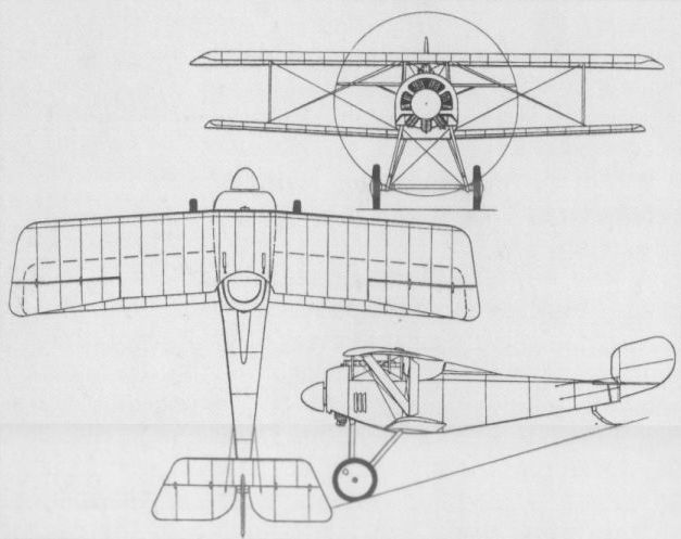
SIEMENS-SCHUCKERT (SSW) D II Germany
Late in 1916, at the suggestion of the Idflieg, SSW began work on a new single-seat fighter designed by Dipl Ing Harald Wolff around the new 11-cylinder Siemens-Halske Sh III geared rotary engine rated at 160 hp. The result, the D II, was a rotund single-bay biplane primarily of wooden construction, the wings featuring two hollow box spars and the fuselage being a circular-section semi-monocoque of three-ply, intended armament being two 7,9-mm LMG 08/15 machine guns. Three prototypes were initially built, the D II, the D IIa and the D IIb. Although completed early 1917, delays in availability of the Sh III engine prevented flight test of the prototypes, the first of these flying in June. Erratic engine behaviour notwithstanding, the D IIs demonstrated excellent climb performance - the D IIb attaining 16,405 ft (5 000 m) in 15.5 min during August - and three more development aircraft were ordered. Two of these, designated D IIc kurz (short) and D IIc lang (long), differed in wing span and area. The D IIc kurz had a span of 27 ft 10 2/3 in (8,50 m) and a wing area of 208.8 sq ft (19,40 m2) whereas the D IIc lang had a span and area of 29 ft 6 1/3 in (9,00 m) and 193.97 sqft (18,02 m2) respectively, and reduced chord on the upper wing. The third aircraft, the D IIe, had dural wing spars, broad-chord I-type interplane struts and unbraced wings. The D IIc kurz entered flight test on 22 October 1917, the D IIc lang following on 15 November, and an initial order for 20 series aircraft, designated D III and based on the D IIc kurz was placed in December. The D IIc wing cellule was found to lack rigidity in flight, dictating introduction of interplane bracing cables which negated the original purpose of the dural spars, this aircraft later being rebuilt to D IV standards.
SIEMENS-SCHUCKERT (SSW) D III Germany
With the choice of the D IIc kurz (short) as the basis for the initial production Sh III-powered SSW fighter biplane to which the designation D III was assigned, an order for 20 aircraft was placed in December 1917, this being augmented by an order for a further 30 in February 1918. The first two series D IIIs initially had a two-bladed propeller similar to that of the D II, but this was replaced by a smaller-diameter four-bladed propeller which permitted a reduction in the height of the undercarriage chassis. The Siemens-Halske Sh III 11-cylinder rotary engine had a nominal rating of 160 hp, but its maximum output was 210 hp at sea level. The standard armament of twin 7,9-mm LMG 08/15 synchronised machine guns was fitted. The first D IIIs came off the line in January 1918, and, between March and May, a total of 41 was sent to the Front where they demonstrated good handling qualities and outstanding climb capabilities. The Sh III engine proved troublesome, however, having been placed in service prematurely, and all D IIIs were returned to SSW for modification. This involved introduction of the improved Sh IIIa engine and the cutting away of the lower portion of the engine cowling to improve cooling. In addition, some revision was made to the rudder contours. These modifications were also incorporated in a further 30 D IIIs ordered in the interim, to bring total production to 80 aircraft. A modified version, the D IIIa with ailerons on the upper wing only, participated in the second D-type contest (17 May - 28 June 1918), but was not found to offer worthwhile advantages over the standard model.
Max speed, 110 mph (177 km/h) at sea level.
Time to 3,280 ft (1000 m), 1.75 min.
Range, 224 mis (360 km).
Empty weight, 1,153 lb (523 kg).
Loaded weight, 1,598 lb (725 kg).
Span, 27 ft 7 7/8 in (8,43 m).
Length, 18 ft 8 1/2 in (5,70 m).
Height, 9 ft 2 1/4 in (2,80 m).
Wing area, 202.8 sq ft (18,84 m2).
SIEMENS-SCHUCKERT (SSW) D IV Germany
By the end of 1917, the Idflieg regarded the D III as an interim development and was pressing for acceleration of work on the D IV. Retaining the Sh IIIa engine and twin LMG 08/15 gun armament, the D IV differed from its predecessor fundamentally in having a revised wing configuration developed by Heinrich Kann, the basic structure remaining unchanged. The D IV utilised an improved wing profile, the chord of the upper wing being reduced to that of the lower wing, resulting in a reduction of 40 sqft (3,72 m2) in gross area. Rate of climb remained virtually unchanged from that of the D III, but most other aspects of the performance were improved. No fewer than 280 D IVs were ordered in March 1918, although the type did not attain operational use until August, and no more than 50-60 were to achieve active service. Production did not cease with the Armistice, continuing through January 1919, a total of 119 having been completed prior to the end of World War I. A number of D IVs (and D IIIs) continued to be operated by the Reichswehr and by the Grenzschutz Ost (Border Protection East) force, flown by volunteers to protect the German population against the Red Army in the Baltic states and Germany's eastern borders.
Max speed, 114 mph (184 km/h).
Time to 3,280 ft (1000 m), 1.9 min.
Range, 239 mis (385 km).
Empty weight, 1,190 lb (540 kg).
Loaded weight, 1,627 lb (738 kg).
Span, 27 ft 4 3/4 in (8,35 m).
Length, 18 ft 8 1/2 in (5,70 m).
Wing area, 162.75 sg ft (15,12 m2).
SIEMENS-SCHUCKERT (SSW) D V Germany
Developed in parallel with the D IV, the D V was an essentially similar Sh IIIa-powered fighter differing only in having a two-bay wing cellule. Three prototypes of the D V were ordered, the first of these participating in the second D-type contest at Adlershof in May-June 1918, and the third being completed in August. By consensus the D V held less promise than the D IV, two of the prototypes being rebuilt to D IV configuration and one being lost during flight test.
Time to 3,280 ft (1000 m), 1.8 min.
Empty weight, 1,133 lb (514 kg).
Loaded weight, 1,618 lb (734 kg).
Span, 29 ft 0 3/4 in (8,86 m).
Length, 18 ft 8 1/2 in (5,70 m).
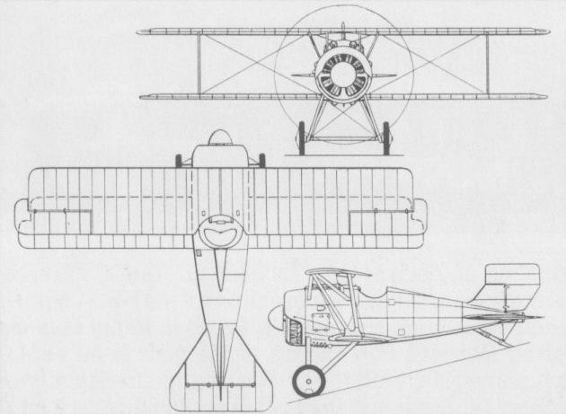
The D III
SIEMENS-SCHUCKERT (SSW) Dr I Germany
In parallel with development of the D II, the SSW evolved a single-seat triplane fighter, the Dr I. First flown in July 1917, the Dr I was powered by a 110 hp Siemens-Halske Sh I nine-cylinder rotary engine and employed a D I fuselage. In the course of flight testing, the Dr I crashed and was seriously damaged. During reconstruction the wing area was increased by 31.22 sq ft (2,90 m2), and in this rebuilt form the fighter climbed to an altitude of 15,420 ft (4 700 m) in 20.6 min. A development of the design, the Dr II with a 160 hp Sh III engine, was discontinued at an advanced stage in construction. The following data relate to the Dr I prior to reconstruction.
Empty weight, 1,124 lb (510 kg).
Loaded weight, 1,532 lb (695 kg).
Span, 28 ft 2 5/8 in (8,60 m).
Length, 17 ft 4 2/3 in (5,30m).
Wing area, 194.83 sqft (18,10 m2).
SIEMENS-SCHUCKERT (SSW) DDr I Germany
Dubbed unofficially the ‘‘Flying Egg”, the DDr I represented one of the earliest examples of the twin-engined centreline thrust concept, 120 hp Sh Ia rotary engines being mounted fore and aft of the pilot in an abbreviated nacelle, with the tractor engine driving a two-bladed propeller and the pusher engine driving a four-blader. An equi-span staggered triplane with the rudders and elevator carried by tubular steel outriggers, the DDr I carried an armament of two synchronised 7,9-mm LMG 08/15 machine guns. The design found favour with the Idflieg, to which it was presented in June 1917, the prototype flying for the first time in November, but crashing on its maiden flight. Engine control problems and inadequate stability revealed during the brief flight of the DDr I led to cancellation of a more powerful version of the basic design, the DDr II with Sh III engines.
Empty weight, 1,499 lb (680 kg).
Loaded weight, 2,006 lb (910 kg).
Span, 35 ft 9 1/8 in (10,90 m).
Length, 19 ft 0 1/4 in (5,80 m).
Wing area, 322.93 sq ft (30,00 m2).
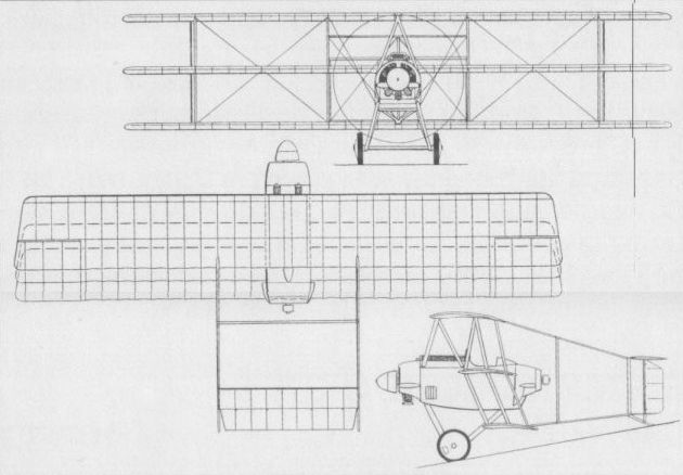
The extraordinary twin-engined DDr I.
SIEMENS-SCHUCKERT (SSW) D VI Germany
The SSW was awarded a contract by the Idflieg in April 1918 for the development of a single-seat parasol mono¬plane fighter powered by the Sh IIIa rotary engine, three prototypes being ordered under the designation E IV, but this being changed to D VI in the following September. A unique feature of the D VI was the provision of a jettisonable main fuel tank beneath the fuselage. No prototype was completed prior to the Armistice, but two emerged in 1919, flight trials being carried out between February and May of that year. During these one of the prototypes was destroyed and the other was allegedly sabotaged by SSW workers to prevent it falling into the hands of the Allied Control Commission.
Max speed, 137 mph (220 km/h).
Time to 19,685 ft (6 000 m), 16 min.
Range, 217 mis (350 km).
Empty weight, 1,190 lb (540 kg).
Loaded weight, 1,565 lb (710 kg).
Span, 30 ft 8 7/8 in (9,37 m).
Length, 21 ft 3 7/8 in (6,50 m).
Height, 8 ft 11 in (2,72 m).
Wing area, 134.12 sq ft (12,46 m2).
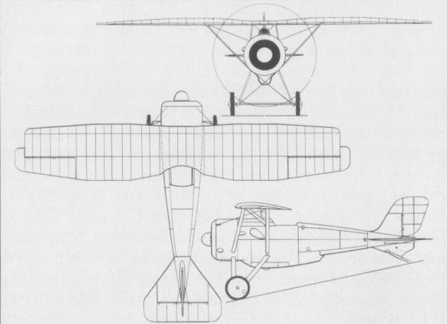
ZEPPELIN-LINDAU V1 Germany
The V1 was a single-seat all-metal fighter designed by Dipl-Ing Claudius Dornier and built in the summer of 1916 by the Abteilung "Dornier” of the Zeppelin-Werke Lindau GmbH at Lindau-Reutin. Featuring a fuselage of pod type, a 160 hp Maybach Mb III engine mounted as a pusher with the propeller revolving within the wire-braced steel-tube framework carrying the tail assembly, the V1 employed newly-developed metal-working techniques, but proved seriously overweight. A series of ground hops was performed by Bruno E Schroter during September 1916, but this pilot refused to fly the prototype owing to its extreme tail-heaviness. On 13 November 1916, an initial flight test was performed by Oblt Haller von Hallerstein, but the V1 performed a loop immediately after take-off, crashing and killing the pilot.
Span, 34 ft 7 3/8 in (10,55 m).
Length, 23 ft 3 5/8 in (7,10 m).
Height, 8 ft 8 1/4 in (2,65 m).
Wing area, 264.8 sq ft (24,60 m2).

The Dornier-designed V1 which crashed immediately after taking-off on its first flight.
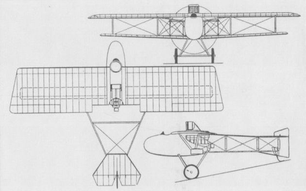
The Zeppelin-Lindau V1 single-seat fighter.
ZEPPELIN-LINDAU D I Germany
The D I single-seat fighter biplane created by the Abteilung ‘‘Dornier” in 1918 at the Lindau-Reutin plant was of all-metal construction with stressed fuselage skinning and cantilever wings of torsion-box construction, and carried a jettisonable fuel tank beneath the fuselage - features well ahead of the contemporary state of the art. Powered by a 160 hp Mercedes D IIIa engine, the first prototype flew on 4 June 1918, but shed the upper wing during flight testing in the following month, apparently justifying the caution with which the innovatory Dornier fighter was viewed by the Inspektion der Fliegertruppen (Idflieg). Nevertheless, two further prototypes powered by the 185 hp BMW IIIa engine were completed, with strengthened wing bracing and attachments. One of these participated in the third D-Type contest, but displayed a disappointing performance. The D I carried twin synchronised 7,92-mm machine guns. Although no production was ordered, three additional examples were completed (two with the Mercedes and one with the BMW engine), two of these being taken to the USA for evaluation after the Armistice. The data relate to the BMW IIIa-engined model.
Max speed, 124 mph (200 km/h) at sea level.
Time to 3,280 ft (1000 m), 2.6 min.
Range, 168 mis (270 km).
Empty weight, 1,598 lb (725 kg).
Loaded weight, 1,947 lb (883 kg).
Span, 25 ft 7 in (7.80 m).
Length, 20 ft 11 9/10 in (6,40 m).
Height, 8 ft 6 1/3 in (2,60 m).
Wing area, 200.86 sq ft (18,66 m2).
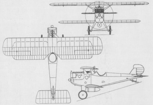
Two of the four examples of the D I were taken to the USA for evaluation.
NIELSEN & WINTHER TYPE Aa Denmark
Designed and built by Nielsen & Winther A/S, a Copenhagen machine tool manufacturer, possibly with some assistance from the Swedish Thulin concern, the Type Aa single-seat fighter was first flown on 21 January 1917. Of wooden construction, the Type Aa was powered by a 90 hp Thulin rotary engine (a copy of the Le Rhone) and was armed with a single 8-mm Madsen machine gun mounted on the upper wing and firing above the propeller disc. Ground tests with synchronising equipment took place in 1918, reportedly using a Type Aa with the gun mounted on the side of the fuselage, but there is no evidence that air firing tests took place. Six Type Aa fighters were delivered to the Danish Army during 1917, but these were withdrawn from service in 1919 owing to the unreliability of their engines. Prototypes were completed of a two-seat reconnaissance version, the Type Ab, and a float-equipped version of the single-seater, the Type Ac.
Max speed, 93 mph (150 km/h).
Time to 9,840 ft (3 000 m), 15 min.
Empty weight, 772 lb (350 kg).
Loaded weight, 1,212 lb (550 kg).
Span, 25 ft 3 1/8 in (7,70 m).
Length, 21 ft 7 7/10 in (6,60 m).
Height, 9 ft 2 1/4 in (2,8 m).
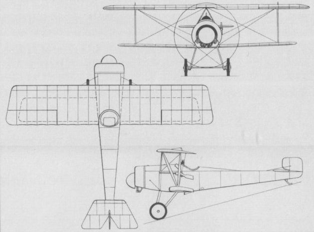
The Type Aa was delivered to the Danish Army in 1917, but was withdrawn in 1919.
HERETER T.H.(ALFARO 8) Spain
Designed for the Concurss de Aviones of 1919, which had been conceived to encourage the growth of an independent aircraft industry by means of competitive design of combat aircraft for the Aviacion Militar, the Hereter T.H. (also known as the Alfaro 8) was designed by Heraclio Alfaro and built by the Talleres Hereter of Barcelona. A single-seat single-bay equi-span biplane powered by a 180 hp Hispano-Suiza 8Ab engine, the T.H. fighter had still to commence flight testing in March 1919, when the contest took place. It was flown for the first time in the following month by Domingo Rosillo, but broke its undercarriage during landing. No further development was undertaken and no data are available.
Designed for the Concurss de Aviones of 1919, which had been conceived to encourage the growth of an independent aircraft industry by means of competitive design of combat aircraft for the Aviacion Militar, the Hereter T.H. (also known as the Alfaro 8) was designed by Heraclio Alfaro and built by the Talleres Hereter of Barcelona. A single-seat single-bay equi-span biplane powered by a 180 hp Hispano-Suiza 8Ab engine, the T.H. fighter had still to commence flight testing in March 1919, when the contest took place. It was flown for the first time in the following month by Domingo Rosillo, but broke its undercarriage during landing. No further development was undertaken and no data are available.
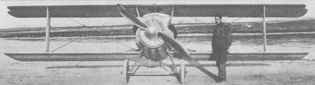
The Hereter T.H. was completed too late for the fighter competition for which it was designed.
DIAZ TYPE C Spain
Designed to participate in the Concurso de Aviones held at Cuatro Vientos in March-April 1919, the single-seat fighter built by Amalio Diaz of Getafe, Madrid, was apparently based on a 1917 design of Julio Adaro, the construction of which was never completed. The Diaz Type C (Caccia) was a two-bay equi-span biplane with an abbreviated cabane and powered by a 180 hp Hispano-Suiza 8Ab engine. It failed to qualify in the Concurso as it did not fully meet the requirements of the specification that had been prepared by the Aviacion Militar, the fighter contest being won by the Hispano-Barron. Nevertheless, the Diaz Type C received a consolation prize of half the second prize which had not been awarded. No data for the Diaz fighter are available.
Designed to participate in the Concurso de Aviones held at Cuatro Vientos in March-April 1919, the single-seat fighter built by Amalio Diaz of Getafe, Madrid, was apparently based on a 1917 design of Julio Adaro, the construction of which was never completed. The Diaz Type C (Caccia) was a two-bay equi-span biplane with an abbreviated cabane and powered by a 180 hp Hispano-Suiza 8Ab engine. It failed to qualify in the Concurso as it did not fully meet the requirements of the specification that had been prepared by the Aviacion Militar, the fighter contest being won by the Hispano-Barron. Nevertheless, the Diaz Type C received a consolation prize of half the second prize which had not been awarded. No data for the Diaz fighter are available.

The Diaz Type C was a participant in Spain’s 1919 Concurso de Aviones.
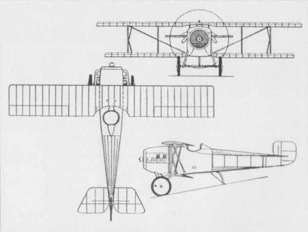
HISPANO BARRON Spain
In 1919, the newly-established Hispano (later Hispano-Suiza) concern at Guadalajara built a prototype single-seat fighter to participate in the Concurso de Aviones to be held that year. The Hispano contender was designed by Eduardo Barron, who, in 1917, had supervised construction of a copy of the SPAD S.VII at the Talleres Hereter SA in Barcelona, 12 being built for the Aeronautica Militar Espanola as the Espana. The fighter designed by Barron for Hispano was a single-bay, unstaggered biplane of wooden construction with fabric skinning and powered by a 180 hp Hispano-Suiza 8Aa eight-cylinder water-cooled engine. Armament comprised a single 7,7-mm Vickers machine gun mounted above the upper wing. Flown by a Chilean pilot, Luis O'Page, the Hispano Barron was intended to compete with two indigenous fighters at Cuatro Vientos, the Hereter T.H. (Alfaro 8) and the Diaz Type C, and was declared the winning contender. The availability of proven single-seat fighters from abroad at low prices motivated against a production order, however, and only the one prototype was completed, this later being tested with a 200 hp Hispano-Suiza engine.
Max speed, 1118 mph (190 km/h).
Loaded weight, 1,852 lb (840 kg).
No further details available.

Flown in 1919, the Barron-designed fighter was winner in the Concurso de Aviones.
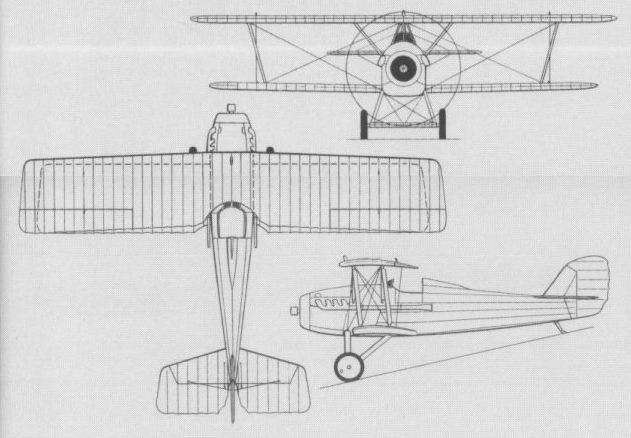
ADAMOLI-CATTANI Italy
In 1918, Signori Adamoli and Cattani designed the smallest practicable single-seat fighter around the then most powerful rotary engine extant, the 200 hp Le Rhone. The fighter, which was of wooden construction with fabric skinning, was an unequal-span unstaggered biplane with Warren-truss type interplane bracing, unusual features consisting of the supplanting of orthodox ailerons with hinged and interlinked wing leading edges, and the use of rigid tubes rather than cables for actuation of the movable tail surfaces. The prototype was begun at the Farina works in Turin, but transferred to the Officine Moncenisio in Condove for completion. Armament comprised two 7,7-mm machine guns. When flight testing was initiated it was discovered that the Le Rhone engine developed only 160 hp and the fighter was thus seriously underpowered, development being abandoned after limited trials. The following estimated performance data were based on the use of a fully rated engine.
Max speed, 186 mph (300 km/h).
Endurance, 2.25 hrs.
Empty weight, 1,036 lb (470 kg).
Loaded weight, 1,488 lb (675 kg).
Span. 28 ft 2h in (8,60 m).
Length 20 ft 0 1/8 in (6,10 m).
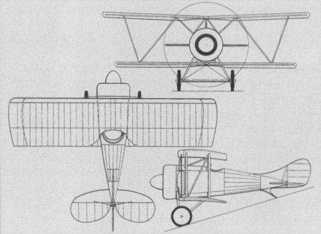
The Adamoli-Cattani fighter prior to flight test.
ANSALDO A.1 BALILLA Italy
Owing much to the S.V.A., the A.1 Balilla (Hunter) single-seat fighter was flown for the first time in the autumn of 1917, but, lacking the agility of its contemporaries, it was manufactured in only limited quantities, a total of 166 Balillas being built in 1918. These were confined to home defence tasks, and 75 were supplied to Poland in 1920-1, a further 50 being licence-built by Plage & Laskiewicz. The Balilla was of wooden construction and carried an armament of two synchronised 7,7-mm Vickers guns. The power plant was either the 205 hp SPA 6A or the 220 hp higher compression version of that engine, while the A.Ibis was fitted with the 250 hp Isotta-Fraschini V6. The following details apply to the 220 hp A.1.
Max speed, 137 mph (220 km/h) at sea level.
Time to 9,840 ft (3000 m), 8.5 min.
Endurance, 2.5 hrs.
Empty weight, 1,411 lb (640 kg).
Loaded weight, 1,951 lb (885 kg).
Span, 25 ft 2 1/3 in (7,68m).
Length, 21 ft 3 7/8 in (6,50 m).
Height, 9 ft 4 1/4 in (2,85 m).
Wing area, 226.05 sq ft (21,00 m2).
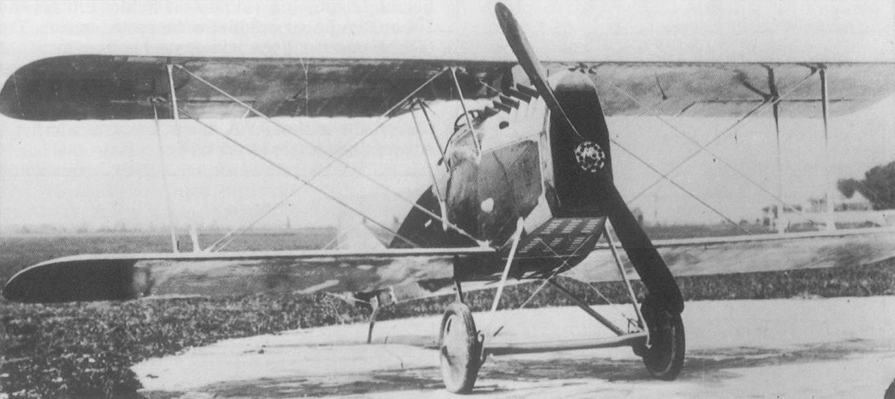
The Ansaldo A.1 Balilla was built in limited numbers and confined largely to home defence.
ANSALDO S.V.A. Italy
In the summer of 1916, Ingegneri Umberto Savoia and Rodolfo Verduzio of the Direzione Tecnica dell' Aeronautica Militare (Technical Directorate of Military Aviation), together with Ingegner Celestino Rosatelli, began designing a single-seat fighter around the 205 hp SPA 6A six-cylinder water-cooled engine. The task of supervising the development and production of the fighter was assigned to the Societa Ansaldo, and thus the prototype, first flown on 19 March 1917, was designated S.V.A. (Savoia-Verduzio-Ansaldo). The S.V. A. was a conventional biplane of wooden construction with interplane bracing of the Warren truss type and an armament of two synchronised 7,7-mm Vickers machine guns. It displayed exceptional speed but, inherently stable, was considered to lack the manoeuvrability demanded for fighter-versus-fighter combat. However, its excellent range rendered it suitable for the reconnaissance fighter role, and the Aviazione Militare decided to adopt the S.V.A. for this task. Deliveries of the initial production version, the S.V.A.2, had meanwhile commenced in the autumn of 1917, 65 being built by the year's end and this model being assigned to training.
Max speed, 137mph (220 km/h).
Time to 9,840 ft (3000 m), 11.35 min.
Endurance, 3 hrs.
Empty weight, 1,477 lb (670 kg).
Loaded weight, 2,100 lb (952 kg).
Span, 29 ft 10 1/4 in (9,10 m).
Length. 26 ft 6 7/8 in (8,10 m).
Height, 8 ft 8 1/3 in (2,65 m).
Wing area, 260.49 sq ft (24,2 m3).
ANSALDO S.V.A.3 Italy
Built under licence by the AER concern at Orbassano, the S.V.A.3 was a reconnaissance fighter production derivative of the S.V.A. fighter, and essentially similar to the S.V.A.4 built in parallel by the Ansaldo factories at Borzoli and Bolzaneto. In the spring of 1918 a special interceptor version was produced, this having wings of reduced span and area. Known as the S.V.A.3 ridotto (reduced), this model was used primarily for airship interception, and although standard armament remained two synchronised 7,7-mm Vickers guns, some examples were fitted with an additional weapon firing upwards at an oblique angle. Power was provided by an SPA 6A engine of 220 hp.
Max speed, 149 mph (240 km/h).
Time to 13,125 ft (4 000 m), 13min.
Endurance, 3 hrs.
Empty weight, 1,470 lb (667 kg).
Loaded weight, 1,965 lb (891 kg).
Span, 25 ft 5 1/8 in (7,75 m).
Length, 26 ft 6 7/8 in (8.10 m).
Height, 8 ft 8 1/3 in (2,65 m).
Wing area, 236.8 sq ft (22,0 m2).
ANSALDO S.V.A.4
The S.VA.4 was the first reconnaissance fighter development of the S.V.A. to be built in substantial quantities. It did not demand an escort in performing reconnaissance missions as it could accept combat with fighters on reasonably equal terms, and break off combat at will by utilising its high speed. It was powered by a 205 hp SPA 6A six-cylinder water-cooled engine, and normally carried two synchronised 7,7-mm Vickers guns, although the starboard gun was sometimes removed when a reconnaissance camera was carried. The S.V.A.4 entered service with the Aviazione Militare early in 1918.
Max speed, 134 mph (216 km/h).
Time to 9,840 ft (3 000m), 12 min.
Max endurance, 3.6 hrs.
Empty weight, 1,545 lb (701 kg).
Loaded weight, 2,150 lb (975 kg).
Span, 29 ft 10 1/4 in (9,10 m).
Length, 26 ft 6 7/8 in (8,10 m).
Height, 8 ft 8 1/3 in (2,65 m).
Wing area, 260.49 sq ft (24,20 m2).
ANSALDO S.V.A.5
Built in larger numbers than any other single-seat derivative of the S.V.A., the S.V.A.5 was a reconnaissance-fighter-bomber armed with two 7,7-mm synchronised Vickers machine guns and carrying two reconnaissance cameras or light bombs slung on the fuselage sides on special clips. Initial production examples were powered by the 205 hp SPA 6A engine, but later examples had the higher compression version of that engine rated at 230hp. Some S.V.A.5s were fitted with the 250 hp Isotta-Fraschini V6 engine with which a maximum speed of 149 mph (240 km/h) was attainable. The majority of the 1,248 S.V.A. aircraft built during 1917-18 were S.V.A.5s.
Max speed, 143 mph (230 km/h).
Time to 9,840 ft (3 000 m), 10 min.
Normal endurance, 3 hrs.
Empty weight, 1,500 lb (680 kg).
Loaded weight, 2,315 lb (1050 kg).
Span, 29 ft 1014 in
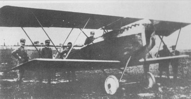
The original S.V.A. fighter prototype which entered flight test in March 1917.
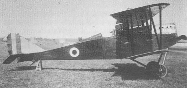
Evolved as a reconnaissance fighter, the S.VA.4 entered service early in 1918.
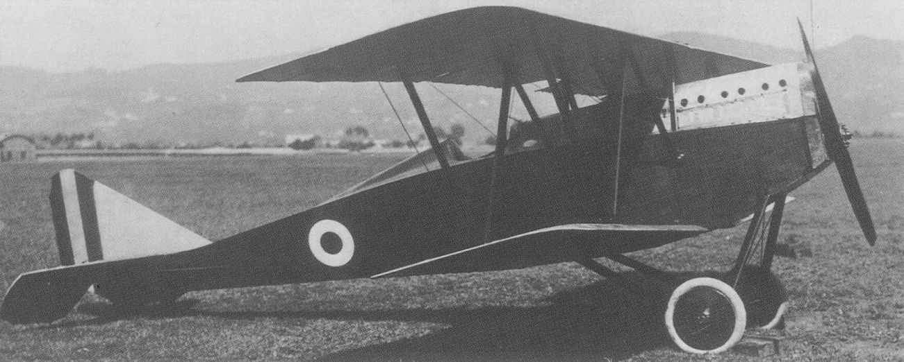
The S.V.A.5 was built in larger numbers than any other Savoia-Verduzio-Ansaldo fighter.
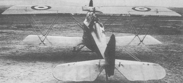
The S.V.A.3 is illustrated here in its ridotto (reduced) span version which was used primarily for airship interception in 1918.
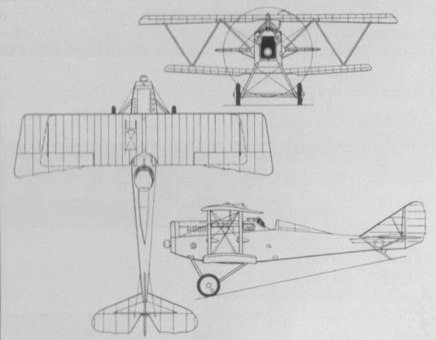
The S.V.A.3 is illustrated here in its ridotto (reduced) span version which was used primarily for airship interception in 1918.

The S.V.A.5 was a multi-role aircraft.
ANSALDO I.S.V.A.
A single-seat float fighter version of the S.V.A., the I.S.V.A. (the "I” prefix indicating Idro or water) was built at La Spezia in 1918. Power was provided by a 205 hp SPA 6A engine and armament consisted of two synchronised 7,7-mm Vickers machine guns. A total of 50 I.S.V.A. fighters was manufactured and these aircraft were used both for the defence of naval bases and coastal reconnaissance.
Max speed, 121 mph (195 km/h) at sea level, 112 mph (180 km/h) at 6,560 ft (2 000 m).
Endurance, 3 hrs.
Empty weight, 1,936 lb (878 kg).
Loaded weight, 2,425 lb(1 100 kg).
Span, 29 ft 10 1/4 in (9,10 m).
Length, 30 ft 6 1/8 in (9,30 m).
Height, 12 ft 1 2/3 in (3,70 m).
Wing area, 263.72 sq ft (24,5 m2).
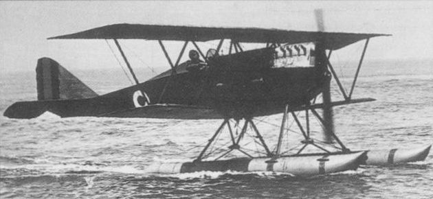
The I.S.V.A. float fighter was used for the defence of naval bases and coastal reconnaissance.
DUCROT SLD Italy
During World War I, a number of Italian industrial concerns were invited to convert their facilities to cater for aircraft manufacture, one such being the Palermo-based firm of Vittoria Ducrot, which, in February 1916, initiated licence manufacture of flying boats. Anxious to progress from licensee to prime contractor, Ducrot established its own design office under Ing Manlio Stiavelli, who, with Guido Luzzatti, designed a high-performance single-seat fighter, the SLD (Stiavelli-Luzzatti-Ducrot). Powered by a 200 hp Hispano-Suiza 35 engine, the SLD placed emphasis on aerodynamic cleanliness, featuring an oval-section plywood monocoque fuselage which was carried above the lower wing by struts which also carried the undercarriage. Trials commenced in October 1918, but no details of the results of these survive.
Max speed, 186 mph (300 km/h).
Time to 16,405 ft (5 000 m), 10.0 min.
Empty weight, 1,345 lb (610 kg).
Loaded weight, 1,786 lb (810 kg).
Wing area, 236.8 sq ft (22,00 m2).

Aerodynamic cleanliness was an obvious feature of the single example of the Ducrot SLD.
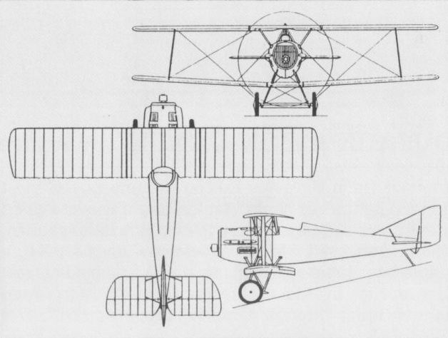
The Ducrot SLD single-seat fighter.
MACCHI M.5 (TIPO M) Italy
The Societa Anonima Nieuport-Macchi (predecessor of Aeronautica Macchi) gained experience in flying boat design by producing improved copies of the Austro-Hungarian Lohner 'boat. Early in 1917, engineers Buzio and Calzavara developed a single-seat fighter for the Regia Marina based on the L.3 (M.3) two-seat bomber-reconnaissance flying boat. Initially known as the Tipo (Type) M, the fighter was of wooden construction with fabric and plywood skinning, and was powered by a six-cylinder Isotta-Fraschini V.4B engine strut-mounted above the hull and driving a pusher propeller, maximum output being 187 bhp. The pilot sat beneath the radiator and was provided with a single 7,7-mm Vickers machine gun. Intended for use in the Adriatic, the Tipo M was fully aerobatic, further prototypes being produced as Tipo Ma and, with control refinements, as Tipo M bis and Ma bis, the last-mentioned entering production and the designation M.5 subsequently being adopted. The M.5 entered service with the Regia Marina in November 1917, frequently escorting bombers attacking Austro-Hungarian naval bases in the Adriatic and proving faster than opposing Phonix land-based fighters. The single Vickers gun was replaced by a twin-gun arrangement in some aircraft, and a total of 244 was built (44 of these by the Societa Aeronautica Italiana) of which 68 were completed in 1917, and production giving place to the M.5 mod during 1918.
Max speed, 117 mph (189 km/h).
Time to 3,280 ft (1 000 m), 3.5 min.
Endurance, 3.66 hrs.
Empty weight, 1,587 lb (720 kg).
Loaded weight, 2,183 lb (990 kg).
Span, 39 ft 0 1/2 in (11,90 m).
Length, 26 ft 6 1/8 in (8,08 m).
Height, 9 ft 4 1/4 in (2,85 m).
Wing area, 301.4 sqft (28,00 m2).
MACCHI M.5 MOD Italy
Early in 1918, Nieuport-Macchi developed a more powerful version of the M.5 single-seat fighter flying boat as an interim measure pending availability of the higher-performance M.7. The latter was being developed to the designs of Alessandro Tonini to counter the increased efficacy of Austro-Hungarian fighters being encountered over the Adriatic. Designated M.5 mod, the interim fighter achieved enhanced performance by using a 247 bhp Isotta-Fraschini V.6 engine, its installation being accompanied by a 7-ft 2 5/8-in (2,20-m) reduction in the span of the upper wing. A twin 7,7-mm Vickers gun armament was standardised. One hundred M.5 mod fighters were built, these progressively replacing the M.5s in Regia Marina service, and 66 of them were still on strength when the Regia Aeronautica was formed in 1923. These subsequently gave place to the M.7ter in the mid-’twenties.
Max speed, 127 mph (205 km/h).
Time to 3,280 ft (1000 m), 3.5 min.
Endurance, 3.66 hrs.
Empty weight, 1,664 lb (755 kg).
Loaded weight, 2,381 lb (1080 kg).
Span, 31ft 9 7/8 in (9,70 m).
Length, 26 ft 6 7/8 in (8,10 m).
Height, 9 ft 4 1/4 in (2,85 m).
Wing area, 279.87 sqft (26,00 m2).
MACCHI M.6 Italy
Completed in 1917 for comparison with the M.5, the M.6 single-seat fighter differed essentially in having a modified wing cellule. The Vee-type interplane bracing struts and sloping auxiliary Vee struts supporting the overhanging portion of the upper wing gave place to parallel struts positioned farther outboard, additional parallel steel tube struts being introduced farther inboard. The M.6 was similarly powered to the M.5 (Isotta-Fraschini V.4B) and carried a single 7,7-mm Vickers gun. Comparative trials revealed no advantages over the standard M.5 and further development of the M.6 was discontinued.
Max speed, 117 mph (189 km/h).
Time to 13,125 ft (4 000 m), 20 min.
Endurance, 3.0 hrs.
Empty weight, 1,675 lb (760 kg).
Loaded weight, 2,271 lb (1030 kg).
Wing area, 312.16 sqft (29,00 m2).
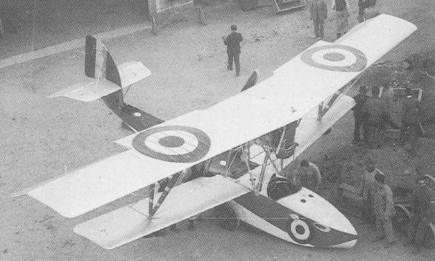
The M.5 was the first of a series of fighter flying boats developed by Macchi.
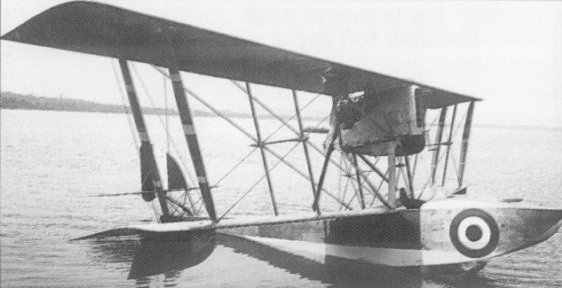
The single M.6 was built for comparison with the M.5, differing in wing cellule design.

The Macchi M.5, which appeared in 1917.
MACCHI M.14 Italy
Owing little to the Hanriot HD.I that was licence-built by Nieuport-Macchi, the M.14 single-seat sesquiplane fighter was designed by Alessandro Tonini. Of wooden construction and featuring Warren truss style interplane bracing, the M.14 was powered by a 110 hp Le Rhone 9J nine-cylinder rotary engine and had provision for an armament of twin synchronised 7,7-mm Vickers guns. Flight testing commenced in the spring of 1918, but the prototype was destroyed in June of that year. Nevertheless, a series of 10 M.14 fighters was built, official evaluation trials being conducted at Montecelio during 1919. However, no additional orders were placed for the type and those M.14s completed were employed as advanced trainers, at least one receiving a civil registration (I-BADG).
Max speed, 113 mph (182 km/h) at sea level.
Time to 3,280 ft (1 000 m), 3.5 min.
Endurance, 2 hrs.
Empty weight, 970 lb (440 kg).
Loaded weight, 1,411 lb (640 kg).
Span, 26 ft 10 4/5 in (8,20 m).
Length, 18 ft 6 1/2 in (5,65 m).
Height, 8 ft 7 1/8 in (2,62 m).
Wing area, 178.69 sq ft (16,60 m2).

Macchi’s first landplane fighter, the M.14 served primarily in the training role.
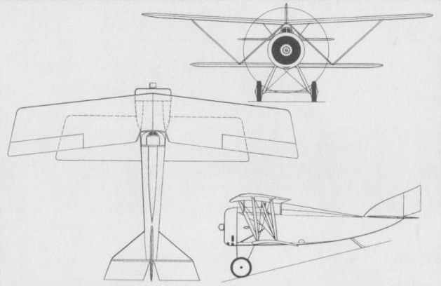
MACCHI M.7 Italy
The M.7 was essentially a progressive development of the M.5 and entered flight testing early in 1918. Powered by a 247 bhp Isotta-Fraschini V.6 engine, the M.7 was of wooden construction similar to that of its predecessors and carried an armament of twin 7,7-mm Vickers guns. It featured a simplified wing cellule, with paired, splayed interplane struts. Series production was initiated, but orders were curtailed with the end of hostilities, 11 being completed of which three were delivered before the end of World War I. Two each were purchased by Argentina and Sweden in 1919, and three were procured by Brazil in 1921. Despite the cancellation of orders for the Regia Marina, development of the basic design continued, one example being fitted with a hull of increased fineness ratio, and two were modified to M.7 bis standard for participation in the 1921 Schneider Trophy contest. The M.7 bis had wing span and area reduced to 25 ft 5 in (7,75 m) and 256.19 sq ft (23,80 m2) respectively, and captured the Trophy in August 1921 with an average speed of 117.75 mph (189,50 km/h) in a contest in which the Macchi 'boat was, in fact, the only participant.
Max speed, 130 mph (210 km/h).
Time to 16,405 ft (5000 m), 23 min.
Endurance, 3.66 hrs.
Empty weight, 1,708 lb (775 kg).
Loaded weight, 2,381 lb (1080 kg).
Span, 32 ft 7 3/4 in (9,95 m).
Length, 26 ft 6 9/10 in (8,10 m).
Height, 9 ft 8 1/8 in (2,95 m).
Wing area, 286.33 sq ft (26,60 m2).
MACCHI M.7TER Italy
Only nominally a development of the wartime M.7 fighter, the M.7 ter, flown as a prototype in October 1923, was virtually a new design, with a redesigned hull, a revised and lighter structure and wings of revised planform and reduced area. Primarily of wooden construction, with a 247 bhp Isotta-Fraschini V.6 engine and twin-Vickers gun armament, the M.7 ter was ordered into series production to re-equip the Squadriglie Caccia Marittima as the M.7terA, the M.7terAR having folding wings for operation from the seaplane carrier Miraglia. The M.7terB was powered by a 480 hp Lorraine 12Db engine, and, in 1927, the Societa Aeronautica Italiana re-engined 14 M.7terA 'boats with the 250 hp Isotta-Fraschini Semi-Asso engine. Total production of the M.7 ter exceeded 100 machines and these equipped all six Squadriglie Caccia Marittima by 1925 at the principal Italian naval bases, these eventually forming the 80° Gruppo. Eighty-three were in service in 1927, including 29 of the folding-wing AR version, the last being withdrawn from first line service in 1930.
Max speed, 129 mph (208 km/h).
Time to 3,280 ft (1000 m), 2.75 min.
Endurance, 3 hrs.
Empty weight, 1,775 lb (805 kg).
Loaded weight, 2,381 lb (1 080 kg).
Span, 32 ft 7 3/4 in (9,95 m).
Length, 29 ft 0 1/3 in (8,85 m).
Height, 9 ft 8 9/10 in (2,97 m).
Wing area, 252.96 sqft (23,50 m2).
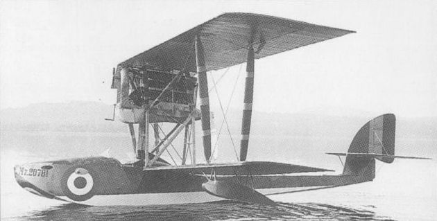
A further development of the M.5, the M.7 continued the Macchi fighter flying boat formula.
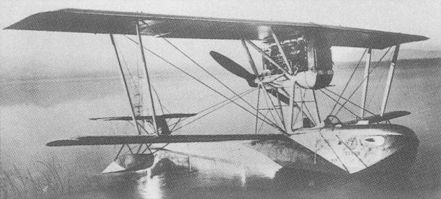
Remaining in service until 1930, the M.7ter was almost wholly a new design.
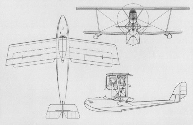
Remaining in service until 1930, the M.7ter was almost wholly a new design.
MARCHETTI MVT (S.50) Italy
Designed by Alessandro Marchetti and built by the Vickers-Terni industrial organisation at La Spezia, the MVT single-seat fighter biplane was flown in 1919. Of all-metal construction, the MVT was powered by a 220 hp SPA 6a water-cooled engine and carried an armament of two synchronised Vickers machine guns. The fuselage, which was suspended between the upper and lower mainplanes, was flattened aft to emulate an aerofoil surface, and the semi-elliptical wings were of extremely thin section, lateral control being provided by wing warping. On 9 December 1919, the MVT recorded a speed of 155 mph (250 km/h) - absence of FAI officials preventing this being certified as a world speed record - and demonstrated the ability to climb to 16,405 ft (5 000 m) in 11 min. In 1920, the MVT was fitted with longer-span wings, splayed interplane bracing struts, a revised cabane and a redesigned horizontal tail. A 285 hp SPA 62a engine was fitted with which 171 mph (275 km/h) was attained under test at Montecelio. When Marchetti was appointed chief designer to SIAI, the MVT was redesignated S.50 and was entered in the official fighter contest of 1923. Three were supplied to the newly-created Regia Aeronautica for evaluation, but a plan to procure a batch of 12 failed to materialise. One S.50 was modified as a twin-float seaplane. The following data relate to the SPA 62a-powered MVT.
Max speed, 155 mph (250 km/h).
Time to 3,280 ft (1 000 m), 2.0 min.
Endurance, 2.1 hrs.
Empty weight, 1,647 lb (747 kg).
Loaded weight, 2,176 lb (987 kg).
Span, 28 ft 6 1/2 in (8,70 m).
Length, 25 ft 5 1/8 in (7,75 m).
Height, 8 ft 6 1/3 in (2,60 m).
Wing area, 231.43 sq ft (21,50 m2).
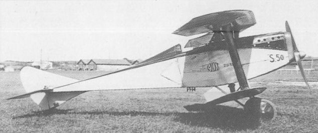
As the S.50, the Marchetti MVT was entered in the Italian fighter contest of 1923.
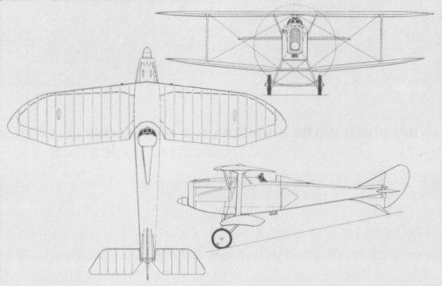
POMILIO GAMMA Italy
Early in 1918, the Pomilio concern of Turin completed the prototype of a single-seat fighter designated Gamma (the third letter of the Greek alphabet). Powered by a 200 hp SPA 6A water-cooled engine, the Gamma was a single-bay, unequal-span biplane of wooden construction. Demonstrated for an official commission, the Gamma proved both fast and manoeuvrable, but was considered to possess an inadequate climb rate. The second prototype was therefore fitted with a 250 hp Isotta-Fraschini V6 engine as the Gamma IF. The official commission disagreed on the merits of the fighter and it was not until the closing weeks of World War I that a small batch of Gamma IF fighters was ordered, but these did not enter service with the Aviazione Militare. Ottorino Pomilio and his brother settled in the USA in 1918, establishing the Pomilio Brothers Corp. The following data relate to the Gamma IF.
Max speed, 140 mph (225 km/h).
Time to 9,840 ft (3 000 m), 7.5 min.
Endurance, 3.0 hrs.
Empty weight, 1,499 lb (680 kg).
Loaded weight, 2,094 lb (950 kg).
Span, 26 ft 2 1/2 in (7,99 m).
Length, 20 ft 8 in (6,30 m).
Wing area, 235.74 sqft (21,90 m2).
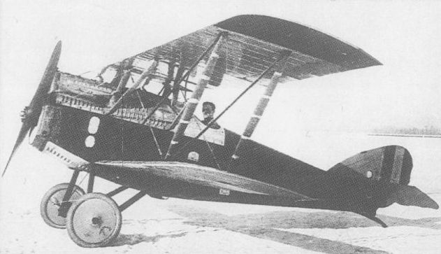
The Pomilio Gamma, first prototype being illustrated, was not adopted.

The Pomilio Gamma, second prototype being illustrated, was not adopted.
TEBALDI-ZARI (BREDA) Italy
In 1919, the Zari brothers’ factory in Bovisio Mombello, Milan, completed the prototype of a single-seat fighter sesquiplane to the designs of one Ing Tebaldi. Of wooden construction and of unequal-span, heavily-staggered sesquiplane configuration, it was powered by a 190 hp Isotta-Fraschini V6 six-cylinder water-cooled engine and was unusual in that it had oversize mainwheels on an undercarriage of exceptionally wide track, the axle for which was incorporated in the lower wing. The design rights and prototype were purchased by Breda, and, re-engined with a 300 hp Hispano-Suiza HS 42 eight-cylinder water-cooled power plant, the Tebaldi fighter became the subject in 1922 of a draft agreement between Breda and the Commissariato d’Aeronautica for three aircraft. No contract followed, but the original prototype was modified for participation in the 1923 fighter contest of the newly-created Regia Aeronautica. Carrying an armament of two 7,7-mm guns, the Tebaldi fighter was given redesigned wings, with the upper wing of longer span and narrower chord, stagger was reduced, and the gap between the fuselage and the lower wing increased. The incline of the outer struts was also increased to attach at the undercarriage axle, so that the outer panels of the lower wing could be removed for comparative flight testing of the aircraft as a sesquiplane. Further redesign was then undertaken, the chord of the upper wing being increased, ailerons enlarged and the outer panels of the lower wing eventually being discarded permanently. The fighter did not find favour with the Regia Aeronautica and Breda abandoned further development. The following data relate to the final HS 42-powered sesquiplane configuration.
Max speed, 158 mph (255 km/h) at 6,560 ft (2 000 m).
Time to 16,405 ft (5 000 m), 16 min.
Endurance, 3.0 hrs.
Empty weight, 1,819 lb (825 kg).
Loaded weight, 2,425 lb (1100 kg).
Span, 29 ft 6 1/3 in (9,00 m).
Length, 25 ft 7 in (7,80 m).
Height, 6 ft 6 3/4 in (2,00 m).
Wing area, 236.81 sq ft (22,00 m2).
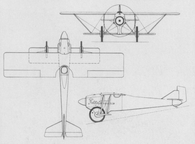
The final form of the Tebaldi-Zari fighter with detachable lower outer wing panels shown dotted.
TNCA SERIE C MICROPLANO Mexico
In February 1918, the Talleres Nacionales de Construcciones Aeronauticas (TNCA), or National Aircraft Manufacturing Workshops, at Balbuena Airfield, Mexico City, completed the prototype of a single-seat fighting scout to the designs of Francisco Santarini and Capt Guillermo Villasana. A single-bay unstaggered biplane known as the Micropiano, the aircraft was powered by a 180 hp Hispano-Suiza eight-cylinder Vee-type water-cooled engine driving a Mexican Anahuac propeller, and was of metal construction. The intended armament was either one or two synchronised machine guns. Although flight trials of the Micropiano were allegedly satisfactory, no series production was undertaken owing to the overthrow of the Carranza regime and the ensuing civil war.
Max speed, 137 mph (220 km/h).
Empty weight, 1,014 lb (460 kg).
Loaded weight, 1,433 lb (650 kg).
Span, 26 ft 2 7/8 in (8,00 m).
Length, 21 ft 7 4/5 in (6,60 m).
Height, 8 ft 4 2/5 in (2,55 m).
Wing area, 193.76 sq ft (18,00 m2).
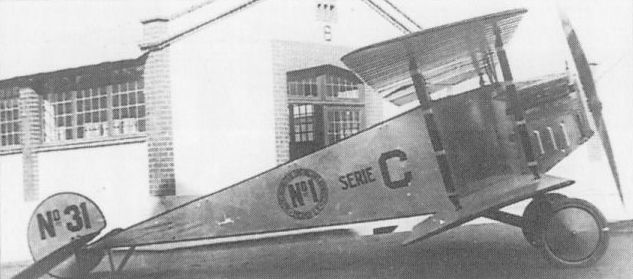
The Micropiano failed to achieve production owing to the overthrow of its sponsors.
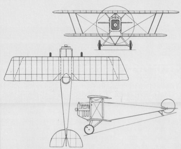
SPYKER-TROMPENBURG V.3 Netherlands
The N V Nederlandsche Automobiel- en Vliegtuigenfabriek Trompenburg, manufacturer of the Spyker automobile, developed the Spyker-Trompenburg V.3 single-seat fighting scout in 1918, specifically to meet a requirement of the Army’s Aviation Division, the LVA (Luchtvaartafdeling). Contracts were placed for 72 V.3 fighters on behalf of the LVA, a further 20 for the naval air component, the MLD (Marineluchtvaartdienst), and six for the LVA of the Royal Netherlands Indies Army. The V.3 was a single-bay unstaggered biplane of wooden construction with fabric covering and powered by a 130 hp Clerget rotary engine. Proposed armament comprised twin synchronised 7,92-mm machine guns. In the event, the prototype V.3 was not flown until July 1919, by which time, as a result of the Armistice, the LVA had cancelled its contract, and development of the V.3 was discontinued.
Max speed, 112 mph (180 km/h).
Time to 3,280 ft (1 000 m), 3.0 min.
Span, 26 ft 10 1/3 in (8,19 m),
Length, 20 ft 0 1/8 in (6,30 m).
Height, 8 ft 6 1/3 in (2,60 m).
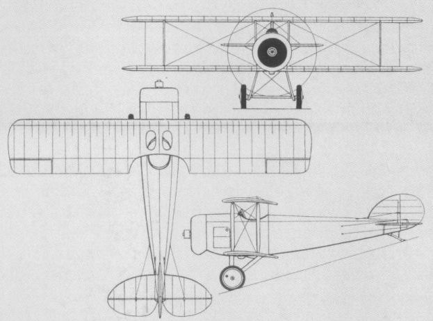
The Spyker-Trompenburg V.3, flown mid-1919.
ANATRA ANADIS Russia
In the spring of 1916, the chief engineer of the Anatra company of Odessa, a French designer named Elisee Alfred Descamps, was ordered to build a single-seat fighter based on the Anasal (also known as the Anatra DS) two-seat reconnaissance biplane. Retaining the Anasal’s two-bay configuration and fabric-covered wooden construction, the fighter, dubbed the Anadis, differed only in having the rear cockpit deleted, provision made for forward-firing armament and the unusual 150 hp Salmson 9U (Canton-Unne) water-cooled radial replaced by a similarly-rated Hispano-Suiza Vee-eight water-cooled engine. The prototype Anadis was flown on 23 October 1916 by the factory test pilot, another Frenchman, Jean Robinet. He and Descamps then planned to modify the Anadis as a two-seater and fit it with extra tankage for their use in escaping Russia in the event that the threatened revolution took place. This plan was discovered and exposed by one Lt Kononenko, an Imperial Army acceptance pilot attached to Anatra, flight testing consequently continuing as a single-seater. Trials continued until 11 November, the official report to the Imperial Army stating that it was ”... not inferior to any German aircraft of the same type (sic) and with greater power." Nevertheless, no further examples were ordered and the prototype languished at the Odessa factory until 14 October 1917, when, piloted by Staff Capt N A Makarov, it took-off for a flight Odessa-Salonika-Rome-Marseilles-Paris and back to Russia. Unfortunately, the Anadis suffered engine failure near Iasi, Romania, and was written-off as a result of the ensuing forced landing. No photograph of the Anadis is known to have survived.
Max speed, 95 mph (153km/h).
Time to 3,280 ft (1000m), 7.5 min.
Empty weight, 1,466 lb (665 kg).
Loaded weight, 2.568 lb (1165 kg).
Span, 37 ft 4 4/5 in (11,40 m).
Length, 25 ft 5 1/10 in (7,75m).
Wing area, 398.27 sq ft (37,00 m2).
GRIGOROVICH M-11 Russia
In the summer of 1916, Dmitri P Grigorovich designed and built a small single-bay biplane fighter flying boat to meet a requirement of the Imperial Russian Navy. Designated M-11 (and also known as the Shch-I, indicating Shchetinin, in whose Petrograd factory it was built, and istrebitel', or fighter), it was initially tested as a tandem two-seater powered by a 100 hp Gnome Monosoupape engine mounted as a pusher, this later being replaced by a 100 hp Le Rhone. Several examples of the two-seat M-11 were built, but inadequate performance resulted in their relegation to the role of trainers for M-5 and M-9 reconnaissance flying boat pilots. Development concentrated on a single-seat version, which, at the time, was claimed to be the fastest flying boat in the world. The single-seat M-11 carried one fixed forward-firing 7,62-mm gun and armour protection was provided for the pilot, a semi-circular armoured shield replacing the normal windscreen. Forward view and gun sighting were provided by a small aperture in this shield - one example being fitted with a sighting periscope. The hydrodynamic qualities of the M-11 were poor but, on 6 April 1917, series production began against a contract for 100 single-seaters with the Le Rhone engine. The M-11 was employed in the Black Sea primarily as an escort for M-9 flying boats, but was not entirely successful and only 60 were completed.
Max speed, 92 mph (148 km/h) at sea level.
Time to 3,280 ft (1 000 m), 11 min.
Endurance, 2.7 hrs.
Empty weight, 1,490 lb (676 kg).
Loaded weight, 2,041 lb (926 kg).
Span, 28 ft 8 2/5 in (8,75 m).
Length, 24 ft 11 1/4 in (7,60 m).
Wing area, 279.87 sqft (26,00 m2).
GRIGOROVICH M-12 Russia
A progressive development of the M-11, the M-12 single-seat fighter flying boat retained the 110 hp Le Rhone pusher engine and fixed 7,62-mm Maxim machine gun of its predecessor. The hull nose was redesigned, however, in an attempt to obtain improved hydrodynamic characteristics, the vertical tail surfaces were revised to improve stability and some attempt was made to reduce structural weight. Climb rate and ceiling were greatly improved, but only a small number of M-12s was built, and these, together with the M-11s, were used until the end of the civil war, sometimes being fitted with skis for shore-based operations.
Max speed, 87 mph (140 km/h) at sea level.
Time to 3,280 ft (1 000 m), 6 min.
Endurance, 2.7 hrs.
Empty weight, 1,367 lb (620 kg).
Loaded weight, 1,918 lb (870 kg).
Dimensions as for M-11.
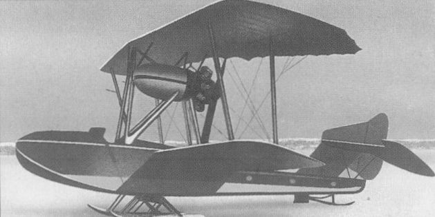
Optional skis allowed the M-11 flying boat to operate from frozen lakes and compacted snow.
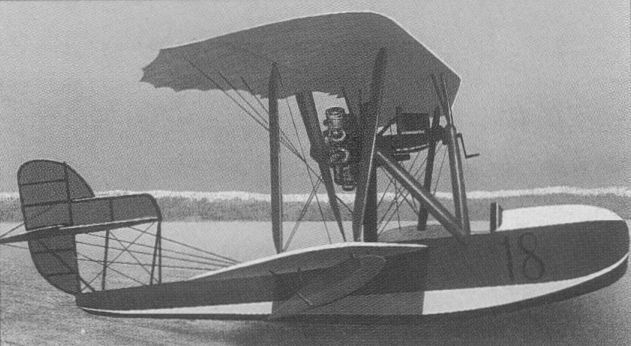
Летающая лодка М-12
KAZYANENKO No 5 Russia
A highly original single-seat fighter was designed at the Kiev Polytechnic Institute in 1917 by three brothers, Yevgeny, Ivan and Andrei Kazyanenko. Built in the Institute workshops and referred to as the No 5, the fighter was a single-bay biplane and the angle of the mainplanes was adjustable relative to the centre struts. The 100 hp Gnome Monosoupape rotary engine was mounted over the cg in the plywood monocoque fuselage, driving a three-bladed pusher propeller mounted behind a cruciform tail. The pilot was seated in the nose of the aircraft and was provided with a single machine gun. Flight testing was initiated at the end of June 1917, but, on 1 July, the tailskid broke during landing, resulting in serious damage to the propeller, the tail assembly and the extension shaft. It would seem that further development was abandoned.
Span, 23 ft 9 1/2 in (7,25 m).
Length, 22 ft 10 in (6,96 m).
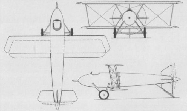
The highly original Kazyanenko No. 5.
LEBED’ X Russia
In 1916, the Aktionernoe Obitsestvo Vozdukhoplavaniya V A Lebedev, a company established in St Petersburg in 1912 by Vladimir A Lebedev and Prof A A Lebedev, developed an equi-span biplane of original design as the Lebed’ X. Owing much to experience gained with the Lebed' VII, an unarmed copy of the Sopwith Tabloid, the Lebed’ X was built in two versions: a single-bay biplane intended as a single-seat fighter and a two-bay biplane intended for the reconnaissance role. Both were powered by the 80 hp Le Rhone rotary and were armed with a single synchronised machine gun, but proved underpowered. Neither fighter nor reconnaissance model progressed further than prototype test.
Max speed, 84 mph (135 km/h).
Empty weight, 915 lb (415 kg).
Span, 34 ft 5 1/3 in (10,50 m).
Length, 22 ft 11 1/2 in (7,00 m).
Wing area, 312.16 sq ft (29,00 m2).
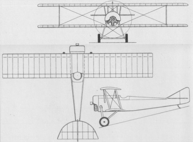
The Lebed' X experimental fighter of 1916.
MOSCA-B bis Russia
During 1916, the MB Mosca-Bystritsky (Moskva-MB) developed a single-seat fighter derivative of its two- seat reconnaissance monoplane. Appreciably smaller and more powerful than the two-seater, the Mosca-B bis fighter retained such features as wing warping for lateral control and detachable flying surfaces permitting the aircraft to be towed along roads. Powered by either an 80 hp Le Rhone or Clerget rotary engine, the Mosca-B bis was delivered with either a 7,7-mm unsynchronised forward-firing machine gun with propeller-mounted steel bullet deflectors or, alternatively, with a similar weapon mounted above the cockpit and firing clear of the propeller disc. A total of 50 Mosca-B bis fighters had been built up to 1918, and a few additional aircraft of this type were reportedly built after the Revolution.
Max speed, 81 mph (130 km/h).
Time to 3,280 ft (1000 m), 3.5 min.
Empty weight, 710 lb (322 kg).
Loaded weight, 1,074 lb (487 kg).
Span, 25 ft 11 in (7,90 m).
Length, 20 ft 0 1/8 in (6,10 m).
Wing area, 129.17 sq ft (12,00 m2).
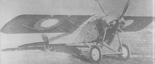
The Mosca-B bis fighter was built in series with both Le Rhone and Clerget rotary engines.
OL’KHOVSKY TORPEDO Russia
Capt Vladimir M Ol’khovsky, Commanding Officer of the 5th Air Park at Bryansk, undertook the design and construction of a two-seat fighter-reconnaissance aircraft which, dubbed the Torpedo - an allusion to the shape of its fuselage - featured the first wooden monocoque fuselage to be built in Russia. A parasol monoplane utilising wing warping for control and entirely of wooden construction, the Torpedo was completed in Odessa in February 1917 with an 80 hp Le Rhone 9C rotary engine. This was replaced by a 110 hp Le Rhone 9J prior to the flight test programme, which was conducted between 6 and 20 March 1917. The flying characteristics of the Torpedo were considered good, and, after completion of tests, the aircraft was handed over to the Odessa part-unit of the Gatchina school, no further examples being built.
Time to 3,280 ft(1 000 m), 4.0 min.
Service ceiling, 16,405 ft (5 000 m).
No further details available.
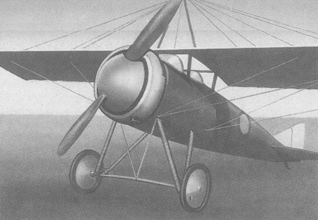
The so-called Torpedo fighter-reconnaissance aircraft designed by Vladimir Ol’khovsky.
RBVZ S-XVI Russia
Conceived in response to a demand for an escort fighter for the Ilya Muromets bombers and similarly built by the RBVZ (Russko-Baltiiskii Vagonnyi Zavod - Russo-Baltic Wagon Works), the S-XVI was an equi-span single-bay two-seat biplane designed by Igor I Sikorsky. Of wooden construction, the S-XVI accommodated its two crew members in slightly staggered side-by-side seats and was noteworthy in utilising the Lavrov-developed synchronisation gear for its single 7.7-mm gun. It was, in fact, one of the world’s first fighters to possess gun-synchronising equipment. Intended to be powered by a 100 hp Le Rhone rotary, the first S-XVI was completed on 6 February 1915 with an 80 hp Gnome rotary because of the non-availability of the more powerful engine. Two more S-XVIs were delivered in the following month and a contract for 18 was placed with the RBVZ on 17 December 1915, these being delivered between January and March 1916. Although highly manoeuvrable, the S-XVI possessed a comparatively poor performance because of insufficient power. A further small batch of S-XVIs was completed in 1917, some being used during the Revolution and examples remaining in service until 1923. One S-XVI was fitted with a 60 hp Kalep rotary engine, had an enlarged upper wing (by 21.53 sq ft/2,0 m2) and lacked the lower-wing ailerons of the standard model. Another was unsuccessfully tested with floats and others were operated with ski undercarriages. Several were fitted with a 7.7-mm gun above the upper wing to supplement the synchronised weapon.
Max speed, 75 mph (120 km/h).
Time to 3,280 ft (1 000 m), 8.0 min.
Empty weight, 897 lb (407 kg).
Loaded weight, 1,490 lb (676 kg).
Span, 27 ft 6 3/4 in (8,40 m).
Length, 20 ft 4 in (6,20 m).
Height, 9 ft 1 1/2 in (2,78 m).
Wing area, 272.98 sq ft (25,36 m2).
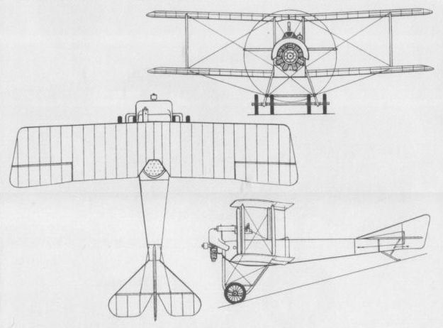
RBVZ S-XX Russia
Displaying some Nieuport influence, the S-XX single-seat fighter designed by Igor Sikorsky was a single-bay unequal-span unstaggered biplane of wooden construction with fabric skinning. Armament comprised a single synchronised 7,7-mm machine gun, and five S-XXs were built in September 1916. The first of these was powered by a 100 hp Gnome rotary, but the second and, presumably, the remaining three S-XXs received the 120 hp Le Rhone engine with which they were allegedly faster than the Nieuport 17. However, the S-XX was considered inferior to the newer enemy aircraft that had begun to appear at the Front, and, therefore, no series production was undertaken. The following data relate to the S-XX with the Le Rhone engine.
Max speed, 118 mph (190 km/h).
Time to 6,560 ft (2 000 m), 6.33 min.
Empty weight, 871 lb (395 kg).
Loaded weight, 1,257 lb (570 kg).
Span, 28 ft 2 1/2 in (8,60 m).
Length, 21ft 3 7/8 in (6,50 m).
Wing area, 182.99 sq ft (17,00 m2).

The S-XX failed to achieve series production, being inferior to newer enemy aircraft.
SLYUSARENKO Russia
In the second half of 1917, the factory of V V Slyusarenko in St Petersburg, which had previously licence-built Farman, Morane and Lebed’ types, built an original single-seat fighter to the designs of G P Adler. A mid-wing monoplane of wooden construction, it had a circular-section plywood monocoque fuselage and a fabric-covered wing, the power plant being either a 130 hp Clerget or 120 hp Le Rhone nine-cylinder rotary engine. Material shortages and labour difficulties which were to lead to the closure of the V V Slyusarenko factory early in 1918 prevented completion of the flight testing of the fighter, which was claimed to have attained a speed of 101 mph (163 km/h) during initial trials. No illustrations of the Slyusarenko fighter nor data relating to this type are available.
In the second half of 1917, the factory of V V Slyusarenko in St Petersburg, which had previously licence-built Farman, Morane and Lebed’ types, built an original single-seat fighter to the designs of G P Adler. A mid-wing monoplane of wooden construction, it had a circular-section plywood monocoque fuselage and a fabric-covered wing, the power plant being either a 130 hp Clerget or 120 hp Le Rhone nine-cylinder rotary engine. Material shortages and labour difficulties which were to lead to the closure of the V V Slyusarenko factory early in 1918 prevented completion of the flight testing of the fighter, which was claimed to have attained a speed of 101 mph (163 km/h) during initial trials. No illustrations of the Slyusarenko fighter nor data relating to this type are available.
TERESHCHENKO No 7 Russia
Built in the workshops of the Kiev Polytechnic Institute under the direction of engineer Vladimir P Grigoriev, a side-by-side two-seat reconnaissance-fighter, referred to as No 7 and designed by F Tereshchenko, was completed on 28 August 1916. A single-bay biplane of wooden construction with fabric covering and a 100 hp Gnome Monosoupape nine-cylinder rotary engine, the Tereshchenko No 7 featured 10 deg of sweepback on the wings, the angle of attack of which could be adjusted in flight. Flight testing was initiated in Moscow in September 1916, and was continued until January 1917, when the prototype was returned to Kiev for modifications. Flight testing was resumed on 29 June 1917, but the ultimate fate of the prototype is unknown.
Max speed, 87 mph (140 km/h).
Empty weight, 1,102 lb (500 kg).
Loaded weight, 1,896 lb (860 kg).
Span, 26 ft 3 in (8,00 m).
Length, 19 ft 8 1/4 in (6,00 m).
Wing area, 236.81 sq ft (22,00 m2).
ENGELS MI Russia
In 1916, several single-seat fighter flying boats were developed to meet a requirement formulated by the Directorate of Naval Aviation for what was referred to as a ‘‘counter-fighter"; a water-borne fighter intended specifically to oppose the Albatros W 4 that had appeared in the Baltic. The most novel of the contenders was the MI (Morskoi istrebitel) designed by Ye R Engels. Flown at the beginning of December 1916, this was a parasol cantilever monoplane flying boat with a V-section hull, downswept wingtips incorporating flotation chambers providing the necessary stability on the water. Control was by wing warping, power was provided by a pusher Gnome-Monosoupape rotary of 100 hp and provision was made for a single fixed forward-firing 7,62-mm Maxim gun. During its initial flight at the beginning of December 1916, the Engels MI achieved 106 mph (170 km/h), and although it suffered an accident during its third flight (the starboard rear spar breaking and the wing warping cable fouling the propeller), an order was placed with the Mel’tser factory on 27 April 1917 for 60 examples powered by the 120 hp Le Rhone. The first was completed on 24 August 1917, and the second two weeks later, on 9 September, one being transferred to the Navy on 10 October, but work at the factory subsequently came to a standstill. The second example was eventually delivered to the Naval Aviation School at Nizhny Novgorod (Gorky) in March 1920, and tested with skis, but no others were completed.
Empty weight, 849 lb (385 kg).
Loaded weight, 1,224 lb (555 kg).
Span, 29 ft 6 1/3 in (9,00 m).
Length, 24 ft 7 1/4 in (7,50 m).
Wing area, 152.85 sq ft (14,20 m2).
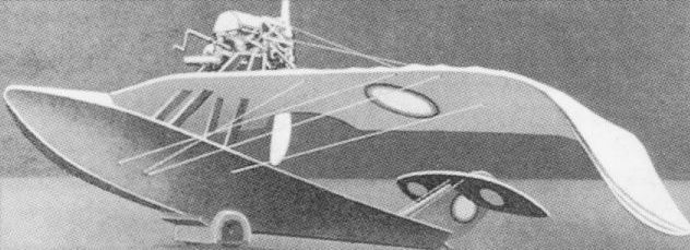
The Engels-designed MI water-borne fighter.
BERKMANS SPEED SCOUT USA
In 1916, the brothers Maurice and Emile Berkmans began design of a single-seat fighter known as the Speed Scout. Powered by a 100 hp Gnome Monosoupape nine-cylinder rotary engine, the Speed Scout was of conventional wooden construction but featured a circular-section laminated monocoque fuselage. Like the contemporary Curtiss S-2, the Speed Scout employed a rigidly-anchored cross-axle undercarriage to which a measure of shock-absorbency was imparted by the use of Ackermann spring wheels, these featuring curved spring-steel spokes which served as shock absorbers. Proposed armament comprised two synchronised 0.3-in (7,62-mm) machine guns. The fighter commenced its test programme in the spring of 1918, and demonstrated a high standard of manoeuvrability and excellent climb performance, attaining an altitude of 22,0 ft (6 706 m) on one occasion, but ground handling proved poor. The Speed Scout was demonstrated for the Army Aviation Section, which, having no need for a new single-seat fighter with World War I virtually at an end, procured the prototype for stress analysis of the monocoque construction.
Max speed, 115 mph (185 km/h).
Initial climb, 1,100 ft/min (5,59 m/sec).
Endurance, 2.5 hrs.
Empty weight, 820 lb (372 kg).
Loaded weight, 1,190 lb (540 kg).
Span, 26 ft 0 in (7,92 m).
Length, 18 ft 8 in (5,69 m).
Height, 7 ft 10 in (2,39m)
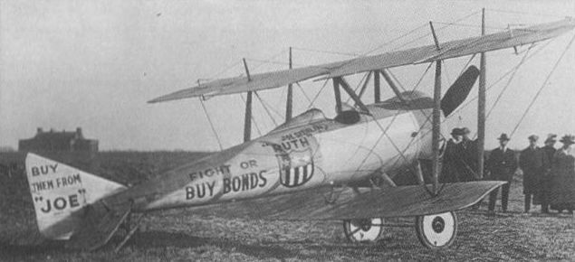
Berkmans Speed Scout, a private venture prototype tested by the US Army in 1918.
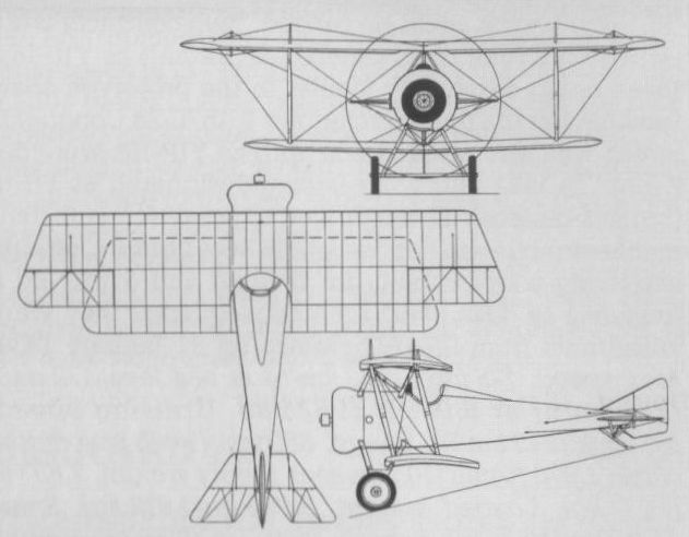
BURGESS (HT-B) HT-2 USA
In the late autumn of 1916, the US Navy framed a requirement which, issued on 17 November, called for a float-equipped single-seat fighting scout with a max speed of at least 95 mph (153 km/h) and an endurance of 2.5 hrs. It was envisaged that a 165 hp Gnome Monosoupape 9N rotary engine would be used. To meet this requirement, W Starling Burgess of the Burgess Company of Marblehead, Mass, a division of the Curtiss Aeroplane and Motor Corporation, produced the HT-B which was demonstrated to the Navy Department on 19 May 1917. A fabric-covered wooden sesquiplane in which close attention had been paid to aerodynamic cleanliness, the HT-B had fabric-covered K-type interplane struts, the short floats embodying shock absorbers. The intended armament comprised a single 0.3-in (7,62-mm) machine gun, but the rotary engine being unavailable, the HT-B was fitted with a water-cooled Curtiss OXX-2 of 100 hp. With this it was underpowered, max attainable speed being 85 mph (137 km/h). Nevertheless, the Navy considered the HT-B to possess excellent aerodynamic and hydrodynamic qualities, placing a contract for six examples (later amended to include two additional aircraft). Known unofficially as the Speed Scout, the first HT-B was delivered to Squantum on 11 September 1917, and the second to Pensacola in the following month, neither carrying armament. These were followed by six more of a slightly modified version known as the HT-2, all being delivered by the end of 1917. No details of the subsequent career in US Navy service of the HT-B are available, but this is understood to have been brief and did not long survive the demise of the Burgess Company in November 1918.
Max speed, 85 mph (137 km/h) at 1,000 ft (305 m).
Endurance, 2. 0 hrs.
Span, 34 ft 4 in (10,46 m).
Length, 22 ft 3 in (6,87 m).
Height, 10 ft 9 in (3,28 m).
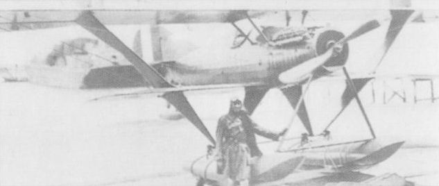
Also known as the Speed Scout, the Burgess HT-B sesquiplane (on photo) was the prototype for the slightly modified H-2 of which six were built in 1917.
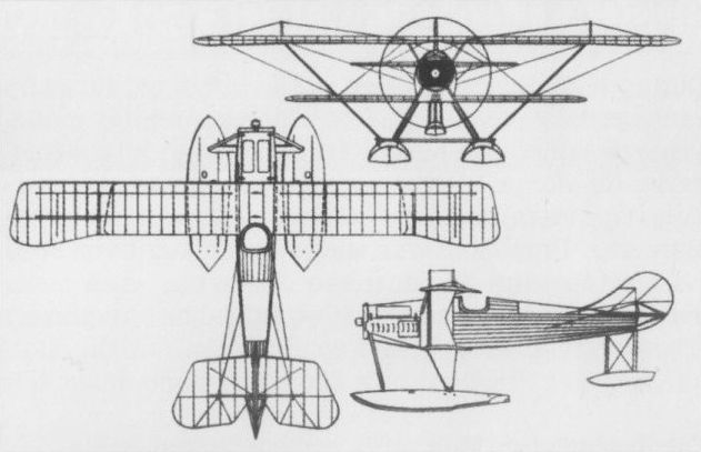
Also known as the Speed Scout, the Burgess HT-B sesquiplane was the prototype for the slightly modified H-2 (shown) of which six were built in 1917.
CANTILEVER AERO BULLET USA
The first of two single-seat cantilever sesquiplanes designed by Dr William W Christmas of the Cantilever Aero Company with the assistance of Vincent J Burnelli, and built by the Continental Aircraft Company, was flown for the first time in mid-January 1919. It crashed and was totally destroyed shortly after its first take-off. Initially known as the Scout and subsequently as the Bullet (or Christmas Bullet), it was powered by a 185 hp Liberty 6 six-cylinder water-cooled engine and was primarily of wooden construction. Unusual features included the use of internal rotating torque tubes to operate the ailerons (although conventional cables were fitted at one stage) and a warping tail-plane. The second prototype was powered by a Hall-Scott L-6 six-cylinder water-cooled engine and this also crashed on its first flight in the summer of 1919, development subsequently being abandoned. The following performance data were claimed but are believed exaggerated.
Max speed, 175 mph (282 km/h).
Ceiling, 14,700 ft (4 480 m).
Range, 550 mis (885 km).
Empty weight, 1,820 lb (825 kg).
Loaded weight, 2,100 lb (952,5 kg).
Span, 28 ft 0 in (8,53 m).
Length 21ft 0 in (6,40 m).
Wing area, 170 sq ft (15,79 m2).

The first of the two Christmas Bullets, both of which crashed on their first flights.
CURTISS S-3 USA
Essentially a triplane derivative of the S-2 "Wireless" (signifying lack of wing bracing wires) unarmed biplane "scout”, the S-3, or "Triplane Speed Scout", possessed a similar fuselage and 100 hp Curtiss OXX-3 engine, and initially retained the ducted propeller spinner featured by the biplane. Interplane bracing employed ‘‘K”-type struts and, on its second flight during the summer of 1917, the S-3 attained an altitude of 16,500 ft (5 030 m), which was a record at the time. For initial trials, the centre wing was attached to the fuselage at low shoulder position, but the gap between all three wings was subsequently increased and the centre wing was raised above the fuselage. After redesign of the rudder and the discarding of the ducted spinner, the S-3 successfully completed evaluation trials and four were ordered during the course of 1917 for the US Army Signal Corps. It was proposed to arm the S-3 with two unsynchronised Lewis guns which were to fire over the propeller arc, but the S-3s were, in the event, delivered to the Signal Corps without armament.
Max speed, 115 mph (185 km/h).
Time to 9,000 ft (2 745 m), 10 min.
Empty weight, 970 lb (440 kg).
Loaded weight, 1,320 lb (599 kg).
Span, 25 ft 0 in (7,62 m).
Length, 19 ft 6 in (5,94 m).
Height, 8 ft 7 in (2,62 m).
Wing area, 142.6 sq ft (13,25 m2).
CURTISS S-6 USA
A refined version of the S-3 with revised strutting carrying the centre section of the upper wing and the root attachments of the centre wing, a modified undercarriage and other changes, the S-6 triplane of 1917 was the first US "scout" to be fitted with twin forward-firing machine guns, these being gas-operated Lewis guns which were mounted side-by-side on inverted and inclined "V" struts immediately beneath the centre section of the upper wing and firing outside the propeller disc. Only a single example of the S-6 was built and tested.
Max speed, 110 mph (177 km/h).
Loaded weight, 1,377 lb (625 kg).
Span, 25 ft 0 in (7,62 m).
Length, 19 ft 6 in (5,94 m).
Height, 8 ft 7 in (2,62 m).
Wing area, 142.6 sq ft (13,25 m2).

The first Curtiss S-3 in the form in which it was originally flown.
CURTISS 18-T USA
Designed by Charles B Kirkham, the Curtiss 18-T two-seat fighter triplane was ordered by the US Navy on 30 March 1918 when a contract was placed for two prototypes. The first of these was flown on 7 May 1918. Designed around the Curtiss-Kirkham K-12 water-cooled 12-cylinder engine of 400 hp, the 18-T was of extremely clean aerodynamic design by contemporary standards and featured a monocoque three-ply fuselage and side radiators positioned between the lower wings. The proposed armament comprised two forward-firing synchronized 0.3-in (7,62-mm) Marlin machine guns and two 0.3-in (7,62-mm) Lewis guns on a Scarff mounting in the rear cockpit. Known unofficially as the "Wasp” (an allusion to the sound emitted by the K-12 engine during landing approach), the 18-T initially suffered some tail heaviness which was corrected by applying five degrees of sweepback to the wings for further trials. A max speed of 163 mph (262 km/h) was achieved with full military load in August 1918, the 18-T being acclaimed as the world's fastest aeroplane as a result. The US Navy promptly ordered two examples, the first of which was delivered in February 1919. In the summer of 1919, the first prototype was fitted with longer-span two-bay wings, these having a span and area of 40 ft 7 1/2 in (12,38 m) and 400 sq ft (37,16 m2) respectively, and in this form the aircraft became the 18T-2, the short-span version becoming the 18T-1. The 18T-2 established a world altitude record of 34,910 ft (10 640 m) on 18 September 1919, and a second 18T-2 was built by Curtiss for export to Bolivia, where it arrived in 1920. The following data relate to the 18T-1.
Max speed, 165 mph (265 km/h).
Time to 12,500 ft (3810 m), 10 min.
Endurance, 5.9 hrs.
Empty weight, 1,980 lb (898 kg).
Loaded weight, 3,050 lb (1 383 kg).
Span, 31ft 10 in (9,70 m).
Length, 23 ft 4 in (7,11m).
Height, 9 ft 10 3/4 in (3,02 m).
Wing area, 288 sqft (26,76 m2).
CURTISS 18-B USA
US Army interest in the 18-T prompted Curtiss to offer the same basic design in two-bay biplane configuration, and an order was placed by the US Army for two examples in August 1918. Known unofficially as the "Hornet”, the 18-B two-seat fighter employed an identical fuselage to that of the 18-T and a similar Curtiss-Kirkham K-12 engine. The proposed armament comprised two forward-firing Marlin guns and two Lewis guns on a flexible mount. The two prototypes were delivered to the US Army during the summer of 1919, one being confined to static testing and the other crashing shortly after the commencement of flight trials, and further development was then abandoned.
Max speed, 160 mph (257 km/h).
Empty weight, 1,690 lb (767 kg).
Loaded weight, 2,867 lb (1300 kg).
Span, 37 ft 5 3/4 in (11,41 m).
Length, 23 ft 4 in (7,11 m).
Wing area, 306 sq ft (28,43 m2).
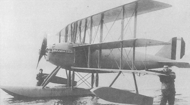
Modified with long-span, two-bay wings, the second Curtiss 18T was redesignated as the 18T-2.
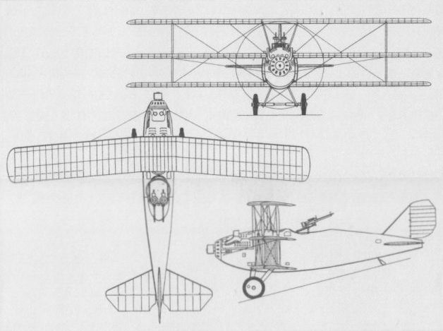
To correct tail-heaviness, the Curtiss 18-T was given five degrees of wing sweepback soon after first flight, as illustrated here.
CURTISS CB USA
The CB (Curtiss Battleplane), unofficially known as the "Liberty Battler", was an experimental two-seat fighter developed and flown early in 1918 as a result of difficulties being experienced with the Liberty-engined version of the Bristol F2B. Powered by a 425 hp 12-cylinder Liberty 12 water-cooled engine, the CB two-bay biplane was an early example of "Curtiss ply" construction - two layers of 2-in (5,08-cm) wide wood veneer being cross-laminated over a form to build up a monocoque fuselage shell. In an effort to maintain fuselage streamlining, the radiators were slung under the upper wing centre section, where they were found to have a seriously detrimental effect on the airflow. The fairing of the upper wing into the top fuselage contour resulted in a very narrow wing gap, with consequent aerodynamic penalties. While it provided the rear gunner with an excellent field of fire, it impaired the forward and downward view of the pilot, necessitating the provision of small windows in the fuselage sides. Flown in May 1918, the sole prototype CB proved to have extremely poor handling characteristics and crashed early in its test programme.
Empty weight, 3,575 lb (1622 kg).
Span, 39 ft 4 in (11,98 m).
Length, 27 ft 1 in (8,25 m).
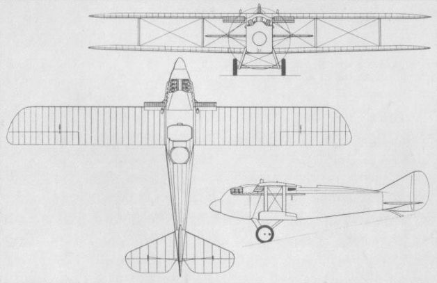
The sole Curtiss Battleplane (CB) of 1918, also known as the "Liberty Battler”.
CURTISS GS USA
During 1917, the US Navy issued the Curtiss company with a contract for five single-seat fighting scout float seaplanes powered by a US-built version of the 100 hp Gnome nine-cylinder rotary, the GS designation indicating "Gnome Scout". These were completed under the designation GS-2 when a supplementary contract was issued for a sixth aeroplane which was assigned the designation GS-1. The GS-1 was a single-seat triplane with a single central float and outrigger stabilizing floats which drew heavily on Curtiss S-3 experience. An unusual feature was the introduction of shock absorbers in the struts between the fuselage and the central float. These resulted in the float angle being subject to change at high speed on the water and producing an undesirable porpoising. Delivered to the US Navy early in 1918, the GS-1 was flown several times by US Navy acceptance pilots, but was eventually damaged beyond repair as a result of a heavy landing. The five similarly-powered GS-2s differed from the GS-1 primarily in being of biplane configuration, but little is recorded of these aircraft apart from the fact that they suffered from tail heaviness. No data are available for either GS-1 or GS-2.
During 1917, the US Navy issued the Curtiss company with a contract for five single-seat fighting scout float seaplanes powered by a US-built version of the 100 hp Gnome nine-cylinder rotary, the GS designation indicating "Gnome Scout". These were completed under the designation GS-2 when a supplementary contract was issued for a sixth aeroplane which was assigned the designation GS-1. The GS-1 was a single-seat triplane with a single central float and outrigger stabilizing floats which drew heavily on Curtiss S-3 experience. An unusual feature was the introduction of shock absorbers in the struts between the fuselage and the central float. These resulted in the float angle being subject to change at high speed on the water and producing an undesirable porpoising. Delivered to the US Navy early in 1918, the GS-1 was flown several times by US Navy acceptance pilots, but was eventually damaged beyond repair as a result of a heavy landing. The five similarly-powered GS-2s differed from the GS-1 primarily in being of biplane configuration, but little is recorded of these aircraft apart from the fact that they suffered from tail heaviness. No data are available for either GS-1 or GS-2.
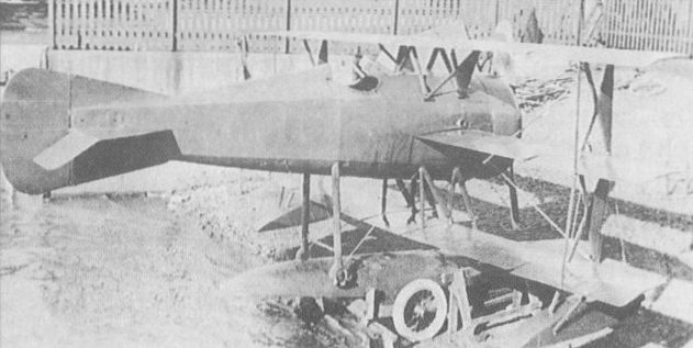
The GS-1 "Gnome Scout” triplane was similar in most respects to five GS-2 biplanes that preceded it.
CURTISS HA USA
Designed by Capt B L Smith of the US Marine Corps as a two-seat patrol fighter floatplane for use in the Dunkirk-Calais area, the HA - known unofficially as the "Dunkirk Fighter” - was intended to combat the Brandenburg float fighters and was built at the experimental plant of the Curtiss Engineering Corporation. Of conventional wooden construction with fabric skinning, the HA was powered by a 425 hp Liberty 12 engine and featured an unusually rotund fuselage. Proposed armament comprised two synchronized 0.3-in (7,62-mm) Marlin machine guns and two Lewis guns of the same calibre on a Scarff mounting in the rear cockpit. The HA was flown for the first time on 21 March 1918, but was found to be unstable longitudinally and seriously tail heavy. The initial test terminated in a crash. Curtiss was then awarded a contract for two further prototypes, the first of which, the HA-1, utilized salvaged components from the original HA and featured revised vertical tail surfaces, an annular-type radiator and relocated wings. The HA-1 demonstrated appreciably improved handling qualities, but was written off after a fire in the air. The third HA prototype, the HA-2, differed appreciably from the HA-1 (see following entry). The following data apply to the HA-1 float fighter.
Max speed, 126 mph (203 km/h).
Time to 9,000 ft (2 743 m), 10 min.
Empty weight, 2,449 lb (1 111 kg).
Loaded weight, 3,602 lb (1634 kg).
Span, 36 ft 0 in (10,97 m).
Length, 30 ft 9 in (9,37 m).
Height, 10 ft 7 in (3,23 m).
Wing area, 387 sq ft (35,95 m2).
CURTISS HA-2 USA
The third HA float fighter prototype embodied considerable redesign as the HA-2. Powered by a 12-cylinder Liberty 12 water-cooled engine, like the preceding prototypes, the HA-2 had longer-span wings of marginally increased chord and gap, the upper wing being raised clear of the fuselage, the decking of which was lowered. The radiator was redesigned, but cooling problems were encountered and although the HA-2 proved more docile than the lighter HA-1, it possessed insufficient promise to warrant further development.
Max speed, 118 mph (190 km/h).
Time to 7,900 ft (2408 m), 10 min.
Empty weight, 2,946 lb (1 336 kg).
Loaded weight, 3,907 lb (1772 kg).
Span, 42 ft 0 in (12,80m).
Length, 30 ft 9 in (9,37m).
Height, 11 ft 5in (3,48 m).
Wing area, 490 sq ft (45,52 m2).
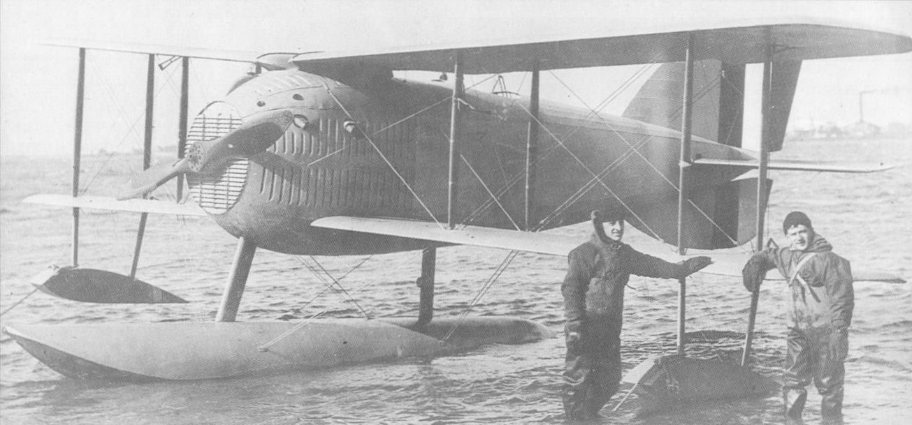
Prototype Curtiss HA, also known as the "Dunkirk Fighter", intended to serve in Europe.
The second HA (later HA-1) contained some parts of the first but was a new aeroplane with a later Navy serial number.
The second HA (later HA-1) contained some parts of the first but was a new aeroplane with a later Navy serial number.

The Curtiss HA-2 of which only a single prototype was built, differed from the HA in respect of wing and engine cowling detail.
ENGINEERING DIVISION (POMILIO) FVL-8
At the request of the US Army’s Engineering Division at McCook Field, Ottorino Pomilio of the Turin-based company of Pomilio Brothers undertook the design of a single-seat fighter around the then-new 280 hp Liberty eight-cylinder water-cooled engine. Designated FVL-8, the Pomilio-designed fighter was of wooden construction with plywood fuselage skinning and carried an armament of twin synchronised 0.3-in (7,7-mm) Vickers machine guns. Six prototypes of the FVL-8 were built in Indianapolis, the first of these being delivered in February 1919, but no series production was undertaken.
Max speed, 133 mph (214 km/h).
Empty weight, 1,726 lb (783 kg).
Loaded weight, 2,284 lb (1036 kg).
Span, 26 ft 8 in (8,13m).
Length, 21ft 8 in (6,60 m).
Height, 8 ft 2 in (2,49 m).
Wing area, 284 sqft (26,38 m2).
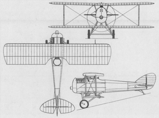
ENGINEERING DIVISION VCP-1 USA
Designed in 1918 by Alfred Verville and Capt V E Clark, the VCP-1 (the designation indicating Verville-Clark-Pursuit) single-seat single-bay fighter biplane was built at McCook Field and powered by a 300 hp Wright-Hispano "H” engine. Advanced features for its time included a laminated wood veneer fuselage and I-type interplane struts, and the first of the two VCP-1 prototypes was completed and flown in August 1919, initially with an annular radiator and large spinner. A more conventional radiator and spinner combination was subsequently adopted, and the sole VCP-1 completed was eventually fitted with a 660 hp Packard 1A-2025 12-cylinder Vee engine to participate in the 1920 Pulitzer Prize Race as the VCP-R. Further modifications were incorporated for the 1922 Pulitzer Prize Race and the designation changed to R-1.
Max speed, 154 mph (248 km/h) at sea level, 152 mph (245 km/h) at 6,500 ft (1980 m).
Initial climb, 1,690 ft/min (8,58 m/sec).
Range, 298 mis (479 km).
Empty weight, 2,014 lb (913 kg).
Loaded weight, 2,669 lb (1211 kg).
Span, 32 ft 0 in (9,75 m).
Length, 22 ft 4 in (6,81 m).
Height, 8 ft 4 in (2,54 m).
Wing area, 269 sq ft (24,99 m2).
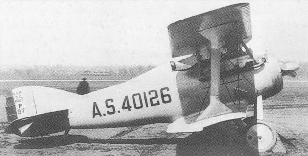
The sole example of the VCP-1 completed with the original annular radiator.
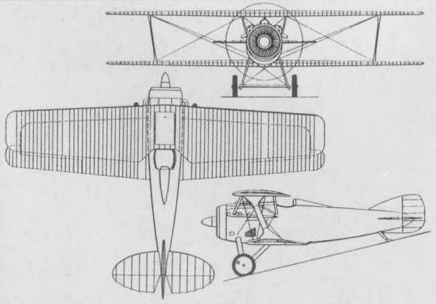
HEINRICH PURSUIT USA
During the 19 months in which the USA participated in World War I, several attempts were made to develop competent single-seat fighters of original design. Among these was the Heinrich Pursuit designed by Albert S Heinrich and built by the Victor Aircraft Corp. The Heinrich Pursuit was an aerodynamically clean, single-bay, unequal-span biplane powered by a 100 hp Gnome nine-cylinder rotary engine. Two examples were ordered by the US Army Signal Corps and built in 1917, the first of these being delivered in November of that year. Some testing was undertaken at McCook Field, Dayton, Ohio, but official US policy at this time was to forego fighters of national design in favour of tested foreign types. Nevertheless, the Heinrich Pursuit was considered to have potential as a fighter trainer, and two additional aircraft were ordered. These employed the more reliable Le Rhone rotary of 80 hp, had a strengthened cabane and paired rather than single struts and a lighter structure, gross weight being reduced by 170 lb (77 kg). These aircraft were built in 1918, but no further development was undertaken. The following data relate to the Gnome-engined version.
Max speed, 115 mph (185 km/h).
Loaded weight, 1,235 lb (560 kg).
Span, 26 ft 0 in (7,92 m).
Wing area, 162.5 sq ft (15,09 m 2).
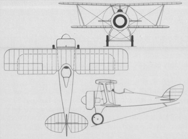
LANZIUS L II USA
The L II was derived from the tandem two-seat L I developed by the Lanzius Aircraft Company of New York in 1917 under US Army Signal Corps contract (and referred to by the manufacturer as the "Lanzius Variable Speed Aeroplane”). The L II single-seat fighting scout of circa 1919 was novel in featuring wings possessing both variable camber and variable incidence. A two-bay equi-span biplane powered by a 350 hp Packard 1A-1237 six-cylinder vertical inline water-cooled engine, the L II utilised a system of cables and pulleys to change camber and incidence, the latter varying from 0 deg to 15 deg. Flight testing is believed to have been conducted at McCook Field, only one prototype being completed.
Loaded weight, 1,200 lb (544 kg).
Span, 38 ft 0 in (11,58 m).
Length, 25 ft 0 in (7,62 m).
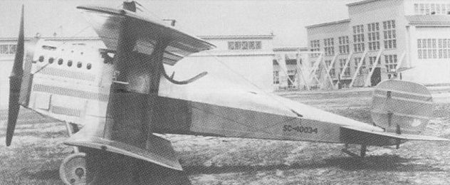
LOENING M-8 USA
Daringly innovative for its day, the M-8 two-seat fighter, flown for the first time in August 1918, was the first product of the Loening Engineering Corp formed earlier that year by Grover C Loening. Despite some prejudice against the monoplane configuration, the M- 8, designed around the new 300 hp Wright (Hispano-Suiza) Model H engine, was a braced shoulder-wing monoplane. Possessing an exceptionally low structural weight, the M-8 carried an armament of two 0.3-in (7,62-mm) Lewis guns in the rear cockpit, the gunner having an excellent field of fire. The M-8 was of wooden construction and two prototypes were completed. These demonstrated such outstanding performance that a contract was placed for 5,000 aircraft before the Armistice terminated plans for large-scale production. Although only the prototypes went to the Army, the Navy ordered a single example as the M-8-0, following this with orders for a further 54 aircraft (of which 36 were built by the Naval Aircraft Factory). Forty-six of these were of the M-8-0 and M-8-1 types, which, although designed as fighters, were used for observation purposes, the remaining six being completed as twin-float seaplanes under the Navy designation LS-1.
Max speed, 144 mph (232 km/h) at sea level.
Time to 6,500 ft (1 980 m), 5.2 min.
Empty weight, 1,663 lb (754 kg).
Loaded weight, 2,368 lb (1 074 kg).
Span, 32 ft 9 in (9,98 m).
Length, 24 ft 0 in (7,31 m).
Height, 6 ft 7 in (2,00 m).
Wing area, 238.9 sq ft (22,19 m2).
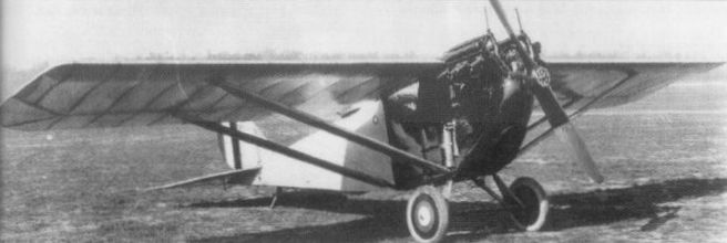
The Armistice of 1918 ended plans for large-scale production of the M-8.
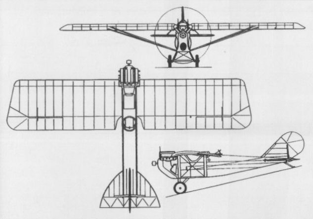
L.W.F. MODEL G-2 USA
The L.W.F. Engineering Company, established in December 1915 by Edward Lowe, Charles Willard and Robert Fowler, developed the Model G in late 1917 as a two-seat reconnaissance aircraft. The Model G was destroyed in a crash on 16 January 1918, but a more powerful version, the G-2, was completed and flown in the spring of 1918, this being intended as a two-seat heavy fighter and reconnaissance-bomber. Powered by a 435 hp Liberty 12 water-cooled engine, the G-2 carried an unprecedented armament of seven 0.3-in (7,62- mm) machine guns, four of these being grouped around the engine and synchronised to fire through the propeller disc, two being Scarff-mounted in the rear cockpit and the remaining gun firing through a ventral aperture. Although flight testing was considered successful, the sole G-2 crashed and was destroyed in fog on 18 November 1918. A third example was subsequently completed as a mailplane, but further development as a combat aircraft was abandoned.
Max speed, 138 mph (222 km/h) at sea level.
Time to 10,000 ft (3050 m), 9.3 min.
Endurance, 4 hrs.
Empty weight, 2,675 lb (1213 kg).
Loaded weight, 4,023 lb (1825 kg).
Span, 41ft 7 1/2 in (12,69 m).
Length, 29 ft 1 3/4 in (8,88 m).
Height, 9 ft 4 3/4 in (2,86m).
Wing area, 516 sq ft (47,94 m2).
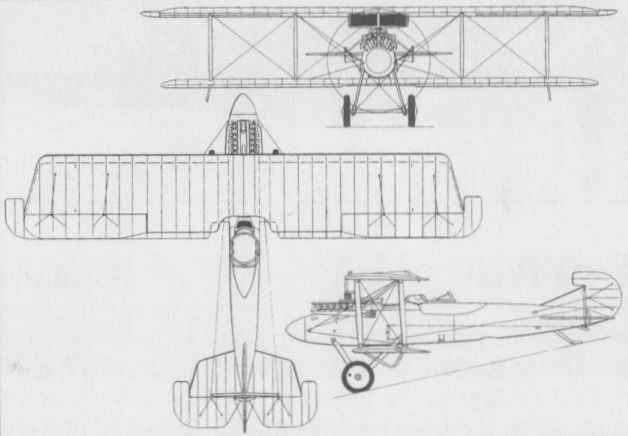
Flight testing during 1918 of the L.W.F. G-2 was dogged by misfortune.
ORDNANCE ENGINEERING (ORENCO) TYPE B USA
In 1917, Etienne Dormoy, formerly a designer with the Societe Pour Aviation et ses Derives (SPAD) and a member of the French Aeronautical Mission to the USA, designed a single-seat fighter for the Ordnance Engineering Corporation founded in the previous year. This concern (which was to use the acronym Orenco from early 1919) completed a prototype known as the Type B (the Type A having been a two-seat training biplane) which was flown early in 1918. A two-bay staggered biplane of wooden construction, the Type B was powered by a 160 hp Gnome Monosoupape nine-cylinder rotary engine and was intended to carry an armament of three 0.3-in (7,62-mm) Marlin machine guns - one beneath the upper wing and two beneath the lower wing. Four examples were ordered by the Aviation Section of the Signal Corps (together with five examples of the Type C trainer derivative), but the US government had meanwhile elected to manufacture proven European fighters, and no series production of the Type B was therefore undertaken.
Max speed, 135 mph (217 km/h) at sea level.
Time to 5,000 ft (1525 m), 3.3 min.
Range, 200 mis (322 km).
Empty weight, 935 lb (424 kg).
Loaded weight, 1,295 lb (587 kg).
Span, 26 ft 0 in (7,92 m).
Length, 18 ft 10 in (5,74 m).
Height, 7 ft 4 in (2,23 m).
Wing area, 180 sq ft (16,72 m2).
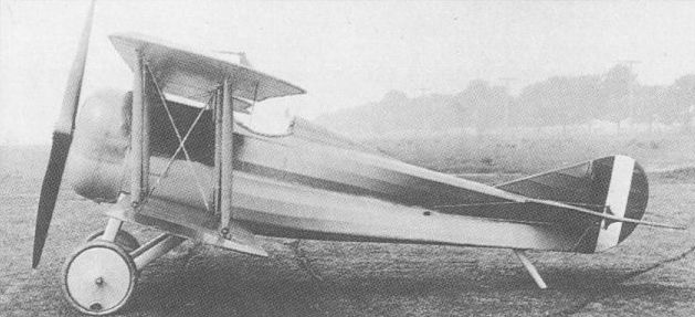
The Type B, the first example of this fighter being illustrated by the photograph.
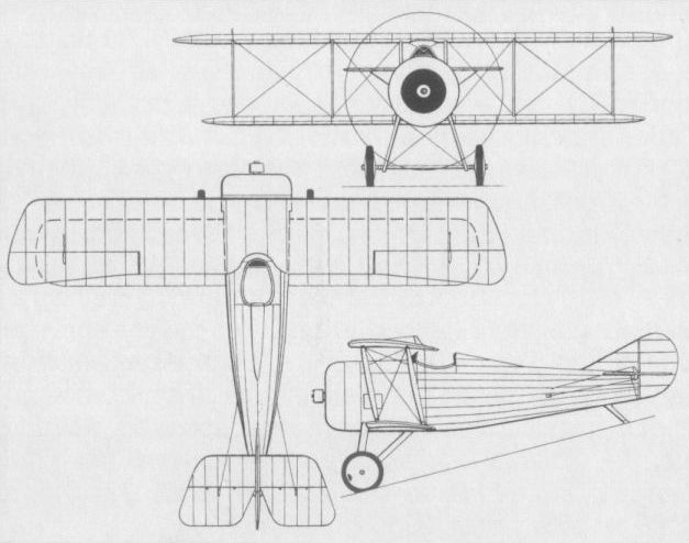
ORDNANCE ENGINEERING (ORENCO) TYPE D USA
Towards the end of 1918, the Ordnance Engineering Corporation offered a new single-seat fighter designed around the 300 hp Hispano-Suiza H eight-cylinder water-cooled engine, the Type D, receiving an order for four aircraft. A two-bay equi-span staggered biplane of wooden construction with an armament of two 0.3-in (7,62-mm) guns, the first Type D was completed in January 1919 (and shortly thereafter the company adopted the acronym Orenco). Tested by what had by then become known as the Air Service, the Type D received a glowing commendation, but Curtiss submitted the winning bid for the production of a series of 50 aircraft, for which various modifications were introduced. The parent company further developed the design as the Type D2 with unequal-span wings of single-bay configuration, three being ordered by the Air Service as PW-3s. Demonstrating structural weaknesses during ground trials, these were declared unsafe and were not flown. The following data relate to the Orenco-built Type D prototypes.
Max speed, 147 mph (237 km/h) at sea level.
Time to 5,0 ft (1525 m), 4.3 min.
Range, 275 mis (442 km).
Empty weight, 1,666 lb (756 kg).
Loaded weight, 2,432 lb (1103 kg).
Span, 30 ft 0 in (9,14 m).
Length, 21 ft 6 in (6,55 m).
Height, 8 ft 3 in (2,52 m).
Wing area, 261 sqft (24,25 m2).
CURTISS-ORENCO D USA
The first single-seat fighter of indigenous US design to achieve production status, the Model D was conceived around the 300 hp Hispano-Suiza H eight-cylinder water-cooled engine. The first of four prototypes built by the Ordnance Engineering Corporation (Orenco) was completed in January 1919. Curtiss was assigned a production contract for 50 aircraft and undertook some redesign. This included the introduction of dihedral and overhanging, balanced ailerons, and revision of the engine installation. Of wooden construction with ply-covered fuselage and fabric-covered wings, the Curtiss-built Model D utilised a 330 hp Wright-built derivative of the French engine and carried an armament of two 0.3-in (7,62-mm) machine guns, deliveries commencing in August 1921. One Model D was experimentally fitted with French Lamblin radiators attached to the fuselage sides, and another was fitted with a turbo-supercharger for high altitude trials.
Max speed, 139 mph (224 km/h) at sea level, 136 mph (219 km/h) at 6,500 ft (1980 m).
Climb, 1,140 ft/min (5.8 m/sec).
Endurance, 2.5 hrs.
Empty weight, 1,908 lb (865 kg).
Loaded weight, 2,820 lb (1279 kg).
Span, 32 ft 11 5/8 in (10,05 m).
Length, 21 ft 5 1/2 in (6,54 m).
Height, 8 ft 4 in (2,54 m).
Wing area, 273 sq ft (25,36 m2).
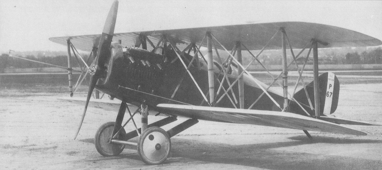
Although developed by Ordnance Engineering, the Type D fighter was destined to be built in series by the Curtiss company.
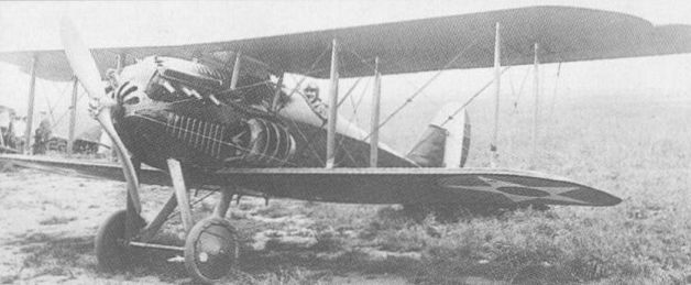
One Curtiss-Orenco D was experimentally fitted with Lamblin "pineapple" radiators as seen here.
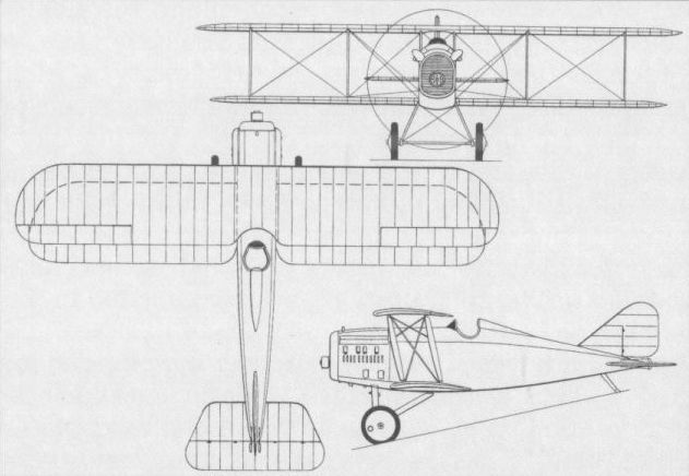
Although developed by Ordnance Engineering, the Type D fighter was destined to be built in series by the Curtiss company.
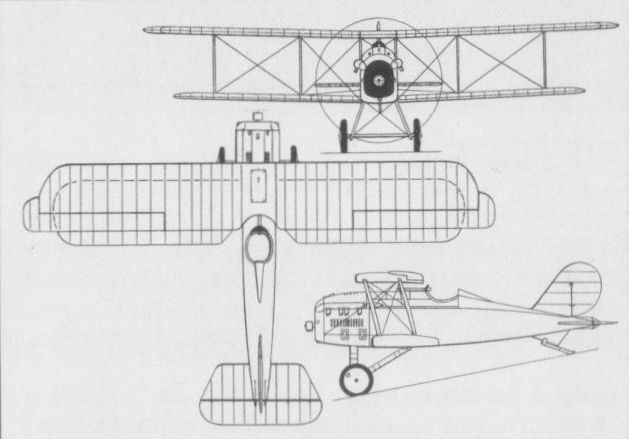
For early post-war service with the Army Air Corps, Curtiss built 50 Orenco Ds after modifying designs of the Ordnance Engineering Corp.
PACKARD LUSAC-11 USA
Designed at the behest of the US Army Engineering Division by Georges Lepere, a member of the French Aeronautical Mission to the USA, the LUSAC (an acronym for Lepere US Army Combat) was a two-seat two-bay staggered biplane of wooden construction powered by a 425 hp Liberty 12 water-cooled engine. Intended armament comprised two fixed forward-firing 0.3-in (7,62-mm) guns with a third on a flexible mounting in the rear cockpit. Flown for the first time in August 1918, the Lepere two-seat fighter was placed in production as the LUSAC-11 by the Packard Motor Company, but although large-scale manufacture was envisaged, only 30 had been completed when contracts were terminated with the end of World War I. The LUSAC-11 never entered service with the Air Service, but established several world altitude records in the early 'twenties.
Max speed, 133 mph (214 km/h) at sea level.
Time to 6,500 ft (1980 m), 6.0 min.
Range, 320 mis (515 km).
Empty weight, 2,561 lb (1162 kg).
Loaded weight, 3,746 lb (1699 kg).
Span, 41 ft 7 in (12,67 m).
Length, 25 ft 3 in (7,69 m).
Height, 10 ft 7 in (3,22 m).
Wing area, 415.6 sq ft (38,60 m2).
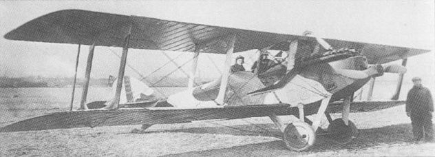
The LUSAC-11 was ordered into production, but failed to achieve service status.
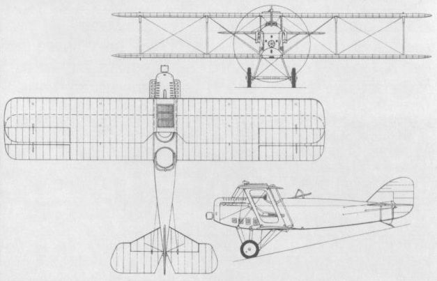
PIGEON-FRASER PURSUIT USA
At a time when the biplane configuration had become the norm for single-seat fighting aircraft, George N Albree designed a single-seat shoulder-wing monoplane intended for use as a fighting scout. Two prototypes were delivered to the US Army Signal Corps by the Pigeon Hollow Spar Company in September 1917. The aircraft was of wooden construction and powered by a 100 hp Gnome rotary engine. One of the two prototypes was used for static testing and the second was test flown on behalf of the Signal Corps. The aircraft was intended to be fitted with a single machine gun, but no armament was ever provided and the Signal Corps considered the aircraft both unreliable and too slow. Consequently, no series production was undertaken.
Max speed, 103 mph (166 km/h).
Loaded weight, 1,250 lb (567 kg).
Span, 37 ft 11 in (11,56 m).
Length, 24 ft 0 in (7,31m).
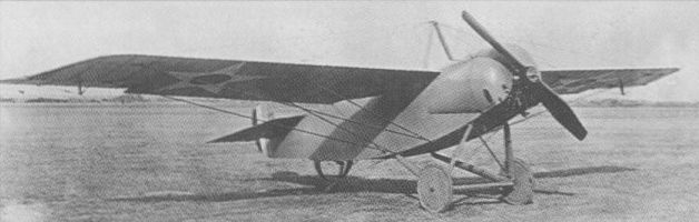
The second of the two prototypes of the Pigeon-Fraser Pursuit of 1917.

The second of the two prototypes of the Pigeon-Fraser Pursuit of 1917.
STANDARD M-DEFENSE USA
During 1917, the Aviation Section of the US Army Signal Corps placed an order with the Standard Aircraft Corporation for six examples of a single-seat fighter designed by Charles H Day. Intended specifically as a lightweight target defence interceptor, the Standard fighter was dubbed the M-Defense and was a two-bay staggered biplane of wooden construction with fabric skinning, power being supplied by an 80 hp Le Rhone nine-cylinder rotary engine. The first two M-Defense fighters were delivered in January 1918, but although manoeuvrability and handling qualities were commended, performance was considered to be inadequate for the combat role. The remaining four M-Defense fighters were therefore cancelled, but production was ordered of a modified version, the E-1, for the advanced training task, a total of 168 being built.
Max speed, 97 mph (156 km/h) at sea level, 82 mph (132 km/h) at 10,000 ft (3 050 m).
Time to 6,000 ft (1830 m), 10.6 min.
Endurance, 1.8 hrs.
Loaded weight, 1,150 lb (522 kg).
Span, 24 ft 0 in (7,31m).
Length 18 ft 10 in (5,74 m).
Height, 8 ft 1 in (2,46 m).
Wing area, 152.5 sqft (14,17 m2).
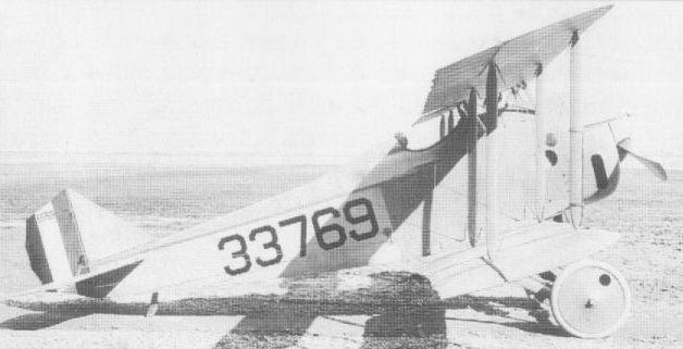
The first example of the M-Defense which was delivered to the Signal Corps in January 1918.
STURTEVANT B USA
One of the most unusual single-seat pursuit aircraft designed and built in the USA during World War I was the Sturtevant B, created by Grover C Loening of the Sturtevant Aeroplane Company of Boston, Mass. Embodying a number of advanced features, such as a welded steel tube structure, the Sturtevant B was a sesquiplane of unique configuration in that the lower plane was a narrow-chord surface with the primary purpose of providing anchorage for the apices of the quadrupod bracing struts. The mainplane was faired into the forward fuselage decking. Power was provided by a 140 hp Sturtevant A5 eight-cylinder water-cooled engine with radiators mounted beneath the mainplane centre section leading edge on each side of the fuselage. Four examples of the Sturtevant B were ordered by the US Army Signal Corps in 1916, the first of these flying on 20 March 1917. Malfunction of the tail control surfaces led the test pilot to decide to terminate the flight and the virtually unmanageable aircraft struck a tree during the landing approach and was wrecked. This accident led to the US Army cancelling the remaining three aircraft. No specification for the Sturtevant B is available.
One of the most unusual single-seat pursuit aircraft designed and built in the USA during World War I was the Sturtevant B, created by Grover C Loening of the Sturtevant Aeroplane Company of Boston, Mass. Embodying a number of advanced features, such as a welded steel tube structure, the Sturtevant B was a sesquiplane of unique configuration in that the lower plane was a narrow-chord surface with the primary purpose of providing anchorage for the apices of the quadrupod bracing struts. The mainplane was faired into the forward fuselage decking. Power was provided by a 140 hp Sturtevant A5 eight-cylinder water-cooled engine with radiators mounted beneath the mainplane centre section leading edge on each side of the fuselage. Four examples of the Sturtevant B were ordered by the US Army Signal Corps in 1916, the first of these flying on 20 March 1917. Malfunction of the tail control surfaces led the test pilot to decide to terminate the flight and the virtually unmanageable aircraft struck a tree during the landing approach and was wrecked. This accident led to the US Army cancelling the remaining three aircraft. No specification for the Sturtevant B is available.
THOMAS-MORSE MB-1 USA
The Thomas-Morse Aircraft Corporation, formed in January 1917 by a merger of the Thomas Brothers Aeroplane Company with the Morse Chain Works, established itself with the S-4, the first aircraft specifically designed for fighter pilot training. Late in 1917, the designer of the S-4, B Douglas Thomas (unrelated to the founding brothers), initiated design of a two-seat fighter, the MB-1. A parasol monoplane primarily of wooden construction and powered by a 400 hp Liberty 12 water-cooled 12-cylinder Vee-type engine, the MB-1 represented an exercise in achieving minimum structural weight in order to enhance performance. All metal parts were provided with lightening holes - even the control column being perforated - and plywood bulkheads featured large cut-outs, the result being inadequate strength. The undercarriage of the first of two MB-1s collapsed during the first attempted take-off early in 1918, and although it has been alleged that the MB-1 was never flown, repairs were performed on the first prototype and the aircraft was flown once, crashing following take-off. The two airframes were delivered to McCook Field, but all further testing was prudently abandoned in favour of the more orthodox MB-2.
Loaded weight, 2,375 lb (1077 kg).
Span, 37 ft 0 in (11,28 m).
Length, 22 ft 0 in (6,70m).
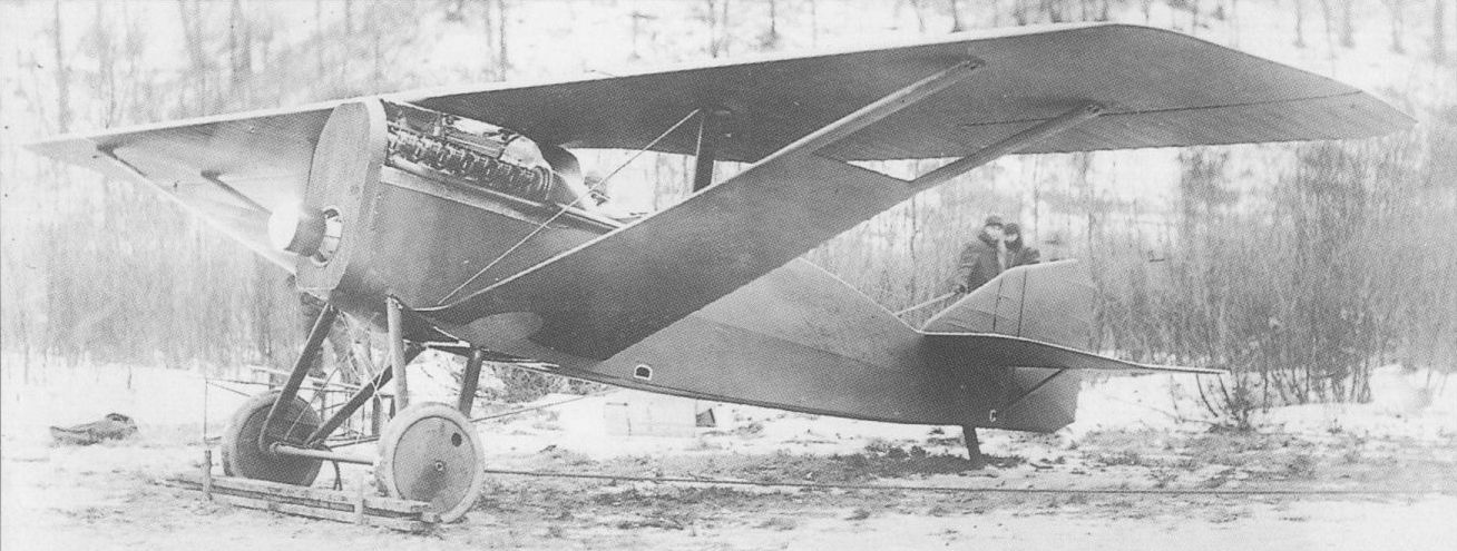
Constructed in such a fashion as to save as much weight as possible, the MB-1 proved structurally inadequate and was only flown twice.
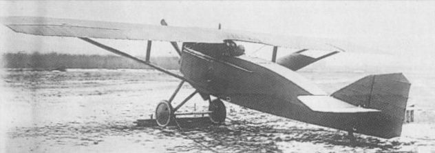
Over-zealous lightening of the airframe made the MB-1 structurally unsound.

THOMAS-MORSE MB-2 USA
Designed after the crash of the MB-1, the MB-2 was a two-seat fighter of unstaggered, equi-span biplane configuration intended to use a geared Liberty 12 engine. Of fabric-covered wooden construction, the upper wing was a two-spar structure and the lower wing a three-spar structure. Intended armament comprised two synchronised machine guns (one 0.3- in/7,62-mm and the other 0.5-in/12,7-mm) in the forward fuselage and one 0.3-in weapon on a ring mount in the rear cockpit. The flight test MB-2 was delivered in November 1918, two prototypes having been ordered by the Signal Corps, and the first of these being completed in single-bay configuration. Structural testing indicated that the wing cellule possessed insufficient strength and the aircraft was modified as a conventional-structure two-bay biplane. The US Army did not consider the potential performance of the MB-2 to warrant series production and development was discontinued. No performance details of the MB-2 are recorded.
Empty weight, 2,047 lb (929 kg).
Loaded weight, 2,773 lb (1258 kg).
Span, 31 ft 0 in (9,45 m).
Length, 24 ft 0 in (7,31 m).
Height, 8 ft 0 in (2,43m).
Wing area, 323 sq ft (30,00 m2).
THOMAS-MORSE MB-3 USA
Ordered by the US Army on the basis of a promised 150 mph (241 km/h) maximum speed and a 1,500 ft/min (7,62 m/sec) initial climb, the MB-3 designed by B Douglas Thomas was a single-seat unstaggered single-bay biplane of wooden construction with fabric covering. It featured intermediate interplane struts through which the flying and landing wires passed. Powered by a 300 hp Hispano-Suiza H eight-cylinder water-cooled Vee-type engine, the MB-3 carried an armament of two 0.3-in (7,62-mm) guns, the first of four prototypes entering flight test on 21 February 1919, and subsequently becoming the structural test article at McCook Field. Handling and manoeuvrability were adjudged excellent, but the small size of the cockpit and the poor view for the pilot that it offered were criticised, as was also the fuel system, the main tank developing leaks and tending to break through the fuselage after a few hours flying owing to inadequate structural support. The engine cooling system was inefficient and modifications - at some cost in performance - were necessary before, in June 1920, Thomas-Morse received a contract for 50 MB-3s powered by the licence-built Wright-Hispano H. An Army requirement for a further 200 aircraft was to be fulfilled (after competitive bidding) by Boeing, these aircraft being of the improved MB-3A model (radiators transferred from upper wing to fuselage sides, additional fuel and a 320 hp Wright-Hispano H-3 engine) and delivered between 29 July and 27 December 1922. These, like the production MB-3s, carried an armament of one 0.5-in (12,7-mm) and one 0.3-in (7,62-mm) gun rather than the twin guns of the smaller calibre mounted by the prototypes. The last 50 MB-3As were fitted with an entirely new tail unit (not retrofitted to earlier aircraft). Eleven MB-3s (not MB-3As) were ordered from Thomas-Morse by the US Navy for use by the Marine Corps, this contract being completed in February 1922. In November of the following year, the 10 surviving Marine MB-3s, having been in storage from July 1922, were “sold" to the Army and several were flown at Langley Field. The following data relate to the late-production MB-3A.
Max speed, 140 mph (225 km/h) at sea level, 138 mph (222 km/h) at 6,500 ft (1980 m).
Initial climb, 1,235 ft/min (6,27 m/sec).
Endurance, 2.25 hrs.
Empty weight, 1,716 lb (778 kg).
Loaded weight, 2,539 lb (1152 kg).
Span, 26 ft 0 in (7,92m).
Length, 20 ft 0 in (6,10 m).
Height, 8 ft 6 in (2,59 m).
Wing area, 228.55 sq ft (21,23 m2).
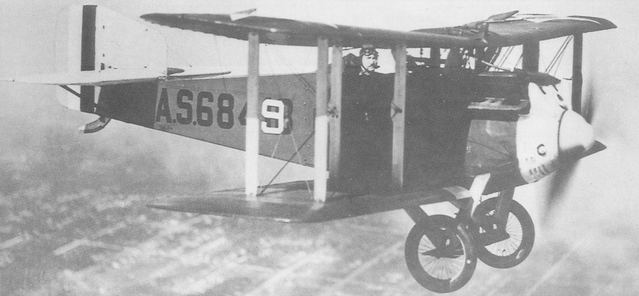
A Boeing-built MB-3A in USAAS service, showing the modified, enlarged fin finally adopted.
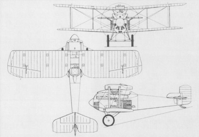
The basic series form of the MB-3A
LEWIS & VOUGHT VE-7 USA
Designed specifically as a tandem two-seat advanced trainer for the US Army, the VE-7 was the first product of the Lewis & Vought Corp. Founded on 18 June 1917 by Birdseye B Lewis and Chance M Vought, this was predecessor of the Chance Vought Corp (established in May 1922). A wooden two-bay equi-span biplane powered by a 150 hp Hispano-Suiza Model A engine, the VE-7 was completed in February 1918. It was adopted by the US Navy in October 1919, with the 180 hp Wright Hispano E-2 engine. A total of 129 was to be completed (69 by the Naval Aircraft Factory) and of these a substantial proportion emerged as VE-7G two- seat and VE-7S single-seat fighters. The former was a modification of the VE-7H unarmed single-float observation seaplane with controls transferred from rear to forward cockpit. A single fixed forward-firing synchronised 0.3-in (7,62-mm) Vickers gun was provided, together with a Lewis gun of similar calibre in the rear cockpit, and a wheel undercarriage was fitted. When provided with emergency flotation gear and hydrovanes, this type was designated VE-7GF. The single-seat fighter model was introduced in 1921. Forty were produced by Lewis & Vought and a further 24 by the Naval Aircraft Factory. These had the forward cockpit deleted and an armament of one synchronised 0.3-in (7,62-mm) Vickers gun. With wheel undercarriage, flotation gear and hydrovanes, it was designated VE-7SF, and with single main float and outrigger stabilising floats it was known as the VE-7SH. The VE-7S equipped the US Navy's first shipboard fighter squadron, VF-2, aboard the USS Langley. The following data relate to the VE-7SF.
Max speed, 117 mph (188 km/h) at sea level.
Time to 5,000 ft (1 525 m), 5.5 min.
Range, 290 mis (467 km).
Empty weight, 1,505 lb (683 kg).
Loaded weight, 2,100 lb (953 kg).
Span, 34 ft 1 3/8 in (10,40 m).
Length, 24 ft 5 1/8 in (7,44 m).
Height, 8 ft 7 in (2,62 m).
Wing area, 284.5 sqft (26,43 m2).
LEWIS & VOUGHT VE-9 USA
Essentially an improved VE-7, the VE-9 embodied comparatively minor changes, and these were mostly confined to the fuel system, a pair of interconnected tanks replacing the single tank of the earlier model. The VE-9 was powered by a 180 hp Wright Hispano E-3, and 21 were ordered by the US Navy in two versions; the single-seat VE-9 fighter with wheel undercarriage for shipboard use and the two-seat VE-9H unarmed observation float seaplane for catapult use from battleships and cruisers. The latter had modified vertical tail surfaces for improved water and catapult stability. The first VE-9 was delivered to the US Navy on 24 June 1922, the fighter version serving alongside the VE-7S aboard the USS Langley. Data for the VE-9 are as for the VE-7S.
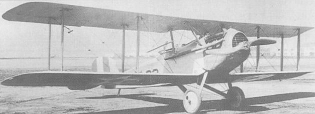
The two-seat VE-7G fighter variants of a trainer design.
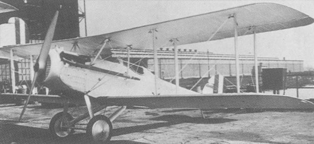
The VE-9 was, like the VE-7, built in single- (on photo) and two-seat fighter versions.

The single-seat VE-7S fighter variants of a trainer design.
LEWIS & VOUGHT VE-8 USA
Based on the VE-7, but with a 300 hp Hispano-Suiza Model H engine, reduced overall dimensions, increased wing area, a shorter, faired cabane and paired 0.3-in (7,62-mm) synchronised Vickers guns, the VE-8 single-seat fighter was completed in July 1919. Four were ordered by the US Army, but, in the event, only two were completed and one of these was assigned to static tests. The VE-8 was flight tested at McCook Field in 1920, but the results were highly unfavourable. The aircraft proved overweight, with heavy controls, inadequate stability and sluggish performance.
Max speed, 140 mph (225 km/h) at sea level.
Time to 5,000 ft (1 525 m), 4.25 min.
Loaded weight, 2,435 lb (1105 kg).
Span, 31 ft 0 in (9,45 m).
Length, 21 ft 4 in (6,50 m).
Height, 8 ft 7 7/8 in (2,64m).
Wing area 307 sq ft (28,52 m2).

The VE-8 proved unsuccessful when tested at McCook Field in 1920.
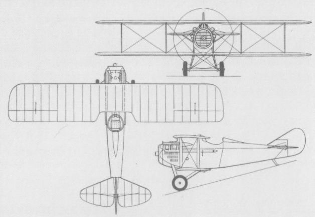
SAB 1 France
After resigning as a director of SPAD (Societe Pour Aviation et ses Derives), Louis Bechereau established SAB (Societe et Ateliers Bechereau) and was joined in designing a single-seat fighter by Bernard, Bleriot and Birkigt. This, the SAB 1, was built by Avions Pierre Levasseur, and was a somewhat corpulent two-bay biplane powered by a 300 hp Hispano-Suiza 8Fb watercooled eight-cylinder engine. Flight testing was initiated during 1918 in competition with the Nieuport 29, five examples being built. Selection of the Nieuport fighter by the Aviation Militaire resulted in discontinuation of further development of the SAB fighter.
Max speed, 130 mph (210 km/h).
Time to 6,560 ft (2 000 m), 5.78 min.
Empty weight, 1,726 lb (783 kg).
Loaded weight, 2,474 lb (1 122 kg).
Span, 30 ft 6 1/8 in (9,30 m).
Length, 22 ft 7 5/8 in (6,90 m).
Height, 8 ft 4 1/3 in (2,55 m).
Wing area, 311.09 sq ft (28,90 m2).
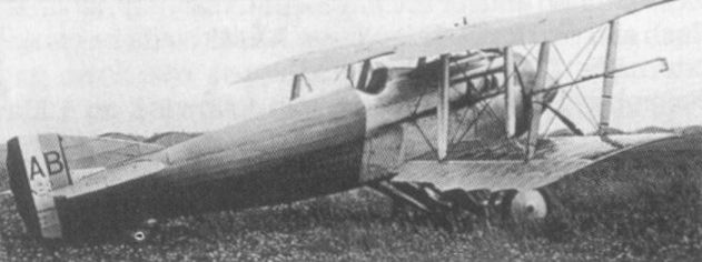
Five examples were built for testing in 1918 of the SAB 1 fighter.
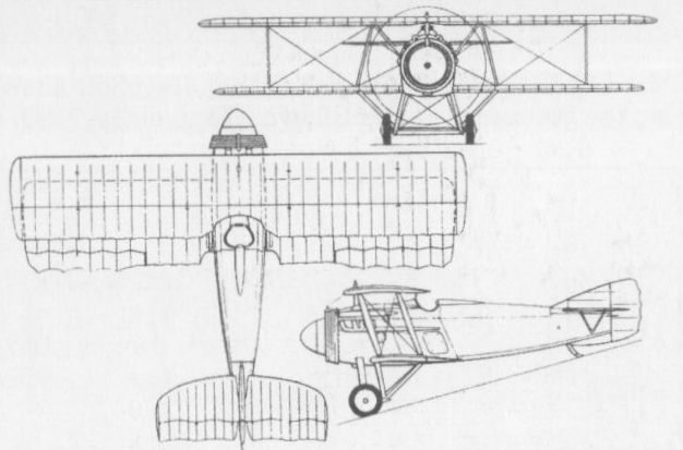
SPAD S.XX France
Late in 1917, Herbemont designed a new fighter with a monocoque fuselage and a 37-mm Puteaux cannon mounted in the Vee of a 300 hp Hispano-Suiza 8G engine and firing through the propeller shaft, as on the S.XII. This, the S.XVIII (the SFA designation being Spa.XVIII Cal-2), was under construction in April 1918, and was described as a monoplace protege, being intended to be flown as a single-seater in combat, but having provision for a second crew member. Both wings were two-spar structures, the upper having pronounced sweepback, and the single interplane struts were of broad-chord I-type. Development problems with the 300 hp engine-cannon combination led to revision of the design to take a standard 300 hp direct-drive HS 8Fb engine and an armament of twin 7,7-mm Vickers guns, the designation being changed to S.XX and the prototype appearing in August 1918. Official trials were conducted in the following month and the S.XX was ordered into production with a planned output of 200 aircraft monthly. Initially a Lewis gun was provided for the second occupant, whose function was now to fend off stern attacks by enemy fighters, and later twin Lewis guns on a T.O.3 mounting were provided. Production was scaled down with the Armistice, and only 95 S.XXs were built, these remaining in French service until 1923. One example was purchased by Japan in October 1921, being designated Hei 2.
Max speed, 142 mph (229 km/h) at 6,560 ft (2 000 m).
Time to 6,560 ft (2 000 m), 4.6 min.
Loaded weight, 2,438 lb (1106 kg).
Span, 32 ft 2 1/2 in (9,80 m).
Length, 23 ft 11 1/2 in (7,34 m).
Height, 9 ft 5 in (2,87 m).
Wing area, 312 sq ft (29,00 m2).
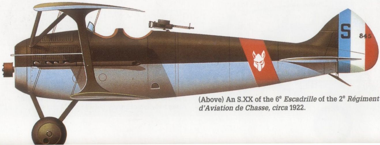
An S.XX of the 6* Escadrille of the 2e Regiment d‘Aviation de Chasse, circa 1922.

The prototype S.XX, which appeared in August 1918
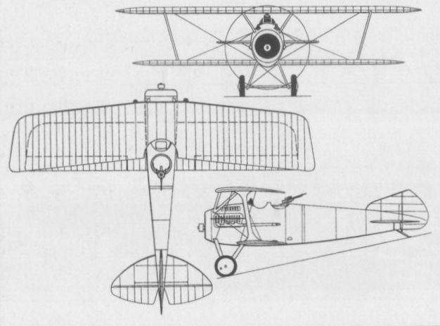
The series production SPAD S.XX fighter.
SPAD S.XXII France
The pilot's view from the cockpit of the S.VII and all its Bechereau-designed successors had been adversely criticised from 1916 onwards. In an attempt to remedy this defect, the S.XXII was evolved just as hostilities were drawing to a close. The design development was undertaken by Louis Bechereau, presumably by special arrangement or contract as he had left SPAD in the spring of 1917. The result was a single-seat fighter of highly unusual appearance. To improve downward view, the lower wing was attached well aft and given pronounced forward sweep and inverse taper towards the root. The three-spar upper wing had equally marked sweepback. Like preceding Bechereau single-seat fighters, the S.XXII had single-bay interplane bracing with intermediate struts. Power was provided by the 300 hp Hispano-Suiza 8Fb and armament consisted of twin 7,7-mm Vickers guns. As late as 29 November 1918, the prototype S.XXII had still to be assembled at Buc. This aircraft was completed in 1919 and flown, but the extent of flight testing has gone unrecorded and the design was taken no further in the post-Armistice period. Neither weights nor performance data are available.
Span, 26 ft 6 1/8 in (8,08 m).
Length, 20 ft 6 in (6,25m).
Wing area, 217.44 sq ft (20,20 m2).
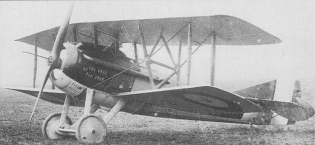
The S.XXII was unusual in having an aft-mounted, inverse-taper, forward-swept lower wing.

The SPAD S.XXII fighter flown in 1919.
BAJ TYPE IV France
Designed by Charles Audenis and built by the Boncourt-Audenis-Jacob concern at Bron, the BAJ Type IV was a tandem two-seat fighter powered by a 300 hp Hispano-Suiza 8Fb eight-cylinder water-cooled engine and mounting an armament of one synchronised 7,7-mm Vickers machine gun and a pair of 7,7-mm Lewis guns on a T.O.3 ring mounting in the rear cockpit. Of relatively clean design, with aerofoil-section single interplane struts and a close-cowled engine, the Type IV was officially ordered on 1 May 1918 by the Aviation Militaire. The first prototype was delivered to Villacoublay for official trials late in November 1918, but these were apparently delayed by the need for modifications which were undertaken by the Hanriot concern and completed on 28 January 1919. The first prototype was returned to the Boncourt-Audenis-Jacob concern for repairs in the summer of 1919, official trials being continued with a second prototype. No production order for the Type IV was placed and no specification for this type has apparently survived.
Designed by Charles Audenis and built by the Boncourt-Audenis-Jacob concern at Bron, the BAJ Type IV was a tandem two-seat fighter powered by a 300 hp Hispano-Suiza 8Fb eight-cylinder water-cooled engine and mounting an armament of one synchronised 7,7-mm Vickers machine gun and a pair of 7,7-mm Lewis guns on a T.O.3 ring mounting in the rear cockpit. Of relatively clean design, with aerofoil-section single interplane struts and a close-cowled engine, the Type IV was officially ordered on 1 May 1918 by the Aviation Militaire. The first prototype was delivered to Villacoublay for official trials late in November 1918, but these were apparently delayed by the need for modifications which were undertaken by the Hanriot concern and completed on 28 January 1919. The first prototype was returned to the Boncourt-Audenis-Jacob concern for repairs in the summer of 1919, official trials being continued with a second prototype. No production order for the Type IV was placed and no specification for this type has apparently survived.
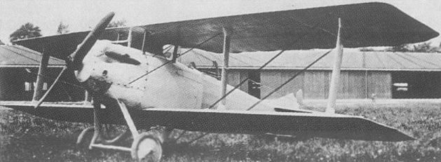
The BAJ Type IV tandem two-seat fighter, of which two prototypes were built in 1918.
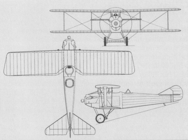
BOREL-BOCCACCIO Type 3000 France
Designed by Paul Boccaccio for the Gabriel Borel concern, the Type 3000 two-seat fighter was tested in 1919 under the official designation Borel C2. Although trials at Villacoublay revealed a good performance, the aircraft had appeared too late to warrant further development under post-World War I circumstances. A two-bay biplane powered by a 300 hp Hispano-Suiza 8Fb eight-cylinder water-cooled engine, the Type 3000 carried an armament of one fixed and synchronised 0.303-in (7,7-mm) Vickers machine gun and two 0.303-in (7,7-mm) Lewis guns on a Scarff-type mounting in the rear cockpit. Provision was made for a third Lewis gun which, fitted in the fuselage floor, was intended to fire aft and downward. Various modifications were made to the undercarriage, the tailplane bracing, the radiators and the exhaust manifolds during the course of trials, but only the one prototype was completed.
Max speed, 161 mph (260 km/h) at 3,280 ft (1000 m).
Time to 6,560 ft (2 000 m), 5.65 min.
Endurance, 3 hrs.
Empty weight, 1,779 lb (807 kg).
Loaded weight, 2,954 lb (1 340 kg).
Span, 37 ft 4 3/4 in (11,40 m).
Length, 23 ft 5 1/2 in (7,15 m).
Wing area, 349.84 sq ft (32,5 m2).

BREGUET BUC & BLC France
Evolved indirectly from the BU3 two-seat twin-boom pusher biplane of late 1914 as a smaller and lighter development of its bomber derivative, the BUM (B=Breguet, U=Salmson engine and M=Michelin-built), the BUC (the letter "C” signifying Chasse) was intended primarily as a bomber escort. It had a similar 200 hp Salmson (Canton-Unne) 14-cylinder radial engine and carried a 37-mm Hotchkiss cannon on a flexible mounting in the forward cockpit of the fuselage nacelle. Modest production of the BUC was undertaken for the Aviation Militaire, and, with the installation of a 220 hp Renault 12Fb 12-cylinder water-cooled engine in place of the Salmson, prototype trials were performed in June 1915, a few additional aircraft being built under the designation BLC. The performance of both the BUC and BLC versions of the Breguet de Chasse was unspectacular and, with fewer than 20 delivered, they were declared obsolete by the Aviation Militaire before the end of 1916. During that year, a further 17 essentially similar aircraft were supplied to the Royal Naval Air Service, these differing from the BUC/BLC primarily in having the 225 hp Sunbeam Mohawk 12-cylinder engine, armament being a single 0.303-in (7,7-mm Lewis machine gun (which was an alternative weapon to the Hotchkiss on French machines). The RNAS was disappointed with the performance of the Breguet de Chasse, which proved unsuitable for employment in the fighting role, and the service withdrew the type from its first-line inventory in June 1916. The following specification relates to the BLC.
Max speed, 86 mph (138 km/h) at sea level, 83 mph (133 km/h) at 6,560 ft (2 000 m).
Time to 3,280 ft (1000 m), 6.5 min.
Endurance, 3 hrs.
Empty weight, 2,557 lb (1160 kg).
Loaded weight, 3,384 lb (1 535 kg).
Span, 53 ft 9 1/2 in (16,40m).
Length, 31 ft 2 in (9,50 m).
Height, 12 ft 1 1/2 in (3,70 m).
Wing area, 581.27 sqft (54,0 m2).
BREGUET TYPE 5 France
The Type 5, derived from the Type 4 bomber late in 1915, was regarded by the Aviation Militaire as a two-seat escort fighter or reconnaissance-fighter, and possessed a configuration similar to that of the earlier BUC/ BLC. Powered by a 220 hp Renault 12Fb 12-cylinder water-cooled engine, the Type 5 fighter, or Bre 5 Ca2, never equipped a complete escadrille, a few aircraft of this type being issued to each of the units operating the Bre 5 B2 bomber version, for which it was expected to act as escort. Armament comprised a 37-mm Hotchkiss cannon on a flexible mounting in the forward cockpit and a rear-firing 7,7-mm Lewis gun on an elevated mounting over the leading edge of the upper wing. Eleven Type 5 fighters were operational with the Aviation Militaire by 1 February 1916, but the type was generally unpopular.
Max speed, 83 mph (133 km/h) at 6,560 ft (2 000 m).
Time to 6,560 ft (2 000 m), 22 min.
Endurance, 3.5 hrs.
Empty weight, 2,976 lb (1350 kg).
Loaded weight, 4,167 lb (1890 kg).
Span, 57 ft 5 in (17,50 m).
Length, 32 ft 5 3/4 in (9,90 m).
Height, 12 ft 9 1/2 in (3,90 m).
Wing area, 621.1 sqft (57,70 m2).
BREGUET TYPE 6 France
The Type 6 (Bre 6 Ca2) two-seat escort fighter was a 225 hp Salmson A9 water-cooled nine-cylinder radial-engined counterpart of the Renault-powered Type 5, and resulted from a fear that Renault engine production would prove inadequate to meet demands. The Type 5 airframe was modified to take the Salmson engine mounted immediately above the rear undercarriage legs and driving the propeller by means of an extension shaft, the power plant being entirely enclosed. Armament of the Type 6 fighter normally consisted of a short - barrel 37-mm Hotchkiss cannon in the forward fuselage. Performance, weights and dimensions were essentially similar to those of the Type 5.
BREGUET TYPE 12 France
The Type 12 (Bre 12 Ca2) was a two-seat night fighter derivative of the basic Type 5 design which, introduced during the course of 1916, was allocated to various units defending Paris, and remained in service well into the summer of 1917. Powered by either the 220 hp Renault 12Fb or 250 hp Renault 12Fbx engine, the Type 12 featured a revised forward undercarriage unit with twin wheels and a modified fuselage nacelle. The 37-mm Hotchkiss cannon in the nose position was coupled with a Sautter-Harle searchlight which, operated by a wind-driven generator mounted under the front of the nacelle, was aligned with and moved with the gun. An aft-firing 7,7-mm Lewis machine gun was usually fitted on an elevated mount over the upper wing leading edge, and four landing lamps were mounted beneath each lower wing. Performance, weights and dimensions were essentially similar to those of the Type 5.

The standard production Breguet BLC was powered by the Renault 12Fb engine.
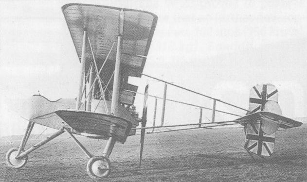
The Breguet de Chasse used by the RNAS, differed from the BUC/BLC in having a Sunbeam Mohawk engine.
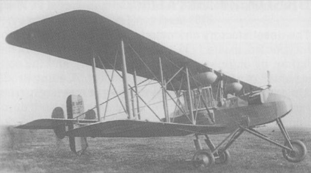
A Salmson A9 engine installation distinguished the Type 6 from the Renault-engined Type 5.

A 37-mm Hotchkiss cannon was mounted in the forward cockpit of the Breguet Type 5 fighter
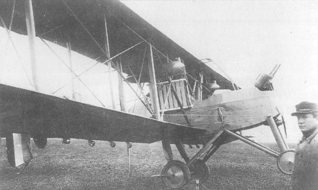
With searchlight attached to its Hotchkiss nose-mounted cannon, the Type 12 was a night fighter.
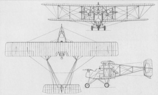
The standard production Breguet BLC was powered by the Renault 12Fb engine.
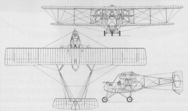
The Breguet Type 5 (Bre 5 Ca 2) fighter.
BREGUET TYPE 17 France
The Type 17 two-seat fighter was developed from the classic Type 14 bomber, and resembled the latter in both structure and appearance, but was both more powerful and more compact. Powered by a 420 hp Renault 12K 12-cylinder water-cooled engine, the Type 17 was a two-bay biplane and a prototype appeared in the summer of 1918. Armament comprised two fixed forward-firing 7,7-mm Vickers guns and twin Lewis guns of the same calibre on a T.O.3 mount for the observer. Provision for an additional Lewis gun was made, this to fire downwards and rearwards through a trap in the fuselage floor. Official trials resulted in a request for modifications, new wings and a 450 hp Renault 12K1 engine being fitted. Limited production was undertaken as the Bre 17 C2, this having increased span wings with horn-balanced ailerons of reduced chord. Armament was unchanged and the Type 17 remained in service until the mid 'twenties.
Max speed, 135 mph (218 km/h) at 6,560 ft (2 000 m), 132 mph (213 km/h) at 9,840 ft (3 000 m).
Time to 6,560 ft (2 000 m), 5.75 min.
Loaded weight, 4,056 lb (1840 kg).
Span, 46 ft 10 in (14,28 m).
Length, 26 ft 7 in (8,10 m).
Height, 11 ft 2 1/2 in (3,42 m).
Wing area, 487.6 sqft (45,30 m2).
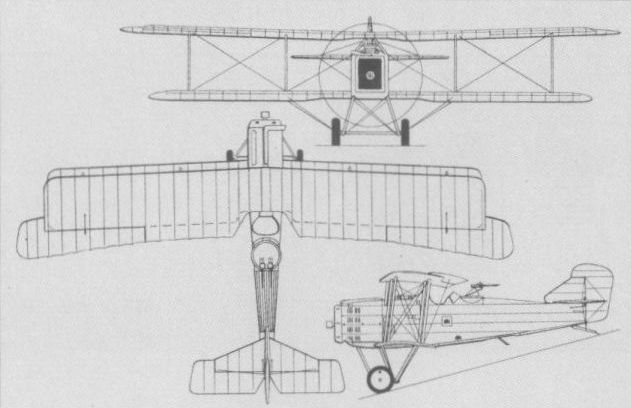
BREGUET LE France
The Breguet LE (Laboratoire Eiffel) single-seat fighter monoplane was aerodynamically an exceptionally advanced design for its time, emphasis being placed on minimising drag in order to achieve high performance. The basis of the design was produced by the Director of the Laboratoire Eiffel in collaboration with the Breguet design staff, the Breguet company having overall responsibility for translating the basic concept into a prototype. The first prototype LE was fitted with a 180 hp Hispano-Suiza 8Ab eight-cylinder water-cooled engine. Proposed armament consisted of a single 7,7-mm Vickers machine gun totally enclosed within the fuselage, although, in the event, this was never fitted. The LE made a short initial flight at Villacoublay in mid-March 1918, but the undercarriage failed on landing. After repairs, a further flight was made on 28 March, this terminating when the aircraft dived into the ground at full throttle, the pilot, Jean Saucliere, losing his life. Developments of the LE with a 220 hp Lorraine-Dietrich and a 300 hp Hispano-Suiza 8Fb were proposed, and construction of an airframe to take the latter power plant was nearing completion at the time of the loss of the first prototype, when further work was suspended. The following performance data are contemporary estimates for the LE.
Max speed, 137mph (220 km/h) at 13,125 ft (4 000 m).
Time to 13,125 ft (4 000 m), 10 min.
Empty weight, 1,091 lb (495 kg).
Loaded weight, 1,543 lb (700 kg).
Span, 32 ft 1 1/2in (9,78 m).
Length, 20 ft 10 in (6,35 m).
Height, 6 ft 6 3/4 in (2,00 m).
Wing area, 215.28 sq ft (20,0 m2).
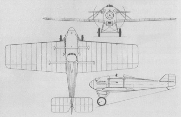
CAUDRON TYPE O France
An unequal-span single-bay single-seat biplane designed by Paul Deville in 1917 for the high-altitude fighter role, the Caudron Type O (all Caudron types were initially assigned letter-type designations in sequence) was originally flown with a 120 hp Le Rhone nine-cylinder air-cooled rotary although designed for the 150 hp Gnome Monosoupape 9N or 170 hp Le Rhone 9R rotaries. Examples fitted with the higher-powered engines were flown during the spring of 1918. Armament comprised either one or two 7,7-mm Vickers machine guns and the aerofoil employed for the wings was of special flat section and was expected to enable the fighter to reach altitudes of the order of 29,530 ft (9 000 m). Only prototypes were completed and the following data relate to the version powered by the 170 hp Le Rhone 9R rotary.
Max speed, 130 mph (210 km/h) at 13,125 ft (4 000 m).
Time to 13,125 ft (4 000 m), 10 min.
Empty weight, 882 lb (400 kg).
Loaded weight, 1,433 lb (650 kg).
Wing area, 182.99 sq ft (17,00 m2).
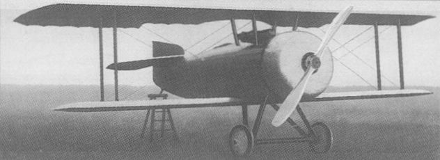
Designed for the high-altitude fighter role, the Caudron Type O only achieved prototype status.
CAUDRON R XI & R XII France
Evolved by Paul Deville from the R IV reconnaissance bomber designed by Rene Caudron, the R XI three-seat biplane was originally intended as a Corps d 'Armee aircraft, but was destined to find its forte as a three-seat escort fighter. Powered by two 215 hp Hispano-Suiza 8Bda eight-cylinder water-cooled engines, the R XI appeared in March 1917, and entered service in February 1918. Armament comprised five 7,7-mm Lewis guns on flexible mounts - two in the nose cockpit, two in the dorsal cockpit and one firing downwards and rearwards beneath the front gunner’s cockpit - and while initial models retained the HS 8Bda engines, later versions were fitted with the 235 hp HS 8Beb. The R XI enjoyed considerable success as an escort for the Breguet 14 during the closing months of WWI and during the summer of 1918. It also served in the fighter-reconnaissance role. At the time of the Armistice, the R XI equipped six 15-aircraft escadrilles of France’s Aviation Militaire. A more powerful version, the R XII with 300 hp HS 8Fb engines, was tested during the summer of 1918, but apparently failed to display significantly better results than those obtained with the R XI. Prototype trials with the R XII were completed in the autumn of 1919, but no further development was undertaken. The following data relate to the HS 8Bda-engined R XI.
Max speed, 114 mph (183 km/h) at 6,560 ft (2 000 m), 108 mph (173 km/h) at 13,125 ft (4 000 m).
Time to 6,560 ft (2 000 m), 8.17 min.
Endurance, 3 hrs.
Empty weight, 3,135 lb (1422 kg).
Loaded weight, 4,777 lb (2167 kg).
Span, 58 ft 9 1/2 in (17,92 m).
Length, 36 ft 9 3/4 in (11,22 m).
Height, 9 ft 2 1/4in (2,80 m).
Wing area, 583.96 sq ft (54,25 m2).
CAUDRON R XIV France
Possessing a strong family resemblance to the R XI but having an increased wing span and area resulting from the introduction of an additional bracing bay on each side, an enlarged rudder and 300 hp Hispano-Suiza 8Fb eight-cylinder water-cooled engines, the R XIV was also a three-seat escort fighter. It had an armament of one 37-mm Hotchkiss cannon on a rotating mounting in the forward gunner’s cockpit and paired Lewis guns in the dorsal gunner’s cockpit. The fuselage was essentially similar to that of the R XI, and one example of the R XIV was completed in August 1918. No details of the subsequent testing of this aircraft have survived and the only data available are as follows:
Empty weight, 3,851 lb (1 747 kg).
Wing area, 678.15 sq ft (63.00 m2).
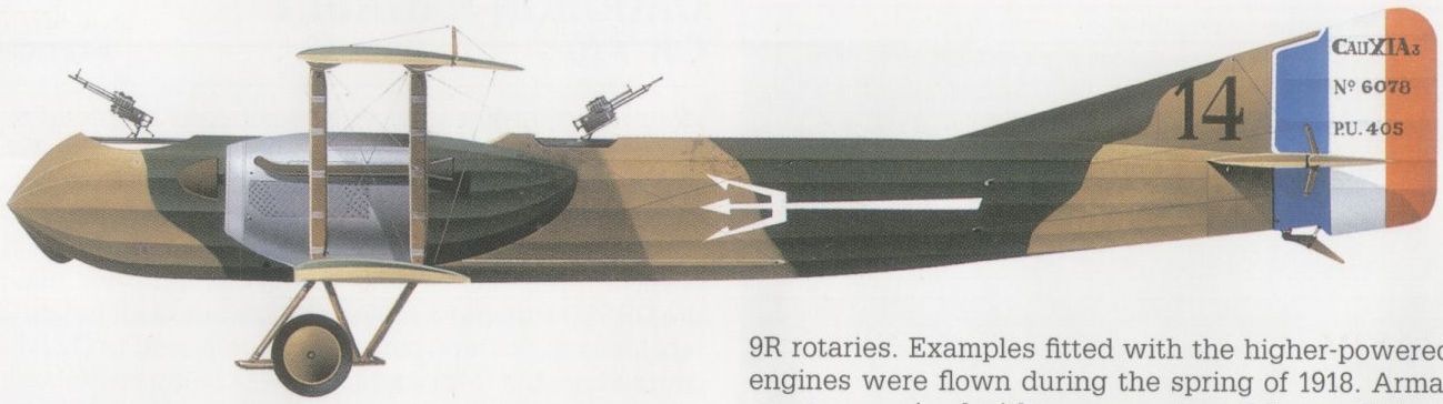
A Caudron R XI used by Escadrille C46 in 1918, providing escort protection for the bombers of 13e Escadre.
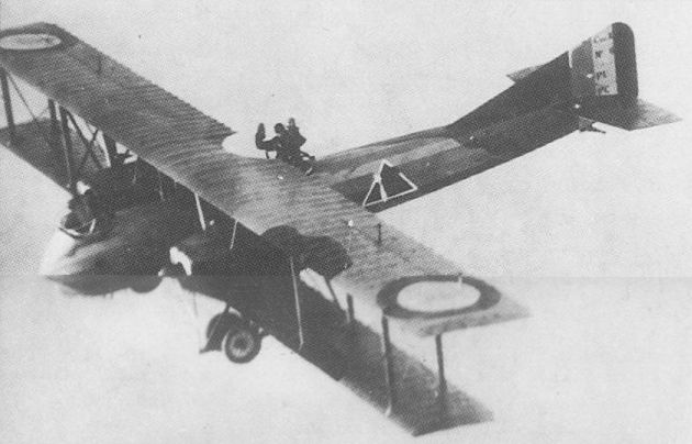
A Caudron R XI serving with the 96th Aero Squadron, US Air Service.
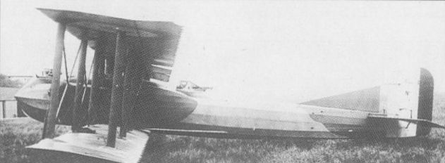
A 37-mm Hotchkiss cannon was carried in the front cockpit of the sole Caudron R XIV.

The Caudron R XI three-seat escort fighter.
COURTOIS-SUFFIT-LESCOP C.S.L.1 France
Designed by Roger Courtois-Suffit in collaboration with Capitaine Lescop, the C.S.L.1 single-seat fighter was flown for the first time in January 1918, having been constructed by the SAIB (Societe Anonyme d'Applications Industrielles du Bois) concern. The C.S.L.1 was, significantly, one of the first (if not the first) aircraft to feature leading-edge wing flaps, these being fitted to the lower mainplanes and elevated or depressed through a limited range of movement. The leading edge of the tailplane was also hinged. Intended for the 200 hp Clerget 11E eleven-cylinder rotary or, failing that, the 160 hp Gnome Monosoupape 9Nc nine-cylinder rotary, the C.S.L.1 was in fact fitted with the 140 hp Clerget 9Bf nine-cylinder rotary. A second prototype was to have been fitted with the 200 hp unit, but it is doubtful if this was completed. The following data are estimated for the C.S.L.1 with the 200 hp engine.
Max speed, 149 mph (240 km/h) at sea level.
Time to 13,125 ft (4 000 m), 14 min.
Endurance, 2.5 hrs.
Empty weight, 1,080 lb (490 kg).
Loaded weight, 1,720 lb (780 kg).
Span, 25 ft 7 in (7,80 m).
Wing area 204.5 sq ft (19,0 m2).
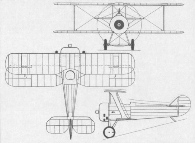
DE BRUYERE C1
One of the most unorthodox single-seat fighters built and flown during World War I was an extraordinary pusher biplane fighter of canard configuration and attributed to a French engineer named de Bruyere. A single-bay biplane with inverted N-type interplane struts, rotary-tip ailerons on the upper wings, a fixed canard surface, and dorsal and ventral vertical surfaces at the rear, the de Bruyere C1 was apparently powered by a 150 hp Hispano-Suiza 8Aa water-cooled engine. This was installed in the centre fuselage, immediately aft of the wings, driving a stern-mounted propeller via a long extension shaft in a fashion reminiscent of that of the Tatin-Paulhan Torpille of 1911. The fuselage was a light metal shell and a nosewheel undercarriage was used. No record has survived to indicate the reason for the highly unusual arrangement adopted by de Bruyere for his fighter, but it could have been dictated by the desire to carry a 37-mm shell-firing Hotchkiss gun. The first flight test was attempted at Etampes in April 1917, the aircraft becoming airborne, but rolling over and crashing on its back. It is not believed that any attempt was made to repair it and continue the flight test programme, and no further details have been found.
One of the most unorthodox single-seat fighters built and flown during World War I was an extraordinary pusher biplane fighter of canard configuration and attributed to a French engineer named de Bruyere. A single-bay biplane with inverted N-type interplane struts, rotary-tip ailerons on the upper wings, a fixed canard surface, and dorsal and ventral vertical surfaces at the rear, the de Bruyere C1 was apparently powered by a 150 hp Hispano-Suiza 8Aa water-cooled engine. This was installed in the centre fuselage, immediately aft of the wings, driving a stern-mounted propeller via a long extension shaft in a fashion reminiscent of that of the Tatin-Paulhan Torpille of 1911. The fuselage was a light metal shell and a nosewheel undercarriage was used. No record has survived to indicate the reason for the highly unusual arrangement adopted by de Bruyere for his fighter, but it could have been dictated by the desire to carry a 37-mm shell-firing Hotchkiss gun. The first flight test was attempted at Etampes in April 1917, the aircraft becoming airborne, but rolling over and crashing on its back. It is not believed that any attempt was made to repair it and continue the flight test programme, and no further details have been found.
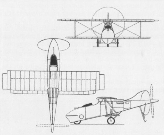
The bizarre de Bruyere completed in 1917, and which crashed on its first flight attempt.
DE MARCAY 4 France
During World War I, the SAECA Edmond de Marcay built substantial numbers of SPAD fighters under licence, and it was hardly surprising, therefore, that the first original de Marcay fighter should bear some resemblance to the SPAD S.XIII, although, in fact, there was no commonality between the aircraft. The initial design was based on the use of an eight-cylinder Liberty engine, but the difficulties experienced with this power plant led to revision of the design to take a 300 hp Hispano-Suiza 8Fb eight-cylinder water-cooled engine as the de Marcay 2 C1. An unequal-span staggered single-seat biplane with horn-balanced ailerons on the upper wing only and an armament of two synchronised 7,7-mm Vickers machine guns, the de Marcay 2 C1 was completed early in 1919. Although it was the fastest fighter participating in the 1919 Service Aeronautique contest held at Villacoublay, no production order was placed for the de Marcay 2 C1 and only one prototype was completed.
Max speed, 156 mph (252 km/h) at sea level, 144 mph (232 km/h) at 9,840 ft (3 000 m).
Time to 16,405 ft (5 000 m), 16.27 min.
Span, 30 ft 4 1/8 in (9,25 m).
Length 21 ft 8 3/5 in (6,62 m).
Wing area, 269.1 sqft (25,00 m2).
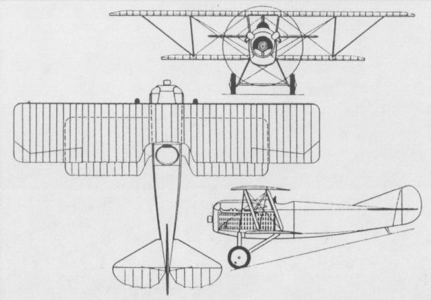
DESCAMPS 27 France
Formerly the chief engineer of the Anatra factory at Odessa in South Russia, Elisee Alfred Descamps returned to France after the Russian revolution and designed a single-seat fighter, the Descamps 27, which was flown for the first time in the spring of 1919. Powered by a 300 hp Hispano-Suiza 8Fb eight-cylinder water-cooled engine and carrying an armament of two synchronised 7,7-mm Vickers guns, the Descamps 27 was a two-bay biplane, but its configuration was unusual in that the lower wing featured pronounced forward sweep to improve the forward and downward view of the pilot. Twin box-like radiators flanked the cockpit. Although the fighter was found to have a good performance during official trials, choice fell on the similarly-powered Nieuport 29 and further development of the Descamps 27 was abandoned.
Max speed, 143 mph (230 km/h) at sea level, 107 mph (172 km/h) at 22,965 ft (7000 m).
Time to 6,560 ft (2 000 m), 4.76 min.
Endurance, 2 hrs.
Empty weight, 1,614 lb (732 kg).
Loaded weight, 2,361 lb (1071 kg).
Span, 32 ft 3 4/5 in (9,85 m).
Length, 22 ft 9 5/8 in (6,95 m).
Height, 8 ft 5 1/4 in (2,57 m).
Wing area, 248.65 sq ft (23,10 m2).
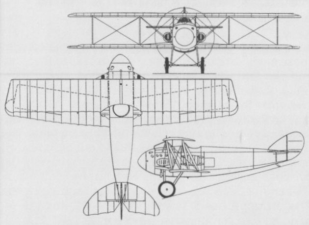
FARMAN F 30 France
The F 30 (not to be confused with the earlier Farman Type 30 two-seat pusher) was developed by the Societe Henry et Maurice Farman to meet a requirement for a two-seat fighter. Powered by a 260 hp Salmson 9Za water-cooled nine-cylinder radial and carrying an armament of one fixed 7,7-mm Vickers gun and one flexible 7,7-mm Lewis gun, the F 30 C2 was an unequal-span, single-bay biplane with plywood-covered fuselage and was tested in the spring of 1917 with inauspicious results. The aircraft, subsequently referred to as the F 30A, was therefore extensively revised as the F 30B (although still referred to officially as the F 30 C2) with equal-span wings and two-bay bracing, fabric skinning replacing the plywood covering of the fuselage. Testing of the F 30B was conducted at Villacoublay during the summer of 1917, but the aircraft suffered fore and aft instability, and, as its cg problems remained insoluble, was finally abandoned early in 1918. The following data relate to the F 30B.
Max speed, 129 mph (208 km/h) at 6,560 ft (2 000 m), 122 mph (196 km/h) at 13,125 ft (4 000 m).
Time to 9,840 ft (3 000 m), 11 min.
Endurance, 2.5 hrs.
Empty weight, 1,499 lb (680 kg).
Loaded weight, 2,425 lb (1100 kg).
Span, 36 ft 1 1/2 in (11,01 m).
Length, 23 ft 11 1/4 in (7,29 m).
Height, 9 ft 8 1/2 in (2,96m).
Wing area, 373.62 sqft (34,71 m2).
FARMAN F 31 France
Designed around the 400 hp Liberty 12 12-cylinder water-cooled engine, the F 31 two-seat fighter was an exceptionally angular equi-span, two-bay biplane with the fuselage mounted in mid-gap. Armament comprised two fixed forward-firing 7,7-mm Vickers guns and a single 7,7-mm Lewis gun on a flexible mounting in the rear cockpit. The sole prototype of the F 31 was completed in the summer of 1918, and was still under test at Villacoublay in November 1918, the Armistice precluding any further development of the type.
Max speed, 134 mph (215 km/h) at 6,560 ft (2 000 m).
Time to 6,560 ft (2 000 m), 5.85 min.
Empty weight, 1,916 lb (869 kg).
Loaded weight, 3,239 lb (1 469 kg).
Span, 38 ft 6 7/8 in (11,76 m).
Length, 24 ft 1 1/4 in (7,35 m).
Height, 8 ft 5 1/2 in (2,58 m).
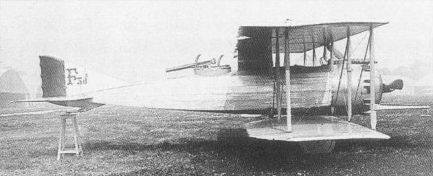
The Farman F 30 in its definitive form as the F 30B with upper and lower wings of equal span and two-bay bracing.
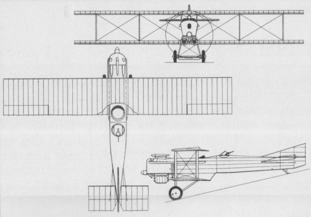
The Farman F 31 which was abandoned after the Armistice.
FBA AVION CANON France
Although the Franco-British Aviation Company (FBA) specialised in the design and development of flying boats, the company’s designer, Louis Schreck, evolved a side-by-side, two-seat cannon-armed land-based fighter which was tested in 1916. Usually referred to as the FBA Avion canon, although also known as the FBA 1 Ca2, the aircraft mated an aerodynamically clean wooden monocoque fuselage with the wings of an FBA Type H flying boat and carried a short-barrel 37-mm Hotchkiss cannon in the extreme fuselage nose. The 150 hp water-cooled eight-cylinder Hispano-Suiza 8A engine was mounted as a pusher and this power plant was apparently replaced by a 175 hp HS 8Aa engine during the course of 1917 when the aircraft was still under development. However, performance was unsatisfactory and further development of the aircraft was not pursued. The following data relate to the Avion canon with the lower-powered engine.
Max speed, 83 mph (133 km/h) at sea level, 76 mph (123 km/h) at 6,560 ft (2 000 m).
Time to 3,280 ft (1 000 m), 8.55 min.
Endurance, 3.0 hrs.
Empty weight, 1,678 lb (761 kg).
Loaded weight, 2,571 lb (1166 kg).
Span, 47 ft 6 3/4 in (14,50 m).
Length, 33 ft 2 3/4 in (10,13 m).
Height, 10 ft 11 3/4 in (3,35 m).
Wing area, 441.33 sq ft (41,00 m2).
GALVIN HC France
Of extraordinarily unorthodox configuration, the Galvin Hydravion de Chasse reportedly underwent flight testing from the Rhone in the summer of 1919. Of wooden construction with fabric skinning and a light alloy nose cone, the Galvin single-seat float fighter was an equi-span staggered single-bay biplane. Its fuselage consisted of two entirely separate elements with a gap between in which the propeller of a 160 hp Gnome nine-cylinder rotary engine rotated. Both forward and rear fuselage were individually supported by a remarkably long and broad central float, the former by paired N-struts and wire bracing, and the latter by I-struts fore and aft - the rearmost providing an attachment point for an inordinately large rudder - with wire bracing to the wings. Small stabilising floats were attached to the lower wing immediately beneath the V-type interplane struts. The intended armament of the Galvin fighter was allegedly three machine guns, but no records of the testing of this unique aircraft have survived.
Max speed, 124 mph (200 km/h) at sea level.
Endurance, 2.0 hrs.
Empty weight, 1,146 lb (520 kg).
Loaded weight, 1,764 lb (800 kg).
Span, 26 ft 3 in (8,00 m).
Length, 23 ft 7 1/2 in (7,20 m).
Height, 7 ft 6 1/2 in (2,30 m).
Wing area, 199.14 sqft (18,59 m2).
GOURDOU-LESEURRE GL-1 (TYPE A) France
The first aircraft to be designed by Charles E P Gourdou and Jean A Leseurre, the GL-1 (also known as the Type A) was a single-seat parasol monoplane fighter powered by a 180 hp Hispano-Suiza 8Ab eight-cylinder water-cooled engine. Of mixed construction, with an all-metal fuselage primarily of steel tube with plywood covering and a fabric-covered wing with steel spars and wooden ribs, the GL-1 was officially evaluated at Villacoublay on 10 May 1918. Structurally overweight, the prototype was tested with one of its two 7,7-mm Vickers guns removed and with reduced fuel. It demonstrated in this configuration level speeds higher than contemporary fighters powered by a 300 hp Hispano-Suiza engine. Although the design team believed that the structural weight problem could be resolved, official testing indicated that the wing had insufficient strength, and redesign was therefore undertaken to result in the GL-2 alias Type B.
Max speed, 150 mph (242 km/h) at 3,280 ft (1000 m).
Time to 3,280 ft (1000 m), 2.41 min.
Endurance, 1.5 hrs.
Empty weight, 1,323 lb (600 kg).
Loaded weight, 1,733 lb (786 kg).
Span, 29 ft 6 1/3 in (9,00 m).
Length, 21 ft 7 4/5 in (6,60 m).
Height, 7 ft 6 1/2 in (2,30 m).
Wing area, 179.22 sq ft (16,65 m2).
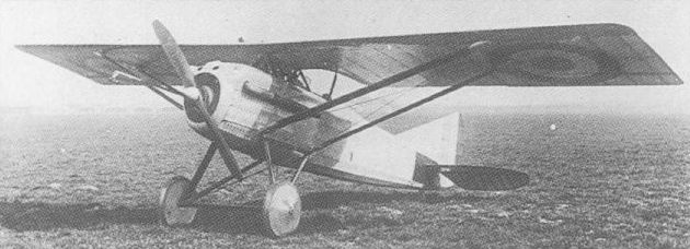
Progenitor of a long line of fighting monoplanes, the GL-1 was the first aircraft designed by MM Gourdou and Leseurre.
GOURDOU-LESEURRE GL-2 (TYPE B) France
By comparison with its progenitor, the GL-1, the GL-2 (Type B) had an entirely new and heavily reinforced wing, new horizontal tail surfaces mounted higher on the rear fuselage, and revised rudder and undercarriage. The 180 hp Hispano-Suiza 8Ab engine was retained and armament comprised two synchronised 7,7-mm Vickers guns. The number of pairs of inclined wing bracing struts was increased from two to four, one pair attaching to the wing at half-span and another at three-quarter-span, the cantilevered portion thus being only one-quarter of the half-span. This resulted in an extremely rigid structure, the wing load factor being 10.4 compared with 3.5 for the GL-1. Twenty GL-2s were ordered for the Aeronautique Militaire and built by Mayen et Zodiac. The first was delivered to Villacoublay in late November 1918. Subsequent aircraft were fitted with a taller rudder and enlarged fin to rectify a directional control deficiency, but with the termination of hostilities, Aeronautique Militaire interest in the GL-2 waned and development was cancelled.
Max speed, 152 mph (245 km/h) at sea level.
Time to 16,405 ft (5 000 m), 17.5 min.
Empty weight, 1,257 lb (570 kg).
Loaded weight, 1,874 lb (850 kg).
Span, 30 ft 10 in (9,40m).
Length, 21 ft 1 1/8 in (6,43m).
Wing area, 202.37 sq ft (18,80 m2).
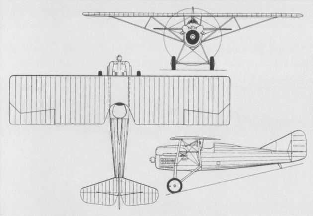
HANRIOT HD.1 France
The first fighter to be produced by the Societe anonyme des Appareils d’Aviation Hanriot, the HD.1 was designed by Emile Dupont and was built in the summer of 1916. Powered by a 100 hp Le Rhone rotary engine and carrying an armament of one synchronised 7,7-mm Vickers machine gun (although a few aircraft were later to be fitted with two Vickers guns), the HD.1 was an extremely compact and agile single-seat fighter. Appearing later than the SPAD S.VII which was already in production, it was not ordered by France’s Aviation militaire. It was adopted by Italy, however, and licence manufacture was undertaken by the Societa Nieuport Macchi which delivered 125 to the Aeronautica del Regio Esercito in 1917, 706 in 1918, and a further 70 after the Armistice. The HD.1 was also adopted by Belgium, to which country Hanriot supplied 79 fighters of this type from August 1917. The HD.1 continued in service in both Italy and Belgium into the mid-’twenties. In 1921, Switzerland purchased 16 from Italian war surplus stocks and retained these in service until 1930. The following data relate to the HD-1 powered by the 120 hp Le Rhone 9Jb.
Max speed, 115 mph (184 km/h) at sea level, 111 mph (178 km/h) at 6,560 ft (2 000 m).
Time to 3,280 ft (1 000 m), 2.97 min.
Ceiling, 19,685 ft (6 000 m).
Range, 224 mis (360 km).
Empty weight, 983 lb (446 kg).
Loaded weight, 1,437 lb (652 kg).
Span, 28 ft 6 1/2 in (8,70 m).
Length, 19 ft 2 1/4 in (5,85 m).
Height, 9 ft 7 1/2 in (2,94 m).
Wing area, 195.9 sq ft (18,20 m2).
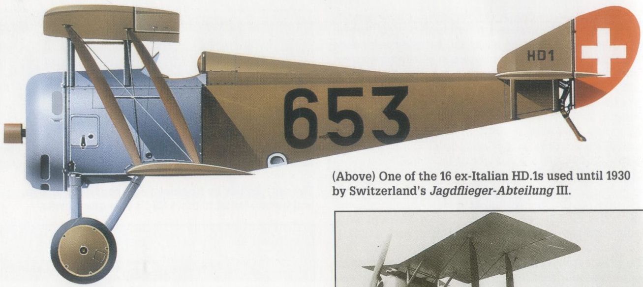
One of the 16 ex-Italian HD.1s used until 1930 by Switzerland’s Jagdflieger-Abteilung III.
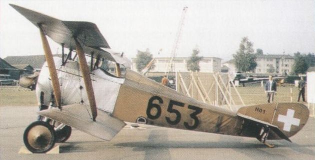
Of French design, the HD.1 served principally in Italy, Belgium and Switzerland.
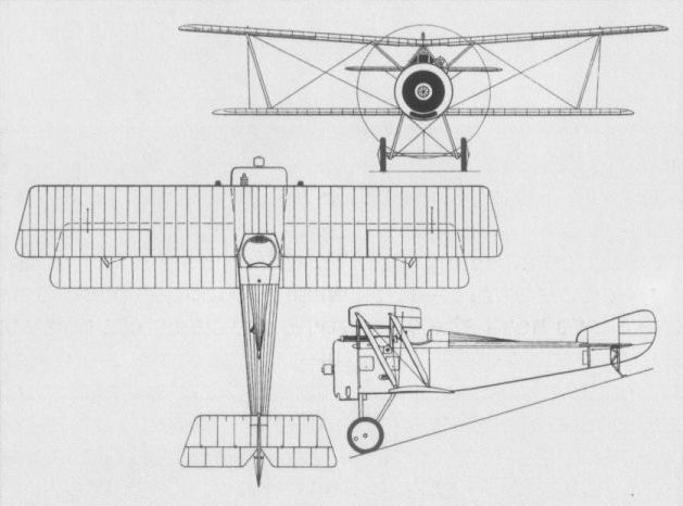
HANRIOT HD.2 France
At the end of 1917, a derivative of the HD.1 intended for use by France’s Aviation maritime as a single-seat fighter floatplane was tested as the HD.2. Possessing an airframe essentially similar to that of the HD.1, the HD.2 was powered by a 130 hp Clerget 9B rotary engine and carried an armament of twin synchronised Vickers machine guns. Two prototypes were tested with float undercarriages of differing lengths, and several HD.2s with wheel undercarriages were delivered to the Aviation maritime at Dunkirk for trials purposes. These included operations from a 40-ft (12-m) platform mounted above a turret of the battleship Paris in the harbour at Toulon. Later, in August and September 1918, similar trials were conducted at Saint-Raphael with one of the HD.2 prototypes converted to landplane form and re-engined with a 120 hp Le Rhone. Ten HD.2 float fighters were purchased on behalf of the US Navy, these subsequently being converted to landplanes by the Naval Aircraft Factory. They were used for training at Langley Field and one was employed in August 1919 for trials from a platform mounted on the battleship USS Mississippi. The following data relate to the float-equipped HD.2.
Max speed, 114 mph (183 km/h).
Service ceiling, 15,750 ft (4 800 m).
Range, 186 mis (300 km).
Empty weight, 1,091 lb (495 kg).
Loaded weight, 1,594 lb (723 kg).
Span, 28 ft 6 1/2 in (8,70 m).
Length, 22 ft 11 1/2 in (7,00 m).
Height, 10 ft 2 in (3,10 m).
Wing area, 195.9 sqft (18,20 m2).

One of the prototype HD.2s which were essentially float seaplane versions of the HD.1.
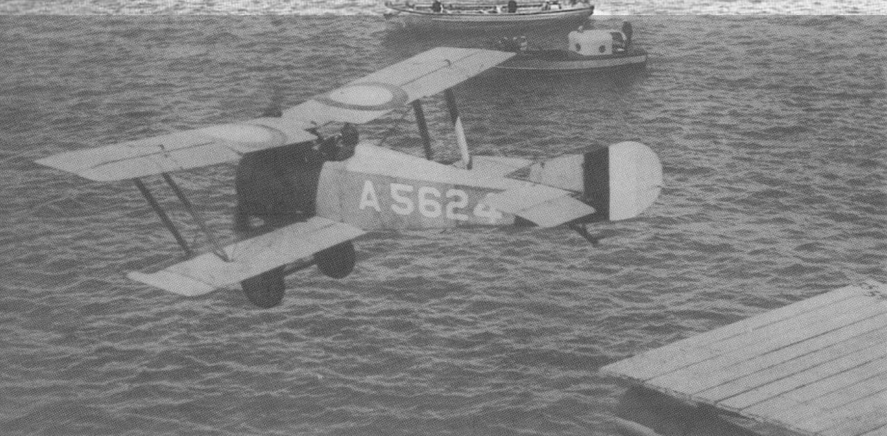
A US Navy HD.2 taking off from the USS Mississippi after conversion from the standard floatplane form.
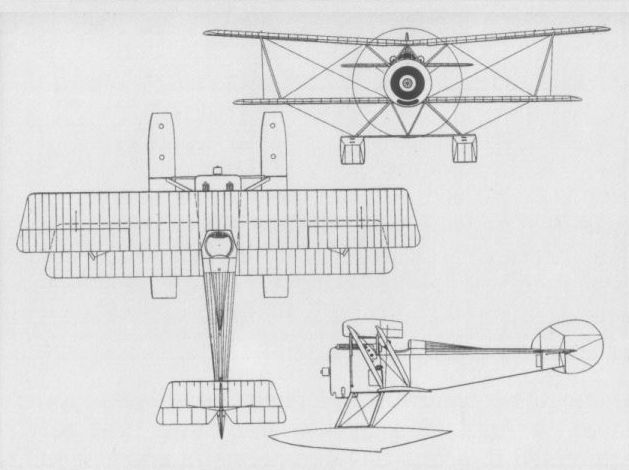
A US Navy HD.2 in the standard floatplane form as first supplied.
HANRIOT HD.3 France
Design development of a compact, well-proportioned two-seat fighter was initiated as the HD.3 in the autumn of 1917, and a prototype flew before the end of the year. Powered by the excellent new 260 hp Salmson (Canton-Unne) 9Za radial, the HD.3 had an armament of two fixed synchronised 7,7-mm Vickers guns and two 7,7-mm Lewis guns on a flexible mounting for the aft-facing gunner. A preliminary order was placed on behalf of the Aviation militaire for 120 HD.3s in April 1918, the total subsequently being raised to 300 when it was also ordered for the Aviation maritime. Few HD.3s had been delivered, in fact, by the time of the Armistice, but at least 75 were completed for the Aviation militaire and a rather smaller quantity for the naval service. One example of the HD.3 was fitted with twin floats as the prototype of the HD.4, series production of which was frustrated by the Armistice, and a night fighter version was tested as the HD.3bis. This latter had mainplanes of thicker section, enlarged ailerons and a revised rudder.
Max speed, 119 mph (192 km/h) at 6,560 ft (2 000 m), 116 mph (187 km/h) at 9,840 ft (3 000 m).
Time to 3,280 ft (1 000 m), 3.35 min.
Service ceiling, 18,700 ft (5 700 m).
Endurance, 2.0 hrs.
Empty weight, 1,675 lb (760 kg).
Loaded weight, 2,601 lb (1180 kg).
Span, 29 ft 6 1/4 in (9,00 m).
Length, 22 ft 9 1/2 in (6,95 m).
Height, 9 ft 10 in (3,00 m).
Wing area, 274.49 sq ft (25,50 m2).
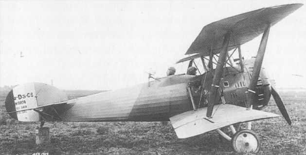
The two-seat HD.3 was the first Hanriot fighter to serve with the French military services.
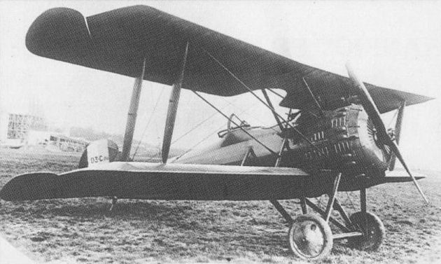
Wing changes distinguished the HD.3bis from the standard production HD.3.

The standard production HD.3.
HANRIOT HD.5 France
Encouraged by the success that attended the HD.3, Emile Dupont designed another two-seat fighter around the excellent Hispano-Suiza 8Fb water-cooled engine of 300 hp. Unlike preceding Dupont designs, the HD.5 was an unstaggered two-bay biplane with an extremely small wing gap. The forward portion of the upper wing centre section was cut out to accommodate the pilot’s head, the aft portion also being cut away to improve the field of fire of the gunner. Armament comprised two synchronised 7,7-mm Vickers machine guns and either one or two 7,7-mm Lewis guns on a flexible mount in the rear cockpit. Only one prototype of the HD. 5 was built, flight testing commencing in the late spring of 1918, but further development was not pursued.
Max speed,132 mph (213 km/h) at sea level.
Range, 304 mis (490 km).
Empty weight, 1,764 lb (800 kg).
Loaded weight, 2,756 lb (1250 kg).
Span, 34 ft 10 1/2 in (10,63 m).
Length, 24 ft 0 7/8 in (7,34 m).
Height, 8 ft 4 in (2,54 m).
Wing area, 327.23 sqft (30,40 m2).
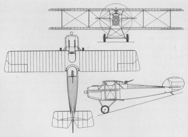
The HD-5 only achieved prototype status.
HANRIOT HD.6 France
Evolved in parallel with the HD.5 and of generally similar configuration, but larger and more powerful, the HD.6 two-seat fighter was powered by a 530 hp Salmson 18Z two-row radial water-cooled engine. This was essentially two Salmson 9Z engines on a common crankcase and flight testing was delayed by difficulties with this experimental power plant, eventually commencing in the spring of 1919. Armament consisted of two synchronised 7,7-mm Vickers guns for the pilot and three 7,7-mm Lewis guns for the gunner, two on a rotating TO.3 mount and one firing through a trap in the fuselage floor. The pilot, seated beneath a cut-out in the upper wing, was offered a singularly poor field of vision. Performance did not show a significant improvement over that of the more compact and simpler HD.3, and development was discontinued by the late summer of 1919.
Max speed, 140 mph (225 km/h).
Time to 3,280 ft (1000 m), 2.78 min.
Range, 373 mis (600 km).
Empty weight, 1,786 lb (810 kg).
Loaded weight, 2,756 lb (1250 kg).
Span, 44 ft 7 3/8 in (13,60 m).
Length, 29 ft 0 1/3 in (8,85 m).
Height, 9 ft 6 in (2,90 m).
Wing area, 511.3 sq ft (47,50 m2).
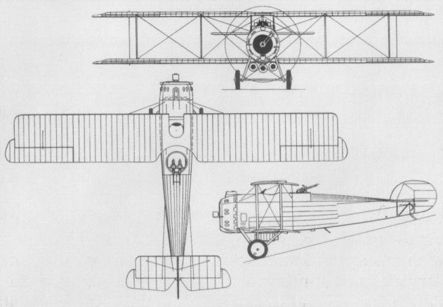
The heavy two-seat HD.6 was powered by the unusual Salmson water-cooled radial.
HANRIOT HD.7 France
Designed as a potential successor for the SPAD S.XIII, the HD.7 single-seat fighter employed wings and tail surfaces essentially similar to those of the two-seat HD.3. Flown for the first time in the summer of 1918, the HD.7 was powered by a water-cooled Hispano-Suiza 8Fb eight-cylinder engine of 300 hp and mounted an armament of two 7,7-mm synchronised Vickers machine guns. The performance of the HD.7 proved good, but marginally inferior to that of its principal competitor for production orders, the Nieuport 29. With selection of the latter for series manufacture, further development of the HD.7 was discontinued.
Max speed, 135 mph (218 km/h).
Time to 16,405 ft (5 000 m), 19.3 min.
Range, 559 mis (900 km).
Empty weight, 2,712 lb (1230 kg).
Loaded weight, 4,189 lb (1 900 kg).
Span, 32 ft 1 5/8 in (9,80 m).
Length, 23 ft 7 1/2 in (7,20 m).
Height, 9 ft 10 in (3,00 m).
Wing area, 301.39 sq ft (28,00 m2).
HANRIOT HD.8
The HD.8 single-seat fighter was designed for the experimental Le Rhone 9R nine-cylinder air-cooled rotary engine and commenced flight testing in March-April 1918. Apparently, the HD.8 was plagued by various problems, mostly stemming from its power plant, and, as a result, was never submitted by its manufacturer for official testing. No illustrations of the HD.8 seem to have survived. The following data are based on manufacturer’s estimates.
Max speed, 124 mph (200 km/h) at 13,125 ft (4 000 m).
Endurance, 2hrs.
Empty weight, 1,058 lb (480 kg).
Loaded weight, 1,521 lb (690 kg).
Span, 31ft 5 7/8 in (9,60 m).
Length, 20 ft 2 1/8 in (6,15 m).
Wing area, 269.1 sqft (25,00 m2).
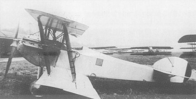
Flown in 1918, the HD.7 was unsuccessful in competition with the Nieuport 29.

Hanriot HD.7
HANRIOT HD.9 France
A single-seat reconnaissance fighter derived from the two-seat HD.3, the HD.9 was placed in the broad category of Avions de Corps d'Armee (thus being the HD.9 Apl) and its armament consisted of a single synchronised 7,7-mm Vickers machine gun. The airframe was basically that of the HD.3 and the installation of the 260 hp Salmson 9Z radial engine was identical, but fuel capacity was considerably increased. The first example of the HD.9 was completed in November 1918 as the initial aircraft built against an order for 10 machines. However, its career was cut short by the Armistice and there is no evidence that all nine remaining aircraft were completed.
Max speed, 137 mph (220 km/h) at sea level.
Range, 497 mis (800 km).
Empty weight, 1,565 lb (710 kg).
Span, 29 ft 6 1/4 in (9,00 m).
Length, 22 ft 9 1/2 in (6,95 m).
Wing area, 274.49 sq ft (25,50 m2).

Derived from the HD.3, the HD.9 was overtaken by the Armistice and only one was built.
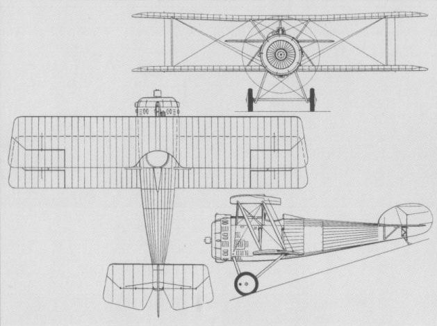
The Salmson 9Z-engined HD.9 of late 1918.
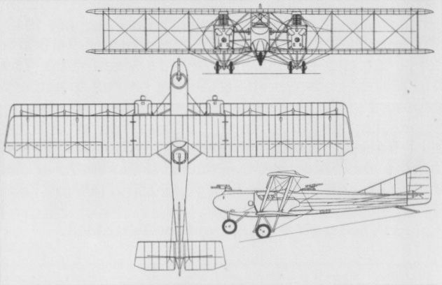
The Letord 6 derivative of the Letord 3.
LETORD 6 France
Derived from the Letord 3 Bn3 three-seat night bomber for use in the escort fighter role, the Letord 6 Ca3 prototype was completed late in 1917 and entered flight test in January 1918. Like its bomber counterpart, the Letord 6 was a four-bay equi-span biplane with negative wing stagger. Powered by two 220 hp Hispano-Suiza 8Be eight-cylinder water-cooled engines, it carried a pilot and two gunners, the nose gunner being provided with a 37-mm Hotchkiss cannon and the dorsal gunner having a single 7,7-mm Lewis gun. The Letord 6 was undoubtedly obsolescent in concept by the time that it entered test, and development appears to have been discontinued at an early stage.
Max speed, (approx) 93 mph (150 km/h).
Span, 58 ft 10 2/3 in (17,95 m).
Length, 36 ft 3 in (11,05 m).
Height, 11 ft 5 3/4 in (3,50 m).
Wing area, 742.73 sq ft (69,00 m2).
MORANE-SAULNIER TYPE L France
The most famous parasol monoplane of its period, the Type L two-seater, which appeared in 1913, saw service as a fighter as a result of fortune rather than original intent. Derived from the Type G-19 - the first aircraft of Leon Morane and Raymond Saulnier to feature a parasol wing configuration - the Type L emulated previous Morane-Saulnier types in its use of wing warping for lateral control. At the start of World War I, 50 examples ordered by Turkey were immediately sequestered for use by France's Aviation Militaire, and, in October 1914, chosen by Commandant Bares, the Chef du Service Aeronautique aux Armees, for fighting duties. Powered by either the seven-cylinder Gnome or nine-cylinder Le Rhone 9C rotary, both rated at 80 hp, the Type L was described as a Morane de chasse, and, at times, was armed with an 8-mm Hotchkiss or 7,7-mm Lewis machine gun fired from the rear cockpit. Sometimes flown as a single-seater in the fighting role, the Type L gained the distinction of carrying into combat the first fixed forward-firing machine gun to be used operationally by a tractor aircraft. Just over 50 Type L aircraft were delivered to the Royal Flying Corps, with which they performed unspectacular service throughout 1915 in the reconnaissance role, and others were supplied to the Russian Military Air Fleet. The following data relate to the standard two-seat Type L.
Max speed, 71 mph (115 km/h) at 6,560 ft (2 000 m).
Time to 3,280 ft (1 000 m), 5.75 min.
Endurance, 2.5 hrs.
Empty weight, 849 lb (385 kg).
Loaded weight, 1,444 lb (655 kg).
Span, 36 ft 9 in (11,20 m).
Length, 22 ft 6 3/4 in (6, 88 m).
Height, 12 ft 10 3/4 in (3,93 m).
Wing area, 196.9 sq ft (18, 30 m2).
MORANE-SAULNIER TYPE N France
Effectively the earliest operational single-seat fighters were the Morane-Saulnier Type N and its German contemporary, the Fokker E I, although the former had not been conceived with a military application in mind. Both types were flown in May 1914, the latter as the M 5, and the Type N was demonstrated in the following month at Aspern, Vienna. Retaining the wing warping lateral control of earlier Morane-Saulnier shoulder-wing monoplanes, but embodying noteworthy aerodynamic refinements, the Type N was powered by an 80 hp Le Rhone 9C rotary engine, and its operational use was pioneered by Eugene Gilbert who flew an early example fitted with a forward-firing 8-mm Hotchkiss machine gun with propeller-mounted steel bullet deflectors and dubbed Le Vengeur. This armament was similar to that of the Type L flown by Roland Garros. The performance of Le Vengeur prompted an official order for a small series of aircraft for use by the Aviation Militaire and these entered service in the summer of 1915. In January 1916, 24 Type N aircraft were ordered for the Royal Flying Corps, these being delivered between March and June 1916, and becoming known unofficially to the service as "Morane Bullets". A few were delivered to the Russian Military Air Fleet, but most had been withdrawn from French operational service before the end of 1915, and those delivered to the RFC were phased out in the following summer. As supplied to the RFC, the Type N was fitted with either the Lewis or Vickers machine gun, both of 7,7-mm calibre.
Max speed, 89 mph (144 km/h) at sea level.
Time to 3,280 ft (1000 m), 4.0 min.
Endurance, 1.5 hrs.
Loaded weight, 976 lb (443 kg).
Span, 26 ft. 8 5/8 in (8,15 m).
Length, 19 ft 1 1/2 in (5,83 m).
Height, 7 ft 4 1/2 in (2,25 m).
Wing area, 118.4 sqft (11,00 m2).
MORANE-SAULNIER TYPE G France
The appellation Type G was something of a generic designation in that several very different Morane-Saulnier designs were known as such, the last of these being a single-seat fighter designed in the summer of 1915 and built after the initial production batch of Type N aircraft for the Aviation Militaire. A refined development of the basic Type G of 1912, but featuring a fully-faired fuselage and powered by an 80 hp Le Rhone 9C, the Type G fighter had a centrally-mounted 8-mm Hotchkiss machine gun with standard bullet deflectors on the propeller. Possessing a general resemblance to the Type N, the Type G fighter's raison d'etre has gone unrecorded, but it is improbable that more than one or two examples were built as no production contract was placed on behalf of the Aviation Militaire. No data other than the overall dimensions have survived.
Span, 29 ft 11 in (9,12 m).
Length, 21 ft 8 2/3 in (6,62 m).
Height, 8 ft 4 in (2,54 m).
MORANE-SAULNIER TYPE I France
The Type I single-seat fighter was fundamentally a Type N re-engined with a 110 hp Le Rhone 9J nine-cylinder rotary and stemmed from interest evinced by Maj-Gen Trenchard in a more powerful version of the basic aircraft. An order was placed in January 1916 on behalf of the RFC for one aircraft. Twelve more were ordered during the following March when the first example was flown for the first time. The Type I was intended to have a single 7,7-mm Lewis gun with French Alkan synchronising mechanism, but the four examples supplied to the RFC mid-July 1916 were fitted with a centrally-mounted Vickers gun. No additional Type I fighters were delivered to the British service as this aircraft had meanwhile been overtaken by the similarly-powered, but extensively redesigned, Type V which afforded greater endurance. The Type I was not adopted by the Aviation Militaire.
Max speed, 104 mph (168 km/h) at sea level.
Time to 6,560 ft (2 000 m), 6.75 min.
Endurance, 1.33 hrs.
Empty weight, 736 lb (334 kg).
Loaded weight, 1,124 lb (510 kg).
Span, 27 ft 0 1/2 in (8,24 m).
Length, 19 ft 1 in (5,81m).
Height, 8 ft 2 1/2 in (2,50 m).
Wing area, 118.4 sqft (11,00 m2).
MORANE-SAULNIER TYPE V France
Developed in parallel with the Type I, the Type V single-seat fighter was a larger aircraft with a three-hour endurance. First flown in April 1916, and powered by a 110 hp Le Rhone 9J engine, it differed from the Type I in having larger wings and deepened ventral contours to accommodate increased fuel tankage. Armed with a single 7,7-mm Vickers gun mounted centrally ahead of the cockpit, the Type V was intended primarily to meet an RFC requirement formulated at the beginning of 1916, and the first of 12 aircraft for that service was officially accepted on 13 May 1916. The Type V proved singularly unpopular, as did also the Type I, and the operational career of the 110 hp Morane-Saulnier fighters with the RAF proved to be brief, terminating on 19 October 1916. A number of 110 hp aircraft, probably Type Vs but possibly Type Is, was supplied to Russia, 18 of these being in service on 1 April 1917, and several reportedly survived the revolution of that year to see operational use with the Red Air Fleet.
Max speed, 102 mph (165 km/h) at sea level.
Time to 3,280 ft (1 000 m), 3.35 min.
Span, 28 ft 7 1/2 in (8,75 m).
Length, 19 ft 1 in (5,81m).
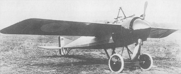
The shoulder-winged Morane-Saulnier Type N single seater had been completed early in 1914 and was actually in Austria being demonstrated by Roland Garros to the authorities there on 28 June 1914, the day Prince Franz Ferdinand was assassinated and set in train the events quickly leading to war in Europe. Early examples of the Type N that went into French service in 1914 were powered with the 80hp Gnome, as were a small batch delivered to the Imperial Russian Air Service, whereas the final machines delivered to the RFC used the 110hp Le Rhone. Top level speed was 102mph at 6.560 feet, while the aircraft's operational ceiling was 13,125 feet. During the spring of 1915, the Type N, previously used as a fast, unarmed scout, was fitted with the Garros-devised bullet deflecting propeller cuffs and a Hotchkiss machine gun and transformed into a fighter, as with the French machine seen here. Not built in great numbers, the French took only 49 to equip Escadrille MS 23, while the Russians formed one squadron and the RFC took sufficient to partially equip Nos 3 and 60 squadrons.
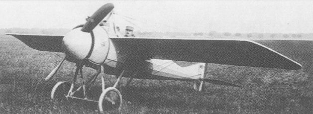
Essentially a Type N variant, the Type I had a more powerful Le Rhone engine.
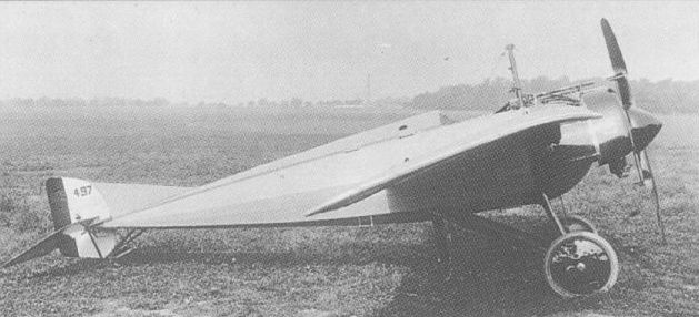
No production took place of the fighter version of the Morane-Saulnier Type G.
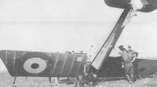
Little success attended the Type V, a dozen examples of which saw brief service with the RFC.
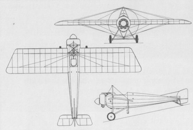
A single gun armed the Type G fighter.
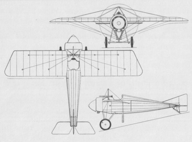
The Type N had propeller-mounted bullet deflectors for its single machine gun.

The Morane-Saulnier Type V
MORANE-SAULNIER TYPE P (MoS 21) France
During the summer of 1916, Morane-Saulnier produced two different single-seat fighter versions of the Type P reconnaissance two-seat parasol monoplane. Both were powered by the 110 hp Le Rhone 9J nine-cylinder rotary, but whereas the first single-seater was a simple conversion retaining the forward cockpit of the two-seater and carrying a single synchronised 7,7-mm Vickers gun, the second version featured a lower-mounted wing, an armament of twin synchronised 7,7-mm guns and an aft-positioned cockpit. Allegedly the first Allied twin-gun fighter, the latter was 183 lb (83 kg) heavier than the former in loaded condition and 5.6 mph (9 km/h) slower at sea level, recorded performance figures proving inferior to those of the two-seat Type P. Two prototypes of the initial version and at least one prototype of the two-gun version were evaluated by the Aviation Militaire, but neither was adopted for series production and the single-seat Type P was officially abandoned in December 1916. The following data relate to the two-gun version.
Max speed, 97 mph (156 km/h) at sea level.
Time to 6,560 ft (2 000 m), 8.67 min.
Endurance, 2.5 hrs.
Empty weight, 955 lb (433 kg).
Loaded weight, 1,528 lb (693 kg).
Span, 36 ft 9 in (11,20 m).
Length, 23 ft 7 1/2 in (7,20 m).
Height, 10 ft 8 3/4 in (3,27 m).
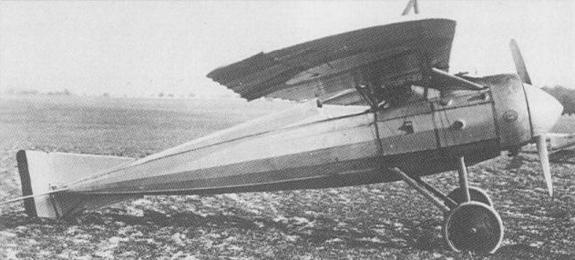
The second fighter version of the Type P introduced twin-gun armament.
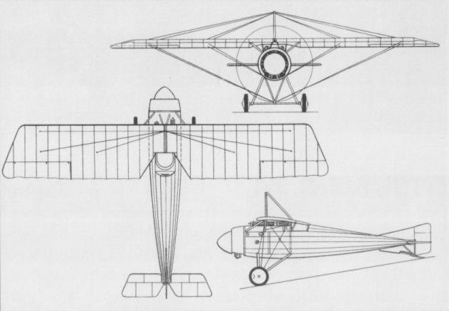
The second fighter version of the Type P introduced twin-gun armament.
MORANE-SAULNIER TYPE AC (MoS 23) France
Differing from earlier single-seat Morane-Saulnier shoulder-wing monoplanes essentially in having ailerons for lateral control rather than utilising wing warping and in employing rigid wing bracing, the Type AC appeared in the autumn of 1916. Powered by either the 110 hp Le Rhone 9J or 120 hp Le Rhone 9JB nine-cylinder rotary engine and carrying a single synchronised 7,7-mm gun, the Type AC was aerodynamically clean by contemporary standards, its fuselage being faired to a circular cross section. Thirty production aircraft were ordered for the Aviation Militaire, deliveries commencing late 1916. Although of advanced design and possessing a good performance, the Type AC was considered inferior to the SPAD S.VII, and, in consequence, was not adopted in quantity. Two examples were supplied to the UK for RFC evaluation.
Max speed, 111 mph (178 km/h) at sea level.
Time to 6,560 ft (2 000 m), 5.92 min.
Endurance, 2.5 hrs.
Empty weight, 959 lb (435 kg).
Loaded weight, 1,451 lb (658 kg).
Span, 32 ft 1 4/5 in (9,80 m).
Length, 23 ft 1 1/2 in (7,05 m).
Height, 8 ft 11 1/2 in (2,73 m).
Wing area, 161.46 sq ft (15,00 m2).

Ailerons replaced wing warping on the Type AC, which also featured rigid wing bracing.

The Morane-Saulnier Type AC fighter.
MORANE-SAULNIER TYPE AF (MoS 28) France
Although possessing a fuselage closely resembling that of the Type AI monoplane developed in parallel, the Type AF was not merely a biplane version of its contemporary, the two aircraft differing dimensionally. The first single-seat fighter of biplane configuration to be developed by Morane-Saulnier, the Type AF was fitted with a 150 hp Gnome Monosoupape 9Nb rotary and a single 7,7-mm Vickers gun. First flown on 23 June 1917, the Type AF demonstrated excellent handling qualities and good performance, but it offered little improvement on the SPAD S.XIII which was already in quantity production. The Morane-Saulnier biplane, therefore, was not ordered for the Aviation Militaire. However, in November 1917, a derivative designated Type AFH was readied for testing, this being intended for launching from a ship’s deck. The Type AFH had a single central pontoon-type float with a beam of 8 ft 10 1/3 in (2,70 m) and a length of 4 ft 8 2/3 in (1,44 m), and a small tail float, allowing the fighter to alight on water and take-off on wheels incorporated in the central float. Some flight testing of the Type AFH was conducted, but this shipboard fighter version was not adopted. The following data relate to the Type AF.
Max speed, 129 mph (207 km/h) at 3,280 ft (1 000 m).
Time to 6,560 ft (2 000 m), 4.83 min.
Empty weight, 928 lb (421 kg).
Loaded weight, 1,431 lb (649 kg).
Span, 24 ft 6 in (7,47m).
Length, 16 ft 10 3/4 in (5,15 m).
Height, 7 ft 8 1/2 in (2,35 m).
Wing area, 164.8 sq ft (15,31 m2).

The first Morane-Saulnier biplane fighter, the Type AF, did not achieve production.
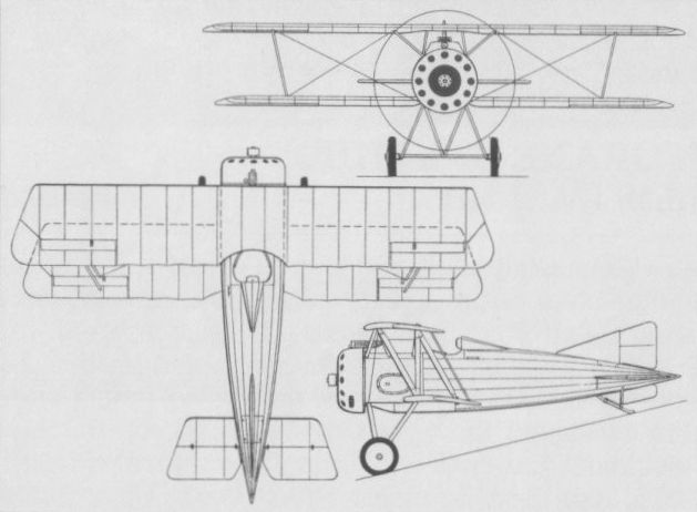
MORANE-SAULNIER TYPE AI (MoS 27) France
In the summer of 1917, Morane-Saulnier produced two new fighters in parallel, the Type AI (MoS 27) parasol monoplane and the Type AF (MoS 28) single-bay biplane. Powered by a 150 hp Gnome Monosoupape 9Nb nine-cylinder rotary, the Type AI was primarily of wooden construction and carried a single synchronised 7,7-mm Vickers gun. The prototype was officially tested in early August 1917 at Villacoublay, demonstrating an exceptional performance. In the following month, a Type AI was tested with a twin-gun installation, this aircraft having slightly enlarged tail surfaces and revealing only a modest reduction in climbing performance. Accordingly, the Type AI was ordered into production both in its single-gun version as the MoS 27 and with twin guns as the MoS 29. Considerably in excess of 1,000 examples of the two versions were subsequently built, deliveries commencing early in 1918. However, the Type AI had been withdrawn from Aviation Militaire service in May 1918 - as a result, said some sources, of structural deficiencies. Others blamed the temperamental nature of the Monosoupape engine. Following withdrawal, most Type AIs were re-engined with the 120 hp Le Rhone 9JB or 135 hp 9Jby and employed as fighter trainers under the designation MoS 30. Two examples of the Type AI were completed with a full wooden monocoque fuselage, one having the Monosoupape engine and the other a 170 hp Le Rhone 9R, but further development was not pursued. The following data relate to the twin-gun MoS 29 version.
Max speed, 137 mph (221 km/h) at sea level.
Time to 6,560 ft (2 000 m), 5.25 min.
Empty weight, 912 lb (414 kg).
Loaded weight, 1,486 lb (674 kg).
Span, 27 ft 11 in (8,51m).
Length, 18 ft 6 2/5 in (5,65 m).
Height, 7 ft 10 1/2 in (2,40 m).
Wing area, 144.13 sq ft (13,39 m2).
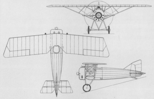
Both single-gun MoS 27 and twin-gun MoS 29 (shown) versions of the Type AI were produced.
MORANE-SAULNIER TYPE AN (MoS 31 TO MoS 34) France
Designed to use a 450 hp Bugatti 16-cylinder water-cooled engine, the Type AN two-seat fighter completed in the summer of 1918 was a large, two-bay equi-span staggered biplane with a monocoque fuselage. Officially tested at Villacoublay on 27 October 1918, the Type AN produced disappointing results and alternatives to the unorthodox Bugatti engine were investigated. The 400 hp Liberty 12 was installed in the Type ANL and the 450 hp Renault 12Kb in the Type ANR, both being tested in 1919. The armament of the AN series aircraft consisted of a forward-firing 7,7-mm Vickers gun and twin 7,7-mm Lewis guns on a flexible mount in the rear cockpit. The final variant of the basic design, the Type ANS, was fitted with a 530 hp Salmson 18Z 18-cylinder water-cooled two-row radial. Development continued through 1919, the Type ANL becoming the MoS 32, the ANR becoming the MoS 33 and the ANS becoming the MoS 34, but, although some promising results were obtained, further development was discontinued. The following data relate to the Bugatti-engined prototype.
Max speed, 140 mph (225 km/h) at sea level.
Time to 6,560 ft (2 000 m), 6.66 min.
Loaded weight, 3,902 lb (1 770 kg).
Span, 38 ft 5 4/5 in (11,73 m).
Length, 27 ft 4 1/2 in (8,34 m).
Height, 9 ft 1 in (2,77m).
Wing area, 441.33 sq ft (41,00 m2).
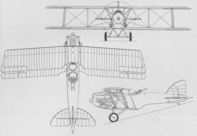
Type AN-derived, the Renault-powered ANR (shown) was similar to the Salmson-engined ANS.
NIEUPORT 10 France
Founded in 1910 by Edouard Nieuport, the Etablissements Nieuport became responsible for a series of fighting aircraft to the designs of Gustave Delage that was to extend over a quarter-century. The first of this distinguished line, the Nie 10, was allegedly derived from a racing biplane intended for the Gordon-Bennett contest and appeared before the end of 1914 as a military two-seater. At first, the French authorities evinced little interest, but subsequent to the British Royal Naval Air Service ordering 24, the Nie 10 was purchased in quantity. Initially, there were two versions: the Nie 10 AV (avant) in which the observer occupied the front seat and the Nie 10 AR (arriere) in which he occupied the rear seat. These were mostly converted to single-seat configuration for the fighting role, with a single machine gun mounted above the upper wing. Of orthodox wood-and-fabric construction, the Nie 10 was of sesquiplane configuration, the narrow-chord lower wing having less than half the area of the upper wing, and was powered by an 80 hp Gnome or Le Rhone rotary engine. It entered service with both France’s Aviation Militaire and the Royal Naval Air Service in May 1915, and was licence-built by Nieuport-Macchi in Italy, and by Dux and Lebedev in Russia, where production continued until 1920. Some Russian-built single-seaters were powered by the 100 hp Monosoupape or 110 hp and 120 hp Le Rhone engines, and were referred to as the Nie 10bis. The following data relate to the 80 hp single-seat version.
Max speed, 91 mph (146 km/h) at sea level.
Time to 6,560 ft (2 000 m), 16.5 min.
Empty weight, 904 lb (410 kg).
Loaded weight, 1,455 lb (660 kg).
Span, 25 ft 11 in (7,90 m).
Length, 22 ft 11 1/2 in (7,00 m).
Height, 8 ft 10 1/4 in (2,70 m).
Wing area, 193.76 sq ft (18,00 m2).

The early two-seat version of the Nie 10 sesquiplane.
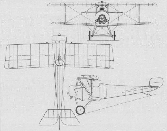
The definitive single-seat version of the Nie 10 sesquiplane.
NIEUPORT 11 France
One of the outstanding landmarks in the history of fighter evolution, the Nie 11, promptly christened the Bebe by its pilots, was a scaled-down refinement of the Nie 10. The first operational Nie 11 was delivered to the Aviation Militaire on 5 January 1916, and within a month there were 90 at the Front. Relatively fast and highly manoeuvrable, the Nie 11 soon outfought and contained the Fokker monoplanes. Armed with an overwing Hotchkiss or Lewis machine gun and powered by an 80 hp Le Rhone rotary, it was supplied to the Royal Naval Air Service in some numbers and was licence-built by Dux in Russia and by Nieuport-Macchi and Elettro-Ferroviarie in Italy. The former Italian company built 450 and the latter 93. Twenty were also built in the Netherlands. In addition to the gun, some Nie 11s carried eight Le Prieur rockets attached to the interplane struts. Although the Nie 11 was referred to as a sesquiplane, its lower wing had exactly half the area of the upper wing. Its main weakness was in the lower wing, which tended to twist and break under stress.
Max speed, 104 mph (167 km/h) at sea level.
Time to 9,840 ft (3 000 m), 15 min.
Empty weight, 705 lb (320 kg).
Loaded weight, 1,058 lb (480 kg).
Span, 24 ft 8 in (7,52 m).
Length, 18 ft 6 in (5,64 m).
Height, 7 ft 10 1/2 in (2,40 m).
Wing area, 143.16 sq ft (13,30 m2).
NIEUPORT 16 France
Fundamentally the Nie 11 adapted to take the more powerful Le Rhone 9J rotary engine of 110 hp, the Nie 16 was faster, but, retaining the wing area of its predecessor, its higher wing loading adversely affected its handling characteristics and it was nose heavy. The standard overwing Lewis gun remained the normal armament, but some Nie 16s had the gun mounted on the forward decking and synchronised by the Alkan mechanism to fire through the propeller. Additionally, eight Le Prieur rockets could be carried on the interplane struts. The Nie 16 began to appear in the early spring of 1916, supplementing and then replacing the Nie 10s and 11s. It was ordered by the RNAS, which transferred 17 of the Nie 16s to the RFC from 18 March 1916, the latter subsequently ordering more and taking at least 28 into its inventory. Small numbers were delivered to Belgium and it was licence-built by Dux in Russia. Its service life was comparatively brief as it was soon succeeded by the superior Nie 17.
Max speed, 103 mph (165 km/h) at sea level.
Time to 9,840 ft (3 000 m), 10.16 min.
Empty weight, 827 lb (375 kg).
Loaded weight, 1,213 lb (550 kg).
Span, 24 ft 8 in (7,52 m).
Length, 18 ft 6 in (5,64 m).
Height, 7 ft 10 1/2 in (2,40 m).
Wing area, 143.16 sq ft (13,30 m2).
NIEUPORT 18 France
Despite being assigned an official SFA designation, the Nie 18 single-seat fighter sesquiplane powered by an 80 hp Le Rhone 9C rotary apparently failed to attain service status and little is recorded of this type. Its external appearance suggested that it was a derivative of the Nie 11, the fuselage and tail assembly of the earlier type being mated with a wider-track undercarriage and a wing cellule with revised bracing geometry, the V-type interplane struts having a pronounced outward rake. A contemporary manual quoted the wing area of the Nie 18 as 13,00 m2 (139.9 sq ft) which was possibly a rounded figure.

An Nie 11 of the Romanian Sqn, September 1917.
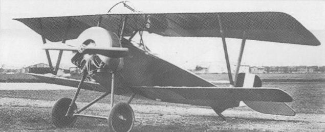
An Nie 11 built by Nieuport-Macchi in Italy.
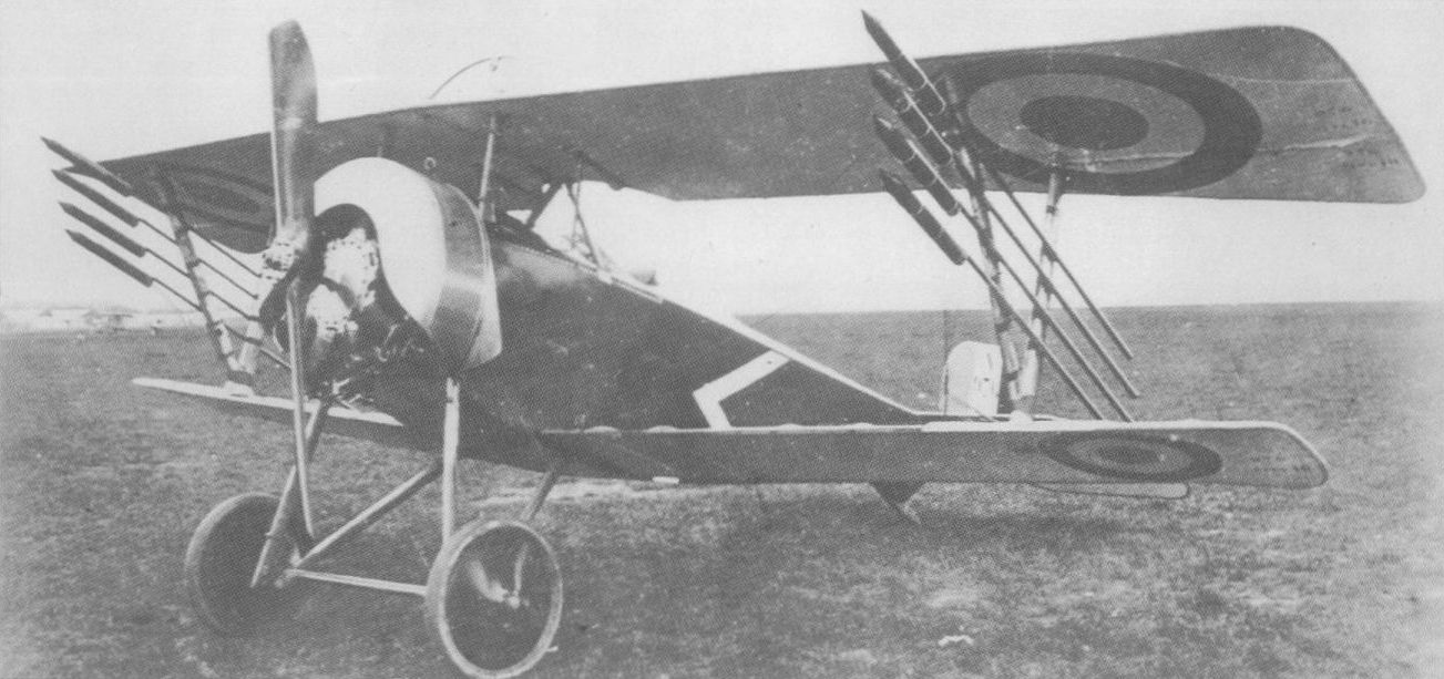
The Nieuport 16 proved to be an only partially successful attempt to extend the production life of the Ni 11 Bebe. To do this, the company replaced the Bebe's 80hp rotary with the bigger and heavier 110hp Le Rhone making the machine notoriously nose heavy, particularly with power off. Most Ni 16s ended their days by having their gun removed and replaced by eight Le Prieur rockets for use as 'Zeppelin chasers', as in the case of this French machine.

The Nie 11, popularly known as the Bebe.
NIEUPORT 12 France
A larger, more powerful derivative of the Nie 10, the Nie 12 was conceived as a two-seat reconnaissance fighter. Soon after its service debut with the Aviation Militaire it was successfully operated as an escort fighter. Powered by a 110 hp Clerget 9B rotary, the Nie 12 had an armament comprising a single machine gun on a ring mounting in the rear cockpit, this sometimes being supplemented by a forward-firing gun braced to the upper wing. Produced in considerable numbers in France for the escort role and supplied to the Imperial Russian Air Service, the Nie 12 was also licence-built in the UK by William Beardmore for the RNAS. The Beardmore-built Nie 12s featured an extended lower wing, some having full engine cowlings and fixed fin and plain rudder replacing the Nieuport balanced rudder. Forty Nie 12s were transferred to the Royal Flying Corps. In 1916, an improved two-seat fighter version, the Nie 12bis with a 130 hp Clerget 9, was introduced by the Aviation Militate. The following data relate to the 110 hp model.
Max speed, 91 mph (146 km/h) at 6,560 ft (2 000 m).
Time to 6,560 ft (2 000 m), 14.25 min.
Empty weight, 1,213 lb (550 kg).
Loaded weight, 1,874 lb (850 kg).
Span, 29 ft 6 in (9,00 m).
Length, 22 ft 11 1/2 in (7,00 m).
Height, 8 ft 10 1/4 in (2,70 m).
Wing area, 236.81 sq ft (22,00 m2).
NIEUPORT 20 France
By mid-1916, the RFC in France possessed a small number of Nieuport two-seaters in which the 110 hp Le Rhone engine had replaced the 110 hp Clerget of the standard Nie 12. This version of the two-seat fighter was apparently built in small numbers only for the RFC with the SFA designation Nie 20. By early August 1916, 30 had been allotted to the RFC by the French authorities, the first two production aircraft being delivered on 15 September 1916. Anxiety to secure as many Nieuport single-seaters as possible led to a reduction in Nie 20 deliveries, only 21 being supplied to the RFC, with which the type saw limited operational use.
Max speed, 98 mph (157 km/h) at sea level.
Time to 6,560 ft (2 000 m), 12.05 min.
Empty weight, 999 lb (453 kg).
Loaded weight, 1,658 lb (752 kg).
Span, 29 ft 6 in (9,00 m).
Length, 22 ft 11 1/2 in (7,00 m).
Height, 8 ft 10 1/4 in (2,70 m).
Wing area, 236.8 sqft (22,00 m2).
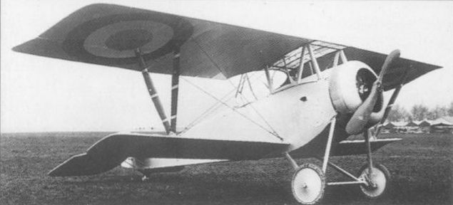
The Nie 12 was fundamentally a larger and more powerful derivative of the Nie 10.

The Nie 12 was fundamentally a larger and more powerful derivative of the Nie 10.
NIEUPORT 17 France
Appearing mid-1916, the Nie 17 rapidly established itself as an outstanding fighter. Although it retained the basic geometry and proportions of the Nie 11 and 16, it was a new, somewhat larger and more refined aircraft. Most Nie 17s were powered by either the Le Rhone 9Ja of 110 hp or 9Jb of 120 hp, but a few of the earliest had the 110 hp or 130 hp Clerget. At some time in 1916, the Nie 17 equipped every fighter escadrille of the Aviation Militate, and at least one naval unit. Many of those in French service had a synchronised Vickers gun, while the substantial number supplied to the RFC were armed with a Lewis gun on a Foster overwing mounting. One hundred and fifty were built in Italy by Nieuport-Macchi, and the Nie 17 was supplied to Belgium and Russia. Twenty were also supplied to the Netherlands and two to Finland, and, in September 1917, the American Expeditionary Force received 75 fighters of this type. A classic design, the Nie 17 was to serve as a basis for a number of later types.
Max speed, 103 mph (165 km/h) at sea level.
Time to 9,840 ft (3 000 m), 11.5 min.
Range, 155 mis (250 km).
Empty weight, 827 lb (375 kg).
Loaded weight, 1,235 lb (560 kg).
Span, 26 ft 9 in (8,16 m).
Length, 19 ft 0 in (5,80 m).
Height, 7 ft 10 in (2,40 m).
Wing area, 158.8 sq ft (14,75 m2).
NIEUPORT 21 France
Although apparently intended as a fighter trainer, the single-seat Nie 21 was flown operationally as a fighter in French escadrilles. Fundamentally a variant of the Nie 17 in which the 110 hp Le Rhone 9J gave place to the 80 hp Le Rhone 9C, the Nie 21 was built in considerable numbers, and, because many were fitted with a horseshoe-form engine cowling, it was frequently mistaken for the Nie 11. It had the larger wings and bracing geometry of the Nie 17, however, and in RNAS service (at least five being acquired) it was known confusingly as the Nie 17B. The Nie 21 was supplied to Russia, and, from September 1917,181 were acquired by the US Air Service for training duties. At least one was tested with the 90 hp Le Rhone 9Ga engine.
Max speed, 94 mph (150 km/h) at sea level.
Time to 9,840 ft (3 000 m), 15.7 min.
Empty weight, 705 lb (320 kg).
Loaded weight, 1,091 lb (495 kg).
Span, 26 ft 9 in (8,16 m).
Length, 19 ft 8 1/4 in (6,00 m).
Height, 7 ft 10 in (2,40 m).
Wing area, 158.77 sq ft (14,75 m2).
NIEUPORT 23 France
The Nie 23 differed from the Nie 17 in comparatively minor respects. A new form of interrupter gear for the Vickers gun led to the weapon's installation slightly to starboard of the centreline and dictated some internal structural changes. There were minor modifications to the upper wing and the 120 hp Le Rhone 9Jb rotary was adopted as standard. The Nie 23 was used side by side with the Nie 17 in French escadrilles and was licence-built by Dux in Russia where it became the most numerous Nieuport serving with the Imperial Russian Air Service. It was supplied to Belgium and at least 80 were delivered to the RFC with which it entered service mid-March 1917. In British squadrons, replacement of the Vickers by a Foster-mounted Lewis gun rendered distinguishing Nie 23 from Nie 17 almost impossible.
Max speed, 103 mph (165 km/h) at sea level.
Time to 9,840 ft (3 000 m), 11.5 min.
Empty weight, 827 lb (375 kg).
Loaded weight, 1,235 lb (560 kg).
Span, 26 ft 9 in (8,16 m).
Length, 19 ft 0 1/4 in (5,80 m).
Height, 7 ft 10 in (2,40 m).
Wing area, 158,77 sqft (14,75 m2).
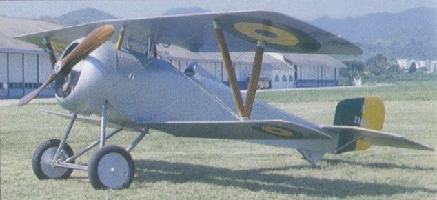
The Nie 21, that being a replica with some genuine components in Brazil’s Museu Aeroespacial.
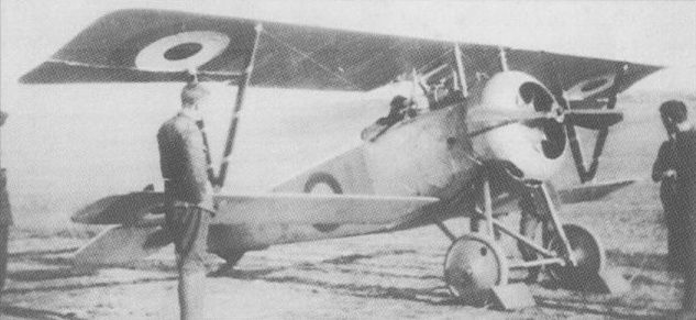
An Nie 17 of the RFC, this particular example serving in Palestine with No 111 Squadron.
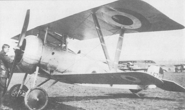
The Nie 23 served side-by-side in French escadrilles with the fundamentally similar Nie 17.
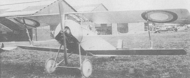
The Nie 21
NIEUPORT Triplane
During 1915, Gustave Delage had fitted a Nieuport 10 fuselage with triplane wings of unusual fore-and-aft geometry for experimental purposes, the arrangement being patented on 10 January 1916. Progressive development led, later in 1916, to an even more unorthodox triplane arrangement in which the middle wing, attached to the forward ends of the upper fuselage longerons, was foremost and the upper wing rearmost. Utilising a Nie 17 fuselage, powered by a 110 hp Le Rhone engine and armed with a single synchronised Lewis gun, this triplane was officially tested late in 1916, but was not ordered for the Aviation Militate, and, in consequence, received no official SFA type designation. One example armed with a Vickers gun was acquired for evaluation by the RFC on 26 January 1917, but its flying characteristics were found to be unacceptable. The RNAS also acquired one example in March 1917, this differing in having a Nie 17bis fuselage and a 130 hp Clerget engine. Although allotted to No 11 (Naval) Sqn, it had been discarded by 27 June 1917. The following data relate to the 110 hp version.
Max speed, 110 mph (176 km/h) at 3,000 ft (915 m).
Time to 10,000 ft (3 050 m), 13.6 min.
Empty weight, 919 lb (417 kg).
Loaded weight, 1,386 lb (629 kg).
Span, 26 ft 3 1/2 in (8,01 m).
Length, 19 ft 2 1/2 in (5,85 m).
Height, 7 ft 5 in (2,26m).
Wing area, 143.16 sq ft (13,30 m2).

The first of the extraordinary Nieuport triplanes with centre wing foremost.
NIEUPORT (LORRAINE-DIETRICH) France
The rotary engine having reached its development limit by late 1917, Gustave Delage turned his attention to stationary engines, and, on 23 October 1917, it was reported that a Nieuport fighter with a Lorraine-Dietrich water-cooled eight-cylinder Vee engine was under test. Fitted with either a 240 hp Lorraine-Dietrich 8Bb or 275 hp 8Bd, this was a somewhat ungainly aircraft, with a large gap and an aft-positioned cockpit. Forward view was impaired by large fairings over the engine cylinder blocks with the radiator mounted between them. Although this prototype was undergoing what were described as "acceptance tests” at Villacoublay, it was evidently discarded in favour of a similarly-powered, but more refined, prototype which, according to one report, was to be ready at the end of January 1918. This differed markedly from its predecessor, having equi-span sweptback wings of increased area, horn-balanced ailerons on both upper and lower mainplanes, a larger vertical tail and the radiator repositioned in the wing centre section. It is reasonably certain that the engine was the 275 hp 8Bd and flight testing was reported to be continuing late in April 1918. Previously, in February, time to 6,560 ft (2 000 m) had been recorded as 5.66 min and to 13,125 ft (4 000 m) as 16.5 min. An early estimate of maximum speed with a Lorraine-Dietrich engine of 220 hp was 137 mph (220 km/h) at 13,125 ft (4 000 m). The following data for weights are estimated.
Empty weight, 1,179 lb (535 kg).
Loaded weight, 1,874 lb (850 kg).
Wing area, 226.5 sq ft (21,00 m2).
NIEUPORT (HISPANO-SUIZA) France
Produced in parallel with the second Lorraine-Dietrich-engined prototype, a virtually identical airframe was fitted with one of the first 300 hp Hispano-Suiza eight-cylinder water-cooled engines and was reported to be in course of testing on 1 May 1918. As the prototype was fitted with two 7,7-mm Vickers machine guns it was obviously not merely a test vehicle for the HS 8Fb engine which it was intended to install in the Nie 29 and the prototype of which was nearing completion. Much was expected of the Nie 29 at that time, and it would have been logical for the Nieuport company to have abandoned its first 300 hp Hispano-Suiza-engined fighter in order to concentrate on the more advanced and refined monocoque-type fighter. That is as may be, but development of the former would seem to have been discontinued by the time that the Nie 29 entered flight test. The following data are based on manufacturer’s estimates.
Max speed, 143 mph (230 km/h) at 13,125 ft (4 000 m).
Time to 13,125 ft (4 000 m), 10 min.
Endurance, 2.5 hrs.
Empty weight, 1,323 lb (600 kg).
Loaded weight, 2,094 lb (950 kg).
Wing area, 226.05 sqft (21,00 m2).
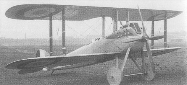
The first of the Lorraine-Dietrich-engined Nieuport prototypes.
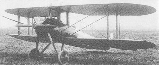
The second of the Lorraine-Dietrich-engined Nieuport prototypes.
NIEUPORT 17bis France
Despite a preference for the Le Rhone engine to the Clerget on the part of Gustave Delage, a modified Nie 17 appeared late in 1916 with a 130 hp Clerget and full-length fuselage side fairings as the Nie 17bis. Seeing only limited French service, the Nie 17bis was ordered by the RNAS, both from the parent company and from British Nieuport & General Aircraft, some 80 eventually being delivered to the British service. Most RNAS Nie 17bis fighters mounted both a synchronised Vickers gun and an overwing Lewis gun, but the type failed to attain expectations, and later British Nieuport contracts for 100 aircraft were cancelled. Replaced in first line use by the Camel from June 1917, the Nie 17bis was relegated to the training role.
Max speed, 118 mph (190 km/h) at sea level.
Loaded weight, 1,263 lb (573 kg).
Span, 26 ft 9 in (8,16 m).
Length, 19 ft 0 in (5,80 m).
Height, 7 ft 10 in (2,40 m).
Wing area, 158.8 sq ft (14,75 m2).
NIEUPORT 17bis (DERIVATIVE I) France
Nieuport single-seat fighter prototypes were numerous, but apparently undesignated - no record of their chronology having apparently survived. One that appears to have been related to the Nie 17bis and which has been described incorrectly as the Nie 25 was a Clerget-powered fighter with a faired fuselage like that of the Nie 17bis. This was mated to an upper wing lacking sweepback and a wooden fin and plain rudder rather than the characteristic Nieuport steel-tube balanced rudder. Setting this prototype apart from other Nieuports was its immense cone de penetration mounted as a stationary fairing ahead of the propeller. It may conceivably have had a 150 hp Clerget 9Bd rotary engine, but this is uncertain.
NIEUPORT 17bis (DERIVATIVE II) France
By early November 1916, Nieuport had built and flown a single-seat fighter prototype reported to be "practically the same as” the Nie 17bis, but powered by a 150 hp Le Rhone engine. It is assumed - though without positive evidence - that this was the prototype featuring a Le Rhone engine enclosed by an unusually long-chord cowling. Having an Nie 17bis-type faired fuselage, it possessed vertical tail surfaces of generally similar profile to those of the Clerget-engined Nie 17bis derivative (see previous entry) with the cone de penetration, but with a horn-balanced rudder and a new tailplane and elevator assembly. The upper wing was mounted on two inverted Vee-type cabane struts and the Vickers gun was mounted on the port upper longeron. It would seem likely that this aircraft was an early prototype for the Nie 24.
NIEUPORT (Hispano-Suiza) France
Construction began early in November 1916 of a new single-seat Nieuport fighter "designed to compete with the SPAD” and powered by a 150 hp Hispano-Suiza water-cooled engine with a circular frontal radiator. A contemporary report stated that "the empennage, rudder and elevators are all covered with three-ply wood and fabric”, and indicated that "M Delage expects great things of this machine". The Hispano-Suiza powered prototype was a clean and elegant aircraft, with a faired fuselage and close coamings around the cockpit. The lower wing was broader in chord than that of preceding Nieuport fighters, but the fact that this prototype was not developed beyond the flight test stage suggests that its performance offered an insufficient improvement on that of the similarly-powered SPAD S.VII.
NIEUPORT 24 France
Yet a further refinement of the basic Nie 17/17bis series, the Nie 24 employed a new aerofoil section, was fitted with a wooden tail unit and was powered by a 130 hp Le Rhone 9Jb rotary. Official trials in February and March 1917 of an aircraft designated Nie 24 produced results not significantly better than those of the Nie 17 and 23. Nevertheless, the Nie 24 was ordered in quantity and was in service with French escadrilles in June 1917. The fact that the Nie 24 was, in the event, preceded operationally by the Nie 24bis suggests that some problems delayed the service debut of the earlier model. A few Nie 24s were supplied to the RFC in the summer of 1917, others were supplied to Russia, a total of 121 was acquired by the USA in November 1917, and production of 77 was undertaken by Nakajima in Japan from 1921/22 as the Ko-3 fighter-trainer with the 80 hp Le Rhone engine.
Max speed, 109 mph (176 km/h) at sea level.
Time to 9,840 ft (3 000 m), 9.4 min.
Empty weight, 783 lb (355 kg).
Loaded weight, 1,206 lb (547 kg).
Span, 26 ft 11 in (8,21m).
Length, 19 ft 3 in (5,87 m).
Height, 7 ft 10 in (2,40 m).
Wing area, 158.77 sq ft (14,75 m2).
NIEUPORT 24bis France
Precisely why the Nie 24bis preceded the Nie 24 in operational service has never been satisfactorily explained. However, the Nie 24bis had something of the appearance of a stop-gap hybrid in that the elegant vertical tail, comprising fixed fin and horn-balanced rudder, adopted for the Nie 24 was discarded in favour of the balanced rudder of such types as the Nie 17bis. It seems likely that problems had been encountered with the manufacture or strength of the new vertical tail, and the earlier form had been retained while these were being resolved. With its fully-faired fuselage, the Nie 24bis therefore resembled the Nie 17bis with a 130 hp Le Rhone 9Jb in place of the similarly rated Clerget. It is also assumed that the Nie 24bis had the new aerofoil section adopted for the Nie 24. Normal armament comprised a single synchronised Vickers gun, while those delivered to the RFC - which service received at least five - conservatively retained the unsynchronised overwing Lewis gun. The American Expeditionary Force received 140 Nie 24bis fighters and the type was manufactured in Russia by Duks from 1917 until 1920. In service with France's Aviation Militaire, the Nie 24bis was rapidly superseded by the Nie 24.
Max speed, 106 mph (170 km/h) at sea level.
Time to 9,840 ft (3 000 m), 9.66 min.
Loaded weight, 1,225 lb (556 kg).
Dimensions as for Nie 24.
NIEUPORT 25 France
Gustave Delage retained an affection for the Vee-strutted sesquiplane that exceeded the basic design’s realisable potential, and the Nie 25 apparently represented the ultimate variant, at least in respect of engine power. The Nie 25 was essentially a Nie 24 airframe adapted to take a 200 hp Clerget 11E 11-cylinder rotary. Armament consisted of a single synchronised Vickers gun. This type is believed to have first flown in July 1917, possibly initially with a 150 hp Clerget 9Bd engine, and the fact that it had an SFA type number suggests that series production was contemplated. However, the Clerget 11E was beset with difficulties and it was presumably for this reason that the Nie 25 was not built in quantity. One example was flown by Charles Nungesser and bore his colourful personal markings.
Time to 9,840 ft (3 000 m), 8.0 min.
No other data available for publication.
NIEUPORT 27 France
Despite receiving a new SFA designation, the Nie 27 differed from the Nie 24 only in having an articulated two-part undercarriage axle and simplified tailskid similar to those of the Nie 25. The standard engine remained the Le Rhone 9Jb or 9Jby of 120 hp and 130 hp respectively, and the single synchronised Vickers gun was retained. The last Vee-strutted Nieuport sesquiplane to see operational service, the Nie 27 attained use with French escadrilles during the summer of 1917, but was rapidly outmoded. At least 87 were supplied to the RFC, which was not to withdraw this type finally until 20 April 1918, long after the Nie 27 was outclassed on the Western Front. It was used in quantity by Italy, and, in November 1917, a total of 287 Nie 27s was acquired by the US Air Service for the fighter training role. In Japan, Nakajima built 25 Nie 27s in 1923, and these served in the Imperial Army as fighters with the same Ko 3 designation as the Nie 24s.
Max speed, 107 mph (172 km/h) at sea level.
Time to 9,840 ft (3 000 m), 9.42 min.
Loaded weight, 1,179 lb (535 kg).
Span, 26 ft 11 in (8,21m).
Length, 19 ft 3 in (5,87 m).
Height, 7 ft 10 in (2,40 m).
Wing area, 158.77 sq ft (14,75 m2).
NIEUPORT 27 (Derivative) France
On 22 October 1917, Gustave Delage’s Vee-strutted sesquiplane fighter was described in the following terms by General Petain: "The Nieuport is inferior to all enemy aircraft. It is essential that it be withdrawn very soon from all the escadrilles at the Front.” Whether a prototype apparently derived from the Nie 27 and intended to overcome that fighter’s shortcomings made its debut before or after Petain’s condemnation is not recorded, but it would seem to have represented Delage’s very last attempt to keep alive the combination of rotary engine and Vee-type interplane strut. Retaining the Nie 27 fuselage, tail surfaces, undercarriage and, apparently, the 130 hp Le Rhone 9Jby engine, this prototype in fact departed from the sesquiplane arrangement in adopting a two-spar lower wing of broader chord. The Vee-type struts featured broad apices to provide appropriate pick-up points. Armament consisted of paired synchronised 7,7-mm guns.

Nie 24 of Escadrille N.91, Aviation Militaire, 1917
Nie 24 with a USAS Construction [training] Sqn, France, early 1918.
Nie 27 of the Italian 81a Squadriglia, summer 1917
Nie 27 of No 1 Sqn, RFC, at Builleul, France, in October 1917.
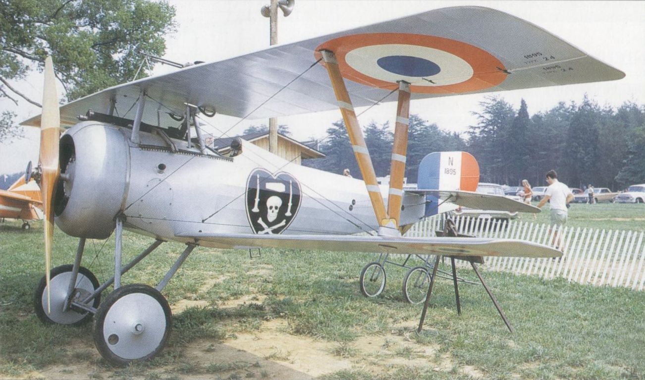
A preserved example with Nungesser emblem in USA.
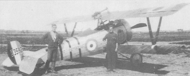
The Nie 24bis actually preceded the Nie 24 into service and closely resembled the Nie 17bis.
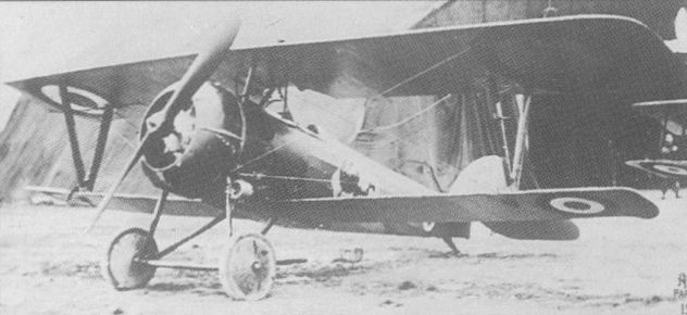
The Nie 27 was the last Vee-strutted Nieuport sesquiplane to achieve operational status.
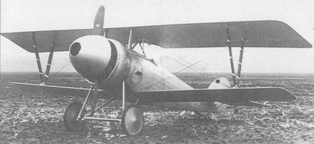
Little is known about this Nieuport single-seater, which was unarmed and might have been a purely experimental aircraft. Its fuselage and undercarriage might have been similar to those of the Nie.17bis, but its all wood fin and rudder resembled those of the Hispano-Suiza powered fighter; the strut-braced tailplane and elevators appeared to be similar to those of previous production types. A Clerget engine of unknown type and output was fitted, and had on its crankshaft an enormous cone de penetration that must have seriously impaired the cooling of the engine. The tailskid was hinged to a small and inept-looking inverted pyramid of struts. The mainplanes had no sweepback, and straight-edged ailerons were fitted. It is not known precisely where this single-seater fitted chronologically in the sequence of Nieuport types.
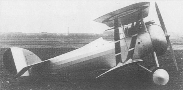
The Nie 27 derivative prototype which used a biplane rather than sesquiplane configuration.
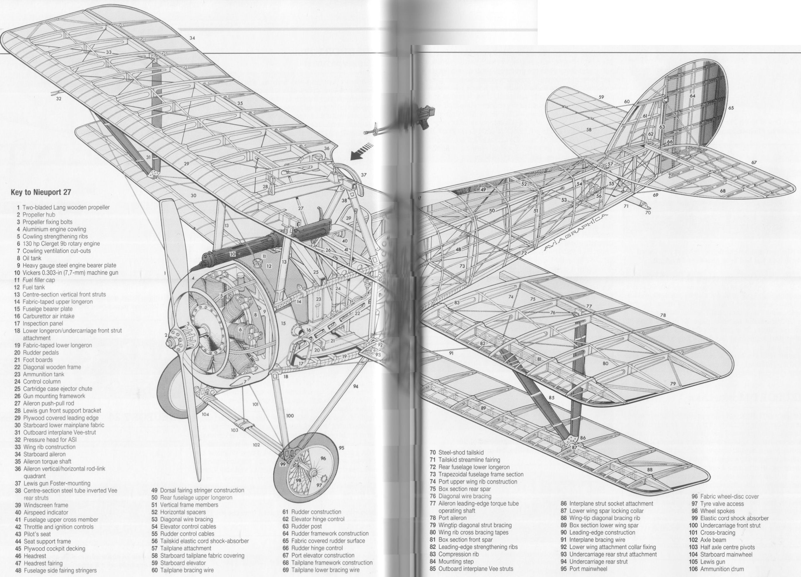
Nieuport 27
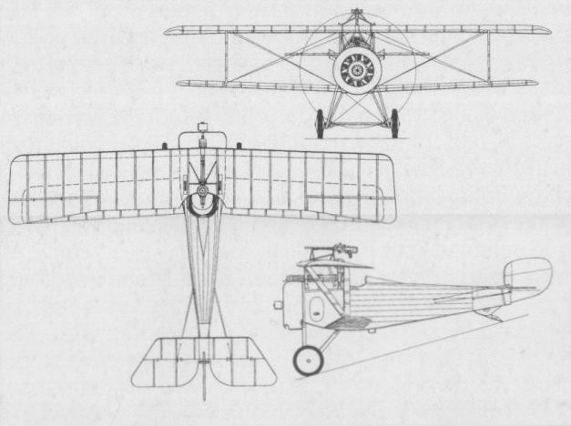
The Nie 17bis which appeared late in 1916.
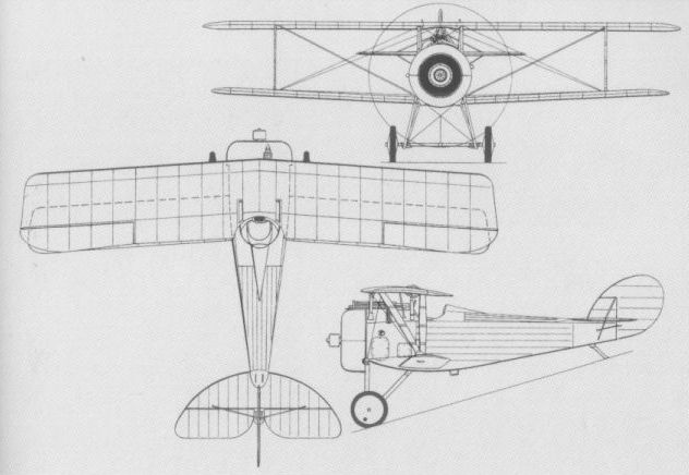
The Nie 27 was a further Nie 24 derivative.
NIEUPORT 28 France
Marking the final abandonment by Gustave Delage of the Vee-strutted sesquiplane configuration, the Nie 28 was an elegant fighter of conventional biplane configuration with parallel interplane struts. Powered by a 150 hp Gnome Monosoupape 9N rotary, the Nie 28 was initially fitted with a single 7,7-mm Vickers gun. A prototype was flying in June 1917 with pronounced dihedral on the upper wing, an abbreviated cabane and no dihedral on the lower wing. At least one other aircraft was flown with this configuration. The upper wing arrangement proved unsuccessful, and, in mid-October, the aircraft was tested with a raised upper wing from which dihedral was eliminated. This
arrangement was, in turn, superseded a month later by a compromise which retained the wing position but adopted 1.5 deg dihedral for the upper wing, and this was standardised for production. The single-gun armament was deemed inadequate and a second Vickers gun was attached to the fuselage portside. The Nie 28 was not adopted by France’s Aviation Militaire, but it was acquired for the American Expeditionary Force, which received 297 from March 1918. Unpopular for its tendency to shed its wing fabric at high speeds or during high-g manoeuvres, the Nie 28 was found to be no match for the Fokker D VII and was withdrawn after four months of unsatisfactory service. Twelve were acquired by the US Navy, 15 by Switzerland and a few by Greece.
Max speed, 123 mph (198 km/h) at 6,560 ft (2 000 m).
Time to 6,560 ft (2 000 m), 5.5 min.
Range, 248 mis (400 km).
Empty weight, 961 lb (436 kg).
Loaded weight, 1,539 lb (698 kg).
Span, 26 ft 9 1/4 in (8,16 m).
Length, 21 ft 0 in (6,40 m).
Height, 8 ft 2 1/2 in (2,50 m).
Wing area, 172.23 sq ft (16,00 m2).
NIEUPORT (Clerget 11E) France
By 1 December 1917, Nieuport was flying the prototype of an enlarged development of the Nie 28 powered by a 200 hp Clerget 11E 11-cylinder rotary and carrying an armament of twin 7,7-mm Vickers guns. Compared with the Nie 28, this prototype had larger dimensions overall - the wing area being increased by 53.82 sq ft (5,00 m2) - wings rigged with appreciable dihedral and a cut-back wing centre section to improve the pilot's upward view. To what extent the development problems suffered by the Clerget 11E engine affected this prototype is not known, but the aircraft had been abandoned by 1 May 1918.
Max speed, 124 mph (200 km/h) at 13,125 ft (4 000 m).
Time to 13,125 ft (4 000 m), 12 min.
Endurance, 2.5 hrs.
Empty weight, 1,168 lb (530 kg).
Loaded weight, 1,874 lb (850 kg).
Wing area, 226.5 sq ft (21,00 m2).
NIEUPORT Monocoque France
In parallel with the Clerget 11E-engined prototype, Nieuport produced the company’s first monocoque fighter, this being reported to be ready for testing on 1 December 1917. With an appearance suggesting a close relationship with the Nie 28, this prototype was powered by a 165 hp Gnome Monosoupape 9N rotary engine enclosed by a bulbous cowling and carried an armament of a single 7,7-mm Vickers gun to port of the tandem faired centreline struts forming the cabane. The wooden monocoque fuselage was characterised by extremely clean lines and the tail surfaces were of basically similar geometry to that adopted for the later Nie 29. The monocoque prototype had apparently been abandoned by April 1918, by which time a second aircraft had been tested with a 170 hp Le Rhone 9R. Performance was only marginally better than that of the Nie 28 and neither Monosoupape 9N or Le Rhone 9R was satisfactory. It is probably for these reasons that further development of the first Nieuport monocoque fighter was not pursued.
Max speed (Le Rhone), 123 mph (198 km/h) at 6,560 ft (2 000 m).
Time to 9,840 ft (3 000 m), 7.33 min.
Endurance, 2.25 hrs.
Loaded weight (Monosoupape), 1,411 lb (640 kg).
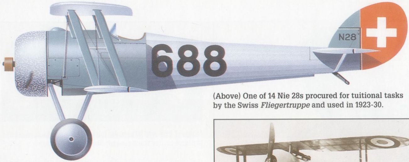
One of 14 Nie 28s procured for tuitional tasks by the Swiss Fliegertruppe and used in 1923-30.
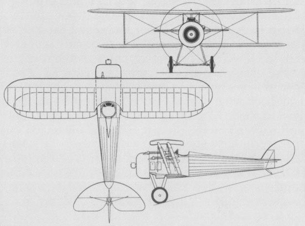
The " demi-diedre" production Nie 28 with 1.5-deg dihedral and deeper cabane.
NIEUPORT Monoplane France
In October 1917, Nieuport had a prototype fighter monoplane under construction with the aim of combining the structural simplicity and reduced drag of this configuration with a reasonable downward view for the pilot. The shoulder-mounted wing was braced by substantial lift struts attached to a rigid undercarriage structure incorporating a substantial spanwise surface of broad chord and streamline section. Glazed cut-outs in the wing roots gave the pilot some downward view and the wings and faired fuselage were fabric-covered. Powered by a 150 hp Gnome Monosoupape 9N rotary, the monoplane is presumed to have flown at the end of 1917 or beginning of 1918, at which time a second prototype with a 180 hp Le Rhone 9R was scheduled to fly about the end of January. The latter embodied some revision of the wings, which introduced inverse taper on the inboard trailing edges, and an extended fin. As of 1 May 1918, the Monosoupape-powered prototype was still under test, while the prototype with the Le Rhone had been abandoned. Armament comprised two synchronised 7,7-mm Vickers guns. Although the monoplane was not officially accepted, it represented the first Nieuport application of the configuration that was later to be greatly refined as the Nie 31. The following data is based on manufacturer’s estimates.
Max speed, 137 mph (220 km/h) at 13,125 ft (4 000 m).
Time to 13,125 ft (4 000 m), 13 min.
Endurance, 2.0 hrs.
Empty weight, 955 lb (433 kg).
Loaded weight, 1,565 lb (703 kg).
Wing area, 188.37 sq ft (17,50 m2).
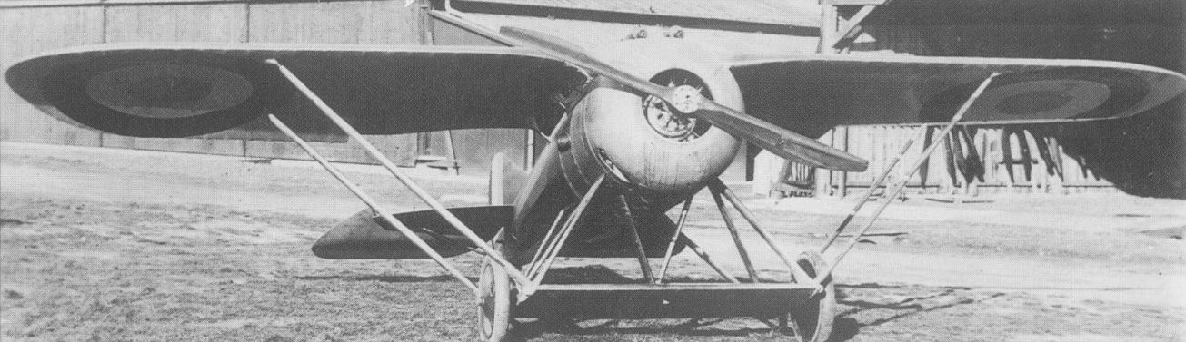
The Nieuport monoplane of 1917 in its second form.
This is thought to be the Nieuport Monoplane as it first appeared. There are no cut-outs visible where the wing joins the fuselage.
This is thought to be the Nieuport Monoplane as it first appeared. There are no cut-outs visible where the wing joins the fuselage.
NIEUPORT 29 France
Flown for the first time early in June 1918, the Nie 29 combined several features previously tested by Gustave Delage on earlier prototype fighters. A nominally staggered two-bay equi-span biplane powered by a 300 hp Hispano-Suiza 8Fb eight-cylinder water-cooled engine and carrying an armament of two 7,7-mm Vickers guns, the Nie 29 featured a wooden monocoque fuselage (thin tulip wood strips glued in spirals in alternating directions) and fabric-covered wings. An initial series order on behalf of the Aviation Militate was placed in 1920, the first being delivered on 11 February 1921. A variant referred to as the ‘‘Nie 29 Type 22 m2” with wing area reduced by 53.82 sqft (5,00 m2) was displayed at the Salon de l'Aeronautique in December 1922, but did not attract a production contract. Another variant, with a Gnome 9N rotary engine, was identified as the Nieuport 29G. With the death of Louis Nieuport, the Etablissements Nieuport amalgamated with the Astra concern in 1921 to become Nieuport-Astra, and subsequent to the commencement of production deliveries of the Nie 29, Nieuport aircraft were restyled Nieuport-Delage, the new fighter thus becoming the Ni-D 29. The Aviation Militaire strength peaked at 25 escadrilles equipped with this type in 1925. In excess of 250 were built by Nieuport-Astra, Schreck, Levasseur, Potez, Bleriot, Letord, Farman and Buscaylet, the excellent manoeuvrability and sturdiness of the Ni-D 29 attracting considerable foreign attention. Several were exported to Argentina, 21 were supplied to Belgium (where 87 more were built by SABCA), six were delivered as pattern aircraft to Italy (where 80 were built by Caproni and 95 by Macchi) and one as a pattern aircraft to Japan. In this last-mentioned country, no fewer than 608 were built by Nakajima with the designation Ko-4 for the Imperial Army between 1923 and 1932, these remaining in service until 1933, and seeing extensive use during the Manchurian and Shanghai conflicts. Twenty were sold to Spain (where 10 more were licence-built) and nine went to Sweden.
Max speed, 147 mph (236 km/h) at sea level.
Time to 16,405 ft (5 000 m), 14 min.
Endurance, 2.5 hrs.
Empty weight, 1,874 lb (850 kg).
Loaded weight, 2,623 lb (1190 kg).
Span, 31ft 2 in (9,50 m).
Length, 21ft 1 1/2 in (6,44 m).
Height, 8 ft 8 3/4 in (2,66 m).
Wing area, 290.63 sqft (27,00 m2).

An Ni-D 29 of the Escadrille Lafayette, part of the 35 Regiment d'Aviation Mixte.
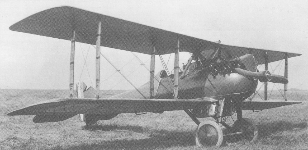
The Nie (later Ni-D) 29 was built in substantial numbers in five countries.
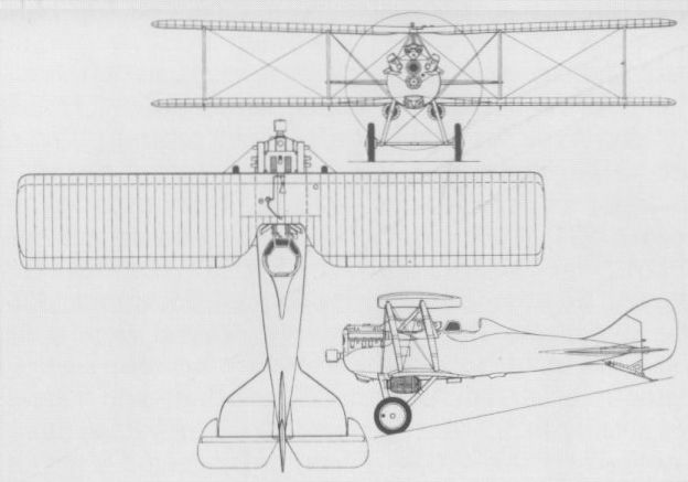
NIEUPORT 31 France
Developed in 1918 to a slightly later timescale than the Nie 29, the Nie 31 was a refined derivative of the earlier monoplane prototypes from which, configurationally, it differed primarily in having an enlarged spanwise auxiliary aerofoil surface. Technically a sesquiplane, but effectively a shoulder-wing monoplane, the Nie 31 (also referred to as the Nie 31 Rh indicating the engine type) was powered by a 180 hp Le Rhone 9R nine-cylinder rotary and was tested during the course of 1919. The wing, which was of exceptionally broad chord, incorporated substantial cut-outs at the trailing-edge roots to provide the pilot with a measure of downward view. The auxiliary surface braced beneath the fuselage provided attachment points for the inclined aerofoil-section wing bracing struts. It also enclosed the undercarriage axle and the upper portions of the wheels. The wooden monocoque fuselage was essentially similar to that of the Nie 29, and the intended armament consisted of two 7,7-mm Vickers guns. Development was abandoned despite excellent performance achieved on comparatively low power, possibly as a result of the rotary engine being by consensus passe by this time.
Max speed, 143 mph (230 km/h).
Endurance, 2.0 hrs.
Empty weight, 1,102 lb (500 kg).
Loaded weight, 1,720 lb (780 kg).
Span, 28 ft 2 1/2 in (8,60 m).
Length, 21 ft 7 4/5 in (6,60 m).
Height, 7 ft 10 1/2 in (2,40 m).
Wing area, 193.76 sq ft (18,00 m2).

PONNIER M.1 France
In 1915, Avions Ponnier produced the M.l single-seat fighter, allegedly to the designs of Emile Eugene Dupont, who was subsequently to be responsible for the Hanriot HD-1. An unequal span single-bay nominally staggered biplane of wooden construction with fabric skinning and powered by an 80 hp Le Rhone 9C rotary engine, the M.1 had a single 7,7-mm Lewis gun on an overwing mounting. Featuring an inordinately large propeller spinner and extremely small tail surfaces, an early example of the M.1 (possibly the prototype) crashed on 29 January 1916 while being evaluated at Avord by Charles Nungesser. Nonetheless, production was undertaken by La Societe Anonyme Francaise de Constructions Aeronautiques, which, early in 1916, succeeded Avions Ponnier, but was still controlled by Louis Alfred Ponnier. Most M.1s were procured by the Aviation Militaire Beige, which apparently received at least 18, and one or two went to French units. Some Belgian M.1s were flown without the spinner and they were later fitted with fixed fins of low aspect ratio, and enlarged tailplanes and elevators. According to the Belgian ace Willy Coppens, the M.1 was found to be unusable and soon disappeared. It never equipped a French unit and was declared obsolete in November 1916. A similar, but slightly larger, Ponnier two-seater was designed as the M.2 and offered to the RFC in January 1916. There is no evidence that it was built, however.
Max speed, 104 mph (167 km/h) at sea level.
Time to 3,280 ft (1000 m), 4.67 min.
Empty weight, 671 lb (304 kg).
Loaded weight, 1,023 lb (464 kg).
Span, 20 ft 3 1/3 in (6,18 m).
Length, 18 ft 10 1/5 in (5,75 m).
Height, 7 ft 6 1/2 in (2,30 m).
Wing area, 145.3 sqft (13,50 m2).
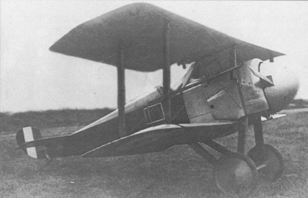
The Ponnier M.1 is illustrated here in its initial production form without fixed tail fin.
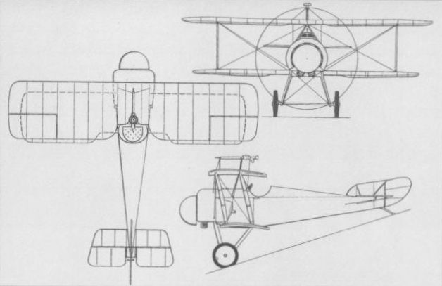
The definitive M.1 with fixed fin and enlarged tailplane and elevators.
S.E.A.4 France
The Societe d'Etudes Aeronautiques (S.E.A.) was formed in 1916 by Henry Potez and Marcel Bloch. Together with Louis Coroller, they designed in 1917 a two- seat fighter-reconnaissance aircraft, the S.E.A.4, which was powered by the new 370 hp Lorraine-Dietrich 12Da 12-cylinder water-cooled engine. An equi-span two-bay biplane, the prototype flew in April 1918, and underwent official testing at Villacoublay on the 28th of that month. As a result of this and subsequent operational evaluation at Le Plessis-Belleville and Perthe, 1,000 examples of the S.E.A.4 C2 were ordered. Potez, Bloch and an industrialist, Bessonneau, established the Societe Anjou Aeronautique to fulfil part of this order, the remainder being contracted to SFCA (Societe Anonyme Francaise de Constructions Aeronautiques), the Ateliers d’Aviation L Janoir and SAIB (Societe Anonyme d'Applications Industrielles du Bois). The first series S.E.A.4 C2 was completed on Armistice Day, 11 November 1918, Anjou Aeronautique finishing 30 before going into liquidation. A new company was then set up at Aubervilliers, Aeroplanes Henry Potez, with the initial task of completing unfinished S.E.A.4 C2s, a total of 115 reportedly being finished, and another 25 adapted as passenger transports being built as Potez VIIs.
Max speed, 128 mph (206 km/h) at 6,560 ft (2 000 m).
Time to 6,560 ft (2 000m), 6.3 min.
Endurance, 2.25 hrs.
Empty weight, 2,210 lb (1002 kg).
Loaded weight, 3,401 lb (1543 kg).
Span, 39 ft 4 1/2 in (12,00 m).
Length, 27 ft 10 1/2 in (8,50 m).
Height, 10 ft 2 in (3,10 m).
Wing area, 403.66 sq ft (37,50 m2).
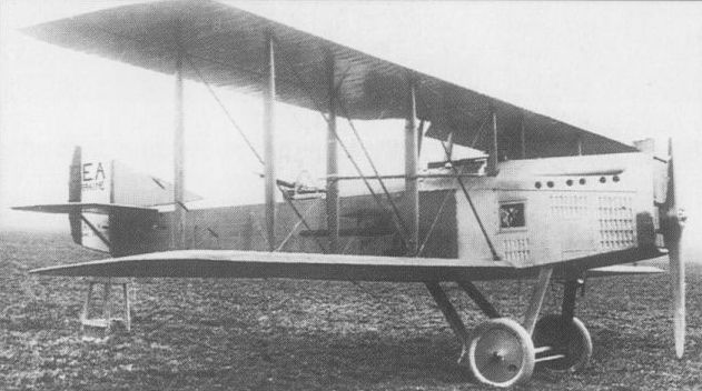
Orders were placed for 1,000 S.E.A.4s, but the Armistice cut production to only 145.
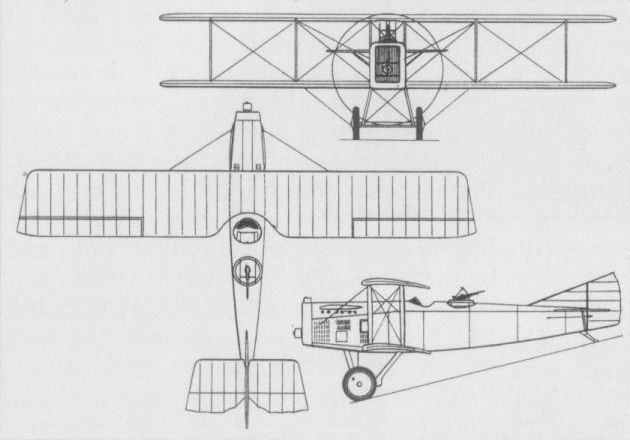
The S.E.A.4 C2 two-seat recce-fighter.
R.E.P. C1 France
Confined through most of World War I to manufacture of aircraft under licence (eg, Voisin biplanes, Sopwith 1 1/2-Strutters, Caproni trimotors), the R.E.P. (Robert Esnault-Pelterie) concern completed a single-seat fighter of original design early in 1918. This, the R.E.P. C1, was a rather angular single-bay biplane of steel-tube construction with fabric skinning. Powered by a 250 hp Salmson (Canton-Unne) CU9Za engine, it placed emphasis on upward and forward view for the pilot, having an abbreviated cabane with the centre section cut away above the cockpit. Armament consisted of two asymmetrically-mounted, synchronised Vickers guns in the fuselage. Performance tests were flown at Villacoublay on 27 March and 11 April 1918, and, although the recorded figures were good for the power available, the design did not find favour.
Max speed, 135 mph (217 km/h) at 3,280 ft (1000 m), 122 mph (196 km/h) at 16,405 ft (5 000 m).
Time to 9,840 ft (3 000 m), 8.52 min.
Endurance, 1.5 hrs.
Empty weight, 1,451 lb (658 kg).
Loaded weight, 2,134 lb (968 kg).
Span, 27 ft 6 in (8,38 m).
Length, 20 ft 10 in (6,35 m).
Height, 8 ft 3 1/2 in (2,53 m).
Wing area, 220.34 sq ft (20,47 m2).
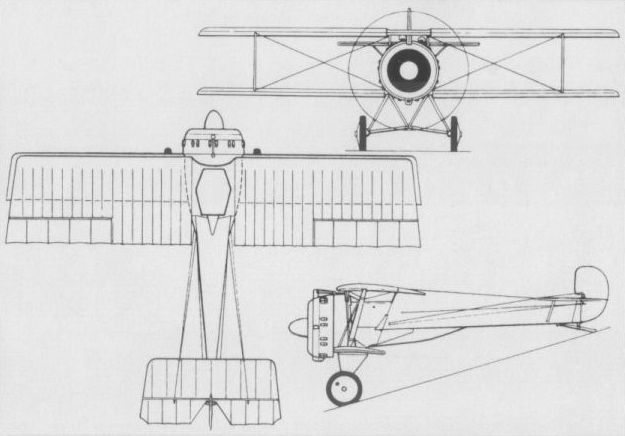
SALMSON 3 France
In the autumn of 1917, Society des Moteurs Salmson designed a single-seat fighter powered by the unusual Salmson 9Z nine-cylinder water-cooled radial engine successfully employed for the Sal 2 A2 two-seat reconnaissance aircraft. This, the Sal 3, was undergoing testing, according to an official report, on 1 December 1917, which commented ‘‘Visibility bad in all directions and fatiguing to fly.” A two-bay equi-span biplane, the Sal 3 fighter was at Villacoublay in January 1918 with a 230 hp Salmson 9Za engine "having its radiator fitted”, suggesting that modifications had been made to the design. Despite the initially unfavourable official opinion of this type, the makers persevered, and although the Sal 3 was not accepted for series production, it was listed in an October 1918 data chart of ‘ ‘New experimental aeroplanes", this indicating that the Sal 3 then had a 260 hp Salmson 9Zm engine. Armament comprised two 7,7-mm Vickers guns. No subsequent development was undertaken. The following data relate to the fighter with the higher-powered engine.
Max speed, 134 mph (215 km/h) at 6,560 ft (2 000 m).
Time to 6,560 ft (2 000 m), 5.73 min.
Empty weight, 1,537 lb (697 kg).
Loaded weight, 2,264 lb (1027 kg).
Span, 32 ft 3 4/5 in (9,85m).
Length, 21 ft 0 in (6,40 m).
Height, 8 ft 1 2/3 in (2,48 m).
Wing area, 257.69 sqft (23,94 m2).
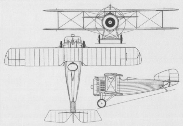
SPAD SA.1 France
The acronym SPAD originally signified the Societe Provisoire des Aeroplanes Deperdussin. In 1913, following Armand Deperdussin's involvement in a major financial scandal, the company went into liquidation. Its assets, including the services of its chief designer, Louis Bechereau, were acquired in August 1914 by a syndicate headed by aviation pioneer Louis Bleriot. This retained the SPAD acronym which now stood for Societe Pour Aviation et ses Derives. The first fighter designed by Bechereau for the new SPAD organisation, the SA.1 was of somewhat bizarre concept, attempting to offer effective forward-firing armament while retaining a tractor engine arrangement. Powered by an 80 hp Le Rhone rotary engine and first flown on 21 May 1915, the SA.1 was of so-called "pulpit” type in that the observer/gunner occupied a small plywood nacelle ahead of the propeller. A two-seat unstaggered equi-span single-bay biplane, with auxiliary intermediate struts stiffening the points of intersection of the flying and landing cables and giving the superficial impression of a two-bay arrangement, the SA.1 was of fabric-covered wood and wire construction. The armament consisted of a single 7,7-mm Lewis gun with limited traverse and elevation mounted in the forward nacelle, which was supported by two V-struts pivoted to the undercarriage struts and secured to the propeller hub by an extension of the propeller shaft revolving in a ball-race attached to the rear of the nacelle. The entire nacelle had to be swung downwards to provide access to the engine. Very limited production (possibly fewer than a half-dozen) of the SA.1 was undertaken for the Aviation Militaire before, by November 1915, it gave place to the SA.2. Neither SA.1 nor its successor proved popular with the aircrews, the observer/gunner inevitably being crushed by the engine in the event of the aircraft nosing over.
Max speed, 84 mph (135 km/h) at sea level.
Endurance, 2.75 hrs.
Empty weight, 928 lb (421 kg).
Loaded weight, 1,562 lb (708 kg).
Span, 31ft 4 in (9,55 m).
Length, 23 ft 11 in (7,29 m).
Height, 8 ft 6 1/2 in (2,60 m).
Wing area, 273 sq ft (25,36 m2).
SPAD SA.2 France
Evolved from the SA.1, from which it differed essentially in having a 110 hp Le Rhone 9J engine, modified nacelle attachments and gun mount, and a revised horizontal tail with parallel leading and trailing edges, the SA.2 was introduced in November 1915. The 7,7-mm Lewis gun was provided with an unusual mounting, being suspended between two curved vertical steel tubes hinged at their top to a vertical pylon and rotating at their base through some 180 deg, thus providing both elevation and traverse. SPAD apparently received contracts for 100 SA.2 two-seat fighters, of which 57 were supplied to the Russian Imperial Air Service and at least one was completed as an SA.3. The remainder were supplied to the Aviation Militaire, but these saw relatively limited use at the Front, where, on 1 February 1916, only four SA.2s were with operational units, a further five being recorded with (presumably) training elements.
Max speed, 87 mph (140 km/h) at sea level.
Time to 3,280 ft (1 000 m), 6.5 min.
Endurance, 3.0 hrs.
Empty weight, 913 lb (414 kg).
Loaded weight, 1,485 lb (674 kg).
Dimensions as for SA.1 apart from a length of 25 ft 9 in (7,85 m).
SPAD SA.3 France
While based fundamentally on the SA.2 two-seat fighter, the SA.3 was of highly innovatory concept in that it featured fore- and aft-mounted 7,7-mm Lewis guns and it was intended that either occupant could control the aircraft while the other operated his gun. No record has apparently survived of the geometry of the dual control arrangement, which must have been exceptionally complex, but the difficulty of adequate communication between the two widely-spaced cockpits - with the 110 hp Le Rhone 9J rotary engine and its propeller between - must have proved insurmountable. The SA.3 may have inspired the SPAD Type C, a "pulpit” type three-seater (presumably for a pilot plus front and rear gunners), although it is doubtful that this type was built. It may be presumed that data for the SA.3 were generally similar to those for the SA.2.
SPAD SA.4 France
Despite the patent obsolescence of concept of the basic Type A design, it was surprisingly taken a stage further as late as February 1916 when the SA.4 made its debut. This reverted to the 80 hp Le Rhone 9C rotary - possibly owing to cooling problems with the 110 hp 9 J - and was apparently intended solely for the Russian Imperial Air Service, which had received more than half of the total production of the SA.2. In the event, only 10 SA.4s were built by SPAD for Russia, the first example flying on 22 February 1916. One example was supplied to the Aviation Militaire. Armament was similar to that of the SA.2 and at least some of the Russian SA.4s had a revised upper wing in which outboard panels were attached to a centre section (earlier models had had two wing panels meeting on the centreline). The SA.4 had ailerons on the upper wing only, the chord of this wing being increased over that of the lower.
Max speed, 96 mph (154 km/h) at sea level.
Time to 3,280 ft (1000 m), 5.0 min, to 9,840 ft (3000 m), 23.5 min.
Endurance, 2.5 hrs.
Span, 31 ft 4 in (9,55 m).
Length, 25 ft 9 in (7,85 m).
Height, 8 ft 6 1/2 in (2,60 m).

The SA.2 saw service with both the Aviation Militaire and the Russian Imperial air arm.
SPAD S.VII France
Evolved by Louis Bechereau virtually in parallel with the unorthodox Type G (SG.1) was the relatively conventional Type H which retained the characteristic interplane bracing of preceding SPAD fighters and was of similar construction. Powered by the new 150 hp water-cooled Hispano-Suiza 8Aa eight-cylinder Vee-type engine, the prototype, referred to contemporaneously as the SH.1, was flown in April 1916. Trials indicated that the SH.1 offered a pronounced advance on existing fighter equipment and SPAD received a contract on 10 May for 268 aircraft under the official designation Spa.VII C1 (monoplace de chasse). The derivation of this designation is obscure, but SPAD's series of letter designations in alphabetical sequence appears to have been discarded in favour of a system more or less conforming with the designation assigned by the SFA (Service des Fabrications de l'Aviation). Consequently, the production version of the Type H was given the company designation S.VII. A sturdy aircraft possessing great structural strength and fine handling qualities, the S.VII closely resembled the SH.1. It retained the circular frontal radiator, but dispensed with the large spinner with frontal opening, and wing area was increased by 19.90 sq ft (1,85 m2). Armament comprised a single 7,7-mm Vickers gun with Birkigt synchronisation mechanism. Initial delivery tempo was slow; by 25 February 1917, only 268 S.VIIs had been delivered to the Aviation Militaire plus 39 to the Royal Flying Corps. The S.VII was initially referred to as the mitrailleuse volante of Georges Guynemer (France’s leading ace), but by December 1916, he had told Bechereau that "the 150 hp SPAD is no match for the Halberstadt ... it [the Halberstadt] climbs better and, consequently, has an overall advantage". One consequence was the introduction of the 180 hp HS 8Ab engine in S.VIIs from the spring of 1917. Apart from production by the parent company, the S.VII was to be built in France by the Societe SPAD et Janoir, Bleriot Aeronautique, Kellner, Regy, Gremont, S.E.A. and De Marcay, some 5,500 being produced. In addition, 120 were built in the UK by Mann Egerton and 100 by L Bleriot (Aeronautics) for the RFC, and in Russia slightly more than 100 had been built by Dux when lack of engines terminated production. Most French escadrilles de chasse flew the S.VII at one time or another, and, in addition to its use in the UK and Russia, it was operated by Belgium, Italy and the USA. After World War I, S.VIIs served with Brazil, Czechoslovakia, Estonia, Finland, Greece, Peru, Poland, Portugal, Romania, Siam and Yugoslavia. The following data relate to the 180 hp S.VII.
Max speed, 132 mph (212 km/h) at 6,560 ft (2 000 m).
Time to 6,560 ft (2 000 m), 4.67 min.
Endurance, 1.5 hrs.
Empty weight, 1,102 lb (500 kg).
Loaded weight, 1,552 lb (704 kg).
Span, 25 ft 8 in (7,82 m).
Length, 19 ft 11 3/8 in (6,08 m).
Height, 7 ft 2 5/8 in (2,20 m).
Wing area, 192.14 sqft (17,85 m2).
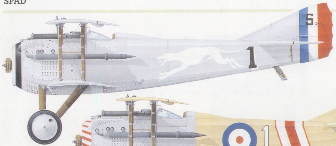
An S.VII of the French Escadrille SPA 81

An S.VII of No 23 Sqn of the RFC at La Lovie in France, July 1917.
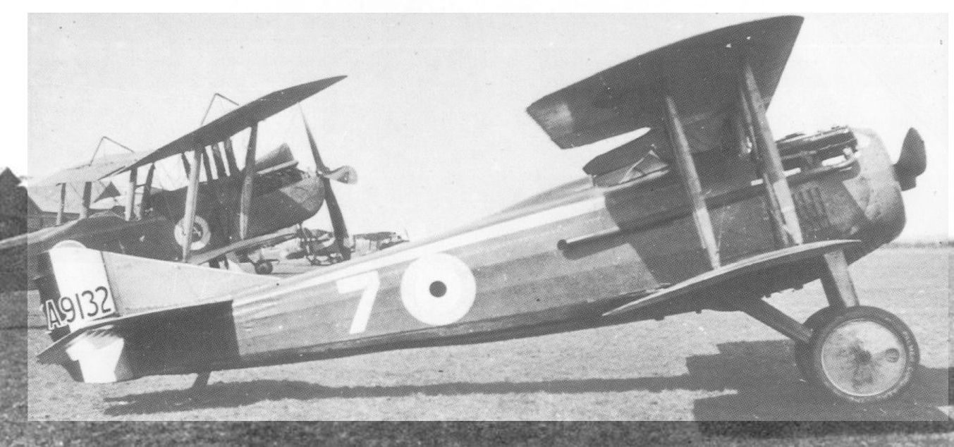
The S.VII illustrated by the photo being a Mann Egerton-built example.
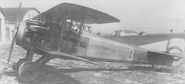
A Czechoslovak Army S.VII photographed at Cheb in Western Bohemia during 1920-21.

SPAD S.VII
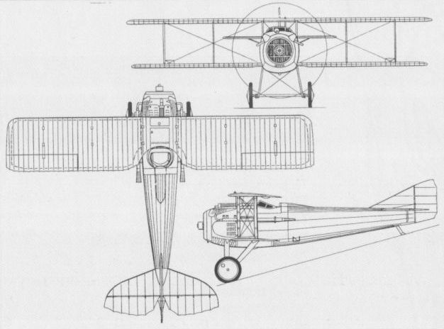
The S.VII
SPAD S.XI France
The basic SPAD S.XI was intended by Louis Bechereau as a two-seat fighter. When the prototype appeared in September 1916, it was clearly descended from the S.VII, but it had conventional two-bay interplane bracing for its longer wings, which were staggered and featured sweepback. Powered by a 220 hp Hispano-Suiza 8Bc eight-cylinder water-cooled Vee-type engine, the S.XI was found to possess extremely sensitive handling qualities and was deemed unsuited for the fighter role. It was adopted as a Corps d'Armee reconnaissance aircraft, however, entering production as the S.XI A2. It proved a dismal failure in service, largely for reasons unassociated with the basic design, yet 1,000 examples were produced. In an attempt to create a two-seat night fighter, one of these was experimentally fitted with a frontal searchlight as the S.XI Cn2. The mounting of the searchlight ahead of the propeller clearly drew on SPAD’s earlier experience in mounting the forward nacelle of the Type A series. It may be assumed that the S.XI Cn2 proved unsuccessful under test as only one example was completed. The following data are for the S.XI A2, but those for the Cn2 version can be assumed to have been similar.
Max speed, 112 mph (180 km/h).
Time to 9,845 ft (3 000 m), 12.6 min.
Endurance, 2.25 hrs.
Empty weight, 1,497 lb (679 kg).
Loaded weight, 2,282 lb (1035 kg).
Span, 36 ft 9 1/3 in (11,21 m).
Length, 25 ft 8 2/3 in (7,84 m).
Height, 9 ft 2 1/4 in (2,80 m).
Wing area, 322.93 sq ft (30,00 m2).

The sole two-seat night fighter version of the S.XI with a searchlight in front of the propeller.
SPAD S.XII France
Late in 1916, France's leading fighter ace, Georges Guynemer, asked Louis Bechereau to design for him a fighter capable of mounting a 37-mm shell-firing gun. Bechereau developed from the S.VII a generally similar aircraft powered by a 200 hp Hispano-Suiza 8C engine and incorporating a 37-mm Puteaux cannon firing through a hollow propeller shaft, an arrangement made possible by the engine’s spur reduction gear. A supplementary 7,7-mm Vickers gun was fitted, and the main-planes, unlike those of the S.VII, had modest stagger. The SFA designation of the aircraft was Spa.XII Cal. Series aircraft were powered by the 220 hp Hispano-Suiza 8Cb engine, and, although 300 of the cannon-armed S.XII fighters were ordered, their operational use proved to be very limited. They could be flown with any hope of success only by pilots of considerable skill and experience. The cannon was a single-shot weapon, fumes filled the cockpit when it was fired and reloading in combat was tricky. Owing to the bulk of the gun, the S.XII used (at Guynemer’s suggestion) Deperdussin-type flying controls (ie, a wheel on a rocking arch). No escadrille was ever completely equipped with this fighter, which was allotted in small numbers and only to selected pilots. Guynemer made his first operational sortie on the S.XII on 5 July 1917, and 15 months later, on 1 October 1918, there were only eight S.XIIs with operational escadrilles.
Max speed, 126 mph (203 km/h) at 6,560 ft (2 000 m).
Time to 6,560 ft (2 000 m), 6.05 min.
Endurance, 1.75 hrs.
Empty weight, 1,295 lb (587 kg).
Loaded weight, 1,947 lb (883 kg).
Span, 26 ft 3 in (8,00 m).
Length, 21 ft 0 in (6,40 m).
Height, 8 ft 4 1/2 in (2,55 m).
Wing area, 217.44 sqft (20,20 m2).
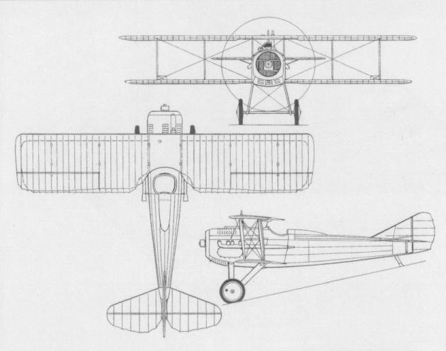
The S.XII which mounted a 37-mm cannon.
SPAD SG.1 France
Louis Bechereau’s first attempt to produce a single-seat fighter was apparently the Type G which had the gunner's nacelle ahead of the propeller of the SA series replaced by a similarly-shaped nacelle containing remotely-controlled armament. A concept prototype was provided by modifying the original SA.1 prototype with a revised forward nacelle from which four dummy machine gun barrels protruded. It is not known whether this aircraft was ever fully armed and flown - if so it would have a strong claim to having been the world's first multi-gun fighter with fixed weapons. The SG.1 - a designation which has still to be authenticated - was a single-seat fighter presumably based on the modified SA.1 prototype, but with a single fixed heavy machine gun in the forward nacelle and which, according to French sources, emerged in April 1916 with a 110 hp Le Rhone rotary engine. What must have been the SG.1 was mentioned in a Royal Flying Corps report on French aircraft of April 1916, which stated that the fighter was armed with a "heavy Hotchkiss mitrailleuse d'infanterie with a belt of 1,000 rounds carried in a streamlined basket in front of the propeller". The following data were provided by the report, the wing area quoted suggesting that the SG.1 was somewhat smaller than the SA types. No photograph of the SG.1 has apparently survived.
Max speed, 100 mph (161 km/h) at 6,560 ft (2 000 m), 96 mph (154 km/h) at 9,840 ft (3 000 m).
Time to 6,560 ft (2 000 m), 7.25 min, to 9,840 ft (3 000 m), 11.5 min.
Wing area, 200 sqft (18,58 m2).
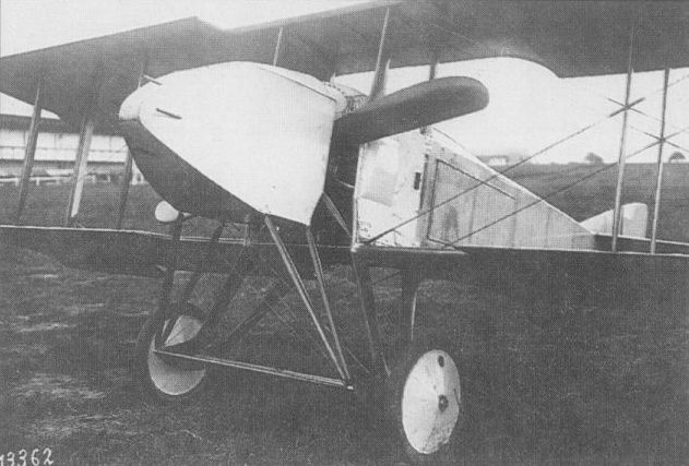
The concept prototype of the SG.1 was apparently Louis Bechereau’s first attempt to produce a single-seat fighter for the SPAD concern.
SPAD SG prototype modified from the prototype SA.1. The nacelle was extensively modified in order to allow a Hotchkiss to be fitted, being considerably shorter than that used on the SA series, and of circular cross section. The guns are mockups.
SPAD SG prototype modified from the prototype SA.1. The nacelle was extensively modified in order to allow a Hotchkiss to be fitted, being considerably shorter than that used on the SA series, and of circular cross section. The guns are mockups.
SPAD S.XIII France
The combat inadequacies of the S.VII led to substantial revision of the basic design to accept the 200 hp Hispano-Suiza 8B engine and paired synchronised 7,7 mm Vickers machine guns. Designated S.XIII (Spa.XIII Cl), the new fighter embodied many features of the S.VII, notably the single-bay interplane bracing with intermediate struts, rod-and-crank aileron actuation and circular radiator cowling. It bore a close family resemblance to the S.XII, but was, in fact, a completely separate and structurally different aircraft. All major dimensions were larger than those of the S.VII, and an initial batch of 20 S.XIIIs was under construction in February 1917. The Aviation Militaire had 372 S.XIIIs on strength by 1 April 1918. Orders placed with the parent company and eight other contractors (ACM de Colombes, Bernard, Bleriot, Borel, Kellner, Levasseur, Nieuport and S.C.A.) were eventually to exceed 8,470 aircraft, but it seems unlikely that more than 7,300 were completed. In service, the S.XIII was handicapped by the several shortcomings of the geared engine, but saw widespread service. As at 1 October 1918, 764 S.XIIIs were with operational units of the Aviation Militaire, and the RFC received 61 Kellner-built examples between November 1917 and April 1918. Others went to Italian, Belgian and US fighter units, and later production aircraft had modified wings with blunt tips and the 220 hp Hispano-Suiza 8Bc, 8Bd or 8Be. The S.XIII remained in French service until 1923. The following data relate to the 220 hp S.XIII.
Max speed, 135 mph (218 km/h) at 6,560 ft (2 000 m).
Time to 6,560 ft (2 000 m), 4.67 min.
Endurance, 1.67 hrs.
Empty weight, 1,326 lb (601 kg).
Loaded weight, 1,888 lb (856 kg).
Span, 27 ft 1 in (8,25 m) and later 26 ft 6 in (8,08 m).
Length, 20 ft 6 in (6,25 m).
Height, 8 ft 6 1/2 in (2,60m).
Wing area, 227.23 sqft (21,11 m2) and later 217.44 sqft (20,20 m2).
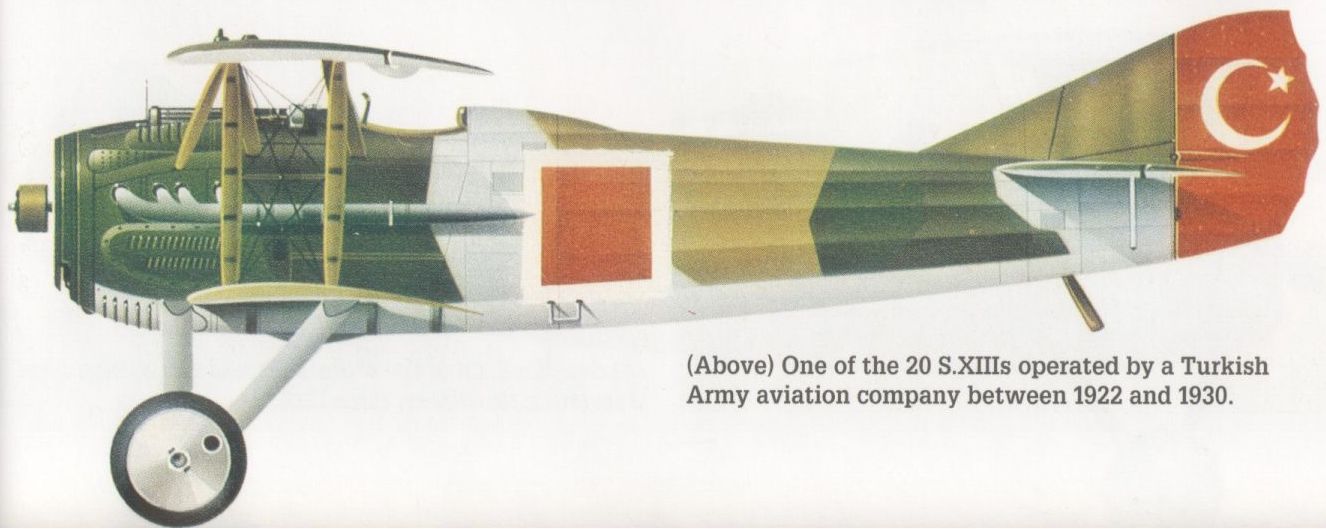
One of the 20 S.XIIIs operated by a Turkish Army aviation company between 1922 and 1930.
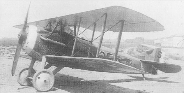
The S.XIII, the photo depicting an aircraft of the 22nd Aero Sqn of US Air Service, 1919.

An S.XIII flown by Capt Eddie Rickenbacker (seen in front of aircraft) of the 94th Aero Sqn.

The S.XIII
SPAD S.XIV France
Based on the fuselage and engine/armament combination of the S.XII, with the 37-mm Puteaux cannon firing through the hollow propeller shaft, the S.XIV was a single-seat twin-float fighter designed by Andre Herbemont, Bechereau’s assistant. Powered by the 220 hp Hispano-Suiza 8Bc engine and armed with a single 7,7-mm Vickers machine gun in addition to the cannon, the S.XIV had long-span wings with true two-bay bracing, and the prototype was flown for the first time on 15 November 1917. SPAD built a further 39 S.XIVs for the Aviation Maritime, their floats being manufactured by Levasseur. The recorded maximum level speed of this fighter was claimed as a record for float-equipped aircraft at that time.
Max speed, 127 mph (205 km/h) at sea level.
Time to 6,560 ft (2 000 m), 7.3 min.
Empty weight, 1,696 lb (770 kg).
Loaded weight, 2,337 lb (1060 kg).
Span, 32 ft 2 in (9,80 m).
Length, 24 ft 3 in (7,40 m).
Height, 13ft 1 1/2 in (4,00m).
Wing area, 282 sqft (26,20 m2).
SPAD S.XXIV France
Last in the line of wartime SPAD single-seat fighters of Bechereau origin, the S.XXIV was developed as a carrier-based fighter for France’s Aviation Maritime. Flown for the first time on 5 November 1918, the S.XXIV was a wheel undercarriage-equipped version of the S.XIV twin-float fighter seaplane that had flown almost a year earlier. The tardiness in developing the S.XXIV apparently resulted in the discontinuation of further development at an early stage in flight testing. Like the S.XIV, the S.XXIV was powered by a 220 hp Hispano-Suiza 8Bc engine and was intended to be fitted with a similar armament. No performance data are available.
Empty weight, 1,433 lb (650 kg).
Span, 32 ft 2 in (9,80 m).
Length, 21 ft 3 1/8 in (6,48 m).
Height, 8 ft 4 4/5 in (2,56 m).
Wing area, 282 sq ft (26,20 m2).

The cannon-armed S.XIV which was built in small numbers for France’s Aviation Maritime.
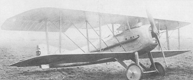
The S.XXIV was the last in the line of Bechereau-designed fighters of World War One.
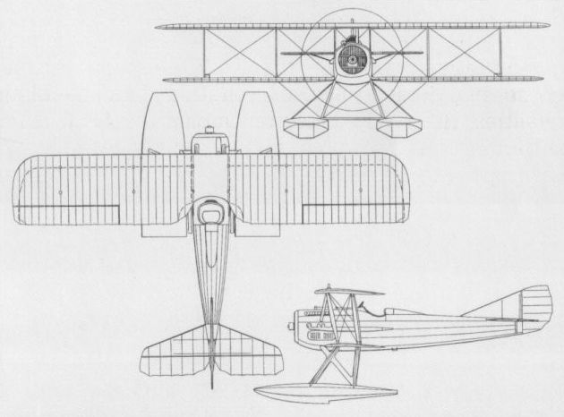
The S.XIV floatplane fighter of 1917.
SPAD S.XV France
After Louis Bechereau left SPAD in the spring of 1917, responsibility for subsequent aircraft design devolved upon Andre Herbemont, and the first fighter entirely of his creation was the S.XV, a small single-seater with twin synchronised 7,7-mm Vickers guns, and, initially, a 160 hp Gnome Monosoupape rotary engine. The S.XV had a clean, wooden monocoque fuselage, single-bay wings and a large spinner-like fairing ahead of the propeller (probably similar to the Nieuport cone de penetration). The S.XV first flew on 31 July 1917, and a second version, the S.XV/2 with extended wings, a redesigned tail and a simplified engine installation, followed in August. Neither was a success and some redesign was undertaken, the S.XV/3 with a lengthened fuselage having reportedly flown in January 1918. A fourth version, the S.XV/4, was to have had a 170 hp Le Rhone engine, but appears to have been abandoned by 1 May 1918, the date of an official listing. Two much-modified examples of the S.XV were built after the end of the War with the 80 hp Le Rhone engine as sporting single-seaters. The following data relate to the S.XV/2.
Max speed, 124 mph (199 km/h) at 6,560 ft (2 000 m).
Time to 6,560 ft (2 000 m), 5.67 min.
Endurance, 2.5 hrs.
Empty weight, 811 lb (368 kg).
Loaded weight, 1,378 lb (625 kg).
Span, 23 ft 3 1/2 in (7,10 m).
Length (S.XV), 17 ft 6 5/8 in (5,35 m).
Height, 7 ft 6 1/2 in (2,30 m).
Wing area, 188.4 sq ft (17,50 m2).
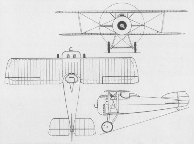
The S.XV/2 with extended wing and new tail.
SPAD S.XVII France
Essentially a strengthened S.XIII airframe with a 300 hp Hispano-Suiza 8Fb engine, the S.XVII had the same overall dimensions as the earlier fighter, but the fuselage was bulkier and fully faired throughout its length, the stringers being set closer together. The wing structure was substantially strengthened, a visible reinforcement being the auxiliary flying wires under the lower wings. Late in 1917, the 300 hp engine had been installed in an S.XIII airframe, presumably as a prototype for the S.XVII, but this had crashed early in its test programme. Subsequent production apparently did not extend beyond the 20 aircraft of what may be assumed to have been an initial development batch. Operational trials with the S.XVII were performed in June 1918, and examples were flown by pilots of Les Cicognes.
Max speed, 135 mph (217 km/h) at 6,560 ft (2 000 m).
Time to 6,560 ft (2000 m), 5.4 min.
Endurance, 1.25 hrs.
Empty weight, 1,411 lb (640 kg).
Loaded weight, 1,984 lb (900 kg).
Span, 26 ft 6 in (8,08 m).
Length, 20 ft 6 in (6,25 m).
Height, 8 ft 6 1/2 in (2,60 m).
Wing area, 215.28 sqft (20,00 m2).
SPAD S.XXI France
Virtually contemporary with and very similar to the S.XVII, the S.XXI single-seat fighter was powered by the 300 hp Hispano-Suiza 8Fb engine and carried an armament of twin 7,7-mm Vickers guns. The fuselage and tail unit of the S.XXI were fundamentally similar to those of the S.XVII, but whereas the latter had ailerons on the upper wing only, the S.XXI had ailerons on both upper and lower surfaces of slightly extended, equi-span wings. Test flying of the S.XXI had been concluded by October 1918, and the type was abandoned for operational purposes in the following month. Two S.XXIs were briefly retained for experimental purposes after World War I terminated.
Max speed, 137 mph (221 km/h) at 6,560 ft (2000 m).
Time to 6,560 ft (2 000 m), 5.67 min.
Endurance, 1.67 hrs.
Span, 27 ft 7 1/4 in (8,44m).
Length, 21 ft 0 in (6,40 m).
Height, 7 ft 11 in (2,42 m).
Wing area, 253 sq ft (23,50 m2).
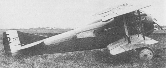
The S.XXI was basically similar to the S.XVII, but had ailerons on both upper and lower wings.
WEYMANN W-1 France
An extraordinarily innovative single-seat fighter completed at Villacoublay by the Societe de St Chamond in the autumn of 1915 to the designs of Charles Terres-Weymann was the W-1, with an extension shaft-driven stern-mounted pusher propeller reminiscent of that used by the 1911 Tatin-Paulhan Torpille. An all-metal, single-bay unstaggered equi-span biplane with ailerons in both upper and lower wings, the W-1 had a slab-sided fuselage occupying the entire wing gap and a cruciform tail with rudders above and below. The pilot was seated immediately ahead of the wings with two fixed machine guns, and an 80 hp Clerget seven-cylinder rotary engine was mounted behind the cockpit at the CG. Entirely enclosed, this engine, which drove a two-bladed propeller aft of the cruciform tail via an extension shaft, drew cooling air from an intake immediately below the pilot’s seat, exhaust gases being ducted to an efflux above and behind. The W-1, which had a tricycle undercarriage and a skid under the ventral fin, offered its pilot excellent visibility from the cockpit. However, engine cooling presented insurmountable problems and testing of the aircraft was abandoned in December 1915 after only two short flights. No data relating to the W-1 appear to have survived other than wing area of 247.58 sq ft (23,00 m2).
An extraordinarily innovative single-seat fighter completed at Villacoublay by the Societe de St Chamond in the autumn of 1915 to the designs of Charles Terres-Weymann was the W-1, with an extension shaft-driven stern-mounted pusher propeller reminiscent of that used by the 1911 Tatin-Paulhan Torpille. An all-metal, single-bay unstaggered equi-span biplane with ailerons in both upper and lower wings, the W-1 had a slab-sided fuselage occupying the entire wing gap and a cruciform tail with rudders above and below. The pilot was seated immediately ahead of the wings with two fixed machine guns, and an 80 hp Clerget seven-cylinder rotary engine was mounted behind the cockpit at the CG. Entirely enclosed, this engine, which drove a two-bladed propeller aft of the cruciform tail via an extension shaft, drew cooling air from an intake immediately below the pilot’s seat, exhaust gases being ducted to an efflux above and behind. The W-1, which had a tricycle undercarriage and a skid under the ventral fin, offered its pilot excellent visibility from the cockpit. However, engine cooling presented insurmountable problems and testing of the aircraft was abandoned in December 1915 after only two short flights. No data relating to the W-1 appear to have survived other than wing area of 247.58 sq ft (23,00 m2).
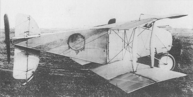
The design of the Weymann W-1, built at Villacoublay in 1915, defied convention.
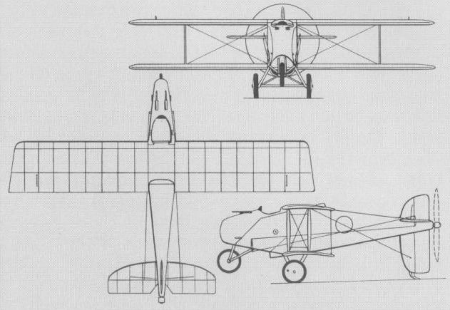
The Weymann W-1 with Clerget engine.
WIBAULT WIB 1 France
Initially known simply as the WIB C1 (Avion monoplace de chasse) and later as the WIB 1 C1, the first design of Michel Wibault was a single-bay slightly staggered biplane built by Niepce et Fetterer at Boulogne-Billancourt. Of all-metal construction with fabric-covered wings and a fuselage covered by detachable light alloy panels forward and fabric aft, the Wibault fighter was powered by a 220 hp Hispano-Suiza 8B eight-cylinder water-cooled engine and armed with twin synchronised 7,7-mm Vickers machine guns. By contemporary standards, the engine installation of the WIB 1 was aerodynamically very clean, with the cowling fairing neatly into a large propeller spinner and shallow radiators mounted on each side beneath the lower wing. Short, broad-chord ailerons were carried by the lower wing only. The prototype was completed at the end of October 1918, and was flown for the first time shortly afterwards at Villacoublay. The combination of modest weight and aerodynamic cleanliness resulted in very good performance despite a relatively low powered engine during its official evaluation on 12 February 1919. The WIB 1 proved slightly faster than the more powerful Nieuport 29 with which it was in competition for an Aviation Militaire contract. In the event, however, the Nieuport was selected for production because of its faster climb and lighter controls, and further work on the Wibault fighter was discontinued.
Max speed, 147 mph (237 km/h) at sea level, 128 mph (206 km/h) at 16,405 ft (5 000 m).
Service ceiling, 22,965 ft (7000 m).
Loaded weight, 1,975 lb (896 kg).
Span, 25 ft 7 in (7,80 m).
Length, 20 ft 8 in (6,30 m).
Height, 7 ft 10 1/2 in (2,40 m).
Wing area, 235.2 sq ft (21,85 m2).
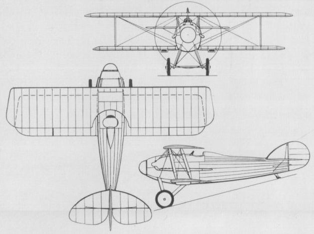
DUFAUX France
In the early spring of 1916, Armand Dufaux completed the prototype of an original two-seat fighter biplane in which a 110 hp Le Rhone 9J air-cooled rotary engine was buried in the forward fuselage to drive a two-bladed propeller amidships, the union between the forward and rear fuselage sections being provided by a substantial tubular member which passed through the propeller hub, this support being augmented by tie rods between the undercarriage V-struts and the tail-skid support. The pilot and gunner sat in side-by-side staggered seats immediately ahead of the engine, the latter (to starboard) having a single 7,7-mm Lewis gun. Built by the Societe pour la Construction et l’Entretien d'Avions (CEA), the Dufaux fighter commenced official tests at Chateaufort in April 1916, but the problems of engine cooling, structural rigidity, etc, apparently militated against further development.
Max speed, 87 mph (140 km/h) at sea level.
Time to 6,560 ft (2 000 m), 13.15 min.
Endurance, 2.0 hrs.
Empty weight, 1,168 lb (530 kg).
Loaded weight, 1,631 lb (740 kg).
Span, 26 ft 1 2/5 in (7,96 m).
Length, 20 ft 0 in (6,10 m).
Height, 9 ft 1 1/4 in (2,80 m).
DUFAUX AVION-CANON France
Armand Dufaux’s avion-canon was one of the most original fighters of World War I in that it was designed around a fixed forward-firing 37-mm Hotchkiss cannon. The aircraft itself was of conventional layout, being a single-bay single-seat biplane with a two-bladed tractor propeller. In order to cater for the centrally-mounted cannon firing through a hollow propeller shaft, two nine-cylinder air-cooled rotary engines were mounted athwartships. The cannon passed between the engines and the hollow propeller shaft was driven by bevel gearing. Built in the workshops of the CEA, Dufaux’s avion-canon was tested in 1917, and allegedly achieved speeds in excess of 124 mph (200 km/h). It was demonstrated before the Minister of Aviation of the day, but further development was not pursued and neither illustrations nor data relating to this extraordinary fighter appear to have survived.
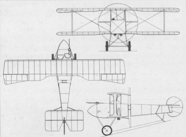
HAFELI DH-4 (M IV) Switzerland
Designed by August Hafeli and owing much to experience gained with the DH-3 (M III) series of two-seat reconnaissance aircraft, the DH-4 (M IV) single-seat fighter was powered by a 150 hp Hispano-Suiza HS-41 eight-cylinder water-cooled engine. The prototype, built by the K + W (Konstruktions-Werkstatte) at Thun, was flown early in 1918. Of wooden construction with fabric covering and carrying an armament of one synchronised machine gun, the DH-4 was found to possess a disappointing performance and poor handling characteristics. Tests by the Swiss Fliegertruppe were initiated in May 1918, but terminated in August, when the sole prototype was returned to the K + W for structural load testing, no further flight trials being undertaken.
Max speed, 92 mph (148 km/h).
Initial climb, 886 ft/min (4,5 m/sec).
Range, 186 mis (300 km).
Empty weight, 1,410 lb (640 kg).
Loaded weight, 1,951 lb (885 kg).
Span, 32 ft 1 4/5 in (9,80 m).
Length, 19 ft 8 1/4 in (6, 00 m).
Height, 8 ft 6 1/3 in (2,60 m).
Wing area, 236.8 sq ft (22, 00 m2).
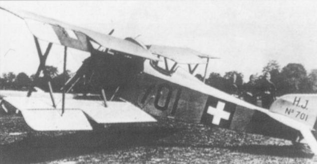
Built for the Schweizerische Fliegertruppe, the DH-4 failed to meet specifications.
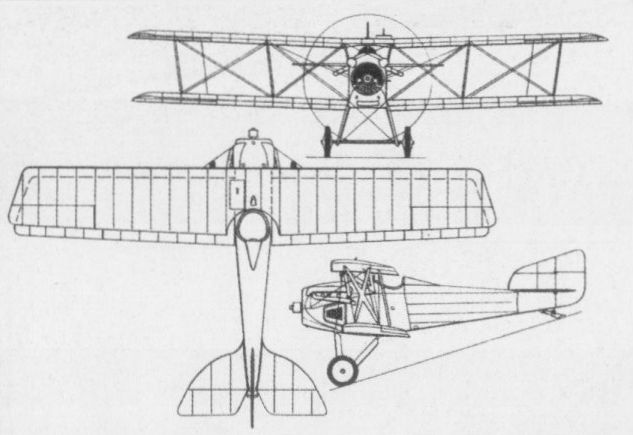
SODERTELGE SW 15 Sweden
Designed by V Forssman and owing much to the Siemens-Schuckert D Ia - the drawings of which had been supplied by the German company to Baron Carl Cederstrom, the first Swedish aviator and manager of the Sodertelge Verkstader - the SW 15 was built in 1917. A single-seat fighting scout powered by a Vabis-built Benz Bz II six-cylinder water-cooled engine rated at 110 hp, the SW 15 was primarily of wooden construction with steel-tube wing spars and fabric skinning. An unequal-span single-bay staggered biplane, the prototype crashed on 17 June 1917, ground looping and killing its pilot, Bertil de Mare. The SW 15 was repaired and fitted with two 8-mm Schwarzlose m/14 machine guns with synchronization gear developed by Capt G von Porat and Ing Kolthoff. As a result of further flight testing, two more SW 15s were built for Flygvasendet, but these enjoyed strictly limited success, one flying 19 times and the other four times, both being finally grounded in December 1921.
Max speed, 78 mph (125 km/h) at sea level.
Span, 27 ft 1 1/4 in (8,26 m).
Length, 19 ft 4 1/4 in (5,90 m).
Height, 8 ft 2 1/3 in (2,50 m).
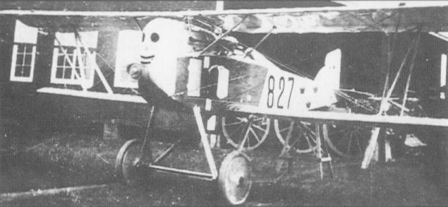
The SW 15 enjoyed strictly limited success and only three examples were built.
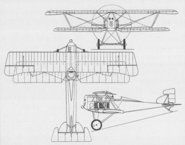
THULIN K Sweden
In 1917, Dr Enoch Thulin of the AETA (AB Enoch Thulins Aeroplanfabrik) produced his first single-seat fighter, the Thulin K. A shoulder-wing monoplane of wooden construction employing the wing warping principle for lateral control, the fighter was powered by a 90 hp Thulin A (licence-built Gnome) rotary engine and was intended to carry a single machine gun. Two Thulin K fighters had been ordered on 19 December 1916 for Flygkompaniet, these being financed by collections made by women in Southern Sweden. The first was delivered in March 1917, the second being delivered later in the year and neither being fitted with armament. Earlier, in January, the Dutch Navy had placed an order for five Thulin Ks, one of which was to be completed as a two-seater. This order was increased to 10 single-seaters and three two-seaters in May 1917, a supplementary order for two more single-seaters being placed in 1919. All the Thulin K fighters were delivered to the Netherlands without armament, but the Dutch Navy fitted them with a synchronised machine gun and several were tested with a 20-mm Madsen cannon.
Max speed, 93 mph (150 km/h) at sea level.
Service ceiling, 18,000 ft (5 485 in).
Loaded weight, 1,146 lb (520 kg).
Span, 29 ft 10 1/4 in (9,10 m).
Length, 21 ft 3 9/10 in (6,50 m).
Height, 8 ft 4 2/5 in (2,55 m).
Wing area, 150.7sq ft (14.00 m2).