
Книги
Putnam
F.Mason
The British Fighter since 1912
176
F.Mason - The British Fighter since 1912 /Putnam/
A.D. Sparrow
Following the creation of the Naval Wing in 1912, the Admiralty established an Air Department whose purpose was to deal with all matters relating to naval aviation. The popular but eccentric Harris Booth, late of the National Physical Laboratory, was given charge of all technical considerations and, in due course, headed an aircraft design section whose products were to be contracted out for manufacture by private companies.
One of Booth’s first designs was the A.D. Sparrow, or Scout, of 1915, an extraordinary-looking pusher biplane intended for anti-Zeppelin fighting, and to be armed with a two-pounder Davis recoilless, quick-firing gun; and it was the installation of this weapon that dictated the design of the nacelle. The A.D. Sparrow was a single-bay, heavily-staggered biplane, powered by an 80hp Gnome rotary engine; the tail booms were rigged parallel in plan and elevation and carried an enormous 21ft-span tailplane and elevator with widely-spaced twin fins and rudders. In order to provide ground clearance for the propeller, the nacelle was attached to the upper wings and, with large wing gap, the lower wing was a continuous structure placed five feet below the nacelle. A twin wheel-and-skid undercarriage of exceptionally narrow track was fitted, stability on the ground being achieved by the tail skids at the base of the tail fins.
Almost certainly owing to the esteem in which Booth was held, four examples of the Sparrow were ordered - two from the Blackburn Aeroplane & Motor Co of Leeds, and two from Hewlett & Blondeau Ltd. It is said that all four were built and delivered to the RNAS at Chingford, Essex, but, being somewhat overweight and underpowered, were found to be difficult to control in the air and were soon abandoned. As far as is known, the Davis gun was never fitted.
Type: Single pusher engine, single-seat, single-bay biplane scout.
Manufacturers: The Blackburn Aeroplane & Motor Co Ltd, Leeds; Hewlett & Blondeau Ltd, Leagrave, Bedfordshire.
Powerplant: One 80hp Gnome rotary engine driving two-blade propeller.
Structure: Predominantly wood with fabric covering; twin wheel-and-skid undercarriage.
Dimensions (Approx only,): Span, 33ft 5in; length, 22ft 9in; height, 10ft 3in.
Weights and Performance: Not known.
Armament: Intended to be armed with one 2-pdr Davis recoilless, quick-firing gun in the nose of the nacelle.
Prototypes: Four, Nos 1452-1453 (Hewletts), and 1536-1537 (Blackburn). No production.
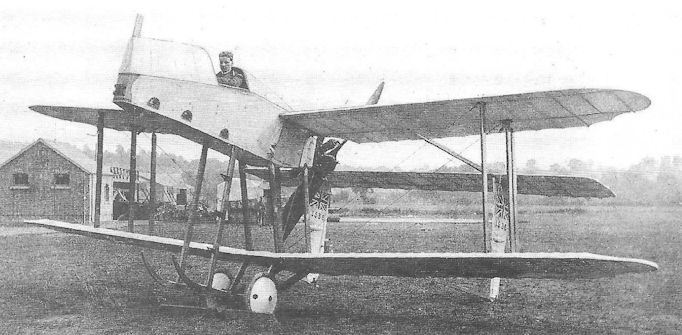
The Sparrow No 1536 at Chingford in 1915.

A.D. Sparrow
Alcock A.I
Flight-Lieut John W Alcock (later to be knighted for his epic first non-stop flight across the Atlantic) was serving with No 2 Wing, RNAS, at Mudros in the Aegean during the summer of 1917 when he built a small biplane scout, variously referred to as the Alcock A.I and ‘Sopwith Mouse’. Many of the design calculations were performed by Cdr Constantine of the Greek Navy at Mudros.
Alcock’s fighter employed numerous components from crashed aircraft, including the fuselage, undercarriage and most of the lower wing from a Sopwith Triplane, and the upper wing of a Pup, into which was inserted a new centre section with cutout. A 100hp Gnome monosoupape engine drove a two-blade propeller, and the two-bay wings were rigged without effective stagger, the interplane struts converging downwards owing to the considerable difference in the two wing chords. It is not known whether the vertical tail surfaces (dorsal and ventral fins, and unbalanced rudder) were newly constructed or salvaged components, but the tailplane and elevator bear a similarity to those of the Pup.
The fuselage was located roughly in the centre of the wing gap, clear of the lower wing, with the new centre section of the upper wing level with the pilot’s horizontal line of sight. Twin synchronized Vickers guns were mounted forward of the cockpit.
Contrary to the account in the official history (The War in the Air, Vol. 5), Alcock did not fly his aircraft, being shot down in a Handley Page O/400 and captured by the Turks on 30 September 1917, before its completion. Nevertheless it was subsequently flown, probably on 15 October by Wing Capt Francis Rowland Scarlett (later Air Vice-Marshal, cb, dso, raf), and was later destroyed when it was struck on the ground by a D.H.4 at Mudros.
Type: Single-engine, single-seat, two-bay biplane fighting scout.
Manufacturer: Flight-Lieut J W Alcock, RNAS, and personnel of No 2 Wing, RNAS, Mudros.
Powerplant: One 100hp Gnome monosoupape engine driving two-blade propeller; later fitted with 110hp Clerget engine.
Armament: Two synchronized 0.303in Vickers machine guns.
The Author is indebted to Mr J M Bruce for permission to reproduce the above material, which represents the result of research among former members of No 2 Wing, RNAS. The official history also incorrectly states that the Alcock A.I was powered by a captured Benz engine.
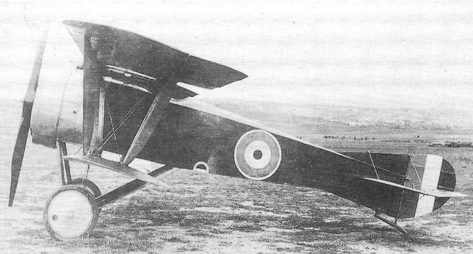
The Alcock A.I, probably after being fitted with the Clerget engine.
Armstrong Whitworth F.K.1
The Aeroplane Department of the heavy engineering enterprise, Sir W G Armstrong, Whitworth & Co Ltd, came into being at the beginning of 1914, its first works manager and aircraft designer being the Dutch-born Frederick Koolhoven. A qualified pilot himself, who had already acquired design experience working on Deperdussin monoplanes, Koolhoven’s first aircraft for Armstrong Whitworth was a small single-bay unstaggered biplane designated the F.K.1.
Of exceptional simplicity in the interests of possible future production orders as a military scout, the F.K.1 was intended to be powered by an 80hp Gnome rotary; however, as this engine was not immediately available, recourse was made to the 50hp version, with the result that the aircraft was substantially underpowered. Although the tail unit included a fixed fin forward of the rudder hinge-post, there was initially no tailplane, a balanced elevator being fitted.
The F.K.1 was first flown by Koolhoven himself in September 1914. He was clearly dissatisfied with the longitudinal and lateral control, and the ailerons were replaced by much enlarged surfaces with inverse taper, and a fixed tailplane was added.
Although no reliable design and performance figures appear to have survived, the aircraft was obviously inferior to such contemporary aircraft as the Sopwith Tabloid and Bristol Scout, and its development was not pursued.
Type: Single-engine, single-seat, single-bay tractor biplane.
Manufacturer: Sir W G Armstrong, Whitworth & Co Ltd, Newcastle-upon-Tyne.
Powerplant: One 50hp Gnome rotary engine driving two-blade propeller.
Structure: Steel and wood composite construction; square-section box-girder fuselage, fabric covered. Twin-wheel, single-skid undercarriage.
Performance: Max speed, 75 mph at sea level; landing speed, 30 mph.
Armament: None.
Prototype: One (first flown by Frederick Koolhoven in September 1914). No production.
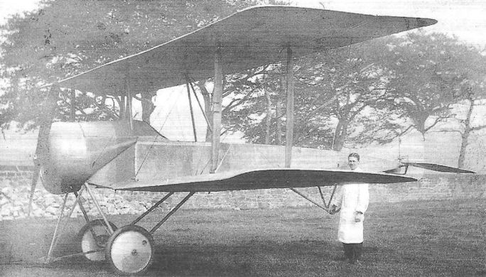
The Armstrong Whitworth F.K.1 in its original form with parallel-chord ailerons and no tailplane.
Armstrong Whitworth F.K.12
If the products of Sopwith and Vickers, in the search for an escort fighter, had appeared quaint, that of Frederick Koolhoven at Armstrong, Whitworth was nothing less than incongruous. Both the L.R.T.Tr and the F.B.11 had employed single nacelles in which to accommodate additional gunners, both selecting the top wing as a logical position from which to gain the widest field of fire. Koolhoven decided on two nacelles, and placed them at the front of the central wing of a large single-bay triplane, powered by a single 250hp Rolls-Royce Mark I.
When the F.K.12 first appeared towards the end of 1916, the central wing - with by far the greater span - was located well forward on the fuselage, so that the engine only just extended beyond the leading edge; the top and bottom wings were much smaller structures, carried on struts above and below the fuselage and rigged without stagger. The gunners’ nacelles were long structures mounted above the central wing, extending forward of the propeller. The undercarriage comprised a pair of main-wheels mounted on a single strut extending from beneath the engine and attached to the leading edge of the lower wing, and a small, sprung auxiliary wheel under each lower wingtip. A rear skid was carried on long pyramidal struts extending downwards from the fuselage immediately to the rear of the lower wing.
The first configuration was not considered successful and was followed by a no less extraordinary aircraft which was probably newly built, rather than an adaptation of the first. This retained the same arrangement of ‘short-long-short’ wings as previously but with a much deeper fuselage occupying the entire gap between the two lower wings. These two-bay wings were set further aft on the fuselage so that the engine extended further forward. The twin gunners’ nacelles, now mounted beneath the central wing, were much shorter so the gunners’s cockpits were behind and outboard of the propeller. (They were incidentally no more than two feet from the open ends of the big Rolls-Royce engine’s exhaust manifolds.)
The undercarriage now comprised two pairs of landing wheels mounted on heavy vertical members attached to the sides of the fuselage and were thus of very narrow track; a conventional tailskid was attached under the rear fuselage, and the wingtip balancing wheels were discarded in favour of hooped skids.The aircraft, No 7838, was flown by Lieut-Cdr Peter Legh, but no reliable records of the flight trials of the aircraft have been traced. A total of four F.K.12 prototypes was ordered by the War Office, but it is thought likely that the two aircraft described here were the only examples completed.
Type: Single-engine, three-seat, two-bay triplane escort fighter.
Manufacturer: Sir W G Armstrong, Whitworth & Co Ltd, Newcastle-upon-Tyne.
Powerplant: One 250hp Rolls-Royce Mk I twelve-cylinder liquid-cooled in-line engine driving four-blade propeller.
Armament: Two 0.303in Lewis machine guns on rocking-post mountings in nacelles carried on central wing.
Prototypes: Four ordered, Nos 7838-7841. It is not known how many were completed.
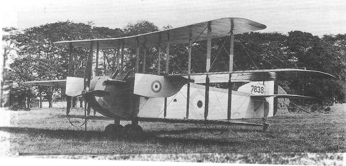
The second version of the Armstrong, Whitworth F.K.12 escort fighter, No 7838, with enlarged fuselage and underslung gunners’ nacelles.
The rebuilt triplane, probably the F.K.6, was designed as an escort fighter and Zeppelin destroyer.
The rebuilt triplane, probably the F.K.6, was designed as an escort fighter and Zeppelin destroyer.
Armstrong Whitworth F.K. 10
Possibly originally undertaken as a design exercise to investigate the potential of the quadruplane configuration, Frederick Koolhoven’s F.K.10 attracted the interest of the Services as a possible fighter. A prototype was built during the late summer of 1916, emerging as a lanky two-seater powered by a 110hp Clerget engine and featuring a slim, angular fuselage in which the pilot’s cockpit was located forward of the wings, and an observer’s cockpit aft of them. The wings, of only 3ft 7in chord, spanned 27ft 10in, and were rigged with a total stagger of 4ft 3in. The tail comprised a rather crude horn-balanced rudder with fixed fin below the fuselage, fixed tailplane and unbalanced elevator. The undercarriage consisted of single faired struts on each side, with the spreader bar heavily cable-braced between its extremities and the lower longerons. Single interplane and cabane I-struts were employed, and the second from top wing possessed no centre section so as to leave the crew’s field of view less obstructed. Ailerons were fitted on all wings. A single synchronized Vickers gun was provided for the pilot and was mounted on the aircraft’s centreline over the engine cowling, the observer’s cockpit being equipped with a mounting for a Lewis gun.
A total of three prototypes is believed to have been built by Armstrong Whitworth, after which the War Office ordered five production aircraft from Angus Sanderson of Newcastle, and the Admiralty ordered three from the Phoenix Dynamo company of Bradford, though it is not known whether all were built. Most were fitted with 130hp Clergets.
The production F.K.10s were rather more elegantly styled than the original prototype, with larger fuselage section and tidied-up tail surfaces. One of the RFC machines was flown by the Training Unit at Gosport, and the first RNAS aircraft, N511, underwent its Service trials at Boroughbridge in April 1917; another of the naval aircraft was completed as a bomber with racks for light bombs.
Type: Single-engine, two-seat, single-bay quadruplane fighter.
Manufacturers: Sir W G Armstrong, Whitworth & Co Ltd, Newcastle-upon-Tyne; The Phoenix Dynamo Manufacturing Co Ltd, Bradford; Angus Sanderson & Co, Newcastle-upon-Tyne.
Powerplant: One 110hp Clerget engine; also 130hp Clerget; 110hp Le Rhone.
Dimensions: Span, 27ft 10in; length, 22ft 3in; height, 11ft 6in; wing area, 390.4 sq ft.
Weights: (130hp Clerget). Tare, 1,236lb; all-up, 2,019lb.
Performance: (130hp Clerget). Max speed, approx 90 mph at sea level; climb to 10,000ft, 37 min 10 sec; service ceiling, 10,000ft; endurance, 2 1/2 hr.
Armament: One synchronized 0.303in Vickers machine gun on nose, and one 0.303in Lewis gun on real' cockpit mounting.
Prototypes: Believed three, A5212-A5214 (built by Armstrong, Whitworth).
Production: Total of eight ordered (B3996-B4000 for RFC, built by Angus Sanderson; N511, N512 and N514 built by Phoenix Dynamo).
Summary of Service: Single examples flown by the RFC at Gosport, and by the RNAS at Mansion, both probably in 1917.
Armstrong Whitworth F.K.10, N511, built by Phoenix Dynamo Manufacturing Co. with 130 h.p. Clerget, horse-shoe cowling, modified coaming about pilot’s cockpit, and Scarff ring-mounting for observer’s gun.
Armstrong, Whitworth F.M.4 Armadillo
Variously described elsewhere as ‘pugnacious’ and ‘far from elegant’, the F.M.4 Armadillo was surely nothing short of ugly, and was possibly the brainchild of Frederick Koolhoven, who had left Armstrong, Whitworth to join the British Aerial Transport company following the failure of his F.K.10 and 12, his place being taken as chief designer by Fred Murphy.
Subject of Licence No 18, two prototypes (X19 and X20) of this small two-bay biplane were authorized, and X19
appeared in September 1918. Rigged with scarcely any stagger, the wings were of fairly broad chord, and the upper wing - without conventional centre section - was attached to the top shoulders of the square-section fuselage. This was in keeping with Koolhoven’s latest preoccupation, that of setting the upper wing level with the pilot’s eyes.
The fuselage was a plain wooden box girder with flat ply sheet covering the sides, but without any attempt to provide any rounded decking. The engine was a 230hp Bentley B.R.2 rotary with a cowling that completely enveloped the cylinders, and included a fairly small aperture for cooling air entry. A most incongruous feature was a humped fairing, curving up from the front of the cowling to the top line of the upper wing, inside which were mounted the aircraft’s twin Vickers guns.
The reasoning behind this wing layout was obviously to provide the pilot with an excellent field of view forward and above, but the bulk of the nose and the lower wings severely restricted the pilot’s view of the ground, especially when landing, despite cutouts in the wings, and the aircraft was severely criticised on this account - not to mention many others.
It is difficult to understand what lay behind the production of this machine so late in the War for, with over one hundred horsepower more that the Le Rhone Camel of the previous year available, the speed performance of the Armadillo showed scarcely any advance. It is not known whether the second example was completed.
Type: Single-engine, single-seat, two-bay biplane fighter.
Manufacturer: Sir W G Armstrong, Whitworth & Co Ltd, Newcastle-upon-Tyne.
Powerplant: One 230hp Bentley B.R.2 rotary engine.
Dimensions: Span, 27ft 9in; length, 18ft 10in; height, 7ft 10in; wing area, 232 sq ft.
Weights: Tare, 1,250lb; all-up, 1,860lb.
Performance: Max speed, 125 mph at sea level; climb to 10,000ft, 6 min 30 sec; ceiling, 24,000ft.
Armament: Two synchronized 0.303in Vickers machine guns under fairing over the nose.
Prototypes: Two; X19 and X20 authorised under Licence No 18. X19 flown in September 1918; X20 may not have been completed. No production.
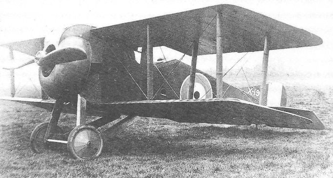
The first Armstrong, Whitworth F.M.4 Armadillo, X19; when it first appeared the undercarriage V-struts were much slimmer: in this photograph they appear to have been strengthened considerably.
Armstrong, Whitworth Ara
Unlike previous Armstrong Whitworth fighter aircraft the Ara, designed by Fred Murphy, was of orthodox configuration, although one or two features were unusual, and these tended to reflect a sense of awkwardness of gait.
Its design began in the summer of 1918 and followed what was to become a familiar path, ending in oblivion. No doubt persuaded that the rotary engine had reached the limit of its power potential, and perhaps disappointed by the modest performance of the Bentley-powered Armadillo, Murphy turned almost inevitably to the ABC Dragonfly, and produced a two-bay biplane of moderate stagger and small ailerons on upper and lower wings. The outboard pairs of interplane struts were located very close to the wingtips.
Reminiscent of the Armadillo’s flat-sided fuselage, the Ara’s box girder was scarcely tapered towards the tail, but was at least provided with a curved top decking; the relative thickness of the rear fuselage in side elevation served to accentuate the small area of the fin and rudder. The upper wing was mounted clear of the fuselage and sufficiently close to be in line with the pilot’s eye level.
Perhaps Murphy’s most noteworthy design feature was the pointed crankcase cowling of the Dragonfly, a highly practical and, it is assumed, efficient attempt to limit the drag of the untidy radial engine; while other Dragonfly-powered aircraft appeared with blunt cowlings, with little or no attempt to improve the shape of the propeller hub, Murphy achieved from the outset a near perfect solution.
The first prototype Ara, F4971, was completed in the spring of 1919, and was followed by a second aircraft on which the wing gap was increased so that not only was the upper wing raised slightly further above the fuselage but the lower wing was positioned about six inches below it.
Victim of the Dragonfly’s frustrating problems, the Ara passed into obscurity towards the end of 1919 following the closure of its manufacturer’s aviation department, despite an outstanding performance. No record of its handling qualities appears to have survived.
Type: Single-engine, single-seat, two-bay experimental biplane fighter.
Manufacturer: Sir W G Armstrong, Whitworth Co Ltd, Newcastle-upon-Tyne.
Powerplant: One 320hp ABC Dragonfly I nine-cylinder radial engine.
Dimensions: Span, 27ft 5in; length, 20ft 3in; height, 7ft 10in; wing area, 257 sq ft. Weights: Tare, 1,320lb; all-up, 1,930lb.
Performance: Max speed, 150 mph at sea level; climb to 10,000ft, 4 min 30 sec; ceiling, 28,000ft; endurance, 3 1/4 hr.
Armament: Two synchronized 0.303in Vickers machine guns mounted within the lower segments of the nose cowling.
Prototypes: Three, F4971-F4973 (first flown in mid-1919). No production.
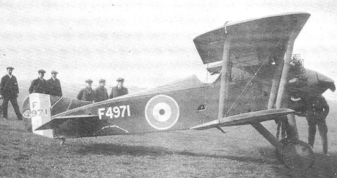
The first Ara prototype, F4971. It is not known when, or even whether this fighter was ever presented for Service evaluation at Martlesham Heath.
Siddeley S.R.2 Siskin
The following two aircraft, the Siddeley Siskin and the Nieuport Nighthawk, were the only aircraft, originally powered by the infamous ABC Dragonfly radial engine, to occupy a significant place in the history of British aviation, even though the original aircraft subsequently underwent a fair degree of alteration by foster parent companies.
The Siddeley-Deasy Motor Car Company of Coventry, apart from undertaking the manufacture of other companies’ designs during the First World War, began to build aircraft of inhouse design during 1917, after Maj F M Green, J Lloyd and S D Heron (formerly of the Royal Aircraft Factory) joined the firm in senior design appointments. After designing a modified version of the R.E.8 (taken from the production line and re-designated the R.T.1, but which was not put into production), Maj Green began detailed work on a design which he had sketched out while still at Farnborough, where he had intended using the 300hp RAF 8 fourteen-cylinder two-row radial engine, then under early development.
However, by the time the new aircraft design had begun to take shape early in 1918, aircraft designers were becoming enamoured with the potential offered by the ABC Dragonfly single-row radial which was claimed to possess an exceptionally good power/weight ratio. Green accordingly adopted this engine and tendered his design to Air Board Specification A.1A (which became RAF Specification Type I in April 1918). Based on the promised power/weight ratio of 0.53 bhp/lb, the aircraft was expected to achieve a top sea level speed of around 160 mph. In the event the Dragonfly never exceeded a figure of more than 0.445 bhp/lb. Nevertheless, Siddeley-Deasy received a contract in May to produce six prototypes, C4541-C4546. Owing to delayed delivery of the first engine cleared for flight, the first Siskin to fly (the third prototype, C4543) was not taken aloft until May 1919, and even then the engine was developing no more than about 270 hp.
The S.R.2 Siskin (named in accordance with TDI 506A and 538) was an attractive aeroplane, displaying much of the S.E.5’s character, though with interesting new features, not least of which was the undercarriage; this comprised single oleo struts for each wheel, each end of the axle being attached to the apices of paired V-struts by radius struts. The engine cowling was also novel, with each cylinder aligned to lie in a fluted channel in the crankcase cowling, this arrangement being intended to ensure the best possible cooling air flow through the cylinder fins. Like the S.E.5 and other Factory aircraft, the Siskin possessed tail fins above and below the rear fuselage. Despite the disappointing engine power, the Siskin returned a maximum speed of 145 mph at 6,500 feet when C4543 visited Martlesham Heath in July 1919.
By March 1920 the first five Siskin prototypes had flown, all with Dragonfly engines, even though it had already been decided to seek an alternative engine. Such an engine was near at hand. This was a development of the RAF 8 fourteen-cylinder engine referred to above. On leaving the Factory to join Siddeley-Deasy, S D Heron had sought and gained permission to continue its design development in his new appointment. Considerable progress was made before differences of opinion arose over cylinder design and Heron left the company to take up a design appointment in America. His departure resulted in a run-down in effort on the new engine, now named the Jaguar, until S M Viale took over the design late in 1919. By mid-1920 the engine was bench running and showing some promise, and an early Jaguar I, rated at 325 hp, was flown in the first Siskin prototype, C4541, on 20 March 1921.
By then a much improved version of the aircraft, the Armstrong Whitworth Siskin III had been ordered in prototype form and a whole new chapter in the Siskin’s life was about to open.
Type: Single-engine, single-seat, single-bay biplane fighter.
Manufacturer: The Siddeley-Deasy Motor Car Co Ltd, Coventry.
Specification: Air Board Specification A.1A (later RAF Type I).
Powerplant: One 320hp ABC Dragonfly I; later 325hp Siddeley Jaguar I.
Structure: Fabric and ply covered wooden box-girder construction.
Dimensions: Span, 27ft 6in; length, 21ft 3in; height, 9ft 9in; wing area, 247 sq ft.
Weights: Tare, 1,463lb; all-up, 2,181lb.
Performance: Max speed, 145 mph at 6,500ft; climb to 10,000ft, 7 min 50 sec; service ceiling, 23,800ft.
Armament: Two synchronized 0.303in Vickers machine guns on upper nose decking.
Prototypes: Six ordered, C4541-C4546 (first flight, May 1919, by C4543). No confirmation can be traced that C4546 was completed.
Austin-Ball A.F.B.1
Captain Albert Ball was still only nineteen years of age in April 1916, while flying B.E.2Cs on reconnaissance flights over the Western Front with No 13 Squadron, RFC. In a letter, written that month to his parents he tells of his idea for an aircraft ‘better than the Fokker’. Several months later, while on leave in England, Ball met representatives of the Austin Motor Company, who in turn approached the Air Board to seek an order to build two examples of Ball’s aircraft. It was, however, Ball himself who secured the order by going straight to Maj-Gen Sefton Brancker, Director of Air Organisation.
It is a quirk of irony that, when Ball expressed his first ideas for his fighter, he had not yet been in combat, yet by the time the Austin-Ball A.F.B.1 was ready for flight in July 1917, the young pilot had been dead for two months - killed on active service on 7 May after gaining a total of 44 air victories and being awarded the Victoria Cross, three DSOs and the MC, all before his 21st birthday.
Ball’s aircraft reflected his particular style of combat, a fast single-seater and an upward-firing gun with which to rake an enemy aircraft from below. It was a portly, single-bay biplane, powered by the 200hp Hispano-Suiza, and armed with one Lewis gun firing through the hollow propeller shaft and another on a Foster mounting on the upper wing. A well-shaped nose cowling was made possible by mounting the engine radiators on the fuselage sides, while the deep fuselage allowed the top wing to be located close to the fuselage - thereby providing the pilot with an excellent field of view over the wing, and at the same time retaining a good wing gap. The only significant criticism levelled at the design concerned the absence of a fixed tail fin, a deficiency that was evidenced by poor lateral control, although the rudder was balanced.
When first tested at Martlesham Heath in July 1917, the un-numbered A.F.B.1 returned the excellent top speed of 138 mph at sea level, and could reach 10,000 feet in under nine minutes. While this performance was at least comparable with that of the the S.E.5A, and superior to the Camel, the forward armament of a hub-firing Lewis gun - though radical by 1916 standards - was not favoured in an era of twin synchronized Vickers. Nevertheless, there was more irony in the fact that Ball never became fully reconciled with the S.E.5 (preferring the nimble Nieuport), yet his aircraft was clearly conceived along similar lines. Moreover there is some circumstantial evidence to suggest that it was in recognition of Austin’s perseverence with the A.F.B.1 that the company was awarded a huge production contract - for over 800 S.E.5As!
Type: Single-engine, single-seat, single-bay biplane fighting scout.
Manufacturer: The Austin Motor Co (1914) Ltd, Birmingham.
Powerplant: One 200hp Hispano-Suiza engine driving four-blade propeller.
Dimensions: Span, 30ft 0in; length, 21ft 6in; height, 9ft 3in; wing area, 290 sq ft.
Weights: Tare, 1,525lb; all-up, 2,077lb.
Performance: Max speed, 138 mph at sea level; climb to 10,000ft, 8 min 55 sec; service ceiling, 22,000ft; endurance, 2 1/4 hr.
Armament: One 0.303in Lewis machine gun firing through hollow propeller shaft, and one Lewis gun on Foster mounting on upper wing centre section.
Prototype: Two A.F.B.1s were ordered, but it is believed that the second was not completed. No production.
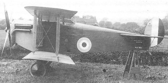
The Austin-Ball A.F.B.1. It has often been incorrectly suggested that the aircraft possessed anhedral on the wings, probably stemming from an optical illusion created by the small sweepback on the parallel-chord surfaces.
Austin A.F.T.3 Osprey
It has been shown that, in 1917, the Austin Motor Company was already making positive efforts to contribute aircraft of its own origination, even though the Austin-Ball A.F.B.1 was not strictly the company’s own design. The issue that year by the War Office of an official Specification, A.1A, for a successor to the Sopwith Camel was an added spur to perseverance.
Before John North left Austin to join Boulton & Paul, he had schemed up the design of a small triplane fighter, much on the lines of the Sopwith Clerget Triplane, but intended for the new Bentley B.R.2 rotary engine. John Kenworthy now left the Royal Aircraft Factory - where he had been engaged in the design of the S.E.5 - to join Austin as chief designer, and took over responsibility for the new triplane, termed the A.F.T.3 (and later named the Osprey).
Despite it being officially notified as a contender to meet an Air Board requirement, Kenworthy discovered that Austin was required to obtain a licence to build prototypes under the new Regulations, and this may conceivably reflect the Air Board’s belief that the triplane configuration would no longer be adequate to meet the new operational requirement. Such prejudice may have been justifiable, having regard to the relatively high performance already being demonstrated by conventional biplanes, but certainly suggests that the Austin aeroplane was compromised from the start.
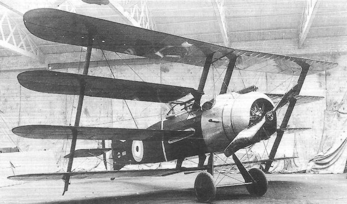
Nevertheless, Licence No 17 was issued for the manufacture of three prototypes, X15-X17. The Osprey was an attractive little aircraft, being flown early in 1918 and submitted for evaluation in March (by which time the Sopwith Snipe had already been adjudged the successful contender under Specification A.1A). Built very much on the lines of the Sopwith Clerget Triplane, with wooden box-girder fuselage, the Austin was a smaller aircraft, although its wing gaps were deeper and the wing chord greater. Considerable thought had been given to simplicity of construction and ease of maintenance, all six ailerons being interchangeable, as were the interplane struts. An interesting undercarriage feature (obviously ‘borrowed’ from Austin cars) was the attachment of a leaf-spring to the centre of the spreader bar, extending outwards to the bottom of the V-struts and attached to the half-axles at its extremities, which were bound with elastic chord.
The rudder was a small angular, balanced surface, but no fixed fin was fitted, and the tailplane was adjustable in flight. The armament comprised twin synchronized Vickers guns on the nose decking and, as originally called for in Specification A.1A, provision had been made to mount a Lewis gun on the steel tubular carry-through members of the centre wing.
After the announcement of the Sopwith Snipe’s success, Austin stopped work on the Osprey, and the other two prototypes remained unbuilt after the withdrawal of the Licence.
Type: Single-engine, single-seat, two-bay triplane fighter.
Manufacturer: The Austin Motor Co (1914) Ltd, Birmingham.
Powerplant: One 230hp Bentley B.R.2 rotary engine driving two-blade propeller. Dimensions: Span, 23ft 0in; length, 17ft 7in; height, 10ft 8in; wing area, 233 sq ft.
Weights: Tare, 1,106lb; all-up, 1,888lb.
Performance: Max speed, 118.5 mph at 10,000ft; climb to 10,000ft, 10 min 20 sec; service ceiling, 19,000ft.
Armament: Two synchronized 0.303in Vickers machine guns on fuselage decking forward of cockpit; provision originally made for one Lewis gun on centre wing carry-through structure.
Prototypes: Three ordered, X15-X17, under Licence No 17; X16 and X17 not completed.
It has been shown that, in 1917, the Austin Motor Company was already making positive efforts to contribute aircraft of its own origination, even though the Austin-Ball A.F.B.1 was not strictly the company’s own design. The issue that year by the War Office of an official Specification, A.1A, for a successor to the Sopwith Camel was an added spur to perseverance.
Before John North left Austin to join Boulton & Paul, he had schemed up the design of a small triplane fighter, much on the lines of the Sopwith Clerget Triplane, but intended for the new Bentley B.R.2 rotary engine. John Kenworthy now left the Royal Aircraft Factory - where he had been engaged in the design of the S.E.5 - to join Austin as chief designer, and took over responsibility for the new triplane, termed the A.F.T.3 (and later named the Osprey).
Despite it being officially notified as a contender to meet an Air Board requirement, Kenworthy discovered that Austin was required to obtain a licence to build prototypes under the new Regulations, and this may conceivably reflect the Air Board’s belief that the triplane configuration would no longer be adequate to meet the new operational requirement. Such prejudice may have been justifiable, having regard to the relatively high performance already being demonstrated by conventional biplanes, but certainly suggests that the Austin aeroplane was compromised from the start.
Nevertheless, Licence No 17 was issued for the manufacture of three prototypes, X15-X17. The Osprey was an attractive little aircraft, being flown early in 1918 and submitted for evaluation in March (by which time the Sopwith Snipe had already been adjudged the successful contender under Specification A.1A). Built very much on the lines of the Sopwith Clerget Triplane, with wooden box-girder fuselage, the Austin was a smaller aircraft, although its wing gaps were deeper and the wing chord greater. Considerable thought had been given to simplicity of construction and ease of maintenance, all six ailerons being interchangeable, as were the interplane struts. An interesting undercarriage feature (obviously ‘borrowed’ from Austin cars) was the attachment of a leaf-spring to the centre of the spreader bar, extending outwards to the bottom of the V-struts and attached to the half-axles at its extremities, which were bound with elastic chord.
The rudder was a small angular, balanced surface, but no fixed fin was fitted, and the tailplane was adjustable in flight. The armament comprised twin synchronized Vickers guns on the nose decking and, as originally called for in Specification A.1A, provision had been made to mount a Lewis gun on the steel tubular carry-through members of the centre wing.
After the announcement of the Sopwith Snipe’s success, Austin stopped work on the Osprey, and the other two prototypes remained unbuilt after the withdrawal of the Licence.
Type: Single-engine, single-seat, two-bay triplane fighter.
Manufacturer: The Austin Motor Co (1914) Ltd, Birmingham.
Powerplant: One 230hp Bentley B.R.2 rotary engine driving two-blade propeller. Dimensions: Span, 23ft 0in; length, 17ft 7in; height, 10ft 8in; wing area, 233 sq ft.
Weights: Tare, 1,106lb; all-up, 1,888lb.
Performance: Max speed, 118.5 mph at 10,000ft; climb to 10,000ft, 10 min 20 sec; service ceiling, 19,000ft.
Armament: Two synchronized 0.303in Vickers machine guns on fuselage decking forward of cockpit; provision originally made for one Lewis gun on centre wing carry-through structure.
Prototypes: Three ordered, X15-X17, under Licence No 17; X16 and X17 not completed.
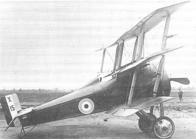
The Austin A.F.T.3 Osprey, X15, probably at the time of its official trials in March 1918.
Austin Greyhound
As the Austin Osprey was undergoing its flight trials in March 1918, the design of Austin’s last wartime military product was submitted to the Air Board on news that a new Specification was about to be issued for a Bristol Fighter replacement. The new design was the handsome Greyhound, a two-seat, two-bay biplane of strictly conventional appearance and construction. Unlike the privately-funded Sopwith Bulldog, the Greyhound was officially sponsored from the start and was therefore among the first aircraft to be allotted the new 320hp ABC Dragonfly I, a nine-cylinder aircooled engine on which many hopes were to be pinned. In due course the new Air Ministry’s Specification Type III was issued and the Greyhound seemed a promising contender for acceptance.
Designed by John Kenworthy, the Greyhound featured a flat-sided and fairly deep fuselage, the pilot and observer/ gunner enjoying an excellent field of view, this being partly afforded by a lower wing of narrow chord. The wings, rigged with moderate stagger, were of unequal span and chord, and carried ailerons top and bottom. The tail comprised fixed ventral and dorsal fins, with the tailskid integral with a triangular segment below the rudder - reminiscent of the S.E.5A. The rudder’s horn balance was faired to provide an unbroken outline with the dorsal fin.
Although quickly completed during the summer of 1918, under a contract signed on 18 May, the first of three prototypes was held up by prolonged engine trials, and it was the second aircraft, H4318, which underwent official evaluation at Martlesham Heath in January 1919. H4317 followed on 15 May that year, and remained with the A & AEE until September 1920. The third aircraft made its maiden flight in February 1920, the same month that H4318 was delivered to the RAE (the Factory at Farnborough having been renamed an Establishment to avoid confusion with the new RAF), but was damaged and written off after a landing accident on 29 August 1921.
Despite an enormous amount of work on it, the Dragonfly engine never truly succeeded in overcoming its fundamental mechanical weaknesses and brought about the abandonment of numerous promising aircraft, among them the attractive Greyhound. It might have proved possible to substitute another engine had such a decision been taken early on, but after the Armistice aircraft production contracts were being severely cut back, and the design staff at Austin was, in any case, quickly shrinking.
Type: Single-engine, two-seat, two-bay biplane fighter.
Manufacturer: The Austin Motor Co (1914) Ltd, Birmingham.
Air Ministry Specification: Type III of 1918.
Powerplant: One 320hp ABC Dragonfly I nine-cylinder air-cooled radial engine driving two-blade propeller.
Structure: All-wooden construction with fabric, ply and aluminium sheet covering.
Dimensions: Span, 39ft 0in; length, 26ft 8 1/2 in; height, 10ft 4in; wing area, 400 sq ft.
Weights: Tare, 1,838lb; all-up, 3,032lb.
Performance: Max speed, 134 mph at sea level, 126 mph at 10,000ft; climb to 10,000ft, 10 min 50 sec; service ceiling, 22,000ft; endurance, 3 hr.
Armament: Two synchronized 0.303in Vickers Mk I machine guns in nose, and one Lewis gun with Scarff ring on rear cockpit.
Prototypes: Three, H4317-H4319; all built, but no subsequent production.
Avro Type 504 Night Fighters
It is of course well known that the Avro 504 was the most widely-used British training aircraft of the First World War, no fewer than 8,340 examples being produced during the War itself (and many others afterwards). Scarcely recalled is the fact that specially converted versions were used as early as 1915 on anti-Zeppelin patrols. On 15 May that year Flt Sub-Lt Mulock, flying an Avro, intercepted LZ38, but was unable to attack it with his two grenades and two incendiary bombs before the enemy airship climbed away from the fighter.
Following such early efforts as these, it was decided to convert the Avro 504 to a single-seater for the anti-Zeppelin role, fitting an extra fuel tank in place of the front cockpit, and arming it with a Lewis gun mounted to fire upwards through a cutout in the upper wing centre section. With an endurance of no less than eight hours, this version was termed the Avro 504C, with a low aspect ratio fin for the RNAS, and the 504D, without fin for the RFC. These aircraft were powered by 80hp Gnome rotaries.
Of much greater significance was the decision, taken early in the winter of 1916-17, to equip Home Defence squadrons with the Avro 504J and K, again modified as single-seaters, but now armed with a Lewis gun on a Foster mounting above the wing; the gravity fuel tank was moved from the centre of the wing to the port side. Power was provided by either a 100hp Gnome monosoupape engine or a 110hp Le Rhone, and these aircraft could reach an altitude of 18,000 feet; they were specifically introduced to replace the RFC’s aging B.E.2Cs, whose ceiling was little more than 12,000 feet. One other motive for this decision was to enable the night fighter pilots, who would soon be flying the tricky Camel at night, to gain experience with a rotary-powered tractor fighter. In the event, no fewer than 226 Avro 504J and K night fighters were still flying with the Home Defence units, including five squadrons, at the time of the Armistice.
The accompanying data table refers to the Avro 504K night fighter of 1918.
Type: Single-engine, single-seat, two-bay biplane night fighter.
Manufacturers: A V Roe & Co Ltd, Manchester and Hamble, Hampshire; The Grahame-White Aviation Co Ltd, Hendon, London; The Humber Motor Co Ltd, Coventry.
Powerplant: One 100hp Gnome monosoupape engine; 100hp Le Rhone; 110hp Clerget. Span, 36ft 0in; length, 29ft 5in; height, 10ft 5in; wing area, 330 sq ft.
Weights: (Mono-Gnome). Tare, 1,100lb; all-up, 1,800lb.
Performance: (Mono-Gnome). Max speed, 94 mph at sea level; climb to 10,000ft, 15 min 30 sec; absolute ceiling, 18,200ft; endurance, 3 1/2 hr.
Armament: One 0.303in Lewis gun with Foster mounting on upper wing centre section. Production: Total of 274 Avro 504Js and Ks issued to Home Defence units during 1918. Summary of Service: Avro 504Js and Ks served with Nos 33, 36, 51, 75, 77, 90, 92 and 155 (Home Defence) Squadrons, RFC and RAF, during 1918, and with Nos 186, 187, 188, 189, 190 and 198 (Night Fighter Training) Squadrons.

A high altitude Home Defence Avro 504K single seater with Lewis gun on the top centre section.
A Humber-built Avro 504K single-seat night fighter of a Home Defence unit, with Lewis gun on Foster mounting.
A Humber-built Avro 504K single-seat night fighter of a Home Defence unit, with Lewis gun on Foster mounting.
Avro Type 508
One of several companies which tried their hand at gun-carrier biplanes in the two years before the War was A V Roe & Co Ltd, a manufacturer that had made long strides since its founder, the pioneering pilot-designer Alliott Verdon Roe, had taken his first faltering steps into the air on 8 June 1908 at Brooklands. By the time the Avro 508 was produced in December 1913 the company had already launched the Type 504 - the most widely used trainer flown in Britain during the First World War.
The Type 508 was a two-seat, three-bay pusher biplane whose square-section nacelle was constructed of ash longerons and spruce struts and was fabric-covered; it accommodated an observer-gunner in the nose and the pilot amidships, forward of the fuel tank. At the rear, carried on steel tubular bearers, the 80hp Gnome rotary drove a two-blade pusher propeller. Ailerons were fitted on both upper and lower wings.
The aircraft was exhibited in an in complete state at Belle Vue Gardens, Manchester, on New Year’s Day, 1914, and the following month appeared in its finished state on the Avro stand at the Olympia Aero Show in London.
The Avro 508 won no production order, probably on account of being somewhat underpowered. Indeed it is not known for certain whether the single example was ever flown.
Type: Single pusher engine, two-seat three-bay gun carrier biplane.
Manufacturer: A V Roe & Co Ltd, Miles Platting, Manchester, and Brooklands, Surrey
Powerplant: One 80hp Gnome rotary air-cooled engine driving two-blade pusher propeller.
Structure: Wings and nacelle constructed in wood with fabric covering; steel tubular engine bearers. Twin-wheel and single-skid undercarriage.
Dimensions: Span, 44ft 0in; length, 26ft 9in; height, 10ft 0in; wing area, 468 sq ft.
Weights: Tare, 1,000lb; all-up, 1,680lb.
Performance: Max speed, 65 mph at sea level; endurance, 4 1/2 hr.
Armament: Provision intended for a single machine gun on nose of nacelle.
Prototype: One (possibly not flown); no production.

Avro 508 pusher biplane at Brooklands in 1914.
Avro Type 511 Arrowscout
Displaying numerous obvious Avro design characteristics, the Avro Type 511 was one of three aeroplanes displayed by the company at the Olympia Aero Show in March 1914. It was a small aircraft designed to undertake fast scouting duties in the event of war, and for this reason the Type 511 gained its unofficial name of Arrowscout.
Designed by H E Broadsmith, the company’s assistant designer, the 511 featured staggered, swept-back wings with single broad-chord interplane struts. Power was provided by an 80hp Gnome monosoupape in a close-fitting circular cowling and was intended to bestow a top speed of between 95 and 100mph, but this was not achieved in practice. At the other end of the scale, the landing speed of 35mph was achieved by the use of two small interconnected flaps under the lower wings - an innovation whose efficiency was demonstrated many years before it was almost universally adopted. In other respects - the compound-circular balanced rudder without fin, ailerons on upper and lower wings and landing wheels with central skid - the 511 was unremarkable.
The Type 511 is believed to have been first flown by Fred Raynham during April 1914, but little further flying was done before the swept wings were replaced by unswept surfaces and the aircraft re-designated the Type 514; in this form it was first flown by Raynham during July. With the outbreak of war in the following month work on the aircraft was discontinued.
Type: Single-engine, single-seat single-bay scout biplane.
Manufacturer: A V Roe & Co Ltd, Clifton Street, Miles Platting, Manchester; and Brooklands Aerodrome, Byfleet, Surrey.
Powerplant: One 80hp Gnome monosoupape seven-cylinder rotary engine.
Structure: Box-girder fuselage with four ash longerons with spruce cross struts; sparless swept wings of cellular construction. All fabric covered.
Dimensions: Span, 26ft 0in; length, 22ft 4in; height, 9ft 4in; wing area, 235 sq ft.
Weights: Tare, 675lb; all-up, 1,165lb.
Performance: Max. speed, about 90mph; landing speed, 35mph.
Armament: None fitted
Prototype: One (first flight, probably April 1914). No production.
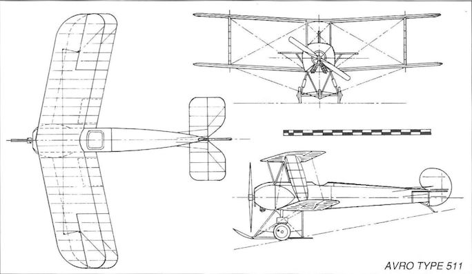
Avro Type 511
Avro Type 521
This single-bay derivative of the famous Avro 504 was intended to be a two-seat fighter. It was designed late in 1915 and embodied features from several 504 subvariants, including the straight upper longerons of the 504 prototype, the short-span ailerons and tail unit of the 504A, the cabane struts peculiar to the 504E and the V-strut undercarriage of the 504G.
The wing span was reduced from the 504’s 36ft to about 27ft 6in, and generous cut-outs were provided in upper and lower wings, as were ailerons. Power was provided by a 110hp Clerget rotary in cowlings reminiscent of the 504.
Mr J M Bruce has speculated that the Type 521 was evolved by way of a naval version of the 504, which may or may not have been completed; however, he points out that, not being intended for the RNAS, the 521 was fitted with a balanced rudder without fixed tailfin.
The prototype was flown early in 1916 at Trafford Park, Manchester, by Fred Raynham, who complained that it was longitudinally unstable and ‘unpleasant to fly’; it was however sent to the Royal Aircraft Factory for evaluation in mid-February.
In due course a production order followed for 25 aircraft, intended for the RFC, but it seems that few, if any, were delivered, and that the Type 521 which is known to have crashed at Gosport in 1917 was in all likelihood the prototype.
Type: Single-engine, two-seat, single-bay scout biplane.
Manufacturer: A V Roe & Co Ltd, Miles Platting, Manchester.
Powerplant: One 110hp Clerget rotary engine driving two-blade propeller.
Structure: All-wood construction with fabric covering.
Dimensions; Span, approx 27ft 6in.
Prototype and Production: One prototype, No 1811 (first flown by F P Raynham in January or February 1916), 25 production aircraft ordered, Nos 7520-7544, but it is not known how many, if any, were completed.
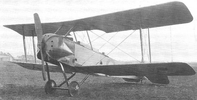
The Avro Type 521 prototype at Farnborough in January 1916 during evaluation.
Avro Type 530
It might be contended that the secret of success enjoyed by the Bristol F.2B Fighter was due to two circumstances, namely that it had already been developed into an aircraft for which there was a demand before any would-be competitor, and that it avoided using the Hispano-Suiza engine. Almost every one of those other challengers, as has been shown, favoured the Hispano engine and, as a result, were defeated by the prior claims on its faltering supply on behalf of the S.E.5.
The Avro 530 was just one more such aircraft which fell victim of the short supply of Hispano engines. The aircraft was directly comparable with the Bristol Fighter and was, if anything, slightly superior in some aspects of performance. Built at Avro’s works in Manchester and first flown at Hamble in Hampshire in July 1917, it featured a 200hp Hispano-Suiza engine with a frontal radiator, all enclosed in an annular cowling; cooling airflow to the radiator passed through a large spinner which itself improved the shape of the nose. The deep fuselage was a wire-braced wooden box-girder, fabric-covered and formed to improved aerodynamic shape by secondary stringers. The wooden, two-bay, two-spar wings of RAF 14 section were also fabric-covered and not only included ailerons, but also underwing trailing-edge flaps on upper and lower wings for landing - the latter being operated by a handwheel in the pilot’s cockpit.
Unfortunately the fuselage was so deep that, in placing the upper wing in line with the pilot’s eye level - so as to achieve the best possible field of view upwards and downwards - the wing scarcely cleared the upper decking of the front fuselage; this was further aggravated by fairing over the single forward-firing synchronized Vickers gun. Careful attention to detail elsewhere included fairing the undercarriage V-struts together to provide a single aerodynamic member on each side.
Only one example of the Type 530 was completed, and it became immediately obvious that the aircraft possessed no future while fitted with the Hispano-Suiza engine, even though the engine for which the Avro was designed was the 300hp version. The sole prototype was therefore extensively modified to incorporate the 200hp Sunbeam Arab eight-cylinder water-cooled in-line engine. The landing flaps were removed in favour of lengthened ailerons, and the fairings were removed from the undercarriage V-struts.
However, by the time these changes had been made, production of the well-established Bristol Fighter - a much-liked aircraft among its crews - had accelerated to an impressive rate, and there could therefore be no question of introducing a new aircraft with untried operational qualities.
Type: Single-engine, two-seat, two-bay biplane fighter.
Manufacturer: A V Roe & Co Ltd, Manchester.
Powerplant: One 200hp Hispano-Suiza engine driving two-blade propeller; later one 200hp Sunbeam Arab engine.
Dimensions: Span, 36ft 0in; length, 28ft 6in; height, 9ft 7in; wing area, 325.5 sq ft.
Weights: Tare, 1,695lb; all-up, 2,500lb.
Performance: Max speed, 114 mph at sea level; climb to 10,000ft, 15 min; service ceiling, 18,000ft; endurance, 4 hr.
Armament: One synchronized 0.303in Vickers machine gun faired on nose, forward of the pilot’s cockpit; one Lewis gun with Scarff ring on the rear cockpit.
Prototype: One, first flown in July 1917. No production.
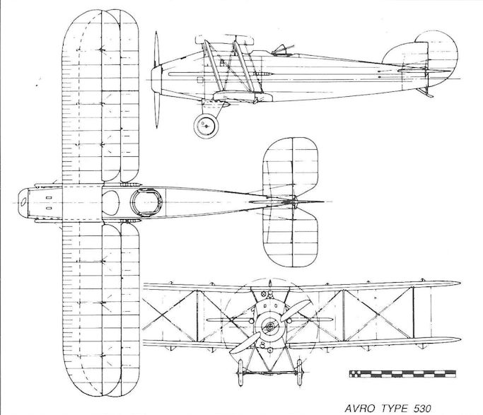
Avro Type 530
Avro Type 531 Spider
Among the manufacturers who were prompted to produce ‘home defence’ fighters at the time of the Gotha raids on England in 1917-18 was A V Roe which designed and built the Type 531 as a privately financed project. It was hoped that this ingenious little single-seat biplane would be selected to replace the Avro 504 K ‘night fighters’ then serving with the Home Defence squadrons.
Employing numerous components of the 504 for ease and speed of manufacture, the Type 531 featured entirely new wings, the lower wing being much shorter and narrower than the upper, the two wings being interbraced by a triangulated system of six faired steel tubular struts without any flying or landing wires; this system, it was argued, would simplify the tedious and time-consuming rigging of the aircraft in the field. To afford the best possible field of vision for the pilot, the cockpit was located directly beneath a large cutout in the centre section of the very broad chord upper wing.
When first flown, the aircraft (dubbed the Spider on account of its Warren girder strut arrangement) was powered by a 110hp Le Rhone rotary engine, but this was soon replaced by a 130hp Clerget. It was flown in mock combat with contemporary in-service scouts (including the Camel and SE.5A) and proved more than a match by reason of its excellent manoeuvrability - this despite the Avro’s traditional lack of a fixed vertical tail fin. However, it was quickly pointed out that the Spider’s agility was to some extent achieved by its reversion to a single gun armament. The adoption of the single front gun had been supported by the argument that it was more desirable to possess more ammunition for a single gun than less for two, particularly for night fighting. Plans were afoot to fit 150hp Bentley B.R.1 or 170hp ABC Wasp engines, but by mid-1918 the German air attacks on England had petered out, while new aircraft - such as the Sopwith Snipe - were approaching Service entry. Two serial numbers were allotted to Spiders, but neither was taken on Service charge, and it is thought that only one example was completed.
Type: Single-engine, single-seat fighting scout biplane
Manufacturers: A V Roe & Co Ltd, Clifton Street, Miles Platting, Manchester
Powerplant: One 110hp Le Rhone 9-cylinder rotary engine; one 130hp Clerget 9-cylinder rotary engine.
Structure: Fuselage of spruce longerons and frames; twin spar wings with steel Warren girder interplane bracing. All fabric-covered.
Dimensions: Span, 28ft 6in; length, 20ft 6in; height, 7ft 10in; wing area, 189 sq ft.
Weights (Clerget): Empty, 1,148lb; loaded, 1,734lb.
Performance (Clerget): Max speed, 120 mph at sea level; climb to 5,000ft, 4.0 min; service ceiling, 19,000ft.
Armament: One fixed synchronized 0.303in Vickers machine gun with 800 rounds.
Prototype: One (probably B3952, first flown in April 1918). No production.
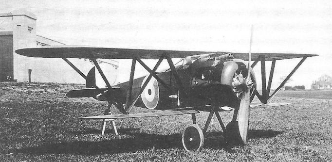
The Avro 531 Spider single seat fighter with 110 h.p. Le Rhone engine at Hamble in 1918.
B.A.T. F.K.22 and F.K.23 Bantam
In 1917 Samuel Waring (later Lord Waring of Foots Cray) founded the British Aerial Transport company (B.A.T.) of Willesden, London, and secured the services of Frederick Koolhoven - late of Armstrong, Whitworth - as chief designer; he brought with him Bob Noorduyn, also of Dutch descent, as his chief draughtsman. Accordingly the aircraft which came to be produced by the new company continued to bear the initials applied to those designed by Koolhoven for his previous employer.
These new designs were all to be radical by accepted British standards, but nonetheless represented a realistic approach to fighter design. All the fighters were to be of wooden monocoque construction with split-axle undercarriage, and all but the last wartime design (the Basilisk) were to be characterized by the upper wing being located on top of and attached directly to the top of the fuselage. All were to be high performance aircraft.
The first Koolhoven design for B.A.T. was the F.K.22, an aircraft intended for the 120hp ABC Mosquito, but this engine failed to advance beyond bench testing, so the airframe was altered to take the 170hp ABC Wasp, but this also failed to come up to early expectations, the aircraft being temporarily referred to as the Bantam Mk I. In the end the F.K.22, B9945, underwent trials in February 1918 at Martlesham Heath powered by a 100hp Gnome monosoupape rotary, being designated the B.A.T. F.K. 22 Bantam Mk II.
The Bantam’s fuselage was a true monocoque structure with three-ply birch sheet wrapped round ash formers to provide a near-elliptical cross-section; the tail fin was built integrally with the fuselage. Each wing was constructed in three sections, only the outer sections having dihedral. Both centre sections were attached directly to the fuselage, the top wing incorporating a large circular aperture so the pilot’s head protruded above the upper surface. Ailerons were fitted on upper and lower wings, and wooden interplane struts were employed.
Despite the earlier reference to the Bantam Mk I, this was correctly applied to an entirely new design, which Koolhoven referred to as the F.K.23. It was smaller than the F.K.22, but the same basic form of monocoque construction was applied although the upper wing was now built as a single structure and possessed no dihedral. The lower wing was still made in three sections, with dihedral on the outer sections, and with no stagger.
Because the aircraft’s centre of gravity was fairly far aft and the fuselage relatively short, the tail control surfaces possessed a short moment, a deficiency that became all too obvious during spin recovery; the Bantam’s spin was vicious and rotation accelerated quickly, so that coarse and powerful use of the controls was essential. One or two aircraft were lost from spins and Maj Christopher Draper, a noted exponent of the Bantam, was fortunate to escape without injury when he spun a Bantam into the ground - thanks to the great strength of the fuselage structure.
The Bantam Mk I was very fast and highly manoeuvrable, and earned a small production order for twelve aircraft, to be powered by the 170hp ABC Wasp I. It underwent some re-design, the rudder being increased in area to assist spin recovery, steel tubular interplane struts fitted and dihedral introduced to the upper wing. Wasp I- and II-powered Bantams were submitted for evaluation in October 1918 and March 1920 under the new Air Ministry Specification series No 1A (later termed the Directorate of Research Type 1) and produced a sparkling performance; the latter version returned a maximum speed of 150 mph at sea level, and a time to 10,000 feet of just under seven minutes.
The Wasp was never popular in the RAF and, as there appeared to be sufficient Snipes in storage for demands of the foreseeable future, there was no call to increase the production order. Of the twelve production aircraft built, eight were eventually sold to private owners, and one (F1660) was sent to America for tests and evaluation; two of the civil aircraft finished up in Holland. The last two aircraft of the production order (F1663 and F1664) were held in storage until 1920, when they were assembled as J6579 and J6580 with Wasp II engines for various tests at the RAE and A & AEE; after the engine failed in J6580, a 200hp Armstrong Siddeley Lynx was fitted, but both aircraft were finally struck off charge in January 1922.
Type: Single-engine, single-seat, two-bay biplane fighter.
Manufacturer: The British Aerial Transport Co Ltd, Willesden, London.
Air Ministry Specification: No 1A of 1918.
Powerplant: Bantam Mk 1.170hp ABC Wasp I; 200hp ABC Wasp II; Bantam Mk II. 100hp Gnome monosoupape; 100hp Le Rhone.
Dimensions: Production Bantam I. Span, 25ft 0in; length, 18ft 5in; height, 6ft 9in; wing area, 185 sq ft.
Weights: Production Bantam I. Tare, 833lb; all-up, 1,321lb.
Performance: Production Bantam I (Wasp I). Max speed, 128 mph at sea level; climb to 10,000ft, 9 min; service ceiling, 20,000ft.
Armament: Two synchronized 0.303in Vickers machine guns mounted low down on the sides of the nose.
Prototypes: Six B.A.T.22s ordered, B9944-B9949; only B9944 and B9947 confirmed as being completed.
Production: Twelve B.A.T.23s ordered, F1653-F1664; F1663 and F1664 became J6579 and J6580 respectively.
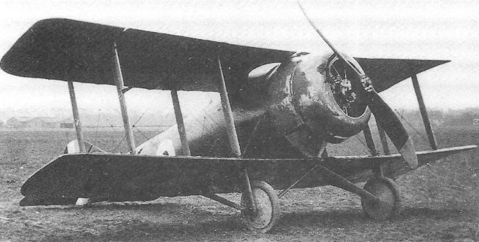
The B.A.T. F.K.22/2 Bantam Mk II with 100hp Gnome monosoupape rotary engine; note the wide-track undercarriage in relation to the aircraft’s span.
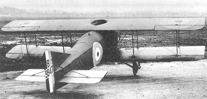
The B.A. T. F.K.22 Bantam, B9947, showing well the flat top wing and the cockpit aperture.
B.A.T. F.K.25 Basilisk
It is to be assumed that by the time Frederick Koolhoven arrived at his final wartime fighter design, the F.K.25 Basilisk, he had become disenchanted with his habit of attaching the top wing directly to the top of the fuselage, for in this aircraft the upper wing was built in two halves and joined on the aircraft’s centreline; the wing was located well clear of the fuselage, being braced to it by a single, central N-strut.
The engine was once again the 320hp ABC Dragonfly - alas, still uncured of its self-destructive tendencies - and therein, of course, lay the ultimate fate of the aircraft. Apart from this fatal shortcoming, the Basilisk was a rugged, high performance fighter.
Three prototypes were ordered, and the first of these, F2906, was flown in September. Its two Vickers guns were mounted on the upper decking of the nose, but were soon to be covered by a large tapered fairing which extended aft to form the front coaming of the cockpit; the sides of the cockpit were cut fairly low so that, in conjunction with the cutaway lower wing root trailing edge, the pilot’s field of view downwards was extremely good. The fin and horn-balanced rudder were of continuous contour of attractive shape, but early tests demanded a slight increase in rudder area. Plain ailerons were fitted on all four wings, although these were replaced by extended horn-balanced ailerons on the second aircraft.
The first Basilisk prototype was lost in a tragic accident early in May 1919, which cost the life of Flight-Cdr Peter Legh rn - the first post-War death of a test pilot. In an attempt on the world’s altitude record while flying from Hendon, the Basilisk’s engine caught fire and the aircraft crashed. This accident was cited as the cause of the death of the pilot, who might otherwise have survived had the aircraft been fitted with a metal-asbestos firewall forward of the cockpit, this statement leading to the mandatory introduction of such a firewall on every military and civilian aircraft thereafter.
All three Baslisks came to be built, the remaining two spending much of their time at Martlesham Heath between July 1919 and September 1920, when they were grounded on account of their recalcitrant Dragonfly engines.
Type: Single-engine, single-seat, two-bay biplane fighter.
Manufacturer: The British Aerial Transport Co Ltd, Willesden, London.
Powerplant: One 320hp ABC Dragonfly seven-cylinder radial engine.
Dimensions: Span, 25ft 4in; length, 20ft 5in; height, 8ft 2in; wing area, 212 sq ft.
Weights: Tare, 1,454lb; all-up, 2,182lb.
Performance: Max speed, 142.5 mph at 6,500ft; climb to 10,000ft, 8 min 25 sec; service ceiling, 22,500ft; endurance, 3 1/4 hr.
Armament: Two synchronized 0.303in Vickers machine guns on upper nose decking.
Prototypes: Three, F2906-F2908. (F2906 first flown in September 1918). No production.
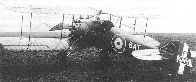
The ill-fated B.A. T. Basilisk prototype, F2906.
Beardmore W.B.III
The well-known engineering and shipbuilding firm of William Beardmore & Co Ltd of Dalmuir, Dunbartonshire, became involved in aero-engine manufacture shortly before the outbreak of war in 1914 when it obtained a licence to produce Austro-Daimler engines. Soon afterwards the company received subcontracts to produce the B.E.2C and, rather later, the Sop with Pup. When, in 1916, major sub-contractors were encouraged to originate designs of their own, Lieut G Tilghman Richards was appointed Chief Designer in Beardmore’s aviation department.
After two designs, the W.B.I (a bomber) and the W.B.II (a reconnaissance aircraft) had failed to receive quantity orders, Beardmore undertook extensive modification of the Sopwith Pup to improve its application to operations aboard ship, principally by reducing its dimensions for storage by introducing folding wings. To do this the Pup’s wings were re-arranged to eliminate stagger, four additional interplane struts were added close to the fuselage to retain rigidity on the wing-fold chord line and to maintain the truss with the wings folded. The fuselage was lengthened by about twelve inches so as to avoid interference between the tailplane and the outboard interplane struts, and folding skids were introduced under the lower wings.
The prototype W.B.III was in fact produced by modifying a Beardmore-built Pup (9950), originally intended for the Admiralty. Also included was provision to fold the undercarriage into the fuselage beneath the cockpit to reduce storage height; an alternative arrangement was provided to enable the entire undercarriage to be jettisoned in the event of an emergency ditching on water.
A total of one hundred W.B.IIIs was ordered under the Service designation S.B.3, the S.B.3D being said to denote ‘dropping’ undercarriage, and S.B.3F (for ‘folding’ undercarriage). S.B.3s served aboard hms Furious, Nairana and Pegasus, and at the time of the Armistice fifty-five were on RAF charge, the remainder in store. It is said that a small number was supplied to Japan.
Type: Single-engine, single-seat shipboard interceptor scout biplane.
Manufacturer: William Beardmore & Co Ltd, Dalmuir, Dunbartonshire.
Powerplant: One 80hp Le Rhone air-cooled rotary engine, or one 80hp Clerget air-cooled rotary engine.
Construction: Wooden construction throughout with ash longerons and diagonal spacers, spruce wing spars and ribs, and birch riblets. Front of fuselage covered with aluminium sheet, and ply in area of cockpit; remainder fabric-covered.
Dimensions: Span, 25ft 0in; length, 20ft 2 1/4 in; height, 8ft 1 1/4 in; wing area, 243 sq ft.
Weights: Tare, 890lb; all-up, 1,289lb.
Performance: Max speed, 103mph at sea level; climb to 5,000ft, 9 min; service ceiling, 12,400 ft; endurance, 2 3/4 hr.
Armament: One 0.303in Lewis machine gun mounted over the wing centre section to starboard, angled slightly upwards to fire over the propeller.
Prototype: One, 9950 (converted Pup, first flown January 1917)
Production: One hundred aircraft (N6100-N6129 and N6680-N6749)
Summary of Service: Known to have served aboard ships of the Grand Fleet and aboard hm Carriers Furious, Nairana and Pegasus during 1918-19.
Beardmore W.B.IV
Encouraged no doubt by the Admiralty’s ready acceptance of radical features in his W.B.III, Tilghman Richards of William Beardmore pursued another naval fighter of even more unusual ingenuity - this time in a two-bay biplane of the Company’s own design, intended to meet Specification N.1A. In order to achieve stability while floating on the sea, following an emergency ditching, not only was the undercarriage capable of being jettisoned but the engine, a 200hp Hispano-Suiza, was located behind the pilot and on the aircraft’s centre of gravity, driving the tractor propeller by an extension shaft which passed between the pilot’s feet. The radiator was placed behind the engine, mounted between the rear interplane struts.
The pilot was afforded an excellent all-round field of view, his cockpit being raised high in the nose of the aircraft, forward of the wings, and was watertight below the coaming. The fuselage was unusual in itself in being entirely plywood-clad, and another innovation was the provision of a large flotation chamber faired into the underside of the nose and projecting on each side to form a large lateral buoyancy surface. When the W.B.IV first appeared, it also featured floats faired under each lower wingtip. For shipboard stowage the wings could be folded back.
Three W.B.IVs were ordered by the Admiralty, but only one, N38, came to be built. Flown late in 1917, this sole example was delivered to the RNAS Isle of Grain station for trials which may have included ditching tests without the wing floats fitted. At all events the aircraft was damaged while alighting on the water, the nose buoyancy chamber being damaged with the result that N38 sank.
Many contemporary observers considered the W.B.IV to have been one of the most advanced aircraft produced during the First World War with regard to its innovative, yet practical features.
It was, after all, the first British aircraft in which the engine drove a tractor propeller by means of an extension shaft - pre-dating aircraft such as the Westland F.7/30 by at least fifteen years. Its top speed of only 110 mph was, however, considered disappointing by the standards set by contemporary scouts and no production was ordered.
Type: Single-engine, single-seat, two-bay shipborne fighting scout biplane.
Manufacturer: William Beardmore & Co Ltd, Dalmuir, Dunbartonshire.
Admiralty Specification: N.1A (of 1917)
Powerplant: One 200hp Hispano-Suiza water-cooled in-line engine driving two-blade propeller through an extension shaft.
Construction: All-wood construction with ply-covered fuselage. Jettisonable undercarriage and folding wings. Buoyancy chamber incorporated under the front fuselage.
Dimensions: Span, 35ft 10in; length, 26ft 6in; height, 9ft 10 1/2 in; wing area, 350 sq ft.
Weights: Tare, 2,055lb; all-up, 2,595lb.
Performance: Max speed, 110 mph at sea level; climb to 5,000ft, 7 min; service ceiling, 14,000ft; endurance, 2 1/2 hr.
Armament: One fixed, synchronized 0.303in Vickers machine gun in port side of nose with breech inside cockpit; and one 0.303in Lewis gun on tripod mounting above the pilot’s windscreen.
Prototypes: Three ordered (N38-N40) but only N38 completed and flown (1917).
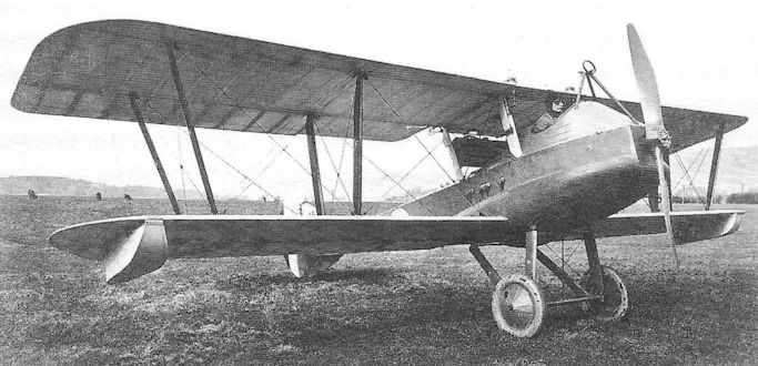
The Beardmore W.B.IV (200 h.p. Hispano Suiza Engine), N38, with its midships engine location, aft of the pilot’s cockpit.
Beardmore W.B.V
Designed and built at the same time as the W.B.IV, which it resembled more than superficially, the Beardmore W.B.V shipborne single-seat fighter also approximated to the naval requirements set out in Admiralty Specification N.1A, but additionally made provision to mount a French 37mm quick-firing Canon Puteaux - called for in an Appendix to the Specification.
In the W.B.V the 200hp Hispano-Suiza engine was located conventionally in the nose of the aircraft with the barrel of the cannon lying in the vee between the cylinder banks; the gun’s muzzle projected forward into the hollow propeller shaft, and the breech extended aft into the pilot’s cockpit forward of the control column.
Increased wing chord and slightly greater fin area in the tail was provided, but the large nose buoyancy chamber of the W.B.IV was omitted, the latter being to some extent offset by the provision of inflatable flotation bags which, when not inflated, lay flush along the underside of the lower wing leading edge. Folding wings and jettisonable undercarriage were included, as on the W.B.IV.
Once more three prototypes, N41 - N43, were ordered and at least two were completed. However, during flight trials by RNAS pilots, it was considered extremely dangerous to attempt to load the Puteaux gun behind the control column while in flight - possibly in combat conditions. The naval pilots are said to have refused to expose themselves to such obvious risks, and the shell-firing gun was removed, being replaced by a Vickers and Lewis gun, as on the W.B.IV. Now bereft of its raison d’etre there was clearly no need to pursue further trials, and the W.B.V’s further development was halted. Its marginally improved performance had, after all, only been achieved by deleting the large nose buoyancy chamber.
Type: Single-engine, single-seat two-bay shipborne fighting scout biplane.
Manufacturer: William Beardmore & Co Ltd., Dalmuir, Dunbartonshire.
Admiralty Specification: N.1A and Appendix.
Powerplant: One 200hp Hispano-Suiza liquid-cooled engine driving two-blade propeller.
Construction: As Beardmore W.B.IV but without nose buoyancy chamber; engine mounted conventionally in the nose.
Dimensions: Span, 35ft 10in; length, 26ft 7in; height, 11ft 10in; wing area, 394 sq ft.
Weights: Tare, 1,860lb; all-up, 2,500lb.
Performance: Max speed, 112 mph at sea level; climb to 5,000 ft, 6 min; service ceiling, 14,000 ft; endurance, 2 1/2 hr.
Armament: Initially armed with single 37mm Canon Puteaux firing through the propeller shaft; after removal it was replaced by a fixed 0.303in Vickers gun in the nose and a Lewis gun mounted to fire upwards through a cutout in the upper wing centre section.
Prototypes: Three (N41-N43), of which N41 and N42 are known to have been completed (in 1917). No production.
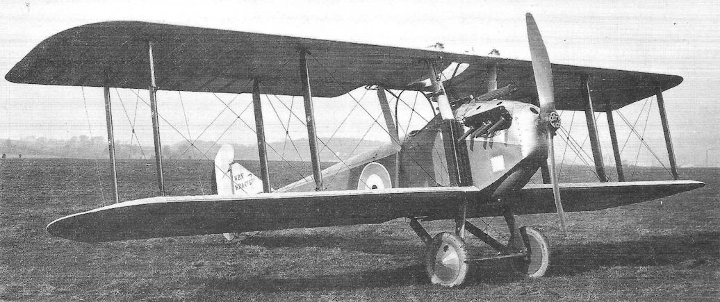
The second Beardmore W.B.V, N42, with a single Lewis gun in place of the 37mm cannon.
Blackburn Triplane
At a time when it must have seemed that British aircraft designers were prepared to go to any lengths to create the oddest conceivable fighters in their search for a solution of the forward-firing gun requirement, even the Blackburn Triplane appears anachronistic, to say the least.
It will be recalled that the eccentric Harris Booth, while at the Admiralty’s Air Department, had designed a peculiar pusher biplane, known as the A.D. Sparrow scout, and that two such aircraft were built by the Blackburn company of Leeds. In 1916 Booth left the Air Department and immediately joined Blackburn, where he set about the design of a pusher triplane which one can only conjecture as being loosely based on his original Sparrow concept with which he seems to have been obsessed.
Retaining the Sparrow’s parallel tail booms, its huge tailplane and tailskids at the base of the rudders, the nacelle was arguably of improved shape, through which the spars of the centre wing passed. A wider-track undercarriage was provided and, initially, a 110hp Clerget rotary was selected. All flying surface trailing edges were formed with wire - which imposed an archaic appearance of scalloped edges when the fabric tautened under the effects of dope. Booth even proposed retaining the two-pounder Davis recoilless gun although it is difficult to reconcile this weapon with the aircraft’s role as a scout.
The aircraft was completed towards the end of 1916 when it was despatched to Eastchurch, having undergone an engine change to the 1000hp Gnome monosoupape. On 20 February 1917 the Triplane was accepted by the Admiralty as N502, but one month later it was struck off charge as serving no useful purpose. It had been claimed that the aircraft possessed a maximum speed of 115 mph with the monosoupape engine, but this must be discounted as most improbable.
Type: Single pusher engine, single-seat, single-bay triplane scout.
Manufacturer: Blackburn Aeroplane & Motor Co Ltd, Leeds.
Powerplant: One 110hp Clerget engine driving four-blade propeller; later one 100hp Gnome monosoupape with two-blade propeller.
Dimensions: Span, 24ft 0in; length, 21ft 5 5/16 in; height, 8ft 6in; wing area, 221 sq ft.
Weights: (100hp Gnome). Tare, 1,011lb; all-up, 1,500lb.
Performance: (100hp Gnome). Max speed, probably approx 95 mph; endurance, 3 hr.
Armament: Intended as one 2-pdr Davis recoilless gun in nose of nacelle.
Prototype: One, N502.
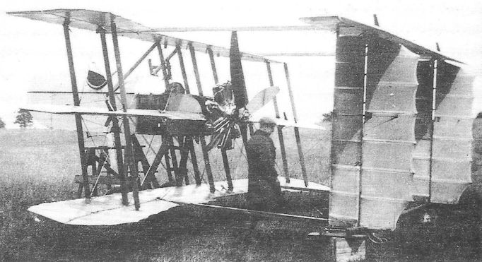
Designed by Harris Booth, the Blackburn Triplane carried a Davis two-pounder recoilless gun.
The Blackburn Triplane as first constructed with 110 hp Clerget rotary engine driving a four-bladed airscrew
The Blackburn Triplane as first constructed with 110 hp Clerget rotary engine driving a four-bladed airscrew
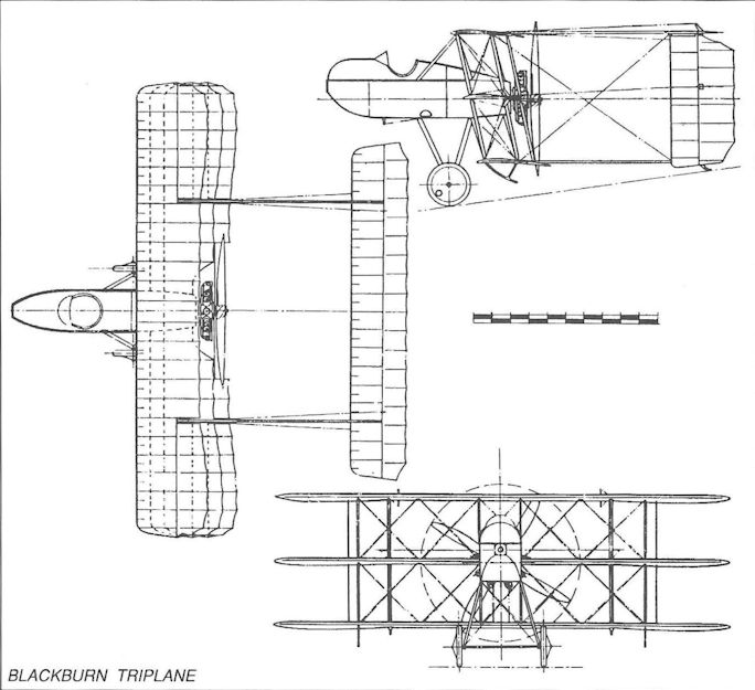
Blackburn Triplane
Blackburn N.1B
The Admiralty’s requirement, set out in Specification N.1B, calling for a long-range escort fighter capable of accompanying the large patrol flying boats, prompted the Blackburn Aeroplane company to produce a design to compete with the Supermarine N.1B Baby, which would make its first flight in February 1918. Another contender, which had flown but proved unsuccessful with a speed of only 93 mph, was the Norman Thompson N.1B two-seat flying-boat.
The Blackburn N.1B, designed by Harris Booth - not hitherto renowned for beauty of design - was a remarkably elegant little biplane flying-boat with a span of only 34ft 10in. The hull was designed by Major Linton Hope, with the slightly staggered wings placed above the hull, and the 200hp Hispano-Suiza pusher engine located close up under the upper wing centre section. The pilot’s cockpit was situated forward of the wings with a single Lewis gun in front and offset to starboard, and the gracefully upward-curving rear hull section supporting a biplane tail with twin fins and rudders. Wingtip balancing floats were fitted directly below the interplane struts.
For all the promise shown by the Blackburn design, the Admiralty requirements were changed before the first prototype was completed, and only the hull of N56 had been finished when work on the N.1B was halted. (This hull was incorporated in a post-War aircraft, the Blackburn Pellet, and entered for the 1923 Schneider Trophy race; the aircraft was however destroyed in an accident before the race.)
The accompanying data are design figures only.
Type: Single pusher engine, single-seat biplane flying-boat escort fighter.
Manufacturer: The Blackburn Aeroplane & Motor Co Ltd, Leeds.
Powerplant: One 200hp Hispano-Suiza engine driving two-blade pusher propeller.
Dimensions: Span, 34ft 10in; length, 28ft 3 1/2 in.
Weights: Tare, 1,721lb; all-up, 2,390lb.
Performance: Max speed, 114 mph at sea level; climb to 10,000ft, 18 min; ceiling, 16,000ft; endurance, 3 hr.
Armament: One 0.303in Lewis gun forward of pilot’s cockpit, offset to starboard.
Prototypes: Three ordered, N56-N58; only N56 partly completed.
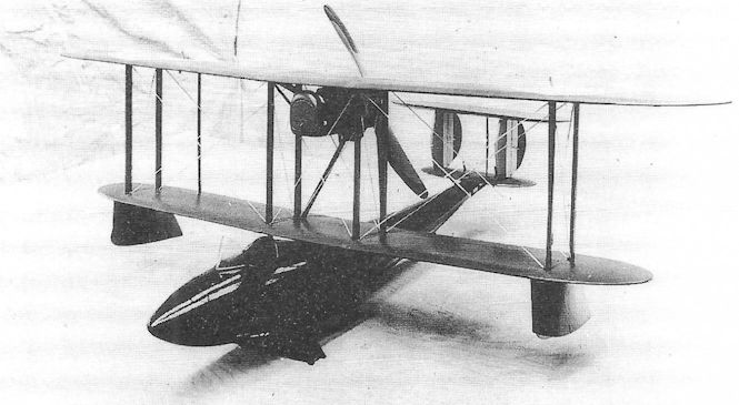
The wind-tunnel model of the Blackburn N.1B single-seat flying boat.
Boulton & Paul P.3 Bobolink
Established since 1873 as a wood-working firm, Boulton & Paul of Norwich entered the aircraft industry during the First World War and quickly created for itself an excellent reputation for its production of aircraft such as the Sopwith Camel, under the management of Geoffrey ffiske. In August 1917, Boulton & Paul secured the services of John North (late of the Austin Motor Co) as its chief designer, and straightway determined to submit designs of its own. North’s first aircraft, known by the company as the Hawk - but later changed to Bobolink, when Boulton & Paul were required to give names of birds to their fighters, beginning with ‘Bo...’ - was extremely unfortunate not to be rewarded by a production order.
Taking the bull by the horns, North entered the design competition held under the Specification A.1A, which called for a single-seat fighter to replace the Sopwith Camel. Like the ultimate winner, the Sopwith Snipe, the Bobolink was powered by the Bentley B.R.2 rotary and featured two-bay wings and twin synchronized Vickers guns. Like the Snipe, six prototypes, C8652-C8657, were ordered. A number of ingenious features were included in the design, not least of which were the fuel tanks: the fuel was carried in two tanks behind the pilot, side-by-side and separated by a sheet of armour; in the event of fire in one tank, it could be jettisoned to reduce the risk of the aircraft being totally destroyed. ‘N’-type interplane struts were employed to simplify rigging of the wings, which were of very light weight (each lower mainplane weighed only 29 pounds).
The Bobolink was probably first flown in January 1918, and underwent its official trials in March. It proved to be lighter than the Snipe and slightly faster, but was criticised on account of poor ground handling, resulting from its very narrow track undercarriage. There is some evidence that handling problems in the air may have delayed the Bobolink’s trials, and that this may have told against the aircraft; the decision in favour of the Snipe was announced before the report on John North’s entry was completed. Some photographs show the Bobolink with a somewhat overbalanced rudder, suggesting a hurried cure for a lack of directional control.
Type: Single-engine, single-seat, two-bay biplane fighter.
Manufacturer: Boulton & Paul Ltd, Norwich, Norfolk.
Powerplant: One 250hp Bentley B.R.2 rotary engine driving two-blade propeller.
Dimensions: Span: 29ft 0in; length, 20ft 0in; height, 8ft 4in; wing area, 266 sq ft.
Weights: Tare, 1,226lb; all-up, 1,992lb.
Performance: Max speed, 125 mph at 10,000ft; climb to 10,000ft, 9 min 20 sec; service ceiling, 19,500 ft; endurance, 3 1/4 hr.
Armament: Two synchronized 0.303in Vickers machine guns in the fuselage nose forward of the cockpit.
Prototype: Six, C8652-C8657. (Some records suggest that C8652-C8654 were referred to as P.5 Hawks; only C8655 is known to have been built.)
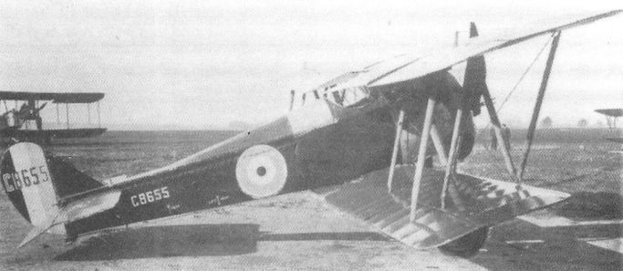
The Boulton & Paul P.3 Bobolink, C8655, with unbalanced rudder and interconnecting strut between the upper and lower ailerons.
Bristol Scout A and B
Formed in February 1910 by Sir George White, the British and Colonial Aeroplane Co Ltd had been engaged in aircraft manufacture since the first appearance in the spring of that year of the Boxkite, an adaptation of the Henry Farman biplane with 50hp Gnome engine. As a result of wide-ranging recruitment at home and abroad the company acquired the services of a number of distinguished aircraft designers, among them Frank Sowter Barnwell and the Romanian Henri Coanda, who joined the company in December 1911 and January 1912 respectively. Three semi-autonomous design offices were established, and Coanda was given charge of general design policy, at the same time pursuing his own advanced ideas on biplanes and monoplanes. His only pusher biplane design was the two-seat P.B.8, intended as a trainer and powered by an 80hp Gnome; this was never flown as the War Office requisitioned its engine on the outbreak of war. Another of Coanda’s designs, begun in 1913, was a single-seat monoplane, the S.B.5, intended for the Italian government; this also was never flown, and work had only started on the fuselage before the project was abandoned.
With the increasing interest being shown in single-seat military scouts, Frank Barnwell was given permission to re-design the S.B.5 as a scout biplane, with wings and tailplane very similar in plan to those of the P.B.8, and using much of the unfinished fuselage of the S.B.5.
This little aeroplane, affectionately known as the ‘Baby Biplane’, but increasingly as the Bristol Scout, was the forerunner of a long-lived class of Bristol designs. Powered by an 80hp Gnome, the Scout featured the same ailerons and wing stagger as the P.B.8 and incorporated a balanced rudder and two-wheeled V-strut undercarriage. A measure of its simplicity of structure and size may be judged by its all-up weight of no more than 957lb with pilot and fuel for three hours’ flight.
Accorded the Bristol sequence number 206, the Scout was flown at Larkhill in February 1914 by Harry Busteed, and in a very short time proved capable of a speed of 95 mph. It then appeared the following month at the Olympia Show where its small size caused something of a sensation.
In April the Scout returned to Filton to be fitted with slightly larger wings which improved the handling qualities and reduced the landing speed without significantly affecting the top speed; the engine cowling was also improved. Busteed then flew the aircraft to Farnborough where, on 14 May, it underwent an AID performance test, returning a speed range from 40 to 97.5 mph.
Thereafter No 206 was flown in a number of sporting events and, purchased by the 22-year-old Lord John Carbery (later Carberry), it was unfortunately lost in the English Channel when it ran out of fuel on the return flight of the London-Paris-London air race on 11 July - but not before the pilot and aeroplane had established an unofficial British air speed record of 100.5 mph. Carbery had fitted an 80hp Le Rhone in place of the Gnome.
The next two Scouts, which differed from No 206 principally in the engine cowling (and were referred to as the Scout B, while the earlier machine became the Scout A in retrospect), were requisitioned by the War Office at the outbreak of war and delivered to Farnborough during the latter half of August.
Type: Single-engine, single-seat, single-bay scout biplane.
Manufacturer: The British and Colonial Aeroplane Co Ltd, Filton, Bristol.
Powerplant: Scout A. One 80hp Gnome, and later 80hp Le Rhone engine driving two-blade wooden propeller. Scout B. One 80hp Gnome engine.
Structure: Predominantly light-gauge steel tubular construction with fabric covering; simple V-strut twin-wheel undercarriage.
Dimensions: Scout A. Span, 22ft 0in (later 24ft 7in); length, 19ft 9in; height, 8ft 6in; wing area, 161 sq ft (later 198 sq ft). Scout B. Span, 24ft 7in; length, 20ft 8in; height, 8ft 6in; wing area 198 sq ft.
Weights: Scout A. Tare, 617lb (later 750lb); all-up, 957lb (later 1,100lb). Scout B. Tare, 750lb; all-up, 1,100lb.
Performance: Scout A. Max speed, 95 mph (later 100 mph); initial climb, 800 ft/min; endurance, 3 hr (later 5 hr). Scout B. Max speed, 100 mph; initial climb, 1,000 ft/ min; endurance, 2 1/2 hr.
Armament: Initially none, but Scout B No 633 later fitted with two 0.303in rifles mounted on sides of nose to fire outside the propeller.
Prototypes and Service: One Scout A, ‘No 206’ (first flown by Harry Busteed on 23 February 1914 at Larkhill). Two Scout Bs, 633 and 634 (first flown in August 1914), served with Nos 3 and 5 Squadrons, RFC.
Bristol Scout C and D
The development of Barnwell’s Bristol Scout continued without interruption after the two Scout Bs had been requisitioned by the War Office on the outbreak of war. Soon afterwards the War Office and Admiralty expressed growing enthusiasm for the new class of Scout aircraft and placed orders with several manufacturers, notably with Sopwith for the Tabloid. On 5 November 1914 Bristol received an order from the War Office for twelve improved Scouts (the Scout C), but two days later the Admiralty ordered twenty-four, and claimed priority of delivery. A rather one-sided compromise was reached as the Admiralty received the first example on 16 February 1915, while the following twelve Scout Cs were delivered to the RFC between 23 April and 13 June that year. By the end of the summer a total of 161 Scout Cs had been ordered, of which the RFC received 87 and the RNAS 74.
Produced at Brislington, Bristol, the Scout C differed externally from the B in dispensing with external engine cowling stiffeners, but all early aircraft retained the 80hp Gnome engines; however, War Office aircraft from the twenty-third onwards were powered by 80hp Le Rhones, while the Admiralty insisted on continuing with Gnomes owing to their better reliability. Production continued until February 1916 but, despite the number built, Scouts never fully equipped any Squadron, instead being distributed among a dozen units at home and in France.
When, in 1916, shortage of 80hp Gnomes arose, a small number of Scout Cs was completed with 80hp and 110hp Clerget rotaries; with the latter engine the Scout C had a top speed of 109 mph at 3,000 feet (compared with 92 mph when powered by the standard Gnome).
It was, nevertheless, in a Gnome-powered Scout C of No 6 Squadron that Capt Lanoe G Hawker DSO, RFC, won the Victoria Cross on 25 June 1915. Armed only with a single-shot Martini carbine, mounted to fire to starboard of the propeller, he succeeded in forcing down three German two-seaters, all armed with machine guns. Armament carried by other Scouts at this time included a 0.45in Martini carbine firing incendiary ammunition and, occasionally, a Lewis machine gun.
The RNAS undertook numerous anti-Zeppelin patrols using Scout Cs, and on 3 November 1915 Flight-Lt H F Towler rn made the first deck take-off from hms Vindex, formerly an Isle of Man steamer which had been fitted with a small flight deck forward. On 2 August the following year Flight-Lt C T Freeman rn, also flying from Vindex, took off to attack one of a pair of Zeppelins; although he succeeded in hitting his target with a Ranken dart, the airship turned back and made good its escape.
More spectacular were the experiments involving the mounting of a Bristol Scout C, No 3028, on the upper wing of Sqn Cdr John Cyril Porte’s prototype Baby, No 9800, a large three-engine flying-boat - the object being to carry anti-Zeppelin fighters further from the coast so as to have a better chance of engaging the German airships. Flown by Porte himself on 17 May 1916, the flying-boat took off and the Bristol Scout, flown by Flight-Lt M J Day rn of hms Vindex, separated successfully at 1,000 feet over Harwich. Although completely successful, the idea was not taken up as new fighting scouts were about to come into service with more chance of success and using more conventional methods of attack.
Meanwhile Barnwell had left Bristol for service with the RFC, but returned in August 1915 to prepare a further improvement in the Scout, based on reports of the Type C by the Services. The principal change was intended to be adoption of the 100hp Gnome monosoupape, which required a slightly enlarged engine cowling, but which bestowed a top speed of about 110 mph at sea level. In the event, of the 160 Scout Ds produced, only the first 60 delivered to the RNAS were powered by the big engine, which was found to suffer from severe engine vibration (causing the centre section fuel tank to leak), so that the remaining 20 Admiralty aircraft reverted to 80hp Gnomes. The great majority of the RFC aircraft were fitted with 80hp Le Rhones - which still returned a respectable speed of 100 mph at sea level.
The Scout D also introduced rafwires in place of twisted-strand cables, and the underwing skids were moved closer to the wingtips. A few RFC Scout Ds were delivered to France early in 1916 armed with a single Vickers machine gun equipped with Vickers-Challenger interrupter gear, enabling it to fire through the propeller arc, while some of the RNAS examples were similarly armed, but with Scarff-Dibovski interrupter gear. Many Scout Ds went further afield; they were flown operationally by Nos 14, 67 (Australian) and 111 Squadrons in Palestine, with Nos 30 and 63 in Mesopotamia, and with No 47 Squadron in Macedonia.
The wartime Bristol Scouts were very popular little aeroplanes among their pilots, with crisp and light handling qualities; they were only robbed of a prominent place in the annals of the RFC by their lack of a synchronized gun until too late to be capable of matching opponents possessed of much superior performance.
Type: Single-engine, single-seat, single-bay biplane scout.
Manufacturer: The British & Colonial Aeroplane Co Ltd, Filton and Brislington, Bristol.
Powerplant: Scout C. 80hp Gnome; 80hp Le Rhone; 80hp Clerget; 110hp Clerget. Scout D. 80hp Le Rhone; 100hp Gnome monosoupape, 80hp Gnome.
Dimensions: Scout C and D. Span, 24ft 7in; length, 20ft 8in; height, 8ft 6in; wing area, 198 sq ft.
Weights: Scout C (80hp Le Rhone). Tare, 757lb; all-up, 1,195lb. Scout D (100hp Gnome monosoupape). Tare, 760lb; all-up, 1,250lb.
Performance: Scout C (80hp Le Rhone). Max speed, 92.7 mph at sea level; initial rate of climb, 1,000 ft/min; service ceiling, 15,500ft; endurance, 2 1/2 hr. Scout D (100hp Gnome monosoupape). Max speed, 110 mph at sea level; initial rate of climb, 1,100 ft/ min; service ceiling, 13,500 ft; endurance, 2 hr.
Armament: Varied greatly from no fixed armament to a wide range of single weapons, either fixed to fire above or on either side of the propeller (including Lewis machine gun, service rifle, cavalry carbine, 0.45in Martini-Henry rifle or shot gun firing chain shot) or Vickers machine gun on nose decking to fire forward through propeller arc by means of various types of interrupter gear.
Prototypes and Production. No prototypes. Scout C production: 161 aircraft (Nos 1243-1266 and 3013-3062, 74 for the Admiralty; Nos 1602-1613, 4662-4699 and 5291-5327, 87 for the War Office. Scout D production: 160 aircraft (Nos 7028-7057 and A1742- A1791, 80 for the War Office; Nos 8951-9000 and N5390-N5419, 80 for the Admiralty).
Summary of Service: Scout C and D served in small numbers with Nos. 1, 2, 3, 4, 5, 6, 7, 8, 9, 10, 11, 12, 13, 15, 16, 18, 21, 24 and 25 Squadrons, RFC, in France, and Nos 14, 30, 47, 63, 67 (Australian) and 111 Squadrons, RFC, in Near and Middle East. Also many RNAS Stations at home, in France and the Mediterranean, as well as hm Seaplane Carrier Vindex.
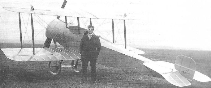
The Bristol Scout A in its original guise with small wings, uncovered wheel spokes and semi-enclosed engine cowling; standing in front is Harry Busteed.
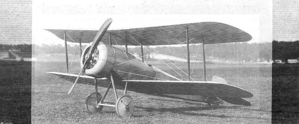
Bristol Scout A prototype after fitting with 24 ft. 7 ins. span wings and circular cowling.
The extremely business-looking 80 h.p. Bristol Scout. Note the method of carrying the shield all round tie engine.
The extremely business-looking 80 h.p. Bristol Scout. Note the method of carrying the shield all round tie engine.
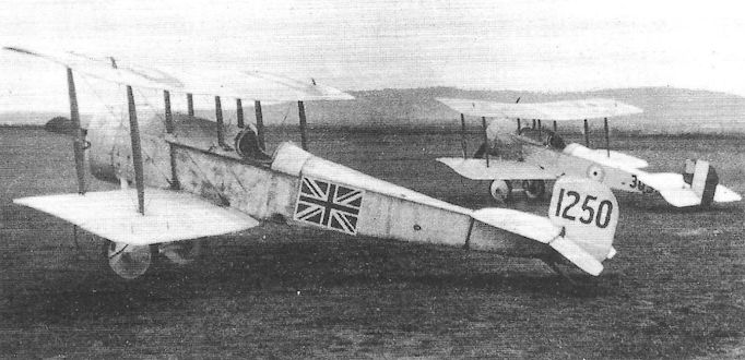
Bristol Scout Cs. The nearest aircraft, No 1250, bearing the early Union flag marking, is known to have served with the RNAS at Redcar early in 1915.

A Bristol Scout D, No 7052, from the first production batch of aircraft powered by the 80hp Le Rhone.

A Bristol Scout D of the second Le Rhone-powered batch, built for the RFC. A number of these aeroplanes were fitted by the Service with an external Vickers gun, as shown here, equipped with either Challenger or Scarff-Dibovski interrupter gear.

Bristol Scout A
Bristol S.S.A.
At Filton, while Barnwell was producing the Scout No 206, Henri Coanda embarked on a new single-seat tractor biplane at the request of the French firm of Breguet, it being intended for production in France. Known formally as the S.S.A. (or Single-Seat Armoured), this aircraft was required to feature armoured protection for the pilot, engine and fuel tank, a requirement met by enclosing all within a single monocoque component of sheet steel, the pilot’s seat being formed by the shape of the rear bulkhead.
An 80hp Clerget rotary engine was contained within a steel cowling with a large hemispherical spinner pierced with radial slots to permit entry of cooling air to the engine. The staggered wings were placed well forward to balance the weight of the armoured ‘bath’, while the tail unit was carried on an exceptionally slender rear fuselage. The undercarriage was also novel in consisting of castoring mainwheels to assist cross-wind landing, while the landing skids extended aft from the wheels, thereby dispensing of the need to provide a tailskid. The tail surfaces were similar to those of the Scout A.
First flown by Sidney Sippe at Larkhill on 8 May 1914 (given the company sequence number 219) suffered a heavy landing on arrival at Farnborough. After repair it was flown by Harry Busteed at Filton on 26 June, but crashed on landing when an undercarriage bracing wire failed. The pilot was slightly injured, although the aircraft itself was severely damaged.
The French authorities however agreed to accept delivery of it at Breguet’s factory, where it was to be rebuilt, and Bristol took no further part in the S.S.A.’s development.
Type: Single-engine, single-seat, single-bay armoured scout biplane.
Manufacturer: The British and Colonial Aeroplane Co Ltd, Filton, Bristol.
Powerplant: One 80hp Clerget rotary engine driving two-blade propeller.
Structure: Steel monocoque front fuselage accommodating pilot, engine, fuel and oil tanks; steel tubular frame structure in wings, rear fuselage and tail, all fabric-covered. Twin castoring mainwheels.
Dimensions: Span, 27ft 4in; length, 19ft 9in; wing area 200 sq ft.
Weights: Tare, 913lb; all-up, 1,200lb.
Performance: Max speed, 106 mph at sea level; endurance, 3 hr.
Armament: None.
Prototype: One (sequence No 219; first flown by Sidney Sippe at Larkhill on 8 May 1914); no production.
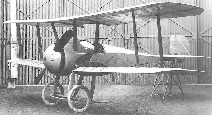
The Bristol S.S.A. armoured scout.
Bristol F.2A
In March 1916 Frank Barnwell began the design of a new two-seat fighter embodying many of the lessons learned from the Royal Aircraft Factory’s B.E.2 (of which Bristol had produced several hundreds). Intended to use the 120hp Beardmore engine, this design was referred to as the R.2A, and was a fairly large two-bay biplane with wings of equal span; the pilot’s cockpit was located under a large trailing edge cutout, and his observer/gunner was situated close behind with a Lewis gun on a Scarff ring. A single synchronized Lewis gun was mounted forward on the upper starboard longeron. It was realised that the R.2A would be somewhat underpowered and in May the design was altered to introduce a 150hp Hispano-Suiza, and to feature wings of unequal span and part-Warren girder interplane struts; this was the R.2B.
Two months later Bristol was offered one of the new 190hp Rolls-Royce vee-twelve water-cooled engines (soon to be named the Falcon I), and Barnwell undertook a fresh re-design, the F.2A, based largely on the R.2s and returning to the equal-span two-bay wings of the original design, but retaining the sprung tail skid of the R.2B. The front Lewis gun was changed to a Vickers and re-positioned in the centre of the nose where it was located in a tunnel through the front fuel tank; fifty gallons of fuel were carried in two tanks, sufficient for 3 1/4 hours’ flying.
The fuselage box girder structure was strengthened and an adjustable-incidence tailplane incorporated, permitting the aircraft to be flown ‘hands-off over a wide speed range. The rear fuselage was given more pronounced taper in side elevation, thereby slightly increasing the observer/gunner’s rearward field of fire. Wireless equipment was to be provided as a standard fitting. One of the characteristic features of the F.2 family that would become familiar for many years was the continuous lower wing structure which was located about ten inches below the fuselage, being ‘carried’ by struts attached to the lower fuselage longerons. The centre section of this wing was an open structure with steel carry-through spars without fabric covering. The wings, with top and bottom ailerons, were rigged with 17.1 inches of stagger.
The first prototype, A3303, was flown on 9 September at Filton by Capt C A Hooper, and went on to Upavon for Service evaluation on the 21st. It was soon found that the Falcon’s vertical radiators, mounted on the sides of the nose, obscured the pilot’s field of view during landing and a new nose configuration was designed to incorporate a single annular radiator within the engine cowling.
A second prototype, A3304, was flown on 25 October, this aeroplane being fitted with a 150hp Hispano-Suiza - also with front annular radiator. This was the version intended for production, but all Hispano-Suizas were now required for the Royal Aircraft Factory’s S.E.5, and an order was issued for fifty F.2As, to be powered by Rolls-Royce Falcon Is. The production version also featured blunt wingtips, a feature that was to remain unchanged in all subsequent F.2s.
These F.2As began delivery to the RFC in February 1917 and were issued to No 48 Squadron at Rendcombe, Gloucestershire, where a special training unit was formed for the Bristols’ crews. No 48, commanded by Maj A Vere Bettington (later Gp Capt, CMG, raf) flew to Bertangles in France on 8 March, moving on to Bellevue soon after. The Squadron’s debut in action on 5 April ended in disaster when six F.2As, led by Capt W Leefe Robinson vc, ran into five Albatros D IIIs, led by Manfred von Richthofen. Four of the Bristols were shot down, two of them by the enemy leader. Further casualties were suffered in the days following until it became apparent to the British pilots that the F.2A was being flown incorrectly in combat, and that relying wholly on the rear gun was to exploit only a small part of the fighter’s potential. Gradually the pilots began to fly their aircraft as if they were single-seaters, using the front gun offensively, and relying on the rear gun primarily for defence. Thereafter the Bristol’s true value was fully appreciated and, when the F.2B arrived soon after, the RFC found that it had a superb general purpose fighter.
[There was to be a curiously analogous combat twenty-three years later, when Boulton Paul Defiant two-seat turret fighters of No 141 Squadron, fighting their first combat in the Battle of Britain, encountered enemy Messerschmitt single-seaters over the English Channel. Once again the British pilots fought their fighters as gun platforms for their rear gunners and once more suffered catastrophic losses, six out of nine Defiants being destroyed. After the incident, however, there was to be no recourse to front gun armament - the Defiant had none.]
Type: Single-engine, two-seat, two-bay biplane general purpose fighter.
Manufacturer: The British & Colonial Aeroplane Co Ltd, Filton and Brislington, Bristol.
Powerplant: First prototype and production F.2As. One 190hp Rolls-Royce Falcon I 12-cylinder water-cooled in-line engine. Second prototype. 150hp Hispano-Suiza.
Structure: Wooden structure with duralumin, ply and fabric covering, reinforced locally with steel tubular members.
Dimensions: Span, 39ft 3in; length, 25ft 10 in; height, 9ft 6in; wing area, 389 sq ft.
Weights: Falcon I. Tare, 1,700lb; all-up, 2,700lb.
Performance: Falcon I. Max speed, 110 mph at sea level; climb to 10,000ft, 14 min 30 sec; service ceiling, 16,000ft; endurance, 3 1/4 hr.
Armament: One 0.303in Vickers machine gun in nose with Constantinesco CC interrupter gear, and one Lewis gun on Scarff ring in rear cockpit.
Prototypes: Two, A3303 (first flown on 9 September 1916 by Capt CA Hooper at Filton), and A3304.
Production: 50 aircraft (A3305-A3354).
Summary of Service: Bristol F.2As served with No 48 Squadron, RFC, in France, and at a training unit at Rendcombe.
Bristol F.2B Fighter
The first Bristol F.2 with alterations recommended by the AID during the F.2A trials was flown on 25 October 1916. These modifications included the covering of the lower wing centre section below the fuselage, and the angling downwards of the upper longerons from the rear of the front cockpit forward in order to improve the pilot’s view while landing. The first 150 F.2Bs, from a contract for 200 (A7101-A7300), retained the 190hp Rolls-Royce Falcon I of the earlier F.2A, but from A7251 onwards the 220hp Falcon II was fitted.
The next order for 250 aircraft introduced the definitive Falcon III of 275hp, and this engine remained standard for the Fighter for the remainder of the War and beyond - although several alternative engines were adopted when pressure on Falcon production increased sharply in 1918.
The Bristol F.2B Fighter was one of a handful of truly great British fighters of the War, alongside such aircraft as the S.E.5A, and Sopwith Pup and Camel. The shock defeat of No 48 Squadron, with its heavy losses of F.2As, might have had serious repercussions had the War Office concluded that the British fighters suffered a fundamental design flaw, and decided to cancel the large production contracts which had by then been negotiated. Fortunately it was the line pilots themselves who took matters into their own hands, changing tactics by employing the Fighter’s front gun offensively.
By the time No 11 Squadron, commanded by Maj Cuthbert Trelawder Maclean (later Air Vice-Marshal, cb, dso, mc, RAF), arrived in No 13 Wing at La Bellevue, the new tactics were paying off handsomely. On 20 June the Squadron drew first blood when an Albatros D III attacked a Bristol head-on, but was met and destroyed by a short burst from the British fighter’s front gun. The pilot of the F.2B was Lt Andrew Edward McKeever, a Canadian from Ontario who was to become the finest exponent of the two-seat fighter. This was his first victory, and by the end of the year (when he was posted to England as an instructor) he had destroyed a total of thirty enemy aircraft, of which eight fell to the gun of his observer, Sergeant L F Powell. McKeever was to be awarded the DSO and two MCs (and Powell the DCM), only to die on Christmas Day 1919 from injuries suffered in a car accident.
Such was the esteem in which the Bristol Fighter was now held that in July 1917 the War Office decided to standardize the aircraft on all fighter- and corps-reconnaissance squadrons of the RFC, replacing the B.E.2 and B.E.12 and, in due couse, the R.E.8 - a process that lasted well into the post-War years. On 2 September the parent company received an order for a further 800 F.2Bs (which it could meet as the B.E.2 production at Filton was coming to an end), and the following month orders for a further 800 were placed with three manufacturing sub-contractors.
Meanwhile No 20 Squadron (Maj E H Johnston) at St Marie-Capelie, and No 22 Squadron (Maj L W Learmont dso, mc) at Boisdinghem had received F.2Bs, replacing F.E.2s, and in September No 39 Squadron at Woodford, Essex, changed to F.2Bs for Home Defence duties. The same month a small number of Bristol Fighters joined the newly-formed No 111 Squadron in Palestine, joining Bristol Scouts, D.H.2s and Nieuports.
As the numbers of F.2Bs in France continued to grow, it became increasingly noticeable that German pilots were deliberately avoiding combat with them unless they possessed overwhelming numerical superiority. Even so, there were Bristol pilots who seemed undaunted by unfavourable odds. On 30 November 1917 McKeever and Powell encountered two German reconnaissance two-seaters escorted by seven Albatros single-seaters, and shot down both the former and two of the latter before making good their escape.
In 1918 the pace of production was further increased, with a total of 2,867 aircraft completed by Bristol and four sub-contractors (the latter producing 1,000 aircraft between them). Inevitably it was not long before Rolls-Royce reported that it would be unable to keep pace with engine demand, as production of both the Eagle and Falcon was already running at capacity, while the very large 600hp Condor would soon enter production. This situation had been foreseen some months earlier, but continuing indecision by the War Office had already led to delays in the delivery of engines. A number of alternative engines had been specified, including the 200hp Sunbeam Arab and the 200hp Hispano-Suiza, the latter being intended for aircraft built by the National Aircraft Factory No 3 at Aintree, Liverpool. The available Falcons were intended to be confined to aircraft built by Bristol, with Arabs suggested as suitable alternatives should airframe production outstrip engine availability. In the event only a tiny number of Bristol-built F.2Bs was completed with the Sunbeam engine.
These alternative engines underwent official tests in F.2Bs early in 1918, the Hispano-Suiza in B1201 during January, and the Arab in B1204 in March. The performance in both was most unsatisfactory and bestowed a much inferior performance compared with those aircraft with Falcons. Moreover, production of the 200hp Hispano-Suiza had encountered problems, and the reduced numbers available were reserved for the S.E.5A, with the result that the Hispano-powered F.2B was abandoned, and the NAF No 3-built aircraft were completed with Falcons.
Choice of the Arab had also been unfortunate. The engine had been ordered in considerable numbers as early as 1916, largely on the strength of design figures submitted before it had undergone rigorous testing. In January 1917 the engine had been ordered in quantity from the Auston Motor Company and from Willys-Overland in Canada. When the trials were completed in May that year, the engine was found to have serious cylinder and crankcase design faults, so that final drawings could not be issued until December. Production plans had called for 1,800 engines to be delivered by the end of 1917, but only 81 had been completed. Furthermore, when installed in the Bristol Fighter, it is said that engine life was an average of only four hours due to excessive vibration causing crankshaft failure.
Because of the much-reduced performance of the Arab engine, it was decided to confine it to F.2Bs entering service with Corps Reconnaissance squadrons in April 1918, and to issue Falcon-powered aircraft to the Fighter and Fighter-Reconnaissance squadrons. This was rescinded after the creation of the Air Ministry on 2 January 1918, and it transpired that Arab-powered aircraft were only used as replacements for second-line units.
By mid-1918 fifteen squadrons had been equipped with F.2B Fighters. Of these, Nos 11, 48 and 62 were flying primarily fighter patrols, including escort duties, over the Western Front; Nos 20, 22 and 88 Squadrons were performing fighter-reconnaissance duties in France; No 12 was engaged in Corps Reconnaissance (what would later be termed army co-operation), and would be joined by No 9 Squadron in July. Nos 33, 36, 39,'75, 140 and 141 Squadrons were based on airfields in England for home defence against German bombers and airships, and would be joined by No 76 Squadron soon after. Further afield No 34 Squadron was engaged in fighter-reconnaissance on the Italian Front, being joined by No 139 in July. In Palestine No 67 Squadron was flying fighter patrols in aircraft that had formerly been used by No 111 Squadron. One other Squadron, No 35, would begin to equip with Bristol F.2Bs in France, replacing Armstrong Whitworth F.K.8s for army co-operations duties, but was not fully operational before the Armistice in November.
Before going on to summarise the Bristol Fighter’s peacetime activities, it is necessary to mention some of the numerous experiments undertaken with the aircraft as it underwent a continuous programme of development. Engines which were flown experimentally in the aircraft included the 230hp Siddeley Puma (and a 290hp high-compression version), 200hp Wolseley Viper, 300hp Hispano-Suiza and 200hp RAF 4D; single-bay wings were flown on several test aircraft, and three-bay high aspect ratio wings were also flown, both types in 1923.
Although strictly outside the scope of this work, extensive plans were laid to build Bristol Fighters in the United States of America (on the recommendation of General Pershing), and with them to equip American forces, as that country had entered the War with scarcely a respectable modern military aeroplane. Unfortunately these plans were long delayed, partly due to an attempt to fit the unsuitable American Liberty 12 engine in the aircraft; various other American engines were tried, including the Liberty 8, Wright H, Curtiss D-12 and a 350hp Packard, but none produced any significant improvement over Frank Barnwell’s original design. In all, some 68 aircraft (including prototypes) were produced in America.
Post-War Service
The Armistice of November 1918 ended any immediate threat of air attack on Britain, and brought about enormous reductions in her air force, so much so that home-based interceptor fighter squadrons almost entirely disappeared in the post-War cutbacks. The Bristol Fighter, of which the new Royal Air Force possessed no fewer than 1,583 at the end of the War, had shown itself to be an excellent reconnaissance fighter, well suited to the role of army cooperation.
As the RAF assumed the role of air policing, under international mandate in the Middle East, squadrons equipped with D.H.9s and Bristol F.2Bs were sent out to, or re-formed at numerous foreign stations, many of them with very rudimentary landing strips. The majority of wartime F.2B squadrons remained in being only until 1919 or 1920, the exception being No 20 which, without even returning to Britain from the continent after the Armistice, was posted direct to India for service on the North West Frontier, continuing to fly Bristol Fighters until March 1932 - the longest term of service by an F.2B Squadron.
It had already been discovered that operating the Falcon-powered fighters in the harsh conditions of heat and dust in the Middle East during the War had resulted in very low serviceability among the aircraft, their engines frequently overheating and quickly wearing out. The Royal Aircraft Establishment (formerly the Factory) at Farnborough undertook a programme of trials to find means by which these problems might be overcome. Early remedies included the simple expedient of cutting extra louvres in the engine cowling to allow unrestricted airflow through the frontal radiator; radiator shutters were removed and, eventually, tropical radiators with coarse matrices were introduced; aircraft thus built or modified became Bristol Fighter Mark Ils, and also carried desert survival equipment.
In due course aircraft engaged in operations, particularly on the North West Frontier of India, were required to carry up to twelve 20-pound Cooper fragmentation bombs, and this in turn demanded local strengthening of the airframe; these aircraft were termed Mark IIIs. In 1926 further design changes introduced Handley Page slots on the upper wings, revised upper fin and an enlarged, horn-balanced rudder and further strengthening of the undercarriage, aircraft with these modifications being Mark IVs. And all the while the Rolls-Royce Falcon III remained the standard engine.
At home a total of four army cooperation Squadrons (Nos 2, 4, 13 and 16) continued flying F.2Bs until the late nineteen-twenties, and No 24 Squadron flew them on communications duties. Nos 5,20,28 and 31 were equipped with successive versions in India and on the North West Frontier until the early nineteen-thirties, as Nos 6, 14 and 208 served on various stations throughout the Middle East (Nos 4 and 208 Squadrons were also engaged in the brief activities in Turkey during and after the Chanak crisis of 1922, and No 2 was sent to China for several weeks in 1927 to protect the international settlement at Shanghai).
The ‘Brisfit’ was a very popular aeroplane among its crews throughout its long service, largely thanks to its excellent Rolls-Royce Falcon engine; it was a sturdy aircraft, capable of withstanding considerable combat damage in war, and rough field conditions before the age of metalled runways.
Type: Single-engine, two-seat, two-bay biplane army co-operation reconnaissance fighter.
Manufacturers (in Britain): The British & Colonial Aeroplane Co Ltd (Bristol Aeroplane Co Ltd), Filton and Brislington, Bristol; Sir W G Armstrong, Whitworth & Co Ltd, Newcastle-upon-Tyne; The Gloucestershire Aircraft Co Ltd, Cheltenham; Harris & Sheldon Ltd, Birmingham; Marshall & Sons, Gainsborough; National Aircraft Factory No 3, Aintree, Liverpool; Angus Sanderson & Co, Newcastle-upon-Tyne; The Standard Motor Co Ltd, Coventry; The Austin Motor Co (1914) Ltd, Birmingham.
Air Ministry Specification: Spec 21/21 covered post-War re-building and reconditioning of wartime aircraft.
Powerplant: One 190hp Rolls-Royce Falcon I twelve-cylinder liquid-cooled in-line engine; 220hp Falcon II; 275hp Falcon III; 200hp Sunbeam Arab; 200hp Hispano-Suiza; 300hp Hispano-Suiza; 230hp Siddeley Puma; 290hp Siddeley Puma (high compression); 200hp RAF 4D; 200hp Wolseley W4A Viper; 290hp Liberty 8; 400hp Liberty 12.
Structure: All-wooden construction with ply and fabric covering.
Dimensions: (Falcon) Span, 39ft 3in; length, 25ft 10in; height, 9ft 9in; wing area, 405.6 sq ft.
Weights: (Falcon III) Tare, 1,934lb; all-up, 2,779lb.
Performance: (Falcon III) Max speed, 126 mph at sea level, 105 mph at 15,000 ft; climb to 10,000ft, 11min 15 sec; service ceiling, 20,000ft; endurance, 3 hr.
Armament: One fixed, synchronized 0.303in Vickers machine gun mounted centrally beneath nose cowling with Constantinesco CC interrupter gear, and one or two Lewis guns on rear cockpit Scarff ring; later aircraft could carry up to twelve 20lb Cooper fragmentation bombs under the lower wings.
Prototypes: See Bristol F.2A
Production: (in Britain) Total of 5,329 built. (Bristol, 3,451: A7101-A7300, Bl 101-B1350, C751-C1050, C4601-C4900, D7801-D8100, E2151-E2650, E5253-E5308, F4271-F4970, H1240-H1707, J6586-J6800 (Mk II), J7617-J7699 (Mk II), J8242-J8291 (Mk III), J8429- J8458 (Mk III); Gloster, 550: C9836-C9985, E9507-E9656, H834-H1083; Austins, four known: H6O55-H6O58; Armstrong, Whitworth, 250: E1901-E2150; Harris & Sheldon, 100: F5074-F5173; Marshalls, 150: D2626-D2775; NAF No 3, 500: D2126-D2625; Angus Sanderson, 250: E2651-E2900; Standard Motors, 74: E5179-E5252.)
Summary of RFC and RAF Service: Bristol F.2Bs equipped Nos 9, 11, 12, 20, 22, 48, 62 and 88 Squadrons, and also served with Nos 4, 10, 12, 15, 16 and 35 Squadrons, Western Front; Nos 33,36, 39,76,140 and 141 Squadrons, Home Defence; equipped No 67 Squadron (later No 1 Squadron, Australian Flying Corps) and flew with No 111 Squadron in Palestine; Nos 34 and 139 Squadrons, Italian Front. Post-War, F.2Bs equipped Nos 2, 4, 13, 16 and 24 Squadrons at home; Nos 100 and 105 Squadrons in Ireland, 1918-1922; No 8 Squadron, Belgium, 1918-1920; Nos 5, 20, 28, 31 and 114 Squadrons in India; Nos 6, 14 and 208 Squadrons in Middle East.
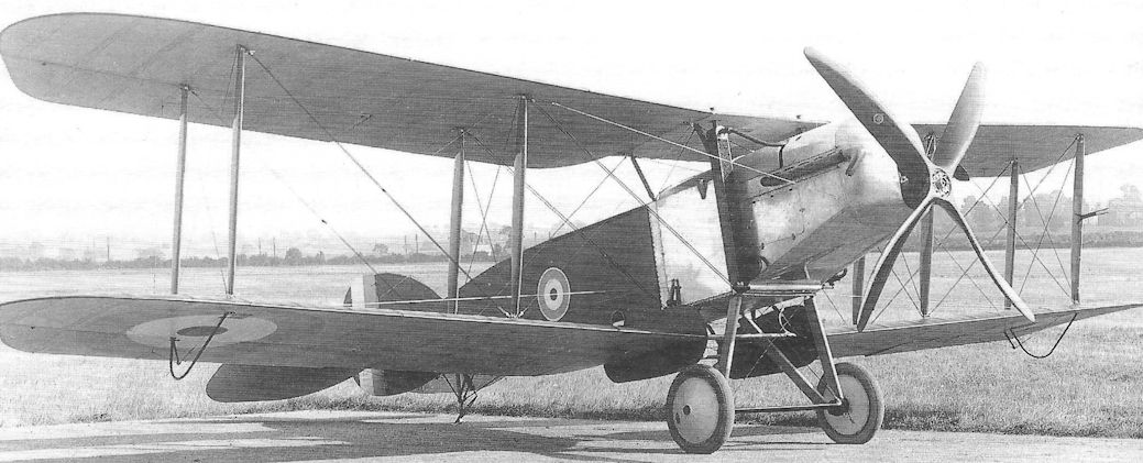
The first Bristol F.2A prototype, A3303, at about the time of its first flight on 9 September 1916, powered by a 190hp Rolls-Royce Falcon I with vertical radiators on the sides of the nose. This aircraft featured wing-root endplates and wingtips reminiscent of the B.E.2, of which Bristol had produced so many.
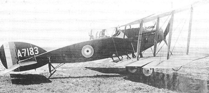
The second F.2B to be fitted with a Rolls-Royce Falcon III engine, A7183 from the first production batch built by The British (A Colonial Aeroplane Company. This aircraft was used primarily for engine testing.
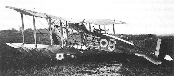
F.2B night-fighter B1252 of No. 39 Sqn, showing wing-tip lights and pilot's ring-sight.
An F.2B of a Home Defence Squadron in 1918; this aircraft is inscribed ‘Presented by Maharajah Bahadur Sir Rameswar Singh of Darbhanga, No. 2 “The Lord Chelmsford’”.
An F.2B of a Home Defence Squadron in 1918; this aircraft is inscribed ‘Presented by Maharajah Bahadur Sir Rameswar Singh of Darbhanga, No. 2 “The Lord Chelmsford’”.
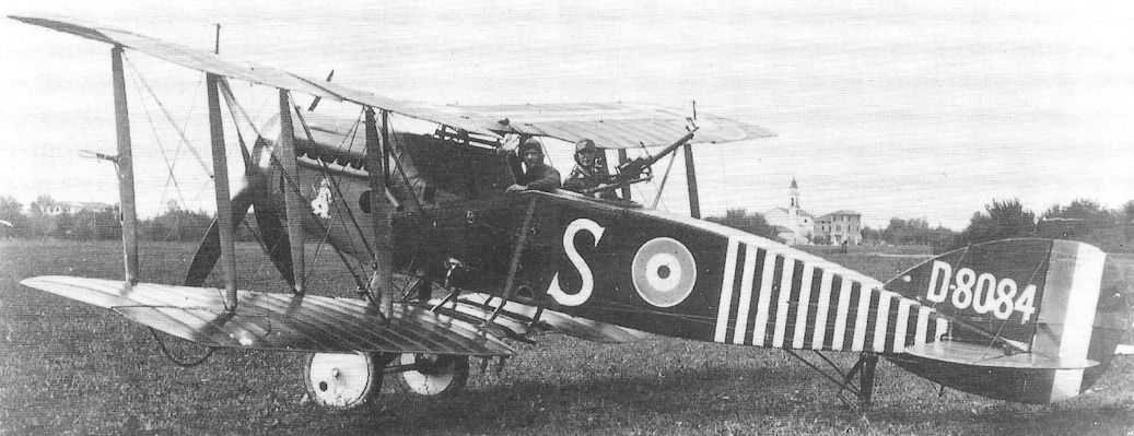
A Bristol F.2B Fighter of No 139 Squadron, D8084 ‘S’, at Villaverla on the Italian Front in 1918; formed from ‘Z’ Flight of No 34 Squadron, No 139 Squadron destroyed 27 enemy aircraft in only four months.
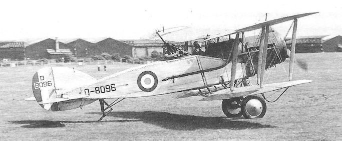
The beautifully restored Bristol F.2B, painted as D8096, is maintained in flying condition by the Shuttleworth Trust at Old Warden, Bedfordshire; it is here shown at Filton.
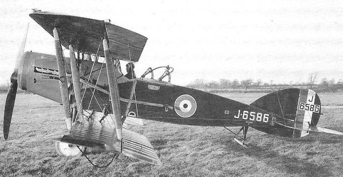
J6586 was the first Bristol Fighter Mark II, which made its first flight in December 1920; it underwent trials at Martlesham Heath with the tropical radiator in 1921 and was converted to a dual-control trainer in 1924.

Bristol Type 12 F.2A
Bristol M.1 Monoplanes
All credit is due to Frank Barnwell at Bristol for his defiance in the face of ill-informed prejudice by venturing into the realm of monoplane design. Ever since the summary ban imposed by the War Office following a number of crashes involving monoplanes in 1912, reluctance by the military authorities to accept such aircraft had discouraged designers and manufacturers from flying in the face of such misplaced prejudice. Even when the Germans introduced their successful series of Eindekker scouts in 1915, the War Office remained trenchantly unconvinced.
Barnwell’s M.1 design, started early in 1916, was lent urgency by the increasing casualties over the Western Front even though, with the arrival of such fighters as the Airco D.H.2, the air fighting was becoming less one-sided. The first example, known as the M.1A and built as a private venture, was first flown without armament at Filton on 14 July by the great free-lance test pilot, Fred Raynham, and at once demonstrated a marked performance superiority over current biplane scouts, returning a maximum speed of 132 mph at sea level on a 110hp Clerget engine.
The new monoplane’s fuselage retained the wooden box-girder of the Bristol biplane scouts, but faired throughout its length to circular section with formers and stringers. The two-spar wings were attached at their main spar ends to the upper longerons, being externally cable-braced below to the bottom longerons and above to a pair of hooped tubular members which formed a cabane under which the cockpit was located; this cabane thus provided some protection for the pilot in the event of the aircraft overturning while landing. The wings, rigged with two degrees of dihedral but zero incidence, were of distinctive planform, possessing elliptical leading edge and straight trailing edge with rounded tips. The tailplane and elevator were scarcely altered from those of the Scout biplanes, but a fixed fin was introduced forward of the unbalanced rudder. A large hemispherical spinner with a small aperture in the nose was fitted over the two-blade propeller, having been shown on some Scout Ds to result in a marked reduction in drag - although care had to be taken to avoid engine overheating.
The prototype underwent AID evaluation in July, confirming the initial performance measurements, and these led to the purchase of the first aircraft (which became A5138) and an order for four further prototypes (A5139-A5142), modified to include a synchronized Vickers gun with Constantinesco CC interrupter gear, mounted on the port upper longeron. This version, the M.1B, featured a cutout panel in the starboard wing root for downward vision, and the cabane hoops were discarded in favour of four straight tubular members arranged pyramidally. The 110hp Clerget engine was retained, although one of the M.1Bs was tested with a 150hp Bentley A.R.1 engine in March 1917.
Despite being eagerly awaited by RFC squadrons on the Western Front, a production contract was delayed, due it was said to War Office apprehension at the Bristol’s high landing speed - 49 mph; this may have stemmed from the rumour that a senior officer crashed one of the prototypes, having misjudged his landing speed.
When production M.1Cs (with 110hp Le Rhone engine, cutouts in both wing roots and a centrally mounted Vickers gun with Sopwith-Kauper interrupter gear) appeared, it transpired that none was scheduled for France. A total of 125 aircraft was built and, apart from a small number used for training on Salisbury Plain and at Hounslow, Marske and Montrose, these only served with squadrons in the Balkans and the Middle East. First was No 14 Squadron in Palestine at Deir-el-Belah in May 1917, followed
in August by No 111 Squadron on the same aerodrome; M.1Cs were issued to ‘A’ Flights of Nos 17 and 47 Squadrons at Mikra Bay in Salonika for operations against the Turks and Bulgars, and these Flights merged to form No 150 Squadron in January 1918. The only other Squadron was No 72 which received the monoplanes at Basra in March 1918. The last to be declared obsolete were those of No 150 Squadron when it was disbanded in September 1919.
After the Armistice an M.1B and several M.1Cs were repurchased by Bristol, reconditioned and sold to civilian owners who flew them in sporting events for several years.
Type: Single-engine, single-seat, shoulder-wing monoplane fighting scout.
Manufacturer: The British & Colonial Aeroplane Co Ltd, Filton and Brislington, Bristol.
Powerplant: M.1A. One 110hp Clerget engine. M.1B. 110hp Clerget; 150hp Bentley A.R.1. M.1C. 110hp Le Rhone.
Structure: Wooden box-girder formed to circular section; two-spar wings attached to upper longerons and cable-braced to lower longerons and cabane members over cockpit.
Dimensions: Span, 30ft 9in; length, 20ft 3in (M.1A), 20ft 5 1/2 in (M.1C); height (M.1C), 7ft 9 1/2 in; wing area, 163 sq ft.
Weights: M.1C. Tare, 896lb; all-up, 1,348lb.
Performance: M.1C. Max speed, 130 mph at sea level; 111.5 mph at 10,000ft.; climb to 10,000ft, 10 min 25 sec; service ceiling, 20,000ft; endurance, 1 3/4 hr.
Armament: M.1A, nil. M.1B and M.1C. One 0.303in Vickers machine gun with either Constantinesco CC or Sopwith-Kauper interrupter gear.
Prototypes: One M.1A, A5138 (first flown by Fred Raynham on 14 July 1916); four M.1Bs, A5139-A5142.
Production: Total of 125 M.1Cs, C4901-C5025.
Summary of Service: M.1Bs and M.1Cs flew with Nos 14, 72, 111 and 150 Squadrons (the last-named Squadron being formed from ‘A’ Flights of Nos 17 and 47 Squadrons). All these Squadrons served either in Macedonia or the Middle East.
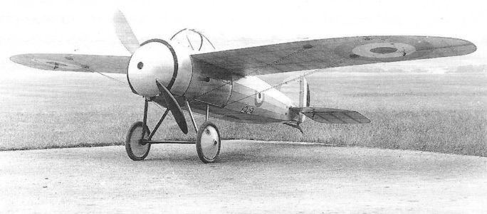
The exceptionally clean lines of the Bristol M.1A prototype, A5138, are evident in this photograph taken in July 1916 at the time of its first flight.
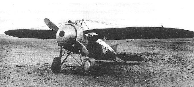
Despite retaining its Vickers gun, this Bristol M.1C is said to have been serving with the Wireless Experimental Establishment at Biggin Hill late in, or shortly after, the War.
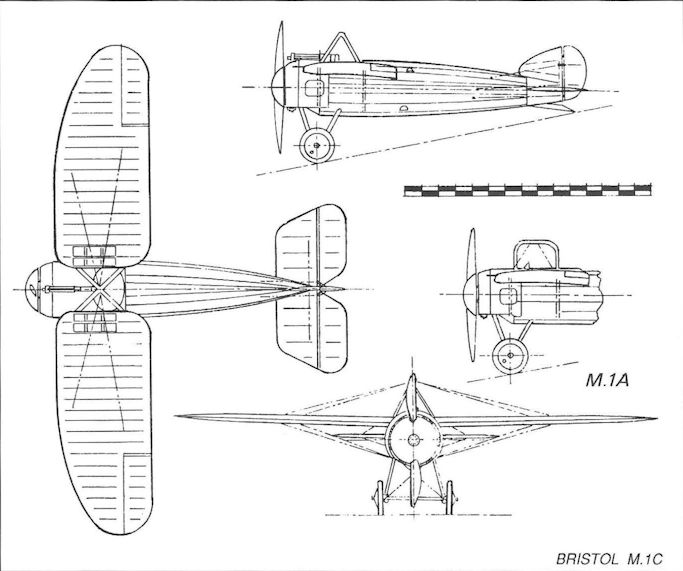
Bristol M.1C
Bristol Type 8 S.2A
Once the Bristol Type 6 T.T.A. had passed out of the design stage, Frank Barnwell turned his attention to another original idea to overcome the lack of a reliable synchronized front gun, this time producing what was in effect a two-seat development of the Scout D, but instead of pursuing the customary tandem cockpit layout, which would be expected to require lengthening the fuselage by several feet, he adopted side-by-side accommodation of the crew in a single cockpit. While the pilot could concentrate on controlling the aircraft, his gunner could load, aim and fire the armament.
Two prototypes, Nos 7836 and 7837, were produced to meet an Admiralty requirement for a two-seater, and the first was flown at Filton in May 1916. Powered by a 110hp Clerget rotary, it featured the tail unit of the Scout D as well as similar wings, though with reduced rake at their tips. The centre section of the upper wing was somewhat wider than on the Scout owing to the increased fuselage width, while the cabane struts were angled outwards, but without stagger; because the lower wing was mounted slightly further aft, stagger was maintained on the interplane struts. The broader fuselage also allowed for a wider track undercarriage.
As neither prototype was ever fitted with armament, it is not known what gun mounting was intended, although it seems probable that the gun would have been fitted on top of the wing to fire over the propeller.
The S.2A was not adopted for production, despite a moderately good performance, having been overshadowed by the Sopwith Pup with synchronized front gun. Trouble had been experienced with the Clerget engine in the first prototype, possibly due to inadequate cooling, and the second prototype was later flown at Gosport with the Gnome monosoupape engine.
Type: Single-engine, two-seat, single-bay biplane scout.
Manufacturer: The British & Colonial Aeroplane Co Ltd, Filton, Bristol.
Powerplant: One 110hp Clerget engine; also 100hp Gnome monosoupape engine.
Dimensions: Span, 28ft 2in; length, 21ft 3in; height, 10ft 0in.
Weights: All-up, 1,400lb.
Performance: Max speed, 95 mph at sea level; endurance, 3 hr.
Armament: Probably a single Lewis machine gun mounted above the wing centre section.
Prototypes: Two, Nos 7836 and 7837 (first flown in May 1916). No production.
Bristol Type 6 T.T.A.
In September 1915, at much the same time that Rex Pierson at Vickers began work on his twin-engine F.B.8 gun carrier, Frank Barnwell started the design of an aircraft of similar concept. The Bristol designer, however, went further in attempting to provide what was intended to be a more effective armament by including a gun for rearward defence.
His Type 6 twin-tractor aircraft (T.T., later to be termed the T.T.A.) was a very large three-bay biplane, scheduled to be powered by two 150hp RAF 4A engines; by the time the prototype began to take shape, however, all available engines of this type had been earmarked for the B.E.12, and Bristol had to make do with a pair of 120hp Beardmore engines. The crew consisted of a gunner in the nose, provided with a pair of free Lewis guns, and the pilot whose cockpit was behind the wings; a single rearward-firing free Lewis gun was to be fitted aft of the rear cockpit. Very large ailerons, each pair with two interconnecting struts, were fitted to upper and lower wings, while the tail unit was, in effect, an enlarged version of that on the Bristol Scout, being without a fixed fin. Fuel was carried in three main fuselage tanks and one behind each engine, with pressure feed being provided by a wind-driven pump.
Two aircraft, Nos 7750 and 7751, were ordered at a price, less engines, of £2,000 apiece, and the first was flown by Captain C A Hooper, rfc, on 26 April, being followed by the second on 27 May. One was flown for evaluation at Upavon, but came in for criticism on several counts, including the pilot’s very poor field of vision, the impossibility of communication between the two crew members and the general sluggishness of the controls.
However, like so many aspiring fighter aircraft designed before the end of 1915, the T.T.A. was overtaken by events with the arrival of the synchronized front gun, and further work on its development was abandoned.
Type: Twin-engine, two-seat, three-bay biplane gun carrier.
Manufacturer: The British & Colonial Aeroplane Co Ltd, Filton, Bristol.
Powerplant: Two 120hp Beardmore engines driving two-blade propellers.
Dimensions: Span, 53ft 6in; length, 39ft 2in; height, 12ft 6in; wing area, 817 sq ft. Weights: Tare, 3,820lb; all-up, 5,100lb.
Performance: Max speed, 86.7 mph at sea level; climb to 6,000ft, 17 min 15 sec; service ceiling, 9,500ft.
Armament: Two free-firing Lewis machine guns on nose cockpit, and a single rearward-firing Lewis gun on rear cockpit. (No armament fitted for trials.)
Prototypes: Two, Nos 7750 and 7751 (first flown by Capt C A Hooper RFC on 26 April 1916). No production.
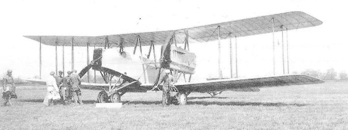
The Bristol T.T.A. before its delivery to Upavon for evaluation; it is said that the figure on the extreme left is Captain C A Hooper.
Bristol M.R.1
In mid-1916 the British & Colonial Aeroplane Co was asked by the War Office to examine the possibility of producing an all-metal version of the Bristol F.2A that would be more suitable for service in the Middle East than the contemporary wooden aircraft.
A preliminary scheme was prepared by Frank Barnwell in July that year, and this was later passed to W T Reid to develop into reality. Though by no means the first metal aeroplane in Britain or elsewhere, much of Reid’s work was of a truly pioneering nature, and the final design incorporated numerous innovative features that became the subject of patents held jointly by Reid and his employers.
Two prototypes were ordered, but the first, A5177, was not completed until October 1917, and was delivered initially with wooden wings. A5177 superficially resembled the Bristol F.2A, particularly as the lower wing section, located below the fuselage, was an open structure. Power was provided by a 150hp Hispano-Suiza mounted on steel tubular bearers bolted to the front of all four longerons. The fuselage was constructed in four sections, each a wire-braced steel tubular box girder, bolted together and covered with aluminium sheet. No attempt was made to include double-curvature sheeting, but local strengthening was achieved by riveting sections of corrugated aluminium on the inside of the skin, thereby maintaining a smooth external finish. The steel wings, built by the Steel Wing company of Cheltenham, were fabric covered (as were the tail surfaces), and the interplane and cabane struts were of steel tube, hot rolled to slim elongated section; Raf-wires were widely employed.
At one time it was intended to fit wings constructed on the Mayrow principle with composite steel and duralumin sub-structure and, although such wings were subjected to static tests, it is unlikely that they were flown on an M.R.1.
First flown by Capt Barnwell, A5177 was delivered to representatives of the Air Board on 23 October, but the steel wings were not completed until 1918, when the first set appeared on the second prototype, A5178, followed later on A5177. A5178 was also fitted with a 180hp Wolseley Viper engine.
Apart from the obvious lessons learned in the design of predominantly metal aeroplanes, the two M.R.1s provided a great deal of information about the specialised tools and manufacturing techniques essential for any large-scale switch to metal aircraft - a field in which their manufacturers would in due course take a leading part.
Type: Experimental single-engine, two-seat, two-bay biplane fighter.
Manufacturer: The British & Colonial Aeroplane Co Ltd, Brislington, Bristol.
Powerplant: One 150hp Hispano-Suiza engine driving two-blade propeller; also 180hp Wolseley Viper engine.
Structure: All-metal construction. Fuselage of steel tubular box-girder construction with aluminium semi-monocoque sheet covering. Two-spar wings using rolled high-tensile steel strip with fabric covering.
Dimensions: Span, 42ft 2in; length, 27ft 0in; height, 10ft 3in; wing area, 458 sq ft.
Weights: Tare, 1,700lb; all-up, 2,810lb.
Performance: Max speed, 110 mph at sea level; climb to 10,000ft, 20 min.
Armament: One synchronized 0.303in Vickers machine gun mounted to fire through tunnel in the top engine cowling; one Lewis gun with Scarff ring on rear cockpit amidships.
Prototypes: Two, A5177 and A5178 (first flight by A5177 in October 1917). One of these aircraft carried a spurious number, A58623, during ground tests in 1918. No production.
Bristol Type 21 Scout F and F.1
Throughout 1917 Capt Frank Barnwell had been engaged in advancing his basic Bristol Scout concept, but inevitably had to turn his attention away from the rotary engine when it became generally accepted as having reached the realistic limit of its power. The Scout E was schemed up to accommodate a proposed 200hp ten-cylinder water-cooled radial known as the ‘Cruciform’, but when this failed to materialise, Barnwell altered his design to take the much sought-after 200hp Hispano-Suiza in-line engine. The new design was designated the Scout F.
When, however, a contract for six prototypes was raised, on 4 June 1917, it was made clear that the Hispano engine would not be available (owing to prior claims for the S.E.5A), and that the 200hp Sunbeam Arab should be used instead. Installation of this engine itself presented little trouble, and Barnwell, by placing the water header tank over the engine, managed to achieve a very clean cowling. His locating of the radiator within a tunnel fairing between the undercarriage V-struts proved exceptionally neat, and became an established position for this cumbersome component of water-cooled engines. Another unusual feature, though not unique at the time, were the N-type interplane struts which obviated the need for incidence cable bracing.
Although the first Scout F prototype, B3989, was completed in November 1917, it was not flown until March the following year, mainly because of troubles being experienced by the Arab engine, early examples displaying severe vibration which seemingly defied cure. While efforts were being made to rectify these problems, numerous improvements were made in the cockpit and armament installation on the Scout. However, despite putting up an excellent performance during trials (138 mph at sea level, and climb to 10,000 feet in 9 minutes 20 seconds), the manufacturer decided to cast around for yet another engine and to abandon the existing design. Only two Scout Fs were completed, the second being flown at the Central Flying School.
It is likely that Barnwell was already aware of the engine designs of Alfred Hubert Roy (later Sir Roy) Fedden and L F G Butler at the Bristol company of Brazil Straker. These two engines, the two-row, fourteen-cylinder Mercury and the single-row, seven-cylinder Jupiter radials, were to become subjects of fairly large production orders after the Brazil Straker company was bought by the Cosmos Engineering Company. Attracted by the Mercury’s high power output and low overall diameter, Barnwell decided on this engine for his revised Scout F.1, B3991. Indeed, the Mercury had only been bench run in about February 1918. When installed in the F.1, extreme care was taken to keep drag to an absolute minimum by enclosing it in a compound curved cowling, through which only the cylinder heads protruded. The Scout F.1 was officially tested in September 1918 and produced a top speed of 145 mph at sea level.
Unfortunately, with the signing of the Armistice, the order for 200 Cosmos Mercury engines was cancelled, and further development of the Scout F.1 also came to an end and, although one further prototype, B3992, only awaited an engine, it too was dismantled - although the wings underwent structural strength tests at Farnborough in 1919.
Type: Single-engine, single-seat, single-bay biplane fighter.
Manufacturer: The British & Colonial Aeroplane Co Ltd, Filton, Bristol.
Powerplant: Scout F. One 220hp Sunbeam Arab II water-cooled in-line engine. Scout F.1. One 347hp Cosmos Mercury fourteen-cylinder air-cooled radial engine.
Dimensions: Span, 29ft 7 1/2 in; length, (Scout F) 20ft 10in, (Scout F.1) 20ft 0in; height, 8ft 4in; wing area, 260 sq ft.
Weights: Scout F. Tare, 1,436lb; all-up, 2,210lb.
Performance: Scout F. Max speed, 138 mph at sea level; climb to 10,000ft, 9 min 20 sec; service ceiling, 21,000ft. Scout F.1. Max speed, 145 mph at sea level; climb to 10,000ft, 5 min 25 sec.
Armament: Twin synchronized 0.303in Vickers machine guns on upper nose decking.
Prototypes: Six prototypes ordered, B3989-B3994. B3989 and B3990 were built as Scout Fs; B3991 was begun as a Scout F but completed as Scout F.1; B3992-B3994 were not completed. No production.
Bristol Badger
The Bristol designation F.2C came to be used, after the appearance in service of the famous F.2B Fighter in 1917, for a proposed replacement, the design of which began in November that year. Originally this project was intended to be fitted with either a Bentley B.R.2 rotary engine or a 260hp Salmson water-cooled radial engine.
The promise held out by the powerful new ABC Dragonfly, however, attracted the attention of Frank Barnwell, who then embarked on an entirely new design with this engine - though still retaining the F.2C designation.
Named the Type 23 Badger (to conform to Technical Department Instruction No 538 of 1918 which required multi-seat fighters to be named after mammals), the new aircraft was a two-seat, single-bay, staggered biplane of fabric-covered, wooden box-girder construction, with the N-type interplane struts which had been a feature of the Bristol Scout F. Ailerons were fitted to the upper wing only and - again reverting to the Scouts - no fixed tail fin was included.
Three prototypes, F3495-F3497, were ordered on 14 May but, in view’ of troubles and delays being experienced with the Dragonfly engine, design work continued slowly during 1918. Ironically, the first prototype was damaged in a crash landing during take-off for its first flight on 4 February 1919, the accident being caused by an air lock in the fuel feed. The pilot, Cyril Uwins, was unhurt.
This aircraft, the Badger Mk I, was repaired and given an improved, more pointed engine cowling, and the opportunity was taken to fit a slightly enlarged rudder. The work only occupied ten days, and F3495 was handed over to the Air Board on 15 February; it subsequently underwent prolonged performance and handling trials at Martlesham Heath, remaining there until September 1920.
Meanwhile the second prototype, the Badger Mk II F3496, had been scheduled for the 400hp Cosmos Jupiter I nine-cylinder radial engine, but the bench tests delayed delivery so that its first flight was not accomplished until 24 May 1919. Production of the Jupiter, which would have recovered the heavy cost of development for its manufacturers, had been cancelled after the Armistice, foreshadowing virtual ruin for Cosmos Engineering Co Ltd. Believing that the Jupiter engine held considerable promise, the British & Colonial Aeroplane company began negotiating the acquisition of all assets of the Cosmos company - under some pressure from the British Government. A preliminary order was then placed for six experimental engines for test purposes, two of these being intended for flight in the Badger.
No trouble was experienced with the Jupiter in F3496 during trials. The aircraft, however, had been criticised on account of inadequate lateral and directional control, and it was decided to fit a conventional fixed fin. This prototype was handed over to Air Ministry charge in June and was delivered to Martlesham in October, but is believed to have crashed the same month after being fitted with a Dragonfly IA engine...
Owing to the handling deficiencies of the second Badger, the third of the original prototypes was delayed pending wind-tunnel tests, and was first flown in February 1920. Another Badger had been completed in 1919 for aerodynamic tests, powered by an Armstrong Siddeley Puma engine, but in fact only the wings and undercarriage were of Badger design. Locally referred to as the Badger X (for experimental) the aircraft was entered on the Civil Register as K110, but had already crashed on 22 May that year.
If one accepts that this was indeed the fourth Badger, a fifth had been designed to conform to RAF Type II Specification of 1918 - later re-designated the D of R Type II. A single prototype, J6492, was ordered on 19 November 1918 as a Badger Mk II, to be powered by a 500hp Cosmos Jupiter II. This aeroplane featured new control surfaces including a horn-balanced rudder integral with the outline of the fin, and ailerons with ‘park-bench’ balances; the latter, designed by Leslie Frise (Barnwell’s assistant), were in effect a combination of aerodynamic and mass balances, strut-mounted on but angled forward of the control surface. They were to be developed later into the patented Frise balanced ailerons.
J6492 was flown in March 1920 and taken on charge by the Air Ministry immediately. It was straightway loaned to its manufacturer to continue flight testing of the Jupiter engine, paying several visits to Martlesham Heath and Farnborough before being struck off charge at the RAE in October 1923.
For all its delays and setbacks, the Badger was an important aircraft, and the work it did provided a great amount of data which enabled the Air Ministry to begin drafting realistic fighter requirements from 1922 onwards. The Jupiter, whose development and progressive improvement continued for a further ten years (and remained in RAF service until the eve of the Second World War), may be seen as the first truly successful static radial replacement for the old rotary engine. The industry was fortunate indeed that Roy Fedden - the originator of the Cosmos Jupiter - remained as Chief Engineer with the Bristol engine company for the next 22 years.
Type: Single-engine, two-seat, single-bay experimental biplane fighter.
Manufacturer: The British & Colonial Aeroplane Co Ltd, Filton, Bristol (later The Bristol Aeroplane Co Ltd.)
Air Ministry Specification: RAF Type II (later D of R Type II).
Powerplant: Badger Mk I. One 320hp A.B.C. Dragonfly I. Badger Mk II. 450hp Cosmos Jupiter I; 500hp Cosmos Jupiter II.
Dimensions: Span, 36ft 9in; length, 23ft 8in; height, 9ft 1in; wing area, 357.2 sq ft.
Weights: Tare, 1,948lb; all-up, 3,152lb.
Performance: Max speed, 135 mph at sea level (Mk II, 142 mph at sea level); climb to 10,000ft, 11 min 0 sec; service ceiling, 20,600ft.
Armament: Two synchronized 0.303in Vickers machine guns in nose, and one Lewis gun with Scarff ring on rear cockpit.
Prototypes: Four ordered, F3495-F3497 (Mk I, F3495, first flown 4 February 1919; Mk II, F3496, 24 May 1919); J6492 (flown in March 1920). No production.
Airco D.H.1
In June 1914 Geoffrey de Havilland, one of Britain’s pioneer designer/pilots and originator of the Royal Aircraft Factory’s B.E. series at Farnborough, joined the Aircraft Manufacturing Company (Airco) at Hendon and at once embarked on a pusher biplane intended for air fighting and reconnaissance.
Benefitting from his experience at Farnborough, de Havilland’s first Airco design, the D.H.1 almost inevitably featured the pusher engine configuration owing to the absence of any reliable gun interrupter gear. The two-man crew comprised a gunner/observer in the nose of the nacelle and the pilot situated amidships. Power was intended to be provided by a 120hp Beardmore at the outset, but no example was available and the D.H.1 was fitted with a 70hp Renault. With this engine the prototype was first flown by de Havilland himself at Hendon in January 1915 and, despite its limited power, returned a fairly good performance by current standards. The two-bay wings, of two-spar construction, were provided with generous gap but without stagger, and the tail unit, comprising tailplane, elevator, fin and rudder, was carried on two pairs of wooden booms which converged in plan to meet on the rudder hinge line - though there was no stern post as such. As originally completed the prototype, probably un-numbered, featured a pair of air brakes each consisting of a three-feet aerofoil hinged to the fuselage immediately aft of the front centre section struts; these were found to be unsatisfactory and were quickly discarded.
The D.H.1 was ordered into limited production, but by the time the first examples began to appear the Beardmore engine was becoming available and was first fitted in aircraft No 4606, this version being designated the D.H.1A. By that time, however, Airco had become heavily involved with development of the more important D.H.2 single-seat fighter, and the majority of production D.H.1As came to be built by Savages Ltd of King’s Lynn, Norfolk. On all production aircraft the coaming of the front cockpit was cut down much lower so as to improve the arc of fire for the Lewis gun.
A total of seventy-two production D.H.1s and 1As was produced; only six were sent overseas, these joining the Middle East Brigade and No 14 Squadron at Ismailia in 1916. At home, twenty-four aircraft served with Home Defence squadrons, and forty-three were delivered to training units (including No 35 Reserve Squadron and No 199 Training Squadron). The survivors were finally withdrawn from RAF charge at the time of the Armistice in 1918.
Type: Single-engine, two-seat reconnaissance and fighting scout with pusher engine.
Manufacturers: The Aircraft Manufacturing Co Ltd, Hendon, London (prototypes and early production aircraft); Savages Ltd., King’s Lynn, Norfolk (production D.H.1As)
Powerplant: (D.H.1) One 70hp Renault liquid-cooled in-line engine. (D.H.1A) One 120hp Beardmore liquid-cooled in-line engine. Two-blade propellers.
Structure: Fabric-covered wooden construction with two-bay, two-spar wings with upper and lower ailerons. Wooden tail booms.
Dimensions: Span, 41ft 0in; length (D.H.1), 28ft 11 5/8 in; (D.H.1A) 28ft 11 1/4 in; height (D.H.1), 11ft 4in; (D.H.1A) 11ft 2in; wing area, 426.25 sq ft.
Weights: (D.H.1) tare, 1,356lb; all-up, 2,044lb. (D.H.1A), tare, 1,610lb; all-up, 2,340lb.
Performance: (D.H.1) max speed, 80 mph at sea level; climb to 3,500ft, 11 min 15 sec. (D.H.2) max speed, 90 mph at sea level; climb to 5,000ft, 10 min 25 sec; service ceiling, 13,500ft.
Armament: One 0.303in Lewis gun on pillar mounting in front cockpit.
Prototypes: One D.H.1 (probably un-numbered, flown by Geoffrey de Havilland at Hendon in January 1915), and one D.H.1A (No 4606, converted from D.H.1)
Production: Total of 72 production D.H.1s and 1As between Nos 4600-4648 and A1611-A1660.
Summary of Service: 24 aircraft to Home Defence squadrons, 43 to Home Training Units and 6 to the Middle East (see text).
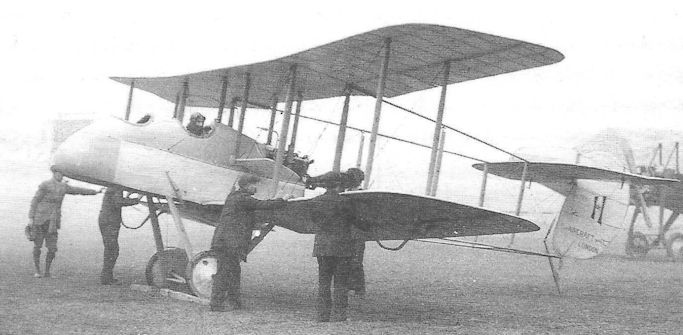
Capt. G. de Havilland in the prototype D.H.1 with 70hp Renault engine with the original air brake aerofoils immediately aft of the pilot’s cockpit, at Hendon in January 1915.
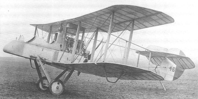
No 4606, the D.H.1A prototype with 120hp Beardmore engine complete with large radiator directly behind the pilot’s head; note the observer's cut-down cockpit and gravity fuel tank under the upper wing.
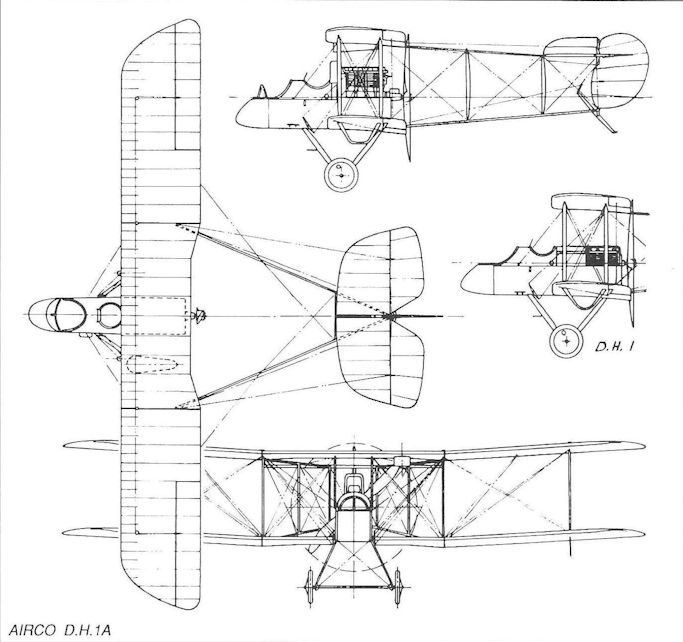
Airco D.H.1A
Airco D.H.2
The steadily-increasing tempo of air combat during the early months of 1915, particularly over the Western Front, progressing from the use of hand-held small arms to the inclusion of synchronized automatic weapons fixed to the aircraft to fire forward through the tractor propellers of purpose-built fighters - with the appearance of the German E-series monoplanes - concentrated the attention of British designers on the need to develop a reliable gun interruptor mechanism.
Until, however, such equipment arrived, recourse was made to the established ‘gun bus’ formula that had been pursued with some success by such manufacturers as the Royal Aircraft Factory, Vickers, Sopwith, and by Geoffrey de Havilland himself with his two-seat D.H.l and 1A. Realising that in many respects these aircraft were too large and cumbersome to engage in nimble dogfighting, he set about designing a single-seat derivative, much reduced in size and weight. His D.H.2 has come to be recognised as the first British fighter aircraft to be designed specifically with the aerial dogfight as its raison d’etre.
With a span of only 28ft 3in (compared to the D.H.1’s 41 feet), the 100hp Gnome monosoupape rotary-powered D.H.2 prototype completed its initial flight trials in July 1915. When the aircraft was first flown the idea of fixing the gun in the nose to fire forward along the aircraft’s line of flight had not been accepted by the War Office; instead, two flexible brackets were provided on either side of the cockpit, and the pilot was required to transfer his gun from bracket to bracket - and control his aircraft in combat at the same time. This was despite the fact that a French pilot, Roland Garros in a Morane Type L scout, had already demonstrated in combat the superiority of a fixed centreline gun. In due course a single central gun mounting was provided for the D.H.2
Be that as it may, it was not until 7 February 1916 that the first RFC Squadron, No 24 commanded by Major Lanoe George Hawker vc, arrived in France, followed by Nos 29 and 32 some weeks later. The first German aircraft fell to the guns of a No 24 Squadron D.H.2 on 2 April.
A total of 400 D.H.2s was produced by Airco, of which 266 were sent to France during 1916, 32 to the Middle East and 100 equipped training units in Britain; the other two flew with Home Defence units.
The D.H.2 was to a large extent responsible for the final eclipse of the ‘Fokker scourge’ and was heavily engaged during the Battle of the Somme. No 24 Squadron alone fought no fewer than 774 combats, in the course of which its pilots destroyed 44 enemy machines. Major Hawker himself was shot down and killed after a marathon combat with the legendary Manfred von Richthofen on 23 November 1916. No 32 Squadron’s commanding officer, Maj L W B Rees, had won the Victoria Cross for single-handedly attacking an enemy formation of ten enemy two-seaters on 1 July.
At first regarded by its pilots as a tricky aeroplane to fly, mainly on account of its very sensitive controls and the difficulty of spin recovery, the D.H.2 soon came to be greatly appreciated for its tough structure and manoeuvrability, and as experience and training improved. Once the central gun mounting had been adopted, pilots could concentrate on flying their fighters directly at their targets. Nevertheless, when the gun interruptor gear had been developed successfully, conventional tractor scouts quickly replaced the old pusher biplanes, and the D.H.2 gradually disappeared from front line service early in 1917.
Type: Single-engine, single-seat fighting scout biplane with pusher engine.
Manufacturer: The Aircraft Manufacturing Co Ltd., Hendon, London
Powerplant: One 100hp Gnome monosoupape air-cooled rotary engine; a few aircraft with 110hp Le Rhone rotary engine; two blade propellers.
Structure: Fabric-covered wooden construction with two-bay, two-spar wings; steel tubular booms supporting tail unit.
Dimensions: Span, 28ft 3in; length, 25ft 2 1/2 in; height, 9ft 6 1/2 in; wing area, 249 sq ft.
Weights (Gnome): Tare, 943lb; all-up, 1,441lb.
Performance (Gnome): Max speed, 93 mph at sea level; climb to 5,000ft, 8 min 25 sec; service ceiling, 14,000ft; endurance, 2 3/4 hr.
Armament: One 0.303in Lewis machine gun on offset pillar mounts on either side of the nose, or a single central mounting. Prototype: One, 4732 (first flown by Geoffrey de Havilland, probably in July 1915).
Production: Total of 451 ordered, but only 400 delivered (from 5916-6015, 7842-7941, 8725, A2533-A2632, A4764-A4813, A4988-A5087).
Summary of Service: Served with Nos 24, 29 and 32 Sqns, Western Front; Nos 5, 11 and 18 Sqns, Palestine; No 111 Sqn. and ‘X’ Flt, Macedonia; ‘A’ Flt, No 47 Sqn.; RNAS Composite Fighting Sqn.; No 10 Reserve Squadron, Joyce Green.
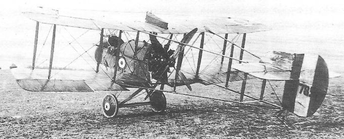
A production D.H.2, No 7851, with 110hp Le Rhone driving a four-blade propeller, with 32 Squadron, which it probably joined in summer 1916.
Earlier aircraft were fitted with their fuel tank under the port upper wing, unlike this example whose tank is above the starboard wing.
Earlier aircraft were fitted with their fuel tank under the port upper wing, unlike this example whose tank is above the starboard wing.
Airco D.H.5
The first appearance in operational service of de Havilland’s D.H.5 as late as May 1917 was a curious anachronism that tended to emphasise the mediocrity of this, the only essay into tractor scout design by Airco. De Havilland’s preoccupation with the D.H.3 and D.H.4 bombers for much of 1916, and the survival of his D.H.2 in service throughout that year together served to sidetrack the designer away from fully exploiting the arrival of the first British gun interrupter equipment until the summer. Even so, the configuration of the D.H.5 was unorthodox owing to de Havilland’s determination to perpetuate the excellent field of vision for the pilot that had been a feature of the D.H.2 pusher.
To achieve this the D.H.5 was rigged with a pronounced backward stagger of 27 inches on the wings, enabling the pilot’s cockpit to be located directly below the leading edge of the upper wing. Unfortunately this peculiar feature led to some unsavoury handling characteristics, particularly at low airspeeds. Powered by a 110hp Le Rhone rotary, the aircraft first appeared in prototype form as A5172 in the early autumn of 1916, the fuselage in effect being a wooden box girder with flat sides and with rounded top decking formed by frames and stringers; both wings and fuselage were internally cross-braced with wire stays. The main fuel tank was located immediately behind the pilot, with a small gravity tank above the upper wing. Although the prototype flew with a small horn-balanced rudder (of a shape characterised in de Havilland’s designs for the next twenty years), production aircraft possessed slightly larger, but unbalanced rudders; these aircraft also differed from the prototype in having the fuselage faired to octagonal cross-section.
At least 550 D.H.5s were built by Airco and three sub-contractors, and the first entered operational service with No. 24 Squadron in May 1917, straightway attracting criticism on account of their dismal performance at altitude, being inferior to the new two-seat Bristol F.2B Fighter and the nine-month-old Sopwith Pup. It was also discovered that elevator control rapidly diminished as speeds approached the stall.
Accordingly the D.H.5 came to be employed increasingly as a ground-strafing fighter and, despite its armament of only one Vickers machine gun, proved to be well suited to this hazardous role - largely on account of the pilot’s excellent field of vision. Aircraft of No 41 Squadron were used to good effect during the Battle of Ypres in August, and for the Battle of Cambrai in November D.H.5s of Nos 64 and 68 Squadrons were also equipped to carry up to four 20lb Cooper bombs.
Cambrai was effectively the D.H.5’s swansong and, during the next three months, all were replaced by S.E.5As in operational service. Nor did they survive long among the training units.
Type: Single-engine, single-seat tractor biplane fighting scout; also ground attack fighter.
Manufacturers: The Aircraft Manufacturing Co Ltd, Hendon, London; Darracq Motor Engineering Co Ltd, Fulham, London; British Caudron Co Ltd, Cricklewood, London; March, Jones & Cribb Ltd., Leeds.
Powerplant: One 110hp Le Rhone nine-cylinder air-cooled rotary engine; some aircraft with one 110hp Clerget air-cooled rotary engine.
Structure: Fabric-covered all-wood box girder fuselage faired to octagonal section; single-bay two-spar wings rigged with 27 inches of backward stagger.
Dimensions: Span, 25ft 8in; length, 22ft 0in; height, 9ft 1 1/2 in; wing area, 212 sq ft.
Weights: Tare, 1,010lb; all-up, 1,492lb.
Performance: Max speed, 109 mph at sea level; climb to 10,000ft, 12 min 25 sec; service ceiling, 16,000ft; endurance, 2 3/4 hr.
Armament: One 0.303in Vickers machine gun with Constantinesco CC interrupter gear on top of nose, offset to port; provision later made to carry up to four 20lb Cooper bombs.
Prototype: One, A5172 (first flown by Geoffrey de Havilland in the autumn of 1915).
Production: Approx. 550 aircraft from A9163-A9361 (Airco); A9363-A9562 (Darracq); B331-B380 (British Caudron); and B4901-B5000 (Marsh, Jones & Cribb); one aircraft, B7775, rebuilt by No. 1 (Southern) Aeroplane Repair Depot.
Summary of Service: Served with Nos. 24, 32, 41, 64 and 68 (Australian) Squadrons; also with Schools of Aerial Fighting.
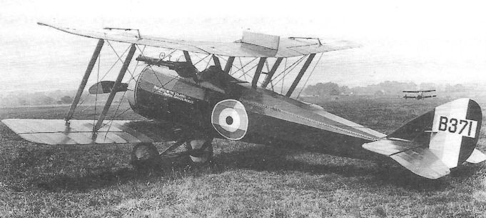
A production D.H.5, B371, built by the British Caudron Co Ltd, with the five-gallon gravity fuel tank on the starboard upper mainplane. The inscription on the side of the fuselage reads ‘Presented by the Solanki - Princes, Chiefs d Nobles ’, showing this to be one of many aircraft subscribed by the British Empire.

Airco D.H.5
Fairey F.2
The Fairey F.2, a twin-engine biplane with a span of 77 feet, was described by its makers as a long-range fighter intended for the RNAS, although no record appears to have survived describing precisely what its exact operational use was intended to be, although it may reasonably be conjectured to have been as a gun-carrying escort aircraft, also capable of carrying a small load of bombs.
As the first Fairey-designed aircraft to be built (the company having produced a small number of Short seaplanes in 1915), the F.2 was a three-seat, three-bay biplane, rigged without stagger and with considerable wing overhang braced from kingposts above the outboard interplane struts. Of all-wood, fabric-covered construction, it was intended to be powered by two 200hp Brotherhood tractor engines in the first two aircraft, followed by two aircraft with 190hp Rolls-Royce Falcons arranged as pushers; in the event, only one aircraft was completed, in the autumn of 1916, and this was powered by Falcons installed as tractors. It is believed that construction of the other three aircraft was started but not proceeded with, owing to the non-availability of the Brotherhood engines. In any event, the sole completed aircraft was not flown until about May 1917.
The F.2 carried a pilot and two gunners, the latter being provided with Lewis guns on Scarff rings in the nose and amidships; the pilot’s cockpit was located just forward of the wing leading edges. A monoplane tail unit was incorporated carrying twin fins and unbalanced rudders. The undercarriage comprised a robust structure of ten struts, arranged W-fashion in end elevation, mounting four wheels in tandem pairs.
As was mandatory on all large naval aircraft, the wings were made to fold so as to enable the big aeroplane to be hangared.
Type: Twin-engine, three-seat, three-bay biplane long-range fighter.
Manufacturer: The Fairey Aviation Co Ltd, Hayes, Middlesex.
Powerplant: Two 190hp Rolls-Royce Falcon I 12-cylinder water-cooled engines driving four-blade tractor propellers.
Structure: All-wood, wire-braced construction with fabric covering.
Dimensions: Span, 77ft 0in; length, 40ft 6 1/2 in; height, 13ft 5 5/8 in; wing area, 718.4 sq ft. Weight: All-up, 4,880lb.
Performance: Max speed, 92.5 mph at sea level; climb to 5,000ft, 6 min; endurance, 3 1/2 hr.
Armament: Two 0.303in Lewis machine guns on Scarff rings in nose and midships cockpits; aircraft capable of carrying small bombs.
Prototypes: Four ordered, Nos 3702-3705; only one, No 3704, completed in late autumn 1916 (believed first flown in May 1917). No production.
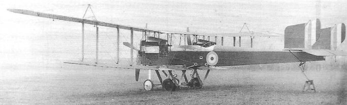
The sole Fairey F.2, No 3704, with cowled Rolls-Royce Falcon I engines; the maximum speed of over 90 mph was fairly creditable for such a large aircraft, though any sort of fighter-like agility is extremely unlikely.
Fairey Hamble Baby
The task of enabling the Sopwith Baby fighter seaplane to carry a small bomb load and still retain some vestige of worthwhile performance occupied the attention of several design teams, not least those at Port Victoria, Fairey Aviation and the Blackburn company. The most significant contribution, not only with regard to the Baby itself but to aircraft design in general, was made by Richard Fairey. He introduced to the Baby the principle of increasing wing camber by means of wing flaps for takeoff, thereby increasing lift - an idea pioneered by A W Judge and A A Hoile at the Varioplane company. Fairey, however, went one stage further by introducing differential control of the flaps for use as conventional ailerons as well. The Fairey Patent Camber Gear was the first such use in the world of flaps-cum-ailerons, and the principle remains in use in numerous modern aircraft.
The Sopwith Baby underwent considerable redesign at Fairey, although the original fuselage remained almost unaltered. A Sopwith-built Baby, No 8134, was tested at Hayes and Hamble with the new wings which were increased in span and given rounded tips, the new flaps being hinged along the entire trailing edges of both wings.
Production Fairey-built Babies incorporated vertical tail surfaces of more angular shape, as well as an enlarged tail float and Fairey-designed main floats.
A total of 180 Fairey Hamble Babies was ordered from Fairey and Parnall & Sons, the latter company producing 130, these aircraft retaining the original Sopwith floats and tail unit; the first 30 Parnall and the first 20 Fairey examples were powered by 110hp Clerget rotaries, and the remainder by the 130hp version.
A further variation involved the last 74 Parnall-built Babies, known as Baby Converts, which were completed as landplanes; these retained the original float mounting struts, to which were attached twin landing skids and wheels.
Hamble Babies served with the RNAS and RAF at home and overseas, undertaking anti-submarine patrols in the Aegean, and bombing operations against Turkish installations in the Levant.
Type: Single-engine, single-seat, single-bay float-equipped biplane bombing scout.
Manufacturers: The Fairey Aviation Co Ltd, Hayes, Middlesex, and Hamble Point, Hampshire.
Powerplant: One 110hp or 130hp Clerget rotary engine driving two-blade propeller.
Dimensions: Span, 27ft 9 1/4 in; length, 23ft 4in; height, 9ft 6in; wing area, 246 sq ft.
Weights (110hp Clerget): Tare, 1,386lb; all-up, 1,946lb.
Performance: Max speed, 92 mph at sea level; climb to 2,000ft, 5 min 30 sec; service ceiling, 7,500ft; endurance, 2 hr.
Armament: One synchronized 0.303in Lewis machine gun on upper nose decking.
Prototype: Total of 180. (Fairey: N1320-N1339 and N1450-N1479; Parnall: N1190- N1219 and N1960-N2059).
Summary of Service: Hamble Babies served with the RNAS and RAF (after April 1918) at Calshot, Cattewater and Fishguard, and aboard hm Seaplane Carrier Empress; also at Santa Maria di Leuca (Italy), Suda Bay (Crete), Lemnos (Aegean), Port Said and Alexandria.
Grahame-White Type 6
An almost exact contemporary of the Royal Aircraft Factory’s F.E.3, the Grahame-White Type 6 gun-carrier was designed by John Dudley North, the 19-year-old graduate of the Aeronautical Syndicate who joined Claude Grahame-White at Hendon in 1912. Like the F.E.3, North’s Type 6 also used a tail boom which passed through the pusher propeller shaft.
However the design differed in several important respects. Careful to avoid a lack of torsional rigidity in the tail unit (which was to lead to the F.E.3 being grounded), North retained two conventional steel tubular tail booms below the propeller shaft boom, thereby obtaining a triangular section structure that could be cross-braced to provide greater strength. Like the F.E.2, the engine, this time a 90hp Austro-Daimler, was located in the front of the nacelle - completely enclosed - but in this instance the engine’s crankshaft itself was extended aft, below the cockpits, to chain reduction sprockets at the rear of the nacelle. The observer-gunner’s cockpit was located in the centre of the nacelle, with the pilot’s cockpit immediately behind him.
A 30-calibre Colt machine gun on a flexible mounting, capable of traversing 90 degrees either side and 50 degrees in azimuth, was positioned in front of the gunner’s position.
Grahame-White was clearly competing against Farnborough’s F.E.2 and F.E.3, as well as Vickers’ Gunbus, for Admiralty orders, and his Type 6 duly appeared at the 1913 Olympia Aero Show. When, however, the Farnborough pilots criticised the suspect tail support structure of the F.E.3, interest centred on the Vickers E.F.B. series. North accordingly abandoned the unorthodox tail boom arrangement and in his next gun-carrier essay, the Type 11, adopted the conventional four-boom layout.
Type: Single pusher engine, two-seat, fighting biplane.
Manufacturer: The Grahame-White Aviation Co Ltd, Hendon, Middlesex.
Powerplant: One 90hp Austro-Daimler water-cooled in-line engine driving two-blade pusher propeller.
Structure: Predominantly steel tubular structure with fabric-covered parallel-chord unstaggered wings; three-boom tail support structure. Skid-and-wheel undercarriage.
Dimensions: Span, 42ft 6in; length, 33ft 9in.
Weights: Tare, 2,2001b; all-up, 2,950lb.
Performance: Max speed, 70 mph at sea level; initial climb, 340 ft/min; endurance, 2 3/4 hr.
Armament: One 30-calibre Colt machine gun on nose of nacelle.
Prototype: One. No production and no Service number allotted.

The Grahame-White Type 6. Scarcely apparent in this photograph is the exceptionally narrow-track undercarriage, the landing wheels being located inboard of the skids.
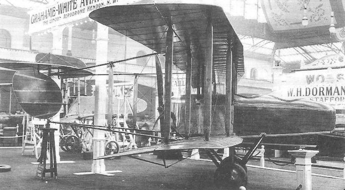
The Grahame-White Type 11 'Warplane' on display at Olympia on 16 March 1914. Behind it on the left is one of Grahame-White's famous pre-War ‘Charabancs’.
Grahame-White Type 11
Among the so-called gun-carrier pusher biplanes exhibited at the 1914 Olympia Aero Show was John North’s Grahame-White Type 11 - which acquired the company’s uncompromising name Warplane. With proportions somewhat similar to those of the Vickers E.F.B.3, the Type 11 was similarly powered by a 100hp Gnome monosoupape which drove a very large four-blade pusher propeller; however by introducing chain drive the propeller was well clear of the wing’s trailing edge, without the need to incorporate a cut-out.
The two-spar, two-bay wings were of parallel chord with slight sweep-back on leading and trailing edges, and were rigged without stagger; ailerons were fitted to both upper and lower wings. The undercarriage, with twin wheels, featured three struts on each side but dispensed with skids.
Observers at the Olympia Show expressed some surprise at the short tail moment, the leading edge of the dorsal fin and tailplane being only some six feet from the wing trailing edge, and also at the fact that the fin and much of the elevator were almost clear of the slipstream. Nevertheless the Type 11 attracted much acclaim, largely it is suspected on account of the superb craftsmanship evident in its manufacture.
Unfortunately, the misgivings voiced at Olympia were confirmed when the French pilot, Louis Noel, first flew the Warplane at Hendon in May, and reported very poor longitudinal stability and control. Despite a speed roughly comparable with that of the Vickers E.F.B. series, these flawed handling properties discouraged North from pursuing the gun carrier pusher biplane formula any further.
Type: Single pusher engine, two-seat, two-bay gun carrier biplane.
Manufacturer: The Grahame-White Aviation Co Ltd, Hendon, Middlesex.
Powerplant: One 100hp Gnome monosoupape engine driving four-blade pusher propeller.
Dimensions: Span: 37ft 0in.
Weights: Tare, 1,000lb; all-up, 1,550lb.
Performance: Max speed, 80 mph at sea level.
Armament: Intended to make provision to mount a Lewis machine gun on the front cockpit.
Prototype: One (first flown by Louis Noel at Hendon in May 1914). No production.
The Grahame-White Type 11 'Warplane' on display at Olympia on 16 March 1914. Behind it on the left is one of Grahame-White's famous pre-War ‘Charabancs’.

Grahame-White Type 11
Grahame-White
Both Vickers and Grahame-White tried their hands at two-seat tractor scouts in 1914, the Vickers aircraft appearing at the Olympia Show that year, powered by a 100hp Gnome monosoupape, this was not, however, sufficiently promising to warrant diverting work away from the Gunbus series, which Harold Barnwell considered most likely to attract substantial production orders, and the Vickers Two-Seat Scout was abandoned that summer.
The Grahame-White two-seat scout, the Type 13, was - like the Sopwith ‘Spinning Jenny’ - developed from a seaplane intended for the 1914 Round-Britain race (which was cancelled); but in this instance, however, the aircraft had been fitted with floats that were too short so that, when the pilot opened the throttle prior to its first flight, the aircraft nosed over. It was recovered from the water and re-built with wheel undercarriage.
The manufacturers clearly believed that the little Type 13 possessed adequate performance to attract the Admiralty or the War Office in the role of reconnaissance scout. The wings were heavily staggered and employed N-type interplane struts, which were fairly unusual for the period, while the forward cabane struts were raked sharply back. The undercarriage evidently gave trouble as it was modified to incorporate plain V-struts with their apex on the extremities of the axle spreader bar. Ailerons were fitted to the top wing only, and there was no fixed tailplane.
The pilot occupied the rear cockpit which was located well aft of the upper wing’s trailing edge, there being no cutout in this wing. However, a gesture to the pilot’s field of vision was made by providing large triangular transparent panels in the sides of the box-section fuselage, and transparent panels in the lower wing roots; large cut-outs were also provided in the trailing edge roots of the lower wings. On the other hand the observer’s cockpit was positioned directly below the upper wing centresection and, although it was over the lower wing’s leading edge, the observer’s downwards view was restricted by large convex fairings on either side of the fuselage aft of the engine.
Power was provided by the familiar Gnome monosoupape engine which bestowed a top speed of 85 mph; fuel sufficient for an endurance of 5 1/2 hours could be carried. The strut and bracing arrangement seems to have been unnecessarily complex and would undoubtedly have led to difficulties in service; in any case the Service authorities decided against adoption of the aircraft for the reconnaissance role, probably on account of the distance and difficulty of communication between pilot’s and observer’s cockpits.
The sole example of the Type 13 is believed to have been flown as a trainer by the RNAS who shared the aerodrome at Hendon with Grahame-White.
Type: Single-engine, two-seat, single-bay tractor biplane scout.
Manufacturer: The Grahame-White Aviation Co Ltd, Hendon, Middlesex.
Powerplant: One 100hp Gnome monosoupape engine driving two-blade propeller.
Dimensions: Span, 27ft 10in; length, 26ft 6in.
Weights: Tare, 1,040lb; all-up, 1,800lb.
Performance: Max speed, 85 mph at sea level; endurance, 5'6 hr.
Armament: None.
Prototype: One (probably flown in about October 1914, and used by the RNAS at Hendon). No production.
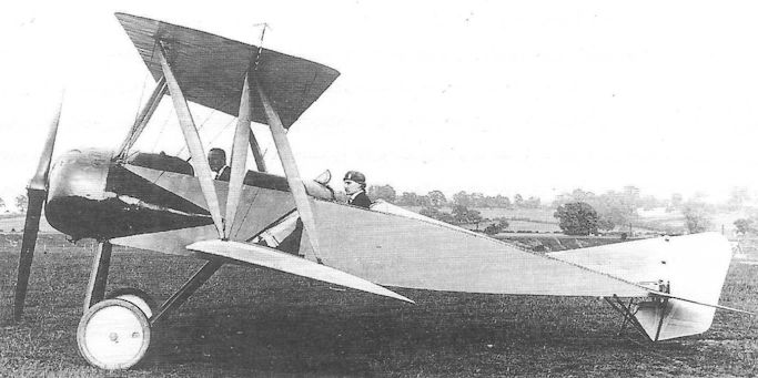
The Grahame-White Type 13 two-seat scout as it appeared immediately after re-building with wheel undercarriage and before this was changed to incorporate V-struts.
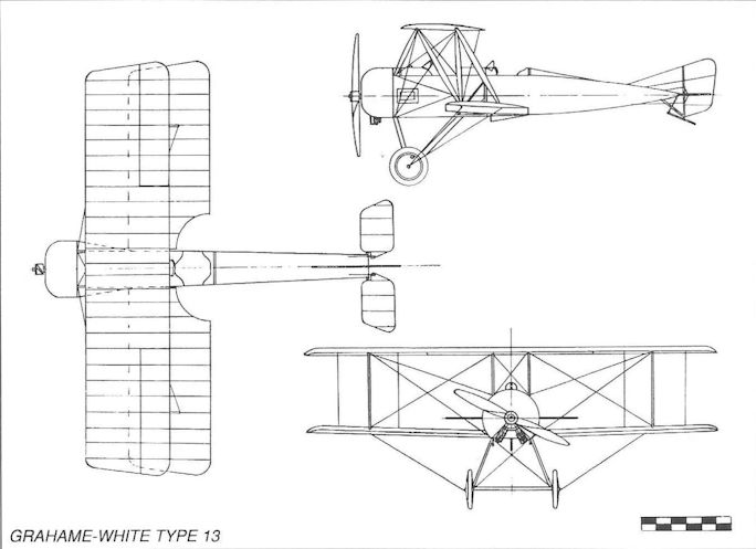
Grahame-White Type 13 Scout
Grahame-White
One of the lesser-known contenders for consideration as a single-seat scout was the Grahame-White Type 20 single-bay biplane which is believed to have flown in mid-1916.
Characterized by unusually thick, staggered wings with large gap, the Type 20 was of all-wood construction, the slim fuselage being formed to circular section. The tail unit comprised a fixed fin and balanced rudder, but no tailplane was fitted forward of the balanced elevator. Ailerons were fitted on both upper and lower wings, hinged to the rear spars. The twin V-strut twin-wheel undercarriage was raked forward, presumably so as to dispense with a landing skid.
Power was provided by an 80hp Clerget 7Z seven-cylinder rotary engine within a narrow-chord oil-sling ring, this engine being licence-built by Gwynnes Ltd of Hammersmith. Also considered as an alternative to this engine was the 80hp Le Rhone.
With a top speed probably between 80 and 90 mph (without armament fitted), it is unlikely that this little aeroplane excited much serious attention at the War Office or Admiralty and, as far as is known, underwent no official trials; its development, therefore, was probably very shortlived.
Grahame-White Type 21
Clearly representing an attempt to refine the Type 20, the Grahame-White Type 21 appeared early in April 1917, powered by an 80hp Le Rhone engine driving a four-blade propeller. Most readily visible change was the use of I-form interplane and cabane struts with prominent spacer fairings at their extremities.
In almost every respect, however, the design differed in detail; the fuselage, instead of being formed to almost circular section, was a plain, flat-sided, wooden box-girder, only faired with rounded top decking; the fin and rudder were enlarged , although the latter was now no longer balanced; the front pair of undercarriage struts was mounted further forward - directly behind the engine, and a small, faired headrest was incorporated immediately aft of the cockpit. The previous design’s large wing gap was retained, as was the unusually large number of bracing wires.
In all likelihood the wings were of reduced thickness, for the Type 21 returned a speed of 107 mph at sea level, a not unreasonable performance on only 80 horsepower, although there is no evidence that any armament was ever carried.
There appeared to be little inherently disagreeable about the Type 21, except that it flew about a year later than other scouts of similar capabilities; and, apart from a possible training role, it could have contributed little to meeting the needs of the fighting Services.
Mann, Egerton H.1 and H.2
The Norwich car manufacturer, Mann, Egerton & Co, entered the aircraft industry in 1915 and became engaged in building Short Type 184 patrol seaplanes on sub-contract, going on to produce a small number of an improved version of this aircraft, known as the Mann, Egerton Type B. Other subcontracted aircraft followed, including the French Spad S.VII, and in 1917 the company embarked on an aircraft entirely of its own origin, designed by J W Carr and intended to approximate to the Admiralty requirement for a naval land or ship-based single-seat scout, set out in Specification N.1A - to which the Beardmore W.B.IV was also being designed. An important aspect of this requirement was the aircraft’s ability to remain afloat for a specified period after an enforced alighting on the water.
This aeroplane was the Mann, Egerton H.l, a compact two-bay, equal-span biplane powered by a 200hp Hispano-Suiza engine and with the facility of wing-folding for shipboard stowage. To enable the aircraft to ditch in greater safety, the undercarriage was jettisonable and, to remain afloat, a large external buoyancy chamber was attached below the engine cowling, extending aft beyond the trailing edge of the lower wings. In addition, there were floats under the lower wingtips.
The only prototype H.1, N44, was flown in late September or early October by Clifford B Prodger, followed almost immediately by its official trials. All went well to begin with, it being pleasant to fly and manoeuvrable, and even declared suitable for night flying. Unfortunately it failed the flotation test.
A second aircraft, the H.2 (N45) was immediately put in hand, fundamentally the same as N44 but without external buoyancy chambers; instead, internal inflatable air bags were provided, which could be trimmed by hand pump. The engine exhaust pipes were shortened considerably, and the rudder was increased in area and horn balanced.
The discarding of the external impedimenta allowed a significant all-round increase in performance. The H.2 was the officially tested in December and flew at Isle of Grain, but no production order was awarded.
Type: Single-engine, single-seat, two-bay land-based or shipborne biplane scout.
Manufacturer: Mann, Egerton & Co Ltd, Norwich, Norfolk.
Powerplant: One 200hp Hispano-Suiza engine driving two-blade propeller.
Dimensions: Span, 30ft 9in; length, 21ft 11in; height, 8ft 11 1/2 in; wing area, 310 sq ft.
Weights: H.1. Tare, 1,838lb; all-up, 2,404lb. H.2. Tare, 1,760lb; all-up, 2,326lb.
Performance: H.1. Max speed, 100 mph at 6,500ft; climb to 10,000ft, 18 min; service ceiling, 12,800ft; H.2. Max speed, 113 mph at 6,500ft; climb to 10,000ft, 12 min 30 sec; service ceiling, 16,800ft.
Armament: One synchronized 0.303in Vickers machine gun on fuselage, forward of cockpit, offset to port; one Lewis gun above upper wing centre section.
Prototypes: One H.1, N44, and one H.2, N45. N44 was first flown in late September or early October 1917. No production.
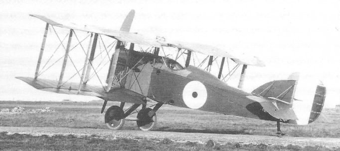
The H.2, N45. Small biplanes of the First World War, equipped with folding wings, seldom featured any stagger owing to the difficulty of maintaining rigidity of structure on asymmetric lines of fold, not to mention the complexity of tensioning of control runs to the ailerons.
Martinsyde S.1
The association that grew up between H P Martin and George Handasyde before the First World War resulted in the establishment of Martinsyde Ltd at Brooklands, a company which achieved distinction with a series of attractive monoplanes. With the appearance of the outstanding Sopwith Tabloid at Brooklands, however, it was not long before Martinsyde joined the growing number of companies determined to compete for military orders for small tractor biplane scouts.
Superficially resembling the Tabloid, particularly in the engine cowling, the first single-seat scout was the Martinsyde S.1, powered by an 80hp Gnome; it differed, however, in the undercarriage design which incorporated two mainwheels and a pair of skids in front of which were added two smaller, balancing wheels. Later this unwieldy arrangement was discarded in favour of conventional V-struts on each side and plain twin-wheel undercarriage, also dispensing with the skids.
On account of its ability to mount a Lewis gun on the upper wing from the outset, the S.1 quickly earned production orders, and the first of about sixty Service aircraft appeared towards the end of 1914, all being produced by the parent company. Fewer than a dozen joined RFC squadrons on the Western Front, and one of these gave rise to a famous incident. Capt Louis Strange was flying an S.1 of No 6 Squadron and, finding that the ammunition drum on the Lewis gun had jammed, stood up in his cockpit to gain a firmer grip on the drum so to release it - holding the control column between his knees. The aircraft began to climb steeply, stalled and entered an inverted spin and, not having the benefit of seat straps, Strange was thrown out of the cockpit, still retaining his hold on the drum. Fortunately this, which only moments earlier he had been trying to free, remained jammed, and after losing about 5,000 feet the aircraft righted itself and the pilot managed to struggle back into his cockpit.
Four S.1s were shipped to the Middle East Brigade in 1915, equipping one Flight of No 30 Squadron in Mesopotamia. More than forty were supplied to training units in Britain that year and the S.1 was withdrawn from operational use in France during the summer of 1915, but a small number was shipped out to Mudros in the Aegean in 1918 to equip No 144 Squadron. Several other examples were tested at the Royal Aircraft Factory with early front gun interrupter equipment.
Type: Single-engine, single-seat, single-bay tractor biplane scout.
Manufacturer: Martinsyde Ltd., Brooklands, Surrey.
Powerplant: One 80hp Gnome engine driving two-blade propeller.
Structure: All-wood with fabric covering; ailerons on upper and lower wings.
Dimensions: Span, 27ft 8in; length, 21ft 0in; wing area, 208 sq ft.
Performance: Max speed, 87 mph.
Armament: One 0.303in Lewis machine gun on upper wing, firing above propeller.
Prototype and Production: One prototype, believed to be No 710. 61 production examples: Nos 724, 741, 743, 748-749, 2448- 2455, 2820-2831, 4229-4252 and 5442-5453 (some of these may not have been completed).
Summary of Service: S.ls served in small 4, 6, 9, 10, 14, 16, 23, 24, 30, 67 and 144 numbers on each of the following: Nos. 1, 2, Squadrons, RFC.
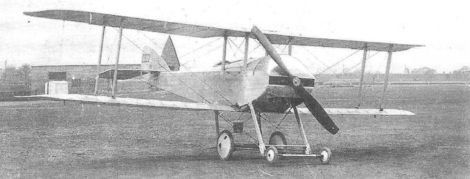
The Martinsyde S.1 with the initial four-wheel undercarriage.
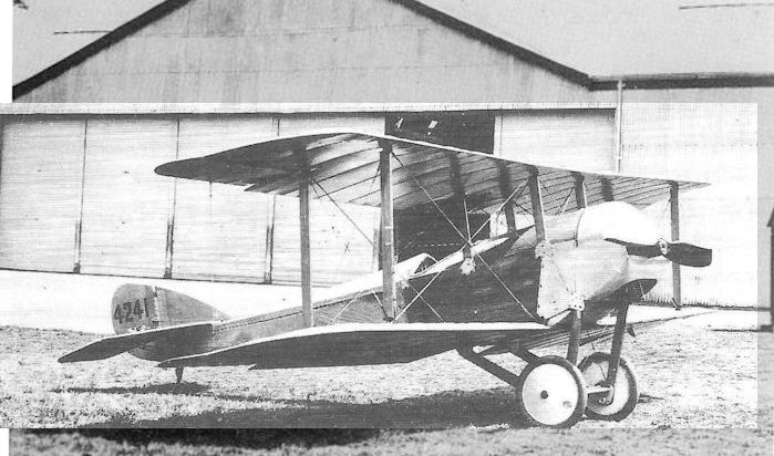
The Martinsyde S.1 with the later two-wheel undercarriage.
Martinsyde G. 100 and G.102 Elephant
Built during the summer of 1915, the Martinsyde G.100 was designed largely by A A Fletcher and, from the outset, was intended as a long-range escort single-seat fighter. It was a well-proportioned two-bay tractor biplane with moderate stagger and was fitted with ailerons on upper and lower wings. Power was provided by a 120hp Beardmore straight-six water-cooled engine which, in the prototype No 4735, drove a three-blade propeller - an unusual feature for its day.
Probably flown by F P Raynham at the end of August, the prototype was followed by 100 production aircraft in two batches, the three-blade propeller having been replaced by the more customary two-blade type. Although G.100s were distributed among several squadrons, which employed them as escorts for their own bombing machines, only No 27 came to be fully equipped with the type, arriving in France on 1 March 1916. And it was about this time that the sobriquet ‘Elephant’ gained popularity - presumably on account of the aeroplane’s unusually large proportions for a single-seater - so much so that this animal was portrayed in No 27 Squadron’s Badge (which has remained in use to this day).
Indeed, with a fuel load sufficient to sustain a 5 1/2-hour endurance, the power and load-carrying capacity of the Elephant quickly recommended it for use as a bombing aircraft, although it continued to be used in offensive fighting patrols. The first bombing attack was carried out by six Elephants of No 27 Squadron against Bapaume on 1 July 1916, the day on which the Somme offensive was launched.
Normal gun armament of the Elephant in the air fighting role was a single Lewis gun above the upper wing centresection; to this was frequently added a second Lewis gun immediately aft of the pilot’s cockpit, firing rearwards; it is difficult to imagine how the pilot, while controlling his aircraft in combat, could contrive to aim and fire this gun with the slightest accuracy.
Soon after the G.100s first arrived in France, a more powerful version, the G.102, appeared, powered by the 160hp Beardmore engine. Although of poorer reliability, this engine increased the Elephant’s speed by about 7 mph. This version remained in service for the rest of the War, principally with home-based training units, but also in the Middle East.
Type: Single-engine, single-seat, two-bay biplane escort fighter (also extensively used as a bomber).
Manufacturer: Martinsyde Ltd, Brooklands, Surrey.
Powerplant: G.100. One 120hp Beardmore straight six-cylinder water-cooled in-line engine driving two-blade propeller. G.102. 160hp Beardmore.
Dimensions: Span, 38ft 0in; length, 26ft 6in (G.102, 27ft 0in); height, 9ft 8in; wing area, 410 sq ft.
Weights: G.100. Tare, 1,759lb; all-up, 2,424lb. G.102. Tare, 1,793lb; all-up, 2,458lb.
Performance: G.100. Max speed, 96 mph at sea level; climb to 10,000ft, 19 min; service ceiling, 14,000ft; endurance, 5 1/2 hr. G.102. Max speed, 103 mph at sea level; climb to 10,000ft, 15 min 55 sec; service ceiling, 16,000ft; endurance, 4 1/2 hr.
Armament: One 0.303in Lewis machine gun mounted above the upper wing centre section to fire above the propeller arc, and one Lewis gun mounted aft of the cockpit to fire rearwards.
Prototype: One G.100, No 4735 (probably first flown by F P Raynham in August 1915 at Brooklands).
Production: G.100, 100 aircraft (Nos 7258-7307 and 7459-7508); G.102, 171 aircraft (A1561-A1610, A3935-A4004 and A6250-A6300).
Summary of Service: Martinsyde Elephants served with Nos 18, 20, 21, 23, 25 and 27 Squadrons, RFC, in France, with Nos 51, 63 and 110 Squadrons based in Britain, and with Nos 30, 67, 72 and 142 Squadrons in the Middle East).
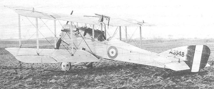
A production Martinsyde G.102, A3948, with the Lewis gun on the upper wing; just visible is the spigot mounting for another Lewis gun on the port side of the cockpit’s rear coaming.
Martinsyde R.G.
Following the transfer of the Martinsyde G.100/102 Elephant from its intended role of fighter to bomber, George Handasyde remained determined to pursue a similar but smaller fighter design, the R.G. (=Revised G-Type), and he, working with A A (‘Tony’) Fletcher, came up with a single-bay biplane of exceptionally clean lines and compact configuration, powered initially by a 190hp Rolls-Royce Falcon I engine driving a four-blade propeller. It is likely that the first prototype, probably A318, was flown in January 1917.
When first officially tested at Farnborough in February this aircraft returned a top speed of 130 mph at sea level, and an ability to reach 10,000 feet in 10 minutes 20 seconds (compared with 125 mph and 14 minutes 10 seconds of the Factory’s own S.E.5 prototype which underwent the same tests during the following month.
However, it had already been decided to go ahead with production of both the S.E.5 and the Sopwith Camel and, even thought Handasyde acquired a 275hp Falcon III for the R.G., this was doomed by circumstances also; despite returning a speed of 136 mph during its official tests in June, it had by then been decreed that that all Falcon IIIs would be reserved for Bristol F.2B Fighters.
Type: Single-engine, single-seat, single-bay biplane scout.
Manufacturer: Martinsyde Ltd., Brooklands, Surrey.
Powerplant: One 190hp Rolls-Royce Falcon I (later 275hp Falcon III) 12-cylinder water-cooled in-line engine driving four-blade propeller.
Dimensions: Span, 32ft 0in; length, (Falcon I) 25ft 8in, (Falcon III) 25ft 10in; height, 9ft 10in; wing area, 310 sq ft.
Weights: (Falcon III) Tare, 1,740lb; all-up, 2,261lb.
Performance: (Falcon III) Max speed, 136 mph at sea level; climb to 10,000ft, 7 min 20 sec; service ceiling, 23,500ft; endurance, 2 hr.
Armament: Two fixed, synchronized 0.303in Vickers machine guns on nose decking.
Prototypes: Believed three, possibly A318-A320 (believed first flown in January 1917). No production.
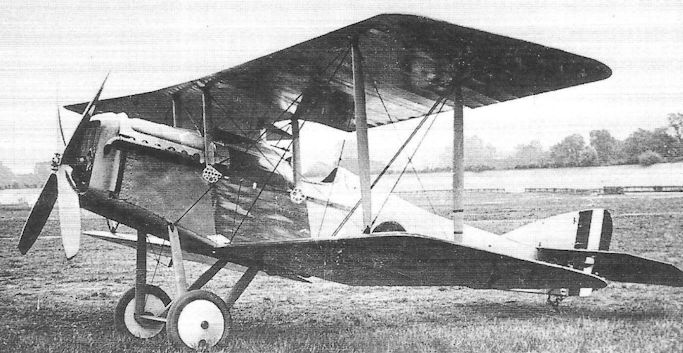
The attractive Martinsyde R.G. at Brooklands in 1917; its similarity with the S.E.5A (which ironically came to be built in quantity by Martinsyde) is striking, even though it avoided use of the recalcitrant Hispano-Suiza engine.
Martinsyde F.1
Designed early in 1917, possibly by Tony Fletcher shortly before he left Martinsyde Ltd, the F.1 was the first of a new series of fighters which culminated in the Buzzard. It was clearly influenced by the Bristol F.2 Fighter, even to the extent of placing the fuselage in the wing gap and clear of the lower wing. It was a two-bay biplane, and in effect a scaled-up derivative of the successful G. 100/102 Elephant, the airframe being strengthened to accommodate the new Rolls-Royce Mark III (Eagle III).
The broad-chord wings were rigged with slight stagger, and ailerons were fitted to upper and lower wings. The upper wing was clear of the top decking of the fuselage by some nine inches, while the lower wings were left uncovered below the fuselage, as on the Bristol F.2A; however, unlike the Bristol, the F.1’s wings remained uncovered - resulting in unnecessary end drag.
The F.1 was officially declared to be a fighter, and it certainly possessed a fairly respectable performance for such a big single-engine aircraft. Nevertheless, a feature of the F.1, which drew puzzled comments from Martlesham following its trials in July 1917, was the location of the crew, the observer’s cockpit being directly below the upper wing (with entry to it only possible through a large aperture in the wing’s centre section); the pilot’s cockpit was about five feet aft of the observer, well clear of the wing trailing edge and with precious little view forward. No armament was fitted in the prototype, A3933, and no logical suggestion indicated exactly what gun armament was proposed.
With the Bristol Fighter becoming firmly established in production, it was hardly surprising that development of the F.1 was not pursued further, and it is not known if the planned second prototype was even completed.
Type: Single-engine, two-seat, two-bay biplane fighter.
Manufacturer: Martinsyde Ltd, Brooklands, Surrey.
Powerplant: One 250hp Rolls-Royce Mark III (Eagle III) engine driving four-blade propeller.
Dimensions: Span: 44ft 6in; length, 29ft lin; height, 8ft 6in; wing area, 467 sq ft.
Weights: Tare, 2,198 lb; all-up, 3,260 lb.
Performance: Max speed, approx 112 mph at sea level; climb to 10,000ft, 13 min 40 sec; service ceiling, 16,500ft; endurance, 3 3/4 hr.
Armament: None fitted in prototype.
Prototypes: Two ordered, A3933 and A3934 (A3933 flown in May 1917). No production.
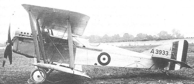
The Martinsyde F.1, A3933, the nature and proposed location of whose armament remains something of an enigma.
Martinsyde F.2
The Martinsyde F.2 was produced almost simultaneously with the F.1, but was designed under the direction of E Bouillon, newly appointed chief designer of the company. Owing some obvious family resemblance to the previous Martinsyde fighters, the F.2 diverged from the widely influential Bristol F.2 Fighter in being a single-bay biplane and with the lower wing close up to the fuselage - although the rear spar was not directly attached to the lower longerons.
Unfortunately the aircraft’s future was compromised from the start by the choice of a 200hp Hispano-Suiza engine, which would have had to be replaced in the event of a production order. The wings were well staggered and the top wing, unlike the F.1, was located well above the fuselage, and this time the pilot sat forward of the observer/gunner. However, when the aircraft underwent its trials in May 1917, it was criticised on account of the view from the pilot’s cockpit, and in order to rectify this small cutouts were made in the side coamings in the front of the cockpit.
The dominance of the Bristol Fighter, sealed the fate of the Martinsyde F.2 which otherwise returned a fairly creditable performance. At least its conventional armament of a synchronized Vickers gun and a Scarff ring-mounted Lewis evoked no adverse comments.
Type: Single-engine, two-seat, single-bay biplane reconnaissance fighter.
Manufacturer: Martinsyde Ltd, Brooklands, Surrey.
Powerplant: One 200hp Hispano-Suiza engine driving two-blade propeller.
Dimensions: Span: 32ft 0in; length, 25ft 0in; height, 8ft 2in; wing area, 334 sq ft.
Weights: Tare, 1,547lb; all-up, 2,355lb.
Performance: Max speed, 120 mph at sea level; climb to 10,000ft, 13 min 30 sec; service ceiling, 17,000ft; endurance, 2 1/2 hr.
Armament: One synchronized 0.303in Vickers machine gun mounted on nose, forward of pilot’s cockpit and to port of aircraft’s centreline, and one Lewis gun with Scarff ring on rear cockpit.
Prototype: Believed one only. (Assumed to have flown in May 1917 at Brooklands). No production.

The Martinsyde F.2 at Brooklands in 1917; just visible are the cutouts in the pilot’s cockpit coaming, made to improve the view for landing.
Martinsyde F.3
Realising that to persevere with the two-seat fighter would likely lead nowhere, with official determination to introduce the Bristol F.2B Fighter into widespread production, George Handasyde returned to the single-seater and, in the F.3, produced what was widely regarded as an outstanding aircraft. Once more, however, he was to be frustrated by the absence of the right engine at the right time.
The F.3 has been described as having the appearance of a ‘cleaned-up’ S.E.5A, with fastidious attention paid to minor details. The single-bay wings possessed considerable stagger (24 inches), a feature that placed the lower rear spar rather far aft under the lower longerons; yet by careful fairing, Handasyde avoided an untidy ‘step’ in the under fuselage contours. The twin Vickers guns were concealed within the upper nose decking and, by and large, the pilot was provided with a good field of view.
Six F.3s were ordered during the late summer of 1917 and the first, B1490, flew in November with a non-standard Rolls-Royce Falcon which developed 285hp and which was installed without radiator shutters. The aircraft was officially tested the same month, being reported on with some enthusiasm and returning a top speed of 142 mph level.
Early in 1918, a standard Falcon III was installed in the F.3 and tested in May; this time radiator shutters were included and the performance was found to have suffered slightly - although one assumes that the pilot had more control of engine temperatures. Nevertheless, with production of Rolls-Royce engines by then stretched to the limit, there was no likelihood of the F.3 being ordered into production. Accordingly the design underwent changes to accommodate the 300hp Hispano-Suiza engine, and the aircraft emerged as the F.4 Buzzard.
Type: Single-engine, single-seat, single-bay biplane fighter.
Manufacturer: Martinsyde Ltd, Brooklands, Surrey.
Powerplant: One 285hp Rolls-Royce Falcon experimental; later 275hp Rolls-Royce Falcon III.
Dimensions: Span, 32ft 10in; length, 25ft 8in; height, 8ft 8in; wing area, 320 sq ft.
Weights: Tare, 1,790lb; all-up, 2,325lb.
Performance: Max speed, 142 mph at sea level; climb to 10,000ft, 6 min 50 sec; service ceiling, 24,000ft.
Armament: Two synchronized 0.303in Vickers machine guns in upper nose decking.
Prototypes: Six, B1490-B1495. B1490 first flown in November 1917.
Summary of Service: Four F.3s recorded as having been delivered to Home Defence units in 1918.
Martinsyde F.4 Buzzard
The prototype Martinsyde F.4 Buzzard was, in effect, the F.3 example experimentally fitted with a 300hp Hispano Suiza engine, selected on account of the heavy demand for the Rolls-Royce Falcon III by the Bristol Fighter during 1918. The 18.5 litres engine, which by then was beginning to acquire a much improved reputation for reliability, despite its problems of sub-standard manufacture in the previous year, was a bored-out version of the 200hp engine, perpetuating the 90-degree Vee-eight water-cooled in-line design, and returning a power-weight ratio of 0.50 bhp/lb.
The F.3 thus modified was re-termed the F.4 Buzzard, according to the new ruling that single-seat fighters should be named after birds of prey. The only other modification of note made to the F.3 was the re-positioning of the cockpit ten inches further aft, thereby improving the pilot’s view, particularly downwards. The prototype was tested at Martlesham Heath in June, recording performance figures markedly superior to those of the production Snipe - 10 per cent better speed, 38 per cent faster climb and 35 per cent greater ceiling. (A junior draughtsman, employed in preparing production drawings of the F.4 at this time was a young man named Sydney Camm.)
On the strength of these excellent figures, Martinsyde was awarded a production order for 150 machines, and it was being said that the Buzzard would enter widespread service with the RAF in 1919. During July and August Martinsyde’s order was increased to 450, and 1,000 further aircraft were ordered from Boulton & Paul, Hooper, and Standard Motors. Three examples of a special long-range version, the Buzzard Mk IA, were also ordered from Martinsyde (H6540-H6542).
Production got underway very quickly at Brooklands, but, with the signing of the Armistice, all the ‘shadow’ contracts were cancelled outright. Martinsyde was instructed to complete only those aircraft on which work had started, with the result that a total of 338 Buzzards was built, of which 57 had reached the RAF; none was ever to reach an operational squadron, although at least five were flown by the Central Flying School for several months.
The decision not to adopt the Buzzard as front line equipment in the peacetime Royal Air Force in preference to the Snipe has been frequently called into question by historians down the years, in view of the Martinsyde’s obvious superiority in performance. In support of the decision, however, it should be emphasised that the Buzzard was over 25 per cent more costly to produce than the Snipe (a powerful deciding factor in the atmosphere of post-War austerity), and that almost 200 more Snipes had been built and were in storage at Aircraft Parks. The Snipe had, moreover, reached operational squadrons - albeit few of them - and a host of aspiring peacetime pilots had been weaned on Sopwith fighters.
True, the Sopwith company was to go into voluntary liquidation in 1920, but Martinsyde was to follow suit only one year later.
Nevertheless, Buzzards underwent a good deal of post-War development and experiment. Several examples acquired Falcon III engines, a two-seat reconnaissance version was produced, and a floatplane appeared. The three long-range Buzzard IAs, referred to above and intended to be the precursors of an escort fighter for the RAF’s Independent Force of bombers, were subjected to lengthy trials both at Martlesham Heath and Farnborough, H6541 not being struck off charge by the RAE until July 1923.
Many of the War-surplus Buzzards were re-purchased by Martinsyde, only to be sequestrated in 1921 by Aircraft Disposals Co Ltd when the manufacturers closed down. Four of these ‘Tin-sides’ were supplied to the Irish Air Corps, and another was presented to Japan, where subsequent indigenous designs displayed unmistakable Martinsyde influence.
Type: Single-engine, single-seat, single-bay biplane fighter.
Manufacturer: Martinsyde Ltd, Brooklands, Surrey.
Powerplant: One 300hp Hispano-Suiza Vee-eight water-cooled in-line engine driving two-blade Lang propeller.
Structure: Cable-braced wooden box-girder fuselage with fabric, ply and duralumin sheet covering; unequal-span two-bay two-spar wooden wings rigged with moderate stagger.
Dimensions: Span, 32ft 5 5/8 in; length, 25ft 5 5/8 in; height, 10ft 4in; wing area, 320 sq ft.
Weights: Tare, 1,811lb; all-up, 2,398lb;
Performance: Max speed, 146 mph at sea level, 139.5 mph at 15,000ft; climb to 10,000ft, 6 min 40 sec; service ceiling, 26,000ft; endurance, 2 1/2 hr.
Armament: Two synchronized 0.303in Vickers machine guns mounted within the nose cowling; provision made to carry light bombs up to total weight of about 220lb.
Prototype: One Martinsyde F.3 modified.
Production: A total of 338 Buzzards was built from a total of 1,453 ordered (Martinsyde, 453: D4211-D4360 and H6540-H6542 (Mk IAs); and H7613-H7912 of which 178 were completed; Boulton & Paul, 500, all cancelled: H8763-H9112 and J1992-J2141; Hooper Ltd, 200, all cancelled: J3342-J3541; and The Standard Motor Co, Ltd, 300, all cancelled: J5592- J5891).
Summary of Service: Eleven Buzzards are recorded as having been flown by RAF Station detachments and flights during 1919 and 1920, five by the Central Flying School and two by the RAF Communications Wing).
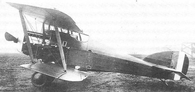
The attractive Martinsyde F.3, showing the neatly faired fuselage below the cockpit evolved to cover the lower wing’s rear spar attachment.
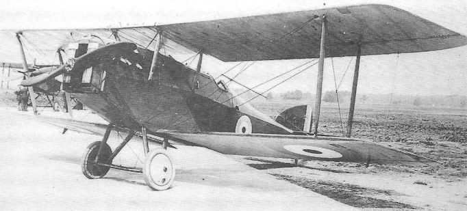
Standard production Martinsyde F.4 Buzzard, D4256, probably at Martlesham Heath in May 1919. (300 h.p. Hispano-Suiza motor.)
Nestler Scout
A relatively little known and short-lived single-seat scout was designed by the Frenchman M Boudot for the small company of F C Nestler Ltd of Westminster, London, during 1916, a firm that had been on the fringe of the aircraft industry since before the War, when it negotiated the British franchise in foreign aeroplanes.
The Nestler Scout was a small aircraft for the 100hp Gnome monosoupape engine fitted and, no doubt, was fast on this account. Though unremarkable, it was a well-proportioned single-bay biplane with moderately staggered wings with ailerons fitted top and bottom. There was no fixed fin, and the rudder was not unlike that of the Avro 504. The fuselage appears to have been the customary fabric-covered wooden box-girder with curved upper decking, and the wings were evidently built in two halves, being joined on the centreline of the aircraft without centre section.
The aircraft was accepted by the Air Board for preliminary trials and a freelance pilot engaged for the purpose in January. This was J B Fitzsimmons, an ex-RFC pilot who had been invalided from the Service. It is said that the Nestler was an agile aeroplane and Fitzsimmons evidently found little trouble in its handling. However on 26 March the pilot was engaging in some low level aerobatics in a high wind when the fabric began stripping from the wings; the aircraft crashed into a hangar and Fitzsimmons was killed.
The Scout was totally wrecked and no attempt was made to continue work on the design. Boudot later joined the Grahame-White company on the design staff.
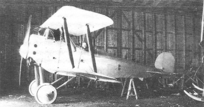
The Nestler Scout early in 1917, possibly in a shed at Hendon where it underwent flight trials.
Nieuport B.N.1
The manufacturer Nieuport & General Aircraft Co Ltd of Cricklewood had been formed before the War with the purpose of producing French Nieuport aircraft under licence in Britain. During 1917 the company was contracted to build several hundred Sopwith Camels, and at this time, in a quest to follow up with aircraft of its own design, secured the services of Henry Folland as its chief designer, one of a growing number of experienced designers and engineers who were becoming disenchanted with conditions at the Royal Aircraft Factory.
Folland’s first design essay with Nieuport was the B.N.1, yet another contender for selection as the Camel’s replacement under the Air Board’s Specification A.1A. The aircraft bore the unmistakable stamp of Folland’s design influence, with features such as the I-form interplane struts and the ventral tail fin, reminiscent of the S.E.4.
The B.N.1 was, however, an unstaggered, two-bay biplane powered by one of the first half-dozen Bentley B.R.2 rotaries to become available, and armed with two synchronized Vickers guns and a free Lewis gun on the upper wing. A large conical spinner was originally fitted over the propeller, but this was soon discarded.
Three prototypes, C3484-C3486, were ordered, and the first B.N.1 was completed and flown in February 1918. It arrived at Martlesham Heath at the beginning of March to take part in the competitive evaluation under Specification A.1A (also officially attended by the Sopwith Snipe, Austin Osprey and Boulton & Paul Bobolink). Unfortunately, on 10 March, the Nieuport caught fire in the air near Sutton Bridge, and was totally destroyed. As it was too late to complete a replacement aircraft for the trials, Nieuport was obliged to withdraw.
There is no doubt that the B.N.1 was superior in most aspects of performance to the Snipe, and the only record of a speed measurement that appears to have survived shows that it possessed a maximum speed of 127 mph at 15,000 feet (compared with 110 mph by the Snipe at that height), while its absolute ceiling of 26,000 feet contrasted with about 21,500 feet of the Snipe. As stated previously, it was the Sopwith Snipe which was declared the winner.
One of the other B.N.1 prototypes underwent structural strength tests, and the third was scrapped without being completed.
Type: Single-engine, single-seat, two-bay biplane fighter.
Manufacturer: The Nieuport & General Aircraft Co Ltd, Cricklewood, London.
Air Board Specification: A.1A of 1917.
Powerplant: One 230hp Bentley B.R.2 rotary engine driving two-blade propeller.
Dimensions: Span, 28ft 0in; length, 18ft 6in; height, 9ft 0in; wing area, 260 sq ft.
Weight: All-up, 2,030lb.
Performance: Max speed, 127 mph at 15,000ft; climb to 15,000ft, 16 min; absolute ceiling, 26,000ft; endurance, 3 hr.
Armament: Twin synchronized 0.303in Vickers machine guns on the nose forward of the cockpit, and one Lewis gun on sliding mounting above the upper wing centre section to fire over the propeller. (The Lewis gun was probably removed for the official tests.)
Prototypes: Three ordered, C3484-C3486; only C3484 was completed and flown (first flight, February 1918). No production.
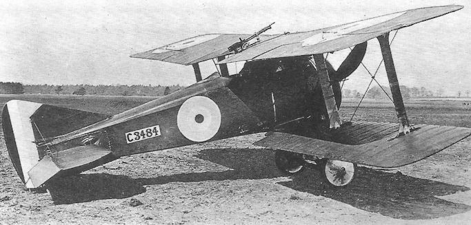
The Nieuport B.N.1, C3484, at Martlesham Heath in March 1918. This aircraft lacked ailerons on the lower wings.
The B.N.1 bore no relationship to any French Nieuport, being designed by H P Folland.
The B.N.1 bore no relationship to any French Nieuport, being designed by H P Folland.
Nieuport Nighthawk
It has been said that the Nieuport Nighthawk fighter marked both the beginning and end of the Dragonfly engine saga, and its inclusion in this work at this point may be seen in the latter context as well as representing the transition from the wartime fighter genre to that of an austerity which characterized the beginnings of RAF re-equipment in peacetime. As already explained, aircraft such as the Sopwith Snipe and Bristol F.2B Fighter provided the main equipment of the fighter squadrons for half a dozen years after the Armistice - and the RAF could count itself fortunate that aircraft of such adequacy were available at all.
It will be recalled that in October 1917 the Air Board, in deciding upon a new fighter engine to power the proposed Camel replacement, selected the Bentley rotary. Five months later the Sopwith Snipe was announced as being the new fighter, and both aircraft and engine were ordered into large-scale production. That these decisions were correct, despite severe criticism at the time, was to be confirmed by subsequent events. A few days after the decision was taken to order the Bentley, the Air Board became aware of the ABC Dragonfly radial which promised to develop 40 per cent more power at a weight increase of only 26 per cent; not for a further ten months would these figures be seen to be wildly optimistic, while almost two years would pass before the extent of the Dragonfly’s design weaknesses were fully appreciated.
In the meantime the Air Board (and later the Air Ministry) raised two fighter Specifications in which it was implicit that the aircraft should be powered by the Dragonfly engine - and the aircraft designers needed no second bidding. The Nieuport Nighthawk was designed by Henry Folland, who called on his experience with both the S.E.5 and Nieuport B.N.1 to produce an exceptionally neat two-bay biplane, yet keeping an eye on the need for ease of manufacture. To this end he employed numerous S.E.5 components, and the tail assembly was virtually unchanged from that of the B.N.1.
While the performance of the Dragonfly was still far from being confirmed, Nieuport received an order for three Nighthawk prototypes (F2909-F2911) on 25 April 1918 to Air Board Specification A.1(C) - which was shortly to be consolidated within the new RAF Type I Specification. As a measure of the misplaced faith in the Dragonfly engine demonstrated by the Air Ministry that summer, it should be stated that orders totalling 11,050 engines (as a cost of almost £12m) were placed with thirteen manufacturers, far exceeding any previous order placed for an aircraft or aero engine.
Long before flight-cleared engines were delivered for the Nighthawk prototypes, the Air Ministry placed an order for 150 production aircraft on 28 August 1918 with Nieuport (England) Ltd, and there is no doubt that considerable progress had been made with airframe component manufacture by the date of the Armistice.
Records of the delivery dates of the first few flight-cleared Dragonfly I engines to Nieuport are convoluted, but it seems that the first example(s) may have arrived sometime in January or February, and it is said that a flight by the first prototype may have been made in April. (Doubt must be cast on this as it seems that flight clearance of all Dragonflies may have been temporarily withdrawn that month while bench-running engine temperatures were examined.) It is, however, known that F2911 was flying by the end of May, and that this aircraft was delivered to Martlesham Heath in June, remaining there for seven months, during which it flew less than a dozen hours.
In September that year the entire Dragonfly development and production programme was cancelled, contractors being required only to complete engines already more than half completed. In the event some 1,147 Dragonfly Is and IAs were delivered, the majority into storage; for the most part these had been produced by Vickers Ltd in its Crayford works.
The total number of production Nieuport Nighthawks completed (excluding the prototypes) was 70, plus 54 airframe spares without engines. Of these at least seven were delivered to the RAE at Farnborough for various engine tests - between them surviving more than a dozen forced landings - while about six underwent various trials at the A & AEE at Martlesham; one was used by the Marine Aircraft Experimental Establishment (MAEE) on the Isle of Grain for flotation tests before going on to Farnborough. Thirteen were taken over by the Gloucestershire Aircraft Company, as well as an unknown number of airframes from storage, and rebuilt as Mars VI/Nighthawks or Mars X/Nightjars. Some of the above, including at least three of the RAE aircraft, had their Dragonfly engines removed and replaced by Bristol Jupiter engines as part of the long and successful development of this engine. As far as can be discovered, the last Nieuport Nighthawk to remain flying was J2405, an original Dragonfly aircraft delivered to the RAE in January 1920; it took part in the Jupiter development, as well as tests with Fairey metal propellers before meeting its end in a forced landing on 30 September 1930.
Type: Single-engine, single-seat, two-bay biplane fighter.
Manufacturers: Nieuport (England) Ltd, Cricklewood; The Nieuport and General Aircraft Co Ltd, Cricklewood; The Gloucestershire Aircraft Co Ltd, Cheltenham, Glos.
Specification: Air Board Specification A.I(C) of 1917, later RAF Type I of 1918.
Powerplant: One 320hp ABC Dragonfly I; also Bristol Jupiter II.
Dimensions: Span, 28ft 0in; length, 18ft 6in; height, 9ft 6in; wing area, 276 sq ft.
Weights: Tare, 1,500lb; all-up, 2,218lb.
Performance: Max speed, 151 mph at sea level, 134 mph at 15,000ft; climb to 10,000ft, 7 min 10 sec; service ceiling, 24,500ft; endurance, 3 hr.
Armament: Two synchronized 0.303in Vickers machine guns on upper nose decking.
Prototypes: Three, F2909-F2911 (F2909 may have been first flown in April 1919).
Production: A total of 286 Nieuport Nighthawks was ordered: H8513-H8662, J2392-J2462, J6801-J6848 and J6925-J6941; of these, 70 were completed with Dragonfly I or IA engines, and 54 airframes were assembled without engines or guns. The remainder were cancelled.

The third Nieuport Nighthawk prototype, apparently at Martlesham Heath in the second half of 1919 during performance trials; no armament is fitted.
Parnall Scout
The Parnall Scout of 1916 was one of those aircraft which themselves came to naught yet, being somewhat adventurous in approach, contributed more than a modicum to the growing fund of knowledge about design parameters. Parnall & Sons of Bristol, an established firm formerly engaged in general woodworking, had for some time been manufacturing Avro 504s and Fairey Hamble Babies, and the high quality of workmanship evident in those aircraft had prompted the Admiralty to encourage the company to embark on designs of its own.
Designed by A Camden Pratt, the company’s first aircraft was a relatively big, single-engine biplane intended for the RNAS as a night fighter which, in 1916, would have been a euphemism for an ‘anti-Zeppelin’ aircraft. However, unlike other such aircraft, it was intended to possess high performance and great strength. To these ends a water-cooled 250hp Sunbeam in-line engine was selected as powerplant and an extremely strong structure designed. The two-bay wings of unequal span were rigged with considerable stagger, the upper wing being located fairly close to the fuselage to afford the pilot a good upward field of vision; the lower wing was also a continuous structure, located below the fuselage. The sturdy undercarriage, comprising twin V-struts, was positioned well forward to cater for the big engine.
Whether the Scout ever flew is not known. It was delivered to Upavon for its official tests - and such tests occasionally included an aircraft’s maiden flight - but on measurement of its weight and c.g. range it was immediately decided that the safety factor was dangerously deficient. As far as is known, all work on the aircraft stopped forthwith. It was subsequently burned to make space available for other work at the factory.
Type: Single-engine, single-seat, two-bay biplane night fighter.
Manufacturer: Parnall & Son, Eastville, Bristol.
Powerplant: One 250hp Sunbeam water-cooled in-line engine driving two-blade propeller.
Dimensions: Span, 44ft 0in.
Performance: Design max speed, 113.5 mph at sea level.
Armament: Intended to fit a two-pounder Davis recoilless gun, inclined to fire upwards at about 45 degrees immediately forward of the cockpit.
Prototype: One, N505 (probably completed in July 1916, but it is not known whether it was flown). No production.
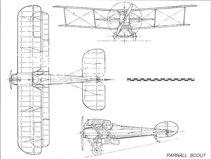
Parnall Scout
Pemberton-Billing P.B. 9
Noel Pemberton Billing, the colourful aviation pioneer who had developed a fully-equipped aerodrome in Essex before any manned aeroplane had achieved sustained, powered flight in Britain - and had himself later gained his Royal Aero Club pilot’s Certificate after only four hours’ tuition, started the design of marine aircraft in September 1913 in a small factory he acquired at Woolston, Southampton; as evidence of his faith in these aircraft he adopted the word ‘Supermarine’ as his telegraphic address. The Pemberton-Billing P.B.1 flying boat was shown at Olympia in March 1914.
As soon as the War started in August that year he turned his attention to the design of a small single-seat tractor scout and completed the work in a single day. Simplicity of manufacture was the keynote of this aircraft, termed the P.B.9, its 50hp Gnome rotary being mounted within ply panels which avoided the use of compound curves, while the wings featured no dihedral and no stagger. Construction of the aircraft was completed within one week, giving rise to the nickname ‘Seven Day Bus’. There were no centre section struts, the inboard pairs of interplane struts being attached to upper and lower wings close to the fuselage, so that the aircraft was, in effect, a one-and-a-half-bay biplane.
The P.B.9 was first flown in August by Victor Mahl (who had tuned Howard Pixton’s winning Sopwith Tabloid for the 1914 Schneider Trophy race, and had only learned to fly at Brooklands in May that year). The aircraft was almost certainly fairly tricky to fly, and was probably never fitted with any armament. It was not selected for purchase by the Services, but was later used by the RNAS for training at Hendon, being allocated the naval serial number 1267.
Type: Single-engine, single-seat biplane scout.
Manufacturer: Pemberton-Billing Ltd., Woolston, Southampton
Powerplant: One 50hp Gnome seven-cylinder rotary driving 8ft diameter wooden propeller.
Structure: All-wood box structure with ash longerons, covered with ply and fabric. Wings of twin ash spar construction built as single components, the lower wing spars passing beneath the fuselage.
Dimensions: Span, 26ft 6in; length, 20ft 0in; wing area, 205 sq ft.
Weight: Tare, 560lb.
Performance: Max speed, 78 mph at sea level; initial rate of climb, 500 ft/min; range, approx 150 miles.
Armament: None fitted.
Prototype: One (first flown by Victor Mahl in August 1914); later allocated No 1267 (naval). No production.
Pemberton-Billing P.B.23 and P.B.25
In the seven months following the first flight of the P.B.9 in August 1914, Noel Pemberton Billing undertook the design of a further dozen aircraft, none of whose manufacture has been confirmed, although one of these may have been the P.B. Boxkite (said to have been allocated the number 1374, and powered by a 50hp Gnome rotary engine). His P.B.23, a single-engine pusher biplane scout, was almost certainly inspired by Geoffrey de Havilland’s Airco D.H.2, which predated it by more than two months.
However, whereas the D.H.2’s nacelle was mounted directly on the lower wing, the P.B.23 featured a well-streamlined, metal-clad nacelle strut-mounted in the wing gap, with two pairs of plain struts being attached to the upper longerons and the upper wing, and pairs of plain struts to the lower longerons and the lower wing spars. Twin fins and rudders were located inboard on the wide-span tailplane, the entire empennage being carried on four booms which extended aft from the rear spars of the upper and lower mainplanes. The P.B.23 featured parallel-chord unswept wings, the lower wings having pronounced dihedral, but the upper wing being flat. A single, fixed forward Lewis machine gun was located low down in the nacelle’s extreme nose and could, with difficulty, be re-armed from the cockpit.
The 80hp Le Rhone, fitted initially, was obviously underpowered when the P.B.23 first flew in September 1915, and it was proposed to fit a 100hp Gnome monosoupape. The aircraft failed to impress the War Office, but the Admiralty ordered twenty examples of a modified version (allocated the serial numbers 9001-9020). In fact this version, which emerged as the P.B.25, only superficially resembled the earlier aircraft. The nacelle was lengthened and constructed entirely of wood with fabrics covering. Both wings were swept back eleven degrees, and the lower wing’s dihedral much reduced; the lower fuselage/wing mountings now comprised a pair of N-struts. The vertical tail surfaces were increased in area.
The first ‘production’ P.B.25, 9001 (officially termed the Scout) was fitted with an uncowled 110hp Clerget rotary engine driving a two-blade propeller, but 9002 was powered by the 100hp Gnome driving a four-blade propeller, and with the latter the aircraft returned a performance about ten per cent better than that of the D.H.2. Be that as it may, the Airco aircraft had already been selected for production and its continued delivery to the RFC squadrons in France was a matter of considerable urgency, so that the P.B.25 does not appear to have reached any operational unit. Moreover, the Scout quickly gained a bad reputation for being particularly difficult to handle during take-off and landing. Examples are known to have flown with the RNAS at Hendon and Eastchurch, but reliable confirmation that all twenty aircraft ordered were completed cannot be gained.
The accompanying data refers to the Pemberton-Billing P.B.25.
Type: Single-engine, single-seat, single-bay pusher biplane scout.
Manufacturer: Pemberton-Billing Ltd., Woolston, Southampton.
Powerplant: One 100hp Gnome monosoupape nine-cylinder rotary engine; one 110hp Clerget nine-cylinder rotary engine.
Structure: All-wooden construction, fabric-covered.
Dimensions: Span, 33ft 0in; length, 42ft lin; height, 10ft 5in; wing area, 277 sq ft.
Weights: Tare, 1,080lb; all-up, 1,576lb.
Performance: Max speed, 99mph at sea level; climb to 6,000ft, 8 min 30 sec; range, approx 200 miles.
Armament: One 0.303in Lewis machine gun on nose of nacelle immediately forward of cockpit.
Production: Twenty aircraft ordered (9001-9020), but completion of all aircraft has been questioned.
Pemberton-Billing P.B.29E
If the problem of acquiring a synchronized front gun for fighting scouts was being surmounted at the turn of 1915, another difficulty was not. German airship raids over southern England had occupied the minds of several aircraft designers for some months, not to mention the acute embarrassment caused to the War Office and Admiralty, for the difficulties posed by locating, attacking and destroying the huge and almost silent intruders at night seemed insuperable. Warning of their approach was seldom forthcoming, so that by the time intercepting aircraft could take-off - always assuming that a pilot, trained or experienced in night flying was available - the airship would most likely have travelled on to another area.
Pemberton-Billing, always a man to brush aside orthodoxy, conceived the idea of the patrol fighter capable of remaining aloft throughout the hours of darkness. It would, on account of the considerable fuel load necessary, be a relatively large aeroplane. In the late autumn of 1915 he therefore completed the design of a radical aircraft, the P.B.29E, to demonstrate his ideas.
The large twin-engine quadruplane featured high aspect ratio two-bay wings; the second wing mounted two 90hp Austro-Daimler engines in underslung nacelles driving pusher propellers, this wing being attached to the upper longerons of the fuselage. The fuselage accommodated pilot and observer, as well as the fuel tanks, while the bottom wing was a continuous structure which passed below the fuselage. A third crew member, the gunner, occupied a position in a nacelle in the gap between the two upper wings and was provided with a Lewis gun with all-round field of fire above the aircraft. Outboard of the engines all four wings were swept back about ten degrees.
Aft of the cockpit the rear fuselage was faired to a triangular cross section and carried a biplane tail unit with twin fins and rudders. The main units of the undercarriage were mounted directly below the engines so as to provide very wide track for ease of landing at night.
The aircraft, which, as far as is known, was not allocated any serial number, was first flown at Chingford, Essex, on Sunday 16 January 1916, the only apparently surviving evidence of this fact being that Pemberton Billing himself referred to the flight having taken place on that day in a Parliamentary bye-election speech he gave in the Mile End constituency which he was contesting. The P.B.29E, known in the Woolston works as the Night Fighter, had taken only seven weeks to build, but was destroyed in a flying accident several weeks later, not however before it had been flown by several naval pilots. However, Noel Pemberton Billing’s thoughts had already turned irrevocably towards politics and he determined to sell his company, thereby effectively ending his direct participation in the production of aircraft.
Type: Twin-engine, three-crew anti-airship patrol/interceptor quadruplane.
Manufacturer: Pemberton-Billing Ltd., Woolston, Southampton.
Powerplant: Two 90hp Austro-Daimler six-cylinder water-cooled in-line pusher engines driving four-blade propellers.
Structure: All-wood construction with fabric covering; two-spar, two-bay quadruplane wings and biplane tail with twin fins and rudders.
Dimensions, weights and performance: Not known (designed for up to 10 hours’ endurance)
Armament: One 0.303in Lewis gun in free mounting on gunner’s cockpit in nacelle occupying centre section gap between the two upper wings.
Prototype: One, probably first flown on 16 January 1916 at Chingford, Essex. No production.
Supermarine Night Hawk
It is necessary and perhaps logical at this point to diverge from the strict chronological sequence of events to continue the saga of Pemberton Billings’ anti-Zeppelin quadruplane because, although the P.B.29E had been destroyed early in 1916, the Admiralty had shown sufficient interest in the large, long-endurance gun carrier to warrant further development. The fact that this development continued for another year before a new aircraft appeared is in itself irrelevant, and the appearance of other companies’ aircraft in the meantime - conceived along similar lines - serves to emphasize Pemberton Billings’ particular flair for original thought.
The departure of Noel Pemberton Billing to the House of Commons and the subsequent formation of the Supermarine Aviation Works Ltd at Woolston under Hubert Scott-Paine were accompanied by the continuation of the theme demonstrated by the P.B.29E anti-airship patrol fighter. The new aircraft, initially referred to as the P.B.31E and whose design drawings bore the signature of one Reginald J Mitchell, was renamed the Supermarine Night Hawk and pursued the general configuration of the P.B.29E.
The quadruplane wings and biplane tail were retained, although the overall strength factor was substantially increased and three-bay wings introduced. The pusher Austro-Daimlers were replaced by 100hp Anzani tractors driving four-blade handed propellers. The fuselage, now of square section from nose to tail, occupied the whole of the centre wing gap and the upper gun nacelle now extended from the centre fuselage upwards to the level of the top wing’s upper surface. The primary offensive weapon, a 1 1/2-pounder Davis gun was installed at the front of this superstructure in a traversing mounting, and a Lewis gun, for defence, was mounted on a Scarff ring at the rear of the superstructure; a second Lewis, also on a Scarff ring, was located in the nose of the fuselage. The pilots’ cockpit was situated in the fuselage below the wing trailing edge, being enclosed and surrounded by extensive glazing; dual controls were provided. A novel feature was the provision of a rest bunk to enable crew members to relax in turn during lengthy flights. Another was the installation of a small searchlight, mounted on gimbals in the extreme nose and intended to illuminate targets as well as to assist night landings; power for the searchlight was to be provided by a small auxiliary engine carried in the aircraft.
To enable the Night Hawk to remain airborne for up to about eighteen hours, over 2,000lb of fuel could be carried in nine tanks in the fuselage, all fuel leads being armoured against battle damage.
Despite being generally underpowered, the Anzani engines proved capable of bestowing the maximum required speed of 75mph, although the normal patrol speed would in all likelihood have been between 55 and 60mph; the landing speed was 35 mph.
Although it was Pemberton-Billing who had enlisted the Admiralty’s support for the Night Hawk before his eventual election as Member for East Herts, the aircraft was not completed until after his departure and was therefore generally referred to as a product of Supermarine. It was allocated the naval serial number 1388, and was test flown by Clifford B Prodger at Eastchurch, beginning in February 1917. A second example, 1389, was cancelled, but no reason was ever given for the cancellation and it has been assumed that the increasing success being achieved by relatively conventional interceptors led the Admiralty to lose interest in Pemberton-Billings’ radical idea. Be that as it may, the idea of locating a gunner in a separate nacelle, with all-round field of fire clear of the propeller arc, had sparked widespread interest among the fighter designers, and a number of single-engine aircraft appeared in the latter war years displaying variations on the same theme.
Type: Twin-engine, four-crew anti-airship patrol interceptor.
Manufacturer: The Supermarine Aviation Works Ltd, Woolston, Southampton.
Powerplant: Two 100hp Anzani nine-cylinder air-cooled radial tractor engines driving four-blade handed wooden propellers.
Structure: All-wood construction with fabric and ply covering; three-bay quadruplane wings with approx, ten degrees of sweepback on the outer sections. Inverse tapered ailerons on all wings. Four-main wheel undercarriage.
Dimensions: Span (top wing), 60ft 0in; length, 37ft 0in; height, 17ft 8 1/2 in; wing area, 962 sq ft.
Weights: Tare, 3,677lb; all-up, 6,146lb.
Performance: Max speed, 75mph at 1,000ft; landing speed, 35 mph; time to 10,000ft, 60min; normal endurance, 9hr; maximum endurance, 18hr.
Armament: One 1 1/2-pounder Davis gun on traversing mounting in the nose of the gunner’s superstructure, and one 0.303in Lewis machine gun on Scarff ring at the rear; one Lewis gun on Scarff ring in the fuselage nose.
Prototypes: One, No 1388, first flown by Clifford B Prodger at Eastchurch in February 1917. Second prototype, 1389, cancelled. No production.
Port Victoria P.V.2 / P.V.2bis
Aircraft whose designation carried the prefix Port Victoria were those produced by an RNAS unit situated on the Isle of Grain on the northern banks of the Medway estuary in Kent. Originally commissioned as the Royal Naval Aeroplane Repair Depot early in 1915, the name Port Victoria was adopted to distinguish it from the nearby RNAS seaplane base. It later became the Marine Experimental Depot, of which one component came into being as the Experimental Construction Depot under the command of Lt J W Seddon rn.
The first aircraft produced, the P.V.1, was a development of the Sopwith Baby, fitted with high-lift wings to enable it to be flown safely while mounting external bombs and other military equipment. The first original design to be undertaken was the P.V.2, a small twin-float anti-Zeppelin seaplane fighter, intended to be armed with a Davis two-pounder gun. Initially completed with angular pontoon floats, the aircraft, N.1, was a sesquiplane, the lower wing being of short span and chord, and the upper wing of broad chord and span. When viewed from ahead, the interplane and float struts formed a ‘W’, the interplane struts being angled sharply outwards. Power was provided by a 100hp Gnome monosoupape driving a four-blade propeller. The upper wing, in two halves, was attached to the top fuselage longerons providing an excellent field of fire for the Davis gun and uninterrupted upward field of vision for the pilot.
However, by the time N.1 was completed, the Davis gun had been abandoned, and the aircraft was converted into a straightforward fighting scout by mounting two Lewis guns on the upper wings. It was quickly found that these wings created a blind area for the pilot during alighting and the seaplane was rebuilt with a continuous upper wing raised twelve inches above the fuselage, and at this time Linton Hope floats replaced the earlier pontoons. In this form N.1 was re-designated the P.V.2bis and first flown early in 1917 and, although not ordered into production, it proved popular among its pilots and contributed much valuable information for the development of later aircraft from Port Victoria.
Type: Single-engine, single-seat, twin-float sesquiplane fighting scout seaplane.
Manufacturer: RNAS Experimental Construction Depot, Port Victoria, Isle of Grain, Kent.
Powerplant: One 100hp Gnome monosoupape air-cooled nine-cylinder rotary engine driving four-blade propeller.
Structure: Wire-braced wooden box-girder fuselage formed to circular section and fabric-covered; fabric-covered two-spar wings with faired steel tube interplane and float struts.
Dimensions: Span (P.V.2), 27ft 0in; (P.V.2bis), 29ft 0in; length, 22ft 0in; height (P.V.2), 8ft 4in; (P.V.2bis), 9ft 4in; wing area (P.V.2), 168 sq ft; (P.V.2bis), 180 sq ft.
Weights (P.V.2bis): Tare, 1,211 lb; all-up, 1,702 lb.
Performance (P.V.2bis): Max speed, 93 mph at sea level; climb to 3,000 ft, 6 min; service ceiling, 10,000 ft.
Armament: Intended to mount one Davis two-pounder gun above fuselage with ten rounds of ammunition; changed to proposal to mount two Lewis guns above the wing centre section to fire above the propeller.
Prototype: One, N.1 (first flown at the Isle of Grain as P.V.2 in June 1916, and as P.V.2bis early in 1917). No production.
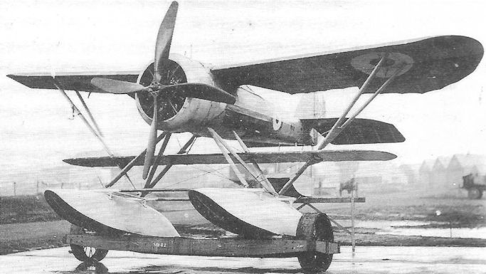
The P.V.2, N.1, with Linton Hope floats.

The P. V.2bis, N1, with the upper wing raised above the fuselage and a new centresection inserted.
Port Victoria P.V.4
Shortly after Port Victoria embarked on its P.V.2 anti-Zeppelin seaplane, work started on a two-seat pusher landplane fighter powered by a 110hp Le Rhone rotary. This aircraft was not built, and may have been designated the P.V.3. The design was, however, considered so favourably that Port Victoria was officially instructed to commence a twin-float derivative which became the P.V.4. Pursuing the P.V.2’s sesquiplane wing layout with upper wing attached to the crew nacelle’s top longerons, the resulting design was exceptionally compact, the gunner being located in the extreme nose with a Scarff ring-mounted Lewis gun forward of the pilot’s cockpit. The tail unit was carried on two pairs of converging booms attached to upper and lower mainplanes. Linton Hope floats were fitted from the outset.
The main problem lay in the official choice of the 150hp Smith ‘Static’ radial engine. The P.V.4’s airframe was completed during the autumn of 1916, but the Smith engine was never delivered and, in order to meet the stipulated maximum speed of 92 mph, only such engines as the 150hp Hispano-Suiza or 190hp Rolls-Royce Falcon would have sufficed - but neither could be fitted in the P.V.4. In the event recourse had to be made to a 110hp Clerget and, not surprisingly, the top speed performance fell far short of the target. Moreover, use of the Clerget moved the aircraft’s centre of gravity too far aft, and when the tailplane was rigged to counterbalance this, all longitudinal control was lost below 63 mph.
By that time, however, pusher fighters were regarded as de trop with the arrival of reliable gun interrupter gears, so it was not thought worthwhile to undertake the necessary redesign of the P. V.4’s tail unit, and its further development was therefore abandoned.
Type: Single pusher engine, two-seat twin-float sesquiplane fighting scout seaplane.
Manufacturer: RNAS Experimental Construction Depot, Port Victoria, Isle of Grain, Kent.
Powerplant: One 110hp Clerget 9Z nine-cylinder air-cooled rotary engine driving four-blade pusher propeller.
Structure: Wire-braced wooden box-girder central nacelle formed to near-circular section with wooden two-spar sesquiplane wings. Twin Linton Hope main floats and tail float.
Dimensions: Span, 32ft 0in; Weight: all-up: 2,400lb.
Performance: Max speed, 80.5 mph at sea level.
Armament: One 0.303in Lewis machine gun on Scarff ring in nose of nacelle.
Prototype: One, N.8 (first flown at the Isle of Grain in mid-1917). No production.
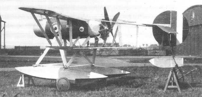
Designed largely by Capt William Higley Sayers RNAS, the P. V.4 was delayed by the non-delivery of the American-designed Smith Static engine.
Port Victoria P.V.5 and P.V.5A
At the beginning of 1917 the system of British aircraft procurement and supply came under scrutiny with a reorganization of the Air Board. This, among other things, led to the transfer of aircraft supply to the Ministry of Munitions, and the Admiralty’s Experimental Construction Depot at Port Victoria hovered on the brink of extinction. At that time, two new aircraft were nearing completion, ordered by the Air Department to meet the need for a single-seat fighting scout seaplane, capable also of light bombing duties.
These aircraft, which differed markedly from each other, were the P.V.5 and P.V.5A; both had been designed for the 150hp Smith Static and were awaiting this engine when the Depot’s future was threatened. In due course, owing to the non-delivery of the Smith engine, it was decided to go ahead with the P.V.5 with a 150hp Hispano-Suiza, but to abandon the P.V.5A. The former aircraft, N53, was an attractive twin-float sesquiplane, clearly based on the P.V.2, with the main floats and high-lift wings braced together with struts appearing as a ‘W’ when seen from the front. The engine was neatly enclosed in an unusual annular cowling with the faired valve covers just breaking the external contours. Although designed for Linton Hope floats, N53 was completed with flat-bottom pontoons, canted outwards so as to force water spray away from the propeller and engine radiator, and to provide some measure of shock absorption. A single synchronized Vickers gun was mounted immediately forward of the cockpit, and a pair of 65lb bombs could be carried in the fuselage.
It is said that the P.V.5 was first flown in July 1917, but did not undergo official trials until September. It proved very popular among its pilots, being manoeuvrable and pleasant to fly. Climb and ceiling were, however, disappointing and the maximum speed was lower than specified in the Admiralty requirement. Soon after these trials had been completed, it was decided to resurrect the P.V.5A - conventional by comparison with the P.V.5 in being a single-bay biplane with wings of equal span. The aircraft, N54, was completed around the end of 1917 with Linton Hope floats, and powered by a 200hp Hispano-Suiza. Completing its official trials in April 1918, it returned a much better performance than its predecessor, albeit sacrificing its pleasant flying qualities.
Not surprisingly, however, as almost eighteen months had elapsed since the issue of the original requirement, the Sopwith Baby, Pup and Camel had demonstrated their ability to meet almost all the Admiralty’s shipborne aircraft scouting requirements, and any further need for the P.V.5s had disappeared.
Type: Single-engine, single-seat, twin-float sesquiplane (P.V.5) and single-bay biplane (P.V.5A) fighting scout/light bomber.
Manufacturer: RNAS Experimental Construction Depot, Port Victoria, Isle of Grain.
Powerplant: P.V.5. One 150hp Hispano-Suiza engine; P.V.5A. 200hp Hispano-Suiza.
Dimensions: P.V.5. Span, 32ft 0in; length, 25ft 6in; height, 9ft 9in; wing area, 245 sq ft. P.V.5A. Span, 33ft lin; length, 26ft 9in; height, 13ft 1in; wing area, 309 sq ft.
Weights: P.V.5. Tare, 1,788lb; all-up, 2,456lb. P.V.5A. Tare, 1,974lb; all-up (no bombs), 2,518lb.
Performance: P.V.5. Max speed, 94.5 mph at sea level; climb to 6,500ft, 20 min 15 sec; service ceiling, 9,900ft. P.V.5A. Max speed, 102.5 mph at sea level; climb to 6,500ft, 9 min; service ceiling, 13,700ft.
Armament: Both aircraft armed with one synchronized 0.303in Vickers machine gun forward of cockpit on top decking. P.V.5 could carry two 65lb bombs.
Prototype: P.V.5, N53 (believed first flown in July 1917); P.V.5A, N54. No production.
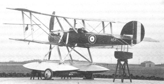
The P.V.5A, N54, with equal-span wings and Linton Hope floats at the time of its official trials in April 1918.
Port Victoria P.V.7 and P.V.8
Early in 1916 the Admiralty directed the Experimental Construction Depot at Port Victoria and the Experimental Flight at Eastchurch to examine the feasibility of producing a small scout capable of taking off from a very short platform aboard a Torpedo-Boat Destroyer, specifying the use of a geared 45hp ABC Gnat engine.
Both agencies produced independent designs, Capt W H Sayers rfc producing the P.V.7 at Port Victoria; at Eastchurch, Lieut G H Millar rnvr devised a rather different sort of aircraft. However, when Sqn Cdr H R Busteed moved from Eastchurch to assume command of Port Victoria, he took with him both Millar and his design, which was then designated the P.V.8. To differentiate between their design origins, the P.V.7 came to be called the Grain Kitten, and the P.V.8 the Eastchurch Kitten.
The P.V.7 was unquestionably the more attractive of the two, with sesquiplane wings, outward canted and paired interplane struts, gracefully tapering fuselage in plan and low aspect ratio ailerons on the top wing only. There was a spigot-mounted Lewis gun above the wing. However, tested first on 22 June 1917, the P.V.7 proved difficult to handle on the ground, and tail-heavy in the air; moreover the sesquiplane layout, with high-lift wings, was shown to be unsuitable for the tiny aeroplane.
By contrast, the aesthetically less-pleasing Eastchurch Kitten was much more successful. It featured heavily staggered single-bay wings of equal span employing I-form interplane and cabane struts from a crashed Sopwith Triplane, and when first flown on 7 September, it featured a balanced elevator without fixed tailplane. The pilot, Harry Busteed himself, reported severe longitudinal instability, with the result that a fixed tailplane was added, and much of the elevator horn balance was removed. To provide some shock absorption during landing, very big landing wheels with large-section tyres were fitted.
As with almost all Port Victoria’s aircraft, the engines promised for the two Kittens never materialised, and both aircraft had to be modified to take the direct-drive 35hp version of the ABC Gnat. This engine, designed by Granville Bradshaw, was an ingenious horizontally-opposed twin-cylinder aircooled engine weighing 115lb dry. Yet, despite the obvious success of the P.V.8, and the ease with which it could be flown, interest in the idea was shortlived.
Type: Single-engine, single-seat, single-bay lightweight biplane scout.
Manufacturer: RNAS Experimental Construction Depot, Port Victoria, Isle of Grain.
Powerplant: One direct-drive 35hp ABC Gnat horizontally-opposed two-cylinder aircooled engine.
Dimensions: P.V.7. Span, 18ft 0in; length, 14ft 11in; height, 5ft 3in; wing area, 85 sq ft. P.V.8. Span, 18ft Oin; length, 15ft 7 1/2 in; height, 5ft 5in; wing area, 106 sq ft.
Armament: Both aircraft equipped to carry one 0.303in Lewis gun above wing centre section.
Prototypes: P.V.7, N539 (first flown by H R Busteed on 22 June 1917). P.V.8, 540 (first flown by Busteed on 7 September 1917). No production.

The P.V.7 Grain Kitten, N539, whose good looks belied poor flying qualities.
Port Victoria P.V.7 and P.V.8
Early in 1916 the Admiralty directed the Experimental Construction Depot at Port Victoria and the Experimental Flight at Eastchurch to examine the feasibility of producing a small scout capable of taking off from a very short platform aboard a Torpedo-Boat Destroyer, specifying the use of a geared 45hp ABC Gnat engine.
Both agencies produced independent designs, Capt W H Sayers rfc producing the P.V.7 at Port Victoria; at Eastchurch, Lieut G H Millar rnvr devised a rather different sort of aircraft. However, when Sqn Cdr H R Busteed moved from Eastchurch to assume command of Port Victoria, he took with him both Millar and his design, which was then designated the P.V.8. To differentiate between their design origins, the P.V.7 came to be called the Grain Kitten, and the P.V.8 the Eastchurch Kitten.
The P.V.7 was unquestionably the more attractive of the two, with sesquiplane wings, outward canted and paired interplane struts, gracefully tapering fuselage in plan and low aspect ratio ailerons on the top wing only. There was a spigot-mounted Lewis gun above the wing. However, tested first on 22 June 1917, the P.V.7 proved difficult to handle on the ground, and tail-heavy in the air; moreover the sesquiplane layout, with high-lift wings, was shown to be unsuitable for the tiny aeroplane.
By contrast, the aesthetically less-pleasing Eastchurch Kitten was much more successful. It featured heavily staggered single-bay wings of equal span employing I-form interplane and cabane struts from a crashed Sopwith Triplane, and when first flown on 7 September, it featured a balanced elevator without fixed tailplane. The pilot, Harry Busteed himself, reported severe longitudinal instability, with the result that a fixed tailplane was added, and much of the elevator horn balance was removed. To provide some shock absorption during landing, very big landing wheels with large-section tyres were fitted.
As with almost all Port Victoria’s aircraft, the engines promised for the two Kittens never materialised, and both aircraft had to be modified to take the direct-drive 35hp version of the ABC Gnat. This engine, designed by Granville Bradshaw, was an ingenious horizontally-opposed twin-cylinder aircooled engine weighing 115lb dry. Yet, despite the obvious success of the P.V.8, and the ease with which it could be flown, interest in the idea was shortlived.
Type: Single-engine, single-seat, single-bay lightweight biplane scout.
Manufacturer: RNAS Experimental Construction Depot, Port Victoria, Isle of Grain.
Powerplant: One direct-drive 35hp ABC Gnat horizontally-opposed two-cylinder aircooled engine.
Dimensions: P.V.7. Span, 18ft 0in; length, 14ft 11in; height, 5ft 3in; wing area, 85 sq ft. P.V.8. Span, 18ft Oin; length, 15ft 7 1/2 in; height, 5ft 5in; wing area, 106 sq ft.
Armament: Both aircraft equipped to carry one 0.303in Lewis gun above wing centre section.
Prototypes: P.V.7, N539 (first flown by H R Busteed on 22 June 1917). P.V.8, 540 (first flown by Busteed on 7 September 1917). No production.
Early in 1916 the Admiralty directed the Experimental Construction Depot at Port Victoria and the Experimental Flight at Eastchurch to examine the feasibility of producing a small scout capable of taking off from a very short platform aboard a Torpedo-Boat Destroyer, specifying the use of a geared 45hp ABC Gnat engine.
Both agencies produced independent designs, Capt W H Sayers rfc producing the P.V.7 at Port Victoria; at Eastchurch, Lieut G H Millar rnvr devised a rather different sort of aircraft. However, when Sqn Cdr H R Busteed moved from Eastchurch to assume command of Port Victoria, he took with him both Millar and his design, which was then designated the P.V.8. To differentiate between their design origins, the P.V.7 came to be called the Grain Kitten, and the P.V.8 the Eastchurch Kitten.
The P.V.7 was unquestionably the more attractive of the two, with sesquiplane wings, outward canted and paired interplane struts, gracefully tapering fuselage in plan and low aspect ratio ailerons on the top wing only. There was a spigot-mounted Lewis gun above the wing. However, tested first on 22 June 1917, the P.V.7 proved difficult to handle on the ground, and tail-heavy in the air; moreover the sesquiplane layout, with high-lift wings, was shown to be unsuitable for the tiny aeroplane.
By contrast, the aesthetically less-pleasing Eastchurch Kitten was much more successful. It featured heavily staggered single-bay wings of equal span employing I-form interplane and cabane struts from a crashed Sopwith Triplane, and when first flown on 7 September, it featured a balanced elevator without fixed tailplane. The pilot, Harry Busteed himself, reported severe longitudinal instability, with the result that a fixed tailplane was added, and much of the elevator horn balance was removed. To provide some shock absorption during landing, very big landing wheels with large-section tyres were fitted.
As with almost all Port Victoria’s aircraft, the engines promised for the two Kittens never materialised, and both aircraft had to be modified to take the direct-drive 35hp version of the ABC Gnat. This engine, designed by Granville Bradshaw, was an ingenious horizontally-opposed twin-cylinder aircooled engine weighing 115lb dry. Yet, despite the obvious success of the P.V.8, and the ease with which it could be flown, interest in the idea was shortlived.
Type: Single-engine, single-seat, single-bay lightweight biplane scout.
Manufacturer: RNAS Experimental Construction Depot, Port Victoria, Isle of Grain.
Powerplant: One direct-drive 35hp ABC Gnat horizontally-opposed two-cylinder aircooled engine.
Dimensions: P.V.7. Span, 18ft 0in; length, 14ft 11in; height, 5ft 3in; wing area, 85 sq ft. P.V.8. Span, 18ft Oin; length, 15ft 7 1/2 in; height, 5ft 5in; wing area, 106 sq ft.
Armament: Both aircraft equipped to carry one 0.303in Lewis gun above wing centre section.
Prototypes: P.V.7, N539 (first flown by H R Busteed on 22 June 1917). P.V.8, 540 (first flown by Busteed on 7 September 1917). No production.
Port Victoria P.V.9
At about the time that the Port Victoria Kittens were nearing completion in 1917, the Experimental Construction Depot at Port Victoria received instructions to design a single-seat scout seaplane, retaining the best features of the P.V.2, but with improved performance, as a possible replacement for the Sopwith Baby.
Given a free hand, there is little doubt but that Cdr Seddon’s design staff could have come up with an outstanding design. Unfortunately, instead of being permitted to use a high-lift wing section, the Admiralty insisted on the RAF 15 aerofoil, with the result that climb performance and ceiling were to suffer.
The P.V.9 was an attractive aeroplane although, on account of the unsuitable wings, it was bigger than originally intended. It was, like the P.V.2, a sesquiplane and retained the earlier seaplane’s ‘W’ arrangement of interplane and float struts. The fuselage was again located within the gap, and very close to upper and lower wings, thereby providing the pilot with an excellent field of view. An innovative feature was the location of the fuel tanks within the sides of the fuselage forward of the cockpit, but outside the fuselage primary structure so that the cockpit could occupy the unrestricted width of the primary box girder. A single synchronized Vickers gun was mounted on the nose decking, and a free-firing Lewis gun was provided on top of the upper wing centresection forward of a generous cutout in the upper wing trailing edge. The undercarriage consisted of twin pontoon-type main floats and a streamlined, circular-section tail float.
The P.V.9 was originally intended to be powered by a 110hp Clerget, but instead was fitted with a 150hp Bentley B.R.1 rotary. The single prototype, N55, first flew in December 1917 but, owing to recurring trouble with this engine, was not officially tested until May. Unfortunately the aircraft underwent its trials with an unsuitable propeller, with the result that the performance returned did not accurately reflect the P.V.9’s real potential. That, however, was immaterial - as were the complimentary remarks about the aircraft in general - as the proposed role of the aircraft had long since been rendered superfluous by the capabilities of the Sopwith Pup and Camel; therefore there was no further need for the P.V.9’s development.
Type: Single-engine, single-seat, twin-float, single-bay sesquiplane scout.
Manufacturer: RNAS Experimental Construction Depot, Port Victoria, Isle of Grain.
Powerplant: One 150hp Bentley B.R.1 rotary engine driving two-blade propeller. Dimensions: Span, 30ft 11in; length, 25ft 2in; height, 9ft 0in; wing area, 227 sq ft.
Weights: Tare, 1,404lb; all-up, 1,965lb.
Performance: Max speed, 110.5 mph at 2,000ft; climb to 10,000ft, 27 min 20 sec; service ceiling, 11,500ft.
Armament: One synchronized 0.303in Vickers machine gun on fuselage forward of the cockpit, and one Lewis gun on upper wing centre section.
Prototype: One, N55 (first flown in December 1917). No production.
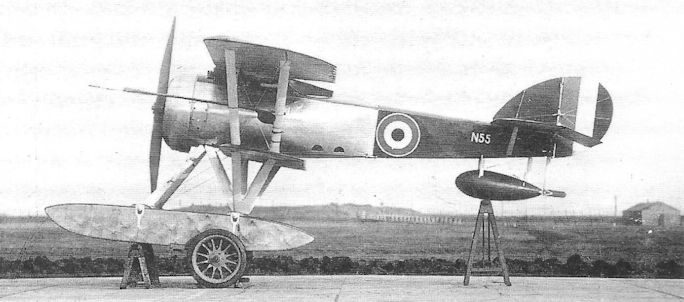
The Port Victoria P.V.9 prototype, N55; the presence of the long pressure boom on the interplane struts suggests that the photograph was taken at the time of its official tests.
RAF. B.E.2
Originally designed by Major Frederick Michael Green and Geoffrey de Havilland in 1911, the B.E.1 (Bleriot Experimental) two-seat tractor biplane demonstrated considerable evidence of advanced structural and aerodynamic thought, and its general configuration could be traced throughout its immediate successor, the B.E.2 which, in numerous sub-variants, continued to serve until the final year of the War. The prototype B.E.2 was flown by de Havilland himself at the Military Trials of 1912 and, although ineligible to compete, was shown to be superior in all respects to the Cody biplane which was declared the winner. The B.E.2, B.E.2A and B.E.2B were all unequivocally reconnaissance aircraft, being without provision for any sort of armament. Powered by the 70hp Renault, a total of 44 aircraft accompanied the RFC squadrons to France in 1914.
<...>
Royal Aircraft Factory B.S.1
Designed by Geoffrey de Havilland in 1912 at the Royal Aircraft Factory, the B.S.1 (c.f. Bleriot Scout, indicating a tractor aeroplane) was the first singleseat high-speed scout to be built as such anywhere in the world. It was an extraordinarily advanced concept and an attractive little biplane with well-staggered wings. In some respects it clearly owed its design to experience gained in the B.E.2 (Bleriot Experimental) - itself a derivative of the classic Bleriot tractor monoplane.
Unlike, however, the customary rectangular-section fuselage, the B.S.1 featured a circular-section wooden monocoque structure blending into a 100hp two-row ten-cylinder Gnome engine. Streamlined flying wires, or Raf-wires, were employed and cut-outs in the upper and lower wings provided the pilot with a good field of vision.
De Havilland first flew the B.S.1 during March 1913, but later the same month the aircraft crashed from a flat spin and was damaged, the pilot suffering a broken jaw. The aeroplane was repaired and, in an attempt to improve directional control, the rudder was enlarged and fins added above and below the rear fuselage. A new engine, the 80hp Gnome, was fitted together with a propeller of reduced pitch; the aircraft was re-designated the B.S.2, and shortly afterwards the S.E.2 (Santos Experimental). Before its accident, the B.S.1’s performance had been measured, returning a speed of 91.4 mph, a climb of 900 feet per minute, and an endurance of three hours.
Type: Single-engine, single-seat tractor biplane scout.
Manufacturer: The Royal Aircraft Factory, Farnborough, Hants.
Powerplant: 100hp Gnome ten-cylinder two-row air-cooled engine.
Structure: Wooden monocoque fuselage of circular section; two-spar wings of spruce and ash construction with fabric covering.
Dimensions: Wing span, 27ft 6in; length, 22ft. 0in.
Weight: All-up, approx. 1,200lb.
Performance: Max speed, 91 mph at sea level; initial climb, 900ft/min; endurance, three hours.
Armament: None.
Prototype: One (first flown by Geoffrey de Havilland in March 1913). No production.
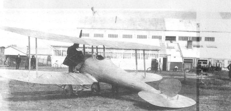
The remarkably clean, almost visionary Royal Aircraft Factory BS I was another creation of designer/pilot Geoffrey de Havilland and made its debut in early 1913. Extolled by the noted early military aviation historian, J.M.Bruce, as being the sire of all future single seat fighters of World War I, the BS I had what can only be described as a vivid performance, for its day, being capable of 92mph, coupled to a 900 feet per minute initial rate of climb. All this on the power of an 80hp Gnome! In its earliest form, seen here, the BS I's rudder, unaided by any fin, was simply inadequate to provide effective directional control and anyway was too weak, as it demonstrated by breaking away on 27 March 1913, breaking de Havilland's jaw in the ensuing crash. Rebuilt with a more effective tail unit, the aircraft became the SE 2.
Royal Aircraft Factory F.E.3/A.E.1
Built at the Royal Aircraft Factory early in 1913, the F.E.3 (Fighting Experimental) was an interesting two-bay two-seat pusher biplane designed as a gun-carrier. The principal feature of note was the absence of the customary pairs of tail booms to support the empennage, their place being taken by a single tubular boom around which the hollow propeller shaft rotated. Torsional rigidity of the tail unit was achieved by plentiful bracing wires, tensioned between the wings and sternpost, and between the landing skids and tailplane.
Power was provided by a French 80hp Chenu engine (of somewhat unreliable reputation that had recently powered Coventry Ordnance and Martin Handasyde sporting aircraft) which drove the pusher propeller by means of a shaft under the nacelle to a chain drive at the rear.
After brief flying trials in the hands of de Havilland and other Farnborough pilots the aircraft was fitted with a single 1 1/2-pdr Coventry Ordnance quick-firing gun which fired through the engine cooling intake, but only ground firing tests were performed during the summer of 1913.
The aircraft was also referred to as the A.E.1 (Armoured Experimental), but was not proceeded with, and saw no service.
Type: Single pusher engine, two-seat, two-bay biplane.
Manufacturer: Royal Aircraft Factory, Farnborough, Hants.
Powerplant: One 80hp Chenu engine with shaft and chain drive to four-blade pusher propeller mounted on hollow shaft through which passed the single tail support boom.
Structure: Mixed wood and metal nacelle structure with metal and fabric covering; twin-spar wooden three-bay wing structure with moderate stagger and fabric covering. Single tubular tail support boom.
Dimensions: Span, 48ft; length, 33ft; wing area, 480 sq ft.
Weight Loaded: 2,100lb.
Performance: Max speed, 75 mph at sea level; initial climb, 350 ft/min; ceiling, 5,000ft.
Armament: Ground trials with 37mm 1 1/2-pdr COW gun in nose of nacelle.
Prototype: One. No production.
RAF F.E.6
Relatively little is known of the F.E.6, other than it was a two-bay, single-engine pusher biplane which was built in the second half of 1914 by the Royal Aircraft Factory, and was powered by a 120hp Austro-Daimler driving a four-blade propeller. It followed the unusual configuration of the F.E.3 in that the tail unit was carried on a single steel boom which extended aft through the propeller shaft.
From the accompanying sketch, taken from a Factory drawing, the F.E.6 can be seen to possess no wing stagger and that ailerons were fitted to the upper and lower wings. The mainwheels of the undercarriage appear to have been carried on oleo struts and there was a small auxiliary nosewheel. The gun armament may have been a 6-pounder Davis recoilless weapon. Whether the aircraft was built and flown exactly to this design is not known.
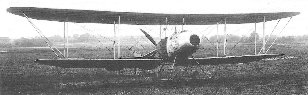
The Royal Aircraft Factory’s F.E.3 at Farnborough in 1913. The F.E.3, known also as the A.E.1, carried its tail on a single boom and mounted a 1’5-pounder C.O.W. gun in the nacelle. The opening in the nose admitted cooling air to its internally mounted radiators.
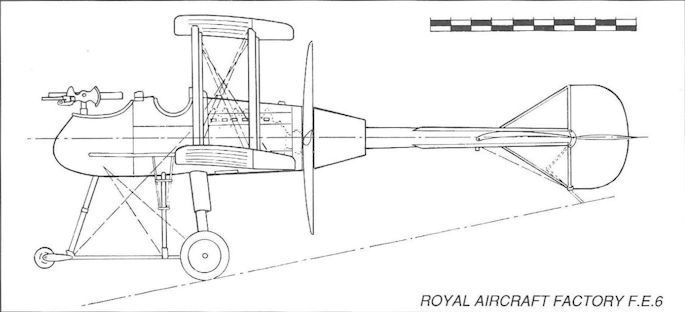
Royal Aircraft Factory F.E.6
R.A.F. S.E.2/2A
It has already been stated that the Royal Aircraft Factory’s B.S.1, having crashed in March 1913, was rebuilt as the B.S.2, and that this machine was shortly to be re-designated the S.E.2, these initials denoting Scout Experimental.
The revision of the B.S.1 had centred largely upon the vertical tail surfaces, as its failure to recover from the spin from which it crashed pointed to a serious lack of directional control, a characteristic confirmed by those pilots who had flown it. Small fixed dorsal and ventral fins were added, and these certainly improved the aeroplane’s handling, serving to prompt a further rebuild in which more extensive changes were made.
The new configuration, termed the S.E.2A and allotted the Army number 609, featured much enlarged dorsal and ventral fins and a revised rudder whose contours blended smoothly into the fins. A tailskid was now added in place of the strengthened lower segment of the rudder on which the S.E.2 had rested while on the ground. The wooden monocoque fuselage of the B.S.1 and S.E.2 was replaced aft of the cockpit by a structure of longerons, stringers and frame spacers covered with fabric. The engine cowling was given longer chord with a smaller diameter front aperture, and a large spinner was added to the propeller. All wing and undercarriage struts were replaced by members of improved section, the bracing wires were changed to Raf-wires and the landing skids improved (the latter were later removed altogether). Responsibility for these extensive alterations was entrusted to a design section leader at Farnborough named Henry Phillip Folland.
The S.E.2A was taken on charge by No 5 Squadron RFC, commanded by Maj J F A Higgins (later Air Marshal Sir John, kcb, kbe, dso, AFC, raf) at Farnborough in January 1914, and soon afterwards joined No 3 Squadron at Netheravon. Later, in October that year, it flew out to France for operations over the Western Front, where its armament was said to vary from the pilot’s 0.45in Service revolver to a pair of army rifles mounted on the sides of the fuselage to fire outside the propeller arc.
It is perhaps of interest to note that, apart from being faster than almost all other aircraft in France, the S.E.2A was faster than the Sopwith Tabloid at the time its seaplane version won the Schneider Trophy race, and that it achieved this performance with an 80hp Gnome.
Type: Single-engine, single-seat, single-bay scout biplane.
Manufacturer: The Royal Aircraft Factory, Farnborough, Hants.
Powerplant: One 80hp Gnome engine driving two-blade propeller.
Structure: All-wood construction. Wooden monocoque rear fuselage of the S.E.2 replaced by built-up wooden structure covered by fabric in the S.E.2A. Twin wheel-and-skid undercarriage.
Dimensions: Span, 27ft 6in; length, 22ft. All-up Weight: 1,200lb.
Performance: (S.E.2) Max speed, 80 mph; (S.E.2A) 96 mph at sea level.
Armament: Two 0.303in fixed rifles mounted on the sides of the fuselage firing forward and angled outwards to avoid the propeller blades.
Prototype: One only, No. 609; this later served with Nos 3 and 5 Squadrons RFC between January 1914 and March 1915.

The sole S.E.2, seen here at Farnborough, later served with the RFC in France.
RAF SE.2 was a reconstruction of the crashed BS.l which flew in October 1913.
RAF SE.2 was a reconstruction of the crashed BS.l which flew in October 1913.
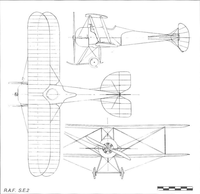
RAF S.E.2
RAF. B.E.2
<...>
The next version, the B.E.2C - the most famous of all B.E.s - bore the fruits of research by Edward Teshmaker Busk, the Assistant Engineer Physicist at the Royal Aircraft Factory who, by studying the flying characteristics of a B.E.2A, prepared the first practical data on the stability and controllability of aeroplanes to become available in Britain. Retaining the fuselage, engine installation and undercarriage of the B.E.2B, the prototype B.E.2C first appeared in June 1914, having wings of considerable stagger; ailerons replaced wing warping, and a fixed fin was added forward of the rudder.
Certainly the stability and control of the B.E.2 had been transformed, and its steadiness in the air seemed to recommend its value as a reconnaissance machine, the role assumed at that time to be the raison d’etre of the military aeroplane. On this account, production orders totalling 144 aircraft had been placed by the Admiralty with commercial sub-contractors before the end of 1914, as well as orders for 146 aircraft placed with the British & Colonial Aeroplane Co Ltd by the War Office. The first Squadron wholly equipped with B.E.2Cs was No 8, and this arrived in France in mid-April 1915. Early aircraft retained the 70hp Renault engine that powered the previous B.E. series, but at about this time production B.E.2Cs began appearing with the Royal Aircraft Factory’s own engine, the RAF 1A, and this had a number of different exhaust manifolds, the best known being a pair of vertical stacks attached to the leading edge of the upper wing. At the same time the B.E.2C’s landing gear underwent change, the twin skids being omitted; a pair of steel tube spreader bars were introduced at the apex of the V-struts, between which passed the wheel axle. Rather later, oleo struts replaced the front tubular V-struts. The wheel axle was not attached rigidly to the spreader bars and springing was achieved by binding the spreader bars with lengths of rubber cord.
It was in the late summer of 1915 that the B.E.2C entered the most tragic phase of its history, for this was the moment when the Germans introduced their Fokker monoplane scouts, armed with a mechanically synchronized front gun, an innovation that not only revolutionized but generally simplified offensive air combat tactics.
No 8 Squadron in particular, which had assumed the role of long-range reconnaissance well behind the German lines, now suffered heavy losses under the guns of the enemy scouts, as did the growing number of squadrons equipped with B.E.2Cs. Although pilots took matters into their own hands and attempted to mount Lewis guns on makeshift structures for their defence, these only served to further reduce the B.E.’s already modest performance.
In truth the one characteristic that had commended the B.E.2C to its crews had been its steady, leisurely flying gait, so much so that, if attacked by an enemy scout, it possessed no agility with which to escape destruction. By September 1915 Nos 2, 4, 6, 7, 8, 9, 10, 12, 13, 15 and 16 Squadrons (more than half the total) were equipped with B.E.2Cs in France, and all were to suffer very heavy casualties.
The only remedy available, if the RFC was to continue to perform its allotted reconnaissance role, was to provide fighting escorts, but it was to be several months before suitable escort fighters could be brought into service. In the meantime the ‘Fokker scourge’ continued unabated. Increasingly the B.E.2Cs had also been employed as bombers, both with the RNAS and the RFC, but weighed down with bombs, however small, they were no less vulnerable to enemy scouts than the reconnaissance aircraft. In home skies, however, they came to be used with mounting success in the antiairship role, the first being the destruction of the Schutte-Lanz SL.II, shot down by Lieut W Leefe Robinson over Cuffley, Hertfordshire, on the night of 2/3 September 1916, for which he was awarded the Victoria Cross; on the night of the 24th of that month 2/Lieut Frederick Sowrey shot down Zeppelin L32 over Billericay, Essex. Both pilots belonged to No 39 (Home Defence) Squadron. Three other Zeppelins also fell to B.E.2C pilots.
It was the steadiness as a potential gun platform, as well as the ease with which it could be flown at night, that rendered the B.E.2C a suitable aircraft to counter the German airships, and in this role the aircraft appeared with a variety of weapons, and most Home Defence B.E.2Cs were armed with either single or twin Lewis guns, firing incendiary ammunition from flexible mountings. Some of the RNAS aircraft were flown as singleseat night fighters, the observer’s front cockpit being faired over. Other examples were experimentally flown with Le Prieur rockets mounted on the outer pairs of interplane struts, but in general the addition of such external accoutrements simply deprived the aircraft of the last vestiges of useful speed. B.E.2Cs served widely overseas, and several were employed as single-seat fighters in the Middle East, but with marked lack of success.
Many attempts were made to improve the B.E.2C’s speed performance, and the experimental installation of the 150hp Hispano Suiza engine early in 1916 certainly bestowed a useful speed of 95 mph at sea level; the increased weight of the engine by some 400lb, however, severely affected the handling of the aircraft, and the few examples were, perhaps surprisingly, confined to training duties.
The persistence with which the War Office continued to order production of the B.E.2C (as well as the later B.E.2D and B.E.2E, neither of which proved any better as fighting aircraft), fuelled the growing accusations that illogical preference was being afforded for aircraft designed at the State-owned Royal Aircraft Factory - even though every production B.E.2 was manufactured by private sub-contractors.
The accompanying data refers to the B.E.2C.
Type: Single-engine, two-seat, two-bay reconnaissance biplane; also anti-airship night interceptor.
Manufacturers: The Royal Aircraft Factory, Farnborough, Hants (B.E.2C prototype only). Barclay, Curie & Co Ltd, Glasgow; William Beardmore & Co Ltd, Dalmuir, Dunbartonshire; The Blackburn Aeroplane & Motor Co Ltd, Leeds; The British & Colonial Aeroplane Co Ltd, Bristol; The Daimler Co Ltd, Coventry; William Denny & Bros, Dumbarton; The Eastbourne Aviation Co Ltd, Eastbourne; The Grahame-White Aviation Co Ltd, Hendon, London, Handley Page Ltd, London; Hewlett & Blondeau Ltd, Clapham, London; Martinsyde Ltd, Brooklands, Surrey; Napier & Miller Ltd, Old Kirkpatrick, Renfrewshire; Ruston, Proctor & Co Ltd, Lincoln; Vickers Ltd (Aviation Dept), Knightsbridge, London; The Vulcan Motor & Engineering Co (1906) Ltd, Southport, Lancs; G & J Weir Ltd, Glasgow; Wolseley Motors Ltd, Birmingham.
Powerplant: 70hp Renault; 90hp RAF 1A; 105hp RAF IB; 105hp RAF ID; 90hp Curtiss OX-5; 150hp Hispano-Suiza.
Structure: Steel tubular construction with ply, metal sheet and fabric covering; cable bracing, later Raf-wire bracing. Two-bay, twin-spar wings with steel tubular interplane struts with wooden fairings. Early aircraft with twin-skid, twin-wheel undercarriage, later replaced by plain V-strut, twin-wheel unit without skids; some aircraft with oleo struts as forward member of V-strut structure.
Dimensions: Span, 37ft 0in; length, 27ft 3in; height, 11ft 1 1/2 in; wing area, 371 sq ft.
Weights (RAF 1A engine): Tare, 1,370lb; all-up, 2,142lb.
Performance (RAF 1A engine): Max speed, 77 mph at sea level; climb to 10,000ft, 45 min 15 sec; service ceiling, 10,000ft; endurance, 3 1/4 hr.
Armament: Varied from none to four Lewis guns, sometimes including a rearward-firing gun on the pilot’s cockpit; anti-airship aircraft were usually armed with single or twin Lewis guns on spigot or flexible mountings, and individual aircraft had provision for canisters of Ranken darts, or up to ten Le Prieur rockets on the interplane struts.
Production: The best estimate available of the total number of B.E.2Cs built is 1,310, of which about 330 were delivered initially to the RNAS (some were transferred to the RFC).
Summary of Service: B.E.2Cs served with Nos 2, 4, 5, 6, 7, 8, 10, 12, 15, 16 and 21 Squadrons, RFC, on the Western Front, and Nos 19 (Reserve), 33, 36, 39, 50, 51, 75 and 141 Squadrons, Home Defence.
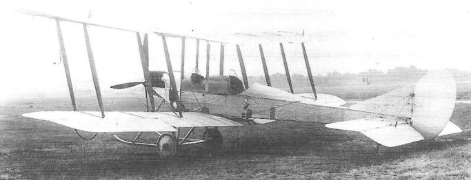
The prototype B.E.2C at Farnborough on 2 July 1914. Staggered wings and a tail fin made the aircraft extremely stable.
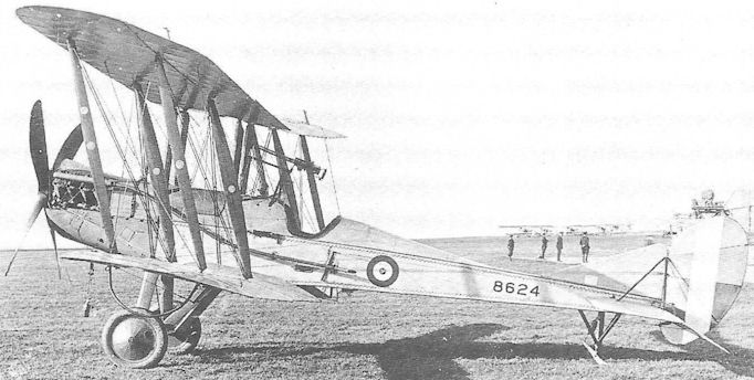
A B.E.2C, No 8624, of the RNAS, probably at Cranwell, modified as a single-seat fighter and armed with a single Lewis gun over the pilot's cockpit. Equipped with Holt flares under the lower wings, this was probably flown as a night fighter.
Royal Aircraft Factory F.E.2
Origins of the Royal Aircraft Factory’s F.E.2 lay in Geoffrey de Havilland’s second aeroplane, which was bought by the Factory on his appointment as designer and pilot at Farnborough at the end of 1910. It was initially named the F.E.1 (Farman Experimental, on account of its resemblance to contemporary Farman biplanes), but after a crash it was re-built in September 1911 with a 50hp Gnome engine and re-designated the F.E.2. It was again re-built, this time with a 70hp Renault, in 1913, but crashed the following year. In the meantime de Havilland had prepared a new design, ostensibly based on the F.E.2 yet bearing little resemblance to the previous aeroplane, being a three-bay pusher biplane in which an observer-gunner occupied the front cockpit, with the pilot’s cockpit behind and raised about eighteen inches. This version, the F.E.2A, appeared early in 1915 and was designed as a fighting aircraft from the outset, so the designation was accordingly changed to Fighting Experimental. A dozen aircraft were ordered for the RFC to be powered by the 100hp Green, but this was found to be unsatisfactory owing to poor power-weight ratio and the next version, the F.E.2B, was modified to take the 120hp Beardmore driving a two-blade propeller, the top half of the engine being uncowled.
The F.E.2B was ordered into production at the Factory and four sub-contractors, and the first aircraft was handed over to the RFC in May, being delivered to No 6 Squadron at Abeele in France, commanded by Maj G S Shepherd. The first aircraft was flown to France by Capt Louis Arbon Strange (later Lt-Col, dso, obe, mg, afc*) on 15 May. Within three months the ‘Fokker scourge’ was being experienced by the Allied air forces on the Western Front, and more fighter squadrons were hurriedly formed with F.E.2Bs, namely Nos 20, 22 and 25, and these moved to France early in 1916. Armed with a single Lewis gun in the bow position, the F.E.2B began to make its presence felt even though, unlike the Fokker monoplane, it lacked a synchronized front gun. In fact both the F.E.2B and the single-seat D.H.2 (the latter also arriving in France in growing numbers) possessed surprising agility. The famous German pilot, Max Immelmann, fell to the aircraft of 2/Lieut G R McCubbin and Corp J H Waller of No 25 Squadron on 18 June 1916. During the great Battles of the Somme F.E.2Bs gave valuable service both in air combat and in gun attacks against enemy ground forces.
A total of 1,939 F.E.2Bs was built, and served on 32 RFC squadrons. A new version, the F.E.2C night fighter, was produced in which the cockpits of the two crew members were transposed, the pilot occupying the front cockpit to facilitate night landing. However, only two examples were built, of which one served with No 25 Squadron in 1916.
Although a change to the 160hp Beardmore in later F.E.2Bs had improved the aircraft’s speed at sea level from 80 mph to 91 mph, it was considered inadequate to meet the new German fighting scouts that were coming into service in 1916. A further engine change, to the 250hp Rolls-Royce Mk I or III engine - later named the Eagle - in a somewhat cleaner cowling, characterized the F.E.2D which arrived in service in June. Unfortunately the first aircraft to land in France was delivered intact to the Germans when the pilot accidentally landed at Lille, mistaking it for St Omer.
The more powerful Rolls-Royce gave little improvement at low altitude but, owing to less power loss as height increased, bestowed a gain of about 10 mph at 5,000 feet. Be that as it may, the Germans were already one step ahead with their Fokker D II, soon to be joined by the D III with a speed of 100 mph - and twin front guns.
Moreover, with the arrival of the long awaited gun synchronizing gear in Britain and France, a new generation of front-gun tractor biplane scouts was on the threshold of service, so that the days of the pusher biplane fighter were, by the autumn of 1916, already numbered. As the F.E.2D began joining or replacing the F.E.2B in service it became immediately clear that the Germans had, by examination of the captured aircraft, identified the F.E.2D’s weak spot - an absence of rearward defence - and, as losses to enemy tractor scouts increased, a second Lewis gun on a telescopic mounting was added between the cockpits capable of firing aft over the top wing. To do so the observer had to stand on his seat, exposing almost the whole of his body to the slipstream. Nevertheless there occurred a number of combats in which the old pusher fighters gave good account of themselves, as exemplified by a fight on 6 July 1917, between six F.E. 2Ds of No 20 Squadron and about forty enemy fighters; the British pilots forced down five German aircraft, one of which was flown by the redoubtable Manfred von Richthofen, who was wounded.
The suitability of the F.E.2 for night flying prompted the RFC to adapt the 2D for night bombing, the value of which was becoming apparent by early 1917. Henceforth, therefore, this responsibility was increasingly assumed by the F.E.2D squadrons in France. At home, F.E.2Bs and 2Ds were issued to Home Defence squadrons, starting at the end of 1916, in the role of anti-Zeppelin night fighters, but usually proved unable to reach the height normally flown by the enemy airships. Several interceptions were thwarted by the F.E.’s inability to climb much above about 14,000 feet. A number of experiments was undertaken to improve the fighters’ armament, including the mounting of a one-pounder quick-firing gun, twin Lewis guns coupled to a searchlight on the nose, and of 0.45in Maxim guns. As a means of reducing weight and drag, Nos 36 and 51 (Home Defence) Squadrons converted their F.E.2Ds to single-seaters by fairing over the front cockpit and arming their aircraft with either one or two fixed Lewis guns in the nose.
In the course of constant attempts to wring more speed from the old biplane, trial installations of the 284hp Rolls-Royce Eagle III, 200 hp RAF 3A and 230hp BHP engines were examined, the latter aircraft being the F.E.2H. None was adopted for service, and the F.E.2B and 2D soldiered on right up to the Armistice, aircraft that were regarded with affection, but whose passing was not mourned.
Type: Single pusher engine, two-seat, three-bay fighting scout biplane.
Manufacturers: The Royal Aircraft Factory, Farnborough, Hants; Boulton & Paul Ltd, Norwich, Norfolk; Richard Garrett & Sons, Leiston, Suffolk; Ransomes, Sims & Jefferies, Ipswich, Suffolk; G & J Weir Ltd, Glasgow; Alex Stephen & Sons, Glasgow.
Powerplant: (F.E.2A) 100hp Green; (F.E.2B) 120 or 160hp Beardmore; (F.E.2C) 160hp Beardmore; (F.E.2D) 250hp Rolls-Royce (Eagle) Mk I or III. For other experimental installations, see text.
Dimensions: Span, 47ft 9in; length, 32ft 3in; height, 12ft 7 1/2in; wing area, 494 sq ft.
Weights: (F.E.2D) Tare, 2,509lb; all-up, 3,469lb.
Performance: (F.E.2D) Max speed, 94 mph at 5,000ft; climb to 5,000ft, 11 min; service ceiling, 17,500ft; endurance, 3 1/4 hours.
Armament (late F.E.2Bs and F.E.2D fighters): One bracket-mounted 0.303in Lewis machine gun in front of observer’s cockpit, and one Lewis gun mounted between cockpits.
Prototypes: F.E.2 (Renault), No 604; F.E.2A, No 2864; F.E.2D, No 7995.
Summary of Production: (F.E.2B), 51 by Royal Aircraft Factory; 250 by Boulton & Paul; 436 by Weir; 250 by Ransomes; 60 by Garrett; 150 by Stephens; 740 by unknown manufacturers. (F.E.2D), 85 by Royal Aircraft Factory; 300 by Boulton & Paul.
Summary of RAF Service: F.E.2Bs served with Nos 6, 11, 12, 16, 18, 20, 23, 24, 28, 33, 36, 51, 58, 64, 83, 90, 100, 101, 102, 116, 118, 131, 133, 148, 149, 166, 191, 192, 199, 200 and 246 Squadrons of the RFC and RAF. F.E.2Ds served with Nos 20, 25, 33, 51, 57, 83, 101, 102, 148, 149 and 192 Squadrons.
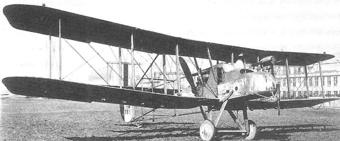
An F.E.2B, built by G & J Weir Ltd, and experimentally modified as a night fighter with two Lewis guns attached to a searchlight, power for which was provided by a wind-driven generator under the nose. Note the four lights under each wing - presumably added to facilitate night landing - and the Holt flare brackets. The 120hp Beardmore engine drives a two-blade propeller. The speed of this aircraft must have been severely reduced by all these accoutrements!
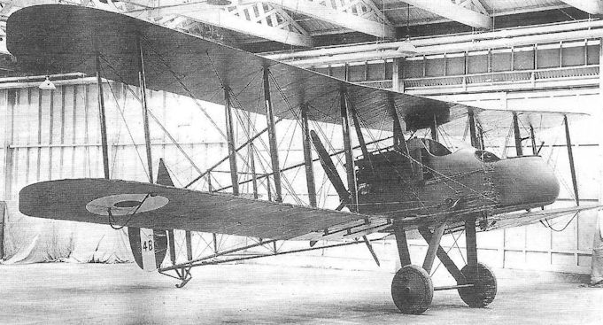
A late production F.E.2B night fighter, B487, built by Ransomes, Sims & Jefferies of Ipswich with a 160hp Beardmore.
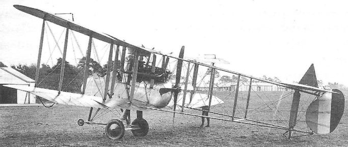
The prototype F.E.2D, 7995, showing the 200hp Rolls-Royce Mk I driving a four-blade propeller, and stack-type exhaust pipes; note the nosewheel-type main undercarriage and the low-sided pilot's cockpit - characteristic of early F.E.2Ds.
R.A.F. S.E.4 and 4A
Designed by Henry Folland, the S.E.4 was intended quite simply to be the fastest aeroplane in the world. First flown by Norman Spratt in June 1914 - only two months after the Sopwith Tabloid seaplane had won the Schneider Trophy at 86 mph and demonstrated a top speed of around 100 - the S.E.4 achieved a speed of 135 mph, faster by a considerable margin than any other aeroplane then flying.
Power was provided by the 160hp Gnome fourteen-cylinder two-row rotary, totally enclosed in a smooth-contoured cowling fronted by a large spinner which, after trouble due to engine overheating, had an intake cut in the nose to allow more airflow to pass through to the engine. The fuselage was reminiscent of the S.E.2A but was covered overall with ply. The wings were similar to those of the earlier aircraft but rigged without stagger, and featured single cabane and interplane struts on each side; full-span ailerons-cum-flaps replaced the former wing warping.
The most unusual feature was the undercarriage which initially comprised a transverse half-elliptic leaf spring attached to the apex of an inverted tripod, the landing wheels being attached to the extremities of the spring. This proved unsatisfactory owing to a tendency of the aircraft to roll while taxying and, after initial flight trials, it was replaced by a conventional pair of V-struts.
Although no armament was ever fitted, there is no doubt but that the aircraft attracted interest as a potential fighting scout, and it was flown on occasion by Maj J M Salmond (later Marshal of the Royal Air Force Sir John, gcb, cmg, cvo, dso), who reported favourably on it.
The big Gnome, however, continued to give trouble, and the landing speed (at 52 mph) was considered too high for Service pilots. The engine was replaced by a 100hp Gnome monosoupape and, not surprisingly, the speed performance decreased to mediocrity. Development of the S.E.4 was finally abandoned when it was badly damaged following a wheel collapse while landing.
The S.E.4A
Only superficially related to the S.E.4, the S.E.4A was said to be an attempt to suit the former aircraft to quantity production and, in so doing, almost all the S.E.4’s novel features disappeared, other than the ailerons-cum-flaps. It is true that the S.E.4A flew initially with a huge open-nosed spinner, but engine overheating ensued nonetheless and a conventional cowling without spinner was substituted. It may be of interest to remark that the outline and structure of the S.E.4’s tail unit was to reappear almost unaltered in the design of the much more illustrious S.E.5 which started in 1916.
Four examples were produced in 1915, being flown frequently by Maj Frank Goodden, who by then had been appointed the Factory’s Chief Test Pilot. Provision was made to mount a Lewis gun above the upper wing, and at least one S.E.4 was based at Joyce Green on Home Defence duties at the end of that year. However, the aeroplane’s performance was not outstanding and failed to arouse further official interest.
Type: Single-engine, single-seat, single-bay tractor biplane.
Manufacturer: The Royal Aircraft Factory, Farnborough, Hants.
Powerplant: S.E.4. 160hp Gnome; 100hp Gnome monosoupape. S.E.4A. 80hp Gnome; 80hp Le Rhone.
Structure: Composite wood and steel construction with ply and fabric covering. S.E.4 with single interplane and cabane struts; twin interplane and cabane struts on S.E.4A.
Dimensions: S.E.4. Span, 27ft 6in; length, 21ft 4in; height, 9ft 0in (with tripod undercarriage); wing area, 188 sq ft. S.E.4A. Span, 27ft 5 1/10in; length, 20ft 10in; height, 9ft 5in.
Performance: S.E.4 (160hp Gnome). Max speed, 135 mph at sea level; initial rate of climb, over 1,600 ft/min. (100hp Gnome). Max speed, 92 mph at sea level. S.E.4A. Max speed, approx 90 mph at sea level.
Armament: S.E.4. None. S.E.4A. Provision for single Lewis gun on upper wing.
Prototype and Production: One S.E.4, No. 628. Four S.E.4As.

The sole S.E.4 as first flown with the tripod undercarriage. The I-shaped wing struts are clearly shown.
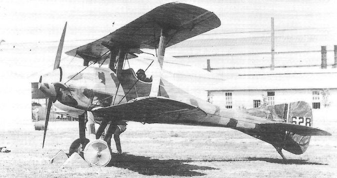
The S.E.4 with conventional V-strut undercarriage. The early wartime attempt at camouflage is interesting.
R.A.F. F.E.8
Designed under the leadership of the Royal Aircraft Factory’s chief draughtsman, John Kenworthy, the F.E.8 was born shortly before the appearance of a successful British gun interrupter gear and was therefore, of necessity, a pusher biplane scout. Generally regarded as possessing more pleasing lines than the business-like Airco D.H.2, the F.E.’s performance was extraordinarily similar; like the D.H.2, production of the F.E.8 was spurred by the growing number of German fighting scouts over the Western Front.
The prototype F.E.8, possibly allotted the number 7456, was first flown in about October 1915, but crashed the following month; a second prototype, possibly 7457, was hurriedly constructed and rushed to France, where it was favourably commented upon - prompting the immediate raising of production sub-contracts with private manufacturers, namely the Darracq company and Vickers.
However, delays in establishing these production lines resulted in the F.E.8 not reaching fighter squadrons in France until June 1916, the first being two aircraft with No 29 Squadron at Abeele, commanded by Maj E L Conran. The first to be fully equipped with F.E.8s was No 40 Squadron which, commanded by Maj Robert Loraine (one of the original RFC pilots, and later Lt-Col, DSO, mc), arrived at St Omer in August.
It was in the late summer of 1916 that reports filtered back to the Factory that the F.E.8 was suffering a spate of spinning accidents, and that the aircraft was attracting an ill-reputation in this respect, being referred to as the ‘spinning incinerator’. It was quickly established that, although pusher aircraft tended to spin more readily from the stall, the F.E.8 possessed spinning characteristics not significantly different from other aircraft. The indefatigable Factory pilot, Maj Frank Goodden, deliberately spun an F.E.8 three times in each direction from no more than 3,500 feet, and recovered by applying the customary control movements. The fact was that RFC pilots were still not, in 1916, being instructed in spin recovery as a matter of routine during their flying training.
Nevertheless the F.E.8s clearly became outclassed in air combat within three months of their first arrival over the Western Front. Yet they continued in service, even though casualties increased sharply. No 40 Squadron was to suffer a disaster when, on 9 March 1917, nine F.E.8s were attacked by Jasta 11, led by Manfred von Richthofen. In a fight that lasted half an hour, eight of the British machines were forced down or destroyed, and the last aircraft crashed on landing.
The F.E.8 was ultimately withdrawn from operational service in July that year, when No 41 Squadron disposed of its aircraft in favour of Airco D.H.5s.
Type: Single pusher engine, single-seat, two-bay biplane scout.
Manufacturers: The Royal Aircraft Factory, Farnborough, Hants; The Darracq Motor Engineering Co Ltd, Fulham, London; Vickers Ltd (Aviation Department), Knightsbridge, London.
Powerplant: 100hp Gnome monosoupape rotary engine driving four-blade propeller (as standard); also 110hp Le Rhone and 110hp Clerget.
Dimensions: Span, 31ft 6in; length, 23ft 8in; height, 9ft 2in; wing area, 218 sq ft.
Weights: Tare, 895lb; all-up, 1,346lb.
Performance: Max speed, 94 mph at sea level; climb to 10,000ft, 17 min 30 sec; service ceiling, 14,500ft; endurance, 2 1/2 hr.
Armament: Prototype armed with remotely controlled 0.303in Lewis machine gun mounted low in the extreme nose of the nacelle. Production aircraft armed with spigot-mounted Lewis gun level with the pilot’s eyes.
Prototypes: Two; possibly Nos 7456 and 7457, built by the Royal Aircraft Factory, and first flown in about October 1915.
Production: 295 (245 by Darracq: Nos 6378-6477, A41-A65 and A4869-A4987; 50 by Vickers, Nos 7595-7644). Two aircraft, 3689 and 3690, were apparently allocated to the Admiralty but were probably not built.
Summary of Service: F.E.8s served with Nos 5, 29, 40 and 41 Squadrons, RFC, in France, and with various home-based training units.

The first prototype R.A.F. F.E.8 at Farnborough in November 1915 shortly before its crash, showing its general similarity with the D.H.2; note the position of the remotely-controlled Lewis gun in the nose.
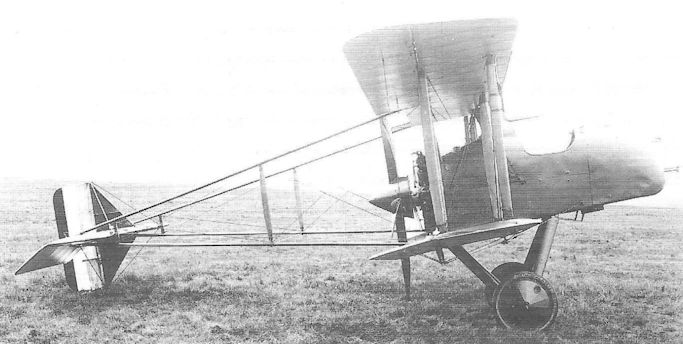
Another view of the F.E.8 prototype here showing the unstaggered, parallel-chord wings, and the large spinner on the four-blade propeller.
RAF B.E.12
It is believed that the Royal Aircraft Factory’s B.E.12 was first flown at about the same time as the Sopwith Pup. No two fighters, conceived to counter the same threat, can have been more different, yet well illustrate the different approaches to the supply of military aircraft by Government and commercial industry. Whereas the Sopwith Pup was an inspired design born of independent thought, the B.E.12 was evolved, for reasons of expediency, from an existing design of barely adequate mediocrity.
To meet urgent demands from the RFC in France for a single-seat fighter to meet the threat posed by the new German scouts, the Royal Aircraft Factory simply adapted the B.E.2C, producing a prototype by modifying a Bristol-built aircraft (No 1697) by installing a 150hp RAF 4A engine, changing to single-bay wings and deleting the front cockpit. Sub-contracted production was put in hand at the Coventry Ordnance Works, Daimler and Standard Motors, all in Coventry.
By the beginning of July 1916 a single B.E.12 had been delivered to No 10 Squadron at Chocques in France, and the first Squadron, fully equipped with the aircraft, was No 19 which arrived at Fienvilliers on 1 August under the command of Maj R M Rodwell. No 21 Squadron re-equipped with B.E.12s later the same month. It soon became apparent that by simply increasing the engine power and adopting single-bay wings did not transform the B.E.2C into an effective fighter, and in the following month it was - at the insistence of General Trenchard himself - withdrawn from the fighter role in France and transferred to bombing. Losses had become prohibitive.
Meanwhile the Factory had attempted to improve the B.E.12’s manoeuvrability by fitting a top wing similar to that of the B.E.2E, but adding extended ailerons on the top wing only, with enormous horn balances. This aircraft, No 6511, was termed the B.E.12A, but after trouble was experienced during flight tests, the aircraft reverted to standard ailerons on upper and lower wings; the aircraft’s designation was temporarily changed to B.E.12Ae, but soon reverted to B.E.12A. Needless to say, after the previous experiences, B.E.12As were not issued to RFC squadrons in France, although a small number was sent to Palestine in 1917 for use by No 67 (Australian) Squadron until early the following year.
Both B.E. 12s and 12As were issued to Home Defence squadrons at the end of 1916, and on the night of 16/17 June 1917 Lieut L P Watkins of No 37 Squadron, flying B.E.12 No 6610, shot down Zeppelin L48 from 14,000 feet over Theberton, Suffolk.
The B.E.12B was a version specially developed in 1917 as a night fighter and was powered by a 200hp Hispano-Suiza engine. Its armament comprised a pair of Lewis guns side-by-side on a special mounting above the upper wing centresection; the starboard gun was fitted with a Hutton illuminated sight and, for firing directly ahead (over the propeller), a plain ring and bead sight was attached to the starboard cabane struts. For upward firing and changing the ammunition drums, the guns pivoted downwards so as to be within reach of the cockpit. The engine and exhaust system were similar to those on the S.E.5A - by then being developed by the Factory.
A total of thirty-six B.E.12Bs was issued to Home Defence Squadrons.
Type: Single-engine, single-seat, single-bay biplane scout.
Manufacturers: The Royal Aircraft Factory, Farnborough, Hants; The Coventry Ordnance Works Ltd, Coventry; The Daimler Co Ltd, Coventry; The Standard Motor Co Ltd, Coventry.
Powerplant: B.E.12 and 12A. One 150hp RAF 4A engine. B.E.12B. 200hp Hispano-Suiza.
Structure: Wooden construction with fabric covering; plain V-strut, twin-wheel undercarriage without skids.
Dimensions: Span (B.E.12 and 12B), 37ft 0in; length, 27ft 3in; height (B.E.12), 11ft 1 1/2 in; wing area, 371 sq ft.
Weights: (B.E.12A) Tare, 1,610 lb; all-up, 2,327lb.
Performance: B.E.12A. Max speed, 100 mph at sea level; climb to 10,000ft, 24 min 15 sec; service ceiling, approx 12,000ft.
Armament: B.E.12. Either one synchronized 0.303in Vickers machine gun or one fixed Lewis gun on each side of the fuselage on Strange mountings. B.E.12B. Twin Lewis guns mounted on upper wing centre section to fire above the propeller arc.
Prototypes: One B.E.12 prototype, No 1697, modified (probably first flown in February 1916). One B.E.12A prototype, No 6511.
Production: 600, according to known serial numbers. (50 by Standard, Nos 6136-6185; 50 by Coventry Ordnance, A562-A611; and 500 by Daimler, Nos 6478-6677, A4006-A4055, A6301-A6350 and C3081-C3280).
Summary of Service: B.E.12s served with Nos 10, 19 and 21 Squadrons, RFC, in France; Nos 17, 47 and 150 Squadrons, RFC, in Macedonia; Nos 36, 37, 50, 51, 76 and 76 (Home Defence) Squadrons, RFC. B.E.12As served with No 67 (Australian) Squadron in Palestine, and Nos 50, 76 and 112 (Home Defence) Squadrons, RFC. B.E.12Bs served with Nos 50, 51, 76 and 77 (Home Defence) Squadrons, RFC.
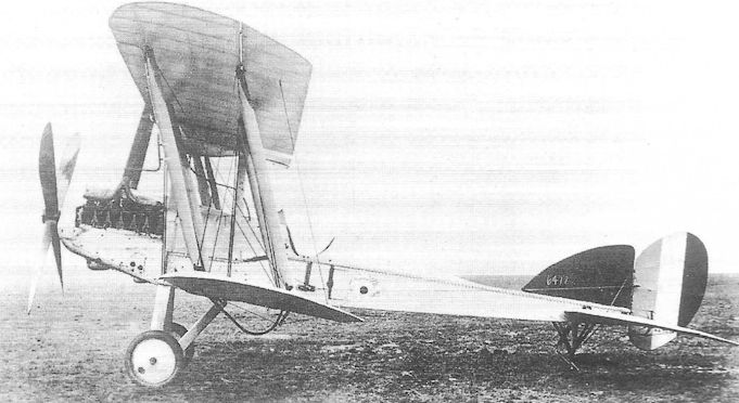
Production B.E.12 6478. Its fin appears to be an in-service replacement, and has yet to have the machine's serial number painted on it.

Серийный BE.12a без вооружения
A single-bay B.E.12A, A6303, which was unusual in having strut-linked ailerons instead of the customary cables; note also the large overhang of the upper wings.
A single-bay B.E.12A, A6303, which was unusual in having strut-linked ailerons instead of the customary cables; note also the large overhang of the upper wings.
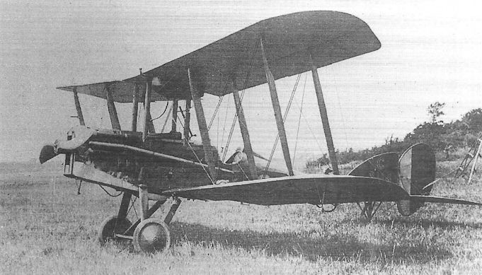
An Hispano-Suiza powered Daimler-built B.E.12B, C3114, of a Home Defence unit based at Gosport; this version reverted to two- bay wings.

A Bristol-built B.E. 2E night fighter, No 7216, equipped to carry Le Prieur rockets on the interplane struts; the mounting for a Lewis gun may be discerned above the pilot's cockpit, although the gun is not fitted, Note the larger fin fitted on the B.E.2E.
R.A.F. F.E.4
Outline sketches of the Royal Aircraft Factory’s F.E.4 had been prepared soon after the outbreak of War when it seemed possible that large gun-carrying aircraft might be demanded by the military. It was not until well into 1915 that detail design was taken over by S J Waters and Henry Folland, the purpose of the aircraft being loosely described as being ‘ground attack’, for which it was required to carry a 1 1/2-pounder Coventry Ordnance Works quick-firing gun.
Two aircraft were built during 1916; they were very large biplanes, powered by two pusher engines, and normally carried a crew of three, two seated in tandem in a nose cockpit with the pilot in front, and a Lewis gunner aft of the wings. The two-bay wings were of unequal span, that of the upper wing being no less than 75 feet, and a daring innovation was the absence of cabane struts, the engines being mounted within the wing gap clear of the lower wing and outboard of the inner interplane struts. A sturdy twin mainwheel undercarriage of wide track was included with large oleo struts below the engines, and without cross-axle, and a pair of auxiliary nosewheels was fitted in the extreme nose. Another unusual feature was the upper outer section of each wing which could be folded downwards for ease of stowage. The tail comprised biplane surfaces, a central fin and three rudders.
The first F.E.4 appeared with a pair of RAF 5 engines (in effect RAF 4As adapted as pushers) which incorporated miniature four-blade fans in front and driven from the crankshafts to assist engine cooling. The second aircraft was powered by two 250hp Rolls-Royce Eagle Is, their crankcases enclosed in sheet-metal cowlings. While the first example, No 7993, was sent to the Central Flying School, the second embarked on a series of engine trial installations, the Eagles being replaced in turn by two 200hp RAF 3As, 150hp RAF 4As and 170hp RAF 4Bs. It is interesting to note that, when powered by the RAF 3As, the aircraft was also fitted with a gunner’s cockpit fairing above the upper wing.
The F.E.4 was already obsolete when it first flew, and it is difficult to see how effective the COW gun could ever have been, fired as it was from the rear seat in the nose cockpit. Although production was planned to be undertaken by The Daimler Company, these arrangements were abandoned.
Type: Twin pusher engine, three-seat, two-bay biplane ground attack fighter.
Manufacturer: The Royal Aircraft Factory, Farnborough, Hampshire.
Powerplant: Two 150hp RAF 5 in-line engines driving four-blade pusher propellers; also two 250hp Rolls-Royce Eagle I; two 200hp RAF 3A; two 150hp RAF 4A; two 170hp RAF 4B.
Dimensions: Span, 75ft 2in; length, 38ft 2 1/2 in; height, 16ft 9in; wing area, 1,032 sq ft.
Weights: (RAF 5). Tare, 3,754lb; all-up, 5,988lb.
Performance: (RAF 5). Max speed, 84.3 mph at sea level; climb to 10,000ft, 30 min 5 sec; ceiling, 12,000ft.
Armament: One 1 1/2-pounder COW gun in the rear of the nose cockpit; two Lewis machine guns on the sides of the nose cockpit, and a third Lewis gun with a movable mounting in a gunner’s cockpit amidships.
Prototypes: Two, Nos 7993 and 7994. No production.
Summary of Service: One aircraft, No 7993, with the Central Flying School.
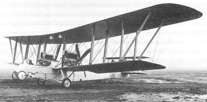
The first F.E.4, No 7993, powered by a pair of 150hp RAF 5 pusher engines; note the gravity tanks, one for each engine under the wing centre section.
R.A.F. S.E.5 and S.E.5A
Genesis of the Royal Aircraft Factory’s excellent S.E.5 design lay entirely in the Hispano-Suiza engine, designed by the Swiss engineer Marc Birkigt, a 150hp V-eight liquid-cooled in-line engine of which the War Office ordered fifty examples from France, as well as negotiating a manufacturing licence, in mid-1915. Being thus a Service-sponsored engine, it was not unnatural that the Royal Aircraft Factory should be instructed to produce a suitable fighter design, for its power-weight ratio of about 0.33 bhp/lb compared favourably with most fighter engines extant, such as the 110hp Clerget which returned a figure of 0.28 bhp/lb. Leading the project at Farnborough was the chief engineer, Maj F M Green, with Henry Folland, assisted by John Kenworthy, being responsible for the principal design; Maj Frank Goodden, the Factory’s chief pilot, was also closely involved.
The design was entirely new, although it has been suggested that some of its inspiration lay in the Martinsyde RG, for the compact front fuselage was superficially reminiscent of that aeroplane; the remainder of the aircraft was a natural progression from the S.E.4A.
Fundamental to the design was that it should be relatively simple to fly, yet represent a worthwhile advance in performance, armament and agility over fighters such as the D.H.2 which, it should be remembered, was still in service at the end of 1916. For ease of manufacture, the structure was simple and straightforward with wings of parallel chord, a wooden box-girder fuselage, and tail surfaces little changed from the S.E.4A. The single-bay, staggered wings were built around two spruce spars with internal wire bracing, and with ailerons on upper and lower wings. A large car-type radiator was located immediately forward of the engine, and the fuel tank was mounted on the top longerons directly behind; the tank was initially cowled by an extension of the top engine cowling panel, but the panel was omitted on production aircraft. Early aircraft also featured a small gravity fuel tank above the upper wing, offset to port of the centreline.
After long delays, the fifty Hispano-Suiza engines, ordered the previous year, began delivery in August 1916, and manufacture of three prototype S.E.5s started the following month. These aircraft possessed sharply raked wingtips and short exhaust manifolds each with a single central outlet.
In the morning of 22 November Frank Goodden flew the first prototype S.E.5, A4561, at Farnborough, and expressed delight with the new fighter, a view not shared by Capt Albert Ball dso, who flew the aircraft a day or so later. The second prototype, A4562, was flown on 4 December and soon afterwards went to France for brief operational trials with No 60 Squadron (giving rise to some incorrect impressions that ‘the S.E.5 equipped the Squadron from january 1917 onwards’). The judgement was more reasoned than that of Ball, speaking of the S.E.5 as being comparable with the Nieuport 17 and Spad VII, though more stable and simpler to fly. It was, the report stated, likely to be much steadier in gun firing.
On 28 January the first S.E.5 prototype crashed near Farnborough, killing the Factory’s popular chief pilot, Frank Goodden. The official findings were convoluted, suggesting that the propeller had ‘burst’, and that the ensuing vibration had caused the wing structure to fail. In fact it seems most likely that wing structure collapse occurred in the first instance during aerobatics. Be that as it may, the design was modified to incorporate strengthened rear spars, shortened wings with reduced rake, and strengthened strut/spar joints. The result was an immensely strong airframe that became a hallmark of the S.E.
A preliminary order for 24 S.E.5s had already been received by the Factory, these aircraft being fitted - for the most part - with the imported Hispano engines. However, these aircraft had progressed too far to include the new wing changes. They were issued to No 56 Squadron at London Colney, near St Albans, commanded by Maj R G Blomfield, and used for training before being changed for the strengthened aircraft which were taken to France the following month. Among those pilots who joined the Squadron during the training period was Capt Albert Ball, posted in as a flight commander; he had not yet become reconciled with the S.E.5, and obtained permission to continue flying a Nieuport.
Early production S.E.5s featured semi-enclosed cockpits intended to give protection from the slipstream for the pilot while attempting to load the Lewis gun, or clear stoppages on the Vickers; it was, however, much disliked by the pilots, and was replaced by a small rigid windscreen which became a standard fitting.
Meanwhile licence production of the Hispano-Suiza engine had been undertaken by the Wolseley Motors company, but this had got off to a slow start. The Air Board had sanctioned the purchase of 8,000 engines from the Mayen company in France although, once again, these would not start arriving in Britain until late in 1917 (and were to be found to have poorly manufactured components). A geared version of the 150hp Hispano-Suiza had been developed which produced a nominal 200 bhp; this was tested in the third S.E.5 prototype, A4563, early in 1917, and underwent operational trials with Nos 56 and 84 Squadrons in France. It was readily distinguishable by the higher propeller line and a slightly deeper fuselage forward of the cockpit, the aircraft being re-termed the S.E.5A.
The S.E.5A became the subject of all production contracts placed from March 1917 onwards, and featured a number of other refinements, such as the addition of a streamlined headrest fairing behind the cockpit (although a number of pilots had this removed as they considered it to restrict their rearward vision).
Nor were the early Wolseley-built engines satisfactory, and weaknesses in components led to fairly frequent engine failures. By the time these had been rectified, production of Hispano-Suiza engines was running some six months behind schedule, as were examples of a high-compression version of the 150hp engine, developed by Wolseley and named the Viper.
Despite these difficulties, S.E.5As began re-equipping No 56 Squadron in June, and No 60 Squadron the following month, the majority of their aircraft being produced by Martinsyde at Brooklands. In August No 84 Squadron at Lilbourne in Northamptonshire, commanded by Maj William Sholto Douglas (later Marshal of the Royal Air Force Lord Douglas of Kirtleside, gcb, mc, dfc), received the S.E.5A and moved to France in September. By the end of the year Nos 24, 32, 40, 41, 56, 60 and 84 Squadrons had been re-equipped and were serving in France, a most disappointing number bearing in mind that almost 3,000 aircraft had been on order for almost six months, and only 828 had been delivered. Altogether sixteen squadrons had been expected to be flying the S.E.5A by December 1917.
Added to the engine troubles were problems with the gun interrupter gear (although the Constantinesco equipment was elsewhere considered to be reliable); it was found that the hydraulic system of the interrupter was incompatible with some batches of the Wolseley-built Hispanos - a weakness not finally overcome until February 1918. Nevertheless, by the spring of that year the S.E.5A was generally considered to be over its troubles and to be the best British fighter of the day. It was faster, though less manoeuvrable than the Sopwith Camel, and capable of withstanding considerable damage in combat. Some of the best-known pilots of the RFC and RAF of the First World War flew the aircraft. Maj Edward(‘Mick’) Mannock vc, DSO**, mc*, scored 54 of his 73 victories while flying S.E.SAs with Nos 40, 70 and 85 Squadrons; Lt-Col W A Bishop vc, dso*, mc, dfc, shot down 27 enemy aircraft out of his total score of 72 victories while with Nos 60 and 85 Squadrons. Other high-scoring S.E.5A pilots included Maj J T B McCudden vc, dso*, mc*, dfc, Capt A W Beauchamp-Proctor vc, dso, mc*, dfc, Capt G E H McElroy mc**, dfc*, Capt JIT Jones dso, mc, dfc*, mm, and Lieut A P F Rhys Davids dso, mc*.
The S.E.5A had undergone a number of improvements, including the strengthening of the undercarriage; the forward member of the V-struts, previously a single tubular member, was now doubled, the two steel tubes being faired over with ply or sheet metal. Increasing numbers of aircraft were fitted with direct-drive Wolseley Viper engines but, being heavier than the Hispano, were generally disliked. A geared development, the Adder, also appeared, but this was even heavier.
S.E.5As were issued to Home Defence units but were regarded as unsuitable as interceptors owing to the length of time needed to warm up their engines before take-off. After the first German daylight raids over southeast England in June 1917, No 56 Squadron was ordered back from France (in spite of objections by Trenchard) to Bekesboume in Kent. After having kicked its heels for a fortnight, without so much as seeing a German raider, the Squadron returned to France. Four other Home Defence Squadrons became operational on S.E.5As, but all had been replaced with Camels by the end of the War.
S.E.5As did not fight on the Italian Front, but three Squadrons, Nos 17, 47 and 150, flew the aircraft in Macedonia. In Palestine, Nos 111 and 145 Squadrons’ S.E.s were heavily engaged during General Allenby’s final offensive through Palestine in the late summer of 1918, both in the ground attack role (using 201b Cooper bombs) and in patrols over the enemy aerodromes to discourage German pilots from taking off. No 72 Squadron served in Mesopotamia until February 1919 when its duties were taken over by No 30, also flying S.E.5 As.
Like the Camel, the S.E.5A did not survive long in the peacetime RAF, the last squadron aircraft being withdrawn from Nos 56 and 81 in January 1920. Small numbers served in Canada and Australia.
It had been planned to build 1,000 aircraft in America for the Air Service, and a contract to that effect had been agreed with the Curtiss company; this was cancelled at the end of the War, and only one Curtiss-built example was completed. 57 others, known as S.E.5Es, were however built from components shipped out from Britain in 1922-23 and these served as advanced trainers.
One other version appeared in Britain as the S.E.5B, a much-modified S.E.5A, A8947. In this a Viper engine, with a much cleaned-up mounting and cowling, was fitted, together with sesquiplane wings and outward-raked interplane struts. The car-type radiator was replaced by a chin-mounted unit and the propeller fitted with a large spinner. To provide a performance comparison, the larger wings were afterwards replaced by standard components while retaining the improved engine installation (in a version known as the S.E.5C) but, although this returned the best performance figures of any S.E.5 variant, it appeared much too late to warrant putting it into production.
Type: Single-engine, single-seat, single-bay biplane fighting scout.
Manufacturers: The Royal Aircraft Factory, Farnborough, Hampshire; The Austin Motor Co Ltd, Birmingham; The Air Navigation Co Ltd, Addlestone; Martinsyde Ltd, Brooklands; Vickers Ltd, Crayford and Weybridge, Surrey; Wolseley Motors Ltd, Birmingham.
Powerplant: S.E.5: 150hp Hispano-Suiza; also 200hp Wolseley W.4A Viper. S.E.5A: 200hp Hispano-Suiza; 220hp Hispano-Suiza; 240hp Hispano-Suiza; 200hp Wolseley W.4A Viper; 200hp Wolseley W.4B Viper.
Structure: Wooden box-girder, wire-braced and fabric-covered; twin spruce spar wings, fabric-covered and with ailerons on upper and lower wings; variable incidence tailplane.
Dimensions: Span, 28ft 0in (early S.E.5s), 26ft 7 1/2 in (late S.E.5s and S.E.SAs); length, 21ft 4in (S.E.5), 20ft 11in (S.E.5A); height, 9ft 5in (S.E.5), 9ft 6in (S.E.5A); wing area, 249 sq ft (early S.E.5s), 244 sq ft (late S.E.5s and S.E.SAs).
Weights: S.E.5A (200hp Hispano-Suiza). Tare, 1,400lb; all-up, 1,953lb.
Performance: S.E.5A (200hp Hispano-Suiza). Max speed, approx 135 at sea level; climb to 10,000ft, 10 min 20 sec; service ceiling, 22,000ft; endurance: 3 hr.
Armament: One fixed, synchronized 0.303in Vickers machine gun with Constantinesco interrupter gear on nose, offset to port, with 400 rounds; and one Lewis gun on Foster mounting above upper wing centre section with four 97-round drums. Four 20lb Cooper bombs could be carried on racks under the fuselage.
Prototypes: Three S.E.5 prototypes, A4561-A4563 (first flown by Maj Frank Goodden on 22 November 1916 at Farnborough). One S.E.5B, A8947 (a modified S.E.5).
Production: 48 S.E.5s (excluding prototypes; all built by Royal Aircraft Factory: A4845- A4868 and A8898-A8947); 5,180 S.E.SAs built in Britain (Royal Aircraft Factory, 200: B4851-B4900, C1051-C1150 and D7001-D7050; Martinsyde, 500: B1-B200, D3911-D4010, E3154-E3253 and F5249-F5348; Vickers, 2,165: B501-B700, C5301-C5450, C9486-C9635, D201-D450, D3426-D3575, D5951-D6200, D8431-D8580, E1251-E1400, E3904-E4103, F551-F615, F5449-F5698 and F8946-F9145; Austin, 1,550: B8231-B8580*, C8661-C9310, E5637-E5936, F7951-F8200; Air Navigation Co, 336: C1751-C1950, E5937-E6036 and H674-H710 approx; Wolseley, 400: C6351-C6500, D6851-D7000 and F851-F950. *Some of these aircraft may not have been completed.)
Summary of RFC and RAF Service: S.E.5s served with Nos 56 and 60 Squadrons in France. S.E.SAs served with Nos 1, 24, 29, 32, 40, 41, 56, 60, 64, 68, 74, 84, 85 and 92 Squadrons in France; S.E.SAs served with Nos 17,47 and 150 Squadrons in Greece; S.E.SAs served with Nos 30, 72, 111 and 145 Squadrons in the Middle East; and S.E.SAs served with Nos 50, 61, 81, 87, 93, 94 and 143 Squadrons in the United Kingdom (not all operationally).

The first production Factory-built S.E.5, A4845, displaying the unpopular canopy over the pilot’s cockpit; the engine is also fitted with a single-exit exhaust manifold, though in this instance the exit is at the front of the branch pipe. Note the original style of single-tube undercarriage V-struts.
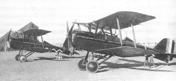
Another famous fighter Squadron with S.E.5As was No 111, two of whose aircraft, identified by the zig-zag markings, are shown at an aerodrome in Palestine at the time of the Allenby offensive. B139, in the foreground is a Martinsyde-built aircraft, carrying four 20lb Cooper bombs.

Despite being beset with a series of engine-related problems the 200hp Hispano-Suiza-powered Royal Aircraft Factory SE 5a gave more than a good account of itself when measured against the later Fokker D VII and Pfalz D XII single seaters that it would encounter from the spring of 1918 onwards. With a top level speed of 137.5mph at sea level, plus an ability to reach 10.000 feet in 11 minutes, the first SE 5a operational deliveries commenced in June 1917. Sadly, the engine troubles, coupled to engine non-availability acted as a bottleneck to the numbers of SE 5as that could be fielded well into 1918, the problem only really being resolved with the emergence of the 200hp Wolseley Viper, a British development of the original French engine. Total SE 5 and SE 5a production reached 5.205 machines by war's end, with Curtiss in the US contracted to produce a further 1.000 for the Americans. While all but one of the Curtiss order were to be cancelled with the Armistice, 56 British SE 5a deliveries were made to the Americans.
The SE 5a seen here is a standard Royal Aircraft Factory-built S.E.5A, B4897, at Farnborough, showing the strengthened undercarriage that was introduced in 1917.
The SE 5a seen here is a standard Royal Aircraft Factory-built S.E.5A, B4897, at Farnborough, showing the strengthened undercarriage that was introduced in 1917.
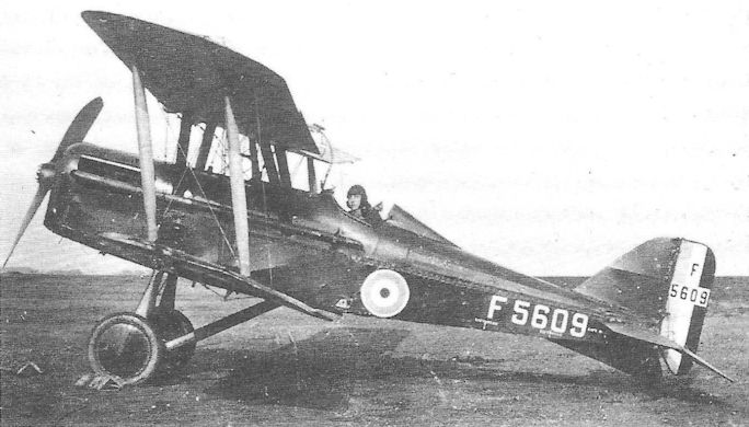
A Vickers-built S.E.5A, F5609, serving with the Central Flying School, possible shortly after the War.

No 85 Squadron was commanded by two successive holders of the Victoria Cross, Bishop and Mannock - the two highest-scoring RAF fighter pilots of all time. The S.E.5A shown here (another very late production aircraft) displays No 85’s distinctive hexagon marking, a device still carried by the Squadron half a century later.
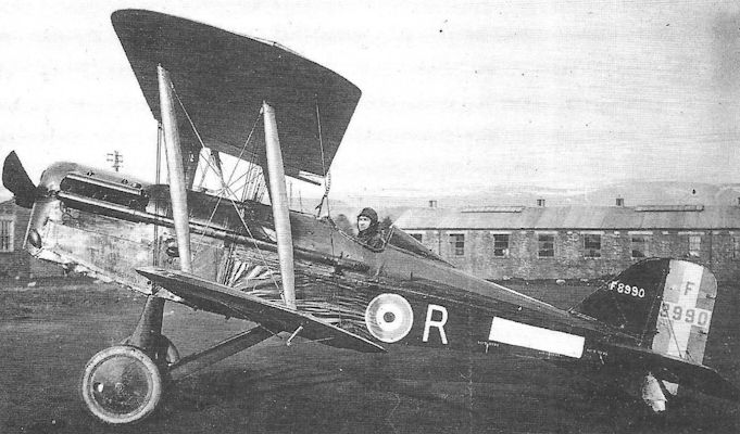
One of the last S.E.5As to be produced, F8990 'R' of No 74 Squadron was built by Vickers Ltd. The photograph was probably taken during 1919.
R.A.F. F.E.9
One of Farnborough’s truly ill-conceived designs was the F.E.9 two-seat reconnaissance fighter, possibly intended as a replacement for the elderly F.E.2B, and which was designed in 1916, and probably flown shortly before the end of that year. Powered by a 200hp Hispano-Suiza, priority supplies of which were reserved for the Factory, the F.E.9 was a pusher biplane originally flown with single-bay wings of greatly differing span and with heavily horn-balanced ailerons on the upper wing only. The crew nacelle extended well forward and was located high up in the wing gap so as to afford the gunner in the nose a good all-round field of fire with a Scarff ring-mounted Lewis gun; a second Lewis gun could be spigot-mounted between the cockpits. The engine radiator occupied the whole depth of space between the nacelle and the upper wing. The tail booms converged in side elevation and supported the tail, being attached to the tailplane’s rear spar; the fin and unbalanced rudder were of roughly equal area.
A total of 27 F.E.9s was scheduled for production, though the number eventually built, quoted from various sources, differed between three and eight. Apart from coming too late on the scene to be of any realistic value in service, the F.E.9 suffered inevitably from greatly overbalanced ailerons, which tended to turn the aircraft on to its back during a steep turn. The horn balances were progressively reduced, but the only result was to reduce the rudder’s effect in turn.
Second and third prototypes appeared in the late spring of 1917 with two-bay wings, at about the time the first aircraft was undergoing flight trials with various aileron and rudder shapes, in the hands of Capt G T R Hill MC (brother of Roderic Hill, and later to become well known as Professor Geoffrey Hill).
One of the F.E.9s was issued to a Home Defence squadron later in 1917, but evidently failed to impress anyone.
Type: Single pusher engine, two-seat, single- and two-bay biplane reconnaissance fighter.
Manufacturer: The Royal Aircraft Factory, Farnborough, Hampshire.
Powerplant: One 200hp Hispano-Suiza water-cooled in-line engine driving four-blade pusher propeller.
Dimensions: Span, 37ft 9 1/2 in; length, 28ft 3in; height, 9ft 9in; wing area, 365 sq ft.
Weight: All-up, 2,480lb.
Performance: Max speed, 105 mph at sea level; climb to 5,000ft, 8 min 25 sec; absolute ceiling, 15,500ft.
Armament: One 0.303in Lewis machine gun with Scarff ring on nose cockpit; provision for a second Lewis gun on a spigot mounting between the cockpits.
Prototypes: Three, A4818-A4820. A further 24 aircraft were scheduled for production but few, if any, were completed.
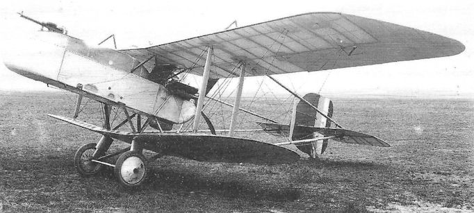
The first F.E.9, A4818, with single-bay wings and displaying the heavilly overbalanced ailerons.
R.A.F. N.E.1
Conceived with the same purpose in mind as the slightly earlier Vickers F.B.25, the Royal Aircraft Factory’s lanky N.E.1 (Night Experimental) made little pretence at elegance. Intended initially as a night anti-airship fighter, it was a three-bay biplane powered by a 200hp Hispano-Suiza engine driving a four-blade pusher propeller in the best Gunbus tradition. The tailbooms, parallel in plan, converged in side elevation to the mainspar of the tailplane, to which was hinged a heavily horn-balanced elevator. A semi-circular fixed fin was mounted symmetrically and centrally on the tailplane and forward of an unbalanced rudder.
The nacelle was located within the wing gap, clear of the lower wing, but the space between nacelle and upper wing was occupied by the engine’s radiator. The divided undercarriage was of very wide track to assist night landing, the oleo struts being anchored directly below the inboard interplane struts.
The starkly functional nacelle mounted a ten-inch searchlight in the extreme nose, and would be operated by the pilot who occupied the front of the cockpit, with the gunner behind him. The principal armament was proposed as being either the Coventry Ordnance Works quick-firing gun or the Vickers Crayford rocket gun, supplemented by either one or two spigot-mounted Lewis guns. An unusual piece of equipment was a radio telephony installation.
A total of six N.E.1s was built, and the first, B3971, is believed to have flown in mid-September 1917. Despite its cumbersome gait, it was found to be simple to fly and land, though its speed was far from outstanding. The aircraft underwent official trials in November that year.
A number of design variations appeared in subsequent examples. The fin shape was revised on at least one aircraft, and the searchlight was omitted from others in which the bow position was occupied by the gunner, with the pilot aft. All aircraft were confined to experimental flying, with the last pair being completed in 1918.
Type: Single pusher engine, two-seat, three-bay biplane night fighter.
Manufacturer: The Royal Aircraft Factory, Farnborough, Hampshire.
Powerplant: One 200hp Hispano-Suiza engine driving four-blade pusher propeller.
Dimensions: Span, 47ft 10in; length, 30ft 2in; height, 9ft 2in; wing area, 555.1 sq ft.
Weights: Tare, 2,071lb; all-up, 2,946lb.
Performance: Max speed, 95 mph at 10,000ft; climb to 10,000ft, 16 min 10 sec; service ceiling, 17,500ft; endurance, 2 3/4 hr.
Armament: One Vickers Crayford rocket gun or one Coventry Ordnance Works quick-firing gun; either one or two spigot-mounted Lewis guns.
Prototypes: Six, B3971-B3976. First flight by B3971 believed to have been in mid-September 1917. No production.
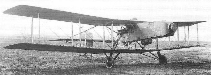
The N.E.1, B3971, at Farnborough in its original configuration, but without any armament mounted.
R.A.F. A.E.3 Farnborough Ram
The Royal Aircraft Factory’s A.E.3, whose initials are believed to have signified Armed (or Armoured) Experimental, was a derivative of the N.E.1 night fighter, but developed for the role of trench strafing in answer to a B.E.F. requirement. It retained the same or similar unstaggered, three-bay wings, tail booms and undercarriage of the N.E.3, but featured a crew nacelle constructed of quarter-inch armour plate.
It is unlikely that the A.E.3 was designed to the same B.E.F. Specification as the Sopwith Salamander trench fighter for, whereas the latter’s armament was appropriate for a trench fighter capable of both air-to-air and air-to-ground combat, the A.E.3 was intended to pour a stream of fire into enemy trenches as it flew relatively slowly, straight and level overhead. For this purpose it was armed in the nose of the nacelle with double-yoked Lewis guns which could be depressed, as well as a third Lewis gun on a telescopic mounting between the cockpits, capable of firing aft and abeam for self-defence.
Three aircraft were ordered, and the first flew at the beginning of April 1918, and all three were flying by June. During this period the Factory at Farnborough was renamed an Establishment (becoming the RAE), and a ruling issued whereby aircraft designed by the former Factory should be referred to as Farnborough products. Thus named the Ram, the A.E.3 was therefore the only Factory aircraft bestowed with an official name.
The Ram Mk I was powered by a 200hp Sunbeam Arab eight-cylinder inline engine, and the Mk II a 230hp Bentley B.R.2 rotary. A Mark III was proposed with a B.R.1 engine and wings of greater chord, but it is assumed that this was not built.
Type: Single pusher engine, two-seat, three-bay biplane trench fighter.
Manufacturer: The Royal Aircraft Factory (Establishment), Farnborough, Hampshire.
Specification: British Expeditionary Force Requirement of 1917.
Powerplant: Mk I, 200hp Sunbeam Arab; Mk II, 230hp Bentley B.R.2 rotary engine.
Dimensions: Span, 47ft 10 1/2 in; length, 27ft 8 1/2 in; height, 10ft 0in.
Performance: Max speed, 95 mph at sea level.
Armament: Two Lewis guns in extreme nose of nacelle and one Lewis gun on telescopic mounting offset to port between cockpits.
Prototypes: Three, B8781-B8783, all built; first flown in April 1918. No production.
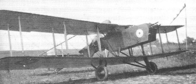
A Farnborough Ram Mk II with Bentley BR.2 rotary engine.
Conceived as a ground-attack fighter, the A.E.3 Ram was the only Farnborough design to be named.
Conceived as a ground-attack fighter, the A.E.3 Ram was the only Farnborough design to be named.

Royal Aircraft Factory A.E.3 Farnborough Ram Mk.II
Robey Peters Tractor Scout
Very little is known about the designs of J A Peters, produced while he was working with Robey & Co Ltd of Lincoln, a company which had undertaken sub-contract manufacture of Sopwith Gun Bus aircraft early in 1915. Three such designs came to be built, of which two were single-seat scouts, one a tractor and the other a pusher biplane. The latter is said to have suffered an accident during its first flight.
Nor is it known whether the little tractor scout was even completed, although the accompanying photograph shows it awaiting installation of its engine - said to have been an 80hp Clerget - and covering of the airframe. Construction appears to have been of wood throughout, and one assumes it would have been fabric covered overall. There is slight stagger on the wings, and ailerons are fitted to upper and lower flying surfaces. A balanced rudder, without fin, is apparent, and all bracing is of twisted-strand cabling.
The position of the pilot’s cockpit is interesting in that it is located directly below mid-chord of the upper wing, so that the trailing edge cut-out would have been of little value in extending the pilot’s field of vision, while the cabane struts and bracing wires, close on either side, would appear to constitute an almost impenetrable maze to negotiate for entry and exit from the cockpit.
There is no evidence in the photograph as to whether any gun armament was intended to be mounted, as the pilot is situated too far forward to operate a gun oh the upper wing, unless it was proposed to mount an upward-firing Lewis gun projecting through the wing centre section. It is not even known whether the cowling shown in the photograph represented the ultimate shape and position of the engine cowling; if so, it would seem that the c.g. limits would have been exceptionally constricted, for it is not known what position was intended for the fuel tank.
From the general design configuration, outlined above, it seems likely that Peters would have been engaged in the design of this aircraft early in 1915, and that the accompanying photograph was taken during the summer of that year.

The Robey Peters Tractor Scout during construction.
Robey Peters Three-Seater
It will be recalled that the Lincoln company of Robey & Co had produced a pair of single-seat scouts to the design of J A Peters during 1915, but that neither had succeeded in attracting significant official attention. A year later the company was encouraged to offer prototypes, under Admiralty sponsorship, of an anti-airship fighter armed with the Davis 2-pounder recoilless quick-firing gun.
This time Peters evolved a large three-bay, three-seat tractor biplane, powered by a 250hp Rolls-Royce (Eagle) engine driving a two-blade propeller. The fuselage was located more or less centrally within the wing gap, and two gunners’ nacelles were attached, underslung beneath the upper wing, it being intended to provide a Davis gun on each. A very sturdy, but rather narrow-track undercarriage, with central skid, was braced to the front fuselage and through the lower wing to the lower fuselage longerons. A well-proportioned, curved fin and balanced rudder lent a facade of elegance to the big aeroplane.
Perhaps the least attractive feature of the design - particularly for the pilot - was the location of his cockpit, only two feet forward of the tail fin. As if to acknowledge the exceptionally poor field of view from this position, large transparent panels were provided in the sides of the cockpit. No windscreen was fitted; instead a spine fairing (of the same contours as the faired headrest) was continued forward of the cockpit. The only explanation for the curious location of the pilot’s cockpit so far aft seems to be that of weight distribution.
Of the two prototypes ordered, the first (believed to be No 9498) was not ready for flight until fairly late in 1917 owing to a low priority for delivery of the Rolls-Royce engine. However, there came anti-climax when the machine crashed on its maiden flight, and the venture was abandoned - presumably without completion of the second prototype.
Peters left Robey shortly afterwards and the following year became chief designer for The Alliance Aeroplane Company of Luton; in 1919 he produced an aircraft intended for the Atlantic Flight competition.
Type: Single-engine, three-seat, three-bay biplane fighter.
Manufacturer: Robey & Co Ltd, Lincoln.
Powerplant: One 250hp Rolls-Royce (Eagle) engine driving two-blade propeller.
Dimensions: Span, 54ft 6in; length, 29ft 6in.
Armament: Two two-pounder Davis recoilless guns intended for gunners’ nacelles on upper wing. Probably never fitted.
Prototypes: Two, Nos 9498 and 9499. Only 9498 believed completed.
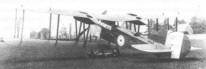
The Robey-Peters Three-Seater. Although the field of view provided for the two gunners could hardly have been better, that from the pilot’s cockpit left much to be desired.
Sage Type 2
Another long-established woodworking company which entered the aircraft industry by means of sub-contract manufacture was Frederick Sage of Peterborough. After engaging in airship component production for the Admiralty, followed by contracts to produce Short 184 seaplanes in 1915, Sage secured the services of Eric Cecil Gordon England, one of Britain’s pioneer airmen (Royal Aero Club Certificate No 68), who was appointed head of the company’s aeronautical department. In January 1916 he was joined by Clifford Wilfrid Tinson, formerly of Bristols and the Admiralty’s Air Department, to become Chief Designer; he took over the design of a new two-seat fighter, the Sage Type 2 (the Type 1 had been an unbuilt bomber project).
The Sage 2 represented a novel approach to a familiar problem, that of mounting a gun to fire directly forward past a tractor propeller. It has been shown that, apart from the ultimate solution provided by gun interrupter gear, several companies had pursued designs that incorporated gunners’ nacelles which tended to be fairly large and imposed substantial drag. Tinson’s design incorporated an enclosed cabin, accommodating both pilot and gunner, its superstructure occupying the entire depth of the wing gap between fuselage and upper wing, so that the gunner could stand with his head and shoulders above the wing. In the absence of a gun ring, he was provided with two spigots on which could be mounted a Lewis gun with arcs of fire both forward and aft.
With a wing span of only 22 feet, the Type 2 was an extraordinarily compact and clean design and, added to the fact that it was powered by a beautifully cowled 100hp Gnome monosoupape, its performance was outstanding for an armed two-seater. Construction was very simple, the fuselage being a wooden box-girder, faired by formers and stringers with curved upper decking; the wing gap was fairly large, and the only wing struts were a pair of V interplane members. The cabin superstructure replaced the customary cabane struts and was of excellent aerodynamic cross-section. Tinson’s former association with Frank Barnwell was evident in the Sage’s balanced rudder, which was identical to that of the Bristol Scout; as on the Scout, there was no fixed vertical fin.
First flown on 10 August 1916, the Sage at once demonstrated its remarkable performance by recording a maximum speed of 112 mph at sea level, but its flying was shortlived. During a test flight at Cranwell on 20 September, its sternpost failed, and in an attempted landing the aircraft struck a tree and was destroyed. Although by then the front gun interrupter gear had been accepted as reliable in service, the Sage would have represented an excellent two-seat escort fighter; however, the Admiralty had no such requirement, and further development was abandoned.
Type: Single-engine, two-seat, single-bay biplane fighter.
Manufacturer: Frederick Sage & Co Ltd, Peterborough.
Powerplant: One 100hp Gnome monosoupape engine driving four-blade propeller.
Structure: All-wooden construction with ply and fabric covering.
Dimensions: Span, 22ft 2 1/2 in; length, 21ft 1 5/8 in; height, 9ft 6in; wing area, 168 sq ft.
Weights: Tare, 890lb; all-up, 1,546lb.
Performance: Max speed, 112 mph at sea level; climb to 10,000ft, 6 min 30 sec; service ceiling, 16,000ft; endurance, 2 1/2 hr.
Armament: One 0.303in Lewis machine gun on fore or aft spigot mountings on upper wing fired by gunner standing in cabane superstructure.
Prototype: One, not allotted serial number (first flown 10 August 1916; crashed 20 September 1916). No production.
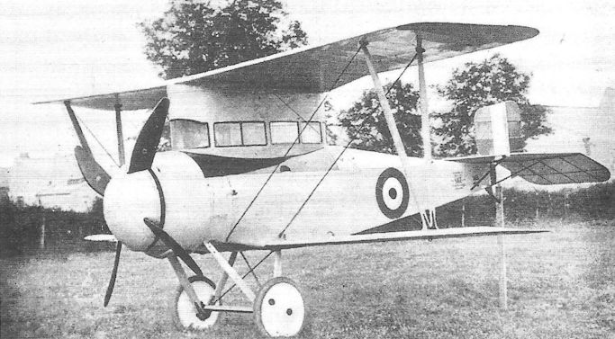
The Sage Type 2 at the RNAS Station, Cranwell, in 1916. Very short wings and fully enclosed cockpits were featured by the two-seat Sage 2.
Short S.81 Gun Carrier
It would be anomalous to omit an entry in this work covering the Short S.81 Gun Carrier, although it is difficult to imagine this large seaplane as a fighter in any accepted sense. It was in fact the last variation in a series of single-engine pusher biplanes which had started life in 1910 as the S.27 Type, and progressed by way of such aircraft as the S.33, S.38, S.62 and S.80, and which had appeared in either land- or seaplane guise. The S.80 had been produced with both wheel and float undercarriage, and the S.81 was an immediate derivative ordered specifically to undergo air gunnery trials with a 1 1/2-pounder Vickers shell-firing gun.
Unlike most other companies’ single-engine pusher biplanes, the Short S.81’s tail booms did not converge to a single sternpost and rudder, but were rigged in parallel both in plan and elevation, each terminating in a sternpost and each supporting a balanced rudder without fixed fin, as well as a cylindrical tail float. The relatively short main floats were rubber sprung (an innovation introduced by Oswald Short) and small cylindrical stabilizing floats were mounted under the lower wingtips.
Power was provided by a 160hp Gnome two-row engine driving a four-blade pusher propeller, the top wing centresection being cut away to provide blade clearance. The reinforced nacelle itself was shortened to no more than five feet and mounted the 1 1/2-pounder gun on a superstructure in the nose; the gunner’s cockpit was located on the port side of the gun’s breech.
Designed by Arthur Camden Pratt, the sole Short S.81, Admiralty No 126, was first flown in about April 1914 at Calshot where Lieut R H Clark-Hill rn flew the gunnery trials. It is said that, when the Vickers gun was fired, the recoil was so severe that the aircraft stalled and dropped 500 feet. Needless to say, the trials were not considered to be a success, and the gun was then passed to the RFC. Further trials with another gun, the recoilless six-pounder Davis, were flown at RNAS Great Yarmouth in March and April 1915. However, with experiments imminent to develop gun synchronizing mechanisms, the gun-carrying pushers’ days were numbered, and the Short S.81 disappeared from the scene.
Type: Single pusher engine, two-seat, twin-float, three-bay biplane gun carrier.
Manufacturer: Short Bros, Eastchurch, Isle of Sheppey, Kent.
Powerplant: One 160hp Gnome two-row engine driving four-blade pusher propeller.
Structure: Light-gauge steel tubular construction with fabric and duralumin covering; twin main float undercarriage with twin wingtip stabilizing floats and twin tail floats. Ailerons on upper wings only.
Dimensions: Span, 67ft 0in; wing area, 540 sq ft.
Weights: Tare, 2,200lb; all-up: 3,600lb.
Performance: Max speed, 60 mph at sea level.
Armament: One 1 1/2-pdr Vickers gun with special mounting on nose of nacelle.
Prototype: One, No.126 (first flown in about April 1914 at Calshot). No production.
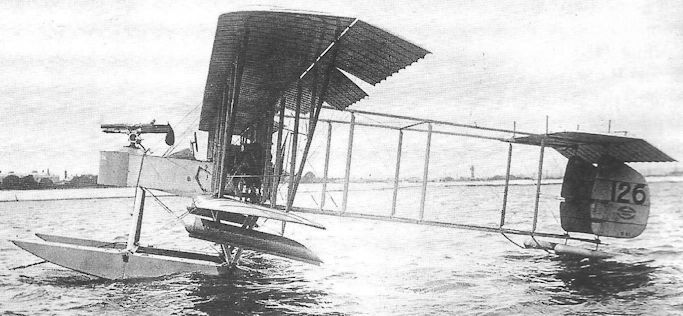
The Short S.81 Gun Carrier, 126, moored at Calshot in 1914. The wingtip floats were found to be necessary as the weight of the gun so raised the aircraft s c.g. that when turning during taxying there was a risk of striking the water with a wingtip.
Short S.364 (Scout No 3)
Although Short Bros Ltd was better known for the company’s large torpedo-carrying seaplanes during the First World War, both Horace and Oswald Short became interested in producing designs intended to meet the Air Department’s Specification N.2A for a two-seat float-equipped scout. What came to be known as Experimental Scout No 1, N36, was designed by Horace in 1916 and was in some respects a scaled-down adaptation of the large Type 310A seaplane. Launched at Rochester on 2 January 1917, the aircraft failed to get airborne in its initial form and, although the fuselage was lengthened to increase the elevator moment and the aircraft was flown by Ronald Kemp three weeks later, it was clear that the design would not interest the Admiralty. (Horace Short was to die on 6 April after a short illness, and his younger brother Oswald took over responsibility for leading the company’s design staff.)
A more realistic approach had, however, already be adopted by Oswald, producing a somewhat more compact two-bay biplane with unstaggered wings of equal span. This was referred to by its company sequence number S.364 (and also as Scout No 3) and, with a 200hp Sunbeam Afridi engine, was first flown by John Lankester Parker on 27 March. It was however found to be underpowered and in due course the engine was replaced by a 260hp Sunbeam Maori.
The fuselage was a box-girder structure with rounded top decking. The twin main floats had been found to be too narrow for safety on the water and were replaced by wider and deeper floats; small cylindrical wing floats were attached under the lower wings directly below the outboard interplane struts. The wings were of an experimental Admiralty aerofoil design, BRI.31, intended to give moderate lift but low drag. No forward gun was envisaged, the armament consisting solely of a Lewis gun on the observer’s cockpit with a Scarff ring.
Although the Admiralty expressed polite interest in the S.364, which had, after all, been designed to the N.2A Specification, the aircraft - as with most Short seaplanes - was expensive, the airframe being costed at f 1,200 and the Maori engine at almost £1,400. By contrast, the Sopwith Pup in its ship-borne version, cost £770, plus just under £700 for the 100hp Gnome, apart from being armed with a front gun and possessing a top speed some 20 mph greater than the S.364. Of course the two aircraft were in no way comparable, yet it was the Pup’s ability to operate from a fairly wide range of vessels with a wheel undercarriage that rendered the N.2A Specification largely superfluous.
Type: Single-engine, two-seat, twin-float, two-bay biplane scout seaplane.
Manufacturer: Short Bros Ltd, Rochester, Kent.
Powerplant: One 200hp Sunbeam Afridi liquid-cooled in-line engine; later replaced by 260hp Sunbeam Maori twelve-cylinder in-line engine.
Dimensions: Span, 39ft 0in; length, 28ft 0in; wing area, 375 sq ft.
Armament: One 0.303in Lewis machine gun with Scarff ring on rear cockpit; provision to carry two 65lb bombs.
Prototype: One (first flown by John Lankester Parker on 27 March 1917); no production.
Sopwith Tabloid
The arrival on the aviation scene of the diminutive Sopwith Tabloid towards the end of 1913 was widely regarded as the most momentous event of the year. Originally conceived as a conveniently-proportioned two-seat sporting biplane, which Harry Hawker could take with him to visit his home in Australia, the design was schemed up in chalk on the floor of a skating rink - then TOM Sopwith’s ‘factory’ in Canbury Park Road, Kingston-upon-Thames - by Sopwith, Hawker, Sigrist and others; it was then formalised by R J Ashfield, the company’s chief draughtsman. Construction of the aircraft, known then as the S.S., was completed in great secrecy within two months, and first flown by Hawker in November 1913 at Brooklands.
Powered by an 80hp Gnome the aeroplane, now named the Tabloid, was a tractor biplane with a single cockpit in which pilot and passenger sat side-by-side. Most unusual for its day, it possessed single-bay wings while the rudder, hinged on the stern post, was without a fixed fin. Lateral control was by means of wing warping, the wings being without ailerons. The engine was almost entirely enclosed, a pair of small slots in the front of the cowling sufficing for cooling purposes.
Delivered to Farnborough by Hawker, the Tabloid underwent official trials on 29 October, demonstrating that with pilot and passenger and with full fuel, it possessed a top speed of 90 mph, a stalling speed of 36 mph and an initial climb rate of 1,200 ft/min. Early in 1914 Hawker set off for Australia taking with him the Tabloid prototype, returning with it in June.
In the meantime the aircraft went into limited production for the RFC and RNAS as a single-seat scout; a fin was added forward of the rudder hingeline, and a cut-out was incorporated in the upper wing above the cockpit.
One of the early production Tabloids was modified with twin-float undercarriage and, powered by a 100hp Gnome monosoupape rotary, was entered for the second Schneider Trophy race at Monaco flown by Howard Pixton on 20 April 1914. Not only did the Tabloid win the race but eclipsed every other contestant, returning an average speed of 85.5 mph, compared with 51 mph of the second place finisher. Pixton went on to establish a new world speed record for seaplanes at 92 mph. (The further history of the Tabloid seaplanes is recorded under the Sopwith Schneider).
By June 1914 five Tabloids had been produced for the RNAS, and production continued until about May 1915, with a total of between 40 and 50 being completed. The aircraft did not carry a gun armament as standard, although several experiments were performed mounting a single Lewis gun. One RNAS Tabloid was fitted with a Lewis gun to fire forward through the propeller, the blades being protected by deflector plates.
After the outbreak of war four Tabloids of the RFC went to France in August, at least two of which flew scouting patrols with Nos 3 and 4 Squadrons. Later two aircraft joined the RNAS Eastchurch Squadron at Antwerp, but these were equipped to carry 201b bombs; indeed, on 8 October, flown by Sqn Cdr Spenser Grey and Flt Lt R L G Marix, they attacked targets in Germany, the latter pilot hitting the airship shed at Dusseldorf and destroying the new German Zeppelin Z IX. Four RNAS Tabloids were shipped out to the Dardanelles early in 1915, but by May the type was being withdrawn from operational service.
Type: Single-engine, single-seat, single-bay biplane scout.
Manufacturer: The Sopwith Aviation Co Ltd, Kingston-upon-Thames, Surrey.
Powerplant: One 80hp Gnome nine-cylinder air-cooled rotary engine driving two-blade propeller.
Structure: All-wood construction; wire-braced box-girder fuselage with curved stringer-formed top decking; two-spar single-bay wings without ailerons. Twin wheel-and-skid undercarriage.
Dimensions: Span, 25ft 6in; length, 20ft 4in; height, 8ft 5in; wing area, 241.3 sq ft.
Weights: Tare, 730lb; all-up, 1,120lb.
Performance : Max speed, 92 mph at sea level; initial climb, 1,200 ft/min; endurance, 3 /2 hr.
Prototype and Production: One prototype and between 40 and 50 production examples. Summary of Service: Served with Nos 3, 4 and 7 Squadrons, RFC, and Nos 1 and 3 Squadrons, RNAS; also aboard HM Seaplane Carrier Ark Royal, and at RNAS Great Yarmouth.

A Tabloid with the Military Wing, Farnborough.
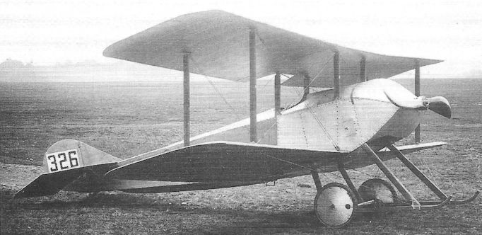
An early production Sopwith Tabloid, No 326.
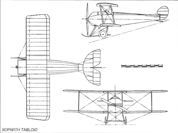
Sopwith Tabloid
Sopwith Two-Seat Scout
The Sopwith Two-Seat Scout was directly related to the Sopwith Admiralty Type 807, a seaplane which was in turn developed from the aircraft prepared for the 1914 Round-Britain contest. In appearance it might be described as a ‘stretched’ Sopwith Tabloid, with lengthened fuselage to accommodate a pair of widely separated cockpits, and two-bay wings; it was powered by a 100hp Gnome monosoupape engine, cowled in a manner reminiscent of the Tabloid. The wings were rigged without stagger, and ailerons were fitted to both upper and lower wings. The aircraft attracted the attention of the Admiralty who placed an order for 24 examples, their intended role being that of anti-Zeppelin patrol. However, with a two-man crew and a heterogeneous choice of hand-held weapons, its ceiling was limited to no more than 3,000 feet, and it is impossible to imagine just how these aircraft could intercept the airship raiders. The armament carried ranged from a Service rifle firing Hales grenades, and a shot-gun firing chain-shot, to a signal pistol with two rounds; others carried a Mauser rifle firing incendiary ammunition.
The Two-Seat Scouts were flown by the RNAS at Hendon, Killingholme and Great Yarmouth on anti-airship patrols, quickly earning the nickname ‘Spinning Jenny’. Pilots overworked their engines in fruitless attempts to climb above 3,000 feet, resulting in frequent engine failures and a subsequent tendency to spin. As spin recovery was not yet included in flying training syllabuses, these gyrations were usually fatal. It is believed that all surviving Two-Seat Scouts had been withdrawn from service by the end of 1915 - without having engaged so much as a single enemy airship.
Type: Single-engine, two-seat, two-bay biplane scout.
Manufacturer: The Sopwith Aviation Co Ltd, Kingston-upon-Thames, Surrey.
Powerplant: One 100hp Gnome monosoupape engine driving two-blade propeller.
Dimensions: Span, 36ft 0in.
Performance: Max speed, 69 mph at sea level; climb to 3,000ft, 20 min; ceiling, 3,000ft; endurance, 3 1/2 hr.
Armament: Choice of weapons included a Service rifle firing Hales grenades, a shot-gun firing chain-shot or a Mauser rifle firing incendiary ammunition; some aircraft had provision to carry small bombs.
Production: No prototype. 24 production aircraft, Nos. 1051-1074.
Summary of Service: Aircraft served on RNAS Stations at Hendon, Killingholme and Great Yarmouth.
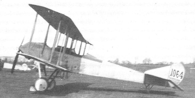
A Sopwith Two-Seat Scout, No 1064.
Sopwith Gun Bus
While it is well known that the Tabloid was the first scout to be produced by the Sopwith Aviation Company, and was later to be followed by a series of such aircraft for which the name Sopwith became synonymous, it should be said that the company had produced a wide range of other types of aircraft. One of these was a fairly large single-engine twin-float pusher seaplane powered by a 100hp Anzani radial engine for the Greek Naval Air Service in 1913.
This aeroplane proved satisfactory to the extent that a follow-up order was placed in March 1914 by that Service for six further examples to be built as landplanes, and to be armed with a single Lewis gun on the nose. These aircraft became known as the Sopwith Gun Buses, but were not ready for delivery to Greece when war broke out with Germany, and all were taken on charge by the British Admiralty. Apart from the wheel-and-skid undercarriage, the original four-bay Gun Bus biplanes also differed from the earlier Greek Seaplane in being powered by a 100hp Gnome monosoupape and the contours of the nacelle’s nose were altered to provide a reasonable field of fire for the gunner. A four-wheel undercarriage was fitted.
Later thirty further Sopwith Gun Buses were ordered by the Admiralty under sub-contract with Robey & Co Ltd of Lincoln, but of these only seventeen were delivered fully assembled, the others being supplied for spares. These aircraft were powered by 150hp Sunbeam engines whose size and weight required an enlarged nacelle and stronger undercarriage, and the lower wing, instead of being attached directly to the bottom of the nacelle, was now a continuous structure which passed below the nacelle and was secured by struts attached to the wingspars; the number of landing wheels was reduced to two, and the aircraft was fitted with an enlarged, balanced rudder.
It is believed that only one Sopwith Gun Bus joined an operational unit, the Squadron commanded by Cdr Charles Rumney Samson rn (later Air Cdre, cmg, dso, AFC, RAF) at Dunkerque early in 1915. Others were used by the RNAS for training at Hendon.
Type: Single pusher engine, two-seat four-bay biplane gun-carrier.
Manufacturers: The Sopwith Aviation Co Ltd, Kingston-upon-Thames, Surrey; Robey & Co Ltd, Lincoln.
Powerplant: One 100hp Gnome monosoupape engine driving pusher propeller (first six aircraft); one 150hp Sunbeam engine (remaining seventeen aircraft).
Structure: All-wood construction with ply and fabric covering; two-spar four-bay wings.
Dimensions (Sunbeam aircraft): Span: 50ft; length, 32ft 6in; wing area, 474 sq ft.
Performance: Max speed, 80 mph at sea level.
Production: 23 aircraft, Nos 801-806 (Gnome engines); Nos 3833-3862 (Sunbeam engines, of which only 3833-3849 were delivered assembled; remainder delivered for spares).
Summary of Service: One aircraft believed to have served with RNAS Squadron at Dunkerque; also used for training at Hendon.
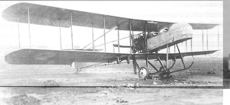
A Robey-built Sopwith Gun Bus, probably the first such aircraft, No. 3833, before installation of the nose Lewis gun and alterations to the nose contours; note the twin wheel-and-skid undercarriage, and the radiator immediately aft of the pilot's cockpit.
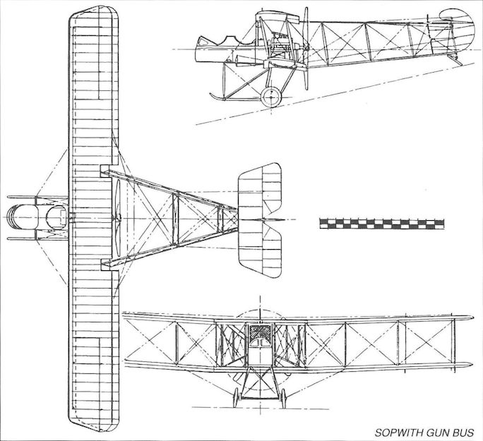
Sopwith Gun Bus
Sopwith Schneider and Baby
When it became obvious that the various gun carrier seaplanes, especially those designed for the large Davis and COW guns (such as the Short S.81 and the so-called North Sea Scout) would be of little value in air-to-air combat, the Admiralty turned logically to the aeroplane that had won the 1914 Schneider Trophy contest - the Sopwith Tabloid modified with floats - and ordered it into production in November 1914.
Early aircraft retained the old wing warping and triangular fin of the racing version, as well as the parallel-sided engine cowling with tapering curve on the upper panel. Most aircraft were armed with a single Lewis gun mounted at a shallow angle to fire through the wing centre section and above the propeller arc. Later examples introduced ailerons and an enlarged, curved fin, and one aircraft was flown with improved Linton Hope floats.
These aircraft were appropriately named Sopwith Schneiders, and a total of about 136 examples was produced. They entered service early in 1915 and served on many of the seaplane stations around the coasts of Britain on antiairship and submarine patrols.
Schneiders also served at sea, being carried by ships of the Home Fleet. One was flown off the seaplane carrier HMS Campania on 6 August 1915 by Flt Lt W L Welsh using a two-wheeled dolly which dropped into the sea after take-off; while the ship steamed into wind at 17 knots, the Schneider’s take-off run was 113 feet. Schneiders also served in the Aegean, at the Dardanelles, in the Eastern Mediterranean and Red Sea.
The Sopwith Baby
In the quest for better performance with the addition of more equipment (the Schneider was also fitted with provision to carry a 65lb bomb), the 110hp Clerget replaced the Gnome in September 1915 and, with this engine, the aircraft became known as the Sopwith Baby. A new cowling was introduced which, being horseshoe-shaped when seen from the front, left the lower one-third of the engine exposed. The Baby also featured a synchronized Lewis gun on the nose decking, firing through the propeller, although some aircraft retained the upward-firing gun of the Schneider. A total of 286 Babies was built, many of them by the Blackburn Aeroplane & Motor Co Ltd of Leeds.
The Schneider was a genuine fighter though it seems unlikely that it would have withstood more than about 2g in combat; it was a generally popular aeroplane and saw considerable service both in home waters and in the Near and Middle East where it was frequently adapted to carry a pair of 65lb bombs - principally for anti-submarine work.
Inevitably, with this constant increase in equipment (as well as sea anchor, homing pigeon, and emergency rations, as well as spare drums for the Lewis gun), yet more power was demanded, and a further engine change resulted in the 130hp Clerget being fitted, this version being built by Blackburn and by the Fairey Aviation Co Ltd (see Fairey Hamble Baby); it also underwent experimental modification by the RNAS at Port Victoria (see under Port Victoria P.V.2/2bis).
Sopwith Babies remained in service right up to the Armistice, and a number was supplied to the Royal Norwegian Naval Air Service with interchangeable wheel, ski and float undercarriage, while both Schneiders and Babies were also supplied to the US Navy.
Type: Single-engine, single-seat, single-bay fighting scout twin-float biplane.
Manufacturers: Sopwith Aviation Co Ltd, Kingston-upon-Thames, Surrey; Blackburn Aeroplane & Motor Co Ltd, Leeds, Yorkshire.
Powerplant: One 100hp Gnome monosoupape engine driving two-blade propeller; 100hp Clerget; 130hp Clerget.
Structure: All-wood construction with two-spar, two-bay wings, fabric and ply covered; twin main float and single tail float undercarriage; wing warping later replaced by ailerons.
Dimensions: Span, 25ft 8in; length 22ft Win (23ft 0in with 130hp Clerget); height, 10ft 0in; wing area, 240 sq ft.
Weights (130hp Clerget): Tare, 1,226lb; all-up, 1,715lb.
Performance (130hp Clerget): Max speed, 100 mph at sea level; climb to 10,000ft, 35 min; endurance, 2 1/4 hr.
Armament: One 0.303in Lewis free-firing machine gun angled upwards to fire through wing above propeller; superseded by a synchronized Lewis gun on fuselage nose; Schneider could carry one 65lb bomb; Baby could carry two. Ranken darts used for anti-airship attacks.
Production: No prototypes. Schneider production (all Sopwith), 1436-1447 (12), 1556-1579 (24) and 3707-3806 (100). Baby production, 8118-8217 (100, Sopwith); N300, N1010- N1039, N1060-N1069, N1100-N1129, N1410-N1449, N2060-N2134 (186, Blackburn).
Summary of Service: Served at RNAS Calshot, Dundee, Dunkerque, Felixstowe, Fishguard, Great Yarmouth, Killingholme, Scapa Flow, and Westgate; and aboard carriers, light cruisers and other ships in home waters, the Mediterranean, Aegean and Middle East.
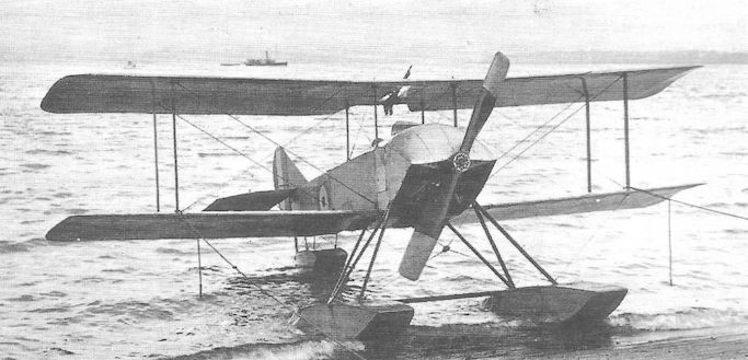
Early Schneiders had a triangular fin, as witness this revealing view. No. 3726 with warping wings.
An early Sopwith Schneider at Calshot in 1915. Note the triangular fin, the absence of ailerons and the upward-firing Lewis gun fitted in an aperture in the top wing.
An early Sopwith Schneider at Calshot in 1915. Note the triangular fin, the absence of ailerons and the upward-firing Lewis gun fitted in an aperture in the top wing.

A Sopwith Baby armed for anti-Zeppelin patrols with Le Prieur rockets attached to the interplane struts; note also the bomb racks under the fuselage, aft of the main float struts.
Sopwith 1 1/2-Strutter
This quaintly-named aircraft earned its place in early British military aviation history as the first RFC and RNAS fighter to be provided with a machine gun synchronized to fire through a tractor propeller for, owing to the previous lack of a reliable synchronizing gear, British fighting scouts had employed free-firing guns mounted in the nose of a nacelle with a pusher engine in the rear. Moreover, because it was now possible to accommodate a gunner in addition to the pilot, the 1 1/2-Strutter became the first British operational two-seat fighting scout and thereby created a design formula that was to survive in the RFC and RAF for more than a quarter century. The 1 1/2-Strutter is thought to have owed its name to the arrangement of the centreplane struts which, being attached to the top fuselage longerons, did not extend the full depth of the interplane gap. In service with the RNAS the aircraft was officially termed the Sopwith Type 9700 and in the RFC the Sopwith Two-Seater.
The structure of the 1 1/2-Strutter followed conventional Sopwith practice, the wire-braced wooden box members of the fuselage being fabric-covered aft of the gunner’s cockpit, and forward by plywood sheet. The pilot was situated directly below the top wing centre section with a single Vickers machine gun mounted centrally on the nose and engine cowling. The observer’s position was some four feet aft of the pilot, the intervening space being occupied by the main fuel tank. Several front gun synchronizing systems appeared in 1 1/2-Strutters, including Vickers-Challenger, Scarff-Dibovski, Ross and Sopwith-Kauper, and either Nieuport or Scarff ring mountings were used for the Lewis gun on the observer’s cockpit. An unusual feature at the time was the provision of an adjustable tailplane whose incidence could be controlled by a wheel in the cockpit.
The 1 1/2-Strutter was originally ordered by the Admiralty both as a two-seat fighter and as a light bomber, and the first prototype, No. 3686, was first flown in mid-December 1915 by Harry Hawker. The early orders for 150 aircraft were placed with Sopwith for the RNAS, of which the last 35 were singleseat bombers, the remainder two-seat fighters. Other orders were placed for the RFC with Sopwith, Fairey, Vickers and Ruston, Proctor for about 600 two-seat fighters. However, shortly before the Battle of the Somme, it was reported that the RFC was desperately short of fighting aircraft in France, with a result that the Admiralty agreed to transfer a total of 77 1 1/2-Strutters to the RFC, all of them two-seat fighters.
The 1 1/2-Strutter evidently impressed its pilots from the outset, the attractively compact aircraft being powered initially by a 110hp Clerget rotary, which bestowed a speed of 107 mph at sea level. Production aircraft from the Sopwith and Ruston, Proctor factories began appearing in April 1916, the Admiralty’s bombers being delivered that month to No 5 Wing, RNAS at Coudekerque in France, and the RFC’s fighters joining Nos 45 and 70 Squadrons at Gosport and Farnborough respectively, also in April. Such was the shortage of fighters on the Somme front that No 70 Squadron began flying its 1 1/2-Strutters to France in May, and the first of the ex-RNAS transfers joined the Squadron’s ‘C’ Flight and followed in July. These were the only RFC 1 1/2-Strutter squadrons to see action over the Western Front during 1916, delivery of new aircraft being slow to accelerate, and No 45 Squadron did not in fact complete its establishment until the last day of September. The RNAS, in addition to its transfer of 1 1/2-Strutters to the RFC, also ‘lent’ one Flight of ‘Naval Eight’, the famous No 8 (Naval) Squadron which also flew the aircraft for a short period.
Although increasingly outclassed by the newly-arrived Albatros D Is, armed with a pair of Spandau front guns and possessing a top speed of 109 mph, the 1 1/2-Strutter acquitted itself well, largely on account of its own front gun which, in the early weeks, appeared to take the Germans unawares. Nevertheless, it was by no means as nimble as the German single-seaters, and casualties began to mount on the two Squadrons. Towards the end of October No 45 Squadron lost three of its aircraft in a single day.
Only one other Squadron, No 43 (later famous as ‘The Fighting Cocks’), flew 1 1/2-Strutters in France, arriving in January 1917. By then the aircraft were being delivered with 130hp Clerget engines, but the additional power did little to improve the aircraft’s performance significantly. No 43 Squadron flew its aircraft with distinction in trench attacks during the Battles of Arras and Messines.
The heavy casualties suffered by the RFC in France during ‘Bloody April’ served to emphasise the desperate need to introduce new fighting scouts into service to counter the new Albatros and Fokkers which had begun to dominate the skies over France. The 1 1/2-Strutter started to be replaced in France from July 1917, although three other Home Defence Squadrons of the RFC (Nos. 37, 44 and 78) began receiving the aircraft in the same month, but most had disappeared from operational service by the end of that year, replaced by Sopwith Camel single-seaters. Only No 78 Squadron retained 1 1/2-Strutters, at Suttons Farm, until July 1918.
Various figures have been quoted for the total production of Sopwith 1 1/2-Strutters, and the number most usually quoted by generally reliable sources is 1,534; it is also stated that as many as 4,500 examples were built under licence in France by Liore et Olivier and Hanriot, of which 514 were purchased for the American Expeditionary Force. At least three squadrons of the Belgian air force flew 1 1/2-Strutters, and some aircraft reached Russia. Shortly before the Armistice twenty aircraft were supplied to Romania, and other examples flew in Latvia and Japan.
Type: Single-engine, single- or two-seat biplane fighter or light bomber.
Manufacturers: The Sopwith Aviation Co Ltd, Kingston-upon-Thames; The Fairey Aviation Co Ltd, Hayes; Hooper & Co Ltd, Chelsea, London; Mann, Egerton & Co Ltd, Norwich; Morgan & Co, Leighton Buzzard; Ruston, Proctor & Co Ltd, Lincoln; Vickers Ltd, Crayford; Wells Aviation Co Ltd, Chelsea, London; Westland Aircraft Works, Yeovil; F. Liore et Olivier, Levallois-Perret, France; Hanriot et Cie, Billancourt, France.
Powerplant: One 110hp Clerget 9Z or 130hp Clerget 9Bc nine-cylinder rotary engine (also 80hp Le Rhone 9C, 110hp Le Rhone 9J, 130hp Le Rhone Jby, and 135hp Clerget 9Ba)
Structure: All-wooden construction with fabric and plywood covering.
Dimensions: Span, 33ft 6in; length, 25ft 3in; height, 10ft 3in; wing area, 346sq ft.
Weights (two-seat fighter): Tare, 1,305lb; all-up, 2,150lb.
Performance (two-seat fighter, Clerget 9Bc): Maximum speed, 107mph at sea level; climb to 10,000ft, 17 min 48 sec; service ceiling, 15,500ft; range, approx. 230 miles.
Armament (two-seater): One fixed, synchronized forward-firing 0.303in Vickers machine gun on nose, and one free 0.303in Lewis machine gun on Nieuport or Scarff mounting on rear cockpit.
Prototype: One, No. 3686 (first flown by Harry Hawker in December 1915)
Production (fighters only; approx, figures): Sopwith, 161; Fairey, 100; Hooper, 100; Mann, Egerton, 55; Morgan, 150; Ruston, Proctor, 350; Vickers, 150; Wells, 100; Westland, 50. Overseas (all versions), figure of 4,500 quoted.
Summary of Service (fighters only): Nos 37, 43, 44, 45, 70 and 78 Squadrons, RFC and RAF; Nos 5 and 8 (Naval) Squadrons, RNAS. (Also thirteen Escadrilles of l'Armee de I’Air, three squadrons of the Belgian Flying Corps, and 88th, 90th and 99th Aero Squadrons of the US Air Service).

An early Sopwith-built 1 1/2-Strutter, No 9708, of No 3 Wing, RNAS, complete mth synchronized Vickers gun and Lewis gun on Scarff ring.
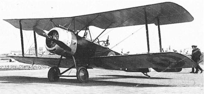
Another view of a 1 1/2-Strutter two-seater of the the RNAS; note the exceptionally tidy engine cowling with the synchronized Vickers gun mounted above it.
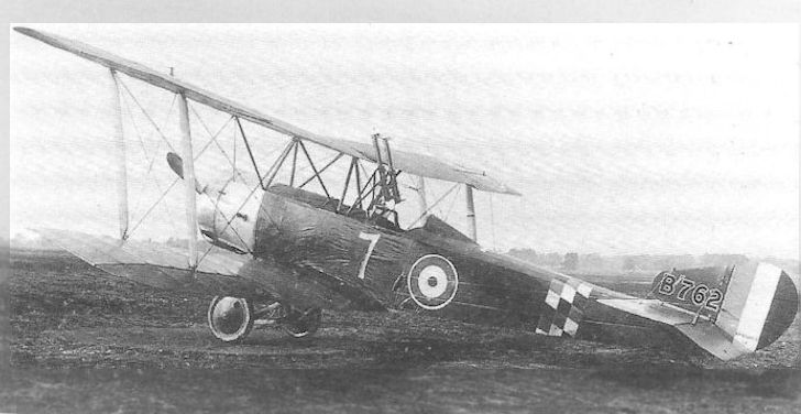
Одноместная модификация.
A single-seat 1 1/2-Strutter, B762, equipped to be flown from the rear cockpit, and with the front cockpit faired over. Twin Lewis guns are mounted over the pilot’s windscreen, and no Vickers gun is fitted. Note the head fairing behind the cockpit. The aircraft had been rebuilt by No 1 (Southern) Aircraft Repair Depot, South Farnborough, for a Home Defence Squadron.
With its twin upward-firing guns, Sopwith 1 1/2 Strutter B762 was one of a number of such aircraft employed for Home Defence in a single-seat form. It served with 78 Squadron from the autumn of 1917, having replaced BE2 and BE12 variants.
Sopwith Camel
The Camel was born of both necessity and circumstance. The need inevitably arose for a fighting scout that was faster and more heavily armed than the Pup and Triplane, without sacrificing those aeroplanes’ excellent handling qualities; it was needed quickly, so that production must be capable of building up rapidly. Compared with the engines available a year earlier, the choice of reliable powerplant was, late in 1916, much wider when Herbert Smith began working on the Camel - even though it seemed likely that rotaries of French origin would continue to dominate the stage for the immediate future. Gun synchronization gears had been made more reliable, with the Constantinesco hydraulic system rather better than the Sopwith-Kauper mechanical gear, although, for perhaps obvious reasons, Smith chose to incorporate the latter in the Camel.
It was therefore logical that the Camel design should not diverge too far from that of the Pup, yet be capable of accommodating a larger, more powerful engine as well as a pair of front guns in an airframe of similar overall size. It seems that after TOM Sopwith had sanctioned the building of four prototypes, the Admiralty stepped in with an order for two more - though it is not clear whether all the ‘private venture’ aircraft came to be completed. As originally designed the Camel was to have featured about 2 1/2 degrees of dihedral on both upper and lower wings but, for ease of manufacture it was decided to make the top wing flat; Smith therefore arbitrarily doubled the dihedral of the lower wing to compensate - thereby creating the Camel’s characteristic ‘pinched wing’ appearance from the front.
The first prototype, referred to as the F.1, was cleared by the company’s experimental department on 22 December 1916, and may have been flown by Harry Hawker on that date. The aircraft was powered by a 110hp Clerget 9Z rotary and featured a flat, constant-chord upper wing, built as a single component and with short ailerons on upper and lower wings. A second prototype, the F.1/1, had tapered wings with broad-chord I-form interplane struts. The third aircraft to fly was the F.1/3, and no firm evidence appears to have come to light to confirm the completion of an F.1/2, but this may have been used for structural tests.
The two Admiralty prototypes, N517 and N518, followed, and the latter underwent trials with the first 150hp Admiralty Rotary No 1, designed by W O Bentley who employed aluminium for the air-cooled cylinders; the engine was soon to be renamed the Bentley Rotary or B.R.1 and, when tests at Martlesham Heath in N518 showed a performance much the same as the original F.1 prototype, this engine was selected to power the majority of RNAS Camels.
The Bentley entered production quickly and by the time Sopwith received the first order for 50 production Camels from the Admiralty a small number of these engines was becoming available, the other aircraft being fitted with 130hp Clerget 9Bs. As the Sopwith order was soon increased to 500 aircraft, contracts were issued to Ruston, Proctor for 250, to Boulton & Paul for 100, to Clayton & Shuttleworth for 100 and to Portholme for 50 aircraft. Production aircraft differed from the prototypes in having their top wings built in three sections for ease of rigging, and featured a cut-out panel in the centresection to increase the pilot’s field of view; the ailerons were also lengthened.
Sopwith began delivery of Camels to the RNAS on 4 May 1917, the first being issued in June to No 4 (Naval) Squadron at Bray Dunes in France, commanded by Sqn Cdr B L Huskisson RN. From the outset the Camel was found to be a tricky aeroplane to fly, particularly among pilots thoroughly accustomed to the almost viceless qualities of the Pup and Triplane. The concentration of major weight components - engine, propeller, guns, fuel and pilot - in an extraordinarily compact envelope - coupled with the fierce gyroscopic couple of the rotary engine imposed a sharp tendency to drop the nose in a right-hand turn, whereas to the left the nose came up; and if the turn was tightened without coarse use of rudder the Camel would snap into a spin in the other direction. Yet, in practised hands, the stubby little aircraft was a magnificent dogfighter, its powerful elevator and sensitive ailerons bestowing a degree of manoeuvrability unmatched by contemporary German scouts - except the Fokker Dr I triplane.
No 4 (Naval) Squadron took less than a fortnight to come to terms with the Camel’s idiosyncracies and, during a patrol along the Belgian coast on the lookout for German bombers on 4 July, came upon a formation of sixteen Gothas, and drove down two. Within a month Nos 3, 6 and 9 (Naval) Squadrons had been fully re-equipped; ‘Naval Eight’ was the next to exchange its beloved Triplanes.
Meanwhile, in the RFC, No 70 at Liettres became the first Camel Squadron in July and was fully equipped in time to support the Ypres offensive which opened on the 31st. No 73 Squadron, newly formed on 1 July under Maj H F A Gordon, received the new fighters at home and, at the end of the year, moved to France.
Moreover, in August, Camels started re-equipping Home Defence units as No 44 Squadron, commanded at Hainault Farm by Maj Gilbert Ware Murlis-Green (later Gp Capt, dso, mc, raf) began the tricky job of flying the aircraft at night. On the night of 3/4 September Murlis-Green, Capt C J Q Brand (later Air Vice-Marshal Sir Quintin, kbe, dso, mc, dfc, raf) and Lt C C Banks took off at night to attack a formation of Gothas over southeast England, but without scoring. Nevertheless, the work done by No 44 proved that the Camel could be flown effectively at night, and helped to bring order to the haphazard system of night defence over England; the use of the Camel by No 44, and in particular by Murlis-Green and Brand, led directly to the development of the Camel as a dedicated night fighter, as will be shown below.
By the end of 1917 Camels were being flown operationally by nine RFC and six RNAS squadrons in France, two RFC squadrons in Italy, and No 44 at home; night flying training on Camels was also being undertaken by Nos 80, 81 and 89 Squadrons in Britain. Some 3,450 aircraft had been ordered, and the fighter was being produced at nine factories. Production contracts placed with Hooper & Co, Marsh, Jones & Cribb, and Portholme specified a change to the 110hp Le Rhone, an engine that entailed a switch to the Constantinesco hydraulic interrupter gear - although the speed performance was slightly inferior to that of the Clerget-powered Camel.
These very large orders would clearly place strain on the supply of Clerget and Le Rhone engines, even though the production of Bentleys was accelerating quickly, and it was decided to investigate a possible change to the 100hp Gnome monosoupape. Despite the lower power of this engine, the Camel’s performance held up remarkably well; yet relatively few Gnome-powered aircraft were produced, and none is thought to have reached an operational unit. In December 1917 a Camel was flown at Martlesham fitted with the 150hp version of the monosoupape engine, which featured an unusual switch in the cockpit enabling the pilot to cut out two, four, six or eight of the nine cylinders. An eye witness has recalled seeing the aircraft approaching, low down and flying on only one cylinder, when the pilot suddenly selected all nine cylinders to the accompaniment of a great blast of flame. However, the 150hp Gnome monosoupape engine was not adopted for service.
Returning to the special problems posed by night fighting in Camels, it was quickly discovered by the No 44 Squadron pilots that firing the two Vickers guns produced such a muzzle flash that all night vision was momentarily destroyed, the guns being located immediately in front of the pilot’s face. Fairly extensive changes were made in developing the Camel as a night fighter, and included removal of the Vickers and substituting a pair of Lewis guns on a special double Foster mounting on the upper wing centre section; the pilot’s cockpit was repositioned about twelve inches further aft to enable him to aim and reload the guns, and the fuel tank was moved from its customary position behind the pilot to the front fuselage to compensate for the aft movement of the cockpit. Navigation lights and Holt flare brackets were added to the wings. Some armament variations appeared on the night fighter squadrons, a few Camel pilots preferring to retain one of the Vickers in place of one of the Lewis guns. Most of the night fighters were painted overall with dark green dope, the national and squadron insignia being partly or completely obscured.
<...>
The air fighting in France during 1918 was some of the bitterest of the entire War. Early in the year the strength of RFC squadrons was increased from eighteen to twenty-four aircraft, and by the opening of the final great German offensive, on 21 March, seven Camel squadrons had achieved the planned establishment. The following day twelve aircraft of No 73 and twelve from No 80 Squadron shot down six German aircraft in the course of a single patrol; on the 24th, Capt J L Trollope mc* of No 43 Squadron alone destroyed six aircraft in a single day, a feat repeated by Capt H W Woollett dso, mc* of the same Squadron on 12 April.
On 21 April Camels of No 209 Squadron (formerly ‘Naval Nine’) were engaged in one of the most famous air combats of the War. On the morning of that day three Flights of Camels left Bertangles for a patrol in strength over the Somme, but one became separated in a fight with Albatros two-seaters. The two remaining Flights, led by the Canadian, Capt A R Brown, continued to their patrol area, in due course becoming involved in a fight with fifteen Fokker Dr I triplanes. Seeing a scarlet-painted enemy scout about to attack one of his novice pilots, Brown went for the enemy fighter and, with a single burst, shot it down near Corbie. Later it was discovered that the pilot, Baron Manfred von Richthofen, victor of 80 air combats, had died in his cockpit. Later it was suggested that von Richthofen had been killed by small arms fire from the ground, but this has been discounted as a means of denying that this great fighter pilot had been defeated in air combat. All the supportable evidence indicates that Brown - himself an experienced pilot - was the true victor.
Camels also fought with considerable success with two squadrons of the United States Air Service in France shortly before the end of the War. Although the 17th Aero Squadron lost six aircraft in a fight on 1 July, this and the 148th Squadron between them destroyed eleven German aircraft on 24 September - out of a total of eighteen shot down on the British Front.
Many famous names featured among Camel pilots, including men like Lt-Col Raymond Collishaw dso, dsc, dfc, Maj D R MacLaren dso, mc, dfc, Maj W G Barker vc, dso, mc, and Capt H W Woollett dso mc* - each of whom shot down more than fifty enemy aircraft during the War.
Lesser-known operations undertaken by the Camel night fighter squadrons were the night offensive patrols - in a later war to be known as intruder operations. No 151 Squadron, flying from Vignacourt during the last months of the War, bombed German airfields at night, as well as destroying sixteen bombers in the vicinity of their bases without loss to themselves.
Four Camel Squadrons, Nos 28, 66, 139 and 225, fought on the Italian Front during 1918, although the last-named was employed to fly escort for bombers crossing the Adriatic to attack targets in Albania. The only Victoria Cross to be won by a Camel pilot was awarded to Lt Alan Jerrard of No 66 Squadron in Italy, three of whose Camels were attacking an Austrian airfield when they were confronted by nineteen enemy fighters. Jerrard fought the enemy alone, shooting down two and enabling his two fellow pilots to escape safely; his aircraft was badly damaged and he was forced to land and surrender.
<...>
Camels remained in service for eighteen months after the War, but were eventually discarded by the RAF, largely in favour of the Sopwith Snipe.
Type: Single-engine, single-seat, single-bay biplane fighting scout, night interceptor and trench fighter.
Manufacturers: The Sopwith Aviation Co Ltd, Kingston-upon-Thames, Surrey; William Beardmore & Co Ltd, Dalmuir, Dunbartonshire; Boulton & Paul Ltd, Norwich; British Caudron Co, Cricklewood, London; Clayton & Shuttleworth Ltd, Lincoln; The Fairey Aviation Co Ltd, Hayes, Middlesex; Hooper & Co Ltd, London SW1; March, Jones & Cribb Ltd, Leeds; Nieuport & General Aircraft Co Ltd, Cricklewood, London; Portholme Aerodrome Ltd, Huntingdon; Ruston, Proctor & Co Ltd, Lincoln.
Powerplant: One 110hp Clerget 9Z nine-cylinder rotary engine driving two-blade propeller; 130hp Clerget 9B (140hp Clerget 9Bf); 110hp Le Rhone 9J; 150hp B.R.1; 100hp Gnome monosoupape, 150hp Gnome monosoupape, 180hp Le Rhone.
Structure: All-wooden structure, wire-braced and fabric-covered; ailerons fitted to upper and lower mainplanes.
Dimensions: (F.1 Camel) Span, 28ft 0in; length (Clerget), 18ft 9in; height (Clerget), 8ft 6in; wing area, 231 sq ft.
Weights: (130hp Clerget) Tare, 929lb; all-up, 1,453lb. (2F.1) Tare, 956lb; all-up, 1,523lb.
Performance: (F.1 Camel, 130hp Clerget) Max speed, 117 mph at sea level, 113 mph at 10,000ft; climb to 10,000ft, 10 min 35 sec; service ceiling, 19,000ft; endurance, 2 1/2 hr. (F.1 Camel, 150hp B.R.1) Max speed, 125 mph at sea level; 121 mph at 10,000ft; climb to 10,000ft, 8 min 10 sec; service ceiling, 22,000ft; endurance, 2 1/2 hr.
Armament: Standard armament was two 0.303in synchronized Vickers machine guns on top of fuselage forward of cockpit. Sopwith-Kauper mechanical, or Constantinesco hydraulic interrupter gear. Many Camels carried up to four 25lb bombs under the fuselage. Home Defence Camels were armed with two Lewis machine guns on a double Foster mounting above the upper wing centre section, firing above the propeller. 2.F1 Camels were usually armed with one synchronized Vickers gun on nose and one Lewis gun on Admiralty mounting above the upper wing.
Prototypes: Four (but possibly six). F.1/1 and F.1/3 prototypes un-numbered; two Admiralty prototypes, N517 and N518. (First flight, possibly 22 December 1916, made by Harry Hawker at Brooklands). N5 was prototype 2F.1.
Production: Generally stated to be a total of 5,695, plus about 230 2F.1s, but at least 100 were cancelled. (Sopwith, 500: N6330-N6379, B3571-B3950, B6201-B6450, and probably F8496-F8595; Boulton & Paul, 1,625: B5151-B5250, B9131-B9330, C1601-C1700, C3281- C3380, D6401-D6700, D9131-D9530, F1301-F1550, F1883-F1957, F6301-F6500, F8646- F8695 and H2646-H2745; British Caudron, 100: C6701-C6800; Clayton & Shuttleworth, 600: B5651-B5750, B7181-B7280, D3326-D3425, D9581-D9680, E4374-E4423, F3096- F3145 and F4974-F5073*; Hooper, 375: B5401-B5450, C1551-C1600, F2083-F2182, H734- H833 night fighters, and H7343-H7412*; Marsh, Jones & Cribb, 175: C8301-C8400 and F5174-F5248; Nieuport & General, 300: C1-C200, F3196-F3245 and F3918-F3967; Portholme Aerodrome, 250: B4601-B4650, B7131-B7180, D9531-D9580, E5129-E5178 and F1958-F2007; Ruston, Proctor, 1,575: B2301-B2550, B5551-B565O, B7281-B7480, C8201- C8300, D1776-D1975, D8101-D8250, E1401-E1600, E7137-E7336, F2008-F2082 and F3968-F4067. 2F.ls: William Beardmore, 200: N6600-N6649, N6750-N6699, N6800- N6949 and N7100-N7149; Hooper, 30: N8130-N8159) *Some of these aircraft probably cancelled). The manufacturer of another small batch around N8204 is not known.
Summary of Service: Sopwith Camels served with Nos 3, 43, 46, 54, 65, 70, 71 (becoming No 4 Squadron, Australian Flying Corps), 73, 80, 151 and 152 Squadrons, RFC and RAF, in France; with Nos 1, 3, 4, 8, 9, 10 and 13 (Naval) Squadrons, RNAS in France (becoming Nos. 201, 203, 204, 208, 209, 210 and 213 Squadrons, RAF, after 1 April 1918); with Nos 28, 66, 139 and 225 Squadrons, RAF, in Italy; with Nos 17 and 150 Squadrons, RAF, in Greece; with Nos 220 and 222 Squadrons, RAF, in the Aegean; with No 47 Squadron in Russia; and with Nos 37, 50, 51, 61, 75, 78, 81, 89, 94, 112, 143, 155, 187, 188, 189, 198, 230, 233 and 274 Squadrons, RAF, in the United Kingdom.
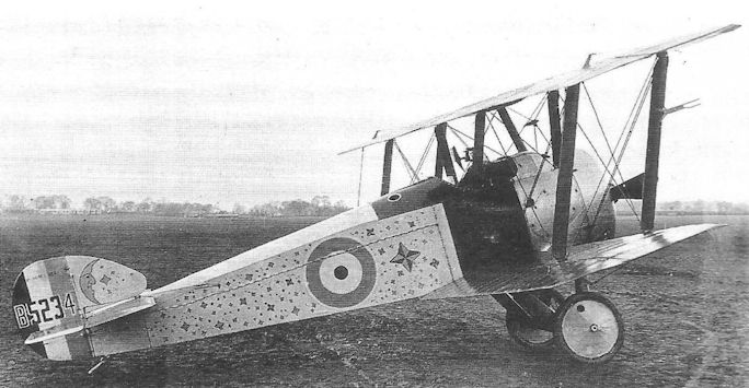
An unarmed Boulton & Paul-built F.1 Camel, B5234, in a distinctly unofficial livery, possibly photographed after the War, suggesting that it was the personal transport of a senior officer.
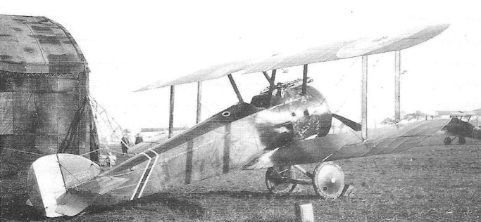
A Sopwith-built F.1 Camel with 150hp B.R.1 rotary engine, B6230, of No. 9 (Naval) Squadron at Bray Dunes, France, the first squadron to be equipped with the fighter in June 1917.
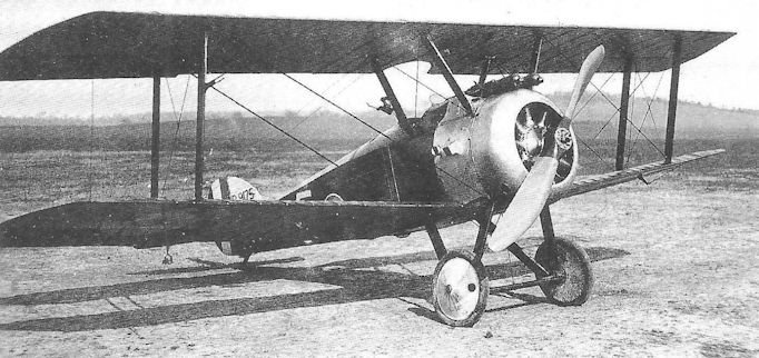
A standard F.1 Camel built by Boulton & Paul, B9175, and flown by No 44 Squadron as a night fighter during the late summer of 1917; the twin Vickers gun armament was later discarded as unsuitable for night fighting.
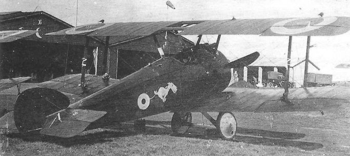
With serial number and unit markings obscured by what appears to be black dope overall, this anonymous Camel night fighter is a standard F.1 with twin Vickers guns but with flare brackets and navigation lights on the wings.
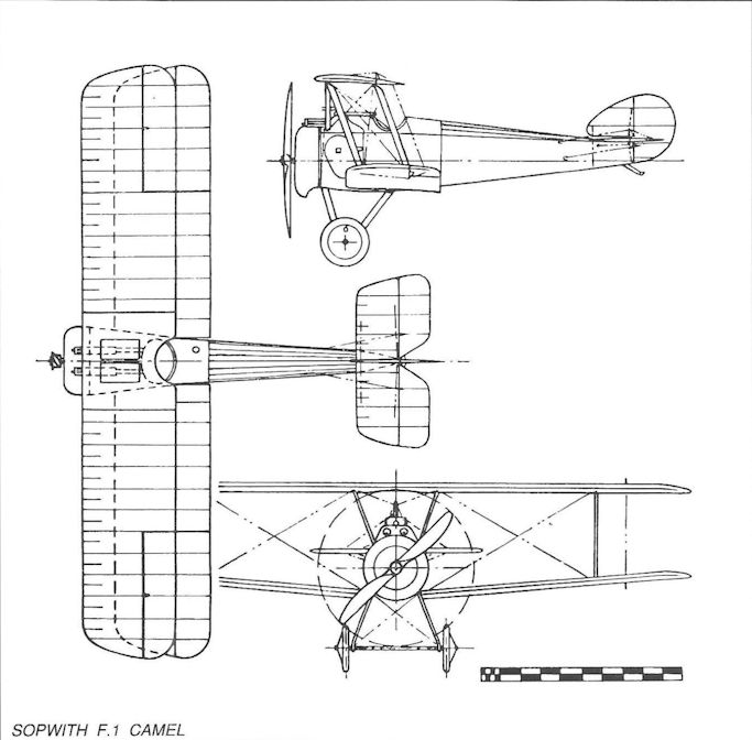
Sopwith L.R.T.Tr.
Designed at a time when the RFC was still seeking a long-range escort fighter capable of firing a gun directly forward without perpetuating the old Gunbus formula, the Sopwith L.R.T.Tr. was certainly the weirdest-looking aircraft to emerge from that company’s shops during the War. Accorded the nickname ‘The Egg Box’ by those at Sopwith, the aircraft (whose initials are thought to have stood for Long-Range Tractor Triplane) featured heavily-staggered, three-bay wings of equal span and chord with I-type interplane and cabane struts similar to those on the Sopwith Triplane scout.
The top wing carried a large streamlined nacelle in the nose of which was situated a gunner’s cockpit intended to have been provided with a pillar mounting for a Lewis gun. The pilot’s cockpit was located beneath the trailing edge of the upper wing, and immediately aft of this was a second gunner’s cockpit, also with a Lewis gun for rearward defence.
The fuselage was a very robust structure built up around a deep, wooden box-girder with rounded top decking. Power was provided by a single 250hp Rolls-Royce Mark I (Eagle I) water-cooled vee-twelve in-line engine with its radiator in the extreme front. The undercarriage with twin V-struts and mainwheels was located almost directly below the aircraft’s c.g. and was supplemented by a chassis extending forward with two balancing wheels. The aircraft could therefore rest tail-up on the balancing wheels or tail-down on the tailskid, depending on the number of crew and quantity of fuel carried.
It is likely that the big Rolls-Royce engine bestowed a useful maximum speed, but by the time the triplane was flown, towards the end of 1916, the RFC’s requirement had lapsed owing to the imminent arrival in service of the Bristol Fighters.
Type: Single-engine, three-seat, three-bay triplane fighter.
Manufacturer: The Sopwith Aviation Company Ltd, Kingston-upon-Thames, Surrey.
Powerplant: One 250hp Rolls-Royce Mark I (Eagle I) in-line engine driving two-blade propeller.
Span, 53ft; length, 38ft.
Performance: Max speed, approx 107 mph Armament: One 0.303in Lewis machine gun on gunner’s position in nose of wing-mounted nacelle, and another on the rear gunner’s cockpit in the fuselage amidships.
Prototype: One. No production.
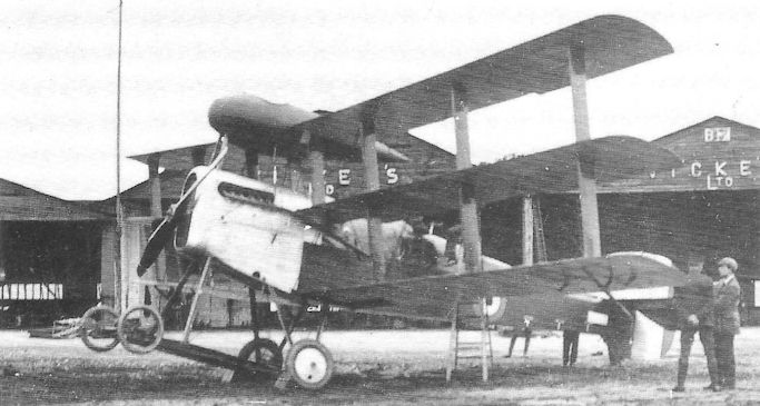
The Sopwith L.R.T.Tr. resting on its tailskid.
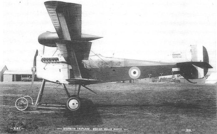
All salient features of L.R.T.Tr., in the form in which it was completed, are shown in this view notably, nacelle, wing and tail shape; landing gear; and mounting for Lewis gun behind rear cockpit. Apart from the facts that the 's' in 'Rolls' is reversed and that Rolls-Royce' is not hyphenated (for this was, perhaps, the first occasion on which the penman was called upon to write the company's name) the Sopwith caption reads: 'S.87 Sopwith Triplane. 250 hp Rolls-Royce 1916.'
The nacelle gunner mounted to his cockpit by means of a step on the front chassis strut, two steps on the engine cowling and a final stirrup step under the nacelle.
The nacelle gunner mounted to his cockpit by means of a step on the front chassis strut, two steps on the engine cowling and a final stirrup step under the nacelle.
Sopwith Pup
As far as any aeroplane of the First World War could be described as a ‘pilot’s aeroplane’, the delightful little Sopwith Scout - universally known as the Pup, other than in official documents - certainly deserved that description. It is said that the design of the Pup was motivated by the ascendancy of German fighting scouts during the latter half of 1915 and the urgency to give the British flying services an aeroplane that could meet the enemy on equal terms. This urgency clearly dictated the utmost simplicity of design and manufacture, and at least one happy circumstance contributed to the tactical excellence of the Pup in service: the long-awaited availability of front gun interrupter gear, so that almost all Pups were armed with a single forward-firing Vickers gun equipped with Sopwith-Kauper mechanical synchronizing gear.
It is difficult to conceive a simpler airframe structure than that of the Pup. The fuselage comprised a box girder made up from ash longerons and spruce spacers, the whole structure wire-braced and surmounted by curved decking formed by stringers. Aft of the front fireproof bulkhead, structure rigidity was achieved by diagonal ash struts. The equal span, single-bay wings were moderately staggered and the cabane struts were splayed outwards to provide a broad centre section which was generously cut away over the pilot’s cockpit. The wing structure was built up on twin spars of spindled spruce with spruce ribs and ash riblets; steel tube was employed in the wingtips and fin, rudder and elevator, as well as the tailplane spar on which the elevator was hinged. The V-struts of the undercarriage were of plain steel tube, and the split wheel axles were sprung by rubber cord, the latter arrangement being patented by T O M Sopwith himself. Relatively small ailerons were fitted on upper and lower wings. At first glance the Pup might appear to be a diminutive offspring of the Sopwith 1 1/2-Strutter - and it was this that may have caused the name Pup to become common usage.
The prototype Pup, No 3691, was passed by Sopwith’s experimental department on 9 February 1916 and was first flown by Harry Hawker at Brooklands almost certainly before the end of that month. Numerous influential visitors from the War Office and Admiralty visited Brooklands to watch the Pup on test, and it was evident that large production orders would be forthcoming. Sopwith was, however, already heavily engaged in producing 1 1/2-Strutters, and it was necessary to initiate considerable sub-contract manufacture, three companies, William Beardmore, Standard Motors and Whitehead Aircraft, being contracted to contribute the lion’s share of Pup production. Meanwhile Sopwith produced five more prototypes, all powered by 80hp Clergets.
Sopwith was, however, primarily an Admiralty contractor, and all six Pup prototypes were delivered to Admiralty charge; and it was for the RNAS that the first production order was placed, for 20 Pups built by Sopwith (N5180-N5199) and powered by 80hp Le Rhone engines. With this modest power the Pup possessed a sea level maximum speed of 111.5 mph, and maintained a top speed of over 100 mph up to around 12,000 feet - a performance not previously matched by any fully-loaded British scout.
The first production Pups began appearing in September 1916 and by the end of that month were being flown by No 1 Wing, RNAS, and had gained their first victories over enemy aircraft. (One of the prototypes had been sent out to France in May for operational trials with Naval ‘A’ Fighting Squadron.)
While Sopwith-built Pups were being delivered to the RNAS in a steadily growing trickle, those destined for the RFC (produced initially by Beardmore) were even slower to materialise, although the first to be delivered arrived on No 54 Squadron, commanded by Maj Kelham Kirk Horn mc, at Castle Bromwich, also in September.
It was a measure of the administrative constraints imposed by the War Office and Admiralty that, despite the heavy aircraft losses suffered by the RFC in the Battle of the Somme during the summer of 1916, there were no means to allow Sopwith to supply Pups to the War Office. Instead, when Sir Douglas Haig appealed to the War Office for reinforcements, the Admiralty - with Cabinet approval - decided to form a new RNAS Pup unit, No 8 (Naval) Squadron on 25 October, under Sqn Cdr G R Bromet (later Air Vice-Marshal Sir Geoffrey, kbe, cb, dso, raf), a Squadron that was to gain immortality with a succession of Sopwith aircraft during the next two years; although only one Flight was initially equipped with Pups, it was soon shown that these aircraft were so much better than the Nieuport Scouts and the 1 1/2-Strutters, and Pups quickly re-equipped the whole Squadron. Within a month the Pups had shot down twenty enemy aircraft, and in February and March 1917 two more units, Nos 3 and 9 (Naval) Squadrons had been equipped with Sopwith-built Pups. During the period immediately before the Battle of Arras, which opened on 9 April, No 3 Squadron, based at Marieux under Sqn Cdr Redford Henry Mulock (later Air Cdre, CBE, dso, raf), destroyed so many enemy aircraft that the Germans began deliberately to avoid combat with the Pups - at a time when other Allied aircraft were suffering catastrophic losses.
Meanwhile No 54 Squadron had completed its working up with Pups and had moved to France on Christmas Eve 1916, and by April the only other two RFC Squadrons to fly these aircraft in France, Nos 46 and 66, had also reequipped. The latter Squadron in particular, commanded by Maj (later Air Vice-Marshal, obe, mc, afc, raf) Owen Tudor Boyd, was very heavily engaged during the Battles of Arras and Messines. No 54 Squadron’s Capt (later Gp Capt) William Victor Strugnell won two Military Crosses when, over a period of three months, he destroyed seven enemy aircraft, the first during the Battle of Arras.
The numerous combat successes by this handful of Pup squadrons during ‘Bloody April’ demonstrated all to clearly that the system of aircraft supply from the factories needed radical overhaul, and that had the Sopwith Pup not taken eight months to begin to emerge from the production lines in 1916, the RFC would have been adequately equipped to meet the emergency that threatened in France in the spring of 1917.
By the autumn of that year the Pups’ single Vickers gun was no longer able to match the new, more heavily armed German scouts, and it was replaced in France by the Sopwith Camel. At home, however, Pups had begun delivery to a number of Home Defence squadrons in order to counter the German bombing attacks which, made by Gotha G IVs, had begun on 25 May 1917 against southeast England.
Alas, through no fault of the aircraft or their pilots but rather because of the lack of a suitable raid warning system, scarcely any success was achieved against the raiders. However the Pup was found to be admirably suitable for night flying and, beginning in December 1917, as the Germans embarked on night raiding with their bombers, they began equipping special night training Squadrons in Britain, namely Nos 187, 188 and 189.
Such were the excellent handling qualities of the Pup that it was a natural instrument for countless experiments, the majority of which were conducted with the naval aircraft. Trials with flotation bags under the lower wings led to their fitting to a number of Pups which operated over the sea; lying flat underneath the lower wings during normal flight, they would inflate if the aircraft was forced to alight on the water, thereby enabling the Pup to remain afloat for several hours.
Pups performed many of the early trials aboard ships at sea. In June 1917 Flt Cdr F J Rutland flew a Pup from a twenty-foot platform on the fo’c’sle of the light cruiser hms Yarmouth which was sailing at 20 knots into wind, an experiment that led to the fitting of similar platforms aboard hm Cruisers Caledon, Cassandra, Cordelia and Dublin. And it was Flt Sub-Lt B A Smart who won a DSO when, on 21 August that year, he took off from hms Yarmouth off the Danish coast to shoot down the Zeppelin L.23 before alighting on the sea beside another British cruiser.
The Pup also made the pioneering landings on the deck of a ship at sea. The first aircraft carrier to be equipped with a fairly large flight deck was hms Furious, whose 228-foot deck was located forward of her superstructure. Sqn Cdr E H Dunning made two successful landings on 2 August 1917 by sideslipping round the superstructure to arrive low over the deck so slowly that naval personnel could grab toggles under the wings to pull the Pup on to the deck. Tragically the Pup suffered a burst tyre on the third landing; it lurched overboard and Dunning lost his life.
Later an after-deck was added to hms Furious to enable aircraft to land more conventionally. However there was nothing to prevent aircraft from slewing sideways and damaging their undercarriage, and some Pups were fitted with skids in place of wheels, as well as rudimentary arrester hooks.
In the RFC many of the Home Defence Pups were powered by 100hp Gnome monosoupape engines, and these served to improve performance at altitude. A pilot who had already won the Military Medal while flying D.H.2s with No 29 Squadron, was flying as an instructor at Joyce Green in mid-1917 and flew a monosoupape aircraft against the raiding Gothas on several occasions. His name was Lieut James Thomas Byford McCudden. A year later, flying the S.E.5 with No 56 Squadron, he raised his victory tally to 57 enemy aircraft destroyed, and in so doing added the Victoria Cross, two DSOs and two MCs to his gallantry decorations. He is on record as having paid unqualified tribute to the little Pup, ‘which could turn twice to an Albatros’ once...’
Type: Single-engine, single-seat, single-bay biplane scout.
Manufacturers: The Sopwith Aviation Co Ltd, Kingston-upon-Thames, Surrey; William Beardmore & Co Ltd, Dalmuir, Dunbartonshire; The Standard Motor Co Ltd, Coventry; Whitehead Aircraft Ltd, Richmond, Surrey.
Powerplant: One 80hp Le Rhone; 80hp Gnome; 80hp Clerget; 100hp Gnome monosoupape engine.
Structure: Wooden box-girder fuselage with ash longerons and spruce spacers, wire-braced and fabric-covered; two-spar staggered wings with spindled spruce spars, spruce ribs and ash riblets; steel tubular wingtips and tail unit with fabric covering.
Dimensions: Span, 26ft 6in; length, 19ft 3 3/4 in; height, 9ft 5in; wing area, 254 sq ft.
Weights: (Le Rhone) Tare, 787lb; all-up, 1,225 lb. (Gnome monosoupape) Tare, 856lb; all-up, 1,297lb.
Performance: (Le Rhone) Max speed, 111.5 mph at sea level; climb to 10,000ft, 14 min; service ceiling, 17,500ft; endurance, 3 hr. (Gnome monosoupape) Max speed, 110 mph at sea level; climb to 10,000ft, 12 min 25 sec; service ceiling, 18,500ft; endurance, 17 hr.
Armament: One 0.303in Vickers machine gun with Sopwith-Kauper synchronizing gear to fire through propeller arc. Some Pups armed with eight Le Prieur rockets in addition to gun; other aircraft fitted with single Lewis gun, but not synchronized.
Prototypes: Six. No 3691 (first flown by Harry Hawker at Brooklands, probably during February 1916); Nos 9496, 9497 and 9898-9900, all built by Sopwith.
Production: Total, 1,770. (Beardmore, Nos 9901-9950 and N6430-N6459; Standard, A626-A675, A7301-A7350, B1701-B1850, B5901-B6150 and C201-C550; Whitehead, A6150-A6249, B2151-B2250, B5251-B5400, B7481-B7580, C1451-C1550, C3707-C3776 and D4011-D4210; Sopwith, N5180-N51199, N6160-N6209 and N6460-N6479)
Summary of Service: Pups served with Nos 46, 54 and 66 Squadrons, RFC, in France; Nos. 46, 61 and 112 Squadrons, RFC, Home Defence; No 66 Squadron, RFC, Italy; with CFS, Upavon, and numerous other training units. Naval Pups served with Nos 3, 4, 8, 9 and 12 (Naval) Squadrons, RNAS; Special Duty Flight; No 1 (Naval) Wing, RNAS; aboard hm Carriers Argas, Campania, Furious and Manxman', hm Light Cruisers Caledon, Cassandra, Cordelia, Dublin and Yarmouth', and hm Battle Cruiser Repulse. Also numerous training units and Stations at home and overseas.
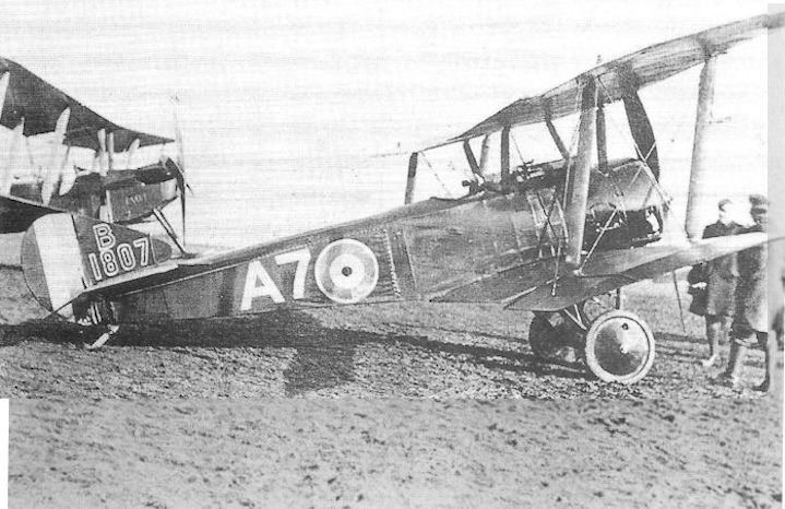
A Standard-built Sopwith Pup, B1807, possibly with an RFC Squadron in France.
After serving with No 36 (Home Defence) Squadron, Sopwith Pup (B1807) survived the war and later became G-EVAVX on the British Civil Register. The serial number on the fin is Black outlined in White
After serving with No 36 (Home Defence) Squadron, Sopwith Pup (B1807) survived the war and later became G-EVAVX on the British Civil Register. The serial number on the fin is Black outlined in White
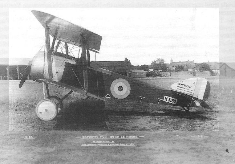
The first production Sopwith Pup, N5180, completed in September 1916 by Sopwith for the Admiralty; it was later flown by the Special Duly Flight, RNAS, ‘A’ Squadron, at Fumes.
The picture being captioned by the makers: S.83 Sopwith 'Pup'. 80 hp Le Rhone 1916.
The picture being captioned by the makers: S.83 Sopwith 'Pup'. 80 hp Le Rhone 1916.
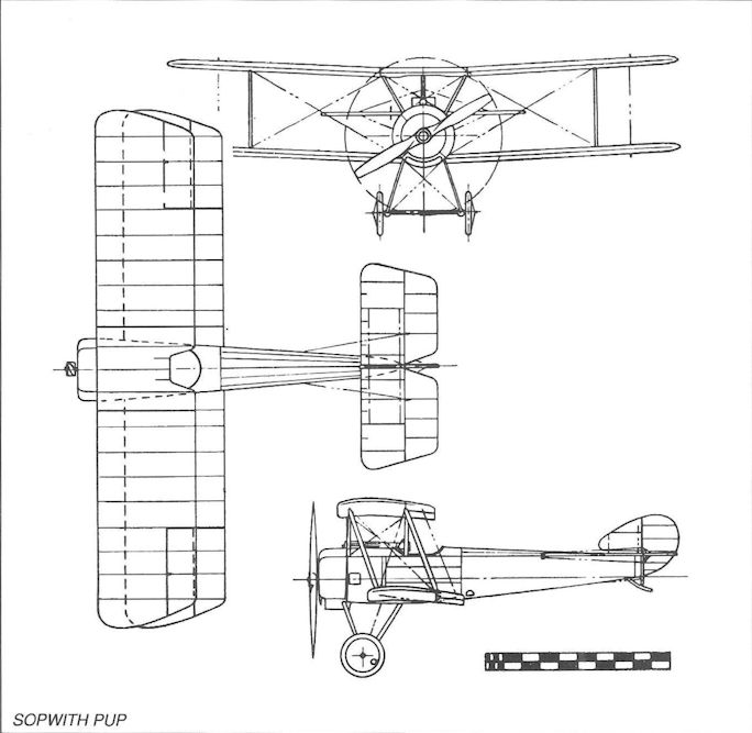
Sopwith Pup
Sopwith Triplane (Clerget)
The Pup had not even reached the RNAS or RFC squadrons when the Sopwith Triplane made its first flight in the hands of Harry Hawker at the beginning of June 1916. That the Pup’s design represented the basis of the Triplane almost goes without saying, yet there were two intermediate stages in the process of thought. In the early spring of that year Herbert Smith had started the design of a somewhat grotesque-looking triplane escort fighter with very high aspect ratio wings, the top wing supporting a nacelle in which the gunner’s cockpit was situated; the aircraft was to be powered by a 250hp Rolls-Royce Mk I engine (see Sopwith L.R.T.Tr.). Smith’s next design was a triplane fighter derived from the 1 1/2-Strutter, this aircraft being scheduled for the 150hp water-cooled Hispano-Suiza engine. Neither of these engines was yet readily available and so the airframes were held temporarily in abeyance.
Smith now turned to the Pup, seeing in the application of triplane wings, possessing the same, or smaller chord than those of the L.R.T.Tr., considerable potential for further improvement in performance and handling. The fuselage aft of the cockpit remained almost identical to that of the Pup, though stressed for a larger engine, but the tail surfaces were later reduced in area, the tip rake of the tailplane and elevators being reversed.
The Triplane wings, however, were radical and ingenious. By limiting the chord to no more than 3ft 3in, compared to the Pup’s 5ft 3in, the wing area was in fact reduced from 254 to 231 sq ft - with exactly the same span; at the same time, with ailerons on all six wings, their total area was increased from 22 to 34 sq ft, thereby retaining the crisp handling with no extra stick load. The pilot’s field of view was improved by the reduced wing chord and by the location of the centre wing in line chordwise with the pilot’s eye level. The I-type interplane and cabane struts were the subject of Patent No 127,858, held by Fred Sigrist, and were rigged to give a total stagger of 36 inches between top and bottom wings, compared with 18 inches between the Pup’s two wings. This arrangement of struts permitted fewer bracing wires to be used, with only a single landing wire and a doubled flying wire necessary on each side. Power for the Triplane was provided initially by the 110hp Clerget engine, although the 130hp version was introduced into at least one production batch before the end of 1916. Most aircraft also retained the single synchronized Vickers gun of the Pup.
The prototype Triplane, N500, was sent to France in June for operational trials with Naval ‘A’ Fighting Squadron at Furnes (and was ordered off against a suspected enemy aircraft within fifteen minutes of refuelling). This aircraft was representative of the proposed initial production version, but the second prototype, N504, was powered by the 130hp Clerget and carried twin Vickers guns.
The first production order was placed by the Admiralty in August, followed by orders from the War Office for 100 aircraft to be built by Sop with, and 166 by Clayton & Shuttleworth of Lincoln. In due course, however, owing to the critical shortage of RFC fighters in France, it was agreed that in return for Spad S.7s which were held by the Admiralty, the War Office would relinquish their orders for Triplanes in favour of the RNAS. In the event none of the original 266 RFC Triplanes were built. Instead, the Admiralty placed orders totalling 145 aircraft with Sopwith and Clayton & Shuttleworth, as well as 25 from Oakleys of Ilford (of which only three were completed).
Once again the artificial bureaucracy that concealed petty jealousies between the Admiralty and War Office robbed the fighting men of the weapons that would have stood them in good stead when the air war took such a disastrous turn in the spring of 1917.
As it was, the RNAS put their relatively small number of Triplanes to excellent use. Production had got underway at Sopwith and Clayton in the late autumn of 1916, and the first deliveries were being made to the RNAS at the turn of the year. By the end of February No 1 (Naval) Squadron at Chipilly, under the command of Sqn Cdr F K Haskins (later Air Cdre, dsc, raf) had received seventeen Triplanes; then it was the turn of ‘Naval Eight’ at Auchel, who gave up their Pups in exchange for Triplanes in March, and No 10 (Naval) Squadron in May.
It was a Canadian pilot on Naval Ten who was to become the greatest fighting exponent of the Triplane in the person of Flight Sub-Lt Raymond Collishaw (later Air Vice-Marshal, cb, dso*, obe, dsc, dfc, raf). Given command of ‘B’ Flight, Collishaw generated an extraordinary esprit by his example, and his pilots - all Canadians and superb pilots in their own right - had their Triplanes painted black overall and given names such as Black Prince, Black Death, Black Sheep and Black Maria (Collishaw’s aircraft), and so on. In air combats during June, Collishaw alone shot down no fewer than sixteen German aircraft, of which thirteen were single-seat fighters; apart from Collishaw himself, four other pilots of ‘Black Flight’ between them destroyed 54 German aircraft. Their flight commander would, by the end of the War become the third highest-scoring British Commonwealth fighter pilot, with a score of 60 victories; he also served with great distinction in the Second World War.
As already stated, a few Triplanes were fitted with the 130hp Clerget, an additional power that gave the little fighter a top speed of 117 mph, and six of the aircraft built by Clayton & Shuttleworth (N533-N538) were armed with twin Vickers guns. A total of six Triplanes was loaned to France, but these were returned to the RNAS when the shortage of fighters became acute early in 1917; even the original prototype was pressed into service with Naval One, while the second served with Naval Eight.
The Triplane’s swansong was during the third Battle of Ypres in August 1917. By the end of the month Naval Ten was being re-equipped with the Sopwith Camel, and by Christmas the Triplane had been withdrawn from operational service.
Type: Single-engine, single-seat, single-bay triplane scout.
Manufacturers: The Sopwith Aviation Co Ltd, Kingston-upon-Thames, Surrey; Clayton & Shuttleworth Ltd, Lincoln; Oakley Ltd, Ilford, Essex
Powerplant: One 110hp or 130hp Clerget rotary engine driving two-blade propeller.
Structure: All-wooden wire-braced box-girder fuselage with fabric covering; triplane, single-bay, two-spar wings with single interplane and cabane I-struts.
Dimensions: Span, 26ft 6in; length, 18ft 10in; height, 10ft 6in; wing area, 231 sq ft.
Weights: (130hp Clerget) Tare, 1,101lb; all-up, 1,541lb.
Performance: (130hp Clerget) Max speed, 117 mph at sea level, 104 mph at 13,000ft; climb to 10,000ft, 11 min 50 sec; service ceiling, 20,500ft; endurance, 2 3/4 hr.
Armament: Either one or two synchronized 0.303in Vickers machine guns on nose top decking with Sopwith-Kauper interrupter gear.
Prototypes: Two, N500 and N504 (N500 first flown by Harry Hawker at Brooklands early in June 1916); both built by Sopwith.
Production: Total of 145 (95 by Sopwith: N5420-N5494 and N6290-N6309; 47 by Clayton & Shuttleworth: N524, N533-N538 and N5350-N5389; three by Oakley, N5910-N5912).
Summary of Service: Triplanes served with Nos 1, 8, 9, 10 and 12 (Naval) Squadrons, RNAS, on the Western Front; also with ‘E’ Squadron, RNAS, in Macedonia; with No 2 (Naval) Wing, RNAS, at Mudros in the Aegean; and at RNAS Manston and Port Victoria. A small number was loaned or supplied to France, the USA and Russia.
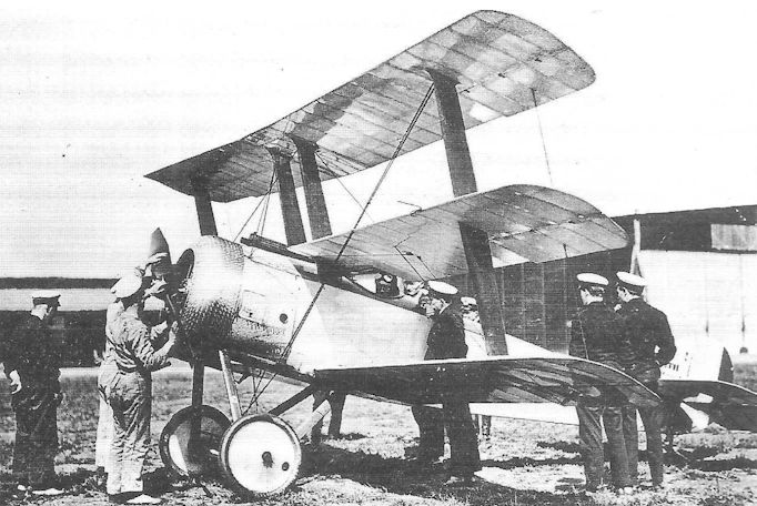
The first prototype Sopwith Triplane, N500, at RNAS Chingford for Admiralty trials and before being given its Service paint scheme. The pilot in the cockpit is said to be Flight-Lt L E Hardstaff Admiralty Test Pilot.
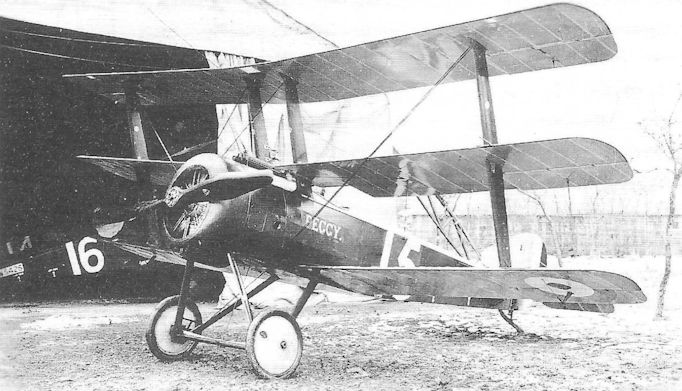
The Triplanes, N5387 ’15’ and N5425 ‘16’ of No 1 (Naval) Squadron.
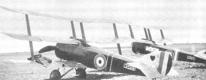
N5493 and N6290 of No 8 (Naval) Squadron. The former aircraft was flown by the Australian pilot, Capt Robert Alexander Little, DSO*, DSC*, the highest-scoring pilot from that country. His score of 47 victories is believed to have been achieved solely while flying Pups and Triplanes with Naval Eight. He was killed on 27 May 1918, while on leave in England, when he took off to attack a Gotha at night; he was blinded by a searchlight as he closed with the raider and crashed.
Sopwith Hispano Triplane
Further evidence of the inconvenience caused by the delays in introducing the Hispano-Suiza engine into production in Britain was afforded by the late appearance of Sopwith’s triplane powered by this engine. Although the design was undertaken at roughly the same time as that of the Clerget-powered Triplane, it has frequently been assumed that the two scouts were closely related; in fact, whereas the Clerget Triplane was related to the Pup, the Hispano aircraft was more closely associated with the earlier 1 1/2-Strutter.
Indeed the only feature, apart from the triplane configuration itself, common to the two designs was the use of broad-chord I-form interplane and cabane struts. The Hispano-powered triplane employed wings of 4ft 3in chord, compared with 3ft 3in on the Clerget aircraft. The fuselage, tail and undercarriage of the former were little changed from those of the 1 1/2-Strutter.
It seems that the first prototype airframe (N509) of the Hispano Triplane was completed in about December 1916, and that the 150hp Hispano-Suiza direct-drive engine was not delivered to Brooklands until March 1917; surviving records suggest that Harry Hawker first flew the aircraft in late April or early May. The engine installation was of more pleasing appearance than that of, for instance, the S.E.5, though not necessarily more efficient, being of almost circular section. It was later found necessary to provide exit louvres in the rear of the cowling to permit better through-flow of cooling air from the frontal radiator. The exhaust system comprised a four-branch collector manifold leading into a four-foot straight exit pipe on each side, extending aft almost as far as the cockpit coaming.
A second prototype, N510, with a 200hp Hispano-Suiza geared-drive engine, was completed later. Unfortunately, due to the delays in receiving their engines, the two triplanes were, by the time they were ready to fly, already being eclipsed by the Camel, S.E.5A, and Bristol F.2B Fighter. Moreover, the new triplanes were only armed with single synchronized front guns. After official trials, however, they were both taken on Admiralty charge, only to be written off in accidents later in 1917, N509 at Mansion and N510 at Eastchurch.
Type: Single-engine, single-seat, single-bay triplane scout.
Manufacturer: The Sopwith Aviation Co Ltd, Kingston-upon-Thames, Surrey.
Powerplant: One 150hp Hispano-Suiza direct-drive in-line engine driving two-blade propeller; second aircraft with 200hp Hispano-Suiza geared engine.
Structure: All-wood box-girder with wire bracing and fabric covering; single-bay, two-spar triplane wings with I-form struts; ailerons on all wings.
Dimensions: Span, 28ft 6in; length, 23ft 2in; wing area, 340 sq ft.
Performance: Max speed, 120 mph at sea level; climb to 10,000ft, 9 min.
Armament: One synchronized 0.303in Vickers machine gun on fuselage top decking immediately forward of the cockpit, firing through the propeller arc.
Prototypes: Two; N509 (probably flown in late April or early May 1917 by Harry Hawker) and NS 10. No production
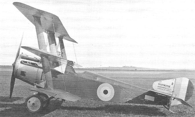
First of the Sopwith Hispano Triplanes, N509, with direct-drive 150hp Hispano-Suiza engine, at Mansion, probably in the late summer of 1917.
Sopwith Camel
<...>
At sea Camels took over much of the work pioneered by the Pup. The 2F.1 Camel was specially developed for work from ships and was flown in prototype form (as N5) as early as March 1917. This version was distinguishable in having a fuselage built in two parts (the joint being just aft of the cockpit), the object of which was to enable the rear section to be detached for storage aboard ship. The joint necessitated a pair of external rocking levers to enable the elevator control cables to be disconnected. The wing span was reduced by about a foot, and the cabane struts, instead of being faired, were plain steel tubes.
As with the RFC’s night fighters, the 2F.1 Camels were armed with an upward-firing Lewis gun, while a single Vickers was usually retained. Their principal task with the Home Fleet was to attack German airships and seaplanes at large over the North Sea, and they achieved a fair degree of success.
Another memorable series of trials involved Camel take-offs from towed lighters. The first attempt was made on 30 May 1918 by the redoubtable Col Charles Rumney Samson (later Air Cdre, cmg, dso, AFC, raf) who was to fly a Camel from a lighter being towed by hm Destroyer Truculent off the coast at Orfordness. Because the lighter was not fitted with a flight deck, the Camel was equipped with skids instead of wheels, and these skids engaged in channels running the full length of the vessel. Unfortunately, as the fighter began its take-off, the skids jumped out of the channels, and the Camel fell over the side and was smashed to pieces as the lighter passed over it. Samson miraculously fought his way out of the wreckage and was rescued unhurt.
Later a short deck was fitted to the lighter and the first successful take-off, using a normal wheel undercarriage, was accomplished by Lt S C Culley rn on 31 July. Towed lighters with Camels were used operationally, and, during a foray by the Harwich Force towards the Heligoland Bight on 11 August 1918, Culley took off from a lighter, climbed to 18,000 feet and shot down the Zeppelin L53 - despite one of his guns jamming. This was the last German airship to be shot down during the War. Two others had recently been destroyed by carrier-borne Camels when, on 19 July, seven aircraft, each carrying a pair of 50lb bombs, had taken off from hms Furious and hit the German airship sheds at Tondern, destroying the Zeppelins L54 and L60; only two of the Camels returned safely to Furious, flown by Captains F W Dickson and Bernard Arthur Smart dso* (the pilot who had shot down a Zeppelin while flying a Pup on 22 August 1917).
One other interesting experiment of 1918 involved naval Camels, that of providing British airships with their own fighter protection. While the 2F.1 Camels N6622 and N6814 of No 212 Squadron were being prepared at Felixstowe, the airship R.23 was being fitted with a horizontal surface beneath its keel, under which the upper wing of the Camel would rest, retained in place by a quick-release hook which engaged with the fighter’s top wing centre section structure. A preliminary drop was made without pilot and with the Camel’s controls locked, and this was followed by a live drop by Lt R E Key dfc of No 212 Squadron who started his engine successfully, dropped away without trouble, and flew round the R.23 before landing at the airship station at Pulham. Similar trials, employing other fighter aircraft, continued until 1925 when they were finally abandoned.
<...>
Weights: (2F.1) Tare, 956lb; all-up, 1,523lb.
Armament: 2.F1 Camels were usually armed with one synchronized Vickers gun on nose and one Lewis gun on Admiralty mounting above the upper wing.
Production: Generally stated to be a total of 5,695, plus about 230 2F.1s, but at least 100 were cancelled.
<...>
At sea Camels took over much of the work pioneered by the Pup. The 2F.1 Camel was specially developed for work from ships and was flown in prototype form (as N5) as early as March 1917. This version was distinguishable in having a fuselage built in two parts (the joint being just aft of the cockpit), the object of which was to enable the rear section to be detached for storage aboard ship. The joint necessitated a pair of external rocking levers to enable the elevator control cables to be disconnected. The wing span was reduced by about a foot, and the cabane struts, instead of being faired, were plain steel tubes.
As with the RFC’s night fighters, the 2F.1 Camels were armed with an upward-firing Lewis gun, while a single Vickers was usually retained. Their principal task with the Home Fleet was to attack German airships and seaplanes at large over the North Sea, and they achieved a fair degree of success.
Another memorable series of trials involved Camel take-offs from towed lighters. The first attempt was made on 30 May 1918 by the redoubtable Col Charles Rumney Samson (later Air Cdre, cmg, dso, AFC, raf) who was to fly a Camel from a lighter being towed by hm Destroyer Truculent off the coast at Orfordness. Because the lighter was not fitted with a flight deck, the Camel was equipped with skids instead of wheels, and these skids engaged in channels running the full length of the vessel. Unfortunately, as the fighter began its take-off, the skids jumped out of the channels, and the Camel fell over the side and was smashed to pieces as the lighter passed over it. Samson miraculously fought his way out of the wreckage and was rescued unhurt.
Later a short deck was fitted to the lighter and the first successful take-off, using a normal wheel undercarriage, was accomplished by Lt S C Culley rn on 31 July. Towed lighters with Camels were used operationally, and, during a foray by the Harwich Force towards the Heligoland Bight on 11 August 1918, Culley took off from a lighter, climbed to 18,000 feet and shot down the Zeppelin L53 - despite one of his guns jamming. This was the last German airship to be shot down during the War. Two others had recently been destroyed by carrier-borne Camels when, on 19 July, seven aircraft, each carrying a pair of 50lb bombs, had taken off from hms Furious and hit the German airship sheds at Tondern, destroying the Zeppelins L54 and L60; only two of the Camels returned safely to Furious, flown by Captains F W Dickson and Bernard Arthur Smart dso* (the pilot who had shot down a Zeppelin while flying a Pup on 22 August 1917).
One other interesting experiment of 1918 involved naval Camels, that of providing British airships with their own fighter protection. While the 2F.1 Camels N6622 and N6814 of No 212 Squadron were being prepared at Felixstowe, the airship R.23 was being fitted with a horizontal surface beneath its keel, under which the upper wing of the Camel would rest, retained in place by a quick-release hook which engaged with the fighter’s top wing centre section structure. A preliminary drop was made without pilot and with the Camel’s controls locked, and this was followed by a live drop by Lt R E Key dfc of No 212 Squadron who started his engine successfully, dropped away without trouble, and flew round the R.23 before landing at the airship station at Pulham. Similar trials, employing other fighter aircraft, continued until 1925 when they were finally abandoned.
<...>
Weights: (2F.1) Tare, 956lb; all-up, 1,523lb.
Armament: 2.F1 Camels were usually armed with one synchronized Vickers gun on nose and one Lewis gun on Admiralty mounting above the upper wing.
Production: Generally stated to be a total of 5,695, plus about 230 2F.1s, but at least 100 were cancelled.
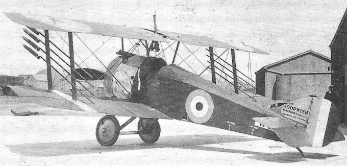
The Sopwith 2F.1 Camel prototype, N5, armed with one Vickers and one Lewis gun and equipped to carry up to eight Le Prieur anti-airship rockets on the interplane struts. The photograph is said to have been taken at Martlesham Heath in 1918.
Sopwith Bee
Sometime in mid-1916 the Sopwith factory found time and space to build a tiny biplane for the personal use of Harry Hawker as both a runabout and an aerobatic mount. Of extreme simplicity, the Sopwith Bee was powered by a 50hp Gnome seven-cylinder rotary engine, and its single-bay wings incorporated wing-warping for lateral control; the rudder was horn balanced.
In common with current Sopwith fighting scouts, every effort was made to concentrate the components of greatest mass in the smallest possible space around the aircraft’s c.g., with the result that the cockpit was close up behind the engine and situated directly beneath the wing centre section; this required the provision of an enormous cutout in the upper wing, and in all probability the pilot’s head protruded above the upper surface. A standard Pup undercarriage was fitted.
It was quite possible that the Admiralty’s requirement for a very small scout, capable of operating from Torpedo-Boat Destroyers (and the appearance of the P.V.7 and P.V.8) that prompted Sopwith to test the Bee in this context, and a single synchronized Vickers machine gun was fitted. However, no records of this venture appear to have survived, and no further development was undertaken.
Type: Single-engine, single-seat, single-bay aerobatic biplane, adapted as a fighting scout.
Manufacturer: The Sopwith Aviation Co Ltd, Brooklands, Surrey.
Powerplant: One 50hp Gnome seven-cylinder rotary engine driving two-blade propeller.
Dimensions: Span, 16ft 3in; length, 14ft 3in.
Armament: Later fitted with one synchronized 0.303in Vickers machine gun.

The diminutive Sopwith Bee at Brooklands tn 1916.
Sopwith Dolphin
Yet another fighter aircraft, designed with the Hispano-Suiza engine in mind, was the Sopwith 5F.1 Dolphin. Designed by Herbert Smith, the Dolphin was almost certainly conceived as the result of promise being shown by the Factory’s S.E.5, yet features of other, less prominent aircraft clearly influenced the Sopwith product, not least the back-staggered D.H.5 with the magnificent field of view for the pilot. Like the Camel, designed by R J Ashfield, and whose fierce manoeuvrability was largely attributable to the concentration of all principal masses within a compact space, Smith placed propeller, engine, radiators, pilot, fuel, guns and ammunition in the front 8ft 9in of the fuselage; before long, two further guns would be added within this space...
One of the novel ideas in vogue at Sopwith was a small design sub-department whose job was to accelerate the manufacture of promising prototype aircraft at the behest of Ashfield and Smith. And thereby two or three Dolphin prototypes were put in hand very quickly. The first was almost certainly flown early in June 1917, powered by one of the few 150hp Hispano-Suiza geared engines released for prototype work. Though by no means a satisfactory aircraft as it stood, this prototype showed such promise, returning a speed of around 136 mph at sea level and providing a superb tactical field of view for the pilot, that on 29 June the War Office provisioning department awarded Sopwith a contract for no fewer then 500 production aircraft - the largest single order yet received by the company - worth over half a million pounds, a staggering sum for a ‘private sector’ aircraft manufacturer at the time.
The Dolphin featured the simple wooden box-girder fuselage, wire-braced and with rounded top decking, and a tail unit not unlike that of the Camel, with unbalanced rudder. The two-bay, two-spar wings were back-staggered twelve inches, and constructed with spindled spruce spars with spruce interplane struts. The upper wing structure was discontinued at the roots, but steel tubular carry-through members formed part of a tubular superstructure which surrounded the cockpit, with the pilot’s head projecting above, thereby allowing an unrestricted field of view in the upper hemisphere. Because the front fuselage was very deep, the wing gap was maintained at a constant 4ft 3in. The nose cowling was also exceptionally deep, in part on account of the frontal car-type radiator and also to the front Vickers guns being buried in the top decking.
The prototype went to France for operational trials on 13 June as at least two further prototypes were nearing completion at Brooklands. These early trials showed that the deep frontal radiator was unsatisfactory, and was discarded in favour of a pair of vertical radiator matrices mounted on the fuselage sides adjacent to the cockpit. A horn-balanced rudder replaced the initial unbalanced unit, although this temporarily resulted in a smaller fin. The repositioning of the radiator allowed much cleaner nose contours, thereby giving the pilot a better (though not ideal) view both forwards and downwards, as well as exposing the front halves of the gun barrels. The second prototype also featured fairly generous cutouts in the lower wing roots to extend the pilot’s view downwards.
At least two of the Dolphin prototypes were in France for Service trials in June, one of which appears to have been forced down behind the enemy lines during July, as a Dolphin featured in the periodic list, issued by the Germans, of Allied aircraft which had fallen into their hands.
The series of modifications showed considerable promise and provided the basis for a standard of preparation in the production aircraft. Further re-styling of the nose immediately forward of the cockpit resulted in improved view for the pilot and the lower wing root cutouts were abandoned. The fin and rudder were tidied up, the rudder horn balance being faired into an enlarged fin, allowing a smooth curve over the upper line. The upper decking of the fuselage aft of the cockpit, previously fabric-covered, was changed to ply for a length of about four feet to allow for hatch access to the wireless bay behind the cockpit. In this form the Dolphin underwent final Service trials at Martlesham Heath in August 1917, returning a performance slightly better than the original evaluation.
Production Dolphins began appearing in October, albeit slowly owing to the continuing shortage of reliable Hispano engines. These aircraft featured a pair of Lewis guns mounted on the front carry-through wing member directly in front of the pilot’s face (incidentally making the Dolphin the most heavily armed single-seat fighter to enter service thus far). However, these additional Lewis guns were unpopular as, in the fierce manoeuvring of combat, the Lewis guns tended to swing about and had a habit of striking the pilot in the face. In due course, individual pilots expressed their own ideas in the matter of armament, usually discarding one or both the Lewis guns.
Because of sub-standard manufacture of the Hispano-Suiza engines (the reduction gears were inconsistently case-hardened, leading to disintegration), it was decided to start by re-equipping home-based squadrons, the first being No 87 at Hounslow in December, commanded by Capt C W J Darwin, followed immediately by No 79 at Beaulieu in Hampshire, commanded by Maj M W Noel; these two Squadrons moved to France early in 1918, by which time No 87 Squadron had decided to mount the two Lewis guns on the Dolphin’s lower wings, firing outside the propeller arc - even though this meant that the guns could not be reloaded after a single 97-round drum had been fired by each.
In January 1918 Dolphins started delivery to No 141 Squadron, a night fighter Home Defence unit formed for the specific defence of London under the 24-year-old Maj Philip Babington mc, afc (later Air Marshal Sir Philip, kcb, MC, AFC, RAF). To this Squadron fell the task of flying the Dolphin at night, and in this the aircraft was hopelessly unsuitable. Landing a Dolphin at any time was tricky enough, but judging height at night was found to be well-nigh impossible, and the aircraft quickly earned the sobriquet ‘Blockbuster’: if, as the result of a misjudged landing approach, the Dolphin overturned, the pilot, whose head projected above the upper wing, was in danger of being decapitated, or at least burned alive if the fuel tank immediately behind him ruptured. This hazard was to some extent reduced in February when Dolphins appeared with crash pylons of various designs above the wings or cockpit. So congested and confined was the Dolphin’s cockpit that no Service pilot could ever express confidence that the aircraft had been designed with the safety and comfort of the pilot uppermost in mind.
Moreover, as with the S.E.5A, the length of time needed to warm up the Hispano engine rendered the Dolphin unsuitable for the interceptor role, and it was quickly replaced by the Bristol F.2B Fighter with Home Defence squadrons.
The first Squadron to re-equip with Dolphins in France during January 1918 was No 19 at Sainte Marie Capelle under Lt-Col William Douglas Stock Sanday dso, mc. By the time the great German offensive opened on 21 March Nos 19, 23 and 79 Squadrons were operational in France, with No 87 arriving the following month. No 87 Squadron was to undertake offensive patrols during the final Allied push during September and October. In a combat typical of this period, Dolphins of No 19, escorting D.H.9 bombers of No 98 Squadron, were attacked by a large formation of enemy fighters; the British aircraft shot down ten of the enemy, but five Dolphins and four D.H.s were lost.
It had been intended to retain Dolphins in service as standardized equipment in the peacetime RAF but, although the quality and supply of the Hispano engine seemed to be under control at last, British engines seemed to be the logical choice. Two late variants of the Dolphin were the Mark II with the 300hp direct-drive Hispano-Suiza (and a maximum speed of about 146 mph at sea level), and the Mark III with 200hp direct-drive Hispano-Suiza. Of these, the Mark II was certainly the most promising, as demonstrated by the prototype, D3615, and was almost certainly the fastest fighter in 1918; moreover, being without the suspect reduction gears, the Hispano had become an altogether more reliable engine.
Nevertheless, it must be said that the previous delays and troubles besetting the Hispano-Suiza engines resulted in an extraordinary waste of money and effort on aircraft such as the Sopwith Dolphin, for almost three-quarters of all those built - over 2,000 of them - never left the storage depots, where they were awaiting their engines, before being scrapped.
Type: Single-engine, single-seat, two-bay biplane fighter.
Manufacturers: The Sopwith Aviation Co Ltd, Kingston-upon-Thames, Surrey; The Darracq Motor Engineering Co Ltd, Fulham, London; Hooper & Co Ltd, London SW.l
Powerplant: Mark I: One 200hp Hispano-Suiza geared engine. Mark II: 300hp Hispano- Suiza direct-drive engine. Mark III: 200hp Hispano-Suiza direct-drive engine.
Structure: Wire-braced box-girder fuselage with spruce longerons and spacers. Twin spindled-spruce spars in back-staggered two-bay wings with steel tubular carry-through centre section structure in upper wing; cockpit located beneath this superstructure.
Dimensions: Span, 32ft 6in; length, 22ft 3 in; height, 8ft 6in; wing area, 263.25 sq ft.
Weights: Tare, 1,410lb; all-up, 1,959lb.
Performance: Max speed, 136 mph at sea level, 114 mph at 15,000ft; climb to 10,000ft, 12 min 5 sec; service ceiling, 20,000ft.
Armament: Two synchronized 0.303in Vickers machine guns on top decking of nose with Constantinesco hydraulic interrupter gear; either one or two Lewis machine guns usually mounted on forward carry-through wing spar member. Provision to carry up to four 25lb bombs.
Prototypes: Believed to be three (the first probably flown at the beginning of June 1917). One prototype Mark II was D3615 (a modified Mark I).
Production: Total of 2,074 aircraft completed, excluding initial prototypes (Sopwith, 1,400: C3777-C4276, D3576-D3775, E4424-E4623 and E4629-E5128; Darracq, 365: C8001- C8200, F7034-F7133 and J151-J215; Hooper, 309: D5201-D5400 and J1-J109).
Summary of Service: Dolphins served operationally with Nos 19,23,79 and 87 Squadrons, RFC and RAF, in France; with No 141 Squadron, RFC, on Home Defence duties between January and March 1918; served non-operationally with Nos 81 and 123 Squadrons (these Squadrons became Nos 1 and 2 Squadrons, Canadian Air Force, respectively); and with Nos 90 and 91 Squadrons, RAF, non-operationally in the United Kingdom).
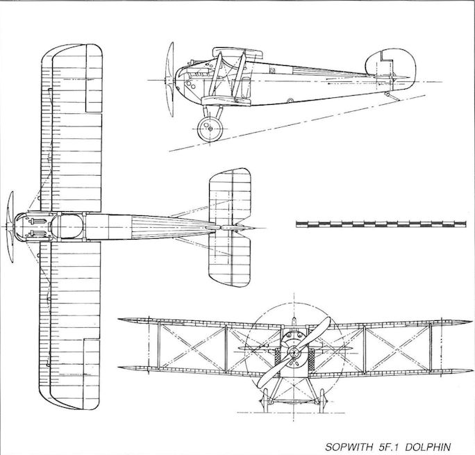
Dolphins of No 87 Squadron. Although the photograph is of indifferent quality, just visible are the Lewis guns mounted on the lower wing of D3775.
Sopwith Hippo
When design of the Sopwith 3F.2 Hippo two-seat fighter began in the summer of 1917 it was perfectly obvious that, unless some unforeseen circumstance rendered the Bristol F.2B Fighter fatally flawed in service, no new design stood any chance of being accepted for production within the Bristol’s operational category. On account of new Defence Regulations, introduced in 1917, which forbade the construction of any aeroplane without sanction from the Air Board or Admiralty (to avoid waste of strategic materials), it was necessary to obtain a licence to go ahead with the construction of the Hippo, and Licence No 16 was issued for two such prototypes, X10 and X11.
The purpose, therefore, of the Hippo was to further exploit the concept of attaching the upper and lower wings of a biplane to the top and bottom of a deep fuselage, and locating the pilot and gunner immediately forward and aft of the top wing respectively. Central to this configuration, intended to provide uninterrupted fields of view for the crew in the upper hemisphere, was the rigging of the wings with considerable back stagger - a configuration formerly approached by the single-seat Sopwith Dolphin. In order to avoid using an engine that was in heavy demand, the Hippo employed the big eleven-cylinder 200hp Clerget 11EB rotary.
The first prototype, which may have been X10, was probably flown in December 1917 and featured only three degrees of dihedral on the wings and short, horn-balanced ailerons, a small angular fin and rudder and a rocking-post mounting for the rear Lewis gun. The second example, known to be X11, followed soon after and differed in numerous respects. The dihedral was increased to five degrees (increasing the illusion from some aspects that the wings were swept forward); lengthened, unbalanced ailerons were included, and the fin and rudder enlarged to give a combined outline similar to that of the Camel. A Scarff ring was fitted on the rear cockpit, and the rear fuselage top decking was reduced in depth.
The Hippo underwent official trials in January but, not surprisingly - owing to the relatively low power output of the Clerget engine - it was not accepted for production, and a second licence for a third Hippo, X18, was withdrawn the following month.
Type: Single-engine, two-seat, two-bay biplane fighter.
Manufacturer: The Sopwith Aviation Co Ltd, Kingston-upon-Thames and Brooklands, Surrey.
Powerplant: One 200hp Clerget 11EB eleven-cylinder rotary engine driving two-blade propeller.
Dimensions: Span, 38ft 9in; length, 24ft 6in; height, 9ft 4in; wing area, 340 sq ft.
Weights: Tare, 1,481lb; all-up, 2,590lb.
Performance: Max speed, 115.5 mph at 10,000ft; climb to 10,000ft, 13 min 25 sec; service ceiling, 17,000ft.
Armament: Two synchronized 0.303in Vickers machine guns in nose, forward of pilot’s cockpit, and either one or two double-yoked Lewis guns on rear cockpit.
Prototypes: Two, X10 and X11 (first flown at Brooklands, probably in December 1917). A third prototype, X18, was cancelled. No production.
Sopwith Buffalo
The appalling carnage that had prevailed on the Western Front during the long years of territorial stalemate brought forth the realisation that the effective use of the aeroplane against battlefield targets could well represent the vital extra dimension needed to break the deadlock between the opposing armies. The greatest obstacle to this use was the huge numbers of soldiers packed into the trenches, who could put up a veritable curtain of small-arms fire against marauding aeroplanes - an obstacle that was to persist in air warfare as recently as 1991.
Thus were born the ‘trench fighters’, the armoured fighters such as the T.F.1 Camel and the T.F.2 Salamander. To this strictly offensive role was soon added what became known as the ‘contact patrol’ fighter, in effect representing a return to the original purpose of the military aeroplane, that of tactical reconnaissance. In later years this specialist aircraft would become known simply as the reconnaissance fighter.
In September 1918 appeared the Sopwith Buffalo, designed with this role in mind. Unlike the Salamander, which was strictly a single-seat ground attack fighter, the Buffalo carried an observer/gunner, and was therefore one step closer to the Bristol Fighter.
Powered by a 230hp Bentley B.R.2 rotary engine, the Buffalo was of fairly orthodox configuration with two-bay, forward-staggered wings, and flying surfaces of typical Sopwith outline; plain ailerons were fitted on all wings. The first of two officially-sponsored prototypes, ordered in July 1918, H5892, was heavily armoured aft as far as the rear of the gunner’s cockpit, and featured rather crude-looking fairings to provide the transition from the engine’s circular section to the flat-sided centre and rear fuselage.
The second aircraft appeared late in October with the side armour extended further aft of the rear cockpit, cutaway trailing edge of the lower wing roots, and with much tidier side fairings. The second example also carried a Scarff ring for the Lewis gun on the gunner’s cockpit in place of the rocking-pillar mounting of the first aircraft. To support the weight of armour while on the ground, the undercarriage was considerably strengthened, as were the inboard wing sections. Not surprisingly the Sopwith Buffalo was not as fast nor manoeuvrable as its elder kin.
The first prototype was sent to France and arrived at Marquise on 20 October 1918 for operational trials, but these had not been completed when the Armistice was signed. The second prototype underwent official trials during November and December at Martlesham Heath but, with rapidly dwindling operational responsibilities, the RAF did not adopt the aircraft for service.
Type: Single-engine, two-seat, two-bay biplane contact patrol fighter.
Manufacturer: The Sopwith Aviation Co Ltd, Kingston-upon-Thames and Brooklands, Surrey.
Powerplant: One 230hp Bentley B.R.2 rotary engine driving two-blade Lang propeller.
Dimensions: Span, 34ft 6in; length, 23ft 3 1/2 in; height, 9ft 6in; wing area, 326 sq ft.
Weights: Tare, 2,178lb; all-up, 3,071lb.
Performance: Max speed, 114 mph at 1,000ft; climb to 3,000ft, 4 min 55 sec; service ceiling, 9,000ft.
Armament: One synchronized 0.303in Vickers machine gun on nose decking, and one Lewis gun on rear cockpit (with Scarff ring on second aircraft).
Prototypes: Two, H5892 and H5893 (H5892 first flown on 19 September 1918, and H5893 in October 1918). No production.

The second Buffalo trench fighter, H5893, showing the fuselage side armour extended aft beyond the gunner’s cockpit together with the rear Scarff gun ring.
Sopwith 2FR.2 Bulldog
Design of the Sopwith FR.2 started in August 1917, soon after the licensing regulations came into effect, and the Sopwith company was issued with Licence No 2 to build four prototypes, X2- X5. The aircraft was intended as an ultimate replacement for the Bristol F.2B Fighter and, as the designation implied, was to be a reconnaissance fighter. As originally designed, the private venture two-seat FR.2 was to be powered by the 200hp Hispano-Suiza but, as the delivery of these engines fell further and further behind schedule, Herbert Smith changed the design to take the eleven-cylinder 200hp Clerget rotary, and this was re-termed the 2FR.2 Bulldog Mk I.
The first prototype, assumed to be X2 (though the aircraft may not have carried the number), appeared early in 1918 with single-bay wings. The pilot’s cockpit was located squarely beneath the upper wing centre section which featured a large central aperture through which the pilot’s head protruded; immediately forward of this cockpit, in a prominent hump, were mounted the twin Vickers guns with most of their barrel length exposed. The observer/gunner’s large cockpit was situated below and aft of the upper wing’s trailing edge and was provided with a pair of Lewis guns, the forward weapon on a telescopic mounting, the other gun in the rear of the cockpit on a swinging pillar to protect the aircraft’s tail. The upper and lower wings were fitted with plain ailerons, and the fin and rudder were similar to those fitted on the modified Sopwith Dolphin.
The single-bay wings were quickly found to be much too small, and a second aircraft (later marked X3) was quickly produced with much enlarged two-bay wings, being initially fitted with horn-balanced ailerons. In due course these were changed to plain ailerons, and in this form X3 underwent official trials in May 1918. However, its performance was generally disappointing, even though the aircraft was applauded on several counts, not least the crew members’ field of view. With a top speed of only 109 mph at 10,000 feet and a service ceiling of no more than 15,000 feet, the Bulldog fell short of the Bristol Fighter - which it was intended to replace.
The third prototype, X4 (designated the Bulldog Mk II) with the 360hp ABC Dragonfly IA nine-cylinder radial engine, and which started its official trials the following month, was compromised from the start by its engine. No armament was fitted and the rear cockpit reduced in size with a close coaming; the secondary structure was removed from the wing centre section, the carry-through members being plain steel tubes attached to the inner ends of the wing spars. In other respects X4 was similar to X3, but neither was awarded a production contract, and it is believed that X5 was not completed.
Type: Single-engine, two-seat, single- and two-bay biplane reconnaissance fighters.
Manufacturer: The Sopwith Aviation Co Ltd, Kingston-upon-Thames and Brooklands, Surrey.
Powerplant: Mark I. One 200hp Clerget eleven-cylinder rotary engine. Mark II. One 360hp ABC Dragonfly IA nine-cylinder air-cooled radial engine.
Dimensions: Two-bay wings. Span, 33ft 9in; length (Mark I), 23ft 0in; height, 8ft 9in; wing area, 335 sq ft.
Weights: Mark I, two-bay wings. Tare, 1,441lb; all-up, 2,495lb.
Performance: Mark I, two-bay wings. Max speed, 109 mph at 10,000ft; climb to 10,000ft, 15 min 35 sec (Mk II, 9 min 28 sec); service ceiling, 15,000ft.
Armament: Two synchronized 0.303in Vickers machine guns on the nose, forward of the pilot’s cockpit, with 1,200 rounds of ammunition; two Lewis guns on the rear cockpit.
Prototypes: Four ordered, X2-X5. X2 was single-bay Bulldog Mk I; X3 was two-bay Bulldog Mk I; X4 was Bulldog Mk II. X5 was probably not completed. No subsequent production.
Sopwith Dragon
As previously told, the final Sopwith Snipe prototype, B9967, was fitted experimentally with a 320hp ABC Dragonfly I engine, and appeared in the spring of 1918 (possibly, as suggested by J M Bruce, as an insurance against any failure of the Nieuport Nighthawk). In this respect it may be contended, though not strictly accurately, that B9967 was therefore regarded as the Dragon prototype.
Be that as it may, the performance attained by the Dragonfly Snipe was such as to encourage Sopwith to persevere and, in September 1918, a contract was received to build a prototype powered by a new version of the Dragonfly, the 360hp Mark IA. This aircraft, E7990, another modified Snipe, first flew in January 1919, and certainly confirmed an excellent performance. Fitted with plain ailerons and the smooth-contoured fin and rudder, this aircraft attained a top speed of 150 mph at sea level, and a service ceiling of 25,000 feet with full ammunition and fuel.
A production order, signed with Sopwith on 16 October 1918 for 300 Snipes (J3617-J3916), was altered on 21 November to cover a similar number of Dragons. Of these the airframes of about 200 aircraft were completed and delivered into storage to await engines. A few, possibly no more than half a dozen, were taken out of storage at random to have their Dragonfly IA engines fitted. One, J3628, was shipped to America for evaluation, and at least two others were at Farnborough during 1919-20 for engine trials. None reached an RAF squadron.
Type: Single-engine, single-seat, two-bay biplane fighter.
Manufacturer: The Sopwith Aviation Co Ltd, Kingston and Brooklands, Surrey.
Powerplant: One 360hp ABC Dragonfly IA nine-cylinder radial engine.
Dimensions: Span, 31ft 1in; length, 21ft 9in; height, 9ft 6in; wing area, 271 sq ft.
Weights: Tare, 1,405lb; all-up, 2,132lb.
Performance: Max speed, 150 mph at sea level; climb to 10,000ft, 7 min 30 sec; service ceiling, 25,000ft.
Armament: Two synchronized 0.303in Vickers machine guns on upper nose decking.
Prototype: One, E7990 (first flown in January 1919).
Production: Small number of aircraft completed from stored airframes (minimum of six known examples).
Sopwith T.F.2 Salamander
The early formative years of British military aviation were spent largely in developing the aeroplane as a battlefield support element, that is to say a vehicle for reconnaissance over the Western Front in France. It is true that the RNAS contrived some outstanding bombing operations in those early years, sometimes achieving results out of all proportion to the efforts expended, what would in later years be termed strategic operations. In the mid-War years the aeroplane came to be used as a weapon against enemy forces in the field: fighting scouts would be armed with a gun or guns as well as light bombs, yet retain their ability to defend themselves on equal terms against enemy fighters. Such an aeroplane was the F.1 Camel.
The Camel also came to be developed into what was known as a ‘trench fighter’, an aircraft whose principal role was to attack battlefield targets, and which carried armour protection against small arms fire from the ground.
That the T.F.1 Camel was regarded as no more than an interim expedient is, however, emphasised by the fact that, when the first example was sent to France for operational trials on 7 March 1918, a purpose-designed trench fighter, the T.F.2 Salamander, was already coming into being.
In January that year Sopwith had been asked to produce an aircraft to meet BEF Specification No 2, with performance superior to that of the T.F.1 Camel. It was therefore not unnatural that the new aircraft would be related to the Snipe rather than the Camel, and this is borne out by the speed with which new prototypes were built. Assembly of the first three of six prototypes (E5429-E5434) began at the end of January; the first was delivered to Brooklands for final assembly on 26 April, made its maiden flight the next day, and was flown to France on 9 May for operational trials - by which time three other prototypes had been flown. At the end of June, when the third aircraft, E5431, underwent Service evaluation, an order for 500 aircraft was placed with Sopwith; later orders for 600 Salamanders, placed with other manufacturers were either reduced or cancelled at the end of the War.
Like the Snipe, the Salamander was powered by a 230hp Bentley B.R.2 rotary and featured two-bay wings. The same plain ailerons and small tail surfaces as those on early Snipes were fitted, although these underwent modifications in step with the Snipe. Unlike the Snipe, however, the Salamander featured a flat-sided fuselage, while the entire front fuselage was constructed in armour plate, weighing no less than 650 pounds. Armament remained the nose-mounted pair of Vickers guns, but with ammunition increased from 1,500 to 2,000 rounds. (Various other armament schemes were flown experimentally, and at least one Salamander was armed with a battery of eight Lewis guns, all mounted to fire downwards.)
Production of Salamanders was accelerating rapidly when the Armistice was signed, but only two were in France at that time. One of these had been delivered to No 86 Squadron at Phalempin, a squadron that had been declared a ‘trench fighting unit’; a week later this order was rescinded. Two other Squadrons in England, Nos 95 at Wyton and 157 at Upper Heyford, had also been declared as ground attack squadrons, and between them took five Salamanders on charge before further deliveries were suspended.
A total of 210 Salamanders had been delivered into storage when production at Sopwith and Glendower was halted in 1919. One production aircraft, F6533, was sent to the United States for evaluation at McCook Field.
Type: Single-engine, single-seat, two-bay biplane trench fighter.
Manufacturers: The Sopwith Aviation Co Ltd, Kingston-upon-Thames, Surrey; The Glendower Aircraft Co Ltd, London.
Specification: British Expeditionary Force Specification No 2 of 1917.
Powerplant: One 230hp Bentley B.R.2 rotary engine driving two-blade propeller.
Dimensions: (Production) Span, 31ft 2 5/8 in; length, 19ft 6in; height, 9ft 4in; wing area, 272 sq. ft.
Weights: (Production) Tare, 1,844lb; all-up, 2,512lb.
Performance: (Production) Max speed, 125 mph at sea level; climb to 10,000ft, 17 min 5 sec; service ceiling, 13,000ft; endurance, 1 1/2 hr.
Armament: Standard armament was two synchronized 0.303in Vickers machine guns on nose with 1,000 rounds per gun.
Prototype: Six, E5429-E5434 (E5429 was first flown on 27 April 1918)
Production: Total of 1,100 Salamanders ordered. (Sopwith, 500, F6501-F7000; Glendower, 100: J5892-J5991; Palladium Autocars, 100: J5992-J6091; No 3 National Aircraft Factory, 400: J6092-J6491). Only 210 aircraft were completed (Sopwith, 160: F6501-F6660; Glendower, 50: J5892-J5941); remainder cancelled.
Summary of Service: Salamanders were delivered to No 86 Squadron in France, and to Nos 95 and 157 Squadrons in the United Kingdom, but these units did not become operational on them.
Sopwith Swallow
The little Sopwith Swallow monoplane fighter was a direct development of the Scooter, a company venture which appeared in June 1918 and employed a Camel fuselage with a parasol wing mounted above but very close to the fuselage, braced with Raf-wires to a pyramidal cabane above the wing and to the lower longerons below. Powered by a 130hp Clerget, it was frequently flown by Harry Hawker for personal transport and as an aerobatic mount.
The Swallow flew in October, again using a Camel fuselage but retaining the twin Vickers guns and powered by a 110hp Le Rhone. The wing was located rather higher above the fuselage to enable the pilot to attend to his guns.
Only one Swallow was built, B9276, and this underwent official trials in May 1919, but displayed no improvement over the Camel. That the Swallow was in any way influenced by the appearance in the summer of 1918 of the German Fokker D VIII parasol monoplane is unlikely, yet the dimensions and weights were extraordinarily similar. However, employing a cantilever wing and the minimum of attachment struts, the German aeroplane was some 15 mph faster on the same nominal power.
Type: Single-engine, single-seat, parasol monoplane fighter.
Manufacturer: The Sopwith Aviation Co Ltd, Brooklands, Surrey.
Powerplant: One 110hp Le Rhone rotary engine driving two-blade propeller.
Dimensions: Span, 28ft 10in; length, 18ft 9in; wing area, 162 sq ft.
Weights: Tare, 889lb; all-up, 1,420lb.
Performance: Max speed, approx 122 mph at sea level; climb to 10,000ft, 9 min 55 sec; ceiling, 18,500ft.
Armament: Two synchronized 0.303in Vickers machine guns on upper decking of nose.
Prototype: One, B9276; first flown in October 1918.
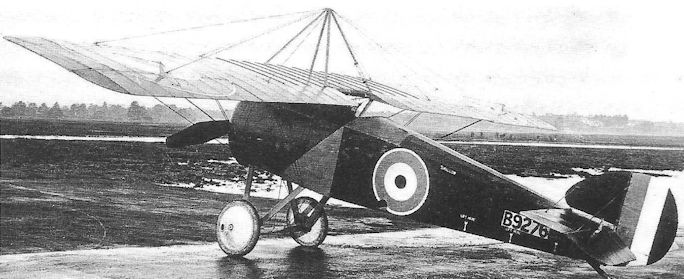
Although the Swallow was first delivered to Martlesham Heath, as shown here, in October 1918, its official tests were not completed until the following May.
Sopwith 8F.1 Snail
Origins of the Sopwith Snail go back to October 1917 when Herbert Smith was managing the design of a small fighter, to be powered by the new ABC Wasp radial engine and intended for submission to meet the Air Board Specification A.1A. As originally designed, this aeroplane, the 8F.1, was to be constructed on strictly conventional lines, that is wooden box-girder fuselage, faired to oval section, although Smith called on a number of successful features from recent Sopwith designs - concentration of principal masses in the nose of the Camel, the benefits of back-staggered wings and forward location of the cockpit prominent among them. Indeed the 8F.1 was smaller than the Camel, though not strictly a light fighter in the accepted sense.
Six 8F.1 prototypes, C4284-C4289, were ordered on 31 October, but on 23 November the Air Board asked that the last two aircraft be designed around a monocoque fuselage. As the first of the monocoque aircraft began to take shape early in 1918, it earned the company nickname Snail, presumably on account of its shell-like fuselage, and this name was adopted officially when the new regulations regarding the naming of aircraft were issued. Thus the monocoque aircraft logically became the Snail Mark I, and the fabric-covered prototype the Mark II.
It was the Mk II which appeared first in April, being easily identifiable by the back stagger on the wings; the top wing was so rigged as to lie directly over the cockpit with the result that a large cutout was necessary in order for the pilot’s head to protrude above the upper surface. The Mark I was completed before the end of the same month and featured normal forward-staggered wings which resulted in the cockpit being below the wing’s trailing edge, which was also cut away.
Both aircraft featured an exceptionally neat installation of the two Vickers guns low in the sides of the nose and almost totally enclosed within the fuselage. The monocoque fuselage was built up with ply skin over circular formers with wooden stringers.
Although the aircraft both returned fairly good performance figures, their handling was severely criticised as demonstrating the vicissitudes of the Camel to an extreme, but with added difficulties at low speeds. Be that as it may, once again the general unreliability of the Wasp engine brought about the end of Snail development, and only one example of each version was completed.
Type: Single-engine, single-seat, single-bay biplane fighter.
Manufacturer: The Sopwith Aviation Co Ltd, Kingston-upon-Thames and Brooklands, Surrey.
Air Board Specification: A.1A of 1917.
Powerplant: One 170hp ABC Wasp seven-cylinder radial engine.
Structure: Mk I. Wooden monocoque fuselage. Mk II. Wooden box-girder fuselage with fabric covering.
Dimensions: Span, 25ft 9in; length, 18ft 8in; height, 8ft 3in; wing area, 250 sq ft.
Weight: All-up, 1,478lb.
Performance: Max speed, 127 mph at sea level; climb to 10,000ft, 7 min 58 sec.
Armament: Two synchronized 0.303in Vickers machine guns in the sides of the nose.
Prototypes: Six ordered, C4284-C4289; only C4284 (Mk II, first flown, April 1918) and C4288 (Mk I, first flown, May 1918) completed; the other aircraft cancelled. No production.
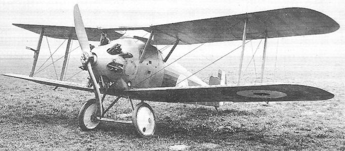
Paradoxically the Snail Mk II, C4284, was the first to fly. The unusual appearance of the centre section struts was caused by the mounting of the guns on the upper longerons, resulting in the forward struts being anchored to the lower longerons.
Sopwith Snark
Although ostensibly designed to RAF Specification Type 1 of 1918, the Sopwith Snark appears to have been a sincere though experimental attempt to carry aloft a much larger forward-firing armament than had hitherto been the norm, and to obtain the necessary lift from a relatively compact airframe Herbert Smith returned once more to the triplane formula.
Bearing in mind that design of the Snark started at roughly the same time that No 87 Squadron began flying its Dolphins with Lewis guns mounted under their lower wings, it is not inconceivable that this idea was in some way associated with the decision taken to fit Lewis guns beneath the lower wings of the new triplane, and four such guns were thus included - in addition to the customary pair of synchronized Vickers guns.
The Snark, of which three prototypes were produced, displayed several interesting features, not least being the monocoque fuselage. The rigging of the wings was unusual in that the stagger was much greater between the centre and lower wings than above, giving the appearance of ‘bent’ interplane struts; the centre section pedestal struts mounting the centre wing on the upper longerons were rigged vertically in front and side elevations, but those attached to the top wing were raked forwards and outwards. The centre wing featured a small trailing-edge cutout above the cockpit, that in the top wing being much more generous.
The airframe of the first prototype was completed in October 1918, but awaited its engine, originally intended to be a 320hp Dragonfly I. However the decision to redesign much of this engine led to a delay, and the extensively modified 360hp Mark IA was not forthcoming until the following March. A further engine change delayed the first flight until July, by which time the other two prototypes had also been completed. The last aircraft, F4070, displayed a much cleaned-up engine cowling, with a large spinner enclosing the propeller hub.
Despite the triplane configuration the Snark possessed a creditable top speed of 130 mph at sea level when flown at Martlesham Heath on official trials in 1921, though it is not clear whether guns or ballast were being carried. It was generally liked by its pilots although its manoeuvrability could not match that of the little Sopwith Triplane of 1916. The inevitable problems of the Dragonfly engine proved to be little more than academic as the Snark was never seriously considered as likely Service equipment.
Type: Single-engine, single-seat, single-bay experimental triplane fighter.
Manufacturer: The Sopwith Aviation Co Ltd, Kingston and Brooklands, Surrey.
Air Ministry Specification: RAF Type I of 1918.
Powerplant: One 360hp ABC Dragonfly IA nine-cylinder radial engine.
Dimensions: Span, 26ft 6in; length, 20ft 9in; height, 10ft 1in; wing area, 322 sq ft.
Weight: All-up, 2,283lb.
Performance: Max speed, 130 mph at sea level.
Armament: Two synchronized 0.303in Vickers machine guns in nose cowling, and four free-firing Lewis guns under the lower wings, each with one 97-round drum.
Prototypes: Three, F4068-F4070 (first flight by F4068, July 1919). No production.
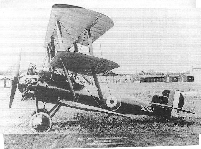
The first Sopwith Snark prototype, F4068. This photograph was taken in September 1918, before the airframe had been cleared for flight and with a non-flight engine installed; it was to be another ten months before a Dragonfly engine, acceptable for flight, was finally installed. Note the early form of engine cowling; on the final prototype this was improved by the addition of a spinner. Ailerons were fitted on all six wings.
The first Snark, F4068, complete - except perhaps for the Lewis guns, attachments for which are nevertheless visible. The maker's photograph number is S.1079, the machine is identified as "No.1 Snark Triplane - 360 hp A.B.C. Engine' and the date is September 1919.
The first Snark, F4068, complete - except perhaps for the Lewis guns, attachments for which are nevertheless visible. The maker's photograph number is S.1079, the machine is identified as "No.1 Snark Triplane - 360 hp A.B.C. Engine' and the date is September 1919.
Sopwith Snipe
The opinion, frequently expressed, that the Sopwith Snipe was ‘the best British fighter’ to be produced during the First World War, needs careful qualification. It was certainly the most highly developed Sopwith fighter to reach combat status before the Armistice. It did not, however, possess the best performance among British fighters in service at that time, although it inherited the superb manoeuvrability of the Camel, the aircraft it was designed to replace. Moreover that manoeuvrability was achieved with more tolerance of control mishandling than was the case in the Camel.
The extravagant claims for the Snipe were probably to some extent made on account of the isolated instances of outstanding combat success - not least that in which Maj W G Barker won the Victoria Cross only fifteen days before the Armistice. Furthermore, the fact that the decision to adopt the Snipe as the RAF’s standard single-seat fighter during the years immediately following the coming of peace suggested that it was the best available. The reasoning that lay behind this decision was that relatively large numbers of Snipes had been stockpiled during the last six months of the War, and that many of the planned manufacturers wished to opt out of the aircraft industry on the coming of peace. Sopwith itself occupied extensive factory space in Kingston and was apparently well staffed to continue with aircraft production in the long term. (It could not be foreseen that, within two years of the War’s end, T O M Sopwith would face crippling tax demands on War Profits and be forced into voluntary liquidation, nor that his pilot and close colleague, Harry Hawker, would step in to save the Canbury Park Road offices and shops with the formation of the H G Hawker Engineering Company. Although Hawker was to lose his life in the same year that his company was formed, that company was to return to the aircraft industry through the revenue earned from repairing and rebuilding Snipes for the RAF in the early 1920s.)
Be that as it may, the Snipe was an excellent and highly adaptable fighter which shouldered a difficult task during the RAF’s transition from war to peace. It should not be forgotten that an extremely high proportion of the RAF’s fighter pilots had served on at least one of Sopwith’s wartime aircraft, and many of these pilots had hopes of being granted commisions in the Service after the War.
The Snipe’s origin lay in the Air Board’s decision to proceed with support for an enlarged version of W O Bentley’s B.R.1 rotary, which had been successfully matched with the Camel. Bentley’s new engine, which retained the aluminium alloy cylinders with steel liners, was increased in bore and stroke, so that its capacity increased from 17.3 to 24.95 litres, in turn producing a power increase to 250hp; more important, the power/weight ratio was considerably improved, rising from 0.375 to 0.526 bhp/lb in the new B.R.2.
The B.R.2 was first bench run in October 1917, and the first of six Sopwith prototypes, B9962, was flown the following month, albeit with a B.R.1 engine. The new aircraft, referred to by Sopwith as the 7F.1 Snipe, was designed to the Air Board’s Specification A.1A, and originally featured single-bay wings and a flat-sided fuselage, as well as a fin and rudder similar to those on the Camel. With a narrow upper wing centre section, the cabane struts were rigged almost vertically. Within a month the first B.R.2 had been delivered and was fitted in the first prototype, which then underwent its preliminary official trials at Martlesham in December.
The second prototype retained the single-bay wings, but the centre section was increased in width; the cabane struts were lengthened and angled slightly outwards from the fuselage. The tail was redesigned with a parallel chord fin and horn-balanced rudder, this shape being retained on the other prototypes and the early production aircraft. The third prototype introduced two-bay wings, this feature being adopted on all subsequent Snipes.
One of the attractive attributes of the Snipe was its comparatively low cost for, compared with the S.E.5A with 200hp Hispano-Suiza engine at a total of £2,067 and the Martinsyde Buzzard at £2,205, the Snipe’s total airframe and engine cost was £1,826, and in March 1918 - when the Snipe was officially declared superior to the other contenders to Specification A.1A - a total of 1,700 Snipes was ordered from Sopwith and six other manufacturers, to be followed soon after by orders for 800 more. Of these, and other Snipes ordered before the end of the War, a total of 2,172 came to be built.
Production of the Snipe was slow to accelerate, principally due to the number of B.R.1 engines still on order, and manufacture was undertaken by Gwynne’s Ltd, Hammersmith, and The Humber Motor Co Ltd, Coventry. Indeed, when the first of the Sopwith-built Snipes began delivery to the RAF, the Service was in no position to introduce the new fighter into widespread use immediately, and growing numbers of fully equipped aircraft began assembling at aircraft parks in Britain.
Such was the ferocity of the German offensive that opened on the Western Front in April 1918 that it was as much as the new RAF could manage to ensure the existing fighter squadrons in France were kept up to strength with their established fighters and with pilots, and it was not until August that No 43 Squadron, commanded by Sqn Ldr C C Miles mc at Fienvillers began receiving Snipes, joining Camels. The next was No 201, which received at least one Snipe during October in France. This aircraft was being flown on the 27th of that month by Maj William George Barker dso* mc** (attached temporarily to the Squadron) when he attacked and shot down a German two-seater from 21,000 feet over the Foret de Mormal. Almost immediately he was attacked by a Fokker D VII and wounded, and was then surrounded by a formation of about fifteen enemy aircraft. Although again wounded, Barker shot one of these down, and forced down two others. He then fainted, and the Snipe fell out of control. Regaining consciousness, he found himself in the midst of another large German formation and, although his left elbow was shattered by a bullet, he shot down another enemy fighter. Now down to 12,000 feet and with smoke coming from his aircraft, Barker decided to ram a D VII, but at the last moment shot it down from a range of about three yards. He dived away and, shaking off yet another enemy formation, just managed to re-cross the lines at a few feet before crashing. Barker survived his wounds to be awarded the Victoria Cross for one of the most remarkable air combats ever fought.
The only other Snipe unit to see combat during the War was No 4 Squadron, Australian Flying Corps. Its aircraft took part in attacks on the German airfield at Rebaix on 30 October and on Enghien on 9 November.
Meanwhile the Snipe had undergone further development. A long-range version, the 7F.1A, intended as an escort fighter for the bombers of the Independent Force, had been produced by fitting an enlarged (50-gallon) fuel tank beneath the pilot’s seat in addition to those forward and aft of the cockpit. These long-range Snipes were being delivered to the RAF when the War ended.
Another interesting version was produced by fitting one of the first examples of the 320hp ABC Dragonfly engine in the last Snipe prototype, B9967, as early as April 1918. Several other aircraft, including E7990 and F7017, were similarly powered, and one underwent trials at Martlesham Heath in October that year, returning a speed of 156 mph at sea level. E7990 became the prototype Sopwith Dragon.
It seems likely that, with hundreds of Snipes at the Aircraft Parks during the last half of 1918, it was intended that the fighter would supersede the Pup, Camel and Beardmore W.B.III with the Royal Navy, and several were with the Grand Fleet at the time of the Armistice; these aircraft were fitted with a hydrovane forward of the undercarriage so as to reduce the risk of overturning in the event of ditching.
Post-War Service
The process of introducing Snipes into service with the RAF continued after the Armistice, Nos 45 and 208 Squadrons in France receiving their first aircraft in November 1918. In England, No 78 (Home Defence) Squadron received a few aircraft, but they did not fully replace the Squadron’s Camels before it was disbanded the following year. Snipes also joined No 81 (Home Defence) Squadron in November for a few weeks. Nos 70 and 80 Squadrons re-equipped with Snipes on the continent during December. These Squadrons, as well as Nos 37 and 143 (Home Defence) Squadrons, flew Snipes for only a few months after the War.
Early in 1920, however, the long term re-equipping with Snipes began in earnest, both at home and overseas. In January that year No 1 Squadron (Sqn Ldr, later Gp Capt John Benjamin Graham MC, AFC) re-formed at Risalpur in India with Snipes which it retained until November 1926, after having moved to Iraq in May 1921. Also in January 1920 No 56 Squadron (Sqn Ldr Duncan William Grinnell-Milne mc, dfc) reformed at Aboukir in Egypt with Snipes, returning to England with them later.
No 25 Squadron (Sqn Ldr Sir Norman Roderick Alexander Leslie bt, cbe) received Snipes at Hawkinge in February 1920 and held the distinction for many months of being the only homebased fighter squadron in the Royal Air Force; it was to keep its Snipes until September 1924, having taken them to Turkey for a year in September 1922 during the Chanak crisis.
No 3 Squadron re-formed with Snipes at Bangalore in India on 1 April 1920 and, by April 1924 the list of Snipe squadrons in the RAF had grown to ten (Nos 3,17,19, 25, 29, 32, 41, 56 and 111 at home, and No 1 in Iraq).
The Snipe continued in service with four Squadrons until 1926, the last being withdrawn from No 1 when that Squadron disbanded at Hinaidi on 1 November that year.
Immediately following the end of the War large numbers of brand-new Snipes were scrapped. Three years later it became all too obvious that this action had been precipitate, and the inevitable attrition among the remaining aircraft gave rise to the possibility that some squadrons would have to be prematurely disbanded owing to a growing shortage of aircraft. At the instigation of Air Marshal Sir John Salmond kcb, cmg, evo, dso, in 1921 commanding the Inland Area, a halt was called to the deliberate destruction of aircraft (whether in store or damaged in accidents) so that a continuing programme of salvaging and re-building could be undertaken by the Service and at the manufacturers. In due course more than 200 Snipes, which would otherwise have been scrapped, were returned to operational service.
With the arrival of new aircraft, such as the Gloster Grebe and Gamecock in the mid-1920s, no one mourned the passing of the Snipe, stalwart fighter though it had undoubtedly been. With it passed into history the old rotary engine - a relic of the earliest days of aviation - now confined to a dwindling number of Avro 504K trainers. To many members of the British public, the Snipe introduced the spectacle of formation aerobatics, which originated at the 1921 Hendon Pageant when Sqn Ldr Christopher Draper led a display by Snipes of the Central Flying School. It fell to No 17 Squadron to give the farewell display by Snipes in 1926.
Type: Single-engine, single-seat, two-bay biplane fighter.
Manufacturers: The Sopwith Aviation Co Ltd, Kingston-upon-Thames, Surrey; Boulton & Paul Ltd, Norwich; Coventry Ordnance Works Ltd, Coventry; March, Jones & Cribb Ltd, Leeds; The Kingsbury Aviation Co, Kingsbury; D Napier & Son Ltd, Acton, London; Nieuport & General Aircraft Ltd, Cricklewood, London; Portholme Aerodrome Ltd, Huntingdon; and Ruston, Proctor & Co Ltd, Lincoln.
Air Board Specification: A.1A of 1917.
Powerplant: Prototype. One 150hp Bentley B.R.1 rotary. Standard. One 250hp Bentley B.R.2 rotary. Experimental: One 320hp ABC Dragonfly I radial engine.
Structure: All-wooden construction with fabric, ply and sheet metal covering.
Dimensions: Standard production. Span, 31ft 1in; length, 19ft 9in; height, 8ft 9in; wing area, 271 sq ft.
Weights: Tare, 1,312lb; all-up, 2,020lb.
Performance: Standard production. Max speed, 125 mph at sea level, 121 mph at 10,000ft; climb to 10,000ft, 9 min 25 sec; service ceiling, 20,000ft; endurance, 3 hr.
Armament: Two synchronized 0.303in Vickers machine guns on the fuselage forward of the cockpit; up to four 25lb bombs could be carried on racks under the fuselage.
Prototypes: Six, B9962-B9967 (B9962 first flown in November 1917 at Brooklands).
Production: 2,172, excluding prototypes (Sopwith, 683: E7987-E8286, F2333-F2532, F7001-F7030, H4865-H4917 and J3617-J3716; Boulton & Paul, 425: E6137-E6536 and J451- J475; Coventry Ordnance Works, 150: E6537-E6686; Napier, 150: E6787-E6936; Nieuport & General, 100: E6937-E7036; Ruston, Proctor, 524: E7337-E7836 and H351-H374; Portholme, 100: E8307-E8406; March, Jones & Cribb, 10: J681-J690; Kingsbury, 30: J6493- J6522).
Summary of Service: Wartime: Snipes served with Nos 43 and 201 Squadrons, RAF, and No 4 Squadron, Australian Flying Corps in France. Post-War: Snipes served with Nos 43, 45, 70, 80, 201 and 208 Squadrons, RAF, in France, Belgium and Germany between November 1918 and February 1920; with Nos 3, 19, 23, 25, 29, 32, 37, 41, 43, 56, 78, 81, 111 and 143 Squadrons, RAF, in the United Kingdom between November 1918 and May 1926; and with Nos. 1, 3, 25 and 56 Squadrons, RAF, in Turkey, the Middle East and India between January 1920 and November 1926.

The second 7F.1 Snipe prototype, B9963, with single-bay wings and 250hp Bentley B.R.2 rotary engine.
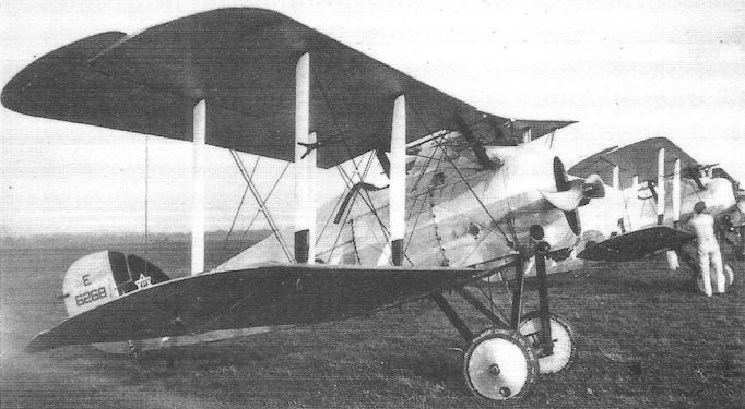
Snipes of No 32 Squadron, at Lympne in 1924. E6268 carried an early version of the Squadron’s unofficial badge on its fin as well as No 32’s blue and white stripe down the fuselage.
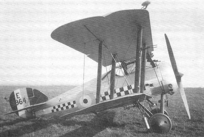
A Nieuport & General-built Snipe of No 56 (Fighter) Squadron with night flying equipment.
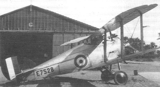
Snipe E7528 of No 25 (Fighter) Squadron deployed to San Stephana in Italy during the Chanak Crisis in 1922.

E8132 was one of the first production batch of Snipes built by Sopwith and is shown here wearing the wartime markings of No 208 Squadron which was based in Germany after the Armistice.
Sopwith Camel
<...>
From the earliest days of the Camel’s service in France the aircraft had been employed as a ground attack aircraft, often carrying light bombs under the fuselage, in addition to its more accustomed role in air-to-air combat, and had frequently suffered heavy losses from ground fire (as did all close support aircraft). Sopwith was accordingly asked to produce a version of the Camel especially for the ‘trench fighting’ role, and in February came up with the T.F.1. An F.1 Camel, B9278 with standard 110hp Le Rhone installed, was prepared featuring armoured protection for the front fuselage, together with a pair of downward-firing Lewis guns between the undercarriage struts in addition to a Lewis gun above the upper wing centre section. The T.F.1 Camel was not put into production, but provided valuable information which led to development of the T.F.2 Salamander - a heavily armed trench fighter that was just reaching France at the time of the Armistice.
<...>
<...>
From the earliest days of the Camel’s service in France the aircraft had been employed as a ground attack aircraft, often carrying light bombs under the fuselage, in addition to its more accustomed role in air-to-air combat, and had frequently suffered heavy losses from ground fire (as did all close support aircraft). Sopwith was accordingly asked to produce a version of the Camel especially for the ‘trench fighting’ role, and in February came up with the T.F.1. An F.1 Camel, B9278 with standard 110hp Le Rhone installed, was prepared featuring armoured protection for the front fuselage, together with a pair of downward-firing Lewis guns between the undercarriage struts in addition to a Lewis gun above the upper wing centre section. The T.F.1 Camel was not put into production, but provided valuable information which led to development of the T.F.2 Salamander - a heavily armed trench fighter that was just reaching France at the time of the Armistice.
<...>
Sopwith Snapper
Last of the Sopwith fighters to fly was the Snapper, enigmatically referred to in some old company records as the R.M.1. Its design started during the spring of 1918, soon after the issue of RAF Specification No I, and seems to have been motivated as an attempt to produce the smallest viable fighter powered by the new 320hp ABC Dragonfly I radial engine, and carrying a normal armament of twin Vickers guns. As originally conceived, the Snapper was intended to have a wooden monocoque fuselage but, in the interests of ease and speed of production, this was abandoned in June 1918, and another start was made, reverting to the time-honoured wooden box-girder structure. The delay was further compounded by a three-month wait while delivery of the more powerful Dragonfly IA was arranged.
The first of three prototypes, F7031-F7033, finally appeared in April 1919. It was a single-bay staggered biplane with the cockpit set well back and with wing trailing-edge cutouts and ailerons on upper and lower wings. The familiar crankcase cowling enclosed much of the Dragonfly engine and was neatly faired into the flat-sided centre and rear fuselage section.
By placing the cockpit well aft, it was possible to mount the front guns, semi-buried in the front decking without need of a humped nose. The now-familiar near-rectangular fin with semi-circular leading edge appeared once again with horn-balanced rudder hinged on the sternpost.
F7031 was first flown at Brooklands in May 1919, and was soon followed by the other two aircraft which featured a re-contoured crankcase cowling which matched the outline of a large spinner with central aperture. One of these aircraft was temporarily admitted to the British Civil Register as K149/G-EAFJ in June for entry by Harry Hawker in that year’s Aerial Derby, but its participation was officially forbidden on the grounds that its engine was still on the Secret List; this was not strictly correct, and a more likely reason was that the Dragonfly IA engine had only been cleared for short flying hours and, in any case, was still technically the property of the Air Ministry.
The first prototype underwent Martlesham trials in September 1919, returning the excellent speed of 140 mph at sea level and 133 mph at 15,000 feet. There is some circumstantial evidence to suggest that the aircraft may have encountered symptoms of wing flutter at this time - though hardly severe enough to endanger the aircraft. Little was known of this phenomenon at that time. The aircraft was returned to Sopwith for some modifications to the wings during October and November, but the nature of these has not been traced. In December the aircraft returned to Martlesham where, it is said, two-bay wings were fitted. The other two Snappers were delivered to the RAE for trials on the Dragonfly engines, and their ultimate fate is not known.
Type: Single-engine, single-seat, single-bay biplane fighter.
Manufacturer: The Sopwith Aviation Co Ltd, Kingston and Brooklands, Surrey.
Air Ministry Specification: RAF Type I Specification of 1918.
Powerplant: One 360hp ABC Dragonfly IA seven-cylinder radial engine.
Dimensions: Span, 28ft 0in; length, 20ft 7in; height, 10ft 0in; wing area, 292 sq ft.
Weights: Tare, 1,462lb; all-up, 2,190lb.
Performance: Max speed, 140 mph at sea level; climb to 10,000ft, 7 min 50 sec; service ceiling, 23,000ft.
Armament: Two synchronized 0.303in Vickers machine guns semi-buried in nose upper decking.
Prototypes: Three, F7031-F7033. (F7031 first flown, May 1919). No production.
Supermarine N.1B Baby
Because progress on the Blackburn N.1B was slow, the Supermarine contender to the same specification was completed and tested before the official requirement was allowed to lapse. Designed by F J Hargreaves, the Baby was of very similar general configuration to that of the Blackburn, but featured a monoplane tail with single tailplane and elevator placed above a single fin and rudder. The hull, also built in mahogany on the Linton-Hope principle, possessed a straight top line, its cross-section being almost circular with a skirted planing bottom. As originally flown, ailerons were only fitted to the upper wings, but were later repeated on the lower wings as well. A small triangular fin was added above the tailplane.
The engine installation, a 200hp Hispano-Suiza pusher engine mounted close under the upper wing centre section, comprised a partly cowled nacelle with flat car-type radiator in front. The front inboard interplane struts were duplicated and located on either side of the wing fold line, thereby maintaining structural rigidity with the wings folded.
First flown in February 1918 by Flight-Lt Goodwin, the Supermarine Baby, N59, well exceeded the performance demanded, returning a sea level top speed of 117 mph; no armament was carried on test, although ballast carried suggested that allowance was being made for a single Vickers gun.
As already stated, the Air Department’s N.1B requirement was abandoned in its original terms, and Supermarine therefore went ahead on its own with development of the Baby, installing a 200hp Sunbeam Arab in place of the Hispano engine. The second and third aircraft, N60 and N61, were not built, but would have also been Arab-powered. N59 underwent official trials in August 1918 with the Arab and, although rather heavier than with the Hispano engine, produced much the same performance figures.
Type: Single pusher engine, single-seat, single-bay biplane flying-boat fighter.
Manufacturer: The Supermarine Aviation Works Ltd, Woolston, Southampton.
Air Department Specification: N.1B of 1917.
Powerplant: One 200hp Hispano-Suiza engine driving four-blade pusher propeller; later one 200hp Sunbeam Arab engine.
Dimensions: Span, 30ft 5 9/16 in; length, 26ft 3 1/2 in; height, 10ft 7in; wing area, 309 sq ft.
Weights: Tare, 1,699 lb; all-up, 2,326lb.
Performance: Max speed, 117 mph at sea level; climb to 10,000ft, 25 min 10 sec; endurance, 3 hr.
Armament: None carried on test, but allowance probably made for a single Vickers machine gun.
Prototypes: Three, N59-N61. Only N59 completed, and first flown in February 1918.
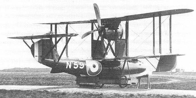
The Supermarine Baby, N59, after being fitted with ailerons on the lower wings, and with the auxiliary fin above the tailplane.
Vickers E.F.B.1 Destroyer
One of the earliest fighting aeroplane requirements, if not the first, issued by the Admiralty after the creation of the Naval Wing of the RFC in 1912, was for a gun-carrying machine whose armament was intended to be used for offensive as distinct from purely defensive purposes. Thus, by implication owing to the inability to fire forward through a tractor propeller, this dictated the pusher biplane configuration.
Vickers, Sons & Maxim Ltd had produced aeroplanes since January 1911, almost all monoplanes, but late the following year Major Archibald Reith Low and George H Challenger set about the design of the first of the famous Gunbus series, the E.F.B.1 (Experimental Fighting Biplane); it was also named the Destroyer, and earned a contract for Vickers early in 1913.
Employing two pairs of steel tail booms attached at their forward ends to the rear spar of the mainplanes and converging to meet at the sternpost, the two-seat aircraft featured generous wing stagger, and the forward raking of the interplane struts was matched by the rake of the tail boom struts, thereby lending the aircraft an air of aggression. The internal structure was of steel tube throughout, the wings being fabric-covered and the nacelle clad in duralumin sheet.
A 60/80hp Wolseley eight-cylinder vee air-cooled engine drove a Vickers-Levasseur two-blade propeller with scimitar-shaped blades. The front cockpit was occupied by the observer who was provided with a 0.303in Vickers-Maxim gun, mounted so as to traverse through 60-degree lateral and vertical arcs.
The E.F.B.1 was displayed at the 1913 Olympia Aero Show, but unfortunately crashed soon afterwards - possibly on its first flight - almost certainly owing to longitudinal instability.
Type: Single pusher engine, two-seat fighting biplane.
Manufacturer: Vickers Ltd, Erith, Kent.
Powerplant: One 60/80hp Wolseley eight-cylinder air-cooled engine driving a four-blade Vickers-Levasseur pusher propeller.
Structure: Fabric-covered, all-metal twin-spar wings with two pairs of steel tubular tail booms. Duralumin sheet-clad, steel-frame nacelle. Skid-and-wheel undercarriage.
Dimensions: Span, 40ft 0in; length, 27ft 6in; height, 11ft 11in; wing area, 380 sq ft.
Weights: Tare, 1,760lb; all-up, 2,660lb.
Performance: Max speed, 70 mph at sea level; initial climb, 450 ft/min; endurance, 4 1/2 hr.
Armament: One 0.303in Vickers-Maxim machine gun in nose of nacelle.
Prototype: One. No production.
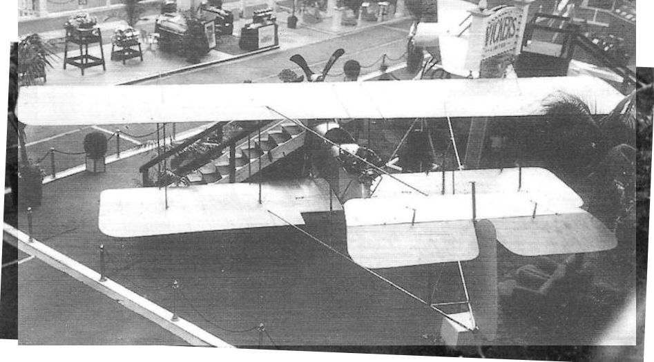
The E.F.B.1 Destroyer on Vickers’ stand at the 1913 Olympia Aero Show. Generous tailplane and elevator areas were characteristic of all the Gunbus designs.
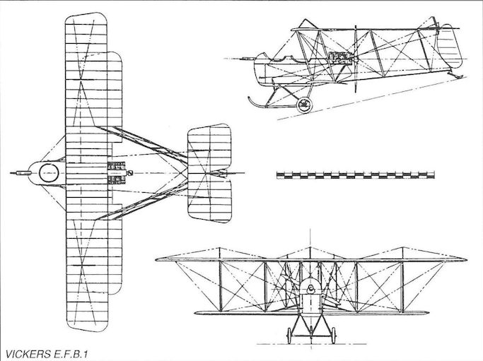
Vickers E.F.B.2
Even before the Vickers E.F.B.1 was lost early in its flight trials, Archibald Low was at work on a new design in a further attempt to meet the Admiralty’s requirement for a gun carrier. Not satisfied with the new Wolseley engine, he now turned to the Gnome monosoupape nine-cylinder rotary, claimed by its manufacturers to develop 100hp. This aeroplane, the E.F.B.2, featured wings of slightly reduced span and overhang, and without stagger, the interplane struts, tail boom struts and stern post all being vertical. The large tailplane was now almost semi-circular in plan, and the single central landing skid gave place to a pair of skids located immediately inboard of the wheels.
An unusual feature was the inclusion of a pair of huge celluloid windows on each side of the nacelle, while the decking immediately forward of each cockpit coaming was also transparent. A trunnion-mounted Vickers-Maxim machine gun, with limited arcs of fire, was incorporated in the extreme nose - but in such a position that prevented accurate aiming.
From all accounts the E.F.B.2 was pleasant to fly, being flown frequently during the second half of 1913 at Brooklands by Capt Herbert F Wood, Vickers’ technical adviser, and by Harold Barnwell, the company’s chief pilot. It was clear, however, that the Gnome monosoupape was not giving anything like its widely advertised power, and the E.F.B.2’s performance was disappointing, failing even to match that of the earlier aircraft. Nevertheless, the aeroplane went a long way in encouraging Low to persevere with the Gunbus formula, backed strongly by Capt Wood.
Type: Single pusher engine, two-seat fighting biplane.
Manufacturer: Vickers Ltd (Aviation Dept), Knightsbridge, London.
Powerplant: One 80hp Gnome monosoupape nine-cylinder air-cooled rotary engine driving two-blade pusher propeller.
Structure: Predominantly steel-tubular construction with fabric-covered wings and tail, and duralumin-covered nacelle; twin skid-and-wheel undercarriage.
Dimensions: Span, 38ft 7in; length, 29ft 2in; height, 9ft 7in; wing area, 380 sq ft.
Weights: Tare, 1,050 lb; all-up, 1,760lb.
Performance: Max speed, 60 mph at sea level; initial climb, 200 ft/min; endurance,2 1/4 hr.
Armament: Single trunnion-mounted 0.303in Vickers-Maxim machine gun in extreme nose of nacelle.
Prototype: One. No production.
Vickers E.F.B.3
Third and last of Archibald Low’s Gunbus designs for Vickers was the E.F.B.3 (or Vickers Type 18B), displayed at the Fifth Olympia Aero Show on 16 March 1914. Convinced that with only minor improvements in the E.F.B.2 his new design would secure a production order from the War Office (for the Admiralty appeared to be showing preference for Sopwith and Short gun carriers), Low determined to improve the efficiency of the upper wing by eliminating the trailing edge cut-out. This necessitated moving the engine aft by about nine inches to allow clearance for the propeller; in order to counteract the shift of c.g., this in turn required moving the crew correspondingly forward.
The transparent panels in the sides of the E.F.B.2’s nacelle were discarded as largely superfluous; steel structural components were used throughout (except for wing and tail surfaces); and the ailerons on top and bottom wings were interconnected by steel struts, replacing wing warping.
Other features of the E.F.B.2 were retained, including the trunnion-mounted front gun and identical tailplane and rudder; yet, despite the alterations to the nacelle, the E.F.B.3 was marginally shorter and lighter than its predecessor. It was therefore difficult to reconcile that the speed performance was not noticeably better. In the course of flight trials a new vertical tail surface was fitted, comprising a fixed triangular fin forward of the sternpost and a revised rudder.
Notwithstanding the Admiralty’s interest elsewhere, twelve production E.F.B.3s were ordered, but before they were completed they were taken over by the War Office, and an extensive redesign undertaken - which emerged as the E.F.B.5. Although the unofficial name Gunbus had been in use for some months in the Vickers works, it was now formally adopted, despite the fact that Sopwith (also using the Brooklands flying field) was using the same name for that company’s similar aircraft.
Type: Single pusher engine, two-seat, two-bay fighting biplane.
Manufacturer: Vickers Ltd (Aviation Dept), Knightsbridge, London.
Powerplant: One 100hp Gnome monosoupape nine-cylinder air-cooled rotary engine driving two-blade pusher propeller.
Structure: All-steel structure with metal-clad nacelle; fabric-covered wings and tail surfaces. Twin wheel-and-skid landing gear.
Dimensions: Span, 37ft 4in; length, 27ft 6in; height, 9ft 9in; wing area, 385 sq ft.
Weights: Tare, 1,050lb; all-up, 1,680lb.
Performance: Max speed, 60 mph at sea level; climb, 300 ft/min: range, 300 miles.
Armament: One 0.303in Vickers machine gun on trunnion mounting in the nose of the nacelle.
Prototype and Production: One prototype which circumstantial evidence suggests later became the prototype E.F.B. 5, with serial number 32; twelve aircraft, Nos. 861-872, were ordered by the Admiralty, but taken over by the War Office before completion, probably as F.B.5s.
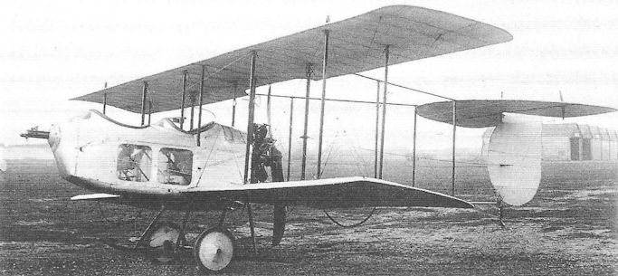
E.F.B.2 with Vickers machine-gun in trunnion mounting and clear-view side panels at Brooklands in 1912.
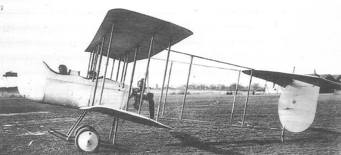
The Vickers E.F.B.3 at Brooklands in 1914.
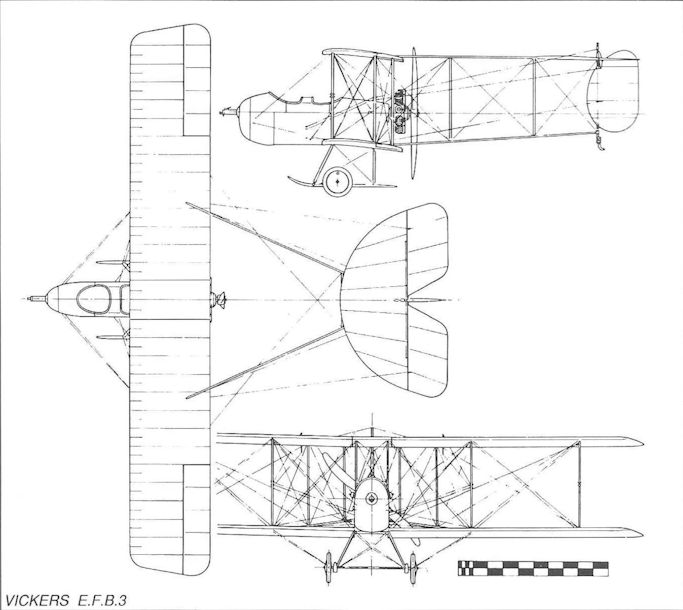
Vickers Type 18B E.F.B.3
Vickers F.B.5 Gunbus
Although the evolution of the initial production version of the Vickers F.B.5 Gunbus has been shown to have followed a natural progression by means of the E.F.B. series of experimental designs, a number of complicating design considerations were necessarily introduced as the reality of production approached. Not unnaturally the manufacturers were at pains in overcoming these complications not to compromise the aircraft’s excellent handling characteristics which had, after all, attracted both the Admiralty and War Office.
To begin with the gun mountings that had appeared in the E.F.B.2 and 3 were clearly unsatisfactory and tended to suggest that Vickers’ own machine gun was not suitable for this class of gun carrier owing to the untidy belt-fed arrangement and the difficulty of aiming the trunnion-mounted gun. Accordingly a new experimental design appeared (the E.F.B.4) in which a drum-fed Lewis gun was to be mounted on a spigot immediately forward of the gunner’s cockpit. While this was regarded as an acceptable compromise, diehard opponents pointed to the necessity to change drums frequently owing to their 97-round capacity. It also led to substantial redesign of the Gunbus nose, and required the gunner to stand exposed while aiming and firing the gun.
Other production considerations had to be faced, and extensive changes in the wing and tail planforms were adopted in the interests of simpler and quicker manufacture. The wing chord was increased and given square tips, while the familiar semi-circular tailplane was replaced by a huge rectangular surface; the rudder was also increased in area.
As already stated, a production order for twelve E.F.B.3s had been placed by the Admiralty in 1914, but these were taken over by the War Office at the outbreak of war, and the original E.F.B.3 is believed to have undergone progressive modification to become the E.F.B.5, or prototype F.B.5, but retained the curved tailplane leading edge.
Convinced that war was imminent, and that the Gunbus would be demanded in substantial numbers, Major Wood recommended that Vickers should begin manufacturing fifty production aircraft without waiting for Service contracts. These were in due course covered by three orders, covering 46 aircraft for the RFC, and two orders covering four Admiralty aircraft. Two of the latter were delivered early in 1915 with 150hp Smith engines.
The Gunbus first flew against the Germans when, on Christmas Day 1914, a German seaplane flew up the Thames Estuary towards London. An F.B.5 took off from Joyce Green but failed to engage, partly due to a faltering engine. The first of the Vickers aircraft to go to France arrived on 5 February 1915 but, such was the infancy of military aviation, squadrons were not yet specialists in any recognised air fighting role, and each possessed a variety of different aircraft, and none was initially wholly equipped with F.B.5s. Those that did possess examples in those early months in France were Nos 5 and 16 Squadrons.
At home, however, the RFC had begun to recognise the need to establish squadrons equipped with aircraft armed with an in-built gun, capable of defending itself without recourse to hand-held small arms. The Gunbus, relatively simple to fly, fairly manoeuvrable, and available in fast growing numbers, was an obvious choice to equip the first specialist fighting scout squadron and, on 11 July, No 11 Squadron (commanded by Maj George William Patrick Dawes, later DSO, afc) arrived in France with a full complement of F.B.5s.
Despite its very modest performance, and the appearance of the early Fokker monoplanes - with their synchronized front gun - the Gunbus acquitted itself well, particularly against enemy aircraft of its own vintage. It was on 7 November 1915 that 2/Lieut Gilbert Stuart Martin Insall of No 11 Squadron won the Victoria Cross for an action involving the destruction of an Aviatik. Having forced the enemy aircraft down he then dropped an incendiary bomb on it. His own aircraft was then damaged by ground fire and was forced to land in the French lines. The following night, despite coming under enemy artillery fire, Insall and his observer repaired the Gunbus and at first light flew it back to their own airfield.
With the increasing ascendancy of German fighting scouts late in 1915, the Gunbus became hopelessly outclassed, but the F.B.5 soldiered on for a further six months until replaced by new Allied fighters. No 11 Squadron received its first Nieuport 13s in March 1916, but did not give up its F.B.5s until July. All told, Gunbuses equipped eight RFC squadrons, of which Nos 2, 5, 7, 11, 16 and 18 flew them in France.
A variant of the Gunbus was the F.B.5A, of which four examples were produced. These possessed armoured nacelles and were powered by 110hp Clerget engines but, being as yet relatively untried, these engines gave trouble and this version was not pursued further.
Unfortunately no accurate figures for total production of the Gunbus have been traced, and it is believed that the number was around 210; rather higher figures, sometimes quoted, are thought to have been confused by inclusion of aircraft withdrawn from France to join training squadrons, and therefore duplicated.
Type: Single pusher engine, two-seat, two-bay fighting biplane.
Manufacturer: Vickers Ltd (Aviation Dept), Knightsbridge, London.
Powerplant: One 100hp Gnome monosoupape engine driving two-blade pusher propeller;also 110hp Clerget (F.B.5A); 150hp Smith Static.
Structure: Steel tubular structure with fabric covering; twin wheel and twin skid undercarriage.
Dimensions: Span, 36ft 6in; length, 27ft 2in; height, 11ft 0in; wing area, 382 sq ft.
Weights: Tare, 1,220lb; all-up, 2,050lb.
Performance: Max speed, 73 mph at sea level; climb to 5,000ft, 16 min; endurance, 4 1/2 hr.
Armament: One 0.303in Lewis machine gun on spigot mounting in front of observer’s cockpit.
Prototype and Production: One prototype, No 32. Known production aircraft: Nos 648, 664, 681 (3); Nos 861-872 (12); 1534-1535 (2); 1615-1651 (36); 2338-2347 (10); 2865- 2868 (4); 2870-2883 (14); 3595-3606 (12); 4736 (1); 5074-5075, 5078-5079, 5083-5084, 5454-5503 (56, built by Darracq), 5618-5623 (6); 5649-5692 (44); 5729 (1), 7510-7519 (10, possibly not all completed).
Summary of Service: F.B.Ss served with Nos. 2, 5, 7, 10 (Reserve), 11, 16, 18 and 24 Squadrons, RFC; No 1 Squadron, RNAS. One aircraft to the Middle East in 1917.

A production Vickers F.B.5 Gunbus. Note the spigot mounting on the nose for a Lewis gun.
Vickers E.F.B.6 and F.B.9
The efforts to extend the successful F.B.5 Gunbus formula, as has been shown, brought forth the twin-engine F.B.7 and F.B.8, which appeared too late to warrant further work on them. Another design, the Vickers E.F.B.6, was less radical in that it retained the basic F.B.5 single pusher engine format. It did however adopt the upper wing’s greatly increased span with large overhang that characterised Flanders’ F.B.7, in an effort to increase the F.B.5’s load-carrying ability. Like the F.B.7, however, this aeroplane was blighted by the plethora of struts and bracing wires necessary for this wing configuration, and its poor performance on only a single engine resulted in the aircraft’s further development being abandoned.
Instead efforts focussed on generally cleaning up the F.B.5 itself, and in December 1915 the prototype F.B.9 was first flown.
<...>
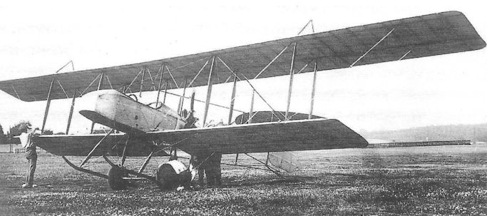
The sole Vickers E.F.B.6 at Brooklands.
Vickers F.B. 7
Designed under contract to Vickers Ltd by R L Howard Flanders (founder of a pioneering aircraft company which carried his name at Brooklands) and generally regarded as the first British twin-engine ‘fighter’, the Vickers F.B.7 was more accurately a gun-carrier, in the same context as the earlier Gunbus series. It was of most ungainly appearance, possessing large wing gap without stagger, but with considerable top wing overhang. This, and the mounting of rotary engines within the wing gap, resulted in a veritable maze of struts and bracing wires.
Designed to mount a one-pounder Vickers gun on the observer’s nose cockpit, the fuselage was of rectangular section at the forward end, fairing to inverted triangular section aft of the pilot’s cockpit below the trailing edge of the upper wing. The twin-wheel undercarriage possessed very wide track and a central skid. Twin kingposts extended above the upper wings in the plane of the outer interplane struts, supporting cable-bracing for the outer sections of the wing. There was no dihedral on upper and lower wing except on the overhang sections of the upper wing. Ailerons were only fitted on the upper wings and there was no fixed tail fin forward of the balanced rudder.
The prototype F.B.7 was powered by uncowled 100hp Gnome monosoupape handed rotaries, but these were enclosed in cowled nacelles soon after its first flight in August 1915. When, however, the War Office ordered a dozen aircraft it was found that these engines were in short supply and the production version, termed the F.B.7A, was to be powered by a pair of 80hp Renault V-eight engines - permitting a small reduction in the number of struts. Only one F.B.7A, which also featured a redesigned fuselage with the pilot’s cockpit moved forward of the wings, was completed, only to be discovered that the aircraft had suffered a substantial loss of performance due to the reduction in available power. Vickers, therefore, sought and obtained cancellation of the production contract.
Type: Twin-engine, two-seat, two-bay tractor biplane gun-carrier.
Manufacturer: Vickers Ltd (Aviation Department), Knightsbridge, London.
Powerplant: F.B.7. Two 100hp Gnome monosoupape handed rotary engines. F.B.7A. Two 80hp Renault V-eight engines.
Structure: Steel tubular construction throughout with ply and fabric covering.
Dimensions: Span, 59ft 6in; length, 36ft 0in; wing area, 640 sq ft.
Weights: (F.B.7). Tare, 2,136lb; all-up, 3,196lb.
Performance: (F.B.7). Max speed, 75 mph at 5,000ft; climb to 5,000ft, 18 min; endurance, 2 1/2 hr.
Armament: Single one-pounder Vickers quick-firing gun in nose.
Prototypes: One F.B.7 (flown in August 1915); one F.B.7A, No 5717. No production.
Vickers F.B.8
Whereas Vickers’ F.B.7 had been designed by Howard Flanders, the company’s second essay in twin-engine fighter design was undertaken by Reginald Kirshaw (‘Rex’) Pierson during the autumn of 1915, and the single example was flown that November. Compared to the F.B.7, Pierson’s aircraft was of extraordinarily compact design, its wing span being over 20 feet shorter and its all-up weight some 500lb less. Powered by the same 100hp Gnome monosoupape handed rotaries as the earlier aircraft, the F.B.8 was accordingly about 20 mph faster; these engines were encircled by oil slinger rings.
The wings of the F.B.8, being of only slightly unequal span, featured no significant overhang, so that untidy kingpost-supported bracing was superfluous and the strut arrangement was altogether tidier; ailerons were fitted to both upper and lower wings. The undercarriage and tail unit, however, remained much the same. The big one-pounder Vickers gun was discarded in favour of a Lewis gun on a spigot mounting forward of the observer-gunner’s bow position.
It is perhaps strange, however, that Pierson persisted in locating the pilot’s cockpit in the same position as in the original F.B.7 (under the trailing edge of the upper wing); the earlier design had been criticised on account of the distance between the two crew members, and communication between them would have been almost impossible during operational flying, and was much reduced in the F.B.7A.
Other than this assumed flaw, the F.B.8 was an ingenious and promising design which might have attracted official interest had not the introduction into single-engine tractor scouts of front gun interrupter gears not been imminent. Even so, as will be evident, Vickers persisted with pusher designs employing free-firing bow guns for some years. Pierson, on the other hand, was to call on his experience with the F.B.8 to produce his famous, much larger F.B.27 Vimy heavy bomber just two years later - an aircraft that bore more than a superficial resemblance to his twin-engine fighter.
Type: Twin engine, two-seat, two-bay tractor biplane gun carrier.
Manufacturer: Vickers Ltd (Aviation Department), Knightsbridge, London.
Powerplant: Two 100hp Gnome monosoupape nine-cylinder handed rotary engines driving two-blade propellers.
Structure: Steel tubular construction throughout with ply and fabric covering.
Dimensions: Span, 38ft 4in; length, 28ft 2in; wing area, 468 sq ft.
Weights: Tare, 1,840lb; all-up, 2,700lb.
Performance: Max speed, 98 mph at sea level; climb to 5,000ft, 10 min; ceiling, 14,000ft; endurance, 3 hr.
Armament: One 0.303in Lewis gun on nose spigot mounting.
Prototype: One (flown in November 1915). No production.
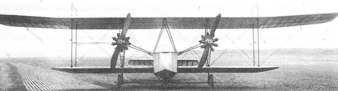
The Vickers F.B.7 in 1915; the picture shows the handed propellers.
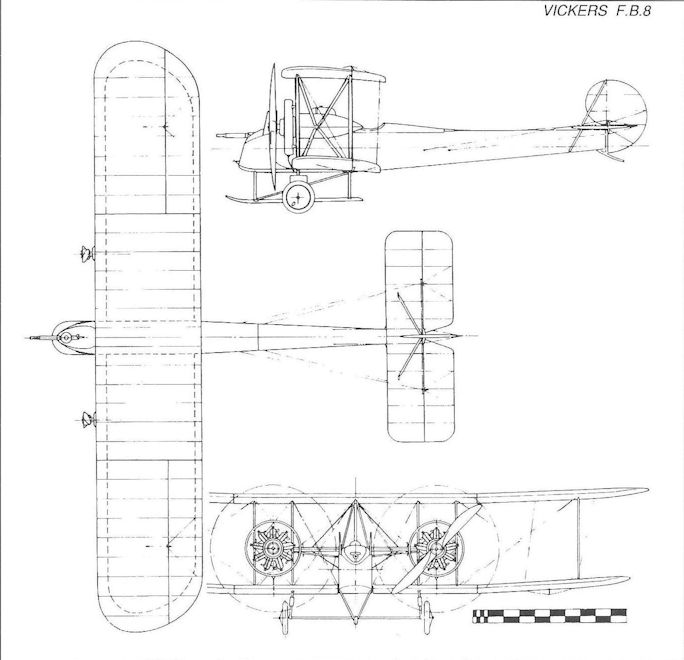
Vickers F.B.8
Vickers E.S.1 and E.S.2
Harold Barnwell’s E.S.1 was, like the F.B.7, first flown in August 1915 and, on account of its remarkable performance, became popularly known as the Barnwell Bullet. In appearance it was very advanced for its day, being a single-bay, unstaggered biplane with fully-cowled 100hp Gnome monosoupape engine. The wooden fuselage was of circular section almost as far aft as the tailplane, and its speed performance (117 mph at sea level) was largely attributable to careful attention to detail design. Wings and tailplane were of rectangular planform, and the fin was gracefully curved to blend with a rounded rudder.
Such was the extraordinary performance demonstrated by the E.S.1 that the War Office sent the only example, No 7509, to France for operational trials with line pilots, although it was in fact unarmed. Unfortunately the E.S.1 met with outspoken criticism from Service pilots who complained that the bulky fuselage and upper wing severely restricted the view from the cockpit. Moreover, being fully cowled, the engine frequently overheated and the aircraft narrowly escaped being consumed by fire. It was eventually written off by Capt P H L Playfair (later Air Marshal Sir Patrick, kbe, cb, cvo, mc).
Encouraged to pursue the design, Vickers had already produced the E.S.2 (sometimes referred to as the E.S.1 Mark II), and this flew in September 1915 with a 110hp Clerget in a shorter chord cowling. Most obvious changes, however, were embodied in the wings which now featured rounded tips of slightly greater span, and an enlarged trailing edge cut-out as well as an aperture in the centre section between the spars to improve the pilot’s field of vision.
Later the Clerget was replaced by a Le Rhone of similar power, and this returned a speed similar to that of the E.S.1 - despite the inclusion of armament in the later aircraft. This comprised a fixed Vickers machine gun mounted on the port upper longeron forward of the cockpit and recessed into the nose decking to fire forward through the propeller by means of the new Vickers-Challenger interrupter gear.
Although the fuselage section was of marginally smaller diameter, the E.S.2 still met with opposition from pilots for its lack of downward visibility, and the E.S.2 (of which two examples were produced) was abandoned. Their value nevertheless lay in the experience they afforded Vickers in the development of later tractor scouts which, from early 1916, began to replace the old pusher Gunbus formula in service.
Type: Single-engine, single-seat, single-bay biplane scout.
Manufacturer: Vickers Ltd (Aviation Department), Knightsbridge, London.
Powerplant: E.S.1. 100hp Gnome monosoupape engine. E.S.2. 110hp Clerget; 110hp Le Rhone.
Structure: Predominantly wooden construction with fabric covering. Ailerons on upper and lower wings; twin-wheel undercarriage without skid.
Dimensions: E.S.1. Span, 24ft 4 1/2 in; length, 20ft 3in; height, 8ft 0in; wing area, 215 sq ft. E.S.2 (Clerget). Span, 24ft 5 1/2 in; length, 20ft 3in; height, 8ft 2in; wing area, 215 sq ft.
Weights: E.S.1. Tare, 843lb; all-up, 1,295lb. E.S.2 (Clerget). Tare, 981lb; all-up, 1,502lb.
Performance: E.S.1. Max speed, 117 mph at sea level; climb to 5,000ft, 6 min 40 sec; service ceiling, 15,500ft; endurance, 3 hr. E.S.2 (Clerget). Max speed, 112 mph at sea level; climb to 5,000ft, 6 min 25 sec; endurance, 2 hr.
Armament: E.S.1, none. E.S.2, one fixed 0.303in Vickers machine gun in the nose with Vickers-Challenger interrupter gear.
Prototypes: E.S.1, one, No 7509 (first flown in August 1915). E.S.2, two, Nos 7759 and 7760 (first flown in September 1915). No production.
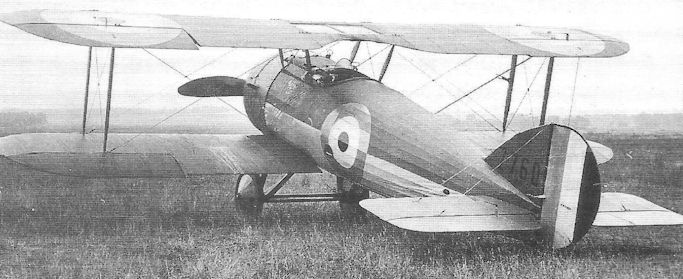
The second E.S.2, No 7760. This view well illustrates the bulky fuselage and the aperture in the upper wing between the cabane struts, introduced to improve the pilot’s upward field of vision. Note also the rounded wingtips.
Vickers E.F.B.6 and F.B.9
The efforts to extend the successful F.B.5 Gunbus formula, as has been shown, brought forth the twin-engine F.B.7 and F.B.8, which appeared too late to warrant further work on them. Another design, the Vickers E.F.B.6, was less radical in that it retained the basic F.B.5 single pusher engine format. It did however adopt the upper wing’s greatly increased span with large overhang that characterised Flanders’ F.B.7, in an effort to increase the F.B.5’s load-carrying ability. Like the F.B.7, however, this aeroplane was blighted by the plethora of struts and bracing wires necessary for this wing configuration, and its poor performance on only a single engine resulted in the aircraft’s further development being abandoned.
Instead efforts focussed on generally cleaning up the F.B.5 itself, and in December 1915 the prototype F.B.9 was first flown. This retained the 100hp Gnome monosoupape rotary but featured smaller wings with rounded tips; the landing skids were omitted and the nacelle nose was redesigned to appear as a D-shape in side elevation. Raf-wires replaced the former twisted-strand cables for interplane bracing; and the spigot mounting for the nose Lewis gun was replaced by a Vickers ring to permit the gun to traverse.
The nose profile underwent further improvement, the bottom line of the nacelle being lengthened to make possible an improved aerodynamic shape. Thus modified the F.B.9 possessed a maximum speed of 82.6 mph at sea level - an increase of about a dozen miles per hour over the F.B.5. At least one F.B.9 with the improved nose profile was powered by a 110hp Le Rhone engine.
Although Vickers had high hopes for this new Gunbus, and orders were placed for about 119 production aircraft, there is little doubt that from the outset the War Office was more interested in the F.B.9 as a trainer than as an operational gun carrier. That alone was ample testimony to its excellent handling qualities, but the truth was that the Gunbus was already being rendered obsolete by the arrival of the synchronized front gun. It is possible, though doubtful, that a few F.B.9s were sent to France, and it is unlikely that any were flown operationally. On the other hand, fifty were distributed among home-based training units, including No 6 Reserve Squadron at Catterick, and No 10 Reserve Squadron at Joyce Green.
The accompanying data refer to the production F.B.9.
Type: Single pusher engine, single-seat, two-bay biplane gun carrier.
Manufacturer: Vickers Ltd, Knightsbridge, London; aircraft built at Weybridge, Surrey.
Powerplant: One 100hp Gnome monosoupape engine driving two-blade pusher propeller (as standard); also 110hp Le Rhone engine.
Dimensions: Span, 33ft 9in; length, 28ft 5 1/2 in; height, 11ft 6in; wing area, 340 sq ft.
Weights: Tare, 1,029lb; all-up, 1,892lb.
Performance: Max speed, 82.6 mph at sea level; climb to 10,000ft, 51 min; endurance, 5 hr.
Armament: One 0.303in Lewis machine gun on Vickers or Scarff ring mounting on front cockpit.
Prototype and Production: One prototype (first flown in December 1915). Approximately 119 production aircraft (Nos 5271-5290,7812-7835, A1411-A1460 and A8601-A8625)
Summary of Service: No evidence has been traced to suggest that F.B.9s flew operationally. Fifty aircraft were distributed among such units as Nos 6 and 10 Reserve Squadrons, and No 187 Training Squadron in the United Kingdom.

Виккерс FB.9 Внешне FB.9 отличался в первую очередь отсутствием противокапотажных лыж
One of the four F.B.5AS built at Bexleyheath with an armour-plated nose and V undercarriage; oleo-type undercarriages were also tried.
A direct, slightly smaller derivative of the Vickers FB 5, the two-seat Vickers FB 9 proved to be another case of providing too little, too late, resulting in the type being largely relegated to the training role. First flown towards the end of 1915, the FB 9 used the same 100hp Gnome Monosoupape as its predecessor, providing the machine with an uncomfortably slow top level speed of 82.6mph at sea level, decreasing to 79mph at 6.500 feet. Even worse was the 19 minutes the aircraft took to reach this altitude. The FB 9's armament consisted of a single .303-inch Vickers gun mounted in the forward, or observer's cockpit. Of the 119 FB9s believed to have been built, including 24 for the RFC from Darracq in France, only two are known to have entered into operational service, both joining 'B' Flight of No 11 Squadron, RFC in June 1916.
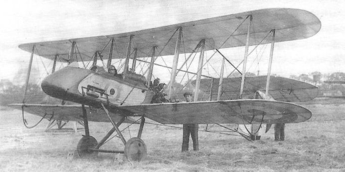
A production F.B.9 with the improved nose profile; this aircraft, almost certainly destined for, or serving with a training unit, is equipped with dual controls, as evidenced by the linked elevator control arms on the side of the nacelle; no provision is made to mount a gun on the front cockpit. Note the absence of landing skids on these F.B.9s.
Vickers F.B.11
This large single-engine aeroplane was one of three strange-looking aircraft built to meet a War Office requirement for a long-range escort fighter, with a suggested secondary role as an anti-Zeppelin patrol fighter, the others being the Sopwith L.R.T.Tr and the Armstrong Whitworth F.K.12. High speed performance was not a prerequisite as it was intended that the aircraft should closely accompany bombing aircraft and provide them with all-round gun protection without breaking formation. The need to fire directly forward was therefore of less significance than all-round protection.
The interpretation of the operational requirement by the three contending manufacturers differed considerably, Howard Flanders at Vickers opting for a single-bay unstaggered biplane, to be powered by one of the new 250hp Rolls-Royce water-cooled in-line engines. Pilot and one gunner were situated in closely-spaced tandem cockpits under the trailing edge of the upper wing, and a second gunner occupied a well-shaped nacelle extending forward from the upper surface of the top wing and supported by a pair of raked struts attached to the fuselage nose. Twin wheels and central skid comprised the undercarriage and, for entry to his cockpit, the nacelle gunner had to ascend a veritable flight of steps up the front port skid strut, up the side of the engine cowling, and on upwards by means of the port front nacelle strut.
Two F.B.11s were ordered and the first was completed some time in July 1916, several weeks before the Rolls-Royce engine could be delivered, and the first flight of the aircraft, A4814, was considerably delayed until the early autumn. By that time the idea of large escort fighters had been abandoned as bombers of the calibre of the Airco D.H.4 - capable of putting up an effective self-defence - were coming into prospect.
Type: Single-engine, three-seat, single-bay biplane escort gun carrier.
Manufacturer: Vickers Ltd (Aviation Department), Knightsbridge, London.
Powerplant: One 250hp Rolls-Royce Vee-twelve water-cooled in-line engine driving two-blade propeller.
Dimensions: Span, 51ft 0in; length, 44ft 6in; height, 15ft 8 1/8 in; wing area, 846 sq ft.
Weights: Tare, 3,340lb; all-up, 4,934lb.
Performance: Max speed, 98 mph at sea level; climb to 5,000ft, 16 min 30 sec; endurance, 4 1/2 hr.
Armament: One 0.303in Lewis machine gun on Scarff ring on gunner’s cockpit aft of the pilot’s cockpit, and one Lewis gun on nacelle gunner’s cockpit with all-round field of fire.
Prototypes: Two, A4814 and A4815 (first flight by A4814 in late September or early October 1916). No production.
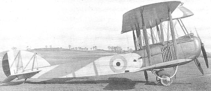
The Vickers F.B.11 late in 1916.

Vickers F.B.11
Vickers F.B.12
Design of the F.B.12 was begun early in 1916 as an attempt to extend the Gunbus formula into the single-seat scout class, presumably to provide a replacement for the ‘first generation’ D.H.2s and F.E.8s. However, by the time it was flown in June that year, both the Sopwith Pup and Triplane had appeared and demonstrated a considerable advance in performance.
If in fact the engine originally intended for the F.B.12, the 150hp Hart nine-cylinder radial, had been available in time, the Vickers aircraft would probably have matched the Pup’s performance, but as it was not, an 80hp Le Rhone was substituted and bestowed a maximum speed of only 95 mph. When it first appeared the aircraft featured short wings with elliptical tips and a circular-section nacelle located in the centre of the wing gap. Armament comprised a single Lewis gun protruding from the upper part of the nose. In this form the engine was soon changed to a 100hp Gnome monosoupape and this increased the speed by about five miles per hour.
A production order was raised for 50 aircraft, including the prototype, and the design underwent much modification before the second example appeared. The wings were lengthened to feature square-raked tips and the nacelle was altered to near-rectangular section, the engine being changed once again, this time to a 100hp Le Rhone; these changes, one imagines, were introduced to facilitate production, but had increased the drag and the aircraft, now termed the F.B.12C, could still only manage about 100 mph, although the rate of climb was improved. Finally a 100hp Anzani engine was installed, but again without significant improvement.
With no advance in performance evident, the F.B.12C‘s production was halted after only seventeen aircraft had been completed. As far as is known, none entered operational service, although it is believed that the Gnome-powered prototype underwent trials in France in December 1916, and an F.B.12C flew with a Home Defence unit the following year.
Type: Single pusher engine, single-seat, two-bay biplane scout.
Manufacturer: Vickers Ltd (Aviation Department), Knightsbridge, London.
Powerplant: F.B.12. 80hp Le Rhone; 100hp Gnome monosoupape. F.B.12C. 110hp Le Rhone; 100hp Anzani.
Dimensions: F.B.12. Span, 26ft 0in; length, 21ft 6in; height, 8ft 7in; wing area, 204 sq ft. F.B.12C. Span, 29ft 9in; length, 21ft 10in; height, 8ft 7in; wing area, 237 sq ft.
Weights: F.B.12 (80hp Le Rhone). Tare, 845lb; all-up, 1,275lb. F.B.12C (100hp Le Rhone). Tare, 927lb; all-up, 1,400lb.
Performance: F.B.12 (80hp Le Rhone). Max speed, 95 mph at sea level; climb to 5,000ft, 9 min 50 sec; service ceiling, 11,500ft. F.B.12C (100hp Le Rhone). Max speed, 100 mph at sea level; climb to 5,000ft, 6 min 55 sec; service ceiling, 14,500ft.
Armament: One 0.303in Lewis machine gun in nose of nacelle.
Prototype: One F.B.12, A7351 (first flown, June 1916).
Production: F.B.12C. 17 aircraft completed (A7352-A7368).
Summary of Service: A7351 underwent trials in France in December 1916; and at least one aircraft flew with a Home Defence unit in 1917.
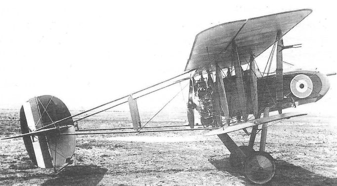
The term 'inertia' is normally applied to a physical object's resistance to any change of state in its motion, sometimes, however, the term is equally applicable to the mind-set of a company's management, as in the case of Vickers' FB 12. First flown in June 1916, the initial FB 12 used an 80hp Le Rhone, but production examples of this single-seat fighter were to have been powered by the 150hp Hart rotary. Following the failure of this engine, the FB 12, with its long-obsolete pusher-engined layout was fitted with a 110hp Le Rhone to become the FB 12C. By the time the FB 12C had flown it was the spring of 1917, subsequent flight trials showing the machine to have a top level speed of 87mph at a time when average fighter speeds exceeded 110mph. To add further to Vickers' troubles, the second FB 12C, serial no A 7352, seen here fitted with a 100hp Anzani was criticised by Martlesham Heath, in June 1917, as lacking sufficient pitch control at low speed and having generally heavy handling traits. Of the 50 production batch ordered, all but 18 were to be cancelled.
Vickers F.B.14
The Vickers F.B.14 was variously referred to as a reconnaissance fighter and a general purpose aircraft. It was a large single-engine, single-bay, two-seat biplane with two crew members in tandem cockpits. Whereas former reconnaissance aircraft had perpetually suffered heavy losses over the Western Front, the F.B.14 was an attempt to provide an aircraft with a speed to match that of enemy scouts. Accordingly, it was intended to fit a 230hp Beardmore-Halford-Pullinger (BHP) engine, but no such engine was available at the time Vickers had completed the first airframe in July 1916 and had to be content with a 160hp Beardmore. Although this naturally reduced the performance of the F.B.14, the War Office placed an order for 150 aircraft, and later increased the figure to 250. Trouble was being experienced with the Beardmore engine, and those airframes which were completed were delivered straight into store to await resolution of the engine problems. A 120hp Beardmore was tried, but such was the further reduction in performance, that this experiment was hurriedly abandoned.
Typical of Howard Flanders’ designs, the F.B.14 featured an upper wing larger than the lower, the interplane struts being splayed outwards. The pilot’s cockpit was located directly beneath the upper wing but was provided with large transparent panels in the wing centre section and in the lower wing roots. A synchronized Vickers gun was mounted in the centre of the nose decking, and the gunner’s cockpit, with a Scarff ring and Lewis gun, were located just aft of a cutout in the upper wing’s trailing edge. Ailerons were fitted to upper and lower wings, and a long, curved fin blended with the unbalanced rudder.
In view of the continuing powerplant difficulties an F.B.14 was set aside to be fitted with a 150hp Lorraine-Dietrich V-eight, liquid-cooled in-line engine. This aircraft was re-styled the F.B.14A. At roughly the same time another F.B.14 (ordered separately) was specially produced to accommodate the big V-twelve 250hp Rolls-Royce Mark IV (later termed the Eagle IV), driving a four-blade propeller. This aircraft, the F.B.14D, C4547, was also given enlarged, two-bay wings, and certainly proved on test at Martlesham in March 1917 to have a significantly better performance, but by then the Bristol Fighter was demonstrating a similar performance - with better to come - and it was not considered worthwhile to pursue the Vickers aircraft. One further experimental version was the F.B.14F powered by a 150hp RAF 4A engine, also driving a four-blade propeller, and this aircraft, A8391, reverted to single-bay wings rigged with increased stagger.
As far as it known very few of the F.B.14s held in store were completed. The F.B.14D, once its trials at Martlesham were completed, was sent to Orfordness for armament experiments, and while there was flown against the Gotha bombers which attacked London in daylight on 17 July 1917, but was unable to bring its experimental gunsights to bear on a target. About half-a-dozen Beardmore-powered F.B. 14s were issued to Home Defence units, but apparently these were not flown operationally, and unsubstantiated records suggest that some may have been sent to the Middle East for service in Mesopotamia; none has been traced as being held on charge by squadrons in that theatre.
Except where stated, the accompanying table of leading particulars refers to the F.B.14 with the 160hp Beardmore.
Type: Single-engine, two-seat, single-bay fighter-reconnaissance biplane.
Manufacturer: Vickers Ltd (Aviation Department), Knightsbridge, London.
Powerplant: F.B.14. 160hp Beardmore; 120hp Beardmore. F.B.14A. 150hp Lorraine-Dietrich. F.B.14D. 250hp Rolls-Royce Mark IV. F.B.14F. 150hp RAF 4A.
Dimensions: Span, 39ft 6in; length, 28ft 5in; height, 10ft 0in; wing area, 427 sq ft.
Weight: Tare, 1,662lb; all-up, 2,603lb.
Performance: Max speed, 99.5 mph at sea level; climb to 10,000ft, 40 min 50 sec; service ceiling, 10,000ft; endurance, 3 3/4 hr.
Armament: One synchronized 0.303in Vickers machine gun on fuselage nose decking, and one 0.303in Lewis gun on Scarff ring on gunner’s rear cockpit.
Prototypes: One F.B.14, A678 (first flown in August 1916); one F.B.14A; one F.B.14D, C4547; one F.B.14F, A8391.
Production: Out of a total of 252 aircraft ordered, only 100 are believed to have been built, and roughly half of these were completed with engines. (A679-A727, A3505, A8341-A8490).
Summary of Service: Either six or seven F.B.14s were issued to Home Defence squadrons.
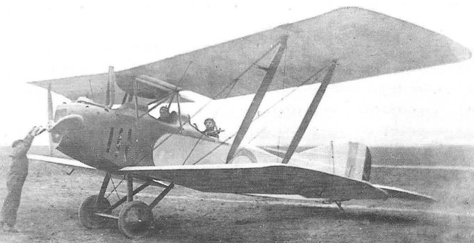
The single-bay Vickers F.B.14A with 150hp Lorraine-Dietrich engine.
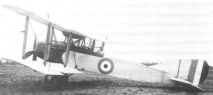
The F.B.14D, C4547, with 250hp Rolls-Royce Mark IV engine.
Vickers F.B.16
The Vickers F.B.16 was designed by Rex Pierson as a private venture in the first place principally to demonstrate the Vickers-sponsored 150hp Hart radial engine which, it will be recalled, had not been ready in time for the F.B.12. The new engine gave its name to Pierson’s design and the Hart Scout originally appeared as a single-bay biplane, its fairly heavily staggered wings being of unequal span and chord with rounded tips. The engine was neatly cowled, but evidently suffered from overheating as the cowling was soon removed. The fin and rudder also underwent alteration, the fin being reduced in area and the rudder shape changed to present a smoothly curved upper line, while the fuselage aft of the cockpit was reduced in depth in favour of a small headrest fairing.
The Hart engine gave almost continuous trouble and it was removed from the F.B.16 which, early in the autumn of 1916, was redesigned and re-emerged as the F.B.16A in December, now powered by a 150hp Hispano-Suiza driving a two-blade propeller. This installation, which featured a frontal radiator, allowed a narrower fuselage which was now flat sided with curved top and bottom fairings. The unequal-span wings were retained but were given raked tips. Armament comprised a synchronized Vickers gun and a Lewis gun on a sliding mounting above the upper wing centresection.
After the first F.B.16A was destroyed in a fatal accident, a second machine, A8963, was built and sent to Martlesham for Service trials during which it returned a top speed of 120 mph at 6,500 feet; it was not, however, recommended for production owing, it is believed, to an official preference for the S.E.5. Nevertheless, its development continued and A8963 reappeared as the F.B.16D in the summer of 1917 with a 200hp Hispano-Suiza, returning to Martlesham in July where its speed at 10,000 feet was recorded as 135 mph. The F.B.16D became a favourite mount of Capt J T B McCudden MC who used to visit Joyce Green when on leave from France.
Once more the F.B.16 underwent extensive redesign, much larger two-bay wings being fitted; the fuselage was also lengthened to allow the installation of a 275hp Lorraine-Dietrich vee-eight liquid-cooled engine, also with a frontal radiator. Although this variant, the F.B.16E, had a top speed of about 144 mph at sea level, this performance was bettered by the final variant, the F.B. 16H, powered by a 300hp Hispano-Suiza, which had a maximum speed of 147 mph and could reach 10,000ft in 7 minutes 50 seconds.
These were some of the highest speeds yet confirmed by a fully-armed fighter at that time (mid-1918), but they were achieved using foreign engines, and the Service policy was moving slowly in favour of British designs; in any case, fighters of comparable performance, such as the Sopwith Snipe and Dolphin, were already approaching production status, and the Vickers work, perhaps unjustly, remained purely experimental.
Type: Single-engine, single-seat, single- and two-bay biplane scout.
Manufacturer: Vickers Ltd (Aviation Department), Knightsbridge, London.
Powerplant: F.B.16. One 150hp Hart radial engine. F.B.16A. 150hp Hispano-Suiza. F.B.16D. 200hp Hispano-Suiza. F.B.16E. 275hp Lorraine-Dietrich. F.B.16H. 300hp Hispano-Suiza.
Dimensions: F.B.16A. Span, 25ft 0in; length, 19ft 0in; height, 7ft 10in; wing area, 199 sq ft. F.B.16D. Span, 25ft 0in; length, 19ft 6in; wing area, 207 sq ft. F.B.16E. Span, 31ft 0in; length, 21ft 0in; wing area, 272 sq ft.
Weights: F.B.16D. Tare, 1,376lb; all-up, 1,875lb. F.B.16E. Tare, 1,495lb; all-up, 2,200lb.
Performance: F.B.16D. Max speed, 140 mph at sea level; climb to 10,000ft, 10 min 25 sec; service ceiling, 18,500ft. F.B.16E. Max speed, 144 mph at sea level; climb to 10,000ft, 7 min 50 sec; service ceiling, 24,000ft.
Armament: F.B.16D. One 0.303in Lewis gun mounted between cylinder banks of engine and firing through propeller shaft, and a Lewis gun on sliding mounting above upper wing centre section. F.B.16E. Two synchronized Vickers guns in cowling above engine and a Lewis gun on sliding mounting above upper wing.
Prototypes: One prototype served as F.B.16 and F.B.16A; a second F.B.16A, A8963, also served as prototype F.B.16D, E and H.
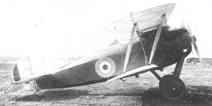
The F.B.16A was the rebuilt prototype with an Hispano-Suiza replacing the Hart engine, with very small gap between the nose decking and the upper wing.
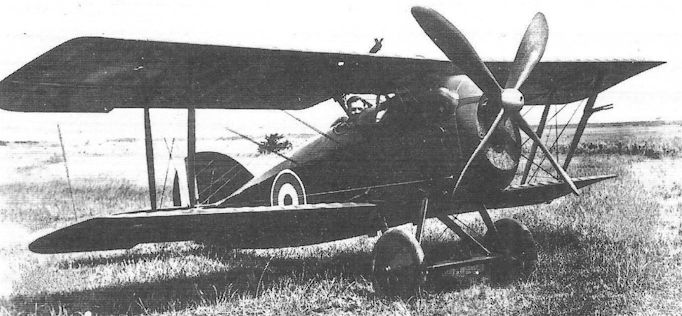
F.B.16D - known to Barnwell as 'Pot Belly', and the favourite hack of the British ace McCudden; in the centre of the spinner the exit hole for bullets from the engine-mounted machine-gun can be seen. The engine is a 150 h.p. Hispano-Suiza
The aircraft is believed to have been painted red overall.
The aircraft is believed to have been painted red overall.

The F.B.16E in the Darracq works awaiting its 200hp Lorraine-Dietrich engine.
Vickers F.B.19
It will be recalled that the Vickers E.S.1 and E.S.2 single-seaters of 1915 had been criticised and probably rejected for service on account of the very poor field of view from the cockpit caused by the circular section of the fuselage. In other respects the aircraft had been commended in the context of standards existing at that time, and Vickers had been sufficiently encouraged to persist with the basic design. The outcome was the F.B.19, which appeared in August 1916 with an almost flat-sided fuselage aft of the carefully faired circular-section nose.
The single-bay wings were of equal span, and when the aircraft first appeared there was no stagger; it was powered by a 100hp Gnome monosoupape. As well as a cutout in the trailing edge of the upper wing, there was a large clear-view aperture between the spars of the wing centre section.
Armament comprised a single Vickers gun located in a channel set into the port side of the forward fuselage below the upper longeron, firing through a small aperture in the front of the engine cowling and equipped with Vickers-Challenger interrupter gear.
When a much-modified version of the F.B.19 appeared soon afterwards with modified wings rigged with considerable stagger, it was termed the Mark II and the original aircraft became the Mark I retrospectively. Despite a very modest performance the Mark II, which inherited the unofficial name Bullet from the earlier E.S. aircraft, was ordered into limited production, with either 110hp Clerget or Le Rhone engines. Six examples were sent to France for operational trials late in 1916, but were not popular and were soon returned home. One aircraft reached No 14 Squadron in the Middle East in May 1917 and another was issued to No 47 in Greece during June, while No 30 in Mesopotamia flew a third. No 111 Squadron included five amongst its assortment of fighters in Palestine during 1918. The only other Squadron to fly F.B.19s was No 141 which received two at Biggin Hill, also in 1918. It is said that a few were shipped to Russia in 1916 and it seems that these can only have been Mark Is, but no reliable records survive to confirm this, nor the number sent.
The accompanying dimensions, weights and performance data refer to the F.B.19 Mark II with 110hp Le Rhone engine.
Type: Single-engine, single-seat, single-bay biplane fighting scout.
Manufacturer: Vickers Ltd (Aviation Department), Knightsbridge, London.
Powerplant: Mark I. 100hp Gnome monosoupape engine; 110hp Le Rhone. Mark II. 110hp Clerget; 110hp Le Rhone.
Dimensions: Span, 24ft 0in; length, 18ft 2in; height, 8ft 3in; wing area, 215 sq ft.
Weights: Tare, 892lb; all-up, 1,478lb.
Performance: Max speed, 98 mph at sea level; climb to 10,000ft, 14 min 50 sec; service ceiling, 15,000ft; endurance, 3 1/4 hr.
Armament: Single 0.303in Vickers machine gun mounted in trough on port side of nose to fire through the propeller arc, synchronized by Vickers-Challenger gear.
Prototypes: Two Mark Is, A1968 and A1969 (first flown in August 1916).
Production: Records suggest that as many as thirty-six F.B.19s were issued to the RFC, although contract cover has only been confirmed for fourteen (two Mark Is, A2120 and A2992, and twelve Mark Ils, A5225-A5236).
Summary of Service: Surviving records show that single Mark Ils served with No 14 Squadron (Middle East), No 30 (Mesopotamia) and No 47 (Greece); No 111 Squadron received five in Palestine in August 1917, and No 141 Squadron flew two at Biggin Hill in 1918. Some were issued to home-based training units in 1918.
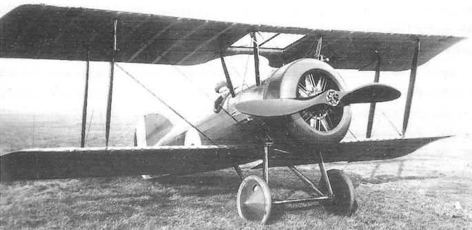
This photograph of an F.B.19 Mk II well illustrates the efforts made to improve the pilot’s field of view from the cockpit.
Vickers F.B.24
Harold Barnwell’s F.B.24 was, like some products of other commercial manufacturers, dogged by official refusal to make available Hispano-Suiza engines for production aircraft on the grounds that delayed production of the engine resulted in all those available being reserved for the S.E.5. When originally projected in the late autumn of 1916, the F.B.24 had been intended to have a 150hp Hart radial engine, but this had met with general disapproval in the F.B.16, and its use was evidently abandoned. Vickers did, however, manage to acquire a 200hp Hispano-Suiza engine for prototype use, and the first aircraft thus powered, the F.B.24B, is said to have been flown at the end of March 1917.
The F.B.24B was a well-proportioned two-bay biplane, intended as a reconnaissance fighter, the wings being of unequal span; the top wing was built in two halves which joined on the aircraft’s centre-line, without centre section. The pilot, being situated directly below the upper wing (with two small clear panels in it), possessed a very poor field of view, while the observer, armed with a Lewis gun on Scarff ring, was located in line with the wing trailing edge which, although cut away, severely restricted the gun’s field of fire.
The performance with the Hispano engine was modest, and it was generally felt that the F.B.24B was underpowered. The next variant to be built, the F.B.24C, was therefore powered by the 275hp Lorraine-Dietrich 8Bd, and both front and side radiator versions were flown; the long curved tail fin, fitted previously, was shortened. This version returned a top speed in the region of 133 mph at sea level.
On account of the criticism of the crew’s poor location, the last two versions built, the F.B.24E and the 24G were re-designed with the top wings attached to the upper fuselage longerons, so that both pilot and observer/gunner had unrestricted view all round above the wings. On both aircraft the lower wing was located clear of the underside of the fuselage, the wing shape and interplane struts remaining much the same as on the F.B.24C, and also retaining the shortened tail fin. However, whereas the F.B.24E was powered by the 200hp Hispano-Suiza, the F.B.24G was fitted with a 375hp Lorraine-Dietrich 13 V-12 engine; the latter was an ungainly-looking aeroplane with lengthened, unstaggered wings and enlarged tailplane, bulky engine installation and ailerons apparently fitted only on the upper wing. Untidy radiators were attached to the sides of the fuselage. Maximum speed was said to be about 140 mph at sea level.
Although not looked upon with much favour by British authorities, the F.B.24G is said to have been produced by Darracq in France after the War.
Type: Single-engine, two-seat, two-bay biplane reconnaissance fighter.
Manufacturer: Vickers Ltd (Aviation Department), Knightsbridge, London.
Powerplant: F.B.24B and F.B.24E, 200hp Hispano-Suiza. F.B.24C, 275hp Lorraine-Dietrich 8Bd. F.B.24G, 375hp Lorraine-Dietrich 13.
Dimensions: F.B.24C. Span, 37ft 6in; length, 26ft 6in; wing area, 384 sq ft. F.B.24G. Span, 38ft 3in; length, 30ft 0in; wing area, 450 sq ft.
Weights: F.B.24C. Tare, 1,709lb; all-up, 2,650lb. F.B.24G. Tare, 2,332lb; all-up, 3,680lb.
Performance: F.B.24C. Max speed, approx 133 mph at sea level; climb to 10,000ft, 11 min; service ceiling, 23,000ft; endurance, 3 hr.
Armament: All versions up to and including F.B.24E armed with one synchronized 0.303in Vickers machine gun on nose, and one Scarff ring-mounted Lewis gun on rear cockpit. The F.B.24G may have been armed with twin synchronized Vickers guns.
Prototypes: Number built not known (first flight by F.B.24B believed to have taken place in March 1917). No production in Britain.
Vickers F.B.25
The resolute persistence with which Vickers continued to build derivatives of the outmoded Gunbus formula, two years after it had been shown to be thoroughly out of place in the presence of dedicated dogfighters, never fails to astonish historians, particularly when one remembers that the company had already demonstrated its ability to build promising tractor scouts in the course of those two years.
It can be argued that the Gunbus was always justified by the nature of its armament, and in the F.B.25 this was to consist of the experimental Vickers Crayford rocket gun. The aircraft was a two-bay staggered biplane, powered by a 150hp direct-drive Hispano-Suiza engine. The nacelle was fairly short, but sufficiently broad-beamed to accommodate the pilot and gunner almost side-by-side, - the gunner’s position to starboard and staggered slightly forward of the pilot. The upper wing possessed no centre section, the two halves meeting on the aircraft’s centreline; the lower wing, however, included a separate centre section, to which the V-struts of the landing gear were attached.
Being proposed as an anti-airship night fighter, the F.B.25 was intended to include a ten-inch searchlight in the extreme nose, but all available evidence suggests that this was never fitted.
The sole example underwent trials at Martlesham Heath in late June or early July 1917 but crashed, possibly while landing in a strong wind (the report on the trials stated that, owing to poor controls, the aircraft proved to be ‘almost unmanageable in a wind over 20 mph’. The serial number of this aircraft is not known, although a document, traced recently, refers to it as No ’13, and it has been suggested that this may indicate A9813 (formerly a cancelled number intended for a Sopwith Triplane).
Type: Single pusher engine, two-seat, two-bay biplane night fighter.
Manufacturer: Vickers Ltd (Aviation Department), Knightsbridge, London.
Powerplant: One 150hp Hispano-Suiza direct-drive engine driving two-blade pusher propeller.
Dimensions: Span, 41ft 6in; length, 28ft lin; height, 10ft 10in; wing area, 500 sq ft.
Weights: Tare, 1,608lb; all-up, 2,454lb.
Performance: Max speed, 91 mph at sea level, 84.5 mph at 10,000 ft; climb to 10,000ft, 27 min 10 sec; service ceiling, 11,500ft; endurance, 4 1/2 hr.
Armament: One Vickers Crayford rocket gun in nose of nacelle.
Prototype: One (believed first flown in June 1917).
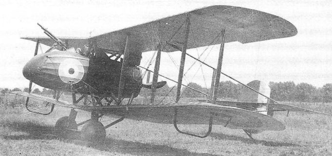
The F.B.25 two-seat night fighter of 1917 in modified form, almost certainly at Joyce Green. As originally designed with a nose-mounted searchlight, the nacelle was some three feet longer, with an auxiliary nosewheel to prevent the aircraft from nosing over when landing.
The trial installation of an oleo-pneumatic undercarriage may also be noted, but the outstanding feature was the Crayford rocket gun intended for attacking hostile airships, an operational philosophy revived in Vickers' COW gun fighter of 1931.
The trial installation of an oleo-pneumatic undercarriage may also be noted, but the outstanding feature was the Crayford rocket gun intended for attacking hostile airships, an operational philosophy revived in Vickers' COW gun fighter of 1931.
Vickers F.B.26 Vampire
Another new Vickers pusher aircraft flown in 1917 was the single-seat F.B.26 (later named the Vampire), an altogether smaller aircraft than the F.B.25. It was originally designed as a day-flghting scout with a pair of Lewis guns in the extreme nose, and was powered by a 200hp Hispano-Suiza engine. As initially flown, the upper wing was, in characteristic Vickers fashion, devoid of centre section and the two halves were attached together on the aircraft’s centreline. The Hispano was at first installed with its car-type radiator at the rear of the engine; this however gave inadequate cooling and after an equally ineffective trial with a pair of radiators mounted transversely under the upper wing rear spar, these radiators were mounted vertically on the sides of the fuselage - and this arrangement sufficed. Various other changes were made to the wings (including the addition of a centre section) and tail unit and a four-blade propeller was substituted.
An Eeman triple-Lewis gun mounting was incorporated in the nose, and the revised prototype, now numbered B1484, underwent official trials at Martlesham Heath in July, returning a speed of 124 mph at sea level and demonstrating a service ceiling of 20,500 feet. Being fitted with flare brackets, it seems clear that the aircraft was then being considered in the role of anti-airship night fighter, and its demonstrated performance would seem to have been consistent with this role, while an excellent field of vision was afforded the pilot. Shortly after the aircraft returned to Joyce Green, the entire Eeman gun installation was raised almost a foot, probably to facilitate re-loading the guns in flight, but the new location severely reduced the pilot’s field of view and it was quickly discarded.
B1484 was to be destroyed in an accident on 25 August when it crashed from a spin shortly after taking off from Joyce Green, killing the famous pilot Harold Barnwell. A second aircraft, B1486, was built, probably during the autumn of 1917, also as a night fighter with the triple-gun Eeman installation. It was taken on charge by No 39 (Home Defence) Squadron at Woodford in October, and passed on to No 141 Squadron in February 1918, then at Biggin Hill; it was not much appreciated on account of poor flying qualities and the usual problem with the Hispano of lengthy warming up before take-off.
At least one other example, B1485, was built in 1918, this time powered by a 230hp Bentley B.R.2 rotary engine. This was intended as a trench fighter and featured 500 pounds of armour protection in the nacelle. The year 1918 also brought the official naming of military aircraft, Vickers aircraft being required to bear names beginning with ‘V’; thus the Bentley-powered F.B.26A became the Vampire Mk II, and, in retrospect, the Hispano-powered F.B.26, the Vampire Mk I. By the time the Vampire Mk II underwent its Service trials by the RAF, however, the Sopwith Salamander had been ordered into production as the principal British trench fighter, and the Vickers aircraft was abandoned.
Type: Single pusher engine, single-seat, single-bay biplane night fighter (Vampire Mk I) and trench fighter (Vampire Mk II).
Manufacturer: Vickers Ltd (Aviation Department), Knightsbridge, London.
Powerplant: Vampire Mk I. 200hp Hispano-Suiza; Vampire Mk II, 230hp Bentley B.R.2 rotary engine.
Dimensions: Span, 31ft 6in; length (Vampire Mk I), 23ft 5in; height, 9ft 5in; wing area, 267 sq ft.
Weights: Vampire Mk I. Tare, 1,407lb; all-up, 2,030lb.
Performance: Vampire Mk I. Max speed, approx 124 mph at sea level; climb to 10,000ft, 9 min 54 sec; service ceiling, 20,500ft; endurance, 3 hr.
Armament: Originally two 0.303in Lewis machine guns in extreme nose, increased to three in Eeman mounting; Vampire Mk II had two Lewis guns in the nose.
Prototypes: Total of six ordered, B1484-B1489; B1484 and B1486 were Vampire Mk Is, and B1485 a Vampire Mk II. B1487-B1489 probably not built. No production.
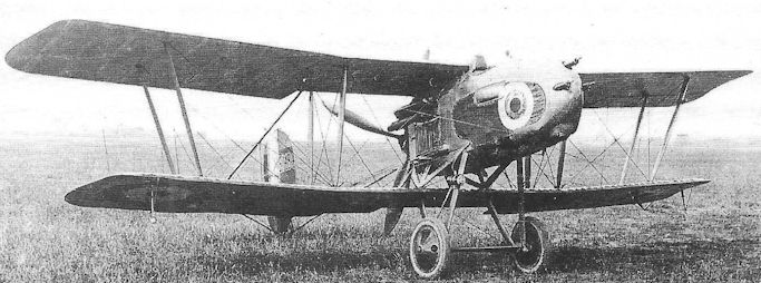
The Vickers F.B.26 Vampire Mk I, B1484, al Joyce Green in the configuration in which it underwent Service trials in July 1917 with the Eeman gun installation.
Westland N.1B
Origins of the Westland Aircraft Works at Yeovil lay firmly in the production of naval aircraft. For two years, since the company’s formation in 1915, the factory had been building Short 184 and 166 seaplanes, as well as Sopwith 1 1/2-Strutters under the management of Robert Arthur Bruce (late of Sopwith), and in 1917 he and Arthur Davenport embarked on the design of a small fighter seaplane, intended to meet the Admiralty requirement N.1B.
Two prototype seaplanes were produced, N16 and N17. They were two-bay biplanes, powered by 150hp Bentley B.R.1 rotary engines. There was provision for wing folding for shipboard stowage, and the floats were interchangeable with landing wheels.
N16 was completed in October 1917 with a pair of short Sopwith floats, to which was added a tail float, mounted on struts beneath the rear fuselage; a small water rudder was hinged to an extension rod from the flying rudder directly above. Camber-changing flaps were carried below the trailing edges of upper and lower wings. Armament comprised a synchronized Vickers gun enclosed in a fairing on the nose decking, and a free-firing Lewis gun was mounted above the upper wing centre section. Racks for two 65lb bombs could be attached below the fuselage.
The second aircraft, N17, differed principally in the float arrangement. Much longer Westland-designed floats were fitted, with adequate length to obviate the need for a tail float. Other changes included the omission of the wing flaps and removal of the fairing over the Vickers gun. N17 was also fitted with the Sopwith floats for a short period to provide a basis for comparison.
Flown on test by Cdr J W Seddon at the Isle of Grain, the Westland seaplanes performed well, and certainly showed themselves superior to the Sopwith Baby. However, with the ability of the Sopwith Pup (to be followed by the Camel) to operate from very short platforms aboard ship and with a wheel undercarriage, the Admiralty was beginning to express less interest in seaplane scouts, and Westland was unlucky not to receive a production contract.
Type: Single-engine, single-seat, twin-float, two-bay biplane scout.
Manufacturer: The Westland Aircraft Works, Yeovil, Somerset.
Admiralty Specification: N.1B of 1917.
Powerplant: One 150hp Bentley B.R.1 rotary engine driving two-blade propeller.
Structure: Wooden construction throughout, with fabric covering.
Dimensions: Span: 31ft 3 1/2 in; length, 25ft 5 1/2 in; height, 11ft 2in; wing area, 278 sq ft.
Weights: Tare, 1,504lb; all-up, 1,978lb.
Performance: Max speed, 108 mph at sea level; climb to 10,000ft, 28 min 40 sec.
Armament: One synchronized 0.303in Vickers machine gun on nose, and one Lewis gun above centre section of upper wing.
Prototypes: Two, N16 and N17 (first flown in October 1917). No production.
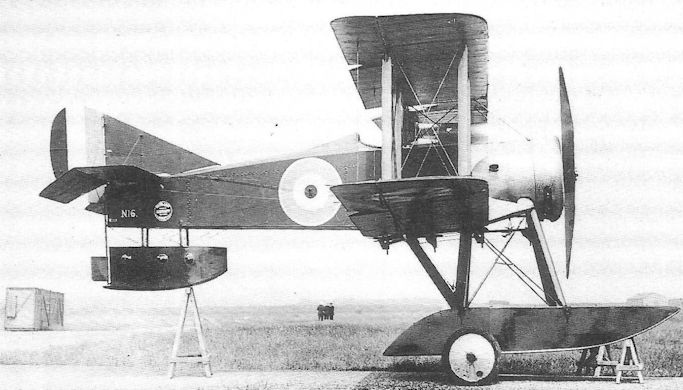
The Westland N.1B, N16, with short floats.
This N.1B floatplane fighter, N.16, was the first aircraft designed and built by Petter's Westland Aircraft Works. Changes in naval policy relating to this type of fighter brought its development to an early end.
This N.1B floatplane fighter, N.16, was the first aircraft designed and built by Petter's Westland Aircraft Works. Changes in naval policy relating to this type of fighter brought its development to an early end.
Westland Wagtail
Designed under the leadership of Robert Bruce and Arthur Davenport, the Westland Wagtail was a private venture essay in the light fighter concept, undertaken during the winter of 1917-18 and shortly afterwards submitted to meet the new Type IA Specification which called for an aircraft to be powered by a 180hp engine, and returning better performance and handling than the Sopwith Camel - which at that time was expected to be phased out of service in 1919.
Almost simultaneously the new 170hp ABC Wasp I seven-cylinder radial engine appeared and, from the outset, attracted considerable interest among aircraft designers on account of its relatively high power/weight ratio of 0.59 bhp/lb. The Wagtail was accordingly designed for this engine. Its structure was strictly orthodox with wooden boxgirder fuselage with spruce longerons and curved upper decking provided by fairings and stringers. Twin ash spars and spruce ribs of RAF 15 section provided the structure of the moderately staggered wings, with upper and lower ailerons. The cockpit was located approximately above the mid-chord line of the lower wing, while the upper wing was generously cut away both between the main spars and on the trailing edge. Twin synchronized Vickers guns were mounted, widely separated, on the nose.
Six prototype Wagtails, C4290-C4295, were ordered by the Air Board in February, principally to conduct engine trials with the new Wasp engine (which was already encountering serious mechanical faults). The fuselage of the first airframe was employed for structural tests - possibly at Farnborough. This order was reduced to three flying prototypes, C4291-C4293, late in March, this despite the fact that all five remaining airframes were well advanced.
First flight of the Wagtail C4291 was made by Capt F Alexander RFC in April 1918, after which the aspect ratio of the fin was reduced, and this modification was introduced on the other two prototypes. The second Wagtail also flew before the end of April, but was extensively damaged when its Bessoneaux hangar was burned down in the famous fire caused when an employee endeavoured to prove that it was possible to extinguish a lighted cigarette by dropping it into a tin of petrol. C4293 was delivered to Martlesham Heath on 8 May for trials, but was damaged in a landing accident there; hurriedly repaired, it was flown to Farnborough for investigation into the engine problems. A fortnight later, however, work was suspended on Wasp-powered aircraft while the manufacturers undertook a redesign of the copper-finned cylinders and of the valve gear.
The second Wagtail, C4292, was rebuilt and fitted with a 200hp Wasp II (with steel-finned cylinders), only to be struck off charge at Martlesham Heath in February 1920. Later that year, two further Wagtails, J6581 and J6582, were ordered and, although these used many components of the two cancelled airframes (C4294 and C4295), the new prototypes differed somewhat from the earlier aircraft. Both were fitted with Wasp II engines at Farnborough in March 1921, before having 150hp Armstrong Siddeley Lynx seven-cylinder radial engines installed. Because of this engine’s greater weight, a nose bay was removed, thereby shortening the nose but maintaining the aircraft’s centre of gravity within limits. A revised fin replaced the former truncated surface, and a strengthened undercarriage was fitted. In this form J6581 was first flown on 15 September 1921, and was followed by J6582 on 7 October. Both aircraft were grounded and struck off charge in August 1922.
Type: Single-engine, single-seat, single-bay biplane light fighter.
Manufacturer: The Westland Aircraft Works, Yeovil, Somerset.
Air Ministry Specification: RAF IA of 1918 (later D of R Type I)
Powerplant: One 170hp ABC Wasp I seven-cylinder air-cooled radial engine driving two- blade propeller; later 200hp Wasp II, and 150hp Armstrong Siddeley Lynx.
Structure: All-wood primary construction with fabric covering; steel elevator and rudder.
Dimensions: Span, 23ft 2in; length, 18ft 11in; height, 8ft 0in; wing area, 190 sq ft.
Weights: (Wasp I). Tare, 746lb; all-up, 1,330lb.
Performance: (Wasp I). Max speed, approx 130 mph at sea level, 125 mph at 10,000ft; climb to 10,000ft, 7 min 30 sec; service ceiling, 20,500ft; endurance, 2 1/2 hr.
Armament: Two synchronized 0.303in Vickers Mk I machine guns on nose with 1,000 rounds of ammunition.
Prototypes: Six ordered, C4290-C4295; C4290 used for ground tests; C4291-C4293 built and flown (C4291 first flown by Capt F Alexander in April 1918); C4294 and C4295 cancelled, but their components were used in two further prototypes, J6581 and J6582 (first flown with Lynx engines on 15 September 1921).

The third Westland Wagtail prototype, C4293, with the abbreviated fin; just visible are the enormous wing centre section cutouts above the cockpit.
Westland Weasel
First flown at about the time of the Armistice, the Westland Weasel was one of almost a dozen aircraft whose future - or, more accurately, the lack of it - was compromised by the failure of Granville Bradshaw’s ABC Dragonfly engine.
The two-seat, two-bay Weasel biplane was designed by Robert Bruce and Arthur Davenport during the summer of 1918 in response to the RAF Type IIIA Specification which called for a successor to the Bristol F.2B Fighter which was expected, under wartime conditions, to be due for replacement during 1919-20. Like the Wagtail, the Weasel possessed no dihedral on the lower wings, but pronounced dihedral on the upper planes. The pilot’s cockpit was located below the rear spar of the upper wing, necessitating an inter-spar aperture in the wing centresection above his head for upward view; being well staggered, the lower wing was sufficiently far aft to give the pilot a good view forward and downwards for landing. Generous trailing-edge cutouts were provided on both upper and lower wings which were both fitted with ailerons. The tailplane incidence was adjustable in flight.
Choice of the Dragonfly engine - recommended, it should be said, by the Air Ministry - proved unfortunate, to say the least. Not only was it found to be almost ten per cent heavier than forecast by the manufacturer, but was thirteen per cent down on power. The cylinder finning proved wholly inadequate for cooling, resulting in constant overheating. More serious was the frequent failure of crankshafts (presumably due to fatique) as it was discovered that the engine’s designed running speed coincided with the crankshaft’s critical vibration frequency in torsion.
Three prototype Weasels were ordered on 3 May 1918, and F2912 was flown in November by Capt Stuart Keep. Little or no further flying was done during the next four or five months while alterations were made in the forward fuselage to take account of the unexpectedly heavy engine. F2913 flew in June and F2914 in September.
The first Weasel underwent preliminary trials at Martlesham Heath in May to establish its handling characteristics with the revised c.g., but was destroyed during November in a forced landing following an engine fire; the pilot, Flt Lt Augustus Henry Orlebar afc was unhurt. (Some records suggest that the aircraft was fitted with an Armstrong Siddeley Lynx engine at the time).
After discontinuation of the Dragonfly engine’s development, all efforts to suit the Weasel for an active Service role were abandoned late in 1919. Instead, the two remaining original prototypes were confined to the development of other engines. F2913 was fitted with a Bristol Jupiter IV radial engine in 1921, and continued flying at the RAE until January 1924, being written off charge in October that year.
F2914 also had a long and varied life, suffering but surviving a number of forced landings. In 1920 its fin and rudder were redesigned to incorporate a horn-balanced rudder; beginning in November it underwent some further alteration and emerged in January 1922, powered by a 350hp Armstrong Siddeley Jaguar II two-row radial engine, appearing in this form in the New Types Park at the RAF Hendon Pageant on 24 June, and again at the 1923 Display. A Jaguar III was fitted in November 1923, and F2914 continued flying at Farnborough until 9 April 1925.
A fourth Weasel prototype had been ordered from Westland on 29 August 1919 under the designation Mark II, designed to the new D of R Type 2 Specification. Powered at the outset by a 450hp Cosmos Jupiter II radial, this aircraft, J6577, first flew in March 1920, but in July appeared at Martlesham with a Jaguar II engine. A year later this was replaced by a 436hp Jupiter IV. J6577 differed from the earlier prototypes in being fitted with horn-balanced ailerons.
The fate of this aeroplane is something of a mystery. After appearing in the New Types Park at Hendon in June 1922, it is said that J6577 crashed near Martlesham Heath following a fire in the air, and was burned out. Several records, however, show that this aircraft was flying at Martlesham in 1923, and the accompanying Air Ministry photograph is date-stamped 20 August 1923; moreover the aircraft as depicted appears to be fitted with heat-exchanger muffs on the exhaust pipes of the type developed by Bristol early in 1923.
The data table refers to the Weasel Mk I with Dragonfly engine.
Type: Single-engine, single-seat, two-bay biplane fighter.
Manufacturer: The Westland Aircraft Works, Yeovil, Somerset.
Air Ministry Specifications: RAF Type IIIA of 1918, and D of R Type 2 of 1919.
Powerplant: One 320hp ABC Dragonfly I; also 350hp Armstrong Siddeley Jaguar II, 450hp Cosmos Jupiter II, 436hp Bristol Jupiter IV, and possibly Armstrong Siddeley Lynx.
Dimensions: Span, 35ft 6in; length, 24ft 10in; height, 10ft 1in; wing area, 368 sq ft.
Weights: Tare, 1,867lb; all-up, 3,071lb.
Performance: Max speed 130.5 mph at sea level; climb to 10,000ft, 10 min; ceiling, 20,700ft.
Armament: Two synchronized 0.303in Vickers machine guns on front fuselage decking, and one Lewis gun with Scarff ring on rear cockpit.
Prototypes: Four, F2912-F2914 (Mk Is) and J6577 (Mk II). No production.
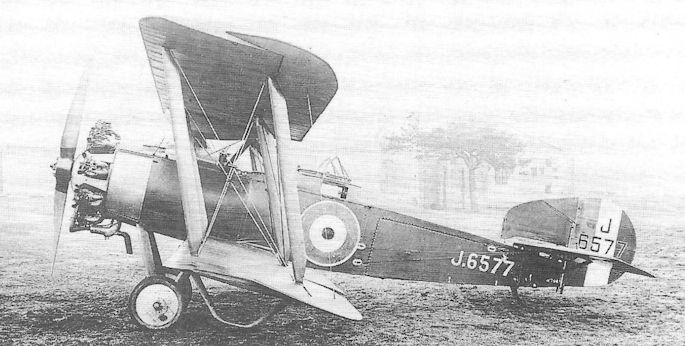
The fourth and final Westland Weasel, the Mk II, J6577, with horn-halanced ailerons, enlarged fin and muffs on engine exhaust pipes.
Whitehead Scout
Another company better known for its sub-contract manufacture of other firms’ designs than its own was Whitehead Aircraft Co Ltd of Townshend Road, Richmond, Surrey. No fewer than 720 Sopwith Pups had been ordered from this relatively modest manufacturer during 1916, yet this considerable workload did not deter the company from venturing to design a single-seat scout of its own that year.
It was perhaps surprising that the Whitehead Scout did not reflect its manufacturer’s familiarity with the highly successful Pup, but the two aircraft could hardly have been more different; indeed, it appears to have owed more to the unsuccessful Vickers E.S.2, which it closely resembled with its circular-section fuselage, gracefully curved fin and rudder and rounded wingtips.
Thus it was a not unattractive little aeroplane, powered by an 80hp Le Rhone, with slightly staggered, parallel chord, single-bay wings. The cockpit, however, was located at the point of the fuselage’s greatest girth so that the pilot could have had scarcely any downward field of vision owing to the width of the side fairings; he was nevertheless provided with a generous cutout in the upper wing trailing edge. The engine cowling featured four external stiffening ribs with oil drainage apertures at the bottom; it is likely that engine overheating would have resulted from the limited frontal cooling air aperture.
Although no pictures have been located which show the sole example of the Whitehead fitted with armament, there seems no reason to suggest that a synchronized Vickers gun could not have been fitted, nor that a more powerful engine would not have been introduced in due course. The aircraft was not, however, selected for production, and was probably rejected on the same grounds as the Vickers E.S.2 - inadequate field of vision from the cockpit.
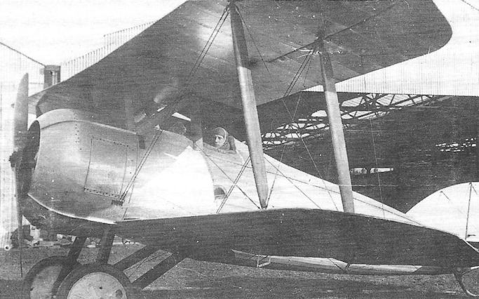
Close-up view of the Whitehead Scout which well illustrates the width of the fuselage ‘shoulders’ on either side of the cockpit.
Wight Baby
The established manufacturer of naval aircraft, J Samuel White of East Cowes in the Isle of Wight, was fortunate to possess the services of Howard Wright, a successful designer of long experience. In 1916 he produced a twin-float single-seat scout, much on the lines of the Sopwith Baby, though somewhat larger and heavier.
Of simple, if not crude, design the Wight aircraft was a single-bay biplane with single-acting ailerons on the top wing only; the wings were of unequal span and chord with double-camber, and the tail surfaces were of generous proportions with a large rectangular tailplane and elevator. Being without stagger or cutout, the upper wing obscured much of the pilot’s field of view. However, the 100hp Gnome monosoupape engine, driving a four-blade propeller, bestowed a fairly respectable top speed of about 90 mph at sea level.
The floats were much longer than those of the Sopwith Baby and therefore obviated the need for a tail float; partway through the Wight’s trials these floats were re-fitted further apart to improve stability on the water.
In 1917 one of the three Baby prototypes was flown at Felixstowe, and afterwards underwent Service trials at the Isle of Grain. By then, however, the aircraft’s performance had been thoroughly eclipsed by other in-service naval scouts and it was not developed further.
Type: Single-engine, single-seat, single-bay, twin-float biplane scout.
Manufacturer: J Samuel White & Co, East Cowes, Isle of Wight.
Powerplant: One 100hp Gnome monosoupape engine driving four-blade propeller.
Structure: Wooden box-girder fuselage with fabric and ply covering; two-spar, folding, double-camber, single-bay wings with unequal span and chord; twin three-step wooden floats.
Dimensions: Span, 30ft 8in; length, 26ft 8in; height, 9ft lin; wing area, 297 sq ft.
Weights: Tare, 1,277lb; all-up, 1,864lb.
Performance: Max speed, approx 90 mph at sea level; climb to 6,500ft, 20 min 30 sec; service ceiling, 9,300ft; endurance, 2 1/2 hr.
Armament: None fitted.
Prototypes: Three, Nos 9097, 9098 and 9100. No production.
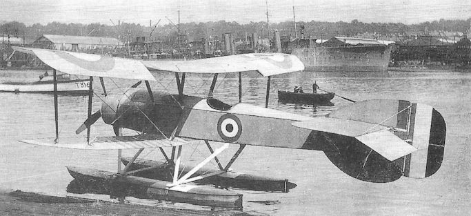
The first prototype Wight Baby, No 9097, at Cowes before the floats were re-positioned further apart.
Wight Quadruplane Scout
Towards the end of 1916 the Isle of Wight company, J Samuel White & Co, was engaged in work on a diminutive quadruplane single-seat scout, occasionally referred to as the Wight Type 4. Originally designed by Howard Wright (who had already left the company) the aircraft was powered by a 110hp Clerget rotary in a narrow-chord ‘oil sling’ cowling and, in its initial form featured wings of two different spans, the lowest being the shortest. Wing chord was only 2ft 9in, and tiny ailerons of some nine inches chord were fitted on the three upper wings. The undercarriage comprised single struts well raked outwards and wheels slotted into the lower wings’ leading edge; this arrangement, however, demanded an exceptionally long mounting for the tailskid in order to provide ground clearance for the lower wing’s trailing edge.
In order to employ an uninterrupted rectangular elevator, the horn-balanced rudder was hinged high on a fixed, triangular fin. As originally designed, the Scout featured twin parallel tubular interplane struts, but lack of side area resulted in these being crudely faired together by the simple expedient of wrapping them with fabric to create a single broad-chord surface; the struts in the lowest wing gap were not so treated. In all likelihood the aircraft was not flown in this somewhat dangerous configuration.
Early in 1917 a complete rebuild of the aircraft was begun. A much altered tail unit was designed, employing a split
elevator with cutout, thereby allowing an unbalanced rudder to be fitted, together with a much enlarged fin. The fuselage was less tapered in side elevation, resulting in a longer sternpost. A more conventional undercarriage was substituted with twin V-struts, the aft members passing through the lower wing to anchor on the lower longerons, allowing the wheels to be located well below the leading edge of the lower wing and thus permitting a conventionally-mounted tailskid.
Wing and aileron chords were increased so that the spars and interplane struts could be moved further apart and, with the increased side area of fuselage and tail, there was no need to fair the struts with fabric. A third and final configuration featured wings moved slightly further aft with progressively shorter spans from top to bottom, and with similar outward rake on the interplane struts; ailerons were only fitted on the two top wings.
Indeed the Scout appeared as a much safer-looking aeroplane, and Marcus Manton went ahead with flight tests. At some time towards the end of 1917 the prototype was purchased by the Admiralty, allotted the naval number N546, and evaluated at Martlesham. Manton stated that N546 ultimately crashed into a cemetary.
It is inconceivable that, despite its innovatory approach, the Quadruplane was ever seriously considered as a realistic operational fighter.
Type: Single-engine, single-seat, single-bay quadruplane scout.
Manufacturer: J Samuel White & Co, Cowes, Isle of Wight.
Powerplant: One 110hp Clerget rotary engine driving two-blade propeller.
Dimensions: Span, approx 19ft.
Prototype: One, N546.

The Wight Quadruplane on its long tailskid mounting, as it originally appeared with high-set rudder, small fin, wrapped wing struts and short undercarriage.
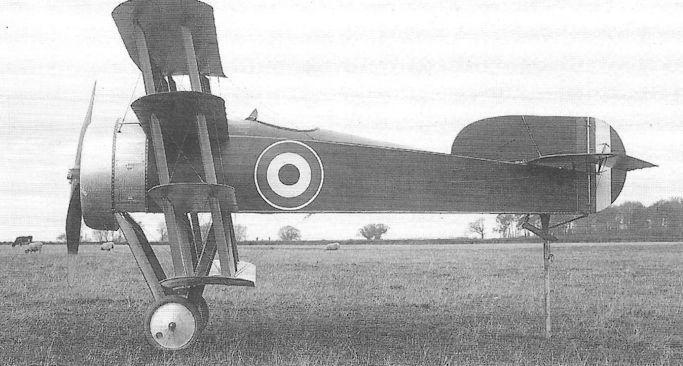
After rebuilding with modified tail, wings, and lengthened undercarriage with conventional tailskid. The lack of forward view for the pilot is readily apparent.