Самолеты (сортировка по:)
Страна Конструктор Название Год Фото Текст

Zeppelin-Staaken R.V

Страна: Германия

Год: 1916

Zeppelin-Staaken - VGO.I/VGO.II - 1915 - Германия<– –>Zeppelin-Staaken - VGO.III / R.IV / R.VII - 1916 - Германия


В.Кондратьев Самолеты первой мировой войны


МОДИФИКАЦИИ
  
   "Цеппелин-Штаакен" R-V и R-VII. Первый опыт воздушных боев показал, что истребители почти всегда атакуют бомбардировщики с задней полусферы. Поэтому, для более эффективной защиты, на очередной модификации "Цеппелина" мотогондолы как бы развернули на 180 градусов.
   Двигатели с винтами установили спереди, а турели - сзади. Кроме того, на R-V еще одну турель с практически неограниченным полем обстрела смонтировали в так называемом "ласточкином гнезде" над верхним крылом, куда при угрозе нападения стрелок поднимался по лестнице.
   Четырехлопастные винты на R-V приводились в движение пятью моторами "Майбах" Mb.IV по 240 л.с. (1 в носу и 2 спарки в гондолах). В фюзеляже R-VII стояли 2 "Мерседеса" по 160 л.с., а в гондолах - 4 "Бенца" по 220 л.с. Обе машины в 1917 году отправили на западный фронт. R-VII разбился по дороге, а R-V некоторое время использовался в качестве ночного бомбардировщика.


O.Thetford, P.Gray German Aircraft of the First World War (Putnam)


Zeppelin-Staaken R V
   Fifth of the "Giant" prototypes, the R V again rung the changes in the engine arrangement. All five motors were 240 h.p. Maybachs, with reversion to a single power plant in the nose and tandem-mounted engines, now arranged to drive four-blade tractor airscrews, outboard. The nacelles housing the outboard engines were experimentally built of wood and covered in ply-sheet, and due to the tractor propeller arrangement, the machine-gun positions were necessarily transferred to the rear. An additional machine-gun emplacement was provided in a streamlined nacelle, also of plywood, positioned in the centre of the top wing and known as the Schwalbenest (Swallow's nest). This machine, serialled R 13/15, saw service on the Western Front. Engines, five 240 h.p. Maybach Mb IV. Span, 42.2 m. (138 ft. 5 5/8 in.). Length, 230 m. (75 ft. 5 5/8 in.). Height, 6.8 m. (22 ft. 3 3/4 in.). Area, 332 sq.m. (3,586 sq.ft.). Weights: Empty, 9,450 kg. (20,790 lb.). Loaded, 13,010 kg. (28,622 lb.). Speed, 135 km.hr. (84.35 m.p.h.). Climb, 3,000 m. (9,840 ft.) in 46 min. Armament, five machine-guns.


G.Haddow, P.Grosz The German Giants (Putnam)


Staaken R.V

   The Staaken R.V was another step in a series of experiments to develop the correct formula for the decentralized-engined Staaken giants. Whereas the previous Staaken types represented a combination of tractor and pusher propulsion, the R.V had all its engines driving tractor airscrews. This configuration was chosen to provide a powerful and free field of fire to the rear. The R.V, with its five Maybach engines, was the most powerful German R-plane until the advent of the Benz-powered Aviatik licence-built Staaken R.XVI.
   The engine layout could best be described as the Staaken R.IV system in reverse. Two engines in each nacelle were coupled to a common gear-box which drove a four-bladed Garuda tractor airscrew. The rear engine was stepped down to allow its transmission shaft to pass under the forward engine. Viewed from above, each engine was offset slightly from the nacelle centre line. In contrast to the R.IV, the similar transmission system of the R.V proved troublesome. The technical problems required a long time to solve, and many minor change were made before the necessary reliability was attained. The more powerful 245 h.p. high-compression Maybach Mb.IVa engines gave rise to greater transmission forces, as compared to the lower-powered engines of the R.IV, and this is where the trouble lay. As a result, the R.V, which was begun in June 1916, was not accepted until 29 September 1917, some three months after the Staaken R.VII 14/15 and Staaken R.VI 25/16.
   The basic airframe followed closely the configuration of the previous Staaken machines, with few exception. The streamlined engine nacelles were a departure, for they were built of a wooden framework covered with plywood. This monocoque construction helped reinforce the engine mounts to the extent that vibrations and oscillation were greatly reduced. The engines were easily accessible, because internal bracing and cable work was eliminated. The streamline form was aerodynamically desirable but time-consuming and expensive to fabricate, precluding its use on succeeding Staaken aircraft. The nacelle underside remained open to allow fuel and vapours to escape. The tail of each nacelle extended well beyond the trailing edges of the wing, and each was equipped with a machine-gun ring that was to be manned by the flight mechanics.
   The single, geared Maybach engine in the nose was cowled by aluminium panels in a manner similar to the R.IV and R.VII machines. The Maybach engines required five large radiator; one was installed above the fuselage nose and the remaining four were attached to the front and rear upper nacelle struts, staggered to avoid blanking each other.
   Wing construction and dimensions were identical to the previous Staaken machines. Night-landing lights were fitted in the lower-wing leading edge in front of the inner struts.
   The fuselage, though structurally similar to earlier Staaken machines, was considerably shortened from the centre-section struts aft. This segment and tail presaged the construction of the R.VI machines. Crew accommodations followed the pattern set by the VGO.III. The flight mechanic's compartment was located directly behind the nose engine, followed by a large open pilots' cockpit and a similar open commander's position. Dorsal and ventral machine-gun positions, located behind the centre section, supplemented the strong tail defence. To provide a forward-firing gun position the gravity tank was encased in a streamlined pod which extended ahead of the upper-wing leading edge. A machine-gun post, known as the "Swallow's Nest", was located in this extension and could be reached by a ladder set between the centre-section struts.
   Strange as it may seem, the R.V was fully equipped with a pneumatic-tube message system with six receiving and sending stations. The problem of communicating in an R-plane was difficult to solve. Various attempts were made in the early giants to use such forms of acoustical communication as telephones, sirens and speaking-tubes. But these failed due to the loss of hearing experienced by crews during long flights. Optical devices ranged from the simple chalkboard to complicated optical systems, such as writing on frosted glass and projecting the message through prisms and lenses on to an opaque surface. Another technique which met with little success was to run messages along a wire track from station to station. In the end, the pneumatic-tube device, although an acceptable technique, lost out to the simpler electric telegraph, which used ten or twenty pre-set signals to furnish information and commands. The pneumatic telegraph in the R.V was operated by turning a crank: a right-hand turn created air pressure and a left-hand turn created suction. A signal light automatically lit in the receiving station when a message was placed in the tube.
   It is known that Lt. Otto Reichardt was transferred to Gotha to take command of the R.V. It may be assumed that the R.V was the last Staaken R-plane to be built in Gotha and that Dipl.-Ing. Lt. Reichardt was responsible for bringing the R.V up to operational status. The crew of the R.V, larger than in most R-planes, numbered eleven men, consisting of one commander, two pilots, three mechanics, one wireless operator, one fuel attendant and three gunners.
   The R.V 13/15 was accepted at Staaken on 29 September and joined Rfa 501 at Ghent on 23 December 1917. Its first bombing mission was on 25 January 1918 when it attacked harbour installations at Calais. During its eight months service career, the R.V flew only sixteen combat missions. This low total is a reflection of the recurring mechanical failures which plagued the power transmission system. The most notable mission recorded in the R.V war diary took place on 7/8 March 1918 when the R.V carried a useful load of 4771 kg. at an altitude of 3300 metres on a flight lasting seven hours. Although the right front clutch failed over London, the R.V returned home safely. Lt. Reichardt was transferred home during late 1918 to serve with Idflieg, where he utilized his experience a front-line pilot and R-plane commander to institute a series of improvements which, it is said, greatly increased the performance of the Staaken R-planes. Later in 1918 he was killed while assisting in the development of the AEG R.I.
   Waldemar Roeder recalls his flying as second pilot on the R.V while serving with Rfa 501. The commander was Lt. Ernst Pickerott and first pilot, Vizefeldwebel Heinz Schmitz. The flying qualities of the R.V, as with all Staaken aircraft, were rather comfortable and stable, if one disregards the rather high control forces, particularly the unbalanced ailerons. The steering wheel had to be turned several times until the ailerons "caught", and then it took considerable time until the aircraft reacted.
   With the fusion of Rfa 500 and Rfa 501 the R.V flew to Morville in October 1918. On 18 October 1918 the R.V was ordered to Dusseldorf-Lohausen. During the flight, fog was encountered in the Rhein area. Much against the better judgment of Schmitz and Roeder, Pickerott ordered an emergency landing. In the attempt, the aircraft was smashed, although the only injury to the crew was a broken ankle suffered by Lt. Pickerott. The crash occurred in what became the Allied Zone of Occupation, and it is entirely possible that reports by former squadron members are true, namely that the aircraft, or parts of it, were delivered to the Allied armistice commission.

Colour Scheme and Markings

   The overall finish consisted of large vari-coloured polygons. White outlined Patee crosses were painted on upper and lower wingtips, fuselage sides and tail.


SPECIFICATIONS

Type: Staaken R.V.
   Manufacturer: Flugzeugwerft G.m.b.H., Staaken, Berlin
   Engines: Five 245 h.p. Maybach Mb.IVa engInes
   Dimensions:
   Span, 42•2 m. (138 ft. 5 1/2 in.)
   Length, 23 m. (75 ft. 5 1/2 in.)
   Height, 6•8 m. (22 ft. 3 1/2 in.)
   Areas: Wings, 332 sq. m. (3572 sq. ft.)
   Weights:
   Empty, 9450 kg. (20,837 lb.)
   Useful load, 3560 kg. (7,850 lb.)
   Loaded, 13,010 kg. (28,687 lb.)
   Wing Loading: 42 kg./sq. m. (8,6 lb./sq. ft.)
   Performance:
   Maximum speed, 135 km.h. (83•9m.p.h.)
   Climb,
   1000 m. (3281 ft.) in 10 mins.
   2000 m. (6562 ft.) in 22 mins.
   3000 m. (9843 ft.) in 34 mins.
   Ceiling approximately, 4500 m. (14,764 ft.)
   Armament: Provision for dorsal, ventral, upper wing and two nacelle machine-gun positions.
   Service Use: Western Front with Rfa 501 in Ghent area 1917-18


J.Herris Zeppelin-Staaken Aircraft of WW1. Vol 1: VGO.1 - R.IV R.29/16 (A Centennial Perspective on Great War Airplanes 47)


Staaken R.V
  
  The Staaken R.V utilized the same basic airframe as the R.IV and earlier VGO predecessors, although its fuselage was shortened behind the wings, but its engine arrangement distinguished it from them. The R.V used five Maybach Mb.IV engines of 245 hp, making it the most powerful R-plane yet built. One engine replaced the coupled engines in the nose of the R.IV, and coupled Maybachs replaced the slightly less powerful coupled Benz engines. However, unlike previous aircraft in the VGO/Staaken series, the nacelle engines were mounted as tractors, not pushers. Thanks to that and the gunners position installed at the rear, this gave the R.V a distinctive appearance.
  The more powerful engines created greater stresses in the clutches and gearboxes that reduced reliability, and these problems took some time to solve. This delayed Army acceptance until September 29, 1917, although the R.V was completed in 1916.
  The engine nacelles were semi-monocoque, with plywood skin over wood frames. The result was good strength and streamlining at the cost of more labor required to construct; this precluded its use on subsequent Staaken aircraft. However, the strength greatly reduced vibration. The bottoms of the nacelles were left somewhat open to vent oil and fuel leaks. Another feature was installation of flexible gun positions with fields of fire to the rear. Together with the dorsal and ventral machine guns this gave the R.V a formidable rearward-firing armament.
  To provide defense to the front, a 'swallow's nest' nacelle was added to the center section of the upper wing leading edge. This small nacelle housed the gravity tank and a gunner and flexible machine gun with all-around field of fire.
  Interestingly, the R.V had a pneumatic-tube message system with six stations for sending and receiving. This worked but the simpler electric telegraph was a better solution.
  Apparently the R.V was the last R-plane built at VGO. Dipl.-Ing. Lt. Otto Reichardt was transferred to Gotha to command the R.V and its large, 11-man crew. R.V was accepted at Staaken and joined Riesenflugzeug-Abteilung 501(Rfa 501) at Ghent on 23 December 1917. Its first bombing mission was January 25, 1918 against the Calais and Dunkirk. According to the Suntrop-Chronik, Koln, the R.V completed 18 combat missions bombing targets such as London, Calais, Dunkirk, Ostende, Ypres, Abbeville, St.Omer, Dieppe, Rouen, and Gravelines. In all 46 flights during the aircraft's service, "Thirteen" was lucky for its crew.
  On October 18 the R.V was ordered to Dusseldorf - Lohausen. When fog was encountered during the flight, Lt. Pickerott, the new aircraft commander, ordered the pilots to make an emergency landing, much against their better judgment. The R.V was nearly destroyed in the attempt, although only Pickerott was injured with a broken ankle.
  Vzfw. Heinrich Schmitz writes in his memories the aircraft was disassembled and returned to Staaken for repair, but the end of the war stopped it.


Staaken Specifications
Type V.G.O. Ill R.IV R.V
Engines 6x160 Hp Mercedes D.III 2x160 Hp Mercedes D.III 4x220 Hp Benz Bz.IV 5x245 Hp Maybach Mb.IVa
Span 42.2 m (138'5 1/2") 42.2 m (138'5 1/2") 42.2 m (138' 5 1/2")
Chord (inner) - 4.6 m (15' 1") 4.6 m (138' 5 1/2")
Chord (outer) - 3.6 m (11' 10") 3.6 m (11' 10")
Length 24.5 m (80' 4 1/2") 23.2 m (76' 1") 23 m (75' 5 1/2")
Height 6.8 m (22' 3 1/2") 6.8 m (22' 3 1/2") 6.8 m (22'3 1/2")
Tail span - 9 m (29' 6") -
Wing Area 332 m2 (3,572 ft2) 332 m2 (3,572 ft2) 332 m2 (3,572 ft2)
Wt. Empty 8,600 kg (18,963 lb.) 8,772 kg (19,342 lb.) 9,450 kg (20,837 lb.)
Wt. Fuel - 2,140 kg (4,719 lb.) -
Wt. Payload - 2,123 kg (4,681 lb.) 3,560 kg (7,850 lb.)
Wt. Loaded 11,600 kg (25,578 lb.) 13,035 kg (28,742 lb.) 13,010 kg (28,687 lb.)
Max Speed 120 km/h (75 mph) 125 km/h (77.5 mph) 135 km/h (83.9 mph)
Climb 1,000 m 16 minutes 10 minutes 10 minutes
Climb 2,000 m 29 minutes 35 minutes 22 minutes
Climb 3,000 m 56 minutes 89 minutes 34 minutes
Ceiling 3,000 m 3,700 m 4,500 m
Duration 6 hours 6-7 hours -

J.Herris - Zeppelin-Staaken Aircraft of WW1. Vol 1: VGO.1 - R.IV R.29/16 /Centennial Perspective/ (47)
Staaken R.V R.13/15 in early camouflage.
J.Herris - Zeppelin-Staaken Aircraft of WW1. Vol 1: VGO.1 - R.IV R.29/16 /Centennial Perspective/ (47)
Staaken R.V R.13/15 in late camouflage.
В.Обухович, А.Никифоров - Самолеты Первой Мировой войны
Цеппелин-Штаакен R V
J.Herris - Zeppelin-Staaken Aircraft of WW1. Vol 1: VGO.1 - R.IV R.29/16 /Centennial Perspective/ (47)
"Цеппелин-Штаакен" R-V
The Staaken R.V differed from its predecessors in its engine arrangement; the nacelle engines were mounted as tractors. Fitting flexible machine guns in the rear of the nacelles gave it very heavy firepower to the rear. Here it is seen with dark night bomber camouflage.The aircraft, military serial R.13/15, completed 18 combat missions such as bombing London, Calais, Dunkirk, Ostende, Ypres, Abbeville, St. Omer, Dieppe, and Rouen. (Peter M. Grosz collection/STDB)
J.Herris - Zeppelin-Staaken Aircraft of WW1. Vol 1: VGO.1 - R.IV R.29/16 /Centennial Perspective/ (47)
Close-up of R.13 showing details.
J.Herris - Zeppelin-Staaken Aircraft of WW1. Vol 1: VGO.1 - R.IV R.29/16 /Centennial Perspective/ (47)
The R.V crew pre-flighting the aircraft for the next night combat mission. On the wing, near the cabin is standing 1st pilot Vizefeldwebel Heinrich Schmitz. May 1918 Schweldewindeke airfield. Note the 'Swallow nest' gun ring mounted at upper wing fuel tank. This mount is a German copy of British Scarf ring. The R.V is fully camouflaged for night operations. According to intelligence reports the day-time camouflage was over-painted by a matt blue lacquer mixture, with dark Prussian blue and ultramarine pigment. (Peter M. Grosz collection/STDB)
J.Herris - Zeppelin-Staaken Aircraft of WW1. Vol 1: VGO.1 - R.IV R.29/16 /Centennial Perspective/ (47)
Photo taken shortly after the propeller was changed from two-bladed to four-bladed Garuda.The small spinner is not yet mounted. The small oil radiator is visible at the bottom of the nacelle. Here was cooling oil for both engines and the gear box which drove the Garuda aircrew. Two Hans Window radiators are mounted on the nacelle struts. The front engine is mounted lower and the rear is higher. (Peter M. Grosz collection/STDB)
J.Herris - Zeppelin-Staaken Aircraft of WW1. Vol 1: VGO.1 - R.IV R.29/16 /Centennial Perspective/ (47)
Close-up of the R.V showing the 'swallow's nest' gun nacelle in the upper wing. (Peter M. Grosz collection/STDB)
J.Herris - Zeppelin-Staaken Aircraft of WW1. Vol 1: VGO.1 - R.IV R.29/16 /Centennial Perspective/ (47)
R.13 warming up all engines, before take-off. The whole aircraft is painted with hexagonal night camouflage. Colors were very probably: green, dark ruby, Prussian blue and yellow, over-painted by matt dark blue lacquer. (Peter M. Grosz collection/STDB)
J.Herris - Zeppelin-Staaken Aircraft of WW1. Vol 1: VGO.1 - R.IV R.29/16 /Centennial Perspective/ (47)
Staaken R.V 13/15. The engines are being tested in preparation for a night mission from Scheldewindeke in 1918. At this time all propellers had two blades; later the nacelle propellers had four blades. (Peter M. Grosz collection/STDB)
J.Herris - Zeppelin-Staaken Aircraft of WW1. Vol 1: VGO.1 - R.IV R.29/16 /Centennial Perspective/ (47)
The R.13 with all propellers fitted with four blades. (Peter M. Grosz collection/STDB)
J.Herris - Zeppelin-Staaken Aircraft of WW1. Vol 1: VGO.1 - R.IV R.29/16 /Centennial Perspective/ (47)
The R.13 during preparation for its next night combat mission. (Peter M. Grosz collection/ STDB)
J.Herris - Zeppelin-Staaken Aircraft of WW1. Vol 1: VGO.1 - R.IV R.29/16 /Centennial Perspective/ (47)
The R.13 during continued preparation for its next night combat mission. (Peter M. Grosz collection/ STDB)
J.Herris - Zeppelin-Staaken Aircraft of WW1. Vol 1: VGO.1 - R.IV R.29/16 /Centennial Perspective/ (47)
The massive R.V being readied for another mission. (Peter M. Grosz collection/STDB)
J.Herris - Zeppelin-Staaken Aircraft of WW1. Vol 1: VGO.1 - R.IV R.29/16 /Centennial Perspective/ (47)
Flight engineer in his gunner's position.
J.Herris - Zeppelin-Staaken Aircraft of WW1. Vol 1: VGO.1 - R.IV R.29/16 /Centennial Perspective/ (47)
Crewman in the 'swallow's nest'. This had a flexible machine gun with 360° field of fire above the wing.
J.Herris - Zeppelin-Staaken Aircraft of WW1. Vol 1: VGO.1 - R.IV R.29/16 /Centennial Perspective/ (47)
View taken from right nacelle showing the gunner's position at the rear of the nacelle giving the R.V great firepower to the rear. On the gun ring is a Parabellum 14/17 with enlarged drum magazine. The side ladder mounted at the nacelle side is clearly seen. (Peter M. Grosz collection/STDB)
J.Herris - Zeppelin-Staaken Aircraft of WW1. Vol 1: VGO.1 - R.IV R.29/16 /Centennial Perspective/ (47)
In-flight photos taken from the starboard engine nacelle. (Peter M. Grosz collection/STDB)
J.Herris - Zeppelin-Staaken Aircraft of WW1. Vol 1: VGO.1 - R.IV R.29/16 /Centennial Perspective/ (47)
Another view taken from the right nacelle showing the dorsal gun position. Guns are not mounted, suggesting the flight is not a combat mission. (Peter M. Grosz collection/STDB)
J.Herris - Zeppelin-Staaken Aircraft of WW1. Vol 1: VGO.1 - R.IV R.29/16 /Centennial Perspective/ (47)
In-flight view taken from the right nacelle gunner position showing the characteristic Staaken tail unit on the R.V. The third rudder was never added to this (Staaken R.13) aircraft. (Peter M. Grosz collection/STDB)
J.Herris - Zeppelin-Staaken Aircraft of WW1. Vol 1: VGO.1 - R.IV R.29/16 /Centennial Perspective/ (47)
In-flight photos taken from the starboard engine nacelle. (Peter M. Grosz collection/STDB)
J.Herris - Zeppelin-Staaken Aircraft of WW1. Vol 1: VGO.1 - R.IV R.29/16 /Centennial Perspective/ (47)
THE ZEPPELIN GIANT AEROPLANE. - Looking down from the machine gunner's nest at the two pilots, the observer, and the commander.
View taken from the 'swallow's nest' of the pilots cockpit and front engine room. Ghent, Belgium is seen in the background. In the cabin are pilots Schmitz and Roeder and behind them is Lt. Pickerott, the aircraft commander, and Reichardt. (Peter M. Grosz collection/ STDB)
J.Herris - Zeppelin-Staaken Aircraft of WW1. Vol 1: VGO.1 - R.IV R.29/16 /Centennial Perspective/ (47)
View aft from the "swallows nest" on the R.V.
J.Herris - Zeppelin-Staaken Aircraft of WW1. Vol 1: VGO.1 - R.IV R.29/16 /Centennial Perspective/ (47)
The Staaken R.V and its eleven crew photographed prior to its crash in October 1918. The aircraft commander Lt. Ernst Pickerott, first pilot Vizefeldwebel Heinrich Schmitz, second pilot Waldemar Roeder. Note the "Kathchen" Paulus Systeme parachute belts worn by some aviators. At this time, the R.V had eleven members: aircraft commander, two pilots, one observer officer, one flight engineer responsible for gasoline distribution, one radio operator, two mechanics, and three gunners. The crew strength varied from eight to 14 members according to the mission type. (Peter M. Grosz collection/STDB)
J.Herris - Zeppelin-Staaken Aircraft of WW1. Vol 1: VGO.1 - R.IV R.29/16 /Centennial Perspective/ (47)
Right nacelle photographed during maintenance. The bottom panels are removed and the inner wood frames of the nacelle structure are clearly seen. The brush-painted matt dark blue colored lacquer application is visible. (Peter M. Grosz collection/STDB)
J.Herris - Zeppelin-Staaken Aircraft of WW1. Vol 1: VGO.1 - R.IV R.29/16 /Centennial Perspective/ (47)
Nacelle during aircraft maintenance. The nacelle construction can be seen under the dismounted bottom panels. At the lower wing root is a four-bladed wind propeller powering the fuel pump. (Peter M. Grosz collection/STDB)
J.Herris - Zeppelin-Staaken Aircraft of WW1. Vol 1: VGO.1 - R.IV R.29/16 /Centennial Perspective/ (47)
R.V cockpit under construction.
J.Herris - Zeppelin-Staaken Aircraft of WW1. Vol 1: VGO.1 - R.IV R.29/16 /Centennial Perspective/ (47)
In-flight view of the inside of the engine nacelle. (Peter M. Grosz collection/STDB)
J.Herris - Zeppelin-Staaken Aircraft of WW1. Vol 1: VGO.1 - R.IV R.29/16 /Centennial Perspective/ (47)
Antenna wheel located at the radio operator's position. (Peter M. Grosz collection/STDB)
J.Herris - Zeppelin-Staaken Aircraft of WW1. Vol 1: VGO.1 - R.IV R.29/16 /Centennial Perspective/ (47)
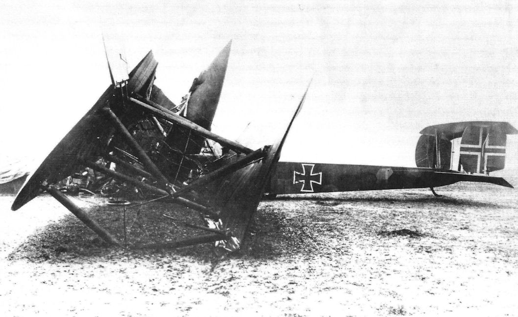
The wreck of Zeppelin Staaken R.V (R.13/15) that crashed near Heistern, 3 October 1918 (18 October in other sources). After flying in heavy rain and fog all engines started to run badly and the new aircraft commander ordered the pilots to make an emergency landing. This was against their better judgment and the results showed why; the R.V was basically destroyed in the landing. Fourteen crew members and passengers were fortunate; only one person (Lt. Pickerott, the aircraft commander) was injured. Note the Balken cross painted at rudder. (Peter M. Grosz collection/ STDB)
J.Herris - Zeppelin-Staaken Aircraft of WW1. Vol 1: VGO.1 - R.IV R.29/16 /Centennial Perspective/ (47)
Another view of the crashed R.V. The fuselage cross shows were the old cross was scraped off and the new cross was painted on. Note the partially opened, nacelle gunner's parachute (probably a Kathchen Paulus Systeme) laying along the right nacelle. From 1917 the Rfa unit started to mount and test parachutes from two Systeme. First: Kathchen Paulus. The life saving parachute (Rettungsfallschirm) type"K. P." primary was used at early LZ, SL, and PL type Airships and observation balloons. Second: The Heinecke parachute system, designed for fighters and two-seater aircraft. Finally after tests the system Heinecke was chosen for Riesenflugze. But probably from an insufficient supply of parachutes, both types were used. (Peter M. Grosz collection/STDB)
J.Herris - Zeppelin-Staaken Aircraft of WW1. Vol 1: VGO.1 - R.IV R.29/16 /Centennial Perspective/ (47)
View of the upper wing of the crashed R.V (R.13/15) bomber. Note the night camouflage (dark blue color) overpainted the lozenge pattern and the scraped crosses. The lozenges on the wing undersides are brighter than on the fuselage and upper side so must be not darkened by dark bluish lacquer. (Peter M. Grosz collection/STDB)
J.Herris - Zeppelin-Staaken Aircraft of WW1. Vol 1: VGO.1 - R.IV R.29/16 /Centennial Perspective/ (47)
Pneumatic tube system in Staaken R-planes.
J.Herris - Zeppelin-Staaken Aircraft of WW1. Vol 1: VGO.1 - R.IV R.29/16 /Centennial Perspective/ (47)
Diagram of the R.V engine nacelles.
J.Herris - Zeppelin-Staaken Aircraft of WW1. Vol 1: VGO.1 - R.IV R.29/16 /Centennial Perspective/ (47)
Staaken R.V R.13/15 early & late camouflage.
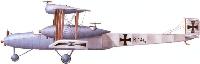
В.Кондратьев - Самолеты первой мировой войны
"Цеппелин-Штаакен" R-V
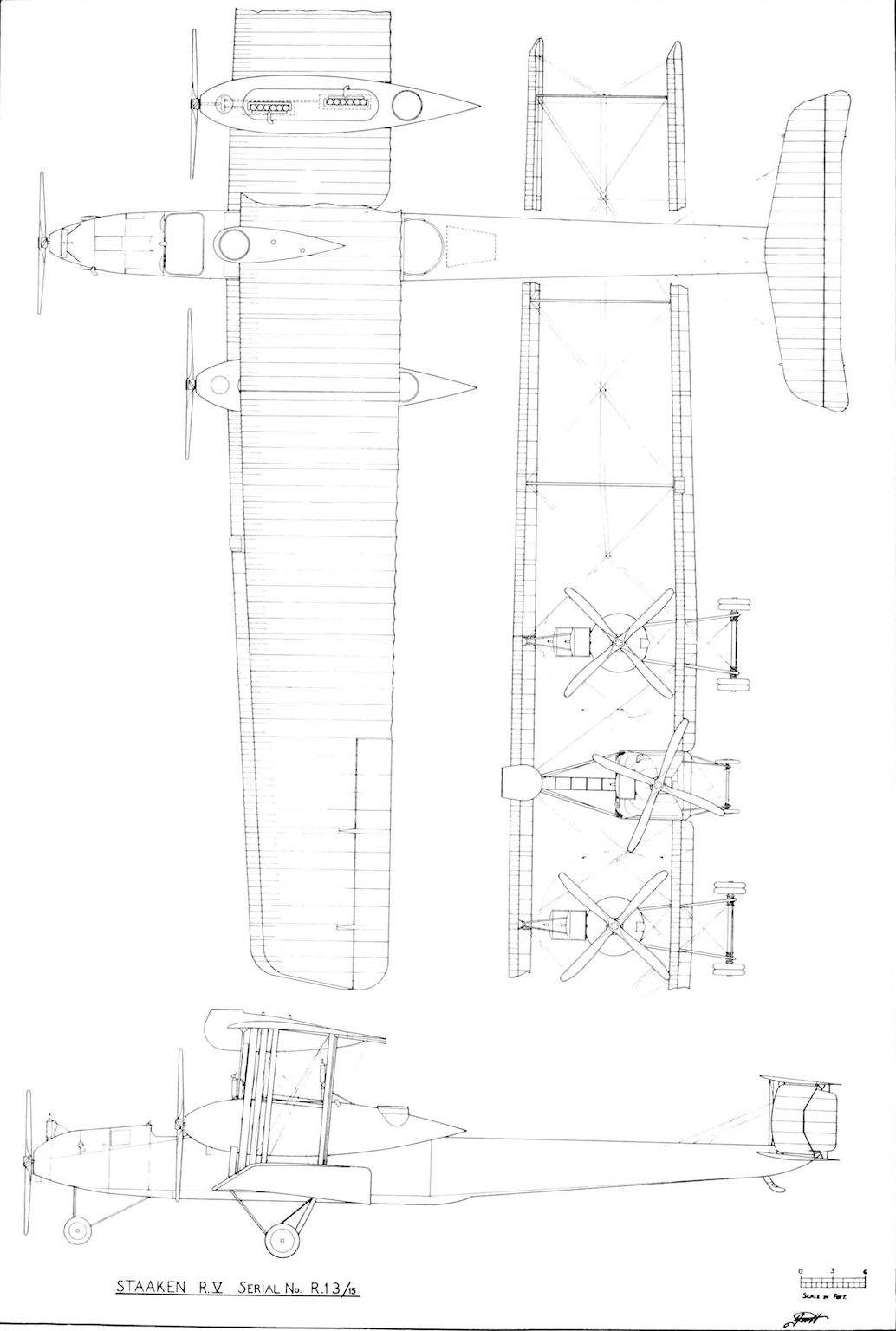
G.Haddow, P.Grosz - The German Giants /Putnam/
Staaken R.V