В.Кондратьев Самолеты первой мировой войны
"Цеппелин-Штаакен" R-XIV и R-XV. Для дальнейшего повышения энерговооруженности своих машин фирма Штаакен в 1917 году вернулась к схеме пятимоторного самолета с носовой силовой установкой. Так появился R-XIV - самый крупный и тяжелый аэроплан эпохи Первой Мировой войны, настоящий шедевр тогдашнего авиастроения.
Объем бензобаков был значительно увеличен, в результате чего почти на треть повысилась дальность полета. Кроме того, на R-XIV нарастили площадь вертикального оперения и ввели роговую компенсацию элеронов.
До конца войны успели построить только 4 таких аппарата и 3 очень похожих на него R-XV. 5 из них принимали участие в боях на западном фронте. Экипаж, вооружение и оборудование R-XIV и R-XV такие же, как на R-VI.
ЛЕТНО-ТЕХНИЧЕСКИЕ ХАРАКТЕРИСТИКИ
("Цеппелин-Штаакен" R-XIV)
Размах, м 42,2
Длина, м 22,5
Площадь крыла, кв.м 334,0
Сухой вес, кг 10350
Взлетный вес, кг 14450
Скорость максимальная, км/ч 135
Дальность полета, км 1300
Время набора высоты, мин/м 45/3000
Потолок, м 4500
O.Thetford, P.Gray German Aircraft of the First World War (Putnam)
Zeppelin-Staaken R XV
Development of the Staaken "Giants" continued in the R XIVs and R XVs of 1918, which, as far as can be ascertained, appeared not to differ. Three R XIVs were built, R 43/16-R 45/16, of which the first numbered machine was shot down by Capt. Yaille of 151 Squadron R.A.F. R 45/16 was used for experiments with control positions. The R XVs were serialled R 46/16-R 48/16, but were probably completed too late to see any service use. All machines were five-engined "Giants" and differed from previous aircraft in each engine having its own individual airscrew, making three tractors and two pushers, and in consequence the abandonment of gun positions in the nacelles. A large central fin was now included in the tail assembly in similar manner to the later R VIs. Engines, five 245 h.p. Maybach Mb IV. Span, 42.2m. (138 ft. 5 5/8 in.). Length, 22.5 m. (73 ft. 10 in.). Height, 6.3 m. (20 ft. 8 in.). Area, 334 sq.m. (3,607 sq.ft.). Weights: Empty, 10,350 kg. (22.770 lb.). Loaded, 14,450 kg. (31,790 lb.). Speed, 130 km.hr. (81.25 m.p.h.). Climb, 3,000 m. (9,840 ft.) in 70 min. Armament, five machine-guns.
Zeppelin-Staaken R XVI (Av)
Early in 1918 the new Benz Bz VI developing 530 h.p. became available, and Aviatik were chosen to fit these engines to the basic Staaken R VI airframe. This was due partly to the parent firm being otherwise fully committed and partly to Aviatik's experience in the building of six R VI machines under licence.
Three aircraft with the Benz engines were ordered, R 49 to R 51, designated Staaken R XVI (Av) and were the ultimate Staaken development. R 49 was completed in October 1918 but smashed its landing gear on a test flight and rebuilding cannot be confirmed. R 50 was finished after the war as a civil machine, but was soon dismantled. Although R 51 was well advanced in construction, it was never completed.
Engines, two 220 h.p. Benz IVa and two 530 h.p. Benz VI driving tractor and pusher airscrews in two nacelles. Spinners were fitted, a refinement not seen on "Giants" built by the parent firm. Span, 42.2 m. (138 ft. 5 1/2 in.). Length, 22.5 m. (73 ft. 10 in.). Height, 6.5 m. (21 ft. 4 1/4 in.). Speed, 130 km.hr. (80.8 m.p.h.). Ceiling, 3,710 m. (12,172 ft.) in 76.5 min.
G.Haddow, P.Grosz The German Giants (Putnam)
Staaken R.XIV
In late 1917 the Staaken R.VI was followed by an improved, more powerful version, designated the Staaken R.XIV. These aircraft were powered by four 350 h.p. Austro-Daimler twelve cylinder engines, the most powerful available at the time. Unfortunately, the Austro-Daimler engine proved unreliable and the hope of developing a "super" R.VI series was shattered.
The R.43/17, first of the new R.XIV series, was almost complete in February 1918. A March 1918 Idflieg status report stated that this aircraft had a new seating arrangement for the pilot, consisting of an open cockpit on the upper fuselage decking to provide a broad field of view. It also provided an unencumbered commander's bomb aiming position in the nose. The engines were installed without reduction gears in order to obtain full-scale performance comparison with geared propellers on other R-planes, and the engine mount was redesigned to eliminate the recurrent failure of engine support struts on the R.VI series. By March the R.43 had already flown many time. Its first flight in the acceptance programme took place on 11 April 1918, on which the R.43 carried a 4020 kg. useful load to 3100 metre altitude in 91 minute. Soon after taking-off on the next day a connecting-rod broke in one of the rear engines. The Austro-Daimlers were replaced by four 300 h.p. Basse & Selve BuS.IVa engines, and was reported once more ready for flight testing on 10 May 1918. However, the new unproven BuS.IVa engines showed a propensity for piston seizure and were in their turn removed from both the R.43 and the R.44 (which had been expected to make its first flight on 3 May 1918). The final installation consisted of five 245 h.p. high-compression Maybach Mb.IVa engines. Since the R.XIV weighed some 2000 kg. more than the R.VI, an additional engine mounted in the nose was necessary to at least keep performance on a par with the R.VI.
It required some two months to modify the fuselage to mount the fifth engine. According to the record, the R.43 was ready for acceptance in July and the R.44 and R.45 were ready for their first flights on 3 July and 10 July 1918 respectively. The R.44 was delivered in August and the R.45 in July 1918. These two machines differed from the R.43 in that the nacelle tractor propellers were driven directly by the engine without benefit of the usual reduction gears.
In his writings after the war, von Bentivegni, the experienced commander of Rfa 501, regretted the fact that no systematic attempt had been made to improve the performance of Staaken R-planes by carefully refining the R.VI series. Instead of concentrating on weight reduction and streamlining, newer machines such as the R.XIV embodied a purposeless increase of fuselage size, weight and drag, which in themselves taxed performance and to some extent nullified the effect of an additional engine.
On the other hand, after comparing his experiences with both four- and five-engined Staaken R-planes, von Bentivegni was convinced that the disadvantages of the nose engine had been overemphasized and its advantages minimized. It should never be forgotten, he said in 1920, that an Staaken R.XIV 43/17 powered by five Maybach Mb.IVa engines, additional engine offered increased reliability, the most important factor in R-plane design. The problem of the high landing gear, which had been responsible for the elimination of the nose engine in the first place, was solved by simply keeping it short. This was made possible by design changes which allowed a normal "tail-down" ground attitude.
Among the disadvantages discussed by von Bentivegni was the proximity of the fuselage engine to the main fuel tanks, a factor that increased the fire hazard in event of a crash. It was his opinion, however, that this danger was more than compensated for by the increased reliability provided by the additional engine. An unexpected problem discovered during operational service was that of unavoidable vibrations of the nose engine. These vibrations had a very deleterious effect on the more delicate instruments installed in the later Staaken machines, particularly on sensitive electric wiring and connections.
According to von Bentivegni, the efficiency of the small-diameter ungeared propellers was hopelessly inadequate, and he considered this modification a total failure. Furthermore, the R.XIV series had strengthened airframes to house the more powerful Austro-Daimler engines. The resultant increase in weight was yet another factor which lowered the performance of these machines. Not until the last months of the war were R.XIV shortcomings eliminated with the advent of the improved R.XIVa series.
The typical Staaken wing was retained on the R.XIV with exception of a 1•5 degree sweepback of the outer wing panels; a trailing edge cut-out above the propellers and the fitting of balanced ailerons which were neatly faired into the wingtip outline. Upper-wing gun positions were installed slightly outboard of the nacelles and between the nacelle struts rather than behind as in the R.VI.
The nacelles, somewhat slimmer than those on the R.VI, were mounted higher in the wing gap, and the nacelle strut arrangement was considerably modified. The R.XIV machines were generally fitted with propeller spinners. The R.45 was at one time equipped with large-diameter four-bladed pusher propellers. whose blades were unusually narrow. The large spinner of the nose engine and the aluminium engine cowling provided a smooth entry to the fuselage, broken only by the protruding radiator and the auxiliary landing gear.
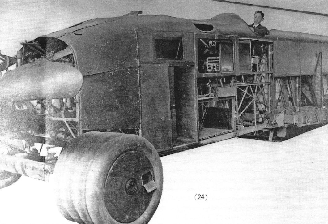
As in the earlier Staaken giants, the flight engineer's compartment was located directly behind the nose. followed by the enclosed navigation and commander's cabin, which also contained the bomb-aiming apparatus that may have been hung externally during use. Then came the large open pilots' cockpit located in the upper decking. The open cockpit was a definite departure from the closed cockpit of the R.VI and demonstrated the crews' preference to fly in "open air" unhampered by window reflection, dazzle and condensation and the strange feeling of being shut in from the rushing air.
By this time the Germans had tested and perfected a parachute that was being issued to service aircrews as it became available. The R.XIV carried a full complement of parachutes stored in external fuselage compartments with short "hook-up" lines running to each of the crew stations.
The armament carried by the R.XIV consisted of six machine-guns distributed as follows: one each in the upper-wing gun positions and two each in the dorsal and ventral positions. The increase in the number of machine-gun over the R.VI, which generally carried four (sometimes five) guns, was a reflection of the intensified night-fighter activity of the Allies.
A novel optical communication system developed by the Karl Bamberg firm was tested on the R.44. The technique consisted of writing a message on a frosted glass and then projecting the image through prisms and lenses on to an opaque remote-reading surface. The device worked well on the ground, but failed under vibration, which blurred the message to illegibility.
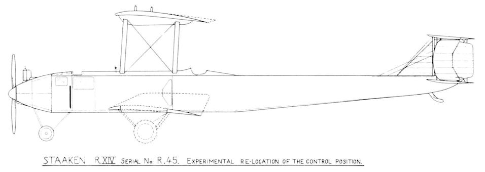
The R.45 was fitted with a cockpit located behind the trailing edge of the wings in a manner similar to the AEG R.I. The purpose of this configuration was to provide a better view of the undercarriage and ground while landing. During tests at Staaken the wing-root panels were left open in order to improve the downward view. By the time the R.45 left for the Front these panels had been covered and the narrow chord four-bladed propellers replaced by the more usual two-bladed propeller.
On 9 August 1918 the R.45 left Staaken for Hanover, and on the next day continued to the Rfa 500 airfield at Morville. Lt. von Plotz and Lt. Steinhauser were the officers aboard R.45 when, accompanied by R.31, it took-off to bomb le Havre on 15 September 1918. After the raid, the R.45 received a wireless message warning it not to return to Morville because enemy aircraft were over the airfield and the landing lights would not be turned on. But the fuel supply was too low to continue on, forcing the commander to make the decision to land. The wireless operator notified the airfield and asked that ground personnel signal with flashlights. The first and second landing attempts failed, and it was not until a number of flares had been shot-off that enough illumination was provided to enable the pilots to touch down on the airfield. In spite of the emergency illumination, the R.45 missed the runway, which the crew noticed by the severe shaking they received. Suddenly, in the darkness, the left wing struck an obstruction, then the right wing and the R.45 stood still. In the morning the damage was inspected and it was found that the left wing had hit a water-tank wagon and a large portable ladder; the right wing some construction material and the roof of a peasant house. This fortunate accident saved the lives of sixty men who were sleeping in a barracks directly in the path of the careering bomber. It is doubtful if the R.45 was repaired in time to participate in further bombing raids before the Armistice.
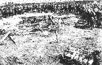
The R.43 and R.44 also saw service on the Western Front during the autumn of 1918. The R.43 has been remembered as one of two R-planes confirmed as shot down by an opposing aircraft. On the night of 10/11 August 1918 the R.43 of Rfa 501 was on a bombing mission when it was lit up by searchlights over Talmas. According to the records, it was an easy target due to the large amount of exhaust smoke. The heavy concentration of lights attracted four British pilots to the scene, one of whom was Capt. A. B. Yuille of 151 Squadron R.A.F. Recently transferred to France from Home Defence duties in England, 151 Squadron was a special nightfighter unit flying Sopwith Camels. The R.43 was attacked from all sides. Yuille closed to about 25 yards, but did not fire a shot until he had settled well below and behind the bomber's tail. Yuille then opened with three short bursts and put one engine out of action. The next two bursts set the fuselage afire around the rear gunner's cockpit. The R.43 started going down, with its nose down and turning on one side. It then dived more steeply, burst into flame and one set of wings dropped off. Yuille followed the burning mass down and watched it crash. The bomber's fall was seen for miles, even by pilots who were bombing is miles away and on the German side of the lines. Five of the crew attempted to bail out, but all seven crew members were killed.
On hitting the ground, one of the bombs exploded, completely wrecking the fuselage. French and British aviation experts scrutinized the remains carefully, finding, surprisingly enough, two Lewis machine-guns (and also two Parabellum) in the wreckage. An interesting British Intelligence comment that "little regard was paid to saving weight in the design of fittings throughout the machine, some fittings being more than ordinarily heavy and cumbersome, even for such a large machine", supports von Bentivegni's comments as noted earlier.
On 11 February 1919 British forces occupying the Rhineland found the R.44 abandoned on the airfield at Cologne. The machine had been stripped of fabric and engines, and only the gaunt skeleton remained.
As a sideline to this history, it should be noted that just prior to the delivery of the last Zeppelin airship built at Staaken (the L.64), the name of the Zeppelin concern was changed again. On 25 January 1918 the Luftschiffbau Zeppelin G.m.b.H. and the Flugzeugwerft G.m.b.H. merged to become the Zeppelin-Werke G.m.b.H. Contemporary photos show cavernous airship hangars serving as construction and assembly areas for Staaken R-planes.
Colour Scheme and Markings
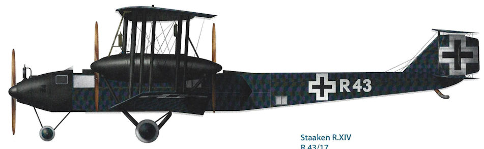
The R.XIV machines were finished overall in printed camouflage fabric. The standard Latin cross was carried on wings, fuselage and tail. The serial numbers were painted in large white figures on the rear fuselage section.
SPECIFICATIONS
Type: Staaken R.XIV
Manufacturer: Zeppelin-Werke G.m.b.H., Staaken, Berlin
Engines: Five 245 h.p. Maybach Mb.IVa engines
Dimensions:
Span, 42•2 m. (138 ft. 5 1/2 in.)
Chord inner, 4•6 m. (15ft. 1 in.)
Chord outer, 3•6 m. (11 ft. 10 in.)
Gap maximum, 4•6 m. (15 ft. 1 in.)
Gap minimum, 3•8 m. (12 ft. 5 1/2 in.)
Dihedral upper, none
Dihedral lower, 2 degrees
Sweepback, 1 1/2 degree
Incidence inner, 3 1/2 degrees
Incidence outer, 1 degree
Length, 22•5 m. (73 ft. 10 in.)
Height, 6•3 m. (20 ft. 8 in.)
Tractor propeller diameter, 4•1 m. (13 f1. 5 1/2 in.)
Nacelle tractor propeller diameter, 3•25 m. (10 ft. 7 1/2 in.)
Nacelle pusher propeller diameter, 4•3 m. (14 ft. 1 in.)
Wheel diameter, 1•3 m. (4 ft. 3 in.)
Areas: Wings, 334 sq. m. (3594 sq. ft.)
Weights:
Empty, 10,350 kg. (22,822 lb.)
Loaded, 14,450 kg. (31,862 lb.)
Performance:
Maximum speed, 130 km.h. (80,8 m.p.h.)
Climbing speed, 100 km.h. (62,1 m.p.h.)
Climb with load, 3000 m. (9843 ft.) in 70 min.
Ceiling, 3700 m. (12,140 ft.)
Range with 1000 kg. bombs, 1300 km. (808 miles)
Fuel: 3150 litres (693 Imp. Gals.)
Armament: Provision for dorsal, ventral and two upper-wing machine-gun positions
Service Use: Western Front with Rfa 500 and Rfa 501 August-November 1918
Staaken R.XIVa
The Staaken R.XIVa serie comprised the last R-planes to be built by Staaken during the war. These aircraft were delivered later than the Staaken R.XV series.
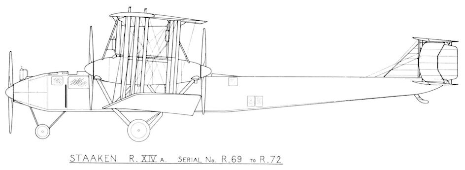
The R.XIVa, as the designation indicates, was an improved version of the R.XIV, modified to increase its rate of climb and operating ceiling with increased war load. To achieve this end, reduction gearing was again fitted to all engines and the weight of the machine was considerably reduced by internal structural changes and removal of upper-wing gun mounts and the bomb-bay fairing. The dimensions of the fuselage and nacelles were reduced, which resulted in a small increase of speed. The only other obvious change was that the elevator surfaces were balanced, making the R.XIVa the first Staaken machine to have all its control surfaces balanced.
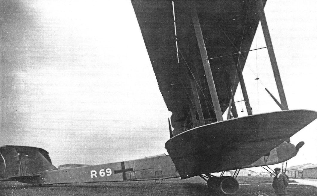
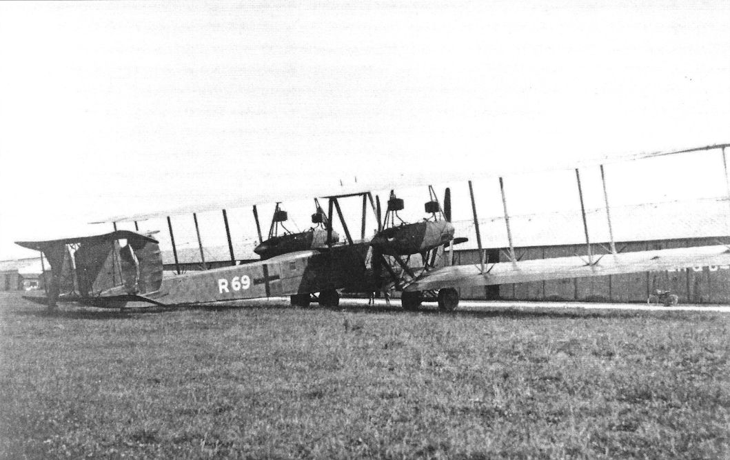
Idflieg ordered four R.XIVa machines from Staaken, and these received the serial number R.69 to R.72. Due to the production programme it was not possible to include all the modifications, particularly weight reduction, on the R.69; however, the R.70 was to be a fully lightened version. The R.69, delivered on 19 October 1918, did not see any front-line service. The R.70 and 71 were probably completed in late 1918 or early 1919, and it is not known if the R.72 was finished.
In 1919 the R.69 was chartered by the Ukrainian Government to fly money into the Ukraine, and was seized by the Inter-Allied Control Commission when it landed on a return flight at Aspern near Vienna. It was subsequently turned over to Italian authorities. The R.70 and R.71 were also flown between Germany and the Ukraine to deliver currency. On 19 September 1919 the R.70 was confiscated by the Roumanian Government when it made a forced landing in Bessarabia. The R.71 crashed and burned of unknown causes in the forest of Ratibor during the summer of 1919.
Schutte-Lanz was also given a contract to build three RXIVa machines numbered R.84 to R.86 at the cost of 600,000 marks each, but none were completed prior to the end of the war. Further details may be found in the Schutte-Lanz chapter.
Color Scheme and Markings
The R.XIVa machines were finished overall in printed camouflage fabric. The standard Latin cross was carried on wings, fuselage and tail. The serial numbers were painted in large white figures on the rear fuselage section. These machines continued to carry the Latin cross during their post-war operations.
SPECIFICATIONS
Type: Staaken R.XIVa
Manufacturer: Zeppelin-Werke G.m.b.H., Staaken, Berlin
Engines: Five 245 h.p. Maybach Mb.IVa engines
Dimensions:
Span, 42•2 m (138 ft. 5 1/2 in.)
Length, 22•5 m. (73 ft. 10 in)
Height, 6•3 m. (20 ft. 8 in.)
Areas:
Wings, 334 sq. m. (3594 sq. ft.)
Tailplanes, 32-4 sq. m. (349 sq. ft.)
Elevators, 9 sq. m. (97 sq. ft.)
Fins, 9•2 sq. m. (99 sq. ft.)
Rudders, 3•6 sq. m. (39 sq. ft.)
Ailerons, 7•15 sq. m. (77 sq. ft.)
Weights:
Empty, 10,000 kg. (22,050 lb.)
Loaded, 14,250 kg. (31,421 lb.)
Maximum useful load, 5000 kg. (11,025 lb)
Performance:
Maximum speed, 135 km.h. (83'9 m.p.h.)
Climbing speed, 95 km.h. (59 m.p.h.)
Climb,
1000 m. (3281 ft.) in 7 mins.
3000 m. (9843 ft.) in 45 mins.
Ceiling, 4500 m. (14,764 ft.)
Range with 1000 kg. bombs, 1300 km. (808 miles)
Armament: Provision for dorsal and ventral machine-gun positions
Staaken R.XV
The Staaken R.XV series remain something of a mystery, for virtually no technical information exists to explain why these machines, though almost identical to the R.XIV type, received a different designation. The R.XV had the same engine configuration as the R.XIV and closely resembled the latter in outward appearance. It is probable that the R.XV was basically an R.XIV airframe modified to improve the performance by lightening the airframe. The airframe does show signs of greater attention to detail and streamlining; for instance, the nose cowling had more refined contours. If any other refinements were made they have not been recorded. There is no doubt, however, about the R.XV designation. The official German equipment tables for R-planes specified six machine-guns for this type.
The R.46/17, the first of three R.XV machines completed, was reported as being ready for its maiden flight on 25 July 1918 and was delivered in August. A contemporary status report stated that the R.47 and R.48 were expected to be completed on 3 August and 13 August respectively: they were both accepted on 1 September 1918. At least two of these aircraft saw service with R-plane squadrons on the Western Front.
A victor's spoils, the complete R.47 was shipped to Japan, and the Inter-Allied Control Commission team that inspected the Staaken factory found the R.48 there in 1919. It may have been parts of this aircraft that were sent to the Isle of Grain for study.
Colour Scheme and Markings
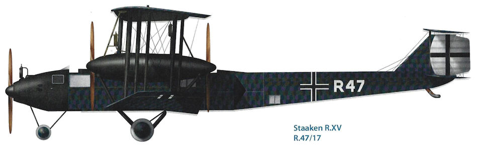
The R.XV machines were finished overall in printed camouflage fabric. The standard Latin cross was carried on wings, fuselage and tail. The serial numbers were painted in large white figures on the rear fuselage section.
SPECIFICATIONS
Type: Staaken R.XV
Manufacturer: Zeppelin-Werke G.m.b.H., Staaken, Berlin
Engines: Five 245 h.p. Maybach Mb.IVa engines
Dimensions: Similar to Staaken R.XIV
Areas: Similar to Staaken R.XIV
Weights: Unknown
Performance: Unknown
Armament: Similar to Staaken R.XIV
J.Herris Zeppelin-Staaken Aircraft of WW1. Vol 1: VGO.1 - R.IV R.29/16 (A Centennial Perspective on Great War Airplanes 47)
Staaken Specifications
Type R.XIV R.XIVa R.XV
Engines 5x245 Hp Maybach Mb.IVa 5x245 Hp Maybach Mb.IVa 5x245 Hp Maybach Mb.IVa
Span 42.2 m (138' 5 1/2") 42.2 m (138'5 1/2") Similar to R.XIV
Chord (inner) 4.6 m (15' 1") - Similar to R.XIV
Chord (outer) 3.6 m (11' 10") - Similar to R.XIV
Length 22.5 m (73' 10") 22.5 m (73' 10") Similar to R.XIV
Height 6.3 m (20' 8") 6.3 m (20' 8") Similar to R.XIV
Tail span - - Similar to R.XIV
Wing Area 334 m2 (3,594 ft2) 332 m2 (3,572 ft2) Similar to R.XIV
Wt. Empty 10,350 kg (22,822 lb.) 10,000 kg (22,050 lb.) -
Wt. Fuel - - -
Wt. Payload - 5,000 kg (11,025 lb.) -
Wt. Loaded 14,450 kg (31,862 lb.) 14,250 kg (31,421 lb.) -
Max Speed 130 km/h (80.8 m/h) 135 km/h (83.9 m/h) -
Climbing Spd 100 km/h (62.1 m/h) 95 km/h (59 m/h) -
Climb 1,000 m - 7 minutes -
Climb 3,000 m 70 minutes (with load) 45 minutes -
Ceiling 3,700 m 4,500 m -
Range (1,000 kg bombs) 1,300 km (808 miles) 1,300 km (808 miles) -
J.Herris Zeppelin-Staaken Aircraft of WW1. Vol 2: R.VI R.30/16 - E.4/20 (A Centennial Perspective on Great War Airplanes 48)
Staaken R.XIV
The next Staaken giant design to be built was designated the Staaken R.XIV; the R.VIII and R.IX designations were used for projects that were not built and the R.X through R.XIII are not known. The R.XIV followed the basic R.VI configuration but the rear nacelle engines were the 350 hp Austro-Daimler V-12. The first R.XIV, R.43/17, flew in March 1918. The nose contours were different than the R.VI because the cockpit was redesigned with an open cockpit to give a better view for the pilots.
The R.43 was built without reduction gears for the propellers to gain performance data to compare with the geared propellers of other R-planes. On April 12, during a flight for its acceptance program, a connecting rod broke in one of its rear V-12 engines. The Austro-Daimler engines were not ready for operational service and the next day they were replaced by 300 hp Basse & Selve BuS.IVa engines. The next flight was scheduled for May 10. However, the Basse & Selve engines were also new designs that were not fully de-bugged and were prone to failure. They in turn were replaced by the proven 245 hp Maybach Mb.IVa engines. However, this required a highly visible modification; a fifth Maybach engine had to be installed in the nose to compensate for their lower power because the R.XIV was substantially heavier than the R.VI which used four of these engines.
Installing the fifth engine in the R.43 took two months; the modified R.43 was ready for acceptance in July. The R.44, which had been built originally with four Basse & Selve engines, did not fly with those engines and was modified with the five Maybach engines. It was delivered in August and the R.45, which was built with the five Maybach engines, was delivered in July. The nacelle tractor propellers for these aircraft did not have reduction gears.
Balanced ailerons were added to the R.XIV design in an attempt to reduce control forces; the balance was kept within the wing outline. Upper wing gun positions were fitted outboard of the engine nacelle centerlines. The nacelles themselves were slimmer than those of the R.VI, mounted higher, and the struts were rearranged. Large spinners were fitted to the tractor propellers.
The R.XIV carried parachutes for all crewmembers; these were carried in external fuselage compartments with lines running to each crewman's station. Six machine guns were carried; one in each upper wing position and two guns in the dorsal and ventral positions. The increased armament reflected the greater Allied use of night-fighters.
The R.45 had its pilots' cockpit moved aft of the wing trailing edge for a better view of the main wheels when landing. Tests were made with wingroot panels open for a better view during landing, but these were covered before R.45 left for the front on August 9, 1918.
During a bombing raid together with R.31, R.45 received a wireless message that it was not to return to its base at Morville, then the home base of Rfa 500, because enemy aircraft over the field meant the landing lights could not be turned on. However, the aircraft commander decided that the low fuel state of R.45 meant that it had to land at Morville. The radio operator notified the field of the decision and requested ground personnel signal with flashlights. The first two landing attempts were not successful; on the third attempt signal flares were fired to better illuminate the field. R.45 landed but missed the runway and hit obstructions that stopped the aircraft. The following morning the obstructions were found to be a water wagon and large ladder on the left and construction material and the roof of a house on the right. Had the R.45 not hit the obstructions, it would have run into a barracks where 60 men were sleeping. R.45 is not thought to have been repaired in time for more missions.
R.43 was one of two R-planes shot down during a bombing mission. On the night of 10/11 August 1918 R.43 was assigned a target not far behind the lines; lit up by searchlights it was attacked by four Sopwith Camels from 151 Squadron, RAF, a specialized night fighter unit that had recently been transferred to France from Home Defence in Britain. R.43 was attacked by four aircraft and shot down by Capt. A.B. Yuille, who got in close under the tail of R.43. R.43 was totally destroyed when a bomb exploded when it hit the ground and all nine crewmen were killed.
The R.XIV, powered by five engines, was not a significant advance over the four-engine R.VI. The fifth engine gave the R.XIV greater reliability in case of engine failure. However, the installation of the nose engine again made the aircraft more likely to catch fire in the event of a crash-landing, and its vibrations affected the more delicate instruments. The smaller diameter and higher RPM of the ungeared propellers also reduced their aerodynamic efficiency. The R.XIV was also heavier than the R.VI for several reasons; it had another engine, its structure was built heavier and stronger for the 350 hp V-12s expected to be used, and various other changes had been made that increased weight.
Staaken R.XIVa
The Staaken R.XIVa was an improved model of the R.XIV, although it was delivered later than the Staaken R.XV The R.XIVa was intended to offer better climb and ceiling than the R.XIV while carrying a greater bombload, so it was given reduction gearing on all engines to improve propeller efficiency. The weight of the R.XIVa was reduced by lightening the structure, removal of the wing machine gun positions, and removal of the bomb bay fairings. A small reduction of the fuselage and engine nacelle cross sectional area contributed to a slight speed increase. The elevators were balanced, a first for a Staaken design.
Idflieg ordered four R.XIVa aircraft, serial numbers R.69 to R.72, from Staaken; these were the last R-planes built by Staaken during the war. The first aircraft, R.69, was built so quickly that not all the modifications could be included. Despite the rushed construction, R.69 was only delivered on Oct. 19, 1918, and did not have time to see operational service. R.70 and R.71 incorporated the modifications and were completed post-war; it is not known if R.72 was completed.
All three aircraft were used to transport money into the Ukraine after the war. R.69 was seized by the IAACC (Inter-Allied Aircraft Control Commission) after landing at Aspern near Vienna on a return flight from the Ukraine. On September 19, 1919 R.70 was seized by Romania when it has to make a forced landing in Bessarabia. R.71 crashed of unknown causes during the summer of 1919.
Schutte-Lanz was given a contract for three R.XIVa aircraft, R.84-R.86, but these were not completed before the Armistice.
Staaken R.XV
The Staaken R.XV was almost identical to the R.XIV; it looked nearly the same and had the same engine configuration, five 245 hp Maybach Mb.IVa engines. The differences are not documented but were probably focused on weight reduction to improve performance because the shape of the nose was slightly refined.
The R.46/17, the first of three R.XV aircraft completed, was ready for its maiden flight on July 25, 1918 and was delivered in August. Both the R.47/17 and R.48/17 were accepted on September 1, 1918. At least two of the aircraft were in time to see service over the Western Front. Postwar, R.47 was shipped to Japan as spoils of victory, and the IAACC found R.48 in the factory in 1919.
Журнал Flight
Flight, December 5, 1918.
NOTES ON GERMAN BOMBERS
THE FIVE-ENGINED GIANT
[Issued by Technical Department (Aircraft Production), Ministry of Munitions.]
(Concluded from page 1347.)
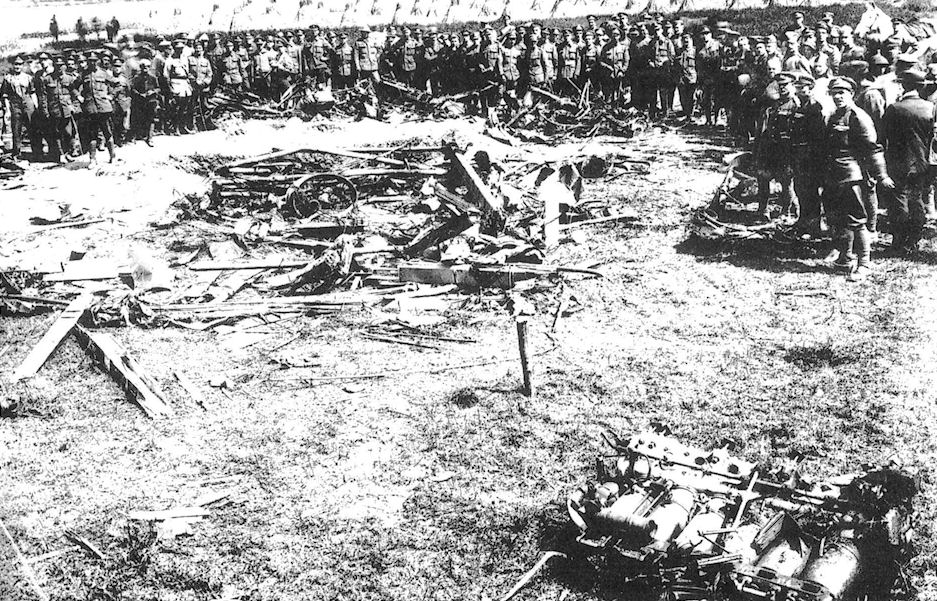
A FIVE-ENGINED bomber was brought down near Talmas on 10th, but unfortunately, owing to the explosion of one of its bombs, the machine was damaged beyond hope of reconstruction.
Some of its components have been recovered, and of these photographs are given in Figs. 67 to 82.
The principal item of interest is the gear box, which is used for all five engines, each of which is a 300 h.p. Maybach of the standard 6-cylinder vertical type.
The power plants are arranged as follows :- In the nose of the machine is one engine driving a tractor screw. On each side of the fuselage, supported by the wings, is a long pair of engine bearers carrying two engines apiece, which drive tractor and pusher screws in a manner exactly similar to that set forth in Fig. 46.
The use of the gear box and driving shafts necessitates the employment of a fly wheel on the engine, to which is added the female portion of a flexible coupling of the type already described.
Whereas the gear box in the four-engined giant, of which notes have already been given in this report, is of a somewhat crude type employing external driving shafts between the gear box and the engine, in the five-engined machine the gear-box design is considerably improved. The casing consists, as shown in photograph No. 67, of a massive aluminium casting provided with four feet which are bolted to the engine bearers.
Two kinds of gear boxes are employed. These differ only in over-all dimensions and the length of the propeller shaft.
The larger type is used for the pusher screw in order to obviate the necessity of cutting a slice out of the trailing edge of the main planes.
All the gear boxes were very badly damaged except that which is shown in Fig. 67. This is the longer type, but it would appear that the shorter design is very similar in appearance.
In each case the gear reduction is 21-41.
Plain spur pinions are used having a pitch of 22 mm. and a width across the teeth of 75 mm. The diameter of the smaller of the driving pinions is 162.5 mm., and that of the larger pinion 282 mm.
The larger pinion is as shown in Fig. 73, considerably dished, but the web is not lightened by any perforations.
The over-all dimensions of the gear box, as represented in Fig. 67, is as follows :-
Length, 1,025 mm.; breadth, 675 mm.; height, 535 mm.
The driving pinion runs on two large diameter roller bearings, carried in gunmetal housings supported in the inner end of the gear box. This part is split vertically, and united by the usual transverse bolts, whilst the conical-shaped portion of the box is solid. The usual oil-thrower rings of helical type are fitted.
At its outer end the pinion shaft terminates in a ring o serrations which engage with serrations provided in the male portion of the flexible coupling, these two parts being held together with bolts and clamping plates. The engine is thus close up against the gear box, in contradistinction to the design of the four-engine power plant. There is practically no external shaft at all. The larger pinion is mounted on a hollow shaft of 92 mm. diameter, carried on roller bearings at each end for radial load, and furnished at the nose end with ball thrust bearings.
In the short type of gear box the larger pinion shaft is left solid, and it would appear that the gear box casing, instead of being made in three pieces, is made in two pieces, i.e., the whole box is simply split vertically.
Reference to photograph No. 68 will show that the smaller pinion shaft projects right through the gear box, and at its outer end carries a projection fitted with a small ball thrust race. This projection acts as a drive for the oil pump, which is mounted on the oil radiator used in connection with each gear box.
It is worthy of notice that the German designers have now fully realised the importance of using geared engines for weight carrying aeroplanes, and are apparently satisfied with the external gear-box principle, although in this case they have made it a very ponderous affair indeed. Needless to say, a great amount of the weight could have been saved, if 12-cylinder engines had been used instead of 6-cylinder.
The weights of the gear box and its attachments are as follows :-
Gear box, long type, 280 lbs.
Fly wheel and female clutch, 44 lbs.
Male clutch, 5 lbs.
Oil radiator, 12 1/2 lbs.
This, it will be seen, represents an additional weight of considerably more than 1 lb. per horse power.
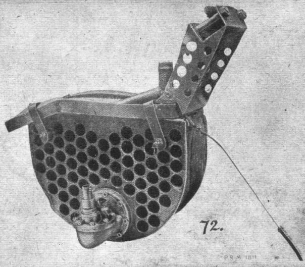
The oil radiator used in conjunction with each gear box is of a roughly semi-circular shape, and is slung underneath the main transverse members of the engine bearers so that it comes immediately beneath the large feet of the gear box, as shown in Fig. 69. This radiator is entirely of steel construction, and embraces 65 tubes of approximately 20 mrn, internal diameter. These are expanded and sweated into the end plates, to one of which is fitted a stout flange, against which is bolted a small gear pump which constantly circulates the oil from the gear box case through the radiator.
This gear pump is driven by a flexible shaft from the small pinion, the shaft and its casing being in all respects similar to those employed for engine revolution counters. As shown in the photograph. Fig. 68, which illustrates the complete gear box upside down, this flexible drive is taken off a small worm gear.
It will also be seen that underneath the oil sump of the gear box proper an electrical thermometer is fitted, which communicates with a dial on the dashboard.
It is a little difficult to see what object can be served by this thermometer, unless it be to indicate the desirability of throttling down a little in the event of the oil getting unduly hot, as there is no apparent means of controlling the draught of air through the oil radiator.
Fitted on each gear box and working in connection with the oil circulation is a filter of the type shown in Fig. 75. This is provided with an aluminium case and a detachable gauze cylinder through which the oil passes.
The arrangement of the gear box is such that the axis of the propeller is raised about 220 mm. above that of the engine crankshaft.
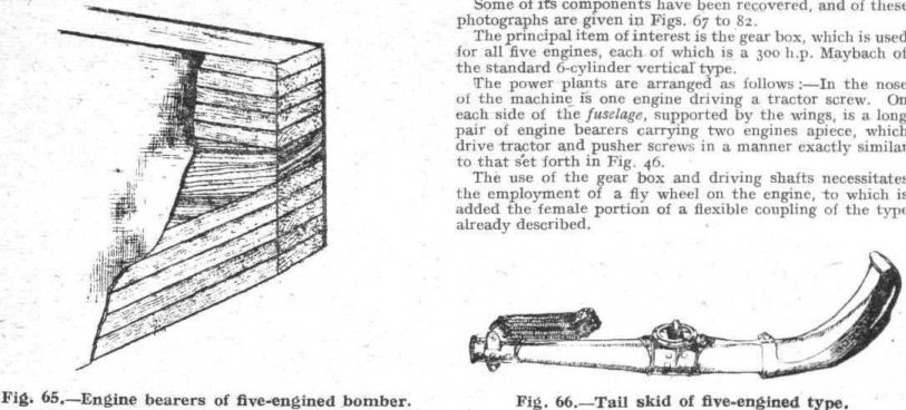
The construction of the long engine bearers is not without interest, as amongst other things, it indicates that German manufacturers are finding themselves short of suitable timber. Each bearer, as shown in Fig. 65, consists of a spruce or pine central portion, to which are applied, top and bottom, five laminations of ash. On each side are glued panels of three-ply, about 1 in. thick.
The engine bearers taper sharply at each end, and are strengthened by massive steel girders under each gear box. One of these girders, which is a single-piece welded construction, is illustrated in the photograph, Fig. 77.
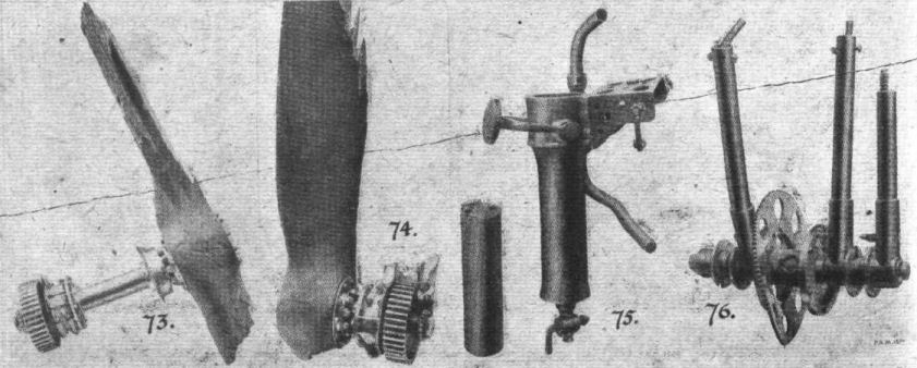
The screws revolve at approximately half the speed of the engine, and having therefore a moderately light centrifugal load to carry, are made of a common wood that would scarcely be safe for direct driving screws.
Although fitted to 300 h.p. Maybach engines, they are marked 260 p.s. (h.p.) Mercedes. The diameter is 4.30 meters and the pitch 3.30, for the pusher screw, but unfortunately, owing to the propellers being badly damaged, not only by the crash, but by fire, it is not possible to state whether the tractor screws are of the same dimensions and pitch.
The construction is very interesting; each screw is made of 17 laminations of what appears to be soft pine, and these laminations are themselves in pieces, and do not run continuously from tip to tip. They are, of course, staggered, so that the joints in successive layers do not coincide. Two plies of very thin birch veneer are wrapped round the blades. The grain of this veneer runs across the blade instead of along it.
It is difficult to say from the appearance of the screw whether this veneer has been put on in the form of two-ply or as two separate layers, one after the other.
Among other details salved from the wreckage is the engine control. This is illustrated in photograph No. 76, and is a very massive affair. It consists of five stout steel tubular levers, two of which it will be noticed have become unbrazed in the fire which broke out when the machine crashed.
The levers are fitted with ratchets so that each one can be operated individually, but the presence of the large-diameter toothed wheel in the centre of the lever shaft would seem to indicate that all five levers could, when desired, be controlled simultaneously. This fitting had, however, been very badly fused, and it is impossible to give details with certainty.
A smaller fitting recovered from the wreckage is illustrated in photograph No. 71, and consists of a windmill of a type similar to that used on the D.H. 9 aeroplane. It is mounted at the top of an aluminium tube, but it is not possible to say for what purpose this mill is employed.
A small and very heavy rotary pump, found in the wreckage is shown in photograph No. 71. This is possibly the hand-driven petrol pump, though it would appear unusually massive for this purpose.
The Douglas type of engine, carried for the purpose of driving the dynamo of the wireless and heating installation, is illustrated in photographs No. 78, 80, 81 and 82, which show various views of the motor and generator. The engine is a very close copy of the 2 3/4 h.p. Douglas, and is made by Bosch. The fly wheel, as shown in photograph No. 80, is furnished with radial vanes which induce a draught through a sheet-iron casing, and direct it past cowls on to the cylinder heads and valve chests.
The generator is direct-driven through the medium of a pack of flat leaf sprints, which act as dogs, and engage with the slots on the fly-wheel boss, as shown in Fig. 82.
What appears to be a transformer, used in conjunction with the wireless set, is illustrated in photograph No. 79.
The ponderous tail skid of this machine is illustrated in Fig. 66. It is built up of laminations of ash, and furnished with a heavy steel shoe and a large universal attachment.
Special Note.
A complete and detailed report on the above-mentioned gear box, giving the fullest possible information and analysis of metals, etc., will shortly be published.
 |
J.Herris - Zeppelin-Staaken Aircraft of WW1. Vol 2: R.VI R.30/16 - E.4/20 /Centennial Perspective/ (48)
|
| Staaken R.XIV R.43/17
|
 |
J.Herris - Zeppelin-Staaken Aircraft of WW1. Vol 2: R.VI R.30/16 - E.4/20 /Centennial Perspective/ (48)
|
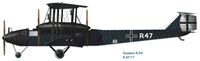
| Staaken R.XIV R.47/17
|
 |
J.Herris - Zeppelin-Staaken Aircraft of WW1. Vol 2: R.VI R.30/16 - E.4/20 /Centennial Perspective/ (48)
|
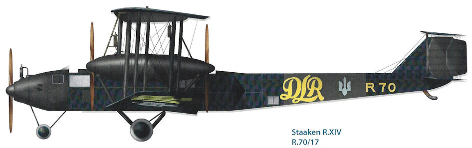
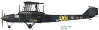
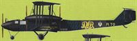
| Staaken R.XIV R.70/17. Postwar Ukrainian Service
|
 |
J.Herris - Zeppelin-Staaken Aircraft of WW1. Vol 2: R.VI R.30/16 - E.4/20 /Centennial Perspective/ (48)
|
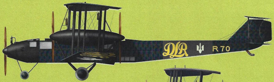
| Staaken R.XIVa R.70 of the Deutsche Luft-Reederei in 1919. The aircraft was used to fly newly printed Ukrainian currency from Germany to help finance Ukraine’s war against Rumania and Poland.
|
 |
J.Herris - Zeppelin-Staaken Aircraft of WW1. Vol 2: R.VI R.30/16 - E.4/20 /Centennial Perspective/ (48)
|
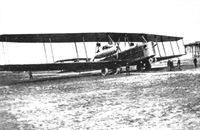
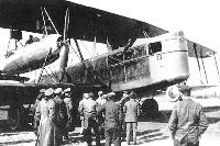
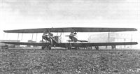
| The Staaken R.XIV R.43/17 in its original configuration with four Austro-Daimler V-12 engines in push-pull configuration like the earlier R.VI. These engines were not ready for production and were replaced by 300 hp Basse & Selve BuS.IVa engines. These engines were not ready for production either and where in turn replaced. (Peter M. Grosz collection/STDB)
|
 |
J.Herris - Zeppelin-Staaken Aircraft of WW1. Vol 2: R.VI R.30/16 - E.4/20 /Centennial Perspective/ (48)
|
|
|
 |
G.Haddow, P.Grosz - The German Giants /Putnam/
|
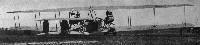
| Staaken R.XIV 43/17 in its original form with four Austro-Daimler engines arranged similarly to the R.VI.
|
 |
J.Herris - Zeppelin-Staaken Aircraft of WW1. Vol 2: R.VI R.30/16 - E.4/20 /Centennial Perspective/ (48)
|
|
|
 |
J.Herris - Zeppelin-Staaken Aircraft of WW1. Vol 2: R.VI R.30/16 - E.4/20 /Centennial Perspective/ (48)
|
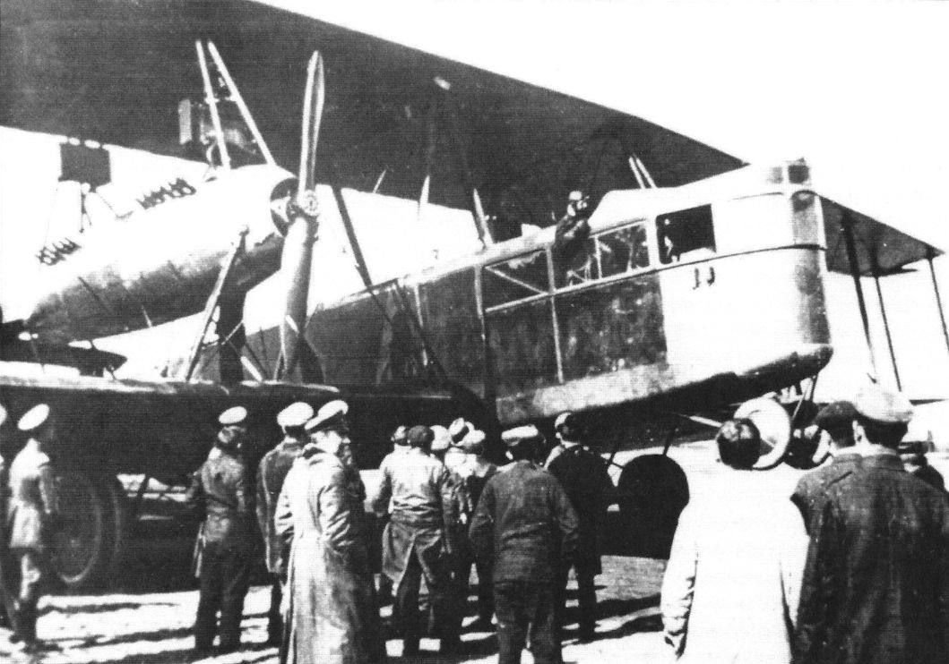
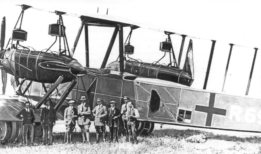
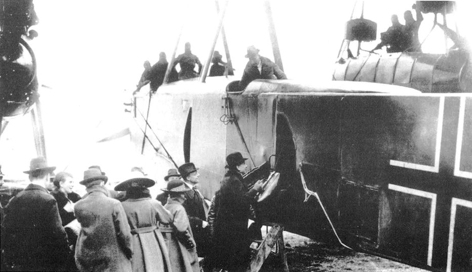
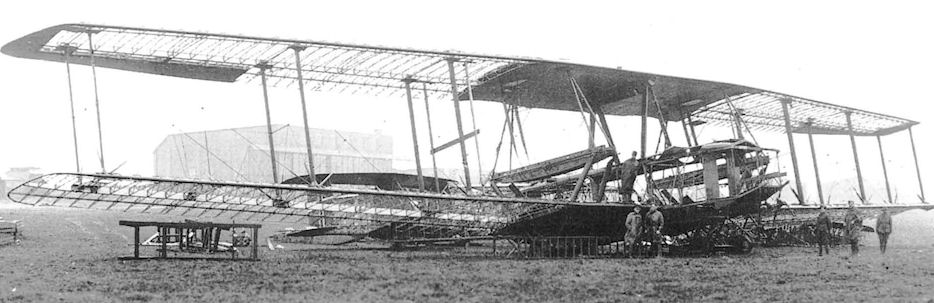
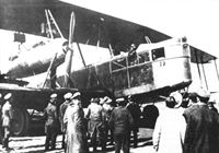
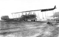
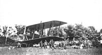
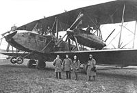
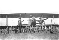
| The Staaken R.XIV R.43 in its original configuration with four 350 hp Austro-Daimler V-12 engines. These engines were not fully developed and were not ready for production, so had to be replaced. The entire nose was glassed in and the nose gun position was raised. Here the R.43 has drawn an admiring crowd of VIPs. (Peter M. Grosz collection/ STDB)
|
 |
J.Herris - Zeppelin-Staaken Aircraft of WW1. Vol 2: R.VI R.30/16 - E.4/20 /Centennial Perspective/ (48)
|
|
|
 |
J.Herris - Zeppelin-Staaken Aircraft of WW1. Vol 2: R.VI R.30/16 - E.4/20 /Centennial Perspective/ (48)
|
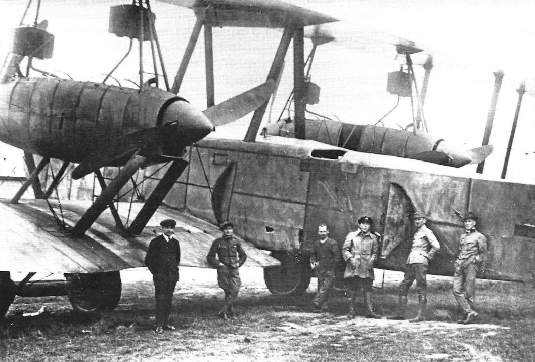
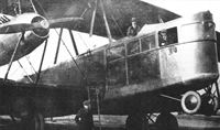
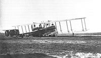
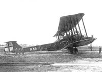
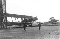
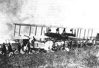
The next Staaken design to be built was the R.XIV. Originally designed with four 350 hp Austro-Daimler V-12 engines in the configuration of the R.VI, they had to be rebuilt with a fifth engine in the nose after the Austro-Daimler engines proved to be not developed enough for production. Here an R.XIV is shown after modification to five engines. (Peter M. Grosz collection/STDB)
The Staaken R.XIV was an improved version of the R.VI, with four 350hp Austro-Daimler engines. R43/17, the first of the type, flew in February 1918 and the few operational aircraft saw active service in late summer 1918. One aircraft, R43, was operating with RFa 501 on the night of 10/11 August when it was shot down.
|
 |
J.Herris - Zeppelin-Staaken Aircraft of WW1. Vol 2: R.VI R.30/16 - E.4/20 /Centennial Perspective/ (48)
|
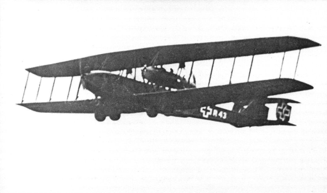
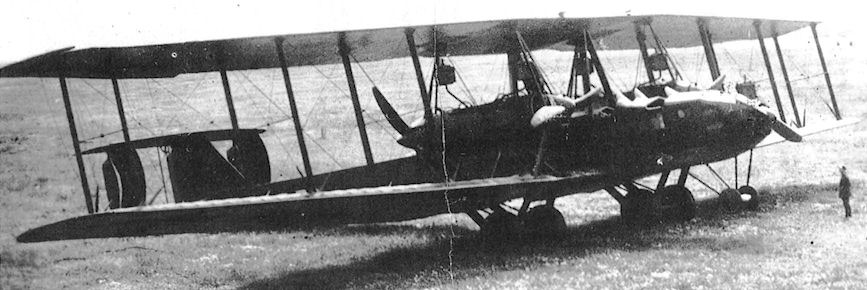
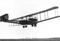
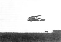
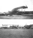
| Staaken R.XIV R.43/17 taking off. (Peter M. Grosz collection/STDB)
|
 |
J.Herris - Zeppelin-Staaken Aircraft of WW1. Vol 2: R.VI R.30/16 - E.4/20 /Centennial Perspective/ (48)
|
| Staaken R.XIV R.43/17 taking off. On the night of 10/11 August 1918, R.43 was shot down by a Sopwith Camel nightfighter of No. 151 Sqdn, the first R-plane shot down by a fighter. (Peter M. Grosz collection/STDB)
|
 |
J.Herris - Zeppelin-Staaken Aircraft of WW1. Vol 2: R.VI R.30/16 - E.4/20 /Centennial Perspective/ (48)
|
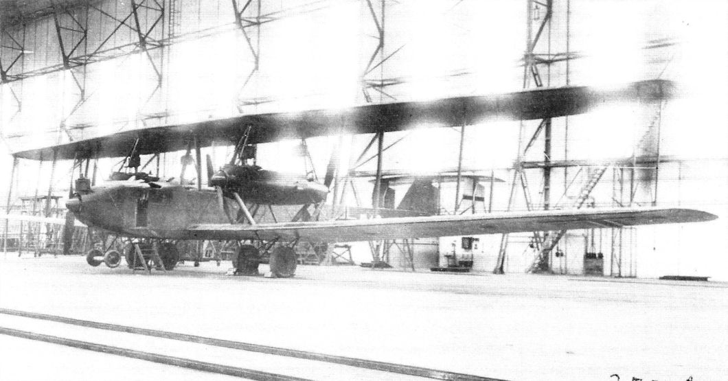
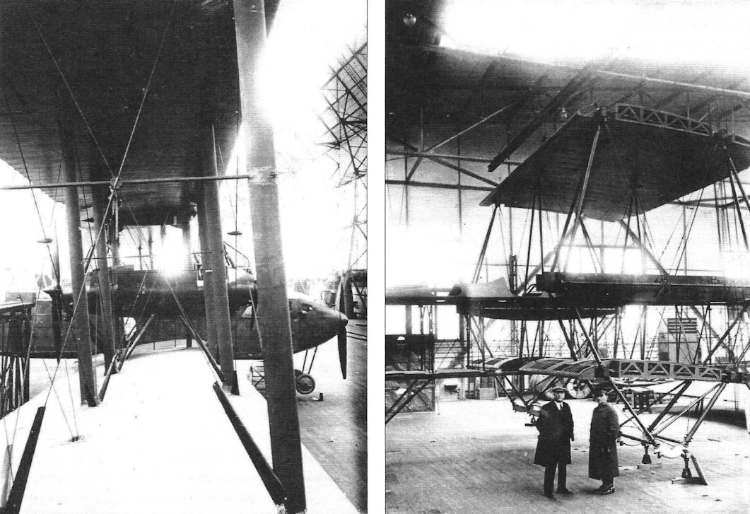
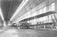
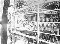
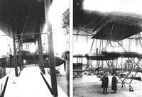
| Staaken R.XIV under construction. The serial is partly obscured but appears to be R.43/17. (National Archives)
|
 |
J.Herris - Zeppelin-Staaken Aircraft of WW1. Vol 1: VGO.1 - R.IV R.29/16 /Centennial Perspective/ (47)
|
| A Staaken R.VI R.30/16 under repair after an engine fire; Staaken R.XIV 43/17 is in the background without engines. (Michael Schmeelke)
|
 |
J.Herris - Zeppelin-Staaken Aircraft of WW1. Vol 2: R.VI R.30/16 - E.4/20 /Centennial Perspective/ (48)
|
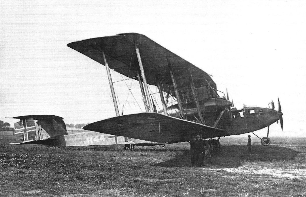
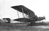
| Staaken R.XIV R.44/17 was completed with five 245 hp Maybach Mb.IVa engines. (Peter M. Grosz collection/STDB)
|
 |
J.Herris - Zeppelin-Staaken Aircraft of WW1. Vol 2: R.VI R.30/16 - E.4/20 /Centennial Perspective/ (48)
|
| Staaken R.XIV R.44/17 taking off. (Peter M. Grosz collection/STDB)
|
 |
J.Herris - Zeppelin-Staaken Aircraft of WW1. Vol 2: R.VI R.30/16 - E.4/20 /Centennial Perspective/ (48)
|
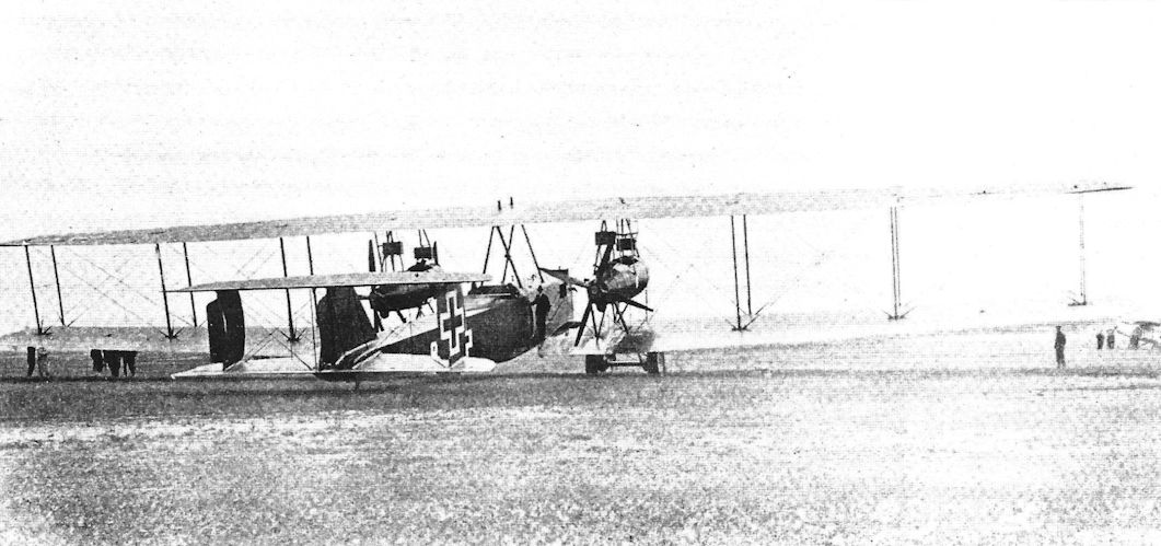
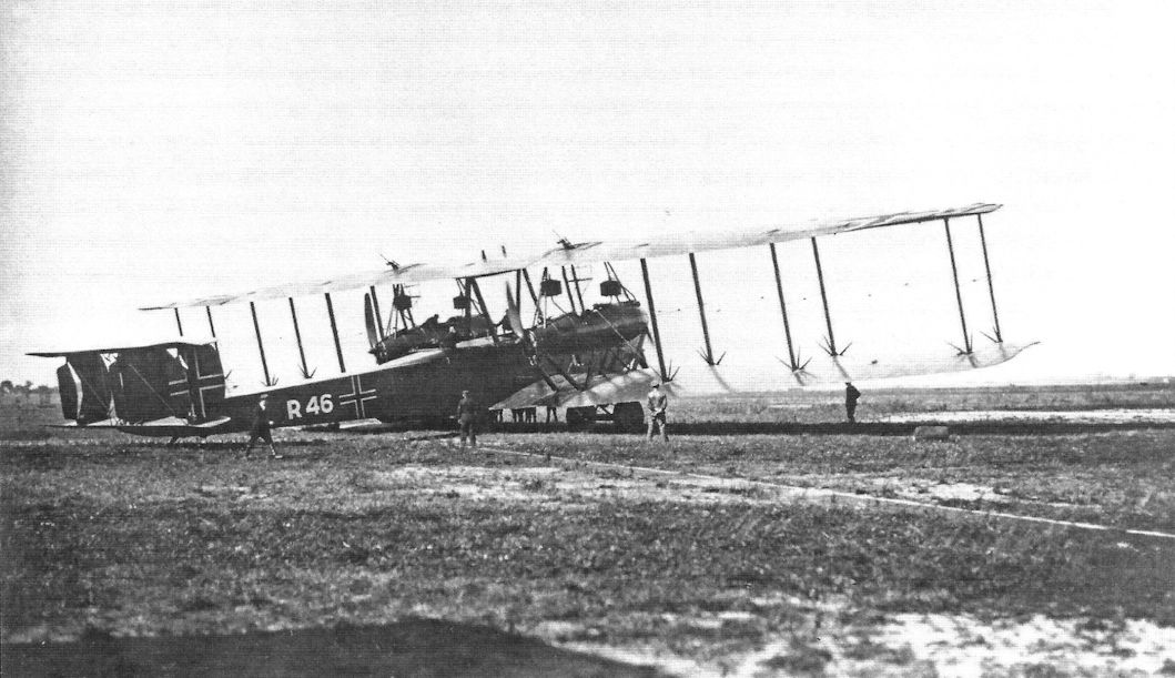
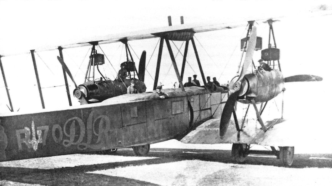
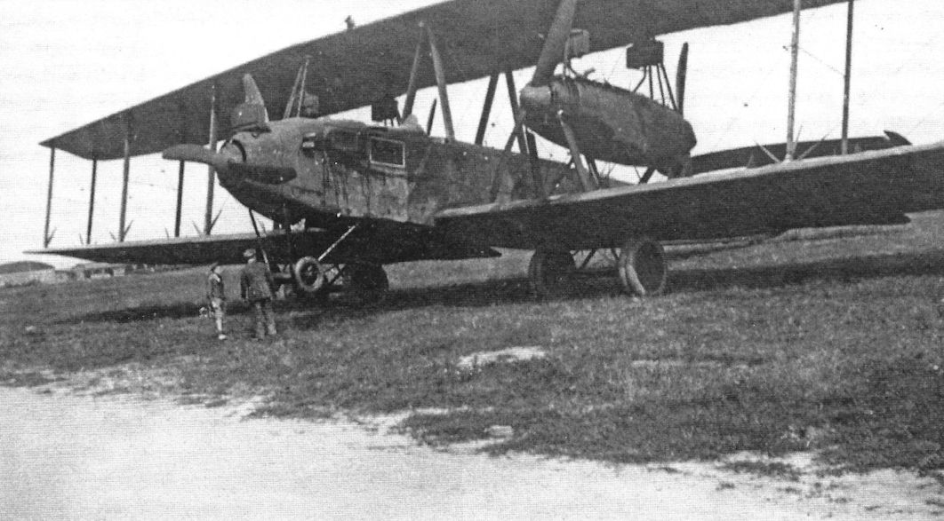
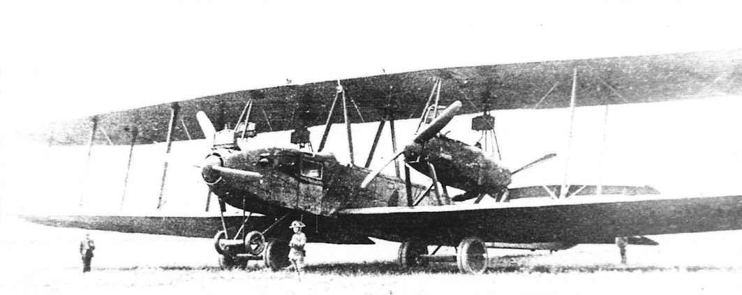
| Staaken R.XIV 45/17 with the pilot's cockpit placed behind the wings.
|
 |
Jane's All The World Aircraft 1919 /Jane's/
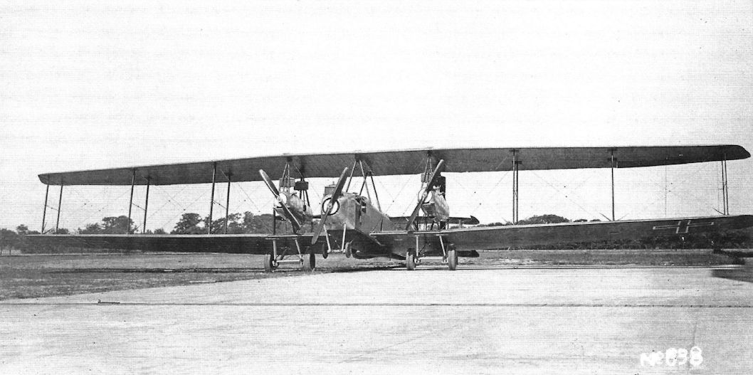
|
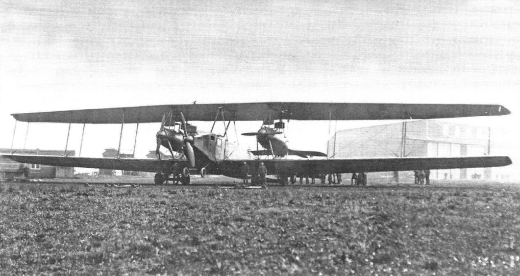
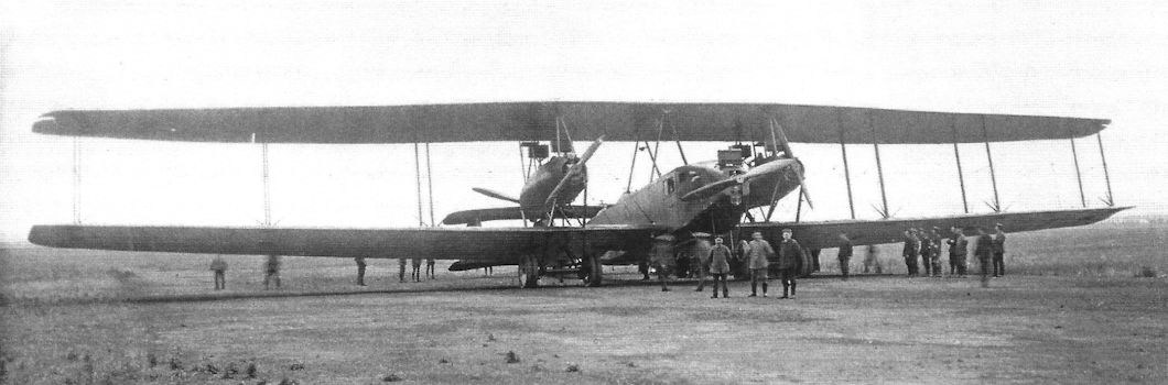
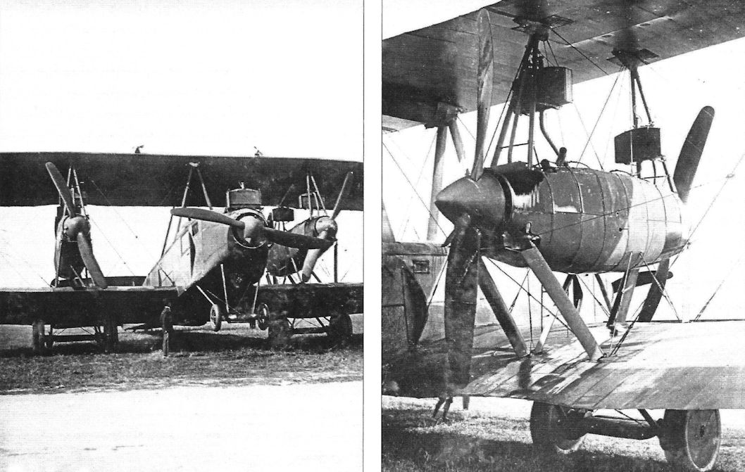
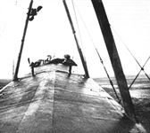
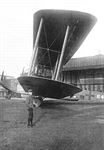
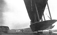
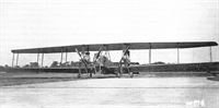
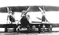
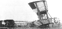
| Rear View of the Zeppelin "Giant" Biplane. (5-250 h.p. Maybach engines.)
|
 |
J.Herris - Zeppelin-Staaken Aircraft of WW1. Vol 2: R.VI R.30/16 - E.4/20 /Centennial Perspective/ (48)
|
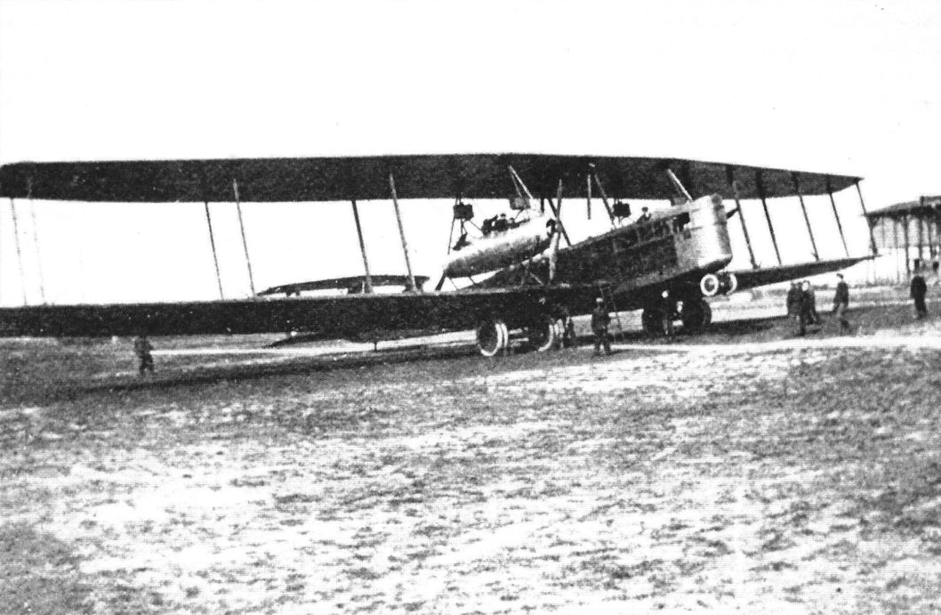
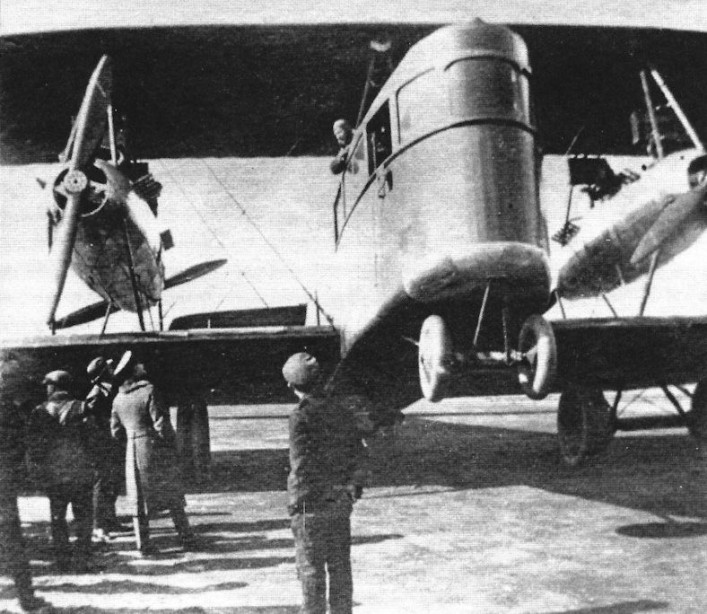
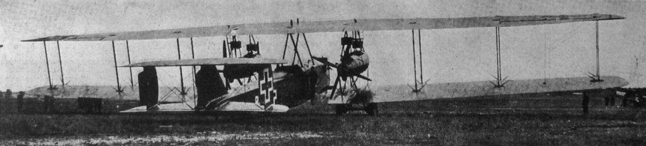
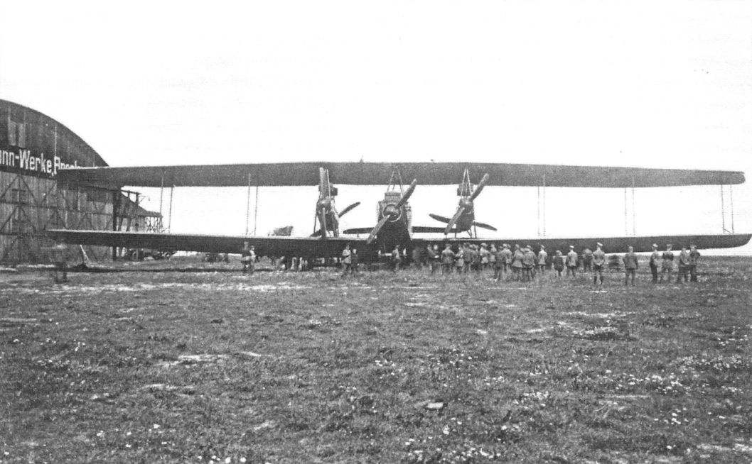
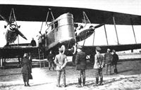
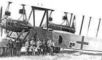
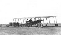
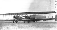
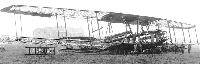
| Staaken R.XIV with five 245 hp Maybach Mb.IVa engines being reviewed. (Peter M. Grosz collection/STDB)
|
 |
J.Herris - Zeppelin-Staaken Aircraft of WW1. Vol 2: R.VI R.30/16 - E.4/20 /Centennial Perspective/ (48)
|
| Staaken R.XIV with five 245 hp Maybach Mb.IVa engines.The Fokker D.VII at right both gives scale to the Staaken and indicates it is on an operational airfield. (Peter M. Grosz collection/STDB)
|
 |
J.Herris - Zeppelin-Staaken Aircraft of WW1. Vol 2: R.VI R.30/16 - E.4/20 /Centennial Perspective/ (48)
|
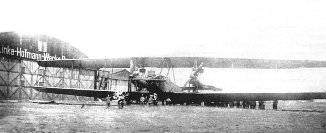
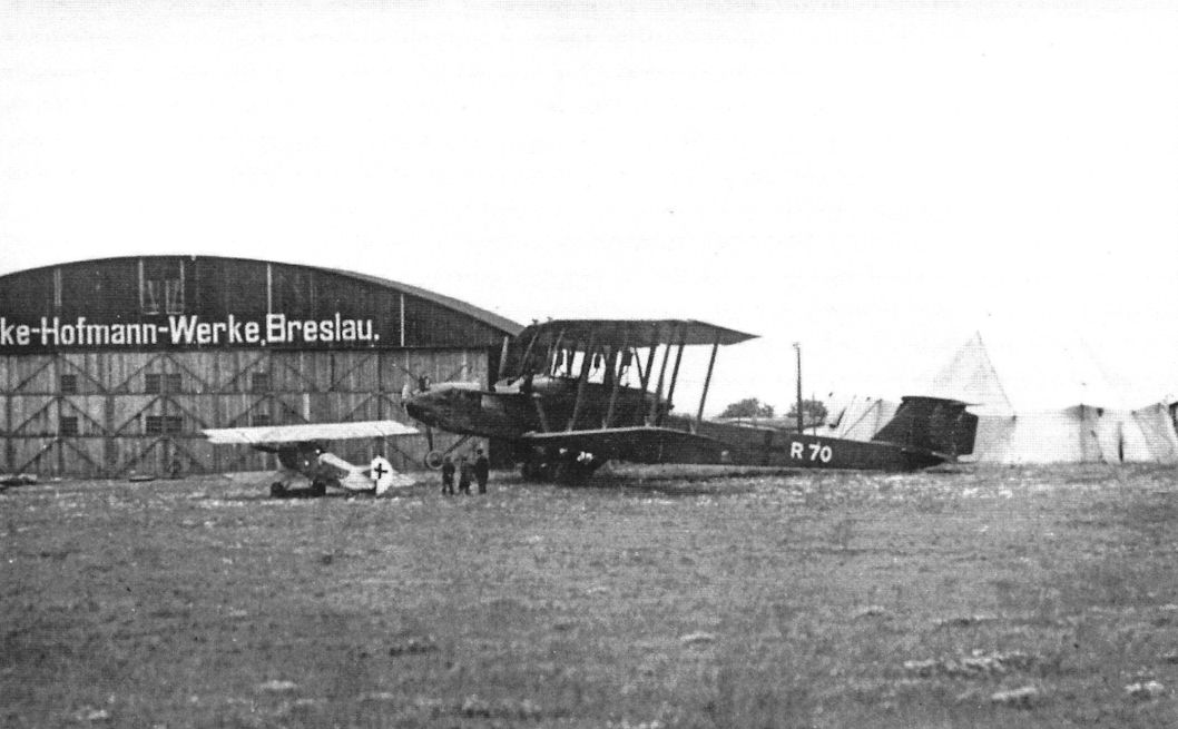
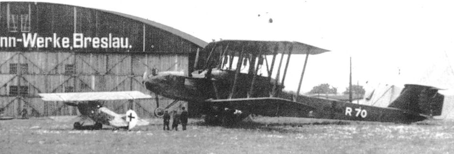
| Staaken R.XIV with the Linke-Hofmann works in the background. Linke-Hofmann was also involved in R-plane development but only one, Linke-Hofmann R.I 40/16, was completed and flown. (Peter M. Grosz collection/STDB)
|
 |
G.Haddow, P.Grosz - The German Giants /Putnam/
|
| Staaken R.XIV.
|
 |
J.Herris - Zeppelin-Staaken Aircraft of WW1. Vol 2: R.VI R.30/16 - E.4/20 /Centennial Perspective/ (48)
|
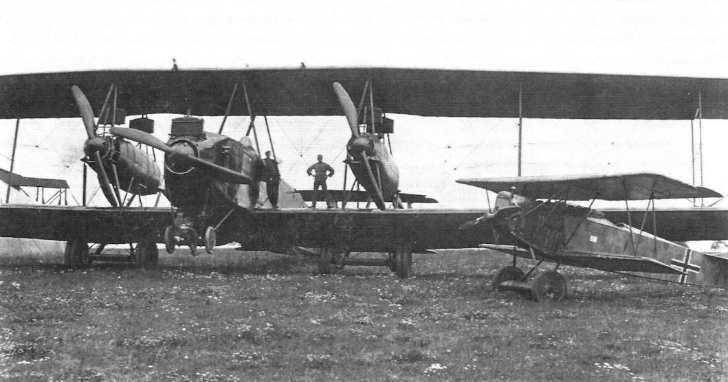
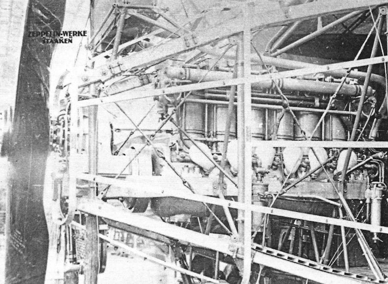
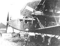
| Staaken R.XIV engine installation. (Peter M. Grosz collection/STDB)
|
 |
J.Herris - Zeppelin-Staaken Aircraft of WW1. Vol 2: R.VI R.30/16 - E.4/20 /Centennial Perspective/ (48)
|
| In flight photo of a Staaken R.XIV. (Peter M. Grosz collection/STDB)
|
 |
J.Herris - Zeppelin-Staaken Aircraft of WW1. Vol 2: R.VI R.30/16 - E.4/20 /Centennial Perspective/ (48)
|
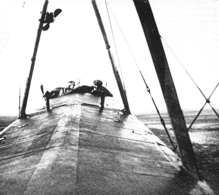
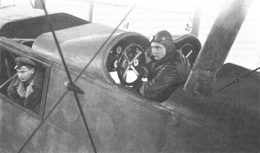
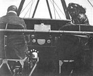
| The cockpit of a Staaken R.XIV in flight. (Peter M. Grosz collection/ STDB)
|
 |
J.Herris - Zeppelin-Staaken Aircraft of WW1. Vol 2: R.VI R.30/16 - E.4/20 /Centennial Perspective/ (48)
|
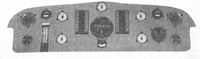
| Staaken R.XIV instrument panel for controlling a five-engine version.
|
 |
J.Herris - Zeppelin-Staaken Aircraft of WW1. Vol 2: R.VI R.30/16 - E.4/20 /Centennial Perspective/ (48)
|
| Staaken R.XV R.46/17 on the factory airfield. (Peter M. Grosz collection/STDB)
|
 |
J.Herris - Zeppelin-Staaken Aircraft of WW1. Vol 2: R.VI R.30/16 - E.4/20 /Centennial Perspective/ (48)
|
| Staaken R.XV R.46/17 on the factory airfield. (Peter M. Grosz collection/STDB)
|
 |
J.Herris - Zeppelin-Staaken Aircraft of WW1. Vol 2: R.VI R.30/16 - E.4/20 /Centennial Perspective/ (48)
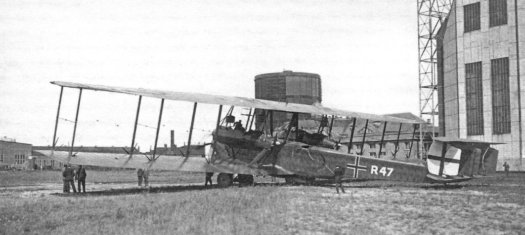
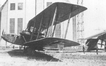
|
| The Staaken R.XV R.47/17 on the factory airfield. (Peter M. Grosz collection/STDB)
|
 |
J.Herris - Zeppelin-Staaken Aircraft of WW1. Vol 2: R.VI R.30/16 - E.4/20 /Centennial Perspective/ (48)
|
| Staaken R.XV R.47/17 on the factory airfield. The white outline of the national insignia has been painted black for night operations. (Peter M. Grosz collection/STDB)
|
 |
K.Delve - World War One in the Air /Crowood/
|
| The German strategic bombing campaign against London continued into 1918. Zeppelin-Staaken RXV R47 was one of three of this variant to see operational service, the first, R46, having been delivered in August 1917.
|
 |
J.Herris - Zeppelin-Staaken Aircraft of WW1. Vol 2: R.VI R.30/16 - E.4/20 /Centennial Perspective/ (48)
|
| The Staaken R.XV was nearly identical to the earlier R.XIV. Its minor modifications were made to reduce weight. The nose was slightly refined. The IAACC found R.48/17 in the factory in 1919. Note the parachute bags (sewn under the fuselage canvas) and static lines for the dorsal gunners. (Peter M. Grosz collection/STDB)
|
 |
J.Herris - Zeppelin-Staaken Aircraft of WW1. Vol 2: R.VI R.30/16 - E.4/20 /Centennial Perspective/ (48)
|
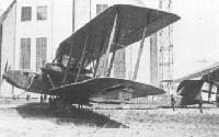
| The Staaken 8301 at the factory in its original configuration for flight testing. (Peter M. Grosz collection/STDB)
|
 |
J.Herris - Zeppelin-Staaken Aircraft of WW1. Vol 2: R.VI R.30/16 - E.4/20 /Centennial Perspective/ (48)
|
| The fuselage and parts of a Staaken R.XV in the factory. (Peter M. Grosz collection/STDB)
|
 |
J.Herris - Zeppelin-Staaken Aircraft of WW1. Vol 2: R.VI R.30/16 - E.4/20 /Centennial Perspective/ (48)
|
| Staaken R.XIVa R69 at the factory. (Peter M. Grosz collection/STDB)
|
 |
J.Herris - Zeppelin-Staaken Aircraft of WW1. Vol 2: R.VI R.30/16 - E.4/20 /Centennial Perspective/ (48)
|
| Staaken R.XIVa R69 at the factory. (Peter M. Grosz collection/STDB)
|
 |
J.Herris - Zeppelin-Staaken Aircraft of WW1. Vol 2: R.VI R.30/16 - E.4/20 /Centennial Perspective/ (48)
|
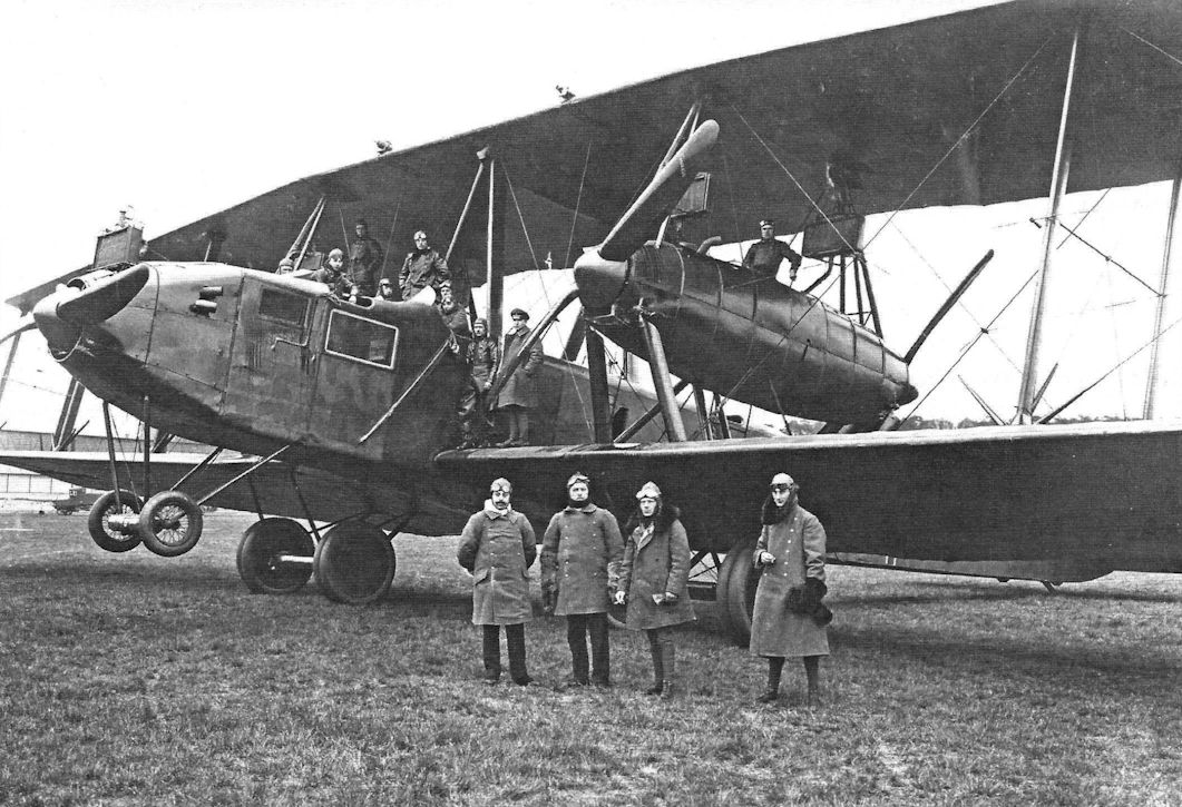
Staaken R.XIVa 69/18 with a visiting Argentine commission at Doberitz.
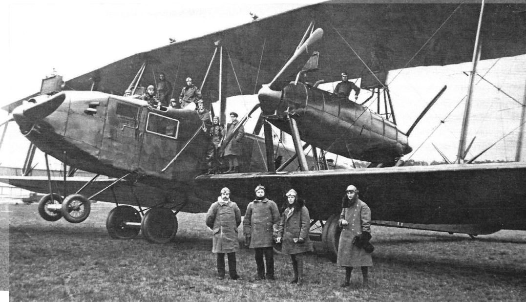
The R.XIVa was an improved R.XIV but the differences were not readily apparent from a photograph. Note the parachute bags seen just under the front of the cabin (sewn beneath the fuselage canvas) and static lines (Zugleine) for pilots. (Peter M. Grosz collection/STDB)
|
 |
J.Herris - Zeppelin-Staaken Aircraft of WW1. Vol 2: R.VI R.30/16 - E.4/20 /Centennial Perspective/ (48)
|
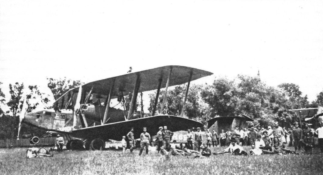
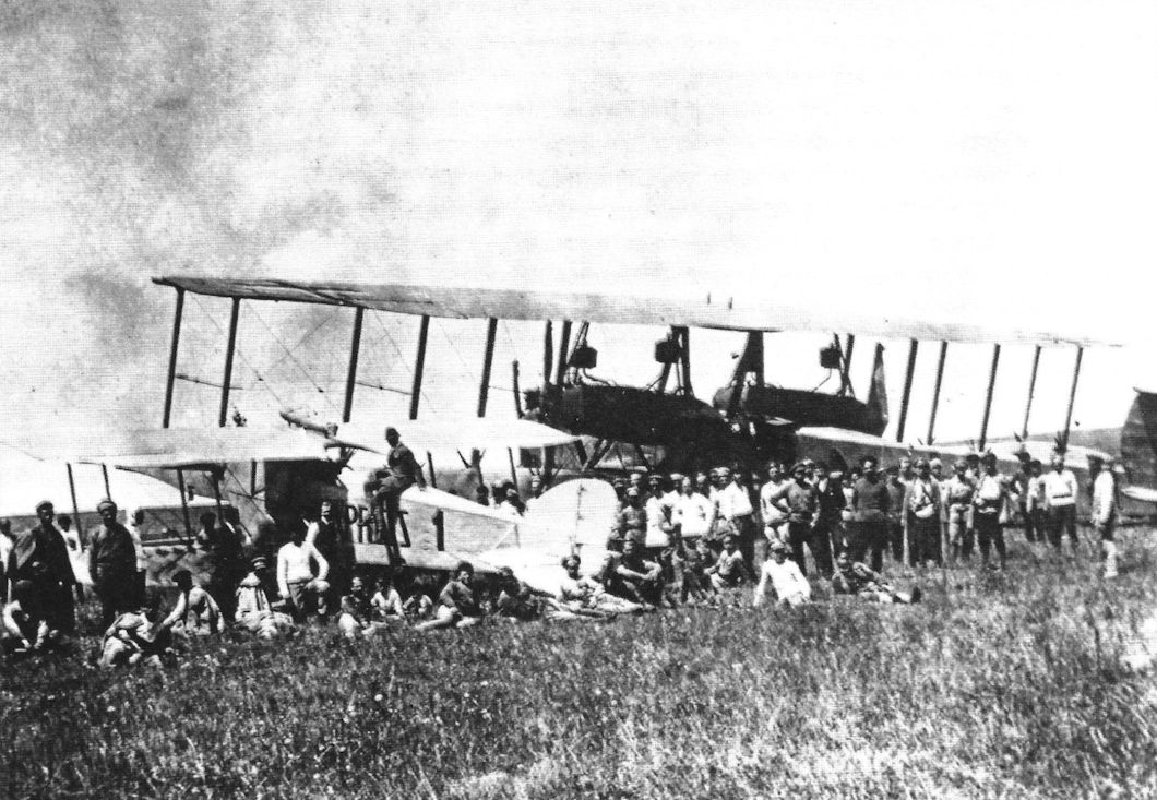
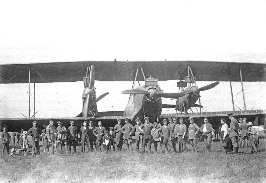
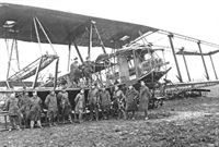
| Staaken R.XIVa 69/18 draws a crowd after landing in the Ukraine. The R.XIVa was an improved R.XIV but used the same powerplants, five 245 hp Maybach Mb.IVa engines. (Peter M. Grosz collection/STDB)
|
 |
J.Herris - Zeppelin-Staaken Aircraft of WW1. Vol 2: R.VI R.30/16 - E.4/20 /Centennial Perspective/ (48)
|
| A Staaken R.XIVa draws a crowd after landing in the Ukraine. The R.XIVa was an improved R.XIV but used the same powerplants, five 245 hp Maybach Mb.IVa engines. (Peter M. Grosz collection/STDB)
|
 |
J.Herris - Zeppelin-Staaken Aircraft of WW1. Vol 2: R.VI R.30/16 - E.4/20 /Centennial Perspective/ (48)
|
| Staaken R.XIVa R69 postwar. The R.XIVa aircraft were not delivered in time for combat. (Peter M. Grosz collection/STDB)
|
 |
J.Herris - Zeppelin-Staaken Aircraft of WW1. Vol 2: R.VI R.30/16 - E.4/20 /Centennial Perspective/ (48)
|
| Staaken R.XIVa with crew. (Peter M. Grosz collection/STDB)
|
 |
G.Haddow, P.Grosz - The German Giants /Putnam/
|
| Staaken R.XIVa 70/18, chartered by the Ukrainian Government. Photo dated 14 June 1919.
|
 |
J.Herris - Zeppelin-Staaken Aircraft of WW1. Vol 2: R.VI R.30/16 - E.4/20 /Centennial Perspective/ (48)
|
| Staaken R.XIVa R.70/18 under charter to the Ukrainian government (Peter M. Grosz collection/STDB)
|
 |
J.Herris - Zeppelin-Staaken Aircraft of WW1. Vol 2: R.VI R.30/16 - E.4/20 /Centennial Perspective/ (48)
|
| Staaken R.XIVa, perhaps R.70/18. (Peter M. Grosz collection/STDB)
|
 |
J.Herris - Zeppelin-Staaken Aircraft of WW1. Vol 2: R.VI R.30/16 - E.4/20 /Centennial Perspective/ (48)
|
| Staaken R.XIVa R.70 in civilian DLR markings. A Ukrainian marking has been applied. (Peter M. Grosz collection/STDB)
|
 |
J.Herris - Zeppelin-Staaken Aircraft of WW1. Vol 2: R.VI R.30/16 - E.4/20 /Centennial Perspective/ (48)
|
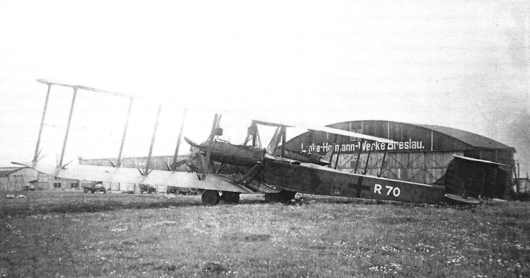
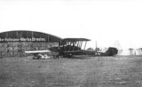
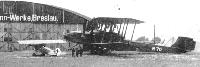
| Staaken R.XIVa at Breslau.This may be another view of R.70. (Peter M. Grosz collection/STDB)
|
 |
J.Herris - Zeppelin-Staaken Aircraft of WW1. Vol 2: R.VI R.30/16 - E.4/20 /Centennial Perspective/ (48)
|
| Staaken R.XIVa R70 at the factory. R.70 displays the final form of national marking without the white outline for night operations. (Peter M. Grosz collection/STDB)
|
 |
J.Herris - Zeppelin-Staaken Aircraft of WW1. Vol 2: R.VI R.30/16 - E.4/20 /Centennial Perspective/ (48)
|
| Staaken R.XIVa R70 at Breslau. (Peter M. Grosz collection/STDB)
|
 |
G.Haddow, P.Grosz - The German Giants /Putnam/
|
| Staaken R.XIVa 70/18 on the Hundsfeld airfield near Breslau.
|
 |
J.Herris - Zeppelin-Staaken Aircraft of WW1. Vol 2: R.VI R.30/16 - E.4/20 /Centennial Perspective/ (48)
|
| Staaken R.XIVa R71 at the factory before it crashed. R71 may have been the last R-plane built by Staaken; R72 was ordered but its completion is not confirmed and there are no photos of it. (Peter M. Grosz collection/STDB)
|
 |
J.Herris - Zeppelin-Staaken Aircraft of WW1. Vol 2: R.VI R.30/16 - E.4/20 /Centennial Perspective/ (48)
|
| Staaken R.XIVa(Schul) photographed in the factory. (Peter M. Grosz collection/STDB)
|
 |
J.Herris - Zeppelin-Staaken Aircraft of WW1. Vol 2: R.VI R.30/16 - E.4/20 /Centennial Perspective/ (48)
|
Staaken R.XIVa (Schul) 84/18 prior to the fitting of propeller spinners.
Staaken R.XIVa(Schul) was built by Schutte-Lanz, which was given a contract for three aircraft, serial numbers R.84 to R.86. None were completed before the war ended. (Peter M. Grosz collection/STDB)
|
 |
J.Herris - Zeppelin-Staaken Aircraft of WW1. Vol 2: R.VI R.30/16 - E.4/20 /Centennial Perspective/ (48)
|
| Staaken R.XIVa(Schul) on the factory airfield. (Peter M. Grosz collection/STDB)
|
 |
J.Herris - Zeppelin-Staaken Aircraft of WW1. Vol 2: R.VI R.30/16 - E.4/20 /Centennial Perspective/ (48)
|
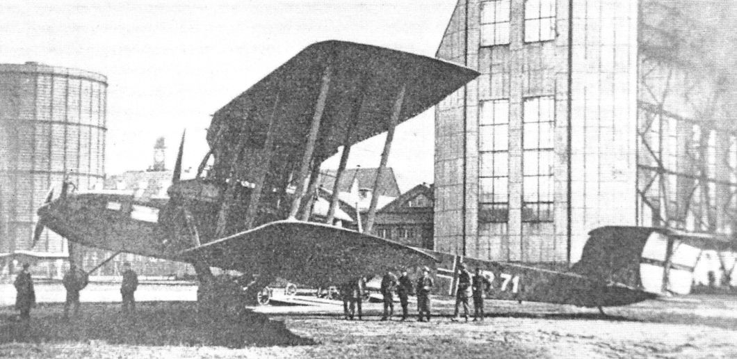
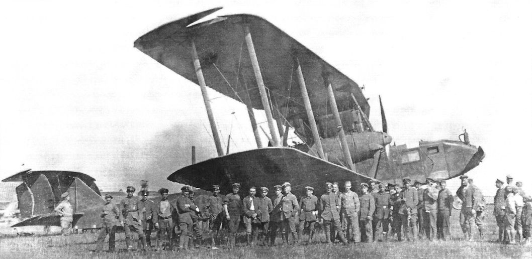
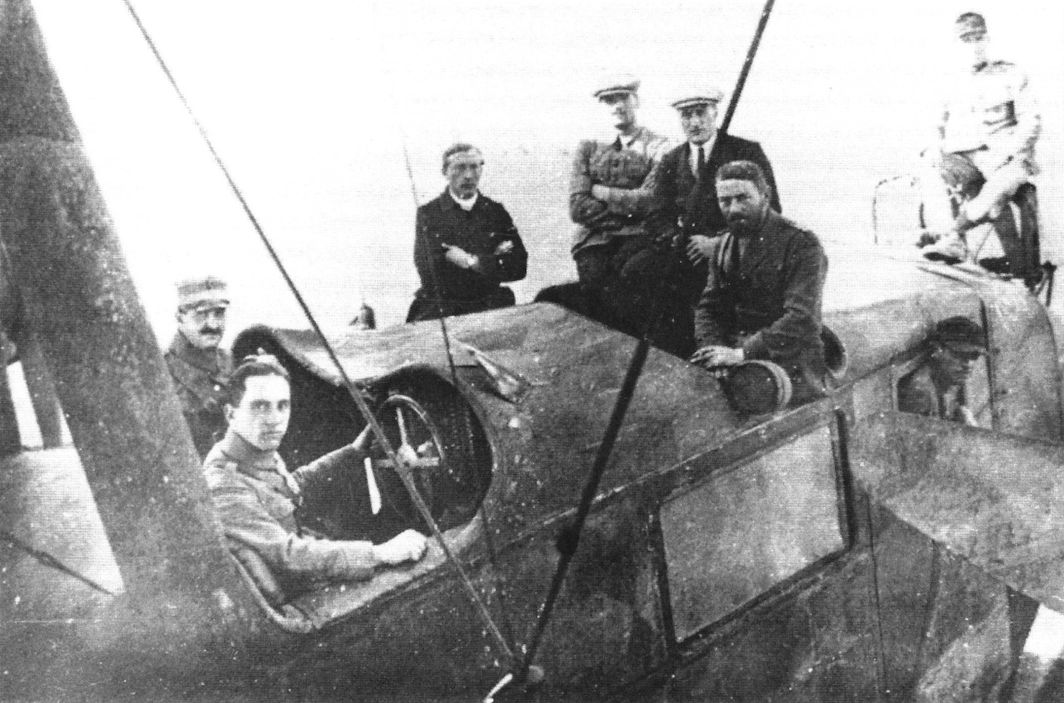
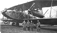
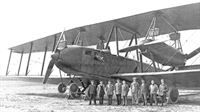
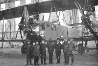
"Цеппелин-Штаакен" R-XIV, послевоенный снимок. На переднем плане - группа авиаконструкторов.
Staaken R.XIVa(Schul) R.84/18 with Schutte-Lanz factory staff. (Peter M. Grosz collection/STDB)
|
 |
J.Herris - Zeppelin-Staaken Aircraft of WW1. Vol 2: R.VI R.30/16 - E.4/20 /Centennial Perspective/ (48)
|
| Staaken R.XIVa(Schul) is the background for a group portrait. (Peter M. Grosz collection/STDB)
|
 |
J.Herris - Zeppelin-Staaken Aircraft of WW1. Vol 2: R.VI R.30/16 - E.4/20 /Centennial Perspective/ (48)
|
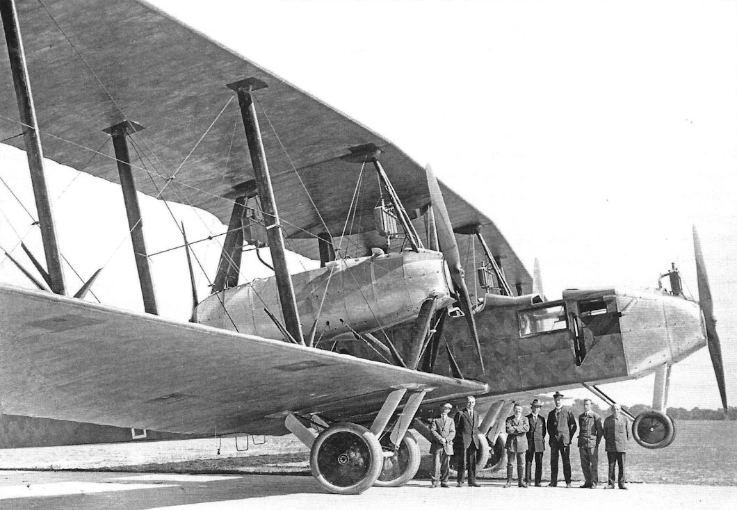
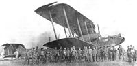
Staaken R.XIVa(Schul) photographed with factory staff. (Peter M. Grosz collection/STDB)
Example of decentralized power arrangement with five 245 h.p. Maybach Mb.IVa engines.
|
 |
J.Herris - Zeppelin-Staaken Aircraft of WW1. Vol 2: R.VI R.30/16 - E.4/20 /Centennial Perspective/ (48)
|
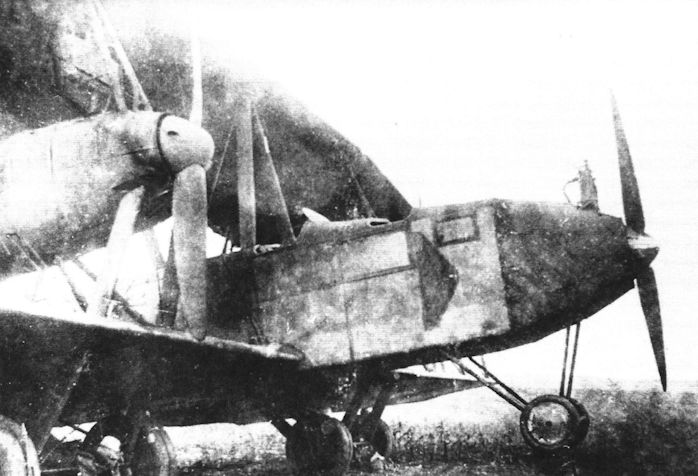
| This detail view of a Staaken R.XIVa. A parachute static line (Zugleine) for the co-pilot is visible below the cockpit. (Peter M. Grosz collection/STDB)
|
 |
J.Herris - Zeppelin-Staaken Aircraft of WW1. Vol 2: R.VI R.30/16 - E.4/20 /Centennial Perspective/ (48)
|
| Staaken R.XIVa. (Peter M. Grosz collection/STDB)
|
 |
J.Herris - Zeppelin-Staaken Aircraft of WW1. Vol 2: R.VI R.30/16 - E.4/20 /Centennial Perspective/ (48)
|
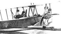
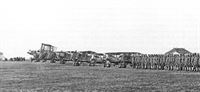
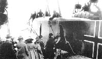
| Staaken R.XIVa lined up with Nieuports and Breguets, probably in the Ukraine. In 1919 the German Government allowed DLR to charter a number of aircraft to the Ukraine Government for the transportation of new money for the young state [that the Germans were printing clandestinely]. The Ukraine was at war with Rumania and Poland and wanted to stimulate its economy by introducing a new currency. Some of the DLR aircraft were secretly transferred to the Ukraine and in addition the Ukraine Government chartered the three five-engine Staaken R.XIVa aircraft from DLR. These aircraft had serial numbers R.69, R.70, and R.71 and registration D.129, D.130, and D.131 respecitively. All three were lost. The first, R.69, was confiscated on 29 July by French troops on behalf of the IAACC at the airport of Wien, Aspern. R.71 crashed and burned on 4 August in Oberschlesien. The last Staaken R.XIVa, R.70, commanded by Captain Count Hans Wolf von Harah and with pilots Heinrich Smiltz and Henrig Tretken, was forced down due to fuel problems on 19 September on its way to Kamenets-Podolski. Upon landing the crew was captured by two soldiers of the Rumanian 37th Infantry Regiment. On board the Rumanians found 303 million Griverns (Ukraine roubles), issued 5,6, and 24 October 1918. The Ukraine passengers were sent to a Ukraine-controlled area on the other side of the river Dnestr, while the Germans were imprisoned. The aircraft was repaired by Rumanian aeronautical engineers and flown by Petre Macavei (Technical 1st Lieutenant) and other crew members to the capital of Rumania, Bucharest. On its way the engine caused more trouble, but in the end the aircraft managed to arrive safely. It never flew again, but was stationed at the airport for several years before it was dismantled. Its wooden propellers went to the military museum in Bucharest. Without aircraft, the DLR had to supply new aircraft and offered the Friedrichshafen G.IIIa for Ukraine operations. (Peter M. Grosz collection/STDB)
|
 |
J.Herris - Zeppelin-Staaken Aircraft of WW1. Vol 2: R.VI R.30/16 - E.4/20 /Centennial Perspective/ (48)
|
| Staaken R.XIVa in the Ukraine. (Peter M. Grosz collection/STDB)
|
 |
J.Herris - Zeppelin-Staaken Aircraft of WW1. Vol 2: R.VI R.30/16 - E.4/20 /Centennial Perspective/ (48)
|
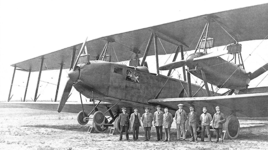
| A Staaken R.XIVa in pristine condition with its crew. (Peter M. Grosz collection/STDB)
|
 |
J.Herris - Zeppelin-Staaken Aircraft of WW1. Vol 2: R.VI R.30/16 - E.4/20 /Centennial Perspective/ (48)
|
| Another view of a Staaken R.XIVa. The number of wheels were reduced to reduce weight. (Peter M. Grosz collection/STDB)
|
 |
J.Herris - Zeppelin-Staaken Aircraft of WW1. Vol 2: R.VI R.30/16 - E.4/20 /Centennial Perspective/ (48)
|
| Staaken R.XIVa on its tail skid. (Peter M. Grosz collection/STDB)
|
 |
G.Haddow, P.Grosz - The German Giants /Putnam/
|
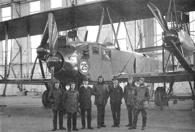
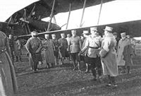
| Staaken test pilots commemorating the completion of the 25th Staaken R-plane, an R.XIVa. Third from the right is Willy Mann who flew the first R-plane built by VGO.
|
 |
J.Herris - Zeppelin-Staaken Aircraft of WW1. Vol 2: R.VI R.30/16 - E.4/20 /Centennial Perspective/ (48)
|
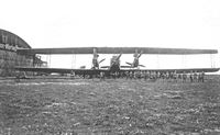
| Staaken personnel. An R.XIV is the background. (Peter M. Grosz collection/STDB)
|
 |
J.Herris - Zeppelin-Staaken Aircraft of WW1. Vol 2: R.VI R.30/16 - E.4/20 /Centennial Perspective/ (48)
|
| Staaken R.XIVa with its ground crew. (Peter M. Grosz collection/STDB)
|
 |
J.Herris - Zeppelin-Staaken Aircraft of WW1. Vol 2: R.VI R.30/16 - E.4/20 /Centennial Perspective/ (48)
|
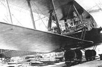
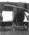
| Staaken R.XIVa nose with large radiator for its nose engine. (Peter M. Grosz collection/STDB)
|
 |
J.Herris - Zeppelin-Staaken Aircraft of WW1. Vol 2: R.VI R.30/16 - E.4/20 /Centennial Perspective/ (48)
|
| Staaken R.XIVa serves as a background for a group photo. (Peter M. Grosz collection/STDB)
|
 |
J.Herris - Zeppelin-Staaken Aircraft of WW1. Vol 2: R.VI R.30/16 - E.4/20 /Centennial Perspective/ (48)
|
| More detail views of a Staaken R.XIVa. Unlike the R.XIV, the R.XIVa omitted the upper wing gun positions over the nacelles. (Peter M. Grosz collection/STDB)
|
 |
J.Herris - Zeppelin-Staaken Aircraft of WW1. Vol 2: R.VI R.30/16 - E.4/20 /Centennial Perspective/ (48)
|
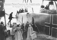
| Staaken R.XIVa(Schul) being promoted as a passenger plane - still with German national insignia. These civilian flights were hardly mentioned in the daily and aeronautical press of the day, and it would appear that they brief and unimportant. The Allies were not enamored having these aircraft flying and Germany could not afford to subsidize them. A parachute shock cord runs from the rear exit to the parachute compartment - in a transport! (Peter M. Grosz collection/STDB)
|
 |
G.Haddow, P.Grosz - The German Giants /Putnam/
|
| Civilian passengers boarding a Staaken R.XIVa. Note the parachute shock cord running from the rear exit to the parachute compartment.
|
 |
J.Herris - Zeppelin-Staaken Aircraft of WW1. Vol 1: VGO.1 - R.IV R.29/16 /Centennial Perspective/ (47)
|
| The cockpit of a Staaken R.XIVa showing its night camouflage. (Piotr Mrozowski collection)
|
 |
J.Herris - Zeppelin-Staaken Aircraft of WW1. Vol 2: R.VI R.30/16 - E.4/20 /Centennial Perspective/ (48)
|
| Staaken R.XIVa with crew and onlookers. (Peter M. Grosz collection/STDB)
|
 |
J.Herris - Zeppelin-Staaken Aircraft of WW1. Vol 2: R.VI R.30/16 - E.4/20 /Centennial Perspective/ (48)
|
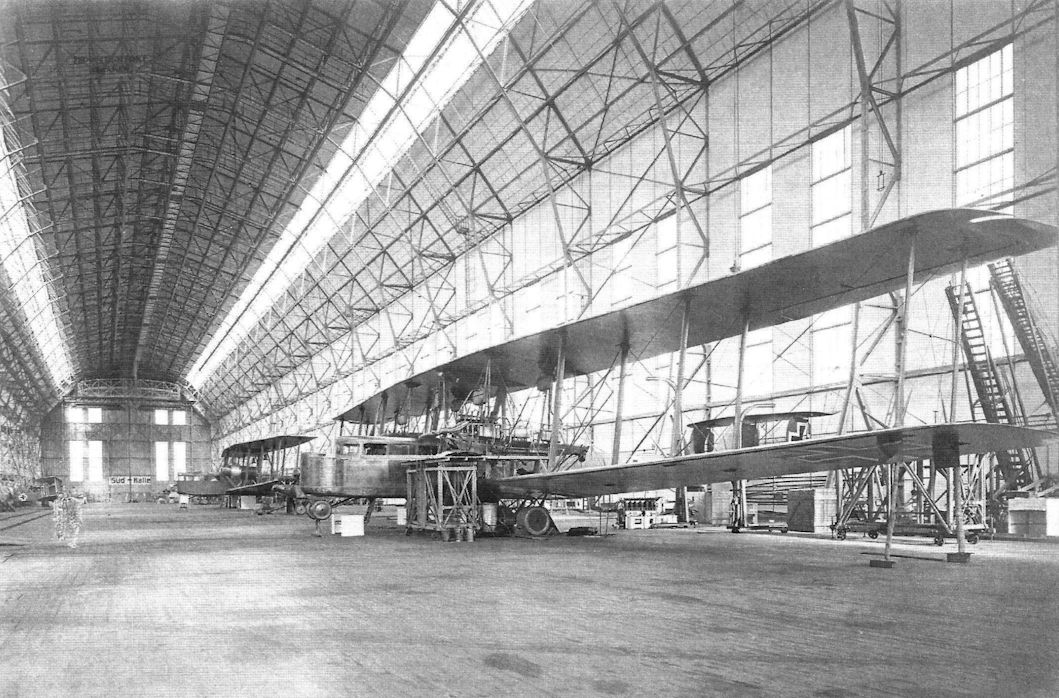
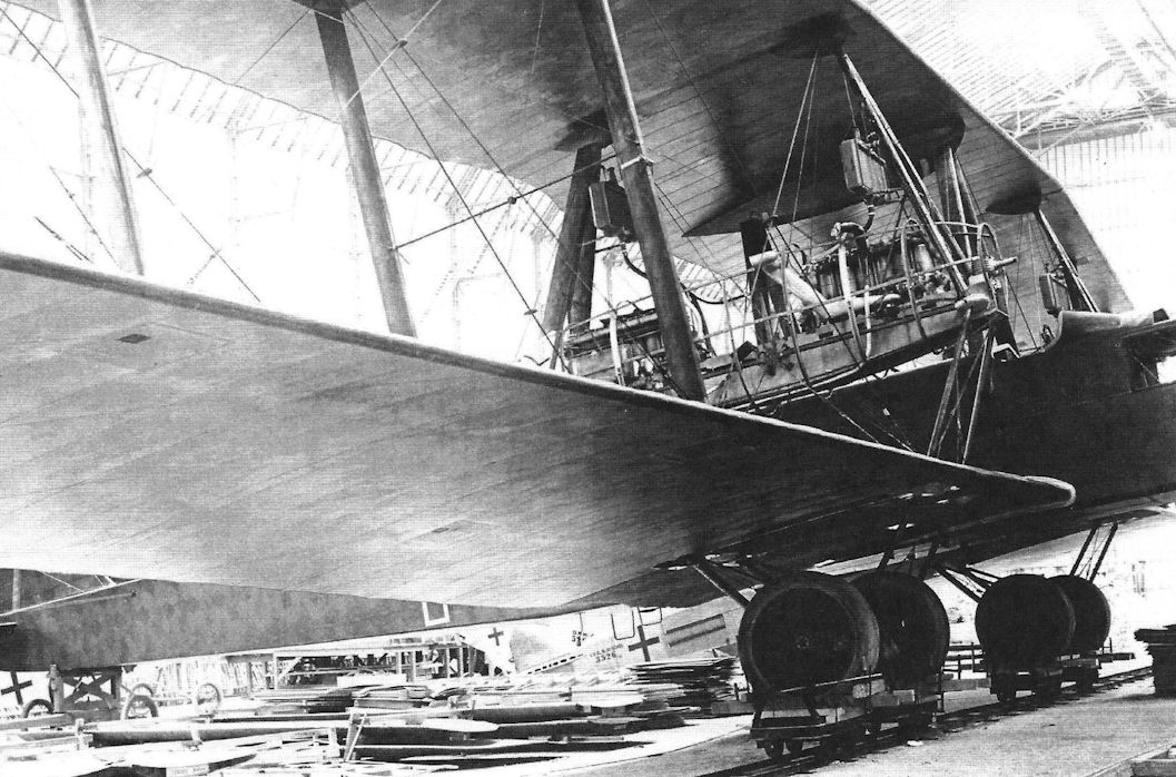
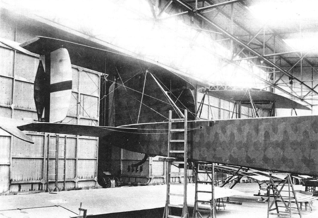
| Unidentified Staaken bombers under construction. (National Archives)
|
 |
J.Herris - Zeppelin-Staaken Aircraft of WW1. Vol 2: R.VI R.30/16 - E.4/20 /Centennial Perspective/ (48)
|
|
|
 |
J.Herris - Zeppelin-Staaken Aircraft of WW1. Vol 2: R.VI R.30/16 - E.4/20 /Centennial Perspective/ (48)
|
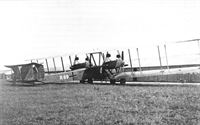
| Staaken R.XIV 45/17. Photograph shows the condition of the machine after a night landing at Morville, Belgium. Notice the position of the cockpit behind the wings, unique to the R.45 among Staaken R-planes.
|
 |
Журнал - Flight за 1918 г.
|
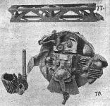
| Some constructional details of the five-engined giant. - 67. Long gear box, complete with male clutch. 68. Long gear box seen from underside. 69. Broken gear box (long type), with bearers and oil radiator. 70. Driving pinion. 71. Windmill.
|
 |
Журнал - Flight за 1918 г.
|
| Fig. 72. - Oil radiator and gear pump of five-engined giant.
|
 |
Журнал - Flight за 1918 г.
|
| Some more details of five-engined giant. - 73. Pusher screw and driven pinion. 74. Tractor screw and pinion. 75. Oil filter of gear box. 76. Engine control levers.
|
 |
Журнал - Flight за 1918 г.
|
| Fig. 77. shows engine bearer transverse-girder. 78. "Douglas" type wireless and heating generator.
|
 |
Журнал - Flight за 1918 г.
|
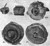
| The five-engined giant. - 79. Pump and transformer, 80. Rear view of engine and flywheel. 81. Wireless generator. 82. Cowling and dynamo drive.
|
 |
J.Herris - Zeppelin-Staaken Aircraft of WW1. Vol 2: R.VI R.30/16 - E.4/20 /Centennial Perspective/ (48)
|
| Staaken R.XIVa, perhaps R.71, after crashing. The pilot had to work hard for such an outcome. (Peter M. Grosz collection/STDB)
|
 |
G.Haddow, P.Grosz - The German Giants /Putnam/
|
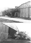
| Wreckage of the Staaken R.44 on the Cologne airfield. February 1919.
|
 |
J.Herris - Zeppelin-Staaken Aircraft of WW1. Vol 2: R.VI R.30/16 - E.4/20 /Centennial Perspective/ (48)
|
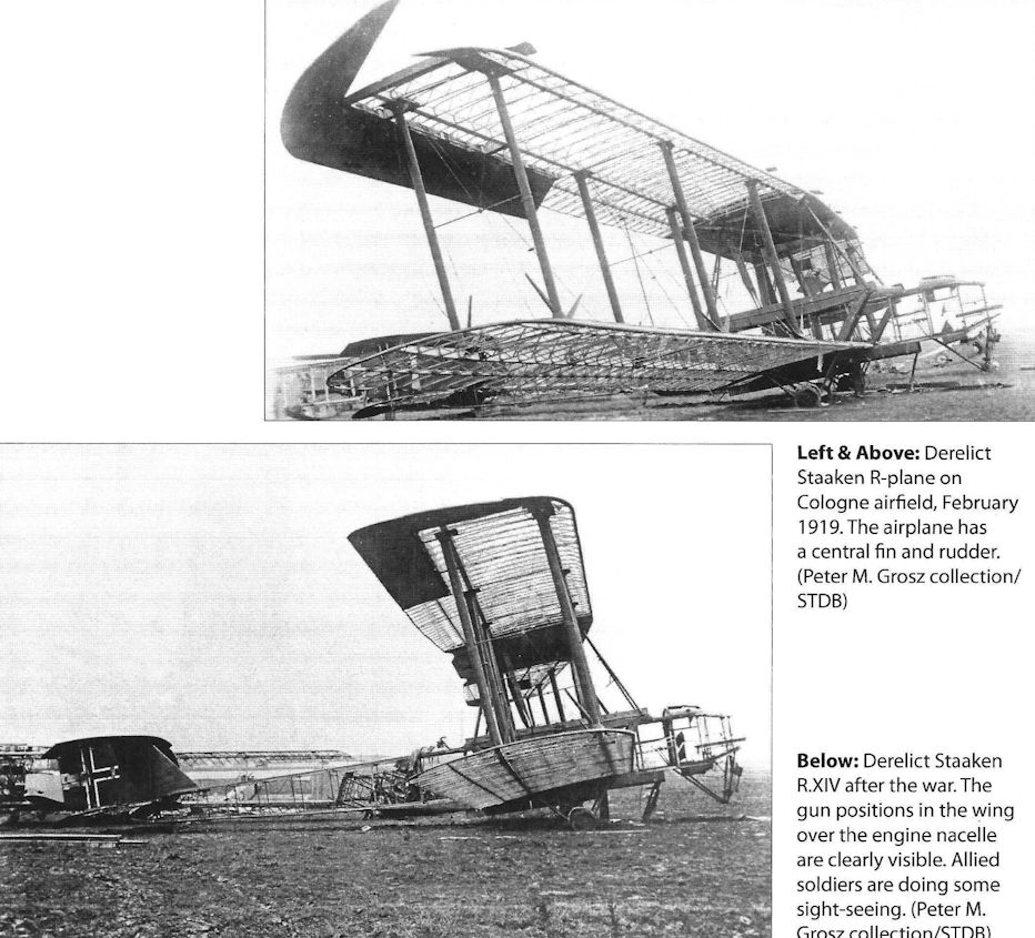
| Derelict Staaken R-plane on Cologne airfield, February 1919. The airplane has a central fin and rudder. (Peter M. Grosz collection/ STDB)
|
 |
Журнал - Flight за 1919 г.
|
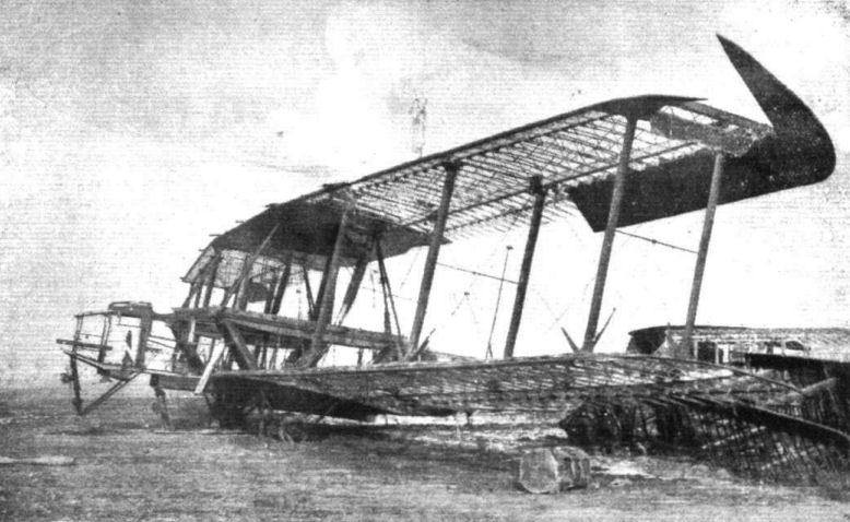
| The skeleton remains on a 5-engined Gotha at Cologne.
|
 |
G.Haddow, P.Grosz - The German Giants /Putnam/
|
| Derelict Staaken R.XIV 44/17 left behind by the Germans at their abandoned airfield in Cologne, 11 February 1919.
|
 |
J.Herris - Zeppelin-Staaken Aircraft of WW1. Vol 2: R.VI R.30/16 - E.4/20 /Centennial Perspective/ (48)
|
| Derelict Staaken R.XIV after the war. The gun positions in the wing over the engine nacelle are clearly visible. Allied soldiers are doing some sight-seeing. (Peter M. Grosz collection/STDB)
|
 |
G.Haddow, P.Grosz - The German Giants /Putnam/
|
| Remains of the Staaken R.XIV 43/17, shot down by Capt. Yuille R.F.C.
|
 |
Журнал - Flight за 1918 г.
|
Fig. 65. - Engine bearers of five-engined bomber.
Fig. 66. - Tail skid of five-engined type.
|
 |
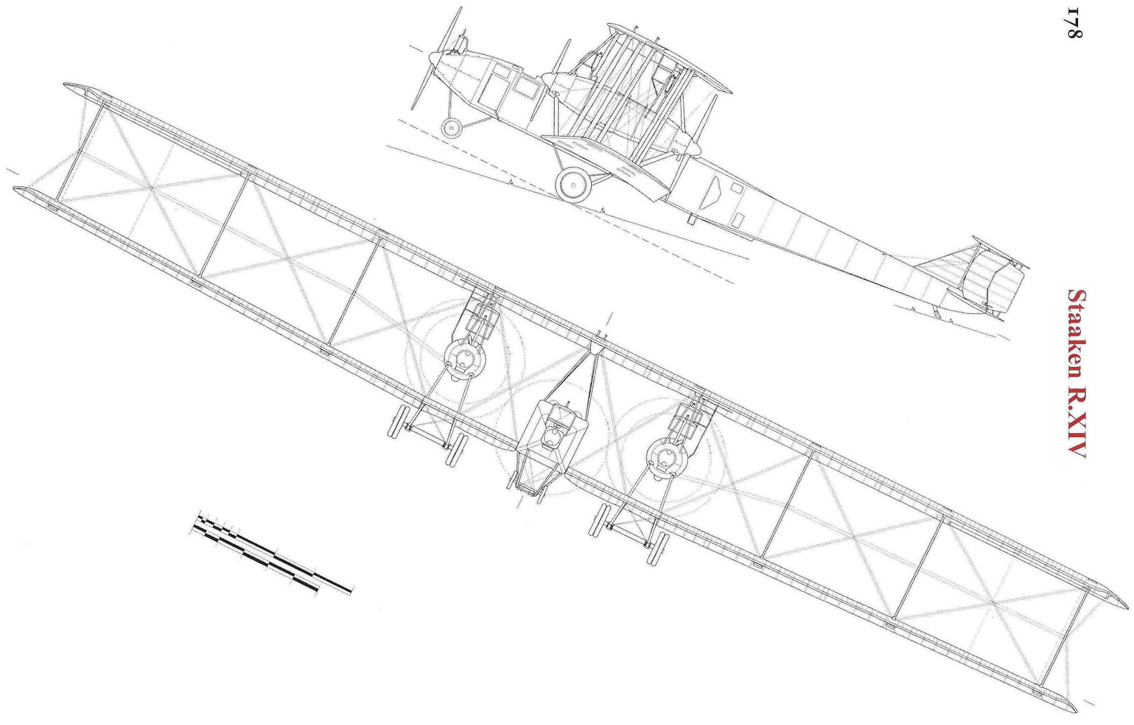
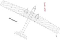
G.Haddow, P.Grosz - The German Giants /Putnam/
|
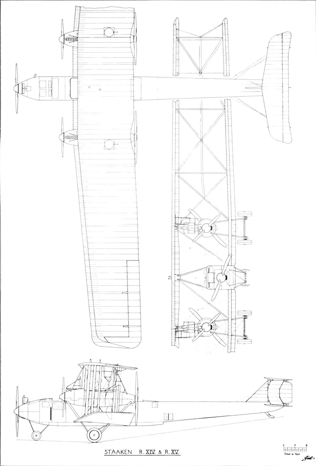
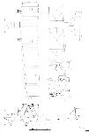
| Staaken R.XIV & XV
|
 |
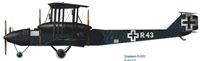
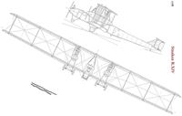
G.Haddow, P.Grosz - The German Giants /Putnam/
|
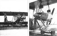
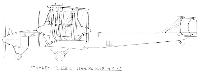
| Staaken R.XIV serial No. R.45. Experimental relocation of the control position.
|
 |
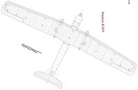
G.Haddow, P.Grosz - The German Giants /Putnam/
|
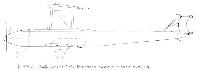
| Staaken R.XIVa
|
 |
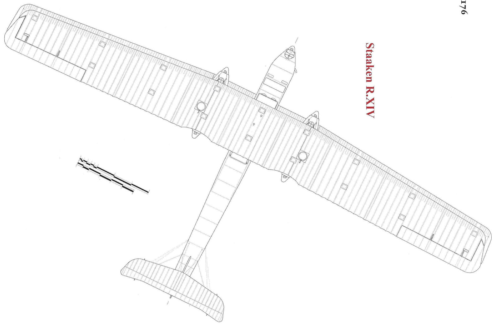
J.Herris - Zeppelin-Staaken Aircraft of WW1. Vol 2: R.VI R.30/16 - E.4/20 /Centennial Perspective/ (48)
|
| Staaken R.XIV
|
 |
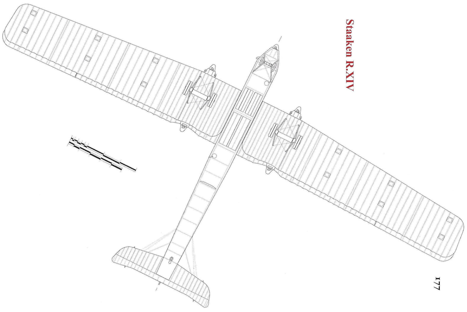
J.Herris - Zeppelin-Staaken Aircraft of WW1. Vol 2: R.VI R.30/16 - E.4/20 /Centennial Perspective/ (48)
|
| Staaken R.XIV
|
 |
J.Herris - Zeppelin-Staaken Aircraft of WW1. Vol 2: R.VI R.30/16 - E.4/20 /Centennial Perspective/ (48)
|
| Staaken R.XIV
|