Описание
Страна: Германия
Год: 1917
Multi-engined giant bomber
Варианты
- Zeppelin-Staaken - L - 1917 - Германия
- Zeppelin-Staaken - R.VI - 1917 - Германия
- В.Кондратьев Самолеты первой мировой войны
- O.Thetford, P.Gray German Aircraft of the First World War (Putnam)
- G.Haddow, P.Grosz The German Giants (Putnam)
- J.Herris Zeppelin-Staaken Aircraft of WW1. Vol 1: VGO.1 - R.IV R.29/16 (A Centennial Perspective on Great War Airplanes 47)
- M.Dusing German Aviation Industry in WWI. Volume 2 (A Centennial Perspective on Great War Airplanes 85)
- Журнал Flight
-

J.Herris - Development of German Warplanes in WWI /Centennial Perspective/ (1)
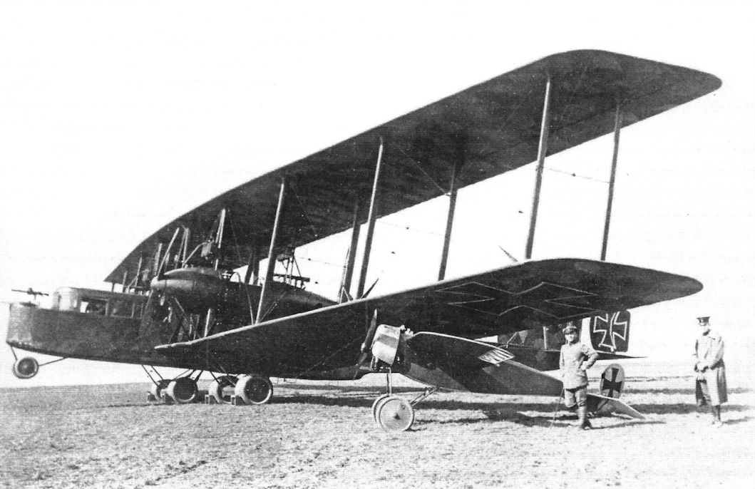
Staaken R.VI R27/16 was camouflaged in dark night colors for night bombing missions over the UK. Interestingly, the large engine nacelles were left in natural metal rather than being painted a dark color. The camouflage was apparently applied at the factory because the national insignia are white outlines applied over the camouflage. The R.VI was the main production R-plane, with 18 being built by Staaken and three other manufacturers. Most were powered by four 260 hp Mercedes D.IVa engines, but some used the 245 hp Maybach Mb.IVa. Most were armed with four machine guns, but some had two additional guns in gun positions on the upper wing; mechanics climbed ladders to reach these. Span was 42.2 meters (138.5 feet).
-

В.Кондратьев - Самолеты первой мировой войны
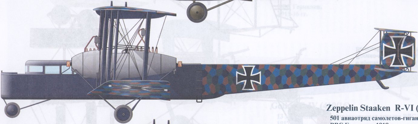
Zeppelin Staaken R-VI (27/16), 501 авиаотряд самолетов-гигантов ВВС Германии, 1918г.
-

J.Herris - Zeppelin-Staaken Aircraft of WW1. Vol 1: VGO.1 - R.IV R.29/16 /Centennial Perspective/ (47)
Staaken R.VI in night camouflage.
-

-

-

-

J.Herris - Zeppelin-Staaken Aircraft of WW1. Vol 2: R.VI R.30/16 - E.4/20 /Centennial Perspective/ (48)
Staaken R.VI R.30/16 Postwar
-

J.Herris - Zeppelin-Staaken Aircraft of WW1. Vol 2: R.VI R.30/16 - E.4/20 /Centennial Perspective/ (48)
Staaken R.VI R.33/16 with personal insignia 'Rodax'
-

-

-

В.Кондратьев - Самолеты первой мировой войны
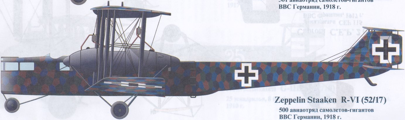
Zeppelin Staaken R-VI (52/17), 500 авиаотряд самолетов-гигантов ВВС Германии, 1918г.
-

В.Обухович, А.Никифоров - Самолеты Первой Мировой войны
Цеппелин-Штаакен R VI
-

J.Herris - Zeppelin-Staaken Aircraft of WW1. Vol 1: VGO.1 - R.IV R.29/16 /Centennial Perspective/ (47)
Staaken R.VI R.25/16; note the factory hand painted camouflage, primarily for daytime use without bluish over-painting. (Peter M. Grosz collection/STDB)
-

J.Herris - Zeppelin-Staaken Aircraft of WW1. Vol 1: VGO.1 - R.IV R.29/16 /Centennial Perspective/ (47)
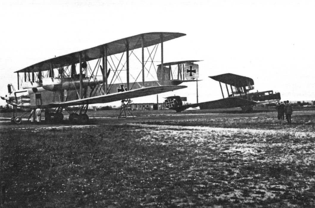
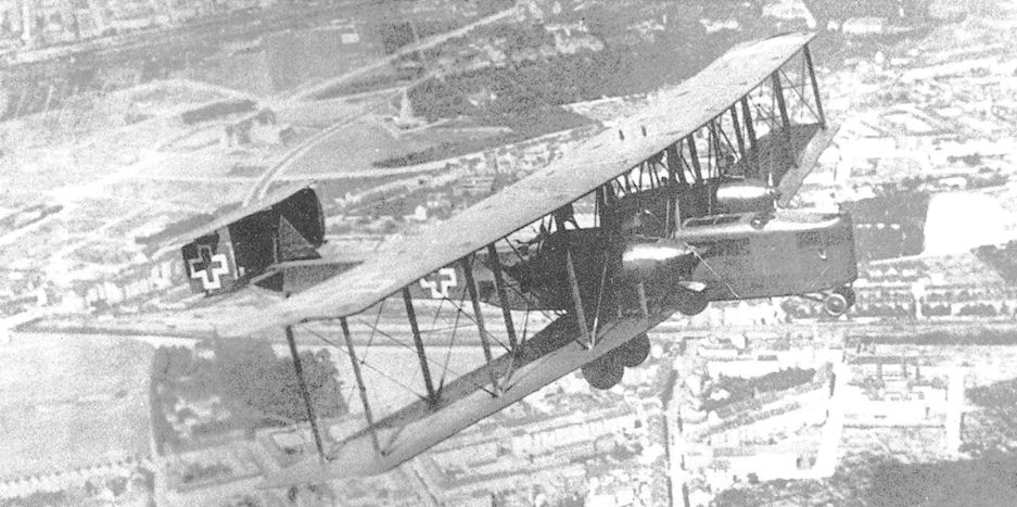
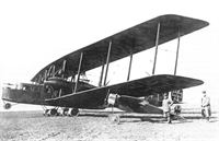
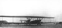
First flown in mid-1917, the Zeppelin-Staaken R VI, with 18 examples built, was to be by far the most numerous of the giant, long ranged R-planes. Powered either by four 245hp Maybach Mb IVs, or four 260hp Mercedes D IVa engines, mounted back to back in twin nacelles to drive two pusher and two tractor propellers, the R VI's top level speed was 84.4mph, while its normal range with a 2,200lb bomb load was around 550 miles. Delivered to Rf Abt 501, by now transferred to the Western Front, the RVIs sometimes operated alongside their smaller G type bretheren in raids against the English mainland and more distant French ports and cities. The Navy operated a sole, float-equipped example of this bomber under the designation Zeppelin-Staaken Type L, serialled 1432.
-

J.Herris - Zeppelin-Staaken Aircraft of WW1. Vol 1: VGO.1 - R.IV R.29/16 /Centennial Perspective/ (47)
Staaken R.VI R.25/16 on its airfield. (Peter M. Grosz collection/STDB)
-

J.Herris - Zeppelin-Staaken Aircraft of WW1. Vol 1: VGO.1 - R.IV R.29/16 /Centennial Perspective/ (47)
Staaken R.VI R.25/16 being manhandled by a large ground crew. (Peter M. Grosz collection/STDB)
-

J.Herris - Zeppelin-Staaken Aircraft of WW1. Vol 1: VGO.1 - R.IV R.29/16 /Centennial Perspective/ (47)
Staaken R.VI R.25/16 being manhandled by a large ground crew. (Peter M. Grosz collection/STDB)
-

J.Herris - Zeppelin-Staaken Aircraft of WW1. Vol 1: VGO.1 - R.IV R.29/16 /Centennial Perspective/ (47)
Staaken R.VI R.25/16 on its field. The photo shows R.25/16 after its top and side fuselage camouflage and nacelles were darkened. (Peter M. Grosz collection/STDB)
-

J.Herris - Zeppelin-Staaken Aircraft of WW1. Vol 1: VGO.1 - R.IV R.29/16 /Centennial Perspective/ (47)
Staaken R.VI R.25/16 with crew on board ready to launch. (Peter M. Grosz collection/STDB)
-

J.Herris - Zeppelin-Staaken Aircraft of WW1. Vol 1: VGO.1 - R.IV R.29/16 /Centennial Perspective/ (47)
Staaken R.VI R.25/16 draws and admiring crowd. (Peter M. Grosz collection/STDB)
-

-

J.Herris - Zeppelin-Staaken Aircraft of WW1. Vol 1: VGO.1 - R.IV R.29/16 /Centennial Perspective/ (47)
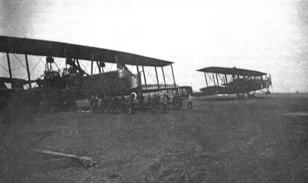
Staaken R.VI R.25 at the left together with another Staaken, probably R.12, on the airfield. (Peter M. Grosz collection/STDB)
Другие самолёты на фотографии: Zeppelin-Staaken VGO.III / R.IV / R.VII - Германия - 1916
-

-

J.Herris - Zeppelin-Staaken Aircraft of WW1. Vol 1: VGO.1 - R.IV R.29/16 /Centennial Perspective/ (47)
Staaken R.VI R.25/16 on its airfield. (Peter M. Grosz collection/STDB)
-

J.Herris - Zeppelin-Staaken Aircraft of WW1. Vol 1: VGO.1 - R.IV R.29/16 /Centennial Perspective/ (47)
Staaken R.VI R.25/16 in their flight gear ready for a winter mission. (Peter M. Grosz collection/STDB)
-

J.Herris - Zeppelin-Staaken Aircraft of WW1. Vol 1: VGO.1 - R.IV R.29/16 /Centennial Perspective/ (47)
Crew of R.25/16 with other Rfa 500 and 501 unit personnel. (Peter M. Grosz collection/STDB)
-

J.Herris - Zeppelin-Staaken Aircraft of WW1. Vol 1: VGO.1 - R.IV R.29/16 /Centennial Perspective/ (47)
Mechanic in an starboard engine nacelle. Note the fairing on the struts. (Peter M. Grosz collection/STDB)
-

J.Herris - Zeppelin-Staaken Aircraft of WW1. Vol 1: VGO.1 - R.IV R.29/16 /Centennial Perspective/ (47)
Mechanics work on Staaken R.VI R.25/16. (Peter M. Grosz collection/STDB)
-

J.Herris - Zeppelin-Staaken Aircraft of WW1. Vol 1: VGO.1 - R.IV R.29/16 /Centennial Perspective/ (47)
Rear view of R.25/16 emphasizing its night camouflage. (Peter M. Grosz collection/STDB)
-

J.Herris - Zeppelin-Staaken Aircraft of WW1. Vol 1: VGO.1 - R.IV R.29/16 /Centennial Perspective/ (47)
Tail details of Staaken R.VI R.25/16. (Peter M. Grosz collection/STDB)
-

J.Herris - Zeppelin-Staaken Aircraft of WW1. Vol 1: VGO.1 - R.IV R.29/16 /Centennial Perspective/ (47)
Front of Staaken R.VI R.26/16 when fitted with 4-bladed propellers. A Zeppelin flies overhead. (Peter M. Grosz collection/ STDB)
-

J.Herris - Zeppelin-Staaken Aircraft of WW1. Vol 1: VGO.1 - R.IV R.29/16 /Centennial Perspective/ (47)
Views of Staaken R.26/16 after completion. (Peter M. Grosz collection/STDB)
-

J.Herris - Zeppelin-Staaken Aircraft of WW1. Vol 1: VGO.1 - R.IV R.29/16 /Centennial Perspective/ (47)
Staaken R.26/16 with 4-bladed propellers ready to start engines. (Peter M. Grosz collection/STDB)
-

J.Herris - Zeppelin-Staaken Aircraft of WW1. Vol 1: VGO.1 - R.IV R.29/16 /Centennial Perspective/ (47)
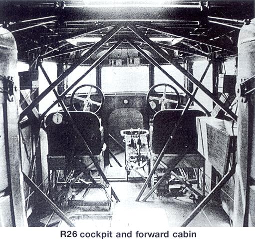
Cockpit of Staaken R.VI R.26/16. (Peter M. Grosz collection/STDB)
-

J.Herris - Zeppelin-Staaken Aircraft of WW1. Vol 1: VGO.1 - R.IV R.29/16 /Centennial Perspective/ (47)
Front view of Staaken R.VI R.26/16 with hand painted camouflage. Here it has 4-bladed propellers. The engine nacelles were probably over-painted with translucent light-blue lacquer. (Peter M. Grosz collection/STDB)
-

-

J.Herris - Zeppelin-Staaken Aircraft of WW1. Vol 1: VGO.1 - R.IV R.29/16 /Centennial Perspective/ (47)
Staaken R.VI R.26/16 with 4-bladed propellers. (Peter M. Grosz collection/STDB)
-

J.Herris - Zeppelin-Staaken Aircraft of WW1. Vol 1: VGO.1 - R.IV R.29/16 /Centennial Perspective/ (47)
Staaken R.26/16 under inspection by factory personnel. Two-bladed propellers are fitted (Peter M. Grosz collection/ STDB)
-

J.Herris - Zeppelin-Staaken Aircraft of WW1. Vol 1: VGO.1 - R.IV R.29/16 /Centennial Perspective/ (47)
Staaken R.VI bombers on the Rfa 500/501 airfield in Belgium with R.26/16 in the foreground. (Peter M. Grosz collection/STDB)
-

J.Herris - Zeppelin-Staaken Aircraft of WW1. Vol 1: VGO.1 - R.IV R.29/16 /Centennial Perspective/ (47)
Staaken R.26/16 at right and R.VII R.14 on the left. (Peter M. Grosz collection/STDB)
Другие самолёты на фотографии: Zeppelin-Staaken VGO.III / R.IV / R.VII - Германия - 1916
-

J.Herris - Zeppelin-Staaken Aircraft of WW1. Vol 1: VGO.1 - R.IV R.29/16 /Centennial Perspective/ (47)
In flight view of R.26/16 showing its cockpit and port engine nacelle and pipe for its throttle controls. (Peter M. Grosz collection/ STDB)
-

J.Herris - Zeppelin-Staaken Aircraft of WW1. Vol 1: VGO.1 - R.IV R.29/16 /Centennial Perspective/ (47)
Staaken R.VI R.26/16 in flight with view of the port engine nacelle. (Peter M. Grosz collection/STDB)
-

J.Herris - Zeppelin-Staaken Aircraft of WW1. Vol 1: VGO.1 - R.IV R.29/16 /Centennial Perspective/ (47)
In flight view of R.26/16 showing its port engine nacelle and pipe for its throttle controls. (Peter M. Grosz collection/STDB)
-

J.Herris - Zeppelin-Staaken Aircraft of WW1. Vol 1: VGO.1 - R.IV R.29/16 /Centennial Perspective/ (47)
Staaken R.26/16 forward propeller gear oil cooler in port nacelle. (Peter M. Grosz collection/STDB)
-

J.Herris - Zeppelin-Staaken Aircraft of WW1. Vol 1: VGO.1 - R.IV R.29/16 /Centennial Perspective/ (47)
Staaken R.26/16 bomb bay. (Peter M. Grosz collection/STDB)
-

J.Herris - Zeppelin-Staaken Aircraft of WW1. Vol 1: VGO.1 - R.IV R.29/16 /Centennial Perspective/ (47)
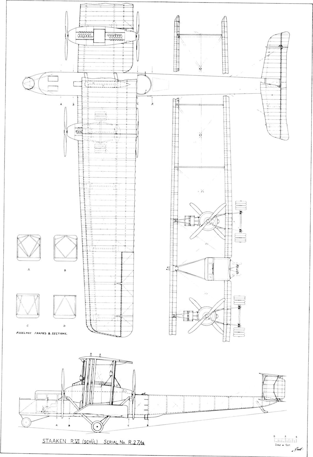
Staaken R.VI (Schul) 27/16 Photo dated 17 October 1917.
-

J.Herris - Zeppelin-Staaken Aircraft of WW1. Vol 1: VGO.1 - R.IV R.29/16 /Centennial Perspective/ (47)
Views of the Staaken R.VI R.27, R.28, and R.29 aircraft. (Peter M. Grosz collection/STDB)
-

J.Herris - Zeppelin-Staaken Aircraft of WW1. Vol 1: VGO.1 - R.IV R.29/16 /Centennial Perspective/ (47)
Views of Staaken R.VI production aircraft from the R.27-R.29 batch. The Garuda propellers all have two blades. (Peter M. Grosz collection/STDB)
-

M.Dusing - German Aviation Industry in WWI. Volume 2 /Centennial Perspective/ (85)
Staaken R.VI (R27/16) with Garuda propeller (built under license by Schutte-Lanz).
Views of Staaken R.VI production aircraft from the R.27-R.29 batch. The Garuda propellers all have two blades. The photo shows the wing camouflage well. The hand-painted camouflage under the wings was not toned down well. (Peter M. Grosz collection/STDB) -

J.Herris - Zeppelin-Staaken Aircraft of WW1. Vol 1: VGO.1 - R.IV R.29/16 /Centennial Perspective/ (47)
Views of Staaken R.VI production aircraft from the R.27-R.29 batch. The Garuda propellers all have two blades. (Peter M. Grosz collection/STDB)
-

G.Haddow, P.Grosz - The German Giants /Putnam/
Zeppelin-Staaken R VI (Schul) R27/16 powered by four Mercedes D IVa.
-

J.Herris - Zeppelin-Staaken Aircraft of WW1. Vol 1: VGO.1 - R.IV R.29/16 /Centennial Perspective/ (47)
Staaken R.VI R.27/16 being viewed by military personnel. (Peter M. Grosz collection/STDB)
-

-

J.Herris - Zeppelin-Staaken Aircraft of WW1. Vol 1: VGO.1 - R.IV R.29/16 /Centennial Perspective/ (47)
Staaken R.VI R.28/16. The propellers all have two blades and it is painted on all surfaces by dark bluish-gray for the final version of the camouflage. (Peter M. Grosz collection/STDB)
Staaken R.VI(Schul) 28/16. Although eight-wheeled undercarriages were deemed adequate for hard surfaces, operation on sandy airfields required doubling the number of wheels to sixteen. Photo dated 5 February 1918. -

J.Herris - Zeppelin-Staaken Aircraft of WW1. Vol 1: VGO.1 - R.IV R.29/16 /Centennial Perspective/ (47)
Staaken R.VI (Schul) 28/16. Fitted with upper wing gun position. Photo dated 18 May 1918.
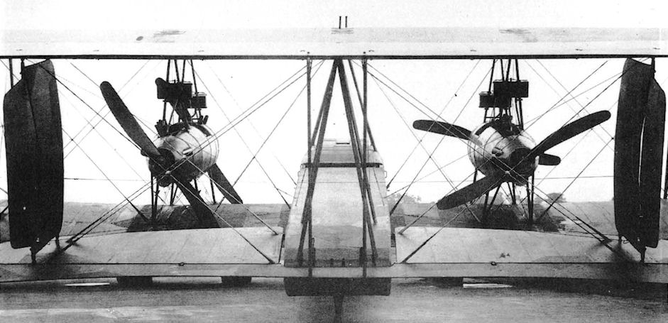
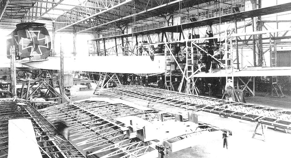
The Staaken R.VI differed from earlier designs in its engine arrangement. For the first time the nose engine was deleted to reduce the danger of fire from a crash-landing and the nacelle engines were mounted in a push-pull configuration; one engine was mounted as a tractor and the other as a pusher. Each engine had its own propeller. The R.VI was put into production to become the largest production aircraft of the war. Production was also spread to other manufacturers under license; R.28 shown here was the first R-plane built by Schutte-Lanz. It wears dark night-bomber camouflage and dwarfs the men around it. -

J.Herris - Zeppelin-Staaken Aircraft of WW1. Vol 2: R.VI R.30/16 - E.4/20 /Centennial Perspective/ (48)
Staaken R.VI R.30/16 was powered by four 260 hp Mercedes D.IVa engines and differed from standard production R.VI aircraft in being used as a test-bed for a Brown-Boveri supercharger driven by a separate 120 hp Mercedes D.II engine mounted in the fuselage behind the copilot. With the supercharger operating, ceiling was increased from the usual 12,500' to 19,357' and speed from 130-135 km/h to 160 km/h. In its original configuration it had the standard twin fins and rudders with no central fixed fin. Five-color printed night camouflage fabric covered the fuselage. (Peter M. Grosz collection/STDB)
-

J.Herris - Zeppelin-Staaken Aircraft of WW1. Vol 2: R.VI R.30/16 - E.4/20 /Centennial Perspective/ (48)
Staaken R.VI R.30/16 with interim form of national insignia and central fin & rudder. (Peter M. Grosz collection/STDB)
-

J.Herris - Zeppelin-Staaken Aircraft of WW1. Vol 2: R.VI R.30/16 - E.4/20 /Centennial Perspective/ (48)
Staaken R.VI R.30/16 with final insignia but before the serial 'R.30' was added. (Peter M. Grosz collection/STDB)
-

J.Herris - Zeppelin-Staaken Aircraft of WW1. Vol 2: R.VI R.30/16 - E.4/20 /Centennial Perspective/ (48)
The exhausts for the supercharger engine are visible behind R.30's cockpit. (Peter M. Grosz collection/STDB)
-

-

J.Herris - Zeppelin-Staaken Aircraft of WW1. Vol 1: VGO.1 - R.IV R.29/16 /Centennial Perspective/ (47)
Nose of Staaken R.VI R.30 with crewmen. Five-color printed night camouflage fabric covered the fuselage. A similar, brush repeated pattern covered the fuselage parts not covered with canvas. (Peter M. Grosz collection/ STDB)
-

J.Herris - Zeppelin-Staaken Aircraft of WW1. Vol 2: R.VI R.30/16 - E.4/20 /Centennial Perspective/ (48)
Staaken R.VI 30/16 prepared for flight. Before installation of supercharger. Oberleutnant Meyer is the pilot.
-

-

J.Herris - Zeppelin-Staaken Aircraft of WW1. Vol 2: R.VI R.30/16 - E.4/20 /Centennial Perspective/ (48)
Staaken R.VI R.30/16 was powered by four 260 hp Mercedes D.IVa engines and differed from standard production R.VI aircraft in being used as a test-bed for a Brown-Boveri supercharger driven by a separate 120 hp Mercedes D.II engine mounted in the fuselage behind the copilot. With the supercharger operating, ceiling was increased from the usual 12,500' to 19,357' and speed from 130-135 km/h to 160 km/h. In its original configuration it had the standard twin fins and rudders with no central fixed fin. Five-color printed night camouflage fabric covered the fuselage. (Peter M. Grosz collection/STDB)
-

J.Herris - Zeppelin-Staaken Aircraft of WW1. Vol 2: R.VI R.30/16 - E.4/20 /Centennial Perspective/ (48)
The Zeppelin R.VI production Four-engined Biplane in Flight. (4-250 h.p. Maybach engines.)
The Staaken R.VI (R30/16) was equipped with an additional 120 hp Mercedes D-II engine mounted in the fuselage, driving a Brown-Boveri compressor. The controllable Helix propeller was tested on this aircraft as well.
Staaken R.VI R.30/16 with interim form of national insignia and central fin and rudder takes off. Its designation 'R30' has now been painted on the rear fuselage. (Peter M. Grosz collection/STDB) -

J.Herris - Zeppelin-Staaken Aircraft of WW1. Vol 2: R.VI R.30/16 - E.4/20 /Centennial Perspective/ (48)
Staaken R.VI R.30/16 postwar without national insignia takes off. (Peter M. Grosz collection/STDB)
-

-

J.Herris - Zeppelin-Staaken Aircraft of WW1. Vol 2: R.VI R.30/16 - E.4/20 /Centennial Perspective/ (48)
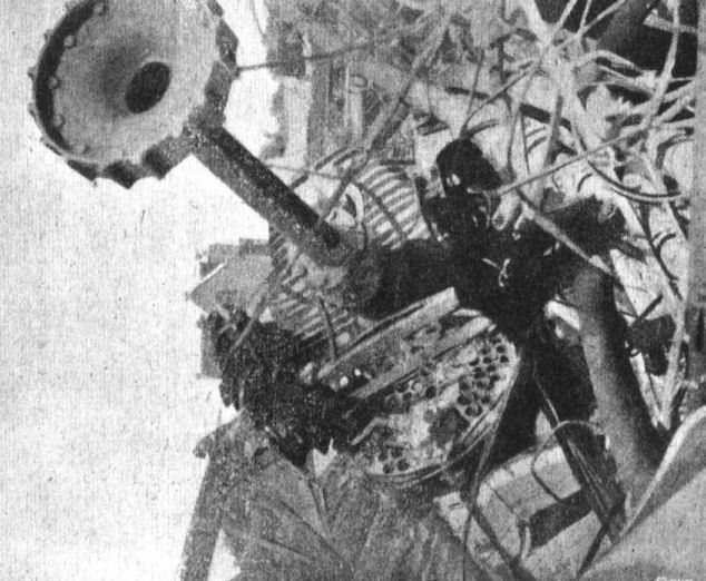
Staaken R VI 30/16. Engine mechanic leaving his nacelle cockpit in flight, to mount the ladder that led to a bulged fairing on the upper wing surface fitted with a machinegun. Not all machines of the type had these installations which utilized captured Lewis guns because of their light weight and ease of portability, but they increased the defensive armament considerably and had better fields of fire than the other gun positions on the aircraft.
-

J.Herris - Zeppelin-Staaken Aircraft of WW1. Vol 2: R.VI R.30/16 - E.4/20 /Centennial Perspective/ (48)
Over-wing gun position in Staaken R.30/16 in the hangar. (Peter M. Grosz collection/STDB)
-
J.Herris - Zeppelin-Staaken Aircraft of WW1. Vol 1: VGO.1 - R.IV R.29/16 /Centennial Perspective/ (47)
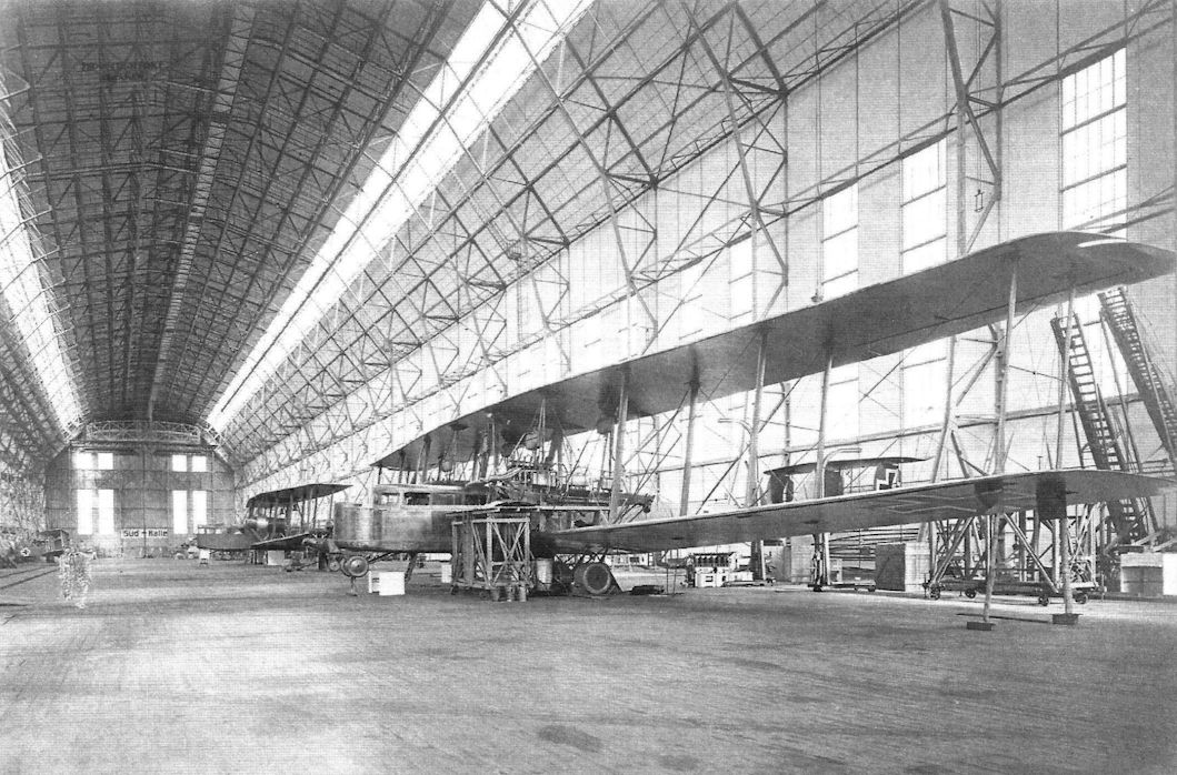
Staaken R.VI 30/16 being fitted with supercharger in the Staaken airship hangar. In the background is the Staaken R.XIV 43/17.
A Staaken R.VI R.30/16 under repair after an engine fire; Staaken R.XIV 43/17 is in the background without engines. Like other Staaken bombers, these types differed primarily by engine configuration; the R.VI had four engines in pusher/tractor configuration and the R.XIV added a fifth engine in the nose. (Michael Schmeelke)Другие самолёты на фотографии: Zeppelin-Staaken R.XIV/R.XV - Германия - 1917
-

M.Dusing - German & Austro-Hungarian Aero Engines of WWI. Vol.3 /Centennial Perspective/ (66)
The interior Staaken R.VI (R30/16) showing the additional 120 hp Mercedes D-II engine mounted in the fuselage to drive a Brown-Boveri compressor. Climb rate and ceiling were significantly improved by the compressor.
The supercharger installation in Staaken R.VI R.30/16. The Brown-Boveri supercharger was driven by a 120 hp Mercedes D II engine. The four primary engines were 260 hp Mercedes D IVa engines. The copilot's seat is in the background. -

M.Dusing - German Aviation Industry in WWI. Volume 2 /Centennial Perspective/ (85)
In the Staak R.VI R30/16 a separate 120 hp Mercedes D.II drove a Brown-Boveri-compressor (BBC) to improve the high altitude performance.
-

J.Herris - Zeppelin-Staaken Aircraft of WW1. Vol 2: R.VI R.30/16 - E.4/20 /Centennial Perspective/ (48)
Experimental controllable pitch propellers were tested on R.30/16 during the war. (Peter M. Grosz collection/STDB)
-

M.Dusing - German Aviation Industry in WWI. Volume 2 /Centennial Perspective/ (85)
Staaken R.VI with Daimler D.IVa engine, preceding gearbox and Helix controllable pitch propeller.
-

J.Herris - Zeppelin-Staaken Aircraft of WW1. Vol 2: R.VI R.30/16 - E.4/20 /Centennial Perspective/ (48)
Engine nacelle of R.30. It appears the experimental controllable pitch propellers were fitted. (Peter M. Grosz collection/STDB)
-

J.Herris - Zeppelin-Staaken Aircraft of WW1. Vol 2: R.VI R.30/16 - E.4/20 /Centennial Perspective/ (48)
Staaken R.VI R.30/16 had an engine failure on May 24, 1918, while performing some tests for Idflieg while flying over Berlin. The engine caught fire and set the lower wing on fire, but R.30 landed safely after diving steeply to blow out the flames, then Dipl-Ing. Noack climbed over the lower wing and extinguished the smoldering fire with a portable fire extinguisher. Experimental controllable pitch propellers were fitted. (Peter M. Grosz collection/STDB)
-

J.Herris - Zeppelin-Staaken Aircraft of WW1. Vol 2: R.VI R.30/16 - E.4/20 /Centennial Perspective/ (48)
Staaken R.VI R.30/16 postwar was painted as Fletcher's World for publicity flights. (Peter M. Grosz collection/STDB)
-

J.Herris - Zeppelin-Staaken Aircraft of WW1. Vol 2: R.VI R.30/16 - E.4/20 /Centennial Perspective/ (48)
Staaken R.VI R.30/16 postwar with Fletcher's World added. Zeppelin LZ 120 Bodensee flys overhead. (Peter M. Grosz collection/STDB)
-

J.Herris - Zeppelin-Staaken Aircraft of WW1. Vol 2: R.VI R.30/16 - E.4/20 /Centennial Perspective/ (48)
Staaken R.VI R.30/16 postwar marked as Fletcher's World for civilian use. Actress Alia Kay is shown in this advertisement. (Peter M. Grosz collection/STDB)
-

J.Herris - Zeppelin-Staaken Aircraft of WW1. Vol 2: R.VI R.30/16 - E.4/20 /Centennial Perspective/ (48)
Staaken R.VI R.30/16 Fletcher's World being used as the stage for a dramatic presentation postwar. (Peter M. Grosz collection/STDB)
-

J.Herris - Zeppelin-Staaken Aircraft of WW1. Vol 2: R.VI R.30/16 - E.4/20 /Centennial Perspective/ (48)
R.32/16 with its crew. The covered parachute lines can be seen. (Peter M. Grosz collection/ STDB)
-

J.Herris - Zeppelin-Staaken Aircraft of WW1. Vol 2: R.VI R.30/16 - E.4/20 /Centennial Perspective/ (48)
R.32/16 with its crew; 4-bladed propellers are fitted. (Peter M. Grosz collection/STDB)
-

J.Herris - Zeppelin-Staaken Aircraft of WW1. Vol 2: R.VI R.30/16 - E.4/20 /Centennial Perspective/ (48)
R.32/16 nacelle with 4-bladed propellers. (Peter M. Grosz collection/STDB)
-

J.Herris - Zeppelin-Staaken Aircraft of WW1. Vol 2: R.VI R.30/16 - E.4/20 /Centennial Perspective/ (48)
Bomb racks underneath R.32. (Peter M. Grosz collection/STDB)
-

J.Herris - Zeppelin-Staaken Aircraft of WW1. Vol 2: R.VI R.30/16 - E.4/20 /Centennial Perspective/ (48)
Coil spring shock absorber on R.32. (Peter M. Grosz collection/STDB)
-

J.Herris - Zeppelin-Staaken Aircraft of WW1. Vol 1: VGO.1 - R.IV R.29/16 /Centennial Perspective/ (47)
Staaken landing gear detail views.
-

J.Herris - Zeppelin-Staaken Aircraft of WW1. Vol 2: R.VI R.30/16 - E.4/20 /Centennial Perspective/ (48)
Coil spring shock absorber for tail skid on R.32. (Peter M. Grosz collection/STDB)
-

-

J.Herris - Zeppelin-Staaken Aircraft of WW1. Vol 2: R.VI R.30/16 - E.4/20 /Centennial Perspective/ (48)
Staaken R.VI (Av) 33/16 with Aviatik personnel. (Peter M. Grosz collection/STDB)
-

J.Herris - Zeppelin-Staaken Aircraft of WW1. Vol 2: R.VI R.30/16 - E.4/20 /Centennial Perspective/ (48)
R.VI R33 was Aviatik built and saw service with Rfa 501, it crashed on October 15, 1918
-

J.Herris - Zeppelin-Staaken Aircraft of WW1. Vol 2: R.VI R.30/16 - E.4/20 /Centennial Perspective/ (48)
Aviatik-built Staaken R. VI(Av) 33/16 being inspected by an Idflieg acceptance team at Leipzig.
-

J.Herris - Zeppelin-Staaken Aircraft of WW1. Vol 2: R.VI R.30/16 - E.4/20 /Centennial Perspective/ (48)
Staaken R.VI R.33/16 with Hptm. Erich Schilling and officers of Rfa 500. The dog on the nose is Schilling's pet Rodax, carried for good luck. (Peter M. Grosz collection/STDB)
-

J.Herris - Zeppelin-Staaken Aircraft of WW1. Vol 2: R.VI R.30/16 - E.4/20 /Centennial Perspective/ (48)
Staaken R.VI of the 33-35/16 production batch. The Staaken below is on the Aviatik factory airfield. (Peter M. Grosz collection/STDB)
-

J.Herris - Zeppelin-Staaken Aircraft of WW1. Vol 2: R.VI R.30/16 - E.4/20 /Centennial Perspective/ (48)
Officers of Rfa 500 with Aviatik-built Staaken R VI 33/16. (Peter M. Grosz collection/STDB)
Staaken R.VI on exhibit for VIPs. The aircraft is covered in hand-painted night lozenge pattern, and the engine nacelles are over-painted dark bluish-gray. (Peter M. Grosz collection/STDB)
The Staaken RVI was the most prolific of the giant R planes with 18 built. They saw service on the Western Front from mid 1917, the first raid against England being on 17 September. -

G.Haddow, P.Grosz - The German Giants /Putnam/
The Staaken R.VI (Av) 33/16 under construction.
-

J.Herris - Zeppelin-Staaken Aircraft of WW1. Vol 2: R.VI R.30/16 - E.4/20 /Centennial Perspective/ (48)
Staaken R.VI of the R.33-R.35/16 production batch in the factory (Peter M. Grosz collection/STDB)
-

J.Herris - Zeppelin-Staaken Aircraft of WW1. Vol 2: R.VI R.30/16 - E.4/20 /Centennial Perspective/ (48)
Staaken R.VI R.33 under repair. Most of the fabric covering has been removed to facilitate the repair work. (Peter M. Grosz collection/STDB)
-

J.Herris - Zeppelin-Staaken Aircraft of WW1. Vol 2: R.VI R.30/16 - E.4/20 /Centennial Perspective/ (48)
Staaken R VI R.33 under repair in the Aviatik factory. (Peter M. Grosz collection/STDB)
-

J.Herris - Zeppelin-Staaken Aircraft of WW1. Vol 2: R.VI R.30/16 - E.4/20 /Centennial Perspective/ (48)
Staaken R.VI of the 33-35/16 production batch being built in the Aviatik factory. (Peter M. Grosz collection/STDB)
-

-

J.Herris - Zeppelin-Staaken Aircraft of WW1. Vol 2: R.VI R.30/16 - E.4/20 /Centennial Perspective/ (48)
Staaken R.VI of the 33-35/16 production batch being built. (Peter M. Grosz collection/STDB)
-

J.Herris - Zeppelin-Staaken Aircraft of WW1. Vol 2: R.VI R.30/16 - E.4/20 /Centennial Perspective/ (48)
Engine nacelle of an Aviatik-built Staaken R VI. (Peter M. Grosz collection/STDB)
-

J.Herris - Zeppelin-Staaken Aircraft of WW1. Vol 2: R.VI R.30/16 - E.4/20 /Centennial Perspective/ (48)
Engine and oil cooler details of an Aviatik-built Staaken R VI. (Peter M. Grosz collection/STDB)
-

J.Herris - Zeppelin-Staaken Aircraft of WW1. Vol 1: VGO.1 - R.IV R.29/16 /Centennial Perspective/ (47)
Staaken R.VI photographed with its crew.
-

G.Haddow, P.Grosz - The German Giants /Putnam/
Staaken R.VI (Av) 34/16.
-

J.Herris - Zeppelin-Staaken Aircraft of WW1. Vol 2: R.VI R.30/16 - E.4/20 /Centennial Perspective/ (48)
Aviatik-built Staaken R VI. (Peter M. Grosz collection/STDB)
-

J.Herris - Zeppelin-Staaken Aircraft of WW1. Vol 2: R.VI R.30/16 - E.4/20 /Centennial Perspective/ (48)
Staaken R.VI of the 33-35/16 production batch on the Aviatik factory airfield. (Peter M. Grosz collection/STDB)
-
J.Herris - Zeppelin-Staaken Aircraft of WW1. Vol 2: R.VI R.30/16 - E.4/20 /Centennial Perspective/ (48)
Aviatik-built Staaken R VI 33-35/16 with a Hergt monoplane. (Peter M. Grosz collection/STDB)
Другие самолёты на фотографии: Hergt monoplane - Германия - 1918
-

J.Herris - German Aircraft of Minor Manufacturers in WW1. Volume I /Centennial Perspective/ (49)
The Hergt Monoplane photographed next to a Staaken R.VI emphasizes the difference in sizes. The aircraft may have been intended to validate Hergt's structural design for the later NFW E.I he designed. Sunlight shines through the Hergt's fabric-covered ailerons.
Другие самолёты на фотографии: Hergt monoplane - Германия - 1918
-

J.Herris - Zeppelin-Staaken Aircraft of WW1. Vol 2: R.VI R.30/16 - E.4/20 /Centennial Perspective/ (48)
Staaken R.VI of the R.33-R.35/16 production batch with Aviatik personnel. (Peter M. Grosz collection/STDB)
-

J.Herris - Zeppelin-Staaken Aircraft of WW1. Vol 2: R.VI R.30/16 - E.4/20 /Centennial Perspective/ (48)
Staaken R.VI of the 33-35/16 production batch. (Peter M. Grosz collection/STDB)
-

J.Herris - Zeppelin-Staaken Aircraft of WW1. Vol 2: R.VI R.30/16 - E.4/20 /Centennial Perspective/ (48)
Staaken R.VI of the R.33-R.35/16 production batch with personnel at the factory. (Peter M. Grosz collection/STDB)
-

J.Herris - Zeppelin-Staaken Aircraft of WW1. Vol 2: R.VI R.30/16 - E.4/20 /Centennial Perspective/ (48)
Aviatik-built Staaken RVI 33-35/16 being appreciated. (Peter M. Grosz collection/STDB)
-

J.Herris - Zeppelin-Staaken Aircraft of WW1. Vol 2: R.VI R.30/16 - E.4/20 /Centennial Perspective/ (48)
Staaken R.VI of the 33-35/16 series on the Rfa field. (Peter M. Grosz collection/STDB)
-

J.Herris - Zeppelin-Staaken Aircraft of WW1. Vol 2: R.VI R.30/16 - E.4/20 /Centennial Perspective/ (48)
Staaken R.VI of the 33-35/16 with crew. (Peter M. Grosz collection/STDB)
-

J.Herris - Zeppelin-Staaken Aircraft of WW1. Vol 2: R.VI R.30/16 - E.4/20 /Centennial Perspective/ (48)
Aviatik-built Staaken RVI 33-35/16 after take-off. (Peter M. Grosz collection/STDB)
-

J.Herris - Zeppelin-Staaken Aircraft of WW1. Vol 2: R.VI R.30/16 - E.4/20 /Centennial Perspective/ (48)
Engine nacelle of R.35/16 in the Berlin museum prior to WW2. (Piotr Mrozowski)
-

J.Herris - Zeppelin-Staaken Aircraft of WW1. Vol 2: R.VI R.30/16 - E.4/20 /Centennial Perspective/ (48)
R.35/16 Remains in the Polish Aviation Museum at Krakow
-

J.Herris - Zeppelin-Staaken Aircraft of WW1. Vol 2: R.VI R.30/16 - E.4/20 /Centennial Perspective/ (48)
R.35/16 Remains in the Polish Aviation Museum at Krakow
-

J.Herris - Zeppelin-Staaken Aircraft of WW1. Vol 2: R.VI R.30/16 - E.4/20 /Centennial Perspective/ (48)
R.35/16 Remains in the Polish Aviation Museum at Krakow
-

J.Herris - Zeppelin-Staaken Aircraft of WW1. Vol 2: R.VI R.30/16 - E.4/20 /Centennial Perspective/ (48)
R.35/16 Remains in the Polish Aviation Museum at Krakow
-

J.Herris - Zeppelin-Staaken Aircraft of WW1. Vol 2: R.VI R.30/16 - E.4/20 /Centennial Perspective/ (48)
R.35/16 Remains in the Polish Aviation Museum at Krakow
-

J.Herris - Zeppelin-Staaken Aircraft of WW1. Vol 2: R.VI R.30/16 - E.4/20 /Centennial Perspective/ (48)
R.35/16 Remains in the Polish Aviation Museum at Krakow
-

J.Herris - Zeppelin-Staaken Aircraft of WW1. Vol 2: R.VI R.30/16 - E.4/20 /Centennial Perspective/ (48)
R.35/16 Remains in the Polish Aviation Museum at Krakow
-

J.Herris - Zeppelin-Staaken Aircraft of WW1. Vol 2: R.VI R.30/16 - E.4/20 /Centennial Perspective/ (48)
R.35/16 Remains in the Polish Aviation Museum at Krakow
-

J.Herris - Zeppelin-Staaken Aircraft of WW1. Vol 2: R.VI R.30/16 - E.4/20 /Centennial Perspective/ (48)
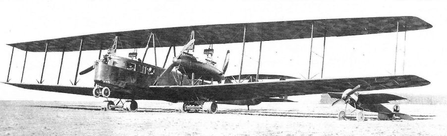
Staaken R.VI(Albs) 36/16, and R. VI(Av) 33/16 of Rfa 500 being prepared for flight.
-

G.Haddow, P.Grosz - The German Giants /Putnam/
The same two aircraft lined up. The balanced ailerons and central fin of R.36, the nearest machine shows this to be a later model than its companion.
-

J.Herris - Zeppelin-Staaken Aircraft of WW1. Vol 2: R.VI R.30/16 - E.4/20 /Centennial Perspective/ (48)
Albatros-built Staaken R.VI of the 36-38/16 with crew. (Peter M. Grosz collection/STDB)
-

M.Dusing - German Aviation Industry in WWI. Volume 1 /Centennial Perspective/ (84)
Albatros-built Staaken R.VI(OAW) "Giant" of the 36-38/16 series on the Rfa field. (1917) (Peter M. Grosz collection/ STDB)
-

M.Dusing - German Aviation Industry in WWI. Volume 1 /Centennial Perspective/ (84)
Albatros-built Staaken R.VI(OAW) 36-38/16 in the snow. (1917) (Peter M. Grosz collection/STDB)
-

J.Herris - Zeppelin-Staaken Aircraft of WW1. Vol 2: R.VI R.30/16 - E.4/20 /Centennial Perspective/ (48)
Staaken-built Staaken R VI 39/16. (Peter M. Grosz collection/STDB)
-

J.Herris - Zeppelin-Staaken Aircraft of WW1. Vol 2: R.VI R.30/16 - E.4/20 /Centennial Perspective/ (48)
Staaken-built Staaken R VI 39/16. (Peter M. Grosz collection/STDB)
-

J.Herris - Zeppelin-Staaken Aircraft of WW1. Vol 2: R.VI R.30/16 - E.4/20 /Centennial Perspective/ (48)
Staaken-built Staaken R.VI 39/16 in its hangar. (Peter M. Grosz collection/ STDB)
-

J.Herris - Zeppelin-Staaken Aircraft of WW1. Vol 2: R.VI R.30/16 - E.4/20 /Centennial Perspective/ (48)
Staaken-built Staaken R VI 39/16. (Peter M. Grosz collection/STDB)
-

J.Herris - Zeppelin-Staaken Aircraft of WW1. Vol 2: R.VI R.30/16 - E.4/20 /Centennial Perspective/ (48)
Staaken-built Staaken R VI 39/16. (Peter M. Grosz collection/STDB)
-

J.Herris - Zeppelin-Staaken Aircraft of WW1. Vol 2: R.VI R.30/16 - E.4/20 /Centennial Perspective/ (48)
Staaken-built Staaken R VI 39/16, taking on bombs prior to a raid. (Peter M. Grosz collection/STDB)
-

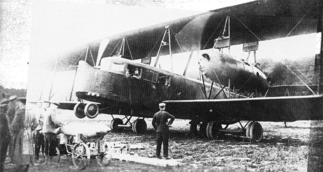
A.Imrie - German Bombers /Arms & Armour/
Staaken R VI 39/16. Eighteen machines of this type were built and they formed the backbone of the equipment of the two Riesenflugzeug-Abteilungen. In just over 12 months' operational service with Rfa 501 from August 1917, R39/16 dropped some 26,000kg of bombs, including three of 1,000kg size, on the UK. While the bombload is being readied in the foreground, the mechanic in the pilot's seat is watching the mechanic in the port nacelle cockpit between the engines as he runs up the two 260hp Maybach Mb IVa to check their serviceability.
-

J.Herris - Zeppelin-Staaken Aircraft of WW1. Vol 2: R.VI R.30/16 - E.4/20 /Centennial Perspective/ (48)
Staaken-built Staaken R.VI 39/16. The R.39 was the only R-plane to drop 1,000 kg bombs on the UK, dropping them on the nights of 16/17 February, 7/8 March, and 19/20 May 1918. (Peter M. Grosz collection/STDB)
-

J.Herris - Zeppelin-Staaken Aircraft of WW1. Vol 2: R.VI R.30/16 - E.4/20 /Centennial Perspective/ (48)
Staaken-built Staaken R.VI 39/16. (Peter M. Grosz collection/STDB)
-

J.Herris - Zeppelin-Staaken Aircraft of WW1. Vol 2: R.VI R.30/16 - E.4/20 /Centennial Perspective/ (48)
Staaken R.VI 39/16 on its field. (Peter M. Grosz collection/STDB)
-

J.Herris - Zeppelin-Staaken Aircraft of WW1. Vol 2: R.VI R.30/16 - E.4/20 /Centennial Perspective/ (48)
Staaken R.VI 39/16 on the Rfa field with R.26 on the right and another R-plane at left. (Peter M. Grosz collection/STDB)
-

J.Herris - Zeppelin-Staaken Aircraft of WW1. Vol 2: R.VI R.30/16 - E.4/20 /Centennial Perspective/ (48)
Staaken R.VI 39/16 lifts off from its field. (Peter M. Grosz collection/STDB)
-

J.Herris - Zeppelin-Staaken Aircraft of WW1. Vol 2: R.VI R.30/16 - E.4/20 /Centennial Perspective/ (48)
Staaken-built Staaken R VI 39/16. (Peter M. Grosz collection/STDB)
-

J.Herris - Zeppelin-Staaken Aircraft of WW1. Vol 2: R.VI R.30/16 - E.4/20 /Centennial Perspective/ (48)
Crew of the Staaken R.VI 39/16. The flying crewmen have Paulus parachute belts. (Peter M. Grosz collection/STDB)
-

J.Herris - Zeppelin-Staaken Aircraft of WW1. Vol 2: R.VI R.30/16 - E.4/20 /Centennial Perspective/ (48)
Engine nacelle of Staaken-built Staaken R.VI 39/16. (Peter M. Grosz collection/STDB)
-

J.Herris - Zeppelin-Staaken Aircraft of WW1. Vol 2: R.VI R.30/16 - E.4/20 /Centennial Perspective/ (48)
Aviatik-built Staaken R.VI 52/17 the day of its maiden flight on May 7, 1918. (Peter M. Grosz collection/STDB)
-

G.Haddow, P.Grosz - The German Giants /Putnam/
Staaken R.VI (Av) 52/17.
-

J.Herris - Zeppelin-Staaken Aircraft of WW1. Vol 2: R.VI R.30/16 - E.4/20 /Centennial Perspective/ (48)
Aviatik-built Staaken R.VI of the R.52-R.54/17 production batch. The nose contours of this batch were different from other R.VI aircraft; the cabin was extended to the front, raising its profile, and the cockpit was open. The nose gun position was raised also. A central fin was also fitted. (Peter M. Grosz collection/STDB)
-

J.Herris - Zeppelin-Staaken Aircraft of WW1. Vol 2: R.VI R.30/16 - E.4/20 /Centennial Perspective/ (48)
Aviatik-built Staaken R.VI of the R.52-R.54/17 production batch on the Rfa field. A central fin was standard. (Peter M. Grosz collection/STDB)
-

J.Herris - Zeppelin-Staaken Aircraft of WW1. Vol 2: R.VI R.30/16 - E.4/20 /Centennial Perspective/ (48)
Aviatik-built Staaken R.VI 52/17 over Leipzig on the way to Rfa 500. The aircraft has its nose gun position at the front of the cabin. It has a central fin and rudder and balanced ailerons. (Peter M. Grosz collection/STDB)
-

G.Haddow, P.Grosz - The German Giants /Putnam/
Staaken R.VI(Av) 52/16 during a test flight over Leipzig.
-

J.Herris - Zeppelin-Staaken Aircraft of WW1. Vol 1: VGO.1 - R.IV R.29/16 /Centennial Perspective/ (47)
Front view of a Staaken R.VI on its field with onlookers giving scale to the aircraft. A parachute installation is visible at the side of the fuselage. (Peter M. Grosz collection/STDB)
-

J.Herris - Zeppelin-Staaken Aircraft of WW1. Vol 1: VGO.1 - R.IV R.29/16 /Centennial Perspective/ (47)
Staaken R.VI on its field. Note the enlarged number of wheels used at airfields that are not reinforced. (Peter M. Grosz collection/STDB)
-

J.Herris - Zeppelin-Staaken Aircraft of WW1. Vol 1: VGO.1 - R.IV R.29/16 /Centennial Perspective/ (47)
Front view of a Staaken R.VI on its field with onlookers giving scale to the aircraft. Note the standard number of wheels used with a reinforced runway. (Peter M. Grosz collection/STDB)
-

J.Herris - Zeppelin-Staaken Aircraft of WW1. Vol 1: VGO.1 - R.IV R.29/16 /Centennial Perspective/ (47)
Staaken R.VI production aircraft from the R.27-R.29 batch. (Peter M. Grosz collection/STDB)
-
J.Herris - Zeppelin-Staaken Aircraft of WW1. Vol 1: VGO.1 - R.IV R.29/16 /Centennial Perspective/ (47)
Front view of a Staaken R.VI on its field with Albatros D.V at right. (Peter M. Grosz collection/STDB)
Другие самолёты на фотографии: Albatros D.V/D.Va - Германия - 1917
-

J.Herris - Zeppelin-Staaken Aircraft of WW1. Vol 1: VGO.1 - R.IV R.29/16 /Centennial Perspective/ (47)
Staaken R.VI bomber in night bomber camouflage runs up its engines. Camouflage is night 5-color printed canvas. Nose, roof, and fuselage bottom are not canvas and are painted. (Peter M. Grosz collection/STDB)
-

J.Herris - Zeppelin-Staaken Aircraft of WW1. Vol 1: VGO.1 - R.IV R.29/16 /Centennial Perspective/ (47)
Staaken R.VI covered with dark, night camouflage and unpainted aluminum nacelles, running up its engines. (Peter M. Grosz collection/STDB)
-

J.Herris - Zeppelin-Staaken Aircraft of WW1. Vol 1: VGO.1 - R.IV R.29/16 /Centennial Perspective/ (47)
A Staaken R.VI bomber undergoing maintenance. Note the camouflage pattern on the underside of the upper wing. (Peter M. Grosz collection/STDB)
-

J.Herris - Zeppelin-Staaken Aircraft of WW1. Vol 1: VGO.1 - R.IV R.29/16 /Centennial Perspective/ (47)
Staaken R.VI bomber on its airfield. (Peter M. Grosz collection/STDB)
-

J.Herris - Zeppelin-Staaken Aircraft of WW1. Vol 1: VGO.1 - R.IV R.29/16 /Centennial Perspective/ (47)
Staaken R.VI bombers on the factory airfield. Printed five-color night camouflage fabric was used to cover the fuselage. (Peter M. Grosz collection/STDB)
-

J.Herris - Zeppelin-Staaken Aircraft of WW1. Vol 1: VGO.1 - R.IV R.29/16 /Centennial Perspective/ (47)
Staaken R.VI bombers on the factory airfield. Printed five-color night camouflage fabric was used to cover the fuselage. (Peter M. Grosz collection/STDB)
-

J.Herris - Zeppelin-Staaken Aircraft of WW1. Vol 1: VGO.1 - R.IV R.29/16 /Centennial Perspective/ (47)
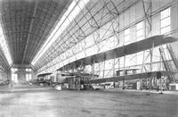
Staaken R.VI of the R.27-R.29 batch under construction (in an airship hall ???). (Peter M. Grosz collection/STDB)
-

J.Herris - Zeppelin-Staaken Aircraft of WW1. Vol 1: VGO.1 - R.IV R.29/16 /Centennial Perspective/ (47)
Staaken R.VI production aircraft from the R.27-R.29 batch. (Peter M. Grosz collection/STDB)
-

J.Herris - Zeppelin-Staaken Aircraft of WW1. Vol 1: VGO.1 - R.IV R.29/16 /Centennial Perspective/ (47)
Staaken R.VI bomber with crewmen. (Peter M. Grosz collection/STDB)
-

J.Herris - Zeppelin-Staaken Aircraft of WW1. Vol 1: VGO.1 - R.IV R.29/16 /Centennial Perspective/ (47)
A Staaken R.VI production aircraft from the R.27-R.29 batch. (Peter M. Grosz collection/STDB)
-

J.Herris - Zeppelin-Staaken Aircraft of WW1. Vol 1: VGO.1 - R.IV R.29/16 /Centennial Perspective/ (47)
A Staaken R.VI bomber on its airfield. It is covered with 5-color printed fabric. Note the small windows for the ventral gunner in the center fuselage and unpainted engine nacelles. (Peter M. Grosz collection/STDB)
-

J.Herris - Zeppelin-Staaken Aircraft of WW1. Vol 1: VGO.1 - R.IV R.29/16 /Centennial Perspective/ (47)
Mechanics study the forward port engine of a Staaken R.VI bomber in its hangar. (Peter M. Grosz collection/STDB)
-

J.Herris - Zeppelin-Staaken Aircraft of WW1. Vol 1: VGO.1 - R.IV R.29/16 /Centennial Perspective/ (47)
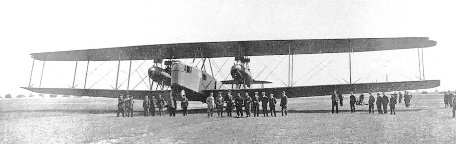
The large size of the Staakens required large airfields as illustrated here. (Peter M. Grosz collection/STDB)
-

J.Herris - Zeppelin-Staaken Aircraft of WW1. Vol 1: VGO.1 - R.IV R.29/16 /Centennial Perspective/ (47)
Staaken R.VI bomber wearing night bomber camouflage in flight over the countryside. (Peter M. Grosz collection/ STDB)
-

J.Herris - Zeppelin-Staaken Aircraft of WW1. Vol 1: VGO.1 - R.IV R.29/16 /Centennial Perspective/ (47)
Staaken R.VI bomber wearing night bomber camouflage in flight over the countryside. (Peter M. Grosz collection/ STDB)
-

J.Herris - Zeppelin-Staaken Aircraft of WW1. Vol 1: VGO.1 - R.IV R.29/16 /Centennial Perspective/ (47)
Aerial view of the tail of the Staaken R.VI bomber. (Peter M. Grosz collection/STDB)
-

J.Herris - Zeppelin-Staaken Aircraft of WW1. Vol 1: VGO.1 - R.IV R.29/16 /Centennial Perspective/ (47)
Views of the Staaken R.VI R.27, R.28, and R.29 aircraft. The in-flight photos were taken during an initial flight before camouflage was applied. (Peter M. Grosz collection/STDB)
-

J.Herris - Zeppelin-Staaken Aircraft of WW1. Vol 1: VGO.1 - R.IV R.29/16 /Centennial Perspective/ (47)
Two mechanics in the starboard engine nacelle. (Peter M. Grosz collection/STDB)
-

J.Herris - Zeppelin-Staaken Aircraft of WW1. Vol 1: VGO.1 - R.IV R.29/16 /Centennial Perspective/ (47)
Staaken R.VI bomber photographed inflight. (Peter M. Grosz collection/STDB)
-

J.Herris - Zeppelin-Staaken Aircraft of WW1. Vol 1: VGO.1 - R.IV R.29/16 /Centennial Perspective/ (47)
Landing gear detail of a Staaken R.VI bomber. (Peter M. Grosz collection/STDB)
-

J.Herris - Zeppelin-Staaken Aircraft of WW1. Vol 1: VGO.1 - R.IV R.29/16 /Centennial Perspective/ (47)
Detail view of an engine bed and oil cooler in a Staaken R.VI. (Peter M. Grosz collection/STDB)
-

J.Herris - Zeppelin-Staaken Aircraft of WW1. Vol 1: VGO.1 - R.IV R.29/16 /Centennial Perspective/ (47)
Staaken R.VI R.26/16 radiator. (Peter M. Grosz collection/STDB)
-

J.Herris - Zeppelin-Staaken Aircraft of WW1. Vol 1: VGO.1 - R.IV R.29/16 /Centennial Perspective/ (47)
View toward the tail of the fuselage interior of a Staaken R.VI bomber. The shadows of the 5-color night camouflage pattern on the exterior show on the inside of the fabric. (Peter M. Grosz collection/STDB)
-

J.Herris - Zeppelin-Staaken Aircraft of WW1. Vol 1: VGO.1 - R.IV R.29/16 /Centennial Perspective/ (47)
Staaken R.VI under construction at the factory with 245 liter fuel tanks at left. (Peter M. Grosz collection/STDB)
-

J.Herris - Zeppelin-Staaken Aircraft of WW1. Vol 1: VGO.1 - R.IV R.29/16 /Centennial Perspective/ (47)
Staaken R.VI final aerodynamically balanced tail assembly.
-

J.Herris - Zeppelin-Staaken Aircraft of WW1. Vol 2: R.VI R.30/16 - E.4/20 /Centennial Perspective/ (48)
Museum photo of P.u.W. bombs as carried by Staakens. (Michael Schmeelke)
-

J.Herris - Zeppelin-Staaken Aircraft of WW1. Vol 2: R.VI R.30/16 - E.4/20 /Centennial Perspective/ (48)
Testing springs used in the landing gear of Staaken Giants. (Peter M. Grosz collection/STDB)
-

J.Herris - Zeppelin-Staaken Aircraft of WW1. Vol 2: R.VI R.30/16 - E.4/20 /Centennial Perspective/ (48)
Constructing part of the landing gear of Staaken Giants. (Peter M. Grosz collection/STDB)
-

J.Herris - Zeppelin-Staaken Aircraft of WW1. Vol 2: R.VI R.30/16 - E.4/20 /Centennial Perspective/ (48)
Jig for fabrication of Staaken Giant wing ribs. (Peter M. Grosz collection/STDB)
-

J.Herris - Zeppelin-Staaken Aircraft of WW1. Vol 1: VGO.1 - R.IV R.29/16 /Centennial Perspective/ (47)
In flight photo of a copilot flying a Staaken R.VI bomber. (Peter M. Grosz collection/STDB)
-

J.Herris - Zeppelin-Staaken Aircraft of WW1. Vol 1: VGO.1 - R.IV R.29/16 /Centennial Perspective/ (47)
Cockpit and radio position of R.25/16. (Peter M. Grosz collection/STDB)
-

J.Herris - Zeppelin-Staaken Aircraft of WW1. Vol 1: VGO.1 - R.IV R.29/16 /Centennial Perspective/ (47)
Cockpit of Staaken R.VI R.26/16. (Peter M. Grosz collection/STDB)
-

Сайт - Pilots-and-planes /WWW/
Пилотская кабина R VI. Широкие окна предоставляли хороший обзор. Впереди виден лаз в носовую открытую площадку, на которой размещалась пулеметная установка.
-

J.Herris - Zeppelin-Staaken Aircraft of WW1. Vol 2: R.VI R.30/16 - E.4/20 /Centennial Perspective/ (48)
Pilots' cockpit of Staaken R VI 31/16. The apparent deficiency in the number of instruments is explained by the fact that engine indicators were situated in the mechanics' cockpits in the engine nacelles, whence they kept the commander informed of the condition of their charges by a signalling system, whose battery of lights and switches can be seen in the roof panel. Note the two barographs that recorded height against time on a clockwork-driven paper cylinder, the carriage of these being a normal requirement on all German military aircraft. The dual flying controls with the throttle levers on the pedestal and the tail trim wheel at the rear is a layout that has not changed in principle over 70 years. The hand-operated drum for the trailing wireless aerial can be seen on the left and two mouthpieces and speaking tubes are draped over the navigator's table on the right. Prominently positioned in the centre of the forward windscreen (note stowed curtain at right vertical member for excluding searchlight glare) is the Drexler bank indicator, which used a front view of the aeroplane on a moving card stabilized by a gyroscope revolving at 20,000rpm powered by three-phase current provided by a windmill generator, thus being independent of the aircraft's electrical system.
-

-

J.Herris - Zeppelin-Staaken Aircraft of WW1. Vol 2: R.VI R.30/16 - E.4/20 /Centennial Perspective/ (48)
Staaken turn and bank indicator. (Peter M. Grosz collection/STDB)
-

J.Herris - Zeppelin-Staaken Aircraft of WW1. Vol 2: R.VI R.30/16 - E.4/20 /Centennial Perspective/ (48)
Pilots' cockpit of Staaken R VI 31/16. The apparent deficiency in the number of instruments is explained by the fact that engine indicators were situated in the mechanics' cockpits in the engine nacelles, whence they kept the commander informed of the condition of their charges by a signalling system, whose battery of lights and switches can be seen in the roof panel in the photo.
-

J.Herris - Zeppelin-Staaken Aircraft of WW1. Vol 2: R.VI R.30/16 - E.4/20 /Centennial Perspective/ (48)
Ceiling communicator switch dashboard layout.
-

J.Herris - Zeppelin-Staaken Aircraft of WW1. Vol 1: VGO.1 - R.IV R.29/16 /Centennial Perspective/ (47)
Staaken inclinometer control panel.
-

J.Herris - Zeppelin-Staaken Aircraft of WW1. Vol 1: VGO.1 - R.IV R.29/16 /Centennial Perspective/ (47)
Gyro inclinometer installed in Staaken bombers.
-

J.Herris - Zeppelin-Staaken Aircraft of WW1. Vol 2: R.VI R.30/16 - E.4/20 /Centennial Perspective/ (48)
Compass used in Staaken Giants. (Peter M. Grosz collection/STDB)
-

J.Herris - Zeppelin-Staaken Aircraft of WW1. Vol 2: R.VI R.30/16 - E.4/20 /Centennial Perspective/ (48)
On the giant bombers of the R category electrically operated bomb releases were used. Shown is the bomb selector panel on Staaken R VI 30/16. Bombs could be released as required or in sequence, but there was also a salvo or jettison override that allowed all bombs to be dropped at the same time. Each selector switch had an adjacent light which was illuminated by contacts that closed once a bomb had left its rack. The instrument at upper right is an altimeter suspended by three coil springs to prevent errors due to vibration; its dial is calibrated in hundreds of metres, maximum scale being 5km (16,400ft).
-

J.Herris - Zeppelin-Staaken Aircraft of WW1. Vol 1: VGO.1 - R.IV R.29/16 /Centennial Perspective/ (47)
Staaken R.VI internal views showing fuel tanks and engineers station. (Peter M. Grosz collection/STDB)
-

J.Herris - Zeppelin-Staaken Aircraft of WW1. Vol 2: R.VI R.30/16 - E.4/20 /Centennial Perspective/ (48)
Electro-pneumatic inner communication post in R.31. (Peter M. Grosz collection/STDB)
-

J.Herris - Zeppelin-Staaken Aircraft of WW1. Vol 2: R.VI R.30/16 - E.4/20 /Centennial Perspective/ (48)
Radio equipment in R.31. (Peter M. Grosz collection/STDB)
-

J.Herris - Zeppelin-Staaken Aircraft of WW1. Vol 1: VGO.1 - R.IV R.29/16 /Centennial Perspective/ (47)
Radio room of a Staaken R.VI. (Peter M. Grosz collection/STDB)
-

J.Herris - Zeppelin-Staaken Aircraft of WW1. Vol 1: VGO.1 - R.IV R.29/16 /Centennial Perspective/ (47)
Two views of the wireless transmitter/ receiver station used in Staaken bombers.
-

J.Herris - Zeppelin-Staaken Aircraft of WW1. Vol 1: VGO.1 - R.IV R.29/16 /Centennial Perspective/ (47)
Two views of the Bosch unit in the Staaken R-planes.
-

J.Herris - Zeppelin-Staaken Aircraft of WW1. Vol 2: R.VI R.30/16 - E.4/20 /Centennial Perspective/ (48)
Zeppelin-Staaken R.VI after a rough landing at Abeale airfield, Belgium, in 1918.
-

J.Herris - Zeppelin-Staaken Aircraft of WW1. Vol 2: R.VI R.30/16 - E.4/20 /Centennial Perspective/ (48)
Staaken R.VI R.33/16 after a rough landing tore off the landing gear. (Peter M. Grosz collection/STDB)
-

Журнал - Flight за 1918 г.
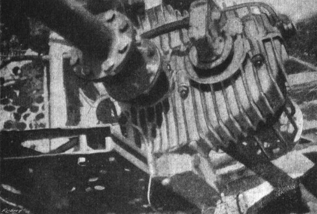
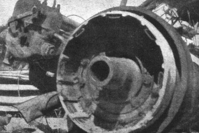
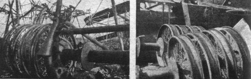
Fig. 47. - Gear box and oil radiator of four-engined giant.
-

Журнал - Flight за 1918 г.
Fig. 48. - Gear-box anf shaft of four-engined giant.
-

Журнал - Flight за 1918 г.
Fig. 49. - Radiator of four-engined giant.
-

Журнал - Flight за 1918 г.
Fig. 53. - Flywheel and female clutch of four-engined giant.
-

Журнал - Flight за 1918 г.
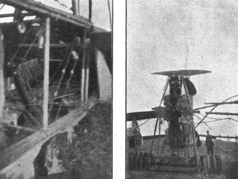
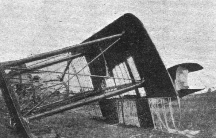
Fig. 54. - Empennage of four-engined giant.
-

Журнал - Flight за 1918 г.
Fig. 55. - Empennage of four-engined giant.
-

Журнал - Flight за 1918 г.
Fig. 56. - Undercarriage of four-englned giant.
Fig. 57. - Axles and wheels of four-engined type. -

Журнал - Flight за 1918 г.
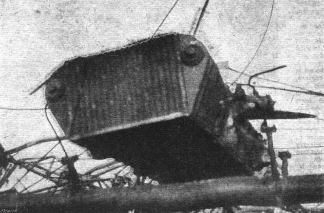
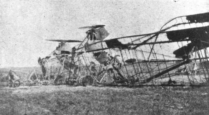
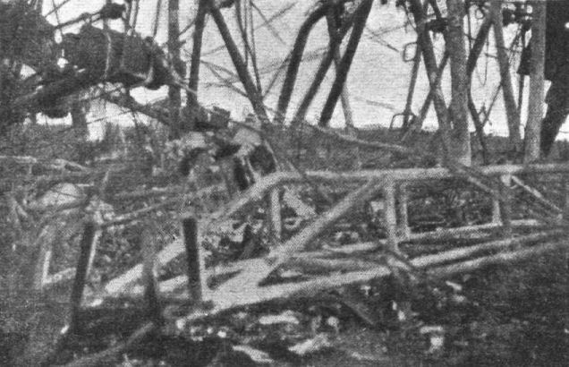
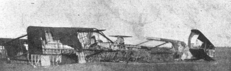
Fig. 58. - General view of wreckage of four-engined giant.
-

Журнал - Flight за 1918 г.
Fig. 59. - Rear end of fuselage and tail-skid of four-engined giant.
Fig. 60. - Power plant of four-engined giant. -

Журнал - Flight за 1918 г.
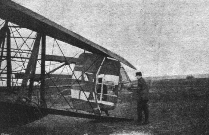
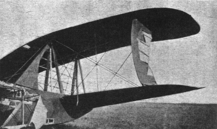
Fig. 61. - Main planes and ailerons of four-engined giant.
-

J.Herris - Zeppelin-Staaken Aircraft of WW1. Vol 2: R.VI R.30/16 - E.4/20 /Centennial Perspective/ (48)
Albatros-built Staaken R VI 37/16 burned out after crashing after being hit by French anti-aircraft fire on the night of June 1/2, 1918. (Peter M. Grosz collection/STDB)
-

Журнал - Flight за 1918 г.
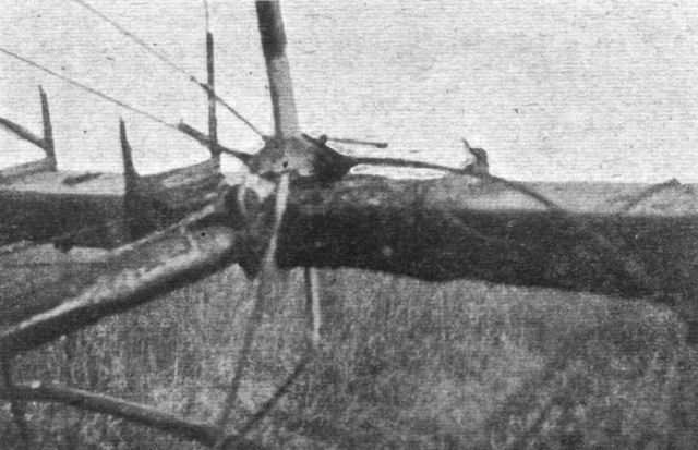
Fig. 62. - Attachment of struts and compression tube on four-engined giant.
-

Журнал - Flight за 1918 г.
Fig. 63. - Bomb carrier of four-engined giant.
-

Журнал - Flight за 1918 г.
Fig. 64. - General view of wreckage of four-engined giant.
-

J.Herris - Zeppelin-Staaken Aircraft of WW1. Vol 2: R.VI R.30/16 - E.4/20 /Centennial Perspective/ (48)
Wreckage of R.31 shot down the night of 15/16 Sep. 18, the second and last R-plane shot down by a Allied fighters, a No.151 Sqdn Camel nightfighter. (Peter M. Grosz collection/STDB)
-

J.Herris - Zeppelin-Staaken Aircraft of WW1. Vol 2: R.VI R.30/16 - E.4/20 /Centennial Perspective/ (48)
Hauptmann Schilling, Kommandeur of Rfa 501, and four members of his crew were killed when Staaken R VI 52/17 crashed into a house south-east of Chimay near Villers la Tour early in the morning of 12 August 1918; they were returning from a short-range operation against Beauvais. Unfamiliar with the more aft position of the pilot's seat compared with previous types and the increased weight of the newly assigned R52, the handling pilot became disorientated when flying blind and lost control. By this time machines of the R category were fitted with quite sophisticated instruments including artificial horizons, but the art of blind flying would not be understood for some years to come.
-

J.Herris - Zeppelin-Staaken Aircraft of WW1. Vol 1: VGO.1 - R.IV R.29/16 /Centennial Perspective/ (47)
German magazine partial cutaway drawing of a Staaken R.VI. (Peter M. Grosz collection/STDB)
-

J.Herris - Zeppelin-Staaken Aircraft of WW1. Vol 1: VGO.1 - R.IV R.29/16 /Centennial Perspective/ (47)
Fuel distribution in an R.VI with supercharger; only the R.30 had this installation.
-

J.Herris - Zeppelin-Staaken Aircraft of WW1. Vol 1: VGO.1 - R.IV R.29/16 /Centennial Perspective/ (47)
Fuel distribution schematics for an R.VI with gravity tank.
-

J.Herris - Zeppelin-Staaken Aircraft of WW1. Vol 1: VGO.1 - R.IV R.29/16 /Centennial Perspective/ (47)
Fuel distribution schematics for an R.VI with gravity tank.
-

J.Herris - Zeppelin-Staaken Aircraft of WW1. Vol 1: VGO.1 - R.IV R.29/16 /Centennial Perspective/ (47)
Construction of the fuel tanks in Staaken bombers.
-

J.Herris - Zeppelin-Staaken Aircraft of WW1. Vol 1: VGO.1 - R.IV R.29/16 /Centennial Perspective/ (47)
Schematics of Staaken R-plane construction
-

-

J.Herris - Zeppelin-Staaken Aircraft of WW1. Vol 1: VGO.1 - R.IV R.29/16 /Centennial Perspective/ (47)
R.VI pilots' flight control console.
-

-

J.Herris - Zeppelin-Staaken Aircraft of WW1. Vol 1: VGO.1 - R.IV R.29/16 /Centennial Perspective/ (47)
Structural details of the center of the front spar of the Staaken upper wing.
-

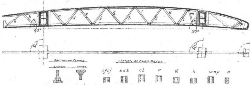
Jane's All The World Aircraft 1919 /Jane's/
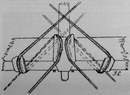
Sketch of the Method of Fastening the Bracing Wires on the Wing-spars of the Zeppelin Four-engined Biplane.
-

Jane's All The World Aircraft 1919 /Jane's/
Details of Ribs and Spars. Wings of Four-engined Zeppelin Biplane.
-

Журнал - Flight за 1918 г.
Fig. 46. - Engine mounting of four-engined giant.
-

Журнал - Flight за 1918 г.
Fig. 50. - Spar sections of four-engined giant.
-

Журнал - Flight за 1918 г.
Fig. 51. - Rib of four-engined giant.
-

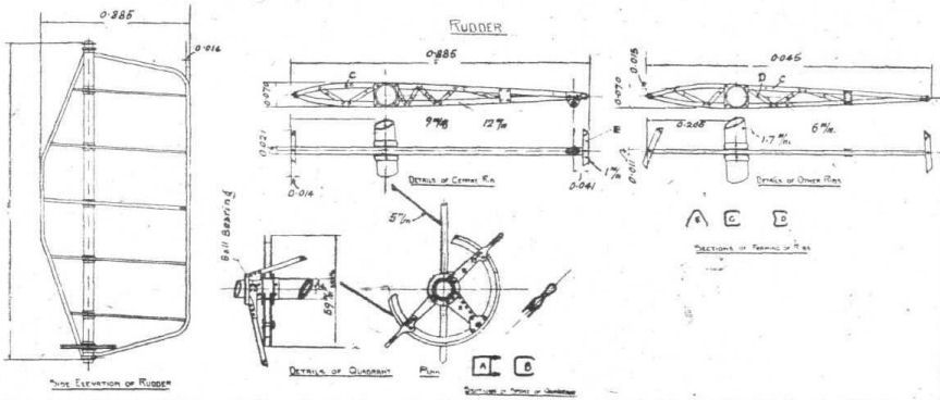
Журнал - Flight за 1918 г.
Fig. 52. - Rudder of four-engined giant.
-

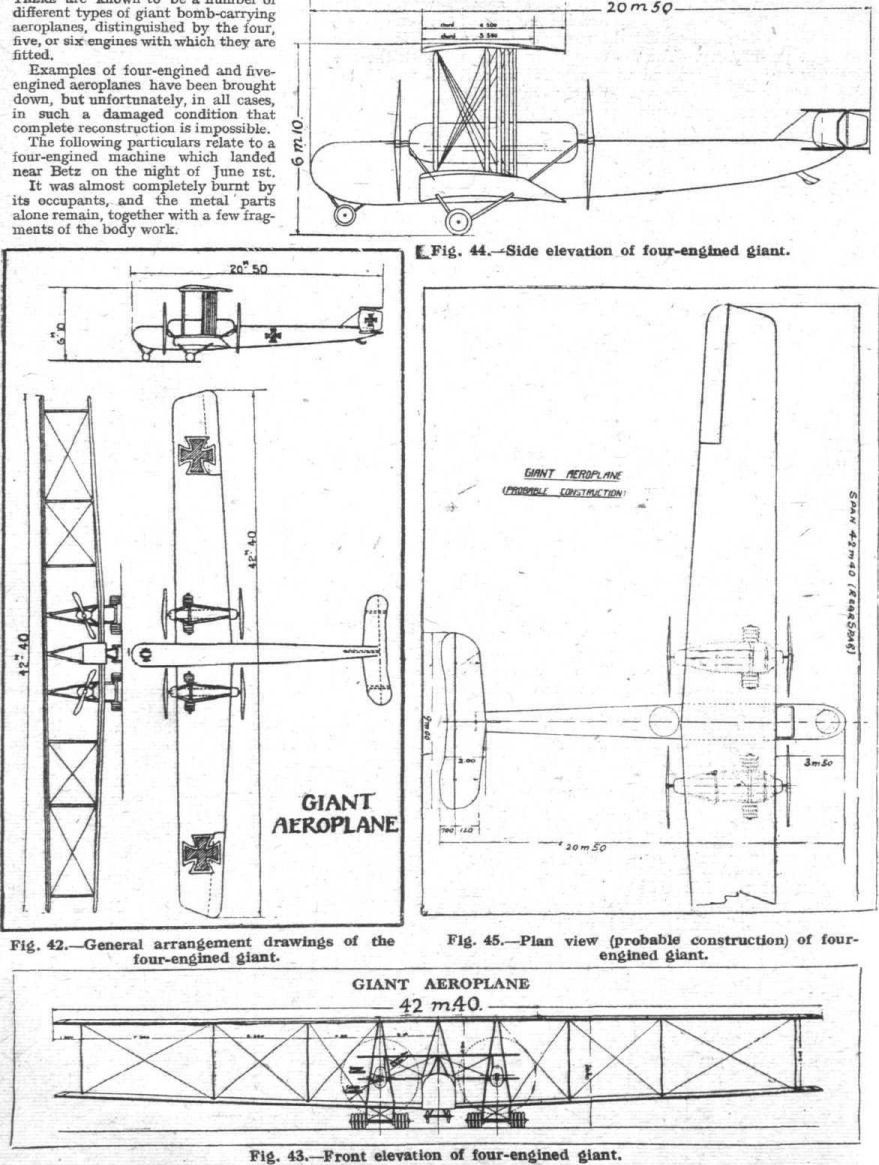
Журнал - Flight за 1918 г.
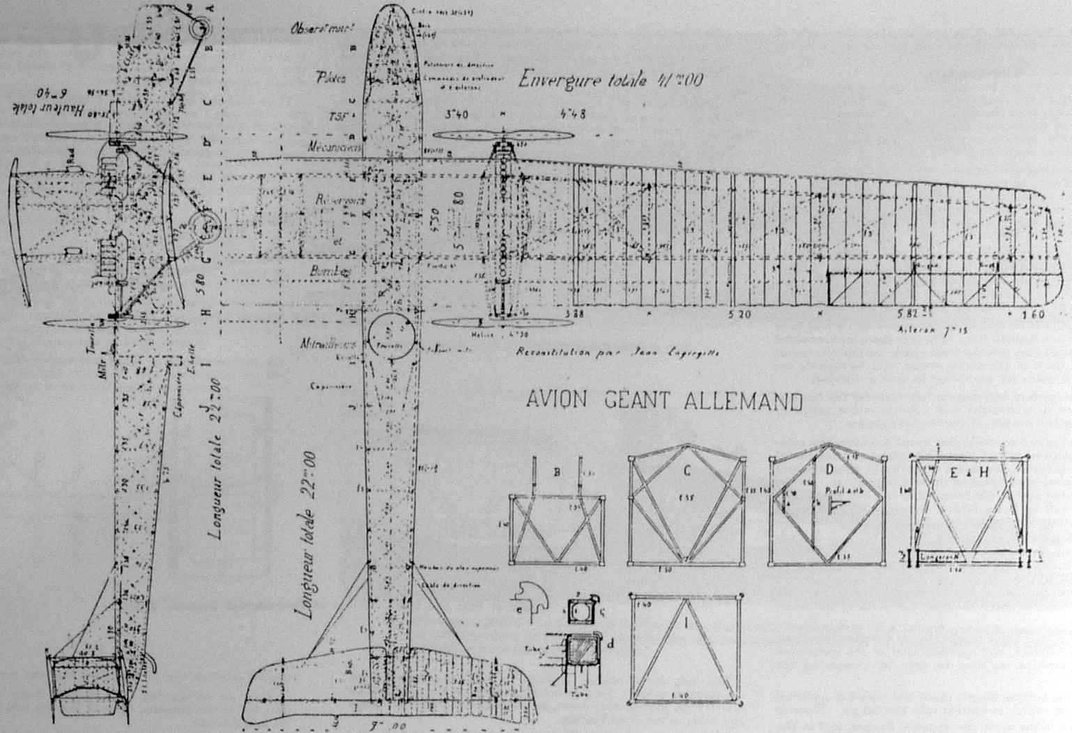
Fig. 42. - General arrangement drawings of the four-engined giant.
Fig. 43. - Front elevation of four-engined giant.
Fig. 44. - Side elevation of four-engined giant.
Fig. 45. - Plan view (probable construction) of four-engined giant. -

J.Herris - Zeppelin-Staaken Aircraft of WW1. Vol 1: VGO.1 - R.IV R.29/16 /Centennial Perspective/ (47)
Drawing of a Staaken R.VI from a French intelligence report. (Peter M. Grosz collection/STDB)
-

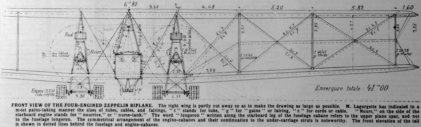
Jane's All The World Aircraft 1919 /Jane's/
Front View of the Four-engined Zeppelin Biplane.
-

Jane's All The World Aircraft 1919 /Jane's/
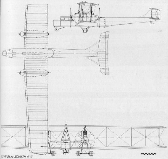
Scale Drawings of the Four-engined Zeppelin Biplane.
-

J.Herris - Zeppelin-Staaken Aircraft of WW1. Vol 1: VGO.1 - R.IV R.29/16 /Centennial Perspective/ (47)
Internal construction of the wings of the R.VI.
-

J.Herris - Zeppelin-Staaken Aircraft of WW1. Vol 1: VGO.1 - R.IV R.29/16 /Centennial Perspective/ (47)
Internal construction of the nose of the R.VI.
-

J.Herris - Zeppelin-Staaken Aircraft of WW1. Vol 1: VGO.1 - R.IV R.29/16 /Centennial Perspective/ (47)
Drawings of the Staaken R.VI showing the internal structure and fuel tanks. The fuel tanks were located over the center of gravity so the center of gravity could be maintained as the fuel was burned. The flight engineer was responsible to use the fuel from the tanks in such a way as to keep the center of gravity within limits.
-

J.Herris - Zeppelin-Staaken Aircraft of WW1. Vol 1: VGO.1 - R.IV R.29/16 /Centennial Perspective/ (47)
Drawings of the Staaken R.VI.
-

-

-

-

В.Кондратьев - Самолеты первой мировой войны
"Цеппелин-Штаакен" R-VI
-

G.Haddow, P.Grosz - The German Giants /Putnam/
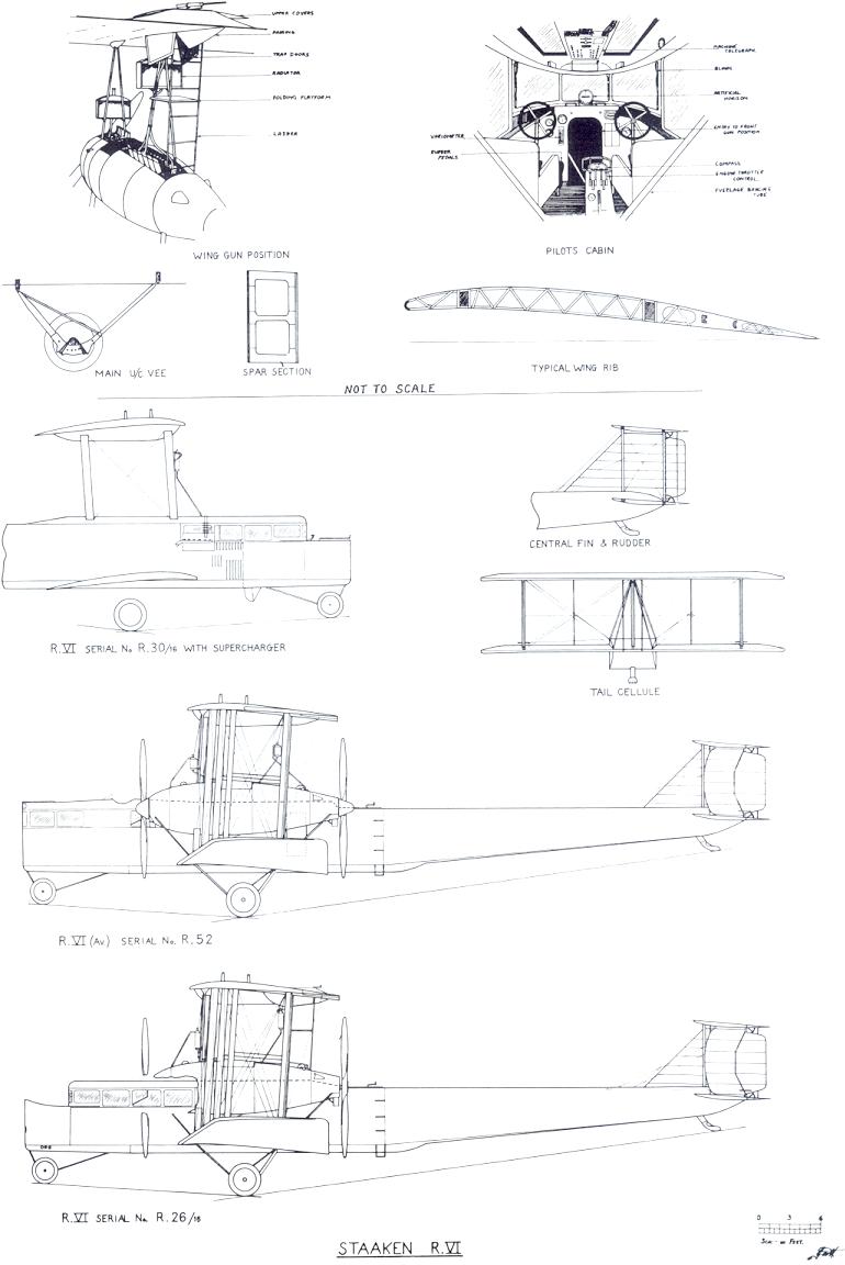
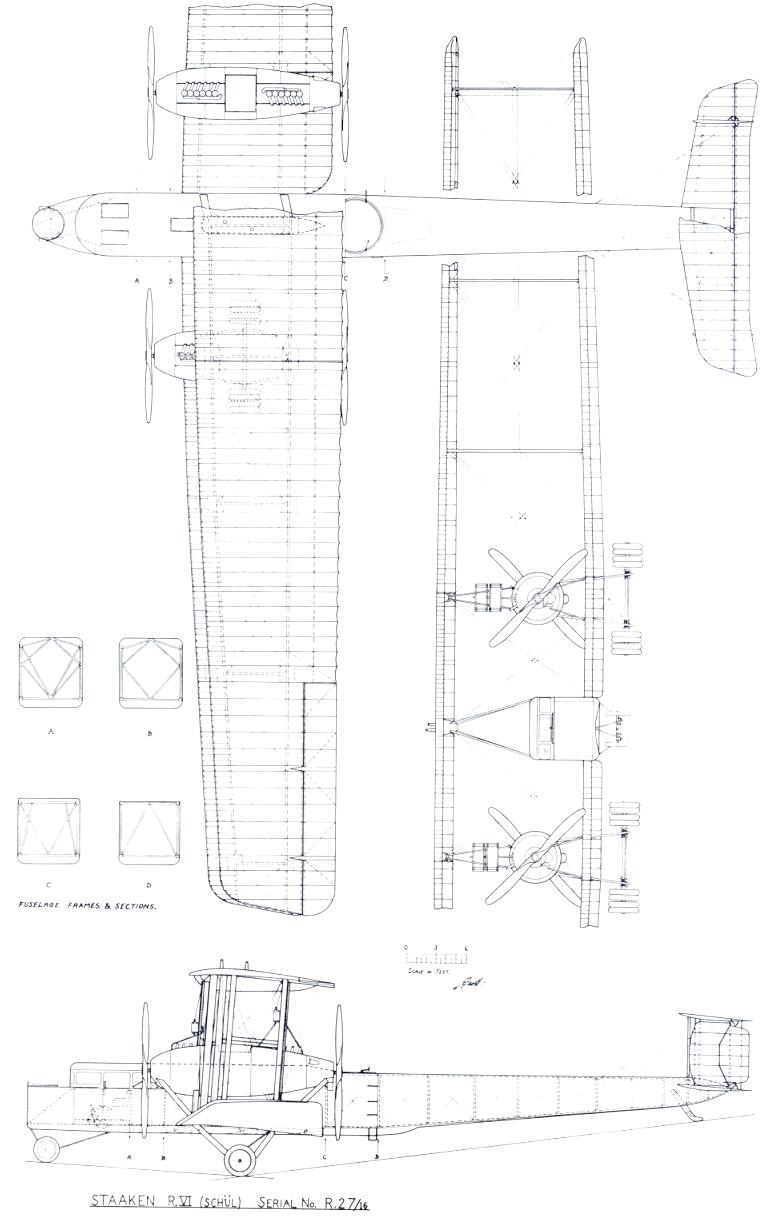
Staaken R.VI (Schul)
-

G.Haddow, P.Grosz - The German Giants /Putnam/
Staaken R.VI
-

-

-

В.Кондратьев Самолеты первой мировой войны
"Цеппелин-Штаакен" R-VI. Первая серийная модификация. Построено 18 экземпляров, из них только один - на фирме Цеппелина, 6 - на фирме Авиатик, 7 - на фирме Шютте-Ланц и 4 - на предприятии Остдойч Альбатрос Верк (OAW). R-VI - четырехмоторный аэроплан с двигателями "Майбах" Mb.IV по 245 л.с. или "Мерседес" D.IVa по 260 л.с. в двух тандемах.
Конструкция смешанная с преобладанием древесины. Фюзеляж обшит фанерой, мотогондолы - дюралем, крылья и оперение - полотном. Самолет оборудован радиостанцией, электрообогревом кабин и внутренним переговорным устройством. Экипаж - 7 человек (штурман-бомбардир, он же - носовой стрелок, 2 пилота, радист, 2 механика, размещавшихся в мотогондолах, хвостовой стрелок).
Защитное вооружение - от трех до шести пулеметов "Парабеллум". В фюзеляжном бомбовом отсеке помещалось 18 бомб по 100 кг, а максимальная бомбовая нагрузка превышала 2 тонны, рекордный показатель для самолетов Первой Мировой войны.
С июня 1917-го и до лета следующего года "Цеппелины" совместно с "Готами" регулярно бомбили Лондон, Дувр, Фолкстон и другие города юго-восточной Англии. За все это время английской ПВО удалось сбить только один четырехмоторный бомбардировщик.
В феврале R-VI сбросил на пригород Лондона 1000-килограммовую бомбу, самый тяжелый авиационный боеприпас, примененный в Первой Мировой. В последние месяцы войны немецкие гиганты действовали главным образом над территориями Франции и Бельгии.
ЛЕТНО-ТЕХНИЧЕСКИЕ ХАРАКТЕРИСТИКИ
Размах, м 42,2
Длина, м 22,5
Площадь крыла, кв.м 334,0
Сухой вес, кг 7680
Взлетный вес, кг 11460
Скорость максимальная, км/ч 130
Дальность полета, км 800
Время набора высоты, мин/м 43/3000
Потолок, м 3800
Описание: