Описание
Страна: Германия
Год: 1916
Варианты
- Zeppelin-Staaken - VGO.I/VGO.II - 1915 - Германия
- Zeppelin-Staaken - R.V - 1916 - Германия
- Zeppelin-Staaken - VGO.III / R.IV / R.VII - 1916 - Германия
- В.Кондратьев Самолеты первой мировой войны
- O.Thetford, P.Gray German Aircraft of the First World War (Putnam)
- G.Haddow, P.Grosz The German Giants (Putnam)
- J.Herris Zeppelin-Staaken Aircraft of WW1. Vol 1: VGO.1 - R.IV R.29/16 (A Centennial Perspective on Great War Airplanes 47)
- J.Herris Zeppelin-Staaken Aircraft of WW1. Vol 2: R.VI R.30/16 - E.4/20 (A Centennial Perspective on Great War Airplanes 48)
- M.Dusing German Aviation Industry in WWI. Volume 2 (A Centennial Perspective on Great War Airplanes 85)
-

J.Herris - Development of German Warplanes in WWI /Centennial Perspective/ (1)
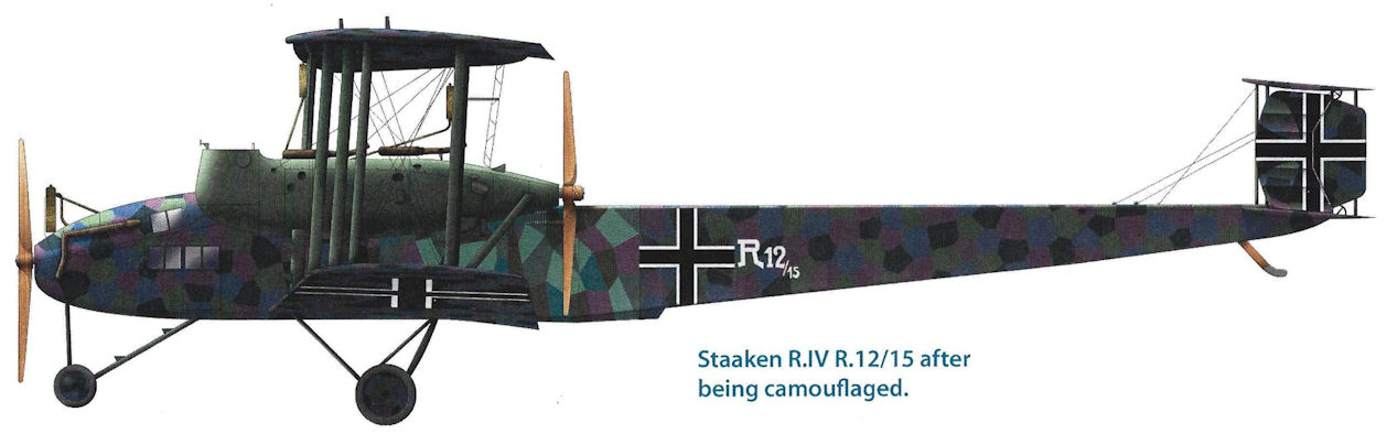
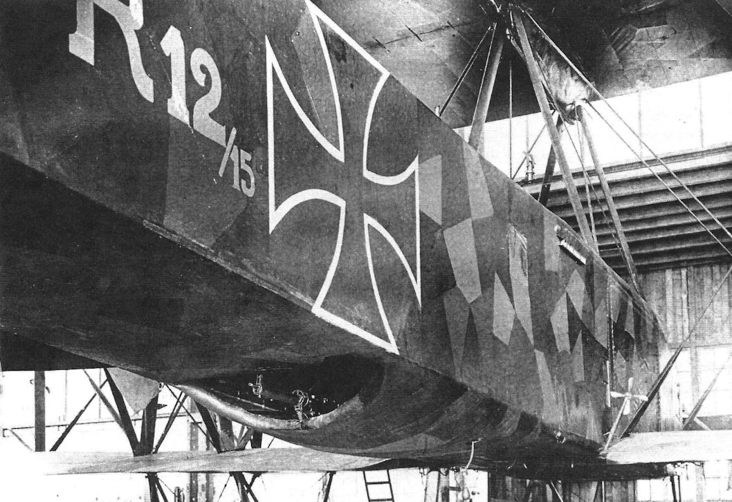
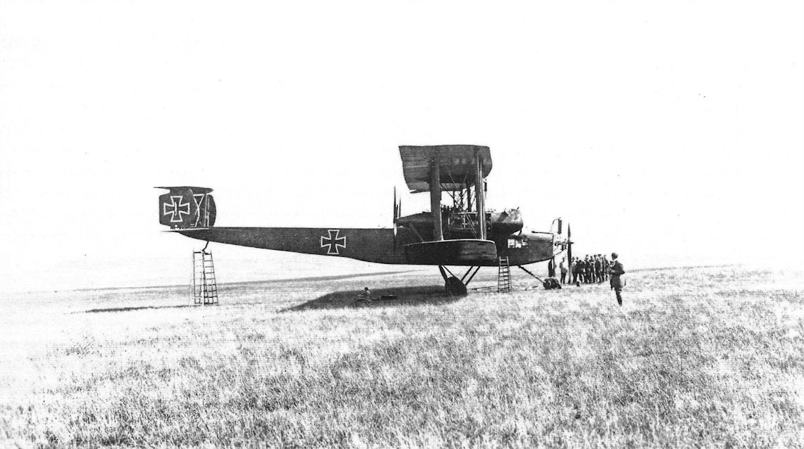
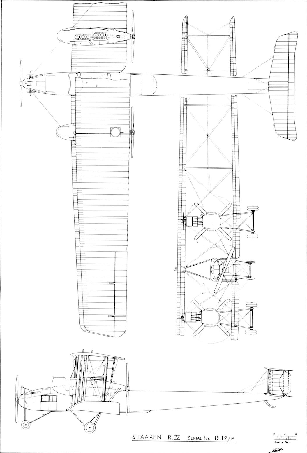
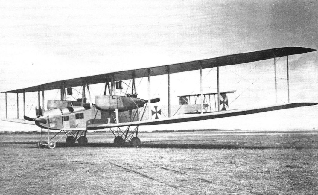
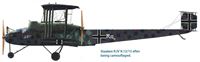
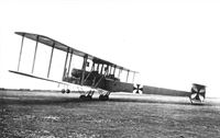
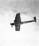
Staaken R.IV R12/15 while operating with Rfa 500 on the Eastern Front. After R12 was transferred to the Western Front for night bombing missions over the UK, it was camouflaged in dark colors similar to the R.VI. Only one R.IV was built but it was very successful, and was the only R-plane to serve on both fronts. Six engines coupled in pairs drove three propellers.
-
J.Herris - Zeppelin-Staaken Aircraft of WW1. Vol 1: VGO.1 - R.IV R.29/16 /Centennial Perspective/ (47)
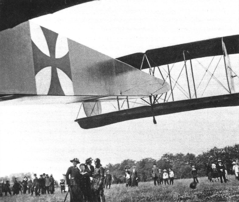
Staaken R.IV R.12/15 after being camouflaged.
-

J.Herris - Zeppelin-Staaken Aircraft of WW1. Vol 1: VGO.1 - R.IV R.29/16 /Centennial Perspective/ (47)
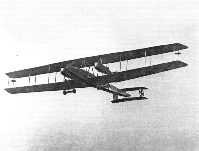
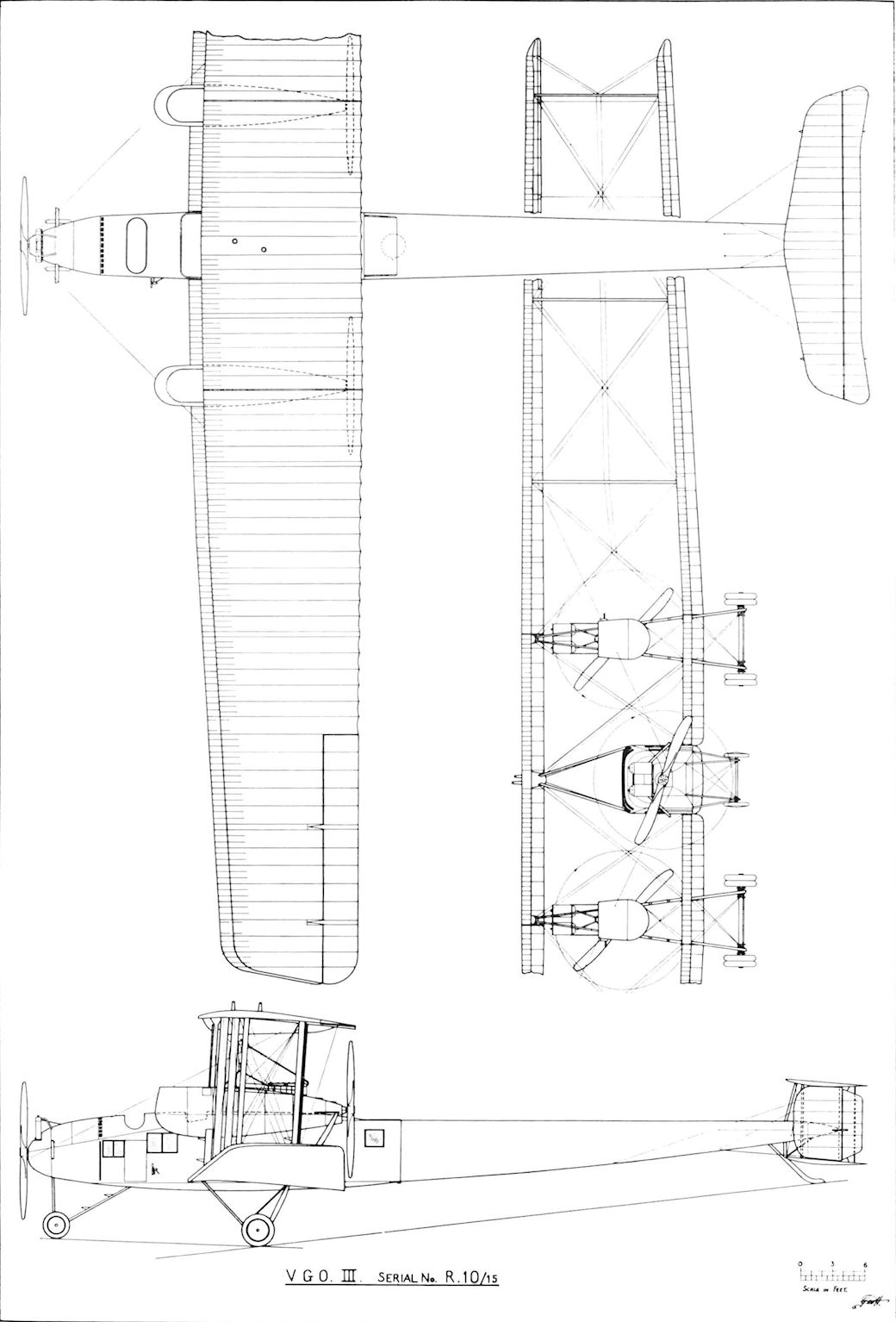
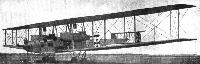
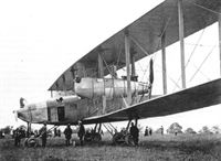
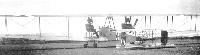
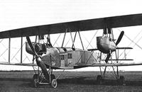
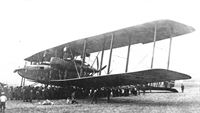
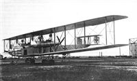
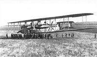
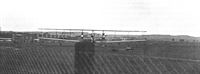
The VGO.III R.10/15 was nearly identical in appearance to the earlier Staaken aircraft but with a simplified tail with no fixed fin. However, the engines were updated to the reliable 160 hp Mercedes mounted in pairs for each propeller.
-
Журнал - Flight за 1919 г.
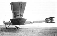
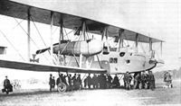
Zeppelin-Staaken V.G.O. III. A GERMAN (ZEPPELIN) GIANT AEROPLANE. - Note the tractor airscrew in the nose of the fuselage.
-
G.Haddow, P.Grosz - The German Giants /Putnam/
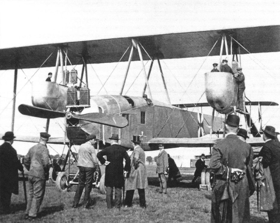
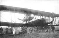
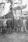
The VGO.III shown fitted with aileron balancing surfaces attached to the rear struts. From left to right: Hans Baumeister, Anton Diemer, Foreman Ridlein, Gustav Klein, Grimmeisen and Boenisch.
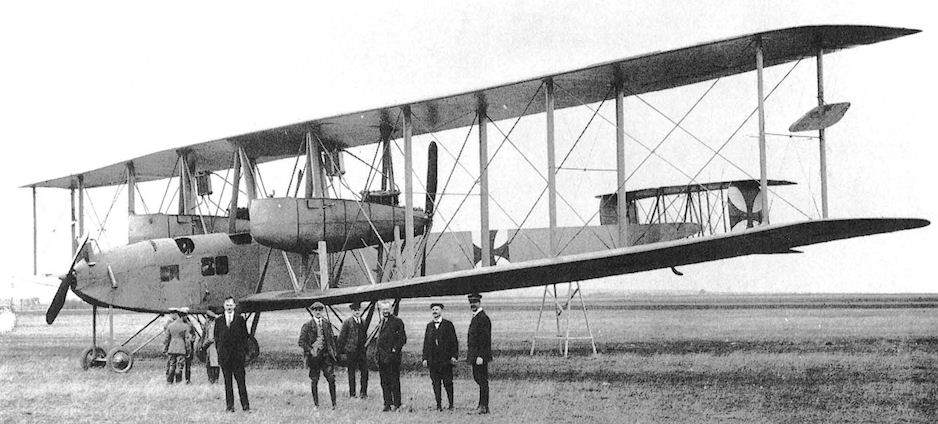
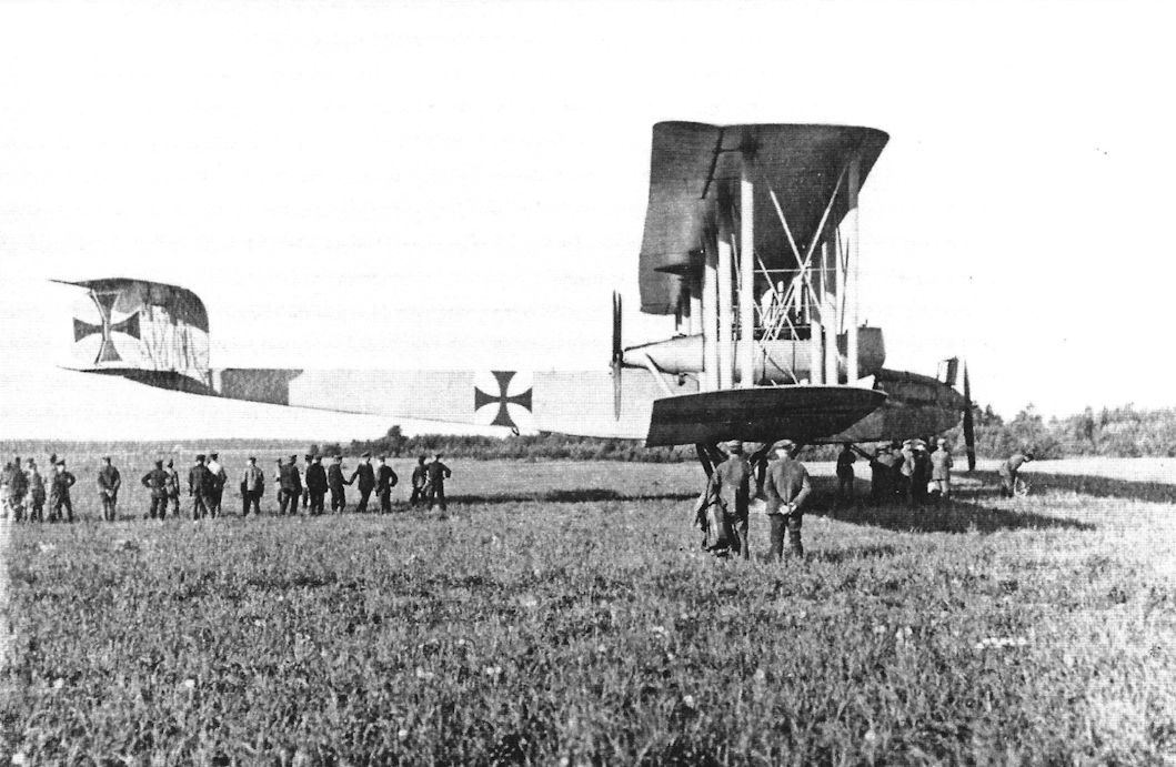
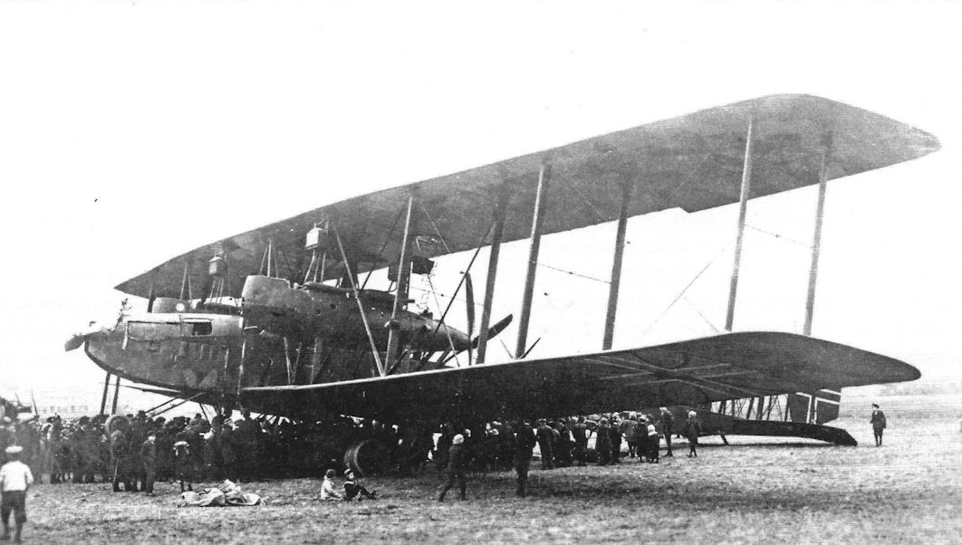
The sole giant Zeppelin-Staaken VGO III, 10/15, went into service with Rf Abt 500 based near Riga in Latvia in 1916, making its first operational sortie on 13 August 1916. Power for the VGO III was provided by six 160hp Mercedes D IIIs, paired to drive the nose-mounted tractor propeller, plus the two outboard pusher propellers. With a wingspan of 42m, or 137.8 feet, the VGO positively meandered along with a top level speed of 75mph. Sadly, the pilot responsible for coaxing the VGO III through her teething troubles, Oblt Hallen, Baron von Hallerstein was to be killed exactly three months after taking the VGO III on its first operational mission, while flight testing the lethally tail-heavy Zeppelin-Lindau V.I fighter. -
J.Herris - Zeppelin-Staaken Aircraft of WW1. Vol 1: VGO.1 - R.IV R.29/16 /Centennial Perspective/ (47)
During flight testing the VGO.III was fitted with an auxiliary aileron balance on the rear outer interplane struts. These surfaces were designed to reduce aileron control forces to improve aileron response and reduce pilot fatigue. The surfaces were hinged aft of their center and connected to the ailerons. Similar methods of aileron balancing were tried by Gotha and Brandenburg seaplanes. However, the surfaces were removed from the VGO.III and not used on other Staaken aircraft. (Peter M. Grosz collection/STDB)
-
J.Herris - Zeppelin-Staaken Aircraft of WW1. Vol 1: VGO.1 - R.IV R.29/16 /Centennial Perspective/ (47)
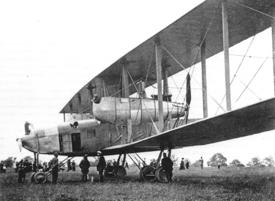
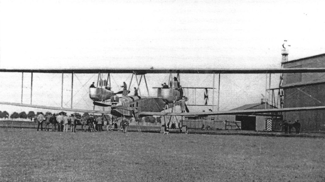
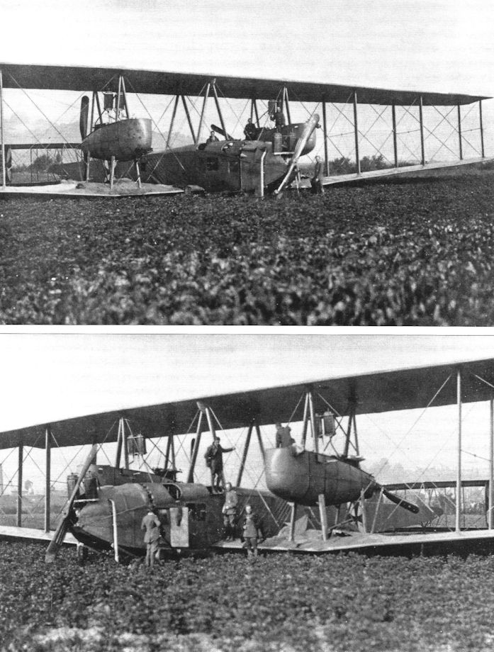
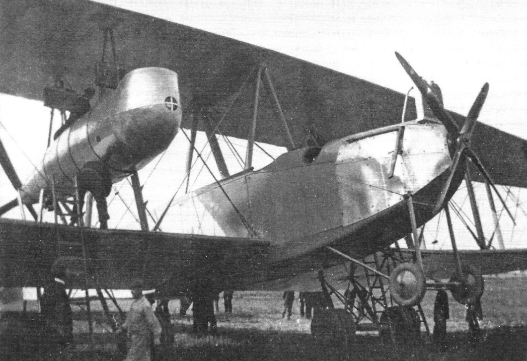
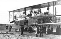
The VGO.III being admired by a group of VIPs and guests. These views show the aircraft's details and massive size. (Peter M. Grosz collection/STDB)
-

J.Herris - Zeppelin-Staaken Aircraft of WW1. Vol 1: VGO.1 - R.IV R.29/16 /Centennial Perspective/ (47)
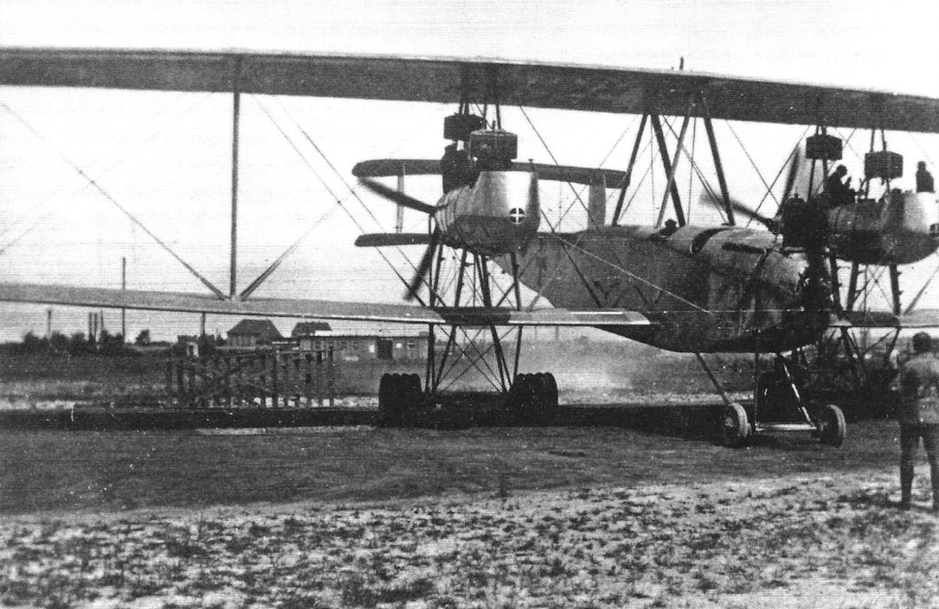
More views of the VGO.III R.10/15. It was a very large, impressive for the time. The overall configuration was conventionally similar to smaller biplanes. The aircraft's size and engine arrangement were the aspects that distinguished it from more common aircraft. (Peter M. Grosz collection/STDB)
-
J.Herris - Zeppelin-Staaken Aircraft of WW1. Vol 1: VGO.1 - R.IV R.29/16 /Centennial Perspective/ (47)
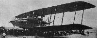
Powered by six engines, the Zeppelin-Staaken VGO III was the first of the strategic bombers' produced by this company. The aircraft saw operational service with RFa 500 on the Eastern Front in the early days of 1915; although its top speed was only 75mph (120kph) and its ceiling only 6,560ft (2,000m) it was defended by five machine guns.
-

J.Herris - Zeppelin-Staaken Aircraft of WW1. Vol 1: VGO.1 - R.IV R.29/16 /Centennial Perspective/ (47)
The VGO.III being admired by a group of VIPs and guests. These views show the aircraft's details and massive size. (Peter M. Grosz collection/STDB)
-
J.Herris - Zeppelin-Staaken Aircraft of WW1. Vol 1: VGO.1 - R.IV R.29/16 /Centennial Perspective/ (47)
During flight testing the VGO.III was fitted with an auxiliary aileron balance on the rear outer interplane struts. These surfaces were designed to reduce aileron control forces to improve aileron response and reduce pilot fatigue. The surfaces were hinged aft of their center and connected to the ailerons. Similar methods of aileron balancing were tried by Gotha and Brandenburg seaplanes. However, the surfaces were removed from the VGO.III and not used on other Staaken aircraft. (Peter M. Grosz collection/STDB)
-
J.Herris - Zeppelin-Staaken Aircraft of WW1. Vol 1: VGO.1 - R.IV R.29/16 /Centennial Perspective/ (47)
Side view of the VGO.III shows its basic configuration is essentially the same as the earlier VGO.I and VGO.II. (Peter M. Grosz collection/STDB)
-
J.Herris - Zeppelin-Staaken Aircraft of WW1. Vol 1: VGO.1 - R.IV R.29/16 /Centennial Perspective/ (47)
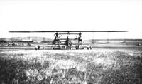
The VGO.III is here shown resting all its tailskid; the more normal attitude was for it to rest on its nose wheels with the tail high.
-

J.Herris - Halberstadt Aircraft of WWI. Volume 2: CL.IV-CLS.I & Fighters /Centennial Perspective/ (45)
Halberstadt D.I fitted with rockets for anti-balloon attacks under test at Doberitz. The aileron horn balances identify it as a D.I. The massive Staaken VGO.III is in the background. (Peter M. Grosz Collection/STDB)
Другие самолёты на фотографии: Halberstadt D.I - Германия - 1916
-

J.Herris - Weird Wings of WWI /Centennial Perspective/ (70)
Halberstadt D.I fitted with rockets for anti-balloon attacks under test at Doberitz. Aileron horn balances identify it as a D.I. Less than a dozen D.I fighters (powered by the 100 hp Mercedes D.I were built before production shifted to the D.II (120 hp Mercedes D.II engine) and D.III (120 hp Argus As.II engine).The massive Staaken VGO.III is in the background. (Peter M. Grosz collection/STDB)
Другие самолёты на фотографии: Halberstadt D.I - Германия - 1916
-
G.Haddow, P.Grosz - The German Giants /Putnam/
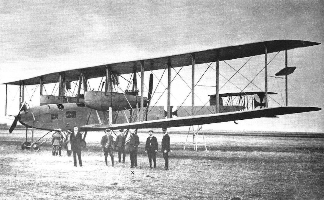
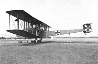
VGO.III 10/15.
-

J.Herris - Zeppelin-Staaken Aircraft of WW1. Vol 1: VGO.1 - R.IV R.29/16 /Centennial Perspective/ (47)
More views of the VGO.III R.10/15. It was a very large, impressive for the time. The overall configuration was conventionally similar to smaller biplanes. The aircraft's size and engine arrangement were the aspects that distinguished it from more common aircraft. (Peter M. Grosz collection/STDB)
-
J.Herris - Zeppelin-Staaken Aircraft of WW1. Vol 1: VGO.1 - R.IV R.29/16 /Centennial Perspective/ (47)
More views of the VGO.III being admired by a group of VIPs and guests. These views show the aircraft's details and massive size. (Peter M. Grosz collection/STDB)
-
J.Herris - Zeppelin-Staaken Aircraft of WW1. Vol 1: VGO.1 - R.IV R.29/16 /Centennial Perspective/ (47)
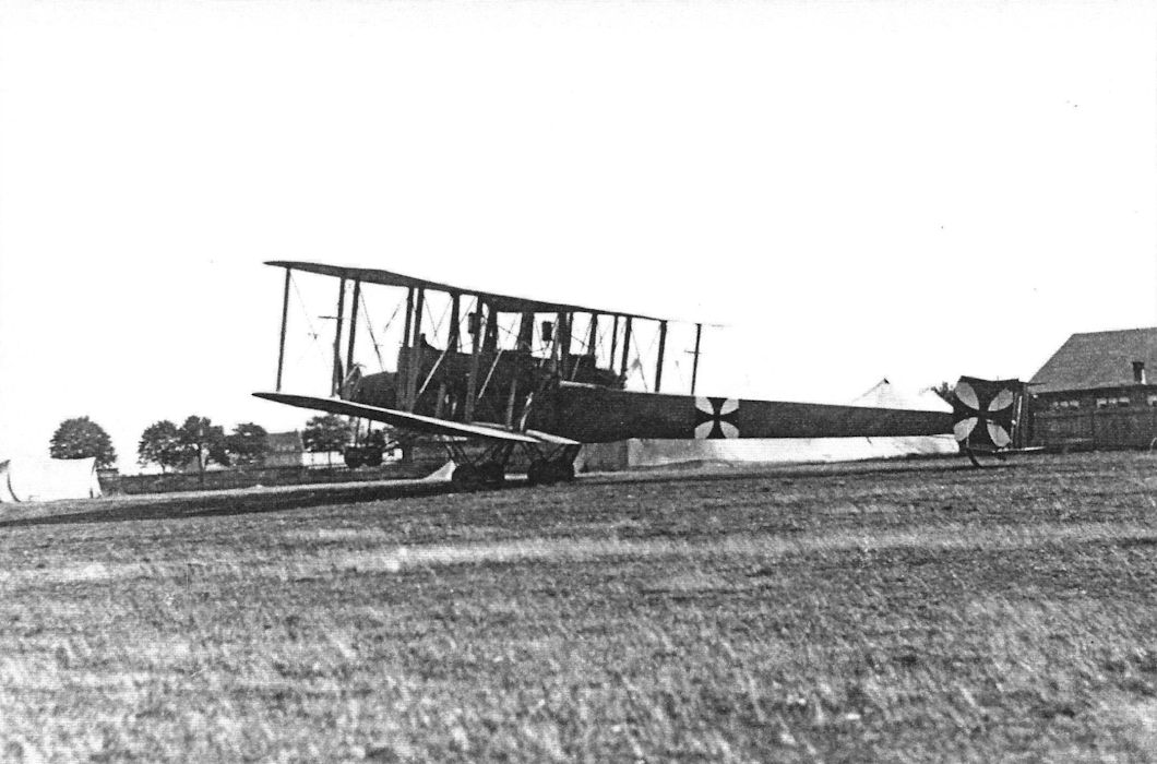
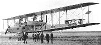
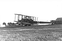
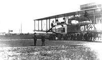
The VGO.III, 8 September 1916 on delivery to Rfa 500.
-

J.Herris - Zeppelin-Staaken Aircraft of WW1. Vol 1: VGO.1 - R.IV R.29/16 /Centennial Perspective/ (47)
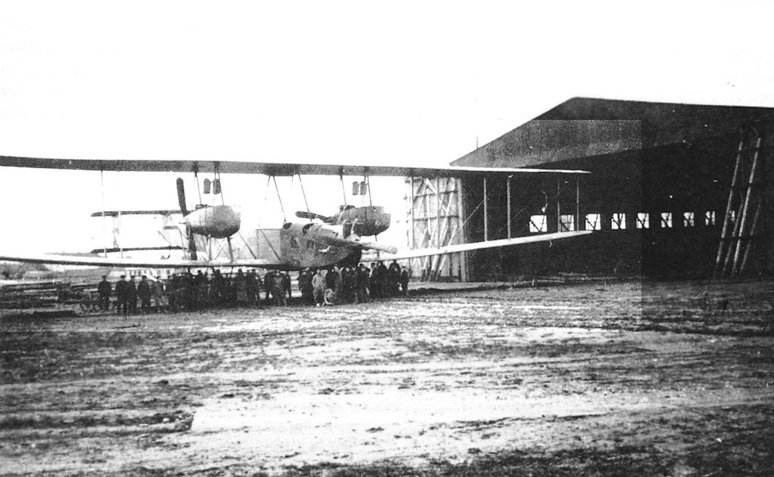
The VGO.III on the tracks outside its hangar at Alt-Auz, summer 1916.
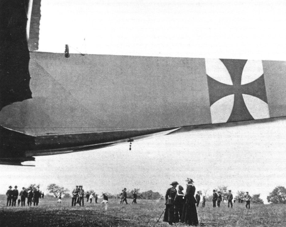
The VGO.III being admired by a group of VIPs. (Peter M. Grosz collection/STDB) -
J.Herris - Zeppelin-Staaken Aircraft of WW1. Vol 1: VGO.1 - R.IV R.29/16 /Centennial Perspective/ (47)
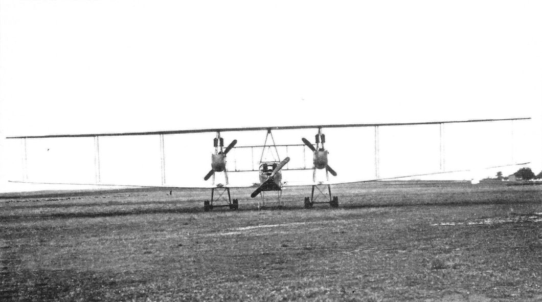
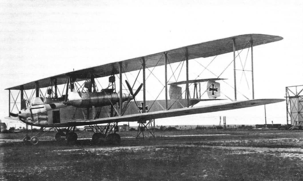
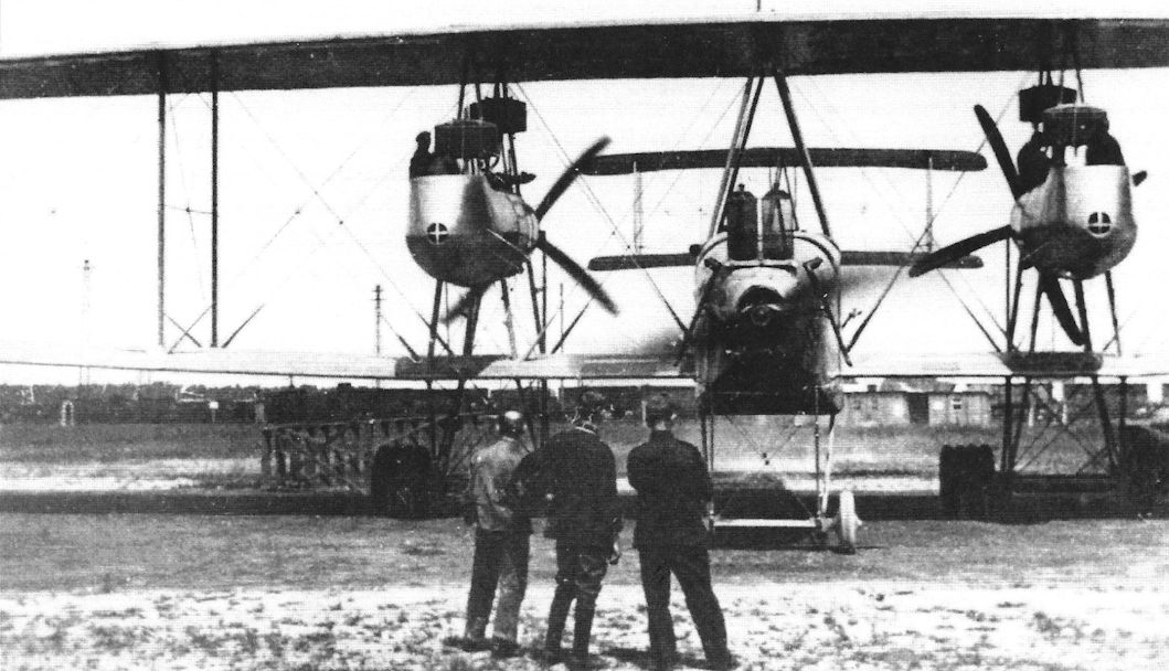
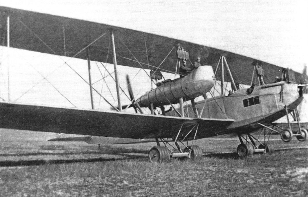
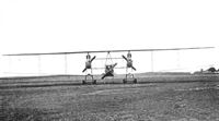
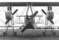
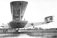
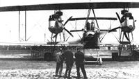
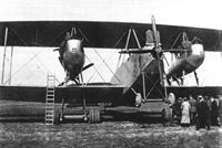
This full front view of the VGO.III shows the six radiators for the six 160 hp Mercedes D.III engines. (Peter M. Grosz collection/STDB)
-
J.Herris - Zeppelin-Staaken Aircraft of WW1. Vol 1: VGO.1 - R.IV R.29/16 /Centennial Perspective/ (47)
This front view of the VGO.III shows the six radiators for the six 160 hp Mercedes D.III engines. This change in engines was to improve reliability by replacing the Maybach HS engines that caused so many problems. The radiators exhibit a great deal of flat-plate area, creating a lot of drag. The central fixed fin of the VGO.II was replaced by enlarged fins attached to the rudders. Other than these detail changes, the VGO.III closely resembled the earlier VGO aircraft. (Peter M. Grosz collection/STDB)
-

J.Herris - Zeppelin-Staaken Aircraft of WW1. Vol 1: VGO.1 - R.IV R.29/16 /Centennial Perspective/ (47)
The VGO.III being admired by a group of VIPs and guests. These views show the aircraft's details and massive size. (Peter M. Grosz collection/STDB)
-

-
J.Herris - Zeppelin-Staaken Aircraft of WW1. Vol 1: VGO.1 - R.IV R.29/16 /Centennial Perspective/ (47)
More views of the VGO.III being admired by a group of VIPs and guests. These views show the aircraft's details and massive size. (Peter M. Grosz collection/STDB)
-
J.Herris - Zeppelin-Staaken Aircraft of WW1. Vol 1: VGO.1 - R.IV R.29/16 /Centennial Perspective/ (47)
The VGO.III being admired by a group of VIPs and guests. These views show the aircraft's details and massive size. (Peter M. Grosz collection/STDB)
-

J.Herris - Zeppelin-Staaken Aircraft of WW1. Vol 1: VGO.1 - R.IV R.29/16 /Centennial Perspective/ (47)
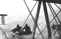
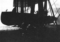
The ventral gun position on a Staaken. From the VGO.II all Staaken bombers had this defensive gun mounting. The British Lewis aircraft machine gun as shown here was very popular in giant bomber crews. (Peter M. Grosz collection/STDB)
-
J.Herris - Zeppelin-Staaken Aircraft of WW1. Vol 1: VGO.1 - R.IV R.29/16 /Centennial Perspective/ (47)
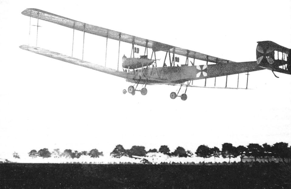
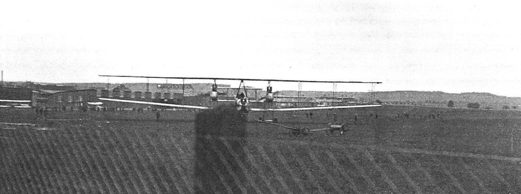
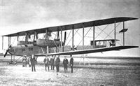
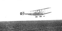
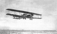
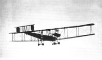
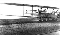
The VGO.III R.10/15 takes off an another flight. (Peter M. Grosz collection/STDB)
-

J.Herris - Zeppelin-Staaken Aircraft of WW1. Vol 1: VGO.1 - R.IV R.29/16 /Centennial Perspective/ (47)
VGO.III 10/15 taking off from Gotha to fly to Doberitz, August 1916
-

J.Herris - Zeppelin-Staaken Aircraft of WW1. Vol 1: VGO.1 - R.IV R.29/16 /Centennial Perspective/ (47)
During flight testing the VGO.III was fitted with an auxiliary aileron balance on the rear outer interplane struts. These surfaces were designed to reduce aileron control forces to improve aileron response and reduce pilot fatigue. The surfaces were hinged aft of their center and connected to the ailerons. Similar methods of aileron balancing were tried by Gotha and Brandenburg seaplanes. However, the surfaces were removed from the VGO.III and not used on other Staaken aircraft. (Peter M. Grosz collection/STDB)
-

J.Herris - Zeppelin-Staaken Aircraft of WW1. Vol 1: VGO.1 - R.IV R.29/16 /Centennial Perspective/ (47)
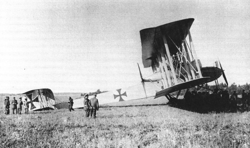
The VGO.III R.10/15 after its landing gear collapsed on landing. (Peter M. Grosz collection/STDB)
-

J.Herris - Zeppelin-Staaken Aircraft of WW1. Vol 1: VGO.1 - R.IV R.29/16 /Centennial Perspective/ (47)
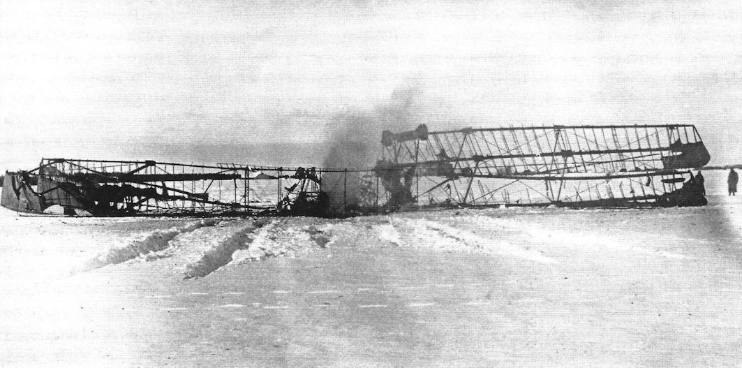
The charred remains of VGO.III after it crashed and burned on landing on January 24, 1917 at Alt-Aus on the Eastern Front. This was the first fatal accident in an R-plane. (Peter M. Grosz collection/STDB)
-

J.Herris - Weird Wings of WWI /Centennial Perspective/ (70)
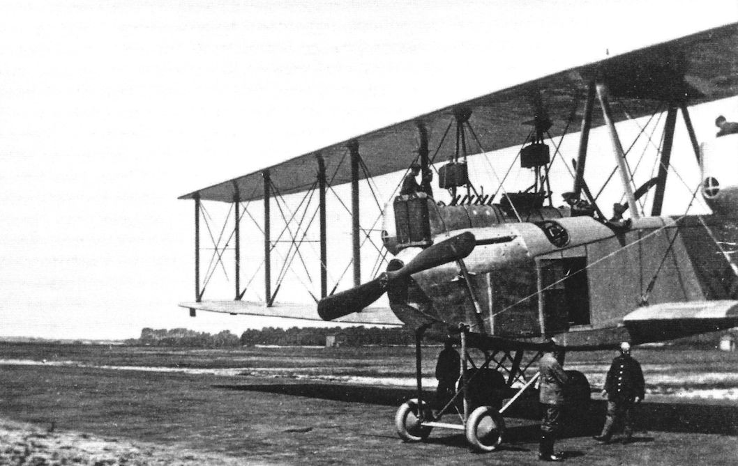
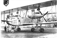
The Staaken R.IV freshly delivered to Rfa 500 on the Eastern Front. After the fuel tanks were full the aircraft sat on its front wheels. At this point the R.IV did not have its upper wing guns added later. Note the small cooling openings at the front of the nacelles. Each engine nacelle had two 220 hp Benz Bz.IV engines driving a single propeller, and the nose propeller was driven by two 160 hp Mercedes D.III engines. Gearing two engines together to drive a single propeller gave additional reliability in addition to greater power. Because the fixed pitch propellers of WWI airplanes could not be feathered, it was important to continue to power the propeller in case of engine failure, and a failed engine could be declutched from the gearbox so the operating engine could continue to power the propeller. A windmilling propeller generates about as much drag as a parachute of similar diameter. (Peter M. Grosz collection/STDB)
-

J.Herris - Zeppelin-Staaken Aircraft of WW1. Vol 1: VGO.1 - R.IV R.29/16 /Centennial Perspective/ (47)
Photo showing Staaken R.IV freshly delivered to Rfa 500 on the Eastern Front. After the fuel tanks were full the aircraft sat on its front wheels. At this point the R.IV did not have its upper wing guns. Note the small cooling openings at the front of the nacelles. (Peter M. Grosz collection/STDB)
-
J.Herris - Zeppelin-Staaken Aircraft of WW1. Vol 1: VGO.1 - R.IV R.29/16 /Centennial Perspective/ (47)
Staaken R.IV 12/15, here seen at Alt-Auz early in its long operational career.
-

J.Herris - Zeppelin-Staaken Aircraft of WW1. Vol 1: VGO.1 - R.IV R.29/16 /Centennial Perspective/ (47)
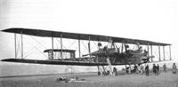
Photo showing Staaken R.IV freshly delivered to Rfa 500 on the Eastern Front. The personnel exercise in the massive aircraft's shadow. (Peter M. Grosz collection/STDB)
-

J.Herris - Zeppelin-Staaken Aircraft of WW1. Vol 1: VGO.1 - R.IV R.29/16 /Centennial Perspective/ (47)
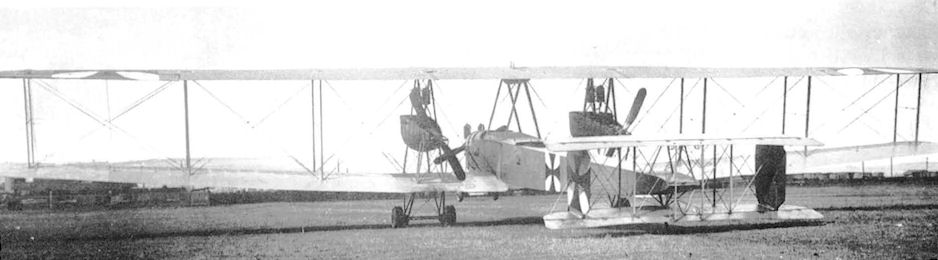
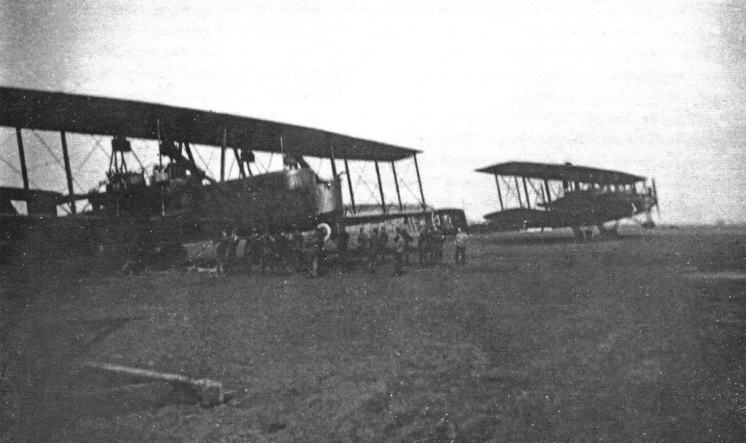
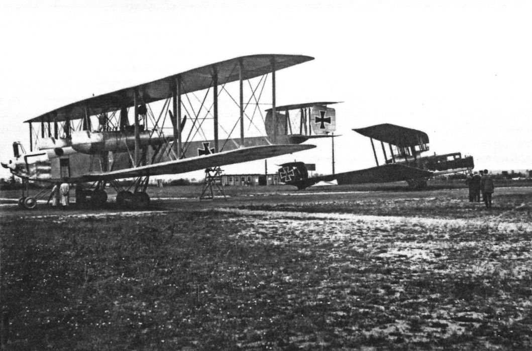
Staaken R.VI R.25 at the left together with another Staaken, probably R.12, on the airfield. (Peter M. Grosz collection/STDB)
Другие самолёты на фотографии: Zeppelin-Staaken R.VI - Германия - 1917
-

J.Herris - Zeppelin-Staaken Aircraft of WW1. Vol 1: VGO.1 - R.IV R.29/16 /Centennial Perspective/ (47)
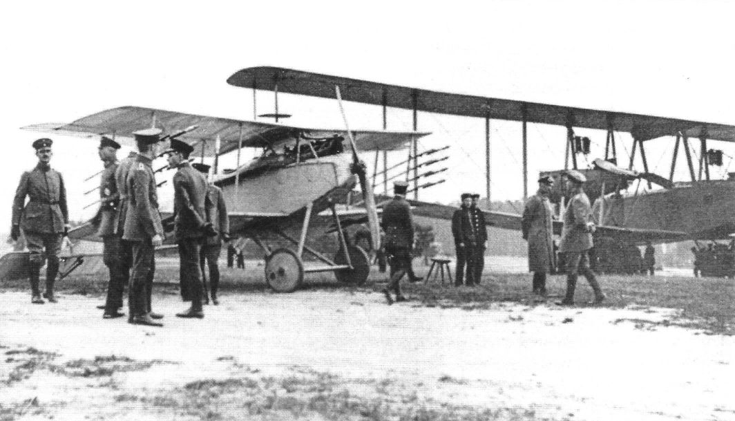
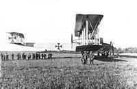
The R.12 being admired by guests before camouflage was applied. (Peter M. Grosz collection/STDB)
-
J.Herris - Zeppelin-Staaken Aircraft of WW1. Vol 1: VGO.1 - R.IV R.29/16 /Centennial Perspective/ (47)
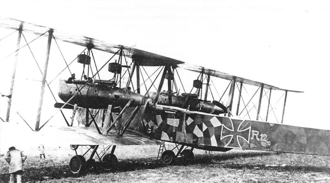
R.12 during service with Rfa 501 on the Western Front at Schweldewindeke airfield. R.12 previously served with Rfa on the Eastern Front, then was upgraded with wing gun positions, parachutes, and over-painted with night camouflage white outlined patee crosses in the normal positions. (Peter M. Grosz collection/STDB)
-
J.Herris - Zeppelin-Staaken Aircraft of WW1. Vol 1: VGO.1 - R.IV R.29/16 /Centennial Perspective/ (47)
Staaken R.IV R.12/15 was the single most successful R-plane; here its crew pre-flights it for another mission at Schweldewindeke airfield. R.12 wears night camouflage with white outlined patee crosses and light painted R.12/15 on fuselage side. R.12 is shown prior parachute mounting. (Peter M. Grosz collection/STDB)
-

-

J.Herris - Zeppelin-Staaken Aircraft of WW1. Vol 1: VGO.1 - R.IV R.29/16 /Centennial Perspective/ (47)
R.12 after parachutes were mounted; the parachute lines are visible on the fuselage side. The nacelle gunners and mechanics also appear to have parachutes in the fuselage. Tractor propellers prevented parachute use from the nacelles. Two big exhaust silencers direct the exhaust out of the engine. (Peter M. Grosz collection/STDB)
-

J.Herris - Zeppelin-Staaken Aircraft of WW1. Vol 1: VGO.1 - R.IV R.29/16 /Centennial Perspective/ (47)
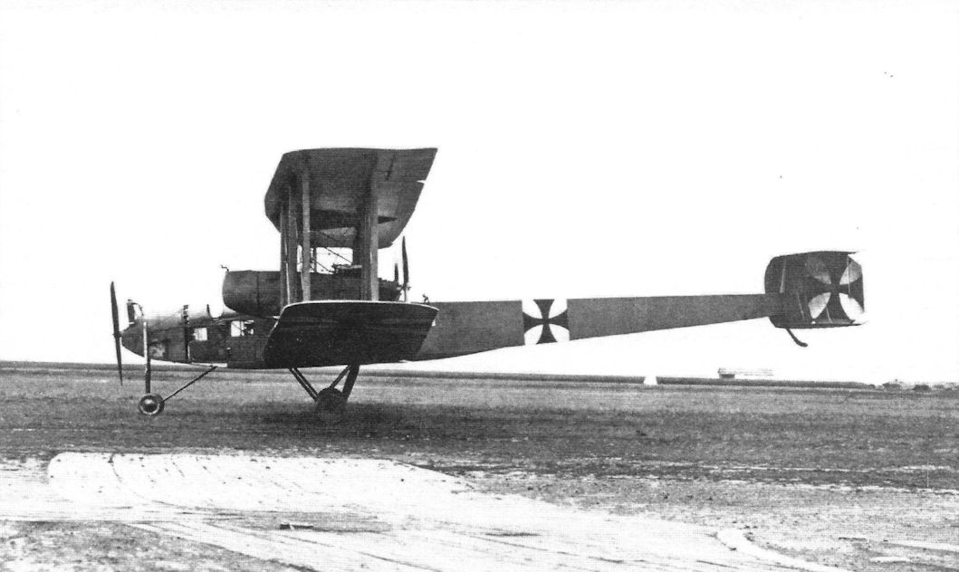
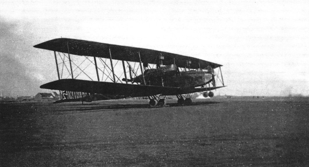
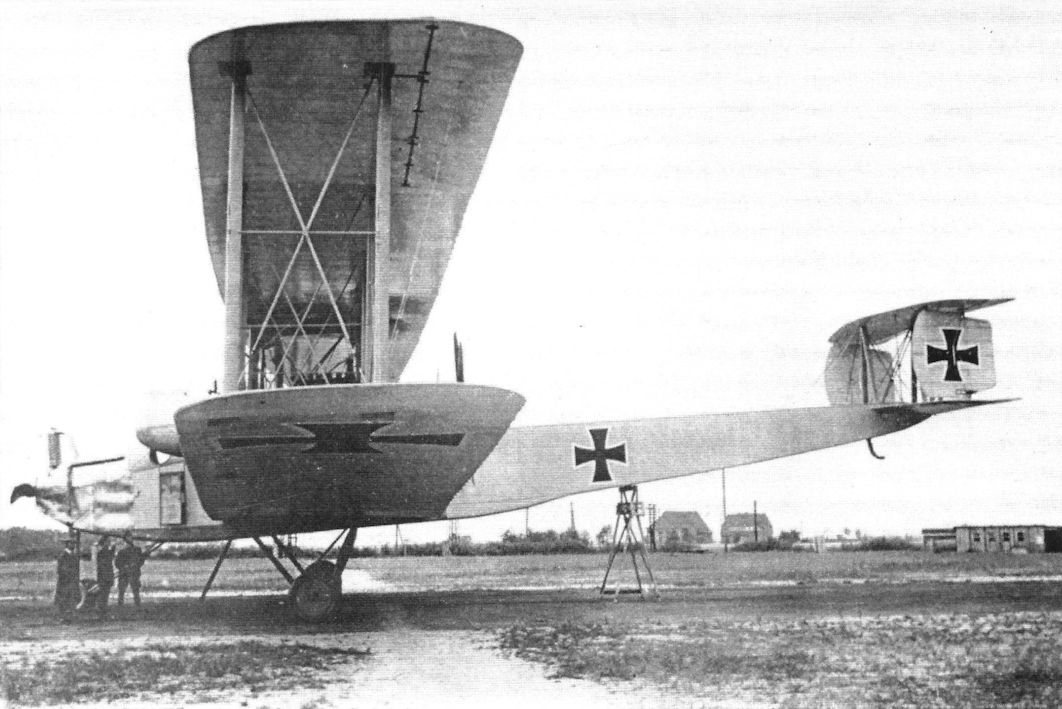
Staaken R.lV 12/15. The only R-plane to see action on both the Eastern and Western Fronts.
R.12 after parachute mounting and new camouflage. The antenna wire seen near bottom machine gun platform show that radio room was located just behind the bomb bay and main fuel tanks. Note the old patee crosses over-painted by black and new Balkenkreuze that were applied. (Peter M. Grosz collection/STDB) -
J.Herris - Zeppelin-Staaken Aircraft of WW1. Vol 1: VGO.1 - R.IV R.29/16 /Centennial Perspective/ (47)
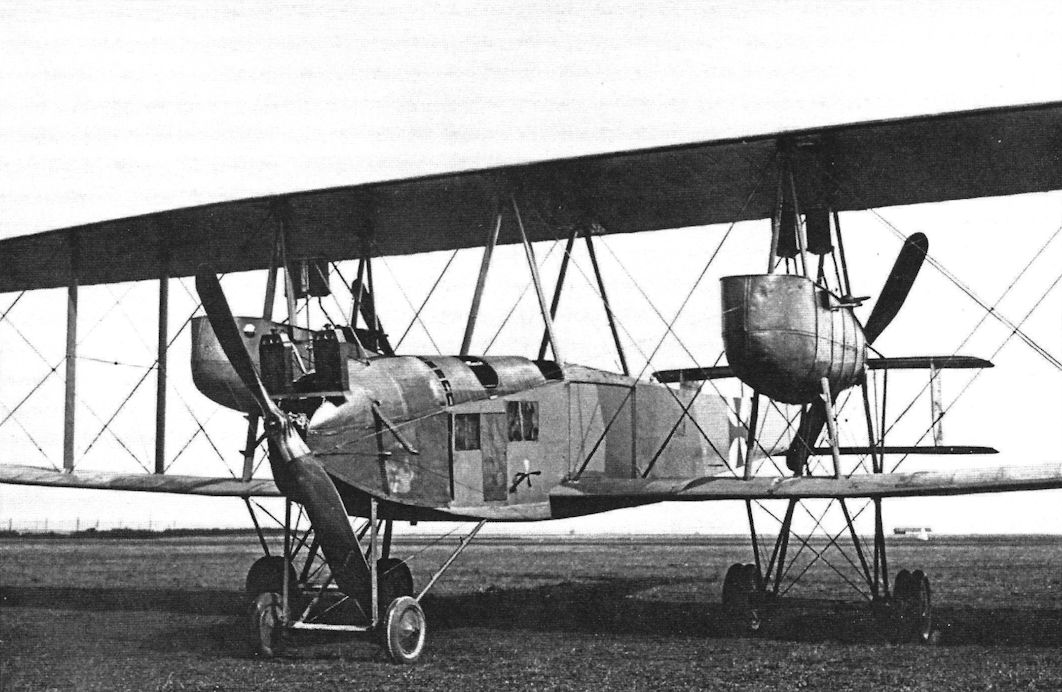
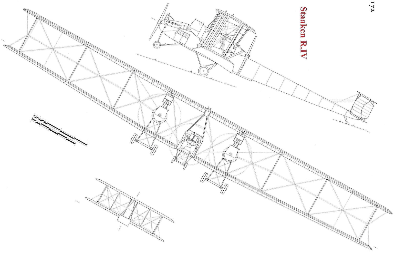
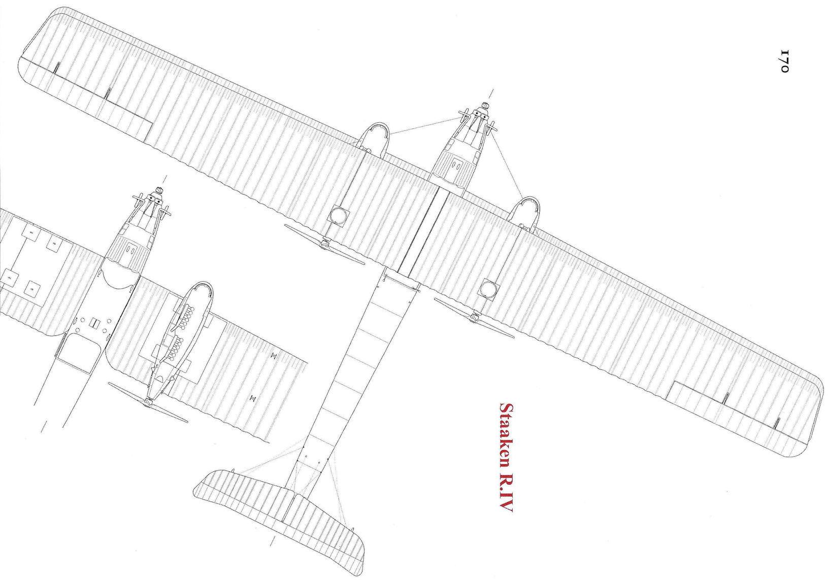
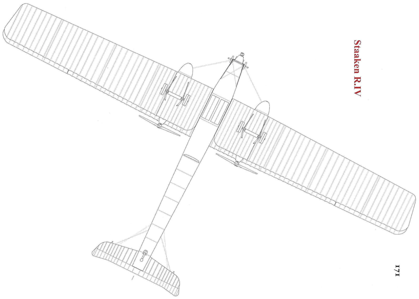
The Staaken R.IV was nearly identical in layout to the VGO.III, although the 160 hp Mercedes engines in the nacelles were replaced by more powerful 220 hp Benz Bz.IV engines. However, the aircraft looks different in this post-war photo due to its dark camouflage for night bombing at Western Front and the late-war style national insignia. (Peter M. Grosz collection/STDB)
-
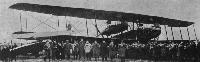
Jane's All The World Aircraft 1919 /Jane's/
The Zeppelin Five-engined "Giant".
-
J.Herris - Zeppelin-Staaken Aircraft of WW1. Vol 1: VGO.1 - R.IV R.29/16 /Centennial Perspective/ (47)
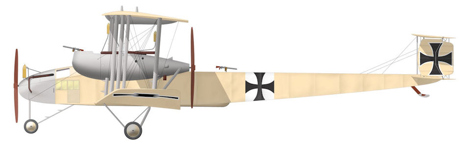
Staaken R.IV 12/15 during service with Rfa 500 on the Eastern Front. It is in its initial construction form without camouflage and with painted black patee crosses on white squares. (Peter M. Grosz collection/STDB)
-
J.Herris - Zeppelin-Staaken Aircraft of WW1. Vol 2: R.VI R.30/16 - E.4/20 /Centennial Perspective/ (48)
Staaken R.IV R.12/15 takes of on another mission.
-
J.Herris - Zeppelin-Staaken Aircraft of WW1. Vol 1: VGO.1 - R.IV R.29/16 /Centennial Perspective/ (47)
The R.12 in flight. (Peter M. Grosz collection/STDB)
-

J.Herris - Zeppelin-Staaken Aircraft of WW1. Vol 1: VGO.1 - R.IV R.29/16 /Centennial Perspective/ (47)
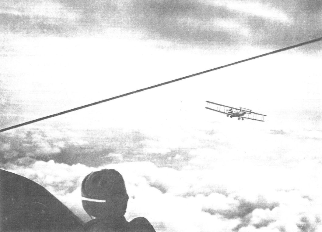
Another Staaken photographed from the Staaken R.IV in flight. (Peter M. Grosz collection/STDB)
-
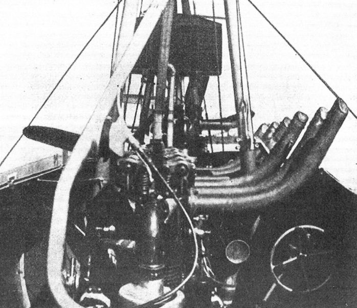
G.Haddow, P.Grosz - The German Giants /Putnam/
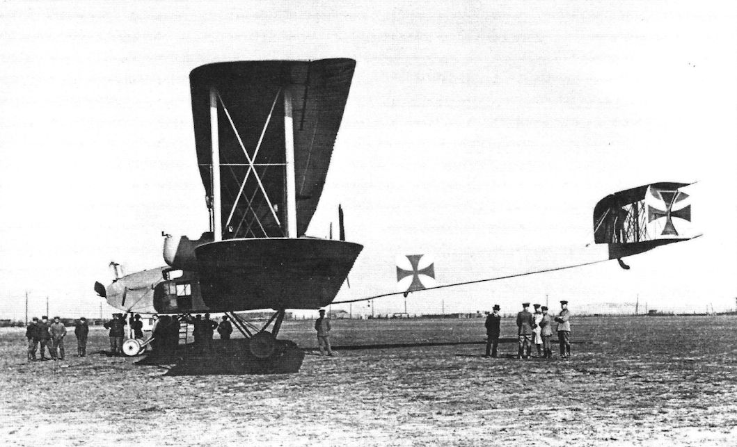
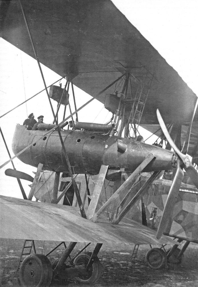
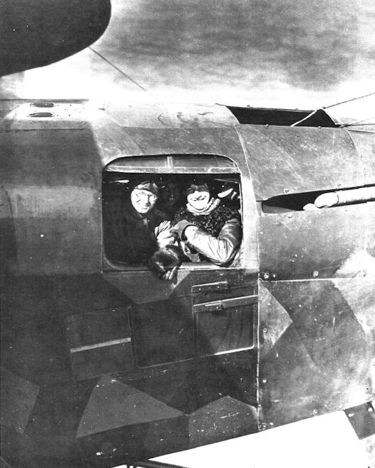
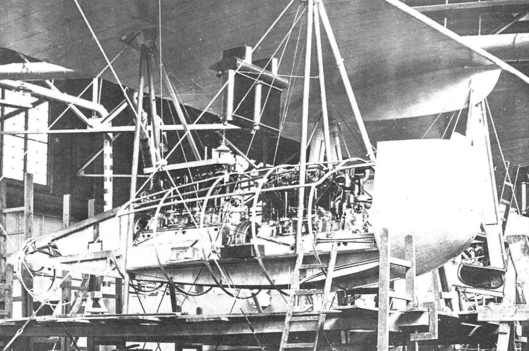
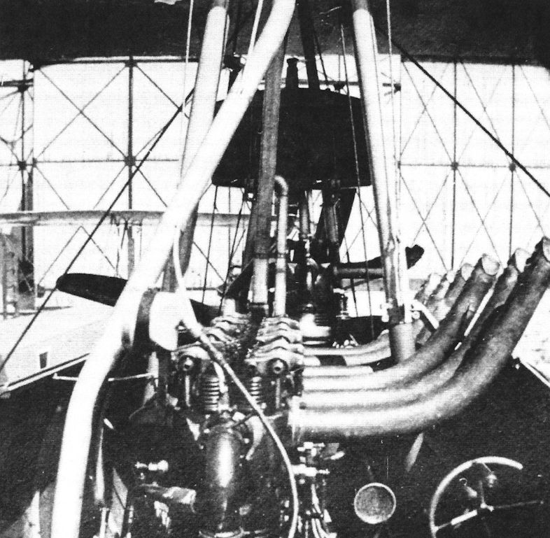
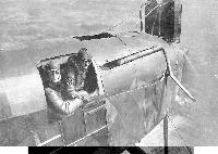
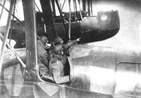
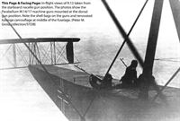
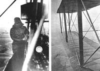
The engineers looking out of the forward eingine-room (engineer compartment) window of German five-engined "Giant" aeroplane Staaken R.IV.
Well-known photograph showing the flight engineers' station for the two front engines. Note two radiators mounted on top of the fuselage, just aft the tractor propeller. (Peter M. Grosz collection/STDB) -
-

-

J.Herris - Zeppelin-Staaken Aircraft of WW1. Vol 1: VGO.1 - R.IV R.29/16 /Centennial Perspective/ (47)
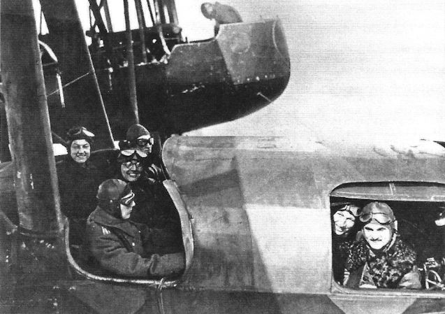
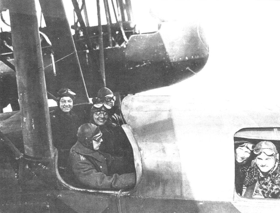
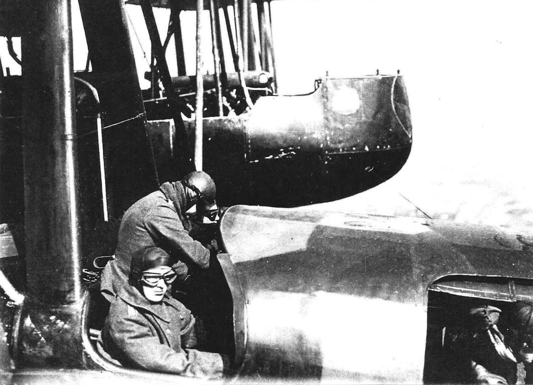
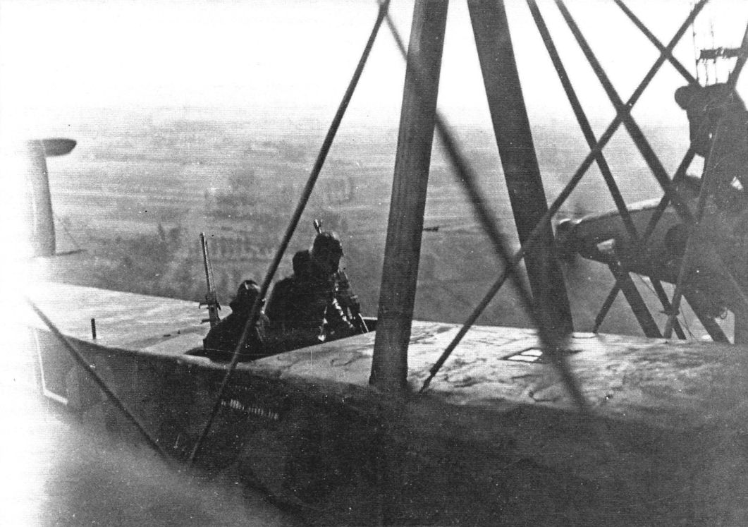
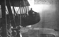
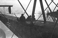
In-flight views of R.12 taken from the starboard nacelle gun position. (Peter M. Grosz collection/STDB)
-

J.Herris - Zeppelin-Staaken Aircraft of WW1. Vol 1: VGO.1 - R.IV R.29/16 /Centennial Perspective/ (47)
In-flight view of the R.12 taken from the starboard nacelle gun position. (Peter M. Grosz collection/STDB)
-

-

J.Herris - Zeppelin-Staaken Aircraft of WW1. Vol 1: VGO.1 - R.IV R.29/16 /Centennial Perspective/ (47)
In-flight view of the R.12 taken from the starboard nacelle gun position. (Peter M. Grosz collection/STDB)
-

-
-
-

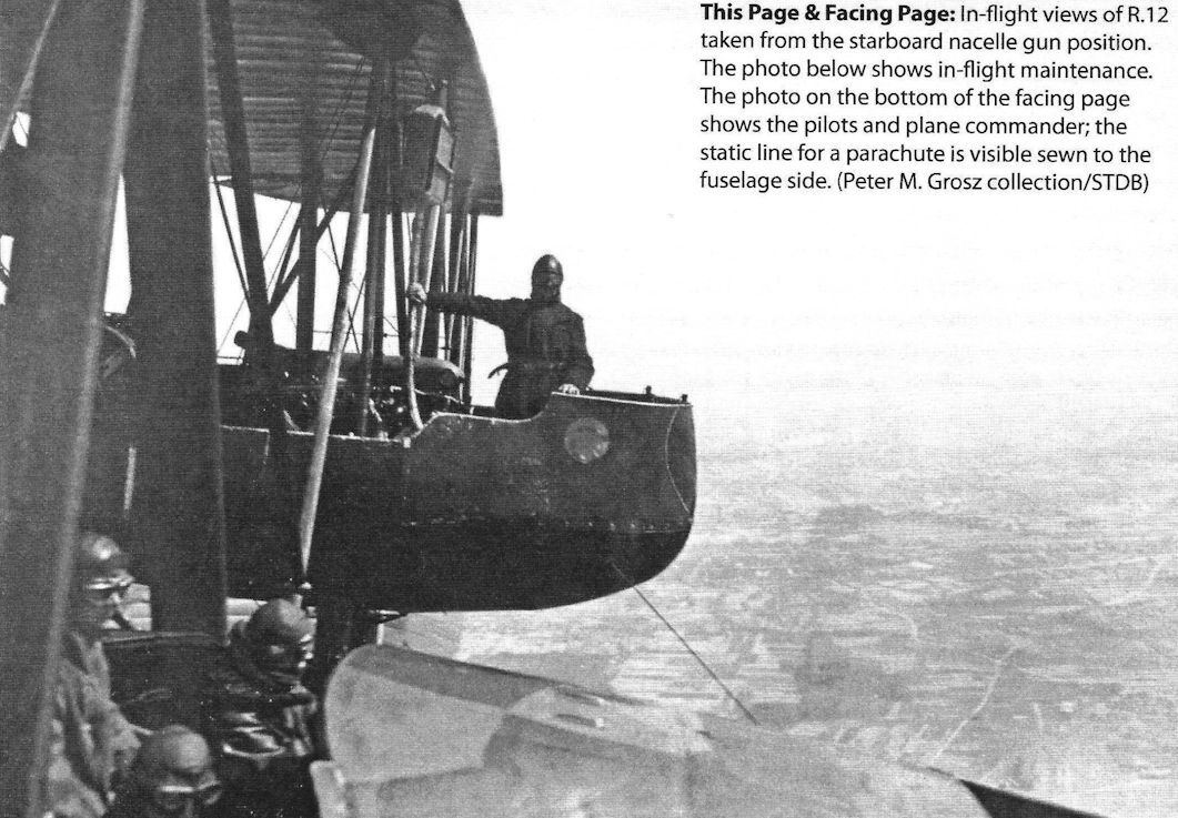
J.Herris - Zeppelin-Staaken Aircraft of WW1. Vol 1: VGO.1 - R.IV R.29/16 /Centennial Perspective/ (47)
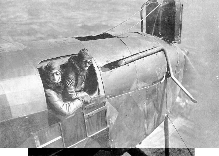
In-flight views of R.12 taken from the starboard nacelle gun position. The photo shows the pilots and plane commander; the static line for a parachute is visible sewn to the fuselage side. (Peter M. Grosz collection/STDB)
-
-
J.Herris - Zeppelin-Staaken Aircraft of WW1. Vol 1: VGO.1 - R.IV R.29/16 /Centennial Perspective/ (47)
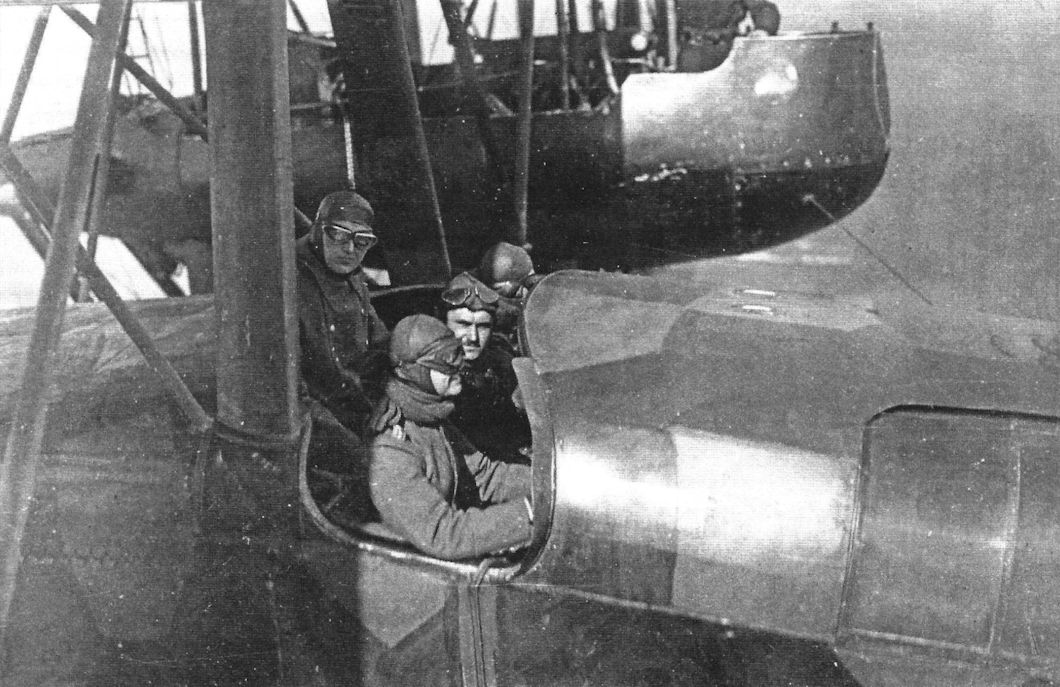
More in-flight views of R.12 taken from the port and starboard nacelle gun positions. (Peter M. Grosz collection/STDB)
-

J.Herris - Zeppelin-Staaken Aircraft of WW1. Vol 1: VGO.1 - R.IV R.29/16 /Centennial Perspective/ (47)
In-flight views of R.12 taken from the starboard nacelle gun position. (Peter M. Grosz collection/STDB)
-

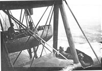
J.Herris - Zeppelin-Staaken Aircraft of WW1. Vol 1: VGO.1 - R.IV R.29/16 /Centennial Perspective/ (47)
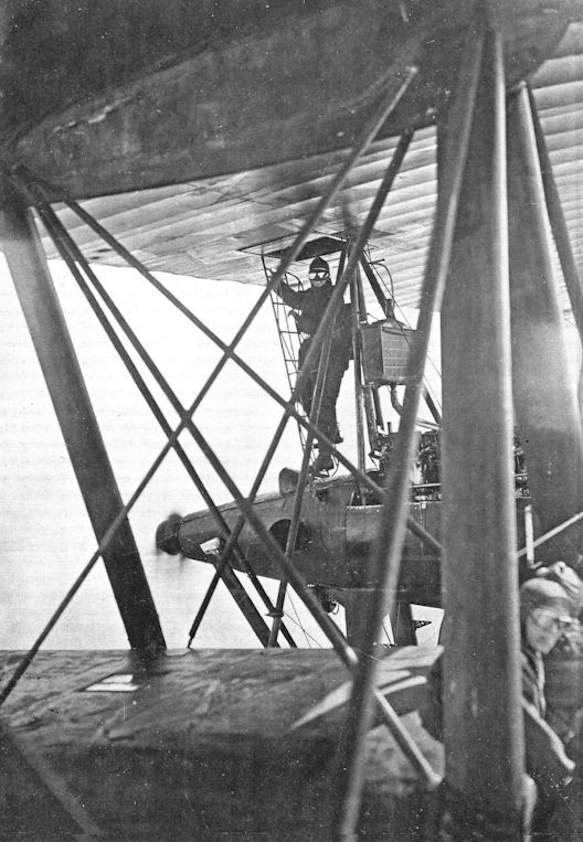
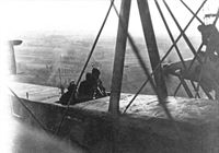
In-flight view of a gunner climbing up to the port over-wing gun position in the R.12. (Peter M. Grosz collection/STDB)
-

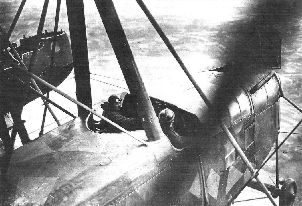
J.Herris - Zeppelin-Staaken Aircraft of WW1. Vol 1: VGO.1 - R.IV R.29/16 /Centennial Perspective/ (47)
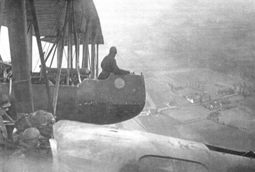
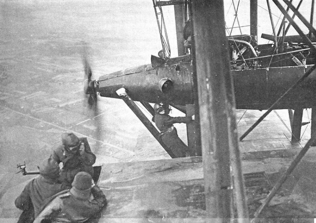
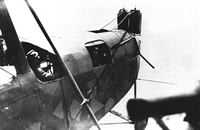
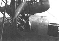
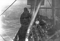
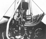
THE NOSE OF A GERMAN GIANT AEROPLANE. - Photograph taken from the port engine nacelle.
In-flight view of the R.12 taken from the starboard nacelle gun position. (Peter M. Grosz collection/ STDB) -
J.Herris - Zeppelin-Staaken Aircraft of WW1. Vol 1: VGO.1 - R.IV R.29/16 /Centennial Perspective/ (47)
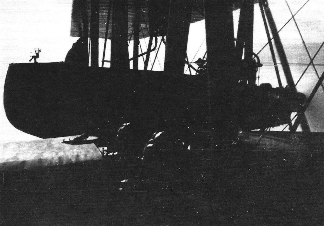
ON BOARD A GERMAN GIANT AEROPLANE. - Photograph showing view looking aft from the port engine nacelle.
-
G.Haddow, P.Grosz - The German Giants /Putnam/
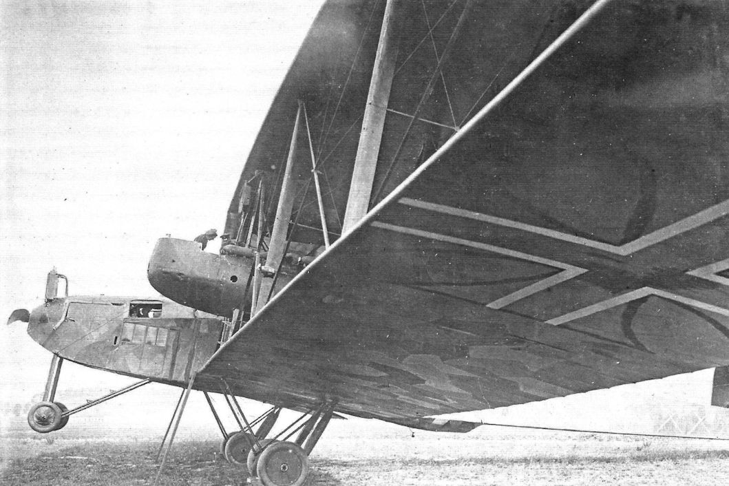
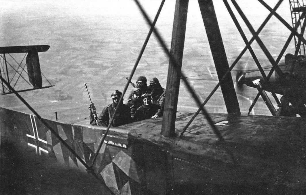
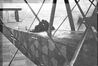
Dorsal gunner's position on the Staaken R.IV.
-
J.Herris - Zeppelin-Staaken Aircraft of WW1. Vol 1: VGO.1 - R.IV R.29/16 /Centennial Perspective/ (47)
In-flight views of R.12 taken from the starboard nacelle gun position. The photos show the Parabellum M.14/17 machine guns mounted at the dorsal gun position. Note the shell bags on the guns and renovated lozenge camouflage at middle of the fuselage. (Peter M. Grosz collection/STDB)
-
J.Herris - Zeppelin-Staaken Aircraft of WW1. Vol 1: VGO.1 - R.IV R.29/16 /Centennial Perspective/ (47)
More in-flight views of R.12 taken from the starboard nacelle gun position. (Peter M. Grosz collection/STDB)
-
-

-

-

J.Herris - Zeppelin-Staaken Aircraft of WW1. Vol 1: VGO.1 - R.IV R.29/16 /Centennial Perspective/ (47)
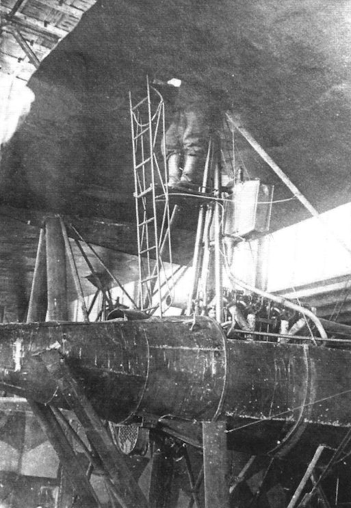
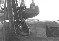
ON BOARD A GERMAN GIANT AEROPLANE. - The mechanic is repairing an oil pump defect during flight. The photograph was taken from the port engine nacelle.
In-flight views of R.12 taken from the starboard nacelle gun position. The photo shows in-flight maintenance. (Peter M. Grosz collection/STDB) -
J.Herris - Zeppelin-Staaken Aircraft of WW1. Vol 1: VGO.1 - R.IV R.29/16 /Centennial Perspective/ (47)
In-flight views of the R.12 taken from the starboard nacelle gun position. (Peter M. Grosz collection/STDB)
-
J.Herris - Zeppelin-Staaken Aircraft of WW1. Vol 1: VGO.1 - R.IV R.29/16 /Centennial Perspective/ (47)
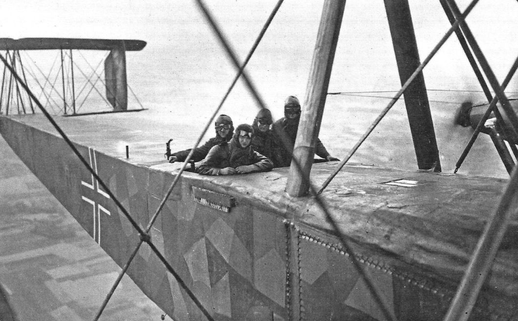
More in-flight views of R.12 taken from the port and starboard nacelle gun positions. (Peter M. Grosz collection/STDB)
-
J.Herris - Zeppelin-Staaken Aircraft of WW1. Vol 1: VGO.1 - R.IV R.29/16 /Centennial Perspective/ (47)
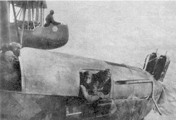
The over-wing gun position on R.12 and the ladder to climb to it. (Peter M. Grosz collection/STDB)
-

J.Herris - Zeppelin-Staaken Aircraft of WW1. Vol 1: VGO.1 - R.IV R.29/16 /Centennial Perspective/ (47)
Right wing upper gun platform. (Peter M. Grosz collection/STDB)
-
J.Herris - Zeppelin-Staaken Aircraft of WW1. Vol 1: VGO.1 - R.IV R.29/16 /Centennial Perspective/ (47)
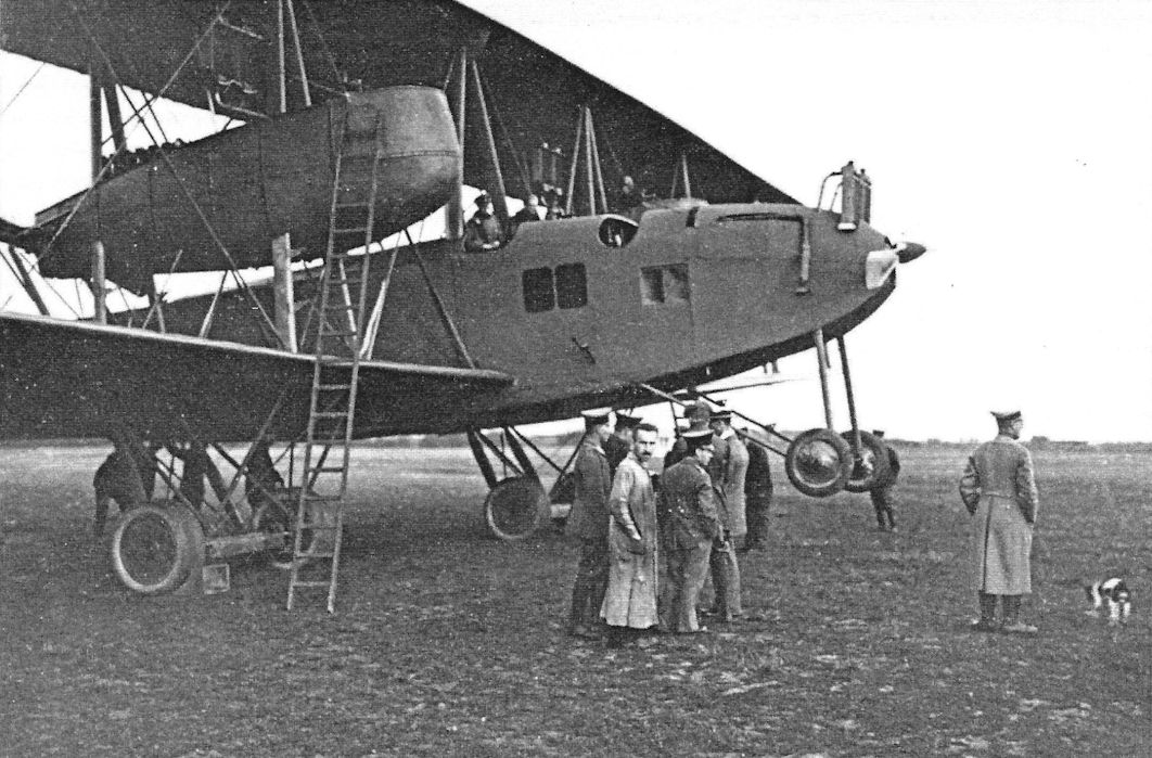
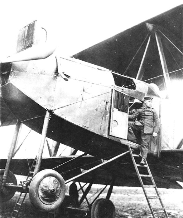
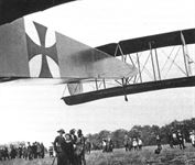
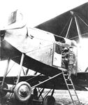
A ZEPPELIN GIANT. - The photograph shows how the fuselage is entered through a door in the side.
Crewman pauses at the R.12 entry door. (Peter M. Grosz collection/STDB) -

J.Herris - Zeppelin-Staaken Aircraft of WW1. Vol 1: VGO.1 - R.IV R.29/16 /Centennial Perspective/ (47)
The camouflaged Staaken R.IV in the hangar.The ventral gun position with British Lewis machine gun is clearly shown. (Peter M. Grosz collection/STDB)
-
J.Herris - Zeppelin-Staaken Aircraft of WW1. Vol 1: VGO.1 - R.IV R.29/16 /Centennial Perspective/ (47)
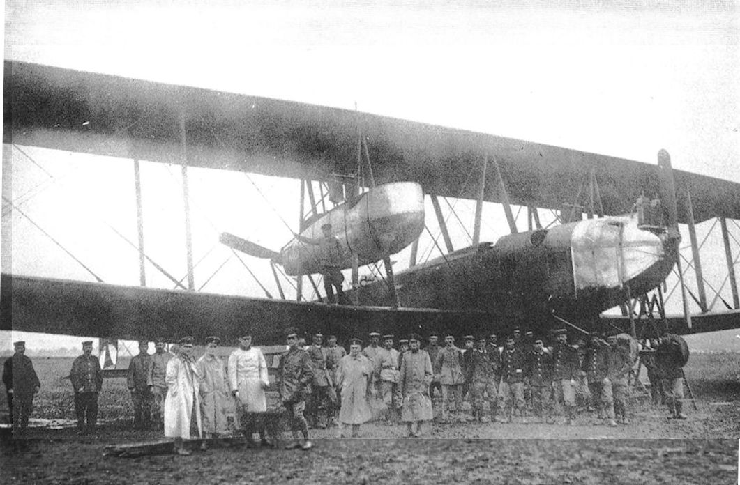
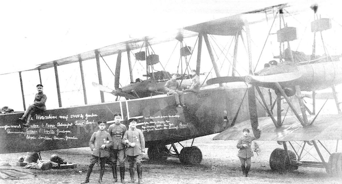
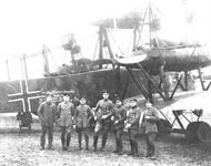
Staaken R.IV R.12/15 was the single most successful R-plane. In this postwar image the crew is photographed with the aircraft at Kassel; the targets, dates of the raids, and total weight of bombs are chalked on the fuselage.
-

J.Herris - Zeppelin-Staaken Aircraft of WW1. Vol 1: VGO.1 - R.IV R.29/16 /Centennial Perspective/ (47)
The Staaken R.IV and its crew at Kassel after the war. The targets attacked, the total weight of bomb dropped and places flown to have been chalked on the fuselage side.
The Staaken R IV 12/15 had the longest operational career of any machine in the R category, and was the only one to be flown on both the Eastern and Western Fronts, from May 1917 until the Armistice. It survived a collision with a balloon cable over London in February 1918 and dropped a total of 25,000kg of bombs. It is seen at Kassel in April 1919 with its fuselage inscribed with the names of the main targets attacked (including London, Harwich, Chelmsford, Oesel Island (Baltic), Calais, Abbeville, Boulogne, Etaples, Doullens and Amiens) and the routeing of several long-distance flights occasioned by ferrying from one theatre of operations to another; eg, Gotha-Doeberitz-Koenigsberg-Riga. -
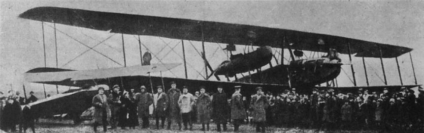
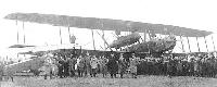
Jane's All The World Aircraft 1919 /Jane's/
Three-quarter Front View of a Zeppelin Five-engined "Giant" bomber, probably one of the R.XIVs or XVs of 1918.
-
G.Haddow, P.Grosz - The German Giants /Putnam/
The Staaken R.lV on display to awed crowds in Kassel postwar, April 1919. (Peter M. Grosz collection/STDB)
-
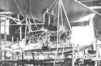
J.Herris - Zeppelin-Staaken Aircraft of WW1. Vol 1: VGO.1 - R.IV R.29/16 /Centennial Perspective/ (47)
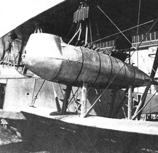
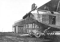
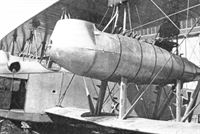
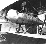
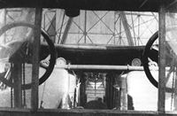
R.IV during assembly. At front or the picture not completed engines nacelle. Note the characteristic for Staaken nacelles, wooden bed for two engines coupled in one gearbox with light aluminium rib structure holding aluminum covers. Initial of radiators are visible, after first flights these were changed for better Hans Window type. (Peter M. Grosz collection/STDB)
-
J.Herris - Zeppelin-Staaken Aircraft of WW1. Vol 2: R.VI R.30/16 - E.4/20 /Centennial Perspective/ (48)
The Staaken R.VII on its factory airfield with admirers. (Peter M. Grosz collection/STDB)
-

J.Herris - Zeppelin-Staaken Aircraft of WW1. Vol 1: VGO.1 - R.IV R.29/16 /Centennial Perspective/ (47)
Staaken R.26/16 at right and R.VII R.14 on the left. (Peter M. Grosz collection/STDB)
Другие самолёты на фотографии: Zeppelin-Staaken R.VI - Германия - 1917
-
J.Herris - Zeppelin-Staaken Aircraft of WW1. Vol 2: R.VI R.30/16 - E.4/20 /Centennial Perspective/ (48)
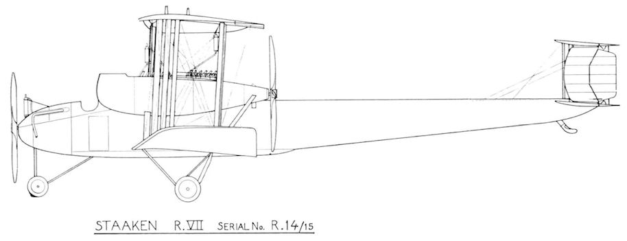
The Staaken R.VII R.14/15 reverted to the configuration of the R.IV and for practical purposes could have been considered an R.IV. However, whereas the R.IV was the most successful R-plane of the war, the R.VII was destroyed in a take-off accident while enroute to the front on August 16, 1917. (Peter M. Grosz collection/STDB)
-
J.Herris - Zeppelin-Staaken Aircraft of WW1. Vol 2: R.VI R.30/16 - E.4/20 /Centennial Perspective/ (48)
The Staaken R.VII on its factory airfield with admirers. (Peter M. Grosz collection/STDB)
-
J.Herris - Zeppelin-Staaken Aircraft of WW1. Vol 2: R.VI R.30/16 - E.4/20 /Centennial Perspective/ (48)
The Staaken R.VII on its field being viewed by VIPs. (Peter M. Grosz collection/STDB)
-
J.Herris - Zeppelin-Staaken Aircraft of WW1. Vol 2: R.VI R.30/16 - E.4/20 /Centennial Perspective/ (48)
The Staaken R.VII being viewed by a crowd of admirers. The nose engines drive a 2-bladed propeller. No camouflage has yet been applied. The radiators for the nacelle engines are separate with the forward radiator above the rear radiator. These unstreamlined radiators generated a lot of drag. (Peter M. Grosz collection/STDB)
-
J.Herris - Zeppelin-Staaken Aircraft of WW1. Vol 2: R.VI R.30/16 - E.4/20 /Centennial Perspective/ (48)
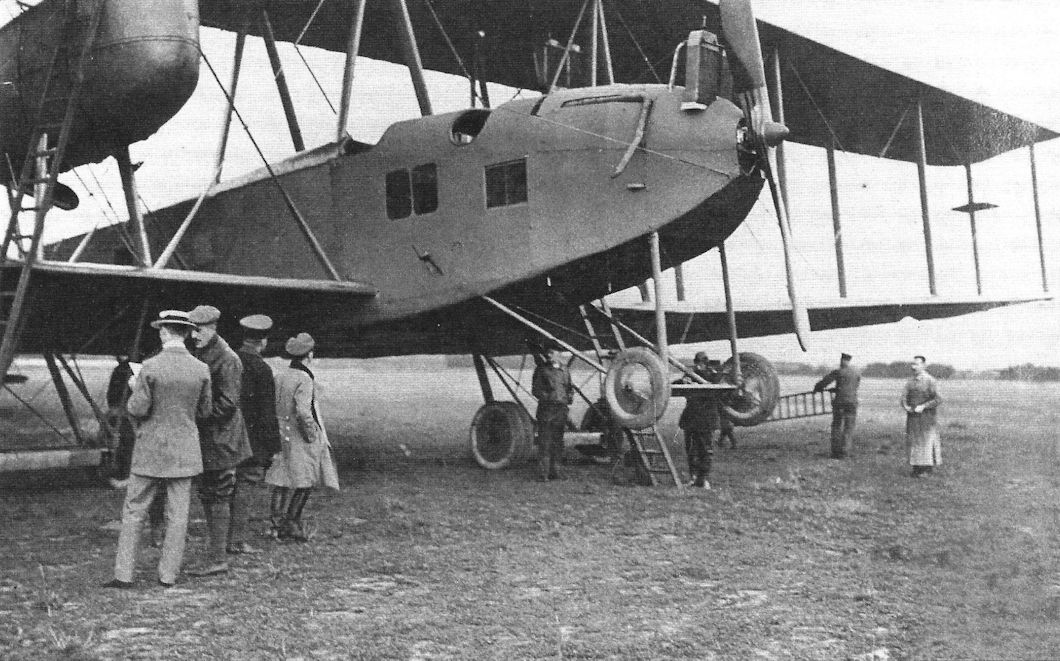
The Staaken R.VII (R.14/16) reverted to the configuration of the R.IV although some details were different. Here it is shown at the factory after completion. (Peter M. Grosz collection/STDB)
-

J.Herris - Zeppelin-Staaken Aircraft of WW1. Vol 2: R.VI R.30/16 - E.4/20 /Centennial Perspective/ (48)
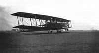
The Staaken R.VII on its field. (Peter M. Grosz collection/STDB)
-
J.Herris - Zeppelin-Staaken Aircraft of WW1. Vol 2: R.VI R.30/16 - E.4/20 /Centennial Perspective/ (48)
The Staaken R.VII runs up its nose-mounted engines. (Peter M. Grosz collection/STDB)
-
J.Herris - Zeppelin-Staaken Aircraft of WW1. Vol 2: R.VI R.30/16 - E.4/20 /Centennial Perspective/ (48)
Front view of the Staaken R.VII. The people viewing the aircraft give scale to its huge size. (Peter M. Grosz collection/STDB)
-
J.Herris - Zeppelin-Staaken Aircraft of WW1. Vol 2: R.VI R.30/16 - E.4/20 /Centennial Perspective/ (48)
The Staaken R.VII on its field photographed from beyond the airfield fence. (Peter M. Grosz collection/STDB)
-
J.Herris - Zeppelin-Staaken Aircraft of WW1. Vol 2: R.VI R.30/16 - E.4/20 /Centennial Perspective/ (48)
The completed Staaken R.VII being admired by VIPs. The nose engines now drive a 4-bladed propeller. The aircraft is resting on its tail skid. The nose engine radiators are prominent and drag producing. (Peter M. Grosz collection/STDB)
-

J.Herris - Zeppelin-Staaken Aircraft of WW1. Vol 2: R.VI R.30/16 - E.4/20 /Centennial Perspective/ (48)
The Staaken R.VII runs up its engines. (Peter M. Grosz collection/STDB)
-

J.Herris - Zeppelin-Staaken Aircraft of WW1. Vol 2: R.VI R.30/16 - E.4/20 /Centennial Perspective/ (48)
The Staaken R.VII with 4-bladed nose engines. The radiators are in out in the slip-stream for maximum cooling. (Peter M. Grosz collection/STDB)
-
J.Herris - Zeppelin-Staaken Aircraft of WW1. Vol 2: R.VI R.30/16 - E.4/20 /Centennial Perspective/ (48)
The Staaken R.VII (R.14/16) on its field. (Peter M. Grosz collection/STDB)
-

J.Herris - Zeppelin-Staaken Aircraft of WW1. Vol 2: R.VI R.30/16 - E.4/20 /Centennial Perspective/ (48)
The Staaken R.VII runs up its engines. (Peter M. Grosz collection/STDB)
-

J.Herris - Zeppelin-Staaken Aircraft of WW1. Vol 2: R.VI R.30/16 - E.4/20 /Centennial Perspective/ (48)
The completed Staaken R.VII being viewed by admirers. (Peter M. Grosz collection/STDB)
-
J.Herris - Zeppelin-Staaken Aircraft of WW1. Vol 2: R.VI R.30/16 - E.4/20 /Centennial Perspective/ (48)
The Staaken R.VII in close-up at the factory. (Peter M. Grosz collection/STDB)
-
J.Herris - Zeppelin-Staaken Aircraft of WW1. Vol 2: R.VI R.30/16 - E.4/20 /Centennial Perspective/ (48)
The Staaken R.VII in close-up at the factory. (Peter M. Grosz collection/STDB)
-
J.Herris - Zeppelin-Staaken Aircraft of WW1. Vol 2: R.VI R.30/16 - E.4/20 /Centennial Perspective/ (48)
The Staaken R.VII details. (Peter M. Grosz collection/STDB)
-
J.Herris - Zeppelin-Staaken Aircraft of WW1. Vol 2: R.VI R.30/16 - E.4/20 /Centennial Perspective/ (48)
The Staaken R.VII provides the background for a portrait of Staaken staff. (Peter M. Grosz collection/STDB)
-
J.Herris - Zeppelin-Staaken Aircraft of WW1. Vol 2: R.VI R.30/16 - E.4/20 /Centennial Perspective/ (48)
In flight photo of the Staaken R.VII taken from its starboard engine nacelle toward the tail. (Peter M. Grosz collection/STDB).
-
-

J.Herris - Zeppelin-Staaken Aircraft of WW1. Vol 2: R.VI R.30/16 - E.4/20 /Centennial Perspective/ (48)
Photo of the port engine nacelle of the Staaken R.VII taken from within the nacelle.The tail is in the left background. (Peter M. Grosz collection/ STDB)
-
J.Herris - Zeppelin-Staaken Aircraft of WW1. Vol 1: VGO.1 - R.IV R.29/16 /Centennial Perspective/ (47)
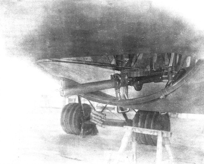
Engine nacelle of a Staaken bomber.
-
J.Herris - Zeppelin-Staaken Aircraft of WW1. Vol 2: R.VI R.30/16 - E.4/20 /Centennial Perspective/ (48)
The Staaken R.VII details. (Peter M. Grosz collection/STDB)
-

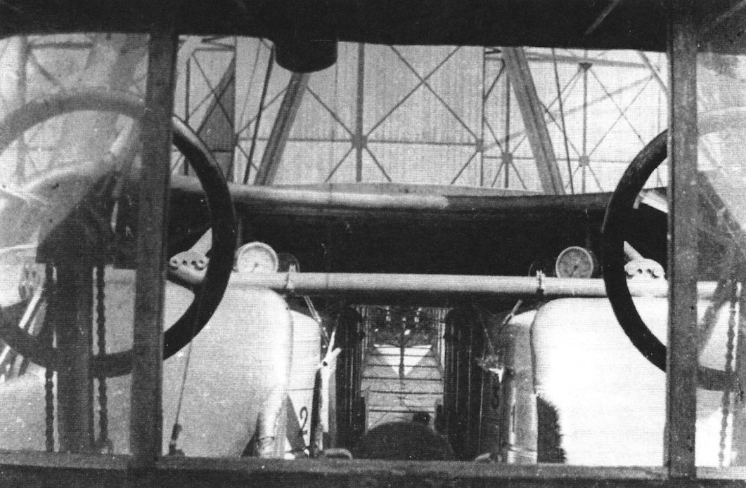
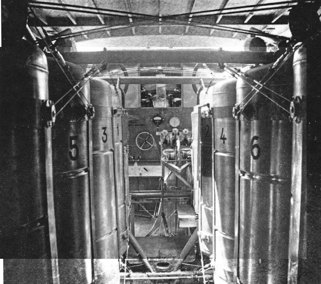
J.Herris - Zeppelin-Staaken Aircraft of WW1. Vol 2: R.VI R.30/16 - E.4/20 /Centennial Perspective/ (48)
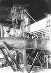
245 liter fuel tanks installed in a Staaken R.VII bomber. Note that each fuel tank has a painted number; it was important for the flight engineer to correctly distribute fuel during the flight to maintain the center of gravity. (Peter M. Grosz collection/STDB)
-
J.Herris - Zeppelin-Staaken Aircraft of WW1. Vol 1: VGO.1 - R.IV R.29/16 /Centennial Perspective/ (47)
Drawing of the nose engines installed in the Staaken R.IV.
-
J.Herris - Zeppelin-Staaken Aircraft of WW1. Vol 1: VGO.1 - R.IV R.29/16 /Centennial Perspective/ (47)
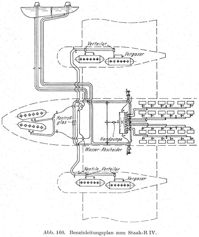
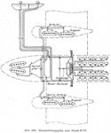
Diagram of the fuel system of the Staaken R.IV.
-

J.Herris - Zeppelin-Staaken Aircraft of WW1. Vol 1: VGO.1 - R.IV R.29/16 /Centennial Perspective/ (47)
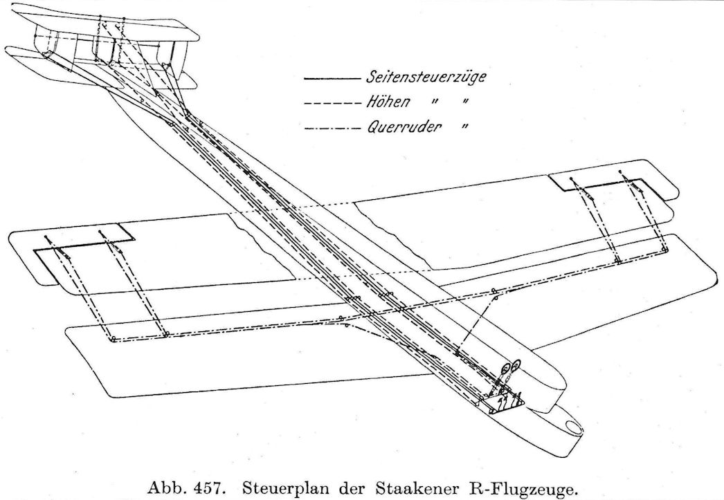
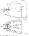
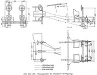
Diagram of the control system of the Staaken R.IV.
-
J.Herris - Zeppelin-Staaken Aircraft of WW1. Vol 1: VGO.1 - R.IV R.29/16 /Centennial Perspective/ (47)
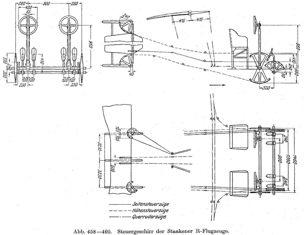
Diagram of the control system details of the Staaken R.IV.
-
J.Herris - Zeppelin-Staaken Aircraft of WW1. Vol 2: R.VI R.30/16 - E.4/20 /Centennial Perspective/ (48)
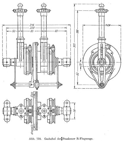
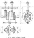
Throttles and engine clutch for paired Staaken engines.
-
J.Herris - Zeppelin-Staaken Aircraft of WW1. Vol 2: R.VI R.30/16 - E.4/20 /Centennial Perspective/ (48)
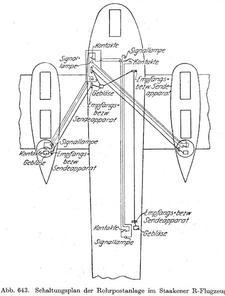
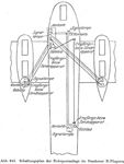
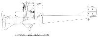
Electro-pneumatic communication tube diagram for the Staaken R-planes.
-
-
G.Haddow, P.Grosz - The German Giants /Putnam/
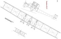
Staaken R.IV
-
G.Haddow, P.Grosz - The German Giants /Putnam/
Staaken R.VII
-
-
-
В.Кондратьев Самолеты первой мировой войны
МОДИФИКАЦИИ
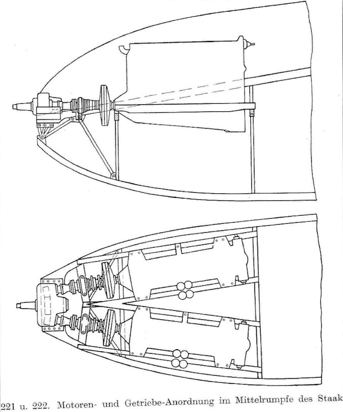
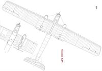
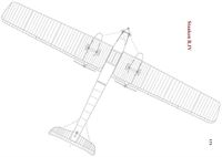
VGO-III и "Цеппелин-Штаакен" R-IV. Силовая установка этих машин состояла из шести двигателей в трех спарках. В каждой мотогондоле VGO-III стояли по два 160-сильных "Мерседеса" D.III на одном валу, а в носовой части фюзеляжа - два таких мотора, установленные бок о бок с общим редуктором. На R-IV таким же образом были смонтированы шесть 220-сильных двигателей "Бенц" Bz.IV. Вооружение - 4-5 пулеметов: 2 в носовых законцовках гондол и 2-3 в фюзеляжных люковых установках за крылом. Бомбовая нагрузка - до 1000 кг. Экипаж - 7-8 человек. В 1916-1917 годах VGO-III и R-IV применялись на русско-германском фронте, в Прибалтике. Летом 1917-го R-IV переведен на западный фронт и до весны следующего года участвовал в налетах на Лондон.
Четырехлопастные винты на R-V приводились в движение пятью моторами "Майбах" Mb.IV по 240 л.с. (1 в носу и 2 спарки в гондолах). В фюзеляже R-VII стояли 2 "Мерседеса" по 160 л.с., а в гондолах - 4 "Бенца" по 220 л.с. Обе машины в 1917 году отправили на западный фронт. R-VII разбился по дороге, а R-V некоторое время использовался в качестве ночного бомбардировщика.
Описание: