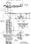
G.Swanborough, P.Bowers United States Navy Aircraft Since 1911 (Putnam)
Aeromarine 39-A, 39-B
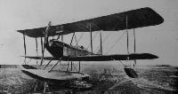
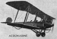
In 1917 the Navy placed with the Aeromarine Plane and Motor Company of Keyport, NJ, what was at that time the largest single order for Navy aircraft - 50 of the Model 39-A and 150 39-B trainers. These were conventional two-bay wood and fabric biplanes and could be fitted with wheels or floats. The 39-As used the four-cylinder Hall-Scott A-7A engine of 100 hp and the seaplane versions had twin wooden floats. The 39-B was powered by the 100 hp Curtiss OXX-6 engine, the seaplanes having the single main pontoon with small wingtip floats for stability which the Navy preferred for its training and service seaplanes and was to retain until seaplane trainers were dropped from the inventory in 1960.
A number of the 39-Bs survived World War I, and two were used for the Navy's early experiments in deck landing. Various types of arrester gear were tried on a dummy carrier deck at Langley Field, Virginia, in 1921. The aeroplane was fitted with the forerunner of the modern hook that engaged the cross-deck arrester cables, while alignment hooks were fitted to the undercarriage to engage longitudinal wires on the deck to keep the machine running straight. In anticipation of forced landings at sea in the course of later operations from shipboard, a hydrovane was fitted ahead of the wheels to prevent nosing over on alighting.
On October 26, 1922, a 39-B piloted by Lt Cdr Geoffrey DeChevalier, Naval Aviator No.7, made the first landing on the deck of the Navy's first aircraft carrier, the USS Langley, a converted collier. This was nine days after the first take-off had been made in a Vought VE-7.
TECHNICAL DATA (Aeromarine 39-A)
Manufacturer: Aeromarine Plane and Motor Company, Keyport, NJ.
Type: Training biplane.
Accommodation: Two pilots.
Показать полностью
Jane's All The World Aircraft 1919
AEROMARINE, PRIMARY TRAINING (ARMY).
Type of machine Land machine.
Name or type No. of machine Model M.L.
Span 37 ft. 3 in.
Overall length 25 ft. 11 In.
Overall height 12 ft. 4 in.
Total wing area 430 sq. ft.
Weight, loaded 2.050 lbs.
Dihedral (top and bottom) 1 degree.
Sweep back None.
Stagger 12 In.
Decalage 1 degree.
Gap 6 ft. 6 in.
Chord 6 ft. 3 In.
Aileron area (two ailerons) 56 sq. ft.
Rudder area 13 ft.
Elevator area (two elevators) 21 sq. ft.
Stabilizer area 33 sq. ft.
Upper plane
Span 37 It. 3 In.
Chord 6 ft. 3 In.
Area (not Including ailerons) 194 sq. ft.
Lower plane
Span 32 ft. 10 in.
Chord 6ft. 3In.
Area 180 sq. ft.
The Aeromarine Model .M L. is a two-place land machine, equipped with the Aeromarine Model L. (6-cylinder) motor.
Seating Arrangement. The seats are arranged in tandem, and controls can be had in either or both cockpits.
Performance.
High speed 90 miles per hour.
Landing speed 42 miles per hour.
Climb 6.000 feet in 10 minutes.
Price: $8,250
Показать полностью
Журнал Flight
Flight, August 2, 1917.
THE AEROMARINE TRAINING TRACTOR BIPLANES.
WHATEVER critics may have to say as regards American high-speed warplanes, it cannot be said that America has not produced some really good machines suitable for training, sporting and similar purposes. Most of the American aircraft firms have, in fact, each one or more designs of this type included in their range of models listed. There should, therefore, be plenty of machines available for the training of that "umpteen-thousand" aviators it is suggested to send over to Europe.
The other week we described the Burgess training machine, and this week we give particulars of the Aeromarine land and water machines, built by the Aeromarine Plane and Motor Co., at Keyport, N.J., U.S.A. Except that the seaplane has a larger wing area, these two types differ only in dimensions and minor details, so that the following notes apply equally to both machines. The designs were got out by Mr. Charles F. Willard, special attention being given to producing, a machine, which, whilst being light and simple in construction, will be capable of withstanding the abnormal strains imposed upon machines of this type.
The main planes are in four sections, two upper and two lower, the former being attached to two pairs of inverted V cabanes, and the latter being secured to the fuselage. Both top and bottom planes are set at a dihedral angle of 1°, and the top plane is staggered forward 1 ft. 6 ins. R.A.F. No. 6 wing-section is employed. The main spars are of I section and the ribs, which are spaced about 1 ft. apart, have the same section, being built up with lightened webs reinforced between the lightening holes to provide against shear. The leading edge is stiffened by a thin veneer to maintain the curvature. The whole of the wing framework is wire braced, and solid wood compression members relieve the main ribs of strains due to drift. The covering is raw Irish linen, having equal strength both in warp and weft, weighing 4 oz. per sq. yard. It is laid diagonally on the wing, with seams lapped and double sewed, and covered with linen tape as a protection from the weather. The fabric is given from three to five coats of dope and a final coat of varnish.
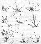
Two pairs of struts on each side of the fuselage separate the top and bottom planes. These struts are hollowed, dovetail jointed and wrapped at five points with linen thread. Their section and proportions have been based upon data obtained from a series of tests on full-sized models. The interplane strut fittings have been designed so that no bolts pass through the spars. One of these fittings was illustrated in "FLIGHT" for March 15th last on page 250. Comparatively large ailerons, of the interconnected type, are hinged to the rear spars of the top plane.
The tail surfaces consist of a divided double cambered stabilising plane mounted on either side of the fuselage, two elevator flaps attached to the trailing edge of the stabilizing plane by four hinges, and a balanced rudder of streamline section mounted between the elevator flaps. The stabilizer sections are easily detachable from the fuselage, being mounted in sockets running through the latter. It is built up of I section spars and ribs, whilst the elevator and rudder frames are of steel tubing with spruce ribs. The steel tube rudder post is attached to a pressed steel stern post on the fuselage. All control surfaces are covered with the same material as the main planes.
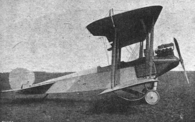
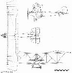
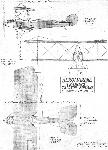
In designing the fuselage special attention has been given to the easy replacement, in case of breakage, of the various parts. The fuselage is of rectangular section, tapering to a vertical knife-edge at the rear. It has a turtle deck top, the portion aft of the cockpits being detachable. The longerons are of large section spruce, lightened by channelling wherever possible. The struts are also of spruce, and the whole structure is strongly wire braced. As on the main planes, the fittings are designed so that no bolts pass through the longerons. The engine mounting is of steel throughout, and is exceptionally strong and light. The forward portion of the fuselage is covered with sheet aluminium, and the remainder with fabric. Two cockpits, in tandem, are provided, the front one for the pupil and the rear one for the pilot. Dual Dep. control is installed, and both cockpits are provided with a full complement of instruments. The fuel tanks are placed alongside the occupant of the front seat, and are filled from the outside. The overall length of the fuselage is 22 ft. 6 ins., and the maximum width and depth 2 ft. 6ins. and 3 ft. 6 ins. respectively. The engine is either a Hall-Scott "A7a" 100 h.p. - as shown in the photographic reproductions - or the Aeromarine 100 h.p. 8-cyl. V, as shown in the scale drawings. In either case, however, the radiators are mounted on the sides of the fuselage.
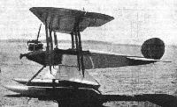
In the land machine the undercarriage is of the conventional V type, designed, as far as possible, with parts interchangeable, so that repairs are easily effected. The seaplane is fitted with a pair of long pontoon floats, arranged catamaran fashion. They are each 16 ft. 6 ins. long, 2 ft. 6 ins. beam, and 1 ft. 5 ins. deep, and have V bottoms and semi-circular tops. Located 7 ft. 6 ins. from the stern of each pontoon is a 3-in. step, with air leads built in to reduce the vaccum at this point. The floats are constructed of spruce, ash and mahogany, the hull consisting of double diagonal planking with fabric in between. They are divided into several water-tight bulkheads. Three pairs of struts connect the floats with the fuselage, and in addition a strut is carried from the floats up to the lower planes immediately under the inner pair of interplane struts. A small float is mounted under the tail.
Показать полностью
