
Книги
Журнал
Flight за 1917 г.
358
Журнал - Flight за 1917 г.
Flight, April 26, 1917.
THE "TOTALLY ENCLOSED" AEROPLANE.
<...>
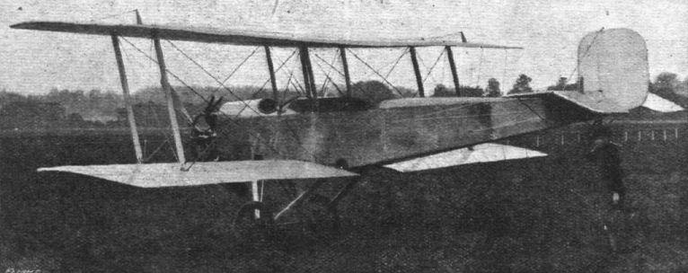
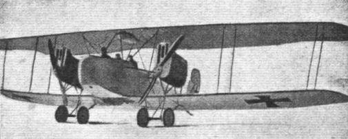
During the spring and summer of 1912 the Austrian Etrich firm built and experimented with an enclosed monoplane of the Taube type. As our illustration shows, this machine was very similar in general arrangement to the ordinary Etrich taube, with the exception that the body had been made considerably more roomy. Constructionally the body was of the girder type with a superstructure giving the covering an elliptical form in section. Windows of non-inflammable material were provided in the sides and nose, and as the engine was mounted very high up in the body, the view forward and downward was exceptionally free, considering that the machine was of the tractor type. The two seats were placed one behind the other, and the pilot occupied the rear one. Apart from the fact of it being enclosed, this monoplane was a departure from standard practice in other respects. For instance, the under-carriage was of the simple Vee type that is so popular on modern machines, but which had not become generally adopted at that time. The wings, which had the usual back swept and upturned tips characteristic of the taube, were attached to the body by a single tubular pivot, and provisions had been made for varying the angle of incidence during flight. This was accomplished by rotating a wheel mounted in the body to the right of the pilot.
For some reason no more machines of this type were built by the Etrich firm, whether this is due to the enclosed feature or to other causes. Probably the reason was that, like so many others, this new departure had too many unknown factors. On the face of it, it would appear that the centre of thrust was too high, being approximately in line with the intersection of the chord line and the resultant, while the centre of resistance of the body and that of the under-carriage were some distance below this point.
THE "TOTALLY ENCLOSED" AEROPLANE.
<...>
During the spring and summer of 1912 the Austrian Etrich firm built and experimented with an enclosed monoplane of the Taube type. As our illustration shows, this machine was very similar in general arrangement to the ordinary Etrich taube, with the exception that the body had been made considerably more roomy. Constructionally the body was of the girder type with a superstructure giving the covering an elliptical form in section. Windows of non-inflammable material were provided in the sides and nose, and as the engine was mounted very high up in the body, the view forward and downward was exceptionally free, considering that the machine was of the tractor type. The two seats were placed one behind the other, and the pilot occupied the rear one. Apart from the fact of it being enclosed, this monoplane was a departure from standard practice in other respects. For instance, the under-carriage was of the simple Vee type that is so popular on modern machines, but which had not become generally adopted at that time. The wings, which had the usual back swept and upturned tips characteristic of the taube, were attached to the body by a single tubular pivot, and provisions had been made for varying the angle of incidence during flight. This was accomplished by rotating a wheel mounted in the body to the right of the pilot.
For some reason no more machines of this type were built by the Etrich firm, whether this is due to the enclosed feature or to other causes. Probably the reason was that, like so many others, this new departure had too many unknown factors. On the face of it, it would appear that the centre of thrust was too high, being approximately in line with the intersection of the chord line and the resultant, while the centre of resistance of the body and that of the under-carriage were some distance below this point.
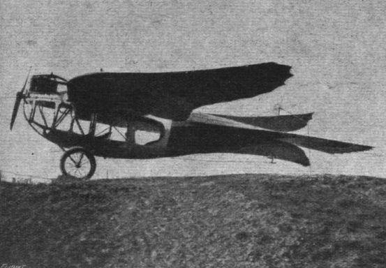
The enclosed Etrich Taube, built and flown in Austria in 1912.

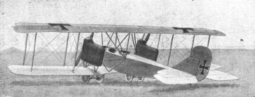
A batch of Hungarian Lloyd biplanes.
Flight, April 26, 1917.
THE "TOTALLY ENCLOSED" AEROPLANE.
IT has already been recorded that at the Aero Show held in Berlin in April, 1912, two enclosed machines were exhibited - the Rumpler and the Bavarian Aircraft Works monoplane. At about the same time, early in April, 1912, there arrived at Brooklands aerodrome a new monoplane from the Avro works. During the weeks that followed this machine was taken through its tests by the late Lieut. Wilfred Parke, R.-N., who put up some very good performances, and demonstrated for the first time in England the practicability of the all-enclosed aeroplane.
A good idea of the general arrangement of the Avro enclosed monoplane can be formed from the accompanying illustration. The body, which was of rectangular section, had flat sides, top, and bottom. The front part of it was fitted with celluloid windows in the sides as well as in the roof and floor. Round the windows the covering consisted of sheet aluminium, while the rear part of the body was covered with fabric. Access to the interior was obtained through an aluminium trap door in the roof, and the pilot was comfortably seated inside, with the warp and elevator lever between his knees, his feet resting on two pedals pivoting on a transverse steel tube and operating the rudder. His switch, throttle, and spark advance levers were mounted on the right-hand side of the body, and his various instruments - altitude recorder, compass, revs, indicator, watch, map holder, and inclinometer - were arranged conveniently around him.
When the machine first made its appearance at Brooklands it was generally thought that, with the respiration of the pilot inside and fine spray of oil thrown out with the exhaust of the engine, the windows would soon become clouded over, and render clear vision impossible after a few minutes' running. In practice this was not found to be the case, and after the longest flight made on this machine, the window in the floor was the only one that showed any signs of mistiness. The engine fitted was, it should be remembered, a Viale, which had no auxiliary exhaust ports in the cylinders, but on the other hand no exhaust pipes were employed to lead the gases away from the windows. Had this been done there appears to be no reason to suppose that the window underneath would have clouded over at all. As a precautionary measure a circular opening was provided in each side of the body, on a level with the pilot's head, so that if the windows should get covered with mist or rain it was possible, by looking out through these openings, to obtain a reasonably good view. After several months of very good flying the Avro monoplane was damaged through running into a wire fence that the pilot had failed to notice, and as the firm were then busy on their other machines the monoplane was put on one side, having during its short career provided quite a lot of useful data for the biplane of similar type which was being got out for the Military Trials.
<...>

The Avro Type F cabin monoplane showing the famous 35 h.p. Viale radial engine which is now preserved for all time.
Flight, April 26, 1917.
THE "TOTALLY ENCLOSED" AEROPLANE.
<...>
Probably the Avro enclosed biplane is best remembered, and will go down to history, as the machine on which the late Lieut. Wilfred Parke, R.N., had the nasty experience that became known to all the aviation world as "Parke's Dive." That the machine came out of this bad spin without breaking anything is not only an outstanding testimony to Avro design, but is of far greater significance in showing that, even with such a great amount of side area, a machine need not be uncontrollable in a bad spin, provided the pilot knows what to do. This Lieut. Parke only discovered at the last moment, but when he put her to it the machine answered the controls at once.
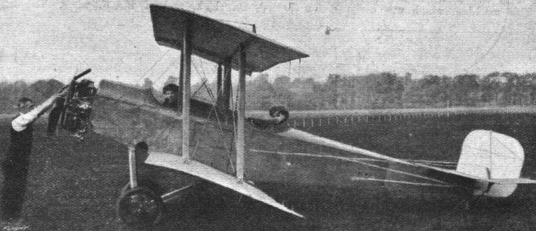
Except for the fact that it had two pairs of wings the enclosed Avro biplane was very similar to the monoplane already described. The main planes were attached to the upper and lower longitudinals of the body respectively, and pilot and passenger were seated tandem fashion inside. Entrance to the body was through a triangular door in the side, this being shown in our illustration. The engine, a 60 h.p. Green, was mounted in the nose of the body, which had here a width of only 15 inches, this being made possible by the fact that the engine was of the vertical type. The radiators were mounted on the side of the body in front of the door. Forming a partition between what may be termed the "engine room" and the occupants' cockpit was a large dashboard with all the instruments. These were therefore, as the passenger sat in front, some distance away from the pilot, who had to look over the passenger's shoulders in order to read the instruments.
The number of windows had been reduced, in this machine, to a long rectangular opening in each side of the body, but the interesting fact was disclosed after a few flights, that during straight flying no draught was felt by the occupants. When the machine was turning and banking a slight wind from the side was noticed, but not sufficient to be in the slightest degree uncomfortable. Although the Avro enclosed biplane was undoubtedly very promising in many respects the authorities did not encourage the production of this type, otherwise the totally enclosed aeroplane might have been very considerably more advanced than is now the case. When the war is over and this type will once more have to be studied seriously, it is to be hoped that the Avro firm, who pioneered the type, will be among the first to take it up again.
<...>
THE "TOTALLY ENCLOSED" AEROPLANE.
<...>
Probably the Avro enclosed biplane is best remembered, and will go down to history, as the machine on which the late Lieut. Wilfred Parke, R.N., had the nasty experience that became known to all the aviation world as "Parke's Dive." That the machine came out of this bad spin without breaking anything is not only an outstanding testimony to Avro design, but is of far greater significance in showing that, even with such a great amount of side area, a machine need not be uncontrollable in a bad spin, provided the pilot knows what to do. This Lieut. Parke only discovered at the last moment, but when he put her to it the machine answered the controls at once.
Except for the fact that it had two pairs of wings the enclosed Avro biplane was very similar to the monoplane already described. The main planes were attached to the upper and lower longitudinals of the body respectively, and pilot and passenger were seated tandem fashion inside. Entrance to the body was through a triangular door in the side, this being shown in our illustration. The engine, a 60 h.p. Green, was mounted in the nose of the body, which had here a width of only 15 inches, this being made possible by the fact that the engine was of the vertical type. The radiators were mounted on the side of the body in front of the door. Forming a partition between what may be termed the "engine room" and the occupants' cockpit was a large dashboard with all the instruments. These were therefore, as the passenger sat in front, some distance away from the pilot, who had to look over the passenger's shoulders in order to read the instruments.
The number of windows had been reduced, in this machine, to a long rectangular opening in each side of the body, but the interesting fact was disclosed after a few flights, that during straight flying no draught was felt by the occupants. When the machine was turning and banking a slight wind from the side was noticed, but not sufficient to be in the slightest degree uncomfortable. Although the Avro enclosed biplane was undoubtedly very promising in many respects the authorities did not encourage the production of this type, otherwise the totally enclosed aeroplane might have been very considerably more advanced than is now the case. When the war is over and this type will once more have to be studied seriously, it is to be hoped that the Avro firm, who pioneered the type, will be among the first to take it up again.
<...>
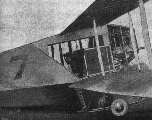
The enclosed Avro biplane, built for the Military Trials of 1912.
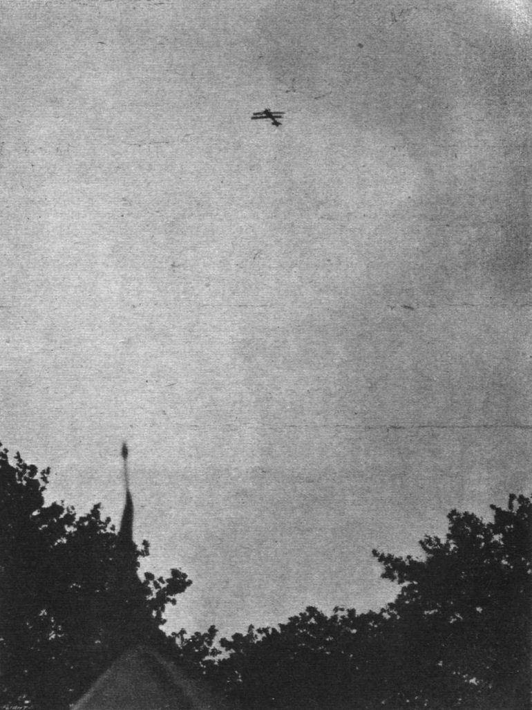
GETTING HER HEIGHT. - The Bristol Scout climbing.

In captivity. - A Bristol biplane captured by the Germans.
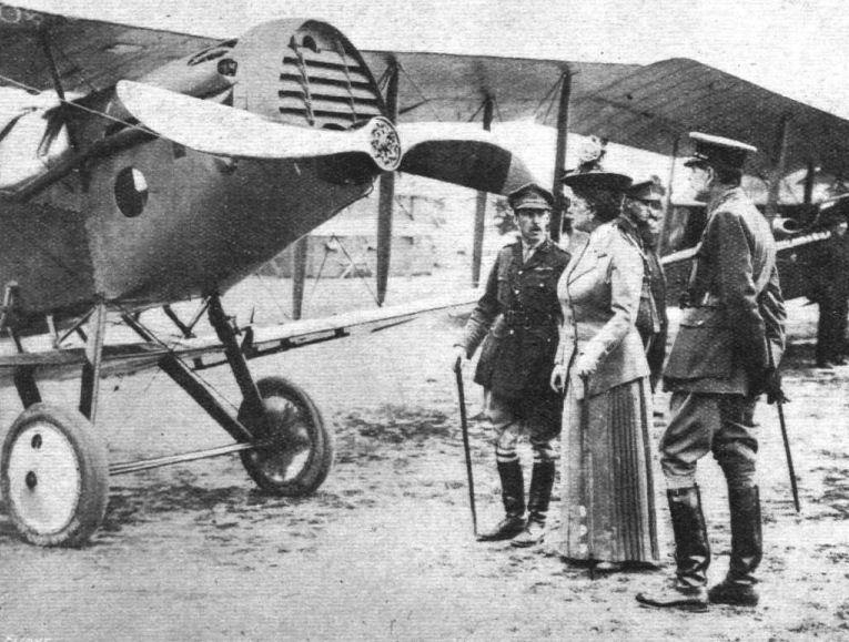
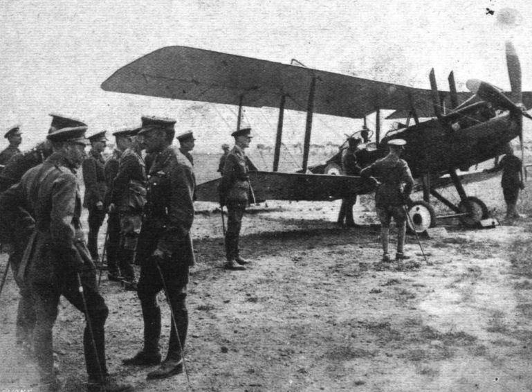
THE ROYAL VISIT TO THE BRITISH WESTERN FRONT. - Queen Mary interested in one of our aeroplanes.
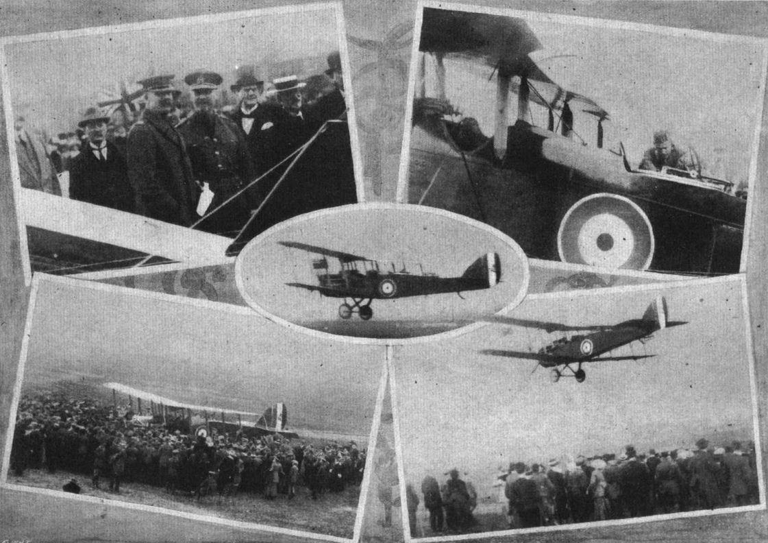
The presentation of the aeroplane "South Africa" by the London Chamber of Commerce, through the Imperial Air Fleet Committee, to the Right Hon. Lieut.-General J.C.Smuts, K.C., as representing the Union of South Africa. Lef to right, from the top: General Smuts and Lord Desborough; Lord Desborough being strapped into the machine previous to his flight with Captain Hucks. Centre: Captain Hucks just getting off. Below: the christening, and Captain Hucks with Lord Desborough about to land.
A de Havilland biplane. The top plane, it will be seen, is staggered backwards.
A de Havilland biplane, brought down in an air fight.
Flight, May 10, 1917.
THE "TOTALLY ENCLOSED" AEROPLANE.
<...>
Regarding what has been done in this country in the way of enclosed aeroplanes since the outbreak of war little can, of course, be said. As, however, the Germans are known to have captured one of the large Handley-Page biplanes practically intact, it may be permissible to give a few particulars of this very successful machine.
Strictly speaking the Handley-Page biplane is not a "totally enclosed" machine, as the gunner, who is placed right out in the nose, and the pilot both have their head projecting above the covering. Had it not been for the fact that this machine is being used for military purposes, there can be little doubt, however, that it would have been totally enclosed, and when machines of this type come to be employed on commercial work in peace time, the total covering in will follow as a matter of course, the general arrangement of the machine naturally lending itself to this feature. It appears probable that in this case the pilot will occupy the front seat, and windows will be provided above, below, in front and on the sides, so that the view will be practically unrestricted in all these directions. For pleasure flying in peace times it would indeed be difficult to imagine a machine offering greater possibilities in the way of comfortable accommodation of passengers, while the weight carrying capability of the machine will render possible the transportation of considerable quantities of lighter goods such as the mails, &c. With only very slight modifications the machine could be transformed from a weapon or war into a commercially useful vehicle of the air, and without any very radical changes, except as regards size, the Handley-Page can be easily pictured as a trans-continental mail carrier of the future.
<...>
Flight, November 29, 1917.
London to Constantinople.
THE Secretary of the Admiralty made the following announcement on November 22nd :- "It will be remembered that during July a successful air attack was carried out on objectives in the vicinity of Constantinople. This was accomplished by a large British bombing aeroplane of the Handley-Page type, which flew from England, where she was constructed, to one of our bases in the Mediterranean. The journey was accomplished in a series of eight flights. Among other places, stops were made at Lyons and Rome. The total distance flown was nearly 2,000 miles, the machine being actually in the air for just over 31 hours. During some parts of the flight strong winds and heavy rain-storms were experienced, and for one stretch of over 200 miles the route lay over mountainous country where it would have been impossible for any machine to land. Nevertheless the aeroplane carried out its journey practically to time table, which is believed to be easily a World's record for a cross-country journey, and also for the Weight carried for the distance, the machine being self-contained as regards engine and aeroplane spares."
IT has been stated unofficially that the machine on the journey to Constantinople was piloted by Squadron-Commander K. S. Savory, Flight Lieutenant H. Macclelland, and Engineer Lieutenant T. Rawlings. The mechanic was P.O. Benjamin Cromack.
TESTING THE ENGINES. - The two Rolls-Royce engines on the "H.P." having a trial run before the start on the London-Constantinople bombing expedition.
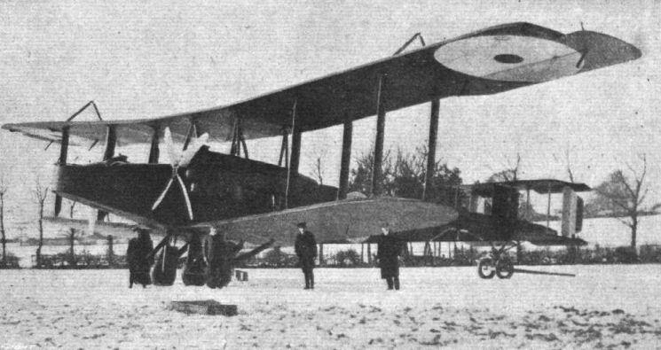
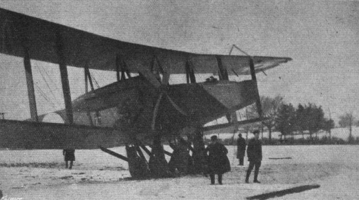
The successful Handley-Page biplane built in England since the outbreak of war and now doing extremely useful work.
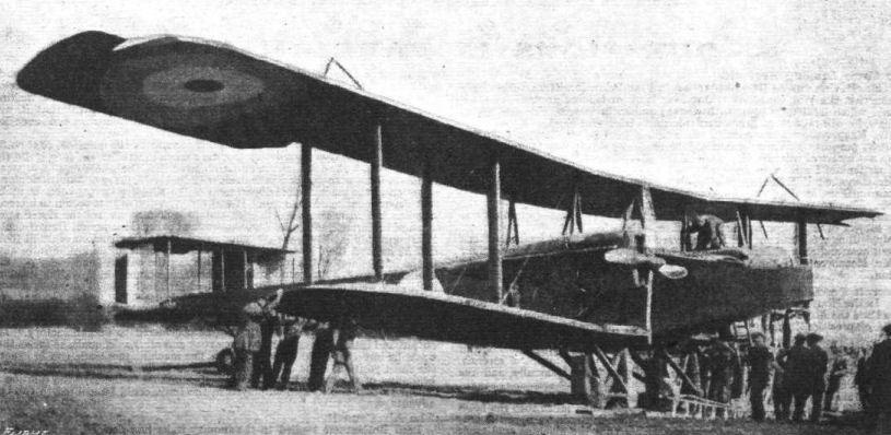
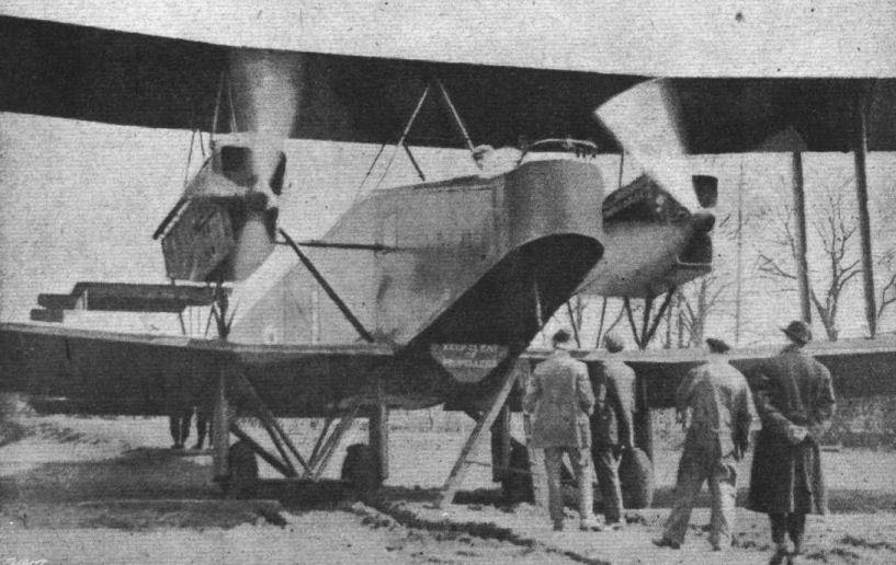
GETTING READY. - A Handley Page biplane of a type similar to that which made the magnificent flight from London to Constantinople. A good idea of the dimensions of the machine is provided by comparison with the people in front.
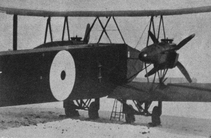
THE HANDLEY PAGE TWIN-ENGINED BIPLANE. - A view of the fuselage from the front.
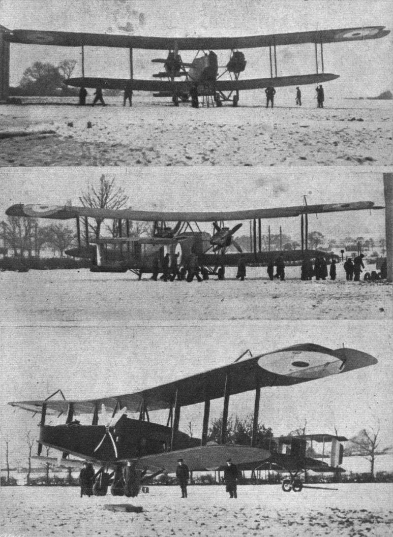
The Handley Page twin-engined biplane.
THE HANDLEY PAGE TWIN-ENGINED BIPLANE. - A rear view of the engine mounting and fore part of the fuselage.
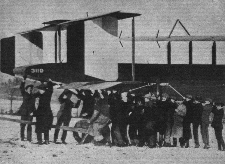
THE HANDLEY PAGE TWIN-ENGINED BIPLANE. - Lifting the tail. A similar photograph to the above was shown on the screen in connection with Mr. Handley Page's recent paper at the Aeronautical Society, and in connection with which the author explained that the tail is really quite easy to lift, the extra help seen in the photograph being rather due to the well-known fact that when a film is being taken, everybody wants to help - by getting into the photograph.

THE HANDLEY-PAGE BOMBER FLIGHT TO CONSTANTINOPLE. - On left: Flight-Commander Savory, D.S.O. and bar, who took part in this raid, with his greyhound mascot. On the right: Squadron-Commander Smyth-Piggot, D.S.O., with his mascot.
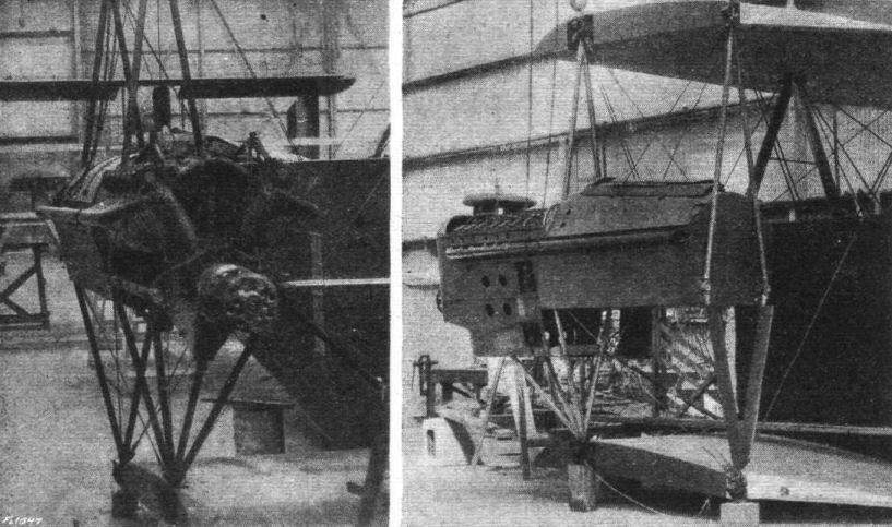
TWO VIEWS OF THE ROLLS-ROYCE ENGINES WHICH MADE THE FLIGHT POSSIBLE. - On the left, a front view of an R.R. installed in the wings of the Handley-Page. The engine housing has been removed to give a better view of the engine. On the right, a three-quarter rear view of the Rolls-Royce engine. In the space behind the engine the petrol tank is carried.
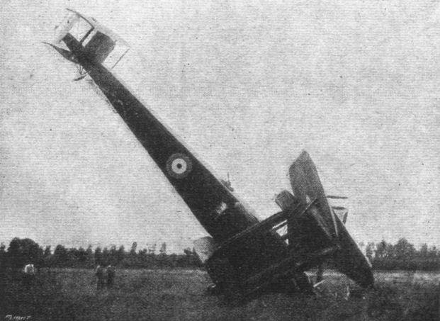
In the Hands of the Enemy. - A Handley-Page biplane shot down in Flanders by anti-aircraft guns. The machine according to Flugsport, had a crew of three and carried sixteen bombs, each weighing 50 kilogs.
What might have been, and even yet may be.
DIVERTING THE CARDINAL WOLSEY RIVER AT HANWORTH PARK. - Mr. H. Sykes, on his Martinsyde, looping in a gale of wind. The machine is travelling away from the spectator, and is in the inverted position.
WINTER FLYING. - On a Martinsyde at Hanworth.
Flight, April 19, 1917.
THE "TOTALLY ENCLOSED" AEROPLANE.
<...>
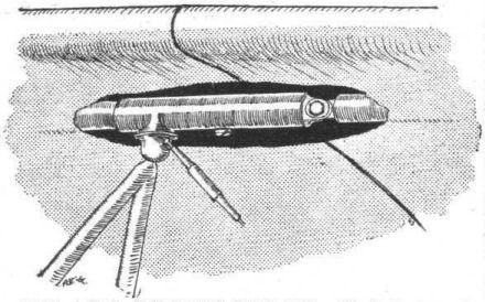
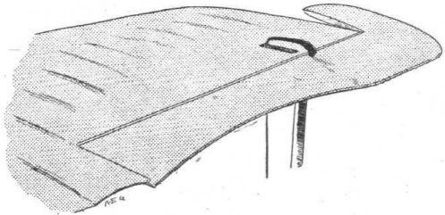
Apart from such early designs as the Henson already referred to, one of the first, if not, indeed, the very first, totally enclosed in the fuselage covering, was the Piggot monoplane exhibited at the Olympia aero show in 1911. This machine, as our illustration shows, had a stream-line body, even to a casing round the propeller boss, and it is, in point of fact, a debatable point whether the designer was primarily concerned with providing comfort for the passengers or obtaining maximum efficiency by stream-lining everything to the greatest possible extent. Be that as it may, the occupants were enclosed in the stream-line body which they entered through circular openings in the floor. Presumably these same openings served to give a view in a downward direction. An additional opening was provided under the engine near the nose, and windows on each side of the engine were to give the passenger a view directly forward. It is quite evident, in view of modern knowledge, that the pilot's range of vision was totally inadequate, and as a matter of fact, when the machine was ultimately tried, an opening was cut in the top of the body, through which the pilot's head projected. The machine was not a very great success, but we should hesitate to put this down to the fact that it was totally enclosed. Rather is it to be assumed that the chief trouble was insufficient power.
<...>
THE "TOTALLY ENCLOSED" AEROPLANE.
<...>
Apart from such early designs as the Henson already referred to, one of the first, if not, indeed, the very first, totally enclosed in the fuselage covering, was the Piggot monoplane exhibited at the Olympia aero show in 1911. This machine, as our illustration shows, had a stream-line body, even to a casing round the propeller boss, and it is, in point of fact, a debatable point whether the designer was primarily concerned with providing comfort for the passengers or obtaining maximum efficiency by stream-lining everything to the greatest possible extent. Be that as it may, the occupants were enclosed in the stream-line body which they entered through circular openings in the floor. Presumably these same openings served to give a view in a downward direction. An additional opening was provided under the engine near the nose, and windows on each side of the engine were to give the passenger a view directly forward. It is quite evident, in view of modern knowledge, that the pilot's range of vision was totally inadequate, and as a matter of fact, when the machine was ultimately tried, an opening was cut in the top of the body, through which the pilot's head projected. The machine was not a very great success, but we should hesitate to put this down to the fact that it was totally enclosed. Rather is it to be assumed that the chief trouble was insufficient power.
<...>
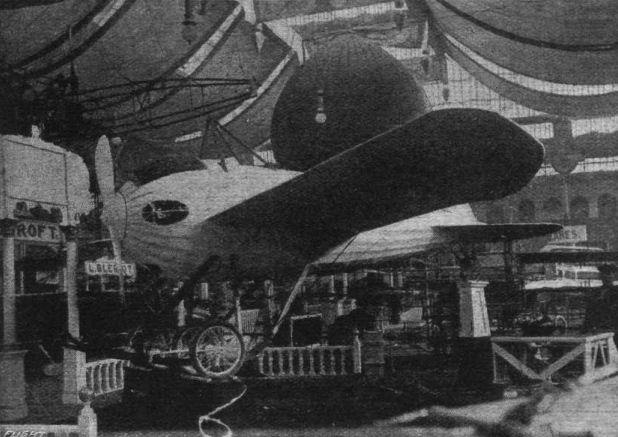
A pronounced example of the stream-line form body, the Piggott monoplane exhibited at the Olympia Aero Show of 1911. The entire framework of this machine is enclosed in a light fabric-covered shell, access to which is obtained from beneath. There is room for pilot and passenger inside, both of whom have an outlook through various small windows. The propeller-boss is conical, and forms a sharp point on the otherwise hemispherical head. The radiator forms a kind of crest above the forehead.
THE GREAT FLIGHT ACROSS SOUTH AFRICA. - General Smuts recently, when accepting the aeroplane subscribed for by the London Chamber of Commerce, had reason to refer to the retaining of the supremacy of the air as being the forerunner of victory. He has intimate knowledge of the activities at the front, and has also in mind the 300 miles South African flight carried out by Captain Moore in the German East African Campaign. In our photograph above, Captain Moore has arrived safely back, the aeroplane being taken, into the hangar.

Captain Moore, the pilot (on the right), studying the route map before his start on the 300 miles flight in the German East African Campaign.
AIR PATROLLING IN THE EASTERN MEDITERRANEAN. - One of our air patrols photographed in the air from another machine.
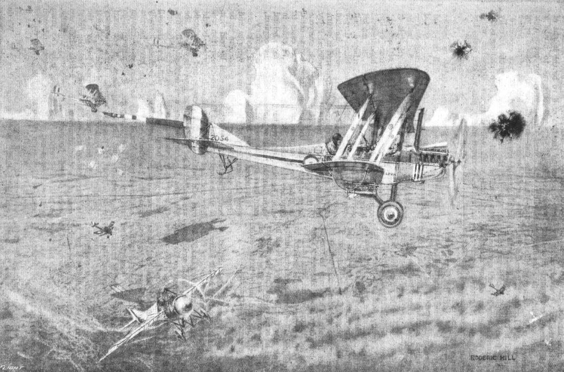
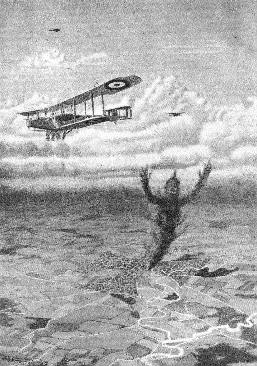
A BRITISH BOMBING MACHINE CROSSING THE LINES ON THE WAY TO AN ENEMY POSITION. - Such a scene as the above may be witnessed any fine day on the Western Front. A bombing raid carried by the R.F.C. in progress. The aeroplanes are seen maling their way over the lines under heavy anti-aircraft fire. In the lower right-hand corner a small hostile patrol has sighted the raid, and has decided that discretion in the better part of valour. A well-known sector of the lines is here shown, the woods appearing as weird dark shapes on the vast panorama. The long straight roads, so typical of France, stretch away over the wide expanse, dotted with little villages strewn, as it were, carelessly over it. As the eye follows them, fading gradually to an ill-defined horizon, it is baffled by the heavy pall of mist which hangs like a purple curtain abruptly from the sky, above which the summits of clouds appear as giant icebergs.
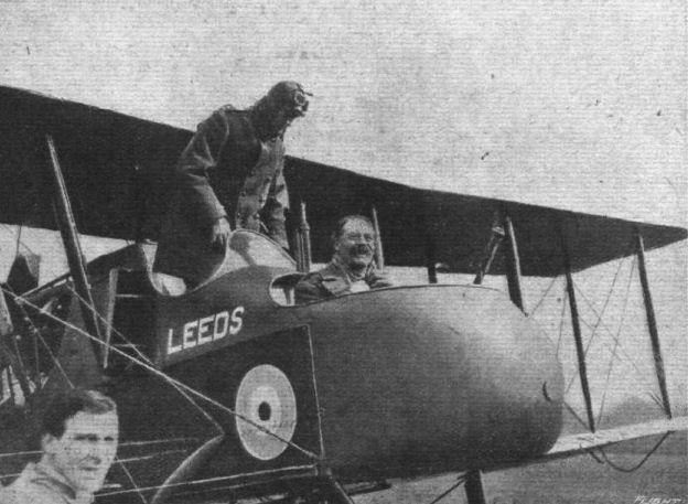
The presentation of an aeroplane to India by the City of Leeds. Lord Desborough after his flight.
Flight, September 6, 1917.
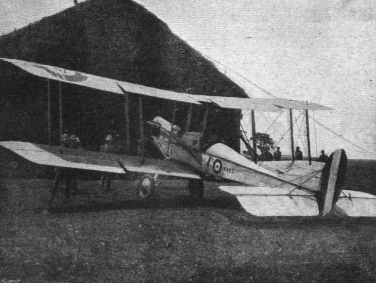
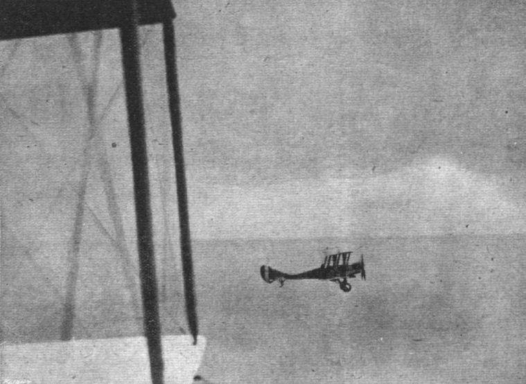
A "DE HAVILLAND" SINGLE-SEATER FIGHTER.
AN interesting illustrated description of a British biplane, appears in a German aeronautical contemporary, which we are now able to reproduce. The data relating to the "de Havilland," so described by our contemporary, are preceded by the following interesting and characteristic remarks :-
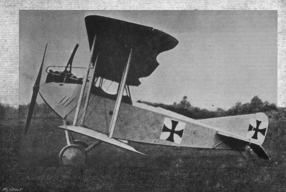
"It was difficult for the English constructors to produce a machine equal to the German aeroplanes, especially as regards the production of a single-seater fighter. The main desiderata in such a machine were high speed, maneuverability, climb and a free field for a machine gun in a forward direction. As English aeronautical engineering was somewhat backward, especially with regard to firing through the propeller, the construction of a tractor single-seater with the engine in front had to be discarded. The result was therefore necessarily a fighter, with the screw at the rear and an open framework carrying the tail, and it was the little de Havilland single-seater which was ordered in large quantities by the British Army. As our readers know, early in 1916 these machines were rushed to the English Front, where whole squadrons were smashed through accidents."
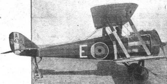
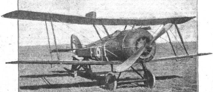
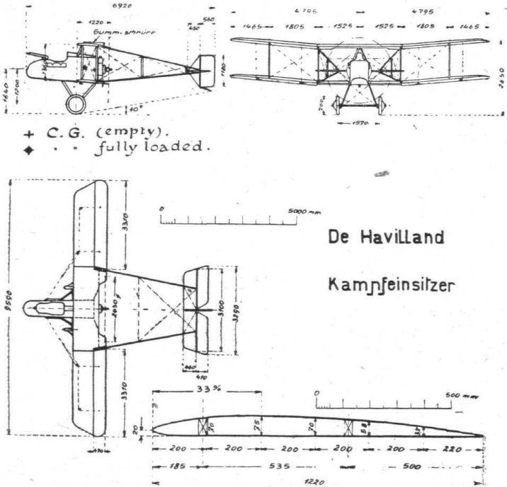
"The de Havilland single-seater consists, as the accompanying illustrations show, of a central portion of 3.5 metres span, to which the wings are attached at a dihedral angle. There are two pairs of inter-plane struts on each side. To the point where occur the first pair of struts the tail booms are attached. Ailerons of 3.31 metres length are fitted to both planes. The ailerons are held flush with the trailing edge by rubber cords on the upper surface. The power plant consists of a 100 h.p. monosoupape driving a four-bladed screw of 2.34 metres diameter. In front of the motor are the petrol and oil tanks and the pilot's seat, and in front of the seat is a pivot for the movable machine gun. The weight of the machine empty is 476 kilogrammes, and with 2 1/2 hours' fuel, pilot and machine gun, it is 722 kilogrammes. The loading is thus 35.6 kilogrammes per square metre. In spite of the great resistance of the wing bracing, the machine attains a speed of 150 kilometres per hour."
Chief Characteristics of "De Havilland" Fighter.
Power plant, 100 h.p. Gnome Monosoupape; fuel, petrol 120 litres, oil 22 litres. Area of planes (inclusive of ailerons): Top plane, 10.7 sq. m.; bottom plane, 9.6 sq. m.; total, 20.3 sq. m. Ailerons, 4 x 1.47 sq. m.; elevators, 1.19 sq. m.; rudder, 0.67 sq. m. Angle of incidence: Main planes, 4.5°; tail plane, 0.8°. Weight, empty, 476 kg.; useful load, 246 kg.; total, 722 kg. Armament, one movable machine gun.
A "DE HAVILLAND" SINGLE-SEATER FIGHTER.
AN interesting illustrated description of a British biplane, appears in a German aeronautical contemporary, which we are now able to reproduce. The data relating to the "de Havilland," so described by our contemporary, are preceded by the following interesting and characteristic remarks :-
"It was difficult for the English constructors to produce a machine equal to the German aeroplanes, especially as regards the production of a single-seater fighter. The main desiderata in such a machine were high speed, maneuverability, climb and a free field for a machine gun in a forward direction. As English aeronautical engineering was somewhat backward, especially with regard to firing through the propeller, the construction of a tractor single-seater with the engine in front had to be discarded. The result was therefore necessarily a fighter, with the screw at the rear and an open framework carrying the tail, and it was the little de Havilland single-seater which was ordered in large quantities by the British Army. As our readers know, early in 1916 these machines were rushed to the English Front, where whole squadrons were smashed through accidents."
"The de Havilland single-seater consists, as the accompanying illustrations show, of a central portion of 3.5 metres span, to which the wings are attached at a dihedral angle. There are two pairs of inter-plane struts on each side. To the point where occur the first pair of struts the tail booms are attached. Ailerons of 3.31 metres length are fitted to both planes. The ailerons are held flush with the trailing edge by rubber cords on the upper surface. The power plant consists of a 100 h.p. monosoupape driving a four-bladed screw of 2.34 metres diameter. In front of the motor are the petrol and oil tanks and the pilot's seat, and in front of the seat is a pivot for the movable machine gun. The weight of the machine empty is 476 kilogrammes, and with 2 1/2 hours' fuel, pilot and machine gun, it is 722 kilogrammes. The loading is thus 35.6 kilogrammes per square metre. In spite of the great resistance of the wing bracing, the machine attains a speed of 150 kilometres per hour."
Chief Characteristics of "De Havilland" Fighter.
Power plant, 100 h.p. Gnome Monosoupape; fuel, petrol 120 litres, oil 22 litres. Area of planes (inclusive of ailerons): Top plane, 10.7 sq. m.; bottom plane, 9.6 sq. m.; total, 20.3 sq. m. Ailerons, 4 x 1.47 sq. m.; elevators, 1.19 sq. m.; rudder, 0.67 sq. m. Angle of incidence: Main planes, 4.5°; tail plane, 0.8°. Weight, empty, 476 kg.; useful load, 246 kg.; total, 722 kg. Armament, one movable machine gun.
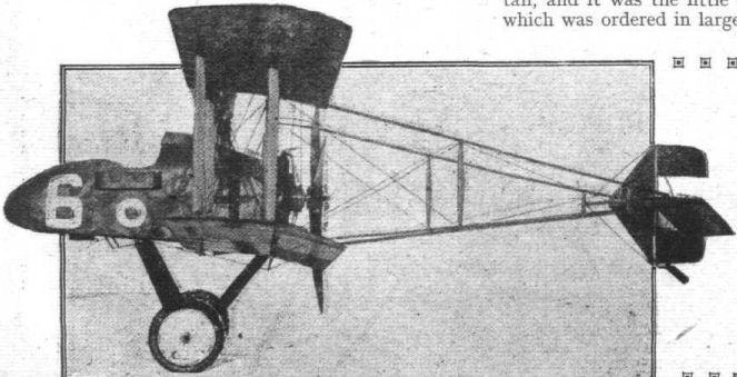
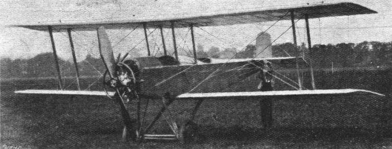
Side view of, according to Flugsport, "de Havilland" fighter.
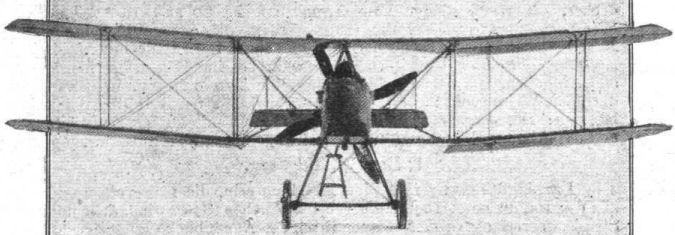
Front view of, according to Flugsport, "de Havilland" fighter.
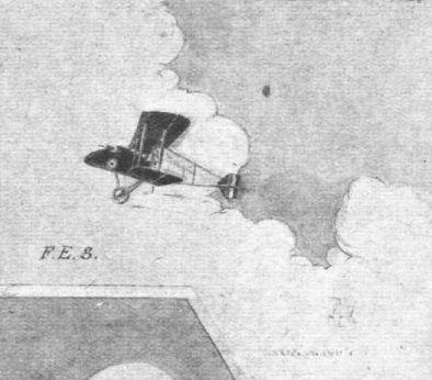
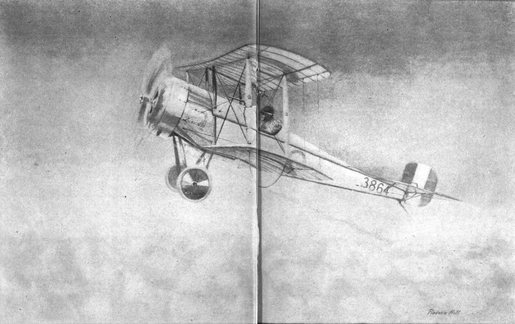
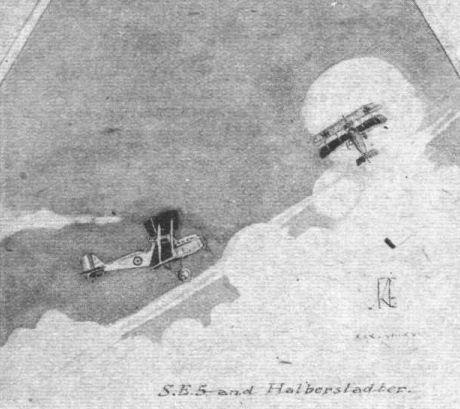
Some unique sketches of aircraft at work overseas by Captain K. H. Riversdale Elliot, Scottish Rifles and R.F.C.. The drawings are particularly accurate and full of movement, and carry the greater weight as from an active pilot.
THE ROYAL VISIT TO THE BRITISH WESTERN FRONT. - King George at an aerodrome.
Some unique sketches of aircraft at work overseas by Captain K. H. Riversdale Elliot, Scottish Rifles and R.F.C.. The drawings are particularly accurate and full of movement, and carry the greater weight as from an active pilot.
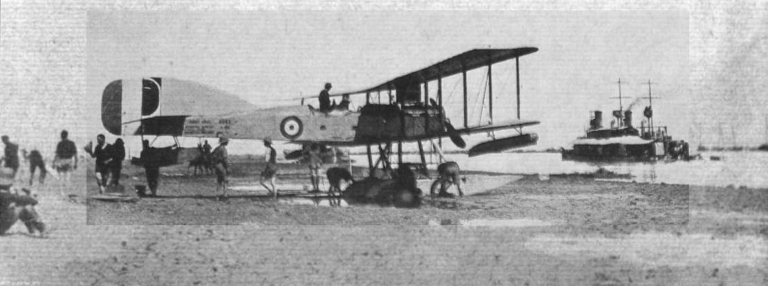
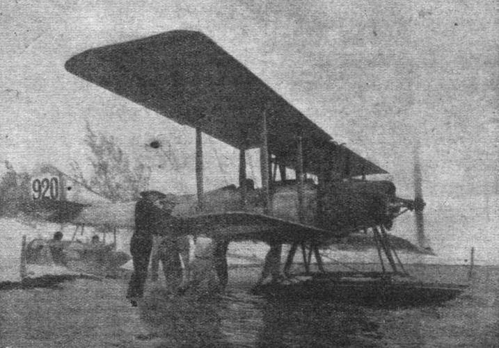
A Short Type 184 seaplane with 225 h.p. Sunbeam engine, beached on the bank of the Tigris for repairs, during the operations against Kut-el-Amara.
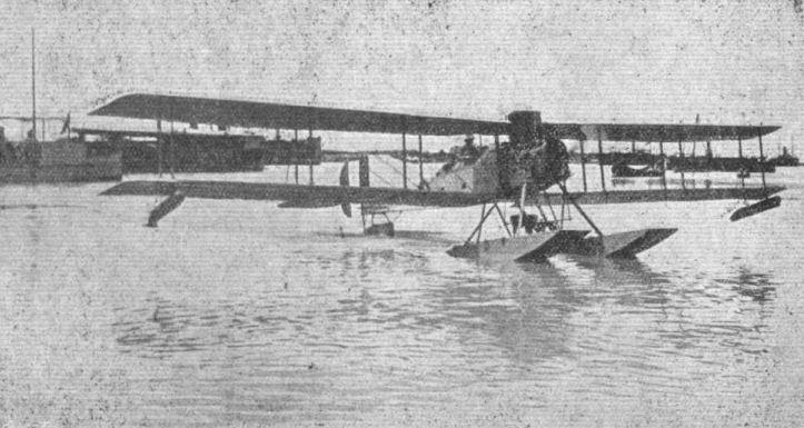
WITH THE BRITISH FORCES IN MESOPOTAMIA. - A seaplane returning to the slipway at Bazra after trials.
A seaplane, in what was German East Africa, about to start a flight over the German cruiser "Konigsberg," for the purpose of "spotting" for artillery work.
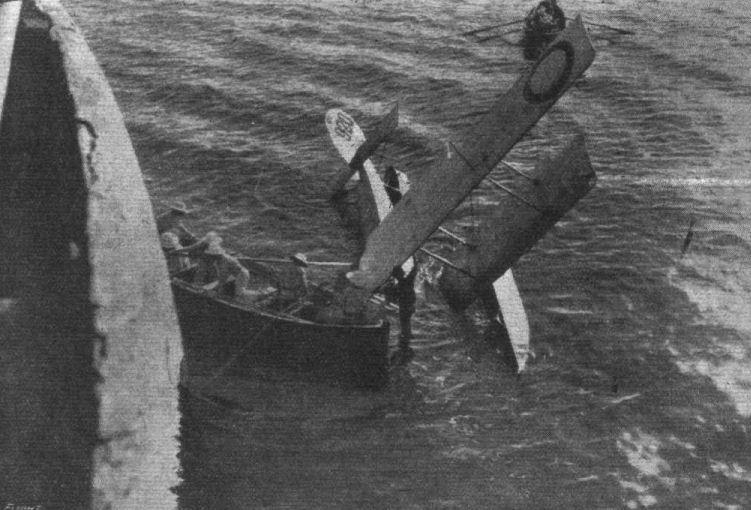
Another view of salving a seaplane after an accident.

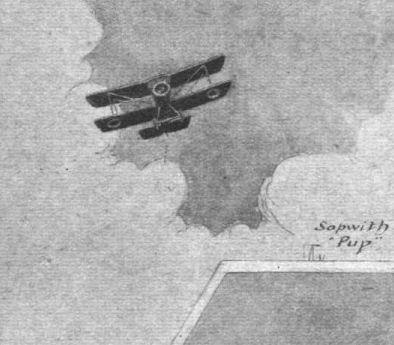
A Sopwith single-seater lands on its back, apparently with never a fracture, after a fight over the German lines.
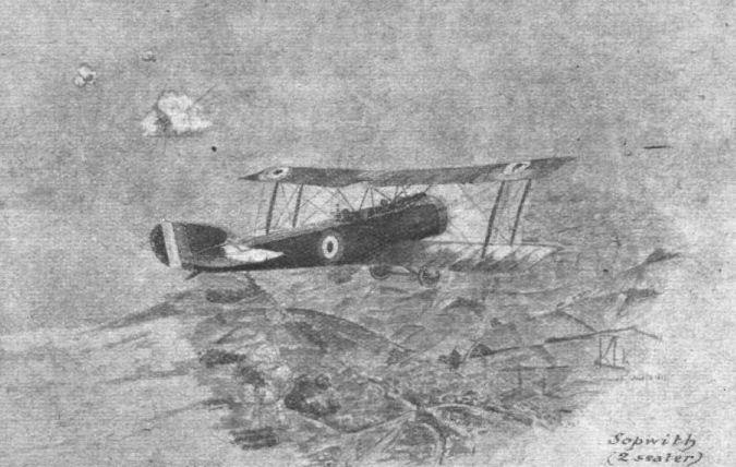
Some unique sketches of aircraft at work overseas by Captain K. H. Riversdale Elliot, Scottish Rifles and R.F.C.. The drawings are particularly accurate and full of movement, and carry the greater weight as from an active pilot.
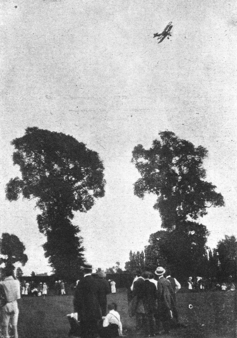
AT THE RECENT SOPWITH SPORTS AT NORBITON. - A snap of a Sopwith "Camel" during an exhibition flight.
Some unique sketches of aircraft at work overseas by Captain K. H. Riversdale Elliot, Scottish Rifles and R.F.C.. The drawings are particularly accurate and full of movement, and carry the greater weight as from an active pilot.
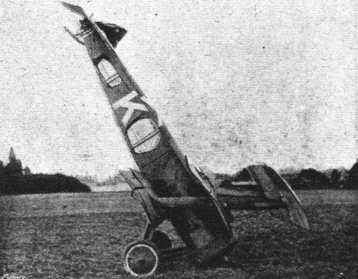
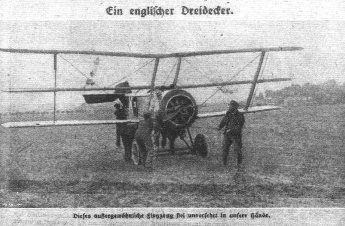
A three-decker in the hands of the enemy . - Another view of the machine "standing'' on its nose which was reproduced in "FLIGHT" on page 920, September 6th. We reproduce the illustration exactly as it appears in an enemy newspaper, and it will be noticed that emphasis is laid upon the fact that the machine is uninjured, which appears to be correct subject to the propeller and very minor details.
Flight, July 19, 1917.
A NEAT SCHOOL MACHINE.
IN the training of a Service pilot it would often be an advantage if a machine were available on which, after having got to feel quite at home in the ordinary training machine, he could put in a little extra practice before making the admittedly somewhat long step to the high-powered fast Service aeroplane. It was with this object in view that the small biplane illustrated in the accompanying photographs was built. This machine, which was designed for the Wright Forge and Engineering Co., Ltd., of Tipton, Staffs., by Mr. W. West wood, is a light two-seater, fitted with a 40-45 h.p. Anzani engine. It is stated by the designer to have a speed range of from 30 to 65 m.p.h., and its climb, although not measured, appears to be quite good.
The upper and lower planes are of the same span, and both are fitted with ailerons interconnected in the usual manner. The top plane is built up in three sections - a centre section and the two outer main sections. The bottom planes are, as in the majority of modern biplanes, attached to the sides of the body. Structurally the wings are built up of ash spars reinforced with steel, and of ribs having spruce flanges and three-ply webs. The leading and trailing edges are of spruce, except for the tips, which are steam-bent ash. As will be seen from the illustrations, there is only one pair of inter-plane struts on each side, the machine following in this respect the lines of a fast single-seater scout.
As regards the wing bracing, this is effected by a somewhat unusual combination of steel tubes and stream-line wires. The lift "wires" consist of streamline steel tube measuring 1/2 in. in width by about 3/16 in. thick, and of R.A.F. wires. The landing "wires" are steel tubes only. External drift wires run to the nose of the body, and assist the internal wing bracing, which is in the form of stranded cable.
A flat non-lifting tail plane is secured to the top of the body and stayed with stream-line steel tubes. To the trailing edge of the tail plane is hinged the divided elevator, which is operated by means of stranded cables from an external crank lever on the side of the body. The rudder is hinged to the stem post of the body, and is partly balanced by a forward projection as shown in the illustrations.
Aerodynamically the body is of the ordinary flat-sided rectangular section type, but constructionally it differs somewhat from the majority of other aeroplane bodies. The designer argues - quite rightly, we think - that for a school machine, which is subject to many and frequently rough landings, it is important that the body should be a strong one. This end is attained in the present machine by an internal construction of the ordinary girder type, with four ash booms and ash and spruce struts in front and rear respectively, the whole being braced with piano wire, supplemented by a covering of three-ply extending the whole length of the body and screwed to rails and struts so as to minimise the danger of short breaks in the rails. A similar body has, we understand, stood up to a nose dive into the ground from a height of about 100 ft. This happened to a monoplane having a similar body.
The pilot's and passenger's seats are arranged tandem fashion, the pilot occupying the rear ore. The instruments comprise: Altimeter, revolutions counter, air speed indicator, switch, throttle and air control.
In the preliminary tests, which were carried out by Mr. Rene Desoutter at Dunstall Park, Wolverhampton, the machine did not show any tendency to spin, and refused, we are informed, to do a tail-slide when stalled to a vertical attitude in the air, the machine coming out in a nose-dive from this attitude. The following are the chief characteristics of the machine :-
Length, 22 ft.; span, 26 ft.; chord, 5 ft.; gap, 5 ft.; weight empty, 720 lbs.; area of wings, 245 sq. ft.; area of tail, 15 sq. ft.; area of elevators, 10 sq. ft.; area of rudder, 6,75 sq. ft.; engine, 40-45 Anzani; propeller, Lang; speed, 30 to 65 m.p.h.
THE W.F. AND E. CO. BIPLANE. - Three-quarter front view.
W.F. & E. biplane. Built at Tipton in 1914 and tested by Rene Desoutter at Dunstall Park.
THE W.F. AND E. CQ. BIPLANE. - Side view.
Flight, July 12, 1917.
SOME 1917 TYPE GERMAN AEROPLANES.
The A.E.G. (Type C. IV).
The Allgemeine Elektrizitats Gesellschaft build two types of machines - one a twin-engined biplane and the other an ordinary two-seater biplane with single engine. The wings of the single-engined machine, which, like all the A.E.G. machines, is built entirely of steel tube, are of 42 ft. 6 ins. span, so that the machine is a fairly large one. The wings are set at a small dihedral angle and also slope back slightly. There are two pairs of struts on each side, and the machine is remarkable for its exceptionally large gap between the planes.
The wings are built entirely of steel tube, with the exception of the leading edge and intermediate ribs. The ailerons, it will be seen from the sketch, are of rather peculiar shape, and form on that account a good guide for purposes of identification.
Like the rest of the machine, the body is built of steel tube, and is flat-sided except in front, where it is covered with three-ply and slightly rounded. The engine, a 175 h.p. Mercedes, is mounted on two longitudinal bearers of square section steel tube. The petrol service tank and radiator are incorporated with the centre section of the top plane, which is straight. The armament consists of two machine guns, the front one fixed and synchronised, the rear one on a gun ring, and of four bombs placed on top of one another inside the body, to the right of the passenger.
A captured German (A.E.G.) biplane with 175 h.p. Mercedes engine. Note the peculiar shape of the ailerons.

Flight, July 12, 1917.
SOME 1917 TYPE GERMAN AEROPLANES.
Twin-Engine A.E.G., 450 h.p.
It has already been mentioned that the Allgemeine Elektrizitats Gesellschaft make a twin-engine biplane. This machine, which is built entirely of steel, is fitted with two Benz or Mercedes engines of 225 h.p. each, placed in nacelles between the wings. The radiators are in the nose of the nacelles, as are also, in contradistinction to the Gotha, the air screws. The fuselage, which has seating accommodation for three occupants, projects a considerable distance ahead of the main plane.
Flight, November 1, 1917.
THE TWIN-ENGINE A.E.G. BOMBING BIPLANE.
IN the early days of the war it was the habit of the lay Press to use the name Taube generically for all military machines of German origin, and this caused some confusion in sometimes spreading the impression that the machines which figured in reports of fights in the air were of the Taube monoplane type, when, as a matter of fact, this type of aeroplane had long since been abandoned by the Germans. In the same manner there would at the present moment appear to be the possibility of causing some confusion by assigning to all German aeroplanes carrying out bombing raids on this country the designation "Gotha." As a matter of fact, it must not be assumed that these raiders are necessarily always of the Gotha type, as Germany possesses others which would in all probability be capable of raids on England, for which they with some amount of probability may be assumed to have been used. We are referring to the large twin-engine biplanes built by the Allgemeine Elektrizitats Gesellschaft, and known as A.E.G. biplanes.
The A.E.G. firm was, perhaps, one of the first in Germany to turn its attention to machines of large dimensions, although not to such extent as the Capronis in Italy or the Handley-Pages in this country. One of the first A.E.G. twin-engine biplanes to become known to our pilots on the western front made its appearance during 1916, and was briefly described by M. Jean Lagorgette in our French contemporary l'Airophile of August, 1916. This machine had a long convered-in fuselage providing accommodation for the pilot and gunners, while the two engines were placed on the wings, sufficiently far out for the two tractor screws to clear the nose of the fuselage. The planes, of which the upper was slightly longer than the lower, were set at a dihedral angle, and were also swept back in the manner beloved by German aeroplane designers. Little was known of these machines, except that they were believed to be made almost entirely of steel.
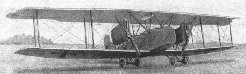
The following particulars of the 1917 type A.E.G. bombers may be of interest, since, as already mentioned, there is a possibility of these being employed for raids on this country as well as the Gothas. The general arrangement will be clear from the accompanying perspective views and scale drawings, which latter should not be very far wrong in any dimension, although we cannot guarantee that they are absolutely correct. They have been plotted with the aid of the perspective views, with which they tally fairly accurately.
Fundamentally the A.E.G. bomber resembles the Gotha biplanes, illustrated descriptions of which were published in our issues of July 12th and August 9th, 1917. In dimensions, however, the two machines differ considerably, the Gotha being somewhat larger. Also the A.E.G. has its two airscrews placed in front of the main planes, whereas in the Gotha they are "pusher" screws. As in the Gotha, the wings of the A.E.G. are swept back, and are also placed at a dihedral angle, which appears to be greater in the bottom than in the top plane. The span, it will be seen from the scale drawings, is the same for both planes, and amounts to 57 ft., while the overall length is about 30 ft. The ailerons, which are of a peculiar shape, are fitted to the top plane only, and are operated by a crank lever working in a slot in the plane as shown in one of the accompanying sketches. This arrangement, which will be familiar to our readers from descriptions of Albatros biplanes, would appear to be in general favour with German designers, whereas it is rarely or never met with in Allied machines.
The tail planes, which are of the monoplane type, consist of fixed stabilising planes and a vertical fin, to which are hinged the elevators and rudder respectively. Both elevators and rudder have forward projections in order to partly balance them, thus relieving the pilot of a certain amount of the strain of working the controls. A tail skid is fitted under the stern of the fuselage, and is sprung, not by means of rubber shock absorbers as is usually the case with our machines, but by means of coil springs. The same is the case with the landing chassis, where coil springs are also used instead of rubber. Whether this "indicates a shortage of rubber" in Germany, or whether, for machines of such large dimensions and heavy weight, it has been found more suitable, it is not possible to say.
As already mentioned, the material used in the construction is, with very few exceptions, steel, practically the only parts made of wood being the ribs of the main planes. The main spars are in the form of steel tubes, which is rather surprising in view of the fact that about the worst use to put a circular or tubular section to is to employ it as a beam laterally loaded, since much of the material of such a section will be situated at or near the neutral axis, where it is adding weight without contributing greatly towards the strength. Possibly the tube has been chosen, in this instance, for reasons connected with the manufacture rather than from considerations of structural suitability. The method of attaching the root of the main spar to the centre section of the top plane is shown in one of our sketches. The short length joining the centre section spar and root of wing appears to be turned from the solid, hollowed out at one end to receive the centre section spar, and having machined on the other a forked end to receive the root of the main spar. The strut socket, which resembles those usually found on German machines, is attached to it by welding.
Like the rest of the machine, the fuselage of the A.E.G. bomber is built up of steel tubes, this material being used for longerons as well as for struts and cross members. These are connected by welding and the joints are stiffened and anchorage provided for the cross bracing wires by triangular pieces of sheet steel welded to longerons and struts. The arrangement will be better understood by reference to one of the accompanying sketches.
With regard to the accommodation for the occupants, this is divided into three divisions. In the front cockpit - in the extreme nose of the body - is a seat for the bomber, who views the ground below and obtains his sights through a circular opening in the floor. On his right the bomber has a rack holding bombs; these are presumably not of a very heavy calibre. Under the centre of the body there is another bomb rack carrying the heavier projectiles. Near the inner ends of the lower plane there are fittings for an additional supply of bombs. The majority of the bombs, however, are not, so far as it is possible to ascertain, carried under the body and wings, but inside the body.
In the centre cockpit there are two seats, side by side, occupied by two pilots, or presumably by two pilot-gunners, one relieving the other at the controls during a long flight. The two seats, although placed side by side, do not extend the whole width of the body, but are placed a little to the left of the centre line, leaving room on the right-hand side for a bomb rack holding about 10 or 12 bombs. Behind the pilot's cockpit is that of the gunner, who operates a machine-gun mounted on a turntable, which allows of firing the gun laterally as well as upwards and to the rear. On the left-hand side in the gunner's cockpit there is another bomb rack carrying a similar store of bombs to that in the pilot's cockpit. In the floor of the bay to the rear of the gunner's cockpit there is a trap door, hinged along its rear edge. By lifting up this trap door, which may be held in its open position by a, catch, the gunner is enabled to fire in a downward and rearward direction when being chased and attacked from behind. A small gun pivot mounted on the floor forms the support for the gun when firing through the trap door.
The engines - which are generally of the 260 h.p. Mercedes type - are placed one on each side on the centre section of the lower plane. They are enclosed in engine housings, with the radiator mounted near the nose. The main petrol tank is not carried in the engine housings, but in the pilot's cockpit, where it forms, as a matter of fact, the support for the two seats. A service petrol tank is fitted in each engine housing, these service tanks being replenished from the main tank by means of a pump. The mounting of the engines on the lower plane centre section is somewhat unusual, and may be best understood by an examination of the scale drawings and general views. It should, of course, be studied in conjunction with the undercarriage, since much of the at first sight cumbersome and unnecessary strutting is dependent upon the design of the chassis. This, it will be seen, has been so designed that the outer wheel on each side occurs directly underneath the corresponding engine, while the inner wheel is supported on another Vee from the lower plane. The object is plainly to let the inner wheels take part of the load of the central fuselage, but the manner of carrying out the idea does not strike one as particularly ingenious. The weight of the body is during a landing primarily supported on the inner ends of the centre section of the bottom plane. Struts are taken, it is true, to the top longerons of the body from the point of attachment of the inner chassis strutts, but even so there is a considerable length of spar between this point and the sides of the body. Altogether the strutting of engines and undercarriages appears clumsy and complicated, and must, it would appear, present a great amount of head resistance. The two axles are slung from the apex of the Vees by coil springs, and not by rubber bands or cords. The speed is not known, but a rough estimate would appear to indicate as a reasonable figure about go m.p.h. The resistance appears to be excessive as regards certain portions, otherwise we should have estimated the speed to be slightly higher.
SOME 1917 TYPE GERMAN AEROPLANES.
Twin-Engine A.E.G., 450 h.p.
It has already been mentioned that the Allgemeine Elektrizitats Gesellschaft make a twin-engine biplane. This machine, which is built entirely of steel, is fitted with two Benz or Mercedes engines of 225 h.p. each, placed in nacelles between the wings. The radiators are in the nose of the nacelles, as are also, in contradistinction to the Gotha, the air screws. The fuselage, which has seating accommodation for three occupants, projects a considerable distance ahead of the main plane.
Flight, November 1, 1917.
THE TWIN-ENGINE A.E.G. BOMBING BIPLANE.
IN the early days of the war it was the habit of the lay Press to use the name Taube generically for all military machines of German origin, and this caused some confusion in sometimes spreading the impression that the machines which figured in reports of fights in the air were of the Taube monoplane type, when, as a matter of fact, this type of aeroplane had long since been abandoned by the Germans. In the same manner there would at the present moment appear to be the possibility of causing some confusion by assigning to all German aeroplanes carrying out bombing raids on this country the designation "Gotha." As a matter of fact, it must not be assumed that these raiders are necessarily always of the Gotha type, as Germany possesses others which would in all probability be capable of raids on England, for which they with some amount of probability may be assumed to have been used. We are referring to the large twin-engine biplanes built by the Allgemeine Elektrizitats Gesellschaft, and known as A.E.G. biplanes.
The A.E.G. firm was, perhaps, one of the first in Germany to turn its attention to machines of large dimensions, although not to such extent as the Capronis in Italy or the Handley-Pages in this country. One of the first A.E.G. twin-engine biplanes to become known to our pilots on the western front made its appearance during 1916, and was briefly described by M. Jean Lagorgette in our French contemporary l'Airophile of August, 1916. This machine had a long convered-in fuselage providing accommodation for the pilot and gunners, while the two engines were placed on the wings, sufficiently far out for the two tractor screws to clear the nose of the fuselage. The planes, of which the upper was slightly longer than the lower, were set at a dihedral angle, and were also swept back in the manner beloved by German aeroplane designers. Little was known of these machines, except that they were believed to be made almost entirely of steel.
The following particulars of the 1917 type A.E.G. bombers may be of interest, since, as already mentioned, there is a possibility of these being employed for raids on this country as well as the Gothas. The general arrangement will be clear from the accompanying perspective views and scale drawings, which latter should not be very far wrong in any dimension, although we cannot guarantee that they are absolutely correct. They have been plotted with the aid of the perspective views, with which they tally fairly accurately.
Fundamentally the A.E.G. bomber resembles the Gotha biplanes, illustrated descriptions of which were published in our issues of July 12th and August 9th, 1917. In dimensions, however, the two machines differ considerably, the Gotha being somewhat larger. Also the A.E.G. has its two airscrews placed in front of the main planes, whereas in the Gotha they are "pusher" screws. As in the Gotha, the wings of the A.E.G. are swept back, and are also placed at a dihedral angle, which appears to be greater in the bottom than in the top plane. The span, it will be seen from the scale drawings, is the same for both planes, and amounts to 57 ft., while the overall length is about 30 ft. The ailerons, which are of a peculiar shape, are fitted to the top plane only, and are operated by a crank lever working in a slot in the plane as shown in one of the accompanying sketches. This arrangement, which will be familiar to our readers from descriptions of Albatros biplanes, would appear to be in general favour with German designers, whereas it is rarely or never met with in Allied machines.
The tail planes, which are of the monoplane type, consist of fixed stabilising planes and a vertical fin, to which are hinged the elevators and rudder respectively. Both elevators and rudder have forward projections in order to partly balance them, thus relieving the pilot of a certain amount of the strain of working the controls. A tail skid is fitted under the stern of the fuselage, and is sprung, not by means of rubber shock absorbers as is usually the case with our machines, but by means of coil springs. The same is the case with the landing chassis, where coil springs are also used instead of rubber. Whether this "indicates a shortage of rubber" in Germany, or whether, for machines of such large dimensions and heavy weight, it has been found more suitable, it is not possible to say.
As already mentioned, the material used in the construction is, with very few exceptions, steel, practically the only parts made of wood being the ribs of the main planes. The main spars are in the form of steel tubes, which is rather surprising in view of the fact that about the worst use to put a circular or tubular section to is to employ it as a beam laterally loaded, since much of the material of such a section will be situated at or near the neutral axis, where it is adding weight without contributing greatly towards the strength. Possibly the tube has been chosen, in this instance, for reasons connected with the manufacture rather than from considerations of structural suitability. The method of attaching the root of the main spar to the centre section of the top plane is shown in one of our sketches. The short length joining the centre section spar and root of wing appears to be turned from the solid, hollowed out at one end to receive the centre section spar, and having machined on the other a forked end to receive the root of the main spar. The strut socket, which resembles those usually found on German machines, is attached to it by welding.
Like the rest of the machine, the fuselage of the A.E.G. bomber is built up of steel tubes, this material being used for longerons as well as for struts and cross members. These are connected by welding and the joints are stiffened and anchorage provided for the cross bracing wires by triangular pieces of sheet steel welded to longerons and struts. The arrangement will be better understood by reference to one of the accompanying sketches.
With regard to the accommodation for the occupants, this is divided into three divisions. In the front cockpit - in the extreme nose of the body - is a seat for the bomber, who views the ground below and obtains his sights through a circular opening in the floor. On his right the bomber has a rack holding bombs; these are presumably not of a very heavy calibre. Under the centre of the body there is another bomb rack carrying the heavier projectiles. Near the inner ends of the lower plane there are fittings for an additional supply of bombs. The majority of the bombs, however, are not, so far as it is possible to ascertain, carried under the body and wings, but inside the body.
In the centre cockpit there are two seats, side by side, occupied by two pilots, or presumably by two pilot-gunners, one relieving the other at the controls during a long flight. The two seats, although placed side by side, do not extend the whole width of the body, but are placed a little to the left of the centre line, leaving room on the right-hand side for a bomb rack holding about 10 or 12 bombs. Behind the pilot's cockpit is that of the gunner, who operates a machine-gun mounted on a turntable, which allows of firing the gun laterally as well as upwards and to the rear. On the left-hand side in the gunner's cockpit there is another bomb rack carrying a similar store of bombs to that in the pilot's cockpit. In the floor of the bay to the rear of the gunner's cockpit there is a trap door, hinged along its rear edge. By lifting up this trap door, which may be held in its open position by a, catch, the gunner is enabled to fire in a downward and rearward direction when being chased and attacked from behind. A small gun pivot mounted on the floor forms the support for the gun when firing through the trap door.
The engines - which are generally of the 260 h.p. Mercedes type - are placed one on each side on the centre section of the lower plane. They are enclosed in engine housings, with the radiator mounted near the nose. The main petrol tank is not carried in the engine housings, but in the pilot's cockpit, where it forms, as a matter of fact, the support for the two seats. A service petrol tank is fitted in each engine housing, these service tanks being replenished from the main tank by means of a pump. The mounting of the engines on the lower plane centre section is somewhat unusual, and may be best understood by an examination of the scale drawings and general views. It should, of course, be studied in conjunction with the undercarriage, since much of the at first sight cumbersome and unnecessary strutting is dependent upon the design of the chassis. This, it will be seen, has been so designed that the outer wheel on each side occurs directly underneath the corresponding engine, while the inner wheel is supported on another Vee from the lower plane. The object is plainly to let the inner wheels take part of the load of the central fuselage, but the manner of carrying out the idea does not strike one as particularly ingenious. The weight of the body is during a landing primarily supported on the inner ends of the centre section of the bottom plane. Struts are taken, it is true, to the top longerons of the body from the point of attachment of the inner chassis strutts, but even so there is a considerable length of spar between this point and the sides of the body. Altogether the strutting of engines and undercarriages appears clumsy and complicated, and must, it would appear, present a great amount of head resistance. The two axles are slung from the apex of the Vees by coil springs, and not by rubber bands or cords. The speed is not known, but a rough estimate would appear to indicate as a reasonable figure about go m.p.h. The resistance appears to be excessive as regards certain portions, otherwise we should have estimated the speed to be slightly higher.
THE A.E.G. BOMBING BIPLANE. - Three-quarter front view.
The twin-engine A.E.G.
THE A.E.G. BOMBING BIPLANE. - Three-quarter rear view.
THE A.E.G. BOMBING BIPLANE. - The attachment of the outer to the central sections of the top plane.
THE A.E.G. BOMBING BIPLANE. - Sketch of one of the ailerons, showing the operating crank.

THE A.E.G. BOMBING BIPLANE. - The tubular fuselage construction.

THE A.E.G. BOMBING BIPLANE. - Plan, front and side elevations to scale.
Flight, December 13, 1917.
THE AGO - AN INTERESTING ENEMY AEROPLANE.
A MOVE in the right direction has undoubtedly been made by the Air Ministry, in collecting a number of enemy aeroplanes, aeroplane parts, and engines at a London depot, and to grant facilities to aeroplane designers and representatives of responsible firms to view this collection. The query might be raised why the collection has not been thrown open to the public, but the various exhibits are of such a nature that they appeal more particularly to the trained engineer than to the general public, arranged as they are to show every constructional detail of the different machines. For the purpose for which the collection is intended the machines and parts are most admirably arranged. Thus, in the case of complete machines, these are shown with one side stripped, up to the centre line of the fuselage. The other side is left uncovered. In this way it is possible to obtain on the one side an impression of the general arrangement of the machine, while, by merely walking over to the other side, one can inspect, at leisure, every spar, strut, wire and fitting, Great care and foresight has been shown, also, in the manner in which various parts, such as spars, &c, have been cut through in places, to allow of inspecting sections and internal construction. In this manner there are practically no component parts of which the general design and detail construction are not instantly clear from a very brief inspection. We do not propose to give, in this issue, a complete list of the exhibits, since, in any case, these change from time to time, but we hope later on to be able to publish sketches and descriptions of other machines.
For the present we will confine ourselves to dealing with one captured enemy aeroplane - the Ago - which, thanks to the courtesy of the Air Board officials, our representatives have had the opportunity of examining in detail.
The first impression one receives on being suddenly confronted with the captured Ago biplane is apt to be one in which surprise mingles with curiosity. As regards its general lines, the Ago is of a strikingly unusual appearance, mainly, no doubt, due to the fact that its wings are tapered very pronouncedly from root to tip. This is very unusual in any modern machine, and when it is suddenly met with in a German machine of comparatively recent date - from various marks on the machine one gathers the impression that it was built certainly no longer ago than the first months of this year - the question that first comes to mind is naturally enough related to the raison d'etre of this unusual design.
In the first place, it is obvious that whatever it was the designer was aiming at, he was prepared to go to considerable trouble to obtain it, since the construction of such tapered wings as those of this Ago are not by any means an attractive proposition commercially, entailing, as it does, the separate construction of half the ribs, no two of which are alike from root to tip in one wing. Also, as the spars converge to a point at the tip, they intersect the ribs at varying distances from root to tip, which again means extra work in manufacture. As for the spars themselves, they also taper from root to tip, again more trouble and expense.
What, then, are the reasons which have led a designer to sacrifice so much from a manufacturing point of view, in order to obtain his end? A walk round the machine soon furnishes the reply to the question. When standing in front of the machine one is at once struck by the peculiar bracing of the front spar. Instead of the usual interplane strut there is on the Ago only a single solid wire running from the front lower spar to the front top spar, while no lift or landing cables of any sort are employed between the two front spars.
This feature, then, will probably be found to contain the solution of the peculiar design. By doing away with the front bracing, a much freer field of firing is obtained; and there can be little doubt that this was the object for which the designer was striving.
Owing to the backward slope of the leading edge of the planes, the outer inter-plane struts are farther back than they would be in a machine with straight wings, and also owing to the taper, closer together and therefore obstructing the field to a smaller extent. The narrower chord near the tip will result in a smaller travel of the centre of pressure, hence possibly the twist on the wings may become less, and the absence of front bracing be a less serious defect than one is inclined to imagine at first.
When we say absence of front bracing, this is not quite correct, since, as already indicated, a single solid wire runs from top to bottom front spar. As is well known, in biplanes, with top and bottom planes of the same area, and with the conventional spacing of gap about equal to chord, the top plane carries about 30 per cent, more load than the bottom one, or roughly, 4/7 and 3/7 respectively. By running a wire from the top to the bottom front spar, the latter is therefore made to carry a certain share of the top spar's load, thus relieving, to a certain extent, the enormous bending moment that must be present on a comparatively heavily loaded machine, whose front spars have a distance of some 13 ft. 6 in. between supports.
So much for the general design of the Ago. As regards the construction there is much detail work that is interesting and unusual. The fuselage, which is, as in the majority of German aeroplanes, of very, roomy proportions, as regards occupants' accommodation, is covered with fabric except the front around the engine, which is covered in with three-ply. The floor of the fuselage is of three-ply from the stern to the gunner's (rear) cockpit. From there to the nose the floor is three-ply, covered with aluminium. In section, the fuselage is rectangular, a light and comparatively flat structure forming a turtle back over the top of the main fuselage framework. This turtle back is built up as a separate unit, and is easily detachable by means of a neat and very simple clip. In case of severe stresses being put on the fuselage, it is therefore an easy matter to detach the top covering and examine and adjust the internal bracing.
The four longerons, which are of square section, are pine, from the rear cockpit to the stern, while in front they are made of ash. The struts are in the form of steel tubes, and the solid wire bracing is attached to the struts in the manner shown in one of the accompanying sketches. A small socket, apparently machined out of the solid steel bar, has holes drilled in its edges, through which the bracing wires pass. This socket is slipped over the end of the tube, which has small dents in its end to give more room for the loop of the wire, and the socket, with its strut, is secured to the longeron by a bolt passing through it, with the nut and a spring washer inside the socket, as shown in section in one of our sketches. Except for the fact that the longerons are pierced by two holes - the horizontal and vertical fuselage struts are staggered in relation to one another - close to one another, this arrangement appears to be very neat, and certainly takes up very little space.
In front, the fuselage bracing is in the form of diagonal steel tubes, no wires being employed. The rear cockpit is occupied by the machine gunner, who 'is seated on a small seat built up of a framework of steel tubing, over which is stretched canvas. This seat is so hinged and sprung that immediately the gunner stands up the seat springs into a vertical position out of his way in case he wishes to do his shooting in a standing position. When horizontal, the seat is supported by a slanting steel tube, pivoted at its lower end to the floor, and having its upper end running in a steel guide, bolted to the under side of the seat. The principle will be better understood by reference to one of the accompanying sketches. The gun is mounted on a swiveling bracket, which, in turn, is supported on a rotatable gun ring of wood, forming, in effect, a turntable, by means of which the gun may be traversed in any desired direction. To prevent damaging the nose of the machine and the propeller, a stop is provided for the gun in the form of two small frames clipped to the rear legs of the cabane, which prevents the gun barrel from travelling too far inboard.
The pilot's seat, which is in the front cockpit, is placed on top of the main petrol tank resting on the floor of the fuselage. A service petrol tank is carried in and mounted flush with the top plane just to the left of the cabane. In the corresponding opening in the upper right hand wing, is carried the radiator, and in connection with these two it is interesting to note that the water and petrol is led through the right and left cabane legs respectively, thus saving a certain amount of piping, which would otherwise be exposed to the air.
The controls are, more or less, of the usual German type, with a vertical lever terminating at the top in a double handled grip, and mounted - via a universal joint - on a longitudinal rocking shaft, having at its other (rear) end crank levers for the attachment of the aileron cables. On the machine in question, no guns were mounted, but from the various fittings it appeared that there were at one time two machine guns mounted above the engine, and with the usual interrupting gear for clearing the propeller blades.
The large engine - a 230 h.p. Benz - is mounted on two longitudinal bearers, which are in turn supported from the fuselage by three direct supports - at the rear a sloping panel of ply-wood, in the middle by tubes sloping up from the junction of the rear panel to the lower longerons, and at the front by another panel of ply-wood, this a vertical one. In addition to these direct supports, the engine mounting is further braced by tubes to the upper longerons, and by diagonal tubes from top to bottom longerons. It has already been mentioned that the main petrol tank is placed on the floor of the pilot's cockpit, while the petrol service tank is mounted in an opening in the top plane. The oil tank, which is comparatively small, is carried under the engine housing on the right-hand side of the crank chamber. The propeller, which was not in place on the machine inspected, probably had a "spinner," or hemispherical nosepiece over the boss, as this would appear to go well with the nose of the fuselage, which is of rounded section at this point.
The main planes are, as already indicated, tapered from root to tip to a very marked extent, the trailing edge sloping considerably more than the leading edge. Successive ribs are of different depth, as well as chord, owing to the fact that the spars, in addition to their convergence, are of varying depth from root to tip. Whether, however, the ribs change progressively in such a manner that all are of actually the same section, but reduced geometrically, or whether they alter in shape as well as in size has not yet been ascertained, but judging from the way in which the spars taper it would appear that the end ribs are not of quite the same section as the inner ones.
Constructionally, the ribs are of the usual I section, with webs which appear to be made of poplar, and with flanges of ash. In between the spars the webs are lightened by cutting out in the usual way. The leading edge is of pine of U, or, more correctly speaking, of a rounded V section between ribs, but left solid where the ribs are attached to it. The trailing edge is a thin lath about 1 in. wide by about 3/16 in. thick.
The main wing spars are of an interesting construction, and their section is shown in the accompanying sketches. The two flanges are glued to thin webs (about 5 mm.), the whole being wrapped in fabric. No tacks or screws are employed for securing the webs to the flanges, the glueing and wrapping being apparently relied upon to be sufficient for the purpose. At the points where occur the ribs a three-ply distance piece is glued into the hollow spar, but so narrow is this that in several places we noticed the tacks through the rib flanges had penetrated the spar flange, missed the three-ply distance piece, and had its end projecting inside the hollow of the spar. The rear spar, which was of slightly smaller dimensions than the front spar, was different in that its upper flange had been spindled out, otherwise the two spars were similar, also in that in both the top flange was not quite so thin as the bottom flange. The spars were constructed of what appeared to be some kind of pine, possibly Dantzig.
Where the bolt, serving as an anchorage for the wire running to the top plane occurred, the spar was strengthened by a packing piece of peculiar form. This is shown in some of our sketches, which will, we hope, help to explain it. It will be seen that the saw cuts in the ends of this distance piece, leaves four tapering ends, which would have the effect of cantilever beams proportioned to carry an end load, the latter being considered as the lateral load on the spar at this point. Whether this, however, was in the designer's mind is doubtful. It is more probable that the shape of the piece is the result of an attempt at stiffening the spar for a considerable distance on each side of the joint, without carrying too much weight. The vertical bolt, to which reference was made above, is not passed through the spar itself, but through an additional stiffening piece glued to the front face of the spar. Two horizontal bolts through the spar, securing on the rear face of the spar the compression strut for the internal wing bracing, are the only attachment, apart from the glue, of this vertical packing piece to the spar proper. It is to be imagined that a pull on the inter-plane wire must result in a tendency to twist the spar, placed, as it is, so far from the vertical neutral axis of the spar. Altogether this joint impresses one as being very poorly designed indeed, in fact, it has the appearance of not having been designed at all.
The outer inter-plane struts are stream-line steel tubes, with a diagonal tube welded to them in the manner shown in the illustrations. In addition to this diagonal tube there is a wire running diagonally in the opposite direction, probably to ensure that the welded joints of the struts shall not have to work in tension under the changes in load, caused by the travel of the centre of pressure.
The ailerons, which have their tips at a slightly smaller angle of incidence than that of the inner ends, are hinged to a false spar slightly to the rear of the rear main spar. The section of this false spar is shown in one of our sketches. The leading edge of the aileron is in the form of a steel tube, partly enclosing which - and at some distance from it - is a strip of three-ply wood, the object of which evidently is to provide the requisite depth of the leading edge of the aileron without going to the extra weight of a tube of sufficient diameter. The method of attaching the ribs to this tube is also indicated in the sketches. A short strip of steel, quite thin, is bent around the tube, its two ends projecting back, and being accommodated in a slot in the rib. This strip is then soldered - and probably pinned, although this could not be ascertained - to the tubular leading edge.
Half-way between consecutive ribs, in order to help it retain its shape, small distance pieces are tacked to the three-ply, having their free ends abutting on the surface of the tube. Another sketch shows the tube to which the inter-aileron strut is attached. The crank lever of the upper aileron is a somewhat weird and complicated affair, having a forward projection curving up over the false spar, and dipping down in an opening between two ribs. To this projection is attached one of the aileron control cables, which runs over a pulley in the lower spar and internally in the lower wing to the cranks on the longitudinal rocking shaft. In plan view the aileron crank lever is bent and runs through a rib, the clip attaching it to the inter-aileron strut being similar to that of the lower aileron shown in the sketch. From this aileron crank, a cable passes over another pulley in the same casing as that of the first, and hence through the lower plane to the controls. It will thus be seen that both elevating and depressing the aileron is a positive movement.
The tubular leading edge of the ailerons is supported by a small bearing at the inner end, and by two clips of steel bent over the tube and bolted to the false spar at certain intervals. Thus each aileron is carried in three bearings. The outer end of the leading edge of the aileron is free. A fact which at once impresses itself on one in looking at the lateral control of the Ago is that the point from which the aileron is actuated is very near its inner end, leaving a very large amount of the aileron area outside, a fact which must give rise to considerable twisting stresses.
The tail planes are of similar construction as that of the main planes, the same form of box spars being employed. The stabilising plane is brought to the same level as the top of the fuselage, by dropping the lower longerons, somewhat after the fashion of the old Deperdussin monoplanes. A clip secures the front spar of the tail plane to the longerons, while the rear spar is attached by means of a sliding clip arrangement, which allows (not during flight) of adjusting the angle of incidence of the tail. The vertical fin, which is of tubular construction, is mounted on and moves with the tail plane. No very great amount of adjustment is therefore possible, as a comparatively small movement of the rear spar of the tail plane brings the rudder against the edge of the cut out portion of the fin. (See illustration.) The rudder, which is also built of steel tubes, has no support above the stern of the body, this being difficult to obtain in conjunction with the adjustable fin. The result is that the rudder is very much overhung and does not look any too strong for its work.
The under carriage is of the Vee type, built of steel tubes streamlined with wooden fairings. The axle is slung, by means of rubber band, from the apex of the Vee, and is enclosed in a streamline casing of aluminium. The lower half of this casing is bolted to the transverse tube of the chassis, while the upper half is hinged along this transverse tube and is allowed to move its trailing edge up and down according to the travel of the axle. A stout wooden tail skid sprung by means of rubber chord inside the fuselage, has, at its outer end, a metal protector in the form of a hemispherical bowl bolted to the end of the skid.

THE AGO BIPLANE. - Some general views. Top: three-quarter front view. The openings in the top plane for the radiator and petrol service tank should be noted. Bottom: view from above, showing in diagrammatic form the construction of top plane. Inset: the tail planes.
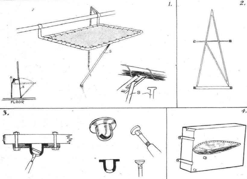
THE AGO BIPLANE. - Some constructional details. 1. The gunner's seat. 2. The rear cabane. 3. A cable attachment extensively employed on the Ago. The cup-shaped socket is machined out of the solid, and has a slot through which passes the shank of the strainer. Three-ply packing is placed between the plate of the fitting and the base so as to make up the thickness of the socket. 4. The petrol service tank lying on its side on the floor. When in place on the machine it is carried in the opening in the upper wing to the left of the cabane.

THE AGO BIPLANE. - More Constructional Details. 1. Dimensions of lower front spar near body. 2. Attachment of tubular struts to fuselage longerons. 3. The hardwood distance piece at the crossing of the internal wing-bracing cables. 4. Section of the lower front spar at the point of attachment of the inter-plane wire. 5. Perspective sketch of same joint. 6. Section of rear spar. 7. (A) construction of false spar and aileron leading edge; (B) An aileron rib (not to scale); (C) Aileron crank and attachment of inter-aileron strut.
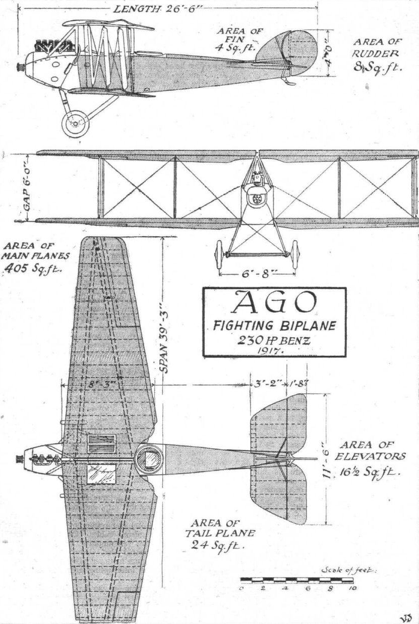
A CAPTURED AGO BIPLANE. - Plan, side and front elevations to scale.
AERIAL RECONNAISSANCE IN THE SNOW. - A German Albatros off for a trip over the lines of the Allies.
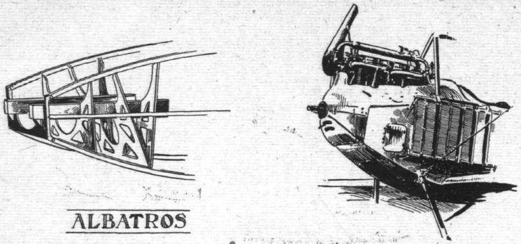
Mounting and housing of vertical water-cooled engines.
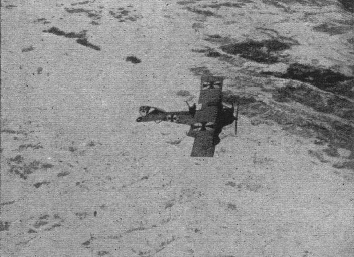
A German aeroplane flying over Volhynia.
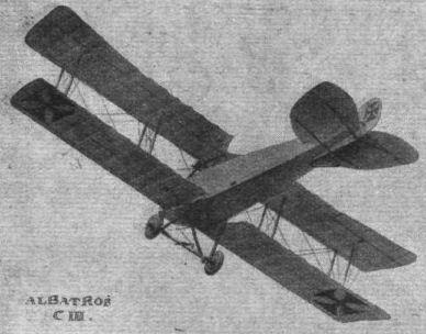
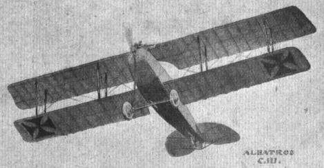
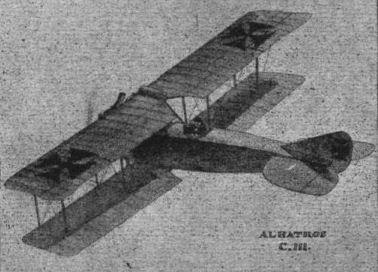
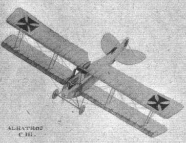
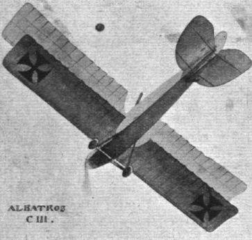

Flight, July 12, 1917.
SOME 1917 TYPE GERMAN AEROPLANES.
Albatros B.F.W. 225 h.p. (Type C. V).
One of these machines, which was captured, had been built at the Bavarian Aircraft Works, Munich, and is almost identical with the Albatros C. III, which has been illustrated in "FLIGHT." Only minor alterations are to be found, as, for instance, in the rudder and tail, which are similar in shape to those of the D.I. The ailerons, it will be seen from the sketch, are balanced by a portion projecting forward in an opening in the wing. The engine is a 6-cyl. vertical Benz, developing 225 h.p. (1,415 r.p.m.). There are two machine guns and two bomb chambers.
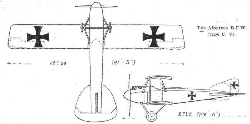
The Albatros B.F.W. (type C. V).
Flight, January 4, 1917.
THE NEW ALBATROS SCOUTING BIPLANE.
In our last issue we gave a few particulars of some of the more recent German aeroplanes, including the new Albatros scout, of which we are able, this week, to give an illustration. Until comparatively recently, the Germans have not paid any particular attention to the reduction of head resistance, the aim of their aeroplane designers having been more particularly directed along lines of stability, as witness the early Tauben and "Arrow" biplanes. While fighting adversaries who were, long before the outbreak of war, specialists, so to speak, in high-speed machines, the gentle. Hun has evidently at last realised the utility, on occasion, of a good pace, always coupled, of course, with other qualities such as climb and manoeuvring power, and at any rate, in the machine illustrated, "Speed" appears to be the keynote of the design. The large powerful engine, the stream-line body, the small wings, and the reduction of struts to a minimum, all point towards it. In the case of the body, it will be noticed that the method of stream-lining has even been carried to the extent of a hemispherical nosepiece over the propeller boss - a refinement which is not normally met with in German machines. The lines near the tail plane give indication that as far as construction is concerned, the body is not a true monocoque, but has four main rails in the usual fashion, and that the streamlining is effected by a superstructure. The nature of the latter is not quite clear, but it appears to be a metal cover, probably aluminium. A detail which was quite clear in the original photograph, but which has been obliterated in the reproduction, is the new fitting for the interplane struts.
Instead of the old familiar steel cup in which rests a ring forming the anchorage for the bracing wires, a much smaller fitting is employed, consisting, apparently, of an eye-bolt, with forked ends passing through the spar, the eye-bolt in the end of the strut fitting into the forked end of that in the spar. The Mercedes engine is almost totally covered in, the radiator, mounted above the engine, only just clearing the fuselage covering. The tail planes, it will be observed, are neatly joined to the body, the appearance being, in fact, that the body covering is run upwards to form the covering of the fin as well. The rudder is partly balanced, wholly on top of the body and some little distance ahead of the elevator, as mentioned in our brief description last week.
Flight, June 28, 1917.
THE ALBATROS D.I "CHASER" BIPLANE.
PERHAPS one of the most formidable of the various types of Hun machines our pilots have been "up against" has been the Albatros "Bu" chaser scout. Although, being comparatively heavy, it cannot claim the high speed and other performance qualities possessed by the "star" machines of the Allies, it has, nevertheless, proved itself a good fighter, and one that is decidedly handy on the control.
Through the courtesy of our authorities we have been able to make a thorough examination of one of these scouts - D. 1/391, 1916, No. 2944, brought down some six months ago on the British front - which has enabled us to add from personal inspection yet another detailed description of an enemy machine to those that have already appeared in "FLIGHT."
Having examined the Albatros "D. 1," it must be admitted that one could not but help admiring its general design and construction. Simplicity and strength formed the keynote throughout, complicated fittings and highly-finished parts being conspicuous by their absence. The "D. 1" bears signs of previous Albatros practice in several instances, mostly in a modified form, but there are also some radical innovations. Perhaps the most noticeable features consist of the monocoque fuselage - which is built up entirely of wood without any wire bracing - and the arrangement of the planes.
The latter, contrary to Hun practice, have neither sweep-back nor dihedral - the top plane, in fact, being one complete unit. The wing curve is similar to the Albatros "C. III," but having a flatter camber, whilst the angle of incidence varies from 5° 3' at the centre to 4° and 2° at the left and right hand wing-tips respectively. A somewhat novel feature consists of the method of adjusting the stagger of the top plane from 0 to 12 cm., by moving it along the top of the cabane. This is effected in the following manner: In each end of the top horizontal tube of the cabane is formed a slot, which receives an eyebolt passing through the main spar of the plane. At each slot are five holes passing horizontally through the tube, one of which - according to the adjustment required - receives the bolt that locks the eyebolt in the cabane. The arrangement is shown in one of the accompanying sketches.
In order that the correct gap should be maintained in each adjustment for stagger, the lower end of the interplane struts and the cabane struts can be adjusted accordingly at their attachments to the planes and fuselage respectively. As may be seen in two of the accompanying sketches, this is done by means of the screw adjustment on the ends of the struts as shown. Only one pair of struts on each side of the fuselage separate top and bottom planes, these struts being of streamline steel tube. The attachment fittings are shown in the sketches, from which it will be seen that the top fittings are slightly different from the lower ones, which, as previously stated, are adjustable. As in other Albatros machines the main spars are located well forward, the front one being some 4 ins. from the leading edge, and spaced 2 ft. 7 1/2 ins. from the rear one. They are of the usual Albatros rectangular section, fabric bound, and are bevelled off on the top at the extremities. The ribs, which are spaced 16 1/4 ins. apart in the top plane and 13 3/4 ins. in the bottom plane - except where the interplane struts are attached where the rib is displaced by a tubular compression member - are built up of slotted-out webs and somewhat narrow flanges. Between the leading edge and the front spar the upper surface of the plane is stiffened by a false rib between each of the ribs proper.
The lower plane is attached to an abutment built out from, and flush with the side of the fuselage. The mounting, which is shown in one of our sketches, consists of a form of bayonet socket-joint, access to which is obtained by means of doors on the under sides of the plane. As on other Albatros machines, the ailerons are given a wash out at the tips and have operating cranks working in slots in the plane. They are hinged on auxiliary spars on the top plane only. The span of the top plane is 28 ft. 4 ins. and that of the lower 26 ft. 9 ins., the chord of both being 5 ft. 9 in., and the gap 5 ft. 3 ins. The total supporting surface is 269 sq.ft.
The stabilising plane, semi-elliptical in plan form, is divided into two parts, and is exceptionally thick (5 3/4 ins.). It is non-lifting, and is mounted, in the line of flight, without any external bracing. The framework is of wood and the covering fabric. Hinged to the trailing edge of the stabilising plane is a single elevator balanced by small triangular extensions forward of the outer extremities. A rounded vertical fin, like the stabilising plane very thick, is mounted on the top of the fuselage some distance forward of the extremity of the latter. It has 'a wood framework and a covering of three-ply. To its trailing edge is hinged the rudder, which is balanced by a triangular portion extending forward, and at the top of, the rudder post. The rear edge of the rudder does not extend further than the extremity of the fuselage. A small triangular fin, also of three-ply, is formed under the fuselage by the supports for the tail skid. The framework of the elevator and rudder is of steel tubing, covered with fabric. The rudder control cables are inside the fuselage; two small doors on the top of the latter allow for inspection and adjustment. The elevator cables also pass inside the fuselage. The junctions of the fins and stabilising planes with the fuselage are rounded off with three-ply.
In the fuselage are to be found many points of interest. It is a modification of the standard Albatros system of fuselage construction, but differs in that it approaches nearer the true monocoque. It is, in fact, a compromise between the two, and suggests itself as an excellent solution to the problem of the "commercial" monocoque - simple in construction, low in cost, and of great strength. In section it varies from circular at the nose, to a horizontal knife-edge at the rear - being flat-sided, with rounded top and bottom in the centre. It is built up of six longerons, three a side, the central ones being of small rectangular section spruce (3/4 x 5/16 in. aft of cockpit, forward of which they are 3/4 x 3/4 in. L-section). The top and middle longerons are placed one above the other, but the bottom ones are closer together. Top and bottom members are, except at certain points, of L-section, and up to the cockpit are of spruce, forward of which ash, 1 3/16 x 1 9/16 in. is employed.
The longerons are supported in simple transverse "formers" or ribs, reinforced at the junctions with the longerons, spaced at intervals of, roughly, 2 ft. These formers are 3/8 in. thick and 3/4 in. deep. At the tail there are two thicket formers of the shape shown in one of the sketches. Forward of the cockpit there are four transverse formers, or supports, of three-ply, carrying the engine bearers, similar to those employed on other Albatros machines. Over the whole of this framework is laid a covering of three-ply, which is tacked and screwed to the longerons and formers. There is no wire bracing, nor are there any struts, except for two forming continuations of the front cabane struts extending to the chassis strut attachment. The pilot's seat is supported by two transverse tubes adjustably mounted on two auxiliary longerons on the side of the fuselage.
The engine, a 170 h.p. Mercedes, No. 27911, does not call for any special reference, being mounted in a similar fashion to those on previous models. The radiators, however, differ from those usually employed. They are of the honeycomb type, and are mounted one on each side of the fuselage. Above, and to the left of the camshaft, is a flat water tank, one end connected to the engine jacket, and the other end to the tops of the radiators. The lower orifices of the radiators are connected to the water pump at the rear of the engine. On each side of the engine is mounted a machine gun, synchronized for firing through the propeller. They are centred about 1 ft., and are operated by two triggers mounted on the grip of the control lever. One of our sketches shows the ammunition-feed arrangement for the two guns.
The control lever is of the Fokker type, operating the ailerons and the elevator. It consists of a 1 3/16-in. tube mounted on a 1 9/16-in. transverse tube supported on a wooden base. A locking device is fitted whereby the lever may be locked against a fore-and-aft movement enabling the pilot to remove his hands, but operate the ailerons with his knees. This locking device, which consists of an arrangement of rods forming an articulated parallelogram, is shown in our sketch, from which other details of the control may be seen.
The landing chassis is of the conventional V-type with rubber sprung axle carrying a pair of 760 x 100 disc wheels. Behind the axle is a transverse tubular tie rod, and the two rear struts are cable braced. The chassis is easily dismantled by withdrawing the struts from the sockets mounted on the fuselage.
Flight, July 12, 1917.
SOME 1917 TYPE GERMAN AEROPLANES.
The Albatros D. I and D. II.
These machines are built by the Albatros works at Johannisthal, Berlin, and its various branches, and under licence by the Bavarian Aircraft Works at Munich. As a detailed description of the D. I type was given in the June 28th issue of "FLIGHT," there is no need to deal with it here. The D. II resembles it very closely, except for minor alterations. For instance, the gap between the planes has been decreased, bringing the top plane much closer to the body, to which it is attached by two sets of struts in "N" formation, sloping outward slightly after the fashion of the Sopwith one and a-half strutter. In this type no provision is made for varying the stagger. In all other respects the D. II resembles closely the D.I, small alterations in dimensions being scarcely noticeable, except under the tape measure.
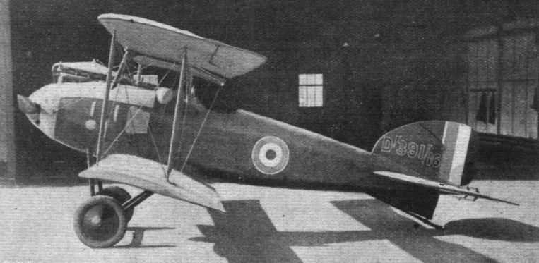
THE ALBATROS D. 1. - Side view.

THE ALBATROS D. 1. - Three-quarter view from behind.

THE ALBATROS D. 1. Three-quarter view from the front.
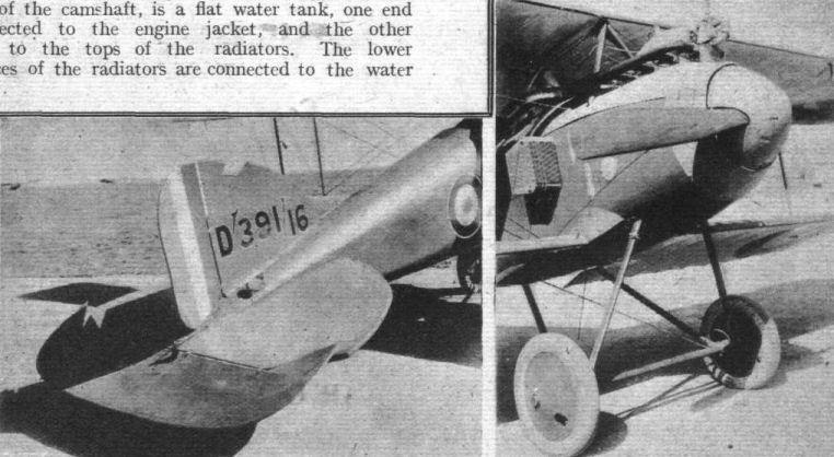
THE ALBATROS D. 1. - View of the nose and of the tail.
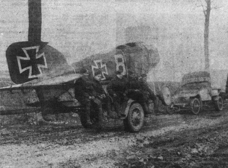
A CAPTURED GERMAN AEROPLANE. - Bringing home the spoils.
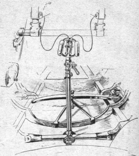
THE ALBATROS D1. - A general view of the control, showing the two gun-triggers inside the grip, and immediately underneath the locking lever.


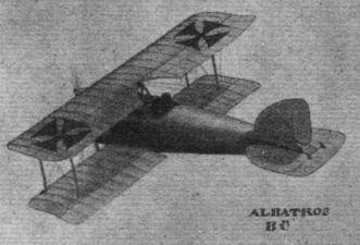
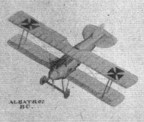
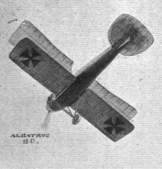
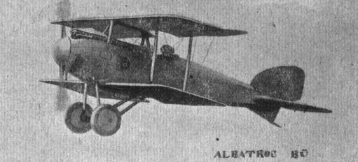
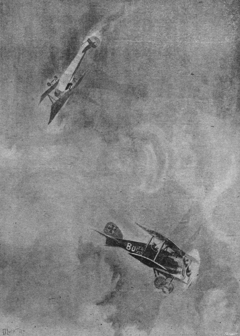
"THE NAVY-THAT-FLIES." - When he was about 150 yards behind me I looked straight over him, and coming out of the loop dived at him and fired a good long burst."
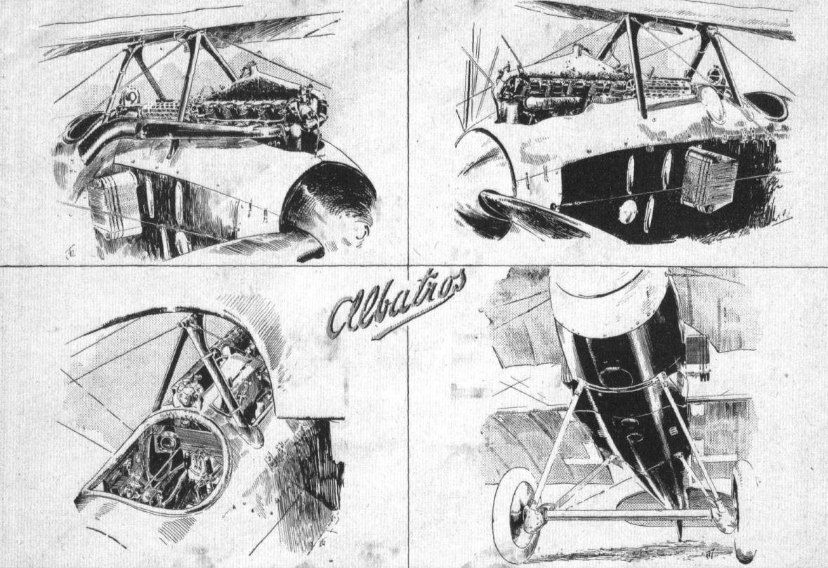
THE ALBATROS D.I. - Top: On the right a view of the exhaust side of the 170 h.p. Mercedes engine, and on the left the inlet side. Both views show the location ot the machine guns. The right-hand lower sketch gives a view of the cockpit, and on the left a view below the nose of the fuselage, showing the mounting of the chassis and the abutments for the wing attachment.

One of the radiators mounted on the side of the Albatros D. 1.
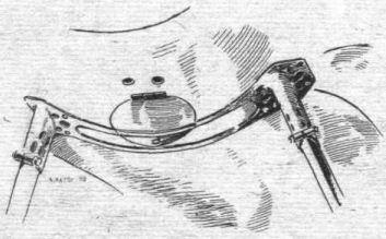
The sockets securing the chassis struts to the fuselage. The struts may quickly be detached by loosening the bolts on the sockets.
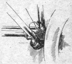
The shock absorber on the landing chassis. It will be seen that the rubber strands are interlaced.
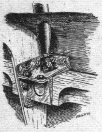
The Albatros D. 1. - The attachment of the cabane to the fuselage, showing the screw adjustment for alteration of stagger.
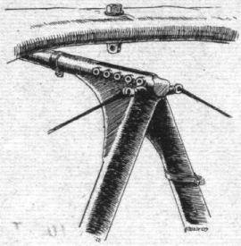
The adjustment of the top plane on the cabane.
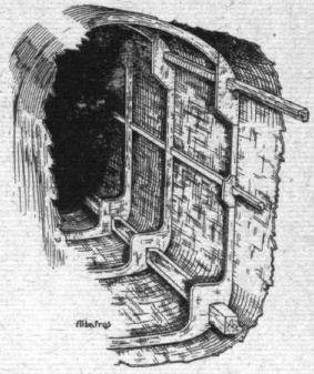
The fuselage construction.
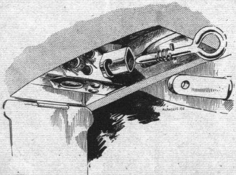
The quick release attachment of the lower plane to the fuselage on the Albatros D. 1.
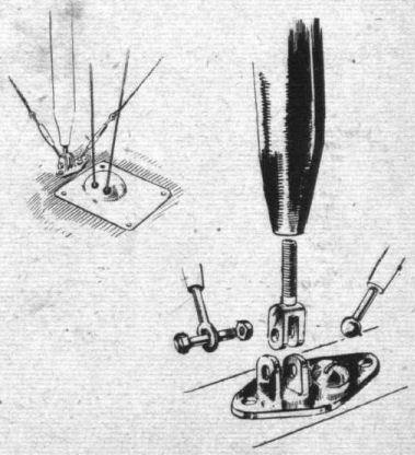
The adjustable interplane strut attachment.
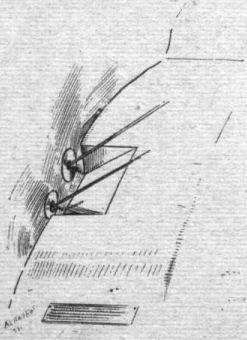
The anchorage of the lift cables on the Albatros D. 1.

The interplane strut attachment to the top plane, and the aileron crank lever.
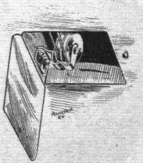
The aileron pulley inspection door on the lower plane.

A diagram showing the cartridge-feed to the machine guns on the Albatros D. 1.
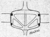
The Albatros D. 1. - Section of fuselage at the junction of the rudder post.
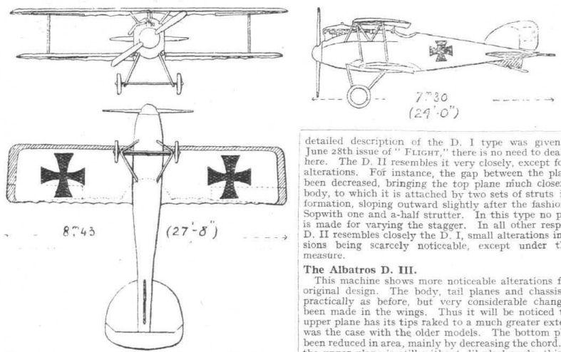
The Albatros D. II.
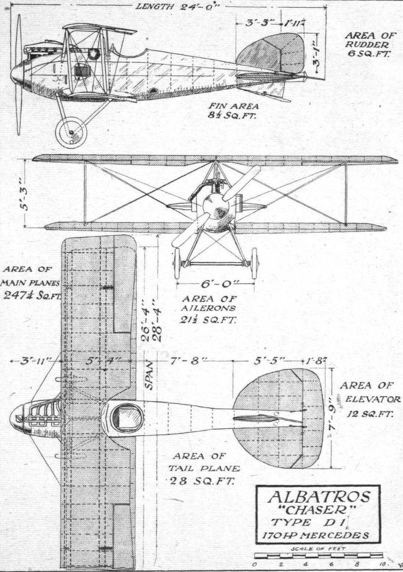
THE ALBATROS D.I "CHASER" BIPLANE. - Plan, side and front elevations to scale.
Flight, July 12, 1917.
SOME 1917 TYPE GERMAN AEROPLANES.
The Albatros D. III.
This machine shows more noticeable alterations from the original design. The body, tail planes and chassis remain practically as before, but very considerable changes have been made in the wings. Thus it will be noticed that the upper plane has its tips raked to a much greater extent than was the case with the older models. The bottom plane has been reduced in area, mainly by decreasing the chord. While the upper plane is still without dihedral angle, this feature has been employed for the lower plane, and the inter-plane struts are of the Vee formation familiar from the French Nieuport chasers. The attachment to the body of the top plane is by means of two struts on each side, sloping backwards and outwards. Instead of the small radiators mounted on the sides of the body, the radiator is mounted in the centre section of the top plane, and the small water tank formerly mounted above the engine has therefore disappeared. In other respects the D. III does not differ greatly from previous models.
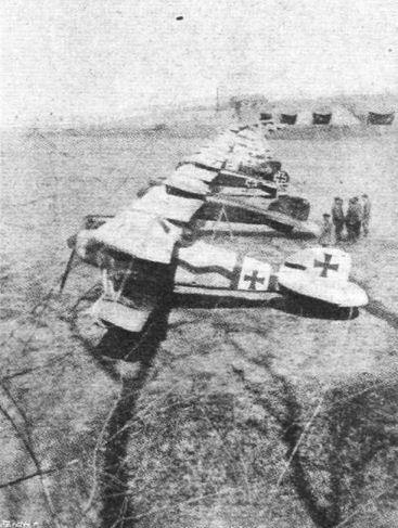
A Fighting Squadron, under the command of Von Richthofen ready for starting on its work.
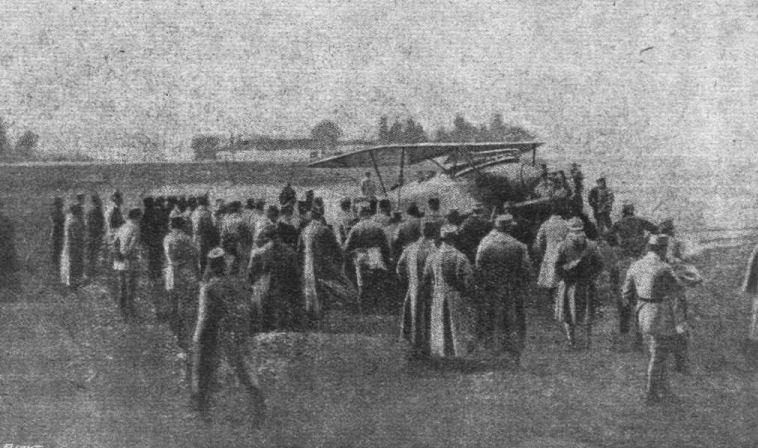
A recent German machine brought down by Capt. Heurtaux, who has now 21 machines to his credit. This is one of the latest types of Albatros,
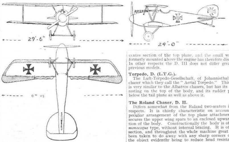
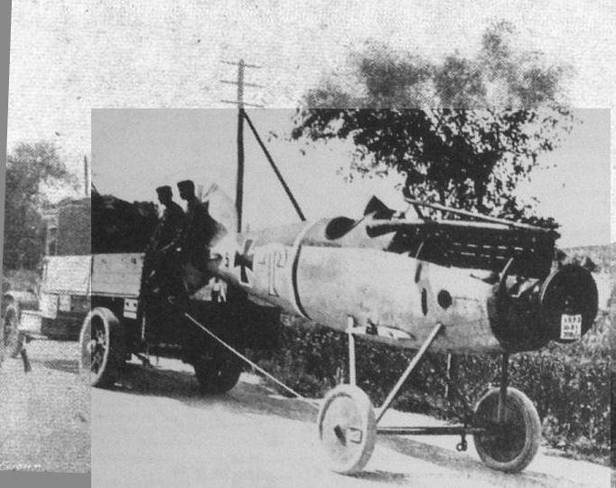
Transporting a German aeroplane . (Albatros) to the front. A single-seater Albatros, with 8-cylinder 250 h.p. Mercedes engine, and geared-down airscrew. This type has been replaced by the D IV type with a 6-cylinder 260 h.p. engine.
Flight, February 15, 1917.
THE AVIATIK BIPLANE - 1916 TYPE.
UNDER present conditions it is naturally a matter of considerable difficulty to obtain detailed information concerning enemy aeroplanes. Even when one of these is brought down intact behind our lines - which is not, unfortunately, very frequently the case, as the greater part of the fights in the air take place beyond the lines, and therefore the enemy machines, when brought down, generally hit behind their own lines - some considerable time must necessarily elapse before our own and the French military authorities have finished their examinations and the machines become available for other inspection. We have, however, been fortunate enough, in spite of the difficulties indicated, to obtain facilities for examining several of the enemy planes from time to time, and have in this way been in a position to publish detailed descriptions illustrated by photographs and sketches, as well as scale drawings, of such German machines as the Albatros reconnaissance biplane, the Fokker monoplane, the Albatros fighting biplane and the L.V.G. fighting biplane. The description of the Aviatik biplane - for the photos, of which we are indebted to our contemporary L'Aerophile - in the present issue brings our list practically up to date -at any rate up to the latter part of 1916 - and during the present year we shall endeavour to keep our readers as well informed regarding the German 1917 types as we have done with the 1916 types in the year just gone by.
In the 1916 type Aviatik biplane the body is of the wood girder variety, covered with fabric at the rear, while from the nose to a point behind the engine, the covering is aluminium. In section, the body is rectangular, and differs from earlier types in that the upper longerons, or rails, are no longer parallel to the line of thrust as they were, but slope down gradually towards the stern post and somewhat abruptly towards the nose of the fuselage.
Diagonal wire bracing is employed, and the wiring plates at the point where the struts abut on the rails are shown in one of our sketches. This wiring plate, for which, by the way, the Aviatik firm hold a patent consists, as will be seen, of a single sheet steel clip totally surrounding the rail and bolted together where its two ends meet, so as to grip the rail. No strut socket is employed, the strut being prevented from slipping by the simple means of punching the metal of the clip upwards in the shape of four small triangles, which project into the end of the strut. In front the four rails converge but do not quite meet, the extreme nose of the body being formed by a steel capping plate having lightening holes cut in it. On this end plate, and two more further back, rest the two longitudinal ash engine bearers, further rigidity being obtained by bracing the engine bed with steel tubes from the body rails.
Immediately behind the engine is the gunner's cockpit, while still further towards the rear is the pilot's seat. This arrangement is rather different from that usually found in German machines, where generally the pilot is in front, as, for instance, in the Albatros fighting biplane and in the L.V.G. It would appear that the gunner's movements must be somewhat hampered, enclosed as he is between struts, wings, &c. Along each side of the body runs a tubular rail mounted on brackets on the side of the body. The gun mounting itself is free to slide along these rails, and can be locked in position by means of a cam operated by a handle as shown in the sketches. In order to compensate for the difference in distance according to whether the gun is near the centre or at the ends of the rail, the gunner's cockpit is of rectangular form, thus allowing him a certain amount of movement forward and backward.
On each side of the gunner is a large petrol tank each containing about 24 gallons of petrol. Mounted on the front struts supporting the upper plane is a small service tank to which petrol is fed from the two main tanks by means of a small propeller-driven pump, a hand-pump being provided in the pilot's cockpit for emergencies. A fourth small cylindrical tank is mounted underneath the motor, an air pressure being maintained in it by a small pump driven off the cam shaft of the engine. Needless to say, such an arrangement of tanks necessitates a very complicating feed and pressure arrangement, and provision has been made for running the engine on the contents of one of the tanks in case the others have been pierced by projectiles. Between them the tanks have a capacity of 55 gallons of petrol.
As already mentioned, the engine - a Mercedes of about 170 h.p. - is mounted on ash bearers in the nose of the body. A large portion of the cylinders projects through the covering, and must hamper the gunner's view very considerably, especially as the exhaust collector rises up above the top plane. The radiator is no longer, as in the earlier types, mounted on the sides of the body, but supported on brackets on the front struts of the cabane, yet not let into the top plane as is the case with that of the L.V.G. biplane. The oil tank, which has a capacity of about 4 1/2 gallons, is placed above the reserve petrol tank, on the left side of the engine. In conformity with general modern German practice the under-carriage is of the simple Vee type; differing, however, from the majority of other makes in that the front and rear chassis struts do not quite meet at the bottom, where they are attached to a short horizontal tube which serves as an anchorage for the shock absorbers. The latter consist of rubber rings, one strand of which is taken below the axle instead of above it in order to form a buffer between the axle and the elliptical tube connecting the apices of the two Vees of the under-carriage. The two front chassis struts are cross-braced by means of cables, eyebolts into which the cables are spliced doing service as terminals and strainers at the same time by passing through the lower horizontal - or skid - portion of the chassis. In the rear bay of the under-carriage bracing is effected by a single cable running across horizontally from the strut on one side to the corresponding strut on the other, the terminals being eyebolts similar to those used in the front bay.
The controls are of the usual type, consisting of a wheel mounted on the top of a vertical tube, the lower end of which is secured to a transverse rocking shaft. A short length of chain passes over a sprocket on the wheel axle, and is connected to the cables, leading to the ailerons. The elevator cables pass, the upper one direct to the upper crank lever on the elevator, and the other over a pulley a short distance in front of the control column. A foot bar with heel rests operates the rudder.
In plan the main planes are of the usual Aviatik type, with the exception, perhaps, that the backward slope is less pronounced than in older types. The wings are not staggered, but both are given a slight dihedral angle, whereas in the older model the lower wing had a pronounced dihedral, while the upper wing was straight. The angle of incidence, which is constant from root to tip, is about 4°, a fact which, coupled with the section employed, appears to indicate a considerable lift but no very great speed. Constructionally the wings are chiefly remarkable on account of the placing of the back spar, which is, it will be seen, placed very far forward in the section. The spars are spruce, with the exception of the upper back spar, which is of ash. They are of the box section, the two halves being spindled out and glued together, with the usual hardwood tongues. The ribs are made throughout of poplar, and the webs lightened as shown in one of our sketches. Compression struts in the form of steel tubes are placed at intervals, those occurring at the points of attachment of inter-plane struts to spars being secured to the strut fitting, while those placed between struts have their own fitting as indicated in the accompanying sketches. The attachment of the spars to the body forms the subject of another illustration. A short steel tube runs across and inside the fuselage, and is sweated into a collar, which, in turn, is secured to a clip passing under the bottom body rails. Into the outer end of this collar is sweated or welded a short eyebolt that passes between the forked ends of the fitting on the root of the spar. An L-shaped pin is passed through a groove in the inner rib and through the three holes, thus locking the spar to the body. This pin is prevented from slipping out by the small cover over the slot in the inner rib, which, when closed down, locks the pin in position. A similar arrangement is employed for attaching the upper wings to the four-legged cabane. The interplane struts are stream-line steel tubes filled with wood, a practice adhered to practically throughout this machine. The strut fitting is shown in a sketch which does not, we think, need any explanation.
The cross bracing, which is in the form of stranded cables, is somewhat peculiar, especially in the inner bay. Here the lift cables are crosses, that is to say, the one runs from the top of the front inter-plane strut to the attachment of the rear bottom spar to the body, and the other from the top of the rear strut to the root of the front lower spar. This practice appears to be generally favoured among German aeroplane constructors, as it is incorporated also in the Albatroses and L.V.G.'s. It has, of course, the advantage of bracing the wings in a fore-and-aft direction, but must, it would seem, put a considerable stress on the inner compression strut inside the upper wing. The landing cables in the inner bay, instead of being attached to the top of the cabane, are anchored to the top body rails, as shown in the front elevation, the object probably being to provide a free movement for the machine gun.
As regards the shape of the tail planes, this will be clear from the scale drawings, but a few words concerning their construction may be of interest. With the exception of the ribs of the fixed tail plane the control organs are made of steel throughout. The fixed stabilising plane rests on the upper body rails, and as these, as already mentioned, are not horizontal, the tail is set at a small angle of incidence in relation to the line of thrust. Underneath it is braced by four short steel tubes to the bottom body rails, and on top by two tubes running to the vertical fin.
As regards the armament of the Aviatik, there are, in addition to the two gun mountings already referred to, two bomb tubes, one on each side of the pilot and slightly ahead of him. The bombs, of which sizes up to about 8 1/2 ins. can be accommodated, are released from the gunner's seat by means of Bowden cables.

Three-quarter front view of the 1916 Aviatik fighting biplane.
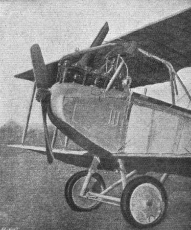
The 140 h.p. engine, and chassis of the Aviatik fighting biplane.
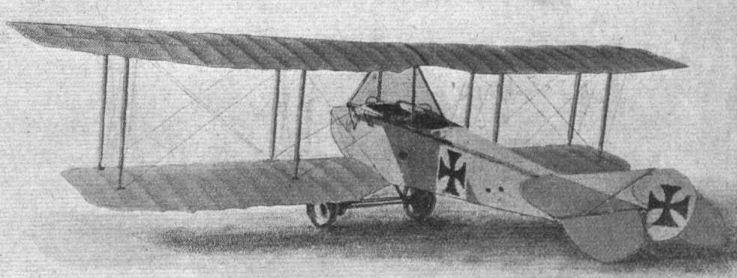
Three-quarter rear view of the 1916 Aviatik fighting biplane.
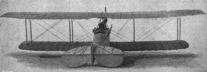
Rear view of the 1916 Aviatik fighting biplane.
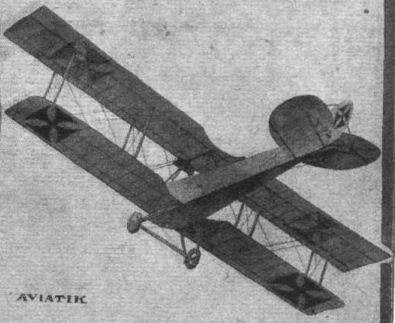
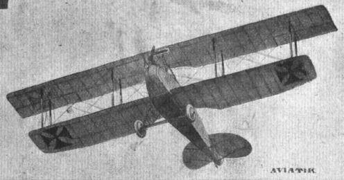

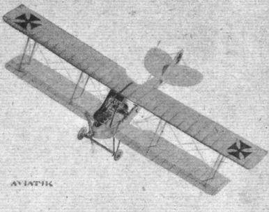
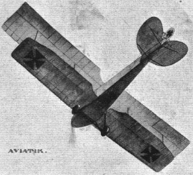
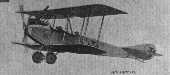
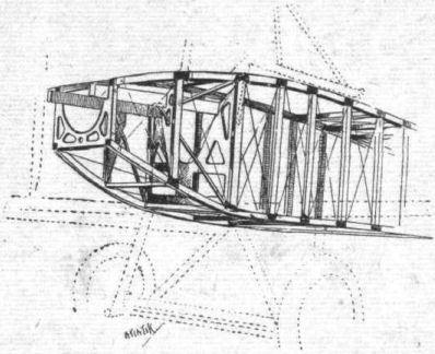
Skeleton view of the fore part of the fuselage, showing the ply-wood engine bearer supports on the 1916 Aviatik biplane.
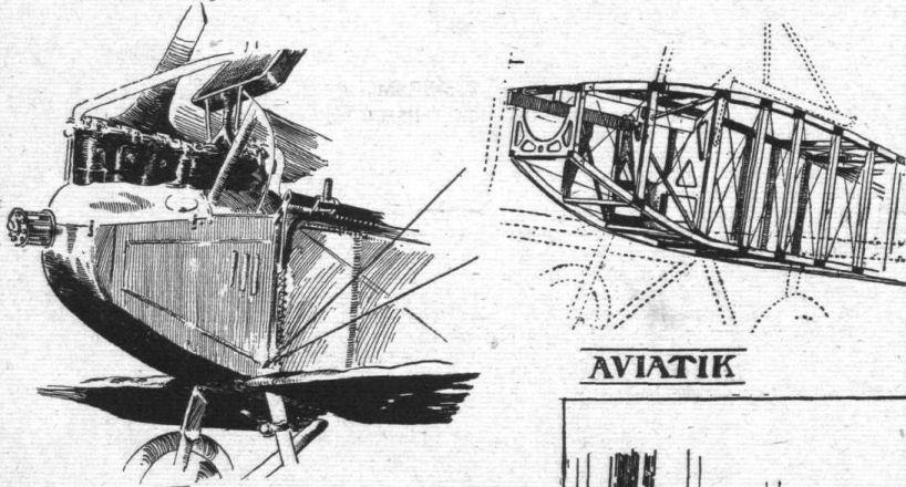
Mounting and housing of vertical water-cooled engines.
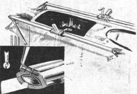
General arrangement and detail of the gun mounting on the 1916 Aviatik biplane.
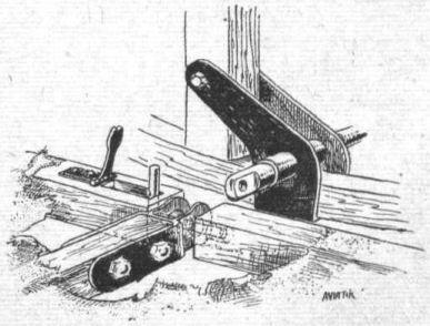
The attachment of the lower plane to the fuselage on the Aviatik biplane. A fork on the wing spar engages with the eye of the tubular cross-member mounted on the fuselage, and a pin, for which a slot is cut in the inner rib of the wing, holds them in place. The pin is locked by means of a spring clip.
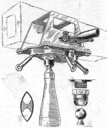
The 1916 Aviatik Biplane The attachment of the interplane struts by ball and socket joint, and the anchorages for the bracing cables.
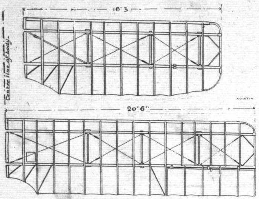
The general arrangement of the upper and lower planes of the 1916 Aviatlk biplane.
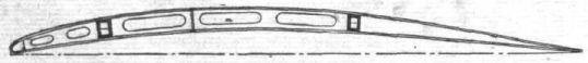
The wing section of the 1916 Aviatik biplane.
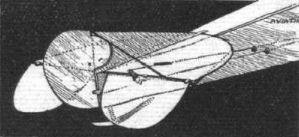
The tail planes and balanced rudderon the 1916 Aviatik biplane.
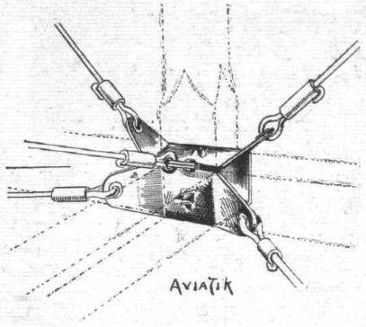
Fuselage bracing clip on the Aviatik biplane.
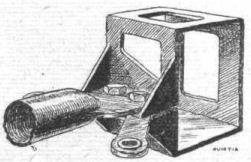
One of the metal clips carrying the tubular compression strut between the spars.

The chassis of the 1916 Aviatik biplane.

THE 1916 AVIATIK FIGHTING BIPLANE. - Plan, side and front elevations to scale.
Flight, April 19, 1917.
THE "TOTALLY ENCLOSED" AEROPLANE.
<...>
Another monoplane with enclosed cabin at the same exhibition was one built by the Bavarian Motor and Aircraft Works. As the illustration shows, this machine was of the underslung type, similar to the Bleriot "Aerocar," but the engine - a 50 h.p. rotary built by the same firm - was mounted in front of the wings. The undercarriage was built up of steel tubes throughout, and the tail planes, which were mounted on tubular outriggers, were also made of steel. The cabin provided seating accommodation for two - side by side. Dual control was fitted so that either of the occupants might handle the machine. Windows in the side and front furnished an excellent view outwards as well as forward, where the engine was mounted so high as to not impede the view to any considerable extent. As a matter of fact, it would appear that the engine, or more correctly speaking the propeller, was placed somewhat too high for the centre of thrust to coincide with the centre of resistance, and possibly there would be a tendency for the tail to drop when the engine was switched off. The workmanship and finish of this machine were excellent, and apart from the points raised above its general lines were rather pleasing. We have, however, no information regarding its performance, and no more of the type were seen after the show. The span was 35 ft. and the overall length 25 ft. The total weight is stated to have been only 660 lb. empty, which appears somewhat optimistic in view of the amount of steel employed in the construction.
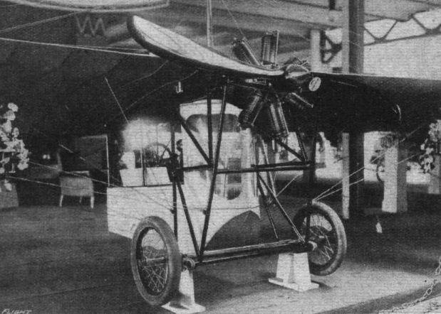
The Bavarian Motor and Aircraft Works monoplane at the Berlin Show of 1912.
Flight, July 12, 1917.
SOME 1917 TYPE GERMAN AEROPLANES.
The D.F.W.-Aviatik.
Before the war the Deutsche Flugzeug Werke, of Lindenthal, Leipzig, produced exclusively machines of the Arrow type. Since the war this type has never been in great favour, and when the firm are now producing a slightly modified machine it appears probable that this was done to meet the requirements of the military authorities. This machine is not only built by the D.F.W. firm, but also, presumably under licence, by the Aviatik Co., another firm whose machines have not been over-popular of late.
One of the chief modifications in the modern type is that the backward slope of the wings has disappeared. The dihedral angle has been retained. The body, which is of rectangular section, is covered with three-ply wood, and is very pointed, towards the nose, where it terminates in a "spinner," covering the propeller boss. The engine is a 6-cyl. Benz. developing 228 h.p. at 1,410 r.p.m. The standard complement of two machine guns is carried, and the bomb chamber will hold six bombs. The weight of the machine empty is 2,100 lbs.
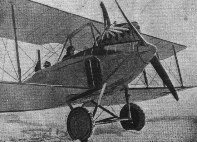
A D.F.W. biplane as built by the Aviatik works. It will be noticed that the wings are no longer swept back, otherwise the machine follows closely along the lines of the prewar type D.F.W. biplanes. The engine in this instance is a 225 h.p. Benz 6-cyl., with exhaust collectors. Two machine guns are carried, one firing forward "through" the propeller, and the other on a turntable in the rear cockpit.
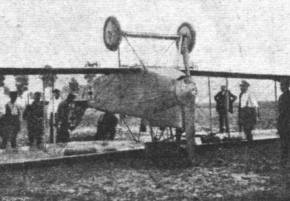
A German aeroplane brought down at Aardenburg in Holland; the occupants were interned. The machine appears to be an Aviatik D.F.W.
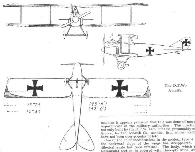
Flight, July 12, 1917.
SOME 1917 TYPE GERMAN AEROPLANES.
The Fokker Chaser Biplane.
Two types of this machine have been turned out by the Fokker firm, one with a 100 h.p. rotary engine (Oberursel) and the other with a 175 h.p. Mercedes. No specimens of these machines have been captured - at least, not in a condition to provide much information - but photographs of one which landed in Switzerland give a good idea of the general arrangement. Both wings, upper and lower, are of equal dimensions as regards span and chord (29 ft. 6 ins. and 4 ft. 10 ins. respectively). There is neither dihedral angle nor sweepback, but a fairly large stagger. The gap is small, bringing the top plane down almost to the upper longerons of the body. A low cabane of the Nieuport type connects the upper plane and the body. The centre section of the upper wing is raised above the rest of the plane so as to give the pilot a better view and facilitate - getting into or out of the cockpit.
As in the Halberstadt, there are two pairs of inter-plane struts on each side, these consisting of circular section steel tubes streamlined with wood fairings. Lateral balance is maintained, not by means of ailerons as in practically all modern biplanes, but by the now obsolete method of warping the wings, the bracing being arranged accordingly.
The body is of the Morane type, of hexagonal section, with a slight turtle back, flattening out towards the rear. The rotary engine is overhung and partly covered in by an aluminium cowl. Above this and slightly to the right is mounted the synchronised machine gun. Occasionally two machine guns are carried, each slightly outward from the centre of the body.
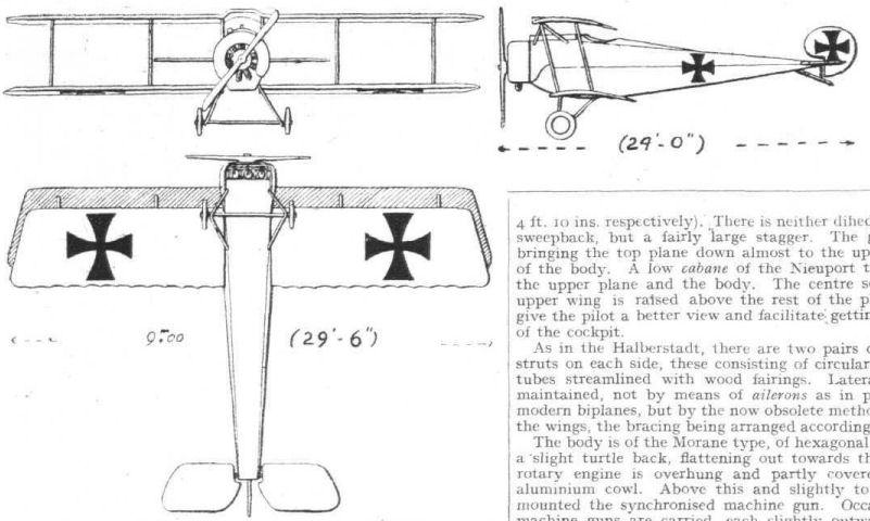
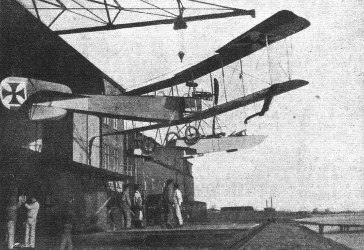
HOISTING HER HOME. - Bringing a German seaplane into its hangar by means of a crane.

A COLD JOB. - A German seaplane on its return from a flight over the North Sea in winter.
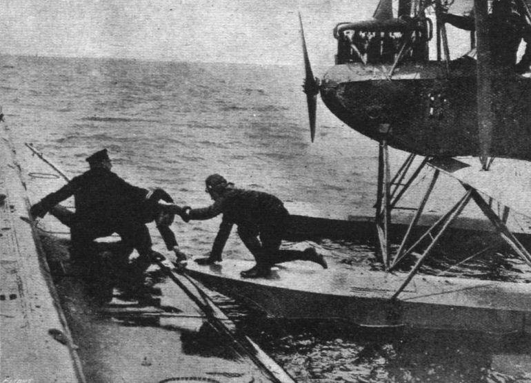
The co-operation of German Air-Raiders with Hun U-Boats. - A German pilot going aboard a U-boat from his seaplane.
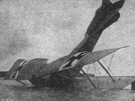
THE MERCEDES HAS A COLD BATH. - A German seaplane after a rough "landing."
Flight, November 8, 1917.
THE GERMAN F.F. BOMBER.
M. JEAN LAGORGETTE
THE Fliigzeugbau Friedrichshafen have, for a considerable time past, specialised in the construction of seaplanes. For some time now they have also been making land machines, of which one type with two engines, now actually in service, is described in the following, from specimens captured recently on the French front near Verdun, and on the Macedonian front.
It is quite possible that these twin-engined machines have been used for raids on England, and on the vicinity of Paris, together with the Gothas, with which latter they have several points in common and of which, in certain respects, they are copies on a reduced scale. Their dimensions are as follows: Length about 11 metres; height, 3 m. 60 (3 m. 80 including air-screws) and 4 m. 10 to the top of the rudder). Span of upper wing, 20 m. 30; span of lower wing, 18 m. 85; the chord of the wings being about 1 m. 80 to 2 m. 30; the total wing surface is 70 sq. metres. The gap is 1 m. 95, close to the fuselage.
The wings are back-swept and set at a dihedral angle, except for the fixed central sections, which are straight on acccount of the mounting of the motors. The stagger is very small. The wing tips are raked and the ailerons have a wider chord at the tips than at the root. The trailing edges are cut away for a considerable distance in order to provide clearance for the propellers. Each motor is mounted on a framework of struts in the form of a V, and they are braced to the fuselage by struts running nearly horizontal. In addition to the motor struts, there are two pairs of interplane struts on each side, which slope outwards as shown in the front view. The overhang of the top plane is braced by diagonal wires running to the lower ends of the outer pair of interplane struts.
As distinct from the Gothas, the wing ribs are parallel to the centre line of the machine. Each of the ailerons has a forward projection near its tip, so as to partly balance it. The span of each aileron is 3 m. 80 and the chord is from 0 m. 50 to 0 m. 60. The area is about 2.3 square metres. The wings are painted green and reddish brown on the upper surface, and a clear blue on the under side.
The tail plane and elevators, the span of which is 3 m. 95 and the length 3 m. 65, resemble the irregular polygonal form of those of certain Albatros machines of 1914. The same applies to the very high rudder, in front of which is a fin of triangular shape, slightly rounded in front, and reminiscent of certain English biplanes, a feature which appears to become general on recent German machines. As on all German aeroplanes the elevators and rudder, like the ailerons, are balanced, and are constructed of steel tubing.
The fuselage is of the ordinary form, of rectangular section with the upper face horizontal. The maximum depth of the fuselage is 1 m 27, and the maximum width 1 m. 20. The cockpits in the fuselage are arranged in tandem, with sufficient space at the sides for changing places. In the nose is the gunner's cockpit, with a circular gun-ring. Behind him is the pilot's seat. Behind this again is the main petrol tank, which is o m. 90 in width, and on each side of this are the bomb racks, placed longitudinally. In the rear cockpit, which is occupied by a gunner, there is a circular gun-ring, similar to that employed in the front cockpit, and in addition there is in the floor a trap door, raised by means of a lever and cable, through which the gunner can fire in a rearward and downward direction by kneeling on the footboards. The front of the fuselage is covered with 3-ply, the rear with fabric. Behind the rear gunner, the fuselage is made detachable by means of four clips and bolts, so that the rear portion, with the tail planes, can be detached from the front part for ease in transport and storing.
The under-carriage differs considerably from that of other German biplanes. Under each motor there is a pair of wheels of 965 mm. diameter on a common axle and having a track of 0 m. 80. They are sprung by means of rubber shock-absorbers from a short skid, which is streamlined. The front and rear of these skids are connected to the lower plane by a strut sloping backwards to the base of each of the two V's which support the engines, and by a strut to the fuselage, placed at a very considerable slope.
The engines are six-cylinder Benz. No. 22799 gives 226 h.p. at 1,410 r.p.m., No. 25344 gives 221 h.p. at 1,400 r.p.m. Each of the engines is enclosed in a little boat-shaped nacelle terminating at the rear in a streamlined piece fitted over the propeller-boss. In the nose of the nacelle is mounted the radiator. The air-screws, which are marked "Imperial," have a diameter of 2 m. 90. The various tanks contain a total of about 550 litres of petrol. The oil tanks are placed under the radiators and extend a short distance to the rear.
In addition to the machine guns, the F.F. biplane appears to carry 12 explosive bombs and a few incendiary bombs. The number appears to vary. The total weight of the machine empty is 2,200 kilogs., the useful load 520 kilogs., and the weight of fuel 432 kilogs., giving a total weight of 3,152 kilogs., which works out at nearly 45 kilogs. per square metre, which is a very heavy loading, and 7 kilogs. per h.p. The machine carries fuel for four hours.


A German (Gotha) seaplane over Constantinople.

A GERMAN GOTHA TWIN-ENGINED BIPLANE. - The span of this big German fighter is 78 ft. 6 ins., length 41 ft. The wings are of about the same span, with balanced ailerons on the upper plane. Three pairs of struts, in addition to the engine struts, are fitted on each side of the body. The latter is of rectangular section covered with three-ply wood in front. Two machine gunners are carried, one in front and one behind, a gangway connecting them. In the floor there is a trap door for firing downwards, the armament consisting, in addition to the machine guns, of three bomb tubes holding 144 bombs. The engines are 6-cyl. Mercedes, each of 260 h.p., driving airscrews placed to the rear of the wings. One of these machines, it is stated by L'Acrophile, was brought down by Captain George Guynemer, the famous French "Ace."
Flight, July 12, 1917.
SOME 1917 TYPE GERMAN AEROPLANES.
TWIN-ENGINE MACHINES, TYPE G. I AND G. II.
The Twin-Engine Gotha Three-seater, 520 h.p.
This machine will probably be found the most interesting of those included in this series, as it played such a prominent part in last Saturday's raid on London. In view of this fact we have given the drawings illustrating it rather more prominence than those of the other machines.
Although by far the largest of the German biplanes, the Gotha is not quite so large as our own Handley-Page biplanes, the sample of which, duly delivered to them at Lille, has undoubtedly provided the Germans with valuable data for their Gotha three-seater. As distinct from the Handley-Page, however, the Gotha has its propellers at the rear of the wings, and a considerable backward slope to the main planes. Also, the tail is of the monoplane type. The top plane is built up in two halves, attached to a central cabane, while the bottom plane is in three sections, one of which runs from the inner side of one engine housing under the fuselage to the inner side of the other engine housing. The main spars are of I section with three-ply flanges. Structurally the ribs are of little interest, but as they are at right angles to the spars they form an angle with the line of flight. This disposition also has the effect of offsetting the inter-plane struts, the front and rear ones of which are not in line. This is not shown in the sketch.
The shape of the tail surfaces can be seen from the illustrations, and they are chiefly remarkable from the fact that they are, as already pointed out, of the monoplane type. Their area is, therefore, very small as compared with that of the tail surfaces of the Handley-Page.
The long enclosed body is of rectangular section, and is covered with three-ply in front and with fabric at the rear. It is built up of four ash longerons and ash struts. The placing of the .three occupants is rather peculiar, being unsymmetrical. If the gunner in the front cockpit is seated centrally in the body, the pilot is placed on the left-hand side with his controls, leaving an open space between him and the starboard wall of the fuselage. This space is, as a matter of fact, provided to form a passage from the front to the rear gunner. Behind the pilot are two bomb racks, while further back still is the cockpit for the second gunner. Two guns are within reach from this seat, one is placed above the body, while the other fires down through a tunnel sloping backwards and downwards from the cockpit, permitting of firing in that direction.
The undercarriage consists, briefly speaking, of two separate Vee chassis, one under each engine, and is, needless to say, built of streamline steel tubes. The engines themselves are housed in roomy nacelles resting on the bottom planes. They are 6-cyl. vertical Mercedes motors, each developing 260 h.p. at 1 400 r.p.m. The cylinders, which are 160-bore by 180-stroke, are in two groups of three each. There are four overhead valves and two sparking plugs to each cylinder, and the usual overhead camshaft is employed. The radiators are mounted in the nose of the engine housing, and under them are placed the oil tanks. The main petrol tanks are situated below the engines.
The armament consists of three machine guns, one in front, capable of being fired in any direction within the hemisphere limited to the rear by the wings. A second is mounted on a transverse rail almost touching the top of the fuselage, while a third can be fired downwards and backwards through a tunnel in the body. In addition, there are several bomb racks carrying a total of 14 bombs.
Flight, December 27, 1917.
THE GOTHA TWIN-ENGINED BOMBING BIPLANE.
WE are able this week to give our readers some further particulars and illustrations of the Gotha bombing-type biplane. From the various samples that have fallen into the hands of the Allies, it would appear that the Gotha bomber has been altered in design, as regards certain details, from time to time. The accompanying scale drawings, therefore, should be looked on as being approximately correct as regards the general design of the Gotha machine.
The total span of the top plane is 78 ft. and that of the lower plane 72 ft. It will be noticed that the top plane, which is in two sections, is given a sweep-back from centre to tips, whilst the lower plane is similarly swept back only from the engine nacelles to the tips, the central plane section between the nacelles being "straight." The amount of sweep-back appears to vary according to type, but 5 # may be taken as being about correct. It will be further noticed that the ribs are at right angles to the spars, and the interplane struts are not, therefore, in line when viewed from the front as is general practice. The only advantage one can see in such an arrangement would be cheapness and ease in construction, but it is doubtful if this is really "worth the candle," when one considers the loss in efficiency that must arise therefrom, especially due to the resistance offered by the ribs should the fabric become a bit slack.
The top plane sections are connected by steel tongues or plates on the inverted V cabanes supporting the plane above the fuselage - these tongues being inserted into clips on the wing spars.
The main spars of the top plane are of I section ash with three-ply glued over the spindled-out portions on each side and wrapped with fabric, giving the equivalent of a rectangular section. The ribs are built up of three-ply webs, cut out for lightness and pine flanges. At each pair of interplane struts, and also between each pair, are tubular steel compression struts. These are held in sockets bolted on the spars, and each bay - which is practically square - is braced with single-strand cable. The spars of the lower plane are of similar construction to the top ones, except that pine is employed instead of ash.
Some models are piovided with ailerons on both top and bottom planes, upper and lower ailerons being connected by steel struts. The ailerons on the top plane are balanced by a small portion extending beyond the wing tip as shown, and are hinged to the rear spars by strap hinges. They are built up of steel tubing, and are operated by a crank arm curving over the rear main spar with its end projecting in a slot formed in the plane - a practice common on German machines.
Top and bottom planes are separated by three pairs of interplane struts a side. These are of steel tubing, streamlined by means of wood fairings and bound with fabric. The interplane struts are attached to semi-spherical fittings mounted on the main spars, and, as may be seen from one of the accompanying sketches, the wire bracing attachment is somewhat novel. The bracing cable is passed through a hole in a cigar-shaped steel fitting and spliced: a bolt on the spar fitting screws into the end of the cigar-shaped fitting, which is locked by a piece of wire. Adjustment is apparently made by screwing the cigar-shaped fitting by means of a tommy bar inserted in another hole drilled at the pointed end of the fitting. Portions of the trailing edges of both top and bottom planes are cut away to give clearance for the propellers.
All the tail planes, stabiliser, fin, elevators, and rudder, are constructed of steel tubing, the various members being welded together. No wire bracing is, however, employed. The rudder and elevators are, like the ailerons, hinged with strap hinges, and the two elevators are coupled together to work in unison. The stabilising plane is braced top and bottom by steel tubes. The Dep. type of control is employed, the wheel column being mounted on a tubular steel rocking shaft supported in bearings on the lower fuselage longerons. The elevator control cables are attached to quadrants mounted above and below the rocking shaft. The aileron control cables are attached to the ends of a chain on a sprocket wheel mounted on the control wheel shaft. The cables pass over pulleys at the bottom of the control column, through the rocking shaft, and inside the lower plane to the ailerons. The rudder is operated by a pressed steel bar fitted with neat stirrups for the pilot's feet. The engine control is situated at the pilot's left hand.
The fuselage is of almost square section, tapering to a vertical knife edge at the rear and a rounded point at the front. The maximum depth and width is about 3 ft. 6 ins. and the length is 39 ft. It is built up of four longerons, which are of laminated ash in front and pine at the rear, and cross struts, cable and wire braced.
The longerons are spindled out in places, and where spindled have a covering of three-ply. The longerons gradually taper in section from the centre, and, on the whole, are not particularly striking as regards strength. The covering of the fuselage is of three-ply, tacked to the longerons and cross struts. Behind the rear cockpit the bottom of the fuselage is tunneled out so as to enable the gunner to fire rearwards and downwards - there are, therefore, no cross struts bracing the lower longerons at this part, which is indicated by a dotted line in the side elevation in the scale drawings.
The arrangement of the cockpits is as follows :- In the nose is a circular cock-pit for the forward gunner, the gun being mounted on a semi-circular rail. Behind the front cockpit, and just forward of the main planes, is the pilot's compartment. The seat is a little to the starboard side, there being a gangway on the port side, leading from the front cockpit to the pilot's and after gunner's compartments. The latter compartment is situated at the trailing edge of the planes, and is provided with a gun mounting on the top of the fuselage, as well as the tunnel gun previously mentioned.
The engines are each 260 h.p. 6-cyl. Mercedes, mounted some 15 ft. apart, and completely enclosed within housings of three-ply and sheet aluminium. A honeycomb radiator is mounted in front of the engine on extensions of the bearers, and below the engine are located the fuel tanks. The engines are supported on stout spruce bearers connected by tubular struts to the lower plane sections the whole of this engine frame is wire braced.
Below each engine nacelle is a two-wheeled undercarriage, consisting of a pair of tubular steel V members, streamlined with wood fairings and fabric bound, carrying a tubular axle, which is, we believe, also streamlined by a fairing. The front members of the V's are connected at their lower ends by a tubular tie-rod, the anchorage for the cross-bracing being at the attachment of the tie-rod, as shown in one of the accompanying sketches. The shock absorbing system is of particular interest, in that rubber is not employed. Instead, two lengths of cable attached to the axle pass under pulleys mounted in the axle box, formed by the apex of the V, and up each of the chassis tubes to a long steel compression spring within the latter. This arrangement is shown diagrammatically in one of our sketches.
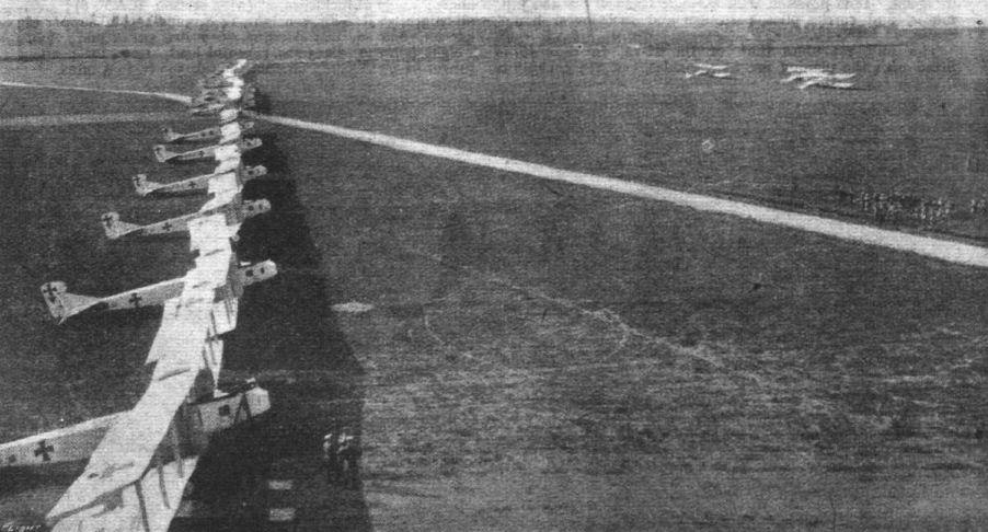
A group of the double-engine Gotha raiders, now familiar to these shores, drawn up at their starting-point.
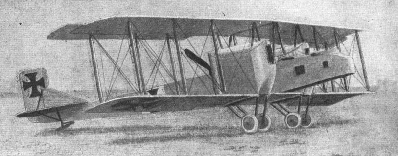
THE GOTHA TWIN-ENGINED BOMBING BIPLANE. - Three-quarter front view.
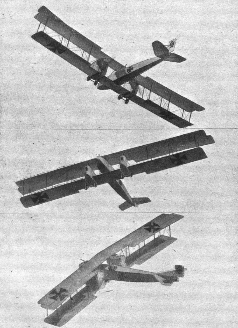
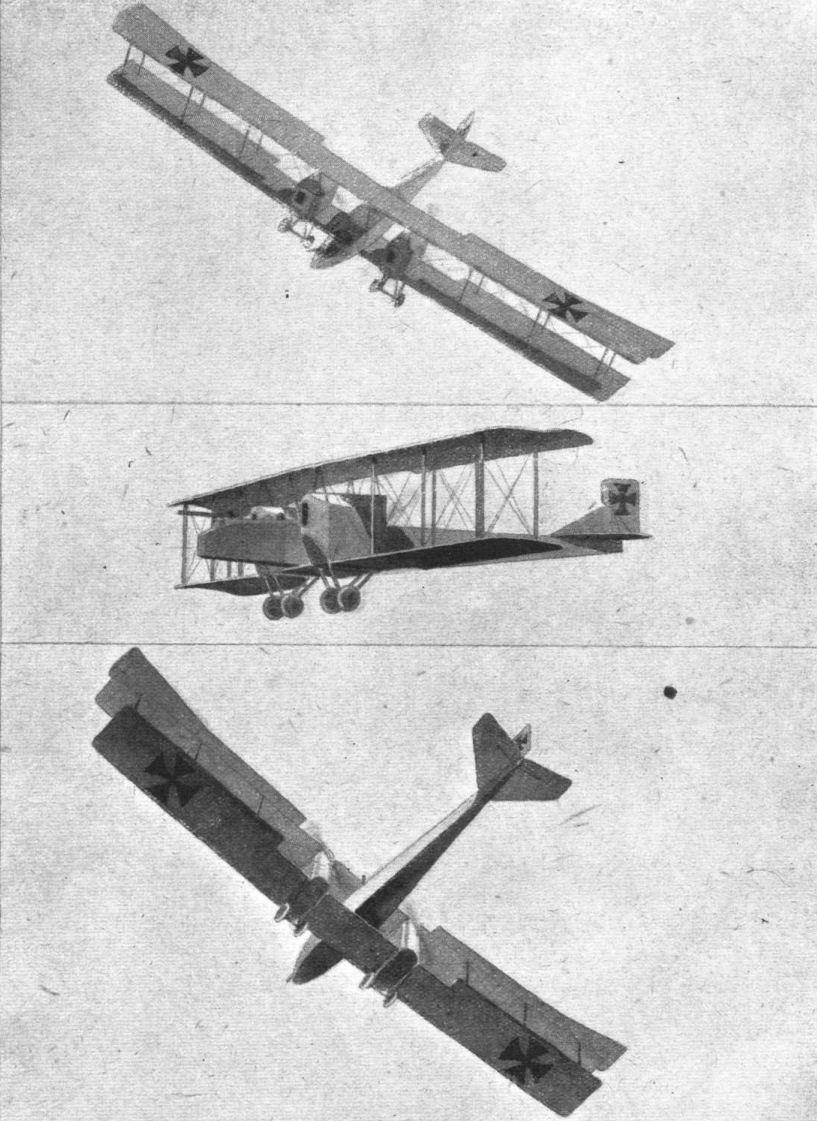
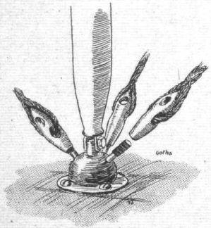
The interplane strut fitting on the Gotha twin-engined bomber.
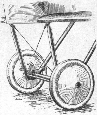
THE GOTHA TWIN-ENGINED BOMBER. - One of the under-carriages, in which steel compression springs and cable within the chassis struts, and connected to the axle, takejthe place of rubber shock absorbers.

The attachment of the bracing tie-rod and cable on the chassis of the Gotha bomber.
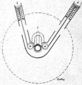
Diagram showing the shock-absorbing device on the Gotha bomber.
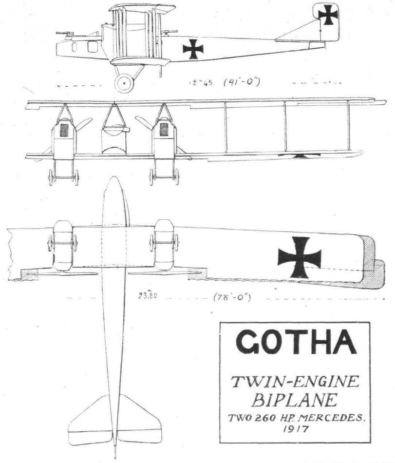

THE GOTHA TWIN-ENGINED BOMBER. - Plan, front and side elevations to scale.
Flight, April 5, 1917.
THE 1916 HALBERSTADT BIPLANE.
THE 1916 Halberstadt fighting biplane - one of Hunland's crack machines, of which much was heard during the latter part of last year - has general details which are interesting from the constructional point of view. Unfortunately, the condition of the one we have been able to inspect, as may be seen from the accompanying photographs, was such that lack of detail in certain parts did not allow of scale drawings being prepared. Sketches of many details, together with the drawing of the complete machine - reconstructed from the "wreckage" and from particulars of a similar model captured more or less intact - will for the time being suffice to give a general impression of this machine.
Prior to the war the Halberstadter Flugzeugwerke was known as the Deutsche Bristol Works, when taubes and Bristol Prier-type monoplanes were manufactured. During 1915 the new firm built a speedy biplane scout, having a Morane-Saulnier-type body and Oberursel motor - being, in fact, very similar to the Fokker biplane of that date. In 1916 the firm produced the improved type under review, which differed from the previous type in several respects, mainly in the arrangement of the planes and the installation of a stationary engine. Variations of this type have, we understand, been turned out, but it may be assumed that they differ only in minor details. The principal dimensions of this particular model are as follows :- The span of the upper and lower planes is 28 ft. 6 1/2 ins. and 25 ft. 9 ins. respectively; chord 5 ft. 1 1/2 ins.; gap 4 ft. 4 ins.; top plane staggered forward about 18 ins.
The fuselage is somewhat similar to that of the Morane-Saulnier, and is of wood construction, the longerons being square in section, hollow and bound with fabric. From one of the accompanying sketches it will be seen that the construction the fuselage is one of the simplest, the struts being k<...>t in position by blocks of wood tacked to the longetons each side of the strut, and by ply angle-pieces tacked to the struts. The wiring plate - for the outside bracing - consists of a single sheet steel plate bent to a right angle and placed in position over the longeron and struts as shown. A bolt at each end of the plate passes through the strut, one of these bolts having an eye formed at its inner end to form the attachment for the cross wire bracing. Aft of the cockpit the fuselage is covered with fabric except for the last bay, which has a three-ply covering. At this part the elevator and rudder control cables pass through long slots, reinforced with metal edgings, in the three-ply. This material is also used for covering the fuselage forward of the cockpit. The top of the latter is in the form oа a turtle deck, which tapers at the rear until flush with the fuselage at a point midway between the tail and he cockpit. This sloping portion of the turtle deck is built up of stringers over which fabric is stretched. In order to keep the fabric separated a short distance from the sides of the fuselage - to avoid contact with nuts, wires, &c. - a beading is tacked along the outer corners of the longerons. The step in the side of the fuselage is fitted with a spring-closed aluminium trap door - as in some of our own machines - the action of which is clearly shown in one of the accompanying illustrations.
The main planes are almost rectangular in planform, being only slightly raked. The top plane is situated very close to the fuselage, and is staggered forward, so that the range of vision appears to be very good. As on most German machines, the camber is fairly pronounced, especially so for a speed machine. In construction they present little out of the ordinary, the spars being of the orthodox I-section with built-up ribs of webs and battens. There are two pairs of interplane struts, of streamline steel tube, on each side of the body. The attachment of these struts to the spars is effected by means of a metal fitting, secured to the spar by two bolts, on which is formed a fork receiving the end of the strut, a bolt passing through both. The struts can thus hinge sideways so that top and bottom planes can, when the bracing wires are slackened, lie one on top of the other for transporting. A smaller fork formed on the side of the fitting serves as an anchorage for the bracing cable, while the incidence bracing cable is attached to a metal clip which passes over a ring contained within the strut fitting. The internal bracing cables are fastened to a long, narrow, wiring plate bolted to the side of the spar. A wood or fibre packing piece is inserted between the spar and the strut fitting to give the latter the correct angle necessitated by the staggering of the planes. A quick-release device, similar to that employed on the L.V-G. machines, is provided for the bracing cables, enabling the latter to be withdrawn without upsetting the adjustment.
One of the accompanying sketches shows the method of attachment of the lower plane to the fuselage, and is, we think, self-explanatory. Suffice it to say that the lugs on the ends of the tubular cross members passing through the fuselage, in continuation of the wing spars, receive the forked ends of the latter, the locking being effected by means of the pin shown. A tongue formed on each of the aforesaid lugs serves as an anchorage for the lift wires.
The top planes are attached to a cabane, with which is incorporated a service petrol tank having the same section as that of the wings. A portion of the latter is, of course cut away to receive this tank.
The ailerons, which are mounted on the top plane only, are operated by a crank lever working in a slot formed in the wing, as in the Albatros machines. The pulleys carrying the aileron control cables are inside the wing, but an aluminium trap door allows for their inspection and adjustment. As is common practice with most German machines, the trailing edge of the aileron is given a slight up-turn.
It will be seen that the tail surfaces follow Morane-Saulnier practice very closely, the elevators being exactly similar in plan-form. The rudder, however, is larger and of a peculiar pointed shape. They are constructed entirely of steel tubing, as shown in one of our sketches. The ribs are built up of lengths of tubing, the ends of which are brazed to the tubular spar - or rudder post, as the case may be - and the tubular trailing and leading edges. Short tubular distance pieces are arranged zig-zag fashion between the upper and lower members of the elevator ribs. The rudder post is supported by two substantial tie-rods of streamline steel tubing, anchored to the fuselage. The wood tail skid is supported by a tubular steel tripod, and is allowed a certain amount of swivel movement. The forward end is held by elastic shock absorbers, whilst the rear end, which comes in contact with the ground, is fitted with a metal shoe.
A control of the Fokker type is fitted, consisting of a vertical column with hand grip, mounted on rocking shaft lying fore and aft and supported between two tubular cross members. The vertical column pivoted so as to rock backwards and forwards (elevator control) over a quadrant, the purpose of the latter being, apparently, to lock the column in position order that the pilot may have his hands free for firing the gun. The control cables from the elevators are in duplicate, and one pair is attached to the column just above the rocking shaft, and the other below to an extension of the column passing through a hole in the floor of the fuselage. The aileron control cables are attached to a double X-shaped quadrant mounted on the rocking shaft, the lower arms passing through the floor of the fuselage and carrying the cables from the aileron crank levers; the top arms carrying the cables which are attached to the ailerons near the trailing edge. A pivoted tubular rudder bar is mounted in the cross member carrying the front end of the rocking shaft. This bar is provided with end plates to prevent the pilot's feet from slipping off; whilst the distance from the seat to the rudder bar can be varied by means of the adjustable link, connecting the bar and the front-spar cross member, shown in our sketch.
The chassis is of the orthodox V-type, each V consisting of two streamline steel struts welded to a short tubular skid, which serves as an anchorage for the rubber shock absorber. The rear strut is attached to the fuselage under the rear wing-spar attachment, a lug being formed on this fitting for the purpose.
A pair of 28-in. wire wheels (disc) are mounted on a tubular steel axle, 1 7/8 in. diameter. The V's of the chassis are connected by two cross members, consisting of streamline steel tubes attached to the lower ends of each strut.
As regards the engines fitted to the 1916 Halberstadts, these are, we understand, either 120 h.p. Argus (Benz type) or the new Mercedes-V. Unfortunately, we have not at present particulars as to the method of mounting the engine, &c, but hope to furnish details later.
Flight, July 12, 1917.
SOME 1917 TYPE GERMAN AEROPLANES.
The Halberstadt Chaser.
Details of this machine are already familiar to readers of "FLIGHT" through an illustrated description which appeared in our issue of April 5th, 1917. We are now able to supplement the information then given by approximate scale drawings and other data from L'Aerophile. The Halberstadt chaser is a single-seater of short span - 28 ft. 6 ins. and 25 ft. 9 ins. - and has, as distinct from the majority of other biplanes of the chaser type, two pairs of inter-plane struts on each side. The wings are staggered, and have a dihedral angle, but are not swept back. Ailerons are fitted to the top plane only, and are warped, their angle of incidence decreasing progressively towards the tips. They are hinged, as in nearly all German machines, not to the rear main spar, but to a false spar placed between the rear spar and the trailing edge. The chord of the wings is just under 5 ft. and the gap 4 ft. 3 ins. The result of this small gap is that the top plane is very low over the body, a tendency in German design that is very noticeable of late.
The engine usually fitted in the Halberstadt chasers is a 120 h.p. Argus 6-cyl. water-cooled. It has overhead valves, which are not, however, operated by an overhead camshaft as in the Mercedes, but by tappet rods and rockers, as in the Benz. The petrol tank, which also serves as a seat, has a capacity of 76 litres (about 17 gallons). The pressure in the tank is maintained by a pressure pump driven off the engine a hand-operated pump being provided for cases of emergency. The petrol service tank, which has a capacity of 18 litres (about 4 gallons), is built into the centre section of the top plane, where are also mounted the radiator and small water tank.
Flight, August 23, 1917.
THE 1916 TYPE HALBERSTADT BIPLANE.
IN our issue of April 5th, 1917, we gave a description and a number of detail sketches of the construction of the German Halberstadt biplane. These, as well as the drawing showing the machine in flight, were prepared from a very incomplete set of parts, most of which were in a hopeless condition, while the whole nose of the machine and large portions of the wings were missing altogether. Nevertheless, by comparing these sketches with an actual complete machine since captured, it was found that all the particulars then given were absolutely correct. That this is so may be easily verified by referring back to our April 5th issue and comparing the drawing of the machine in the air with the photographs of a captured machine which, thanks to the courtesy of the military authorities, our representative was able to inspect at a home aerodrome a few days ago. The machine has, it may be noticed, been painted with the British identification marks for purposes of testing it over English soil and thus find out if there is anything particularly valuable in its performance which might be of any use to our constructors. Let it be said at once that there does not appear to be any phase of performance or evolution in which this once-upon-a-time much-talked-of machine can hold its own compared with a good British or French machine of the same size and power.
So far as it is possible to gather, the Halberstadt has almost, if not quite, disappeared from the Western Front, which fact indicates that it is no longer a match for our or our Allies' modern fighters. The machine which has, more than any other, superseded the Halberstadt is the Albatros single-seater with the Nieuport-type wing bracing, illustrated and described in "FLIGHT" of July 12th. It might be objected that the machine of which we publish photographs this week is of a type that is nearly a year old. This we grant, but to the best of our knowledge there is not in existence - or at any rate not in use - a modern Halberstadt. Whether the reason for this is to be sought in so vastly superior a performance by the other makes of German fighters as to cause the German' authorities to concentrate on the production of these, or whether it is due to the Halberstadt in its present form being difficult to alter and improve to such an extent as to bring its performance up to that of the others, is a matter for conjecture. We have heard it said that while the Halberstadts were in use on the Western Front a surprisingly large percentage of those brought down were observed to come to earth in what appeared be our pilots to be a spinning nose-dive.
If this be so - and we have heard the same remark made by so many independent observers that there can scarcely be any doubt about the correctness of the statement - it rather looks as if the Halberstadt was inclined towards spiral instability. An examination of the photographs tends to confirm this impression. In the first place, the total absence of any fixed vertical surface in front of the rudder, coupled with the fact that the body terminates in a horizontal knife-edge at the rear, at once makes one suspicious as to the adequacy of vertical surface to the rear of the centre of gravity. To make matters worse the body is very deep in front, the vertical surface here being also slightly augmented by a portion of the large water-cooled engine, although in the present machine this is, as a matter of fact, almost totally covered in.
As to the possible reasons why the performance should be inferior to that of other machines of similar horse-power: The body does not impress one as being of particularly good form for low resistance. This is probably chiefly due to the peculiar way in which the turtle back deck is finished off abruptly at a point approximately half-way between the pilot and the tail. The break in the curve of the top covering is very pronounced at this point, and where high speeds are concerned little things like this soon begin to add up and increase the resistance.
In regard to the wings, the first impression one receives is that the strutting and wiring is somewhat clumsy, two pairs of interplane struts on each side being scarcely deemed necessary - at any rate, by British and French designers - in a machine of only some 28 ft. span. Again, the wing section gave our representative, from a superficial inspection it is true, the impression of being very deeply cambered for a fast machine, although, without knowing the exact shape of the section and being able to compare it with known sections, it is not possible to pass judgment on this point. It does not, as well-known wing sections have shown, follow that a deeply cambered section may not have a very excellent L/D ratio as well as a good lift coefficient.
As the Halberstadt has already been described and illustrated with regard to its constructional details, there does not appear to be any reason for elaborating these here. Since, however, the front part of the machine previously described was missing, a few words concerning this part may be of interest. The engine, a 120 h.p. Argus, is, as will be seen from the illustrations, almost totally hidden inside the body, only the top of the cylinders with their valve stems and springs projecting. The exhaust pipes are of a curious formation, looking somewhat like the weirdly shaped freak carrots sometimes deemed worthy of an illustration in the Press. As to the purpose of this writhing mass of tubes, this is not instantly apparent to the uninitiated, one pipe from each cylinder joining one from another, the resultant pipe joining further along its course up with similar ones, the whole to finish in a single outlet to the air.
The only other feature of the Halberstadt biplane that is of any particular interest is the radiator, which is, as will be seen, mounted in the centre section of the top plane, to the curvature of which it conforms. Certainly this arrangement should make for reduced head resistance, and it may be taken for granted that it has been found in practice to give adequate cooling. That its position is such that, should it be pierced by a bullet, the hot water can hardly fail to give the pilot a liberal sprinkling, may be disconcerting to the pilot, but it is interesting from an aerodynamical point of view.
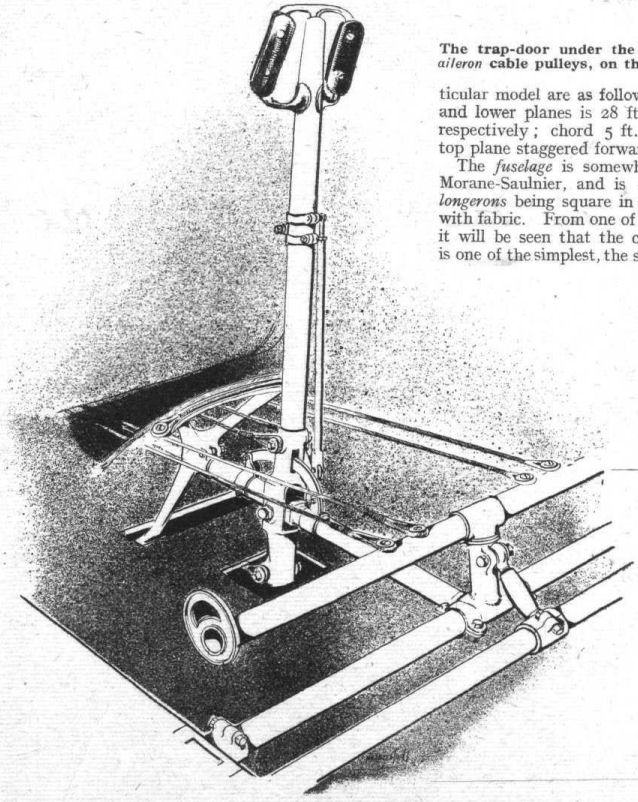
The control of the 1916 Halberstadt biplane, showing the adjusting link, forward of the rudder bar, for varying the distance from the latter to the seat.
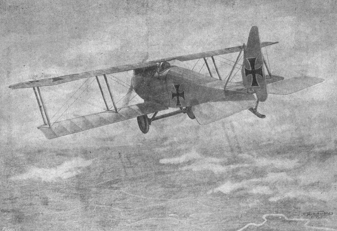
THE 1916 HALBERSTADT FIGHTING BIPLANE. - Drawing of the machine in flight, seen from the rear.
Some unique sketches of aircraft at work overseas by Captain K. H. Riversdale Elliot, Scottish Rifles and R.F.C.. The drawings are particularly accurate and full of movement, and carry the greater weight as from an active pilot.
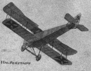
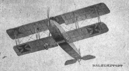
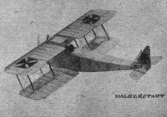
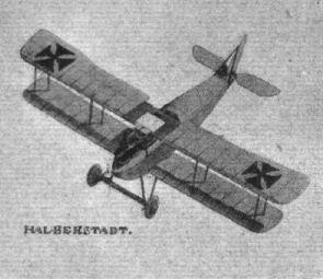
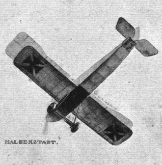
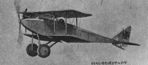
The trap-door under the wing, giving access to the aileron cable pulleys, on the 1916 Halberstadt biplane.
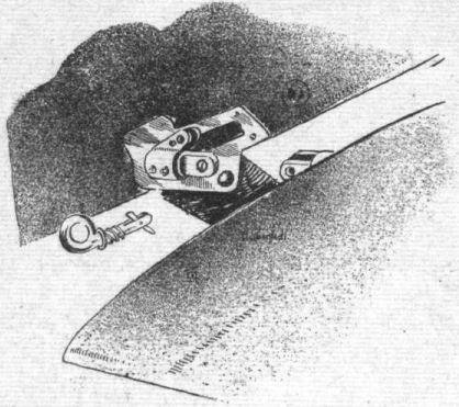
Method of attaching the lower plane to the fuselage of the 1916 Halberstadt biplane. Note the spring locking device on the pin.
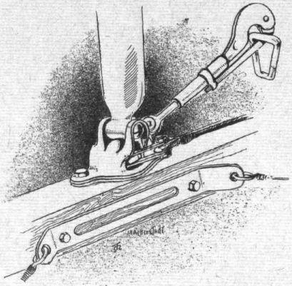
The interplane strut fitting and quick release bracing cable attachment of the 1916 Halberstadt biplane.
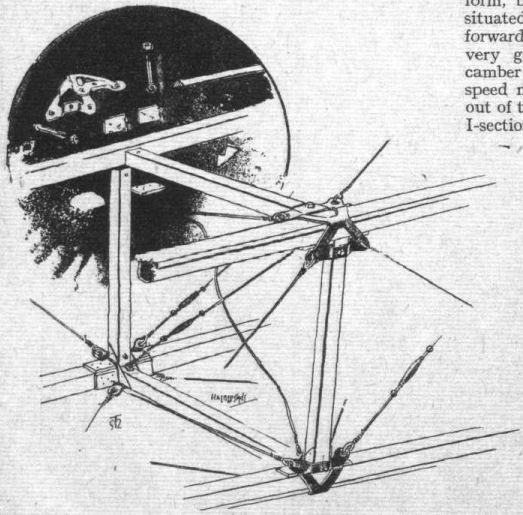
Sketch showing the construction of the fuselage of the 1916 Halberstadt biplane.
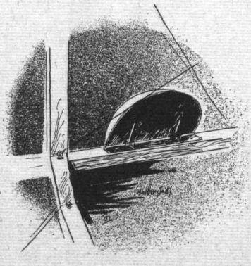
The foot-step trap-door on the fuselage of the 1916 Halberstadt biplane, seen from the inside.
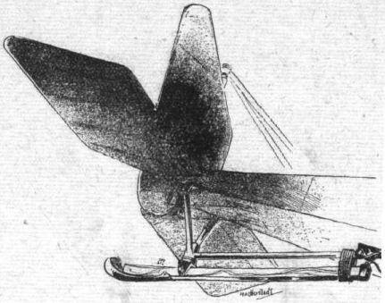
The tail-skid of the 1916 Halberstadt biplane.
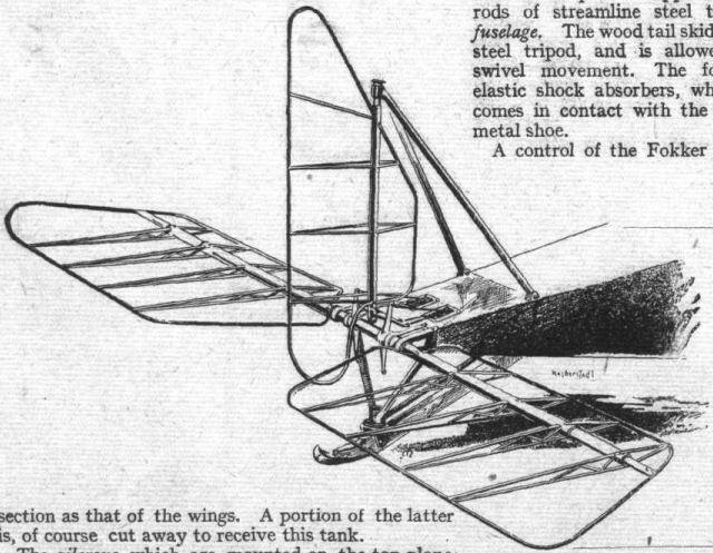
Sketch showing metal construction of the elevators and rudder of the 1916 Halberstadt biplane.
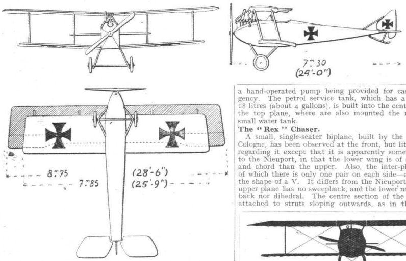
The Halberstadt chaser.
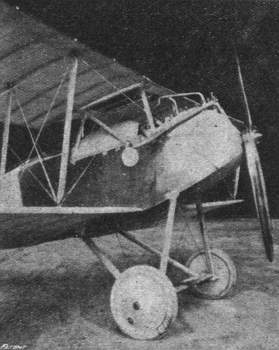
Chassis and engine housing of the Halberstadt biplane.

Three-quarter rear view of the Halberstadt biplane.
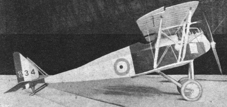
Side view of the Halberstadt biplane.
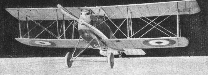
A CAPTURED HALBERSTADT BIPLANE. - Three-quarter front view.
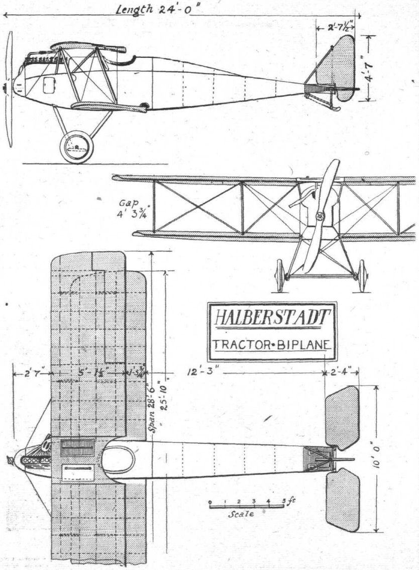
THE HALBERSTADT BIPLANE. - Plan, side and front elevations.
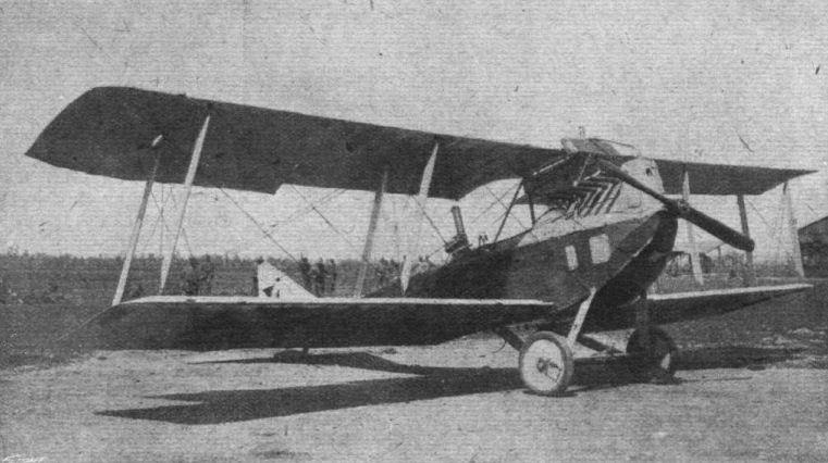
FROM "THE WAR IN ITALY." - An Austrian Aviatic captured by the Italians.
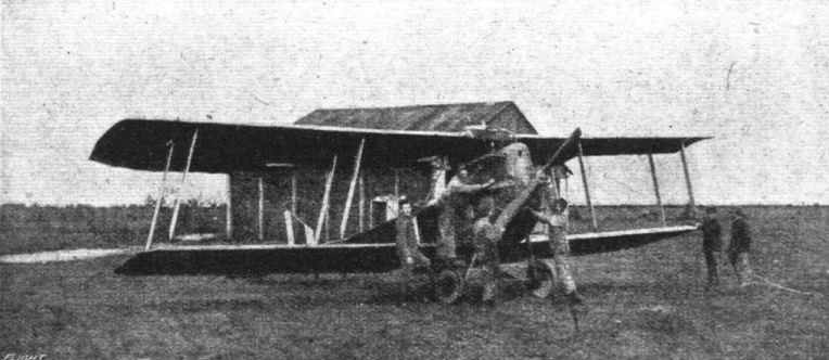
FROM "THE WAR IN ITALY." - An Austrian biplane of the Aviatik type captured by the Italians.
Flight, July 12, 1917.
SOME 1917 TYPE GERMAN AEROPLANES.
The Roland Two-seater.
Since the early days of German aviation the L.F.G. (Luft-Fahrzeug-Gesellschaft) firm have named their machines "Roland," this being the name of their chief designer. The modern Roland two-seater biplane is similar to the single-seater already described. It is considerably smaller than the other German two-seaters, the span being only 30 ft. Both wings are perfectly straight, the top one resting on the roof of the body. On each side is a single inter-plane strut made of ply wood and of streamline section. This member serves the dual function of the usual pair of struts and of incidence wires. The planes are heavily staggered, so much so that the rear spar of the top plane is vertically above the front spar of the bottom plane. Ailerons are fitted to the upper wing only, and are peculiar in that they are hinged along a false spar, forming an angle with the two main spars.
The body is of three-ply wood, rounded section, and is so deep in front that windows have been provided for the pilot and gunner (who occupies the rear cockpit). The engine is a 175 h.p. Mercedes, and the armament consists of two machine guns and under the body four bombs placed longitudinally.
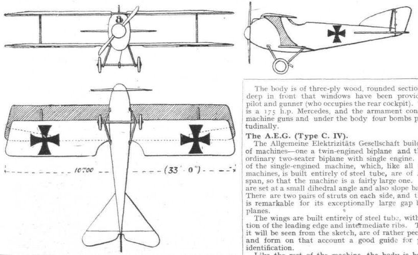
The Roland two-seater.
Flight, July 12, 1917.
SOME 1917 TYPE GERMAN AEROPLANES.
The Roland Chaser, D. II.
Differs somewhat from the Roland two-seaters in several respects. It is chiefly characteristic on account of the peculiar arrangement of the top plane attachment, which secures the upper wing spars to an enclosed upward projection of the body. Constructionally the body is of the true monocoque type, without internal bracing. It is of rounded section, and throughout the whole machine great care has been taken to do away with any sharp corners or angles, the object evidently being to reduce head resistance to a minimum. The main planes, of which the upper measures 29 ft. 6 ins. and the lower 28 ft. span, have no dihedral, bat are swept back as was once the custom in a large number of German aeroplanes. Ailerons are fitted to the top plane only, and are operated Nieuport fashion by cranks on tubs running along the rear spar. The chord of both planes is the same, 4 ft. 9 ins. The stabilising plane and the vertical fin are covered with three-ply wood, and both rudder and elevator are partly balanced by triangular projections, as appears now to be the mode in Germany. The engine fitted is a 175 h.p. Mercedes, with the exhaust pipes bent outward and backwards as on the Albatros. The radiator is incorporated in the centre of the top plane. Two machine guns are fitted, one on each side of the engine, and, of course, with the usual interrupting gear. The weight of the machine empty is 1,450 lbs.
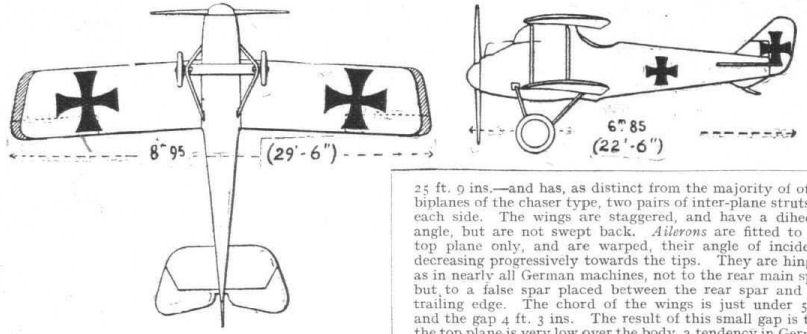
The Roland chaser D. II.
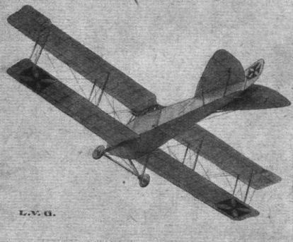
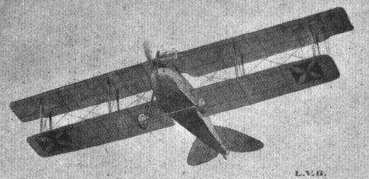

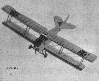

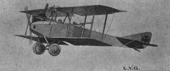
Flight, July 12, 1917.
SOME 1917 TYPE GERMAN AEROPLANES.
The L.V.G. (Type C. IV).
Differs very little from the L.V.G.'s already dealt with in the columns of "FLIGHT." It is of slightly larger overall dimensions, and has an 8-cyl. vertical Mercedes engine. The armament consists of two machine guns mounted as usual and of four bombs.
Flight, July 12, 1917.
SOME 1917 TYPE GERMAN AEROPLANES.
The "Rex" Chaser.
A small, single-seater biplane, built by the Rex Co., of Cologne, has been observed at the front, but little is known regarding it except that it is apparently somewhat similar to the Nieuport, in that the lower wing is of smaller span and chord than the upper. Also, the inter-plane struts - of which there is only one pair on each side - are placed in the shape of a V. It differs from the Nieuport, in that the upper plane has no sweepback, and the lower neither sweepback nor dihedral. The centre section of the top plane is attached to struts sloping outwards, as in the Sopwiths.
The body is of the monocoque type, built of three-ply wood, with projections for the attachment of the lower planes. In front view this machine appears approximately as shown in the accompanying silhouette.

Flight, April 19, 1917.
THE "TOTALLY ENCLOSED" AEROPLANE.
<...>
The following year - 1912 - witnessed the production of quite a number of enclosed aeroplanes, inspired probably by the exhibition at the Paris Salon of the Bleriot "Aerocar" during the previous year. In Germany two examples were on view at the Berlin exhibition held in April of that year One of these was exhibited by the well-known Rumpler firm. This machine was, practically speaking, a standard Taube type monoplane, in which the turtle deck had been increased in depth until it covered the occupants. As our illustration shows, this turtle back or roof only extended to a point a short distance behind the pilot's. Two mica windows in each side provided a view in an outward and upward direction, while a diminutive window, making an angle of about 45 ° with the line of flight, was fitted in a small dash near the rear of the engine. This can be seen in the photograph just ahead of the leading edge of the wing where it joins the body. The forward view obtainable through this latter window was admittedly of a very restricted character, especially as the pilot occupied the rear seat. Whether or not this machine met with any great success cannot be stated, but certainly it was not produced in quantities.
<...>
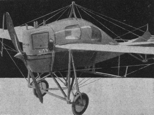
The Rumpler Taube with enclosed body shown at the Berlin Exhibition of 1912.
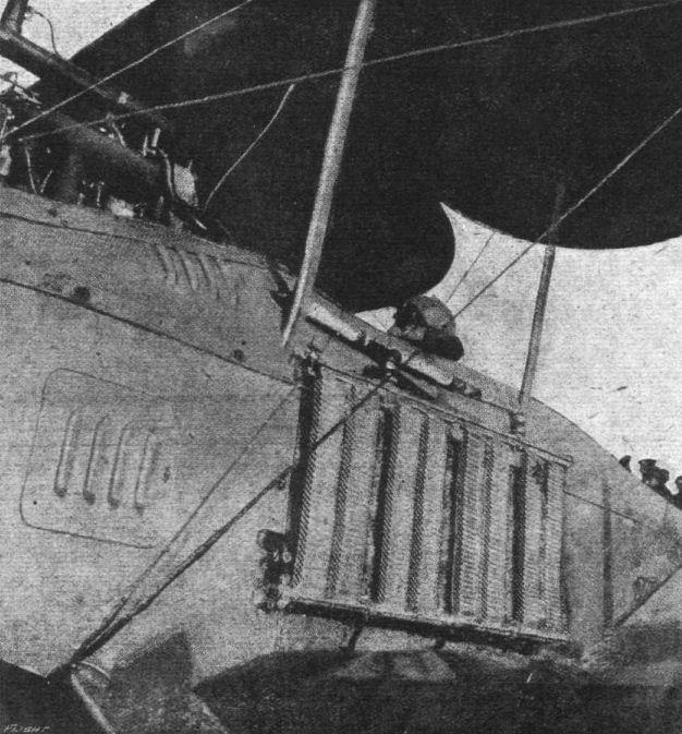
An interesting photograph of the landing of an enemy machine with pilot badly injured and the observer killed. Our contemporary, La Guerrv Aerienne, states in regard to the above that on January 10th, 1915, near Villers-Bocage, Sub - Lieut. Eugene Gilbert, the well-known aviator, brought down this Aviatik. The landing was quite normal, the motor having been stopped through a bullet smashing the radiator. When the French soldiers arrived to seize the machine, the observer, Lieut. von Falkenstein, was noticed to be sitting perfectly still, and it was soon realised that he was dead, whilst the pilot, Lieut. Keller, was completely hors de combat through being seriously wounded.
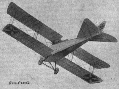
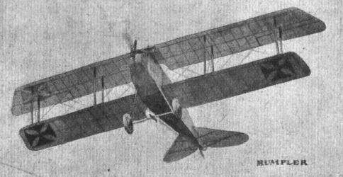
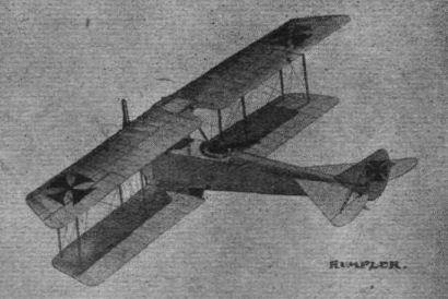
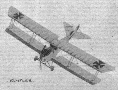
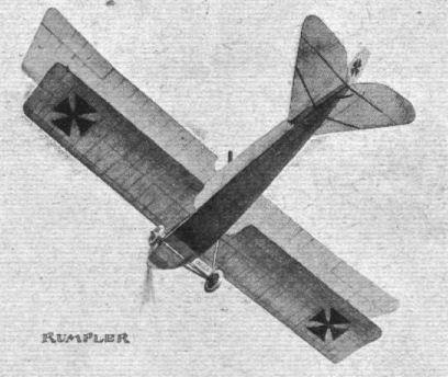
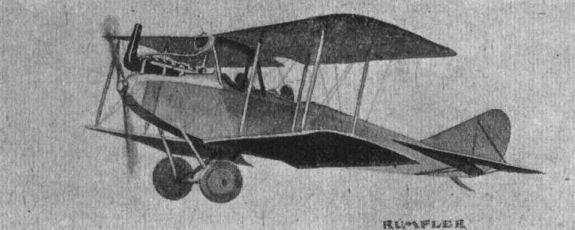
Flight, July 12, 1917.
SOME 1917 TYPE GERMAN AEROPLANES.
260 h.p. Rumpler.
In the main the new 260 h.p. Rumpler two-seater follows along the lines of the older model illustrated in "FLIGHT." It has, however, a 260 h.p. Mercedes engine, and the shape of the tail planes has been altered somewhat, as shown in the sketches.
SOME 1917 TYPE GERMAN AEROPLANES.
260 h.p. Rumpler.
In the main the new 260 h.p. Rumpler two-seater follows along the lines of the older model illustrated in "FLIGHT." It has, however, a 260 h.p. Mercedes engine, and the shape of the tail planes has been altered somewhat, as shown in the sketches.
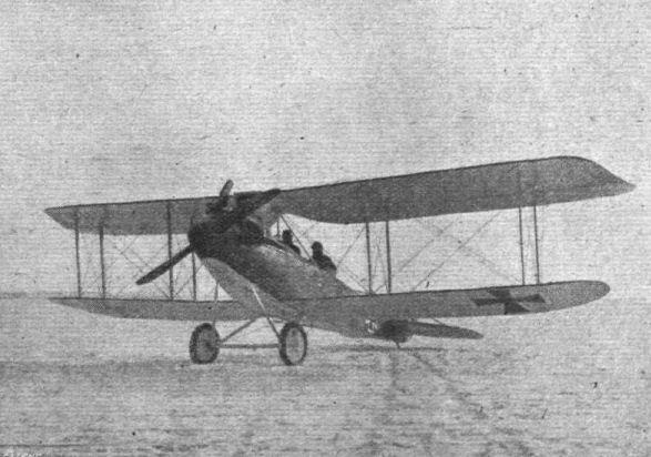
Another view of the 260 h.p. C.IV-type Rumpler biplane. - The annexed illustration, appears to indicate an attempt by the Rumpler firm at better stream-lining, as a hemispherical nose-piece is fitted over the boss of the airscrew, and the sides of the front part of the body are rounded off to gradually carry the curve of the nose-piece into the flat sides of the rear portion of the fuselage. Also, judging by the illustration, it appears that the span is somewhat smaller than in the older type Rumpler biplanes.

The 260 h.p. Rumpler.
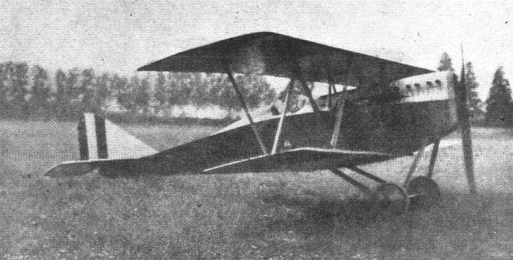
An Italian single-seater tractor biplane, constructed by the Societe Gio Ansaldo. It will be noticed, that the Warren system of interplane strut bracing, which was dealt with by "Marco Polo" in our issue of October 11th, has been adopted.

The seaplane type tractor biplane, constructed by the Italian Societe Gio Ansaldo.
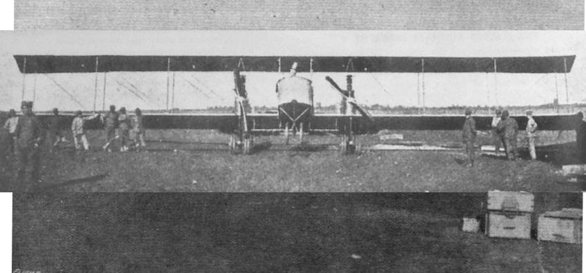
Front view of Caproni Ca 3 biplane of 1916-18, with the most common arrangement of three 150 h.p. Isotta-Fraschini V4B inline engines. Maximum speed 85 m.p.h. in Ca 33 form.
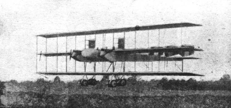
Another view of the 600 h.p. Italian Caproni triplane, which has been doing such good raiding work on the Italian front. The machine is seen returning from a flight.
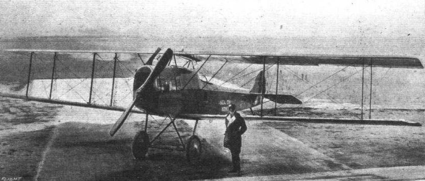
Capt. the Marquis Laureati, standing beside the S.I A . biplane with F.I.A.T. A 12 bis engine, allowing 124 m.p.h., on which he made his non-stop flight of 1,000 miles from Turin to Naples and back. On the Turin-Naples trip Capt. Laureati flew alone, but on his flight from Turin to London he carried a mechanic. The S.I.A. Company, the builders of the machine, is a subsidiary of the Fiat Co. of Turin.
Flight, May 3, 1917.
THE "TOTALLY ENCLOSED" AEROPLANE.
ON looking back it appears that for the year 1913 Russia held the lead as regards the construction of "totally enclosed" aeroplanes, at any rate as far as actual flying of this type is concerned. No other country, during that period, actually witnessed successful flights on an aerial "Limousine." There can be little doubt, however, that in other countries machines were in preparation, although they did not take the air until the following year. In the case of the Sikorsky "Grand," the "enclosed" feature was, perhaps, to a large extent incidental, being the logical result of the other characteristics of the machine, which was of very large dimensions. When the machine first made its appearance there were those who ventured to prophesy that it would never fly, but as soon as everything was in readiness Mons. Sikorsky soon convinced his critics of their mistake. The "Grand" flew, and flew very well indeed.
Our illustration, which shows only a short part of the very long body, gives a good idea of the cabin portion that forms the most interesting feature, in connection with this article, of the machine. This cabin, which extended from the rear of the wings to some distance in front of the leading edge, was divided into three compartments. In the front one were two seats, one on each side of the cabin, in front of which were the dual controls. Normally the controls on the left were the main ones, and in front of them were mounted all the various instruments. Between the two seats was an open space leading to a door opening out on to the open part of the body in the extreme nose. From here observations could be made with ease, as the position was so far forward as to be well clear of all obstructions. For use at night a searchlight was placed right out in the bow, where it would not dazzle the pilot but would illuminate the landing ground.
The central portion of the cabin was set aside for the accommodation of passengers. As was to be expected in a machine so elaborately equipped, the passengers were not asked to squeeze into seats of the ordinary bucket type. Chairs, well upholstered and not fixed to the floor, were placed alongside the windows. Communication between passengers' and pilot's cabins was by means of a glass door, and thus any passenger could walk through the pilot's compartment out on the open front portion of the body, where a more unobstructed view was obtainable. From illustrations of the "Grand," the doors leading out into the open appear to be, instead of sliding, of the swinging pattern, so that opening them against the pressure of the air may have been attended with some difficulty.
To the rear of the passengers' compartment was a partition, with a door leading to the aft cabin, which was divided into two, one part of it being set aside for housing spare parts, while the other contained a sofa on which those weary of the journey might lie down and have a rest. It is stated that the cabin walls so reduced the noise of the engines, that conversation could be carried on quite comfortably inside the cabin.
In general arrangement the Sikorsky "Grand" was characterized by a very long and shallow body above which, the cabin portion extended a considerable distance. A monoplane tail and four vertical rudders constituted the tail units. In front the body rested on the lower main plane, which further supported the four Argus motors of 100 h.p. each that supplied the power. At first these four motors were mounted in pairs, one pair on each side of the body, the front one driving a tractor screw and the rear one a propeller. Later a different arrangement was tried by which the four engines were all placed on the leading edge, two each side, and each driving a tractor screw. Later again the two outer engines were removed altogether, and the machine flew quite well with the remaining two. After having done a considerable amount of flying and established a world's record for passenger carrying - 1 hour 54 minutes with pilot and seven passengers - the "Grand" came to an untimely end through a machine flying overhead shedding its engine, which crashed through the wings of the "Grand."
<...>
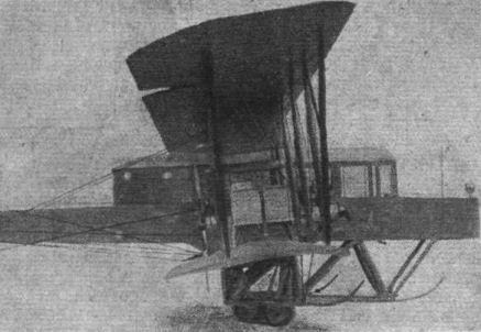
The Sikorsky biplane "Grand," successfully flown during 1913.
Flight, May 3, 1917.
THE "TOTALLY ENCLOSED" AEROPLANE.
<...>
Instead of rebuilding the damaged "Grand," Mons Sikorsky set to work and produced a second machine of somewhat different design, which he named the "Ilia Mourometz." This machine was finished towards the end of 1913, and although its initial trials were not very successful the designer continued to experiment and alter various details, and during the early part of 1914 succeeded in getting some excellent flights out of it. One of the best known of these is the flight made on February 25th, 1914, when Sikorsky made a flight of some 18 minutes' duration accompanied by 15 passengers. In the "Ilia Mourometz" the body was very much deeper than that of the "Grand," so that the cabin did not project above the body proper. Windows were fitted in the side, and extended some distance back of the trailing edge of the wings. The cabin, entered through a side door, which can be seen in our illustration, extended from this door right up to the bows, where the pilot was seated.
Very few particulars of the "Ilia Mourometz" are available, but it appears that it had four engines developing something like 500 h.p. Concerning the machines of this type built since the outbreak of war nothing may, of course, be said, except that some of these were slightly smaller and had only two engines.
<...>
Flight, August 2, 1917.
THE AEROMARINE TRAINING TRACTOR BIPLANES.
WHATEVER critics may have to say as regards American high-speed warplanes, it cannot be said that America has not produced some really good machines suitable for training, sporting and similar purposes. Most of the American aircraft firms have, in fact, each one or more designs of this type included in their range of models listed. There should, therefore, be plenty of machines available for the training of that "umpteen-thousand" aviators it is suggested to send over to Europe.
The other week we described the Burgess training machine, and this week we give particulars of the Aeromarine land and water machines, built by the Aeromarine Plane and Motor Co., at Keyport, N.J., U.S.A. Except that the seaplane has a larger wing area, these two types differ only in dimensions and minor details, so that the following notes apply equally to both machines. The designs were got out by Mr. Charles F. Willard, special attention being given to producing, a machine, which, whilst being light and simple in construction, will be capable of withstanding the abnormal strains imposed upon machines of this type.
The main planes are in four sections, two upper and two lower, the former being attached to two pairs of inverted V cabanes, and the latter being secured to the fuselage. Both top and bottom planes are set at a dihedral angle of 1°, and the top plane is staggered forward 1 ft. 6 ins. R.A.F. No. 6 wing-section is employed. The main spars are of I section and the ribs, which are spaced about 1 ft. apart, have the same section, being built up with lightened webs reinforced between the lightening holes to provide against shear. The leading edge is stiffened by a thin veneer to maintain the curvature. The whole of the wing framework is wire braced, and solid wood compression members relieve the main ribs of strains due to drift. The covering is raw Irish linen, having equal strength both in warp and weft, weighing 4 oz. per sq. yard. It is laid diagonally on the wing, with seams lapped and double sewed, and covered with linen tape as a protection from the weather. The fabric is given from three to five coats of dope and a final coat of varnish.
Two pairs of struts on each side of the fuselage separate the top and bottom planes. These struts are hollowed, dovetail jointed and wrapped at five points with linen thread. Their section and proportions have been based upon data obtained from a series of tests on full-sized models. The interplane strut fittings have been designed so that no bolts pass through the spars. One of these fittings was illustrated in "FLIGHT" for March 15th last on page 250. Comparatively large ailerons, of the interconnected type, are hinged to the rear spars of the top plane.
The tail surfaces consist of a divided double cambered stabilising plane mounted on either side of the fuselage, two elevator flaps attached to the trailing edge of the stabilizing plane by four hinges, and a balanced rudder of streamline section mounted between the elevator flaps. The stabilizer sections are easily detachable from the fuselage, being mounted in sockets running through the latter. It is built up of I section spars and ribs, whilst the elevator and rudder frames are of steel tubing with spruce ribs. The steel tube rudder post is attached to a pressed steel stern post on the fuselage. All control surfaces are covered with the same material as the main planes.
In designing the fuselage special attention has been given to the easy replacement, in case of breakage, of the various parts. The fuselage is of rectangular section, tapering to a vertical knife-edge at the rear. It has a turtle deck top, the portion aft of the cockpits being detachable. The longerons are of large section spruce, lightened by channelling wherever possible. The struts are also of spruce, and the whole structure is strongly wire braced. As on the main planes, the fittings are designed so that no bolts pass through the longerons. The engine mounting is of steel throughout, and is exceptionally strong and light. The forward portion of the fuselage is covered with sheet aluminium, and the remainder with fabric. Two cockpits, in tandem, are provided, the front one for the pupil and the rear one for the pilot. Dual Dep. control is installed, and both cockpits are provided with a full complement of instruments. The fuel tanks are placed alongside the occupant of the front seat, and are filled from the outside. The overall length of the fuselage is 22 ft. 6 ins., and the maximum width and depth 2 ft. 6ins. and 3 ft. 6 ins. respectively. The engine is either a Hall-Scott "A7a" 100 h.p. - as shown in the photographic reproductions - or the Aeromarine 100 h.p. 8-cyl. V, as shown in the scale drawings. In either case, however, the radiators are mounted on the sides of the fuselage.
In the land machine the undercarriage is of the conventional V type, designed, as far as possible, with parts interchangeable, so that repairs are easily effected. The seaplane is fitted with a pair of long pontoon floats, arranged catamaran fashion. They are each 16 ft. 6 ins. long, 2 ft. 6 ins. beam, and 1 ft. 5 ins. deep, and have V bottoms and semi-circular tops. Located 7 ft. 6 ins. from the stern of each pontoon is a 3-in. step, with air leads built in to reduce the vaccum at this point. The floats are constructed of spruce, ash and mahogany, the hull consisting of double diagonal planking with fabric in between. They are divided into several water-tight bulkheads. Three pairs of struts connect the floats with the fuselage, and in addition a strut is carried from the floats up to the lower planes immediately under the inner pair of interplane struts. A small float is mounted under the tail.
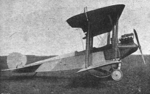
Side view of the Aeromarine training tractor biplane, land type.
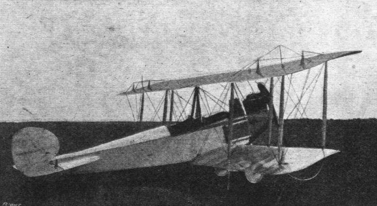
Three-quarter rear view of the Aeromarine training tractor biplane, land type.
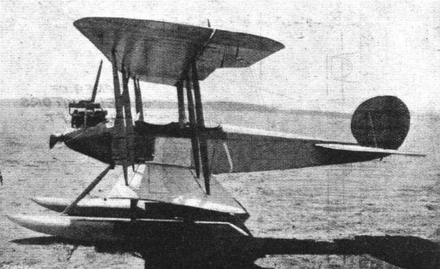
Side view of the Aeromarine training tractor seaplane.
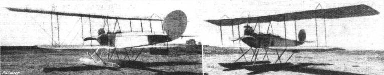
Three-quarter rear and three-quarter front views of the Aeromarine training tractor seaplane.
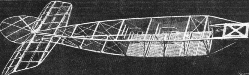
The fuselage construction of the Aeroniarine tractor biplane.
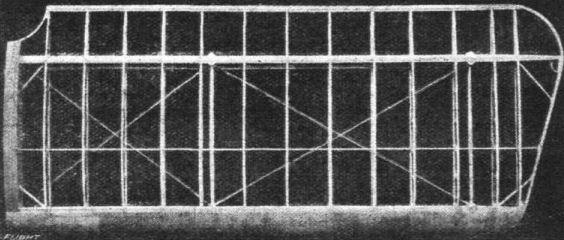
One of the lower planes of the Aeromarine tractor biplane showing construction.
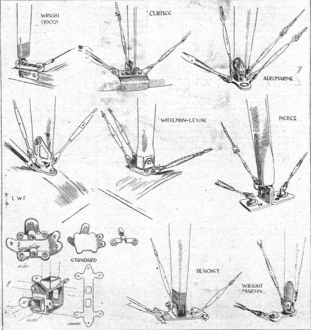
AT THE AMERICAN AERO SHOW. - Some constructional details. Various examples of interplane strut fittings, including the early Wright-type.
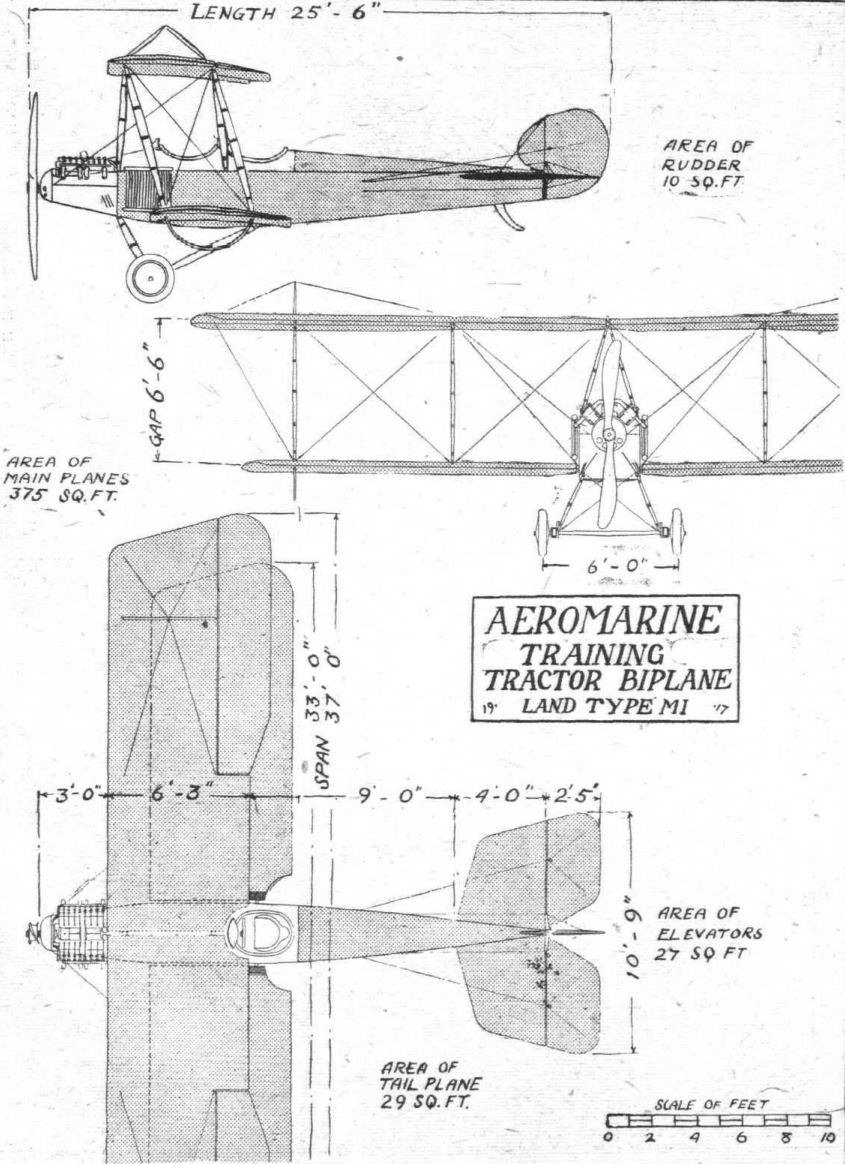
THE AEROMARINE TRAINING TRACTOR BIPLANE, LAND TYPE. - Plan, side and front elevations to scale.
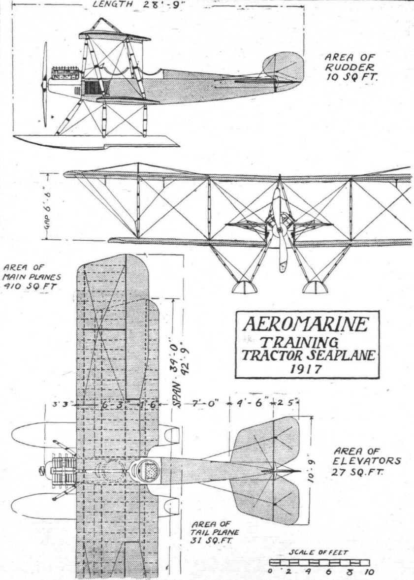
THE AEROMARINE TRAINING TRACTOR SEAPLANE. - Plan, side and front elevations to scale
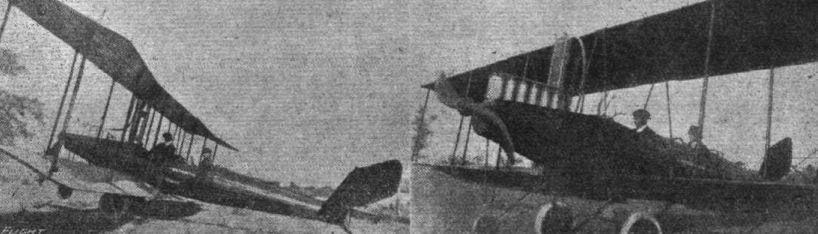
AT THE NEW YORK AERO SHOW. - Two views of the Benoist steel-clad tractor biplane,
AT THE AMERICAN AERO SHOW. - Some constructional details. Various examples of interplane strut fittings, including the early Wright-type.

The Breese - Penguin monoplane, which has been constructed in America for school work at the Plattsburg Camp, N.Y.
Flight, January 18, 1917.
THE BURGESS TYPE "U" SEAPLANE.
A TYPE "U" Burgess tractor seaplane was recently delivered to the Massachusetts Militia, and underwent exhaustive tests with the following results. The speed range, with and against the wind, over a carefully measured course averaged 40 to 67,9 m.p.h., and the climbing speed was 210 ft. per minute. The best gliding angle came out at 1 in 7,5. Other characteristics are given in the accompanying performance curves.
The upper plane is built up in three sections, the central section measuring 14 ft. 7 ins. and the outer 16 ft. 1 in., giving a total span-of 46 ft. 9 ins. The lower plane, having a span of 38 ft. 3 ins., is in two sections, each attached direct to the fuselage. The chord of both planes is 6 ft. 3 ins., and the gap is 6 ft. Inverted V struts support the upper plane above the fuselage, on each side of which two pairs of struts separate upper and lower planes. From the outer interplane struts, a pair of diagonal struts support the extremities of the upper plane. Hinged to the rear spar of the upper plane are ailerons having an area of 45 sq. ft. each. The front spars are located 6 ins. from the leading edge, and the rear spars 1 ft. 9 ins. from the trailing edge. The total supporting area of the planes is about 500 sq. ft., and the total weight of the wings, with struts and wires, is 520 lbs. A factor of safety of six is employed in the construction of the planes.
The tail planes consist of a fixed triangular stabilizing surface in two sections, attached to the fuselage 2 ins. below the top longerons, and two elevator flaps of 12 sq. ft. area each with a partially balanced rudder mounted between them. Forward of the rudder is a vertical triangular fin having an area of 10 sq. ft. The weights of the elevators and rudder are 20 lbs. and 15 lbs. respectively. Dual Dep. control is employed.
The fuselage is 24 ft. 8 ins. in length, 2 ft. 3 ins. wide from the nose to the commencement of the tail plane, where it tapers to a vertical knife edge. It will be noticed that the top longerons extend from end to end in a perfectly straight line level with the line of thrust, whilst the lower ones are given a stream-line curve. On top of the fuselage is a turtle-deck forming the cowling for the engine, and cockpit shields. The greatest depth occurs at the rear interplane struts, where it is 3 ft. 11 ins. The weight of the body is 200 lbs.
The floats consist of one long main pontoon and two wing-tip floats. The former is 19 ft. long, with a beam of 2 ft. 4 1/2 ins. and a depth at the step of 1 ft. 10 ins. It is attached to the fuselage by three pairs of stream-line struts, the front pair, 3 ft. 5 ins. long, joining the fuselage at the nose, the centre and rear pairs, both 2 ft. 6 ins. long, joining at the front and rear spar attachments respectively. From nose of pontoon to the first pair of struts is 3 ft. 2 ins., between first and second pair 4 ft. 8 ins., between second and third 5 ft. 3 ins., leaving 5 ft. 11 ins. to stem. A 2-in. step occurs 10 ft. from the nose. The wing floats have a length of 6 ft/6 ins., and are attached by struts, in continuation of the outer interplane struts, some 3 ft. below the planes. The main pontoon weighs 350 lbs., and the wing floats weigh 70 lbs.
The engine is a Curtiss OXX-2, 100 h.p., eight-cylinder, coupled direct to a Burgess tractor screw, 7 ft. 9 ins. diameter and 5 ft. 4 ins. pitch. It is mounted in a removable housing and is totally enclosed by the cowling. The radiator is mounted in the nose of the fuselage, and weighs 76 lbs.; 51 gallons of water are carried.
The following are the main characteristics of the type "U" Burgess seaplane :-
Span, upper 46 ft. 9 ins., lower 38 ft. 3 ins.; chord, 6 ft. 3 ins.; gap, 6 ft.; overall length, 30 ft. 5 ins.; height, 11 ft. 2 ins.; weight, empty, 1,798 lbs.; useful load, 558 lbs.; speed range, 40-70 m.p.h.
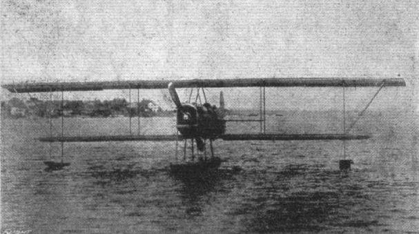
Front view of the Burgess type "U" seaplane.

THE BURGESS TYPE "U" SEAPLANE. - Plan, side and front elevations to scale.
Flight, June 14, 1917.
THE BURGESS "B.P." PRIMARY TRAINING
IN order to meet the requirements of the U.S. Army for a machine for the primary training of pilots, W. Starling Burgess, of the Burgess Co., Marblehead, Mass., U.S.A., designed the tractor biplane described and illustrated herewith. The main characteristic of this machine is in the seating arrangement, the instructor and pupil being seated side by side - an arrangement which is preferred by some instructors.
The extra width of the fuselage at the cockpit due to this seating arrangement is by no means excessive, and, indirectly, is the means of producing a fuselage of nearly perfect streamline form. The general appearance is also added to as a result of this larger width.
Another noticeable feature is in the arrangement of the interplane struts. These are not only inclined forward, as a result of staggering the top plane, but they are also inclined outwards - a practice common with several types of Austrian machines. It will also be noticed that they are inclined outwards at angles which increase from the innermost to the outermost struts.
Throughout the whole machine, simplicity of construction, combined with strength, have been the two considerations that have received the designer's attention, and in both experimental and official trials the machine gave very satisfactory results. The large plane area, 437 sq. ft., and the wing section, R.A.F. 3, render the machine comparatively slow and easy for the pupil to handle.
Both top and bottom planes are in two sections each, the top joined at the centre, and the bottom attached to the fuselage. The dihedral angle of both planes is 3/4 ° and the angle of incidence is 1 1/4°. The top plane is staggered forward 1 ft. 9 ins. The main spars are spaced 4 ft. apart, the forward spar being located 9 ins. from the leading edge. The attachment of the interplane struts occurs at the following distances from the centre :- Fuselage struts, 2 ft. 8 ins.; middle struts, 9 ft. 1 1/2 ins. (top), 7 ft. 2 ins. (bottom); outer struts, 16 ft. 9 ins. (top), 14 ft. 5 ins. (bottom). The wing-tips are raked 16°. Ailerons, of 18 sq. ft. area each, are hinged to the rear spar of top plane only. The area of the top plane, excluding ailerons, is 219 sq. ft., and that of the lower plane 182 sq. ft.
The tail surfaces, which are of somewhat ample proportions, consist of a stabilising plane in two sections, mounted one on each side of the fuselage, having elevator flaps hinged to the trailing edge. A balanced rudder is pivoted on the tubular stern post, and in front is a triangular vertical fin. The stabilizer is supported at its forward end by tubular struts.
The fuselage is of rectangular section tapering to a vertical knife-edge at the rear. The length from the nose to stern post is 21 ft. 2 ins. The maximum width and depth, at cockpit, is 4 ft. and 2 ft. 6 ins. (3 ft. 7 ins. over turtle deck) respectively. The top longerons are parallel to, and 7 ins. above, the line of thrust. Mounted in the nose, in front of the engine, is the radiator, measuring 2 ft. 2 ins. high by 2 ft. 3 ins. wide.
The landing chassis is of the three-wheel type, all three being 26 ins. by 3 ins. disc. The two main wheels are mounted on a tubular axle, running in metal guides and carried by two pairs of tubular steel V-struts. The forward wheel is rigidly supported below the nose of the fuselage by a pair of tubular steel struts. The latter, together with the forward members of the V-struts, are provided with wood streamline fairings. A pair of horizontal tie-rods also connect the front wheel and the main axle.
The general dimensions are as follows :- Span, top 41 ft. 6 ins., bottom 34 ft.; chord, 6 ft. 6 ins.; gap, 6 ft.; stagger, 1 ft. 9 ins.; supporting surface, 437 sq. ft.; overall length, 23 ft. 11 ins.
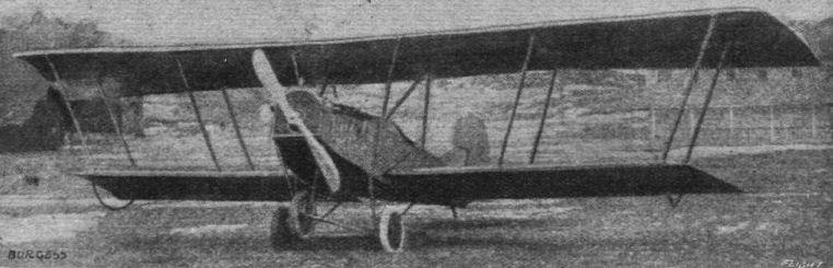
Three-quarter front view of the Burgess training tractor biplane. In this view the arrangement of the struts is clearly shown.

Side view of the Burgess training tractor biplane.

Three-quarter rear view of the Burgess training tractor biplane.
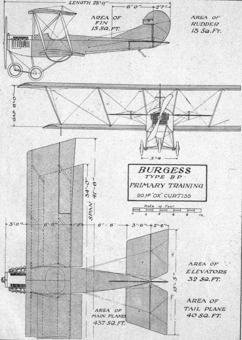
THE BURGESS TRAINING TRACTOR BIPLANE.- Plan, side and front elevation to scale.
Flight, September 27, 1917.
THE BURGESS SPEED SCOUT SEAPLANE.
AN interesting type of seaplane has recently been constructed, and tried out, by the Burgess Co., of Marblehead, Mass., U.S.A., namely, the HT-2 speed scout. A short while back we gave an illustration of this machine, and this week we are able to give further particulars and scale drawings, for which we are indebted to our American contemporary, Aerial Age. A number of original constructional features have been incorporated in this machine, the most noteworthy of which are the interplane struts, float struts, and the shock absorbing attachment of the floats.
Numerous test flights were carried out by W. E. Doherty this summer with the object of discovering if the original design could be improved upon. One or two modifications thus suggested may be found on referring to the scale drawings, viz., vertical surfaces on each pair of king posts on the top plane, the elimination of bracing wires on the ailerons, the cutting away of a portion of the top plane above the pilot's seat, and the mounting of the tail float nearer to the fuselage. Wherever possible, sharp angles have been eliminated, also, by means of balsa-wood streamlining.
The main planes are comparatively narrow in chord, and have neither stagger, sweep-back, nor dihedral. The upper plane is in four sections, the inner sections being joined in the centre by a pair of metal plates at the wing spars. Each of these sections measures 11 feet span, whilst the outer or overhanging sections, to which the ailerons are hinged, measure 5 ft. 10 ins. The two lower plane sections extend 9 ft. 4 ins. at either side of the fuselage, which is 2 ft. 6 ins. wide at this point. The front spars are located 8 ins. from the leading edge, and 1 ft. 8 ins. from the rear spar. Ribs are spaced 9 ins. apart. Internal drift wires are terminated to the ends of tapered compression struts which relieve the ribs of compression strains. The overhang, and the interplane brace wires are doubled, the space between each wire being filled with spruce streamlining strips, the edges of which are routed out to receive the wires.
The interplane struts are of spruce, built up to form a K-shape unit, covered with fabric. There is one of these K-units on each side of the fuselage, but instead of being vertical they slope inwards from the top plane. In continuation of each of these struts is a pair of V struts extending to the floats, another similar pair being carried up from each float to the body, the whole system of struts thus forming a W when viewed from the front. The K-unit is built up as follows: One spruce member runs from the upper rear spar to the lower front spar, a second member runs from the lower rear spar to the top front spar, whilst a third member connects the upper and lower spars, giving the K shape. The junctions with the planes are filled into a curve with balsa-wood to give a streamline effect. Two pairs of short struts slope outwards from the fuselage to the top plane.
The fuselage is of good streamline shape, being circular in front, tapering to a vertical knife-edge at the rear. The forward part near the engine is covered with louvred sheet aluminium. The sides and top are curved beyond the longerons by means of thin horizontal spruce stringers supported on formers, and covered with fabric. The top of the fuselage is in sections, which are separately removable, and a semi-elliptical streamlining ridge is fitted, starting from the pilot's head rest.
The pilot's cockpit is exceptionally deep and roomy, and the top of the cockpit, above the instruments, is formed with celluloid, providing ample lighting to the interior, at the same time serving as a wind shield. Deperdussin control is installed, and the aileron control passes through the sides of the fuselage at a point 1 ft. above the lower plane in line with the forward edge of the K struts, and runs to the top of the latter, thence to a pulley, attached to the underside of the upper wing spar, to the aileron crank. Control wire openings in the fuselage are protected by heavy skin washers sewn to the fabric.
The tail planes consist of a horizontal stabilising surface, a vertical fin, rudder, and elevators. The latter are hinged to a common spar and work in unison. The root of the vertical fin is built into the curved fuselage top, and the rudder has a small balancing surface forward of the hinge; the lines of the rudder continue in the same curve of the fin. Solid wire braces run from both the forward and rear spars of the stabiliser to the top of the rudder post; and also from underneath the forward spar to the tail float.
Two main floats, 11 ft. long, 3 ft. beam, and 1 ft. 5 ins. maximum depth. They are spaced 6 ft. 6 ins. from centre to centre, and are connected by two horizontal struts. The forward horizontal strut is located 2 ft. 2 ins. from the bow, and the rear strut, which acts as a shock absorbing axle, 5 ft. behind it. A single strut on each float runs from the horizontal strut to a point on the fuselage near the radiator. The rear "axle" is mounted on the V struts - which are covered in with fabric - extending from the fuselage and lower plane. This "axle" is attached to the floats by rubber chord, in metal guides which allow a vertical movement. By this means of shock absorbing much of the porpoising when taxying has been eliminated, and many of the hard landings are taken up by it. The floats have a slight V bottom, with a step located 4 ft. from the stern, and turtle-deck tops. A 2-in. air duct passes through the float at the step. The main support for the tail float is provided in a 2 ft. 2 in. extension of the fuselage sternpost, streamlined fore and aft to a width of 7 1/2 ins. A pair of struts, 2 ft. long, support the front end of the float, and bracing wires run from front and rear struts.
A Curtiss OXX-2 100 h.p. 8-cylinder V engine is installed, being totally enclosed by the aluminium cowling. The radiator is mounted in the nose of the fuselage, and is 2 ft. 3 ins. diameter. The tractor screw, specially designed for the machine by the Burgess Co., is 7 ft. 9 ins. diameter by 5 ft. 9 ins. pitch.
The principal dimensions of the Burgess HT-2 are :- Span, top 34 ft. 4 ins., bottom 21 ft. 6 ins.; chord, 3 ft. 6 ins.; gap, 4 ft.; overall length, 22 ft. 3 ins.; overall height, 10 ft.; speed range, 50-95 m.p.h.
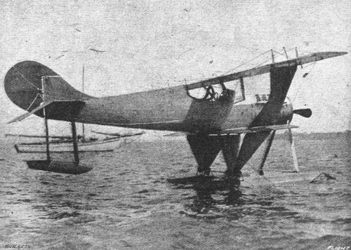
Three-quarter rear view of the Burgess speed scout seaplane.
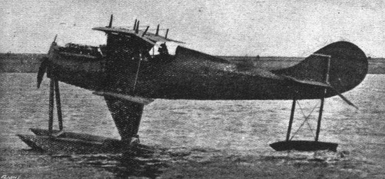
Side view of the small Burgess "single-strutter" tractor seaplane, a front view of which appeared in "FLIGHT" for May 31st last.

Side view of the Burgess speed scout seaplane.

Three-quarter front view of the Burgess speed scout seaplane.
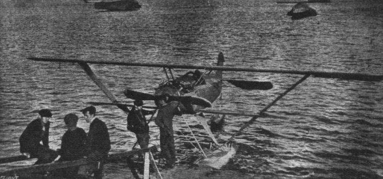
A small "single-strutter" tractor seaplane scout, built by the Burgess Co., of Marblehead, Mass., U.S.A. Pilot Earl S. Doherty is standing in front of the machine (on right).

THE BURGESS SPEED SCOUT SEAPLANE. - Plan, side and front elevations to scale.
Flight, October 4, 1917.
FROM OTHER LANDS.
BURGESS TWIN-MOTORED HYDRO-AEROPLANE.
TRIALS are now under way to list for official purposes the performance results of the twin-motored hydro which has just been completed at the Marblehead factory. The design takes in consideration the advantage of locating a machinegun operator forward of the planes and propellers. The machine, besides being equipped with the usual complement of instruments, has the Sperry gyroscopic stabiliser and other improved installations.
General Dimensions.
Span, upper plane 72 ft. 0 ins.
Span, lower plane 51 ft. 9 ins.
Chord, both planes 7 ft. 7 ins.
Gap between planes 6 ft. 11 ins.
Length over all 32 ft. 5 ins.
Height over all 13 ft. 3 ins.
Gross weight 5,380 lbs.
Motors (2) Sturtevant 5A, each 150 h.p.
Gliding angle 8 1/2 to 1
Climb in 10 minutes 3,500 ft.
Speed range, loaded 78-45 m.p.h.
Planes. - Upper plane is in five sections - the flat centre section 12 ft. 6 ins. wide; the outer sections each 16 ft. 8 ins. wide; and the overhanging sections 11 ft. 4 ins. wide. The ends of the ailerons project beyond the wing tips at either side for a distance of 1 ft. 6 ins.
Ailerons on the upper plane are 12 ft. 10 ins. in length, minimum with 2 ft. 1 in., maximum width 3 ft. 5 ins. A small balancing portion beyond the wing tips extends forward of the rear main wing beam. Control arms are located 7 ft. from the inner end of aileron.
With the exception of the centre sections, the planes are swept back at an angle of 3°. On the lower plane, this angle corresponds to a distance of 10 3/4 ins. that the straight portion of the leading edge recedes from a straight line at right angles to the fuselage centre.
Dihedral angle, centre section, upper plane, 180. Dihedral angle of other wing sections 178 degrees.
Upper and lower planes are set at a 30 incidence angle, equal to rise in the leading edges of 4 15/16 ins. The transverse and lateral centre of gravity is located 2 ft. 11 ins. from the leading edge, at which point a hoisting eye is located.
Centres of wing beams are located as follows: Front beam 9 1/4 ins. from leading edge; beams 4 ft. 6 ins. apart; trailing edge 2 ft. 3 7/8 ins. from centre of rear beam. Wing chord, 7 ft. 7 3/8 ins.
Fuselage. - The fuselage is 27 ft. 6 1/2 ins. long; maximum width, 2 ft. 4 ins. Maximum depth between longerons, 2 ft. 11 ins. The nose extends 6 ft. 11 ins. forward of the main planes. The observer's cockpit is located at the nose, and the pilot is located immediately below the trailing edge of the upper plane.
Location of vertical fuselage members are indicated by dotted lines on the drawing. The fuselage termination is 18 ins. high, formed by a strut which carries the central rudder and also supports the tail float.
Tail Group. - Horizontal stabiliser, 16 ft. across at the trailing edge. Width, 4 ft. 0 1/2 in. The leading edge is straight for a distance of 13 ft. 4 ins,, then curved in a 9 ins. radius to a raked angle. It is non-lifting. Elevators are 16 ft. 8 1/2 ins. from tip to tip. Maximum width, 3 ft. 8 ins. Control posts located 6 ft. apart, one on each flap.
The vertical fin is 3 ft. 2 ins. high, and to it the central unbalanced rudder is hinged. The central rudder is 2 ft. 3 ins. wide.
In addition to the central rudder, there are a pair of balanced rudders located 6 ft. to either side of the fin. These rudders have a maximum height of 3 ft. 2 ins. and a width of 2 ft. 2 ins.
Floats. - Floats are arranged catamaran style, with centres 10 ft. apart. Each float 3 ft. Wide, 19 ft. 1 1/2 ins. long and 2 ft. in overall depth. A step 3 3/4 ins. deep is located 11 ft. 10 1/2 ins. from the front end. Struts to the fuselage are located at the following distances from the nose: 4 ft. 3 ins.; 4 ft. 9 ins.; 5 ft. The dotted and dashed line indicates the water line with the machine fully loaded with a Weight of 5,380 lbs.
The tail float is 19 ins. wide, 4 ft. 8 ins. long and 11 3/4 ins. deep.
Motor Group. - Motor carrying struts are located 11 ft. 7 3/4 ins. apart. The drawing shows the motors covered in with metal cowling. Propellers are 8 ft. 10 ins. in diameter, rotating in opposite directions.
The motors are Sturtevant model 5 A, rated at 150 h.p. These motors are 8-cylinder, 4-stroke cycle, water cooled, with a 4-inch bore and 5i-inch stroke. The normal operating speed of the crankshaft is 2,000 r.p.m., and the propeller shaft is driven through reducing gears. The weight per h.p. of the motor is 3.4 lbs.
Fuel is consumed at the rate of 26 gallons per hour, and tanks have a capacity sufficient for an eight-hour flight. - (Aerial Age, U.S.A.)
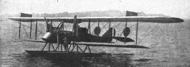
The latest twin-motored Burgess seaplane, at Marblehead, Mass., U.S.A.

BURGESS TWIN-MOTORED SEAPLANE. - Plan, side and front elevations to scale.
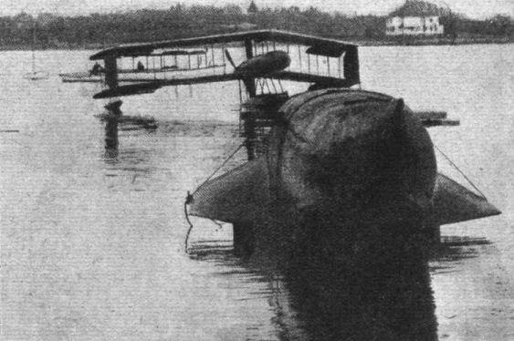
A large flying boat hull, built by the Burgess Co., of Marblehead, Mass., U.S.A. In the background is a Burgess-Dunne seaplane.
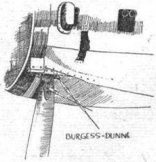
AT THE AMERICAN AERO SHOW. - Some constructional details. The rear strut attachment to the nacelle of the Burgess-Dunne seaplane.
Flight, March 15, 1917.
AT THE AMERICAN AERO SHOW - SOME NEW TYPES.
The Cooper Training Biplane.
In general design this machine, built by the John D. Cooper Aeroplane Corp., of Bridgeport, Conn., mainly for training purposes, resembles the Caudron tractor biplane. The wings and tail planes have flexible ribs as on the latter machine. The single seater nacelle is also similar. As shown in the accompanying illustration, the machine is equipped with two floats, mounted on the skids, but for land use these can be substituted by Farman-type wheels. These floats measure 9 ft. long, 1 ft. 10 ins. beam, and 9 ins. deep, and each weigh 46 lbs. Two tail floats are also fitted. A 5-cyl. two-cycle Frederickson rotary engine (70 h.p.) is employed, mounted on a steel plate at the nose of the nacelle. All control wires are solid, except when they run over the ball-bearing pulleys, when cable is employed. General dimensions :- Span (top) 33 ft., (bottom) 22 ft.; chord, 4 ft. 6 ins.; gap, 4 ft. 4 ins.; weight (empty), 500 lbs.
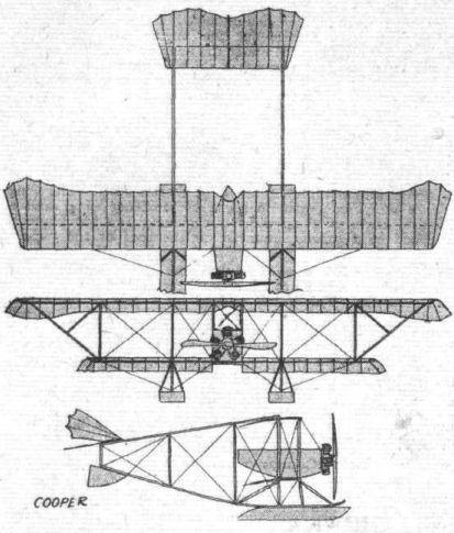
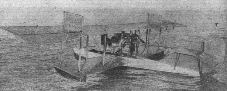
The Curtiss aero-yacht de luxe, built for the America Trans-Oceanic Co. It is luxuriantly fitted up, and carries five passengers. We hope to give further details of this machine shortly.
Flight, May 10, 1917.
THE "TOTALLY ENCLOSED" AEROPLANE.
ALTHOUGH the seaplane as a type, lends itself extremely well to closing in the occupants, it was not until 1914 that any serious attempt was made to provide the "totally enclosed" feature on a seaplane of the flying boat type. Shortly before war broke out Lieut. Porte, R.N., now a Commander in the R.N.A.S., it may be remembered, contemplated a flight across the Atlantic in the Curtiss flying boat, "America." In view of the duration of the trip it was deemed advisable to protect the pilot and passenger as much as possible against the weather, and to this end a cabin-like superstructure was added to the main hull of the machine. The latter was a biplane flying boat with two Curtiss motors placed on Vee struts between the wings. The upper plane had a span of 74 ft., and the overall length of the machine was 34 ft. Fully loaded the weight was about 5,000 lbs., and the speed somewhere in the neighbourhood of 65 m.p.h.
Owing to the great depth of the boat itself the cabin walls only projected some 18 inches above the deck, and yet the distance from the floor boards to the roof of the cabin was about 5 ft., so that by stooping slightly the occupants were able to move about in the cabin with comparative freedom. Since the machine was to have been flown over stretches of sea where meeting other machines were scarcely to be expected, the windows did not extend very far behind the pilot's seat, those curving round in front being the most important. Access to the cabin was through a hatch that could be closed once the machine was on her way, and through which, if necessary, the passenger might reach the engine to make any adjustments. Should the machine come down low enough to make signals to passing ships, the passenger would have to lean over the gunwales by the hatch as the windows in the cabin did not provide a view in a downward direction.
<...>

The cabin of the Curtiss flying boat "America," on which Commander J. C. Porte, R.N., was to have attempted to cross the Atlantic in the summer of 1914.
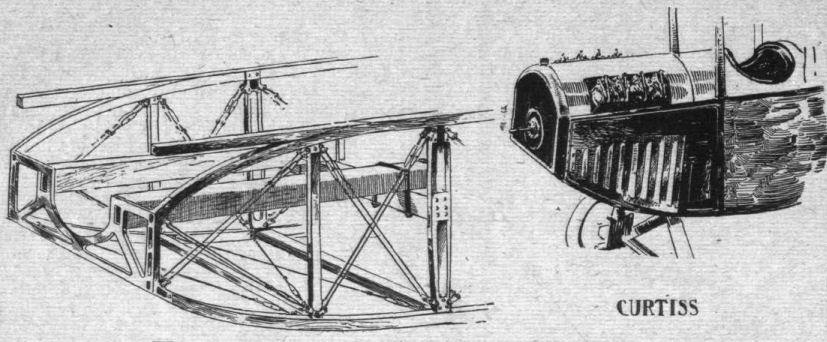
Mounting and housing of water-cooled engines.
AT THE AMERICAN AERO SHOW. - Some constructional details. Various examples of interplane strut fittings, including the early Wright-type.
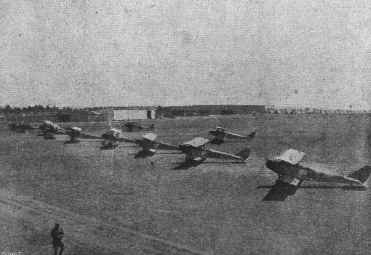
THE UNITED STATES AVIATION SCHOOL AT SAN DIEGO, CAL. - A general view.
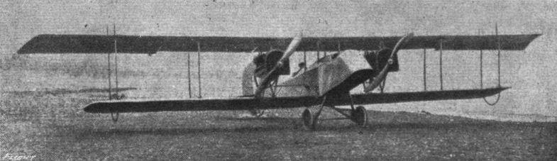
The Curtiss J.N. twin-engined biplane.
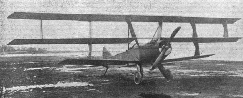
The Model L was a side-by-side two-seater and a contemporary of the JN-4.
The 100 h.p. Curtiss triplane, on which Miss Ruth Law proposes to make an attempt on an American coast to coast flight, following on her recent record, when she flew from Chicago to New York. Her idea is to start from San Francisco for New York in the spring.
The 100 h.p. Curtiss triplane, on which Miss Ruth Law proposes to make an attempt on an American coast to coast flight, following on her recent record, when she flew from Chicago to New York. Her idea is to start from San Francisco for New York in the spring.
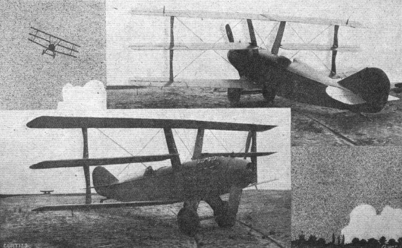
TWO VIEWS OF THE LATEST CURTISS TRIPLANE SCOUT. - Several modifications on the model illustrated in our issue for January 25th last will be noticed. It is of smaller span, and all three planes are equal. The body is of better streamline form, and the chassis struts are arched.
Flight, March 15, 1917.
AT THE AMERICAN AERO SHOW - SOME NEW TYPES.
The Curtiss Autoplane.
THIS machine, one of the greatest attractions of the exhibition, constitutes a modern designer's idea of the "limousine of the air." The body is a combination of motor car and aeroplane practice, and follows very closely the lines of a modern limousine or coupe car-body. It is constructed mainly of aluminium, the windows being of celluloid. Elaborate upholstery and tapestries are employed for the interior, which accommodates two passengers at the rear and a "chauffeur" forward. Right in front is a circular radiator, through which passes a starting handle for the engine, a Curtiss OXX 100 h.p., which is located under the bonnet. From the engine, power is transmitted through a shaft, extending to the rear of the body, to the four-bladed propeller located at the top. There is a pair of wheels fore and aft, mounted in a similar way as on the Curtiss tractor triplane. The axle of the front pair, however, follows motor car practice, in that the wheels are pivoted and connected to the control so as to enable the machine to be steered on the ground. The triplane wings are also similar to the triplane tractor, except that they are staggered and the lower plane is of shorter span. The wing section is "F-2" with an angle of incidence of 4# and a dihedral angle of 3# to the lower plane. The top plane is attached to a cabane mounted on the roof of the "car," whilst the centre and lower planes are attached to the body itself. Covered-in K-shape interplane struts separate the planes, and interconnected ailerons are fitted to top and centre planes. The tail is carried by a pair of horizontal tubular outriggers attached to the centre plane. The tail surfaces consist of a rectangular horizontal stabiliser, divided elevators, rudder and triangular vertical fin. Mounted on the bonnet, just above the front wheels, is a small plane. The general dimensions are as follows :- Span (top and centre) 40 ft. 6 ins., (bottom) 23 ft. 4 ins.; chord (top and centre) 4 ft., (bottom) 3 ft. 6 ins.; gap, 3 ft. 3 ins.; stagger, 11 ins.; overall length, 27 ft.; height, 10 ft.; width of body, 3 ft. 6 ins.; speed range, 45-65 m.p.h.; useful load, 710 lbs.
Flight, May 10, 1917.
THE "TOTALLY ENCLOSED" AEROPLANE.
<...>
At the aero show held at New York early this year there was exhibited a Curtiss triplane, which aroused the greatest interest owing to the decidedly novel lines on which it was constructed. The Curtiss Autoplane as it was called was really a motor car with wings, and although there were those who, at the time of the show, were inclined to smile and regard the machine as something of a joke on the part of the Curtiss firm, or at most a machine built solely for the purpose of creating a sensation at shows and in processions, a brief consideration will suffice to show that the machine, in spite of unconventional design, is not the freak aerodynamically some critics suggest. The engine, a 100 h.p. Curtiss, is mounted in front under a bonnet, motor car fashion, and is provided with the ordinary starting handle projecting through the radiator in the nose. A four wheeled under carriage is fitted, the front wheels of which are connected up to the controls in such a manner as to allow of steering the machine on the ground at low speeds. Inside the limousine body are three seats, the pilot's in front, and two passenger seats side by side further back. The upper plane is attached to a cabane resting on the roof of the body, while the two lower planes, the bottom one of which is of shorter span than the other two, are attached to the body. The propeller is mounted approximately on a level with the centre wing, and is driven through a long shaft from the engine. In addition to the rear elevator which, with the other tail units, is mounted on two booms, there is a small front elevator projecting out from the engine bonnet, giving the impression of mud guards.
At first sight it would appear that the head resistance would be somewhat excessive, but owing to the shape of the body, a section through a plane on level with the bottom of the windows would approximate very closely to a stream line section, so that the real resistance may probably be found to be a good deal less than one would at first expect. Placed where it is, the propeller should coincide pretty well with the centre of resistance, as it must be remembered that the upper wing carries a greater load than the other two, and that, although the resistance of the body is acting fairly low down, the bottom plane is of short span and offers but little resistance. The machine would have a very low centre of gravity, certainly, but this has not proved detrimental to good flying in such machines as the Morane parasol, and the centre of side area also appears to be quite low in comparison with the centre of lift of the three wings. A constructional feature which could, we think, be improved upon is the method of mounting the tail planes, which does not impress one as being any too strong. Otherwise the machine appears to us to promise very well in many respects, and the Curtiss firm are to be congratulated on being first to produce what really seems to be the first attempt at the comfortable enclosed small machine of the future. At the moment we have not been able to ascertain whether or not the machine has been flown, but although alterations and improvements are still to be expected, it does appear to us that this machine is a step in the right direction. For a three seater the power does not impress one as being quite sufficient, but it should not be a matter of great difficulty to install a more powerful engine, if that should be found advisable, which we fancy will be the case.
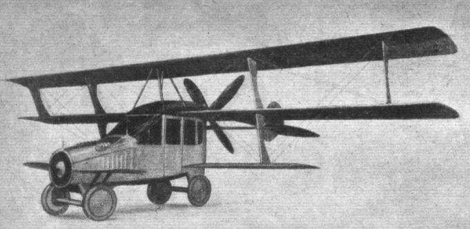
The Curtiss "Autoplane" exhibited at the 1917 New York Aero Show.
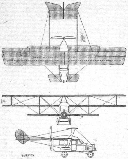

AT THE AMERICAN AERO SHOW. - Some constructional details. The front steerable wheels on the Curtiss "Autoplane."
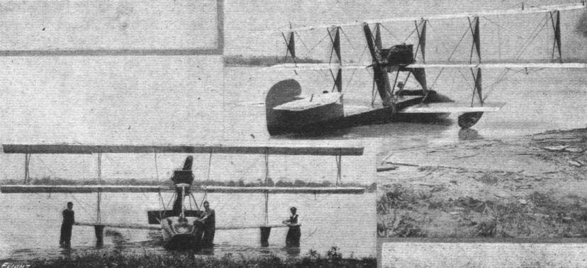
Two further views of the Curtiss model F.L. triplane flying boat, which was illustrated in a recent issue of "FLIGHT."

The Curtiss triplane flying boat about to "land."
Flight, May 10, 1917.
THE "TOTALLY ENCLOSED" AEROPLANE.
<...>
Since the war the Curtiss firm have built a great number of large flying boats, following more or less along the lines of the "America," from which some have, however, differed very considerably as regards size. A case in point is the flying boat known as the type H-12, which was illustrated in our issue of April 26th, 1917. In general arrangement this machine differs comparatively little from the "America," and it has not, therefore, been included in our descriptions of "totally enclosed" aeroplanes to which category it naturally belongs.
<...>

One of the large Curtiss H-12 flying boats, which has a wing spread of 92 ft. 8 1/2 ins., an overall length of 46 ft. 5 1/2 ins., and weighs 5,945 lbs. The power plant consists of two 200 h.p. VX-3 Curtiss motors, and the speed is in the neighbourhood of 85 m.p.h.
Flight, August 30, 1917.
THE NEW CURTISS H-S-I FLYING BOAT.
ONE of the latest models turned out by the Curtiss Co. is seen in the accompany illustrations. The H-S-1 is a medium-sized boat, coming between the 90 h.p. and the 400 h.p. H-12 models. It is not designed for speed, but is a relatively slow sailing craft of great steadiness, which can be driven for hours without fatiguing the pilot, and is thus eminently suitable for coast patrol work, for which it has been primarily designed. It is powered with a single Curtiss V-2 200 h.p. and carries pilot, passenger and fuel for 6 hours' cruise.
The hull resembles that of the H-12, in that it is fitted with the planing fins at the sides, but the cockpit is not enclosed as on the H-12. Harold Kantner, the well-known American pilot, flew from Buffalo to Detroit and back with a passenger on this machine last July, and reported that the boat handled very well.
The follewing are the principal characteristics of the H-S-1: Span (top), 59 ft. 4 ins, (bottom) 45 ft. 8 ins.; chord, 6 ft. 3 1/16 ins.; gap, 7 ft. 6 ins.; no stagger and no dihedral angle; angle of incidence, 4° (wing section, R.A.F. 6); overall length, 38 ft. 6 ins.; height, 14 ft. 3 ins.; total supporting surface, 626 sq. ft.; loading, 6-7 lbs. per square foot; weight (empty), 3,215 lbs.; useful load, 1,000 lbs.; speed range, 52-73 m.p.h.; climbing speed, 500 ft. in 3 mins.
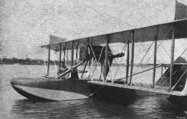
The new 200 h.p. Curtiss H-S-1 flying boat on the Niagara River, just before its flight from Buffalo to Detroit and back.
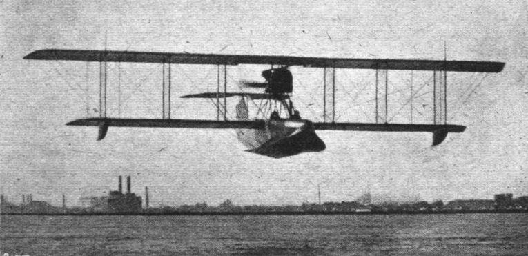
The Curtiss H-S-1 flying boat in full flight.
Flight, September 20, 1917.
THE G.A.C. "VERVILLE" PUSHER BIPLANE.
THE "Verville" pusher biplane, manufactured by the General Aeroplane Co., of Detroit, Mich., U.S.A., has been designed primarily for bombing and observation work, and, being of the pusher type, is capable of being efficiently armed for defensive or fighting purposes. It can be fitted with either wheels or floats, and a factor of safety of seven is employed throughout. All wiring is double, the factor of safety being taken on one wire. The cable joints are wrapped with 24 gauge soft copper wire, sweated with solder, and all joints are at least 3 ins. long. All metal parts are treated with primer and baked with three coats of non-corroding enamel.
The main planes are 40 ft. and 30 ft. span top and bottom respectively, the top plane being staggered forward 8 ins., and top and bottom planes each set at a dihedral angle of 5.
A highly efficient section permits the use of liberal sized I-beam section spruce spars. The ribs are of I-beam section spruce with web and cap strips. The trailing edge is made of Shelby steel tubing. Strong internal drift wire bracing is carried out with Roebling aviator wire, and the whole of the internal wing structure is treated with shellac. The wings are covered with unbleached Irish linen as specified by the British Government. It has a strength in weft of 91 lbs. per inch width, and in warp of 103 lbs., and is doped with nine coats of Emaillite and surfaced with three coats of Valspar to reduce friction to a minimum and to render the wing impervious to the action of air and water. The linen cloth is stitched with No. 8 Irish linen thread at intervals of 4 ins. along ribs, thus obviating the use of nails, which have a tendency to split the members. This method, which adds to the staying qualities of the wing structure with ease and without injury, also renders the recovering of the wing framework a simple operation. The linen used is 35 ins. wide, and is sewed with the English welt seam.
The interplane struts - of which there are two pairs each side of the nacelle, and two shorter pairs on the latter supporting the central panel of the top plane - are made of Virginia silver spruce, well seasoned, and coated with three rubbed coats of Valspar. The strut ends are copper tipped, and the struts are bound at intervals of 12 ins. with three wraps of 3/4-in. grey silk to relieve shattering of the wood fibre. They are built with a 2 1/2 to 1 streamline fineness ratio, and have a weight to resistance ratio of 6. The strut wing fastenings are of unusual design and obviate the disadvantages of the conventional fastenings by bolts and piercing of the spar. The lower spars extend through a metal box at the body, and are joined internally by a steel casing. The two outer sections of the top plane are attached to a small central panel.
The ailerons, 40 sq. ft. in area, are hinged to the extremities of the top wing at the rear wing spar by five cold rolled steel hinges. Two sets of pylons are mounted near the aileron edge in a steel casing. The equalising aileron control passes through an aluminium pulley box and fair leaders along the front spar of the top wing; 2 1/4-in. Lynite pulleys having brass bushings are used throughout.
The tail planes consist of a semi-circular stabilizing surface, 18 sq. ft. area, to the trailing edge of which are hinged two elevator flaps, 18 sq. ft. area, and an elliptically-shaped rudder, 12 sq. ft. area. The stabiliser and elevators are mounted on the top pair of the V outriggers, whilst the rudder is mounted - so that it is partly balanced - on the vertical strut connecting the top and bottom pairs of outriggers. The nacelle, which is of good streamline form, is constructed of ash and spruce, heavily wired top and bottom, and is covered and crowned with light gauge aluminium or protected with light chrome steel sandwich armour to suit military requirements. The engine is covered by a hinged cowl. The pilot and passenger are accommodated in tandem seats in roomy, well protected cockpits, situated so as to provide the maximum range of vision. The cockpits are veneered with bass wood and upholstered with green leather. The seats, which are of the aluminium bucket type, are comfortably upholstered, and the seat cushions are filled with sufficient Kapok to float a 250-lb. man for 24 hours. The engine-bearers, built of oak and spruce, are fitted in the steel engine plate at the rear of the body, and careful provision is made for suitably attaching the radiator.
The laminated dashboard is made of polished mahogany, and is equipped with altitude barometer recording to 15,000 ft., Tycos inclinometer, Tycos speed indicator, Tycos tachometer, petrol pressure gauge, eight-day clock, oil pressure gauge, electric light switch, dashboard light, motor cut-out switch, hand throttle and magneto control. Four Ever-Ready cells are provided for lighting dashboard light, wing tip light, and head and tail lights. The hand pump is convenient to the pilot at the side of the body.
The engine is a 100 h.p. Curtiss OXX-2, 8-cylinder, driving direct an 8 ft. diameter, 6 ft. pitch propeller. The radiator is mounted behind the engine, the water capacity being 3 gallons. The service petrol tank, which has a capacity of 35 gallons, is made of 22 gauge terne coated steel, and is equipped with baffle plates, capacity gauge, pressure gauge, auxiliary pressure pump, 5/16-in. carburettor outlet and a 2 1/4-in. airtight brass filler cap. A 3-gallon auxiliary gravity tank is also supplied. The Dep. type of control is employed.
In the seaplane the main floats are of the twin type, braced to the body by stout streamline members and counter wired oak ribs. They are diagonally spruce planked and longitudinally planked with Honduras mahogany, the two layers being interspersed with 4-oz. treated sheeting. The floats are divided into two watertight compartments by an aluminium bulkhead, and are rendered accessible by 24-in. aluminium inspection covers. The floats have the V-type entering edge, which spreads to a flat surface at rear, and are internally treated with boiled oil. Their displacement factor is 2 1/4 to 1. The tail float of mahogany streamline section has a displacement capacity of 350 lbs.
The chassis for land is of the wheel and skid type, the two 26-in. by 5-in. Goodyear wheels being sprung on a tubular Shelby steel split hinged axle at the centre of the chassis, and is stoutly thrust wired. The shock absorbers are made of ?-in. Goodyear cord elastic, wound around twin drums over the axle head. The wheel hub is made of manganese bronze, and the wheels are dished with aluminium.
The principal characteristics of the "Verville" pusher are:-
Span: (top), 40 ft., (bottom), 30 ft.; gap, 5 ft.; chord 5 ft.; length overall, 25 ft. 10 ins.; supporting surface, 350 sq. ft. ; stagger, 8 ins.; dihedral, 5° ; gliding angle 1 in 7; angle of incidence of planes: (normal), 3°, (fast), 2°, (slow), 140, tail plane, 0°; safe range of incidence, 0° to 14°; power plant, Curtiss OXX-2; fuel capacity, 5 hours; speed range (fully loaded), 4 hours (45 to 78 m.p.h.); climbing speed 2,800 ft. in 10 minutes; weight (empty), 1,360 lbs. (land), 1,500 lbs. (sea); useful load, 600 lbs. (land), 450 lbs. (sea).
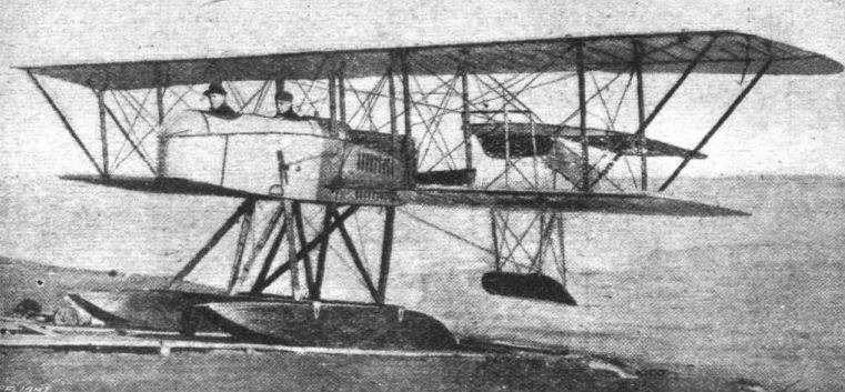
THE G.A.C. "VERVILLE " PUSHER SEAPLANE. - Three-quarter front view.
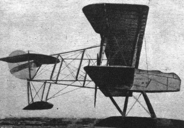
Side view of the G.A.C. "Verville" pusher seaplane.

Three-quarter front view of the G.A.C. "Verville" pusher biplane, fitted with wheel landing chassis instead of floats.
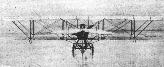
Rear view of the land-type G.A.C. "Verville" pusher biplane.

THE G.A.C. "VERVILLE " PUSHER SEAPLANE. - Plan, front and side elevations to scale.
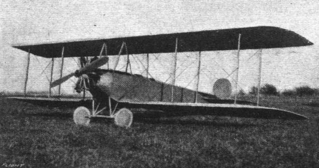
The Grinnell tractor biplane, an American machine somewhat reminiscent of the Flanders biplane in Brooklands' days of old.
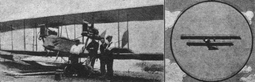
Two views of the twin Ford-motored Harley-Stromer hydro-biplane. It is said that in the 19 months the machine has been in use over 700 flights have been made. A new model is being constructed which it is proposed to sell for $3,000 each.

AN AMERICAN VARIABLE ANGLE OF INCIDENCE AEROPLANE. - Three views of the Lanzius tractor biplane, designed and built by the Lanzius Aircraft Co. of New York, U.S.A. We hope to give particulars of this interesting machine later.
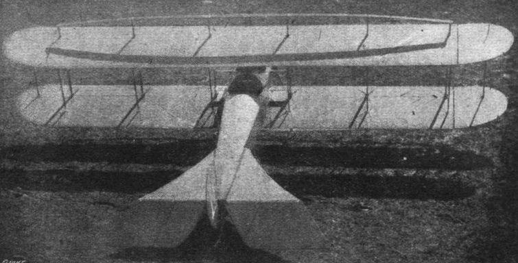
Another view, from above, of the Lanzius variable angle of incidence biplane.
Flight, March 29, 1917.
THE LAWRENCE AEROPLANE.
AN AMERICAN INHERENTLY STABLE AEROPLANE.
DURING 1915 and 1916 exhaustive experimental work on a new type of aeroplane was carried out by the Lawrence-Lewis Aeroplane Co. at Tampa Bay, Florida, U.S.A. The results apparently proved highly successful, as work is now proceeding with two new models - A-1 speed type, and B-1 load-carrying type - following the same principles.
From the accompanying illustrations of the experimental A-1 type, it will be seen that the machine is a totally-enclosed tractor biplane flying boat, although we understand that it can also be converted into a land machine. The main feature consists in the fact that neither ailerons nor wing-warping is required for the lateral control, this being obtained entirely by virtue of the aerodynamic properties of the machine. During the trials, consisting of over 150 flights under varied weather conditions, it was demonstrated that the machine possessed a marked degree of inherent stability, had an exceptionally high gliding angle, and a wide-speed range.
The simplicity of control was another marked feature. The boat is of the short-hull type, the walls being extended upwards to the top planes, and rearwards to the tail. Windows are formed in the sides from the pilot's seat, at the rear of the planes, to the nose. The main planes are, we believe, slightly arched downwards at the tips. The principal dimensions of models A-1 and B-1 are :-
A-1: span, 30 ft.; chord 6 ft.; gap, 4 ft. 8 ins.; overall length, 25 ft.; stagger, 6°; weight, 1,750 lbs.; useful load, 800 lbs.
B-1: span, 42 ft.; chord, 7 ft. 6 ins.; gap, 5 ft. 8 ins.; overall length, 29 ft.; stagger, 6°; weight, 2,200 lbs.; useful load, 1,500 lbs.
The engine, which in each case is a 140 h.p. Hall-Scott, is mounted on the hull and drives a tractor screw, located high up in front of the bows.
Flight, May 10, 1917.
THE "TOTALLY ENCLOSED" AEROPLANE.
<...>
During the years 1915 and 1916 experiments were carried out in America with a highly original flying boat of the enclosed type, built by the Lawrence-Lewis Aeroplane Co. of Chicago. This machine, of which no detail information is yet available, has a main float or boat built of wood in the usual way, to which is added a superstructure of stringers and fabric forming a long cabin. The pilot obtains a view of the surrounding country through windows in the side and nose of this cabin, and as the propeller is mounted high up, and the pilot is placed a considerable distance behind the lower plane, he has a fairly free view in practically all directions. The engine is placed down in the nose of the boat and drives the tractor screw through gearing. The biplane wings are remarkable on account of the fact that no system of lateral control, either warp or ailerons, is employed, the wings being apparently shaped to give a certain amount of inherent lateral stability. It has been announced that further particulars of this machine will be published shortly, and in view of the decided originality of the machine these will be awaited with interest.
<...>
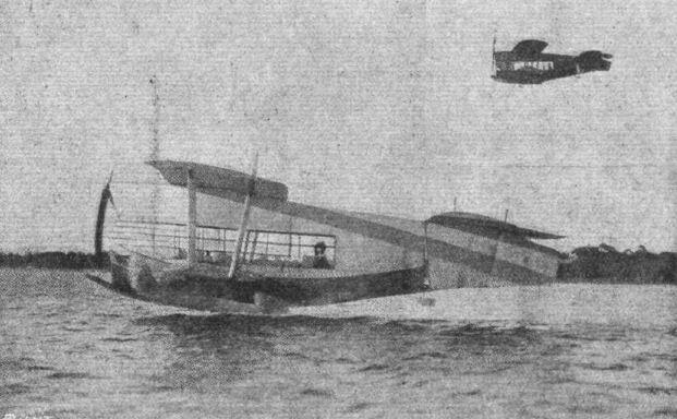
Two views of the Lawrence inherently stable flying boat, showing it leaving the water from a standing start in under 5 secs.; and, inset, the machine in flight.
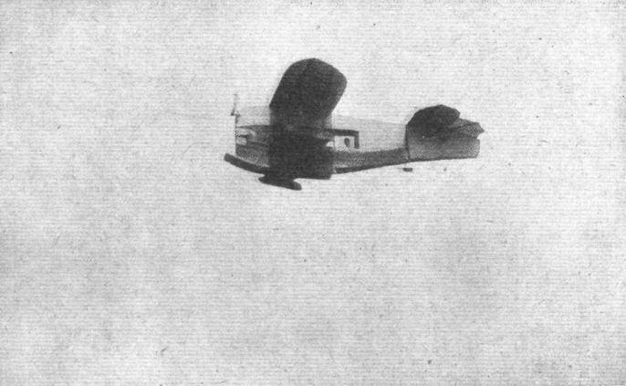
The Laurence tractor flying boat, built and flown near Chicago during 1915-16.
Flight, October 11, 1917.
THE LAWSON TRAINING TRACTOR BIPLANE.
WE have just received from the Lawson Aircraft Corporation, of Green Bay, Wis., U.S.A., the accompanying illustrations and particulars of a decidedly businesslike-looking tractor biplane recently completed at their works. This machine is of the primary training type, built to conform with the specifications No. 1,000 issued by the U.S. Army.
Besides several important constructional features - details of which we are not for the present at liberty to disclose - the Lawson iractor possesses the following features valuable to machines of this type: Its minimum flying speed is as low as 37 m.p.h., whilst the maximum speed is 75 m.p.h. The landing chassis is extremely strong and the axle carrying the two main wheels is well sprung, allowing the axle a wide range of action vertically between the guide plates, which may be seen in the view of the uncovered fuselage. A third, additional, wheel mounted in front of the other two, provides against the machine turning over on its nose should the pupil land the machine at too sharp an angle.
As may be seen, the fuselage, which is a little over 25 ft. in length, is of rectangular section, with spruce longerons and struts, and wire bracing. It is covered with Irish linen as far as the engine housing, which latter part is covered with sheet metal. The tandem seats are mounted on stout longitudinals carried by second, third and fourth sets of upright struts. Dual stick control is installed.
The engine is a 100 h.p. Hall-Scott model A-7A, coupled direct to an 8-ft. diameter tractor screw having an 8-in. pitch. The engine mounting consists of two stout bearers, supported by a system of tubular stays, as shown. The radiator is mounted above the engine underneath the leading edge of the top plane. The exhaust pipe extends upwards and rearwards over the top plane.
On its first flight, under the pilotage of Mr. Alfred Lawson, the machine left the ground after a run of 40 ft., and when landing stopped within 70 ft. of first point of contact.
The main characteristics of the Lawson tractor are as follows :-
Span, (top) 44 ft. 6 ins., (bottom) 32 ft. 6 ins.; chord, (top) 7 ft., (bottom) 6 ft. 5 ins.; gap, 6 ft. 9 ins. ; stagger, 9°; dihedral angle, 1°; wing section, U.S.A.3; angle of incidence, 4 1/2 °; overall length, 25 ft. 6 ins.; height, 10 ft.; weight, empty, 1,300 lbs.; useful load, 600 lbs.; loading, 4.5 lbs. per square foot; speed range, 37-75 m.p.h.; climb, 2,600 ft. in 10 minutes; gliding angle, 1 in 10.
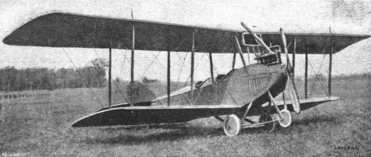
Three-quarter front view of the Lawson training tractor biplane.

Side view of the Lawson primary training tractor biplane.
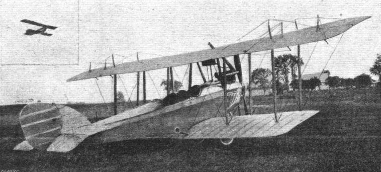
Three-quarter rear view of the Lawson training tractor biplane. Inset, the machine in flight.
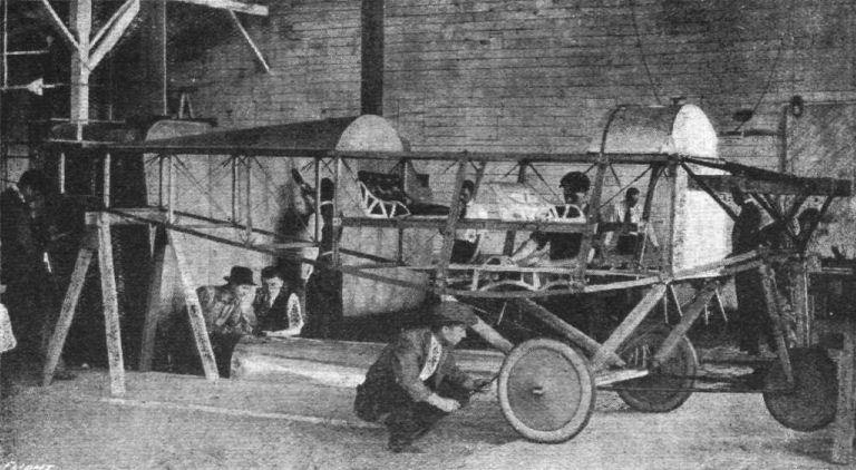
A view of the uncovered fuselage of the Lawson primary training tractor biplane.
Flight, August 9, 1917.
THE L.W.F. TRACTOR BIPLANE.
THERE is a double meaning in the mystic denomination "L.W.F." In one case it gives the initial letter of the name of each of the three members of the L.W.F. Engineering Company (of Long Island, N.Y., U.S.A.) - Messrs. Edward G. Lowe, Jr., Chas. F. Willard, the designer of the machine, and Robert G. Fowler, the pioneer exhibition flyer. It is also symbolic of one of the main features of the machine, viz. - the Laminated Wood Fuselage.
One of the aims of the designer has been to, as far as possible, secure the standardisation of as many parts as possible, and all components are put through rigid tests prior to assembly. As will be seen, the main planes are given a slight backward slope as well as a dihedral angle, in order to give the greatest possible inherent stability without sacrificing the general efficiency of the machine. The amount of sweep-back is 2 ft., and the dihedral angle is 1 degree. The top plane, having a span of 46 ft. 6 ins., is in two, sections, each section being attached to two pairs of inverted V struts mounted on the fuselage. The method of attachment forms the subject of one of our sketches, from which it will be seen that quick assembly and vice versa is greatly facilitated. It may be noted here that this fitting, together with most of the other fittings on the L.W.F. biplane, is a substantial drop forging. The lower plane, which has a span of 38 ft. 8 ins., is also in two sections, and is attached direct to the fuselage. The method of attachment is shown in one of the accompanying sketches.
This fitting consists of a plate following the curvature of the fuselage, to which it is attached by four bolts. Formed on the plate is a dome-shaped projection on which is formed a lug which receives the fork on the end of the wing-spar. Inside the fuselage is a steel compression tube connecting opposite fittings. Provision is made for the attachment of the bracing cables on both the top and bottom plane fittings.
The front spar is located 9 ins. from the leading edge and 3 ft. from the rear spar. The leading edge of the wing is covered with two-ply wood on the top, extending to the front spar, in order to maintain the correct curvature. The wings are covered with a strong fabric complying with R.A.F., specifications, laid diagonally with seams double lapped, and sewn to the ribs.
Two pairs of fabric covered stream-lined struts on each side of the fuselage, separate top and bottom planes. The interplane strut fitting, which is illustrated by one of the accompanying sketches, is of the "ball-bearing" type. The ball is formed on the strut socket, and fits into a cup formed on the wing-plate. The strut can thus be adjusted for varying degrees of stagger, and when once adjusted a pin is driven through the cup and into the ball, thereby locking the whole at that particular angle. One end and the sides of the wing-plate are bent up to form attachments for the bracing cables.
The ailerons, which are hinged to the rear spar of the top plane, are of the double acting type, having an area of 38 sq. ft. The non-lifting double cambered stabilising plane is in two sections, one mounted by quick detachable fittings to each side of the fuselage. A triangular vertical stabilising surface is mounted on the top of the fuselage forward of the rudder, which, as with the elevators, is constructed of steel tubing. Any standard type of control, such as Farman or Dep. is fitted, or if required, the L.W.F. three-in-one.
In the fuselage is to be found the most interesting feature of the L.W.F. machine. It is 23 ft. 6 ins. long, 3 ft. 6 ins. deep (maximum) and 2 ft. 7 1/2 ins. wide maximum. It is built up of three plys of wood, between each of which is a layer of silk. One ply of wood runs longitudinally, whilst the other two are laid spirally to the right and left respectively. The whole shell-is then covered with a specially prepared fabric, and, in the case of hydro-aeroplane models, stitched through and through with very fine, strong wire. It is then given a final treatment of waterproof varnishes. The two cockpits are arranged in tandem, comfortably upholstered and fitted with wind screens.
The landing chassis is of the conventional two-wheel V type, but a three-wheel type, suitable for instruction work, can be fitted if required. A swivelling tail skid is also provided. Provision has been made whereby a complete water-gear may be fitted, consisting of two main floats or pontoons and a small float under the tail.
The power plant consists of either a 140 h.p. 8-cylinder model 5 Sturtevant, or a 135 h.p. Thomas. In each case the exhaust is led well away from the pilot and passenger. The radiator is mounted in the nose of the fuselage, in front of the engine, and is elliptical in shape
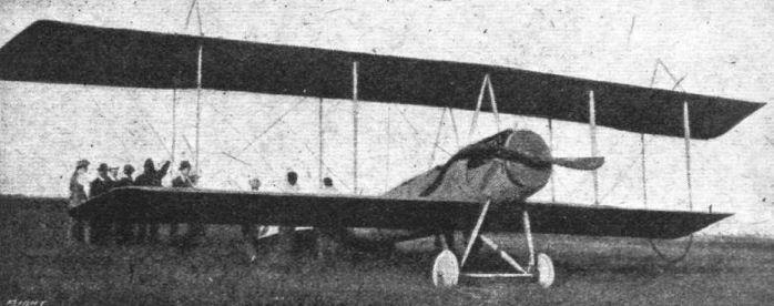
Three-quarter front view of the L.W.F. tractor biplane.

Three-quarter rear view of the L.W.F. tractor biplane.
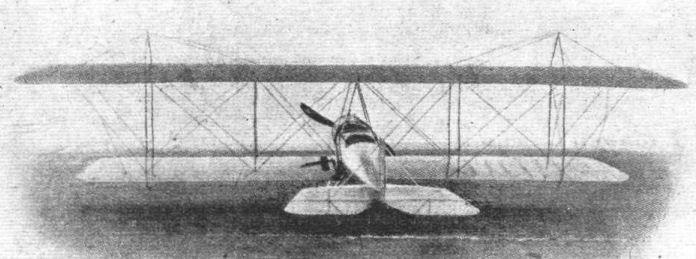
AT THE NEW YORK AERO SHOW. - The L.W.F. tractor biplane.
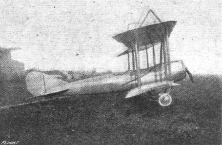
Side view of the L.W.F. tractor biplane.
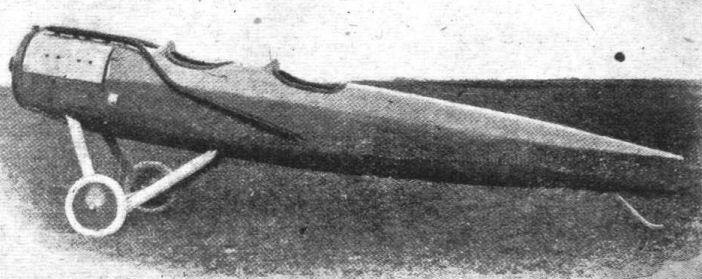
The laminated wood fuselage of the L.W.F. tractor biplane.
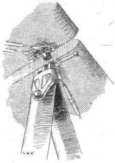
The mounting of the top plane sections to the cabane on the L.W.F. tractor biplane.
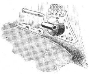
The attachment of the lower plane to the fuselage of the L.W.F. tractor biplane.
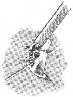
The L.W.F. Tractor Biplane. - The tail-brace fitting.
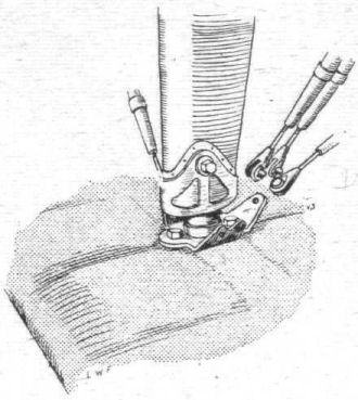
The interplane strut attachment on the L.W.F. tractor biplane.
AT THE AMERICAN AERO SHOW. - Some constructional details. Various examples of interplane strut fittings, including the early Wright-type.
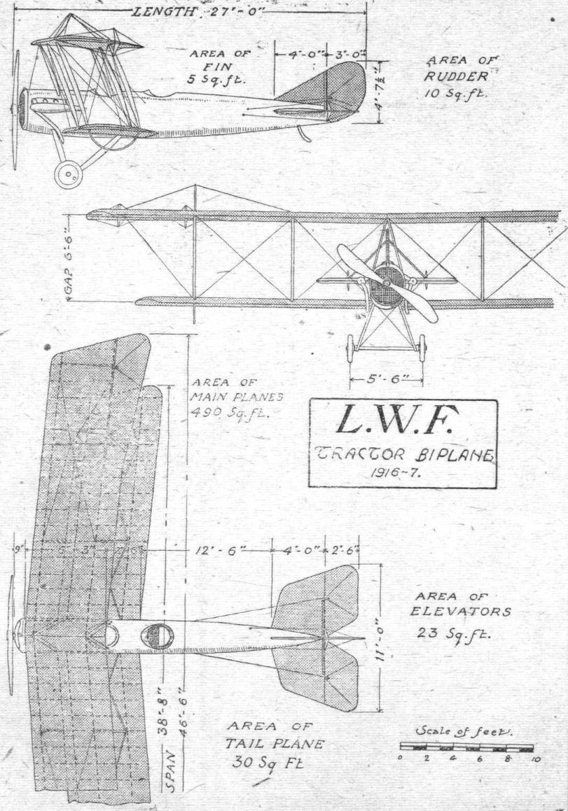
THE L.W.F. TRACTOR BIPLANE. - Plan, side and front elevations to scale.

The new Marlin scout, which has been constructed in Texas, its speed being put at 100 miles an hour.

Wright-Martin tractor seaplane. The larger model S.
Flight, November 29, 1917.
FROM OTHER LANDS.
THE MARYLAND FLYING BOAT.
VARIOUS types of machines have been built by the Maryland Aeroplane Co., which was incorporated at Baltimore, U.S.A., last year, but they have specialised principally in flying boats. The accompanying illustration shows the latest four-seater twin-engined model flying boat, the most interesting feature of which is the method of suspending the motors. By such a method, the motor suspension is independent of the wing structure, thus eliminating one of the principal objections to twin motors. The entire weight of the motors is directly transmitted to and carried upon the boat hull, making possible the employment of wing construction of the same lightness as used in single installations.
The hull has a beam of 46 ins., and an overall length of 32 ft.; the bottom is of the double V type. Provision is made for four passengers, and dual Dep. control is installed. The power plant consists of two 8-cylinder E.N.V. motors, developing 90 h.p. each at 1,250 r.p.m. A radiator for each motor is situated at the forward end of the latter. The propellers are three-bladed, 7 ft. 9 ins. diameter, with a pitch of 5 ft. 3 ins. The capacity of the fuel tanks is 40 gallons.
The general specifications are: Span, top 56 ft., bottom 42 ft.; chord, 5 ft. 6 ins.; gap, 6 ft. 6 ins.; angle of incidence, 7; net weight, 2,200 lbs.; speed range, 38-65 m.p.h. 4 A single motored (75 h.p.) two-seater machine, quite similar in design, but smaller in proportion, is also being turned out by the Maryland Co.
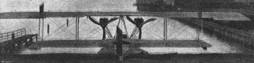
Rear view of the Maryland twin-engined flying boat.
Flight, 1917
Eaton designed New York Aero Floatplane
1916 2-place sesquiplane powered by two 100 h.p. Aeromarine motors, built by the firm New York Aero Construction Co. of Newark NJ (not to be confused with the est.1916 New York Italian Aeroplane Co, NY.)
Eaton designed New York Aero Floatplane
1916 2-place sesquiplane powered by two 100 h.p. Aeromarine motors, built by the firm New York Aero Construction Co. of Newark NJ (not to be confused with the est.1916 New York Italian Aeroplane Co, NY.)
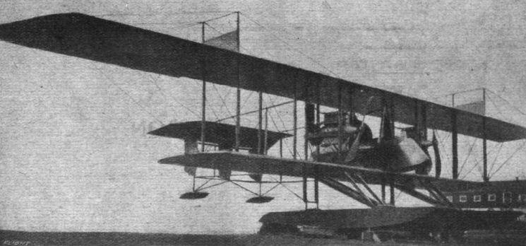
A large twin-engined seaplane built by the New York Aero Construction Co. The planes measure 73 ft. and 44 ft. span, 7 ft. 6 ins. and 6 ft. 6 ins. chord top and bottom respectively. The engines are two 100 h.p. Hall-Scott 7-A models.
Flight, March 15, 1917.
AT THE AMERICAN AERO SHOW - SOME NEW TYPES.
The S. S. Pierce Sporting Tractor.
This is a small, single-seater tractor biplane, lightly but strongly built, specially to meet the requirements of the sportsman. The fuselage is of streamline form, circular in section, mounted 6 ins. above the lower plane on the central interplane struts. The engine, designed specially for the machine by the S. S. Pierce Aero Corp., is a 3-cyl. Y-type, air-cooled, of 35-40 h.p. The planes are staggered 1 ft. and are set at 4° incidence. There are only four pairs of interplane struts, two central pairs to which the fuselage is attached, and one pair on each side of the latter. The tail planes are of somewhat unusual design, the main horizontal surface, which is semi-circular in shape and serves as the elevator, is pivoted on a small horizontal surface projecting from the sides of the rear extremity of the fuselage. The rudder is hinged to a triangular vertical fin. Lateral control is by ailerons on the top plane. A V-type landing chassis is employed, carrying a pair of 26-in. by 4-in. wheels, 4 ft. 4 ins. apart. A Paragon tractor screw, 7 ft. dia. by 3 ft. 6 ins. pitch, is coupled direct to the engine. The exhaust from the engine is led through nickeled pipes below the lower plane. General dimensions :- Span (top) 26 ft., (bottom) 20 ft.; chord, 4 ft.; gap, 5 ft. 6 ins.; supporting surface 182 sq. ft.; overall length, 20 ft.; weight (empty), 630 lbs.; speed range, 35-50 m.p.h.; climbing speed, 300 ft./min.
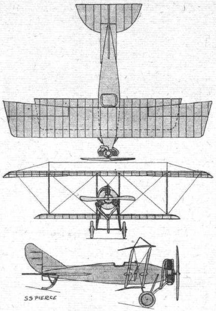
AT THE AMERICAN AERO SHOW. - Some constructional details. Various examples of interplane strut fittings, including the early Wright-type.
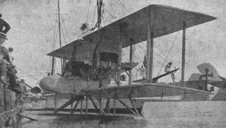
A large twin-engine seaplane, built for the U.S. Navy, at the U.S Naval Yard, Washington, to the designs of Constructor Holden C. Richardson. It has a span of 57 ft., a chord and gap of 9 ft. 6 ins. and 10 ft. respectively, and a total supporting surface of 1,000 sq. ft. The engines are Curtiss VX type, 160 h.p., and the speed range is 45-80 m.p.h., the full flying load being 6,000 lbs.
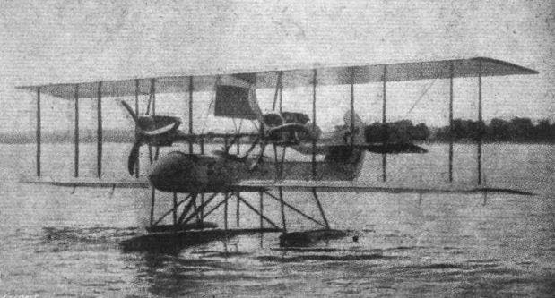
The U.S. Navy twin-engine Seaplane. - Note the central pontoon float and the two auxiliary floats, located one under each engine.
Flight, May 24, 1917.
THE STANDARD H-3 TRACTOR BIPLANE
ONE of the recent successful military machines of our new ally, America, is the Standard model H-3 tractor biplane, a number of which are in use with the U.S. Army and Navy. From the accompanying scale drawings and illustrations it will be seen that the main characteristic of this machine lies in the swept-back planes. These, which have a span of 40 ft. 1 in. top and bottom, have a sweep back of 10°, as well as a forward stagger of 10°, or 1 ft. 3 in., and a dihedral angle of 3°. They are in sections, the two lower ones being attached direct to the fuselage, and the two top ones attached to a small central panel 2 ft. 8 1/2 in. wide. The main spars are of channel-section, spaced 3 ft. 9 in. apart, the front spar being 9 in. from the leading edge. The ribs, built up of spruce webs and battens mortised, glued and nailed together, are spaced 11 in. apart. Solid spruce compression ribs are located at the inter-plane strut attachments, as well as one between each of the inner and outer pair of struts. The wing frame is braced with steel piano wire, and the woodwork is shellaced and varnished before covering in order to prevent the absorption of moisture and consequent distortion. The covering is of unbleached Irish linen treated with four coats of dope and a finishing coat of spar varnish. Ailerons are mounted on both top and bottom planes, each having an area of 15 1/2 sq. ft. They are inter-connected as follows: two light spruce-struts connect each upper and lower aileron, and cables from the trailing edges of the top ailerons are led to the control via a pulley located at the lower end of the outer rear inter-plane strut fitting. The lower ailerons are connected by cables led to similar pulleys on the upper ends of the struts and running beneath the top plane.
Two pairs of struts support the central panel of the top plane above the fuselage, and two pairs on each side of the latter separate the top and bottom planes. The ends of the struts are bronze tipped, secured by a single removable pin to the socket. The latter is bent to shape out of sheet steel, and is welded to a plate which is clamped by four bolts on the spar without piercing the latter. Anchorages for the bracing cables are formed on the fitting as shown in the sketch.
The fuselage is rectangular in section, tapering to a vertical knife-edge at the rear. It is 25 ft. long with a maximum width and depth of 2 ft. 9 in. and 3 ft. 6 in. respectively. The longerons are of ash, tapering rearwards from 1 in. square. The uprights are tapered and channeled, and are attached to the longerons by sheet metal clips. The pilot's cockpit is situated well aft of the planes, and the passenger's at the trailing edge. A 135 h.p. 6-cylinder vertical Hall Scott engine is installed in the nose of the fuselage, being supported by stout bearers, the forward ends of which are carried by a heavy-gauge steel plate forming the extremity of the fuselage. The engine portion of the fuselage is covered with sheet aluminium, and a rounded nose of the same material is mounted on the front. The rest of the fuselage is covered with fabric including the turtle deck, which is built up of spruce battens.
The control can be converted in a few minutes from the Dep type to the Curtiss type, the shoulder yoke operating the ailerons in the latter type being folded out of the way when not required. All control cables run over ball bearing bronze pulleys.
The tail planes consist of a non-lifting stabilising surface, to which are hinged two elevator flaps, a vertical fin and a nonbalanced rudder hinged to the fuselage stern post. The elevators are hinged to the stabilising plane in a semi-circular groove, which fits closely to the tubular leading edge of the elevator, so that no gap is formed. The rudder is similarly hinged.
The landing chassis consists of two laminated ash U members upon which is sprung a tubular steel axle, having a streamline covering, carrying a pair of 26 in. x 5 in. disc wheels. The shock absorber acts on the pantagraph principle, the axle being bound to the U members by rubber cord, and anchored to the same by two shackle bars, one above the other. The axle is thus forced to move in a vertical path, thereby evenly distributing the strain on the rubber cord. Where the shackles are clamped to the forward part of the U member, the wood is protected by strips of sheet bronze.
The following are the principal dimensions of the Standard H-3 Span, 40 ft.; chord, 6 ft. 6 in.; gap, 6 ft. 6 in.; height, 10 ft. 7 in.; gliding angle, 1 in 8; weight empty, 1,700 lbs.; useful load, 800 lbs.; speed range, 46-84 m.p.h.; climbing speed, 3,500 ft. in 10 minutes.
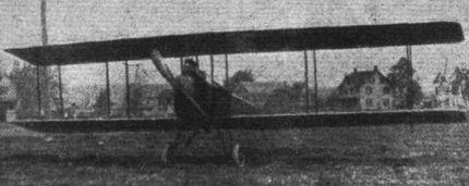
AT THE NEW YORK AERO SHOW. - The Standard military tractor.
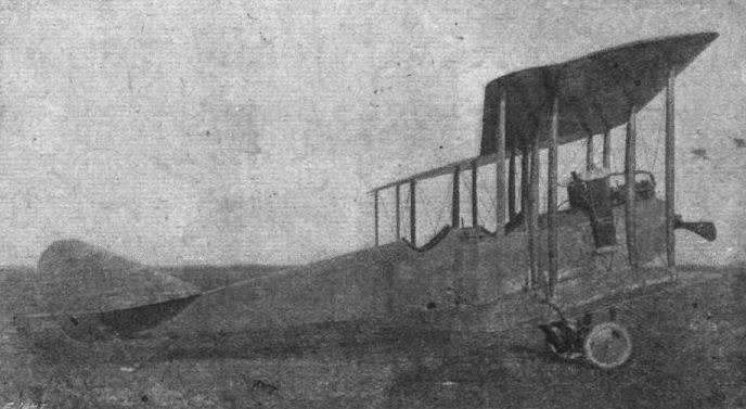
Side view of the Standard H-3 tractor biplane.
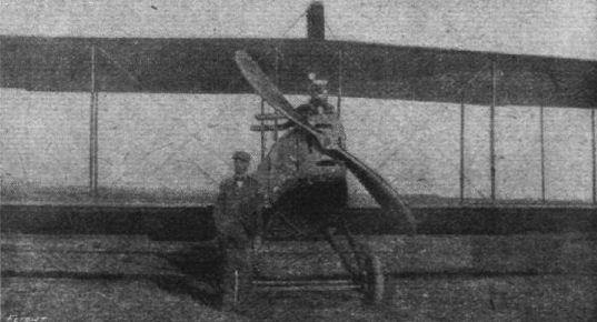
The Standard -H-3 tractor biplane and its designer, Charles H. Day.
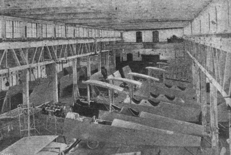
Several Standard H-3 fuselages in course of construction.
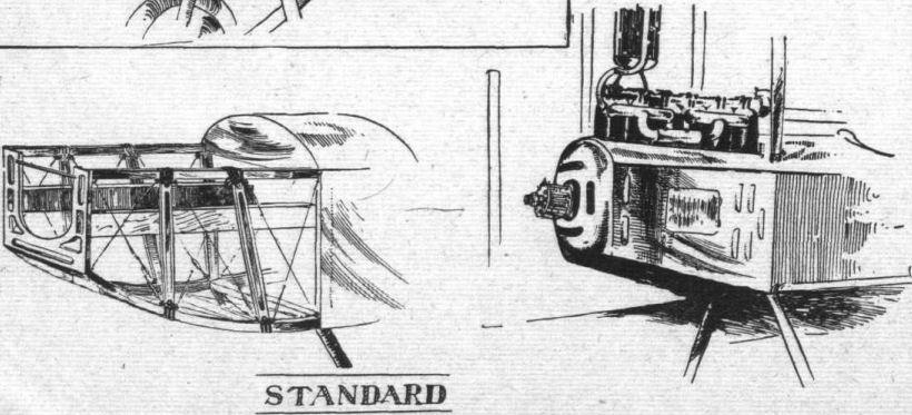
Mounting and housing of vertical water-cooled engines.
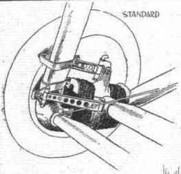
AT THE AMERICAN AERO SHOW. - Some constructional details. The shock-absorbing device on the chassis of the Standard tractor.
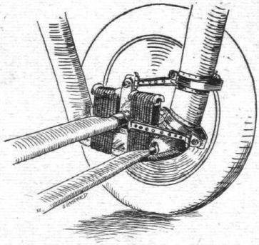
The "Pantograph" shock-absorbing device on the Standard H-3 chassis.
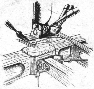
Sketch showing the attachment of the interplane strut and compression rib to the main wing spar, with fittings.
AT THE AMERICAN AERO SHOW. - Some constructional details. Various examples of interplane strut fittings, including the early Wright-type.

THE STANDARD H-3 TRACTOR BIPLANE. - Plan, side and front elevations to scale.
Flight, October 18, 1917.
TWO STANDARD TRACTOR BIPLANES.
Since our description of the Standard H-3 tractor biplane, which appeared in "FLIGHT" for May 24th last, two other models have been turned out by the Standard Aero Corporation of New Jersey, U.S.A., viz., the "J" preliminary training tractor and the J-R reconnaissance type. Both are from the designs of Chas. H. Day, and follow more or less closely previous Standard practice. The model J has given very satisfactory results as a training machine, and is now, it is stated, being manufactured in quantity. The special feature of this machine is its low landing speed - 37 m.p.h. This, together with the three-wheeled landing chassis, makes it a comparatively safe and easy machine for beginners to practice landings - always the bugbear of the embryo pilot. Strength, another valuable asset in a training machine, has also received the attention of the designer, a factor of safety of 7.5 being employed throughout the machine.
A certain amount of natural lateral stability is obtained by giving the wings a back-sweep of 5, whilst the low wing loading of 4.5 lbs. per square foot and the employment of the R.A.F.3 wing section make for good climb and the low speed. Unlike the H-3, the top plane, which alone carries the ailerons, overhangs the lower plane by 6 ft. each side. It is also staggered forward about 1 ft. Attachment of the top plane is made to a small central panel, of the same width as the fuselage, supported above the latter by four struts. The overhung is braced from a cabane mounted above the outer pair of interplane struts. The two sections of the lower plane are attached direct to the fuselage. The wing and other fittings, as on the H-3, are noteworthy for their elaborate character, necessitating intricate brazing. The pantograph type rubber shock-absorbing device is fitted to the landing gear as before ; the main wheels measure 26 ins. by 4 ins., and the front wheel is 20 ins. by 4 ins. The control is of the dual, interchangeable Dep.-Curtiss type. The engine is a 90-100 h.p. four-cylinder vertical Hall-Scott "A-7," coupled direct to a Standard black walnut tractor screw. The radiator, which is long and narrow, is mounted above the engine. Except for detail improvements, the model J is otherwise similar constructionally to the H-3, so the following characteristics, together with the accompanying illustrations and scale drawing, should suffice :-
Span, (top) 44 ft., (bottom) 32 ft.; chord, 6 ft.; gap5 ft. 11 ins.; sweep-back, 5°; dihedral angle, 3 per cent.; wing section, R.A.F.3; angle of incidence, 2 1/2°; overall length, 26 ft. 7 ins.; area of top plane, 264 sq. ft.; bottom plane, 165 sq. ft.; total supporting surface (including ailerons), 429 sq. ft.; area of ailerons, 42 sq. ft.; loading, 4.5 lbs. per square foot; weight, empty, 1,350 lbs.; useful load, 600 lbs.; speed range, 37-68 m.p.h.; climb, 2,600 ft. in 10 minutes ; gliding angle, 1 in 8.
The Standard model J-R is similar in general form to the model J. It has, in fact, been evolved from experiments made with, and data obtained from, this latter machine. Instead of a 90 h.p. engine, one of 175 h.p. - the 6-cyl. Hall-Scott model A-5A - has been installed, whilst the wing section is the U.S.A.6. These two modifications, together with a reduction in wing area, give a maximum speed of 95 m.p.h. and a climb of 5,000 ft. in 10 minutes. The span of the top and bottom planes is 42 ft. 10 ins. and 31 ft. respectively, the chord, gap, stagger, sweep-back, dihedral and angle of incidence are the same as on the model J. The central panel of the top plane is, as before, the same width as the fuselage, 2 ft. 6 ins. A space of 1 1/2 ins. is left between the panel and the wing sections, as is also between the fuselage and the lower wings. Among the special features of the J-R are the following: In the two-wheeled steel landing gear, which combines lightness with strength and is well streamlined, the axle rises and falls in vertical guides, and when normal rests in U-shaped steel cases stream-lined with aluminium. All the interplane struts are provided with ball and socket fittings, giving an even bearing for any angle of the struts. The engine bed is extremely rigid, being braced by means of steel tube stays connecting the ash bearers to the fuselage longerons. The exhaust is led over the top plane by means of a single complete manifold from the exhaust ports, after the fashion obtaining in the majority of German machines. An auxiliary fan-driven gear pump, projecting out from the fuselage, pumps fuel from the main tank of 51 gallons capacity, to the gravity tank, of 7 3/4 gallons capacity, which is mounted on the underside of the central top plane panel.
The fuselage is 24 ft. 3 ins. in length, the maximum width is 2 ft. 6 ins., and the maximum depth, at the forward cockpit, is 3 ft. 4 ins. The rounded nose-piece at the forward end of the engine is made detachable. The upper longerons are horizontal to the line of flight, whilst the lower ones follow a continuous curve from nose to tail. Sheet metal is employed for the covering of the engine housing and the top turtle deck as far back as the rear or pilot's cockpit. The remainder of the fuselage is fabric covered. Single Dep. control is installed. The stabilising tail plane is horizontal to the line of flight, and is supported by a pair of bracing wires above and below at each side of the fuselage.
The Hall-Scott A-5A is a six-cylinder vertical water-cooled engine developing 175 h.p. at 1,400 r.p.m. It has a bore and stroke of 5 1/4 ins. and 7 ins. respectively. It weighs 605 lbs., and has a fuel consumption of 14 galls, per hour.
The following are the main characteristics of the J-R: Span, (top) 42 ft. 10 ins., (bottom) 31 ft.; chord, 6 ft.; gap, 5 ft. 11 ins.; stagger, 10°; sweep-back, 5°; dihedral angle 3 per cent.; wing section, U.S.A.6; angle of incidence, 2 1/2°; overall length, 27 ft. 2 ins.; area of top plane, 258 sq. ft.; bottom plane, 159 sq. ft.; total supporting surface (including ailerons), 417 sq. ft.; area of ailerons, 42 sq. ft.; loading, 5.75 lbs. per square foot; weight, empty, 1,764 lbs.; useful load, 636 lbs.; speed range, 48-95 m.p.h.; climb, 5,000 in 10 minutes; gliding angle, 1 in 11.
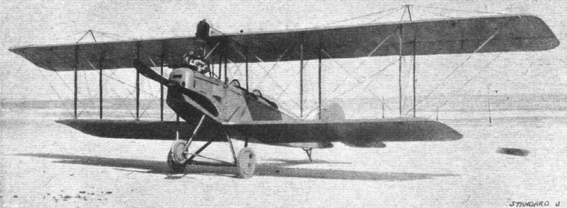
Three-quarter front view of the Standard model J tractor biplane.
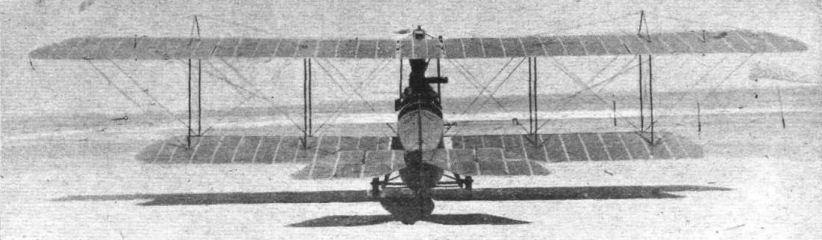
Rear view of the Standard model J tractor biplane.

View showing the mounting of the 90 h.p. Hall-Scott 4-cyl. vertical engine in the Standard model J tractor biplane. The arrangement of the three-wheeled landing chassis is also clearly shown.
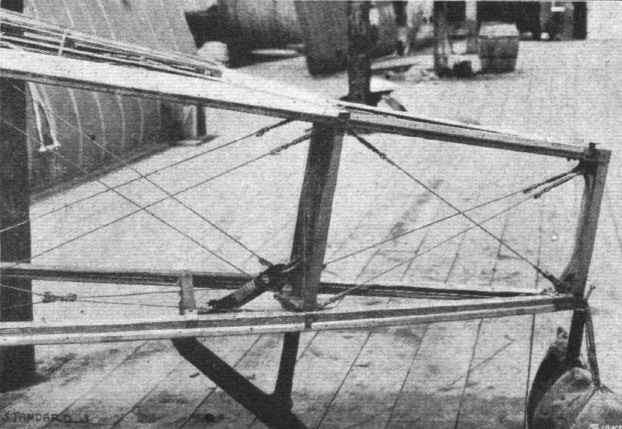
The tail end of the fuselage of the Standard model J tractor biplane.

Three-quarter front view of the Standard model J-R tractor biplane.
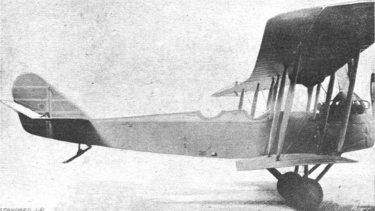
Side view of the Standard model J-R tractor biplane.
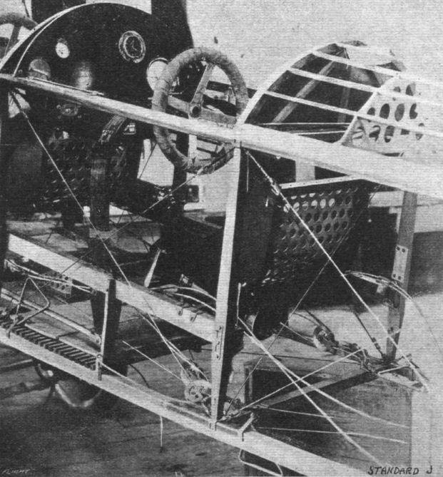
The rear cockpit of the Standard model J tractor biplane.
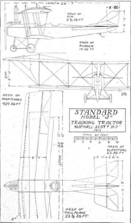
The Standard Model J Training Tractor Biplane. - Plan, side and front elevations to scale.
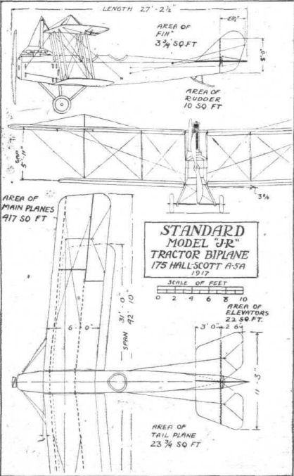
The Standard Model J-R Tractor Biplane. - Plan, side and front elevations to scale.
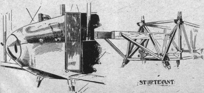
Mounting and housing of water-cooled engines.
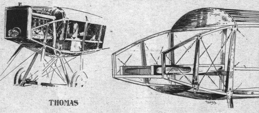
Mounting and housing of water-cooled engines.
AT THE AMERICAN AERO SHOW. - Some constructional details. Control-surface crank-lever on the Thomas tractor.

AT THE AMERICAN AERO SHOW. - Some constructional details. Tail-skid on the Thomas tractor.
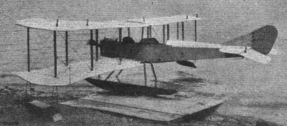
The Thomas (U.S.A.) model S H-4 tractor seaplane, designed mainly for training purposes.
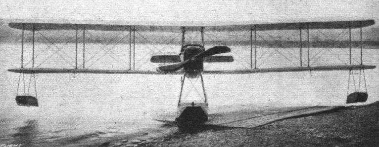
Front view of the Thomas SH-4 tractor seaplane.
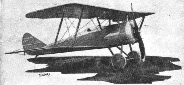
An American "one-and-a-half-strutter" scout. The latest Thomas-Morse tractor biplane.
Flight, March 15, 1917.
AT THE AMERICAN AERO SHOW - SOME NEW TYPES.
The Witteman-Lewis Training Tractor.
In general appearance the Witteman-Lewis machine follows the conventional military tractor-type biplane, special attention having been paid to strength rather than original design. It has a rectangular section fuselage, tapering to a vertical knife-edge at the rear, and a turtle-deck top. Pilot's and passenger's cock-pits are in tandem, the former one being situated back of the planes. A 70 h.p. Hall-Scott A-7 engine is mounted in the nose, with the radiator in front, and fuel capacity is provided for a flight of three hours' duration. A V-type chassis is employed, with bridge-type shock absorbers. Dep. dual control is fitted. General dimensions :- Span (top) 42 ft., (bottom) 34 ft. ; chord, 5 ft. 6 ins.; gap, 5 ft. 10 ins.; overall length, 27 ft.; net weight, 1,400 lbs.; speed range, 35-70 m.p.h. The triangular tail surface has an area of 36 sq. ft.

The Wittemann-Lewis 90 h.p. model T.T. tractor biplane, built at Newark, N.J., U.S.A. Note the deep cowling totally enclosing the engine.

AT THE AMERICAN AERO SHOW. - Some constructional details. The Witteman-Lewis bridge-type shock-absorber.
AT THE AMERICAN AERO SHOW. - Some constructional details. Various examples of interplane strut fittings, including the early Wright-type.
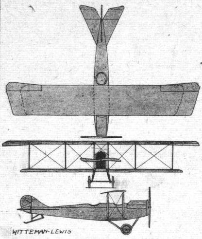
AT THE AMERICAN AERO SHOW. - Some constructional details. Various examples of interplane strut fittings, including the early Wright-type.
Flight, March 22, 1917.
THE WRIGHT-MARTIN MODEL "V" RECONNAISSANCE BIPLANE.
THE Wright-Martin Model "V" is a two-seater tractor biplane of 150 horse-power, designed for long range military reconnaissance, with the observer's cockpit well forward of the entering edge of the lower wings.
The power plant consists of a Simplex Model A Hispano-Suiza eight-cylinder water-cooled engine (made under the Birkigt patent), driving direct a two-bladed tractor screw. The propeller is equipped with the French standard hub, keyed and locked to the tapered crankshaft extension.
As with the Model R, the motor unit is located in a demountable nose compartment, of tubular and pressed-steel construction, enclosed with hammered sheet aluminum bonnet fitted with large doors and louvred ventilators. The fuselage entry is formed by the oval German silver cellular radiator located immediately back of the propeller. The radiator is supported by novel means directly on the pyramided motor mounting, with a vibration-absorbing medium interposed. An oil radiator is located flush with the under cowl and connects with a separate oil tank of 4 gallons capacity in the rear of the engine compartment.
The wings are staggered and have a slight dihedral angle. Three sections comprise the upper plane, the two outer sections being attached to a central panel supported above the fuselage by two pairs of struts. The lower wings are in two sections attached direct to the fuselage. The hinged wing attachments are locked together with nickel steel quick-detachable pins. The curve is the Vought 4, developed to meet the requirements of maximum efficiency, wide speed range and structural safety. A noteworthy characteristic is the minimum translation of the centre of pressure throughout the useful range of incidence angles.
The chord, 5 ft. 9 1/2 ins., is the same for both planes, and a differential incidence setting is used. The curve permits of the employment of two very substantial spruce I-section main spars and a third stringer spar of the semi-continuous built-up type, the latter disposed between the main beams to increase the wing strength, and serve as an aligning member for the ribs themselves. These latter are of the built-up type, bench-made to metal patterns to insure uniformity and interchangeability. Rib materials are spruce for battens and poplar for webs, the assembly carefully glued up and brass nailed. Wide box ribs are used at all panel points and light false nose ribs of spruce are employed between the main ribs. All ribs are re-inforced to strengthen them in longitudinal shear. Leading edges are of spruce, hollowed, while the trailing edges are of white ash. Wing tip bows are of bent ash, hollowed and maple-dowelled to the spars and nose pieces. The lower wings are fitted with wide rubber stripped contre-plaque flooring at the roots, and have comfortable hand-hold grips adjacent to the rear spars at the tips.
All the wood-work of the wings is given one coat of wood filler and two coats of waterproof varnish; metal parts are given three coats durable enamel, baked on. This treatment obtains throughout the machine. The wing covers are made from uncalendered Irish linen, sewed and laid diagonally. The fabric is secured to the ribs by sewing and tacking and reinforced with suitable linen taping. The cloth is treated with five coats of Wright-Martin doping mixture, and finished with two coats of Glidden special flexible waterproof varnish.
In the cellule, the interplane struts are of solid spruce, streamlined and tapered and fitted with pressed steel socket ends. The fittings are stampings from chrome vanadium steel, with baked enamel finish. Turnbuckles are of the clevis-and-pin type, with nickel steel shanks and bronze barrels. All wires, struts and similar components are quickly detachable by removing nickel steel lock pins, and render assembly or replacement easy and very quick. Wires and turnbuckles are enamelled for preservation against weather. Roebling stranded cable is used, and all eyes have saddles, and are copper served and soldered. The lower wing trailing edges next the fuselage and the centre section are cut away to facilitate the pilot's view. Four large ailerons are hinged to the rear spars, having a semi-closed gap. Each aileron frame is of spruce and tubular steel, carefully reinforced, the covering and its treatment being the same as with the wings. Three hinges per aileron are employed and a very simple' and direct control is used, top and bottom ailerons being connected by spruce struts.
The fuselage is of rectangular section, fiat-sided, and fully enclosed, accommodating pilot and passenger in well-crowned and padded tandem cockpits - the pilot being placed in an advantageous position in the rear cockpit. A special feature is the detachable nose. This houses the motor and radiator, the fuel and oil tanks, equipment and supplies, and the live load being in well-arranged, compact, individual compartments in the main body. The fuel tanks are removed from proximity to the motor compartment to minimise fire risk, the service tank being located in the cowl aft of the front cockpit. The main tanks are placed longitudinally, and to the rear of the front seat on padded floor cradles. Fuel is supplied by pressure. An, air-pump, integral with the motor, serves the system, except for starting. The cockpit rims are padded and leather-covered, while the cockpits are upholstered in leather.
The fuselage tapers aft of the wings to a vertical tubular knife edge at the rear, which serves as an anchorage for the fin and rudder assembly. It is constructed, with the exception of the steel motor mounting, of ash and spruce longerons, struts and cross members, amply cross braced with Roebling's vanadium steel wire and Wright-Martin short-type turnbuckles. The fittings are substantial throughout, and, in the main, are steel stampings, embossed and die-formed from special steel. A substantial system of "follow-through" has been detailed into the fuselage design forward.
On the dashboard of the rear cockpit are neatly grouped the various flight and mechanical instruments. Transparent wind shields add to the comfort of pilot and passenger. Forward the fuselage is covered with sheet aluminium, whilst rearward linen fabric is employed, with provision for quick inspection of the truss members by means of a detachable deck. A large door renders the enclosed tail-skid mechanism get-at-able.
The chassis is of the two-wheeled type, and is designed to greatly minimise resistance. This cornponent is readily demountable as a unit, or individual parts may be disassembled with a minimum of inconvenience and disturbance of adjacent members. Practically all the parts are removable through the agency of quick-detachable nickel steel lock pins of large diameter. The chassis is composed of two sets of ash V struts of streamline section, combined with a streamlined system of twin parallel steel cross tubes attached to the steel boxes at the apices of the Vs, and an improved wheel and axle assembly. The whole unit is cross-braced with heavy cable and corresponding turnbuckles and fittings. The chassis struts are attached to the fuselage, with suitable steel clip-and-pin fittings. The cross tubes, or horizontal compression members, are of large diameter, and are fitted with forged q.d. clevis ends, pinned and brazed in. This member supports, and with its sheet aluminium stream line houses, the axle, which is hinged at the centre. The cross tube and axle hinge load is carried by two diagonal steel cables running up to the fuselage forward attachment plates. The axles are nickel steel tubing, specially heat-treated, and the outside diameter is large with a substantial wall thickness suitably reinforced at points of greatest load.
Either axle member can be withdrawn through its shock absorber spool, without affecting the adjustment of the shock absorbing mechanism. The axle hinge pins are quickly get-at-able by removing a small plate on the housing. The axles and rubber shock absorber retainers operate in a detachable enclosed guide of substantial construction and move vertically whilst the machine is taxi-ing. This design eliminates all Binding and the necessity of troublesome radius rod members. The shock absorbers are cotton encased rubber cord of large diameter, approximately 10 yards being used for each axle, and the strand is laced over and retained by belled steel spools of demountable construction. The wheels made in the Wright-Martin factory are of very sturdy construction, yet reasonably light. They are shod with 26-in. by 4-in. Goodyear double tube tyres, and have specially-designed hubs, with pressed steel flanges shrunk on, the spoke rows being more than 6 ins. apart. The spokes are heavy gauge, of best-quality steel, 36 being used to each wheel, tangent laced.
Bronze bushings are fitted and the hubs are self-lubricating, with grease capacity for a full season's use. Hexagonal bronze hub caps screwed on and pinned are used to hold the wheels in position. The air valve is accessible through a small circular aluminium door in the casing, which latter is of the same material as the wing covers, similarly doped and finished. The wheel tread is 5 ft. 3,5 ins., or slightly more than one-seventh the span of the lower wing. The weight of the complete chassis, including disc wheels and shock absorbers, is only 86 lbs.
A tail skid of low head resistance protects the rear of the machine. This is of substantial ash construction, operating semi-universally against the tension of the rubber shock absorber coils, enclosed within the fuselage. The skid floats on a reinforced tubular steel cross strut, and is aligned by heavy helical springs concentric with the strut. A large aluminium door in the side of the fuselage allows easy inspection and adjustment of the skid mechanism, and this construction has reduced the resistance of this component to a minimum. The skid is shod with a bronze shoe, which is secured in place by bolts and readily replaced when worn out. There are empennage brace anchorages in connection with the skid or stern post.
The empennage consists of a moderately double cambered fixed horizontal stabiliser of high aspect ratio, to which are attached the dual elevators, on each side of the unbalanced rudder, forward of which is the fixed vertical fin. The design of the empennage enables the units to be very quickly assembled, the chief novelty being in the system of inter-locking the various parts and the minimized external bracing required to adequately support the surfaces to the fuselage structure. Only four streamline steel tubes are required, two from the fin downward to the rear spar of the stabiliser, and two diagonally forward from the stabiliser to the fuselage lower longerons. These braces, like the struts and other components noted above, are fitted with approved clevis ends and are locked in place with nickel steel pins. All elevator and rudder ribs are carefully sparred, and these surfaces provided with a light spruce spar disposed 10 ins. forward of the trailing edge to aid in equalising the load on the ribs tthemselves. Bracing wires anchored on or in proximity to the trailing edge are not used, and the control arms are designed to eliminate brace wiring as much as possible. The frames of the tail components are made entirely of cold-drawn seamless steel tubing of various sizes and thicknesses, and in some cases of special section, depending on the function of the particular part. Steel members are joined by special forged or drawn steel fittings pinned in place and then brazed. No welding operations whatever are employed in making up the empennage frames. All ribs and spars are attached to the tubular frame members by sheet socketing clips tangent brazed in place. The internal cross bracing consists principally of the wire and fitting system employed in the main planes, though four light sectioned spruce diagonals are used in addition. The stabiliser rib structure is constructed over an I-section spruce spar of large section located laterally 1 ft. 2 ins. back from the entering edge. By the use of this substantial spar, all external bracing to the forward part of the horizontal stabiliser has been eliminated, and the necessary depth of section is provided for the double-cambered profile. Elevator and rudder hinge fittings are steel stampings pinned and brazed in place. These are provided with means for lubrication, and the surfaces are unhinged by withdrawing quick-detachable pins. Quarter-inch nickel steel bolts and steel jaw clips attach, respectively, the stabiliser front spar and entering edge to the fuselage. The rear spar is secured by two 3/16-in. bolts, and the whole assembly locked by the fin extension which telescopes into the fuselage tubular stern post, there secured by a lanyarded taper pin. The whole system is then interbraced by the streamlined tubing outside stays.
The Dep. system of control is used, consisting of the wheel column, and ash and steel foot rudder bar. The rudder bar is substantially mounted on a steel pedestal secured to the flooring and fuselage truss. The 16-in. corrugated control wheel is mahogany rimmed, with an aluminium spider and chain sprockets of bronze, all mounted on a steel column.
The control surfaces are operated through doubled control cables, changes in direction being taken care of by substantial chains passing over pressed steel pulleys of novel design. An enclosed rock shaft is disposed in the elevator control mechanism back of the of the pilot's seat to eliminate any lost motion and the usual crossing and slacking of these control wires, and all adjustments can be made from the cockpit.
The general characteristics of Model "V" machine are :- Span, 39 ft. 8,5 ins.; chord, 5 ft. 9,5 ins.; gap, 5 ft. 7 ins.; overall length, 27 ft. 2 ins.; overall height, 9 ft. 5,5 ins.; stagger, 1 ft.; dihedral angle, 1" 15; supporting surface, 430 sq. ft. ; loading, 5,66 lbs./sq. ft. (16,86 lbs./b.h.p.); weight empty, 1,725 lbs.; useful load, 905 lbs. (including fuel and oil for 6 hours' flight).
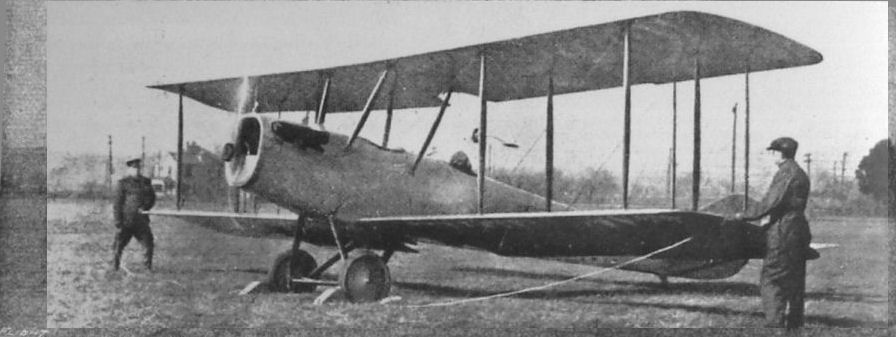
Three-quarter front view of the Wright-Martin Type V tractor, with 150 h.p. Hispano-Suiza engine.
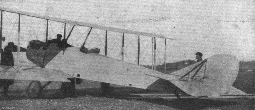
THE WRIGHT-MARTIN MODEL " V " TRACTOR BIPLANE. - View from the rear.
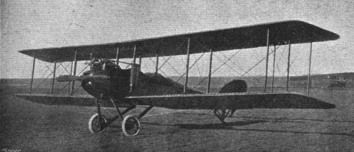
The Wright-Martin two-seater reconnaissance tractor biplane used by the U.S. Government. This machine differs from the model R ("FLIGHT," March 1st, 1917) in many respects, notably the equal-span wings, the tail and chassis.

The tail components of the Wright-Martin model "V" tractor biplane.
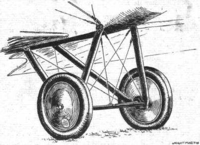
Sketch of the chassis of the Wright-Martin model "V" tractor biplane.
Flight, March 1, 1917.
THE WRIGHT-MARTIN MODEL "R" TRACTOR BIPLANE.
THIS machine has been designed for land reconnaissance work in the absence of enemy aeroplanes and for general sport use. From the Wright-Martin Corporation we learn that it gets off the ground at 47 miles an hour and has a high-speed figure of 86 miles, carrying a useful load of 960 lbs., more than half of which may be fuel and oil, sufficient for a non-stop tour of 425 air miles with pilot and observer, and 140 lbs. of luggage. This high speed figure has even been increased to 90 miles an hour in speed tests, and 4,050 ft. have been climbed in 10 minutes.
The upper plane, which is of greater span, is in six sections and the lower in four. The sections are secured in assembly by a substantial steel plate and four-bolt system, this same fitting serving as interplane strut anchorage, through the medium of an original universal strut socket, which permits play both fore and aft laterally. R.A.F. 6-section is employed for both top and bottom planes. The wing spars, stringers, leading and trailing edges are of spruce, as well as the end bows, which latter are laminated. The main ribs are of spruce, spaced 15 ins. apart. Between each main rib are two intermediate false ribs, also of spruce. The main ribs are composed of battens and webs bored with the conventional lightening holes. There are vertical reinforcements to strengthen the ribs in longitudinal shear, and the webs are tongued and dove-tail into the rabbitted section of the front and rear lateral spars. The internal bracing is of the conventional system, heavy plated vanadian steel wire being used, with turn-buckles and wiring plates secured to spars by nickel steel bolts. The wing frames are all built up on jig assembly tables, this insuring absolute interchangeability of respective parts and facilitating manufacture and inspection. The wings are covered with Irish linen answering U.S. Signal Corps specifications for strength and quality. The fabric is sewn diagonally and placed "on the bias" over the wing frames with linen tape over the ribs. It is given five coats of Wright-Martin doping mixture and two coats of Rexspar varnish, for weather-proofing. A novel feature is found in the metal strip attached to and protecting the leading edge of the wings. This is applied over the fabric to protect the latter when the machine is dismantled and the wings are set on edge.
The spruce struts are of approved streamline section, hollowed for lightness and offer the greatest possible strength-weight ratio. The respective cross sections are the same throughout the strut length, except at the extreme ends, where the strut tapers to its steel base. They are wrapped at the centre with linen tape, and are quick detachable through the use of vanadian steel pins anchoring the sockets to the main plane fittings. The top plane extensions are supported by means of tubular steel diagonal struts which are fitted with wooden streamliners.
External bracing is by Roebling stranded aviation cable with a novel design of wire terminal end and turnbuckle which presents a minimum of head resistance and weight, and is instantly detachable through the removal of the vanadian steel pins. The wing tips are protected by skids placed below the outermost struts. The complete wing truss is well braced against drift by means of four heavy cables running to the nose of the fuselage. All load and supporting cables are doubled. Both wings are given a moderate dihedral angle laterally (1°), and the upper wing is staggered approximately 12 ins. forward to increase the observer's range of vision.
There is an adjustable horizontal stabiliser, 26,6 sq. ft. in area, on each side of the rear end of the fuselage, to the rear lateral spar of which are hinged the dual elevators. A small vertical fin, 7,3 sq. ft. area, is mounted under the fuselage forward of the rudder. The latter, having an area of 8,7 sq. ft., is hinged to the stern-post of the fuselage and both fin and rudder are braced with heavy sectioned wire and turnbuckles.
Elevator and rudder cables are in duplicate, and enclosed in the fuselage for the greater part of their length. The ailerons, on the upper wings only, are hinged to the outboard sections at the rear wing spar, and are given an increased chord in order to facilitate their action and render the lateral control extremely powerful and positive. They are built up of spruce framing, adequately braced internally to eliminate distortion and have an area of 24 sq. ft. each. A novel method of operating the ailerons has been incorporated which eliminates the necessity of vertical control in either upward or downward direction by direct pull wires led through well-anchored brass tubes running laterally in the lower wings.
The fuselage has been designed to provide, with the addition of a small fin, the necessary directional stability with a minimum of side resistance. It is of excellent streamline form and tapers from the well-pointed nose to a horizontal knife edge at the rear. Among its features it incorporates the detachable nose which enables the complete motor unit with accessories to be quickly removed and another substituted with a minimum loss of time. This is an especially valuable feature from the military stand-point.
It is of the box girder construction, having ash longitudinal spars throughout, with ash struts and cross members forward and spruce in the rear. It is adequately braced with Roebling vanadian steel wire and turnbuckles. In general design the fuselage is of the conventional two-place tandem type accommodating the motor forward in the detachable nose, the observer or passenger in the front and the pilot in the rear cockpit.
Forward the fuselage is covered in with aluminium side plates and motor hood, as well as deck cowls to the rear of the pilot's seat. The rest of the fuselage is covered with Irish linen of the same specifications as that of the wings, and given the same treatment and finish. The top of the fuselage aft of the rear cockpit is made up as a separate crown unit and is readily detachable in order to facilitate inspection and adjustment of the various components.
On either side of the passenger's seat are the petrol tanks. Fuel is supplied the carburettor through the agency of the air pump attached to the motor. The seats in both cockpits are mounted on tubular steel standards so designed that the seat is braced against both lateral and longitudinal stresses. The dual control is mounted upon a series of triangulated standards, which give adequate rigidity and strength. In order that lost motion will not be experienced in the elevator control, a separate rock shaft coupled with the control standard has been mounted behind the pilot's seat which connects direct with the control arms on the twin elevators and thus eliminates the crossing of control wires. The cockpits are upholstered.
The instrument board is fitted with the usual flight instruments, and the throttle control is mounted on the longeron close to the instrument board. J. M. fire extinguishers are mounted on the fuselage strut directly beneath the dash of the rear cockpit, and is accessible from either cockpit. A motometer, mounted in an accessible place above the engine in the water-cooling system, is readable from both cockpits.
The chassis is of Q.D. tubular steel construction, employing three pairs of struts. The suspension is by means of multiple rubber absorbers coacting with a steel bridge. The axle, of nickel steel tubing, is of the hinged type supported in the centre by 1 1/2-in. tubular steel compression struts, and two adjustable load cables running upwardly to the fuselage. The chassis itself is adequately braced against lateral and longitudinal drift by means of a series of heavy cable tension members. The wheels are of heavy duty type, and fitted with 26 x 4 1/2 in. straight clincher double tube tyres. The wheel hubs are bronze bushed and fitted with an effective lubricating system. The chassis is readily demountable through the removal of the nickel steel assembly bolts.
A tail skid of novel design allows a universal movement of this member to facilitate taxi-ing and minimise wear and tear on the fuselage itself. The skid is supported by a pyramid of four tubular braces attached to the fuselage longerons streamlined with wood fairings. The skid itself is adjustable through a corded rubber shock absorber and aligning cords.
The power plant consists of a six-cylinder 150 h.p. Hall-Scott motor, mounted direct on the shaft of which is an 8 ft. 6 in. tractor screw, having a pitch of 5 ft. 8 in., and an efficiency of 78 to 80 per cent.
The motor is mounted in the detachable nose on pressed steel front and rear plates which support the deep sectioned motor bed. The nose section is well braced with double wire and turnbuckles in the same manner as the fuselage. Birch is used in the construction of the tractor screw, which is built up of inch laminations, with the tips sheathed in copper.
The radiator is of a new type located above the motor and securely braced by stream-lined steel tubes to the upper wings. This new disposition does not appreciably interfere with the vision of either pilot or observer. The control system is optional. It may be either a three-in-one or the standard "Dep." The three-in-one is composed of a vertical column with the wheel for the rudder, lateral movement of the column, for the ailerons and rocking fore-and-aft for the elevators.
The following are the general specifications of this machine :- Overall length, 26 ft. 8 1/2 ins.; overall height, 11 ft. 4 ins.; span (upper), 50 ft. 8 1/2 ins., (lower), 36 ft. 10 3/4 ins.; chord, 5 ft. 6 ins.; gap, 6 ft. ; area, upper 232 sq. ft., lower 178 sq. ft.; total supporting surface, 458 sq. ft. Loading per sq. ft., 6,25 lbs.; loading per b.h.p., 19 lbs.; speed range, 47-86 m.p.h.; climb, 3,500 ft. in 10 mins.; gliding angle, 1 in 8; capacity of petrol tanks, 70 galls.; oil tank, 9,5 galls.; petrol and oil consumption per, hour, 14,2 galls, and 12,5 lbs. respectively. Weight, empty, without power plant, 1,107 lbs.; power plant, 798 lbs.; fuel, &c, for 4 hrs. flight, 480 lbs.; useful load, 503 lbs.; total gross weight, 2,880 lbs.
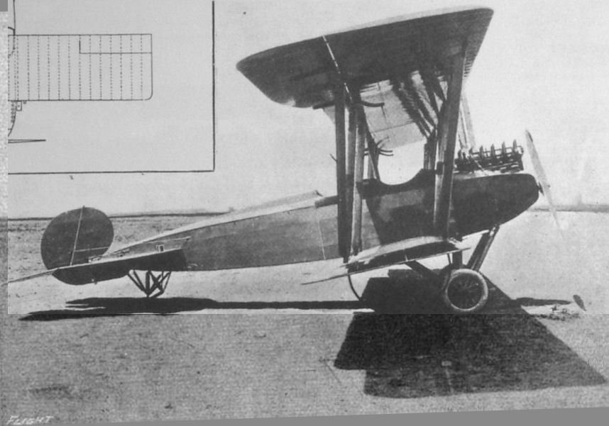
Side view of the Wright-Martin tractor biplane. Note the small vertical fin under the tail.
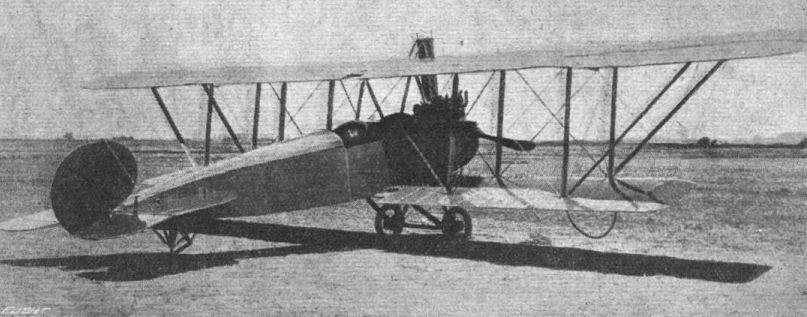
A three-quarter rear view of the Wright-Martin tractor biplane.
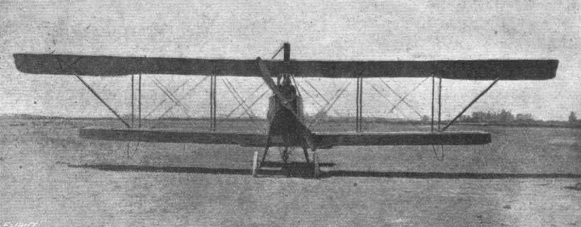
THE WRIGHT-MARTIN MODEL "R" TRACTOR BIPLANE. - The machine viewed from the front.
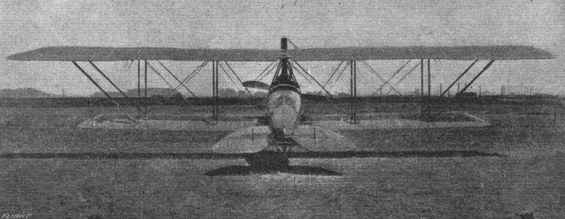
The Wright-Martin Model "R" tractor biplane seen from the rear.
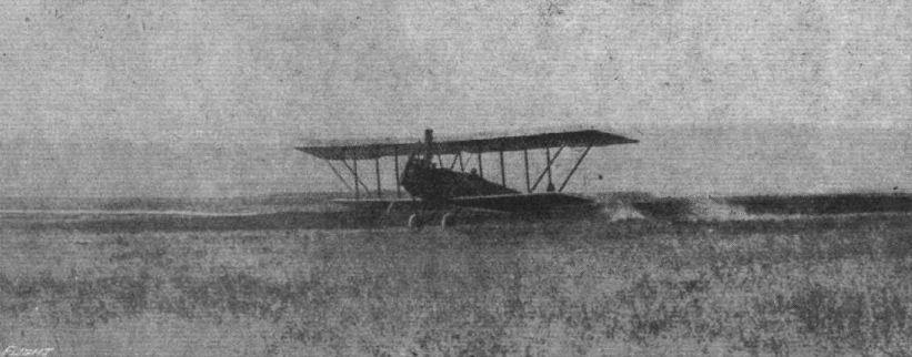
The Wright-Martin tractor lands after a successful flight.

The front portion of the Wright-Martin tractor biplane, showing the 150 h.p. Hall-Scott engine.
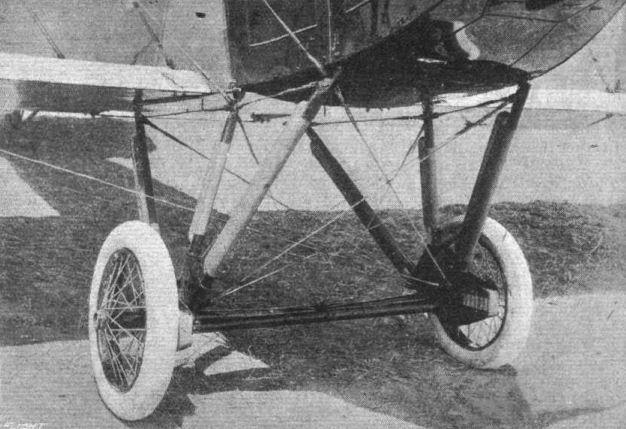
The landing chassis of the Wright-Martin tractor biplane, showing the bridge-type rubber shock absorbers.
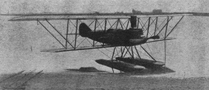
Wright-Martin tractor seaplane. The convertible land or water model R.
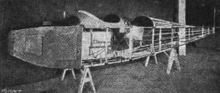
The Wright-Martin fuselage, showing method of construction.
AT THE AMERICAN AERO SHOW. - Some constructional details. Various examples of interplane strut fittings, including the early Wright-type.

Flight, May 3, 1917.
THE "TOTALLY ENCLOSED" AEROPLANE.
<...>
The year 1914 saw the advent of several aeroplanes of the enclosed type. In France one of the earliest to take the air was the Albessard tandem monoplane, shown in the accompanying photograph. This machine had a very roomy body, which was fitted with windows in front, where were accommodated the pilot and two passengers that constituted the human complement. The engine, a 100 h.p. Anzani, was mounted high up in the nose of the body, and was thus well out of the way as regards obstructing the pilot's view. Altogether the Albessard was excellent for visibility, especially in a forward and downward direction, owing to the absence of any bottom plane to restrict the view, but although the machine flew it was never a great success, in all probability due to the arrangement of the wings in tandem, which all authorities agree is a very inefficient one.
Flight, April 19, 1917.
THE "TOTALLY ENCLOSED" AEROPLANE.
<...>
During the summer of 1911 another enclosed machine was being constructed, this time at the works of Mons. Bleriot. It was built to the order of that distinguished patron of aviation, Mons. Deutsch de la Meurthe, and had a cabin body with seating accommodation for four passengers. The cabin was most elaborately equipped, and was provided with mica windows through which the occupants were to get a good view of the country over which the machine was flying. The pilot was seated out in the open in front of the cabin, and to facilitate communication between passengers and pilot a speaking-tube similar to those used on motor cars was fitted. This machine had a fixed tail plane, but no rear elevator, longitudinal balance being maintained by the use of an elevator mounted on outriggers a short distance in front of the cabin. The power plane was a 14-cylinder 100 h.p. Gnome motor mounted level with the trailing edge of the wings, and above the roof of the cabin. Ready for flight, but without the passengers, the machine weighed about 1,500 lb., so that with the full complement of passengers the weight must have been in the neighbourhood of 2,300 lb., a by no means small load to be carried by a single pair of wings. During its trial nights this machine flew quite well with pilot alone, but it is doubtful whether it was ever really successful with a full load of passengers. The flat front of the cabin presented some 20 odd sq. ft. of surface normal to the wind, and if the speed be assumed to be about 50 m.p.h. this surface alone would absorb something like 30 h.p.
<...>
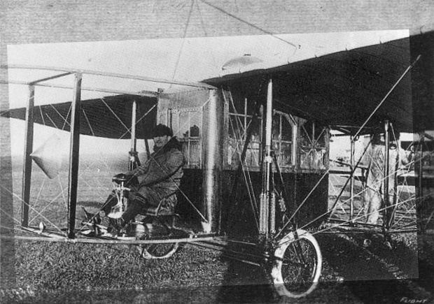
The pilot at the controls of the Type XXIV, in front of the 4-passenger cabin. Note conical windshield mounted forward.
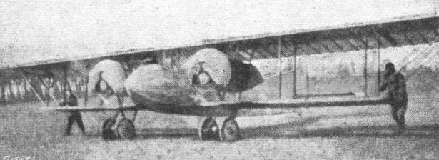
The French Caudron "G6" twin-engine fuselage biplane.
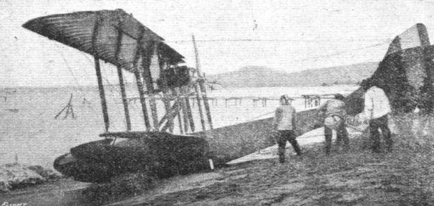
An Italian Navy F.B.A. flying boat.
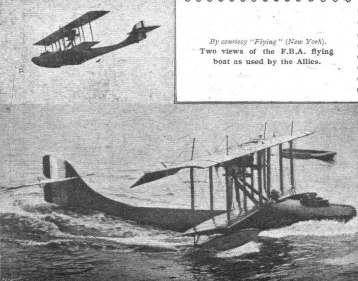
Two views of the F.B.A. flying boat as used by the Allies.
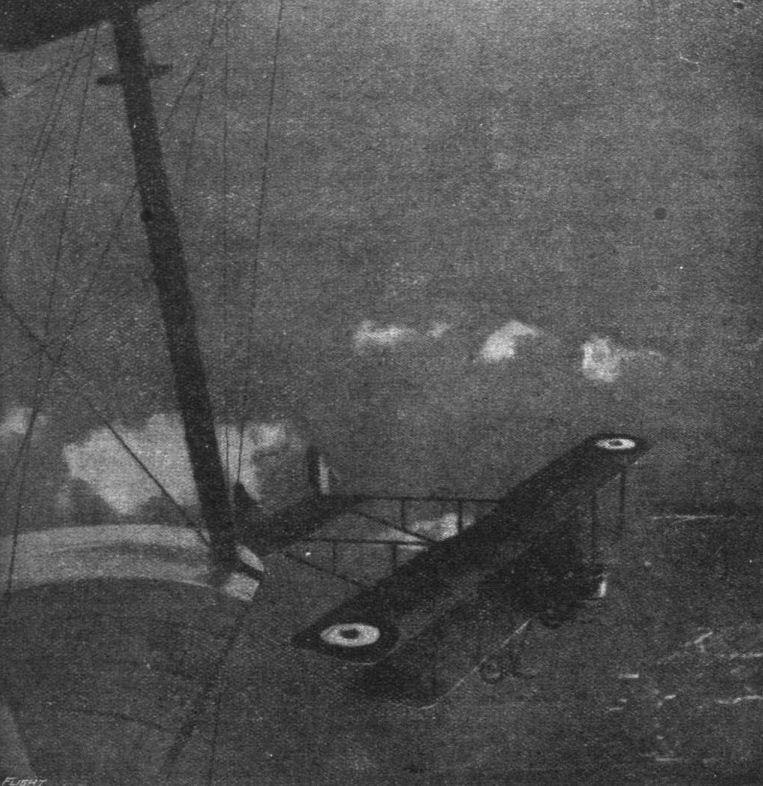
Aerial guardians of Paris, who day and night keep watch against attacks by the air, upon the capital, a monotonous task of strenuous duty, which carries with it little glory by reason of its complete effectiveness as an antidote to the Zeppelin marauders.
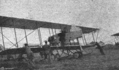
AVIATION IN JAPAN.- At Tokorozawa Military Central Aerodrome. A Japanese 70 h.p. Maurice Farman type of the Japanese Aerial Force.
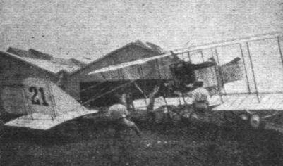
AVIATION IN JAPAN.- A 90 h.p. Maurice Farman on the home ground.

A REMARKABLE ESCAPE. - In these days of high-power high-speed machines it may be well to look back lest one forgets that earlier in the war much excellent work was done on machines which did not begin to compare with the modern aeroplane as regards efficiency and performance. The above photograph, which Is reproduced by courtesy of La Guerre Aerienne, shows the appearance of a biplane on which, in 1915, Captain Morris, since taken prisoner by the Germans, and Corporal de Ram had been for a reconnaissance flight. The machine was heavily shelled, several struts and other wing parts being broken. Corpl. de Ram, in spite of the unsecure foothold offered, climbed out on the lower wing, while at a height of 2,000 metres, and made fast, as well as possible under the conditions, some of the broken parts, which feat enabled the machine to reach home in safety.
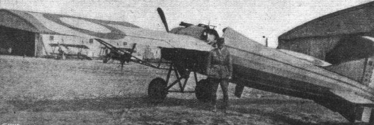
A Morane Monoplane flown by one of the members of the Lafayette Escadrille.
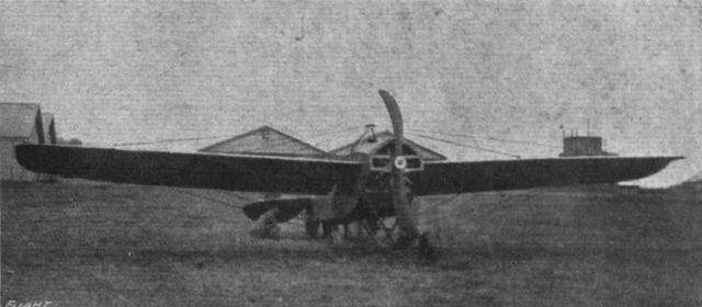
Aviation in Japan. - A 100 h.p. Nieuport at the Tokorozawa Aerodrome.
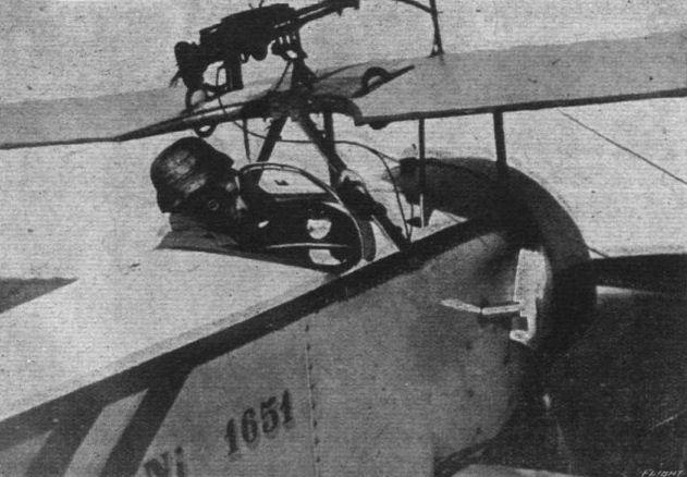
From "The War in Italy." - An Italian Nieuport biplane.
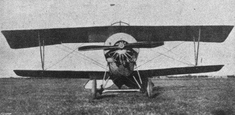
FROM "THE WAR IN ITALY." - An Italian Nieuport biplane as seen from the front.
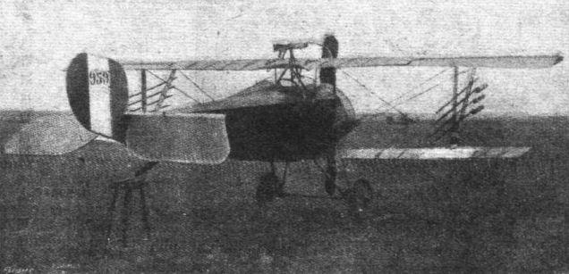
Nieuport 1 1/2-plane,Type 16. The rockets are used for attacking kite balloons and airships.
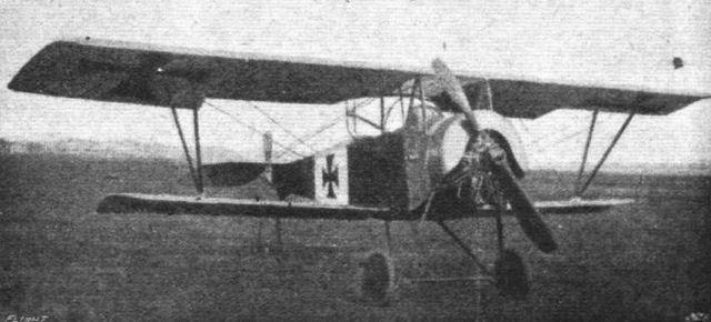
Nieuport 1 1/2-plane, Type 12.
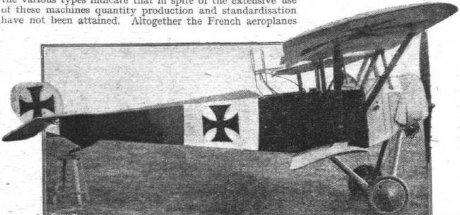
Nieuport two-seater, Type 12. Motor 110 h.p. Clerget.
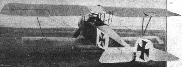
Nieuport two-seater, Type 12. The Vee struts slope outwards.

The body of the Nieuport 1 1/2-plane.
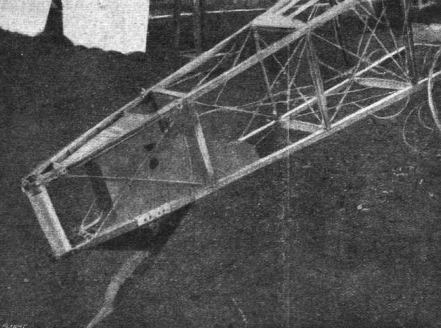
Body and tail skid of the Nieuport 1 1/2-plane.

Controls and pilot's seat of the Nieuport 1 1/2-plane.

Framework of a Nieuport top plane.
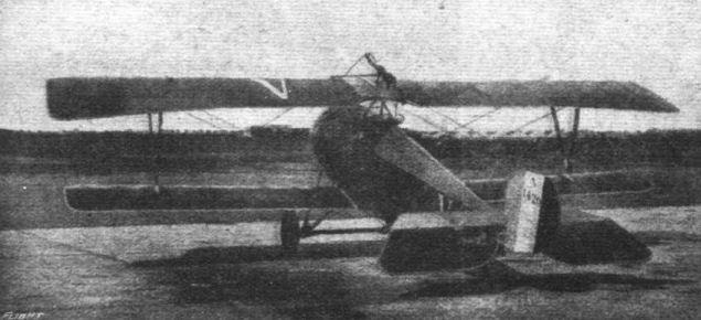
Rear view of the Nieuport 1 1/2-plane,Type 17.
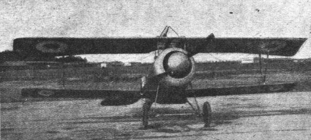
Front view of the Nieuport 1 1/2-plane, Type 17.
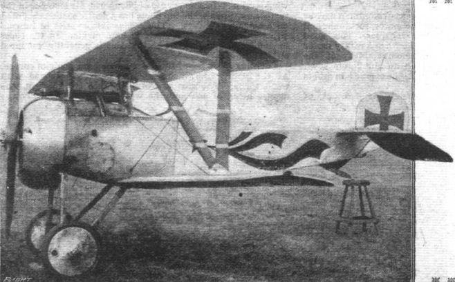
Nieuport single-seater fighter, Type 17, with fixed machine gun.
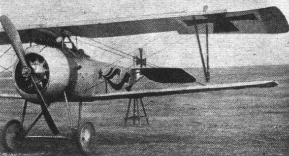
Nieuport single-seater fighter, Type 17, with fixed machine gun.
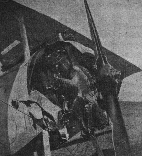
Aeroplane versus anchor cable. - Returning from a flight on his Nieuport, Sergt. Courtois, who had had his propeller damaged by bullets, was making for home against the sun. This accounted for the fact that he failed to see the anchor cable of a French kite balloon. As luck would have it, it was the propeller which struck the cable, otherwise the issue might have been serious. As it was, the Nieuport seemed to hesitate an instant, then, as the cable parted, it resumed its flight. On landing it was found that some ten yards of cable was twisted round the propeller shaft, otherwise no damage had been done. The observer in the kite balloon managed to land safely at Eure-et-Loir.
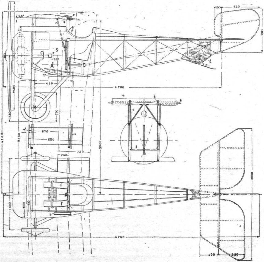
Scale drawings (in mm.) of the Nieuport single-seater.
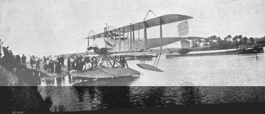
A Paul Schmitt hydravion, built in 1916 for the United States Government.
THE PAUL SCHMIDT TRACTOR SEAPLANE. - A similar machine was presented by Mr. August Belmont to the U.S. Navy, and is now undergoing tests at Pensacola.
THE PAUL SCHMIDT TRACTOR SEAPLANE. - A similar machine was presented by Mr. August Belmont to the U.S. Navy, and is now undergoing tests at Pensacola.
Flight, August 16, 1917.
FROM OTHER LANDS.
THE SPAD SCOUT.
IMPROVEMENT is so rapid and changes so frequent in the design of the Spads, developed by the Societe Anonyme pour l'Aviation et ses Derives, Paris, that the type used within the next few months may differ in several respects from that in use to-day. The accompanying drawing shows the outlines of the type "S. VII," which is said to be one of the most recent. Fighting craft of this type are piloted by members of the Lafayette Escadrille, and used with good effect equipped with one and sometimes two Lewis or Vickers machine-guns.
Approximate general dimensions of the "S. VII" are as follows:-
Span, upper plane 25 ft. 6 ins.
Span, lower plane 25 ft. 6 ins.
Chord, both planes 4ft. 7 ins.
Gap between planes 4 ft. 2 ins.
Overall length 20 ft. 0 ins.
Total weight 1,525 lbs.
Useful load 470 lbs.
Climb in 10 minutes 9,3oo ft.
Speed at sea level 132 m.p.h.
Speed at 3,000 metres 126 m.p.h.
Motor, Hispano-Suiza "V." type 160 h.p.
Both planes are nearly rectangular in plan, the ends being square and not raked, with corners slightly rounded off. The deep cut-out portion of the top plane, over the pilot's seat, as well as the close spacing of the interplane struts, shows a large area of plane surface aft of rear wing beams. As the ailerons are comparatively narrow, they must be carried on a subsidiary wing spar located about 9 ins. back of the main beam.
It will be noticed that the interplane bracing is unusual; the wires from each side of the fuselage extend directly to the end struts, crossing at the intermediate struts. Where the wires cross there is a steel tube brace connecting the forward with rear intermediate wing struts.
The fuselage is exceptionally deep, and the bottom is curved below the lower longerons as well as the sides and top, giving a smooth stream-line effect. The fore end of the machine, which houses the motor, is covered with aluminium, with a circular radiator opening which resembles the cowling of a rotary motor. Protuberances on either side of the cowl show where the camshaft covers of the Hispano-Suiza motor project. Perforations are made in the cowling, about the motor projections, for the admission of air.
The rudder is hinged at a point about 10 ins. beyond the fuselage termination. The usual fixed stabilising plane and elevators are employed. The vertical fin extends 12 ins. forward of the leading edge of the tail plane.
Wheels of the landing gear have a track of 5 ft.; the axle runs in slots which guide it up and backward in line with the rear chassis struts. Shock absorption is with rubber cord.
The Hispano-Suiza motor develops 160 h.p. at about 1,500 r.p.m. Eight cylinders arranged V-type, water-cooled four-cycle, 4.7245-ins. bore by 5.1182-ins. stroke; piston displacement, 718 cubic ins. Weight, including carburettor, magnetos, starting magneto, crank and propeller hub, but without radiator, water or oil, and without exhaust pipes, 445 lbs. Fuel consumption, 1/2 lb. of gas per horse-power hour; oil consumption, 3 quarts per hour.

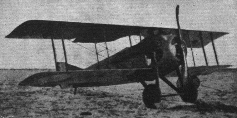
A view of the Spad used by the Lafayette Escadrille.
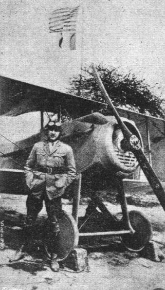
Edward F. Hinckle, of the Lafayette Escadrille, standing in front of the first aeroplane to carry the American flag over the French lines.


A captured French machine on view at the German Aeronautical Exhibition of War Booty.
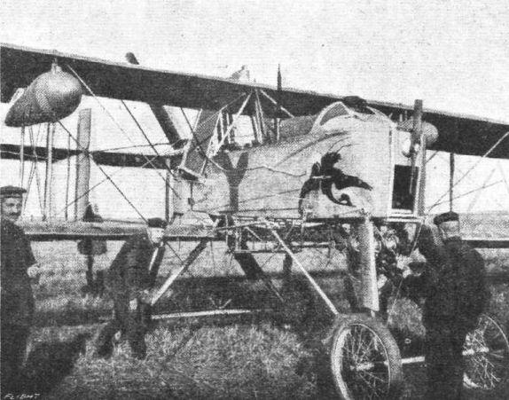
In the Hands of the Enemy. - A French Voisin biplane captured by the Germans. Under the nacelle can be seen a bombrack and a search-light.

Aviation in Japan. - A Japanese military machine of the Curtiss type.

AVIATION IN JAPAN. - Mr. Yukiteru Oxaki, the famous pilot of the Japanese Aeronautical Society.