Описание
Страна: Германия
Год: 1916
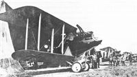
Two-seat reconnaissance and photographic duties
Варианты
- Rumpler - C.I/C.Ia - 1914 - Германия
- Rumpler - 6B1/6B2 - 1916 - Германия
- Rumpler - C.III/C.V - 1916 - Германия
- Rumpler - C.IV - 1916 - Германия
- Rumpler - C.VII / Rubild Mb - 1917 - Германия
- Rumpler - C.VIII - 1917 - Германия
- В.Кондратьев Самолеты первой мировой войны
- А.Александров, Г.Петров Крылатые пленники России
- O.Thetford, P.Gray German Aircraft of the First World War (Putnam)
- J.Stroud European Transport Aircraft since 1910 (Putnam)
- J.Herris Rumpler Aircraft of WWI (A Centennial Perspective on Great War Airplanes 11)
- J.Herris Pfalz Aircraft of WWI (A Centennial Perspective on Great War Airplanes 5)
- M.Dusing German Aviation Industry in WWI. Volume 1 (A Centennial Perspective on Great War Airplanes 84)
- A.Jackson British Civil Aircraft since 1919 vol.3 (Putnam)
- P.Grosz, G.Haddow, P.Shiemer Austro-Hungarian Army Aircraft of World War One (Flying Machines)
- E.Hauke, W.Schroeder, B.Totschinger Die Flugzeuge der k.u.k. Luftfahrtruppe und Seeflieger 1914-1918
- Журнал Flight
-
J.Herris - Rumpler Aircraft of WWI /Centennial Perspective/ (11)
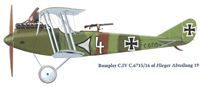
Rumpler C.IV C.6715/16 of Flieger Abteilung 19
-
J.Herris - Rumpler Aircraft of WWI /Centennial Perspective/ (11)
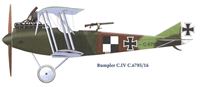
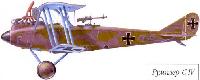
Rumpler C.IV C.6785/16
-
J.Herris - Rumpler Aircraft of WWI /Centennial Perspective/ (11)
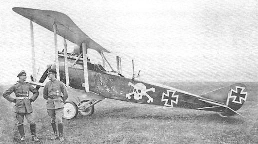
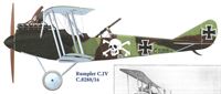
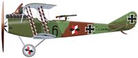
Rumpler C.IV C.8288/16
-
J.Herris - Rumpler Aircraft of WWI /Centennial Perspective/ (11)
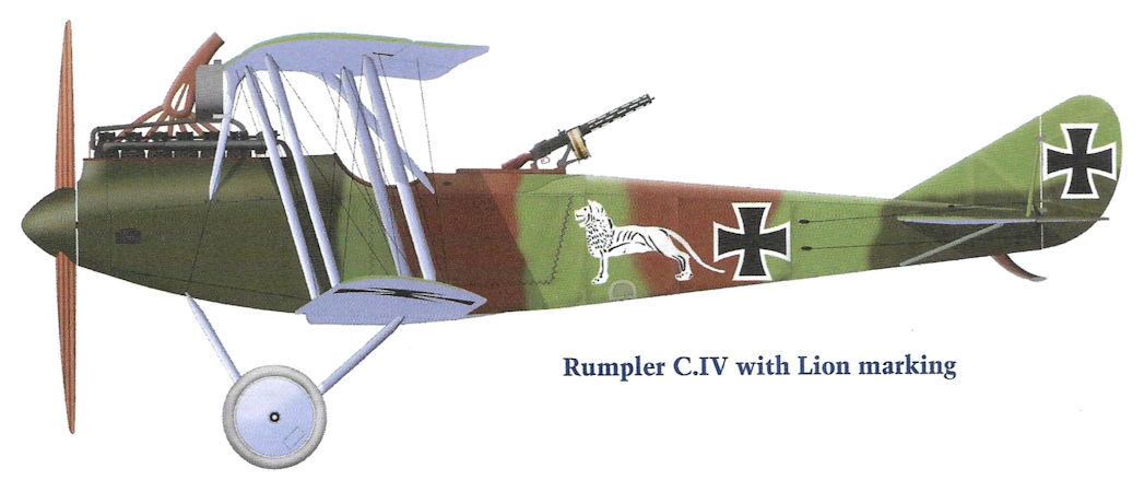
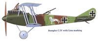
Rumpler C.IV with Lion marking
-
-
J.Herris - Rumpler Aircraft of WWI /Centennial Perspective/ (11)
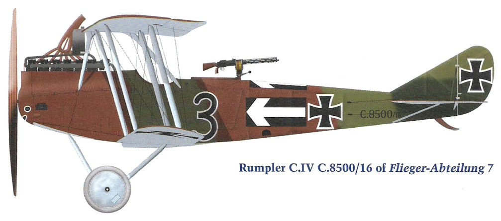
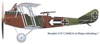
Rumpler C.IV C.8500/16 of Flieger-Abteilung 7
-
J.Herris - Development of German Warplanes in WWI /Centennial Perspective/ (1)
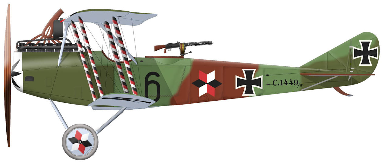
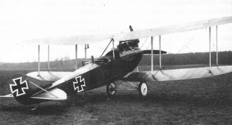
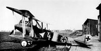
This Rumpler C.IV is a later-production model without propeller spinner. It wears standard factory camouflage enhanced with red/white/black (German national colors) markings on the fuselage, wheel covers, wing struts, and nose, making it more colorful than most Rumplers.
-
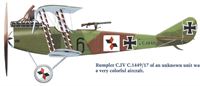
J.Herris - Rumpler Aircraft of WWI /Centennial Perspective/ (11)
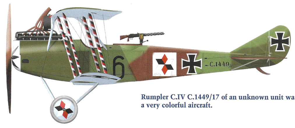
Rumpler C.IV C.1449/17 of an unknown unit was a very colorful aircraft.
-
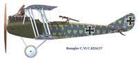
J.Herris - Rumpler Aircraft of WWI /Centennial Perspective/ (11)
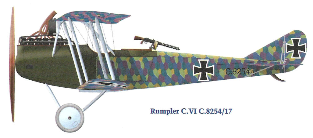
Rumpler C.VI C.8254/17
-
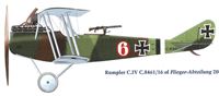
J.Herris - Rumpler Aircraft of WWI /Centennial Perspective/ (11)
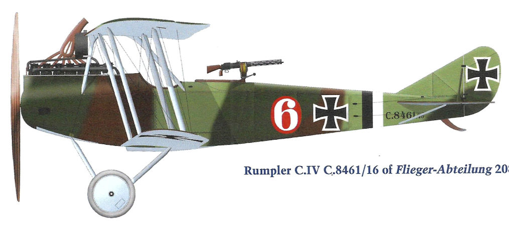
Rumpler C.IV C.8461 of Flieger-Abteilung 208
-
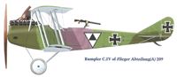
J.Herris - Rumpler Aircraft of WWI /Centennial Perspective/ (11)
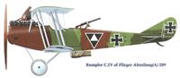
Rumpler C.IV of Flieger Abteilung(A) 209
-
J.Herris - Rumpler Aircraft of WWI /Centennial Perspective/ (11)
Rumpler C.IV of Flieger Abteilung(A) 209
-
J.Herris - Rumpler Aircraft of WWI /Centennial Perspective/ (11)
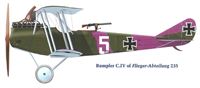
Rumpler C.IV of Flieger-Abteilung 235
-

J.Herris - Rumpler Aircraft of WWI /Centennial Perspective/ (11)
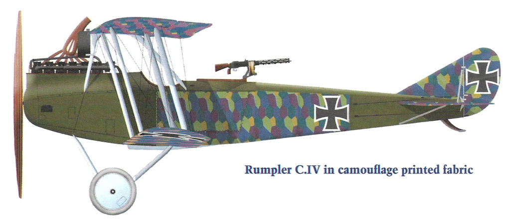
Rumpler C.IV in camouflage printed fabric
-
В.Кондратьев - Самолеты первой мировой войны
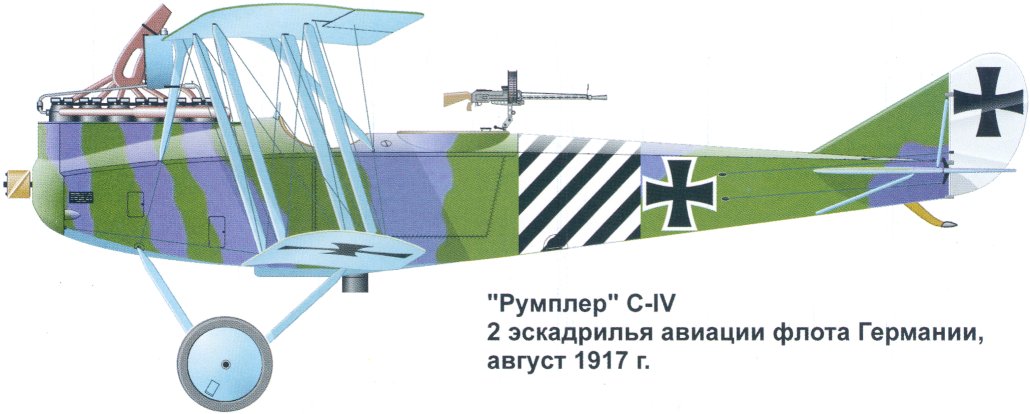
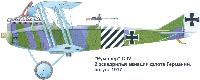
"Румплер" C-IV, 2 эскадрилья авиации флота Германии, август 1917г.
-

J.Herris - Rumpler Aircraft of WWI /Centennial Perspective/ (11)
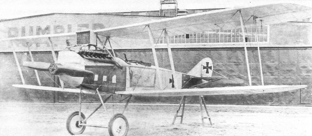
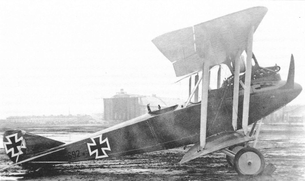
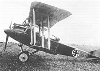
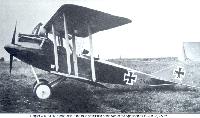
Early production Rumpler C.IV 6692/16 in factory finish. Other than its use of the Mercedes D.IVa engine and the rounded planform of the lower wings, from the side it looks very similar to a late-production Rumpler C.III. (The Peter M. Bowers Collection/The Museum of Flight)
-
-

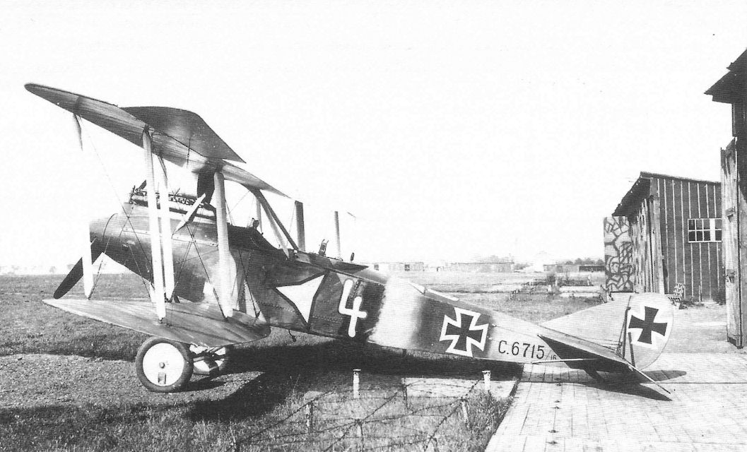
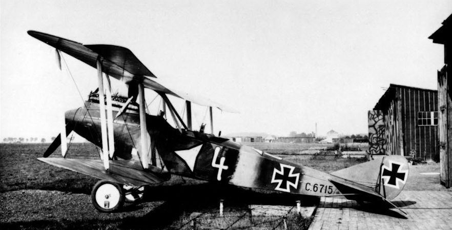
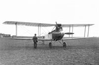
J.Herris - Rumpler Aircraft of WWI /Centennial Perspective/ (11)
Fitted with the 260 hp Mercedes D.IVa six-cylinder engine, the graceful Rumpler C.IV was as fast as Allied fighters at its ceiling, where few fighters could reach it. It became the premier German long-range photo-reconnaissance airplane. Over-compressed engines designed for more power at higher altitude maintained its edge throughout the war. The Rumpler C.IV airframe was also used for the specialized lichtbild (photo) aircraft.This early-production Rumpler C.IV of Flieger Abteilung 19 is barely distinguishable from a late-production Rumpler C.III. Later production C.IV aircraft discarded the propeller spinner and gained speed due to reduced drag. The high-flying Rumpler C.IV is the best-known Rumpler aircraft of the war and probably the most important.
-
J.Herris - Development of German Warplanes in WWI /Centennial Perspective/ (1)
The Rumpler C.IV, using the final C.III airframe and powered by the 260 hp Mercedes D.IVa, was the premier German reconnaissance airplane. It could reach high altitude, where it was as fast as Allied fighters - if they could reach it. Subsequent designs combined the same airframe with different engines and equipment for specialized, high-altitude missions.
-
J.Herris - Rumpler Aircraft of WWI /Centennial Perspective/ (11)
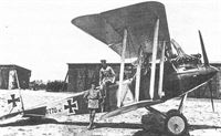
Early production Rumpler C.IV 6745/16 in factory finish shows its clean lines.
-
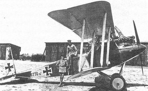
J.Herris - Rumpler Aircraft of WWI /Centennial Perspective/ (11)
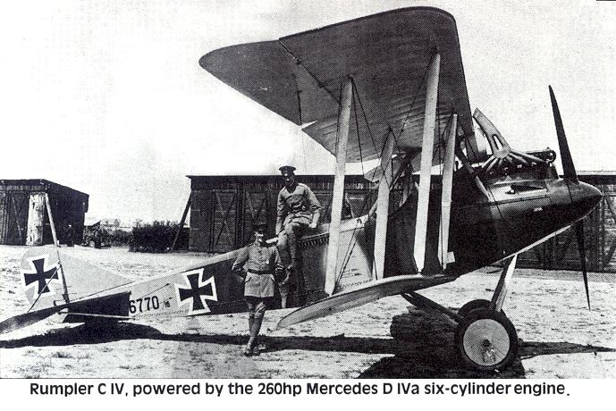
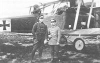
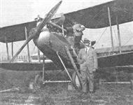
Early production Rumpler C.IV 6770/16 and crew.
-
J.Herris - Rumpler Aircraft of WWI /Centennial Perspective/ (11)
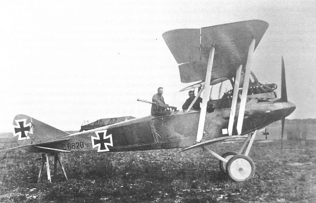
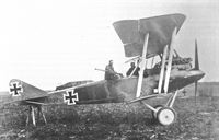
Early production Rumpler C.IV 6820/16 in factory finish prepares for another mission.
Early production Rumpler C.IV 6820/17 was powered by the Mercedes D IVa which gave it excellent performance at high altitude. The D IVa was very reliable for the time. -
J.Herris - Rumpler Aircraft of WWI /Centennial Perspective/ (11)
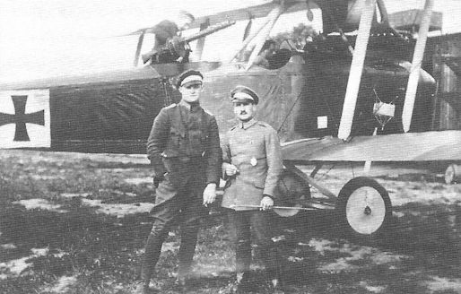
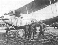
Early-production Rumpler C.IV with flight crew and early national insignia.
-
J.Herris - Rumpler Aircraft of WWI /Centennial Perspective/ (11)
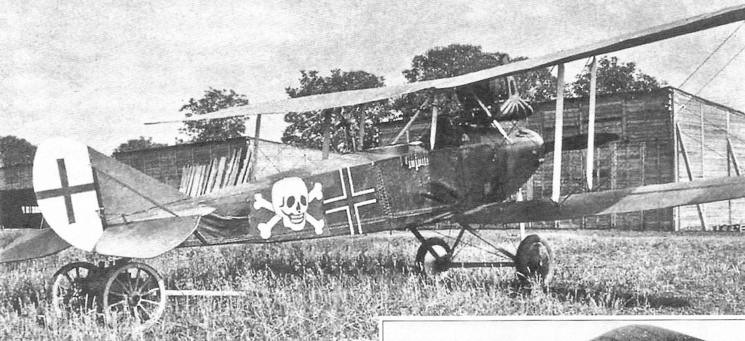
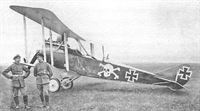
Rumpler C.IV C.8288/16 wears a skull and cross- bones marking, something seen far more commonly on fighters than reconnaissance airplanes. The proud crew is enjoying the moment.
-
-
-
J.Herris - Rumpler Aircraft of WWI /Centennial Perspective/ (11)
Rumpler C.IV with early national insignia and painted camouflage is lined up with the rest of its unit.
-
H.Cowin - Aviation Pioneers /Osprey/
If the Rumpler C III had proven to be a disaster waiting to happen, its successor from the same stables was just the reverse. Powered by a 260hp Mercedes D IVa, the Rumpler C IV followed closely upon the C III, ensuring that the firm was in a position to continue producing two seaters almost without interruption during the spring of 1917. The C IV, with its top level speed of 109mph at sea level, combined with a superb high altitude capability of 21,000 feet saw the C IV providing stalwart service through to the cessation of hostilities.
-
J.Herris - Rumpler Aircraft of WWI /Centennial Perspective/ (11)
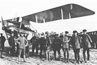
"Румплеры" C-IV одной из разведывательных эскадр западного фронта
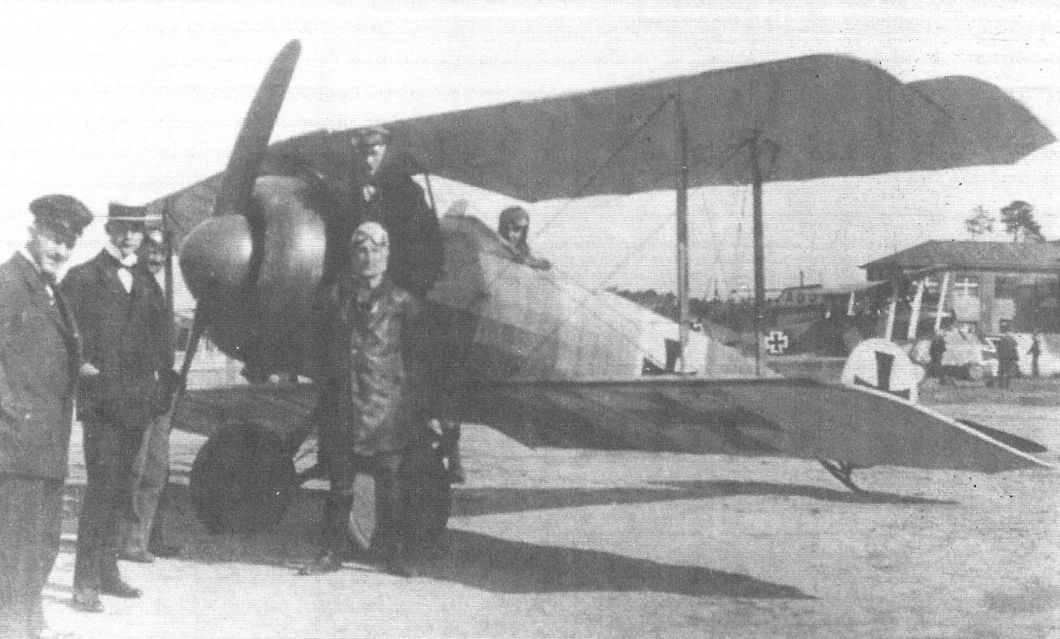
An early-production Rumpler C.IV is a fine backdrop for this group portrait; another rests in the background. The high-flying Rumplers were effective German reconnaissance aircraft as they were able to escape most attackers by taking advantage of the ceiling of 21,000ft (6,400m). -

J.Herris - Rumpler Aircraft of WWI /Centennial Perspective/ (11)
Early-production Rumpler C.IV in factory finish.
-
Журнал - Flight за 1917 г.
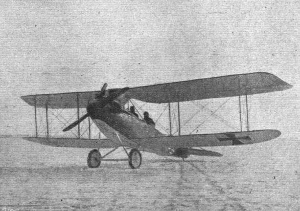
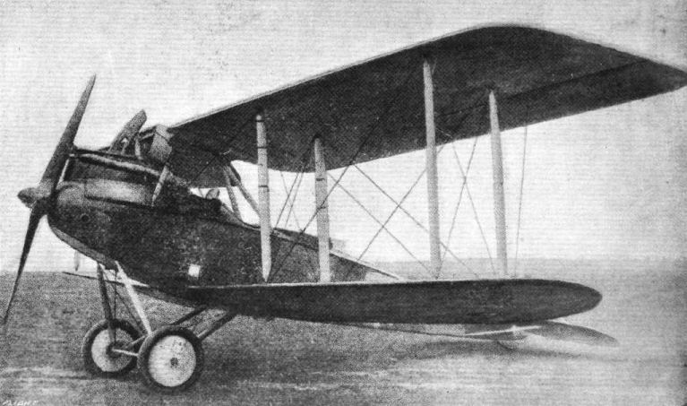
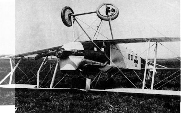
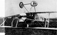
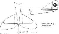
Another view of the 260 h.p. C.IV-type Rumpler biplane. - The annexed illustration, appears to indicate an attempt by the Rumpler firm at better stream-lining, as a hemispherical nose-piece is fitted over the boss of the airscrew, and the sides of the front part of the body are rounded off to gradually carry the curve of the nose-piece into the flat sides of the rear portion of the fuselage. Also, judging by the illustration, it appears that the span is somewhat smaller than in the older type Rumpler biplanes.
-
M.Dusing - Germania Flugzeugwerke and Its Aircraft /Centennial Perspective/ (41)
Presentation of the 300th repaired Rumpler aircraft (Ru C.IV).
-
M.Dusing - Germania Flugzeugwerke and Its Aircraft /Centennial Perspective/ (41)
Another view of the 300th repaired Rumpler aircraft with Director Egwin Leiber at left and a Germania pilot at right. (Peter M Grosz collection/STDB)
-
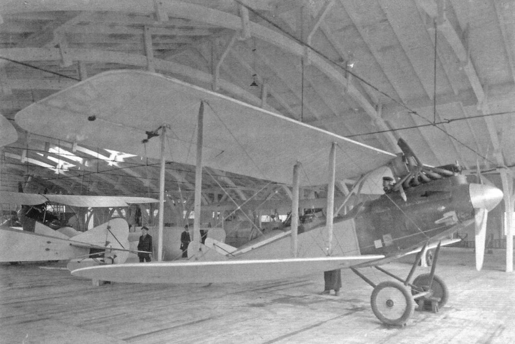
M.Dusing - Germania Flugzeugwerke and Its Aircraft /Centennial Perspective/ (41)
Refurbished Rumpler C.IV aircraft in the "Starting Hall".
-

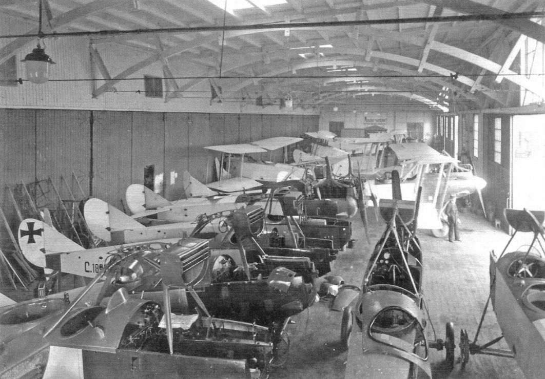
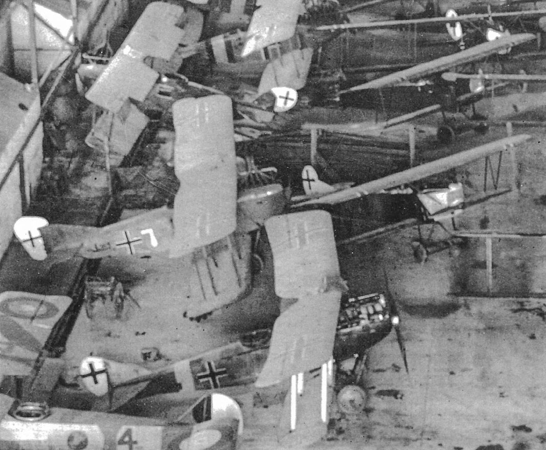
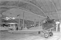
M.Dusing - Germania Flugzeugwerke and Its Aircraft /Centennial Perspective/ (41)
Hangar full of refurbished Rumpler aircraft.
-
J.Herris - Rumpler Aircraft of WWI /Centennial Perspective/ (11)
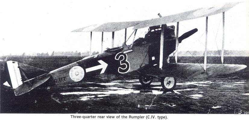
A nonchalant crew photographed with their Rumpler. The arrow marking on the side and top of the fuselage is the unit marking of Flieger-Abteilung 7.
-
J.Herris - Rumpler Aircraft of WWI /Centennial Perspective/ (11)
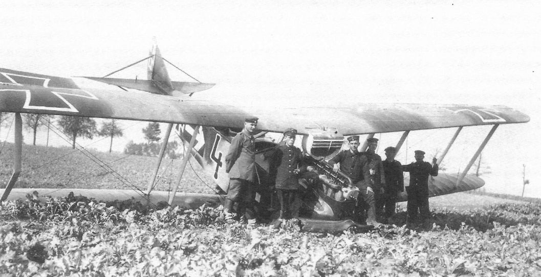
Maybach-engined Rumpler C.IV 1423/16 tactical number '4' of Flieger-Abteilung 7. Although having the same tactical number, this may be a different aircraft then that shown above; notice the arrow markings on the upper wings not on the airplane above. Of course, the upper wing arrows may have been added after repair. From this batch onward the type designation, in this case 'C.4', was added to the serial number to distinguish the sub-types of the family. Roman numerals were used after this batch.
-
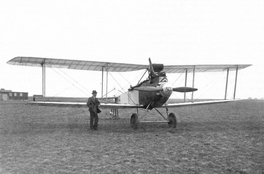
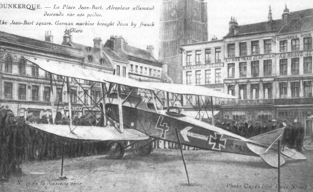
J.Herris - Rumpler Aircraft of WWI /Centennial Perspective/ (11)
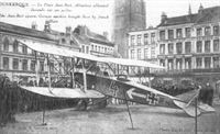
Crudely retouched postcard of Rumpler C.IV 8428/16 (w/n 2276) captured by the French. The aircraft was on display at the Place Jean Bart in Dunkerque. As evidenced by the white arrow unit marking this was a Fl. Abt. 7 aircraft. It was thoroughly studied by the French.
-
J.Herris - Rumpler Aircraft of WWI /Centennial Perspective/ (11)
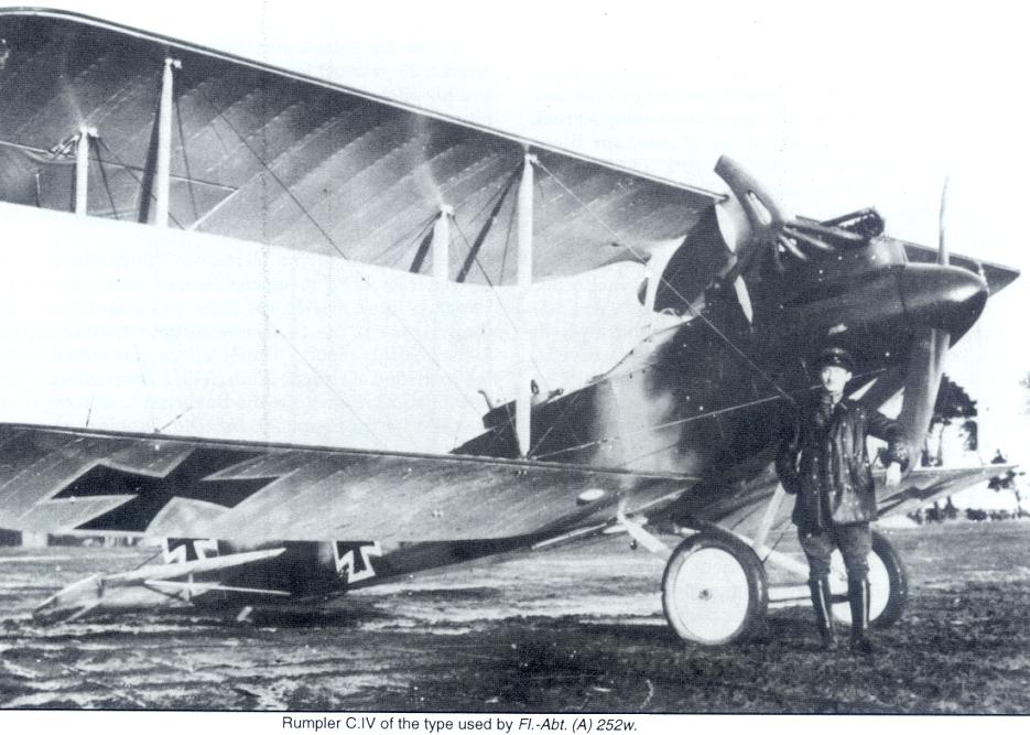
Later production Rumpler C.IV 8476/16 in factory painted camouflage has the new nose contours without spinner. Eliminating the spinner reduced drag and added 10-15 km/h to the aircraft's speed.
-
J.Herris - Rumpler Aircraft of WWI /Centennial Perspective/ (11)
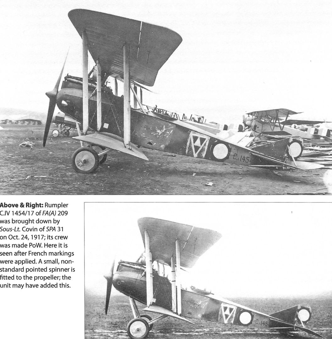
Rumpler C.IV 1454/17 of FA(A) 209 was brought down by Sous-Lt. Covin of SPA 31 on Oct. 24,1917; its crew was made PoW. Here it is seen after French markings were applied. A small, nonstandard pointed spinner is fitted to the propeller; the unit may have added this.
-
J.Herris - Rumpler Aircraft of WWI /Centennial Perspective/ (11)
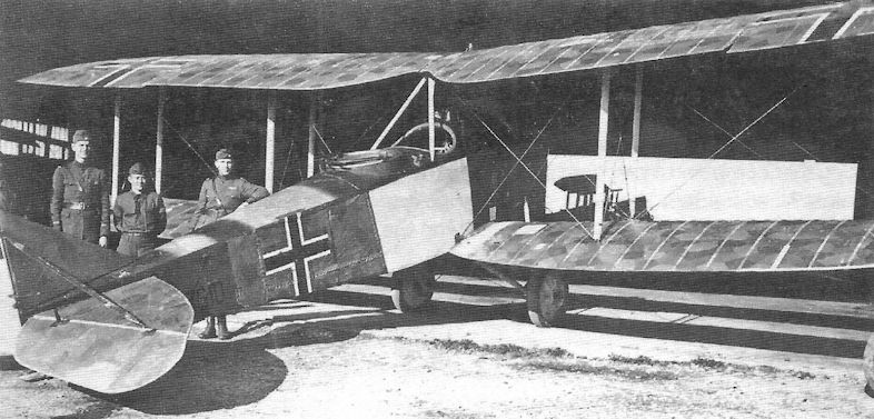
Rumpler C.IV 7610/17 in American hands in 1918 as shown by the straight-sided Balkenkreuz, apparently after repairs. It had the Mercedes D.IVa engine typical of the C.IV.
-

J.Herris - Rumpler Aircraft of WWI /Centennial Perspective/ (11)
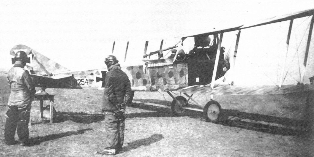
Rumpler C.VI 8254/17 has a flare rack for the observer and is covered with printed camouflage fabric.
-

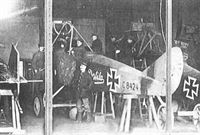
J.Herris - LVG Aircraft of WWI. Volume 2: Types C.II-C.V /Centennial Perspective/ (35)
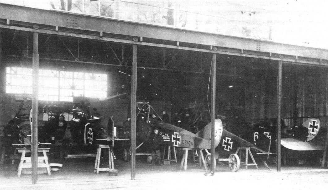
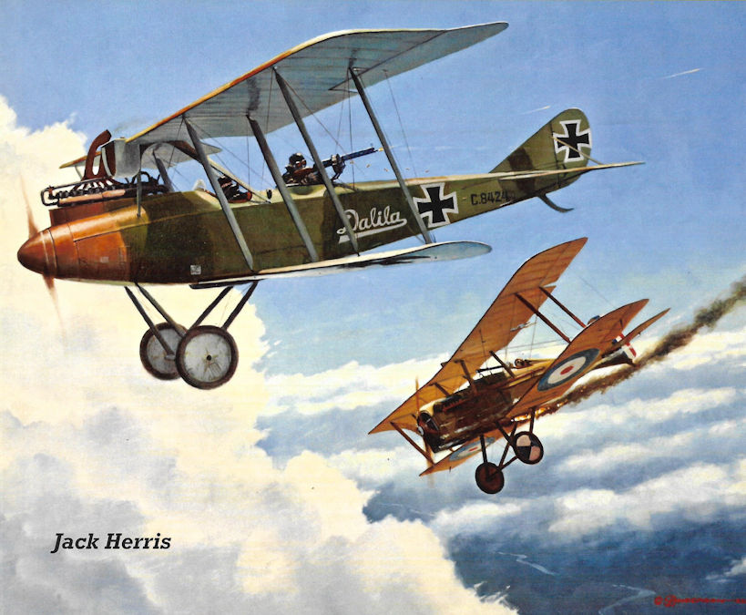
LVG C.V 9437/17 (at right) and Rumpler C.IV C8424/16 Dalila are among the aircraft being repaired in this hangar. Two more LVG C.V aircraft are visible along with another aircraft, perhaps an LVG C.V, at left. The photo was taken at AFP 4.
Другие самолёты на фотографии: LVG C.V - Германия - 1917
-
J.Herris - Rumpler Aircraft of WWI /Centennial Perspective/ (11)
Rumpler C.IV 8424/16 Dalila of the first production batch undergoes maintenance.This early production C.IV is the subject of Steve Anderson's cover painting. LVG C.V aircraft are on both sides of Dalila.
Другие самолёты на фотографии: LVG C.V - Германия - 1917
-
J.Herris - Rumpler Aircraft of WWI /Centennial Perspective/ (11)
Rumpler C.IV 8485/17 of FA(A) 219 wears an interesting camouflage scheme. Like the earlier C.III from which the C.IV got its airframe, the C.IV was lightly designed for minimum weight to maximize climb and ceiling. The result was the airframe had to be locally strengthened a number of times based on operational experience.
-
J.Herris - Rumpler Aircraft of WWI /Centennial Perspective/ (11)
Colorfully-marked Rumpler in late insignia
-

M.Dusing - German Aviation Industry in WWI. Volume 2 /Centennial Perspective/ (85)
Rumpler C.IV (6A7) (1916)
-
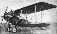
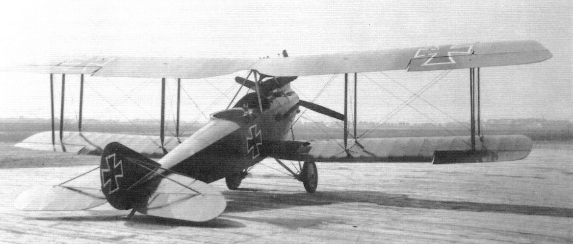
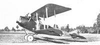
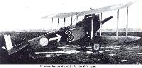
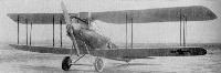
Журнал - Flight за 1918 г.
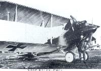
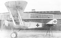
THE C. IV-TYPE RUMPLER BIPLANE. - Three-quarter front view of the 260 h.p. Mercedes D.IVa model.
-

M.Dusing - German Aviation Industry in WWI. Volume 2 /Centennial Perspective/ (85)
Rumpler C.IV(Mb) (6A7). Later production R.IV aircraft omitted the spinner, which improved speed. (1916)
-
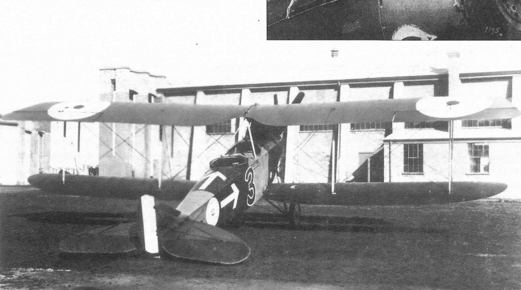
J.Herris - Rumpler Aircraft of WWI /Centennial Perspective/ (11)
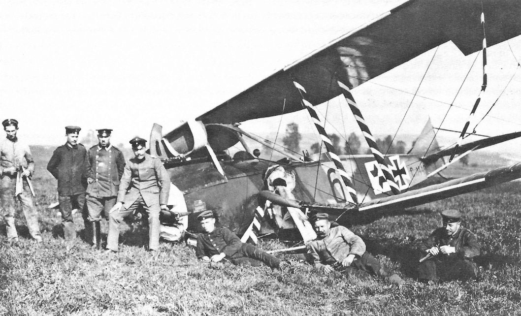
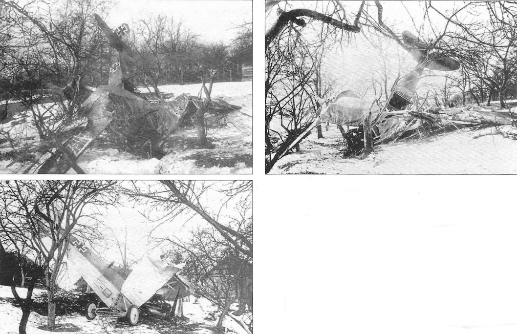
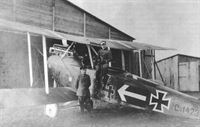
Is this a case of before and after? Rumpler C.IV tactical number '3' of Flieger-Abteilung 1 with crew on facing page above and after coming down behind Allied lines in other photos, although the first photo may be a different aircraft. Rumpler C.IV C.8500/16 with 260 hp Mercedes D.IVa was captured on 29 December 1917, brought down at Monchy by ground fire. Given the capture number G.117, it was closely examined and was the basis of the report in Jane's All the World's Aircraft. It is in the early factory finish plus the unit insignia of the arrows on the fuselage sides and top. The eyes painted on the nose are thought to be individual markings. Unfortunately, the photos were taken after the iron cross national insignia had been painted over with roundels.
-
-
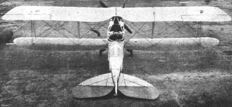
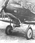
Сайт - Pilots-and-planes /WWW/
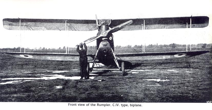
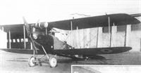
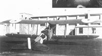
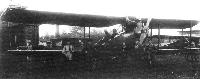
Front view of the 2-Seater Rumpler.
-
Сайт - Pilots-and-planes /WWW/
Fig. 3. - The Rumpler biplane - C 4 type.
-
-
-
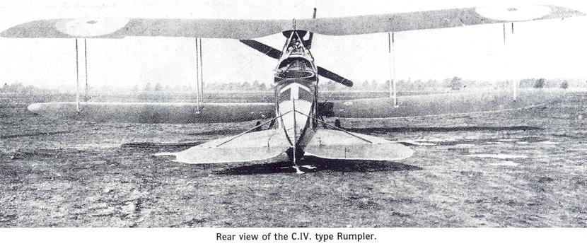
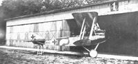
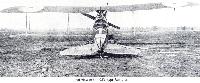
Журнал - Flight за 1918 г.
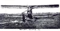
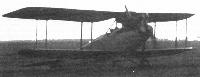
Rear view of the 2-Seater Rumpler.
-
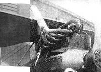
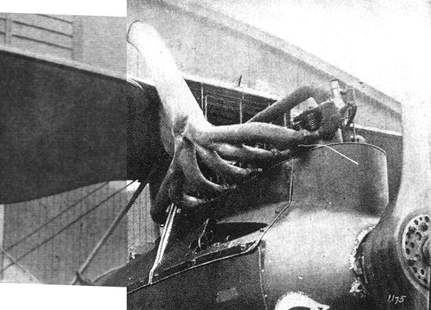
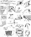
Журнал - Flight за 1918 г.
The exhaust manifold and engine cowling of the 2-Seater Rumpler.
-
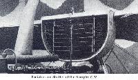
Сайт - Pilots-and-planes /WWW/
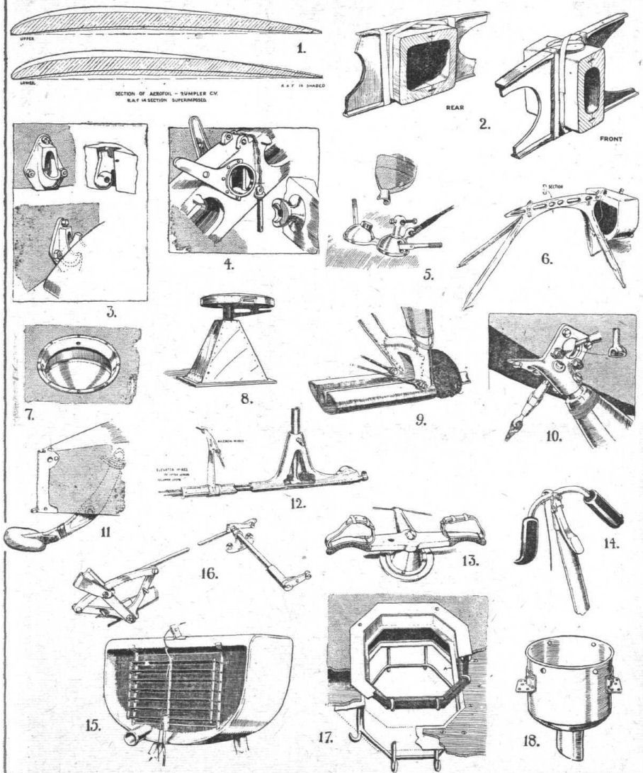
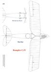
Под верхним крылом самолета устанавливался радиатор в полукруглом туннеле с регулирующей заслонкой впереди.
-
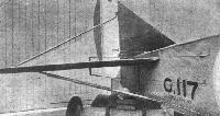
Журнал - Flight за 1918 г.
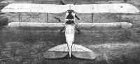
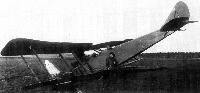
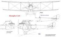
Tail and Fin Bracing of the Rumpler. Note the saw-teeth on the low tail stay type to prevent mechanics from lifting the machine by this tube.View of the 2-Seater Rumpler tail.
-

J.Herris, J.Leckscheid - Fokker Aircraft of WWI. Vol.3: Early Biplane Fighters /Centennial Perspective/ (53)
The AGO company building seen in the background identifies this photo as being taken at Berlin Johannisthal. The photo gives a good impression of what was going on at Adlershof and Johannisthal in 1917 and 1918, a Rumpler C.IV and men working on a wing laying on the ground can be seen in the background.
Другие самолёты на фотографии: Fokker D.V / M.22 - Германия - 1916
-
J.Herris - Rumpler Aircraft of WWI /Centennial Perspective/ (11)
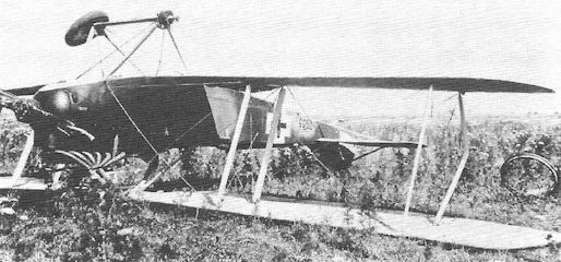
This late-production Rumpler had a wind-driven electrical generator to power the crew's electrically-heated flying suits.
-

J.Herris - Rumpler Aircraft of WWI /Centennial Perspective/ (11)
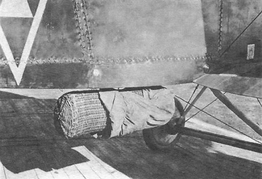
Rumpler C.IV of Flieger-Abteilung (A) 209 carries a wicker supply cannister. When dropped the canister descended by parachute. Flieger-Abteilung (A) 209 also used AEG N.I night bombers for this purpose.
-
J.Herris - Rumpler Aircraft of WWI /Centennial Perspective/ (11)
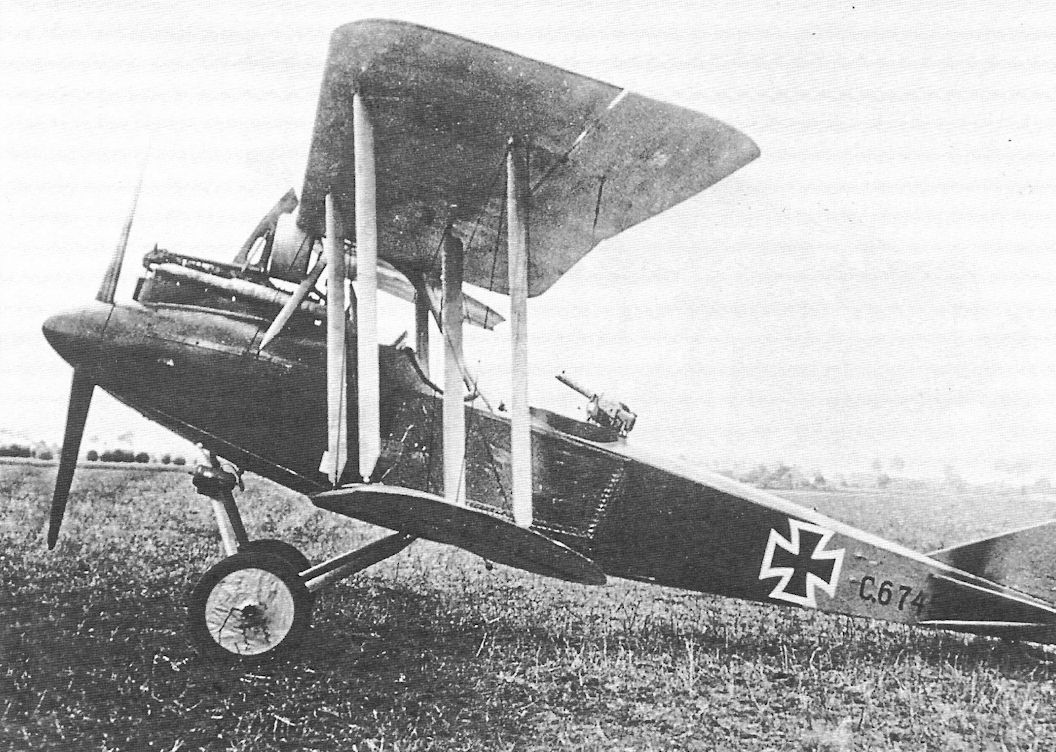
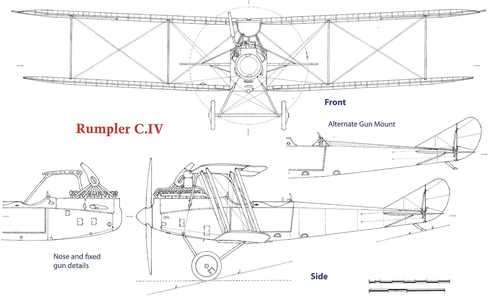
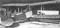
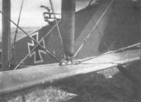
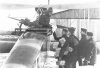
Close-up view of a Rumpler C.IV; the unusual straight-tube observer's gun mount is visible.
-

J.Herris - Rumpler Aircraft of WWI /Centennial Perspective/ (11)
This early-production Rumpler C.IV retains the straight bar observer's gun mount.
-
J.Herris - Rumpler Aircraft of WWI /Centennial Perspective/ (11)
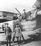
The crew of this Rumpler C.IV appeal for kindness with their markings "Good People don't shoot". In case that appeal does not work the observer has a machine gun on an unusual straight mounting. One pilot told the author he chose to fly Rumplers instead of fighters because he "just didn't have the heart to dive down on an unsuspecting enemy and shoot him down."
-

J.Herris - Rumpler Aircraft of WWI /Centennial Perspective/ (11)
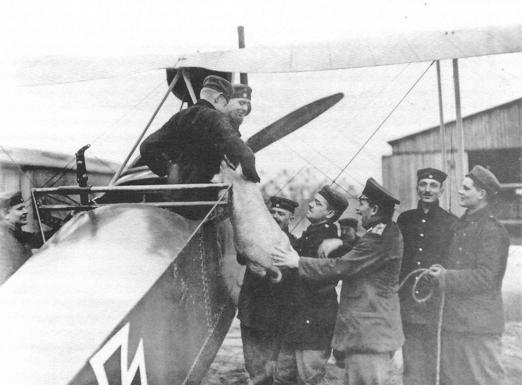
The crew of this Rumpler C.IV delivers Christmas dinner. This photo gives a better view of the unusual mounting for the observer's flexible gun.
-
J.Herris - Rumpler Aircraft of WWI /Centennial Perspective/ (11)
Another view of a Rumpler C.IV delivering packages to the front. Despite use of the unusual observer's gun mounting, which must have caused more drag than standard mountings, this appears to be a different aircraft, or at least a different occasion, than that above.
-

J.Herris - Rumpler Aircraft of WWI /Centennial Perspective/ (11)
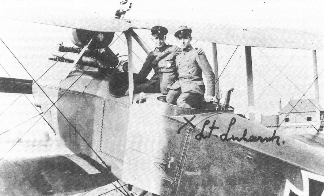
Rumpler C.IV of Flieger-Abteilung 18; Lt. Heinz Lubarsch was the observer.
-

J.Herris - Rumpler Aircraft of WWI /Centennial Perspective/ (11)
Printed lozenge fabric on a late-production Rumpler.
-

J.Herris - Rumpler Aircraft of WWI /Centennial Perspective/ (11)
The ground crew photographed with their Rumpler. The triangle marking on the fuselage side appears to be the unit marking of Flieger-Abteilung (A) 209, although the colors are reversed from their usual presentation.
-
J.Herris - Rumpler Aircraft of WWI /Centennial Perspective/ (11)
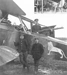
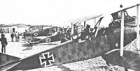
Both reconniassance units and fighter units had unit markings, but personal insignia were more common in fighter units. Here a Rumpler in early factory camouflage, with paint chipping off the fabric, proudly displays a lion personal marking. Details of the unit and crew are not known, but one wonders if this was a Bavarian lion.
-
J.Herris - Rumpler Aircraft of WWI /Centennial Perspective/ (11)
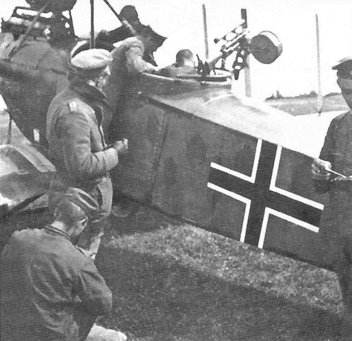
A mid-production (no spinner but wearing painted camouflage instead of fabric printed with the lozenge pattern) Rumpler seems to be the center of attention for this busy gathering. Crewmen in flight clothing indicate it is either ready for flight or has just returned.
-
J.Herris - Rumpler Aircraft of WWI /Centennial Perspective/ (11)
Confident flight crew photographed by their Rumpler.
-
J.Herris - Rumpler Aircraft of WWI /Centennial Perspective/ (11)
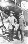
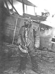
A German aviator in his primitive electrically-heated flying suit and face shield to prevent frostbite.
-

J.Herris - Rumpler Aircraft of WWI /Centennial Perspective/ (11)
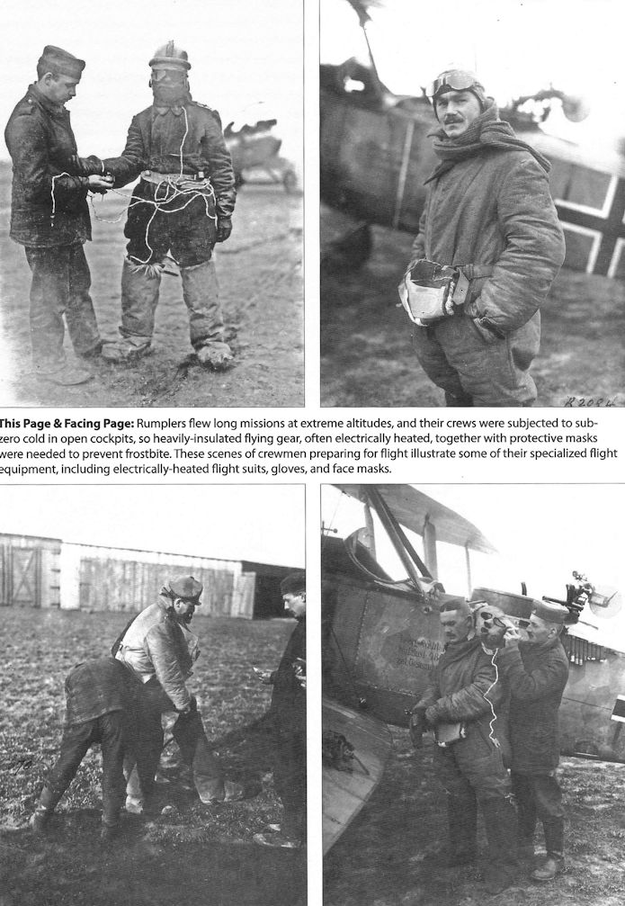
Rumplers flew long missions at extreme altitudes, and their crews were subjected to subzero cold in open cockpits, so heavily-insulated flying gear, often electrically heated, together with protective masks were needed to prevent frostbite. These scenes of crewmen preparing for flight illustrate some of their specialized flight equipment, including electrically-heated flight suits, gloves, and face masks.
-

Z.Czirok - German Aircraft in Hungarian Service /Centennial Perspective/ (92)
Planes and personnel of Fliegerabteilung 30 in 1918 on the Salonika Front. (Thorsten Pietsch)
-
J.Herris - Rumpler Aircraft of WWI /Centennial Perspective/ (11)
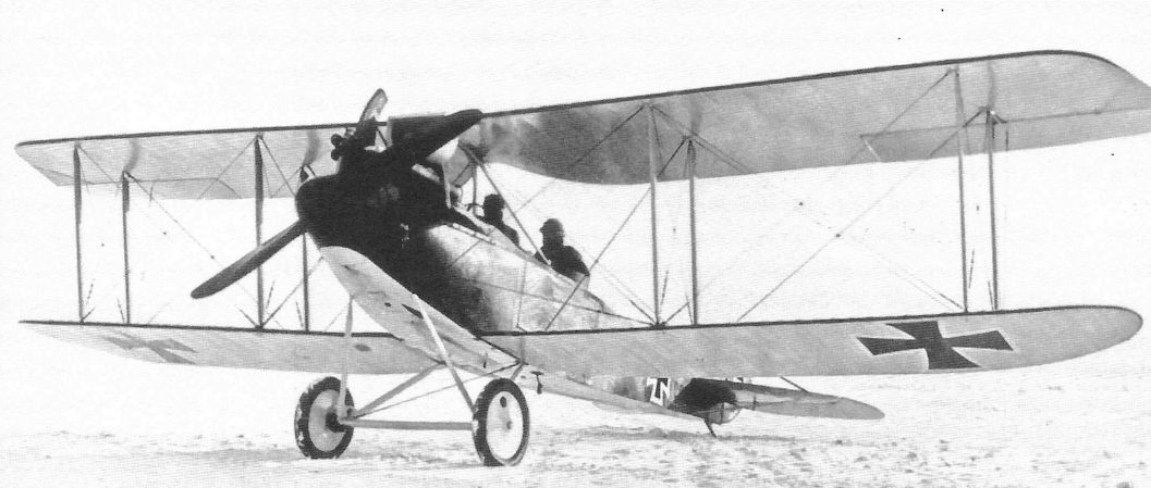
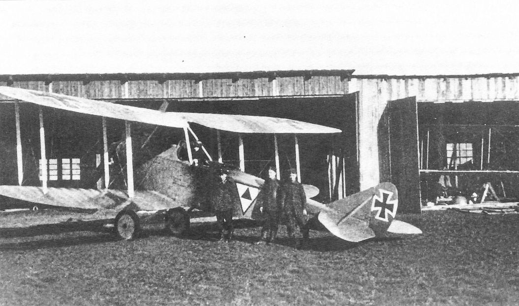
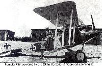
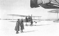
Rumpler C.IV on a snowy airfield at Minsk, Russia.
-
J.Herris - Rumpler Aircraft of WWI /Centennial Perspective/ (11)
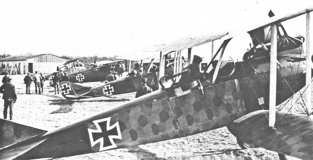
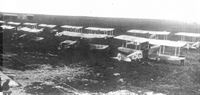
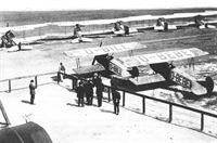
An interesting collection of two-seaters, typifying the equipment of 1917-18. In the foreground is a Rumpler C IV, the other aircraft being a Rumpler C VII, a Hannover CL IIIa and a D.F.W. C V.
Two Rumplers are lined up in this well-known photograph with a Hannover CL.II and DFW C.V in the background. Unusually, the early Rumpler nearest the camera, C.IV 8267/16, is covered with printed camouflage fabric. The second Rumpler, C.IV 6695/16, was sent back to "Lager West" from AFP 6 in April 1917 for strengthening of the rear fuselage.Другие самолёты на фотографии: DFW C.V - Германия - 1916Hannover (Hawa) CL.II/CL.III/CL.IIIa - Германия - 1917
-
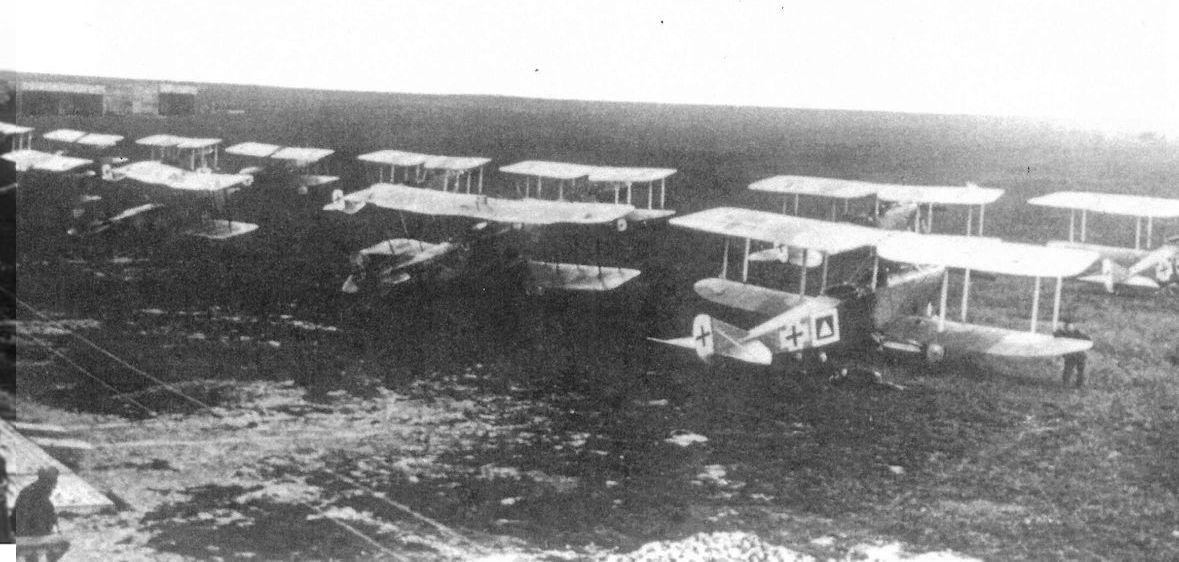
J.Herris - AEG Aircraft of WWI /Centennial Perspective/ (16)
Two AEG N.I bombers are seen in in this photo of FA(A) 209. The aircraft on the far right in the row nearest the camera is a Rumpler C.IV; to its left in the row nearest the camera are two AEG N.I night bombers.
Другие самолёты на фотографии: AEG N.I / C.IV N - Германия - 1917
-
J.Herris - AEG Aircraft of WWI /Centennial Perspective/ (16)
This view of the inside of the Zeppelin hangar in Trier shows AEG J.II 353/18 tactical '7' with its wings still on. A USAS Salmson 2 A2 is at lower left with a Rumpler C.IV in the center, an LVG C.VI behind the AEG J.II, and Fokker D.VII fighters among the aircraft that can be identified.
Другие самолёты на фотографии: AEG J.I / J.II - Германия - 1917Fokker D.VII / V11 / V18 / V22 / V24 - Германия - 1917LVG C.VI - Германия - 1918Salmson Sal.2 - Франция - 1917
-

R.Bennett - Last Gathering of Eagles 1918-1920 /Aeronaut/
Same unit, some of the same flyers posing with a Fokker D.VII inside the hangar. A Rumpler C.IV is in the background. (Author's collection)
Другие самолёты на фотографии: Fokker D.VII / V11 / V18 / V22 / V24 - Германия - 1917
-
-
J.Herris - Pfalz Aircraft of WWI /Centennial Perspective/ (5)
Pfalz C.I, later redesignated Rumpler C.IV (Pfal), at the Pfalz factory.
-
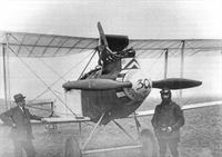
J.Herris - Pfalz Aircraft of WWI /Centennial Perspective/ (5)
Pfalz C.I, later Rumpler C.IV (Pfal), at the Pfalz factory. Test pilot Gustav Bauer stands third from right.
-

J.Herris - Pfalz Aircraft of WWI /Centennial Perspective/ (5)
This Pfalz C.I, later redesignated Rumpler C.IV (Pfal), clearly shows the ailerons on all four wings and the actuating struts between the upper and lower ailerons that distinguished the Pfalz-built aircraft from the standard Rumpler C.IV.
-

J.Stroud - European Transport Aircraft since 1910 /Putnam/
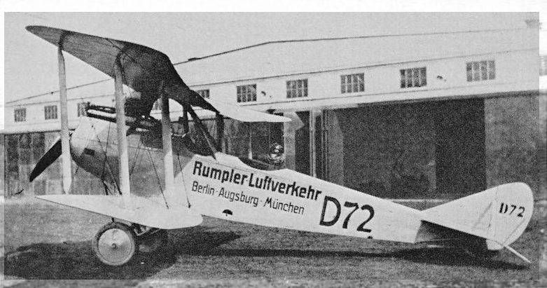
Rumpler-Luftverkehr’s Rumpler C IV D-72 photographed in 1919.
After the war Rumpler used both C.I and C.IV aircraft in a short-lived airline, Rumpler Luftverhehr (Rumpler Air Traffic). Here D72 shows its heritage of clean lines in March 1919. Its route of Berlin-Augsburg-Munich is painted on the fuselage. -

A.Jackson - British Civil Aircraft since 1919 vol.3 /Putnam/
Slingsby Type 58 Rumpler С IV replica
-

J.Herris - Rumpler Aircraft of WWI /Centennial Perspective/ (11)
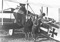
An experimental Rumpler C-type with a massive, 345 hp Austro-Daimler V-12 engine installed. Fitted with this powerful engine provided by Austria-Hungary, the airplane was delivered to the Austro-Hungarian Luftfahrtruppen and given serial number 00.01. It crashed and was not repaired. Unfortunately, there is no record of its performance with this powerful engine, but it may have been somewhat nose heavy.
-
P.Grosz, G.Haddow, P.Schiemer - Austro-Hungarian Army Aircraft of World War One /Flying Machines/
Rumpler C.VII with AD V12 Dm345 (1917)
The Rumpler C.VII derivative (Type 6A11?) photographed upon completion at the Rumpler factory in Johannisthal in late February 1918. The undercarriage has been raised to provide clearance for the increased propeller diameter required by the 300 hp Daimler engine. -

-

A.Olejko - War Wings Over Galicia 1918-1919 /Aeronaut/
Flying mosaic... In the winter of 1918/1919, a large number of types of aircraft were used in Polish aviation, which from the German, Austro-Hungarian and Russian air forces went to the Polish squadrons fighting in the Polish-Ukrainian war. In the photograph is Rumpler C.IV and Hannover CL.II.
Другие самолёты на фотографии: Hannover (Hawa) CL.II/CL.III/CL.IIIa - Германия - 1917
-
C.Owers - Fokker Aircraft of WWI. Vol.7: Postwar /Centennial Perspective/ (67)
Ploughshares - Civilian Fokker D.VII biplanes O-BILL and O-BEBE with Belgian Rumpler C types on a civil airfield. The Fokkers and at least one Rumpler are still in lozenge fabric. (via D Brackx)
Другие самолёты на фотографии: Fokker D.VII / V11 / V18 / V22 / V24 - Германия - 1917
-
-
-

-
-
J.Herris - Rumpler Aircraft of WWI /Centennial Perspective/ (11)
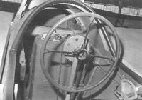
Control wheel in a Rumpler cockpit; early-production aircraft had a control stick for the pilot.
-
J.Herris - Rumpler Aircraft of WWI /Centennial Perspective/ (11)
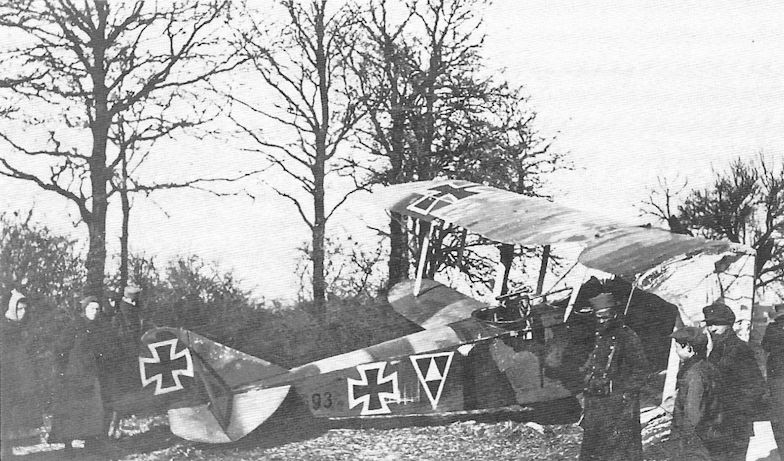
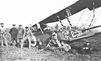
Later production Rumpler C.IV 1449/17 has suffered a landing accident. It wears standard factory camouflage enhanced with red/ white/black (German national colors) markings on the fuselage, wheel covers, wing struts, and nose, making it much more colorful than most Rumplers.
-
J.Herris - Rumpler Aircraft of WWI /Centennial Perspective/ (11)
Early-production Rumpler C.IV after a bad landing. The aircraft has the typical factory painted camouflage finish for early production aircraft.
-

J.Herris - Rumpler Aircraft of WWI /Centennial Perspective/ (11)
Rumpler C.IV tactical number '4' of Flieger-Abteilung 7 after a rough landing.
-
J.Herris - Rumpler Aircraft of WWI /Centennial Perspective/ (11)
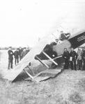
Rumpler C.IV x693/1x, probably 6693/16, of FA(A) 209, brought down behind French lines. When Rumpler C.IV aircraft were used for general two-seater duties at lower altitudes they were more vulnerable to fighters and anti-aircraft fire.
-
J.Herris - Rumpler Aircraft of WWI /Centennial Perspective/ (11)
Rumpler C.IV 7955/18 serving with FA304b after a bad landing.
-
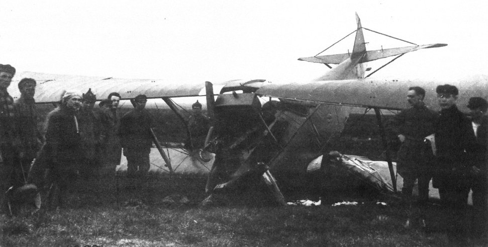
P.Grosz, G.Haddow, P.Schiemer - Austro-Hungarian Army Aircraft of World War One /Flying Machines/
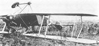
A hard landing, probably during first flight trials at Aspern in late April 1918, put an end to further testing of the Rumpler C.VII 00.01.
Rumpler C.IV mit Daimler-Motor 350 PS, Flugzeugnummer 00.01
Rumpler C.IV с двигателем Daimler 350 л.с., номер самолета 00.01 -
J.Herris - Rumpler Aircraft of WWI /Centennial Perspective/ (11)
The unusual observer's gun mounting is visible on this crashed Rumpler, supporting its identification as an early production C.IV.
-
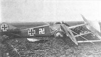
J.Herris - Rumpler Aircraft of WWI /Centennial Perspective/ (11)
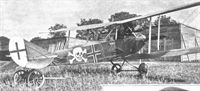
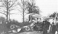
Crash of Rumpler C.IV 8512/16. The Swastika is aft of the one on the C.VII.
-
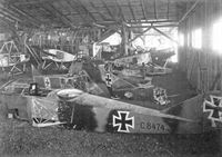
M.Dusing - Germania Flugzeugwerke and Its Aircraft /Centennial Perspective/ (41)
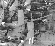
Aircraft wrecks delivered for repair: Rumpler C.IV 8474/16, Rumpler C.I 6519/16, Rumpler C.IV 8280/16, and Albatros C.VII 1295/16.
Другие самолёты на фотографии: Albatros C.VII - Германия - 1916Rumpler C.I/C.Ia - Германия - 1914
-

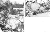
A.Olejko - War Wings Over Galicia 1918-1919 /Aeronaut/
Krakow 1919... Crash of Rumpler C.IV number 51 (painted on one side only) used at the Pilots School in Krakow, where the plane came from the 2nd Moving Air Park. (collection of J. Butkiewicz)
-

J.Herris - Rumpler Aircraft of WWI /Centennial Perspective/ (11)
Steve Anderson's evocative painting of the famous Rumpler C.IV, the aircraft for which Rumpler is still known today. C.IV 8424/16 Dalila was from the first C.IV production batch. Only the highest-performance Allied fighters had any hope of intercepting a Rumpler C.IV if it was on a high-altitude reconnaissance mission. At high altitude the aerodynamic Rumpler C.IV was as fast as Allied fighters and had a good chance of besting them in combat.
-
Журнал - Flight за 1918 г.
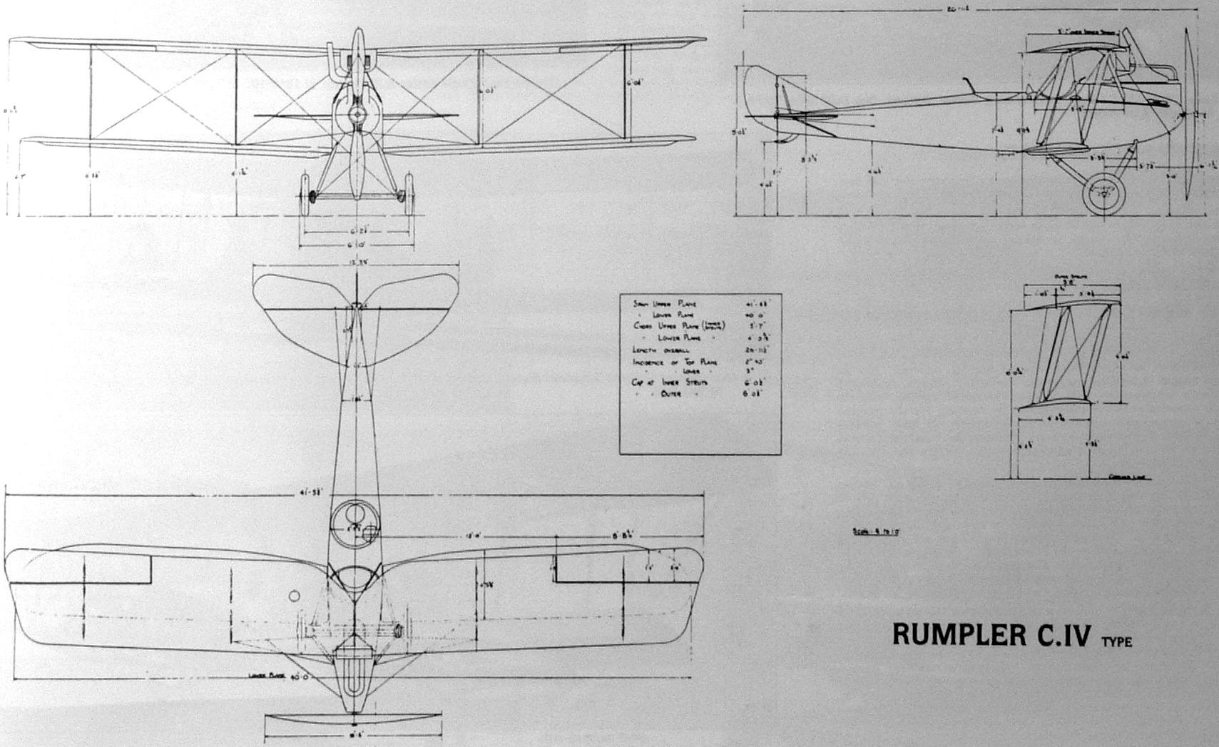
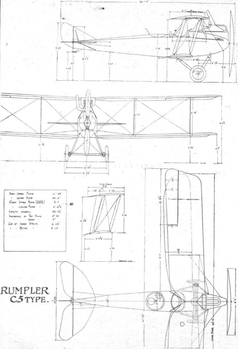
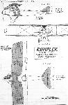
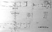
THE 2-SEATER RUMPLER, C. 5 TYPE. - Figs. 1 to 18.
-
Журнал - Flight за 1917 г.
The 260 h.p. Rumpler.
-

M.Dusing - German & Austro-Hungarian Aero Engines of WWI. Vol.2 /Centennial Perspective/ (65)
Drawing of D IVa powered Rumpler C.IV.
-
-
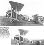
Журнал - Flight за 1918 г.
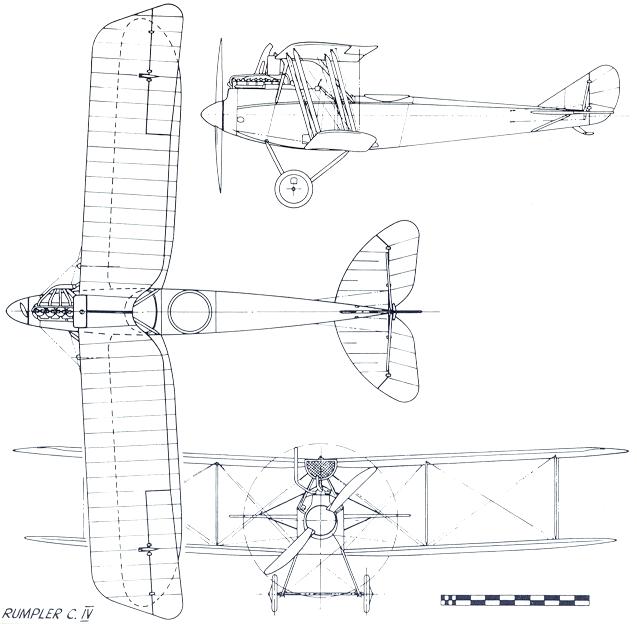
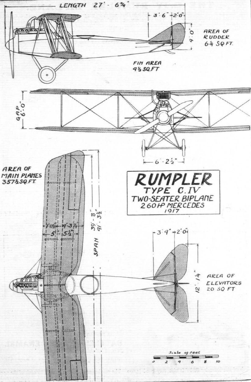
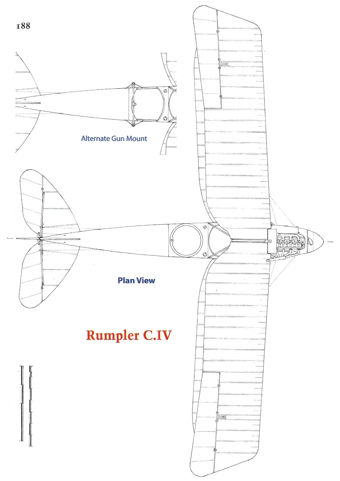
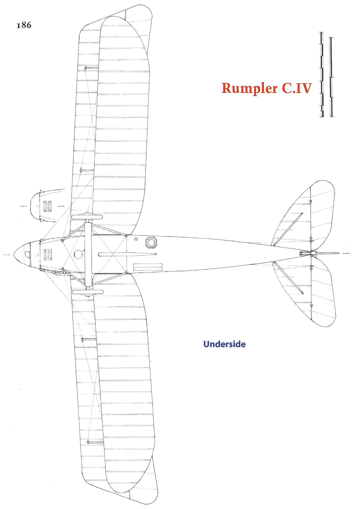
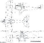
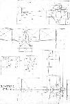
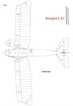
THE C.IV-TYPE RUMPLER BIPLANE. - Plan, side and front elevations to s:ale.
-
Jane's All The World Aircraft 1919 /Jane's/
Rumpler C.IV type.
-
Журнал - Flight за 1918 г.
THE 2-SEATER RUMPLER, C. 5 TYPE. - General arrangement to scale.
-

В.Кондратьев - Самолеты первой мировой войны
"Румплер" C-IV
-
-
-
В.Кондратьев Самолеты первой мировой войны
Румплер C-IV / RUMPLER C-IV
"Троек" построили довольно мало - всего 75 штук, так как уже в конце 1916-го появился еще более усовершенствованный образец - C-IV, оснащенный самым мощным из имевшихся тогда в Германии 260-сильным авиадвигателем. Он также отличался усиленной структурой планера и элеронами с роговой аэродинамической компенсацией.
C-IV выпускался в течение 1917 года на фирмах Румплер, Байру и Германия. На восточный фронт эта машина попала лишь накануне завершения боевых действий. Зато она активно использовалась во Франции, в Палестине и Северной Италии, где на "Румплерах" летали немецкие экипажи в составе австрийских ВВС. Пилоты Антанты считали скоростной и высотный C-IV одним из наиболее "трудносбиваемых" самолетов противника.
ДВИГАТЕЛЬ
"Мерседес", 260 л.с. ( C-IV)
ВООРУЖЕНИЕ
1 синхронный "Шпандау" и 1 турельный "Парабелум" (C-IV), а также - до 100 кг бомб.
ЛЕТНО-ТЕХНИЧЕСКИЕ ХАРАКТЕРИСТИКИ
C-IV
Размах, м 12,7
Длина, м 8,4
Сухой вес, кг 930
Взлетный вес, кг 1390
Скорость максимальная, км/ч 170
Время набора высоты, м/мин 2000/8
Потолок, м 6800
Описание: