
Книги
Flying Machines
P.Grosz, G.Haddow, P.Shiemer
Austro-Hungarian Army Aircraft of World War One
996
P.Grosz, G.Haddow, P.Shiemer - Austro-Hungarian Army Aircraft of World War One /Flying Machines/
Albatros D.II(Oef) Series 53
Impressed by the successful debut of the Albatros fighters on the Western Front in August 1916 and their fine handling characteristics, the LFT and industry moved with uncommon alacrity to put the Albatros D.II and D.III fighters into production in order to meet the increasing strength of the Italians and to replace the dangerous Brandenburg D.I fighter. Oeffag, having secured license rights from the German Albatros company, had production well under way when the contract was signed on 4 December 1916, calling for 50 aircraft, originally composed of 20 D.II and 30 D.III fighters.
The Oeffag-built D.II differed but slightly from its German counterpart. The engine, a 185 hp Daimler, was more powerful. The wing chord was increased by 10mm (0.4 in) and the fuselage was slightly altered. The D.II production prototype, 53.01, first flew in January 1917. The common D.II/D.III fuselages were completed in February, but assembly of the wing cellule for both was postponed until completion of the static load tests. Flight trials were delayed by the sub-zero weather and also had to await the development of a proper radiator and selection of a suitable propeller. Finally the D.II(Oef) was released by a Flars engineering commission on 4 May 1917, whereupon 16 machines (all that were built), numbered 53.01 to 53.16, were accepted and promptly dispatched to the Front. All but two aircraft were armed with one or two machine guns fitted with the Bernatzik synchronization mechanism.
The majority of the Albatros D.II(Oef) fighters were sent to the less-active Russian Front to serve with Fliks 3, 5, 7, 10, 14, 20, 22, 25, 26, and 37. The D.II was also flown by Fliks 2, 19, 35, 41/J, 42/J, and 46 on the Isonzo Front and Fliks 21, 24, and 48 in the Tirol. Although a few victories were recorded, in general the D.II(Oef) fighter served to introduce two-seater pilots to the vagaries of handling a facile, high performance aircraft. Its operational function was well described in a Flik 37/D appreciation: "...too slow, its rapid climb has little effect because Russian aircraft practically never cross the lines; therefore the D.II mainly performs escort work." By the end of 1917, the D.II(Oef) was relegated to training duties, and two were offered for sale by the Austrian government in 1920.
Albatros D.II(Oef) Series 53 Specifications
Engine: 185 Daimler
Wing: Span Upper 8.50 m (27.89 ft)
Span Lower 8.00 m (26.25 ft)
Chord Upper 1.70 m (5.58 ft)
Chord Lower 1.70 m (5.58 ft)
Dihedral Upper 0 deg
Dihedral Lower 1 deg
Sweepback Upper 0 deg
Sweepback Lower 0 deg
Gap 1.35 m (4 43 ft)
Stagger 0.12 m (0.39 ft)
Total Wing Area 24 sq m (258 sq ft)
General Length 7.35 m (24.12 ft)
Height 2.71 m (8.89 ft)
Track 1.80 m (5.91 ft)
Loaded Weight 898 kg (1980 lb)
Maximum Speed: 170 km/hr (106 mph)
Climb 1000m (3,281 ft) in 4 min 30 sec
2000m (6,562 ft) in 7 min
3000m (9,843 ft) in 12 min 30 sec
Albatros D.III(Oef) Series 53.2
Production of the Albatros D.III(Oef) had kept in step with the D.II (sharing a common fuselage, undercarriage, and tail surfaces) to enable Oeffag to switch to D.III output as soon as the static load tests of the re-designed "sequiplane" wing cellule were satisfactorily completed. Not content with the original German design, Oeffag engineers developed a stronger wing and airframe - in the process creating a tough, beautifully-built aircraft that could take increasingly more powerful engines without extensive modification. The popular Oeffag-built D.III fighter remained in production until the end of the war in three different series:
Qty Series Number Engine Order Date
34 53.20-53 185 Dm 4 December 1916
11 53.54-64 185 Dm 3 February 1917
61 153.01-61 200 Dm 3 February 1917
50 153.62-111 200 Dm 18 July 1917
100 153.112-211 200 Dm 8 October 1917
70 153.212-281 200 Dm 18 May 1918
230 253.01-230 225 Dm 18 May 1918
100 253.231-330 225 Dm August 1918
The maiden flight of the D.III(Oef) production prototype, 53.21, took place in mid-February 1917. The Flars engineering commission, after inspecting the prototype on 4 May, specified several minor modifications. Production acceptances which began on 17 May were interrupted to repeat the static load test of the wing cellule (on 26 May) as a precautionary measure triggered by reports of recurring D.III wing failures on the Western Front. The far-sighted action of Oeffag engineers was vindicated for, by refusing to copy the German wing cellule, they had made significant improvements which were outlined in an LFT report: 1) The German spars and ribs are appreciably weaker than those of the 53.2 series. 2) Ribs between the main and auxiliary spar are solid and constructed of heavier plywood. 3) Spar flange thickness is increased from 10 to 20 mm at stress points. 4) Metal reinforcing is added between the main and auxiliary spar. 5) The front auxiliary spar is prevented from twisting by a metal fixture at the fuselage juncture. The German and Oeffag-built machines were dimensionally identical, with only small variations in wingspan, gap and area. Fully loaded, the Oeffag-built D.III was heavier than the German D.III, weighing 964 kg (2126 lb) compared to the German D.Ill's weight of 912 kg (2010 lb); the difference was due to the heavier 185 hp Daimler engine. Greater power gave the D.III(Oef) series 53.2 fighter a higher rate of climb and a maximum speed of 180 km/h (112 mph), as compared with the 165 km/h of the 160 hp Mercedes-powered German fighter.
Output grew rapidly but the shortage of synchronization mechanisms, a chronic problem, forced Oeffag to manufacture precision parts to keep production moving. An enthusiastic reception met the first D.III(Oef) fighters when they reached the Front in June 1917. Finally, squadrons possessed a fighter that an average pilot could fly with relative ease and safety. By September 1917, sufficient experience had been gathered to assess the fighter's virtues and shortcomings. Although the series 53.2 and 153 were equal in speed to the Brandenburg D.I, they had a much superior rate of climb, showed excellent maneuverability and above all, were regarded as safe aircraft. Only one Flik reported lower wing vibration. At first the fighter was not fully trusted in a steep dive (nor was this recommended), but this restriction was lifted on later models. The synchronization mechanism was often unreliable, an all too common problem, and the steel-tube machine-gun supports required strengthening. A weak tail skid structure and poor quality cowling fasteners were problems quickly corrected. The 45 Albatros D.III(Oef) series 53.2 fighters were distributed among many Fliks on the Italian Front and in smaller numbers on the Russian Front. They formed the initial complement of Flik 51/J. When production ended in July 1917, the series 53.2 was replaced by the structurally identical but more-powerful D.III(Oef) series 153. With the appearance of newer fighters, the series 53.2 was used as a fighter-trainer by frontline training units.
Albatros D.III(Oef) Series 53.2 Specifications
Engine: 185 Daimler
Wing Span Upper 9.00 m (29.53 ft)
Span Lower 8.73 m (28.64 ft)
Chord Upper 1.50 m (4.92 ft)
Chord Lower 1.10 m (3.61 ft)
Dihedral Upper 0 deg
Dihedral Lower 1 deg
Sweepback Upper 0 deg
Sweepback Lower 0 deg
Gap 1.47 m (4 81 ft)
Stagger 0.22 m (0.72 ft)
Total Wing Area 20.56 sq m (221 sq ft)
General Length 7 35 m (24.12 ft)
Height 2.80 m (9.19 ft)
Track 1.80 m (5.91 ft)
Empty Weight 690 kg (1521 lb)
Loaded Weight 964 kg (1980 lb)
Maximum Speed: 180 km/hr (112 mph)
Climb: 1000m (3,281 ft) in 3 min 20 sec
3000m (9,843 ft) in 14 min 30 sec
5000m (16,405 ft) m 32 min
Albatros D.III(Oef) Series 153
As soon as it became available, the high-compression 200 hp Daimler engine was mounted in the standard production airframe and output continued under the designation Albatros D.III(Oef) series 153. Between July 1917 and June 1918 a total of 281 fighters, numbered 153.01 to 153.281, were delivered. The second production batch, starting with airframe 153.112, was designed with a rounded nose to eliminate the spinner, which was prone to fly off and damage the airframe. In addition, German wind tunnel tests had demonstrated that replacing the spinner by a simple, rounded nose improved propeller efficiency, which in this case resulted in a speed increase of some 14 km/h (9 mph). Armament consisted of two buried Schwarzlose machine guns mounted with butts projecting into the cockpit and firing through blast tubes mounted alongside the engine. The slow-firing guns and often erratic synchronization systems were universally damned by pilots, more so because the D.III was an extremely stable gun platform. When several Fliks suggested that the guns be raised to eye level, three such fighters were built by Oeffag (153.161, 153.162, 153.181) and sent to the Front for evaluation. However, raised, cowl-mounted guns were not installed on production machines until the advent of series 253 in mid-1918.
The introduction of the series 153 fighters coincided with the formation of specialized fighter squadrons, such as Fliks required performance and flight characteristics to engage in successful combat with enemy aircraft of similar type. It is the best-liked fighter at the Front." In the opinion of Offizierstellvertreter Friedrich Hefty, a Flik 42/J pilot credited with five victories, the "200 hp D.III was a superbly-designed aircraft, beautifully balanced and especially suited for aerobatics. Its rate of climb was equal to the Hanriot and the Camel, but slower in level flight than the SPAD." Every Flik lauded the D.III's all-round qualities. Not only was it robustly built and well finished (an Oeffag hallmark), but also its ease of maintenance endeared it to ground personnel. As usual the rocky airfields took their toll. In January 1918, seven Flik 55/J fighters were withdrawn for two weeks to repair rear airframe damage that occurred during take-off and landing. Oeffag raised the tail-skid support by 6 cm (2.4 in) to prevent the tail from bottoming out. Due to the temporary shortage of high-grade wing-bracing wire, some series 153 fighters were delivered in late 1917 with inferior stranded cable, which stretched to such a degree that lower wings began to vibrate in flight and allowed the wings to take on a pronounced V-form.
In January 1918, Flik 42/J, a crack unit, submitted a combat summary which stated that "enemy aircraft are encountered in flights of eight or nine machines. To attack the well-coordinated enemy with inferior numbers is a hopeless task. In doing so our squadrons suffer inevitable losses without being able to control the air. The only solution is to attack the enemy in equal numbers; only then will the effectiveness of our type 153, powered by the high-compression engine (200 hp Daimler), reach its full potential. The supply of new fighters is totally inadequate." A rough indication of the combat attrition is shown by the following statistic. In August 1918, some 142 series 153 fighters were listed in the frontline inventory; three months later, the LFT's inventory was reduced to 57 machines, of which only 12 were in flyable condition. In spite of the high losses, an important fact to remember is that in terms of victories scored, the Albatros D.III(Oef) series 153 leads the list of all Austro-Hungarian fighters. This is a tribute to the aircraft and the pilots of the specialized fighter units, especially Fliks 3/J, 41 /J, 42/J, 51/J, 55/J, 56/J, 63/J, and 68/J, who fought gallantly and held their own against great numerical odds on the Italian Front.
Albatros D.III(Oef) Series 153 Specifications (With Spinner)
Engine: 200 hp Daimler
Wing: Span Upper 9.00 m (29.53 ft)
Span Lower 8.73 m (28.64 ft)
Chord Upper 1.50 tn (4.92 ft)
Chord Lower 1.10 tn (3.61 ft)
Dihedral Upper 0 deg
Dihedral Lower 1 deg
Sweepback Upper 0 deg
Sweepback Lower 0 deg
Gap 1.47 m (4.81 ft)
Stagger 0.22 m (0.72 ft)
Total Wing Area 20.56 sq m (2.2.1 sq ft)
General: Length 7.35 m (24.12 ft)
Height 2.80 m (9.19 ft)
Track 1.80 m (5.91 ft)
Empty Weight 710 kg (1566 lb)
Loaded Weight 987 kg (2176 lb)
Maximum Speed: 188 km/hr (117 mph)
Climb: 1000m (3,281 ft) in 2 min 35 sec
2000m (6,562 ft) in 6 min 35 sec
3000m (9,843 ft) in 11 min 20 sec
4000m (13,124 ft) in 18 min 50 sec
5000m (16,405 ft) in 33 min
Albatros D.III(Oef) Series 253
On 18 May 1918, Oeffag received a contract to supply 230 Albatros D.III(Oef) series 253 fighters, numbered 253.01 to 253.230, to be powered by the improved 225 hp Daimler engine that was just entering quantity production. An additional batch of 100 series 253 fighters, numbered 253.231 to 253.330, was ordered in August with delivery scheduled to end in December 1918. Requiring only minor internal modification, the series 253 began to replace the series 153 in May 1918 and continued in production until the war ended. Counting the 30-odd machines completed after the war, Oeffag built a total of 260 series 253 fighters.
The first units to receive the new 225 hp fighter were Fliks 61/J and 63/J in mid-June 1918, whose pilots were lavish with praise. Flik 61/J labelled it as "first class and superior to any fighter." Flik 63/1 considered the new fighter as "equal to all combat requirements; it is very much liked, only the squadron does not receive sufficient numbers." By July 1918, seven fighter Fliks acclaimed the series 253 as the finest fighter they had flown. Flik 56/J reported the series 253 "meets every demand, is solid and well constructed, climbs rapidly and is preferred over the Aviatik D.I because of its peerless flight characteristics." When various LFT staff officers at the Front were asked to summarize their requirements for future planning the reply was unanimous: "Unquestionably the most maneuverable and safest fighter at the Front. It has the pilots' complete trust. Because of its excellent handling and performance, it is preferred over every other fighter. Mass production is urgent." Given full priority for materials and engines, Oeffag responded by increasing average monthly output of the series 253 by 50 percent over the series 153.
Among the 24 participants that competed in the Fighter Evaluation at Aspern in July 1918, only three were standard production machines - the Aviatik D.I 338.03 and two Albatros D.III(Oef), 253.32 and 253.35. In spite of having the highest wing loading, the Albatros fighters achieved a faster rate of climb than all other contestants with exception of the Aviatik D.I and the WKF 80.10 (D.I) prototype. Oberleutnant Benno von Fiala recommended returning the raised machine guns to the buried position (as in the earlier series) because blowing gases and oil interfered with aiming. In this connection, Flik 61/J reported that pilots flying machines with raised guns were forced to sit on two cushions to use the sights properly. At least up to aircraft 253.116, series 253 fighters left the factory armed either with buried or raised guns, apparently at random. Whether raised armament was planned as standard equipment on later production aircraft is not known.
As of 1 August 1918, sixty-six series 253 fighters were at the Front, serving primarily with Fliks 3/J, 41/J, 42/J, 51/J, 55/J, 56/J, 61/J, and 63/J. By October 1918, all but 29 of the initial production batch had been accepted. After the war, Poland purchased 38 series 253 fighters (253.212-230, 232, 234-239, 243-248, 252-254, 256, and 257). So impressed was the Polish air service that in August 1919 Oeffag received a letter of commendation, praising the engineers and mechanics for the "exceptional, diligent and thorough work" done on the series 253. Several series 253 fighters took part in Austrian Volkswehr skirmishes with the troops of the new Yugoslavian state in Karnten until fighting finally ceased in June 1919.
Albatros D.III(Oef) Series 253 Specifications
Engine: 225 hp Daimler
Wing: Span Upper 9.00 m (29.53 ft)
Span Lower 8.73 m (28.64 ft)
Chord Upper 1.50m (4.92 ft)
Chord Lower 1.10 m (3.61 ft)
Dihedral Upper 0 deg
Dihedral Lower 1 deg
Sweepback Upper 0 deg
Sweepback Lower 0 deg
Gap 1.47 m (4.81 ft)
Stagger 0.24 m (0.77 ft)
Total Wing Area 20.56 sq m (221 sq ft)
General: Length 7.43 m (24.38 ft)
Height 2.64 m (8.67 ft)
Track 1.80 m (5.91 ft)
Empty Weight 722 kg (1592 lb)
Loaded Weight 995 kg (2194 lb)
Maximum Speed: 202 km/hr (125 mph)
Climb: 1000m (3,281 ft) in 3 min 5 sec
2000m (6,562 ft) in 7 min 10 sec
3000m (9,843 ft) in 11 min 20 sec
4000m (13,124 ft) in 17 min 15 sec
5000m (16,405 ft) in 27 min

Albatros D.III(Oef) 53.24, Flieger Detachment Hauptmann Nikitsch

Albatros D.III(Oef) 153.140, Flik 51/J

Albatros D.III(Oef) 253.64, Flik 42/J

The Albatros D.II(Oef) 53.01 during flight tests in January 1917. The engine has the winter cowling installed and armament is not fitted.

Albatros D.II(Oef) 53.01 with Hauptmann Walter Lux Edler von Treurecht, CO of Flik 21/D in Pergine, June 1917. It was armed with two buried machine guns fired through blast tubes mounted alongside the engine.

Another factory photograph of Albatros D.II(Oef) 53.06 fitted with an experimental propeller for flight tests. At this stage, the aircraft was unarmed.

Albatros D.II(Oef) 53.06 photographed on the Oeffag airfield. It was flown by Flik 37/D in October-November 1917. The slanted tail-skid support differentiates the Oeffag version from the German-built D.II.
Albatros D.II 53.06 in Wr. Neustadt. Werksflugfeld, Februar 1917, aufgenommen in fabriksneuem Zustand, abweichend mit deutschem Teeves & Braun-Kühler
Albatros D.II 53.06 в Wr. Нойштадт. Заводской аэродром, февраль 1917 года, в совершенно новом состоянии, но с немецким радиатором Teeves & Braun.
Albatros D.II 53.06 in Wr. Neustadt. Werksflugfeld, Februar 1917, aufgenommen in fabriksneuem Zustand, abweichend mit deutschem Teeves & Braun-Kühler
Albatros D.II 53.06 в Wr. Нойштадт. Заводской аэродром, февраль 1917 года, в совершенно новом состоянии, но с немецким радиатором Teeves & Braun.

Albatros D.II(Oef) 53.14 with Feldwebel Franz Koudela (r) of Flik 26/D at Zastawna in August 1917. The twin blast tubes for the machine guns are mounted under the engine intake manifold. Additional engine cooling louvres have been cut in the cowling.

Albatros D.II(Oef) 53.16, the last D.II built, having its guns aligned on the Flik 7 airfield.

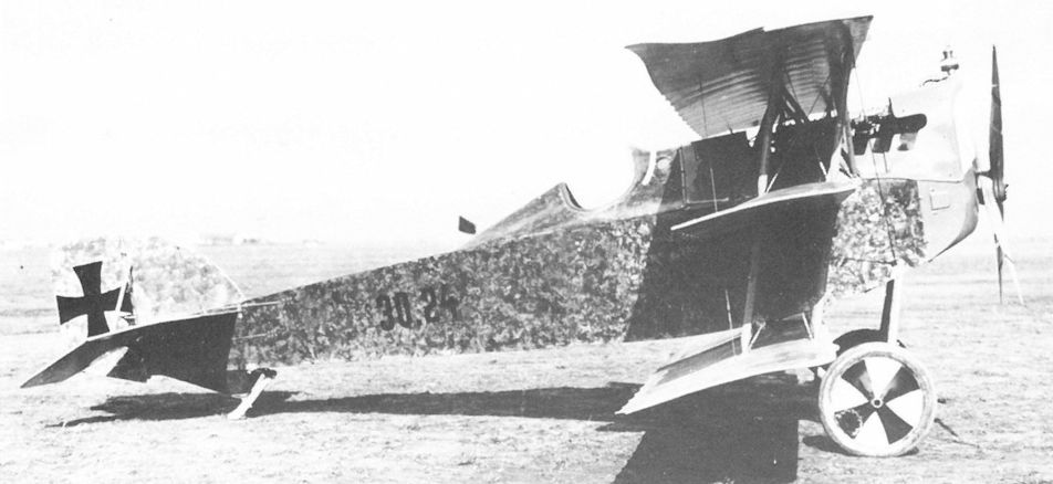
Albatros D.III(Oef) 53.24, delivered in June 1917, attained four victories while serving with Fliks 13 and 31, Fliegerdetachment Nikitsch, Flik 39/D, and Kampfstaffel Harja. In 1918 it was used as a trainer by the Feldfliegerschule at Campoformido.

Lineup of Flik 41/J during the visit of the Archduchess Maria Theresa on July 26, 1917 at Sesana; she is at the far left of the photo.
This D.I with the Buddhist good luck emblem, the swastika, was with Flik 41J when this photograph was taken despite the original caption stating it was taken at Flik 12. Albatros (Oef) 53.27 is seen in the background. This D.l was flown at times by Godwin Brumowski and test flown by Gottfried Banfield. Serial number unknown.
With few exceptions, an angled machine gun or a Type II VK gun canister comprised the armament on Brandenburg D.I fighters. Shown here are 28.65 and 28.64 (swastika insignia) of Flik 41/J in August 1917. The purpose of the flags extending from the canisters is not known, but could be an indication that the guns are armed.

Albatros D.III(Oef) 53.30 served with Flik 6 in Albania in the summer of 1917. The small Oeffag triangular logo can be seen on the nose.

A Brandenburg C.I(U) series 67 biplane with the 4th Army in Poland, summer 1917. The slim, blunt-ended Asboth propeller design was originally developed by the propeller test facility at Fischamend. In the background is an Albatros D.III(Oef) 53.32.

Non-commissioned ace Stabsfeldwebel Josef Kiss flying Albatros D.III(Oef) 53.33 over the rugged Alpine terrain which characterized much of the combat enviroment on the Italian Front.

Accepted in July 1917, the long-lived Albatros D.III(Oef) 53.50 served with Flik 17/D (August 1917 - January 1918), Flik 27/D (April-May 1918), and Flik 54/D (June 1918) until finally ending with Flik 3/J as a trainer, which may explain why the wings and tail have been painted in a bright color. The seldom-seen strut brace to the lower-wing leading edge gives evidence of the aircraft’s age.
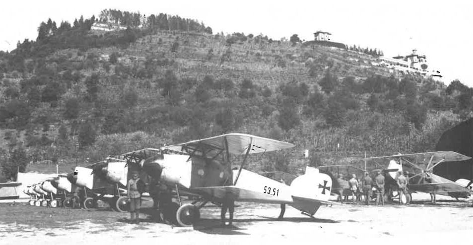
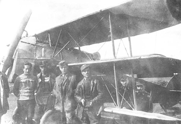
Eight Albatros D.lIl(Oef) fighters of Jagdstaffel Oberleutnant Elssler parading on the Pergine airfield awaiting Kaiser Karl's inspection on 14 September 1917. A Brandenburg D.I(Ph) series 28 fighter and two Aviatik C.I series 37 biplanes are in the second row. Villa Guila della Rosa is in the far right.

The mechanics of Flik 35/D on the airfield St Veit (Wippach) posing with aircraft 53.56. The top surfaces, tail and wheel have been camouflaged. The most noticeable differences from the German D.III are the engine, the radiator configuration, the fuselage access panels, and the slant of the tail skid support.

The twin Schwarzlose guns slanted to fire over the propeller and installed on the center section of the Albatros D.III(Oef) 53.57 was another frontline modification. Korporal Eugen Bonsch of Flik 51/J achieved his first combat victory in this aircraft on 1 September 1917.

Series 153 production deliveries were delayed until the correctly matching propeller was empirically determined by means of flight tests performed with the Albatros D.III(Oef) 153.01 prototype in June 1917. The prototype was assigned to Flek 6 as an advanced trainer. A Sottoscope is mounted front of the cockpit.

Albatros D.III(Oef) 153.24 of the Jagdstaffel Galanestie, airfield Galanestie (Bukovina) in the winter of 1917. In the cockpit is Oberleutnant Hans Fischer, commander of the Jagdstaffel.

Aircraft 153.31 on the Oeffag firing range to adjust the synchronization mechanism. The long blast tubes can be seen under the exhaust headers. A supplementary radiator provides for proper engine cooling.

By the time this Albatros D.III(Oef) 153.41 was delivered to Flik 2/D in September 1917, these machines were generally flown without the spinner. If the attachment was faulty, the spinner could separate and cause fatal damage. This aircraft, one of the few to survive the war, was listed as stored in damaged condition in March 1919.

Albatros D.III(Oef) 153.95 of Flik 2/D on the Pianzano airfield in the fall of 1917. The markings are believed to be those of Oberleutnant Fritz Losert.

Flik 59/D mechanics posing with 153.104 on the San Gaicomo airfield in early 1918. The twin machine gun blast tubes project from the fully-cowled engine.

Leutnant Otto Schrimpl of Flik 61/J with his Albatros D.III(Oef) series 153 on the airfield at Motta di Livenza in March 1918.

Beginning with aircraft 153.112, the Oeffag-built Albatros D.III fighters were delivered with a rounded nose. The experimental hexagonal camouflage was adopted from a similar German pattern. This fighter served with Flik 41/J before being assigned to the Feldfliegerschule at Campoformido.

Zugsfuhrer Eugen Bonsch of Flik 51/J was credited with five victories between March and June 1918 while flying 153.140.

Albatros D.III(Oef) 153.181 of Flik 61/J was armed with raised machine guns. Although most pilots preferred this arrangement for aiming and accessibility, some objected to the blow-back of gases, powder particles, and especially the chamber lubricating oil which hampered their vision.

Albatros D.III(Oef) 153.255 was assigned to Flik 63/J in May 1918. In the autumn of 1918, it was modified as a single-seat photo-reconnaissance fighter and served with Flik 46/P.

The unarmed Albatros D.III(Oef) 253.01 production prototype was employed for engine and propeller evaluation at Aspern. Compared to the series 153, the overall length was increased slightly and the introduction of wire trailing edges on the ailerons and elevators gave them a scalloped appearance.

Flik 56/J being dressed for combat in front of his Albatros D.III(Oef) 253.36 that has raised guns. Aircraft 253.30, in the background, has buried guns.

Korporal Geza Keisz of Flik 42/J made a successful forced landing in aircraft 253.64 after the lower-wing fabric peeled off during air combat on 28 August 1918. Owing to the aircraft shortage, Keisz used Hefty's aircraft, whose markings it carries. The swirled camouflage pattern was a printed fabric.

Albatros D.III(Oef) 253.120 being assembled at the factory. Owing to the rubber shortage, wheels with wood and steel-band “tires” were used to move the aircraft about the factory. The aircraft was flown by Zugsfuhrer Kurt Steidl of Flik 3/J when he participated in shooting down Sopwith Camel E.1498 of 66 Squadron on 7 October 1918.

A formidable lineup of seven Albatros D.III(Oef) series 253 fighters during acceptance testing at the factory. The furthest aircraft is the Oeffag 50.13 prototype.

The rather sombre Albatros D.III(Oef) 253.08 of Oberleutnant Stefan Stec of Flik 3/J. The red and white checkerboard was the insignia of Pilsudski's Polish Legion that fought on the Austro-Hungarian side. The aircraft is armed with buried machine guns.

Lacking synchronization, pilots sometimes took matters into their own hands. Stabsfeldwebel Kurt Gruber of Flik 41/J in an Albatros D.III(Oef) fighter that is armed with a Schwarzlose gun mounted on a pillar and angled to fire forward outside of the propeller arc. This arrangement was also seen on a number of two-seater machines.

The buried machine gun installation was standard on Albatros D.III(Oef) fighters until the introduction of cowl-mounted guns. Here aircraft 53.22 shows the blast tube, the perforated gun jacket, and the engine decompression handle in front of the windscreen. The synchronization mechanism was adjusted with the aid of a plywood disc mounted in front of the propeller.
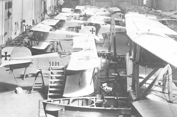
The Oeffag 50.09 prototype during final assembly in June 1917. Here it shares the large assembly hangar with the Oeffag K 423 flying boat and early production Albatros D.III(Oef) series 153 fighters.

The neat arrangement in the assembly hall reflects the craftsmanship for which Oeffag aircraft were renowned. In the far left, the Albatros D.III(Oef) 53.21 production prototype awaits propeller installation, while in the far right the D.II(Oef) 53.06 and D.III(Oef) 53.20 are nearing completion. In the foreground, Oeffag C.II series 52.5 biplanes under assembly. The date is February 1917.

One of the three Albatros D.III(Oef) series 153 fighters armed with twin raised Schwarzlose machine guns was aircraft 153.162 that was dispatched to Flik 42/J for frontline evaluation in February 1918. The altimeter on the left is supported in a shockproof mounting. In the center is the Phylax tachometer and on the right, a bank indicator.

After serving as the series 153 prototype, the Albatros D.III(Oef) 153.01 was based at Flek 6 to investigate remote-camera installation. The Sottoscope was mounted on the right side of the cockpit. The handle in the foreground is used to decompress the 200 hp Daimler engine for starting. The machine guns are mounted internally below the two cowling access doors.

Installation of a remotely-controlled camera behind the pilot's seat (removed) of an Albatros D.III(Oef) fighter. The negative-changing handle is connected to the wooden box holding the glass plate negatives. The ring opens the fuselage aperture. The camera shutter release is not yet installed. Mounted on the fuselage are a spirit level and an Oeffag plate counter. The black box on the left is for the Bordbuch (aircraft logbook).

Albatros D.III(Oef) 253.64, Flik 42/J

Albatros D.II(Oef) Series 53

Albatros D.III(Oef) Series 53.2 and 153

Albatros D.III(Oef) Series 153 (round nose) and 253
Asboth Helicopter
In late 1917, Oscar von Asboth left Fischamend to become a director of the Ungarische Luftschraubenfabrik GmbH, the former propeller manufacturing subsidiary of UFAG. At his own expense, Asboth commissioned UFAG to build a model helicopter followed by a man-carrying version based on the designs he had discussed with Balaban at Fischamend and for which he received Austrian patents 76,184 and 79,539 dated April 1917. His was a four-rotor helicopter tethered by a single cable attached to the airframe by a gimballed yoke that allowed the airframe to move about all axes. The four wooden rotors each had a diameter of 3 meters. Unfortunately, before any tests were run the model version, powered by a French 20 hp rotary engine, and the virtually completed full-sized airframe were destroyed in a fire at the UFAG factory on 9 September 1918. Five months of effort had come to naught.
In late 1917, Oscar von Asboth left Fischamend to become a director of the Ungarische Luftschraubenfabrik GmbH, the former propeller manufacturing subsidiary of UFAG. At his own expense, Asboth commissioned UFAG to build a model helicopter followed by a man-carrying version based on the designs he had discussed with Balaban at Fischamend and for which he received Austrian patents 76,184 and 79,539 dated April 1917. His was a four-rotor helicopter tethered by a single cable attached to the airframe by a gimballed yoke that allowed the airframe to move about all axes. The four wooden rotors each had a diameter of 3 meters. Unfortunately, before any tests were run the model version, powered by a French 20 hp rotary engine, and the virtually completed full-sized airframe were destroyed in a fire at the UFAG factory on 9 September 1918. Five months of effort had come to naught.

The Asboth helicopter frame with rotary engine and fuel tank installed at the UFAG factory shortly before it was destroyed by fire on 9 September 1918. Initially it had been planned to install a 230 hp in-line engine.

Asboth’s helicopter as patented on 30 April 1917. There are crew and machine-gun positions above and below the rotor plane.
Aviatik 30.14
The 30.14 prototype is significant in that it was the first fighter designed and built entirely in the Dual Monarchy. On 8 June 1916, Berg proposed to the LFT a biplane fighter powered by a 160 hp Daimler engine, armed with a fixed machine gun, and having a calculated top speed of 185 km/h (115 mph). Concurrently, Berg also proposed a light reconnaissance monoplane powered by a 120 hp Daimler engine. Neither project was approved by Flars because Aviatik was barred from engaging in prototype work in order devote full effort to the Knoller program. When Uzelac got wind of the fighter project in August 1916, he fortunately intervened to support the Aviatik proposal.
Construction of the 30.14 fighter prototype started in August. The uncovered airframe was inspected on 26 September by Flars engineers who listed various shortcomings for correction, especially strengthening the steering controls and flying surfaces. On 16 October 1916, the 30.14 stood ready for its maiden flight at Aspern. It was a clean biplane of pleasing lines, marred only by the tail assembly which appears undersized in relation to the airframe. The high center-section struts provided an unobstructed field of view. It was the first step towards the more compact D.I fighter, to which it bore an unmistakable family resemblance.
Feldwebel Ferdinand Konschel, an experienced Flars test pilot, was carefully briefed for the maiden flight. Ingenieur Julius Kolin recalled warning Konschel to exercise caution, but his counsel was shrugged off by Berg. According to Kolin's theoretical calculations, Berg's experimental airfoil could demonstrate an extreme center of pressure shift under certain flight conditions. Berg had adopted a Knoller-type airfoil whose rib section had a pronounced reflex curvature at the very narrow trailing-edge section. Although the airfoil was judged efficient for high speeds, little was known about its low speed and stall characteristics.
In the face of unpredictable wind gusts, Konschel had intended to perform only a few preparatory hops. Witnesses reported that after some 30 meters of low hops, Konschel unexpectedly lifted off - involuntarily according to some. With the engine at low rpm, he wove a wobbly flight path and executed a flat turn at 100 meters height. As Konschel throttled back to land, the prototype plunged straight into the ground. The crash protocol blamed Konschel's death on "a nose-heavy aircraft and inadequate control surfaces." The official inquest, however, attributed the crash to control-pulley failure. Nevertheless, Kolin remained certain that the center of pressure shift was the real culprit. With Knoller's assistance, Kolin designed a new airfoil for use on future Aviatik aircraft. Though beset by misfortune, the 30.14 prototype was the progenitor of the Aviatik D.I fighter that remained in service until the end of the war.
Aviatik 30.14 (Single-Seat Fighter) Specifications
Engine: 160 hp Daimler
Wing: Span Upper 8.00 m (26.25 ft)
Chord Upper 1.60 m (5.25 ft)
Chord Lower 1.50 m (4.92 ft)
General: Length 6.86 m (22.51 ft)
Loaded Weight 715 kg (1577 lb)
Aviatik 30.19, 30.20, and 30.21
On 25 September 1916, Flars approved three fighter prototypes based on the 30.14 design and incorporating some 40 improvements specified by Flars. Three prototypes, designated Aviatik 30.19 to 30.21, were built; one for flight evaluation, one for static tests, and one as a spare. Aviatik was directed to proceed with all possible speed.
Originally scheduled to start flight tests in November 1916, the 30.19 airframe inspection by Flars was delayed until 28 December, and the maiden flight took place on 24 January 1917. The Aviatik 30.19, prototype for the Aviatik D.I, here retro-fitted with a one-piece upper wing, during flight evaluation at Aspern.
LFT pilots were cleared to fly the 30.19, powered by a 185 hp Daimler engine, on 13 February. Flars test pilot Oberleutnant Oskar Fekete reported on 31 March 1917 that the 30.19 had flight characteristics similar to the Aviatik C.I but was superior all around. Fie emphasized the fighter's "fabulous climb and enormous maneuverability" and felt that any competent two-seater pilot should be able to fly the type without prior schooling. On 15 May 1917, the 30.19 prototype (retro-fitted with a one-piece upper wing) and the first production Aviatik D.I, 38.01 were dispatched to Fluggeschwader I (later renamed Flik 101/GJ on the Isonzo Front for evaluation under frontline conditions. Armed with a free-firing machine gun mounted on the upper wing, the 30.19 was flown at the Front by Hauptmann Karl Sabeditch from 18 May until July 1917, when it was badly damaged and written-off. On 23 May 1917, Sabeditch downed a Caproni bomber, thereby achieving the first victory both for himself and an Aviatik fighter aircraft (30.19).
The 30.20 prototype failed the load test on 17 March. A one-piece wing was designed to replace the two-piece upper wing and cabane center-section. As soon as the 30.20 passed the third load test on 28 April 1917, the design was released for production as the Aviatik D.I series 38 fighter. The 30.20 prototype was written-off after the load tests.
The 30.21 was used for flight trials until February 1917, when, after a minor landing mishap, the airframe was modified by Aviatik as the prototype for the Aviatik D.II and renumbered 30.22.
Aviatik 30.19 Specifications
Engine: 185 hp Daimler
Wing: Span Upper 8.00 m (26.25 ft)
Span Lower 7.84 m (25.72 ft)
Gap 1.35 m (4.43 ft)
General: Track 1.80 m (5.91 ft)
Aviatik 30.20 Specifications
Engine: 185 hp Daimler
Wing: Span Upper 8.00 m (26.25 ft)
Span Lower 7.92 m (25.98 ft)
Chord Upper 1.45 m (4.76 ft)
Chord Lower 1.30 m (4.27 ft)
Dihedral Upper 0 deg
Dihedral Lower 0 deg
Sweepback Upper 0 deg
Sweepback Lower 0 deg
Gap 1.35 m (4.43 ft)
Stagger 0.25 m (0.82 ft)
Total Wing Area 20.4 sqm ( sq ft)
General: Length 6.86 m (22.51 ft)
Height 2.50 m (8.20 ft)
Track 1.80 m (5.91 ft)
Empty Weight 734.5 kg (1620 lb)
Loaded Weight 854.5 kg (1884 lb)

Feldwebel Ferdinand Konschel posing with the Aviatik 30.14 prototype shortly before his fatal crash on 16 October 1916.
The first Austrian Aviatik fighter prototype, the 30.14 which crashed in October 1916.
The first Austrian Aviatik fighter prototype, the 30.14 which crashed in October 1916.

The Aviatik 30.19, prototype for the Aviatik D.I, here retro-fitted with a one-piece upper wing, during flight evaluation at Aspern.
Aviatik 30.19, Prototyp für Berg D.I. Aspern Mai 1917, im Juni zur Fronterprobung beim FIG I
Aviatik 30.19, прототип Berg D.I. Асперн, май 1917 г., фронтовые испытания в июне в FIG I.
Aviatik 30.19, Prototyp für Berg D.I. Aspern Mai 1917, im Juni zur Fronterprobung beim FIG I
Aviatik 30.19, прототип Berg D.I. Асперн, май 1917 г., фронтовые испытания в июне в FIG I.

The Aviatik 30.21 was slightly damaged at Aspern in the course of testing. It was subsequently rebuilt with a wireless wing cellule and redesignated 30.22, to become the prototype of the Aviatik D.II.

Aviatik 30.14
Aviatik 30.24
An Aviatik proposal for a two-seat triplane was rejected by Flars in July 1917 but development of a single-seat version continued. Drawings submitted on 17 September 1917 showed a triplane cellule fitted to a standard Aviatik D.I fuselage and tailplane. In September 1917, Aviatik received a contract to build four experimental triplane fighters to be powered by 185/200 hp Daimler engines. The first triplane fighter, designated 30.24, began flight testing in October 1917. Powered by a 185 hp Daimler engine, the Aviatik 30.24 had inferior performance compared with a similarly-engined Aviatik D.I.
The 30.24 was returned to the factory for installation of a 200 hp Daimler engine and twin machine guns. It reappeared at Aspern on 26 February 1918 for further tests that showed little improvement. The triplane was transferred to Flek 8 and then to Flek 6 in Wiener-Neustadt, where a variety of experimental radiators were installed as part of the program to improve forward view of the Aviatik fighters. 30.24 was accepted in September 1918. The remaining three prototypes (designations unknown), completed but disassembled, were accepted at the end of October 1918. The 30.24 was offered for sale to the Czechoslovakian government in April 1920.
Aviatik 30.24 Specifications
Engine: 185 hp Daimler
Wing: Span Upper 7.23 m (23.70 ft)
Span Middle 7.13 m (23.38 ft)
Span Lower 7.00 m (22.97 ft)
Gap Upper 0.85 m (2.79 ft)
Gap Lower 0.85 m (2.79 ft)
Total Wing Area 22.73 sq m (245 sq ft)
General: Length 6.25 m (20.51 ft)
Height 2.75 m (9.02 ft)
Empty Weight 730 kg (1610 lb)
Loaded Weight 900 kg (1985 lb)
Maximum Speed: 174 km/hr (108 mph)
Climb: 1000m (3,281 ft) in 2 min 40 sec
Aviatik 30.24 during flight testing at Aspern in October 1917. The fuselage and tail were adapted from the Aviatik D.I design. The lower wing is suspended below the fuselage by four small struts.
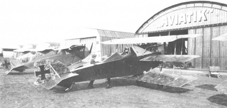
The Aviatik 30.24 in front of the company hangar at Aspern. The aerodynamically-balanced ailerons on the top wing were unique for Berg-designed fighters. Cellon panels in the middle wing enhanced the pilot’s view downward. To the left are an Aviatik D.II 39.01 and a D.I 138.17.
Fitted with a 200 hp Daimler engine, an experimental radiator and twin machine guns, the 30.24 was inspected by ace Feldwebel Josef Kiss (middle) during a visit to Aspern in 1918. The rigging wires run through the middle wing panel.
Aviatik 30.24, nach Kühlerumbau und Waffeneinbau, Erprobung in Aspern. 2. von links Feldpilot Offzstv Kiss
Авиация 30.24, после переделки радиатора и установки вооружения, испытания в Асперне. 2-й слева пилот Offzstv Kiss
Aviatik 30.24, nach Kühlerumbau und Waffeneinbau, Erprobung in Aspern. 2. von links Feldpilot Offzstv Kiss
Авиация 30.24, после переделки радиатора и установки вооружения, испытания в Асперне. 2-й слева пилот Offzstv Kiss
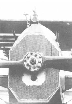
The octagonal radiator tested on the Aviatik 30.24 prototype was an attempt to improve aerodynamic characteristics.
Aviatik 30.24
Aviatik C.I (Lo) Series 114 and 214
Lohner was given a contract for 50 Aviatik C.I biplanes, drawn down from an open order for 72 aircraft signed on 27 January 1917. Work began in April. The first airframe was static tested at Aspern in July, releasing the type for delivery in August 1917. Virtually all aircraft left the factory without armament, which was installed at the Front. The contract had scheduled 24 Aviatik C.I (Lo) series 114 aircraft powered by the 185 hp Daimler engine and 26 series 214 aircraft powered by the 200 hp Daimler. However a critical shortage of the latter engine forced a change in production quantities to 32 series 114 aircraft (114.01 to 114.32) and 18 series 214 aircraft (214.01 to 214.18). Even so, eight series 214 machines were accepted without engines. In the field, aircraft 214.06, 14, 15, and 18 were fitted with used 185 hp Daimler engines.
As of October 1917, the series 114 was supplied singly to Fliks 2/D, 4/D, 8/D, 10/F, 16/D, 19/D, 23/D, 27/F, 46/D, 47/D, 49/D, 50/D, 53/D, 57/F, and 58/D, but were soon replaced by other aircraft. The series 214 formed the first equipment of Fliks 22/D, 38/D, 40/P, 49/D, and 52/D. Series 114 and 214 were flown as trainers by Fleks 6 and 8, and the Feldfliegerschule Campoformido. The Lohner-built Aviatik C.I machines did not gain the full confidence of frontline personnel. In general, the Aviatik-built version was preferred because of superior workmanship and performance. Some series 114 and 214 aircraft were modified as single-seat, photoreconnaissance fighters by covering the rear seat and replacing the observer with a sack of sand to balance the aircraft. The frontline inventory of 1 August 1918 listed eleven Aviatik C.I (Lo) series 114 and five series 214 aircraft.
Aviatik C.I(Lo) Series 114 Specifications
Engine: 185 hp Daimler
Wing: Span Upper 8.40 m |27.56 ft)
Span Lower 8.40 m (27.56 ft)
Chord Upper 1.70 m (5.58 ft)
Chord Lower 1.60m (5.25 ft)
Total Wing Area 24.8 sq m (267 sq ft)
General: Length 7.68 m (25.20 ft)
Height 2.96 m (9.71 ft)
Track 1.80 m (5.91 ft)
Empty Weight 650 kg (1433 lb)
Loaded Weight 990 kg (2183 lb)
Climb: 1000m (3,281 ft) in 3 min 50 sec
3000m (9,843 ft) in 17 min 12 sec
Aviatik C.I(Lo) Series 214 Specifications
Engine: 200 hp Daimler
Wing: Span Upper 8.40 m |27.56 ft)
Span Lower 8.40 m (27.56 ft)
Chord Upper 1.70 m (5.58 ft)
Chord Lower 1.60 m (5.25 ft)
General: Length 7.68 m (25.20 ft)
Height 2.96 m (9.71 ft)
Empty Weight 732 kg (1614 lb)
Loaded Weight 1045 kg (2304 lb)
Maximum Speed: 178 km/hr (110.5 mph)
Climb: 1000m |3,281 ft) in 3 min 46 sec
3000m (9,843 ft) in 14 min 5 sec
Aviatik 30.14 (new), 30.15, and 30.16
Based on the design experience gained with the 30.14 prototype, Aviatik engineers proposed an improved fighter (30.19) and a derivative two-seat biplane. On 26 September 1916, Flars ordered three, two-seat prototypes numbered 30.14, 30.15, and 30.16. (After the destruction of the 30.14 fighter, the number was re-assigned). The 30.14 reconnaissance prototype, powered by a 185 hp Daimler engine, came to Aspern for flight tests on 26 November. It was similar to the production version (designated C.I) except that the upper wing consisted of two panels and a separate center section. Details regarding the flight trials are lacking but the severe 1917 winter certainly retarded progress. On 9 February 1917, the 30.14 broke its back in a collision with a trainer on the ground. A new fuselage was provided. When Uzelac flew the machine on 22 February, he was impressed by "its fighter-like handling characteristics" and instructed Flars to push the development program with all possible speed.
Construction of the 30.15 prototype began in October 1916 and it appeared at Aspern in January 1917. The overall flight performance was reported excellent. The fuselage was damaged on 23 January when the tail skid collapsed while landing. Aviatik chief pilot, Stabsfeldwebel Fritz Wurbel was unable to fly the repaired machine on 10 February because it had been sabotaged. The elevator had been incorrectly wired and the tires slashed. The 30.15 was released for evaluation by Flars pilots on 13 February 1917.
During the first load test on 22 February, the rear spar of the third prototype, 30.16, collapsed at a 3.7 load factor. A strengthened wing, tested on 5 March, again failed. The upper wing, re-designed as a single structure, was tested on 23 March 1917 with satisfactory results.
On 29 April 1917, Uzelac demanded top priority to bring the promising two-seater, now designated C.l, into production. The 30.15 and 30.16 prototypes were repaired, brought up to production standard, and entered LFT service under the designations Aviatik C.l 37.02 and 37.03. Some sources claim that prototype 30.14 became 37.01, but this is inconsistent with the fact that the 30.14 prototype was written-off on 21 March 1918 as was the 37.01 on 22 April 1918.
Aviatik 30.15 Specifications
Engine: 185 hp Daimler
Wing: Span Upper 8.40 m (27.56 ft)
Chord Upper 1.75 m (5.74 ft)
General: Length 6.83 m (22.41 ft)
Track 1.80 m (5.91 ft)
Aviatik C.I Series 37 and 137
According to Graf Sternberg, if Berg's two-seater proposal of 8 June 1916 had been given priority instead of the Knoller program, the Aviatik C.I could have been operational in the autumn of 1916 and not, as it happened, a year later. Only after Uzelac's intervention in August 1916 was Aviatik allowed to proceed with construction of three C.I prototypes (30.14-30.16). When these were test flown, there was little doubt that Aviatik had produced a very fine aircraft.
In March 1917, Flars ordered 96 Aviatik C.I aircraft (including three prototypes 37.01-37.03 (ex-30.15, 30.16, and possibly 30.14 new) and four pre-production machines for evaluation (37.04-37.07, delivered in March and April 1917). Provided the tests were successful, Aviatik was to deliver 49 C.I series 37, numbered 37.08 to 37.56, powered by a 185 hp Daimler engine and 40 C.I series 137, numbered 137.01 to 137.40, powered by a 200 hp Daimler engine. Oberleutnant Oskar Fekete, an expert test pilot who flew the pre-production 37.04 under ideal conditions at Wiener-Neustadt, wrote on 31 March 1917:
An exceedingly easy-to-fly machine. Stability in all axes very good. Reacts fully to the rudder. Very good climb rate and great speed. Glide flat and pleasant. Landing easy. View in all directions very good. An ideal observation type, suited to mountainous terrain and small airfields.
On 29 April 1917, Uzelac requested top priority for the C.I and prepared for license manufacture at Lohner, Lloyd, MAG, and WKF that raised the production total to 255 C.I aircraft.
Prior to general squadron release, a few machines were assigned to Flek 6 for instructional purposes and to Flik 19 for frontline evaluation. Flik 19 soon reported structural problems (12 May 1917), causing Uzelac to halt production and ground the C.I biplanes for inspection and modification. The structural report issued on 11 July 1917 specified strengthening the engine bearers, aileron supports, center-section struts, tail skid, control surfaces, wing leading edges, and lower-wing attachment fixtures. Given the added weight of the modifications, the C.I failed to achieve the contractual climb rate, but the penalty was waived since the required speed was exceeded. When the Aviatik C.I appeared at the Front in August 1917, aircrew reaction was unexpectedly negative. Both Flik 23 and 46 found the C.I unsatisfactory because of the fragile airframe and sloppy workmanship. Flik 46, perceiving the C.I "impossible as a two-seater," changed 37.46 into a single-seat fighter by installing twin synchronized machine guns, decking over the rear cockpit and removing 30 kg (66 lb) surplus equipment. The C.I single-seat conversion, especially the photo-reconnaissance version, was to become very popular in 1918.
Unfavorable assessments continued. In October 1917, Flik 32 reported the C.I as unsuitable for photo work because aircraft instability caused photos to blur. Complaints were received about the cramped observer's cockpit and the inability to carry cameras larger than 30cm focal length. Flik 34 wrote in October 1917 that the C.I, greeted with high hopes because of its performance, was soon grounded because of structural problems. Even after strengthening, the squadron "had little confidence in the type." To place these statements into the proper perspective, it must be remembered that pilots, accustomed to flying heavy, stable aircraft such as the Brandenburg C.I, found the sensitivity of the Aviatik C.I strange and disconcerting. With time frontline personnel came to appreciate its qualities. Pilot Philipp Vacano recalled that "the C.I was light on the controls and had to be flown with a certain touch. Unfortunately, not every pilot had it. The C.I responded to small gusts and even the motion of an observer swinging the machine gun would induce oscillations." Max Hesse, in his memoirs, reckoned the C.I was "suitable only for daredevils." The wheel control was cumbersome but a stick control was never fitted. The unusual rudder pedals - similar to automobile pedals - prompted so much criticism that they were replaced by a customary rudder bar beginning with aircraft 37.25.
Armament consisted of a fixed machine gun mounted on the center-section, firing at a 15 degree angle over the propeller, and a gun for the observer. In general, the machine guns were not installed at the factory due to the shortage of guns and interrupter mechanisms. In June 1917, aircraft 37.21 was sent to Fischamend for installation of a wooden rotating turret that became production standard beginning with aircraft 37.49. Aircraft 37.13 was tested with twin, forward-firing machine guns.
The Aviatik C.I series 37 saw operational service on the Italian Front, where it was assigned to Fliks 17/D, 21/D, 24/F, and 48/D in the South Tirol and to Fliks 2/D, 5/D, 12/Rb, 19/D, 22/D, 23/D, 32, 34/D, 35/D, 46/P, and 58/D on the Isonzo Front. In the spring of 1918, the C.I series 37 was slowly being replaced by aircraft of greater range, durability, and load-carrying ability.
Aviatik C.I Series 37 Specifications
Engine: 185 hp Daimler
Wing: Span Upper 8.40 m (27.56 ft)
Span Lower 8.25 m (27.07 ft)
Chord Upper 1.70 m (5.58 ft)
Chord Lower 1.70 m (5.58 ft)
Sweepback Upper 0 deg
Sweepback Lower 0 deg
Gap 1.52 m (4.99 ft)
Stagger 0.36 m (1.18 ft)
Total Wing Area 24.8 sq m (267 sq ft)
General: Length 6.86 m (22.51 ft)
Height 2.26 m (7.41 ft)
Track 1.80 m (5.91 ft)
Empty Weight 653 kg (1440 lb)
Loaded Weight 976 kg (2152 lb)
Maximum Speed: 178 km/hr (111 mph)
Climb: 1000m (3,281 ft) in 3 min 52 sec
Aviatik C.I Series 137
After aircraft 37.01 was evaluated with a 200 hp Hiero engine, the engine was replaced by a 200 hp Daimler in June 1917. As such the 37.01 became the prototype for the Aviatik C.I series 137. Acceptances began in September 1917 and ran concurrent with the series 37 until June 1918, when the last of 40 C.I series 137 aircraft was accepted. Because fighters were given priority for the 200 hp Daimler engine, most of the series 137 machines were delivered with rebuilt 185 hp Daimler engines, and 13 left the factory without engines due to the engine shortage.
When the Aviatik C.I series 137 biplanes arrived at the Front in November 1917, aircrews appreciated the good performance but criticized the shoddy workmanship. Such a lightly-designed aircraft required materials and a level of craftsmanship that Aviatik seemed unable to meet. The rocky airfields encountered on the Italian Front played havoc with the airframe, particularly the plywood-covered fuselage. Responding to aircrew complaints, the fuselage of 137.32 was load tested on 5 January 1918 and corrective measures taken. As a two-seater, the C.I series 137 saw operational service with Fliks 5/D, 17/D, 21/D, 23/D, 27/D, 39/D, 47/D, 49/F, 50/D, 53/D, 58/D, 59/D, and 73/D.
Aviatik C.I Single-Seat Conversion
The fact that Flik 23 and 46/F had obtained good results with the single-seat fighter conversion of the C.I did not escape the attention of the LFT. With only one crew member aboard, the C.I was judged equal to the Aviatik D.I. By converting the C.I, Fliks were able to provide their own fighter protection when none was available from fighter units or supply parks. The single-seat photo-reconnaissance fighter could penetrate enemy airspace and, if intercepted, engage Allied fighters on near-equal terms. Conversion was easy. The machine gun ring was removed and correct ballast placed in the enclosed observer's cockpit. For photographic missions, a 50 or 70cm (20-28 in) focal-length camera was installed, provided with a remote plate-changing device actuated by the pilot. At least 16 C.I series 37 (37.09, 13, 17, 22, 23, 27, 34, 35, 36, 43, 44, 45, 46, 48, and 54) and 12 series 137 (137.02, 04, 14, 20, 21, 26, 28, 30, 31, 35, 36, and 37) were converted to photoreconnaissance fighters in 1917-1918.
On 12 July 1918, the LFT restricted the Aviatik C.I to the single-seat photo-reconnaissance role or to training duties at Fliks for advanced fighter instruction. The Aviatik C.I had arrived too late and was too failure-prone to achieve its full potential as an all-round reconnaissance aircraft. But as a photo-reconnaissance fighter, the C.I, especially the more reliable license machines, served admirably until the war's end.
Aviatik C.I License Production
The success of the Aviatik C.I led Flars to place license-production orders with Lloyd, Lohner, MAG and WKF for a total of 255 aircraft. The individual series are covered in detail in the appropriate chapters:
Company Series No. Engine Number Ordered Number at Front on 1 August 1918
Lohner 114.01-32 185 Dm 32 11
Lohner 214.01-18 200 Dm 18 5
Aviatik 37.01-56 185 Dm 56 25
Aviatik 137.01-40 200 Dm 40 13
Lloyd 47.01-45 185 Dm(MAG) 45 26
WKF 83.01-40 185 Dm 40 25
MAG 91.01-24 185 Dm(MAG) 24 24
Total 255 129
Aviatik C.I(Ll) Series 47
In April 1917, Lloyd was ordered to prepare for the license production of 45 Aviatik C.I reconnaissance biplanes as part of a contract for 96 aircraft signed on 18 January 1917. Parts assembly began in May and the first Aviatik C.I (Lloyd Type JR) left the factory in September 1917. The Aviatik C.I(Ll) were numbered 47.01 to 47.45 and powered by re-built 185 hp Daimler(MAG) engines.
In November 1917, Lloyd was directed to convert all Aviatik C.I(Ll) biplanes to single-seat fighters and 40 of these were to have photo-reconnaissance equipment installed. Owing to severe supply shortages, all aircraft were accepted unarmed and only 16 (aircraft 47.04, 47.06, 47.07, 47.09-47.13, 47.15, 47.19-47.23, 47.38, and 47.40) had photo equipment installed. Thirteen aircraft were delivered without engines. As it was customary to retain the observer's gun ring, aircraft 47.01 to 47.18 were fitted with a tubing mount and the remainder with a wooden-ring mount.
Not all Aviatik C.I(Ll) biplanes reached the Front. The April 1918 frontline status report listed 27 C.I series 47 aircraft, of which 11 lacked engines. The Lloyd-built C.I was employed as a fighter by Flik 101/G and as a two-seat reconnaissance machine or photo single-seater by Fliks 17/D, 24/F, and 39/D. Powered by re-built, worn-out engines, the performance had diminished accordingly; consequently in July 1918, the C.I(Ll) series 47 was restricted to training use, of which 24 were on charge as of October 1918. Seventeen Aviatik C.I(Ll) biplanes were offered for sale to Czechoslovakia in April 1920.
Aviatik C.I(Ll) Series 47 Specifications
Engine: 185 hp Daimler (MAG)
Wing: Span Upper 8.40 m (27.56 ft)
Span Lower 8.30 m (27.23 ft)
Chord Upper 1.70 m (5.58 ft)
Chord Lower 1.65 m (5.41 ft)
Sweepback Lower 1 deg
Gap 1.55 m (5.09 ft)
Stagger 0.36 m (1.18 ft)
Total Wing Area 24 sq m (258 sq ft)
General: Length 7.15 m (23.46 ft)
Height 2.60 m (8.53 ft)
Empty Weight 670 kg (1477 lb)
Loaded Weight 1016 kg (2240 lb)
Maximum Speed: 170 km/hr (106 mph)
Climb: 1000m (3,281 ft) in 4 min 30 sec
2000m (6,562 ft) in 9 min 15 sec
3000m (9,843 ft) in 17 min 50 sec
Aviatik C.I(WKF) Series 83
To follow the Knoller and Lloyd production, Flars signed an open contract on 18 January 1917, for 72 Aviatik biplanes and in April specified the initial production batch to consist of 16 Aviatik C.I(WKF) series 83 powered by the 185 hp Daimler engine and 24 series 183 powered by the 200 hp Daimler engine. Due to the shortage of 200 hp engines, the series 183 airframes under construction were fitted with 185 hp engines and redesignated accordingly. Consequently, WKF delivered a total of 40 Aviatik C.I(WKF), numbered 83.01 to 83.40. WKF was scheduled to begin deliveries in June 1917 with production ending in October. The first aircraft, 83.01, was commissioned on 27 June 1917 but acceptances were delayed to allow structural modifications (same as specified for the Aviatik C.I series 37 in July) to be incorporated by WKF, which may be one reason why the C.I(WKF) acceptances did not begin until February 1918. By then, frontline experience had demonstrated the value of the Aviatik C.I in the single-seat photo-reconnaissance role. In March 1918, forty single-seat conversion kits for the WKF-built C.I were ordered and about twelve aircraft were so modified in the factory. As a result of chronic shortages, many series 83 aircraft were accepted less engine and armament. It was planned to install these in the field. About half the aircraft were armed with a forward-firing synchronized machine gun and a few were armed with the Type II VK gun canister mounted on the upper wing. All machines were provided with a standard observer machine-gun ring.
The Aviatik C.I(WKF) saw only limited operational service. Seven series 83 were attached to newly-formed Flik 73/D in mid-1918. Although one was lost in combat, the lack of suitable flight personnel, plus rough airfield conditions which damaged many aircraft, led to the type being supplanted by the more rugged Brandenburg C.I. One each of series 83 aircraft was assigned to Fliks 17/D, 23/D, and 27/F for use as a trainer in preparation for arrival of the UFAG C.I. Of the 25 C.I(WKF) biplanes in the field as of 1 April 1918, most appear to have fulfilled an advanced trainer requirement.
On 31 October 1918, eleven C.I(WKF) series 83 biplanes were in storage and in 1920 two were offered for sale to Czechoslovakia.
Aviatik C.I(MAG) Series 91
In April 1917, MAG received a letter of intent to build 96 Aviatik C.I and D.I aircraft. The contract was signed on 17 July 1917. The planned production total of 50 Aviatik C.I(MAG) biplanes, powered by the 200 hp Daimler(MAG) engine, was reduced to 24 (numbered 91.01 to 91.24) on 9 October 1917. Delivery was scheduled between 2 and 30 March 1918. The first factory flight (aircraft 91.06) was performed by Antal Feher on 16 February 1918, and military acceptances were completed almost on schedule in April. Aircraft 91.01-91.03, 91.05, 91.09, and 91.10 were delivered as single-seat photo-reconnaissance aircraft. All aircraft were accepted less armament, and aircraft 91.05-91.09 and 91.15-91.19 were delivered without engines.
In March 1918, the Aviatik C.I(MAG) biplanes were ordered sent to the 6th Army on the Piave Front. Aircraft 91.23 and 91.24 were damaged in transit. There is no record of any frontline employment; rather, on 17 August 1918, aircraft 91.01-91.22 were scheduled for modification into dual-control trainers and dispatched for conversion to the Al-Ma factory in Prag in October. In the postwar strife at least three aircraft, 91.16, 91.17, and 91.18, were used by the 3rd Squadron of the Hungarian Red Airborne Corps.
Aviatik C.I(MAG) Series 91 Specifications
Engine: 200 hp Daimler (MAG)
Wing: Span Upper 8.40 m (27.56 ft)
Span Lower 8.40 m (27.56 ft)
Chord Upper 1.70 m (5.58 ft)
Chord Lower 1.65 m (5.41 ft)
Gap 1.53 m (5.02 ft)
Stagger 0.36 m (1.18 ft)
Total Wing Area 25.7 sq m (277 sq ft)
General: Length 6.86 m (22.51 ft)
Loaded Weight 1067 kg (2353 lb)
Maximum Speed: 175 km/hr (109 mph)
Climb: 1000m (3,281 ft) in 3 min 38 sec
3000m (9,843 ft) in 15 min 45 sec
5000m (16,405 ft) in 33 min 40 sec
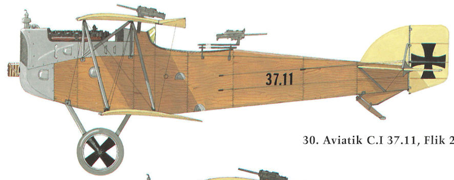
Aviatik C.I 37.11, Flik 23
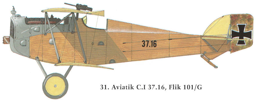
Aviatik C.I 37.16, Flik 101/G
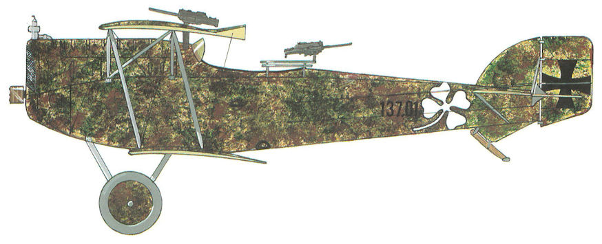
Aviatik C.I 137.01, Flik 50/D
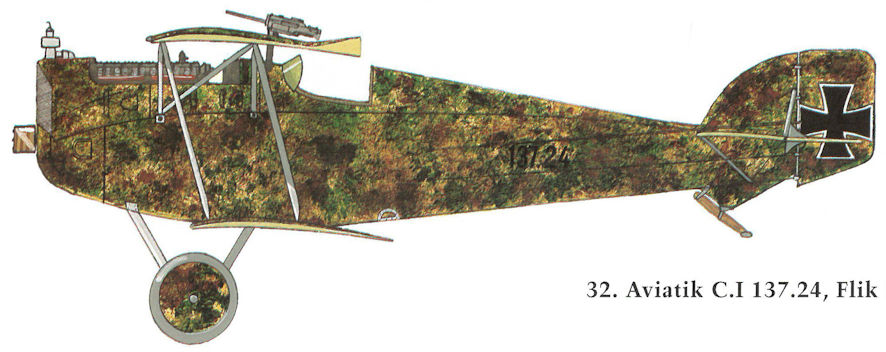
Aviatik C.I 137.24, Flik 21/D
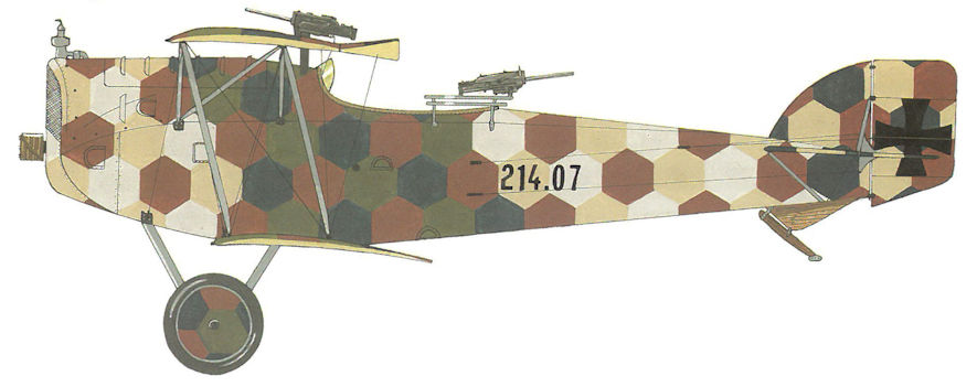
Aviatik C.I(Lo) 214.07, Flik 22/D
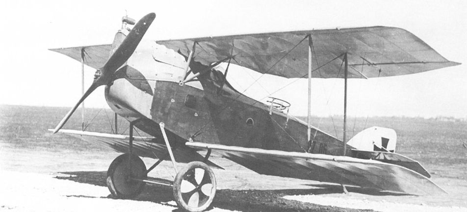
The Aviatik C.I 37.06, one of the four pre-production machines, photographed at Aspern during flight testing in April-May 1917.
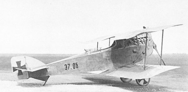
Compared to the final production version, the Aviatik C.I 37.06 had a slightly smaller fin and rudder. The C.I was powered by a 185 hp Daimler engine.
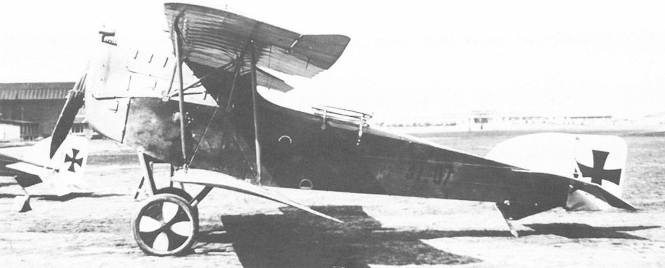
Seen here at Aspern in May 1917, the last pre-production Aviatik C.I 37.07 also was fitted with a modified fin and rudder. Barely visible is the Type II VK gun canister mounted on the upper wing for flight tests.
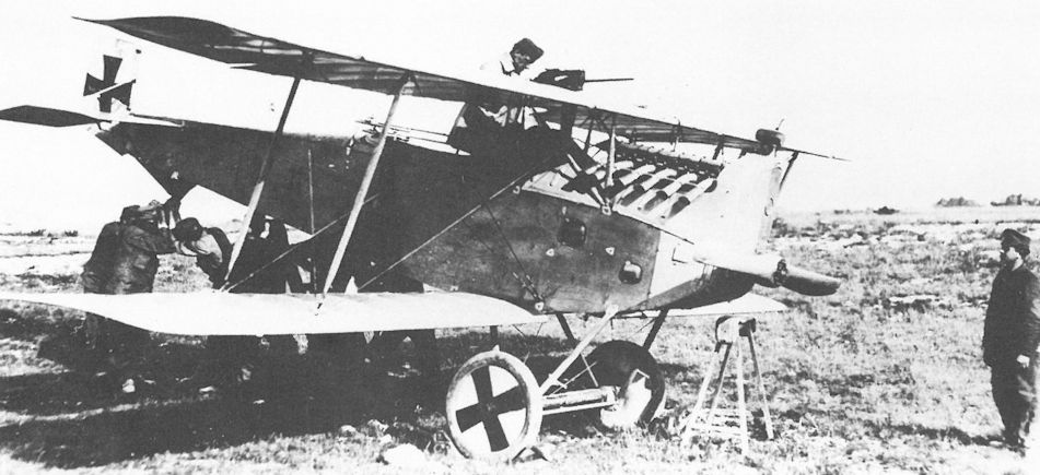
With few exceptions, the forward armament consisted of a free-firing machine gun mounted on the top wing and firing at a 15 degree angle over the propeller. Here the Schwarzlose gun of Aviatik C.I 37.11 is being adjusted.
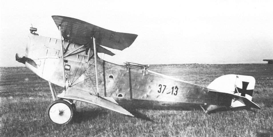
Had the Knoller episode not occurred, it is possible the Aviatik C.I would have arrived at the Front in 1916, rather than mid-1917. Aviatik C.I 37.13 was one of the early production machines.
Aviatik-Berg C.I 37.13 in Aspern, Erprobung, Serienausführung
Aviatik-Berg C.I 37.13 в Асперн, испытания, серийное производство
Aviatik-Berg C.I 37.13 in Aspern, Erprobung, Serienausführung
Aviatik-Berg C.I 37.13 в Асперн, испытания, серийное производство
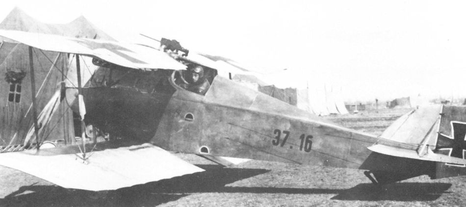
The two-seat Aviatik C.I 37.16 configured as a single-seat fighter by decking over the observer's position. Many of the C.I machines converted to photo fighters would have looked like this. Originally the aircraft was supplied to Flik 48 on 30 June 1917. It was attached to Flik 101/G in March 1918 as an escort fighter.
Eight Albatros D.lIl(Oef) fighters of Jagdstaffel Oberleutnant Elssler parading on the Pergine airfield awaiting Kaiser Karl's inspection on 14 September 1917. A Brandenburg D.I(Ph) series 28 fighter and two Aviatik C.I series 37 biplanes are in the second row. Villa Guila della Rosa is in the far right.
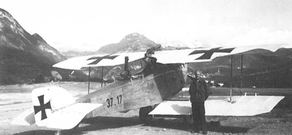
In beautiful surroundings, Aviatik C.I 37.17 of Flik 48/D was photographed with full armament in the autumn of 1917. It was flown as a singleseat photo-reconnaissance aircraft by Flik 46/P in March 1918.
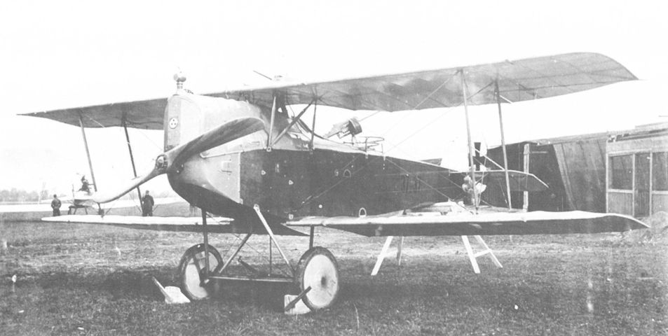
Aviatik C.I 37.37 was operational with Fliks 5/D, 35/D, and 49/D between February and May 1918. In September 1918 it was at Al-Ma factory in Prague for repair.
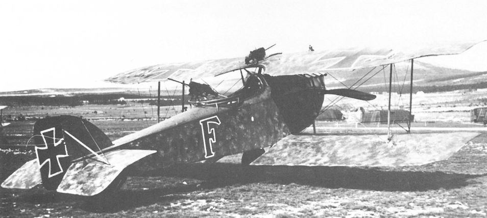
Sporting full camouflage and unit insignia, Aviatik C.I 37.47 was attached to Flik 46/P at Prosecco from September 1917 to May 1918. The tail fin has been reinforced with wire bracing.
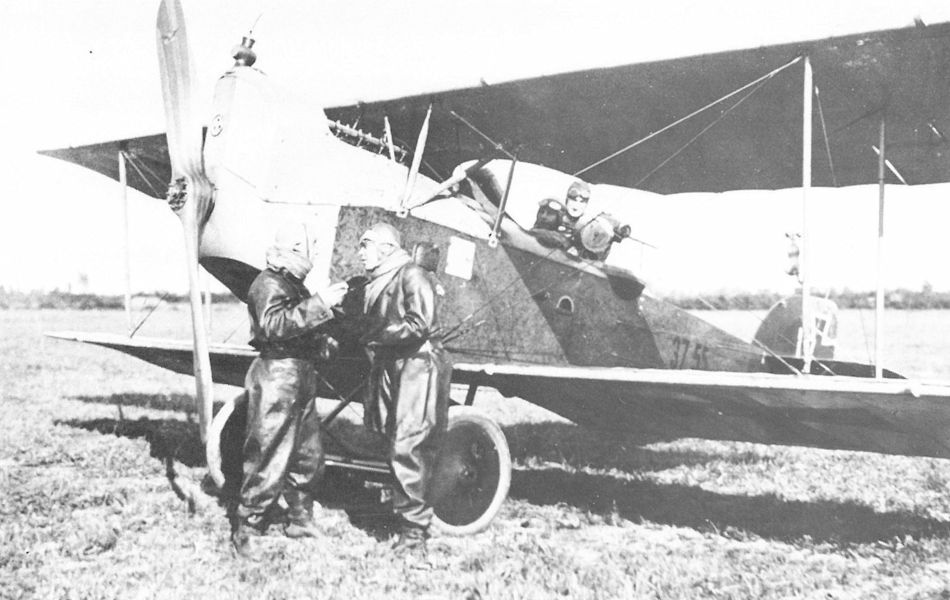
Beginning with aircraft 37.49, a wooden ring turret was installed on production aircraft, shown here on Aviatik C.I 37.55 of Flik 22/D in May-June 1918. The additional drag cable running between the upper wing strut and lower engine cowling was a modification found on some late production aircraft.
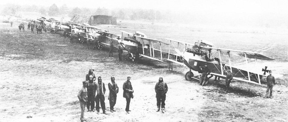
A medley of aircraft flown by Flik 23/D at Divacca on the Isonzo Front in mid-1917, headed by a Brandenburg C.I(U) 69.57, followed by a Brandenburg C.I(U) 129.46, an Aviatik C.I series 37, and four Brandenburg C.I biplanes flanking a Brandenburg D.I fighter.

Aircrew of Flik 50/D preparing for takeoff in Aviatik C.I 137.01 at San Martino on 17 May 1918. The fixed machine gun is a Schwarzlose M 7/12, the observer’s an M 16.
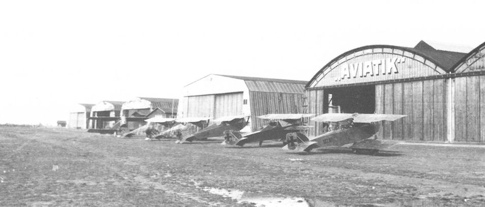
The Aviatik hangar at Aspern provides a perfect backdrop for seven Aviatik aircraft undergoing flight and acceptance testing in the autumn of 1917. From the right are C.I 137.07, 30.24, 39.01, two D.I series 138, and a C.I.

An Aviatik C.I series 137 aircraft sporting a four-bladed propeller, a sure sign that it was powered by a 200 hp Daimler engine. The wooden gun ring was installed on all C.I series 137 aircraft beginning with machine 137.19.
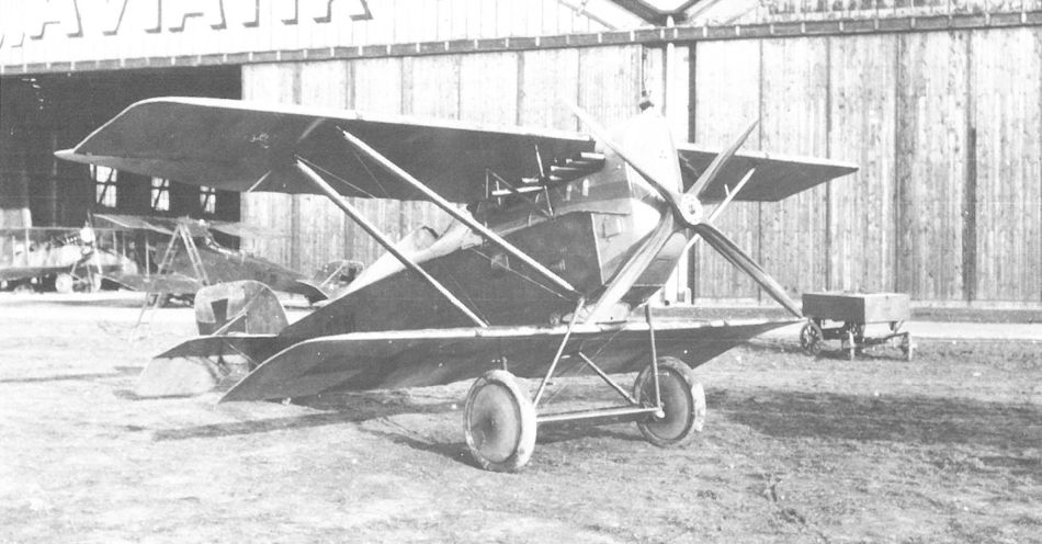
The unarmed Aviatik D.II 39.01 in front of the Aviatik hangars at Aspern in the fall of 1917. The four-bladed propeller was usually matched with a 200 hp Daimler engine. Behind the tail is Aviatik C.I 137.15.
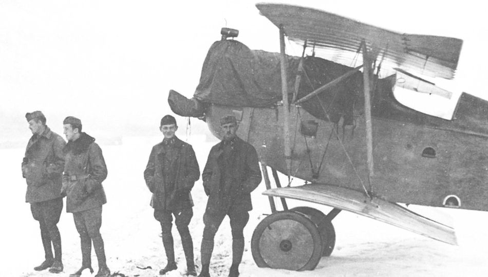
Personnel of Flik 101/G posing with the Aviatik C.I 137.20 escort fighter. It was delivered in October 1917 to Flep 3 in Trient where it was converted to a single-seat fighter. It was armed with a single, wing-mounted Schwarzlose M 16 machine gun.
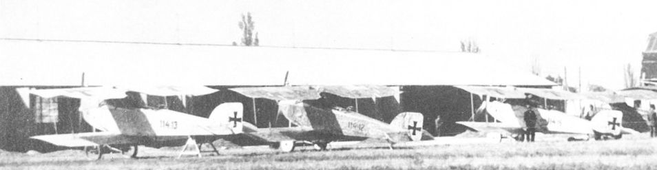
The Aviatik C.I (Lo) 114.13, 114.12, and 114.15 at Aspern undergoing acceptance testing. Forward armament, installed at the Front, consisted of a single, synchronized Schwarzlose machine gun or a Type II VK gun canister on the upper wing.
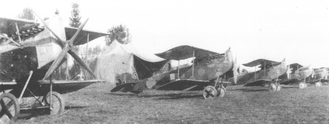
The Aviatik C.I (Lo) 214.03 (middle) of Flik 46/P on the Cinto Caomaggiore airfield in May 1918. A four-bladed propeller (left) was often fitted to Aviatik C.I machines powered by the 200 hp Daimler engine.
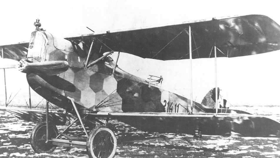
This Aviatik C.I(Lo) 214.11 was placed in service with a 185 hp Daimler engine instead of the 200 hp engine as planned. The machine was attached to Flik 49/D in May 1918 and written off at the field flying school in Campoformido in June. The barrel of the wing-mounted Schwarzlose gun is just visible.
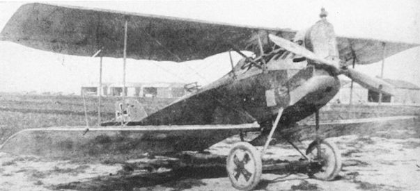
The Aviatik C.I(WKF) 83.03 on the Aspern airfield in early 1918.
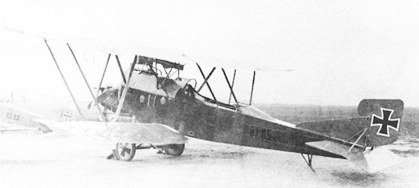
The Knoller C.II(WKF) 81.05. The large, single-piece celluloid windscreen was a WKF characteristic. In the background is the Aviatik C.I(WKF) 83.03 undergoing flight trials.
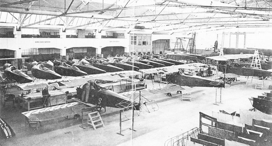
An Aviatik C.I(WKF) 183.07 (center), Knoller C.II(WKF) 81.06 (right) and at least 26 Aviatik C.I biplanes, including 83.13 and 83.07, being assembled in the modern WKF factory in the spring of 1918.
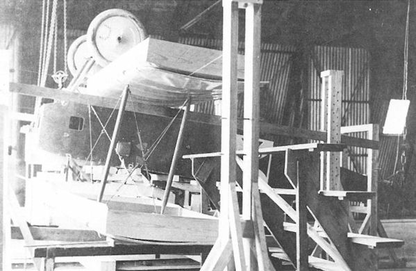
The square boxes on the wing surfaces held sand for load testing of the Aviatik 30.16 in February-March 1917. Later brought up to production standard, the aircraft was redesignated Aviatik C.I 37.03.
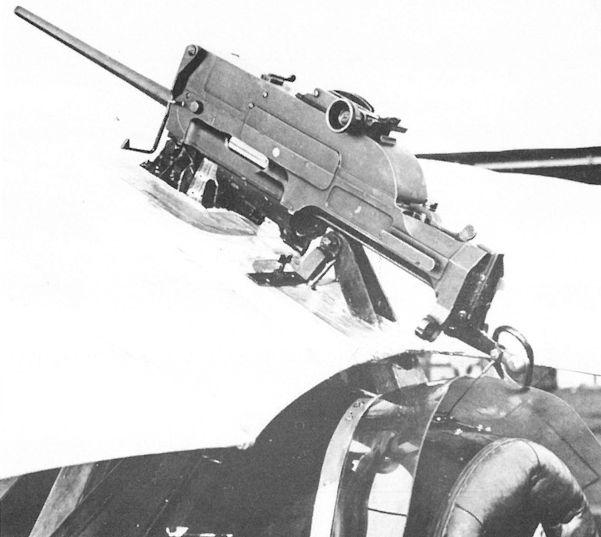
Developed strictly as an airborne weapon, the Schwarzlose M 16 machine gun mounted on the top wing of an Aviatik C.I 137.20 converted to a single-seat fighter by Fluggeschwader I (Flik 101/G). A thin cable is attached to the trigger mechanism and the cocking handle can be seen above the windscreen. A corn and V-sight is mounted on the left side.
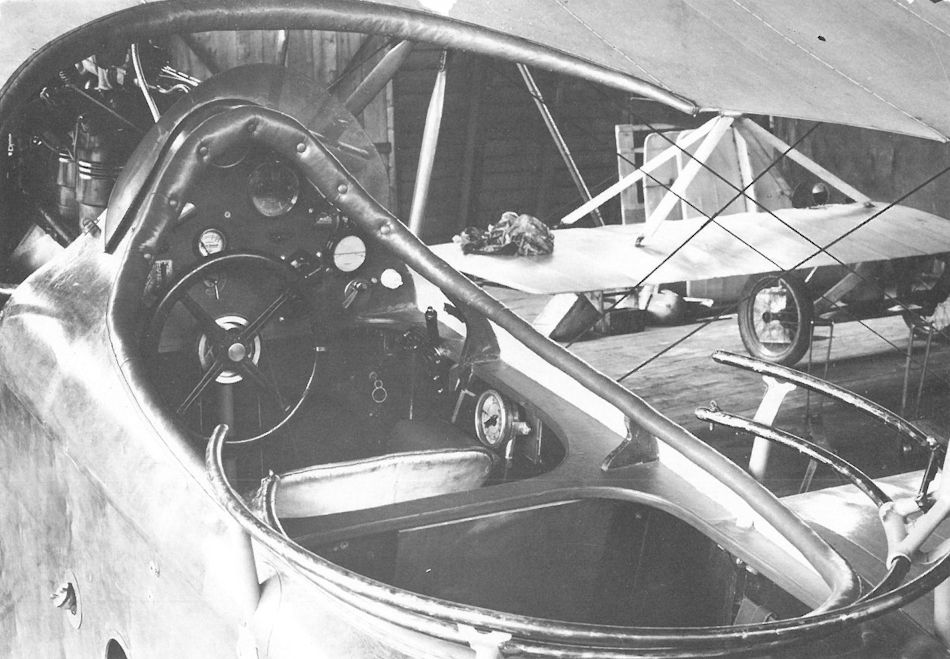
The well-padded cockpit of the Aviatik C.I (37.07?) reveals the control wheel, flight instruments, and engine throttle. On the fuselage side are the fuel inlet cap and entry step.
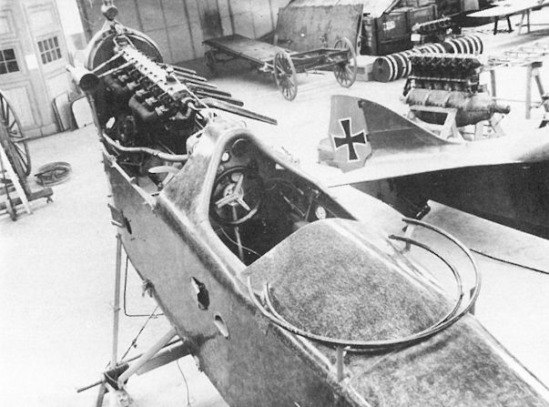
An Aviatik C.I(WKF) converted to a photo-reconnaissance fighter at the WKF factory. The rear cockpit has been faired over, but the gun ring has been retained for re-conversion to a two seater if required. According to some reports, the gun ring fooled Allied fighter pilots into believing the aircraft was a two seater. In the background is the beautifully-faired tail of the WKF 80.04 prototype.
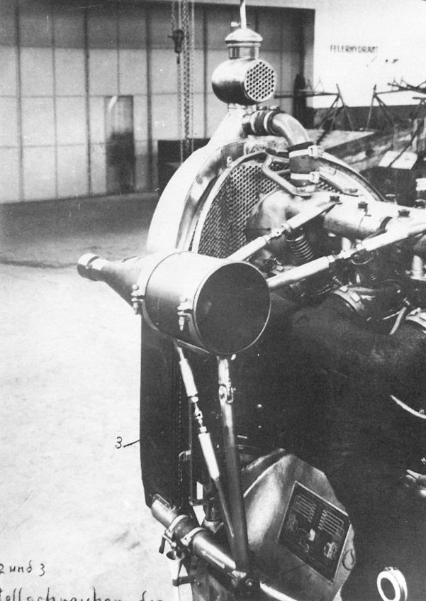
A close-up view of the Sottoscope mounted on the engine and radiator support of the same Aviatik C.I(WKF) photo-fighter conversion.

The Aviatik 30.14 prototype (new) after colliding with the Brandenburg B.I 05.26 on 9 February 1917. 30.14 has the original two-piece upper wing and center section cabane. The balanced rudder differed from the production C.I.
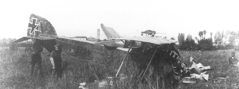
Photographs of the two-seater conversions in operational service are rare. The raised, streamlined deck covering the rear cockpit has been dislodged by the crash of Aviatik C.I 37.54 converted to a photo single seater. Attached to Flik 46/P, this aircraft was written off on 21 September 1918.
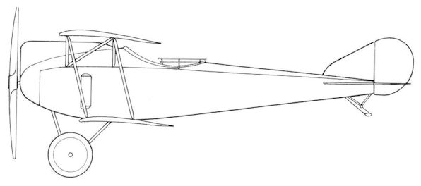
Dated 3 November 1916, this factory drawing shows the Aviatik 30.15, one of the three C.I prototypes, in its original design configuration.
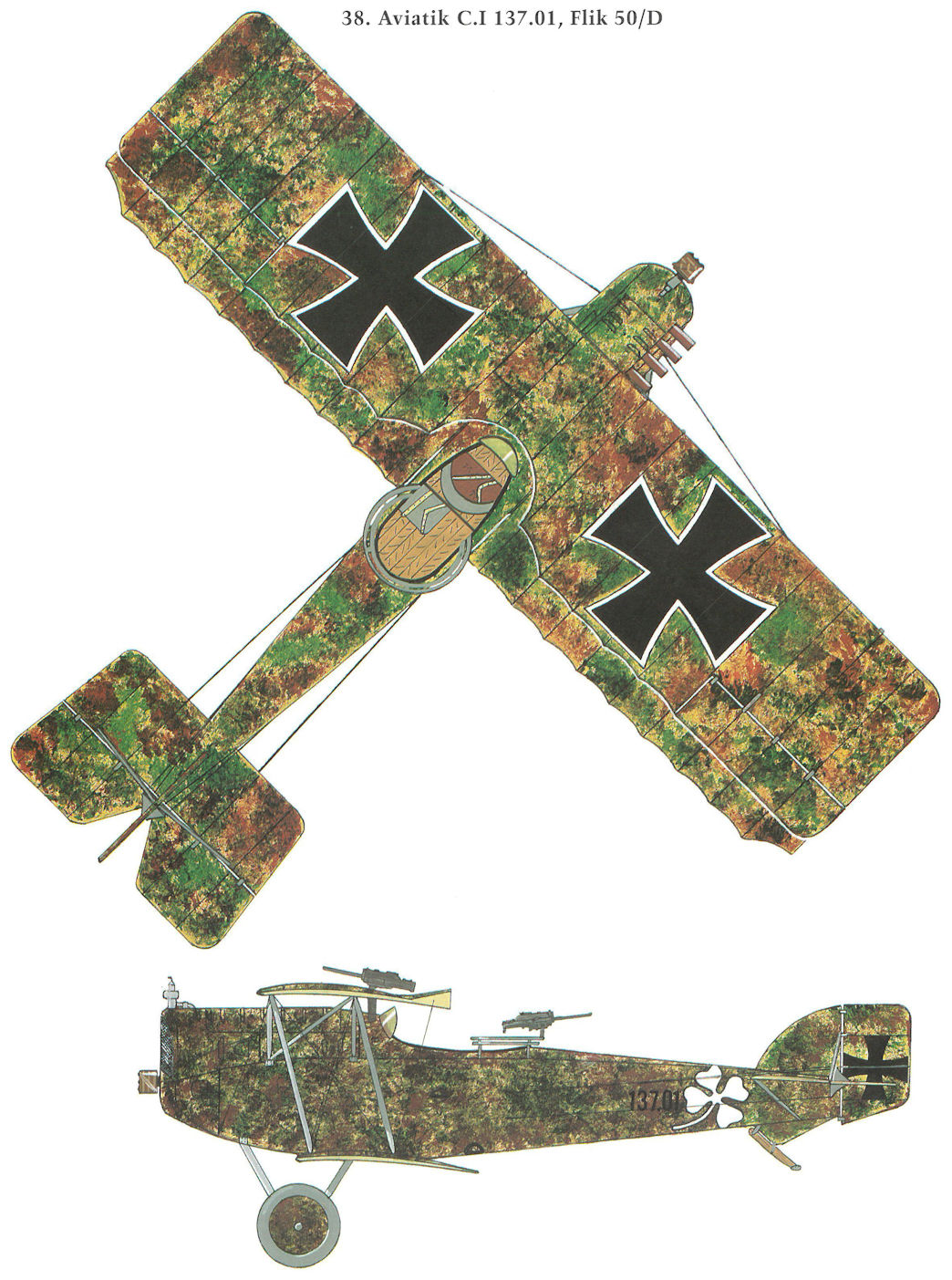
Aviatik C.I 137.01, Flik 50/D
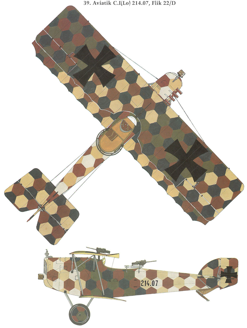
Aviatik C.I(Lo) 214.07, Flik 22/D
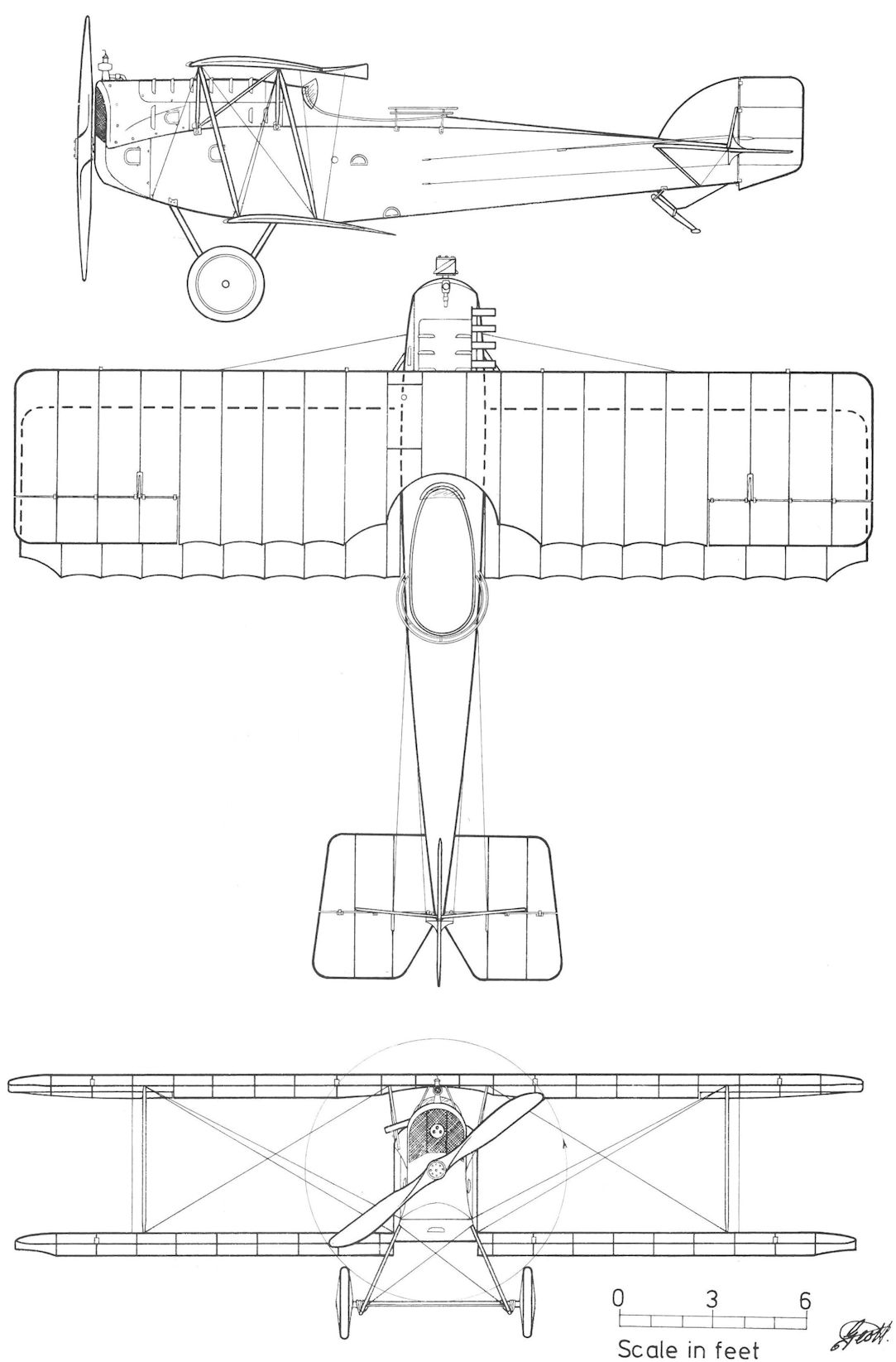
Aviatik C.I Series 37 and 137
Aviatik D.I (Lo) Series 115 and 315
Preparations were underway at Lohner in mid-1917 to replace Aviatik C.I production with the Aviatik D.I fighter, of which 93 had been ordered: 21 from the open 27 January 1917 contract and 72 as part of the 17 July 1917 contract. On 18 May 1918, a further 96 D.I were ordered for a total of 189 aircraft, reduced to 165 in September 1918. Production was divided into 89 series 115 fighters (115.01 to 115.89) powered by the 200 hp Daimler engine and 76 series 315 (315.01 to 315.76) by the 225 hp Daimler engine. The first two series 115 fighters were accepted in December 1917, but owing to subzero winter weather the 17 fighters delivered between 10-31 December 1917 were not accepted until March 1918. Forty series 115 fighters and all those over 115.62 had twin machine gun armament installed at the Front. By 31 October 1918, a total of 88 machines had been accepted.
In May 1918, shortly after the series 115 fighters had reached the Front, five Flik 60/J aircraft experienced wing trailing edge failure: among them Stabsfeldwebel Albin Heidi (115.30 on 11 May 1918), Oberleutnant Fritz Pisko (115.05 on 16 May 1918 and 115.26 on 18 May 1918) and Leutnant von Szabo (115.24 on 19 May 1918). Other squadrons reported similar incidents. Oberleutnant Frank Linke-Crawford, commander of Flik 60/J and a 27-victory ace, complained in mid-May 1918 that "At present I have seven Berg single-seaters (series 115) whose wings tear apart at high speed at great risk to life. Therefore I cannot permit them to be flown against the enemy." To fix the problem, a Lohner production engineer accompanied a repair team to the Front to fix the wings. Investigation showed that Lohner had substituted a lighter rib section and had attached the fabric in a manner different than specified by Aviatik. How this fact escaped the resident Flars inspector is inexplicable. Uzelac ordered the series 115 returned to the factory for wing replacement. Aircraft beginning with 115.66 left the factory in strict compliance with specifications.
Unfortunately, Uzelac's order came too late. It is indicative of the sense of duty Austro-Hungarian flying personnel showed throughout the war that they continued to fly the dangerous Lohner-built fighters at "great risk to their lives." Ironically, Linke-Crawford was flying aircraft 115.32 during his last combat on 31 July 1918. Eye-witnesses reported that Linke-Crawford, pursued by British fighters, had just levelled out after a high-speed dive and spin when he was seen "throwing papers overboard." This impression is believed to have been given by shreds of fabric tearing from the wing as a result of the violent maneuvers. As he throttled back to nurse his badly-damaged machine home, Linke-Crawford was attacked and shot down.
Similar reports of failure led to swift if belated action. The Lohner-built machines were grounded or restricted to noncombat duties. On 4 August 1918, the Army High Command ordered the 200 hp Daimler engines removed from aircraft 115.01 to 115.48 and installed in Aviatik D.I series 238 and 284 fighters to replace their 160 hp engines. Fifteen series 115 fighters, fitted with used 185 hp Daimler engines, were assigned to training duties. A handful of newer production machines remained operational with Fliks 14/J, 56/J, 60/J, and 72/J and singly with Fliks 63/J, 73/J, and 74/J. At least eight, modified for photo-reconnaissance work in September 1918, were assigned to Flik 40/P and 70/P, but saw limited employment. Because the Lohner-built fighters engendered universal mistrust and were considered "unsympathetic aircraft," pilots preferred to operate more robustly-built machines whenever possible. No wonder then that only one pilot, (Linke-Crawford) can be found who was credited with a victory while flying a Lohner-built series 115 fighter (115.32)! The series 115, no matter how well constructed, could not outlive its destructive reputation. In 1920, fifteen series 115 fighters (most with numbers below 115.48) were offered for sale to the Czechoslovakian government.
Aviatik D.I(Lo) Series 115 Specifications
Engine: 200 hp Daimler
Wing: Span Upper 8.00 m (26.25 ft)
Span Lower 7.89 m (25.89 ft)
Chord Upper 1.45 m (4.76. ft)
Chord Lower 1.45 m (4.76 ft)
Total Wing Area 21.7 sq m (233 sq ft)
General: Height 2.50 m (8.20 ft)
Empty Weight 668 kg (1473 lb)
Loaded Weight 798 kg (1760 lb)
Maximum Speed: 185 km/hr (115 mph)
Climb: 1000m (3,281 ft) in 2 min 38 sec
3000m (9,843 ft) in 9 min 52 sec
Aviatik D.I (Lo) Series 315
By September 1918, series 315 production was in full swing. Records show that only three or four fighters were dispatched from Vienna and it is doubtful if these reached any frontline unit. By 31 October 1918, a total of 22 series 315 fighters had been accepted. Of the remaining 54, half were ready for acceptance and the other half about 50 percent complete. Production had been scheduled to end in December 1918.
Aviatik D.I(Lo) Series 315 Specifications
Engine: 225 hp Daimler
Wing: Span Upper 8.00 m (26.25 ft)
Span Lower 7.89 m (25.89 ft)
Chord Upper 1.45 m (4.76 ft)
Chord Lower 1.45 m (4.76 ft)
Total Wing Area 21.7 sq m (233 sq ft)
General: Length 6.80 m (22.31 ft)
Height 2.50 m (8.20 ft)
Empty Weight 638 kg (1407 lb)
Loaded Weight 912 kg (2011 lb)
Climb: 1000m (3,281 ft) in 2 min 47 sec
2000m (6,562 ft) in 6 min 47 sec
3000m (9,843 ft) in 12 min 45 sec
4000m [13,124 ft) in 22 min
Aviatik D.I Series 38
The Aviatik D.I was the first fighter designed in Austria-Hungary to enter LFT service. It had evolved from the ill-fated 30.14 prototype, followed by the definitive D.I prototypes (30.19-30.21) that made their successful debut in early 1917. Thus began a broad D.I manufacturing program involving six manufacturers that would account for 43 percent of the total fighter acceptances through October 1918. Eager to replace the dangerous Brandenburg D.I, Uzelac urged Aviatik to begin production at once. The first production machine, 38.01, arrived at Aspern for flight tests in April 1917. That month Flars ordered 48, later increased to 72, D.I fighters, numbered 38.01 to 38.72 and powered by the 185 hp Daimler engine. At the time the formal contract was signed on 17 July 1917, two D.I fighters were at the Front and production was entering high gear.
The first Aviatik D.I fighter, 38.01, was accepted on 3 May 1917. After being inspected and approved by a Flars engineering commission on 12 May, it was sent to Fluggeschwader I (later Flik 101/G) on 15 May 1917 for service evaluation along with the 30.19 prototype. Aircraft 38.02 went to Flik 12 where it was flown by Hauptmann Godwin Brumowski (17 & 26 June). The first Aviatik D.I victory, an Italian Nieuport, was credited to the CO of Fluggeschwader I, Hauptmann Karl Sabeditsch (flying 38.01) on 20 August 1917. In June 1917, D.I assembly (24 aircraft nearing completion) was slowed in order to analyze the airframe to determine potential weak spots such as had appeared during the Aviatik C.I's service introduction. Taking no chances, Flars directed that the D.I be strengthened in a manner similar to the C.I. In August-September 1917, small numbers of the new Aviatik D.I began to reach Fliks 4, 23, 28, 35, 41/J, and 42/J. Unlike the C.I, initial squadron reaction was generally positive. Pilots praised the performance and regarded the D.I as having "the best climb rate of any fighter without sacrificing maneuverability. The flight characteristics exceed those of all contemporary fighters." In fact, test pilot Antal Feher, flying 38.03 on 12 June 1917, reached a speed of 197 km/h (122 mph), some 10 km/h (6 mph) faster than the new 200 hp Albatros D.III(Oef) series 153 fighter.
But these fine attributes were negated by the lack of a satisfactory machine gun synchronization mechanism. The wing-mounted machine gun, fixed at a 15 degree angle to fire over the propeller, was reported to be "utterly ineffective." Pilots discovered that it was almost impossible to attack an opponent unless the aircraft was in a dive, thereby losing altitude and leaving the pilot at a disadvantage. Even so, a few victories were recorded by skillful pilots. In addition to Sabeditsch, known are Offizierstellvertreter Friedrich Hefty of Flik 42/J and Feldwebel Karl Benko of Flik 28, who were credited with a victory each on 27 and 29 October 1917, respectively. The D.I series 38 also was operational with Fliks 32, 47, 53/D, and 58/D, and went on to serve as a fighter-trainer with Fliks 63/J, 68/J, and 74/J.
When Uzelac learned in November 1917 that the D.I was being delivered without gun synchronization some six months after entering service, he ordered Aviatik, who had been working on the problem, to demonstrate progress to date. As of December, twin synchronized machine guns were installed, but at the expense of accessibility, for the guns were mounted alongside the engine out of the pilot's reach in event of a stoppage. Work was under way to modify the airframe for placing the guns in front of the pilot. Tests in mid-January 1918 were successful and beginning in June-July 1918, all D.I fighters were delivered with accessible guns. The problems of cartridge lubrication spray and restricted frontal visibility made it necessary to install the aiming sight alongside the engine. The pilot was required to lean to one side to aim the guns. Consequently, much attention was given to improving visibility, especially reducing the size of the large nose radiator. Many radiator shapes were tested but none proved entirely successful. Nor did the thin wing section permit installation of an airfoil radiator. Throughout the production cycle, and in seeming random fashion, D.I fighters left the factory with either the original nose radiator, a twin side-mounted type, or a block radiator mounted on the upper-wing leading edge.
It is difficult to understand why Berg, himself a pilot, designed the D.I with such an awkward steering-wheel control. Flik 42/J reported the control as "unsympathetic for fighter pilots, especially difficult to fly in gusty weather." When the more-powerful D.I series 138 appeared still fitted with a control wheel, the outspoken commander of Flik 61/J, Oberleutnant Ernst Strohschneider, vented his displeasure in January 1918 by writing that the fighter "was obviously designed by someone who had never flown." In truth, the wheel control was not all that bad since the light and nimble D.I responded easily to small control movements, but in deference to popular demand it was soon replaced by a stick control.
Produced in four series, the Aviatik D.I remained in production until the war's end. Being structurally identical, one series did not follow another as might be expected; rather all four were produced in parallel according to engine availability, which had difficulty keeping pace with aircraft output. The D.I was ideally suited for license manufacture because of its relatively simple design. Using wood and plywood with a minimum of complex metalwork, the airframe was ideal for semi-skilled woodworkers to build. In April 1917, Lohner, MAG, and Thone & Fiala received large license orders, followed by Lloyd and WKF in early 1918. As of 31 October 1918 (the last month for which acceptance figures are available), a total of 677 D.I fighters had been accepted. Had production ended as scheduled in December 1918, a grand total of 983 D.I fighters would have been delivered, as shown in the nearby chart. Information regarding the various license-built D.I fighters can be found in the appropriate chapters.
Aviatik D.I Series 38 Specifications
Engine: 185 hp Daimler
Wing: Span Upper 8.00 m (26.25 ft)
Span Lower 7.89 m (25.89 ft)
Chord Upper 1.45 m (4.76 ft)
Chord Lower 1.45 m (4.76 ft)
Sweepback Upper 0 deg
Sweepback Lower 0 deg
Gap 1.35 m (4.43 ft)
Stagger 0.26 m (0.85 ft)
Total Wing Area 20.3 sq m (219 sq ft)
General: Length 6.86 m (22.51 ft)
Height 2.92 m (9.58 ft)
Track 1.80 m (5.91 ft)
Empty Weight 580 kg (1279 lb)
Loaded Weight 850 kg (1874 lb)
Maximum Speed: 187 km/hr (116 mph|
Climb: 1000m (3,281 ft) in 2 min 18 sec
3000m (9,843 ft) in 8 min 4 sec
5000m (16,405 ft) in 20 min 18 sec
Aviatik D.I Series 138
The most popular Aviatik D.I version was the series 138 powered by the 200 hp Daimler engine. Pressed by the LFT to increase the engine power, Austro-Daimler brought out the 200 hp Daimler engine in early 1917. The power rating was increased by raising the compression ratio and the use of four valves per cylinder. British engineers who tested a captured Daimler engine (taken from aircraft 138.27) reported that it "possessed more originality in design than the majority of enemy engines up to the present time" (July 1918). As part of the 17 July 1917 open contract, 88 D.I series 138 fighters were ordered. These were numbered 138.01 to 138.64 and 138.97 to 138.120 (the numbers 138.65 to 138.96 remained unused). The first aircraft was accepted in September 1917 and the last in November 1918 at the factory by the resident inspecting officer.
When the 200 hp Aviatik D.I fighters arrived at frontline units beginning in October 1917, they were met with the same mix of enthusiasm and criticism as had greeted the D.I series 38. Flik 42/J reported in January 1918 that the Aviatik was faster, possessed a superior rate of climb, and was more maneuverable than the Albatros D.III(Oef), but that the visibility and armament were unsatisfactory. With respect to climb and speed, Flik 52/D assessed the series 138 as equal to the Sopwith Camel. In February 1918, aircraft 138.98 and 138.114 were dispatched to the German test center at Adlershof for comparison with German fighters. Idflieg (Inspectorate of Aviation Troops) reported that the D.I demonstrated better climb and speed than the Albatros D.V but was less maneuverable.
A British technical evaluation of a captured D.I (138.27, enemy aircraft number AG 6, flown by Korporal Andreas Kulscar of Flik 4) provides some insight into the Aviatik design practice. The inspection appraisal stated that "everything had been designed to meet the requirements of easy production; everything being kept simple as possible to this end. This does not mean workmanship is inferior. As a matter of fact, the workmanship is very good generally speaking, although the finish may be here and there of a slightly less polished order than is found on some machines." The wings and airframe were of simple construction, but of a "simplicity which does not result in scamped workmanship and hurried finish but which bears evidence of careful design, with ease of production always kept in mind." The timber employed for the wings was of excellent quality, better than that found in the average German machine. The simple fittings combined high strength with light weight. Welding was used to a much smaller extent as compared to German practice. The tailplanes were constructed of large diameter steel tubing, but were single, whereas many German machines used two small-diameter tubes to form a rib.
The wing was unusual in that the rib section had a pronounced reflex curvature towards the trailing edge and the rear third was remarkably narrow. This feature, introduced by Professor Knoller, was said to reduce the center of pressure travel and result in improved longitudinal stability. But the aerodynamic advantages gained were, to some extent, negated by the danger of fatigue failure caused by the constant inflight flexing of the narrow trailing section. In fact, such failures were a common and sometimes fatal occurrence. In July 1918, Flik 72/J reported that "the wing strength is insufficient. Rib failures have occurred in both wings, causing relatively many accidents including two fatalities." Similar sentiments were voiced by Flik 74/J, noting that the upper wing on the exhaust side was especially vulnerable. The squadron had lost three Aviatik D.I fighters due to wing failure. In response, Berg designed a wing with a smaller chord and additional ribs that reduced the rib spacing by half. Although series 38, 138 and 238 fighters with the new wings were leaving the Aviatik factory in July 1918, it appears that the original wings continued in production, possibly to use up existing stocks. In June 1918, fifteen D.I fighters (38.61, 138.61-63 and 238.56-66) were fitted with a shortened and specially reinforced lower wing that was favorably received by field formations. It is not known if this modification was adopted by the license manufacturers. Notwithstanding the wing reinforcement, the Aviatik D.I continued to have a reputation for being fragile, leading most pilots to prefer the Albatros D.III(Oef) in spite of the D.I's better performance.
As shown in the accompanying photographs, three types of radiators (nose, side, and leading edge) were employed on Aviatik D.I production aircraft. Apparently these were randomly installed as they became available. The radiators were manufactured by Erenyi, Weich, Windhoff, and Hirschfelder. A number of experimental radiator designs were tested in hopes of improving forward visibility.
D.I series 138 fighter production spanned a fifteen-month period during which output was geared to the availability of the 200 hp engine. It was supplied to fighter squadrons such as Fliks 14/J, 42/J, 51/J, 56/J, 60/J, 63/J, 68/J, 72/J, and 74/J and in single examples to Fliks 4/D, 15/F, 19/F, 23/D, 28/D, 34/D, 46/F, 53/D, 54/D, 57/F, 58/F, 73/D, and 101/G. As of July 1918, a few served with Flik 37/P as photo-reconnaissance fighters and as trainers with Fleks 6, 19, and the two field flying schools. On 1 August 1918, forty-eight series 138 fighters were serving with frontline squadrons.
Aviatik D.I Series 138 Specifications
Engine: 200 hp Daimler
Wing: Span Upper 8.00 m (26.25 ft)
Span Lower 7.89 m (25.89 ft)
Chord Upper 1.45 m (4.76 ft)
Chord Lower 1.45 m (4.76 ft)
Sweepback Upper 0 deg
Sweepback Lower 0 deg
Gap 1.35 m (4.43 ft)
Stagger 0.26 m (0.85 ft)
Total Wing Area 20.3 sq m (219 sq ft)
General: Length 6.86 m (22.51 ft)
Height 2.92 m (9.58 ft)
Track 1.80 m (5.91 ft)
Maximum Speed: 195 km/hr (121 mph)
Climb: 1000m (3,281 ft) in 1 min 42 sec
2000m (6,562 ft) in 4 min 30 sec
3000m (9,843 ft) in 7 min 36 sec
4000m (13,124 ft) in 12 min 10 sec
5000m (16,405 ft) in 16 min 26 sec
6000m (19,686 ft) in 26 min
Aviatik D.I Series 238
The chronic shortage of high-powered engines set the stage for the next version of the Aviatik D.I fighter. Because ample stocks of new and reconditioned 160 hp Daimler engines were on hand, Flars tested an Aviatik D.I powered by that engine in December 1917. It was concluded that the combination was capable of attaining acceptable performance for operational service and was approved for production accordingly. The 160 hp Aviatik D.I series 238 acceptances began in January 1918 and ended in August 1918 when the last of 120 fighters was accepted. The serial numbers assigned were 238.01 to 238.90 and 238.105 to 238.134 (the numbers 238.91 to 238.104 remained unused). At least 20 series 238 fighters were accepted without engines. Armament consisted of twin synchronized machine guns but some 50 fighters were delivered unarmed due to the gun shortage. A few series 238 fighters were fitted with redesigned, all-plywood tail surfaces and ailerons, but the number built is unknown. In August 1918, Flik 1 reported that the wooden parts tended to warp out of shape and, being heavier, impeded maneuverability.
The introduction of the retrograde D.I series 238 fighter in April-May 1918 triggered universal condemnation by Flik pilots. Flik 6/F complained in May 1918 that the underpowered fighter was too slow to intercept Allied observation machines. The series 238 was regarded as adequate for close-escort missions by Flik 23/D but useless in an offensive role and inferior to Allied fighters. Because pilots were unwilling to fly the underpowered D.I, a few resourceful Fliks installed more powerful engines. For instance, Flik 6/F reported no trouble installing 185 hp Daimler engines taken from wrecked aircraft or scrounged from rear-area depots. On 12 July 1918, the LFT ordered the replacement of all 160 hp engines in the series 238 by new or used 200 hp engines but only a few conversions were made. Those aircraft not used as trainers languished for months in storage until engines could be found.
The D.I series 238 (some powered by 185 or 200 hp engines) was flown as a fighter by Fliks 1/J, 6/F, 13/J, 23/D, 28/D, and 64/F. The type served as an advanced trainer in Fliks 14/J, 43/J, 55/], 56/J, 72/J, 74/J, and with Flek 6 and the two field flying schools. Several series 238 were used as photoreconnaissance fighters by Fliks 37/P, 40/P, and 46/P. On 1 August 1918, eighty-nine Aviatik D.I series 238 fighters were carried in the frontline inventory.
Aviatik D.I Series 238 Specifications
Engine: 160 hp Daimler
Wing: Span Upper 8.00 m |26.25 ft)
Span Lower 7.89 m (25.89 ft)
Chord Upper 1.45 m (4.76 ft)
Chord Lower 1.45 m (4.76 ft|
Sweepback Upper 0 deg
Sweepback Lower 0 deg
Gap 1.35 m (4.43 ft)
Stagger 0.26 m (0.85 ft)
Total Wing Area 20.3 sq m (219 sq ft)
General: Length 6.86 m (22.51 ft)
Height 2.92 m (9.58 ft)
Track 1.80 m (5.91 ft)
Maximum Speed: 192 km/hr (119 mph)
Climb: 1000m (3,281 ft) in 2 min 6 sec
2000m (6,562 ft) in 5 min 50 sec
3000m (9,843 ft) in 10 min 12 sec
4000m (13,124 ft) in 15 min 24 sec
5000m (16,405 ft) in 21 min 34 sec
Aviatik D.I Series 338
By the middle of 1918, output of the new 225 hp Daimler engine had reached a level sufficient to supply two production fighters, the Albatros D.III(Oef) series 253 and the Aviatik D.I series 338. Contracts for a total of 294 Aviatik D.I fighters powered by the 225 hp engine were awarded to Aviatik, Lohner, Lloyd and WKF. These aircraft had strengthened wings and engine bearers, and were armed with twin guns mounted at eye level.
As part of the contract dated 18 May 1918, Aviatik built a pre-production batch of eight D.I series 338 fighters for evaluation. These were numbered 338.01 to 338.08. Shortly thereafter, Flars ordered 100 production fighters numbered 338.21 to 338.120 (numbers 338.09 to 338.20 remained unused). The pre-production machines arrived at Aspern in June-July 1918 for flight trials. Engine cooling posed a vexing problem. The nose radiator originally fitted to aircraft 338.01 was replaced by twin Hefa side radiators to improve cooling efficiency and forward visibility. Various other side radiators and an Oefam airfoil radiator (tested in aircraft 338.07) were rejected in favor of a block radiator mounted on the upper wing leading edge which became the production standard.
Two fighters, 338.03 and 338.04, participated in the Fighter Evaluation held on 9-13 July at Aspern. The climb trials performed with aircraft 338.03 were interrupted when the side radiators began to boil over at altitude, but enough data was obtained to demonstrate a remarkable climb rate, second to none. Tested against a captured Sopwith Camel, aircraft 338.06 was faster and showed equal maneuverability with ability to perform sharp turns without altitude loss. In August 1918, aircraft 338.01 and 338.02 were dispatched to Flik 1/J at Igalo for service trials. Here take-off for interception occurred only after enemy aircraft were positively reported or visually sighted. Since it was a task suitable "only for the most rapid climbing and fastest fighter," the fast-climbing D.I series 338 was the ideal aircraft. Flik 1/J commander Oberleutnant Bela Macourek and Offizierstellvertreter Julius Arigi were both credited with two victories while flying a series 338 fighter. Production fighters began to reach the Front in September 1918, but only very few saw combat service in the waning days of the war.
After the crash of aircraft 338.89 which killed Aviatik test pilot Feldwebel Franz Tordik on 16 October 1918, investigation discovered a faulty aileron-pulley support. On 29 October appropriate modifications were ordered on the 34 completed fighters: 338.01 to 338.08, 338.21 to 338.35 and 338.86 to 338.96 and those in production. The reasons for the non-consecutive production run is not known. At the war's end, the resident inspection officer accepted 27 completed series 338 fighters at the factory; the remaining 23 were almost complete. Series 338 production was scheduled to end in December 1918.
Postwar plans calling for the Aviatik D.I series 338 to equip the Austrian air arm were forbidden by the treaty stipulations. Acceding to Czechoslovakian demands, 24 series 338 fighters and ancillary equipment were loaded on freight cars for shipment in December 1918. But the Austrian demobilization office did not grant an export permit until mid-January 1919. By then the fighters, damaged by weather exposure and theft, had only scrap value.
Aviatik D.I Series 338 Specifications
Engine: 225 hp Daimler
Wing: Span Upper 8.00 m (26.25 ft)
Span Lower 7.89 m (25.89 ft)
Chord Upper 1.45 m (4.76 ft)
Chord Lower 1.45 m (4.76 ft)
Sweepback Upper 0 deg
Sweepback Lower 0 deg
Gap 1.35 m (4.43 ft)
Stagger 0.26 m (0.85 ft)
Total Wing Area 20.3 sq m [219 sq ft)
General: Length 6.86 m (22.51 ft)
Height 2.92 m (9.58 ft)
Track 1.80 m (5.91 ft)
Climb: 1000m (3,281 ft) in 1 min 59 sec
2000m (6,562 ft) in 4 min 12 sec
3000m (9,843 ft) in 7 min 30 sec
4000m (13,124 ft) in 12 min
5000m (16,405 ft) in 16 min 24 sec
6000m (19,686 ft) in 27 min 30 sec
Aviatik D.I(Ll) Series 48, 248 and 348
License production of the Aviatik D.I(Ll), under way at Lloyd before the formal contract was signed on 18 May 1918, comprised 100 fighters in the following series:
Quantity Series Number Engine
10 48.01-10 185 hp Daimler(MAG)
20 248.01-20 160 hp Daimler(MAG)
70 348.01-70 225 hp Daimler(MAG)
All Aviatik D.I(Ll) series 48 and 248 fighters left the factory modified to receive cameras, etc., for photoreconnaissance work. None had machine guns installed. Although scheduled to receive re-built engines - some taken from retired Aviatik C.I(Ll) machines - aircraft 248.04-248.18 and 248.20 were delivered without engines. The series 48 and 248 fighters were dispatched to Flek 6 in Wiener-Neustadt and placed in storage. Subsequently, a few were flown as trainers or assigned to home defense duties in August 1918. Twenty eight were offered for sale to Czechoslovakia in 1920.
The first Aviatik D.I(Ll) series 348 fighter was accepted in September 1918. On 31 October 1918, the remaining 69 series 348 fighters were reported completed and awaiting acceptance at Aszod but never delivered to the LFT. A handful were taken over and flown by the Hungarian air service. Aircraft 348.45, 348.46 and 348.49 were attached to the 4th Squadron of the Hungarian Red Airborne Corps at Gyor in April 1919. Hungarian pilot J. Kretz, flying 349.49, shot down a Czech Lebed XII two-seater over Gyor during the postwar fighting. According to Hungarian sources, some D.I(Ll) series 348 fighters were deployed for coastal defense and a few were captured by Italian or Yugoslav troops. As late as 1942, the fuselage of 348.61 was on display in the Hungarian War Museum in Budapest.
WKF 80.08
This prototype has been identified as an Aviatik D.I built by WKF. As was customary at the time, a production airframe (possibly 84.01) was assigned a prototype number for purposes of engineering inspection and flight evaluation before being given a standard series number. The 80.08 prototype, powered by a 185 hp Daimler engine, was recorded at Aspern on 27 May 1918.
Aviatik D.I(WKF) Series 84, 184, 284, and 384
WKF became one of the five companies to build the Aviatik D.I under license in July 1917, when Flars placed an order for 48 Aviatik D.I(WKF) fighters, followed by a contract for 50 more on 10 May 1918. In mid-1918, when the original production batches were re-numbered according to engine availability, the production break-down was as follows:
Qty Serial No. Engine Order Date First Acceptance
10 84.01-10 185 Dm 10 May 1918 September 1918
24 184.01-24 200 Dm July 1917 May 1918
24 284.01-24 160 Dm July 1917 May 1918
40 384.01-40 225 Dm 10 May 1918 August 1918
As was the case with the Aviatik C.I(WKF), the acceptances commenced almost a year after the order was placed. About half the fighters were accepted without engines and the remainder left the factory fitted with reconditioned engines. Records show of the total (45) accepted through October 1918, only six left the factory with machine guns installed.
Aviatik D.I(WKF) Series 84
The Aviatik D.I(WKF) series 84.01 to 84.10 were intended (and possibly specially equipped) as advanced, single-seat trainers. It is possible that a few served in that capacity with Flek 6 in September-October 1918. All ten survived the war and were in storage awaiting disposal in March 1919. Eight were offered for sale to the Czechoslovakian government in 1920.
Aviatik D.I(WKF) Series 184
Of the 24 ordered, only a single D.I(WKF) fighter (184.01) was accepted prior to 31 October 1918. It joined Flik 72/J in June 1918. At the war's end, 23 series 184 airframes (numbered 184.02 to 184.24), virtually completed and scheduled for delivery in November, were provisionally accepted by the resident Flars representative. The airframes appear to have been scrapped since they do not figure in the postwar disposal records.
Aviatik D.I(WKF) Series 284
All D.I(WKF) series 284.01 to 284.24 were accepted prior to September 1918. Confusion exists because WKF completed 24 additional series 284 airframes, originally numbered 284.25 to 284.48. Prior to delivery, Flars decreed that these were to receive the 225 hp Daimler engine and be re-designated series 384. However, before implementation at least 35 series 284 fighters entered the records when they were assigned to rear-area distribution centers, but only a handful actually reached operational units before the war ended. Known are Flik 14/J in the South Tirol and the two field flying schools. One series 284 fighter saw service with Flik 6 in Albania. On 28 August 1918, six Aviatik D.I(WKF) series 284 were released by the LFT to the Navy, but it is doubtful if the transfer occurred. In 1920, aircraft 284.07, 20, 28, and 31 were offered to the Czechoslovakian government.
Aviatik D.I(WKF) Series 384
Ten Aviatik fighters powered by 225 hp Daimler engines were accepted as series 384 while still carrying their old numbers (284.25, 27, 28, 29, 31, 32, 37, 39, 42, and 48). However, it appears they never left the factory, for after the war 40 series 384 airframes were counted at the WKF factory in good condition - the last 30 airframes, scheduled for delivery in November and December 1918, having been accepted by the resident Flars officer.
Aviatik D.I(MAG) Series 92
On 9 October 1917, the total of 46 Aviatik D.I(MAG) fighters, ordered on 17 July 1917, was increased to 72 at the expense of the Aviatik C.I(MAG). In addition another 100 fighters were ordered on 10 May 1918. Acceptances of the fighters, numbered 92.01 to 92.172 and powered by the 200 hp Daimler(MAG) engine, began in April 1918. By 31 October, 121 had been accepted, almost all without armament and some without engines.
When Flik 72/J on the Piave Front received the first Aviatik D.I(MAG) in August 1918, evaluation flights produced such dismal results that the squadron rejected the type because "...it is impossible to fly this aircraft over the enemy...the wing cellule is even weaker than that of the early Aviatik D.I series 38, 138 and 238 fighters" which had been grounded in July 1918 by the Army Command. The 6th Army Command ordered Flik 72/J pilots to inspect and test the series 92 machines stored at Pordenone. It was found that aircraft below 92.50 had been manufactured according to the old Aviatik D.I drawings. The wing cut-out was missing. When tested in a spin, the lower wing (not the short-span version as in late model Aviatik-built fighters) "always showed breakage." Furthermore, the quality of MAG workmanship was defective and slipshod. Nevertheless, in the summer of 1918 the Aviatik D.I(MAG) became operational in small numbers with Fliks 1/J, 6/F, and 13/J on the Balkan Front and in south Tirol with Fliks 7/J, 20/J, and 23/D. Flik 7/J was unique in that it was the only unit totally composed of MAG-built Aviatik fighters. In September-October at least 42 aircraft were rejected by three Army commands and withdrawn from the Front. On 10 October 1918, Flik 74/J tested aircraft 92.18 fitted with reinforced wing ribs and found that at 150 km/h (93 mph - well below its top speed of 187 km/h - 116 mph) the upper-wing trailing edge and the lower wing vibrated so severely that "...one cannot develop trust in the aircraft."
Twenty-five Aviatik D.I(MAG) fighters were offered to the Czechoslovakian government in 1920. The Hungarian Red Airborne Corps had in service aircraft 92.83 (later civil register HJ 83), 92.85 (HJ 85), 92.80 (armed with a Gebauer motor machine-gun), 92.106 (HJ 106), 92.107 (HJ 107) and 92.115 (HJ 115). Aircraft 92.148 of the 3rd Squadron that landed in Austria in 1919 was confiscated and returned to Hungary on 28 March 1920. The highest serial number identified in Hungarian postwar records is 92.170.
Aviatik D.I(MAG) Series 92 Specifications
Engine: 200 hp Daimler (MAG)
Wing: Span Upper 8.00 m (26.25 ft)
Span Lower 8.00 m (26.25 ft)
Chord Upper 1.45 m (4.76 ft)
Chord Lower 1.45 m (4.76 ft)
Gap 1.47 m (4.82 ft)
Stagger 0.18 m (0.59 ft)
Total Wing Area 22.0 sq m (237 sq ft)
General: Length 6.86 m (22.51 ft)
Height 2.55 m (8.37 ft)
Loaded Weight 888 kg (1958 lb)
Maximum Speed: 200 km/hr (124 mph)
Climb: 1000m (3,281ft) in 2 min 15 sec
2000m (6,562 ft) in 5 mm 30 sec
3000m (9,843 ft) in 10 min
4000m (13,124 ft) in 17 mm
5000m (16,405 ft) in 27 min
Aviatik D.I(Th) Series 101 and 201
At the time when the formal production contract was signed on 21 June 1917, the first Thone & Fiala-built Aviatik D.I airframe was reported two weeks away from structural tests. A total of 60 Aviatik D.I fighters were ordered as follows:
Qty Series Number Engine Order Date
21 101.01-21 200 Dm 21 June 1917
9 201.01-09 185 Dm 21 June 1917
30 101.31-60 200 Dm May 1918
(Aircraft 201.01-03 were renumbered 101.22-24.)
Initially all Aviatik D.I(Th) fighters were intended for training purposes and consequently had rebuilt engines installed. Flars reported minor quality-control problems in July 1917, but these were quickly overcome and aircraft of superior workmanship were delivered thereafter. The first production machine, 101.01, arrived at Fischamend on 9 November 1917 for machine-gun installation and was returned to Thone & Fiala on 19 December 1917 to serve as a pattern aircraft. Production acceptances began in March 1918. Owing to the machine-gun shortage, only the first 15 aircraft were delivered armed. Through 31 October 1918, a total of 34 Aviatik D.I(Th) fighters was accepted; ten were provisionally accepted after the war and 16 partially-completed airframes were scrapped.
Twenty series 101 and two series 201 fighters were listed in the 11th Army frontline inventory of 20 August 1918. Records show that the series primarily saw combat service with Flik 31/P as a photo-reconnaissance fighter. The downing of an Italian Hanriot fighter by Leutnant Vjekoslav Tomasic of Flik 31/P on 4 October 1918, flying aircraft 101.05, is the only known victory achieved with this series. Aircraft 101.32 and 101.33, assigned to Flek 6, were later taken over by the Austrian air service.
The airframe of aircraft 101.37, presently exhibited in the Technical Museum in Vienna, is noteworthy for its excellent craftsmanship. A few years ago, a rotary-engined biplane (Austrian civil registration A 9) was discovered in a barn and identified as the original Aviatik D.I(Th) 101.40 airframe. Now beautifully restored by the Champlin Fighter Museum in Arizona, it is exhibited in its original 1918 appearance.
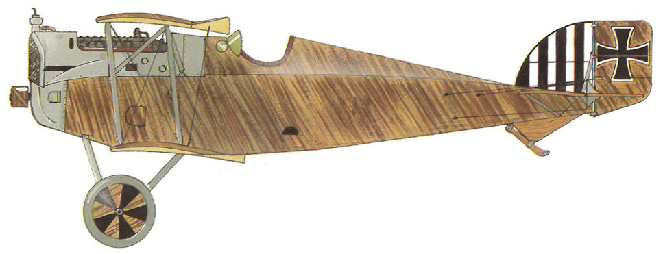
Aviatik D.I 38.37, Flik 63/J

Aviatik D.I 138.XX, Flik 74/J
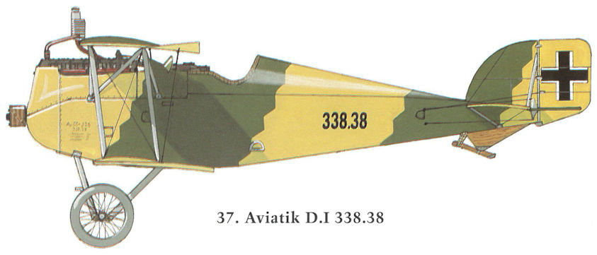
Aviatik D.I 338.38
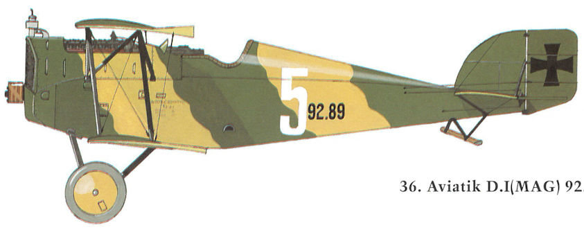
Aviatik D.I(MAG) 92.89
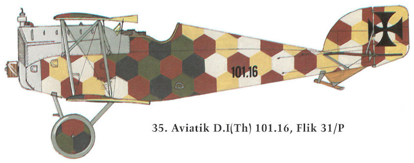
Aviatik D.I(Th) 101.16, Flik 31/P
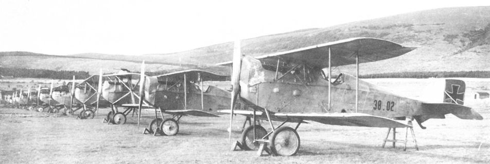
The Aviatik D.I 38.02 and 38.01 lead the line-up of Flik 101/G aircraft in September 1917. Accepted on 3 May 1917, D.I 38.01 was ordered dispatched to Fluggeschwader I on 15 May. D.I 38.02 was accepted in June 1917. Both fighters were armed with an over-the-wing machine gun.
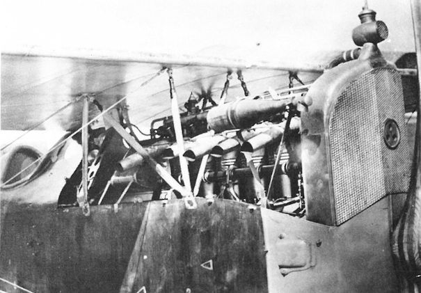
The Sottoscope for ground viewing is mounted just above the exhaust stacks on Aviatik D.I 38.06. This aircraft remained attached to Flek 6 at Wiener-Neustadt for equipment trials.
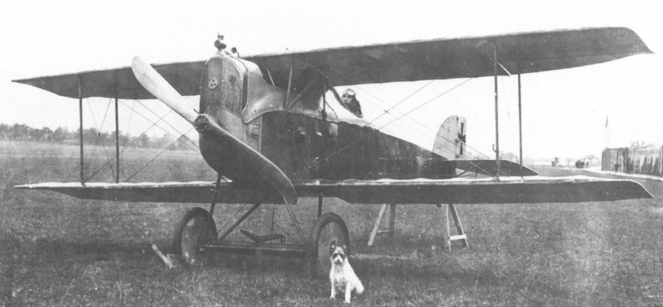
Aviatik D.I 38.15 served with Fliks 35/D and 4/D. At the end of the war, it was attached to the weapons school at Aspern. The angled Schwarzlose machine gun is hidden by the upper wing.
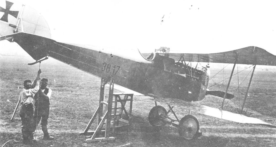
Aircraft type Aviatik "Berg" D.I Oblt. Marian Gawel from Flik 32 on the Italian Front in autumn 1917 during the timing of the machine gun.
The Schwarzlose M 16 machine gun of Aviatik D.I 38.17 being aligned at Flik 32/D. The diving attitude required to fire straight ahead was disparaged as a serious combat liability by Austro-Hungarian fighter pilots.
The Schwarzlose M 16 machine gun of Aviatik D.I 38.17 being aligned at Flik 32/D. The diving attitude required to fire straight ahead was disparaged as a serious combat liability by Austro-Hungarian fighter pilots.
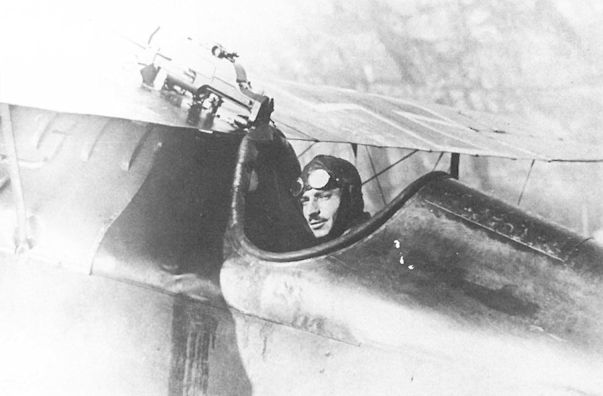
The deep cockpit of the Aviatik D.I 38.29 of Flik 17/D certainly protected the pilot from the elements but made aiming difficult. A ring gunsight is mounted on the front attachment of the Schwarzlose M 16 gun. The dark stain on the fuselage is from the gun chamber lubrication oil.
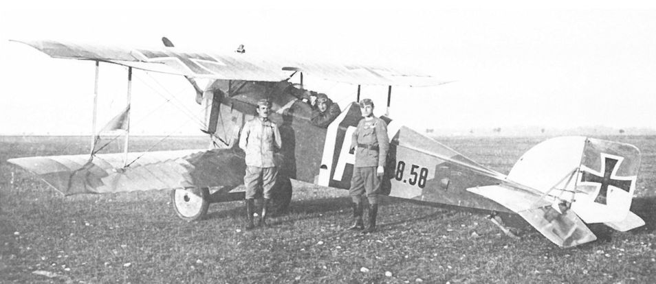
The Aviatik D.I 38.58 fitted with side radiators and cowl-mounted guns. After serving with Flik 56/J, 38.58 flew with the Wiener-Neustadt defense flight in the fall of 1918. The rear strut carries an identification pennon.
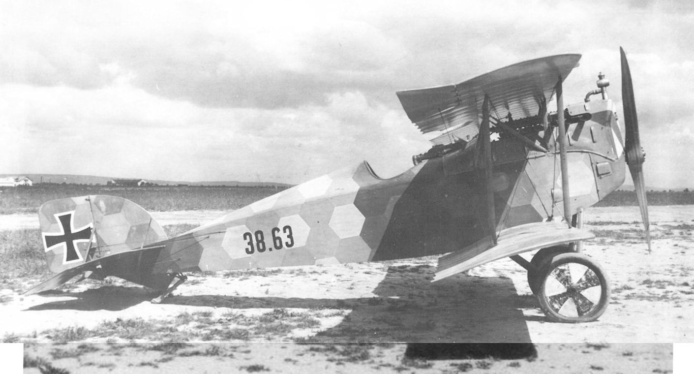
"Авиатик" D.I из состава авиароты 74J (Flik 74J), июль 1918 г. Пилот - Йозеф Маршалек
As of June-July 1918, Aviatik D.I fighters began leaving the factory with raised guns mounted within reach of the pilot. Aviatik D.I 38.63, attached to Flik 74/J, crashed on 15 July 1918 because of wing failure.
The Aviatik (Berg) DI fitted with a 200 hp Austro-Daimler engine, this being an aircraft of the first series, and one of the first D Is to be fitted with Schwarzlose guns immediately ahead of the cockpit (38.63)
Aviatik-Berg D.I 38.63 in Aspern, Einfliegerei 1918, nach der Übernahme der Flik 74J zugeteilt, Flugzeugführer Kpl Josef Marszalek stürzte nach Tragflächenbruch am 15. Juli 1918 damit ab, schwer verletzt
Aviatik-Berg D.I 38.63 в Асперне, летавший в 1918 году во Flik 74J, пилот Kpl Йозеф Маршалек разбился после разрушения крыла 15 июля 1918 года, тяжело ранен.
The unarmed Aviatik D.II 39.01 in front of the Aviatik hangars at Aspern in the fall of 1917. The four-bladed propeller was usually matched with a 200 hp Daimler engine. Behind the tail is Aviatik C.I 137.15.
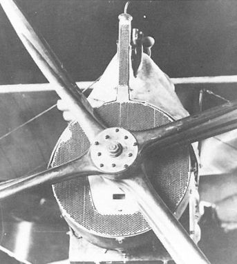
An, experimental circular radiator was flight tested on Aviatik D.I 138.11 in October 1917. The lower cowl fairing remains to be installed.
The Aviatik 30.24 in front of the company hangar at Aspern. The aerodynamically-balanced ailerons on the top wing were unique for Berg-designed fighters. Cellon panels in the middle wing enhanced the pilot’s view downward. To the left are an Aviatik D.II 39.01 and a D.I 138.17.
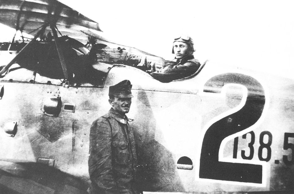
Leutnant Othmar Wolfan of Flik 56/J in Aviatik D.I 138.54 with raised guns accessible to the pilot. This placement was preferred by most pilots.
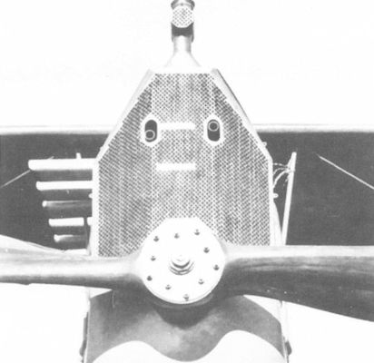
Aviatik D.I 138.111 was given a production radiator with oblong machine gun cut-outs. The projecting extension is an air-cooled condenser for the radiator.
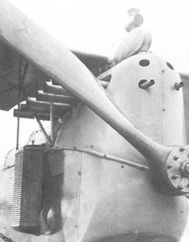
Twin side radiators, mounted behind the front center-section struts, under test on the Aviatik D.I 138.111. The streamlined condenser tank was a unique feature.
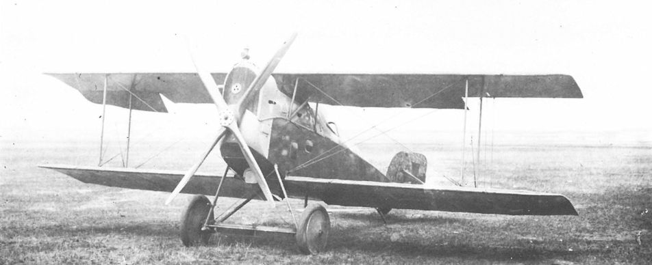
The LFT sent two Aviatik D.I fighters to Germany for test. Here is 138.114 at the Adlershof test center in March-April 1918. The four-bladed propeller was often used in conjunction with the 200 hp Daimler engine.
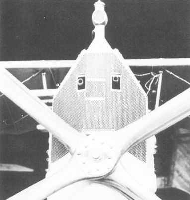
Aviatik D.I 138.116, showing a production radiator with twin rectangular cut-outs for the machine guns mounted at pilot’s eye level.
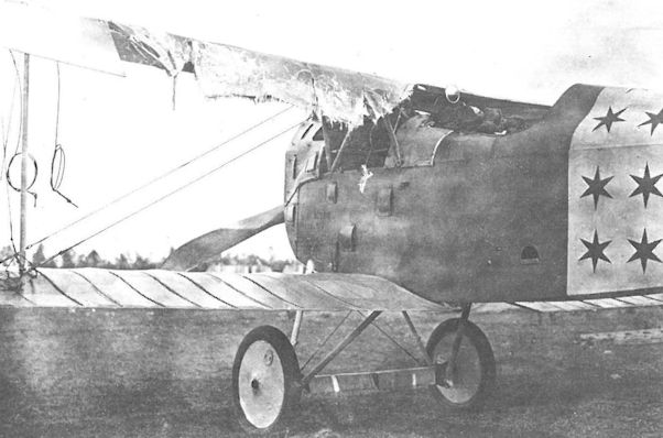
The flexing stresses to which the thin rear rib section was exposed could cause failures. Korporal Alfred Wiesinger of Flik 74/J was fortunate to bring 138.119 down safely on 18 September 1918. The rear-view mirror on the center section helped prevent being surprised from behind.
The Aviatik hangar at Aspern provides a perfect backdrop for seven Aviatik aircraft undergoing flight and acceptance testing in the autumn of 1917. From the right are C.I 137.07, 30.24, 39.01, two D.I series 138, and a C.I.
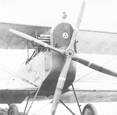
Standard production radiator with a single aperture for the starboard gun, mounted in Aviatik D.I Series 138. The bright red stripe signifies that the propeller is experimental; the white stripe signifies it is company property.

Aviatik D.I 238.41 armed with raised machine guns and fitted with side radiators. It was dispatched to the Front on 20 July 1918.
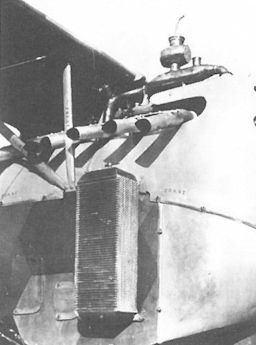
Production side radiators as mounted on Aviatik D.I 238.41. Stencilling the aircraft number on cowl and struts was mandatory.
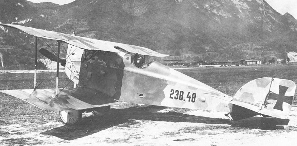
Photographed at the Jagdfliegerschule Pergine, D.I 238.48 has the nose radiator and buried guns. The deep cockpit protected the pilot, but his forward vision was restricted.
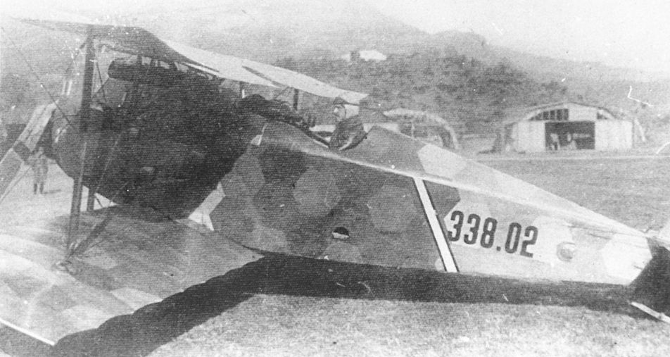
Aviatik D.I 338.02 with Oberleutnant Bela Macourek, CO of Flik 1/J in Igalo (Bocche di Cattaro) in August 1918. The pilot’s seat has been raised to provide an improved forward view.
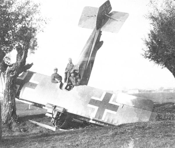
Aviatik D.I 338.38 being inspected by Italian troops near Egna, 10 November 1918.
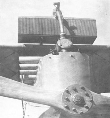
Aviatik D.I 338.42 with a block radiator mounted over the leading edge, an installation seen on some late production aircraft. The gun blast tubes are visible just above the engine cowling.
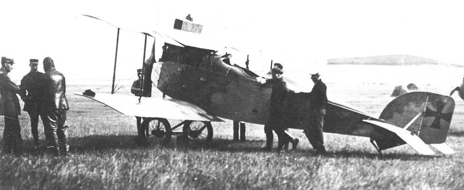
Colonel Bares of the the Inter-Allied Aeronautical Control Commission talking with Hauptmann Karl Nikitsch before going aloft in the unarmed Aviatik D.I 338.53 at Fischamend in 1919.
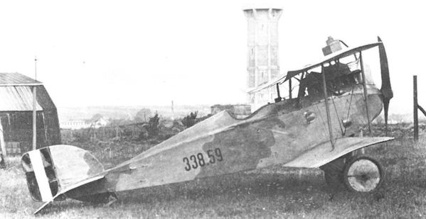
An unarmed Aviatik D.I 338.59 with the early Austrian Volkswehr insignia on the rudder at Fischamend in 1919. All Aviatik D.I fighters had limited forward visibility because of the high engine placement.
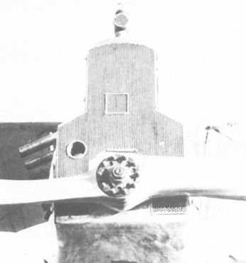
Aviatik D.I with an experimental radiator cut-back to provide improved sighting for the raised machine guns. The “5°” stencilled on the upper wing signifies the correct angle of incidence.
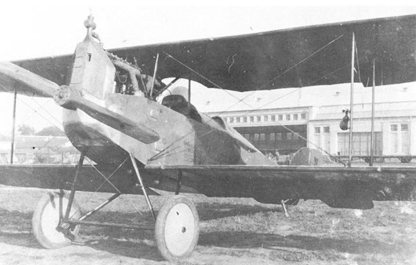
Aviatik D.I (MAG) 92.18 in front of the MAG factory in Matyasfold. This aircraft, fitted with strengthened wing ribs, was tested by Flik 72/J on 10 October 1918. The slot in the radiator is for one of the twin machine guns which remain to be installed.
Aviatik D.I, Flugzeugnummer 92.18. hochliegender MG-Einbau
Aviatik D.I, самолет № 92.18, высокорасположенный пулемет
Aviatik D.I, Flugzeugnummer 92.18. hochliegender MG-Einbau
Aviatik D.I, самолет № 92.18, высокорасположенный пулемет
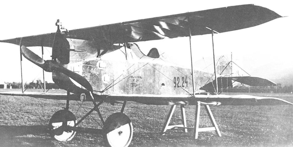
The Aviatik D.I (MAG) 92.24 at the Front. It was shipped from the factory in July 1918. The blast tubes of the twin buried guns protrude from the cowling.
Aviatik-Berg D.I. Flugzeugnummer 92.24. tiefliegender MG-Einbau
Aviatik D.I, самолет № 92.24, низкорасположенный пулемет
Aviatik-Berg D.I. Flugzeugnummer 92.24. tiefliegender MG-Einbau
Aviatik D.I, самолет № 92.24, низкорасположенный пулемет
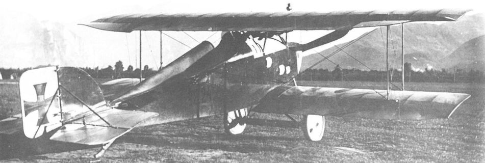
Another view of 92.24 showing the highly-reflective finish characteristic of factory-fresh aircraft.
Aviatik-Berg D.I, Flugzeugnummer 92.24. Fliegerkompanie 7, Pergine
Aviatik-Berg D.I, Flugzeugnummer 92.24. Fliegerkompanie 7, Pergine
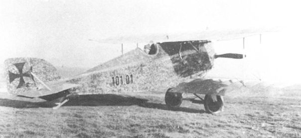
The first Aviatik D.I(Th) 101.01 built by Thone & Fiala was sent to Fischamend in November 1917 for armament installation and returned to the factory as a pattern aircraft in December.
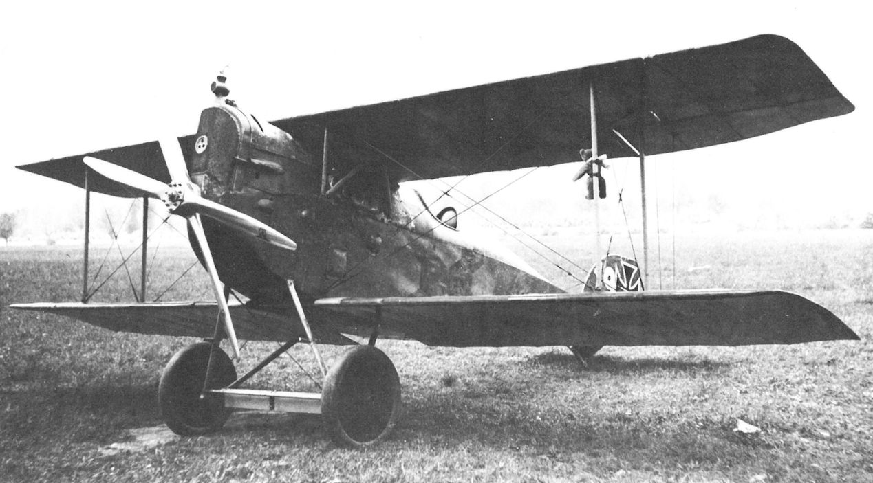
Aviatik D.I(Th) 101.12 of Flik 9/J at Ospedaletto fitted with a four-bladed propeller, usually a sign that a 200 hp Daimler engine is installed. This aircraft has buried guns and a teddy bear mascot hung on the wing strut.
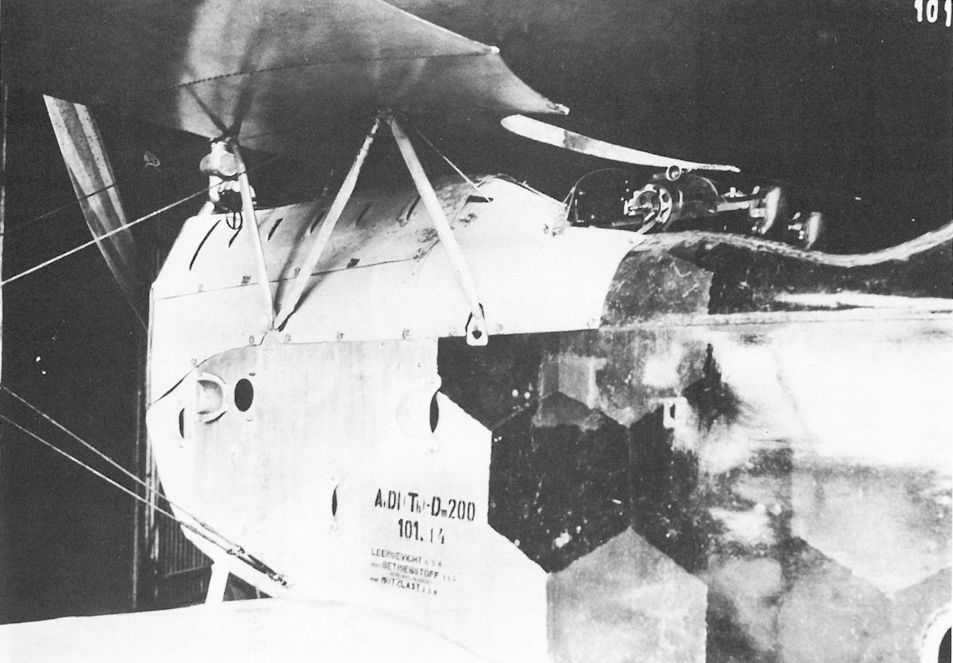
Aviatik D.I(Th) 101.14 with accessible twin Schwarzlose M 16 machine guns mounted at eye level. Because of the engine and radiator obstruction, the guns were aimed by leaning out of the cockpit and sighting through a rear and forward sight; the latter is seen mounted forward of the center-section struts.
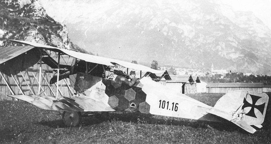
Aviatik D.I(Th) 101.16 of Flik 31/P at Levico in the summer of 1918. The cowling panels have been removed to provide improved cooling.
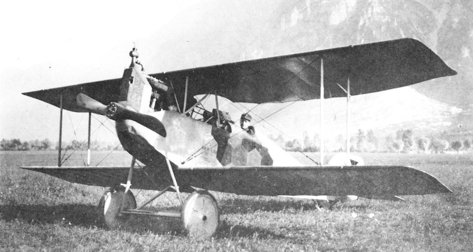
Aviatik D.I(Th) 101.16 of Flik 31/P at Levico in the summer of 1918. The cowling panels have been removed to provide improved cooling.
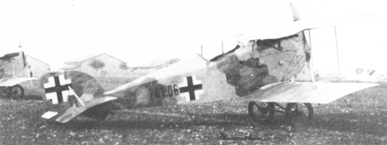
An unarmed Aviatik D.I(Th) 201.06, one of nine such aircraft accepted between June and September 1918.
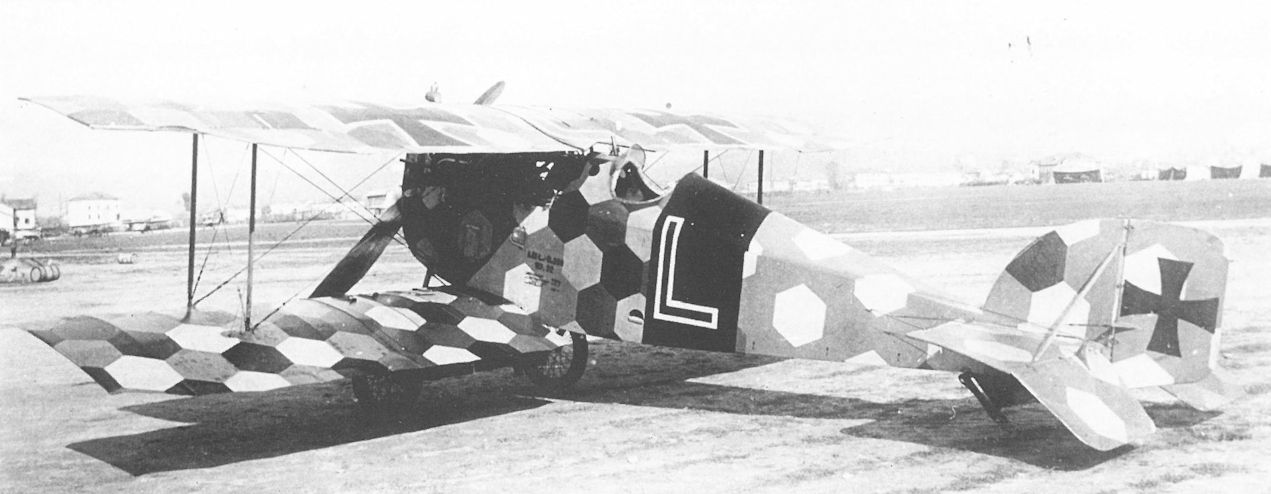
Linke-Crawford’s Aviatik D.I (Lo) 115.32 of Flik 60/J photographed on the Feltre airfield in late spring of 1918. Linke-Crawford was shot down in this machine on 31 July 1918; structural failure of the wing is thought to have contributed to his death.
Aviatik D.I 115.32 sports Frank Linke Crawford's last insignia, a capital L on a red band on the fuselage sides and on the center section of the top wing. Linke claimed seven victories flying this plane before he died in it. Its lozenge camouflage was hand painted. The Aviatik was lightly-built, contributing to its good maneuverability and performance, but it was fragile and susceptible to structural failure. (Carlo Lucchini)
Aviatik D.I 115.32 sports Frank Linke Crawford's last insignia, a capital L on a red band on the fuselage sides and on the center section of the top wing. Linke claimed seven victories flying this plane before he died in it. Its lozenge camouflage was hand painted. The Aviatik was lightly-built, contributing to its good maneuverability and performance, but it was fragile and susceptible to structural failure. (Carlo Lucchini)
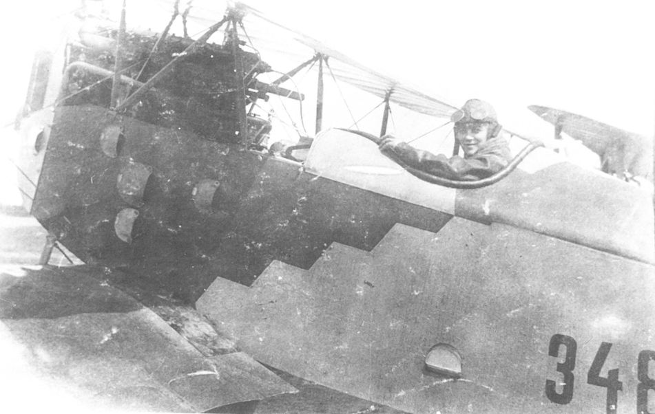
The unarmed Aviatik D.I(Ll) 348.01 at Aspern in September 1918.
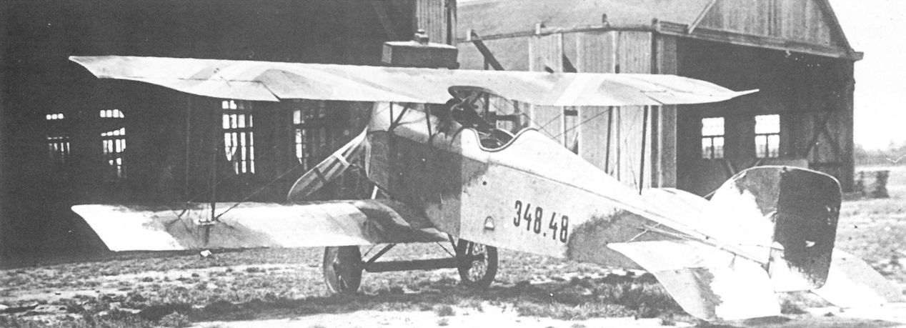
Prior to May 1919, when the red star became the national insignia, the Aviatik D.I(Ll) 348.48 was photographed in the colorful chevron markings of the post-war Hungarian Air Service.
Aviatik-Berg D.I 348.48 in Budapest 1919; verwendet in der Räterepublik, übermalte Balkenkreuze, statt dessen die ungarischen Nationalfarben in Pfeilform am Oberflügel, die Trennlinien des k.u.k. Tarnschemas sind neu übermalt worden
Aviatik-Berg D.I 348.48 в Будапеште 1919 г .; в Советской республике кресты были заменены на стрелки венгерских национальных цветов на верхнем крыле. Камуфляж перекрашен.
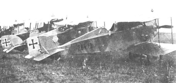
Aviatik D.I(WKF) 284.13 possibly attached to Flik 1/J at Igalo. The next in line is Aviatik D.I 338.02 that served with Flik 1/J in August 1918.
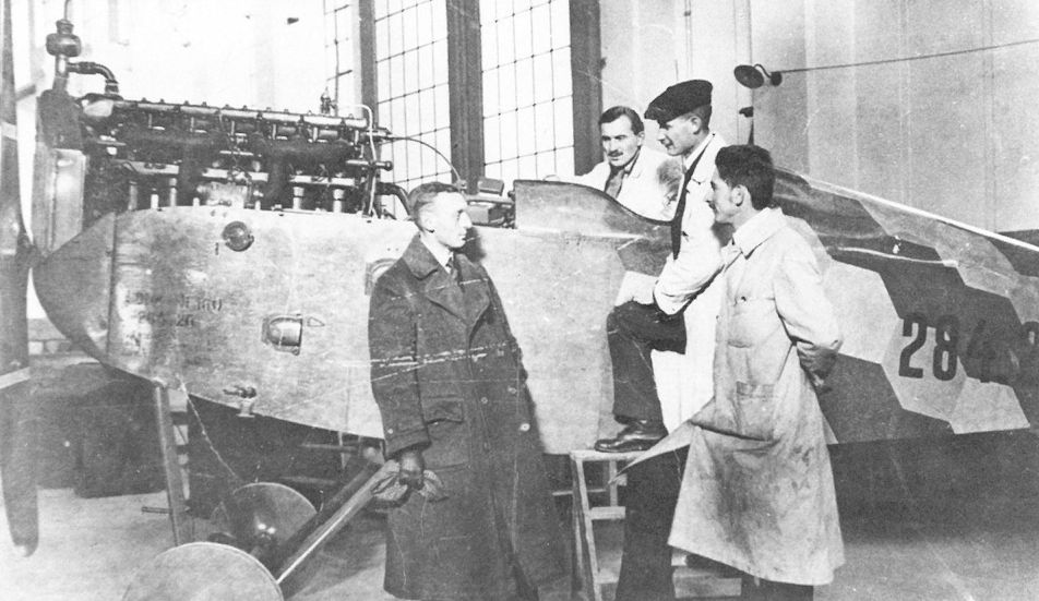
A group of WKF engineers posing with the uncompleted Aviatik D.I(WKF) 284.26 airframe. The engine is a 160 hp Daimler.
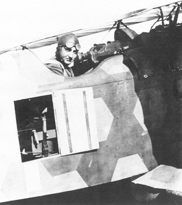
The open door shows the remotely-controlled camera securely held by leather straps in an Aviatik D.I photo-reconnaissance fighter. The pilot, Oberleutnant Ludwig Stillmungus, commander of Flik 40/P, was killed in combat on 12 August 1918.
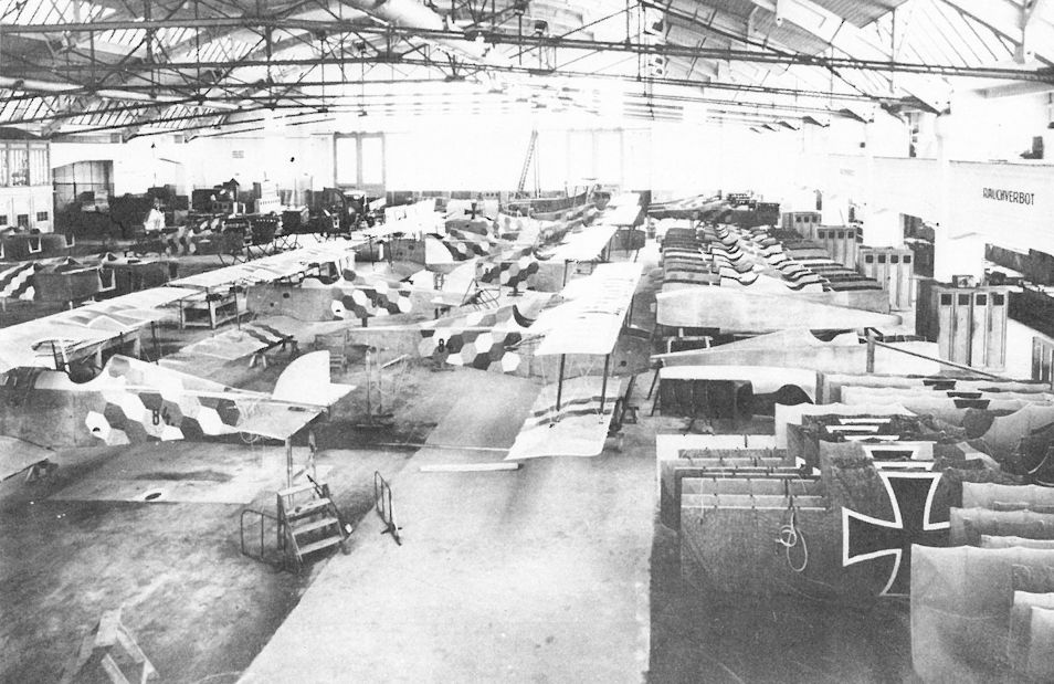
Mass production in the WKF factory. In the foreground are six Aviatik D.I(WKF) series 84 fighters under construction. Barely discernible in the background are two series 284 and one series 384 fighter.
WKF-Fabrikshalle, Wien 10. Laxenburgerstraße, im Bau Jagdeinsitzer Aviatik D.I-Serie 84.
Здание фабрики WKF, Вена 10. Laxenburger Strasse, сборка истребителей Aviatik D.I серии 84.
WKF-Fabrikshalle, Wien 10. Laxenburgerstraße, im Bau Jagdeinsitzer Aviatik D.I-Serie 84.
Здание фабрики WKF, Вена 10. Laxenburger Strasse, сборка истребителей Aviatik D.I серии 84.
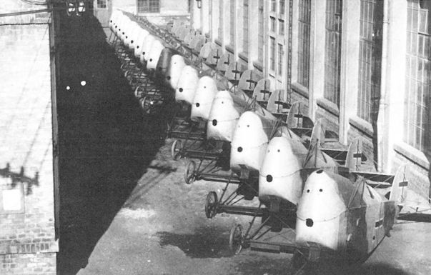
Eighteen completed Aviatik D.I(Lo) series 315 fighters awaiting assembly at the Lohner factory in late 1918. There is no record of these machines reaching the Front.
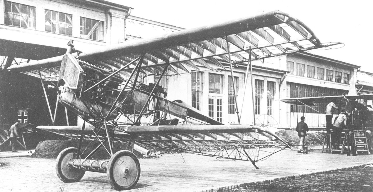
The fully-assembled airframe of a MAG-built Fokker D.VII rolled out for inspection shortly before the end of the war. Mechanics are working on an Aviatik D.I(MAG) in the background.
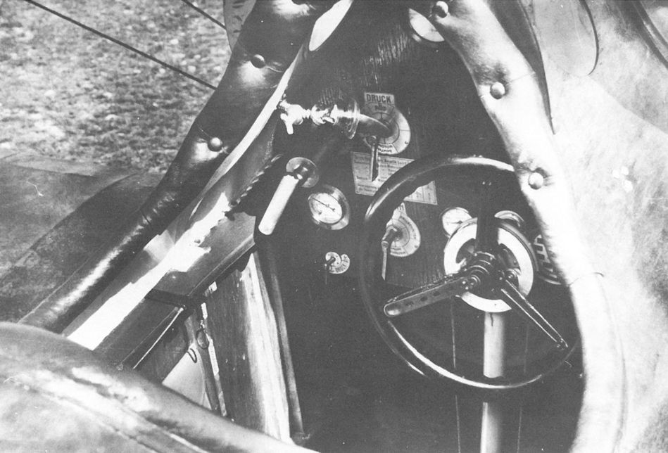
The cockpit of Aviatik D.I 38.06 showing the early control wheel that was replaced by a control stick on later production aircraft. The instrument panel was illuminated by two circular windows on each side of the cockpit and a small, swivelling light fixture. Valves for oil, gas and pressure for the fuel tank, etc are clearly marked on the panel with etched metal tags.
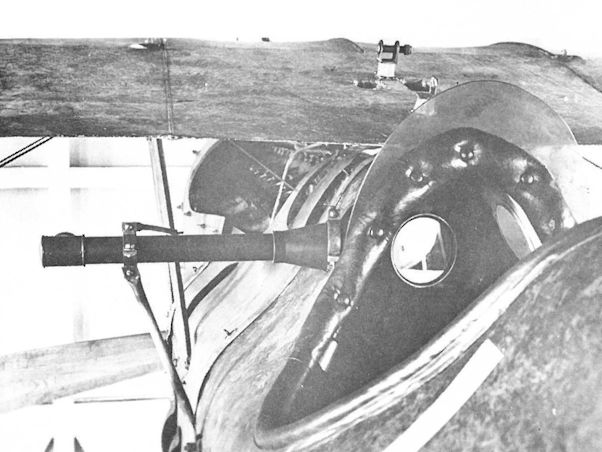
Beset by poor forward visibility, tests were performed with a forward-looking periscope on the Aviatik D.I series 38 fighter. The lugs for mounting the slanted machine gun can be seen on the upper wing.
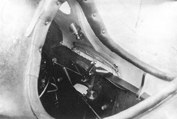
Aviatik D.I 38.06 cockpit with remote camera controls installed. Visible (from top to bottom) are the round window and small hooded light to illuminate the instruments, a level flight indicator, and the throttle, below which can be seen the camera plate-changing lever. The ring behind the throttle operates the fuselage aperture.
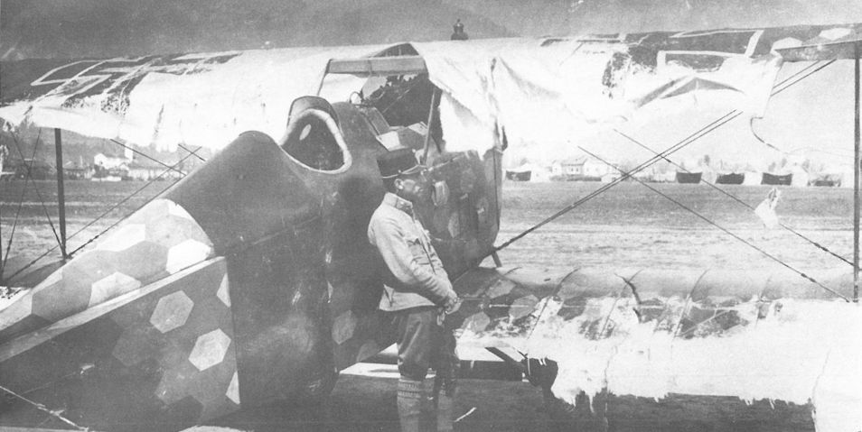
Fortunate to survive, Oberleutnant Fritz Pisko of Flik 60/J contemplates the massive wing failure of his Aviatik D.I (Lo) 115.26 on 18 May 1918. An official investigation showed that Lohner had substituted a lighter rib design and attached the fabric contrary to Aviatik specifications.
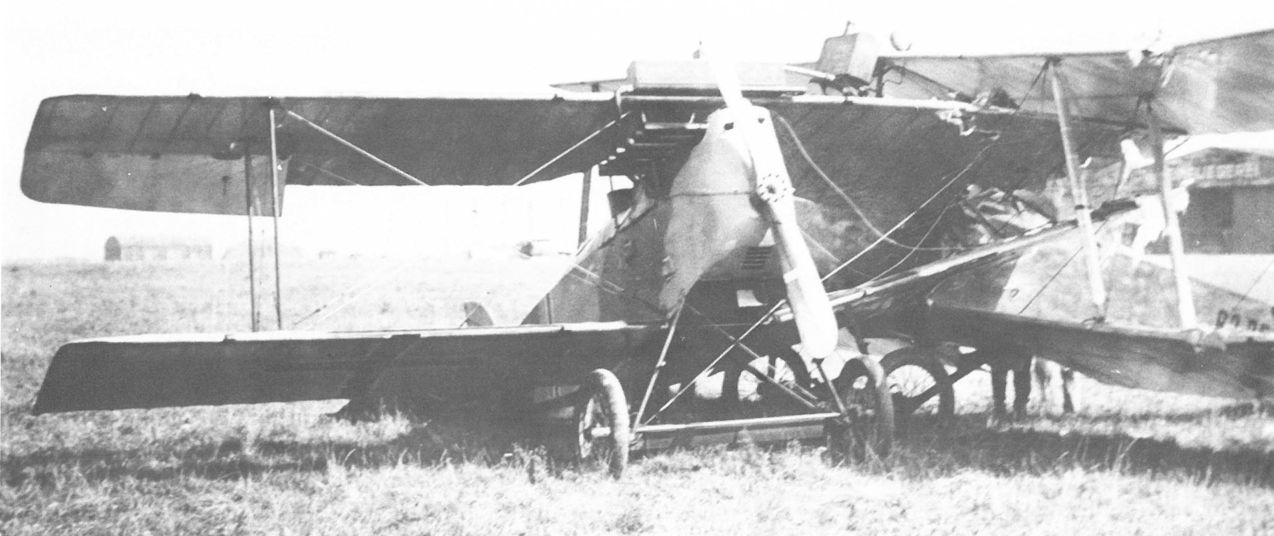
Among the few of the series accepted was the Aviatik D.I (Lo) 315.08 in which Feldwebel Ernst Kerschischnig collided with Brandenburg C.I 63.25 on 27 September 1918 at Aspern. The leading edge radiator was standard for the series 315.
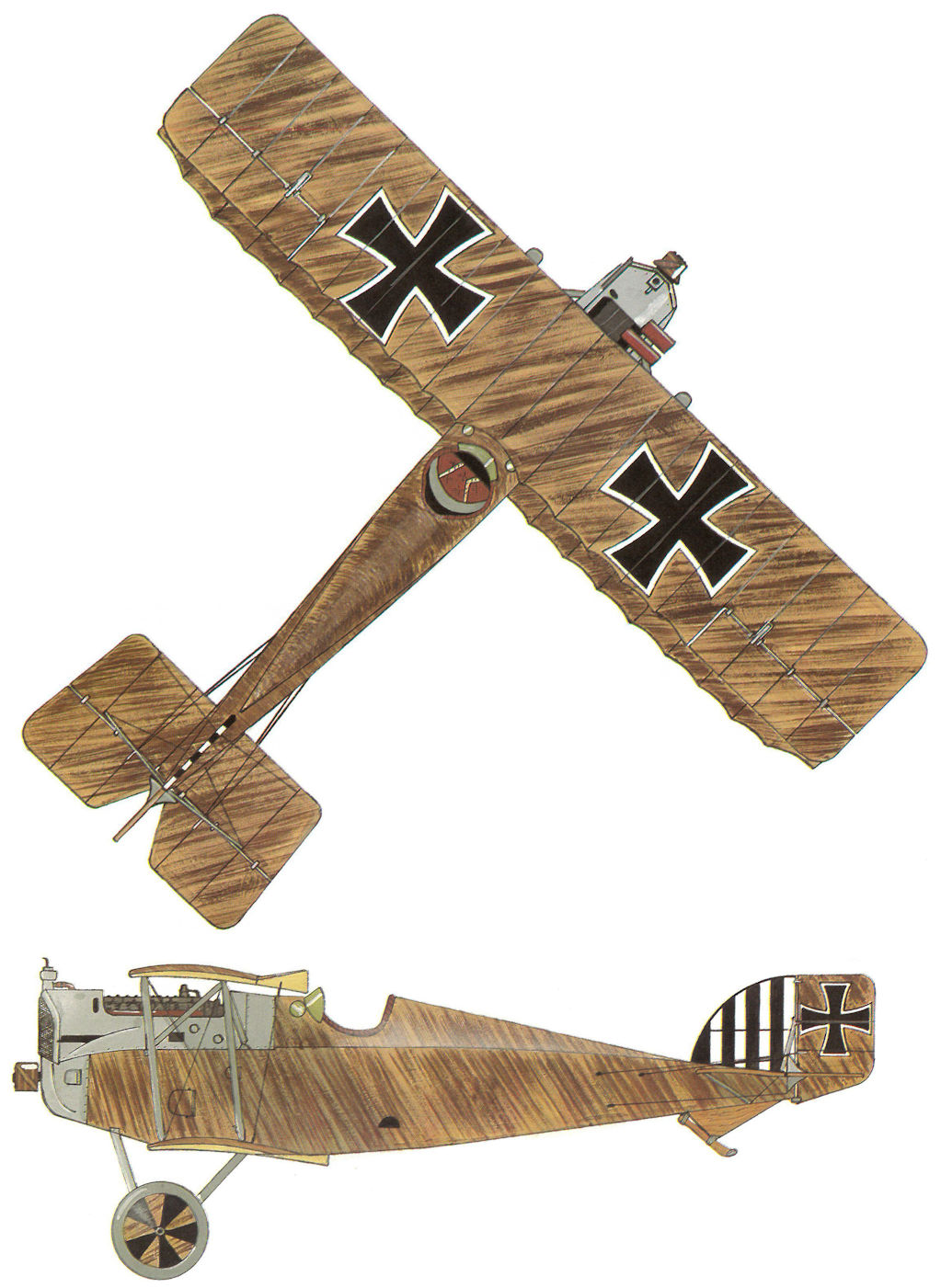
Aviatik D.I 38.37, Flik 63/J
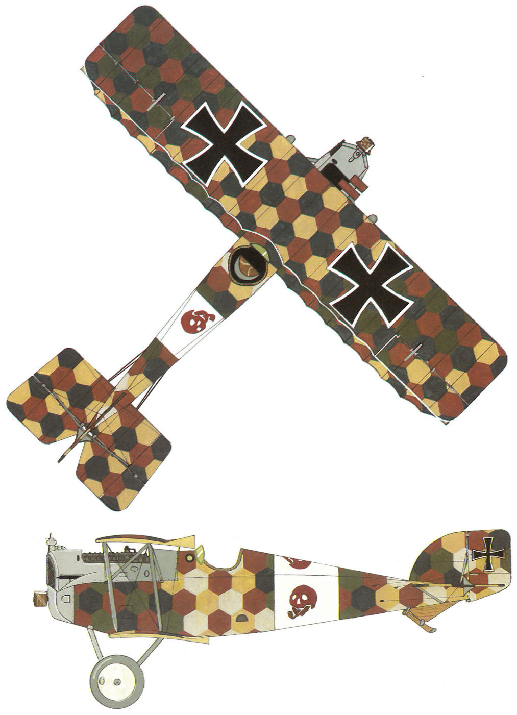
Aviatik D.I 138.XX, Flik 74/J
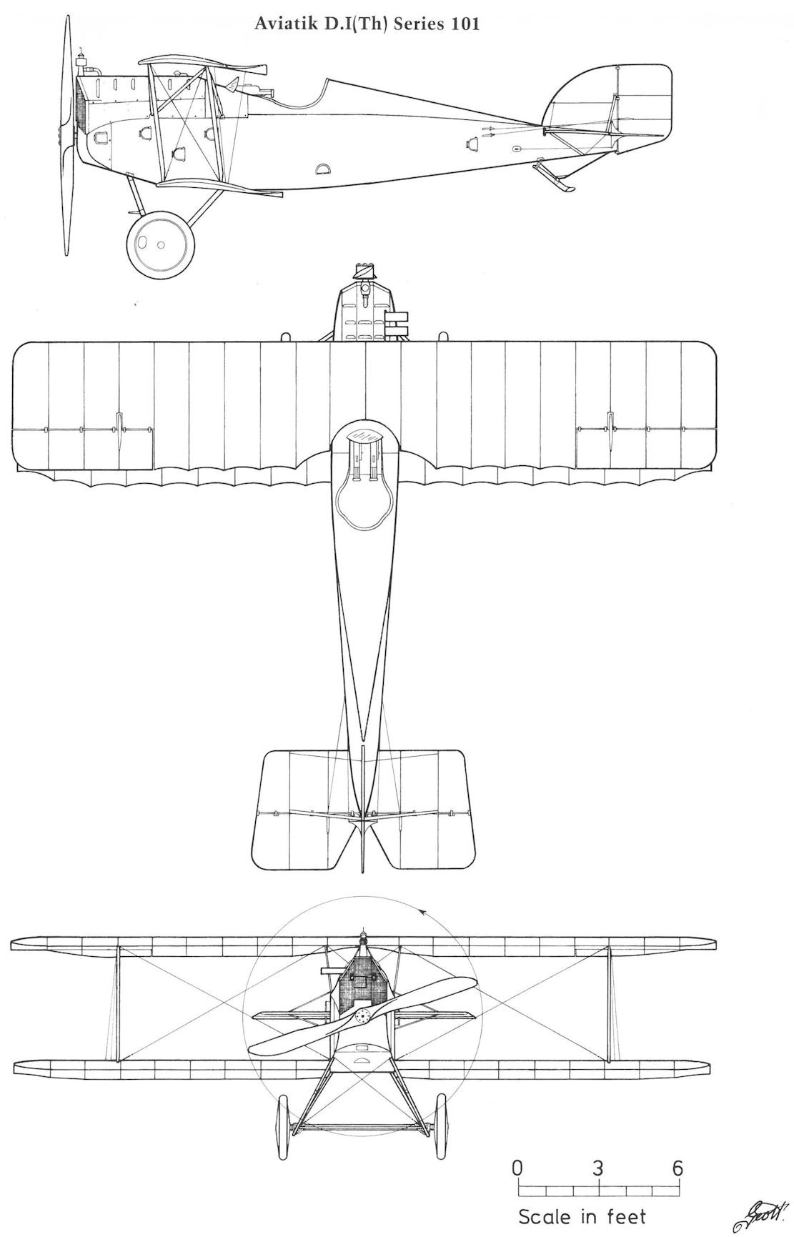
Aviatik D.I(Th) Series 101
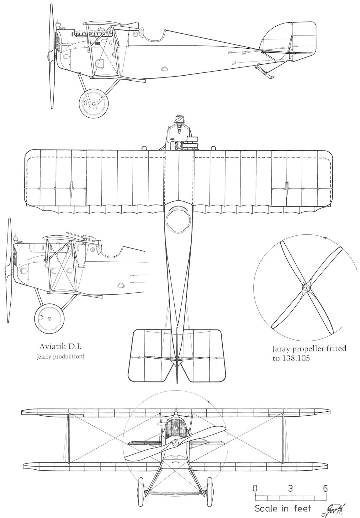
Aviatik D.I Series 38 and 138 (early version)
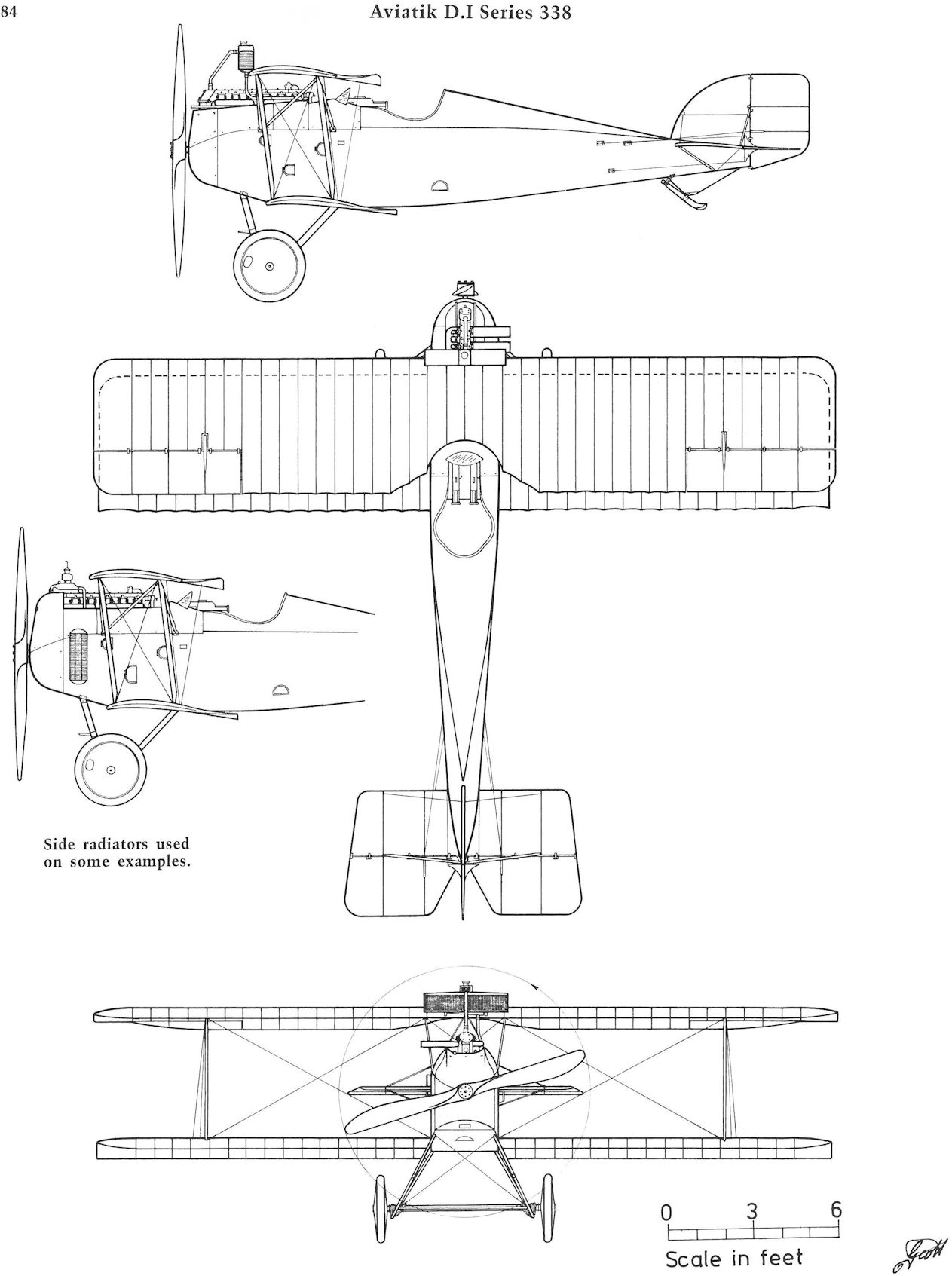
Aviatik D.I Series 338
Aviatik 30.22
Along with the 30.19 fighter, Berg proposed a high-speed version without wire bracing powered by a 200 hp Daimler engine. The top wing was supported by two diagonal struts and the lower wing was fully cantilevered. On 20 September 1916, Aviatik was permitted to proceed at its own risk with Flars providing technical support. The prototype, consisting of the modified 30.21 airframe, appeared at Aspern on 26 February 1917 under the designation 30.23 but changed to 30.22 in March 1917. Uncertain of structural integrity, Flars carefully checked the stress calculations and subjected the airframe to exacting load tests before proceeding with flight trials. The wing cellule failed the specified load conditions on 13 March; it was reinforced and tested successfully on 23 April 1917.
The 30.22 first flew on 25 April 1917. Test pilot Feldwebel Tordik reported greater sensitivity than that of the 30.19. But the bottom wing was seen to flex appreciably in flight, causing Aviatik to withdraw the 30.22 for modification. It came to Aspern for further testing on 2 June and was returned to the factory where it was last reported in July 1917. Further data are lacking. The high speed demonstrated by the 30.22 caused Flars to order a small batch of Aviatik D.II series 39 fighters for frontline evaluation.
Aviatik 30.22 Specifications
Engine: 200 hp Daimler
Wing: Span Upper 7.50 m (24.61 ft)
Span Lower 5.20 m (17.06 ft)
Chord Upper 1.55 m (5.09 ft)
Chord Lower 1.55 m (5.09 ft)
Dihedral Upper 0 deg
Dihedral Lower 0 deg
Sweepback Upper 0 deg
Sweepback Lower 0 deg
Gap 1.45 m (4.76 ft)
Stagger 0.25 m (0.82 ft)
Total Wing Area 19.5 sq m (210 sq ft)
General: Length 6.98 m (22.90 ft)
Height 2.45 m (8.04 ft)
Track 1.80 m (5.91 ft)
Empty Weight 681.5 kg (1503 lb)
Loaded Weight 801.5 kg (1767 lb)
Maximum Speed: 199 km/hr (124 mph)
Climb: 1000m (3,281 ft) in 4 min 56 sec
2000m (6,562 ft) in 11 min 7 sec
3000m (9,843 ft) in 26 min
4000m (13,124 ft) in 41 min
Aviatik 30.38
The Aviatik 30.38, a production D.II series 39 fighter powered by a 200 hp Hiero engine in place of the standard 200 hp Daimler, participated in the July 1918 Fighter Evaluation for comparison purposes. During the evaluation the 30.38 recorded substantially lower climb rates than the production Aviatik D.II. On 25 September 1918, the 30.38 was at the Aviatik factory undergoing modification. Further information is lacking.
Aviatik 30.38 Specifications
Engine: 200 hp Hiero
General: Empty Weight 655 kg (1444 lb)
Loaded Weight 915 kg (2018 lb)
Climb: 1000m (3,281 ft) in 4 min
2000m (6,562 ft) in 11 min
3000m (9,843 ft) in 18 min 50 sec
Aviatik D.II Series 39 and 339
Flight tests of the 30.22 "wireless" prototype were sufficiently promising for Flars to order, on 5 December 1917, nine Aviatik D.II "wireless" fighters for further trials followed by a second batch of 10 aircraft on 10 May 1918. A total of 16 D.II fighters were completed, consisting of aircraft 39.01 to 39.11 powered by the 200 hp Daimler engine and D.II 339.01 (ex 39.09) to 339.06 powered by the 225 hp Daimler. The series numbers 139 and 239 were not used. The modest D.II purchase by Flars was solely for engineering and high-speed investigation, including brief frontline evaluation. The D.II was never intended to replace the Aviatik D.I fighter nor was it considered a priority program at any time.
Aircraft 39.01 and 39.03 made their appearance at Aspern on 10 August 1917, performing flight trials through November. On 3 October 1917, 39.01 attained 217 km/h (135 mph) making it the fastest Austro-Hungarian fighter to date, although the climb rate was below that of the Aviatik D.I series 138. Aircraft 39.02, assigned in February 1918 to the weapons group at Fischamend, was used to test the experimental Elektro machine gun fitted with a British Aldis sight. Subsequently it was tested with the Gebauer motor machine gun. The nose radiator was standard with exception of aircraft 39.10, 39.11, 339.01 and 339.02 that were equipped with Hefa side radiators and aircraft 339.03 and 339.06 with leading-edge wing radiators.
In February 1918, aircraft 39.01 and 39.03, known as the "U-Berg" type (U = unverspannt = wireless) and armed with twin synchronized machine guns, were assigned to Flik 61/J for service evaluation personally supervised by the commanding officer, Oberleutnant Ernst Strohschneider. The technical report submitted in May 1918 stated that the speed was far greater than that of the Albatros D.III(Oef). This was especially true of 39.03, which had a metal fairing between the fuselage and lower wing to improve airflow. Visibility was just as poor as in the series 138. At full throttle, the propeller wash caused the wing struts to vibrate some 6 to 8 centimeters, causing alarming airframe vibration, particularly in tight turns. Aileron control was sluggish.
Three "wireless" fighters participated in the July 1918 Fighter Evaluation at Aspern: 339.02 fitted with a four-bladed propeller and armed with the Gebauer motor machine gun, the 30.38 prototype (a D.II airframe powered by a 200 hp Hiero engine) and 339.01 (ex-39.09). Oberleutnant Benno Fiala reported that the 339.01 (equipped with side radiators) had the better visibility that could be enhanced by fitting a top-wing radiator and reducing the engine cowling height. Among the competitors, 339.01 recorded the slowest rate of climb, requiring an additional 12 minutes to reach 5000 meters (16,405 ft) compared to the fastest climber, the Aviatik D.I 338.03. The experimental nature of the D.II program is evident from the fact that the three D.II variants all had different wing areas.
In July 1918, five D.II fighters (39.04 to 39.08) were dispatched to the Front for service assessment. Aircraft 39.10 and 39.11, equipped as photo-reconnaissance fighters, were assigned to Flik 46/P in September 1918. One D.II series 39 was based at the field flying school Neumarkt. Aircraft 339.03 and 339.06 were dispatched to the 6th Army on the Piave Front in September 1918. It is unlikely that any of the above aircraft saw combat service. The Aviatik D.II, an interesting high-performance project, was not considered for further production according to the August 1918 schedule.
Aviatik D.II Series 39 Specifications
Engine: 200 hp Daimler
Wing: Span Upper 7.50 m (24.61 ft)
Span Lower 5.20 m (17.06 ft)
Chord Upper 1.75 m (5.74 ft)
Chord Lower 1.65 m (5.41 ft)
Total Wing Area 19.5 sq m (210 sq ft)
General: Length 6.98 m (22.90 ft)
Height 2.45 m (8.04 ft)
Track 1.80 m (5.91 ft)
Loaded Weight 845 kg (1863 lb)
Maximum Speed: 217 km/hr (135 mph)
Climb: 1000m (3,281 ft) in 3 min 5 sec
2000m (6,562 ft) in 6 min 2 sec
3000m (9,843 ft) in 10 min 55 sec
4000m (13,124 ft) in 18 min 7 sec
Aviatik D.II 339.01 Specifications
Engine: 225 hp Daimler
Wing: Span Upper 8.00 m (26.25 ft)
Total Wing Area 22.44 sq m (242 sq ft)
General: Length 7.10 m (23.29 ft)
Height 2.60 m (8.53 ft)
Track 1.80 m (5.91 ft)
Empty Weight 668 kg (1473 lb)
Loaded Weight 947 kg (2088 lb)
Climb: 1000m (3,281 ft) in 3 min 39 sec
2000m (6,562 ft) in 7 min 17 sec
3000m (9,843 ft) in 11 min 32 sec
4000m (13,124 ft) in 16 min 54 sec
5000m (16,405 ft) in 28 min 36 sec
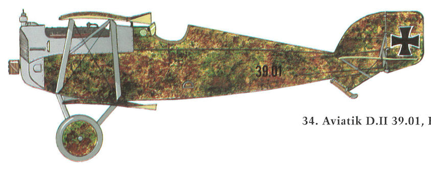
Aviatik D.II 39.01, Flik 61/J
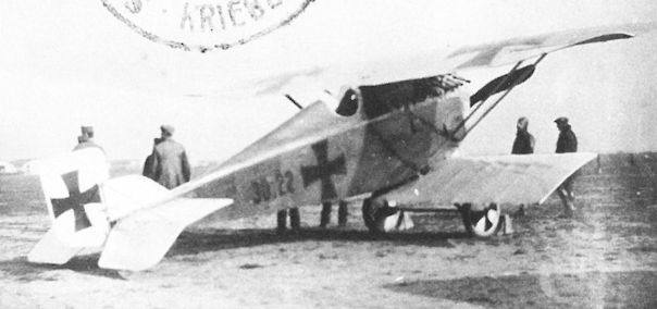
Aviatik 30.22 prototype. The strut-braced upper wing and the cantilever lower wing devoid of wire bracing made it possible to reach a top speed of 199 km/h (124 mph), the highest attained by an Austro-Hungarian aircraft in mid-1917.
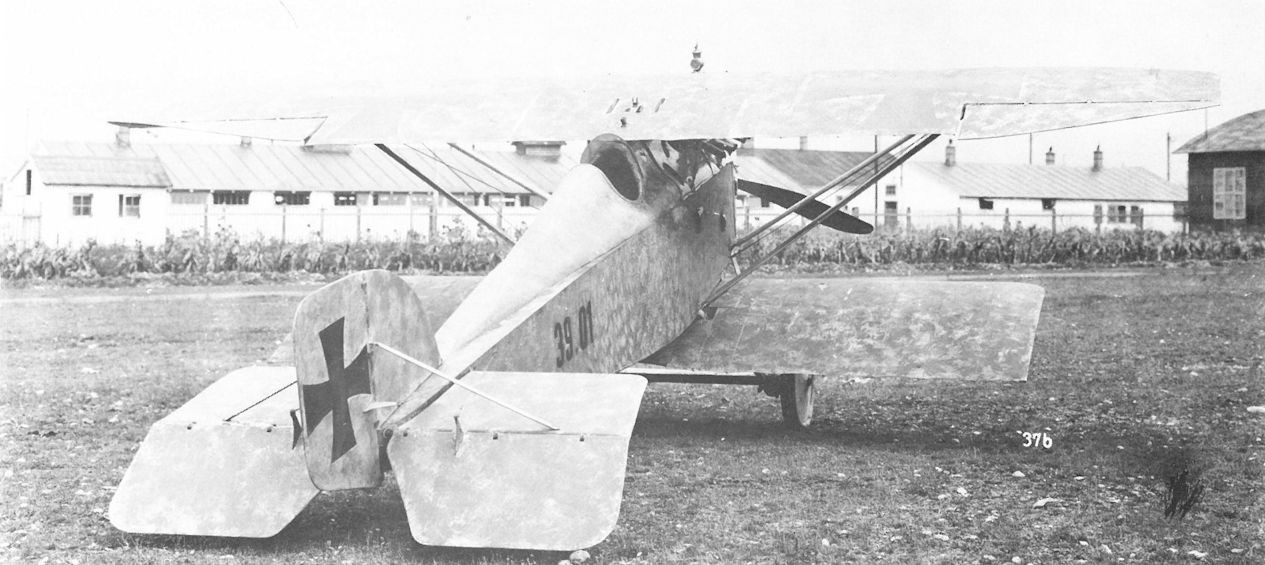
The Aviatik D.II 39.01 at Aspern, showing the mounting studs for the over-the-wing machine gun and the short, cantilevered lower wing. The sole cable bracing was between the wing struts.
The unarmed Aviatik D.II 39.01 in front of the Aviatik hangars at Aspern in the fall of 1917. The four-bladed propeller was usually matched with a 200 hp Daimler engine. Behind the tail is Aviatik C.I 137.15.
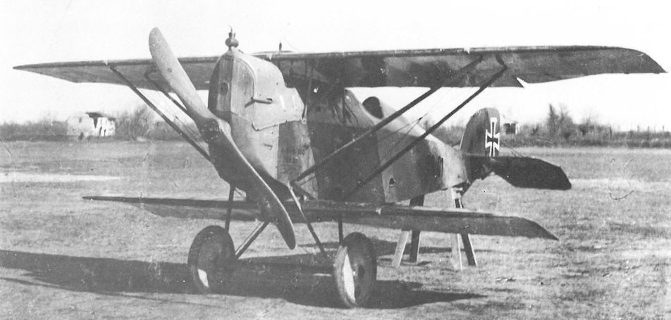
The Aviatik D.II 39.01 armed with twin, buried machine guns was assigned to Flik 61/J for frontline evaluation in February 1918. The airfield is Motta di Livenza.
The Aviatik 30.24 in front of the company hangar at Aspern. The aerodynamically-balanced ailerons on the top wing were unique for Berg-designed fighters. Cellon panels in the middle wing enhanced the pilot’s view downward. To the left are an Aviatik D.II 39.01 and a D.I 138.17.
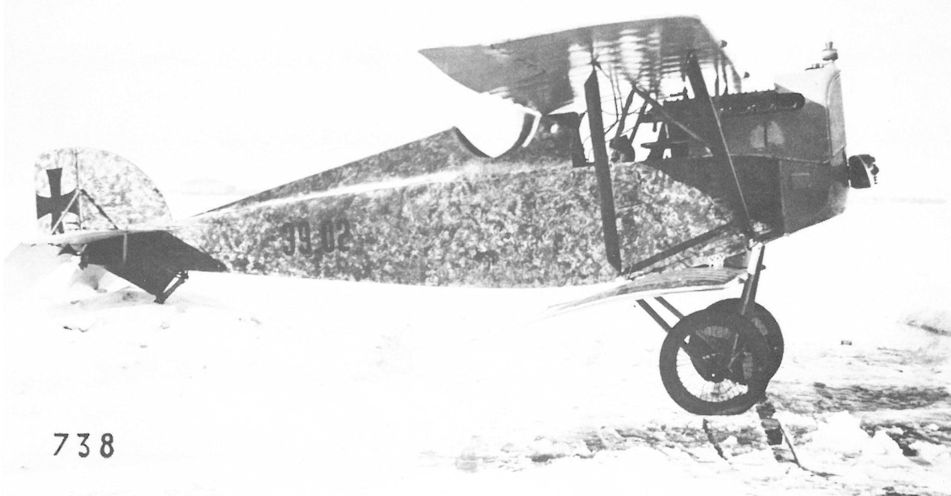
In March 1918, the weapons test section at Fischamend investigated the experimental Elektro machine gun and a captured Aldis sight on Aviatik D.II 39.02.
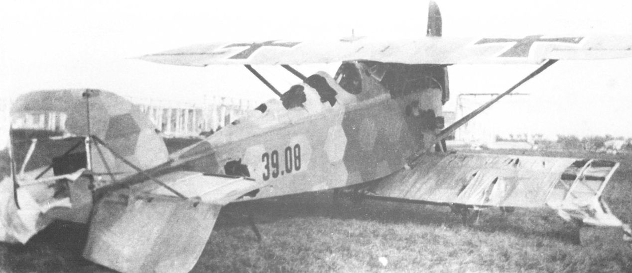
Ravaged by Allied souvenir hunters, the bedraggled Aviatik D.II 39.08 was photographed at Casarsa in November 1918.
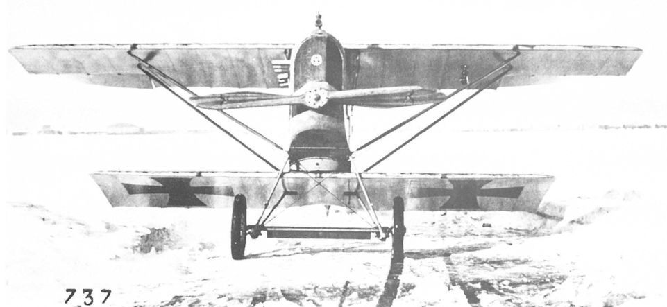
The compact design of Aviatik D.II 39.02 is shown to good advantage in this view. Austria-Hungary was a leader in propeller design by virtue of the wind tunnel facility at Fischamend. The unique propeller shape was a result of that activity.
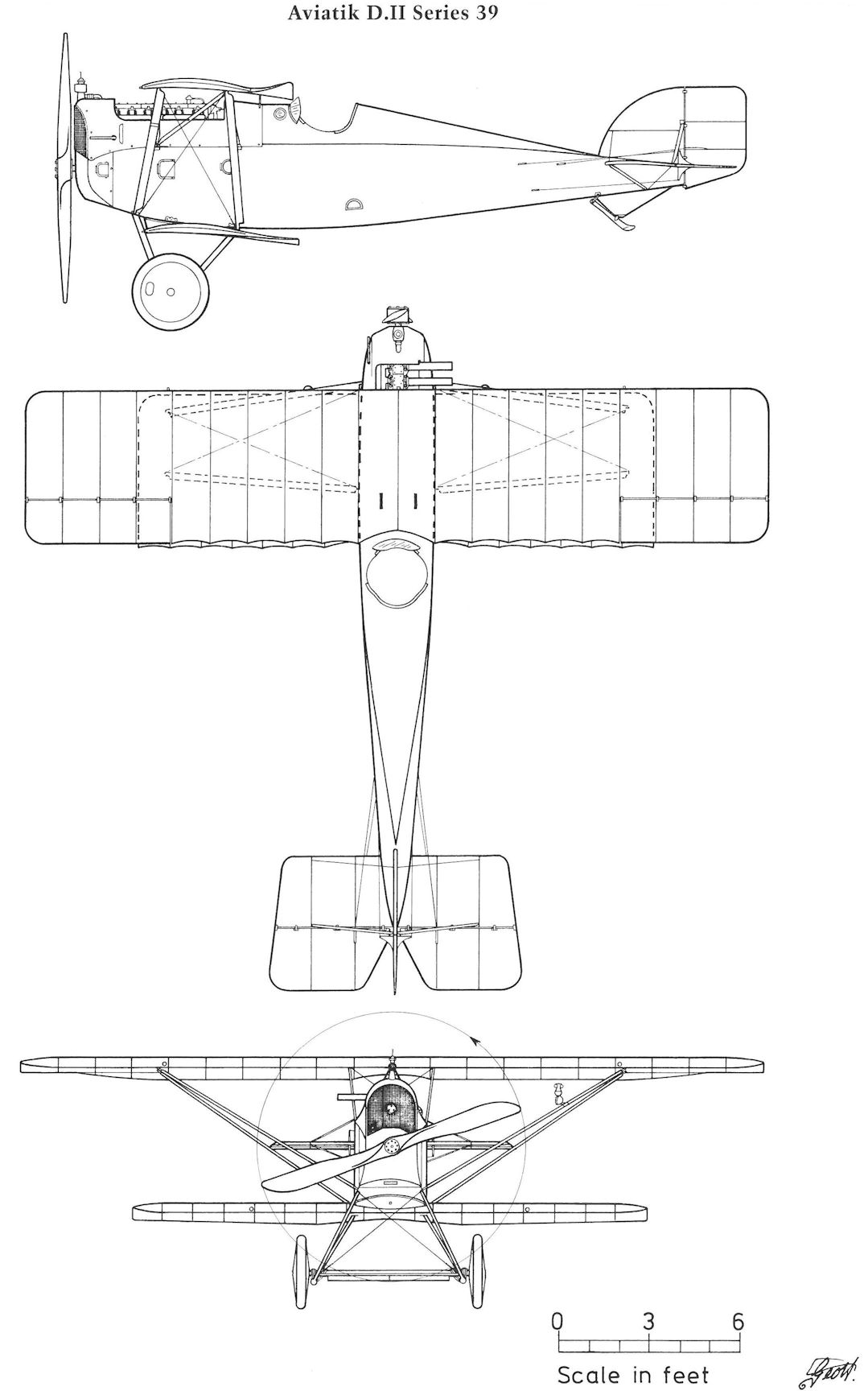
Aviatik D.II Series 39
Aviatik 30.25
The development of the 360 hp six-cylinder and 300/350 hp Daimler V-12 engines had reached a stage in mid-1916 that enabled the Flars design department to begin work on a high-performance aircraft using these engines. In September 1916, Aviatik was given the task of building two "Mises-Saliger" prototypes at Esslingen under the direction of Leutnant Saliger. However, on 14 November 1916 the LFT stopped the work and directed Aviatik to concentrate on the C.I and D.I production. The Mises-Saliger project (no Aviatik prototype number had been assigned) was transferred to Lohner on 11 December 1916, where the program continued under the designation Lohner 10.21 and 10.22. Concurrently, Berg had designed a competing biplane powered by a 360 hp Daimler six-cylinder engine. The project study, dated 6 December 1916 and officially numbered 30.25, was evaluated by Flars who declined to support Berg's proposal and the project was dropped.
Frontline experience had shown that fast, camera-equipped, single-seat fighters could return unharmed with acceptable reconnaissance photographs and, if necessary, engage or evade Allied interceptors. In mid-1917, specifically to meet the photo-fighter requirement, Aviatik modified a C.I airframe (reported as ex-37.41) to carry two synchronized machine guns and a 30cm focal-length camera in lieu of the observer. A parachute was provided for the pilot. The aircraft, designated 30.25 and powered by a 185 hp Daimler engine, was flight tested in September 1917 by Flars test pilot Hauptmann Oskar Fekete, who felt the conversion of extant Aviatik C.I aircraft was easier and less costly than placing a new type into production. The 30.25 was assigned to Flek 6 in Wiener-Neustadt as a single-seat trainer. On 29 November 1917, during a practice flight, the prototype suddenly stood on its nose and trailing a white smoke plume, crashed into the ground and was demolished.
Aviatik 30.25 Specifications
Engine: 185 hp Daimler
Maximum Speed: 186 km/hr (116 mph)
Climb: 1000m (3,281 ft) in 3 min 20 sec
5000m (16,405 ft) in 30 min 30 sec

The Aviatik 30.25 was a single-seat photo-reconnaissance fighter modified from a production C.I airframe. A remotely-controlled camera was installed behind the pilot’s seat.
Aviatik 30.25, Umbau aus Berg C.l 37.41, Versuchsflugzeug als Photo-einsitzer mit festem Kameracinbau
Aviatik 30.25, переделка из Berg C.I 37.41, экспериментальный одноместный фоторазведчик с фиксированной камерой
Aviatik 30.25, Umbau aus Berg C.l 37.41, Versuchsflugzeug als Photo-einsitzer mit festem Kameracinbau
Aviatik 30.25, переделка из Berg C.I 37.41, экспериментальный одноместный фоторазведчик с фиксированной камерой

Aviatik 30.25 Project
Aviatik 30.27 and 30.29
The LFT aircraft specifications for 1918 listed a Type 5 fighter, an ultra-light interceptor powered by a 150 hp rotary engine. This took into account that, as of May 1917, rotary engine production had begun at the Oesterreichische Waffenfabrik AG, Steyr in anticipation of receiving sufficient supplies of Voltol (castor oil substitute) from Germany. A Steyr rotary engine based on the 150 hp Le Rhone was submitted for duration tests in November 1917. It is not generally known that Steyr delivered 35 out of 150 ordered Le Rhone (St) engines through September 1918 and the rest were nearing completion when the war ended.
Only Aviatik's rotary-engined fighters were flight tested, although several manufacturers had similar fighters under development at the war's end. The drawings for the first Aviatik prototype, 30.27, were completed in January 1918. The prototype arrived at Aspern for flight tests in March. Preliminary trials demonstrated severe wing twist when the ailerons were actuated. The aircraft was re-built with a larger wingspan, longer fuselage and a fully-cowled engine. During trials in May 1918, the modified 30.27 reached a maximum speed of 200 km/h (124 mph), but the climb rate did not meet the LFT criteria.
The Aviatik 30.29 was similar in all respects to the 30.27. Both aircraft participated in the July 1918 Fighter Evaluation at Aspern. Neither received praise or condemnation and any hope of a favorable critique disappeared when the upper wing of 30.29 failed in flight.
The manufacturer's drawings, dated March 1918, refer to a version, based on the 30.29 and designated Aviatik D.III, for which series production was contemplated. But Voltol production, sufficient to meet German but not export requirements, thwarted LFT plans to put a rotary-engined interceptor into service. Consequently, interceptor development was accorded low priority. Because "no aircraft were ready," in September 1918 Flars recommended sending the completed Steyr engines to Germany in return for Oberursel rotary engines at a later date.
Aviatik 30.27 Specifications (Open Cowl)
Engine: 150 hp Le Rhone (St)
Wing: Span Upper 6.60 m (21.65 ft)
Span Lower 6.60 m (21.65 ft)
General: Track 1.80m (5.91 ft)
Empty Weight 350 kg (772 lb)
Loaded Weight 600 kg (1323 lb)
Maximum Speed: 200 km/hr (124 mph)
Climb: 1000m (3,281 ft) in 1 min 24 sec
2000m (6,562 ft) in 3 min 6 sec
3000m (9,843 ft) in 7 min 58 sec
4000m (13,124 ft) in 15 min 15 sec
5000m (16,405 ft) in 22 min 32 sec
Aviatik 30.27 Specifications (Closed Cowl)
Engine: 150 hp Le Rhone (St)
Wing: Span Upper 6.82 m (22.38 ft)
Span Lower 6.60 m (21.65 ft)
Chord Upper 1.40 m (4.59 ft)
Chord Lower 1.25 m (4.10 ft)
Maximum Speed: 190 km/hr (118 mph)
Climb: 1000m (3,281 ft) in 2 min 11 sec
2000m (6,562 ft) in 5 min 20 sec
3000m (9,843 ft) in 9 min 18 sec
4000m (13,124 ft) in 18 min 12 sec
Aviatik 30.31 and 30.32
The Aviatik 30.31 and 30.32 prototypes were similar to the final version of the 30.27 fighter. When it became evident that lack of lubricating oil would prevent the operational use of rotary engines, development work was interrupted and both aircraft were reported stored in "good condition" in the Aviatik hangars in July 1918. At war's end, they were pro-forma accepted to enable Aviatik to receive payment for the aircraft.
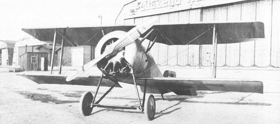
Aviatik 30.27 (first version). Among test pilots, the aircraft was nicknamed Schnucki (slang for a cuddly girl friend). It was armed with twin Schwarzlose machine guns. The aileron wash-out is quite pronounced.
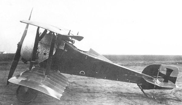
The Aviatik 30.27 (first version) was designed to meet the 1918 interceptor specification. The loaded weight was a mere 600 kg (1323 lb).
Aviatik 30.27, Prototyp für Berg D.III, Leichtbaueinsitzer
Aviatik 30.27, прототип Berg D.III, легкий одноместный истребитель
Aviatik 30.27, Prototyp für Berg D.III, Leichtbaueinsitzer
Aviatik 30.27, прототип Berg D.III, легкий одноместный истребитель
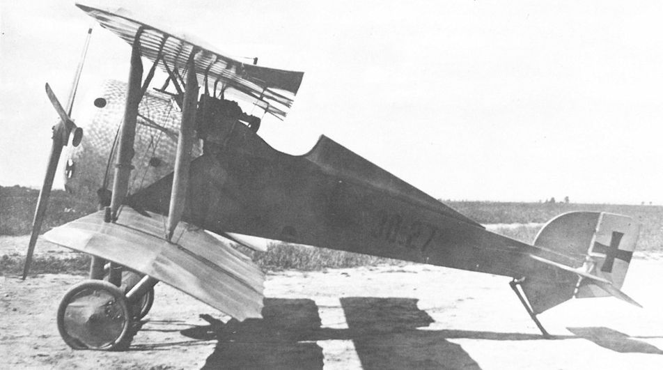
Aviatik 30.27 (second version) fitted with strengthened wings, elongated fuselage, and fully-cowled engine. The thin, four-bladed propeller was an attempt to maximize thrust. Although a top speed of 200 km/h (124 mph) was recorded, the rate of climb was deemed insufficient for an interceptor.
Aviatik 30.27, nach Rumpfumbau, kleineres Seitenruder und Anbau eines vierflügeligen Jaraypropcllers für bessere Steigleistung
Aviatik 30.27, после переделки фюзеляжа, уменьшенного руля направления и установки четырехлопастного пропеллера Jaray для лучшей скороподъемности
Aviatik 30.27, nach Rumpfumbau, kleineres Seitenruder und Anbau eines vierflügeligen Jaraypropcllers für bessere Steigleistung
Aviatik 30.27, после переделки фюзеляжа, уменьшенного руля направления и установки четырехлопастного пропеллера Jaray для лучшей скороподъемности
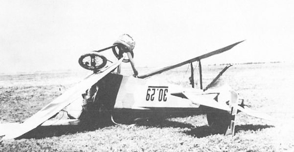
Aviatik 30.29. On 10 July 1918 the upper leading edge folded back just as Hauptmann Karl Nikitsch was entering a loop during the Fighter Evaluation. He was fortunate to survive the crash from 2000 meters (6562 ft) without serious injury!
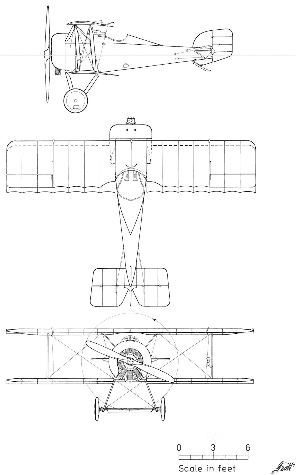
Aviatik 30.27 (first version)
Aviatik 30.30
The drawings for the Aviatik 30.30 high-altitude fighter, the most powerful fighter built by Aviatik, were completed in May 1918. It was powered by a 230 hp Hiero engine. The design provided for an "open" center-section, giving good visibility, and accessible machine guns - features pilots had found lacking on the Aviatik D.I. Although good performance was recorded at the July 1918 Fighter Evaluation, the 30.30 apparently did not find favor with the pilots. In Cavigioli's book the 30.30 is incorrectly designated as the prototype for the Aviatik D.III when, in fact, Flars had not included any Aviatik fighter for production through March 1919. In September 1918, the 30.30 prototype was undergoing reconstruction at the Aviatik factory, but details are lacking.
Aviatik 30.30 Specifications
Engine: 230 hp Hiero
Wing: Span Upper 8.60 m (28.21 ft)
Total Wing Area 26.5 sq m (285 sq ft)
General: Empty Weight 683.5 kg (1507 lb)
Loaded Weight 943.5 kg (2080 lb)
Maximum Speed: 198 km/hr (123 mph)
Climb: 1000m (3,281 ft) in 3 min 2 sec
2000m (6,562 ft) in 5 min 4 sec
3000m (9,843 ft) in 9 min 6 sec
Aviatik 30.39
The Aviatik 30.39 fighter, similar to the 30.30 but powered by a 225 hp Daimler engine, competed in the July 1918 Fighter Evaluation at Aspern. Weighing slightly less than the 30.30, its rate of climb was about equal, but it was slower than the production Aviatik D.I series 338. In September 1918, the 30.39 was at Aviatik-Esslingen awaiting modification. Further information is lacking.
Aviatik 30.39 Specifications
Engine: 225 hp Daimler
Wing: Total Wing Area 26.5 sq m (285 sq ft)
General: Empty Weight 663 kg (1462 lb)
Loaded Weight 937 kg (2066 lb)
Climb: 1000m (3,281 ft) in 2 min 28 sec
2000m (6,562 ft) in 5 min 8 sec
3000m (9,843 ft) in 9 min
4000m (13,124 ft) in 16 min 30 sec
5000m (16,405 ft) in 25 min 30 sec

The Aviatik 30.30 high-altitude fighter, the most powerful built by Aviatik, was armed with two Schwarzlose machine guns.
The Aviatik 30.30 was designed specifically for high-altitude combat over the Italian front
The Aviatik 30.30 was designed specifically for high-altitude combat over the Italian front

Aviatik 30.30. The fuselage and tail were plywood-covered and only the massive block radiator on the upper wing interrupted the prototype’s clean lines.
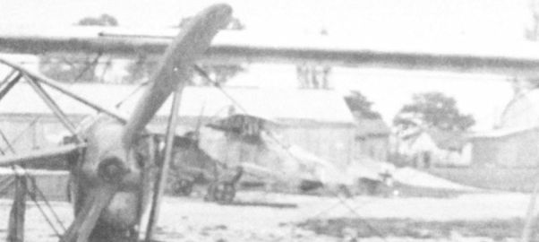
In the blurred background, the Aviatik 30.39 prototype was photographed by chance through the wings of an overturned Brandenburg G.I bomber.

Aviatik 30.30
Aviatik 30.40
The Aviatik 30.40 prototype, powered by a 150 hp Le Rhone(St) rotary engine, was Aviatik's most ambitious effort to meet the interceptor requirement. Weighing only 586 kg (1292 lb) fully loaded, it was the lightest fighter built in Austria-Hungary. The airframe was derived from the 30.27 biplane, and the strut-braced parasol wing had been thoroughly tested on the Aviatik D.II. Based on promising performance recorded during trials in July and August 1918, the 30.40 was proposed for production by Thone & Fiala. But until the supply of Voltol was assured, the LFT was forced to exclude the rotary-engined fighter from further consideration. In late October 1918, the 30.40 was pro-forma accepted to enable Aviatik to receive payment for the aircraft.
Aviatik 30.40 Specifications
Engine: 150 hp Le Rhone (St)
Wing: Span Upper 7.30 m (23.95 ft)
Total Wing Area 10.5 sq m (113 sq ft)
General: Length 5.35 m (17.55 ft)
Empty Weight 366 kg (807 lb)
Loaded Weight 586 kg (1292 lb)
Maximum Speed: 192 km/hr (119 mph)
Climb: 1000m (3,281 ft) in 1 min 30 sec
2000m (6,562 ft) in 2 min 50 sec
3000m (9,843 ft) in 6 min 50 sec
4000m (13,124 ft) in 10 min
5000m (16,405 ft) in 16 min 50 sec
6000m (19,686 ft) in 22 min
Aviatik 30.42
The Aviatik 30.42 prototype was reported in "good condition" in the Aviatik hangar at Aspern on 7 October 1918. Since it is listed jointly with the 30.27, 30.31 and 30.32 prototypes, the 30.42 also may have been a rotary-engined biplane fighter but confirmation is lacking. In late October, the 30.42 was pro-forma accepted to enable Aviatik to receive payment for the aircraft.

Aviatik 30.40

The Aviatik 30.40 parasol fighter during flight trials at Aspern in July and August 1918. Armament would have consisted of two Schwarzlose machine guns mounted at eye level.
Aviatik 30.40, Versuchsflugzeug mit Parasoltragfläche, Umbau aus Berg 30.27, mit Steyr Rh 160 PS
Aviatik 30.40, экспериментальный самолет с крылом-парасоль, переоборудованный из Berg 30.27, со Steyr Rh 160 л.с.
Aviatik 30.40, Versuchsflugzeug mit Parasoltragfläche, Umbau aus Berg 30.27, mit Steyr Rh 160 PS
Aviatik 30.40, экспериментальный самолет с крылом-парасоль, переоборудованный из Berg 30.27, со Steyr Rh 160 л.с.

Aviatik 30.40. The washed-out ailerons, a typical Berg feature, are clearly in evidence. Although the photograph was taken in the summer of 1918, the old-style markings have not been replaced.

Aviatik 30.40
Aviatik 30.26 and 30.28
On 25 June 1917, Aviatik received a contract to build two long-range reconnaissance prototypes (Fernaufklarungs-Flugzeug) to which the numbers 30.26 and 30.28 were assigned. The 30.26, powered by a 230 hp Hiero engine, arrived at Aspern on 8 March 1918 for flight trials. Its impressive climb rate caused Uzelac to urge the "completion of flight testing with utmost dispatch." The 30.26 was slightly damaged in a forced landing on 11 April 1918. The absolute ceiling of 4750 meters (15,584 ft) reached on 14 April did not meet expectations, although the prototype was accepted by Flars later that month. There are indications that the wingspan was increased and the empty weight reduced to raise the ceiling, but to no avail. On 15 June 1918, Flars reported that since the type lacked the required performance it would not go into production.
After the war Berg told Riccardo Cavigioli, a member of the Inter-Allied Armistice Commission, that the 30.26 (as the Aviatik C.II) was destined for the Italian Front had production not been stopped by the Armistice. The statement is not supported by LFT evidence. An Aviatik C.II was not included in the August 1918 production program. Rather, Aviatik was scheduled to build the G.III series 131 bomber and the Fokker D.VII fighter through mid-1919.
The Aviatik 30.28 prototype, designed to take a 345 hp Daimler V-12 engine, was not completed. Further details are lacking.
Aviatik 30.26 Specifications
Engine: 230 hp Hiero
Wing: Span Upper 10.56 m (34.65 ft)
Total Wing Area 32.4 sq m (349 sq ft)
General: Length 7.40 m (24.28 ft)
Empty Weight 832 kg (1835 lb)
Loaded Weight 1282 kg (2827 lb)
Maximum Speed: 158 km/hr (98 mph)
Climb: 1000m (3,281 ft) in 3 min 53 sec
2000m (6,562 ft) in 8 min 34 sec
3000m (9,843 ft) in 15 min 2 sec
4000m (13,124 ft) in 25 min 28 sec
4700m (15,585 ft) in 40 min 48 sec

Unmistakably a Berg design, the Aviatik 30.26 was armed with twin forward-firing machine guns and a single Schwarzlose gun for the observer.

Aviatik 30.26
Saliger Three-Engine Bomber
Before he went to Oeffag in early 1917, Ingenieurleutnant Karl Saliger was attached to the Flars construction section. In January 1917, Saliger submitted a proposal for a bomber powered by one 300 hp Daimler V-12 tractor engine and two 200 hp Hiero pusher engines. The empty weight was projected at 2630 kg, the loaded weight at 3470 kg, with a useful load of 390 kg. There appears little doubt that this design was the pattern for the Aviatik 30.23 bomber that was built under government supervision.
Aviatik 30.23
Flars reported on 29 December 1916 that a new three-engined bomber project would shortly be submitted for approval. The layout and specifications were completed in January 1917 by Ingenieurleutnant Karl Saliger of the Flars bomber group. Powered by one 300 hp Daimler V-12 and two 200/230 hp Hiero pusher engines, the bomber was designed for a crew of three and a bomb load of 440 kg (882 lb). Construction of two prototypes, designated 30.23 and 30.34, was assigned to Aviatik under a cost-plus-fixed-fee contract under Flars supervision. Work on two prototype bombers began in February 1917 with completion scheduled for April-May 1917.
Progress was slow. In January 1917, Saliger transferred to Oeffag leaving Aviatik engineers, who were already fully occupied with in-house projects, to set the pace. After Saliger's death in July 1917, Berg assumed engineering control, and probably this was the reason that the 30.23 became known as the "Berg" bomber. In June 1917, the 30.23 bomber's fuselage was complete and the flying surfaces were in the process of being covered.
"Bureaucratic inertia", according to Berg, had delayed engine delivery but, in fact, other programs had been given priority. Consequently, it was not until 7 January 1918 that the 30.23 bomber was completed. Ground trials commenced on 6 March, followed by the maiden flight on 13 March, with satisfactory performance reported. Because the rudder response was felt to be inadequate, three configurations were tested before the correct shape was found. The single wheels were replaced by twin wheels. Finding the proper configuration airscrew to maximize performance proved, as always, extremely time-consuming. Berg wanted to employ reduction gearing to lower propeller revolutions, but Ingenieur Kolin calculated that the power loss would be excessive. Speed and climb trials, on 5 April, 27 April and 24 May 1918, demonstrated results that "compared favorably with contemporary German bombers." On that basis, Flars ordered four additional bombers on 29 May 1918 (see Aviatik G.III series 131).
On 7 August 1918, contingent on completing a three-hour duration flight, the 30.23 prototype was scheduled to join Flik 102/G for evaluation. The 30.23 prototype was formally accepted by the LFT in October 1918 and remained at Aspern until the war's end.
Aviatik 30.23 Specifications
Engine: 300 hp Daimler & 2 x 230 hp Hiero
Wing: Span Upper 17.10 m (56.10 ft)
Total Wing Area 83.6 sq m (900 sq ft)
General: Length 12.30 m (40.35 ft)
Empty Weight 2681.6 kg (5913 lb)
Loaded Weight 3784.1 kg (8344 Ibj
Maximum Speed: 110 km/hr (68 mph)
Climb: 1000m (3,281 ft) in 5 min 29 sec
2000m (6,562 ft) in 13 min 10 sec
3700m (12,139 ft) in 45 min
Aviatik 30.34
Aviatik began construction of two bomber prototypes, 30.23 and 30.34, in February 1917. The fuselage of 30.34 was ready for the plywood covering in June when work was halted to give priority to 30.23 completion. In December 1917, Aviatik proposed replacing the center engine by a forward gun turret, mounting the outer engines as tractors, and dividing the undercarriage to allow bomb rack installation under the fuselage. Calculations submitted by Aviatik showed that the bomber would have greater reliability due to reduced engine and fuel weight. Flars rejected the proposal but approved the installation of three 230 hp Hiero engines and urged that work start at once. The 30.34 was reported "almost complete" on 15 March 1918. In a letter dated 24 August 1918, Aviatik complained to Flars that the program had been neglected, nor had the Hiero engines been delivered - this at a time when the LFT command urged the development of the Aviatik G.III prototypes "by all possible means." Even so, at war's end the 30.34 was only 80 percent finished.
Aviatik G.III Series 131
On 15 March 1918, two days after the maiden flight of the three-engined 30.23 prototype, Flars confirmed an order for four pre-production bombers, designated Aviatik G.III series 131, intended for weapons trials and service evaluation. The contract was signed on 29 May 1918. Loosely based on the 30.23 and 30.34 layout, the series 131 was designed around three 230 hp Hiero engines and fitted with a split undercarriage. On 23 July 1918, Berg submitted project specifications for three versions:
Version 1: a day bomber carrying three crew members, armed with three machine guns and capable of lifting a 400 kg (882 lb) bomb load.
Version 2: a night bomber with a two-man crew, armed with two machine guns and a bomb capacity of 1000 kg (2205 lb).
Version 3: a ground-attack machine armed with three guns, carrying extra ammunition but no bombs, and 300 kg (662 lb) of armor plate to protect the three-man crew.
To improve lift, Flars proposed a 50 percent wing-area increase over the 30.23. Uzelac suggested fitting the 30.23 with a nose turret to increase firepower and using the center engine to drive a supercharger to attain higher altitude. These suggestions were rejected, although in August 1918 Flars approved plans to fit two G.III bombers with a nose turret in place of the third engine. Details of the final design are unknown, but the configuration of the production bomber was contingent on the flight test results of the two prototypes at the time under development. Flars urged work on the G.III to proceed "with all possible speed" and placed a production order for an additional 25 bombers. Provided the operational trials were successful, the production would be increased to 50 machines at the expense of Fokker D.VII(Av) output. As projected in August 1918, Aviatik was slated to deliver the first of 29 G.III bombers in October 1918 and continue at the rate of three bombers per month through August 1919. As reported on 31 October 1918 when assembly work was halted, two G.III airframes were 20 percent and two 15 percent complete.
The Aviatik G.I and G.II have not been identified in LFT records. It is believed that these designations may have been reserved for the 30.23 and 30.34 prototype bombers after being removed from prototype status arid sent to the Front for evaluation.
Aviatik G.III Series 131 Day Bomber Specifications
Engine: 3 x 230 hp Hiero
Wing: Total Wing Area 126 sqm (1356 sq ft)
General: Empty Weight 2500 kg (5513 lb)
Loaded Weight est. 3865 kg (8522 lb) est.
Aviatik G.III Series 131 Night Bomber Specifications
Engine: 3 x 230 hp Hiero
Wing: Total Wing Area 126 sq m (1356 sq ft)
General: Empty Weight 2500 kg (5513 lb) est.
Loaded Weight 4425 kg (9757 lb) est.
Aviatik G.III Series 131 Ground Attack Specifications
Engine: 3 x 230 hp Hiero
Wing: Total Wing Area 126 sq m (1356 sq ft)
General: Empty Weight 2500 kg (5513 lb| est.
Loaded Weight 3610 kg (7960 lb) est.

The structural design of the Aviatik 30.23 was efficient and modern. Here is the bomber in its final configuration. The design called for twin machine guns to be installed in a turret behind the front engine.

Aviatik 30.23 during flight tests at Aspern in April-May 1918. The rear turret was to be armed with twin machine guns. After the war, the prototype was confiscated by the Italians under peace treaty terms.

Drawing of the Saliger three-engine bomber project, dated 2 January 1917.

Aviatik 30.23

Aviatik 30.23
Aviatik 30.03
The 30.03 biplane was the first aircraft assembled by the Aviatik company in Vienna with help of skilled workmen loaned by the German Aviatik company. Identified on existing manufacturer's drawings as the prototype for the B.II series 32 biplane, the 30.03, powered by a 100 hp Daimler engine, was accepted in September 1914. In mid-1915, the 30.03 was tested with both 150 hp and 160 hp Daimler engines with a box radiator installed over the engine in preparation for producing the “improved B.II" series 34. The 30.03 was later attached to Flek 3 as a trainer and was officially written-off in May 1918.
Aviatik B.II Series 32 and 32.7
On 22 July 1914, the newly-organized Aviatik company received an LA order for 33 (later reduced to 23) biplanes based on the original P 14 design and powered by a 120 hp Daimler engine. These aircraft were designated oAv-1 to oAv-23. Since delivery was of the utmost urgency, the LA command recognized that components or even airframes for the initial 10 aircraft must come from Germany. With the help of skilled workmen on loan from the German company, the first four Austrian-built biplanes (including the 30.03 prototype) were completed and accepted in September 1914. On 4 March 1915, an additional 21 biplanes were ordered followed by four on 15 September 1915, giving a total of 48, the last of which was accepted in December 1915. In February 1915, the aircraft were re-designated Aviatik B.II series 32 and numbered 32.01 to 32.48.
Initially, pilots reported unpleasant flight characteristics. At full throttle and in a climb the B.II pulled strongly left, and in a glide pulled to the right. Flying in gusty weather was very tiring. Because of the small controls, the aircraft had a tendency to veer off course which required the pilot's constant attention. This was ameliorated by increasing the aileron and rudder surfaces and changing the wing adjustment. The B.II was underpowered; consequently in August 1915 a 150 hp Daimler engine was installed in some aircraft. From September 1914 until withdrawal in September 1915, the B.II was used for unarmed reconnaissance by Fliks 3, 11, 13 and 14 on the Eastern Front where operating altitude was not a factor. Even here, Flik 14 reported that one B.II required one and a half hours to reach 1000 meters (3281 ft)! In the mountainous terrain of the Karnten Front, Flik 16, having received seven B.II biplanes in early June 1915, found that none could climb above 2900 meters (9515 ft) - not nearly high enough to evade ground fire from Italian troops holding positions at 2800 meters (9187 ft). In fact, Flik 16 did not operate over Italian lines until the arrival of the Lloyd C.II in September 1915. At the end of 1915, the B.II series 32 biplanes were withdrawn from the Front and assigned to Fleks 2-6, 8, and 9 as basic trainers. Nine were still active in July 1917. Those which were not modified for dual control retained the original serial number.
In late 1915, Flars ordered 12 Aviatik B.II dual-control trainers numbered 32.51 to 32.62 and fitted with reconditioned 120 hp Daimler engines. The contract was signed on 5 February 1916, at which time delivery was already under way. It is probable that these were re-built aircraft for they do not appear in the Flars new aircraft acceptance lists. A total of 26 B.II biplanes were re-built as dual-control trainers. In May 1916, the designation B.II series 32.71 to 32.96 was established to set them apart from the standard B.II series 32 biplanes. The dual-control trainers were re-designated as follows:
Conversion Number Original Number Conversion Number Original Number
32.71 32.01 32.84 32.52
32.72 32.04 32.85 32.53
32.73 32.08 32.86 32.54
32.74 32.15 32.87 32.55
32.75 32.16 32.88 32.56
32.76 32.17 32.89 32.57
32.77 32.26 32.90 32.29
32.78 32.28 32.91 32.45
32.79 32.34 32.92 32.58
32.80 32.41 32.93 32.24
32.81 32.42 32.94 32.59
32.82 32.43 32.95 32.33
32.83 32.51 32.96 32.39
Until the advent of the Aviatik trainers, Austro-Hungarian aircrews received their instruction on single-control aircraft. Dual-control lessons began on 15 March 1916 at Flek 4, followed in short order by Fleks 2 and 3. In July 1917, the remaining 15 B.II series 32.7 trainers were scheduled for replacement by the Brandenburg B.I(Fd), but five or six were still flying in mid-1918.
Aviatik B.II Series 32 Specifications
Engine: 120 hp Daimler
Wing: Span Upper 14.00 m (45.93 ft)
Span Lower 10.54 m (34.58 ft)
Chord Upper 1.88 m (6.17 ft)
Chord Lower 1.88 m (6.17ft)
Sweepback Upper 4.5 deg
Sweepback Lower 4.5 deg
Gap 1.91 m (6.27 ft)
Stagger 0 m (0 ft)
Total Wing Area 45 sq m (484 sq ft)
General: Length 8.63 m (28.31 ft)
Height 3.15 m (10.33 ft)
Track 2.05 m (6.73 ft)
Empty Weight 825 kg (1819 lb)
Loaded Weight 1250 kg (2756 lb)
Maximum Speed: 110 km/hr (68 mph)
Climb: 1000m (3,281 ft) in 10 min 20 sec
Aviatik B.II Series 34
Because the B.III was not ready for production, Flars directed Aviatik to continue building the B.II to avoid interrupting output. Flight trials of the "improved B.II" were performed with the 30.03 prototype. Assembly was already in progress, when in September 1915 contracts were signed for 24 B.II series 34 biplanes, followed on 30 November 1915 by a second batch of 25. These were numbered 34.01 to 34.49. The occurrence of the serial number 34.00 in Flars records leads to the assumption that this may have been a production prototype or possibly aircraft 30.03. The B.II series 34 was fitted with a 150 hp Daimler engine and a box radiator mounted over the engine. In most other respects, the airframe was identical to the B.II series 32. Acceptances began in September 1915 and ended in April 1916.
Beginning September 1915, the B.II series 34 was supplied to Flik 16 in Karnten; Fliks 2, 4, 8, and 12 on the Isonzo Front; and Fliks 1, 3, 5, 11, 13, 14, 18, 20, 22, 26, and 27 on the Eastern Front. Being higher powered, the B.II series 34 was well-received and provided reliable service as a general-purpose machine. Some machines were equipped with a wireless transmitter for artillery spotting. Infrequent bombing attacks were flown by aircraft carrying three 20kg (44 lb) bombs, dropped by the observer through a trap-door in the fuselage.
The B.II series 34 was gradually retired from service beginning in mid-1916 and, as customary, transferred to training units. Beginning in January 1917, as they came to Aviatik for repair, 43 B.II series 34 were fitted with dual controls. Twenty-three trainers were in service on 31 August 1917, and a handful were still flying in late 1918.
Aviatik B.II Series 34 Specifications
Engine: 150 hp Daimler
Wing: Span Upper 14.00 m (45.93 ft)
Span Lower 10.58 m (34.71 ft)
Chord Upper 1.88 m (6.17ft)
Chord Lower 1.88 m (6.17 ft)
Sweepback Upper 4.5 deg
Sweepback Lower 4.5 deg
Gap 1.91 m (6.27 ft)
Stagger 0 m (0 ft)
Total Wing Area 45 sq m (484 sq ft)
General: Length 8.63 m (28.31 ft)
Height 3.15 m (10.33 ft)
Track 2.05 m (6.73 ft)
Empty Weight 830 kg (1830 lb)
Loaded Weight 1220 kg (2690 Ib)
Maximum Speed: 123 km/hr (76 mph)
Climb: 1000m (3,281 ft) in 8 min 30 sec

Aviatik B.II 32.12, Flek 8

Aviatik B.I, Flik 1

Still awaiting positive identification, it is believed that this photo shows the modified Aviatik 30.03, powered by a 150 hp Daimler engine and fitted with a box radiator.

Aviatik B.II 32.12 with Hauptmann Karl Banfield and his students at Flek 4 in Szombathely.

Flight instructor Leutnant Stephan Wagner posing in Aviatik B.II 32.13 at Wiener-Neustadt. The pilot’s cockpit was in the front. The Hazet side radiators have been replaced by a box radiator over the engine.

An Aviatik B.II series 32.7 trainer showing the balanced elevator installed when the aircraft were modified for dual control.

The Aviatik B.II 32.88 dual-control trainer was modified from aircraft 32.56. The control column extension can be seen under the rear cockpit.
Aviatik B.II 32.88 Doppelsteuer-Schulflugzeug, Umbauserie aus Ba 32
Учебно-тренировочный самолет с двойным управлением Aviatik B.II 32.88, переоборудованный из Ba 32
Aviatik B.II 32.88 Doppelsteuer-Schulflugzeug, Umbauserie aus Ba 32
Учебно-тренировочный самолет с двойным управлением Aviatik B.II 32.88, переоборудованный из Ba 32

Aviatik B.II 34.05 was one of the 12 B.II machines accepted at Aspern in September 1915. It served with Flik 3 from October 1915 to October 1916 on the Eastern Front. It is shown here after conversion to a dual-control trainer.

Aviatik B.II 34.05 of Flik 3 on the Gaje Starobrodzkie airfield (Russian Front), 1 February 1916. Carrying a hand-held weapon, such as the Mannlicher M 95 rifle, sufficed at this stage in the war.

Aviatik B.II 34.26 of Flik 8 on the Isonzo Front in the fall of 1915. This machine was equipped with three pivot mounts for the observer’s machine gun.

In January 1916, some B.II series 34 biplanes were retro-fitted in the field with the tubular gun ring. Aviatik B.II 34.30 was attached to Flik 5 in April 1916 and Flik 3 in July-September 1916. Used as a trainer it was written-off in July 1918.

Forty-three Aviatik B.II series 34 biplanes were converted to dual-control trainers. One of these was aircraft 34.40 that was attached to Flek 4 in September 1917.

Aviatik B.II 32.12, Flek 8

Aviatik B.II Series 32 and 34
Aviatik B.III Series 33
The Aviatik B.III was designed in early 1915 by Karl Illner and Ingenieur Alfred Gassner, completely independent of help from the parent company in Germany. It did not prove successful at the Front. The production contract, signed on 9 April 1915, called for 25 aircraft with delivery to be completed in June 1915. Because of protracted engineering delays, the contract was cancelled and assigned to the Aviatik B.II series 34, a type then in production. The B.III was finally approved on 6 September 1915 when Flars ordered 28 aircraft powered by a 160 hp Daimler engine. An additional 24 aircraft were ordered on 20 April 1916. Delivery of the 52 B.III biplanes, numbered 33.01 to 33.52, was scheduled to be completed in May 1916.
However, even after months of design effort, Aviatik proved incapable of demonstrating an acceptable production prototype. Flars directed Mises to provide assistance. In December 1915, an "experimental series 33 aircraft" using the Aviatik 30.01 airframe fitted with a Mises-designed wing was flight tested. When flown under ideal conditions, the B.III prototype was reported as being superior to the Aviatik B.II series 34. Nevertheless, Aviatik was penalized by Flars because the B.III production aircraft had failed to reach contractual performance specifications.
Beginning February 1916, the B.III was assigned to Fliks 5, 10, 14, 20, 22 and 27 on the Eastern Front. Overweight and underpowered, the B.III proved to be sluggish, and in gusty weather the aircraft's pendulum behavior earned it the sobriquet of "rocking chair" by flight crews who regarded the type as "deplorable." The B.III did not last long at the Front, and in the summer of 1916 it was withdrawn and assigned to training service.
The large cockpit that enabled the instructor to easily reach the flight controls, the gentle qualities and slow speed made the B.III an acceptable trainer. In fact, only one aircraft, 33.27, was fitted with dual controls. A total of 37 were assigned to Fleks 3, 4, 14, and 15 in July 1917. The B.III continued to train pilots through 1918 in decreasing numbers.
Aviatik B.III Series 33 Specifications
Engine: 160 hp Daimler
Wing: Span Upper 15.30 m (50.20 ft)
Span Lower 11.27 m (36.97 ft)
Chord Upper 2.10 m (6.89 ft)
Chord Lower 2.10 m (6.89 ft)
Sweepback Upper 6 deg
Gap 2.00 m (6.56 ft)
Total Wing Area 42.2 sq m (454 sq ft)
General: Length 9.40 m (30.84 ft)
Height 3.47 m (11.38 ft)
Track 2.20 m (7.22 ft)
Empty Weight 920 kg (2029 lb)
Loaded Weight 1357 kg (2992 lb)
Maximum Speed: 122 km/hr (76 mph)
Climb: 1000m (3,281 ft) in 8 min 5 sec
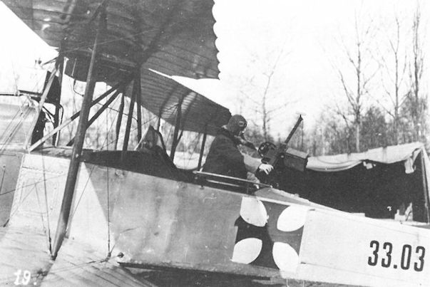
Photographs of aircraft armed with the Bergmann LMG 15nA machine gun are rare. One of the few is the Aviatik B.III 33.03, assigned to Flik 20 on the Eastern Front in February 1916. Sharing a large cockpit with the pilot, the observer is checking a German Bergmann LMG 15nA machine gun.
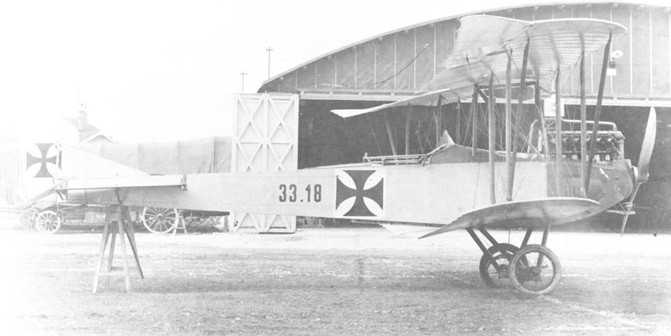
Assigned to Schulkompagnie 1 in December 1916, the Aviatik B.III 33.18 served as an advanced trainer until it was written-off in May 1917. The generator drive belt connecting the propeller hub to the wireless generator is missing.
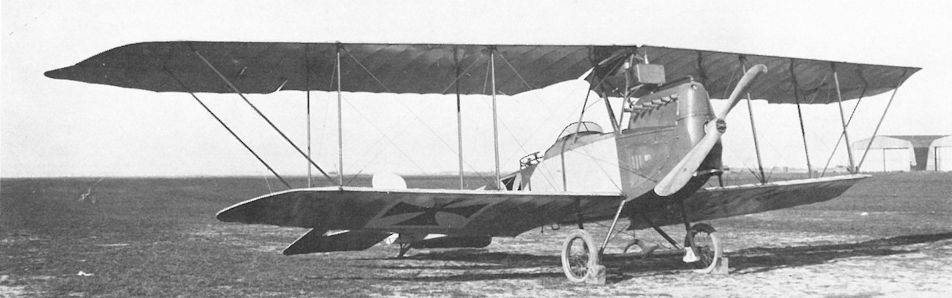
Aviatik B.III 33.18 during acceptance testing at Aspern in March 1916. Power was supplied by a 160 hp Daimler engine.
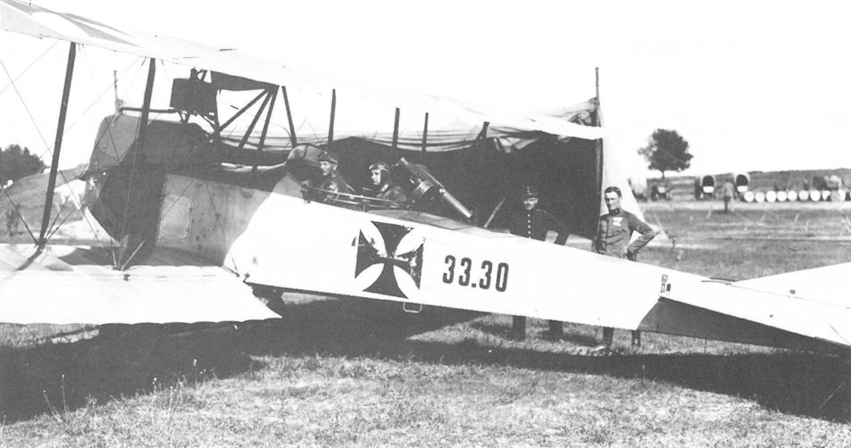
Posed ready for takeoff, this Aviatik B.III 33.03 was accepted in June 1916 and went on to serve with Flik 27 on the Russian Front.
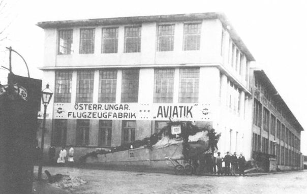
Personnel of the Aviatik factory in Vienna celebrating the completion of their 100th aircraft, an Aviatik B.III series 33 biplane, in mid-1916.
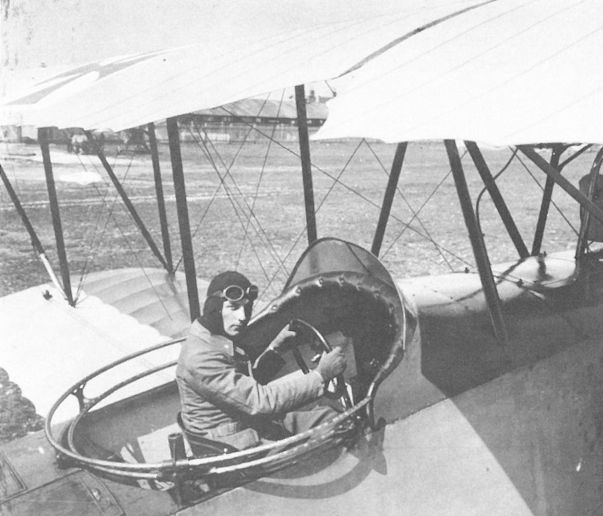
The Aviatik B.III was dubbed “the rocking chair" and Leutnant von Festraets, ensconced in the large common cockpit, shows why. For training purposes the instructor and student could both work the controls.
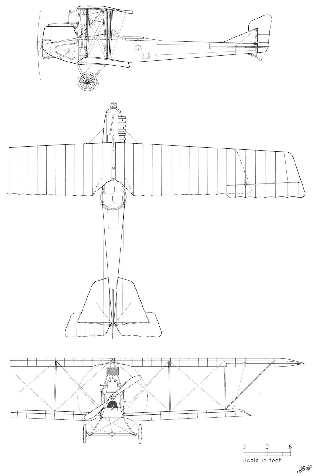
Aviatik B.III Series 33
Aviatik 30.04
To provide aircrews with experience in handling twin-engined aircraft, Flars purchased three trainers from Aviatik, numbered 30.04, 30.12 and 30.13. Assembly of the 30.04 began in mid-1916. It was powered by two 100 hp Daimler engines mounted in a modified B.III series 33 airframe that was strengthened throughout. The 30.04 trainer, attached to Flek 6 in December 1916, remained on active status until it was damaged in November 1917. It was officially written-off on 10 January 1918.
Aviatik 30.12 and 30.13
In June 1916, design work began on two twin-engined trainers, designated 30.12 and 30.13, using stock Aviatik B.II series 32 airframes modified for two 100 hp Daimler engines. Aircraft 32.47, that had been returned for repair in January 1917, became one of the above trainers. In April 1917, 30.12 left the Esslingen factory and 30.13 was nearing completion. In June 1917, both trainers were back at Aviatik for repair and installation of additional fuselage bracing. 30.12 was turned over to Flars on 14 August and formally accepted in October. Both trainers were subsequently placed in storage (30.12 in November 1917) without fulfilling their intended training role.
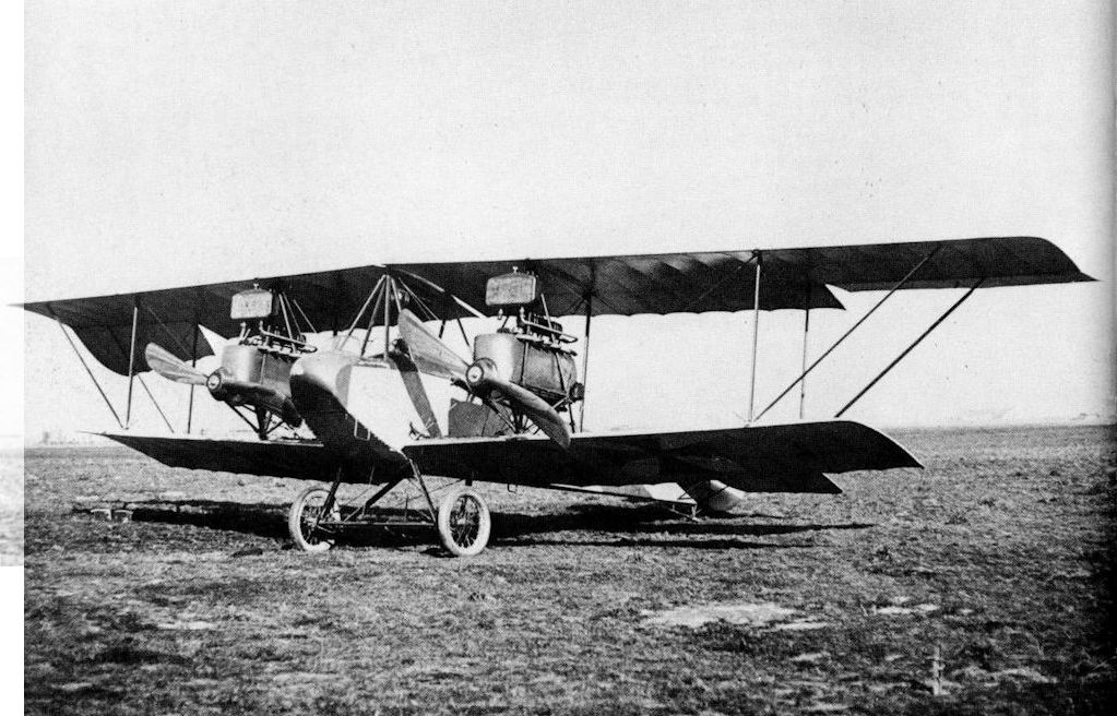
The Aviatik 30.04 was adapted from a B.III series 33 biplane to serve as a twin-engined bomber trainer.
Aviatik 30.04. Frontansicht, interessant ist der Einbau zweier Lohnerpropeller für Ba 14
Aviatik 30.04. Вид спереди, интересна установка двух тянущих винтов Lohner на Ba 14
Aviatik 30.04. Frontansicht, interessant ist der Einbau zweier Lohnerpropeller für Ba 14
Aviatik 30.04. Вид спереди, интересна установка двух тянущих винтов Lohner на Ba 14
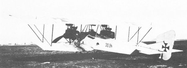
In this view, the Aviatik 30.04 shows the modified B.III series 33 fuselage and tail surfaces of increased area.
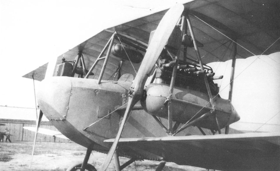
The Aviatik 30.12 or 30.13 during flight tests at Aspern in 1917. The airframe was a modified Aviatik B.II series 32 biplane
Aviatik 30.07
Work on the experimental 30.07 bomber, the largest aircraft built in Austria-Hungary, began on 5 November 1915 when Flars established a design team of Flars engineers jointly directed by Oberleutnant Professor Richard von Mises and Ingenieurleutnant Karl Saliger. By January 1916 the airframe configuration had been agreed upon. The wing profile was tested in Knoller's wind tunnel at the Polytechnic Institute, where Professor Richard Katzmayr analyzed propeller and propulsion design. In his writings, Mises conveys the excitement and manifold difficulties encountered in bringing such a complex project to completion.
On 24 November 1915, Aviatik received a Regiebau contract (a government-managed, cost-plus-fixed-fee agreement) for which the company provided space and labor but assumed no engineering responsibility. Component manufacture began at Esslingen in December 1915, causing the Flars resident inspector to complain that regular production work was being neglected. Airframe assembly of the Mises bomber, now numbered 30.07 (project designation Gr.I), was under way in January 1916.
The 30.07 bomber was constructed around two internal transmission units, powered by the experimental 300 hp Daimler V-12 engine. Each was fitted with a double-ended crankshaft that drove, via two gearboxes and outrigger shafts, a pair of counter-rotating, tractor airscrews mounted athwart the fuselage. The power units, installed sideways in the fuselage, were separated by the pilot's cockpit. The outriggers were mounted independently of the wing structure, a desirable feature in case of transmission shaft failure. The power units were manufactured by Daimler and serviced by MAG engineers.
The transmission was bench-tested in mid-March 1916, followed by full airframe thrust measurements on 19 May. When the bomber appeared for taxi trials on 1 June, the undercarriage collapsed, requiring a stronger shock cord assembly. One totally unexpected problem was the "hours of frustrating toil" required to start the engines. The new engines were prone to sparkplug oiling, and worse, since an auxiliary starting mechanism was not provided, it was physically awkward and exhausting to swing the propellers. An extended taxi run was performed on 27 June. Finally, after careful engine servicing on July 1, test pilot Ingenieur Franz Sattler performed taxi runs and several short hops to satisfy himself that the aircraft was controllable in flight. On 2 July 1916, with Mises in the co-pilot's seat, 30.07 made its maiden flight around the Aspern airdrome lasting ten minutes. Two days later on its second flight, 30.07 reached 350 meters (1148 ft) but during landing, the bomber lost speed and stalled-in from four meters (13 ft). The damage was expected to be repaired by 20 July, allowing time for minor structural changes and engine removal for overhaul.
The 30.07 was destroyed on 28 July 1916. In an official report, Mises stated that the 30.07 hung sharply to the right at takeoff. Sattler reacted by pulling up too quickly and crashed from 20 meters (66 ft) onto the right wing. "Kindling wood", remarked Mises who, like Sattler, was spared injury thanks to the strongly-built pilot's enclosure. In spite of the short time aloft, flight evaluation was generally positive; the prototype flew smoothly with great stability and, except for the sluggish aileron response, was relatively easy to control. Most of the improvements concerned the engines. Mises recommended better cooling, new carburetors, and auxiliary engine starters. The bomber was grossly overweight owing to the unexpectedly high drive-system weight, which in turn reduced the useful load by 1000 kg (2205 lb). Some 300 kg (662 lb) would have to be removed to make the design viable. The Mises bomber remained a priority program and construction of the improved 30.17 and 30.18 bombers was already under way.
Aviatik 30.07 Specifications
Engine: 2 x 300 hp Daimler
Wing: Span Upper 22.60 m (74.15 ft)
Chord Upper 3.00 m (9.84 ft)
Chord Lower 3.00 m (9.84 ft)
Sweepback Upper 4 deg
Gap 3.06 m (10.04 ft)
Total Wing Area 118 sq m (1270 sq ft)
General: Length 15.37 m (50.43 ft)
Height 4.45 m (14.60 ft)
Track 3.60 m (11.81 ft)
Empty Weight 2800 kg (6174 lb)
Loaded Weight 4500 kg (9926 lb)
Maximum Speed: 135 km/hr (84 mph)
Aviatik 30.17 and 30.18
Concurrent with the assembly of the Aviatik 30.07 (Gr.I) prototype, preliminary design work continued on two prototypes, 30.17 (designation Gr.II) and 30.18 (Gr.III), that would incorporate improvements based on the limited experience gained with the 30.07. The guidelines, laid down on 3 August 1916, recommended raising the engines to place the exhaust system in the slipstream and installing a modified transmission system. The fuselage was shortened and fitted with a ventral gun position. The undercarriage was redesigned with lighter wheels and steel springs replaced the rubber shock cords. Components salvaged from the 30.07 crash were used in the 30.17 airframe. As projected, the 30.17 and 30.18 bombers were powered by two 345 hp Daimler V-12 engines, manned by a crew of four and capable of carrying a 350-500 kg (772-1102 lb) bomb load.
At the time the contract for two bombers was signed on 5 October 1916, the assembly of the 30.17 was nearing completion at Esslingen. It arrived at Aspern in late October 1916. By then the bomber program had lost much of its impetus. Mises was unable to devote full time to his project for he had been promoted to supervise the Flars engineering department. Mises hinted at personality clashes within Flars but did not elaborate. As Flars' "technical fireman", he travelled extensively to correct problems and in October 1916, Mises was ordered to Flek 11 in Mostar to gain flying experience with operational aircraft. In his absence, the Mises bomber program came to a halt. Faced by the escalating air war on the Italian Front, the LFT could hardly justify diverting manpower and scarce materials for a project that promised no immediate benefit. In fact, little flying was undertaken with the 30.17 during the winter months. To make production space available at Esslingen, on 10 May 1917 the 30.17 was transferred to Flek 6 in Wiener-Neustadt where sufficient tests were performed to enable Oberleutnant Antal Lanyi-Lanczendorfer to submit a fairly comprehensive flight report (23 November 1917):
1) the aircraft begins to roll with engines turning at 900 rpm.
2) suspension and tail skid are very good; tires are unsatisfactory.
3) the aircraft can take off and fly on one engine.
4) the aircraft maneuvers freely. When a gust caused the left wing to drop, it was righted easily using the ailerons.
5) rudders are well balanced and elevator controls are more sensitive than those of the Brandenburg G.I.
6) all controls can be manipulated without using excessive force.
7) aircraft lands easily, undercarriage strength appears adequate.
8) faults: the engines oil-up rapidly and are difficult to stop.
After the engines had been removed and modified by Daimler, the 30.17 was ordered to Strasshof on 28 January 1918 to install service equipment in preparation for frontline evaluation with Flik 102/G. But at Wiener-Neustadt on 19 March, the 30.17 was damaged beyond repair during a landing approach. It appears that a low-altitude stall, such as destroyed the 30.07, was the cause. Fortunately, the robust cockpit structure prevented injury to the flight crew.
The last Mises bomber, 30.18, completed in December 1916, was given a lighter airframe and ailerons were fitted to the lower wings. Flight trials began at Aspern in January 1917. The 30.18 was slightly damaged on 25 May 1917 because the new 345 hp Daimler engines failed to produce full power. From June to September 1917, cursory flight tests were performed at Flek 6 using the more reliable 300 hp Daimler engines. The 30.18, again fitted with 345 hp engines, was damaged on 1 April 1918 during the course of flight and speed trials. The bomber was reported in good condition at Aspern on 25 October 1918.
Aviatik 30.17 Specifications
Engine: 2 x 345 hp Daimler V-12
Wing: Span Upper ca 22.60 m (74.15 ft)
Chord Upper 3.00 m (9.84 ft)
Chord Lower 3.00 m (9.84 ft)
Gap 3.06 m (10.04 ft)
Total Wing Area 118 sq m ( sq ft)
General: Length 14.45 m (47.41 ft)
Height 4.25 m (13.94 ft)
Track 3.60 m (11.81 ft)
Empty Weight 3078 kg (6787 lb)
Loaded Weight 4720 kg (10,408 lb)

Aviatik 30.18

The fully-assembled Aviatik 30.07 bomber tied down for propeller thrust measurement on 19 May 1916 at Aspern.

The Aviatik 30.07 with engines running during thrust measurement at Aspern. The raised gun rings provided a wide field of fire.
Aviatik 30.07, Grossbombenflugzeug. Konstruktion Ing. v. Mises
Aviatik 30.07, Grossbombenflugzeug. Konstruktion Ing. v. Mises

Aviatik 30.07 at Aspern 19 May 1916. The unnecessary complexity of the quadruple rudders and twin elevators suggest a certain naivete in the realm of large aircraft design.

Aviatik 30.07 prototype bomber being prepared for engine and transmission tests at Esslingen in April-May 1916, prior to final assembly. The two 300 hp Daimler V-12 engines were mounted sideways and each drove two outrigger airscrews.

The Aviatik 30.07, after crashing from 4 meters on 4 July 1916, was dismantled for modification. The needlessly complicated transmission system added extra weight, to the detriment of load carrying capacity.

Running up the engines on the Aviatik 30.17. Compared to the 30.07, the control surfaces were increased, the front turret height reduced, and engine ventilation louvres added.

The beautifully-finished fuselage of the Aviatik 30.17 contrasts starkly with the maze of struts and transmission fixtures. The bulge under the fuselage is the fuel tank.

Certain to attract attention, the Aviatik 30.18 shows the nose-mounted propeller to drive the wireless generator, the nose landing lights, and the fuel tank bulge under the fuselage.
Aviatik 30.18, v. Mises-Großflugzeug, dritte Type, Aspern
Aviatik 30.18, v. Mises-Großflugzeug, третий тип, Асперн
Aviatik 30.18, v. Mises-Großflugzeug, dritte Type, Aspern
Aviatik 30.18, v. Mises-Großflugzeug, третий тип, Асперн

The Aviatik 30.18 photographed in early 1917. Ailerons were fitted on both wings and connected by two struts, and the wing struts were made narrower. In other respects the prototype was similar to the 30.17.

Aviatik 30.18
Balaban-Bloudek Helicopter
After leaving the propeller laboratory at Fischamend, Balaban became chief engineer at UFAG. Working with Oberingenieur Stanko Bloudek, Balaban proposed a free-flying helicopter to Flars. In return, Balaban received detailed specifications that he felt were unrealistic and well beyond what could be reasonably achieved. On 27 August 1917, Balaban and Bloudek proposed to Flars a helicopter design that appears simple and practical. If accepted, UFAG agreed to have the airframe ready for testing within four weeks after delivery of a 100 hp rotary engine. But Flars declined to support the work, much to Balaban's regret. Flight experimentation, performed at UFAG with a model having a 1.5 meter rotor diameter, demonstrated, perhaps for the first time, that auto-rotation in event of engine failure was feasible.
After leaving the propeller laboratory at Fischamend, Balaban became chief engineer at UFAG. Working with Oberingenieur Stanko Bloudek, Balaban proposed a free-flying helicopter to Flars. In return, Balaban received detailed specifications that he felt were unrealistic and well beyond what could be reasonably achieved. On 27 August 1917, Balaban and Bloudek proposed to Flars a helicopter design that appears simple and practical. If accepted, UFAG agreed to have the airframe ready for testing within four weeks after delivery of a 100 hp rotary engine. But Flars declined to support the work, much to Balaban's regret. Flight experimentation, performed at UFAG with a model having a 1.5 meter rotor diameter, demonstrated, perhaps for the first time, that auto-rotation in event of engine failure was feasible.

Artist’s impression of the free-flying Balaban-Bloudek helicopter proposed to Flars on 27 August 1917. The fuel tank is located above the rotors; the inverted cone below the engine is a fairing. The movable vanes beneath the pilot provide directional control.
Lohnerwerke GmbH, Wien-Floridsdorf
Lohner had begun to manufacture Taube airframes for Igo Etrich whose painstaking experiments, begun in 1904, were crowned with success in April 1910 when the Taube finally achieved controllable flight. With customers waiting, but lacking funds to start manufacturing, Etrich licensed Lohner on 7 July 1910 to build five Taube monoplanes. Shortly thereafter Etrich sold the Taube patents and airfield property at Wiener-Neustadt to the Motor-Luftfahrzeug-Gesellschaft (MLG), an aeronautical trading firm (balloons, airships and aircraft) managed by the Viennese financier Camillo Castiglioni. Lohner continued to build the Taube airframes which were transported to Wiener-Neustadt where engine, fuel system and instruments were installed under the supervision of Karl Illner, formerly Etrich's test pilot and shop manager. Of the 58 Etrich Taubes built by Lohner, 10 were exported to Italy, Russia, Spain, England, China and Germany, 29 were delivered to the Austro-Hungarian air service between 1911 and 1913, and the remainder were sold privately or retained by the MLG flight school. Attempts to modernize the Taube design in 1913 by streamlining and increasing power were unproductive. The Taube had reached the end of its development cycle, a fact recognized far earlier in Austro-Hungarian military circles than in German ones.
Lohner 10.08 to 10.11
Soon after mobilization, the Lohner-MLG flying school in Wiener-Neustadt closed its doors and sold four of the school's Etrich Taube trainers to the LA on 24 August 1914. These were assigned the numbers 10.08 to 10.11 in February-March 1915.
The Lohner 10.08 trainer, powered by a 65 hp Daimler engine, evidently remained in service for several years, since it was not officially written-off until 10 January 1918.
The Lohner 10.09 trainer, powered by a 65 hp Daimler engine, initially carried the designation F-01. As 10.09, it served with Flek 1 from 1914 and was last reported active in December 1915.
The Lohner 10.10 trainer, powered by a 80 hp CAM (Clerget) in-line engine, was flown by Flek 1 in 1914. After being damaged and extensively rebuilt by Fischamend, it was designated F-3 (later 72.03). It should be noted that this "new" F-3 (ex 10.10) was a replacement for a written-off Fischamend-built Taube also numbered F-3. The reason for the confusing re-assignment of numbers is not known.
The Lohner 10.11 was a ground instruction Taube about which further data is lacking.
K.u.K. Fliegerarsenal Flugzeugwerk Fischamend
Fischamend
At the time the Luftschifferabteilung (LA) was formed in 1909, funds were allocated for establishing a development and repair center to support all aspects of aeronautical technology. In 1911-1912 the center was moved from the overcrowded Vienna Arsenal to the vast Fischamend airfield (21 km west of Vienna on the Danube). The new facility consisted of 1) an observation balloon workshop, a gas-generating plant, and supply depot, 2) an experimental department to test and accept military aircraft, 3) an aircraft and engine repair shop, and 4) an airship department. The military command soon realized that the vast expense of building and maintaining an airship fleet would rapidly deplete the limited aviation budget; consequently the LA gradually abandoned airship activity in favor of more cost-effective aeroplanes.
When the Fliegerarsenal (Flars) was established in March 1915, the Fischamend aviation center came under its command. Fischamend was responsible for a wide range of aeronautical work encompassing instrumentation, bombs, wireless, photography, radiators, helicopters and airborne weaponry. However, the primary flight test and aircraft acceptance center remained at Aspern. Professor Richard Knoller, aided by von Karman, Julius Kolin, and Wilhelm Zurovec, designed and built a full-scale propeller wind tunnel and testing laboratory, acknowledged as the most advanced of its time. The propeller test laboratory was completed in early 1917.
In 1912-1913, the aircraft repair shop (later named Flugzeugwerk = aircraft works) began to manufacture aircraft because the Motor-Luftfahrzeug-Gesellschaft (MLG) and Lohner had difficulty meeting delivery schedules. The 14 Lohner-built Etrich Type F Taubes, ordered in May 1912, proved severely nose-heavy and had to be rebuilt by Lohner. The unstable Etrich-Lohner Type X Taube with side-by-side seating for training use (four ordered in April 1912) required modification and were not delivered until 1913. Fearing that the overburdened Lohner factory would encounter delays in producing the 28 Type B Pfeilfliegers and precipitate an "aircraft shortage," the LA secretly manufactured ten Etrich Taubes in the Flugzeugwerk without seeking permission of Etrich or MLG, the rightful patent owners. When MLG got wind of this in late 1913, the LA confessed to patent infringement but countered by invoking a contractual fine for late aircraft delivery. Although the controversy was eventually settled, the relationship between the LA and MLG-Lohner became severely strained. MLG was accused of being no more than a trading organization (which it was) having "little incentive to foster the development of the Etrich Taube" - a fair criticism. Throughout the war Castiglioni, the business director of MLG, remained an anathema to the LA command.
Etrich 70.01 to 70.06
With the implementation of the unified numbering system on 8 February 1915, the oldest pre-war Etrich Taube trainers were assigned the series 70 designation, reserved for "out-of series" and prototype aircraft:
Original Designation Second Designation Final Designation
Condor 70.01 72.35 after repair in April 1915
Falke 70.02 72.37 after repair in April 1915
S.III 70.03 written-off
X-IV 70.04 written-off November 1915
S.V 70.05 72.38 after repair in May 1915
X-III 70.06 72.33 after repair
The first two came from a batch of Maneuver Etrich 1911 (Etrich Type B) named Adler (eagle), Buzzard, Condor, Dohle (jackdaw), Elster (magpie), Falke (falcon) and Geier (vulture), ordered from Lohner on 10 May 1911.
In 1913, Fischamend delivered eight School Etrich, designated S.I to S.VIII. Records show that on 1 February 1914 five School Etrich, numbered S.I to S.V, were stationed at various Flugparks for training purposes.
Four Etrich Type X trainers were ordered from Lohner on 19 April 1912, but not delivered until March 1913 owing to severe stability problems which required rebuilding the airframe.
As shown above, in the course of repair at least four series 70 Taubes were later rebuilt as a standard Etrich A.II(Fd) series 72 trainer.
Etrich Taube (Fd) 70.01
Engine: 90 hp Daimler
Wing: Span 14.00 m (45.93 ft)
Total Wing Area 32.5 sq m (350 sq ft)
General: Length 10.00 m (32.81 ft)
Height 3.50 m (11.48 ft)
Empty Weight 480 kg (1058 lb)
Loaded Weight 750 kg (1654 lb)
Maximum Speed: 105 km/hr (65 mph)
Climb: 1000m (3,281 ft) in 20 min
Etrich A.I(Fd) Series 71
For the Grand Army Maneuvers in the summer of 1912, the LA ordered 14 Maneuver Etrich 1912 Taubes (Type F) from Lohner on 28 May 1912. Flight tests proved the Type F to be severely nose-heavy, which made it necessary to relocate the passenger from the front to a position behind the pilot, shift the fuel tank, and move the engine aft by two cylinder lengths. The aircraft were christened Aar, Achilles, Adjudant, Afra, Ajax, Allans, Amazone, Amourette, Anita, Anny, Aram, Arnim, Asra, and Atair. At a later date Albus joined the ranks.
On 17 February 1915 those aircraft remaining in the LA inventory were designated Etrich A.I(Fd) series 71 and assigned the following series 71 numbers:
Original Designation Second Designation Final Designation
Aar 71.01 72.42 after repair July 1915
Achilles 71.02 72.32 after repair March 1915
Albus 71.03
Ajax 71.04
Anita 71.05
Aram 71.06 72.43 after repair July 1915
Arnim 71.07 72.34 after repair March 1915
Atair 71.08
Anny 71.09
Afra 71.10 72.36 after repair
The Etrich A.I(Fd) Taubes were powered by 65 hp or 90 hp Daimler and 85 hp Hiero engines. Serving as ground or basic trainers with Fleks 3, 4, 5, and 7, six Etrich A.I(Fd) were on charge as of 6 October 1915, and at least one, 71.03, served through November 1916.
Etrich A.II(Fd) Series 72
In addition to eight Etrich Type S Taubes, the Flugzeugwerk built approximately 30 Type F Taubes; the first ten appeared in 1912-1913 under the designation F.1 to F.10. These had been surreptitiously built without notifying the rightful patent owners (MLG and Etrich) as described in the introduction. The designations were changed in February 1915 when the extant Taubes F.1 to F.20 became Etrich A.II(Fd) 72.01 to 72.20. A total of 43 Etrich A.II|Fd) Taubes up to number 72.43 have been identified, composed of Fischamend-built Type F Taubes and other Taubes which after repair and/or modification were re-designated as shown below. In several cases after a Taube had been written-off, its number was not cancelled but re-assigned to a different aircraft.
Redesignation of various Taubes to Etrich A.II(Fd) Series 72 was as follows:
Original Second Final Original Second Final
10.10 F.3 72.03 Condor 70.01 72.35
Buzzard F.14 72.14 Afra 71.10 73.36
S.VI F.29 72.29 Falke 70.02 72.37
S.II F.30 72.30 S.V 70.05 72.38
Achilles 71.02 72.32 F.2 72.02 72.41
X-III 70.06 72.33 Aar 71.01 72.42
Arnim 71.07 72.34 Aram 71.06 72.43
Operated by most LFT training units, the Etrich A.II(Fd), either powered by the 85 hp Hiero engine or the 65 hp Daimler, served as a ground instructor or performed basic-training flights. Pilot Franz Zuzmann recalled that it was virtually impossible to crash a Taube. It was inherently stable and the wing-warping controls required great exertion to change aircraft direction. The instant the steering controls were centered (hands off!) the Taube would resume its normal flight attitude. Although landing accidents were common, they rarely caused severe injury. As of 6 October 1915 seventeen A.II(Fd) Taubes were listed in flying condition and 21 were under repair. Twelve were still on charge in July 1917.
Etrich A.II(Fd) Series 72
Engine: 65 hp Daimler
Wing: Span 14.60 m (47.90 ft)
Total Wing Area 31.5 sq m (339 sq ft)
General: Length 9.73 m (31.92 ft)
Height 3.28 m (10.76 ft)
Empty Weight 540 kg (1191 lb)
Loaded Weight 790 kg (1742 lb)

Etrich A.II(Fd) 72.02

Among the civil aircraft confiscated at the beginning of hostilities was the German Etrich Taube owned by Carl Ehrlich. The LFT number assigned was 00.50.

The original Etrich Taube (Etrich II) coming in for a landing at Wiener-Neustadt in April 1910.

This Manovertaube was one of six purchased from Lohner in May 1911. Oberleutnant Ritter Blaschke von Zwornikkirchen has just completed the first overland flight from Wiener-Neustadt to Fischamend, 25 July 1911.

Oberstleutnant Emil Uzelac, commander of the Luftschifferabteilung, during the Offiziers-Flugmeeting in October 1912. The aircraft is an Etrich Type F Taube, of which 14 were supplied by Lohner.

Flight pupil Rudolf Blass at Flek 1 in Ujvidek in one of the old Taubes of the former Lohner-MLG flying school. Initially numbered F-01, it was re-numbered 10.09 in March 1915.
Lohner-Etrich A.I, Flugzeugnummer 10.09. Flugfeld Ujvidek, am „Steuer“ Rudolf Blasz
Lohner-Etrich A.I, номер 09/10. Аэродром Уджвидек, у «штурвала» Рудольф Блас
Lohner-Etrich A.I, Flugzeugnummer 10.09. Flugfeld Ujvidek, am „Steuer“ Rudolf Blasz
Lohner-Etrich A.I, номер 09/10. Аэродром Уджвидек, у «штурвала» Рудольф Блас

One of the aircraft on display at the Budapest Aircraft Exhibition in April 1917 was this Etrich A.II(Fd) 72.13 (ex F.13).

Shown here at the Offiziersfliegen in Wiener-Neustadt (October 1912) is either Aram or Arnim which in February 1915 became respectively Etrich A.I(Pd) 71.06 (later 72.43) or 71.07 (later 72.34).

The Lohner-Etrich Geier is representative of the five Taubes delivered to the Army in June-July 1911 which included Condor and Falke. Condor was still active in February 1915 when it was designated 70.01. After repair and modification in April 1915, it was designated Etrich A.II(Fd) 72.35. Falke was re-designated 70.02 and finally 72.37.

This Maneuver Etrich 1911, delivered as Buzzard in June 1911, was later assigned the number F.14 and finally became Etrich A.II(Fd) 72.14.

Offizierstellvertreter Hans Matti with the Etrich X-III, a Taube that featured side-by-side seating for instructional purposes and was delivered by Lohner after a long delay in 1913. Re-numbered 70.03 in February 1915, it was soon written-off.

The Lohner-built Etrich Aar (Type F) took part in the Grand Army Maneuvers and the Offiziersfliegen of 1912. In February 1915, it was designated Etrich A.I(Fd) 71.01 and after repair and modification in July 1915, the designation was changed to Etrich A.II(Fd) 72.42.

Training activity at Flek 5, Szeged in 1916. The first aircraft, 72.27, has the outer wings removed and may have been used for ground instruction. The third aircraft in line is 72.26.

Etrich A.I(Fd) 71.05 Anita in early red and white military markings being hauled on its special wagon. The six-cylinder 90 hp Daimler has been replaced by a four-cylinder 65 hp Daimler engine for training use. No photographs have been found showing the series 71 designation on an aircraft.

The Maneuver Etrich Taube 1912, (Type F) under construction at the Flugzeugwerk in 1912-1913, was built without the knowledge or permission of the rightful patent owners.

Etrich S.V, built by the Flugzeugwerk in 1913, in a typical training accident. Because of the Taube's slow speed and innate stability, crashes were rarely fatal. It was re-numbered 70.05, and after repair in May 1915, Etrich A.II(Fd) 72.38.

Etrich A.II(Fd) 72.02 (ex F.2), powered by a 85 hp Hiero engine, in a typical low-impact landing accident. The instructor’s cockpit behind the pilot has been covered over for solo flight. In July 1915, this trainer was re-numbered 72.41.

The pilot of this Etrich A.II(Fd) of Flek 5 (1916) could not avoid a gentle crash on a hillside. The red and white insignia was a holdover from prewar days. In this instance the rear cockpit is uncovered for the instructor.

Etrich A.II(Fd) Series 72

Etrich A.II(Fd) 72.02
Fruba Fighter
By the time he designed the Fruba Fighter in late 1918, Ingenieur Julius Kolin could look back on a productive aeronautical career that had begun in Professor Knoller's aero laboratory in 1911. As Knoller's assistant, Kolin played an important part in constructing the first Knoller prototype (30.05) at Thone & Fiala. In 1915, Kolin became the production supervisor of the Knoller biplanes at Aviatik. In 1916, he rejoined Knoller to work in the new propeller test facility at Fischamend. It was here that Kolin designed and tested the wooden rotors for the PKZ 2 helicopter. And here he met Sigmund Jaray, a prewar furniture manufacturer, who had the task of fabricating the helicopter rotors.
In 1918, Kolin designed a high-performance fighter which was to be built in Jaray's aircraft repair facility known as the Flugzeug Reparatur und Bau Anstalt (Fruba - aircraft repair and manufacturing facility) that had been established in late 1916. As aerodynamic consultant to Julius von Berg, Kolin was well apprised of latest Aviatik rotary-engined fighters, which may account for the similarity of the Fruba fighter to Aviatik designs. Kolin had in mind
to build a vertical take-off aircraft, capable of hanging in the air and shooting upwards. I replaced the then inferior steel and steel tubing of the structural components by high-strength veneer and veneer tubing. This was possible owing to the high skill of Jaray personnel in handling wood. The end result was an aircraft of 540 kg (1191 lb) weight fully loaded and a propeller thrust of 650 kg (1433 lb) using a 150 hp Le Rhone(St) rotary engine.
The Fruba fighter, completed in late 1918, fell victim to the Armistice and, according to Kolin, was never properly tested.

The completed Fruba interceptor fighter at the Fruba factory in late 1918. Ingenieur Julius Kolin, the designer of the aircraft, is sitting on the wheel. The similarity of the Fruba fighter to the Aviatik rotary-engined fighters may be explained by the fact that Kolin was a longtime consultant to Julius von Berg and was involved in some of the Aviatik designs.
Gassner Giant Bomber
Ingenieur Alfred Gassner completed drawings in 1916 for a giant bomber powered by four 250 hp engines. Writing in 1919, Gassner simply said that the realization of this bomber was "a victim of the prevailing circumstances." Gassner subsequently proposed the giant aircraft as a civil transport capable of carrying 36 passengers.
Ingenieur Alfred Gassner completed drawings in 1916 for a giant bomber powered by four 250 hp engines. Writing in 1919, Gassner simply said that the realization of this bomber was "a victim of the prevailing circumstances." Gassner subsequently proposed the giant aircraft as a civil transport capable of carrying 36 passengers.

The Gassner giant bomber converted to a civil version transport as publicized in 1919. It is reminiscent of the German Staaken R.VI giant bomber of 1917.
Hocke Experimental Biplane
In December 1917, aerodynamic and stability tests of a model of the Hocke aircraft (also written Holcker in Flars records) were underway in Professor Knoller's vertical wind tunnel. Satisfactory results led to the construction of a full-sized prototype powered by a four-cylinder Hiero engine. No information, other than photographs, has been found to explain the purpose of this unusual experimental aircraft.
In December 1917, aerodynamic and stability tests of a model of the Hocke aircraft (also written Holcker in Flars records) were underway in Professor Knoller's vertical wind tunnel. Satisfactory results led to the construction of a full-sized prototype powered by a four-cylinder Hiero engine. No information, other than photographs, has been found to explain the purpose of this unusual experimental aircraft.


The Hocke Experimental Biplane was built to investigate the aerodynamic effect of moveable control surfaces mounted above the wing but for what specific purpose, whether for ground or flight trials, is not known.
Holeka Biplane
The 1 to 12.5 scale model of the reconnaissance biplane, designed by Hauptmann Rudolf Holeka, was built by Oeffag. In December 1917, the model was tested in Professor Knoller's vertical wind tunnel at the Vienna Polytechnic Institute under the supervision of Leutnant Richard Katzmayr to investigate the aerodynamic effects of the unusual fuselage, tail section, and ventral gun position. Despite modification of the model, the tests were unsuccessful and the project was dropped in March 1918.
The 1 to 12.5 scale model of the reconnaissance biplane, designed by Hauptmann Rudolf Holeka, was built by Oeffag. In December 1917, the model was tested in Professor Knoller's vertical wind tunnel at the Vienna Polytechnic Institute under the supervision of Leutnant Richard Katzmayr to investigate the aerodynamic effects of the unusual fuselage, tail section, and ventral gun position. Despite modification of the model, the tests were unsuccessful and the project was dropped in March 1918.

The Holeka biplane model in the vertical wind tunnel at the Vienna Polytechnic Institute.

Side view of the Holeka biplane with the ventral gun position.
Knoller 30.05
As their first aircraft, the Knoller 30.05 prototype embodied many of Knoller and Fiala's theoretical and structural ideas. The Knoller rib section, tested in his wind tunnel, had a highly-flexible trailing edge designed to flatten with increasing velocity to reduce drag. Weight and drag were minimized by a wireless wing cellule using a Warren-truss layout. Knoller's participation in the re-design of the Lohner B.I (Type B) and B.II (Type C) biplanes may have delayed the preparation of a proposal acceptable to the LA. On 11 January 1915, the LA signed a contract with Thone & Fiala to build one prototype (30.05) and five production aircraft designated Knoller B.I (Th) series 35.8.
The 30.05 prototype, powered by a 100 hp Mercedes engine, arrived for flight testing at Aspern on 6 June 1915. Some 20 flights totalling 8 hours duration were performed under Knoller's supervision. Various modifications, including stronger struts and an auxiliary tailplane (a biplane tail was designed but not used), failed to ameliorate the dangerous flight characteristics. The 30.05 was grounded in September 1915 for being "hazardous to life." On 8 November 1915, Thone &. Fiala proposed fitting a strengthened center-section and other changes but the work was shelved to concentrate their effort on the Knoller B.I (Th) production machines.
On 16 February 1916, the Flars acceptance group issued orders to write-off the 30.05, but the Flars command intervened and on 1 August 1916 irresponsibly lifted the flight ban. Fortunately, in view of its dangerous flight characteristics the 30.05 never was flown again. It was accepted in February 1917 and employed as an instructional airframe in a mechanics school.
Knoller B.I(Th) Series 35.8
On 11 January 1915, the LA ordered five Knoller B.I(Th) biplanes, numbered 35.81 to 35.85 and powered by a 100 hp Mercedes engine. The first machine, 35.81, delivered on 8 October 1915, performed the maiden flight on 13 November 1915, and was flown three times by Feldwebel Franz Kuntner with an passenger aboard. "Peculiar" flight characteristics were reported, induced by excessive fuselage twisting and a noticeable deformation of the outer wing when the ailerons were actuated. New ailerons and tailplane and a reinforced center-section failed to reduce wing deformation or improve the flight traits during tests on 4 and 15 December 1915. Withdrawn for modification, the 35.81 was ready to continue trials on 8 January 1916, being joined by the new, modified 35.82 later that month. To eliminate the tail heaviness and "bizarre" control response, Knoller and Fiala had designed new ailerons, an improved rib section, an airfoil-shaped tailplane, and changed the stagger. To reduce deformation, the wings were now given wire bracing. Flight evaluation by experienced test pilots (Kuntner, Hans Mandl, Viktor Nowy, Max Perini, Johann Varga) between January and mid-April, 1916, produced a formidable list of structural deficiencies and control problems.
Although continuing flight investigations had exposed severe shortcomings, Flars inexplicably purchased an additional batch of ten aircraft, numbered 35.86 to 35.95, on 12 February, 1916. The first five production aircraft (35.81 to 35.85), suitably modified, were delivered in March 1916. The additional weight of the airframe modifications had reduced the performance below the contractual specifications. Sporadic testing of the five aircraft continued through 24 July 1916, when the acceptance group stopped all flights, contending that the aircraft were unsuitable for frontline or training service. Nevertheless, production of the next ten aircraft (35.86 to 35.95) proceeded apace. The first two aircraft were delivered on 21 November 1916 and the last in June 1917. Records show only one of these aircraft had been flown before all were placed in storage. The 15 stored airframes were provisionally accepted in October 1917.
The inadequacy of the Knoller-Fiala design had been amply demonstrated. Yet in the face of the aircraft's unacceptable characteristics, Knoller's lofty reputation kept the program alive and contrary to pilots' advice, the LFT stubbornly approved Knoller aircraft production at Aviatik, Lohner, Phonix and WKF beginning August 1916.
Knoller C.I(Ph) Series 25
In spite of dangerous aerodynamic and structural problems encountered in the early Knoller biplanes, the LFT and Flats, with unwarranted optimism, awarded Phonix an order on 24 December 1915 for 48 Knoller C.I(Ph) biplanes for which 200 hp Hiero engines were specified. Production was already under way and deliveries were scheduled to end on 13 February 1916. In fact, the first production aircraft, 25.01 powered by a 160 hp Daimler engine, did not arrive at Aspern until 15 April 1916. During the flight evaluation, the 25.01 was returned to Phonix for repair at least five times, once because a fuselage frame broke while taxiing (2 August 1916). Being very lightly built, the Knoller C.I(Ph) reached a top speed of 167 km/h (104 mph) and 2000 meters (6562 ft) in 10 minutes, a very respectable performance for its day. The 25.01 was reported stable but tail-heavy and the control forces were far too heavy. Toward the end of May 1916, Uzelac flew the 25.01. His impulsive statement that “the crate is good" was unfortunately mis-interpreted as highest praise and sufficient cause to continue production. Flars rejected Knoller's plea to make further modifications on grounds that "a serviceable, high-performance aircraft should be placed into operational service as soon as possible."
While the next two aircraft, 25.02 and 25.03, with lightened fuselages were being completed, 25.01 was reinforced, again flight tested and accepted on 25 October 1916. Faced with delays and preferring to await frontline evaluation results, Flars reduced the production order to 16 aircraft (25.01 to 25.16) - all that would be built. In November 1916, the 25.01 went to Flik 23 where it was flown by Hauptmann Heinrich Kostrba, an experienced pilot. His report was totally negative: “stability poor, nose-heavy, difficult to control in wind gusts, maximum speed only 130 km/h (81 mph), forward visibility deficient." Damaged during landing, 25.01 was returned to Phonix for repair.
Considering that Phonix was already building the superior Brandenburg C.I, it is difficult to understand why an additional 24 Knoller
C.I(Ph) aircraft were ordered on 29 December 1916. Fortuitously, the contract was annulled. Pilots were advised to fly the type “only when absolutely necessary (ie: performing acceptance flights) and avoid sharp turns". When the reinforced C.I(Ph) 25.08 was finally load tested on 21 September 1917, the airframe failed at a load factor of 3.9, well below the proscribed factor of 5.0. In September 1917, Flars proposed using the Knoller C.I(Ph) as a trainer powered by a 160 hp Daimler engine, but the proposal was rejected. Inexplicably, rather than halting production the remaining aircraft were completed, the last being accepted in March 1918. Having served no useful purpose, 15 engineless airframes were placed in storage.
Knoller C.I(Ph) Series 25 Specifications
Engine: 160 hp Daimler
Wing: Span Upper 12.7 m (41.67 ft)
Chord Upper 2.25 m (7.38 ft)
Chord Lower 1.76 m |5.77 ft)
Sweepback Upper 10 deg
Gap 2.10 m (6.89 ft)
Stagger 0.57 m (1.87 ft)
Total Wing Area 36.0 sq m (387 sq ft)
General: Length 8.50 m (27.89 ft)
Height 3.30 m |10.83 ft)
Track 2.23 m (7.32 ft)
Empty Weight 780 kg (1720 lb)
Loaded Weight 1217 kg (2683 lb)
Maximum Speed: 158-167 km/hr (98-104 mph)
Climb: 1000m (3,281 ft) in 4 min 45 sec
2000m (6,562 ft) in 10 min 2 sec
3000m (9,843 ft) in 17 min 5 sec
KNOLLER C.II (Lo) Series 19 and 119
In the absence of a suitable design, Lohner, like Aviatik and WKF, was forced to accept the license-production of 48 Knoller C.II biplanes, assembly of which began in July 1916. The contract, formally signed on 8 December 1916, stipulated delivery of 48 aircraft to begin on 13 October 1916 and end on 6 January 1917. Production was to have been split evenly between 160 hp and 185 hp Daimler-engined versions, but the 185 hp engine shortage limited planned production to 16 C.II (Lo) aircraft, numbered 19.01 to 19.16. The remaining 32 machines, powered by the 160 hp Daimler engine, were to be numbered 119.01 to 119.32. In practice, the numbering scheme was changed and some unexplained numbers (ie. 19.25) have appeared in LFT records.
Performance of the first C.II (Lo) series 19 biplanes, flight tested in November-December 1916, fell far short of expectation. Acceptance flights of the 24 completed C.II (Lo) machines was stopped in December 1916 pending correction of faults found in the Aviatik-built Knoller machines. In January 1917, aircraft 19.25, fitted with a reinforced center-section, arrived at Aspern for flight testing; however, after the wing failure of the C.II (Av) 36.07 in February 1917, Lohner designed a "normal" upper front wing spar, stronger wing fixtures and other modifications that were applied to the Aviatik and WKF-built Knoller machines as well. By mid-1917, after endless structural modifications to strengthen the airframe, the Knoller C.II aircraft were deemed safe to fly and the first Lohner production machines were accepted in May 1917.
Flars, the driving force behind the Knoller program, was insistent that the type be evaluated at the Front. Aircraft 19.04, 19.07-19.10, a few series 119 machines, and several Aviatik-built C.IIs, were dispatched to Flik 50 and the Flieger-Versuchsabteilung Stryj (aircraft test section, later designated Flik 70) for trials in November-December 1917. Limited operational sorties were flown. The Knoller C.II was unpopular with aircrews who reported it useless as an operational machine. Flik 50 criticized the poor flight characteristics, the fragile construction, and the sloppy workmanship of the Lohner-built Knollers. The type was withdrawn from the Front.
Most of the 185 hp engines of the C.II (Lo) series 19 were removed and the airframes placed in storage, but series 119 continued flying as an advanced trainer with Fleks 1, 5, 6, and 8. As of August 1918, four series 19 and two series 119 were carried in the frontline inventory; presumably these were used to carry mail. At the war's end, nine series 119 machines based at Flek 5 in Szeged became Hungarian property and two served with the Hungarian 5th Air Squadron. Aircraft 119.15, under repair at the Al-Ma factory in Prague, became Czechoslovakian property. After many years on exhibit in Prague, it has recently been restored.
Knoller C.II(Lo) Series 19 Specifications
Engine: 185 hp Daimler
Wing: Span Upper 10.00 m (32.81 ft)
Span Lower 8.00 m (26.25 ft)
Chord Upper 2.08 m (6.84 ft)
Chord Lower 1.08 m (3.54 ft)
Sweepback Upper 5.5 deg
Stagger. 0.68 m (2.23 ft)
Total Wing Area 28.0 sq m (301 sq ft)
General: Length 8.50 m (27.89 ft)
Height 3.20 m (10.50 ft)
Track 2.064 m (6.77 ft)
Empty Weight 695 kg (1532 lb)
Loaded Weight 1057 kg (2331 lb)
Maximum Speed: 161 km/hr (100 mph)
Climb: 1000m (3,281 ft) in 4 min 3 sec
Knoller C.II(Lo) Series 119 Specifications
Engine: 160 hp Daimler
Wing: Span Upper 10.00 m (32.81 ft)
Span Lower 8.00 m (26.25 ft)
Chord Upper 2.08 m (6.84 ft)
Chord Lower 1.08 m (3.54 ft)
Sweepback Upper 5.5 deg
Stagger 0.68 m (2.23 ft)
Total Wing Area 28.0 sq m (301 sq ft)
General: Length 8.50 m (27.89 ft)
Height 3.20 m (10.50 ft)
Track 2.06 m (6.77 ft)
Empty Weight 751 kg (1656 lb)
Maximum Speed: 125 km/hr (78 mph)
Climb: 1000m (3,281 ft) in 5 min 16 sec
3000m (9,843 ft) in 24 min 10 sec
Aviatik 30.08
The 30.08 prototype, a standard Knoller B.I(Av) 35.02 airframe fitted with a 85 hp Hiero engine for evaluation purposes, was under construction in May 1916. The 30.08 prototype was ready for acceptance on 21 November 1916. In early 1917, a 100 hp Mercedes engine was fitted, returning the prototype to the standard Knoller B.I(Av) configuration. Renumbered 35.02, the aircraft was provisionally accepted and stored at the Aspern aircraft depot.
Aviatik 30.09
In April 1916, Professor Knoller proposed a single-seat fighter conversion of the Knoller B.I(Av) powered by a 145 hp Hiero engine and armed with a gun canister on the upper wing. The aircraft was assigned the prototype designation 30.09. The maiden flight was performed by Feldwebel Ferdinand Konschel on 8 July 1916, who reported poor flight characteristics. A Flars engineering inspection on 21 August 1916 listed numerous defects, including shoddy workmanship. The 30.09 prototype, ready for acceptance on 21 November 1916, was not accepted until March 1917. In 1918 the 30.09 served as an instructional airframe at the Aspern apprentice school.
Aviatik 30.10
Assembly of the Aviatik 30.10 biplane, prototype for the Knoller C.II(Av), began in the early summer of 1916. Although chief engineer Berg had expressed serious misgivings regarding structural integrity, the prototype was built as specified. Completed on 11 September 1916, the 30.10 was immediately grounded by Flars engineers to reinforce a fuselage frame.
During the maiden flight on 20 September, the 30.10, powered by a 160 hp Daimler engine (not a 185 hp Daimler as specified), achieved respectable performance, reaching a top speed of 169 km/h (105 mph) and an altitude of 1000 meters (3281 ft) in 5:11 minutes. However, wing flexing and severe slipstream buffeting left the trailing-edge fabric in tatters. On 3 October the repaired 30.10 was aloft for further tests when a fuselage frame broke due to excessive elevator force and several lower wing ribs came apart. The 30.10 was grounded and, as part of the Knoller C.II(Av) program, submitted to static load tests that it failed on 31 October 1916. Aviatik director Janisch argued that the test should have been performed using a new production airframe, but Flars correctly insisted on the choice of a random airframe to prevent the company from taking special measures to assure test compliance. Further information is lacking.
Aviatik 30.11
Existing archival records regarding the Aviatik 30.11 prototype are in conflict. One citation identifies the 30.11 as a Knoller B.I(Av) biplane modified to carry one machine gun for armament. Another document states that the prototype was similar to the Knoller C.I(Ph) but fitted with an observer's machine gun tower (Turm). Since no record of construction has been found, it is possible the 30.11 remained on the drawing board.
KNOLLER B.I(Av) Series 35
Flars approved production of the Knoller B.I(Av) biplane at a time when the Thone &. Fiala 30.05 prototype was grounded because of structural weakness. Despite Professor Knoller's reputation and optimism, the design simply was not ready for manufacture. But powerful political pressure was involved. On 31 December 1915, Aviatik signed a contract for 32 Knoller B.I(Av) biplanes, numbered 35.01 to 35.32. They were powered by a 100 hp Mercedes engine. Delivery, scheduled to end on 5 March 1916, was not completed until two years later during which time only cursory flight testing took place.
The Knoller B.I(Av) 35.01 was completed on 24 December 1915. Initial test reports revealed that not only did the aircraft possess abysmal flight characteristics but also displayed a catalog of structural and aerodynamic deficiencies. Other Knoller aircraft fared no better. During the maiden flight of 35.02 on 8 March 1916 both elevator horns failed. The observer's seat of 35.07 broke through the fuselage on 24 July 1916. That day, worried by recurring failures, Oberleutnant Viktor Nowy and Hauptmanns Josef Cejnek and Karl Nikitsch issued a joint statement condemning the Knoller B.I because "its use would place life in jeopardy." Thus, contrary to standing orders, the supervising acceptance officer temporarily prohibited further flights. Production was halted in August to await Knoller's improvements, but in reality the basic design was unsound and little could be done. Following an in-flight rudder arm fracture (35.10) and repeated load test failures (35.13 and 35.14), the acceptance officer reported on 31 October 1916 that the customary gust loads expected in flight had not been taken into account. Critics felt that while Knoller's theoretical calculations may have promised exceptional performance, his lack of design skill had produced a weak aircraft riddled with dangerous flight characteristics.
All Knoller B.I aircraft were grounded on 8 November 1916 to allow Flars once again to methodically check the load calculations. The 35.01 was written-off after passing the static load tests on 6 March 1917. Four aircraft (35.03, 07, 08 and 12) were assigned to various training or test units and the remaining completed aircraft were stored at Aspern awaiting disposition. While Aviatik assembled the last aircraft, Knoller and Flars, as late as June 1917, were busy designing stronger fittings for the Knoller B.I(Av)! In August 1917 Flars, finally admitting the total failure of the Knoller program, accepted 31 B.I(Av) aircraft at 80 percent of cost value. The airframes were stripped and scrapped.
Knoller B.I(Av) Series 35 Specifications
Engine: 100 hp Mercedes
Wing: Span Upper 10.90 m |35.76 ft)
Span Lower 8.16 m (26.77 ft)
Chord Upper 1.65 m (5.41 ft)
Chord Lower 1.65 m (5.41 ft)
Dihedral Lower 3 deg
Sweepback Upper 5.5 deg
Gap 1.80 m (5.91 ft)
Stagger 0.85 m (2.79 ft)
Total Wing Area 29.86 sq m (321 sq ft)
General: Length 7.67 m (25.16 ft)
Height 3.01m (9.88 ft)
Track 2.05 m (6.73 ft)
Empty Weight 628 kg (1385 lb)
Loaded Weight 937 kg (2066 lb)
Maximum Speed: 132 km/hr (82 mph)
Climb: 1000m (3,281 ft) in 8 min 10 sec
KNOLLER C.Il(Av) Series 36 and 136
Following the crash of the Aviatik 30.06 prototype, Flars switched the proposed contract for 48 machines to the Knoller C.II biplane. That this type went into production when the Knoller program was in deep trouble and largely discredited supports Graf Adalbert Sternberg's (a member of parliament) accusation of political influence wielded by Knoller's supporters. Two contracts were signed by Aviatik; one on 4 August 1916 for 24 Knoller C.II(Av) series 36 aircraft powered by a 185 hp Daimler engine, and the other on 23 September for 24 C.II(Av) series 136 powered by a 160 hp Daimler engine. The aircraft were numbered 36.01 to 36.24 and 136.01 to 136.24 respectively.
In June 1916, with assembly already under way, Aviatik reported delays because manufacturing drawings were incomplete because of the many changes required by Knoller. The first production aircraft, 36.01, performed its maiden flight on 10 September 1916. Both the 30.10 prototype and 36.01 were temporarily grounded on 13 September 1916 for modification. Responsibilities were so ill-defined that director Janisch refused to work on the 36.01, and conversely Knoller rejected improvements suggested by Aviatik. To rectify "extreme" tail-heaviness, not alleviated by relocating the observer and internal equipment, Knoller devised an S-shaped airfoil for the tailplane. Aviatik regarded the additional lift forces imposed on the tail and fuselage as dangerous. In a climb, the aircraft remained tail-heavy and in level flight nose-heaviness increased with speed. The glide characteristics were considered good but the landing speed was unacceptably high. Throughout the flight test program, Knoller's ultra-light construction resulted in a long list of structural failures, among them: weak tail skid and control surfaces (26 October), rudder failure (8 November), static load test failure (36.08 - 21 November and 28 December), wing rib fracture (36.02 - 14 December), undercarriage collapse (36.02 and 36.04 - reported 12 January 1917).
While the C.II aircraft were grounded, a much-modified 36.13, fitted with strut joints machined from solid steel, finally passed the static load tests on 9 January 1917. Flars permitted flight testing to continue on 17 January "but only if absolutely necessary." Steep turns were to be avoided until new strut joints were installed throughout. Despite growing aversion to Knoller aircraft, test flights continued. Flying 36.07, two aircrew were killed on 10 February 1917 when a lower wing came off. Once again the C.II was grounded. The flight restriction was lifted on 4 April, but Aviatik, under pressure to produce its own designs, had lost interest in the C.II and stopped work. Out of a total of 18 or 19 completed, only 8 C.II(Av) series 36 aircraft were accepted. None of the series 136 aircraft were completed. Forty C.II airframes were in storage at Aviatik when the war ended.
Although Uzelac vetoed the idea, a special unit, known as the Flieger-Versuchsabteilung (experimental flying section) later to become Flik 70, was established to evaluate the C.II under service conditions. Aircraft 36.08, 36.10, 36.11, 36.14, and 36.20 formed part of the Knoller C.II contingent that went to the Eastern Front in July 1917. The Knoller C.II had such a poor reputation that few pilots cared or dared to fly it. The 18 January 1918 report shows that the years of effort were hardly worthwhile:
The C.II can be flown only by skilled pilots, especially while landing. It tosses and swings in gusty weather but reacts rapidly and positively to the controls. In turns, altitude loss is rapid if airspeed is not carefully maintained. The observer is buffetted by a frightening propeller wash, to such a degree that he must hold on and take care not to fall out while operating the machine gun. In cold weather, impossible for the observer. Pleasant to fly in calm conditions. Good view forward.
In August 1918, only one C.II series 36 was listed in the frontline squadron inventory against four C.II series 19, two series 119, and five series 81. A few series 36 aircraft became advanced trainers at Flek 5 or found use as instructional airframes in mechanic training schools.
Knoller C.II(Av) Series 36 Specifications
Engine: 185 hp Daimler
Wing: Span Upper 10.37 m (34.02 ft)
Span Lower 8.14 m (26.71 ft)
Chord Upper 2.09 m (6.86 ft)
Chord Lower 1.68 m (5.51 ft)
Sweepback Upper 5.5 deg
Stagger 0.59 m (1.94 ft)
Total Wing Area 30 sq m (323 sq ft)
General: Length 8.54 m (28.02 ft)
Height 3.02 m (9.91 ft)
Track 2.06 m (6.76 ft)
Empty Weight 695 kg (1532 lb)
Loaded Weight 975 kg (2150 lb)
Maximum Speed: 160 km/hr (99 mph)
Climb: 1000m (3,281 ft) in 4 min 24 sec
Knoller C.II(WKF) Series 81
Faced by the failure of the Lloyd C.IV and lacking an inhouse replacement, Flars filled the production gap by assigning WKF the Knoller C.II, a design of great but never-realized expectations. To the extent that drawings were available, WKF began parts manufacture for 24 Knoller C.II(WKF) biplanes, numbered 81.01 to 81.24, in July 1916. By the time the contract was officially signed on 22 December 1916, most of the assembly work was complete. Originally the 185 hp Daimler engine was specified, but owing to the engine shortage, all aircraft were delivered with reconditioned 160 hp Daimler engines. The contract called for delivery to begin on 15 November and end on 31 December 1916. The first three aircraft were ready for acceptance in December 1916, but the flight trials of the first aircraft, 81.02, demonstrated such serious structural faults, particularly the wing attachment fixtures, that further modification was required before the aircraft were deemed airworthy.
After the Flars inspection and critique (commissioning) on 14 January 1917, aircraft 81.02 was returned to the factory to await new drawings for re-designed parts issued in April. After a suitably modified aircraft (81.05) was re-commissioned on 21 May 1917, additional modifications were specified for all aircraft. By now Lloyd C.V output had priority at the expense of Knoller production, so it was not until December 1917, after a year's delay, that the first three Knoller C.II(WKF) biplanes were accepted.
In spite of their obsolescence, aircraft 81.01, 81.02, and 81.05 were dispatched to Flik 66/D and 81.03 and 81.04 to Flik 67/D in January 1918, but details regarding service use are lacking. Other Knoller C.II(WKF) biplanes were sporadically flown as advanced trainers by Fleks 1, 5, 8, and 18. Aircraft 81.11 and 81.23 had a special four-hour fuel tank installed for service with the airmail flight at Aspern.

Knoller C.II(Lo) 119.15

The Knoller 30.05 showing its wireless Warren-truss wing cellule. The small auxiliary tailplane was one of many unsuccessful modifications made to improve the flight characteristics.

The Knoller 30.05 prototype on the Aspern airfield in June 1915. At the time it was an advanced design, but saddled with intractable structural deficiencies and dangerous flight characteristics.

Knoller B.I(Av) 35.20 at Aspern in the winter of 1916. Although of graceful appearance, the airframe was dangerously weak and the flight characteristics were hazardous.
Knoller B.I 35.20 in Aspern, Einfliegerei, Winter 1915/16
Knoller B.I 35.20 in Aspern, Einfliegerei, Winter 1915/16

Knoller B.I(Av) 35.20. The Warren-truss wing bracing, a feature found on all Knoller aircraft, was used by Knoller to eliminate the need for wire bracing.

The modified Knoller B.I(Th) 35.82 during the flight testing at Aspern in April 1916. Cable bracing has been added to reduce wing deformation.
Knoller B.I 35.82 in Aspern, Einfliegerei, Bau bei Thöne & Fiala
Knoller B.I 35.82 in Aspern, Einfliegerei, Bau bei Thöne & Fiala

Another photograph of the Knoller B.I(Th) 35.82. Modifications included new control surfaces and a modified rib profile. The stagger has been changed to eliminate tail heaviness, but flight characteristics remained poor.

The light-cowled Knoller C.I(Ph) 25.05 on the flight line at Aspern between a Knoller C.II(WKF) 81.01 and a Lloyd C.V (WKF). Although the 200 hp Hiero engine was specified for production aircraft, 25.05 was powered by a 160 hp Daimler engine for flight tests.

The strengthened Knoller C.II (Lo) 19.10 at Aspern in 1917. The aircraft was fitted with an airfoil-shaped tailplane (known as the S-tail) to overcome control problems. After further modification, 19.10 was sent to the Russian Front for evaluation.

The Knoller C.II (Lo) 19.25 with stronger center center-section struts and an extra cross brace. Aircraft 19.25 powered by a 160 hp Daimler engine properly belonged into the 119 series but the serial number has not been changed to reflect this.

One of the few Knoller aircraft to serve a useful purpose, the Knoller C.II (Lo) 119.05 flew the airmail route between Aspern and Krakau in the summer of 1918.

Touted as super-planes, the Knoller biplanes were a disastrous failure and a great embarrassment to the Luftfahrtruppe. Shown here is the Knoller C.II(Lo) 119.18.

Typical of the many structural problems that Knoller aircraft experienced was the trailing edge damage, photographed after the maiden flight of the Aviatik 30.10 prototype on 20 September 1916.

The Knoller C.II(Av) 36.07 during flight trials at Aspern in early 1917. Two aircrew were killed when the lower left wing tore off in flight on 10 February 1917.

After many modifications to strengthen the airframe, Knoller C.II(Av) 36.10 joined the Flieger-Versuchsabteilung in July 1917. The Schwarzlose machine gun remains to be installed in the Type II VK canister.

Knoller C.II(WKF) 81.05 ready for flight acceptance in front of the WKF hangar at Aspern. It was dispatched to Flik 66/D in January 1918.
The Knoller C.II(WKF) 81.05. The large, single-piece celluloid windscreen was a WKF characteristic. In the background is the Aviatik C.I(WKF) 83.03 undergoing flight trials.

Leading the line-up is the first Knoller C.II(WKF) 81.01 during flight trials at Aspern in September 1917. After acceptance in December, 81.01 was ordered to join Flik 66/D. The remaining aircraft are Lloyd C.V(WKF) biplanes, among them 82.24, 82.25, and 82.28.
An Aviatik C.I(WKF) 183.07 (center), Knoller C.II(WKF) 81.06 (right) and at least 26 Aviatik C.I biplanes, including 83.13 and 83.07, being assembled in the modern WKF factory in the spring of 1918.
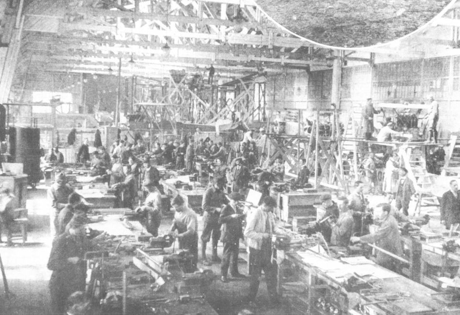
The busy Phonix prototype assembly shop in 1917. In the middle background is a Knoller C.I(Ph) under assembly. The workman on the high scaffolding is holding the propeller of the 20.11 bomber. A flying boat is under construction on the far right, behind which the Phonix C.I prototype can be seen.

The Knoller C.II (Lo) Series 19 and 119 shared the same airframe. Series 19 was powered by a 185 hp Daimler engine and series 119 by a 160 hp Daimler engine.

Knoller C.II(Av) Series 36

Knoller B.I(Th) Series 35.8
Knoller 70.01 (new) and 70.02 (new)
Professor Richard Knoller's final contribution to the war effort was a biplane fighter featuring the Knoller flexible wing profile. Designed to flatten with increasing speed, this lowered the drag that in turn added a small increment of speed. Powered by a 230 hp Hiero engine, a top speed of 240 km/h (149 mph) was projected. On 11 January 1917, the Flugzeugwerk began the detail drawings for two prototypes, designated Knoller 70.01 and 70.02. The final drawings were not finished until June 1917, at which time the wings, fuselage structure, and metal components were nearing completion. A small scale model was satisfactorily tested in Knoller's vertical wind tunnel.
The 70.01 prototype, in its original form fitted with wing-warping controls, was flown for the first time on 23 November 1917 by test pilot Karl Kriger. Later that month it was damaged during a ground maneuver and in the course of repair at the Flugzeugwerk, fitted with ailerons and a strengthened upper wing. Sent to Aspern in March 1918, the 70.01 prototype was tested through 20 June 1918 when it was damaged in a landing accident. Because Flugzeugwerk designers were fully engaged in the design of a 350 hp Knoller observation biplane, the task of modifying the 70.01 and completing the 70.02 prototype was assigned to the Flugzeug Reparatur und Bau Anstalt (Fruba), the aircraft repair branch of the Sigmund Jaray propeller works in Vienna. Before proceeding with flight testing, Flars, on 7 August 1918, planned to load test the 70.01 prototype to confirm the structural integrity of the uncommon wing cellule and small box spars, which were not readily verified by the customary static calculations. It is not known if these load tests were performed. The second prototype, 70.02, completed in September 1918, was to continue the flight test program. If the design proved successful, it was proposed that Fruba build a pre-production batch of ten fighters, one of which was to be sent to Adlershof for further load testing under German air service procedure. When the war ended development was stopped. Both prototypes were provisionally accepted in October 1918 so that Fruba could receive payment for work performed.

The Knoller 70.01 prototype shown at Fischamend prior to the first flight which took place on 23 November 1917. The engine was a 230 hp Hiero.

The Knoller 70.01 as originally flown in November 1917 with wing warping control.
During testing it was necessary to add a horizontal brace between the inner wing struts, but even so the wing bracing appears none too robust. The exact working of the wing-warping mechanism has not been determined.
During testing it was necessary to add a horizontal brace between the inner wing struts, but even so the wing bracing appears none too robust. The exact working of the wing-warping mechanism has not been determined.

The modified Knoller 70.01 showing the strengthened upper wing and the four-bladed propeller often used with engines of higher power. Armament was not installed. It climbed to 2000 meters (6,562 ft) in 10 minutes 20 seconds.

Because the wing-warping control gave problems, the Knoller 70.01 was modified with ailerons fitted on the upper wing. Presumably the local painter was unsure of the designation and, taking no chances, added a question mark. Photographed at Aspern in March 1918.
Knoller D.I: der Entwurf dieses Flugzeuges stammte von Professor Knoller
Knoller D.I: конструктор этого самолета профессор Кноллер.
Knoller D.I: der Entwurf dieses Flugzeuges stammte von Professor Knoller
Knoller D.I: конструктор этого самолета профессор Кноллер.

Knoller 70.01 (new)
Lloyd 40.01
On its first public appearance at the Third International Flugmeeting at Aspern, director Bier brilliantly piloted the Lloyd LS 1 biplane (competition number 20) to four world altitude records. On 27 June 1914, Bier reached an altitude of 6170 meters (20,244 ft) with one passenger and on 28 June, 5440 meters (17,849 ft) with two passengers. Bier's flying skills earned him third prize overall behind Edmund Sparmann flying for Lohner and Roland Garros for Nieuport. The record-breaking Lloyd LS 1 biplane was powered by a 145 hp Hiero engine. Praised as the best in-line engine at the Flugmeeting, it was designed by Otto Hieronimus who soon became famous for his wartime engines.
Although identified as a Lloyd product, sufficient evidence exists to demonstrate that the LS 1 was built by DFW in Leipzig. In light of the fact that Lloyd took seven months to deliver the first production aircraft, it is unlikely that the fledgling company was capable of building and fine-tuning a record-breaking competition aircraft between the opening of the factory (8 May 1914) and the first day of the Flugmeeting (21 June 1914). The LS 1 biplane (Lloyd Stahlrumpf - steel fuselage) had the characteristic DFW welded steel-tube fuselage, whereas every Lloyd fuselage was built of wood. A similar biplane photographed at the DFW factory further supports the contention that the LS 1 was built in Leipzig.
The Lloyd LS 1 (less engine) was purchased by the LA in September 1914. A new 145 hp Hiero engine was installed and the ventral radiator replaced by one mounted above the engine. From January to August 1915, the LS 1 was flown by Flik 6 at Igalo on the Montenegro Front. In military records the LS 1 was designated Lloyd 20M (M for meeting) before receiving the prototype designation 40.01 in February 1915. In late 1915, the LS 1 was purchased as surplus by Lloyd for display at the Budapest Military Aircraft Exhibition in 1917. Miraculously, the LS 1 survived the Great War, the post-war strife, and the battle for Budapest in 1944. Restored, it can now be seen at the Transportation Museum in Budapest.
Lloyd 40.01 Specifications
Engine: 145 hp Hiero
Wing: Span Upper 14.00 m (45.93 ft)
Sweepback Upper 8 deg
Sweepback Lower 8 deg
Stagger 0.60 m (1.97 ft)
Total Wing Area 44 sq m (474 sq ft)
General: Length 9.00 m (29.53 ft)
Height 3.00 m (9.84 ft)
Empty Weight 700 kg (1544 lb)
Loaded Weight 1100 kg (2426 lb)
Maximum Speed: 130 km/hr (81 mph)
Lloyd 40.02
The Lloyd Type LS 2 was built by DFW on the lines of the successful DFW MD 14 biplane but powered by a 160 hp Daimler engine. After being demonstrated in Berlin, the Lloyd LS 2 was flown by DFW pilot Max Schuler, with Friedrich Seekatz as passenger, from Berlin to Budapest, with one refueling stop, on 30 June 1914. It was to have continued to Sofia the same day in hopes of obtaining a Bulgarian production order for the new Lloyd company in Aszod, but the threat of war stifled such hopes. The LS 2 was purchased by the LA on 5 September 1914. Beginning in April 1915, it was flown by Flik 6 pilots, among them Julius Arigi, on the rugged Montenegro Front. At this time a 145 hp Hiero engine was installed. The Lloyd LS 2 (also known as the Lloyd Militar Doppeldecker Nr.2 and Ll 2S) was redesignated 40.02 in February 1915. As a result of crankshaft failure on 3 May 1915, the Lloyd Ll 2S (40.02) was forced down and sank in the Bay of Traste (Adriatic). The crew, civilian pilot Heinrich Bill and Oberleutnant Emanuel Mainx, were rescued by the Navy.
Lloyd 40.02 Specifications
Engine: 160 hp Daimler
Wing: Sweepback Upper 7 deg
Sweepback Lower 7 deg
Total Wing Area 40 sq m (431 sq ft)
Lloyd C.I Series 41
Lloyd's first production contract, signed on 29 July 1914 - the day after Austria-Hungary declared war on Serbia - called for one prototype and 12 production aircraft based on the record-breaking DFW MD 14 design. Inexplicably, the prototype was designated Lloyd Ll 14 (the number Ll 13 was not used) and the production machines were numbered Lloyd Ll 1 to Ll 12. In early 1915, the designations were changed to Lloyd C.I 41.01 to 41.12 and 41.14 respectively. All were powered by the 145 hp Hiero engine. Unlike the DFW-built LS 1 (40.01) prototype, the Lloyd C.I (Type K.B.3.14) did not use steel-tube construction for the fuselage. Production delivery, scheduled to begin on 19 September 1914 at the rate of two aircraft per week, was greatly delayed due in part to the lack of trained workmen. The last machine was not accepted until August 1915, almost a year behind schedule.
Because Lloyd engineer and test pilot Viktor Wittmann perished in a C.I crash (10 April 1915), the first C.I biplanes at the Front were grounded in May, possibly for modification. The fact that most production machines had plywood panels partially replacing the original fuselage fabric points to possible weakness in that direction.
The Lloyd C.I, a safe and tractable flier, initially performed unarmed reconnaissance duties in the Balkans with Flik 6, on the Isonzo Front with Fliks 2, and 4, in Karnten with Flik 16, and the Tirol with Flik 17. At the time, the C.I was the sole Austro-Hungarian aircraft capable of flying over the mountainous terrain of Montenegro and Italy where an operational altitude of 4000 meters (13,124 ft) was mandatory. In February 1916, the remaining C.I biplanes were withdrawn from combat (except 41.14 at Flik 6 that lasted until June 1916) and modified for use as trainers. Plywood-covered replacement fuselages for eight aircraft were nearing completion in the Lloyd factory in July 1916. Flown by Fleks 3 to 6 and 8, the war-weary C.Is were somewhat unpopular with aircrews. Five trainers, some re-engined with rebuilt 150 hp Daimler engines, were still active in August-September 1917.
Lloyd C.I Series 41 Specifications
Engine: 145 hp Hiero
Wing: Span Upper 14.40 m (47.24 ft)
Span Lower 13.60 m (44.62 ft)
Chord Upper 2.00 m (6.56 ft)
Chord Lower 2.00 m (6.56 ft)
Dihedral Lower 2 deg
Sweepback Upper 8 deg
Sweepback Lower 8 deg
Gap 1.95 m (6.40 ft)
Stagger 0.35 m (1.15 ft)
Total Wing Area 44 sq m (473 sq ft)
General: Length 8.90 m (29.20 ft)
Height 3.15 m (10.33 ft)
Loaded Weight 1250 kg (2756 lb)
Maximum Speed: 115 km/hr (71.5 mph)
Climb: 1000m (3,281 ft) in 6 min
3000m (9,843 ft) in 23 min
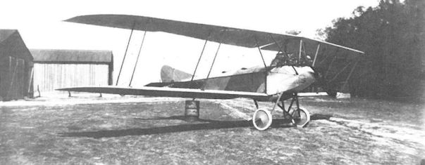
The DFW “racing military biplane" shown here at the DFW factory is possibly the aircraft that participated in the Third International Flugmeeting as the Lloyd LS 1. For the competition a 145 hp Hiero engine and spinner were installed, possibly at Aszod by DFW workmen.
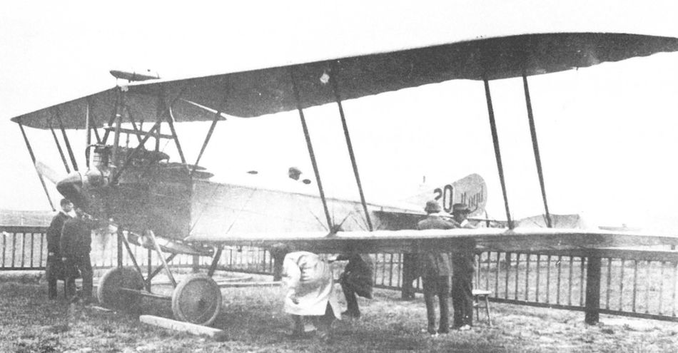
Officials of the Third International Flugmeeting inspecting the graceful Lloyd LS 1 (No.20) whose elegant design and faired belly radiator (a DFW patent) were praised by the aviation press. The design was closely patterned after the DFW MD 14 biplane.
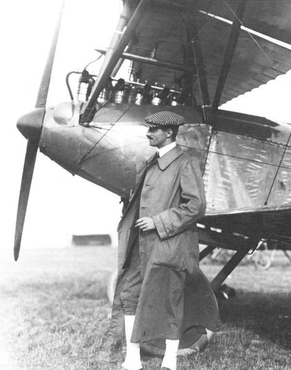
Heinrich Bier, general manager of the Lloyd company, posing with the record-breaking Lloyd LS 1 (40.01) that he flew at the Third International Flugmeeting in June 1914 at Aspern.
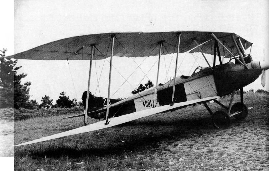
The Lloyd 40.01 after restoration by the Transportation Museum in Budapest. The engine is not original, the radiator is missing, and the rudder is enlarged. The wings have been recovered, but according to museum staff, the fuselage retains its original fabric.
Little valid information survives on this Austrian Army Air Service-operated Lloyd C I of early 1914 design origins, other than that it was powered by a 120hp Austro-Daimler and that it set a new altitude record of 21,709 feet on 27 June 1914. Only built in small numbers, the type led to the Lloyd C II through C V series, the workhorses of both the reconnaissance and training units of the Austro-Hungarian Air Service; reconnaissance, in the early years, being the only real function of military aircraft.
Little valid information survives on this Austrian Army Air Service-operated Lloyd C I of early 1914 design origins, other than that it was powered by a 120hp Austro-Daimler and that it set a new altitude record of 21,709 feet on 27 June 1914. Only built in small numbers, the type led to the Lloyd C II through C V series, the workhorses of both the reconnaissance and training units of the Austro-Hungarian Air Service; reconnaissance, in the early years, being the only real function of military aircraft.
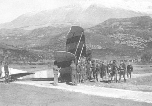
The damaged Lloyd LS 1 at Flik 6 in the spring of 1915. The aircraft carries the early military designation “LL 20 M” and the red-white-red national insignia on the wings and fuselage.
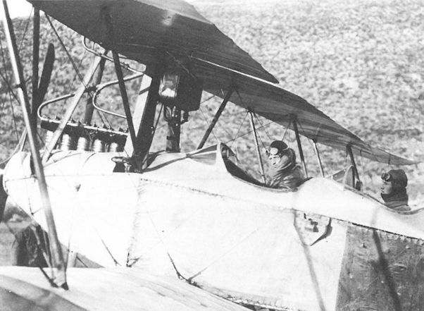
The Lloyd Ll 2S (40.02) at Flik 6 in Igalo in April 1915. The triangular fixture below the cockpit is a makeshift machine gun mount. A total of three radiators are installed.
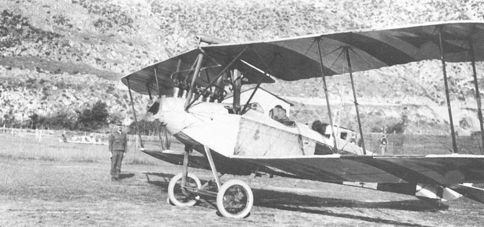
The German-built Lloyd Ll 2S (40.02) at Flik 6 in Igalo in April 1915. A gravity fuel tank is mounted above the top wing.
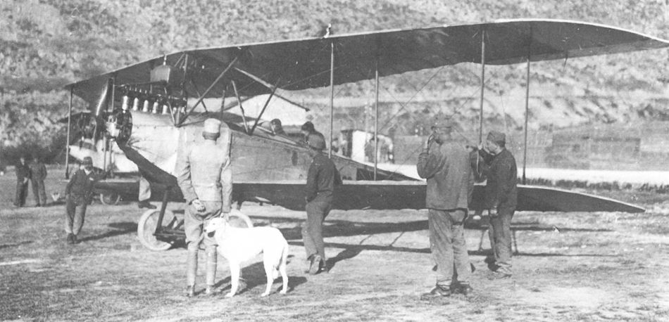
Shown with the original fabric-covered fuselage, the Lloyd C.I 41.02 served with Flik 6 at Igalo from March through July 1915. The pilot is Zugsfuhrer Julius Arigi with flight student Oberleutnant Emanuel Mainx, April-May 1915.

The triple socket mount, installed as a field modification on the Lloyd C.I 41.03, required the observer to manhandle the 29 pound (13 kg) Schwarzlose M 7/12 machine gun from side to side in combat.
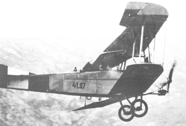
Flik 4 on the Isonzo Front flew Lloyd C.I 41.07 in the summer of 1915. The aileron has been replaced. A belt-driven wireless generator can be seen below the nose. The application of the plywood fuselage reinforcement is rather crude and has been finished with rounded strips.
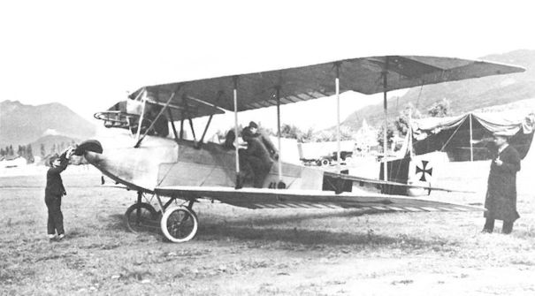
Mechanics testing the engine of the Lloyd C.I 41.10 of Flik 16 on the Seebach airfield near Villach, 4 September 1915. The upper wing markings do not extend across the aileron.
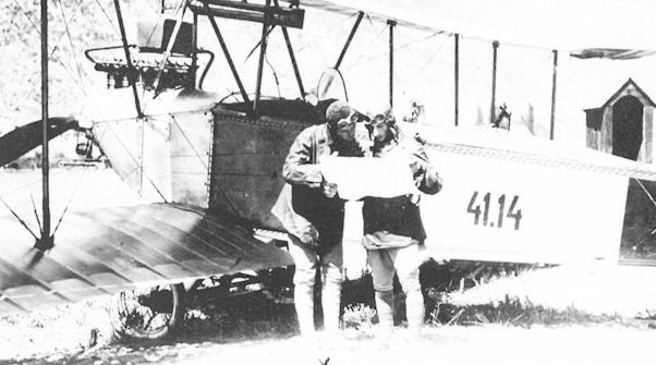
The Lloyd C.I 41.14, prototype for the production series, shows the original laced, fabric fuselage to good advantage. A wireless aerial spool projects from the observer’s cockpit and a generator is mounted under the engine hub. Three machine gun pivots have been installed. The aircraft served with Flik 6 between July 1915 and May 1916.
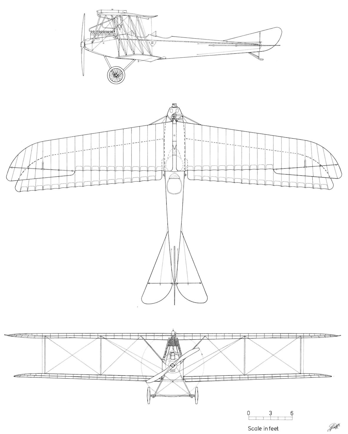
Lloyd 40.02
Lloyd 40.03
According to LFT records, the Lloyd 40.03 was powered by a 160 hp Daimler engine and shipped to WKF. The 40.03 may have served as a manufacturing sample for the Lloyd C.III built by WKF under license as the C.III(WKF) series 43.5
Lloyd 40.09
The Lloyd 40.09 biplane, powered by a 160 hp Daimler engine, was the prototype for the Lloyd C.IV series 44, the first production aircraft scheduled for the all-wood veneer wing. To obtain comparative performance figures, the 40.09 was flown with both veneer and fabric-covered wings and wings of differing shape. The initial series of flight tests, completed in July 1916, demonstrated that the fabric-winged version had slightly better speed (6 km/h - 4 mph) but a marginally lower rate of climb. A second test series with new fabric and veneer wings undertaken in mid-August 1916 yielded slightly improved performance, both versions being about equal. With the completion of flight trials, the 40.09 prototype (fitted with fabric-covered wings) was re-designated as a C.IV series 44 aircraft but the actual number has not been identified.
Lloyd 40.12
Developed in parallel with the 40.11, the Lloyd 40.12 prototype (company Type K.B.3.16A) was under construction in August-September 1916. Listed in Flars records as a modification of the fabric-winged Lloyd C.IV series 44, the 40.12, powered by a 160 hp Daimler engine, was regarded as the definitive prototype for the veneer-winged C.IV series 44.4. Because of the excellent performance achieved by the 40.11 (Lloyd C.V), further development and scheduled production of the 40.12 (as series 44.4) was cancelled. A factory drawing dated October 1916 shows that the 40.12 prototype was re-designated C.IV 44.41 and remained the sole example of the series. The airframe, less engine, was stored at Flek 17 in September 1918.
Lloyd 40.12 Specifications
Engine: 160 hp Daimler
Wing: Span Upper 13.28 m (43.57 ft)
Span Lower 12.68 m (41.60 ft)
Chord Upper 1.54 m (5.05 ft)
Chord Lower 1.52 m (4.99 ft)
Dihedral Lower 2 deg
Sweepback Upper 8 deg
Sweepback Lower 8 deg
Gap 1.80 m (5.91 ft)
Stagger 0.35 m (1.15 ft)
Total Wing Area 30.74 sq m (331 sq ft)
General: Length 8.00 m (26.25 ft)
Height 2.95 m (9.68 ft)
Track 1.90 m (6.23 ft)
Loaded Weight 1200 kg (2646 lb)
Lloyd C.II Series 42
On 22 July 1915, the largest contract to date was awarded to Lloyd for 62 C.II reconnaissance biplanes (Type K.B.3.15) powered by the 145 hp Hiero engine. In May 1916, an additional eight C.II biplanes were ordered to provide work for the Lloyd factory, bringing the total to 70 aircraft numbered 42.01 to 42.70. Deliveries lagged substantially behind the December 1915 completion schedule, primarily because output of the license-built Hiero (Mar) engines, first installed in aircraft 42.18, did not keep pace with C.II production. Nor was the new engine sufficiently reliable. According to Flik 17 (December 1915) "It was impossible to perform more than two or three flights without the engine acting up," an experience shared by other squadrons. Although Marta technicians, rushed to the Front, were gradually able fix the problems, engine performance tended to drop off "after only 10 to 12 hours" greatly reducing the rate of climb. Deliveries were further delayed by a severe injury to the sole Lloyd acceptance pilot in August, who was not replaced until December 1915. Records show that the majority of the C.II biplanes reached the Front between February and July 1916.
The first C.II biplanes, accepted at Aszod in August 1915, were dispatched to Fliks 16 and 17. With time, the Lloyd C.II was in service with virtually every combat squadron stationed on the Russian Front (Fliks 9, 11, 13, 14, and 26), and Italian Front (Fliks 7, 15, 16, and 17). In late 1916, with the arrival of superior aircraft, the C.II was gradually withdrawn from the Front and placed into training service. Some were fitted with dual controls. Although not very popular as school machines, 20 C.II trainers were still flying as late as August 1918.
Lloyd C.II Series 42 Specifications
Engine: 145 hp Hiero
Wing: Span Upper 14.62 m (47.97 ft)
Span Lower 13.84 m (45.41 ft)
Chord Upper 2.00 m (6.56 ft)
Chord Lower 1.70 m (5.58 ft)
Dihedral Lower 2 deg
Sweepback Upper 8 deg
Sweepback Lower 8 deg
Gap 1.85 m (6.07 ft)
Stagger 0.13 m (0.43 ft)
Total Wing Area 38.3 sq m (412 sq ft)
General: Length 8.82 m (28.94 ft)
Height 3.16 m (10.37 ft|
Track 2.05 m (6.73 ft)
Empty Weight 900 kg (1985 lb)
Loaded Weight 1329 kg (2931 lb)
Maximum Speed: 128 km/hr (80 mph)
Climb: 1000m (3,281 ft) in 6 min
Lloyd C.III Series 43
Lloyd delivered its first C.III in August 1916, just as the last of 44 license-built C.III|WKF) series 43.5 was accepted. It was never intended for Lloyd to manufacture the C.III, but delays in perfecting the veneer wing, scheduled for the Lloyd C.IV series 44, led Flars to order 16 aircraft (eight each of C.II and C.III) on 22 May 1916 to provide factory work. The C.III, referred to as a "lightened C.II" and carrying the same model number (Type K.B.3.15), was powered by the 160 hp Daimler engine. Acceptances of the C.III biplanes, numbered 43.01 to 43.08, began in August and ended in September 1916.
Beginning in September 1916, the Lloyd-built C.III biplanes were sent to the newly-established Fliks 32 and 33 stationed on the Rumanian Front and performed general reconnaissance assignments with full satisfaction. During 1917, the Lloyd and WKF-built C.III aircraft were distributed among various Fliks for advanced flight and proficiency training. Further details can be found under Lloyd C.III(WKF) series 43.5.
Lloyd C.III Series 43 Specifications
Engine: 160 hp Daimler
Wing: Span Upper 14.62 m (47.97 ft)
Span Lower 13.84 m (45.41 ft)
Chord Upper 2.00 m (6.56 ft)
Chord Lower 1.70 m (5.58 ft)
Dihedral Lower 2 deg
Sweepback Upper 8 deg
Sweepback Lower 8 deg
Gap 1.85 m (6.07 ft)
Stagger 0.13 m (0.43 ft)
Total Wing Area 38.3 sq m (412 sq ft)
General: Length 8.82 m (28.94 ft)
Height 3.16 m (10.37 ft)
Track 2.05 m (6.73 ft)
Loaded Weight 1310 kg (2888 lb)
Maximum Speed: 137 km/hr (85 mph)
Climb: 1000m (3,281 ft) in 8 min
Lloyd C.IV Series 44 and 44.2
Static calculations for the veneer-winged Lloyd C.IV series 44 biplane (Type K.B.3.16) were submitted to Flars for approval in February 1916. Production was under way in April and on 1 May 1916, Flars signed a contract for 48 C.IV series 44 biplanes, powered by the 160 hp Daimler engine, to be delivered between 13 May and 30 June 1916. When Flars learned that the veneer wing was experiencing serious manufacturing delays, the production total was reduced to 20 aircraft in July. Rather than stop output entirely and hoping to salvage what remained of the program, Flars decreed that all C.IV production aircraft were to be delivered with fabric-covered wings such as had been tested on the 40.09 prototype. The first C.IV aircraft was accepted in December 1916. Because the C.IV was overweight by 210 kg (463 lb), Lloyd incurred a penalty payment.
In LFT records a total of 21 C.IV biplanes have been identified, consisting of 13 series 44, numbered 44.01 to 44.13, and eight series 44.2, numbered 44.21 to 44.28. The additional machine is believed to have been the renumbered 40.09. No explanation has been found why production was split into two separate batches, but indications are that series 44.2 was delivered with dual controls for training purposes. Because of marginal performance, the Lloyd C.IV biplanes were sent to the Eastern Front in February 1917 to serve with Fliks 11 and 26 and later Flik 43. Several were attached to frontline squadrons on the Italian Front as advanced trainer or communication aircraft. In August 1918 all remaining aircraft were ordered to home-front training establishments.
Of the total C.IV aircraft built by Lloyd (21) and WKF (16), six were listed on frontline squadron inventory as of 1 August 1918. Eight Lloyd-built machines were offered for sale to Czechoslovakia in 1920.
Lloyd C.IV Series 44 Specifications
Engine: 160 hp Daimler
Wing: Span Upper 14.52 m (47.64 ft)
Span Lower 13.72 m (45.01 ft)
Chord Upper 1.55 m (5.09 ft)
Chord Lower 1.55 m (5.09 ft)
Dihedral Lower 1 deg
Sweepback Upper 8 deg
Sweepback Lower 8 deg
Gap 2.00 m (6.56 ft)
Stagger 0.35 m (1.15 ft)
Total Wing Area 38 sq m (408 sq ft)
General: Length 8.79 m (28.84 ft)
Height 3.18 m (10.43 ft)
Track 2.05 m (6.73 ft)
Empty Weight 909.7 kg (2006 lb)
Loaded Weight 1334.7 kg (2943 lb)
Maximum Speed: 137 km/hr (85 mph)
Climb: 1000m (3,281 ft) in 5 min 30 sec
2000m (6,562 ft) in 13 min 40 sec
3000m (9,843 ft) in 21 min 10 sec
Lloyd C.IV Series 44.4
Concurrent with ordering 24 Lloyd C.V biplanes on 13 December 1916, Flars ordered eight C.IV series 44.4 biplanes (Type K.B.3.16A) as back-up insurance should unforeseen problems occur with the C.V's more innovative design. The veneer-winged biplanes were numbered 44.41 to 44.48 and powered by a 160 hp Daimler engine. As soon as it became apparent that the Lloyd C.V was a superior aircraft, the production contract for the C.IV series 44.4 biplanes was cancelled. Only one Lloyd C.IV series 44.4 aircraft appeared in the LFT inventory; it was number 44.41, the re-numbered 40.12 prototype.
Lloyd C.IV Series 44.4 Specifications
Engine: 160 hp Daimler
Wing: Span Upper 13.28 m (43.57 ft)
Span Lower 12.68 m (41.60 ft)
Chord Upper 1.54 m (5.05 ft)
Chord Lower 1.52 m (4.99 ft)
Sweepback Upper 8 deg
Sweepback Lower 8 deg
Gap 1.80 m (5.91 ft)
Stagger 0.35 m (1.15 ft)
Total Wing Area 33.16 sq m (357 sq ft)
General: Length 8.00 m (26.25 ft)
Height 2.95 m (9.68 ft)
Track 1.90 m (6.23 ft)
Empty Weight 843 kg (1859 lb)
Loaded Weight 1297 kg (2860 lb)
Maximum Speed: 135 km/hr (84 mph)
Climb: 1000m (3,281 ft) in 6 min
Lloyd C.III(WKF) Series 43.5
For WKF's initial production contract, Flars chose a more powerful version of the popular and uncomplicated Lloyd C.II biplane. Designated Lloyd C.III(WKF), the airplane differed only in the engine installation that WKF modified for the 160 hp Daimler; all other parts were interchangeable with the Hiero-engined Lloyd C.II. After receiving a letter of intent, WKF began assembly work in mid-1915, and full-scale production was under way in December. The contract, signed on 8 February 1916, called for 24 Lloyd C.III series 43.5 biplanes to be delivered beginning in December 1915 and ending in March 1916. On 23 May 1916, twelve additional C.III biplanes were ordered, scheduled for delivery in April 1916. The contract was later amended to include an additional eight C.III biplanes as a substitute for the Lloyd C.IV(WKF) that had been delayed by development problems. Thus a total of 44 Lloyd C.III(WKF) biplanes, numbered 43.51 to 43.94, was delivered between January and August 1916.
In February 1916, the first WKF-built C.III biplanes began to reach operational units, comprising the initial equipment of the newly-established Fliks 21 and 23 on the southern Tirol Front. When Flik 15 was transferred to this Front from the Balkans in March 1916, it also was equipped with Lloyd C.III(WKF) biplanes. The type was flown singly by Fliks 2, 4, and 12 on the Isonzo Front and Flik 16 in Karnten. On the Eastern Front, the C.III(WKF) comprised the original equipment of the newly-formed Fliks 26, 29, 30, and 31, and some "second-hand" machines were assigned to Fliks 1, 9, and 11. In October 1916, Flik 34 (Isonzo Front) was given three old C.III(WKF) machines to train novice pilots in landing on small airfields, rather than endanger the valuable Brandenburg C.I(Ph) series 27 aircraft for this purpose.
When it arrived at the Front in early 1916, the C.III(WKF) was regarded as a serviceable, all-round reconnaissance type of average performance. Most aircraft were fitted with wireless equipment. Flik 15 reported in June 1916 that the C.III had fully met the high demands imposed by the surrounding mountainous terrain. In particular, new aircraft were repeatedly able to attain 4000 meters (13,124 ft) with full service load plus 60 kg (132 lb) bombs. However, the type was inferior to the new Brandenburg C.I that had become operational at about the same time. As a consequence, frontline units often took the new(er) Daimler engines from their C.III aircraft and installed the pirated powerplants in Brandenburg machines. That the C.III was, in effect, a "hidden supply depot" remained unknown to the high command. In the summer of 1916, the complaints of "soft" wings, vibrating struts, and degrading performance began to increase, and the C.III machines were withdrawn or dispatched to units on the Eastern Front.
In March 1917, the C.III aircraft were removed altogether from operational service and modified into dual-control trainers. They were flown by advanced students primarily at Fleks 2 to 6 and 8. As of 1 July 1917, there were 32 C.III trainers in Flek inventory, and a handful were still flying in late 1918. Eight of these were offered for sale to the Czechoslovakian government in April 1920.
Lloyd C.IV(WKF) Series 44.5 and 44.6
Having gained experience in building the Lloyd C.III, Flars now assigned WKF the license-production of the Lloyd C.IV biplane fitted with the new Lloyd veneer-covered wing. Component manufacture was well under way when Flars confirmed the letter of intent by signing a contract on 22 May 1916 for 24 Lloyd C.IV(WKF) biplanes. All were to be delivered by 24 June 1916. It soon became apparent that delays were inevitable owing to problems encountered in manufacturing the veneer wing. Flars considered cancelling the WKF contract, but rather than scrap completed parts, the C.IV production total was reduced to sixteen aircraft as outlined below. The remainder of the order was filled by an additional eight Lloyd C.III biplanes.
Because of the veneer wing delays, Flars directed in July 1916 that the first eight C.IV aircraft would be delivered with fabric-covered wings (tested on the Lloyd 40.09 prototype) to keep the factory workers occupied and achieve some measure of output. These aircraft were designated Lloyd C.IV(WKF), numbered 44.51 to 44.58 and powered by a 160 hp Daimler engine. They were identical with the Lloyd C.IV series 44.
The first machine was accepted in November 1916. In December, several series 44.5 biplanes were dispatched to Flik 7 and Flik 9 on the Russian Front and remained in operational service until February 1917, when they were replaced. Some of these aircraft were modified for dual control in October 1917 and used as training aircraft. Along with the Lloyd-built C.IV, the machines were periodically attached to frontline units such as Fliks 50, 52/D, 54/D, 58/D, 59/D, and 64/F and to rear-area units such as Flek 4 and 17. Three were offered for sale to the Czechoslovakian government in 1920.
The second batch of eight aircraft, designated Lloyd C.IV(WKF) 44.61 to 44.68, represented a totally new design based on the Lloyd C.IV 44.41 (40.12) prototype. These machines were fitted with single-bay, veneer-covered wings and given a compact, streamlined fuselage and new tail unit. Power was supplied by a 160 hp Daimler engine. The first four aircraft were accepted after great delay in February 1917. The C.IV(WKF) series 44.6 saw limited frontline service. Flik 9 had one aircraft (44.63) in March 1917 and another was flown by Flik 54/D in November 1917. Five were listed in storage in October 1918.
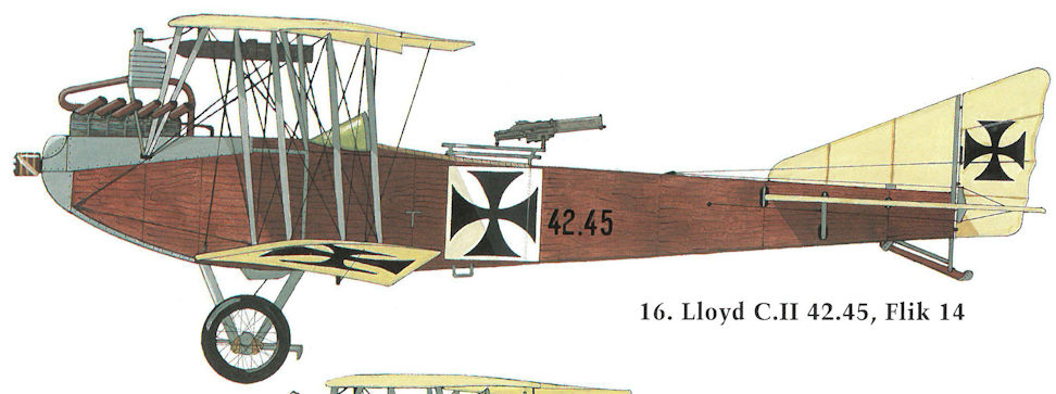
Lloyd C.II 42.45, Flik 14
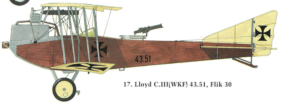
Lloyd C.II(WKF) 43.51, Flik 30
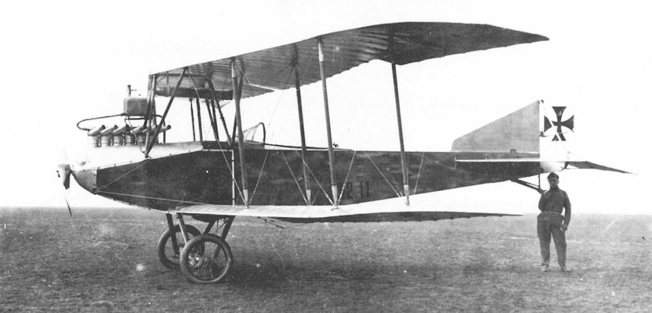
Lloyd C.II 42.11 of Flik 7, an early production machine, captured by the Italians on 21 December 1915 after a forced landing due to engine failure. Derived from the C.I, the C.II had a plywood-covered fuselage, a lighter, stronger wing, and a straight, pointed rudder.
Lloyd C.II 42.11. Flugzeug hinter den italienischen Linien niedergegangen; Lt i.d.Res. Georg Kraigher mußte am 21. Dezember 1915 bei einem Bombenflug auf Strigno und Asiago infolge Triebwerksdefekt notlanden, unverletzt gefangen; Lt Kraigher war aus Gewichtsgründen solo gestartet (4 x 20 kg Skoda- und 4 x 10 kg Carbonit-Bomben an Bord), ohne Beobachter, um die Strecke von Pergine (Flik 7) zum Ziel durchfliegen zu können
Lloyd C.II 42.11. Самолет упал за линией фронта на стороне Италии; Lt i.d. Res. Георгу Крайгеру пришлось совершить вынужденную посадку 21 декабря 1915 года во время вылета на бомбардировку городов Стриньо и Азиаго из-за отказа двигателя, он был захвачен целым и невредимым; Лейтенант Крейгер взлетел в одиночку для уменьшения веса (4 х 20 кг Skoda и 4 х 10 кг карбонитовые бомбы на борту), без наблюдателя, чтобы иметь возможность пролететь по маршруту от Перджина (Flik 7) до цели.
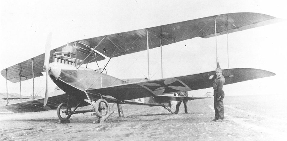
Posing for photographs for a technical manual, this Lloyd C.II 42.26, formerly of Flik 15, was flown as a trainer by Schulkompagnie 1 in late 1916. It was one of the last to have a socket-mounted machine gun.
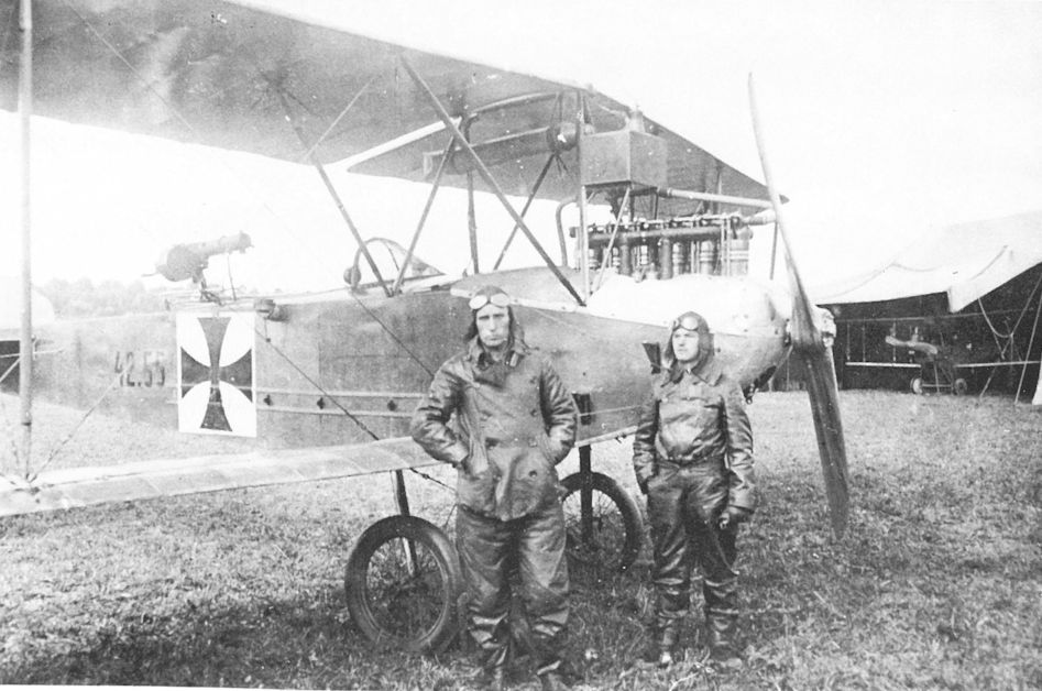
Leutnant Lambert Hubner and Zugsfuhrer Franz Koudela of Flik 26 with the Lloyd C.II 42.55. The wooden strips and insulators running along the fuselage, usually protected by a Cellon cover, formed part of the wireless transmitting antenna.
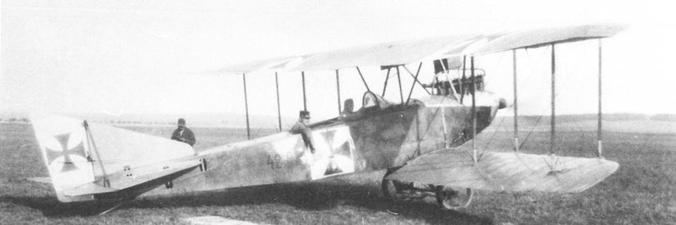
The unarmed Lloyd C.II 42.58 was flown as a dual-control trainer by Flek 8 in December 1916.
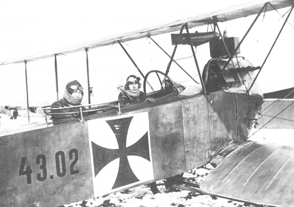
The Lloyd C.III 43.02, one of eight built, was flown operationally by Flik 33 between November 1916 and February 1917. Identical to the C.II, the only discernible difference is the right-hand exhaust of the Daimler engine.
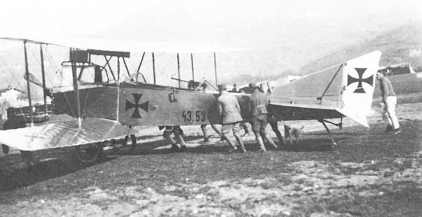
Flik 21 ground crews hauling the Lloyd C.III(WKF) 43.53 into the hangar to repair a broken tail skid (April 1916). Early production machines were fitted with a dorsal gun tripod and side mounts to which the machine gun, in this case a German Bergmann LMG 15, could be shifted.
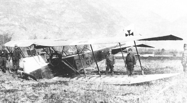
Returning from a bombing raid on the Piave bridges, the Lloyd C.III(WKF) 43.57, piloted by Korporal Franz Neumann, suffered engine failure on 23 March 1916. The C.III can be identified by the right-hand exhaust stacks of the 160 hp Daimler engine. On the C.II, the 145 hp Hiero exhausts were on the left.
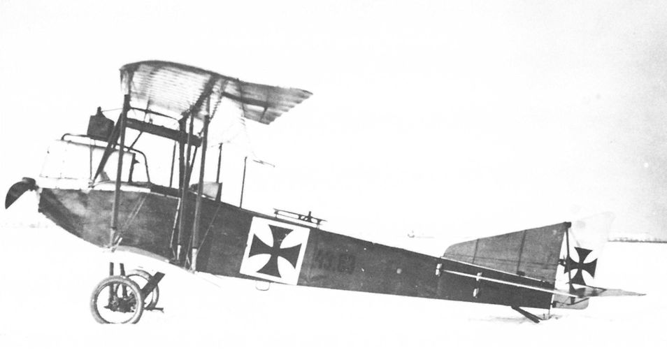
Lloyd C.III(WKF) 43.63 at Aspern in the winter of 1916, after serving with Flik 15 from April to August 1916. Production machines were soon fitted with the standard machine-gun ring at the factory. The open slots below the fin allowed adjustment of the tailplane incidence.
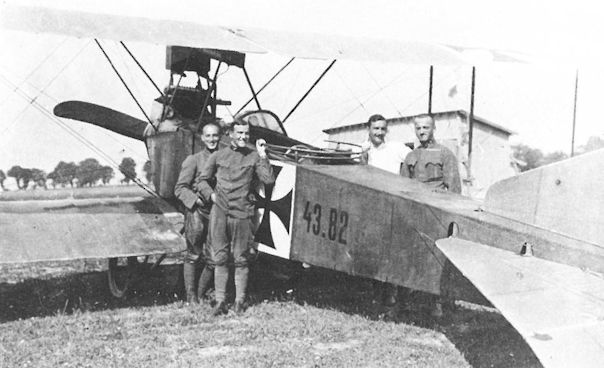
After serving with Flik 29, this Lloyd C.III(WKF) 43.82 came to Flik 26 in the summer of 1916, where it was modified into a dual-control trainer (above) in May 1917. Shown are (l-r) Leutnant Anton Wolf, Oberleutnants Karl Woral and Ernst Ritter von Pfiffer, and Feldwebel Franz Schobesberger of Flik 26 at Przewoziec airfield, Galicia.

Shown here at Aspern in early 1917, the Lloyd C.IV 44.08 was fitted with twin-bay, fabric-covered wings. The bump behind the observer’s position made space available for a camera, film cassettes, and a wireless transmitter.
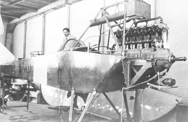
Lloyd C.IV(WKF) 44.51, powered by a 160 hp Daimler engine, at the WKF factory prior to application of the national markings. It differed from the Lloyd-built C.IV in that the cabane was strengthened. The degree of finish is exemplary.
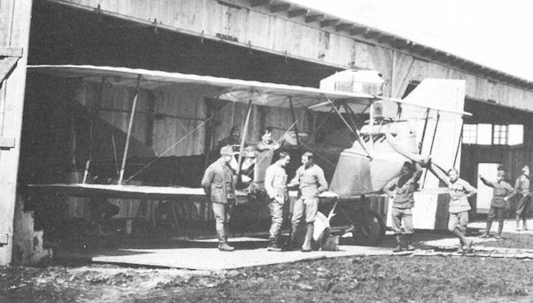
The Lloyd C.IV(WKF) series 44.5 biplane, emerging from a Flik 9 hangar, is either aircraft 44.54, 44.57, or 44.58. All three were attached to Flik 9 at Kragla, Galicia, in February 1917. The gravity tank was built into the machine-gun canister.
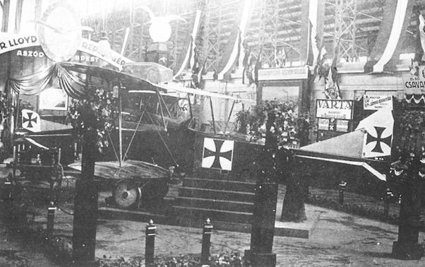
Shown at the Military Aircraft Exhibition in Budapest in April 1917, the single-bay Lloyd C.IV 44.41 (ex 40.12) had more sharply-pointed wings in contrast to earlier Lloyd aircraft. In the background can be seen the tail of the second version of the Lloyd 40.05 (D.I Series 45).
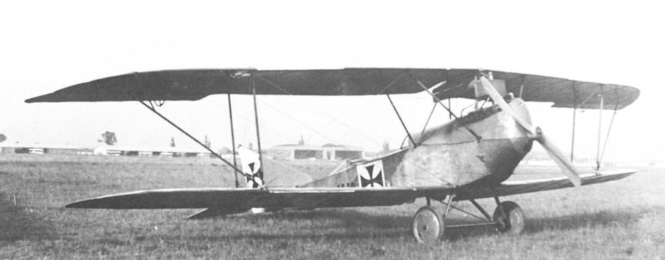
The Lloyd 40.09 as shown here with the veneer-covered wings, was a forerunner of the Lloyd 40.12 prototype, which it closely resembled.
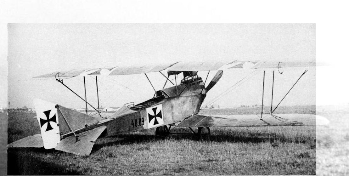
Derived from the Lloyd C.II, the 40.09 had a more streamlined fuselage, a fully-cowled engine, and gun-ring. Other than a single diagonal strut bracing the wing tip, the wing cellule appears identical to that of the Lloyd 40.04.
Lloyd 40.09, Aspern, Einfliegerei, Versuchsflugzeug zur Ba 44. Fournierflächen
Lloyd 40.09, Асперн, облет, испытательный самолет для Ba 44. Крылья имеют конструкцию Fourniertragflächen (вместо полотна использовались полосы шпона).
Lloyd 40.09, Aspern, Einfliegerei, Versuchsflugzeug zur Ba 44. Fournierflächen
Lloyd 40.09, Асперн, облет, испытательный самолет для Ba 44. Крылья имеют конструкцию Fourniertragflächen (вместо полотна использовались полосы шпона).
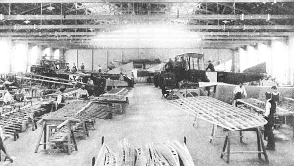
Lloyd C.III(WKF) biplanes being assembled in the WKF factory in mid-1916. Compare the conventional, fabric-covered wing under construction (left foreground) with the typical interior framework of the Lloyd veneer-covered wing on the right.
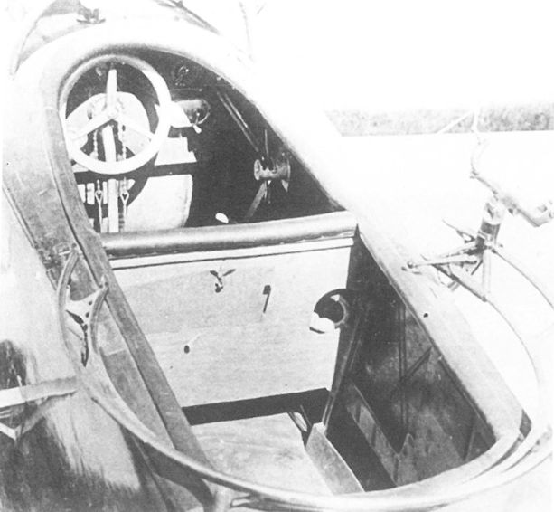
Close-up of the common cockpit of the Lloyd C.II 42.20 shows the beautifully varnished fuselage, the tubular gun ring, and the machine gun bracket. The round opening in the fuselage frame is for a flight instrument (or compass?), visible to both crew members.
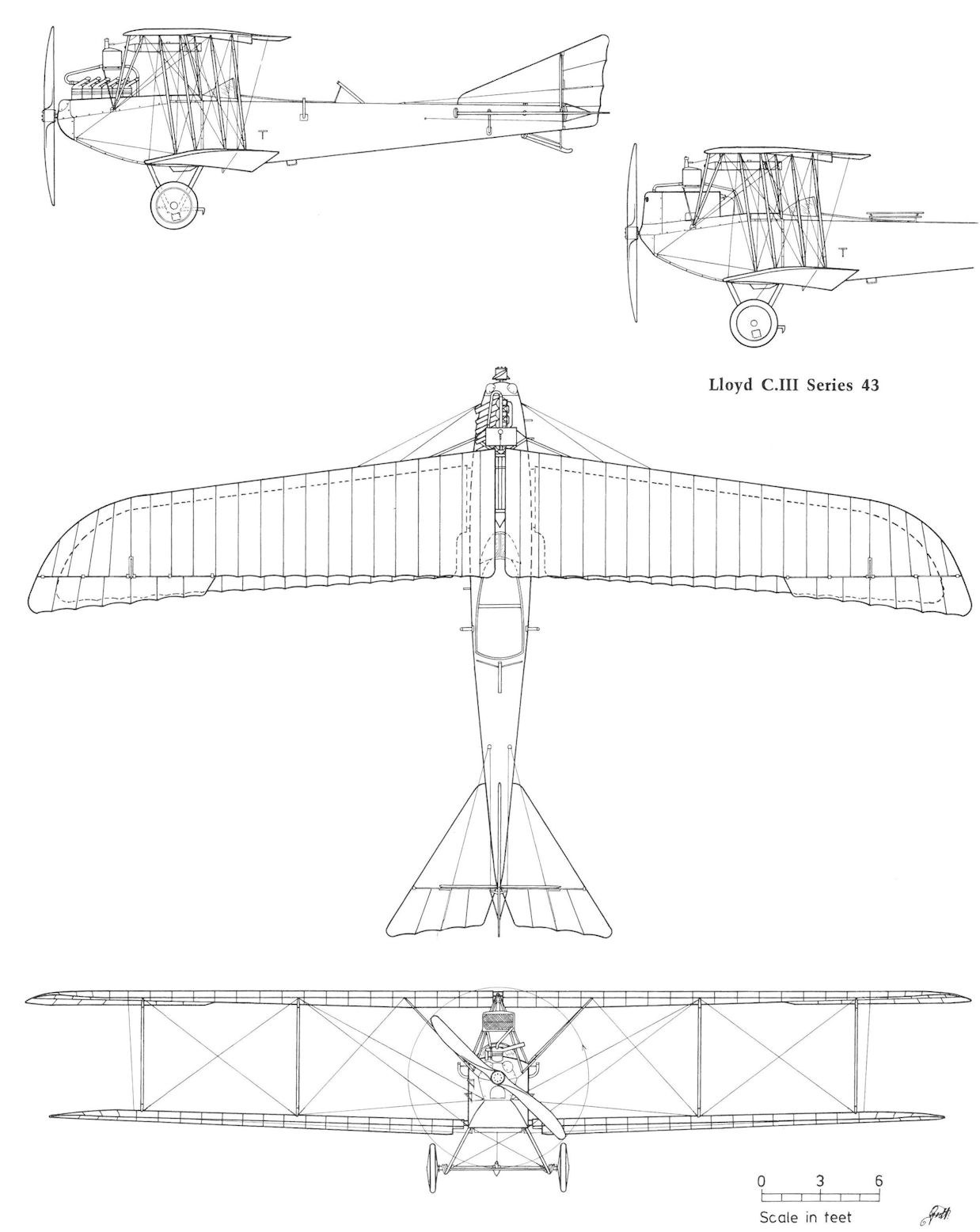
Lloyd C.II Series 42 and C.III Series 43
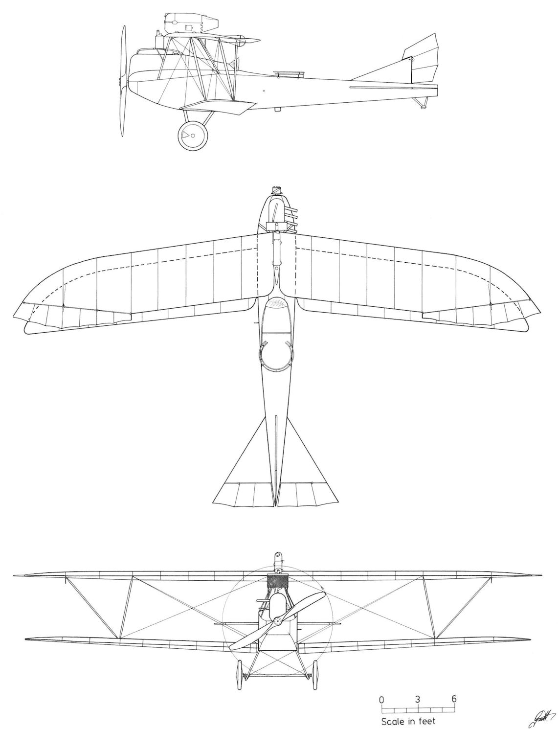
Lloyd C.IV Series 44.4
Lloyd 40.04
The Lloyd 40.04 was the first of several prototypes built to investigate the veneer wing, Bier's most notable invention. A typical veneer wing consisted of five to nine ribs per wing panel, to which were attached some 10 to 16 stringers (10 mm square) spaced at even intervals around the rib profile and running the length of the wingspan. The top and bottom stringers were joined by a 2 mm plywood web running spanwise between the ribs, forming a series of box frames that imparted great strength. The outer skin was composed of 1.2 mm veneer plywood glued and nailed to the support structure. Because the inherent strength of the veneer wing eliminated the requirement for most metal fixtures and all internal wire and tube bracing, Bier reasoned that it could be assembled by unskilled workers in less time than a conventional wing. Unlike a fabric-covered wing, the veneer wing retained the airfoil shape between the ribs and could be given a glass-like finish. But the task of reducing excess weight and developing proper assembly techniques proved extremely time-consuming. In practice, the veneer wing was not as "easy to manufacture" as had been forecast. In the field minor repairs proved troublesome, and despite a varnish-coated interior, moisture condensation caused internal plywood deterioration that could not be verified by inspection.
Powered by a 160 hp Daimler engine, the 40.04 was basically a C.II fuselage fitted with veneer wing cellule. The inherent wing strength is demonstrated by the fact that the large-span wing of 14.5 meters (47ft 7in) was braced by a single pair of interplane struts. The Lloyd 40.04, completed about the time Bier filed for his wing patent (27 April 1916), was reported in the Lloyd shops for modification in July, and flight tests continued in August 1916. In Flars records the 40.04 belongs to the group of experimental aircraft (40.09 and 40.12) that served to test and develop the veneer wing for the Lloyd C.IV series 44 and C.V series 46 biplanes.
Lloyd 40.04 Specifications
Engine: 160 hp Daimler
Maximum Speed: 147 km/hr (91 mph)
Climb: 1000m (3,281 ft) in 5 min 10 sec
3000m (9,843 ft) in 25 min 12 sec
Lloyd 40.05
Before the appearance of synchronized guns, designers, in their quest for an unrestricted forward field of fire, sought solutions in aircraft of bizarre shape. The ungainly Lloyd 40.05 (Type FJ - Flugzeug Jager - aircraft hunter) was no exception. The gunner standing above the engine in a raised turret had an ideal position but one wonders how the pilot, given his limited field of view from the rear cockpit, was to keep the adversary in sight or communicate with the gunner. Perhaps the gunner was provided with some form of steering control? The 160 hp Daimler-engined 40.05 prototype, under construction in January 1916, appeared for flight tests in late spring 1916. Whereas structural information is quite complete in Lloyd records, the lack of performance data leads to the assumption that the 40.05 prototype, a private-venture undertaking, performed only the most perfunctory flight tests.
Between July and September 1916, the 40.05 was modified as a single-seat fighter. According to project drawings, it was armed with three machine guns; one in a Type II VK canister over the wing and two mounted on the lower wing outside the propeller arc. After the 40.05 fighter was demonstrated at Aspern in December 1916, Flars issued this critique: "In regard to its dimensions, the reconstructed 40.05 does not appear to be the basis for a competitive fighter. Unless good performance is achieved, further work should be stopped." In the event, development of the 40.05 fighter was discontinued and production plans for the derivative Lloyd D.I series 45 fighter shelved.
Lloyd 40.05 Specifications
Engine: 160 hp Daimler
Wing: Span Upper 11.17 m |36.65 ft)
Span Lower 10.72 m (35.17 ft)
Chord Upper 1.45 m (4.76 ft)
Chord Lower 1.45 m (4.76 ft)
Sweepback Upper 8 deg
Sweepback Lower 8 deg
Gap 1.90 m (6.23 ft)
Total Wing Area 25 sq m (269 sq ft)
General: Length 6.92 m (22.70 ft)
Height 3.10 m (10.17 ft)
Loaded Weight 962 kg (2121 lb)
Lloyd D.I Series 45
Manufacture of the Lloyd single-seat fighter, based on the 40.05 prototype, was discussed by Flars in July 1916. The design drawings were completed in September and 16 series 45 fighters, powered by the 160 hp Daimler engine, were ordered in December. Armament consisted of a single Type II VK gun canister mounted over the center-section. No mention was made of the two machine guns mounted over the lower wing as originally proposed by Lloyd. Officially the design was referred to as "series 45", but had it gone into production the designation "D.I" would have been appropriate. In February 1917, the contract was annulled to make way for the Lloyd C.V.
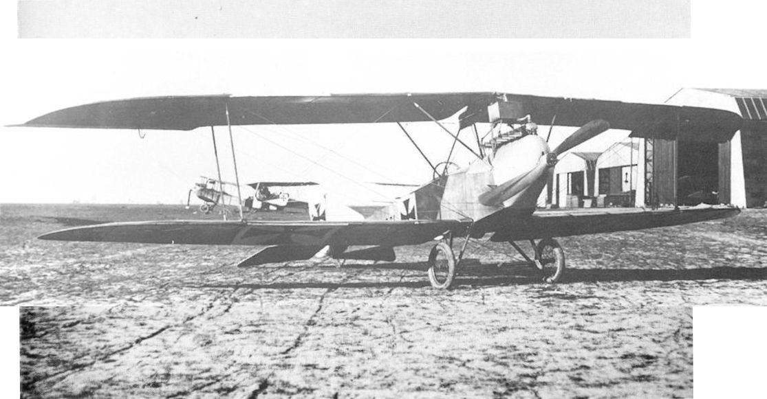
The simple elegance of the veneer wing is emphasized in this view of the Lloyd 40.04, photographed at Aspern in mid-1916.
Lloyd 40.04, Aspern. Einfliegerei, Versuchsflugzeug mit Fourniertragflächen, einstieliges Tragwerk
Lloyd 40.04, Асперн. Облет, экспериментальный одностоечный биплан, крылья имеют конструкцию Fourniertragflächen (вместо полотна использовались полосы шпона).
Lloyd 40.04, Aspern. Einfliegerei, Versuchsflugzeug mit Fourniertragflächen, einstieliges Tragwerk
Lloyd 40.04, Асперн. Облет, экспериментальный одностоечный биплан, крылья имеют конструкцию Fourniertragflächen (вместо полотна использовались полосы шпона).
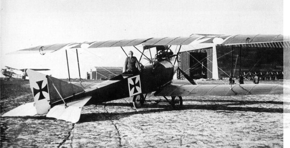
The Lloyd 40.04 prototype at Aspern. A distinguishing feature of the Lloyd veneer wing is the relatively few wing ribs in relation to the wingspan.
Lloyd 40.04. Rückansicht; deutlich sind die Fournierplattensegmente erkennbar
Ллойд 04/40. Вид сзади; отчетливо видны полосы шпона в конструкции крыльев (Fourniertragflächen).
Lloyd 40.04. Rückansicht; deutlich sind die Fournierplattensegmente erkennbar
Ллойд 04/40. Вид сзади; отчетливо видны полосы шпона в конструкции крыльев (Fourniertragflächen).
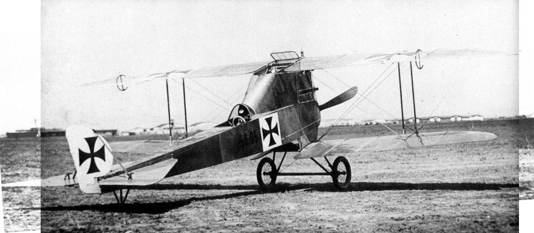
Lloyd 40.05 prototype at the Aspern test center in mid-1916. The barely-visible controls (or instrumentation) in the gunner's position may indicate some form of steering control.
Lloyd 40.05. Rückansicht mit dem Beobachterstand neben den oberen Tragflächen, Fournierflügel
Lloyd 40.05. Наблюдатель рядом с верхними крыльями
Lloyd 40.05. Rückansicht mit dem Beobachterstand neben den oberen Tragflächen, Fournierflügel
Lloyd 40.05. Наблюдатель рядом с верхними крыльями
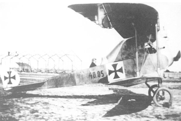
The pilot’s view in the Lloyd 40.05 prototype was severely restricted by the raised gunner’s position over the engine. The “hung-on” ailerons are characteristic of the veneer wing.
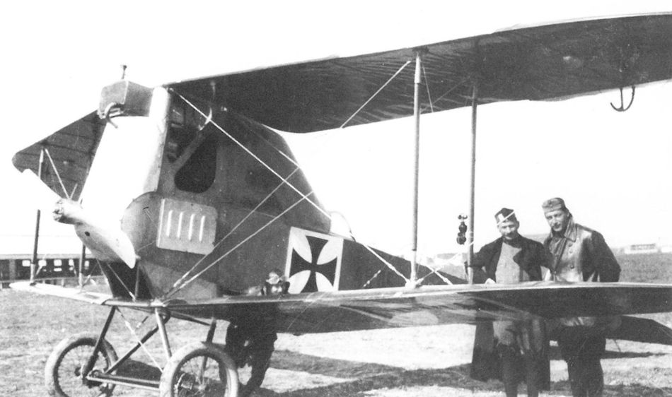
Lloyd 40.05: The fuselage windows, the fully-cowled engine, the lower-wing fuselage construction, and the aileron quadrants fail to detract the eye from the embarrassed pilot hiding behind the wing.
Shown at the Military Aircraft Exhibition in Budapest in April 1917, the single-bay Lloyd C.IV 44.41 (ex 40.12) had more sharply-pointed wings in contrast to earlier Lloyd aircraft. In the background can be seen the tail of the second version of the Lloyd 40.05 (D.I Series 45).
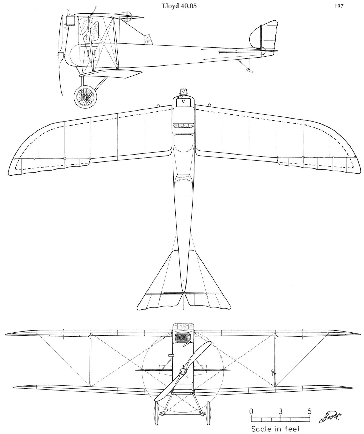
Lloyd 40.05
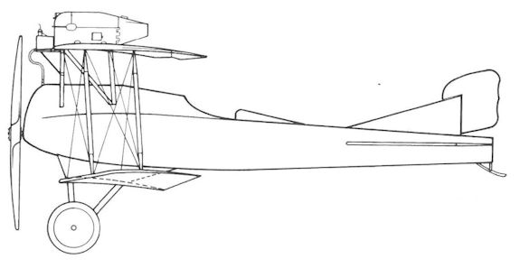
The Lloyd D.I Series 45 fighter, taken from a design drawing dated September 1916. The airframe was modified from the Lloyd 40.05 prototype and exhibited at the Budapest Military Aircraft Exhibition in April 1917.
Lloyd 40.08
The LFT reacted swiftly to the appearance of the three-engined Caproni bomber in August 1915 by ordering that "the construction of new and more powerful bombers be pushed by all means at hand." Lloyd, Oeffag, and Phonix each received design and construction funds for two prototypes of triplane configuration with a central pilot's nacelle and two outer fuselages. By insisting on such a complex structure, Flars had saddled the manufacturers with engineering and aerodynamic problems that required a degree of design and technical proficiency which none of the firms possessed at that time. Powered by a 12-cylinder engine mounted in a central nacelle and two smaller engines in each side fuselage, the bomber was required to remain aloft on either the center or the outer engines and carry a 200 kg (442 lb) bomb load for a duration of six hours. Two gunners stationed in a large nose turret and two rear gunners provided defensive protection.
In January 1916, Lloyd, the first company to respond, submitted drawings and specifications for two triplane bombers, known as the Luftkreuzer I and II (Type LK I and LK II - aerial cruiser). Construction of the Lloyd 40.08 (LK I) was well under way in April 1916. To meet the first week of June deadline, overtime and Sunday work was authorized. Furthermore, Flars hoped to speed progress by keeping Oeffag and Phonix abreast of the latest technical information gained by Lloyd. The 40.08 was powered by a centrally-mounted 300 hp Daimler V-12 pusher engine and two 160 hp Daimler tractor engines in the side fuselages. The tail consisted of four rudders mounted between an upper elevator and a lower stabilizer rather haphazardly suspended beneath the outer fuselages by a light tubing framework. Twin tail skids were fitted under the two center rudders. The veneer wings were constructed in typical Lloyd fashion and finished to a high gloss.
The bomber, completed on 20 June 1916, was rolled out for engine thrust measurement on the Aszod airfield. In a horizontal, take-off position, the 40.08 appears nose-heavy and the center of gravity seems dangerously high. In fact the 40.08 did tip on its nose during ground tests, fortunately causing little damage. To avoid a repeat occurrence, a robust tricycle undercarriage was fitted. The modification work, performed at Aspern, began in July and ended late October 1916 when Oberleutnant Antal Lanyi-Lanczendorfer was assigned the task of performing the maiden flight. There is no direct proof that the 40.08 ever took to the air, although the possibility of a few ground hops can not be discounted. An official German source stated that, with the exception of taxi trials, no flight data was obtained. On 2 November 1916, Flars, reporting "great difficulties in flight testing," planned to cut the weapons load to reduce overall weight. Sporadic development work continued. A Flars recommendation, dated December 1916, to add an "extended tail skid" was approved on 13 February 1917. Flars engineers prepared the appropriate drawings which were also sent to Phonix. A proposal, dated 30 March 1917, to rebuild the 40.08 bomber in order "to gain information to decide the future of the remaining triplane bombers" (Lloyd 40.10, Oeffag 50.04 and Phonix 20.11) was rejected; all work was terminated and the airframes placed in storage. On 17 January 1918, the stripped 40.08 airframe was ordered shipped to the Eger Fliegermaterial-Depot IV for disposal.
Lloyd 40.08 Specifications
Engine: 300 hp Daimler & 2 x 160 hp Daimler
Wing: Span Upper 23.26 m (76.31 ft)
Span Middle 22.38 m (73.42 ft)
Span Lower 16.84 m (55.25 ft)
Chord Upper 2.40 m (7.87 ft)
Chord Middle 2.20 m (7.22 ft)
Chord Lower 2.00 m (6.56 ft)
Dihedral Lower 2 deg
Sweepback 8 deg
Gap Upper 2.1 m (6.89 ft)
Gap Lower 1.75 m (5.74 ft)
Stagger 0.20 m (0.66 ft)
Total Wing Area 110 sq tn (1184 sq ft)
General: Length 9.55 m (31.33 ft)
Height 5.01 m( 16.44 ft)
Loaded Weight 4840 kg (10,672 lb)
Lloyd 40.10
The Lloyd 40.10 triplane bomber (Type LK II), ordered at the same time as the 40.08, differed in several important respects. By locating the side fuselages below the middle wing, the center of gravity was lowered but at the expense of a reduced field of fire. The center nacelle was simplified and a nose undercarriage was fitted. The general arrangement drawings were completed in January 1916 and construction was approved in February. Assembly of the wing and fuselage, halted in July to await the outcome of the 40.08 tests, was resumed in September and suspended in October 1916 to await airframe modifications with which the Lloyd design bureau was still engaged in January 1917. The 40.10 prototype was never completed. The airframe was shipped to Aspern for storage and on 17 January 1918 sent to the Eger Fliegermaterial-Depot IV for disposal.

The Lloyd 40.08 tied down for thrust measurement at Aszod in July 1916. The fragile tail skid structure appears incapable of withstanding anything but light landing forces.

The front turret had sufficient room for two gunners with a magnificent view in all directions, an advantage not shared by the pilot.

The Lloyd 40.08 bomber in June 1916. The pilot’s cockpit was located behind a raised nose turret. The lower wing was connected to the center fuselage by a streamlined housing that, judging from the windows, contained the bombardier’s position.

To avoid nose-overs, the Lloyd 40.08 was converted to a tricycle configuration by fitting a four-wheeled nose gear. The robust undercarriage skids mounted behind the main wheels prevented the tail from touching. The fragile tail skids were removed.

The Lloyd 40.08 bomber under construction at Aszod. The side fuselages were adapted from the Lloyd C.II biplane. The raised gun mount was removed for flight tests. The uncovered wings show the internal construction of the veneer-covered wing.

Surprisingly, the Lloyd 40.08 suffered only minor damage once the restraining hawsers were removed for engine taxying trials.

Lloyd 40.08

In the Lloyd 40.10 bomber prototype, the side fuselages were re-located to lower the center of gravity. Construction was virtually complete when the project was stopped in early 1917.
Lloyd 40.06
The earliest record of LA interest in a multi-engined battleplane (Kampflugzeug) dates back to 30 March 1914, when Uzelac, recognizing the importance of airborne firing trials in France and Germany, provisionally approved the development of a twin-engined battleplane armed with two machine guns. A proposal already submitted by Lohner was returned for additional study. The first formal battleplane specifications were issued to Albatros (Phonix), Aviatik, Lloyd, Thone & Fiala, and UFAG on 18 August 1914. Specified was a speed of 125 km/h (78 mph), a combat radius of 500 km (311 miles), two 165 hp Daimler engines (accessible in flight), a crew of two pilots, and two observer-gunners and 120 kg (265 lb) of armor plate. On 9 November 1914, the proposals tendered by Aviatik, Albatros, and Lloyd were tentatively approved on a cost-plus-fixed-fee basis with construction approval contingent on design improvements as requested by Flars.
The Lloyd battleplane was designed around two 160 hp Daimler engines mounted in the fuselage facing forward and connected to a central gearbox from which outrigger shafts drove two tractor propellers mounted between the wings. The central gearbox, designed by Bier and Melczer, consisted of a complex steel-band, variable-friction clutch to start the propellers and a claw coupling to transmit full engine power (German patent 307,750 dated 10 March 1916). The production contract was signed on 28 February 1916 and work on the Lloyd 40.06 (company designation Type KF 1 - Kampflugzeug 1) was well underway in April. The gearbox built by MAG was tested in May 1916, but recurrent mechanical failures caused Lloyd to dismantle the partially-completed airframe in October 1916 to provide factory space while development of the clutch mechanism continued.
The Flars commander, Major Ludwig Leidl, wrote on 29 December 1916 that the "Lloyd battleplane, ordered in 1914, has little chance of being useful in the field. In light of escalating gearbox development costs, it is requested that a committee be formed to bring the project to a conclusion." The committee, consisting of Flars, Lloyd, and MAG representatives, witnessed an engine bench test on 20 January 1917, the results of which have not been recorded, but the project, now almost three years old and clearly obsolescent, inexplicably was allowed to continue. On 17 May 1917, Lloyd reported the clutch-gearbox transmission as "almost complete," provided that special alloy steel required for the "spiral clutch band could be found, hopefully in Germany." At the end of May 1917, Flars wrote that in spite of its obsolescence, continuation of the 40.06 program would make "a valuable contribution to the study of geared drive systems." But the steel band was not forthcoming and work on the 40.06 prototype bomber was terminated in June 1917.
Lloyd 40.06 Specifications
Engine: 2 x 160 hp Daimler
Wing: Span Upper 19.64 m (64.43 ft)
Span Lower 18.05 m (59.22 ft)
Chord Upper 2.50 m (8.20 ft)
Chord Lower 2.50 m (8.20 ft)
Dihedral Lower 4 deg
Sweepback Upper 8 deg
Sweepback Lower 8 deg
Gap 2.50 m (8.20 ft)
Total Wing Area 72.4 sq m (779 sq ft)
General: Length 10.82 m (35.50 ft)
Height 3.60 m (11.81 ft)
Loaded Weight 2660 kg (5865 lb)
Lloyd 40.07
By late 1915, development of the 350/400 hp Praga V-12 engine was reportedly making good progress and pre-production examples for flight investigation were expected imminently. Flars planned to install the engine in the Lloyd 40.07 (Type KF 2) battleplane, identical in outward appearance to the 40.06 (Type KF 1), to compare the characteristics of the two different propulsion systems. Lloyd commenced work on the 40.07 prototype on 13 February 1916. Manufacture of the wings and fuselage, reported nearly complete, was suspended in July 1916 owing to difficulties encountered by the Erste bohmisch-mahrische Maschinenfabrik "Praga," who despite repeated urging by Flars, were unsuccessful in delivering a workable engine. As a result, Flars cancelled the Lloyd 40.07 project in the summer of 1917.
Lloyd 40.07 Specifications
Engine: 350 hp Praga
Wing: Span Upper 19.64 m (64.43 ft)
Span Lower 18.05 m (59.22 ft)
Chord Upper 2.50 m (8.20 ft)
Chord Lower 2.50 m (8.20 ft)
Dihedral Lower 4 deg
Sweepback Upper 8 deg
Sweepback Lower 8 deg
Gap 2.50 m (8.20 ft)
Total Wing Area 72.4 sq m (779 sq ft)
General: Length 10.82 m (35.50 ft)
Height 3.60 m (11.81 ft)
Loaded Weight 2660 kg (5865 lb)

An artist’s impression of the Lloyd 40.06 battleplane in flight.

Lloyd 40.06
Lloyd 40.15
Design work on the unorthodox 40.15 triplane fighter, powered by a 185 hp Daimler (MAG) engine, began in late summer 1917. Extant three-view drawings, dated 12 September 1917, portray a rather ungainly aircraft with several unique features such as might be expected from Lloyd. The wings were fully cantilevered and indications are that they were of mixed veneer and fabric construction. Rotating wingtip ailerons were fitted to the middle wing and the lower wing was mounted behind the undercarriage struts. The fuselage longerons were shaped to conform to the wing section to provide a smooth interface where the wings joined the fuselage. This feature was patented by Bier in 1919. Twin machine guns were mounted within reach of the pilot.
Information regarding this intriguing prototype is sparse. According to Flars records, the 40.15 triplane was delivered in December 1917. Another reference, dated March 1918, reported the triplane in process of being assembled, leading to the speculation that it may have been rebuilt. Since flight and performance data is lacking, it is believed that extensive testing did not take place.
Lloyd 40.15 Specifications
Engine: 185 hp Daimler
Wing: Span Upper 7.60 m (24.93 ft)
Span Middle 5.80 m (19.03 ft)
Span Lower 4.20 m (13.78 ft)
Chord Upper 1.64 m (5.38 ft)
Chord Middle 1.27 m (4.17 ft)
Chord Lower 1.00 m (3.28 ft)
Gap Upper 1.34 m (4.40 ft)
Gap Lower 0.80 m (2.62 ft)
Stagger Upper 1.34 m (4.40 ft)
Stagger Lower 0.80 m (2.62 ft)
Total Wing Area 22.2 sq m (239 sq ft)
General: Length 7.10 m (23.29 ft)
Height 2.82 m (9.25 ft)
Track 1.60 m (5.25 ft)
Loaded Weight 900 kg (1985 lb)
Lloyd 40.16
Drawings and specifications for the Lloyd 40.16, completed in September 1917, show a fighter configured to maximize the view in all directions. The wing cellule was given a large amount of stagger and the outer wing struts were eliminated. The wings were supported by four broad, slanted struts running to the plywood-covered fuselage. As originally conceived, the design had rotating wing-tip ailerons and veneer wings, but when the prototype was rolled out in December 1917, photographs show conventional ailerons and wings of composite veneer and fabric construction. As in the 40.15, the upper fuselage longerons conformed to the wing section.
Although designed for the 220 hp Benz (Mar) engine, Flars allocated a new 185 hp Daimler (MAG) engine on 27 May 1918 in preparation for the July Fighter Evaluation at Aspern. Here the 40.16 was inspected by fighter pilots, but it received no mention in the flight records nor in the pilots' assessments. Further details are lacking.
Lloyd 40.16 Specifications
Engine: 220 hp Benz (Mar)
Wing: Span Upper 8.58 m (28.15 ft)
Span Lower 7.60 m (24.93 ft)
Chord Upper 1.50 m (4.92 ft)
Chord Lower 1.30 m (4.27 ft)
Gap 1.53 m (.5.02 ft)
Stagger 1.35 m (4.43 ft)
Total Wing Area 24.53 sq m (269 sq ft]
General: Length 6.92 m (22.70 ft)
Height 2.58 m (8.46 ft)
Track 1.50 m (4.92 ft)
Loaded Weight 1000 kg (2205 lb)
Lloyd 40.17 to 40.20
On 26 June 1918, Flars awarded Lloyd a contract for four experimental single-seat fighter biplanes to be powered either by 200/230 hp Daimler or Hiero engines and armed with twin machine guns. Static calculations, checked by Flars in July 1918, were returned to Lloyd with the comment that the lower wing did not meet the structural strength requirement. At the end of October 1918, all four prototypes were reported ready to commence flight testing at Aszod. Further details are lacking.
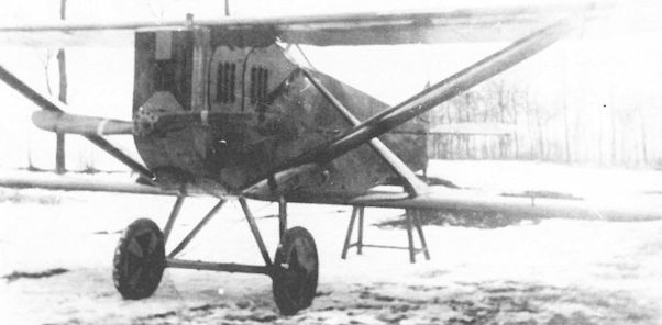
The wing cellule of the Lloyd 40.16 was devoid of bracing wires. The engine was enclosed behind a large, box radiator which served to accentuate the square fuselage contours.
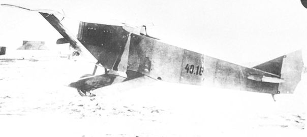
The Lloyd 40.16 prototype fighter at Aszod in the winter of 1917. The upper wing strut is airfoil-shaped to provide added lift. The high polish applied to the veneer wing surfaces is clearly evident.
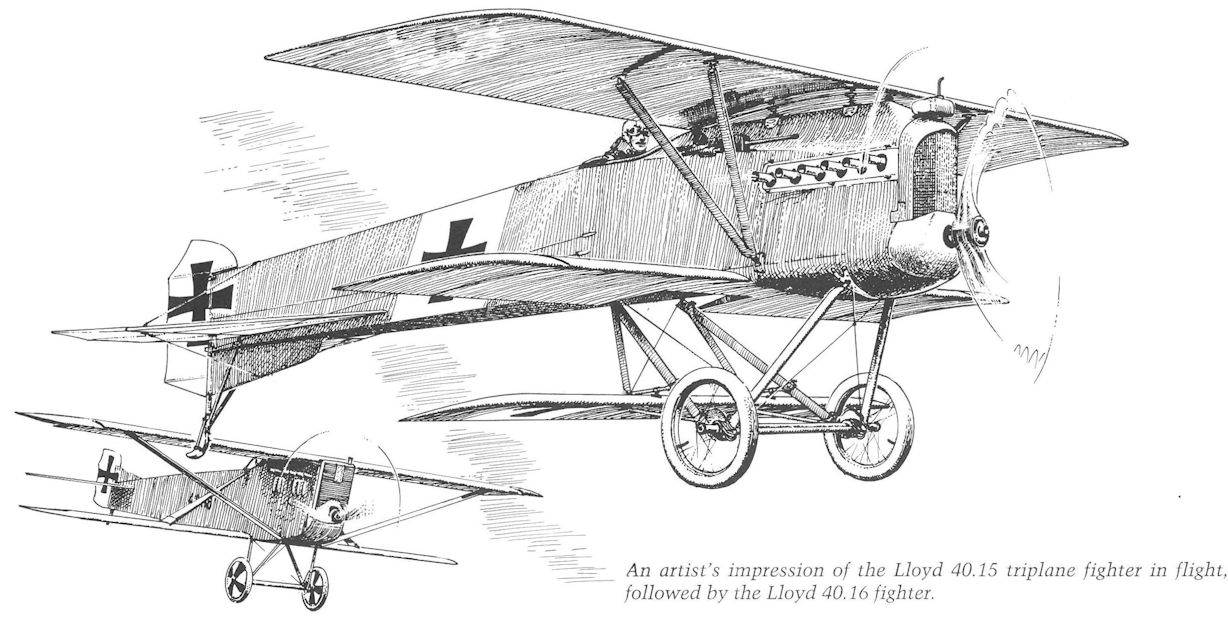
An artist's impression of the Lloyd 40.15 triplane fighter in flight, followed by the Lloyd 40.16 fighter.
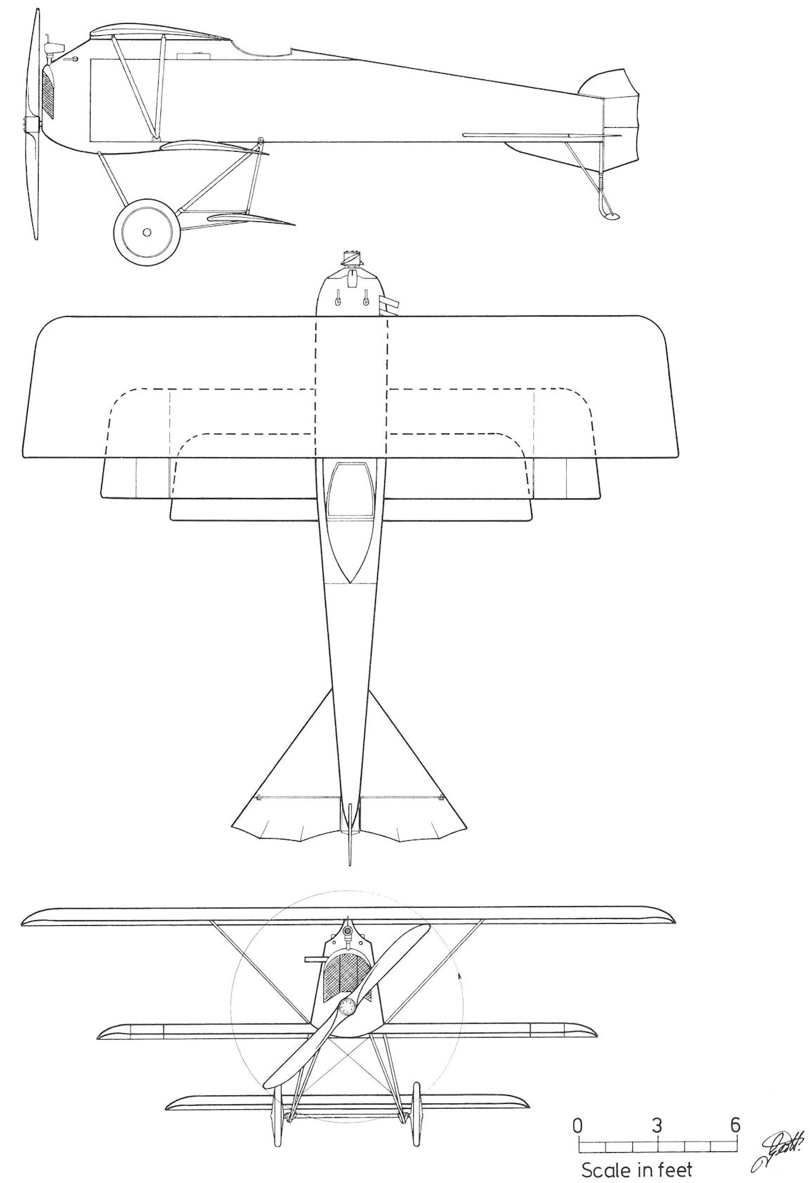
Lloyd 40.15
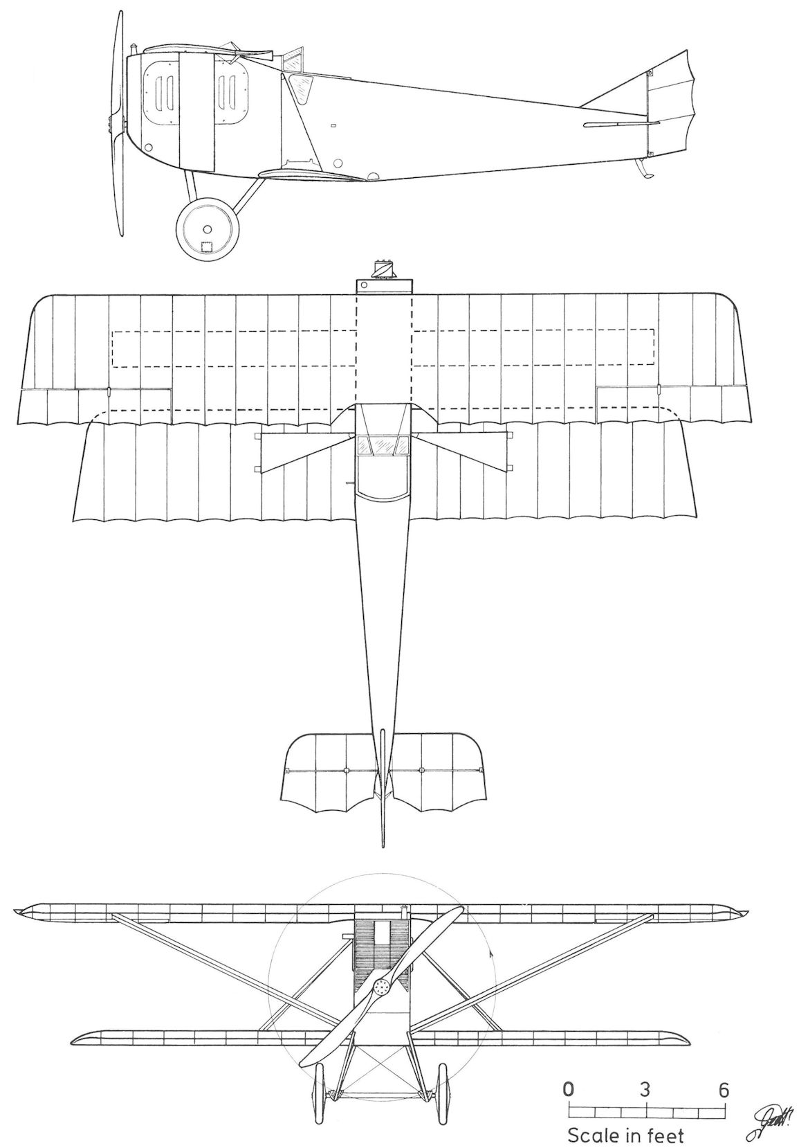
Lloyd 40.16
Lloyd 40.11
In designing the veneer-winged 40.11 prototype, chief engineer Melczer departed from DFW-inspired aircraft and created a more compact airframe which, by careful attention to detail, was light, strong and handsomely streamlined. Design studies began in late spring 1916 and the 40.11, powered by a 160 hp Daimler engine, was under construction in August. The maiden flight, performed in October 1916, demonstrated that "the 40.11 possessed good speed and performance." In November 1916, Flars engineers scrutinized the 40.11 and specified various changes prior to issuing the production release. Brought up to frontline standard, the 40.11 was given the designation Lloyd C.V 46.01 and dispatched to Flik 13 on the Russian Front. On 4 October 1917, pilot Zugsfuhrer Adolf Wiltsch and Oberleutnant Roman Schmidt, flying the 46.01, shot down a single-seat fighter for their first and third victories respectively. 46.01 was later assigned to Flek 1 in Ujvidek as a trainer and in 1918, served as a liaison aircraft with Fliegerzug 1 in Lublin.
Lloyd 40.11 Specifications
Engine: 185 hp Daimler
Wing: Span Upper 11.25 m (36.91 ft)
Span Lower 11.00 m (36.09 ft)
Chord 1.60 m (5.25 ft)
Upper Gap 1.85 m (6.07 ft)
General: Length 7.25 m (23.79 ft)
Lloyd 40.13 and 40.14
40.13 and 40.14, were ordered for flight trials. Derived from the C.V, the all-wood design had a smaller wingspan and a deeper fuselage with a raised observer's cockpit to provide a wide field of fire. Forward armament consisted of twin machine guns. The recently-available 220 hp Benz (Mar) engine, manufactured under license by Automobil A.G. "Marta" of Arad, supplied the power. Mindful of the delays incurred in manufacturing the veneer wing, Lloyd provided four sets of interchangeable wing cellules, two for each prototype, for comparative tests.
Intended for the 40.13, cellule A (almost identical to the C.V wing) was rejected outright and the prototype was test flown with cellule B, a single-bay, wire-braced, veneer wing of reduced span and area. Prototype 40.14 performed flight trials with cellules C and D, both low-aspect ratio wings of greater area and devoid of wire bracing. A Vee-strut running from the lower wing to the fuselage provided support. Unlike the B cellule, the C and D upper wings were of one piece. Cellule D was unique in that the rear section of the lower wing was fabric covered. On 21 and 29 May 1917, Flars engineers inspected the partially-completed airframes and suggested a number of minor improvements prior to flight tests.
After engine installation in June 1917, the performance of the 40.13 proved slower than expected and it was returned to the factory for modification. In spite of Flars opinion expressing "no particular confidence or expectation with regard to performance," the program remained active. The more powerful 250 hp Benz (Mar) engine was installed in both prototypes. The 40.13 was timed for speed in March 1918 and, as late as August-September 1918, trials continued at Aspern and Fischamend.
Prototype 40.14, first flown in July 1917, underwent an exhaustive program to investigate the characteristics of the C and D wing cellules, but results are not known. The 40.13 and 40.14 were reported at Aspern in September 1918 and offered for sale to Czechoslovakia in April 1920.
Lloyd 40.13 Specifications ('B' wings)
Engine: 220 hp Benz (Mar)
Wing: Span Upper 9.42 m (30.91 ft)
Span Lower 8.20 m (26.90 ft)
Chord Upper 1.65 m (5.41 ft)
Chord Lower 1.58 m (5.18 ft)
Dihedral Lower 2 deg
Sweepback Upper 8 deg
Sweepback Lower 8 deg
Gap 1.56 m (5.12 ft)
Stagger 0.40 m (1.31 ft)
Total Wing Area 22.5 sq m (242 sq ft)
General: Length 7.21 m (23.65 ft)
Height 2.78 m (9.12 ft)
Useful Load 220 kg (485 lb)
Loaded Weight 1200 kg (2646 lb)
Lloyd 40.14 Specifications ('C' Wings)
Engine: 220 hp Benz (Mar)
Wing: Span Upper 8.60 m (28.21 ft)
Span Lower 8.50 m (27.89 ft)
Chord Upper 1.82 m (5.97 ft|
Chord Lower 1.82 m (5.97 ft)
Dihedral Lower 2 deg
Sweepback Upper 4.1 deg
Sweepback Lower 4.1 deg
Gap 1.60 m (5.25 ft)
Stagger 0.42 m (1.38 ft)
Total Wing Area 25.5 sq m
General: Length 7.21 m (23.65 ft)
Height 2.78 m (9.12 ft)
Loaded Weight 1200 kg (2646 lb)
Maximum Speed: 180 km/hr (112 mph)
Climb: 1000m (3,281 ft) in 4 min
Lloyd 40.14 Specifications ('D' Wings)
Engine: 220 hp Benz (Mar)
Wing: Span Upper 8.60 m (28.21 ft)
Span Lower 8.60 m (28.21 ft)
Chord Upper 2.04 m (6.69 ft)
Chord Lower 2.04 m (6.69 ft)
Dihedral Lower 2 deg
Sweepback Upper 4.06 deg
Sweepback Lower 4.06 deg
Gap 1.60 m (5.25 ft)
Stagger 0.59 m (1.94 ft)
Total Wing Area 29.03 sq m (312 sq ft)
General: Length 7.21 m (23.65 ft)
Height 2.78 m (9.12 ft)
Loaded Weight 1220 kg (2690 lb)
Maximum Speed: 180 km/hr (112 mph)
Climb: 1000m (3,281 ft) in 4 min
Lloyd C.V Series 46
The Lloyd C.V project was first mentioned in the LFT aircraft production list of July 1916. At the time the 40 C.V biplanes were ordered from Lloyd and WKF in December 1916, Flars exhorted Lloyd to expedite the prototype trials (40.11) and the C.V design work "in order to begin manufacture at the earliest date." In all, Flars approved production orders totalling 144 C.V aircraft in the following sequence:
Qty Manufacturer Series Number Engine Order Date
24 Lloyd 46.01-24 Dm 185 13 December 1916
24 Lloyd 46.25-48 Dm 185 12 February 1917
48 Lloyd 46.51-98 Bz 220(Mar) 18 January 1917
16 WKF 82.01-16 Bz 220(Mar) 21 December 1916
32 WKF 82.17-48 Bz 220(Mar) 18 January 1917
The designers were able to achieve a significant performance increase by careful attention to weight reduction and streamlining. Each wing panel was composed of 14 spanwise stringers (in place of wing spars) equally-spaced around seven wing ribs and covered by a 1.2mm (0.04in) veneer skin polished to a high finish. Designed with semiskilled labor in mind, the wing construction was time-consuming but, on the other hand, very robust and capable of withstanding much abuse. However, unforeseen difficulties arose when the C.V reached the Front. If holed by shrapnel, the veneer skin was prone to peel back in the slipstream. The veneer covering was difficult to repair (nor had instructions been issued) and even slightly-damaged wings had to be exchanged at rear-area depots. Moisture condensation on the interior wing surface could cause warping or delamination that was impossible to detect. The C.V was armed with an observer's gun and sometimes with a Type II VK gun canister. Aircraft 46.25 was tested with a synchronized machine gun in June 1917, but it was not adopted as a standard feature. The camera and wireless equipment were installed behind the observer's position. A 50 kg (110 lb) bomb load could be carried in lieu of the observer.
Static testing was completed on 24 February 1917. The production airframes were inspected on 10 March by Flars engineers who expressed disappointment that "the company, in spite of repeated urgings, had not presented a single airframe on which the deficiencies listed in the November 1916 inspection were corrected." Contractually the company was scheduled to deliver 46 aircraft by early February 1917, but the first five aircraft were not accepted until July, the majority following in August-September 1917. Of the 48 ordered, twenty C.V aircraft were accepted without engines since the Aviatik C.I, also built by Lloyd, was given priority for the 185 hp Daimler engine. To investigate compatibility, a 200 hp Hiero engine was installed and tested in aircraft 46.02.
In September 1917, the first Lloyd C.V series 46 biplanes began to reach squadrons on the Eastern Front - eventually comprising Fliks 1, 9, 11, 13, 18, 22, 25, 26, 27, 30, 36/D, and 52/D. The initial reaction was mixed. Although speed and maneuverability were praised, pilots complained that the wheel control and unfamiliar rudder pedals were inappropriate for the very sensitive control response. The pedals, an innovation specified by Flars, were replaced by a normal rudder bar. In October 1917, a staff paper summed up the C.V: "Robustly built, very maneuverable, lateral stability good but longitudinal stability poor. Tail-heavy in a climb and excessively nose-heavy in a glide." The C.V, clearly unsuited for novice and average pilots, was pronounced a "handful" even by experienced veterans.
On the Italian Front where many airfields were situated in mountain valleys, further removed from the combat zone than was customary on the Western Front, the C.V's usefulness was limited by its short range. Given the two-hour fuel supply, pilots had cause for anxiety when operating over mountainous terrain, where an forced landing was synonymous with crashing. In the main, the C.V was used as a communication machine or as an advanced trainer at the two field flying schools.
Lloyd C.V Series 46 Specifications
Engine: 185 hp Daimler
Wing: Span Upper 11.19 m (36.71 ft)
Span Lower 11.00 m (36.09 ft)
Chord Upper 1.58 m (5.18 ft)
Chord Lower 1.60m (5.25 ft)
Dihedral Lower 2 deg
Sweepback Upper 5 deg
Sweepback Lower 5 deg
Gap 1.85 m (6.07 ft)
Stagger 0.35 m (1.15 ft)
Total Wing Area 27.63 sq m (297 sq ft)
General: Length 7.22 m (23.69 ft)
Height 3.00 m (9.84 ft)
Loaded Weight 1125 kg (2481 lb)
Maximum Speed: 165 km/hr (102.5 mph)
Climb: 1000m (3,281 ft) in 4 min 15 sec
3000m (9,843 ft) in 17 min
4600m (15,092 ft) in 40 min
Lloyd C.V Series 46.5
With the availability of the 220 hp Benz(Mar) engine in late 1916, a total of 96 Lloyd C.V biplanes using this engine were ordered from Lloyd and WKF. The task of modifying the C.V airframe was assigned to WKF engineers, who encountered engine development problems which delayed the frontline introduction of the Lloyd series 46.5 machines until November 1917. The Lloyd acceptance flights, primarily flown by test pilot Antal Feher at Aszod, began on 12 November 1917 and ended on 19 March 1918. Because the Brandenburg C.I(U) series 169 were accorded priority, approximately ten C.V series 46.5 aircraft were delivered without engines.
When it arrived on the Italian Front in late 1917, the C.V series 46.5 was reported by Fliks 6, 27, and 37 as extremely difficult to fly, possessing an excessively steep glide and high landing speed. Unless the landing was executed with "verve," the C.V had a propensity to stall without warning. The army staff reported that "even experienced pilots, including the very best, have great difficulty landing." Yet, as always, there were exceptional pilots who could look back with some satisfaction at having mastered the aircraft's vagaries. According to Feldpilot Franz Zuzmann, who piloted the C.V on airmail runs to the Ukraine, "The machine needed the right touch. You had to be a good pilot. The C.V reacted like a fighter to the slightest control movement, especially when landing. You had to touch down with lots of speed or else you could easily crash. The aircraft was sensitive at low speeds. You had to be fearless." The antipathy towards the type explains why it was soon relegated to communication or training duties.
On 12 July 1918, a LFT command decided to withdraw all Lloyd C.V biplanes from frontline units and assign 20 as trainers to the Feldfliegerschule Campoformido. However, in August 1918 the remaining C.V biplanes in field units were ordered withdrawn. Those not used as ground instruction airframes were placed in storage. As of October 1918, 62 C.V biplanes were reported in damaged condition, either at mechanics' schools or in storage depots.
After the war, 55 Lloyd C.V biplanes were offered for sale. At least five served with the Polish Air Force 2nd Squadron in November-December 1918 and several were flown by Hungarian and Ukrainian units in the immediate post-war period.
Lloyd C.V Series 46.5 Specifications
Engine: 220 hp Benz (Mar)
Wing: Span Upper 11.19 m (36.71 ft)
Span Lower 11.00 m (36.09 ft)
Chord Upper 1.58 m (5.18 ft)
Chord Lower 1.60 m (5.25 ft)
Dihedral Lower 2 deg
Sweepback Upper 5 deg
Sweepback Lower 5 deg
Gap 1.85 m (6.07 ft)
Stagger 0.10 m (0.33 ft)
Total Wing Area 27.63 sq m (297 sq ft)
General: Length 7.22 m (23.69 ft)
Height 3.00 m (9.84 ft)
Loaded Weight 1185 kg (2613 lb)
Maximum Speed: 170 km/hr (106 mph)
Climb: 1000m (3,281 ft) in 4 min
2000m (6,562 ft) in 10 min 16 sec
3000m (9,843 ft) in 16 min 15 sec
WKF 80.09
To forestall Flars criticism and the possibility of a penalty payment, WKF installed a standard 185 hp Daimler engine in a Lloyd C.V(WKF) series 82 airframe to demonstrate that the poor performance of the Benz-powered version was the fault of the engine and not of WKF engineering. The test aircraft was designated 80.09. After flight evaluation, the airframe was delivered to Aspern on 9 October 1917, and assigned to the mechanic's school at in Wiener-Neustadt on 1 March 1918 where it was written-off after a crash in May or July 1918. The airframe was stored at Aspern in August 1918. The designation 82.50, also assigned to the 80.09, does not appear to have been used in practice.
Lloyd C.V(WKF) Series 82
When the 220 hp Benz(Mar) engine, based on the reliable German Benz Bz.IV and built under license by Automobil AG "Marta" in Arad, became available in late 1916, it was chosen to power the WKF-built Lloyd C.V. On 21 December 1916, WKF signed a contract for 16 biplanes, of which eight were specified as "Benz trainers" to familiarize aircrews with the new engine. An additional 48 aircraft were ordered on 18 January 1917, making a total of 64, with deliveries scheduled to begin in January 1917. Because of the delay incurred by engine problems, Flars later reduced the production total to 48 aircraft. These were designated Lloyd C.V(WKF) 82.01 to 82.48.
Oberingenieur Schieferl of WKF was responsible for adapting the C.V airframe for the Benz engine. Progress dragged because the new engine required frequent repair and replacement of the carburetor, water pump, cylinders, and pistons. The cooling system had to be totally re-built, which according to WKF "added an additional 180 kilos (397 lb) plus an enormously large radiator to achieve proper engine operation." The first completed C.V(82.02) after being inspected by Flars on 24 March 1917, was dispatched to Lloyd for final outfitting. When commissioned on 18 May 1917, the aircraft was rejected because of recurrent engine failures. In spite of the best efforts of Marta engineers through June 1917, the C.V failed the speed and climb tests on 2 July 1917. To demonstrate that the company was faultless, WKF installed a standard 185 hp Daimler engine in a C.V airframe for testing (see 80.09). By August 1917, the engine problems were finally brought under control and military acceptances were in full swing, a welcome relief as the factory was jammed with completed airframes which obstructed production flow.
The added cooling system weight adversely affected the already critical flight characteristics of the C.V, originally designed for the lighter 185 hp Daimler engine. The Benz-engined version was extremely tricky to fly, requiring a deft touch to avoid accidents. Even the most experienced and prudent pilots showed great respect (see Lloyd C.V series 46). Beginning in September 1917, most of the WKF-built C.V biplanes were sent to units on the Russian Front where operational conditions were less demanding. Here the aircraft saw sporadic service until the cessation of hostilities with Russia in December 1917. A few machines served with Fliks 6/F and 64/F on the Albanian Front through the summer of 1918. Several C.V(WKF) biplanes were flown as advanced trainers by Fliks 19/F and 66/D on the Piave and by Fleks 6, 8, 13, and 14. Four were attached to the postal flight to deliver mail to the army units in the Ukraine. As of October 1918, thirty-one damaged C.V (WKF) airframes were in storage, an indication of the high accident rate associated with this aircraft.
Lloyd C.V(WKF) Series 82 Specifications
Engine: 220 hp Benz (Mar)
Wing: Span Upper 11.19 m (36.71 ft)
Span Lower 11.00 m (36.09 ft)
Chord Upper 1.60 m (5.25 ft)
Chord Lower 1.60 m (5.25 ft)
Sweepback Upper 5 deg
Sweepback Lower 5 deg
Gap 1.85 m (6.07 ft)
Stagger 0.10 m (0.33 ft)
Total Wing Area 27.12 sq. m (292 sq ft)
General: Length 7.11 m (23.33 ft)
Height 3.13 m (10.27 ft)
Track 1.80 m (5.91 ft)
Empty Weight 860 kg (1896 lb)
Loaded Weight 1214 kg (2677 lb)
Climb: 1000m (3,281 ft) in 5 min 6 sec
3000m (9,843 ft) in 22 min 8 sec

Lloyd C.V 46.30, Flik 53/D

Compared to the production C.V aircraft, the C.V prototype, 40.11 (46.01), had the radiator mounted on the wing leading edge and a gravity tank was not installed.

The Lloyd C.V 46.06 demonstrates the emphasis on streamlining. The control cables were enclosed in the upper wing and fuselage to reduce drag. The C.V was fast; fitted with an experimental propeller, a top speed of 200 km/h (124 mph) was attained.
Lloyd C.V 46.06 in Aspern, Einfliegerei, Herbst 1917, mit strömungsgünstig verkleidetem Motor
Lloyd C.V 46.06 в Асперне, осень 1917 года с полностью закапотированным двигателем.
Lloyd C.V 46.06 in Aspern, Einfliegerei, Herbst 1917, mit strömungsgünstig verkleidetem Motor
Lloyd C.V 46.06 в Асперне, осень 1917 года с полностью закапотированным двигателем.

The overall clean lines and reflecting veneer surfaces are shown by this new Lloyd C. V 46.07 on the Flik 22 airfield at Rohozna in October 1917. Only the C.V series 46 had the gravity tank mounted above the wing.

Personnel of Flik 30 in Czernowitz, autumn 1917, give scale to the relatively small size of the Lloyd C.V 46.32. Some aircraft were armed with a Type II VK gun canister on the upper wing. The number 7 on the radiator indicates the capacity.

Lloyd C.V 46.33 probably employed as a squadron hack or advanced trainer in late 1918. The unbraced, fabric-covered tail surfaces were designed to use straight metal tubing to reduce labor.

Owing to its limited operational service, photographs of the Lloyd C. V series 46.5 are scarce. The gravity tank was mounted below the wing. The 220 hp Benz(Mar) engine required additional cooling vents in the fuselage.

The Lloyd C.V 46.63 at Fliegerpark 2 awaiting wheel installation in the captured Italian airship hangar at Casarsa in early 1918. The Benz engine required a number 9 radiator.

Eight new Lloyd C.V series 46 reconnaissance biplanes lined-up on the occasion of the Lloyd aviation day at Aszod on 1 July 1917. Chief pilot Ziegler and test pilot Antal Lanyi-Lanczendorfer provided excitement and thrills for hundreds of spectators, local officials, and dignitaries.
The light-cowled Knoller C.I(Ph) 25.05 on the flight line at Aspern between a Knoller C.II(WKF) 81.01 and a Lloyd C.V (WKF). Although the 200 hp Hiero engine was specified for production aircraft, 25.05 was powered by a 160 hp Daimler engine for flight tests.

The Benz-engined Lloyd C.V biplanes, as this WKF-built 82.01, suffered many accidents when landing owing to the high flare-out speed even on smooth, hard airfields.
WKF-Lloyd C.V, Flugzeugnummer 82.01, Juli 1918. Flek 8
WKF-Lloyd C.V, Flugzeugnummer 82.01, Juli 1918. Flek 8

One of the “Benz trainers”, the Lloyd C.V(WKF) 82.08, at Flek 6 in Wiener-Neustadt before being assigned to the mechanics school in March 1918. The Type II VK gun canister was unpopular because it made the aircraft even more nose-heavy.

The fine lines of the Lloyd C.V(WKF) 82.08 accented by the uncluttered wing cellule belies the poor flight characteristics of the Benz-engined version.

The Lloyd C.V(WKF) 82.13 of Flik 8/D in Tarnopol was fitted with a winter cowling for cold-weather flying. The rifle was insurance (for providing food) in the event of a forced landing in Russian territory. The pilot has an awkwardly-positioned rear-view mirror, or is it intended for the observer! This aircraft also served with Fliks 3 and 13 before being sent to a mechanics’ school.

Squadron members of Flik 13/D posing with the Lloyd C.V(WKF) 82.15 at Proskurow, Ukraine, in March 1918. The cowling has been removed to work on the engine. An airspeed indicator is mounted on the front strut.
WKF-Lloyd C.V. Flugzeugnummer 82.15, im September 1917 an 2.AK, im Jänner 1918 ETP 4
WKF-Lloyd C.V. Flugzeugnummer 82.15, im September 1917 an 2.AK, im Jänner 1918 ETP 4

The cowling has been removed to allow mechanics to service the engine of Lloyd C.V(WKF) 82.24. The aircraft served with Flik 6 in the autumn of 1917 at Tirana airfield, Albania. The glossy finish contributed to the aircraft’s high speed.
Leading the line-up is the first Knoller C.II(WKF) 81.01 during flight trials at Aspern in September 1917. After acceptance in December, 81.01 was ordered to join Flik 66/D. The remaining aircraft are Lloyd C.V(WKF) biplanes, among them 82.24, 82.25, and 82.28.

An unidentified Lloyd C.V(WKF) armed with a Type II VK gun canister, photographed on the Russian Front. Flying units complained that the aircraft’s small fuel capacity greatly limited its combat range, another reason it was rarely flown in the mountainous terrain of the Italian Front.

The compact Lloyd 40.14, fitted with the Type C “wireless” wing cellule, on the flight line at Aspern. The type was armed with two forward-firing machine guns and a flexible gun for the observer.

The cockpit of the Lloyd C.V(WKF) 82.08 trainer demonstrates the close proximity of pilot and observer, a design feature found in virtually all Austro-Hungarian aircraft. Ballast Festbinden! (Tie down ballast!) on the folded observer’s table refers to sand bags carried when the aircraft was flown without an instructor aboard.

Lloyd C.V 46.30, Flik 53/D

Lloyd C.V Series 46

Lloyd 40.14
When Jakob Lohner & Co began to build aircraft in 1909, the new enterprise formed an ideal adjunct to its coach and auto chassis manufacturing business. The company, founded in 1821 and renamed Jakob Lohner & Co in 1868, was managed by Ludwig Lohner from 1892 until his death in 1925. Lohner was the first company to build automobiles in Austria, assisted by Ferdinand Porsche (of Volkswagen fame) who was hired in 1899 to develop an electric automobile. Over 300 examples were built, notably fire engines, some of which were still chasing fires in the late Twenties. In 1906 Porsche became technical director of the newly-organized Oesterreichische Daimler Motoren AG (known as Austro-Daimler) but maintained close ties with Lohner regarding aircraft engine development.
Lohner's first aircraft were custom-built models commissioned and sometimes designed by wealthy, would-be aviators. Beginning with rudimentary gliders, Lohner's activity soon expanded into powered aircraft, of which the biplane designed by Rittmeister Hans Umlauff von Frankwell, an army officer and graduate engineer, was particularly successful. Not only did Umlauff provide technical expertise, but he guided the Lohner shop manager, Karl Paulal, through the intricacies of aircraft construction. Despite the fact that Paulal lacked formal engineering training, his intuitive grasp of aircraft design made him chief aircraft designer at Lohner.
Umlauff's biplane, completed in the summer of 1910, was promising enough for Lohner and Austro-Daimler (who contributed a new light-weight 65 hp aero engine designed by Porsche) to jointly launch an improved version. The Lohner-Daimler Pfeilflieger (arrow flyer), characterized by an exaggerated sweepback (a Lohner trademark), made its maiden flight on 18 October 1910. Umlauff, piloting the Pfeilflieger, hit the headlines with a series of notable flights and achieved fame by winning the coveted Vienna-Budapest-Vienna prize on 24 June 1911. The Pfeilflieger, of which 212 were built in various versions through 1916, formed the bulk of Lohner's army aircraft business.

The progenitor of all the Lohner Pfeilfliegers with their accentuated sweepback was the Lohner-Daimler Pfeilflieger I (AC 318) flown with great success by Umlauff in 1911.

Lohner Pfeilflieger I (Austria, 1910) The first of the 216 Lohner-built biplanes with swept wings built from 1910 to 1915/1916, powered by a 65 hp Austro-Daimler 4-cylinder inline engine. It was designed by Rittmeister Hans Umlauff von Frankwell, an army officer and graduated engineer, together with Leopold Bayer. It was built under the supervision of Lohner`s shop manager Karl Paulal and was finished in the summer of 1910. It crashed in 1911 and was rebuilt as Pfeilflieger II.
Lohner Pfeilflieger AD 355
The Pfeilflieger AD 355, powered by a 120 hp Daimler engine, was built to compete in the Second International Flugmeeting at Aspern, during the course of which on 17 June 1913, Karl Illner established a world record of 5010 meters (16,437 ft) carrying two passengers, thus earning him third place against strong French competition. Pfeilflieger AD 355 was offered to the LA in May 1914, but its purchase was rejected notwithstanding Uzelac's request that a second aircraft join the aging Aspern for training purposes. With the start of hostilities, AD 355 less engine was procured by the LA on 15 August 1914. Further information is lacking.
Lohner Pfeilflieger (AD 355) Specifications
Engine: 120 hp Daimler
Wing:
Span Upper 13.70 m (44.95 ft)
Total Wing Area 42.0 sq m (452 sq ft)
General:
Length 7.90 m (25.92 ft)
Height 3.00 m (9.84 ft)
Empty Weight 620 kg (1367 lb)
Maximum Speed: 100 km/hr (62 mph)
Lohner Pfeilflieger AD 551
This aircraft was purchased by the LA on 17 January 1915 with ten other aircraft according to Lohner records. Photographs and information are lacking.
Lohner Pfeilflieger AD 565
Pfeilflieger AD 565, fitted with a 100 hp Mercedes engine, was delivered to the LA on 17 August 1914 and a second time (after repair?) on 27 January 1915. There is no record of service use or photographs.
Lohner Pfeilflieger "Helvetia" AD 566
On 10 February 1914, Lohner began work on three Type C Pfeilfliegers, powered by the 85 hp Hiero engine, intended for competition use. One machine, christened Helvetia, flown at Aspern on 21 March 1914 by Oberleutnant Karl Banfield, was exhibited at the annual Berne Fair and demonstrated by Banfield in the Swiss military aircraft competition in April 1914. It was rejected and returned to Vienna. On 15 August 1914, the LA purchased Helvetia less engine. Further information is lacking.
Lohner Pfeilflieger AD 752
Lohner records show this aircraft was delivered to the LA on 27 January 1915. Photographs and information are lacking.
Lohner 10.04
At the beginning of the war, the LA purchased every available aircraft it could lay its hands on. One such was Pfeilflieger (AD 606) which Paulal had designed for the newly-developed 250 hp Daimler V-12 engine for competition in the Third International Flugmeeting at Aspern. Lohner and Daimler engineers worked feverishly to prepare the biplane, but plagued by recurrent engine problems which Porsche vainly attempted to rectify, Oberleutnant Karl Banfield (competition No. 21) failed to win any prizes. Despite the poor showing, the large Pfeilflieger with its massive V-12 engine created a sensation when it first appeared on the Aspern aerodrome. Pfeilflieger AD 606, purchased less engine on 15 August 1914, initially received the LA designation Lohner D-250, and in February 1915, the number 10.04 was assigned. Used as a trainer, the Lohner 10.04, now powered by a 120 hp Daimler engine, was written-off on 15 November 1915.
AD Lohner 10.04 (AD 606) Specifications
Engine: 120 hp Daimler
Wing: Span Upper 14.40 m (47.24 ft)
Span Lower 9.90 m (32.48 ft)
Chord Upper 1.95 m (6.40 ft)
Chord Lower 1.80 m (5.91 ft)
Total Wing Area 41.07 sq m (442 sq ft)
General: Length 8.60 m (28.21 ft)
Height 3.50 m (11.48 ft)
Empty Weight 1050 kg (2315 lb)
Loaded Weight 1300 kg (2867 lb)
Lohner 10.05
Among the competition Pfeilfliegers financed by Lohner and MLG was Pfeilflieger AD 578, construction of which began on 24 March 1914. The Pfeilflieger, powered by a 120 hp Daimler engine, was flown in the Schicht Flug by Oberleutnant Karl Banfield (competition No.9) who, prohibited as an Army officer from using his name, used the pseudonym 'Mumb.' Although the aircraft had been expected to win the speed competition, Banfield had to be content with second prize. It is believed the AD 578 was the same as the Lohner D-R (Daimler Renndoppeldecker - racing biplane) which was purchased less engine in August 1914 and assigned number 10.05 in February 1915. According to von Mises' diary a new 120 hp Daimler engine was installed in May 1915. 10.05 served with Flek 1 and 6 as a trainer before being written-off in June 1915.
Lohner 10.06
Encouraged by the success of the first Lohner-Daimler Pfeilflieger in 1911, Lohner began work on the Heeres Konkurrenz Apparat (army competition machine - AC 822) on 1 March 1912. Powered by a 120 hp Daimler engine, Aspern made its maiden flight on 3 May 1912 piloted by Oberleutnant Philipp Blaschke Ritter von Zwornikkirchen. Competing in the Berlin-Vienna long-distance race, Blaschke took second prize on 10 June 1912 (although he had to be pushed across the finish line), beaten by the sole pilot to finish by air - Hellmuth Hirth in a Rumpler Taube. In the ensuing First International Flugmeeting at Aspern, Blaschke and passenger Karl Banfield established two world records for rate of climb and altitude, reaching 4360 meters (14,305 ft) on 29 June 1912. In recognition of the achievement Emperor Franz Joseph, in a magnanimous gesture, bestowed a monetary sum equal to the obligatory dowry, permitting Blaschke to finally wed his betrothed. French competitors, accustomed to nimble, light aircraft, derided the massive Aspern as "the flying chateau."
The LA purchased Aspern, the first of a long line of Pfeilfliegers operated by the air service, on 24 July 1912, using it primarily to train pilots in handling the 120 hp engine. At mobilization, Aspern was assigned to Flik 14 on the Eastern Front, but no record of operational service has been found. Aspern, given number 10.06 in February 1915, remained unreported until October 1918, when it was listed as stored in damaged condition at Fischamend, possibly having been preserved for the planned LFT collection of historic aircraft.
Lohner 10.06 (AC 822) Specifications
Engine: 120 hp Daimler
Wing: Span Upper 15.80 m (51.84 ft)
Span Lower 10.80 m (35.43 ft)
Chord Upper 1.90 m (6.23 ft)
Chord Lower 1.70 m (5.58 ft)
Total Wing Area 44.0 sq m (473 sq ft)
General: Length 9.80 m (32.15 ft)
Height 3.30 m (10.83 ft)
Empty Weight 725 kg (1599 lb)
Loaded Weight 1095 kg (2414 lb)
Maximum Speed: 110 km/hr (68 mph)
Climb: 1000m (3,281 ft) in 10 min
Lohner 10.10 (new)
Construction of Pfeilflieger AD 567 - one of the three Lohner built for the Schicht Flug (April 1914) - began on 19 February 1914. Powered by 140 hp Hiero engine, it was flown by Oberleutnant Robert Baar (using the pseudonym Bareth, competition No.8), who won the speed and distance prizes and took second prize in the reliability competition. AD 567, less engine, was purchased by the LA on 15 August 1914. This is possibly the same aircraft as the Lohner L-140 which served with Flik 6 in the Balkans until 20 December 1914 when it made a forced landing in the Adriatic.
On 31 March 1915, an LA directive ordered aircraft L-140 to be given the designation 10.10 which had been previously assigned to an Etrich Taube trainer. Further information is lacking.
Lohner 10.10 (new) Specifications
Engine: 140 hp Hiero
Wing: Span Upper 13.60 m (44.62 ft)
Span Lower 9.00 m (29.53 ft)
General: Length 8.80 m (28.87 ft)
Height 3.50 m (11.48 ft)
Empty Weight 725 kg (1599 lb)
Loaded Weight 990 kg (2183 lb)
Maximum Speed: 130km/hr(81 mph)
Lohner 10.14
In the Third International Flugmeeting, Lohner entered a brand-new Meeting Apparat 1914 (provisionally identified as AD 580) powered by a "special" 140 hp Daimler engine. Company pilot Viktor Wittmann (competition No.26) only managed fifteenth place in the overall standings because of engine problems. Lohner sold Pfeilflieger AD 580 less engine to the LA on 27 January 1915. The aircraft, assigned the military designation D 26, was flown by Flik 1 on the Serbian Front. On 31 July 1914, D 26 grazed a chimney while landing but fortunately neither Oberleutnants Raoul Stojsavljevic nor Franz Kabelac were injured. In February 1915, D 26 received the designation 10.14 and was last reported in 1915 serving as a trainer with Flek 3 in Graz-Thalerhof.
Lohner 10.16
The Lohner Pfeilflieger (AD 553), powered by a 90 hp Daimler engine, was built to compete in the 1914 Schicht Flug. To prepare for the competition (in which he would fly the new Pfeilflieger AD 567) Oberleutnant Baar used this machine for altitude and duration practice flights in early April 1914. In the Schicht Flug AD 553 was flown by Viktor Wittmann (competition No. 10), winning the reliability prize. In June 1914 at the Third International Flugmeeting, Edmund Sparmann piloting AD 553 (competition No.25) was awarded the War Ministry prize for the best all-round results achieved by a citizen flying an indigenous aircraft.
AD 553 was purchased by the LA in August 1914 and assigned the number 10.16 in February 1915. According to operational records, Pfeilflieger 10.16 served with Flik 2 on the Italian Front from 7 July to September 1915 and was written-off in January 1917.
Lohner B.I Series 11
The stage was set for military production after Aspern’s (later 10.06) record-breaking feats had demonstrated the usefulness of the Pfeilflieger design - an aircraft that could compete with Europe's best. Because of budget restrictions the Austrian and Hungarian national Aero Clubs spearheaded a fund-raising campaign "to build an Austro-Hungarian air fleet destined to stand proudly beside those of Germany and France." Lohner, assured of financial support, began the construction of four military Pfeilfliegers known as the Lohner Type B. Work on the first, named Bravo (AC 960), powered by a 65 hp Daimler engine and probably intended for training, began on 11 July 1912. Construction of Bora (AC 982) and Butterfly (AC 983), powered by the 90 hp Daimler engine and equipped for full military use, began on 23 July 1912. Bravo was delivered on 27 September 1912 in time for Blaschke to demonstrate the graceful biplane to enthusiastic crowds at the Offiziersfliegen in Wiener-Neustadt on 6 October 1912. Bora was completed on 16 October 1912 and delivered to the LA on 27 November 1912. Butterfly was completed on 27 November and delivered in December 1912. The fourth Pfeilflieger was Cyklon, a lightened Type B airframe powered by the new 85 hp Hiero engine. Cyklon was the forerunner of the Lohner Type C (see Lohner B.II Series 12).
The flight and performance characteristics were very encouraging and on 26 November 1912, the LA formally purchased Bora, Bravo, and Butterfly and ordered 28 Type B biplanes (AD 201-228) powered by the 90 hp Daimler engine. The last production aircraft was accepted on 14 May 1913, one month behind schedule. With time, the LA insisted on modifications that added about 100 kg (220 lb) weight, causing Lohner to warn of the impossibility of meeting performance guarantees. Beginning with the seventh aircraft an improved forged-steel undercarriage was fitted that, according to Lohner records, permitted a larger wing chord, adding 3.5 square meters (37.7 sq ft) of wing area. Starting with the ninth aircraft the fuselage was lengthened slightly. Having received basic training in the undemanding Etrich Taube monoplanes, pilots in preparation for taking a Type B aloft were told that "now flying would begin in earnest" and warned that "the sensitive controls required real flying skill." In truth, the flight characteristics were docile and easy to master by even an average pilot.
The Type B aircraft were based at Flugparks around the empire. Extensive operational training service during the Balkan crisis caused heavy wear and tear. When Bandit was repaired in December 1913, Lohner replaced the original wing with a lightened, stronger cellule known as the "Spanish wing." The top wing halves were joined at the center line and supported by inverted-vee struts that eliminated the center-section cabane. The rounded ailerons were changed to a rectangular shape. The wing tips could be folded down for storage. The LA allocated funds to retrofit all Type B aircraft with a modified "Spanish wing." By 1 February 1914, seven aircraft had been so modified; one was fitted with the original "Spanish wing"; 14 had the old cellule and the rest were in repair.
After the fatal wing failure of the Type C Pfeilflieger in March 1914, the Type B was also load tested. When ominous cracking sounds were heard, the test was halted in order to reinforce the cellule with additional bracing, but in the second try the wings failed well below the specified load factor. In fact, the entire airframe was pitifully understrength, leading the crash committee to conclude that "only the mediocre flight characteristics which demanded careful piloting had spared the pilots' lives." The LA grounded all Type B biplanes pending wing reinforcement. This work was assigned to Lohner and the Fischamend repair shop. The final blow fell on 28 April 1914, when Feuerwerker Georg Wally was killed because the fuselage of Bravo collapsed in mid-air. In a long memorandum, Uzelac placed the blame squarely on Lohner. The company, secure in its monopolistic position, had neglected to keep pace with modern aircraft engineering practices abroad. LA officers who had visited German and British factories criticized the poor detail workmanship throughout and use of defective materials. "Every officer sent abroad noticed the flawless wood used in aircraft construction, unlike the knot-rich wood used by Lohner for load-carrying members."
On the first (partial) mobilization day, 25 July 1914, a total of 39 Army aircraft were in flyable condition, consisting of 30 Lohner B-types (of which 11 were in storage or repair), seven Lohner D-types (two in repair), and the Lohner C-01 and C-02 prototypes.
Of the first war experiences, Flik 2 on the Serbian Front and Fliks 7, 8, and 14 on the Russian Front reported that the Type B machines were barely capable of performing operational tasks. All but two of Flik 2's complement of six Type B biplanes were out of service or in repair in August 1914, and six replacement machines arrived in poor shape, having been in storage since December 1913. The Fifth Army submitted a report in August 1914 deploring the fragility of the aging B-types. It took the total dedication of Flik 2 personnel, commanded by Oberleutnant Baar, to keep two patched up aircraft airborne albeit with rapidly decreasing performance. As soon as German replacement aircraft became available in September-October, the Type B disappeared from the Front.
In February 1915, the B-types were designated Lohner B.I series 11 and allocated numbers 11.01 to 11.31. Since this represented almost the total number of B-types built, it is apparent that combat losses were negligible and badly-damaged machines were rebuilt rather than written-off. Benign flight characteristics made the B.I acceptable as a primary trainer; consequently, 16 B.I machines were dispatched to Fischamend in late 1915 to be fitted with a stronger wing cellule and dual controls designed by Ingenieurleutnant Karl Saliger. In addition, Fischamend built 20 Type B dual-control trainers during 1916. In the process, the new and rebuilt aircraft received the designation Lohner B.I(Fd) series 73. The B.I(Fd) series 73 trainers remained in service through 1918 with Fleks 1, 2, 3, 6, and 7. The last original Lohner B.I aircraft, 11.18, was removed from service in June 1917 for the planned aircraft museum at Fischamend.
Lohner B.I Series 11 Specifications
Engine: 90 hp Daimler
Wing: Span Upper 13.40 m (43.96 ft)
Span Lower 9.60 m (31.50 ft)
Chord Upper 1.88 m (6.17 ft)
Chord Lower 1.83 m (6.00 ft)
Gap 1.90 m (6.23 ft)
Stagger 0.56 m (1.84 ft)
Total Wing Area 37.5 sq m (404 sq ft)
General: Length 8.50 m |27.89 ft)
Height 3.00 m (9.84 ft)
Empty Weight 630 kg (1389 lb)
Loaded Weight 970 kg (2139 lb)
Maximum Speed: 115 km/hr (71 mph)
Climb: 1000m (3,281 ft) in 12 min
List of Lohner Type B Aircraft
Works Number Name Delivery Date Stationed 1 Feb 14 New No. 8 Feb 15 Fischamend Number (a)
AC 960 Bravo 27 Sep 12 Flugpark 1 11.24
AC 982 Bora 16 Oct 12 Flugpark 8 11.21
AC 983 Butterfly 7 Dec 12 Flugpark 8 -
AD 201 Bellona 1 Feb 13 Flugpark 14 11.13 (b)
AD 202 Bajadere 3 Feb 13 - 11.02 73.02
AD 203 Bela 12 Feb 13 Flugpark 8 11.10 73.10
AD 204 Blitz 3 Mar 13 Flugpark 14 11.15 73.15
AD 205 Bandit 4 Mar 13 Flugpark 14 11.05 73.05
AD 206 Barbara 11 Mar 13 Flugpark 7 11.07 73.07
AD 207 Bomerang 12 Mar 13 Flugpark 7 11.20
AD 209 Boheme 15 Mar 13 Flugpark 2 11.17
AD 209 Baldur 19 Mar 13 Flugpark 8 11.04 73.04
AD 210 Boy 21 Mar 13 - 11.23
AD 211 Bombe 26 Mar 13 Flugpark 2 11.19
AD 212 Bella 9 Mar 13 Flugpark 2 11.11 73.11
AD 213 Brutus 2 Apr 13 - 11.27
AD 214 Bojar 3 Apr 13 Flugpark 2 11.18
AD 215 Barbar 4 Apr 13 Flugpark 14 11.06 73.06
AD 216 Bote 9 Apr 13 Flugpark 2 11.22
AD 217 Brunhilde 11 Apr 13 Flugpark 1 11.26
AD 218 Bulle 12 Apr 13 Flugpark 7 11.29
AD 219 Brigant 29 Apr 13 Flugpark 4 11.25 73.25
AD 220 Bob 29 Apr 13 - 11.16
AD 221 Baby 29 Apr 13 - 11.31
AD 222 Beduine 29 Apr 13 - 11.09 73.09
AD 223 Bertha 24 Apr 13 Flugpark 8 11.14
AD 224 Bub 27 Apr 13 Flugpark 2 11.30 (b)
AD 225 Bajazzo 3 May 13 Flugpark 14 11.03 73.03
AD 226 Beate 4 May 13 Flugpark 2 11.08 73.08
AD 227 Buddha 9 May 13 Flugpark 14 11.28
AD 228 Belisar 14 May 13 Flugpark 8 11.12 73.12
AD- B-1 - - 11.01 (c) 73.01
AD- B-30 - Flugpark 7 11.30 (b)
(a) A total of 16 Type B aircraft (14 above and 2 unidentified) were modified by Fischamend and placed in the B.I(Fd) 73.01 to 73.36 series.
(b) Although Bellona (AD 201) and Bub (AD 224) were lost in 1914, they were assigned a number in February 1915, the reason for which is not known. It is likely that aircraft B-30 received the number 11.30, but confirmation is lacking.
(c) Aircraft B-1 (11.01) has been listed as a replacement for Butterfly but confirmation is lacking.
Lohner (B.III) Series 13
Karl Hiner's great success piloting the Pfeilflieger (AD 355), powered by the new 120 hp Daimler engine, at the Second International Flugmeeting in June 1913 was welcome news to the LA, who had ordered six Lohner Type D Pfeilfliegers powered by the same engine and configured as long-range reconnaissance aircraft with a specified flight duration of 10 hours. The Type D went into production on 7 May 1913 and the contract was signed on 25 June. The following aircraft were delivered between 24 August and 11 September 1913: Delibab (AD 356-13.04), Delphin (AD 357-13.01), Dental (AD 358-13.02), Don Juan (AD 359-13.03), Don Quichotte (AD 360), and Dreadnaught (AD 361).
At the summer 1913 Kaiser Maneuvers, eleven emergency landings caused by erratic running engines led the LA to disassemble the Type D aircraft for storage at Fischamend until the problem was resolved. By December 1913 the Type D had been returned to Lohner and after modification five aircraft were reported in flying condition on 1 February 1914. As a precautionary measure following Elsner's crash (see the Lohner B.II series 12), a Type D airframe was also load tested and showed similar premature wing failure. Installation of additional wire bracing, recommended as an interim solution by Professor Knoller, rescinded the grounding order.
In mid-1913, the LA began to investigate air-to-ground wireless communication and at the end of May 1914, Professor Dr Leopold Kann installed an experimental Telefunken-Siemens-Halske transmitter in Dental for flight evaluation. The 50 meter (164 ft) aerial caused some concern but it remained well clear of the elevator in flight. Ground signal reception was clear and ensuing spotting trials to direct artillery fire produced excellent results. Austro-Hungarian historians claim that this was the first successful direction of artillery fire from the air.
Lohner reported on 18 July 1914 that the "planned reconstruction" (what was involved is not known) of six Type D plus one competition aircraft could not be completed until late autumn 1914. Pushed by the exigencies of war, the work was cancelled and four Type D Pfeilfliegers went to the Front with Flik 1. After rotted wing ribs were found in the course of routine inspection, the rear-area aircraft park replaced the ribs and wingtip sections. Two Type D aircraft were lost. Dreadnought, with Oberleutnants Hugo Schwab and Franz Kabelac aboard, was downed on 14 August by Russian troops because the aircraft was incapable of climbing over 500 meters (1640 ft). On 16 August, Oberleutnant Josef Flassig and Leutnant Engelbert Wolf lost their lives when Don Quichotte crashed due to wing failure. The news spread like wildfire through the LA, destroying the last vestige of confidence in Lohner aircraft. As a result, the four remaining Type D aircraft were grounded and scrapped.
Lohner (B.III) Series 13 Specifications
Engine: 120 hp Daimler
Wing: Span Upper 16.50 m (54.13 ft)
Span Lower 11.40 m (37.40 ft)
Chord Upper 2.09 m (6.86 ft)
Chord Lower 1.86 m (6.10 ft)
Gap 2.26 m (7.41 ft)
Stagger 1.05 m (3.44 ft)
Total Wing Area 49.4 sq m (532 sq ft)
General: Length 9.50 m (31.17 ft)
Height 3.50 m (11.48 ft)
Track 2.20 m (7.22 ft)
Empty Weight 755 kg (1665 lb)
Loaded Weight 1225 kg (2701 lb)
Maximum Speed: 130 km/hr (81 mph)
Climb: 1000m (3,281 ft) in 10 min
Lohner B.I(Fd) Series 73
When the Lohner B.I series 11 biplanes were withdrawn from the Front in mid-1915, sixteen were converted by the Flugzeugwerk into dual-control trainers to take advantage of their docile flying qualities. After receiving a modified fuselage and a stronger wing cellule designed by Ingenieurleutnant Karl Saliger of Flars, the converted trainers were re-designated Lohner B.I(Fd) series 73. In December 1915, the Flugzeugwerk began to build 20 new Lohner B.I(Fd) trainers numbered 73.13, 14, 16-24, and 26-34. When production was completed in October 1916, the total B.I(Fd) series built were numbered 73.01 to 73.36. Power was supplied either by a 90 or 100 hp Daimler engine. The Fischamend-built B.I(Fd) biplanes served as transition trainers with Fleks 1-6 and 13 as well as Schulkompagnie 1 and 2. As of 1 July 1917, twenty were still in active school service.
Lohner B.I(Fd) Series 73 Specifications
Engine: 200 hp Hiero
Wing: Span Upper 14.00 m (45.93 ft)
Chord Upper 1.80m (5.91 ft)
Chord Lower 1.80 m (5.91 ft)
Sweepback Upper 17 deg
Gap 1.835-1.960 m (6.02-6.43 ft)
Stagger 0.40 m (1.31 ft)
Total Wing Area 43.7 sq m (470 sq ft)
General: Length 8.60 m (28.21 ft)
Height 3.40 m (11.15 ft)
Track 2.18 m (7.15 ft)
Empty Weight 740 kg (1632 lb)
Loaded Weight 994 kg (2192 lb)

Lohner Aspern (AC 822) with Oberleutnants Blaschke and Eduard Nittner in the common cockpit, a feature which became standard on most Austro-Hungarian two-seaters through 1918.

Lohner Aspern (later 10.06) serving as an LA trainer in May 1914. Curiously, the radiator is mounted behind the engine.

Shortly before the take-off for Vienna, the Lohner Aspern was photographed at Berlin-Johannisthal on 9 June 1912 with Blaschke at the controls and Oberleutnant Eduard Nittner as navigator.

In hopes of winning an export order, Lohner entered the Helvetia (AD 566) in the Swiss military aircraft competition held at Bern in April 1914. On the left is designer Karl Paulal watching Oberleutnant Banfield prepare for a test flight in Vienna. For the Bern competition more-efficient, strut-mounted radiators were installed.

Viktor Wittmann flew this Daimler-powered Lohner Meeting Apparat 1914 (AD 5801) in the Third International Flugmeeting. Pfeilflieger AD 580 was purchased by the LA and assigned the number D 26 until February 1915 when it became 10.14.

Oberleutnant Karl Banfield (middle) and his passenger Grunwald (right) in front of Pfeilflieger AD 578 (later 10.05) prior to taking off for Budapest during the Schicht Flug in April 1914. The decal shows the airscrew was manufactured by Lohner.

Flown by Karl Illner during the Second International Flugmeeting, the Lohner Pfeilflieger (AD 355 - competition number 10) broke a world altitude record on 17 June 1913. It was purchased by the LA on 15 August 1914.

Edmund Sparmann, piloting the Lohner Pfeilflieger AD 553, won the special War Ministry prize in the Third International Flugmeeting in June 1914. Designated Lohner 10.16, it was written-off in January 1917.

The Lohner Pfeilflieger (AD 606), powered by a 250 hp Daimler engine, being prepared for the Third International Flugmeeting at Aspern in June 1914.

Lohner L-140 (10.10 new), believed to be AD 567, served with Flik 6 until 20 December 1914 when Korporal Julius Arigi and Leutnant Levak landed in shallow water in the Adriatic due to engine failure.

Every pre-war Lohner Type B aircraft was assigned a name beginning with the letter “B” painted in large letters on the fuselage. Lohner Bajadere is shown here fitted with the original Type B wing cellule. Either the radiator has been removed or it is mounted on the port side.

Lohner B.I 11.02 (ex-Bajadere) trainer as modified by Fischamend with the Saliger wing cellule, twin rudder struts, rectangular ailerons and relocated radiator. It was later redesignated B.I (Ed) 73.02.

The early Lohner Type B production machines, represented by Blitz (later B.I 11.15, then 73.15) at the Second International Flugmeeting in 1913, had a large tail wheel that was later replaced by a unique double tail skid.
Pre-war lineup of early production Lohner B.I series 11 aircraft. In February 1915 Blitz was assigned serial 11.15 and Barbar was assigned serial 11.06. Source: Aeronaut.
Pre-war lineup of early production Lohner B.I series 11 aircraft. In February 1915 Blitz was assigned serial 11.15 and Barbar was assigned serial 11.06. Source: Aeronaut.

A poor photograph of the Lohner Bomerang (11.20) showing the double tail skid and the “Spanish wing” with folding wing tips.

The Lohner Cyklon (AC 957), a lighter Type B, was purchased by the LA and used as an engine and load-test aircraft in preparation for Type C production.

The Lohner Don Juan (later 13.03) performed the first Flik 1 wartime mission on 31 July 1914 while based at Homok-Balvanyos in southern Hungary. Pilot Kadett Benno Fiala Ritter von Fernbrugg and Apparatchauffeur Erdstein are in the common cockpit that provided staggered seating for the crew.

The Lohner Delibab with the original tricycle undercarriage featuring a third wheel that functioned as a brake. A conventional tail skid was also fitted. After serving with Flik 1, Delibab was given the number 13.04 and assigned to Flek 2 as a trainer.

The Lohner B.I(Fd) 73.12 (originally Lohner Belisar, then redesignated B.I 11.12) was completely rebuilt by the Flugzeugwerk in 1916. It was written-off in May 1918.

Lohner B.I(Fd) 73.28 was not fitted with dual controls and had a smaller cockpit. Although built in 1916, the complex undercarriage and twin tailskids, designed in 1912, were retained.

One of the new Lohner B.I biplanes built by the Flugzeugwerk was aircraft 73.28. Like all Lohner B.I aircraft, rebuilt or new, which passed through the Flugzeugwerk, this machine was fitted with the modified Saliger wing cellule.

Cockpit of the Lohner B.I(Fd) 73.28. On the left, mounted below a manometer and hand pump, are two pump and pressure control levers. A barograph graces the control wheel and a tachometer the right cowling.

After purchase by the LA, Pfeilflieger AD 606 was numbered 10.04 and fitted with a modified tailplane and rudder. Flown as a trainer by Flek 1 in Ujvidek, it was written-off on 15 November 1915.
Löhner DD, Flugzeugnummer 10.04, Kopfstand in Ujvidek, Flek 1, 1915.
Löhner DD, номер 10.04, штаб-квартира в Уйвидеке, Flek 1, 1915 год.
Löhner DD, Flugzeugnummer 10.04, Kopfstand in Ujvidek, Flek 1, 1915.
Löhner DD, номер 10.04, штаб-квартира в Уйвидеке, Flek 1, 1915 год.

This drawing of the Lohner Type D Pfeilflieger, dated 9 January 1914, armed with two machine guns is among the earliest Austro-Hungarian armament proposals on record, (from Lohner 1909-1923, R. Keimel)

Lohner B.I Series 11 (early version)
Lohner 10.01 to 10.03
After the Pfeilflieger Type C accident (see Lohner B.II series 12), the LA thoroughly tested each new design before approving production. Consequently, for static testing and flight trials, three prototypes of the improved Lohner Type E Pfeilflieger (AD 810 - AD 812) were ordered on 30 October 1914. Powered by the 100 hp Daimler engine, the first two aircraft, E-01 and E-02, were delivered on 10 December 1914 and E-03 on 21 January 1915. The designations were changed to 10.01-10.03 in February 1915. After passing military tests, the Type E was produced by Lohner as the B.III series 14 and by UFAG as the B.III (U) series 14.5.
Serving as trainers, the Lohner E-01 (10.01) was written-off in October 1916 and the E-02 (10.02), the static load test airframe, later was flown by Fleks 2 and 4 through mid-1915 at least. From the outset the Lohner E-03 (10.03) prototype was modified, being equipped with a simplified wing cellule incorporating a thicker "Knoller profile." Later the complex Lohner undercarriage was redesigned with sprung axles replacing the shock-cord assembly. The E-03 (10.03) was flown as a trainer by Flek 4 until May 1915, when at the direction of Major von Umlauff, Lohner rebuilt the 10.03 by modifying the wings and installing a 100 hp Mercedes engine. As such the 10.03 became the prototype for the Lohner Type G and was assigned the designation B.IV 15.01 (see Lohner B.IV series 15 chapter).
Lohner 10.01 (AD 810) Specifications
Engine: 100 hp Daimler
Wing: Span Upper 13.60 m (44.62 ft)
Span Lower 9.10 m (29.86 ft)
Total Wing Area 31.9 sq m (343 sq ft)
General: Length 8.43 m (27.66 ft)
Height 3.48 m (11.42 ft)
Empty Weight 625 kg (1378 lb)
Loaded Weight 920 kg (2029 lb)
Climb: 1000m (3,281 ft) in 11 min
Lohner 10.07
In April 1913, Lohner began the construction of a Gebirgsflieger (mountain flyer - AD 350), powered by a 80 hp Gnome rotary engine, designed to climb faster and operate at higher altitude than heavier aircraft with water-cooled engines. On 20 August 1913, shortly after completion, Uzelac test flew the machine which was delivered to the LA on 30 August 1913 under the designation "experimental machine G-1." Used as a trainer, it was based at Flugpark 3 in Gorz in February 1914. There is no record of wartime service.
A second, private-venture Gebirgsflieger (AD 490) powered by a 100 hp Gnome, begun on 27 October 1913, was built in response to the success of the French rotary-engined aircraft at the Second International Flugmeeting. Because Lohner did not employ a full-time company acceptance pilot, it was not unusual for military pilots to carry out this task. On 27 February 1914, Oberleutnant Eugen Elsner performed the maiden flight which, according to a witness, demonstrated the plane's precise maneuverability, a rapid rate of climb, and high speed. Although built at the express wish of the LA, a subsequent lack of interest caused bitter recriminations. The machine did not participate in the two 1914 competitions. When purchased by the LA on 15 August 1914, it was designated LG-490 and entered training service with Flek 1 and later Flek 6. Numbered 10.07 in February 1915, the trainer was badly damaged on 2 December 1915 and written-off.
Lohner 10.07 (AD 490) Specifications
Engine: 100 hp Gnome
Wing: Span Upper 12.00 m (39.37 ft)
Span Lower 8.60 m (28.21 ft)
Chord Upper 1.56 m (5.12 ft)
Chord Lower 1.50 m (4.92 ft)
Total Wing Area 26.7 sq m (287 sq ft)
General: Length 7.80 m (25.59 ft)
Height 3.50 m (11.48 ft)
Empty Weight 460 kg (1014 lb)
Loaded Weight 780 kg (1720 lb)
Climb: 1000m (3,281 ft) in 8 min
Lohner 10.12
Buoyed by the success of the Type B biplane, the LA requested Lohner to develop a lighter version with improved climbing ability for operation in mountainous terrain. A lighter engine was chosen, namely the four-cylinder 85 hp Hiero. Construction of the prototype known as the Gebirgsflieger Type C (mountain flyer - AD 353) was begun as a private venture on 4 April 1913. The prototype appeared at the Second International Flugmeeting at Aspern on 14 June 1913 for viewing only and was delivered to the LA in August. On 24 August 1913, crewed by Leutnant Hans Mandl and Oberleutnant Nikolaus Wagner Edler von Florheim, it became the second aircraft to fly over the Semmering, and the first carrying a passenger. While testing the engine the next day, the carburetor caught fire, destroying the top wing in the process.
The LA purchased the Type C prototype (AD 353) on 10 September 1913 under the military designation C-01. Before committing the type for production, C-01 was flight tested in concert with a second prototype, designated C-02 (see Lohner 10.13). In February 1914 C-01 was stationed at Flugpark 3 in Gorz. The designation was changed to 10.12 in February 1915.
Lohner 10.13
Lohner built a second Gebirgsflieger Type C prototype (AD 406) for factory flight test and evaluation. The completion date was prior to 10 September 1913. In view of the imminent delivery of Type C production machines, Uzelac requested the purchase of this company-owned aircraft for use as a transition trainer. Designated C-02, the Pfeilflieger was turned over to the LA on 13 December 1913 and formally purchased on 29 January 1914. Lohner C-02 was stationed at Flugpark 1 in February 1914 and redesignated 10.13 in February 1915. It was last reported based at Flek 7 in May 1915.
Lohner B.II Series 12
For operation in mountainous terrain, the LA ordered the Type C Gebirgsflieger (mountain flyer), a lighter Type B that was powered by the new 85 hp Hiero four-cylinder engine which weighed 51 kg (112 lb) less than the six-cylinder, 90 hp Daimler. The Type C was a new design featuring a vertical fuselage sternpost as compared to the Type B's horizontal sternpost. To serve as an engine and structural-test machine, Cyklon (AC 957 - a lightened Type B) was purchased on 27 November 1912 and delivered to the LA in December. After Cyklon failed the load test, chief engineer Paulal blamed "the less-robust construction and worn airframe" and assured the LA that the production Type C would have a safety factor of at least 5 (3.5 was specified) which may explain why a production airframe was not subjected to load tests.
The Type C prototype, designated C-01 (later 10.12), was delivered to the LA in August 1913. The second prototype remained the property of Lohner until purchased by the LA as C-02 (10.13) in January 1914. On 10 December 1913, the LA ordered 24 Type C Gebirgsflieger which were designated C-1 to C-24 (AD 500-523). Another Gebirgsflieger, designated C-25 and given a reinforced engine mount and longer fuselage, was delivered in July 1914. As their first production order, UFAG received a contract for 18 Type C, designated C-41 to C-58, on 9 January 1914.
The first production aircraft, designated C-1, was accepted on 4 February 1914 and five machines followed in short order. Lohner flight testing was performed by company pilots Viktor Wittmann, Edmund Sparmann and Ferdinand Konschel with Lili Steinschneider, the first Hungarian woman pilot, often in the observer's seat. After a demonstration by Karl Illner, Uzelac who positively enjoyed flying new aircraft, took the Type C aloft. He reported vibrations of such intensity that his hands were "electrified," forcing him to wrap his arms around the wheel to maintain control. Being flown without a passenger, the aircraft was extremely nose heavy and only by pulling the control column hard against his chest was Uzelac able to land safely. Lohner blamed the vibrations on the Hiero engine, but Uzelac said such vibrations were absent from the Hiero-engined Etrich Taubes. On the plus side, the Type C with a passenger aboard showed good performance and flight characteristics.
Oberleutnant Eugen Elsner, an experienced pilot assigned to the Versuchsflik (test section) and responsible for aircraft acceptance, was one of the officers who performed the customary "sign-off" flight. In reply to Elsner's inquiry whether tight turns and dives were safe, Paulal avowed that "there was absolutely nothing to fear." On 9 March 1914, a black day for the LA, Elsner and his passenger, Zugsfuhrer Philipp Srna, were killed when the left wing of aircraft C-2 collapsed in flight. Eye witnesses reported that the accident occurred in level flight, but Lohner claimed that Elsner was pulling out of a "full-throttle dive." All Type C aircraft were grounded, Lohner and UFAG production stopped, and an order for an additional 18 aircraft deferred pending the outcome of the crash committee findings.
When airframe C-5 was tested on 14 March 1914, the wings failed much like Elsner's crash at a load factor of 2.4. Lohner then reinforced the wing cellule but it was not enough. On the third test, performed 20 March 1914, a new wing with heavier fittings, stronger struts, and additional wire bracing achieved satisfactory results. It was recommended that the existing wings be reinforced in the same manner, but the LA countermanded the crash commission on grounds that the profusion of additional wire rigging would make it difficult, if not impossible, to properly align the wings. Nor would the resulting performance meet the contractual specifications. In April 1914, the LA ordered Lohner to deliver new wings at the company's expense, but later provided funds to speed replacement in view of the deteriorating political situation. Professor Richard Knoller designed the new Type C wing employing a stronger spar and thicker rib section that "Paulal had so steadfastly refused to consider in the past."
At the time of mobilization the Type C aircraft were grounded, but notwithstanding their poor condition six aircraft were provisionally reinforced and ready for assignment on 1 August 1914. Lohner was scheduled to complete the remaining modification by 31 October 1914. The Type C served with Fliks 4 and 6 in the Balkans and Fliks 8, 10, and 15 on the Russian Front. The first reports from the Front were hardly encouraging. On 25 August 1914, the commander of Flik 10 reported:
The squadron's six aircraft have such strong vibrations induced by the unbalanced Hiero engine that in spite of great care taken during flight and landing, rigging wires snap and metal fittings, fuel and water lines break. Because of the vibrations, the instruments are unreadable.
On the other hand, five Type C biplanes were flown by Flik 6 at Igalo from October-December 1914 with moderate success. Armed with an observer's machine gun mounted on the port side, Lohner C-11 supported infantry attacks at Grab (9 November 1914) and Trebinje (28 December 1914), thought to be among, if not the first, "infantry contact patrols" of the war. Another first occurred on 30 November 1914, when Oberleutnants Bela Losonczy von Losoncz and Johann Wierzejski of Flik 15, flying a Lohner Type C Pfeilflieger, shot down a Russian aircraft with a repeating rifle. At the Front, the Type C was flown only because no other aircraft were available, and it was quickly withdrawn as soon as German replacement aircraft arrived.
In February 1915, the Type C was re-designated Lohner B.II 12.01 to 12.25 (ex C-1 to C-25). The Type C was withdrawn from the Front in May 1915 and seven dispatched to Fischamend for installation of new wings and other modifications. From early 1916 through March 1917, the Flugzeugwerk Fischamend built 45 Type C trainers, designated Lohner B.II (Fd) series 74. In June 1917, the last original Lohner B.II (12.17) was retired from service and placed into the aircraft collection at Fischamend.
Lohner B.II Series 12 Specifications
Engine: 85 hp Hiero
Wing: Span Upper 13.00 m (42.65 ft)
Span Lower 9.20 tn (30.18 ft)
Chord Upper 1.50 m (4.92 ft)
Chord Lower 1.49 m (4.89 ft)
Gap 1.85 m (6.07 ft)
Stagger 0.95 m (3.12 ft)
Total Wing Area 30.4 sq m (327 sq ft)
General: Length 8.30 m (27.23 ft)
Height 3.20 m (10.50 ft)
Empty Weight 560 kg (1235 lb)
Loaded Weight 920 kg (2029 lb)
Maximum Speed: 125 km/hr (78 mph)
Climb: 1000m (3,281 ft) in 7 min
Lohner B.III Series 14
To restore confidence in Lohner aircraft after the Pfeilflieger wing failures, Professor Knoller was chosen to redesign the wing structure. First appearing in the Lohner Type E, Knoller's design had fewer wing ribs, a thicker rib section, reduced wire bracing, and wing tips supported by V-struts. The Knoller wing, approved by the LA in November 1914, was specified for 24 Type E Pfeilfliegers, of which 16 were ordered from Lohner and 8 from UFAG. The aircraft built by Lohner (AD 813-828), initially numbered E-1 to E-16, were re-designated B.III 14.01 to 14.16 in February 1915. The UFAG-built aircraft were numbered E-20 to E-27; then changed to E-51 to E-58 before being re-designated B.III (U) 14.51 to 14.58. When the contract was signed on 4 January 1915, Type E assembly was already underway. Deliveries were scheduled to end in early February; however, most of the aircraft were not accepted until April 1915.
The Type E was issued singly to Fliks 2 (Serbian Front), 12 (Isonzo Front), and 16 (Karnten). Fitted with a 100 hp Daimler engine, the aircraft were reported so badly underpowered as to be virtually useless. Soon after the start of hostilities with Italy, Army Group Rohr wrote:
Flik 12 is equipped with Type E Pfeilfliegers that are unable to carry machine gun or bomb armament. Owing to the poor rate of climb and radius of action, the aircraft are barely equal to the difficult mountainous terrain (Karnten region). To direct the heavy artillery, we urgently request aircraft with more powerful engines.
As a result, many of the B.III series 14 aircraft were dispatched directly from the factory to training units (Fleks 1-5 and 7) and were soon joined by those from the Front. By October 1915, five B.IIIs remained in training inventory, and plans to modify these for dual controls were dropped. As late as July 1917, four B.III trainers were still active.
Lohner B.III Series 14 Specifications
Engine: 100 hp Daimler
Wing: Span Upper 13.60 m (44.62 ft)
Span Lower 9.14 m (29.99 ft)
Chord Upper 1.65 m (5.41 ft)
Chord Lower 1.55 m (5.09 ft)
Sweepback Upper 12 deg
Gap 1.90 m (6.23 ft)
Stagger 0.71 m (2.33 ft)
Total Wing Area 31.9 sqm (343 sq ft)
General: Length 8.43 m (27.66 ft)
Height 3.15 m (10.33 ft)
Empty Weight 685 kg (1510 lb)
Loaded Weight 1000 kg (2205 lb)
Maximum Speed: 115km/hr(71 mph|
Climb: 1000m (3,281 ft) in 11 min 20 sec
Lohner B.IV Series 15
In May 1915, under the direction of Major von Umlauff Lohner rebuilt the Lohner 10.03 (Type E) prototype with new wings, a simplified undercarriage, and a 100 hp Mercedes engine. The rebuilt Pfeilflieger was designated Type G and upon delivery on 21 June 1915, received the military designation B.IV 15.01. It was the sole Type G built by Lohner, although UFAG delivered a batch of eight aircraft designated B.IV(U) series 15.5. Aircraft 15.01 was written-off in August 1915.
Lohner B.IV Series 15 Specifications
Engine: 100 hp Mercedes
Wing: Span Upper 13.60 m (44.62 ft)
Span Lower 9.10 m (29.86 ft)
Total Wing Area 31.9 sq m (343 sq ft)
General: Length 8.43 m (27.66 ft)
Empty Weight 725 kg (1599 lb)
Loaded Weight 1000 kg (2205 lb)
Maximum Speed: 115 km/hr(71 mph)
Climb: 1000m (3,281 ft) in 11 min
Lohner B.II(U) Series 12.4
The first production contract UFAG received, signed on 9 January 1914, called for 18 Lohner Type C biplanes powered by the 85 hp Hiero engine. The original aircraft designation, C 41 to C 58, was changed to Lohner B.II(U) 12.41 to 12.58 in February 1915. The UFAG factory began production on 1 March 1914 and the first aircraft were rolled out in early June, only to be returned for "reconstruction" because serious structural deficiencies had been discovered in the Lohner-built Type C biplanes. Acceptance of the strengthened Type C began in August and ended in November 1914. The UFAG-built B.II was assigned to Fliks 4, 8, 9, 15 and 16. The most notable accomplishment occurred when six aircraft of Flik 9, carrying bombs in place of the observers, attacked the Serbian arsenal at Kragujevac on 24 November 1914. Flik 9 reported the undercarriages were so fragile that most of the aircraft suffered structural damage. Beginning in May 1915, the remaining biplanes were sent to Fleks 1-5 and 7 to serve as trainers until 15 November 1915, at which time those damaged aircraft requiring extensive repairs were to be written-off. However, a few UFAG-built B.II biplanes remained in training inventory until May 1916.
Lohner B.III(U) Series 14.5
UFAG signed a production contract on 18 January 1915 for eight Lohner Type E biplanes powered by the 100 hp Daimler engine. As assembly work was already underway, the aircraft were scheduled for delivery between 1 and 25 February 1915. To avoid conflict with Lohner, the designation numbers E-20 to E-27 were changed to E-51 to E-58 and remained in force until February 1915, when the aircraft were redesignated Lohner B.III(U) 14.51 to 14.58. The biplanes, accepted during April-May 1915, served with Fleks 1, 2, 3, 5, 7, and 9 as trainers. Aircraft 14.58 was attached to Flik 16 as a trainer on the Italian Front in May-June 1916. Two aircraft remained active as secondary school machines until 1918.
Lohner B.IV(U) Series 15.5
On 15 May 1915, UFAG received an order for eight Lohner B.IV(U) biplanes, numbered 15.51 to 15.58 and based on the Lohner Type G prototype (15.01). The airframe was identical to the Lohner B.III(U) series 14.5 except that a 100 hp Mercedes engine and a new undercarriage were fitted. Of the eight aircraft, accepted between May and July 1915, four were intended for Flik 12 on the Isonzo Front but they saw little operational service because of their poor performance. In mid-1916 all eight biplanes were attached to Fleks 1-5 and 7 and as of July 1917, three B.IV(U) series 15.5 trainers were still in service.
Lohner B.II(Fd) Series 74
The rationale for building a patently obsolete pre-war aircraft when modern trainers were available appears hardly justifiable, even if the design was stable and easy to fly. Yet in early 1916, the Flugzeugwerk began production of 46 new Lohner B.II(Fd) series 74 trainers, the last of which was delivered in March 1917! Another seven were modified from original Lohner-built airframes. The series that numbered 74.01 to 74.53 was powered by a 85 hp Hiero engine. In the course of its training duties, the B.II(Fd) was often repaired and modified. It was flown as an advanced trainer at Fleks 1-7, 12, and 13 and Schulkompagnie 1. Forty-five B.II(Fd) biplanes were in the training command inventory as of 1 July 1917, and at least 15 were still active in mid-1918.
Lohner B.II(Fd) Series 74
Engine: 85 hp Hiero
Wing: Span Upper 13.50 m (44.29 ft)
Sweepback Upper 13 deg
Gap 1.80 m (5.91 ft)
Total Wing Area 32.0 sq m (344 sq ft)
General: Length 8.30 m (27.23 ft)
Track 1.90 m (6.23 ft)
Empty Weight 530 kg (1169 lb)
Loaded Weight 776 kg (1711 lb)
Climb: 1000m (3,281 ft) in 8 min 10 sec

Lohner B.II 12.21, Flek 1

Lohner B.II(Fd) 74.11, Flek 4

Employing the customary Lohner sweepback, the Gebirgsflieger G-1 (AD 350) was designed to operate in mountainous terrain. It was based at Flugpark 3 in Gorz in February 1914.

Virtually identical to the G-1, the new Gebirgsflieger 10.07 (AD 490), shown in the Lohner factory, differed primarily in being powered by a 100 hp Gnome engine and fitted with a tail fin of increased area.

On 25 August 1913, a carburetor fire destroyed the top wing of the Lohner C-01 prototype. After repair the aircraft was stationed at Flugpark 3 in Gorz and redesignated 10.12 in February 1915.

Sporting an early form of national insignia on the tail, the new Lohner C-7 (later B.II 12.07) demonstrates the characteristic upperwing bracing and the original box radiator suspended in the center section. Lohner C-7 was attached to Flik 10 in September 1914.

Lohner B.II 12.07 (compare with photo of C-7) converted by Fischamend to series 74 standard, with a reduced number of wing ribs, a reinforced center section, and wing-tip struts in lieu of the upper-wing bracing.

The cockpit of this Lohner Type C Pfeilflieger of Flik 6 has been cut away to attach a crude gun socket. The field of fire appears suitable only for attacking targets below the aircraft. Photograph taken at airfield Igalo, Montenegro Front.

The Lohner B.II 12.21 decked out in red and white markings was flown as a trainer by Flek 1 in 1915. The rear cockpit cut-out facilitated egress and visibility.

The UFAG-built Lohner C 51 (later B.II(U) 12.51) of Flik 15 caught in a not uncommon predicament on the primitive frontline airfields, such as this one at Krakau. The Pfeilflieger is fitted with the extra center-section struts and additional cable bracing.

A busy group of mechanics rigging the Lohner B.II(U) 12.54 in the aircraft workshops of Szeged-Rokus prior to being dispatched to Flik 5 in April 1915.

"Лёнер" B-II, довоенный снимок
Reinforced with extra wire bracing and a diagonal strut to the inner wing panel, this Type C served with Flik 6 in Igalo (Bocche di Cattaro) in 1914. The cockpit cut-out is fitted with a machine gun pivot. The twin radiators mounted on the outer-section struts were a standard Type C modification.
Reinforced with extra wire bracing and a diagonal strut to the inner wing panel, this Type C served with Flik 6 in Igalo (Bocche di Cattaro) in 1914. The cockpit cut-out is fitted with a machine gun pivot. The twin radiators mounted on the outer-section struts were a standard Type C modification.

A Fischamend modification of the Type C showing the simplified wing (reduced number of ribs) but still fitted with the diagonal wing strut and upper wing bracing.

Flugzeugparade in Wiener-Neustadt is the title of this photograph with four Lohner Type C, two Type B, and at least eight Etrich Taubes lined up in the spring of 1914.

Lohner E-01 (later 10.01) served as a trainer until written-off in October 1916.

Lohner B.III 14.02 served as a trainer with Flek 1 in Ujvidek in 1915.

A Lohner B.III series 14 trainer photographed in front of the aircraft hangars at Wiener-Neustadt. The engine is a 100 hp Daimler.

Lohner B.III(U) 14.52 trainer has the simplified undercarriage, a rather uncommon modification. The radiator has been partially covered for cold weather operation. The aircraft served with Fleks 3 and 2 in 1916.

Lohner B.III(U) 14.56 trainer of Flek 7 with added wing-tip bracing and original undercarriage. Attached to the tail is a large red and white identification streamer.

Lohner B.IV(U) series 15.5 biplane in flight. It is fitted with the simplified undercarriage.

Lohner B.II(Fd) 74.15 built by the Flugzeugwerk Fischamend. The wing cellule, redesigned by Saliger, had fewer ribs. The original king-post bracing was replaced by wing-tip struts.

Lohner B.II(Fd) 74.15. The 1912-design undercarriage was obsolete by 1916 standards, not to mention the additional labor required to manufacture the complicated assembly.

The Lohner B.IV (U) 15.57 trainer served with Fleks 1, 2, and 3. It was later fitted with a 100 hp Daimler engine. These aircraft did not have dual controls.
Löhner B.IV, Flugzeugnummer 15.57 (U), Havarie des Pilotenschüler
Löhner B.IV, №15.57 (U), авария летчика-студента
Löhner B.IV, Flugzeugnummer 15.57 (U), Havarie des Pilotenschüler
Löhner B.IV, №15.57 (U), авария летчика-студента

Good photographs of the UFAG-built Lohner B.IV series 15.5 aircraft are hard to find; consequently, crash photos will have to suffice. Lohner B.IV(U) 15.58 was attached to Fleks 4 and 7 between December 1915 and May 1916, at which time it was written-off

The Lohner B.II(Fd) 74.41 was delivered in November 1916. Rebuilt by in January 1917, it was given a single-seat cockpit, a nicely-rounded engine cowling, and a greatly simplified undercarriage.

Lohner G-1 (AD 350)

Lohner B.II Series 12

Lohner B.IV(U) Series 15.5
Lohner-Etrich AD 354
On 14 June 1913, Lohner-MLG entered two Lohner-Etrich Renn Gebirgs monoplanes (racer mountain type - works number AD 127 and AD 354, powered by an 85 hp Hiero engine) in the Second International Flugmeeting at Aspern, assigned to pilot Gianni Widmer and both carrying the competition number 26. When the radiator hose on AD 127 ruptured, Widmer, although badly scalded, quickly switched to the second monoplane (AD 354), but he failed to place in the top ten finishers. In early 1914, Etrich “No.58" was purchased by the LA and given the designation Versuchs Gebirgs Etrich E-1 (experimental mountain type). From available photographs, it appears that AD 354 and Etrich E-1 (No.58) are the same aircraft. Etrich E-1 was under repair at Flugpark 3 in Gorz during January-February 1915, but appears to have been written off and consequently not listed in the February 1915 LA directive for re-numbering aircraft.
Lohner-Etrich (AD 354) Specifications
Engine: 85 hp Hiero
Wing: Span 14.40 m (47.24 ft)
Chord 2.60 m (8.53 ft)
Total Wing Area 28.0 sq m (301 sq ft)
General: Length 9.00 m (29.53 ft)
Height 3.00 m (9.84 ft)
Empty Weight 605 kg (1334 lb)
Maximum Speed: 80 km/hr (50 mph)
Climb: 300m (1,000 ft) in 10 min
Lohner 10.15
The Schichtpreis Eindecker Type 1914 (AD 489) was the last aircraft built by Lohner to incorporate Taube wing-warping controls. Construction was begun in October 1913 and completed on 29 December 1913. On 4 February 1914, Lohner offered the monoplane, powered by a 80 hp Gnome rotary engine, to the LA for testing and would supply new wings if desired, but the LA was not interested.
AD 489 was one of the two aircraft entered by Lohner pilot Viktor Wittmann in the Schicht Flug but he chose to fly Pfeilflieger AD 553 (10.16). In June 1914, AD 489 was flown by Gianni Widmer (competition No.23) in the Third International Flugmeeting, but he failed to win any prizes. Requisitioned at the start of the war, AD 489 was sold to the LA in October 1914 and designated Gnome-Etrich or Lohner A 23. It became Lohner 10.15 in April 1915. In its long training career, the monoplane served with Fleks 1 and 8 and was still active with Flek 6 as late as November 1917.
Lohner 10.15 Specifications
Engine: 80 hp Gnome
Wing:
Span 11.60 m (38.06 ft)
Total Wing Area 32.0 sq m (344 sq ft)
General:
Length 7.70 m (25.26 ft)
Height 2.50 m (8.20 ft)
Empty Weight 278 kg (613 lb)
Loaded Weight 658 kg (1451 lb)
Maximum Speed: 130 km/hr (81 mph)
Climb: 1000m (3,281 ft) in 9 min

Lohner-Etrich racer mountain type (AD 354) being readied for start in the Second International Flugmeeting in June 1913. It is believed this aircraft entered the LA inventory in early 1914 under the designation Etrich experimental mountain type E-1.

Viktor Wittmann and passenger in the Lohner Schichtpreis Eindecker 1914 (AD 498) which although built for the Schicht competition failed to compete. It was the last wing-warping aircraft built by the firm.

From the war’s start until at least November 1917, Lohner 10.15 (AD 498) was flown as a trainer by Fleks 1, 6 and 8. The modified rudder has an aerodynamic balance.

Lohner 10.15
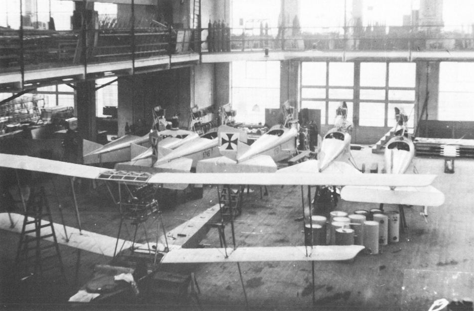
The well-lit and spacious Lohner factory provides a backdrop for assembly of a Lohner flying boat and six B.VII series 17.3 Pfeilfliegers.
Lohner Parasol (AD 426?)
To compete in the Schicht Flug of 1914, Lohner and MLG financed the construction of the only parasol aircraft (AD 426?) built by Lohner. On 19 April 1914, the opening day of the competition, the Parasol (competition No.5) was badly damaged when it side-slipped into the ground at Wigstadtl. Neither pilot Alois Stiploschek nor the passenger were injured. Subsequently, Ferdinand Konschel flew the Parasol (competition No.22) in the Third International Flugmeeting at Aspern in June 1914, winning second place honors in the national speed event. According to Lohner records, the repaired Parasol, powered by an 80 hp Gnome engine, was delivered to the LA on 27 January 1915. Whether aircraft D 22, mentioned in a Flik 4 combat report, was in fact the Lohner Parasol is unconfirmed and doubtful.
Lohner Parasol (AD 426) Specifications
Engine: 80 hp Gnome
Wing: Span 10.80 m (35.43 ft)
Total Wing Area 18 sq m (194 sq ft)
General: Length 7.80 m (2.5.59 ft)
Height 3.40 m (11.15 ft)
Empty Weight 367 kg (809 lb)
Loaded Weight 602 kg (1327 lb)
Maximum Speed: 145 km/hr (90 mph)
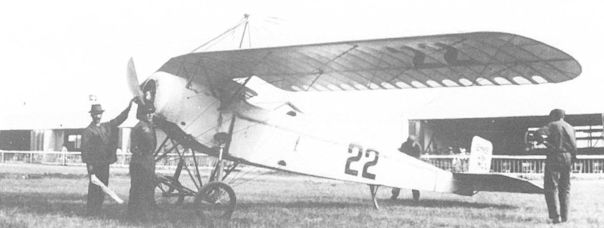
The Lohner Parasol (AD 426 - competition number 22) as flown by Ferdinand Konschel during the Third International Flugmeeting in June 1914. Purchased by the LA on 27 January 1915, it may have seen limited service with Flik 4 as aircraft D 22.
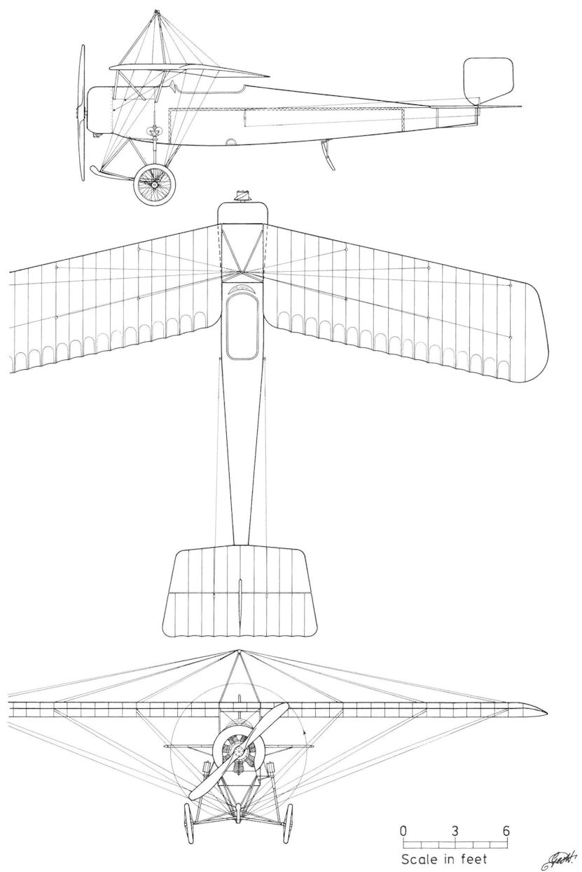
Lohner Parasol (AD 426)
Lohner 10.17
Before embarking on the production of 24 Lohner B.VII (Type J) Pfeilfliegers, the LA ordered one prototype, designated J-01 (AE 201) and powered by a 150 hp Daimler engine, for test and evaluation. When the contract was signed on 17 January 1915, the J-01, later designated 10.17, was nearing completion. It was delivered on 5 March 1915 and performed its maiden flight on 18 March with Fahnrich Edmund Sparmann at the controls. Some minor control problems resulting from the airfoil-shaped tailplane were reported, but these would be corrected on the production machines. In comparison trials supervised by Flars engineer Richard von Mises, the 10.17 prototype, powered by the improved 160 hp Daimler engine, reached 2000 meters (6562 ft) in 17 minutes as compared to 26 minutes with the original 150 hp engine. Because of protracted engine problems, the 10.17 was not accepted until 14 August 1915. It was assigned to Flik 17, one of the first squadrons to receive the Lohner B.VII series 17 production aircraft. During frontline trials the 10.17 reached an altitude of 3500 meters (11,482 ft) in September 1915, and flew several operational missions. The 10.17 was sent to the factory in March 1916 for repairs which were completed in May. It is on record that 10.17 served with Flik 16 through October 1916.
Lohner 10.28
To evaluate the experimental 150 hp Praga V-12 engine the LA ordered one Lohner Type Js prototype, 10.28 (AE 310), on 29 October 1915, from a projected batch of three aircraft (AE 310-312). The air-cooled Praga V-8 and V-12 engines proved extremely unreliable and only sporadic flight tests were performed. Karl Kriger's flight log recorded one (maiden?) flight of the 10.28 at Aspern in March 1916. After Flars prepared the installation drawings in January 1917, Lohner fitted a 150 hp (or 120 hp) Daimler engine and the re-engined 10.28 was accepted by Flars on 1 March 1917. The 10.28 was under repair in September 1917, written-off in October and stored at the Aspern depot in March 1918.
Lohner B.V Series 16
Since the Rapp Motoren Werke of Munich were represented in Austria-Hungary by the Motor-Luftfahrzeug-Gesellschaft (in which Lohner had an interest), it was to be expected that an aircraft powered by a Rapp engine would be proposed to the LA. The result was that Lohner received a contract on 17 January 1915 for 24 Type H Pfeilfliegers powered by the 140 hp Rapp V-8 engine. Recurring engine problems - primarily carburetor fires, excessive oil consumption and endless mechanical modifications - delayed the first Type H acceptance until April 1916, a year later than scheduled. In the event, the LFT cancelled the order after accepting only six machines because the Type H was too heavy to meet the performance specifications. These were designated Lohner B.V series 16.01 to 16.06 (AE101-106). Plagued by recurrent carburetor fires in training service with Fleks 3, 4, 8, 9, and 14, the dangerous B.V aircraft were grounded and placed in storage to await further developments, (see Lohner B.VI series 16.1)
Lohner B.IV Series 16 Specifications
Engine: 140 hp Rapp
Wing: Span Upper 14.40 m (47.24 ft)
Span Lower 10.00 m (32.81 ft)
Chord Upper 1.85 m (6.07 ft)
Chord Lower 1.70 m (5.58 ft)
Sweepback Upper 13 deg
Gap 2.10 m (6.89 ft)
Stagger 0.69 m (2.26 ft)
Total Wing Area 38.5 sq m (414 sq ft)
General: Length 8.70 m (28.54 ft)
Height 3.25 m (10.66 ft)
Track 2.05 m (6.73 ft)
Empty Weight 840 kg (1852 lb)
Loaded Weight 1225 kg (2701 lb)
Maximum Speed: 122 km/hr (76 mph)
Climb: 1000m (3,281 ft) in 11 min 5 sec
Lohner B.VI Series 16.1
After the Lohner B.V failure, the LFT required Lohner to redesign the remaining 18 aircraft on order to meet the performance specifications. Known as the Type H2, the airframe was lightened throughout and fitted with a shorter, plywood-covered fuselage replacing the fabric-covered one of the B.V. The wing cellule had a reduced span, sweepback and stagger. These new aircraft were designated Lohner B.VI series 16.11 to 16.28 (AE 107-124). Delivered after a year's delay, the Rapp-engined B.V and B.VI biplanes were assigned directly to training units. In June 1916, the training command was forced to ground all of them because of recurrent carburetor fires. After corrective measures, limited flying was resumed at Fleks 2-6, 8, 9, and 14. In the fall of 1917, the remaining aircraft (17 or 18) were assigned to Flugpark 1 and sporadically flown until June 1918, when a fatal crash attributed to an engine fire caused the B.V and B.VI biplanes to be withdrawn from service altogether. Several were used as non-flying instructional airframes at the officer flying school in Wiener-Neustadt through 1918. According to one report, aircraft 16.01 was fitted with the experimental Praga engine in August 1916 for flight testing.
Lohner B.VI Series 16.1 Specifications
Engine: 140 hp Rapp
Wing: Span Upper 12.80 m (41.99 ft)
Span Lower 11.40 m |37.40 ft)
Chord Upper 1.78m (5.84 ft)
Chord Lower 1.78 m (5.84 ft)
Sweepback Upper 6 deg
Gap 1.90 m (6.23 ft)
Stagger 0.39 m (1.28 ft)
Total Wing Area 38.45 sq m (414 sq ft)
General: Length 7.60 m (24.93 ft)
Height 3.00 m (9.84 ft)
Track 2.05 m (6.74 ft)
Empty Weight 802 kg (1768 lb)
Loaded Weight 1205 kg (2657 lb)
Climb: 1000m (3,281 ft) in 10 min 15 sec
Lohner B.VII Series 17
The last and most-successful Pfeilflieger design was the Lohner B.VII (Type J), built in greater number than any other Lohner landplane. Conceived as a load-carrying aircraft (Lastflugzeug), the Type J was a development of the Type D series 13 but fitted with the more powerful 150 hp Daimler engine. On 17 January 1915, the LA gave Lohner a contract for one prototype (10.17) and 24 Type J production aircraft designated B.VII 17.01 to 17.24 (AE 202-225). An additional 24 B.VII (U) Pfeilfliegers were ordered from UFAG in March. Lohner deliveries were scheduled to commence in April 1915 and continue at a rate of four aircraft per week, but the first machine was not accepted until August 1915. The fabric-covered fuselage was fitted with the favored common cockpit that provided staggered seating for the pilot and observer. Armament consisted of hand-held weapons until early 1916, when some aircraft were retro-fitted with a single machine gun mounted on a simple pivot fixture. With an observer aboard, the bomb load was about 80 kg (176 lb). A maximum bomb load of 220 kg (485 lb) could be carried in lieu of the observer, but there is no record of aircraft operated in this configuration.
The B.VII began to reach squadron service in August 1915, replacing the Lloyd C.I and C.II biplanes stationed in mountainous terrain. The B.VII series 17 Pfeilfliegers were assigned to Fliks 6, 9, and 15 in the Balkans and to Fliks 7, 16, and 17 in South Tirol and Karnten. Judging by early combat reports, Lohner had designed a rugged machine that was highly regarded for its load-carrying ability and performance. Years later, Julius Arigi remembered the Lohner B.VII as being "the first series aircraft that was totally effective in high mountains and, most importantly, an aircraft that we, as pilots, fully trusted." Between August 1915 and mid-1916, the B.VII series 17 performed numerous long-range reconnaissance and bombing raids, some of five or six hours duration. However, the reliability of the 150 hp Daimler engine left much to be desired. After the outspoken commander of Flik 16, Hauptmann Raoul Stojsavljevic, voiced his displeasure during a visit to Vienna in November 1915, his squadron was the first to receive the more powerful Lohner B.VII series 17.3 in December 1915.
Lohner B.VII Series 17.3
The B.VII series 17.3 was powered by the improved 160 hp Daimler engine that had been test flown in the Lohner 10.17 and was just coming into production. Sixteen B.VII series 17.3 biplanes, numbered 17.31 to 17.46 (AE 808-823), were ordered and although the contract was not signed until 20 March 1916, acceptances had already begun in December 1915 and ended in March 1916, only one month behind schedule. The B.VII series 17.3 began to arrive at the Front in December 1915 and served with Fliks 7, 8, 16, and 17 and singly with Fliks 12 and 19 on the Isonzo Front.
The B.VII's range and bomb load presented the LFT with the opportunity to attack targets deep in Italian territory. Among the most notable was the bombing raid against the Milan electro-generating works undertaken on 14 February 1916. While older Lohner B.VII and Lloyd C.II machines performed a diversionary raid on Schio, twelve B.VII series 17.3 would attack the prime target. Aircrews of Fliks 7, 17, and 16, based at Gardolo and Pergine, prepared for a round trip of about 380 km (236 miles) over imposing mountainous terrain that presented a formidable obstacle. Hauptmann Eugen von Steinner-Goltl, commander of Flik 17, recalled:
We took off with 270 liters fuel and 80 kg bombs and assembled at 1600 meters in the dawning light. My Gral II took the lead, steering a straight compass course so we would quickly reach Milano without undue fuel consumption. At 3000 meters we crossed the enemy lines some 700 meters below us. We were met by murderous artillery fire. After our compass froze, we navigated by the distinctive lakes and valleys. On the way the squadron dispersed entirely. After one and a half hours, the Lombard plain greeted us. My heart laughed, so much flatland - so many landing possibilities. Finally my observer picked out Milan in the haze.
Gral II only just got home. Spending almost five hours in the air "we landed with a stalled engine; inspection showed a broken crankshaft." Given the conditions, it is remarkable that the target was hit at all and that no aircraft were lost. Of the 12 aircraft that took off from Pergine, nine reached Milano and damaged the Porta Volta power station, one bombed Monza by mistake and two made forced landings in friendly territory. Of the few B.VII that carried a machine gun, one succeeded in shooting down an Italian aircraft. Other attacks under similar circumstances were undertaken in 1916. Flik 7 lost two B.VII (17.40 and 17.41) behind the Italian lines during a squadron attack on the Piave bridges on 27 March 1916. In the course of an attack on Udine, aircraft 17.42 became Baracca's second victory on 16 May 1916. Only two B.VII aircraft served on the Russian Front, one when Flik 7 was transferred to Galicia and one with Flik 26.
Lohner B.VII Series 17.3 Specifications
Engine: 160 hp Daimler
Wing: Span Upper 15.40 m 150.52 ft}
Span Lower 11.20 m (36.74 ft)
Chord Upper 2.00 m (6.56 ft)
Chord Lower 1.83 m (6.00 ft)
Sweepback Upper 13 deg
Gap 2.21 m (7.25 ft)
Stagger 0.352 m (1.15 ft)
Total Wing Area 44.0 sq m (473 sq ft)
General: Length 9.50 m (31.17 ft)
Height 3.75 m (12.30 ft)
Track 2.22 m (7.28 ft)
Empty Weight 990 kg (2183 lb)
Loaded Weight 1441 kg (3177 lb)
Maximum Speed: 121 km/hr (75 mph)
Climb: 1000m (3,281 ft) in 7 min 41 sec
Lohner B.VII(U) Series 17.5
Following the successful tests of the Lohner B.VII prototype (10.17), UFAG was given a contract to build 48 Lohner B.VII(U) biplanes on 30 March 1915. Deliveries were scheduled to start on 30 April and end on 2 July 1915. In March 1915, the contract was reduced to 24 aircraft in favor of the Brandenburg G.I(U) series bomber. After four aircraft were accepted, production was stopped in August 1915 to repair unacceptable welds, for which UFAG was penalized. The last of 24 Lohner B.VII(U) biplanes, numbered 17.51 to 17.74 and powered by 150 hp Daimler (MAG) engines, was delivered in January 1916. Because of the unreliable MAG-built engines, the aircraft were declared unfit for frontline service. Beginning in November 1915, the UFAG-built B.VII biplanes were flown as secondary trainers with Fliks 2 and 19 as well as Fleks 2-6, 8, and 9 and Schulkompagnie 1 and 2. Five were still in use as trainers when the war ended.
Lohner B.VII Series 17.8
Nine older B.VII series 17 machines (known are 17.01-05, 09, 12, and 20) were rebuilt by Lohner to take the 160 hp Daimler engine. Fitted with a new motor mount and fuselage frames and a machine gun ring for the observer, the modified aircraft were designated Lohner B.VII series 17.8, numbered 17.81 to 17.89. These aircraft arrived at the Front in February-March 1916. They were assigned to Fliks 12 and 23 on the Isonzo Front and Fliks 7, 8, and 17 in the Tirol.
With the appearance of the Brandenburg C.I, the B.VII aircraft were withdrawn and assigned to Fleks 3-5, 7-9, and 13 for advanced pilot training. As of July 1917, thirty-seven B.VII aircraft were listed in LFT inventory and by October 1918, this number had been reduced to eight damaged B.VII aircraft stored at Flep 2.
Lohner B.VII Series 17.8 Specifications
Engine: 160 hp Daimler
Wing: Span Upper 15.40 m (50.52 ft)
Span Lower 11.20 m (36.74 ft)
Chord Upper 2.00 m (6.56 ft)
Chord Lower 1.83 m (6.00 ft)
Sweepback Upper 13 deg
Gap 2.21 m (7.25 ft)
Stagger 0.35 m (1.15 ft)
Total Wing Area 44.0 sq m (473 sq ft)
General: Length 9.50 m (31.17 ft)
Height 3.75 m (12.30 ft)
Track 2.22 m (7.28 ft)
Empty Weight 941 kg (2075 lb)
Loaded Weight 1392 kg (3069 lb)
Maximum Speed: 124 km/hr (77 mph|
Climb: 1000m (3,281 ft) in 9 min

Lohner B.VII 17.19, Flik 5

Lohner B.VII 17.36, Flik 17

By virtue of having no visible radiator, this Lohner Type J biplane is believed to be the 10.28 prototype powered by the aircooled 150 hp Praga V-12 engine.

Lohner B.V 16.03 trainer, powered by a 140 hp Rapp engine, was at Flek 3 in September 1916. The Lohner B.V (Type H) and the B.VII (Type J) were virtually identical aircraft except for the engine installation.

The Lohner B.VI 16.22 (Type H2 - AE 122) was accepted in the summer of 1916 and flown as a trainer until the type was retired from service in June 1918.

Two aircrew of Flik 16 with the Lohner B.VII 17.05 at the time equipped with a Siemens-Halske g.2 wireless transmitter. In February 1916, the aircraft was fitted with a 160 hp Daimler engine and assigned a 17.8 series number.

The Lohner B.VII 17.06 was attached to Flik 6 from November 1915 through 4 October 1916 when it was written-off after a crash. The exhaust stacks of the 150 hp Daimler engine are on the port side.

Lohner BVII of Fliegerkompanie 16 in autumn 1916: up to mid 1915 this had been an aircrew training unit but in May it moved to the Carinthian Front for operations, remaining operational as a general purpose' unit until the end of the war.
The mountainous Karnten region provides a backdrop for the Lohner B.VII 17.31 of Flik 16 in the fall of 1916.
The mountainous Karnten region provides a backdrop for the Lohner B.VII 17.31 of Flik 16 in the fall of 1916.

A publicity shot of Steinner-Goltl’s Gral II (17.35) taking on bombs in preparation for the Milano raid on 14 February 1916. In actuality, the bombs would be loaded by armorers before the aircrew boarded the aircraft.

The Lohner B.VII 17.38 of Flik 7 at Kalusz, Galicia, in October 1916. The machine is armed with an observer’s machine gun mounted on a gun ring. The small bulge below the propeller is a belt-driven wireless dynamo.

Photographic instruction in a Lohner B.VII(U) 17.53 at Schulkompagnie 2 in Wiener-Neustadt. This aircraft was written-off in February 1918. The external crank for operating the elevator indicates a want of design expertise.

Lohner B.VII(U) 17.58 at a training unit. Except for the twin lift cables attached to the front undercarriage joint, the UFAG-built machines were virtually identical to the Lohner B.VII series 17.01 to 17.24. The upper wing leading-edge protrusions were stacking bumps.

In flight, the Lohner B.VII(U) 17.61 shows off its massive sweptback wings and characteristic hanging ailerons. Although flown as secondary trainers, dual controls were not installed.

Lohner B.VII 17.88 at Aspern in 1916 after modification and installation of a 160 hp Daimler engine. It was destroyed in a training crash at Flek 7 on 12 March 1918.
The well-lit and spacious Lohner factory provides a backdrop for assembly of a Lohner flying boat and six B.VII series 17.3 Pfeilfliegers.

The Danish Madsen M 15 installed on the Lohner B.VII 17.06 of Flik 6 in late 1915. The gun mount is a field modification. The Madsen was unpopular and soon replaced by the Schwarzlose gun.

Lohner B.VI Series 16.1

Lohner B.VII Series 16.1
Lohner D.I Series 111
Flars approved the development of the Lohner D.I (Type AA) fighter in August 1916 and ordered four prototypes, three biplanes and one triplane. Designed by Leopold Bauer, the first prototype, designated 10.20, made its debut at Aspern on 5 September 1916. Powered by a 160 hp Daimler engine, it was ground tested by Lohner pilot Karl Kriger, who was to receive Kr 2000 for performing the maiden flight. On 26 October Flars warned Lohner not to fly the aircraft unless the following problems were corrected: the taxiing stability was poor, the control surfaces were too small, the undercarriage lacked shock cords, and the poor visibility made ground maneuvers hazardous. It was returned to the factory for modification on 31 October.
The 10.20 re-appeared at Aspern on 17 November with a lengthened fuselage. Taxi trials, beginning on 23 November, showed insufficient rudder area but an enlarged rudder tested on 17 December failed to improve ground control. After a tail fin and larger rudder were installed, the rudder response was judged satisfactory and on 29 December 1916, Kriger performed a short hop, believed to be the maiden flight. Upon landing several wing ribs broke. New wings were fitted on 31 December 1916. Flars, contending that the modified prototype "had no future," withheld additional funds but testing of the D.I prototype continued although there was no hope of production. Between 6 January and 28 January 1917, Kriger performed a series of test flights that, despite a severe tail-heavy condition, demonstrated satisfactory performance. Attempts to correct the tail-heaviness were moderately successful, but on 14 February, the 10.20 was damaged in a forced landing and returned to the factory for modification.
When the much-altered 10.20, now designated 10.20A (later D.I 111.01) returned to Aspern on 3 March 1917, it was fitted with twin-strutted wings. Kriger performed the maiden flight on 4 March with satisfactory results. After a series of test flights in April, some with Oberleutnant Oskar Fekete at the controls, the 10.20A (111.01) was accepted by Flars on 29 April 1917. Sporadic trials continued until 6 June 1917, when the prototype was demolished by Oberleutnant Ludwig Hautzmayer, who was lucky to escape with his life. Kriger had warned that the 10.20A required a highly-skilled pilot.
Meanwhile, Lohner had completed the second Type AA prototype, designated 10.20B (later D.I 111.02). Virtually a new design, a raised fin running from cockpit to tail now graced the fuselage, and a more powerful 185 hp Daimler engine was installed. The I-strutted wing cellule was braced to the fuselage by a pair of V-struts, which eliminated the need for interplane wires. Kriger, who performed the maiden flight on 2 June 1917 at Aspern, reported a "fair amount of nose-heaviness." Flight testing continued in June-July. On 2 August, the 10.20B was accepted by Flars, and Lohner pilot Kriger continued flight testing the fighter through October 1917. The 10.20B (111.02) was based at Aspern in February 1918, and last reported at Flugpark 1 in March 1918.
Following close on the heels of the 10.20B, the third Type AA prototype, D.I 111.03 (a prototype number was not assigned), was assembled at Aspern on 25 June 1917. Of conventional layout, the 111.03 had a large tail fin, a wire-braced wing cellule, and a 185 hp Daimler engine supplied the power. The maiden flight was performed by Kriger on 28 June 1917. A few test flights were recorded through October 1917, when further investigation of the type stopped. The D.I 111.03 was reported at Aspern in February 1918, sent to Flek 6 as an instruction airframe in March, and written-off in August 1918.
Lohner 10.20 (D.I 111.01) Specifications
First Version, I-Strut
Engine: 160 hp Daimler
Wing: Span Upper 6.55 m (21.49 ft)
Span Lower 6.00 m (19.68 ft)
Total Wing Area 16.12 sq m (173 sq ft)
General: Length 4.70 m (15.42 ft)
Height 2.90 m (9.51 ft)
Lohner 10.20A (D.I 111.01) Specifications
Third Version, Twin Struts
Engine: 160 hp Daimler
Wing: Span Upper 7.00 m (22.97 ft)
Span Lower 7.00 m (22.97 ft)
Chord Upper 1.50 m (4.92 ft)
Chord Lower 1.50 m (4.92 ft)
General: Empty Weight 570 kg (1257 lb)
Loaded Weight 826 kg (1821 lb)
Lohner 10.20B (D.I 111.02) Specifications
Engine: 185 hp Daimler
Wing: Span Upper 7.30 m (23.95 ft)
Span Lower 6.70 m (21.98 ft)
Total Wing Area 17.98 sq m (193 sq ft)
General: Length 6.00 m (19.68 ft)
Height 2.95 m (9.68 ft)
Lohner D.I 111.03 Specifications
Engine: 185 hp Daimler
Wing: Span Upper 7.60 m (24.93 ft)
Span Lower 7.60 m (24.93 ft)
Chord Upper 1.50m (4.92 ft)
Total Wing Area 20 sq m (2.15 sq ft)
General: Length 6.35 m (20.83 ft)
Height 3.00 m (9.84 ft)
Empty Weight 623 kg (1374 lb)
Loaded Weight 889 kg (1960 lb)
Maximum Speed: 175 km/hr (109 mph)
Climb: 1000m (3,281 ft) in 2 min 40 sec
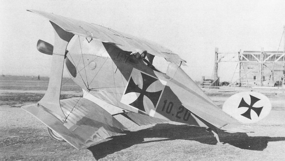
The Lohner 10.20 (Type AA) prototype (first version), here awaiting radiator installation. The aircraft was designed by Leopold Bauer, who had had no previous experience in singleseat fighter design. The abbreviated fuselage was just 4,70 meters (15.4 ft) long. The prototype was retroactively designated D.I 111.01.
Löhner DD, Flugzeugnummer 10.20 (kurze Ausführung mit I-Stiel)
Löhner DD, самолет № 10.20 (укороченная версия с I-образными стойками)
Löhner DD, Flugzeugnummer 10.20 (kurze Ausführung mit I-Stiel)
Löhner DD, самолет № 10.20 (укороченная версия с I-образными стойками)
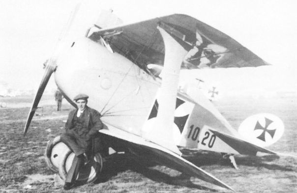
Lohner 10.20 prototype (first version - D.I 111.01) with Lohner test pilot Karl Kriger at Aspern in early September 1916. After ground tests demonstrated dangerous characteristics, the prototype was returned to the factory for modification.
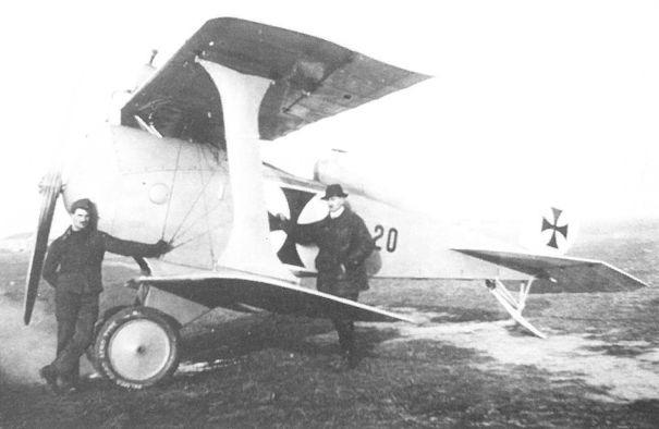
Lohner 10.20 prototype (second version - D.I 111.01) modified with a lengthened fuselage and new vertical surfaces, with designer Bauer at right. Kriger performed a short maiden flight on 29 December 1916.
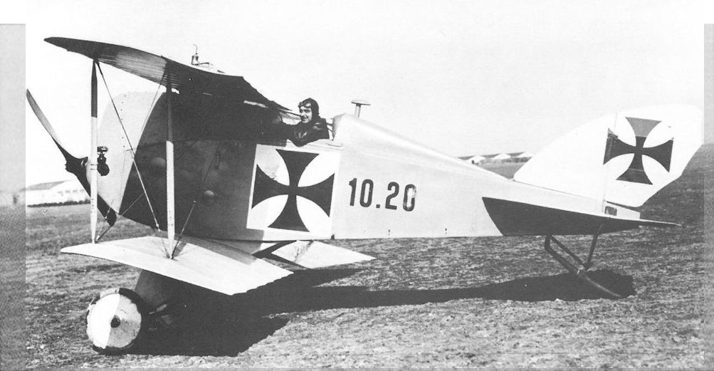
The Lohner 10.20A prototype (third version - D.I 111.01) was practically a new aircraft. It was given a modified fuselage, a tail fin, an enlarged rudder, and a new wing cellule. Kriger, in the cockpit, performed the first flight on 4 March 1917. The prototype was demolished in a crash on 6 June 1917.
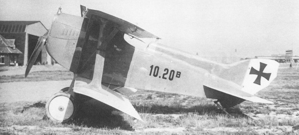
The Lohner 10.20B (D.I 111.02) prototype fighter during flight testing at Aspern in the summer of 1917.
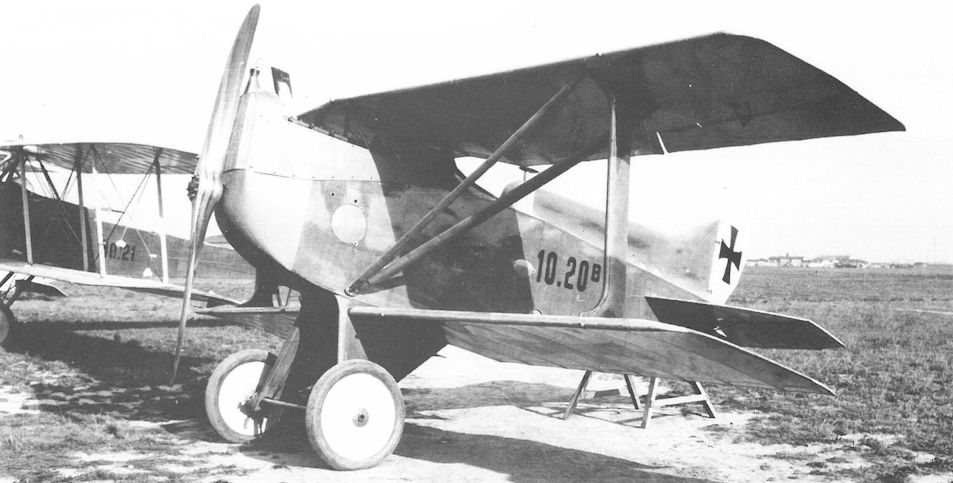
The Lohner 10.20B (D.I 111.02) was the second Type AA prototype built by Lohner. It was first flown on 2 June 1917 by Kriger who reported severe nose-heaviness.

Lohner D.I 111.03, the third Type AA prototype, performed its maiden flight on 28 June 1917. Sporadic testing continued through October 1917, when the D.I program was stopped.
The third Typ AA series fighter, the Lohner 111.03 was abandoned in favour of the Aviatik D I.
The third Typ AA series fighter, the Lohner 111.03 was abandoned in favour of the Aviatik D I.

Lohner D.I 10.20 (111.01)
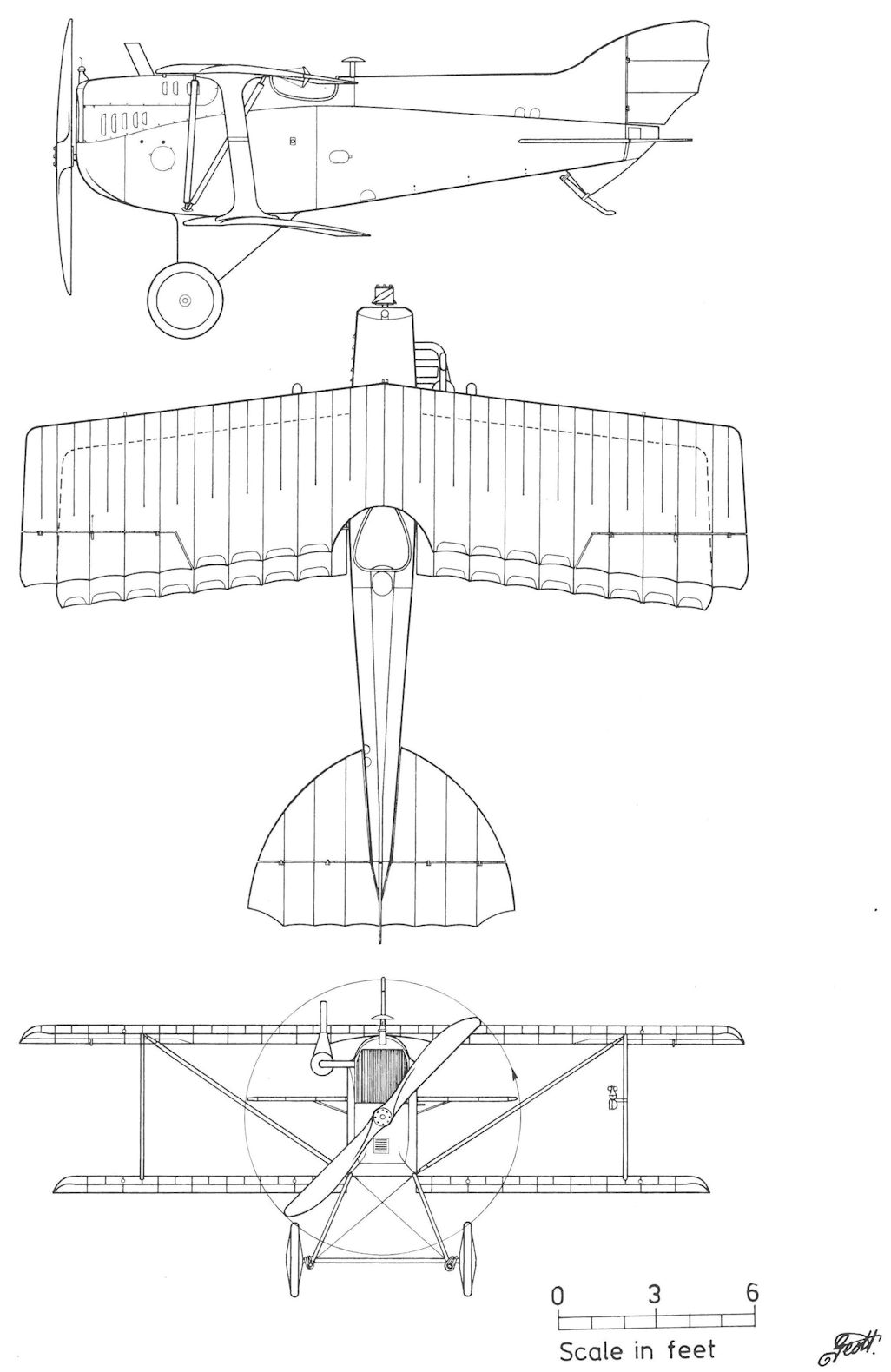
Lohner D.I 10.20B (111.02)
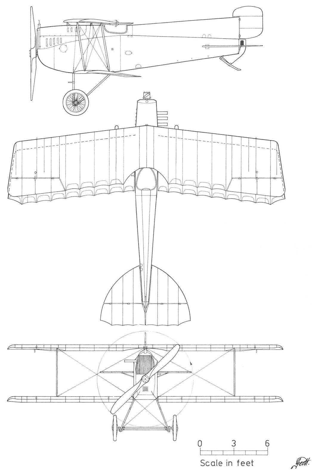
Lohner D.I 111.03
Lohner 10.18
The Lohner 10.18 (Type Jc - AE 778) was the first army aircraft designed by Lohner's new chief engineer, Leopold Bauer. It was created to meet the armed two-seater (military class C) specification issued in late 1915. As might be expected, the 10.18 had little in common with its predecessors. The fuselage was plywood-covered, the wing cellule simplified, and the sweepback greatly reduced. Extant records show that the 10.18, powered by a 185 hp Daimler engine, was assembled at Aspern on 4 January 1916, ready for flight on 20 January, and test pilot Karl Kriger performed the maiden flight on 5 February 1916.
Having completed tests as the prototype for the Lohner C.I series 18 production aircraft, the 10.18 temporarily was fitted with a 140 hp Rapp V-8 engine to evaluate the engine for use in the Lohner B.VI series 16.1 biplane. In August 1916, the 10.18, once again powered by a 185 hp Daimler engine, was assigned to the aircraft test group at Aspern for training and experimental purposes.
Lohner C.I Series 18
With the conclusion of the Lohner 10.18 evaluation trials, Lohner signed a contract on 10 March 1916 for 24 C.I biplanes (Type Jc) powered by a 160 hp Daimler engine. Parts manufacture had begun in December 1915 and delivery was scheduled to start on 5 April and end in July 1916. Flars stopped delivery in June 1916 because, compared with the Brandenburg C.I, the first production machines demonstrated "hopelessly inadequate" performance even after the contractual flight specifications had been lowered. Lohner, unable to rectify the shortcomings, was obliged to pay a penalty. After a long delay, Flars accepted a total of 23 C.I biplanes numbered 18.01 to 18.23.71 Unsuitable for frontline service, the C.I machines were used as trainers by Fleks 1, 4-9, 11, and 14 and Schulkompagnie 2. In November 1917, nine damaged aircraft were dispatched to Flugpark 1 for disposal, but a few remained in training service until mid-1918.
Lohner C.I Series 18 Specifications
Engine: 160 hp Daimler
Wing: Span Upper 12.80 m (41.99 ft)
Span Lower 12.10 m (39.70 ft)
Chord Upper 1.78 m (5.84 ft)
Chord Lower 1.78 m (5.84 ft)
Sweepback Upper 8.5 deg
Gap 1.90 m (6.23 ft)
Stagger 0.26 m (0.85 ft)
Total Wing Area 38.45 sq m (414 sq ft)
General: Length 9.25 m (30.35 ft)
Height 3.30 m (10.83 ft)
Track 2.05 m (6.73 ft)
Empty Weight 869 kg (1916 lb)
Loaded Weight 1333 kg (2939 lb)
Maximum Speed: 132 km/hr (82 mph)
Climb: 1000m (3,281 ft) in 7 min 56 sec
Lohner C.I Series 18.5
On 22 September 1916, a contract was signed for 17 improved Lohner C.I biplanes (Type Jcr) numbered 18.51 to 18.67. Flight evaluation was performed with aircraft 18.24 that was modified to Type Jcr standard and reportedly renumbered 18.51. The Type Jcr, powered by a 160 hp Daimler engine, was fitted with a new wing cellule and lightened throughout, resulting in improved but still mediocre performance. The series 18.5 machines were flown as trainers by Fleks 3, 5, 7, 9, 12, and 13. In March 1917, aircraft 18.61 to 18.64, additionally armed with a Type VK II machine gun canister, were pressed into home-defense duty with the Flars Versuchsflik (test squadron) at Aspern. As of July 1917, thirty- six C.I aircraft were listed on training status, perhaps not all in flying condition.
Lohner C.I Series 18.5 Specifications
Engine: 160 hp Daimler
Wing: Span Upper 12.44 m (40.81 ft)
Chord Upper 1.78 m (5.84 ft)
Chord Lower 1.78 m (5.84 ft)
Sweepback Upper 8.5 deg
Gap 1.90 m (6.23 ft)
Stagger 0.26 m (0.85 ft)
Total Wing Area 43.3 sq m (465 sq ft)
General: Height 3.00 m (9.84 ft)
Empty Weight 759 kg (1674 lb)
Loaded Weight 1216 kg (2681 lb)
Maximum Speed: 134 km/hr (83 mph)
Climb: 1000m (3,281 ft) in 5 min 37 sec
2000m (6,562 ft) in 12 min 45 sec
3000m (9,843 ft) in 22 min 56 sec

The Lohner 10.18 during flight tests at Aspern in February 1916. A distinct departure from the Pfeilflieger, the 10.18 represented chief engineer Bauer’s first landplane design for Lohner.

The shortage of rubber for aircraft tires prompted the development of a spring-steel substitute, shown here being evaluated on the Lohner 10.18 on a rain-soaked airfield.

The 10.18 finished its career at Aspern, suspended from the rafters for investigation of parachute installation and jumping techniques.

"Лёнер" С-I Компоновка фюзеляжа Лёнера СI, как и многих других австрийских самолетов, копировала популярный Ганза-Бранденбург СI
The Lohner C.I series 18 (Type Jc), the first landplane designed by Leopold Bauer, failed to meet the performance requirements and was placed in service as a trainer. Aircraft 18.23 was attached to Flek 7 until written-off after a crash in May 1918.
The Lohner C.I series 18 (Type Jc), the first landplane designed by Leopold Bauer, failed to meet the performance requirements and was placed in service as a trainer. Aircraft 18.23 was attached to Flek 7 until written-off after a crash in May 1918.

Lohner C.I 18.52. Outwardly identical to the series 18, the C.I series 18.5 (Type Jcr) aircraft had a new wing cellule and lightened airframe but also proved unsuitable for frontline use and finished the war as a trainer with Flek 12.

A few Lohner C.I series 18 and 18.5 aircraft served to evaluate new equipment. Here a “Wolf” exhaust silencer is being tested on aircraft 18.63.

Sitting in a well-padded ‘easy chair’, the pilot of the Lohner C.I 18.23 was confronted (underneath the coaming right to left) by an altimeter, manometer, engine water manometer (below), fuel switch and hand pump switch and lever. Several other instruments are not visible. The tachometer is mounted on the windshield.

Lohner C.I Series 18
Lohner 10.21
In early 1914, Uzelac asked Lohner to submit specifications for a multi-seat battleplane powered by two 150 hp engines. The LA returned the drawings for additional study on 30 March 1914. One month later, Lohner received funds to design a twin-engined battleplane which featured steering vanes mounted between the outer wing struts to counteract the turning moment and maintain a straight flight in the event one engine failed. The schematic planview was published in Austrian Patent No. 79202 granted on 2 May 1914. The battleplane drawings were re-submitted to the LA on 27 May 1914, but further work was held in abeyance.
The LA issued new battleplane specifications on 20 August 1914, calling for a speed of 125 km/h (78 mph) and a climb to 1000 meters (3281 ft) in 8 minutes carrying a crew of six. The contract to build one prototype, known as the Lohner Type U (AD 925) and later designated 10.21, was signed on 31 August 1914. The final drawings, dated 9 July 1915, had four crew members; two located in the forward turret, one pilot behind the wings, and one gunner in the rear cockpit. The Lohner 10.21, the first twin-engined aircraft built for the LFT, was reported ready for flight trials in January 1916, but test pilot Karl Kriger's log book reveals that final assembly and ground tests were not completed until 14 April 1916 when he piloted the 10.21 on the maiden flight. During the course of sporadic testing through June 1916, the wing steering vanes and braking wheel were removed. The opposite-rotating 150 hp Daimler engines were replaced by engines revolving in the same direction but performance remained unsatisfactory. The 10.21 was accepted in June 1916 and assigned to Flek 6 in Wiener-Neustadt for further evaluation. Showing little interest, the LFT placed the 10.21 in storage until it was written-off in October 1917. The serial number was reassigned to the single-engined Lohner Type F.
Lohner 10.21 Specifications
Engine: 2 x 150 hp Daimler
Wing: Span Upper 21.00 m (68.90 ft)
Span Lower 16.00 m (52.49 ft)
Chord Upper 2.54 m (8.33 ft)
Chord Lower 2.20 m (7.22 ft)
Total Wing Area 77 sq m (829 sq ft)
General: Length 13.00 m (42.65 ft)
Height 4.20 m (13.78 ft)
Empty Weight 1920 kg (4234 lb)
Loaded Weight 2700 kg (5954 lb)
Maximum Speed: 120 km/hr (74.5 mph)

The Lohner 10.21 prototype in its initial configuration was fitted with auxiliary steering vanes in the wing gap. The third wheel in the unique tricycle undercarriage performed the braking function.

The Lohner 10.21 in its final form with the third wheel and steering vanes removed. The twin rudders provided sufficient directional stability and the tail skid was adequate as a brake.

The Lohner 10.21 during evaluation at Flek 6 showing the ample crew positions and the centrally-located pilot’s cockpit. The radiators have been raised into the slipstream from behind the engines.

Lohner 10.21
Lohner C.II Series 112
Ludwig Lohner and Bauer visited Berlin in February 1916 in an unsuccessful attempt to obtain a Roland C.II manufacturing license from the Luft-Fahrzeug-Gesellschaft. Undaunted, Lohner submitted a derivative project to Flars on 14 April 1916 that was rejected. An improved design submitted by Lohner was supported by Flars, who in August 1916 ordered the first of four prototypes. The first airframe, designated 10.19 (Type AB), was inspected on 1 March 1917 by Flars engineers who criticized the poor forward visibility even though Bauer had positioned the 185 hp Daimler engine low in the fuselage. In addition to some minor changes, Flars demanded that the fuselage frames be relocated to increase the observer's space and strengthen the machine gun mount. The maiden flight of the 10.19 prototype (later designated C.II 112.01), with Kriger at the controls and Bauer as observer, occurred on 4 April 1917. Testing by Kriger and Flars pilots continued through 7 June 1917, at which time Flars prohibited LFT pilots from flying the 10.19 owing to weak wing struts which "had been miscalculated in the design stage." Furthermore, Kriger now refused to fly the aircraft because of a dangerous tail-heavy condition. It was an indication of stability problems that would hamstring the project for almost a year without being resolved.
In June, the C.II 112.01 (10.19) was sent to Lohner for modification and returned to Aspern in July 1917 with wings of increased area moved aft to alleviate the tail-heaviness. Between 2 August and 1 December 1917, Kriger made occasional test flights but the 112.01 continued to demonstrate unacceptable stability and inadequate climb. Testing was stopped and the prototype placed into storage.
During June 1917, the remaining three C.II production prototypes were tested in short order. Aircraft 112.03 was assembled at Aspern on 16 June and first flown on 20 June. Kriger reported a severe nose-heavy condition. Only a few flights were performed at Aspern in July after which the 112.03 was dismantled and placed into storage in August.
Aircraft C.II 112.04 was assembled at Aspern on 18 June 1917 and flown for the first time on 21 June. Like the other C.II prototypes, it demonstrated severe stability problems. After Kriger logged several flights in September 1917, the 112.04 was dismantled and placed into storage.
Aircraft 112.02, the last to be flown, was assembled at Aspern on 18 June and Kriger performed the maiden flight on 29 June 1917. The 112.02 airframe was static load tested in August but failed to meet the required load factor of 5. Aircraft 112.02 was dismantled and stored at the Lohner factory where it was reported in May 1918. In October 1918, the government purchased the four C.II biplanes, paying only three-quarters of the contracted price because the performance requirements had not been met.
Lohner 10.19 (C.II 112.01) Specifications
Engine: 185 hp Daimler
Wing: Span Upper 9.30 m (30.51 ft)
Span Lower 8.40 m (27.56 ft)
Chord Upper 1.60 m (5.25 ft)
Chord Lower 1.60 m (5.25 ft)
Total Wing Area 30.0 sq m (323 sq ft)
General: Length 7.43 m (24.38 ft)
Height 2.95 m (9.68 ft)
Empty Weight 785 kg (1731 lb)
Loaded Weight 1080 kg (2381 lb)
Maximum Speed: 178 km/hr (110.5 mph)
Climb: 1000m (3,281 ft) in 6 min 35 sec
2000m (6,562 ft) in 14 min 2 sec
3000m (9,843 ft) in 31 min 45 sec

Posed in front of the company hangars at Aspern, the pristine Lohner 10.19 (C.II 112.01) prototype belies its dangerous flight characteristics. The V-struts that supplanted the interplane wire bracing was a drag-reduction feature. The observer’s field of fire was exemplary, however.

The Lohner 10.19 (112.01) was test flown at Aspern between April and December 1917. The deep plywood-covered fuselage obviated the need for a vertical tailplane.

The Lohner C.II 112.04 arrived at Aspern for flight tests in June 1917. With the wings moved aft to compensate for tail heaviness, it proved nose heavy and unstable in flight.

Showing none of the elegant Roland C.II lines, this derivative Lohner project, dated 10 April 1916, was rejected by Flars. The engine was a 160 hp Daimler and the overall length was about 7.3 meters.

Lohner C.II 112.01 (10.19) and 112.04
Lohner Dr.I 111.04
The last of the four Lohner fighters authorized in August 1916 and approved by Flars on 7 May 1917 was Leopold Bauer's triplane design powered by a 185 hp Daimler engine. Known as the Lohner Type A, it received the military designation Dr.I 111.04. Apart from the wings, the airframe was identical to the D.I 111.03. The triplane was completed on 23 June 1917 and the first (maiden?) flight recorded in Kriger's log book occurred on 7 July 1917 when he took the triplane to 4000 meters (13,124 ft) in 20 minutes. It was disassembled on 8 July 1917 for minor structural modification and returned to Aspern in August. On 5 September 1917, Kriger reached 5000 meters (16,405 ft) in 26 minutes, a time that Flars regarded as "mediocre" compared to the 21 minutes achieved by the Aviatik D.I biplane just then entering squadron service. Hauptmann Oskar Fekete and Oberleutnant Franz Muller of Flars, who performed the evaluation, reported totally unsatisfactory flight characteristics and visibility from the cockpit. Trials were continued through October 1917. The Dr.I 111.04 was accepted by Flars in February 1918 and stored at Aspern. Later sent to Flek 6 for disposal, the Dr.I 111.04 triplane was written-off on 11 October 1918.
Lohner Dr.I 111.04 Specifications
Engine: 185 hp Daimler
Wing: Span Upper 8.80 m (28.87 ft)
Span Middle 8.10m (26.57 ft)
Span Lower 8.80m (28.87 ft)
Chord Upper 1.00 m (3.28 ft)
Chord Lower 1.00 m (3.28 ft)
Total Wing Area 24.0 sq m (258 sq ft)
General: Length 6.35 m (20.83 ft)
Height 3.00 m (9.84 ft)
Empty Weight 693 kg (1528 lb)
Loaded Weight 946 kg (2086 lb)
Maximum Speed: 178 km/hr (110.5 mph)
Climb: 1000m (3,281 ft) in 2 min 8 sec
2000m (6,562 ft) in 6 min 5 sec
3000m (9,843 ft) in 11 min
4000m (13,124 ft) in 16 min 7 sec
5000m (16,405 ft) in 26 min

The Lohner Dr.I 111.04 (Type A) prototype, completed in June 1917, was one of the first fighter triplanes built by a Central Power.
Tested in 1917, the Typ A triplane was destined to be the last of the Lohner fighters.
Tested in 1917, the Typ A triplane was destined to be the last of the Lohner fighters.

This view of the Lohner Dr.I 111.04 shows the slanted wing strut configuration, the reasons for which are not readily apparent. Only one Lohner Dr.I prototype was built. The workmanship and finish were good, but the design itself was not satisfactory. The Dr.I was slightly faster and had a better climb rate than the Lohner D.I biplane with the same engine, which was unusual for a triplane development of an earlier biplane design. Regardless, poor flying qualities doomed the design.

Lohner Dr.I 111.04
Lohner 10.21 (new) and 10.22
The Fliegerarsenal (Flars - aviation arsenal) issued specifications in July 1916 for a long-range reconnaissance aircraft and requested Lohner to submit project drawings for two aircraft powered by the experimental 300 hp Daimler V-12 engine and capable of carrying a crew of three, including two observer-machine gunners in the rear cockpit. Lohner proposed the Type F [Fernerkundungs Flugzeug - long-range reconnaissance aircraft). Before much progress was made, the project was cancelled in favor of a 350 hp aircraft designed by Ingenieurleutnant Karl Saliger and Dr Richard von Mises of the Flars construction bureau.
Structural drawings for the Saliger-Mises design had been completed in September 1916. From the outset Flars had planned to assign the construction to Aviatik, a company with spare manpower, but Aviatik suddenly had its hands full with C.I and D.I aircraft production. Consequently, on 11 December 1916, the LFT command shifted the project to Lohner. The Saliger-Mises specifications called for a top speed of 200 km/h (124 mph) with a rate of climb of 1000 meters (3281 ft) in 4 minutes, a duration of two hours, an armored seat for the pilot, a common cockpit for the crew, one fixed machine gun, and a rear gun located to fire a 180-degree traverse. Parts assembly began in the Lohner shops in January 1917. The first prototype, numbered 10.21 (w/n 33/438), stood assembled at the factory on 24 April 1917. Since the 350 hp engine was not ready, the experimental 300 hp Daimler V-12 engine was installed. The second machine, 10.22 (Type F-w/n 33/439), was completed but not assembled.
The Lohner flight log shows that the 10.21 was at Aspern ready for flight trials on 2 May 1917. Now began a year-long program, delayed by problems with the new Daimler V-12 engine. From the record it is clear that the 10.21 was used primarily as a test-bed for engine trials. Ground tests were performed on 7 May. During taxi trials on 11 May, the undercarriage shock cords tore apart. On the maiden flight, performed on 12 May, Lohner test pilot Karl Kriger reported severe engine vibrations and tail skid failure. On 16 May, the tailplane broke while taxiing. The "nose and tail heaviness" was reported solved by structural modifications in June 1917. Work was also underway to design a new tail skid and widen the rear cockpit to hold a third crew member. The task of finding a suitable propeller to match the engine-airframe characteristics consumed much of the test program.
The 10.21 prototype was turned over to the Flars test group on 4 June 1917 and Karl Kriger continued the flight investigation through October 1917, during the course of which the climb rate to 1000 meters (3281 ft) had been lowered from 15 to 3:45 minutes as a result of engine and propeller improvements. On 28 October the engine was removed to install aluminum pistons which, among other modifications, increased the engine rating to 345 horsepower. The 10.21 continued sporadic flights at Aspern to evaluate engine performance up to 4000 meters (13,123 ft) altitude. When last reported in October 1918, the 10.21 prototype was based at Aspern in flying condition.
In February 1918, preparations were underway to install the experimental 360 hp Daimler six-cylinder engine in 10.22, the second Type F prototype. The 10.22 appeared at Aspern on 14 May 1918 and performed its maiden flight on 27 May. Returned to the factory owing to a minor mishap on 8 June 1918, the 10.22 was last reported at Aspern in August 1918.
Lohner 10.21 Specifications (new)
Engine: 300 hp Daimler
Wing: Span Upper 15.0 m (49.21 ft)
Span Lower 15.0 m (49.21 ft)
Chord Upper 1.96 m (6.43 ft)
Chord Lower 1.96 m (6.43 ft)
Total Wing Area 50.0 sq m (538 sq ft)
General: Length 10.3 m (33.79 ft)
Height 3.50 m (11.48 ft)
Empty Weight 1150 kg (2536 lb)
Loaded Weight 1800 kg (3969 lb)
Maximum Speed: 157 km/hr (97.5 mph)
Climb: 1000m (3,281 ft) in 15 min
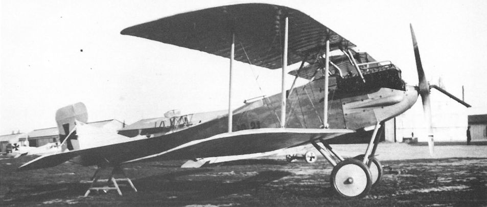
Lohner 10.21 (new), powered by the experimental 300 hp Daimler V-12 engine, at Aspern at the time of the maiden flight in May 1917. Photographs of the similar 10.22 prototype are not available.
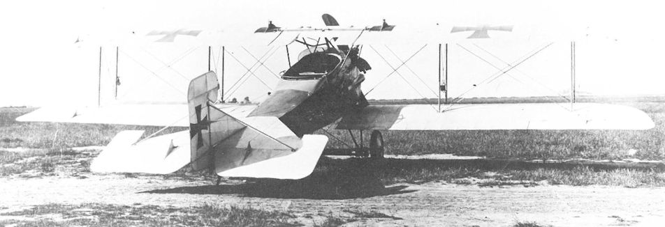
Later fitted with a balanced elevator and minor modifications, the Lohner 10.21 served primarily as a test vehicle for the new Daimler V-12 engines. The large cockpit was designed to carry a crew of three. Each engine bank has its own radiator on the upper wing.
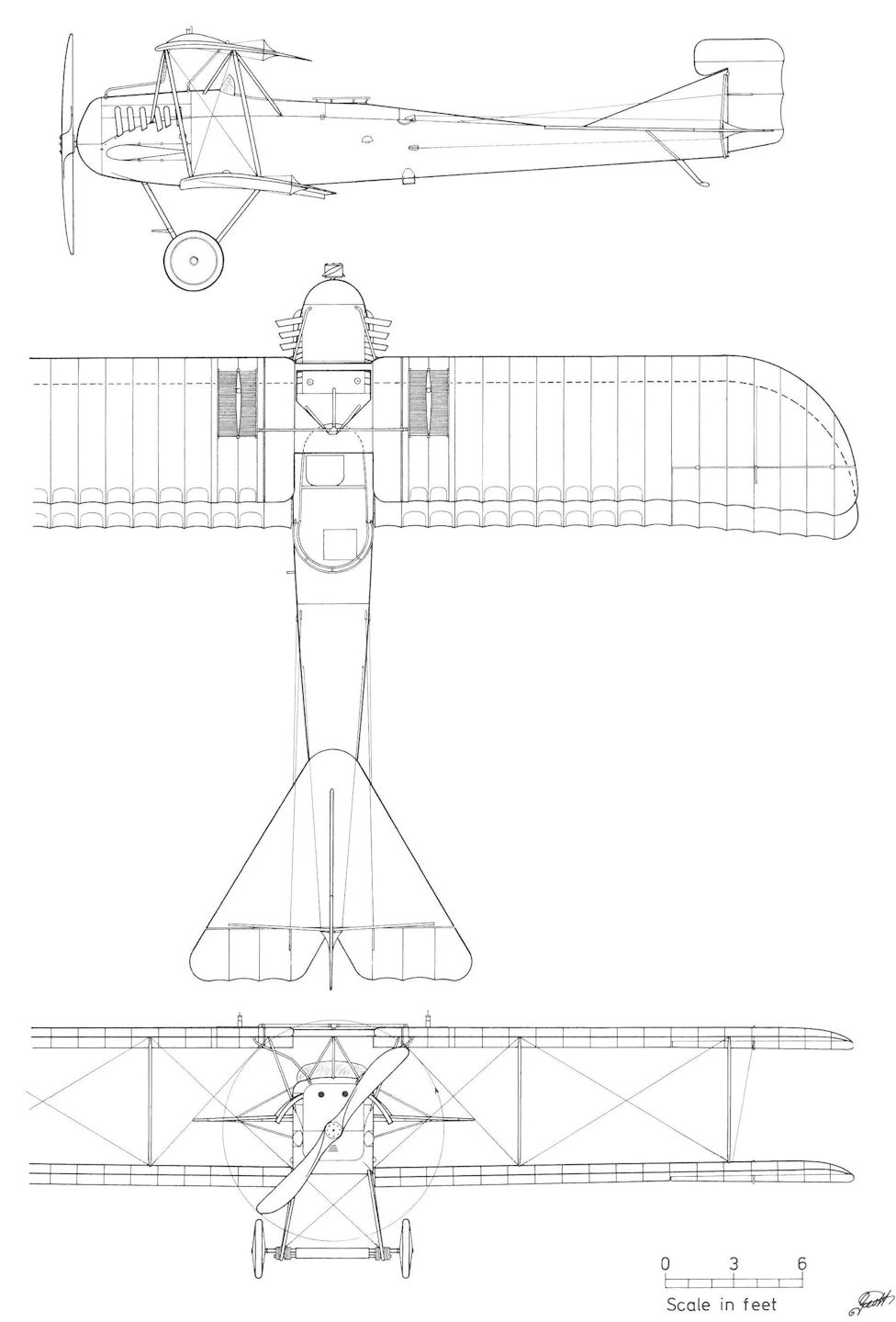
Lohner 10.21 (new)
Lohner 10.23
The last landplane designed by chief engineer Bauer was the Lohner 10.23 (Type AC) powered by a 360 hp Daimler six-cylinder engine. Built to similar specifications as the Oeffag 50.13, Brandenburg L 15, and Lohner 10.21, the 10.23 was a long-range reconnaissance machine with a duration of four hours. Facts are sparse, but it is known that the 10.23 was reported at Aspern on 19 June 1918 awaiting camera installation. According to Cavigioli, a not-always reliable source, the prototype was approved by the Flars purchasing commission on 10 July 1918, but the August 1918 delivery calendar does not reflect this assertion. After the war the 10.23 prototype was returned to the Lohner factory where it was reported under modification for civilian use on 4 June 1919. Named Express I and placed in service as a courier machine, it made its first courier flight from Aspern to Kamenez-Podolskij in the Ukraine on 7 July 1919 and returned on 17 July. According to Swiss sources, Express I was confiscated by the Inter-Allied Control Commission and purchased by Aero Gesellschaft Comte, Mittelholzer St Co. In 1920, it was given the Swiss civil registry number CH-30.
Lohner 10.23 Specifications
Engine: 360 hp Daimler
Wing: Span Upper 11.20 m (36.74 ft)
Span Lower 11.00 m (36.09 ft)
Chord Upper 1.90 m (6.23 ft)
Chord Lower 1.90m (6.23 ft)
Total Wing Area 40.0 sq m (430 sq ft)
General: Length 7.60 m (24.93 ft)
Height 3.20 m (10.50 ft)
Empty Weight 920 kg (2029 lb)
Loaded Weight 1615 kg (3561 lb)
Maximum Speed: 197 km/hr (122 mph)
Climb: 1000m (3,281 ft) in 3 min 30 sec

The Lohner 10.23 prototype was designed for long-range reconnaissance work. Armament consisted of twin synchronized machine guns and a flexible gun mounted in a roomy turret.

After the war, Lohner 10.23 was modified as a courier machine. Named Express I, it flew to the Ukraine and later between Vienna and Zurich.

Lohner 10.23
Oeffag 50.01
The Oeffag 50.01 experimental biplane was designed and built at the Daimler engine factory in Wiener-Neustadt while the Oeffag company was in the process of being established. The structural drawings were completed in January 1915 under the supervision of Ingenieur Eduard Zaparka and Karl Ockermuller. When the prototype, powered by a 160 hp Daimler engine, was first flown in early 1915, the I-strutted wing cellule braced with only a single set of cables, was reported prone to deformation. Oeffag data sheets give the completion date as September 1915, but it is believed this date refers to a final modification of the 50.01, possibly fitted with conventional struts.
Engine: 160 hp Daimler
Wing: Span Upper 14.58 m (47.83 ft)
Span Lower 13.90 m (45.60 ft)
Chord Upper 2.25 m (7.38 ft)
Chord Lower 2.00 m (6.56 ft)
Dihedral Upper 2 deg
Dihedral Lower 2 deg
Sweepback Upper 9 deg
Sweepback Lower 9 deg
Gap 1.92 m (6.30 ft)
Stagger 0.17 m (0.56 ft)
Total Wing Area 54 sq m (581 sq ft)
General: Length 8.40 m (27.56 ft)
Height 3.27 m (10.73 ft)
Loaded Weight 1350 kg (2977 lb)
Maximum Speed: 120 km/hr (74.5 mph)

The 50.01 experimental biplane was unique in that it was fitted with a triple I-strut wing cellule.

The Oeffag 50.01 during flight testing in early 1915. Dimensionally, the 50.01 was identical to the 50.02 prototype.
Oeffag 50.02
The Oeffag C.I series 51 production contract stipulated that the 50.02 prototype was to be delivered on 15 June 1915. Oeffag documents record the 50.02 as "completed" in December 1915, an indication that during the course of flight testing extensive modification was required. Dimensionally similar to the 50.01, the 50.02 was fitted with a conventional three-bay wing cellule and powered by a 160 hp Daimler engine. On entering service, the 50.02 was assigned to Flek 6 and Schulkompagnie 1. After repair in 1917, it was assigned to Flek 10. While on an airmail run between Cracow and Lemberg, a carburetor fire caused the 50.02 to crash land and burn at Rzeszow, Galicia on 22 May 1918.
Oeffag 50.02 Specifications
Engine: 160 hp Daimler
Wing: Span Upper 14.58 m (47.83 ft)
Span Lower 13.90 m (45.60 ft)
Chord Upper 2.30 m (7.55 ft)
Chord Lower 2.00 m (6.56 ft)
Dihedral Upper 2 deg
Dihedral Lower 2 deg
Sweepback Upper 9 deg
Sweepback Lower 9 deg
Gap 1.92 m (6.30 ft)
Stagger 0.17 m (0.56 ft)
Total Wing Area 54 sq m (581 sq ft)
General: Length 8.60 m (28.21 ft)
Height 3.27 m (10.73 ft)
Useful Load 488 kg (1076 lb)
Loaded Weight 1350 kg (2977 lb)
Maximum Speed: 120 km/hr (74.5 mph)
Climb: 1000m (3,281 ft) in 7 min 30 sec
Oeffag C.I Series 51
The LFT awarded Oeffag its first production contract on 17 July 1915, specifying one prototype (50.02) and 24 C.I biplanes numbered 51.01 to 51.24. Four production machines were in assembly in December 1915. The first C.I (51.01) arrived at Aspern for flight testing in January 1916. Acceptance was delayed until 24 March 1916 because a suitable company test pilot was not available. The last aircraft were accepted in June 1916.
The C.I, powered by a 160 hp Daimler engine, was assigned to the newly established Fliks 25 and 27 in April-May 1916 and later to Fliks 9, 11, and 18 on the Galician (Russian) plain where the terrain was flat and undemanding. Popularly known as the "Skodaflugzeug", the C.I was a stable, safe, and solidly-constructed aircraft, regarded as ideal for radio-spotting duties because of its low speed and pleasant flight and landing characteristics, but for air combat it was considered sluggish. In late 1916, the C.I was withdrawn; some were equipped with dual controls and issued to Fliks 6, 14, 20, 23, 31, 43, and 49 and to Fleks 6, 10, and 11 as advanced trainers. Twenty-two C.I trainers were still in service as of September 1917, and eight in August 1918 - some flying airmail between Aspern and Lemberg. Seven survived the war and were offered for sale by the Austrian government in 1920.
Oeffag C.I Series 51 Specifications
Engine: 160 hp Daimler
Wing: Span Upper 14.58 m (47.83 ft)
Span Lower 13.90 m (45.60 ft)
Chord Upper 2.30-2.00 m (7.55-6.56 ft)
Chord Lower 2.00 m (6.56 ft)
Dihedral Upper 2 deg
Dihedral Lower 2 deg
Sweepback Upper 9 deg
Sweepback Lower 9 deg
Gap 1.93 m (6.33 ft)
Stagger 0.17 m (0.56 ft)
Total Wing Area 54 sq m (581 sq ft)
General: Length 8.40 m (27.56 ft) (less propeller)
Height 3.27 m |10.73 ft)
Track 2.20 m (7.22 ft)
Loaded Weight 1350 kg (2977 lb)
Maximum Speed: 125 km/hr (78 mph)
Climb: 1000m (3,281 ft) in 7 min

The Oeffag 50.02, the prototype of the C.I series 51, differed from the 50.01 primarily in having a conventional wing cellule and modified tail surfaces.
Oeffag 50.02 in Wr. Neustadt. Werksflugfeld 1916, Versuchsflug zur Ba 51
Oeffag 50.02 in Wr. Neustadt. Werksflugfeld 1916, Versuchsflug zur Ba 51
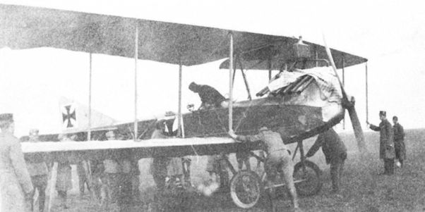
During its long service career, the 50.02 was flown as a trainer by Schulkompagnie 1 at Wiener-Neustadt in 1917.
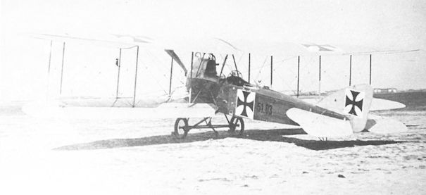
Oeffag C.I 51.03 was accepted in April 1916, served with Flik 18, then as a trainer, and was offered for sale in 1920.
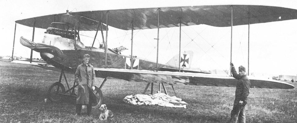
The Oeffag C.I 51.11 was armed with a single, flexible machine gun. After serving with Flik 11, it was assigned to training duties and was still active in late 1918.
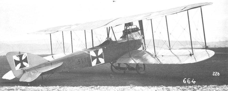
After service with Flik 27 from June to October 1916, the Oeffag C.I 51.18 was used as a trainer by Flek 6 in Wiener-Neustadt in 1917. The gun ring has been removed and dual controls installed.
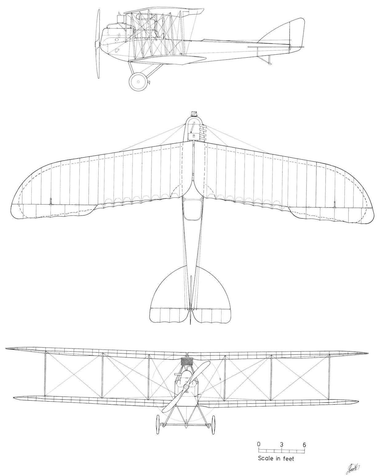
Oeffag C.I Series 51
Oeffag 50.08 to 50.12
The four Oeffag-Saliger "high-performance" reconnaissance prototypes, designated 50.08 to 50.11 (Oeffag Type AF) and powered by a 185 hp Daimler engine, were designed by Ingenieurleutnant Karl Saliger. Work had begun in January 1917 when he came to Oeffag from Flars. By the time the contract was signed in May 1917, one prototype was already undergoing flight trials. In fact, by 19 March sufficient flight data had been gathered for Flars to report that the 50.08 prototype was unfit for field service because of dangerous flight characteristics. It was necessary for Saliger to redesign the wings with a new airfoil section and change the fin and rudder. The modified 50.08 was commissioned on 31 May 1917, and the flight evaluation was successfully completed by the end of June. Only the static load tests stood in the way of releasing the design for production.
The second prototype, 50.09, was expected to be ready for flight tests in early June 1917, after which it was scheduled for armament installation and firing trials in Fischamend. The fourth prototype, 50.11, was reported ready for flight trials in July 1917.
Oeffag test pilot Hans Matti flew the third prototype, 50.10, on the maiden flight on 28 June 1917. During a flight demonstration at Aspern on 16 July 1917, the 50.10, piloted by Matti with Saliger as passenger, went into a low altitude spin and crashed, killing both occupants. The court of inquiry recorded that the 50.10 "had functioned splendidly in the previous 38 flights" and the crash officially was attributed to pilot error. It should be noted that Matti's father investigated the crash and found that the control wires had been partially filed through. The culprit was never found. Bereft of Saliger's leadership, the proposed order of 48 Oeffag Type AF aircraft was cancelled by Flars.
Yet the program remained alive; perhaps there was some glimmer of hope that the Type AF could be brought up to production standard after all. Major structural changes were made to the Oeffag 50.08 and in September 1917, Hauptmann Fekete, a skilled test pilot, reported a top speed of 175 km/h (109 mph) - equal to the Albatros D.III fighter - but judged the flight characteristics as poor. Lengthening the fuselage was suggested but with Saliger gone, nothing more was done.
50.08, 50.09, and 50.11 prototypes were sent as instruction airframes to the mechanics school in Wiener-Neustadt in March 1918. 50.11 remained on flight status and crashed on 4 April 1918 at Weikersdorf.
According to Oeffag documents, the 50.12 biplane, also a Type AF, was powered by a 230 hp Hiero engine and had slightly increased wing area. Believed a replacement for the destroyed 50.10 prototype, the 50.12 is not mentioned in extant Flars records nor have photographs been found, although Oeffag performance records indicate that flight tests may have been carried out.
Oeffag 50.08 Specifications
Engine: 185 hp Daimler
Wing: Span Upper 9.50 m (31.17 ft)
Span Lower 9.50 m (31.17 ft)
Chord Upper 1.40m (4.59 ft)
Chord Lower 1.40 m (4.59 ft)
Maximum Speed: 176 km/hr (109 mph)
Climb: 1000m (3,281 ft) in 4 min 8 sec
Oeffag 50.10 Specifications
Engine: 185 hp Daimler
Wing: Span Upper 9.50 m (31.17 ft)
Span Lower 9.50 m (31.17 ft)
Chord Upper 1.40 m (4.59 ft)
Chord Lower 1.40 m (4.59 ft)
Gap 1.40 m (4.59 ft)
Stagger 0.23 m (0.77 ft)
Total Wing Area 24 sq m (258 sq ft)
General: Length 7.13 m 123.39 ft)
Height 2.64 m (8.66 ft)
Empty Weight 695.8 kg (1534 lb)
Loaded Weight 1066.8 kg (2352 lb)
Maximum Speed: 180 km/hr (112 mph)
Climb: 1000m (3,281 ft) in 4 min
Oeffag 50.12 Specifications
Engine: 230 hp Hiero
Wing: Span Upper 9.50 m (31.17 ft)
Span Lower 9.50 m (31.17 ft)
Chord Upper 1.50m (4.92 ft)
Chord Lower 1.50 m (4.92 ft)
Dihedral Upper 0 deg
Dihedral Lower 1 deg
Sweepback Upper 0 deg
Sweepback Lower 0 deg
Gap 1.50 m (4.92 ft)
Stagger 0.28 m (0.92 ft)
Total Wing Area 25.16 sq m (271 sq ft)
General: Length 7.13 m (23.39 ft)
Height 2.63 m (8.63 ft)
Track 2.07 m (6.79 ft)
Loaded Weight 1180 kg (2602 lb)
Maximum Speed: 182 km/hr (113 mph)
Climb: 4000m (13,124 ft) in 19 min 35 sec
Oeffag 50.15
The Oeffag 50.15 prototype, powered by a 230 hp Hiero engine, was under construction in October 1918. Further information is lacking.
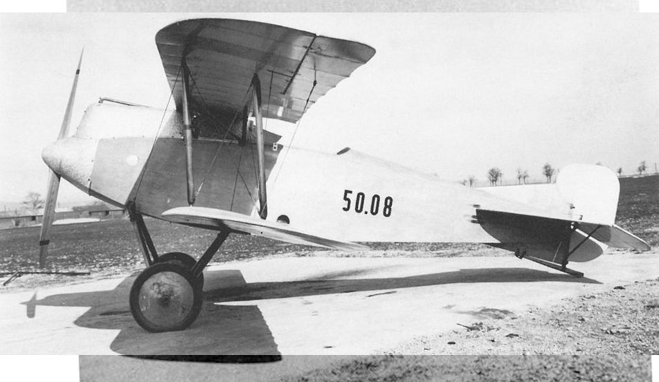
The Oeffag 50.08 (first version) with small fin. Saliger took pains to design a compact, uncluttered airframe with a minimum of bracing and struts that was reminiscent of a single-seat fighter.
Oeffag 50.08 in Wr. Neustadt, Werksflugfeld 1917, Aufklärerprototyp, Konstruktion Ing. Saliger
Oeffag 50.08 в Wr. Нойштадт, заводской аэродром 1917 г., прототип разведчика, конструктор Салигер
Oeffag 50.08 in Wr. Neustadt, Werksflugfeld 1917, Aufklärerprototyp, Konstruktion Ing. Saliger
Oeffag 50.08 в Wr. Нойштадт, заводской аэродром 1917 г., прототип разведчика, конструктор Салигер
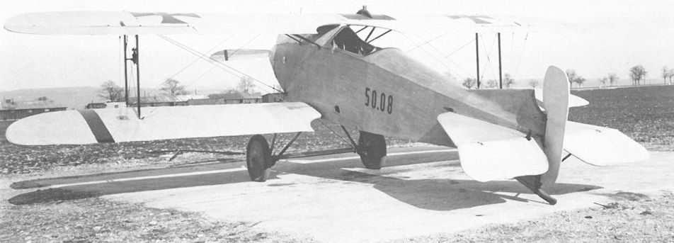
The Oeffag 50.08 (first version) prior to the maiden flight in February-March 1917. The airfoil radiator was unusual for an Austro-Hungarian two-seat aircraft.
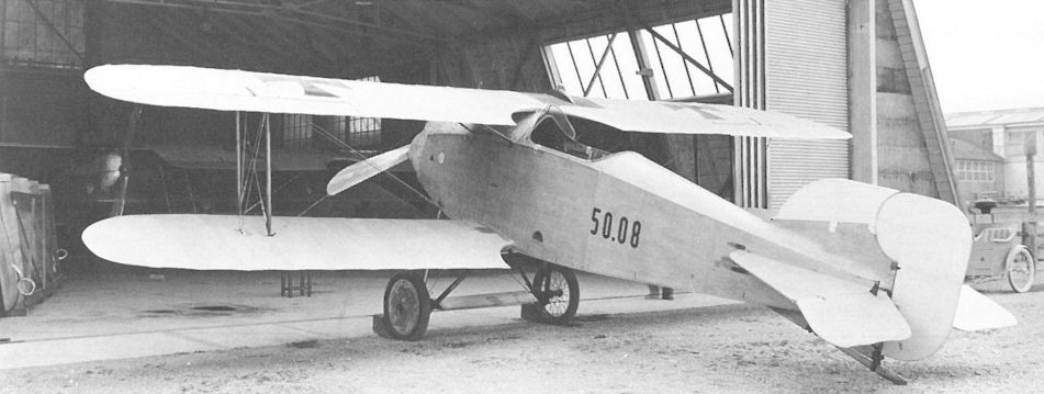
The Oeffag 50.08 (second version) fitted with a temporary tail fin of increased area and a new wing cellule, July 1917. As customary with prototypes, the observer’s gun ring remains to be installed.
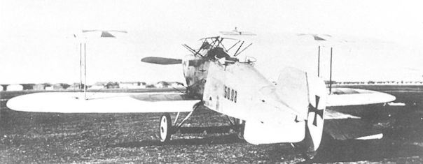
Oeffag 50.08 (third version) underwent major modification. The cabane section was opened to improve the pilot’s view, and a new fin and rudder were installed. The photograph at left was taken in August-September 1917.

The Oeffag 50.08 (third version) was flight-tested in September 1917, demonstrating high speed but mediocre flight characteristics.
The Oeffag 50.09 prototype during final assembly in June 1917. Here it shares the large assembly hangar with the Oeffag K 423 flying boat and early production Albatros D.III(Oef) series 153 fighters.
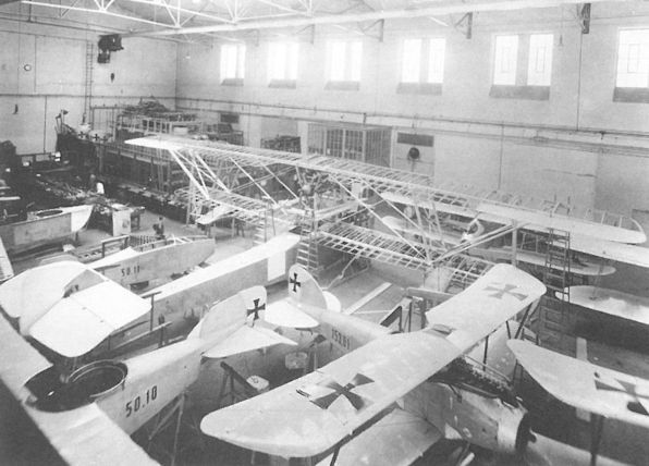
The death of Saliger and Matti in the crash of the Oeffag 50.10 prototype on 16 July 1917 effectively put an end to the Type AF program. The Oeffag 50.11 fuselage under construction is in the background and the completed 50.09 is behind the wings of the K 423 flying boat.
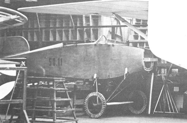
The unfinished Oeffag 50.11 awaiting completion in the factory. This prototype crashed on 4 April 1918, killing both occupants.
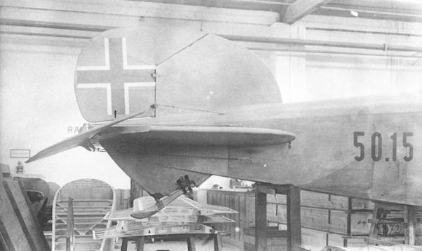
The only known photograph provides a tantalizing glimpse of the Oeffag 50.15 prototype, here under construction in October 1918.
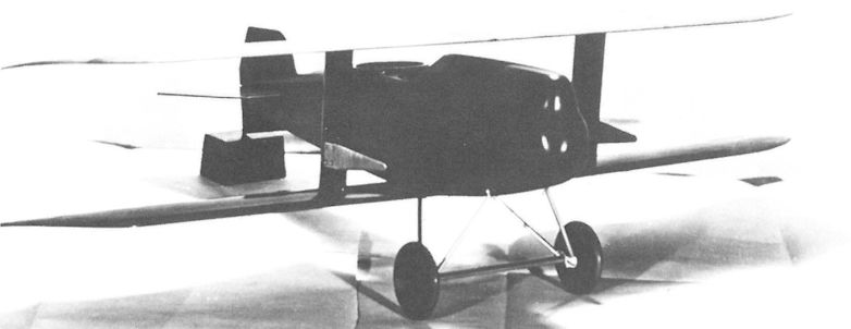
Wind tunnel model of the Oeffag Type AF tested in January 1917.

Oeffag 50.08
Oeffag 50.03
The 50.03 prototype, powered by a 160 hp Daimler engine, made its appearance in early 1916. It was similar to the Oeffag C.I but slightly smaller and fitted with a simplified two-bay wing cellule. When the wing failed to pass the static load tests, the prototype was written-off and replaced by a second 50.03 in April 1916.
Regarded as the C.II series 52 prototype, the second 50.03 was fitted with a constant-chord wing of reduced span, rigged without sweepback or stagger. Flight tests of the 160 hp Daimler-powered prototype commenced in May 1916 at Aspern. The aircraft was rammed on the ground on 30 June 1916, interrupting the flight tests. Series production, which had been halted in April to await the test results, was further delayed while repairs were carried out. Testing was completed in August and the second 50.03 was accepted by the LFT on 7 October 1916. Serving as a trainer, the 50.03 was still in service in November 1917.
Engine: 160 hp Daimler
Wing: Span Upper 12.71 m (41.69 ft)
Span Lower 11.82 m (38.78 ft)
Chord Upper 1.75 m (5.74 ft)
Chord Lower 1.75 m (5.74 ft)
Dihedral Upper 0 deg
Dihedral Lower 0.5 deg
Sweepback Upper 0 deg
Sweepback Lower 0 deg
Gap 1.58 m (5.18 ft)
Stagger 0 m (0 ft)
Total Wing Area 38 sq m (409 sq ft)
General: Length 9.05 m (29.69 ft)
Height 3.20 m (10.50 ft)
Empty Weight 834 kg (1839 lb)
Loaded Weight 1298 kg (2862 lb)
Maximum Speed: 144 km/hr (89.4 mph)
Climb: 1000m (3,281 ft) in 6 min 10 sec
3000m (9,843 ft) in 32 min
Oeffag 50.06
Design work on the 50.06 reconnaissance biplane began in September-October 1916. Powered by a 185 hp Daimler engine and reduced in size to increase performance, the 50.06 represented a refinement of the C.II airframe. After Flars engineers inspected the 50.06 in late December 1916, they urged Oeffag to proceed with utmost speed and proposed on 31 January 1917, that provided the flight testing was performed with dispatch, Lohner would also build the type under license. Trials in January-February 1917 demonstrated a respectable rate of climb and speed. After a tail fin recommended by Oberleutnant Oskar Fekete was fitted, the project was suddenly stopped for unknown reasons. No further development was undertaken.
Oeffag 50.06 Specifications
Engine: 185 hp Daimler
Wing: Span Upper 10.18 m (33.40 ft)
Span Lower 10.18 m (33.40 ft)
Chord Upper 1.57 m (5.15 ft)
Chord Lower 1.57 m (5.15 ft)
Dihedral Upper 0 deg
Dihedral Lower 1 deg
Sweepback Upper 0 deg
Sweepback Lower 0 deg
Gap 1.60 m (5.25 ft)
Stagger 0 m (0 ft)
Total Wing Area 29.5 sq m (318 sq ft)
General: Length 8.00 m (26.25 ft)
Height 2.80 m (9.19 ft)
Empty Weight 900 kg (1985 lb)
Loaded Weight 1205 kg (2657 lb)
Maximum Speed: 157 km/hr (97.5 mph)
Climb: 1000m (3,281 ft) in 4 min 8 sec
Oeffag 50.07
The Oeffag 50.07 prototype was a lightened C.II airframe (ex 52.82) fitted with a 200 hp Hiero engine for performance evaluation. The prototype made its appearance in February 1917 and remained under investigation until June, at which time the static load calculations were approved by Flars. The 50.07 demonstrated improved performance but the Oeffag C.II biplanes were unpopular with aircrews, making it inadvisable to proceed with a Hiero-engined version. After service with Flik 59/D and as a trainer with Schulkompagnie 2, the 50.07 was written-off in July 1918.
Oeffag 50.07 Specifications
Engine: 200 hp Hiero
Wing: Span Upper 12.71 m |41.69 ft)
Span Lower 11.82 m (38.78 ft)
Chord Upper 1.75 m (5.74 ft)
Chord Lower 1.75 m (5.74 ft)
Dihedral Upper 0 deg
Dihedral Lower 0.5 deg
Sweepback Upper 0 deg
Sweepback Lower 0 deg
Gap 1.58 m (5.18 ft)
Stagger 0 m (0 ft)
Total Wing Area 38 sq m (409 sq ft)
General: Length 9.05 m (29.69 ft)
Height 3.27 m (10.73 ft)
Useful Load 420 kg (926 lb)
Loaded Weight 1240 kg (2734 lb)
Maximum Speed: 162 km/hr (101 mph)
Climb: 1000m (3,281 ft) in 5 min
Oeffag C.II Series 52 and 52.5
Oeffag signed a production contract on 8 February 1916 to supply 32 C.II reconnaissance biplanes, numbered 52.01 to 52.32 and powered by the 160 hp Daimler engine. Production, scheduled for completion by 30 April 1916, was interrupted in April to await the flight test results of the second 50.03 prototype. It was not until August 1916, after the damaged 50.03 was repaired and tests concluded, that C.II production resumed. The first nine series aircraft were accepted in October 1916. Because the C.II failed to meet performance specifications, Oeffag was assessed a penalty payment.
Although the Oeffag C.II represented a considerable design refinement over the C.I, its performance (especially climb) and maneuverability were below expectations. The C.II series 52 aircraft were dispatched to the Russian Front to serve singly with Fliks 3, 5, 13, 14, 18, 20, 22, 25, 27, and 30, replacing the older Aviatik types. They were used mainly for close reconnaissance and radio spotting, whereas the Brandenburg C.I, with its superior altitude and climb performance, was preferred for long-range work.
Production was already under way when, on 4 December 1916, Flars ordered a second batch of 32 Oeffag C.II biplanes, numbered 52.50 to 52.81. The type was known as the "lightened series 52," the modifications of which had been tested in the Oeffag 50.07 prototype. Although a 185 hp Daimler engine was specified, operational records show that most of the C.II series 52.5 aircraft were flown with 160 hp engines installed. Deliveries, scheduled to commence in October and end on 28 November 1916, did not begin until February 1917 and ended in June. The C.II series 52.5 aircraft were assigned to Fliks 5, 11, 13, 18, 22, and 26 on the Russian Front, to Fliks 31, 36, and 44 on the Rumanian Front, and Flik 6 in Albania.
Structurally, the C.II was designed for efficient production and ease of rigging. But in the field the type was roundly criticized. Flik 18 reported that "the observer's cockpit is too small and provides insufficient space for ammunition, bombs, camera, map cases, carbine, machine gun, and flare pistol. The aircraft has sluggish controls and is unsuited for combat. The flat glide and high landing speed are a disadvantage on small airfields." Other Fliks criticized the poor visibility, indifferent maneuverability, slow speed, and the weak plywood-covered fuselage. Beginning 1917, the older C.II aircraft, some modified for dual control, were assigned to various Fliks and Fleks as advanced trainers. In August 1918, six C.II trainers were at the Front and 14 flew military airmail routes. After the war, a few were seen in Polish and Czechoslovakian military service.
Oeffag C.II Series 52 Specifications
Engine: 160 hp Daimler
Wing: Span Upper 12.71 m (41.70 ft)
Span Lower 11.82 m (38.78 ft)
Chord Upper 1.75 m (5.74 ft)
Chord Lower 1.75 m (5.74 ft)
Dihedral Upper 0 deg
Dihedral Lower 0.5 deg
Sweepback Upper 0 deg
Sweepback Lower 0 deg
Gap 1.58 m (5.18 ft)
Stagger 0 m (0 ft)
Total Wing Area 38 sq m (409 sq ft)
General: Length 8.40 m (27.56 ft) less propeller
Height 3.27 m (10.73 ft)
Track 2.22 m (7.28 ft)
Loaded Weight 1205 kg (2657 lb)
Maximum Speed: 140 km/hr (87 mph)
Climb: 1000m (3,281 ft) in 6 min 19 sec
3000m (9,843 ft) in 28 min
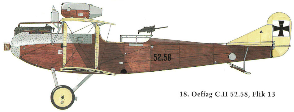
Oeffag C.II 52.58, Flik 13
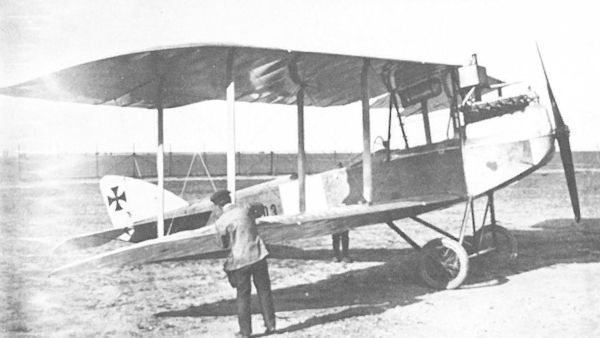
The first Oeffag 50.03 prototype had the banana-shaped wing of the Oeffag C.I but configured in a simplified two-bay cellule. The fuselage cross insignia remains to be applied.
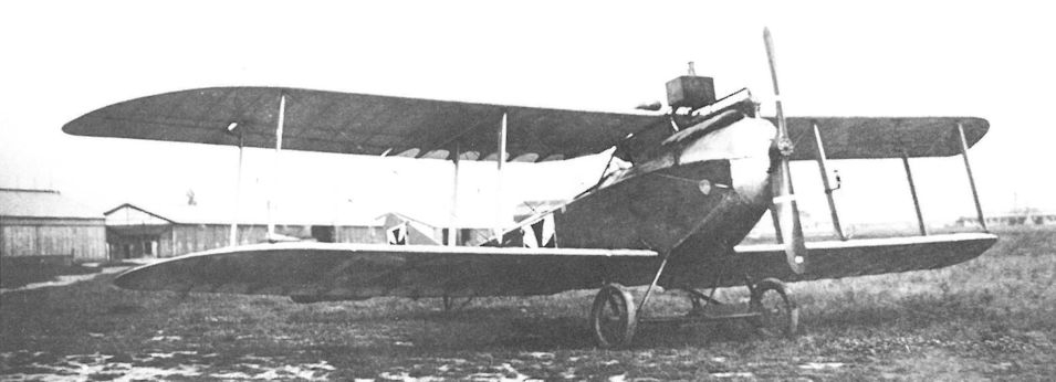
The second Oeffag 50.03 prototype showing the slanted wing struts. The Oeffag 50.03 became the prototype for the Oeffag C.II series 52 production aircraft.
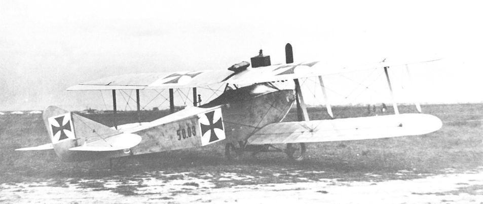
The second Oeffag 50.03 prototype at Aspern in May 1916. It was fitted with straight, constant-chord wings. As customary the observer’s machine-gun ring remains to be installed pending results of flight tests.
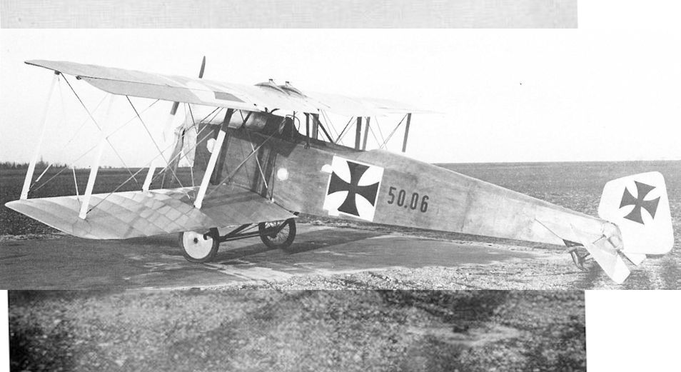
Oeffag 50.06 prototype. The twin airfoil radiators, the faired interplane struts, and the fully-cowled engine are evidence of the designer’s preoccupation with drag reduction.
Oeffag 50.06 in Wr. Neustadt. Werksflugfeld 1917, Versuchsflugzeug mit geänderter Tragflächen- und Leitwerksanordnung, Rumpf Ba 52
Oeffag 50.06 в Wr. Нойштадт. Заводской аэродром 1917 г., экспериментальный самолет с измененным крылом и оперением, фюзеляж Ba 52
Oeffag 50.06 in Wr. Neustadt. Werksflugfeld 1917, Versuchsflugzeug mit geänderter Tragflächen- und Leitwerksanordnung, Rumpf Ba 52
Oeffag 50.06 в Wr. Нойштадт. Заводской аэродром 1917 г., экспериментальный самолет с измененным крылом и оперением, фюзеляж Ba 52
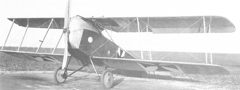
Based on the Oeffag C.II, the smaller 50.06 prototype, although showing acceptable speed and climb, was not placed into production.
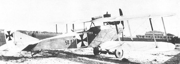
The Oeffag 50.07 was a lightened C.II airframe fitted with a 200 hp Hiero engine for performance and flight evaluation. Photographed on the Wiener-Neustadt airfield.
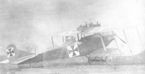
The Oeffag C.II 52.02 was fitted with an experimental, raised machine gun turret, barely discernible in this poor quality, but rare, photograph.
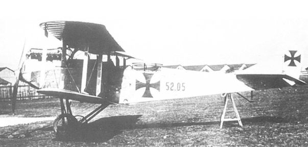
Oeffag C.II 52.05 was unique in that it was fitted with an unbalanced elevator, a feature not seen on other production machines. The tripod tailskid is characteristic of the first production batch. It was attached to Flik 18 from December 1916 to April 1917.
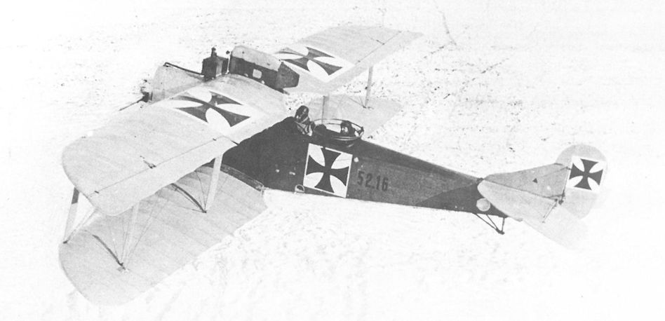
Oeffag C.II 52.16 on the snow-covered airfield of Flik 18, February 1917. The constant-chord wing facilitated production and the lack of sweepback and stagger simplified rigging. Forward armament was provided by a Type II VK gun canister.
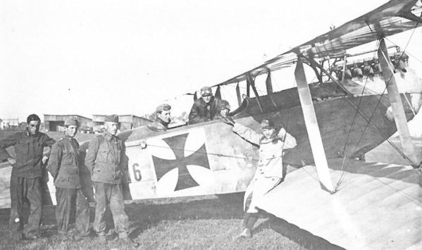
The unarmed Oeffag C.II 52.16, possibly fitted with dual controls, served as an advanced trainer with Flik 22/D in Kolomea, July 1917.
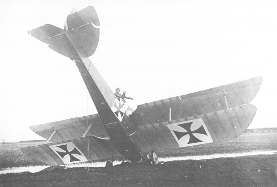
A minor mishap provides Oeffag C.II 52.21 the opportunity to show the slanted wing struts similar to those of the Brandenburg C.I. A narrow trapdoor in the observer’s cockpit was used to drop small bombs. The aircraft flew with Flik 14/D from January through October 1917.

The brand-new Oeffag C.II 52.57 posing on the Oeffag airfield, here fitted with a winter cowling, shows off its elegant lines. The sprung tailskid was the primary identification feature of the second production series.
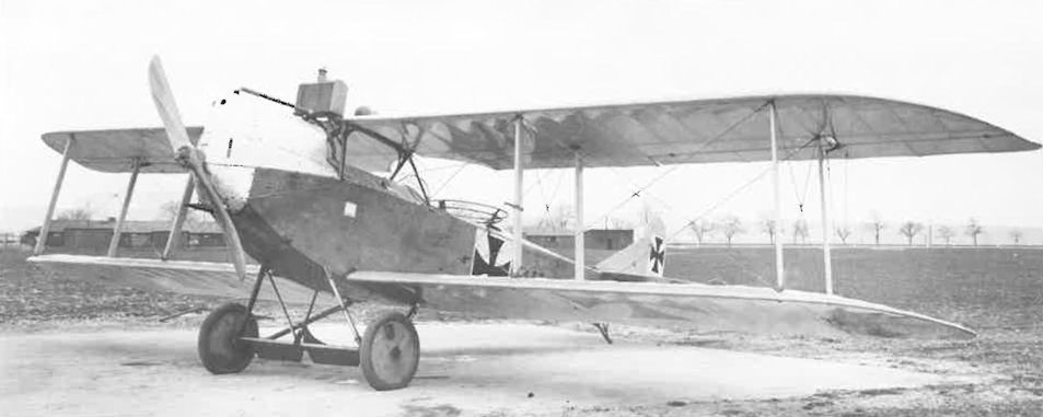
Oeffag C.II 52.67 with winter engine cowling installed. The undercarriage was fitted with a claw brake and axle flaps that were free to rotate in the slipstream. The aircraft was assigned to the training command in August 1917 and the airmail unit in June 1918.
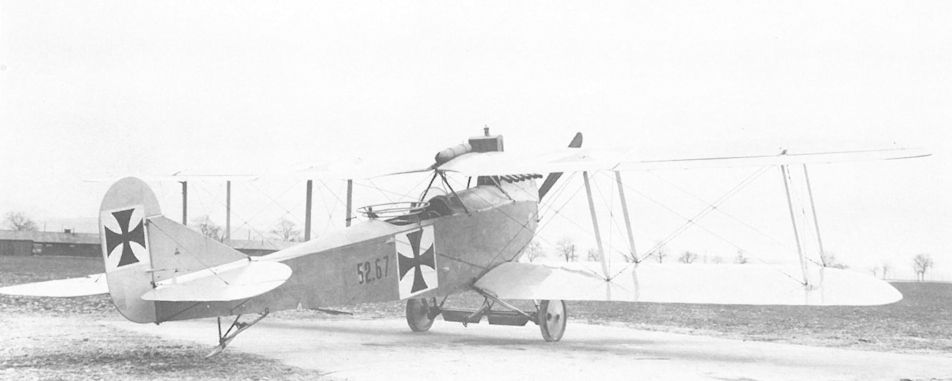
On the factory airfield, the Oeffag C.II 52.67 shows the unusual, high aspect-ratio ailerons and the sprung tail skid. The rudder and elevator control cables were located on the outside of the fuselage.
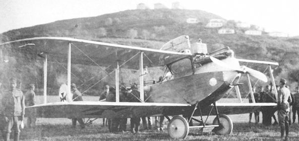
The Oeffag C.II series 52.5(6) biplane was flown by Flik 6 in Skutari, Albania in 1917. The platform beneath the propeller hub was a mount for the belt-driven wireless generator. The round bulge below the observer’s cockpit is the aluminum compass housing.
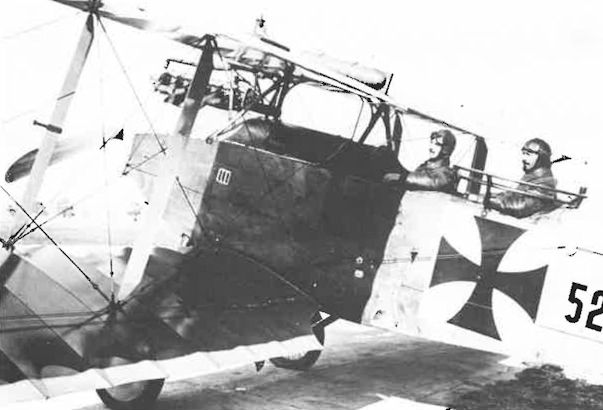
The close-up photo of an Oeffag C.II series 52 biplane gives evidence of the exposed seating and the narrow fuselage that aircrews criticized after the type reached the Front.
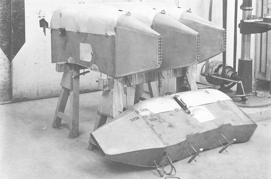
Type II VK canisters awaiting installation at the Oeffag factory. The canister in front, intended for the Oeffag C.II 52.56, shows the gravity tank connection and the mounting studs.
The neat arrangement in the assembly hall reflects the craftsmanship for which Oeffag aircraft were renowned. In the far left, the Albatros D.III(Oef) 53.21 production prototype awaits propeller installation, while in the far right the D.II(Oef) 53.06 and D.III(Oef) 53.20 are nearing completion. In the foreground, Oeffag C.II series 52.5 biplanes under assembly. The date is February 1917.
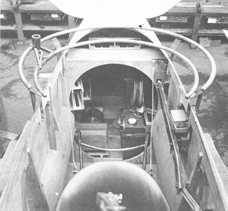
Shown on an Oeffag C.II biplane, the tubular-ring turret was fitted to all two-seaters until replaced by wooden gun rings in late 1918. Light in weight, the ring provided ample flexibility and was easy to operate. The triangular slide held the socket for the machine gun and a simple locking clamp prevented movement.
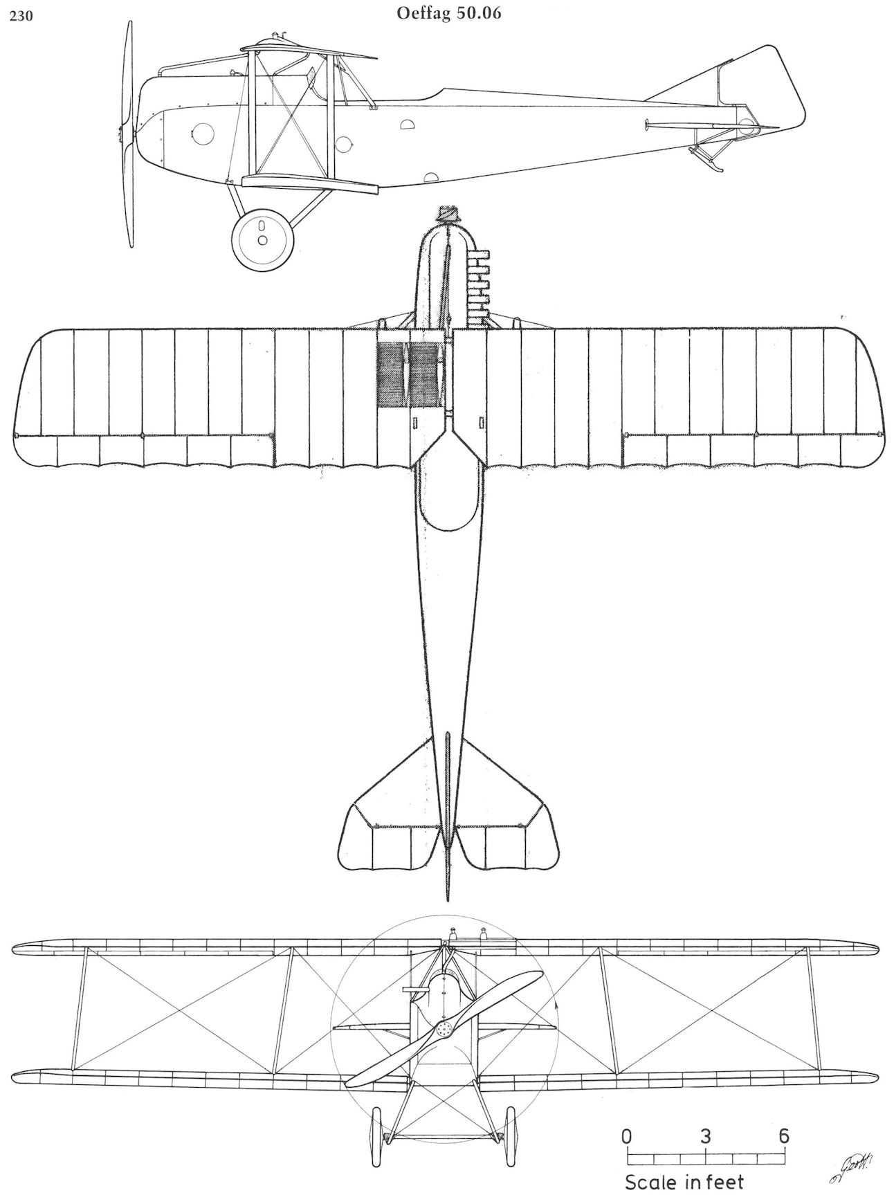
Oeffag 50.06
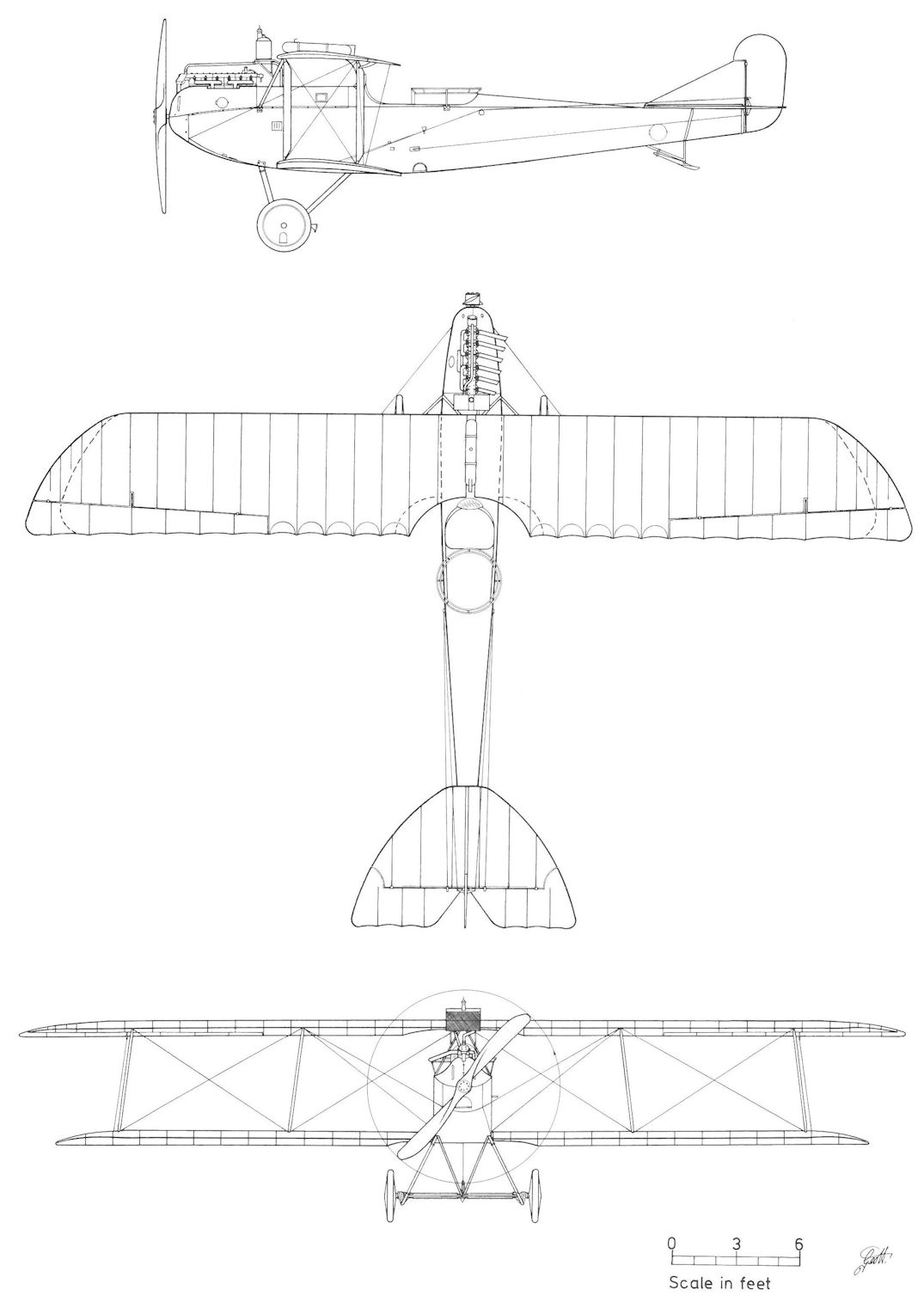
Oeffag C.II Series 52.5
Oeffag 50.04 and 50.05
In early 1916, Oeffag submitted a proposal for a biplane bomber powered by two buried 150 hp engines connected to a common gearbox driving two wing-mounted propellers. The project remained under consideration until August 1916 when it was shelved. In May 1916, Oeffag became the third company to join the "large bomber program" along with Lloyd and Phonix when it received a contract to build two triplane bombers, designated 50.04 and 50.05. The fuselage and wing panels, based on the Lloyd 40.08 layout, were already completed and the first prototype was expected in early July 1916. However, that month work was halted owing to the serious faults uncovered in the 40.08 design. Flars was hopeful the program could be revived in May 1917, but when the 40.08 modifications proved unsuccessful, all work was stopped. The unfinished 50.04 and 50.05 airframes were sent to Eger for storage in January 1918.
In early 1916, Oeffag submitted a proposal for a biplane bomber powered by two buried 150 hp engines connected to a common gearbox driving two wing-mounted propellers. The project remained under consideration until August 1916 when it was shelved. In May 1916, Oeffag became the third company to join the "large bomber program" along with Lloyd and Phonix when it received a contract to build two triplane bombers, designated 50.04 and 50.05. The fuselage and wing panels, based on the Lloyd 40.08 layout, were already completed and the first prototype was expected in early July 1916. However, that month work was halted owing to the serious faults uncovered in the 40.08 design. Flars was hopeful the program could be revived in May 1917, but when the 40.08 modifications proved unsuccessful, all work was stopped. The unfinished 50.04 and 50.05 airframes were sent to Eger for storage in January 1918.
Oeffag 50.13
As soon as the massive 360 hp six-cylinder Daimler inline engine became available for flight tests, aircraft manufacturers were encouraged to design appropriately large reconnaissance and bomber biplanes carrying a crew of two or three. Professor Knoller began wind tunnel investigation in June 1917 to choose the airfoil for the 50.13 (Type BF) prototype. The 50.13, a private venture undertaking, was ready for engine installation in February 1918, but because of production delays the engine did not arrive until May. Final installations, including fixed machine gun and camera, were completed in July. Flight test report no.14 (13 August 1918) recorded that Oeffag test pilot Leutnant Alois Stiploschek and passenger attained a top speed of 130 km/h (81 mph) and reached 4000 meters (13,124 ft) in 58.5 minutes. The engine, which is known to have been experiencing developmental problems, was probably responsible for the poor performance. On 10 September 1918, the 50.03 was on its 18th test flight when the engine failed. With great skill, test pilot Stiploschek executed an emergency landing in a vineyard near Felixdorf. Fortunately no one was injured, but the prototype was destroyed, effectively putting an end to the development program.
Oeffag 50.13 Specifications
Engine: 360 hp Daimler
Wing: Span Upper 12.30 m (40.35 ft)
Span Lower 12.30 m (40.35 ft)
Chord Upper 1.60m (5.25 ft)
Chord Lower 1.60 m (5.25 ft)
Dihedral Upper 0 deg
Dihedral Lower 0 deg
Sweepback Upper 0 deg
Sweepback Lower 0 deg
Gap 1.60 m (5.25 ft)
Total Wing Area 36.96 sq m (398 sq ft)
General: Length 9.17 m (30.08 ft)
Height 3.18 m (10.43 ft)
Track 2.00 m (6.56 ft)
Empty Weight 1170 kg (2580 lb)
Loaded Weight 1740 kg (3837 lb)

The massive Oeffag 50.13 prototype photographed in July or August 1918. To support the airframe weight, twin wheels have been installed. The imposing biplane was designed to fulfill the LFT long-range reconnaissance requirement.
Oeffag 50.13 in Wr. Neustadt. Werksflugfeld 1918, Langstreckenaufklarer mit dem neuen 360 PS-Sechszylinder von Austro-Daimler
Oeffag 50.13 в Wr. Нойштадт. Заводской аэродром 1918 г., дальний разведчик с новым шестицилиндровым двигателем мощностью 360 л.с. от Austro-Daimler
Oeffag 50.13 in Wr. Neustadt. Werksflugfeld 1918, Langstreckenaufklarer mit dem neuen 360 PS-Sechszylinder von Austro-Daimler
Oeffag 50.13 в Wr. Нойштадт. Заводской аэродром 1918 г., дальний разведчик с новым шестицилиндровым двигателем мощностью 360 л.с. от Austro-Daimler

The massive Oeffag 50.13 prototype photographed in July or August 1918. To support the airframe weight, twin wheels have been installed. The imposing biplane was designed to fulfill the LFT long-range reconnaissance requirement.
A formidable lineup of seven Albatros D.III(Oef) series 253 fighters during acceptance testing at the factory. The furthest aircraft is the Oeffag 50.13 prototype.

Oeffag 50.13
Oeffag 50.14
The construction of the Oeffag 50.14 (Type CF) triplane fighter was underway in late 1917 and a 225 hp Daimler engine was installed in the completed airframe in April 1918. During flight testing, about which information is sparse, the two-piece upper wing was replaced by a one-piece wing and the elevator area was increased. The 50.14, now powered by a 200 hp Daimler engine, appeared at the Fighter Evaluation at Aspern in July 1918. Having neither performance nor maneuverability to commend it, the large triplane aroused no enthusiasm and the project was dropped.
Oeffag 50.14 Specifications
Engine: 225 hp Daimler
Wing: Span Upper 8.40 m (27.56 ft)
Span Middle 8.40 m (27.56 ft)
Span Lower 8.40 m (27.56 ft)
Chord Upper
Chord Middle 1.20 m (3.94 ft)
Chord Lower 0.90 m (2.95 ft)
Dihedral Upper 0 deg
Dihedral Middle 1 deg
Dihedral Lower 1.33 deg
Sweepback Upper 0 deg
Sweepback Middle 0 deg
Sweepback Lower 0 deg
Gap Upper 1.130 m (3.71 ft)
Gap Lower 0.850 m (2.79 ft)
Stagger Upper 0.479 m (1.57 ft)
Stagger Lower 0.155 m (0.51 ft)
Total Wing Area 23.8 sq m (256 sq ft)
General: Length 6.40 m (21.00 ft)
Height 2.98 m (9.78 ft)
Track 1.55m (5.09 ft)
Loaded Weight 970 kg (2139 lb)

In its original state, the unarmed Oeffag 50.14 prototype was tested with a two-piece upper wing. May 1918.

The modified Oeffag 50.14 showing the one-piece upper wing and larger elevator. The underside of the lower wing tip was fitted with protective skid pads to prevent damage in case of a ground loop.

The modified Oeffag 50.14, fully armed and fitted with additional cooling louvres on the engine cowl, in July 1918.

Oeffag test pilot Alois Stiploschek having his chin chucked in front of the Oeffag 50.14. The test pilots serve to emphasize the prototype’s bulk.

Oeffag 50.14
Austro-Hungarian Helicopter Development
The concept of a vertical aircraft or helicopter (Hubschrauber) began to challenge the imagination of Austro-Hungarian scientists toward the end of the 19th century. Noteworthy are the investigations of Josef Popper-Lynkeus, Anton Jarolimek, Professor Georg Wellner, and Wilhelm Kress. In 1894, Wellner experimented with a rotating-wing model that achieved a lift coefficient of 15 kg per horsepower. Kress built a small 33 kg model with counter-rotating propellers powered by an electric motor. In 1895 his associate, Dr. Waechter, successfully demonstrated the model indoors and out to the Technical Military Committee. Subsequently, Kress proposed a man-carrying helicopter weighing 325 kg driven by a 20 hp engine. From these rough beginnings, ideas were generated that would find their realization in time of war.
Major Stephan Petroczy von Petrocz, the commander of the Lehr Bataillon in Wiener-Neustadt, conceived the idea of replacing the hydrogen-filled observation balloon by a motor-driven helicopter. To this end, in April 1916, he met with Austro-Daimler director and chief engineer Ferdinand Porsche, several of his assistants, and Oeffag director Karl Ockermuller and Diplom-Ingenieur Karl Balaban to discuss the feasibility of building such an aircraft. The result was that Petroczy submitted a proposal to the LFT command on 28 April 1916, calling for development of a captive (tethered) helicopter for use as a static observation platform. The advantages cited were: less danger of fire, less conspicuous and smaller target while aloft, increased operational readiness, elimination of expensive hydrogen generating equipment, and fewer ground-handling personnel required. The belief that, compared to a balloon, the tethered helicopter was more resistant to wind shear was an optimistic dream.
Power was to be supplied by a 300 hp electro-motor that Daimler was developing for aircraft use. The war ministry approved the project on 5 May 1916. Oeffag was funded to build several experimental, rotating test rigs and to investigate the operating parameters of large-diameter airscrews or rotors. It soon became apparent that the key to success lay in developing a high-efficiency airscrew. The best available had an efficiency of 61 percent, whereas 90 percent or better was required. Balaban moved to Fischamend to work with Leutnant Oskar von Asboth in Professor Knoller's propeller test facility. The result was the perfection of large helicopter rotors up to 8 meters (26.2 ft) in diameter using the highest quality mahogany and yielding a 90-95 percent efficiency.
Eager to proceed, the Fliegerarsenal (Flars) issued specifications calling for a tethered helicopter carrying one observer and a large parachute for the entire aircraft. An operating altitude of 500 to 1000 meters (1,640-3,281 ft) in wind conditions up to 14 knots was required. The empty weight was estimated at 580 kg, plus the weight of the tethering cable (1000 meters at 150 kg) and the vertical wind component on the cable (230 kg) brought the total weight to 960 kg. With an estimated lifting force of 1200 kg, the reserve lift of 240 kg was deemed sufficient for one machine gun, camera, and telephone. Writing in 1922, Balaban felt that such rigid specifications hampered development. It would have been wiser to complete the propeller-rotor development and experiment with flying models first and then write the specification based on experienced! At the time the helicopter work was beginning to bear fruit, Petroczy was promoted to command Flars (mid-1917), enabling him to divert additional funds into his pet project. He proposed building two manned, and two smaller, unmanned helicopters of different configuration.
PKZ 1 Helicopter
Oberleutnant Dr. Theodor von Karman (later of Cal Tech fame) and Ingenieurleutnant Wilhelm Zurovec, both attached to Flars, were assigned the task of constructing a prototype helicopter applying the latest information from the propeller laboratory. Eschewing endless theoretical calculations, Karman and Zurovec proceeded with empirical trials. As first envisaged, the tethered helicopter had 10 to 12 lifting rotors arranged in a circle, but the problem of weight and complexity reduced the final choice to a four-rotor design. After testing rubber-band powered models without success, Zurovec conceived a unique compressed air motor (weighing 4 kg and developing 6 hp at 2400 rpm) which enabled him to construct a 35 kg flying model. Starting in June 1917, flight tests explored various stabilizing surfaces, center of gravity shift, and rotor configurations. Unable to achieve dynamic stability with one or two tethering cables, Karman and Zurovec found that a three-cable system gave the best results. A further 50 flights, ranging in height from 10 to 15 meters, were performed in the great balloon hangar at Fischamend between July 1917 and March 1918.
Meanwhile, on 21 August 1917, the MAG company in Matyasfold had been given the task of building a full-scale, manned helicopter based on the Karman-Zurovec model work. Having little financial incentive and directed by the military bureaucracy, MAG progress was slow, to some degree due to late delivery of the Daimler electro-motor. Completion, scheduled for October, did not occur until February 1918. The aircraft, called a Schraubenfesselflieger (SFF - rotor-driven tethered aircraft) was identified in post-war literature as the Petroczy-Karman-Zurovec PKZ 1. The design was patented jointly by Karman and Zurovec (German patent 346,425, dated 28 June 1917). Karman remained as project director, but it appears that Zurovec began work on his own PKZ 2 helicopter project in November 1917. The PKZ 1 motor weighed 195 kg and produced 190 hp at 6000 rpm - 60 hp less than projected because the winding insulation was of inferior quality. In flight, power would have been transferred by an aluminum cable 800 meters long. On the first test in Fischamend (date unknown), the PKZ 1 (empty weight 650 kg) took off with surprising abruptness at a rotor speed of 700 rpm and rose to the maximum tethered height of 50 cm. Next, three men climbed aboard and the helicopter easily hovered at the limit of the restraining cables. After 15 minutes into the fourth flight, the over-burdened motor burned through. With high-grade electrical copper and quality insulation impossible to obtain, Daimler was unable to repair the motor. Since the private initiative of Liptak had sped the PKZ 2 to completion, the PKZ 1 was transferred to the Liptak factory but, lacking a motor, nothing was done. Nevertheless, the PKZ 1 had demonstrated the feasibility of an electric-powered helicopter as predicted by the model tests in Fischamend.

Вертолет PKZ-1, 1917г.
The PKZ 1 tethered helicopter had four counter-rotating rotors driven at 800 rpm through bevel gears by a central electro-motor located beneath the observer’s cockpit. Initially, the rotors were 3.9 meters, and later 4.2 meters, in diameter.
The PKZ 1 tethered helicopter had four counter-rotating rotors driven at 800 rpm through bevel gears by a central electro-motor located beneath the observer’s cockpit. Initially, the rotors were 3.9 meters, and later 4.2 meters, in diameter.

Testing the PKZ 1 in February 1918 at the MAG factory in Matyasfold. In flight, the tethering cables would have been attached to both ends of the airframe and to an arm extended from the center section.

Test rig for evaluating the Austro-Daimler electric motor that was originally developed for fixed-wing aircraft and used in the PKZ 1 helicopter.

The final version of the PKZ 1 model, with twin rotors spinning at 1200 rpm just before lift-off in front of the Pischamend propeller windtunnel. The compressed air motor was driven at 50 atm pressure supplied by 100 compressed air cylinders. The model is approximately 2.36 meters long. A miniature observer and machine gun can be seen in the central turret.

The Oeffag helicopter test rig designed and built by Balaban in 1916. The drag of the biplane rotators must have been prohibitively high in relation to the lift generated. The drawing was made from a contemporary magazine photograph.
PKZ 2 Helicopter
The Petroczy-Karman-Zurovec PKZ 2 helicopter, despite its name, was invented by Wilhelm Zurovec for which he alone received German patent No.347,578, dated 12 February 1918. Unlike the PKZ 1, which was government funded, the PKZ 2 was privately financed by the Hungarian Bank and the firm of Dr. Liptak & Co AG, a large iron foundry and steel fabricator located near Budapest which established an experimental section under Zurovec's direction in late 1917.
In the design of the PKZ 2 helicopter, Zurovec incorporated the concept of using counter-rotating rotors to cancel torque effects. Each rotor, with a diameter of 6 meters (19 ft 8 in), represented an ingenious combination of old-world craftsmanship with modern applied engineering. Power was supplied by three 100 hp Gnome rotary engines, that drove the rotors at 600 rpm through a common gearbox. The light, tubular airframe, easily disassembled for transport, rested on a patented central air-bag cushion (1 meter diameter) and three smaller cushions mounted on the outriggers. The cushions were kept inflated by an air pump attached to the rotor drive. Three tethering cables affixed to the outriggers ran through pulleys anchored in the ground and were controlled by separate, electric winches. The total weight of the PKZ 2 with fuel for one hour, but without observer and machine gun, was approximately 1200 kg. Two forms of parachute rescue were planned. One was to carry the observer and aircraft safely to earth, and the other was a cannon-launched parachute that would clear the rotors and lift the observer to safety.
The PKZ 2 was test flown for the first time at the Liptak factory on 2 April 1918. After several flights, one lasting up to one hour, tests were suspended on 5 April because engine power was insufficient to permit safe hovering above 1.2 meters height. The Gnome engines were replaced by three 120 hp Le Rhones. Flight testing continued from 17 to 21 May, during which flights between 10 and 50 meters altitude were recorded. During periods of calm weather and smooth engine operation, the excess lift measured at ground level was 150 to 200 kg. As the PKZ 2 climbed, the loss of ground effect and the increase in tethering cable weight steadily reduced the excess lift. Yet, as long as excess lift sufficed to maintain proper cable tension, the PKZ 2 remained in stable hovering flight. At higher altitudes, the excess lift became marginal, causing the machine to slowly oscillate with increasing amplitude. Provided the tethering cables were retracted at about 1,5 meters/second, the oscillations to cease in about 15 to 20 seconds.
On 10 June 1918, Zurovec was called upon to demonstrate the PKZ 2 for high ranking military authorities. Although the rotary engines had recently been overhauled, their operation the day before was erratic, and Zurovec, fearing the worst, was reluctant to proceed. But what could a mere Leutnant do against the weight of official brass eager to see the wonder machine fly? Taking advantage of the zero wind conditions, the PKZ 2 with the observer's basket in place took-off at 5:40 am and twice rose to 7-8 meters height, showing "considerable rocking motion." The basket was removed and the PKZ 2 took off again at 6:07 am in a wind of 6-7 meters per second, climbing to a height of 12 meters. Due to overheating, the engine power dropped off and the helicopter began to pitch with increasing frequency until the tether-winch crew could no longer control the machine. The PKZ 2 crashed from two meters height, severely damaging the airframe and splintering the rotors. In a careful review of progress to date, Uzelac, realizing that the technical problems were too complex to resolve quickly, cancelled the project on 21 June 1918. Zurovec, Karman, and Liptak were directed to compile a record that would be a basis for further investigation when peace returned. Zurovec, refusing to accept defeat, devised a method to water-cool the rotary engines! He reported on 1 September that the PKZ 2 helicopter would be ready for further testing on 1 November 1918. By then it was too late.
Karman-Zurovec Remote-Control Helicopter
An unmanned helicopter design based on the Karman-Zurovec concept was proposed in September 1917. Driven by an electric motor, it was designed to carry aloft meteorological instruments and wireless equipment for gathering weather data and communicating in mountainous areas. Flars reported that the remote-control helicopter, now powered by a single Gnome rotary engine, would be ready for flight testing in mid-February 1918. Further information is lacking.

Первый взлет вертолета PKZ 2, 4.8.1918.
The PKZ 2 aloft on 5 April 1918 at the Liptak factory grounds, the onlookers braced against the downdraft. The designer, Wilhelm Zurovec, is shown reaching for one of the pneumatic landing cushions. After this flight more powerful Le Rhone rotary engines were installed.
The PKZ 2 aloft on 5 April 1918 at the Liptak factory grounds, the onlookers braced against the downdraft. The designer, Wilhelm Zurovec, is shown reaching for one of the pneumatic landing cushions. After this flight more powerful Le Rhone rotary engines were installed.

Вертолет PKZ 2 c 3-мя моторами Le-Rhone 120 h.p. В корзине Zurovec.
The modified PKZ 2 after installation of three 120 hp Le Rhone engines, new pneumatic buffers, and a precarious observer’s basket shown here with Zurovec aboard. Although Karman claimed he flew the PKZ 2, no manned flights were performed.
The modified PKZ 2 after installation of three 120 hp Le Rhone engines, new pneumatic buffers, and a precarious observer’s basket shown here with Zurovec aboard. Although Karman claimed he flew the PKZ 2, no manned flights were performed.

The unmanned PKZ 2 fitted with the observer’s basket flying at an altitude of 25 meters. A total of 36 unmanned flights were made, some at heights up to 50 meters in low wind conditions.

Project drawing of an armored version of the PKZ 2 equipped to carry two observers and machine gun armament. The central console contained a parachute.

PKZ 2 Helicopter
Phonix 20.10
In response to the Kampflugzeug (battleplane) program of August 1914 (see Lloyd 40.06), Phonix submitted a proposal for a twin-engined biplane that, after further refinement, was approved by Flars in July 1915. Construction began in January 1916 and the completed aircraft, designated 20.10, was rolled out in September. The crew consisting of pilot and two gunners was housed in a narrow fuselage that had no provision for bombs. Two 200 hp Hiero engines were mounted on a framework independent of the wing structure and the fuselage was raised above the lower wing for aerodynamic reasons.
Test reports concerning the 20.10 prototype have not been found. Reviewing the program in December 1916, Flars could see no useful military function "for what was basically a 1914 design", but requested completion of modifications for purposes of testing and possible use as a trainer. Returned to the factory for installation of a strengthened undercarriage and rudders of increased area, the 20.10 was reported complete on 14 July 1917 and arrived at Aspern on 22 November 1917. Flight testing, if any, was of short duration, for in December the damaged prototype was placed in storage. The provisional order of 14 battleplanes, reduced from 24 in February 1916, was cancelled.
Phonix 20.11 and 20.12
The Phonix proposal for a triplane bomber configured to the Flars "large bomber program" guidelines (see Lloyd 40.08) was dated 3 March 1916. Phonix received a contract on 6 March 1916 to build two prototype bombers, designated 20.11 and 20.12. Designer Kirste had located the side fuselages between the lower wings, a more sensible approach than the awkwardly-placed fuselages of the Lloyd 40.08. At Flars' request to increase the field of fire, Kirste submitted an alternate layout with raised fuselages, but common sense prevailed and the original design was proceeded with - no doubt reflecting the lessons learned from the 40.08 ground tests. Construction of two bombers began in April 1916. Allowing work to continue on the 20.11 prototype, Flars however halted work on the 20.12 (nacelle and fuselages complete) in September 1916 and cancelled manufacturing plans by assigning the series 25 designation, originally reserved for the production bomber, to the Knoller C.I(Ph).
Construction of the 20.11 prototype went slowly. The final layout drawing dated February 1917 shows low side fuselages fitted with raised gunner's positions. A 300 hp Daimler V-12 pusher engine was mounted in the center nacelle and two 160 hp Daimler engines were installed in the side fuselages. A concerted effort to finish the 20.11 began in June 1917 but Flars, admitting its limited military value, cancelled the project in August, freeing Phonix to devote its energies to more important tasks. The unfinished 20.11 and 20.12 airframes were sent to the Eger depot in January 1918 for disposal.
Phonix 20.11 Specifications
Engine: 300 hp Daimler & 2 x 160 hp Daimler
Wing: Span Upper 24.00 m (78.74 ft)
Chord Upper 2.30 m (7.55 ft)
Chord Middle 2.30 m (7.55 ft)
Chord Lower 2.30 m (7.55 ft)
Gap Upper 1.50 m (4.92 ft)
Gap Lower 1.50 m (4.92 ft)
Total Wing Area ca 120 sq m (1291 sq ft)
General: Length 12.20 m (40.03 ft)
Empty Weight ca 2400 kg (5292 lb)
Loaded Weight ca 4800 kg (10,584 lb)
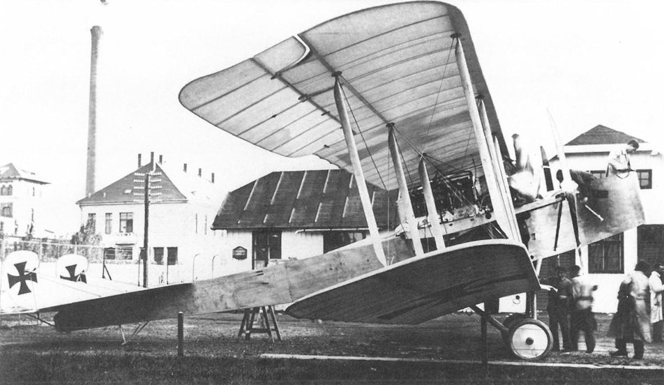
The Phonix 20.10 battleplane prototype photographed at the factory in September 1916. The long propeller drive shafts allowed the designers to place the engines near the center of gravity. The forward fuselage section has been indented to clear the propellers.
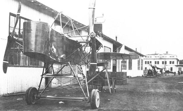
The just-completed Phonix 20.10 prior to being shipped to Aspern for test in late 1916. Photographs of the final version with reinforced undercarriage and larger rudders are not available.
The busy Phonix prototype assembly shop in 1917. In the middle background is a Knoller C.I(Ph) under assembly. The workman on the high scaffolding is holding the propeller of the 20.11 bomber. A flying boat is under construction on the far right, behind which the Phonix C.I prototype can be seen.
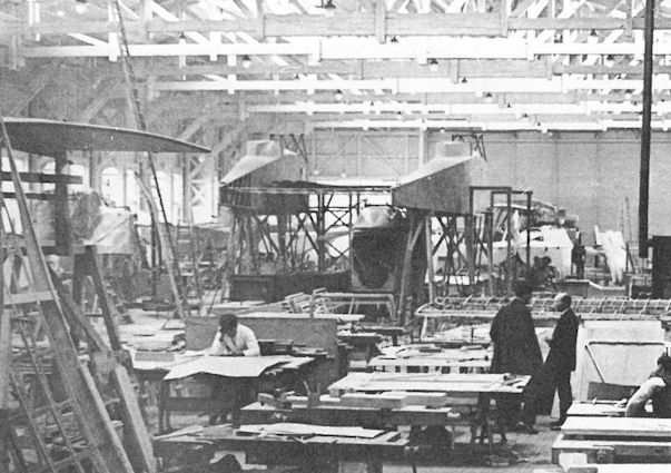
The Phonix 20.11 (or mock-up!) under construction in the Phonix factory. The height above the ground gives the impression that raised fuselages may have been considered at one time.
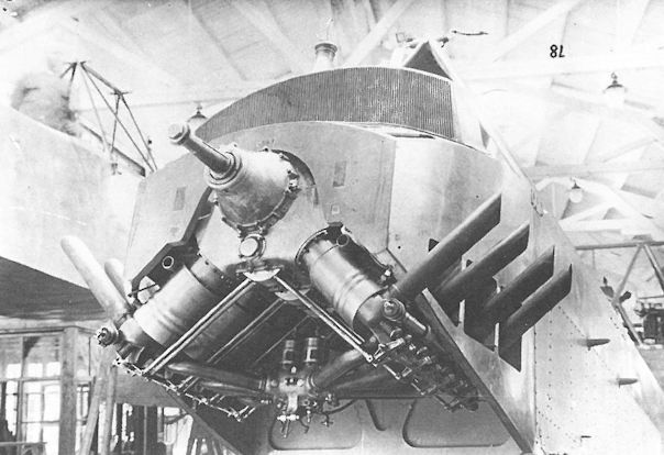
Other than this photograph of the 200 hp Hiero inverted V-8 engine installed in the Phonix 20.02 prototype, no photographs of the prototype have been found. The outer fuselage of the Phonix 20.11 bomber, that was never completed, is in the left background.
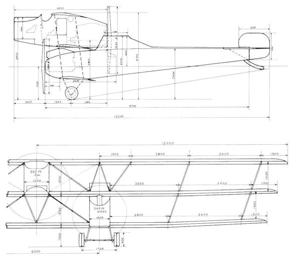
Project drawing of the Phonix 20.11 bomber prototype, signed by Kirste on 3 March 1916. Construction was started in April 1916 but the prototype was never completed.
Phonix 20.14
In late 1916, at a time when the first Phonix-built Brandenburg D.I fighters were under construction, Diplom-Ingenieur Kirste was already busy adapting a wireless Nieuport wing cellule to the airframe to improve the flight characteristics. The Nieuport sesquiplane configuration had made a deep impression on German and Austro-Hungarian engineers, but most were unaware that the design worked best with light, rotary-engined fighters because in-line engined versions were simply too heavy. The drawings and technical specifications for the "improved D.I" were finished in November 1916 and one month later, the prototype was rolled out. Kirste had modified a production D.I airframe (28.48) by raising the fuselage to the level of the upper wing, thereby eliminating the center-section struts. The area of the upper wing was increased. The narrow lower wing was supported by a single V-strut and a slanted fuselage brace. The 28.48 prototype, powered by a 185 hp Daimler engine, was tested by Hauptmann Karl Nikitsch. A crash on 16 January 1917 damaged the prototype before the trials were completed.
The rebuilt airframe, now designated 20.14, was fitted with a new, longer fuselage, modified ailerons and a redesigned tail. A pair of additional wing struts served to dampen vibration. Flight trials which began in June 1917 demonstrated speed superior to the production Brandenburg D.I(Ph) but the rate of climb was inferior to that recorded by the Sparmann-winged Phonix 20.15 prototype. In spite of structural simplicity, reduced drag and better visibility, Phonix soon jettisoned the sesquiplane concept in favor of Sparmann's more robust and efficient wing cellule.
On 20 August 1917, the 20.14, on loan to the Navy, was reported damaged by Linienschiffsleutnant Wenzel Wosecek during a night landing exercise at Trieste. Another crash was reported in October 1917, after which the 20.14 was repaired and, according to unconfirmed reports, sold to the Navy.
Phonix 20.14 (28.48) Specifications (First Version)
Engine: 185 Daimler
Wing: Span Upper 8.60 m (28.21 ft)
Span Lower 6.00 m (19.68 ft)
Chord Upper 1.70 m (5.58 ft)
Chord Lower 1.00 m (3.28 ft)
Dihedral Upper 0 deg
Dihedral Lower 2 deg
Sweepback Upper 0 deg
Sweepback Lower 0 deg
Gap 1.40 m (4.59 ft)
Total Wing Area 19.5 sq m (210 sq ft)
General: Length 6.30 m (20.67 ft)
Height 2.73 m (8.96 ft)
Track 1.72 m (5.64 ft)
Empty Weight ca 665 kg (1466 lb)
Loaded Weight ca 920 kg (2029 lb)
Phonix 20.16
In February 1917, Kirste designed an improved Nieuport wing cellule for the 20.16 fighter prototype. The wings were given a high-lift profile and refined wingtip contours. The upper wing was set lower on the fuselage for better visibility. The fuselage was taken from production airframe 28.73. In spite of using the more powerful 200 hp Daimler engine, the Phonix 20.16 did not demonstrate acceptable fighter characteristics when tested in April-May 1917, effectively putting a halt to development of the sesquiplane concept.
The 20.16 was returned to Phonix for modification in June. Further improving on the 20.15 cellule, Sparmann changed the rib profile and made the lower and upper wings of unequal chord. A re-designed center section provided greater strength. After flight tests and inspection by Uzelac in August 1917, the 20.16 was pronounced "ripe for production." Considered the true prototype of the Phonix D.I fighter, 20.16 flight investigation continued through February 1918.
Phonix 20.16 Specifications (First Version)
Engine: 200 hp Daimler
Wing: Span Upper 9.60 m (31.50 ft)
Span Lower 6.60 m (21.65 ft)
Chord Upper 2.00 m (6.56 ft)
Chord Lower 1.20 m (3.94 ft)
General: Track 1.72 m (5.64 ft)

The modified Brandenburg D.I(Ph) 28.48 (later 20.14) with the “Nieuport wing cellule” designed by Kirste, photographed when it was rolled out in December 1916.

The Phonix-built 28.48 prototype is fitted with a sesquiplane format wing cellule with a Vee strut and additional diagonal bracing struts. A standard Series 28 fuselage was modified with it filling the wing gap with the upper wing mounted atop the fuselage. The upper wing also mirrored the planform of the Nieuport (11,16, and 17) top wing. The aircraft exhibited greater speed and climb than the standard Series 28 fighter. It was damaged in a landing accident prior to undergoing formal tests and was rebuilt with a lengthened fuselage as prototype 20.14.
The simplicity of the sesquiplane layout and the absence of wire bracing is evident in this view of the modified 28.48. For flight tests armament was not installed.
The simplicity of the sesquiplane layout and the absence of wire bracing is evident in this view of the modified 28.48. For flight tests armament was not installed.

A rear quarter view of the 20.14 prototype showing it still had the Nieuport-style upper wing, modified lower vee-strut wing arrangement, and the diagonal bracing strut. The fuselage was lengthened following the crash of the 28.48.
Although an improvement on the production Brandenburg D.I, the 20.14 could not match the superior performance of the Phonix 20.15 prototype and was not developed further.
Although an improvement on the production Brandenburg D.I, the 20.14 could not match the superior performance of the Phonix 20.15 prototype and was not developed further.

Port side view of the 20.14 that succeeded the 28.48. A vertical fin has now been added to give the 20.14 greater directional stability than the standard Brandenburg D.I and 28.48 prototype.
The Phonix 20.14 (ex 28.48) was fitted with a longer fuselage, new tail, and washed-out ailerons.
The Phonix 20.14 (ex 28.48) was fitted with a longer fuselage, new tail, and washed-out ailerons.

The Phonix 20.16 (second version), fitted with an improved Sparmann wing cellule, was considered the true prototype of the Phonix D.I. During initial tests in July 1917, it was flown unarmed.

Brandenburg D.I(Ph) 28.48 (modified)

Phonix 20.14

Phonix 20.16
Phonix C.I Series 121
The development of the Phonix C.I can be traced back to the Brandenburg C.II 66.51 prototype that in early 1917 was undergoing flight test at Aspern. On 9 March 1917, Phonix received a contract to build 96 biplanes based on the Brandenburg C.II 66.51. The partially-completed airframe, designated Brandenburg C.II(Ph) 121.01, was inspected by Flars engineers on 11 May 1917, but work was stopped because Flars cancelled the Brandenburg C.II program later that month.
According to Kirste, the complex, star-strutted wing was replaced on the original Brandenburg C.II(Ph) 121.01 prototype by a Sparmann wing cellule - a lighter, single-bay structure similar to that developed for the Phonix D.I fighter. A second prototype, designated 121.02, was given Sparmann wings of increased span and the pilot's view was enhanced by lowering the upper wing and moving his seat aft and higher. Both prototypes were powered by a 185 hp Daimler engine. The modified 121.01 prototype was flight tested at Aspern in June 1917, demonstrating longitudinal stability superior to the 66.51, but inferior performance. Nor did the 121.02 prototype which arrived at Aspern in July fare better.
In the meantime, Flars had changed the original contract to 24 aircraft, based on a Kirste proposal for a new design, known as the Phonix C.I, that, by virtue of the powerful 230 hp Hiero engine, promised improved performance and flight characteristics. The first true Phonix C.I prototype (designated 121.02) appeared at Aspern for flight tests in August 1917. It was joined by the second prototype (121.01) at a later date. They were fitted with a two-piece upper wing, a cabane center section, and diagonal struts bracing the wingtips. The fuselage was completely re-designed. The key to success was the decision to install the powerful 230 hp Hiero engine. After flight tests were satisfactorily completed, Phonix received a second contract for 24 aircraft on 19 October 1917.
When the Phonix C.I program became seriously bogged down in late 1917 (for reasons unknown), Uzelac ordered 40 UFAG C.I(Ph) series 123 biplanes from Phonix as insurance against failure. The fact that the wing cellule failed the static load test on 7 March 1918, almost a year after the C.I program had begun, is an indication that something was amiss. The problem was resolved by strengthening the wing struts, thus allowing 17 Phonix C.I biplanes to be accepted that month.
In April-May 1918, the first Phonix C.I aircraft were dispatched to the Front for combat evaluation. In spite of the fact that the Army High Command had frozen production orders until the C.I was proven sound, Uzelac, convinced of its qualities, had ordered a further 60 machines in early April but too late to avoid a substantial output drop in mid-1918. Nevertheless, Uzelac's defiance of orders was soon vindicated when the initial reports of universal and enthusiastic approval for the Phonix C.I were received from the Front in mid-May 1918. Flars responded by placing large production orders. In the long run, the Army Command preferred the Phonix C.I because it was easier to fly, climbed higher, and was more robust than the UFAG C.I. This was reflected in the August 1918 production program in which the Phonix C.I appears as the dominant reconnaissance aircraft. In an ironic about-face, the LFT proposed that UFAG deliver the Phonix C.I beginning December 1918!
The signed and proposed orders for the Phonix C.I as of 31 August 1918 totalled 565 aircraft composed of the following:
Qty Manufacturer Series No. Order Date First Acceptance
24 Phonix 121.01-24 9 Mar 1917 Mar 1918
24 Phonix 121.25-48 11 Jul 1917 Apr 1918
112 Phonix 121.49-160 10 May 1918 Aug 1918
200 Phonix not assigned Aug 1918 Jan 1919 (a)
100 Lloyd 49.01-100 Aug 1918 Dec 1918
25 Lloyd not assigned Aug 1918 Mar 1919 (b)
80 UFAG not assigned Aug 1918 Dec 1918 (b)
(a) approved by LFT, awaiting War Ministry approval.
(b)proposed by LFT.
The Army chief of staff reported on 10 August 1918 that "the Phonix C.I is such a superb aircraft that for most assignments one can dispense with fighter protection." In fact, at higher altitudes it was faster than the feared Sopwith Camel fighter. The maneuverable C.I was armed with a forward-firing, synchronized machine gun and an observer's gun which covered a wide field of fire. The observer's tubular gun ring, installed on aircraft up to 121.10, was replaced by an integral Priesel gun ring on all other machines. Allied fighter pilots often mistook the C.I for a fighter and when attacking from the rear received an unpleasant surprise. In this manner Italy's leading ace, Maggiore Francesco Baracca, was shot down on 19 June 1918 by observer Oberleutnant Arnold Barwig and Zugsfuhrer Max Kauer of Flik 28/D flying aircraft 121.17. To fully exploit the splendid qualities of the C.I, Flars engineers installed a variety of equipment. Some aircraft were armed with bomb racks under each wing, capable of carrying six 12 kg (26 lb) bombs, a feature tested on aircraft 121.89 in August 1918. Beginning with airframe 121.49, a Klemperer camera mounting was built into every aircraft. Wireless transmitting equipment, exhaust silencers and flame suppressors for night work became standard. A universal fuselage adapted to take a variety of equipment and a modified tailplane were introduced with airframe 121.111.
The Phonix C.I was operational on the Piave Front with Fliks 4/D, 5/F, 12/Rb, 19/F, 28/D, 34/D, 52/D, 57/Rb, 58/F, 62/K, and 103/G, and in the Tirol with Fliks 10/F, 11/F, 15/F, 16/D, 17/D, and 27/F. While losses in air combat were few, the attrition rate was high and only six Phonix C.I aircraft were at the Front on 20 October 1918. A contributing factor was the fact that the major production acceptances did not occur until September-October 1918 and many of these aircraft arrived too late or were in transit when the war ended. By virtue of its overall excellence, the Phonix C.I was slated to become the primary general-purpose aircraft had the war continued into 1919. It is a pity that this formidable aircraft, whose development had started in mid-1917, did not reach frontline units sooner and in greater numbers.
After the war, a few Phonix C.I biplanes were operational with the Czechoslovakian air service. The post-war Austrian Army air service requested 30 Phonix C.I biplanes for police service, but in accordance with peace treaty stipulations all remaining aircraft were destroyed. At the invitation of the Swedish newspaper Dagens Nyheter and the Royal Swedish Aeronautical Society, Edmund Sparmann flew aircraft 121.105 to Stockholm for demonstration on 6 July 1919. It was purchased by the Swedish air service in December 1919. Between 1920 and 1928 the Swedish government aircraft factory at Malmen built 32 C.I derivatives, known as the Dront, under license. The last Dront was written off in 1935, surely a tribute to the design's integrity.
Phonix C.I Series 121 Specifications
Engine: 230 hp Hiero
Wing: Span Upper 11.00 m (36.09 ft)
Span Lower 8.60 m (28.21 ft)
Chord Upper 1.70 m (5.58 ft)
Chord Lower 1.50 m (4.92 ft)
Dihedral Upper 1 deg
Dihedral Lower 1 deg
Sweepback Upper 0 deg
Sweepback Lower 0 deg
Gap 1.59 m (5.22 ft)
Total Wing Area 29.0 sq m (312 sq ft)
General: Length 7.60 m (24.93 ft)
Height 2.95 m (9.68 ft)
Empty Weight 820 kg (1808 lb)
Loaded Weight 1240 kg (2734 lb)
Maximum Speed: 170-175 km/hr (105.5-109 mph)
Climb: 1000m (3,281 ft) in 4 min 30 sec
2000m (6,562 ft) in 10 min 45 sec
3000m (9,843 ft) in 20 min 35 sec
4000m (13,124 ft) in 34 min 50 sec
5000m (16,405 ft) in 55 min
Phonix Reconnaissance Biplane (Type 13)
In an authoritative article published in 1919, mention is made of the Phonix Type 13, a two-seat biplane of C.I configuration but with slightly reduced overall dimensions and weight, that reputedly was built and flown. Further details are lacking.
Phonix Type 13 Specifications
Engine: 230 hp Hiero
Wing: Span Upper 9.50 m (31.17 ft)
Chord Upper 1.60m (5.25 ft)
Chord Lower 1.60 m (5.25 ft)
Gap 1.50 m (4.92 ft)
Stagger 0.62 m (2.03 ft)
Total Wing Area 23.92 sq tn (257 sq ft)
General: Length 7.4 m (24.28 ft)
Track 1.90 m (6.23 ft)
Empty Weight 770 kg (1698 lb)
Loaded Weight 1200 kg (2646 lb)
Maximum Speed: 175 km/hr (109 mph)
Climb: 1000m (3,281 ft) in 3 min 45 sec
Phonix C.I(Ll) Series 49
The long-range production program issued on 31 August 1918 projected the Phonix C.I as the sole reconnaissance aircraft to be built beyond March 1919. Therefore Flars ordered 100 Phonix C.I(Ll) series 49 biplanes from Lloyd in August 1918, with a further 25 pending War Ministry approval. The Phonix C.I 121.53, intended as a pattern aircraft, was flown to Aszod in September 1918, where assembly was well under way. As of 31 October 1918, when information from Hungary ceased, construction of 20 Phonix C.I(Ll) biplanes was reported "in progress" but how many were completed is not known.
Approximately 10 Phonix C.I(Ll) biplanes saw service with the Hungarian Red Airborne Corps in clashes with Czech and Rumanian forces during 1919. These aircraft were powered by the 200 or 225 hp Daimler (MAG) engines, rather than the customary 230 hp Hiero. At the time the national airmail organization, MAeFort was established in May 1920, twenty Phonix C.I(Ll) biplanes, registered H-OP-1 to HO-P-20, became part of the inventory. They were ordered destroyed in 1921 by the Inter-Allied Aeronautical Control Commission in observance of the peace treaty stipulations.

Phonix C.I 121.17, Flik 28/D

Phonix C.I 121.57, Flik 57/Rb

This view of the Phonix C.I 121.01 prototype shows the inaccessible pilot’s cockpit buried underneath the wing and further confined by the curved center-section strut, a feature much disliked by pilots.

The first step in the development of the Phonix C.I was aircraft 121.01, here fitted with Sparmann wings but retaining the short fuselage and tail surfaces of the Brandenburg C.II(Ph) prototype. Flight tests began at Aspern in June 1917.

Another step in the evolution of the Phonix C.I was the 121.02 prototype, flight tested in July 1917, with Sparmann wings, a new center section, and longer fuselage to accommodate the relocated pilot’s cockpit that has been moved aft. Like the 121.01, it was powered by a 185 hp Daimler engine.

Another photograph of the Phonix C.I 121.02, here in camouflage paint. A 230 hp Hiero engine supplied the power and the airfoil radiator was replaced by a box radiator.
The Phonix C.I was designed to fulfill the same role as the unsuccessful Lohner C.II and had many similar design characteristics, including lack of a fixed fin to give the gunner a good field of fire. In contrast to the Lohner, the Phonix C.I was very successful and was actually the best Austro-Hungarian C-type to reach service. It was robust, maneuverable, and fairly fast, and gave excellent service. It also had a successful postwar career, being built under license in Sweden. The Brandenburg seaplane fighters like the W.12, W.19, W.29, and W.33 had a similar tail design for the same reason.
The Phonix C.I was designed to fulfill the same role as the unsuccessful Lohner C.II and had many similar design characteristics, including lack of a fixed fin to give the gunner a good field of fire. In contrast to the Lohner, the Phonix C.I was very successful and was actually the best Austro-Hungarian C-type to reach service. It was robust, maneuverable, and fairly fast, and gave excellent service. It also had a successful postwar career, being built under license in Sweden. The Brandenburg seaplane fighters like the W.12, W.19, W.29, and W.33 had a similar tail design for the same reason.

Making its appearance in August 1917, the new Phonix C.I 121.02 prototype, modified according Kirste’s design, was virtually identical to the production C.I. Weak undercarriage struts were a minor problem on early production aircraft
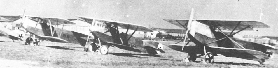
The modified Brandenburg L 14, designated 60.58, at Aspern for evaluation in the summer of 1917. On the left is the the Phonix C.I 121.03 and on the right the Brandenburg C.II 66.51.

The Priesel gun ring became a standard production installation starting with the Phonix C.I 121.11. Seen below the rack for flare cartridges is the streamlined compass housing. The aircraft was flown by Flik 28/D between May and July 1918.

"Феникс" С-I. Стрелок этой машины, по австрийским данным, сбил знаменитого итальянского аса Франческо Баракку
Phonix C.I 121.17 was flown by Oberleutnant Arnold Barwig and Zugsfuhrer Max Kauer when Maggiore Baracca, the leading Italian ace, was shot down on 19 June 1918. Kauer achieved a total of four victories in this aircraft. The blast tube for the synchronized machine gun can be seen in the nose. The struts carry identification streamers.
Phonix C.I 121.17 was flown by Oberleutnant Arnold Barwig and Zugsfuhrer Max Kauer when Maggiore Baracca, the leading Italian ace, was shot down on 19 June 1918. Kauer achieved a total of four victories in this aircraft. The blast tube for the synchronized machine gun can be seen in the nose. The struts carry identification streamers.

Photographed on 12 May 1918, this Phonix C.I 121.27 is fitted with the four-bladed propeller for flight evaluation at Aspern. The air regulating shutter on the box radiator is a test modification.
Phönix C.I, 121.27, August 1918, Flugfeld Aspern; bemerkenswert ist die Vierblatt-Luftschraube
Phönix C.I, 121,27, август 1918 года, аэродром Асперн; обратите внимание на четырехлопастный винт
Phönix C.I, 121.27, August 1918, Flugfeld Aspern; bemerkenswert ist die Vierblatt-Luftschraube
Phönix C.I, 121,27, август 1918 года, аэродром Асперн; обратите внимание на четырехлопастный винт

The broad fuselage contours are placed into perspective by mechanics preparing the Phonix C.I 121.28 for flight. The date is 29 May 1918 but the Flik is unknown.

Anatra C.I 010.106 with early Czech markings flanked by a Phonix C.I 121.50 (with rear gun ring removed) and a Brandenburg C.I, possibly at Kbely airfield in early 1919.

Photographed in 1919 at Fischamend, the Phonix C.I 121.72 demonstrates the late-1918 Balkenkreuz on the fuselage. The crosses on the wings have been painted over. Some aircraft had openings in the turret, possibly to save weight.

Identified by the red star, the Phonix C.I(LI) 49.03 served with the 3rd Squadron of the Hungarian Red Airborne Corps. The effaced outlines of the late-1918 Balkenkreuz insignia can be discerned on the top wing.

This Phonix C.I(Ll) 49.05 also was attached to the 3rd Squadron. The exhaust stacks of the 225 hp Daimler engine, as shown here, were on the right side, the 230 hp Hiero on the left. The camouflage is the pattern used by Lloyd in late 1918.
The busy Phonix prototype assembly shop in 1917. In the middle background is a Knoller C.I(Ph) under assembly. The workman on the high scaffolding is holding the propeller of the 20.11 bomber. A flying boat is under construction on the far right, behind which the Phonix C.I prototype can be seen.

Phonix C.I 121.17, Flik 28/D

Phonix C.I Series 121
Phonix 20.15
The Phonix 20.15 prototype was the first step towards the Phonix D.I production fighter that was built for the Army and Navy through 1918. Taking German experience into account, Diplom-Ingenieur Sparmann designed a wing cellule that provided the pilot with an uninterrupted field of view and was more robust than the wireless Nieuport system of the 20.14. The 20.15 prototype, modified from the 28.50 airframe and powered by a 185 hp Daimler engine, performed the first test flights in June 1917. The flight characteristics were far superior to the Brandenburg D.I, but the performance had hardly improved. The solution was more horsepower, as exemplified by the Phonix 20.16 prototype. The Phonix 20.15 was assigned to the training command and last reported stored in damaged condition at Flugpark 1 in Wiener-Neustadt. It was offered for sale to Czechoslovakia in April 1920.
Phonix 20.18
When the new Phonix D.I fighter appeared in October 1917, it was reported as having "superb flight characteristics but only average performance." Phonix engineers were already at work on an improved version, the 20.18 prototype, that weighed about 130 kg (287 lb) less. During comparative trials performed on 19 December 1917, the 20.18 reached 5000 meters (16,405 ft) in 19 minutes versus 28 minutes for the D.I. Flars ordered the type into production as the Phonix D.II (200 hp Hiero) and D.IIa (230 hp Hiero). For armament tests and fine tuning in preparation for manufacture, the 20.18 prototype was evaluated through January-April 1918. It was later redesignated Phonix D.II 322.09 and assigned to the fighter school in Campoformido. In September, the 322.09 (ex-20.18) had a 230 hp Hiero engine installed and was transferred to the Navy under the new designation Phonix D.III, Navy number J 32.
Phonix 20.18 Specifications
Engine: 200 hp Hiero
Wing: Span Upper 9.80 m (32.15 ft)
Total Wing Area 25.0 sq m (269 sq ft)
General: Length 6.85 m (22.47 ft)
Height 2.79 m (9.15 ft)
Empty Weight 635 kg (1400 lb)
Loaded Weight 935 kg (2062 lb)
Maximum Speed: 175 km/hr (109 mph)
Phonix 20.22
For the forthcoming Fighter Evaluation in July 1918, Phonix prepared five prototypes; 20.22, 20.23, 422.23, 20.24, and 20.25. The first three were standard D.II/D.IIa airframes modified to improve maneuverability, performance, pilot's visibility, and machine gun accessibility. Besides the more-powerful 230 hp Hiero engine, the 20.22 prototype had an upper wing of increased area, a lower wing of reduced span, and ailerons on all wings. The pilot's seat was raised and the machine guns were mounted at eye level. Flight and altitude tests of the 20.22 took place in May 1918. At the Evaluation, Oberleutnant Frank Linke-Crawford, Oberleutnant' Marian Gawel, and Stabsfeldwebel Franz Kuntner flew the 20.22 and were impressed by its maneuverability. On 17 July 1918, Stabsfeldwebel Karl Urban, a Flik 14/J pilot, was killed when the upper wingtips of the 20.22 folded back while executing a sharp loop. Flars, noting that similar incidents had occurred at the Front, ordered the wings of all Phonix D.II fighters presently in production to be reinforced.
Phonix 20.22 Specifications
Engine: 230 hp Hiero
General: Empty Weight 685 kg (1510 lb)
Loaded Weight 945 kg (2084 lb)
Maximum Speed: 185 km/hr (115 mph)
Climb: 1000m (3,281 ft) in 2 min 58 sec
2000m (6,562 ft) in 6 min 24 sec
3000m (9,843 ft) in 11 min 46 sec
4000m (13,124 ft) in 16 min 1 sec
Phonix 20.23
The Phonix 20.23 prototype was adapted from a D.II airframe and powered by a 225 hp Daimler engine; the upper wing was raised slightly to improve the pilot's view and the aileron cables ran through the lower wing. Both Oberleutnant Benno Fiala Ritter von Fernbrugg and Frank Linke-Crawford praised the facile maneuverability and the accessible machine guns after flying the 20.23 during the Fighter Evaluation in July 1918. Fiala, extolling the excellent field of view, recommended that the cabane arrangement be made mandatory for all fighters. Linke-Crawford wrote that "for my squadron I desire a Phonix single-seater with the pilot's view and machine guns located as in the 20.23; ailerons on both wings (20.22 and 422.23) and, if possible, the Gebauer motor machine gun. The bead sight should be replaced by an aiming telescope (English type with large field of view) or the new electrical sight."
Phonix 20.23 Specifications
Engine: 225 hp Daimler
General: Empty Weight 685 kg (1510 lb)
Loaded Weight 965 kg (2128 lb)
Climb: 1000m 13,281 ft) in 2 min 50 sec
2000m (6,562 ft) in 5 min 50 sec
3000m (9,843 ft) in 10 min 30 sec
4000m (13,124 ft) in 15 min 30 sec
5000m (16,405 ft) in 27 min
Phonix 20.28 and 20.29
On 28 July 1918, Flars ordered Phonix to build two experimental fighters incorporating the improvements demonstrated at the Fighter Evaluation (see 20.22, 20.23, and 422.23) preparatory to placing the type in production as the Phonix D.III series 222.100. Flars allocated two Phonix D.II airframes for modification: 122.12 was re-numbered 20.28 and 222.03 became 20.29, both were powered by the 230 hp Hiero engine. In accordance with the frontline pilots' preferences, the prototypes were fitted with four ailerons to increase maneuverability; the rudder-elevator controls and contours were revised to increase sensitivity and the machine guns were mounted within reach of the pilot. Engine bearers, fuselage frames and engine cowling were strengthened throughout.
Phonix D.I 128, 228 and 328
In 1917 the LFT began to award large "open" aircraft contracts from which smaller production batches would be drawn down as needed. In March 1917, from an open contract of 264 aircraft, Flars ordered 120 Phonix D.I fighters provided, of course, that the 20.15/20.16 prototype program was successfully concluded. Manufacture began in August 1917 and deliveries, scheduled to end on 31 December 1917, actually did not finish until May 1918. The Phonix D.I, identical with the 20.16 prototype, was fitted with the Sparmann wing cellule and canted wing struts. The plywood-covered, wood fuselage was derived from the Brandenburg D.I but was somewhat longer to accommodate the larger 200-hp Hiero engine. Armament consisted of twin machine guns mounted well forward, alongside the engine.
Eleven D.I fighters were accepted in October 1917 and the last in April-May 1918. The different series designations simply identified the engine manufacturer and in other respects the fighters were identical, although a few early production models (228.01, 228.02) had a top wing with one less rib between cabane and wing strut:
Phonix D.I 128.01-31 200 hp Hiero
Phonix D.I 228.01-55 200 hp Hiero (Fi)
Phonix D.I 328.01-34 200 hp Hiero (Bd)
Shortages greatly affected smooth production flow. When Uzelac learned in November 1917 that 50 D.I fighters were in storage awaiting machine guns or installation of the new Zaparka synchronization system, he immediately ordered the aircraft to the Front where LFT armorers could install the armament on arrival. During flight comparison in September 1917, the Phonix D.I was reported as being faster in speed and climb than the Albatros D.III(Oef) and having significantly better flight characteristics than the Aviatik D.I. In October 1917, the German Idflieg reported that the new Phonix D.I deserved notice because "it possesses totally amazing qualities, especially the quickness of maneuver and stability when throttled down. The pilot can stall the aircraft virtually on the spot and drop several hundred meters without losing control."
Beginning in December 1917, the D.I was flown as an escort fighter with Fliks 4/D, 15/D, 17/D, 48/D, 54/D, and 66/D and as a fighter with Fliks 14/J, 30/J, 60/J, 61/J, and 63/J. Being easy to fly, many two-seater pilots had little difficulty in making the transition to this single-seater and many came to prefer the D.I over other fighters. A number of D.I machines were converted to perform photo-reconnaissance work and in several cases these were fitted with a 230 hp Hiero engine to increase performance. But some fighter units saw the D.I in a different light. Flik 60/J reported in February 1918 that the "D.I is not favored by pilots because the speed and climb are inferior to the Nieuport, SPAD, and Sopwith fighters." Flik 30/J complained that the D.I was too slow (the fighter pilot's eternal lament!) and "almost too stable for quick combat maneuvers." Yet the robustly-built D.I possessed no hidden vices and, unlike the Aviatik D.I, could dive at high speed without fear of structural failure. The fact that 72 Phonix D.I fighters were still operational on 1 August 1918 speaks well for its all-round, if not spectacular, qualities.
Phonix D.I Series 128, 228, & 328 Specifications
Engine: 200 hp Hiero
Wing: Span Upper 9.80 m (32.15 ft)
Span Lower 9.00 m (29.53 ft)
Chord Upper 1.70 m (5.58 ft)
Chord Lower 1.20 m (3.94 ft)
Dihedral Upper 1 deg
Dihedral Lower 1 deg
Sweepback Upper 0 deg
Sweepback Lower 0 deg
Gap 1.51 m (4.95 ft)
Stagger 0.70 m (2.30 ft)
Total Wing Area 25.0 sq m (269 sq ft)
General: Length 6.75 m (22.15 ft)
Height 2.65 m (8.69 ft)
Track 1.70 m (5.58 ft)
Empty Weight 716 kg (1579 lb)
Loaded Weight 951 kg (2097 lb)
Maximum Speed: 178 km/hr (110.5 mph)
Climb: 1000m (3,281 ft) in 3 min 5 sec
2000m (6,562 ft) in 7 min
3000m (9,843 ft) in 12 min 15 sec
4000m (13,124 ft) in 18 min 39 sec
5000m (16,405 ft) in 27 min 39 sec
Phonix D.II Series 122, 222, and 322
The Phonix D.II fighter which replaced the D.I in production in March 1918 was re-designed to improve performance and maneuverability. About 50 kg (110 lb) were pared from the airframe without changing the basic layout. The lightened cellule had a one-piece upper wing and vertical wing struts. High-aspect ailerons, elimination of dihedral, a new tailplane, and balanced elevators quickened aircraft response. When the tests of the 20.18 prototype were completed in early 1918, Flars ordered 48 fighters with the following series designations:
Phonix D.II 122.01-26 200 hp Hiero
Phonix D.II 222.01-14 200 hp Hiero (Fi)
Phonix D.II 322.01-08 200 hp Hiero (Bd)
Beginning May 1918, the Phonix D.II became operational with Fliks 9/J, 14/J, 30/J, 55/J, 60/J and 68/J. Several accidents in May were traced to engine bearer failure; although held blameless, Phonix was required to supply reinforcement kits at no charge, and modification was completed in July. An unfortunate incident occurred in June 1918. Scheduled to be re-equipped with Phonix D.II fighters, Flik 43/J performed familiarization flights, in the course of which a pilot was killed because of wing failure. Flik 43/J refused to fly the fighter. Although the Phonix D.II fighter remained operational for the duration of the war and Flik technical reports were positive, the D.II was flown only sporadically. This was primarily because fighter pilots overwhelmingly preferred the more robust, 225 hp Albatros D.III(Oef) series 253 fighter.
Phonix D.II Series 122, 222, St 322 Specifications
Engine: 200 hp Hiero
Wing: Span Upper 9.80 m 132.15 ft)
Span Lower 9.00 m (29.53 ft)
Chord Upper 1.70 m (5.58 ft)
Chord Lower 1.20 m (3.94 ft)
Total Wing Area 25.0 sq m (269 sq ft)
General: Length 6.75 m (22.15 ft)
Height 2.65 m (8.69 ft)
Phonix D.IIa Series 422
In March 1918, Flars ordered 48 Phonix D.IIa fighters numbered 422.01 to 422.48. The D.IIa was structurally identical to the D.II but was powered by the new 230 hp Hiero engine. Flight testing was performed with aircraft 122.13, which on 11 May 1918 clocked an exceptional time of 17:20 minutes to reach 5000 meters (16,405 ft). Because of insufficient output of the 230 hp Hiero engine, some 20 percent of the series 422 fighters were delivered with the 200 hp Hiero instead. Like the D.II, the engine bearers proved weak and had to be strengthened in the field.
The first D.IIa fighters were dispatched to the Front in late May 1918, reaching Fliks 9/J, 14/J, 30/J, 32/D, 43/J, 55/J, 60/J, and 68/J. One D.IIa was flown as a photo-reconnaissance fighter by Flik 37/P. Ten D.IIa fighters were transferred to the Navy (designated J.21 to J.30) and assigned to naval defense flights based at Altura (Pola) and Igalo. The D.IIa was highly regarded by fighter pilots who appreciated the extra power and its rugged construction. Flik 1/J at Igalo pronounced the D.IIa and the Aviatik D.I series 338 as being the only fighters capable of performing interception work. As of 1 August 1918, thirty-four D.IIa fighters were listed in the frontline inventory.
Phonix D.IIa Series 422 Specifications
Engine 230 hp Hiero
Wing Span Upper 9.80 m (32 15 ft)
Span Lower 9 00 m (29 53 ft)
Chord Upper 1 70 m (5.58 ft)
Chord Lower 1 20 m (3 94 ft)
Dihedral Upper 0 deg
Dihedral Lower 0 deg
Sweepback Upper 0 deg
Sweepback Lower 0 deg
Gap 1.51m (4.95 ft)
Stagger 0.70 m (2.30 ft)
Total Wing Area 25 0 sq m (269 sq ft)
General Length 6.75 m (22.15 ft)
Height 2 65 m (869 ft)
Track 1 70 m (ft)
Maximum Speed 180-185 km/hr (112-115 mph)
Climb. 1000m (3,281 ft) m 3 mm
Phonix D.III Series 222.100
Among the fighters entered in the July 1918 Fighter Evaluation was a production Phonix D.IIa fighter (422.23) fitted with ailerons on top and bottom wings to enhance maneuverability. Pilots who test flew the fighter recommended it for production provided the inaccessible machine guns were relocated at eye level within arm's reach. Flars notified Phonix that a production order of 100 fighters, tentatively designated "D.II series 222 neu" and powered by 200 hp Hiero (Fi) engine, would receive approval. Eager to make further improvements, Phonix engineers were given approval on 28 July 1918 to modify and test two production fighters (see 20.28 and 20.29) in anticipation of production. The new fighter, known as the D.III, had a revised wing planform and a fuselage designed for accessible machine guns mounted at eye-level.
On 18 September 1918, Phonix received formal production approval for 100 D.III fighters, numbered 222.101 to 222.200 and powered by the 230 hp Hiero engine. Delivery was scheduled to begin in October 1918 and end in March 1919. In fact, on 27 October 1918, the LFT, desperate for additional aircraft to stem the Allied offensive on the Piave, considered the immediate dispatch to the Front of 61 completed D.III fighters (222.101 to 222.159, 222.163 and 222.164) which were awaiting flight acceptance. But time had run out and none left Aspern. As of 26 February 1919, aircraft 222.101 to 222.174 were stored at Stadlau. These were the cause of a legal suit against the Austrian government by Phonix who, claiming the aircraft had been "de facto" accepted, now demanded full payment.
In the spring of 1919, Sparmann and Maximilian Perini, both expert pilots, demonstrated a Phonix D.III in Stockholm. It was purchased by the Swedish Army Air Force in April 1920 (Swedish No.935), followed in July by 20 D.III fighters, designated 941 to 979 (odd numbers) and powered by a 200-hp Hiero engine. Three Phonix D.III fighters were still active in 1926.
The fact that the LFT chose only two fighters for production into 1919 - the Fokker D.VII and the Phonix D.III - stands as a high tribute to Phonix engineering and workmanship.
Phonix D.III Series 222.100 Specifications
Engine: 230 hp Hiero
Wing: Span Upper 9.80 m (32.15 ft)
Span Lower 9.00 m (29.53 ft)
Chord Upper 1.70 m (5.58 ft)
Chord Lower 1.20 m (3.94 ft)
Dihedral Upper 0 deg
Dihedral Lower 0 deg
Sweepback Upper 0 deg
Sweepback Lower 0 deg
Total Wing Area 25.0 sq m (269 sq ft)
General: Length 6.62 m (21.72 ft)
Height 3.01 m (9.88 ft)
Track 1.79 m (5.87 ft|
Empty Weight 685 kg (1510 lb)
Loaded Weight 951 kg (2097 lb)
Maximum Speed: 180-185 km/hr (112-115 mph)
Climb: 1000m (3,281 ft) in 2 min
3000m (9,843 ft) in 12 min
5000m (16,405 ft) in 24 min

Phonix D.I 228.(18), Flik 60/J

Phonix D.I 328.22, Flik 12/Rb

Phonix D.I 328.26, Flik 14/J

Phonix D.IIa 422.21, Flik 55/J

Phonix D.III 222.126

Although the 20.14 offered better speed and climbing capability than the standard 28-series KD fighter. The 20.15 utilized the standard Series 28 fuselage with square-tipped KD wings but replaced the 'star-strutter' interplane struts with conventional struts with wire bracing. The wings were staggered and the lower wing had dihedral. The large vertical fin added to the 20.14 prototype was retained for enhanced stability. A standard VK gun canister was fitted and the engine was an Austro-Daimler with the exhausts on the starboard side. The 20.15 looked more like what will become the Phonix D.I.

The Phonix 20.23 participated at the Fighter Evaluation at Aspern in July 1918. It was one of the few Phonix fighters powered by a Daimler engine.

Front end of the Phonix 20.23, showing the accessible machine guns mounted at eye level. The blast tubes are fixed to the engine intake manifold and camshaft drive housing.

Oberleutnant Roman Schmidt’s Phonix D.I 128.12 of Flik 30/J on the San Pietro di Campo airfield in August 1918. The small headrest was a D.I identification feature. In the background is a Phonix D.I series 228.

Phonix D.I 128.16. Fighter pilots criticized the fighter’s lack of forward visibility, an important asset in air combat. The offset, circular gun sight is visible between the rear center-section struts.

Phonix D.I 228.02 was flown by Flik 42/f in December 1918 - January 1918. Here the slanted struts of the Sparmann wing cellule are shown to good advantage. The top wing is an early version with one less rib between cabane and aileron than seen on later production machines.

Phonix D.I 228.45 during acceptance testing at Aspern in the winter of 1917. It served as a photo-reconnaissance fighter with Flik 37/P.
Derived from the Hansa-Brandenburg D I, the Phonix D I adopted a more conventional interplane strut arrangement and a prominent fin. First flown in mid-1917, the Phonix D I entered service in February 1918, with 150 going to the Austro-Hungarian Army air arm and 40 to the Austro-Hungarian Navy. Not particularly agile, the D I, with its 200hp Hiero, had a top level speed of 112mph at sea level and was said to have a good rate of climb. Armed with twin 8mm Schwarzlose, the proneness of these guns to jamming, along with their inaccessibility in the D I was a point of major criticism. The machine seen here was the 45th of the second 50 production batch.
Phönix D.I, 228.45, Abnahme im Dezember 1917. Flik 37, im Juli 1918 abgestürzt
Phönix D.I, 228.45, принят в декабре 1917 года, Flik 37, разбился в июле 1918 года.

The pilot nearly disappears in the deep, spacious cockpit of the Phonix D.I 328.26 fighter of Flik 14/J, photographed on the Feltre airfield in 1918.
Phönix D.I, 328.26, Flik 14. Flugfeld Feltre. Mit diesem Flugzeug erzielte am 19. Mai 1918 Feldpilot Fw Johann Malzeinen Luftsieg über einen Sopwith-Jagdeinsitzer
Phönix D.I, 328.26, Flik 14. Аэродром Фельтре. На этом самолете 19 мая 1918 года пилот Иоганн Мальц одержал воздушную победу над одноместным истребителем Sopwith.

A curiously-marked Phonix D.I 328.27 of Flik 30/J displaying two different wing panels. The elongated tailplane was characteristic of the Phonix D.I.

This Phonix D.I 328.33 was flown as a photo-reconnaissance fighter by Oberleutnant Rudolph Schultheiss of Flik 16/D at Feltre in July 1918. The offset radiator cap is another D.I identification feature. The straps hanging below the fuselage may indicate that the aircraft was equipped to carry light bombs. The teddy bear was a popular mascot.

Loading a remotely-operated camera into a Phonix D.I in service with Flik 37/P on the San Lorenzo airfield. The rear-view mirror and circular gun sight are just visible on the right.

Mounted on a Phonix D.I fighter, this Sottoscope has a longer shape and a small viewing aperture. Like all Sottoscopes, it is mounted at a fair distance from the pilot’s eye. The machine-gun blast tube projects from the fuselage just below the intake manifold of the 200 hp Hiero engine.

The Phonix 20.18, powered by a 200 hp Hiero engine, showing the new tailplane and balanced elevator. Twin synchronized machine guns were mounted in the fuselage.

The Phonix 20.18, powered by a 200 hp Hiero engine, showing the new tailplane and balanced elevator. Twin synchronized machine guns were mounted in the fuselage.

Korporal Karl Tinner of Flik 9/J with his Phonix D.II 122.01. Unlike the Phonix D.I, the D.II had no headrest and the aileron cables ran through the bottom wing. The twin, synchronized guns were mounted alongside the engine and fired through blast tubes.
Phönix D.II, 122.01, Flik 9, im Cockpit Kpl Karl Linner. Bei einem Sperrflug mit vier Bristol F.2b-Fighter der 139. Squadron in einem Luftkampf verwickelt und über Levico abgeschossen, brennend abgestürzt, Pilot Kpl Linner tödlich verletzt (24. August 1918). Im Oktober 1918 kassiert
Phönix D.II, 122.01, Flik 9, в кокпите Kpl Karl Linner. Во время боя с четырьмя истребителями Bristol F.2b 139-й эскадрильи, сбитых над Левико, самолет загорелся, пилот Kpl Linner смертельно ранен (24 августа 1918 г.). Умер в октябре 1918 г.

Phonix D.II and pilot Feldwebel Josef Schreiner of Flik 9/J at Ospedaletto on 10 September 1918. The central radiator cap is a D.II identification feature. An offset telescopic sight is mounted left of the oil-stained windscreen. The over-painted Maltese crosses have been replaced by straight crosses on the wingtips.

The tipped Phonix D.II provides an opportunity to study the characteristic wing and tailplane planform, the high aspect-ratio ailerons, the balanced elevators, and the final version of the national insignia. The aircraft is believed to be that of Zugsfuhrer Karl Teichmann of Flik 14/J.

Nineteen-victory ace, Offizierstellvertreter Josef Kiss of Flik 55/J, with his Phonix D.IIa 422.10 at Pergine. Kiss was shot down and killed in this machine on 24 May 1918. In the background is aircraft D.IIa 422.08.

Phonix D.IIa 422.14 was the fighter flown by Feldwebel Alexander Kasza of Flik 55/J at Pergine. The bulbous exhaust stacks reduced noise.
Phönix D.IIa, 422.14, Flik 55, Maschine von Feldpilot Sandor Kasza. Mit dieser Maschine erzielte er am 9. Juni 1918 über einen englischen Bristol-Fighter einen Luftsieg; insgesamt sechs Luftsiege
Phönix D.IIa, 422.14, Flik 55, машина пилота Шандора Каса. На этой машине он 9 июня 1918 года одержал воздушную победу над английским истребителем «Бристоль»; всего шесть побед

As a forerunner of the Phonix D.III, the Phonix D.IIa 422.23 was modified to participate in the Fighter Evaluation at Aspern in July 1918. Fitted with ailerons on all wings, it was reported very maneuverable, easy to fly and land. Taken over by the Navy in August 1918, the fighter was designated J 21 and operated out of Igalo and Durazzo.

Phonix D.III 222.126 showing the flattened fuselage in front of the pilot to accommodate the raised, twin machine guns. The aileron connecting strut of the 422.22 has been replaced by a cable.

The last D.III built, 222.174, photographed during assembly at Stadlau. The machine gun blast tubes installed alongside the engine indicate the approximate position of the machine guns on the decking.

Phonix D.III J.41 (first of 50 fighters ordered for the Austro-Hungarian Navy) was purchased by the Swedish Army Air Force in 1920. Another original Phonix D.III (No. 947) is presently on exhibition at the Swedish Air Force Museum.

Phonix D.III 222.126


Phonix D.II Series 122, 222 and 322

Phonix D.III Series 222.100
Phonix 20.19 and 20.21
Designer Eduard Zaparka, who had joined Phonix in late 1917, was responsible for the Phonix 20.19 and 20.21 (Phonix Type 10) prototypes that used the unique wing structure invented by him (see Zaparka fighter). The 20.19 arrived at Aspern for evaluation in January 1918, performing sporadic test flights before it was returned to the factory for installation of new wings in March. On 23 May 1918, the modified 20.19 was flown in competition with three aircraft also powered by the 230 hp Hiero engine: the Phonix C.I 121.44, the UFAG C.I 161.14, and the Brandenburg C.I(Ph) 429.01. As the lightest aircraft of the group, the 20.19 reached 5000 meters (16,504 ft) in 48 minutes; the 429.01 was second with a time of 56 minutes. The 20.19 and 20.21 appeared at the July Fighter Evaluation at Aspern for inspection. In the course of load testing on 19 August 1918, the 20.19 achieved a remarkable 9.1 factor of safety. The second Zaparka prototype, 20.21, fitted with a larger fin, continued flight trials through September.
A second climb competition convened on 20 September demonstrated the rapid progress made by the Austro-Hungarian aircraft industry. The 20.19 that four months earlier had been first was now eclipsed by four new aircraft: the UFAG 60.03, two improved Phonix C.I biplanes (121.71 and 121.82), and the WKF 80.07, even though the 20.19 had reached 4000 meters (13,124 ft) in 37 minutes. The Phonix-Zaparka aircraft were not included in the 31 August 1918 production calendar. Both the 20.19 and 20.21 were accepted at the war's end to permit Phonix to receive payment for the aircraft.
Phonix 20.19 Specifications
Engine: 230 hp Hiero
Wing: Span Upper 10.50 m (34.45 ft)
Span Lower 8.95 m (29.36 ft)
Chord Upper 1.70 m (5.58 ft)
Chord Lower 1.40 m (4.59 ft)
Gap 0.91 m (2.99 ft)
Stagger 0.70 m (2.30 ft)
General: Empty Weight 730 kg (1610 lb)
Loaded Weight 1050 kg (2315 lb)
Maximum Speed: 175 km/hr (109 mph|
Climb: 1000m (3,281 ft) in 3 min 36 sec
2000m (6,562 ft) in 8 min 45 sec
3000m (9,84-3 ft) in 16 min 48 sec
4000m (13,124 ft) in 27 min 8 sec
5000m (16,405 ft) in 48 min

The Phonix 20.19 at Aspern in the spring of 1918. For the production version the armament would have consisted of two forward-firing machine guns and a ring-mounted observer’s gun.

Phonix 20.19
Phonix 20.24 and 20.25
During the winter of 1917, Kirste began design work on a high-performance fighter that represented the "total experience gathered by the aircraft industry during the war." The drawings and specifications were approved by Flars in January 1918. Two prototypes, known as the "Kirste fighters," were built. The 20.24 was powered by a 230 hp Hiero engine and fitted with a new rib section. The 20.25, powered by a 225 hp Daimler engine, retained the D.II rib section and had a slightly larger fin. By ingenious design, Kirste extracted maximum strength from a light and simple airframe. The oval, veneer-covered fuselage, the wide center section and narrow lower wing gave the pilot a superb field of view. An unusual feature was a fire-proof fuel tank mounted between pilot and engine. The prototypes, completed in May, were flight tested in June 1918.
The 20.24 and 20.25 appeared at the Fighter Evaluation on the last day (13 July) and were available for inspection only because they were not completely ready. Oberleutnant Fiala commended the electrical reflex sight on 20.24 and suggested minor internal changes. According to Phonix records, had the fighter gone into production it would have been designated Phonix D.IV. The prototypes arrived too late to be included in the 31 August 1918 production calendar. Both prototypes were accepted in October 1918 to permit Phonix to receive payment for the aircraft.
Phonix 20.24 Specifications
Engine: 230 hp Hiero
Wing: Span Upper 8.50 m (27.89 ft)
Span Lower 7.50 m (24.61 ft)
Chord Upper 1.50 m (4.92 ft)
Chord Lower 1.50 m (4.92 ft)
Dihedral Upper 0 deg
Dihedral Lower 0 deg
Sweepback Upper 0 deg
Sweepback Lower 0 deg
Gap 1.65 m (5.41 ft)
Stagger 0.71 m (2.33 ft)
Total Wing Area 23.50 sq m (253 sq ft)
General: Length 6.60 m (21.65 ft)
Height 2.70 m (8.86 ft)
Track 1.40 m (4.59 ft)
Empty Weight 665 kg (1466 lb)
Loaded Weight 950 kg (2095 lb)
Maximum Speed: 185 km/hr (115 mph)
Climb: 1000m (3,281 ft) in 2 min 10 sec
5000m (16,405 ft) in 18 min

Phonix 20.24, powered by a 230 hp Hiero engine, showing the fine lines of the veneer-covered, oval fuselage. The machine guns were internally mounted within reach of the pilot but below eye level to avoid the oil spray.

The Phonix 20.25. demonstrating the compactness of the “Kirste fighters.” By virtue of their excellent performance, the fighters would have been considered for production had the war continued.
A revealing side view of the Phonix D IV single seater of which only two prototypes had been completed at the time of the Armistice. While superficially similar to the earlier Phonix D I to D III series, the D IV was virtually a totally new design. Gone were the slab-sided fuselages of the earlier machines, to be replaced by a generally smoother, oval-sectioned body, terminating in a fin and rudder of significantly increased areas. Little information survived the war concerning the D IV's performance. From this image, it would seem that the Austro-Hungarians did not follow their German allies in switching to using the straight-sided Balkankreuse national marking from mid-April 1918.
A revealing side view of the Phonix D IV single seater of which only two prototypes had been completed at the time of the Armistice. While superficially similar to the earlier Phonix D I to D III series, the D IV was virtually a totally new design. Gone were the slab-sided fuselages of the earlier machines, to be replaced by a generally smoother, oval-sectioned body, terminating in a fin and rudder of significantly increased areas. Little information survived the war concerning the D IV's performance. From this image, it would seem that the Austro-Hungarians did not follow their German allies in switching to using the straight-sided Balkankreuse national marking from mid-April 1918.

Phonix 20.25, powered by a 225 hp Daimler engine, was armed with externally-mounted machine guns and the fuselage was flattened to accommodate them. The lower wing and fin are carefully faired into the fuselage for minimum drag.

Phonix 20.24. The narrow fuselage gave the pilot a fine downward field of vision. Engine cooling was always a problem and although airfoil-shaped radiators were available, the box radiator may have been the only solution.

Phonix 20.24
Priesel KEP Fighter
Oberleutnant Guido Priesel, a graduate engineer who had built two prewar aircraft in Hohenelbe, Bohemia joined Flars in February 1915 after he was wounded on active service. As a Flars weapons expert, Priesel was instrumental in developing the Type II VK machine gun canister, bomb racks and release mechanisms, and a successful synchronization system. In April 1917, Priesel was given leave to manage the construction of his third aircraft, a monoplane, as a private venture undertaking of Petera & Sohne in Hohenelbe. The monoplane's fabrication, under the supervision of Leutnant Arthur Olessak, was virtually complete and awaiting installation of a 145 hp Hiero engine which Flars had provided when Priesel stopped the project in September 1917 in favor of a new biplane fighter.
For Petera, a small coach builder, the project had become too expensive, forcing Priesel to join forces with Karl Hoier, a factory owner in Fischamend who provided financial backing in return for which, it appears, he obtained the rights to Priesel's various patents. The new venture was named Wieland Technische Werkstatte. Olessak, assisted by Leutnant Hans Stephenson and Flars engineer Robert Gabriel, supervised the construction of the Priesel KEP (Kampfeinsitzer Priesel) for which Flars had assigned four workers. Another 16 workers were detached to fabricate 150 observer's machine-gun fixtures designed and patented by Priesel.
As proposed to Flars, the advantages of the Priesel KEP were improved pilot visibility, minimum weight (less than the Aviatik D.I), an unsynchronized machine gun mounted on the upper wing, a wing cellule free of fuselage interference drag, and minimal wing bracing. Because of the novel design, the static calculations prepared by Stephenson in March 1918 were rejected by Flars. Army pilots were prohibited from flying the aircraft.
After Priesel was killed in a crash while engaged in Flars weapon experiments on 20 March 1918, Major von Petroczy was given the task of preparing the aircraft for flight testing. According to Stephenson, civilian test pilot Karl Kriger fearlessly flew the aircraft to Aspern on its maiden flight on 6 April 1918 and performed one or two additional flights. In view of unsatisfactory wind tunnel tests, Flars recommended on 5 August 1918 a complete reconstruction, namely replacing the tail empennage, rear fuselage and wing profile and exchanging wing warping for aileron control. A lighter but more powerful rotary engine would replace the 145 hp Hiero engine. These plans never materialized. The Priesel KEP was offered for sale to the Czechoslovakian government in 1920.

The Priesel KEP prototype in the courtyard of the Wieland factory at Fischamend. The attention to streamlining is reflected in the careful fairing of the radiator, engine, and cooling system.

The Priesel KEP. The absence of center section bracing is remarkable, in fact the entire wing cellule is solely supported by the rear undercarriage struts, two lower fuselage struts, and interplane wire bracing.
Priesel-Versuchsdoppeldecker, Konstruktion von Hptm Guido Priesel
Priesel-Versuchsdoppeldecker, Konstruktion von Hptm Guido Priesel

The Priesel KEP. It is not clear how the wing warping system worked. According to Stephenson, the entire wing cellule could be tilted in flight. One can only admire Karl Kriger’s reckless courage in piloting this bizarre design on its maiden flight.

The Priesel monoplane was nearing completion at Petera & Sohne in Hohenelbe in September 1917, when construction was stopped. In its completed form, wing warping and wire wing bracing probably would have been fitted.

Priesel KEP
Saliger Rotary-Engined Fighter
While working in the Flars construction section, Saliger proposed a Nieuport fighter derivative powered by a 160 hp Gnome rotary engine. The span was projected at 10 meters and the loaded weight was 680 kg. If lubricant for the Le Rhone rotary engine built by Steyr had been available, this particular project might have been realized.
While working in the Flars construction section, Saliger proposed a Nieuport fighter derivative powered by a 160 hp Gnome rotary engine. The span was projected at 10 meters and the loaded weight was 680 kg. If lubricant for the Le Rhone rotary engine built by Steyr had been available, this particular project might have been realized.

Drawing of the Saliger rotary-engined fighter project, dated 2 January 1917.
UFAG C.I(Ph) Series 123
In early 1918, when it became apparent that the development of the Phonix C.I was experiencing delays, Uzelac, concerned that the program might fail, ordered Phonix to build 40 UFAG C.I(Ph) series 123 aircraft as insurance. The production was well underway when the contract was signed on 10 May 1918. However, by then the Phonix C.I problems had been solved. LFT records give no reason why the UFAG C.I(Ph) program was allowed to continue at Phonix, but it is likely, since the two companies were closely related and were accustomed to sharing engineering data, that manufacture had progressed beyond cancellation. When queried by the War Ministry as to why the airframes had not been transferred to UFAG, Uzelac replied that this would delay the delivery of the UFAG C.I by two months. Acceptances of the UFAG C.I(Ph), numbered 123.01 to 123.40, began in July and ended in October 1918. About half reached operational service. Twenty-two new aircraft never reached the Front but were stored awaiting disposition in March 1919.
UFAG 60.01
Engineering work on an improved version of the C.I reconnaissance biplane, slated to become the UFAG C.II, was underway in the summer of 1918. Two prototypes, numbered 60.01 and 60.03, were built and flown. Antal Feher, who tested many UFAG-built machines, recorded that the 60.01, powered by a 230 hp Hiero engine, was basically a modified UFAG C.I that was fitted with ailerons of greater span and a balanced rudder. The dihedral and stagger remained the same. Further information is lacking.
UFAG 60.03
In July 1918, the drawings and static calculations for the 60.03, the definitive C.II prototype, were completed by Ingenieur Bela Oravecz and airframe assembly was well underway. Similar to the C.I in appearance, the 60.03 had an increased wingspan and an aerodynamically-balanced rudder. As reported in August 1918, the C.II had better glide characteristics and a lower landing speed than the C.I. In a climb competition for 230 hp Hiero-powered aircraft held on 19 September 1918 , the 60.03 was barely beaten by the WKF 80.07, winner of the trials. Flars had plans to produce the C.II, but the war ended before any decision was made. The 60.03 prototype was offered for sale to the Czechoslovakian government in 1920.
UFAG 60.03 Specifications
Engine: 230 hp Hiero (Fi)
Wing: Span Upper 10.30 m (33.79 ft)
Span Lower 9.74 m (31.95 ft)
Chord Upper 1 66 m (5 45 It)
Chord Lower 1.66 m (5.45 ft)
Total Wing Area 28.64 sq m (308 sq ft)
General Track 1 90 m (6 23 ft)
Empty Weight 750 kg (1654 lb)
Loaded Weight 1150 kg (2536 lb)
Climb: 1000m (3,281 ft) in 4 min 45 sec
2000m (6,562 ft) in 10 min 53 sec
3000m (9,843 ftl in 20 mm 46 sec
4000m (13,124 ft) m 31 mm 14 sec
UFAG C.I Series 161
Hard on the heels of the failed Brandenburg C.II program, UFAG engineers developed the UFAG C.I, which incorporated the best C.II features but eliminated the complex wing struts in favor of a simple wing cellule braced by a single interplane strut. In quick succession two C.I prototypes, numbered 161.01 and 161.02, were built. The partially-completed airframe of 161.01, powered by a 200 hp Hiero engine, was inspected by Flars engineers on 30 May 1917. The second prototype, 161.02, rolled out in June 1917, was identical except for the installation of a more powerful 230 hp Hiero engine and slightly enlarged wing area.
Promising flight trials performed at Albertfalva and Aspern between June and September 1917 demonstrated satisfactory handling characteristics and excellent performance. Although the static load test on 20 October 1917 showed an acceptable 6.3 load factor, Flars rejected the I-strut interplane bracing and required UFAG to install conventional wing struts. The modification to production standard was completed in November 1917, but the sub-zero weather delayed completion of flight trials until mid-January 1918. The static load test of a production airframe (161.09) was successfully concluded on 18 February 1918.
By March 1918, eleven C.I biplanes had been accepted and a number were dispatched to Fliks 47/D and 58/D in April for frontline evaluation. Being fast and maneuverable, the C.I was reported eminently suitable for wireless, photographic, and bombing work. Flars responded by placing large production orders which, by the end of May 1918, amounted to 284 aircraft, divided into three batches as shown below. Phonix became involved in the UFAG C.I production because in early 1918 the Phonix C.I was experiencing development problems and Uzelac, concerned the program might not succeed, wanted Phonix to have a back-up production aircraft in place.
Qty Series Numbers Order Date First Acceptance
24 161.01-22 13 May 1917 September 1917 (a)
220 161.31-250 4 Feb/18 May 1918 May 1918
40 123.01-40 18 May 1918 July 1918
(a) Of the first 24 aircraft ordered in May 1917, only 22 were production C.I biplanes and of these, only 20 aircraft were formally accepted by the LFT. It is believed that the two Brandenburg C.II(U) prototypes were included in this order.
To improve handling, the second UFAG C.I production batch was delivered with increased wingspan, a broader rudder, and an elevator of increased area. Beginning with aircraft 161.91, a small tail fin and an unbalanced rudder became standard. Bomb racks for twelve 12 kg (26 lb) bombs were fitted to all aircraft starting with 161.131. A few machines were powered by the 250 hp Benz (Mar) engine. At least three airmen owed their lives to the Tubus parachute packed in containers in the fuselage floor. Armament consisted of a fixed, synchronized machine gun and an observer's gun mounted on a large, wooden ring. Twin forward-firing guns, tested on aircraft 161.31 in July 1918, were not installed on production machines.
The UFAG C.I was assigned to most reconnaissance squadrons on the Italian Front, where the type found ready acceptance. It was flown by Fliks 4/K, 5/F, 8/D, 11/F, 15/P, 16/K, 17/K, 19/K, 22/K, 23/K, 24/K, 27/F, 32/D, 35/K, 36/K, 39/P, 44/K, 45/D, 47/F, 49/D, 50/D, 52/K, 53/D, 57/Rb, 58/P, 62/K, 66/K, 67/DS, 71/S, and 102/G. The good maneuverability, slightly better than the Phonix C.I, was especially praised as was the high speed which enabled aircrews to evade enemy fighters. The operational ceiling was about 4000 meters (13,124 ft); at higher altitudes pilots complained of instability and preferred the Phonix C.I for such work. Being a thoroughbred, average pilots found the UFAG C.I difficult to fly at first. Former pilot Philipp Ritter von Vacano remembered the C.I as “a right efficient reconnaissance machine, but with a nasty inclination to sudden and unexpected tail-heaviness while climbing," a tendency that could not be corrected by adjusting the wing alignment. As usual, the rough, unkempt airfields took their toll in fuselage fractures. Fliks 22/K and 67/DS reported in August 1918 that gun rings had torn loose because of wind pressure and vibration or during minor landing mishaps, once causing serious injury.
On 1 August 1918, a total of 76 UFAG C.I biplanes was at the Front compared to 16 Phonix C.I, and on 20 October the totals were 51 and 6 respectively. It is clear that the UFAG C.I had a greater impact on the air war. Through October 1918 a total of 166 UFAG C.I biplanes, including 40 built by Phonix, had been accepted by the LFT. According to the August 1918 delivery calendar, production was scheduled to end in February 1919 in favor of the Phonix C.I, which was regarded a better aircraft. In a curious reversal, UFAG was scheduled to build and deliver 80 Phonix C.I(U) biplanes beginning in December 1918.
During the Hungarian revolution in 1919, UFAG C.I output continued. At least 17 machines were flown by the Hungarian Red Airborne Corps. The highest serial recorded was aircraft 161.200 which landed on Austrian territory in 1919. In addition to civil and air mail conversions in 1920, six C.I machines were completed as the "NL Sportplane" by the Neuschloss-Lichtig works, and several C.Is were assigned to the Hungarian Legugyi Hivatal clandestine military establishment.
UFAG C.I 161.01 Specifications
Engine: 200 hp Hiero
Wing: Span Upper 8.92 m (29.26 ft)
Span Lower 8.92 m (29.26 ft)
Chord Upper 1.55 m (5.09 ft)
Chord Lower 1.55 m (5.09 ft)
UFAG C.I 161.02 Specifications
Engine: 230 hp Hiero
General: Maximum Speed 180 km/hr (112 mph)
Empty Weight 680 kg (1499 lb)
Loaded Weight 1060 kg (2337 lb)
Climb: 1000m (3,281 ft) in 2 min 50 sec
3000m (9,843 ft) in 11 min 20 sec
UFAG C.I (First Series 161.03-161.22) Specifications
Engine: 230 hp Hiero
Wing: Span Upper 9.12 m (29.92 ft)
Span Lower 9.12 m (29.92 ft)
Chord Upper 1.60 m (5.25 ft)
Chord Lower 1.60 m (5.25 ft)
Stagger 0.62 m (2.03 ft)
General: Length 7.41 m (24.31 ft)
Height 3.04 m (9.97 ft)
Track 1.80 m (5.91 ft)
Empty Weight 730 kg (1610 lb)
Loaded Weight 1131 kg (2494 lb)
Climb: 1000m (3,281 ft) in 3 min 50 sec
2000m (6,562 ft) in 9 min 5 sec
3000m (9,843 ft) in 16 min 3 sec
4000m (13,124 ft) in 25 min 52 sec
UFAG C.I (Second Series 161.03-161.22) Specifications
Engine: 230 hp Hiero
Wing: Span Upper 9.50 m (31.17 ft)
Span Lower 9.40 m (30.84 ft)
Chord Upper 1.60 m (5.25 ft)
Chord Lower 1.60 m (5.25 ft)
Dihedral Upper 0 deg
Dihedral Lower 1 deg
Sweepback Upper 0 deg
Sweepback Lower 0 deg
Gap 1.54 m (5.05 ft)
Stagger 0.62 m (2.03 ft)
Total Wing Area 26.3 sq m (283 sq ft)
General: Length 7.41 m (24.31 ft)
Height 2.70 m (8.86 ft)
Track 1.90 m (6.23 ft)
Empty Weight 750 kg (1654 lb)
Loaded Weight 1150 kg (2536 lb)
Climb: 1000m (3,281 ft) in 4 min 5 sec
2000m (6,562 ft) in 10 min
3000m (9,843 ft) in 18 min 35 sec
4000m (13,124 ft) in 31 min

UFAG C.I 161.37

UFAG C.I 161.92, Flik 66/K

UFAG C.I 161.138

UFAG C.I 161.01 prototype at Aspern. As was often the case, the observer’s turret was not installed until flown with sandbag weights to determine the optimum position for the observer.

UFAG C.I 161.01 prototype with the original, I-strutted wing cellule during flight trials at Albertfalva in June-July 1917. Unlike the Brandenburg C.II, the pilot’s cockpit is readily accessible.

UFAG C.I 161.01 prototype photographed at Aspern in summer 1917. The narrow, deep fuselage and small rudder were the primary features adopted from the Brandenburg C.II design.

The UFAG C.I 161.11, from the pre-production batch ordered in May 1917, had a shorter wingspan than subsequent production series. The emphatic stagger has been retained but the sweepback was eliminated. For strength and safety, Flars preferred the twin, steel-tube wing struts to the original, wooden I-struts.

Without forward armament installed, UFAG C.I 161.11 performed its maiden flight at Albertfalva on 30 January 1918 and was delivered to the LFT in February. It remained with Fleks 6 and 8 at Wiener-Neustadt to acquaint aircrews with the new type.

The UFAG C.I 161.14, of the pre-production batch, was first flown by Antal Feher on 16 January 1918. Compared to the 161.01 prototype, the center section structure has been strengthened. The angle of incidence could be changed by adjusting the front strut. The aircraft served with Flik 16/D in January 1918 and Flik 44/D in August 1918.

By 1918, The Austro-Hungarian aviation industry was capable of designing and building aircraft equal to the best. One of these was the fine UFAG C.I, as demonstrated by 161.21 that first flew in March 1918.

Photographed at Flik 23/D in the summer of 1918, the UFAG C.I 161.67 was fitted with underwing bomb racks. Each wing could hold six 12.5 kg bombs. The production series had an increased wing span. The blast-tube and shell-ejection apertures of the synchronized gun are visible below the engine. Running from the observer’s ring is the line leading to the parachute stored in the fuselage floor.

Beginning with UFAG C.I 161.91, a tail fin and unbalanced rudder were standard production features. The aircraft was delivered in June 1918 for testing and experimental work at Aspern. The ear radiators, shown here, were rejected because of the reduced forward visibility, especially while landing. In August 1918, aircraft 161.91 was sent to the Al-Ma repair facility in Prague.

"Уфаг" С-I в австрийском "ступенчатом" камуфляже
Flik 4/P flew the UFAG C.I 161.106 in September 1918. The early crosses on the upper wing have been over-painted and replaced by late 1918 markings. The field of fire for the observer is exemplary.
Flik 4/P flew the UFAG C.I 161.106 in September 1918. The early crosses on the upper wing have been over-painted and replaced by late 1918 markings. The field of fire for the observer is exemplary.

In celebration of the 1000th aircraft built by UFAG, the UFAG C.I 161.121 decked out in garlands and flags, sometime in August 1918.

The Phonix-built UFAG C.I(Ph) 123.36 was one of the 22 aircraft that never reached the Front. It was confiscated as part of Allied reparations in 1919-1920 and assigned the British designation A/43.

UFAG C.I 161.37

UFAG C.I 161.92, Flik 66/K

UFAG C.I 161.138

UFAG C.I Series 161
UFAG D.I (60.02)
The UFAG D.I monoplane fighter was designed by Oberingenieur Stanko Bloudek who, when interviewed some years ago, recalled that it was begun as a private venture project conceived along the lines of the Fokker E.V parasol fighter. Assembly was at an advanced stage in the autumn of 1918, but difficulties encountered in the construction of the wooden, semi-monocoque fuselage delayed progress. Power was supplied by a 150 hp Le Rhone(St) rotary engine, making it likely that the D.I was designed to the LFT interceptor fighter specification. Bloudek claimed that he devised a simplified synchronization mechanism to control the twin machine guns. The three-view drawing is based on an original factory drawing dated 5 June 1918. Neither the UFAG monoplane fighter project nor the prototype number 60.02 have been mentioned in extant LFT documents. Pending the discovery of new information, it seems logical to assume that the prototype number 60.02 was reserved for the D.I monoplane.
UFAG D.I(60.02) Specifications
Engine: 150 hp Le Rhone (St)
Wing: Span Upper 8.50 m (27.89 ft)
Chord Upper 1.80 m (5.91 ft)
Dihedral Upper 0 deg
Sweepback Upper 0 deg
Total Wing Area 15.6 sq m (168 sq ft)
General: Empty Weight 380 kg (838 lb)
Loaded Weight 630 kg (1389 lb)
UFAG Series 65
The series 65 designation was never assigned or used by UFAG, nor did UFAG build the "Brandenburg D.I(U) series 65 fighter" under license, as has often been claimed. In fact, in the extant LFT documents there is no record that Flars ever contemplated having UFAG manufacture the Brandenburg D.I fighter.

UFAG D.I 60.02
Mises Type GG Bomber Projects
Oberleutnant Dr Richard von Mises, head of the Flars construction section at Fischamend, proposed a series of bizarre triplane bombers, powered by four 300 hp engines, in July-August 1916. The triplanes' wing span was set at 27 meters (88.6 ft) and the empty weight was estimated at 8800 kg, with a fuel load of 1500 kg and a useful load of 1500 kg.
Oberleutnant Dr Richard von Mises, head of the Flars construction section at Fischamend, proposed a series of bizarre triplane bombers, powered by four 300 hp engines, in July-August 1916. The triplanes' wing span was set at 27 meters (88.6 ft) and the empty weight was estimated at 8800 kg, with a fuel load of 1500 kg and a useful load of 1500 kg.

Mises Type GG 1 bomber project. The middle fuselage was armed with two dorsal and two ventral, forward-firing machine guns. The side gondolas were each armed with one dorsal and one ventral gun.

Mises Type GG 2 bomber project. The lower fuselage contained two pilots and fuel supply. The large gun pavilion on the top wing was armed with eight machine guns.

Mises Type GG 4 bomber project. This design featured five separate fuselages, the reason for which is difficult to fathom.
The death of Saliger and Matti in the crash of the Oeffag 50.10 prototype on 16 July 1917 effectively put an end to the Type AF program. The Oeffag 50.11 fuselage under construction is in the background and the completed 50.09 is behind the wings of the K 423 flying boat.
The Oeffag 50.09 prototype during final assembly in June 1917. Here it shares the large assembly hangar with the Oeffag K 423 flying boat and early production Albatros D.III(Oef) series 153 fighters.
Oesterreichisch-Ungarische Flugzeugfabrik "Aviatik" GmbH
Muthgasse 38-38, Vienna XIX
The Automobil und Aviatik AG of Muhlhausen-Burzweiler (Alsace) approached the Hungarian Ministry of Commerce in early 1913 with an offer to establish a small aircraft factory provided that the War Ministry would guarantee production orders. Although the Austro-Hungarian government sanctioned the venture in April 1913, financial support was not forthcoming, leaving Aviatik no option but to drop its proposal. A year later, on 3 July 1914, Aviatik and A. Weiser und Sohn AG of Vienna formed a joint undertaking known as the Oesterreichisch-Ungarische Flugzeugfabrik "Aviatik" GmbH to build aircraft for the Luftschifferabteilung (LA). In fact Weiser, a Viennese coach and boat builder, had already been active in aviation but with unfortunate consequences. The Flugzeugwerke Weiser, organized in late 1913 under the direction of Karl Illner (formerly a director and chief pilot of the Motor-Luftfahrt-Gesellschaft), entered an elegant parasol in the Schicht Flug competition. When the new aircraft crashed on 24 April 1914, killing the designer Ingenieur Raimund Pitschmann, work on a Weiser biplane, scheduled to appear at the International Flugmeeting, was stopped. At the time, discussions with Aviatik were under way and a joint Aviatik-Weiser venture, enhanced by an LA order for seven Aviatik biplanes in May 1914, launched Weiser's aviation business.

Designer Raimund Pitschmann (far left), Karl Illner (third from right), Weiser executives and the Schicht brothers (right) in front of the ill-fated Weiser parasol at the start of the Schicht Plug on 19 April 1914.
WKF 80.01 to 80.03
References which would correctly identify the WKF 80.01-80.03 prototypes have not been found in LFT records. It has been suggested that these prototype designations were assigned to the first aircraft of the first three production series built by WKF; namely, the Lloyd C.III(WKF) series 43.5, the Lloyd C.IV(WKF) series 44.5, and the Knoller C.II(WKF) series 81, but confirmation is lacking.
WKF 80.04
The 80.04 two-seat reconnaissance biplane, the first prototype to originate from the WKF design department, was conceived by Ingenieur Alfred Gassner. He chose a fuselage configuration on the basis of wind tunnel tests which had shown a hexagon cross-section to have superior directional stability than a square or round section and less drag than a square one. The robust, plywood-covered fuselage featured a deep "keel" to reduce the aerodynamic interference at the wing-fuselage juncture and facilitate mounting a one-piece lower wing. The generous fuselage depth allowed lowering the engine axis to provide good forward visibility and the installation of a 90cm camera entirely within its profile. To minimize drag, the patented Lloyd veneer-covered wing was adapted by Gassner in the form of a semi-cantilever cellule braced solely by a pair of crossed V-struts attached to the fuselage.
Construction of the prototype, a private-venture undertaking, began in July and was completed in September 1917, when the prototype arrived at Aspern for evaluation. Power was supplied by a 200 hp Daimler engine. The initial flight tests failed to demonstrate "any noteworthy performance." There is little doubt that redundant weight, often the case with new aircraft, was the reason. In the course of static load testing, directed by Schieferl on 27 October 1917, the 80.04 airframe did not fail until a load factor of 8 was reached, well above the required factor of 5. Even then only a single center-section strut fitting had collapsed. This fully confirmed the strength of the WKF design and the veneer-covered wing cellule developed by Lloyd. Flight performance testing continued in November 1917, after which date the 80.04 prototype disappears from Flars records.
WKF 80.04 Specifications
Engine: 200 hp Daimler
Wing: Span Upper 8.96 m (29.40 ft)
Span Lower 7.82 m (25.66 ft)
Chord Upper 1.90 m (6.23 ft)
Chord Lower 1.60 m (5.25 ft)
Stagger 0.45 m |1.48 ft)
General: Length 7.30 m (23.95 ft)
Height 2.70 m (8.86 ft)
Track 1.80 m (5.91 ft)
Empty Weight 630 kg (1389 lb)
Loaded Weight 1030 kg (2271 lb)

Photographed at the time of its debut in September 1917, the WKF 80.04 prototype shows off its clean, purposeful lines. As was customary, the optimum location of the observer’s seat and gun ring was determined in the course of flight testing.

WKF 80.04. The highly-polished wing cellule devoid of wire bracing, the prominent spinner, and well-faired nose radiator demonstrate designer Gassner’s concern with streamlining.

In the final version of the WKF 80.04, the fin and rudder areas were increased. A four-bladed propeller provided increased thrust to obtain maximum performance.
WKF-C-Flugzeug, 80.04. Umbau, mit anderem Motor bzw. Motorverkleidung
Самолет WKF-C, 80.04. Переделка, с другим двигателем или капотом двигателя
WKF-C-Flugzeug, 80.04. Umbau, mit anderem Motor bzw. Motorverkleidung
Самолет WKF-C, 80.04. Переделка, с другим двигателем или капотом двигателя
An Aviatik C.I(WKF) converted to a photo-reconnaissance fighter at the WKF factory. The rear cockpit has been faired over, but the gun ring has been retained for re-conversion to a two seater if required. According to some reports, the gun ring fooled Allied fighter pilots into believing the aircraft was a two seater. In the background is the beautifully-faired tail of the WKF 80.04 prototype.

WKF 80.04
WKF 80.05
In early September 1917, Gassner began the layout of a triplane fighter using a narrow hexagonal fuselage made sufficiently deep to provide adequate wing gap for aerodynamic efficiency. The wings and tailplanes were veneer-covered and, like the fuselage, were polished to a mirror finish. Four ailerons provided good manoeuvrability. The light but robust undercarriage was not wire-braced, having been intentionally designed to give way in the event of a crash. On 13 September 1917, Flars asked WKF to submit a formal proposal for building four fighter prototypes. The contract, signed on 5 November, provided WKF with funds to support work on the 80.05 triplane and three biplane fighters, numbered 80.06, 80.10, and 80.12.
The 80.05 triplane, powered by a 200 hp Daimler engine, made its debut at Aspern in October-November 1917 for engineering inspection and flight testing. Flars regarded the structural concept favorably but reported the climb performance lagged behind that of rotary-engined triplane fighters. To reduce the wing loading, wings of greater area were fitted to the prototype in early March 1918. Further information regarding the 80.05 flight evaluation is unavailable. A postwar article stated that the 80.05 prototype was rejected on grounds of insufficient pilot visibility and the arrival of the far-superior WKF 80.06 biplane fighter.
The 80.05 triplane, reported "assembled" at Fischamend in October 1918, was turned over to the Fischamend industrial works for disposal on 22 May 1919.
WKF 80.05 (Final Version) Specifications
Engine: 200 hp Daimler
Wing: Span Upper 8.00 m (26.25 ft)
Span Middle 7.80 m (25.59 ft)
Span Lower 7.60 m (24.93 ft)
Chord Upper 1.20 m (3.94 ft)
Chord Middle 0.95 m (3.12 ft)
Chord Lower 1.00 m (3.28 ft)
Total Wing Area 22.49 sq m (242 sq ft)
General: Length 6.82 m (22.38 ft)
Height 2.70 m (8.86 ft)
Track 1.70 m (5.58 ft)
Climb: 3000m (9,843 ft) 11 min

The first version of the WKF 80.05 prototype photographed during flight testing at Aspern in October-November 1917. The tail control surfaces were fabric covered and actuated by control rods within the fuselage.

The second version of the WKF 80.05 fitted with wings of increased span. To provide the pilot with maximum forward visibility, the radiator has been moved to the wing leading edge.

WKF 80.05
WKF 80.07
Concurrent with the 80.06 fighter, the WKF engineering department designed a two-seat version known as the WKF 80.07. Equipped with veneer-wings and powered by a 230 hp Hiero engine, the 80.07 was completed in late 1917 - early 1918. Flars reported that the fixed machine gun was installed in February 1918. For unknown reasons the 80.07 does not appear again in the official records until 7 August 1918, when it was reported at Aspern. On 19 September 1918, the 80.07 was flown against four aircraft in competitive trials: the Phonix 20.21 and UFAG 60.03 prototypes and two production Phonix C.I biplanes, 121.72 and 121.82, all powered by the 230 Hiero engine (except the last, which had a "Marcellino-Fiat" engine, possibly a new design or one taken from a captured machine). Of the five two-seaters, the 80.07 demonstrated the best rate of climb that was labelled as being "exceptionally superior." Nothing is known of its subsequent history.
WKF 80.07 Specifications
Engine: 230 hp Hiero
Climb: 1000m (3,281ft) in 4 min 11 sec
2000m (6,562 ft) in 9 min 50 sec
3000m (9,843 ft) in 18 min 12 sec
4000m (13,124 ft) in 30 min 20 sec
4650m (15,256 ft) in 46 min 40 sec

The WKF 80.07 two-seat biplane showing the typical clean WKF layout. After it made its maiden flight in early 1918, the 80.07 did not appear again in Flars records until September.

WKF 80.07
WKF 80.06 and 80.06B
While the 80.05 triplane was nearing completion in October 1917, the design of the elegant WKF 80.06 fighter prototype was well under way. The choice of a suitable airfoil was being investigated in Professor Knoller's wind tunnel. As conceived by Gassner, the hexagonal Fischrumpf (fish fuselage) formed a delicately streamlined shape tapering down to a faired plywood tail empennage. Veneer-covered wings combined with conventional strut and wire bracing gave the cellule great inherent strength. The first flight date is not known, but occurred before the machine guns were installed in February 1918. In the course of performance trials in March, the 80.06, powered by a 200 hp Daimler engine, attained 5000 meters (16,405 ft) in the respectable time of 22 minutes, matching the climb of 200 hp production fighters such as the Albatros D.III(Oef) and Phonix D.II. Refitted with a 230 hp Hiero engine, the 80.06 arrived at Aspern on 30 April 1918, but a severe crash ended the flight program and thwarted the static load tests which had been scheduled for July 1918.
As a replacement, WKF built a new prototype, designated 80.06B and powered by the new 225 hp Daimler engine. The extensively redesigned airframe featured a longer nose, a larger tail fin, reduced wing gap, and ailerons fitted to both wings. Significantly, Gassner switched to fabric-covered wings as a weight-saving measure and to facilitate production. The WKF 80.06B, in effect a new aircraft, participated in the July 1918 Fighter Evaluation at Aspern in concert with the Hiero-engined WKF 80.10 and 80.12 prototypes. All three fighters were reported as being similar in design but the 80.06B was probably the most advanced. As a result of the excellent performance achieved by the WKF contingent, the design was chosen for production under the designation WKF D.I. Whether the innovative throttle mounted on the control-column (80.06B), praised by the pilots, was used on production aircraft is not known. To iron out last-minute problems, flight testing of the 80.06B continued through August 1918. The prototype was last reported stored in good condition at Aspern on 31 October 1918.
WKF 80.06 Specifications
Engine: 200 hp Daimler
Wing: Span Upper 8.80 m (28.87 ft)
Span Lower 8.40 m (27.56 ft)
Chord Upper 1.70 m (5.58 ft)
Chord Lower 1.60 m (5.25 ft)
Gap 1.66 m (5.45 ft)
Stagger 0.45 m (1.48 ft)
Total Wing Area 26.4 sq m (284 sq ft)
General: Empty Weight 650 kg (1433 lb)
Loaded Weight 915 kg (2018 lb)
WKF 80.06B Specifications
Engine: 225 hp Daimler
Wing: Total Wing Area 26.2sq. m (282 sq ft)
General: Empty Weight 732 kg (1614 lb)
Loaded Weight 1004 kg (2214 lb)
Climb: 1000m (3,281 ft) in 2 min 30 sec
2000m (6,562 ft) in 5 min 26 sec
3000m (9,843 ft) in 10 min 18 sec
4000m (13,124 ft) in 15 min 30 sec
5000m (16,405 ft) in 25 min 45 sec
WKF 80.10
For the forthcoming Fighter Evaluation at Aspern on 9-13 July 1918, WKF prepared three prototypes: the 80.06B, 80.10, and 80.12. Very little is known about the last two prototypes, but they differed little from the basic 80.06B layout and were powered by the 230 hp Hiero engine. In the course of the climb competition, the 80.10 was flown by several pilots on 21 May 1918. The 80.10 prototype reached 5000 meters (16,405 ft) in the average time of 21:30 minutes and 6000 meters (19,686 ft) in 28:20 minutes, a very fine showing indeed.
Among the fighter aces present at Aspern, Hauptmann Maximilian Perini, Oberleutnants Linke-Crawford, Friedrich, Gawel, and von Fiala all took turns evaluating the 80.10. Von Fiala had this to say:
This aircraft also good. Machine gun installation incomplete. Flight characteristics: maneuvrable, elevator operation symmetrical. Extreme tail-heaviness was not corrected by the company. Aileron connection strut broke owing to vibration, actuation similar to Sopwith. Throttle must be moved from the fuselage wall.
In the comparative climb tests, the 80.10 was exceeded only by the much lighter (by 77kg - 170lb) Aviatik D.I 338.03. Further data is lacking.
WKF 80.10
Engine: 230 hp Hiero
Wing: Total Wing Area 26.2 sq. m (282 sq ft)
General: Empty Weight 754 kg (1663 lb)
Loaded Weight 1012 kg (2231 lb)
Climb: 1000m (3,281 ft) in 2 min 10 sec
2000m (6,562 ft) in 5 min 15 sec
3000m (9,843 ft) in 9 min 20 sec
4000m (13,124 ft) in 14 min 55 sec
5000m (16,405 ft) in 21 min 15 sec
6000m (19,686 ft) in 28 min 20 sec
WKF 80.12
The 80.12 fighter prototype was first reported at Aspern on 27 May 1918 and like the 80.10, was powered by a 230 hp Hiero engine. The 80.12, the third fighter entered by WKF in the Fighter Evaluation, was reported even more tail-heavy than the 80.10, so much so that it was impossible to complete the scheduled climb and altitude flights and had to be withdrawn. In July, the 80.12 prototype was used as a test vehicle for developing a suitable top wing radiator in preparation for releasing the design to production under the designation WKF D.I.
WKF D.I Series 85
WKF had the satisfaction of seeing the WKF D.I series 85 fighter chosen for production, based on the fine showing of the 80.06B and 80.10 prototypes. Initially the LFT command saw fit to hedge its position, having been burned by premature production in the past. Forty-eight WKF D.I fighters had been specified in the 24 August 1918 production program, but implementation remained provisional. The LFT cautioned that
The test program is being conducted on a priority basis to ascertain whether the WKF D-type is equal to other fighters now in development. If the WKF fighter should demonstrate even an iota less performance than the Fokker D.VII, then WKF will be given a type of equal performance to build.
In the event this should occur, the LFT proposed the new Pfalz D.XV, which the Germans regarded as equivalent to the Fokker D.VII.
However, the WKF D.I prevailed. The exact date when the WKF D.I was ordered is unknown, but by mid-September WKF had production approval in hand for 48 D.I fighters, powered by the 230 hp Hiero engine and numbered 85.01 to 85.48. Twenty aircraft were scheduled for delivery in December 1918 and the balance in January 1919.
Externally the design, supervised by Ingenieur Alfred Gassner, adhered closely to the 80.06B layout with only minor changes. The interplane struts were now canted inward and faired, the tail surfaces enlarged slightly, and the ailerons independently actuated. Internally, the D.I was fitted with full military equipment. Twin synchronized Schwarzlose M 16R machine guns were mounted on the decking within the pilot's reach. The D.I could also operate as a photo-reconnaissance fighter, and space was provided for a 70 or 90 cm camera behind the cockpit. A window at the pilot's feet and a cowl-mounted Sottoscope facilitated terrain recognition. The D.I was provided with an installation rarely seen in WW I fighters: a wireless transmitter and receiver to "receive signals from a director aircraft." As with all late Austro-Hungarian aircraft, a seat parachute was standard equipment.
Making great progress, WKF appeared to be ahead of schedule. Schieferl reported that the first production fighters were undergoing military acceptance when the war ended. As of 31 October 1918 the resident Flars officer had accepted two completed fighters. Flight testing and assembly work continued and in January 1919, twenty-four D.I fighters were reported stored in good condition at the WKF factory.
In February 1919, two D.I fighters were flown from Hennersdorf to Wiener-Neustadt for demonstration to a Polish military commission. However, the planned purchase of 20 fighters failed to materialize because during the flight exhibition both aircraft were defective or damaged.
WKF D.I Series 85 Specifications
Engine: 230 hp Hiero
Wing: Chord Upper 1.70 m (5.58 ft)
Chord Lower 1.50 m (4.92 ft)
Stagger 0.48 m (1.57 ft)
General: Length 7.10 m (23.29 ft)
Loaded Weight 1000 kg (2205 lb)
Maximum Speed: 195 km/hr (121 mph)
Climb: 5000m (16,405 ft) in 21 min

WKF D.I 85.04

Опытный истребитель 80.06В - прототип WKF D.I.
WKF 80.06. The multifold stringers of the veneer-wing construction made it impossible to install an airfoil radiator, while a nose radiator would have hampered the pilot’s forward vision.
WKF 80.06. The multifold stringers of the veneer-wing construction made it impossible to install an airfoil radiator, while a nose radiator would have hampered the pilot’s forward vision.

The WKF 80.06 fighter prototype prior to full military-load trials at Aspern. The twin Schwarzlose machine guns are mounted within easy reach of the pilot, the position preferred by most pilots.

As a result of the excellent performance achieved by the WKF 80.06B at the Fighter Evaluation in July 1918, the type was chosen for production as the WKF D.I.

Front view of the WKF 80.06B. The fabric-covered wings were easier to manufacture and weighed less than veneer-covered ones. From a design standpoint, the 80.06B was as modern as any fighter built in the last months of the war.

The replacement WKF 80.06B at Aspern with fabric-covered wings, dual ailerons, reduced gap, and other modifications.
WKF-Jagdeinsitzer-Prototyp, Flugzeugnummer 80.06B., Ersatzbau für den abgestürzten Prototyp 80.06. Prototyp für die Serie 85. Flugfeld Hennersdorf
Одноместный прототип WKF, номер 80.06B., Замена разбившемуся прототипу 80.06. Опытный образец серии 85. Аэродром Хеннерсдорф
WKF-Jagdeinsitzer-Prototyp, Flugzeugnummer 80.06B., Ersatzbau für den abgestürzten Prototyp 80.06. Prototyp für die Serie 85. Flugfeld Hennersdorf
Одноместный прототип WKF, номер 80.06B., Замена разбившемуся прототипу 80.06. Опытный образец серии 85. Аэродром Хеннерсдорф

Серийный экземпляр WKF D.I №85.04 на испытаниях.
WKF D.I 85.04 demonstrating its clean and purposeful lines. The buried controls actuating the ailerons and tail surfaces show the great emphasis on drag reduction.
WKF-Jagdeinsitzer D.I, Flugzeugnummer 85.04, Herbst 1918. Werkflugplatz Hennersdorf
WKF D.I 85.04 demonstrating its clean and purposeful lines. The buried controls actuating the ailerons and tail surfaces show the great emphasis on drag reduction.
WKF-Jagdeinsitzer D.I, Flugzeugnummer 85.04, Herbst 1918. Werkflugplatz Hennersdorf

WKF D.I 85.04 with Dr. Richard von Mises in the cockpit preparatory to postwar evaluation at the Hennersdorf airfield.

The cockpit of the WKF 80.06 fighter prototype showing the accessible Schwarzlose M 16 machine guns. In the center is the tachometer that was used by the pilot to monitor firing the machine guns within the proper rpm limits. From left to right can be seen a clock dial, a bank indicator, an altimeter, two manometers with on-off cocks below, and a fuel gauge. The twin firing levers are mounted between the control stick handles.

The end of the WKF 80.06 prototype. Although both wing tips were torn off by the severity of the crash, the veneer wing cellule remained intact. The undercarriage appears to have given way as Gassner intended.

WKF D.I Series 85
Zaparka Fighter
In his curriculum vitae Oberleutnant Eduard Zaparka, designer of the Oeffag 50.01 biplane, stated that he built an advanced, single-seat fighter while serving as technical officer at Flep 3 in Trient (Trento). A patent for the wing structure assigned to Zaparka, registered in September 1917, provides an indication of the approximate date of the fighter's appearance. The smooth monocoque fuselage, the sophisticated wing structure, and the fact that a full structural load-test program was performed attests to the high level of craftsmanship and technical skill found in some rear-area units. Although built within the military organization, the fabrication was ostensibly performed without knowledge or intervention of the Flars technical branch in Vienna, judging from the total lack of documentation regarding this unusual fighter. After Zaparka joined Phonix in 1918, among the projects he worked on was a rotary-engined parasol fighter that surely drew on the experience gained at Flep 3.
In his curriculum vitae Oberleutnant Eduard Zaparka, designer of the Oeffag 50.01 biplane, stated that he built an advanced, single-seat fighter while serving as technical officer at Flep 3 in Trient (Trento). A patent for the wing structure assigned to Zaparka, registered in September 1917, provides an indication of the approximate date of the fighter's appearance. The smooth monocoque fuselage, the sophisticated wing structure, and the fact that a full structural load-test program was performed attests to the high level of craftsmanship and technical skill found in some rear-area units. Although built within the military organization, the fabrication was ostensibly performed without knowledge or intervention of the Flars technical branch in Vienna, judging from the total lack of documentation regarding this unusual fighter. After Zaparka joined Phonix in 1918, among the projects he worked on was a rotary-engined parasol fighter that surely drew on the experience gained at Flep 3.

The Zaparka fighter was powered by a captured 150 hp Le Rhone engine manufactured by Societa Motori Gnome e Rhone in Torino. The control rod for rotating the wings can be seen emerging from the fuselage near the cockpit and rear undercarriage strut.
Zaparka-Versuchsdoppeldecker. Frontversuch am Flugfeld in Gardolo, 1918. Hptm Zaparka konstruierte einen Einsitzer mit verstellbaren Flügeln
Экспериментальный биплан "Запарка". Фронтовые испытания на аэродроме в Гардоло, 1918 год. Hptm Zaparka сконструировал одноместный самолет с регулируемыми крыльями.

All indications are that the wings could be rotated in flight to change the angle of incidence, but the exact mechanism is not known. The compact and streamlined design of the Zaparka fighter is plainly evident.

The uncovered lower wing shows the structure patented by Zaparka on 6 September 1917. The monocoque fuselage and unique wing structure were advanced technical features incorporated in the design.

A glum ground crew giving a last, fond farewell to the badly damaged Zaparka fighter. It is not known whether the aircraft made a hard landing or was damaged in ground trials. It was not rebuilt.

Zaparka Experimental Biplane
AGO C.I
The purchase of one Ago C.I twin-boom, pusher biplane powered by a 160 hp Mercedes engine was approved on 22 September 1915, but was never carried out because the German authorities refused to grant an export permit.
The purchase of one Ago C.I twin-boom, pusher biplane powered by a 160 hp Mercedes engine was approved on 22 September 1915, but was never carried out because the German authorities refused to grant an export permit.
Albatros B.I Series 21
Between 12 August 1914 and 4 February 1915, the LA purchased 31 Albatros biplanes both from Albatros in Johannisthal and directly from the German air service. These were assigned the designations Alb.1 to Alb.31. In February 1915, the two-bay biplanes (Alb.1 to Alb.26 - German B.II) were re-numbered B.I series 21, and the three-bay biplanes (Alb.27 to Alb.31 - German B.I) became B.I series 22. Evidently this caused confusion, and within a short time the LFT decreed that all German-built Albatros biplanes would carry the same series designation, namely B.I 21.01 to 21.31. These biplanes were powered by the 100 hp Mercedes engine and were unarmed. In practice, many Fliks referred to the aircraft by nicknames such as Lump, Elly, Steffel, Loni, or Muzzl which were often prominently displayed on the fuselage.
Desperately short of aircraft, air service officers went directly to German factories to pick up the aircraft and fly them home. On 9 September 1914, the British journal The Aeroplane reported that eleven Austrian officers flew six Albatros machines from Johannisthal to Vienna in the early days of the war. As they replaced the war-weary Lohner Pfeilfliegers in August-September 1914, the Albatros machines were praised as the best operational two-seaters by virtue of their ruggedness, pleasant flight characteristics, and easy maintenance. The B.I served with Fliks 1, 5, 8, 10, 11, and 13 on the Russian Front until the fall of 1915.
Albatros B.I Series 21 (Three-Bay)
Engine: 100 hp Mercedes
Wing: Span Upper 14.48 m (47.51 ft)
Span Lower 13.30 m (43.63 ft)
Chord Upper 1.70 m (5.58 ft)
Chord Lower 1.50 m (4.92 ft)
General: Length 8.56 m (28.08 ft)
Height 3.15 m (10.33 ft)
Track 2.19 m (7.18 ft)
Empty Weight 752 kg (1658 lb)
Loaded Weight 1197 kg (2639 lb)
Maximum Speed: 100 km/hr (62 mph)
Climb: 2000m (6,562 ft) in 35 min
Phonix 20.01
The first contract signed on 17 August 1914 by the Oesterreichisch-Ungarische Albatros company (henceforth referred to as Phonix) required the company to deliver a prototype on 1 October 1914 to serve as a test aircraft in preparation for delivering the Albatros B.I(Ph) series 23 production machines. Having served its purpose, the prototype, designated oAlb.01 (changed to 20.01 in February 1915) and powered by a 145 hp Hiero engine, was allocated to Flik 12 in May 1915 as an unarmed reconnaissance machine. After repairs in August 1915, the 20.01 was flown as a trainer by Flek 8 in Wiener-Neustadt. In September 1917, Phonix received information that its first aircraft was stored in damaged condition at Aspern. The LFT accepted the "scrap value" offer of Kr 500, allowing Phonix to preserve the 20.01 for posterity. The 20.01 was presented to the Heeresgeschichtliches Museum in Vienna where it is presently displayed.
Phonix 20.02
The Phonix 20.02 prototype (w/n 31) was ordered on 23 May 1915 as a test-bed for the experimental 200 hp Hiero inverted V-8 engine that was under development in early 1915. Flars also specified a turret capable of mounting a 7cm cannon. On 27 July 1916, the prototype (possibly the modified 23.32 airframe) arrived at Aspern where subsequent ground trials demonstrated such extreme engine vibration that flight tests and further engine development were cancelled.
To install the experimental 300 hp Daimler V-12 engine, the 20.02 was returned to Phonix for modification, which began on 8 November 1916 and included fitting new engine bearers, the adoption of a staggered wing cellule and relocating the center-section struts and undercarriage, and removal of armor plating. The static calculations, approval of which was mandatory for flight testing, were submitted on 5 March 1917. The Daimler-engined 20.02 had logged 46.5 hours of flying time by September 1917. In December, preliminary design work was in progress for installing the more powerful 350 hp Daimler V-12 engine, but it is doubtful if this work was completed, for in January 1918 the 20.02 was stored at Aspern where it remained for the duration of the war.
Phonix 20.03
The Phonix 20.03, powered by a 100 hp Daimler engine, was attached to Flek 2 from November 1915 to December 1915. Further information is lacking.
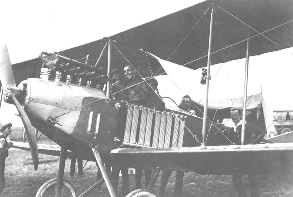
Until beaten by Bier flying a Lloyd biplane (40.01), Ernst von Lossl set a world record at the Third International Flugmeeting with three passengers (jammed in the front seat) flying the German Albatros biplane (competition No. 17 - 140 hp Hiero engine). It is likely this aircraft was taken over by the air service when the war started.
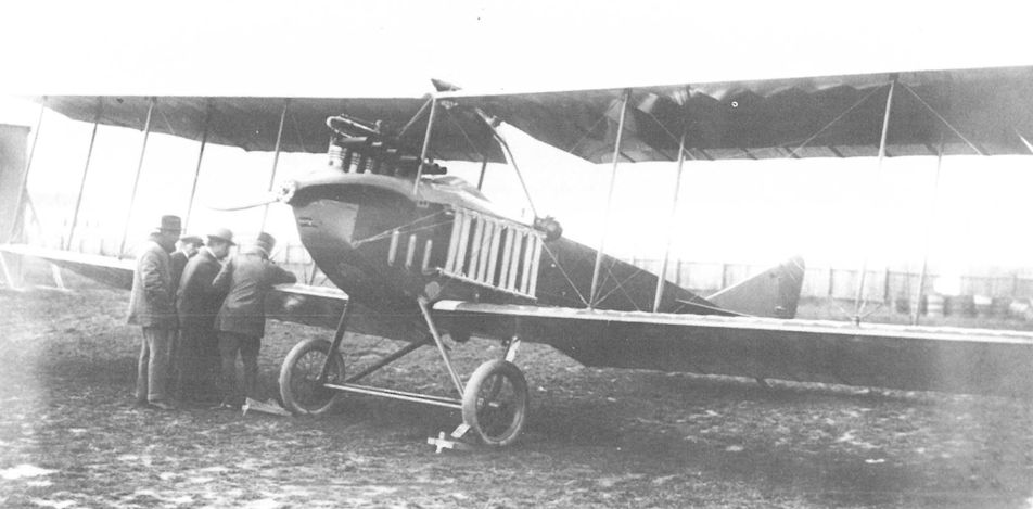
This Phonix-built Albatros B.I, powered by a 145 hp Hiero engine, was test flown by Leo Roth at Aspern in late 1914. Although no proof exists, it may have been the first form of the 20.01, or possibly an Albatros B.I(Ph) series 23 production airframe experimentally fitted with three-bay wings.
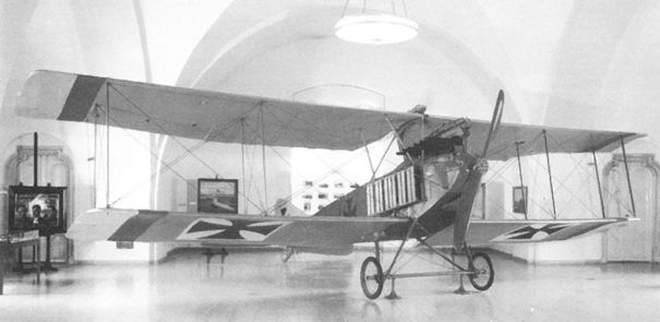
The Phonix 20.01 prototype with a 150 hp Daimler engine photographed at the Heeresgeschichtliches Museum. An identification plate on the lower wing inscribed "Albatros Typ ODD Nr.I, Berlin-Johannisthal” could signify that the wings were replacement ones manufactured by the German Albatros company.
Other than this photograph of the 200 hp Hiero inverted V-8 engine installed in the Phonix 20.02 prototype, no photographs of the prototype have been found. The outer fuselage of the Phonix 20.11 bomber, that was never completed, is in the left background.
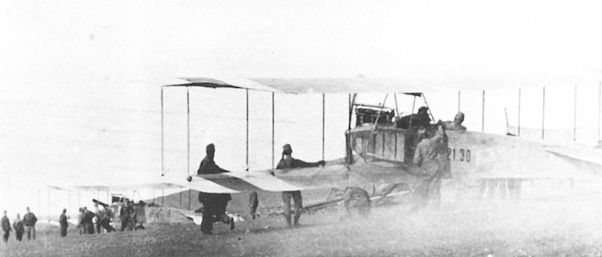
A demonstration of the confusion arising from aircraft number changes. In the foreground is a three-bay Albatros B.I 21.30 (ex 22.30). It served with Flik 1 until damaged by fire in June 1915. According to a Flars directive it was designated 21.22 (neu) in June 1916. In the distance is an Albatros B.I with the original (three-bay) designation 22.29, soon changed to 21.29.
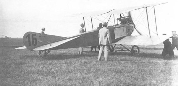
Here fitted with single-bay wings, the German Albatros biplane (competition No. 16 - 150 hp Benz engine) was flown by Hellmuth Hirth in the Third International Flugmeeting at Aspern in June 1914. The aircraft may have served as a pattern aircraft at Phonix.
Albatros B.I Series 21
Between 12 August 1914 and 4 February 1915, the LA purchased 31 Albatros biplanes both from Albatros in Johannisthal and directly from the German air service. These were assigned the designations Alb.1 to Alb.31. In February 1915, the two-bay biplanes (Alb.1 to Alb.26 - German B.II) were re-numbered B.I series 21, and the three-bay biplanes (Alb.27 to Alb.31 - German B.I) became B.I series 22. Evidently this caused confusion, and within a short time the LFT decreed that all German-built Albatros biplanes would carry the same series designation, namely B.I 21.01 to 21.31. These biplanes were powered by the 100 hp Mercedes engine and were unarmed. In practice, many Fliks referred to the aircraft by nicknames such as Lump, Elly, Steffel, Loni, or Muzzl which were often prominently displayed on the fuselage.
Desperately short of aircraft, air service officers went directly to German factories to pick up the aircraft and fly them home. On 9 September 1914, the British journal The Aeroplane reported that eleven Austrian officers flew six Albatros machines from Johannisthal to Vienna in the early days of the war. As they replaced the war-weary Lohner Pfeilfliegers in August-September 1914, the Albatros machines were praised as the best operational two-seaters by virtue of their ruggedness, pleasant flight characteristics, and easy maintenance. The B.I served with Fliks 1, 5, 8, 10, 11, and 13 on the Russian Front until the fall of 1915.
The load capacity of the Albatros B.I made it the ideal choice to carry the experimental wireless equipment for frontline trials. On 27 December 1914, Uzelac and Oberleutnant Dr Leopold Kann (who supervised the installation) flew to Flik 1 in Muzzl (Alb.7) in which a wireless transmitter weighing 42 kg (92 lb) and a 220-volt generator weighing 18 kg (40 lb) were installed. What is believed to be the first wartime use of air-to-ground wireless communication to direct artillery fire occurred on 12 January 1915, when two Flik 1 officers, Oberleutnants Max Hesse and Ludwig Dumbacher, successfully spotted the salvoes of a 42cm battery fired against Russian rail supply lines at Tarnow (Galicia) with devastating effect. Subsequently Flik 1 installed similar wireless equipment in three Albatros biplanes. In September 1915 the Albatros B.I series 21 biplanes were withdrawn from operational use and assigned to Fleks 1, 2, and 5 as secondary trainers. Ten were carried in the training command inventory as of February 1917.
Albatros B.I Series 21 (Twin-Bay)
Engine: 100 hp Mercedes
Wing: Span Upper 12.80 m (41.99 ft)
Chord Upper 1.80 m (5.91 ft)
Chord Lower 1.80 m (5.91 ft)
Total Wing Area 20.1 sq m (216 sq ft)
General: Length 7.76 m (25.46 ft)
Height 3.15 m (10.33 ft)
Track 2.19 m (7.18 ft)
Empty Weight 725 kg (1599 lb)
Loaded Weight 1165 kg (2569 lb)
Maximum Speed: 110 km/hr(68 mph)
Climb: 2000m (6,562 ft) in 40 min
Phonix 20.04
The Phonix 20.04, ordered on 4 March 1915 and powered by a 145 hp Hiero engine, was a standard Albatros B.I(Ph) series 24.5 airframe fitted with a large turret to investigate the suitability of the 3.7cm Hotchkiss rapid-fire cannon for air warfare. Test pilot Antal Feher was at the controls for the first airborne firing trials on 26 February 1917 when five shots were fired at an altitude of 1000 meters (3280 ft). Although the firing results are not known, similar Navy experiments had demonstrated that the firing rate was too slow to achieve effective results. In May 1918, the 20.04 was used for airborne cinematographic experiments before being attached to the weapons research group at Fischamend for trials involving the 12 kg (26 lb) aircraft bomb and the 1 kg (2.2 lb) Fliegermaus anti-personnel bomb. In 1920, the 20.04, less engine, was offered for sale to Czechoslovakia.
Phonix 20.05, 20.06, and 20.07
On 28 March 1915, Flars ordered three Albatros B.I(Ph) series 24 aircraft, powered by 145 hp Hiero engine, for the purpose of testing various machine gun installations mounted over the center section to provide forward firepower in the absence of a workable interrupter gear. Aircraft 20.07 was used to flight test the first wing cellule designed by Professor Knoller to improve the climbing characteristics of the B.I design. In the spring of 1916, all three aircraft were fitted with the new 200 hp Hiero engine for performance trials involving radiator evaluation and propeller matching. The three Phonix prototypes continued to give useful service. Aircraft 20.05 was flown by Flek 2 as a trainer and written-off in July 1918. Aircraft 20.06, re-engined with a 145 hp Hiero(Mar) engine, was assigned to the Flars test group at Fischamend and in June 1918 used for radio and weapon trials. Aircraft 20.07, modified as a dual-control trainer, was assigned to Flek 2 and written-off in November 1917.
Phonix 20.17
Only two references to the elusive Phonix 20.17, powered by a 145 hp Hiero engine, have been found. In August 1918 the Phonix 20.17 was attached to Flek 3 at Thalerhof where it was again listed as "stored in damaged condition" in October 1918.
Albatros B.I(Ph) Series 23 (First Series) and Series 21.3
The Oesterreichisch-Ungarische Albatros Werke (henceforth referred to as Phonix) received its first production contract on 17 August 1914 calling for one prototype (oAlb. 01) and 29 series machines. Two additional aircraft, ordered in March 1915, brought the total delivered to 31. The original designation, oAlb.1 to oAlb.31, was changed to Albatros B.I(Ph) 23.01 to 23.31 in February 1915. The Albatros B.I(Ph) production drawings as prepared by Phonix were based on the German 100/120 hp Albatros B.II but given slightly larger overall dimensions, additional wing bracing, and minor structural changes to accommodate the more powerful 145 hp Hiero engine. The B.I(Ph), like its German B.II counterpart, was a versatile, rugged machine and, being easy to fly, the series remained in training service through 1918.
Acceptances began in January 1915 and the first aircraft arrived at the Front in March. They were used for general reconnaissance work by Fliks 5, 7, 8, 10, and 15 on the Russian Front, by Fliks 6 and 9 in Serbia, and by Fliks 2, 8, and 12 on the Isonzo Front until replaced by newer aircraft beginning September 1915.
In 1916, about 20 of the B.I(Ph) series 23 aircraft were returned to Phonix for conversion to trainers. In the process, ten became the Albatros B.I(Ph) series 21.3 and the rest became B.I(Ph) series 24 trainers. The new series 21.3 aircraft were fitted with dual controls and Marta-built Hiero engines, and in 1918 three had repaired 100 hp Mercedes engines installed. The converted trainers served with the officer's flying school at Wiener-Neustadt and Fleks 2, 3, 6, 8, 9, and 22 through 1918.
In several instances the original LFT records regarding the conversion number are ambiguous and confusing, a situation impossible to clarify because the individual aircraft records have been destroyed. Unless noted, the conversions shown below are believed correct:
Conversion Number Original Number Conversion Number Original Number
21.30 23.07 24.30 (b) 23.06
21.31 (a) 23.12 24.39 23.26
21.32 23.18 24.40
21.33 23.19 24.41 23.09
21.34 23.21 24.42 23.24
21.35 23.22 24.44 (c) 23.10
21.36 23.23 24.72 (d) 23.20
21.37 23.25 24.75 (e) 23.17
21.38 23.27 24.81 23.28
21.39 23.31 24.83 23.30
(a) 23.12 is also listed as converted to 24.01 and 24.40.
(b) 24.30 later became 24.70.
(c) 24.44 later became 24.80.
(d) 24.72 is recorded as having been converted from 24.11.
(e) 24.75 is recorded as having been converted from 24.03.
Albatros B.I(Ph) Series 23 Specifications
Engine: 145 hp Hiero
Wing: Span Upper 13.20 m (43.31 ft)
Span Lower 11.37 m (37.30 ft)
Chord Upper 1.80 m (5.91 ft)
Chord Lower 1.80m (5.91 ft)
Sweepback Upper 3 deg
Sweepback Lower 3 deg
Gap 1.78 m (5.84 ft)
Stagger 0 m (ft)
Total Wing Area 40.9 sq m (440 sq ft)
General: Length 8.35 m (27.39 ft)
Height 3.33 m (10.93 ft)
Track 2.22 m (7.28 ft)
Empty Weight 860 kg (1896 lb)
Loaded Weight 1235 kg (2723 lb)
Maximum Speed: 110 km/hr (68 mph)
Climb: 1000m (3,281 ft) in 10 min 40 sec
Albatros B.I(Ph) Series 24 and Series 24.5 (Second Series)
In August 1914, Phonix engineers were already at work improving the Albatros B.I(Ph), later known as series 24, by reducing the weight, installing a new radiator, and improving the sweepback adjusting mechanism. A total of 82 Albatros B.I(Ph) series 24 biplanes were built, composed of 53 new aircraft and 29 converted from older series 23 or 24 airframes.
Qty Series No. Order Date Comments
32 24.01-32 28 Mar 1915 includes 4 converted series 23
9 24.33-46 8 Sep 1915 includes 5 converted series 23
(24.47-50) numbers not assigned
16 24.51-66 20 Jul 1915 Knoller wing from 24.51 up
20 24.67-86 converted series 23 and 24
Power was supplied by a 145 hp Hiero engine and three aircraft (24.14, 23, and 30) were later fitted with Daimler engines. The first production machine was accepted in July 1915, and by December the type was operational with Fliks 2, 4, 8, and 12 on the Isonzo Front, Flik 9 and 15 in the Balkans, and Flik 7 in the East. According to expert Karl Meindl, credit for the first air victory scored on the Italian Front goes to Oberleutnants Hassan Risa Effendi Pieler and observer Roman Florer when, flying Albatros B.I(Ph) 24.10, they downed an Italian Farman with a Mauser pistol on 13 September 1915.
It was soon apparent that even the lightened series 24 had difficulty climbing over 2200 meters (7218 ft), a distinct liability in mountainous country. At Flars' request, Professor Knoller designed a new wing cellule to increase the rate of climb and operational ceiling. The Knoller KNV wing (Knoller Verspannung? - Knoller bracing) had increased span and area, a new rib profile, and a tapered planform supported by diagonal wing-tip struts. At least 12 series 24 aircraft were retro-fitted with the KNV wing. It was also installed on 16 new machines (24.51 to 24.66), ordered in July 1915 and scheduled for delivery in August-September 1915, but acceptances were delayed until early 1916. The series 24.5 served for a short time with Fliks 2, 4, 12, and 19 on the Italian Front until about May 1916, when they were gradually replaced by the Brandenburg C.I.
In mid-1916, Phonix retro-fitted 20 Albatros B.I(Ph) series 23 and 24 aircraft for advanced training service, receiving in the process the KNV wing, dual controls, and a new designation (24.67 to 24.86):
Conversion Number Original Number Conversion Number Original Number
24.67 24.17 24.77
24.68 24.78 24.09
24.69 24.15 24.79 24.29
24.70 24.30 24.80
24.71 24.13 24.81 23.28
24.72 24.11 24.82
24.73 24.07 24.83 23.30
24.74 24.05 24.84
24.75 24.03 24.85
24.76 24.01 24.86
Twelve B.I(Ph) series 24 aircraft were modified in 1916-1917 for dual controls, but unlike the above machines, they did not receive a new designations. They were 24.16, 23, 32, 34, 36, 38, 40, 54, 59, 61, 63, and 66. Single Albatros B.I(Ph) series 24 aircraft continued to serve individually as advanced trainers with Fliks 4, 8, 14, 19, 28, and 34, but the bulk were assigned to Fleks 2, 3-6, 8, and 22 and Schulkompagnie 1 and 2 at Wiener-Neustadt. As of September 1917, the training command operated 46 B.I(Ph) series 24 trainers, of which 28 survived the war.
Albatros B.I(Ph) Series 24 Specifications
Engine: 145 hp Hiero
Wing: Span Upper 13.40 m (43-96 ft)
Span Lower 11.72 m (38.45 ft)
Chord Upper 1.80 m (5.91 ft)
Chord Lower 1.80 m |5.91 ft)
Sweepback Upper 4 deg
Gap 1.78 m (5.84 ft)
Total Wing Area 42.0 sq m (452 sq ft)
General: Length 8.35 m (27.39 ft)
Height 3.33 m (10.93 ft)
Track 2.22 m (7.28 ft)
Empty Weight 834 kg (1839 lb)
Loaded Weight 1276 kg (2814 lb)
Maximum Speed: 110 km/hr (68 mph)
Climb: 1000m (3,281 ft) in 13 min 25 sec
Albatros B.I(Ph) Series 24.5 Specifications (Knoller Wing:)
Engine: 145 hp Hiero
Wing: Span Upper 13.90 m (45.60 ft)
Span Lower 11.80 m (38.71 ft)
Chord Upper 2.30 m (7.55 ft)
Chord Lower 1.70 m (5.58 ft)
Sweepback Upper 4 deg
Gap 2.05 m (6.73 ft)
Stagger 0.35 m (1.15 ft)
Total Wing Area 42.6 sq m (458 sq ft)
General: Length 8.35 m (27.39 ft)
Height 3.54 m (11.61 ft)
Track 2.22 m (7.28 ft)
Empty Weight 815 kg (1797 lb)
Loaded Weight 1252 kg (2761 lb)
Maximum Speed: 121 km/hr (75 mph)
Climb: 1000m (3,281 ft) in 8 min 54 sec
Albatros B.I(Ph) Series 22 (Third Series) and Series 21.7
The Albatros B.I(Ph) series 22 was the third and last B.I series produced by Phonix. A total of 31 were accepted, consisting of 8 aircraft ordered on 20 July 1915 and numbered 22.01 to 22.08, and a second batch of 23 aircraft ordered on 8 November 1915 and numbered 22.10 to 22.32. The airframe was identical with the series 24 with the exception that a more powerful 160 hp Mercedes engine was installed. Production deliveries began in August-September 1915. A few of the early series 22 aircraft were delivered with the standard twin-bay wing cellule, whereas the remainder (possibly beginning with 22.05) were fitted with the Knoller KNV wing.
The series 22 was flown as a general-purpose reconnaissance machine by Fliks 1, 10, 20, and 22 and singly by Fliks 3, 8, 11, 13, 14, 25, and 30. The added power gave the series 22 the best performance of the Phonix-built B.I aircraft which, coupled with the improved observer's armament, allowed the type to be employed in a more aggressive role. At least 18 victories (all on the Russian Front) were achieved flying the series 22, compared to only one or two with the series 23 and 24.
Beginning September 1916, the series 22 aircraft began to be withdrawn from the Front. The 19 surviving aircraft were modified as trainers, fitted with a 100 hp Mercedes engine, and re-designated series 21.7 in the following manner:
Conversion Number Original Number Conversion Number Original Number
21.71 22.02 21.81 22.13
21.72 22.12 21.82 22.17
21.73 22.32 21.83 22.18
21.74 22.01 21.84 22.19
21.75 22.30 21.85 22.20
21.76 21.86 22.07
21.77 21.87 22.24
21.78 21.88 22.31
21.79 22.05 21.89 22.21
21.80 22.03
The converted B.I(Ph) series 21.7 aircraft served as advanced trainers with Flek 2 in Wiener-Neustadt and singly with Fleks 3 and 22. Aircraft 21.78 and 21.83 were converted to single-seater trainers. In October 1918, eleven series 21.7 aircraft remained on the LFT inventory.
Albatros B.I(Ph) Series 22 Specifications
Engine: 160 hp Mercedes
Wing: Span Upper 13.40 m (43.96 ft)
Span Lower 11.66 m (38.25 ft)
Chord Upper 1.80 m (5.91 ft)
Chord Lower 1.80 m (5.91 ft)
Sweepback Upper 2 deg
Sweepback Lower 2 deg
Gap 1.78 m (5.84 ft)
Stagger 0 m (0 ft)
Total Wing Area 42.0 sq m (452 sq ft)
General: Length 8.35 m (27.39 ft)
Height 3.33 m (10.93 ft)
Track 2.22 m (7.28 ft)
Empty Weight 928 kg (2046 lb)
Loaded Weight 1385 kg (3054 lb)
Maximum Speed: 114 km/hr (71 mph)
Climb: 1000m (3,281 ft) in 9 min 25 sec
2000m (6,562 ft) in 22 min 30 sec
3000m (9,843 ft) in 46 min
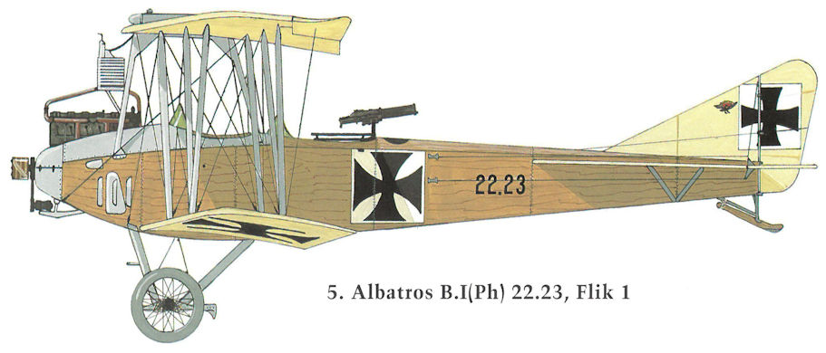
Albatros B.I(Ph) 22.23, Flik 1
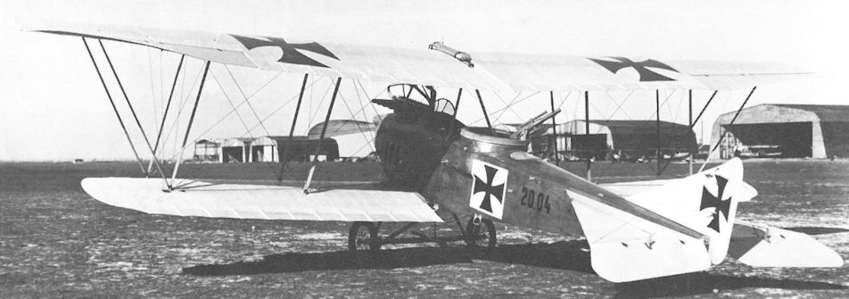
The Phonix 20.04 at Aspern in February 1917 with the 3.7 cm Skoda-Hotchkiss cannon installed.
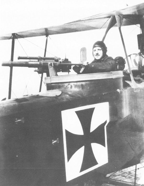
Phonix 20.04. The fuselage of the standard Albatros B.I(Ph) series 24.5 airframe has been widened to provide space for the turret installation of the Hotchkiss cannon.

The 37mm Hotchkiss L/23 rapid-fire cannon installed in the Phonix (Albatros ???) 20.04 prototype for firing trials, 29 August 1918.
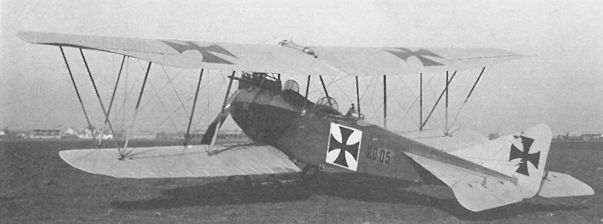
The Phonix 20.05 was used to develop service criteria for the new 200 hp Hiero engine. For these trials, the aircraft was fitted with the Knoller wing cellule.
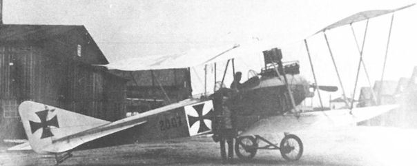
The Knoller wing cellule was first tested on the Phonix 20.07. The prototype was later modified for dual control, as shown here, and flown by Flek 2 as a trainer.
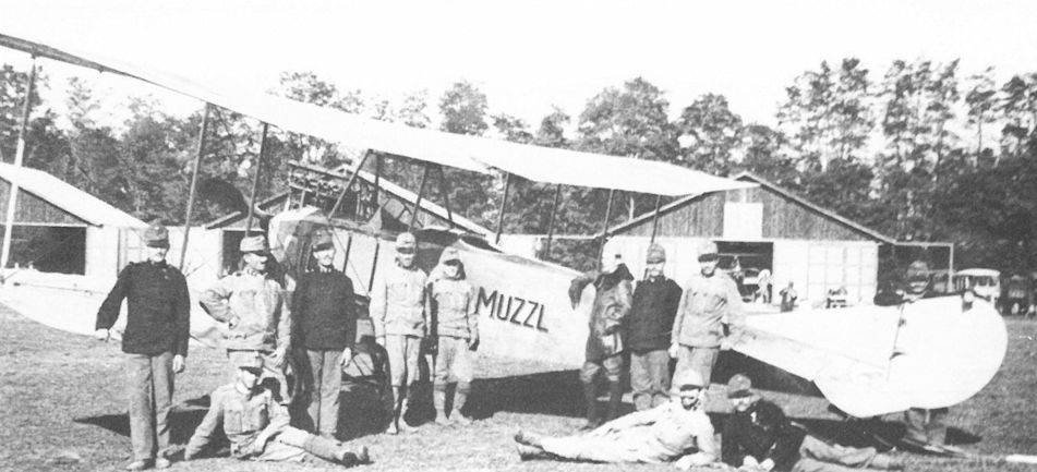
Leutnant Bela Feszl (leather jacket) of Flik 1 with Albatros Alb.7 Muzzl (later B.I 21.07) on 25 November 1914 shortly after being transferred from Flik 14. It should be noted that the two-bay biplane, shown here in its earliest version, was designated B.II by the German air service.
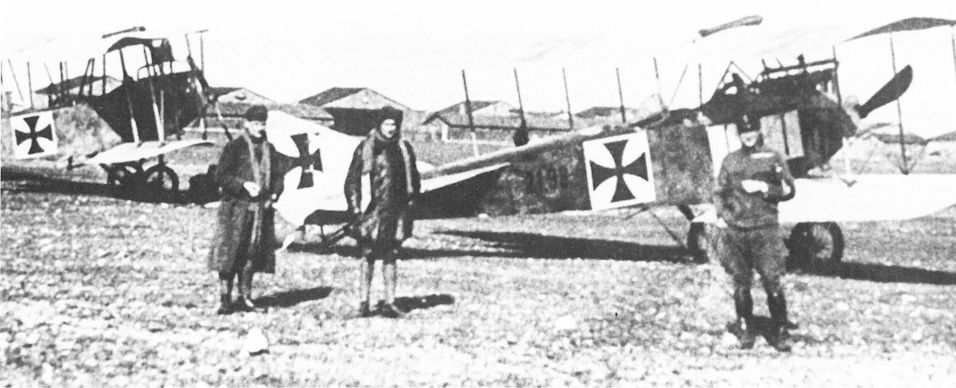
The Albatros B.I(Ph) 21.38, converted to a dual-control trainer from aircraft 23.27 in 1916, served with Flek 9 until written-off in October 1918.
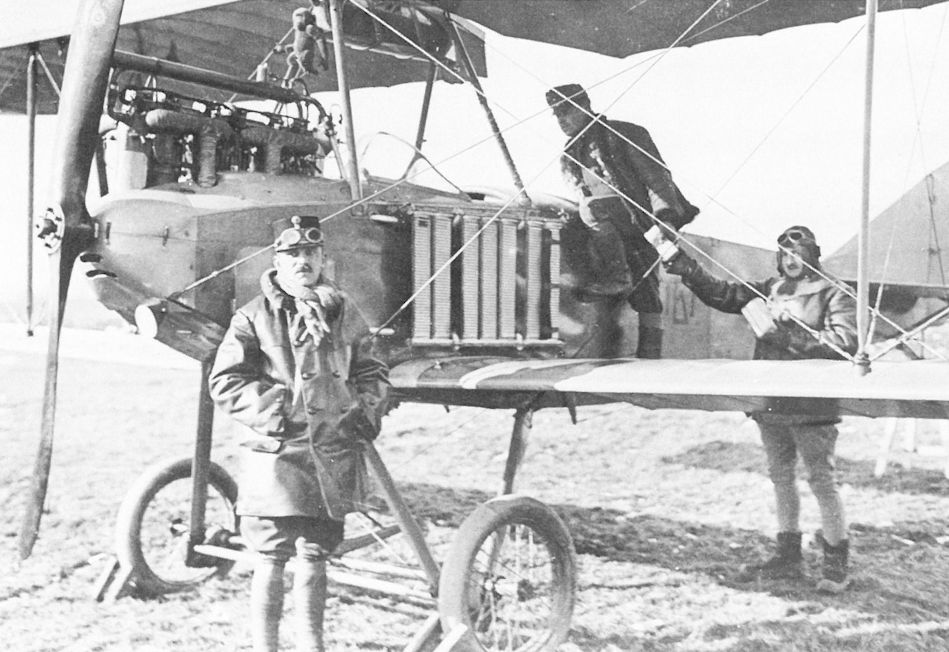
Oberleutnant Alfred Schindler and his Albatros B.I series 21 being readied for take-off at Przemysl. A monkey mascot hangs from the center section strut.
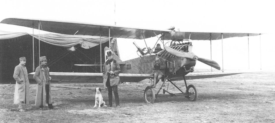
Albatros B.I(Ph) 22.01 of Flik 1 on the airfield at Zastawna in late autumn 1915. A few of the early series 22 aircraft were delivered with the original two-bay wing cellule.
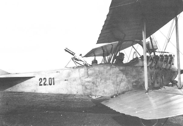
Albatros B.I(Ph) 22.01. It appears that the series 22 aicraft were the first to have a factory-installed gun ring. The one shown here was a precursor of the standard, tubular gun ring.
Albatros B.I, 22.01, Flik 1, Flugzeugverlust am 7. Juli 1915
Albatros B.I, 22.01, Flik 1, потерян 7 июля 1915 г.
Albatros B.I, 22.01, Flik 1, Flugzeugverlust am 7. Juli 1915
Albatros B.I, 22.01, Flik 1, потерян 7 июля 1915 г.
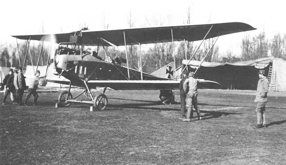
The majority of the series 22 were delivered with KNV wings. Shown here is Albatros B.I(Ph) 22.20 of Flik 20 on the Wladimir Wolynski airfield in 1916. In June-July 1916, Flik 20 aircrews achieved two victories flying this aircraft.
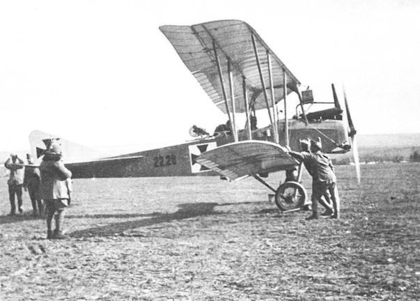
The tapered planform of the KNV wing is evident in this photo of Albatros B.I(Ph) 22.28. It was flown by Flik 1 on the Eastern Front between March and October 1916. The generator under the nose indicates that wireless equipment was installed.
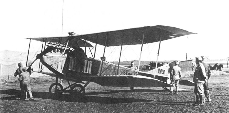
Albatros B.I(Ph) 23.02 of Flik 15 was destroyed by fire during refueling at Brzesko on 7 April 1915. Series 23 aircraft can be identified by the fuselage side radiators.
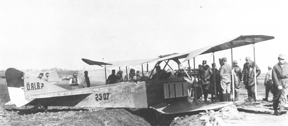
The sheet-steel fuselage armor fitted to series 23 aircraft can be discerned underneath the observer’s position on this Albatros B.I(Ph) 23.07. At the Front the armor was often regarded as superfluous and removed. In 1916 this machine was converted to a trainer and re-numbered 21.30.
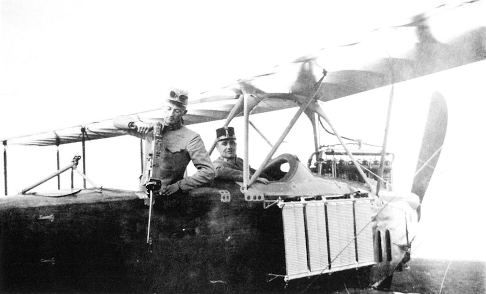
Albatros B.I(Ph) 23.24 of Flik 7 on the Russian Front demonstrating the rudimentary gun mountings installed in the field. The machine gun is the 6.5mm Schwarzlose M.12 originally built for export to Greece. Unlike the German B.II, the Phonix-built version had additional center-section struts.
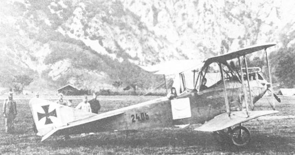
Albatros B.I(Ph) 24.06 served with Flik 12 from September 1915 through February 1916 at Aisovizza, Isonzo Front. The mountainous terrain made altitude performance a priority with aircrews.
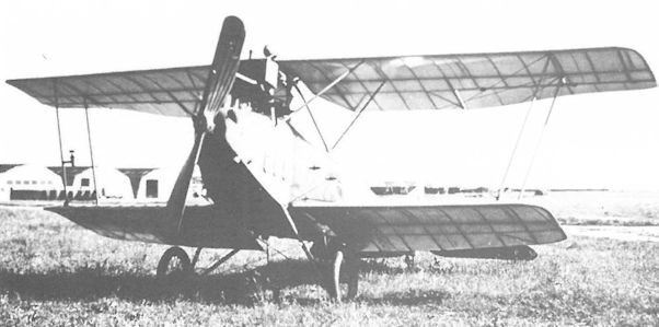
Albatros B.I(Ph) 24.36 was fitted with an experimental single-bay wing of greatly reduced span. It was attached to the training command from 1917 through 1918.
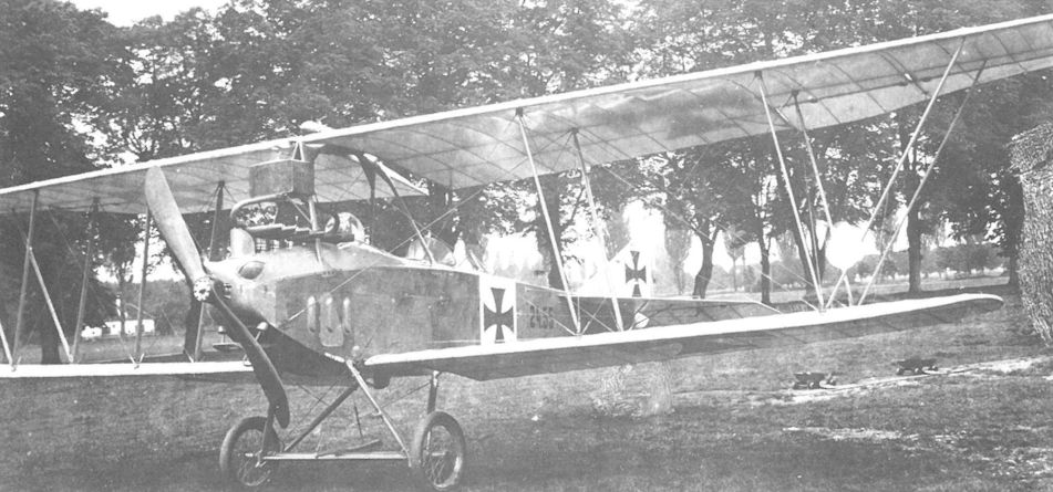
New Albatros B.I(Ph) 24.55 demonstrates the KNV wing cellule. The aircraft was flown by Flik 2 in February-March 1916 and later assigned to training service.
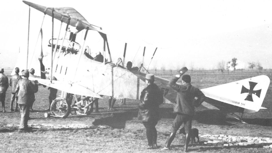
Preparing for take-off at Flik 4 in Aisovizza is the Albatros B.I(Ph) 24.57. The empty generator platform under the propeller hub shows that wireless equipment was not carried. The simple machine gun tripod was installed in the field.
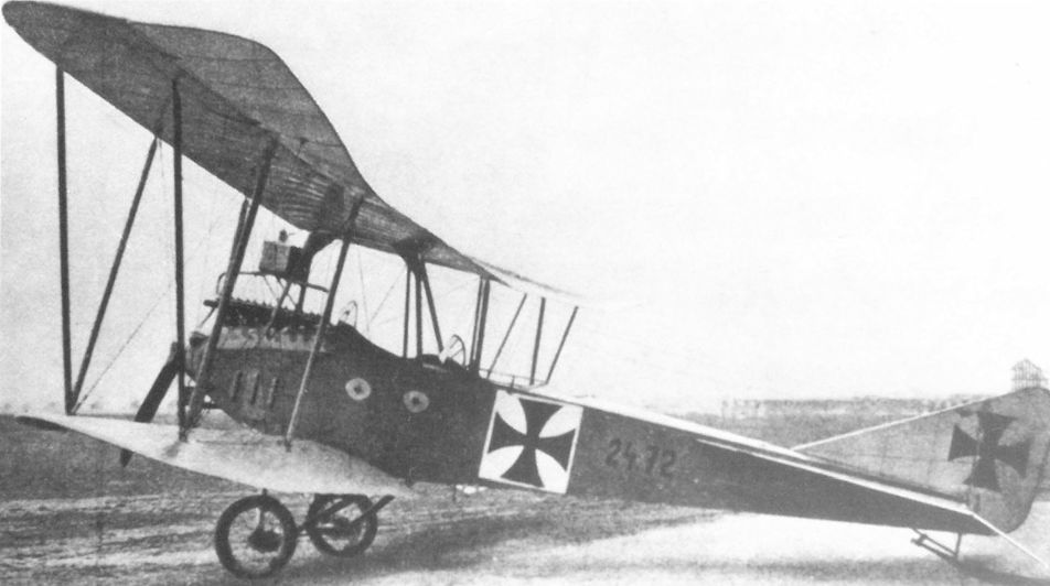
Converted to an advanced trainer, the Albatros B.I(Ph) 24.72 was used for gunnery and wireless instruction at the officer’s flying school at Wiener-Neustadt. A standard tubular gun ring was installed during conversion from 24.11.
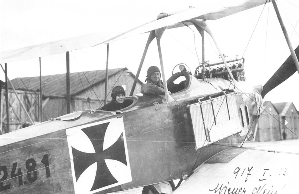
Albatros B.I(Ph) 24.81, converted from aircraft 23.28, was fitted with the new Knoller wing cellule but retained the side radiators, the fuselage armor, and the characteristic pilot’s visor. It was attached to Schulkompagnie 1 in Wiener-Neustadt until written-off in April 1917.
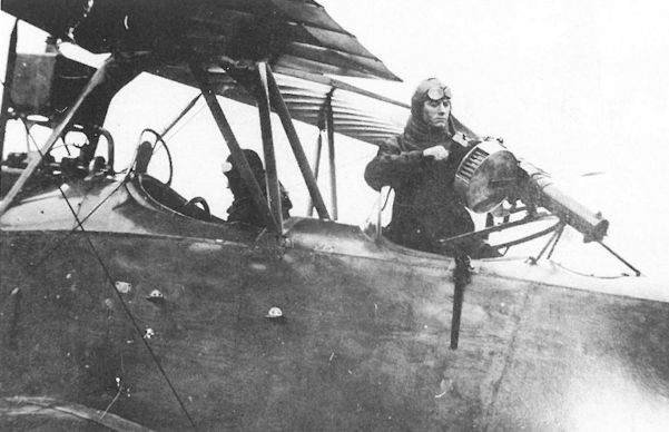
The semi-circular gun mount, fitted to an Albatros B.I(Ph), was a field modification that presaged the standard tubular-ring turret of 1916. The webbed ammunition belt for the Schwarzlose M 7/12 gun is fed from a standard-issue drum.
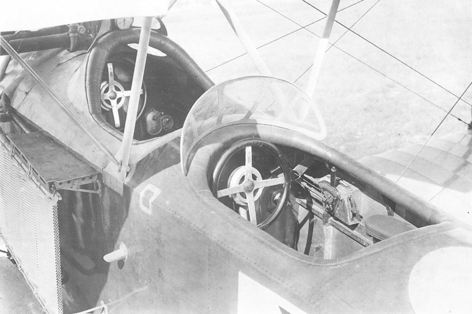
The side radiators on the Albatros B.I(Ph) 24.40 dual-control trainer are a sure sign that it was converted from a series 23 airframe. The throttle can be seen on the right side. The arrow on the control wheel spoke indicates when the controls are centered.
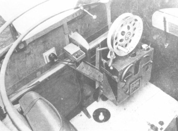
Wireless equipment installed in the rear cockpit of the Albatros B.I(Ph) 24.72, showing the antenna spool, the antenna weight, and the opening in the corrugated metal floor.
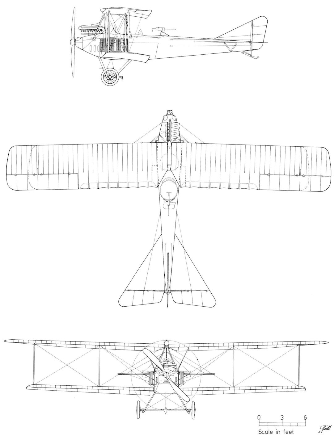
Albatros B.I(Ph) Series 23
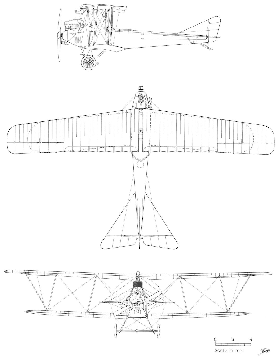
Albatros B.I(Ph) Series 22 (KNV Wing)
Albatros C.XII
In 1917, the possibility of manufacturing the German Albatros C.XII under license was discussed by the LFT, but the appearance of the promising Phonix C.I and UFAG C.I reconnaissance biplanes put an end to the proposal.
In 1917, the possibility of manufacturing the German Albatros C.XII under license was discussed by the LFT, but the appearance of the promising Phonix C.I and UFAG C.I reconnaissance biplanes put an end to the proposal.
Albatros J.I Series 09
To facilitate "contact between aircraft and infantry" the German air service developed armor-plated aircraft in 1916, designed to withstand infantry fire at an altitude of 700 meters (2297 ft). When the J-type (infantry) aircraft reached the Front in June 1917, aircrews praised the all-round protection offered by the armor plating, a feature that far outweighed the poor performance and sluggish flight characteristics. The LFT did not posses an armored aircraft, although steps had been taken at Phonix to develop one. To gain combat experience, Flars purchased three German Albatros J.I armored biplanes less engines in December 1917. These were numbered 09.01 (ex J.400/17), 90.02 (J.726/17) and 90.03 (J.730/17), and were powered by the Marta-built 250 hp Benz engine. During the evaluation tests at Aspern, aircraft 09.02 crashed in flames on 28 February 1918. Aircraft 09.01 was damaged at the Front on 5 May 1918 and returned to Aspern for repairs. The only J.I used operationally was 09.03, which served with Flik 69/S between July and September 1918.
Albatros J.I Series 09
Engine: 250 hp Benz (Mar)
Wing: Span Upper 14.14 m (46.39 ft)
Span Lower 12.94 m (42.45 ft)
Chord Upper 1.80 m (5.91 ft)
Chord Lower 1.60 m (5.25 ft)
Dihedral Upper 2.5 deg
Dihedral Lower 2.5 deg
Sweepback Upper 2.5 deg
Sweepback Lower 2.5 deg
Stagger 0 m (0 ft)
Total Wing Area 42.82 sq m (461 sq ft)
General: Length 8.84 m (29.00 ft)
Height 3.37 m (11.06 ft)
Track 2.20 m (7.22 ft)
Empty Weight 1398 kg [3083 lb)
Loaded Weight 1808 kg (3987 lb)
Maximum Speed: 140 km/hr (87 mph)
Climb: 1000m (3,281 ft) in 5 min
2000m (6,562 ft) in 12 min 6 sec
3000m (9,843 ft) in 26 min
4000m (13,124 ft) in 52 min

Cockpit and gunner’s position of the Albatros J.I 09.01 showing the control wheel, the side doors for the pilot, and the German adaptation of the British Scarff machine-gun ring. The work number, 4267, is stencilled on the lower wing.
Aviatik B.I Series 31 and 31.7
Seven Aviatik biplanes purchased prior to the outbreak of war (5 June 1914) were shipped from the Muhlhausen factory on 20 June. Between September 1914 and January 1915, an additional 30 Aviatik biplanes were purchased, but only a grand total of 25 (including 30.01 and 30.02) were delivered, some supplied from German Army stocks. The original LA designation Av.1 to Av.23 was changed to Aviatik B.I 31.01 to 31.23 in February 1915. As was often the case in late 1914, some squadron aircraft were identified solely by names such as Baba, Dutch, Elsa, Muki, and Rosa, by Roman numerals such as Av.l and Av.XII, or by the work number such as Aviatik 282. Most of the Aviatik biplanes were the twin-bay Type P.14, but at least three were the Type P.15 fitted with a three-bay wing cellule.
In early July 1914, LA pilots were performing familiarization flights. The Aviatik biplane was rugged and stable but being relatively heavy, tended to be underpowered with its 100 hp Mercedes engine. At least six aircraft were retro-fitted in the field with 120 hp Daimler engines to obtain better performance. Most sources agree that on 2 August 1914 Aviatik B.I (Av.2) of Flik 5 had the honor of performing the first Austro-Hungarian war flight over enemy territory. The B.I was flown by Fliks 3, 5, 7, and 8 on the Russian Front and Fliks 2 and 4 on the Serbian Front. By mid-1915, the B.I was rapidly reaching the end of its usefulness. Flik 7 reported in August 1915 that the worn-out B.I could not climb over 900 meters (2953 ft). In September 1915, the extant B.I biplanes were withdrawn and assigned to Fleks 2-6, 8, 9, and 12 as trainers, while eight machines were sent to the Aviatik factory in Vienna for modification to dual control. To identify the dual-control version, the designations were changed as follows:
Conversion Number Original Number Conversion Number Original Number
31.71 31.01 (Av.1) 31.75 31.15 (Av.15)
31.72 31.05 (Av.5) 31.76 31.19 (Av.19)
31.73 31.06 (Av.6) 31.77 31.22 (Av.22)
31.74 31.07 (Av.7) 31.78 -
Fitted with 120 hp Daimler engines, the dual-control trainers were flown by Fleks 3, 4, and 6. As of July 1917, three Aviatik B.I series 31 and six series 31.7 were still on charge.
Designation Work Number Type Designation Work Number Type
Av.1 283 P.14 Av. 13 291 P.14
Av.2 280 P.14 Av. 14 324
Av.3 282 P.14 Av.15 323
Av.4 292 P.14 Av. 16 322
Av.5 287 Av. 17 319
Av.6 288 P.14 Av. 18 317 P.14
Av.7 289 P.14 Av.19
Av.8 300 P.14 Av.20 P.15
Av.9 299 P.15 Av.21 P.15
Av. 10 293 Av.22
Av. 11 297 Av.23
Av. 12 298
Aviatik B.I Series 31
Engine: 100 hp Mercedes
Wing: Span Upper 14.00 m (45.93 ft)
Span Lower 10.60 m (34.78 ft)
Chord Upper 1.88 m (6.17 ft)
Chord Lower 1.88 m (6.17 ft)
Dihedral Lower 6 deg
Gap 1.91 m (6.27 ft)
Total Wing Area 45 sq m (484 sq ft)
General: Length 8.63 m (28.31 ft)
Height 3.15 m (10.33 ft)
Track 2.05 m (6.73 ft)
Empty Weight 825 kg (1819 lb)
Loaded Weight 1250 kg (2756 lb)
Maximum Speed: 100 km/hr (62 mph)
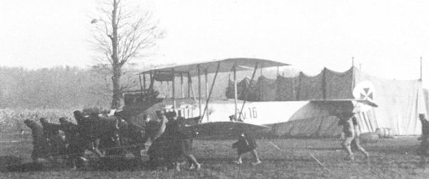
Ground crews rolling the Aviatik Av.16 to take-off position on the Flik 4 airfield at Sabac in 1914. Some of the early-production Aviatik P.14 biplanes were fitted with a button tail.
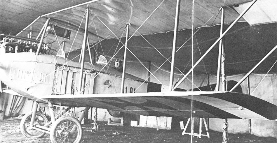
Aviatik B.I 31.01 (ex Av.1) was flown by Flik 8 up to April 1915, then Flik 7 on the Russian Front. It was still flying in September 1917 as a dual-control trainer, re-numbered B.I 31.71.
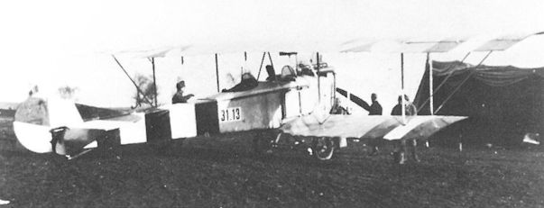
Aviatik B.I 31.13 (ex Av.13) on the Miechow airfield where Flik 7 operated in concert with German Fliegerabteilung 36 in March 1915. The crew was captured when the aircraft was shot down by Russian artillery on 27 fitly 1915.
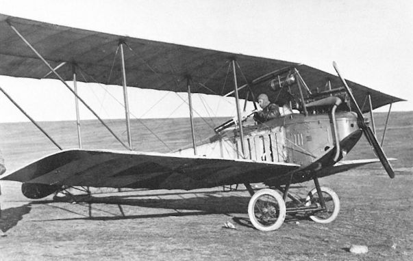
Aviatik B.I Baba in the Przemysl fortress during the second siege by the Russians in March 1915. The aircraft delivered mail and medicines and flew out with mail and military documents. It was among the first fitted with a machine gun.
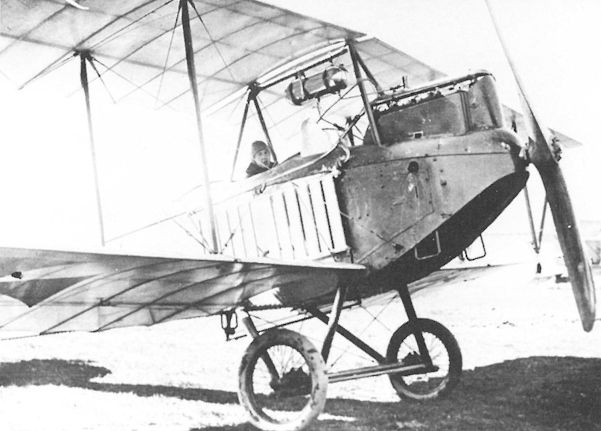
The lever connecting the dual controls is clearly visible on this Aviatik B.I series 31.7 trainer powered by a 120 hp Daimler engine.
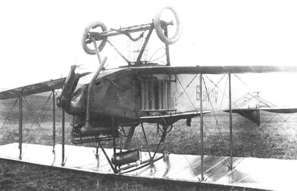
Twin vertical bomb racks were fitted to Aviatik Av.9 (later B.I 31.09). Flown by Flik 2, it was written-off as a trainer exactly two years later.
Aviatik 30.01
The German-built Aviatik B.488/14 (Type P.15, w/n 272), powered by a 100 hp Argus engine, was taken over from the German air service on 25 August 1914. Being an out-of-series purchase, the biplane was assigned the designation Av.01, later changed to 30.01. In December 1915, the 30.01 was fitted with a modified wing cellule designed by Leutnant Dr Richard von Mises of Flars. The static load tests were performed in February 1916. It is believed the modified 30.01 became the prototype for the Aviatik B.III series 33.
Aviatik 30.01
Engine: 100 hp Mercedes
Wing: Span Upper 12.0 m (39.37 ft)
Total Wing Area 40 sq m (430 sq ft)
General: Length 8.7 m (28.54 ft)
Height 3.1 m (10.17 ft)
Empty Weight 690 kg (1521 lb)
Aviatik 30.02
A second out-of-series Aviatik biplane (Type P.15, w/n 303), powered by a 100 hp Mercedes engine, was purchased from the German air service in late 1914 and assigned designation Av.02, later changed to 30.02. The aircraft was flown by Flik 8 on the Russian Front in January 1915, by Flik 3 in May, by Flik 7 during June-August 1915, and as a trainer by Fleks 3 and 4 in December 1916 until it was written-off in June 1917.

The Aviatik Av.02, (Type P.15) at Flik 8 in Krakau, December 1914. It saw active service from January 1915 until September 1915 and served as a trainer from December 1915 until it was written off in June 1917. Dual controls were not fitted.
DFW Mars Monoplane 00.01
Heinrich Bier, technical director of the Deutsche Flugzeug Werke (DFW) in Leipzig and designer of the DFW Mars aircraft, demonstrated a Mars monoplane at Aspern on 11 January 1913 for the benefit of the military authorities who were so impressed that one Mars monoplane (w/n 24, less engine) was purchased for study purposes. The LA installed a 85 hp Hiero engine and promptly discovered that the Mars could not be tested at Mostar or Gorz because the hangars or tents were too small to accomodate the large wingspan; consequently it remained at Fischamend. Assigned serial number 00.01 in February 1915, the Mars monoplane was written-off in August or October 1915.
Heinrich Bier, technical director of the Deutsche Flugzeug Werke (DFW) in Leipzig and designer of the DFW Mars aircraft, demonstrated a Mars monoplane at Aspern on 11 January 1913 for the benefit of the military authorities who were so impressed that one Mars monoplane (w/n 24, less engine) was purchased for study purposes. The LA installed a 85 hp Hiero engine and promptly discovered that the Mars could not be tested at Mostar or Gorz because the hangars or tents were too small to accomodate the large wingspan; consequently it remained at Fischamend. Assigned serial number 00.01 in February 1915, the Mars monoplane was written-off in August or October 1915.
Lloyd 40.01
On its first public appearance at the Third International Flugmeeting at Aspern, director Bier brilliantly piloted the Lloyd LS 1 biplane (competition number 20) to four world altitude records. On 27 June 1914, Bier reached an altitude of 6170 meters (20,244 ft) with one passenger and on 28 June, 5440 meters (17,849 ft) with two passengers. Bier's flying skills earned him third prize overall behind Edmund Sparmann flying for Lohner and Roland Garros for Nieuport. The record-breaking Lloyd LS 1 biplane was powered by a 145 hp Hiero engine. Praised as the best in-line engine at the Flugmeeting, it was designed by Otto Hieronimus who soon became famous for his wartime engines.
Although identified as a Lloyd product, sufficient evidence exists to demonstrate that the LS 1 was built by DFW in Leipzig. In light of the fact that Lloyd took seven months to deliver the first production aircraft, it is unlikely that the fledgling company was capable of building and fine-tuning a record-breaking competition aircraft between the opening of the factory (8 May 1914) and the first day of the Flugmeeting (21 June 1914). The LS 1 biplane (Lloyd Stahlrumpf - steel fuselage) had the characteristic DFW welded steel-tube fuselage, whereas every Lloyd fuselage was built of wood. A similar biplane photographed at the DFW factory further supports the contention that the LS 1 was built in Leipzig.
The Lloyd LS 1 (less engine) was purchased by the LA in September 1914. A new 145 hp Hiero engine was installed and the ventral radiator replaced by one mounted above the engine. From January to August 1915, the LS 1 was flown by Flik 6 at Igalo on the Montenegro Front. In military records the LS 1 was designated Lloyd 20M (M for meeting) before receiving the prototype designation 40.01 in February 1915. In late 1915, the LS 1 was purchased as surplus by Lloyd for display at the Budapest Military Aircraft Exhibition in 1917. Miraculously, the LS 1 survived the Great War, the post-war strife, and the battle for Budapest in 1944. Restored, it can now be seen at the Transportation Museum in Budapest.
Lloyd 40.01 Specifications
Engine: 145 hp Hiero
Wing: Span Upper 14.00 m (45.93 ft)
Sweepback Upper 8 deg
Sweepback Lower 8 deg
Stagger 0.60 m (1.97 ft)
Total Wing Area 44 sq m (474 sq ft)
General: Length 9.00 m (29.53 ft)
Height 3.00 m (9.84 ft)
Empty Weight 700 kg (1544 lb)
Loaded Weight 1100 kg (2426 lb)
Maximum Speed: 130 km/hr (81 mph)
The DFW “racing military biplane" shown here at the DFW factory is possibly the aircraft that participated in the Third International Flugmeeting as the Lloyd LS 1. For the competition a 145 hp Hiero engine and spinner were installed, possibly at Aszod by DFW workmen.
DFW B.I Series 01
In mid-1914, the LA purchased three MD 14 biplanes, powered by a 100 hp Mercedes engine, from the Deutsche Flugzeug Werke (DFW) in Leipzig. They were shipped to the Lloyd company (a DFW subsidiary) in Aszod for assembly. As was often the case, the purchase contract was formally approved after delivery had taken place, on 5 September 1914. At the pleading of the LA liaison officer in Berlin, an additional six DFW B.I (MD 14) biplanes were released on 5 November 1914. The B.I became operational with Flik 8 in August 1914 and also served with Flik 13 on the Eastern Front. Flying a DFW B.I during the Battle of Komarow (26 August - 1 September 1914), Oberleutnants Rudolf Holeka and Heinrich Kostrba of Flik 13 brought back decisive reconnaissance information which earned them the Militarverdienstkreuz third class, one of the highest decorations awarded to subalterns in 1914. In February 1915, the old designations, DFW 1 to DFW 9, were changed to conform to the new numbering system, becoming DFW B.I 01.01 to 01.09, respectively. Retired from frontline service in June-July 1915, at least four DFW B.I biplanes became school machines at Flek 2 and the Fliegeroffiziersschule (officers flying school) in Wiener-Neustadt. The last three DFW trainers were written-off in 1917. One was placed in storage for the planned aircraft museum in Fischamend.
LFT Designation
New Original ex-German Designation Works Number
01.04 DFW 4 B.442/14 151
01.05 DFW 5 B.443/14 152
01.06 DFW 6 B.444/14 153
01.07 DFW 7 B.445/14 154
01.08 DFW 8 B.446/14 175
01.09 DFW 9 — 176
DFW B.I Series 01
Engine: 100 hp Mercedes
Wing: Span Upper 14.0 m (45.93 ft)
Chord Upper 1.9 m (6.23 ft)
Gap 1.70 m (5.58 ft)
Total Wing Area 44.0 sq m (473 sq ft)
General: Length 8.40 m (27.56 ft)
Height 3.00 m (9.84 ft)
Empty Weight 680 kg (1499 lb)
Loaded Weight 1100 kg (2426 lb)
Maximum Speed: 110 km/hr (68 mph)
Climb: 1000m (3,281 ft) in 12 min
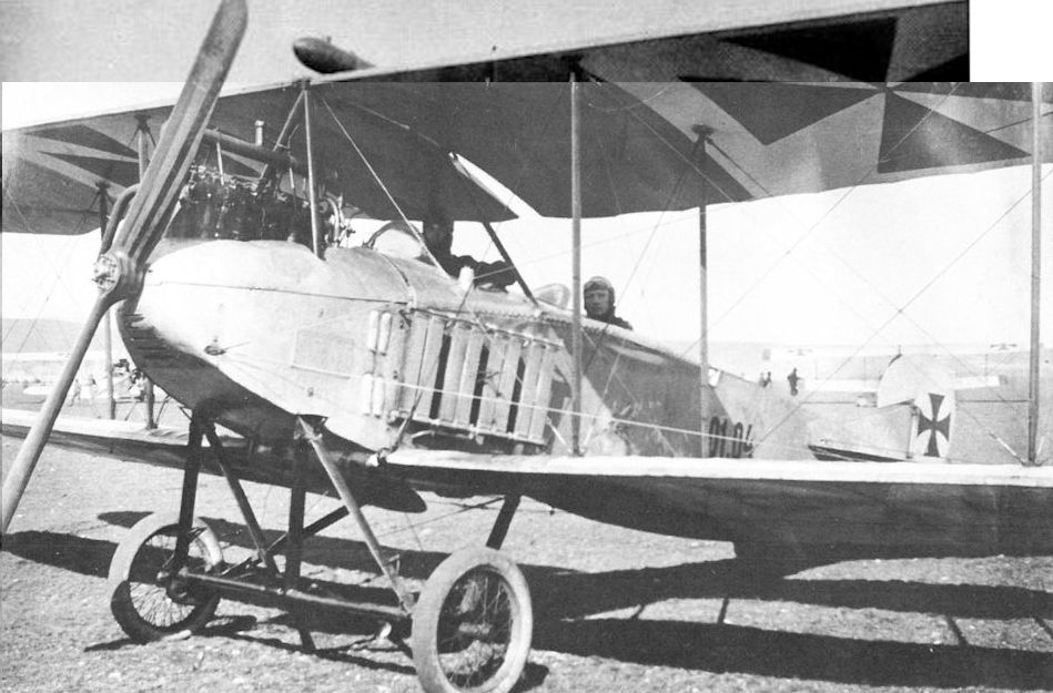
Leutnants Rudolf Spiess and Karl Spiess in the DFW B.I 01.04 (ex DFW 4) at the Fliegeroffiziersschule in Wiener-Neustadt. The faint outlines of the German serial number B.442/14 can be seen on the fin. The balanced rudder is a repair modification made by school mechanics.
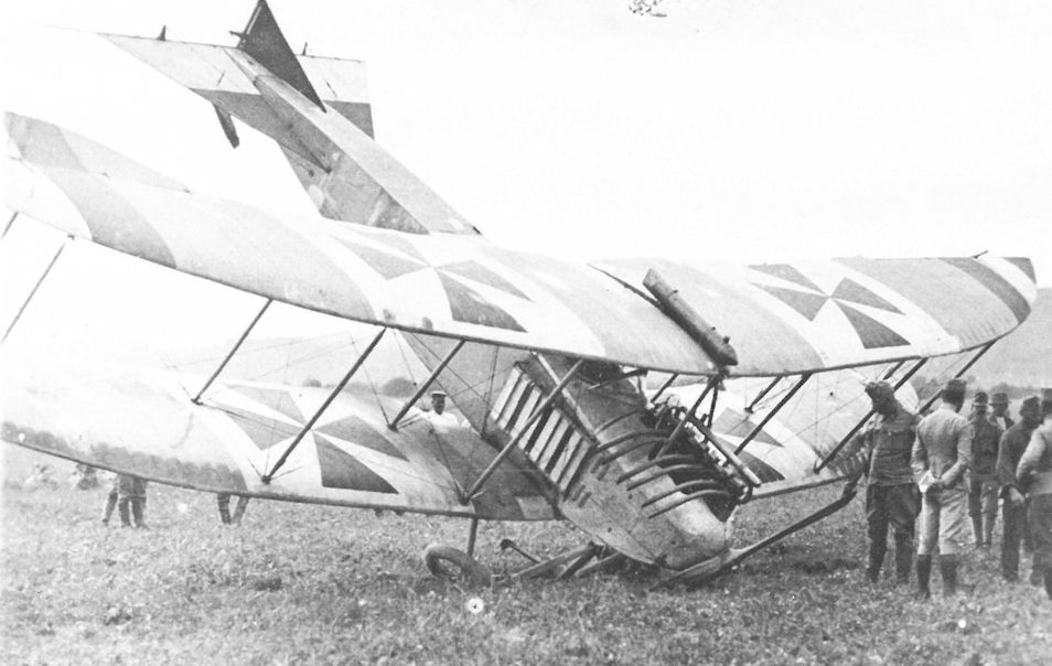
The rough airfields on the Eastern Front were not kind to aircraft, but DFW B.I 01.08 (ex B.446/14, DFW 8) of Flik 13 suffered only minor undercarriage damage on 22 November 1914. Repaired, it was flown by Flik 13 until June 1915, then as a trainer with Flek 2. DFW B.I 01.08 was written-off in June 1917.
Fokker B.I Series 03
The long-lived Fokker B.I (Type M 7 and M 10) biplane was flown throughout the war by scores of Austro-Hungarian airmen, first as a light reconnaissance aircraft and then as a basic and secondary trainer. It was praised for its tractable and safe flight characteristics. The LFT purchased a total of 39 Fokker biplanes and one M 5L monoplane according to the following schedule:
Qty Type Series Number Order Date
11 M 7 03.01,02, 04-12 20 September 1914 (a)
1 M 5L 03.03 29 January 1915
12 M 10 03.13-24 17 October 1914
4 M 7 03.25-28 6 May 1915 (rebuilt, less engines)
12 M 10 03.29-40 29 January 1915 (less engines)
(a) It is known that Fokker sent ex-B.494-505/14 to the LFT.
The Fokker 03.03 (M 5L) unarmed monoplane was initially attached to Flek 6 as a "practice aircraft," possibly in preparation for the arrival of the Fokker monoplane fighters that were ordered in July 1915. Reported damaged on 30 August 1915, the Fokker 03.03 subsequently was assigned to Flik 8 as a trainer and was written-off in March 1918.
Fokker 03.03 (M 5L)
Engine: 80 hp Oberursel
Wing: Span Upper 11.0 m (36.09 ft)
Chord Upper 1.80 m (5.91 ft)
General: Length 6.90 m (22.64 ft)
Maximum Speed: 130 km/hr (81 mph)
Climb: 1000m (3,281 ft) in 4 min 30 sec
2000m (6,562 ft) in 15 min
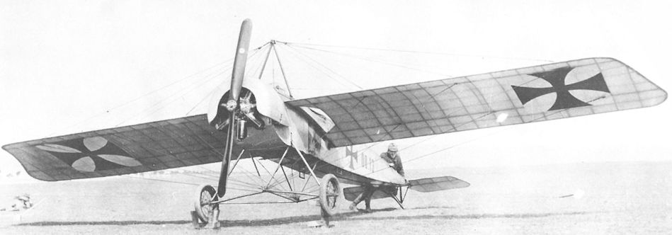
The Fokker M 5L 00.13 most likely came directly from a German unit in the field in 1915. Designated 00.13, it served as a trainer with Flek 6 until it was written off in September 1916. Here it is being photographed for an identification manual.
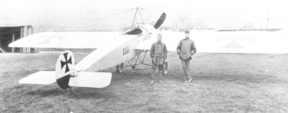
Oberleutnant Wedige von Froreich (l) of Flik 8 posing with the Fokker 03.03 (M 5L) at Haidenschaft, 25 December 1915. It is inconsistent with the LFT numbering system that an A-type monoplane was given a series number from among a large group of biplanes, but this may simply have been a matter of expediency.
Fokker A.Ill Series 03.4
Weeks before German frontline units received the new Fokker E.I (M 5KMG) fighter armed with the revolutionary synchronized machine gun, the LFT knew of its existence and had ordered 12 monoplane fighters on 7 June 1915, followed by further purchase orders totalling 33 fighters. Due to Western Front demands, the German air service refused to grant export permission until late 1915, when the sale of 12 Fokker E.III (M 14) fighters was approved. LFT acceptance of the 12 E.III fighters, designated A.III 03.41 to 03.50, 03.53, and 03.54, began in February 1916 and ended in July, just as the Fokker monoplane fighter was in process of being replaced on the Western Front.41 Aircraft 03.41 and 03.42 were powered by the French-built 100 hp Gnome rotary engine, the remainder by the 100 hp Oberursel.
It should be noted that at the time when the 12 E.III fighters were under construction in November 1915, two Fokker E.I fighters were already operational with Flik 4 on the Italian Front. The two fighters, numbered E.I 64/15 and 65/15 (80 hp Oberursel engine), had been accepted by the German air service on 4 November 1915 and left the Fokker factory the next day. The question of whether they arrived at Flik 4 directly from Schwerin or were diverted from a German squadron on the Eastern Front remains open. Initially Flik 4 pilots flew the E.I fighters in their German markings, until the two fighters were designated A.III 03.51 and 03.52 respectively.
Oberleutnant Hassan Riza Effendi Pieler flew the first recorded Fokker A.III combat sortie on 12 November 1915 to intercept a flight of Caproni bombers attacking the Flik 4 airfield at Aisovizza, but a jammed gun forced him to retire.
Hauptmann Mathias Bernath, CO of Flik 4 flying 03.51 (ex-E.I 64/15), was credited with the first Austro-Hungarian single-seat fighter victory when he downed an Italian Maurice Farman biplane near San Lorenzo di Mossa on 25 November 1915. On 18 February 1916, a Caproni squadron on its way to bomb Laibach (Ljubljana) was intercepted by Hauptmann Heinrich Kostrba (03.51) and Bernath (03.42). They both received credit for downing Caproni C.478 at 0845 hours. Kostrba obtained his second victory by shooting down an Italian Caudron at 0925 hours. Twenty-five minutes later, Kostrba, Oberleutnant Ludwig Hautzmayer (03.52), Fahnrich Max Brociner (03.41), and a two-seater from Flik 8 shared a victory over Caproni C.703 returning from the raid. Three further victories were recorded by Fokker A.III fighters of Flik 19: Oberleutnant Maximilian Perini (03.42) shot down a Voisin for his first victory on 10 May 1916; Stabsfeldwebel Stefan Huzjan (03.52), a Voisin for his second victory; Oberleutnant Hautzmayer (03.42), a Caudron for his third victory. No victories were recorded by the Fokker A.III fighters assigned to Fliks 8, 12, and 28 on the Isonzo Front. Obviously so few fighters had a negligible impact on the air war, particularly since pilots were prohibited from following their prey over the lines to prevent the synchronization mechanism from falling into enemy hands. Moreover, the A.III was rapidly becoming obsolete. An LFT summary dated 10 August 1916, comparing the A.III with the new Brandenburg C.I, praised the latter as being superior in both speed and climb. With the introduction of the new Brandenburg and Albatros biplane fighters in November 1916, the Fokker A.III was shifted to the less-active Eastern Front, serving with Fliks 1, 8, 9, 13, 18, 25, and 29 until the remaining two or three machines were withdrawn to end their career as single-seat trainers.
Fokker A.III Series 03.4
Engine: 100 hp Oberursel
Wing: Span Upper 10.04 m (32.94 ft)
Chord Upper 1.80 m (5.91 ft)
Total Wing Area 16.0 sq m (172 sqft)
General: Length 7.20 m (23.62 ft)
Height 2.40 m (7.87 ft)
Empty Weight 400 kg (882 lb)
Loaded Weight 615 kg (1356 lb)
Maximum Speed: 140 km/hr (87 mph)
Climb: 1000m (3,281 ft) in 5 min
2000m (6,562 ft) in 15 min
3000m (9,843 ft) in 30 min
Fokker A.III Series 03.51-52
Engine: 80 hp Oberursel
Wing: Span Upper 8.95 m (29.36 ft)
Total Wing Area 16.0 sq m (172 sq ft)
General: Length 6.75 m (22.15 ft)
Height 2.88 m (9.45 ft)
Track 2.00 m (6.56 ft)
Empty Weight 358 kg (789 lb)
Loaded Weight 563 kg (1241 lb)
Maximum Speed: 130 km/hr (81 mph)
Climb: 1000m (3,281 ft) in 7 min
2000m (6,562 ft) in 20 min
3000m (9,843 ft) in 40 min
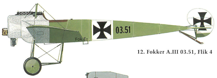
Fokker A.III 03.51, Flik 4
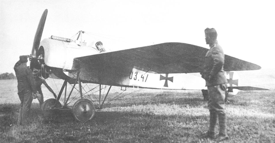
Fokker A.III 03.47 armed with a Spandau LMG 08 machine gun being readied for flight in Galicia.
Fokker A.III, Flugzeugnummer 03.47, bewaffnet mit einem Maschinengewehr Type 08/15
Fokker A.III, самолет № 03.47, вооружен пулеметом типа 08/15
Fokker A.III, Flugzeugnummer 03.47, bewaffnet mit einem Maschinengewehr Type 08/15
Fokker A.III, самолет № 03.47, вооружен пулеметом типа 08/15
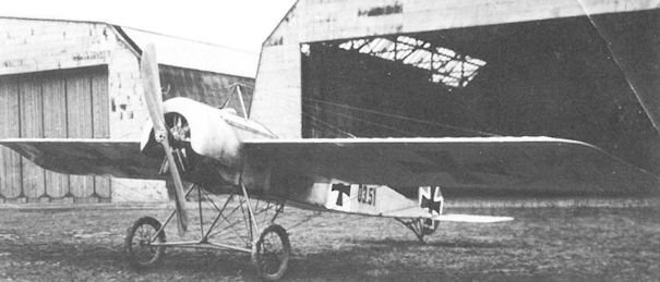
Fokker A.III 03.51, one of the two or three unarmed A.III trainers based at Flek 6 in Wiener-Neustadt in 1917.
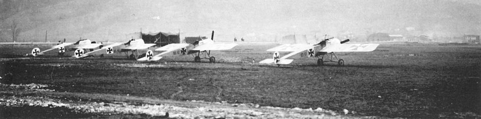
A line-up (l to r) of Fokker A.III 03.42, 03.41, 03.52, and 03.51, probably in February 1916 on the Aisovizza airfield. At the time the photograph was taken, these fighters were assigned to Fliks 4 and 19 but had been banded together to form the Fokker-Kampfstaffel.
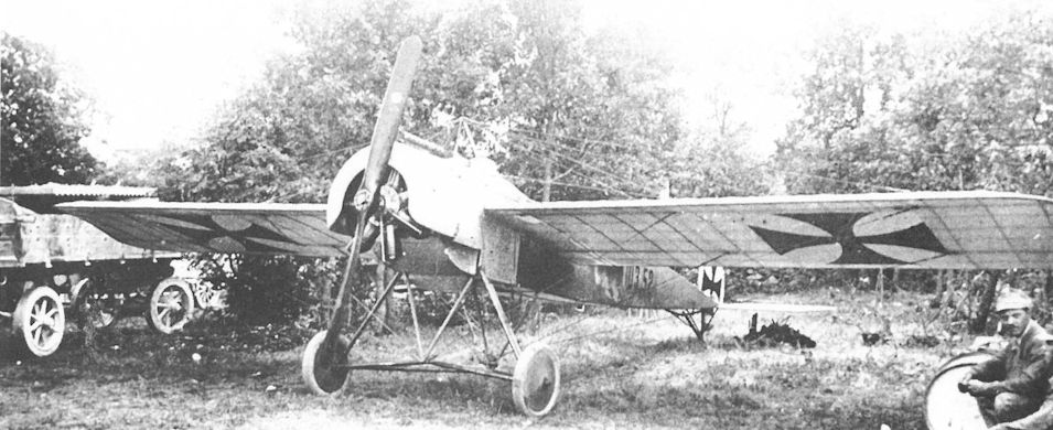
During combat on 15 August 1916, Fokker A.III 03.52 (ex E.I 65/15) collided with A.III 03.44, killing two pilots of Flik 19 and 28.
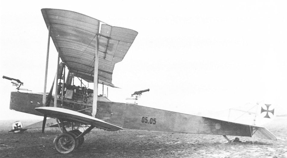
Photographed at Flik 19, the 05.05 prototype shows the excellent field of fire provided by the raised machine-gun positions. A Fokker fighter, series 03, is in the background. (This photograph was printed on pebble-texture paper which accounts for the loss of detail). (AHT AL0579-063)
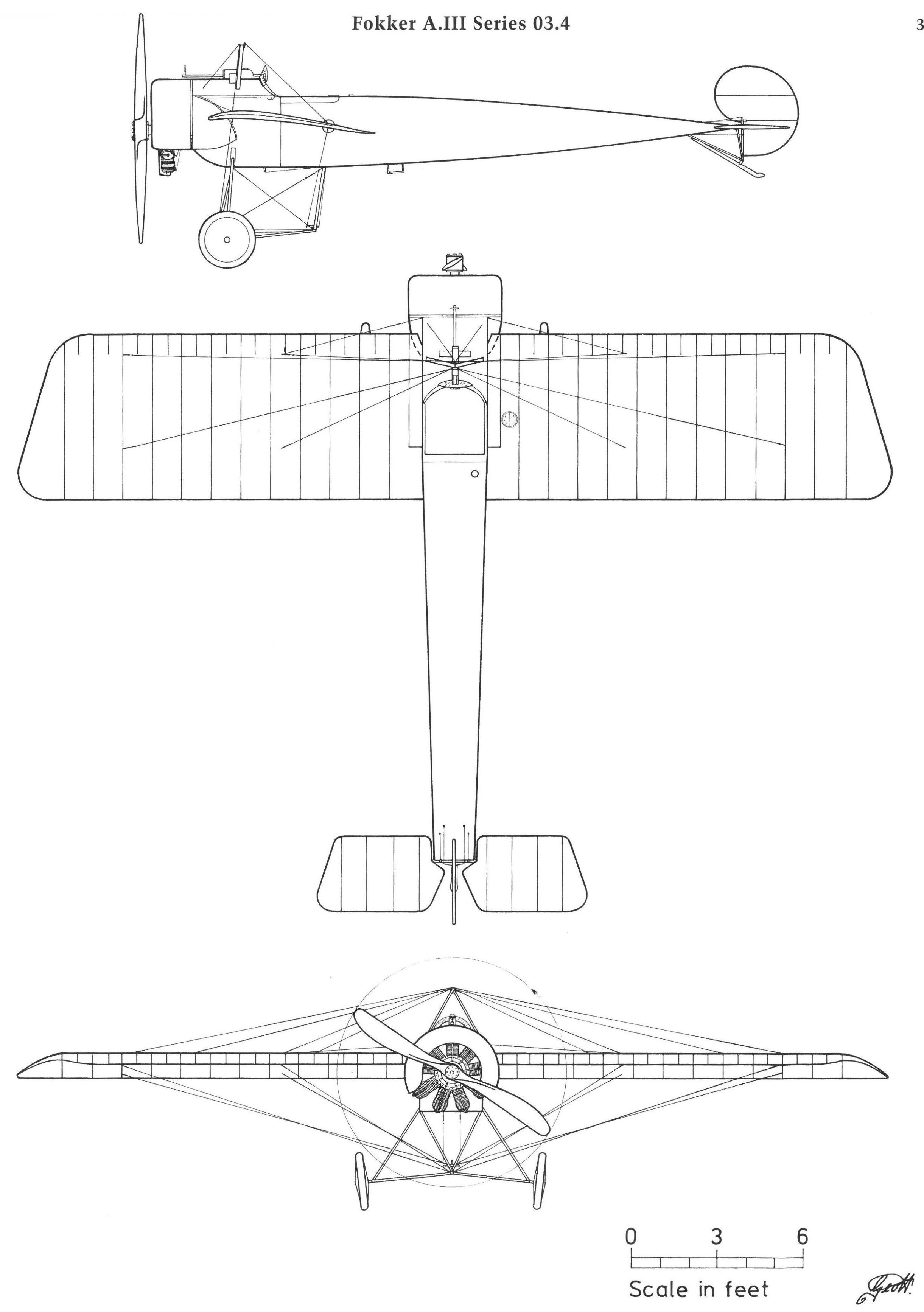
Fokker A.III Series 03.4
Fokker B.I Series 03
The long-lived Fokker B.I (Type M 7 and M 10) biplane was flown throughout the war by scores of Austro-Hungarian airmen, first as a light reconnaissance aircraft and then as a basic and secondary trainer. It was praised for its tractable and safe flight characteristics. The LFT purchased a total of 39 Fokker biplanes and one M 5L monoplane according to the following schedule:
Qty Type Series Number Order Date
11 M 7 03.01,02, 04-12 20 September 1914 (a)
1 M 5L 03.03 29 January 1915
12 M 10 03.13-24 17 October 1914
4 M 7 03.25-28 6 May 1915 (rebuilt, less engines)
12 M 10 03.29-40 29 January 1915 (less engines)
(a) It is known that Fokker sent ex-B.494-505/14 to the LFT.
The first 12 biplanes, released by the German air service to help relieve the critical aircraft shortage, were delivered in January-February 1915 and received the designation Fok.1 to Fok.12. In February 1915, the designation was changed to Fokker B.I 03.01 to 03.40. Inexplicably, number 03.03 was assigned to the Fokker M 5L monoplane, although it did not belong to this series. The last Fokker B.I was delivered in January 1916. Four M 7 biplanes rebuilt (i.e.: repaired) by the Fokker works were numbered 03.25 to 03.28. All M 7 and M 10 machines were powered by the 80 hp Oberursel U.O rotary engine.
As of mid-1915, the unarmed Fokker B.I saw service in the Balkans with Flik 6, on the Eastern Front with Fliks 14, 25, and 27, on the Isonzo Front with Fliks 4, 8, 12, and 19, and with Fliks 16 and 17 in Karnten and the Tirol until early 1916. Flik 6 found that the B.I's low rate of climb and ceiling made them useless in the mountainous terrain of Montenegro. It was soon replaced by more powerful machines. A few B.I biplanes remained at the Front as trainers until February 1917. At home they were assigned to Fleks 3, 4, 6, 8, and 9 as secondary trainers. Seven were still active on 31 August 1918.
Fokker B.I (M 7) Series 03
Engine: 80 hp Oberursel
Wing: Span Upper 11.70 m (38.39 ft)
Span Lower 7.20 m (23.62 ft)
Chord Upper 1.50 m (4.92 ft)
Chord Lower 1.50 m (4.92 ft)
Total Wing Area 26.0 sq m (280 sq ft)
General: Length 8.00 m (26.25 ft)
Height 2.95 m (9.68 ft)
Empty Weight 380 kg (838 lb)
Loaded Weight 679 kg (1497 lb)
Maximum Speed: 130 km/hr (81 mph)
Climb: 1000m (3,281 ft) in 8 min
2000m (6,562 ft) in 15 min 30 sec
Fokker B.I (M 10) Series 03
Engine: 80 hp Oberursel
Wing: Span Upper 11.30 m (37.07 ft)
Span Lower 7.77 m (25.49 ft)
Chord Upper 1.6 m (5.25 ft)
Chord Lower 1.6 m (5.25 ft)
Stagger 0 m (0 ft)
Total Wing Area 28.0 sq m (301 sq ft)
General: Length 7.50 m (24.61 ft)
Height 2.50 m (8.20 ft)
Empty Weight 409 kg (902 lb)
Loaded Weight 712 kg (1570 lb)
Climb: 2000m {6,562 ft) in 25 min

Affectionally dubbed Oelsardine (oil sardine) for the greasy rotary-engine exhaust which coated pilot and airframe, this Fokker B.I 03.09 (M 7) is shown here serving out its career as a secondary trainer with Flek 6.

Fokker B.I (M 10) Series 03
Fokker 03.91 (M 16)
On learning that the Fokker M 16 two-seat prototype possessed superior performance, the LFT command urgently requested War Ministry approval to purchase "one experimental Fokker biplane, powered by a 160 hp Daimler engine, because the domestic designs have inadequate performance." An engine had already been dispatched to Schwerin. On 24 December 1915, Fokker received an order for one M 16 prototype and a provisional contract for 16 production machines. Because flight trials had not been completed, the production contract was changed in February 1916 in favor of 24 B.II series 03.6 biplanes. In the event that the prototype proved successful, Aviatik was to manufacture a derivative under license (see Aviatik 30.06). Following designer Martin Kreutzer's flight demonstrations for a group of visiting Flars representatives, the M 16 (w/n 435) was shipped to Aspern on 13 April 1916 for evaluation. However, the flight trials were terminated when the Aviatik 30.06 crashed on 7 May. The Fokker M 16, numbered 03.91, was assigned to Flek 6 in Wiener-Neustadt until placed in storage and officially written-off in April 1918.
Fokker 03.91 (M 16)
Engine: 160 hp Daimler
Wing: Span Upper 11.60 m (38.06 ft)
Chord Upper 1.70 m (5.58 ft)
Chord Lower 1.70 m (5.58 ft)
Gap 1.40 m (4.59 ft)
Total Wing Area 32.0 sq m (344 sq ft)
General: Length 7.65 m (25.10 ft)
Height 2.85 m (9.35 ft)
Track 2.00 m (6.56 ft)
Empty Weight 620 kg (1367 lb)
Loaded Weight 1056 kg (2328 lb)
Maximum Speed: 155 km/hr (96 mph)
Climb: 1000m (3,281 ft) in 5 min
2000m (6,562 ft) in 13 min
3000m (9,843 ft) in 26 min
Aviatik 30.06
To compensate for the cancellation of 16 Fokker M 16 biplanes (in favor of Fokker monoplane fighters) in January 1916, Flars arranged for Aviatik to license-manufacture a derivative of the Fokker M 16, powered by a 160 hp Daimler engine. Ingenieur Alfred Gassner, in charge of the project and assisted by engineers from Fischamend, designed a wooden fuselage to replace the steel-tube structure and modified the wings and control surfaces. Assembly of the prototype, designated 30.06, began in mid-March 1916, at which time Aviatik learned that a pending contract of 48 aircraft (designated series 36) was contingent on the satisfactory outcome of the prototype trials.
Disappointing flight tests in April 1916 required installation of new wings and tail surfaces. The modified 30.06 prototype crashed on 7 May 1916, killing the pilot and injuring the observer. This unfortunate event ended Gassner's association with Aviatik and stopped further development of the aircraft.
Aviatik 30.06 Specifications
Engine: 160 hp Daimler
Wing: Span Upper 11.54 m (37.86 ft)
Span Lower 10.90 m (35.76 ft)
Chord Upper 1.55 m (5.09 ft)
Chord Lower 1.55 m (5.09 ft)
Gap 1.40 m (4.59 ft)
General: Length 7.25 m (23.79 ft)
Fokker B.III Series 04.1
Sometime in April 1916, Flars officials were astounded when the Fokker M 18 prototype (w/n 501) arrived at Aspern "without prior knowledge or consent," an unprecedented event to be sure, but one typical of Fokker's sales tactics. The 120 hp Mercedes-powered M 18 was favorably received as the LFT required a transition trainer. Consequently, the production machines were modified, fitted with a 100 hp Mercedes engine and, unlike the prototype, with wing-warping control. Production began in June 1916 but redesign of the wing to accommodate warping control incurred some delay. Eighteen fighter-trainers, less engine, were formally purchased in December 1916, although only a total of 17 entered LFT inventory. These were designated B.III 04.11 to 04.27. The M 18 prototype (w/n 501), originally numbered 03.92, was re-numbered 04.11. Seven production machines were accepted in August and nine in September 1916. It appears that some, but not all, B.III machines were fitted with a free-firing machine gun mounted over the center section.
In October 1916, Fliks 4, 12, 19, and 28 (Isonzo Front), 16 (Karnten), and 17, 21, and 24 (South Tirol) began to receive the B.III fighter-trainers that were flown primarily "to accustom pilots to the more powerful Brandenburg D.I." The B.III trainer was retired from the Front in February 1917 and assigned to Flek 6. During 1917 MAG, who built the Fokker B.III (series 04.3) under license, repaired and refurbished several trainers, enabling them to remain in service until late 1918.
Fokker B.III Series 04.1
Engine: 100 hp Mercedes
Wing: Span Upper 9.05 m (29.69 ft)
Chord Upper 1.25 m (4.10 ft)
Total Wing Area 22.0 sqm(237 sqft)
General: Length 5.70 m (18.70 ft)
Height 2.69 m (8.83 ft)
Track 1.70 m (5.58 ft)
Empty Weight 442 kg (975 lb)
Loaded Weight 700 kg (1544 lb)
Maximum Speed: 150 km/hr (93 mph)
Climb: 1000m (3,281 ft) in 6 min 10 sec
2000m (6,562 ft) in 15 min 10 sec
3000m (9,843 ft) in 25 min 25 sec
4000m (13,124 ft) in 39 min 34 sec
Fokker B.III(MAG) Series 04.3
MAG received its first production contract on 26 August 1916 for 50 aircraft which included eight Fokker B.III(MAG) biplane trainers, numbered 04.31 to 04.38 and powered by a 100 hp Mercedes engine. The type was based on the Fokker D.I (Type M 18). Armament was not installed although space for a single machine gun was provided. The first aircraft, 04.31, was rolled out in September 1916, and in October seven completed aircraft were awaiting the delivery of tires in order to perform the acceptance flights. Aircraft 04.31 was scrutinized by a Flars engineers at Aspern on 21 November 1916. MAG recorded that German specifications, to which the airframe was originally designed, differed from those issued by Flars, which may explain why the remaining seven aircraft were not accepted until March-May 1917. The seven Fokker B.III(MAG) biplanes were assigned to Flek 6 in Wiener-Neustadt as unarmed trainers and as of 1 July 1917, five were still active.
An interesting development was reported in January 1918 when aircraft 04.36 (retained by MAG for test purposes) was modified for the new 11-cylinder 150 hp Le Rhone(St) rotary engine. In this form it was first flown on 26 February 1918, according to Flars "to investigate engine behavior in flight."
Fokker B.III(MAG) Series 04.3 Specifications
Engine: 100 hp Mercedes
Wing: Span Upper 9.60 m (31.50 ft)
Span Lower 9.60 m (31.50 ft)
Chord Upper 1.25 m (4.10 ft)
Chord Lower 1.25 m (4.10 ft)
Dihedral Upper 0 deg
Dihedral Lower 0 deg
Sweepback Upper 0 deg
Sweepback Lower 0 deg
Gap 1.25 m (4.10 ft)
Stagger 0.38 m (1.25 ft)
Total Wing Area 21.4 sq m (230 sq ft)
General: Length 6.70 m (21.98 ft)
Height 2.32 m (7.61 ft)
Track 1.69 m (5.54 ft)
Empty Weight 480 kg (1058 lb)
Loaded Weight 730 kg (1610 lb)
Maximum Speed: 135 km/hr (84 mph)
Climb: 1000m (3,281 ft) in 4 min 25 sec

The freshly-painted Fokker 03.91 (M 16) upon its arrival at the Aspern test center in April 1916. The wing-tip skids prevented the tips from touching, particularly on uneven or rough airfields. The military serial number has not yet been applied, nor does armament appear to have been installed.

The second M.16 (w/n 435) is shown here after arrival at Aspern on April 15, 1916, with Austro-Hungarian insignia applied. Military designation of 03.91 was assigned in Austrian service.

Fokker mechanic Carl Henze demonstrating the flexible Schwarzlose M 16 machine gun. A forward-firing synchronized gun is mounted beside the pilot. This aircraft, the second M 16 prototype built, was sometimes referred to as the M 16/11 in Fokker records.

The Aviatik 30.06, based on the Fokker M 16, is shown here on the aerodrome at Aspern. The prototype was variously referred to as the “Gassner-Aviatik,” the “Fokker Walfisch” or the “Fokker-Fischamend."

The pilot’s position directly behind the front wing spar of 30.06 required an open center section to provide good visibility. An observer’s gun ring was not installed for flight tests.

The fatal crash of the 30.06 on 7 May 1916 shows that the aircraft was modified with balanced elevators and a Fokker-style rudder.

The Fokker M 18 (w/n 501) prototype photographed at the German test center at Doberitz in the spring of 1916. It was powered by a 120 hp Mercedes engine and armed with one Spandau MG 08/15 machine gun.

The Fokker M 18 (w/n 501) prototype, now re-designated B.III 04.11, and a production B.III (04.27) were assigned to Fluggeschwader I when it was established in December 1916. The B.III 04.11 was used as an unarmed trainer through February 1917 at Divacca.

Installation of the 100 hp Mercedes engine in the Fokker B.III(MAG) 04.31. The MAG work number “1” is painted on the lower fuselage in front of the radiator.

Fokker B.III(MAG) 04.31 was virtually a carbon copy of the Fokker D.II (M 18). One positive MAG identification feature is the extension of the rear center-section struts to serve as a turn-over guard.

Fokker 03.91

Aviatik 30.06

Fokker B.III Series 04.1
Fokker Series 03.55 to 03.60 (M 17)
In July 1916, the LFT accepted Fokker's offer to substitute the M 17 biplane fighter for the last six E.III monoplanes then on order. Currently in production for the German air service as the Fokker D.II, the M 17 was powered by a 100 hp Oberursel engine and fitted with twin-bay wings equipped with wing-warping controls. One M 17 was accepted in September 1916 and the remaining five were delivered in October and November. They were assigned the numbers 03.55 to 03.60, but no type designation (B.II would have been appropriate) has been found in LFT records. Deemed unsuitable for front-line service due to its slow speed and climb, the unarmed M 17 was relegated to training duties at Fleks 6, 7, and 16. Three M 17 trainers were still in service in mid-1918. Aircraft 03.60 was tested with an experimental "wing brake" in January 1917 at Aspern.
Fokker Series 03.55 (M17)
Engine: 100 hp Oberursel
Wing: Span Upper 8.75 m (28.71 ft)
Chord Upper 1.15 m (3.77 ft)
Chord Lower 1.15 m (3.77 ft)
Gap 1.30 m (4.27 ft)
Stagger 0.30 m (0.98 ft)
Total Wing Area 18.5 sq m (199 sq ft)
General: Length 6.40 m (21.00 ft)
Height 2.76 m (9.06 ft)
Track 1.70 m (5.58 ft)
Empty Weight 427 kg (942 lb)
Loaded Weight 634 kg (1398 lb)
Maximum Speed: 145 km/hr (90 mph)
Climb: 1000m (3,281 ft) in 4 min 30 sec
2000m (6,562 ft) in 9 min 30 sec
3000m (9,843 ft) in 17 min
4000m (13,124 ft) in 27 min
Fokker B.II Series 03.6
Because the Fokker M 16 prototype (03.91) flight trials were still underway, in February 1916 Flars purchased 24 Fokker B.II (M 17) fighter-trainers in lieu of the scheduled 16 M 16 biplanes. In July 1916 a "large number of completed B.II fighters were stored at the Fokker factory awaiting arrival of machine guns." Unbeknownst to the resident LFT inspector, these were to be installed at Aspern, and the suggestion that Fokker armament expert Ingenieur Heinrich Lubbe perform this task was rejected. Records show that only 23 Fokker B.II, numbered 03.61 to 03.83, were accepted: 03.61 in April, 19 aircraft (less engines) in August, and three in September 1916. As delivered to the LFT, the Fokker B.II had single-bay wings, a 80 hp Oberursel engine, and wing-warping controls that were considered more suitable than ailerons for training purposes.
The B.II 03.61 (w/n 499) prototype remained at Aspern until June 1916 when it was dispatched to Flik 11 on the Eastern Front for evaluation. An amusing episode related by pilot Pius Moosbrugger shows the caution with which aircrews approached the unfamiliar rotary engine:
Since the engine had to be started by swinging the propeller and the pilot had no throttle control, we felt a real danger existed should the aircraft leap forward and injure the ground crew. Our solution was to tie the Baby Fokker to a tree by its tail skid, and after the engine was running properly, we simply cut the rope with an axe. Unfortunately, the shortage of expensive castor oil soon made it necessary to send the Baby Fokker home.
Returned to Aspern, the 03.61 was used for testing a variety of machine-gun installations. The remaining B.II biplanes, assigned to Fleks 4, 6, and 8, served as unarmed single-seat trainers, a role they performed through 1918
Fokker B.II Series 03.6
Engine: 80 hp Oberursel
Wing: Span Upper 7.20 m (23.62 ft)
Chord Upper 1.25 m (4.10 ft)
Chord Lower 1.25 m (4.10 ft)
Gap 1.30 m (4.27 ft)
Stagger 0.30 m (0.98 ft)
Total Wing Area 16.0 sq m (172 sq ft)
General: Length 6.20 m (20.34 ft)
Height 2.71 m (8.89 ft)
Track 1.70 m (5.58 ft)
Empty Weight 274 kg (604 lb)
Loaded Weight 481 kg (1061 lb)
Maximum Speed: 130 km/hr (81 mph)

Fokker B.II Series 03.6
Fokker D.I(MAG) Series 04.4
Included in the 50 aircraft order of 26 August 1916 were eight Fokker D.I(MAG) fighters, numbered 04.41 to 04.48 and powered by the 160 hp twin-row Oberursel U.III rotary engine purchased in Germany. The type was identical to the Fokker D.III(Type M 19), of which Fokker shipped a pattern airframe (w/n 972) to MAG on 2 October 1916. Two fighters were completed in February 1917, and on 24 March aircraft 04.41 was inspected at Aspern by Flars engineers who ordered some minor modifications. MAG had cause to complain bitterly because only two Oberursel engines were available to flight test the remaining seven aircraft, delaying acceptance completion until October 1917.
With exception of one aircraft at Flik 30, no Fokker D.I(MAG) fighter is known to have been in frontline service. In fact, owing to the difficulty of servicing the twin-row Oberursel engine, flying was kept at a minimum. Eventually all eight Fokker D.I(MAG) fighters were stored at Flek 6 in Wiener-Neustadt, where they were to be found in October 1918.
Fokker D.I(MAG) Series 04.4 Specifications
Engine: 160 hp Oberursel
Wing: Span Upper 9.60 m (31.50 ft)
Span Lower 9.60 m (31.50 ft)
Chord Upper 1.25 m (4.10 ft)
Chord Lower 1.25 m (4.10 ft)
Dihedral Upper 0 deg
Dihedral Lower 0 deg
Sweepback Upper 0 deg
Sweepback Lower 0 deg
Gap 1.25 m (4.10 ft)
Stagger 0.30 m (0.98 ft)
Total Wing Area 21.4 sq m (230 sq ft)
General: Length 6.35 m (20.83 ft)
Height 2.40 m (7.87 ft)
Track 1.69 m (5.54 ft)
Empty Weight 480 kg (1058 lb)
Loaded Weight 687 kg (1515 lb)
Maximum Speed: 153 km/hr (95 mph)
Climb: 1000m (3,281 ft) in 2 min 40 sec
2000m (6,562 ft) in 7 min 15 sec
3000m (9,843 ft) in 16 mm 30 sec
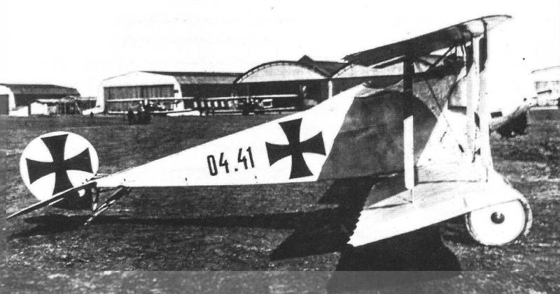
The Fokker D.I(MAG) 04.41 was identical to the German Fokker D.III (M 19) fighter. The 160 hp Oberursel twin-row rotary engine required a broad-bladed propeller that had not yet been installed.
Eight examples of the Fokker D.III were license-built by MAG in Austria, where they received the designation D I (MAG). Pictured here is the first of these aircraft, 04.41, lacking both armament and its propeller.
Eight examples of the Fokker D.III were license-built by MAG in Austria, where they received the designation D I (MAG). Pictured here is the first of these aircraft, 04.41, lacking both armament and its propeller.
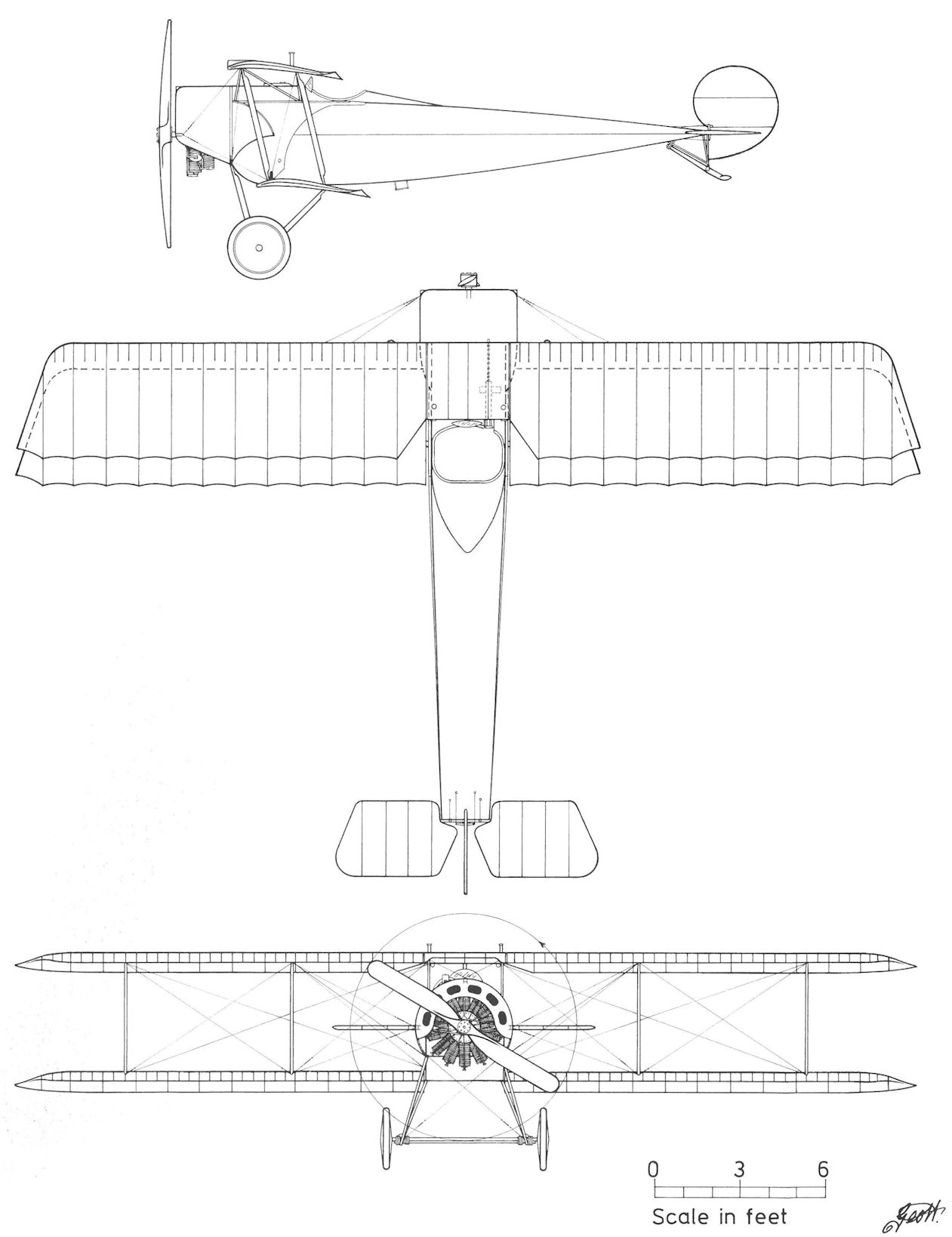
Fokker D.I(MAG) Series 04.4
Fokker D.II(MAG) Series 04.5
The remaining aircraft ordered on 26 August 1916 were 34 Fokker D.II(MAG) fighters, increased to 42 aircraft on 19 April 1917. These were numbered 04.51 to 04.92 and powered by a 185 bp Daimler(MAG) engine. The D.II(MAG) fighter was based on the Fokker D.IV (M 21) but MAG made some minor structural changes. Production began in January 1917 and the first machine, 04.51, was inspected at Aspern on 24 March. Acceptance was delayed pending choice of radiator and placement of the twin Schwarzlose machine guns. Acceptances began in June 1917 as planned and ended in December, four months later than scheduled. Test pilot Antal Feher's logbook shows that he performed 23 acceptance flights between October and December 1917.
Aircraft 04.51, with guns installed by the armaments section at Fischamend, was returned to Matyasfold in July 1917 as a weapons sample. Owing to the gun shortage, two aircraft were armed with only one gun and nine delivered unarmed. In July 1917, aircraft 05.54 and 04.61 were assigned to Aspern for flight and performance test and to investigate the efficiency of various radiator installations.
Flik 49 was assigned aircraft 04.52 as an "experimental fighter" in the fall of 1917 for testing on the Eastern Front. Structurally it was criticized, especially the weak undercarriage. When the Fokker D.II(MAG), a mid-1916 design, arrived on the Italian Front in January 1918, it was immediately condemned as obsolete by at least five Fliks. An army command report, dated 4 March 1918, regarded the type too slow and acceptable only as a fighter-trainer. Consequently, the D.II(MAG) served as a transition trainer at Fliks 22/D, 37/D, 56/J, 57/Rb, 62/D, 65/D, and 66/D on the Piave Front and Flik 64/F in Albania, as well as the field flying schools at Campoformido and Neumarkt.
As of 20 August 1918, twenty D.II(MAG) fighters were carried in the frontline inventory. Fifteen fighters, two fitted with Mercedes engines, were offered to the Czechoslovakian government in 1920.
Fokker D.II(MAG) Series 04.5 Specifications
Engine: 185 hp Daimler (MAG)
Wing: Span Upper 10.20 m (33.46 ft)
Span Lower 9.70 m (31.82 ft)
Chord Upper 1.23 m (4.04 ft)
Chord Lower 1.23 m (4.04 ft)
Gap 1.30 m (4.27 ft)
Stagger 0.29 m (0.95 ft)
General: Length 6.70 m (21.98 ft)
Height 2.55 m (8.37 ft)
Track 1.70 m (5.58 ft)
Empty Weight 645 kg (1422 lb)
Loaded Weight 865 kg (1907 lb)
Maximum Speed: 175 km/hr (109 mph)
Climb: 1000m (3,281 ft) in 3 mm 5 sec
3000m (9,843 ft) in 11 min
5000m (16,405 ft) in 34 min 56 sec
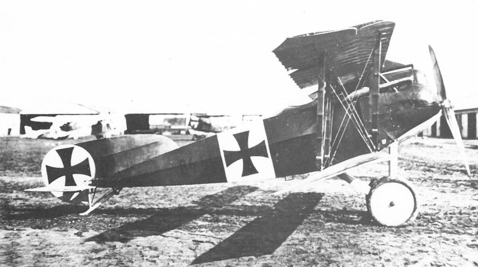
The Fokker D.II(MAG) 04.51 (w/n 17) at Aspern in March 1917. The larger tail fin, broader strut fairings and fully-cowled engine differentiate it from its German counterpart, the Fokker D.IV (M 21).
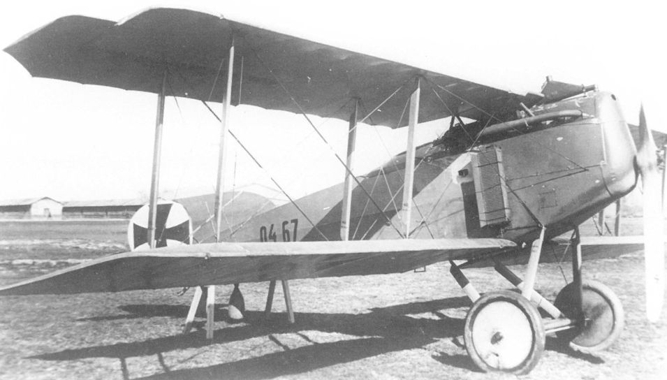
This Fokker D.II(MAG) 04.67 has an empty cartridge chute installed behind the radiator, a feature not seen on other machines. The aircraft was sent to the front in January 1918 as a fighter-trainer.
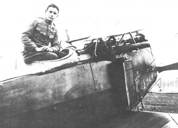
Zugsf. Julius Santer, Flik 22/D, in a Fokker D.II(MAG) armed with a single Schwarzlose M 7/12 machine gun, shown mounted on the right side just in front of the cockpit. Spring 1918. The two 'turn-over' posts above the center section did not appear on German D.IV fighters. (Peter M. Grosz collection/STDB)
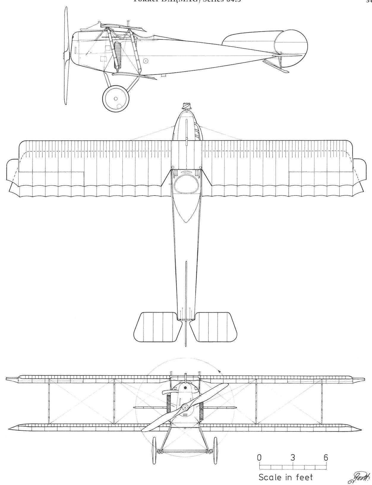
Fokker D.II (MAG) Series 04.5
MAG-Fokker(90.04)
The Fokker V 12 biplane (w/n 1980), Fokker's second design submitted for the LFT interceptor requirement, was begun on 22 October 1917 and shipped to Matyasfold, less engine and armament, on 3 January 1918. After MAG installed a 150 hp Le Rhone (St) rotary engine, Flars engineers were invited to inspect and fly three new MAG-Fokker prototype fighters in early May 1918: the V 7 (90.03), the V 12 (90.04), and the V 22 (90.05). Tony Fokker was on hand to demonstrate their aerobatic qualities. The favorable impression made by the V 12 resulted in the first LFT purchase of Schwerin-built aircraft since 1916. The LFT purchased the V 12 and 14 D.VI series 04.100 fighters in June 1918. The V 12, referred to as the "MAG-Fokker 150 hp Le Rhone biplane," was flown at the July Fighter Evaluation by Oberleutnants Linke-Crawford and Gawel, but their comments have not been recorded.
The provisional prototype designation, 90.04, assigned by the authors, is consistent with the list of MAG prototypes, but confirmation is lacking.
Fokker D.VI Series 04.100
By June 1918, the Waffenfabrik Steyr had delivered about thirty 150 hp Le Rhone rotary engines, deemed a sufficient number to undertake service evaluation. In the absence of a suitable indigenous fighter, Flars purchased 15 Fokker D.VI fighters, comprised of the 90.04 (V 12) prototype and 14 production machines surplus to German air service requirements. On 27 August 1918, Fokker shipped the first seven fighters (D.VI 1632-1635/18, 1641/18, 1642/18, 1644/18) to the MAG factory at Matyasfold for engine and armament installation. On 8 August 1918, Fokker confirmed the LFT's request to change the remaining eight D.VI on order to either Fokker D.VII or D.VIII fighters. War Ministry approval was pending when the war ended.
Engine and armament installation at MAG was nearing completion in late 1918. All seven fighters, still carrying the LFT designation 04.101 to 04.107, entered service with the Hungarian Red Airborne Corps in 1919. Six were at Szombathely in 1919. The single remaining Hungarian D.VI was written-off in 1926.
Fokker D.VI Series 04.100
Engine: 150 hp Le Rhone (St)
Wing: Span Upper 7.70 m (25.26 ft)
Span Lower 5.81 m (19.06 ft)
Chord Upper 1.60m (5.25 ft)
Chord Lower 1.20 m |3.94 ft)
Total Wing Area 17.1 sq m (184 sq ft)
General: Length 5.78 m (18.96 ft)
Height 2.65 m (8.69 ft)
Empty Weight 393 kg (867 lb)
Loaded Weight 583 kg (1286 lb)
Maximum Speed: 200 km/hr (124 mph)
Climb: 1000m (3,281 ft) in 2 min 25 sec
2000m (6,562 ft) in 5 min 8 sec
3000m (9,843 ft) in 9 min 16 sec
4000m (13,124 ft) in 14 min 9 sec
5000m (16,405 ft) in 22 min 9 sec
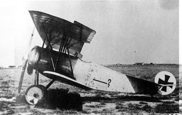
Fokker V 12 at Aspern. The question mark is a sign that the designation was not known to the airfield mechanics. The cowling has been bulged to accomodate the larger diameter of the 11-cylinder Le Rhone(St) rotary engine.
Fokker D.VI, Nr. 1980; Fragezeichen (?), da noch keine Serien-Flugzeugnummer bekannt war
Fokker D.VI, № 1980; Вопросительный знак (?), поскольку серийный номер самолета еще не известен
Fokker D.VI, Nr. 1980; Fragezeichen (?), da noch keine Serien-Flugzeugnummer bekannt war
Fokker D.VI, № 1980; Вопросительный знак (?), поскольку серийный номер самолета еще не известен
Fokker D.VII (Series 04.200?)
At the close of the First Fighter Competition at Adlershof in February 1918, Fokker informed the LFT liaison officer that a D.VII with an all-wood, veneer-covered fuselage (replacing steel tubing and fabric) would soon appear at MAG for demonstration. In the event, this particular variant (w/n 2268) was diverted to the Second Fighter Competition in May 1918 and never reached Matyasfold. The shortage of steel tubing motivated Flars to ask Fokker to build a second, all-wood D.VII, powered by a 200 hp Daimler engine. As with the previous machine, the wooden fuselage was constructed at Fokker's recently-acquired Flugzeugwerke Lubeck-Travemunde. When flight tested at Schwerin on 8 and 14 August 1918, the wooden D.VII achieved climb rates comparable to the standard BMW-engined version. It left Schwerin on 27 August for Aspern where it was reported stored in damaged condition on 2 September 1918. Perhaps there was little reason to repair the fighter, for Germany, producing sufficient aircraft-quality steel tubing for its own needs, had guaranteed the LFT enough tonnage to support the projected D.VII production program.
In August 1918, after evaluating the Fokker 90.05 (V 22), Flars chose the Fokker D.VII to supersede the Aviatik D.I and Albatros D.III fighters beginning October 1918. The production program promulgated in August 1918 scheduled delivery of 660 Fokker D.VII fighters between December 1918 and March 1919, consisting of 255 built by Aviatik, 225 by Fokker, 150 by MAG, and 30 by Thone & Fiala. Production by WKF and Lohner was considered but no firm commitments were made.
Flars awarded Fokker a contract for 75 Fokker D.VII fighters less engine and armament in August 1918. A second order of 150 fighters was awaiting war ministry approval. The LFT delivery schedule called for 10 fighters in October 1918, 15 in November, and thereafter 50 per month through March 1919. Initially, Flars had planned to install the 200 or 240 hp Hiero engine, but since the 225 hp Daimler(MAG) engine was in production at MAG, that engine was chosen. A standard production Fokker D.VII, 7805/18 (w/n 3657), powered by a 225 hp Daimler engine to investigate engine compatibility, performed the maiden flight at Schwerin on 11 October 1918. The first six D.VII production airframes (w/n 3861, 3863 to 3867) were shipped to MAG for engine and armament installation on 23 October 1918. In the turmoil of the war's closing days, the shipment was delayed at Cinkota-Nagyicce but eventually reached Matyasfold. On 12 March 1919, the six Fokker D.VII fighters, powered by MAG-built 225 hp Daimler engines and armed with two Schwarzlose machine guns, were listed in the inventory of the Hungarian First Flying Group.
Twenty-four completed D.VII airframes for the LFT were stored at Schwerin when the war ended and further work on 38 wing sets at Fokker's Perzina works was cancelled in December 1918. Fokker invoiced the LFT for the six D.VII supplied as "series 93." But as this series designation was assigned to MAG, it is believed that the Fokker-built D.VII fighters would have received the LFT series designation 04.200.
Fokker D.VII (Wooden Fuselage)
Engine: 200 hp Daimler
Climb: 1000m (3,281 ft) in 2 min
2000m (6,562 ft) in 4 min 2 sec
3000m (9,843 ft) in 7 min 2 sec
4000m (13,124 ft) in 10 min 7 sec
5000m (16,405 ft) in 14 min 4 sec
Fokker D.VII (Series 04.200?)
Engine: 225 hp Daimler
Wing: Span Upper 8.57 m (28.12 ft)
Span Lower 7.00 m (22.97 ft)
Chord Upper 1.60 m (5.25 ft)
Chord Lower 1.20 m (3.94 ft)
Gap 1.41 m (4.63 ft)
Stagger 0.65 m (2.13 ft)
Total Wing Area 20.8 sq m (223 sq ft)
General: Length 7.00 m (22.97 ft)
Height 2.75 m (9.02 ft)
Track 1.80 m (5.91 ft)
Empty Weight 670 kg (1477 lb)
Loaded Weight 874 kg (1927 lb)
Fokker D.VII(Av) Series 132
In August 1918, Flars chose the Fokker D.VII as the principal next-generation fighter by placing firm and pending orders for a total of 630 aircraft, of which Aviatik received the largest share. As part of the blanket order dated 29 May 1918, Aviatik received a contract for 150 Fokker D.VII(Av) series 132 fighters powered by the 225 hp Daimler engine. An additional order of 105 D.VIIs was under consideration. Delivery was scheduled to begin in November 1918, followed by 40 aircraft in December and 70 per month through March 1919. Berg, viewing the turn of events with great bitterness, attempted to keep his Aviatik D.I in production, but in the end had to acquiesce to his employer's wishes and reluctantly join the team of draftsmen at MAG that was preparing D.VII manufacturing drawings. When the D.VII airframe supplied by Fokker was measured, Aviatik engineers discovered that the Fokker factory drawings were "quite different and incorrect." On 31 October 1918 when production work was stopped, Aviatik had not progressed beyond the preliminary planning stage and the D.VII contract was annulled. For additional information on the Fokker D.VII see the Fokker D.VII series 04.200 and Fokker D.VII(MAG) series 93.
MAG-Fokker 90.05
When the Fokker V 11/II emerged as one of the winners of the First Fighter Competition at Adlershof in January-February 1918, the LFT liaison officer recommended immediate production. Fokker, quick to respond to any business proposition, informed Flars (19 February) that he could supply “40 D.VII fighters per month provided steel tubing was made available." Fokker stated that two D.VII variants intended for the LFT were scheduled for completion in four weeks. One, designated V 22 (w/n 2342), had the standard D.VII steel-tube fuselage. The other was a D.VII fitted with a plywood-covered, all-wood fuselage. On 2 March 1918, Fokker requested two Schwarzlose M 16 machine guns for the completed V 22 in which the latest version of the “Fokker central interrupter mechanism" was installed.
Flars test pilot Stabsfeldwebel Franz Kuntner, a former Fokker flying school instructor, flew the V 22, powered by the 200 hp Daimler engine, on 15-16 March 1918 at Schwerin. His flight report praised the performance and maneuverability, the view from the cockpit, and the machine gun placement. The 200 hp Daimler engine gave the V 22 a climb performance which exceeded that of the Mercedes-engined D.VII. The V 22 was shipped to Matyasfold on 24 April 1918. In light of Kuntner's enthusiastic report, the LFT's negative reaction was surprising, but it must be borne in mind that the Fokker D.VII had yet to be proven in combat. The LFT assessment, dated 20 April 1918, stated categorically that V 22 production was out of the question because:
1) The performance of our new 225 hp Daimler and 240 hp Hiero-engined fighters will probably match, if not exceed, that of the V 22.
2) Before Fokker production can attain full output (five months or more) our new fighters will be available.
3) The 200 hp Daimler engine is no longer in production.
4) The range is below that of our single-seat fighters. Useful load must be reduced at the expense of increased fuel load.
5) In spite of a lower useful load, the V 22 weighs more than the Aviatik D.I (useful load 190 vs 240 kg).
6) The structural strength probably is inferior to our aircraft.
7) The machine-gun installation and pilot's visibility are excellent but this should be attainable in our new fighters.
Flars engineers visited Matyasfold in May 1918 to inspect the V 22 and marvel at Fokker's always impressive flight demonstration. The V 22 was now fitted with a two-bladed propeller. The V 22 (designated MAG-Fokker 90.05) appeared at the Fighter Evaluation (9 to 13 July), but LFT pilots were prohibited from flying the V 22 on the grounds that static test data had not been submitted, the aircraft was incorrectly rigged, and the engine ran poorly. To redress the problem, on 25 July 1918 Seekatz accompanied Uzelac to Aspern where Leutnant Theodor Mallinkrodt of the German Air Service proceeded to show what the D.VII was made of, including "15 loops and power dives." On the following day in a speed competition against the 225 hp Aviatik D.I series 338 fighter, the 200 hp V 22 proved marginally faster. Now totally convinced, Uzelac gave a verbal commitment to purchase 200 Fokker D.VII fighters. By the end of August, production orders had been negotiated with Aviatik, Fokker, MAG and Thone 81 Fiala (see appropriate chapters for details). According to Seekatz, Uzelac had ordered the installation of a 225 hp Daimler engine in the V 22 for continuing flight evaluation. Whether this was actually done is not known.
MAG-Fokker 90.05 Specifications
Engine: 200 hp Daimler (MAG)
Wing: Span Upper 8.90 m (29.20 ft)
Total Wing Area 20.2 sq m (217 sq ft)
General: Length 6.95 m (22.80 ft)
Empty Weight 719 kg (1585 lb)
Loaded Weight 909 kg (2004 lb)
Climb: 2000m (6,562 ft) in 5 min
3000m (9,843 ft) in 9 min
4000m (13,124 ft) in 13 min 30 sec
5000m (16,405 ft) in 19 min
Fokker D.VII(MAG) Series 93
Upon completion of the Fokker V 22 (90.05) evaluation, Fokker, Aviatik and MAG were given production contracts in late August 1918 for the Fokker D.VII fighter. MAG was to build 150 machines, numbered 93.01 to 93.150 and powered by the 225 hp Daimler(MAG) engine. The first ten machines were to be delivered in December 1918, twenty in January 1919, and 60 in February and March. The large backlog of Aviatik D.I fighters precluded delivery of the Fokker fighters at an earlier date.
Fokker sent drawings and manufacturing specifications to Matyasfold where Aviatik and MAG personnel prepared manufacturing drawings, parts lists and material specifications. According to Aviatik reports, the actual D.VII airframe supplied (90.05?) differed in some aspects from the Fokker-supplied drawings. At the end of October 1918, MAG had 35 Fokker D.VII(MAG) in final assembly and parts for an additional 25 were in process. The war ended before any were accepted. Viktor Storer, a Flars officer, recalled that flight testing of the production prototype was virtually complete at the time of the Armistice.
A small number of MAG-built D.VIIs found their way into the Czechoslovakian and Hungarian air services. At least nine, but probably more, were flown by the 8th Squadron of the Hungarian Red Airborne Corps which was staffed by many former Flik 42/J pilots. Five fighters, concealed from the Inter-Allied Aeronautical Control Commission, surfaced in 1924-1925 when they were refurbished for the Hungarian civil aviation authority. A few remained in service until 1932. One Fokker D.VII(MAG) fighter, designated H-MFOD (later HA-FOD), put on display in the Museum of Transportation, was destroyed in World War II.
Fokker D.VII(MAG) Series 93 Specifications
Engine: 225 hp Daimler (MAG)
Wing: Span Upper 8.57 m (28.12 ft)
Span Lower 7.01 m (23.00 ft)
Chord Upper 1.60 m (5.25 ft)
Chord Lower 1.20 m (3.94 ft)
Dihedral Upper 0 deg
Dihedral Lower 0 deg
Sweepback Upper 0 deg
Sweepback Lower 0 deg
Gap 1.42 m (4.66 ft)
Stagger 0.70 m (2.30 ft)
Total Wing Area 20.3 sq m (218 sq ft)
General: Length 7.10 m (23.29 ft)
Height 2.87 m (9.42 ft)
Track 1.80 m (5.91 ft)
Empty Weight 670 kg (1477 lb)
Loaded Weight 874 kg (1927 lb)

Fokker D.VII(MAG) 93.07

The second Fokker D.VII with wooden, plywood-covered fuselage photographed at the Lubeck-Travemunde factory prior to delivery on 27 August 1918.
The fully-assembled airframe of a MAG-built Fokker D.VII rolled out for inspection shortly before the end of the war. Mechanics are working on an Aviatik D.I(MAG) in the background.

A Hungarian Fokker D.VII (MAG) captured by Czechoslovak forces in the course of the postwar fighting. The aircraft was armed with two Spandau LMG 08/15 machine guns.

Fokker D.VII (MAG) 93.07 of the Hungarian Voros Repuloesapat (Red Airborne Corps) in trouble. A number of the MAG-built Fokkers saw service in the postwar border clashes.

Fokker D.VII(MAG) Series 93
MAG-Fokker Triplane (90.01)
In the monthly MAG progress report of July 1917, Flars was told that a single-seat triplane with "a continuous wing strut and powered by a 185 hp Daimler(MAG) engine" was under construction and was expected to appear for flight tests in August. Another reference which may to relate to the above aircraft was a Flars technical order dated 24 August 1917, dispatching a 185 hp Daimler engine to "Fokker for installation in a triplane." A Flars engineer who visited Matyasfold on 25 October 1917 submitted this report:
MAG-Fokker triplane with 185 hp Daimler(MAG) engine: a MAG company aircraft. At present only taxi trials, since ostensibly the lower wings vibrate excessively. Wing spars have been strengthened and the triplane is being reassembled.
Unfortunately, the photograph attached to the report was missing. There is no Fokker company record of an in-line engined triplane being shipped to MAG in 1917, but it is probable that Fokker engineers at Matyasfold had a hand in its design, possibly based on the Fokker V 6 triplane. The provisional prototype designation, 90.01, assigned by the authors, is consistent with the list of MAG prototypes, but confirmation is lacking.
MAG-Fokker Triplane (90.02)
On 13 June 1917, Fokker instructed his prototype shop to build one biplane fighter prototype (company designation D VI, w/n 1661) powered by a 110 hp Oberursel Ur.II rotary engine. In mid-stream, the design was changed to a triplane later known as the V 4. After being demonstrated to military authorities in Schwerin, the V 4 was shipped to Matyasfold, arriving there on 3 September 1917. The cowling and several parts were lost in transit, and during assembly it was discovered that the French Le Rhone engine supplied by the LFT did not fit the mounting. On 25 October 1917, a Flars engineer, after inspecting the triplane and its new flexible-shaft interrupter gear, proposed the type for production, powered by the Steyr-built 150 hp Le Rhone rotary engine. Further details are lacking. The provisional prototype designation, 90.02, assigned by the authors, is consistent with the list of MAG prototypes, but confirmation is lacking.
MAG-Fokker 90.03
In December 1917, aircraft manufacturers received a Flars specification for a "very-light, rapidly-climbing interceptor" powered by a 150 hp Le Rhone (St) engine of which the first production examples were available for flight testing. Having been kept abreast of LFT intentions via MAG, Fokker had ordered two fighters from the prototype shop. The first of these was the V 7 triplane (w/n 1981), authorized on 24 October 1917 and shipped to MAG on 3 January 1918 for engine installation. The airframe was identical to the production Dr.I triplane, except that the fuselage was lengthened by 55cm (21.6 in) to compensate for the additional weight of the eleven-cylinder Le Rhone (St) rotary engine.
The V 7 was demonstrated to Flars engineers at Matyasfold on 12 March 1918 by Fokker test pilot Neisen. The LFT purchased the V 7 less engine, machine guns, and propeller on 7 June 1918. Under the designation MAG-Fokker 90.03, it was entered in the Fighter Evaluation of 9-13 July 1918. During the first demonstration flight the rudder control broke, forcing MAG company pilot Feldwebel Josef Nemeth to land in rough terrain, which severely damaged the aircraft.
MAG-Fokker 90.03 Specifications
Engine: 150 hp Le Rhone (St)
Wing: Span Upper 7.20 m (23.62 ft)
Span Middle 6.22 m (20.41 ft)
Span Lower 5.73 m (18.80 ft)
Chord Upper 1.00 m (3.28 ft)
Chord Middle 1.00 m (3.28 ft)
Chord Lower 1.00 m (3.28 ft)
Dihedral Upper 0 deg
Dihedral Lower 0 deg
Sweepback Upper 0 deg
Sweepback Lower 0 deg
Gap Upper 0.88 m (2.89 ft)
Gap Lower 0.86 m (2.82 ft)
Stagger Upper 0.23 m (0.75 ft)
Stagger Lower 0.26 m (0.85 ft)
Total Wing Area 17.5 sq m (188 sq ft)
General: Length 6.40 m (21.00 ft)
Height 2.95 m (9.68 ft)
Track 1.67 m (5.48 ft)
Empty Weight 376 kg (829 lb)
Loaded Weight 571 kg (1259 lb)
Climb: 1000m (3,281 ft) in 1 min 30 sec
2000m (6,562 ft) in 4 min
3000m (9,843 ft) in 7 min 20 sec
4000m (13,124 ft) in 11 min 30 sec

The Hungarians modified a few Fokker D.VII (MAG) fighters into unarmed two-seaters with twin fuel tanks in the top wing and four-bladed propellers. Fokker D.VII (MAG) H.08 was originally numbered 93.08.
Fokker E.V
Reporting on the results of the Second Fighter Competition at Adlershof in June 1918, the LFT liaison officer wrote:
The Fokker parasol powered by the 145 hp Oberursel Ur.Ill engine is the best fighter and superior to the Fokker D.VII. Initially intended as an interceptor (home-defense squadrons), it is now in demand by many of the frontline formations (i.e.: commanding officers who were present at the Competition).
Flars purchased a production E.V 113/18 parasol fighter less engine, hoping to evaluate it in the forthcoming Fighter Evaluation convened at Aspern on 9-13 July, but the E.V did not leave Schwerin until 20 July 1918. After a Steyr-built 150 hp Le Rhone engine was installed by MAG, the E.V was assembled at Aspern on 25 July. On the next day, Seekatz watched Leutnant Mallinkrodt of the German air service perform "the most daring maneuvers that earned enormous applause from the spectators present." Uzelac congratulated Mallinkrodt and ordered Leutnants Kasser and Gawel aloft. "Kasser even made a few loops" and both pilots waxed enthusiastic about the parasol. Seekatz reported that the "colossal forces" encountered during Mallinkrodt's demonstration, which he performed "almost more upside-down than normal" had bent the rear wing struts. Stronger struts were ordered from Schwerin. Flight testing was nearly completed when the Fokker E.V was irreparably damaged in a landing accident in August 1918.
Although LFT interest in the parasol fighter as a home-defense interceptor remained high and Uzelac had mentioned a purchase of 50 aircraft, German production of Voltol, a castor oil substitute for rotary engines, was insufficient to supply both air services. Flars requested Fokker build a parasol powered by a 225 hp Daimler in-line engine with the assurance of substantial production orders should the combination prove successful. The war ended before the Daimler-engined fighter, reported under construction in September 1918, was completed.
In August 1918, Flars debated assigning Aviatik, MAG, and Thone & Fiala the license-manufacture of the Fokker D.VII and E.V fighters in a ratio of three-to-one beginning in early 1919, but the continuing shortage of Voltol forced a change of plans. In consequence, Flars proposed sending the completed 150 hp Le Rhone(St) rotary engines to Germany in exchange for either BMW in-line or Oberursel rotary engines at a later date when the Voltol supply was assured.
Friedrichshafen G.IIIa(Daim) Series 07
After the Brandenburg G.I debacle the LFT, in November 1917, requested the German air service to release sufficient Friedrichshafen G.III bombers to form a small long-range bombing force. The request was rejected because the Friedrichshafen bombers could not be spared; instead the LFT was offered, and subsequently purchased, the inferior Gotha G.IV bomber. However, to investigate the possibility of license production, the Germans released one Friedrichshafen G.IIIa airframe, less engines, to serve as a test and pattern aircraft. Upon delivery in April 1918, it was assigned the number 07.01.
The problems experienced with the Gotha G.IV series 08 bombers led the LFT to renew its request for 50 Friedrichshafen bombers. The sale was approved but a devastating fire at Friedrichshafen factory on 13-14 April 1918 nullified the order. With license production growing rapidly at Daimler and Hansa, Germany finally released 20 Friedrichshafen G.IIIa (Daim) bombers on 1 August 1918. To avoid the engine installation problems which had plagued the Gothas, the 260 hp Mercedes D.IVa engines were to be installed at the Daimler factory in Germany. The series designation assigned was 07.02 to 07.21, but none of the bombers were delivered prior to the end of the war.
Friedrichshafen G.IIIa(Daim) Series 07
Engine: 2 x 260 hp Mercedes D.IVa
Wing: Span Upper 24.00 m (78,74 ft)
Chord Upper 2.35 m (7.71 ft)
Chord Lower 2.35 m (7.71 ft)
Total Wing Area 94.9 sqm (1021 sq ft)
General: Length 12.72 m (41.73 ft)
Height 3.39 m (11.12 ft)
Empty Weight 2700 kg (5954 lb)
Loaded Weight 3935 kg (8677 lb)
Maximum Speed: 160 km/hr (99 mph)
Friedrichshafen G.IIIa(Oef) Series 54
Flars originally proposed that Lohner or UFAG manufacture the Friedrichshafen bomber, but neither company had sufficient production capacity. Consequently, Oeffag received a contract on 18 May 1918 for 50 Friedrichshafen G.IIIa bombers, regarded at the time as the most effective German bomber. Oeffag had signed a license agreement with the Friedrichshafen Flugzeugwerke on 12 May 1918. To serve as pattern aircraft, two Daimler-built Friedrichshafen G.IIIa bombers, with 250 hp Benz Bz.IV(Mar) engines installed, arrived by rail in August 1918.
Meanwhile, Oeffag found that the German construction drawings required substantial revision, delaying the assembly of the first machine, 54.01, until September 1918, at which time the first five Oeffag-built machines should have been delivered. In the event, aircraft 54.01 was scheduled for delivery in December 1918, to be followed by four production bomber in January 1919. At the war's end the contract was cancelled before a single series 54 bomber had been completed. Nor were the 20 Friedrichshafen G.IIIa(Daim) series 07 bombers, ordered from Daimler in Germany, delivered.
Friedrichshafen G.IIIa(Oef) Series 54 Specifications
(based on German specifications)
Engine: 2 x 250 hp Benz (Mar)
Wing: Span Upper 24.05 m (78.90 ft)
General: Length 12.65 m (41.50 ft)
Height 3.40 m (11.15 ft|
Empty Weight 3000 kg (6615 lb)
Loaded Weight 4500 kg (9923 lb)
Maximum Speed: 140 km/hr (87 mph)
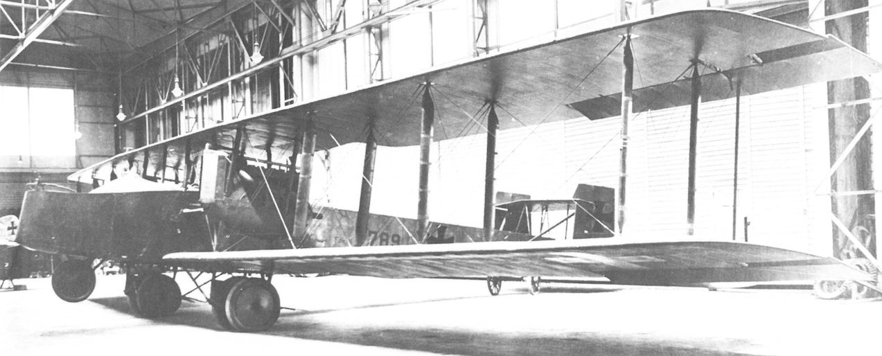
Friedrichshafen G.IIIa(Daim) 789/17 awaiting propeller installation in the Oeffag flight hangar at Wiener-Neustadt.
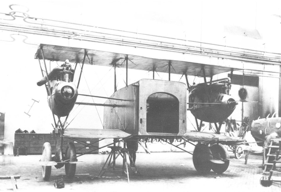
All but the largest German aircraft were designed to be disassembled for rail shipment. The Friedrichshafen G.IIIa (Daim) 789/17 center fuselage module is in process of assembly after arrival at the Oeffag factory.
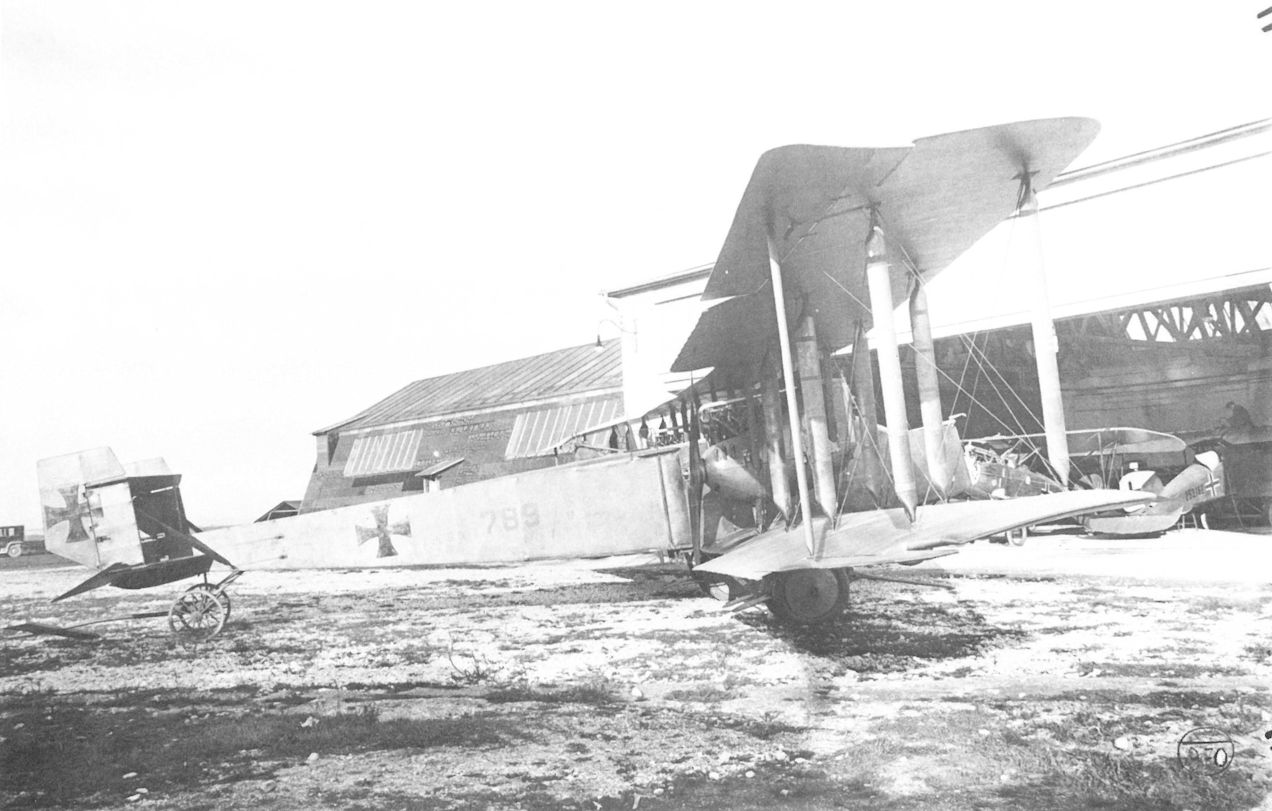
The G.IIIa(Daim) 789/17 fully assembled and ready for flight trials on the Oeffag airfield. Neither of the two Friedrichshafen bombers delivered to Oeffag received an LFT designation number.
Gotha G.IV(LVG) Series 08
In lieu of the Friedrichshafen G.III bomber which was not released for export, on 23 December 1917 the LFT purchased six Gotha G.IV(LVG) bombers powered by 230 hp Hiero engines, followed by 14 in February and 20 in April 1918. The serial numbers assigned were 08.01 to 08.40, but only 39 were delivered as one bomber was demolished in a "typical landing accident" by an LVG factory pilot.
The bombing squadrons, Flik 101/G, 102/G, and 103/G, received the new bombers in March-April 1918. Technicians labored long to correct the excessive engine vibration, caused by weak engine bearers and unsuitable propellers, which led to piping leaks, instrument and structural failure. In the summer of 1918, the Gotha bombers began limited night attacks against Italian cities and tactical targets such as troop concentrations, river crossings, and Caproni bomber airfields far behind the lines. Difficult to fly under any condition owing to a center of gravity shift after the bombs were dropped, pilots considered the Hiero-engined version even more demanding since the carburetor characteristics made it virtually impossible to synchronize engine revolutions to maintain a straight course. Records show that only a handful of the 37 bombers in frontline inventory on 1 August 1918 were fully serviceable. Similar to German experience, operational accidents (11) caused the greatest attrition, primarily due to engine failure. A further two were shot down, two damaged in an Italian bombing raid, and five demolished by a tornado-like storm. As the war progressed, bombing squadrons increasingly turned to the reliable, single-engined Brandenburg C.I(U) series 169 and 369 bombers. By late September 1918, the Gotha G.IV was virtually grounded, performing only sporadic training flights, as work to correct the engine problems continued.
Gotha G.IV(LVG) Series 08
Engine: 2 x 240 hp Hiero
Wing: Span Upper 23.70 m (77.75 ft)
Span Lower 21.90 m (71.85 ft)
Dihedral Upper 6 deg
Dihedral Lower 6 deg
Sweepback Upper 2.1 deg
Sweepback Lower 2.1 deg
Gap 2.22 m (7.28 ft)
Total Wing Area 89.5 sq m (963 sq ft)
General: Length 12.44 m (40.81 ft)
Height 3.90 m (12.80 ft)
Empty Weight 2265 kg (4994 lb)
Loaded Weight 3500 kg (7718 lb)
Maximum Speed: 140 km/hr (87 mph)
Climb: 1000m (3,281 ft) in 8 min 1 sec
2000m (6,562 ft) in 18 min 6 sec
3000m (9,843 ft) in 33 min 6 sec

Gotha G.IV(LVG) 08.05 with a group of LPT officers of Flik 103/G awaiting inspection by Archduke Joseph on 20 May 1918. A propeller-driven dynamo is affixed to the inner wing strut.

On the Aviano airfield, Flik 101/G mechanics assemble the Gotha G.IV(LVG) 08.10 in April 1918. The engine-undercarriage module is awaiting installation in the background. The bomber was destroyed in an emergency landing on 15 September 1918.

Gotha G.IV(LVG) 08.11. The rear gunner’s position has wire guards to protect the gunner from the rotating propellers. Similarly, the undercarriage is fitted with wire guards to prevent stones and debris from flying into the propellers.

Gotha G.IV(LVG) 08.11 showing the landing lights that were installed by the LFT. This was one of the five Gotha bombers destroyed in the storm of 23/24 September 1918.

The Gotha G.IV(LVG) 08.20 was modified at Aspern in July 1918 and given reinforced engine bearers, new radiator jalousies, and improved carburetor controls.
Gotha G.IV-Bomber, Flugzeugnummer 08.20; das Flugzeug war in Aspern bei Propellerversuchen eingeteilt
Бомбардировщик Gotha G.IV, самолет № 08.20; самолет был назначен на испытания пропеллеров в Асперне.
Gotha G.IV-Bomber, Flugzeugnummer 08.20; das Flugzeug war in Aspern bei Propellerversuchen eingeteilt
Бомбардировщик Gotha G.IV, самолет № 08.20; самолет был назначен на испытания пропеллеров в Асперне.

The first Gotha G.IV(LVG) to land on the Flik 101/G airfield at Aviano is surrounded by curious spectators. The bomber is covered in German, dark-hexagon camouflage fabric.

Gotha G.IV(LVG) Series 08
Gotha G.V and G.VII
Idflieg offered the LFT five surplus Gotha G.V and 30 Gotha G.VII twin-engined bombers, less engines, as dual-control trainers in August 1918. Perhaps unknown to the LFT was the fact that, after much experimentation, the Gotha G.VII bomber proved a disappointing failure because it was unable to reach the specified operational altitude of 6000 meters (19,685 ft). This made it unsuitable for the day bomber and long-range reconnaissance role for which it had been designed. Uzelac declined the offer on grounds of "the poor service record experienced with the 40 Gotha G.IV(LVG) bombers in spite of having reinforced the airframe."
Idflieg offered the LFT five surplus Gotha G.V and 30 Gotha G.VII twin-engined bombers, less engines, as dual-control trainers in August 1918. Perhaps unknown to the LFT was the fact that, after much experimentation, the Gotha G.VII bomber proved a disappointing failure because it was unable to reach the specified operational altitude of 6000 meters (19,685 ft). This made it unsuitable for the day bomber and long-range reconnaissance role for which it had been designed. Uzelac declined the offer on grounds of "the poor service record experienced with the 40 Gotha G.IV(LVG) bombers in spite of having reinforced the airframe."
Brandenburg 05.01 to 05.04
The first Brandenburg aircraft to reach LA service was the Type FD (work number FD 13) which was accepted on 20 April 1915. This and the three Type FD biplanes that followed were former German air service machines. The Brandenburg Type FD (a lightened and improved Type D) was fitted with either two- or three-bay wings and had a plywood-covered fuselage. A 100 hp Mercedes engine supplied the power. On 27 May 1915, the first three FD biplanes were assigned numbers 05.01 to 05.03, followed by 05.04 (ex-B.1091/14) later. The four biplanes served with Flik 11 on the Eastern Front from April to December 1915. Aircraft 05.02 and 05.03 were equipped with a Type g.2 wireless transmitter. Flik 11 reported in September 1915 that 05.04 was shoddily built and suffered from deformed spars, echoing German air service charges of deficient construction that stopped further procurement of Brandenburg aircraft by the German air service. In the spring of 1916, the four aircraft were withdrawn, refurbished by Fischamend, and placed in training service with Fleks 3, 8, and 11.
Brandenburg 05.01 (Type FD)
Engine: 100 hp Mercedes
Wing: Span Upper 14.50 m (47.57 ft)
Total Wing Area 46 sq m (495 sq ft)
General: Length 9.40 m (30.84 ft)
Height 3.00 m (9.84 ft)
Empty Weight 790 kg (1742 lb)
Maximum Speed: 90 km/hr (56 mph)
Brandenburg B.I Series 05.1
The satisfactory performance and flight characteristics of the Brandenburg B.I biplane (Type LDD) found the hard-pressed LFT a ready customer, and more of these aircraft were purchased from Germany than any other type. Developed from the Type FD, the B.I saved some 162 kg (357 lb) by replacing the steel engine mounts with wood and resorting to structural refinements. A new feature was the slanted wing struts to obtain equal bending forces over the spar lengths. A 100 hp Mercedes engine supplied the power. Of the total of 102 Brandenburg B.I biplanes ordered, 16 were diverted to the civil Hansa-Brandenburg flying school in Fuhlsbuttel (near Hamburg) where many LFT pilots received their basic training; these were not assigned a serial number.
Qty Series Numbers Order Date Comments
16 05.11-26 20 Jul 1915 pilot in rear cockpit.
52 05.27-78 14 Aug 1915 from 05.60 delivered with dual controls.
4 none 14 Aug 1915 to Fuhlsbuttel, no serial number assigned.
6 05.79-84 13 Sep 1915 fitted with rebuilt engines.
12 05.85-96 22 Dec 1915
12 none 5 Feb 1917 to Fuhlsbuttel, no serial number assigned.
In the summer of 1915, the B.I joined Fliks 1, 5, 7, 9, 10, 11, 13, 14, 18, and 20 on the Russian Front as an unarmed general reconnaissance type. A few examples also saw service on the Italian Front with Fliks 2 and 17. Generally free of faults, the B.I was well liked by aircrews. But deliveries were delayed by the death of chief pilot Franz Reiterer and Hauptmann Bela Mogan on 21 October 1915, when the wings of their "training machine" collapsed during a factory acceptance flight. By 23 December 1915 only 33 B.I biplanes had been delivered and service records show that all aircraft starting with 05.44 were assigned directly to training units, primarily Fleks 7 and 8.
Beginning August 1915, some of the B.I biplanes shipped to the Flugzeugwerk Fischamend for repair were converted to trainers and re-designated B.I (Fd) series 06.5. In addition the Flugzeugwerk began to build a license version in mid-1916 that would total 355 aircraft by the war's end (see Fischamend section for details).
Brandenburg B.I Series 05.1
Engine: 100 hp Mercedes
Wing: Span Upper 12.30 m (40.35 ft)
Span Lower 11.60 m (38.06 ft)
Chord Upper 1.50 m (4.92 ft)
Chord Lower 1.50 m (4.92 ft)
Dihedral Upper 0.18 m (0.59 ft) at tip
Dihedral Lower 0.18 m (0.59 ft) at tip
Sweepback Upper 0.20 deg
Sweepback Lower 0.18 deg
Gap 1.74 m (5.71 ft)
Stagger 0.18 m (0.59 ft)
Total Wing Area 33 sq m (355 sq ft)
General: Length 8.40 m (27.56 ft)
Height 3.10 m (10.17 ft)
Track 2.00 m (6.56 ft)
Empty Weight 618 kg (1363 lb)
Loaded Weight 975 kg (2150 lb)
Maximum Speed: 118 km/hr (73 mph)
Climb: 1000m (3,281 ft) in 8 min
Brandenburg B.I(Fd) Series 06.5
Conversion of the Brandenburg B.I series 05.1 biplanes to dual-control trainers began at the Flugzeugwerk in August 1915. In addition, the Flugzeugwerk modified 37 B.I aircraft (05.60-05.96) that had been delivered with dual controls already installed. In May 1916, the 49 converted and modified B.I trainers were re-designated Brandenburg B.I(Fd) series 06.51 according to the following table:
New No. Original No. New No. Original No. New No. Original No. New No. Original No.
06.51 05.77 06.64 05.54 06.76 05.65 06.88 05.69
06.52 05.78 06.65 05.56 06.77 05.67 06.89 05.70
06.53 05.79 06.66 05.90 06.78 05.81 06.90 05.71
06.54 05.80 06.67 05.11 06.79 05.82 06.91 05.72
06.55 05.86 06.68 06.80 05.83 06.92 05.73
06.56 05.88 06.69 06.81 05.84 06.93 05.74
06.57 05.93 06.70 06.82 05.85 06.94 05.75
06.58 05.94 06.71 05.16 06.83 05.87 06.95 05.76
06.59 05.95 06.72 05.61 06.84 05.89 06.96 05.66
06.60 05.96 06.73 05.62 06.85 05.91 06.97 05.25
06.61 05.12 06.74 05.63 06.86 05.18 06.98 05.27
06.62 05.32 06.75 05.64 06.87 05.68 06.99 05.15
06.63 05.33
The B.I(Fd) series 06.5, powered by a 100 hp Mercedes engine, was first placed in service at Flek 7 in Parndorf, followed in July 1916 by Fleks 10, 11, 12, and later Fleks 4, 8, 13, and 16. On 1 July 1917, twenty-six B.I series 06.5 biplanes were in service. As the rigors of basic training depleted the original Brandenburg B.I complement, their place was taken by Fischamend-built B.I trainers.
Brandenburg B.I(Fd) Series 75 to Series 279
In mid-1916, the Flugzeugwerk delivered the first Brandenburg B.I, the only aircraft built specially as a trainer in Austria-Hungary during the war. The B.I trainer, continually improved to lighten the airframe and speed production, kept Fischamend busy until the war's end. Almost all of the B.I trainers were powered by used or rebuilt Daimler and Hiero engines, replacing the original 100 hp Mercedes engines that were no longer available. To compensate for the different engine dimensions and weights, the B.I airframe underwent progressive modification in a variety of series. Inexplicably, the Flugzeugwerk failed to manufacture sufficient replacement parts with the result that in the summer of 1917, some 70 percent of all Brandenburg B.I trainers were grounded for lack of spares.
Beginning in the summer of 1916, the versatile B.I trainer was flown by every Austro-Hungarian training unit. After the war, many remained on Czechoslovakian, Polish, Yugoslavian and Hungarian territory; many were sold as surplus, and small numbers were built in Poland, Hungary and Czechoslovakia. These formed an important component of the fledgling national air services, and a few B.I biplanes were still flying as late as 1938.
Unfortunately, an accurate compilation of the structural differences and characteristics (dimension, weight, etc.) that would explain the various series has not been found. Through September 1918, the Flugzeugwerk delivered a total of 355 B.I biplanes. At least 60 were completed in October and in the immediate post-war period. The following tabulation lists all known numbers:
Serial Number Quantity Built Engine Control First Delivery
75.01-17 17 100 Mercedes Single July 1916
75.51-61 11 100 Mercedes Single Oct 1917
76.01-59 59 100 Mercedes Single July 1916
76.60-99 40 100 Mercedes Dual May 1917 0)
176.01-99 99 100 Mercedes Single Aug 1917
276.01-24 24 100 Mercedes July 1918
77.51-91 41 100 Daimler Single June 1917
78.01-51 51 120 Daimler Dual Aug 1917
278.01-03 3 Daimler late 1918
79.01-21 21 145 Hiero Jan 1918
279.01-49 49 Hiero late 1918
Although the designations 77.00, 177.00, 178.00 and 179.00 appear in LFT documents, none of these types appear to have progressed beyond the project stage.
Brandenburg B.I(Fd) Series 75
Engine: 100 hp Mercedes
Wing: Span Upper 12.30 m (40.35 ft)
Span Lower 11.70 m (38.39 ft)
Chord Upper 1.50 m (4.92 ft)
Chord Lower 1.50 m (4.92 ft)
Sweepback Upper 2 deg
Gap 1.72 m (5.64 ft)
Stagger 0.16 m (0.52 ft)
Total Wing Area 36.7 sq m (395 sq ft)
General: Length 8.40 m (27.56 ft)
Height 3.10 m (10.17 ft)
Track 2.00 m (6.56 ft)
Empty Weight 703 kg (1550 lb)
Loaded Weight 863 kg (1903 lb)
Maximum Speed: 120 km/hr ( mph)
Climb: 1000m (3,281 ft) in 7 min 40 sec
Brandenburg B.I(Fd) Series 76
Engine: 100 hp Mercedes
Wing: Span Upper 12.30 m (40.35 ft)
Span Lower 11.70 m (38.39 ft)
Chord Upper 1.50 m (4.92 ft)
Chord Lower 1.50 m (4.92 ft)
Sweepback Upper 2 deg
Gap 1.73 m (5.68 ft)
Stagger 0.12 m (0.39 ft)
Total Wing Area 35 sq m (377 sq ft)
General: Length 8.40 m (27.56 ft)
Height 3.10 m (10.17 ft)
Track 2.00 m (6.56 ft)
Empty Weight 712 kg (1570 lb)
Loaded Weight 872 kg (1923 lb)
Maximum Speed: 120 km/hr ( mph)
Climb: 1000m (3,281 ft) in 8 min 5 sec

Brandenburg B.I(Fd) 06.54, Flek 22

Brandenburg B.I(Fd) 76.13, Flek 7

Hansa-Brandenburg factory in Briest in late 1915. To the left of the administration building can be seen a Brandenburg FD, and to the right the Types DD, LDD, and GF.

The three-bay Brandenburg 05.01 (Type FD) served with Flik 11 from May through November 1915. Attached to Fleks 3, 9, and 11, Brandenburg 05.01 was written-off in July 1917.

Brandenburg 05.02 while serving with Flik 11 on the Eastern Front. Austro-Hungarian markings have been added to the tail surfaces and outboard of the original German wing insignia. A large streamer was attached to the tailskid. Rebuilt by Fischamend after a crash, it was destroyed in a mid-air collision (with 22.27) during a training flight on 17 May 1916.
Brandenburg B.I. dreistielig. Flugzeugnummer 05.02
Brandenburg B.I. трехстоечный. Номер самолета 05.02
Brandenburg B.I. dreistielig. Flugzeugnummer 05.02
Brandenburg B.I. трехстоечный. Номер самолета 05.02

The Brandenburg 05.03 on the Flik 11 airfield at Zastawna in the summer of 1915. As a trainer, it was flown by Flek 8 in December 1916, and was still active in August 1917.

Originally purchased by the German air service as B.1091/14, the Brandenburg 05.04, a two-bay Type FD, was flown by Flik 11 in 1915. It was rebuilt and attached to Fleks 3, 8, and 11 through December 1916.

Six completed Brandenburg B.I series 05.1 (LDD) biplanes in the Briest factory awaiting shipment to Aspern in late 1915. Some are fitted with side radiators and some with Mercedes radiators mounted on the center section struts.

Brandenburg B.I 05.25 (Type LDD) undergoing maintenance with Flik 17 on a mountain airfield at Gardolo, 1915. This machine has the side-mounted radiators. Rebuilt at Fischamund in 1916 as a dual trainer it received the new serial 06.97.

Initially the pilot’s cockpit was situated behind, the observer. Starting with Brandenburg B.I 05.26 the pilot’s cockpit was moved to the forward position and an aerodynamically-balanced rudder was fitted.

The long-lived Brandenburg B.I 05.34 served with Flik 1 (shown here - December 1915 to June 1916), Flik 29 (October 1916) and as a trainer with Flek 11 until it was written off in March 1918. An Austro-Hungarian radiator has replaced the original Mercedes radiator.

When the new machine-gun rings were issued in the spring of 1916, they were installed as a frontline modification. This Brandenburg B.I 05.37 flew with Flik 11 from January to March 1916, and as a trainer with Flek 11 in 1917.

The characteristic Brandenburg slanted struts, shown here on Brandenburg B.I 05.45 of Flek 7 in 1917, were introduced with the design of the Type LDD.

Rittmeister Alexander Meyer, later CO of Flik 18, as a student in the Fischamend-modified Brandenburg B.I(Fd) 06.51 (ex 05.77).

Brandenburg B.I(Fd) 06.73 (ex 05.62) photographed at Flek 7 in Parndorf on 19 January 1918.

Brandenburg B.I(Fd) 06.97 (ex 05.25) at Flek 5 in Szeged. Like all the series 06.5 trainers it was equipped with dual steering controls. Power was supplied by a 100 hp Mercedes engine.
Pilot Korporal Bohumil Munzar poses with Brandenburg B.I at Wiener Neustadt in 1916. The wheel control can be seen in the rear cockpit of 06.97. This machine was originally 05.25 until it was modified into a dual-control B.I by Flugzeugwerke Fischamund and given a new serial. The cockpit is a communal one on this machine.
Pilot Korporal Bohumil Munzar poses with Brandenburg B.I at Wiener Neustadt in 1916. The wheel control can be seen in the rear cockpit of 06.97. This machine was originally 05.25 until it was modified into a dual-control B.I by Flugzeugwerke Fischamund and given a new serial. The cockpit is a communal one on this machine.

Brandenburg B.I(Fd) 76.43 with an aerodynamically-balanced rudder. It was accepted in March 1917. The 100 hp Mercedes engine was cooled by side radiators.

Brandenburg B.I(Fd) 76.51 in late-1918 markings, probably photographed in Czechoslovakia after the war. It was accepted in May 1917. The box radiator was mounted between the engine and the top wing.

Brandenburg B.I(Fd) 76.95 fitted with a ski undercarriage for winter service. The additional strut for bracing the rudder was seen on later series aircraft.

Two Brandenburg B.I(Fd) series 77 trainers of Flek 17 on the airfield at Hureczko (Przemysl) in July 1918. On the right is aircraft 77.73.

Brandenburg B.I(Fd) 77.55 photographed at Fischamend at the time of delivery in September 1917. The series, powered by a 100 hp Daimler engine, had a modified nose and fuselage contour.

Brandenburg B.I(Fd) 78.01, powered by a 120 hp Daimler engine, photographed at Fischamend at the time of delivery in August 1917. It was fitted with dual controls.

Brandenburg B.I(Fd) 79.03, powered by a 145 hp Hiero engine, was accepted in January 1918. A proposal in 1918 that UFAG manufacture 100 B.I series 79 trainers was not approved.

Brandenburg B.I(Fd) 176.54 of Flek 17 on the airfield at Hureczko (Przemysl) in July 1918. It was delivered by the Flugzeugwerk in November 1917.

In 1919 a crowd of Czechoslovakian citizens surround the Brandenburg B.I(Fd) 176.95. One of the last series 176 built, it was accepted in June 1918.

Two Czechoslovakian air service officers with the Brandenburg B.I(Fd) 276.19 in early Czechoslovakian markings. Delivered in September 1918, it was based at Flek 16 in Eger (Cheb) in late 1918.
The observer's cockpit has been joined to the pilot's without any provision for a gun ring.
The observer's cockpit has been joined to the pilot's without any provision for a gun ring.
The Aviatik 30.14 prototype (new) after colliding with the Brandenburg B.I 05.26 on 9 February 1917. 30.14 has the original two-piece upper wing and center section cabane. The balanced rudder differed from the production C.I.

The Brandenburg LDD “HBF Nr.55” of the Hansa-Brandenburg Flugschule in Fuhlsbuttel, where many LFT pilots were trained. Being a civilian (private) flying school, neither a German nor an Austro-Hungarian military designation was assigned.

Brandenburg B.I Series 05.1

Brandenburg B.I(Fd) Series 76.6, 176, and 276
Brandenburg 05.07
Little did Hansa-Brandenburg chief pilot Franz Reiterer know when he established three unofficial world altitude records that his feat would launch the most successful landplane designed by Heinkel during the war, destined to become the workhorse of the Austro-Hungarian air service. On 22 September 1915, Reiterer, piloting the prototype Brandenburg Type DD biplane (work number DD 94), reached 5000 meters (16,405 ft) in 58 minutes with three passengers aboard and 5500 meters (18,045 ft) in 68 minutes with two passengers. He captured the absolute altitude record on 29 September when he reached 6500 meters (21,326 ft) carrying one passenger. For its day, this was a remarkable achievement. The DD prototype had evolved from the 100 hp Type LDD (see B.I series 05.1) by fitting a 160 hp Mercedes engine and by paying close attention to weight and drag reduction through careful detail design. The prototype DD climbed to 3000 meters (9843 ft) in 4 minutes - three times as fast as contemporary LFT biplanes. In addition to purchasing the DD prototype (designated 05.07, but commonly called the Reiterer Rekord Maschine), Flars ordered ten DD biplanes for evaluation on 30 September 1915. These were designated C.I series 61.5, the first of 1258 Brandenburg C.I biplanes accepted during the war from three manufacturers.
The 05.07 prototype reached Flik 2 at Aisovizza in October 1915 for frontline evaluation. Armament consisted of two machine guns, one mounted on a fixed pivot in the rear cockpit and a second mounted on a raised tubular structure to provide the observer, or a third crew member, with a clear field of fire over the top wing. The raised mount, unpopular with crews, was soon discarded. Whether this device was used when Leutnant Bogut Burian and observer Oberleutnant Stefan von Vuchetich downed an Italian aircraft on 18 November 1915 is not known, but it was the second victory recorded on the Italian Front.
Officially, the 05.07 “experimental series 61“ was purchased on 24 April 1916. After repair by Phonix in June 1916, the 05.07 returned to the Eastern Front where it served with Flik 11 through May 1917. Subsequently the 05.07 prototype was attached to Flek 13 as a trainer and was written off in August 1917.
Brandenburg 05.07 (Type DD)
Engine: 160 hp Mercedes
General: Empty Weight 688 kg (1517 lb)
Maximum Speed: 152 km/hr (94 mph)
Climb: 1000m (3,281 ft) in 4 min
3000m (9,843 ft) in 13 min
Brandenburg C.I Series 61.5 (First Series)
The C.I all-purpose reconnaissance biplane was Hansa-Brandenburg's great contribution to the Austro-Hungarian war effort. Comprising roughly one quarter (1258) of the total Army aircraft accepted (4768), the versatile Brandenburg C.I (Type DD) was flown at one time or another by virtually every Austro-Hungarian two-seater crew on all Fronts from early 1916 until the cessation of hostilities. Indifferent to punishment and easy to fly, the C.I must stand with the memorable aircraft of the war.
On 30 September 1915, a day after the Brandenburg 05.07 prototype's record-breaking flight, the LFT placed an order for ten C.I series 61.5 biplanes followed by an unprecedented order of 109 production machines, based on the successful frontline evaluation of the 05.07 prototype at Flik 2:
Qty Series Numbers Manufacturer Contract Date
10 61.51-60 Brandenburg 11 October 1915
48 61.01-48 UFAG 11 December 1915
1 manufacturing sample? Brandenburg 12 December 1915
12 61.61-72 Brandenburg 12 December 1915
36 63.51-86 Brandenburg 18 December 1915
22 64.51-72 Brandenburg 18 December 1915
By the end of December the first ten C.I finished airframes were awaiting arrival of the 160 hp Daimler engines from Vienna. Static load tests, using airframe 61.51, were completed in February 1916. According to the company history, 75 aircraft (composed of C.I series 61.5, 63.5, 64.5, and possibly some B.I series 05.1 biplanes) were produced at the Rummelsburg factory. Final outfitting and flight testing took place at Briest. As demand grew, some aircraft were dispatched to Aspern prematurely, arriving in an unfinished state owing to tardy delivery of internal equipment and instruments from Vienna. This caused the Aspern acceptance group to complain of "incomplete aircraft requiring time-consuming extra work."
The structure of the durable C.I was entirely conventional. The fuselage was comprised of a simple but strong wooden framework covered with thin plywood sheathing. Following preferred LFT practice, the pilot and observer were seated in close proximity and provided with ample stowage space for ammunition, camera and small bombs. The sturdy two-bay wing cellule had the characteristic slanted steel-tube struts faired with wood wrapped in fabric. The wings were composed of wooden box spars and ribs, internally braced with compression tubes and cables. A wire trailing edge imparted a scalloped effect when the fabric was tightened by doping. Early C.I biplanes were delivered without sweepback, but with the installation of heavier, more powerful engines, sweptback (or, in some cases, forward swept) wings provided proper stability. The tail empennage was fashioned from light steel tubing and fabric covered. The robust undercarriage was a simple V-type sprung with elastic shock-cord. A claw brake was affixed to the axle of most aircraft. The C.I series 61.5 biplanes were powered by a 160 hp Daimler engine.
In March 1916, the first nine C.I biplanes were dispatched to Fliks 2, 4, 19, 23, and 28 on the Isonzo Front. In the Balkans, Flik 6 received the first C.I in May 1916. The C.I was praised by LFT aircrews for its superiority over existing two-seater aircraft. Many pilots remembered the C.I with affection. Stabsfeldwebel Friedrich Hefty echoed the sentiments, recalling the C.I "as very stable, easy to fly, possessed of a good rate of climb and exceedingly reliable in the field." The secret of the C.I's longevity was inherent in the robust airframe which, with continuing modification, was able to accept heavier engines of increasing power without relinquishing any of its fine structural and flight characteristics - a true measure of design integrity.
According to the meticulous research of Karl Meindl, more victories were scored in aircraft 61.64 than any other two seater. On 22 August 1916, pilot Stabsfeldwebel Julius Arigi and observer Feldwebel Johann Lasi of Flik 6 shot down five Italian Farmans within a half-hour over the Skumbi estuary in Albania. It was the highest score attained during a single mission by any Austro-Hungarian pilot. Arigi gained his sixth victory when he and Leutnant Fabian Lukas-Sluja in 61.64 downed a Farman over Fjeri on 6 September 1916. Lastly Arigi, again flying 61.64, and Kadett Viktor Renvez were victorious over a Caproni bomber on 18 September 1916 near Arta. Among the most spectacular of air combats was the destruction of the Italian airship M 4 in flames near Aisovizza on 4 May 1916 by Hauptmann Adolf Heyrowsky and Oberleutnant Fiala Ritter von Fernbrugg in aircraft 61.55. With the arrival of improved Brandenburg C.I biplanes in mid-1917, the series 61.5 machines were gradually withdrawn from operational service, although some lasted until December 1917 on the less-active Albanian Front. A few aircraft served out their useful life as advanced trainers with Fleks 5, 6, 8, and 9.
The Brandenburg C.I's superiority over current LFT equipment led to large production contracts at Phonix and UFAG. Up to 31 October 1918, at which point acceptance records are no longer complete, a total of 1258 C.I biplanes had been delivered. Below are the various series presented in order of production:
Hansa-Brandenburg
Qty Series Nos. Engine
22 61.51-72 160 Dm
36 63.51-86 160 Merc
22 64.51-72 160 Dm
80 (6.4% of total)
Phonix
Qty Series Nos. Engine
70 26.01-70 160 Dm
88 27.01-88 160 Dm
40 29.50-89 200 H
72 129.01-72 200 H
32 229.01-32 200 H
40 29.01-40 200 Dm
56 329.01-56 200 H
48 429.01-48 230 H
446 (35.4% of total)
UFAG
Qty Series Nos. Engine
24 61.01-24 160 Dm
48 64.01-48 160 Dm
64 68.01-64 160 Dm
32 63.01-32 160 Dm
56 67.01-56 160 Dm
48 69.01-48 200 Dm
50 69.50-99 200 H
22 169.01-22 220 Bz
112 169.31-142 220 Bz
30 169.151-180 250 Bz
72 269.01-72 200 Dm
72 369.01-72 230 H
32 369.101-132 230 H
70 369.141-210 230 H
732 (58.2% of total)
Brandenburg C.I Series 61.5
Engine: 160 hp Daimler
Wing: Span Upper 12.30 m (40.35 ft)
Span Lower 11.70 m (38.39 ft)
Chord Upper 1.70 m (5.58 ft)
Chord Lower 1.70 m (5.58 ft)
Dihedral Upper 0.15 m (0.49 ft) at tip
Dihedral Lower 0.15 m (0.49 ft) at tip
Sweepback Upper 0 deg
Gap 1.70 m (5.58 ft)
Stagger 0.44 m (1.44 ft)
Total Wing Area 38.2 sq m (411 sq ft)
General: Length 8.15 m (26.74 ft)
Empty Weight 741 kg (1634 lb)
Loaded Weight 1215 kg (2679 lb)
Maximum Speed: 151 km/hr (94 mph)
Climb: 1000m (3,281 ft) in 5 min 20 sec
3000m (9,843 ft) in 25 min 10 sec
5000m (16,405 ft) in 36 mm 40 sec
Brandenburg C.I Series 63.5 (Second Series)
On 18 December 1915, Flars ordered 36 Brandenburg C.I biplanes, numbered 63.51 to 63.86, the only C.I series powered by the 160 hp Mercedes engine. The airframes, built at Rummelsburg, were sent to Briest for engine, fuel system, and instrument installation. When acceptances began in June 1916, Flars accused Briest of shoddy workmanship and use of non-standard parts, and submitted a list of 38 quality control rejections found on 63.60 - a brand-new aircraft delivered with a "soiled and neglected appearance." Such complaints confronted Dr. Walter Lissauer when he came to Briest as Castiglioni's trouble-shooter to straighten out production problems.
As they became available, the C.I series 63.5 biplanes were sent to virtually every Flik stationed on the Russian and Rumanian Fronts. As of 1 July 1917, thirty C.I series 63.5 aircraft were listed in the frontline inventory. In September 1917, when operational flight training for newly-arrived pilots was assigned to frontline squadrons, series 63 and 63.5 biplanes were employed. At least 10 were converted to dual control by Phonix and UFAG. In 1918 three machines carried mail between Aspern and Kiev, and later that year six were attached to home defense units in spite of their obsolescence.
Brandenburg C.I Series 63.5
Engine: 160 hp Mercedes
Wing: Span Upper 12.30 m (40.35 ft]
Span Lower 11.70 m (38.39 ft)
Chord Upper 1.70 m (5.58 ft]
Chord Lower 1.70 m (5.58 ft)
Sweepback Upper 0 deg
Sweepback Lower 0 deg
Gap 1.80 m (5.91 ft)
Stagger 0.44 m (1.44 ft)
Total Wing Area 37.0 sq m (398 sq ft)
General: Length 8.40 m (27.56 ft)
Height 3.20 m (10.50 ft)
Track 2.00 m (6.56 ft)
Empty Weight 770 kg (1698 lb)
Loaded Weight 1219 kg (2688 lb)
Maximum Speed: 142 km/hr (88 mph)
Climb: 1000m (3,281 ft) in 5 min 21 sec
Brandenburg C.I Series 64.5 (Third Series)
The Brandenburg C.I series 64.5 had the new "universal" fuselage that facilitated quick installation of photographic, wireless, and bombing equipment according to mission objectives. Another innovation was an adjustable rear spar fitting to tailor the sweepback to individual aircraft. Power was supplied by a 160 hp Daimler engine.
Twenty-two C.I biplanes, numbered 64.51 to 64.72, were ordered on 18 December 1915. These machines were accepted between October 1916 and February 1917, and began to reach the Front in February-March 1917. By July, 21 series 64.5 biplanes were based on the Eastern Front with Fliks 3, 9, 11, 13, 14, 18, 20, 22, 25, 26, 29, and 40 and in the Tirol with Flik 45. In May 1917 aggressive Russian fighters assembled for the Kerenski offensive took advantage of the C.I's slow speed and climb. Faced with the inability of carrying out assignments in spite of fighter escort, frontline units urgently requested more powerful aircraft (May 1917). Some squadrons took matters into their own hands. Flik 22, after installing a more powerful 185 hp Daimler engine, reported aircraft 64.53 "well suited for close reconnaissance, spotting, and photo work."
The series 64.5 biplanes, retired from combat service by the end of 1917, found continued use as advanced trainers with Fliks 4, 20, and 36, as well as Fliks 5, 8, and 12 and the field flying school Neumarkt. At least five aircraft were converted to dual control.
Brandenburg C.I Series 64.5
Engine: 160 hp Daimler
Wing: Span Upper 12.30 m (40.35 ft)
Span Lower 11.70 m (38.39 ft)
Chord Upper 1.70 m (5.58 ft)
Chord Lower 1.70 m (5.58 ft)
Sweepback Upper 1 deg
Sweepback Lower 1 deg
Gap 1.74 m (5.71 ft)
Stagger 0.51 m (1.67 ft)
Total Wing Area 35.0 sq m (377 sq ft)
General: Length 8.30 m (27.23 ft)
Height 3.20 m (10.50 ft)
Track 2.06 m (6.76 ft)
Empty Weight 745 kg (1643 lb)
Loaded Weight 1219 kg (2688 lb)
Maximum Speed: 144 km/hr (89 mph)
Climb: 1000m (3,281 ft) in 6 min 35 sec
Phonix 20.08 and 20.09
Following the conclusion of the Hiero engine trials in the Phonix 20.05-20.07 prototypes, Flars had Phonix install the new 200 hp Hiero engine in two Brandenburg C.I(Ph) series 26 airframes for frontline evaluation. The two test aircraft, numbered 20.08 and 20.09, were dispatched to Flik 19 on the Italian Front in May 1916. The improved performance imparted by the more powerful engine received the highest praise. After being fitted with standard production engines in July 1916, both aircraft rejoined Flik 19. Aircraft 20.08 was destroyed in an emergency landing on 21 December 1916, but 20.09 was active until 3 January 1918 when it was badly damaged by anti-aircraft fire and written-off. The Phonix 20.08 and 20.09 prototypes were the precursors of the Brandenburg C.I(Ph) series 29.5, the first to be built powered by 200 hp Hiero engines. As late as January 1918, Hauptmann Adolf Heyrowsky, CO of Flik 19, praised the Hiero-engined Brandenburg C.I, exemplified by the 20.09, "as the best of all types powered by this engine.
In May-July 1917, aircraft 20.09 and 29.51 were armed with a powerful battery of six downward-firing machine guns mounted at a 45-degree angle in the rear cockpit and remotely fired by the pilot. The battery was devised by Hauptmann Heyrowsky. Taking part in the Eleventh Isonzo Battle, the first attack was flown on 21 August 1917 by Zugsfuhrer Istvan Fejes (20.09) and Feldwebel Karl Reithofer (29.51) to strafe Italian infantry in the Vertobja defile at dawn. Occasional strafing missions were flown through October 1917. The success was such that Phonix was requested to modify the Brandenburg C.I as an armored ground-attack aircraft.
Phonix 20.09 Specifications
Engine: 200 hp Hiero
Climb: 1000m (3,281 ft] in 5 min 12 sec
2000m (6,562 ft) in 11 min 40 sec
3000m (9,843 ft) in 19 min 55 sec
4000m (13,124 ft) in 37 min 45 see
Phonix 20.13
In March 1917, Phonix began work on the installation of the new 220 hp Benz(Mar) engine in the Brandenburg C.I(Ph) 29.90, the last of the series, to evaluate the engine characteristics in flight. The aircraft was delivered in the summer of 1917. Although officially re-designated Phonix 20.13, the original number remained in force. Aircraft 29.90 was reported attached to the test group at Fischamend in October 1918 and offered to Czechoslovakia in 1920.
Brandenburg C.I(Ph) Series 26 (First Series)
On 13 December 1915, the LFT gave Phonix a contract for 24 Brandenburg C.I(Ph) series 26 reconnaissance biplanes powered by the 160 hp Daimler engine and in early 1916 the first acceptances were underway. A second contract signed on 23 May 1916 brought the total production to 70 aircraft numbered 26.01 to 26.70, the last of which was accepted in August 1916. The first eight aircraft built were recorded as being "slightly abnormal" in that the center-section tubing and fuselage frames were smaller. Standard output began with aircraft 26.09 which, before going to the Front, was sent to UFAG to serve as a pattern for the series 61 production model.
In the spring of 1916 the Brandenburg C.I(Ph) began to reach wide squadron service on the Isonzo Front (Fliks 2, 4, 19, 23), the Tirol Front (Fliks 15, 17, 21, 24) and the Eastern Front (Fliks 1, 3, 5, 7, 8, 9, 10, 14, 18, 20, 22, 25, 27, 29, 30). With arrival of the UFAG and Phonix-built Brandenburg C.I biplanes, LFT aircrews for the first time had in their hands a truly versatile reconnaissance and light bombing machine of impeccable flight characteristics. Strong and reliable, the series 26 aircraft were highly regarded in the field, especially those retrofitted with the 185 hp Daimler engine. Even as late as September 1917, Flik 20 reported their preference for the re-engined series 26 over the newer UFAG-built series 67 and 269 because of "their good climb and speed and, above all, sensitive control." By then the 160 hp version, although praised for its stability, was too slow in speed and climb and was "useful only as a makeshift artillery spotter provided reliable fighter cover was on hand." The fact that the durable series 26 was still operational in September 1917 is a tribute to Phonix quality workmanship and the inherently robust design.
At least seven series 26 aircraft were fitted with dual controls and entered training service in which role at least 24 were still active in late 1918. Several aircraft were flown on the airmail routes between Aspern and Kiev and other points.
Brandenburg C.I(Ph) Series 26 Specifications
Engine: 160 hp Daimler
Wing: Span Upper 12.30 m (40.35 ft)
Span Lower 11.70 m (38.39 ft)
Chord Upper 1.70 m (5.58 ft)
Chord Lower 1.70 m (5.58 ft)
Dihedral Upper 0.15 deg
Dihedral Lower 0.15 deg
Sweepback Upper 1 deg
Sweepback Lower 1 deg
Gap 1.74 m (5.71 ft)
Stagger 0.54 m |1.77 ft)
Total Wing Area 38.4 sq m (413 sq ft)
General: Height 2.95 m (9.68 ft)
Empty Weight 797 kg (1757 lb)
Loaded Weight 1238 kg (2730 lb)
Maximum Speed: 140-145 km/hr (87-90 mph)
Climb: 1000m (3,281 ft) in 6 min 20 sec
Brandenburg C.I With Raised Gun Turret
In parallel with other raised gun-turret experiments (see 05.07 and series 61.5, 61 and 64), several Phonix-built Brandenburg C.I biplanes were tested with similar armament. Aircraft 26.17, the first Phonix-built aircraft so equipped, was assigned to Flik 7 for service evaluation in September 1916. After four flights, Flik 7 reported that "when sitting in the tower, the observer has no view except through the top. Communication between pilot and observer is near impossible as is accurate bomb aiming. It is difficult to train the gun forward although satisfactory to the sides and rear. The speed is slower than comparable aircraft. When banking in a turn, 26.17 sideslipped but after removal of the tower, the aircraft flew well." Further service tests with raised gun turrets in aircraft 27.23, 27.24, and 27.25 were equally unsuccessful. Turrets were installed on aircraft 27.85 to 27.88 but removed before leaving the factory.
Brandenburg C.I(Ph) Series 27 (Second Series)
The Brandenburg C.I(Ph) series 27 which replaced series production in August 1916 was delivered with the Phonix-designed "universal fuselage" that had been introduced with the Brandenburg C.I(U) series 64 in April 1916. The fuselage was designed for various engines and fitted with appropriate fixtures to allow photographic, bombing, or wireless equipment to be easily installed by field personnel. The contract for the first 56 series 27 biplanes, part of a blanket order of 200 aircraft, was signed on 24 June 1916, followed by an additional order for 32 signed on 18 September 1916. Powered by a 160 hp Daimler engine, the last of the series 27 biplanes, numbered 27.01 to 27.88, was accepted in February 1917.
In the autumn of 1916, the Brandenburg C.I(Ph) series 27 began to be distributed among frontline units who expressed a high regard for the type. But by mid-1917, the series 27, now considered as underpowered, was assigned to less demanding roles and gradually withdrawn in favor of more powerful replacements. As was often the case, many series 27 machines were retained as advanced trainers by frontline units or fitted with dual controls and assigned to training service. In inactive sectors some soldiered on: the 24 series 27 aircraft attached to the two Ostarmee Fliks were not withdrawn until August 1917. A handful were employed for gyroscope, parachute, photography, night-flying and armament experiments at Fischamend and Aspern. With the inauguration of airmail service between Aspern and Kiev on 31 March 1918, six series 27 aircraft joined the aircraft pool that operated on expanding routes.
In August 1916, Flars established series 27.8 designation for a version powered by a 200 hp Hiero engine. This designation was rescinded and replaced by the series designation 29.5.
Brandenburg C.I(Ph) Series 27 Specifications
Engine: 160 hp Daimler
Wing: Span Upper 12.30 m (40.35 ft)
Span Lower 11.70 m (38.39 ftj
Chord Upper 1.70 m (5.58 ft)
Chord Lower 1.70 m (5.58 ft)
Sweepback Upper 1 deg
Gap 1.74 m (5.71 ft)
Stagger 0.54 m (1.77 ft)
Total Wing Area 38.4 sq m (413 sq ft)
General: Length 8.40 m (27.56 ft)
Height 3.20 m (10.50 ft)
Empty Weight 778 kg (1715 lb)
Loaded Weight 1219 kg (2688 lb)
Maximum Speed: 141-148 km/hr (88-92 mph)
Climb: 1000m (3,281 ft) in 5 min 30 sec
3000m (9,843 ft) in 26 min 5 sec
Brandenburg C.I(Ph) Series 29.5 (Third Series)
As soon as the results of the frontline evaluation became known - that the Brandenburg C.I powered by the new 200 hp Hiero engine (see 20.08 and 20.09) presented an ideal combination - Flars placed a production order in July 1916 for 40 Brandenburg C.I(Ph) series 29.5 biplanes numbered 29.50 to 29.89. Aircraft above 29.80 had the license-built Hiero(Fi) engine installed. Series 29.5 acceptances began in September 1916 and ended in January 1917. That month Flik 19 reported that the more powerful series 29.5 aircraft were well suited for long-range reconnaissance and excelled at short-range artillery and photographic work, stating that "The type has all the attributes of a fine observation machine." In the absence of fighter protection, the series 29.5 often performed escort duties. These tractable and solid aircraft were evenly distributed among units on the Italian Front, namely Fliks 2, 4, 12, 15, 16, 17, 23, 24, 28, 34, 35 and 58/D, until their gradual replacement by more-modern types in late 1917, although a few remained operational well into 1918. Others were employed as advanced trainers by frontline units (Fliks 37, 46/F, 69/D, 73/D, and 102/G) or flying schools.
Brandenburg C.I(Ph) Series 29.5 Specifications
Engine: 200 hp Hiero
Wing: Span Upper 12.30 m (40.35 ft)
Span Lower 11.70 m (38.39 ft)
Chord Upper 1.70 m (5.58 ft)
Chord Lower 1.70 m (5.58 ft)
Sweepback Upper 1 deg
Gap 1.74 m (5.71 ft)
Stagger 0.54 m (1.77 ft)
Total Wing Area 38.4 sq m (413 sq ft)
General: Length 8.37 m (27.46 ft)
Height 3.20 m (10.50 ft)
Track 2.07 m (6.79 ft)
Empty Weight 805 kg (1775 lb)
Loaded Weight 1238 kg (2730 lb)
Maximum Speed: 155-163 km/hr (96-101 mph)
Climb: 1000m (3,281 ft) in 4 min 12 sec
2000m (6,562 ft) in 9 min 42 sec
3000m (9,843 ft) in 17 min 36 sec
4000m (13,124 ft) in 30 min 10 sec
5000m 116,405 ft) in 54 min 40 sec
Brandenburg C.I(Ph) Series 129 and 229 (Fourth and Fifth Series)
To increase performance, Phonix engineers refined the Brandenburg C.I airframe and introduced an airfoil radiator and a shorter under-carriage without cable bracing, neither of which proved satisfactory. On 23 December 1916, Flars placed the first order (24 aircraft) followed by others that eventually totalled 104 aircraft. Series 129 and 229 were structurally identical except those powered by the license-built 200 hp Hiero (Fi) engine were assigned the designations 129.01 to 129.72 and those with the original Hiero were numbered 229.01 to 229.32. Acceptances began in February 1917 and production of both models ran concurrently until completion in June 1917. The first aircraft 129.01 (initially designated 23.01) was inspected by Flars engineers on 18 January 1917 and arrived for acceptance tests at Aspern on 7 February 1917. Early production models proved nose-heavy, which was corrected by rigging the wings with a slight forward sweep. This rarely-used aerodynamic correction resulted in unusual stability problems which caused much adverse comment. The nose-heaviness was eliminated on later production aircraft, but the series 129/229 was never as maneuverable as the older series 29.5 although they were well-received by squadron personnel. Possessing a superior rate of climb and large fuel capacity, these versatile machines were flown by virtually every two-seater unit on the Italian Front until the end of the war.
Brandenburg C.I(Ph) Series 129 &. 229 Specifications
Engine: 200 hp Hiero
Wing: Span Upper 12.30 m (40.35 ft)
Span Lower 11.70 m (38.39 ft)
Chord Upper 1.70 m (5.58 ft)
Chord Lower 1.70 m (5.58 ft)
Sweepback Upper 1 deg
Gap 1.74 m (5.71 ft)
Stagger 0.54 m (1.77 ft)
Total Wing Area 38.4 sq m (413 sq ft)
General: Empty Weight 794 kg (1751 lb)
Loaded Weight 1230 kg (2712 lb)
Maximum Speed: 155-159 km/hr (96-99 mph)
Climb: 1000m (3,281 ft) in 3 min 58 sec
Brandenburg C.I(Ph) Series 29 (Sixth Series)
From a blanket order of 264 aircraft placed on 9 March 1917, Flars called down 40 Brandenburg C.I(Ph) series 29 biplanes numbered 29.01 to 29.40. These were the only Phonix-built Brandenburgs powered by the 200 hp Daimler engine. After Flars engineers inspected the 29.01 production prototype, the engine cowling was lowered and the pilot's seat moved forward to enhance vision. Aircraft acceptances began in July and ended in November 1917. Although reported slightly slower in speed and climb, the type was appreciated by aircrews because of the reliable engine. Joining the series 129, 229 and 329, series 29 was operational through the war's end in the Tirol with Fliks 8, 10, 17, 21, 23, 24, 45, 54/D, and 101 /G; on the Isonzo Front (later Piave) with Fliks 2, 4, 12, 16, 28, 32, 35, 46/F, 47, 49/F, and 50, and in Albania with Flik 6.
Brandenburg C.I(Ph) Series 29 Specifications
Engine: 200 hp Daimler
Wing: Span Upper 12.30 m (40.35 ft)
Span Lower 11.70 m (38.39 ft)
Chord Upper 1.70 m (5.58 ft)
Chord Lower 1.70 m (5.58 ft)
Total Wing Area 38.4 sq m (413 sq ft)
General: Length 8.37 m (27.46 ft)
Height 3.20 m (10.50 ft)
Empty Weight 811 kg(1788 lb)
Loaded Weight 1260 kg (2778 lb)
Maximum Speed: 154 km/hr (96 mph)
Climb: 1000m (3,281 ft) in 4 min 50 sec
Brandenburg C.I(Ph) Series 329 (Seventh Series)
From a blanket order of 264 aircraft placed on 9 March 1917, Flars called down 56 Brandenburg C.I(Ph) series 329 biplanes, numbered 329.01 to 329.56 and powered by a 200 hp Hiero engine. These were accepted between July and November 1917. Built concurrently with the series 29 and similarly designed with lowered engine bearers to improve forward view, the series 329 suffered from nose-heaviness. Consequently, early machines were delivered with forward-swept wings which made them tricky to fly, being prone to side-slipping in turns. To alleviate the problem, some Fliks installed the 70cm camera behind the observer's seat or replaced the Type II VK gun canister with a fuselage-mounted synchronized gun. Since the series 329 had a relatively low rate of climb, most were used for low-altitude work, including night bombing. For ground attack, engine cooling louvres were added and an internal gun mount installed for firing downwards through the bomb-aiming aperture. Eight fragmentation bombs carried under the wings completed the armament. Flown by Fliks 22/D and 26/D, these aircraft successfully attacked Italian lines in the Piave Offensive of June 1918. Other units known to have flown the series 329 were Fliks 8, 10, 15, 16, 17, 21, 24, 27, 45, 48, and 54/P on the Tirolean Front and Fliks 2, 4, 12, 19, 23, 28, 32, 34, 35, 37, 46/F, 47, 50, 53/D, 57/F, 59/D, and 101/G on the Isonzo and later Piave Front.
Brandenburg C.I(Ph) Series 329 Specifications
Engine: 200 hp Hiero
Wing: Span Upper 12.30 m (40.35 ft)
Span Lower 11.70 m (38.39 ft)
Dihedral Upper 2 deg
Dihedral Lower 2 deg
Total Wing Area 38.4 sq m (413 sq ft)
General: Length 8.37 m (27.46 ft)
Maximum Speed: 145 km/hr (90 mph)
Climb: 1000m (3,281 ft) in 4 min 30 sec
2000m (6,562 ft) in 8 min 55 sec
3000m (9,843 ft) in 13 min 55 sec
4000m (13,124 ft) in 18 min 55 sec
Brandenburg C.I(Ph) Series 429 (Eighth Series)
At the time when Phonix received an order for 48 Brandenburg C.I(Ph) series 429 aircraft in February 1918, production of the C.I(Ph) had ceased. Since the company was fully engaged with the Phonix C.I, it would not be until June 1918 that the first series 429 aircraft would be accepted. In the interim, Phonix had developed an experimental armored ground-attack machine (229.02) that the LFT was keen to place in service. With the 230 hp Hiero (Fi) engine, the series 429 had sufficient power to carry armor, multi-gun batteries, and fragmentation bombs. As envisioned by Flars, aircraft 429.01 to 429.24 were intended as "infantry aircraft" and 429.25 to 429.48 as "battle aircraft", but the distinction between these two functions is not known. With armor plate in extremely short supply, series 429 aircraft were accepted without armor and employed as general-purpose reconnaissance and low-altitude bombing machines. The powerful series 429 aircraft were reported pleasant to fly, meeting every demand placed on them. The type reached the front in June 1918, and served with Fliks 2/D, 19/D, 22/D, 28/D, 34/D, 35/D, 47/D, 49/D, 52/D, 53/D, 57/Rb, 67/DS, and 69/S on the Piave Front; by Fliks 17/D, 24/D, 31/D, and 54/D in Tirol; and Fliks 6/F and 64/F in Albania. Nine aircraft were retained by Flars for experimental purposes including wireless, searchlight and bomb-rack installation, and test firing of several different cannons.
The August 1918 production program scheduled an additional 120 series 429 aircraft (24 as armored trench-strafers) with deliveries beginning in October 1918, but manufacture never commenced. At least five series 429 aircraft took part in the post-war border strife in Karnten.
Brandenburg C.I(Ph) Series 429 Specifications
Engine: 230 hp Hiero
Wing: Span Upper 12.30 m (40.35 ft)
Span Lower 11.70 m (38.39 ft)
Total Wing Area 38.4 sq m (413 sq ft)
General: Length 7.85 m (25.75 ft)
Height 2.95 m (9.68 ft)
Empty Weight 825 kg (1819 lb)
Loaded Weight 1195 kg (2635 lb)
Maximum Speed: 160 km/hr (99 mph)
Climb: 1000m (3,281 ft) in 4 min 58 sec
2000m (6,562 ft) in 10 min 15 sec
3000m (9,843 ft) in 18 min 51 sec
4000m (13,124 ft) in 31 min 42 sec
5000m (16,405 ft) in 58 min 48 sec
Brandenburg C.I(U) Series 61 (First Series)
The Brandenburg C.I(U) series 61 was the forerunner of a long line of UFAG-built C.I biplanes that, with engines of increasing power and continuing structural refinement, formed the lion's share of UFAG output through 1919. The first series, built according to manufacturing drawings supplied by Phonix, comprised 24 Brandenburg C.I(U) biplanes numbered 61.01 to 61.24 and powered by 160 hp Daimler engines. At the time UFAG signed the formal production contract on 13 December 1915, assembly was underway and some machines were already completed. Flight tests at Aspern in December 1915 were reported as very promising, but delivery was postponed in order to make last-minute modifications arising from the Flars engineering critique of the Phonix counterpart (26.09). The specified cockpit armor plate, tested on aircraft 61.01 in February 1916, was eliminated because the extra weight reduced performance and the protection afforded was regarded as minimal.
Between February and the autumn of 1916, the Brandenburg C.I(U) series 61 machines served primarily with Fliks 2, 4, and 12 on the Isonzo Front and Fliks 7 and 24 in southern Tirol. Single machines were found in Fliks 8, 15, 17, and 23. Built with the same sturdy workmanship as the Phonix machines, the series 61 aircraft were praised for their handling qualities, stability, and innate ruggedness, especially by squadrons that had been flying older, pre-war designs. With the arrival of more powerful aircraft at the Front, the series 61 aircraft were modified into dual-control, advanced trainers, serving with Fleks 5, 6, 8, and 9. In July 1917, ten Brandenburg C.I(U) series 61 trainers were on hand and a few survived the war.
It should be noted that, in spite of common manufacturing drawings supplied by Phonix, only standard parts such as wheels, axles and radiators were interchangeable among the C.I variants built by Brandenburg, Phonix, and UFAG. Because each firm made changes in accordance with their own design and manufacturing practices, parts availability, and perhaps a dash of engineering ego, few of the parts were common to all.
Brandenburg C.I(U) Series 61 Specifications
Engine: 160 hp Daimler
Wing: Span Upper 12.30 m (40.35 ft)
Span Lower 11.70 m (38.39 ft)
Chord Upper 1.70 m (5.58 ft)
Chord Lower 1.70 m (5.58 ft)
Dihedral Upper 0.15 m (0.49 ft)
Dihedral Lower 0.15 m (0.49 ft)
Sweepback Upper 1 deg
Sweepback Lower 1 deg
Gap 1.75 m (5.74 ft)
Stagger 0.51 m (1.67 ft)
Total Wing Area 38.5 sq m (414 sq ft)
General: Length 8.23 m (27.00 ft)
Height 2.95 m (9.68 ft)
Track 2.06 m (6.76 ft)
Empty Weight 803 kg (1771 lb)
Loaded Weight 1256 kg (2769 lb)
Maximum Speed: 138 km/hr (86 mph)
Climb: 1000m (3,281 ft) in 5 min 40 sec
Brandenburg C.I(U) Series 64 (Second Series)
Production of the Brandenburg C.I(U) series 61 was followed by the series 64, of which 48 were ordered under a letter of intent in April 1916 and formalized in June 1916, by which time 20 machines had been completed. The aircraft, powered by a 160 hp Daimler engine, were numbered 64.01 to 64.48. The Brandenburg C.I(U) series 64 introduced the important concept of the "universal fuselage," designed to accept different engines and to accommodate a variety of photographic, wireless, and bombing equipment according to mission requirements. The universal fuselage was designed by the Phonix engineering department, which also made minor improvements to the wing structure, metal fittings, and undercarriage. When acceptances ended in August 1916, production continued with the identical series 68 because numbers over 64.5 were assigned to aircraft built by Brandenburg.
Beginning May 1916 these machines performed general-purpose tasks with distinction, especially on the Russian Front with Fliks 1, 3, 7, 9, 10, 11, 14, 18, 22, 26, 27, and 40. In 1917 some of the more worn-out aircraft were used as unarmed advanced trainers at frontline units, and at least six were converted to dual control. Several series 64 aircraft were still flying in 1918.
Brandenburg C.I(U) Series 64 Specifications
Engine: 160 hp Daimler
Wing: Span Upper 12.30 m (40-35 ft)
Span Lower 11.70 m (38.39 ft)
Chord Upper 1.70m (5.58 ft)
Chord Lower 1.70 m (5.58 ft)
Dihedral Upper 0.15 m (0.49 ft)
Dihedral Lower 0.15 m (0.49 ft)
Sweepback Upper 1 deg
Sweepback Lower 1 deg
Gap 1.74 m (5.71 ft)
Stagger 0.51 m (1.67 ft)
Total Wing Area 38.5 sq m (414 sq ft)
General: Length 8.23 m (27.00 ft)
Height 2.95 m (9.68 ft)
Track 2.06 m (6.76 ft)
Empty Weight 771 kg (1700 lb)
Loaded Weight 1213 kg [2675 lb)
Maximum Speed: 138-140 km/hr (86-87 mph)
Climb: 1000m (3,281 ft) in 6 min 55 sec
Brandenburg C.I(U) Series 68 (Third Series)
With emphasis shifting to indigenous production in 1916, Flars began to award large "open" contracts to enable the aircraft firms to obtain financing, order parts and materials in advance, and engage in development work. On 24 June 1916, UFAG received an order for 152 aircraft that eventually comprised (in order of appearance) 64 Brandenburg C.I(U) series 68, 32 series 63, and 56 series 67 biplanes.
Since series numbers starting with 64.5 were assigned to Hansa-Brandenburg, series 64 production was continued under the designation series 68. In fact, Brandenburg C.I(U) series 68 were identical with series 64 until aircraft 68.41, when minor structural improvements were made. Acceptances of aircraft numbered 68.01 to 68.64 began in August and ended in December 1916. Series 68 aircraft were supplied to all Fronts, namely Fliks 7, 11, 22, 26, 37, 40, and 47 on the Russian Front; Fliks 13, 29, 31, 33, 36, and 39 on the Rumanian Front; and Fliks 2, 4, 12, 15, 16, 19, 23, 28, 32, and 35 on the Italian Front. By the spring of 1917, units on the Italian Front reported that the 160 hp Brandenburg C.I aircraft no longer possessed adequate performance to fulfill all operational requirements, but the shortage of aircraft and engines kept these near-obsolescent aircraft in frontline use. Flik 6/F reported in October 1917 that "Three series 68 machines had been in service for over a year, a tribute to their strong construction and excellent workmanship" but they were unable to climb above 2500 meters (8200 ft), which limited them to low-altitude duties, wireless practice, and flight training. Even on the quiet Rumanian Front, one pilot wrote in 1917 "We still fly the ancient sixty-eights - weary hearses, broad and slow as turtles, because the home front can't supply aircraft fast enough."
As replacements arrived in the autumn of 1917, the series 68 aircraft, some fitted with dual controls, were relegated to advanced training duties, many of which were performed at frontline units or the two field flying schools. A few trainers were still at the Front in 1918. The rear fuselage section of a series 68 aircraft can be seen in the Leonardo da Vinci Museum in Milan.
Brandenburg C.I(U) Series 68 Specifications
Engine: 160 hp Daimler
Wing: Span Upper 12.30 m (40.35 ft)
Span Lower 11.70 m (38.39 ft)
Chord Upper 1.70 m (5.58 ft)
Chord Lower 1.70 m (5.58 ft)
Stagger 0.51 m (1.67 ft)
Total Wing Area 38.5 sq m (414 sq ft)
General: Length 8.23 m (27.00 ft)
Height 3.41 m (11.19 ft)
Empty Weight 797 kg (1757 lb)
Loaded Weight 1244 kg (2743 Ib)
Maximum Speed: 143-146 km/hr (89-91 mph)
Climb: 1000m (3,281 ft) in 5 min 28 sec
Brandenburg C.I(U) Series 63 (Fourth Series)
The Brandenburg C.I(U) series 63 was identical to the series 64 except that it was powered by a 160 hp Mercedes engine. UFAG was scheduled to deliver 32 aircraft, numbered 63.01 to 63.32, in parallel with the series 64 beginning April-May 1916, but the engines were late in arriving from Germany, delaying the acceptances until September-November 1916. The type was flown on all Fronts until mid-1917 when the surviving 25 machines were in the process of being replaced, although a few squadrons retained the type as a transition trainer until 1918. Others, fitted with dual controls, were assigned to training units.
Brandenburg C.I(U) Series 63 Specifications
Engine: 160 hp Mercedes
Wing: Span Upper 12.30 m (40.35 ft)
Span Lower 11.70 m (38.39 ft)
Chord Upper 1.70 m (5.58 ft)
Chord Lower 1.70 m (5.58 ft)
Sweepback Upper 1 deg
Sweepback Lower 1 deg
Gap 1.74 m (5.71 ft)
Stagger 0.51 m (1.67 ft)
Total Wing Area 38.5 sq m (414 sq ft)
General: Length 8.23 m (27.00 ft)
Height 3.41 m (11.19 ft)
Track 2.06 m (6.76 ft)
Empty Weight 794 kg (1751 lb)
Loaded Weight 1247 kg (2750 lb)
Maximum Speed: 142 km/hr (88 mph)
Climb: 1000m (3,281 ft) in 6 min 53 sec
Brandenburg C.I(U) Series 67 (Fifth Series)
Having gathered sufficient experience in manufacturing the Brandenburg C.I, UFAG engineers began to make improvements on their own. The result was the series 67 which featured a lighter fuselage and undercarriage, flush-mounted wing struts, and a stronger wing cellule. Production began in October 1916 and ended in April 1917 after a total of 56 aircraft, numbered 67.01 to 67.56, were built. Power was supplied by a 160 hp Daimler engine, and in the field some aircraft were fitted with a 185 hp Daimler engine to increase performance. Aircraft 67.01, armed with a machine gun mounted under the lower wing outside of the propeller arc and a quick-change bomb rack, was tested by Flars in January
1917.
The Brandenburg C.I(U) series 67 aircraft were regarded as "well-balanced, maneuverable, and imbued with good climb and excellent diving capability," but somewhat underpowered. Lacking the performance of more powerful machines, the series 67 aircraft were assigned primarily to squadrons on the less-active Russian (Fliks 1, 7, 18, 20, 30, 38, 40, and 43) and Rumanian Front (Fliks 31, 33, 36, and 39) in early 1917. The series remained on the Eastern Front until the cessation of hostilities in December 1917. Most of the series 67 aircraft were slowly withdrawn from active service in the autumn of 1917 and continued to perform a useful function as a trainer, of which some 18 were still available in August 1918.
Brandenburg C.I(U) Series 67 Specifications
Engine: 160 hp Daimler
Wing: Span Upper 12.30 m (40.35 ft)
Span Lower 11.70 m (38.39 ft)
Chord Upper 1.70 m (5.58 ft)
Chord Lower 1.70 m (5.58 ft)
Dihedral Upper 0.16 m (0.52 ft)
Dihedral Lower 0.16 m (0.52 ft)
Sweepback Upper 0.5 deg
Sweepback Lower 0.5 deg
Stagger 0.51 m(1.67 ft)
Total Wing Area 38.5 sq m (414 sq ft)
General: Length 8.23 m (27.00 ft)
Height 3.41 m (11.19 ft)
Track 2.06 m (6.76 ft)
Empty Weight 789 kg (1740 lb)
Loaded Weight 1236 kg (2725 lb)
Maximum Speed: 154 km/hr (96 mph)
Climb: 1000m (3,281 ft) in 5 min 5 sec
Brandenburg C.I(U) Series 69 (Sixth Series)
The successful frontline evaluation of the Brandenburg C.I powered by the new 200 hp Hiero engine (see Phonix 20.08 and 20.09) resulted in large engine orders at Hiero and three license manufacturers. Adapting the C.I airframe for the smaller but heavier Hiero engine presented few problems when UFAG engineers began work in September 1916. Known as the Brandenburg C.I(U) series 69, this version had a slightly smaller wing chord, reduced tail fin and rudder area, and a lighter steel-tube undercarriage. The rear spar was shortened to provide a wider range of sweepback adjustment. Plans to replace the box radiator with an airfoil radiator mounted in the wing did not materialize. The first production airframe (69.03) was inspected by Flars engineers on 26 January 1917. Aircraft 69.02 was flight tested on 27 February achieving "excellent maneuverability, a top speed of 177 km/h (110 mph), and a climb to 1000 meters (3281 ft) in 4.2 minutes" - fine numbers indeed even if the aircraft was not carrying full military load.
Flars ordered a total of 98 aircraft; the last series was powered by engines built under license by the Oesterreichische Fiat Werke.
Qty Series Number Engine Order Date First Acceptance
48 69.01-48 200 Hiero 8 December 1916 January 1917
50 69.50-99 200 Hiero(Fi) 24 April 1917 April 1917
Beginning in April 1917, the series 69 biplanes were distributed among the squadrons on the Italian Front and formed the equipment of the newly-established Fliks 44-47. In the summer of 1917, after the type reached the Eastern Front it was in service with virtually every LFT two-seater unit, all of which praised its all-round military qualities. The versatile series 69 was utilized for artillery spotting, long-range reconnaissance and bombing missions, and contact patrols. In September-October 1917, there were complaints from the Front of wing fabric pulling loose and flaking dope, perhaps a sign that material quality and workmanship had begun to deteriorate; nevertheless, the airframe remained well-built and solid. The Brandenburg C.I(U) series 69 was active to the war's end but high utilization resulted in commensurately high attrition - as of 1 August 1918, twenty-three were listed in frontline squadron inventory; and in October only two.
Brandenburg C.I(U) Series 69 Specifications
Engine: 200 hp Hiero
Wing: Span Upper 12.30 m (40.35 ft)
Span Lower 11.70 m (38.39 ft)
Chord Upper 1.64 m (5.38 ft)
Chord Lower 1.64 m (5.38 ft)
Dihedral Upper 0.16 m (0.52 ft)
Dihedral Lower 0.15 m (0.49 ft)
Gap 1.74 m (5.71 ft)
Stagger 0.51 m (1.67 ft)
Total Wing Area 36 sq m (387 sq ft)
General: Length 8.35 m (27.39 ft)
Height 3.33 m (10.93 ft)
Track 2.06 m (6.76 ft)
Empty Weight 799 kg (1762 lb)
Loaded Weight 1251 kg (2758 lb)
Maximum Speed: 168-177 km/hr (104-110 mph)
Climb: 1000m (3,281 ft) in 5 min 24 sec
Brandenburg C.I(U) Series 169 (Seventh Series)
The Brandenburg C.I(U) series 169, the last C.I version to remain in production, was also the most powerful of the C.I family by virtue of the 250 hp Benz(Mar) engine. But it was not until the Benz engine problems were ironed out that the series 169 was regarded as being successful. A total of 164 Brandenburg C.I(U) series 169 aircraft were accepted from July 1917 through October 1918, and assembly of an additional 100 aircraft was in progress when the war ended:
Qty Series No. Engine Order Date First Acceptance
22 169.01-22 220 Bz(Mar) 13 May 1917 July 1917
48 169.31-78 220/250 Bz(Mar) 13 May 1917 Oct. 1917
64 169.79-142 220/250 Bz(Mar) 17 Nov. 1917 January 1918
30 169.151-180 250 Bz(Mar) 18 May 1918 August 1918
100 169.181-280 250 Bz(Mar) (assembly in progress, late 1918)
Adapting the Benz engine to the C.I airframe presented little difficulty, but aircraft delivery was delayed until the optimum propeller design was found, an empirical process that required lengthy flight tests. Instead of 48 as programmed, only 22 series 169 aircraft were delivered in the first production batch; the remaining airframes were delivered as series 269. The 22 series 169 were accepted in July 1917 and arrived on the Eastern Front in August for evaluation.
The new aircraft were greeted with a mixed response. A report submitted by Flik 37/D in October 1917 stated that "the most universally-employable model is series 169, although underpowered. As a result the aircraft slips in turns and cannot be throttled back without losing height. Series 169 is slower than series 69 (200 hp Hiero) and series 269 (200 hp Daimler)." Severe nose-heaviness, lack of maneuverability, and significant loss of speed and climb performance were also reported. The nose-heaviness was ameliorated by sweeping the wings forward. But mediocre speed and climb was blamed on the erratic power output and poor reliability of the Benz engine. Frontline aircraft were grounded and factory acceptances were stopped pending correction of the engine shortcomings. Existing 220 hp Benz (Mar) engines were rebuilt by Marta and an upgraded version, fitted with improvements such as aluminum pistons and individual steel cylinders, developed 250 hp with complete satisfaction and reliability.
Test pilot Antal Feher evaluated a rebuilt 250 hp Benz (Mar) engine in aircraft 169.31 on 31 October 1917 with excellent results. Wasting no time, Flars ordered these engines installed on production-line airframes and acceptances continued in November 1917. Brandenburg C.I(U) series 169 aircraft were widely distributed among the two-seater units on the Italian Front for general-purpose reconnaissance. Frontline opinion of the series 169 powered by the 250 hp Benz (Mar) engines was summed up by the Flik 27/F technical officer who reported in April 1918 that "Engine reliability, airframe strength, and flying qualities stand up exceedingly well under demanding circumstances."
The type also proved effective as a day and night bomber. It was fitted with bomb racks (System Klemperer or Kohlbach) to carry a load of 200-250 kg (441-551 lb) bombs under the fuselage. In mid-1918, the bombing units relied on these machines in place of the intractable Gothas, performing night bombing raids with good effect. According to UFAG factory drawings, aircraft 169.161 to 169.180 were to be armed with a synchronized machine gun and carry two parachutes stored in tubes installed behind the observer's seat. The parachutes were pulled from the tubes by a long line attached to the aircrew when they jumped. When the war ended, production was underway of a C.I light bomber version (100 aircraft, numbered 169.181 to 169.280) to bridge the gap until the arrival of the twin-engined Friedrichshafen G.IIIa bombers. About 30 series 169 aircraft, powered by 250 hp Benz(Mar) engines, served with the Hungarian Red Airborne Corps, the highest number recorded being 169.210. Another four series 169 machines, found on railway flat cars at Maribor, were taken over by Serbo-Croat-Slav (Yugoslav) forces in November 1918.
Brandenburg C.I(U) Series 169 Specifications
Engine: 250 hp Benz (Mar)
Wing: Span Upper 12.30 m (40.35 ft)
Span Lower 11.70 m (38.39 ft)
Chord Upper 1.64m (5.38 ft)
Chord Lower 1.64 m (5.38 ft)
Dihedral Upper 0.16 m (0.52 ft)
Dihedral Lower 0.15 m (0.49 ft)
Gap 1.74 m (5.71 ft)
Stagger 0.51 m (1.67 ft)
General: Length 8.35 m (27.39 ft)
Height 3.33 m (10.93 ft)
Track 2.06 m (6.76 ft)
Empty Weight 930 kg (2051 lb)
Loaded Weight 1381 kg (3045 lb)
Maximum Speed: 160 km/hr (99 mph)
Climb: 1000m (3,281 ft) in 4 min 15 sec
3000m (9,843 ft) in 16-18 min
5000m (16,405 ft) in 50-55 min
Brandenburg C.I(U) Series 269 (Eighth Series)
To avoid interrupting aircraft output caused by the failure of the Benz (Mar) engine, UFAG installed the 200 hp Daimler engine in the then-extant series 169 airframes and delivered them as Brandenburg C.I(U) series 269, numbered 269.01 to 269.72. The 72 aircraft were accepted between August and November 1917. Because Daimler engines were in short supply, 20 aircraft were accepted without engines. Series 269 formed part of the order for 96 aircraft placed on 24 April 1917.
The series 269 aircraft reached the Eastern Front in August 1917 and later the Italian Front where they were fairly evenly distributed among two-seater units. Series 269 aircraft, regarded as underpowered and sluggish, were unpopular but the type remained active through the war's end. As of 1 August 1918, there were 41 series 269 biplanes at the Front, including a few that were attached to frontline training establishments.
UFAG resumed series 269 production after the war, building a few to use the remaining 200 hp Daimler engines in stock. Aircraft in the range 269.77 to 269.82 served with the Hungarian Red Airborne Corps.
Brandenburg C.I(U) Series 269 Specifications
Engine: 200 hp Daimler
Wing: Span Upper 12.30 m (40.35 ft)
Span Lower 11.70 m (38.39 ft)
Chord Upper 1.64 m (5.38 ft)
Chord Lower 1.64 m (5.38 ft)
Dihedral Upper 0.16 m (0.52 ft)
Dihedral Lower 0.15 m (0.49 ft)
Gap 1.74 m (5.71 ft)
Stagger 0.51 m (1.67 ft)
Total Wing Area 36 sq m (387 sq ft)
General: Length 8.35 m (27.39 ft)
Height 3.33 m (10.93 ft)
Empty Weight 827 kg (1824 lb)
Loaded Weight 1278 kg (2818 lb)
Maximum Speed: 155-158 km/hr (96-98 mph)
Climb: 1000m (3,281 ft) in 4 min 30 sec
3000m (9,843 ft) in 18-19 min
5000m (16,405 ft) in 50-58 min
Brandenburg C.I(U) Series 369 (Ninth Series)
When the superb 230 hp Hiero engine designed by Otto Hieronimus became available in mid-1917, UFAG was the first to install it in a C.I airframe, designated series 369. Other than a reduction in overall fuselage length, very little structural modification was necessary to accommodate the new engine. The first series 369 aircraft were accepted in August 1917, and output ended in October 1918 after a total of 174 had been delivered:
Qty Series Number Order Date First Acceptance
48 369.01-48 13 May 1917 August 1917
24 369.49-72 11 July 1917 March 1918
32 369.101-132 11 July 1917
70 369.141-210 18 May 1918 June 1918
Reaching the peak of structural and aerodynamic refinement, the Brandenburg C.I series 169, 369, and 429 were among the most versatile general-purpose aircraft of 1918 and employed in every conceivable role: long-range photo-reconnaissance, low-level ground attack, night bombing, and artillery spotting. Owing to supply problems, only about half the series 369 aircraft were armed with a synchronized machine gun. Wing bomb racks for a 200 kg (441 lb) bomb load were optional. Klemperer racks for eight 12 (26 lb) bombs were installed at the factory beginning with machine 369.101.
As was customary, the type was distributed among all two-seater units on the Italian Front starting in October 1917. The series 369 was an instant success - commended for its excellent performance, ease of handling, utility, and the reliability of the Hiero engine. Hauptmann Stojsavljevic of Flik 16/D wrote on 25 December 1917 that "the series 369 is so superior in climb and in speed that it sometimes can not be escorted by the Albatros D.III(Oef) series 153 fighter. The type has the ability to perform unescorted long-range flights and can climb quickly to any desired height." Flik 22/D was not alone in its praise when it reported in February 1918 that "compared to series 169 and 269, the series 369 is the best aircraft in the squadron. This type alone has made it possible to complete difficult assignments with success against strong enemy opposition." By August 1918, a few Fliks began to complain of a performance drop in production aircraft. Low-grade aviation fuel and diminishing quality of materials and workmanship took their inevitable toll after four years of war.
For night bombing attacks, four C.I biplanes (129.72, 369.05, 369.31 and 369.33) were fitted with a 50 cm Goerz Type S 228 searchlight to facilitate night navigation and bombing. The searchlight-equipped series 369 biplanes reached Flik 37/D in February-March 1918 for frontline evaluation. Owing to weight and drag, the airspeed sank from 165 kmh to 135 kmh (103-84 mph), flying characteristics suffered accordingly, and only four 12 kg (26 lb) bombs could be carried. The heavy searchlight (110 kg) was replaced by two small wing-mounted floodlights for night landing, but searchlight experiments were continued with Brandenburg G.I twin-engined bombers.
The fact that only 68 out of 174 accepted series 369 biplanes were at the Front shortly before the Armistice is an indication of the combat attrition suffered by these hardworking aircraft. Some six series 369 biplanes were flown by post-war Austrian troops in the Karnten border skirmishes. Eleven series 369 biplanes were offered to the Czechoslovakian government in 1920. That year UFAG built at least three series 369 biplanes, designated H-EB 1 to H-EB 3, which were flown by the para-military Legugyi Hivatal in Hungary.
Brandenburg C.I(U) Series 369 Specifications
Engine: 230 hp Hiero
Wing: Span Upper 12.30 m (40.35 ft)
Span Lower 11.70 m (38.39 ft)
Chord Upper 1.64m (5.38 ft)
Chord Lower 1.64 m (5.38 ft)
Dihedral Upper 3.5 deg
Dihedral Lower 3.5 deg
Gap 1.74 m (5.71 ft)
Stagger 0.51 m (1.67 ft)
Total Wing Area 36 sq m (387 sq ft)
General: Length 8.30 m (27.23 ft)
Height 3.15 m (10.33 ft)
Empty Weight 880 kg (1940 lb)
Loaded Weight 1331 kg (2935 lb)
Maximum Speed: 160-165 km/hr (99-102.5 mph)
Climb: 1000m (3,281 ft) in 4 min
3000m (9,843 ft) in 14-16 min
5000m (16,405 ft) in 48-55 min
An Explanatory Note About Hansa-Brandenburg Serial Numbers:
When the LFT assigned new serial numbers to aircraft in February 1915, Hansa-Brandenburg was assigned the company designation 05. The first nine numbers, 05.01 to 05.09, were allocated to out-of-series or prototype aircraft. Series production aircraft began with the Hansa-Brandenburg B.I 05.11. At a later date, production aircraft were numbered 61.5 and up and prototype aircraft were assigned numbers beginning with 60.5. To avoid confusion, the table shows the series designations assigned to Brandenburg and UFAG, although the types were not identical nor were parts interchangeable:
Type UFAG Hansa-Brandenburg
Brand C.I 61.01-24 61.51-72
Brand G.I 62.01-12 62.51-77
Brand C.I 63.01-32 63.51-86
Brand C.I 64.01-48 64.51-72
Brand D.I not built by UFAG 65.50-99
Brand C.II 66.01 (cancelled) 66.51 (two built)

Brandenburg C.I(Ph) 26.09, Flik 23

Brandenburg C.I(Ph) 26.17, Flik 7

Brandenburg C.I(Ph) 27.83, Flik 35

Brandenburg C.I(Ph) 29.63, Flik 19/D

Brandenburg C.I(Ph) 329.08, Flik 101/G

Brandenburg C.I(Ph) 429.22, Flars

Brandenburg C.I 61.64., Flik 6

Brandenburg C.I(U) 64.22, Flik 13

Brandenburg C.I(U) 169.119, Flik 105/G

Brandenburg C.I(U) 369.127, Flik 59/D

Brandenburg C.I(U) 369.158

The Brandenburg Type DD (05.07) Reiterer Rekord Maschine on the Briest airfield prior to fitting of armament. The inward canted struts were an identification feature of all Brandenburg C.I aircraft.

As originally envisaged by Brandenburg, the 05.07 was protected by two gunners in the rear cockpit as shown here. The cramped space and performance loss would have made such installations unpopular at the Front.

Oberleutnant Stefan von Vuchetich and Hauptmann Ferdinand Cavallar Ritter von Grabensprung of Flik 2 photographed in the 05.07.

At Flik 11, the raised gun turret was removed and replaced by a standard machine-gun ring and a forward-firing Schwarzlose machine gun.

The Phonix 20.08, armed with a Type 11 VK gun canister and Schwarzlose observer’s gun, ready for take-off on the Flik 19 airfield at Haidenschaft in September 1916.
20.08 displays a large windscreen for the pilot, the close proximity of the two crew members and the mounting for the observer's machine gun when at rest.
20.08 displays a large windscreen for the pilot, the close proximity of the two crew members and the mounting for the observer's machine gun when at rest.

Photographed at Flik 19 in September 1916, the Phonix 20.09 was originally armed with a German Bergmann LMG 15 on the upper wing and a Schwarzlose M 7/12 for the observer. The aircraft was withdrawn for repairs in February 1917, during which time a multi-gun battery was installed in the rear seat.

23.02 on a snow covered airfield. Note that the serial is stencilled on the interplane struts. The cross on the tail carried over from the rudder to the fin, hence the piece "cut" out of the cross in this photograph.
The Brandenburg C.I(Ph) 129.02 at Aspern in February 1917, shown with its original designation, 23.02. The series 23 allocation was changed to series 129 to avoid confusion with existing Albatros B.I(Ph) series 23 aircraft. The aircraft served with Flik 4 until written-off in June 1917.
The Brandenburg C.I(Ph) 129.02 at Aspern in February 1917, shown with its original designation, 23.02. The series 23 allocation was changed to series 129 to avoid confusion with existing Albatros B.I(Ph) series 23 aircraft. The aircraft served with Flik 4 until written-off in June 1917.

An early Phonix produced C.I, 26.09, with gravity tank mounted on top of the upper wing. It wears the standard early color scheme of clear doped fabric and varnished ply surfaces. The Series 26 was the first series of the C.I built by Phonix. Aspern 1916
The Brandenburg C.I(Ph) 26.09, a standard production aircraft, was loaned to UFAG as a pattern aircraft before being sent to Flik 23. In the summer of 1916, Hauptmann Heinrich Kostrba and Oberleutnant Johann Frint achieved several victories in this machine on the Italian Front.
The Brandenburg C.I(Ph) 26.09, a standard production aircraft, was loaned to UFAG as a pattern aircraft before being sent to Flik 23. In the summer of 1916, Hauptmann Heinrich Kostrba and Oberleutnant Johann Frint achieved several victories in this machine on the Italian Front.

The Brandenburg C.I(Ph) 26.17, the first aircraft fitted with the raised gun turret, during flight tests at Aspern in the summer of 1916.
Phonix-built 26.17 had trials with a "pulpit" fairing to give the observer a clear field of fire over the upper wing. The machine was tested by Flik 13 for front-line evaluation. The "pulpit" was an example of the fine woodworking skills of the Phonix craftsmen.
Phonix-built 26.17 had trials with a "pulpit" fairing to give the observer a clear field of fire over the upper wing. The machine was tested by Flik 13 for front-line evaluation. The "pulpit" was an example of the fine woodworking skills of the Phonix craftsmen.

In its original version, the raised gun turret on Brandenburg C.I(Ph) 26.17 represented a high level of woodworking skill. Its purpose was to obtain a wide field of fire, including the forward sector.

Brandenburg C.I(Ph) 26.17 during frontline evaluation with Flik 13 on the Debelowska airfield, 17 August 1916. To avoid turbulence over the tail, the turret was fitted with a faired aft section.

Retired from operational service, this Brandenburg C.I(Ph) 26.24, was one of several converted to a dual-control trainer with a second control wheel mounted in the rear cockpit. The machine provided advanced training for Flik 26 at Zastowna, 1917.

Oberleutnant Otto Bernatzik, technical officer of Flik 8, posing with Brandenburg C.I(Ph) 26.49, in which his synchronization system was first installed and tested as a field modification. The gun aperture is to the right of his head. A captured Italian Villar Perosa machine gun is mounted in the observer's cockpit.

Brandenburg C.I(Ph) series 26 armed with the Motorenwerk Pischamend MWF Nr.2 machine gun installation, identified by the round underwing ammunition container.

Brandenburg C.I(Ph) 27.16 of Flik 32 on the Haidenschaft airfield. The upper engine cover has been removed for warm weather operation. Forward armament is a MWF Nr.2 installation. The observer’s machine gun is held by a bracket to prevent swinging when not in use.

Returned to the preferred configuration, the Brandenburg C.I(Ph) 27.23 of Flik 34 with the pilot and observer in close proximity and fitted with the versatile tubular gun ring. The white cross background has been removed to reduce visibility.

Flik 22 and Flik 34 combat-tested the raised gun turret in late 1916 and early 1917. Here is the Brandenburg C.I(Ph) 27.23 of Flik 34 shortly before takeoff. The external celluloid cover protected a gimballed compass.

The enclosed turret was built in various configurations. The turret-equipped Brandenburg C.I(Ph) 27.24 was delivered after modification in October 1916 and tested by Flik 17 in March 1917.
Brandenburg C.I, 27.24, Versuchsbau mit MG-Turm
Brandenburg C.I, 27.24, с экспериментальной пулеметной башней
Brandenburg C.I, 27.24, Versuchsbau mit MG-Turm
Brandenburg C.I, 27.24, с экспериментальной пулеметной башней

Brandenburg C.I(Ph) 27.50 of Flik 28 in January-March 1917 armed with the Type II VK gun cannister that for many aircraft remained the standard forward-firing armament until the war’s end.

Brandenburg C.I(Ph) 29.09, 29.04, and 69.29 of Flik 45 lined up for inspection on the Brixen airfield, Tirol in August-September 1917.

Brandenburg C.I(Ph) 29.40 on the Flik 26 airfield in Pordenone. It also served with Flik 13 on the Eastern Front after hostilities with Russia had ceased. This aircraft has a wooden gun ring.

At Flik 19, the Brandenburg C.I(Ph) 29.51 was armed with the Heyrowsky gun battery installed in the rear cockpit. Flown by Feldwebel Karl Reithofer, it was used with 20.09 to strafe Italian positions in August 1917.

A machine gun battery composed of six M 7/12. guns as conceived by Hauptmann Heyrowsky for ground strafing. Installed in the rear cockpit of a Brandenburg C.I, the battery was remotely cocked and fired by the pilot.

Brandenburg C.I(Ph) 29.54 of Flik 16 at Seebach near Villach in the winter of 1916. Judging by other photographs, it appears the Hiero engine was operated without the upper winter cylinder cowling in cold weather.
Brandenburg C.I 29.54 at a later stage of its career when with Flik 23 about June 1917, when its upper surfaces have been camouflaged and a dark diagonal stripe (red/black?) added to the fuselage.
Brandenburg C.I 29.54 at a later stage of its career when with Flik 23 about June 1917, when its upper surfaces have been camouflaged and a dark diagonal stripe (red/black?) added to the fuselage.

The Brandenburg C.I(Ph) 29.63 of Flik 19, in which Oberleutnant Josef Purer and Zugsfuhrer Istvan Fejes of Flik 19 downed two Italian Nieuport fighters on 19 June 1917. The forward armament consists of a Type II VK canister fitted with two M 7/12 machine guns, and the observer's weapon is a Bergmann LMG 15nA machine gun.

Brandenburg C.I(Ph) 29.75 served with Flik 2 between January and July 1917 and in March 1918 with Flik 102/G as a trainer. The small generator platform is visible under the nose.

Brandenburg C.I(Ph) 29.89 is known to have served with Flik 23 from January to April 1917, Flik 28 from July to August 1917 and Flik 73 ID in May 1918. The dark coloring and suppression of national insignia may have been associated with night bombing flights.

Photographed in the same position on the same airfield, aircraft 29.89 Komet was flown on meteorological flights from Gardolo in September 1918. The wooden gun ring and Type II VK gun canister have been removed. The pilot is Stabsfeldwebel Karl Maurer and the observer Oberleutnant Dr. Hans Pernter, who became the Austrian Minister for Education in 1936-1938.
Photographed on Gardolo airfield on 27 September 1918, C.I 29.89 was received in plain finish but now has the fuselage and upper surfaces overpainted at Flep level in a camouflage pattern. The incorrect thick fuselage crosses were probably added at this time. This machine is named KOMET and carried the gravity tank on the upper wing. The pilot is Stabsfeldwebel Karl Maurer, while the observer was the future Austrian Minister of Education, Oberleutnant Dr. Hans Pernter.
Photographed on Gardolo airfield on 27 September 1918, C.I 29.89 was received in plain finish but now has the fuselage and upper surfaces overpainted at Flep level in a camouflage pattern. The incorrect thick fuselage crosses were probably added at this time. This machine is named KOMET and carried the gravity tank on the upper wing. The pilot is Stabsfeldwebel Karl Maurer, while the observer was the future Austrian Minister of Education, Oberleutnant Dr. Hans Pernter.

A badly-battered Brandenburg C.I(Ph) series 29 photographed by Allied troops at Campoformido, 8 November 1918. Later production machines were fitted with the wooden gun ring as shown here.

Brandenburg C.I(Ph) 129.02 (ex 23.02) showing the airfoil radiator that was replaced by a more efficient box radiator mounted above the engine. Here the undercarriage has cable bracing.

A standard production Brandenburg C.I(Ph) 129.12 with box radiator and cable-braced undercarriage. It was attached to Flik 23 between April and June 1917 and Flik 17/D in August 1918.

The dark painted Brandenburg C.I(Ph) 129.72 was fitted with exhaust flame damper and searchlight for night operations with Flik 37/D and 49/F on the Eastern Front.

The Brandenburg C.I(Ph) 229.09 shows the high fuselage sides around the pilot’s cockpit. The short exhaust ports caused pilots much annoyance and exhaust headers were often installed. Between its acceptance on 22 March 1917 and July 1918, this aircraft served with Fliks 2, 101/G, 73/D and 54/D.

Brandenburg C.I(Ph) 329.08 and 329.13 of Flik 101/G in February 1918. To reduce visibility for night bombing, the white border around the rudder cross has been eliminated. There is no cross on the fuselage.

Brandenburg C.I(Ph) 329.36 at Flep 1 in Santa Maria la Longa in May 1918. Either used for training or communication purposes, the armament has been removed. It was operational with Flik 34/D from October 1917 to January 1918.

This Brandenburg C.I(Ph) 329.50 of Flik 26/D was armed with a forward-firing gun in which the ammunition was stored in the fuselage. The wooden gun ring was installed on at least half the series 329 built.

Brandenburg C.I(Ph) 329.54 was used by Flars for weapons trials. In June 1918 it was fitted with the experimental Rosmanith gun ring. The Type II VK canister is lacking the machine gun.

Brandenburg C.I(Ph) 429.29 showing the synchronized gun mounted along side the engine with which all series 429 were armed. The Phonix wooden gun ring was criticized as being too small and fragile.

Brandenburg C.I(Ph) 429.36 of Flik 57/Rb on the Piave Front in September 1918. The aircrew are wearing harnesses for parachutes which were carried in a circular container below the fuselage. A line between the harness and container pulled out the parachute when the aircrew jumped.

A Brandenburg C.I(Ph) series 429, formerly of the weapons testing group at Fischamend, carrying the post-war markings of the Austrian Volkswehr. The streamlined bump below the observer’s position is an internal compass housing.

After service with Flik 21, the Brandenburg C.I(U) 61.01 was attached to the Versuchsflik in Fischamend. Here it was fitted with a raised turret and a synchronized Schwarzlose gun for weapons trials.
In September 1916, aircraft 61.01 was at Fischamend where a raised turret and a synchronized, forward-firing machine gun were installed for firing trials. The raised turret did not prove successful in the field.
The C.I was developed before a synchronizing mechanism was available, hence the scaffold on the prototype. However, this machine, 61.01, seen here at Fischamend, has a forward-firing, synchronized Schwarzlose machine gun, therefore why this experimental raised gun mount was built onto this airframe is unknown.

Showing little signs of wear, the Brandenburg C.I(U) 61.01, the first C.I built by UFAG, was photographed at Flik 21 in March 1916. The observer’s machine gun was the sole armament.

Brandenburg C.I(U) 61.13 of Flik 17 being prepared for an operational mission in June 1916. To provide proper cooling in hot weather, the upper engine cowling has been partially removed. If wireless were being used, a dynamo would be installed on the mount below the propeller hub.

The Brandenburg C.I 61.57 of Flik 19 was shot down by Capitano Francesco Baracca on 7 April 1916. Among the C.I production aircraft, only series 61.5 aircraft were fitted with an unbalanced rudder.

A Brandenburg C.I series 61.5 showing the gravity tank, machinegun fixture, observer’s gun ring, and the varied color of the plywood fuselage panelling.

The most victories of any LFT biplane were obtained by Arigi’s Brandenburg C.I 61.64 of Flik 6 based at Skutari in August-September 1916. Forward armament was provided by a Type II VK gun canister.

Truing-up the wings was a necessary chore on all wooden aircraft. Here a Brandenburg C.I 61.70 undergoes adjustment. The slanted Mercedes radiator was found only on Brandenburg-built aircraft. A primitive machine-gun fixture was fitted to the upper wing.

Brandenburg C.I(U) 63.20 of Flik 29 piloted by Oberleutnant Rudolf Patzelt. Judging by the blast tube mounted below the ignition cable tube, the aircraft was armed with a synchronized gun. Retired from operational service, the machine crashed on 21 July 1918 while carrying mail between Budapest and Vienna.

Because of its limited frontline service, few good photographs of series 63 aircraft are available. Brandenburg C.I(U) 63.22 was attached to Flik 20 between January and July 1917. It is possible that the Mercedes engine did not have a fully-enclosed cowling.

The brand-new Brandenburg C.I 63.53 upon arrival at Aspern in July 1916. Other than an improved wing cellule, the structure was the same as series 61.5. Sent to Flik 13, it was downed by Russian ground fire on 11 January 1917 with loss of both crew members.

The veteran Brandenburg C.I 63.55 served with Flik 32 and Flik 3 and as a trainer with Flek 6 before being assigned to the weapons school in 1918. It was among the nine series 63.5 biplanes offered to the Czechs in 1920.

The Mercedes engine mounted in this Brandenburg C.I instantly identifies it as a series 63.5 machine. At the time the series was introduced, the Type II VK gun canister had been adopted as standard armament.

Brandenburg C.I(U) 64.01 at Aspern, fitted with the streamlined, raised observer’s turret to provide forward defense. Because it affected flight performance and made communication with the pilot almost impossible, the raised turret was soon discarded.

Brandenburg C.I 64.01 of Flik 4 at Aisovizzo bei Gorz is shown without the streamlined housing for the gunner it once carried.
After the raised turret was removed, Brandenburg C.I(U) 64.01 was armed with the MWF Nr.1 gun mount over the gravity tank. Adjacent to the pilot’s cockpit is the Cellon cover for the gimballed compass. The aircraft was flown by Flik 4 between May 1916 and February 1917 and survived the war as a trainer.
After the raised turret was removed, Brandenburg C.I(U) 64.01 was armed with the MWF Nr.1 gun mount over the gravity tank. Adjacent to the pilot’s cockpit is the Cellon cover for the gimballed compass. The aircraft was flown by Flik 4 between May 1916 and February 1917 and survived the war as a trainer.

Brandenburg C.I(U) 64.02 with Flik 26 in Kudlatowka in the winter of 1916. It is armed with a Type II VK gun canister. The aircraft was written-off in January 1918.

The armament of 64.07 comprised a Schwarzlose M 7/12 mounted above the gravity tank in this Flars-designed fixture tentatively identified as the MWF Nr.1 mounting. The box in front of the pilot contained ammunition for the upper wing machine gun. The poor aerodynamic qualities of this installation soon led to better methods being adopted.
During takeoff and landing the observer’s gun was prevented from swinging by securing it to a special fixture.
During takeoff and landing the observer’s gun was prevented from swinging by securing it to a special fixture.

Brandenburg C.I(U) 64.14 of Flik 16 in Seebach bei Villach on 11 July 1916. Although it is summer, the engine is fully enclosed by the winter cowling. The aircraft was attached to Fluggeschwader I in April 1917.

Since some Austro-Hungarian airfields were close to home, there was ample opportunity to treat one's sister or girl friend to a joyride as Oberleutnant Alfons Veljacic of Flik 4 is doing in Brandenburg C.I(U) 64.46. The cocking and firing handles of the MWF Nr.1 gun installation are mounted on the center-section struts.

A Flik 9 ground crew pushing the Brandenburg C.I 64.51 through a muddy airfield. The summer engine cowling is installed to expose the cylinder head to the slipstream.

Brandenburg C.I 64.51 of Flik 9 operating from Kragla airfield on the Russian Front in March 1917. Although powered by a Daimler engine, it is equipped with a Mercedes radiator.

Brandenburg C.I series 64.5 in Braila, Roumania in 1917. A wireless dynamo is not installed. The fuselage bumps between the undercarriage struts conceal the bomb-rack attachment points.

An unarmed Brandenburg C.I(U) series 64 trainer fitted with a dual control wheel in the rear cockpit. The engine cowling has been removed entirely.

Brandenburg C.I(U) 67.21 was retained at Aspern for experimental trials. The machine is seen fitted with an airfoil radiator for evaluation. The small fuselage window, seen above the lower-wing leading edge, was introduced with this series.
67.21 with fully cowled engine as built; the cowlings were sometimes removed in service, especially during hot weather. Note the very neat, correctly-proportioned fuselage national markings.
67.21 with fully cowled engine as built; the cowlings were sometimes removed in service, especially during hot weather. Note the very neat, correctly-proportioned fuselage national markings.

The experimental Racher engine silencer mounted on Brandenburg C.I(U) 67.21 on 21 December 1917.

Brandenburg C.I(U) 67.36 was sent to Flik 43 in April 1917. The flush-mounted struts, introduced with this series, reduced drag.
A Brandenburg C.I(U) series 67 biplane with the 4th Army in Poland, summer 1917. The slim, blunt-ended Asboth propeller design was originally developed by the propeller test facility at Fischamend. In the background is an Albatros D.III(Oef) 53.32.

Close-up view of the 160 hp Daimler engine in the Brandenburg C.I(U) series 67 biplane. The interplane bracing has been covered with streamlined sheathing, another innovation of this series.

Brandenburg C.I(U) 68.21 served with Flik 33 and 29 between November 1916 and August 1917. All series 68 machines were armed with the Type II VK gun canister.

Brandenburg C.I(U) 68.40 of Flik 36 in winter configuration, December 1916. The wireless dynamo is mounted below the propeller hub, but the drive belt is missing. The sophisticated design of the wheel chocks is interesting.

Brandenburg C.I(U) 68.52 of the improved series (68.41 to 68.64), during acceptance testing at Aspern in winter of 1916-1917. The aircraft served with Flik 33 from March to August 1917.

Brandenburg C.I(U) of Flik 36 with full equipment for the observer, including Schwarzlose M 7/12 gun with spare ammunition drum, wireless sender and antenna spool, bombs, map board, and stereocamera with plate cassette. The carbine and pistol were generally carried on the Eastern Front - more to shoot game than the enemy - after a forced landing and long trek through the front lines.

The long-lived Brandenburg C.I(U) 68.60 served with Flik 23 (spring 1917), Flik 26/D (as an unarmed trainer shown here at Zastawna in the winter of 1917), and Flik 59/D (June 1918) before being assigned to a training unit. It was offered for sale to Czechoslovakia in 1920. The Type II VK gun canister has been replaced by a gravity tank.

The excellent protection afforded the pilot is evident in this photo of a Brandenburg C.I(U) series 69, showing also the rear-view mirror, the gun-cocking grip, and the fixture to secure the machine-gun for takeoff and landing. The Type II VK canister and upper wing have been crudely camouflaged in the field.

Brandenburg C.I(U) 69.02, a one-off variant with 10cm (4 in) reduced wing span, was flight tested on 27 February 1917. It remained at Aspern for test purposes; shown here with a large exhaust header and a silencer.

Brandenburg C.I(U) 69.50 with Hauptmann Johann Steiner and Oberleutnant Albert Fix of Flik 26/D in the summer of 1917. The two bumps under the center fuselage are bomb rack attachment points. Seven 12.5 kg PuW bombs could be carried.
A medley of aircraft flown by Flik 23/D at Divacca on the Isonzo Front in mid-1917, headed by a Brandenburg C.I(U) 69.57, followed by a Brandenburg C.I(U) 129.46, an Aviatik C.I series 37, and four Brandenburg C.I biplanes flanking a Brandenburg D.I fighter.
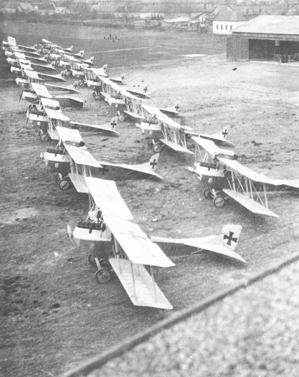
Seventeen Brandenburg C.I(U) biplanes (left front: 69.71 and 69.35) and one Brandenburg C.II(U) lined up for flight acceptance at the UFAG airfield in Albertfalva, April 1917.

Brandenburg C.I(U) 69.73 was sent to the 3rd Army in May 1917. The attention given to streamlining is evident in the clean engine cowling and faired center-section struts. The cowling opening allows access to the distributor housing.

Brandenburg C.I(U) 69.91 illustrates the long and varied operational life these aircraft often experienced. It served with Flik 35/D (June 1917), Flik 12/D (August-December 1917), Flik 22/D (March 1918), and Flik 62/D (June 1918).

Brandenburg C.I(U) 169.02 of Flik 69/S at Gajarine on 2 July 1918. This machine also served with Flik 40 (September 1917), Flik 1/D, Flik 49/F (December 1917-March 1918), and Flik 105/G (October 1918). The gun canister is armed with twin guns and bomb racks are installed.

Brandenburg C.I(U) 169.22 served with Fliks 26/D (September 1917), Flik 22/D, 103/G (May 1918), and Flik 34/D (June 1918). This particular aircraft still retains the steel-tube machine gun ring.

Brandenburg C.I(U) 169.32 on the airfield at San Giacomo di Veglia on 30 May 1918 with pilot Offizierstellvertreter Valta and Leutnant Kaiser of Flik 52/D. The over-the-wing mount was devised by squadron personnel.

The Brandenburg C.I(U) 169.40 joined the Flars test section in November 1917 for ski undercarriage and exhaust silencer evaluation. A variety of skis was tested but none appear to have been used operationally.

Brandenburg C.I(U) 269.06 of Flik 20 at Wladimir Wolynski, Poland in November 1917. Zugsfuhrer Arthur Brunner and Leutnant Stanislaus Crobath of Flik 10/F were killed when 269.06 was shot down over Lake Garda on 18 March 1918.

Brandenburg C.I(U) 269.49 and 269.33 of Flik 49/D on the airfield at Navarole in May 1918. Series 269 aircraft retained the old-style observer’s machine gun ring.

A Brandenburg C.I(U) 269 with the concave tailplane leading edge found only on series 69 to 369 aircraft, as were the three tailplane support struts on the underside.

Brandenburg C.I with the movable searchlight mounted below the observer’s cockpit. The electric dynamo is mounted below the propeller hub and driven by a flexible belt.

The Brandenburg C.I(U) 369.09 at Aspern. This aircraft was used for searchlight experiments from July through October 1918, and served with the Austrian Volkswehr in 1919. The wind vane on the Priesel gun ring compensated for the slipstream and helped the observer turn the turret.
Brandenburg C.I, Flugzeugnummer 369.09, Februar 1918, Waffenversuchsfiik des Fliegerarsenals, später k.u.k. Luftpost
Brandenburg C.I, Flugzeugnummer 369.09, Februar 1918, Waffenversuchsfiik des Fliegerarsenals, später k.u.k. Luftpost

Brandenburg C.I(U) 369.31 or 369.33 of Flik 37/D at San Lorenzo on 12 February 1918. The twin landing lights mounted on the lower wing indicate that this dark-painted aircraft operated as a night bomber.

Brandenburg C.I(U) 369.36 made its maiden flight at the factory on 29 October 1917. The varnished, natural-plywood fuselage covering contrasts starkly with the light-colored wings.

C.I 369.43 wears plain finish with a marking that appears to be the red/white/red marking of Flik 12.
Not all series 369 aircraft were fitted with a wooden gun ring. The observer is inspecting a long focal-length camera, which extends almost to the ground. After acceptance on 3 November 1917, the Brandenburg C.I(U) 369.43 logged a long service career, being flown by Fliks 35/D, 46/P, 12/Rb, and 48/D through August 1918.
Not all series 369 aircraft were fitted with a wooden gun ring. The observer is inspecting a long focal-length camera, which extends almost to the ground. After acceptance on 3 November 1917, the Brandenburg C.I(U) 369.43 logged a long service career, being flown by Fliks 35/D, 46/P, 12/Rb, and 48/D through August 1918.

The robust elegance and smooth contours are clearly evident in the Brandenburg C.I(U) 369.156, a late production model. The blast tube from the synchronized machine gun is barely visible. It served with Flik 27/F in August 1918.

Brandenburg C.I(U) 369.158 with suppressed national markings to reduce visibility during night bombing flights. The aircraft was delivered to the Front in August 1918.

Seven German 12kg PuW bombs hung underneath Brandenburg C.I(U) 69.08 from Fluggeschwader 1, 26 May 1917.

Underwing bombs and bomb racks on a Brandenburg C.I.
Anatra C.I 010.106 with early Czech markings flanked by a Phonix C.I 121.50 (with rear gun ring removed) and a Brandenburg C.I, possibly at Kbely airfield in early 1919.

The cockpit of a Brandenburg C.I(U) series 67 biplane. Visible are the rear-view mirror, the control wheel with gun trigger for the Type II VK canister, the closely-clustered instruments, and the outboard aiming sights for the pilot. In the foreground is a fixture to secure the observer’s machine gun when not in use.

For protection during strafing attacks, an armor-plated fuselage, pilot’s enclosure, and folding hood were flight tested by Phonix in a Brandenburg C.I(Ph) in the summer of 1918. The lettering on the head armor reads “push open from inside. ”

Although the UFAG specifications called for twin synchronized guns, the shortage of synchronization mechanisms often made it necessary to install twin guns above the wing. Discernible are the cocking grips, the cowl-mounted Sottoscope, and the gimballed compass protected by an aluminum shield. Brandenburg C.I(U) 369.28 was photographed at Flik 19/F at San Ghiacomo in April 1918.

The Priesel gun turret as installed on a Brandenburg C.I. The elevating mechanism used two coil springs to compensate for the gun’s weight. When not in use, the gun was stored within the rear fuselage opening. The photo, taken during firing trials, is dated 24 June 1918.

Stabsfeldwebel Josef Kiss checking a special sighting device and extended handle on a Schwarzlose M 7/12 gun. It was mounted on a Flik 24/D Brandenburg C.I in April-May 1918.
Among the few of the series accepted was the Aviatik D.I (Lo) 315.08 in which Feldwebel Ernst Kerschischnig collided with Brandenburg C.I 63.25 on 27 September 1918 at Aspern. The leading edge radiator was standard for the series 315.

C.I(Ph) 129.33 of Flik 21, on the Pergine airfield in the summer of 1917, provides a view of the streamlined container for the Schwarzlose gun devised by pilot Hauptmann Walter Lux Edler von Treurecht, commander of Flik 21.

Brandenburg C.I(U) 369.127, Flik 59/D

Brandenburg C.I(U) 369.158

Brandenburg C.I(Ph) 26.17

Brandenburg C.I(Ph) Series 27

Brandenburg C.I(Ph) Series 429

Brandenburg C.I Series 61.5

Brandenburg C.I(Ph) Series 29.5

Brandenburg C.I(U) Series 68

Brandenburg C.I(U) Series 169
Brandenburg 05.05
Prior to the war, some military planners saw aerial combat in a naval context, fought by giant battleplanes heavily armed with cannon and machine guns. Indeed, every belligerent power built at least one such aircraft. On 25 May 1915, the LFT ordered a prototype battleplane from Hansa-Brandenburg, known as the Type GF and developed from the Type ZM bomber originally built for the German Navy. The prototype, designated 05.05 (work number GF 52) was powered by two 160 hp Mercedes tractor engines. The wooden fuselage was plywood covered and fitted with two gun positions fore and aft. Triple rudders provided limited maneuverability with one engine out.
Upon joining the LFT (date unknown), the 05.05 was sent to the Isonzo Front for evaluation, but operational records are lacking. On 15 October 1915, an unpredictable bora storm severely damaged the airframe. Repair and installation of rudimentary bomb racks were completed by the Phonix factory on 6 March 1916. The Brandenburg 05.05, assigned to Flik 19 in March, was totally destroyed on 6 April 1916 in a landing accident after returning from a bombing raid. Perhaps it was this event that gave cause for Flars to report the bomber as unsuitable for frontline service owing to its inability to fly safely or remain aloft on one engine. Unfortunately, the engine-out problem was never satisfactorily solved by Brandenburg, much to the detriment of the improved G.I (type GF) bomber, series production of which was already underway.
Photographed at Flik 19, the 05.05 prototype shows the excellent field of fire provided by the raised machine-gun positions. A Fokker fighter, series 03, is in the background. (This photograph was printed on pebble-texture paper which accounts for the loss of detail). (AHT AL0579-063)
Hansa-Brandenburg factory in Briest in late 1915. To the left of the administration building can be seen a Brandenburg FD, and to the right the Types DD, LDD, and GF.
Brandenburg 60.55 (ex 05.09)
Confronted by the lack of an indigenous fighter to meet the growing Italian air strength and by Idflieg’s refusal to export its best fighters, the LFT turned to Brandenburg, knowing that a company-sponsored prototype was already under test. Appearing in the spring of 1916, the Brandenburg Type KD fighter featured an unusual "pyramid" wing bracing which imparted great strength and, being wireless, was claimed to reduce drag. In April 1916, the LFT ordered an improved KD prototype for testing and issued a letter of intent for 50 D.I (Type KD) fighters to start production, although the formal contract was not signed until August.
Assembly of the second KD prototype, numbered 05.09, later redesignated 60.55, was under way in May 1916 and required "only a few modifications before commencing flight trials." Compared to the first KD prototype, the 60.55 had finer fuselage lines, a flush-mounted airfoil radiator, and a raised rear fuselage that eliminated the requirement for a fixed fin. A 160 hp Daimler engine supplied the power. In July or August 1916, the 60.55 prototype was dispatched to Flik 26 for frontline evaluation, although armament was not fitted. The fact that production aircraft appeared without apparent modification indicates that the trials were satisfactory, but details are sparse. The 60.55 was repaired by Phonix in January 1917 before serving as a trainer with Flek 6 in September 1917. It was stored in damaged condition at Flugpark 1 in October 1918.
Brandenburg D.I Series 65.5 and 65.7
Oberst Uzelac informed his staff in August 1916 that "the Fokker fighter is outmoded; therefore I have authorized the production of a light biplane fighter that is equal to all combat requirements." He was referring to the Brandenburg D.I (Type KD), the prototype of which (60.55) was currently undergoing evaluation by Flik 26. Production began in May 1916, and by the time the formal contracts were signed assembly at Briest and production preparation at Phonix were well advanced. A total of 122 D.I fighters were ordered:
Qty Manufacturer Series No. Engine Order Date
24 Phonix 28.01-24 Dm 185 24 June 1916
20 Brandenburg 65.50-69 Dm 160 25 August 1916
30 Brandenburg 65.70-99 Dm 150 25 August 1916
24 Phonix 28.25-48 Dm 185 3 December 1916
24 Phonix 28.49-72 Dm 185 29 January 1917
The D.I (or KD as it was commonly called) is easily identified by the unorthodox pyramid struts, originally proposed by Professor Knoller as a means of attaining great strength and lowering drag by eliminating wire bracing. In static load tests the pyramid cellule attained a safety factor of 9, but at the expense of a structure heavier than that of conventional design. Two series were produced, the D.I series 65.50 to 65.69, powered by a 185 hp Daimler engine, and series 65.70 to 65.99 powered by a 150 hp Daimler engine. The D.I series 65.7 was lightened throughout but, given the reduced horsepower, demonstrated only marginal improvement in maneuverability and climb. Squadron introduction, slated for September 1916, was delayed by rework after flight trials had revealed weak engine supports and excessive wing-tip vibration. One D.I series 65.5 fighter was accepted in October and the remaining 19 in December 1916. Series 65.7 acceptances began in November 1916 and the Phonix-built series 28 in
January 1917.
Writing in 1942, Oberst Adolf Heyrowsky, commander of Flik 19 (first to receive the new fighter) regarded the D.I obsolete on arrival. He felt that the 3000 meter ceiling was unacceptable and the tricky flight characteristics much too difficult for inexperienced pilots, especially since the D.I exhibited a sudden tendency to spin "with consequent casualties." At Flik 19, Heyrowsky grounded the D.I pending further instruction. Uzelac arrived unannounced on 7 November 1916 to personally discuss the problem, but Heyrowsky was absent from the airfield. Upon return, Heyrowsky faced a wrecked D.I. Asking who had flown the machine against his strict orders, the hesitant answer was "Oberst Uzelac, he crashed violently and is in the local hospital." Fearing the worst, Heyrowsky rushed to the hospital to learn that Uzelac had received a severe concussion, but upon regaining consciousness had summoned his chauffeur and was gone.
So began the D.I's service history, the first fighter to be built in quantity for the LFT. In late 1916, the D.I series 65.5 and 65.7 were supplied to the Isonzo Front, namely Fliks 4, 12, 16, 19, 23, 28, 34, and 41 /J and Fluggeschwader I, serving primarily as an escort fighter. The initial combat experience was universally discouraging. In February 1917, a Flars report stated that the D.I was unsatisfactory because of its poor climb and dangerous flight characteristics. "Until a short while ago, the KD was praised as being everything a pilot could wish for; today it carries the unflattering name of 'Totschlager' (killer)." Assigned the task of making improvements, Dr. von Mises of Flars solicited the opinions of frontline pilots, one of whom was Julius Arigi who had already installed a "homemade" fin and rudder on his machine, not unlike the final version that was tested on 3 April 1917 and adopted. Arigi was awarded a substantial cash prize. Replacement kits were dispatched to the Front on 17 May 1917. At best it was a stopgap measure.
The prevailing attitude of operational units is best illustrated in an excerpt from a Flik 23 report (20 May 1917) recommending the fighter's withdrawal. The incident described was not uncommon:
Leutnant Mirko Vrbanic, one of our best KD pilots, stalled during an escort mission at 3000 meters and was able to regain control just short of crashing. In the pilots' unanimous opinion, they cannot give full attention to the combat at hand if they are so totally occupied with controlling the aircraft. In addition, the climb is so slow that the fighter must take off well before our observation aircraft in order to reach escort altitude. The KD's ceiling is much inferior to that of enemy Nieuports, which generally operate between 4 and 5000 meters.
Even crack fighter units such as Flik 41/J reported that:
the KD is absolutely useless (June 1917) ... the best pilots (and only they can fly the type) are shackled, ruin their nerves and perish in crashes over the airfield, without their expert skill achieving anything.
The non-combat losses far exceeded those in combat: Flik 41/J lost eleven D.I fighters to accidents alone in July. That month, Flik 42/J reported that "the KD is inferior to enemy fighters. The enemy, aware that our fighters lose altitude in a turn, utilizes this to his advantage." One wonders how the novice fighter pilot must have felt hearing the D.I popularly referred to as der fliegender Sarg (the flying coffin).
The KD was armed with the heavy (37 kg - 82 lb) Type II VK gun canister (aptly nicknamed "the baby coffin") on the top wing. This bulky installation "further reduced the existing marginal flight characteristics." Several interim solutions of storing the ammunition in the fuselage and fitting an oblique firing gun were tested but not used in combat. Later a few Phonix-built KDs were armed with one synchronized gun installed below the exhaust manifold.
Damned by most, the D.I achieved marginal success in the hands of expert pilots, among them Arigi, Brumowski, Fiala, Kiss, and Linke-Crawford. But almost all victories were gained in the Phonix-built version. An analysis of 68 confirmed D.I victories shows that only three can be attributed to pilots flying the Brandenburg-built fighter. Why this should be is not known, but perhaps the Phonix machine was of superior construction. In all fairness it must be said that the D.I was not entirely to blame for its deadly reputation. Fighter pilot training was rudimentary, undertaken in obsolete two seaters, with only a few students fortunate enough to obtain advanced instruction in high-performance fighter-trainers.
On 26 May 1917, Uzelac, writing to the 5th Army, acknowledged the D.I's defects, but until the expected arrival of new fighters in July it was impossible to make a change. The hard-pressed Fliks had little choice but to continue flying the D.I fighter. As of 1 July 1917, 41 Brandenburg and 49 Phonix-built D.I fighters were at the Front. As a last resort some Fliks modified the D.I for photo-reconnaissance work, achieving good results in a role where speed, not maneuverability, counted. As new fighters arrived, the Brandenburg D.I was gradually withdrawn from operational service, finding employment as Flik-based trainers for newly-arrived pilots or assigned to training units, notably Fleks 4, 5, and 6. The LFT ordered all Brandenburg D.I fighters removed from the Front on 27 January 1918.
Brandenburg D.I Series 65.5
Engine: 160 hp Daimler
Wing: Span Upper 8.50 m (27.89 ft)
Span Lower 8.30 m (27.23 ft)
Chord Upper 1.50m (4.92 ft)
Chord Lower 1.50 m (4.92 ft)
Sweepback Upper 0 deg
Sweepback Lower 0 deg
Gap 1.60 m (5.25 ft)
Stagger 0.50 m (1.64 ft)
Total Wing Area 24.0 sq m (258 sq ft)
General: Length 6.63 m (21.75 ft)
Height 2.75 m (9.02 ft)
Track 1.72 m (5.64 ft)
Empty Weight 745 kg (1643 lb)
Loaded Weight 1020 kg (2249 lb)
Maximum Speed: 185 km/hr (115 mph)
Climb: 1000m (3,281 ft) in 4 min 8 sec
Brandenburg D.I Series 65.7
Engine: 150 hp Daimler
Wing: Span Upper 8.50 m (27.89 ft)
Span Lower 8.30 m (27.23 ft)
Chord Upper 1.50 m (4.92 ft)
Chord Lower 1.50 m (4.92 ft)
Dihedral Upper 0 deg
Dihedral Lower 0.08 m (0.26 ft) at tip
Sweepback Upper 0 deg
Sweepback Lower 0 deg
Gap 1.60 m (5.25 ft)
Stagger 0.50 m (1.64 ft)
Total Wing Area 25.21 sq m (271 sq ft)
General: Length 6.63 m (21.75 ft)
Height 2.80 m (9.19 ft)
Track 1.72 m (5.64 ft)
Empty Weight 672 kg (1482 lb)
Loaded Weight 940 kg |2073 lb)
Maximum Speed: 179 km/hr (111 mph)
Climb: 1000m (3,281 ft) in 3 min 30 sec
Brandenburg D.I(Ph) Series 28 and 28.5
A total of 72 Brandenburg D.I(Ph) fighters, numbered 28.01 to 28.72, were ordered from Phonix between June 1916 and January 1917. Using aircraft 65.57 as a sample, Phonix engineers made a number of significant changes. Power was increased by installing a 185 hp Daimler engine, which imparted a slight performance increase. The center-section structure was simplified and the pilot's seat was raised to enable gun aiming without leaning out of the cockpit. Acceptances, delayed by a propeller shortage, began in January 1917, and the first series 28 fighters arrived at Flik 41/J and 42/J in February-March 1917. Being lighter and more powerful than their German counterpart, series 28 fighters possessed take-off characteristics that "did not engender fear that speed had to be maintained." The series 28 D.I(Ph) was vastly preferred over the series 65.5 and in the hands of pilots such as Brumowski, Kiss, or Linke-Crawford, scored the lion's share of the victories for this type. Yet for the average or novice fighter pilot, the Brandenburg D.I's tricky flight habits and propensity to spin at all altitudes made it an extremely hazardous aircraft.
Beginning with 28.51, aircraft were delivered with a lightened airframe. The large, rounded tail fin and rudder was either retro-fitted or installed on all production aircraft. Even so, when the last Phonix-built fighters were accepted in mid-1917, the Brandenburg D.I was already out-classed. In the fall of 1917, the remaining fighters were gradually withdrawn and assigned to training units in which they served until late 1918.
Brandenburg D.I(Ph) Series 28 Specifications
Engine: 185 hp Daimler
Wing: Span Upper 8.50 m (27.89 ft)
Span Lower 8.50 m (27.89 ft)
Chord Upper 1.50m (4.92 ft)
Chord Lower 1.50 m (4.92 ft)
Dihedral Upper 0 deg
Dihedral Lower 1.8 deg
Sweepback Upper 0 deg
Sweepback Lower 0 deg
Gap 1.60 m (5.25 ft)
Stagger 0.50 m (1.64 ft)
Total Wing Area 24.0 sq m (258 sq ft)
General: Length 6.30 m (20.67 ft)
Height 2.79 m (9.15 ft)
Track 1.72 m (5.64 ft)
Empty Weight 714 kg (1574 lb)
Loaded Weight 1047 kg (2309 lb)
Maximum Speed: 175-185 km/hr (109-115 mph)
Climb: 1000m (3,281 ft) in 3 min 55 sec
Brandenburg D.I(Ph) Series 28.5 Specifications
Engine: 185 hp Daimler
Wing: Span Upper 8.50 m (27.89 ft)
Span Lower 8.50 m (27.89 ft)
Chord Upper 1.60 m (5.25 ft)
Chord Lower 1.60 m (5.25 ft)
Gap 1.60 m (5.25 ft)
Stagger 0.50 m (1.64 ft)
Total Wing Area 25.5 sq m (274 sq ft)
General: Length 6.30 m (20.67 ft)
Height 2.79 m (9.15 ft)
Empty Weight 690 kg (1521 lb)
Loaded Weight 958 kg (2112 lb)
Maximum Speed: 175-177 km/hr (109-110 mph)
Climb: 1000m (3,281 ft) in 4 min 30 sec
An Explanatory Note About Hansa-Brandenburg Serial Numbers:
When the LFT assigned new serial numbers to aircraft in February 1915, Hansa-Brandenburg was assigned the company designation 05. The first nine numbers, 05.01 to 05.09, were allocated to out-of-series or prototype aircraft. Series production aircraft began with the Hansa-Brandenburg B.I 05.11. At a later date, production aircraft were numbered 61.5 and up and prototype aircraft were assigned numbers beginning with 60.5. To avoid confusion, the table shows the series designations assigned to Brandenburg and UFAG, although the types were not identical nor were parts interchangeable:
Type UFAG Hansa-Brandenburg
Brand C.I 61.01-24 61.51-72
Brand G.I 62.01-12 62.51-77
Brand C.I 63.01-32 63.51-86
Brand C.I 64.01-48 64.51-72
Brand D.I not built by UFAG 65.50-99
Brand C.II 66.01 (cancelled) 66.51 (two built)

Brandenburg D.I(Ph) 28.10, Flik 41/J

Photographed shortly after arrival at Flik 12, the new Brandenburg D.I 65.53 awaits installation of the Type II VK gun canister. It was one of the fighters Brumowski flew in Flik 41/J. Hauptmann Godwin Brumowski scored a victory in this aircraft on 3 December 1916. Only a total of three victories were recorded for the Brandenburg-built D.I fighters.

Brandenburg D.I 65.54 during acceptance testing at Briest in late 1916. Armament was installed on arrival in Aspern. Because of the unique pyramid struts, the D.I was dubbed “star-strutter” in the post-war press.

A non-commissioned pilot and mechanics of Flik 23 posing in front of Brandenburg D.I 65.63 on the Prosecco airfield in 1917. The cut-back engine cowling provides greater cooling in summer months.

Zugsfuhrer Karl Seiler of Flik 35 (and mascot) in his Brandenburg D.I 65.79 at St. Veit (near Wippach) in 1917. Compare the improved pilot’s view with that of the pilot in D.I 65.54.
D.I 65.79 on a mountain airfield. Note the squadron dog on the horizontal tailplane. This machine served with Fliks 35 and 23 before being withdrawn from the front and used as a trainer for wireless instruction. This photograph gives a good idea of the type of terrain that was confronted on the Italian Front.
D.I 65.79 on a mountain airfield. Note the squadron dog on the horizontal tailplane. This machine served with Fliks 35 and 23 before being withdrawn from the front and used as a trainer for wireless instruction. This photograph gives a good idea of the type of terrain that was confronted on the Italian Front.
A medley of aircraft flown by Flik 23/D at Divacca on the Isonzo Front in mid-1917, headed by a Brandenburg C.I(U) 69.57, followed by a Brandenburg C.I(U) 129.46, an Aviatik C.I series 37, and four Brandenburg C.I biplanes flanking a Brandenburg D.I fighter.
Eight Albatros D.lIl(Oef) fighters of Jagdstaffel Oberleutnant Elssler parading on the Pergine airfield awaiting Kaiser Karl's inspection on 14 September 1917. A Brandenburg D.I(Ph) series 28 fighter and two Aviatik C.I series 37 biplanes are in the second row. Villa Guila della Rosa is in the far right.

The unarmed Brandenburg D.I(Ph) 28.01 fighter during flight testing at Aspern in January 1917. The center section has been simplified and the strut attachment points are covered with cuffs. On 1 March 1917, Hauptmann Franz Rabitsch, commander of Fluggeschwader I, lost his life when this aircraft crashed on a familiarization flight.

Offizierstellvertreter Julius Arigi of Fluggeschwader I flying the Brandenburg D.I(Ph) 28.06 fitted with the fin and rudder that he designed and that was later adopted as standard equipment. Arigi achieved two victories in this machine on 24 April and 3 May 1917.
Brandenburg D.I, Type KD, 28.06, Fluggeschwader I, Feldpilot Offzstv Julius Arigi erzielte mit diesem Flugzeug drei Luftsiege
Brandenburg D.I, Type KD, 28.06, Fluggeschwader I, Feldpilot Offzstv Julius Arigi одержал на этом самолете три воздушные победы.
Brandenburg D.I, Type KD, 28.06, Fluggeschwader I, Feldpilot Offzstv Julius Arigi erzielte mit diesem Flugzeug drei Luftsiege
Brandenburg D.I, Type KD, 28.06, Fluggeschwader I, Feldpilot Offzstv Julius Arigi одержал на этом самолете три воздушные победы.

"Ханза-Бранденбург" серии 28.
Brandenburg D.I(Ph) 28.24 was flown by Oberleutnant Karl Urban of Flik 16/D, shown here on 14 August 1917 fitted with the rounded fin and rudder.
Oblt. Urban in Brandenburg D.I 28.24 of Flik 16 with two red bands around the fuselage each side of the cross location. The fuselage cross has been scrapped off. Hptm. Stojsavljevic was wounded and shot down in this machine on 12 January 1918. Another source states that 28.24 was written off after an emergency landing caused by a carburettor fire in the air in the Spring of 1917.

Feldwebel Josef Kiss of Flik 24 scored three victories in this Brandenburg D.I(Ph) 28.37 in the summer of 1917. It was one of the few D.I(Ph) fighters armed with a synchronized machine gun.
Phonix-built Hansa-Brandenburg Dl of Fliegerkompanie 24 at Pergrine in summer 1917.
Phonix-built Hansa-Brandenburg Dl of Fliegerkompanie 24 at Pergrine in summer 1917.

A number of experimental fixtures were tested for fighters, as in the Brandenburg D.I(Ph) 28.46 shown here. The movable fixture allowed access and possibly aiming by the pilot. The fighter was flown by Oberleutnant Johann Low, commander of Flik 101/G.

Starting with aircraft 28.51, the production D.I airframes were lightened. The ammunition belt chute leading to the angled gun can be seen between the wing struts. The manufacturer’s nameplates are attached to the bottom of the nose. Brandenburg D.I(Ph) 28.58 was attached to Flik 16/D in September 1917.
Lineup of Flik 41/J during the visit of the Archduchess Maria Theresa on July 26, 1917 at Sesana; she is at the far left of the photo.
This D.I with the Buddhist good luck emblem, the swastika, was with Flik 41J when this photograph was taken despite the original caption stating it was taken at Flik 12. Albatros (Oef) 53.27 is seen in the background. This D.l was flown at times by Godwin Brumowski and test flown by Gottfried Banfield. Serial number unknown.
With few exceptions, an angled machine gun or a Type II VK gun canister comprised the armament on Brandenburg D.I fighters. Shown here are 28.65 and 28.64 (swastika insignia) of Flik 41/J in August 1917. The purpose of the flags extending from the canisters is not known, but could be an indication that the guns are armed.
This D.I with the Buddhist good luck emblem, the swastika, was with Flik 41J when this photograph was taken despite the original caption stating it was taken at Flik 12. Albatros (Oef) 53.27 is seen in the background. This D.l was flown at times by Godwin Brumowski and test flown by Gottfried Banfield. Serial number unknown.
With few exceptions, an angled machine gun or a Type II VK gun canister comprised the armament on Brandenburg D.I fighters. Shown here are 28.65 and 28.64 (swastika insignia) of Flik 41/J in August 1917. The purpose of the flags extending from the canisters is not known, but could be an indication that the guns are armed.

Cockpit of Brandenburg D.I 65.87 showing the large tachometer and fuel gauge (top), the control stick, manometer, and selector switches. The throttle quadrant is on the left, whereas most Austro-Hungarian aircraft had the throttle on the right.

Brandenburg D.I Series 65.7

Brandenburg D.I(Ph) Series 28
Brandenburg 05.08
The LFT ordered an "improved Type GF" prototype bomber, designated 05.08 on 21 July 1915. Although adhering to the the basic GF layout, Heinkel reworked the 05.08 to incorporate the lessons learned from the frontline evaluation of the 05.05. Drawings, submitted to the LFT for approval in October 1915, show a robust steel-tube framework that comprised a central core from which engines, wings, undercarriage, and bombs were suspended. By concentrating the engine and undercarriage loads, the wing and fuselage structure was simplified and reduced in weight. The two 160 hp Mercedes were mounted completely independent of the wing cellule on a framework attached directly to the central core. Structurally, the 05.08 differed only slightly from the G.I series 62.5 bomber, for which a large production program was planned.
Records show that the 05.08 was assigned to Flik 19 for service evaluation in May 1916 and participated in several bombing raids. Returning from an attack on Udine (16 May 1916), Austro-Hungarian anti-aircraft troops, unfamiliar with the only twin-engined aircraft on the Isonzo Front, energetically peppered the airframe with shrapnel splinters. It was reported that the 05.08 was unable to remain aloft on one engine.
Brandenburg G.I(U) Series 62
On 31 July 1915, UFAG was given a contract to build six twin-engined bombers, powered by 160 hp Daimler engines, based on the Brandenburg 05.05/05.08 prototypes and contingent upon the successful completion of flight tests. Another six bombers were ordered on 25 February 1916, followed by 12 more in March 1916 in lieu of 24 Lohner B.VII(U) biplanes. The Flars representative reported slow progress in January 1916 and requested "definition of the next manufacturing steps." As described in the Brandenburg G.I series 62.5 chapter, the bomber was experiencing serious problems and in April 1916, the UFAG production order was reduced to 12 Brandenburg G.I(U) bombers, numbered 62.01 to 62.12.
The first production machine, 62.01, was 80 percent complete in March 1916, but technical problems and lack of interest delayed its completion until August 1916 when test pilot Oberleutnant Antal Lanyi-Lanczendorfer performed the maiden flight. After structural modifications required by Flars were finished in November 1916, three bombers were accepted. Six UFAG-built bombers were assigned to Fluggeschwader I in March 1917 but owing to intractable technical problems only one bombing attack was flown. See the Brandenburg G.I series 62.5 chapter for details.
Brandenburg G.I(U) Series 62 Specifications
Engine: 2 x 160 hp Daimler
Wing: Span Upper 18.00 m (59.05 ft)
Span Lower 10.00 m (32.81 ft)
Chord Upper 2.00 m (6.56 ft)
Chord Lower 2.00 m (6.56 ft)
Sweepback Upper 0 deg
Sweepback Lower 0 deg
Gap 2.00 m (6.56 ft)
Stagger 0.24 m (0.79 ft)
Total Wing Area 64.0 sq m (689 sq ft)
General: Length 9.83 m (32.25 ft)
Height 3.75 m (12.30 ft)
Track 2.50 m (8.20 ft)
Maximum Speed: 133 km/hr (83 mph)
Climb: 1000m (3,281 ft) in 8 min
3000m (9,843 ft) in 30 min
Brandenburg G.I Series 62.5
The outcome of the Brandenburg 05.05 trials at Flik 19, although prematurely terminated, encouraged the LFT to order production for 48 G.I bombers (Type GF) at Brandenburg and 24 at UFAG. By allocating the largest aircraft expenditure to date and by-passing extensive service trials, the LFT hoped to speed the introduction of a long-range bombing weapon. But in April 1916, Flars reported that "twin-engined aircraft were unfit for operational service because of their inability to remain aloft on one engine, making long-range missions impossible." In consequence, the production orders were cut back to 39 aircraft as follows:
Qty Series Number Manufacturer Order Date
6 62.01-06 UFAG 7 July 1915
6 62.51-56 Brandenburg 12 December 1915
21 62.57-77 Brandenburg 18 December 1915
6 62.07-12 UFAG 25 February 1916
Flars accepted the first six G.I series 62.5 bombers from Brandenburg in June 1916, but with serious reservations. Summoned to Aspern on 13 July 1916 to discuss the bomber's shortcomings, Heinkel and Ingenieur Brandenburg of UFAG were informed that the flight characteristics and structural strength, especially the weak undercarriage, were not equal to frontline standard. Heinkel's proposal to install a third engine in the nose was rejected. Hansa-Brandenburg refused to fix the problems and the G.I became an bone of acrimonious contention between the company and the LFT. Since the Hansa-Brandenburg company was located in Germany, outside the sphere of legal intervention, the LFT forced the Phonix company to assume full financial responsibility for Brandenburg's business dealings with the Austro-Hungarian military establishment.
Structurally the G.I was similar to the 05.08 prototype except that the engine mounts were simplified. Two 160 hp Daimler engines, fitted with the slanted Mercedes radiators, supplied the power. A bombardier-gunner was stationed in the nose turret; the pilot and rear gunner shared a common cockpit located aft of the center section. The bomb load consisted of five 50 kg (110 lb) and four 20 kg (44 lb) bombs. The G.I was first supplied in December 1916 to Fluggeschwader I (later Flik 101/G) based at Divacca on the Italian Front, reaching a total of five Brandenburg and six UFAG-built machines in March 1917. The undercarriage had been reinforced and fitted with twin wheels but little else had been done to prepare the bomber for operational service. LFT units were accustomed to performing frontline repairs, but in this instance they had their hands full. A furious squadron commander complained that "the required work went far beyond the normal duties expected of a newly-formed unit." Because UFAG-built bombers had superior workmanship, they were selected for the modification work. New bomb racks were designed and installed. Replacement gun turrets were fitted. The commander-bombardier's position was moved forward to the nose and a mid-section seat was installed to protect him and his "costly instruments" from a possible landing mishap. The bomb-release mechanism was relocated for easy accessibility. One can only applaud the skill and ingenuity of the squadron personnel, but in spite of their Herculean efforts only a single G.I bombing mission was recorded in the Fluggeschwader I war diary. In April-May 1917, all G.I bombers were placed in storage, stripped of engines, instruments, and tires, to await the outcome of the dispute between Flars and Brandenburg, who adamantly refused to pay for correcting the various deficiencies. In September 1917, an exasperated officer wrote "the over-hastily ordered G.I bombers languish at Aspern because none of the responsible authorities care a whit. The aircraft were accepted after only one test flight. Everyone is waiting for the argument to end."
In late 1917 when the Austro-Hungarian army reached the Piave, the army command requested night bombing attacks such as the German Bombengeschwader 4 had effectively demonstrated on the upper Italian Front. The LFT decided to rejuvenate the Brandenburg bombers, now in storage for almost a year. Between December 1917 and May 1918, over 30 G.I bombers were rebuilt by the Flars workshops and the Flugzeug Reparatur und Bau Anstalt (Fruba). They were fitted with horizontal bomb racks; the pilot's cockpit was moved forward to improve visibility, and the engine mountings were reinforced. The modified G.I was assigned to Fliks 101/G, 102/G, and 103/G, as well as Flek 22 in Strasshof. According to Flik 102/G "a weight lifter was required to fly the machine, it being beyond the capacity of a normal person to perform flights of long duration." The fully-loaded bomber was so tail heavy that it was difficult to get it off the ground. During landing, fuselage and tailskid fractures were not uncommon. At best the G.I was used as a twin-engined trainer in preparation for the imminent arrival of the Gotha G.IV (LVG) bomber from Germany.
Brandenburg G.I Series 62.5
Engine: 2 x 160 hp Daimler
Wing: Span Upper 18.00 m (59.05 ft)
Span Lower 18.00 m (59.05 ft)
Chord Upper 2.00 m (6.56 ft)
Chord Lower 2.00 m (6.56 ft)
Dihedral Upper 0.18 m (0.59 ft) at tip
Dihedral Lower 0.18 m (0.59 ft) at tip
Sweepback Upper 0 deg
Sweepback Lower 0 deg
Gap 2.10 m |6.89 ft)
Stagger 0.25 m (0.82 ft)
Total Wing Area 70.0 sq m (753 sq ft)
General: Length 9.80 m (32.15 ft)
Height 3.60 m (11.81 ft)
Track 2.55 m (8.37 ft)
Empty Weight 1776 kg (3916 lb)
Loaded Weight 2740 kg (6042 lb)
Maximum Speed: 144 km/hr (89 mph)
Climb: 1000m (3,281 ft) in 8 min
Brandenburg G.I Equipped With Searchlight
Two Brandenburg G.I bombers, 62.76 and 62.77, were retained at Briest for installation of a 15,000-candlepower Goerz 600 mm searchlight
mounted behind the rear cockpit. Electrical power was supplied by a 5 kw dynamo. A control wheel allowed the forward observer to rotate the gimballed light in all axes. The pilot's seat was moved forward and German PuW bomb racks for horizontal storage were installed. During night tests with a Brandenburg G.I carrying a 9000 candlepower searchlight, ground targets were readily identified from 1500 meters (4622 ft). For navigational purposes, the wind direction and velocity (i.e., drift) could be calculated with fair accuracy by observing the terrain. Contrary to expectations, the searchlight proved unsuitable for night landing. Wing lights were more suitable. Aircraft 62.76 and 61.17, powered by 185 hp Daimler and 200 hp Hiero engines respectively, were shipped to Aspern on 3 August 1917, and reported ready for flight tests in November. Further details are lacking.
Brandenburg G.I with Cannon Armament
In early 1916, Flars engineer Oberleutnant Dr. Leopold Kann visited Germany to discuss arming a G.I bomber with a cannon and to inspect similar Idflieg experiments. Flars had chosen a 7cm Skoda cannon firing a high-explosive shell at a muzzle velocity of 235 meters/second (771 ft/sec). The elevation range was 35 degrees and the traverse slightly less. Rather large for aircraft use, the cannon's weight of 200 kg (441 lb) gave the gunner a handful. On 20 June 1916, the cannon was mounted in aircraft 62.54 (Type GF Spezial). The aircraft was delivered to Fischamend for firing trials where, according to Antal Feher's flight log, the first flight was performed on 4 March 1917 (no cannon was mentioned) - an indication that the project was proceeding slowly. In August 1918, the 62.54 was at the Fruba factory for modification as a trainer. However, cannon experiments continued. A new Skoda mounting, intended for installation in aircraft 62.62, was tested in late June 1918. Further details are lacking.
An Explanatory Note About Hansa-Brandenburg Serial Numbers:
When the LFT assigned new serial numbers to aircraft in February 1915, Hansa-Brandenburg was assigned the company designation 05. The first nine numbers, 05.01 to 05.09, were allocated to out-of-series or prototype aircraft. Series production aircraft began with the Hansa-Brandenburg B.I 05.11. At a later date, production aircraft were numbered 61.5 and up and prototype aircraft were assigned numbers beginning with 60.5. To avoid confusion, the table shows the series designations assigned to Brandenburg and UFAG, although the types were not identical nor were parts interchangeable:
Type UFAG Hansa-Brandenburg
Brand C.I 61.01-24 61.51-72
Brand G.I 62.01-12 62.51-77
Brand C.I 63.01-32 63.51-86
Brand C.I 64.01-48 64.51-72
Brand D.I not built by UFAG 65.50-99
Brand C.II 66.01 (cancelled) 66.51 (two built)
Brandenburg 05.06
In July 1915 Hansa-Brandenburg was authorized to begin design and construction of a large bomber designated 05.06 and powered by four 100 hp Mercedes engines mounted in a push-pull configuration. On 23 November 1915, the resident inspector reported the wings and fuselage were ready and expected final completion on 1 December 1915. The formal contract was signed on 6 March 1916, specifying a bomber powered by four 160 hp Mercedes engines, capable of carrying six 50 kg (110 lb) bombs at a speed of 135 km/hr (84 mph). The increase in engine power required additional interior bracing and heavier spreader tubes and spar fittings. Throughout the remainder of the year, work was at a virtual standstill, for which Flars later blamed Heinkel, claiming "he realized the project was doomed to fail and stopped work on it."
On 29 March 1917, when Oberleutnants Kamillo Korner and Theodor von Karman of Flars inspected the nearly finished 05.06 airframe, they found that the contractual empty weight had increased by 1381 kg (3045 lb). The three crewmen (reduced from four), fuel, oil, and water, but not including bombs, would bring the flying weight to 4621 kg (10,189 lb), a figure which placed the required safety factor beyond reach. To Karman "it was obvious that the wings and fuselage were much too weak...also the tail structure appears very fragile." All interior fittings showed serious deficiencies although the engine bearers appeared robust enough. During the engine trials the rear fuselage vibrated dangerously. Deemed that it was far removed from serving any useful role, Korner and Karman advised against reconstruction or acceptance of the aircraft. Eventually Flars did pay Kr 60,180 ($ 11,846) in cancellation fees.
Both the Hansa-Brandenburg aircraft catalog of 1922 and Heinkel's postwar publicity brochures fail to mention the ill-fated 05.06 project, nor have drawings or specifications been found in extant archives.
Brandenburg 60.54
On 16 March 1916, Brandenburg received a contract for an experimental three-man bomber powered by a 300/345 hp Daimler V-12 engine buried in the fuselage. The engine was connected to reduction gearbox connected to two propeller drive shafts. Flars felt the project would provide useful information of a configuration where the "propellers were neither in front nor behind the engine." Under the revised designation scheme, the prototype number assigned to this obscure project was 60.54.
Fuselage assembly was under way in May 1916 but the resident Flars inspector doubted that the 15 June delivery date could be met. When the completed fuselage and engine installation was inspected in July, it was discovered that "by virtue of the centrally-mounted engine, faulty exhaust evacuation presented a serious fire hazard." Construction moved at a leisurely pace until October 1916 when work ceased entirely. In March 1917, Flars attempted to pressure Brandenburg into finishing the aircraft, but to no avail and the project was cancelled. The 60.54 prototype is not mentioned in the post-war Hansa-Brandenburg literature nor have drawings or specifications been found.
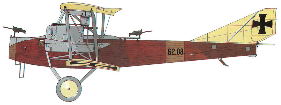
Brandenburg G.I(U) 62.08, Fluggeschwader I
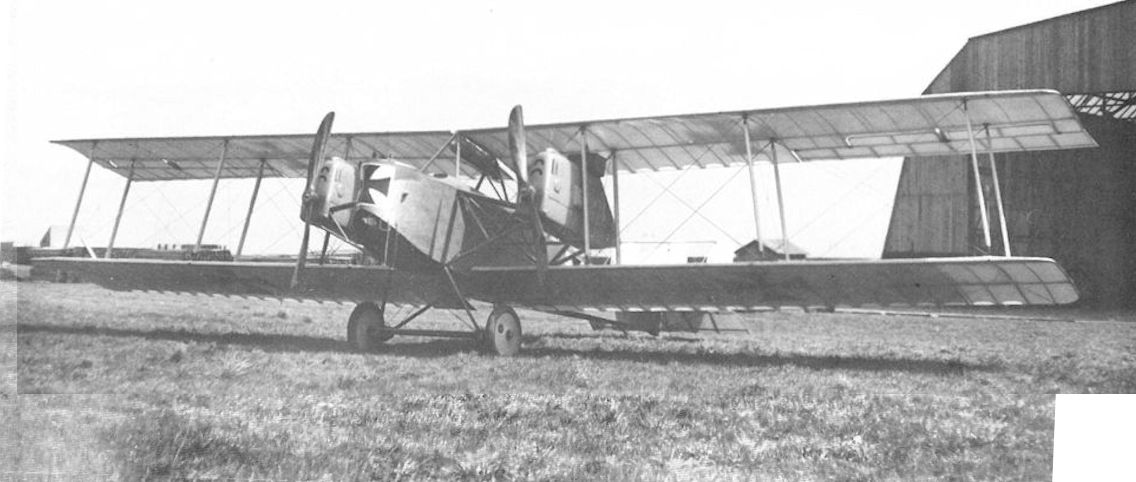
Brandenburg G.I(U) 62.01 in August 1916 with the single-wheeled undercarriage, large, tapered engine cowlings, and rear-mounted radiators. The first UFAG-built bomber was accepted in November 1916.
Note the scalloped effect of the trailing edge on this G.I. This is caused by the fabric on top of the wing not being taken back to the rear edge of the wing and the light shining through the one layer on the bottom of the wing.
Note the scalloped effect of the trailing edge on this G.I. This is caused by the fabric on top of the wing not being taken back to the rear edge of the wing and the light shining through the one layer on the bottom of the wing.

The Brandenburg G.I(U) 62.01 modified with a twin-wheeled undercarriage and cut-back engine cowlings. This aircraft remained attached to the training command.
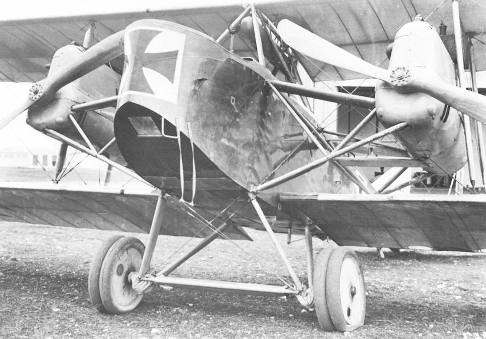
Brandenburg G.I(U) 62.01. The twin-wheeled undercarriage shows signs of overload. The flexible entry ladder is an incongruous touch, illustrative of the deficient design of this aircraft.
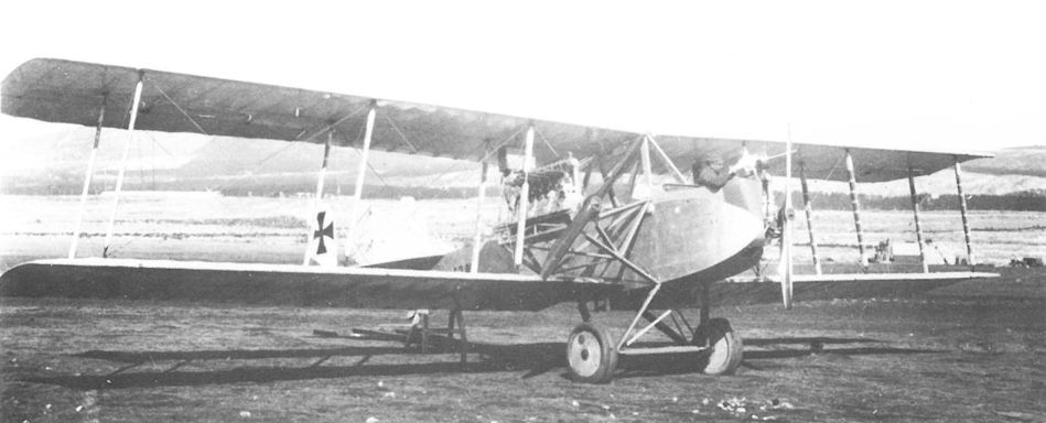
Серийные "Бранденбурги" G-I венгерской постройки.
Brandenburg G.I(U) 62.08 on the Fluggeschwader 1 airfield at Divacca in March 1917. Like the Brandenburg C.I, the wing struts are canted. The fabric-wrapped wing struts were characteristic of the UFAG-built G.I.
Brandenburg G.I(U) 62.08 on the Fluggeschwader 1 airfield at Divacca in March 1917. Like the Brandenburg C.I, the wing struts are canted. The fabric-wrapped wing struts were characteristic of the UFAG-built G.I.
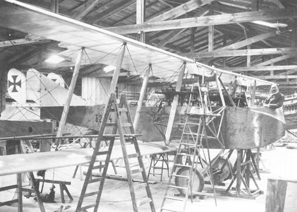
A Brandenburg G.I (62.54?) in the final assembly hall at Briest. At a later date the position of the radiator was shifted to the rear of the engine nacelle.
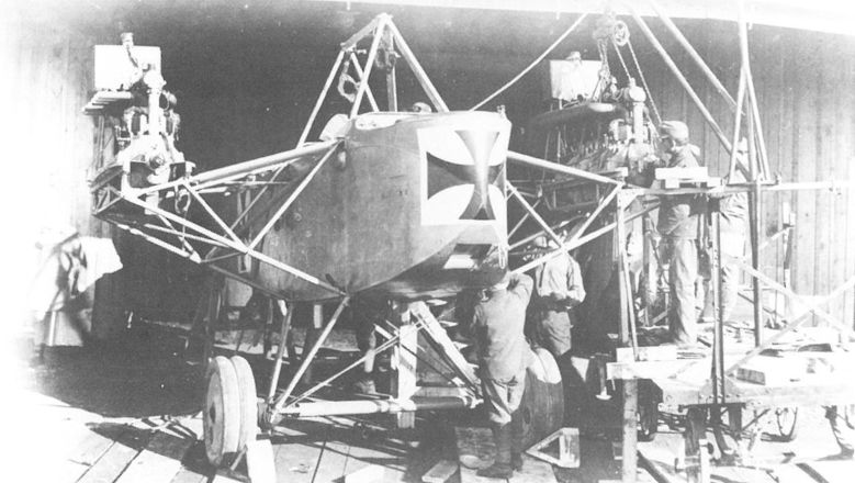
A Brandenburg G.I(U) being assembled at Fluggeschwader I in Divacca in March 1917. That the engines were mounted independent of the wing structure is the sole technical feature deserving mention.
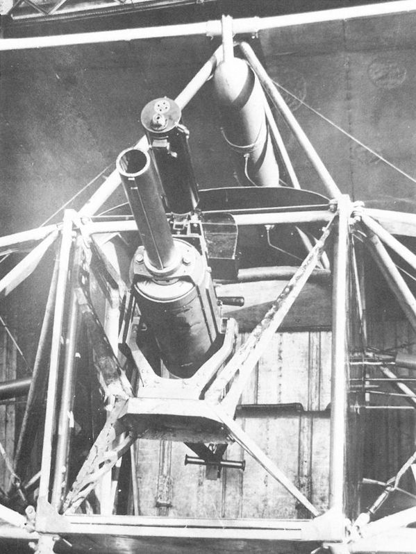
Close-up of the Brandenburg G.I 62.54 on 29 July 1918. A Schwarzlose M 7/12 machine gun, mounted over the cannon barrel, fired tracer ammunition to facilitate gun training. The gunner’s position appears very cramped.
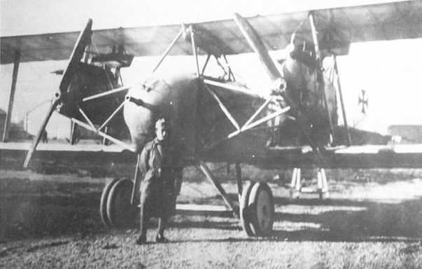
The Brandenburg G.I 62.54 with the 7 cm Skoda cannon installed and an aiming sight projecting through the gunner’s window. Twin wheels have been fitted.

The Brandenburg G.I 62.54 shown here at Briest with a cannon (or mock-up) mounted in a movable turret fitted with a triangular Cellon aiming window for the gunner.
In the blurred background, the Aviatik 30.39 prototype was photographed by chance through the wings of an overturned Brandenburg G.I bomber.
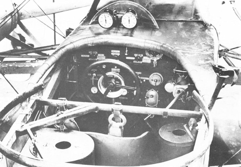
Brandenburg G.I(U) 62.01. The pilot’s cockpit and rear gunner’s turret with the round bomb containers installed at random positions in the fuselage, probably as an afterthought. The tachometers are mounted behind the windscreen. The pilot’s view of the terrain while landing was totally obscured by the lower wing.
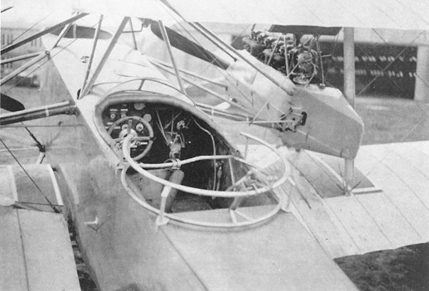
A close-up of the 05.08 prototype shows that the mid-fuselage observer’s cockpit of the 05.05 has been eliminated, although the poorly-situated pilot's cockpit has been retained.
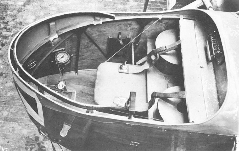
The bombardier’s position in the Brandenburg G.I(U) 62.01. The bomb release triggers are mounted on the shelf above the bomb tubes. Also seen are a clipboard holder, a gimballed compass, and a tripod to hold the bomb-sight above the aiming door. The bombardier was too far removed from the pilot for efficient communication, even if a speaking tube was installed.
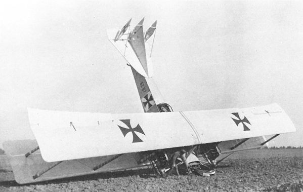
Brandenburg G.I(U) 62.07 demonstrating the danger to which the nose gunner was exposed because of the weak undercarriage. Flight operations were generally performed with the engine cowlings removed.
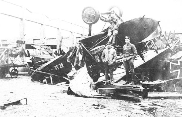
Seven Brandenburg G.I bomber-trainers, including 62.56, were destroyed in a fierce storm on 23/24 September 1918 in northern Italy.
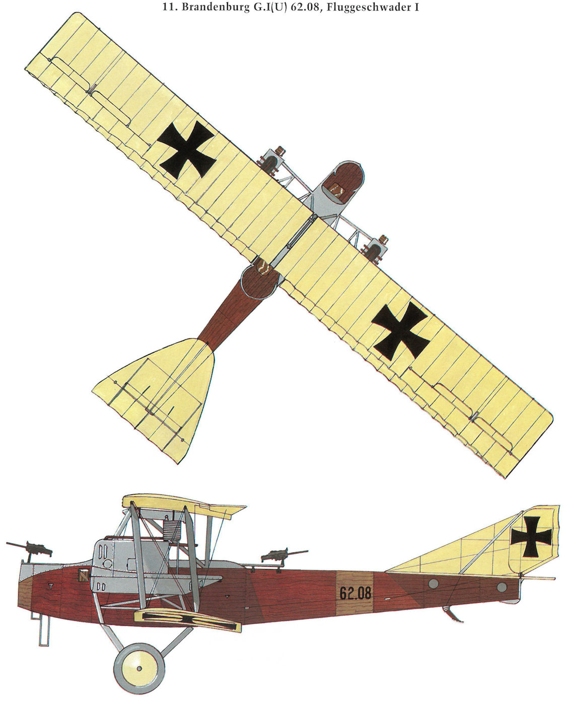
Brandenburg G.I(U) 62.08, Fluggeschwader I
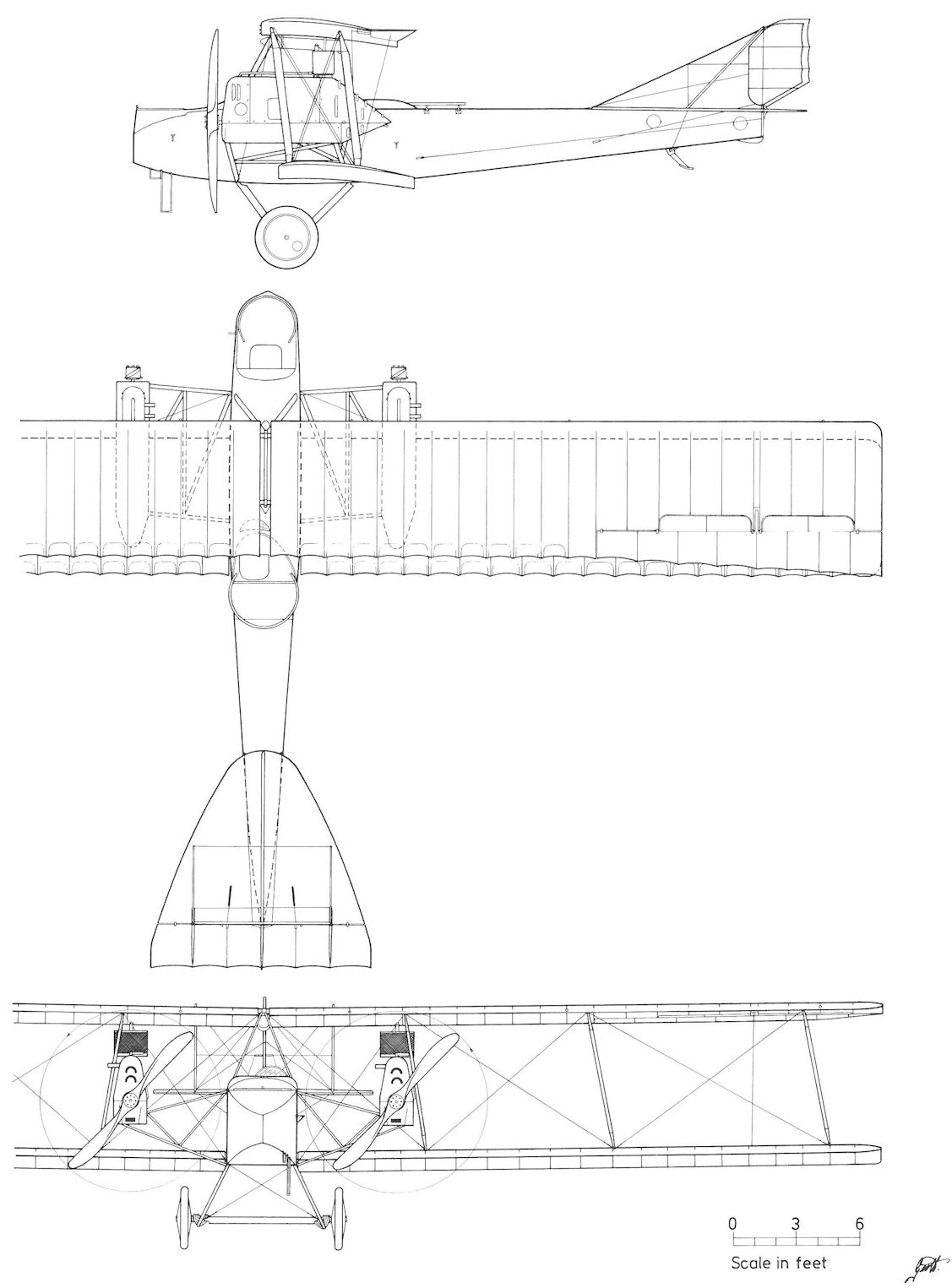
Brandenburg G.I(U) 62.01
Hansa-Brandenburg 60.56 and 60.57
Concurrent with the Type KD fighter, Brandenburg developed a derivative two-seat version known as the Type KDD, featuring a highly-streamlined airframe. In the spring of 1916, Flars ordered four prototypes: 60.56 powered by a 160 hp Daimler engine, the 60.57 powered by a 200 hp Hiero engine, and two unspecified machines. The purchase contract was signed in August 1916.
In May 1916 the 60.56 was reported "ready for flight trials in about four weeks." However, before leaving the factory, the wing cellule required rebuilding to increase the wing area. Fitted with a new wing, the 60.56 performed preliminary flight trials in June 1916 before being returned to the factory for further work. The modified 60.56 was rolled out again on 5 July 1916 for flight tests, but these proved disappointing. Flars called for extensive airframe modification to achieve the specified 170 km/h (106 mph) airspeed. Returned to the factory in August and reportedly fitted with a third wing cellule, the 60.56 reappeared for further testing in October 1916. The 60.56 was accepted by the LFT in November 1916.
The airframe of the second prototype, 60.57, under construction in August and incorporating all improvements, was completed in October 1916 but the Hiero engine was not supplied until March 1917, followed by a visit of the Flars commissioning team (Oberleutnants Korner and von Karman) to Briest that month. The 60.57 was completed on 18 May 1917. Flight tests demonstrated the need for "small improvements, namely increased fin, rudder, and elevator areas to obtain better control characteristics." In July 1917, 60.57 was dispatched to Aspern.
Flight testing of both the 60.56 and 60.57 prototypes was held to a minimum since pilots voiced a strong aversion to the enclosed cockpit that severely limited visibility and threatened to trap the pilot in event of a crash. And the appearance in October 1916 of the improved Brandenburg Type K (C.II 66.51 and 66.81) with an open pilot's cockpit made further flight investigation of the 60.56 and 60.57 redundant. Both prototypes were listed in the Flek inventory for test purposes in September 1917. 60.56 was reported stored in damaged condition at Flugpark 1 on 20 October 1918, and was offered for sale to the Czechoslovakian government in 1920. The 60.57 was attached to the radio experimental section at Aspern in September 1918.
Brandenburg 60.56 (Type KDD)
Engine: 160 hp Daimler
Wing: Span Upper 11.27 m (36.97 ft)
Span Lower 10.32 m (33.86 ft)
Chord Upper 1.62 m (5.31 ft)
Chord Lower 1.62 m (5.31 ft)
Dihedral Upper 0 deg
Dihedral Lower 0 deg
Sweepback Upper 0 deg
Sweepback Lower 0 deg
Gap 1.71 m (5.61 ft)
Stagger 0.54 m (1.77 ft)
Total Wing Area 29.23 sq m (315 sq ft)
General: Length 7.75 m (25.43 ft)
Track 1.80 m (5.91 ft)
Empty Weight 820 kg (1808 lb)
Loaded Weight 1184 kg (2611 lb)
Maximum Speed: 189 km/hr (117 mph)

The modified 60.56 on the Briest airfield showing the fully enclosed pilot’s cockpit partially closed with a Cellon windscreen.

The modified 60.56 on 5 July 1916. The fuselage decking has been raised to fill the wing gap, the struts have been faired, and the stabilizer area increased.

Because the tapered fuselage sides made it difficult to install a conventional gun ring, the 60.56 was later fitted with a raised turret for the observer, barely visible in this poor photograph.

The Hiero-engined Brandenburg 60.57 (Type KDD) awaiting demolition in 1919. The small V-strut interplane bracing has been eliminated, and to improve longitudinal stability a fin has been added. A raised gun ring is fitted to the observer’s cockpit.

Brandenburg KDD 60.57
Brandenburg C.II Series 66.5 and 66.8
On 25 August 1916, the LFT signed a provisional production contract for a two-seat observation biplane (derived from the Type KDD (60.56) prototype) that later became known as the Brandenburg C.II (Type K). Two batches were ordered, consisting of eight C.II series 66.5 biplanes powered by a 160 hp Daimler engine and 40 C.II series 67.5 biplanes powered by a 200 hp Hiero engine. In late 1916 the contract was changed, calling for 24 C.II series 66.5 (Daimler) and 24 C.II series 66.8 (Hiero) biplanes. On 21 November 1916, Flars cancelled the Brandenburg contract, preferring to have Phonix and UFAG manufacture the C.II under license at lower cost. However, the prototype development program at all three companies remained a priority undertaking.
Brandenburg had begun preliminary design work on the Type K (C.II) in June 1916, choosing to build the fuselage first to await the outcome of the static load tests of the pyramid wing cellule that had been giving difficulties. The deep rectangular fuselage, which filled the wing gap, provided the observer with a superb field of fire over the top wing and tail. The first layout envisioned the pilot as totally encapsulated within the fuselage, his only view provided by two side windows as in the 60.56 (Type KDD). When the C.II 66.51 prototype was rolled out in October 1916 for flight tests, the pilot was located in an open cockpit but still situated under the center section. Flight performance was reported as "exceptionally good." The Flars commissioning team that visited Briest in January 1917 was pleased by the fine performance but voiced concern over the difficulty of pilot egress and the structural integrity of the pyramid strut configuration.
The C.II 66.51 was flight tested from January to March 1917 at Aspern. Test pilots Oberleutnant Oskar Fekete and Stabsfeldwebel Kurt Gruber reported it as easy to fly, showing none of the unpleasant shortcomings of the Brandenburg D.I, but the rate of climb, directional stability, and pilot's view required improvement. In comparison to the Aviatik C.I, Fekete felt the C.II's higher landing speed, poor glide ratio, and slower climb made it less suitable for mountainous terrain and small airfields. The prototype was accepted by Flars on 21 February 1917. Brandenburg delivered a new wing cellule that was flight evaluated between 2-14 May 1917 but offered no improvement. In May, work on the 66.51 prototype was halted in favor of the more-promising C.II derivatives, the Phonix C.I series 121 and the UFAG C.I series 161. The 66.51 airframe was stored at Aspern from March to October 1918.
The second C.II 66.81 was completed on 18 May 1917. Flight tests carried out in June proved unsatisfactory due to "the poor longitudinal stability" induced by the heavier 200 hp Hiero engine. The construction of an enlarged fin and lengthened fuselage was temporarily halted to give priority to the L 15 prototype. On 8 August 1917 the modified 66.81 stood ready to recommence flight testing, but promising results achieved with the Phonix C.I and UFAG C.I made it unwise to expend further effort on the Brandenburg design. The 66.81 was stored in damaged condition at Aspern in October 1918.
Brandenburg C.II 66.51
Engine: 185 hp Daimler
Wing: Span Upper 9.40 m (30.84 ft)
Span Lower 9.40 m (30.84 ft)
Chord Upper 1.65 m (5.41 ft)
Chord Lower 1.65 m (5.41 ft)
Dihedral Upper 0 deg
Dihedral Lower 0 deg
Sweepback Upper 0 deg
Sweepback Lower 0 deg
Gap 1.61 m(5.28 ft)
Stagger 0.48 m (1.57 ft)
Total Wing Area 28.03 sq m (302 sq ft)
General: Length 7.40 m (24.28 ft)
Track 1.72 m (5.64 ft)
Empty Weight 728 kg (1605 lb)
Loaded Weight 1092 kg (2408 lb)
Climb: 1000m (3,281 ft) in 3 min 30 sec
Brandenburg C.II(U) Series 66
No aircraft carrying the series 66 designation were built by UFAG. Records show that in 1916 UFAG received a contract for 24 Brandenburg C.II(U) series 66 biplanes based on the Brandenburg C.II 66.51 prototype currently under development at Briest. When the two UFAG-built Brandenburg C.II prototypes made their appearance in March 1917, Flars had changed the designations to Brandenburg C.II(U) 161.01 and 161.02. But with the arrival of the two UFAG C.I production prototypes, Flars changed the numbers once again. The two Brandenburg C.II(U) prototypes were renumbered to 160.01 and 160.02, and the UFAG C.I prototypes were assigned the numbers 161.01 and 161.02.
Brandenburg C.II(U) Series 160
In July 1916, UFAG received a contract to build 24 Brandenburg C.II(U) series 66 biplanes based on the Brandenburg C.II 66.81 prototype. When UFAG completed the two C.II(U) prototypes, Flars had changed the designation to 161.01 and 161.02. Both prototypes were powered by a 200 hp Hiero engine. A Flars commissioning team inspected the 161.01 airframe on 29 March 1917. Test flying delayed by weather had made little progress when, in May 1917, Flars cancelled the Brandenburg C.II program because the performance did not meet frontline requirements and the derivative UFAG C.I showed far more promise. When the UFAG C.I series 161 production prototypes (161.01 and 161.02) appeared in May 1917, to avoid confusion the two Brandenburg C.II(U) prototypes were re-numbered 160.01 and 160.02. It appears the C.II(U) aircraft were flown sporadically through early 1918. In test pilot Antal Feher's logbook one can read that climb trials with aircraft 160.01 and 160.02 were performed in January 1918. In March, the two prototypes went to Flek 8 as ground instruction airframes.
Brandenburg C.II(U) 160.02 Specifications
Engine: 200 hp Hiero
Climb: 1000m (3,281 ft) in 4 min 27 sec (160.02)
2000m (6,562 ft) in 10 min 46 sec (160.02)
3000m (9,843 ft) in 16 min 53 sec (160.02)
An Explanatory Note About Hansa-Brandenburg Serial Numbers:
When the LFT assigned new serial numbers to aircraft in February 1915, Hansa-Brandenburg was assigned the company designation 05. The first nine numbers, 05.01 to 05.09, were allocated to out-of-series or prototype aircraft. Series production aircraft began with the Hansa-Brandenburg B.I 05.11. At a later date, production aircraft were numbered 61.5 and up and prototype aircraft were assigned numbers beginning with 60.5. To avoid confusion, the table shows the series designations assigned to Brandenburg and UFAG, although the types were not identical nor were parts interchangeable:
Type UFAG Hansa-Brandenburg
Brand C.I 61.01-24 61.51-72
Brand G.I 62.01-12 62.51-77
Brand C.I 63.01-32 63.51-86
Brand C.I 64.01-48 64.51-72
Brand D.I not built by UFAG 65.50-99
Brand C.II 66.01 (cancelled) 66.51 (two built)
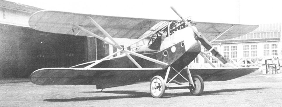
Brandenburg C.II(U) 161.01, powered by a 200 hp Hiero engine, at the UFAG factory in Albertfalva in April 1917. To avoid confusion with the UFAG C.I 161.01 prototype, the number was later changed to 160.01.
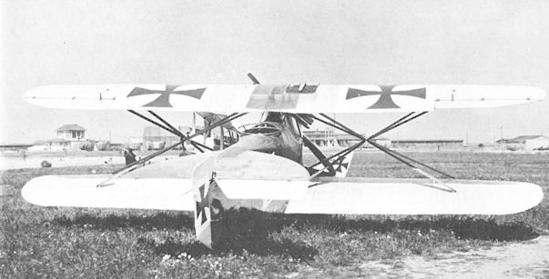
Brandenburg C.II 66.51. The low rudder and high fuselage provided the rear gunner with an unobstructed field of fire. The center section above the pilot’s cockpit was covered with transparent Cellon.
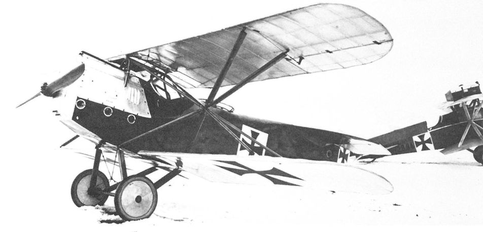
The Brandenburg C.II 66.51 (Type K), powered by a 160 hp Daimler engine, at Aspern in January 1917. As in the 60.57, the pilot had no easy egress in the event of a crash.
The modified Brandenburg L 14, designated 60.58, at Aspern for evaluation in the summer of 1917. On the left is the the Phonix C.I 121.03 and on the right the Brandenburg C.II 66.51.
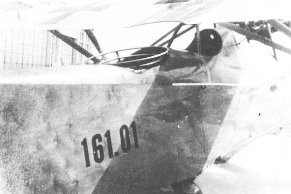
Brandenburg C.II(U) 161.01 (later 160.01). The inaccessible cockpit location, which made a quick exit difficult in an emergency, explains why pilots had such an aversion to the aircraft. The center section is covered with transparent Cellon.
Seventeen Brandenburg C.I(U) biplanes (left front: 69.71 and 69.35) and one Brandenburg C.II(U) lined up for flight acceptance at the UFAG airfield in Albertfalva, April 1917.
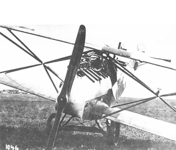
The Brandenburg C.II 66.81, powered by a 200 hp Hiero engine, damaged in a minor landing accident at Aspern. The side hatch to the pilot's cockpit is open. This prototype was fitted with a rounded rudder.
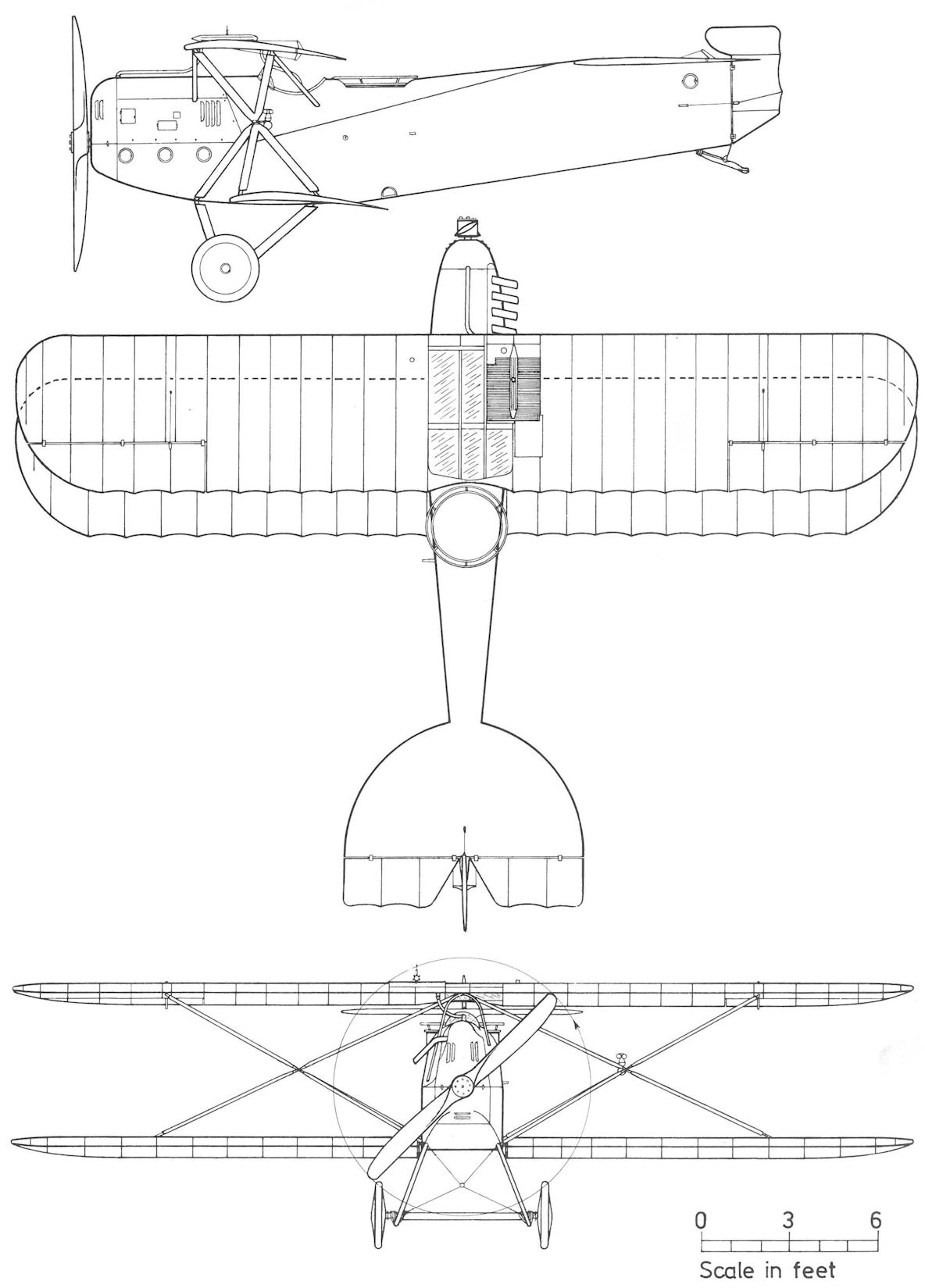
Brandenburg C.II 66.51
Brandenburg 60.58
The success of the Nieuport sesquiplane fighter on the Western Front motivated Brandenburg to propose in July-August 1916 a derivative design powered by a 160 hp inline engine. It was rejected by Flars, who preferred to await the frontline assessment of the Brandenburg D.I expected to reach the Front in November. A month later, Flars asked Brandenburg to reduce the D.I's weight, eliminate the heavy pyramid struts, and generally improve the flight characteristics. Brandenburg responded by proposing the Type LKD fighter powered by a 200 hp Hiero engine.
The maiden flight of the Brandenburg L 14 (formerly Type LKD) took place at Briest in February 1917, followed by performance trials in March. The results were "unexceptional ... the wing tips vibrated severely and reinforcement was necessary." Tests were interrupted when the tail skid collapsed on touch down, badly damaging the fuselage and tail empennage. During May-June 1917, the L 14 was rebuilt with modified wing struts, new tail surfaces, and stronger engine bearers, but progress was reported "extremely slow" since Brandenburg chose to give priority to building seaplanes for the German and Austro-Hungarian Navies. The modified L 14 was test flown on 26 June 1917, demonstrating improved performance although the empty weight had increased by 80 kg (176 lb). A top speed of 203 km/hr (126 mph) and "appreciably better" flight characteristics than the D.I series 65.5 were reported.
The L 14, now designated 60.58, was transferred to Phonix on 12 July 1917 for LFT evaluation, but Flars expressed no enthusiasm since flight tests with similar Phonix prototypes (20.14 and 20.16) had offered scant improvement. In March 1918, the 60.58 was placed in storage, remaining Phonix property until the war's end, when payment was received for the prototype.
Brandenburg 60.58 (Type LKD, L 14) First Version
Engine: 200 hp Hiero
General: Empty Weight 660 kg (1455 lb)
Loaded Weight 850 kg (1874 lb)
Maximum Speed: 200 km/hr (124 mph)
Climb: 1000m (3,281 ft) in 2 min 25 sec
Brandenburg 60.58 (Type LKD, L 14) Second Version
Engine: 200 hp Hiero
Wing: Span Upper 10.20 m (33.46 ft)
Span Lower 8.35 m (27.39 ft)
Chord Upper 1.70 m (5.58 ft)
Chord Lower 1.40 m (4.59 ft)
Dihedral Upper 0 deg
Dihedral Lower 0 deg
Sweepback Upper 0 deg
Sweepback Lower 0 deg
Gap 1.58 m (5.18 ft)
Stagger 0.53 m (1.74 ft)
Total Wing Area 25.58 sq m (275 sq ft)
General: Length 7.06 m (23.16 ft)
Track 1.70 m (5.58 ft)
Empty Weight 740 kg (1632 lb)
Loaded Weight 940 kg (2073 lb)
Maximum Speed: 203 km/hr (126 mph)
Climb: 2000m (6,562 ft) in 6 min
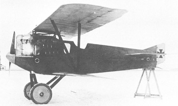
The Brandenburg L 14. The wireless wing cellule reduced drag at the expense of structural integrity. The large white area in front of the cockpit is a Cellon-covered window to provide interior lighting.
The modified Brandenburg L 14, designated 60.58, at Aspern for evaluation in the summer of 1917. On the left is the the Phonix C.I 121.03 and on the right the Brandenburg C.II 66.51.
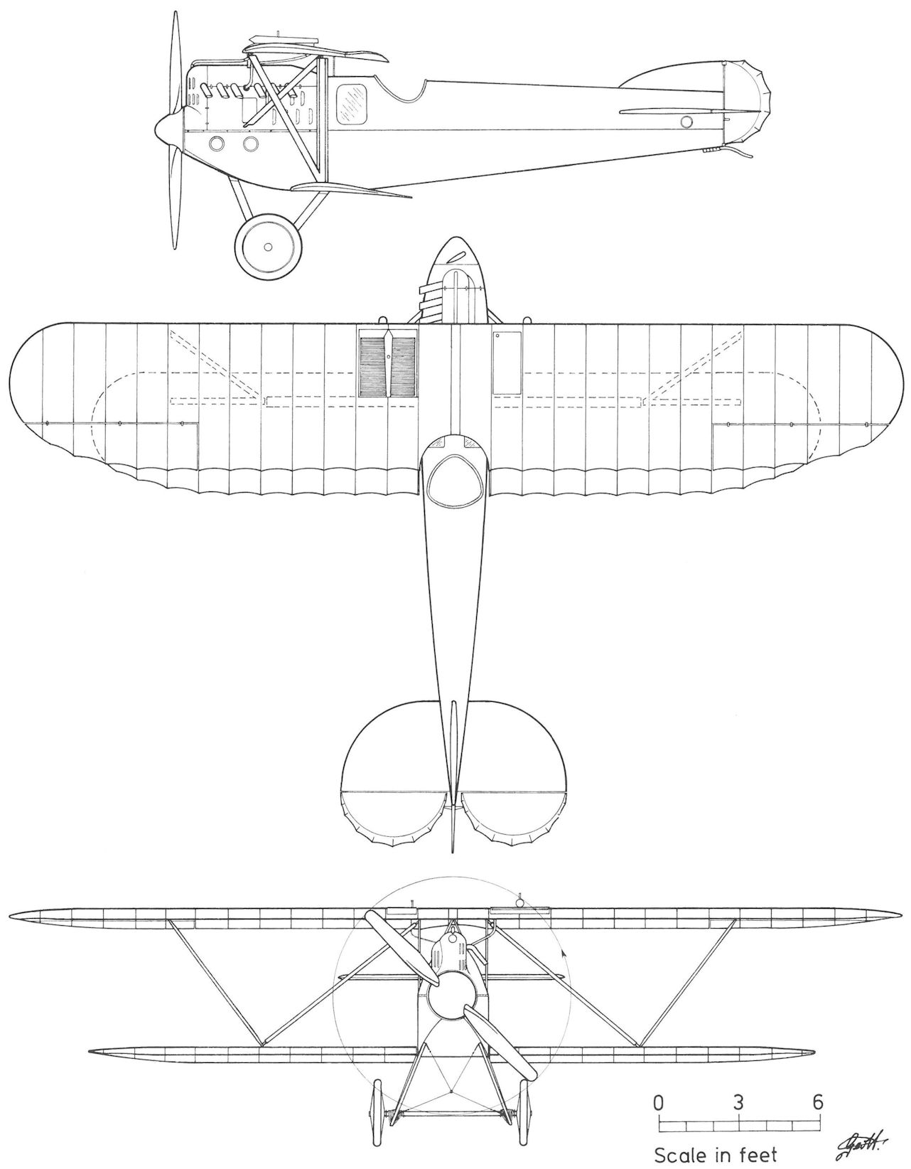
Brandenburg 60.58
Brandenburg L 15
In late 1916, Flars issued technical specifications for a biplane powered by the new 345 hp Daimler engine. Brandenburg responded with the L 15 design, which Flars approved for construction in December 1916. In February 1917 work on the nearly-completed airframe was suspended because "neither the engine nor a mock-up was available" to determine proper installation parameters. Von Mises, who had been involved in drafting the Flars specification, approved aerodynamic and layout details in May 1917. When the L 15 appeared for its maiden flight in June 1917, it had a single-bay wing cellule and a compact, slab-sided fuselage. The L 15 proved to be extremely nose heavy in flight, which may have contributed to the accident that broke the fuselage while landing.
The L 15 was extensively rebuilt in July 1917. The fuselage was reinforced and lengthened by 80 cm (31.5 in). The new wing was increased in span, substantially strengthened, and given a two-bay configuration. Work was completed on 8 August 1917. Flight trials now revealed an "unusually severe tail heaviness", a problem that was not resolved until early December 1917. After test flights by Flars pilot Stabsfeldwebel Franz Kuntner, the prototype was transferred to Aspern. Phonix, assuming fiscal responsibility, sold the L 15 to the LFT on 11 January 1918. No further records of flight tests have been found, although the L 15 was still at Aspern on 1 October 1918.
Brandenburg L 15 (Second Version)
Engine: 345 hp Daimler
Wing: Span Upper 13.80 m (45.28 ft)
Span Lower 13.80 m (45.28 ft)
Chord Upper 2.25 m (7.38 ft)
Chord Lower 2.25 m (7.38 ft)
Dihedral Upper 0 deg
Dihedral Lower 0 deg
Sweepback Upper 0 deg
Sweepback Lower 0 deg
Gap 1.86 m (6.10 ft)
Stagger 0.41 m (1.35 ft)
Total Wing Area 52.66 sq m (567 sq ft)
General: Empty Weight 1015 kg (2238 lb)
Loaded Weight 1500 kg (3308 lb)
Maximum Speed: 195 km/hr (121 mph)

Brandenburg L 15. Evidence that there was a single-bay version of the Brandenburg L 15 comes from this crash photograph taken in June 1917 at Briest.

Brandenburg L 15
Brandenburg L 16
Upon receiving technical specifications of the Sopwith Triplane from Flars, Brandenburg replied on 26 June 1917 that construction of a prototype triplane would begin immediately, with completion optimistically estimated in 5 to 6 weeks. Static calculations for the triplane fighter, known as the L 16 - Brandenburg's last landplane of the war - were submitted for approval on 13 August 1917, and later that month Brandenburg requested a 200 hp Daimler engine for installation. When Flars engineering representatives inspected the completed triplane in Briest on 1 December 1917, they were struck by the "surprisingly large dimensions." The date of the L 16's first flight is unknown. Brandenburg technical data sheets lay claim to an incredible climb rate of 2000 meters (6562 ft) in 3 minutes (with a 185 hp Daimler engine), figures surely based on slide rule calculations and not on actual results. On 1 March 1918, the L 16, now in Phonix's hands, was hangared at Aspern but flight activity remained sporadic. Surpassed by modern biplane fighters with superior performance, the heyday of the triplane was history. On 20 June 1918, the L 16 was reported stored at Phonix where it remained until the war's end, at which time Phonix received payment for the prototype.
Brandenburg L 16
Engine: 200 hp Daimler
Wing: Span Upper 9.00 m (29.53 ft)
Span Middle 9.00 m (29.53 ft)
Span Lower 9.00 m (29.53 ft)
Chord Upper 1.30 m (4.27 ft)
Chord Middle 1.20 m (3.94 ft)
Chord Lower 1.30 m (4.27 ft)
Dihedral Upper 0 deg
Dihedral Lower 0 deg
Sweepback Upper 0 deg
Sweepback Lower 0 deg
Gap Upper 1.20 m (3.94 ft)
Gap Lower 1.30 m (4.27 ft)
Stagger 0.50 m (1.64 ft)
Total Wing Area 33.5 sq m (360 sq ft)
General: Length 7.17 m (23.52 ft)
Height 2.82 m (9.25 ft)
Track 1.70 m (5.58 ft)
Empty Weight 740 kg (1632 lb)
Loaded Weight 935 kg (2062 lb)
Maximum Speed: 190 km/hr (118 mph)
Climb: 1000m(3,281 ft) in 1 min
2000m (6,562 ft) in 3 min
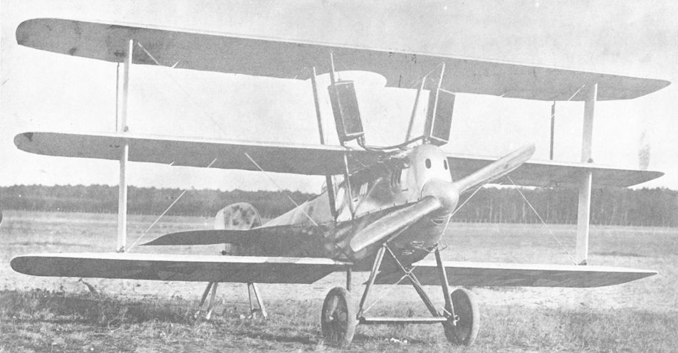
Three other triplane fighter essays of 1917 were the rotary-powered Euler Dr I, the 185hp Austro-Daimler powered Hansa-Brandenburg L 16 (photo) and the Korting engined DFW Dr I.
For the initial flight trials at Briest, the Brandenburg L 16 prototype was fitted with temporary strut-mounted radiators for the 200 hp Daimler engine.
For the initial flight trials at Briest, the Brandenburg L 16 prototype was fitted with temporary strut-mounted radiators for the 200 hp Daimler engine.
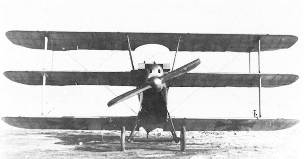
The Brandenburg L 16 at Aspern had a single radiator mounted forward of the middle wing, an indication it might have been reengined with a 185 hp Daimler engine.
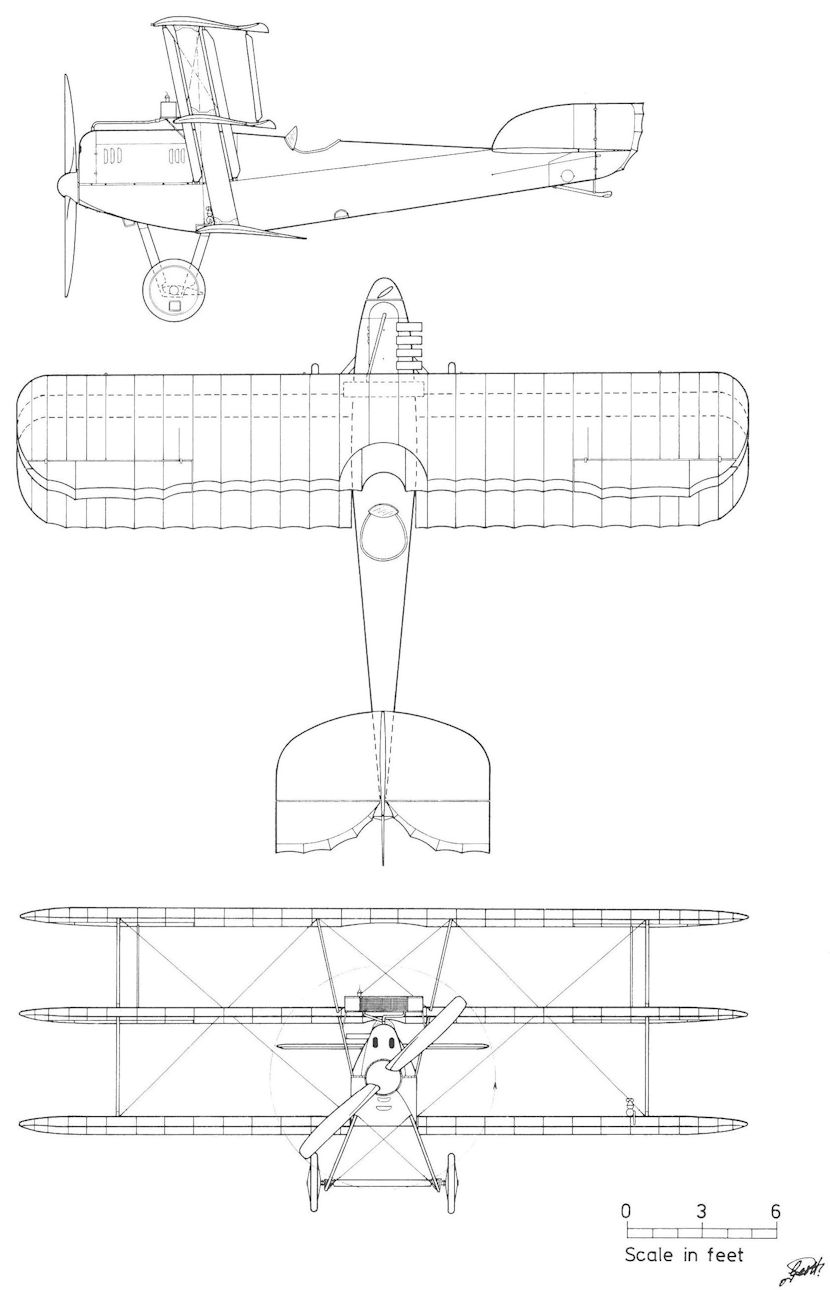
Brandenburg L 16
Junkers J.I
The all-metal Junkers J.I ground attack biplane, with its armored engine and crew compartment, had proved a useful weapon on the Western Front for performing ground contact patrols. Strafing attacks by Brandenburg C.I biplanes on Italian positions had demonstrated the effectiveness of such tactics, but the LFT was eager to reduce aircrew casualties. In July 1918, the purchase of two Junkers J.I biplanes was approved and two 250 hp Benz(Mar) engines were dispatched to Dessau for installation. Generalmajor Uzelac and members of his technical staff visited Junkers-Fokker on 28 September 1918 to inspect the factory and airfield. Since no aircraft had been delivered when the war ended, the contract was annulled.
The all-metal Junkers J.I ground attack biplane, with its armored engine and crew compartment, had proved a useful weapon on the Western Front for performing ground contact patrols. Strafing attacks by Brandenburg C.I biplanes on Italian positions had demonstrated the effectiveness of such tactics, but the LFT was eager to reduce aircrew casualties. In July 1918, the purchase of two Junkers J.I biplanes was approved and two 250 hp Benz(Mar) engines were dispatched to Dessau for installation. Generalmajor Uzelac and members of his technical staff visited Junkers-Fokker on 28 September 1918 to inspect the factory and airfield. Since no aircraft had been delivered when the war ended, the contract was annulled.

Generalmajor Uzelac (hands clasped) and his travelling staff visiting the junkers factory in Dessau on 28 September 1918. On his left is Oberstleutnant Ferdinand Deutelmoser. Schiffsbau-Ingenieur 1.Klasse Theodore Weichmann, one of his technical advisors, is fourth from left. In the background is the Junkers J.I 852/17.
LVG C.VI Series 08.100
Concerned that the worker's strike at UFAG and production delays at Phonix could threaten the supply of two-seater biplanes, the LFT made plans in early 1918 to purchase 50 German LVG C.VI biplanes as insurance. Built completely of wood, including wing and undercarriage struts, the versatile C.VI was also eyed as a potential candidate for license manufacture. On 27 March, a 230 hp Hiero engine was shipped to Johannisthal for installation in a C.VI, and LVG flight tests were satisfactorily concluded on 14 April. An order for 50 LVG C.VI biplanes, numbered 08.101 to 08.150, was approved on 27 July 1918. However, the order was subject to a performance comparison with the latest Phonix and UFAG C.I production machines. The Phonix C.I emerged the winner and, with manufacturing problems on the mend, the LFT cancelled the C.VI order on 31 August 1918. In fact, the LFT recommended that LVG stop C.VI production and build the Phonix C.I instead. LVG C.VI 3978/18 (engine unknown but possibly the Hiero-engined test machine) and a Benz-powered C.VI 3843/18 were listed in the 1919 inventory of LFT aircraft.
Concerned that the worker's strike at UFAG and production delays at Phonix could threaten the supply of two-seater biplanes, the LFT made plans in early 1918 to purchase 50 German LVG C.VI biplanes as insurance. Built completely of wood, including wing and undercarriage struts, the versatile C.VI was also eyed as a potential candidate for license manufacture. On 27 March, a 230 hp Hiero engine was shipped to Johannisthal for installation in a C.VI, and LVG flight tests were satisfactorily concluded on 14 April. An order for 50 LVG C.VI biplanes, numbered 08.101 to 08.150, was approved on 27 July 1918. However, the order was subject to a performance comparison with the latest Phonix and UFAG C.I production machines. The Phonix C.I emerged the winner and, with manufacturing problems on the mend, the LFT cancelled the C.VI order on 31 August 1918. In fact, the LFT recommended that LVG stop C.VI production and build the Phonix C.I instead. LVG C.VI 3978/18 (engine unknown but possibly the Hiero-engined test machine) and a Benz-powered C.VI 3843/18 were listed in the 1919 inventory of LFT aircraft.
Pfalz D.IIIa
The proposal submitted in March 1916 by the Oesterreichische Maschinen AG Korting to manufacture Pfalz E-type fighter monoplanes was rejected by the LFT on the grounds that superior fighters would soon become available from indigenous firms. But Pfalz maintained contact with the LFT, and in late 1917 Flars dispatched a 200 hp Daimler engine for installation in a Pfalz D.IIIa fighter. The Daimler-engined D.IIIa was reported ready for flight testing on 28 December 1917, and there were great hopes for the frontline trials scheduled to begin in January 1918. But factory flights demonstrated severe tail-heaviness at full power and nose-heaviness when throttled down. Partially at fault was the 200 hp Daimler engine that weighed 46 kg (101 lb) more than the 160 hp Mercedes for which the D.IIIa fighter was designed. The lighter and less powerful 160 hp Daimler engine was sent to Speyer on 11 March 1918 for installation in the D.IIIa, but flight tests continued to disappoint. Plans for Lloyd and WKF to manufacture the Pfalz D.IIIa were cancelled.
The proposal submitted in March 1916 by the Oesterreichische Maschinen AG Korting to manufacture Pfalz E-type fighter monoplanes was rejected by the LFT on the grounds that superior fighters would soon become available from indigenous firms. But Pfalz maintained contact with the LFT, and in late 1917 Flars dispatched a 200 hp Daimler engine for installation in a Pfalz D.IIIa fighter. The Daimler-engined D.IIIa was reported ready for flight testing on 28 December 1917, and there were great hopes for the frontline trials scheduled to begin in January 1918. But factory flights demonstrated severe tail-heaviness at full power and nose-heaviness when throttled down. Partially at fault was the 200 hp Daimler engine that weighed 46 kg (101 lb) more than the 160 hp Mercedes for which the D.IIIa fighter was designed. The lighter and less powerful 160 hp Daimler engine was sent to Speyer on 11 March 1918 for installation in the D.IIIa, but flight tests continued to disappoint. Plans for Lloyd and WKF to manufacture the Pfalz D.IIIa were cancelled.
Pfalz Dr.I
In September 1917, the Pfalz Dr.I prototype triplane fighter clocked the fastest rate of climb ever recorded by a German aircraft. A pre-production batch of ten fighters was ordered for combat evaluation by the German air service. Based on the outcome, the LFT planned to assign the MAG company the license manufacture of the Pfalz Dr.I powered by a 145 hp Oberursel Ur.Ill rotary engine. The project was dropped when frontline experience in early 1918 showed that the Dr.I was structurally deficient, not to mention the unavailability of rotary-engine lubricant.
In September 1917, the Pfalz Dr.I prototype triplane fighter clocked the fastest rate of climb ever recorded by a German aircraft. A pre-production batch of ten fighters was ordered for combat evaluation by the German air service. Based on the outcome, the LFT planned to assign the MAG company the license manufacture of the Pfalz Dr.I powered by a 145 hp Oberursel Ur.Ill rotary engine. The project was dropped when frontline experience in early 1918 showed that the Dr.I was structurally deficient, not to mention the unavailability of rotary-engine lubricant.
Pfalz D.XV
A Pfalz proposal, submitted to the LFT in March 1918, to install a 225 hp Daimler engine in the new Pfalz D.XII fighter was held in abeyance because Pfalz engineers became fully engaged solving the hot weather radiator problem that delayed the introduction of the D.XII by several months. On 27 August 1918, the LFT approved the purchase of two Pfalz D.XII fighters, and one 225 hp Daimler engine was shipped to Speyer for installation, but there is no record of a Daimler-engined D.XII being flight-tested. By the time the War Ministry got around to issuing the formal purchase approval on 3 October 1918, the new Pfalz D.XV fighter had superceded the D.XII and the purchase order was changed accordingly. At Armistice the order was cancelled, as was the program for WKF to build 12 Pfalz D.XV fighters in February and March 1919.
A Pfalz proposal, submitted to the LFT in March 1918, to install a 225 hp Daimler engine in the new Pfalz D.XII fighter was held in abeyance because Pfalz engineers became fully engaged solving the hot weather radiator problem that delayed the introduction of the D.XII by several months. On 27 August 1918, the LFT approved the purchase of two Pfalz D.XII fighters, and one 225 hp Daimler engine was shipped to Speyer for installation, but there is no record of a Daimler-engined D.XII being flight-tested. By the time the War Ministry got around to issuing the formal purchase approval on 3 October 1918, the new Pfalz D.XV fighter had superceded the D.XII and the purchase order was changed accordingly. At Armistice the order was cancelled, as was the program for WKF to build 12 Pfalz D.XV fighters in February and March 1919.
Rumpler Taube 1913
In addition to engines, propellers, and miscellaneous parts, the LA purchased one 1913 Rumpler Taube from the defunct Autoplan Werke in April 1914. Although flown as a trainer at Flugpark 14, the Taube did not receive a military designation. It was damaged on 29 May and again on 4 June 1914. Whether it remained active after this date is not known.
In addition to engines, propellers, and miscellaneous parts, the LA purchased one 1913 Rumpler Taube from the defunct Autoplan Werke in April 1914. Although flown as a trainer at Flugpark 14, the Taube did not receive a military designation. It was damaged on 29 May and again on 4 June 1914. Whether it remained active after this date is not known.
Rumpler B.I Series 02
Early in the war when LA officers combed Germany for any aircraft they could lay their hands on, two Rumpler B.I biplanes (Type 4A) were purchased from the air service. Being out-of-series aircraft, they received numbers R 01 (later 00.04) and R 02 (00.05). In January and March 1915, twenty-two B.I biplanes (including B.1018-1022, 1025, 1028, 1033 and 1034/14, released for sale by the German air service), entered LA inventory as series R 1 to R 22. On the Eastern Front in the spring of 1915, another seven were transferred directly from Flieger Abteilung 30 to the LFT. These aircraft were later designated Rumpler B.I 02.01 to 02.29. All were powered by a 100 or 120 hp Mercedes engine.
The Rumpler B.I flew reconnaissance and bombing sorties with Fliks 5 and 13 on the Russian Front, with Fliks 4 and 9 in the Balkans, and later with Flik 4 on the Italian Front. As they came in for repair, at least ten aircraft were refitted with the 100 hp Daimler engine. By early 1916 the remaining B.I biplanes had been assigned to training service with Fleks 1 to 5, 7, 8, 11, and 13. As of 1 July 1917, fifteen were still active, and a long-lived nine Rumpler B.I machines were carried on the training aircraft inventory on 31 August 1918.
LFT Designation ex-German Designation
New Original
02.01 R 1 B.470/14
02.25 R25 B.1039/14
02.26 R26 B.484/14
02.27 R27 B.712/14
02.28 R28 B.477/14
02.29 R29 B.725/14
Rumpler B.I Series 02
Engine: 100 hp Mercedes
Wing: Span Upper 13.00 m (42.65 ft)
Span Lower 12.80 m (41.99 ft)
Chord Upper 1.88 m (6.17 ft)
Chord Lower 1.80 m (5.91 ft)
Total Wing Area 39.0 sq m (420 sq ft)
General: Length 8.2 m (26.90 ft)
Empty Weight 750 kg (1654 lb)
Loaded Weight 1150 kg (2536 lb)
Maximum Speed: 105 km/hr (65 mph)
Climb: 1000m |3,281 ft) in 9.5 min
2000m (6,562 ft) in 27.5 min
3000m (9,843 ft) in 48.5 min

Rumpler B.I 477/14 (02.28) was transferred to the LFT from Flieger Abteilung 30 at the Front. Still in its original German markings, it was flown later as a trainer in Wiener-Neustadt.

This Rumpler B.I 484/14 (02.26) was operational with Flik 1 with the German insignia still intact. It would be repainted when it came in for repair.

A Mercedes-engined Rumpler B.I (02.08?).

The longer 100 hp Daimler engine did not deter resourceful LFT fitters. Here it is installed in the B.I 02.25.

Rumpler B 1 (02.01, w/n 217) in which Feldwebel Franz Juhasz of Flik 5 suffered a minor landing mishap in early 1915. The tail markings, possibly applied at the Rumpler factory, were non-standard.

In training service a number of B.I biplanes were retro-fitted with an aerodynamically-balanced rudder, shown here on Rumpler B.I 02.02. The marking on the tailplane is unusual.

Rumpler B.I Series 02
Rumpler C.VII 00.01(new)
On 18 September 1917, Flars made a tentative arrangement for Rumpler to build six Rumpler two-seat biplanes and two single-seat fighters for test and evaluation, with delivery dependent on engine availability. With the appearance of the 300 hp Daimler V-12 engine in early 1918, Flars planned to purchase three Rumpler C.VII biplanes to compare the performance of similar Austro-Hungarian and German aircraft powered by this engine. According to Rumpler test pilot Friedrich Budig, he flew a Rumpler Type 6A11 (a C.VII derivative) in February 1918, believed to be the 00.01(new). It was reported ready for delivery on 2 March 1918 and arrived at Aspern in late April 1918, accompanied by director Edmund Rumpler to supervise the flight trials. The new biplane, now numbered 00.01, was badly damaged in a landing accident. It does not appear to have been repaired.
On 18 September 1917, Flars made a tentative arrangement for Rumpler to build six Rumpler two-seat biplanes and two single-seat fighters for test and evaluation, with delivery dependent on engine availability. With the appearance of the 300 hp Daimler V-12 engine in early 1918, Flars planned to purchase three Rumpler C.VII biplanes to compare the performance of similar Austro-Hungarian and German aircraft powered by this engine. According to Rumpler test pilot Friedrich Budig, he flew a Rumpler Type 6A11 (a C.VII derivative) in February 1918, believed to be the 00.01(new). It was reported ready for delivery on 2 March 1918 and arrived at Aspern in late April 1918, accompanied by director Edmund Rumpler to supervise the flight trials. The new biplane, now numbered 00.01, was badly damaged in a landing accident. It does not appear to have been repaired.
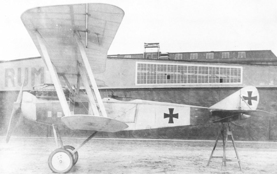
Rumpler C.VII with AD V12 Dm345 (1917)
The Rumpler C.VII derivative (Type 6A11?) photographed upon completion at the Rumpler factory in Johannisthal in late February 1918. The undercarriage has been raised to provide clearance for the increased propeller diameter required by the 300 hp Daimler engine.
The Rumpler C.VII derivative (Type 6A11?) photographed upon completion at the Rumpler factory in Johannisthal in late February 1918. The undercarriage has been raised to provide clearance for the increased propeller diameter required by the 300 hp Daimler engine.
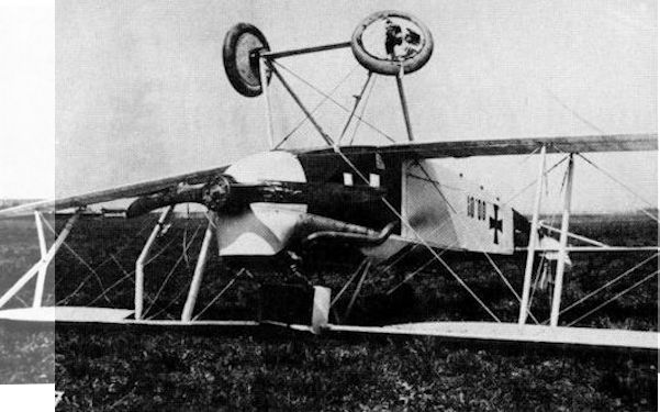
A hard landing, probably during first flight trials at Aspern in late April 1918, put an end to further testing of the Rumpler C.VII 00.01.
Rumpler C.IV mit Daimler-Motor 350 PS, Flugzeugnummer 00.01
Rumpler C.IV с двигателем Daimler 350 л.с., номер самолета 00.01
Rumpler C.IV mit Daimler-Motor 350 PS, Flugzeugnummer 00.01
Rumpler C.IV с двигателем Daimler 350 л.с., номер самолета 00.01
Rumpler C.VIII (derivative)
As part of the 18 September 1917 order for six two-seat aircraft, Rumpler delivered a modified C.VII powered by a 300 hp Daimler engine (see Rumpler 00.01) in April 1918. A second Rumpler biplane, a C.VIII derivative fitted with a 230 hp Hiero engine, was reported under construction on 2 March 1918 and ready for delivery in about four weeks. It is on record that Rumpler test pilot Friedrich Budig damaged a Rumpler Type 6A8 (C.VIII), powered by a 230 hp Hiero engine, in May 1918. Other than a photograph taken at Aspern, information regarding this version is lacking.
As part of the 18 September 1917 order for six two-seat aircraft, Rumpler delivered a modified C.VII powered by a 300 hp Daimler engine (see Rumpler 00.01) in April 1918. A second Rumpler biplane, a C.VIII derivative fitted with a 230 hp Hiero engine, was reported under construction on 2 March 1918 and ready for delivery in about four weeks. It is on record that Rumpler test pilot Friedrich Budig damaged a Rumpler Type 6A8 (C.VIII), powered by a 230 hp Hiero engine, in May 1918. Other than a photograph taken at Aspern, information regarding this version is lacking.
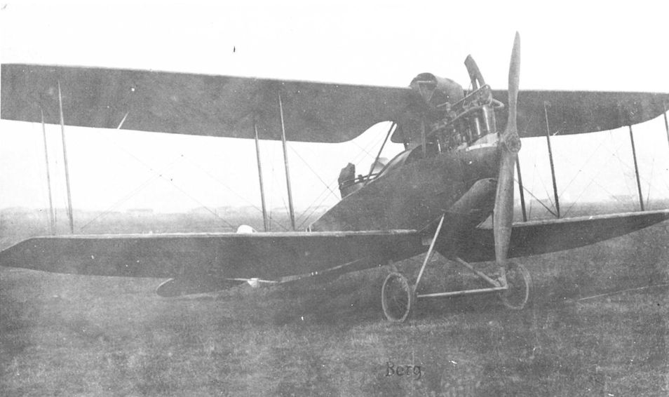
The Rumpler C.VIII derivative powered by a 230 hp Hiero engine photographed at Aspern. A close inspection of the photograph shows that part of the engine cowling may have been blown against the radiator during engine testing.
Dornier Cl.II
On 27 August 1918, the LFT recommended the purchase of two Zeppelin C.II(Ja) reconnaissance biplanes, powered by 230 hp Hiero engines, for evaluation. The War Ministry approved the purchase in October. Designed by Ingenieur Paul Jaray, the Zeppelin C.II(Ja) was constructed of duraluminum and covered with fabric. Twenty had been ordered by the German Fliegertruppe. But after having visited the Zeppelin factory in September 1918, the LFT command changed its mind and replaced the Zeppelin C.II(Ja) by the Dornier Cl.II, which was regarded as a more modern design due to its all-metal, stressed-skin construction. At the cessation of hostilities, the contract for the purchase of two Dornier Cl.II biplanes was annulled. To prepare for all-metal aircraft manufacture in Austria, the Zeppelin Werke established a subsidiary in mid 191(?), in Horbranz near Bregenz, known as the Zeppelin Werke Oesterreich GmbH. No production was undertaken.
On 27 August 1918, the LFT recommended the purchase of two Zeppelin C.II(Ja) reconnaissance biplanes, powered by 230 hp Hiero engines, for evaluation. The War Ministry approved the purchase in October. Designed by Ingenieur Paul Jaray, the Zeppelin C.II(Ja) was constructed of duraluminum and covered with fabric. Twenty had been ordered by the German Fliegertruppe. But after having visited the Zeppelin factory in September 1918, the LFT command changed its mind and replaced the Zeppelin C.II(Ja) by the Dornier Cl.II, which was regarded as a more modern design due to its all-metal, stressed-skin construction. At the cessation of hostilities, the contract for the purchase of two Dornier Cl.II biplanes was annulled. To prepare for all-metal aircraft manufacture in Austria, the Zeppelin Werke established a subsidiary in mid 191(?), in Horbranz near Bregenz, known as the Zeppelin Werke Oesterreich GmbH. No production was undertaken.
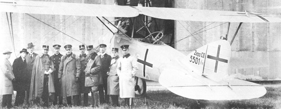
Generalmajor Emil Uzelac (in white gloves and cape) and his staff visiting the Zeppelin factory at Friedrichshafen to inspect the Zeppelin C.II(Ja) in late September 1918. Designer Paul Jaray is second from left.
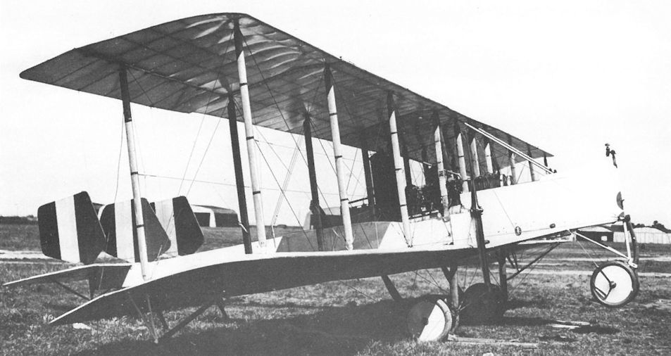
The Caproni Ca 3 (Ca 703) was captured on 18 Feb. 1916 in damaged condition. It was repaired by Phonix and was photographed at Aspern in December 1917. The number 00.52 is hidden behind the wing.

Not all captured Allied aircraft were given a number, including this Pomilio PD in Austro-Hungarian markings on the Campoformido airfield in November 1917. It was destroyed during flight trials by Flik 2/D.
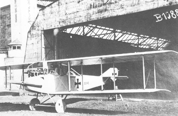
The Italian SAML S1 (S.2436), downed on 5 June 1917, was repaired by Flars and assigned number 00.45 for flight evaluation. The rudder is not original.

The Italian SIA 7b (No.5930) received double designation numbers: Flars EvKo number 77 and LFT captured aircraft number 00.62. It was captured on 15 January 1918.
Anatra C.I Series 010
After the Treaty of Brest-Litovsk (3 March 1918), Arthur A. Anatra, owner of the Anatra Aircraft Works in Odessa, offered to supply a variety of aircraft to LFT liaison officers who accompanied troops occupying the Ukraine. A total of 111 Anatra DS, 63 Anade, and 68 Farman XX biplanes and 149 partially-completed DS airframes were for sale. The LFT command was informed on 12 April 1918 that "for training and airmail communication the Anatra DS is eminently suitable. The detail finish is of far superior quality than is presently possible for us. The undercarriage springing and tires are made of rubber." The DS, powered by a 150 hp Salmson R-9 engine, was developed from a licensed, pre-war Aviatik design. After a four-hour evaluation flight by DS No. 863 on 10 April 1918, a contract was signed on 5 May 1918 for 200 machines, now designated Anatra C.I (popularly named Anasal) and numbered 010.01 to 010.200. Twenty-five were to be delivered as dual-control trainers. Most of the radiators would be supplied by the LFT. Contractually the aircraft were to be delivered by 15 August 1918. A Flars technical group came to Odessa to accept the aircraft. LFT and former Russian air service pilots who stood by to fly the aircraft from Odessa to Flep 4 at Lemberg were often held up by the lack of fuel and lubricant. Striking workers delayed rail shipment and Bolshevik sabotage destroyed a number of aircraft. By the end of September, 114 Anatra C.I had been accepted in Odessa. A total of 66 had been delivered to Austria-Hungary up to 25 October 1918, when the LFT cancelled the 134 Anasal biplanes remaining at the Anatra factory.
Anatra C.I Series 010
Engine: 150 hp Salmson
Wing: Span Upper 12.62 m (41.40 ft)
Span Lower 10.18 m (33.40 ft)
Chord Upper 1.79 m |5.87 ft)
Chord Lower 1.79 m (5.87 ft)
General: Length 8.1 m (26.57 ft)
Loaded Weight 1164 kg (2567 lb)
Maximum Speed: 144 km/hr (89 m[
Climb: 1000m (3,2.81 ft) in 6 min 20 sec
2000m (6,562 ft) in 13 min

Still carrying the LFT designation, this Anatra C.I 010.121 was taken over by the Czechoslovakian air service after the war. The Anatras were not flown in from Siberia by the Czech Legion as has often been claimed.
Anatra C.I 010.106 with early Czech markings flanked by a Phonix C.I 121.50 (with rear gun ring removed) and a Brandenburg C.I, possibly at Kbely airfield in early 1919.

Anatra DS, captured by Austrians, Flugzeugnummer 832
Anatra C.I (w/n 832) was delivered to Flep 4 in Lemberg on 9 July 1918. The design was based on the German Aviatik P 20 biplane for which Anatra had obtained a license in 1914.
Anatra C.I (w/n 832) was delivered to Flep 4 in Lemberg on 9 July 1918. The design was based on the German Aviatik P 20 biplane for which Anatra had obtained a license in 1914.

Above: This blurred but interesting photograph shows an LFT Anatra C.I in late markings surrounded by what appear to be members of the French and Czechoslovakian military mission.

Anatra C.I Series 010
Bleriot Monoplanes
During the war, two or three Bleriot monoplanes were operated as primary trainers. One unnumbered machine, Bleriot IX w/n 931, was still flying as late as October 1918 at Flugpark 1.
During the war, two or three Bleriot monoplanes were operated as primary trainers. One unnumbered machine, Bleriot IX w/n 931, was still flying as late as October 1918 at Flugpark 1.

The Bleriot IX trainer (60 hp Gnome) was attached to the Fliegeroffiziersschule in Wiener-Neustadt in 1917. Although no serial number is visible, it is believed to be machine 00.02.
Caudron G 3
The Caudron G 3 pusher was one of two Caudron biplanes flown by the French pilot Pierre Chanteloup in the Third International Flugmeeting at Aspern in June 1914. Out of 32 entries, Chanteloup took eighth place. The Caudron G3, confiscated by the military authorities on 13 August 1914, is believed to have been Chanteloup's machine.
Caudron G 3 00.06
The Italian Caudron G 3 C 507 was captured by Flik 4 on 4 July 1915. Pilot Feldwebel Max Brociner flew the G 3, with black crosses covering the Italian roundels, for the first time on 27 July 1915 and went on to perform eight reconnaissance flights over enemy territory in August. Curiously, it was the only flight-ready aircraft reported by Flik 4 on 16 August 1915!

The Caudron G 3 pusher was in service as a basic trainer at Aspern through July 1915. To date no record of a serial number assigned to this aircraft has been found.

An Italian Caudron G 3 (00.06) after coming down inside Austro-Hungarian lines on 4 July 1915. Pilot Feldwebel Max Brociner wearing a fez is standing in front of the inner wing strut.

Dorand AR 1 3041 received Flars captured aircraft number 00.57 after it was captured in November 1917.
Dorand A.R.1, Nr. 3041. französisches Beuteflugzeug, erhielt die Flugzeugnummer 00.57
Dorand A.R.1, № 3041. Французский трофейный самолет получил номер 00.57.
Dorand A.R.1, Nr. 3041. französisches Beuteflugzeug, erhielt die Flugzeugnummer 00.57
Dorand A.R.1, № 3041. Французский трофейный самолет получил номер 00.57.
Stastik Dreadnaught
The Dreadnaught was designed as a heavy military machine by Jan Stastik, a Czech engineer who had gained experience with Igor Sikorsky in Russia. The Dreadnaught was assembled and exhibited in Prague in June 1914 and subsequently moved to the Pardubice airfield for flight trials. Before these took place, war was declared and the Dreadnaught, confiscated by the Austro-Hungarian Army, was taken to the military aerodrome at Fischamend for testing. If one is to believe the press, the "giant aeroplane, powered by two 100 hp Gnome rotary engines, was designed to carry numerous passengers and fuel tanks holding 800 liters (211 gal) with room to spare for explosives and assorted weaponry." The maiden flight was scheduled for 21 October 1914. At about 40 meters (131 ft) into the take-off run, the undercarriage collapsed, the Dreadnaught turned turtle and was totally demolished.
Stastik continued his aeronautical activities. The LA received a letter on 4 April 1915 from J. Stastik St Co. in Prague requesting extended leave so that Stastik, who had been called to the colors, could complete the "new flying apparatus System Stastik, expected to be available for utilization in ten days." Further information is lacking.

Dreadnaught No.1 prior to the one and only attempt to fly it on 21 October 1914. Stastik can be seen in the fully-enclosed cockpit checking the controls.

The rear fuselage was tapered to provide a free flow of air to the Gnome rotary engine. The Dreadnaught was one of the earliest twin-engined aircraft designs on record and may have been the first tandem-engined design.

The twin-engined Stastik Dreadnaught No.1 being assembled at Fischamend. The engine cowling was later cut away to provide better cooling.

The violence of the crash tore out both engines but miraculously designer Stastik escaped serious injury. Dual control wheels can be seen in the cockpit.