J.Davilla, A.Soltan French Aircraft of the First World War (Flying Machines)
Ateliers de Constructions Mecaniques & Aeronautiques Paul Schmitt
<...>
His seventh design (c/n 7) had a Renault engine and a conventional rudder.
Schmitt was one of the most innovative pioneers of French aviation. However, relatively few of the aircraft he designed would see operational service. This was due primarily to production delays resulting in Schmitt's airplanes being obsolescent by the time they entered service. Despite the limited success with his own designs, Schmitt produced up to five airplanes a day under license, the most important being the Breguet 14.
Paul Schmitt 3
The Paul Schmitt Type 3 was the ninth (c/n 9) airplane built by Schmitt. The landplane version was powered by a 150-hp Canton Unne P9 engine. One source states that 160-hp Gnome engines were used, but this has not been verified. The airplane entered service with the Aviation Militaire in 1915. It is estimated that six were built and these probably carried military serials P.S.3 through P.S.8. The Type 3 was originally intended as a bomber, but was actually used only by training units.
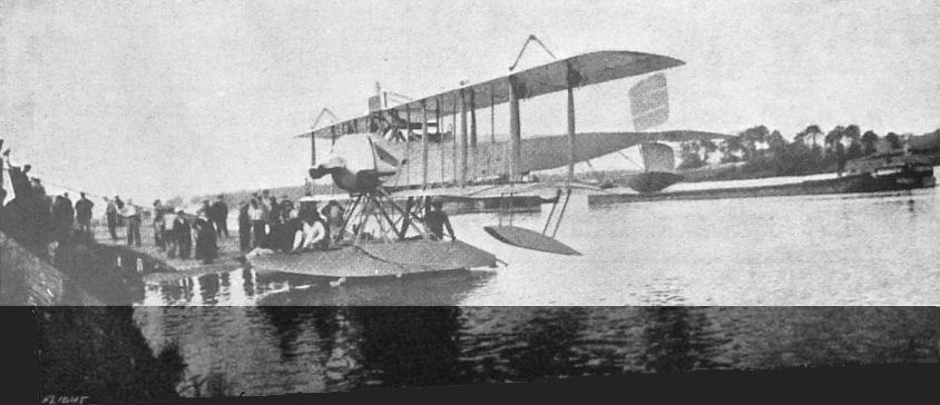
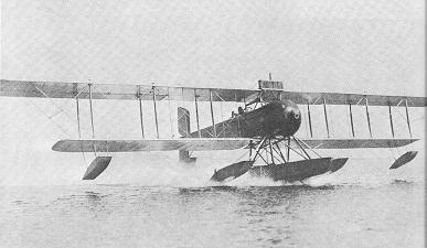
A floatplane variant of the Type 3 may have been purchased by the Aviation Maritime. It had the same basic layout and P9 engine of the landplane. The three-bay wing was retained, but the surface area was reduced. The navalized Type 3 had a single float under the center fuselage and two smaller floats at the wing tips. The radiator was relocated from beneath the fuselage (where water ingestion would have been a problem) and placed along the centerline of the top wing. The floatplane was built for an American M. Belmon and shipped to the United States in 1916. The Type 3 floatplane also carried the designation "9"; this may have been the construction number.
Paul Schmitt 3 Two-Seat Bomber/Trainer with Either a 150-hp Canton Unne P9 or a 160-hp Gnome
Span 17.50 m; length 10 m; height 3.15 m; wing area 49 sq. m
Empty weight 650 kg; loaded weight 1,100 kg
Maximum speed: 116 km/h; range 460 km
Approximately 6 built
Paul Schmitt 9
Little is known about the Paul Schmitt 9, a two-seat bomber built in 1916 and powered by a 160-hp Canton Unne engine.
It should be noted, however, that the Paul Schmitt 3 had the same engine and was given c/n number 9. It is quite possible that the Paul Schmitt 9 some sources refer to is, in fact, the Paul Schmitt 3 prototype.
Показать полностью
L.Opdyke French Aeroplanes Before the Great War (Schiffer)
Deleted by request of (c)Schiffer Publishing
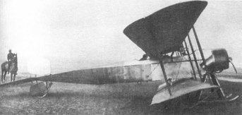
Schmitt's classic Type 7 appeared in 1913, was shown at the 1913 Salon, and was advertised to fly between 30 and 120 kmh. In February, April, June, and July 1914, Victor Garaix, Schmitt's appointed test pilot, broke 43 world records: altitude with 4 to 9 passengers, speed with 4 to 6, distance with 6 and endurance with 3 and 6 passengers. It had an all-metal frame without brace-wires. The fuselage section began as a flattened rectangle forward, became nearly square amidships, then triangular, and finally tapered to a horizontal tailpost. The wings still pivoted at the cabane pivot; the undercarriage was heavy, with skids and 2 pairs of wheels. Type 7 was sometimes fitted with an extra pair of wheels at the skid-ends, 6 wheels in all.
(Span: (upper) 17.5 m; (lower) 13.5 m; wing area: 49 sqm; empty weight: 650 kg; gross weight: 1500 kg: incidence variation: between 0° and 12°; speed variation from 40 to 116 kmh)
After he achieved second place at the 1914 Concours de Securite, he sold Type 7 to the Army, and Schmitt was encouraged to develop a smaller 2-seat Type 8 which was not finished before the outbreak of the war. Type 9, a still further development, was eventually ordered in quantity in 1916. These later Schmitts were fitted with 2 or 4 wheels.
Показать полностью
Журнал Flight
Flight, December 13, 1913.
THE STANDS AT THE PARIS AERO SHOW.
PAUL SCHMITT.
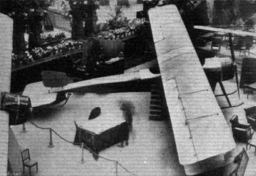
Societe Anonyme des Aeroplanes "Paul Schmitt" are exhibiting a very interesting machine - a tractor biplane, with variable angle of incidence. It is built almost entirely of steel and gives one the impression of being immensely strong. The advantages of being able to alter the angle of incidence, and thereby the speed while the machine is in flight, are too obvious to need enlarging upon, and the manner in which this operation is carried out appears to be a mechanically sound piece of work.
Flight, January 17, 1914.
THE PARIS AERO SALON - 1913.
PAUL SCHMITT.
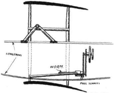
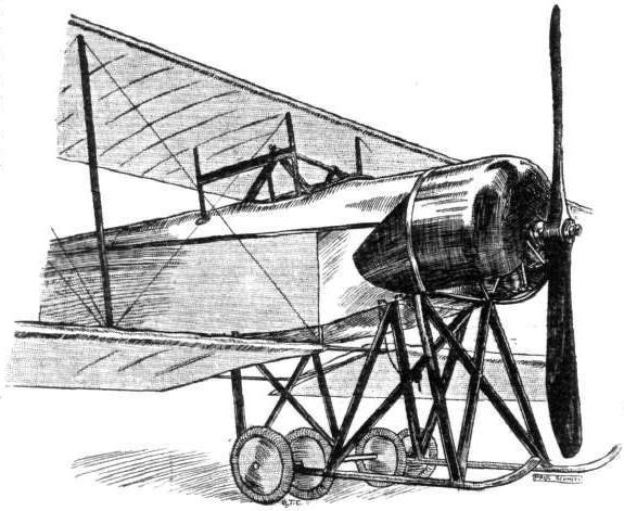
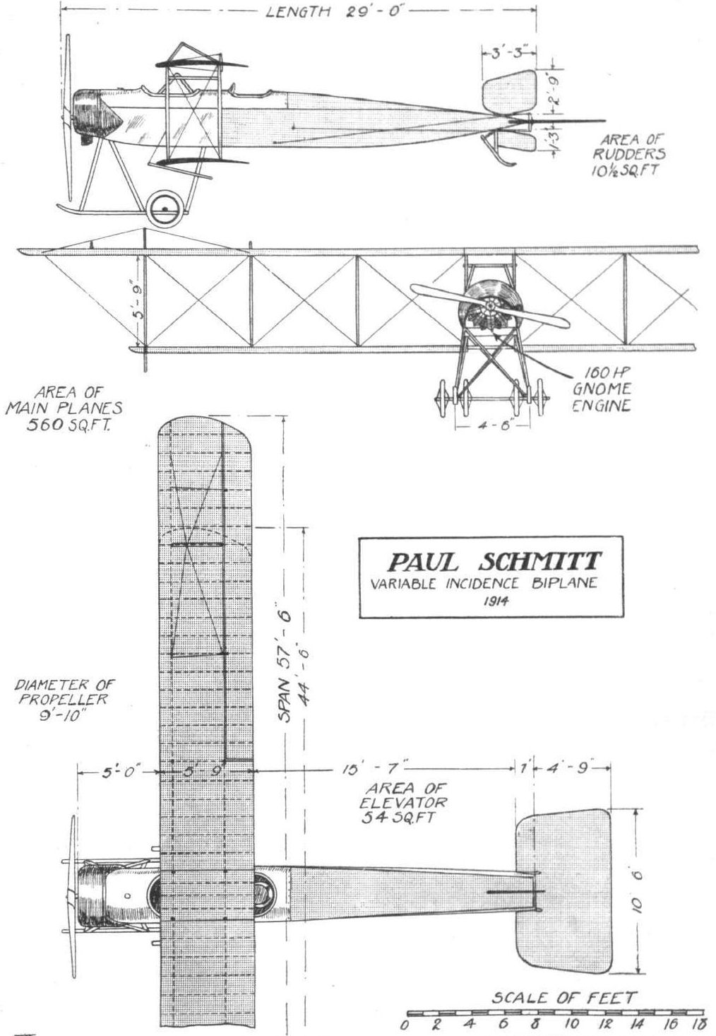
ON the same stand as the Morane-Saulnier monoplanes, but forming a separate exhibit, was the Paul Schmitt biplane, the most interesting feature of which was the provision made for altering the angle of incidence. This machine, which was built of steel throughout, was fitted with a 14-cyl. 160 h.p. Gnome engine, mounted on double bearings in the front of the fuselage. The fuselage, which was built up of steel tubes, was of rectangular section in the front portion, gradually tapering to a triangular section at the rear. In front of the main planes was a very roomy cockpit containing the passengers' seats, which were placed side by side. Access to this cockpit was gained through a door in the side of the fuselage, and the spacious cockpit reminded one more of a motor car than of an aeroplane. The pilot's seat was situated out behind the main planes, and in front of him were the two wheels by means of which the angle of incidence could be altered while the machine is in flight, as well as the ordinary control levers, which consist of a single central lever for ailerons and elevator, and a pivoted foot-bar for the rudder. It is, perhaps, a debatable point whether it is of any great advantage to be able to vary the angle of incidence during flight, and practical tests of this machine will therefore be of great interest. From the accompanying diagrammatic sketch the principle of the system employed for varying the angle of incidence will be easily understood, and the method of carrying it out appears to be a mechanically sound piece of work.
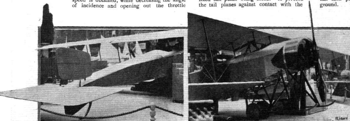
The range of variation in the angle of incidence is from 0 to 12 degrees, and the wings may be moved through that arc in the space of a few seconds. By increasing the angle of incidence and at the same time throttling down the engine, the minimum speed is obtained, while decreasing the angle of incidence and opening out the throttle increases the speed of the machine. The chassis, which was built up of steel tubes throughout, was of the wheel and skid type, the four wheels being carried on a single axle sprung from the skids in the usual way by means of rubber shock absorbers. The tail planes consist of a large balanced elevator and a divided rudder, no fixed tail plane being fitted. A pivoted tail skid protects the tail planes against contact with the ground.
Flight, April 18, 1914.
THE PAUL SCHMITT BIPLANE.
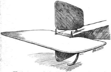
AT the time of the Paris Show we gave a full description of the Paul Schmitt biplane, with an illustration of the method whereby the angle of incidence may be altered during the flight. The recent excellent performances of this machine in the hands of M. Garaix, who, it will be remembered, has beaten the world's height record with six, seven, eight and nine passengers, seem to prove the advantage of the variable angle of incidence in conjunction with its complement, the variable power. It will be noticed that when the angle of incidence is maximum the inter-plane struts slope backwards in relation to the fuselage, thus providing a rearward stagger of the planes. It might appear at first sight that the alteration of the angle of incidence by pivoting the planes round the transverse horizontal axis would lead to displacement of the centre of gravity, but this possibility has been guarded against by so calculating the position of the transverse axis around which the planes are pivoted that the resultant centre of pressure for both planes remains the same, with regard to the centre of gravity, throughout the entire series of alterations of the angle of incidence which ranges from 0° to 12°. The machine is fitted with a 14-cyl. 160 h.p. Gnome engine driving an Integral propeller.
Flight, October 30, 1914.
THE PAUL SCHMITT BIPLANE.
EVER since the early days of aviation, aeroplane designers have realised the advantages to be derived from the use of a variable angle of incidence with its complement, the variation in power, when a good speed range was desired. The solution of the problem of a variable angle of incidence, however, presents certain constructional difficulties which have, no doubt, caused a great number of designers to take the line of least resistance and produce machines in which the angle of incidence remained fixed in relation to the body, but which were capable of a considerable speed variation by altering the flying attitude of the whole machine. That this method of obtaining speed variation does not and cannot give maximum efficiency throughout the entire range of speeds will be readily understood, when it is realized that in a machine having its wings set at a fixed angle of incidence there is only one speed at which the maximum efficiency is obtained, namely, the speed in horizontal flight at which the machine flies with its body horizontal.
Any change in the speed caused by a variation in power through the intermediary of an alteration of the angle of incidence (the flight path is assumed to be horizontal) necessitates a change in the attitude of the whole machine, which again means that the line of flight is no longer parallel to the centre line of the body. The result is that the air, instead of flowing along the top and bottom of the body and causing skin friction only, strikes it at an angle - on top at higher speeds, and on the bottom at lower speeds, and in both cases presenting a certain amount of detrimental surface.
For example, suppose a machine, flying with its fuselage horizontal, will maintain a horizontal flight path with its engine on three-quarter throttle. Now, if the throttle is opened fully the angle of incidence will have to be diminished in order to keep the flight path horizontal, or, in other words, to prevent the machine from climbing. As the angle of incidence is fixed it can only be diminished by changing the attitude of the whole machine, that is to say, by letting it fly "tail high."
Again, for flying at low speeds the engine is throttled down, and the angle of incidence increased by letting the machine fly cabre - i.e., with the tail down, a position which always carries with it the possible danger of a tail slide in case of engine failure. In both cases the air, instead of causing skin friction only, exerts a pressure on the detrimental surface presented by the top or bottom of the body in the "tail high" or "tail low" position respectively. The attendant disadvantages of securing speed variation by altering the flying attitude of the machine has not been dealt with exhaustively in the above, as to do so would be outside the scope of this article, but it will give an idea of the raison d'etre of the variable incidence machine.
As already mentioned, there are certain constructional difficulties which militate against the satisfactory solution of the problem of the variable angle of incidence, but the Paul Schmitt biplane, which was exhibited at the last Paris Aero Show, and which is not, as might be inferred by its name, a German but a French production, is the most practical attempt that has yet been made to overcome the difficulties. Since the method employed of altering the angle of incidence is the most interesting feature of this machine it will be dealt with first.
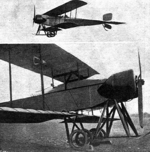
From the accompanying illustrations it will be seen that the two main planes form a separate unit independent of the body, which passes between the planes without touching either of them. Attachment to the fuselage is effected by a transverse tubular shaft resting in ball bearings on the apices of two inverted V tubes, which are in turn bolted to the upper longitudinals of the body. The ends of the transverse axis are rigidly attached to two fore and aft tubes secured to the inner pair of interplane struts. These are connected top and bottom by transverse steel tubes, and pass inside the body, running through slots in the top covering. In this way it will be seen the wings are free to rotate around the transverse axis until the inner plane struts touch some member of the body. They are prevented from doing so by a large nut working on a threaded shaft mounted longitudinally on the floor of the body. This nut is connected by two pivots to the rear pair of interplane struts. On the rear end of the longitudinal shaft are carried two concentrically mounted sprockets from which chains pass to two hand wheels in front of the pilot. Rotation of one wheel causes the shaft to revolve slowly, whilst the other is so geared that a more rapid movement is obtained. As the shaft rotates it displaces the threaded nut in a forward or backward direction, and with it the lower ends of the interplane struts, to which it is pivoted. The amount of movement is such that the main planes swing through an arc of from o to 12 degrees.
By suitably varying the power the machine can be flown at speeds from 22 to 68 m.p.h., maintaining a horizontal flight path, whilst if it is desired to climb quickly, the planes are set at a large angle of incidence and the engine opened out. The number of records which this machine has to its credit are ample proof of the excellence of the design.
Apart from the variable incidence, this machine is interesting on account of the fact that it is built practically throughout of steel. The body is built up of steel tubes autogenously welded. From the nose to a point just behind the seats the body is of rectangular section, whilst to the rear of this point the lower longitudinals converge so as to form a triangular section. In the stern of the body the longitudinals are connected to a short transverse steel tube which forms a pivot for the elevator. This member is unusually large and is partly balanced, no doubt in order to make it easier for the pilot to operate, a feature which is almost a necessity in a machine in which the elevator plays such an important part in the speed variation. In the nose is mounted between double bearings the 160 h.p. Gnome engine, which is partly covered by a shield of a similar form to that employed on the Morane-Saulnier monoplanes. Behind the engine are carried the tanks, and to the rear of these is the passenger's cockpit, which is extremely roomy, and which is entered through a door motor car fashion. Still further back, and on line with the trailing edge of the planes, is the pilot's seat. In front of him are the controls, which are of the usual type, i.e.., a wheel operating the ailerons and elevator, and a foot bar for the rudder.
The landing carriage, although not unduly complicated, is immensely strong, a not unnecessary requirement in a machine carrying at times a useful load of over 1,800 lbs. The accompanying sketch is self-explanatory; suffice it to say that the landing carriage is built of steel tubes throughout. The chief characteristics are: Weight, empty, 1,430 lbs.; area, 480 sq. ft.; minimum speed, 22 m.p.h.; maximum speed, 68 m.p.h.
Показать полностью