
Книги
Журнал
Flight за 1913 г.
819
Журнал - Flight за 1913 г.
Flight, July 5, 1913.
THE PIONEERS.
<...>
A pioneer who is perhaps not so well remembered as he should be is Hargrave, who is, of course, famous as the inventor of the box kite, but whose researches in aviation generally are less well known. He read a most interesting and instructive series of papers before the Royal Society of New South Wales, and in 1885 he succeeded in demonstrating before that assembly the successful flight of a model that was propelled by flapping wings.
<...>
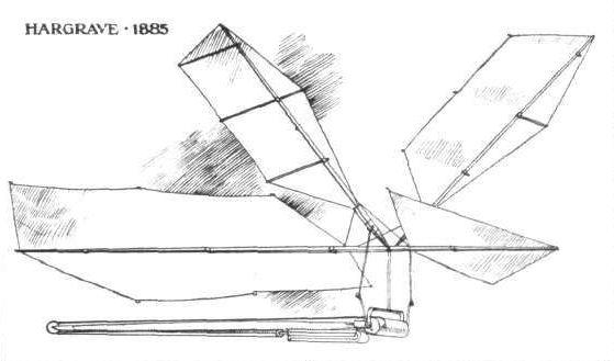
Hargrave's wing-propelled model built in Australia in 1885. - The wings were for propulsion only, the weight in flight being supported by the aeroplane surfaces fore and aft. Several successful flights were made. Elastic provided the motive power.
Flight, September 13, 1913.
Berlin - Paris.
STARTING on Friday of last week at 5.30 a.m. from the Johannisthal aerodrome, the German pilot Herr Friedrich with Dr. Ellias as passenger, on an Etrich-Taube, commenced a voyage which he hoped to terminate the same day in Paris, but circumstances were against him. Although he was bothered by mist, he determined to make the attempt, and after a good flight he descended at Walhrewald, near Hanover, at 7 o'clock, where he replenished his fuel and oil tanks, making a re-start at 9.15, steering away towards the west. Flying well, after a descent at Gelsenkirchen, he arrived at Berghen Sainte-Agathe, about 13 kilometres from Brussels, at 2.15p.m., where the two voyagers replenished the inner man as well as again taking in petrol and oil. At 4 o'clock Friedrich was away again, hoping to reach Paris during the evening, but after passing over the Belgian frontier he encountered a violent storm which was raging in the district, forcing him down at Sart les Bruyeres, a few kilometres from Mons, where he decided to stay for the night, having accomplished roughly about 700 kilometres from his starting point. Next day the weather was still as bad as ever and he therefore postponed the last lap of the journey until Sunday, when he got away at 1.15 in spite of a thick fog, a damaged map, and a compass out of order. After a couple of stops at Guise and Senlis, he arrived at Villacoublay at 5.15 (passing over Paris, which was enveloped in a heavy mist) there to be received with a splendid ovation by a large crowd of his fellow aviators who were in strong evidence by reason of there being a big festival in full swing at the time of his arrival.
Flight, September 20, 1913.
FLYING AT HENDON.
<...>
After two laps had been completed all attention was transferred from the cross-country race to a bird-like machine approaching the aerodrome from the south some 3,000 ft. up. When above the aerodrome the machine was easily recognised as an Etrich, with its dove-like wings and fan-shape fail. The pilot made a beautiful spiral descent, banking well over 60°, just as some of the cross-country competitors were entering the aerodrome. It was a very impressive sight, for the Etrich is certainly one of the prettiest monoplanes extant. The monoplane came to rest close to No. 1 pylon, and was immediately surrounded by a crowd thirsting for information. When the passenger - for there were two on board - removed his goggles, we recognised in him Herr I. Etrich, the designer of the much admired monoplane. The pilot was Alfred Friedrich. With the help of E. Baumann, who acted as interpreter, we ascertained that the aviators had left Paris at 11.20 that morning, arriving at Calais at 1.55, where a stay of 1 1/2 hours was made. The remainder of the journey to Hendon was made without a stop in 2 hours 5 mins., flying at an altitude of about 4,500 ft., and encountering very rough weather. Having found out all about our visitors, we turned our attention to the neglected cross-country race, which had by then finished.
<...>
In spite of the very high wind on Sunday afternoon several of the Hendon pilots ventured out and put up some fine exhibition and passenger flights. The star turns of the afternoon, however, were the splendid displays by Gustav Hamel on the 80 h.p. Bleriot and Igo Etrich on the Etrich-dove monoplane. The former indulged in a cloud-hunt lasting over an hour. It was a performance strange to behold; he made for cloud after cloud, turning again and again, only to find the clouds still above him. Eventually he saw a large one, which he made for and passed over the top. Having accomplished this feat he descended, as he was running short of oil. He was stiff with cold when he alighted, and the barograph recorded a height of 9,500 ft. The flights of the Etrich monoplane were very picturesque, the pilot executing some remarkable highly banked spirals.
HERR FRIEDRICH FLIES TO LONDON.
FOLLOWING on his flight from Berlin to Paris, recorded in last week's issue, Herr Friedrich, on Saturday morning last at 11.20, accompanied by Herr Igo Etrich, on the Etrich-Taube with Chauviere propeller, left Issy for London by way of the air. At Calais he descended at I.55, where he was delayed somewhat in connection with some of the official requirements, so that he was not able to continue his flight until 3.45. At that hour he was away again, arriving at Hendon aerodrome, after a magnificent flight, in the middle of one of the speed races, at 5.50, his altitude being about a thousand metres during most of the trip. Directly it was recognised who the voyagers were, they were very hospitably treated, and during the afternoon Herr Friedrich gave some exhibitions of his flying on the Etrich-Taube. On Wednesday this week, Friedrich was due to leave England again, this time taking as passenger Mr. John Rozendaal, the managing director of the Etrich Co. It is proposed to cross the Channel to Calais, and then fly direct for Utrecht, Holland, before returning to Germany. Mr. Rozendaal has from the earliest days been associated with aviation, he having been in Germany connected with the Wright machines before taking up the Etrich monoplane. It was Mr. Rozendaal also who engineered the late Mr. Latham's flight in Berlin from the Tempelhofer Feld to Johannisthal in 1909.

The Etrich monoplane.
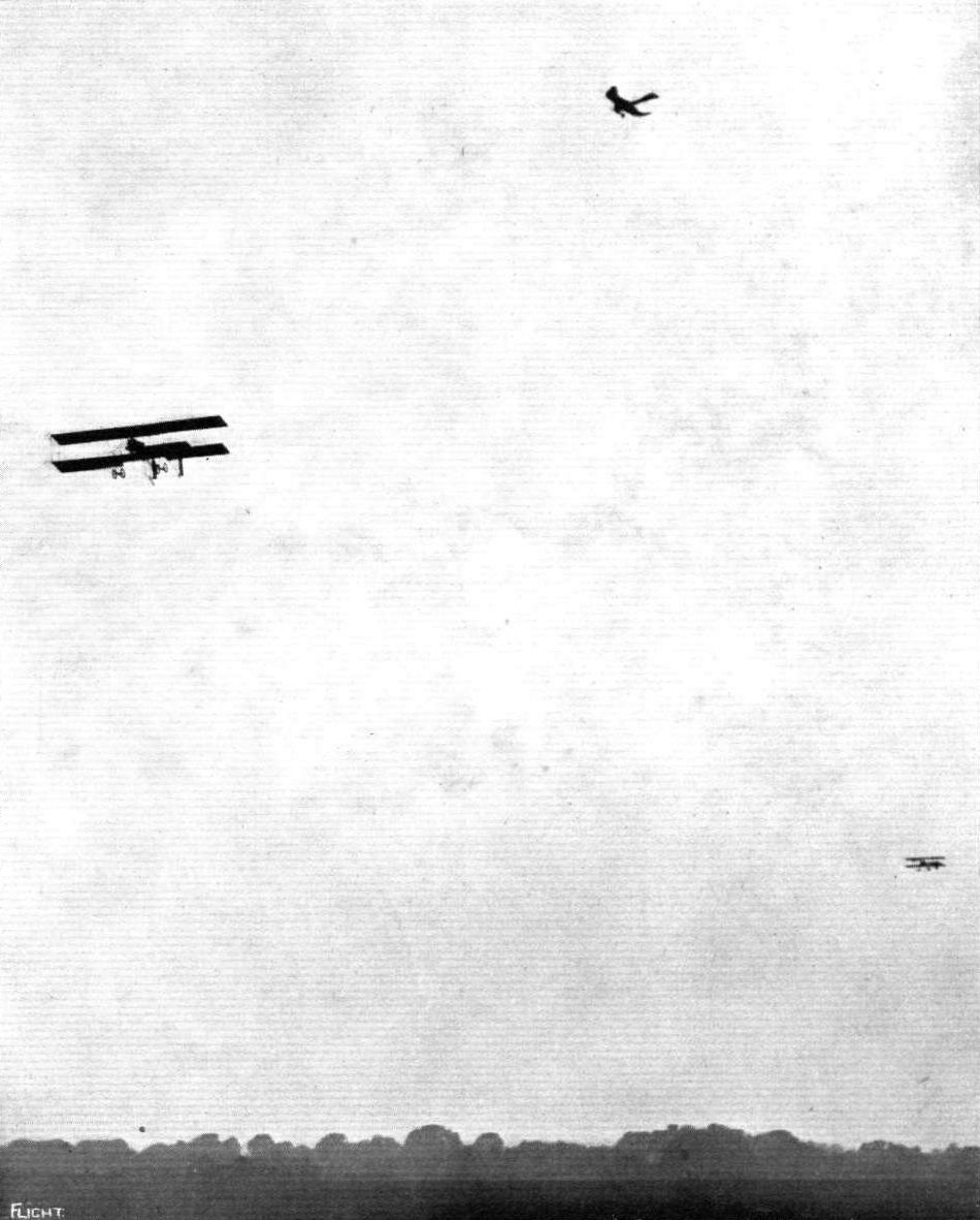
AT HENDON AERODROME. - Arrival of the Etrich-Taube monoplane at Hendon during the progress of a race on Saturday.
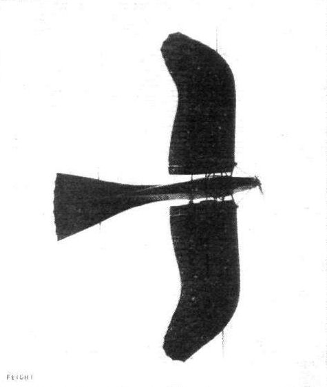
A plan view of the Etrich monoplane as seen from beneath.
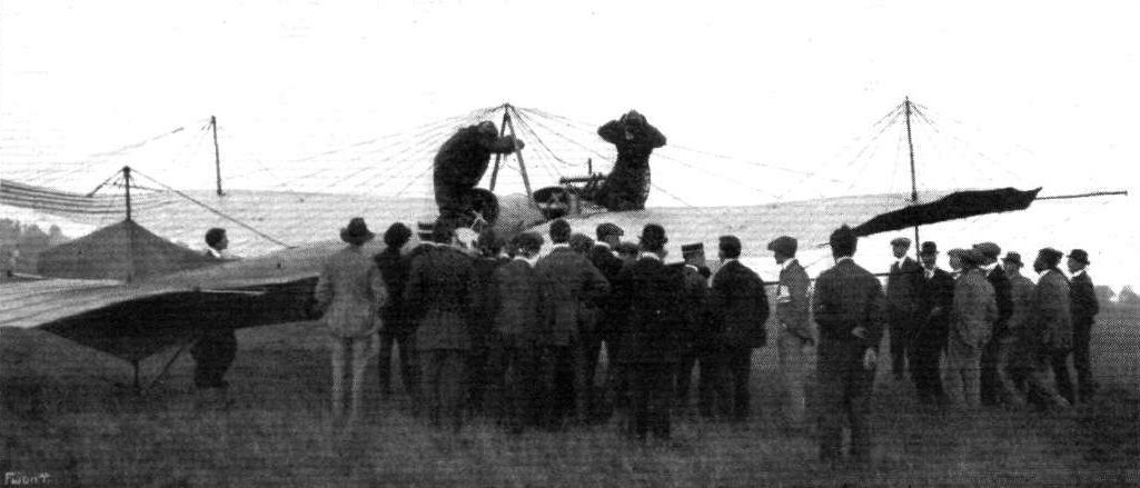
A STRANGER WITHIN OUR GATES. - The gathering of the pilots and others immediatelly after the arrival from France of the Etrich monoplane at Hendon on Saturday.
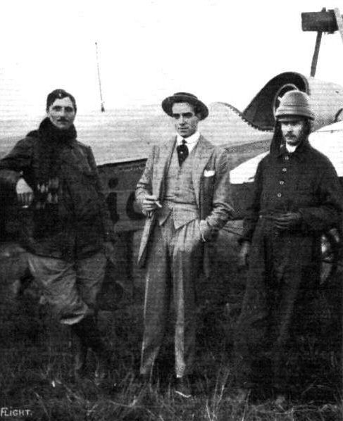
THE ETRICH MONOPLANE AT HENDON. - From left to right: Herr Friedrich (pilot) Mr. Claude Grahame-White and Herr Igo Etrich.
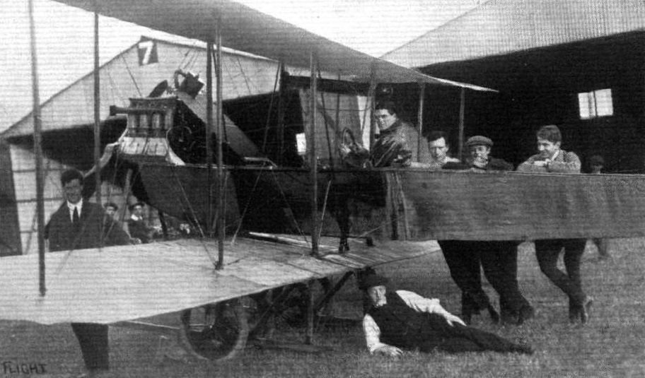
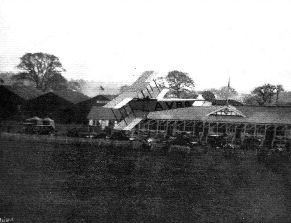
AT THE AVRO FLYING SCHOOL, SHOREHAM. - From left to right, Messrs. Geere (Instructor,) Elliot, Mellersh, England, Rolshoven, and (under fuselage) Shaw.
Flight, February 8, 1913.
WHAT THERE WILL BE TO SEE AT OLYMPIA.
THE MACHINES.
Messrs. A. V. Roe and Co., Ltd.,
Will be exhibiting on their stand one of the 50-h.p. Gnome-engined passenger-carrying biplanes that have given the War Office such satisfaction. It is interesting to recall, too, that a similar machine was recently supplied to the Portuguese Republic. Light, but strongly-constructed, fast, able to carry weight well, the 50-h.p. Avro biplane has proved itself one of the most successful machines of the day. And it reflects great credit on its designer, Mr. A. V. Roe who, having tasted the bitter sweetness of the pioneer, has gone doggedly ahead to such success. Mr. Roe has the distinction of being the only constructor, we believe, in the world who has designed and constructed successful monoplanes, biplanes, and triplanes.
Flight, February 15, 1913.
A. V. ROE AND CO., LTD.
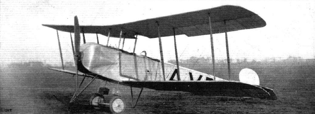
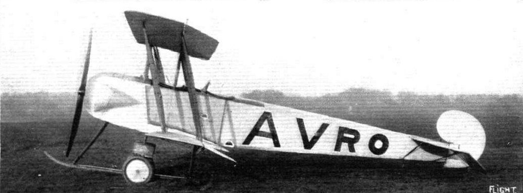
They are exhibiting a 50-h.p. Avro biplane, fitted with a Gnome engine, and arranged to carry a passenger. Similar machines to the one shown have been supplied in numbers to the Royal Flying Corps, and we have heard that they are extremely popular mounts with those pilots who fly them. Back in last October, too, one of these machines was delivered to the Portuguese Republic, it having been bought by public subscription. Perhaps our readers, or at any rate those of them who follow the progress of things fairly closely, will recall that the first machine of this type to leave the Avro works was supplied to Mr. J. Duigan as far back as in the September of 1911. It is thus quite an old design, but that is not to say that it is old-fashioned - it is as much up-to-date to-day as any machine we could mention.
The body of the biplane is an ordinary form of built-up box girder covered with fabric to preserve its lines, and to permit of it travelling through the air with as little disturbance as possible. In front, under a metal cowl, is mounted the 50-h.p. Gnome motor, swung between double bearings and turning a 10 ft. Avro propeller at the rate of 1,200 r.p.m. As our sketch shows, inspection doors are fitted in the side of the body so that the motor may be readily accessible when it requires adjustment. The passenger is seated some distance behind the motor, and his seat is so low down in the body that only the upper part of his head projects through the well-padded cockpit well. Thus he is protected to a great extent from the propeller draught. The pilot is equally as comfortably installed in his cockpit behind and what he is not able to see over the side of the machine, he can obtain a sight of by looking through a window let into the floor between his feet.
The landing gear resembles, to a great extent, that originated by Nieuport, used on Nieuport monoplanes. There are a few improvements, however, among them being that the laminated cross-springs are assembled to the wheel hubs in a rather more satisfactory way than is employed on the Nieuport. Mr. A. V. Roe, too, has introduced, on this machine, a clever form of skid toe, which, instead of being rigid, can adapt itself to any shock caused by striking an obstacle. Its general details can be seen from the sketch we publish.
The planes. - Span 36 ft., and have a chord measurement or 4 ft. 9 ins. Having a high aspect ratio, they are, as may be supposed, very efficient. Their cross-section has a Phillip-type entry, while it has the peculiarity that the under-surface of that part of the section to the rear of the rear-spar is level in normal horizontal flight. Twelve spruce struts separate the planes, and the bracing is entrusted to stranded-steel cable of generous cross section. The planes warp for the correction of lateral balance.
The tail is formed by a flat surface rectangular in plan, at the back of which are hinged two elevator flaps of a total area of 12 square feet. The rudder is novel, in that it is arranged to slide vertically up the rudder bar, against the compression of a coil spring. It is armoured on the underside by a steel shoe, and this is made to serve the double purpose of rudder and tail skid. The average speed of this Avro biplane may be taken as being 65 m.p.h.
Flight, September 20, 1913.
THE AERIAL DERBY.
PILOTS AND HOW TO RECOGNISE THE MACHINES.
No. 8. The Avro Biplane
is of the tractor type with the engine in front. The fuselage, or body, is covered in throughout its entire length. The main planes have a very pronounced dihedral angle.
THE MACHINES, WITH SOME DETAILS.
No. 8. The Avro biplane, fitted with an 80 h.p. Gnome engine, is similar to the usual Avro type, except that the planes are slightly staggered, and that there are minor modifications in the landing chassis. The span of both upper and lower planes is 36 ft.
It is a tractor biplane, and, as is to be expected from the length of experience of its designer and constructor, Mr. A. V. Roe, it is a fast machine, very stable, and thoroughly reliable.
WHAT THERE WILL BE TO SEE AT OLYMPIA.
THE MACHINES.
Messrs. A. V. Roe and Co., Ltd.,
Will be exhibiting on their stand one of the 50-h.p. Gnome-engined passenger-carrying biplanes that have given the War Office such satisfaction. It is interesting to recall, too, that a similar machine was recently supplied to the Portuguese Republic. Light, but strongly-constructed, fast, able to carry weight well, the 50-h.p. Avro biplane has proved itself one of the most successful machines of the day. And it reflects great credit on its designer, Mr. A. V. Roe who, having tasted the bitter sweetness of the pioneer, has gone doggedly ahead to such success. Mr. Roe has the distinction of being the only constructor, we believe, in the world who has designed and constructed successful monoplanes, biplanes, and triplanes.
Flight, February 15, 1913.
A. V. ROE AND CO., LTD.
They are exhibiting a 50-h.p. Avro biplane, fitted with a Gnome engine, and arranged to carry a passenger. Similar machines to the one shown have been supplied in numbers to the Royal Flying Corps, and we have heard that they are extremely popular mounts with those pilots who fly them. Back in last October, too, one of these machines was delivered to the Portuguese Republic, it having been bought by public subscription. Perhaps our readers, or at any rate those of them who follow the progress of things fairly closely, will recall that the first machine of this type to leave the Avro works was supplied to Mr. J. Duigan as far back as in the September of 1911. It is thus quite an old design, but that is not to say that it is old-fashioned - it is as much up-to-date to-day as any machine we could mention.
The body of the biplane is an ordinary form of built-up box girder covered with fabric to preserve its lines, and to permit of it travelling through the air with as little disturbance as possible. In front, under a metal cowl, is mounted the 50-h.p. Gnome motor, swung between double bearings and turning a 10 ft. Avro propeller at the rate of 1,200 r.p.m. As our sketch shows, inspection doors are fitted in the side of the body so that the motor may be readily accessible when it requires adjustment. The passenger is seated some distance behind the motor, and his seat is so low down in the body that only the upper part of his head projects through the well-padded cockpit well. Thus he is protected to a great extent from the propeller draught. The pilot is equally as comfortably installed in his cockpit behind and what he is not able to see over the side of the machine, he can obtain a sight of by looking through a window let into the floor between his feet.
The landing gear resembles, to a great extent, that originated by Nieuport, used on Nieuport monoplanes. There are a few improvements, however, among them being that the laminated cross-springs are assembled to the wheel hubs in a rather more satisfactory way than is employed on the Nieuport. Mr. A. V. Roe, too, has introduced, on this machine, a clever form of skid toe, which, instead of being rigid, can adapt itself to any shock caused by striking an obstacle. Its general details can be seen from the sketch we publish.
The planes. - Span 36 ft., and have a chord measurement or 4 ft. 9 ins. Having a high aspect ratio, they are, as may be supposed, very efficient. Their cross-section has a Phillip-type entry, while it has the peculiarity that the under-surface of that part of the section to the rear of the rear-spar is level in normal horizontal flight. Twelve spruce struts separate the planes, and the bracing is entrusted to stranded-steel cable of generous cross section. The planes warp for the correction of lateral balance.
The tail is formed by a flat surface rectangular in plan, at the back of which are hinged two elevator flaps of a total area of 12 square feet. The rudder is novel, in that it is arranged to slide vertically up the rudder bar, against the compression of a coil spring. It is armoured on the underside by a steel shoe, and this is made to serve the double purpose of rudder and tail skid. The average speed of this Avro biplane may be taken as being 65 m.p.h.
Flight, September 20, 1913.
THE AERIAL DERBY.
PILOTS AND HOW TO RECOGNISE THE MACHINES.
No. 8. The Avro Biplane
is of the tractor type with the engine in front. The fuselage, or body, is covered in throughout its entire length. The main planes have a very pronounced dihedral angle.
THE MACHINES, WITH SOME DETAILS.
No. 8. The Avro biplane, fitted with an 80 h.p. Gnome engine, is similar to the usual Avro type, except that the planes are slightly staggered, and that there are minor modifications in the landing chassis. The span of both upper and lower planes is 36 ft.
It is a tractor biplane, and, as is to be expected from the length of experience of its designer and constructor, Mr. A. V. Roe, it is a fast machine, very stable, and thoroughly reliable.
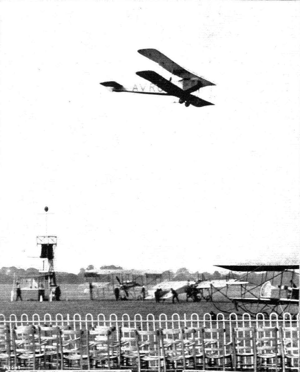
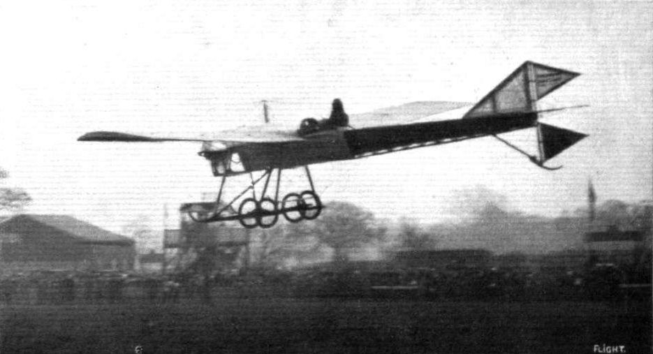
F. P. Raynham flying the Avro biplane at Hendon.
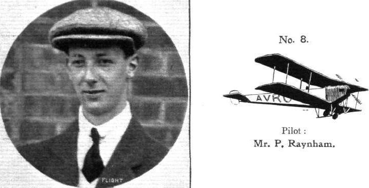
Pilot: Mr. P. Raynham.
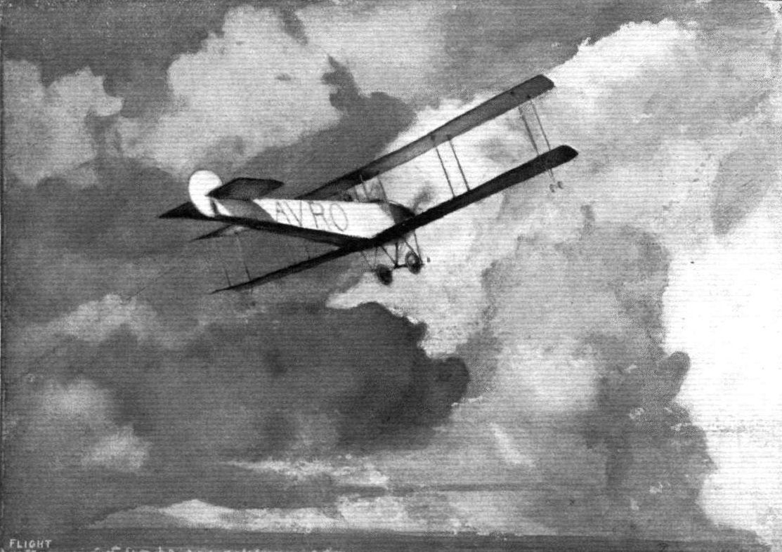
An impression of the Avro at Hendon. From an original drawing by Roderic Hill.
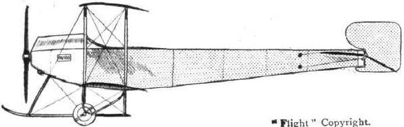
The 50-h.p. Gnome-Avro biplane.
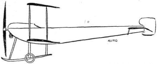
The 50-h.p. Avro tractor biplane.
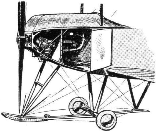
The front section of the Avro biplane, showing the mounting of the 50-h.p. Gnome motor and the inspection doors.
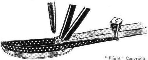
The cleverly sprung skid tip of the Avro biplane.
The tail of the Avro biplane.
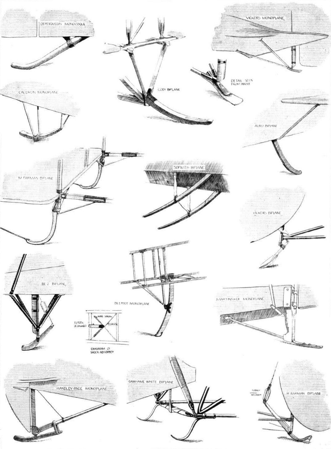
AT OLYMPIA. - A study in tail-skids.
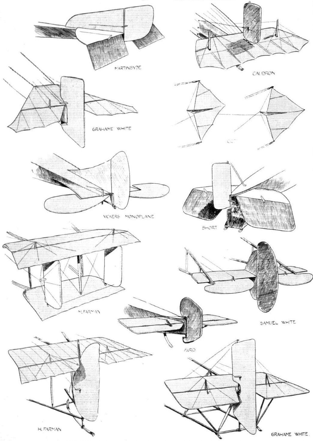
A study in tails.
Flight, February 8, 1913.
WHAT THERE WILL BE TO SEE AT OLYMPIA.
THE MACHINES.
Messrs. A. V. Roe and Co., Ltd.,
Will be exhibiting on their stand one of the 50-h.p. Gnome-engined passenger-carrying biplanes that have given the War Office such satisfaction. It is interesting to recall, too, that a similar machine was recently supplied to the Portuguese Republic. Light, but strongly-constructed, fast, able to carry weight well, the 50-h.p. Avro biplane has proved itself one of the most successful machines of the day. And it reflects great credit on its designer, Mr. A. V. Roe who, having tasted the bitter sweetness of the pioneer, has gone doggedly ahead to such success. Mr. Roe has the distinction of being the only constructor, we believe, in the world who has designed and constructed successful monoplanes, biplanes, and triplanes.

The Avro all-enclosed biplane.
Flight, July 12, 1913.
THE AVRO WATERPLANE.
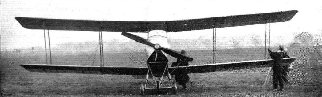
THE new Avro 100 h.p. waterplane, which has been flying so well at Shoreham in the hands of Mr. Raynham, is the first machine to have floats designed by A. V. Roe and Co., their earlier hydroplanes having been built to customers' designs. The result appears to have justified the enterprise, for the machine gets off the water within 60 yards in calm weather, and requires but little more space in a moderate swell.
In general, the Avro waterplane has a close resemblance to the usual Avro type, which is already so well known in the R.F.C. It is, of course, considerably larger throughout, as is rendered necessary by the larger engine power, and by the comparative difficulty of arising from water, as compared with getting off land. Furthermore, there are certain alterations in construction which have been rendered necessary by the altered conditions, as, for example, the substitution of flaps for warping.
The main planes measure 50 ft. in span, as compared with the standard span of 36 ft., and contain five panels instead of three, as in the standard Army type. They have a chord of 6 ft., and the gap between planes is 6 ft. 9 ins. The upper plane only is provided with flaps of 12 ft. 9 ins. span each, increasing in chord towards the tips. These are balanced to pull up as well as down.
The body is supported from the wings in the usual Avro style, with the exception that the planes, instead of detaching from the body itself, detach from a fixed inner cellule having a span of 9 ft., so that the struts at its extremities are immediately above the floats.
These latter are of the pure hydroplane type with 2 steps, and are 14 ft. long x 2 ft. 6 ins. wide, with their inner edges 6 ft. 6 ins. apart. The total buoyancy when submerged is 4,400 lbs., or twice the weight of the machine. The chassis struts are all of steel bound with varnished fabric, and are 14 in number, 7 each side, of which 6 support the cellule from the float, whilst the 7th is carried direct to the engine bearers on the fuselage.
The body itself is rectangular in cross-section with a horizontal top and curved bottom. It tapers at the rear to a vertical rudder post which carries the rudder, and with it a small tail float, which moves with the rudder for steering purposes. The elevators and empennage are of the standard Avro size. The pilot's seat is behind the passenger's, the latter being placed on the centre of gravity of the machine. The engine is enclosed in the usual housing, with a wind-shield for the pilot.
The tractor-screw is an Avro with brass-capped leading edge at the tips, having a diameter of 8.9 ins. and a pitch of 6 ft. The control is by wheel and rudder bar, and is of the usual type.
The weight of the whole machine with full allowance of fuel is just under one ton, and the surface of the main planes being 567 sq. ft. gives a loading of rather under 4 lbs. per sq. ft., and 22 lbs. per h.p. This means, of course, that the machine is not a very high speed one, its estimated velocity being about 48 to 50 miles per hour. This slow speed was adopted as being more likely to be successful, considering the experimental state of our present-day knowledge of hydroplane floats.
It is interesting to know that this machine is already purchased by a private owner, and that several are already on order for the Admiralty.
THE AVRO WATERPLANE.
THE new Avro 100 h.p. waterplane, which has been flying so well at Shoreham in the hands of Mr. Raynham, is the first machine to have floats designed by A. V. Roe and Co., their earlier hydroplanes having been built to customers' designs. The result appears to have justified the enterprise, for the machine gets off the water within 60 yards in calm weather, and requires but little more space in a moderate swell.
In general, the Avro waterplane has a close resemblance to the usual Avro type, which is already so well known in the R.F.C. It is, of course, considerably larger throughout, as is rendered necessary by the larger engine power, and by the comparative difficulty of arising from water, as compared with getting off land. Furthermore, there are certain alterations in construction which have been rendered necessary by the altered conditions, as, for example, the substitution of flaps for warping.
The main planes measure 50 ft. in span, as compared with the standard span of 36 ft., and contain five panels instead of three, as in the standard Army type. They have a chord of 6 ft., and the gap between planes is 6 ft. 9 ins. The upper plane only is provided with flaps of 12 ft. 9 ins. span each, increasing in chord towards the tips. These are balanced to pull up as well as down.
The body is supported from the wings in the usual Avro style, with the exception that the planes, instead of detaching from the body itself, detach from a fixed inner cellule having a span of 9 ft., so that the struts at its extremities are immediately above the floats.
These latter are of the pure hydroplane type with 2 steps, and are 14 ft. long x 2 ft. 6 ins. wide, with their inner edges 6 ft. 6 ins. apart. The total buoyancy when submerged is 4,400 lbs., or twice the weight of the machine. The chassis struts are all of steel bound with varnished fabric, and are 14 in number, 7 each side, of which 6 support the cellule from the float, whilst the 7th is carried direct to the engine bearers on the fuselage.
The body itself is rectangular in cross-section with a horizontal top and curved bottom. It tapers at the rear to a vertical rudder post which carries the rudder, and with it a small tail float, which moves with the rudder for steering purposes. The elevators and empennage are of the standard Avro size. The pilot's seat is behind the passenger's, the latter being placed on the centre of gravity of the machine. The engine is enclosed in the usual housing, with a wind-shield for the pilot.
The tractor-screw is an Avro with brass-capped leading edge at the tips, having a diameter of 8.9 ins. and a pitch of 6 ft. The control is by wheel and rudder bar, and is of the usual type.
The weight of the whole machine with full allowance of fuel is just under one ton, and the surface of the main planes being 567 sq. ft. gives a loading of rather under 4 lbs. per sq. ft., and 22 lbs. per h.p. This means, of course, that the machine is not a very high speed one, its estimated velocity being about 48 to 50 miles per hour. This slow speed was adopted as being more likely to be successful, considering the experimental state of our present-day knowledge of hydroplane floats.
It is interesting to know that this machine is already purchased by a private owner, and that several are already on order for the Admiralty.
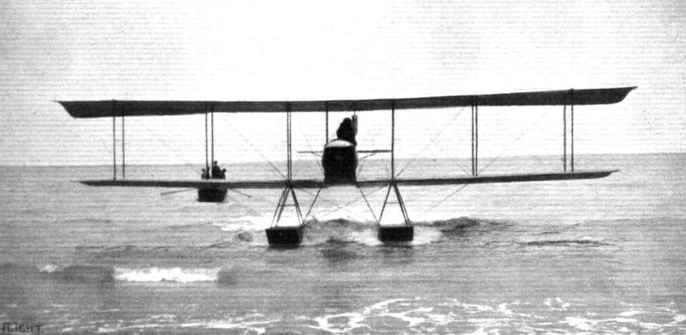
The 100 h.p. Avro hydro-biplane on the sea, as seen from in front.
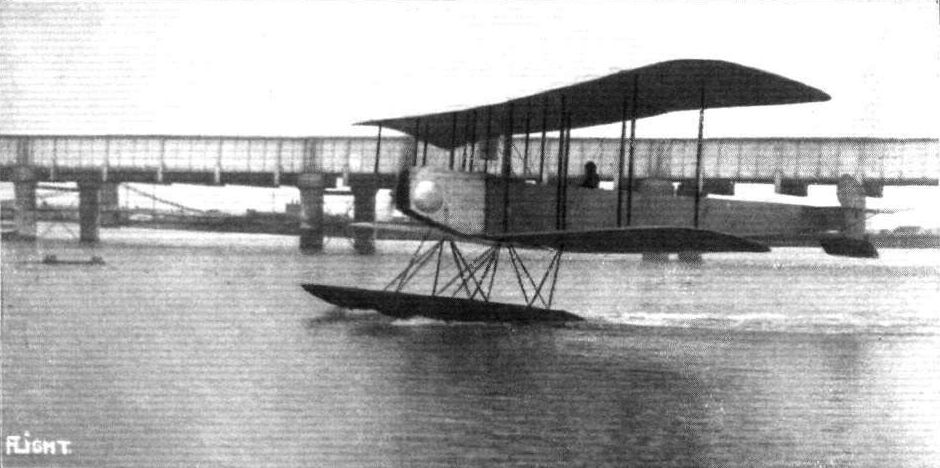
Side view of the 100 h.p. Avro hydro-biplane.
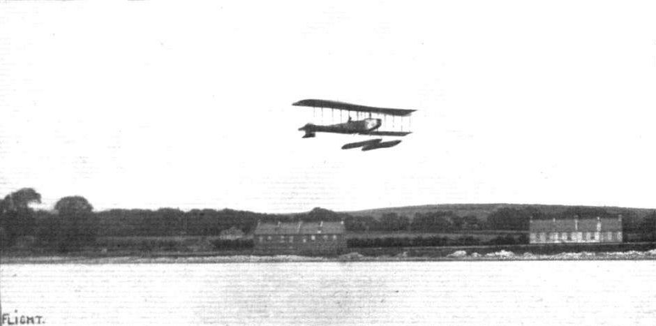
The 100 h.p. Avro hydro-biplane in flight.

THE 100 H.P. AVRO HYDRO-BIPLANE. - Plan, side and front elevations to scale.
Flight, October 11, 1913.
THE WAR OF THE ROSES.
A "WAR of the Roses" was fought out again last week in the form of a race between F. R. Raynham on an Avro biplane, which, of course, was built in Lancashire, and Harold Blackburn on a Blackburn monoplane, a Yorkshire product. The race, which was for a challenge cup offered by the Yorkshire Evening News, started and finished at Leeds, and was held over a circuit of which the chief points were York, Doncaster, Sheffield and Barnsley, a total distance of nearly 100 miles. To see the start about 60,000 people gathered on Moortown on Thursday of last week and both pilots got away from Leeds promptly at 2.14 p.m., Mr. Blackburn with Dr. Christie as passenger and Raynham accompanied by Mr. H. V. Roe. The weather was very bad, the mist making it very difficult to pick up the landmarks and keep on the course, in which respect Blackburn scored over his opponent, as he was more familiar with the country. It will be seen from our table that Raynham had an advantage by the time York was reached, and he was the first away again. At Doncaster, however, he was three seconds behind. Both men got away promptly from the Town Moor, Doncaster, and Blackburn still further improved his position, Raynham being handicapped by being unable to locate the control at Sheffield. He had to make two descents before reaching his destination, and he had the same trouble at the next control, Barnsley. In fact he flew right past it, and when he did descend it was at Dewsbury, some miles away. As it was then hopeless to try and put matters right, he flew direct to Leeds, and arrived some time before Blackburn. Soon after Blackburn's arrival the cup was presented to Dr. Christie, and handed by him to Blackburn. We understand that a return match will be held in Lancashire towards the end of the month, and it is anticipated that the event will become an annual one.
Blackburn. Raynham.
h. m. s. h. m. s.
Start 2 14 0 2 14 0
York arr. 2 39 48 1/5 2 38 59 2/5
,, dep. 3 1 28 4/5 3 0 40
Doncaster arr. 3 33 0 3 33 3
,, dep. 3 51 0 3 5' 3
Sheffield arr. 4 19 50 4 23 50
,, dep. 4 42 0 4 43 0
Barnsley arr. 4 55 23 3/5 -
,, dep. 5 19 0 -
Leeds finish 5 48 0 Disqualifie
Flight, December 6, 1913.
THE 80 H.P. AVRO BIPLANE.
IT is not so very long ago that really high speed was almost invariably associated with the monoplane type of aeroplane; the biplane being looked upon as more suitable for weight carrying at comparatively slow speeds. Things alter rapidly in the aviation world, however, and what seems to be a fantastic dream to-day is an accomplished fact to-morrow.
With his new 80 h.p. biplane, Mr. A. V. Roe has proved that it is possible to-day to produce a machine of the biplane type which is as fast as, if not faster than, most monoplanes, and which, moreover, has the advantage that it can be landed at a speed which is very much below its normal flying speed. As a matter of fact the new Avro biplane possesses a speed range of very nearly 50 per cent.
A good idea of the general arrangement should be gained from the accompanying illustrations. It will be seen that the most noticeable departure from the usual Avro practice is the staggering of the main planes, the reason for this no doubt being, that for the same gap and chord extra efficiency is obtained by having the upper plane placed in advance of the lower plane.
In plan the main planes are of the same shape as those of the 50 h.p. non-staggered type, but in section they are naturally of a much smaller camber and angle of incidence.
Four pairs of struts of hollow spruce connect the main planes, whilst another two pairs of ash struts connect the upper plane to the fuselage. The method of attaching the lower plane to the fuselage is shown in one of the accompanying sketches. It will be noticed, that a steel lug bolted to the lower longeron has two bolts passing through the plane, but not through the spar inside the inner end rib. Thus the spar is not weakened by piercing, and the wing is prevented from slipping out of the socket partly by the bolts passing inside the rib, and partly by the diagonal wing-bracing cables. Another of our sketches shows the method of joining the inter-plane struts to the main spars in a similar way. It is by close attention to details like these that it has been possible to construct a machine which combines light weight with a high factor of safety. It is really the keynote of the new Avro design that the weight has been cut down to a minimum without undue sacrifice of strength.
The fuselage, which is of rectangular section, is built up of longerons of ash channelled out between the strut attachments for lightness and strengthened by flanges of three-ply wood against bending stresses. The struts and cross-members are of spruce, and diagonal cross-wiring completes the construction of the fuselage.
The pilot's and passenger's seats are arranged tandem fashion, the pilot occupying the rear seat, from where he has an excellent view in all directions, and, owing to the small width of the fuselage - 2 ft. 6 ins. to be exact - he is able to survey the country below without the necessity of leaning out over the side. From the passenger's seat an equally excellent view is obtained, and the wind-shield enables him to make his observations in comfort protected as he is against the flow of air. The controls are of the usual Avro type and consist of a vertical lever pivoted on a longitudinal rocking shaft. A to-and-fro movement operates the elevator, whilst the ailerons are actuated by a side-to-side movement of the hand lever. A foot-bar operates the rudder through double control wires. In this particular machine dual control is not fitted, but could easily be introduced by lengthening the longitudinal rocking shaft.
At the rear the fuselage terminates in a vertical knife's edge to which is hinged the rudder, which is of the usual Avro type; as are also the tail plane and elevators. A swivelling tail skid of the laminated steel spring type protects the tail planes against contact with the ground.
In the front portion of the fuselage and enclosed by one of the neatest aluminium shields we have seen is the engine - an 80 h.p. Gnome - which is carried in double bearings, the front one of which is formed by four tubular extensions of the longerons which converge until they meet on a channel steel ring which carries the front ball-bearing. A small inspection door on each side of the engine housing permits of a general examination of the magneto, carburettor, oil pump, &c, whilst for close inspection the whole engine housing can be removed by undoing the butterfly fasteners by means of which the cowl is attached to the fuselage.
The planes as well as the fuselage are covered with a fabric, which has squares of stronger threads woven into it, so that should the fabric become pierced by a bullet or through any cause, these squares will prevent the fabric from tearing.
One of our sketches illustrates the very neat aileron hinge employed. In order to prevent the air from escaping through the opening between the rear spar and the aileron a strip of wood of triangular section is screwed on to the leading edge of the aileron. The edge of this strip of wood is held tight against the rear spar by means of coil springs on the part of the hinge which is attached to the rear spar, thus making a practically air-tight joint at any angle of the aileron, without causing any undue friction which might otherwise interfere with the free movement of the lateral control.
The chassis, it will be noticed, has been slightly altered. Two pairs of V struts of streamlined steel tubes carry on their lower extremities a stout ash skid. Instead of the laminated steel spring axle is fitted a tubular axle which is not connected to the skid, and which carries on its ends the two disc wheels. Two steel tubes run from each end of the axle to a cross-piece, whilst another single tube, pivoted to the lower longeron and passing through the cross-piece of the lower tubes, carries another cross-piece on its lower extremity. Rubber shock absorbers connect the two cross-pieces, thus effecting the springing of the wheels. A neat streamline casing, open at the bottom, encloses the shock absorbers and protects them against oil thrown out from the engine. By sliding the casing up along the tube until the shock absorbers are uncovered, these may readily be adjusted and examined or, if need be, replaced. Stout stranded cables running from the lower ends of the skid struts to the top and bottom of the first pair of inter-plane struts, brace the wings very effectively against drift. During the official tests at Farnborough recently, we understand, the machine, with pilot, passenger and four hours' fuel, climbed 1,000 ft. in 175 mins. Her maximum speed was 80 m.p.h. and her minimum speed 43 m.p.h., thus giving a speed range of nearly 50 per cent.
The weight of the machine with fuel for three hours and a passenger is 1,550 lbs., giving a loading of about 4 1/2 lbs. per square foot.
THE 80 H.P. AVRO BIPLANE. - Three-quarter view from the front.
Avro 504 in its earliest production form in August 1914 after receiving constant-chord aileron in 1913. This was the original machine fitted with an 80 h.p. Gnome. It was on similar machines that a raid was carried out on the Zeppelin factories at Friedrichshafen, in which Commander Briggs was brought down and captured.
THE 80 H.P. AVRO BIPLANE. - View from the front.
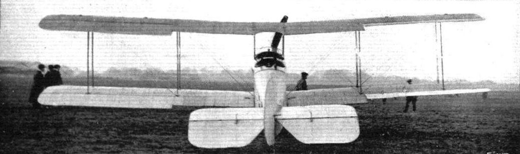
THE 80 H.P. AVRO BIPLANE. - As seen from behind.
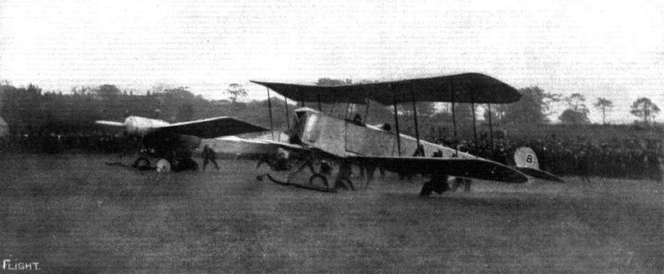
THE YORKSHIRE AIR RACE. - The Avro biplane and the Blackburn monoplane in line just at the moment of getting away.
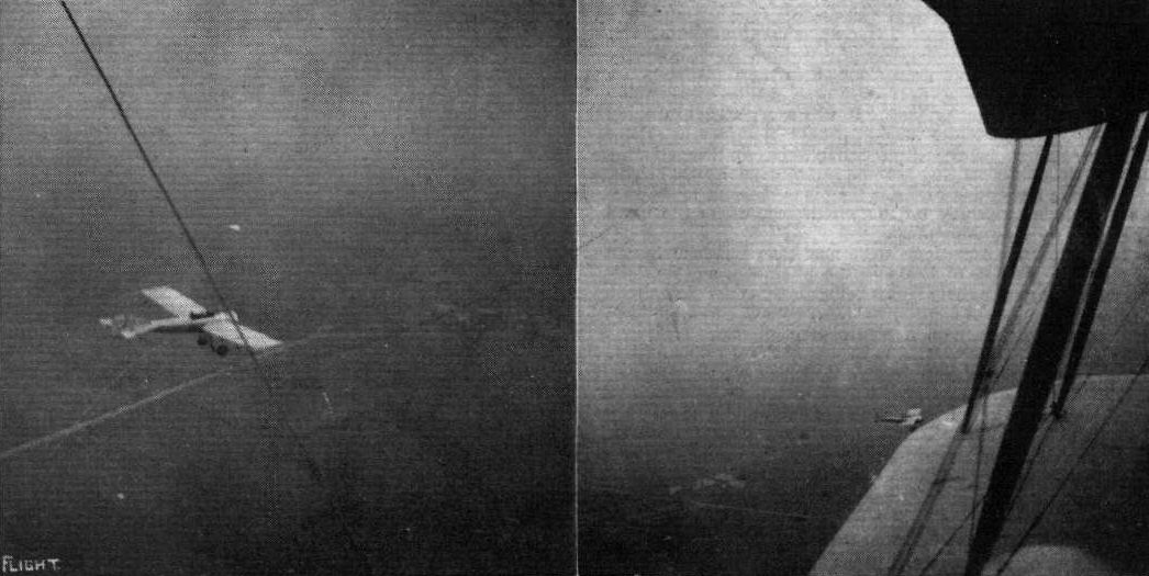
A couple of snaps of the Blackburn monoplane, taken by Mr. H. V. Roe from the Avro biplane, piloted by Mr. F. P. Raynham in the Yorkshire Air Race between York and Doncaster on October 2nd. Both competitors were well up, and by the photographs it will be seen the weather was extremely wretched with a haze over everything.
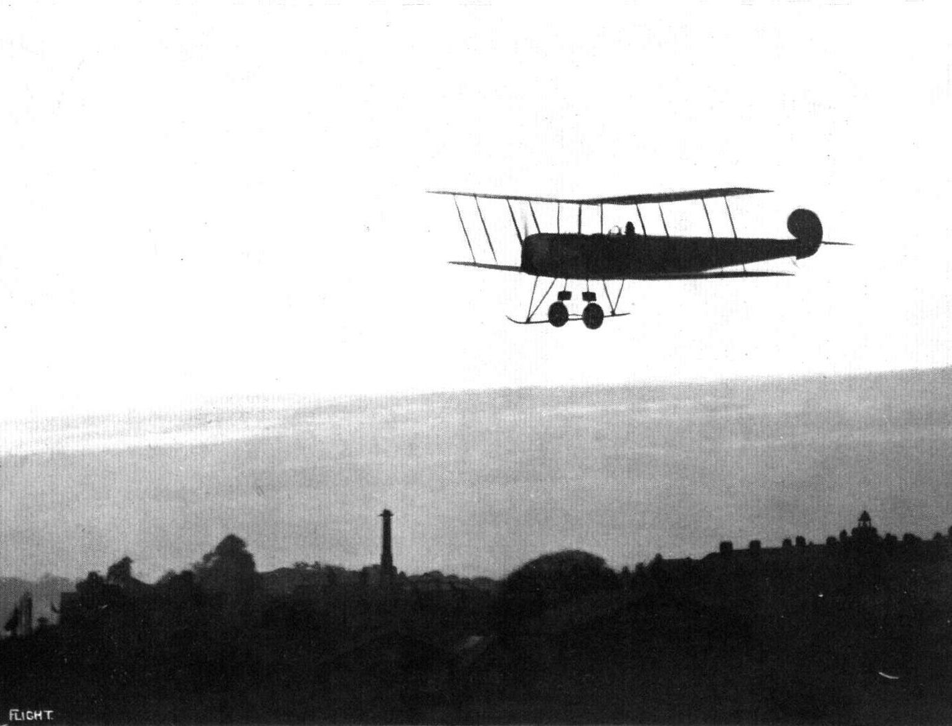
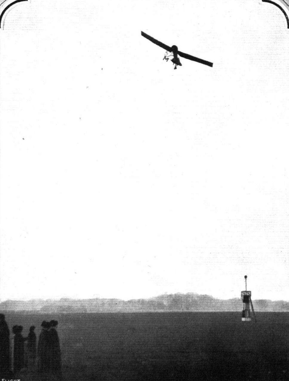
Mr. F. P. Raynham on the remarkable new Avro biplane on which he made such splendid speed flights in the competition at Hendon on Saturday. Our picture shows Mr. Raynham at sunset, in the final for the Shell Trophy, which he only missed winning by a "head."
Mr. Gordon Bell having a turn on the Avro at Hendon.

Sketch showing the neat engine housing and the chassis of the 80 h.p. Avro biplane.
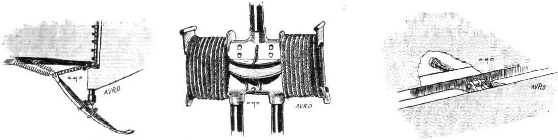
The tall skid, one of the shock absorbers, and an aileron hinge on the Avro biplane.
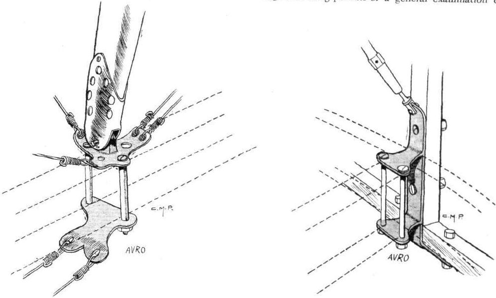
Attachment of inter-plane struts to spar on the Avro biplane, and on the right attachment of lower plane to fuselage.
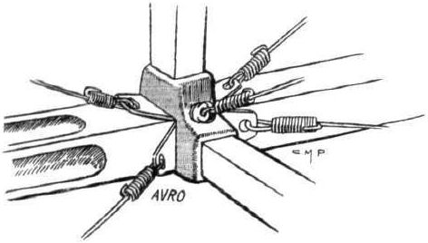
A fuselage joint on the Avro biplane.

THE 80 H.P. AVRO BIPLANE. - Plan, side and front elevation to scale.
Mr Blackburn on the Blackburn monoplane, flying in Saturday's race, for the Aero Show Trophy.
MR. BLACKBURN FLYING THE BLACKBURN MONOPLANE AT HENDON. - A curious optical illusion is produced, it being difficult, without knowledge, to say whether the machine is travelling towards or away from the spectator.
Flight, March 29, 1913.
FROM THE BRITISH FLYING GROUNDS.
The Blackburn at Leeds.
DURING Easter week Mr. Harold Blackburn has been giving exhibition flights at Leeds. On Good Friday and Saturday he made several ascents on Mr. Foggin's new 50-h.p. Gnome-Blackburn, rising on one occasion to a big altitude. This machine climbs exceedingly quickly and shows a speed of about 60 m.p.h. At noon on Monday Mr. Blackburn made his first ascent, flying around Wakefield and the surrounding country. During the whole afternoon flying was in progress, no less than seven ascents being made by Mr. Blackburn. The final flight was made by Mr. Foggin, who mounted his machine for the first time, and made a splendid flight of nearly 20 mins. duration. He rose to a good altitude, and handled his machine in such excellent style that one could hardly believe that this was his first flight on this type of machine. On Tuesday afternoon Mr. Blackburn made a long flight on Mr. Foggin's machine. He made some very fine banked turns with his usual skill, finishing off with a neat vol plane. The flights were witnessed by hundreds of spectators, who were very enthusiastic in showing their appreciation of the flights of Mr. Blackburn and Mr. Foggin.
Flight, May 3, 1913.
Wakefield-Harrogate Flight.
MR. HAROLD BLACKBURN, flying a new type 50-h.p. Blackburn monoplane, left on Tuesday, last week, the Yorkshire Aerodrome, near Wakefield, at 1.34 p.m., for Harrogate. When he reached Leeds he had the town on his left, and was then flying beautifully at an altitude of 2,000 ft. The machine was fitted with map and compass, and Mr. Blackburn made a perfect course for the Queen's Hotel, in front of the Stray, at Harrogate - the ground used for alighting in the Circuit of Britain. He had never been to Harrogate before, but he arrived exactly at the appointed place at 1.52, about the time expected. The distance is some 18 miles. When he arrived over the Stray, he was flying at all 4,000 ft. altitude, and made a very fine spiral glide down, landing just in front of the Queen's Hotel. The descent took 5 minutes.
Unfortunately when he was about to make the return journey, owing to the enormous crowd which had collected on the Stray, he had the misfortune to smash the machine before getting away. Mr. Blackburn was, however, not hurt in the slightest, although greatly disappointed, as this was his first smash.
Flight, August 2, 1913.
BRITISH NOTES OF THE WEEK.
Mr. H. Blackburn Carries Newspapers.
FOR some time, Mr. Harold Blackburn has been doing quite a lot of flying on his 50 h.p. Blackburn monoplane at Leeds, and on Wednesday, Thursday, and Friday of last week he carried a large bundle of the Yorkshire Evening Post from Leeds to York, landing at the ground of the Yorkshire Agricultural Show. On the first day he had to fight his way through a gale, as is shown by the fact that he took an hour for the trip, whereas on the two following days his time was 35 mins. Each day a large crowd gathered at York to welcome Mr. Blackburn, and needless to say the papers were eagerly sought after as souvenirs.
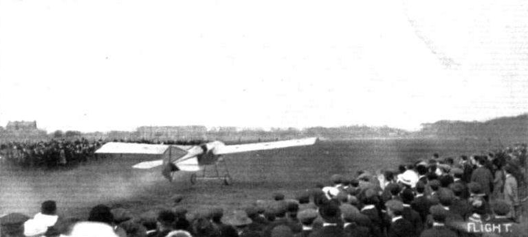
Mr. Harold Blackburn on the Stray, at Harrogate, after his flight from Yorkshire Aerodrome. Starting on the return journey.
Flight, September 6, 1913.
Mr. Blackburn at Bridlington.
THROUGHOUT last week, Mr. Harold Blackburn was giving exhibition flights on his 80 h.p. Blackburn monoplane at Bridlington. Starting from Harrogate, where he had been flying for a few days, on the evening of Monday week, he flew with Dr. M. G. Christie to Bridlington, arriving in the twilight, being received by the Mayor. During the week he took up a number of passengers, and two of them were carried to Filey. Each day Blackburn was flying, and doing some fine banked turns over the bay. On Saturday, after taking up several passengers, he went with Dr. Christie over to Leyburn, a distance of about 75 miles, taking 70 mins. for the trip. Later the two journeyed by way of Ripon to Harrogate, where they landed on the Stray just as it was getting dusk. Flying with the wind this last trip of 40 miles was made in 23 mins. For the past two months Mr. Blackburn has been flying daily, and that the machine has been left out in the open without any protection from the weather speaks well for its sound construction.
Flight, September 20, 1913.
Harrogate to Bridlington and Back.
ON Monday last Mrs. Leigh, of Harrogate, had an exceptional experience in a trip on Mr. Harold Blackburn's monoplane from Harrogate to Bridlington and back, when the return journey was made at a very high speed owing to a terrific following wind, which enabled the distance to be covered in about 40 mins.
Flight, September 27, 1913.
Mr. Harold Blackburn at Harrogate, &c.
ON Monday, last week, Mr. Harold Blackburn, on the 80 h.p. Blackburn monoplane, left Ripon, where he had been giving exhibition flights during the week-end, for Harrogate, taking Dr. Christie, the owner of the machine, as passenger. They landed on the Stray at Harrogate, after doing the flight in 10 mins. at an altitude of about 2,000 ft. At 11.50 Monday morning, Mr. Blackburn started for a trip to Bridlington and back, with Mrs. Leigh as passenger. Mrs. Leigh, who is nearly 70 years of age, is probably one of the oldest ladies who has made such a long trip. They did the 65 miles to Bridlington in a little under the hour, having passed over York and Driffield and encircling the Bay before alighting. The return journey was started at 3.50 in the afternoon, and Harrogate reached 40 mins. afterwards.
The same evening Mr. Harold Blackburn took Dr. Christie up for a flight over the Stray, making some fine banked turns and spirals. On Thursday, Lt.-Gen. Broadwood went for a short passenger trip at Harrogate. They attained an altitude of 4,000 ft., and were flying for about a quarter of an hour. Later on Dr. Christie again accompanied Mr. Blackburn, when they did some fancy flying. Mr. Blackburn was again flying with Dr. Christie on the Friday.
On Saturday, Dr. Christie and Mr. Blackburn left Harrogate for Doncaster, where they arrived after a 40-min. flight. On Saturday afternoon Mr. Blackburn was giving exhibition and passenger flights, taking up seven different passengers during the course of the afternoon. On his first flight with Dr. Christie, he gave a very brilliant display of sharp banked turns, showing the wonderful control he has over the machine. After the exhibition they left just before dusk for Wetherby, where they were staying the night. The distance from Doncaster to Wetherby is about 30 miles. They returned to Doncaster on Sunday noon to give a further exhibition there. During the course of Sunday, about 12 passengers took trips in the machine.
Flight, October 11, 1913.
THE WAR OF THE ROSES.
A "WAR of the Roses" was fought out again last week in the form of a race between F. R. Raynham on an Avro biplane, which, of course, was built in Lancashire, and Harold Blackburn on a Blackburn monoplane, a Yorkshire product. The race, which was for a challenge cup offered by the Yorkshire Evening News, started and finished at Leeds, and was held over a circuit of which the chief points were York, Doncaster, Sheffield and Barnsley, a total distance of nearly 100 miles. To see the start about 60,000 people gathered on Moortown on Thursday of last week and both pilots got away from Leeds promptly at 2.14 p.m., Mr. Blackburn with Dr. Christie as passenger and Raynham accompanied by Mr. H. V. Roe. The weather was very bad, the mist making it very difficult to pick up the landmarks and keep on the course, in which respect Blackburn scored over his opponent, as he was more familiar with the country. It will be seen from our table that Raynham had an advantage by the time York was reached, and he was the first away again. At Doncaster, however, he was three seconds behind. Both men got away promptly from the Town Moor, Doncaster, and Blackburn still further improved his position, Raynham being handicapped by being unable to locate the control at Sheffield. He had to make two descents before reaching his destination, and he had the same trouble at the next control, Barnsley. In fact he flew right past it, and when he did descend it was at Dewsbury, some miles away. As it was then hopeless to try and put matters right, he flew direct to Leeds, and arrived some time before Blackburn. Soon after Blackburn's arrival the cup was presented to Dr. Christie, and handed by him to Blackburn. We understand that a return match will be held in Lancashire towards the end of the month, and it is anticipated that the event will become an annual one.
Blackburn. Raynham.
h. m. s. h. m. s.
Start 2 14 0 2 14 0
York arr. 2 39 48 1/5 2 38 59 2/5
,, dep. 3 1 28 4/5 3 0 40
Doncaster arr. 3 33 0 3 33 3
,, dep. 3 51 0 3 5' 3
Sheffield arr. 4 19 50 4 23 50
,, dep. 4 42 0 4 43 0
Barnsley arr. 4 55 23 3/5 -
,, dep. 5 19 0 -
Leeds finish 5 48 0 Disqualifie
Flight, December 27, 1913.
THE 80 H.P. BLACKBURN MONOPLANE.
ALTHOUGH the doings of the new Blackburn monoplane have not received such publicity as doubtlessly would have been the case had the flights been made in the neighbourhood of one of the well-known aerodromes, this machine has nevertheless done a considerable amount of flying in the north of England, and has, it is to be hoped, helped in no small measure to arouse the interest in aviation in that part of the country. A machine of this type, it will be remembered, was delivered to Dr. M. G. Christie in the middle of August and - piloted by Mr. Harold Blackburn - has been flying regulaêly since then, the distance traversed aggregating 1,800 miles, while over 120 passengers have been carried. It was this same machine which Mr. Blackburn flew with Dr. Christie as a passenger in the inter-county air race, for a distance of 100 miles, the Cup being won by Blackburn.
Constructionally this new machine differs considerably from the older type, and is a distinct advance on anything hitherto turned out by the Blackburn firm. The fuselage is streamline in shape and triangular in section, and is built up in the form of a lattice girder. The front part is of English ash, and is covered with sheet aluminium, giving it additional strength and reducing the head resistance. The engine is covered over for about five-eighths of its circumference by a beaten aluminium cowl, which is continued to form a scuttle dash. This effectively prevents the exhaust from the engine reaching either pilot or passenger.
The main planes are rectangular in form, and of a curvature designed to give maximum lift for a minimum drift. The main spars on which the ribs are built up are of the finest selected straight-grained English ash, the spars being machined out of the solid to the most efficient section, and not built up.
The webs are of silver spruce cut out to their true form and built up with cottonwood flanges, forming the ribs to which is attached the fabric. These ribs are strengthened by cottonwood distance pieces where pierced for spars, and are equally spaced by means of leading and trailing edge laths. The whole of the woodwork is well varnished before being covered with fabric, and is strongly braced internally to take the backward thrust imposed on the planes in flight. The planes are covered with finest quality fabric, which is fitted down with split cane beading.
The machine is supported on a very strong chassis composed of two long skids connected up to the fuselage by heavy ash struts. The skids and struts are of specially selected straight long-grained English ash, thoroughly seasoned and designed to withstand alighting on rough uneven ground. To the skids are attached a pair of wheels whose axle is held down by strong elastic shock absorbers, thus preventing shocks due to landing being transmitted to the main frame. The wheels are built up with specially wide hubs to resist any side thrust, and are streamlined with fabric.
The fabric with which the fuselage and planes are covered is very strong compared to its weight. It is carefully stretched on the framework, and is rendered oil- and water-proof by the application of a non-inflammable solution, which impregnates and tightens the fabric and gives a smooth and highly-polished surface.
The standard type of control is fitted, i.e., foot bar for operating rudder, to-and-fro motion of vertical column for operating elevators, and rotating handwheel for lateral balance. All control wires are duplicated.
An 80 h.p. Gnome engine is mounted in front of the fuselage, the supporting plates being of pressed steel. Engine controls are fitted on the right hand of the pilot's seat, and in a convenient position for rapid operation.
The seats for pilot and passenger are arranged in tandem, the passenger in front being situated over the C.G., thus enabling the machine to be flown either with or without a passenger without altering the balance.
For taking the weight of the machine in flight, each front spar is stayed to the chassis by three stranded cables. Three upper tie wires are attached to the front spar from the pylon. The breaking load of the upper wires is not less than two-thirds that of the lift wires. The three warping wires are attached to one main wire passing over pulleys on the rear chassis. The rear spar is, therefore, not bent when the wing is warped, but has an angular movement about the hinge on the fuselage; the corresponding top wires pass over a pulley on the pylon. All cables have a factor of safety of ten, and are spliced and bound with galvanised steel wire.
A Blackburn propeller of 9 feet diameter, built of specially selected laminated walnut, is coupled direct to the engine.
A lifting tail of 30 sq. feet area is fitted. Rudders and elevators are double surfaced.
The accommodation for both pilot and passenger is very comfortable, and a scuttle is fitted up to each seat which prevents the force of the wind from being uncomfortable on the pilot's and passenger's faces. The speed of the machine is 70 m.p.h., and the gross weight 1,500 lbs.

Front view of the 80 h.p. Blackburn monoplane.
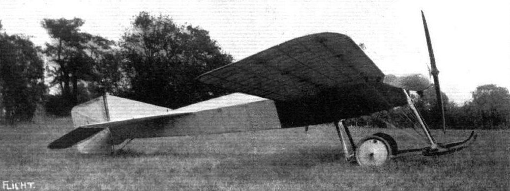
Side view of the 80 h.p. Blackburn monoplane.
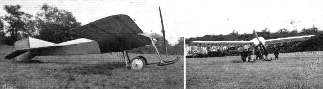
An 80 h.p. two-seater Blackburn monoplane which has just been built for and supplied to Dr. M. G. Christie for touring purpases. On its test flight Mr. Blackburn climbed to about 7,000 ft. in 10 mins., and since its delivery about a couple of weeks ago it has made a number of cross-country flights, and is at present making a tour of the Yorkshire towns piloted by Mr. H. Blackburn, with its owner, Dr. Christie, as passenger. The machine has a fine gliding angle, and ranges in speed from about 40 to 70 m.p.h. In the side view the simplified chassis, the turtle back on the fuselage, and the new tall planes should be noted.
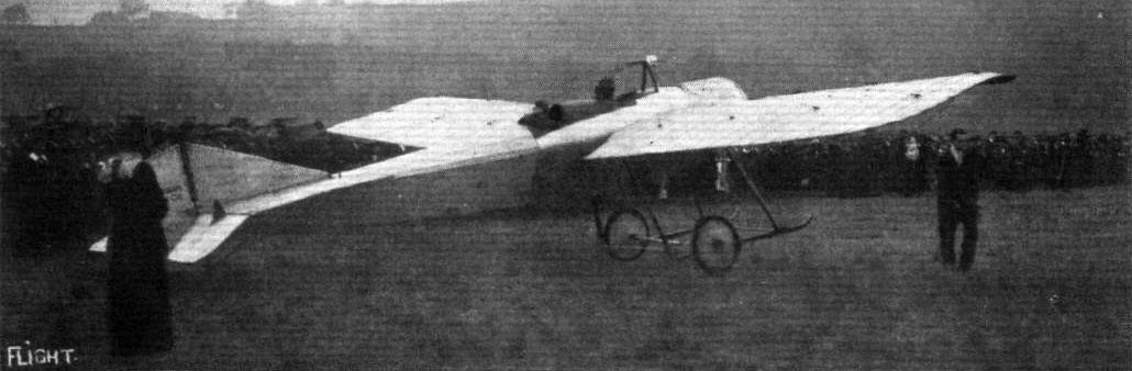
View from behind of the 80 h.p. Blackburn monoplane.
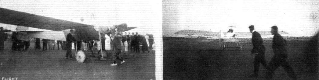
TWO MORE SNAPS OF MR. H. BLACKBURN AND HIS MONOPLANE AT BRIDLINGTON. - On the left "swinging" the propeller, and on the right just away.
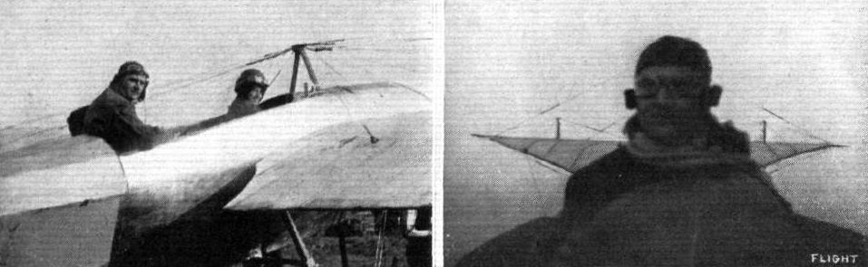
MR H. BLACKBURN AT BRIDLINGTON WITH HIS MONOPLANE. - A couple of snaps taken by Mr. C. S. Burney, of Berkhamsted. On the right is a picture of Mr. H. Blackburn taken from the passenger seat.
THE YORKSHIRE AIR RACE. - The Avro biplane and the Blackburn monoplane in line just at the moment of getting away.
A couple of snaps of the Blackburn monoplane, taken by Mr. H. V. Roe from the Avro biplane, piloted by Mr. F. P. Raynham in the Yorkshire Air Race between York and Doncaster on October 2nd. Both competitors were well up, and by the photographs it will be seen the weather was extremely wretched with a haze over everything.
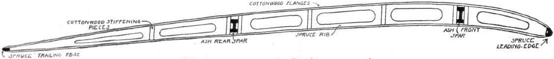
Rib construction on the Blackburn monoplane.
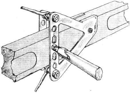
Attachment of bracing cables to main spar.
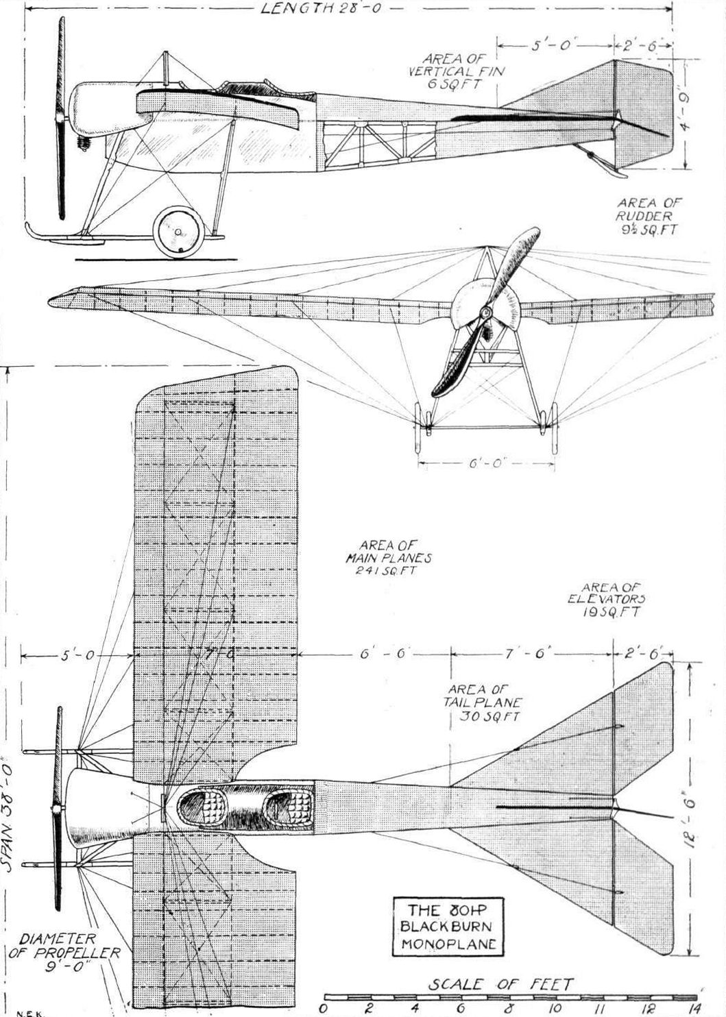
THE 80 H.P. BLACKBURN MONOPLANE. - Plan, side and front elevations to scale.
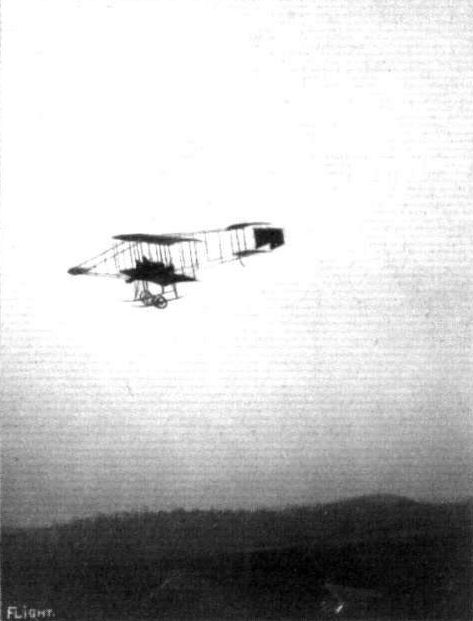
Mr. F. Warren Merriam, with Lieut. Picton Warlow - a pupil - as passenger, making a flight in one of the Bristol biplanes at Brooklands. Mr. Merriam is descending from 2,000 ft. with engine off, the propeller, it will be noted, having stopped.
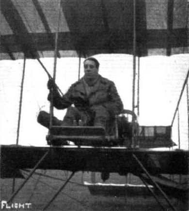
Lieut. E. Peirse, R.N.R., one of the recent successful pupils for his brevet at the Bristol Flying School at Brooklands.
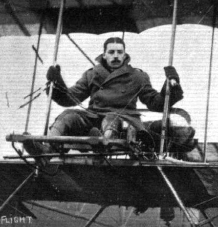
Lieut. M. R. Chidson, R.G.A., one of the recent Bristol pupils at Lark Hill to secure his R.Ae.C. certificate.
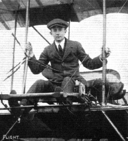
Mr. H. C. Tower who took his brevet at the Bristol School, Salisbury Plain on April 23rd, when he made an excellent flight at 500 ft high.
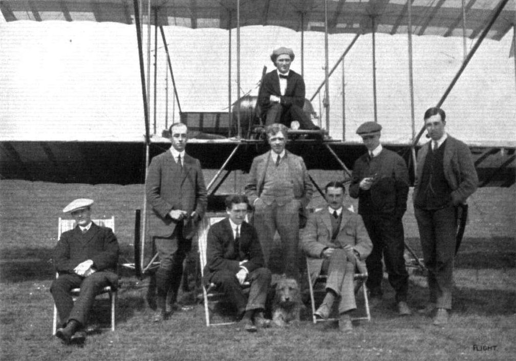
SOME AVIATORS AND PUPILS AT THE EASTBOURNE AERODROME. - From left to right: (seated) Messrs. H. Fill, F. Hucks, F. B. Fowler; (standing) B. Roberts, L. Fry, E. L. Gassier, W. Morkill, and in the pilot's seat, T. A. Rainey.
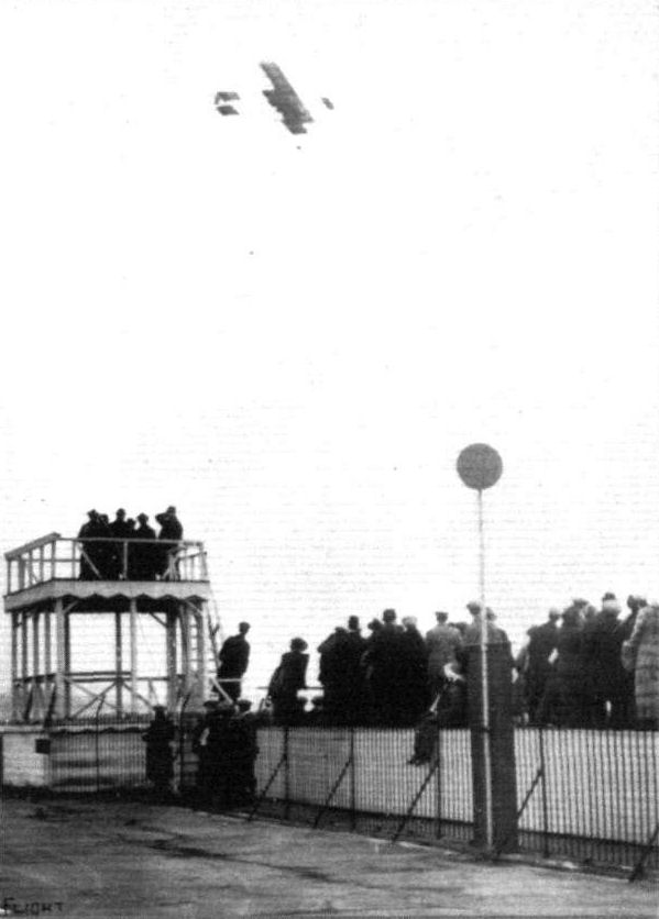
Merriam, during the motor racing at Brooklands on Eister Monday, flying over the course on his Bristol biplane.

THE LONGEST DAY. - The annual pilgrimage to the sun temple at Stonehenge to witness the rising of the sun when it casts the shadow of the Heel Stone directly on to the altar stone - a moment of great significance to the sun-worshippers. Above is seen a Bristol biplane flying over the ruins upon the occasion.
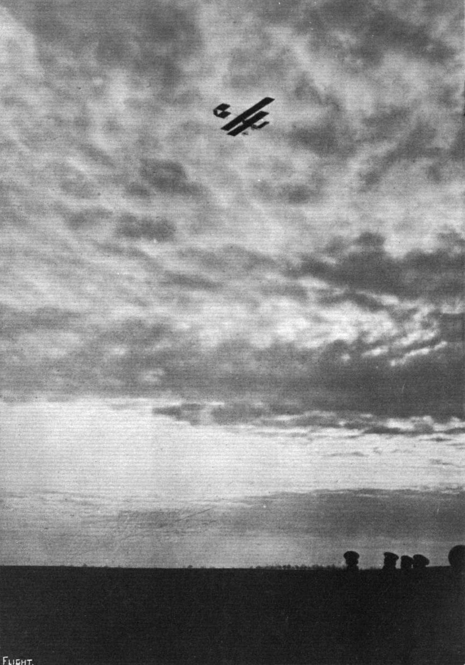
AT EVENTIDE. - A Bristol in Germany under the pilotage of Mr. Pixton.
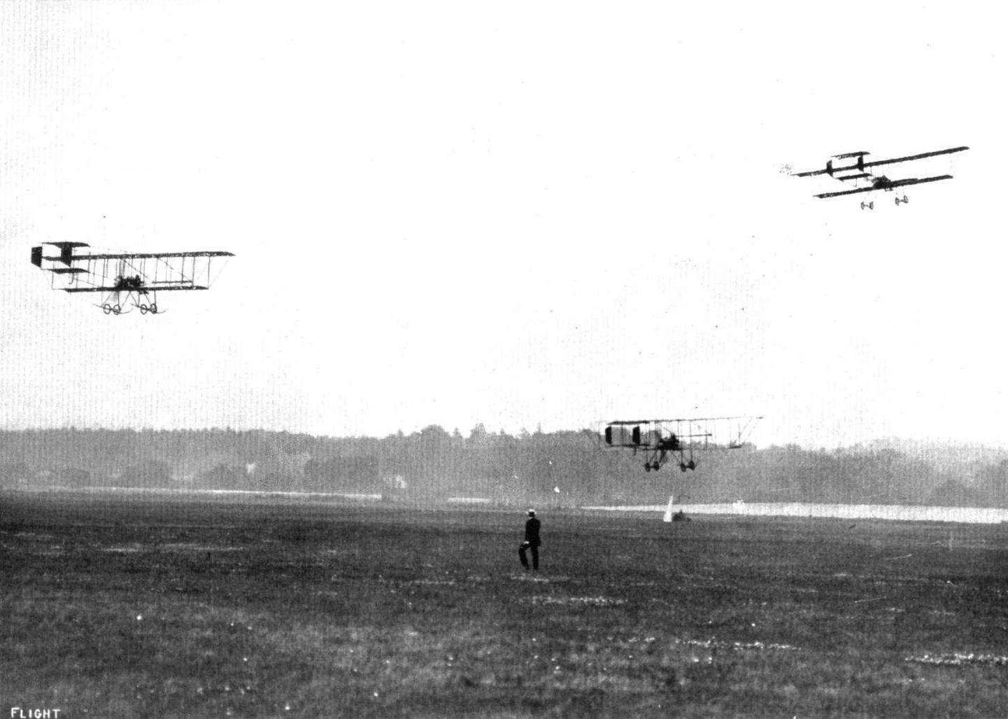
CROSS-COUNTRY RACE AT BROOKLANDS ON SATURDAY LAST. - Mr. W. S. S. Mitchell on the Vickers biplane (No. 8); Mr. W. Bendall, Bristol biplane (No. 10); Mr. F. W. Merriam, Bristol biplane (No. 7), rounding the sheds on the first circuit.
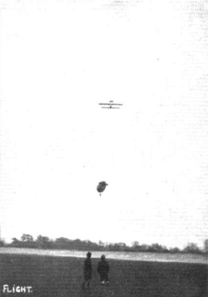
Mr. F. Warren Merriam flying over the Army airship "Delta" on one of the Bristol biplanes on April 23rd at Brooklands.
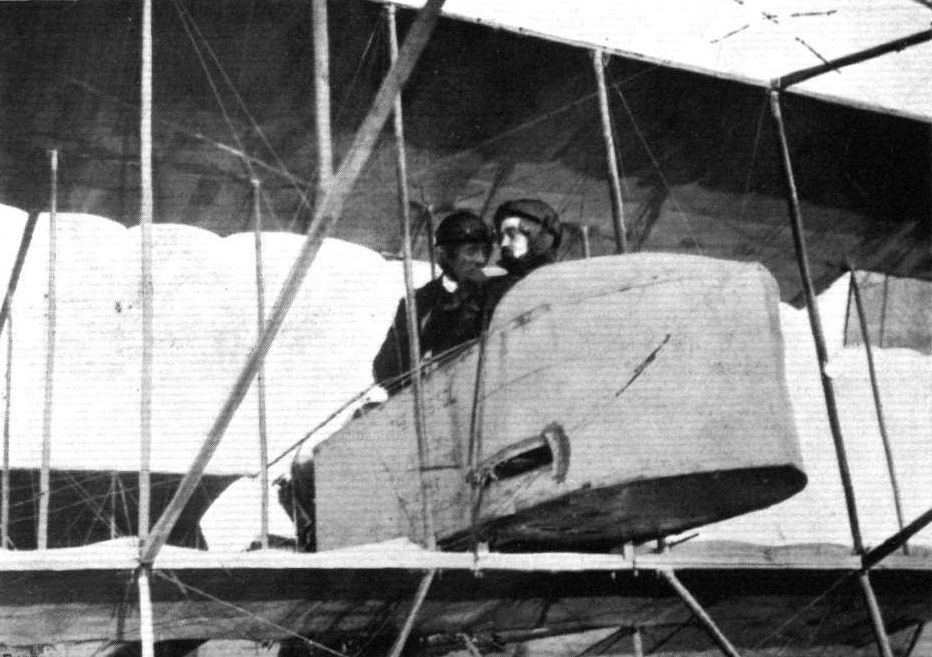
Col. Seely, the British Minister for War, just before his flight at the military aviation ground at Madrid with Capt. Barron in a Bristol biplane.

THE BRISTOL MONOPLANE IN ITALY. - A remarkable photograph of Mr. C. H. Pixton, piloting one of these well-known monoplanes, gliding down to earth at sunset at Mirafiori, near Turin. On the left of the picture can be remarked the rising full moon.
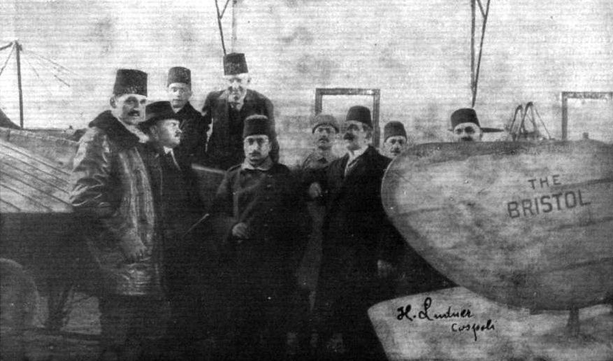
THE BRISTOLS IN TURKEY. - A gathering of several high personages of State after inspection of a couple of Bristols supplied to the Turkish Government.
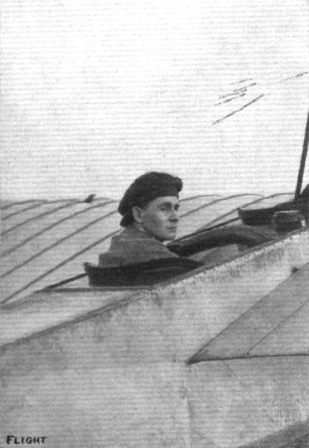
Mr. W. H. S. Garnett, who has just successfully taken his ticket on a 50 h.p. tandem Bristol monoplane at Salisbury Plain.
Flight, February 8, 1913.
WHAT THERE WILL BE TO SEE AT OLYMPIA.
THE MACHINES.
The British and Colonial Aeroplane Co., Ltd.
On the stand of the enterprising manufacturers of Bristol aeroplanes will be shown two machines, an 80-h.p. two-seater monoplane, fitted with a Gnome engine, and a 70-h.p. Renault-engined tractor biplane. The monoplane will be identical with the machine that flew so well in connection with the British Military Aeroplane Trials of 1912, and which was placed third in order of merit among the 32 entries that were received. Replicas of this monoplane have been bought extensively by foreign governments. The backbone of the monoplane, 28.5 ft. in length, is formed by a girder constructed of four longitudinal members of ash, braced by piano wire, with cross members and struts of spruce. For the reduction of head resistance, the whole is covered in by fabric, and the top and bottom are made convex. The 80-h. p. Gnome motor, supported by carlingues on both sides of the crank-case, is mounted in front and half enclosed by a semispherical cowl that prevents any of the oil thrown off by the motor reaching the pilot or passenger. Regarding the wings, which span 43 ft., their chief features are that they are each built about two spars of heavy gauge wood-filled steel tubing, and that the ribs, cut from wood and covered with fabric to prevent them splitting, are fitted loosely over the spars in order to prevent any fatigue in the construction as a result of continual wing warping. The landing gear is of the wheel and skid type, and it has the peculiarity that the hollow vertical chassis struts are attached to the fuselage and to the skids by pin-joints, so that more flexibility may be given to its structure. A flap hinged to the rear of a semicircular fixed tail-plane controls the elevation. Without passengers or fuel, the monoplane weighs 1,050 lbs., and is capable of carrying a useful load of 726 lbs. at an average flying speed of 72 miles per hour. It is interesting to note that this 80-h.p. Bristol monoplane had the best gliding angle, 1 in 7.2, of all the machines entered for the British Military Aeroplane Trials.
<...>
Flight, February 22, 1913.
SOME MORE AEROPLANES AT OLYMPIA.
THE BRITISH AND COLONIAL AEROPLANE CO., LTD.
As the manufacturers of Bristol machines have an organization far and away larger than any similar firm in England, or, we might say, with perhaps one or two exceptions, in the whole world, it is only natural to expect that their exhibit is one of the main centres of interest at Olympia. Both their machines - the monoplane which made its debut in the Military Trials, and the biplane, which has just been evolved from their Filton works - are of distinctive design and, as samples of workmanship stand, bracketed with one other machine shown, unrivalled, among all the various aeroplanes exhibited there. They both have been constructed to the designs of M. Henri Coanda, their clever engineer, of Roumanian birth. Since 1908 has M. Coanda been connected with the study and practice of aeronautics. He first began his experiments with the late Capt. Ferber in France.
It will be remembered that - was it three years ago or four ? - Coanda exhibited at the Paris Show a particularly neatly designed<...>
Flight, May 17, 1913.
THE BRISTOL MONOPLANE,
THE scale drawing and constructional sketches published this week represent the latest Bristol monoplane as exhibited at the Olympia Show. It is a development of the design by M. Coanda which was entered for the Military Trials, and differs principally from its prototype in respect to a larger wing area, which now spreads 280 sq. ft. The chord is 7 ft. 3 ins., and is notable for the extent of the trailing portion aft of the main spar. The weight of the machine, notwithstanding its larger area, is appreciably less than that of the machine entered in the Military Trials; in consequence, it has an increased flexibility of maneouvring power, is able to ascend more quickly in confined spaces, and in general to respond with greater certainty to the pilot's control when a delicate touch is needed during, say, the course of alighting. The fuselage of the machine is rectangular in section, and is built up of four ash booms with strut cross members of spruce. Diagonal steel wire bracing is employed in the usual way to make a rigid girder of the whole structure.
In order to prevent the compression stress on the wing spars being taken by the sides of the body of the machine, the spars themselves, which are of tubular steel, are carried through the body and abut against the masts that carry the guy wires from overhead. These masts are very neatly streamlined, and have somewhat the appearance of short funnels, which gives to the machine in flight an appearance that lends an appropriateness to its being described as a sort of torpedo boat of the air.
The passenger sits immediately behind the forward mast, and the passenger's seat corresponds with the centre of gravity of the machine. His presence or absence does not, therefore, affect the balance. The pilot's seat is situated behind the second mast, and his outlook on either side of the body is facilitated by the cutting away of the wing surfaces. Both seats are of the bucket type, and are independently sprung upon bent malacca cane so as to ease the shock of a rough landing. For the same reason they are upholstered round the edges with leather. A further range of vision is sought by fitting glass windows in the sides and bottom of the fuselage; the glass is of the kind that has wire netting embedded in it to prevent it from flying to pieces when broken. The front edges of the wings are also cut away slightly, it will be noticed, to facilitate the passenger's outlook toward the ground.
Speaking of balance, an interesting detail is the disposition of the fuel and oil tanks relatively to the centre of gravity. The oil tank is placed at a distance behind the C.G., that is three times as great as the distance of the petrol tank forward of that point. The ratio of the consumption of fuel to oil is three to one in units of weight, so that the two tanks are in balance at the start and at all times during flight so long as this ratio of consumption is maintained.
Dual control forms a standard fitting on this design, and incorporated therewith is an unlocking device by which the pilot can throw the passenger's control gear out of action at will; the control movements themselves are of the orthodox type. A to and fro motion of the lever operates the elevator, turning the hand wheel on top of the lever actuates the warp through cables, and the pivoted bar under the pilot's seat controls the rudder.
Particular attention has been paid to the range of the warp, and the wing tips of this machine are capable of moving up and down about 3 feet. On account of the torsion when the wing is warped, the wing does not tend automatically to return to its neutral position. The wing spars are, as has been mentioned, steel tubes; they are cored with wood to give them greater resistance to indentation. The wooden ribs are a free fit on the spars, and kept in position along the span by the special construction of the leading and trailing edges to which they are fastened. The trailing edges of the wings consist of three-ply wood, which is very neatly arranged and gives a well-finished edge. The general staying of the wings is very much the same as at the time of the Military Trials, the upper wires being carried over the two masts and the lower wires of the forward spars being carried forwards to the undercarriage. The lower wires of the rear spar are of course carried to the warping gear on the lower extremity of the rear mast. The innermost of the lower forward stay wires is attached to a steel strap passing under the body.
The two outer lower wires, which are attached to the forward spar and to the undercarriage, have a rake of about 45 degrees in side elevation, and their purpose is to take the drift as well as the lift. The angle is such that under all normal conditions the forward component of the lift due to the obliquity of the wires would exceed the direct drift force against the wing. The difference between the actual drift force at any moment and the resolved component of the lift is taken by the internal wing bracing, which is of an interesting and unusual character. Adjacent to the collars on the two spars to which the lift wires are attached, steel clips are fitted for the attachment of the internal wires. These clips embrace the tubes that are not rigidly fixed thereto. In turn, these clips are embraced by the master ribs of the wing structure. The arrangement of the clips is such that their proximity to the fixed collars on the wing spar gives them a point of abutment that otherwise would of course be lacking.
The undercarriage design of the Bristol monoplane is a striking feature of its construction, principally on account of the very interesting and very massive looking streamline main struts by which it is attached to the body. These struts, which measure some four inches fore and aft, are hollow, and at each end are semi-circular, so that they form a knuckle joint with the piece against which they abut. The joint is completed by a plate and a pin through the centre from which the semi-circle is described. The joint is constructed as a rigid member, but its object is to facilitate a certain amount of give in the right place so as to avoid breakage in the event of very severe shock. The general design is also such as to facilitate the replacement of these struts.
Ordinarily, the weight of the machine is carried on two wheels, which are attached by their axle to the chassis skids by means of elastic straps. Two smaller guard wheels are carried on extensions of the chassis construction, and serve to take the shock of a pique landing or of any obstruction. While rolling, this portion of the chassis projects forward of the propeller, and to that extent tends to preserve it from damage.
The tail unit of the machine consists of a segmental fixed member that is non-lifting and an undivided extension thereto, which forms an elevator flap. The rudder is mounted entirely above the fail, and is pivoted so as to be approximately in balance about its swiveling axis.
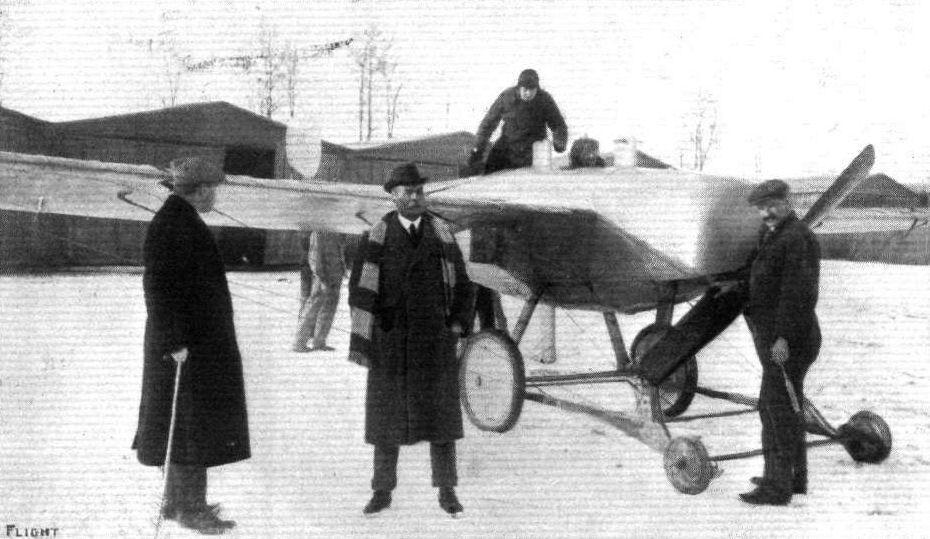
THE ITALIAN GOVERNMENT ORDER FOR BRITISH AEROPLANES. - One of the 80-h.p. Bristol monoplanes on the Mirafiori ground at Turin. On the extreme left is Mr. White Smith, Secretary of the British and Colonial Aeroplane Co., Ltd.; next to him, with muffler on, is the Chief of the Aviation Department in Milan; Pixton is just getting into the pilot's seat, and one of the Bristol mechanics is standing by the propeller.
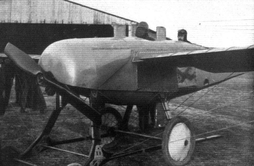
Mr. C. H. Pixton just ready to start from the Four Winds Aerodrome, Madrid, for a flight on his Bristol monoplane, with the Infanta of Spain, who occupies the front seat, and is wearing a fine wire mask for protection against the wind.
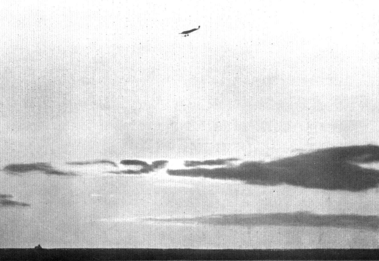
AT THE SETTING OF THE SUN. - A fine glide, the actual angle being 1 in 7.9, into the Cuatro Vientos Aerodrome, Madrid, by Mr. C. H. Pixton on a Bristol monoplane. This was the conclusion of a fifteen minutes' flight with the Infanta of Spain.
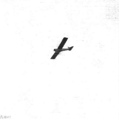
Mr. F. Warren Merriam making a fine high flight on the Bristol tandem monoplane at Salisbury Plain on October 10th.
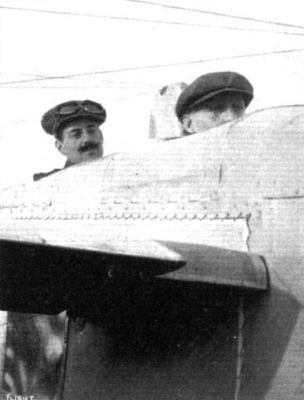
Mr. Henry M. Jullerot, the Manager and Chief Pilot of the Bristol School at Salisbury Plain, on one of the 80-h.p. school monoplanes, with Capt. Landon, a very promising pupil, as passenger.
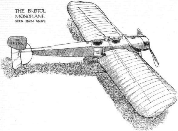
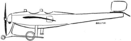
The 80-h.p. Bristol monoplane.
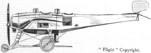
The 80-h.p. Bristol monoplane.
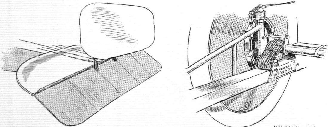
BRISTOL MACHINE DETAILS. - The tail on the left is a standartised unit, it being identical on both the monoplane and the biplane. The sketch on the right shows the flexible suspensioon of one of the main landing-wheels, with its band-brake and torque-rod.

The original method of cane suspension of the seats of the Bristol machine.
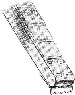
The laminated rear end of the Bristol monoplane skid.
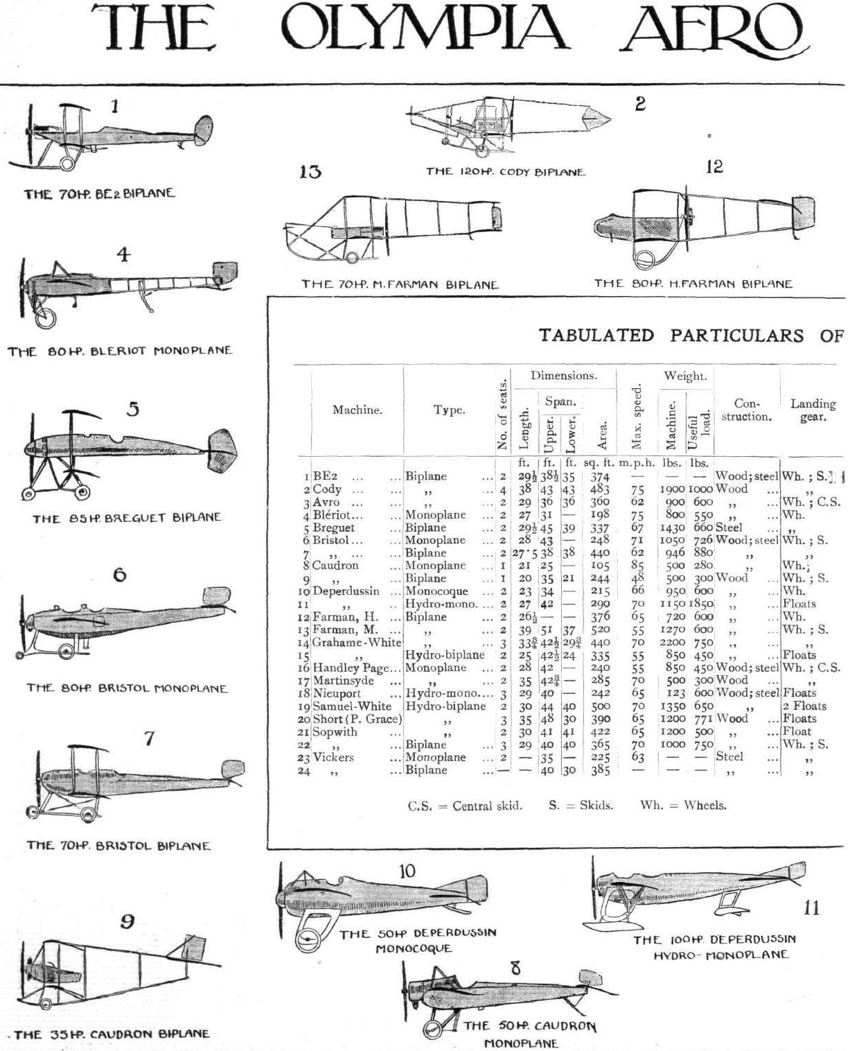
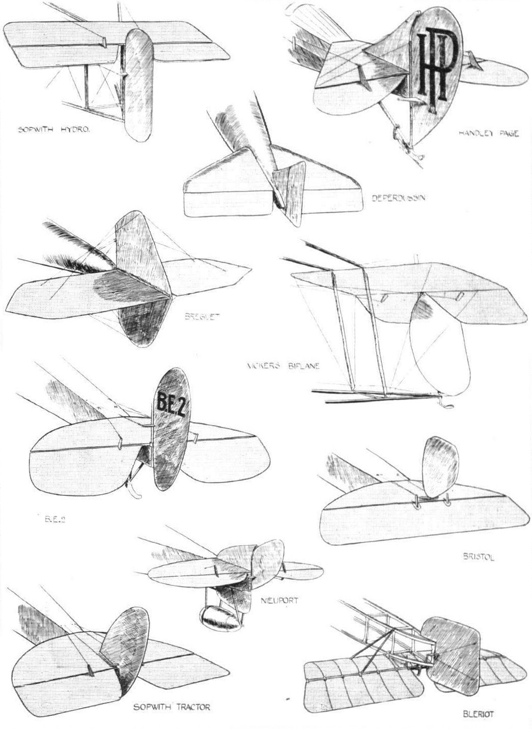
A study in tails.
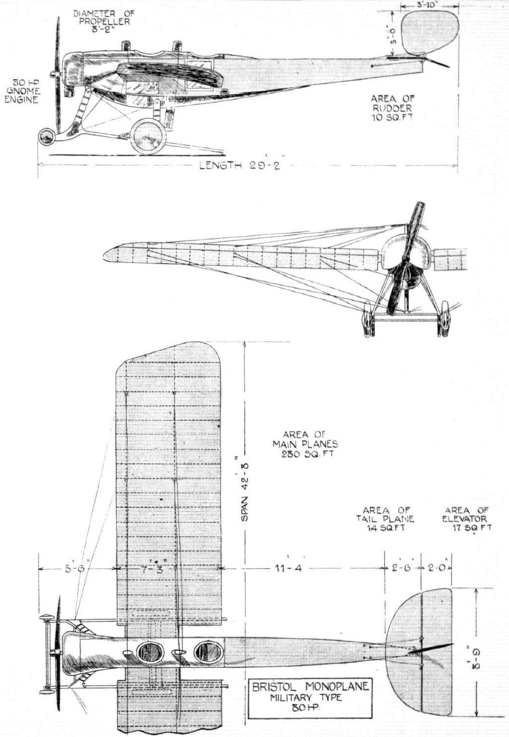
THE BRISTOL MONOPLANE. - Plan, side and front elevation to scale.
Flight, February 8, 1913.
WHAT THERE WILL BE TO SEE AT OLYMPIA.
THE MACHINES.
The British and Colonial Aeroplane Co., Ltd.
<...>
The 70-h.p. Renault-engined tractor biplane that the Bristol firm will be showing will be of a new type. Designed by the firm's well-known engineer, Mr. Henri Coanda, who also prepared the drawings of the monoplane we have just briefly described, this biplane will have many features in common with that machine. Thus, its fuselage will be practically identical with that of the monoplane, its landing gear will be of similar design, and the same method of wing construction will be noticeable in the assembly of its planes. The motor, mounted in front, will be almost entirely covered in by an aluminium shield, and will drive a two-bladed Bristol propeller 2.6 metres in diameter. The control will be the same as that employed on the monoplane, the elevator and wing warping being operated by a vertical wheel mounted on an inverted U-shaped bridge. The dimensions of this biplane will be: overall length, 27.5 ft.; span, 38 ft.; chord, 6 ft.; area, 440 sq. ft.; weight, light, 946 lbs.; total useful load, 880 lbs.; speed, 62.5 m.p.h.
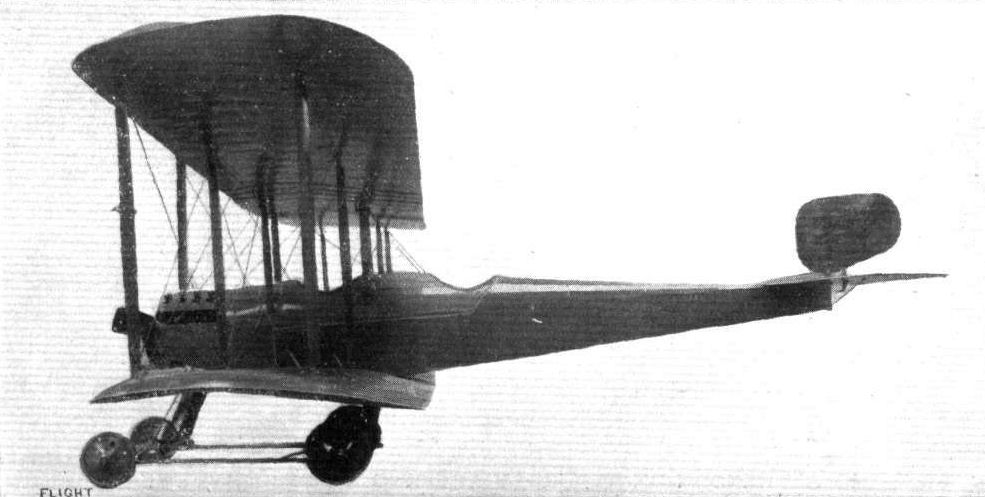
AT OLYMPIA SHOW. - The 70.h.p. Bristol biplane, as seen from the side.
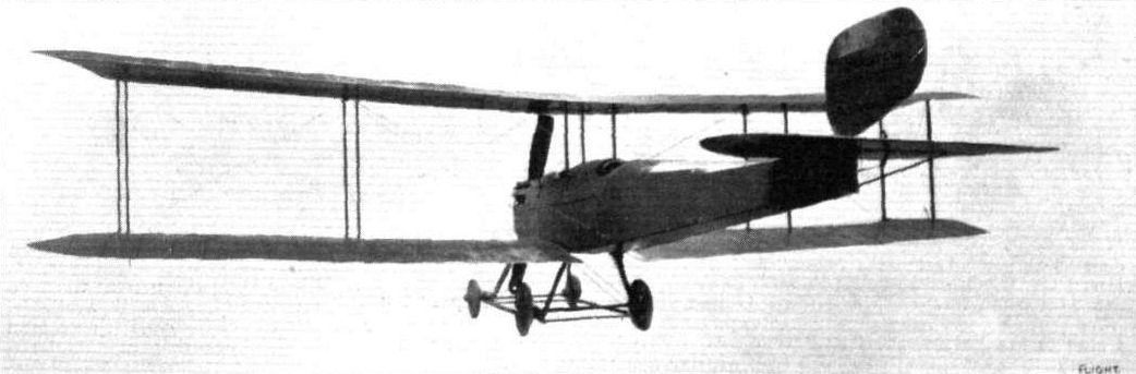
The new 70-h.p. Bristol biplane, one of the features of the Olympia Show.

Lieut. Roger Marshall, R.F.A. (Reserve), another pupil who passed his brevet tests at the Bristol, Lark Hill, School, in a 15-m.p.h. wind.
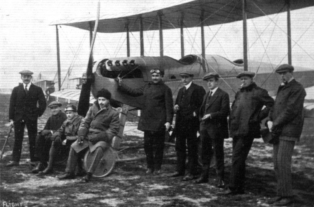
A school group at the Bristol Flying School, Amesbury, Wilts., showing just a few pupils grouped round one of the two-seater biplanes. Reading from left to right: Mr. Jullerot, pilot; Mr. David Tod, pupil, who is flying the monoplane excellently; Lieut. Marshall, pupil; Lieut. Chidson, pupil; Mr. C. H. Platon; Herr Paschen, a pilot of the German Bristol School; Mr. Fellows, of the Bristol Co.; Mr. Harrison, pilot; and Lieut Bromet, R.N., pupil.
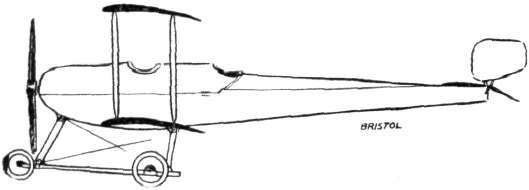
The 70-h.p. Renault-Bristol biplane.
Flight, December 13, 1913.
THE STANDS AT THE PARIS AERO SHOW.
BRISTOL.
AGAIN, this year, the only firm to represent Great Britain is the British and Colonial Aeroplane Company, who are showing a two-seater tandem military tractor biplane, fitted with an 80 h.p. Gnome engine, driving a Bristol propeller of very novel design, which has the inner part of the blades of streamline section, so that evidently the propulsion effect is obtained by the outer portion of the blades only. Some interesting fittings are to be seen on this machine, one being a pair of sights, by means of which the machine may be kept on a certain course when headed for a landmark such as a church tower. Another very interesting fitting is a new bomb-dropping device, invented by Mr. Coanda. This device, which is situated under the fuselage and observer's seat, contains 12 bombs, which maybe dropped at any desired interval, by means of a hand lever in the observer's cockpit. Needless to say the workmanship is up to the usual high "Bristol" standard, which compares very favourably with that seen on French machines.
Flight, December 20, 1913.
THE PARIS AERO SALON - 1913.
THE BRITISH AND COLONIAL AEROPLANE CO., LTD.
The very fine machine exhibited by the British and Colonial Aeroplane Co., Ltd., is a development of the biplane shown by this firm at the last Olympia Aero Show, and has incorporated in it a number of improvements suggested by tests in actual warfare carried out with several of these biplanes in the Balkan. From the accompanying illustrations it will be seen that the machine belongs to the tractor type, which possesses many advantages, and which, therefore, has been frequently adopted. Constructionally the machine is as interesting to the student of aeroplanes as its outlines are pleading to the eye of the artistically minded.
The fuselage, which is of rectangular section, consists of four longerons of ash connected by struts and cross members of spruce, the whole being made rigid in the usual way by means of diagonal cross wiring. A turtle back which gradually flattens out towards the tail, and a boat-shaped structure underneath the fuselage, gives that member a good streamline shape. In the front portion of the fuselage is mounted on overhung bearings the engine, an 80 h. p. Gnome, which is partly covered in by an aluminium cowl. Under this cowl and behind the engine are the oil and petrol tanks, whilst another tank behind the pilot's seat contains an additional supply of petrol which is pumped to the service tank in front by means of a pressure pump. The seats are of the bucket type, and are sprung by means of bent malacca cane supports; they are arranged in tandem, the pilot occupying the rear seat. In front of him are mounted the controls, which consist of a rotatable handwheel mounted on a single tubular column. Rotation of the wheel operates the warp, whilst a to-and-fro movement of the column actuates the elevator. A foot bar is fitted for steering in a horizontal plane. Let into a very neat dash in front of the pilot are all the instruments for cross-country flying, such as compass, clock altimeter, petrol and oil gauges, revolution indicator, and air speed indicator. Well out in front, from where he has an excellent view, is the observer's seat. Mounted in front of this, and projecting down through the fuselage, is the apparatus by means of which the observer determines the speed of the machine in relation to the earth. It consists, roughly speaking, of a rectangular box pointing downwards. In the upper end of this box is a sight through which the observer looks at the ground and at two transverse lines running across the lower end of the box. The distance between these two lines, as well as the distance from the upper sight to the lines is known. From the altimeter the observer knows the height of the machine above the ground, and by determining by means of a stop-watch the time it takes for an object, such as a tree or a house, to pass from one of the transverse lines to the other, it becomes a matter of trigonometry to work out the speed of the machine. A small table giving the necessary figures is mounted on the apparatus so that the determination of the speed may be accomplished in less time than it takes to describe the, in reality, very simple device. A bomb-dropping apparatus, situated in the floor of the fuselage, and consisting of a cylindrical drum on which are mounted twelve cigar-shaped bombs, is worked from the observer's seat by means of a small lever, so that the observer can release a single bomb, or, if necessary, all the twelve bombs with very short intervals. In order to steer the machine over any desired spot, two sights are mounted on top of the fuselage, in front of the observer's seat. The rear sight can be moved sideways for a distance of about 6 ins. If the observer finds that steering a dead straight course for some prearranged landmark will not bring him right over the desired point, he can slightly alter the course by sliding the rear sight to one side or the other so that although the pilot sees the landmark and the two sights in line, the machine is not actually heading straight for the landmark, but slightly to one side or the other. For use at night when the pilot is unable to see the two sights, an electric signalling system is employed, consisting of a series of push buttons in the observer's cockpit and a series of lamps in front of the pilot. Pressing one button lights a lamp which indicates: turn to right whilst passing; another indicates: descend and so on. We have described what might be termed the military portion of this machine at some length because it appears to be the most complete and well thought-out arrangement that has yet been shown to the public.
The chassis consists of four struts of spruce, carrying two ash skids, from which the two pairs of wheels are slung by means of rubber shock absorbers. The wheel axles, which are of strong steel tubing, are streamlined, with wooden pieces lashed on. Stranded cables have taken the place of the usual radius-rods, and the band-brakes which, it will be remembered, were fitted on the machine exhibited at Olympia have been discarded. The extensions of the skids to the rear of the chassis struts have been done away with, and in their place is fitted a tail skid of laminated wood. The main planes, which are of a new section, which has been found to give a very good lift-drift ratio, are separated by six pairs of struts, cross-braced in the usual manner. Both main spars are hinged on the fuselage, and warping is employed for lateral control. The tail planes consist of a semicircular fixed tail plane mounted on top of the fuselage. To the trailing edge of this is hinged the elevator, which is undivided, as the rudder is situated wholly on top of the fuselage.
Tin workmanship is of the usual high "Bristol" quality, and altogether it would have been difficult to find a more worthy representative for this country, but one can only regret that the British and Colonial Aeroplane Co, Ltd., were the only British firm showing, as neither of our leading firms need have feared comparison with the French manufacturers.
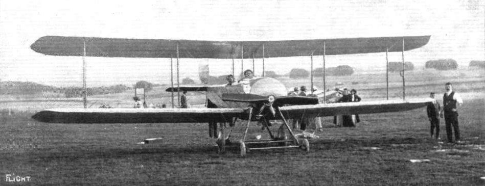
Bristol Coanda Type TB 8 prototype converted from Coanda Monoplane at Larkhill in 1913. - ONE OF THE NEW 80 H.P. BRISTOL TRACTOR BIPLANES ON SALISBURY PLAIN. - In the machine are Messrs. Pixton and Tullerot, who are just off for a trip.

The Bristol stand at the Paris Salon.
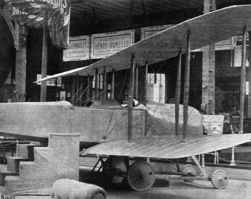
The Bristol biplane.
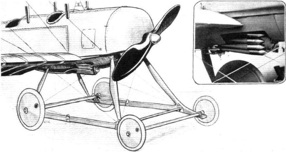
Half-tone sketch of chassis and engine of Bristol biplane. Inset: the bomb-dropping device.
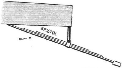
Tail skid of Bristol biplane.

Mr. S. F. Cody, whose biplane secured the first prize, open to the world, in the Military Trials, and the first of the prizes open to British subjects.
S. F. CODY. - A characteristic portrait of this famous aviator who was killed last week.
S. F. CODY. - A characteristic portrait of this famous aviator who was killed last week.
Flight, February 8, 1913.
WHAT THERE WILL BE TO SEE AT OLYMPIA.
THE MACHINES.
The War Office Exhibit.
<...>
The Cody biplane shown will be the identical machine on which, fitted with a 120-h.p. Austro-Daimler motor, Mr. S. F. Cody won the British Military Aeroplane trials on Salisbury Plain in August, 1912. A machine of unusual interest, for it was with the self-same biplane that Mr. S. F. Cody won the two Michelin competitions of 1911, completed the Daily Mail circuit of Britain, did command flights before the King, and won the speed Michelin of 1912. Altogether, this historic biplane has covered more than 7,000 miles in the air.
Flight, February 22, 1913.
SOME MORE AEROPLANES AT OLYMPIA.
THE 120-H.P. CODY BIPLANE.
A very great deal of interest attaches to this Cody machine, for it must be remembered that its constructor was the first to supply the British Army with war kites, built for the British Army their first dirigible balloon, built their first heavier-than-air machine, and won the first prize in their first international aeroplane competition. A duplicate of the biplane that is exhibited not only won the competition to which we have just referred, but, fitted with a 60-h.p. Green engine, it carried off the two Michelin competitions in 1911 and also completed the Daily Mail Circuit of Great Britain, while in 1912, with a 100-h.p. Green engine installed, it won the Michelin cross-country competition. Since it was constructed this biplane has flown upwards of 7,000 miles, which, if it is not a world's record, must be approaching very near to one.
Planes. - The most noticeable feature regarding the Cody plane construction, one of the features to which Mr. S. F. Cody attributes the machine's remarkable speed range, is that the under surface is a great deal more cambered than is the top surface. On most other machines the greater camber is usually noticeable on the upper surface. Behind the rear spars, there is a considerable amount of rib overhang, and, at high speeds, the wind pressure on this overhang is such that it has the effect of reducing the camber of the wing between the two spars. For the spars, they are cut from solid silver spruce, the front spar being rounded off in front, as it forms the leading edge of the plane. Solid spruce struts, 6 ft. 6 in. high, separate the two planes. In cross section they are of the original streamline that Mr. Cody arrived at as the result of experiments five years ago.
The landing gear consists of a hickory skid 16 ft. long, connected to the main planes by struts of the same wood. The rolling wheels form a unit independent of the skid. They have a track of 3 ft. 10 ins., and are sprung by steel compression springs. Regarding the strength of this chassis, it may be interesting to mention that the landing-gear fitted to the Cody monoplane is almost an identical structure to that of the biplane, and that when, flying his monoplane, Mr. Cody inadvertently landed on a cow, he neither felt the shock nor damaged his chassis in the least.
Changes in the attitude of the machine are brought about by two elevators of large area, supported in front of the main plane on bamboo outriggers. They are so connected to the controlling lever that they may be made to move in unison or in opposition, in which latter condition they assist the main plane warping in maintaining lateral equilibrium. Fitted behind the main planes is the propeller, 10 ft. 8 ins. in diameter, of Cody design and manufacture. It is driven by chain transmission, and the sprockets are so designed that the ratio of engine revolutions to propeller revolutions is as 1 3/4 is to 1. This biplane, which can seat three passengers in addition to the pilot, has a speed range of from 47 to 75 miles per hour.
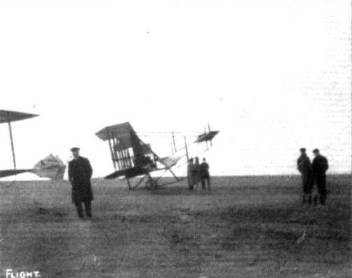
The new Cody Army 'bus at Farnborough, after it was taken over by the Government recently, and before its transference to Olympia for exhibition.
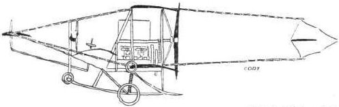
The 120-h.p. Cody biplane.

The 120-h.p. Cody biplane.
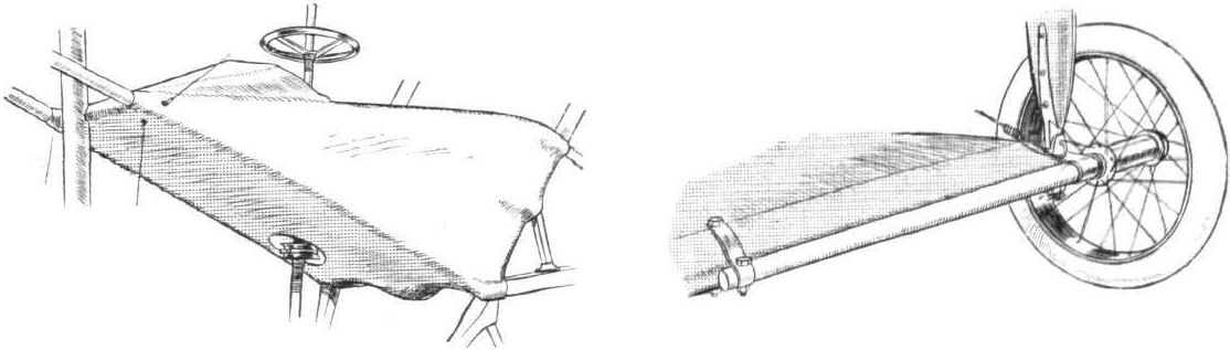
DETAILS OF THE CODY BIPLANE. - The sketch on the left shows the covered-in pilot's cockpit and control wheel, that on the right the mounting of the wing-tip wheels.
AT OLYMPIA. - A study in tail-skids.
A study in tails.
Flight, July 19, 1913.
BRITISH NOTES OF THE WEEK.
The New Cody Biplane.
LAST week-end Col. Cody was testing the new biplane, which he has built with the intention of competing in the Daily Mail race round Britain. In general design the biplane is similar to that which won the military competition, but it is larger, and has only one cruciform tail. The 100 h.p. engine drives a four-bladed Garuda propeller. A central skid with an upturned tusk in front is fitted, and skids are arranged under the outward sections of the main planes to take the place of the wheels which were formerly mounted at the wing tips. When the machine has, been thoroughly tested it will be fitted with three floats with which Col. Cody has been conducting trials on the Basingstoke Canal.
Flight, August 9, 1913.
BRITISH NOTES OF THE WEEK.
Death of Col. Cody.
IT is with the deepest regret that we have to record that the news reaches us as we go to press that Col. Cody, while flying at Aldershot on Thursday morning with a passenger named Evans, met with an accident and was killed, together with his passenger.
Flight, August 16, 1913.
THE CODY WATERPLANE.
No doubt most of our readers will agree that in no better way could we honour the name of the great pioneer, than by publishing illustrations and particulars of the latest machine built by the late Col. S. F. Cody for the Daily Mail race round Britain, the machine in which he had incorporated all the improvements that his great experience and ever-alert inventive genius had suggested to him, and of which his opinion - as expressed by himself a short time before his death - was that she was "A beauty, and as steady as a rock." We believe that the scale drawings and sketches of the Cody Waterplane, which we publish herewith, and which were made a few days before Mr. Cody's death, are the only complete drawings available of the ill-fated machine, and they should therefore be of exceptional value to all who have followed with interest the work of the great pioneer.
Size and weight have always been the characteristics of Cody machines, and it was only to be expected that for a contest like the Daily Mail Round Britain Race, which will impose upon both pilot and machine much more severe strains than any to which aeroplanes have hitherto been subject that these characteristics would be retained, and as regards dimensions and weight the Cody is far in excess of any of the other machines entered. In this latest machine the span of the main planes has been considerably increased, while the overall length has been greatly reduced by bringing both the front elevator and the rudder closer in towards the main planes. It will be remembered that the machine on which Mr. Cody won first prize in the Military Competition last year had two rudders of cruciform shape. In the present machine only a single rudder is fitted, which has consequently had to be made of much larger area, situated, as it is, closer to the main planes, and therefore working on a smaller leverage. One of the features of the earlier Cody biplanes has disappeared, i.e., the divided front elevator, which worked in conjunction with the main planes for maintenance of lateral stability. In its stead is fitted an elevator of more orthodox type, which has a slot cut in the centre for the accommodation of the central elevator booms. These, as well as the tail outriggers are made of bamboo bound with fabric. The nacelle is of a slightly different form to last year's model, providing better accommodation for the pilot's and passenger's seats, which are placed tandem fashion, and which are still of the type more commonly associated with farm implements. A 100 h.p., 6-cyl., all-British Green engine, furnishes the power, and drives through chain and sprocket gearing a propeller of 10 ft. 8 ins. diameter. For experimental purposes a four-bladed Garuda propeller was fitted, which was exchanged later for one of British manufacture (the latter being on the machine when the mishap occurred). The petrol tank, which has a capacity of 60 gallons, is situated above and behind the passenger's seat, while a supply of 14 gallons of oil is carried in a smaller tank situated underneath the engine.
Eight pairs of struts of silver spruce connect the main planes, which are of the typical Cody section, characterized by a deeper camber on the underside of the wing than that on the top. For maintenance of lateral stability, the main planes are warped by moving the control lever from side to side. A to and fro movement of the steering column operates the elevator, whilst rotation of the hand wheel actuates the rudder. It will thus be seen that the feet of the pilot do not perform any function in the control of the machine, and are therefore left free to operate the accelerator and ignition pedals fitted on the floor board of the nacelle. An interesting feature, and one that is not generally known in connection with the Cody control, is that the rudder works in conjunction with the warp, so that in correcting a bank the rudder is put over just sufficiently to counteract the drag on the lower side without any necessity for turning the handwheel.
For use as a land machine, a chassis of somewhat modified form to that of the earlier types is fitted, it having been designed with a view to facilitate interchangeability with floats, and in the accompanying scale drawings we show both types of chassis. The floats, of which there are three, are of Mr. Cody's own design, from which he expected excellent results, but which, unfortunately, he never got a chance to fully test. The main or central float, which is of enormous size, has three steps of peculiar design, while the two smaller floats are of the plain or punt shape. While the smaller floats are situated higher up than the main floats, they are still sufficiently far down to be always in contact with the water until the machine is just about to rise, so that it will be very stable when at rest or taxying on the water. Cedar and mahogany are the materials used in the construction of the floats, the main float being provided with a canvas deck. The speed of the machine is 50 to 60 m.p.h., and the weight, when empty and fitted with the land chassis, is about a ton.
BRITISH NOTES OF THE WEEK.
The New Cody Biplane.
LAST week-end Col. Cody was testing the new biplane, which he has built with the intention of competing in the Daily Mail race round Britain. In general design the biplane is similar to that which won the military competition, but it is larger, and has only one cruciform tail. The 100 h.p. engine drives a four-bladed Garuda propeller. A central skid with an upturned tusk in front is fitted, and skids are arranged under the outward sections of the main planes to take the place of the wheels which were formerly mounted at the wing tips. When the machine has, been thoroughly tested it will be fitted with three floats with which Col. Cody has been conducting trials on the Basingstoke Canal.
Flight, August 9, 1913.
BRITISH NOTES OF THE WEEK.
Death of Col. Cody.
IT is with the deepest regret that we have to record that the news reaches us as we go to press that Col. Cody, while flying at Aldershot on Thursday morning with a passenger named Evans, met with an accident and was killed, together with his passenger.
Flight, August 16, 1913.
THE CODY WATERPLANE.
No doubt most of our readers will agree that in no better way could we honour the name of the great pioneer, than by publishing illustrations and particulars of the latest machine built by the late Col. S. F. Cody for the Daily Mail race round Britain, the machine in which he had incorporated all the improvements that his great experience and ever-alert inventive genius had suggested to him, and of which his opinion - as expressed by himself a short time before his death - was that she was "A beauty, and as steady as a rock." We believe that the scale drawings and sketches of the Cody Waterplane, which we publish herewith, and which were made a few days before Mr. Cody's death, are the only complete drawings available of the ill-fated machine, and they should therefore be of exceptional value to all who have followed with interest the work of the great pioneer.
Size and weight have always been the characteristics of Cody machines, and it was only to be expected that for a contest like the Daily Mail Round Britain Race, which will impose upon both pilot and machine much more severe strains than any to which aeroplanes have hitherto been subject that these characteristics would be retained, and as regards dimensions and weight the Cody is far in excess of any of the other machines entered. In this latest machine the span of the main planes has been considerably increased, while the overall length has been greatly reduced by bringing both the front elevator and the rudder closer in towards the main planes. It will be remembered that the machine on which Mr. Cody won first prize in the Military Competition last year had two rudders of cruciform shape. In the present machine only a single rudder is fitted, which has consequently had to be made of much larger area, situated, as it is, closer to the main planes, and therefore working on a smaller leverage. One of the features of the earlier Cody biplanes has disappeared, i.e., the divided front elevator, which worked in conjunction with the main planes for maintenance of lateral stability. In its stead is fitted an elevator of more orthodox type, which has a slot cut in the centre for the accommodation of the central elevator booms. These, as well as the tail outriggers are made of bamboo bound with fabric. The nacelle is of a slightly different form to last year's model, providing better accommodation for the pilot's and passenger's seats, which are placed tandem fashion, and which are still of the type more commonly associated with farm implements. A 100 h.p., 6-cyl., all-British Green engine, furnishes the power, and drives through chain and sprocket gearing a propeller of 10 ft. 8 ins. diameter. For experimental purposes a four-bladed Garuda propeller was fitted, which was exchanged later for one of British manufacture (the latter being on the machine when the mishap occurred). The petrol tank, which has a capacity of 60 gallons, is situated above and behind the passenger's seat, while a supply of 14 gallons of oil is carried in a smaller tank situated underneath the engine.
Eight pairs of struts of silver spruce connect the main planes, which are of the typical Cody section, characterized by a deeper camber on the underside of the wing than that on the top. For maintenance of lateral stability, the main planes are warped by moving the control lever from side to side. A to and fro movement of the steering column operates the elevator, whilst rotation of the hand wheel actuates the rudder. It will thus be seen that the feet of the pilot do not perform any function in the control of the machine, and are therefore left free to operate the accelerator and ignition pedals fitted on the floor board of the nacelle. An interesting feature, and one that is not generally known in connection with the Cody control, is that the rudder works in conjunction with the warp, so that in correcting a bank the rudder is put over just sufficiently to counteract the drag on the lower side without any necessity for turning the handwheel.
For use as a land machine, a chassis of somewhat modified form to that of the earlier types is fitted, it having been designed with a view to facilitate interchangeability with floats, and in the accompanying scale drawings we show both types of chassis. The floats, of which there are three, are of Mr. Cody's own design, from which he expected excellent results, but which, unfortunately, he never got a chance to fully test. The main or central float, which is of enormous size, has three steps of peculiar design, while the two smaller floats are of the plain or punt shape. While the smaller floats are situated higher up than the main floats, they are still sufficiently far down to be always in contact with the water until the machine is just about to rise, so that it will be very stable when at rest or taxying on the water. Cedar and mahogany are the materials used in the construction of the floats, the main float being provided with a canvas deck. The speed of the machine is 50 to 60 m.p.h., and the weight, when empty and fitted with the land chassis, is about a ton.
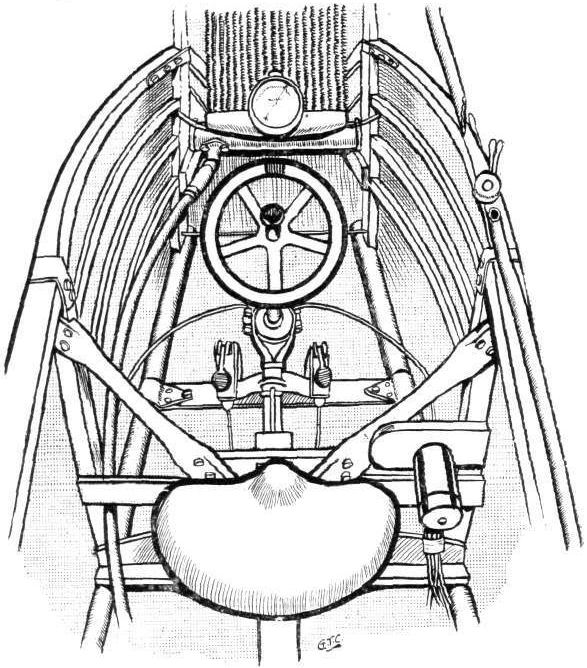
The nacelle of the Cody aeroplane, as seen from above.
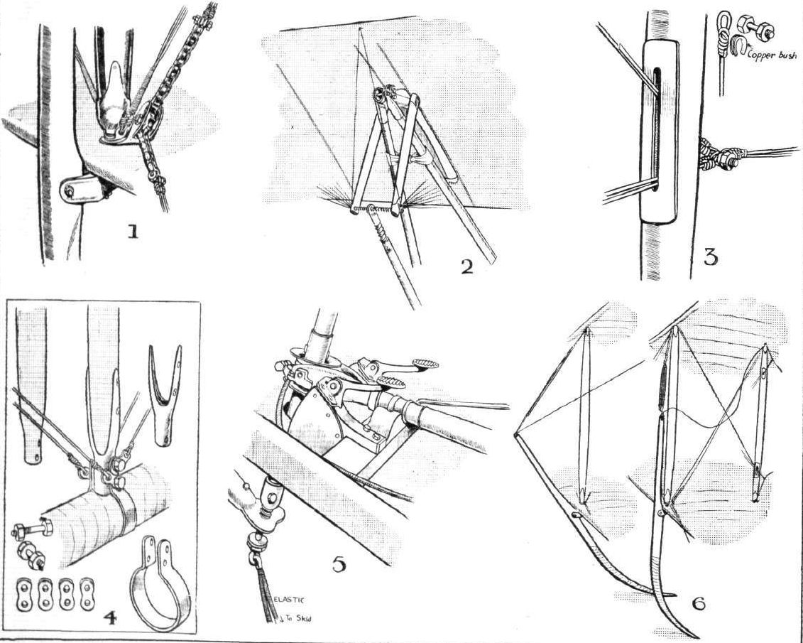
THE CODY WATERPLANE. - 1. A typical strut socket and swiwel joint of skid to main plane. 2. Attachment of elevator to central outriggers. 3. Sketch showing method of carrying warp wires through struts. 4. Analytical sketch of joint between tail boom and strut. 5. Universal joint and pedals operating engine control. 6. A novel form of wing skid.
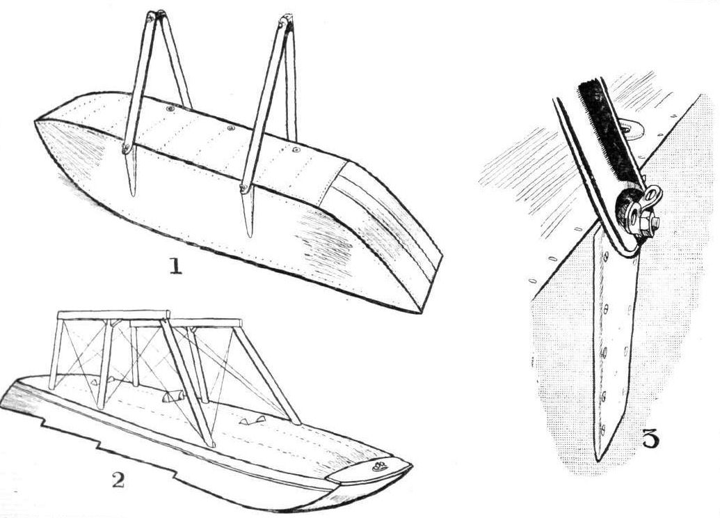
THE CODY WATERPLANE. - 1. One of the side floats. 2. Diagrammatic sketch of main float. 3. Attachment of tubular strut to side float.
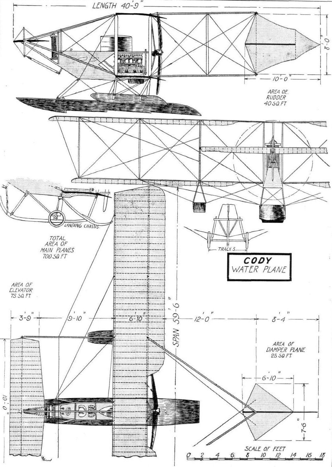
THE CODY WATERPLANE. - Plan, side and front elevations, &c, to scale.

The 100-h.p. Coventry Ordnance biplane, designed by Mr. W. O. Manning, has, since it has undergone general alterations and been fitted with more supporting surface, done quite a lot of flying at Brooklands of late. Mr. P. Raynham has been its pilot, and he flies it, most often, with a passenger up. The biplane has an unusually wide speed range, it being possible to land the machine at a less speed than 20 miles per hour.
Flight, December 6, 1913.
The Davies Glider No. 2.
DURING the last few weeks a considerable number of enquiries have been received with respect to various particulars relative to man-carrying gliders, and there is every indication that a large number of aero clubs intend to make it one of their chief features next season. It is, we all know, a most fascinating form of sport, and provided that something can be done with, say, a pedal-driven propeller to considerably augment the length or duration of the glide, its popularity would undoubtedly be still further increased. A machine of this character is naturally more expensive to build and maintain than a small rubber-driven model. The cost of its production does not, however, exceed that of a properly engined model, and there are many private individuals as well as clubs who, whereas they could not possibly either build or maintain a full-sized engine machine, are quite capable of tackling a glider.
Under the above circumstances, we have much pleasure in publishing the following account and scale drawings of a glider kindly sent us by Mr. W. Davies :-
"My first letter appeared in FLIGHT as far back as August, 1911, and gave a description of my first glider. From start to finish it was nothing but a lump of bad luck. Encouragement and local interest was at the time anything but brisk, and not having suitable grounds I decided to take it to pieces and go back to experimenting with models. It was not very long after having come to this decision that I came across a very suitable ground for gliding experiments, and this having caused the flight fever to come on again, I was quite unable to resist the desire to build another, this time a machine of similar dimensions but with constructional details much improved, and so made as to be easily assembled or taken to pieces, strong and yet light.
"Work went on but very slowly, as I built the machine entirely myself. When finished the space occupied was 21 ft. by 6.5 ft., but it was a long time to rig up the machine. Fortunately, however, I was not handicapped for room, so that the tail and outriggers were put together as one, and the cellule braced with the extensions down. On arriving at the flying ground very little had to be done, except putting up the extensions and bolting on the tail outriggers, which are shown clearly in Fig. 4.
"The gliding ground was at a distance of 6 miles from the building shed, and the transportation of the machine was undertaken quite on a military basis, the axle and wheels were half turned round on the skids, the tail slung on the extension, and the machine pushed off at top speed. The time the very early morning. We arrived at our destination feeling a little knocked up. The crew with me, which numbered six, worked as happy as if at an aviation meeting, all setting to and helping me to get the machine ready. I had decided from my experience with No. 1 that it would be better to get into the seat rather than risk her on her own. Having done so, a really delightful trip took place, at a height of about 5 ft. only from the ground, being pulled quite 50 yards; the wheels making it possible to get up speed quickly, and acting admirably in every way.
"These towed flights were the most successful, free glides being limited; we never seemed to get sufficiently high to accomplish long free glides, the longest free flight being about 130 ft., but much longer towed flights were made.
"I account for this by reason of the insufficient slope of the ground and the small supporting area, which works out at 1 lb. per sq. ft., which is too heavy. I should strongly advise builders to have a loading only of 3/4 lb. per sq. ft. rather than a smaller area and consequently heavier loading. It is much better as a test of your manipulatory skill, and avoids also landing at a speed and with a bump that the above machine did. Above all, be most particular with respect to the wind speed.
"One particular morning that we shall never forget, we motor cycled over to the ricksheds (the hangar) and found the wind much too high, but the sound of my 'Rudge multi' engine must have woke up some of the people in the neighbourhood, who knew quite well that the glider was there, and they must have thought that I had got an aero motor for the machine, for they came simply like a swarm of bees.
"The wind was still too strong, and the people got so very tired of waiting, and not wanting them to lose interest, I decided something should be done. To try a solo flight was madness, so I looked round for a passenger. The machine was wheeled from the shed into the open field, each of the crew at his proper place, a friend of mine (small in build, of course) volunteered to take the place as passenger. This we thought (if anything should be really accomplished) would be quite sensational.
"Before giving and explaining the result, it would be as well perhaps to mention that the angle of the tail plane was very high, thus throwing the centre of pressure further aft and making my position not so dangerous as if placed too far forward (H. Farman fashion); at the same time, this was upsetting theory, as there was no longitudinal dihedral making it safe for myself from a landing point, but stability was so far sacrificed. William Westwood was my passenger, and we sat very close together; the crew pulled the machine and off we went, still remaining on the ground, when all of a sudden up we popped and down we came, a most terrible bump, I pushing the passenger off the back, after crawling from under the wreckage; poor Billy was limping, he had cut his leg, so we took him to see the doctor, where a few stitches were inserted. After the doctor had patched up and made good we returned to the glider, and to my surprise the most important part, the four main spars, had broken through at the spot marked X X on the drawing, after my passenger and I had come through the top plane, and seeing that the cabanes, extensions and ailerons were smashed as well, I thought the best thing to do was to start afresh rather than patch up.
"As a result of the foregoing experience I strongly advise those who are thinking of building a glider to use bamboo for their spars, outriggers and ribs, as it will bend when receiving a shock, and will not break at that. Built on this principle, and strongly braced with 16 g. piano wire, with a strainer to each diagonal, and to employ 300 sq. ft. of supporting surface, and to experiment in a reasonable wind and slope. [A loading of ? lb. per sq. ft. requires a wind of about 20 m.p.h. to soar.]
"No doubt readers looking at Fig. 2 will not admire the tail outriggers in plan, but I found it answered well, as it is the only tail out of four that I have not smashed; it was also very rigid. Fig. 4 shows the method of bolting outriggers to the main cellule - the outriggers themselves are sawn down 6 ins., the plate let in pegged and bound with string. Fig. 5 shows a continuation of the outrigger to the tail strut, where a skid is fitted. Fig. 6 shows how the aluminium strut sockets and brackets for cellule bracing are bolted to the main spars. Fig. 7 is the elevating control, showing universal joint, wood handle bar bolted to 1 1/4 in. solid drawn steel tube.
"Fig. 8 was the most difficult job of all. It was composed of six pieces of ash, three making the complete circle, being screwed and glued together lamination fashion. The spokes were of ten g. piano wire diagonally crossed from the hub to the rim, as shown in the drawing, the wire being fastened through a hole in the plate, and passed through suitable ferrules. This answered admirably."
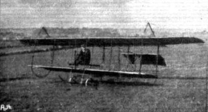
Mr. W. Davies' Glider.
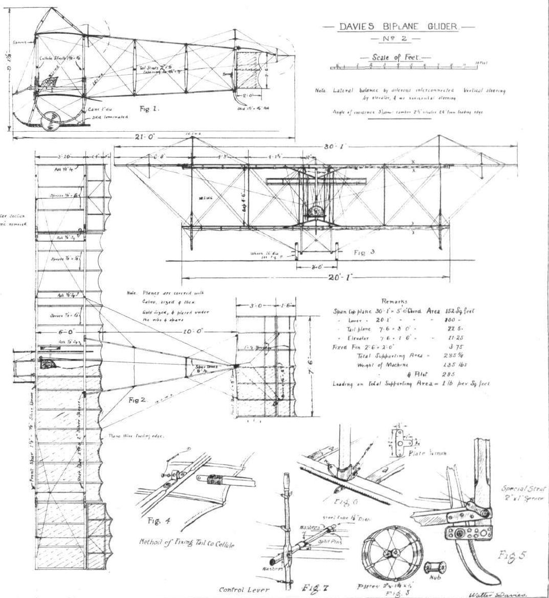
Davies glider No.2 of 1913.
Flight, March 15, 1913.
THE TWINING PROPELLER.
By E. W. TWINING.
<...>
One of these propellers was, some little time ago, supplied to Mr. H. S. Dixon and fitted to his 2-1-P-0 type (tailless) monoplane, with which he was then experimenting on the Aviation Ground at Acton.
Figs. 5 and 6 are photographs of the machine and power-plant, showing the propeller fitted. The diameter is 6 ft. 4 ins. and pitch 4 ft., revolutions 1,000. The engine is a 4-cyl. air-cooled, of 25-h.p. It should, however, be stated in favour of the propeller that although the machine repeatedly got off in runs of less than a hundred yards, the engine was never required to be run "all out."
<...>
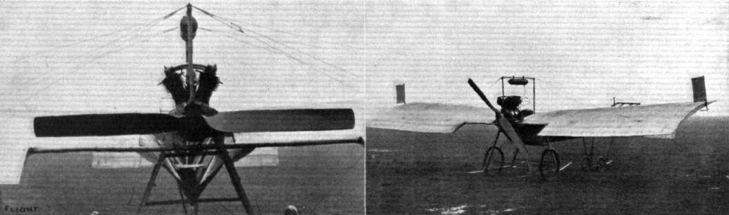
Figs. 5 and 6.
Flight, November 15, 1913.
THE DUNNE BIPLANE.
AT the present time there may be said to be two general types of aeroplanes which have been designed with a view to obtaining inherent automatic stability. One type has been developed in Austria and Germany by Herr Etrich and in this country by Mr. Handley Page, and the other is the Dunne type here described. As the theory of the Dunne machines has already been fully explained in the columns of FLIGHT (June 18th and 25th, 1910), we need not here enlarge upon that subject, but can confine ourselves to a description of the practical construction of the machine. We should like, however, to point out the most essential difference between the Etrich-Handley Page type and the Dunne. In the former stability is obtained by having the trailing edge of the back swept wing tips raised, thus setting these at a negative angle of incidence, whilst in the Dunne the leading edge of the wings are given a negative dihedral angle in order to obtain a negative angle of incidence on the wing tips. Another point in which the Dunne differs very considerably from the other types is that whilst these have tail planes of the ordinary type the Dunne machines have no tail planes, or, more correctly speaking, the back swept main planes perform the duty of the usual tail planes, in so far as they serve as both rudder and elevator.
From the plan view of the machine it will be seen that the main planes slope backwards very considerably, 14 ft. to be exact. Whilst the chord remains the same throughout the whole length of the planes, the rear spars slope less back than do the front ones, so that the amount of overhang of the trailing edge is considerably more at the tips than at the root of the wings. This, of course, has the advantage of allowing larger ailerons to be fitted, as these are hinged to the rear spars. The main spars, the front one of which serves at the same time as leading edge, are made of spruce of rectangular section, over which are built the ribs, which have flanges of spruce and webs of whitewood. As has already been said, the angle of incidence diminishes towards the tip, but another point in which the Dunne differs from other machines is that the camber increases towards the tips, the centre ribs being nearly flat, while those at the tip have a very pronounced camber. The joint of the upper main planes occurs at the centre, while the lower planes butt against the sides of the nacelle.
At the extremities of the wings, and in the gap between the main planes are two side curtains, which are fixed: that is to say, they are not in any way controllable from the pilot's seat. Hinged to the rear spars are four ailerons, which at the same time perform the functions of rudders and elevator. For climbing the ailerons on both sides are turned up, and the downward pressure thus caused, acting as it does on the part of the wings which lies to the rear of the centre of gravity, forces the nose of the machine upwards, or, more correctly speaking, forces the wing tips downwards, thus causing the machine to climb. For descent the reverse procedure is followed, i.e., the ailerons on both sides are depressed. It should be clearly understood that the right and left hand ailerons are worked independently, each pair being connected up to a separate lever in front of the pilot's seat. For making a turn, one lever is pulled backwards, while the other is pushed forward. Thus, for making a left-hand turn the right-hand lever is pushed forward, while the left-hand one is pulled backwards. The movement is in reality the same as that of turning the steering wheel of a motor car. In the forward part of the nacelle is the pilot's seat, from where he has an excellent view in all directions. In front of him is a dashboard with the instruments, whilst the top of the forward part of the nacelle is swept upwards to form a deflector, which sweeps the air up over the pilot's head. The passenger's seat is in the rear of the nacelle, and situated on top of the main petrol tank. As it is well to the rear of the V formed by the trailing edges of the main planes, the passenger has also an unrestricted view in all directions. In front of the passenger are two control levers, which are interconnected with those in front of the pilot, thus affording dual control, but, while the pilot's control levers can be locked in any position required on the quadrant on which they work, the passenger's levers are always left free so that only the pilot has it in his power to lock the controls. At the rear end of the nacelle is the 80 h.p. Gnome engine mounted on overhung bearings, and driving directly a propeller of 8 ft. 2 ins. diameter. On the upper longerons of the nacelle are mounted the oil tank and a small petrol service tank. Petrol flows from the main tank inside the nacelle to a small pump mounted on the rear skid struts, and driven by a miniature propeller. The pump forces the petrol up in the small service tank, whence it runs by gravity to the engine.
The chassis is highly original, although somewhat complicated and, we should be inclined to think, offering a considerable amount of head resistance, but Mr. Dunne finds that its excellent qualities for landing on the roughest ground more than justifies its being retained. As it is fully illustrated in the accompanying sketches, a short description will suffice. The front portion consists of three pairs of struts carrying at their lower extremities two skids, from which is sprung by means of a transverse tube and rubber shock-absorbers another universally pivoted skid which takes the weight of the front part of the machine and prevents it from standing on its nose. To the rear of this portion of the chassis are the wheels, which are also flexibly mounted so that they can "give" in any direction. Springing is effected by means of very powerful coil springs and telescopic tubes. Four steel tubes forming an inverted pyramid carry at their lower extremities another skid which serves to keep the propeller from contact with the ground, whilst the wing tips are similarly protected by two skids mounted on the outer extremity of the lower main plane.
The main petrol tank has a capacity of 22 gallons, and the small service tank holds 4 gallons, while 12 gallons of oil are carried in the oil tank on top of the nacelle. The weight of the machine empty is about 1,400 lbs., and her speed is in the neighbourhood of 55 m.p.h.
Flight, December 13, 1913.
THE STANDS AT THE PARIS AERO SHOW.
NIEUPORT DUNNE
The Nieuport firm are represented by four monoplanes and a biplane, the latter being a French-built Dunne biplane, which machines, it will be remembered, are now constructed in France by the Nieuport firm. In its general arrangement this machine is similar to the British-built Dunne biplanes, but one alteration which, we think, must be considered an improvement was noticeable. We refer to the chassis, which is of an entirely new and very simplified form; in fact, one is inclined to think that the other extreme has almost been reached, for whilst the British-built machines were fitted with a very complicated chassis, this structure has in the French machine been simplified to a degree that makes one question its efficiency. Not the least interesting of the monoplanes shown is the actual machine flown by Helen in his famous flights for the Coupe Michelin, in which he covered officially 16,046 kiloms. 600 metres, while the actual distance covered on these flights in thirty-nine consecutive days is claimed by the firm to be over 21,000 kiloms. The machine, although naturally slightly dirty, does not appear to be any the worse for wear, and is the best proof one could have of the excellence of the Nieuport workmanship.
Of the other monoplanes shown one is of the military type and is fitted with a machine gun, whilst the remaining two are a single-seater racing machine and a tandem two-seater.
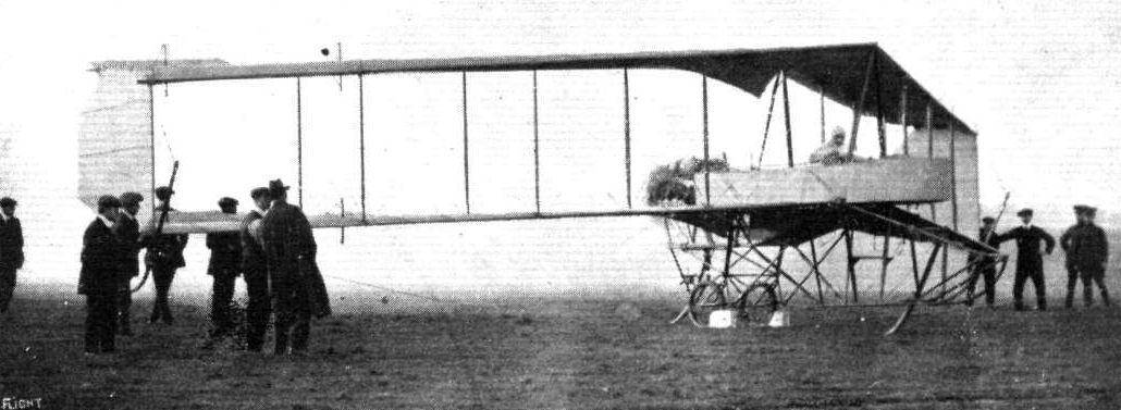
Commandant Felix testing the 80 h.p. Gnome Dunne D.8 at Hendon.
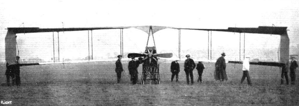
THE DUNNE BIPLANE. - View from the rear.
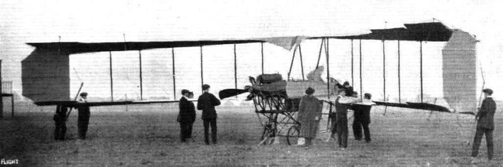
THE DUNNE BIPLANE. - As seen from behind.
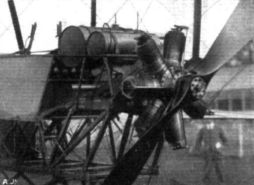
The Gnome engine in place on the Dunne biplane.
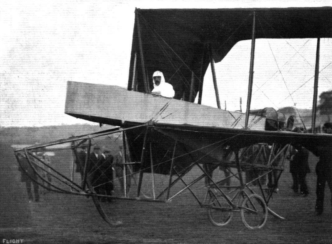
Commander Felix in the pilot's seat of the Dunne aeroplane at Hendon on Saturday. Our photograph shows very clearly the chassis and the arrow front section of the Dunne biplane.
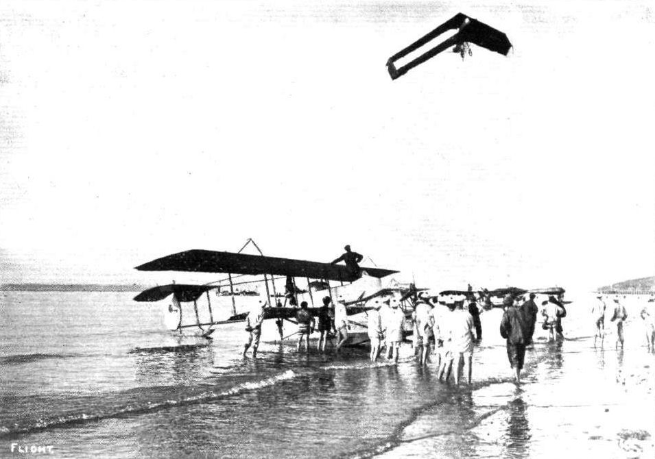
AT DEAUVILLE. - Commandant Felix flying on the Dunne biplane over the sands. Below in the foreground is a Henry Farman waterplane. and in the distance other waterplanes taking part in the French Government Waterplane Trials.
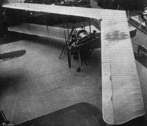
The Dunne machine on the Nieuport stand at the Paris Salon.
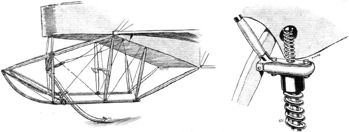
The front (wood) portion of the chassis, and on right the upper part of the shock-absorbing spring, together with the smaller spring designed to prevent excessive recoil on landing.

Sketch of the steel portion of the Dunne landing chassis. On the right a detail of the landing chassis, including one of the six universal-joints incorporated in the chassis.
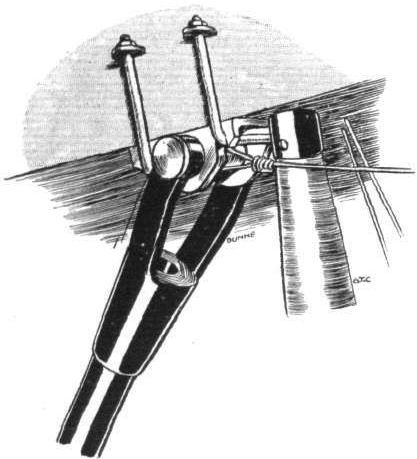
Shows the connection of one of the front steel tubes of the chassis to the fuselage,

The petrol pressure-pump seen from behind.
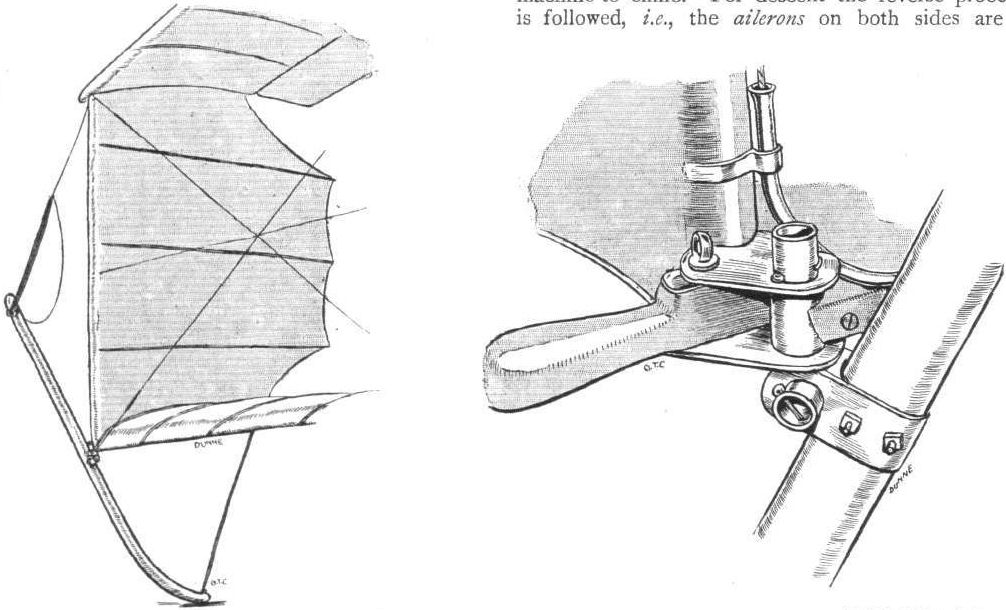
One of the side curtains and wing tip skids, and on right a closer view of the wing tip skid universal-joint.
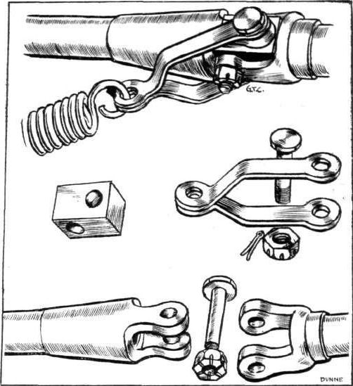
One of the universal-joints, and an analysis of same.
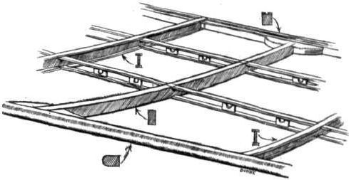
Sketch showing the wing construction of the Dunne biplane.

Diagram to illustrate how steering is effected.
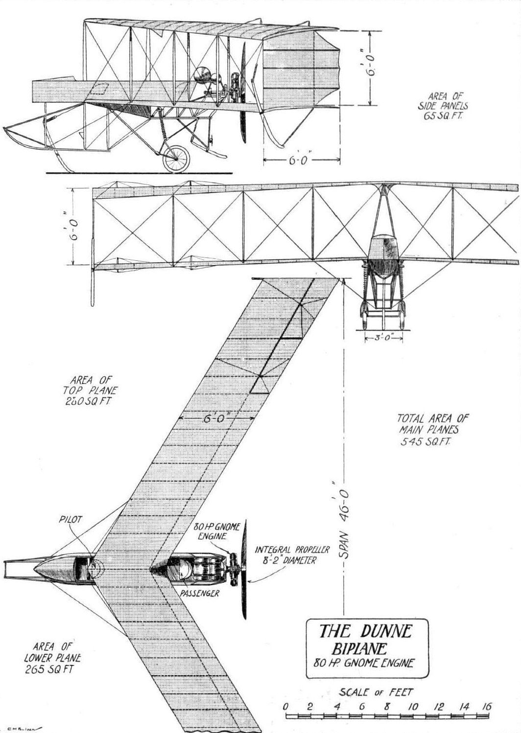
THE DUNNE BIPLANE. - Plan, front and side elevations to scale.
Flight, April 26, 1913.
THE DYOTT MONOPLANE.
A VERY interesting machine has just been completed at the Hewlett and Blondeau Aeroplane Works at Clapham, to the designs of Mr. G. M. Dyott. Although in its outward appearance the machine follows the lines of well-known makes, Mr. Dyott has managed to incorporate in it a very great number of cleverly-thought-out details, which his practical experience as a pilot has suggested to him.
The fundamental feature of the design of this machine is the fact that the gunwales are parallel to the line of flight, a method of construction which greatly facilitates the "tuning up" of the machine, as all adjustments may then be made from this line. This is a point which will be readily appreciated by anybody who has ever had to tune up a machine on the flying ground or in a temporary hangar, the floor of which was not level.
The body, which is of rectangular section, is built up in the usual way of four longerons connected by struts and cross members, the whole being braced by strong diagonal wiring. Ash is the material used in the construction of the front part of the body, where it has to carry the weight of the engine, tanks and pilot, and where consequently the greatest strength is required, while the rear portion of the fuselage is made of spruce. It is interesting to note that the joints of the struts and cross members to the longerons are so designed that not a single nut projects beyond the fuselage, a fact which permits the fabric to be applied absolutely smoothly to the body. From a point just behind the pilot's seat thin streamers, forming a "turtle back," run back to the rudder post, thus forming a nice stream-line. An aluminium cowl covering up the cockpit and front part of the body, and extended beyond the nose of the machine to form an oil-shield over the engine, completes the stream-line.
As will be seen from the plan view of the machine, the wings, which are somewhat reminiscent of the Dep., have two main spars of rectangular section, each spar being built up of three laminations, ash in the centre and spruce on the sides. Both spars fit into sockets situated in two stout transverse struts in the fuselage. In order to allow of the wings being warped, the socket for the rear spar is made a loose fit on the spar, which is pivoted around a strong bolt, secured by a split pin. To dismantle the wings, all that is necessary is to undo the top and bottom stay wires and the two bolts through the rear spars, and the wings can be taken off. The ribs, which are evenly spaced along the spars, are built up of webs of ash with flanges of spruce. The wings, as well as the body, are covered with unbleached linen, doped with S.P.L.A. varnish, the fabric being laced along the trailing edge, so that it may be kept taut under all climatic conditions. Lift and drift are taken by stout stranded cables attached to the lower extremities of the front skid struts, whilst the top bracing is effected by cables secured to a tubular A-shaped pylon. This pylon fits into two sockets on the gunwales, and is braced fore and aft by steel wires. By undoing these wires the pylon may be pulled out of its sockets and stowed away inside the body. The lower pylon, which consists of a single stream-line tube, carrying at its lower extremity a drum for the warping cable, is pivoted to the floor of the fuselage and stayed fore and aft by steel wire, so that it may be folded flat against the body.
Situated well down in the deepest part of the body, so that only the pilot's head projects above the cowl, is the pilot's seat, which is made of welded steel tubing and slung from the gunwales and securely braced to the lower longerons by steel wires. A neat padding of red leather, strapped on, covers the tubular framework of the seat, and the edges of the cockpit are padded in a similar way to protect the pilot, should he be thrown against them owing to a rough landing.
In front of the pilot is a very neatly-designed dashboard with all the different instruments useful for cross-country work, nearly all of which have been specially made for Mr. Dyott. Thus the compass, which is made by Kelvin and James White, Ltd., has only the cardinal points N.S.E.W. marked on it, and the four divisions are painted white, yellow, blue and red respectively. The pilot does not watch the compass card directly, but its reflection in a small mirror seen in one of the accompanying sketches. The north quadrant is painted white, and so the pilot knows that as long as he sees white in the mirror, he is steering a course somewhere between the quadrantal points N.W. and N.E. This does not, of course, give very accurate steering, but Mr. Dyott finds that it is very difficult to keep an aeroplane absolutely on its course in anything but a dead calm, and so prefers this method.
In addition to the usual instruments carried, i.e., revolution indicator and altimeter, this machine is fitted with an instrument of Mr. Dyott's own invention. It is a graphic recorder which shows all the different movements of the control levers. The chart is divided into three parts: Warp, Elevator and Rudder. As the drum revolves, three pointers draw the three different graphs, so that in a straight flight, during which the control levers were not moved at all, the pointers would draw three straight lines, but as soon as the course was altered the pointer connected to the rudder would make a wavy line, and as the warp is used in conjunction with the rudder, the warp pointer would draw a corresponding curve. This instrument should prove of great service, and furnish some very interesting data for comparing the different ways in which different pilots control the same machine.
The method of controlling the machine forms the subject of one of our sketches, which explains it better than a mere description ever could. It will be seen that crossing of the elevator-wires is avoided, so that there is no danger of them rubbing against one another and so becoming frayed and ultimately worn through.
Coming now to the chassis, which is of the wheel and skid type, this structure is interesting, mainly on account of the ease with which its different members may be replaced in case of breakage. By undoing the bracing-wires, all the struts may be pulled out of their respective sockets (the front pair of which are welded to the engine frame) without unscrewing any nuts or screws.
This is one of the really useful features of the machine. The use of screws and bolts has been reduced to a minimum, and wherever possible one bolt has been made to serve two purposes. Thus only four bolts are employed to secure the tail plane, which is of the non lifting type, to the fuselage.
A framework of steel tubing forms the empennage, which is very strong and quite light - about 10 lbs.
Right outside the nose of the machine, where it is easily accessible, is mounted the 50-h.p. Gnome engine, which has no support between the engine and the propeller. Inside the body, and just behind the engine, are situated the oil and petrol tanks, which have a capacity of 8 gallons each. Just behind the pilot's seat is another petrol tank, containing an additional supply of 10 gallons. The petrol is forced from this tank to the one in the nose of the machine by means of a hand-pump, situated to the left of the pilot's seat.
Mr. Dyott is taking this machine out to America, where he is booked to give exhibition flights in California, and at other places. We understand that on a similar machine Mr. Dyott proposes, on his return from America next October, to attempt the flight to India, the arrangements for which are now being made by Mr E. Esdaile.
Flight, May 24, 1913.
THE DYOTT MONOPLANE.
FROM Mr. G. M. Dyott, writing from New York on the 9th, comes some interesting news regarding this new machine, which was illustrated in FLIGHT on April 26th. He writes as follows: "The performance of my machine has surprised everyone, and its construction meets with universal admiration.
"She goes like a rocket, 75 miles an hour, with a 50-h.p. Gnome. The minute the tail is let go it leaves the ground at once, and the whole machine shoots forward at a tremendous speed; at 40 yards she is off the ground and climbing fast, with tail well up, not dragging at all, which is the ideal.
"Of course, the quick starting was one of the main objects of the design, but even I am surprised at her speed, and the way she hops off the ground at 40 yards.
"The machine handles well, and it is a joy to sit in the seat as comfortably as in an armchair, with not a breath of wind in one's eyes, at a speed of 75 miles.
"The field of vision is very fine, and at the same time the pilot can sit down inside if he likes, and neither see nor be seen. Every one at the Field is talking about it; so, on the whole, I am very pleased."
Flight, November 1, 1913.
THE DYOTT MONOPLANE AT HENDON.
AFTER an extensive tour of the U.S.A., where he has given numerous exhibition flights, Mr. G. M. Dyott has brought his machine back to this country, and it is now flying at Hendon. When looking at this machine it is difficult to believe that it has just completed a series of exhibition flights, most of them made under anything but ideal conditions, so well has it kept its ship-shape appearance. Not only has it flown one 2,000 miles, but on two occasions the machine was turned upside down when landing without breaking anything of importance, thus testifying to the qualities of the design and the workmanship.
With the exception of one or two details the machine is not altered since its completion in April this year, on which occasion it will be remembered it was fully described in the columns of FLIGHT. One of the alterations is to the tail skid, which has been replaced by one of cane instead of the long wooden skid with which it was fitted when Mr. Dyott took the machine out to America. Another alteration has been made to the mounting of the transverse steel tube which connects the two skids of the chassis. Instead of securing this tube to the lower extremity of the strut, which method involved a special socket, it is now fitted in a plain socket on the skid and working in compression only, the tension being taken by two stranded cables running parallel with the tube. Should the tube become damaged it can, if necessary, be replaced with a piece of gas pipe, as the socket can be made of the simplest form. The machine is particularly well equipped with all the usual instruments for cross-country work, and is in addition fitted with an instrument for recording the movements of the control levers by means of three pencils which are connected to the warp, rudder and elevator respectively.
We hope shortly to be able to publish a description of this recorder together with some graphs specially prepared for FLIGHT by Mr. Dyott.
From what we have seen of it the machine appears to fulfil admirably the conditions for which it was designed. It has light weight combined with strength, it can be easily dismantled and erected, it has a good climbing speed, on landing it pulls up very quickly and it can land in a small field, as the minimum speed is fairly low.
The upper and lower pylons can be removed by undoing a few wire strainers, and similarly that is all that is necessary to dismantle the chassis, since the struts are a sliding fit in their sockets, and can be pulled out when the diagonal cross wires have been removed by undoing the turnbuckles. The accompanying photograph shows the aluminium covering on the front part of the fuselage removed, an operation which only takes about a minute, and which allows the closest inspection of the engine and controls.
The maximum speed of the machine is about 65 m.p.h., while it can be landed at a speed of about 45 m.p.h. The tanks contain enough fuel for a three hours flight with the 50 h.p. Gnome engine with which it is fitted.
THE DYOTT MONOPLANE.
A VERY interesting machine has just been completed at the Hewlett and Blondeau Aeroplane Works at Clapham, to the designs of Mr. G. M. Dyott. Although in its outward appearance the machine follows the lines of well-known makes, Mr. Dyott has managed to incorporate in it a very great number of cleverly-thought-out details, which his practical experience as a pilot has suggested to him.
The fundamental feature of the design of this machine is the fact that the gunwales are parallel to the line of flight, a method of construction which greatly facilitates the "tuning up" of the machine, as all adjustments may then be made from this line. This is a point which will be readily appreciated by anybody who has ever had to tune up a machine on the flying ground or in a temporary hangar, the floor of which was not level.
The body, which is of rectangular section, is built up in the usual way of four longerons connected by struts and cross members, the whole being braced by strong diagonal wiring. Ash is the material used in the construction of the front part of the body, where it has to carry the weight of the engine, tanks and pilot, and where consequently the greatest strength is required, while the rear portion of the fuselage is made of spruce. It is interesting to note that the joints of the struts and cross members to the longerons are so designed that not a single nut projects beyond the fuselage, a fact which permits the fabric to be applied absolutely smoothly to the body. From a point just behind the pilot's seat thin streamers, forming a "turtle back," run back to the rudder post, thus forming a nice stream-line. An aluminium cowl covering up the cockpit and front part of the body, and extended beyond the nose of the machine to form an oil-shield over the engine, completes the stream-line.
As will be seen from the plan view of the machine, the wings, which are somewhat reminiscent of the Dep., have two main spars of rectangular section, each spar being built up of three laminations, ash in the centre and spruce on the sides. Both spars fit into sockets situated in two stout transverse struts in the fuselage. In order to allow of the wings being warped, the socket for the rear spar is made a loose fit on the spar, which is pivoted around a strong bolt, secured by a split pin. To dismantle the wings, all that is necessary is to undo the top and bottom stay wires and the two bolts through the rear spars, and the wings can be taken off. The ribs, which are evenly spaced along the spars, are built up of webs of ash with flanges of spruce. The wings, as well as the body, are covered with unbleached linen, doped with S.P.L.A. varnish, the fabric being laced along the trailing edge, so that it may be kept taut under all climatic conditions. Lift and drift are taken by stout stranded cables attached to the lower extremities of the front skid struts, whilst the top bracing is effected by cables secured to a tubular A-shaped pylon. This pylon fits into two sockets on the gunwales, and is braced fore and aft by steel wires. By undoing these wires the pylon may be pulled out of its sockets and stowed away inside the body. The lower pylon, which consists of a single stream-line tube, carrying at its lower extremity a drum for the warping cable, is pivoted to the floor of the fuselage and stayed fore and aft by steel wire, so that it may be folded flat against the body.
Situated well down in the deepest part of the body, so that only the pilot's head projects above the cowl, is the pilot's seat, which is made of welded steel tubing and slung from the gunwales and securely braced to the lower longerons by steel wires. A neat padding of red leather, strapped on, covers the tubular framework of the seat, and the edges of the cockpit are padded in a similar way to protect the pilot, should he be thrown against them owing to a rough landing.
In front of the pilot is a very neatly-designed dashboard with all the different instruments useful for cross-country work, nearly all of which have been specially made for Mr. Dyott. Thus the compass, which is made by Kelvin and James White, Ltd., has only the cardinal points N.S.E.W. marked on it, and the four divisions are painted white, yellow, blue and red respectively. The pilot does not watch the compass card directly, but its reflection in a small mirror seen in one of the accompanying sketches. The north quadrant is painted white, and so the pilot knows that as long as he sees white in the mirror, he is steering a course somewhere between the quadrantal points N.W. and N.E. This does not, of course, give very accurate steering, but Mr. Dyott finds that it is very difficult to keep an aeroplane absolutely on its course in anything but a dead calm, and so prefers this method.
In addition to the usual instruments carried, i.e., revolution indicator and altimeter, this machine is fitted with an instrument of Mr. Dyott's own invention. It is a graphic recorder which shows all the different movements of the control levers. The chart is divided into three parts: Warp, Elevator and Rudder. As the drum revolves, three pointers draw the three different graphs, so that in a straight flight, during which the control levers were not moved at all, the pointers would draw three straight lines, but as soon as the course was altered the pointer connected to the rudder would make a wavy line, and as the warp is used in conjunction with the rudder, the warp pointer would draw a corresponding curve. This instrument should prove of great service, and furnish some very interesting data for comparing the different ways in which different pilots control the same machine.
The method of controlling the machine forms the subject of one of our sketches, which explains it better than a mere description ever could. It will be seen that crossing of the elevator-wires is avoided, so that there is no danger of them rubbing against one another and so becoming frayed and ultimately worn through.
Coming now to the chassis, which is of the wheel and skid type, this structure is interesting, mainly on account of the ease with which its different members may be replaced in case of breakage. By undoing the bracing-wires, all the struts may be pulled out of their respective sockets (the front pair of which are welded to the engine frame) without unscrewing any nuts or screws.
This is one of the really useful features of the machine. The use of screws and bolts has been reduced to a minimum, and wherever possible one bolt has been made to serve two purposes. Thus only four bolts are employed to secure the tail plane, which is of the non lifting type, to the fuselage.
A framework of steel tubing forms the empennage, which is very strong and quite light - about 10 lbs.
Right outside the nose of the machine, where it is easily accessible, is mounted the 50-h.p. Gnome engine, which has no support between the engine and the propeller. Inside the body, and just behind the engine, are situated the oil and petrol tanks, which have a capacity of 8 gallons each. Just behind the pilot's seat is another petrol tank, containing an additional supply of 10 gallons. The petrol is forced from this tank to the one in the nose of the machine by means of a hand-pump, situated to the left of the pilot's seat.
Mr. Dyott is taking this machine out to America, where he is booked to give exhibition flights in California, and at other places. We understand that on a similar machine Mr. Dyott proposes, on his return from America next October, to attempt the flight to India, the arrangements for which are now being made by Mr E. Esdaile.
Flight, May 24, 1913.
THE DYOTT MONOPLANE.
FROM Mr. G. M. Dyott, writing from New York on the 9th, comes some interesting news regarding this new machine, which was illustrated in FLIGHT on April 26th. He writes as follows: "The performance of my machine has surprised everyone, and its construction meets with universal admiration.
"She goes like a rocket, 75 miles an hour, with a 50-h.p. Gnome. The minute the tail is let go it leaves the ground at once, and the whole machine shoots forward at a tremendous speed; at 40 yards she is off the ground and climbing fast, with tail well up, not dragging at all, which is the ideal.
"Of course, the quick starting was one of the main objects of the design, but even I am surprised at her speed, and the way she hops off the ground at 40 yards.
"The machine handles well, and it is a joy to sit in the seat as comfortably as in an armchair, with not a breath of wind in one's eyes, at a speed of 75 miles.
"The field of vision is very fine, and at the same time the pilot can sit down inside if he likes, and neither see nor be seen. Every one at the Field is talking about it; so, on the whole, I am very pleased."
Flight, November 1, 1913.
THE DYOTT MONOPLANE AT HENDON.
AFTER an extensive tour of the U.S.A., where he has given numerous exhibition flights, Mr. G. M. Dyott has brought his machine back to this country, and it is now flying at Hendon. When looking at this machine it is difficult to believe that it has just completed a series of exhibition flights, most of them made under anything but ideal conditions, so well has it kept its ship-shape appearance. Not only has it flown one 2,000 miles, but on two occasions the machine was turned upside down when landing without breaking anything of importance, thus testifying to the qualities of the design and the workmanship.
With the exception of one or two details the machine is not altered since its completion in April this year, on which occasion it will be remembered it was fully described in the columns of FLIGHT. One of the alterations is to the tail skid, which has been replaced by one of cane instead of the long wooden skid with which it was fitted when Mr. Dyott took the machine out to America. Another alteration has been made to the mounting of the transverse steel tube which connects the two skids of the chassis. Instead of securing this tube to the lower extremity of the strut, which method involved a special socket, it is now fitted in a plain socket on the skid and working in compression only, the tension being taken by two stranded cables running parallel with the tube. Should the tube become damaged it can, if necessary, be replaced with a piece of gas pipe, as the socket can be made of the simplest form. The machine is particularly well equipped with all the usual instruments for cross-country work, and is in addition fitted with an instrument for recording the movements of the control levers by means of three pencils which are connected to the warp, rudder and elevator respectively.
We hope shortly to be able to publish a description of this recorder together with some graphs specially prepared for FLIGHT by Mr. Dyott.
From what we have seen of it the machine appears to fulfil admirably the conditions for which it was designed. It has light weight combined with strength, it can be easily dismantled and erected, it has a good climbing speed, on landing it pulls up very quickly and it can land in a small field, as the minimum speed is fairly low.
The upper and lower pylons can be removed by undoing a few wire strainers, and similarly that is all that is necessary to dismantle the chassis, since the struts are a sliding fit in their sockets, and can be pulled out when the diagonal cross wires have been removed by undoing the turnbuckles. The accompanying photograph shows the aluminium covering on the front part of the fuselage removed, an operation which only takes about a minute, and which allows the closest inspection of the engine and controls.
The maximum speed of the machine is about 65 m.p.h., while it can be landed at a speed of about 45 m.p.h. The tanks contain enough fuel for a three hours flight with the 50 h.p. Gnome engine with which it is fitted.
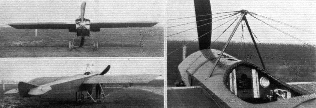
Three views of the Dyott monoplane which is now flying so well in America, as described in a recent issue of FLIGHT.
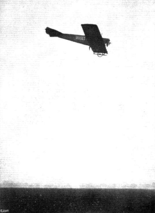
Mr. Dyott flying his monoplane at Hendon Aerodrome on Saturday last.
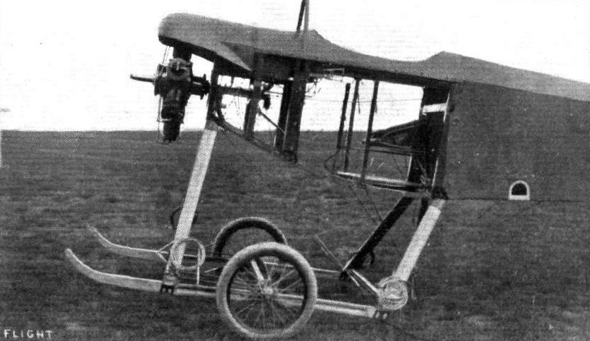
THE DYOTT MONOPLANE. - A view showing the aluminium covering of the front part of the fuselage removed, allowing a thorough inspection of engine and controls.
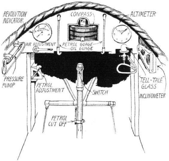
Sketch of the dashboard, showing the different instruments.
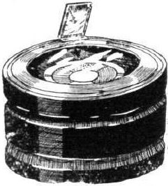
Sketch of the special compass used on the Dyott monoplane.

The locker and auxiliary fuel tank behind the pilot's seat.
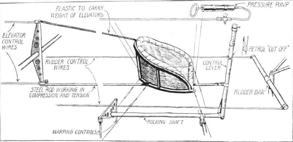
Diagrammatic sketch of the Dyott controls.
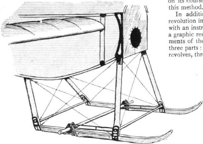
The landing chassis; the wheels have been omitted for the sake of clearness.

Details of the Dyott monoplane: the sketches on the left and in the centre show the lower and upper pylons with their fittings. On the right is seen one of the shock absorbers on the chassis.
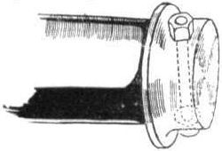
The wheel retaining axle cap on the landing chassis.

Wing section, to scale, of the Dyott monoplane.
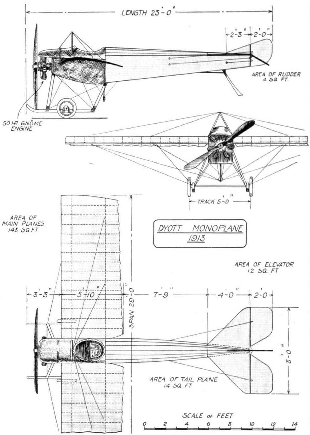
DYOTT MONOPLANE. - Plan, side and front elevation to scale.
Flight, May 3, 1913.
THE E.A.C. MONOPLANE,
A NEW machine has been added to the list of British built aeroplanes. The monoplane in question has been designed for the Eastbourne Aviation Co., Ltd., by Mr. E. L. Gassier, who has had considerable experience in this direction, besides being a practical engineer and an able pilot, so that, although the machine is an experimental one, it should be fairly certain to give a good account of itself.
Looking over the machine, one of the features which first attracts attention, is the presence of ailerons for the maintenance of lateral stability, instead of the method of wing warping usually adopted for that purpose. Although this is a departure from what has now come to be almost standard practice as regards monoplane construction, it is a system which works quite well in machines of the biplane type, and there is no apparent reason why it should not be equally successful when applied to monoplanes, especially when, as in this case, the ailerons are interconnected, so that when one is depressed the other is elevated a corresponding amount. At any rate, the system has much to recommend it, as it does away with the twisting strains imposed upon the wings where the wing-warping system is employed.
From the plan view of the machine it will be seen that the two main spars, which are of rectangular section ash, are placed very close together, so that the rear spar is placed about half-way along the chord. This method of construction imparts a certain amount of flexibility to the trailing edge and has, furthermore, the advantage that it allows a compression strut - in this case a very strong steel tube - to be interposed between the upper longerons of the fuselage in front of the pilot's seat for the purpose of resisting any tendency of the wings to bend the longerons of the body inwards.
Evenly spaced along the spars - except for the three ribs nearest the root, which are placed closer together than the rest - are the ribs, which have webs of three-ply wood, with top and bottom flanges of spruce and ash, respectively.
Very stout stranded cables, anchored to steel plates, which in turn are secured to the apex of the lower pylon by three bolts, take the weight of the machine when in flight, while another cable, running from the steel clip forming the anchorage for the inner lift wire on the rear spar, to the crank case of the engine, takes the drift of the wings.
The advantage of securing all the lift wires to a pylon, forming a separate unit instead of anchoring them to one of the members of the chassis, is that even should the latter become damaged through a rough landing, there is still a very good chance of the pylon remaining intact, so that the chassis may be repaired without in any way disturbing the stay wires.
Top bracing is effected by cables secured to the apex of a single A-shaped pylon of steel tubing of stream-line section. All the lift wires are duplicated, and it is worth noticing that each wire is anchored to a separate bolt.
As the rear spar is situated a considerable distance from the trailing edge, it has not been possible to hinge the ailerons to the rear spar, as is usually done, but a steel tube, situated roughly half-way between the trailing edge and the spar, serves as a pivot for the ailerons.
Stranded cables running from the lower aileron levers around pulleys on the outer steel clips of the front spar to the control lever operate the ailerons, which are interconnected by another cable running along the top of the front spar.
The body, which is of rectangular section, is very deep in the region around the pilot's seat and tapers to a horizontal knife edge at the back. The longerons are of ash and the struts and cross members are of spruce in the rear portion of the body while in the front part ash is employed.
Between the two main spars and on top of the body is situated the tank, which is divided longitudinally by a partition. The left-hand division contains 1 1/2 gallons of oil, whilst in the right-hand one are carried 6 gallons of petrol.
An aluminium casing, running from the nose of the machine up to the front of the tank, serves to deflect the air, and the rear end of the tank is made sloping, so as to serve as a dashboard.
Well down in the deepest part of the body is the seat for the pilot, who controls the machine by means of a centrally pivoted lever, mounted on a rocking shaft. A sideways movement of the lever operates the ailerons, while a to-and-fro motion works the elevator. A foot bar actuates the rudder, which is situated wholly on top of the tail planes. The rudder crank levers are mounted on the lower end of the tube, around which the rudder is pivoted, so that the rudder wires are carried inside the body throughout their entire length.
The tail plane, which is semicircular in plan view, is flat on the underside, while the top surface is cambered. Hinged to its rear edge is an undivided elevator plane of ample proportions.
The empennage is protected from contact with the ground by a tail skid.
A landing chassis of very neat design supports the machine when on the ground. As will be seen from the accompanying sketch it consists of two pairs of ash V struts, separated at their lower extremities by a steel tube. The tubular axle passes through two slots immediately above this tube, from which it is sprung by means of rubber shock absorbers.
On to a steel capping plate, forming the nose of tin machine, is bolted the 35-h.p. V type Anzani engine, which at present furnishes the power. It drives directly a Rapid propeller of 7 ft. dia.
As has been said before, the machine is an experimental one and no attempt has been made to provide a "Show" finish, but the term finish used in this connection must not be confused with workmanship, which latter is of a very high class.

Eastbourne Aviation Company monoplane constructed in 1913.

THE E.A.C. MONOPLANE. - Front view.
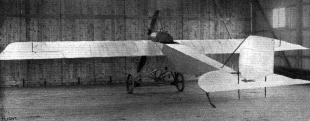
The E.A.C. monoplane, as seen from behind.
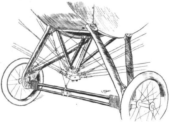
Sketch showing landing chassis and lower pylon with its fittings.
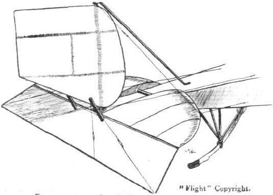
Empennage and tail skid of the E.A.C. mono.

Wing section, to scale, of the E.A.C. monoplane.

THE E.A.C MONOPLANE. - Plan, side and front elevation to scale.
Flight, October 18, 1913.
THE EGGLETON GLIDER.
THE accompanying photographs illustrate a glider which has been built by Mr. K. H. Eggleton, of Eastleigh, Hants, and with which, we understand, numerous successful glides have been made.
It will be noticed that the glider somewhat resembles the well-known Caudron biplane, especially with regard to the arrangement of the nacelle, tail booms and tail plane. The wings are quite different from those of the Caudron both in section and construction, having been designed by Mr. Eggleton himself. The camber, it will be observed, is very pronounced, in order, no doubt, to get sufficient lift at the slower speed at which the glider flies. The main planes, the chassis and the tail booms each form separate units, of which that of the tail booms is made detachable in order to facilitate storage in the hangar, which has a doorway only ten feet wide.
An inspection of the accompanying photos will reveal the fact that no rudder is fitted, as it has been found that steering can be effected by means of the elevator, which is warped in conjunction with the main planes in a similar manner to that employed for carrying out this operation in the Caudron machines. A centrally pivotted vertical lever in front of the pilot, by a side to side movement, operates the warp, while a to-and-fro motion o the lever controls the elevator, which is of the flexing type.
Four tension springs secure the axle to the skids of the chassis, and thus act as shock absorbers instead of the rubber lings usually employed for that purpose. .
Over one hundred flights have been made, we learn, with this glider, several of which were free flights, but in the majority of cases the glider was towed by Mr. Eggleton's assistants, as it was found difficult to secure the use of a hill providing a suitable gradient.
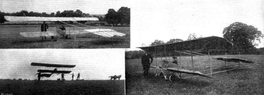
Three views of the Eggleton No.3 biplane glider of 1913.
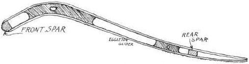
Sketch of wing construction of Eggleton glider.
Flight, October 25, 1913.
THE FLANDERSJBIPLANE.
AFTER a number of delays, due to no inherent fault in the machine itself, the Flanders biplane has proved that it possesses all the good qualities looked for in a machine, which is the product of so able a designer as Mr. L. Howard Flanders, whose name has in the past been more generally associated with the construction of monoplanes. Unfortunately Mr. Flanders cannot be present to witness the excellent flying now done by the machine of his creation, as he has been ordered by his doctor to go for a six months' trip to Australia, in order to recuperate after his recent motor smash. We feel certain that all our readers will join us in wishing Mr. Flanders a speedy recovery.
As for the machine itself, one of the first characteristics noticed is the extremely deep fuselage. On closer inspection the shape of that member is rather unusual, being of pentagonal section in the front portion and tapering away to a triangular cross section at the rear. The lower longeron or keel of the fuselage runs right through from bow to stern, as do also the two upper longerons. The lower longerons starting from the nose of the machine curve down abruptly to form the sides of the rectangular portion of the fuselage, and form a spliced joint with the keel about six feet to the rear of the pilot's seat. The longerons are of hickory in the front portion where the weight is concentrated, and where consequently the greatest strength is required, whilst in the rear the longerons are made of ash. The struts and cross members are of ash in front and of spruce behind, the whole being made rigid in the usual way by diagonal cross wiring. A turtle back formed by longitudinal stringers, and having its highest point in the neighbourhood of the pilot's seat, from where it gradually flattens out towards the tail plane, gives a neat appearance to the top of the fuselage as well as affording protection against the flow of air, as only the pilot's and passenger's heads project above the turtle back.
Another point which characterises this interesting machine is the peculiar arrangement of the main planes, the upper one of which is of considerably greater chord than the lower one, and being furthermore staggered forward. It will be noticed that this is obtained by having the rear struts at right angles to the line of flight whilst the front struts slope forward.
From the front elevation of the machine it will be seen that there is a considerable overhang to the upper plane, the weight of which, when the machine is on the ground, is taken by top bracing wires carried over king posts. Both top and bottom planes are straight, i.e. there is no dihedral angle, but the angle of incidence diminishes towards the tips of the planes, thus forming a pronounced "wash out." With the exception of the two inner plane struts, which serve to support the chassis struts and therefore are made of ash, the plane struts are all made of solid spruce. The wings are built up of spars of I section, ash being the material employed in the centre portion, while the outer part is made of spruce. The ribs have webs of white pine with flanges of ash, the whole being bound with fabric to prevent the wood from splitting. In the present machine wing warping is employed for maintenance of lateral stability, but the next machine will be fitted with ailerons, which has the advantage of doing away with the constant twisting of the wing spars, which may in time cause fatigue.
A hickory skid secured to the keel of the fuselage and running parallel to it is supported in front by a pair of V struts sloping down from the upper longerons of the fuselage. Anchored to the keel are the two portions of the divided axle, which carries on its extreme ends the two landing wheels. The method of springing these is shown in one of the accompanying sketches, which is, we think, self-explanatory. It will be noticed that the whole landing chassis is extremely simple, and offers a minimum of head resistance, while at the same time it is quite efficient. Owing to the proximity of the lower plane to the ground there is a certain cushioning effect in landing which greatly facilitates that operation.
Mounted on the rear of the fuselage are the tail planes which are of the same type as those characteristic of the Flanders monoplane and consisting of a fixed tail plane of semi-circular shape to the trailing edge of which are hinged the elevator planes, and of a rudder composed of, roughly speaking, two semi-circular surfaces of which the upper and smaller one is in front of the pivoting point. Double stranded cables pass from the crank levers on the rudder and elevators to the control levers in front of the pilot's seat. A tail skid of very simple construction prevents the tail planes from coming in contact with the ground.
Inside the very deep fuselage are the pilot's and passenger's seats, arranged tandem fashion, the passenger occupying the front seat, from where he has an exceptionally fine view of the ground below, situated as he is well out in front of the lower plane. In front of him is a petrol service tank with a capacity of 7 gallons, or sufficient for a flight of an hour and a half. Under the passenger's seat is another tank with a capacity of 15 gallons, petrol being transferred from this to the service tank by means of a pressure pump. On a dash in front of the pilot are mounted the revolution indicator, oil pressure gauge, petrol pressure gauge, tell-tale oil glass, air-speed indicator, clock and compass, while on top of the fuselage is mounted an altimeter.
Secured to the nose of the fuselage is the overhung engine, a 60 h.p. Isaacson radial stationary motor, driving directly a Lang propeller of 8 ft. 6 ins. diameter, 5 ft. 6 ins. pitch. After having been overhauled at the Isaacson works at Leeds, this engine is now giving entire satisfaction, having apparently been cured of all the little troubles always experienced in a new engine, and judging from the way it takes the biplane off the ground after a very short run it develops at least all its rated horse power. Certainly, as fitted to the Flanders biplane, it is entirely satisfactory, and it is to be hoped that it will soon gain the popularity that it certainly deserves.
In the hands of Mr. A. Dukinfield Jones, the Flanders biplane is now flying extremely well, getting off in a remarkably short space and climbing at a very steep angle, while her flying speed must be in the neighbourhood of 60 miles per hour. The weight of the machine empty is 1,000 lbs.
An interesting point in connection with the warping of the wings is the fact that the warping cable passes right through from wing to wing, a branch cable being joined to the main cable outside the fuselage and terminating in short lengths of chain which pass round sprockets on the control wheel, operating the warp, so that should these branch cables break, the main cable will still be carrying its load, and the pilot would have a chance of being able to glide down safely, although he would not, of course, be able to use his warp.
Duralumin has been used in the construction of the machine for radius rods, wing-spar clips, rudder and elevator crank levers, and most of the strut joints. The planes are covered with Hewittson's fabric and doped with Cellon.
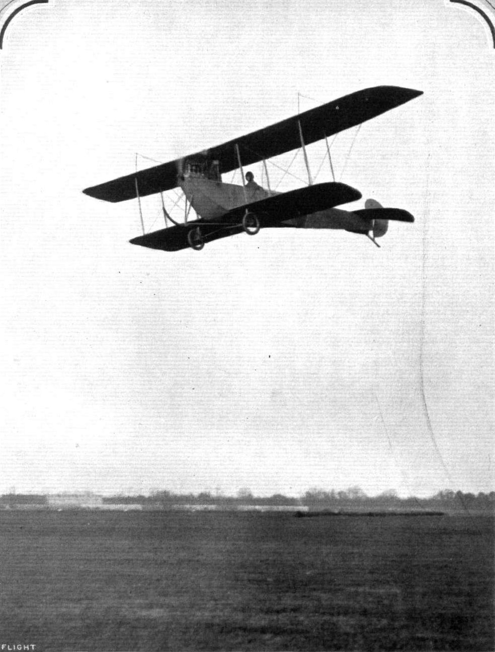
Mr. F. P. Raynham flying the Flanders biplane at Brooklands.
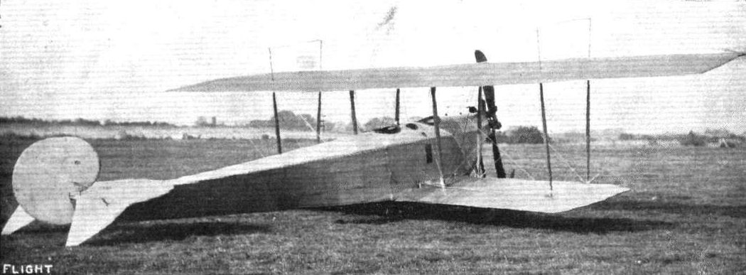
THE ISAACSON ENGINED FLANDERS BIPLANE. - Three-quarter view from behind.
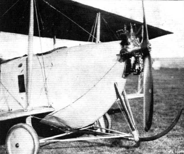
THE ISAACSON ENGINED FLANDERS BIPLANE. - View showing the chassis and engine mounting.
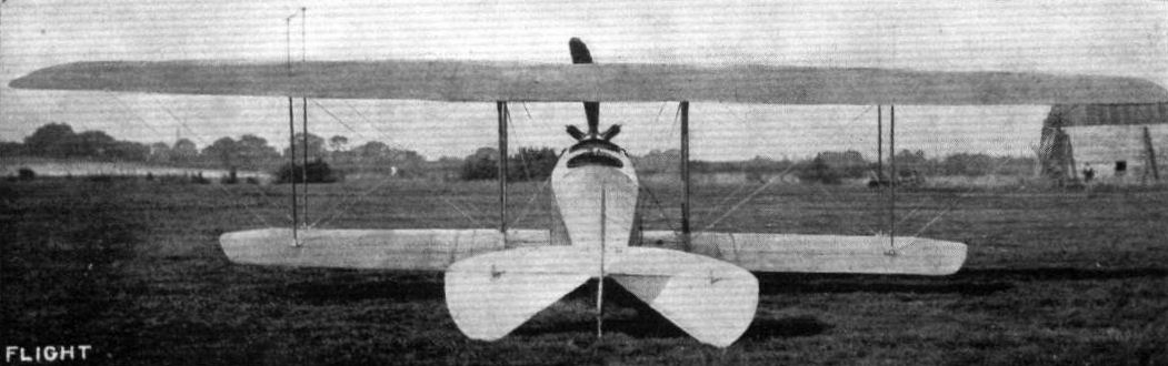
THE ISAACSON ENGINED FLANDERS BIPLANE. - View from behind.
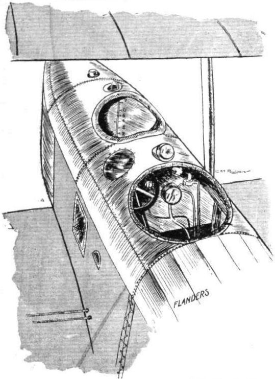
View from above of the pilot's and passenger's seats in the Flanders biplane.
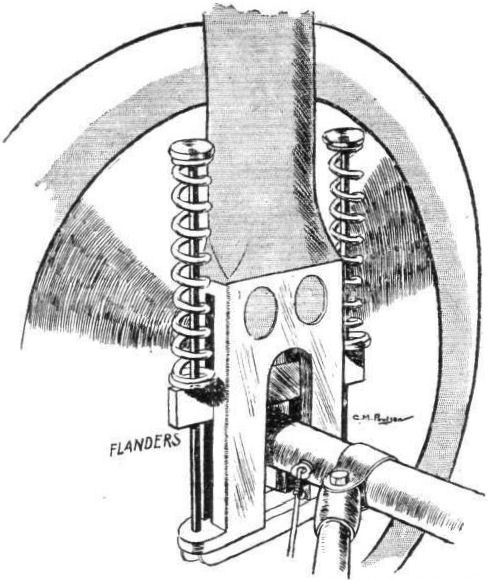
Method of springing the landing wheels.
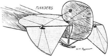
The tail planes on the Flanders biplane.
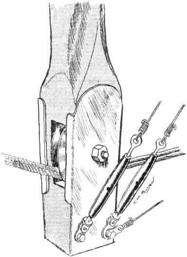
Sketch showing method of carrying warping cables through one of the plane struts.
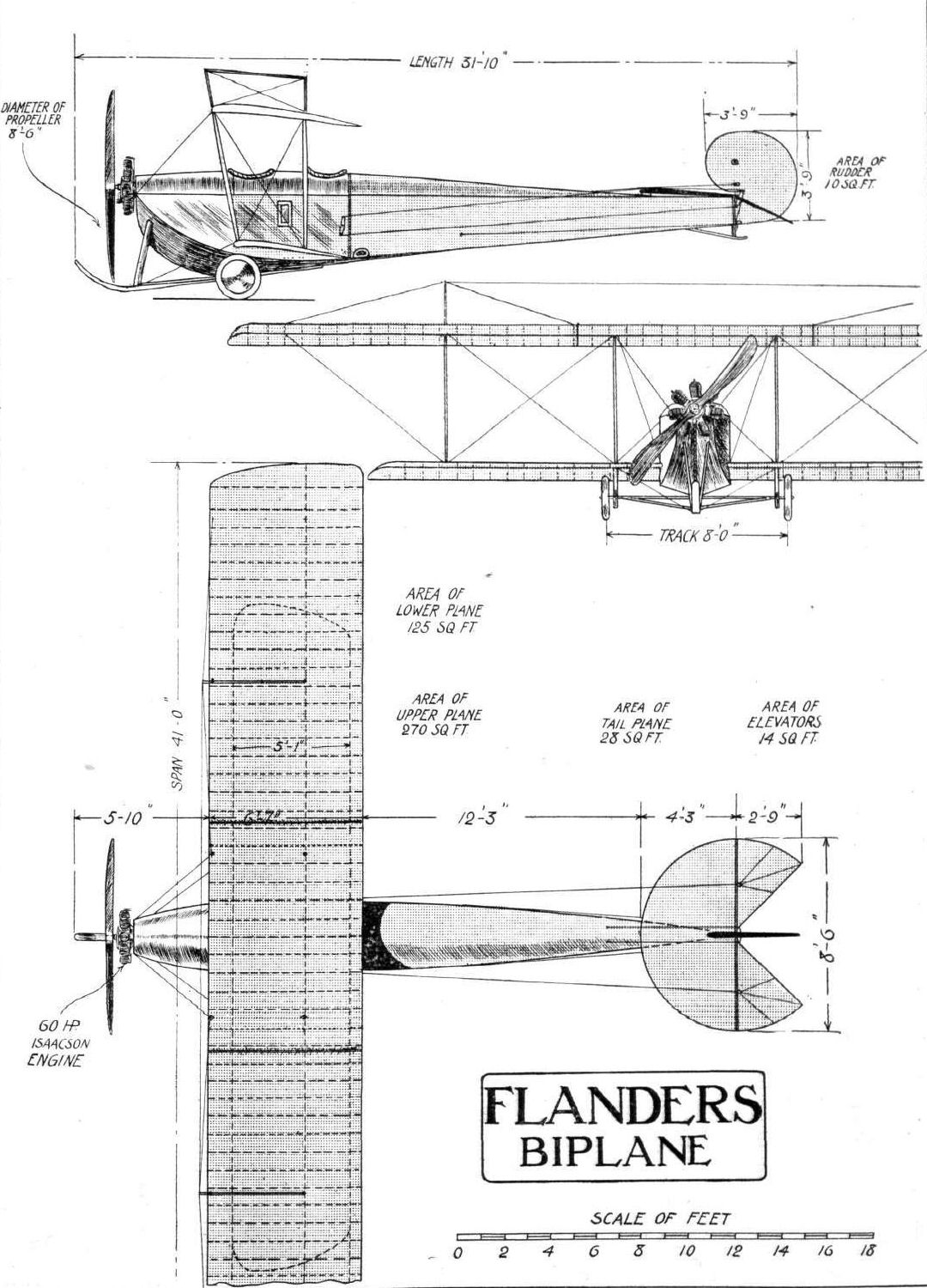
THE FLANDERS BIPLANE. - Plan, side and front elevations to scale.
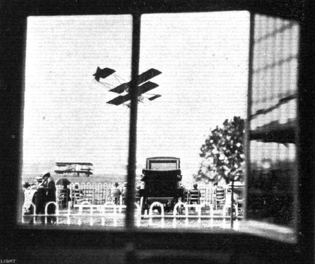
As the flying is seen at Hendon Aerodrome from the Press Club Window. - Mr. Manton is just passing across the line of sight.
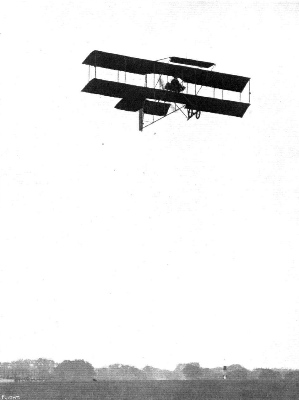
M. D. Manton flying the single-rudder Grahame-White Boxkite, with which he was second in the Speed Handicap at Hendon on 19 July, 1913.
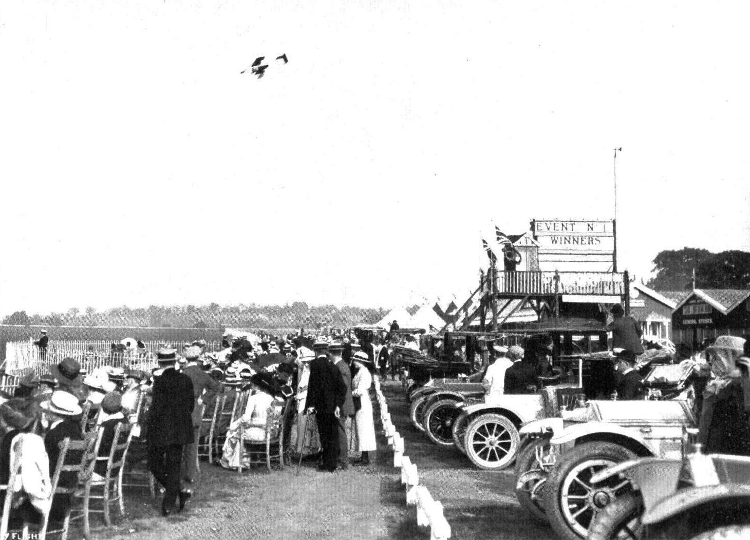
The big crowd watching the flying at Hendon Aerodrome. - Manton is seen in the air.
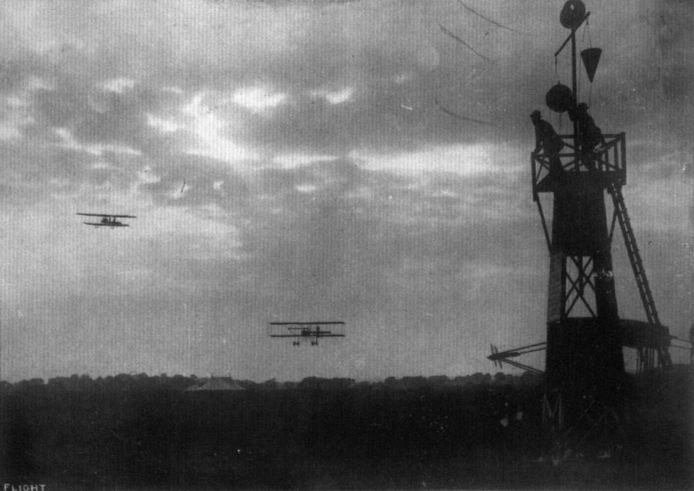
A REMINISCENCE OF HENDON FLYING MEETING. - A good race between Lewis Turner on the Grahame-White biplane and W. H. Ewen on the Caudron.

AN AIR GREETING AT HENDON ON SATURDAY AFTERNOON. - Desoutter, on a Bleriot, passing under and waving his hand to Manton on the Grahame-White biplane.
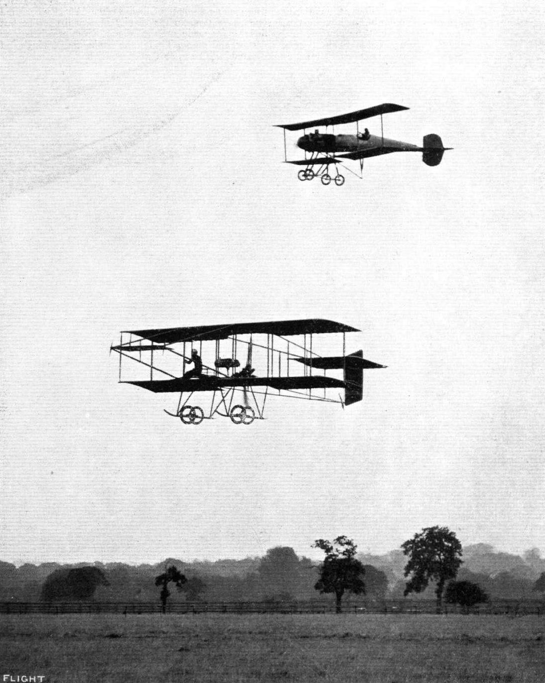
M. A. Debussy on the Breguet, overtaking Carr (below), on the Grahame-White biplane, in a speed handicap at Hendon.
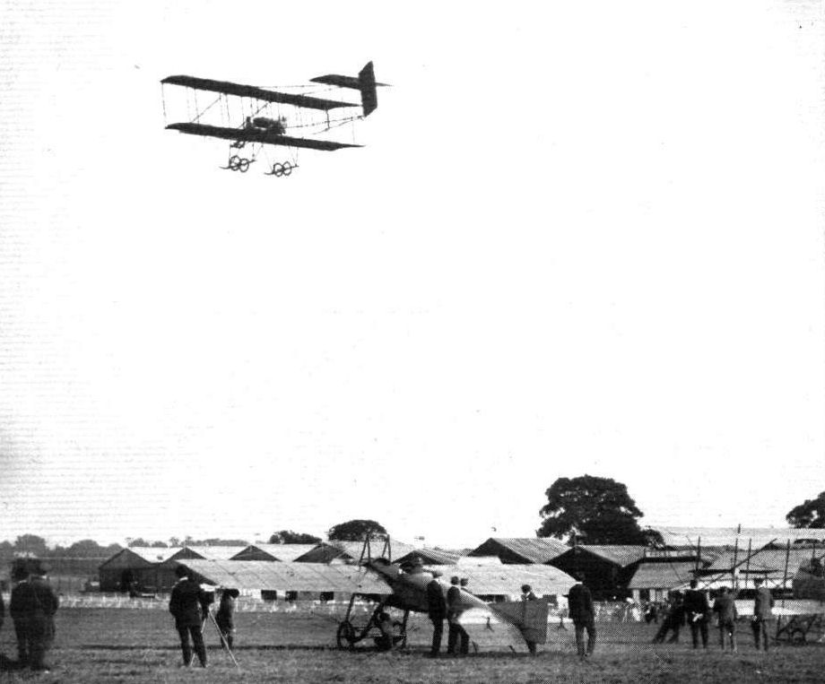
AERIAL FLORAL FETE AT HENDON AERODROME. - The first heat of the Speed Handicap. Manton, on the Grahame-White biplane, completing his first lap, with Brock and Verrier still waiting to take up their start in the race.

Mr. Carr winning his first race at Hendon Aerodrome in the Speed Handicap on Saturday.
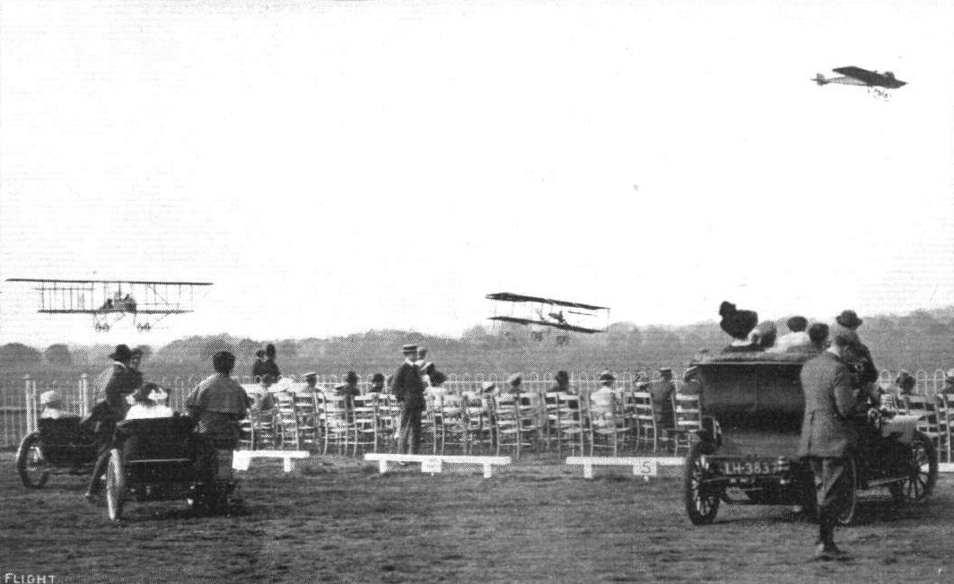
A FINE FINISH AT HENDON. - Marty, Verrier and Manton finishing in the order given in the first heat of the Speed Handicap on "Motor Cycle Day."
Flight, November 29, 1913.
FLYING AT HENDON.
THE Second November Meeting at Hendon last Saturday was an exceedingly busy and interesting one, for in the bare two hours that this time of the year gives us now for our afternoon's amusement, some twenty flights were put up, in addition to a splendid cross-country handicap. The attendance at these meetings still continues to be extremely good, especially in the cheaper enclosures. Just before 2.30 p.m. the speedy 80 h.p. Avro biplane arrived from Brooklands, carrying a passenger, and with P. Raynham in the pilot's seat, the descent into the aerodrome being made with a fine spiral. As they landed Pierre Verrier went up on the Maurice Farman and gave one of his brilliant displays. Shortly after, Raynham took up a passenger on the Avro, and R. H. Carr, with his "motor-man" and a lady and gentleman as passengers, followed on the 100 h. p. Green-G.-W. 'bus. W. Birchenough, W. Strange (the latest G.-W. pilot), on the 50 h.p. G.-W. 'buses, Verrier on the Maurice Farman, and R. Slack on the 80 h.p. Morane-Saulnier came out immediately after. In the meanwhile "something" was attracting a small crowd towards the far end of the Grahame-White sheds. This proved to be "Lizzie," the new 50 h.p. tractor one-and-a-half-plane undergoing an engine test preparatory to the first trial flight. The engine having been run for a few minutes, Louis Noel, who sat in the pilot's seat, gave the signal to let go, and after a fairly short run, the machine left the ground and completed several circuits of the aerodrome in fine style for the first time of asking. Next to the Dunne, this machine when in flight is the strangest looking aircraft we have seen, although it is really not so very much out of the ordinary. It has a Morane-Saulnier type fuselage and tail, and the same main planes that went to make up the 35 h.p. "Popular" pusher biplane turned out by the Grahame-White Co. some little time back. The top plane, which measures 28 ft. span, is mounted high above the fuselage, whilst the lower plane, which has a span of 14 ft., is situated immediately below the bottom longerons. The planes are separated by four pairs of struts and are some 6 ft. apart. A Farman-type landing chassis is employed. On landing, Noel said his new mount was extremely sensitive on the controls, but otherwise behaved splendidly. After this interesting flight, F. W. Goodden ascended on the 35 h.p. Scotch Caudron, Gordon Bell took over the Avro and put up a splendid flight, and Marcus D. Manton came out on his 50 h.p. G.-W. 'bus with a passenger suspended in an extra seat below the pilot and only a few feet from the ground. This additional seat is intended for a "gunner," who will have a gun mounted in front of him. N. Spratt and G. M. Dyott also gave demonstrations on the Breguet biplane and Dyott monoplane respectively. By this time it was 3.30 p.m., and Raynham ascended on the Avro and steered off in the direction of Brooklands, after which a start was made for the cross-country handicap. This was over the four circuit Bittacy Hill course, a distance of about 16 miles. Nine entered for this race and with one exception started, as follows :- W. Strange on a 50 h.p. G.-W. 'bus (10 mins. 10 secs.), W. Birchenough also on a 50 h.p. G.-W. 'bus (9 mins. 40 secs.), Marcus D. Manton on the "three-seater" 50 h.p. G.-W. 'bus (7 mins. 25 secs.), N. Spratt on the Breguet (3 mins. 40 secs.), Louis Noel on the one-and-a-half-plane (3 mins. 25 secs.), Pierre Verrier on the 70 h.p. Maurice Farman (3 mins.), G. M. Dyott on his 50 h.p. Dyott mono. (1 min. 38 secs.), W. L. Brock on the 80 h.p. Bleriot with a passenger (40 secs.), and R. Slack on the 80 h.p. Morane-Saulnier. Spratt was a non-starter, but the others got away without incident. "Lizzie" got off in fine style, after a run of only a few yards. At the end of the first circuit Strange and Birchenough rounded the pylon like the Siamese twins - except that they were literally one on the top of the other. Verrier only completed one circuit, and Birchenough retired on the third lap. Noel brought "Lizzie" close round the pylon at the end of each circuit with clockwork regularity and easily overhauled Strange and Manton, finally crossing the line first, with Dyott 16 secs, behind, and Slack, who made a fine effort from scratch, 7 secs, after Dyott. Brock came in fourth, and would certainly have done better had he not flown so high and wide. The extra head resistance of Manton's third seat appeared to slow him down somewhat, for he came in 50 secs. after Brock, but 28 secs, ahead of Strange. Immediately after the cross-country race, Gustav Hamel went up with a passenger on his 80 h.p. Bleriot, upon which he subsequently made several flights. Six other pilots then ascended and circled the aerodrome together. These were Birchenough, Strange and Manton on G.-W. 'buses, Carr on the 100 h.p. 'bus with passengers, Brock on the 80 h.p. Bleriot, and Slack on the Morane-Saulnier. Philippe Marty then made a flight on Brock's Bleriot, his landing with a strange machine being excellent. The proceedings were brought to a close by Gustav Hamel bringing out his Morane-Saulnier with which he intended to fly upside down and loop the loop, and which had been strengthened for this purpose. He ascended to a height of some thousand feet or so, and made two exceedingly steep dives and also banked the machine until the wings were vertical. He did not, however, attempt anything further than this. The times and handicaps of the cross-country handicap are given below:-
Cross-Country Handicap. (16 miles.) Handicap. Handicap Time
m. s. m. s.
1. Louis Noel (50 h.p. G.-W. tractor biplane) 3 25 24 55
2. G. M. Pyott (50 h.p. Dyott monoplane) 1 38 25 11
3. R. Slack (So h.p. Morane-Saulnier monoplane) scratch 25 18
4. W. L. Brock (80 h.p. Bleriot monoplane) 0 40 25 58
5. Marcus D. Manton (50 h.p. G.-W. biplane) 7 25 26 48
6. W. Strange (50 h.p. G.-W. biplane) 10 10 27 16
<...>
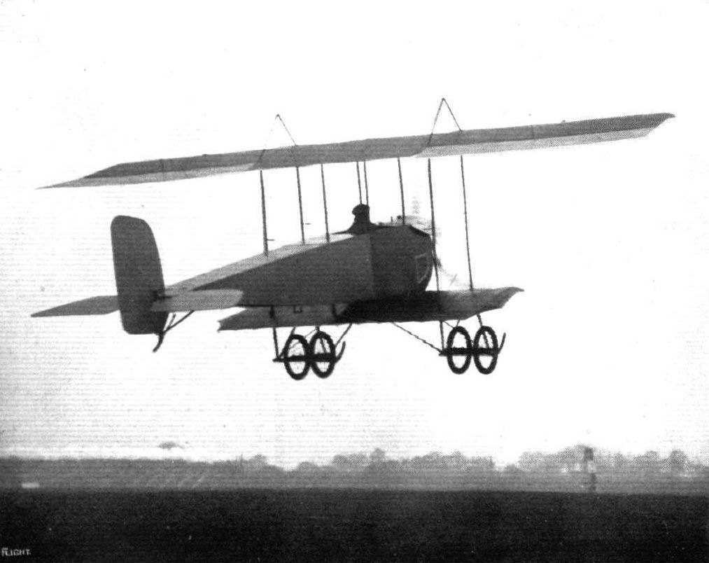
Mr. Louis Noel racing on the new Grahame-White tractor biplane, known down Hendon way as "Lizzie." He created a record by winning, on a new type of machine the first time out, the race in which he took part.
Flight, December 6, 1913.
THE LEWIS AIR-COOLED MACHINE GUN.
THE recent demonstration arranged by the Birmingham Small Arms Co., Ltd., at Bisley, in connection with the Lewis automatic air-cooled machine gun, at which a large number of distinguished naval and military officers and others interested in aviation were present, brings again into prominence the important part that will be played by aerial craft in a war between Powers provided with aeroplanes and dirigibles.
For the armament of such craft, the machine gun has inherent advantages over other weapons, but it is essential that the gun should be specially adapted for this class of work. It is important that it should be entirely self-contained, it should have little weight, be readily dismantled and assembled and be capable of firing in any direction; and since the time of engagement will probably be short, the projectile should be as destructive in its effects as possible. For use on aeroplanes, the weight, cumbrousness and recoil of a gun capable of discharging explosive projectiles render such at a disadvantage compared with the machine which is capable of firing a large quantity of small ammunition at high speed, and hence for this form of aircraft the latter is preferable.
It is claimed that in the Lewis air-cooled machine-gun, shown in the accompanying illustration, these qualities are exemplified. Its weight is 26 1/2 lbs., it can be handled by one man, and fired in any position or direction, its recoil is negligible and the normal rate of firing is 500 rounds per minute, but this can be increased if desired up to 800 rounds per minute, and single rounds, or bursts of any number of rounds up to the full capacity of the magazine, which is 47 rounds, may be fired if desired. The magazine, M, which takes under two minutes to load by hand and considerably less by the aid of a special machine, uses the ordinary service ammunition, and may be charged in a few seconds. The facility with which the assembling or dismantlement of the gun can be carried out is a remarkable feature of the invention, the only tool required being the nose of an ordinary bullet, and it is stated that 1,500 rounds may be fired without dangerously overheating the barrel, which is air-cooled. The system of air-cooling employed is not the least of its good points, as thereby the necessity of carrying a supply of water for cooling purposes is entirely avoided.
On the barrel, B, is a close-fitting sheath or jacket of aluminium with radiating longitudinal fins, surrounding which is a thin tubular steel casing, C, four inches in diameter. The tubular steel casing extends beyond the muzzle of the jacketted barrel, and as the gases of explosion emerge in a conical blast behind the bullet, they act as a kind of pump plunger inside this tubular extension, and suck currents of fresh cool air through the sector-shaped longitudinal passages along the exterior of the barrel. The air ejector thus formed at each discharge is most effective in cooling the barrel and is without mechanism or moving parts. During the first few hundred rounds the temperature rises rapidly until it has reached about 330° F., then more slowly until at the end of 1,000 rounds fired at full speed it does not exceed 440° F., and under ordinary Service conditions will be much lower.
The operating mechanism on the Lewis gun embodies several unique features, but one in particular should be mentioned - the use of a spring removed from the heat of the gun barrel. The gun is gas operated, that is to say, the energy required to load the breech and fire the cartridge is obtained by trapping some or the gases of the explosion through a small hole located a few inches from the muzzle. While the bullet is passing from this orifice to the muzzle, a period of about 1/9000th of a second, the gases deliver a blow to a piston, P, connected to the breech operating mechanism, and the energy thus stored as momentum in the moving mass serves to overcome the resistance represented by unlocking the breech, extracting and ejecting the cartridge case, turning the magazine and winding the spring that is subsequently to close the breech and fire the shot. This cycle of operations is repeated as many as 800 times a minute when the gun is working at its full speed, but the rapidity of fire can be regulated by changing the area of the orifice through which the gases are trapped, and by varying the tension on the clock-spring.
It is apparent that the spring element in such a system must be kept in perfect condition to function indefinitely, and particularly must it be kept from getting even moderately hot, for spring steel is permanently affected at 2700 F. A coiled spring lying along the stem of the piston is thus out of the question, and in the Lewis gun use is made of a "clock spring," S, of special and peculiar design, which is contained in a small oil- and dust-tight case of its own just in front of the trigger. The spring drum has a toothed periphery engaging with a toothed rack on the operating rod, R, and in this way the spring alternately controls and is controlled by the piston rod without being subjected to the temperature of the forward part of the rod itself.
To overcome the trouble often experienced through the jamming of the mechanism for feeding the cartridges, through derangement, a defect to which the belt form of feed is susceptible, or by the introduction of a little dust or sand, a balanced rotary magazine of circular form is employed, by means of which the cartridges and feeding mechanism are protected, and it becomes possible to fire the gun in any position. The cartridges are arranged radially as seen in the illustration, and are retained in a permanent circumferential position by flutes pressed on the outer casing of the magazine, and by slots in the interior, but the nose of the bullet rests in a coarse threaded ring clipped to the pivot about which the magazine turns. Thus as the magazine rotates, the cartridges are forced to descend along this groove until they pass into position for firing.
The construction adopted in order to reduce the recoil is another unique feature of this gun, and operates in the following manner. When the expanding gases emerge as a conical blast from the muzzle, they impinge with very high velocity against the inner surface of the tubular steel casing of the cooling system. For a distance of at least two inches the gases are in contact with the metal surface, and the friction thus set up is sufficient to diminish the recoil by more than one-half. In other words, the recoil of the Lewis machine gun is less than one-half that of any other machine gun of equal weight. It is, in fact, possible to fire the gun while holding it in the hands at arm's length, which is a very good test of its steadiness, and this quality, it need hardly be emphasised, is another advantage of first-class importance, particularly in respect to the use of armament on aircraft.
The tests to which the gun was subjected included firing from a Grahame-White biplane rigged up with an emergency seat below the pilot in flight, and from the 200 and 500 yards ranges at stationary targets. For the former, the target was about 25 ft. square, and from a height of between 400 and 500 ft., in a strong wind, Lieut. Stillingwerf of the Belgian Army scored 11 hits out of about 24 shots; and equally satisfactory results attended another attempt later in the afternoon, when a full magazine was discharged. At the 200 and 500 yards ranges some excellent work was done, and at the latter, out of 470 shots at full speed, more than 280 hits were found to have been made, during the subsequent examination of the targets.
In every respect, the claims made by the Birmingham Small Arms Co., Ltd., for the Lewis gun were well substantiated.
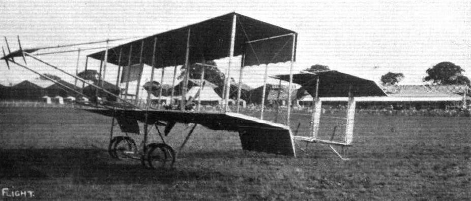
The new Grahame-White School 'bus.
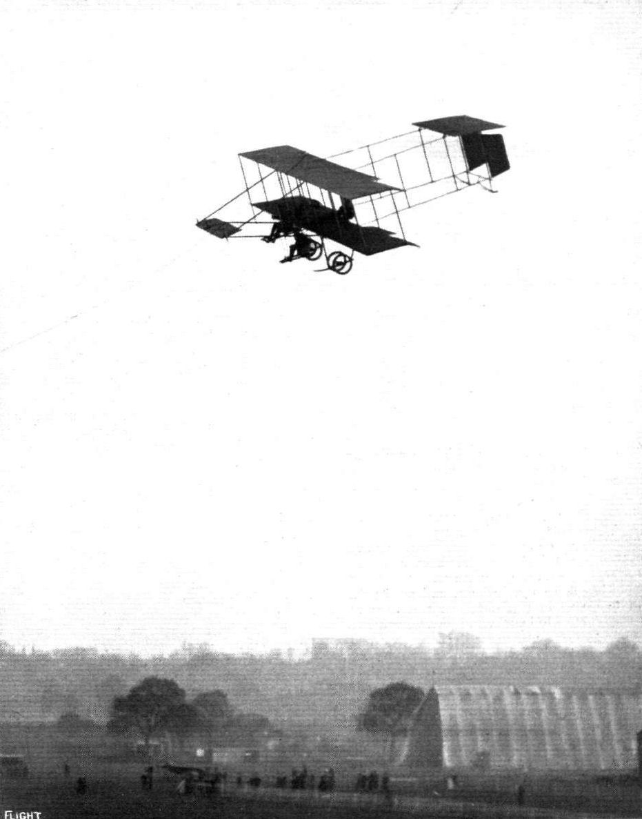
Mr. Manton with a passenger in the underslung seat of his Grahame-White biplane at the London Aerodrome, Hendon. - A strange optical illusion may be noticed in this picture. Whilst looking at it the picture appears to change. Sometimes you seem to be viewing the planes from above and somettmes from beneath.
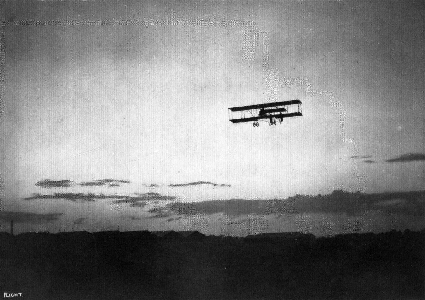
A LABOUR OF LOVE. - Manton flying at sunset, with his mother as a passenger, at Hendon Aerodrome.
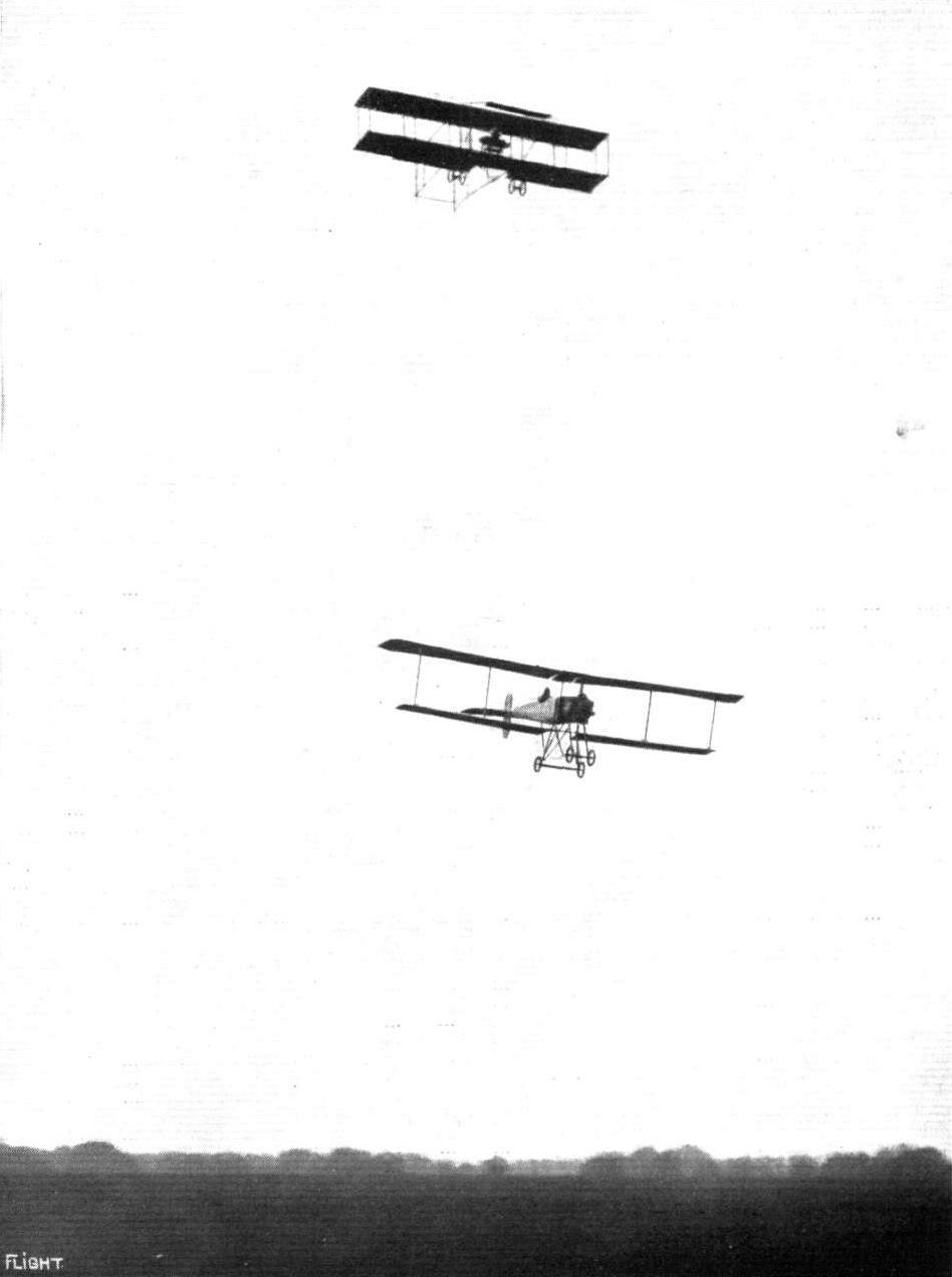
Mr. Norman Spratt on the Breguet (below) and Mr. Marcus D. Manton on the Grahame-White biplane, flying for the Shell Trophy at Hendon on Saturday last.
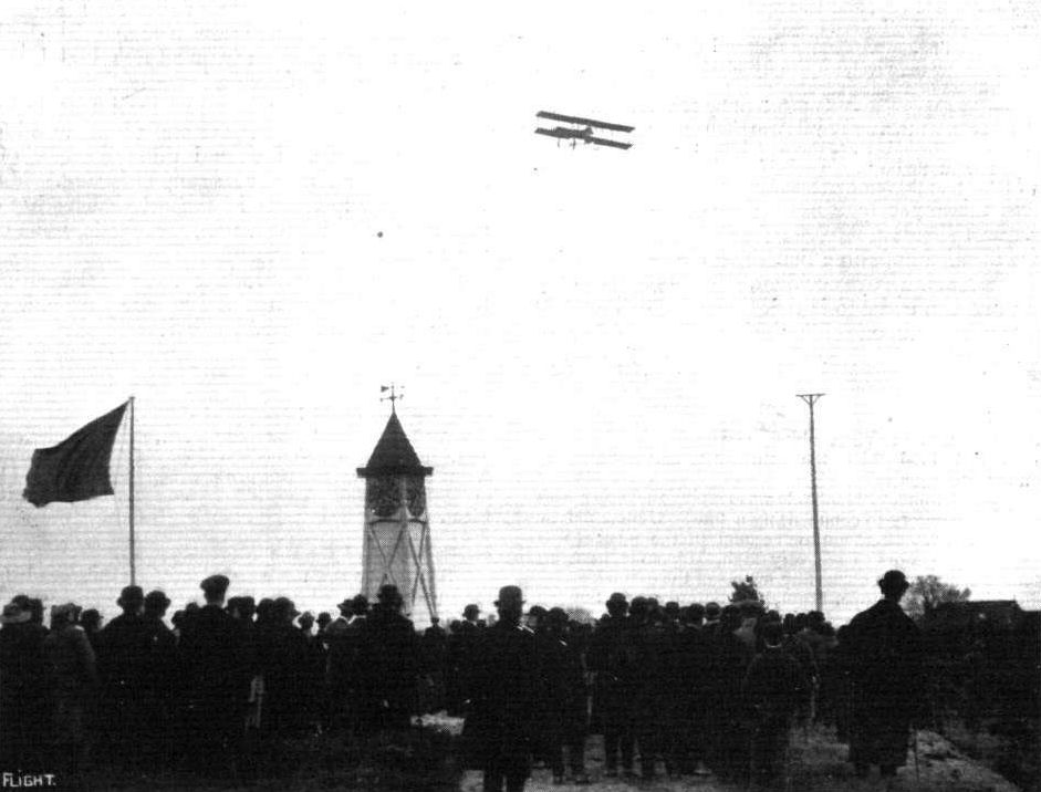
Trying the new Lewis automatic gun on a Grahame-White biplane at Bisley last week. The biplane, piloted by Mr. Marcus Manton, with Lieut. Stillingwerf in the seat underneath, manipulating the gun, is just passing over the Clock Tower at Bisley before firing at the target just beyond.
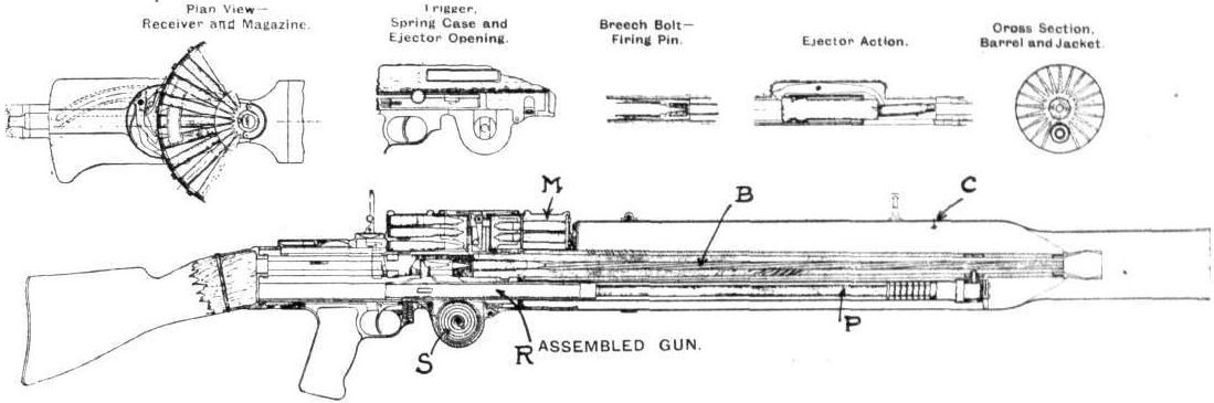
Flight, February 8, 1913.
WHAT THERE WILL BE TO SEE AT OLYMPIA.
THE MACHINES.
The Grahame-White Aviation Co., Ltd.
This progressive firm, the proprietors of the popular London Aerodrome at Hendon, will be showing two biplanes, one a land machine and the other designed for water flying. The first of these machines is equipped with a 90-h.p. Austro-Daimler motor which drives through a steel shaft and chains, a large diameter propeller arranged to the rear of the main planes so that the machine may be used for offensive tactics in war. The motor is mounted at the front of a streamline nacelle. The pilot, sitting behind it, is in a position that makes for maximum safety, should the machine for any reason suffer an unusually heavy landing. The main planes are of the extensioned type, the top plane being considerably longer in span than the lower. For the landing gear, it is exceptionally strong, and has the original feature that each of its two running wheels is flexibly mounted in a slot cut in each of the two unusually wide built-up skids. The tail is supported by an open triangular construction, the top member of which passes through the propeller boss. The second machine that the Grahame-White Co. will be showing will be a two-seater tractor hydro-biplane, driven by a 60-h.p. Anzani air-cooled motor. Its body will be somewhat reminiscent of Nieuport design, and it will be fitted with a pair of main floats of the long catamaran type. In addition, there will be exhibited on the stand various specimens of workmanship, such as a set of propellers, showing them in different stages of manufacture.
Flight, February 15, 1913.
GRAHAME WHITE AVIATION CO., LTD.
Two notable biplanes figure on their stand, one a 90-h.p. military machine, and the other a hydro-biplane of a sporting type, driven by a 60-h. p. Anzani motor. Both bear evidence of much thought on the part of the designers, and of much painstaking care spent upon them in the constructing shops. The design of the first of these machines was due originally to Mr. H. Barber, but in its working out he was assisted by Mr. J. D. North, who also prepared the drawings for the hydro-biplane. Let us confine our attention for the moment to the military machine.
The Grahame-White Military Biplane, as its title conveys, is a machine specially devised for military purposes, and particularly so that its occupants may be able to undertake offence tactics. So that the occupants may have a clear outlook in front of their respective cockpits, the propeller is arranged to the rear, while by using shaft drive the front engine position is retained, a disposition of the motor that is generally thought to be the best from the point of view of the passengers' safety. This machine was originally designed for a motor of 120 h.p., but it appears at the Show temporarily fitted with one of only 90 h.p. To illustrate its application as an aeroplane for attack purposes, a Colt quick-firing gun is mounted in the nose of the machine, and it has a range of 50° in a vertical plane, and 180° horizontally. It would, of course, be impossible for the gunner to make use of the gun's full extent of horizontal range - he would probably only be able to sight it through a deviation of 45° on either side of the longitudinal axis of the machine.
The body of the biplane is essentially a lattice girder with ash longerons, and ash and spruce cross-members, ash being used for the latter members in the neighbourhood of the engine and propeller. That perfect rigidity may be assured, and this is doubly essential in the case of the body of this particular machine on account of its having a transmission shaft mounted inside it, it is double cross-braced with 10-gauge piano wire. In plan, the body is shaped to a careful streamline form, and it is an interesting point that the strut cross-sections are of the same shape, excepting that their curves are plotted to a shorter longitudinal axis. The Austro-Daimler motor is mounted on high ash bearers in front, and drives the propeller, a 10 ft. Chauviere, through shaft and chain transmission. The shaft is a large diameter steel tube turning in self-aligning ball-bearings, and the chain employed is a duplex Brampton. Fitted at the extreme nose of the body is a honeycomb radiator, specially made by the Austro-Daimler firm, and so shaped that it preserves the lines of the body. There is room on either side of the engine for a passenger to sit. They are provided with unusually comfortable spring seats, while under their feet are tool boxes. The pilot sits behind them and controls the machine by a vertical lever governing the elevation and wing warping, and by a pivoted foot lever which operates the rudder. To ensure sweet working, all the controls are carefully mounted on ball-bearings, and all the pulleys used to guide the control wires are turned from vanalium and fitted with ball-bearing centres. Below the pilot's feet is a large petrol tank sufficient for a 6-hours' flight. From that tank, petrol is fed under pressure, automatically provided by the engine exhaust, to a service tank in front, above the level of the engine. The pilot can at all times acquaint himself as to the state of his petrol supply by a specially devised gauge on his left.
Plane construction. - The planes span respectively 42 ft. and 23 ft. and, having a chord measurement of 6 ft., they have a supporting area of 390 sq. ft. The cross-section employed is that of the Eiffel plane No. 8. The interior construction of the plane is particularly interesting. The front span is of generous dimensions, shaped from spruce. The rear span is a wide diameter steel tube. Over the spars are loosely fitted the ribs in such a manner that continual warping of the planes does not fatigue the structure. The ribs are built up of spruce webs and flanges, and where the spars are threaded through them they are thickened up to the full width of the flanges. To strengthen the planes against drift, they are cross-braced inside with 5/32 in. stranded cable, and so that the tension of the braces shall not cause the spars to pull together and so bind the ribs, they are separated by adjustable steel rods.
The landing gear is composed of two built-up skids, each a little over a foot wide, in the centres of which are mounted the landing wheels. These latter organs each have two rims to the one wheel and are so designed to prevent the wheel from canting over sideways, which is, with a single tyre wheel, a very likely thing to happen with the method of suspension used. One of our sketches illustrates this point. The body of the machine is supported from the skids by 10 hollow spruce struts, the front two of which are taken straight to the engine bearers.
The tail, consisting of a flat stabilizing surface 50 sq. ft. in area, two elevator flaps of a combined area of 25 sq. ft., and a vertical rudder of 20 sq. ft. surface, is stayed at the end of an open girder construction, built up of three steel tubular longerons and hollow spruce struts. The top member of this girder, as will be seen from our sketches, passes through the propeller boss.
The Grahame-White military biplane weighs, without passengers or fuel, 2,103 lbs., and is designed to carry a useful load of 750 lbs. With her 120-h.p. engines fitted, she is expected to have a speed range of from 50 to 70 miles per hour.
<...>
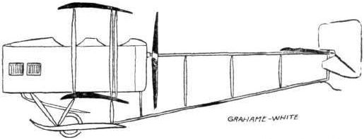
The 90-h.p. Grahame White military biplane.
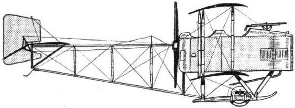
The 90-h.p. Grahame-Whlte military biplane.

The propeller mounting of the 90-h.p. Grahame-White biplane. Notice the manner in which the control wires are taken through the top member of the tail outrigger construction which passes through the propeller boss.

The tail of the 90-h.p. Grahame-White military biplane.
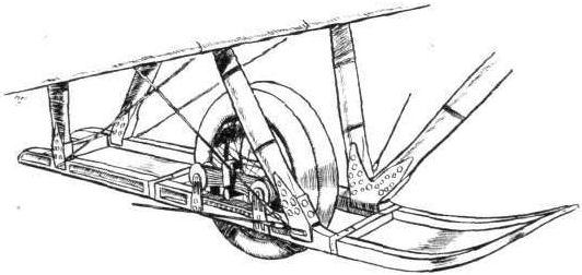
Details of the landing chassis of the 90-h.p. Grahame-White biplane, showing how the double-tyred wheels are sprung in the wide built-up landing skids.
AT OLYMPIA. - A study in tail-skids.
A study in tails.
Flight, February 1, 1913.
THE 35-H.P. GRAHAME-WHITE "POPULAR" BIPLANE.
LISTED at a price of under L400 complete with motor and all the usual accessories, this interesting product of the Grahame-White Co., which only made its appearance during the past week, is essentially the machine for the man of moderate means. It is small, light, inexpensive in first cost and upkeep, simple and cheap to repair, and by no means difficult, we should think, to fly. Thus it makes a strong appeal to the exhibition flyer, the flying school proprietor, and the man who takes up aviation as a sport. Considering the latter type of man, there are very few, and they are very far between, who quite see the point of laying out the more usual price of L1,000 in acquiring a machine with which he can make an occasional cross-country flight. There ought to be many comfortably well off sportsmen who would take up flying as a hobby if it were only brought home to them that flying need not be such an expensive diversion as has been generally thought. For, after all, there is no fascination to compare with the fascination of flying.
In general outline, as the reader will gather from our photographs, this new Grahame-White machine bears a resemblance to that very well-known French make of biplane - the Henry Farman. To our way of thinking this fact does not make the machine any the less interesting. Rather do we admire the Grahame-White Co.'s policy in basing their machine on a design that, in France, has probably brought its originators a greater commercial success than has been achieved by any other aeroplane manufacturing firm we could mention.
The main lifting surfaces of the machine are constituted by two planes, 28 ft. and 14 ft. respectively, in span, set at an angle of 5 of incidence, and braced together by heavy-gauge piano wire and separated by eight hollow struts in two ranks. The four centre struts - for they support the body - are of ash, the outer ones are of spruce. The planes are built about two main ash spars, both of I-section, and the ribs occur at every foot, approximately, along their length. At those points at which vertical struts are attached to the spars, the ribs used are of the hollow box variety in other places, they are built up, I-section, with spruce flanges and three-ply distance pieces. To better maintain the shape of the plane, false ribs, extending from the leading edge to the front spar, are arranged midway between each main rib, and a pair of longitudinal stringers are run, at a point midway between front and rear spars, from one end of the plane to the other. The cross-section employed is that of the later 50-h.p. Gnome-Bleriot wing, the one that Eiffel refers to in his work on wing sections as Aile No. 13 bis. Lateral control of the machine is maintained by two balancing flaps, each of 7 ft. span, hinged to the rear spar at either end of the top plane. They work in conjunction, and are connected one to the other by stranded steel cables, which pass over red fibre pulleys clamped to the front spar.
The landing-gear is of a type which, if it cannot be said of it that it is original, still maintains its own as probably the most serviceable type of undercarriage ever devised. The skids are of ash, and each supports its side of the machine through two vertical ash struts and three steel tubes, which are arranged to give the maximum of rigidity. Throughout, its length between the attachments of the vertical struts, each skid is spindled down to an I-section, and the overhang behind the rear vertical strut is laminated and made flexible in such a way that it may take the weight in landing of the rear part of the machine. Thus we find that the tail skid has been suppressed, as it has been in many machines of late. Of the strength of the chassis there can be little doubt, since the struts have an ample cross-section, and they are only about 18 ins. in length.
Ash outriggers support the tail, and they arc braced by a steel wire and by vertical hollow wooden struts, and horizontal steel tubes. For lightness' sake the outriggers are hollowed out to I-section between those points where bolts pass through them to anchor the sockets accommodating the vertical and horizontal cross-members. The tail, being cambered and set at a positive angle of 20, does a small share of the total lift. Behind it are the two elevator-flaps by which the attitude of the machine is controlled.
The body of the machine, in which the pilot sits, where are accommodated the fuel tanks, and to which the motor is mounted, is essentially a box girder some 12 ft. in length, built up of ash longitudinals, cross-members of oval-section steel tubing, and vertical members of spruce and ash. It is enclosed in front by three-ply wood, and along its sides by fabric. At its rear end it is capped by a flanged steel plate, to which the motor, a 35-h.p. Anzani of the very popular Y-type, is bolted. It drives a propeller of 2.100 m. diameter and 1.500 m. pitch. This propeller, by the way, has been designed by Mr. J. D. North, who is also responsible for the general and detail design of the machine under review. In shape it is somewhat reminiscent of, and yet unlike, the Levasseur propeller, for the fact that its blades, scythe-shaped, revolve point first. The cross-section of its blades, however, is different, for, on what may be considered as the under surface of the blade, Mr. North has made use of the return curve. It is interesting to record that a static thrust of 310 lbs. has been obtained from an exactly similar propeller driven by a similar engine.
Including four hours' supply of petrol and oil, and with the pilot on board, the weight of the machine comes out at slightly over 600 lbs., and thus its surface loading is, approximately speaking, 3 lbs. to the sq. ft. Its average flying speed is estimated at 50 miles an hour.
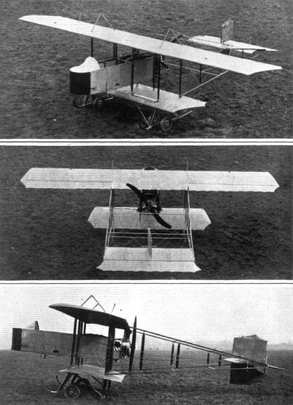
General view of the new 35-h.p. Grahame-White "Popular" biplane.
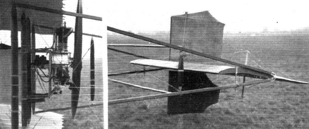
TWO DETAILS OF THE NEW GRAHAME-WHITE "POPULAR" BIPLANE. - On the left, the mounting of the 35-h.p. Y-type Anzani motor, on the right the tail unit.
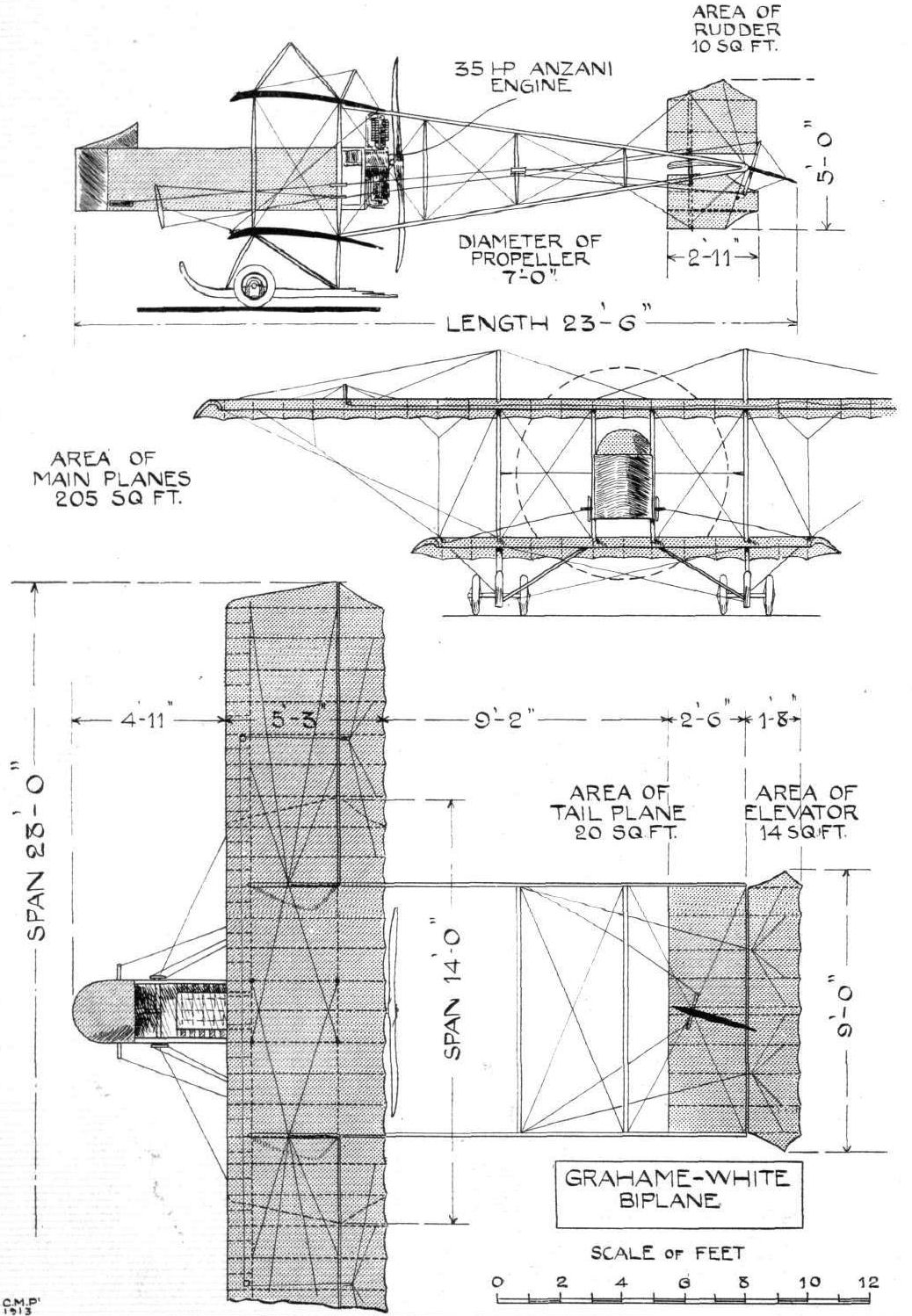
THE 35.h.p. GRAHAME-WHITE "POPULAR" BIPLANE. - Front and side elevations and plan to scale.
Flight, February 8, 1913.
WHAT THERE WILL BE TO SEE AT OLYMPIA.
THE MACHINES.
The Grahame-White Aviation Co., Ltd.
This progressive firm, the proprietors of the popular London Aerodrome at Hendon, will be showing two biplanes, one a land machine and the other designed for water flying. The first of these machines is equipped with a 90-h.p. Austro-Daimler motor which drives through a steel shaft and chains, a large diameter propeller arranged to the rear of the main planes so that the machine may be used for offensive tactics in war. The motor is mounted at the front of a streamline nacelle. The pilot, sitting behind it, is in a position that makes for maximum safety, should the machine for any reason suffer an unusually heavy landing. The main planes are of the extensioned type, the top plane being considerably longer in span than the lower. For the landing gear, it is exceptionally strong, and has the original feature that each of its two running wheels is flexibly mounted in a slot cut in each of the two unusually wide built-up skids. The tail is supported by an open triangular construction, the top member of which passes through the propeller boss. The second machine that the Grahame-White Co. will be showing will be a two-seater tractor hydro-biplane, driven by a 60-h.p. Anzani air-cooled motor. Its body will be somewhat reminiscent of Nieuport design, and it will be fitted with a pair of main floats of the long catamaran type. In addition, there will be exhibited on the stand various specimens of workmanship, such as a set of propellers, showing them in different stages of manufacture.
Flight, February 15, 1913.
GRAHAME WHITE AVIATION CO., LTD.
Two notable biplanes figure on their stand, one a 90-h.p. military machine, and the other a hydro-biplane of a sporting type, driven by a 60-h. p. Anzani motor. Both bear evidence of much thought on the part of the designers, and of much painstaking care spent upon them in the constructing shops. The design of the first of these machines was due originally to Mr. H. Barber, but in its working out he was assisted by Mr. J. D. North, who also prepared the drawings for the hydro-biplane. Let us confine our attention for the moment to the military machine.
<...>
The 60-h.p. Grahame-White Hydro-biplane is a machine designed to satisfy the demands of the sportsman who is inclined to take up water flying and who does not necessarily want to be put to too great an expense in gratifying his hobby.
The body of the biplane, a conventional girder structure, is capped by a flanged steel plate which serves as a mounting for the motor. To strengthen the last bay of fuselage to withstand the situation of the engine, it is cross-braced with 5 in. steel tubing. The body construction is interesting in that it is so simple, so cheap to construct, and forms so sound a "job." Four ash longerons are used. The vertical members of the body are of ash or spruce, according to the strains to be allowed for, while the horizontal cross-members are of steel tubing, a material which permits of a very simple cross bracing fitting being employed. Immediately behind the motor sits the passenger, sheltered from the engine blast by a transparent wind shield. At his back is the main fuel tank, which holds sufficient petrol to keep the machine flying for four hours if need be. Behind that is the pilot's cockpit, very comfortably upholstered. Both pilot and passenger are so seated that they each have a perfect vertical view downwards. The controls are operated by a universally-jointed lever and foot rudder bar in a manner identical to that of the 90-h.p. G.-W. machine.
The planes span 42 ft. 6 in. and 22 ft. 6 in. respectively, and have a chord measurement of 5 ft. In cross section they are similar to the wing of the later 50-h.p. Gnome-Bleriot monoplane. For the internal construction of the planes, the front spar is of I section ash, while the rear spar, reinforced by a steel strip, is also of ash, but left solid as it is necessarily of lesser dimensions. Where vertical struts join the spars, the ribs are of the Farman box variety. In other parts of the plane, they are built up of spruce flanges and 3-ply webs. The extensions to the top plane are 10 ft. in length and they are hinged to the central cellule that they may lie folded down when the machine is stored. Lateral balance is governed by long compensating ailerons, hinged to the backs of these extensions. Twelve struts separate the planes, the four centre ones, which support the body, being of ash, while all the others are of hallow spruce.
Floats. - Two main floats which have a "track" of 12 ft. 6 ins., are employed to enable the machine to alight on and start off from water. They are each 15 ft. long and measure at their maximum cross-section 24 ins. wide by 15 ins. deep. A feature of their design is that the first half of the float is flat on the under-surface while the rear portion is concave, having a maximum camber of 4 ins. Air is projected below the after portion of the floats, so that the machine may glide the more easily over the water, by tubes, about 2 in. in diameter, into which air is forced by miniature scoops (see diagram). The skeletons of the floats are latticed girders of spruce and ash. They are covered in the following manner :- First, a number of strips of cedar, 4 in. wide and 3/32 in. thick are applied to each side at an angle of 45 to the longitudinal axis of the float. These strips in position, they are coated with copal varnish, and while that is still wet a layer of waterproof canvas is put on. This is again varnished and a further layer of cedar veneer applied, making the strips run this time in a direction 90 to the former layer. The floats are finished off by copper nails, which are driven in every two inches or so all over the floats and clinched over. Then, to protect the under-surface, longitudinal ash stringers are applied. Six steel struts, spruce filled, of special streamline section support the body of the machine. The struts are bedded in the float structure on to the spruce main skeleton, and they are reinforced at the point of attachment by flanged steel plates (refer sketch). Floats built on this principle do not come out unduly heavy. These Grahame-White floats weigh less than 100 lbs. each complete with struts and wiring. Without passengers or fuel the machine weighs 850 lbs., and is capable of carrying a useful load of 450 lbs. The machine's flying speed is expected to average 55 m.p.h.

The 60-h.p. Anzani-Grahame-White hydro-biplane.
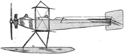
The 60-h.p. Grahame-White hydro-biplane.
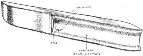
The Grahame-White float, as seen from underneath. Notice that the front section is flat on the underside, while the rear portion is concave.
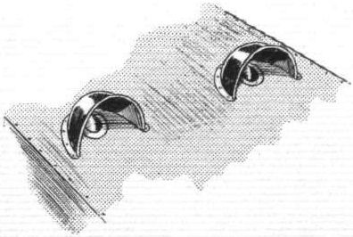
The air vents in the float of the Grahame-White hydro-biplane.
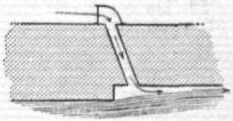
Diagram of the air inlet pipe of the Grahame-White floats.
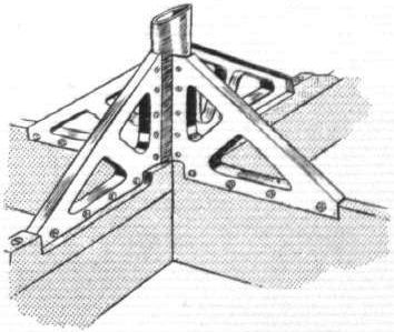
Sketch showing how the chassis struts are attached to the interior float construction on the Grahame-White hydro-biplane.
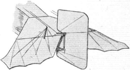
The tail of the Grahame-White hydro-biplane.
A study in tails.
Flight, September 20, 1913.
THE AERIAL DERBY.
PILOTS AND HOW TO RECOGNISE THE MACHINES.
No. 1. The Grahame-White Five-seater Biplane.
This machine may be easily recognised, mainly by its great size, but also by the fact that it has no elevator in front of the main planes. It is also the only machine in the race which has three rudders.
THE MACHINES, WITH SOME DETAILS.
No. 1. 120 h.p. Austro-Daimler Five-seater Grahame-White Biplane. This biplane is the latest and largest of those built by the Grahame-White Co. Some idea of its size may be gathered from the fact that its maximum span is 62 ft. It is designed to carry four passengers besides the pilot, and has proved itself a remarkably steady and efficient flyer. The pilot sits at the extreme front of the nacelle, and so obtains an excellent and unrestricted view, while the passengers are seated in pairs behind him.
The engine is a 120 h.p. water-cooled Austro-Daimler, with the radiator slung by means of wires over the engine, where the full cooling effect of the draught caused by the machine's flight is felt.
Flight, October 11, 1913.
THE GRAHAME-WHITE "AERO-CHAR-A-BANCS."
So popular have the passenger flights at Hendon proved, that, although the Grahame-White Aviation Co.'s "stables" include about half a dozen passenger-carrying machines, these have been found inadequate to cope with the ever-increasing demand, especially at week-ends, for trips round the aerodrome. In order to meet this contingency, a new machine, capable of carrying four passengers - it has already made records with 7 and 10 - in addition to the pilot, has been constructed, and it has already become very popular amongst the spectators, who have nicknamed it "the char-a-bancs."
Superficially the new five-seater bears a certain resemblance to the H. Farman biplanes, but a close inspection reveals the fact that this resemblance is confined to the general disposition of the various members. Aerodynamically it is quite different, and its designer - Mr. J. D. North - has managed to incorporate in it a good many cleverly conceived and skilfully executed constructional details, some of which are shown in the accompanying sketches.
The scale drawings and photographs show the machine to be of the engine behind or "pusher" type, with the pilot's and passengers' seats placed well out in front in a nacelle built up in the usual way of four longerons of ash, connected by struts and cross members of the same wood, the whole structure being rendered rigid by means of diagonal cross wiring. Right out in the nose of the nacelle is the pilot's seat, from where he has an unrestricted view in all directions. In front of him are the levers by means of which the machine is controlled, consisting of a foot bar for controlling the rudders, and a single, central, tubular column mounted on a transverse rocking-shaft, which carries on its extremities, and outside the nacelle, two crank levers, from which cables run to the corresponding levers on the elevator. The cables, through which the ailerons are operated, are lead through the central column and transverse shaft and thence round a pulley to the ailerons. These are operated by the pilot by means of a rotatable hand wheel mounted on the upper extremity of the central column. The axle carrying the drum around which passes the warping cable, is provided with semi-thrust ball bearings in order to reduce frictional resistance, and the control wheel itself is secured on the axle by a large nut forcing it up the tapering axle in a similar manner to that employed in securing a propeller to its shaft. The cable drum is integral with the axle, the whole being machined out of one solid piece of steel.
To the right and left of the pilot are mounted the various instruments, such as pressure gauge, revolution indicator, altimetre, compass, air speed indicator, etcetera. The etcetera includes a motor horn, which creates quite a lot of amusement when sounded while the machine is in flight, as it can be distinctly heard above the very effectively silenced roar of the engine.
Behind the pilot are the four passengers' seats, arranged in pairs. Plenty of room is afforded so that the passengers may enjoy their flight in comfort as distinct from the more or less cramped positions occupied by the passenger in older types of machines. The longerons of the nacelle are extended to carry the engine, a 120 h.p. Austro-Daimler, which is so rigidly mounted that hardly any vibration is felt when sitting in one of the seats. Four stout steel tubes running from the engine bed to the front and rear spars respectively, transmit the thrust to the wings, the unit formed by the nacelle and engine bearers being further secured by means of steel wires taken to various points on the machine.
Slung on the cross wires of the central cellule is the radiator, which, situated as it is right above the engine and between the main planes, receives the maximum amount of draught, thus rendering it very effective. In the bottom of the nacelle, and under the passengers' seats, is a large petrol tank with a capacity of 28 gallons.
From this tank petrol is forced by pressure to a service tank mounted on one of the inner plane struts, from whence it runs by gravity to the two carburettors. Oil is carried in a similar tank mounted on the corresponding plane strut on the other side of the nacelle. As we have already said, the engine is very effectively silenced by means of a silencer designed by Mr. North, and consisting of two concentric cylinders, the inner one of which is divided into 6 compartments, and perforated with small holes. After an extended run of the engine, the inner cylinder will be found to be red hot, while the outer one is barely warm. The advantage of this will be apparent to any one who has ever experienced the sensation of carelessly resting a hand on a hot exhaust pipe.
The wings are constructed in the usual way of ribs, built over two main spars. The ribs are built up of webs of three-ply wood with flanges of spruce, while the main spars are built up of spruce hollowed out for lightness. In section the wings are provided with a very pronounced camber, thus rendering the machine somewhat slow; her flying speed is about 45 m.p.h.
Four tail booms of spruce, hollowed out in a similar manner to the main spars, carry at the rear the biplane tail planes. To the trailing edge of the upper tail plane is hinged the elevator, while hinged to the outer tail struts are the three rudders by means of which the machine is steered. One of the accompanying sketches shows one of the two tail skids by means of which the tail is protected against contact with the ground. Hollow spruce struts are employed in the tail, outrigger and between the main planes in the outer portion, whilst the 8 inner plane struts are made of ash. A very strong landing chassis of the type usually employed in biplanes, and belonging to the wheel and skid type, supports the machine on the ground.
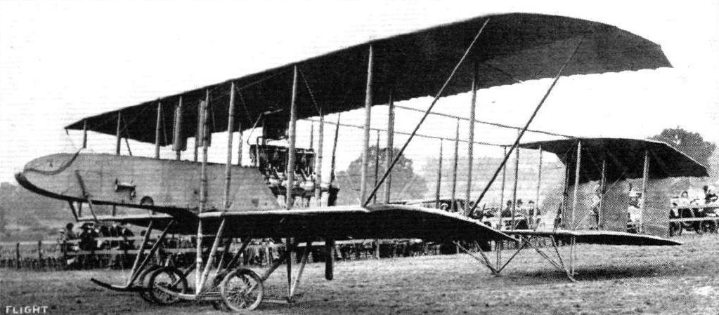
THE GRAHAME-WHITE CHAR-A-BANCS. - A three-quarter view from the front.
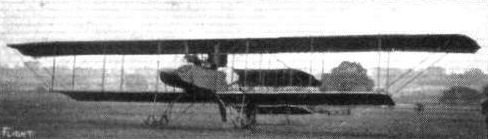
The Grahame-White five-seater.
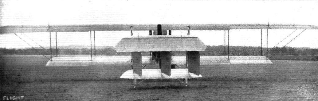
THE GRAHAME-WHITE CHAR-A-BANCS. - View from behind.
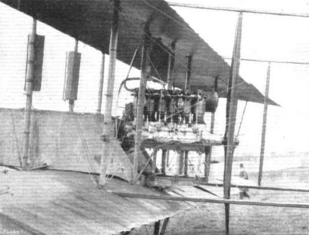
THE GRAHAME-WHITE CHAR-A-BANCS. - A view showing the mounting of the Austro-Daimler engine.
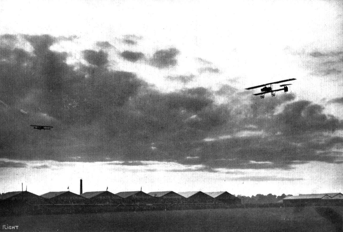
The arrival of the Champel biplane flown by Mr. Sydney Pickles, with Mr. Lawford as passenger, at the Hendon Aerodrome, on Saturday, whilst the competitors in the Aerial Derby were absent on their race round the circuit. On the left is seen the Grahame-White 5-seater biplane, with a mechanic sitting on each wing tip.

Pilot: Mr. Louis Noel.
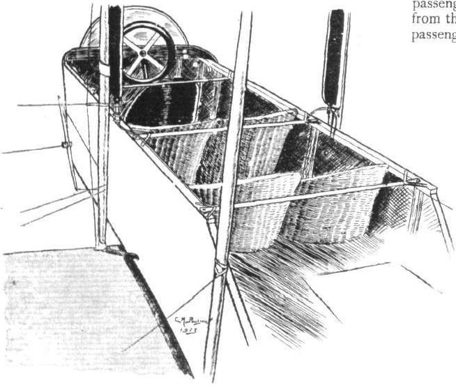
Sketch of the nacelle, showing seating accommodation for pilot and four passengers.
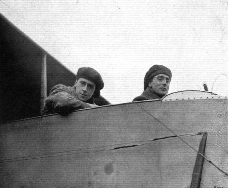
R. H. Carr, the Hendon aviator, at the wheel of the Grahame-White all-British "aero-'bus," with which he has just won the British Michelin Trophy and L500. The passenger, seated behind, is the engineer who accompanied him on his flight. Mr. Carr is making an attempt this week for the Michelin Cross-Country Speed Competition, the trophy for which carries with it a prize of L800.

An Impression of the Grahame-White charabancs flying at Hendon. From an original drawing by Roderic Hill.
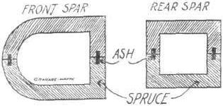
Sections of wing spars.
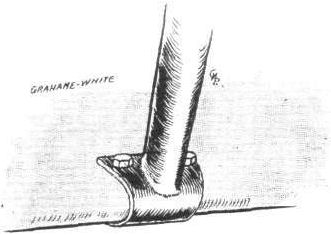
How crank-lever is attached to leading edge of aileron.

A skid strut joint.
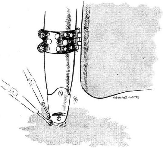
A neat rudder hinge.
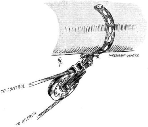
Another neat fitting - the universally-jointed pulley for aileron cable.
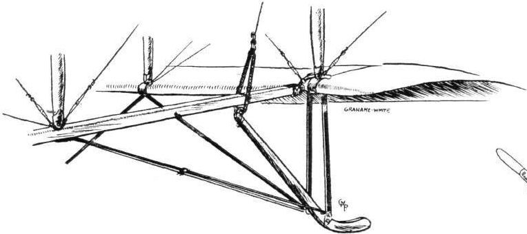
One of the tail skids.

Sketch of quickly detachable fitting of tubular extension struts to main plane struts.
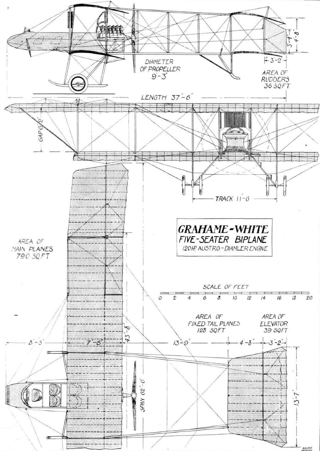
GRAHAME-WHITE 5-SEATER BIPLANE. - Plan, side and front elevations to scale.
Flight, February 8, 1913.
WHAT THERE WILL BE TO SEE AT OLYMPIA.
THE MACHINES.
Messrs. Handley Page.
They will be showing their 50-h.p. Gnome-engined two-seater monoplane, which is a well-known machine at Hendon and Brooklands. It will be the identical machine that the late Mr. Edward Petre flew from Fairlop, through London, over the river Thames, to Richmond, and then on to Brooklands. The machine is distinctive by virtue of its gull-shaped wings which have negative incidence tips. Since it was constructed this monoplane has flown upwards of 2,000 miles and has carried scores of passengers. An interesting appliance with which it is fitted is a Stolz Electrophone by which the pilot and passenger are able to carry on a conversation quite easily, undisturbed by the noise of the engine exhaust. Reports have been current that Messrs. Handley Page would be exhibiting a biplane. The hydro-biplane to which these reports referred, however, is not yet in a sufficiently advanced stage of construction, and wisely enough, this firm of constructors have decided to show a well-tried machine rather than one which would have to be unduly hurried through the works. Their hydro-biplane, by the way, when it appears will be of the tractor type. Its planes will be of similar design to the wings of their monoplanes, and it will be driven by a 100-h.p. Green motor.
Flight, February 15, 1913.
MESSRS. HANDLEY PAGE, LTD.
The 50-h.p. two-seater monoplane exhibited on this stand is now more than a year old. Although it is in such excellent condition, thanks to the renovation it has undergone at the Handley Page works previous to being brought to Olympia, one would scarcely think to look at it that it had been in existence so long. But the fact that it has had severe use does not make it any the less interesting as an exhibit - rather the reverse. It has the distinction of being the only machine that has, so far, flown from one side of London to the other, following the course of the Thames. This was accomplished when the late Mr. Edward Petre flew it last year, from the old Handley Page testing grounds at Fairlop to Richmond and then on to Brooklands. During its lifetime the machine has flown upwards of 2,000 miles and has carried over a hundred passengers at different times.
The 50-h.p. Handley Page monoplane. - To the semi-interested spectator, the first point that catches the eye is the unusual gull-like shape of the wings. Probably many an onlooker will think that they have been shaped in this way for the sake of artistic effect. This, however, is not the case. A much more important consideration underlies their design. They are shaped thus in order that the machine as a whole may be, to a great extent, automatically stable in the air. And the intentions of the designer have been borne out by practical test with the machine, for it has accomplished many trips in high winds, keeping so steady that the pilot has scarcely ever been called upon to use the controls at all. Struck by a forward or a rearward gust, the machine will rise or fall bodily on a level keel as the case may be. A side gust will have the effect of making the machine roll slightly, but the machine, without any help from the controls at all, always returns automatically to its normal level attitude by virtue of the shape of its wings. Considering that the machine is only fitted with a 50 Gnome motor, its performances to date have been remarkably good, for it is not often that one can get a monoplane to fly so well as the Handley Page machine does, and carry a passenger and quite a considerable fuel supply, with an engine of such relatively low horse power. As a further consideration, it must be borne in mind that the machine in question does not come under the category of light monoplanes. Being considered an experimental machine at the time when it was built, no efforts were made to cut down weight. As the machine stands at present, it turns the scale at 850 lbs., but on further machines of this type, Mr. Handley Page calculates that 100 lbs. weight can be saved, without in any way weakening the strength of the structure.
The fuselage is a rectangular section box girder, having ash longitudinal members, and cross and vertical members of spruce and ash, ash being used at those points of the body where the greatest strains have to be borne. The body is brought to a pentagonal section by the application of a triangular keel to the base of the lattice girders. The girder of rectangular section, however, takes the whole of the body strain, the keel being added simply to improve the appearance of the machine and to reduce its head resistance. Protruding from the front of the body is a 50-h.p. Gnome motor, which is not supported by any bearing in front of the crank case. It revolves under an aluminium cowl, which prevents oil from being scattered broadcast by the engine. The wing spars are housed by two boxes suitably arranged on either side of the machine for that purpose, and strong ash struts are carried laterally across the body in their neighbourhood, to take the compression that is always existent in a structure of this type.
The wings, as we have remarked, are gull-shaped, that is, they have a crescent-shaped entering edge, and there is a graduated wash-out from root to tip, the tip being swept back and adjusted incident to the relative wind at a negative angle of incidence. The wing spars are both of ash, the front one being of I section and about 9 in. deep at the root. The rear spar is more of an H section, for the thickness of the wing is not so great where it is built into the structure. They are so designed that in no place will they be called upon to withstand a greater strain than 1,000 lbs. to the square inch. In their construction the ribs must have been the most difficult part of the whole machine, for, as the wing curve varies progressively from root to tip, every rib has a different camber and chord measurement. Solid Honduras mahogany ribs, occur at every few feet along the spars, and the plane sections between these ribs are kepi accurately shaped by false ribs of silver spruce. Longitudinal stringers also help to maintain the correct shape of the wings. The fabric is sewn on diagonally, and on the top surface, where the greater lift occurs, is very strongly attached by having cane strips tacked over it on to the ribs. The wings are stayed above and below by two strong stranded steel cables to the front spar, and three to the rear. A factor of safety of 14 is worked to in their design.
The landing gear consists of a central skid of ash, supporting the body by six ash struts set in three pairs and arranged V-fashioned, as one of our sketches shows. The wheels are mounted on axles, which are universally jointed to a fitting at the base of the middle chassis V, and, from a point near the wheel the body is supported on either side by a compression spring strut. The main lift wires from the wings are attached to a fitting which passes below the front pair of chassis struts.
In the interior of the fuselage there is seating accommodation for two, arranged in tandem, with the pilot in front. A good impression of the pilot's seat can be obtained from one of the accompanying sketches. Since that sketch was obtained, however, a supplementary instrument has been fitted, a Stolz electrophone to wit, which enables the pilot and passenger to carry on a conversation unhindered by the noise of the engine. An American, Mr. Hammer, is the inventor of this device. Throughout, the machine is treated over with Robbialac varnish. Weighing 850 lbs., the machine is capable of raising a useful load of 450 lbs. and of flying at a speed of 54 miles per hour. In future machines of this type, a flying speed of 58 miles per hour will be obtained with the same engine power.
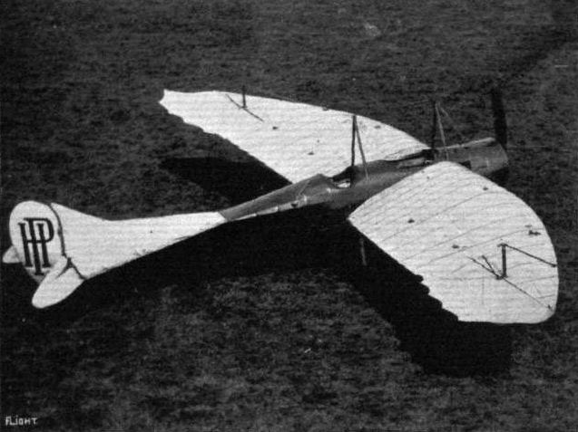
A bird's-eye view of the new Handley Page monoplane, showing the ailerons now used in place of wing warping.

Mr. E. Whitehoouse, with Mr. Ware as passenger, on the Handley Page at Hendon.
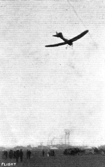
AT THE BURTON FLYING MEETING. - Whitehouse flying the Handley Page monoplane.

The 50-h.p. Handley Page monoplane.
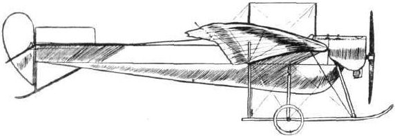
The 50-h. p. Handley Page monoplane.
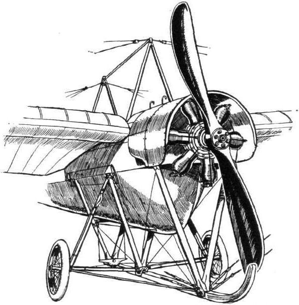
The front section of the Handley Page monoplane.
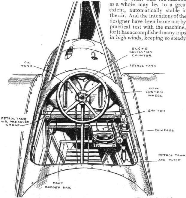
Handley Page Monoplane. - Sketch of the interior of the pilot's cockpit, as seen when standing up in the passenger's seat.
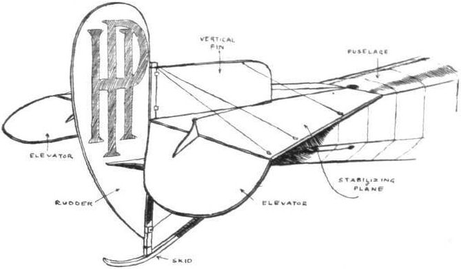
The tail of the Handley Page monoplane.
AT OLYMPIA. - A study in tail-skids.
A study in tails.
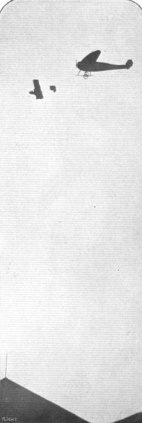
Not a swallow chasing a fly, but the Handley Page and a Henry Farman over the sheds at Hendon.
Flight, November 29, 1913.
THE NEW HANDLEY PAGE BIPLANE.
WHEN looking back to the early days of aviation, for such has been the progress, that Bleriot's flight across the channel seems now - only four years later - a thing of the dim and distant past, one remembers a comparatively small monoplane designed and built by Mr. Handley Page. It was said to be inherently stable, and at the Aero Show at Olympia - in 1911 we think it was - there was shown a small monoplane with crescent shaped wings and streamlined fuse/age. Since then the Handley Page machines have developed both in general airworthiness and in size, until it has now been found more expedient to make a biplane, as constructional difficulties naturally put a limit to the size to which it is convenient and advisable to build monoplanes. And if her first performances are to be taken as a criterion this latest product of the Handley Page firm bids fair to surpass in all-round utility the machines hitherto turned out by that firm.
The fundamental principles underlying the design of this machine are the same as those which were the raison d'etre of the monoplanes, i.e., an attempt has been made to solve the problem of natural inherent stability by means of a certain design of wing form. From the plan view of the accompanying scale drawings, it will be seen that the wings do not differ materially from those of the monoplanes, the back swept wing tips which are set at a negative angle of incidence being practically of the same shape as the tips of the earlier machines. In section the wings differ considerably from the monoplane wings, being much thinner and having a smaller camber.
It is to the curvature of the wings that the stability of the machine is due, as, according to its designer, Mr. Handley Page, the particular curve is so designed that when the machine attempts to climb too steeply, or, in other words, the angle of incidence increases, the centre of pressure moves backwards, thus bringing the machine back to its normal position. Similarly if the machine begins to dive the centre of pressure moves forward, and thereby tends to restore balance. Mr. Handley Page is of the opinion that the machine would fly without the tail planes, and only fits them as an extra precaution, and to gain greater controllability. Constructionally the wings differ considerably from what has now become more or less standard practice. There are two main spars, both of I section, the front one of which is made of spruce, whilst the material used in the rear spar is ash. In addition to these two main spars there are four subsidiary spars of the lattice-girder type, which serve to support the ribs. These latter consist of two thin strips of wood secured to the upper and lower edges of the spars respectively. These strips correspond with the flanges of the ribs in the majority of machines. No webs are employed, and the shape of each individual rib is determined by the depth of the various spars. Thus by having spars tapering towards the tip the camber is gradually decreased. In the lower plane the angle of incidence diminishes from 4° at the root to no angle of incidence at the tips. The upper plane also has a maximum angle of incidence of 40 at the root, but has a negative angle of incidence at the tips.
Although the machine is claimed to be inherently stable, ailerons are fitted to the upper main plane, so that should the pilot desire to right the machine he is able to do so. This is, we think, a very good arrangement, and does not by any means indicate that the designer lacks faith in the stability of his machine, but most pilots, we feel sure, prefer a machine which it is possible to right, should need arise, by means of the usual controls, no matter how stable the machine may be.
From the accompanying illustrations, it will be seen that the planes are staggered forward. The reason for this is that by staggering the planes the gap can be considerably smaller without danger of interference, or, in other words, for the same gap and chord a greater lift is obtained.
Two pairs of A struts of spruce connect the main planes and the fuselage. Four more pairs of struts connect the planes in the usual way, whilst near the tip of the lower wing is a single strut running to the rear spar of the upper plane. From the joint of this single strut to the lower plane a steel tube runs up to the leading edge of the upper plane. Very stout stranded cable is used for the diagonal bracing of the wings as well as for taking the drift. Other cables run from the fuselage at a point near the beginning of the tail plane to the inter-plane struts, thus bracing the wings backwards to the fuselage.
One of the accompanying illustrations is a diagrammatic sketch of the fuselage, and shows the shape of that structure. Constructionally it consists of four longerons of ash connected by struts and cross-members of spruce, the whole being made rigid by means of the usual diagonal cross bracing. To a steel capping plate bolted to the front of the four longerons is secured the engine - a 100 h.p. 10-cyl. Anzani, which drives an Integral propeller of 8 ft. 6 ins. diameter, 5 ft. 6 ins. pitch. The pilot's and passenger's seats are arranged tandem fashion, the pilot occupying the rear seat. Both seats are supported on the lower longerons, and the legs of the occupants project down into the boat-shaped structure underneath the fuselage. One of our sketches illustrates the controls, which consist of a rotatable hand wheel operating the elevator and ailerons, and a foot-bar for actuating the rudder. The tail planes, it will be noticed, are similar to those on the monoplane, and are made of ample size in order to render them more effective, situated as they are, comparatively close to the main planes. The chassis is of the wheel and skid type, with two stout ash skids supported on three pairs of struts of spruce. A single axle carrying the wheels is slung from the skids by means of rubber shock absorbers, and two radius rods from the front struts to the axle keep the latter in place. Diagonal cross wiring and cables running to the lower extremities of the two first pairs of the inter-plane struts prevent the chassis from giving laterally. A short strong ash skid protects the tail planes against contact with the ground.
In front of the pilot is to be fitted a dashboard with all the usual instruments, such as aneroid, clock, compass, revolution indicator, and air-speed indicator. The tanks contain sufficient petrol and oil for a four hours' flight, and the weight of the machine with this and pilot and passenger is 1,775 lbs. The speed of the machine has not yet been ascertained, but she appears to be fairly fast, and seems to climb very well. She has been designed for exhibition work, and the conditions to be fulfilled are good climbing capacity - in order to be able to get out of small fields - and slow landing speed. The machine has been built for an exhibition company in the north of England, and as soon as she has been put through her trials by Mr. Whitehouse, she will be delivered to the purchasers.
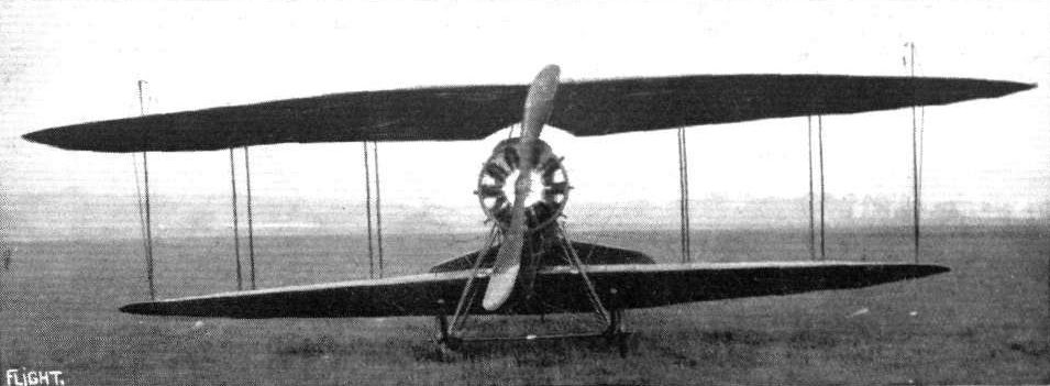
The new Handley Page biplane, as seen from the front.
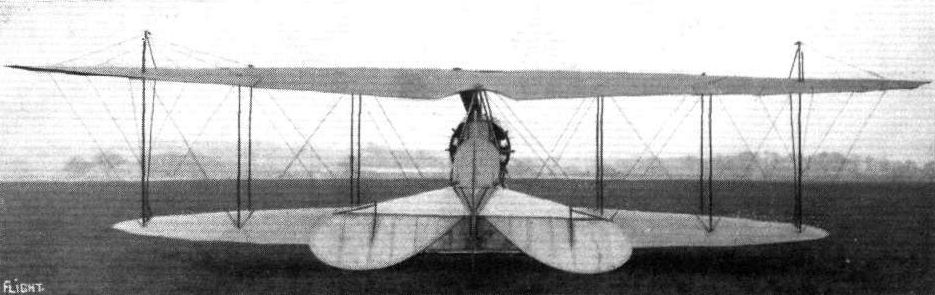
THE NEW HANDLEY PAGE BIPLANE. - A view from the back.
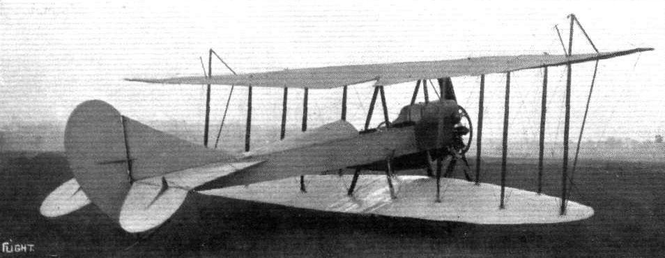
THE NEW HANDLEY PAGE BIPLANE. - A three-quarter view from the back.
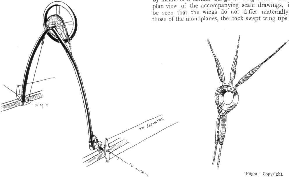
DIAGRAMMATIC SKETCH OF CONTROLS ON THE H.P. BIPLANE. - On the right, sketch showing method of attachment of aileron-wires to control cables.
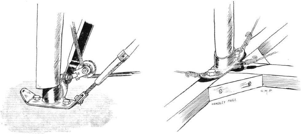
One of the strut sockets on the H.P. biplane showing pulley for aileron cable, and on the right a fuselage joint.

Sketch showing the neat steel clip by means of which a joint is formed for the tail fin, rudder post, tail plane and fuselage on the H.P. biplane.
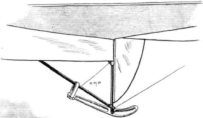
The tail skid of the H.P. biplane.

One of the elevator crank levers on the H.P. biplane.
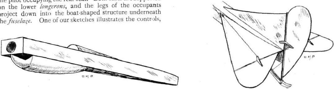
Diagrammatic sketch of the fuselage, and on the right the tail planes on the H.P. biplane.
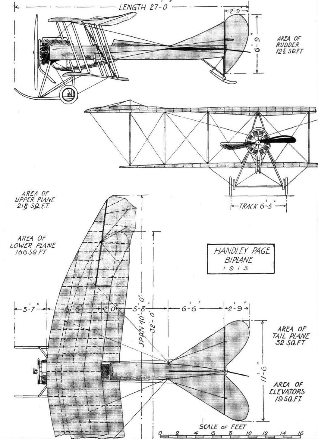
THE NEW HANDLEY PAGE BIPLANE. - Plan, side and front elevation to scale.
Flight, July 5, 1913.
THE PIONEERS.
<...>
Sir George Cayley's influence was considerable, and undoubtedly coloured the work of many who came after him. Those who next appear in chronological sequence among historical pioneers were Henson and Stringfellow, both sometime residents of Chard, in Somersetshire. They worked together on the building of large models, which they tried to make fly by means of small and very ingeniously constructed steam-engines. Ultimately Stringfellow succeeded in producing a monoplane which was self-supporting by the aid of its own power plant, and with this he made a public demonstration in 1848. It was the first time that any sort of aeroplane had ever been built to sustain itself aerodynamically, but the significance of the accomplishment was apparently quite unrecognised by those who witnessed the demonstration at that time. On the other hand, there is a curious old print of the same date that depicts with the liveliest imagination a monoplane on its way to China or some other similarly far-distant locality.
<...>
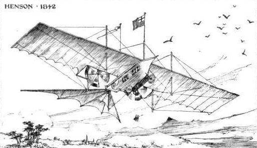
Henson's idea of a monoplane about 1842, as commonly depicted in old prints of that date.
Flight, July 19, 1913.
THE LAKES FLYING CO.'S TRACTOR WATERPLANE.
IN its general appearance the tractor waterplane owned by the Lakes Flying Co. is somewhat reminiscent of the Avro machines. This impression is no doubt created by the shape of the body and tail planes, which as a matter of fact are the remains of a machine built by Messrs. A. V. Roe and Co. for Mr. J. Duigan, the Australian aviator.
This similarity, however, is confined to the rear part of the machine, the front portion, including the main planes, being distinctly different. From the plan view of the machine it will be seen that the main planes have a comparatively high aspect ratio - 8.5 as a matter of fact. The wing section is the same as the old Maurice Farman, i.e., analogous to Eiffel No. 12. Eight pairs of streamlined struts connect the main planes, the whole structure being cross-braced with steel wire in the usual fashion. In order to impart to the machine a certain amount of natural lateral stability the main planes are given a dihedral angle. The chassis is quite simple, and consists of two skids connected to the body by four streamline struts.
A single central float of a special patented design supports the machine when on the water. It is divided into eight watertight compartments, which form a central framework of wood, with duralumin sides, aluminium bottom and Willesden canvas top. In order to minimize the shock when alighting on the water, the float is sprung from the chassis skids, by means of rubber shock-absorbers, in the manner shown in one of the accompanying sketches. It will be seen that this method of attaching the float to the chassis is so simple that the machine could in a very short time be converted into a land machine by substituting a pair of wheels for the float.
In a machine like this, having only a single central float, it has naturally been found necessary to protect in some way the wing-tips against contact with the water. This has been effected by fitting balancers or floats, consisting of an air-sack mounted on a springboard, to the wing-tip. A float of similar construction takes the weight of the tail when the machine is at rest on the water. For steering when "taxiing" at slow speeds, a small water-rudder, situated to the rear of the main float and working in conjunction with the air-rudder, is provided.
Just behind the trailing-edge of the main planes, and well down inside the fuselage, is the pilot's seat, from whence the machine is controlled by means of a central-pivoted hand-lever, which is moved backwards and forwards for elevation and depression, and from side to side for wing warping. A foot-bar operates the rudder. In front of the pilot, and approximately over the centre of gravity, is the passenger's seat, this disposition giving a very good view in all directions. The engine - a 50 h.p. Gnome - is overhung, i.e., has no bearing between it and the propeller. The latter is of the L.F.C.'s own design, and has brass-bound tips to prevent splitting, should it have to negotiate a spray of water thrown up by the float. The petrol and oil tanks are supported between the inner two pairs of plane struts, as shown in one of our sketches. The speed range of the machine is from 50 to 62 m.p.h., and it carries a passenger quite easily when the engine is pulling properly.
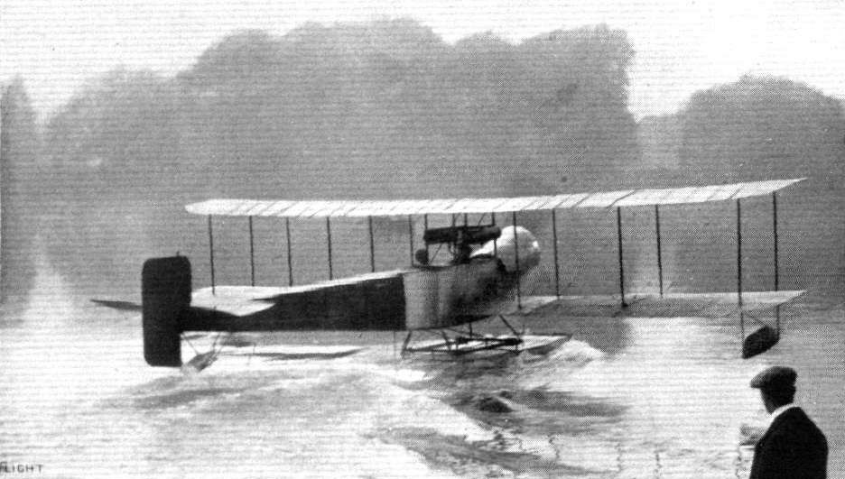
The Lakes Flying Company's tractor hydro-biplane, just getting away with a passenger.
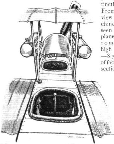
Sketch of the cockpits and mounting of fuel and oil tanks.
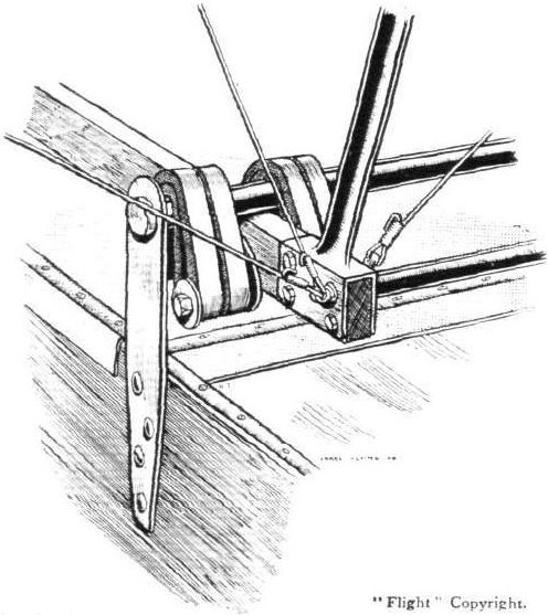
Sketch showing how the main float is sprung from chassis by means of rubber shock-absorbers.

Tail planes and float.
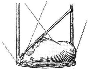
One of the pneumatic floats on wing tip.
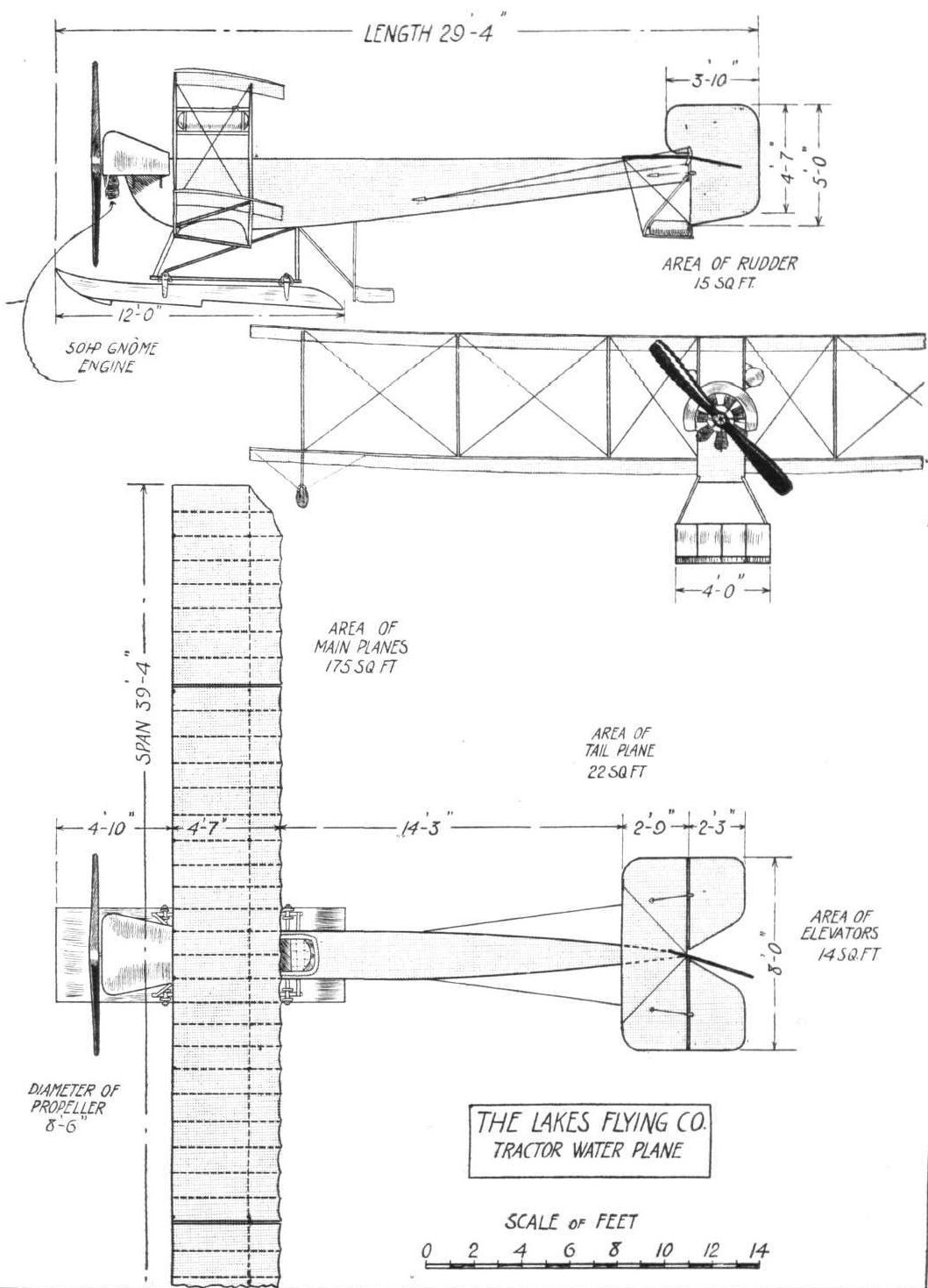
THE LAKES FLYING CO.'S WATERPLANE. - Plan, side and front elevations to scale.
Flight, August 2, 1913.
WATER FLIGHTS AT WINDERMERE.
MR. STANLEY ADAMS is giving visitors to Windermere this year a very great deal of additional enjoyment by his able flying of the "Waterhen" and the more recently built tractor biplane that was described in FLIGHT the other week. Those anxious to enjoy passenger flights over the lake are numerous, and business on a fine day is brisk; besides, Mr. Adams is a cautious pilot, and gives confidence to the spectator. The surroundings of Windermere are beautiful to the eye, but from the pilot's point of view they often have an ominous look, for awkward eddies are not infrequent, and the more ideal the day from the visitor's standpoint the less sometimes is the air in a good state for flying.
Last Saturday Mr. Adams did good service in the enthusiasm he aroused among members of the automobile industry in Lancashire and district who had come down at the invitation of Sir Kenneth and Lady Crossley to enjoy the afternoon at Pull Woods. When the "Waterhen" appeared, all other interests were forgotten, and the booking for flights ultimately kept the steamer waiting at the pier head for a quarter of an hour or more while the last on the list made his trip aloft.
How long, we wonder, before the private air yacht daily spreads its wings in graceful flight above the lake? A silent engine and no castor oil would do more than most things to bring it to pass.

With the Lancashire Branch of the Society of Motor Manufacturers and Traders at Lake Windermere. - On the left Sir Kenneth Crossley just taking his seat in the Waterhen as a passenger, and on the right in flight over Lake Windermere.
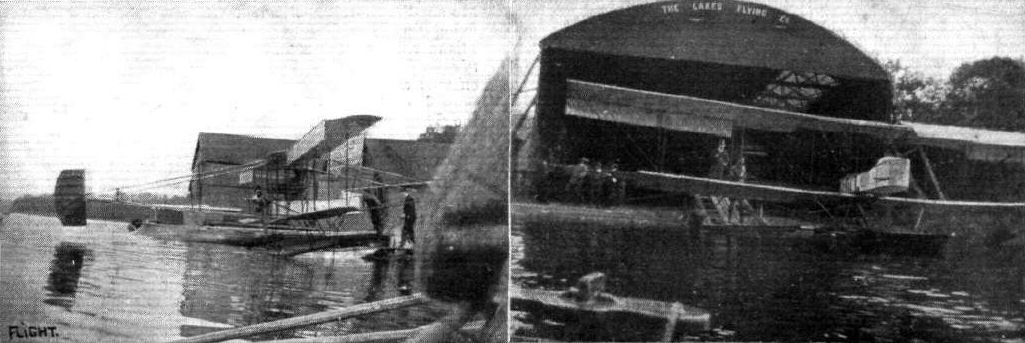
THE WATER BIPLANE OF THE LAKES FLYING CO. A T WINDERMERE. - On the right the machine is just seen before being taken back into the shed. These photographs were taken by Geoffrey Sleath, of Ukley, Yorks, a little cripple-boy of twelve, who is able to hold a camera. The lad is a keen follower of the model section of FLIGHT, the photographs being taken with a "Brownie" camera.
Flight, January 4, 1913.
THE MARTIN-HANDASYDE MONOPLANE.
SINCE the very early Brooklands days, when they were experimenting with an extremely pretty light monoplane, with a 35-h.p. J.A.P. engine, Messrs. Martin and Handasyde have kept firm to a design greatly resembling the Antoinette. Yet, although the Antoinette has lived its day, and now has almost died out, these two enthusiasts have gone forward, keeping true to their faith in their design, to a successful issue. No one will deny that the Martin-Handasyde monoplane as it stands to day is decidedly good as a flying machine, and one of the two prettiest monoplanes that are built in England.
In passing, there is an uncommon interest in the fact that this monoplane is driven by an Antoinette motor. Back in the days when there were more Antoinette monoplanes about than there are now, many were the attempts to get these machines to fly satisfactorily with a different engine. Gnome, E.N.V., and other motors were tried, but the results obtained were not comparable with those arrived at when the Antoinette motor itself was fitted. There seemed to have been a conspiracy between the two, the machine refusing to be put on its best behaviour unless it were companioned by the motor that was designed for it. It may be pure coincidence, it may be something to do with the fact that the same brain, M. Leon Levavasseur's, devised the two. And in support of this phenomenon, or whatever one likes to call it, we find that Mr. Handasyde, having in the course of his experiments fitted his machines with both J.A.P. and Gnome motors, returns to the Antoinette.
Whatever different opinions have been held in the past relative to the general design of the Martin-Handasyde machine, and it may be as well to remark that no machine ever appears in the aerodrome without giving rise to most conflicting opinions as to its worth, everyone has been unanimous in writing down the designer as one who is unusually clever at detail work, and enormously particular regarding the standard of workmanship that he demands from his working staff.
The backbone of the machine is a girder, of a section that may be likened to a triangle standing upon its truncated apex. It is its widest in the neighbourhood of the seats, and tapers away to either end like a boat. Its construction is interesting, for it is not built up in the usual manner with piano-wire bracing and transverse struts. There are four longerons of ash, which taper towards the tail. These are clamped down to a mould, and to them are screwed sheets of three-ply wood, from which, afterwards a diamond shaped piece is cut for lightness sake. Forward of the passenger's seat these sheets of three-ply wood are left solid, for there greater strength is required. The sheets having been applied, the fuselage is removed from the mould, covered with fabric, and doped, and the result is a body that is simple to construct, that is light, and that is extremely strong against longitudinal bending and lateral torsion.
The landing gear is quite Antoinette in its appearance, but in its action, quite different, for elastic shock absorbers are employed, whereas the Antoinette rejoiced in a compressed air suspension. The weight of the whole machine is taken in a single large diameter steel tube that is built into the body at a point just forward of the centre of gravity when the machine is fully loaded. Landing shocks are absorbed by the tube travelling vertically against the tension of rubber amortisseurs. A skid of hickory, shaped like a hockey stick, extends forward below the propeller to protect it, and in front is supported from the body by a stout ash strut.
Everything about the chassis strikes one as being very strong, and the same remark applies to the wings. They are each most intricately constructed about two hollow spars built up of ash and three-ply wood. At the wing root the front spar has a depth of 7 ins. and the rear one 6 ins., and they both taper to 3 ins. at the tip. Both are rigidly braced by spruce king-posts and stranded steel cable. For their shape they taper towards the tip, and there is noticeable a progressive "wash-out" in the camber. Covered and varnished, each wing weighs about 110 lbs.
So that the engine shall offer as little head resistance as possible, it is covered right in by aluminium sheeting, and the lines of this covering are continued on to a point to the rear of the pilot's seat by a fabric-covered superstructure of spruce and three-ply wood.
On either side of the body are the aluminium condensers, 13 ft. 6 ins. long, that recover the steam, which is formed in the cooling-jackets of the motor. They are most extraordinarily light, for the pair only weigh about 9 lbs., and have a cooling surface of nearly 70 square feet.
The tail of the machine takes a little share of the total lift, for although it is flat on the undersurface, it is cambered on top. Elevation is controlled by tail flaps. The motor, turning a Regy propeller of 2 m. 60 diameter and 1 m. 40 pitch at 1,150 r.p.m. on the ground, develops 60-h.p. at 1,300 r.p.m. in the air. She flies at 64 miles per hour.
Flight, February 22, 1913.
SOME MORE AEROPLANES AT OLYMPIA.
MARTIN-HANDASYDE (T. B. ANDRE AND CO., LTD.).
On the stand of Messrs. T. B. Andre and Co. is exhibited an excellent specimen of a Martin-Handasyde monoplane, equipped with an 8-cyl. Laviator motor of 80-h.p. Its lines, a matter, we should think, of general knowledge, greatly resemble those of the Antoinette monoplane. Scarcely two months since, we published a complete description, with several sketches, of a "Martinsyde" monoplane, which was practically identical with the one shown, excepting that it was driven by an engine of lower horse-power, a 60-h.p. Antoinette to wit. Let us, therefore, recall some of the remarks we printed then.
The body is boat-shaped, and has a cross-section which may be represented by a triangle standing upon its clipped apex. It is built up with four ash longerons, which are, in the process of construction, clamped down to a former.
Held in their correct positions by this ormer or mould, sheets of three-ply wood are bolted to either side. The sheets aft of the passenger's seat are then lightened by cutting away a diamond shaped piece from the centre of each. Those forward of that seat are left untouched, for at that part of the body much greater strains have to be borne. In front the motor is bolted to the top two longitudinal members of the body, and it is almost completely covered in by an aluminium shield which lends to the fuselage more of a streamline form than it would otherwise possess. The lines of this shield are continued rearwards to a point behind the pilot's seat, by a superstructure of spruce and three-ply wood, which, covered with fabric and sloped, assists in keeping the occupants sheltered. The pilot sits behind the passenger, and his hands rest on a wheel, mounted at the head of a vertical column, by which he controls the monoplane in flight. His feet operate the steering of the machine in the horizontal plane.
The wings are most carefully and strongly built, as may be seen from a specimen uncovered wing that is on exhibition on the stand. Its spars are of box section, with ash top and bottom strips and three-ply sides. Where they emerge from the sides of the body the front spars are 7 ins. in depth, tapering to 3 ins. at the tips. The rear spars are also 3 ins. deep at the tips, but are slightly smaller than the front spars at the roots. Both spars are braced by stranded cable stays passing over spruce king-posts erected approximately half way along their length. From the base of the front spar king-post an especially stout cable stay is run obliquely forward to a fitting on the front skid. This stay is designed to take the lift and drift of the wing. An equally strong stay proceeds obliquely backwards from the same point to a fitting on the landing wheel mast, which cable is provided, not only to take a share of the lift, but to prevent the wing - which, by the way, weighs something like 110lbs. - from straining forward owing to its own inertia when a landing is being made. Similar braces attached to the roots of the rear spar king-posts proceed to the main chassis mast, and these both take lift and operate the wing warping.
The landing chassis is similar to the Antoinette in appearance, and very similar to it in action, with the exception that, in the Martinsyde, the shocks of landing are absorbed by rubber springs in tension, whereas the Antoinette machine made use of a rather more elaborate system of pneumatic springing. From the point where the central chassis mast leaves the body on the underside, a long, curved hickory skid projects forward under the propeller, in which position it is stayed by a stout compression strut running downwards from the nose of the body. The relatively small landing wheels, shod with wide diameter pneumatic tyres, are mounted on a single axle, to the centre of which is mounted the massive steel tube which supports the main weight of the machine. The structure is made rigid laterally by two streamlined spruce struts.
The tail is purely a flat directive organ, taking no share of the lift. Two flap elevators are hinged to its rear edge. There is a vertical unbalanced rudder preceded by a fin, and the whole is protected by a neat tail skid.
The machine has been designed for a maximum speed of 70 miles per hour. Without passengers or fuel aboard, she turns the scale at 1,100 lbs., and, in flight, can carry a useful load of 660 lbs.
Flight, September 20, 1913.
THE AERIAL DERBY.
PILOTS AND HOW TO RECOGNISE THE MACHINES.
No. 12. The Martinsyde Monoplane
may be recognised by its long narrow fuselage and its tapering wings, which are cut off straight at the tips. Another characteristic feature whereby this machine may be identified is the provision of kingposts on the wings.
THE MACHINES, WITH SOME DETAILS.
No. 12. The 120 h.p. Austro-Daimler-Martinsyde monoplane. This is also an extremely fast 'bus - its speed being about 80 m.p.h. Built on similar lines to the old Antoinette monoplane, it is a most graceful machine. The water-cooled motor is placed in front of the pilot. The fuselage is of triangular section, with the apex pointing downwards, and is quite slender, though very strongly constructed. It is the only aeroplane entered for the race that has the king-post system of wing bracing.
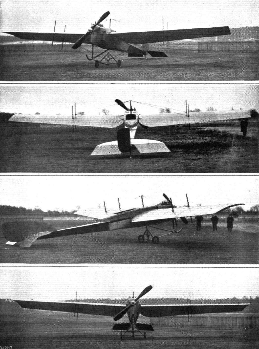
THE MARTIN HANDASYDE, as seen from different points around the machine.
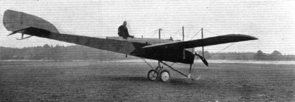
The new Martinsyde monoplane fitted with 120-h.p. Austro-Daimler engine. Mr. Gordon Bell is in the pilot's cabin.
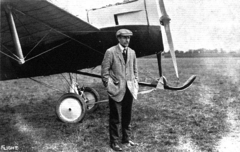
Mr. Barnwell, who secured second place, with only a couple of minutes' interval, on the Martinsyde machine in the Aerial Derby.

Pilot: Mr. H. Barnwell.
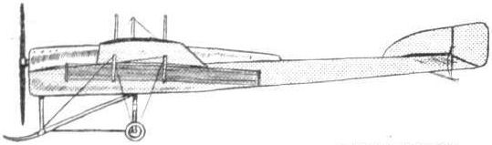
The 80-h.p. Laviator-Martin-Handasyde monoplane.
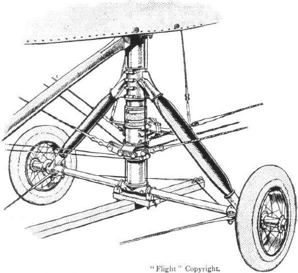
The Martin-Handasyde landing gear and wing-warplng mechanism.

DETAILS OF THE MARTIN-HANDASYDE MONOPLANE. - (1.) The tail skid. (2.) The front skid. (3.) The construction of the wing spars. (4.) The landing gear and wing-warping mechanism. (5.) The anchorage of the chassis-staying cables. (6.) The fitting accommodating the cable which braces the wings against drift. It passes round the nose of the body. (7.) The klng-post tip. (8.) One of the strong cable fastenings that are used on the cables taking the main lift.
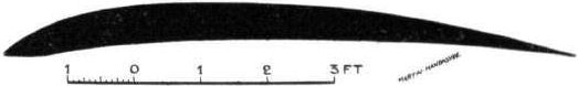
Wing section, to scale, of the Martin-Handasyde monoplane.

One of the M.H. main lift cable fastenings.
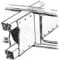
The M.H. wing spar construction.
AT OLYMPIA. - A study in tail-skids.
A study in tails.

THE MARTIN-HANDASYDE MONOPLANE. - Front and side elevations and plan to scale.
Flight, July 5, 1913.
THE PIONEERS.
<...>
It is impossible to mention all the names of those who have contributed useful work as pioneers in the realm of flight, and far less is it possible to do justice to the more important efforts. It is sufficiently clear, however, that for a long period the science of aviation had its most serious students in England. The Aeronautical Society was founded in 1866, and the first paper that was read before its members was an extremely interesting and also a very important contribution by F. H. Wenham. Sir Hiram Maxim, as all the world knows, had very ambitious ideas about what an aeroplane should be, and he built an enormous machine with which he experimented on a rail track laid down in Baldwin's Park, Kent, in 1893. The machine was fitted with a steam engine of his own design and construction, and on one occasion the lift of the planes was sufficient to cause the machine to break through its guard rail and perform a short free flight.
<...>
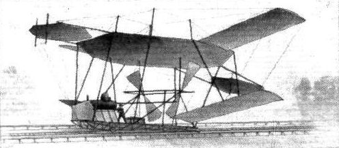
Maxim's large steam-driven aeroplane on its rail track in Baldwin's Park, Kent. During a trial in 1893 it broke through the top guard rail and made a short free flight.
Flight, June 21, 1913.
THE PARSONS BIPLANE.
QUITE apart from the interest attaching to this biplane from the fact that it is the machine on which the Parsons pendulum paddle-wheel stabilizer is going to be tried out, the Parsons biplane is in itself very interesting, as its designer and constructor, Mr. P. Muller, has managed to incorporate in it several new ideas. This, too, in spite of the fact that he was handicapped from the start by having to face the problem of designing a machine which could be flown with a 40 h.p. Aster car engine. To design an aeroplane that will fly with a proper aviation motor is, perhaps, not such a difficult matter, but to have designed a machine that flies - and flies well - with a heavy car engine is no mean achievement.
From the accompanying scale drawings it will be seen that the machine is a biplane of the tractor type with a monoplane fuselage. Although the main planes resemble in their general appearance those of the Caudron biplane, with which our readers are familiar, they differ from that well-known design in several details. For instance, the planes are not warped for maintenance of lateral stability, this function being carried out by flexing the trailing edge of the outer part of the upper plane. From the rear spar to the trailing edge the ribs in that portion of the wing consist of steel tape instead of the usual wood construction, the object being to obtain greater flexibility without the risk of breakage. Running parallel to the trailing edge, and some six inches in front of it, is another steel tape, to which are secured the wires by means of which the trailing edge is flexed. These wires are attached at their other end to a tubular lever pivoted on the rear spar and operated through stranded cables from the controls. In order to obtain greater efficiency the cord of the flexing portion of the wing is made slightly wider than that of the rest of the wing. The main planes are built in three sections for ease of dismantling, and the fabric is laced together at the joints. In order to minimise stresses on the fabric the cords are passed through an aluminium strip, instead of through eyelets in the fabric as is usually done, and the result is an extremely neat joint.
The fuselage, which is of rectangular section, is built up in the usual way, with ash longerons connected by struts and cross members of spruce, the whole being made rigid by diagonal cross-wiring. One of our sketches shows the very neat and inexpensive steel clip which forms the anchorage for these wires, and it will be seen that, with the exception of two small holes just large enough to accommodate one of the wires, the longerons are not pierced. With a view to obtaining greater rigidity against twisting strain, the fuselage does not taper to a knife's edge, but maintains its rectangular section to the rear end. Attached to the fuselage by four long bolts and four steel tubes is the tail plane, which is similar in construction to the main plane, the rear portion of it being flexed up and down for elevation and depression. Steering in a horizontal plane is effected by means of a rudder situated wholly on top of the tail plane, and pivoted on a steel tube approximately on its centre of pressure. One of the accompanying sketches will give a good idea of the arrangement of the tail planes.
A skid of malacca cane protects the tail from contact with the ground, whilst the chassis consists of two ash skids placed widely apart and connected to the lower main plane by six struts of English ash, the whole structure being made rigid by suitable cross-wiring. A single axle carrying two wheels is sprung from the skids by means of rubber shock-absorbers. To prevent this axle from bending in a heavy landing, wires are carried from the centre of it to the lower plane. A rubber shock-absorber is introduced in the wires in order to take up any slack due to the upward travel of the axle. Mounted on transverse tubular bearers is the engine, which, as has already been said, is a 4-cyl. Aster car engine which has been slightly lightened for flying purposes. It is cooled by two radiators placed immediately behind it inside the fuselage. It drives a Normale propeller of 8 ft. 2 in. diameter, 4 ft. 2 in. pitch, at 1,100 r.p.m.
Petrol and oil are carried in a tank in front of the pilot's seat, which consists of a piece of canvas slung from two transverse steel tubes inside the cockpit. It will be noticed that the fabric covering only extends a few feet behind the pilot's seat, terminating in a pyramidal stream lining, as it has been found that the rudder is more effective when the rear portion of the fuselage is left uncovered.
The controls are of the usual type, and consist of a central lever, which is moved from side to side for lateral balance and forwards and backwards for elevation and depression. A foot bar operates the rudder.
Flown by Mr. Jack Alcock, the machine has shown itself capable of very good work, and its performances to date include that of climbing to an altitude of 2,000 ft. At the present moment the Parsons pendulum paddlewheel stabilizer is being fitted, and tests of this interesting device will be carried out in the near future.
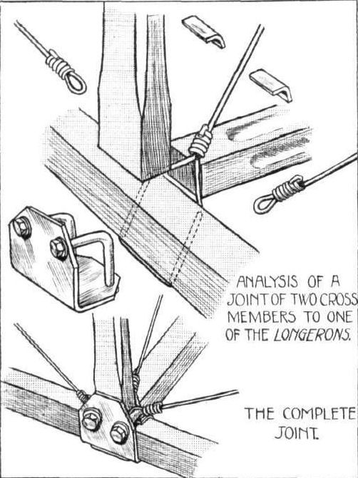
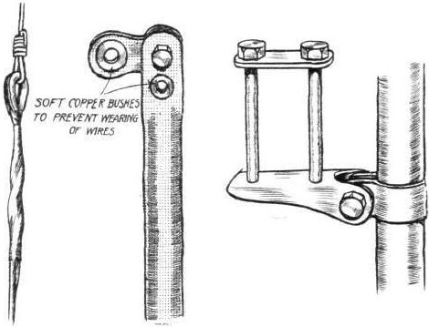
On the left is shown the method of securing the strands of a control cable by soldering a long copper ferrule round them. In the centre is the top of warp operating lever, showing how wire is protected against wear by copper bushes; and on the right a sketch of the attachment of warp operating lever to rear spar.
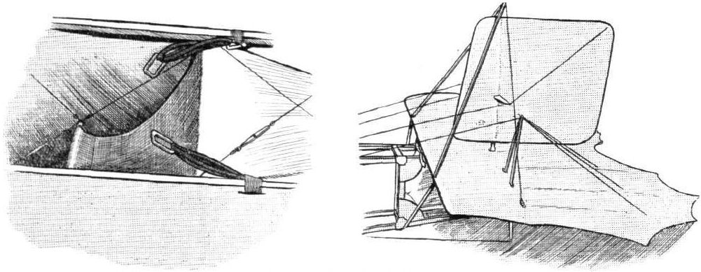
Pilot's seat of Parsons biplane, and on the right arrangement of tail planes.
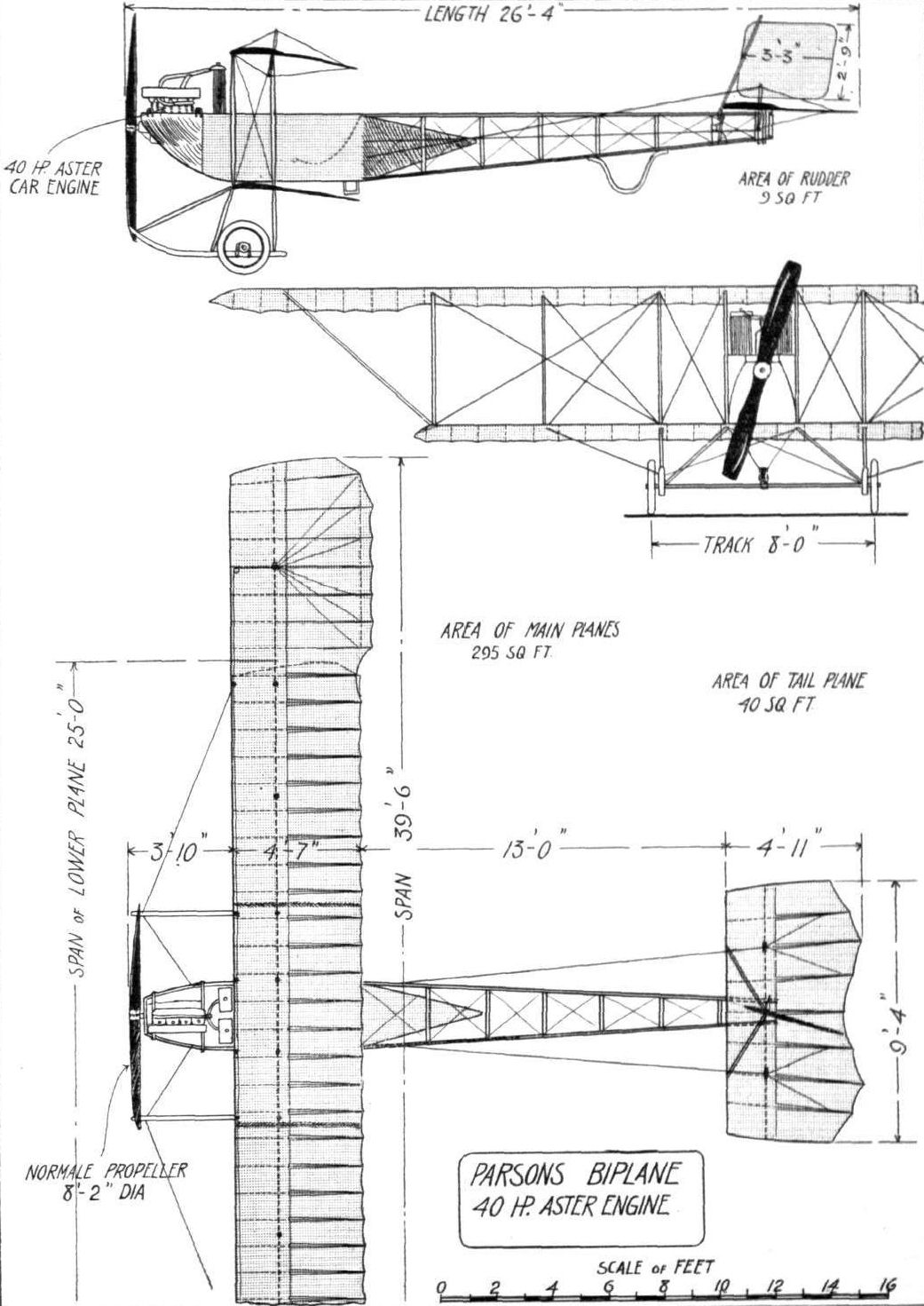
Flight, August 23, 1913.
COMPTON C. PATERSON
PILOT-CONSTRUCTOR.
MR. COMPTON PATERSON, who has just founded a flying school for the instruction of officers and others at Kimberley, in South Africa, and whose portrait we publish this week, initiated himself into the mysteries of aviation in the early part of 1910. In that year he designed and constructed a biplane, somewhat on Curtiss lines, which he proceeded to test on the seashore at Freshfield, near Liverpool. Moreover, he was successful to the extent of flying straights of about half a mile after a very short practice, and rapidly became a proficient pilot of the machine, although he did not secure his certificate until December, 1910, mainly owing to the difficulty of having the qualifying flights witnessed by an official observer. The aerodrome at Freshfield was established by Compton Paterson, who afterwards came to London, and put in some time with the Grahame-White Aviation Co. at Hendon, before making arrangements for a South African tour. It was in December, 1911, that he landed at Cape Town with one of his own biplanes fitted with a 50 h.p. Gnome. Flying demonstrations were given at Kenilworth race course, near Cape Town, and subsequently at the Green Point cycle track. These exhibitions extended through the Christmas holidays of that year. Among his experiences was a mishap which might have had very serious consequences, the fabric on the tail of his machine bursting at an altitude of something like 40 ft. The machine did not immediately fall, but first climbed at an ever-increasing angle for another 20 ft., when it turned over and crashed to the ground upside down. The pilot escaped without serious injury, and in a few weeks was at work repairing the wreck.
From Cape Town, Paterson went to Johannesburg, where he flew during February and March of 1911, and Kimberley was visited in April. So successful was the general effect of his work, that the Cape Town Corporation decided to ask him to give a hydro-aeroplane demonstration, for which purpose Paterson had to design and have suitable floats made locally. As a result of this tour, the people of South Africa have been fairly well stirred up to a realisation of the possibilities of the aeroplane, and Paterson himself has succeeded in establishing the nucleus of an industrial interest in the furtherance of the movement.
"THE HAWK."
BRITISH NOTES OF THE WEEK.
Aviation in South Africa.
UNDER the direction of Mr. Compton Paterson an aviation school has been established at Kimberley, and the first class of defence force officers were to have commenced their training on Monday. An Aviation Corps has also been formed with headquarters at Pretoria. It has started with four officers.
Flight, November 1, 1913.
THE LATE MR. E. W. CHEESEMAN.
A PATHETIC reminder of the fatal accident to Mr. Cheeseman in Africa is to hand this week, in the form of a letter to a member of the staff of FLIGHT, dated Kimberley, two days before his mishap, and two photographs which we reproduce. In this he writes as follows :#
"I am enclosing two photos of the South African Flying School. I am instructing the future Officers of the South African Aviation Corps and also a fair number of civilians, including a lady. We have made fairly good progress. We have two Paterson biplanes, one a front elevator type, and the other, built out here by a pupil (Mr. H. Carpenter), is of the Henry Farman type, but a Paterson section.
Kimberley Aerodrome is 4,000 ft. above sea-level, but the old 'busses lift well with instructor and pupil. The aerodrome is five miles round and a track like a billiard table. Both machines are fitted with 50 h.p. Gnomes. I shall have pleasure at a later date in forwarding photos of the locally built 'bus, and other photos of interest.
"Give my kind regards to the boys and accept best wishes for yourself."
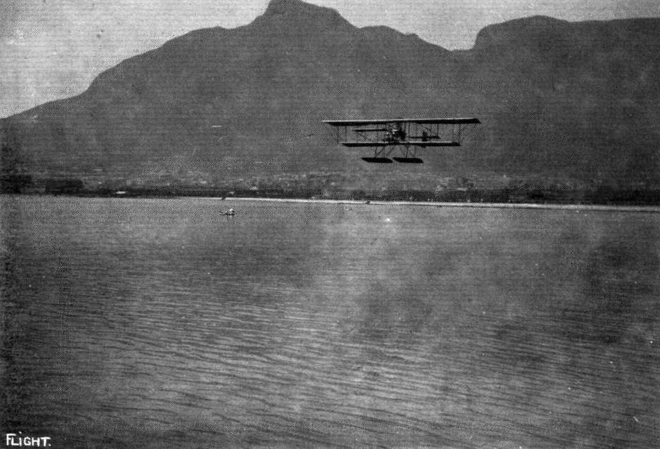
Mr. Compton Paterson on his hydro-biplane flying over Table Bay with Table Mountain in the background.
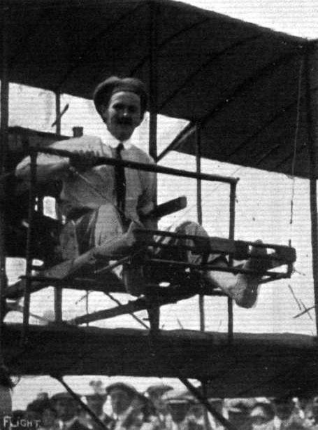
Mr. Compton Paterson in the biplane with which he did such good work in South Africa. Observe the double-handed control that is a feature of this machine.
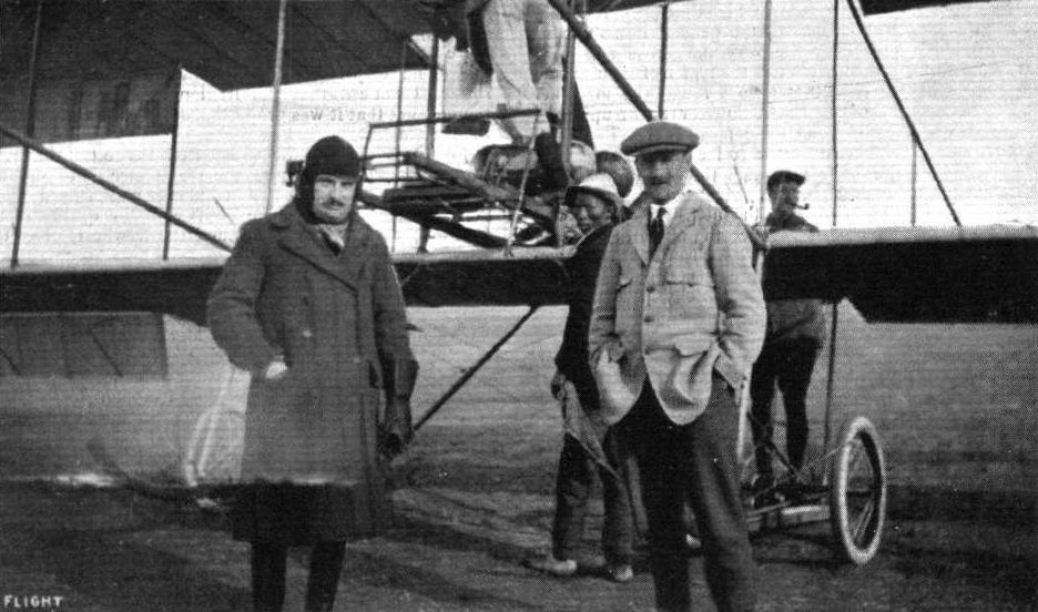
AT THE SOUTH AFRICAN FLYING SCHOOL, KIMBERLEY. - Mr. C. Compton Paterson, Managing Director, and the late Mr. E. W. Cheeseman.
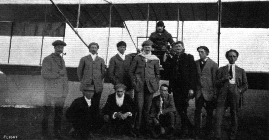
AVIATION IN SOUTH AFRICA. - South African Flying School, Kimberley. Reading from left to right: (kneeling) Messrs. Williams, Van Coller, Creed; (standing) Messrs. A. Turner (chief mechanic), Cleasdale, Van der Spev, Turner, Carpenter, Emmet, Salamon; seated in machine. Chief Instructor the late E. W. Cheeseman.
Flight, July 5, 1913.
THE PIONEERS.
<...>
Another interesting series of experiments was carried out about the same date at Harrow, on a circular track, by Phillips. The machine in question had numerous very thin cambered planes arranged somewhat in the appearance of a Venetian blind. Phillips' name, however, is more generally associated with his experiments on cambered sections, and in particular with a peculiar form of section having a pronounced hump over the front edge, which is sometimes referred to as the "Phillips entry."
<...>

Phillips' aeroplane tested on a circular track at Harrow in 1893. - The supporting surface was divided into numerous lath-like cambered planes, arranged somewhat in the manner of a Venetian blind.
Flight, July 5, 1913.
THE PIONEERS.
<...>
Among those who took great interest in Lilienthal's experiments was Pilcher, then a young English engineer whose name was associated with the firm of Wilson and Pilcher, at one time well known in the automobile industry before their cars were taken over by Messrs. Armstrong, Whitworth. He designed gliders of his own, more or less on Lilienthal lines, and at one time went over to Germany in order to discuss the subject with Lilienthal himself. If anything, he adopted an even more dangerous procedure than the German pioneer, for in order to avoid the necessity of finding a suitable hill as an aerodrome, he would attain the initial altitude necessary for a gliding flight by having his machine towed like a kite. An accident during one of these experiments resulted in his death, and thereby deprived England of a most promising student who, had he lived, might have done much to give this country pre-eminence from the first.
<...>

Pilcher's glider, built on somewhat similar lines to the Lilienthal machine, but having among other differences a light-wheeled undercarriage in order to relieve the pilot of its weight when landing and while on the ground.
Flight, February 8, 1913.
WHAT THERE WILL BE TO SEE AT OLYMPIA.
THE MACHINES.
Mr. J. R. Porter, A.M.I.C.E.
A helicopter will be shown on this stand, a general idea of which can be gathered from the sketch we publish. The machine will consist of two parachute surfaces, one above the other, with a centrifugal propeller, driven by a 50-h.p. Gnome motor, mounted between them. The engine will be provided with gearing, so that the propeller may be reversed. Means will be provided to produce a forward motion by the use of flaps, which, the inventor states, control the air travelling between the two surfaces. The diameter of the outer parachute will be 14 ft., and the machine will stand about 11 ft. high. Accommodation is provided for the pilot in a small boat or coracle swung some distance below the parachute surfaces.
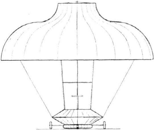
The Porter 50-h.p. Helicopter.
Flight, April 12, 1913.
THE RADLEY-ENGLAND WATERPLANE.
A NEW British-built waterplane of great interest has been constructed at Huntingdon by James Radley in collaboration with Gordon England, who is acting as his engineer and designer. Both have had great experience in aviation, the former as a practical pilot, and the latter, not only as a pilot, but as a designer of successful machines.
In their joint effort they have made a bold attempt to advance aeroplane construction a definite step by building a machine which is designed in the first instance to carry six passengers. Other machines have carried as many passengers or even more upon occasion, but this is a machine in which the accommodation for six passengers has been provided at the outset, and has formed of necessity a basic factor governing the proportions of the aeroplane as a whole.
The machine is a waterplane, and the pilot and five passengers are seated, three in each of the two boat-like floats upon which the machine rests when it alights on the water. In the right-hand float is the accommodation for the pilot, and two seats for passengers are arranged behind him, while the three other passengers occupy corresponding seats in the other float.
As may be judged from the fact that it has to carry this amount of weight, this biplane is by no means small, and its planes afford some 500 sq. ft. of supporting surface. The weight empty is estimated at about 1,400 lbs., and the calculations for the weight loaded were based on the assumption that the normal wing loading would be in the order of 3 1/2 lbs. to the square foot. Actual weights generally differ considerably from estimated weights, and we should expect the final real value to come out somewhat heavier than the abovementioned figure.
The tail is carried by outriggers in the usual manner, but is somewhat interesting in the comparatively small size of the fixed tail plane as compared with that of the elevator flap serving as its extension, which would probably tend to increase the sensitiveness of the vertical directional control. Steering in a horizontal direction is carried out in the orthodox manner by means of two balanced rudders, carried by the outriggers and situated under the tail plane. Lateral balance is obtained by means of ailerons of large proportions hinged from the rear spars of the upper main planes. These various steering surfaces are operated by a control of the usual type, consisting of a universally-jointed lever, a backward and forward movement of which operates the elevator, and a side-to-side movement actuates the ailerons, which, by the way, are interconnected, so that when one is depressed the other is correspondingly elevated. The rudders are controlled by a footbar in the usual manner, the bar, however, being practically unbreakable, as it is built up of some twelve laminations of wood.
As will be seen from the accompanying diagram of the wing section of the main planes, these have a somewhat small camber, 2 ins. maximum, and have a maximum thickness of 2 1/4 ins. The angle of incidence is set at 3 degrees. The main spars, which are of "I" section ash, are situated some eight inches from the leading edge, while the rear spars, which are also of "I" section ash, are spaced only 31 1/2 ins. from the main spars, roughly, half-way between the latter and the trailing edge. The ribs, which are spaced close together at the inner portion of the wings, are built up of spruce with willow web-blocks, or distance pieces. Mahogany is used for the inner struts carrying the engine, while the others are of spruce, those carrying the outriggers being made hollow for the sake of lightness, and bound with fabric.
The floats, each of which is connected to the lower main planes by three ash struts, have mahogany sides and white pine bottoms, while the floor timbers are of oak. Each float is partly covered over with curved decks of teak, and each has two water-tight compartments, either of which is sufficient to keep the whole machine afloat. The shape of these floats can be seen from our illustrations, and it will also be noticed that they are not stepped in any way.
One of the most interesting features in the design of this machine is the manner in which the power plant is arranged. It consists of three 50-h.p. Gnome engines placed in line on a common axis and each supported on either side. Above the engines is a countershaft, which is driven by all three engines in common by means of triple Coventry chains of the roller type. The tubular countershaft is mounted on ball bearings, and is of very large diameter, and carries at its rearmost end a four-bladed propeller of about 9 ft. 10 ins. diameter, which is geared down to about three-fourths of the engine speed. Interposed between the rear engine frame and the propeller is a large ball race which takes both the journal load and the thrust of the propeller. Another unusual feature of the drive is that the chain sprocket of each engine is machined solid with the end-plate of the crank case. Each engine is independently controlled from the pilot's seat by a separate petrol cock and switch, whilst on the control lever is a master switch that cuts out all three engines.
Fuel and oil are contained in tanks supported above the power plant, and each engine is supplied by separate pipes. At present the capacity of the fuel tank is 21 gallons, and the oil 10 1/2 gallons, but it is intended to carry further supplies of fuel and oil in tanks in the floats. Oil is supplied to each engine by a separate pump.
Bracing is everywhere carried out in a thorough manner by stout steel wire, whilst double steel stranded-cables are employed for the control. Drift is also well provided against by means of wires attached to the bows of the floats. The wheels shown, attached to the floats, in our illustrations are only temporary, being fitted for preliminary trials on the ground before taking to the water. It is with this machine that Messrs. Radley and England propose to enter for the latest prizes offered by the Daily Mail.
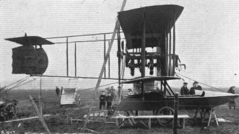
Side view of the Radley-England waterplane.
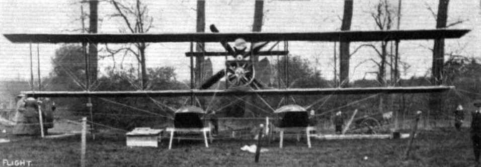
Front view of the Radley-England waterplane.
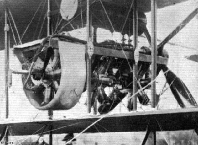
The power plant, consisting of three 50-hp. Gnome engines, on the Radley-England waterplane.

Diagrammatic sketch of the pilot's and passengers' seats in one of the floats of the Radley-England waterplane.
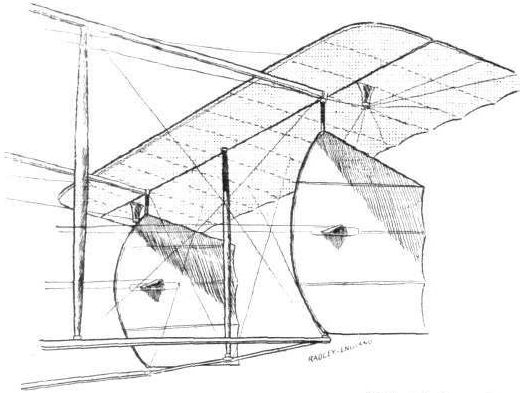
Tail planes of the 150-h.p. Radley-England waterplane.
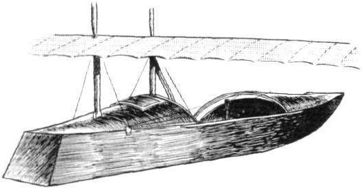
Three-quarter rear view of the Radley-England float.
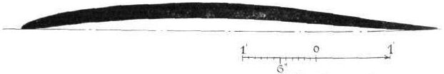
Wing section, to scale, of the Radley-England waterplane.
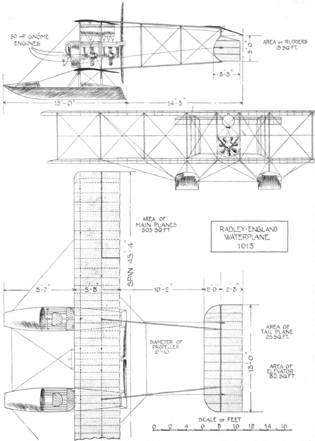
THE RADLEY-ENGLAND WATERPLANE. - Plan, side and front elevation to scale.
Flight, August 16, 1913.
THE RADLEY-ENGLAND WATERPLANE.
SINCE Messrs. J. Radley and G. England built their first experimental machine some months ago, the rough idea for which was provided by Mr. Radley and the design elaborated by Mr. England, they have gained a lot of experience with this type of waterplane. Evidently this experience has strengthened their faith in the flying boat - or rather boats - type, for the biplane which they had entered, although, unfortunately, through engine troubles, withdrawn at the last moment, for the Daily Mail Race, differs, except, of course, for such alterations as have been necessitated by the installation of a 150 h.p. Sunbeam engine, instead of the three 50 h.p. Gnome motors, very little from the first experimental machine.
As the most noticeable innovation is in the shape of the floats, we will refer to this first. It will be remembered that the first biplane was fitted with floats of the punt type, but it was found that they were not strong enough, so in the present machine they have been abandoned for boats.
These, which were built locally by the South Coast Yacht Agency, while not being a great deal heavier than the punt type, are very much stronger, and have the further advantage of being less liable to leak, owing to the fact that they are clinker-built. As some of our readers might be a little in doubt about the exact meaning of the term clinker-built, it may be explained that a boat is said to be clinker-built when the outer boards or planking do not butt up against one another with their edges, but overlap each other a little. Boats of this type are known to be much stronger, weight for weight, than those in which the planking forms butt joints.
Cedar is the material used in the construction of the boats, and two bulkheads divide them into three watertight compartments, so that should one or both of the boats become swamped, the water will only be admitted to the central part, the watertight compartments in the ends being still sufficient to keep the machine afloat.
Accommodation is provided for two people in each float, the seats being placed tandem fashion. The front seat in the right hand boat is occupied by the pilot, who has an excellent view in all directions. The controls consist of a central lever, the side-to-side movement of which operates the warp, while a to and fro motion works the elevator. A foot-bar actuates the rudder. Two pairs of struts connect each float with the lower main plane, whilst another pair of struts running from the prow of the boats to the engine bearers take the oblique stresses set up when the machine alights on the water.
Mounted on very strong bearers is the engine, a 150 h.p. 8-cyl. Sunbeam of the V-type, driving through a two to one reduction gear, a 4-bladed Lang propeller of 9 ft. 6 ins. diameter, 4 ft. 7 ins. pitch. Normally the engine runs at 2,200 r.p.m., at which speed it develops 150 h.p. Between the inner plane struts, and on the same bearers as the engine is a huge tank containing 82 gallons of petrol and 8 gallons of oil, which supply is enough for a 10 hours' flight.
The main planes, which are of the same plan form as those on the experimental machine, but are of a modified monoplane section have a slightly greater span than the old machine. They are built up of hickory spars of I section, with ribs of spruce and poplar. Ten pairs of struts connect the main planes. Spruce is the material used for the struts, with the exception of the engine struts, which are three-ply Honduras mahogany, and all the struts are hollowed out for lightness. Lateral stability is maintained by means of ailerons on the top plane only. These are interconnected, Farman fashion, so that when one moves up the other moves down. The warp cables, as well as those operating the rudder, are carried round pulleys, and through copper fair leads down to the control levers in front of pilot's seat.
Four tail booms carry at their rear end the tail planes, consisting of a fixed tail plane of rectangular plan form and of the non-lifting type, to the trailing edge of which is hinged the elevator. Underneath the tail plane are situated the twin rudders which, as can be seen in the scale drawing, are of exactly similar shape to those on the earlier machine.
The planes are covered with brown Holland, which is rendered air-tight by being doped with British Emaillite. The weight of the machine in flying order, that is to say, with four passengers and sufficient fuel for a 10 hours' flight, is 2,500 lbs., and her flying speed is 60 m.p.h.
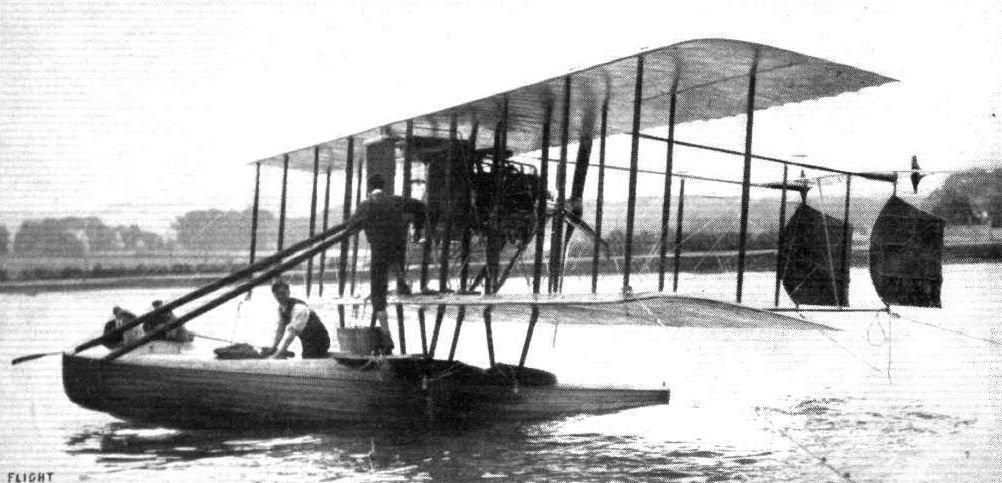
Radley-England Waterplane No.2 was built to compete in the Seaplane Circuit of Britain of 1913 but engine trouble on test caused withdrawal of the machine.

THE RADLEY-ENGLAND WATERPLANE. - A side view.
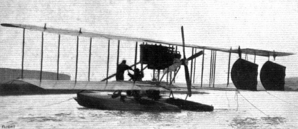
The Radley-England waterplane as seen from behind
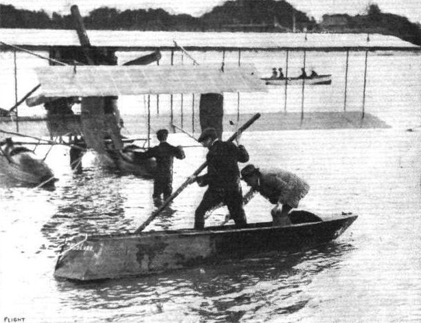
MESSRS. RADLEY AND ENGLAND PUNTING AT SHOREHAM. - This punt is one of the original floats, fitted to their waterplane, converted into a punt.

Sketch showing arrangement of tail planes of Radley-England waterplane.
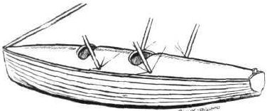
Sketch of one of the main floats of the Radley-England waterplane.
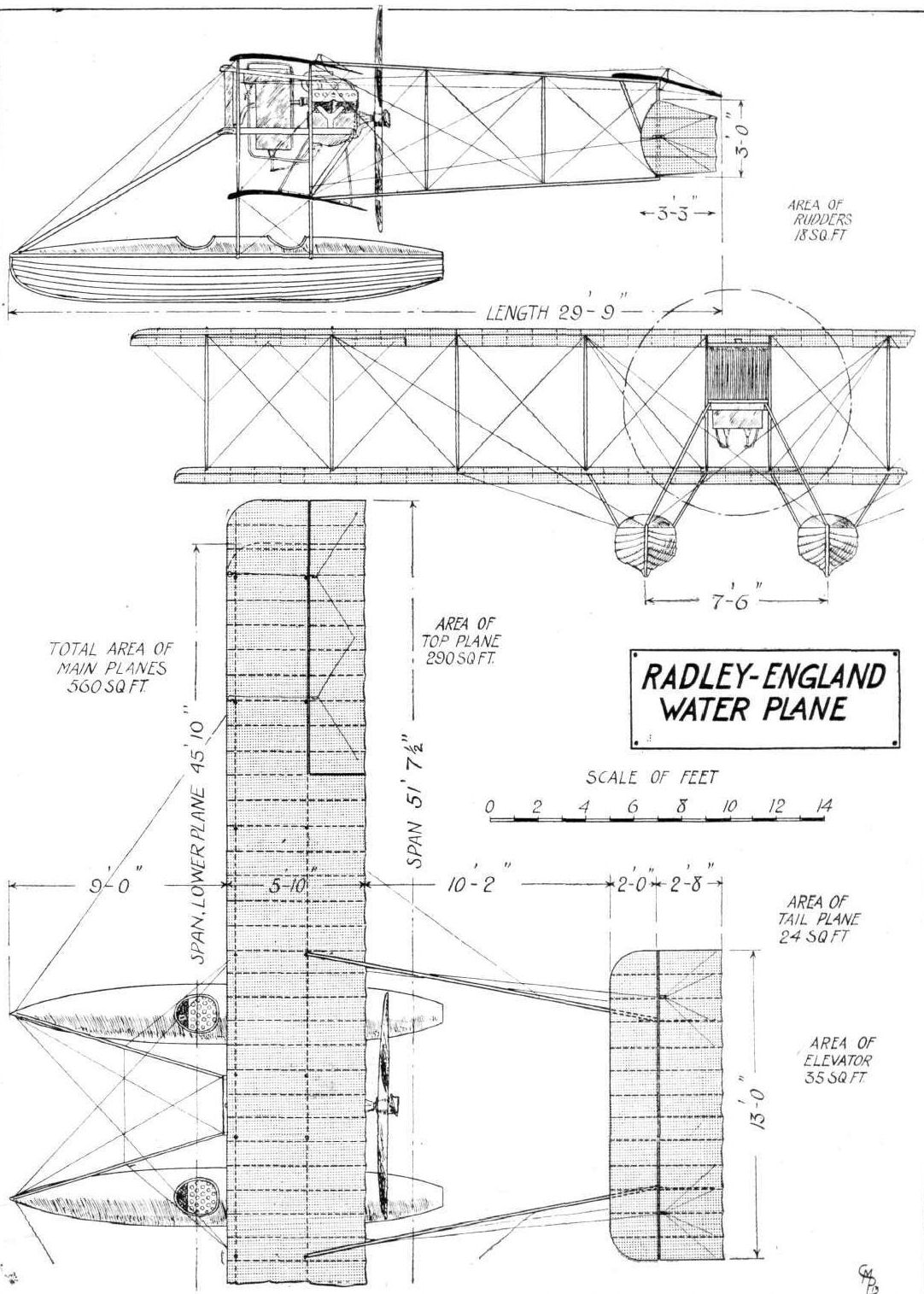
THE RADLEY-ENGLAND WATERPLANE. - Plan, front and side elevations to scale.
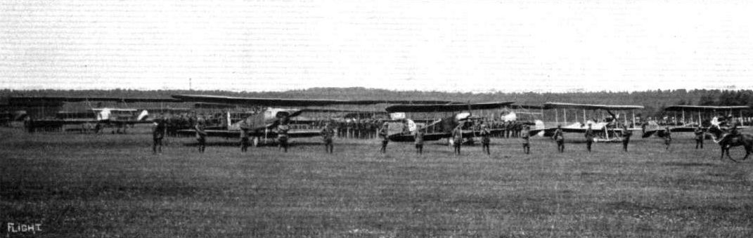
AIRCRAFT ON LAFFAN'S PLAIN FOR THE "FLY PAST" ON THE KING'S BIRTHDAY THIS WEEK. - In the parade there were four BE type (from the left, B.E.3, B.E.4, B.E.2 and B.E.1), six Maurice Farmans, and two Henry Farmans. (Summer of 1913)
Flight, February 8, 1913.
WHAT THERE WILL BE TO SEE AT OLYMPIA.
THE MACHINES.
The War Office Exhibit.
On the space retained for the War Office will be staged two biplanes, a "BE 2" and "a Cody," while suspended from the roof of Olympia will be the Army dirigible "Delta." Of the "BE 2," it may be said that it is one of the two or three most successful machines constructed, which, after all, it is only natural to expect, since the Royal Aircraft Factory have facilities for experimenting with devices to be embodied in standard machines such as perhaps no private firm of aeroplane builders possesses. A fair number of these machines are at present in use in the service of the country, and shortly they will be supplemented by many more of the same design that have been ordered from various British firms. The "BE 2," it may be recalled, holds the British height record, obtained when Mr. G. de Havilland, with Major Sykes as passenger, ascended to 9,500 ft. over Salisbury Plain on August 12th last.
<...>
Flight, November 15, 1913.
BRITISH NOTES OF THE WEEK.
An Exciting Time at Montrose.
THE officers of the Royal Flying Corps stationed at Montrose get some thrilling moments. Last week Capt. Longcroft, on a B.E. biplane, made a flight against an 80 m.p.h. wind, and after three-quarters of an hour, during which the speed indicator pointed to 75 m.p.h., the machine was driven back three miles. The machine rocked very considerably in the gale, and Capt. Longcroft had the greatest difficulty in landing, but this he eventually accomplished after about an hour's work.
Flight, November 29, 1913.
BRITISH NOTES OF THE WEEK.
Capt. Longcroft's Long Flight.
PROBABLY the finest flight with passenger yet made in the world was that of Capt. Longcroft on Saturday, when, accompanied by Lieut.-Col. Sykes, he flew on biplane BE 218 from Montrose to Portsmouth, and then to Farnborough, the distance of 630 miles taking 7 1/4 hrs. The machine, which was fitted with a special petrol tank of 54 gallons capacity, left Montrose at 8.55 a.m., and landed at Farnborough at 4.10 p.m. It will be remembered that Capt. Longcroft previously held the world's record for a flight in a straight line with a passenger with 288.6 miles.
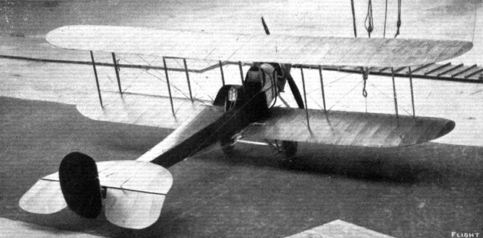
BE 2, the Army biplane, at Olympia Show, being one of the first arrivals at the Aero Exhibition.

Capt. Longcroft, whose splendid record flight is recorded this week, starting off from Montrose for his non-stop run to Portsmouth and Farnborough on one of the B.E. biplanes, built by the Bristol Co.
This photograph depicts a famous pre-war event when Capt. Charles Longcroft of 2 Squadron, RFC flew a record-breaking trip in BE2a '218 with an additional fifty-four-gallon petrol tank in its faired-over front cockpit. In August 1913 he flew from Farnborough to Montrose in 7 hours 40 minutes with only one stop. Endurance and reliability were key elements for the reconnaissance role.
This photograph depicts a famous pre-war event when Capt. Charles Longcroft of 2 Squadron, RFC flew a record-breaking trip in BE2a '218 with an additional fifty-four-gallon petrol tank in its faired-over front cockpit. In August 1913 he flew from Farnborough to Montrose in 7 hours 40 minutes with only one stop. Endurance and reliability were key elements for the reconnaissance role.
AIRCRAFT ON LAFFAN'S PLAIN FOR THE "FLY PAST" ON THE KING'S BIRTHDAY THIS WEEK. - In the parade there were four BE type (from the left, B.E.3, B.E.4, B.E.2 and B.E.1), six Maurice Farmans, and two Henry Farmans. (Summer of 1913)
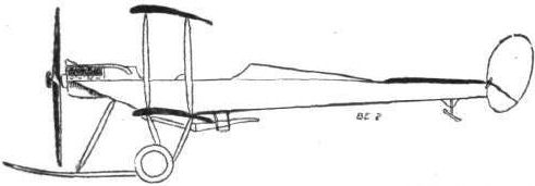
The "BE 2" British Army biplane.
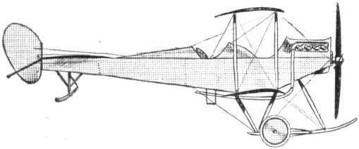
The British Army biplane, BE 2.
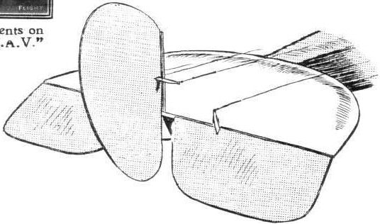
The tail of the BE 2 biplane.
AT OLYMPIA. - A study in tail-skids.
A study in tails.
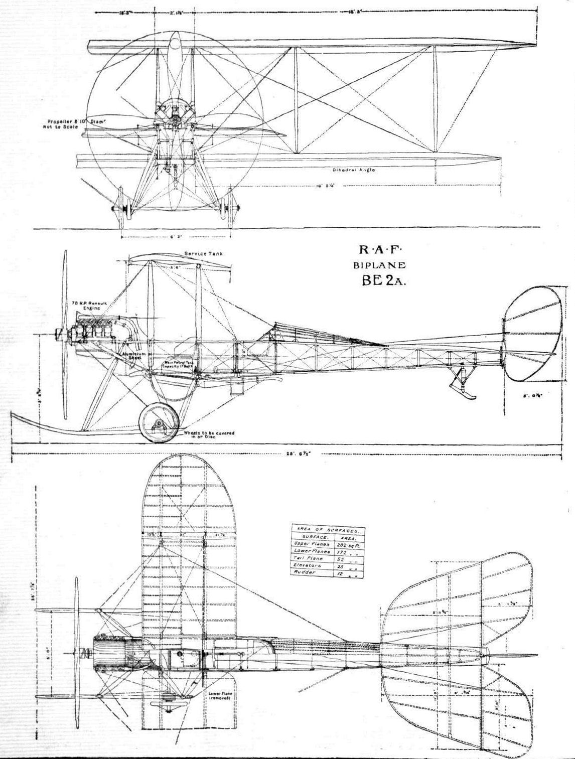
Elevations and plan of the R.A.F. biplane BE 2a, from the Technical Report of the Advisory Committee for Aeronautics, 1911-12.
AIRCRAFT ON LAFFAN'S PLAIN FOR THE "FLY PAST" ON THE KING'S BIRTHDAY THIS WEEK. - In the parade there were four BE type (from the left, B.E.3, B.E.4, B.E.2 and B.E.1), six Maurice Farmans, and two Henry Farmans. (Summer of 1913)
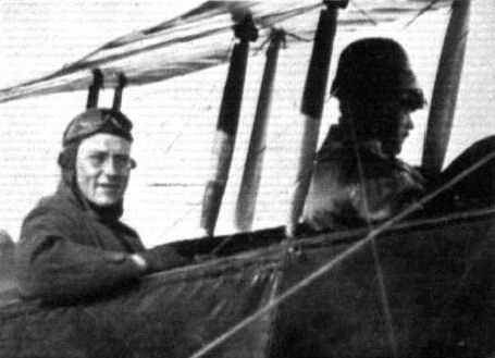
The ubiquitous pilot, Gordon Bell, when he was flying one of the BE's with Capt. Dawes.
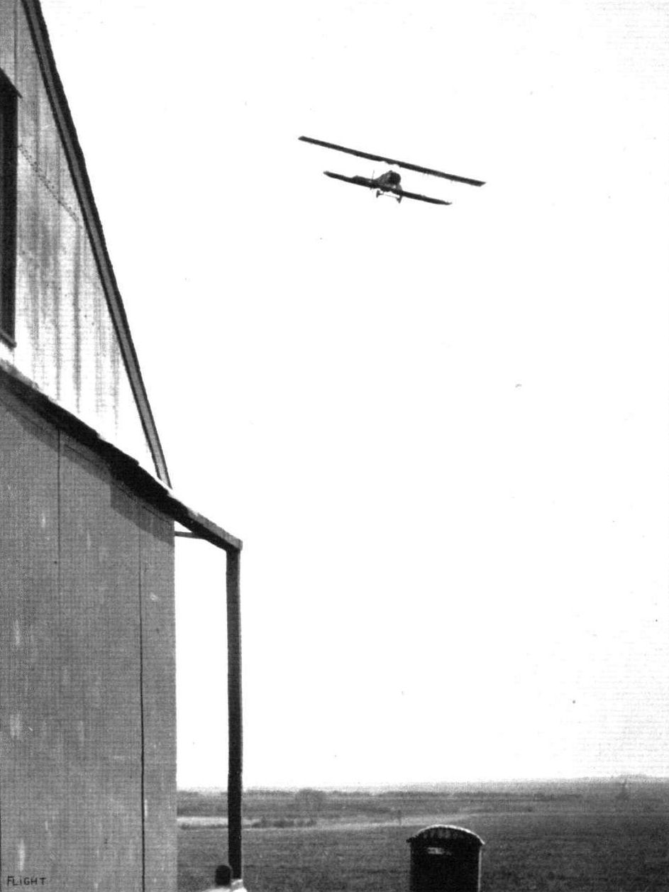
Commander Samson flying a Short biplane at Eastchurch.
Flight, June 7, 1913.
70-H.P. SHORT BIPLANE.
MESSRS. SHORT BROS, execute so much confidential work for the Admiralty that the details of their construction are apt to escape the appreciation of the wider public that they certainly well deserve. Long ago, however, the firm established a reputation for sound aeroplane building, and the enviable good fame has remained, while the Short designs have met with an ever-increasing measure of success. To-day, the position of Short Bros, in the hydro-aeroplane industry is unique, and their factory is marked by extension upon extension.
It is a Short biplane, built originally for Mr. Frank McClean for use over water, that forms the subject of our scale drawings and sketches this week, and equally with ourselves our readers are indebted to Mr. F. K. McClean for the courtesy in placing this machine of his at our disposal for the purpose of their preparation.
Although this particular aeroplane is not a new model, it has the greater advantage of being well tried and a thorough success. Not only was it a good waterplane, but its owner was so favourably impressed with its qualities as a land machine after he had substituted a set of wheels for the floats, that he has since retained it for this purpose, in order to obtain greater enjoyment from its more frequent use over the Royal Aero Club's grounds at Eastchurch, where he has his sheds.
As a type the "pusher," as this machine is familiarly called in order to distinguish it from a tractor biplane of the same make that Mr. McClean also owns, is remarkable for its light loading. It has a wing surface of 750 sq. ft. for the support of 1,250 lbs. plus pilot, passenger and fuel. Allowing 350 lbs. for the people on board and for the petrol, it is evident that the loading is only just over 2 lbs. per sq. ft., a fact which explains the remarkably good gliding-angle of the machine.
An examination of the accompanying scale drawing will show the machine to be of the engine-behind type, with a front elevator. This elevator, however, is of such small size that it might quite conceivably be done away with without in any way impairing the stability of the machine; but it is of use, in so far as it enables the pilot to judge the angle of the rear elevator.
In plan, the main planes are somewhat unusual, as, for a distance of about 16 ft. from the tip, the leading edges slope backwards. This portion of the wing is also given a slight dihedral angle in order to impart a certain amount of natural lateral stability to the machine.
From the front view of the machine it will be seen that the span of the lower plane is considerably shorter than that of the upper plane, and the chord is some 10 ins. narrower. Lateral balance is maintained by means of ailerons of large area - about 28 square feet each - hinged to the rear spar of the top plane.
These ailerons are operated in the usual way through stranded cables running to a drum on the axle of the control wheel in front of the pilot Another cable running along the leading edge of the plane interconnects the two ailerons - Farman fashion.
Four wooden outriggers carry the tail planes, which consist of a fixed-plane of rectangular form, attached to the two upper outriggers, and which has hinged to its trailing edge the rear elevator plane. Underneath the elevator and hinged to the two rear struts connecting the tail-booms are the twin rudders by means of which tin machine is steered in a horizontal direction.
Two tail skids carried on extensions of the rear outrigger struts and sprung from the lower tail-booms by means of rubber shock absorbers protect the tail planes against contact with the ground.
For use on land, the machine is fitted with a chassis of the wheel and skid type. Four struts secured at their upper ends in sockets on the lower main plane carry at their lower extremities two stout wooden skids. A single tubular axle carrying the wheels is sprung from the skids by means of rubber bands. It will be noticed that the arrangement differs from the usual practice in having the wheels inside the skids. Strong diagonal bracing gives rigidity to the whole structure.
Projecting well out in front of the main planes is the nacelle, which carries on its nose the front elevator, and inside which are the pilot's and passenger's seats. From the front seat the pilot controls the machine by means of a hand-wheel mounted on the upper end of a tubular steel column, which in turn is secured to a transverse rocking-shaft. To the ends of this shaft, and outside the nacelle, are brazed two short levers, from which cables pass to the elevators.
A to-and-fro motion operates the elevators, while the ailerons are worked by rotation of the hand-wheel. As the machine is comparatively short for its span, it has been found desirable to have the rudders turn through a great angle for a small movement of the foot bar operating them.
This has been effected by making the levers on the rudders short, and having the foot bar itself long, so that the action is geared up. In front of the pilot are the instruments, altimeter, revolution indicator, compass, clock, map case, &c. Behind the pilot, and right over the leading edge of the lower plane is the passenger's seat. Owing to the positions of the seats both pilot and passenger have an exceptionally fine view of the country underneath.
At the rear end of the nacelle, and mounted on channel steel bearers, is the 70-h.p. Gnome engine, which furnishes the power. Between the rear engine bearer and the engine is a propeller of 8 ft. 6 in. diameter.
Petrol and oil is carried in a tank of streamline form, supported on tubular steel stanchions, which are attached to the upper longerons of the nacelle. The flying speed of the machine is 48 m.p.h.

50-h.p. Short S.38 No. S.62 with modified landing-gear.
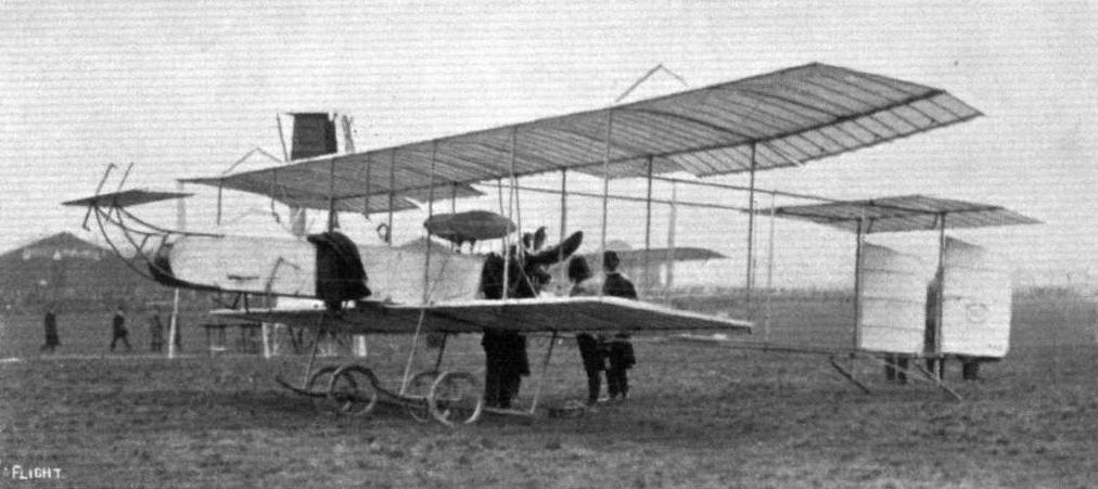
Short S.38 after many improvements became the prototype of a standard biplane for the RNAS which was produced by Short and other manufacturers in wartime. This is S.62 which became RFC 446. On March 22nd last Mr. Gordon Bell, accompanied by his mechanic, flew this machine from Eastchurch to Hendon in a very high wind.

The new under-carriage of the Short biplane.
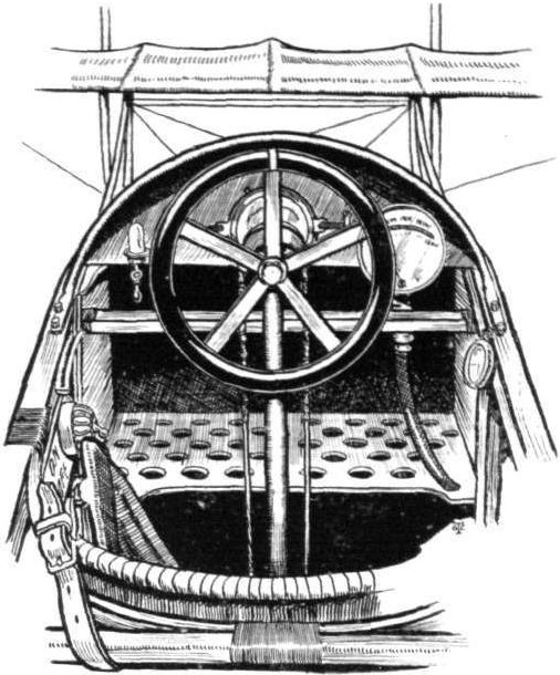
Sketch of the controls on the Short biplane.
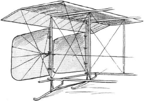
Sketch showing the detail of the tail of the Short biplane.
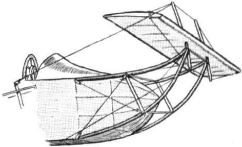
Sketch showing the detail of the forward part of the nacelle with front elevator.

One of the tail skids of the Short biplane, and, on the right, detail of the left side of the landing chassis.
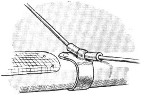
Method of changing direction of control wires on the Short biplane.
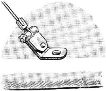
A wire attachment on the Short biplane.
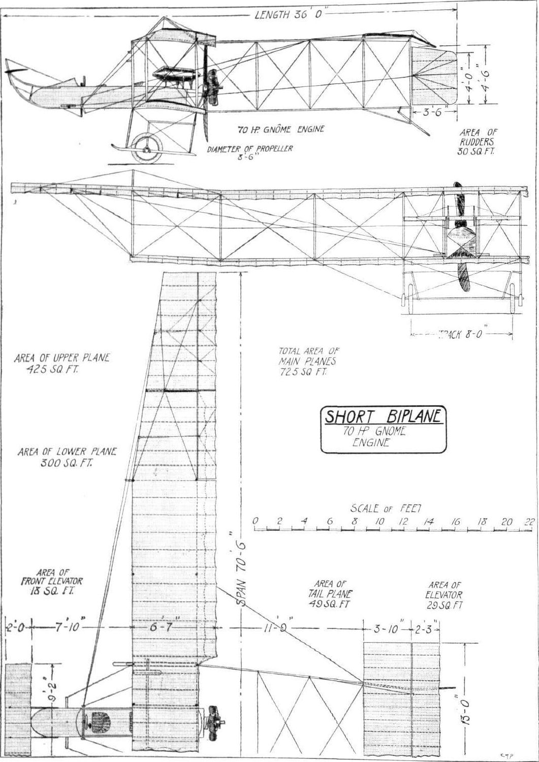
THE 70-H.P. SHORT BIPLANE. - Plan, side and front elevations to scale.
A study in tails.
Flight, February 8, 1913.
WHAT THERE WILL BE TO SEE AT OLYMPIA.
THE MACHINES.
Mr. Percy Grace.
On Mr. Grace's stand - Mr. Grace is, by the way, the agent for Messrs. Short Brothers, the well-known constructors of Eastchurch, Isle of Sheppey - will be shown a Short tractor hydro-biplane fitted with an 80-h.p. Gnome engine. In general design the machine will be very similar to the Short S41 type, which, as readers will remember, made its first flight under the pilotship of Commander Samson, at Weymouth, in May, 1912. In span the machine will measure 48 ft., and it will be 24 ft. 6 in. long. The chord and the gap between the main planes are both 5 ft. Its weight is approximately 1,200 lbs. On the water, it rests upon three floats, two main ones of catamaran type arranged below the cellule, and a smaller float which supports the tail. In addition, a small float is fitted to each tip of the lower plane. As for its seating accommodation, provision has been made, in this machine, for two passengers to occupy the front seats, placed side by side, while the pilot sits behind them. The 80-h.p. Gnome motor is so fitted that it may be started by one of the passengers without leaving the machine. At the time of writing the machine is not yet fully erected, but it will doubtless be complete in every respect by the time Olympia throws open its doors to the public.
Flight, February 22, 1913.
SOME MORE AEROPLANES AT OLYMPIA.
SHORT MACHINES (MR PERCY GRACE).
As the agent for Short machines, Mr. Grace is showing on his stand a new 80-h.p. Short tractor hydro-biplane. Going back a few months, it will be remembered that the first machine of this type that Messrs. Short Brothers built, was a 100-h.p. hydro-biplane, which was supplied to the Admiralty, and which was flown by Commander Samson at the Naval Manoeuvres at Weymouth during the past year. Previous to that, however, he had completed a flight on this machine, which, although it did not receive a great deal of publicity in the general Press, was nevertheless a very fine achievement. The flight to which we refer was a non-stop run that Commander Samson made, taking with him a passenger from Eastchurch to Portsmouth, following the coast line. That same machine has, on many occasions, carried two passengers, beside the pilot, and a complete charge of fuel.
The 80-h.p. Short tractor hydro-biplane. - In general appearance, both that machine and the one shown on Mr. Grace's stand differ but slightly. Naturally there are detail improvements, and among these we might mention that instead of the wings having squared tips they are rounded off, and that Messrs. Short Brothers have used steel tubular stanchions of stream-line section in place of wooden struts to separate the planes.
The body is a simple girder of rectangular section totally enclosed by fabric to reduce head resistance. In front, under an aluminium cowl, rotates the 80-h.p. Gnome motor that drives a large diameter Integral propeller. The engine is carefully shielded in, both on top and below, so that it may not become splashed by any spray that may be thrown up by the floats passing through rough water. In the body are, normally, seats for two, the passenger sitting in front. His seat however, is arranged to slide to the right so that another seat may be placed to his left and so provision made for the carrying of an extra passenger. The pilot's seat is arranged behind the passenger in such a position that he has a very good view of all that is going on around him. He controls the machine by means of a vertical wheel mounted at the head of a column jointed so that it may be rocked to and fro. By pushing the wheel from him or by pulling it towards him he can make the machine descend or ascend; by rotating the wheel he controls the lateral balance. The rudder is connected by a pivoted foot bar on which his feet rest. That the engine may be set in motion without any necessity for the occupants descending from their seats, a starting handle is fitted in the passenger's cockpit. The writer noticed at the Paris Aero Salon that many hydro-aeroplanes fitted with Gnome engines had similar self-starting devices, but at the same time he wondered how they could possibly be of any use, for it is a well known thing that unless a Gnome motor is primed with petrol in each cylinder no amount of swinging over will get it to fire. On the Short machine, however, the constructors have fitted a petrol injector, operated from the pilot's seat, by means of which each cylinder may be given its priming of petrol prior to the motor being swung by the passenger. The main tank is stored on the floor of the body at the approximate centre of pressure of the machine, and from there it is supplied to a service tank under the cowl of the motor by a small wind-driven automatic pump. Enough fuel is carried for a flight of six hours.
The planes span 48 ft. and 30 ft. respectively. They have a chord measurement of 5 ft. and are separated by twelve streamlined steel struts. Ash, of H section, is used for the front spar, whereas the back spar, of the same material, is roughly of rectangular section. The ribs are of spruce, and their construction is such that it is almost impossible for them to split. Lateral balance it controlled by ailerons fitted to the top plane on either side of the machine. The extensions are supported by steel tubes.
Float construction. - Two long catamaran-type floats are connected to the body of the machine by stout steel struts. These floats are not stepped - they are simply plain pontoons. They are separated at a sufficient distance to give the machine a good notational base, but should the machine be inclined to tip sideways for any reason while floating, the tips of the lower plane are guarded by subsidiary floats mounted on them. These latter floats are illustrated by one of our sketches. They are made up in cylindrical form from canvas, with a skeleton of strip steel inside, so that should they become punctured they will still retain their shape. There is also a small float fitted to the tail.
The tail is non-lifting and of conventional type. In order that the machine may be steered readily at slow speeds on the water the air rudder works in conjunction with a water rudder.
This Short tractor hydro-biplane, an excellent sample of careful design and construction throughout, has a maximum flying speed of 65 miles per hour.

The 80-h.p. Short hydro-biplane.

The 80-h,p. Short tractor hydro-biplane.

The floats of the 80-h.p. Short hydro-biplane.
Flight, February 8, 1913.
WHAT THERE WILL BE TO SEE AT OLYMPIA.
THE MACHINES.
The Sopwith Aviation Co.
Here, on Stand No. 22, will be shown two biplanes, one a water flyer and the other a land machine. Let us take the hydro-biplane first. It is, at the moment, receiving its finishing touches at the firm's works at Kingston, and, as soon as the Show is over, Mr. T. O. M. Sopwith proposes to take it out to Monaco to compete in the hydro-aeroplane meet there in April. It is driven by a 90-h. p. Austro-Daimler mounted on exceedingly strong ash and hickory supports, midway between the main planes. The main planes are arranged at a slight dihedral angle to one another. The machine's alighting gear consists of a double-skinned hydroplane hull built by Messrs. Saunders, the well-known yacht builders of Cowes. Tremendously strong, the hull only weighs 180 lbs., and it is wide enough abeam to seat pilot and passenger side by side. The tail is supported by tapering Farman-type outriggers, and an auxiliary elevator is arranged in front, over the bow of the hydroplane hull.
<...>
Flight, February 15, 1913.
SOPWITH AVIATION CO.
Two biplanes, one a hydro-biplane and the other constructed for land work, represent the Sopwith Co. on Stand 22. Both were designed by, and the construction carried out under the supervision of, Mr. T. O. M. Sopwith and his works manager, Mr. F. Segrits, at the Company's works at Kingston-on-Thames. They are no freak machines, these two biplanes of Sopwith's, a rough glance over them will soon convey to the observer that they are designed by practical men. Of the two, the hydro, is the more interesting since it is the more original.
The 90-h.p. Sopwith Hydro-biplane. - As the silhouette sketch that accompanies this description shows, it has a biplane unit somewhat of Farman type, mounted on a stepped hydroplane hull.
The hull, constructed by the well-known yacht builders, Messrs. Saunders, of East Cowes, I.W., is, roughly, 21 ft. in length, and is sufficiently wide in the beam - 4 ft., to be accurate - to seat pilot and passenger side-by-side. Its light framework is covered with two layers of cedar, laced together, and to the skeleton of the hull, by copper wire, a system of construction that Messrs. Saunders have protected by letters patent, and which they employ in building racing motor-craft. Although the hull is of a considerable size, the writer, when he was privileged to see the machine in course of construction, had no difficulty in lifting it; it only weighed 180 lbs. One of our sketches shows the section of the hull in the neighbourhood of the step, which is between 3 ins. and 4 ins. in depth, and which is placed 12 ft. from the stem post. The bottom of the hull being shaped in this manner, the float is rendered all the more seaworthy for it will not "hammer" to the extent that is noticeable with a flat-bottomed or concave -bottomed hull when "planing" over choppy water.
Supplementary wheeled chassis. - So that the machine may be capable of alighting on land as well as on the water, two wheels are provided, one on either side of the float. They are supported from a common axle member, passing through the hull, by short, hollow struts, beaten and welded up from 14 gauge mild steel. The wheels employed are 24 ins. in diameter, and, apart from the resiliency of the large 4-in. tyres used to shod them, no shock-absorbing devices are fitted. The wheeled chassis may be raised above the level of the bottom of the float, when the machine is being used for overseas work only by rotating the axle which supports it in the manner indicated by one of the sketches.
The plane construction. - Both upper and lower planes of the machine are of the same span, 41 ft., and are placed at a slight dihedral angle. They are separated by 12 struts and cross-braced by stranded steel cable in those bays on the same vertical plane as the main spars, while for front-to-back-bracing piano wire is used. The hollow construction of the main spars and of the struts is interesting. The spars are made from a centre portion, I section, cut from ash, to each side of which are bolted plain spruce faces of rectangular section. This makes a particularly strong yet light spar. The struts are made in a similar fashion, excepting that the central section of ash is of rectangular section to which hollowed out spruce cheeks are applied to give ample cross section and to shape the strut to a good streamline form. Our sketches will make these points clear. The ribs are built up of spruce flanges and cotton-wood webs, a hollow spruce nose strip makes a very satisfactory leading edge, and the trailing edge is kept trim by a piece of steel tubing of streamline section. Cotton-wood, by the way, seems to be an extraordinarily good wood to use for rib construction. It is light, and apparently refuses to split. It is possible to put one end of a Sopwith rib in the vice, and twist the other end through 180 without the rib showing any signs of either splitting or of showing a permanent deformation.
The ends of the planes are shaped with steel tubing. It may be as well to remark here that all metal work that is likely to become wet on the machine and so rust, is first heavily enamelled, then bound with glued tape and finally given a good doping over with fabric varnish.
The motor is a 90-h.p. Austro-Daimler, mounted on hickory bearers, and supported sideways between the planes by solid ash struts. These struts are very strongly cross-braced by the heavy gauge steel wire and by steel tubing, so that it would need a shock considerably more severe than is generally the lot of an aeroplane to experience, to dislodge it from its position and send it tumbling on the heads of the occupants seated in front of it. The motor drives direct a Levasseur propeller, 8 ft. 6 ins. in diameter.
The tail is a flat surface, 22 sq. ft. in area, and approximately rectangular in plan form. Behind it are hinged two flaps by which the elevation of the machine is controlled. It is supported by two spruce outriggers which meet at the rudder bar. The skeletons of all the tail organs are constructed of bent steel tube, with ribs of the same material, oxy-acetylene welded in position. There is a front elevator fitted above the nose of the float. Its area is equal to that of the two rear elevating flaps, that is 15 1/2 sq. ft.
Dual control is fitted and is in the form of a wide swinging bridge on which are mounted two vertical wheels, Deperdussin fashion for warping. Ruddering is done by the conventional form of foot bar.
Weighing 1,200 lbs. light, and designed to carry 450 lbs. of useful load, the machine is expected to show an average flight speed of 65 m.p.h. As soon as the Olympia exhibition closes Mr. T. O. M. Sopwith intends taking the hydro-biplane out to Monaco to compete in the hydro-aeroplane competition there in April next.
<...>
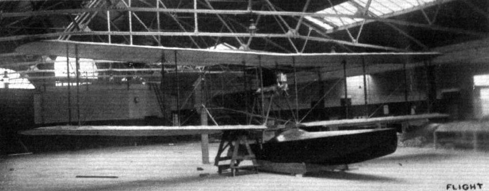
The Sopwith hydro-biplane in course of construction at the firm's Kingston-on-Thames works.
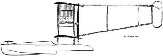
The 90-h.p. Austro-Daimler-Sopwith hydro-biplane.

The 90-h.p. Sopwith hydro-biplane.

Diagram showing how the landing wheels of the Sopwith hydrobiplane may be drawn up clear of the water.
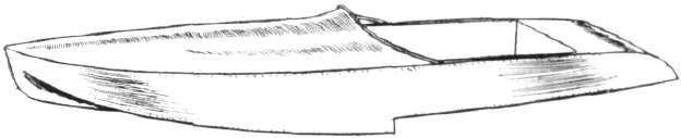
Diagrammatic sketch of the float of the Sopwith hydro-biplane.

Front view of the Sopwith hydroplane hull.
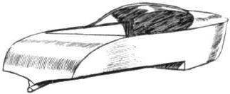
Rear view of the Sopwith hydroplane hull.
Section of the Sopwith float.

The tail of the Sopwith hydro-biplane.
A study in tails.
Flight, August 16, 1913.
THE SOPWITH TRACTOR WATERPLANE.
HAVING already achieved such remarkable success with his tractor-type land machine, Mr. Sopwith decided to enter a biplane of this type, fitted, of course, with floats instead of wheels, for the Daily Mail Race Round Britain, in preference to one of the Bat boat type, and in consideration of the large open stretches of sea which have to be negotiated, we are inclined to think that he has chosen wisely.
In its general outlines, this machine possesses the same smart business-looking appearance which characterizes the land machines, further enhanced perhaps by the tapering nose of the fuselage, allowed of by the installation of a 100 h.p. six-cylinder vertical type British Green engine, instead of the 80 h.p. Gnome motor with which the land machines are usually fitted. The fuselage, which is of rectangular section is built up in the usual way of four longerons of ash, connected by struts and cross members. In the rear part of the body these are made of spruce, while in front, where the weight of pilot, passenger and engine is concentrated, and where, therefore, greater strength is required, these members are made of ash. The main planes, which are very strongly built over main spars of solid spruce of I section are slightly staggered, and are also set at a dihedral angle in order to give the machine a certain amount of lateral stability. From a point just behind the pilot's seat back to the rudder post the fuselage is covered in with fabric, whilst the front portion is covered with aluminium, forming on top of the nose of the fuselage a very neat and cleanly designed cover over the motor. A very interesting detail in connection with the mounting of the Green engine forms the subject of one of the accompanying sketches which is self-explanatory. This method of joining the engine-bearer to the strut makes an enormously strong job, and this joint serves very well as an example of the thoroughness and attention to detail which is typical of Sopwith construction.
The main floats, which have been built by the Sopwith Aviation Co., are of the single step type and are built up of a framework of ash and spruce covered with a double skin of cedar. Two bulkheads divide the floats into three watertight compartments, so that should a float become damaged, causing one compartment to leak, the other two would still have sufficient buoyancy to prevent the float from sinking very deeply into the water. Two pairs of inverted V struts connect each float with a lower main plane, while another pair of struts running to the front part of the fuselage help to take the weight of the engine. Spruce is the material used for chassis as well as plane struts, the latter being hollowed out for lightness.
Inside the comparatively deep fuselage, where ample protection against the wind is afforded to pilot and passenger, are the two seats arranged tandem fashion, the pilot occupying the rear seat. In front of him are the controls, which consist of a rotatable hand wheel, mounted on a single central tubular column. Rotation of the wheel operates the ailerons, which are fitted to both top and bottom planes, and which are inter-connected. A to and fro movement operates the elevator, while a foot bar actuates the rudder. It should be noticed that the control cables are only exposed to the effects of the air and salt water for a very short length, the elevator cables entering the body just in front of the fixed tail plane and the rudder cables a couple of feet from the rudder post. The engine is supplied with petrol and oil from tanks situated under the passenger's seat, the capacity of the tanks being 45 gallons and 10 gallons respectively.
For the purpose of easy egress in case of a smash, the centre portion of the top plane has been left uncovered. In order to minimise end losses due to the air spewing out of the opening thus produced, what might be called baffle plates have been fitted to the inner ends of the wing.
These baffle plates have been made streamline in section, as it was found that an ordinary thin board would bend owing to the pressure of the air trying to escape past it. With full load of fuel and passengers on board the weight of the machine is 2,400 lbs., and her flying speed is 60 to 65 m.p.h.
Flight, August 23, 1913.
THE "DAILY MAIL" ROUND BRITAIN RACE.
"Enchantress," Royal Motor Yacht Club, Off Netley.
Friday afternoon.
THE days when the "Enchantress" was the centre of much competitive activity on Southampton Water in connection with the various motor boat trials that were held there have passed long since, but the floating Club House of the Royal Motor Yacht Club remains as the headquarters of that department of sport, and it is appropriate and courteous that they should have offered the hospitality of the ship in that capacity to the Royal Aero Club on the occasion of the start for the Daily Mail flying race.
With an event timed to start at six o'clock in the morning, it is a matter of convenience that one much appreciates to be on the spot over night, particularly when, as in this instance, the accommodation is of such a thoroughly comfortable order. Having arrived at midday, I found the officials had gone over to Ryde, in order to mark, for the purposes of identification, the various portions of the Sopwith hydro-biplane that is to be flown on the morrow by Mr. H. G. Hawker. This matter accomplished, they returned to the "Enchantress" with the news that no attempt at a start would be made before ten o'clock, owing to the fact that the site of the aeroplane shed in which the machine was housed was such as to make it inconvenient to float the craft before high tide. As a result, there entered into the scheme of things material the more alluring prospect of a reasonably long time in bed.
Saturday morning.
Hopes in this direction proved false, for at five o'clock visitors began to arrive at the gangway outside my cabin window, and I heard voices enquiring diligently for Mr. Perrin, the Secretary of the Royal Aero Club, while various local pressmen ventured a general request for information "about this flying business." After an hour of this sort of thing, I came to the conclusion that it was hopeless to pretend to rest, and the same thought must have struck others, for quite a number of those on board turned up to breakfast about half past six. Among the early visitors were the Mayor and Sheriff of Southampton, who had come down on the Harbour Board tug, a message over night warning them of the delayed start having miscarried.
Time dragged somewhat to the appointed hour, but the arrival of Lieut. Spencer Grey, R.N., on the Sopwith bat-boat, and the later arrival of Lieut. Travers, R.N., on a Borel hydro-monoplane, helped to relieve the situation. The attempt of the latter to get his machine hitched up to a boom alongside the "Enchantress" afforded an interesting demonstration of an important problem in connection with the use of seaplanes. Ultimately, the machine was made fast to a buoy nearer shore.
Ten o'clock arrived, and there was no sign of Hawker. Eleven o'clock struck, and still the expected machine had not put in an appearance. About half-past eleven, however, he was seen flying up the Channel, and in another minute or two he had alighted about half-way between the ship and the shore. Several boats put off to meet him, but most people remained aboard on the understanding that the official start would be timed as the machine passed in full flight near the ship. This was not in the regulations, but merely an idea that some people more or less adopted.
In the meantime, we watched the little group of boats from a distance, and presently saw them clear away from the machine. The engine was started, and at 11-47 the hydro-aeroplane sped along the water in the direction of the open sea. He was off. Without fuss and without an audible cheer, Hawker had started in the great trial. In a few seconds he and his machine were in the air, and almost before anyone had realised that the flight had begun, the machine itself was out of sight and the show was over.
Then followed the usual buzz of conversation, which was naturally mainly directed to the prospect of the pilot's successful accomplishment of his journey. He had 144 miles to fly in order to reach the first control at Ramsgate. This was followed by another 96-mile flight to Yarmouth. Then a journey of 150 miles to Scarborough. It was generally recognised that to have any chance of success he must get to Scarborough on the first day, although the total for the day's journey represented nearly 300 miles.
Sunday was to be a day on which flying was prohibited, but competitors were at liberty to repair their machines. It was evident, therefore, that the best policy would be to make the longest journey possible on Saturday, in order that the maximum work might be done before the arbitrary repairing time came into force.
From this point of view it was, therefore, unfortunate that the start had been made so late, and it appeared that the additional delay was due to difficulty in getting the compass properly arranged.
If the pilot made Scarborough on the Saturday night, he ought to fly as far as Oban on the Monday, the total distance for the second stage being 446 miles, including the Caledonian Canal, which is recognised as being probably one of the worst stretches in the circuit. On the Tuesday he would have to get from Oban to Dublin, which is a journey of 222 miles, and from Dublin to Falmouth, which is a further 280 miles, the day's journey being 500 miles. The importance of reaching Falmouth on the third night is in order to avoid a very long journey on the last day. To complete the circuit in time, Hawker would have to cross the finishing line at Southampton before 4 o'clock on Wednesday afternoon, and it would obviously be taking great chances to try and complete the whole distance from Dublin on the morning and early afternoon of that day.
Reckoning the circuit out in this manner, shows how difficult is the task which has been set for the Daily Mail prize, and the mere fact of the start having taken place so successfully is, at any rate, a credit to the British-built Green engine and the British-built Sopwith biplane. It is a matter for regret that other machines were not present to take part also. Mr. McClean, who was to have started, was apparently in difficulties on the Isle of Grain, and those on board the "Enchantress" heard no further news of him.
"OISEAU GRIS."
Details of the Flying.
As has already been stated, it was at thirteen minutes to twelve on Saturday morning when Mr. Hawker, on the Sopwith machine, rose from Southampton Water. Speeding down the reach, the machine rapidly faded from tight past Calshot, and then passing over the Solent, Mr. Hawker made for the open sea. Keeping well out from the land, at a fairly constant altitude of about 1,000 ft., Brighton, Eastbourne, and Dover were each passed in good time, and then the light southerly wind added its quota of assistance to the 100 h.p. Green engine, which has done its work throughout in such splendid style. Ramsgate, the first control, was reached at 2.11, the 144 miles of the first stage having been traversed in as many minutes. En route Mr. Hawker received an aerial welcome, Mr. Salmet, who was giving exhibition flights at Margate on his Bleriot, meeting him, and flying with him for a short distance. In the actual control, the Mayor of Ramsgate (Alderman Glynn), welcomed, per megaphone, Mr. Hawker, and announced that he had won the cup offered by the town for the first competitor to reach there. The Aero Club officials quickly made their inspection of the machine, and handed Mr. Hawker a clean waybill, so that as soon as the formalities, &c, had been completed, at two minutes past three the engine was started and the machine was away on the next stage to Yarmouth. The story of this part of the journey was but a repetition of what had occurred during the first stage, except for the fact that when crossing the mouth of the Thames there was a slight mist which obscured both banks. Still, Mr. Hawker was able to rely on his compass, and at Walton-on-the-Naze and at Clacton the crowds which assembled saw the machine in the distance going as well as ever.
On arrival at Yarmouth at 4.38 p.m., Mr. Hawker had another enthusiastic welcome. He said he was feeling well, but soon after he got ashore he collapsed, and the doctors diagnosed the case as one of sunstroke. This was borne out by Mr. Kaufer, his passenger, who said they had found the sun very trying, and unfortunately Mr Hawker had not taken the precaution to use goggles. Any further progress was impossible, and Mr. Sopwith at once set about arranging for a relief pilot. Eventually Mr. Sydney Pickles, who, like both Mr. Hawker and Mr. Kaufer comes from Australia undertook, with the generous consent of Messrs. Short Bros., to take the Sopwith on from Yarmouth. During Sunday which was a rest day, Mr. Pickles familiarised himself with the details of the machine, and on Monday morning was quite ready to continue the flight. The weather was, however, against the plucky pilot, and although he made a determined effort to get away at 5.30 a.m., the rough sea and ruing wind baulked him, and there was nothing left for it but to return to the shore, which, perhaps, was just as well, as up Scarborough way the "white horses" were so pronounced as to have washed away the buoys marking the control. The machine was presently dismantled and returned by rail to Cowes ready for a second attempt.
In the meantime, Mr. Frank McCIean and Messrs. Short Bros, had been working away with solid perseverance to remedy the obstinacy of the engine, the fault being ultimately found to be in a cracked cylinder. It was no sooner located than its replacement was arranged for by co-operation with Mr. Fred May, of the Green Engine Co. Its testing, until Mr. May was satisfied with its running, was then started, and at 2 a.m. on Thursday the engine was taken over to Grain Island, where the Short machine was comfortably resting, to be installed. All being well by Thursday evening, Mr. McCIean hoped to make for Southampton by way of the air, and there was the possibility of his making a start during Friday for the race itself.
As to Mr. Hawker, his health all the time was mending, so that on Thursday it was hoped he would be able to make his second attempt today (Saturday morning), early. Failing this, Mr. Sydney Pickles will be in readiness to take the pilot's seat, and endeavour to prove the sterling English worth of both the Sopwith machine and the Green engine. And may good luck come to either one of the plucky trio who are thus upholding the prestige of the home aeroplane industry.
Flight, August 30, 1913.
ROUND BRITAIN WATERPLANE FLIGHT.
DESPITE the fact that Mr. McClean's withdrawal on account of radiator trouble had robbed the event of the competitive interest, when Hawker on the Sopwith biplane started from Southampton Water on Monday morning for his second attempt to follow the British coast round, the progress of his flight was followed with as much eagerness as if he were the "favourite" among many. On the previous Saturday he had had the machine out for half an hour, and found it going as well as ever, while the noise from the engine had been appreciably reduced by lengthening the exhaust pipe. Monday morning opened clear and bright, but shortly after five o'clock a thick mist came up, and all that was seen of the Sopwith machine from the Enchantress was a glimpse of it as it sped over the starting line at half-past five. Once out of Southampton Water, clearer weather was found, and the pilot, this time carefully protected against the elements, steered a straight course down the Solent and out to the English Channel. Round the coast-line a good deal of mist was encountered, and Hawker had to rely on his compass at several points. The conditions were responsible for a slight reduction of speed compared with the previous flight over this stage, but Ramsgate was reached at eight minutes past eight, the 144 miles from Southampton having taken 159 mins. The formalities were completed well within the compulsory time-limit of half an hour, but some small adjustments took up a little more time, and it was eight minutes past nine ere the Sopwith machine was on its way to Yarmouth. The weather was still very thick, and little was seen of the land until Southwold was reached, but the sturdy machine made light of its task, and 1 hour 28 minutes flying saw the stage of 96 miles completed. The machine was taxied to its mooring, and Hawker boarded the motor boat of an Australian friend, Mr. A. Williamson, to enjoy a brief rest and some refreshment, while Mrs. Williamson presented a mascot in the shape of a spray of Australian eucalyptus leaves. This time it was the faithful mechanic, Kauper, who was feeling the strain of the flight.
At 11.44 the machine was once more on the wing and headed for Scarborough, 150 miles away. Still the mist was very trying, and off Cromer the side winds tested the air-worthiness of the Sopwith construction pretty thoroughly. Steering by the compass, however, and keeping at his usual height of about 1,000 ft., Hawker made a good course, and arrived at Scarborough at 2.42 p.m., his arrival being watched by a huge crowd, who had flocked into the town from the surrounding districts. After a brief period of rest on board Mr. W. Jackson's yacht "Naidia," he was back attending to his machine, and in view of the length of the next stage (218 miles). In Aberdeen, he arranged to make an intermediate stop at Berwick to pick up petrol. Soon after four everything was ready for the restart, and the crowd of boats was cleared out of the way to enable the machine to rise. At 4.22, it skimmed along the water for a short distance, and rose steadily to disappear rapidly in a northerly direction. On the way a leak developed in one of the water pipes, and a stop of 1 hr. 5 mins. had to be made at Seaham Harbour in order to effect an adjustment, and to replace the water lost. At 6.40, the journey was resumed, but the fates were against Hawker, and another descent had to be made, this time at Beadnell, about 20 miles south of Berwick. It was at 7.40 p.m., and several things combined to put an end to the day's flying, which had accounted for 495 miles. It was getting too dark to see the compass, the winds were very troublesome, and the engine started misfiring. On examination, however, there appeared to be nothing wrong with |the Green engine, the trouble being really with the water pipes. Hawker and Kauper decided to stay the night and make a. fresh start at 5 o'clock the next morning. As a matter of fact, however, it was five minutes past eight before the Sopwith biplane was again in the air, and 20 mins. later Berwick was passed. At 9.55 a call was made at Montrose for water, when adjustments took up just on half an hour. Aberdeen, the next control on the list, was reached at 10.58, the machine coming down from a height of about 1,500 ft. by a fine spiral vol plane. The weather now was splendid, and both pilot and mechanic declared themselves in fine form. This time just under an hour was spent in attention to men and machine, and at 11.52 the city of granite and marmalade was left behind. Cromarty was the next control, the 134 miles being traversed in 2 hrs. 13 mins., the trip being uneventful except for a tricky wind which was encountered when nearing Cromarty. It was recognised that the 94-mile stage from Cromarty to Oban, over the Caledonian Canal, would probably prove to be the most trying part of the whole route, and Hawker found that the conditions were certainly very erratic. The gusty winds in that mountainous region required very careful negotiating, and although Cromatty was left at five minutes past three, it was six o'clock before Oban was reached. It was then too late to think of starting on the long stage to Dublin, and the pilot and mechanic decided to take advantage of the opportunity of a good long rest, and get away early the next morning. They were astir at 4 a.m., and after a hurried breakfast were quickly at work inspecting the various parts of their machine. Soon after half-past five everything was ready, and at 5.42 Hawker was officially started for Dublin, although in view of the length of the stage he had arranged to call at Larne for petrol. The machine did not rise, however, with its accustomed readiness, and Hawker took her to the beach, about a mile out of Oban. It was there found that there was water in the floats, and an hour was spent in getting rid of it. Then a clean ascent was made, and a straight course steered down the Firth for the Irish coast. Scotland, however, could not be left so easily, and half an hour's stop had to be made at Kiells, in Argyllshire, in order to give a little attention to the engine. He was away again at 8.25, and at half-past nine made a splendid descent into Larne harbour. An hour and a half were spent at this point, the journey south being resumed at 11 o'clock. When only a few miles short of Dublin, Hawker feared that some of the valve springs of his motor were giving out, and he decided to come down and make an inspection. Again it seemed as if his luck had deserted him, for had he known that Mr. Green was waiting at Dublin, with new springs, he would have kept on. As it was, while making the spiral descent, his foot slipped from the rudder bar, apparently through his boot being greasy, he lost control of the machine, and she dropped to the water. Happily the first report that Hawker was injured proved unfounded, but Kauper had an arm broken and was cut about the head. Medical aid was quickly at hand, and he was taken in a motor car to the Mater Misericordiae Hospital, Dublin, where he is making as good progress as can be expected. The machine was smashed, but the catastrophe was not the fault of either the Sopwith machine or the Green engine. It was, as Hawker put it, "just a piece of ghastly bad luck." So ended the great flight when 1,043 miles out of the full distance of 1,540 miles had been covered. It remains to be added that the Daily Mail immediately announced that in recognition of his skill and courage a personal gift of L1,000 would be made to Hawker.
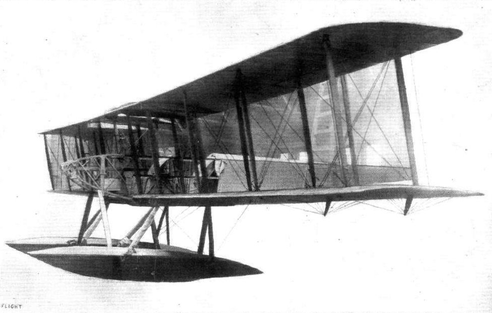
THE SOPWITH WATERPLANE. - A view of the machine taken at the works before being dismantled for transport to Southampton for the Daily Mail Race.
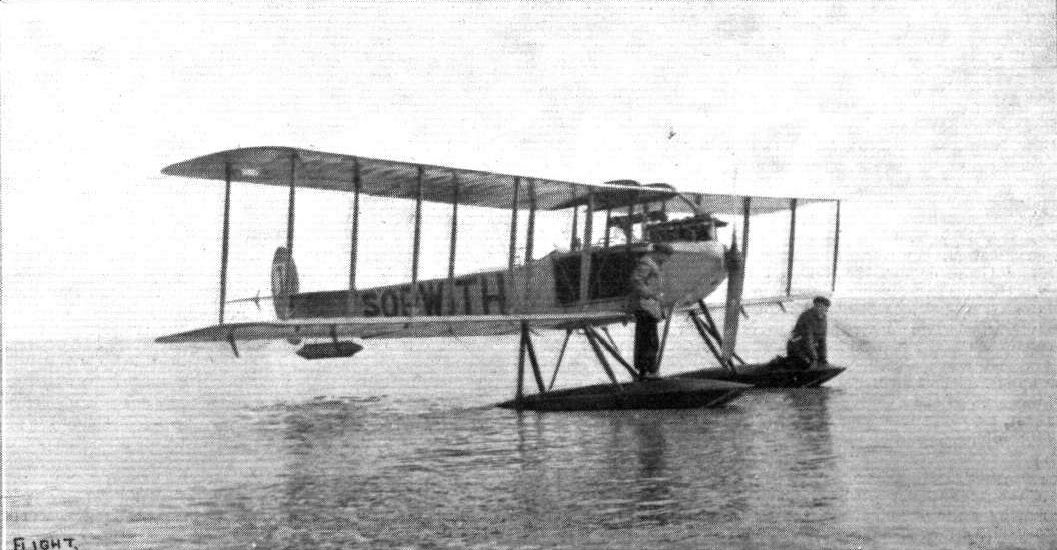
ROUND BRITAIN FLIGHT. - The Green-engined Sopwith waterplane immediately alter arriving at the Yarmouth control. Mr. Hawker and his passenger, Mr. Kauper, are seen on the floats.
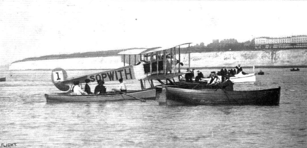
ROUND BRITAIN FLIGHT. - The Green-engined Sopwith waterplane "in control" at Ramsgate on Monday.
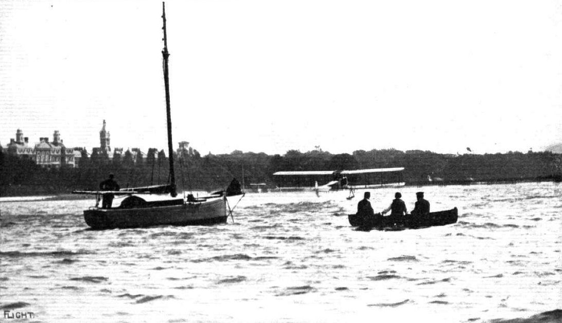
THE ROUND BRITAIN WATERPLANE RACE. - Mr. Hawker starting on the Sopwith machine on Saturday morning, August 16th, from Southampton Water.
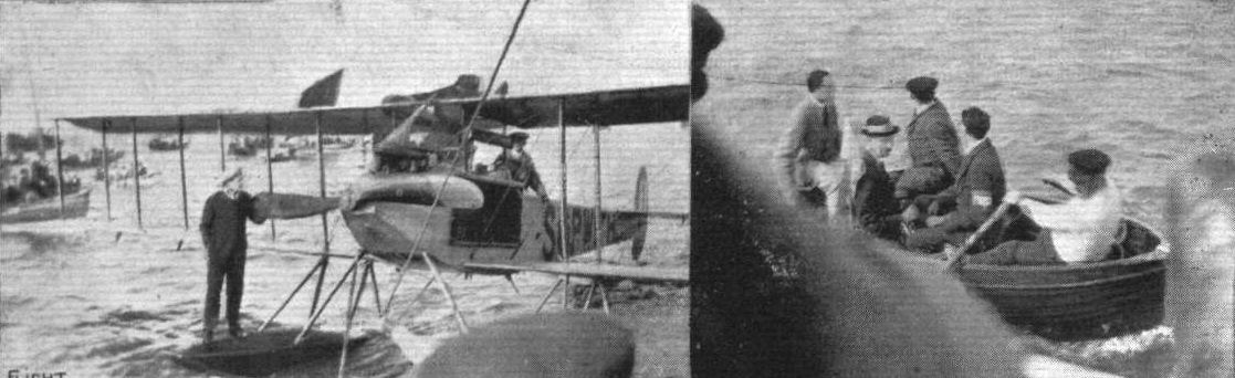
ROUND BRITAIN FLIGHT. - Arrival of the Sopwith machine at Scarborough, and on the right, Royal Aero Club officials - Messrs. Wallace Barr, B. M. Dodds and W. E. Nicoll - escorting Hawker to the official yacht.
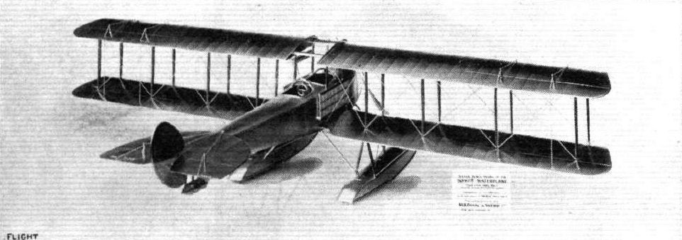
The beautiful silver scale model of the Sopwith waterplane used in the Daily Mail Circuit of the United Kingdom which was presented to Mr. Hawker by the distributors of Shell Motor Spirit. This delightful specimen of the silversmith's art was manufactured by Messrs. Mappin and Webb, Ltd.

"SIX KNOTS AND SIXTY." - Mr. Hawker, on the Sopwith waterplane, shortly after leaving Southampton on Saturday morning, August 16th, in the Daily Mail Round Britain Race, passing over a tramp. - From a drawing by Roderic Hill.
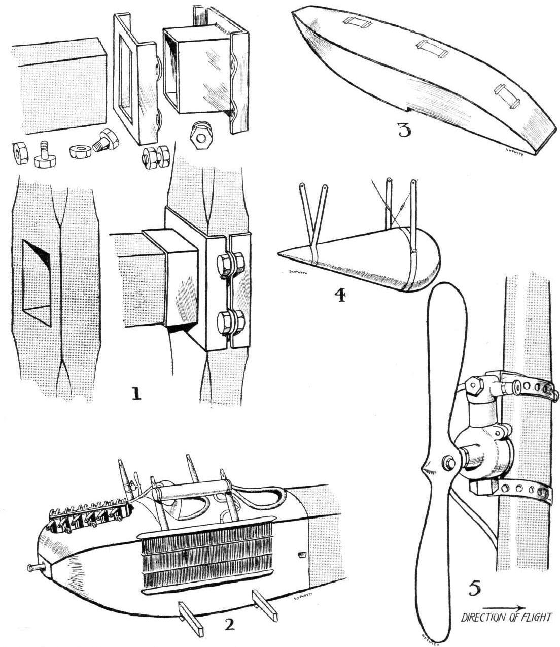
THE SOPWITH WATERPLANE. - 1. Analytical sketch, showing method of joining engine-bearer to fuselage strut. 2. Three-quarter front view of fuselage, showing engine housing and radiators. 3. One of the main floats. 4. The tail float. 5. Petrol pump.
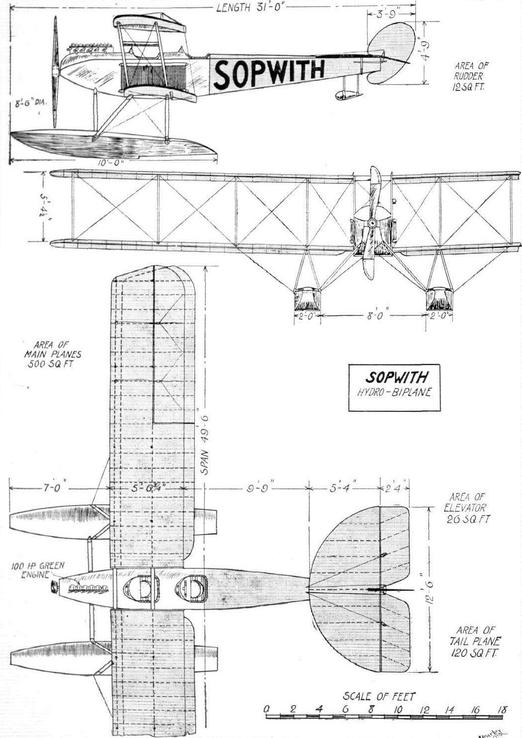
THE SOPWITH WATERPLANE. - Plan, side and front elevations to scale.
Flight, December 20, 1913.
THE NEW 80 H.P. SOPWITH BIPLANE.
WHEN the latest production of the Sopwith Aviation Co. made its bow to the public at Hendon a few Saturdays ago it did so like a bolt from the blue, and wasting no time in showing what it could do, immediately completed two circuits at a speed of about 90 m.p.h. The successes of the former Sopwith machines - designed by Mr. T. O. M. Sopwith and Mr. Segrist - are, no doubt, still fresh in our readers' minds, and with this new 80 h.p. "baby" biplane, in the design of which Mr. H. G. Hawker, who piloted the former machines to success, has played an important part, it seems that further achievements will soon be added to the credit of this go-ahead Kingston firm.
The general lines of the new biplane are similar to those of the other Sopwith tractor machines previously described in FLIGHT, and so, with the help of the accompanying scale drawings and illustrations, we need but briefly describe its principal features. It has been designed with the intention of producing what might be called an exhibition machine, that is to say, a machine capable of performing all sorts of evolutions such as steep bankings, small circles, switchbacks, &c. This machine is therefore of small dimensions, having a span of 25 ft. 6 ins. and an over-all length of 25 ft. The total area of the main planes is 240 sq. ft., which gives a loading of 3 lbs. per sq. ft. light or 4-5 lbs. per sq. ft. fully loaded, the weight of the machine empty and with pilot and 3 1/2 hours' fuel being 670 lbs. and 1,060 lbs. respectively. The main planes, which are comparatively flat, are set at a slight dihedral angle, and the top plane is staggered forward 1 ft. They are built up in two cellules, the lower planes being attached to the lower portion of the fuselage, whilst the top planes are secured to a centre panel supported above the fuselage by two pairs of struts; there are only two other pairs of struts separating the main planes near the extremities. The attachment of the rear spar of the lower plane to the fuselage is shown in one of the accompanying sketches. It should be noticed that the struts, including those of the chassis, are well streamlined. In plan form the planes have a greater length in the trailing edge, as on the Morane monoplane. The fuselage follows usual Sopwith practice, being rectangular in section, tapering to a vertical knife-edge at the rear. The pilot is seated in a small cockpit between the planes, whilst another seat for a passenger is provided on the pilot's right. The forward ends of the top and bottom longerons converge, forming an attachment for the front engine bearer. The 80 h.p. Gnome engine is mounted in the nose of the fuselage, and is almost completely covered by a neat aluminium cowl, but is nevertheless efficiently cooled by the stream of air passing through a narrow slit formed in the cowl by the front engine bearer; the lower extremity of the engine also projects slightly below the cowl. The latter is easily detachable, and hinges forward, giving easy access to the valves. The carburettor, to which the petrol is fed by gravity, projects within the cockpit, and can easily be got at by the pilot or passenger. The landing chassis has been considerably modified, and consists of two short skids, each connected to the fuselage by a pair of struts. At the rear the skids are connected by a streamlined cross strut, in the centre of which is hinged the divided axle, carrying at its outer extremities the covered-in running wheels. In its normal position, the axles lie in a groove formed in the cross strut, thus maintaining the streamline effect of the latter. The axle is sprung by means of rubber shock absorbers attached to the skids, and is held in position by two very short radius rods, hinged to the rear extremities of the skids. In order to prevent the cross strut from bending downwards in the middle, it is braced at this point to the fuselage by a wire. The whole of this arrangement is clearly shown in one of our sketches. The tail consists of a semi-circular stabilizing plane, to the trailing edge of which are hinged two elevator flaps with a balanced vertical rudder, almost circular in shape, between them. The simple tail skid is shown in one of the sketches. Lateral control is by wing warping, the movement being carried out by a wheel mounted on a vertical column, a fore-and-aft movement of which operates the rear elevators through a connecting rod and countershaft. The warp cables are led from a rockshaft to pulleys let into the uprights of the fuselage just above the rear spar attachments of the lower plane. From these pulleys the cables go to the top sockets of the rear outer struts. A continuous cable also runs from each of the outer rear strut sockets of the lower plane over pulleys on the tops of the two rear struts attached to the fuselage. The new tubular steel rudder bar forms the subject of one of our sketches, so needs no further comment here, other than we should think that its shortness has much to commend it on account of the sensitive nature of the control on a machine of this type. As regards the actual performances of this biplane, we referred to these last week, but they are worthy of repetition. Tested over the measured course at Farnborough, fully loaded with fuel for 3 hours, pilot and passenger, a maximum speed of 92 m.p.h. and a minimum speed of 36.9 m.p.h. were attained. The climbing speed was 1,200 ft. in one minute, also fully loaded - quite a credit to British aeroplane design. It was originally intended to take this biplane over to Paris during the Aero Show in order to demonstrate its wonderful capabilities in the home of aviation, so to speak. We understand, however, that this plan has been changed, and that the machine has been sent out to Australia, where Mr. Hawker will put it through its paces above his native soil, and endeavour to rouse the interest of the Australian Government.
After staying there some months, we may hope to see him back in England. Our readers will, we feel sure, join us in wishing both Mr. Hawker and the Sopwith Aviation Co. every success in this latest enterprise.

THE 80 H.P. SOPWITH BIPLANE. - Side view.
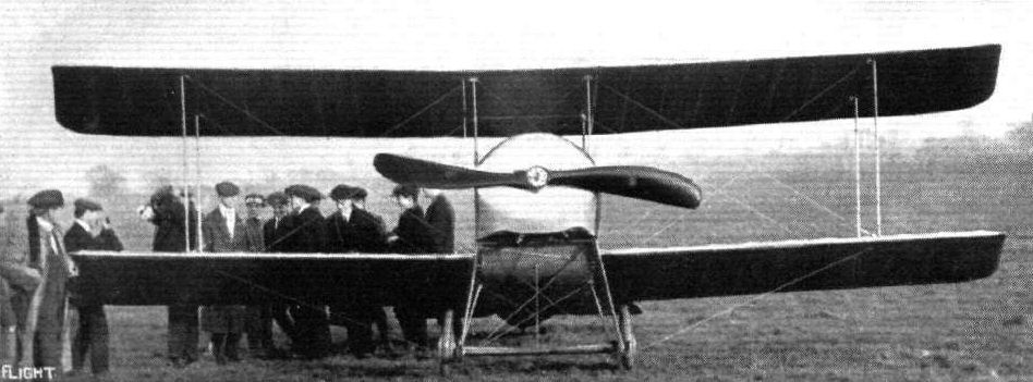
THE 80 H.P. SOPWITH BIPLANE. - View from the front.
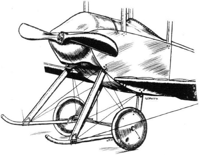
The landing chassis and engine housing of the new 80-h.p. Sopwith biplane.
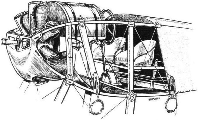
View of the cockpit of the new 80 h.p. Sopwith biplane.
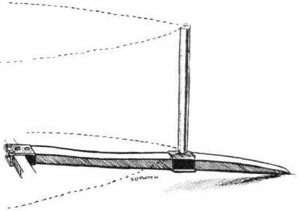
The simple and strong tail skid of the new 80 h.p. Sopwith biplane.
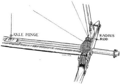
Detailed view of the Sopwith hinged axle and radius-rod on the landing chassis.
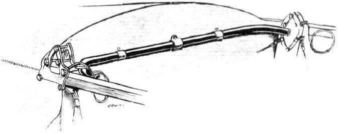
The combined back rest and fuselage cross-member of the 80 h.p. Sopwith biplane.

The new type of rudder-bar on the 80 h.p. Sopwith biplane; note the shortness and inclined position of the same. On the right detailed sketch showing the attachment of the rear spar to the fuselage.
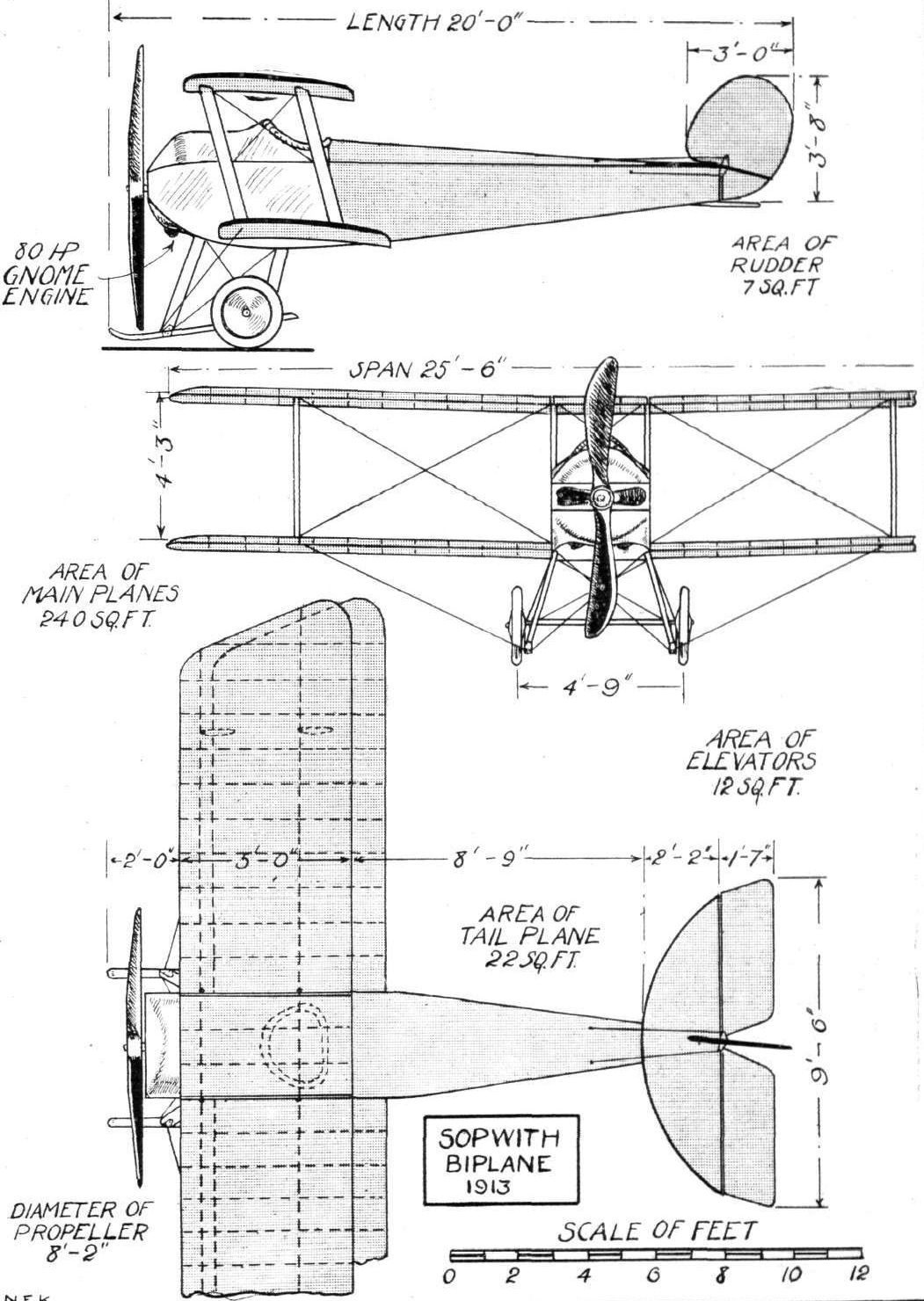
THE 80 H.P. SOP WITH BIPLANE. - Plan, side and front elevations.
Flight, February 8, 1913.
WHAT THERE WILL BE TO SEE AT OLYMPIA.
THE MACHINES.
The Sopwith Aviation Co.
<...>
The Sopwith Co.'s second machine will be a tractor biplane, similar to the one they have supplied to the Admiralty, fitted with an 80-h.p. Gnome. It is a three-seater, two observers being accommodated side by side, well forward on the body, where they have a good view. The pilot sits behind them. Control in the case of both machines is operated by a warp wheel, mounted on a vertical elevator column. Steering is done by a foot-bar.
Flight, February 15, 1913.
SOPWITH AVIATION CO.
Two biplanes, one a hydro-biplane and the other constructed for land work, represent the Sopwith Co. on Stand 22. Both were designed by, and the construction carried out under the supervision of, Mr. T. O. M. Sopwith and his works manager, Mr. F. Segrits, at the Company's works at Kingston-on-Thames. They are no freak machines, these two biplanes of Sopwith's, a rough glance over them will soon convey to the observer that they are designed by practical men. Of the two, the hydro, is the more interesting since it is the more original.
<...>
The 80-h.p. Sopwith Tractor Biplane. - a similar machine to the one recently supplied to the Admiralty, excepting that the machine has staggered planes, and is fitted with an 80-b.p. Gnome motor.
Its fuselage is of the ordinary lattice girder type, built up with ash longitudinals, and cross and vertical struts of spruce, all of which are spindled down to to an I section wherever possible for lightness sake. The sockets, by which they are assembled, are cut from mild steel, and shaped so that they wrap the longitudinal members, a method by which drilling of the spars and consequently weakening them, is avoided.
The motor, a 80-h.p. Gnome, is mounted in front by bearers on either side of the crank-case. It is direct coupled to a Levasseur propeller, 8 ft. 6 ins. in diameter. A metal cowl covers the top half of the engine, so preventing any oil or exhaust fumes reaching the people on board.
The planes are almost identical with those of the hydro-biplane we have just described, excepting that in the tractor biplane the top plane is staggered 1 ft. in advance of the lower one. Similar built-up spars and struts are used in both machines. For facility of transport the planes can quickly be dismantled in two sections. The end section of the rear span on either side of the machine is hinged to the rigid central section so that the warping may be operated without any internal strain occurring in the wing construction.
The landing chassis is of the combined wheel and skid type. The body of the machine is supported from two long hickory skids by six spruce struts. The two pairs of rear struts are assembled to the skid by a welded steel fitting which is also slotted to take the axle of the two landing wheels. The latter are strapped with rubber cord to the skids. Miniature skid-tip wheels are fitted. They are 13 ins. in diameter, and are each supported by a pair of beaten steel fittings. The main skids, the sides of which are hollowed out for lightness, are continued back 3 ft. or so behind the rear chassis struts, in such a manner that there is no necessity to provide a rear tail skid. These continuations of the rear skid have the advantage that they act as most efficient land brakes when it is required to pull the machine up quickly on landing.
The tail is semi-circular in shape and has a radius of 5 ft. As in the hydro-biplane, the skeletons of all the tail organs are constructed from steel tubing.
The machine is arranged to seat three, two observers side by side at the centre of gravity of the machine, and the pilot some little distance behind them. The bottom plane being staggered back, the observers are able to obtain a good view of all that is happening below them. The pilot can get good view below him, too, for the trailing edges of the planes on either side of him are cut away for that purpose. The Sopwith works have a very neat method of forming an eye with stranded steel cable. It is not an entirely original method, as the writer has noticed it on a number of other machines, especially in France. However, since it has not yet been described in these pages, it may be as well to mention it now. The cable is well cleaned, and on it is threaded a flattened tube of very soft copper. Then the cable is turned back, forming a loop, and in the loop is placed an eye. The copper tube is then slipped up, over the loose cable end until it is tight against the eye. It is then twisted several times, and finally the whole job is sweated up together.
Petrol is carried on this machine, in a tank under the passenger's seat. From there it is fed under pressure to a service tank arranged below the motor cowl. Weighing 1,100 lbs. light, this Sopwith biplane, has been designed to carry a useful load of 450 lbs. at a speed of from 65 to 70 miles per hour.
Flight, June 7, 1913.
BRITISH NOTES OF THE WEEK.
New British Height Record.
OF the flying seen at Brooklands last Saturday, the outstanding performance was, of course, the splendid climb made by Mr. H. G. Hawker, on the Sopwith tractor biplane. The conditions were by no means favourable, but the 80-h.p. Gnome stuck gamely to its task until a height of 11,450 ft. was shown by the barograph when the carburettor froze and Mr. Hawker was obliged to descend. The return to earth in a spiral vol plane only occupied 8 mins. The previous record was Lieut.de Havilland's 10,500 ft., which still remains the British record for pilot and one passenger.
Flight, September 20, 1913.
THE AERIAL DERBY.
PILOTS AND HOW TO RECOGNISE THE MACHINES.
No. 9. The Sopwith Biplane
resembles the Avro, but has a different landing chassis, as comparison of the accompanying silhouettes will show.
THE MACHINES, WITH SOME DETAILS.
No. 9. The 80 h. p. Gnome-Sopwith tractor biplane is somewhat similar to the Avro, and is fitted with an exactly similar engine. It is a very fast machine, and a splendid climber. Mr. Hawker's magnificent flight on a similar machine gave a better idea of its flying properties than could many words. The planes have a distinct dihedral angle, and span 41 ft.
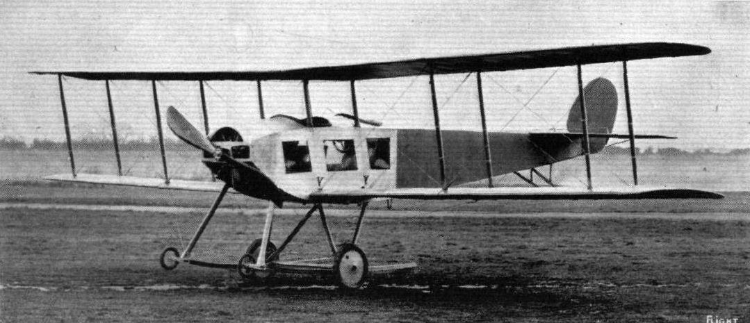
The 80-h.p. Sopwith tractor biplane.
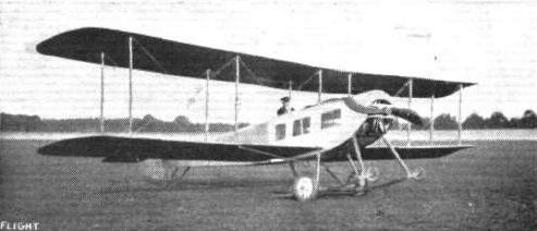
The Sopwith.
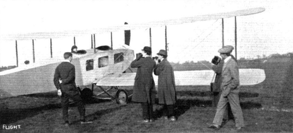
The penalty of popularity. Mr. Hawker on the Sopwith-Tractor having his picture taken at Hendon.
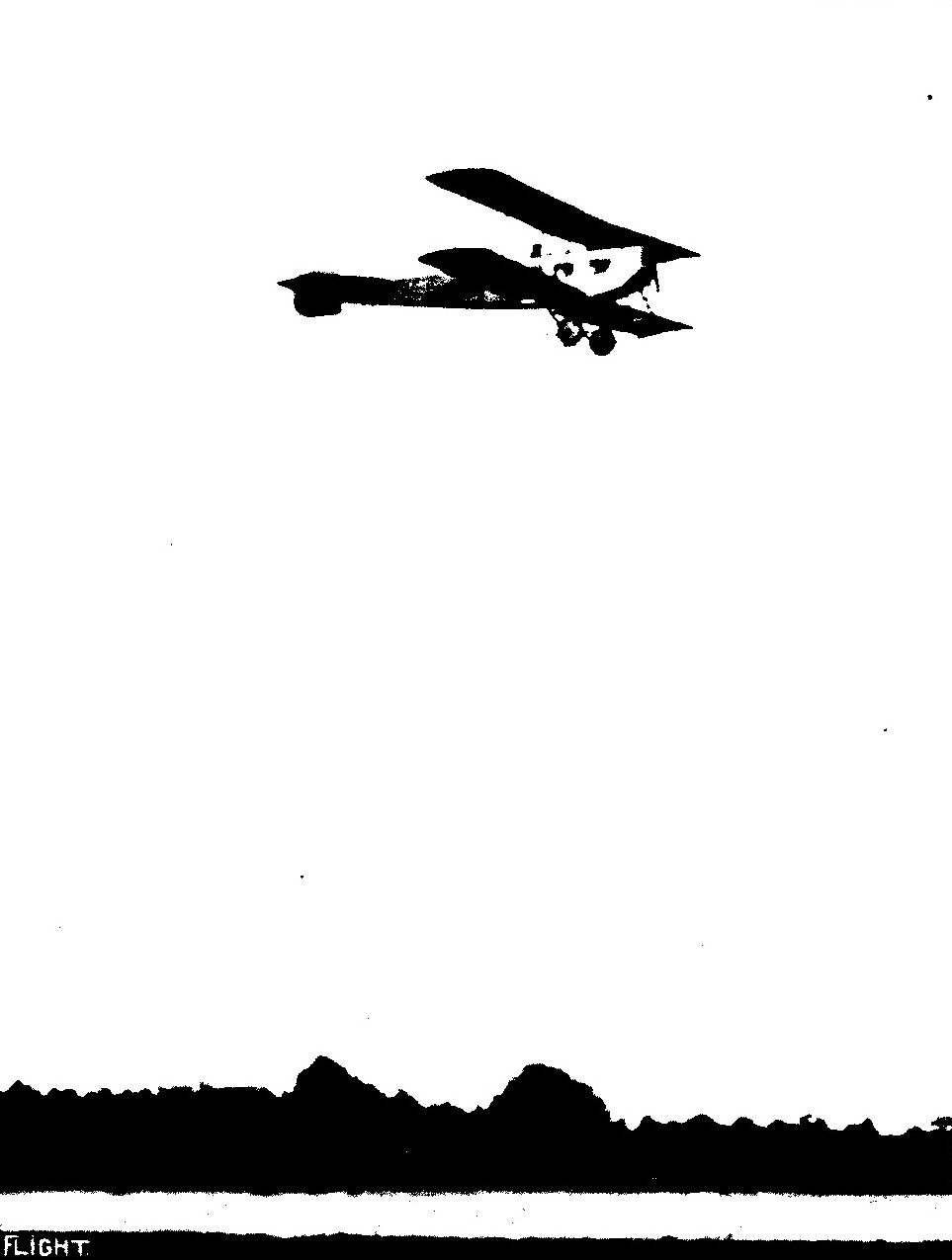
THE BRITISH HEIGHT RECORD. - Mr. Hawker on the Sopwith tractor at Brooklands.
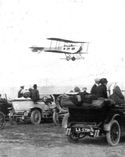
SUNDAY FLYING AT BROOKLANDS. - Mr. H. Hawker giving a fine exhibition of his skill on the 80 h.p. Sopwith tractor.

Brooklands track - familiar in so many views of Sopwith and Hawker aeroplanes - stretches ribbon-like across this study of a Three-seater.
The Sopwith tractor coming straight ahead at Brooklands with Mr. Hawker, who has just made a new height record, at the wheel.
The Sopwith tractor coming straight ahead at Brooklands with Mr. Hawker, who has just made a new height record, at the wheel.
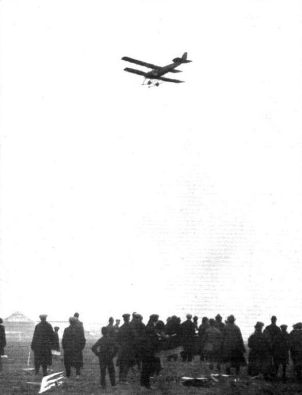
Arrival, during the Model Flying Competition at Hendon, of Lieut. Spencer Grey on the Sopwith biplane.

AN EVENING FLIGHT AT BROOKLANDS. - A turn on the Sopwith tractor.

Biplane versus monoplane in the Easter Aeroplane Handicap for the Shell prize at Brooklands on Easter Monday. - Mr. Barnwell, on the Vickers monoplane, passes Mr. Hawker, on the Sopwith, in the first lap.

Pilot: Mr. H. G. Hawker.
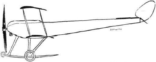
The 80-h.p. Sopwith tractor biplane.
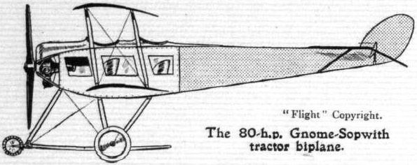
The 80-h.p. Gnome-Sopwith tractor biplane.
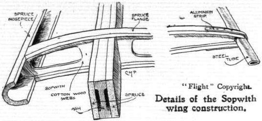
Details ol the Sopwith wing construction,
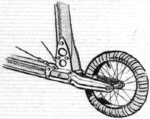
Mounting of the skid tip wheels of the Sopwith tractor biplane.
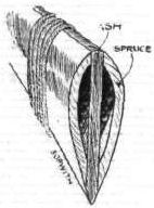
Sketch showing the hollow construction of a Sopwith strut.

A bent steel fitting on the Sopwith tractor biplane assembling a fuselage longitudinal, the vertical cross member, the rear wing spar and chassis strut.
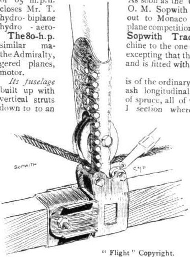
The warping pulley of the Sopwith tractor biplane, showing how the same fitting is combined with the rear spar hinge.

Details of the chassis suspension of the Sopwith biplane as seen from above.
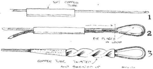
Diagram illustrating how stranded cable terminals are made on the Sopwith biplane.
AT OLYMPIA. - A study in tail-skids.
A study in tails.
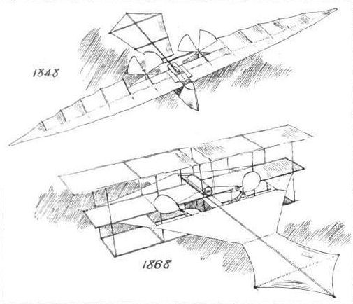
The Stringlellow models. - The monoplane was built in 1848 by Stringfellow after collaboration with Henson, and was the first self-propelled aeroplane of any kind to support itself by its own power. The triplane was built in 1868 bv Strlngfellow, and was demonstrated at the Crystal Palace Exhibition in that year. It was subsequently bought by Prof. Langley, and is now in the Smithsonian Museum at Washington, D.C. The monoplane is in the Victoria and Albert Museum, London.
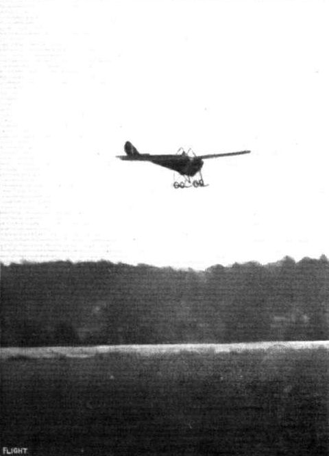
Mr. Barnwell, on the Vickers mono, gilding down into Brooklands Aerodrome after his non-stop flight to Hendon and back on Sunday.
Biplane versus monoplane in the Easter Aeroplane Handicap for the Shell prize at Brooklands on Easter Monday. - Mr. Barnwell, on the Vickers monoplane, passes Mr. Hawker, on the Sopwith, in the first lap.

Ready for the day's work at the Vlckers Flying School at Brooklands Aerodrome.
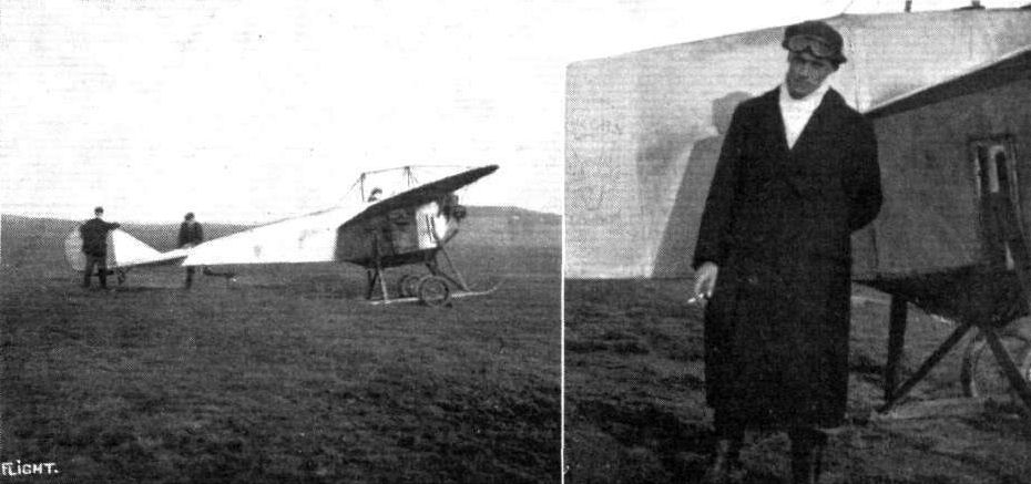
AT THE VICKERS SCHOOL, BROOKLANDS. - On the left, Chief Pilot and School Manager, Mr. R. H. Barnwell, in the seat of Vickers No. 5 monoplane. On the right, Mr. T . W. Elsdon, who has been appointed assistant pilot at the Vickers School.
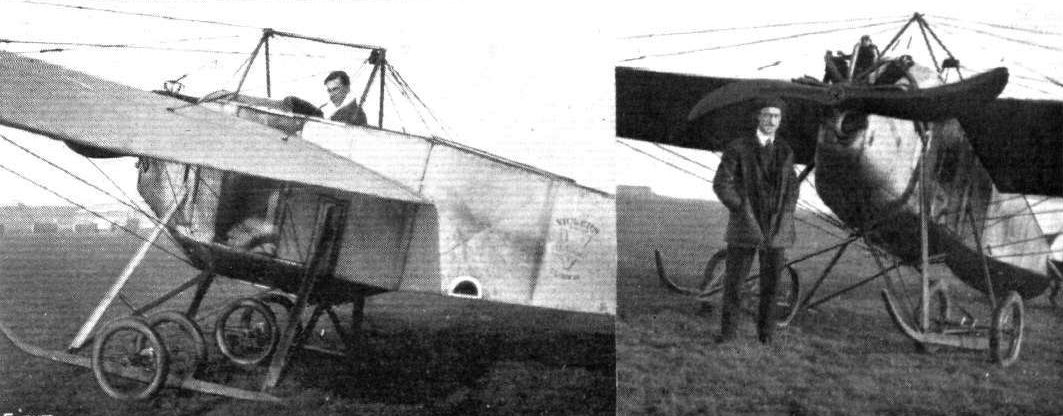
TWO PUPILS AT THE VICKERS FLYING SCHOOL, BROOKLANDS. - On the left in the pilot's seat of Vickers No. 5 monoplane, Mr. A. E. Morgan; on the right, Mr. Henry Webb.
Flight, February 8, 1913.
WHAT THERE WILL BE TO SEE AT OLYMPIA.
THE MACHINES.
Vickers, Ltd.
Two machines, of excellent design and construction, will represent Messrs. Vickers, Ltd., at the Olympia Show. One will be a military biplane, driven by one of the new Wolseley 60-80 semi-air-cooled semi-water-cooled motors. Their other machine will be a monoplane similar in almost every respect to the one which flew in connection with the Military Trials at Salisbury Plain. Unlike that machine, however, it will be driven by a 70-h.p. Gnome motor.
<...>
As for the monoplane they will be showing, we have already mentioned that it will be almost identical to the one that figured in the Military Trials at Salisbury, excepting that the Show machine will be fitted with a 70 h.p. Gnome motor. With an engine of this power and type, the monoplane has been timed to do 63 miles an hour, and to lift a useful load, consisting of passenger, pilot, and fuel sufficient for a 3 1/2 hours' flight, at the rate of 250 ft. per minute. Pilot and passenger will be seated side by side, and they will be provided with duplicate controls. Although it is a moderately fast machine, it can be flown in perfect comfort without the necessity of the occupant wearing goggles. This is obtained by the fitting of transparent wind screens in front of pilot and passenger. A similar machine to this one, but fitted with an 80-h.p. Gnome motor, has attained over 70 miles per hour.
Flight, February 22, 1913.
SOME MORE AEROPLANES AT OLYMPIA.
MESSRS. VICKERS, LTD.
They are represented by two exceedingly businesslike looking machines, an 80-h.p. Gnome engined monoplane and a military biplane equipped with one of the new 60-80-h.p. Wolseley aero motors. For some three years now has this noted firm had in operation an aviation department under the direction of Capt. H. F. Wood, himself a pilot of no mean order. Their designer, Mr. Archibald R. Low, M.A., who is responsible for the drawings of the two machines exhibited, is also an experienced pilot. Both the monoplane and the biplane shown may to all intents and purposes be considered as all-steel machines, for wood only enters into their construction for the shaping of the ribs, for the landing skids, and for the filling pieces by which the tubular struts are brought up to streamline section.
The 80-h.p. Vickers Two-seater Monoplane. - This monoplane is of the same type as the one which, fitted with a 70-h.p. stationary Viale motor, put up such praiseworthy flights at the time of the Military Aeroplane Competitions in August last. The identical machine shown, driven by a 70-h.p. Gnome motor, has done upwards of 500 miles in the air at the Vickers private flying ground at Erith, piloted by the late Mr. Leslie Macdonald and by their present pilot instructor, Mr. Barnwell.
Its body is an all-steel structure, built lattice girder fashion, with light tubular longitudinals and tubular cross members. They are assembled by means of welded steel sockets, the joints being afterwards sweated together and pinned. At the front end the four longitudinals meet in a flat upright plate, which serves as one of the provided by a stout flanged plate arranged some little distance behind the front cap. Seats are provided for the pilot and passenger side by side, and there are transparent wind shields fitted in front of them, so that they may suffer no inconvenience from the propeller draught. So carefully has this been carried out that when the machine is flying the occupants can detect scarcely any wind at all. Dual control is fitted. The seats are arranged well forward in the body, so that the occupants have a good clear view over the leading edge of the wings. To still further increase their range of vision, Cellon windows are let into the sides of the body. An interesting fitting in the cockpit is a Cuft anti-drift compass, which is mounted over a hole in the floor and by which the machine may be kept on a true course in a side wind.
The landing chassis is of the central skid and double wheel type. - Two V's of stout steel tube support the body from a long ash skid, which is curved up in front and which is armoured by the application of Duralumin sheeting. Two axles, carrying the rolling wheels, extend on either side of the skid. Landing shocks are absorbed by elastic springs in tension.
The wings are built about two tubular steel spars cored with wood. Over them the ash ribs are loosely fitted in such a manner that continual warping of the wings does not tend to weaken them in any way. On the under side of the wings three stranded steel cables proceed to each spar, and these take the main lift. In a similar manner the wings are braced from above to a cabane above the pilot's cockpit.
The tail is formed by the splaying out of the body at the rear to give a fixed stabilising surface behind which are hinged the two lifting flaps. On this monoplane, as distinct from the one that flew in connection with the Military Competitions at Salisbury, a vertical fin is fitted, which precedes an unbalanced directional rudder. A small steel skid protects the tail unit, but it is probable that it very seldom comes into play, for most of the weight of the tail on landing is taken by the backward laminated extension of the main landing skid.
Fitted with an engine of 70-h.p., this monoplane shows a speed of 63 miles per hour, and is capable of climbing with the useful load aboard of pilot, passenger, and sufficient fuel for a 3 1/2-hours' flight at the rate of 250 ft. per minute. With an 80-h.p. Gnome motor installed, the machine has been timed to attain and maintain a speed of over 70 miles per hour.
<...>
Flight, May 10, 1913.
FROM THE BRITISH FLYING GROUNDS.
Brooklands Aerodrome.
ALL the schools are now going strong and the Vickers Company have taken two more sheds to house their new machines.
On Tuesday morning last week, Mr. Barnwell, Manager of the Vickers School, had rather a narrow escape over the Weybridge golf course whilst testing a new two-seater monoplane, the machine being caught by a sudden gust of wind and dashed to the ground ere the pilot could recover control. It was only his skilful manoeuvring, coupled with the strength of the chassis, a great feature of the Vickers machines, and the body, which considerably minimised the force of the impact, that prevented a worse accident. As it was, Mr. Barnwell escaped with a good shaking and a few cuts.
<...>

The Vickers war monoplane.
Mr. Barnwell In flight, with a passenger, on Vlckers No. 8 before his recent mishap down Weybrldge way.
Ready for the day's work at the Vlckers Flying School at Brooklands Aerodrome.

A chassis detail of the Vickers monoplane.
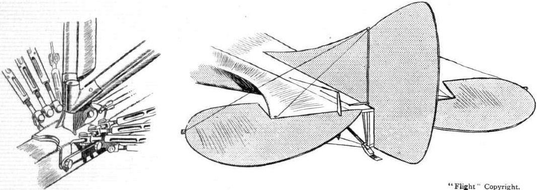
VICKERS MONOPLANE DETAILS. - The sketch on the left illustrates the fitting by which the two front V-set chassis struts are assembled to the central skid. It also shows how the wing cables are attached. That on the right shows the tail.
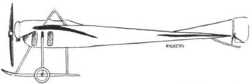
The 70-h.p. Gnome-Vickers monoplane.

The 80-h.p. Vickers monoplane.
AT OLYMPIA. - A study in tail-skids.
A study in tails.
Flight, February 8, 1913.
WHAT THERE WILL BE TO SEE AT OLYMPIA.
THE MACHINES.
Vickers, Ltd.
Two machines, of excellent design and construction, will represent Messrs. Vickers, Ltd., at the Olympia Show. One will be a military biplane, driven by one of the new Wolseley 60-80 semi-air-cooled semi-water-cooled motors. Their other machine will be a monoplane similar in almost every respect to the one which flew in connection with the Military Trials at Salisbury Plain. Unlike that machine, however, it will be driven by a 70-h.p. Gnome motor. From the side elevation sketch we print can be gathered an idea of the arrangement of the new Vickers biplane. It may be considered as an all-steel machine, for wood only enters into its construction for the manufacture of ribs and skids, and for the "stream-lining" of steel tubular struts. The planes, which are staggered, are each built about two wood-filled tubular steel spars, over which the ribs are loosely threaded in such a way that it is impossible for the plane skeleton to become fatigued through continual warping. For this reason also the rear spars in the sections of the planes which warp are hinged to the spars of the rigid central section. The upper and lower planes span 40 and 30 ft. respectively. They are separated by steel stanchions, which are assembled to the planes by means of a special design of socket, by which the planes can be dismantled in a very short space of time. The body of the machine is of steel construction, covered by a "stream-lining" of Duralumin. Projecting in front of the machine, as it does, it affords the observer, who occupies the front seat, an uninterrupted view. More important than that, this design makes it possible for the biplane to be used as a machine for offence purposes. On the machine that will appear at the show, it will be seen that Messrs. Vickers have mounted a Maxim gun, which can be swiveled through an angle of 30 degrees on either side of, and below and above, the longitudinal axis of the machine. In a box, arranged inside the cockpit at the centre of gravity of the machine, will be stored 1,500 rounds of ammunition. This box is so fitted that it may slide forward on wires and so be brought within easy reach of the man who is operating the gun. The pilot sits in the rear seat, but both pilot and passenger are provided with controls by which they may drive the machine. The landing gear is similar in design to that fitted to the B E a Army biplane. Like that latter machine, too, the Vickers biplane may easily be steered at slow speeds over the ground. A Vickers-Levasseur propeller will be used.
<...>
Flight, February 22, 1913.
SOME MORE AEROPLANES AT OLYMPIA.
MESSRS. VICKERS, LTD.
They are represented by two exceedingly businesslike looking machines, an 80-h.p. Gnome engined monoplane and a military biplane equipped with one of the new 60-80-h.p. Wolseley aero motors. For some three years now has this noted firm had in operation an aviation department under the direction of Capt. H. F. Wood, himself a pilot of no mean order. Their designer, Mr. Archibald R. Low, M.A., who is responsible for the drawings of the two machines exhibited, is also an experienced pilot. Both the monoplane and the biplane shown may to all intents and purposes be considered as all-steel machines, for wood only enters into their construction for the shaping of the ribs, for the landing skids, and for the filling pieces by which the tubular struts are brought up to streamline section.
<...>
The 60-80-h.p. Vickers Biplane. - A very interesting machine, not only for the fact that, hitherto, the Vickers organisation have confined their attentions exclusively to monoplane construction, but for the great amount of thought and care that, it is evident, has been spent on its construction and design. Standing before this biplane, the first feature that arrests the attention is that there is a Vickers automatic gun protruding from the front of the neatly rounded Duralumin covered body. Then, even the lay mind can arrive at the principal reason why the propeller has been arranged at the rear of the machine - it is designed to have that position mainly in order to give an unobstructed range of fire in front of the biplane.
The body of the machine, which extends forwards from the main planes, is constructed in a precisely similar manner to that of the monoplane we have just described. In its interior sit the passenger and behind him the pilot, both sheltered to a great extent from the wind by the neat metallic covering that is fitted over the body. Seated in front, the observer, and he will have to be a gunner too, has a perfectly clear view all around him. The gun before him is arranged to swivel through an angle of 60° in both horizontal and vertical planes, while the ammunition is stored in a box, travelling on wires, beneath his seat. When the gun is not in use the ammunition box is in a position just over the centre of pressure of the planes; when it is required to operate it, the box is wound forward on its wire rails and brought within reach of the gunner. As we have remarked, the pilot sits immediately behind him, and he grips a double-handled vertical lever whereby he controls the machine. Still further behind, the motor is mounted, its lugs bolted to the top two members of the fuselage.
The planes are made on a system which has little difference from that observed in the building of the Vickers monoplane wings. They are "staggered," as will be seen from one of our illustrations. Contrary to the more usual plan of using piano wire for the bracing of the planes, stranded steel cable is employed in this machine. As a matter of fact, all the bracing throughout is of stranded cable, excepting in the body, where stout wire is used. The planes are so designed that in a very little time they may be dismantled, leaving only a centre section that is no wider than the body itself. Close examination of this central section of the top plane will reveal that in its interior there is a small petrol tank from which fuel is fed to the motor by gravity. It is supplied from a main tank in the body, under pressure, and the tubes leading to and from it are neatly tucked away behind the wooden tilling pieces that are used to "streamline" the tubular cellule spars. By the way, the machine does not carry an oil tank, for sufficient oil is stored in the base chamber of the motor to last for a six hours' flight.
The landing chassis is, at first sight, very much like that of the monoplane. Its flexible suspension, however, will be found to be altogether different. A central hollow skid of ash is joined to the body by 2 V's of steel tubing. Two other V's of tubing extend downwards and outwards from the side of the body, and, in crutches at their lower extremities, the axles of the landing wheels travel against the tension the strong rubber springs. (See sketch.) Altogether, the chassis is exceptionally light and compact, and, moreover, looks strong enough to bear any ordinary landing strain that it is likely to he subject to. Differing from the monoplane, too, there is no backward extension of the central landing skid. The weight of the tail is carried by a small steel spoon-shaped tail skid, so fixed that it pivots with the rudder and enables the machine to be steered more or less accurately over the ground at slow speeds.
The tail, level with the top main plane in flight, is attached to the top of the tubular steel tail outriggers. In plan form it is approximately rectangular, and its interior construction is of steel throughout, tubing being used for its outline, while the cambered ribs are of channel section, acetylene-welded in position.
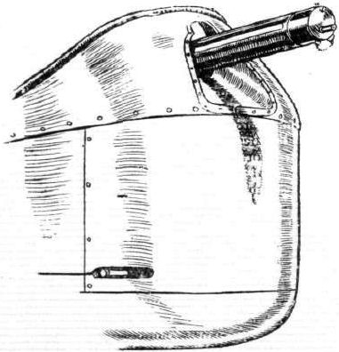
The front of the cockpit of the Vickers biplane, showing the mounting of the automatic gun.
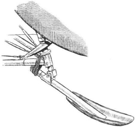
The Vickers biplane tail-skid, which rotates with the rudder, allowing the machine to be steered when running along the ground.
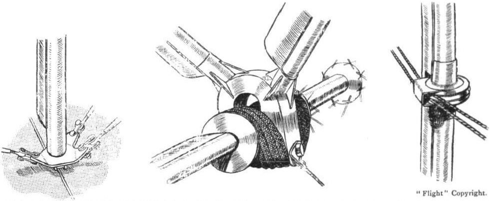
DETAILS OF THE VICKERS BIPLANE. - On the left, quick detachable strut fitting. In the centre, the details of the flexible suspension. The sketch on the right shows how the tail controlling cables are guided round one of the plane struts.
AT OLYMPIA. - A study in tail-skids.
A study in tails.
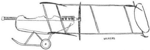
The 60-80-h.p. Wolseley-eriglned Vickers biplane.

The 60-80-h.p. Vickers biplane.
CROSS-COUNTRY RACE AT BROOKLANDS ON SATURDAY LAST. - Mr. W. S. S. Mitchell on the Vickers biplane (No. 8); Mr. W. Bendall, Bristol biplane (No. 10); Mr. F. W. Merriam, Bristol biplane (No. 7), rounding the sheds on the first circuit.
Flight, September 13, 1913.
THE WESTLAKE MONOPLANE.
A NEW and very interesting machine on somewhat original lines has been added to the list of British built aeroplanes. It has been designed and constructed by Mr. A. Westlake at Clacton-on-Sea. Mr. Westlake, who has had considerable experience in motor engineering, and is well known in the motor world, holds several patents relating to aeroplanes and aero-engines, his first patent being taken out so far back as 1904, and he has been constantly experimenting since then, so that, although little publicity has been given to his experiments, he is really one of the earliest workers in aviation in England.
An examination of the accompanying scale drawings and photos will show that in general outlines the Westlake monoplane is somewhat similar to certain well-known German machines. It is, however, only in its graceful lines, that this resemblance manifests itself; on closer inspection it is found to be quite different.
The backbone or fuselage is of rather unusual design, being of pentagonal cross section in front and triangular in the rear portion. The fan shaped tail is formed by sweeping the upper longerons outwards for the last few feet of their length. Carried on a tubular axle, supported on extensions of the longerons, is the elevator, which is of the flat non-lifting type, and is operated through cables passing round a drum on the control wheel in front of the pilot.
It will be noticed that the rudder is situated wholly on top of the empennage and is unusual in that its axis is forwardly inclined instead of being, as is general practice, at right angles to the line of flight. The effect of thus inclining the axis of the rudder is such as to make it act in a certain measure as an elevator so that, in turning, the tail of the machine will rise, thereby causing the machine to dive slightly without using the elevator. This is a great advantage, especially for school work, as most pupils are apt to forget to get the nose of the machine down when making a turn.
The chassis consists of two pairs of A struts, the apex of which forms the cabane, and which carry at their lower extremities a pair of skids from which the tubular wheel axle is sprung by means of rubber shock absorbers. Attachment of the chassis to the fuselage is effected by means of steel clips, which grip the longerons so that in no instance are these weakened by piercing. The chassis is of such simple construction, that should it become damaged through a heavy landing, it could be repaired with almost any material available, such as plain boards or planks. The advantages of this in a Military machine are obvious. The present machine, which is a purely experimental one, is fitted with ailerons, but the next machine will be fitted with warping, which however will be of an unusual nature in that both wings may be warped together so as to increase the angle of incidence and, incidentally, the camber, or they may be warped as in present systems, one moving up when the other moves down, or both may be moved down simultaneously, or again one may be left neutral while the other is warped.
The method of carrying out all these operations by means of a single lever is shown in one of the accompanying sketches, which is, we think, self explanatory. In the sketch only two cables are shown running to the wings, but any required number may be fitted by interposing compensation devices, such as pulleys in the cables.
The new wings are to have two spars in the usual way, the rear one of which will be situated about halfway along the chord, and a third one further back will serve to distribute the pull on the wires over all the ribs. In the present monoplane the ailerons may be worked in a similar way, either together or independently, and may be both raised upwards to form what is virtually negative wing tips.
The next machine it is hoped will possess, due to its variable angle of incidence, a very wide speed range which, of course, is a great advantage as it enables the machine to land at a speed very much below its normal flying speed. This feature impresses one as being of special value for waterplanes, as it would greatly lessen the shock of the floats coming in contact with the water.
As the present machine is fitted with an engine of only 18 h.p. which, as a matter of fact, was built by Mr. Westlake himself from four De Dion air-cooled cylinders, no extended flights have been made, but Mr. Westlake has got several straights out of it, and no doubt, with an engine of more reasonable power, the machine would fly quite well.
For the exploitation of his patents Mr. Westlake has formed a limited company under the title of The East Anglian Aviation Co., Ltd., with which Mr. Arthur Elliott, the West-End estate agent, is associated. The London offices of the company are at 26, Shaftesbury Avenue, but the works and flying ground will be at Clacton-on-Sea, where a very large tract of land has been acquired, which is, we understand, absolutely flat and sheltered from north and easterly winds, and having moreover the advantage of a sandy, sloping foreshore, which should be excellent for waterplane practice. As the locality of the aerodrome is within a few miles of the military town of Colchester and the naval depot at Harwich, a school at Clacton-on-Sea should soon become popular among the officers stationed at these two centres.
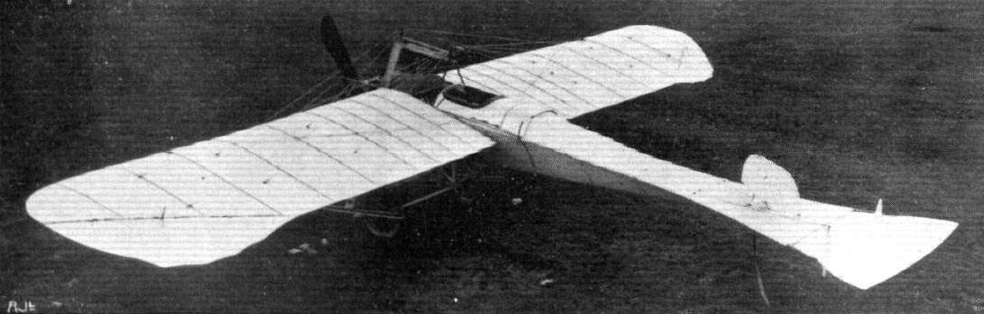
Plan view of the Westlake monoplane.

Side view of the Westlake monoplane.
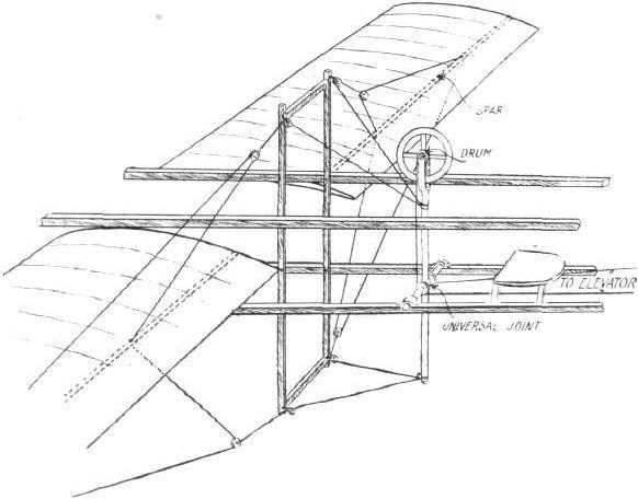
Diagrammatic sketch of the Westlake control arrangements for increasing or decreasing the angle of incidence on both wings simultaneously or independently. In the sketch only two pairs of cables are shown running to each wing. By interposing suitable compensating devices, such as pulleys, any number of cables can of course be used.
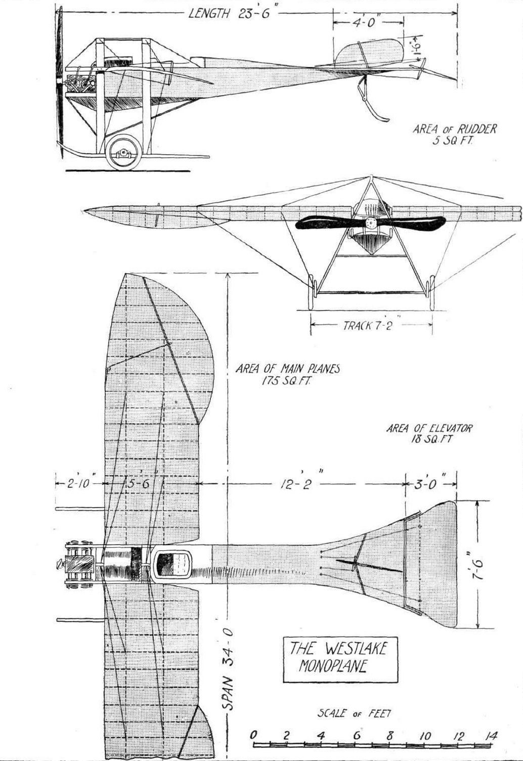
THE WESTLAKE MONOPLANE. - Plan, side and front elevations, to scale.
Flight, February 22, 1913.
SOME MORE AEROPLANES AT OLYMPIA.
J. SAMUEL WHITE AND CO.
On their stand, to the left of the main entrance, this firm is showing a high-powered hydro-biplane. Unfortunately, through a lack of sufficient space, it was found impossible to assemble the whole machine. However, although the outer sections of the planes are not fitted, quite a good idea of the machine as it appears when in flying trim, can be gathered from wash drawings that are shown on the stand. This hydro-biplane has been built to the designs of Mr. Howard T. Wright, who, as most people interested in aviation know, is in charge of the aeronautical department of the above well-known firm of naval Government contractors. He has devised and constructed a machine which he claims will have a speed range of from 30 to 70 miles an hour, which will be capable of alighting on and starting off from rough water, and which will be easy to fly.
Wing construction. - The most notable point regarding the wing construction is the original cross-section that is employed. On the under-surface of the planes there is a single camber, but on the top surface two distinct cambers are noticeable. Mr. Howard T. Wright has taken out patents on this particular aerofoil cross-section, and, it having been tested by Eiffel in Paris, it has been found to give an exceptionally wide speed range. Further, it has the property that the location of its centre of pressure travels but little for wide variations in the angle of incidence. At its maximum speed, the planes are designed and adjusted so that they will fly at a slight negative angle. At the lowest speed, 30 miles an hour, they fly positively incident to the wind at 15. The planes are built about two main spars, which arc of box cross-section and which have spruce sides and elm strips top and bottom. Where struts are carried to the spars, and where the alighting gear is attached, the hollow spars are cored with solid elm. Most of the ribs which give the shape to the plane are of I-section spruce.
Sixteen struts of spruce separate the planes, the eight centre ones being solid, while the remainder are of hollow construction. Compensating ailerons are used for balancing.
Float construction. - The machine rests on the water on two long torpedo-shaped floats, built according to Messrs. J. Samuel White's patents covering their design and method of construction. They each have three steps, the two forward ones being arranged immediately below the two vertical struts that take the main weight of the machine. On the under side they are convex, a shape which makes them particularly suitable for open-sea work. Their interior construction is mostly of three-ply wood and elm, while they are covered with very fine three-ply cedar, a selection of materials which gives enormous strength with quite light weight. Although these floats are of considerable size they only weigh 100 lbs. each complete with their fittings.
The body, which proceeds forward from the main plane, so that the occupants may have a good clear view all around them, is a lattice girder of the usual type with elm longitudinal members and spruce cross pieces, covered with fabric. It seats two persons in tandem, the pilot taking the front seat where he controls the machine by means of a vertical universally jointed lever for fore and aft attitude and balancing, and a foot-bar for the rudder. The big 160-h.p. rotary Gnome motor is mounted between two heavy flanged Steel plates at the rear end of the body, and drives a large diameter Chauviere propeller with armoured tips. Fuel is stored in a large 40-gallon tank, from which the petrol and oil feed down to the engine by gravity.
The tail, supported by a pair of triangular outriggers, carries vertical and horizontal fixed stabilising surfaces, two elevator flaps, and an unbalanced rudder.
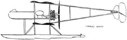
The 160-h.p. Samuel White hydro-biplane.
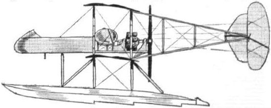
The 180-h.p. Samuel White Navy-plane.
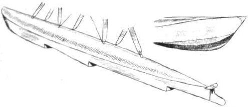
Details of the floats fitted to the J. Samuel White hydro-biplane.
A study in tails.
Flight, August 30, 1913.
THE "WIGHT" WATERPLANE.
THE following very interesting account, received from a correspondent, of the successful debut last week-end of the waterplane designed by Mr. Howard Wright, and built by Messrs. J. S. White and Co., will doubtless be read with interest. It will be remembered that the planes of this machine are peculiar in that they have a double curve.
Our correspondent writes from Cowes under date August 24th :-
"East Cowes, August 24th, 1913.
"You will, I am sure, be interested (and pleased) to know that White's 'plane' went for a fine 'fly' yesterday morning. They got Gordon England to come down, and, after having a look round the bearings at Osborne Bay from a motor boat on Thursday morning, England, in the afternoon, taxied out and got the 'hang' of the machine, but did not attempt a flight as there was rather much wind. Friday blew hard all day, and yesterday morning about 9.30 he taxied out in the Roads and calmly lifted her (whilst going with the wind) and flew most perfectly out over Ryde Pier and back, planing down on the water most satisfactorily. Everyone is delighted; England says she is the best machine he has flown. He adjusted the ailerons when he rose, and did not touch them afterwards; she actually flew at 30 m.p.h., and he found that he had to throttle down his engine very much as she was so anxious to climb, although he had 200 lbs. weight ballast in lieu of passenger. He also said that her lifting power was so great that she could have had much smaller planes.
"He now wants as near an absolute quiet windless day, in order that he may get certain data, inclination, &c, and he will then put her through an exhaustive series of trials; but I think she is quite all right as she flew so perfectly steady in both right- and left-hand turns.
"It would seem as though the cause of the two mishaps was her anxiety to climb with a full throttle, which, of course, turned her over before the pilot could bring her back; but with England, he steadily opened her out with the foregoing result. The full speed of the 'plane' should be 70 m.p.h., but, of course, that has not yet been tried."
Flight, September 6, 1913.
The "Wight" Seaplane Trials.
RELATIVE to the report from a correspondent of the tests made by Mr. Gordon England with the "Wight" seaplane off Cowes last week, we have received the following information from the designer, Mr. Howard Wright:- "The machine as flown weighed 2,200 lbs., 600 lbs. of which was useful load. She leaves the water in about 30 yds. with no wind; she climbed 1,000 ft. in just under 2 mins., and with engine shut off glided from that height about 2 1/2 miles from just over Calshot into Cowes Roads. Her maximum speed at present is 65 m.p.h., and her minimum 30. She was very quick on her controls fore and aft, and just as easy to fly as a first-class land machine. The inertia of the floats is not apparent to the pilot. You can readily see that lifting 44 lbs. per sq. ft. at a speed of 30m.p.h. makes the lift constant quite exceptional. The maximum horse-power employed at any time was 120, propeller revolutions being 1,150. The cause of the early accident was that the centre of pressure is very considerably further forward than the model shows, so that the machine on the first and second occasion was very tail heavy. Our machine is quite automatic laterally. She takes a correct "bank," remains on it, and comes off the banking automatically without the use of the ailerons. The behaviour of the floats on the water appears to be very good.
Flight, October 4, 1913.
THE WIGHT SEAPLANE.
SOME further particulars are now to hand regarding the tests of the Wight seaplane built by Messrs. J. Samuel White and Co., Ltd., of East Cowes, I.W., to designs by Mr. Howard T. Wright. Including these last tests, the machine has been very thoroughly tried by Mr. Gordon England, the aggregate time in the air totalling to 20 hours. During these tests, which were made with full load, we understand that no mechanical weaknesses developed. The speed was 63 m.p.h. with the propeller turning at 1,120 r.p.m. and 31 m.p.h. with 900 r.p.m.
The machine, which is fitted with a 160 h.p. Gnome loses elevation very slowly when flying with 7 cylinders cut off, and flies well with 3 cylinders missing. The present propeller is too powerful for the motor, so that it cannot turn more than 1,120 in the air, which is equivalent to about 120 h.p.
The machine, leaves the water without apparent effort in under 60 yds., i.e., without the "unstuck" effect found in so many hydroplanes. With a 15 to 20 mile "following" wind, it left the water in about 150 yds., and gets up at from 35 to 40 miles per hour. No difficulty was found in rising with a second passenger and full load.
Alightings can be made at 27 miles per hour with no perceptible shock to the pilot, the machine coming to rest in twice the length of the floats. With regard to climbing, the first 500 ft. was attained in 1 min., and 3,000 ft. in 10 mins. In descending 1,000 ft. 1 min. 21 secs, were occupied at the speed of 46 miles per hour, the gliding angle being about 1 in 5 1/2.
The fore and aft control is ample under all conditions; the machine can be readily recovered from 35 degrees forward tilt and from, almost vertical dive in a very short space of time. This was tested fully loaded with a second passenger and light, there being no load on the control lever when flying with the tail up or down.
The lateral control is almost automatic. The machine takes its own banking at turns and remains on the bank and leaves it again on the machine being straightened out without the use of the ailerons.
With a very gusty wind 17 to 20 miles per hour the machine was very easy to control and no physical strain on the pilot.
With a choppy sea, about 3 ft. high, the floats behaved very well when taxiing. The floats do not hit the seas hard, but pass practically through them. The machine can be manoeuvred in a strong wind when travelling at a speed of from 25-30 m.p.h.
The machine behaved satisfactorily when towed.
We may repeat that the dimensions of the machine are: Span, 44 ft.; overall length, 30 ft.; height, 11 ft. 6 ins.; weight, empty, 1,700 lbs., loaded 2,400. The floats are Messrs. White's own patents, while the planes have Mr. Howard T. Wright's double camber.
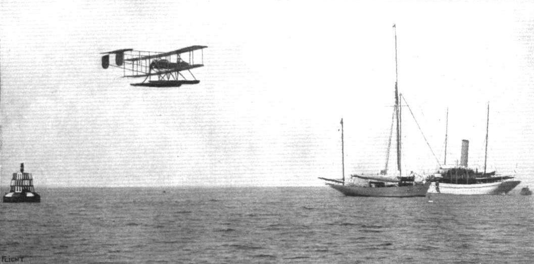
The Wight Seaplane, piloted by Mr. Gordon England, in flight.
Flight, May 31, 1913.
THE "TONG-MEI" 40-H.P. BIPLANE.
By A.E.G.
THE "Tong-mei" tractor biplane, which is now being tested at the Shoreham aerodrome, is a good example of the light single-seater aeroplane, and is somewhat reminiscent of the BE 3 - the highly-staggered planes, deep fuselage and simple landing gear giving this impression.
The plane outline is not common in this country, the trailing-edge being swept back slightly from the second rear strut to the extreme wing-tip, the idea being to gain increased warp efficiency.
A simple and neat hinge is fitted to the rear spar, to lessen fatigue.
The planes are mounted on twelve silver spruce silk-bound struts, shaped to the "Baby" section, as recommended by the National Physical Laboratory.
A particularly good feature is the rib construction, each rib is built up of three laminations of spruce layered together with glue and rivets on a former, the resulting curve being absolutely permanent, and the finished rib is a great deal stronger than one of the ordinary type.
The trailing edge of the upper plane is cut away, above the body, to lessen down draught on the tail.
The outline of the empennage gives a graceful effect, quite in harmony with the rest of the machine. The almost semicircular tail has a slightly cambered top-surface. The 7-ft. 4-in. elevator is built in one piece to give high efficiency, and for a measure of safety should one control cable fail.
A detail feature of the control masts is the cable fixing, designed to retain the cable in case of failure of the bolt or its fastening.
The balanced rudder is mounted on a wood-filled steel mast, which, extended through the body, forms the support of a pivoted tail skid, in BE 3 fashion.
The landing chassis is essentially simple, being designed for use in a country where skilled assistance is difficult to obtain, each member could be replaced by almost any material that came to hand.
The steel clips fastening the struts to fuselage and skids are very simple, but at the same time strong pieces of platework.
The comfort of the pilot has been carefully studied and he is well sheltered behind an aluminium turtle deck, which also streamlines the petrol and oil tanks. Light wood formers carry a lath and fabric combination of the streamline form behind the pilot.
The central lever utilized is practically a modified form of the Bleriot cloche, but the substitution of arms saves some unnecessary weight.
Any organ or part can be very quickly dissembled entirely as a unit, a virtue which will be appreciated by those who have faced the difficulties of transport and travel without proper facilities.
The complete machine, less engine and fabric, weighs only 504 lbs., and with 3 1/2 hours' petrol will fly with a loading of 2 1/3 lbs. per foot.
The engine to be installed is one of the new 40-h.p. A.B.C., the English duration record holder. The combination should be capable of some good performances.
Mr. Tsoe. K. Wong, the designer and constructor of the Tong-mei (English "Dragon Fly"), intends to introduce the type into China, where he hopes it will play its part in the development of China's fourth arm. It is encouraging to note that Mr. Wong has made England the base for his preliminary organisation. He is arranging to take back several English pilots and mechanics.
FLIGHT readers will no doubt wish him every success in his enterprise.
A two-seater machine of the same type is now in course of construction, and will, as soon as it is completed and tested, be dispatched to China.
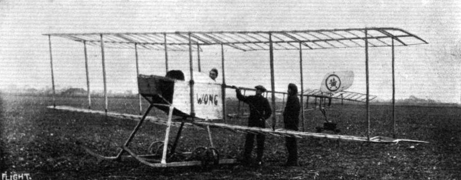
THE "TONG-MEI" TRACTOR BIPLANE, MINUS FABRIC, IN COURSE OF ERECTION. - Mr. Wong in pilot's seat.
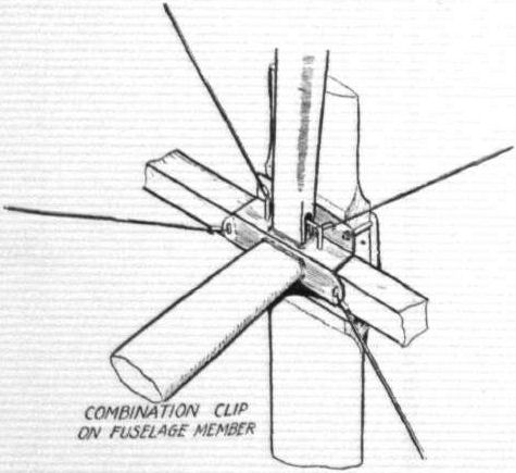


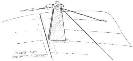
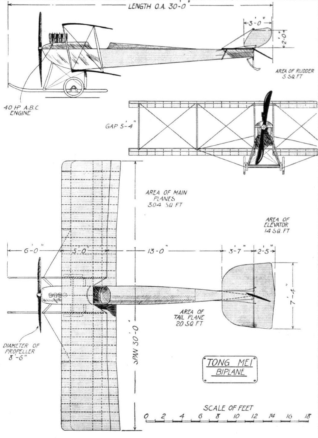
THE "TONG-MEI" TRACTOR BIPLANE. - Plan, side and front elevations to scale.
Flight, November 8, 1913.
THE D.F.W. MILITARY MONOPLANE.
BEFORE beginning a description of the machine itself, a few words about the German Aircraft Works (Deutsche Flugzeug Werke) in which these machines are built may not be amiss. One of the accompanying photographs gives a good idea of the spacious shops of this firm, whose works are situated at Lindenthal, near Leipzig, Germany. The shops are equipped with the most up-to-date machinery, and in the three erecting shops as many as 20 machines can be assembled at a time. The number of employees, we understand, has passed 300, and is constantly on the increase. At the present time four standard types of machines are turned out, i.e., a school monoplane, a military monoplane, a military biplane and a hydro-biplane. All of these types are designed with a view to obtaining a certain amount of inherent natural stability as will be explained later. Another point which has received careful attention is the standardization of all parts, most fittings on both monoplanes and biplanes being interchangeable.
Our scale drawings and photographs this week illustrate the military type monoplane, which the school monoplane resembles in every respect, with the exception of the steel bridge girder fitted underneath the wings of the latter. The fuselage is built up of a framework of steel tubes of ample dimensions, laterally stayed by three ply wood panels. The section of the fuselage is a very elongated ellipse, having its major axis vertical. Inside the fuselage are the pilot's and passenger's seats, arranged tandem fashion, the passenger occupying the front seat, from whence he has an excellent view of the ground beneath, and, if necessary, can make any little adjustments of the engine that may be required. The pilot's seat is placed sufficiently far behind the trailing edge of the main planes to give him an unrestricted view in a downward direction, and so enable him to judge his landings with a great amount of accuracy.
Only engines of the stationary type are fitted, as the constructors of the machine contend that, although somewhat heavier than rotary engines, the stationary engine is more reliable and economical in fuel consumption, two most important qualities in a machine for military use.
The dome-shaped honeycomb radiator is mounted directly in front of the engine which position, in addition to being the best possible for cooling purposes, gives a good streamline form to the fuselage. The bonnet over the engine consists of fine wire gauze, making all engine parts visible, preventing overheating and affording accessibility, as the bonnet opens in sections. The petrol and oil tanks are situated between the passenger's and pilot's seats, and a smaller service tank is mounted on top of the fuselage.
An inspection of the plan view will show that the main planes possess that feature which seems to characterise the majority of German machines, i.e., the back swept wing tips, set at a small negative angle of incidence. In this machine the outer extremities of the wings take the shape of ailerons, being hinged to the rear spar instead of being formed by extending the outer ribs backwards, which is the usual method of construction. The method of having the extensions hinged in this way has proved very satisfactory.
The tail planes consist of a stabilizing plane, which is not, however, rigidly connected to the fuselage, but is pivoted, and may be adjusted from the pilot's seat by means of a rotatable hand wheel situated outside the fuselage, and within easy reach of the pilot's seat. Hinged to the trailing edge of this plane is the undivided elevator. On top of the fuselage is the rudder, which is hinged to the trailing edge of a small vertical fin. A well-sprung tail skid protects the tail planes from contact with the ground.
In front of the pilot are the usual set of control levers, consisting of a rotatable hand wheel mounted on a central tubular column, which, in turn, is mounted on a transverse rocking shaft. A to-and-fro movement of the column operates the elevator, whilst rotation of the wheel actuates the ailerons. The rudder is operated by means of a footbar. Ignition and throttle levers are mounted on the right hand side of the pilot's seat, and on the hand wheel is a switch, while a self-starter is fitted on the instrument board in front of the pilot.
The chassis consists of two "U"-shaped steel tube frames, braced by tubes from a point underneath the fuselage, the whole forming a very strong structure which offers comparatively little head resistance. Two pairs of wheels sprung in the usual way by means of rubber shock absorbers are mounted on the U-shaped frames, and facilitate starting from and alighting on the ground. If desired brakes can be fitted.
Below we give a few particulars which, in connection with the scale drawings, should give a very good idea of the main characteristics of these machines which have met with a good deal of success in competitions, while a number of them have been purchased by the German military authorities :-
Weight, empty: 1,300 lbs.
Useful load: 440 lbs. and fuel for a 4 hours' flight.
Average speed loaded as above: 73 m.p.h.
Climbing speed: 3,300 ft. in 15 mins.
Gliding angle : 1 in 7.5.
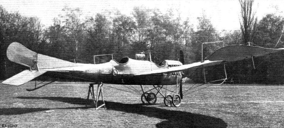
Three-quarter rear view of the D.F.W. military monoplane.
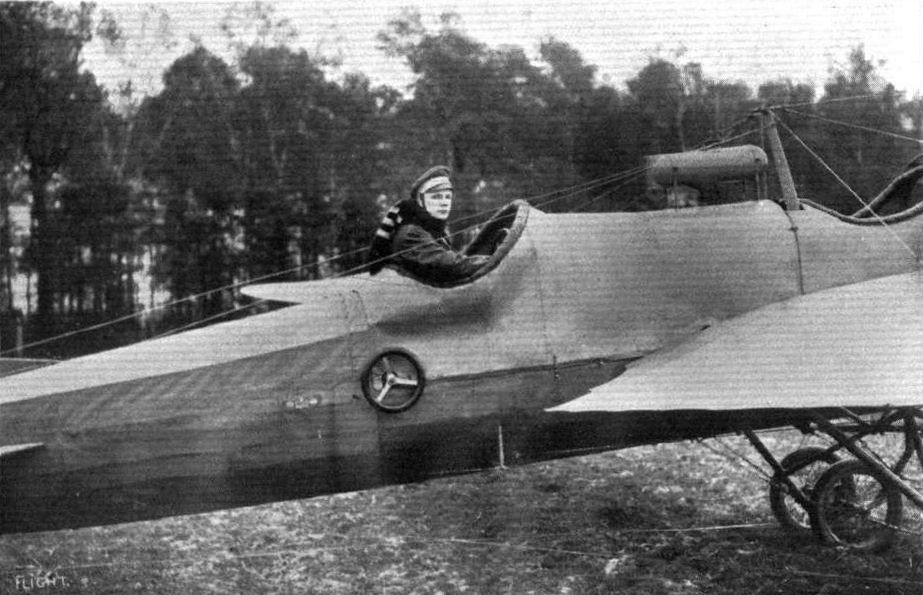
Lieut, von Hiddessen on hts D.F.W. monoplane on which he won the three days' "Prince Henry Reliability Trials." The machine is constructed by the "German Aircraft Works" at Leipzig.
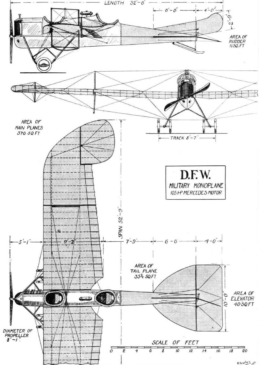
THE D.F.W. MONOPLANE. - Plan, side and front elevation to scale.
Flight, December 20, 1913.
THE D.F.W. BIPLANE AT BROOKLANDS.
QUITE an interesting visitor to these shores is the D.F.W. biplane, which has been down at Brooklands for two or three weeks. Owing to the lack of space, we cannot at the moment do more than publish photographs of this machine, which is being exploited in this country by Mr. G. Cecil Kny, who hopes, by demonstrating the capabilities of his machine as a reliable war plane, to get a share of Government orders. From a cursory glance round this very businesslike-looking aeroplane, it appears likely - though probably not being very fast - to justify Mr. Kny's claim, to go and return, day in and day out, for weeks on end if necessary, as it is said to have done on the Continent. It looks immensely strong, and the 100 h.p. Mercedes engine, with its motor car front radiator, looks capable of doing all that is claimed for it. We shall later be giving a detailed description of this machine, with photographs and scale drawings. The machine is constructed by the Deutsche Flugzeug Werke, who are the makers of the monoplane which was fully dealt with in FLIGHT on November 8th, 1913.
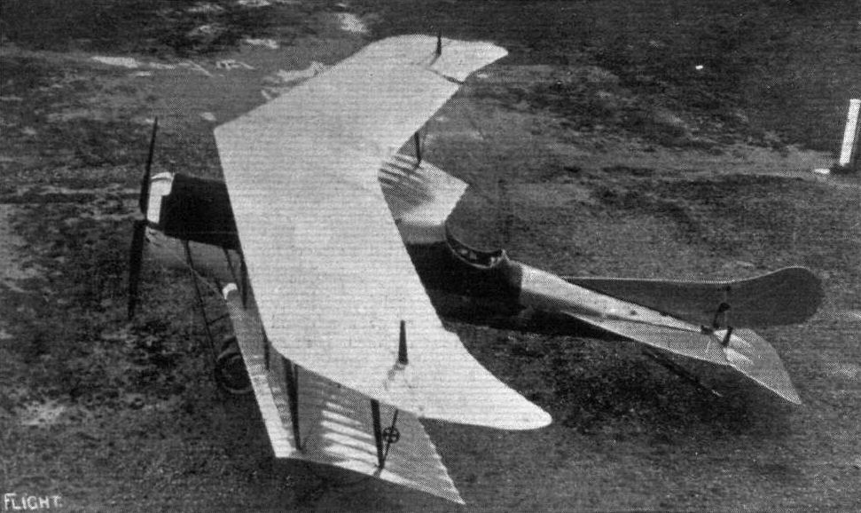
A plan view of the D.F.W, biplane now at Brooklands.
The swept-back wings led to the smaller, more compact DFW Pfeil (Arrow) biplane.
The swept-back wings led to the smaller, more compact DFW Pfeil (Arrow) biplane.
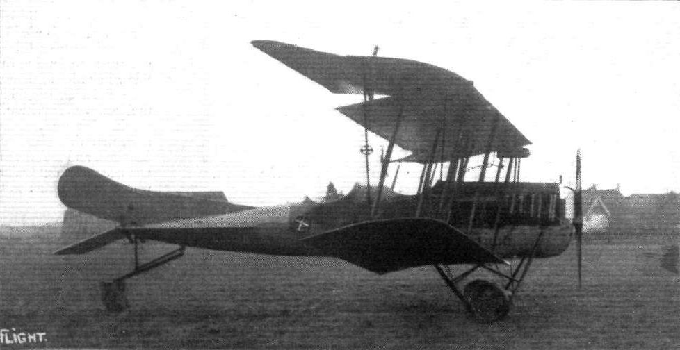
THE D.F.W. BIPLANE AT BROOKLANDS. - Side view.
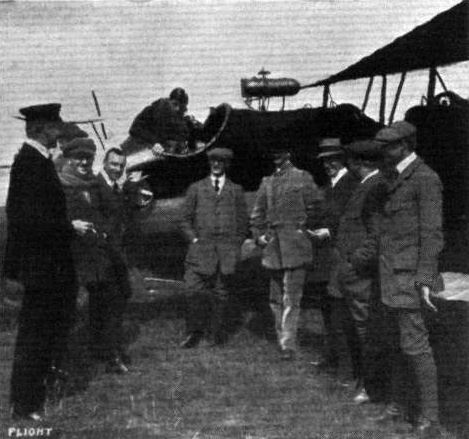
Harry Oelerich, chief pilot of the D.F.W. Flying School, after beating the German duration record by 6 hrs. 8 mins. a few weeks back.
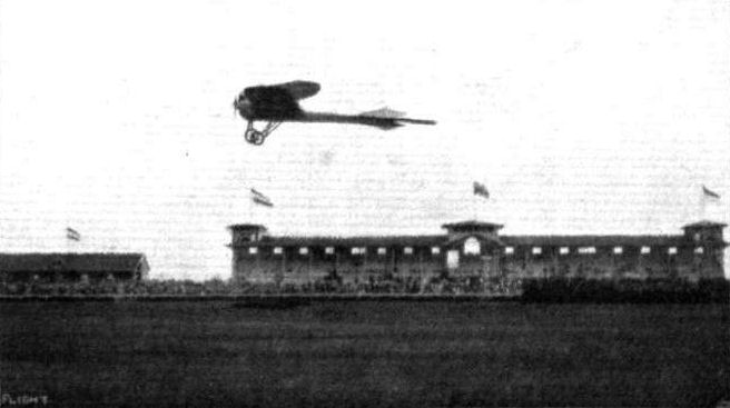
PRINCE HENRY PRIZE. - The start at Wiesbaden in front of the grand stands. Lieut. Joly, on the Gothaer mono, is just getting away.
Flight, July 5, 1913.
THE PIONEERS.
THIS is the tenth anniversary of the conquest of the air by the aeroplane, and it is appropriate that our special number should be made to commemorate the work of the pioneers, as well as other incidental facts, such as, for example, that FLIGHT itself is already in its fifth year of publication.
It was on December 17th, 1903, that the Wrights first achieved power-driven flight with their aeroplane (the first account of which in any English newspaper appeared in FLIGHT'S parent journal - the AUTO.), and prior to that day no man could claim properly to have flown at all. The most important work preceding this accomplishment of the Wrights was, unquestionably, the gliding experiments practised by themselves and by others, commencing with Lilienthal.
With Lilienthal's introduction of the glider the practical side of the art of aviation assumed its first real existence Otto Lilienthal was born at Anclam, in Pomerania, in 1848, and he died in 1896 as the result of a fall during one of his flights. His first work of note was the publication of a book entitled "Bird Flight as a Basis of Aviation," which has since been translated into English, and constitutes one of the classics that should find a place in the library of every student of flight.
In 1891, having come to the conclusion that it was possible to gain some practical experience in the air, in spite of the absence of any suitable engine - provided the experimenter could arrange to fly downhill under the propelling force of gravity - Lilienthal constructed a machine that he purposed using as an aerial toboggan.
His glider consisted of a pair of rigid outstretched wings measuring 23 ft. in span, and having, after various alterations, an area of 86 sq. ft. The wings were cambered, and they were surfaced with cotton twill stretched over a light framework of willow. The machine weighed only 40 lbs. complete.
In order to balance the glider in flight, Lilienthal relied upon his own dexterity in moving his body to and fro or from side to side whenever it was necessary to counteract a shifting of the centre of pressure under the wings. There can be no doubt that the use of his apparatus was fraught with considerable danger, but Lilienthal brought an immense enthusiasm to his work, which was not only an encouragement for himself, but a source of inspiration to others.
Among those who took great interest in Lilienthal's experiments was Pilcher, then a young English engineer whose name was associated with the firm of Wilson and Pilcher, at one time well known in the automobile industry before their cars were taken over by Messrs. Armstrong, Whitworth. He designed gliders of his own, more or less on Lilienthal lines, and at one time went over to Germany in order to discuss the subject with Lilienthal himself. If anything, he adopted an even more dangerous procedure than the German pioneer, for in order to avoid the necessity of finding a suitable hill as an aerodrome, he would attain the initial altitude necessary for a gliding flight by having his machine towed like a kite. An accident during one of these experiments resulted in his death, and thereby deprived England of a most promising student who, had he lived, might have done much to give this country pre-eminence from the first.
Instead, it was in America that the influence of Lilienthal's work took permanent root. Octave Chanute, a distinguished American engineer, but already an old man, was intensely interested in the prospect of flight, and extended his practical patronage to the early movement by financing an important series of experiments in which the central figure was the well-known pilot, A. M. Herring.
It was while reading the simple notice of Lilienthal's fatal accident that Wilbur Wright received his inspiration to study this branch of practical science, and from the first he obtained the whole-hearted co-operation of his brother, Orville. The story of their work has been told too often to need repeating. Lilienthal died in 1896, and thereupon the Wrights commenced their studies. They built their first glider in 1900; it was a biplane, constructed on the trussed-bridge principle introduced by Chanute, but it differed from the Chanute machine in several important respects. Among other things, it embodied the famous wing-warping control, and the pilot, being thereby relieved of the necessity for balancing the aeroplane by gymnastic exercise, was able to lie prone on the lower plane, and so reduce the resistance of his body to a minimum.
<...>
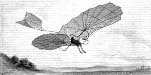
Lilienthal's glider, one of a series built in Germany between 1890 and 1896. With the introduction of these machines real practice in the art of flying first commenced.
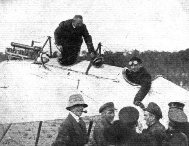
Baierlein in the pilot's seat of the Otto monoplane, the winner in the Round Berlin flight.
Flight, November 15, 1913.
AEROPLANE TYPES.
THE PIPPART-NOLL MILITARY MONOPLANE.
IT cannot be denied that many of the aeroplanes produced in Germany are original in design, so far as other countries are concerned, at any rate. Many German and Austrian manufacturers have adopted the Etrich system of wing form either in its initial design, or modified, as in the case of the Pippart-Noll monoplane. This machine has been designed to meet the German military requirements, and has proved to be a successful flyer. With a 70 h.p. Argus engine it is capable of ascending to a height of about 350 m. in 3 1/2 mins. The fuselage is in the form of a well-defined torpedo, being slightly greater in depth than in width. Two cock-pits are provided for pilot and two passengers, the latter being situated right forward side-by-side, where an excellent view may be obtained down over the front of the main planes. The pilot also has a good view below, being situated level with the trailing edge of the main planes. As previously mentioned, the main planes somewhat resemble the Etrich type in that the wing tips at the trailing edge extend a little to the rear, but they differ from the type in question by being slightly swept back in the form of a V, or arrow. The wings are set at a fairly pronounced dihedral angle. A peculiar feature consists of the empennage, or tail, which, to all intents and purposes, is an extension of the main planes extending rearwards on either side of the fuselage, and terminating with two hinged elevator flaps. The landing chassis is very strong and consists of two U steel-tube struts carrying the spring axle and wheels. The principal dimensions of the 1913 military-type machine are as follows :- Span, 13700 m.; length, 8.800 m.; supporting area, 28 sq. m.; weight, empty, 560 kilogs.; speed, 80-110 k.p.h.
"VEE JAY."

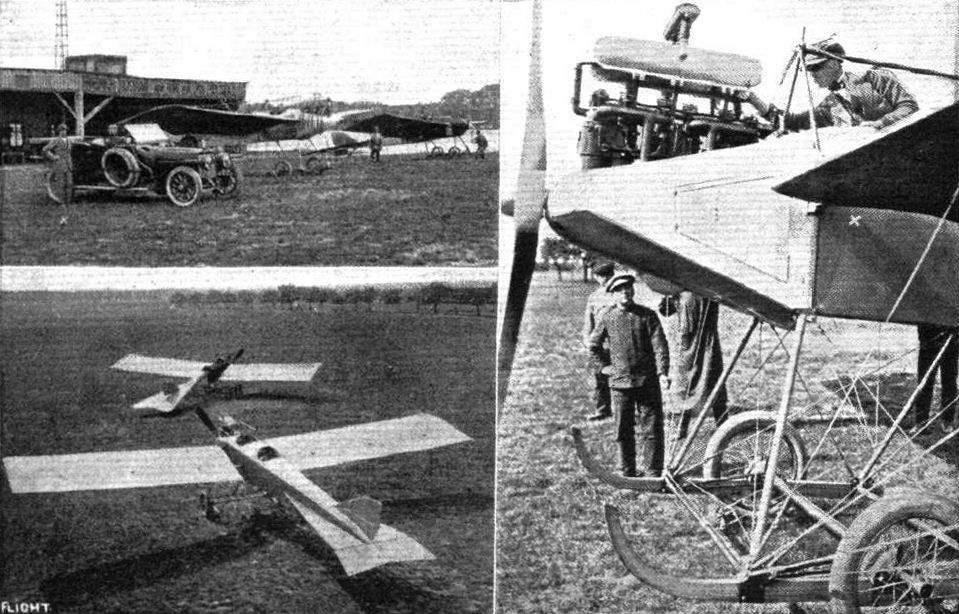
The monoplane which have been designed and constructed by Prince Friedrich Sigismund, son of Prince Friedrich Leopold of Prussia. In the left-hand picture Prince Friedrich Sigismund is standing by his Adler car, which he also drives himself. On the right is a closer view of the chassis and engine mounting, Prince Friedrich being in the pilot's seat attending to the turning of the motor.
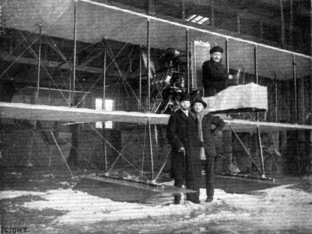
The first Danish hydro-aeroplane constructed by the young aviator, B. Rom (1) to the order of Mr. Loewenstein (2). It has been tested by the well-known Danish aviator, U. Birch, who is seen sitting in the pilot's seat. The biplane is equipped with a 65-h.p. E.N.V. motor, and the two main floats are built of wood, and are divided into nine watertight compartments.
Flight, March 1, 1913.
LIEUT. CALDERARA AND HIS HYDROVOL.
AN interesting personality just arrived in England is Lieut. Mario Calderara of the Italian Navy, whose name is well known to all readers of FLIGHT as the pioneer of service aviation in his own country. Among those who flew over the Arab lines when aeroplanes made their debut in warfare, were several of Lieut. Calderara's pupils, and on that occasion Lieut. Calderara's duties were, for the most part, those of organisation and supervision.
Lieut. Calderara has come to England in the interests of his "hydrovol," to which we referred in FLIGHT on November 23rd last, and because he realises that this country is perhaps more interested than many others in rapidly expanding her aerial forces and should, therefore, afford a promising field for the development of a machine that is essentially designed for service work at sea.
The Calderara "hydrovol" is a singularly interesting monoplane and one of the largest in existence, for it has a wing surface of 770 sq. ft., a span of 66 ft. and a carrying capacity for three men in addition to fuel and oil for 6 1/2 hours with a 100-h.p. Gnome. The weight is 2,644 lbs.
That which is of the greatest interest about the "hydrovol" is the design of the substructure by which it is supported on floats. Lieut. Calderara, being an officer of the Italian Navy, looks at the hydroplane from a very practical standpoint and realises some of the essentials that have not perhaps altogether been grasped by those who have less idea of the use that will be required of such machines under actual conditions. In the first place he has succeeded in providing a wide base for his machine on the water, the outside floats being 21 ft. apart.
Secondly, the centre of gravity of the system is only 4 ft, 6 ins. above the water line and is so disposed relatively to the floats as to eliminate any tendency to slew sideways when first striking the water. A considerable portion of the weight is carried on the large tail, which is mounted at the rear extremity of an openwork frame that is more like those used on the Farman biplanes than it is like anything ordinarily employed in monoplane construction.
Realising that the occupants of aeroplanes used in service work at sea may often be in difficulties through disablement that necessitates their landing on the water in foul weather, the designer has been at some pains to construct the floats and their attachments so as to form a complete unit that can in emergency be used as a raft. With the same object in view it has been sought to make the wings readily detachable, so that under such circumstances if the machine was obviously in danger of founding the wings might be cut adrift. Small sails can be hoisted on the uprights, and a successful experiment of this kind has actually been made.
Lieut. Calderara's present machine has a 100-h.p. Gnome engine, but another is building for the Italian Navy under the supervision of the designer's brother, who is an officer in the Italian Army, and will be fitted with one of the new 160-h.p. Gnome engines. The engine and propeller are situated behind the main wings, the cockpit for the passengers is in front of the engine and the cockpit for the pilot is in front of that for the passengers. In front of the pilot again, the body projects still further to afford space for a gun or other appliance.
As seen in the illustrations, which have very courteously been supplied to us by Lieut. Calderara himself, the wings of the machine have a pronounced dihedral angle, but in future this feature will be abandoned. Hinged balancing planes of 88 sq. ft. surface each, are let in to the trailing edges of the wings, and are operated by the single wheel control, which also works the front and rear elevators and the twin rudders.
We also give diagrams prepared from rough sketches made by the designer, showing the shape of the floats which weigh only 53 lbs. each, and the arrangement of the structure immediately above the floats.
Flight, June 28, 1913.
THE CALDERARA HYDRO-AEROPLANE.
AN interesting function, both socially and scientifically, took place at Lord Blyth's residence, in Portland Place, on Tuesday afternoon last week, when the First Lord of the Admiralty, the Italian Ambassador, the Lord Mayor of London, and many other distinguished guests were invited to meet Lieut. M. Calderara, of the Royal Italian Navy, and to hear a short lecture by Mr. F. Fabbricotti, on the aeroplane that Mr. Calderara built for the Italian navy. The lecture was accompanied by a series of uncommonly interesting kinematograph views, showing the machine in flight.
Our readers are already familiar with the general outlines of the Calderara machine. They will remember that it is an exceedingly large hydro-monoplane, probably, in fact, the largest monoplane in existence. Its other outstanding peculiarity is the raft-like base on which it rides the water, and which permits the mechanics to scramble about the lower part of the machine in comparative safety while it is at sea. Some of the pictures showed the mechanics moving about while the aeroplane was navigating the water, and Lieut. Calderara has actually had mechanics climb from the floats to the body of the machine whilst he was in full flight.
It is always interesting, and frequently instructive, to learn something about the work of other nations in the realm of aviation, and particularly is the opportunity not to be missed when one can hear first hand views on the subject. Moreover, it must further be admitted that the views of any of Wilbur Wright's own pupils on the subject of aeroplane construction, no less than the views of a naval officer on the requirements of a hydro-aeroplane ought to be worthy of consideration.
Mr. Fabricotti made it very clear that Lieut. Calderara did not wish this particular machine to be regarded as an expression of his fixed and inflexible idea of the best type for marine purposes. On the contrary, he had been called upon to design for a specific purpose, and that specific purpose he had fulfilled to the satisfaction of the Italian Navy.
The reason why he chose to build his machine as a monoplane was mainly in order that the wing-tips might be as far removed from the water as possible. The reason why this feature assumed a particular importance on this occasion, was because the wing tips are the most easily damaged of any part of the machine, and the Italian authorities had made a very strong point of securing a hydro-aeroplane that should be as little liable to accidental damage of this character as possible. Indeed, they particularised their views in the matter by limiting the allowance for repairs during the trials to the sum of L20. The size of the machine was, of course, a natural consequence of the weight to be carried in flight, which is always heavier in the case of a hydro-aeroplane.
A portion of the film that was of especial interest was that showing the action of the floats in the water. The floats employed on this machine are those now being built in this country by the Avion Float Co., and the pictures in question were taken at close range with the camera on board the machine. It is, of course, impossible to describe them in detail, but they are certainly of sufficient interest to be seen by those who are directly concerned with hydro-aeroplane development, and we have no doubt that arrangements for seeing the film could be made with Mr. Fabbricotti, who may be addressed at the works of the Avion Float Co., 17, Wharf Road, City Road, London, N.

LIEUT. CALDERARA'S "HYDROVOL" ALIGHTING ON THE SURFACE OF THE WATER. - This is one of the largest monoplanes in existence, having 770 sq. ft. of wing surface. It is of singularly interesting construction, for the hydroplane floats are no less than 21 ft. apart, and the centre of gravity is only 4 ft. 6 ins. above the water line, so that the machine possesses great lateral stability when afloat. In emergency it is possible for the occupants to leave the body of the machine and take refuge on the under structure which serves as a raft. In emergency sail can also be rigged, and facilities have been made for cutting adrift the wings if the machine gets caught at sea in a high wind and is disabled.

Lieut. Calderara's "hydrovol" in flight.

Lieut. Mario Calderara, of the Italian Navy, who pioneered service aviation in his own country, and who trained several of the pilots who flew in the Tripoli campaign.
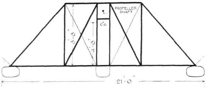
Diagram illustrating the general nature of the substructure ot the Calderara hydrovol.
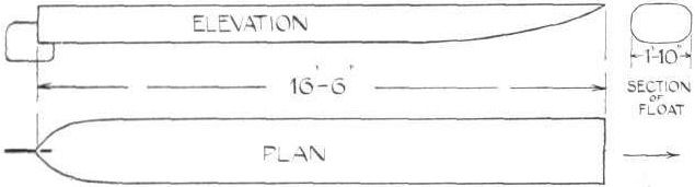
Plan elevation and section of the Calderara floats.
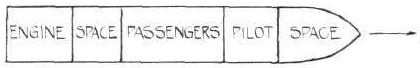
Diagram Illustrating the disposition of the engine, passengers and pilot in the body of the Calderara hydrovol.
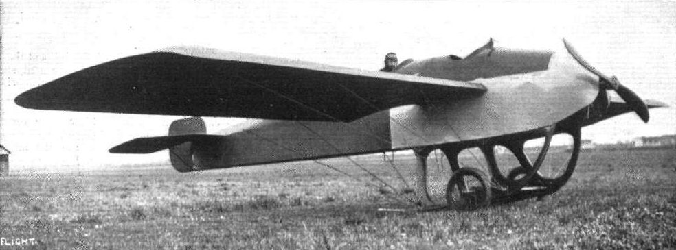
An S.I.A. monoplane constructed by La Societa Italiana degli Aeroplani, of Milan, one of the first really original machines built in Italy. It was on one of these machines that Deroye flew from Milan to Brindisi a few days ago.
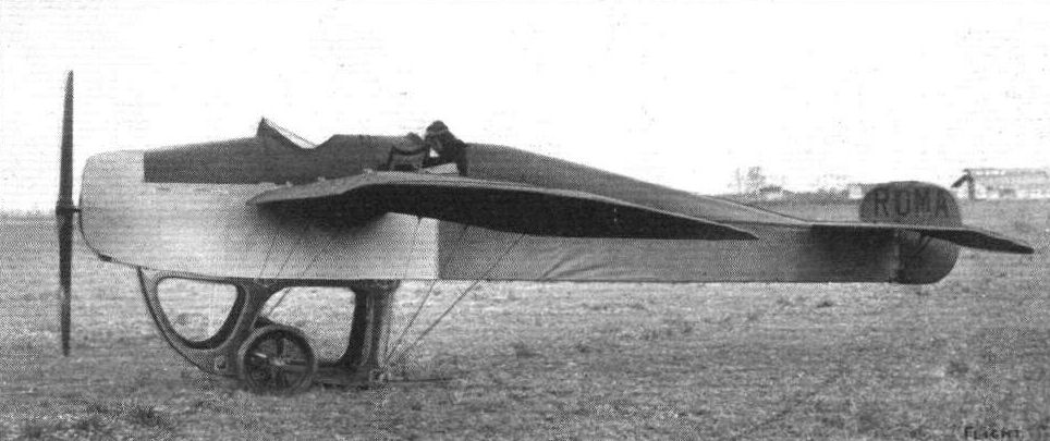
Another view of the S.I.A. monoplane.
Flight, March 29, 1913.
Aviation in New Zealand.
INTEREST in aviation in New Zealand is being kept alive by Mr. A. W. Schaef, of Ingestre Street, Wellington, N.Z., who has designed and built two machines. In our photo he is seen in his latest machine, which he has fitted with a 1912 Y type 35-h.p. Anzani engine and Rapid propeller. The machine has made several flights over the beach at Auckland, and, fitted with floats, also made by Mr. Schaef, it has risen from the surface of the sea. The machine is peculiar in having an elevator above the pilot, working in unison with the tail elevator, and the designer claims that this arrangement ensures more lift and greater stability. Mr. Schaef is the New Zealand agent of the General Aviation Contractors, to whom we are indebted for the photograph.
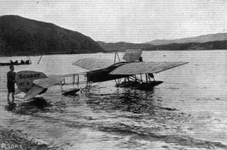
Mr. A. W. Schaef's hydroaeroplane.
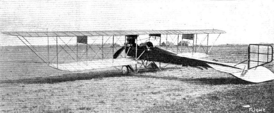
THE SIKORSKY AEROPLANE. - An all Russian machine, both design and construction.
Flight, October 4, 1913.
AEROPLANE TYPES.
THE SYKORSKY BIPLANE.
THE Sykorsky "Grand" biplane, the work of a young Russian designer, is exceptionally interesting on account of its enormous size and disposition of power plant. Unfortunately few details are obtainable, but the accompanying sketch plan and elevation, together with the principal dimensions, should give a general idea of this remarkable machine. It certainly constitutes the first successful attempt at a large, multi-passenger machine or aerial 'bus, for it has been flown by its designer for 1 hour 4 mins. with seven passengers, thus demonstrating its practicability. It has a long rectangular-section metal fuselage having a large glass-sided cabin forward accommodating the pilot and passengers. The foremost portion of the fuselage forms a cockpit in front of the cabin. Various systems of engine mounting have been tried; in its original form, four 100 h.p. Argus motors were mounted on the lower plane, these being arranged tandem fashion on each side of the fuselage - two at the leading edge and two immediately behind them at the trailing edge, and each driving independent tractors or propellers. The rear motors were afterwards brought alongside the front ones, so that all four were on the leading edge. Latest particulars to hand show that only the two motors near the fuselage are employed. The chassis is extremely strong, and consists of four sets of skids, two long ones supporting the fuselage and two shorter ones under the motors. A small skid, carrying two pairs of running wheels, is mounted (by rubber springs) between each of the inner and outer skids. Lateral control is obtained by ailerons hinged to the rear spar of the top plane extensions, and longitudinal control is obtained by a rear elevator hinged to a large lifting tail. Dual wheel (ailerons) and column (elevator) control is fitted. The principal dimensions are as follows: Span 28 m., length 20 m., supporting area 120 sq. m., weight (empty) 2,700 kilogs., speed 85 k.p.h.
"VEE JAY."
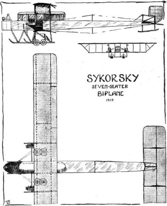
Flight, June 28, 1913.
THE BURGESS FLYING BOAT.
IN this country the type of hydro-aeroplane commonly known as the flying boat, has, up to the present, not come in for much prominence, although several designers are giving a good deal of attention to its problems. In France, and more especially in America, however, it is being constantly experimented with. Scarcely a week passes without a new design appearing in the States, where several have proved quite successful, and it may almost be said to be the fashionable type of aircraft.
Our scale drawings this week are of one of this type of craft - the Burgess flying boat - which was designed to meet the requirements of the United States Navy, and passed all its tests quite successfully in the hands of Frank Coffyn. Its hull, power plant, and main planes each form separate units, which can be assembled and taken down in a very short time.
From the plan view of the machine it will be seen that the sides of the boat are parallel from the prow to a point just behind the trailing-edge of the lower main plane. From there they taper to a vertical knife's edge at the stern. Spruce and oak are the woods used in the construction of the framework of the boat, while the planking consists of two layers of mahogany separated by fabric. The boat is built up of two detachable sections, secured to one another by quickly detachable steel fittings. Two seats, arranged in tandem, are situated in the front part, giving the pilot and passenger an excellent view of all that is beneath them. From his seat the pilot controls the machine through the usual Wright-type levers, which consist of an elevating lever and a combination warp and rudder lever.
One of the most interesting points of this machine is the construction of the main planes. While the lower plane is of the usual Burgess biplane section with two main spars, the upper plane is of a modified monoplane section and has only a single tubular spar situated approximately on the centre of pressure. The top plane is staggered forward, bringing the spar nearly in line with the leading edge of the lower plane. The two planes are connected by six vertical struts, and in addition there are six diagonal struts running from the rear spar on the lower plane to the tubular spar on the upper plane. The lower plane is rigid, and only the upper plane is warped for maintaining lateral stability. From a point on the leading edge of the top plane, just in front of a vertical strut, a cable passes round a pulley at the base of the strut, and is carried right across to another pulley at the base of a corresponding strut on the other side of the machine. By this arrangement the trailing edge is kept from dropping down when the machine is at rest. In a similar way the warping-wires, passing round pulleys at the base of the struts and secured to the ribs at a point roughly half-way between the spar and the trailing edge, take the load when in flight. The ribs of the top plane are made a loose fit on the tubular spar, so that when the trailing edge of one section is pulled down the leading edge moves upwards.
As the diagonal struts are hinged in the centre the wings may be folded by undoing the forward warping wire and folding the diagonal struts. The hinged joint between the planes and the vertical struts then allows of the trailing edge of the top plane dropping down. The trailing edge of the lower plane is then raised so that the planes lie fiat against the struts. The wings can then be pulled out of their sockets and shipped as a unit.
Carried on an engine bed constructed of ash members is the 70 h.p. 8-cyl. V-type engine driving a Chauviere propeller. The engine and its supports form a separate detachable unit. Two stout ash struts running from the engine bed to the forward part of the hull prevent the engine from being carried forward owing to its momentum when alighting on the water.
Petrol is carried in two tanks with a total capacity of 42 gallons, and situated in the central part of the boat. A small pump, driven by a miniature propeller, forces the petrol from the main tanks into a service tank above the engine, and it runs to the carburettor by gravity.
At the rear of the boat are mounted the tail planes. The balanced rudder is used for steering, both in the air and on the water. The fixed tail plane and the elevators form a semicircle, with a portion cut away to permit of movement of the rudder. A small vertical fin is interposed between the boat and the fixed tail plane. The weight of the machine - including pilot, passenger, 48 gals, of petrol and 4 gals, of oil - is 2,100 lbs., and its flying speed is 62 miles per hour.
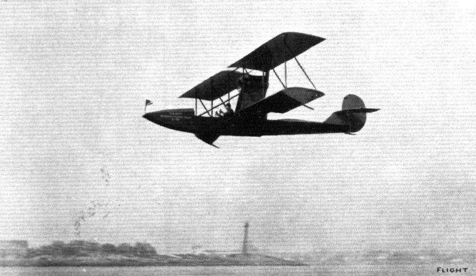
THE LATEST BURGESS HYDRO-AEROPLANE. - The hydro-aeroplane which has been built by the Burgess Co. to meet the U.S. Navy requirements. It will be noticed that the planes are staggered, and although the upper and lower wing surfaces are permanently attached to each other they can be folded together. The power plant is arranged so that it is easily detachable.
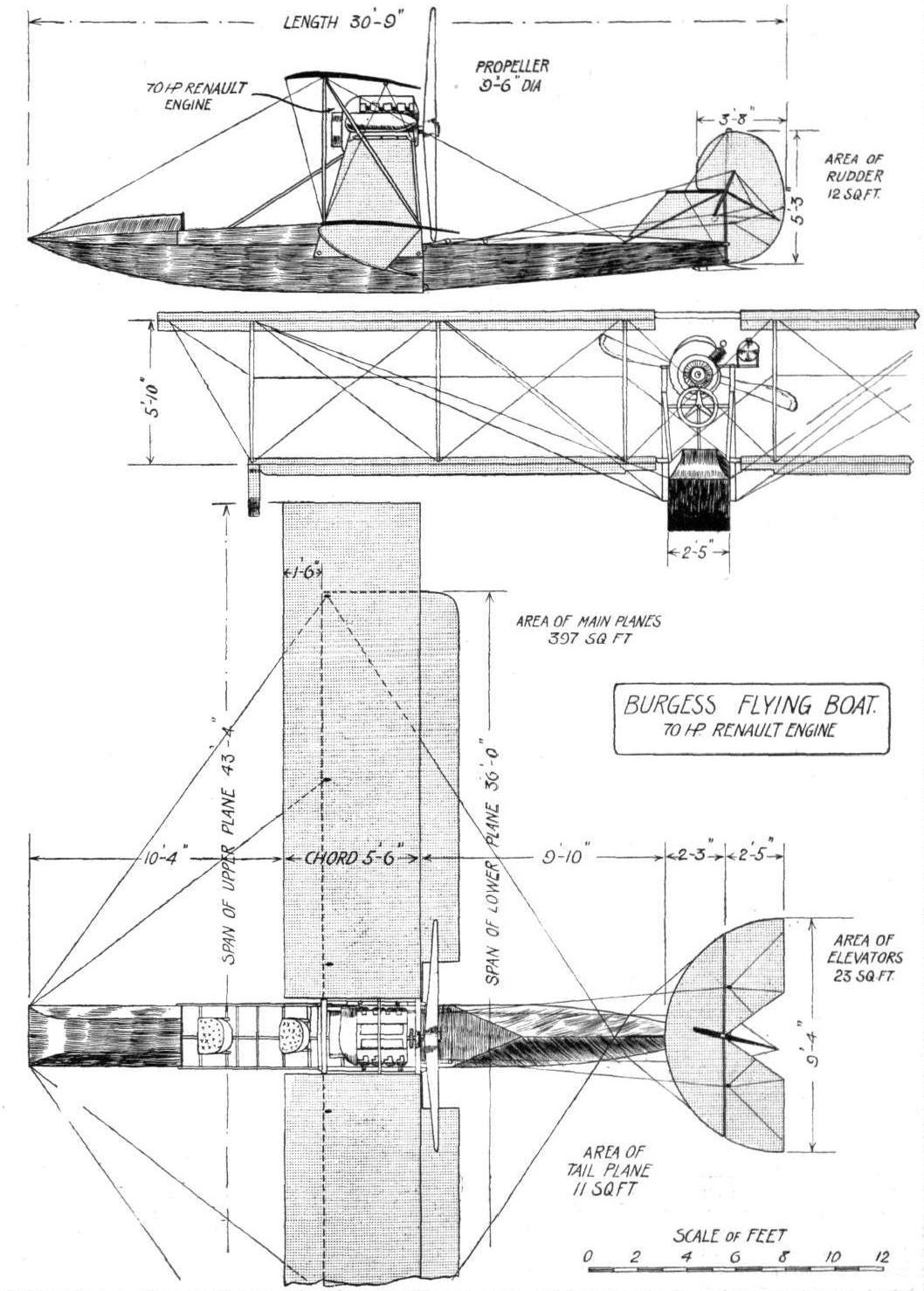
THE BURGESS FLYING BOAT. - Plan, side and front elevation to scale.
Flight, July 5, 1913.
THE PIONEERS.
<...>
Instead, it was in America that the influence of Lilienthal's work took permanent root. Octave Chanute, a distinguished American engineer, but already an old man, was intensely interested in the prospect of flight, and extended his practical patronage to the early movement by financing an important series of experiments in which the central figure was the well-known pilot, A. M. Herring.
It was while reading the simple notice of Lilienthal's fatal accident that Wilbur Wright received his inspiration to study this branch of practical science, and from the first he obtained the whole-hearted co-operation of his brother, Orville. The story of their work has been told too often to need repeating. Lilienthal died in 1896, and thereupon the Wrights commenced their studies. They built their first glider in 1900; it was a biplane, constructed on the trussed-bridge principle introduced by Chanute, but it differed from the Chanute machine in several important respects. Among other things, it embodied the famous wing-warping control, and the pilot, being thereby relieved of the necessity for balancing the aeroplane by gymnastic exercise, was able to lie prone on the lower plane, and so reduce the resistance of his body to a minimum.
<...>

Chanute's glider, piloted by A. M. Herring. - This machine was the prototype of the modern biplane. It was built in America about 1896, and tried on the shores of Lake Michigan near St. Joseph.
Flight, January 18, 1913.
HYDRO-AEROPLANES.
By V. E. JOHNSON, M.A.
<...>
In America Professor Langley carried out his experiments over water. In the autumn of 1908 Glen Curtiss mounted his well-known aeroplane "June Bug" on two canoe-like floats, which resembled the type used in certain forms of catamarans (already described). Now, although this was a machine that had flown well over land, and could be made to travel quite fast on the water, the speed reached was never fast enough for it to rise into the air. Curtiss, however, continued his experiments, chiefly in the improvement of his floats, and in 1910, in the Bay of San Diego (California), he succeeded in rising from the surface with a machine fitted with one central float and a small balancing float in front under the elevator, in place of the usual front wheel (see Fig. 4). Finally, Voisin, having fitted his Canard with three Fabre floats, obtained several fine flights on the Seine near Billancourt Bridge in June, 1910 (Fig. 5). The hydro-aero plane was born.
<...>
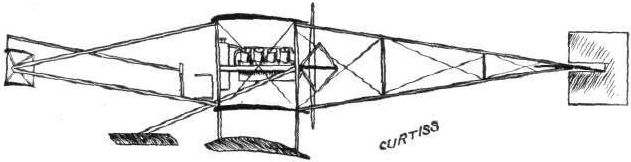
Fig. 4. - Cuitiss's first machine.
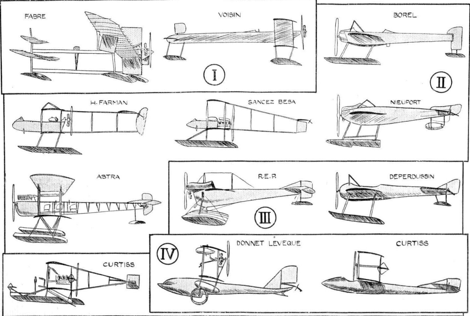
HYDRO-AEROPLANES. - Fig. 5. - Types of Aeroplanes.
Flight, January 4, 1913.
EDDIES.
Paulhan has been flying again. Last Sunday afternoon, on the Seine, at Bezons, he was carrying out tests on a new Curtiss flying boat of which he had just received delivery from Hammondsport, U.S.A. The machine was just unpacked, erected, run down the slipway into the river, the engine started and away he flew without any delay for adjustment of any kind. Fitted with an 80-h.p. water-cooled Curtiss motor, the machine showed its ability to maintain a speed of over 60 miles an hour, with a pilot and passenger on board. The machine by itself, with petrol and oil aboard, weighs less than 1,150 lbs.

The new Curtiss-Paulhan hydro-biplane on which Paulhan has been making some very successful flights on the Seine at Bezons.
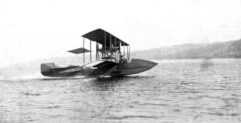
The Curtiss Flying Boat, which has just been awarded the Collier Trophy for 1913. - This machine, it is claimed, will carry six passengers at a speed of 60 m.p.h. The Collier Trophy is awarded annually for the greatest contribution to the advance of aviation, and last year also it was awarded to Mr. Glenn Curtis.
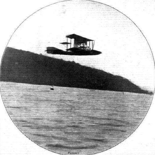
Curtiss's flying boat in flight alter leaving the water.
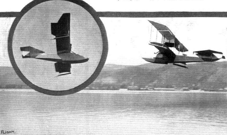
THE LATEST CURTISS FLYING BOAT. - In full flight over the Lake Keuka at Hammondsport, N.Y. Inset is a view of the machine during banked turn.
HYDRO-AEROPLANES. - Fig. 5. - Types of Aeroplanes.
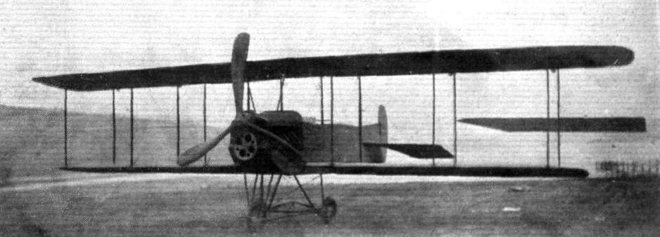
THE LATEST CURTISS BIPLANE. - It will be noticed that, as distinct from former Curtiss practice, this machine, which has chefly designed for military scouting, has a three-bladed tractor.
Flight, July 5, 1913.
THE PIONEERS.
<...>
In America, the work of Langley is the most notable next to that of the Wrights. Professor Langley as secretary of the Smithsonian Institution at Washington, D.C., held one of the highest scientific posts in the country, and he devoted most of his spare time to the study of flight. His experiments on the lift and resistance of inclined flat plates when moved through the air on the end of a whirling arm, are classic, likewise his treatise on the internal work of the wind. His experiments on model flying machines were characterised by a most extraordinary patience and perseverance, much of which was of necessity devoted to the construction of the small steam engine with which they were equipped.
The type of aeroplane that Langley adopted may be described as a tandem monoplane, that is to say it had a similar pair of wings fore and aft. The later flights of his models were very successful, and Langley was commissioned by the American Government to build a full-sized machine. This machine he constructed on more or less the same lines as his models, and an attempt was made to fly it over the Potomac River. It was mounted on the roof of a houseboat, and had a special launching apparatus. This unfortunately failed to act properly, for it tipped the machine head first into the river. The aeroplane was repaired and another attempt was made, but the same thing happened again, and the authorities, being none too enthusiastic, withdrew their further support. Langley very naturally suffered a great disappointment in this, as well he might, for it is a poignant fact that nine days later the Wrights made their first successful flights. It was, in fact, on December 8th, 1903, that the second failure of the Langley aeroplane took place at Arsenal Point, near Washington, and on December 17th that the Wrights achieved their success.
<...>
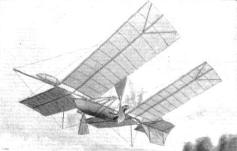
Langley's steam-driven model tandem monoplane, built in America about 1895, and successfully flown over the Potomac River.
Flight, August 23, 1913.
FOREIGN AVIATION NEWS.
Mr. and Mrs. Jas. V. Martin "Farthest North."
MR. MARTIN, writing from Fairbanks, Alaska, under date July 8th, sends us some photographs of the interested crowds and his flying up yonder. His letter runs as follows:- "I enclose herein views of the "Farthest North" in aeroplaning, at least on this side of the globe. The first flights were made at night, the large pictures with the sun in the background, 10.30 p.m. (not midnight). In order to get to Fairbanks the aeroplane crossed and recrossed the Arctic circle.
"I am exhibiting in order to raise funds for the Trans-Atlantic flight. You will remember that in December, 1911, I started the present agitation, and I expect to begin the construction of my machine in England some time this coming winter.
"I wish all my English friends to boost for me, as I shall conduct the flight as England's in every respect.
"My wife, Miss Irvine, will fly with me.
"Best wishes for FLIGHT."
And here's best of luck to Mr. and Mrs. Martin in their endeavours.
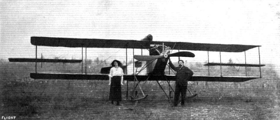
Mr. and Mrs. James V. Martin, with their aeroplane at Fairbanks, Alaska, under the midnight sun. The photograph was taken at 10,30 p.m. on July 3rd.
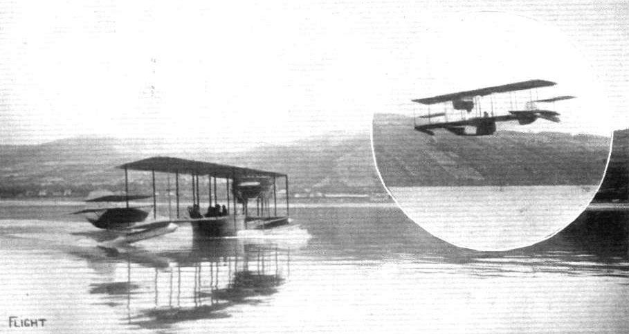
THE CURTISS FOUR-SEATER FLYING BOAT. - What is claimed to be the largest and heaviest hydro-aeroplane ever made has been recently tested on Lake Keuka, near Hammondsport, N.Y. The machine has been built for Mr. Harold F. McCormack by Mr. Glenn H. Curtiss, and follows the general design of his two-seater machine. The wings are of 40 ft. spread, and the machine is equipped with a 90-100 h.p. Curtiss engine. At the hands of Mr. Curtlss it showed a speed of 60 miles an hour along the water and over 60m.p.h. in the air!
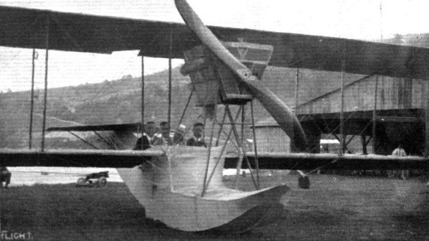
Another view of the four-seater Curtlss flying boat, showing the arrangement of the engine, &c., and the disposition of the seating accommodation.
Flight, July 5, 1913.
THE PIONEERS.
<...>
Another American pioneer was Prof. Montgomery, who designed and constructed some very successful tandem monoplane gliders in California. They were flown by Maloney, who was accustomed to ascend in a balloon in order to obtain the requisite initial altitude. The Montgomery gliders were designed for automatic stability, and apparently gave good results, for it was essentially an entanglement of the launching gear that ultimately caused Maloney's death.
<...>
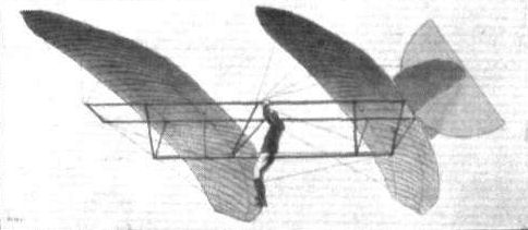
Montgomery's tandem monoplane glider piloted by Maloney. The experiments were made in California about 1905, and were noteworthy on account of the automatic stability of the machine as demonstrated by the fact that several successful glides were accomplished after preliminary ascents in a balloon.
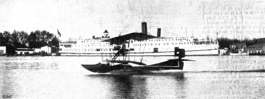
THE COLUMBIA FLYING BOAT FITTED WITH 80 H.P. GYRO MOTOR. - This American-built waterplane is said to get off the water in 200 ft. with a passenger.
Flight, July 5, 1913.
THE PIONEERS.
THIS is the tenth anniversary of the conquest of the air by the aeroplane, and it is appropriate that our special number should be made to commemorate the work of the pioneers, as well as other incidental facts, such as, for example, that FLIGHT itself is already in its fifth year of publication.
It was on December 17th, 1903, that the Wrights first achieved power-driven flight with their aeroplane (the first account of which in any English newspaper appeared in FLIGHT'S parent journal - the AUTO.), and prior to that day no man could claim properly to have flown at all. The most important work preceding this accomplishment of the Wrights was, unquestionably, the gliding experiments practised by themselves and by others, commencing with Lilienthal.
<...>
It was while reading the simple notice of Lilienthal's fatal accident that Wilbur Wright received his inspiration to study this branch of practical science, and from the first he obtained the whole-hearted co-operation of his brother, Orville. The story of their work has been told too often to need repeating. Lilienthal died in 1896, and thereupon the Wrights commenced their studies. They built their first glider in 1900; it was a biplane, constructed on the trussed-bridge principle introduced by Chanute, but it differed from the Chanute machine in several important respects. Among other things, it embodied the famous wing-warping control, and the pilot, being thereby relieved of the necessity for balancing the aeroplane by gymnastic exercise, was able to lie prone on the lower plane, and so reduce the resistance of his body to a minimum.
For three years the Wright brothers' experiments continued, sometimes in the open and sometimes in the laboratory. The longest glide that they made at any time measured 622 1/2 ft., and lasted 26 secs. The amount of time that they actually put in at this work was extraordinary: in a good season they were able to make between 700 and 1,000 flights, and once they made more than 375 flights in less than a week.
When at last they had brought their gliding experiments to such a pitch of perfection that they could not very well hope to gain much more experience along these lines, they decided to take the next and most important step of all, which was to build an engine-driven machine that would make them independent of the winds and of the contour of the ground.
<...>
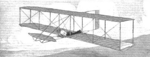
Sketch from a photograph of a Wright glider in ilight. - The first of these machines was built in 1900, and it had wing warping control. When first used the vertical rear plane was fixed, but later it became a pivoted rudder, and then the power-driven aeroplane was arranged for convenient simultaneous control with the warp.
Flight, July 5, 1913.
THE PIONEERS.
THIS is the tenth anniversary of the conquest of the air by the aeroplane, and it is appropriate that our special number should be made to commemorate the work of the pioneers, as well as other incidental facts, such as, for example, that FLIGHT itself is already in its fifth year of publication.
It was on December 17th, 1903, that the Wrights first achieved power-driven flight with their aeroplane (the first account of which in any English newspaper appeared in FLIGHT'S parent journal - the AUTO.), and prior to that day no man could claim properly to have flown at all. The most important work preceding this accomplishment of the Wrights was, unquestionably, the gliding experiments practised by themselves and by others, commencing with Lilienthal.
<...>
It was while reading the simple notice of Lilienthal's fatal accident that Wilbur Wright received his inspiration to study this branch of practical science, and from the first he obtained the whole-hearted co-operation of his brother, Orville. The story of their work has been told too often to need repeating. Lilienthal died in 1896, and thereupon the Wrights commenced their studies. They built their first glider in 1900; it was a biplane, constructed on the trussed-bridge principle introduced by Chanute, but it differed from the Chanute machine in several important respects. Among other things, it embodied the famous wing-warping control, and the pilot, being thereby relieved of the necessity for balancing the aeroplane by gymnastic exercise, was able to lie prone on the lower plane, and so reduce the resistance of his body to a minimum.
For three years the Wright brothers' experiments continued, sometimes in the open and sometimes in the laboratory. The longest glide that they made at any time measured 622 1/2 ft., and lasted 26 secs. The amount of time that they actually put in at this work was extraordinary: in a good season they were able to make between 700 and 1,000 flights, and once they made more than 375 flights in less than a week.
When at last they had brought their gliding experiments to such a pitch of perfection that they could not very well hope to gain much more experience along these lines, they decided to take the next and most important step of all, which was to build an engine-driven machine that would make them independent of the winds and of the contour of the ground.
Their chief difficulty was to find an engine. Although automobiles were already in fashion, and the high speed petrol engine had thus become the obvious type of prime mover to use, they were unable to find any motor suitable for their purpose on the market. Very characteristically, therefore, they set to work to design and construct one in their own workshops, and with this engine they equipped their new and larger aeroplane.
So carefully and so systematically had they worked throughout that the culminating success of their endeavours came almost as a matter of course. On December 23rd, 1903, they succeeded in making four free flights, rising from level ground against the wind. In the following year many more successful flights were accomplished, and by the end of 1905 they had flown journeys exceeding 30 miles in length and lasting over half an hour in duration. By this time also they had so far improved the control of their machine that they felt justified in introducing it to the public. For the time being, therefore, they ceased their experiments in order that they might devote their time to laying the foundations of a commercial enterprise.
Very few people either appreciated or really realised what the Wright brothers had done, for they invited no publicity and most of their achievements were, in fact, unseen. It was, therefore, in France during the year 1907 that the new art first publicly attracted the notice of the man in the street.
Henry Farman and Leon Delagrange were the central figures of this period in the history of aviation, and it is curious, but none the less a fact, that no one at that time gave much thought or credit to the Voisin brothers who had designed and constructed the machines that these pilots were using.
<...>
Wilbur Wright came to France in the autumn of 1908, and it was then that his accomplishments were first recognised by the world at large. Of his flying on that occasion the French press could not find words of too great praise, and as one of the foremost of the French experimenters then remarked, compared with the ability of Wilbur Wright the pilots in France simply did not exist.
<...>
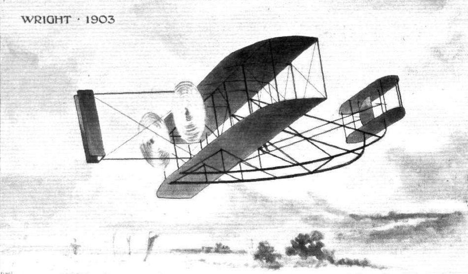
Sketch from a photograph of an early Wright biplane. - The Wrights built their first successful power-driven machine in 1903, and first flew on December 17th of that year. By the end of 1905 they had flown several single journeys exceeding 20 miles in length.
Flight, May 3, 1913.
FOREIGN AVIATION NEWS.
Fatal Accidents.
Two accidents which ended fatally, occurred at Johannisthal on the 24th ult. The first occurred to a Wright biplane, which was being piloted by Princess Schakowskaja, with her instructor Abramovitch as passenger. While the machine was about 30 ft. from the ground, the Princess apparently tried to make it rise too steeply with the result that it capsized. The pilot sustained slight injuries, while Abramovitch was so badly hurt that he succumbed during the night. About a quarter of an hour after this accident another Russian pilot, Dunetz, was making a very steep vol pique, when at a height of about 250 metres the wings of his monoplane collapsed, and he was killed on the spot. On the 22nd the monoplane of Lieut. Eblers fell from a height of 40 metres at the Doeberitz camp and the pilot was instantly killed.
Flight, July 26, 1913.
WHY PILOTS SHOULD USE THE "STRING."
THOSE who have watched Beatty evoluting at Hendon on the Wright biplane with the Gyro engine have probably provided themselves with a variety of reasons to account for the nonchalance with which this American pilot justifies his countrymen's contention that he is "some banker."
Some may say - to the obvious benefit of the Company whose representatives have adopted this very practical method of calling attention to the Gyro engine - that it is all due to the motor, which probably develops about three times as much power as the machine requires for the purposes of straightforward flight. Others, with commendable respect for the genius of the greatest, no less than the first, of the pioneers, may say that it is all in the Wright biplane. Others again may give Beatty himself some little credit for the performance - or frankly fear that he is on his way to "collect it," according to their point of view.
But very few, probably, have given any credit to the little piece of string that Beatty, in common with all Wright pilots, carries on the crossbar between the blinkers of his machine.
We honestly believe that if "the string" were as universally employed as it should be by pilots that it would do more, in proportion to its intrinsic value, for the safety of flying than any other thing that it is possible to conceive.
Wright pilots invariably use "the string." No matter how experienced they may become, they still continue to use it.
Mr. Alec Ogilvie, the most accomplished of Wright pilots in England, uses it on his machine at Eastchurch. Mr. Beatty is using it at Hendon, and it is the secret of the nonchalance with which he performs his banks.
The purpose of the string is to act as a warning of sideslip. So long as the string flies out good and straight parallel to the blinkers on his machine, Beatty knows that he has an axial relative wind. He is certain, in short, that his machine is not side-slipping either inwards or outwards.
So long as he keeps the string parallel with the blinkers he cannot overbank. No matter how much he may appear to be overbanking, the fact remains that he is safe so long as the string tells him that he is so. Were he to overbank, his machine would immediately sideslip like any other machine; and the relative wind, in coming obliquely across the machine in consequence, would blow the string sideways.
Now the pilot who has no string as a guide has to rely solely on his own discretion, which is the slow product of experience grafted upon a personal sensitiveness that characterises different people in varying degree. As a rule, the majority of pilots underbank when turning, that is to say they sideslip outwards more or less. As far as is known, there is no particular danger about side-slipping outwards and so the majority of pilots are on the safe side in thus manoeuvring.
"Flying is a game of cards at which you only have one deal," as a pilot of great experience, and equal caution expressed it to us recently, and a man who overbanks his machine once may not have the opportunity of profiting by his experience. It is, therefore, something to be avoided, and so only those who have built up a very considerable confidence are ordinarily to be seen performing banked turns anywhere approaching the limit of what is possible and also safe. For the inexperienced to do what Beatty does without the guidance of the string would be to court disaster, notwithstanding all that may be said in favour of the Gyro engine and of the Wright machine. Nevertheless, we feel equally firmly convinced that by the guidance of the string any thoroughly qualified pilot might with comparative safety quickly learn to achieve what Beatty performs so easily and so well.
Let it, of course, always be understood that a banked turn of any description tilts the wing pressure at an angle, and so deprives the aeroplane of a part of its support. Unless, therefore, the engine has a great deal of surplus power that can be brought into use at this moment the machine must descend while turning.
The string gives instant warning of this.
If the reserve power is sufficient to enable the machine to continue turning on its own level it suffices to bank the machine while flying horizontally and without previously tilting its nose down. But, on any machine that is not thus adequately engined, it is essential to put the machine into a descending attitude before the bank is commenced.
If a piece of paper such as a foolscap envelope be held in the hand so as to represent the wings of an aeroplane in flight, the difference between banking first and dipping with the elevator afterwards, compared with dipping first and banking afterwards, is self-evident at a glance.
If it is one's object to avoid sideslip in flying - and there can be no question that this is the safer principle of progress - then one's object in control must be always so to manoeuvre the machine that it tends naturally to follow an axial path through the relative wind. Having accepted this idea as a guiding principle, the point of immediate importance is to have a reliable indicator, which, if one accepts the evidence of the Wrights and all their pupils, is already available in "the string."
Hitherto, we have not discussed the string and its possibilities for fear of leading astray those who might be flying other types of machines, notably of course those with a tractor screw. Quite recently, however, we have been informed by Eng. Lieut. E. F. Briggs, R.N., of the Naval Wing of the R.F.C., that he has tried the string on a tractor monoplane and that it seems to answer its purpose thoroughly. If this is so then we most strongly advise all other pilots to start using the string and to find out for themselves whether or no it does not tend to inspire them with increased confidence. When such experienced pilots as Mr. Alec Ogilvie and Mr. Beatty are not ashamed to be seen with it on their machines, no one else need presume to suggest that it appertains to the days of "the apron."
Besides the string, one thing else is needed materially to increase the safety of flying, and we never cease to be amazed that so many pilots continue to fly without it.
We refer, of course, to the air speed indicator, which tells the pilot his velocity through the relative wind. Flying takes place in the atmosphere, the motion relative to the ground is incidental and of no consequence to the aerodynamic principles involved. Every machine has a proper flying speed at which it will fly horizontally in the attitude for which it was designed. The range of speeds above and below the normal are acquired by tilting the machine out of its proper attitude under the influence of the continuous action of the elevator.
Experienced pilots with a good ear for their engine, generally know more or less when they are flying at the proper speed under power, but there are a good many who do not know all the same, and even the experienced pilots are very often at a loss to judge the proper speed while gliding.
Just as the majority of pilots underbank at the turn, so do they come down over steeply in the descent. If they worked by the air speed meter they could descend by a glide with the same precision that they fly horizontally. Also, they would be able repeatedly to make their climbs under the best conditions, because having once determined by experiment the speed at which the particular machine was able to climb most rapidly, they would in future merely pull away at the elevator until the machine was brought down to that speed, and under those conditions they would continue to climb as long as they desired.
Air speed meters are already on the market and there is no excuse whatever for not fitting them. The pilots of the Royal Aircraft Factory carry out all their experimental flying by the aid of an air speed meter and they would never think seriously of flying a machine without one. The instrument in question which was designed at the R.A.F. - but which is not therefore necessarily useless, in spite of popular prejudice against factory products - is manufactured and sold by the well-known instrument makers, Messrs. Elliott Bros.
Another form of air speed meter is the Eteve, for which the Aircraft Manufacturing Company hold the English rights. In fitting it, one flies one's machine horizontally at its normal speed and notes the position of the indicator. On alighting, the instrument is adjusted until the red mark on the scale is coincident with the position occupied by the needle in flight. Whenever the machine is going through the air at the speed that it was flown during the preliminary tests, the needle will stand on the red mark. Whenever the machine increases its speed the needle will move in one direction, and whenever it decreases its speed it will move in the other direction.
It does not matter whether the pilot is gliding or flying straight, he is always able to tell at a glance whether he has his proper air speed or not. In short, the air speed meter gives him, just as the string gives him, a readymade knowledge that he might not satisfactorily acquire during a whole lifetime as a pilot.
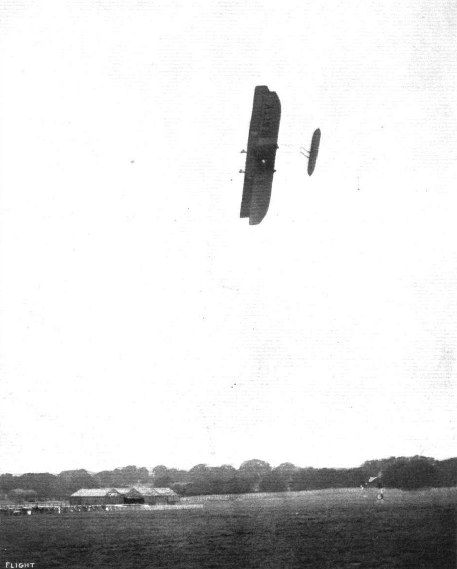
A "plan view" from beneath of Beatty, on his Wright, during one of his banked turns at Hendon.
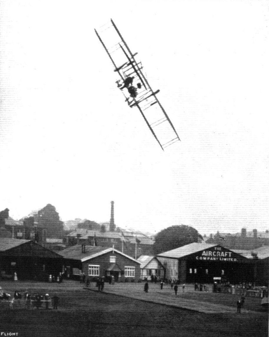
Mr. Beatty making one of his banked turns on his Wright over the sheds at Hendon.
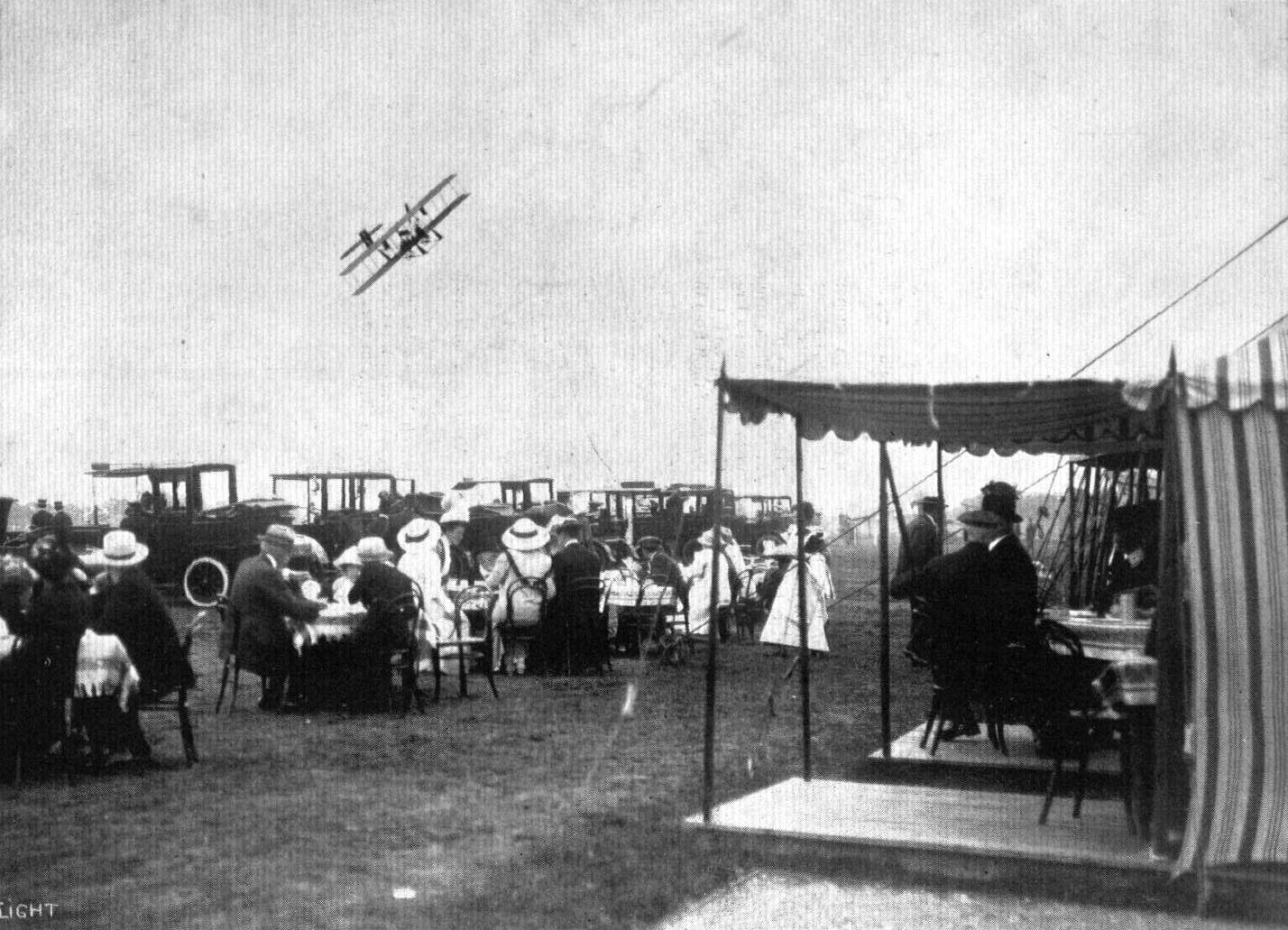
TEA AT HENDON AERODROME WHILST WATCHING THE FLYING. - In the air is Beatty descending on his Wright machine.

What terra firma looks like from an aeroplane with a 45 deg. bank on. From a photograph by C. M. Vought, when flying in a Lillie-Wright at Cicero, Ill., U.S.A.

Mr. Beatty's Wright biplane, with Gyro motor, at Hendon.
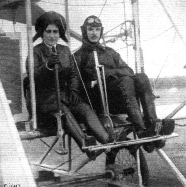
Abramovitch, the famous Russian aviator, and Princess Schakowskaja, who, on a German-built Wright biplane, last week met with an accident at Johannisthal, Abramovitch being so badly injured that he afterwards succumbed. Princess Schakowskaja herself, also a well-known pilot and a pupil of Abramovitch, was at the time acting as pilot. She was not seriously hurt.

Captain Tyrer, who probably holds the record for passenger flights in various aeroplanes, starting for a flight at Hendon with Mr. Beatty in his Wright flyer. Note the position of the Gyro motor.

Sketches illustrating the position of the string as used on the Wright biplane, and as it can be used on a tractor monoplane. A piece of worsted about 12 ins. in length will serve the purpose.
Flight, September 6, 1913.
THE MODEL "C.H." WRIGHT WATERPLANE.
IN the United States the development, of the waterplane has followed somewhat different lines from those pursued over here, owing, no doubt, mainly to the geographical differences between the two countries. A waterplane intended for use on inland lakes and rivers, or even "creeks," as the smaller rivers in the States are called, should obviously be differently designed from one whose field of operation is the coast or open sea. Whilst in this country and on the continent waterplanes with single floats are comparatively few, this type of craft seems to be the more popular in America.
The waterplane illustrated in this issue has been designed for use on small lakes, and is of special interest on account of the fact that it has been evolved at the Wright works, at Dayton, Ohio. With the exception of a few alterations this machine is exactly similar to the well-known standard-type Wright biplane. Two alterations will be noticed at once on inspection of the accompanying scale drawings, i.e. the extension of the rudders above the tail booms and the new position of the blinkers, which, in the standard-type machine are of triangular shape, and placed between the skid and the front down corner strut. Both alterations have doubtless been made with a view to neutralising the effect of the side area of the float. This member, it will be seen, is of comparatively great width, and is of the plain or non-stepped type. Great care has been exercised in determining the shape of the float, and the result has evidently repaid the time and money spent in evolving it, for we are told that it gets off the water in 10 secs., a performance which is little short of marvellous, but it must be admitted that it was under the expert handling of Mr. Orville Wright that this was achieved, a fact which no doubt was contributory to the excellent "get-off."
That the machine not only is quick in rising but also a good weight carrier is proved by the fact that on one occasion Mr. Wright carried three passengers besides a considerable amount of fuel, so that the load earned must have been in the vicinity of 800 lbs. The test flights were made on the Miami River, which is very narrow, and on both sides the banks are very high and covered with trees, so that it will be understood that it was by no means an ideal place for testing a new machine. Mr. Wright, however, was of the opinion that it represented the average conditions that would have to be met if the machine is to be of any use for the purpose for which it was designed - the navigation of small lakes and shallow streams, inaccessible for other types of aircraft.
The weight of the machine empty is 920 lbs. without the float, the weight of which is 240 lbs. The power plant consists of one of the new Wright 6-cyl. 60 h.p. water-cooled engines, driving through a chain and sprocket reduction gear two propellers of 8 ft. 6 in. diameter.

Two views of the new Wright hydro-biplane on the Miami River, Orville Wright being seen in the pilot's seat.
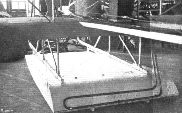
The float of the new 60 h.p. Wright hydro-biplane
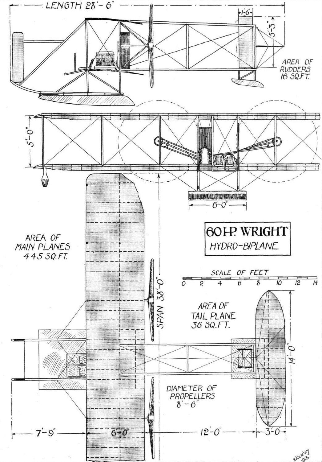
THE 60 H.P. WRIGHT HYDRO-BIPLANE. - Plan, side and front elevations to scale.
Flight, July 5, 1913.
THE PIONEERS.
<...>
The earlier history of aviation in France include the names of Penaud, who may be said to be the inventor of the model aeroplane, for he was the first to employ an elastic motor in 1871. Tatin was one of the first to experiment with power-driven models in 1879, when he used compressed air. Ader, the famous electrical engineer, whose name is identified with telephones, built three steam-driven monoplanes of curious bat-like form, but his success was apparently of the same order as that of Maxim. His machines were constructed almost entirely of hollow spars, and were exceptionally light for their size.
<...>
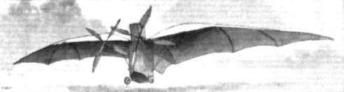
Ader's Avion, a steam-driven bat-like monoplane built by the famous electrical engineer, and tried in 1897. It is said to have lifted itself off the ground for a brief period during a test in the presence of the French Army authorities.
HYDRO-AEROPLANES. - Fig. 5. - Types of Aeroplanes.
Flight, May 3, 1913.
REFLECTIONS ON THE MONACO MEETING.
Astra.
The Cie. Generate Transaerienne are responsible for the construction of the Astra hydro-biplanes, which are of the tractor type. Those entered for the Monaco competition had Canton-Unne engines, but other machines of this make were also present with 12-cyl. Renault engines. It appears that the design of these machines has recently been modified and a new wing section introduced. The earlier successful types had a wing section corresponding to that of the Wright biplane. The present machines have flat bottomed floats rigidly attached to the lower planes by tubular steel struts of circular section.
Flight, December 13, 1913.
THE STANDS AT THE PARIS AERO SHOW.
BATHIAT-SANCHEZ.
Two machines are exhibited on the Bathiat-Sanchez stand; one is the monoplane on which Lieut. Morel made a tour of France, and the other is an all-steel biplane of the "pusher" type which, with a 70 h.p. Renault engine, has attained a speed of 102 kiloms. per hour, and climbed to an altitude of 1,000 metres in 14 mins.
Flight, December 27, 1913.
THE PARIS AERO SALON - 1913.
BATHIAT-SANCHEZ.
<...>
The biplane exhibited by this firm is on more original lines, and belongs, as will be seen from the accompanying illustrations, to the "pusher" type. It is driven by a 70 h.p. Renault engine, mounted on two transverse steel tubes resting in lugs on the upper longerons of the nacelle. As usual, the propeller is mounted on the cam-shaft, and is thus running at half engine speed. The tanks are mounted inside the nacelle in front of the engine, while well out in front are arranged the pilot's and passengers' seats. Accommodation has been provided for pilot and two passengers, the pilot occupying the front single seat, while the passengers' seats are situated side by side just behind the pilot. The controls are of the usual type, consisting of a single lever working the ailerons and elevator, while a pivoted foot-bar actuates the rudder. Just behind the passengers' seats is fitted a starting handle, by means of which the engine may be started without any necessity of swinging the propeller. The main planes, of which the upper one has a slightly larger span than the lower one, are connected by steel tube struts of streamline section; the main spars are also steel tubes, over which are built the ribs, which are constructed of ash. Carried on the rear extremities of an outrigger of somewhat complicated construction are the tail planes, which consist of a single rectangular balanced elevator and two divided rudders, whilst no fixed tail plane is fitted. The tail booms, which are steel tubes, appear to be unnecessarily complicated, and the cross-wiring employed to provide the necessary rigidity would appear to offer quite a lot of head resistance.
The chassis, which is of somewhat unusual type, consists of two main wheels mounted on stub axles and sprung by rubber shock absorbers, while under the nose of the nacelle and supported on another structure of steel tubes, are two smaller wheels. A very stout wooden skid connects the axles of the two pairs of wheels, and terminates at the back in a down-swept heel which takes the place of the ordinary tail-skid. The accompanying illustrations will, we think, explain all the details of the chassis. One point to which we wish to call attention, is the fitting of band brakes to the two main wheels. These brakes are operated by means of a lever on the right hand side of the pilot's seat. For starting the machine the pilot applies the brakes by pulling the lever backwards, and when his engine is running satisfactorily he releases the lever, and the machine starts. The workmanship in both machines is very good, but the biplane, built as it is of steel practically throughout, gives the impression of being rather heavy, although it is said to have attained, with a 70 h.p. Renault engine, a speed of 102 kilometres per hour, and to have climbed to an altitude of 1,000 metres in 14 minutes.

Nacelle and chassis of the Bathiat-Sanchez biplane.
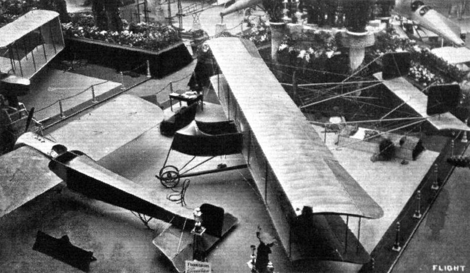
The Bathiat-Sanchez stand at the Paris Salon.
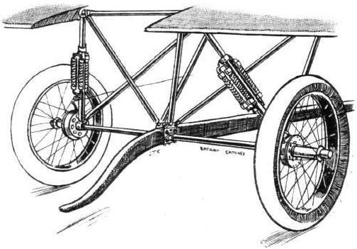
Rear portion of the Sanchez-Besa chassis.
Flight, December 13, 1913.
THE STANDS AT THE PARIS AERO SHOW.
BATHIAT-SANCHEZ.
Two machines are exhibited on the Bathiat-Sanchez stand; one is the monoplane on which Lieut. Morel made a tour of France, and the other is an all-steel biplane of the "pusher" type which, with a 70 h.p. Renault engine, has attained a speed of 102 kiloms. per hour, and climbed to an altitude of 1,000 metres in 14 mins.
Flight, December 27, 1913.
THE PARIS AERO SALON - 1913.
BATHIAT-SANCHEZ.
The Bathiat-Sanchez firm are showing two machines, a monoplane of quite orthodox type and a biplane on somewhat original lines. The monoplane is similar to the one flown by Lieut. Morel on his tour of France. It is fitted with a 7-cylinder 60 h.p. Le Rhone engine, mounted on overhung bearings in the nose of the fuselage. This structure, which is of rectangular section, is built up in the usual way of four longerons of ash, connected with struts and cross-members of spruce, and diagonal cross wiring. The chassis is of a very simple type, consisting of two pairs of ash struts carrying two short skids, from which is slung the single tubular axle carrying the wheels. The main planes, which are set at a slight dihedral angle, are hinged to the fuselage by longitudinal bolts passing through the inner ends of the main spars.
Inside the fuselage, and almost on line with the trailing edge of the wings, is the pilot's seat. In front of him is a small dash, fitted with the usual instruments for cross-country work. The controls consist of a single tubular lever, which works the warp and elevator, whilst a pivoted foot-bar operates the rudder. In order to provide the pilot with a better view of the ground underneath, the trailing edges of the wings have been cut away in the proximity of the fuselage.
Underneath the rear portion of the fuselage are mounted the tail planes, which are somewhat reminiscent of the Bleriot, and consist of a fixed cambered plane, to the trailing edge of which is hinged the elevator. The rudder is pivoted around the stern post of the fuselage.. Some distance in front of the tail planes is a small skid, which protects the tail planes against contact with the ground.
<...>
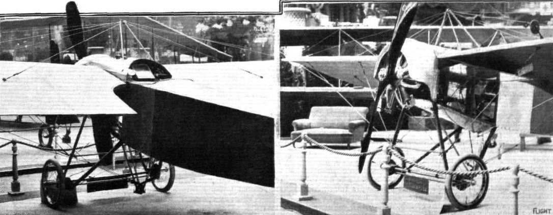
THE BATHIAT-SANCHEZ MONOPLANE. - On the fight the chassis and engine mounting.
The Bathiat-Sanchez stand at the Paris Salon.
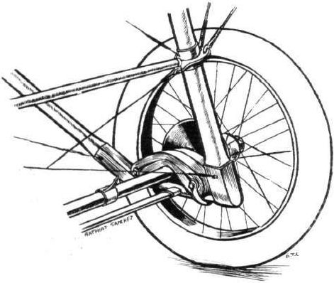
DETAIL OF THE SPRINGING OF THE BATHIAT-SANCHEZ MONOPLANE.
Flight, August 30, 1913.
FROM THE BRITISH FLYING GROUNDS.
A Bleriot built by an Amateur.
MR. VINCENT FILL and his 35 h.p. Anzani-Bleriot type monoplane are seen in our photographs on page 957. This machine has been entirely built by Mr. Fill in his spare time as a pupil at the Eastbourne Aviation Co's flying grounds. Although assisted by the foreman, all the work was practically done by himself. The machine flies well and Mr. Fowler has himself been up on it for some time. The whole work has been thoroughly well carried out, and does great credit to its constructor, who took his ticket on an E.A.C. biplane about three weeks ago, and he is now learning to fly the machine of his own building.

Mr. Vincent Fill and the Anzani-Bleriot built by himself.
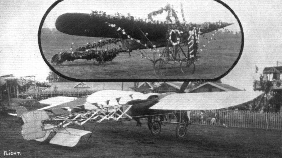
THE AERIAL FETE AT HENDON. - A couple of the decorated aeroplanes. Above, Mr. Cheeseman's Blerlot which secured first prize, and, below, Mr. J. L. Hall's Bleriot.

AERIAL FETE AT HENDON. - Mrs. Cecil Baker, Lady Levinge, Mrs. and Miss Grahame-White, who assisted in the decoration of the winning aeroplane.
Flight, February 1, 1913.
FOREIGN AVIATION NEWS.
Across the Pyrenees,
WHILE most people were wondering when Bielovucic would attempt to cross the Alps, a young Swiss aviator - Oscar Bider - was quietly training at Pau with the object of flying across the Pyrenees to Madrid. The Pyrenees had been crossed several times, notably by Vedrines, Gibert and Garros in the Paris-Madrid race of 1911, but they had all gone over the eastern side. On the 24th ult., Bider mounted his Bleriot monoplane at the Bleriot ground at Pont Long, Pau, and at 7.19 a.m. was officially started. After rising to a good height he steered for Arudy and followed the Ossau Valley past Laruns and the peak of Midi d'Ossau, which is about 9,000 ft. high. He then kept the railway in sight past Jaca, Huesca, Sarragosa, and then through the Ebre Valley to Catalayna. After nearly 5 hrs. of strenuous flying and finding his petrol supply getting very low, Bider decided to land at Guadalajara, which is about 50 kiloms from Madrid. He was there welcomed by Col. Yives, y Vichy, who has done so much to forward aviation in Spain, and other Spanish officers and after a brief rest of half an hour or so he restarted for the Spanish capital where he landed safely at the Four Winds Aerodrome at 1.30 p.m. The Bleriot machine, which was fitted with a 70-h.p. Gnome motor and Kegy propeller, behaved splendidly throughout the trip. It is not without interest to note that on January 24th, 1906, Ferdinand Duro accomplished what seven years ago was considered a very noteworthy feat by crossing the Pyrenees in a balloon.
Flight, February 8, 1913.
WHAT THERE WILL BE TO SEE AT OLYMPIA.
THE MACHINES.
Bleriot.
This well-known firm will be represented at the Show by their latest model, a two-sealer tandem monoplane, fitted with an 80-h.p. Gnome motor. As far as its general appearance is concerned, it will be almost identical with the 70-h.p. Bleriot two-seaters that have been flown with such success in England by Hamel and Hucks. However, being equipped with an engine of higher horse-power, there will necessarily be minor constructional modifications. This new two-seater, termed type XI 2, has proved a great success on the Continent, and the Bleriot works have in band, for various governments and private customers, orders for 30 of them. This monoplane is 27 ft. in length, and its wings span 31 ft. and have an area of 198 sq. ft. Its weight is approximately 800 lbs,, and it has been timed to do 75 miles per hour.
In addition, several photographs will be shown on the stand illustrating the Bleriot firm's latest types of machine. These will portray the new 80-h.p. armoured monocoque, with its cleverly constructed body of cork, paper, and fabric, the canard, on which Perryon has been doing some most surprising stunt flying at Buc of late, anew hydro-monoplane, and the latest type Bleriot side-by-side passenger carrier.
Flight, February 22, 1913.
SOME MORE AEROPLANES AT OLYMPIA.
L. BLERIOT.
A very fine sample of an 80-h.p. Two-seater Bleriot Monoplane is exhibited on their stand. To all intents and purposes the machine may be described as a 50-h.p. Gnome single-seater Bleriot, enlarged up and provided with accommodation to carry a passenger. It has, as well, some few detail alterations that are not present in the 50-h.p. model. Some thirty of these machines are at the present time being put through the Bleriot works at Levallois Perret, for delivery to foreign governments and private customers.
The body. - The chief point of difference that the body has, as compared with the 70-h.p two-seater Bleriot flown in this country by Hucks, is that the tail skid is sprung from the lower member of the fuselage instead of the upper. This change has been made on account of its having been found that the old method of springing was inclined to put too much strain on the body framework. The passenger, who sits behind the pilot, has a perfect view below the machine for his seat is arranged about 2 ft. behind the trailing edges of the wings, while these latter are cut away on either side of the body so as to further improve the view. It may not be generally thought so, but it is nevertheless a fact, the accuracy of which is vouched for by one who has on many occasions flown as a passenger on one of these machines, that the occupant behind obtains quite a good view, as well, over the top of the wings. A seat is provided for the pilot well forward in the body, in such a position that he can practically look down vertically over the leading edge. In front of him, beneath the motor cowl, the tanks are mounted; the oil tank on the left, that for petrol on the right. There is also an auxiliary petrol tank arranged behind the pilot, which feeds the petrol to the service tank in front, under pressure provided by a small hand pump on the right of the pilot. Among the various instruments in front of him is a new mechanical engine speed indicator, of Bleriot design. This is a very important improvement, as hitherto Bleriot has fitted most of his machines with an electric speed indicator which cannot be said to have always proved as reliable as it should be. The classical form of Bleriot cloche control is fitted to this machine. It will be remembered that in our last issue we gave particulars of a new 80-h.p. Bleriot military monoplane in which the cloche control had been suppressed, and its place taken by a vertical hand wheel, mounted on a rocking column. We have heard that the alteration of the control on this latter machine has merely been done by way of experiment. The cloche has proved itself to be such a convenient form of control that Bleriot will probably never depart from it.
The wings span 31 feet, and have a supporting area of 198 sq. ft. In their construction I-section ash spars are used, the ribs of spruce being also of the same section, but built up. They are braced on the underside by two stranded steel cables to each front spar, and by heavy gauge piano wire to each rear spar.
All the cable attachments are designed so that they may be dismantled quickly without interfering with the adjustments. As an illustration of this, we might mention that the machine shown at Olympia came direct from Paris, where it was erected and trued up before being dismantled, packed and dispatched. On its arrival at Olympia, the wings were assembled, the tail unit boiled in its place, and the whole machine got into flying trim without touching a single adjustment, by two Bleriot pilots, Mr. Robert Slack and M. Turod to wit, in under half an hour. And it must be remembered that the circumstances were such that there was no necessity for them to pat themselves about to get the operation completed in record time.
The landing gear is of the usual Bleriot type, with the innovation that now there is fitted a stranded steel cable along the edges of the bottom chassis plank. This cable has been fitted to help take the tension in this bottom plank that is caused by the wing slay cables being fitted to either end of it. There is an improvement also in the design of the spindle of the landing wheels, so that these latter may be readily detachable. By taking out one split pin the spindle may be unscrewed from the bearings on either side of the wheel, and quickly removed, allowing the wheel to drop free.
Flight, April 5, 1913.
REBUILDING A BLERIOT.
APART from the establishments of the leading manufacturers, there are a number of well-equipped workshops up and down the country where quite useful work in connection with aeroplanes is being carried on. For instance, at his flying headquarters at Foryd, Abergele, N. Wales, Mr. Vivian Hewitt has established a fine workshop, which includes a power lathe, shaper, drill and grindstone, and a large assortment of tools, while three mechanics are employed. Electric light is produced on the spot, there are arrangements for re-magnetising magnetos, and a nickel-plating plant. After his trip across the Irish Sea, Mr. Hewitt decided to completely dismantle his Bleriot monoplane and rebuild it, incorporating during the process some ideas of his own. The result is seen in the accompanying photos, and Mr. Hewitt tells us that two of his mechanics have been engaged on the work during the past five months. The only original part of the framework of the machine is the landing chassis, the engine, and the four longitudinal members of the fuselage. Complete, the machine, in its latest form weighs about 35 lbs. more than it did originally. Regarding the alterations which have been carried out, Mr. Hewitt says :-
"The wings each weigh 10 lbs. more than Bleriot's wings, and are fitted with a wooden leading edge instead of a piece of aluminium bent round. The ribs are all slightly thicker, and the wings altogether stronger all round. The front spar and rear spar are fitted with four plates each instead of two. It is impossible for air to enter the wing, where the plates come through the fabric, as small pieces of wood are fastened to the spars inside the wings and the fabric is nailed to these. A piece of cane runs along each ribs over the fabric instead of only as far as the radius of the propeller. Round the tube that the front spar of the wings fits into extra steel brackets have been fitted, thus strengthening it up.
"The cabaine is slightly thicker gauge steel tube, and there is no piece of wood let in at the top. Instead the whole is brazed together, having previously been cut out of steel and carefully fitted. There are four steel warping wheels for the top bracing wires to work on, and the bolt for the four front wires is hall as thick again as in the original machine. The cabane is stayed across near the bottom to take any strain off the fuselage. It is braced from the top to the fuselage by eight wires instead of four.
"The ribbons for staying the underside of the wines are belled out at the ends where tin steel clips are riveted to them, thus obtaining uniform strength throughout. There are four ribbons to each wing.
"The bottom planche has a strong steel ribbon, suitably drilled out, for lightness, running from one end to the other, and connected to the ribbon brackets. The planche is made of hickory.
"The bottom cabane which takes the warping gear is braced together by cross tubes, as can be seen in the photograph. There are also two steel ribbons from one side to the other of the fuselage where the warping cabane bolts on, thus taking up the tendency to push the fuselage members out when climbing. The warping bracket, which was originally aluminium, is now steel machined out of the solid and brazed into the tubes. There are four warping wires instead of two to the wings, and these pass round steel wheels. The wires from the cloche to the warping arm are double the thickness of those originally used.
"The cloche has four steel arms running from the top to the bottom of the bell to which the control wires are attached, so that even should they (the control wires) break from the aluminium the steel arms still hold them. As the arms are all cut out of a single piece of sheet steel, and the whole slipped over the cloche, it is impossible for these to come adrift.
"The fuselage has had light steel plates fitted between it and the distance pieces of the fuselage, thereby making the cross bracing less liable to give, and also preventing the distance pieces from splitting at the bottom.
"The floor has had four pieces of wood screwed on the underneath side, making it less liable to split.
"The elevating tail has stronger tubes to stay it to the fuselage, and the fuselage is stayed from one side to the other where these are bolted on, thus taking the strain off the cross-bracing to a certain extent.
"The body is composed of aluminium, left bright and finished off with copper rivets. It tapers off behind the pilot's seat to a tail. Doors are fitted on each side of it for cleaning the tanks, &c, and the shield over the engine leads into it, as can be seen clearly in the photograph. In every direction accessibility has been aimed at, and it is interesting to note that the doors and engine shields can be taken off in two minutes. In the photographs the aluminium looks as if it were dented. This is not so, as it is only the reflection of the sun.
"A release clip is fitted to the skid and stayed to the fuselage.
"The ribbons are painted white, and also all the wires. The rest of the machine is painted a deep fast red, which shows up very well with the aluminium. All the wires were boiled in soda and water, in case of rust, and before being painted were coated with two coats of red lead."
Flight, April 26, 1913.
HAMEL FLIES FROM DOVER TO COLOGNE.
AMONG the many extraordinary flights which have been accomplished, certainly not the least epoch-making, inasmuch as it was the first flight from England to Germany, was that made by Mr. Gustav Hamel last week, with a passenger, from Dover to Cologne. Starting from the Dover Aerodrome (accompanied by Mr. F. Dupree, of the staff of the Standard, by whom the arrangements for the flight had been made), he left Dover at 12.40 p.m. Making his way across the Channel, the French coast was picked up just south of Dunkirk, and then a course was set by the aid of the compass for Mechlin. Across Belgium and Holland the military Bleriot sped its way, but the storms which had to be passed through put the pilot out a little in his reckoning, and when the Rhine was sighted it was at a point about 60 miles north of Cologne. This deviation lengthened the journey considerably, but Cologne was safely reached at 4.58 p.m., and on alighting the English travellers were courteously received by the German officers. The duration of the flight was 4 hrs. 18 mins., and the distance as the crow flies from point to point is 245 miles. In view of the deviation, Mr. Hamel estimates the distance covered at 320 miles. Altogether, Mr. Hamel passed over five countries.
The Bleriot monoplane which was used was fitted with an 80-h.p. Gnome motor, which, by the way, was equipped with the famous F. and S. ball-bearings. The fuel used was Shell spirit, of which forty gallons were carried, and there was sufficient left at the journey's end to cover another 100 miles, a distance which would have taken the aviator well out of the German Empire. For lubrication purposes Wakefield "Castrol" was used.
The Machine for New Zealand.
HAMEL'S great flight from Dover to Cologne was arranged by the Standard in conjunction with the Imperial Air Fleet Committee, of which Lord Desborough is President, and on the conclusion of the flight the aeroplane was offered to and accepted by the New Zealand Government. A fund has now been opened with the object of paying for the machine, the cost of which has been in the meantime guaranteed by the Standard and Messrs. Wm. Coward and Co., Ltd.
Flight, July 5, 1913.
FLYING AT HENDON.
LAST week was a very busy one at Hendon, for, besides the usual week-end meeting, Wednesday and Thursday were special days. Except that a high wind on Wednesday and Saturday somewhat upset the arrangements, good shows were nevertheless put up on each day. Wednesday's meeting, which was organised by the Institut Francais de Londres, was announced as a combined automobile and aeroplane affair. The part cast for the automobiles consisted of a procession of florally decorated cars, starting from Connaught Square and passing Marble Arch House (the offices of the Institut) where they were inspected by President Poincare. The cars were then to make their way to the Hendon aerodrome - a part of the programme which somehow went astray so far as any procession was concerned. Prizes were given for the best decorated cars, which were arranged in several classes, the prizes being presented by Princesse de Wrede. A prize of ten pounds each was also given to the best decorated monoplane and biplane. Several aeroplanes embellished with flowers and flags lined up in front of the enclosure, and looked, if somewhat unusual, smart. The winners were, E. Cheeseman's 35 h.p. Bleriot monoplane, and Louis Noel's Grahame-White biplane, both of which were simply smothered with flowers - needless to say, they did not fly in this rig-out. J. L. Hall's 50 h.p. Bleriot was effectively decorated, the planes having diagonal ribbons of red, white, and blue, whilst the British and French flags also played an important part in the scheme. During the afternoon Hall made a straight flight across the aerodrome on his decorated machine, but did not attempt a circuit. Jules Nardini's Deperdussin monoplane was patriotically decorated with the Italian flags. Some of the cars looked very pretty, but taking it on the ensemble it was rather disappointing. Two of the winners, M. Guillat's Wolseley car and Mr. George Grossmith's Austin (theatrical section) were quite the prettiest there. The former car was decked with blue cornflowers, red geraniums, and white carnations, with the British and French flags made up of flowers. The colour scheme of the latter car was blue only.
<...>
Flight, September 20, 1913.
THE AERIAL DERBY.
PILOTS AND HOW TO RECOGNISE THE MACHINES.
No. 4. The 50 h.p. Bleriot Monoplane.
This machine may be recognised by its rounded wing tips. Another characteristic feature is that the fuselage or body is only covered with fabric up to a point a short distance behind the trailing edge of the wings, the rear portion of it being left uncovered.
No. 6. The Two-seater Bleriot Monoplane.
This machine differs very little from the smaller single-seater Bleriot, but may be identified - apart from its number, which will be painted in large letters underneath the wings - by the passenger, who can be seen a short distance behind the planes. It is also of slightly larger dimensions than the single-seater machine of the same make.
No. 7. The Two-seater Bleriot Monoplane.
Similar to No. 6.
THE MACHINES, WITH SOME DETAILS.
No. 4. The 50 h.p. Gnome-Bleriot monoplane is far too well known to need much description here. It is one of the most popular of all monoplanes, and has the characteristic Bleriot landing chassis - one of the safest and most ingenious landing gears ever devised.
The flying properties o! these machines have been proved on more occasions than could be numbered, while the exploits of the intrepid M. Pegoud on a similar 'bus form a most eloquent testimony to their stability and reliability. There is no provision for a passenger in this model.
Nos. 6 and 7. The 80 h.p. Bleriot two-seater monoplane is very similar to the 50 h.p. model, as is to be expected. The passenger's seat is situated immediately behind the trailing edge of the planes, while the oil and petrol tanks are found between the pilot and passenger. The wings span 31 ft., and have a suppoiting surface of 198 square feet.
Flight, October 4, 1913.
PEGOUD AND HIS FLIGHT.
IN no country of the world could Pegoud have been certain of three such gloriously fine days as Thursday, Friday and Saturday of last week. Everyone who went to Brooklands to see his marvellous flights had ideal conditions, and if they failed to deem the occasion worthy of inscription as a red-letter day for all time to come, then certainly they will never experience one in all their lives.
Pegoud's flying is simple phenomenal. Seen in the proper spirit, it is one of the most encouraging demonstrations that aviation has yet made. When we first heard of Pegoud and his upside down flights, we not unnaturally regarded it more in the light of a sensational stunt than anything else. Having seen his actual performance, however, we are of the opinion that it is the most scientific flying exhibition that has ever been made.
Eliminating all question of the man himself and his remarkable nerve, his exploits in the air demonstrate on a practical scale the whole of the fundamental theory of aeroplane design. Given a well-designed aeroplane, with a tendency to assume a natural head-first gliding attitude, and it is a safe machine so long as it remains intact, and the pilot remains on board. Even when upside down he still controls it. Even when brought to a standstill in the air, it will still, in due course, recover a controllable position. These qualities appertain to the machine; the wonderful part about the man is that he has the nerve to sit still while they are in process.
To see Pegoud do the tail slide is a sight that no one can possibly forget. He drives his machine up into the air steeper and steeper until it just stands on its tail and stops dead. Then there is that moment of suspense, which is so utterly horrible to those who have witnessed an impromptu performance of this character by a beginner. The machine slides down partially backwards and partially sideways. In the ordinary way it is the beginning of the end for the unhappy pilot. To Pegoud it is nothing alarming. He sits calmly in his seat, and he brings the machine round on to a level keel as if nothing has happened.
It is, of course, essential that Pegoud should have sufficient altitude for his operations. He loses an immense height between the start and the finish of all his evolutions; in some of them we estimated that he must have been descending at the rate of about 500 feet a minute, which is far faster than an express lift as operated in America, although it is not so fast as men are sometimes sent down the shaft of a mine.
When we described Pegoud's evolutions last week, we based the descriptions, as we explained, on information given to us by M. Norbert Chereau, M. Bleriot's representative in London, but one of the diagrams was incorrect in showing the pilot on the outside of the circle whilst looping the loop. In all the experiments of this kind at Brooklands, Pegoud looped the loop with himself on the inside of the circle. It is not that Pegoud would in the least object to being on the outside of the circle, for so far as he is concerned there is hardly any conceivable position in which he would feel inconvenienced. But, an interesting question arises as to whether it is possible to loop the loop with an aeroplane in which a pilot is on the outside of the circle. The wing surfaces in their inverted position are, of course, far less effective than in their proper position, and although they suffice when thus inverted to sustain flight in the form of a steep glide, which is what Pegoud's upside down flying amounts to, it is questionable whether they could be made to force the machine over the loop.
Pegoud himself has said that he cannot roll his machine upside down from a position in which he is originally right way up, the point being, presumably, that the direction of the acting force is governed by the camber of the wing, and is always in such a direction as to prevent a complete rolling over. He can roll over into what is practically a vertical bank, from which position he can slide into a vertical dive, and when thus vertical he can turn over on to his back as he does in the first experiment.
When on his back he remains there frequently for over a minute at a time, so that everyone has an excellent opportunity of thoroughly appreciating the fact that he is really upside down. There is absolutely no doubt about the position. We watched one such flight lying prone on the grass, and looking at the machine through field glasses. The aeroplane was directly overhead, and the pilot's cap became the focus in the line of sight. He was absolutely vertically upside down, and flying fast, in what in that position seemed to be a horizontal path, but which in reality must have been a steep glide.
Pegoud practises two modes of recovery from such a position. Either he uses his elevator so as to make another vertical dive, from which he flattens out in the ordinary way, or else he rolls over by the aid of the warp. This latter manoeuvre is the most extraordinary of all. It is also quite the most difficult to follow, for unless one watches it very closely indeed it is difficult to realise that he has actually changed his position into one that is right way up.
It will be observed that although he cannot roll over from right way up to upside down, he can do the other thing, and it is done so amazingly quickly that before most people on the ground have realised that anything has happened, Pegoud is flying towards them in a normal attitude, and for several seconds most of the spectators are under the impression that he must be still in his inverted position. It is, in short, an almost indescribable manoeuvre, which needs to be seen in order to be appreciated.
None of the diagrams that we published last week in the least gives any idea of what actually takes place. In a diagram one is limited to a line drawn on the plane of the paper, and with the exception of the simple upside down flight, not one of the manoeuvres is thus confined to a single plane of operations.
In looping the loop, which Pegoud did some four times in succession on Saturday, the machine comes almost to a standstill at the top of the circle, or that is how it appears to be to the spectators. So much confidence does Pegoud inspire, however, that instead of having one's heart in one's mouth at such a critical moment one is perfectly content to know that it will be all the same whether the machine completes the circle or just tumbles down backwards. In short, in the four manoeuvres that Pegoud carries out, he covers practically all the possible contingencies in which a pilot might accidently find himself, either through the mismanagement of his machine or excessively severe weather conditions.
So calmly and so perfectly does Pegoud handle his machine, that his amazing flights are almost devoid of sensationalism. Viewed through field glasses, which obscure the general environment, Pegoud's flights look almost commonplace. True, his machine is upside down, but what of that? It goes through the air so easily and so gracefully that it is impossible to get up any excitement over the mere fact of its inverted position. Viewed as a whole by the naked eye, however, the spectacle presented by Pegoud's performances is quite the most wonderful thing that ever has been done in the air, and it is quite capable of impressing one in this sense.
The moral of it all is, firstly, the fundamental importance of flying at a sufficient altitude to be able to recover in safety. Apart from that, there is the fundamental necessity for keeping calm, and for being so secured in the machine as to be capable of retaining control of it in any conceivable position that it may assume. It seemed to us that Pegoud's successful and quick recovery from his terrifying positions depended far more on his nerve in letting the machine take care of itself, than in what he did personally in the way of control.
There is very little doubt that many disasters have taken place through pilots having locked their machine into some awkward position through holding the control in the wrong place. Pegoud never jerked his machine in any of his manoeuvres. Every action was dignified, slow and graceful. He never appeared to force the machine to do anything, and even in the tail slide, when the aeroplane had to all intents and purposes been tossed up like a pancake to come down whichever way it might, there still remained about the whole affair that same easy assurance and absence of effort.
And now, if Pegoud wants to do a real service to aviation, he should sit down and try and describe in detail exactly what he does with his control lever, so that pilots may have something definite to work upon.
Flight, October 11, 1913.
FOREIGN AVIATION NEWS.
Latest Pegoud Developments.
FRESH from his success at Brooklands, Pegoud reappeared at Buc, on Wednesday of last week, and demonstrated some developments of his upside-down flying. Taking his Bleriot to a height of about 800 metres he turned it over and, with the motor still running, flew in that attitude for 59 secs., the machine steering as easily, apparently, as if it had been the right way up. When the machine had glided to within about 500 metres of the earth he turned over again and dived steeply. He then climbed again to a height of 1,200 metres, from which he looped the loop five times in succession, this manoeuvre bringing him to within about 100 metres of the ground, causing some little anxiety to the spectators. Making the machine climb 400 metres, Pegoud did another three loops, keeping his motor running all the time, and remounting once more to a good height, he finished the display by bringing the machine down in a series of very short spirals, the monoplane appearing to be standing vertically on one wing tip at times, while the pilot took his hands off the controls. On Sunday, Pegoud tried to carry out some tests with a two-seater Bleriot, with the passenger seat filled with a sack of ballast. When he dived to loop the loop, however, the machine did not turn over until it had dropped about 400 metres, and then the movement was slow and clumsy. Still Pegoud succeeded in getting it over and back to its normal flying position, when he was able to return by a spiral vol plane to the ground. Later he was up on his ordinary machine, and looped the loop six times in succession.
Flight, November 29, 1913.
B. C. HUCKS LOOPS THE LOOP AT HENDON.
ON Thursday afternoon B. C. Hucks, the first British pilot to carry out the manoeuvre in England, gave a "private view" demonstration of looping the loop, and those who witnessed the performance could not have been otherwise than impressed by the magnificent display of airmanship. In the first place, the loops were perfectly formed loops, and secondly they were done comparatively low down - between 1,500 and 2,000 ft. - a procedure a little unexpected to those of us who saw Pegoud, at Brcoklands, perform similar feats at a height of 3,000-4,000 ft., whilst a finishing touch of eerieness was given to the whole display by these feats being executed for the most part in the clouds. Shortly after noon Hucks brought out his 50-h.p. Gnome-Bleriot - a magnificent machine possessing M. Bleriot's latest and, perhaps, best workmanship - and went up for a trial flight, which, to the alarm of all present, terminated in a forced landing in a field just on the other side of the railway embankment. Fortunately the only damage done was a small hole torn in the bottom of the tail-plane by a hedge, and a safe return to the aerodrome was made shortly after. The tail having been repaired, Hucks again took his seat, and having been safely "tucked in" by his energetic manager, J. C. Savage, and his mechanic, he started off to show us how an Englishman can perform those feats originated by Pegoud. There was not very much wind - 15-20 m.p.h. - but the sky was obscured by low-lying clouds. After making about three circuits of the aerodrome, climbing rapidly to a height of 2,000 ft., and disappearing from time to time in the clouds, we saw him dive suddenly, and then describe a complete loop, the wheels remaining outside the circle. The loop was in the form of a perfect circle, and there was but a momentary pause when the machine was on its back, and when the normal position was regained, one could not notice any appreciable decrease in height. After flying level for a short distance he repeated this manoeuvre behind a thin film of cloud. Another short flight and he disappeared through a cloud, to reappear shortly after upside down, i.e., halfway through the loop. During this time he had dropped only a very short distance, and was just above the paddock and No. 2 pylon. He then proceeded to fly towards the centre of the aerodrome, where he looped the loop three times in quick succession. The first two appeared to be made in the same spot, although, of course, he must have dropped and drifted somewhat, and during the third loop he received a severe bump - due, he told us afterwards, to the backwash from the previous loop ! - which caused the last loop to be made somewhat lower, and at a different angle to the other two. After this last loop he made a very steeply banked spiral, and finally landed by way of a spiral vol plane. He received an enthusiastic reception, for it was one of the most skilful and neatest, not to say beautiful, aeroplane displays ever given in this country.
Flight, December 13, 1913.
THE STANDS AT THE PARIS AERO SHOW.
BLERIOT.
On the Bleriot stand are shown no less than six machines and fuselages of various types, and when one considers that there are at the Salon two more Bleriot stands - one for aeroplanes and one for bateaux glisseur - one begins to realise the activity of this well-known firm.
One of the machines shown belongs to the type XI class, which is already so well known, and which is still among the first of French aeroplanes although it was evolved four years ago. A complete machine of the tandem two-seater type XI-2 is also exhibited, and, although it is to all intents and purposes the same as those seen in England during the past year, its presence at the Salon is amply justified by the amount of good work this type has done in the French and various other military services. Of novel type Bleriots there are three examples, one type fuselage coque, one hydro-monoplane and a "pusher" type biplane.
<...>
Flight, December 20, 1913.
THE PARIS AERO SALON - 1913.
BLERIOT.
THE Bleriot exhibit is certainly the largest at the Show and one of the most interesting, consisting as it does of no less than six machines and fuselages. One of these is the well-known type XI, and the other the equally well-known tandem two-seater, of which we need give no description here, as they are already known to our readers.
<...>
FOREIGN AVIATION NEWS.
Across the Pyrenees,
WHILE most people were wondering when Bielovucic would attempt to cross the Alps, a young Swiss aviator - Oscar Bider - was quietly training at Pau with the object of flying across the Pyrenees to Madrid. The Pyrenees had been crossed several times, notably by Vedrines, Gibert and Garros in the Paris-Madrid race of 1911, but they had all gone over the eastern side. On the 24th ult., Bider mounted his Bleriot monoplane at the Bleriot ground at Pont Long, Pau, and at 7.19 a.m. was officially started. After rising to a good height he steered for Arudy and followed the Ossau Valley past Laruns and the peak of Midi d'Ossau, which is about 9,000 ft. high. He then kept the railway in sight past Jaca, Huesca, Sarragosa, and then through the Ebre Valley to Catalayna. After nearly 5 hrs. of strenuous flying and finding his petrol supply getting very low, Bider decided to land at Guadalajara, which is about 50 kiloms from Madrid. He was there welcomed by Col. Yives, y Vichy, who has done so much to forward aviation in Spain, and other Spanish officers and after a brief rest of half an hour or so he restarted for the Spanish capital where he landed safely at the Four Winds Aerodrome at 1.30 p.m. The Bleriot machine, which was fitted with a 70-h.p. Gnome motor and Kegy propeller, behaved splendidly throughout the trip. It is not without interest to note that on January 24th, 1906, Ferdinand Duro accomplished what seven years ago was considered a very noteworthy feat by crossing the Pyrenees in a balloon.
Flight, February 8, 1913.
WHAT THERE WILL BE TO SEE AT OLYMPIA.
THE MACHINES.
Bleriot.
This well-known firm will be represented at the Show by their latest model, a two-sealer tandem monoplane, fitted with an 80-h.p. Gnome motor. As far as its general appearance is concerned, it will be almost identical with the 70-h.p. Bleriot two-seaters that have been flown with such success in England by Hamel and Hucks. However, being equipped with an engine of higher horse-power, there will necessarily be minor constructional modifications. This new two-seater, termed type XI 2, has proved a great success on the Continent, and the Bleriot works have in band, for various governments and private customers, orders for 30 of them. This monoplane is 27 ft. in length, and its wings span 31 ft. and have an area of 198 sq. ft. Its weight is approximately 800 lbs,, and it has been timed to do 75 miles per hour.
In addition, several photographs will be shown on the stand illustrating the Bleriot firm's latest types of machine. These will portray the new 80-h.p. armoured monocoque, with its cleverly constructed body of cork, paper, and fabric, the canard, on which Perryon has been doing some most surprising stunt flying at Buc of late, anew hydro-monoplane, and the latest type Bleriot side-by-side passenger carrier.
Flight, February 22, 1913.
SOME MORE AEROPLANES AT OLYMPIA.
L. BLERIOT.
A very fine sample of an 80-h.p. Two-seater Bleriot Monoplane is exhibited on their stand. To all intents and purposes the machine may be described as a 50-h.p. Gnome single-seater Bleriot, enlarged up and provided with accommodation to carry a passenger. It has, as well, some few detail alterations that are not present in the 50-h.p. model. Some thirty of these machines are at the present time being put through the Bleriot works at Levallois Perret, for delivery to foreign governments and private customers.
The body. - The chief point of difference that the body has, as compared with the 70-h.p two-seater Bleriot flown in this country by Hucks, is that the tail skid is sprung from the lower member of the fuselage instead of the upper. This change has been made on account of its having been found that the old method of springing was inclined to put too much strain on the body framework. The passenger, who sits behind the pilot, has a perfect view below the machine for his seat is arranged about 2 ft. behind the trailing edges of the wings, while these latter are cut away on either side of the body so as to further improve the view. It may not be generally thought so, but it is nevertheless a fact, the accuracy of which is vouched for by one who has on many occasions flown as a passenger on one of these machines, that the occupant behind obtains quite a good view, as well, over the top of the wings. A seat is provided for the pilot well forward in the body, in such a position that he can practically look down vertically over the leading edge. In front of him, beneath the motor cowl, the tanks are mounted; the oil tank on the left, that for petrol on the right. There is also an auxiliary petrol tank arranged behind the pilot, which feeds the petrol to the service tank in front, under pressure provided by a small hand pump on the right of the pilot. Among the various instruments in front of him is a new mechanical engine speed indicator, of Bleriot design. This is a very important improvement, as hitherto Bleriot has fitted most of his machines with an electric speed indicator which cannot be said to have always proved as reliable as it should be. The classical form of Bleriot cloche control is fitted to this machine. It will be remembered that in our last issue we gave particulars of a new 80-h.p. Bleriot military monoplane in which the cloche control had been suppressed, and its place taken by a vertical hand wheel, mounted on a rocking column. We have heard that the alteration of the control on this latter machine has merely been done by way of experiment. The cloche has proved itself to be such a convenient form of control that Bleriot will probably never depart from it.
The wings span 31 feet, and have a supporting area of 198 sq. ft. In their construction I-section ash spars are used, the ribs of spruce being also of the same section, but built up. They are braced on the underside by two stranded steel cables to each front spar, and by heavy gauge piano wire to each rear spar.
All the cable attachments are designed so that they may be dismantled quickly without interfering with the adjustments. As an illustration of this, we might mention that the machine shown at Olympia came direct from Paris, where it was erected and trued up before being dismantled, packed and dispatched. On its arrival at Olympia, the wings were assembled, the tail unit boiled in its place, and the whole machine got into flying trim without touching a single adjustment, by two Bleriot pilots, Mr. Robert Slack and M. Turod to wit, in under half an hour. And it must be remembered that the circumstances were such that there was no necessity for them to pat themselves about to get the operation completed in record time.
The landing gear is of the usual Bleriot type, with the innovation that now there is fitted a stranded steel cable along the edges of the bottom chassis plank. This cable has been fitted to help take the tension in this bottom plank that is caused by the wing slay cables being fitted to either end of it. There is an improvement also in the design of the spindle of the landing wheels, so that these latter may be readily detachable. By taking out one split pin the spindle may be unscrewed from the bearings on either side of the wheel, and quickly removed, allowing the wheel to drop free.
Flight, April 5, 1913.
REBUILDING A BLERIOT.
APART from the establishments of the leading manufacturers, there are a number of well-equipped workshops up and down the country where quite useful work in connection with aeroplanes is being carried on. For instance, at his flying headquarters at Foryd, Abergele, N. Wales, Mr. Vivian Hewitt has established a fine workshop, which includes a power lathe, shaper, drill and grindstone, and a large assortment of tools, while three mechanics are employed. Electric light is produced on the spot, there are arrangements for re-magnetising magnetos, and a nickel-plating plant. After his trip across the Irish Sea, Mr. Hewitt decided to completely dismantle his Bleriot monoplane and rebuild it, incorporating during the process some ideas of his own. The result is seen in the accompanying photos, and Mr. Hewitt tells us that two of his mechanics have been engaged on the work during the past five months. The only original part of the framework of the machine is the landing chassis, the engine, and the four longitudinal members of the fuselage. Complete, the machine, in its latest form weighs about 35 lbs. more than it did originally. Regarding the alterations which have been carried out, Mr. Hewitt says :-
"The wings each weigh 10 lbs. more than Bleriot's wings, and are fitted with a wooden leading edge instead of a piece of aluminium bent round. The ribs are all slightly thicker, and the wings altogether stronger all round. The front spar and rear spar are fitted with four plates each instead of two. It is impossible for air to enter the wing, where the plates come through the fabric, as small pieces of wood are fastened to the spars inside the wings and the fabric is nailed to these. A piece of cane runs along each ribs over the fabric instead of only as far as the radius of the propeller. Round the tube that the front spar of the wings fits into extra steel brackets have been fitted, thus strengthening it up.
"The cabaine is slightly thicker gauge steel tube, and there is no piece of wood let in at the top. Instead the whole is brazed together, having previously been cut out of steel and carefully fitted. There are four steel warping wheels for the top bracing wires to work on, and the bolt for the four front wires is hall as thick again as in the original machine. The cabane is stayed across near the bottom to take any strain off the fuselage. It is braced from the top to the fuselage by eight wires instead of four.
"The ribbons for staying the underside of the wines are belled out at the ends where tin steel clips are riveted to them, thus obtaining uniform strength throughout. There are four ribbons to each wing.
"The bottom planche has a strong steel ribbon, suitably drilled out, for lightness, running from one end to the other, and connected to the ribbon brackets. The planche is made of hickory.
"The bottom cabane which takes the warping gear is braced together by cross tubes, as can be seen in the photograph. There are also two steel ribbons from one side to the other of the fuselage where the warping cabane bolts on, thus taking up the tendency to push the fuselage members out when climbing. The warping bracket, which was originally aluminium, is now steel machined out of the solid and brazed into the tubes. There are four warping wires instead of two to the wings, and these pass round steel wheels. The wires from the cloche to the warping arm are double the thickness of those originally used.
"The cloche has four steel arms running from the top to the bottom of the bell to which the control wires are attached, so that even should they (the control wires) break from the aluminium the steel arms still hold them. As the arms are all cut out of a single piece of sheet steel, and the whole slipped over the cloche, it is impossible for these to come adrift.
"The fuselage has had light steel plates fitted between it and the distance pieces of the fuselage, thereby making the cross bracing less liable to give, and also preventing the distance pieces from splitting at the bottom.
"The floor has had four pieces of wood screwed on the underneath side, making it less liable to split.
"The elevating tail has stronger tubes to stay it to the fuselage, and the fuselage is stayed from one side to the other where these are bolted on, thus taking the strain off the cross-bracing to a certain extent.
"The body is composed of aluminium, left bright and finished off with copper rivets. It tapers off behind the pilot's seat to a tail. Doors are fitted on each side of it for cleaning the tanks, &c, and the shield over the engine leads into it, as can be seen clearly in the photograph. In every direction accessibility has been aimed at, and it is interesting to note that the doors and engine shields can be taken off in two minutes. In the photographs the aluminium looks as if it were dented. This is not so, as it is only the reflection of the sun.
"A release clip is fitted to the skid and stayed to the fuselage.
"The ribbons are painted white, and also all the wires. The rest of the machine is painted a deep fast red, which shows up very well with the aluminium. All the wires were boiled in soda and water, in case of rust, and before being painted were coated with two coats of red lead."
Flight, April 26, 1913.
HAMEL FLIES FROM DOVER TO COLOGNE.
AMONG the many extraordinary flights which have been accomplished, certainly not the least epoch-making, inasmuch as it was the first flight from England to Germany, was that made by Mr. Gustav Hamel last week, with a passenger, from Dover to Cologne. Starting from the Dover Aerodrome (accompanied by Mr. F. Dupree, of the staff of the Standard, by whom the arrangements for the flight had been made), he left Dover at 12.40 p.m. Making his way across the Channel, the French coast was picked up just south of Dunkirk, and then a course was set by the aid of the compass for Mechlin. Across Belgium and Holland the military Bleriot sped its way, but the storms which had to be passed through put the pilot out a little in his reckoning, and when the Rhine was sighted it was at a point about 60 miles north of Cologne. This deviation lengthened the journey considerably, but Cologne was safely reached at 4.58 p.m., and on alighting the English travellers were courteously received by the German officers. The duration of the flight was 4 hrs. 18 mins., and the distance as the crow flies from point to point is 245 miles. In view of the deviation, Mr. Hamel estimates the distance covered at 320 miles. Altogether, Mr. Hamel passed over five countries.
The Bleriot monoplane which was used was fitted with an 80-h.p. Gnome motor, which, by the way, was equipped with the famous F. and S. ball-bearings. The fuel used was Shell spirit, of which forty gallons were carried, and there was sufficient left at the journey's end to cover another 100 miles, a distance which would have taken the aviator well out of the German Empire. For lubrication purposes Wakefield "Castrol" was used.
The Machine for New Zealand.
HAMEL'S great flight from Dover to Cologne was arranged by the Standard in conjunction with the Imperial Air Fleet Committee, of which Lord Desborough is President, and on the conclusion of the flight the aeroplane was offered to and accepted by the New Zealand Government. A fund has now been opened with the object of paying for the machine, the cost of which has been in the meantime guaranteed by the Standard and Messrs. Wm. Coward and Co., Ltd.
Flight, July 5, 1913.
FLYING AT HENDON.
LAST week was a very busy one at Hendon, for, besides the usual week-end meeting, Wednesday and Thursday were special days. Except that a high wind on Wednesday and Saturday somewhat upset the arrangements, good shows were nevertheless put up on each day. Wednesday's meeting, which was organised by the Institut Francais de Londres, was announced as a combined automobile and aeroplane affair. The part cast for the automobiles consisted of a procession of florally decorated cars, starting from Connaught Square and passing Marble Arch House (the offices of the Institut) where they were inspected by President Poincare. The cars were then to make their way to the Hendon aerodrome - a part of the programme which somehow went astray so far as any procession was concerned. Prizes were given for the best decorated cars, which were arranged in several classes, the prizes being presented by Princesse de Wrede. A prize of ten pounds each was also given to the best decorated monoplane and biplane. Several aeroplanes embellished with flowers and flags lined up in front of the enclosure, and looked, if somewhat unusual, smart. The winners were, E. Cheeseman's 35 h.p. Bleriot monoplane, and Louis Noel's Grahame-White biplane, both of which were simply smothered with flowers - needless to say, they did not fly in this rig-out. J. L. Hall's 50 h.p. Bleriot was effectively decorated, the planes having diagonal ribbons of red, white, and blue, whilst the British and French flags also played an important part in the scheme. During the afternoon Hall made a straight flight across the aerodrome on his decorated machine, but did not attempt a circuit. Jules Nardini's Deperdussin monoplane was patriotically decorated with the Italian flags. Some of the cars looked very pretty, but taking it on the ensemble it was rather disappointing. Two of the winners, M. Guillat's Wolseley car and Mr. George Grossmith's Austin (theatrical section) were quite the prettiest there. The former car was decked with blue cornflowers, red geraniums, and white carnations, with the British and French flags made up of flowers. The colour scheme of the latter car was blue only.
<...>
Flight, September 20, 1913.
THE AERIAL DERBY.
PILOTS AND HOW TO RECOGNISE THE MACHINES.
No. 4. The 50 h.p. Bleriot Monoplane.
This machine may be recognised by its rounded wing tips. Another characteristic feature is that the fuselage or body is only covered with fabric up to a point a short distance behind the trailing edge of the wings, the rear portion of it being left uncovered.
No. 6. The Two-seater Bleriot Monoplane.
This machine differs very little from the smaller single-seater Bleriot, but may be identified - apart from its number, which will be painted in large letters underneath the wings - by the passenger, who can be seen a short distance behind the planes. It is also of slightly larger dimensions than the single-seater machine of the same make.
No. 7. The Two-seater Bleriot Monoplane.
Similar to No. 6.
THE MACHINES, WITH SOME DETAILS.
No. 4. The 50 h.p. Gnome-Bleriot monoplane is far too well known to need much description here. It is one of the most popular of all monoplanes, and has the characteristic Bleriot landing chassis - one of the safest and most ingenious landing gears ever devised.
The flying properties o! these machines have been proved on more occasions than could be numbered, while the exploits of the intrepid M. Pegoud on a similar 'bus form a most eloquent testimony to their stability and reliability. There is no provision for a passenger in this model.
Nos. 6 and 7. The 80 h.p. Bleriot two-seater monoplane is very similar to the 50 h.p. model, as is to be expected. The passenger's seat is situated immediately behind the trailing edge of the planes, while the oil and petrol tanks are found between the pilot and passenger. The wings span 31 ft., and have a suppoiting surface of 198 square feet.
Flight, October 4, 1913.
PEGOUD AND HIS FLIGHT.
IN no country of the world could Pegoud have been certain of three such gloriously fine days as Thursday, Friday and Saturday of last week. Everyone who went to Brooklands to see his marvellous flights had ideal conditions, and if they failed to deem the occasion worthy of inscription as a red-letter day for all time to come, then certainly they will never experience one in all their lives.
Pegoud's flying is simple phenomenal. Seen in the proper spirit, it is one of the most encouraging demonstrations that aviation has yet made. When we first heard of Pegoud and his upside down flights, we not unnaturally regarded it more in the light of a sensational stunt than anything else. Having seen his actual performance, however, we are of the opinion that it is the most scientific flying exhibition that has ever been made.
Eliminating all question of the man himself and his remarkable nerve, his exploits in the air demonstrate on a practical scale the whole of the fundamental theory of aeroplane design. Given a well-designed aeroplane, with a tendency to assume a natural head-first gliding attitude, and it is a safe machine so long as it remains intact, and the pilot remains on board. Even when upside down he still controls it. Even when brought to a standstill in the air, it will still, in due course, recover a controllable position. These qualities appertain to the machine; the wonderful part about the man is that he has the nerve to sit still while they are in process.
To see Pegoud do the tail slide is a sight that no one can possibly forget. He drives his machine up into the air steeper and steeper until it just stands on its tail and stops dead. Then there is that moment of suspense, which is so utterly horrible to those who have witnessed an impromptu performance of this character by a beginner. The machine slides down partially backwards and partially sideways. In the ordinary way it is the beginning of the end for the unhappy pilot. To Pegoud it is nothing alarming. He sits calmly in his seat, and he brings the machine round on to a level keel as if nothing has happened.
It is, of course, essential that Pegoud should have sufficient altitude for his operations. He loses an immense height between the start and the finish of all his evolutions; in some of them we estimated that he must have been descending at the rate of about 500 feet a minute, which is far faster than an express lift as operated in America, although it is not so fast as men are sometimes sent down the shaft of a mine.
When we described Pegoud's evolutions last week, we based the descriptions, as we explained, on information given to us by M. Norbert Chereau, M. Bleriot's representative in London, but one of the diagrams was incorrect in showing the pilot on the outside of the circle whilst looping the loop. In all the experiments of this kind at Brooklands, Pegoud looped the loop with himself on the inside of the circle. It is not that Pegoud would in the least object to being on the outside of the circle, for so far as he is concerned there is hardly any conceivable position in which he would feel inconvenienced. But, an interesting question arises as to whether it is possible to loop the loop with an aeroplane in which a pilot is on the outside of the circle. The wing surfaces in their inverted position are, of course, far less effective than in their proper position, and although they suffice when thus inverted to sustain flight in the form of a steep glide, which is what Pegoud's upside down flying amounts to, it is questionable whether they could be made to force the machine over the loop.
Pegoud himself has said that he cannot roll his machine upside down from a position in which he is originally right way up, the point being, presumably, that the direction of the acting force is governed by the camber of the wing, and is always in such a direction as to prevent a complete rolling over. He can roll over into what is practically a vertical bank, from which position he can slide into a vertical dive, and when thus vertical he can turn over on to his back as he does in the first experiment.
When on his back he remains there frequently for over a minute at a time, so that everyone has an excellent opportunity of thoroughly appreciating the fact that he is really upside down. There is absolutely no doubt about the position. We watched one such flight lying prone on the grass, and looking at the machine through field glasses. The aeroplane was directly overhead, and the pilot's cap became the focus in the line of sight. He was absolutely vertically upside down, and flying fast, in what in that position seemed to be a horizontal path, but which in reality must have been a steep glide.
Pegoud practises two modes of recovery from such a position. Either he uses his elevator so as to make another vertical dive, from which he flattens out in the ordinary way, or else he rolls over by the aid of the warp. This latter manoeuvre is the most extraordinary of all. It is also quite the most difficult to follow, for unless one watches it very closely indeed it is difficult to realise that he has actually changed his position into one that is right way up.
It will be observed that although he cannot roll over from right way up to upside down, he can do the other thing, and it is done so amazingly quickly that before most people on the ground have realised that anything has happened, Pegoud is flying towards them in a normal attitude, and for several seconds most of the spectators are under the impression that he must be still in his inverted position. It is, in short, an almost indescribable manoeuvre, which needs to be seen in order to be appreciated.
None of the diagrams that we published last week in the least gives any idea of what actually takes place. In a diagram one is limited to a line drawn on the plane of the paper, and with the exception of the simple upside down flight, not one of the manoeuvres is thus confined to a single plane of operations.
In looping the loop, which Pegoud did some four times in succession on Saturday, the machine comes almost to a standstill at the top of the circle, or that is how it appears to be to the spectators. So much confidence does Pegoud inspire, however, that instead of having one's heart in one's mouth at such a critical moment one is perfectly content to know that it will be all the same whether the machine completes the circle or just tumbles down backwards. In short, in the four manoeuvres that Pegoud carries out, he covers practically all the possible contingencies in which a pilot might accidently find himself, either through the mismanagement of his machine or excessively severe weather conditions.
So calmly and so perfectly does Pegoud handle his machine, that his amazing flights are almost devoid of sensationalism. Viewed through field glasses, which obscure the general environment, Pegoud's flights look almost commonplace. True, his machine is upside down, but what of that? It goes through the air so easily and so gracefully that it is impossible to get up any excitement over the mere fact of its inverted position. Viewed as a whole by the naked eye, however, the spectacle presented by Pegoud's performances is quite the most wonderful thing that ever has been done in the air, and it is quite capable of impressing one in this sense.
The moral of it all is, firstly, the fundamental importance of flying at a sufficient altitude to be able to recover in safety. Apart from that, there is the fundamental necessity for keeping calm, and for being so secured in the machine as to be capable of retaining control of it in any conceivable position that it may assume. It seemed to us that Pegoud's successful and quick recovery from his terrifying positions depended far more on his nerve in letting the machine take care of itself, than in what he did personally in the way of control.
There is very little doubt that many disasters have taken place through pilots having locked their machine into some awkward position through holding the control in the wrong place. Pegoud never jerked his machine in any of his manoeuvres. Every action was dignified, slow and graceful. He never appeared to force the machine to do anything, and even in the tail slide, when the aeroplane had to all intents and purposes been tossed up like a pancake to come down whichever way it might, there still remained about the whole affair that same easy assurance and absence of effort.
And now, if Pegoud wants to do a real service to aviation, he should sit down and try and describe in detail exactly what he does with his control lever, so that pilots may have something definite to work upon.
Flight, October 11, 1913.
FOREIGN AVIATION NEWS.
Latest Pegoud Developments.
FRESH from his success at Brooklands, Pegoud reappeared at Buc, on Wednesday of last week, and demonstrated some developments of his upside-down flying. Taking his Bleriot to a height of about 800 metres he turned it over and, with the motor still running, flew in that attitude for 59 secs., the machine steering as easily, apparently, as if it had been the right way up. When the machine had glided to within about 500 metres of the earth he turned over again and dived steeply. He then climbed again to a height of 1,200 metres, from which he looped the loop five times in succession, this manoeuvre bringing him to within about 100 metres of the ground, causing some little anxiety to the spectators. Making the machine climb 400 metres, Pegoud did another three loops, keeping his motor running all the time, and remounting once more to a good height, he finished the display by bringing the machine down in a series of very short spirals, the monoplane appearing to be standing vertically on one wing tip at times, while the pilot took his hands off the controls. On Sunday, Pegoud tried to carry out some tests with a two-seater Bleriot, with the passenger seat filled with a sack of ballast. When he dived to loop the loop, however, the machine did not turn over until it had dropped about 400 metres, and then the movement was slow and clumsy. Still Pegoud succeeded in getting it over and back to its normal flying position, when he was able to return by a spiral vol plane to the ground. Later he was up on his ordinary machine, and looped the loop six times in succession.
Flight, November 29, 1913.
B. C. HUCKS LOOPS THE LOOP AT HENDON.
ON Thursday afternoon B. C. Hucks, the first British pilot to carry out the manoeuvre in England, gave a "private view" demonstration of looping the loop, and those who witnessed the performance could not have been otherwise than impressed by the magnificent display of airmanship. In the first place, the loops were perfectly formed loops, and secondly they were done comparatively low down - between 1,500 and 2,000 ft. - a procedure a little unexpected to those of us who saw Pegoud, at Brcoklands, perform similar feats at a height of 3,000-4,000 ft., whilst a finishing touch of eerieness was given to the whole display by these feats being executed for the most part in the clouds. Shortly after noon Hucks brought out his 50-h.p. Gnome-Bleriot - a magnificent machine possessing M. Bleriot's latest and, perhaps, best workmanship - and went up for a trial flight, which, to the alarm of all present, terminated in a forced landing in a field just on the other side of the railway embankment. Fortunately the only damage done was a small hole torn in the bottom of the tail-plane by a hedge, and a safe return to the aerodrome was made shortly after. The tail having been repaired, Hucks again took his seat, and having been safely "tucked in" by his energetic manager, J. C. Savage, and his mechanic, he started off to show us how an Englishman can perform those feats originated by Pegoud. There was not very much wind - 15-20 m.p.h. - but the sky was obscured by low-lying clouds. After making about three circuits of the aerodrome, climbing rapidly to a height of 2,000 ft., and disappearing from time to time in the clouds, we saw him dive suddenly, and then describe a complete loop, the wheels remaining outside the circle. The loop was in the form of a perfect circle, and there was but a momentary pause when the machine was on its back, and when the normal position was regained, one could not notice any appreciable decrease in height. After flying level for a short distance he repeated this manoeuvre behind a thin film of cloud. Another short flight and he disappeared through a cloud, to reappear shortly after upside down, i.e., halfway through the loop. During this time he had dropped only a very short distance, and was just above the paddock and No. 2 pylon. He then proceeded to fly towards the centre of the aerodrome, where he looped the loop three times in quick succession. The first two appeared to be made in the same spot, although, of course, he must have dropped and drifted somewhat, and during the third loop he received a severe bump - due, he told us afterwards, to the backwash from the previous loop ! - which caused the last loop to be made somewhat lower, and at a different angle to the other two. After this last loop he made a very steeply banked spiral, and finally landed by way of a spiral vol plane. He received an enthusiastic reception, for it was one of the most skilful and neatest, not to say beautiful, aeroplane displays ever given in this country.
Flight, December 13, 1913.
THE STANDS AT THE PARIS AERO SHOW.
BLERIOT.
On the Bleriot stand are shown no less than six machines and fuselages of various types, and when one considers that there are at the Salon two more Bleriot stands - one for aeroplanes and one for bateaux glisseur - one begins to realise the activity of this well-known firm.
One of the machines shown belongs to the type XI class, which is already so well known, and which is still among the first of French aeroplanes although it was evolved four years ago. A complete machine of the tandem two-seater type XI-2 is also exhibited, and, although it is to all intents and purposes the same as those seen in England during the past year, its presence at the Salon is amply justified by the amount of good work this type has done in the French and various other military services. Of novel type Bleriots there are three examples, one type fuselage coque, one hydro-monoplane and a "pusher" type biplane.
<...>
Flight, December 20, 1913.
THE PARIS AERO SALON - 1913.
BLERIOT.
THE Bleriot exhibit is certainly the largest at the Show and one of the most interesting, consisting as it does of no less than six machines and fuselages. One of these is the well-known type XI, and the other the equally well-known tandem two-seater, of which we need give no description here, as they are already known to our readers.
<...>
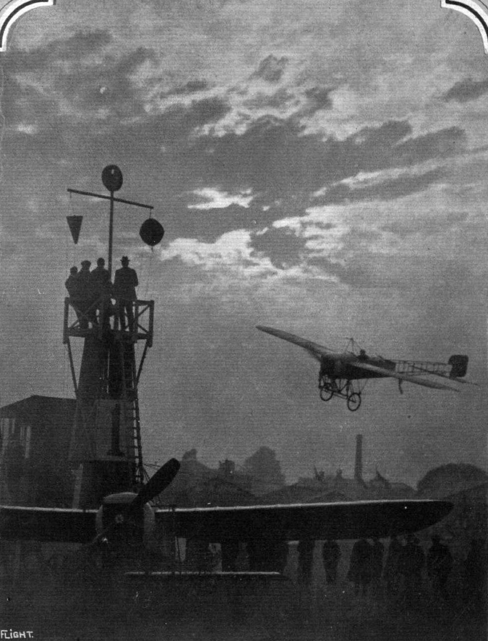
A BEAUTIFUL SUNSET PICTURE AT THE HENDON AERODROME. - Mr. W. L. Brock passing No. 1 pylon on his Bleriot during a race.

ANOTHER CLOSE-RANGE PHOTOGRAPH OF A MACHINE IN FLIGHT. - Mr. Brock, on the Bleriot, passing No. 1 pylon at the Hedon Aefodrome.

Mr. Gustav Hamel making one of his banked turns at the Hendon Aerodrome.
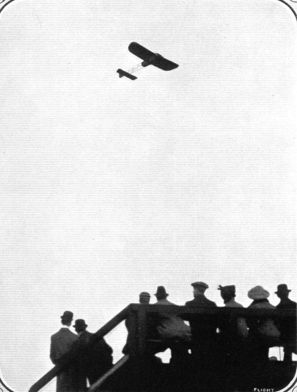
MARCEL DESOUTTER FLYING AT HENDON ON SUNDAY. - At an altitude of 2,000 ft. the oil pipe of his engine broke away, and a dive, heading a 45-mile wind, resulted in a parachute-like dessent in perfect safety, but taking several minutes to finish. Our picture shows Desoutter on his Bleriot starting to climb.
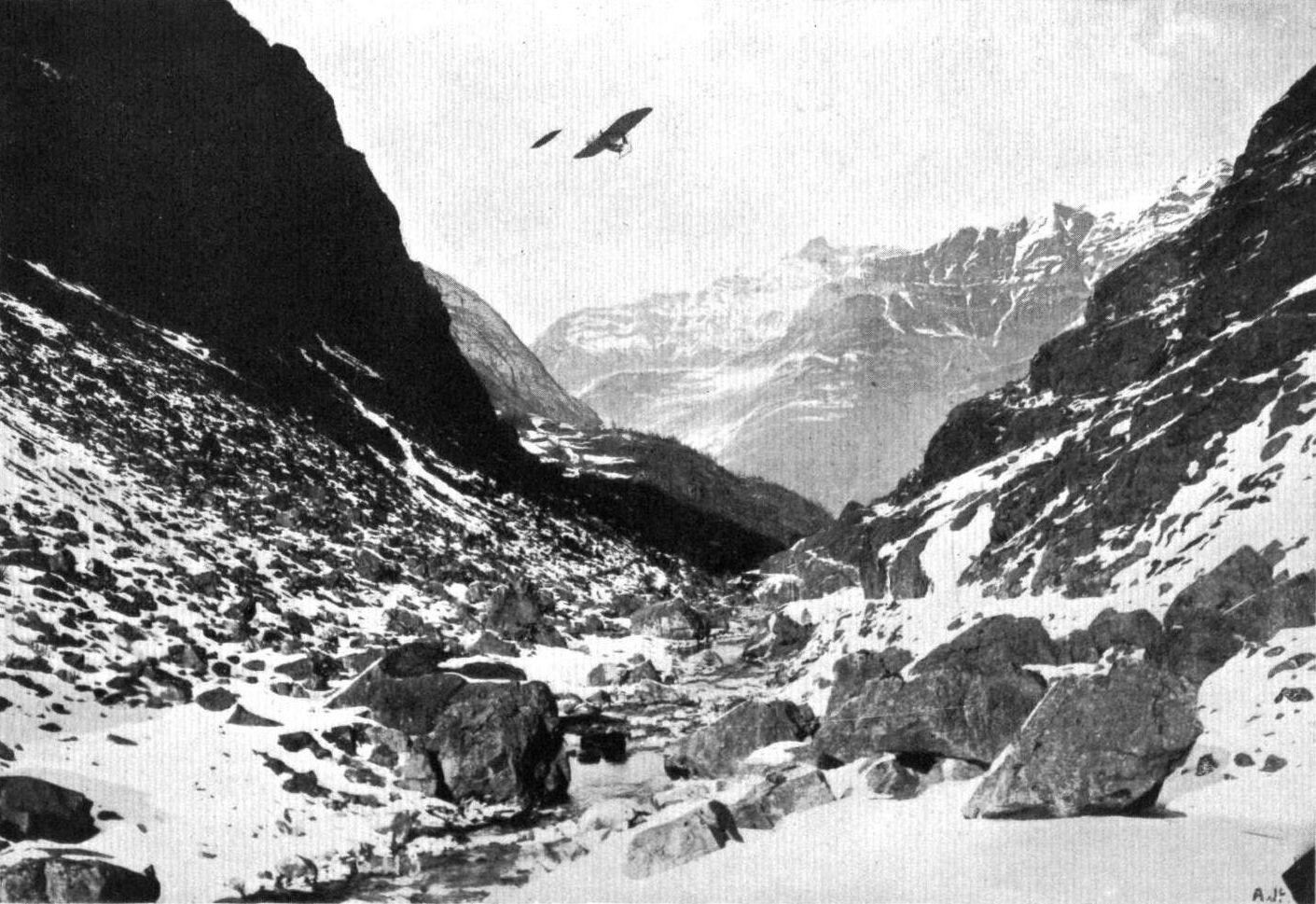
FROM PAU TO MADRID BY AEROPLANE. - The journey of Bider on his Bleriot on Friday last week, when he flew from Pont Long Aerodrome, starting at 7.19 a.m., crossed the Pyrenees, arriving at Guadalajara, where he alighted at 12 o'clock noon, re-starting from there at 1 p.m., and reaching the Quatre-Vents Aerodrome, Madrid, at 130 p.m., a distance of about 500 kiloms. in 5 hrs. 11 mins. Our picture shows M. Bider over the Pyrenees in the vicinity of the Pic du Midi d'Ossan.
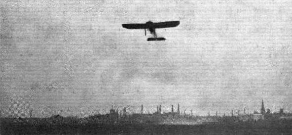
AT THE BURTON FLYING MEETING. - Sydney Pickles, in his Bieriot
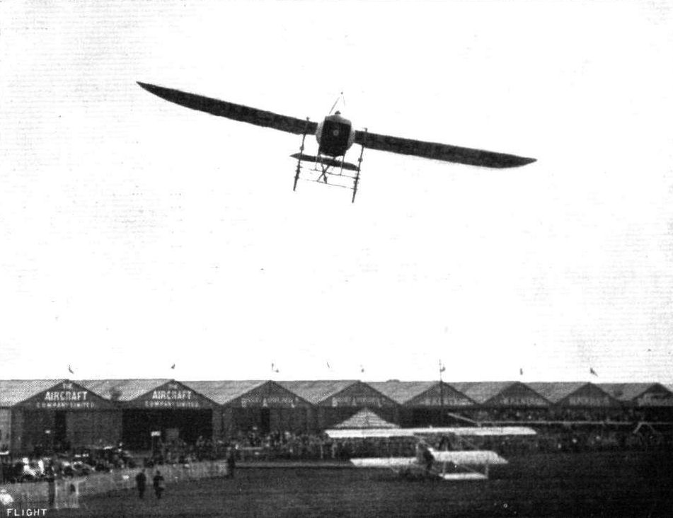
A good picture of B. C. Hucks giving exhibition flights at Hendon on Saturday.
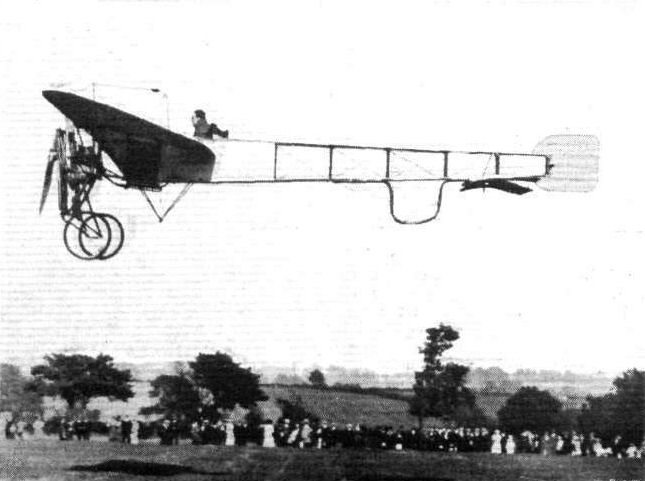
Mr. S. Summerfield, flying at Melton Mowbray during the past season on his Bleriot machine, with which he has done a lot of work in the district.
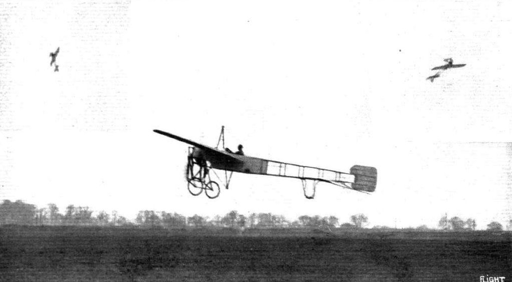
LOOPING THE LOOP. - Mr. B. C. Hucks just off on his Bleriot for his looping demonstrations. Inset on the left he is seen going up on the first part of the loop. On the right, inset, he is seen actually upside down during the looping.
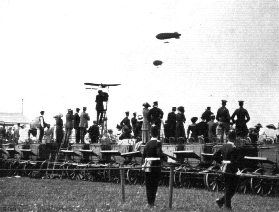
THE PARADE AT LAFFAN'S PLAIN ON THE KING'S BIRTHDAY. - The "Gamma" and "Beta" in the air together, and the I.C.S. Bleriot circling round them.
AN AIR GREETING AT HENDON ON SATURDAY AFTERNOON. - Desoutter, on a Blerlot, passing under and waving his hand to Manton on the Grahame-White biplane.
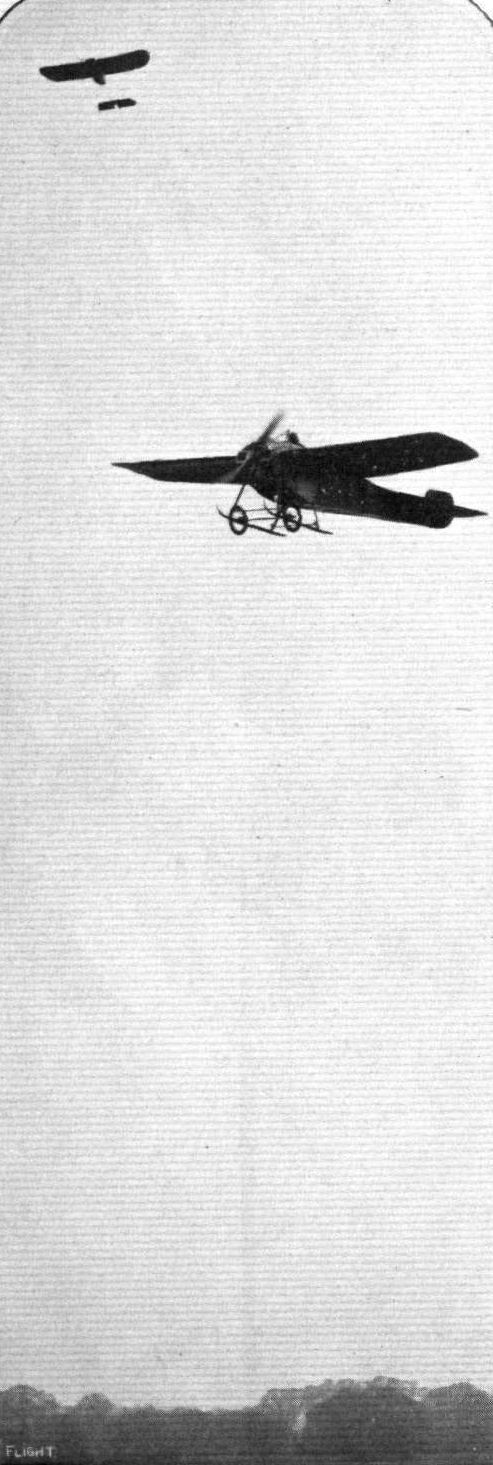
A Hanriot monoplane arriving at Hendon from Brooklands to take part in a competition while one of its future competltors - a Bleriot - is in the air.
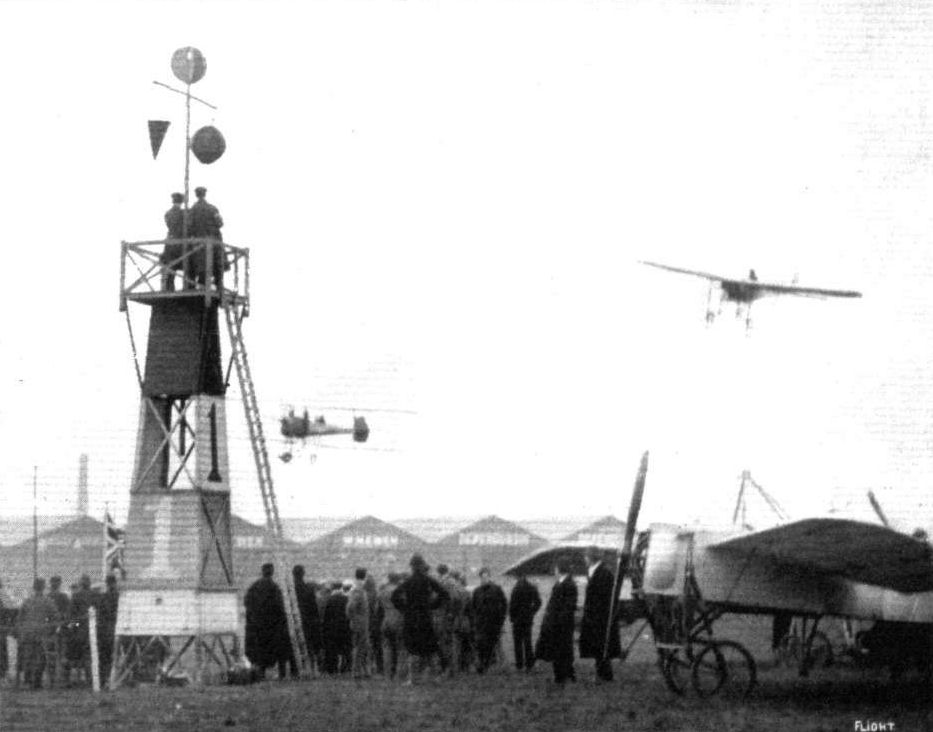
Gustav Hamel, on his Bleriot, and M. Richet, on the Breguet, during the race at Hendon for the Aero Show Trophy.
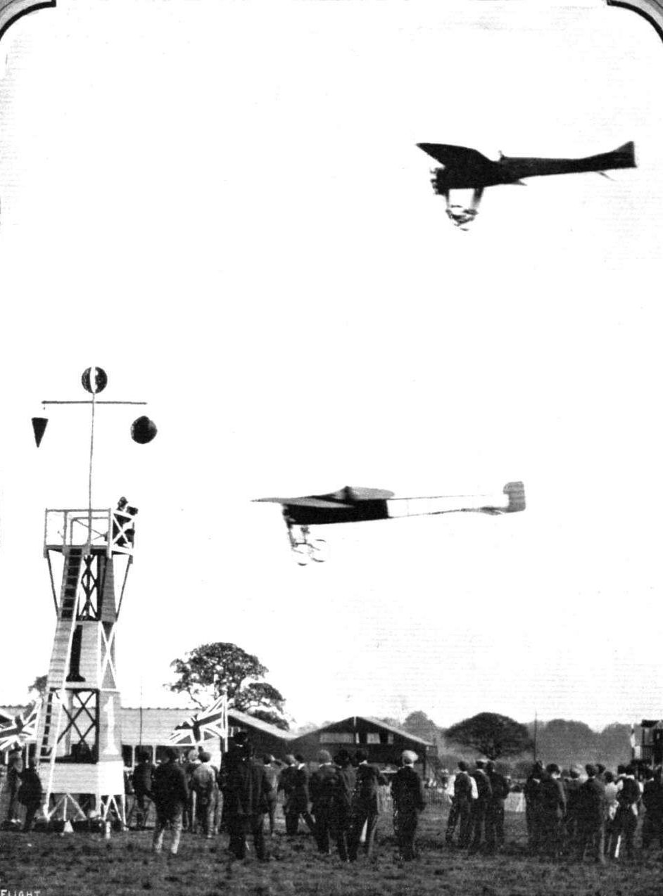
A close finish for second place in the "Shell" Handicap at Hendon on Saturday between Lieut. Porte on the Deperdussin and Mr. R. Slack on the Blerlot.
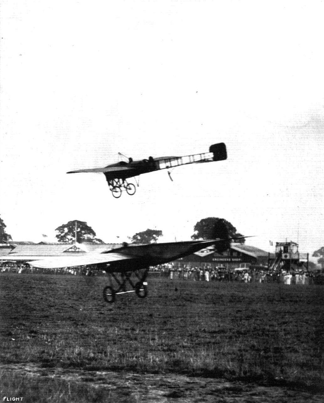
A remarkable photographic record of an incident in the International contest at Hendon on Saturday. - Brock on the Bleriot winning by a few feet only from Marty on the Morane-Saulnier, who flew underneath him as they crossed the line.
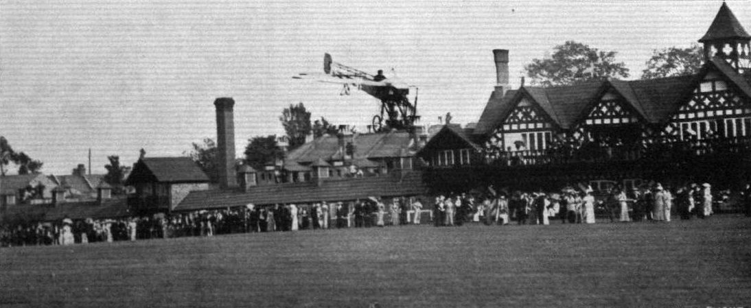
FLYING AT RANELAGH. - M. Gustav Hamel just before landing at Ranelagh last Week, after one of his exhibition flights.
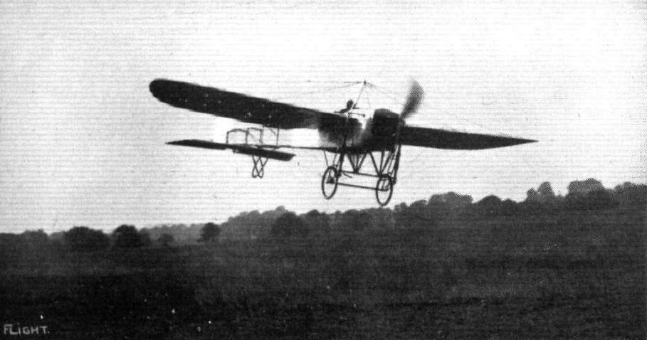
THE FINISH OF A FINE FLIGHT AT HENDON. - Mr. B.C. Hucks descending after his attempt to beat the British altitude record, when he reached 9,800 ft.
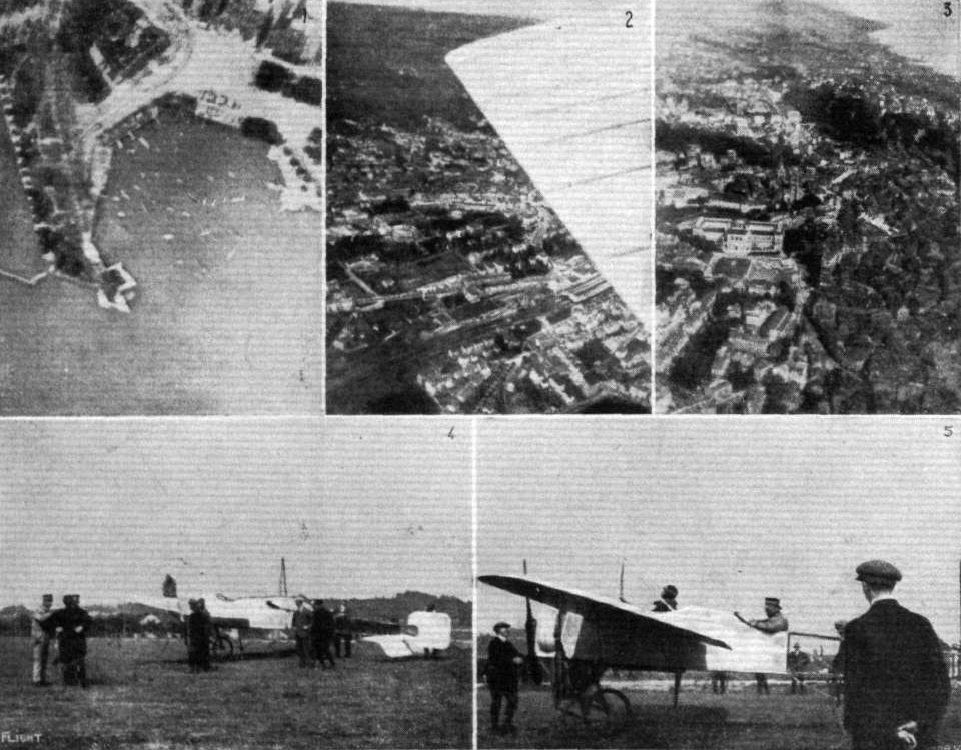
MR. CORBETT WILSON IN SWITZERLAND. - Above are three views of (1) Ouchy, (2) Lausanne Station, (3) general view of Lausanne taken by Capt. Friedrich when passenger with Mr. Wilson; below (4) some of the Swiss officers who went as passengers with Mr. Wilson in conversation with him; and on the right (5) Capt. Instructor Lederry just about to take a flight with Mr. Wilson. - Suisse Sportive.
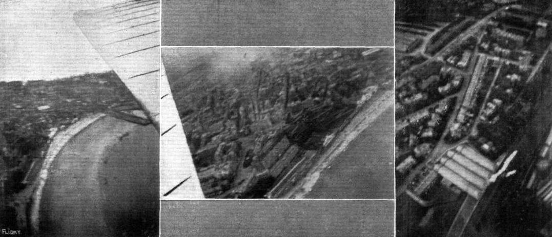
Some snaps from M. Salmet's Bleriot at Scarborough from about 2,000 ft. up, taken by Mr. A. J. A. Wallace Barr recently. The centre photograph and the left show the Grand Hotel and foreshore from different points, and on the right is seen the railway station.
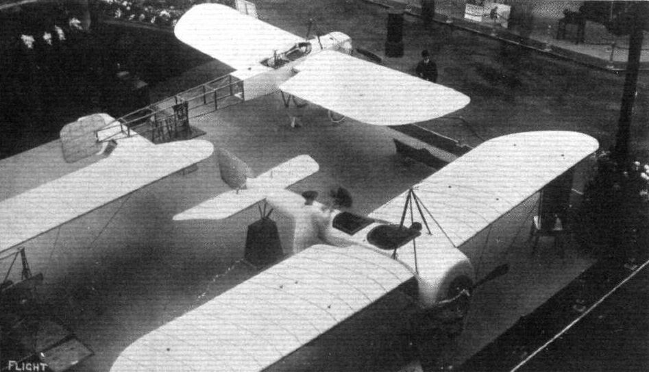
Two of the monoplanes on the Bleriot stand at the Paris Salon.
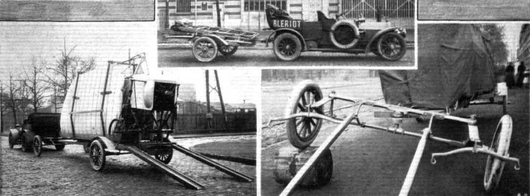
THE BLERIOT MONOPLANE TRANSPORTER. - The top picture shows the transporter folded up and in tow on a pair of its own wheels behind a car; that on the left illustrates the transporter in action, carrying a Bieriot tandem two-seater monoplane. An idea of its construction can be gathered from the right-hand photograph, which shows how the transporter, which can be towed by means of horses or automobile, can be driven over obstacles without upsetting; the balance of the monoplane on board.
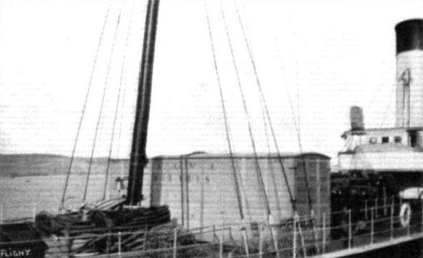
The military Bleriot machine, which Mr. Gustav Hamel flew from Dover to Cologne last week, arriving in its packing case at Dover from France, prior to the achievement.
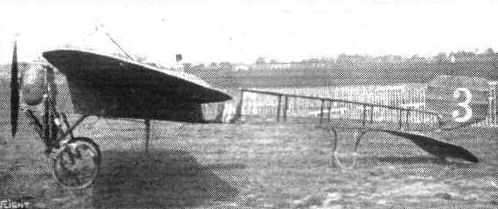
The single-seater Bleriot.

Two views of Mr. Vivian Hewitt's Bleriot in its latest form.
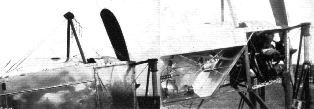
On the left the top cabane, and on the fight showing the engine shield and doors removed. They can be taken off and replaced very quickly.
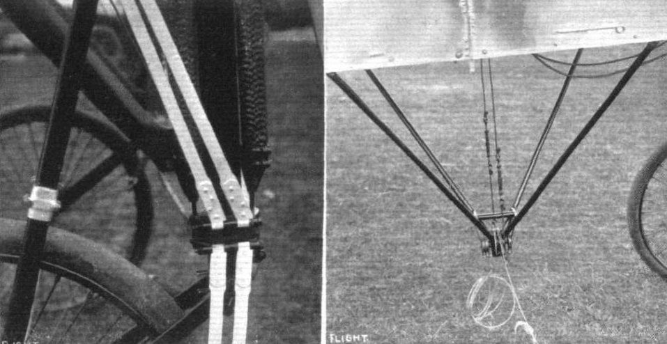
On the left Mr. Hewitt's method of attaching the four ribbons to the bracket is shown, while on the right is the new warping cabane. Note the bracing and steel wheels and the thick wires to the cloche.
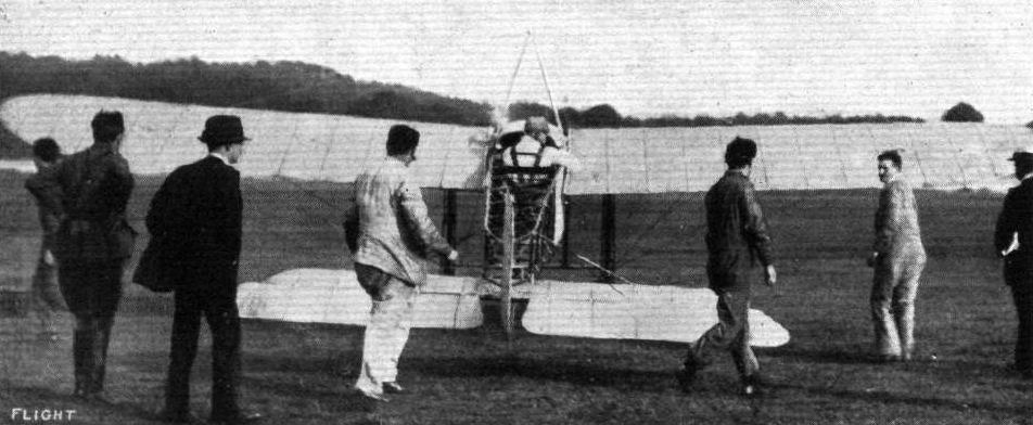
A back view of Pegoud in his Bleriot just at the moment of starting at Brooklands for one of his flights showing him strapped in to his seat, and also the tail as fitted to his Bleriot.
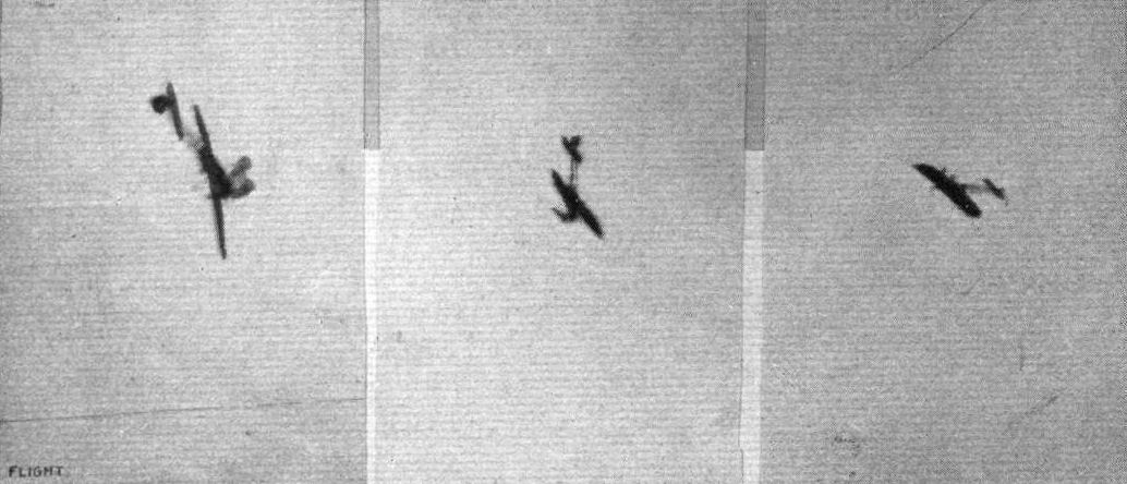
PEGOU'S EXTRAORDINARY FLIGHTS. - Three untouched photographs of bis upside down flying. In the centre: diving for the turn. On the left: turning over. On the rights upside down.
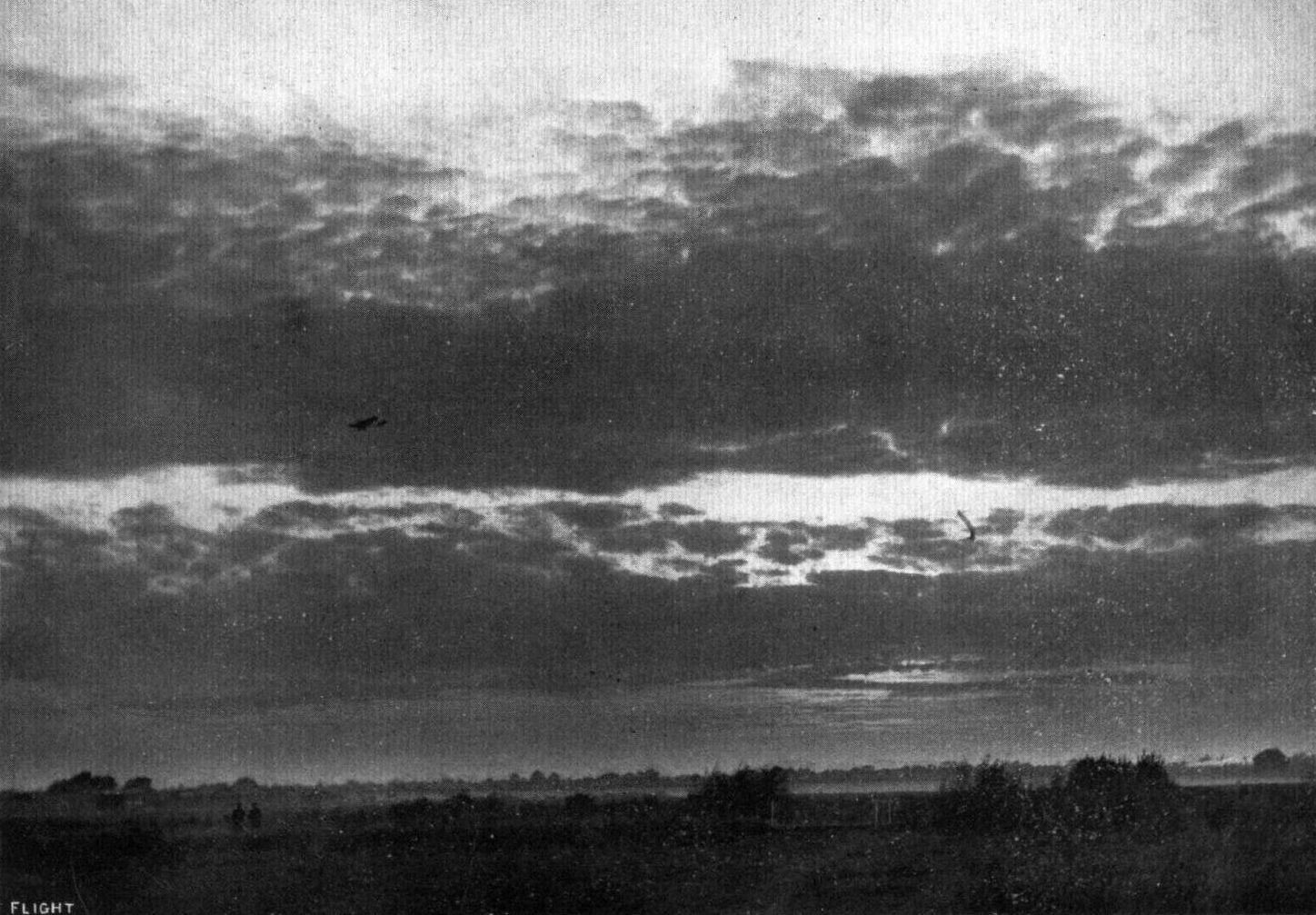
A LOVELY SUNSET AT BROOKLANDS. - In the air, M. Pegoud returning from one of his remarkable flights.

Pilot: Mr. G. Lee Temple.
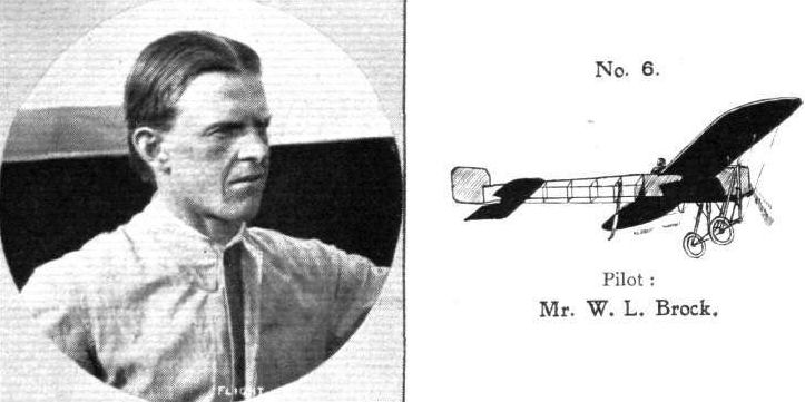
Pilot: Mr. W. L. Brock.
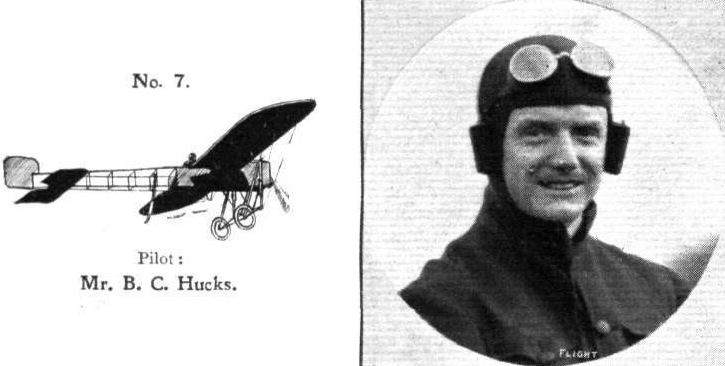
Pilot: Mr. B. C. Hucks.
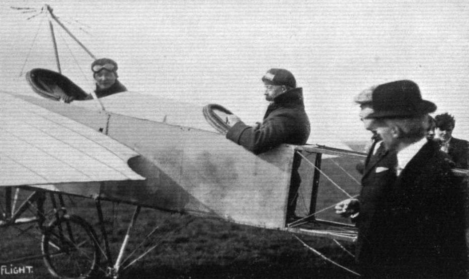
Gustav Hamel takes Sir Joseph Ward for a flight in the "Britannia" at Hendon after its christening.
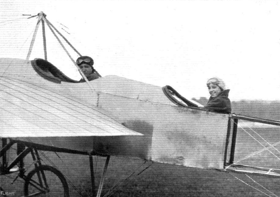
Mr. Gustav Hamel just about to start for a flight with Miss Teddie Gerrard, on the Hippodrome, at Brooklands on Sunday last. Mr. Hamel climbed to nearly 9,000 ft., and in descending stopped his propeller at 6,000 ft.
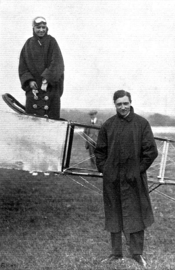
SUNDAY FLYING A T BROOKLANDS. - Mr. Gustav Hamel gives our photographic artist a "sitting" whilst Miss Teddie Gerrard looks on innocent of the fact that she is included on the plate.
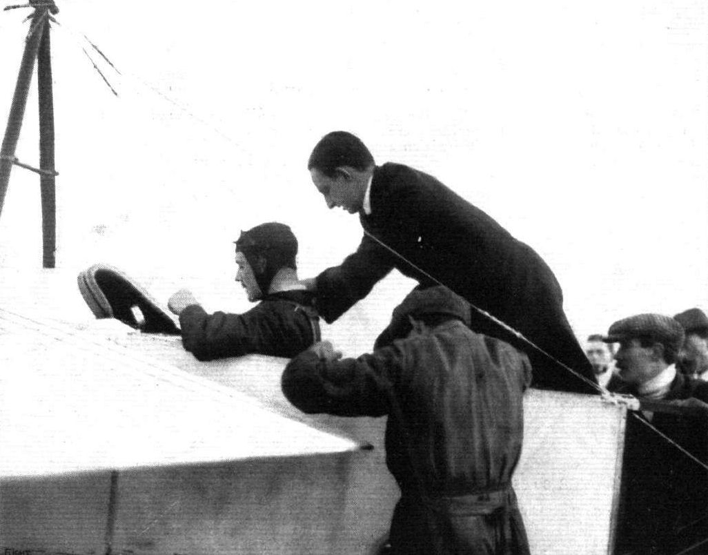
Mr. B. C. Hucks before looping the loop at Hendon having his shoulder-straps fixed safely by his Manager, Mr. J. C. Savage.
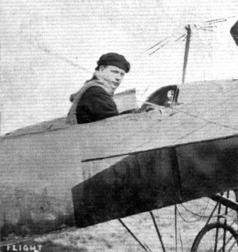
Mr. D. W. Clappen, who took his brevet at the Bleriot School, Hendon, on August 15th.
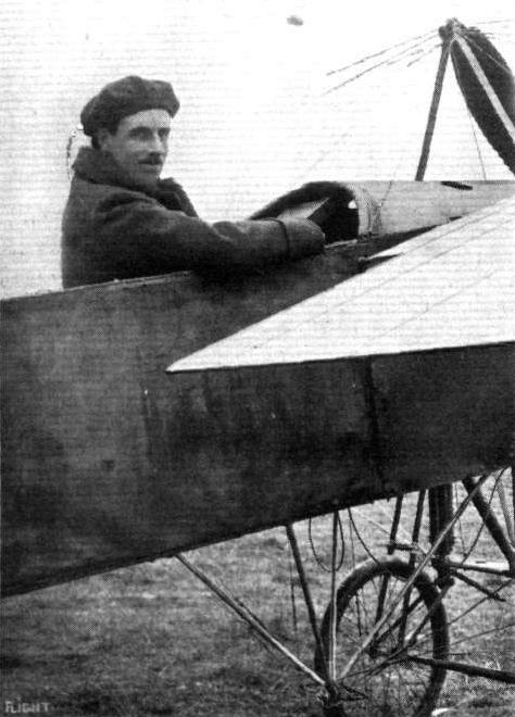
Capt. Geoffrey Cox, 3rd North Staffordshire Regiment (Special Reserve), who has recently taken his certificate at the Bleriot School at Hendon.
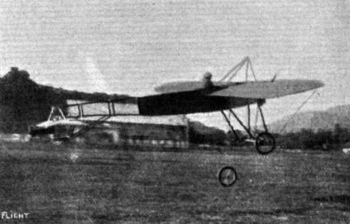
A remarkable incident which occurred to Taddeoli on June 6th when flying from Berne to Bienne in Switzerland. One of the chassis wheels came off without his knowing anything about it, but Bider, who was at the aerodrome, at once started after him on his Bleriot, and by means of energetic dumb show managed to apprise Taddeoli of his danger, so that Taddeoli was able to land so carefully that no further damage of any sort occurred. - Suisse Sportiue.
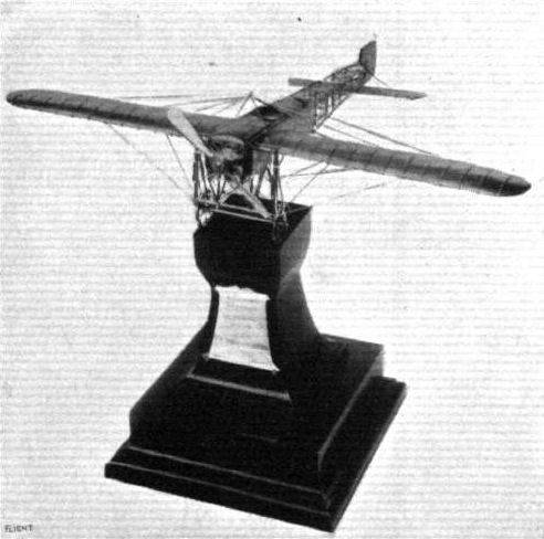
The solid silver model of the Bleriot monoplane used by Mr. Gustav Hamel in his splendid flight from London to Cologne. This artistic work was designed and manufactured by Messrs. Mappin and Webb, and presented to Mr. Hamel by the British Petroleum Company ("Shell" motor spirit) at a banquet on June 5th.
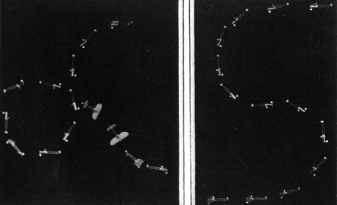
PEGOUD'S RECENT FLIGHTS. - The above plates have been prepared by FLIGHT for the purpose of more graphically showing the evolutions which are performed by M. Pegoud when looping the loop and doing his "S" shaped upside down flight, and how he actually recovers his normal position. The diagrams are prepared by photography from a small model of the Bleriot.
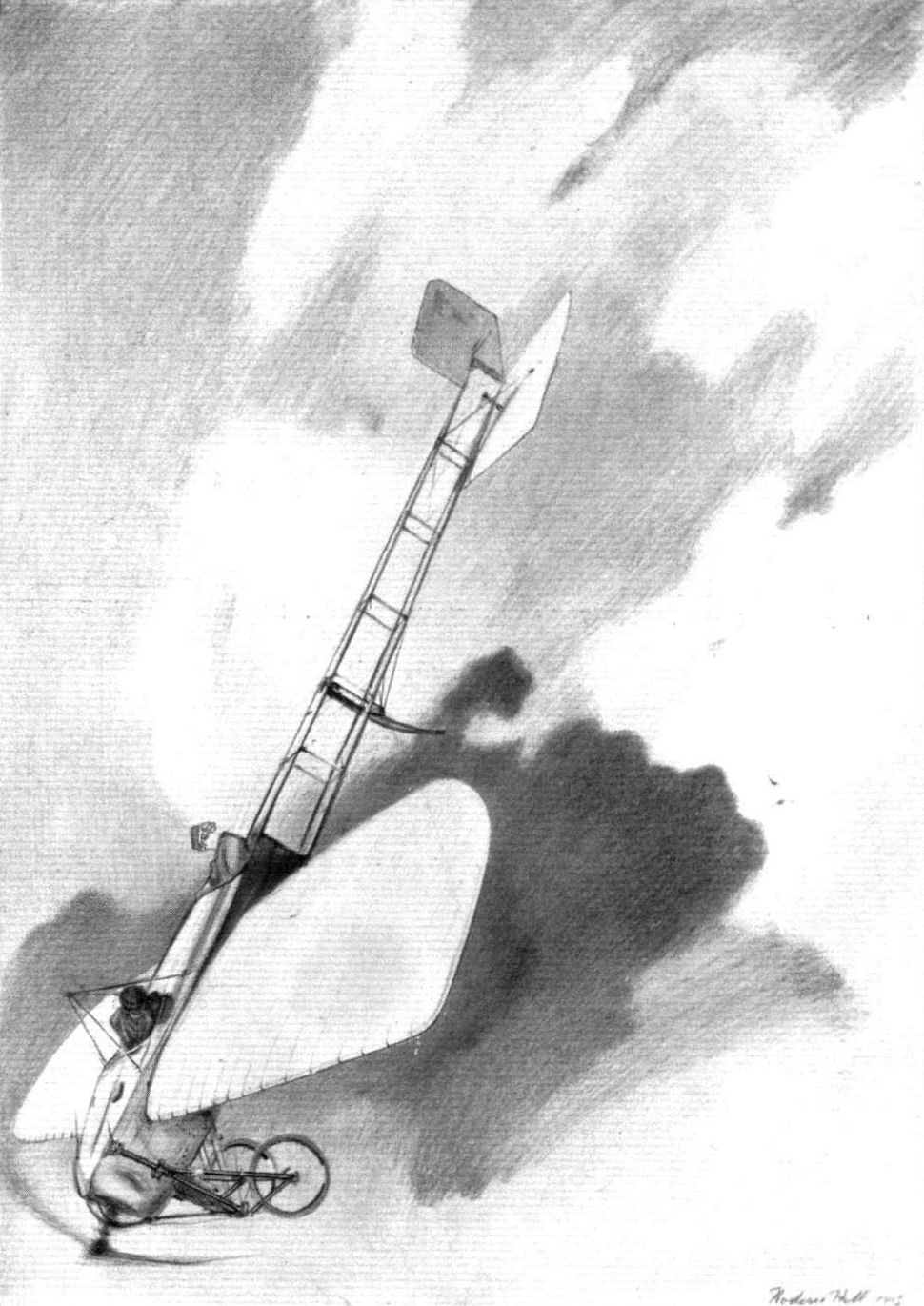
Spiral vol plane by Hamel on 80-h.p. Blerlot, with Miss Trehawke Davies as passenger, May 3rd, on his return from a flight to Windsor, reaching an altitude of 7,000 ft. From a sketch by Roderic Hill.
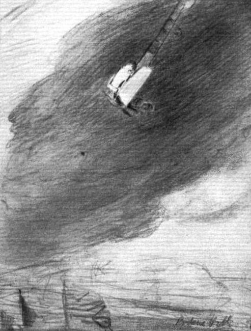
LORD MAYOR'S DAY AT HENDON AERODROME. - An impression of Hamel by Roderick Hill.
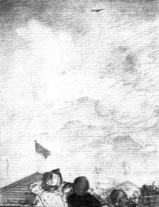
LORD MAYOR'S DAY AT HENDON AERODROME. - Up aloft. Another impression of Hamel by Roderick
Hill.
Hill.
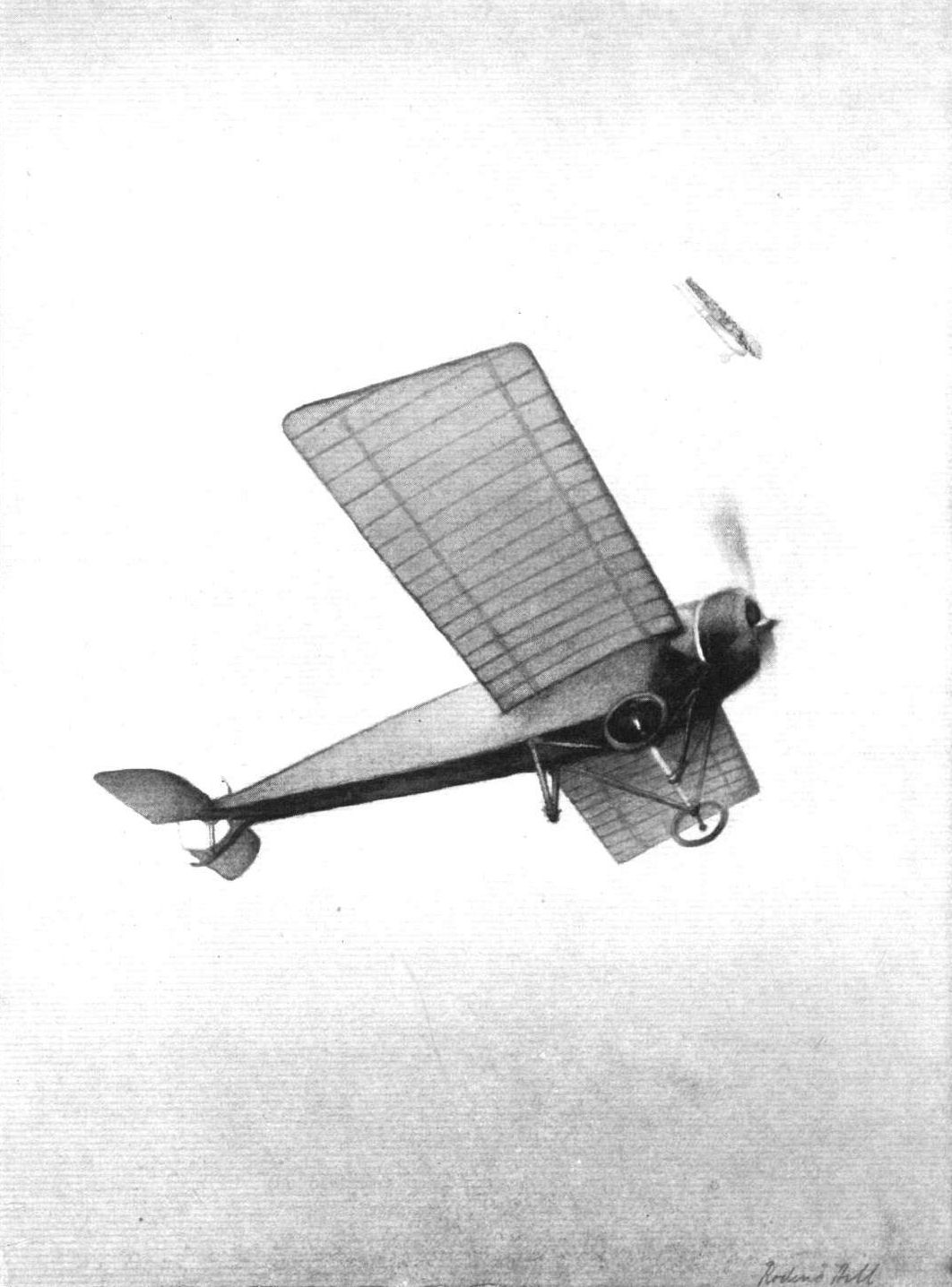
"LADIES DAY" AT HENDON AERODROME. - The Morane-Saulnier and Bleriot circling round each other. From an original drawing by Roderlc Hill.

THE FIRST ENGLISHMAN TO LOOP THE LOOP. - An impression of Mr. B. C. Hucks flying in an inverted position at Hendon Aerodrome on Saturday, November 29th, on a 50 h.p. Bleriot with reinforced wing bracing. From an original drawing by Mr. Roderic Hill.
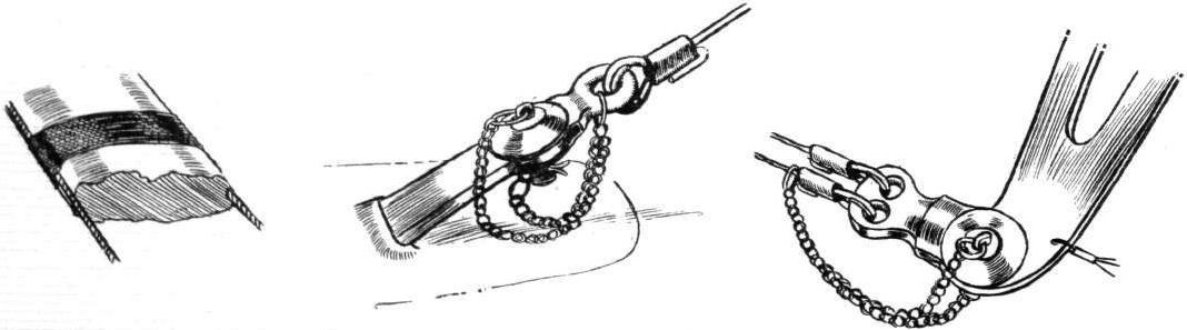
DETAILS OF THE BLERIOT MONOPLANE. - The sketch on the left shows the method of strengthening the bottom cross-plank of the landing chassis and the application of stranded cable. The middle sketch shows the upper wing staywire attachment. That on the right illustrates how the double control-wires are fastened to the rudder lever.
AT OLYMPIA. - A study in tail-skids.
A study in tails.
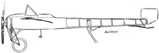
The 80-h.p. Bleriot monoplane.
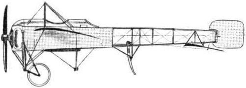
The 80-h.p. Bleriot tandem monoplane.
Flight, February 15, 1913.
NEW 80-H.P. MILITARY GNOME-BLERIOT TWO-SEATER.
A NEW two-seater monoplane has been evolved from the Bleriot works at Levallois Ferret, and tested more or less secretly at Buc. In the rough side and front elevation sketches which we are able to reproduce this week, it will be seen that, in its lines, it is unlike any machine that has previously been turned out from these celebrated French works. The essence of the design is that the propeller is arranged to the rear of the body, so that the passengers, sitting in front of it, may have a perfectly clear view below, and in front of them. Arranged in this way, the machine becomes more capable of being used for offensive purposes than if the propeller revolved in front. Pilot and passenger are seated side-by-side in the front of the fuselage, while in front of them there is a windshield, which can be hinged forward so that they may have no difficulty in climbing in or out of the machine. Behind them are the fuel tanks and the 80-h.p. Gnome motor, the latter being supported on two bearings.
The body of the machine is really in two sections, the section which accommodates the passengers, the tanks and the motor, and that portion of the framework which carries the tail. This latter section is built up with three longitudinals, the upper one passing through the propeller-boss, an arrangement which is made use of on the 90-h.p, Grahame-White military biplane that is described elsewhere in this issue. A drawback to this method of arrangement is that if the propeller bearing ran hot, or if any vibration were set up owing to the propeller becoming damaged, it is likely that the upper member of the tail fuselage would become damaged and, maybe, lead to a collapse of the tail, with probably disastrous results. That the chances of an accident of this kind may be minimised, the propeller bearing of this new Bleriot monoplane carries an electric detecter, in circuit with a small bell near the pilot which warns him should any undue vibration be set up or should the bearing tend to overheat.
The two lower longitudinals of the fuselage extend forward, forming short skids which are intended to protect the nose of the machine in the event of a heavy landing. A modified version of the standard Bleriot landing gear is employed. Probably the most striking peculiarity of the machine is that the distinctive cloche control has been abandoned, and its place been taken by a vertical hand wheel. The rudder is still operated by the feet. Its main dimensions are a great deal bigger than the standard Bleriot machines existing at the present time, and it is expected that this new Bleriot military monoplane will have great things to show as regards weight lifting. It has a span of 12 metres and its overall length is 10.50 metres.

Front and side elevations of the new 80-h.p. Gnome-engined military Bleriot two-seater, which is at present going through its tests at Buc, in France.
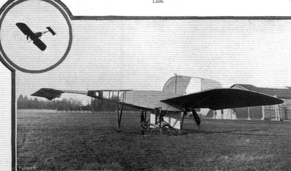
The new 70-h.p. Blerlot "canard" monoplane, with which Bleriot's chief pilot. Pereyon, has been experimenting at Buc, France, for some weeks past. The little inset picture shows the monoplane in flight.
Flight, December 13, 1913.
THE STANDS AT THE PARIS AERO SHOW.
BLERIOT.
On the Bleriot stand are shown no less than six machines and fuselages of various types, and when one considers that there are at the Salon two more Bleriot stands - one for aeroplanes and one for bateaux glisseur - one begins to realise the activity of this well-known firm.
<...>
The Bleriot biplane has been built with a view to meet the requirements of the French Army. In its general lines it may best be compared with a H. Farman biplane, but it differs from that machine in the constructional details. The chassis is of a very novel type and is similar to the chassis of the Nieuport-Dunne biplane.
Flight, December 20, 1913.
THE PARIS AERO SALON - 1913.
BLERIOT.
<...>
The biplane exhibited has, we understand, been built with a view to comply with the requirements of the military authorities, for a machine which, while not particularly fast, will be lighter loaded, and, therefore, have a better climbing capacity than the more heavily-loaded monoplane. Superficially, it must be admitted, this machine resembles the well-known Henry Farman biplane, but aerodynatmically, it is quite distinct, the wing section, for instance being absolutely different from that of the Farman. The main planes, of which the top one has a much greater span than the lower one, are connected by six pairs of struts of flattened steel tubes, cross braced in the usual way. The nacelle, which is of rectangular section, is built up of four longerons of ash connected with struts and cross members of steel tube and spruce. The nacelle is secured to the lower main plane by means of bolts passing through the main spar. In the front portion of the nacelle are the pilot s and passenger's seats, arranged tandem fashion, the pilot occupying the front seat. The controls consist ol a single central tubular column, which actuates the ailerons and elevator, while a pivoted foot-bar operates the rudder. In front of the pilot are mounted the usual instruments for cross-country work.
A tail outrigger, consisting of four steel tubes connected by tubular streamlined struts, carries the tail plane, which consists of a fixed cambered tail plane to the trailing edge of which is hinged the negatively cambered divided elevator. Pivoted round the rear upright strut is the rudder, which is of the Henry Farman type.
One of the most novel features of this machine is the landing chassis, which structure seems to have been reduced to its simplest possible form, and does not at first sight give the impression of being able to stand up to a very rough landing, but according to the manufacturers it has already been tested and found very efficient. It is illustrated by one of the accompanying sketches, which is, we think, self-explanatory.
<...>
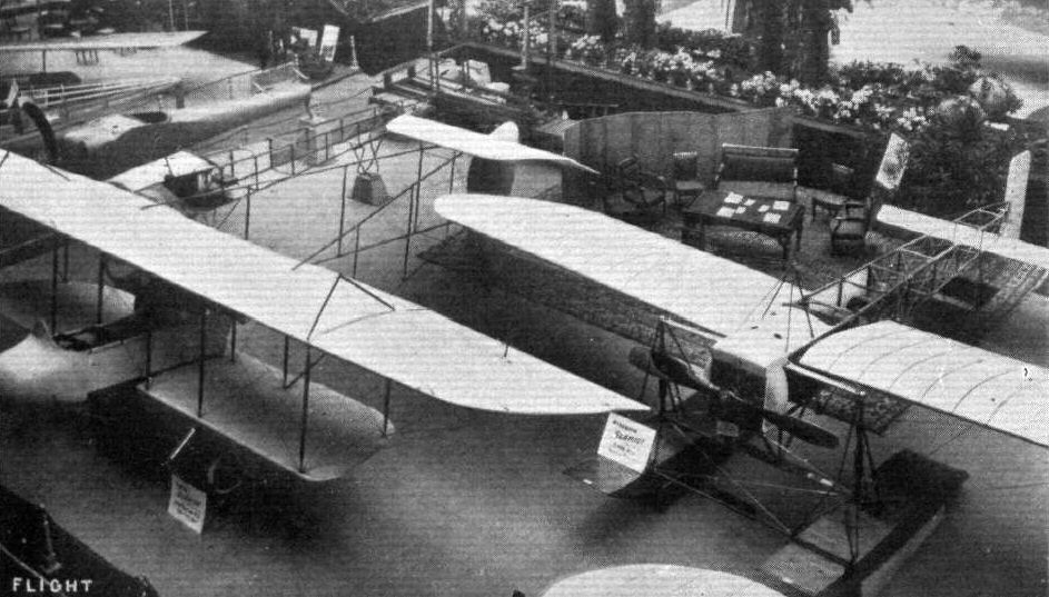
The Bleriot biplane and the Bleriot waterplane at the Paris Salon.
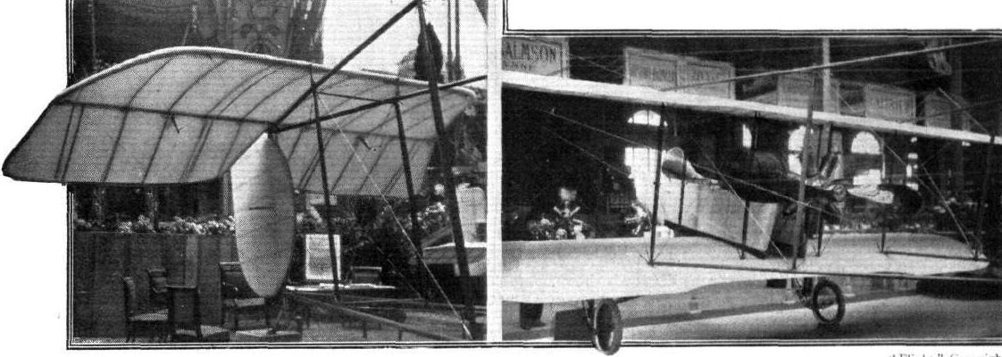
Three-quarter rear view of the new Bleriot biplane. Nearer view of the tall planes.
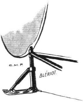
Tail skid of the Bleriot biplane.

One half of chassis of new Bleriot biplane.
Flight, March 29, 1913.
An Armoured Aeroplane.
THERE are many novel features about M. Bleriot's latest monoplane which has been tested at Buc during the past few days by Perreyon. It is of the Canard type, with an elevator in front, and the propeller arranged behind the main plane. There is also a fish-tail shaped rudder placed only 15 cms. behind the propeller, while there are three fish-tail shaped fins arranged at the rear of the inner half of each wing; ailerons extend from this point along the outer half. The body of the machine, which is arranged so that the observer lies flat, and looks through windows, is covered with steel plate to protect the occupants from rifle fire.
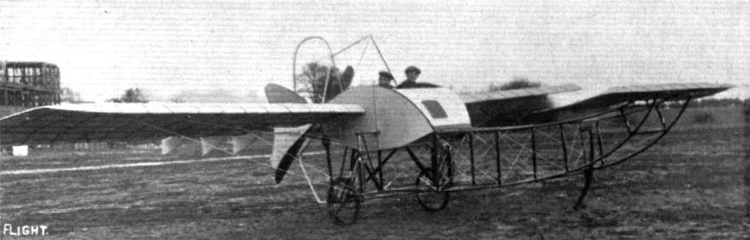
THE NEW ARMOURED BLERIOT. - View from in front, showing the elevator and the general arrangement of the body, with the window for the observer.
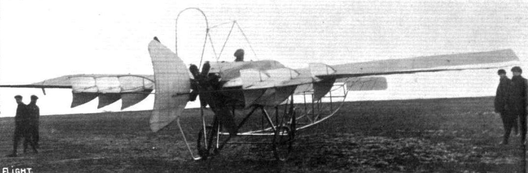
View of the new armoured Bleriot from the back, showing the rudder, the long ailerons, and the fish tail fins on the main plane.
Flight, December 13, 1913.
THE STANDS AT THE PARIS AERO SHOW.
BLERIOT.
On the Bleriot stand are shown no less than six machines and fuselages of various types, and when one considers that there are at the Salon two more Bleriot stands - one for aeroplanes and one for bateaux glisseur - one begins to realise the activity of this well-known firm.
<...>
The fuselage coque type of machine is a tandem two-seater of very good streamline form and is probably a good deal faster than the older type Bleriots, as the head resistance has been considerably decreased.
<...>
Flight, December 20, 1913.
THE PARIS AERO SALON - 1913.
BLERIOT.
THE Bleriot exhibit is certainly the largest at the Show and one of the most interesting, consisting as it does of no less than six machines and fuselages. One of these is the well-known type XI, and the other the equally well-known tandem two-seater, of which we need give no description here, as they are already known to our readers. Of the other machines, probably the most interesting is the tandem two-seater monocoque. This machine, which has, as the name implies, a fuselage of the coque type, is one of the neatest at the Show, and, as far as comfort is concerned, it is one of the best thought out that we have ever seen. It would almost seem impossible to provide such comfort and protection for pilot and passenger in so small a space as is available in this type of machine. The pilot occupies the front seat, which is situated well forward, thus allowing of a very good view in all directions. The passenger's seat is situated in a separate cockpit on line with the trailing edge of the wings, and consists simply of a cushion placed loosely on the floor of the fuselage. By sliding the seat along, the passenger may squat down and lie fully stretched out on the floor, and may inspect the country underneath through an oval opening cut out of the bottom of the coque. By these means he obtains an absolutely unrestricted view in a downward direction, as no part of the chassis interferes in the slightest degree with his observation. For communication between pilot and passenger a speaking tube is provided, and it is fitted with a microphone which allows of conversation being carried on without the necessity of stopping the engine.
The engine, an 80 h.p. Gnome, is mounted on overhung bearings in the nose of the fuselage. It is partly covered in by an aluminium cowl, which has one opening on each side of the fuselage, thus allowing the air to escape. This should, we think, provide excellent cooling for the engine, and at the same time prevent any oil from being blown back in the faces of the pilot and passenger.
The chassis is of the usual Bleriot type, to which M. Bleriot seems to return after having tried various other types, so that one must conclude that he has found it absolutely successful, and it is certain that for landing side to the wind it would be difficult to imagine a more suitable chassis. The tail skid, which is of V shape, consists of two flattened steel tubes, pivoted on the coque and sprung forwards and backwards by wires and shock absorbers, attached to the chassis and the tail, respectively. The tail planes are of the usual Bleriot type, and consist of a fixed tail plane attached to the coque, and a divided elevator of the negatively cambered type.
The main planes are attached to the fuselage by fitting the spars into two transverse tubes, and are braced downwards to the chassis and upwards to a very high cabane.
<...>
Two of the monoplanes on the Bleriot stand at the Paris Salon.
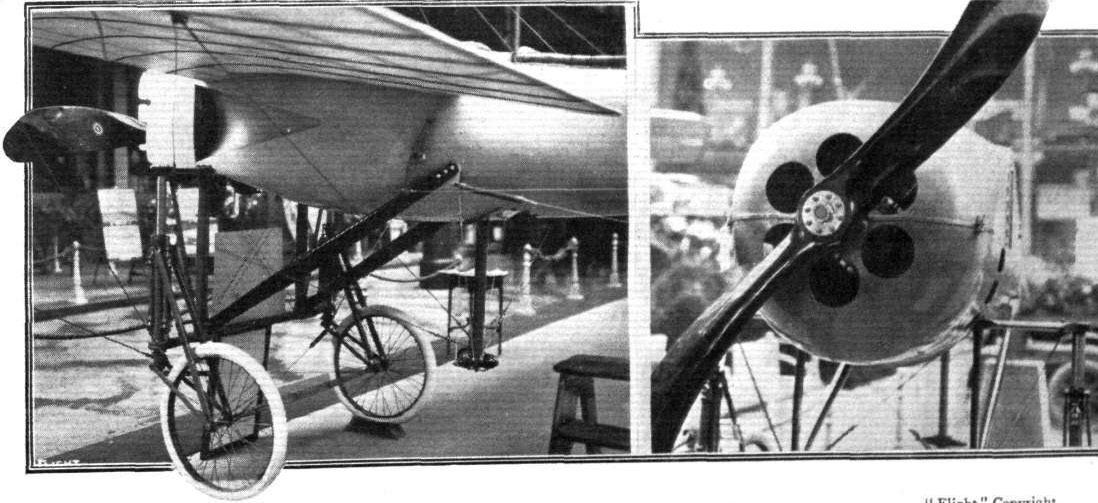
Chassis and engine mounting of the Bleriot monocoque. On the right a view of the armoured nose.
Flight, December 20, 1913.
THE PARIS AERO SALON - 1913.
BLERIOT.
<...>
One of the other machines, of which only the fuselage is shown, is also of the monocoque type, but differs from the one just described in that it is a single-seater. The front portion from the nose of the fuselage to a point behind the pilot's seat is armoured with 3 mm. thick chrome nickel steel. During some experiments carried out it was found that rifle bullets fired from a distance of 400 yds. either glanced off or made but a small dent in the armour, while it was found that the rear wooden portion of the fuselage could be pierced with a great number of bullets without impairing the strength of that structure, so that for military purposes this machine ought to provide comparative safety for the pilot without necessitating flying at a very great altitude. Naturally the armour makes the machine heavier, and as a matter of fact the weight of the armour has been found to be equal to that of a passenger; hence the reason for making the machine a single-seater with the same engine.
<...>
Chassis and engine mounting of the Bleriot monocoque. On the right a view of the armoured nose.
Flight, January 18, 1913.
FOREIGN AVIATION NEWS.
A Bleriot Hydro-Aeroplane.
OVER the Seine between Bezons and Argenteuil on Saturday last some trials were made with a hydro-avion built in the Bleriot works. Perreyon was in charge of the machine which is, of course, a monoplane, with two seats side by side. It is fitted with an 80-h.p. Gnome, and there are two main floats, with an auxiliary float to support the tail. MM. Louis Bleriot and Alfred Leblanc supervised the trials, which included some fifteen flights of varying duration, some with passengers, and among the interested spectators were "Beaumont" and MM. Donnet and Leveque.
Flight, November 29, 1913.
THE NEW BLERIOT HYDRO-AEROPLANE.
ONCE more the Seine at Billancourt has been the scene of experiments with hydro-aeroplanes by M. L. Bleriot; it will be recalled that as far back as in 1906 M. Bleriot experimented in the same neighbourhood with a biplane having elliptical main planes.
The new hydro-aeroplane is of the tandem two-seater type. One of our photographs shows the chassis, which consists of the usual Bleriot chassis with the addition of a few extra tubular struts which support the front portion of the Tellier floats with which this machine is equipped. These floats are sprung in a similar way to the wheels of the land machine, being pivoted around the transverse tube which connects the front chassis struts and being sprung at the rear by means of the usual shock absorbers. This arrangement has, of course, the advantage of lessening the shock of alighting very considerably, and has in the preliminary tests proved very successful. The machine can be converted into a land machine by substituting wheels for the floats, an operation which, we understand, can be carried out in less than an hour.
The tail is supported on the water by means of a float which forms an extension of the rudder and by means of which the machine can be steered on the water.
At the trials an 80 h.p. Le Rhone engine was fitted, and, in the hands of the late M. Perreyon, the machine rose in less than a hundred yards, and flew at a speed of about 100 kilometres an hour. The span of the machine is 11 metres, and she weighs, empty, about 700 lbs. With pilot and passenger and 4 hours' fuel on board, the weight is about 1,400 lbs.
Flight, December 13, 1913.
THE STANDS AT THE PARIS AERO SHOW.
BLERIOT.
On the Bleriot stand are shown no less than six machines and fuselages of various types, and when one considers that there are at the Salon two more Bleriot stands - one for aeroplanes and one for bateaux glisseur - one begins to realise the activity of this well-known firm.
<...>
The hydro-monoplane follows in general lines the land machines. It is a tandem two-seater of the light type; so light, in fact, that only an 80 h.p. Gnome engine is fitted. It must not from its lightness be concluded, however, that it is not a strong machine, for the method of suspension is such that the shock of alighting is very much lessened before it reaches the fuselage, thus making it possible to keep down the weight of that structure. The two Tellier floats with which this machine is fitted swivel round a common axis running across their front portion and are sprung at the rear by means of the usual Bleriot deformable triangle. Each float moves independently of the other, and the upward travel of the floats is 35 centimetres, so that it will be seen that even in case of a very rough amerrissage the shock is greatly diminished both as regards the fuselage and the floats.
<...>
Flight, December 20, 1913.
THE PARIS AERO SALON - 1913.
BLERIOT.
<...>
The hydro-monoplane follows in its general lines the construction of the land machine, and a detailed description of the machine itself is therefore not necessary. Suffice it to say that it is driven by a 9-cyl. 80h.p. Le Rhone engine, which has, owing to the light weight of the machine, been found sufficiently powerful for the purpose. The main interest attaches to the chassis and floats. These latter, which are of the plain, non-stepped type, are attached to the fuselage by means of the usual Bleriot chassis, with the addition of a few extra struts, which support the front transverse steel tubes round which the floats are pivoted. Each float moves independently, the amount of upward travel being 35 centimetres, and they are orientable similarly to the wheels of the land machines. This impresses one as being an excellent feature for alighting on the water in a side wind, as it will probably allow the machine to slide along slightly sideways without upsetting it, thus acting in a similar manner as the swivelling wheels of the land machine. One gathers that the operation of substituting wheels for the floats, or vice versa can be accomplished in a comparatively short time, thus changing it into a land machine.
When the machine is resting on the water, the tail is supported by a tail float of three-ply wood, rigidly attached to the fuselage, and the rudder is extended some distance downwards to allow of steering on the water when taxying. The workmanship is of the highest quality in all of the exhibited machines, and one leaves this stand with a feeling of admiration for the activity and enterprise of the Bleriot firm.
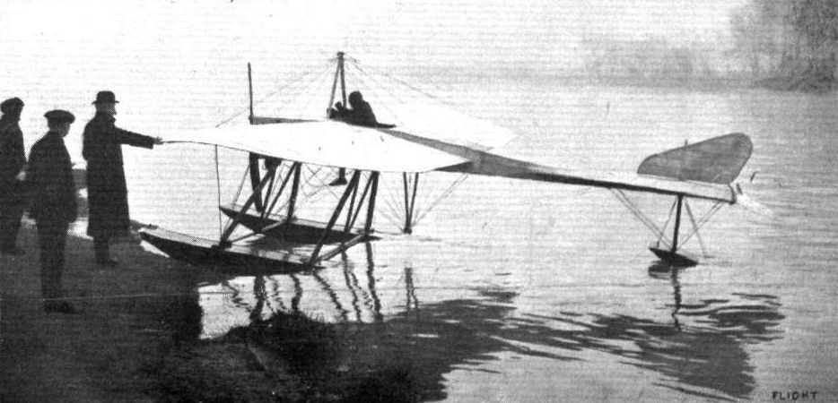
The new Bleriot hydro-monoplane returning to its slipway after an experimental flight by Perryon. M. Bleriot, its designer, may be seen holding on to the machine's left wing tip.
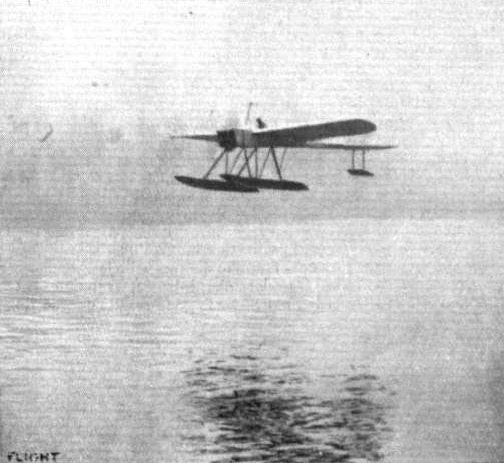
The Bleriot hydro-monoplane in flight over the Seine.
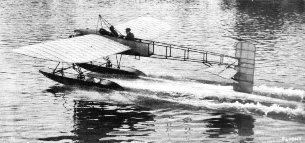
The new 80 h.p. Rhone-Bleriot seaplane showing its paces on the water.
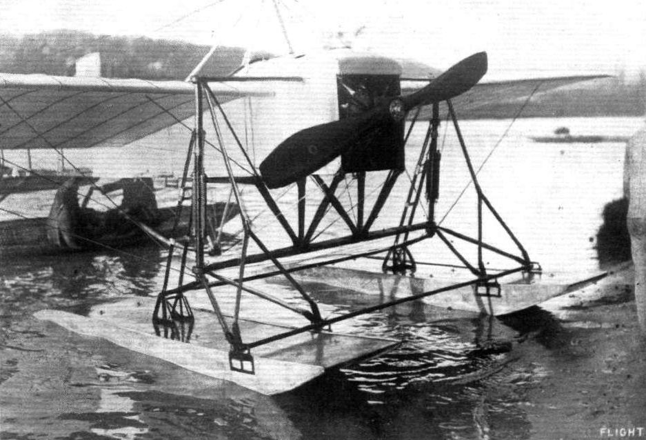
A front view of the floats and chassis, &c, on the new Rhone-engined Bieriot seaplane.
The Bleriot biplane and the Bleriot waterplane at the Paris Salon.
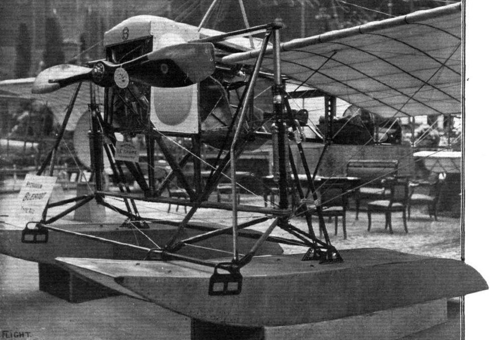
Chassis and floats of Bleriot hydro.
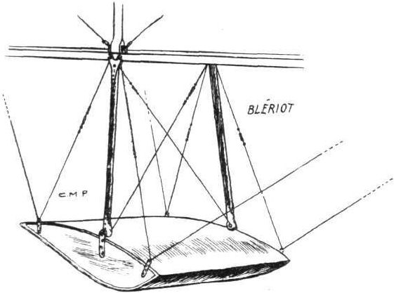
Tail float of Bleriot hydro.
Flight, February 22, 1913.
SOME MORE AEROPLANES AT OLYMPIA.
BOREL MONOPLANES (SOCIETE ANONYME DES AEROPLANES BOREL).
Of hydro-monoplanes there are two exhibited at Olympia which are of French manufacture. Of these the Borel is one. It is a machine differing but slightly from the one that the same firm were showing at the Paris Show some few months since. Its main point of difference is that in this present machine pilot and passenger sit side by side, whereas in the former hydro-monoplane they were accommodated in tandem. On the Continent, the Borel firm have achieved great success, not only with their water-flying machines, but with those they manufacture purely for use over land. As a matter of fact, we have heard it from several sources that as a light and speedy monoplane, and, moreover, one that is capable of being flown in quite high winds, the 50-h.p. Borel monoplane is becoming increasingly popular with the officers of the French army. For their hydro-monoplanes, it will be remembered that they did particularly well at the Tamise hydro-aeroplane meeting in Belgium last year, where they were rated first in order of merit and won the trophy presented by the French Minister of the Colonies.
The body is formed by a rectangular section girder covered in, in front by aluminium sheeting, and by fabric at the rear. On overhung bearings in front is mounted the 80-h.p. Gnome motor, which is covered over to a great extent by a sheet-metal dome, which not only prevents the oil being thrown in all directions, but minimises the chance of it becoming splashed when the machine is ploughing through choppy water. The interior of the cockpit is characterised by the luxurious nature of its various fittings. There is actually, mounted on the dashboard in front of the passenger, a neat flower vase, supported in position by a gold-plated fitting. There, also, are arranged the various instruments, such as compass, engine speed indicator, altimeter, &c, that are essential to a pilot undertaking long cross-country or cross-water trips. The control is in the form of a hand-wheel, which the pilot grips, which he may rock to and fro, and which he may rotate laterally to operate the warping. The steering gear is operated by a foot-bar, and it is an interesting point that the rear float supporting the tail is mounted directly to the rudder, in such a manner that it swings with that organ, and so enables the machine to be steered with considerable accuracy over the water at slow speeds. Dual controls are fitted.
The alighting gear is formed by two main floats of catamaran type without steps, which are supported under the fore part of the machine by an exceptionally strong construction of streamlined steel tubes. The floats are of wooden construction, and have brass nose and tail fittings. With the exception of these latter linings, the remainder of the metallic fittings of the machine are careful y painted, so that they will suffer no deterioration, even if the machine is left moored on the open water for a considerable period.
The wings are of ordinary standard Borel pattern, a pattern which has the characteristic feature that the rear spar in the wing construction is made considerably longer than the front spar, thus giving the wing tip a shape by which, amongst other advantages, a very powerful warp may be obtained. The Borel, or rather the Morane, monoplane, as it was then called, was the first machine to introduce this method of shaping the wing tip, a feature which many other designers have since adopted.
The principal dimensions and characteristics of this machine are: Overall length 8 metres 25; span 10 metres 58; area 18 sq. metres; weight (light) 350 kilos.; useful load (which includes pilot and passenger and enough fuel for a flight of 3 1/2 hours) 280 kilos; speed 63 miles per hour; price L1,320.
Flight, May 3, 1913.
REFLECTIONS ON THE MONACO MEETING.
Borel.
M. Borel was unfortunate in trying to accomplish too much, but his attempt to improve his 80-h.p. hydro-monoplane by the substitution of a 100-h.p. engine and a new pair of wings, was perhaps all the more interesting, inasmuch as it proved to be a failure. It was, however, to be regretted that this result prevented a demonstration with the new 9-cyl. 100-h.p. Gnome rotary engine. There were three of these new Gnome engines at Monaco, but none of them happened to be on aeroplanes that were regularly flying.
The Borel hydro-monoplane is a double float machine, and has its floats rigidly attached to the body by a simple system of steel tubes, which are of flattened cross-section in order to reduce windage. It is difficult to combine streamline section with forms that afford a maximum resistance to bending moment, in the case of float struts, and it was not surprising that, on the occasion of the mishap to the Borel monoplane in Monaco Harbour, several of these struts were bent. It is to the credit of the constructors, however, that there was no sign of fracture, and also to the credit of the workmen, who stayed up all night, that they had replaced all the damaged tubes in readiness for flight the next morning.
In addition to the standard type of monoplane, there was also present under M. Borel's name an entirely different type of craft designed by Denhaut. This particular machine had a dolphin-like body forming a boat in the bows, but with its stern upraised to carry the tail. Whether to call the machine a monoplane or a biplane is a matter for question inasmuch as the lower planes have more the appearance of fins jutting from the side of the boat than they have of aeroplane surfaces. A 100-h.p. Gnome engine is carried on struts at the level of the upper plane, and drives a two-bladed propeller.
Flight, July 26, 1913.
THE BOREL HYDRO-MONOPLANE.
IN this country the Borel monoplanes are comparatively little known, at any rate to the general public, as few of these machines have been seen here since Vedrines demonstrated the excellent qualities of his Borel monoplane in the Circuit of Britain two years ago. Since then the Borel machines have been vastly improved, until to-day they have built up a reputation which places them among the first of French monoplanes of the light, speedy type. It is not only in France, however, that their good qualities have been recognised, as the Italian Government has purchased a great number of the hydro-monoplanes, and the British Admiralty has recently placed an order for eight of these machines with Messrs. Delacombe and Marechal, 166, Piccadilly, who hold the sole rights for the sale and construction in Great Britain and Colonies.
Our drawings and photographs this week illustrate the hydro-monoplane, which is of exactly the same type as those bought by the Admiralty, and similar to the machine exhibited by the Borel firm at the last Aero Show at Olympia.
One of the characteristics of this machine is the very wide fuselage, which affords ample room for the pilot and passenger. It is built up in the usual way, with four longerons connected by struts and cross members, and made rigid by means of diagonal cross wiring. At the rear the fuselage terminates in a vertical knife edge, formed by the rudder post. On this is pivoted the rudder, the upper part of which extends forward above the fuselage, thus effecting partialy balancing of that organ.
Underneath the rear part of the fuselage, and secured to the lower and upper longerons by means of steel clips and tubes respectively, is a small fixed tail plane, which has a very pronounced camber. To the trailing edge of this tail plane is hinged, by means of a steel tube, the elevator, which is, similarly to the rudder, provided with extensions running forward at the ends of the tail plane, so that they are at least partly balanced. It will thus be seen that very little effort is needed on the part of the pilot to operate the controlling surfaces, which fact, in connection with the small depth - about one foot - of the fuselage at the rear makes the machine very easy to handle.
From the side view of the machine it will be seen that the upper and lower longerons converge fairly abruptly towards the front, until they nearly meet in the nose of the machine, thus giving a very good streamline form to the fuselage.
Mounted on channel-steel bearers is the engine, an 80 h.p. Gnome. The front bearer is easily detachable in order to facilitate access to the engine. An aluminium cowl prevents any oil being blown back into the pilot's face, further protection of which is afforded by the rear portion of the aluminium covering, which is swept upwards to form a wind-screen. Behind this wind-screen and inside the body are the pilot's and passenger's seats arranged in tandem, the pilot occupying the front seat. Owing to the width of the fuselage in front, there is ample room in the cockpit; in fact, it is one of the most roomy we have seen, and reminds one more of a motor car than of a flying machine.
In front of the pilot is a very neat dashboard with all the instruments desirable for cross-country flying. The machine is controlled by an arrangement similar to that on the Bleriot monoplane, except that no actual "cloche" is fitted. Dual control is provided, so that during a long flight the passenger may relieve the pilot.
An inspection of the plan view of the machine will show that the trailing edge is considerably longer than the leading edge consistent with the usual Borel practice. This has the advantage, amongst other things, of giving an increased efficiency to the warp, a plan form which was, we believe, originated by the Borel firm. A very interesting point in connection with the wing bracing is the exceptionally good angle of the lower lift wires, obtained by securing them to the lower extremities of the chassis members where these join the floats, which are spaced very widely apart. From the front view of the machine it will be seen that the inner lift cables are nearly vertical, while the outer ones have a corresponding good angle.
One of the accompanying sketches shows the chassis and main floats. The former structure consists of a system of steel tubes, flattened out to obtain a streamline section. The chassis down-corner struts are connected by two horizontal cross members, to the ends of which are attached the two main floats. These are built of wood, capped at the nose and heel with brass. It will be seen that they are of the catamaran or punt type, without a step. As has been said before, the floats are spaced very widely apart, thus affording a very wide "track," and consequently rendering the machine very stable on the water. A tail float of similar construction to the main floats is attached directly to the rudder, and turns with it so that the machine may be steered with considerable accuracy when "taxying" on the water at slow speeds.
Flight, December 13, 1913.
THE STANDS AT THE PARIS AERO SHOW.
BOREL.
Societe Anonyme des Aeroplanes Borel are represented by three machines. One is a land machine of the military-type tandem two-seater, the pilot occupying the rear seat. A hydro-aeroplane of a similar construction as the land machine, with the exception, of course, that it is fitted with floats instead of wheels, is also shown, but the centre of interest of this stand is undoubtedly the torpedo type of machine on which is mounted a machine gun. In its general appearance this machine is somewhat reminiscent of the Paulhan-Tatin aerial torpedo. The pilot's and passenger's seats are situated in the forward portion of the fuselage, whilst the engine is placed inside the fuselage and behind the passenger's seat, and drives through a long shaft the propeller which is situated at the rear of the fuse/age behind the tail planes. In the nose of the machine is mounted a machine gun (Hotchkiss) which is operated by the passenger.
Flight, December 27, 1913.
THE PARIS AERO SALON - 1913.
BOREL.
Three machines are exhibited on the Borel stand - one military tandem two-seater, a hydro., and the "Ruby." The land machine, which is fitted with a 100 h.p. L.U.C.T. engine of Italian manufacture, is of the standard Borel type. The fuselage is built up of longerons of ash, while the struts and cross-members are ash in front and spruce in the rear portion. The seats are arranged tandem fashion, the pilot occupying the rear seat. The controls are the usual Borel, and may be said to be simply the Bleriot controls without the "cloche." The chassis consists of ash struts carrying two short skids, also of ash, from which are sprung the wheels by means of rubber bands wound round the axle and the skid. The hydro-monoplane is also a tandem two-seater and is similar to those now in use in the Navy. It is driven by an 80 h.p. Gnome engine mounted in front of the fuselage on double bearings, of which the front one can be detached by undoing two bolts, thereby facilitating the operation of removing the engine. The fuselage is exactly similar in construction to that of the land machine. The chassis consists of a structure of streamlined steel tubes, which carry at their lower ends the two main floats. These are pivoted round a transverse tube mounted on the front chassis struts, and are sprung at the rear by means of rubber shock absorbers. Owing to the width of the chassis the angle of the lift wires is extremely good, the inner one being almost vertical.
The pilot's and passenger's seats are arranged tandem fashion, each in a separate cockpit, and the controls are of the usual Borel type. A small float, which turns with the rudder, enables the machine to be steered on the water at slow speeds.
The wings are attached to the fuselage by two bolts passing through the spars, the bolt through the front spar being vertical, while the rear spar bolt is horizontal to allow of the wings being warped without bending the spar. In order to provide a better view in a forward and downward direction, the leading edges have been cut away for a distance of a couple of feet on each side of the fuselage.
<...>
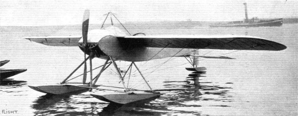
Three-quarter front view of the Borel Hydro-Monoplane showing main floats and chassis.

Side view of Borel Hydro-Monoplane.
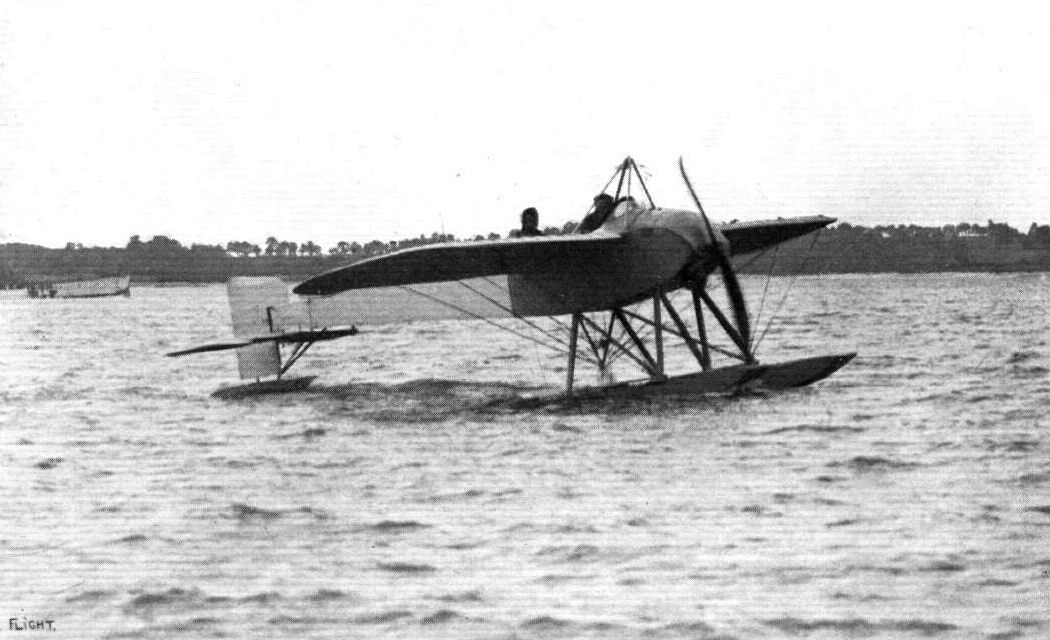
THE ADMIRALTY'S BOREL HYDRO-MONO. No. 83. - Gordon Bell in pilot's seat (back), with Lieut. Travers as passenger, after passing reception tests at Calshot.
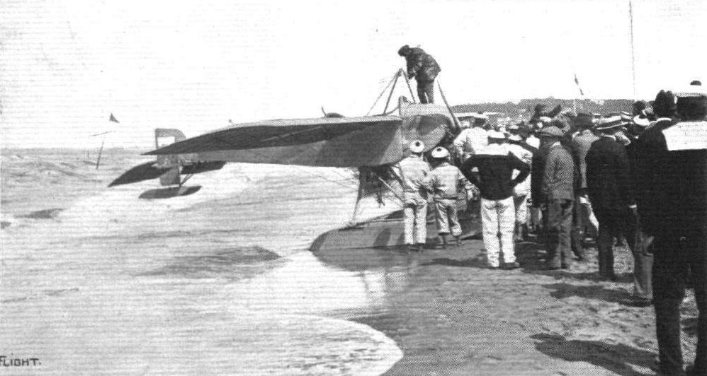
THE PARIS-DEAUVILLE WATERPLANE RACE. - Chemet and his Borel machine immediately after arrival at the control on the beach at Deauville.
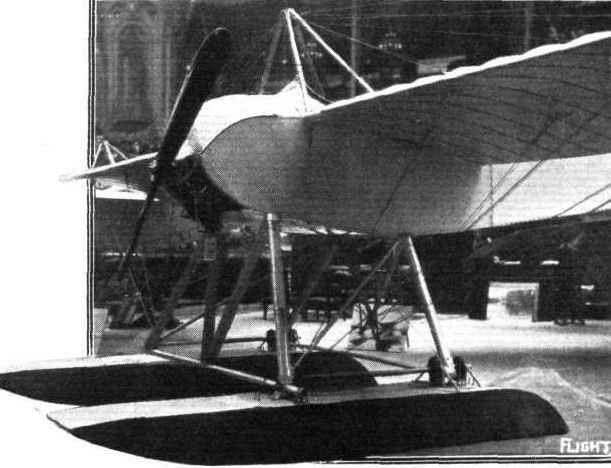
Borel hydro-monoplane.

The Borel exhibited at the Paris Salon.

The 80-h.p. Borel hydro-monoplane.

Sketch showing the two main floats, the chassis and the engine mounting of the Borel hydro-monoplane.
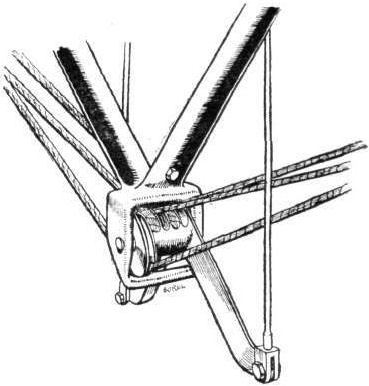
The lower pylon of the Borel hydromonoplane, showing warping gear.
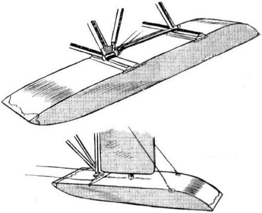
One of the main floats and the small tall float of the Borel hydro-monoplane.
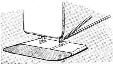
The tail float of the Borel hydro-monoplane, which is rigidly connected to the rudder and moves with it, thus acting as a water rudder when the machine is "taxying.''
HYDRO-AEROPLANES. - Fig. 5. - Types of Aeroplanes.
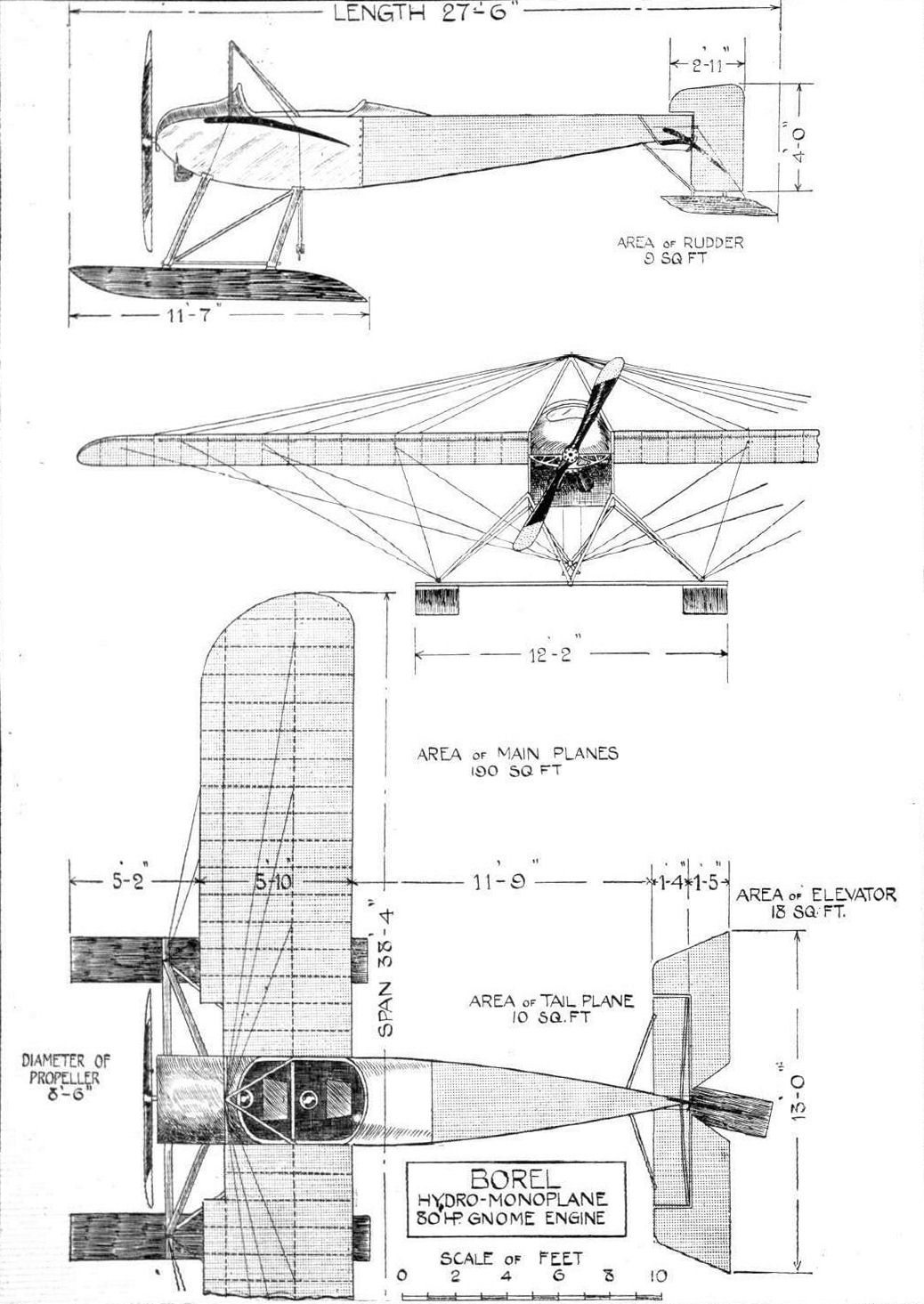
BOREL HYDRO-MONOPLANE. - Plan, side and front elevations to scale.
Flight, August 23, 1913.
THE BOREL MILITARY MONOPLANE.
As the new 80 h.p. Borel monoplane has been specially designed to comply with the requirements of the military authorities, the first consideration has naturally been given to the provision of such qualities as are desirable, not to say essential, in a military machine. As these qualities include speed, weight-carrying power, stability, wide range of vision, facilities for bomb dropping, and the installation of quick-firing guns, as well as a wireless telegraph apparatus, it will be easily understood that numerous difficulties - aero-dynamic and constructional - have to be overcome in order to produce a machine embodying all of these features, and all credit is due to the Borel firm for their bold attempt to solve the problem.
From a glance at the accompanying illustrations it is at once apparent that the most noticeable departure from usual Borel practice lies in the positions of the pilot and the propeller. Whereas all previous Borel monoplanes have been of the tractor type, it will be seen that in this machine the propeller is placed behind the main planes, whilst the pilot's and passenger's seats are situated well out in front of the wings. Needless to say this position provides an excellent view in all directions for the pilot, while the passenger is also so situated that he is able to survey practically all that lies beneath the machine.
In the construction of the nacelle, which is of rectangular section, provision has been made for the mounting of a quick-firing gun, which will be worked by the passenger, whose seat, it will be observed, is placed slightly in front of the pilot's seat, thus giving both more room to enable them to operate gun and controls, respectively, without interfering with each other. The nose of the nacelle has been so designed that in flight it will deflect the air upwards over the heads of the occupants, who will fully appreciate this little attention to their comfort. In the rear end of the nacelle is the 80 h.p. Gnome engine supported between two pressed-steel frames, the front one of which serves at the same time as a support for the rear-wing spar and the rear members of the top pylon. The rear engine frame carries a ball-bearing, in which runs the propeller-shaft, or, more correctly speaking, the extension of the crank case on which the propeller is mounted.
In a monoplane of the engine-behind type, one of the constructional difficulties is that of suitably mounting the tail planes on an outrigger which will withstand torsional strains and at the same time allow of the propeller clearing all its members. In the Borel military monoplane this difficulty has been overcome by constructing the outrigger of three instead of four booms. These are in reality steel tubes, the upper one of which abuts against the boss of the propeller through the interposition of a ball-bearing. The two lower members are secured to the rear end of the chassis skids. One of our sketches shows the method of joining the struts to the tail booms, and it will be noticed that the joint is effected without piercing either boom or strut, and thereby weakening them. Another sketch shows the chassis, which impresses one as being particularly strong without affording an undue amount of head resistance. On the rear ends of the main skids will be noticed two small tusk-like extensions which are sprung in order to lessen shocks due to the tail dropping and which perform really the duties of a tail skid in the absence of a special fitting of that nature.
An interesting point in connection with the control of the machine is that the rudder and elevator cables are carried inside the two lower tubular tail booms, so that should any one of them break there is no danger of them becoming entangled in the propeller.
It has already been said that a wireless telegraph apparatus is carried. This in itself can hardly be said to be a novelty, as already messages have been sent from aeroplanes in flight, but once the machines are on the ground their utility for transmission of wireless messages is greatly decreased owing to the lack of a mast on which to secure the antennes.
The Borel machine has been so designed that it can be made to form its own mast. By standing the machine on its nose, so that it rests on the skids and on the nose of the fuselage, the tail booms are inclined upwards. Another pair of tubes of smaller diameter, which during flight are enclosed in the lower tubular tail booms, now form extensions on which the antennes may be mounted. A small auxiliary motor is provided for the production of the necessary current.
When put through its preliminary trials by M. Daucourt the machine behaved excellently, getting off easily with a passenger and three hours' fuel.
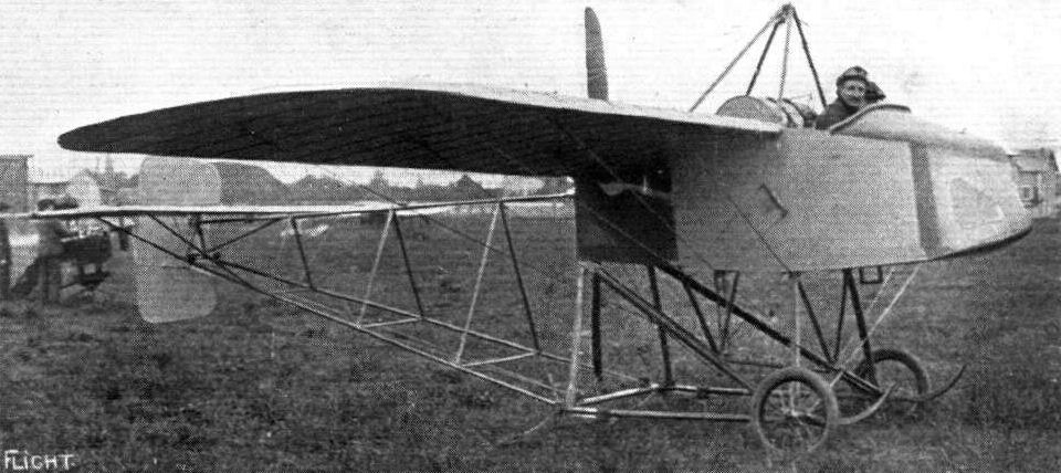
View from in front of the new Borel.
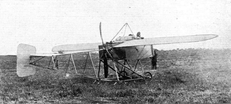
The new Borel military type monoplane.
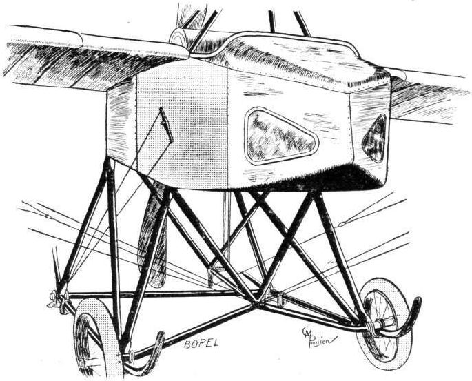
The nacelle and the landing chassis of the new Borel.
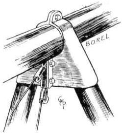
Sketch showing method of joining struts to tail boom of Borel without piercing either.
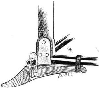
Small sprung rear skid on heel of Borel main skids.
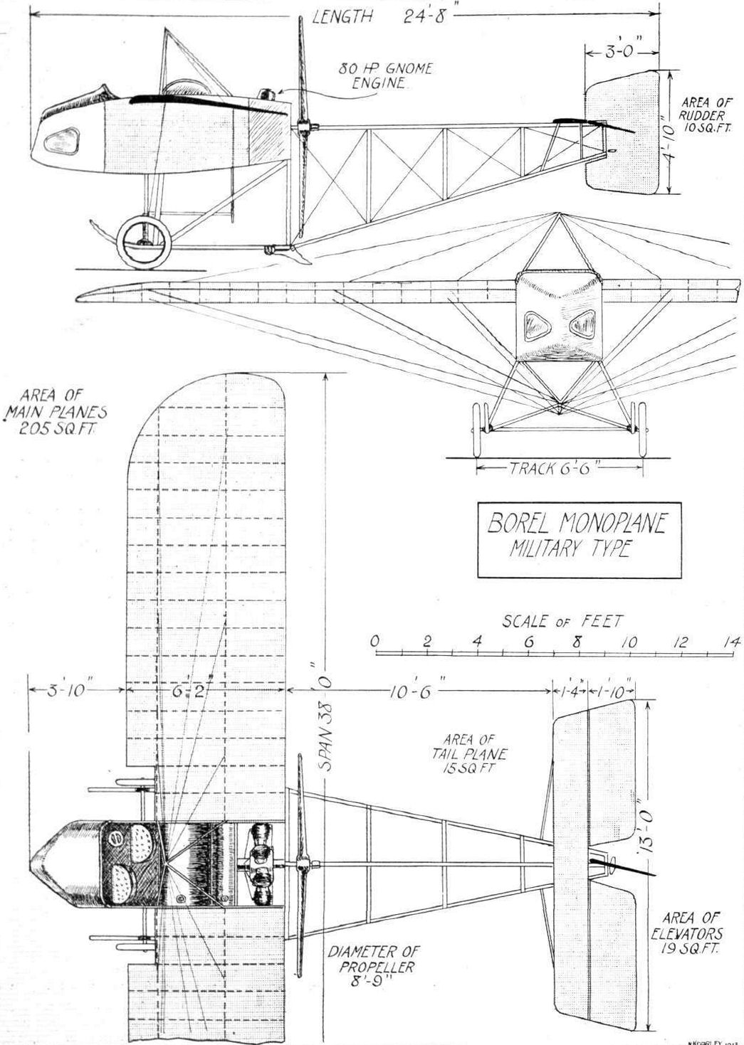
THE BOREL MILITARY TYPE MONOPLANE. - Plan, side and front elevation to scale.
Flight, December 13, 1913.
THE STANDS AT THE PARIS AERO SHOW.
BOREL.
Societe Anonyme des Aeroplanes Borel are represented by three machines. One is a land machine of the military-type tandem two-seater, the pilot occupying the rear seat. A hydro-aeroplane of a similar construction as the land machine, with the exception, of course, that it is fitted with floats instead of wheels, is also shown, but the centre of interest of this stand is undoubtedly the torpedo type of machine on which is mounted a machine gun. In its general appearance this machine is somewhat reminiscent of the Paulhan-Tatin aerial torpedo. The pilot's and passenger's seats are situated in the forward portion of the fuselage, whilst the engine is placed inside the fuselage and behind the passenger's seat, and drives through a long shaft the propeller which is situated at the rear of the fuse/age behind the tail planes. In the nose of the machine is mounted a machine gun (Hotchkiss) which is operated by the passenger.
Flight, December 27, 1913.
THE PARIS AERO SALON - 1913.
BOREL.
Three machines are exhibited on the Borel stand - one military tandem two-seater, a hydro., and the "Ruby." The land machine, which is fitted with a 100 h.p. L.U.C.T. engine of Italian manufacture, is of the standard Borel type. The fuselage is built up of longerons of ash, while the struts and cross-members are ash in front and spruce in the rear portion. The seats are arranged tandem fashion, the pilot occupying the rear seat. The controls are the usual Borel, and may be said to be simply the Bleriot controls without the "cloche." The chassis consists of ash struts carrying two short skids, also of ash, from which are sprung the wheels by means of rubber bands wound round the axle and the skid. The hydro-monoplane is also a tandem two-seater and is similar to those now in use in the Navy. It is driven by an 80 h.p. Gnome engine mounted in front of the fuselage on double bearings, of which the front one can be detached by undoing two bolts, thereby facilitating the operation of removing the engine. The fuselage is exactly similar in construction to that of the land machine. The chassis consists of a structure of streamlined steel tubes, which carry at their lower ends the two main floats. These are pivoted round a transverse tube mounted on the front chassis struts, and are sprung at the rear by means of rubber shock absorbers. Owing to the width of the chassis the angle of the lift wires is extremely good, the inner one being almost vertical.
The pilot's and passenger's seats are arranged tandem fashion, each in a separate cockpit, and the controls are of the usual Borel type. A small float, which turns with the rudder, enables the machine to be steered on the water at slow speeds.
The wings are attached to the fuselage by two bolts passing through the spars, the bolt through the front spar being vertical, while the rear spar bolt is horizontal to allow of the wings being warped without bending the spar. In order to provide a better view in a forward and downward direction, the leading edges have been cut away for a distance of a couple of feet on each side of the fuselage.
<...>

The Borel military monoplane.
The Borel exhibited at the Paris Salon.
Flight, December 27, 1913.
THE PARIS AERO SALON - 1913.
BOREL.
<...>
The remaining machine - the "Ruby" - is undoubtedly the most interesting on the stand, as it represents a very radical departure not only from usual Borel design, but from aeroplane design in general. The raison d'etre of this machine is the consistent demand of the military authorities, for a machine in which the propeller is mounted behind the main planes, while the pilot's and observer's seats are situated well out in front, partly to facilitate observation and partly to allow of a gun being mounted in such a manner that it may be fired in all directions without the propeller interfering with it.
The fuselage, which is of rectangular section, and which tapers gradually towards the bow and the stern, is built up of four longerons of ash, connected by struts and cross-members of spruce. In the central part of the fuselage, and between the two planes, is mounted the engine - a 50 h.p. Gnome - which drives, through a long shaft, a small propeller situated behind the tail-planes. Where the four longerons converge in the rear of the fuselage, is a ball thrust bearing which relieves the long shaft of all end thrust. In the front part of the fuselage are arranged the seats for the pilot and passenger, the pilot occupying the front seat. In front of him is a Hotchkiss machine gun mounted on the apex of a structure of three steel tubes secured to the nose and upper longerons of the fuselage, respectively. Control is by means of a single central steel tube, which operates the warp and elevator, whilst a pivoted foot-bar actuates the rudder.
The chassis is of a very simple form, and consists of two pairs of ash struts, each pair forming a V. Two stub axles, which are pivoted on another pair of V struts, and work in slots between the chassis struts, are sprung from these by means of rubber shock absorbers.
The tail planes, which are of rather unusual shape, as well as the tail skid, are illustrated by one of the accompanying sketches.
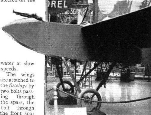
The Borel "Ruby".
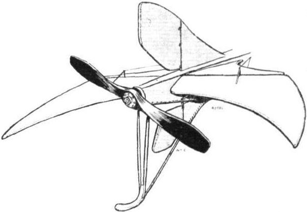
The propeller and tall planes of the Borel "Ruby."
Flight, February 22, 1913.
SOME MORE AEROPLANES AT OLYMPIA.
BREGUET AEROPLANES, LTD.
Breguet Aeroplanes, Ltd., who since July of last year have been constructing military biplanes under licence from the French Breguet firm, have on exhibition an 85-h p. Breguet Warplane, the seventh machine they have built since their works at Willesden were put in operation. The outstanding feature of the machine is that it is built throughout of steel, wood being only employed for the manufacture of its ribs. Since he first turned his mind to aeroplane construction, Louis Breguet has favoured steel as the medium of construction of his machines, and to him must be given the credit of having "set the fashion," as it were, for this system of manufacture. He, also, was one of the first to construct a tractor biplane, a type of machine which he has helped, in no small manner, to popularise. At first he was laughed at for his pains; his biplane was jokingly spoken of as a "coffee pot." But since, he has earned the recognition that he so well deserved.
Next in order of importance of the features of his machine is the peculiarity that the supporting and directional surfaces are flexible. The controls, even, are not directly connected to the planes that they operate; steel tension springs are inserted in the control wires, so that, however harsh may be the pilot's movements of his controlling lever, the directional planes change their attitude gently. It is claimed for the Breguet machine that it has been designed as one harmonious whole, not merely as a series of separate units, such as body, chassis and planes, afterwards assembled together.
The body is of two distinct parts, that forward of the pilot's seat, and the portion that extends away behind it. The latter section is formed by a single steel tube, some three inches in diameter, which is braced by numerous steel wires to a four-armed steel fitting welded over the tube just behind the pilot's seat. By the application of sheet aluminium over these wires a very good streamline covering is obtained. The aluminium covering is further supported by longitudinal wood stringers. To the rear end of the large diameter central tube is attached the tail, universally jointed. In front of the pilot's seat, the foundation of the fuselage is formed by two U-section steel girders, wood filled. At right-angles to them, in front of the passenger seat, are fitted the two uprights to which the top planes are attached. Still further in front they converge to form a substantial base to which the motor is bolted. From a casual glance at the machine, no one would think that the body is built in two sections, so gracefully is it streamlined from end to end. At the forward end the motor, an 85-h.p. 7-cylinder Canton Unne, is fitted, driving direct a propeller, the boss of which is covered by a semi-spherical cowl which effectively preserves the excellent lines of the body. Seated in a comfortably upholstered seat, the pilot controls the machine in its three dimensions of altitude, balance, and direction, by a hand-wheel, mounted on a pivoted column, and by foot pedals. On French built Breguets the warping of the planes is operated by rocking the vertical column laterally. On this point it is evident that the designers of the British Breguets have different ideas, for the plane warping on the biplane exhibited at Olympia is effected by means of the foot pedals. The hand-wheel rotates laterally, and is used to steer the biplane in a manner exactly similar to that of a car. The machine is made to rise or descend by rocking the column to and fro.
The landing gear is of a type by itself, since no other aeroplanes are, to our knowledge, fitted with an undercarriage that resembles it in the least. At rest the main weight of the machine is supported by two large diameter tyred-wheels, which are connected to the body by a pair of tubular oleo-pneumatic springs. Some part of the main weight is further taken by another pair of wheels in front of a much less track, which are jointed to a laminated cross spring bolted laterally across a tubular strut which extends downwards from the extreme nose of the body. These two front wheels are so designed that they pivot in conjunction with the rudder, and in this manner the machine may be effectively steered over the ground at slow speeds.
The planes are built about single tubular steel spars, which are universally jointed to the body. Over them fit the wooden I-section ribs, and they would be free to revolve around the spars were they not kept in position by steel leaf springs. These springs are so arranged that the faster the machine is driven through the air the less incident the ribs, and consequently the planes, become to the direction of the air flow. Owing to this system of plane conduction, which is fully patented, by the way, the machine is rendered unusually stable and at the same time is given a remarkably wide speed range.
Flight, September 6, 1913.
The Maidenhead Smash.
IT was tragical that after his success in the Speed Contest at Hendon on Saturday Debussy should have met with disaster later in the afternoon when taking the machine across to Farnborough. He started from Hendon on the Breguet with Mr. H. de Havilland, who only recently qualified for his brevet, and Mr. R. G. Crouch, of the Breguet Co., as passengers, at about half-past five and all went well until over Maidenhead, when the engine began to give trouble, subsequently found to be due to a broken exhaust-valve. As the engine stopped, the pilot apparently tried to plane down into a field near Bray, but from a height of 60 ft. the machine, after flattening out, dived into a field of mangolds. All three occupants were seriously injured, Mr. Debussy sustaining concussion of the brain and a bad sprain of the right ankle, Mr. de Havilland had his left arm fractured, while Mr. Crouch had his right leg broken, both the latter being also cut and bruised a good deal.
Flight, December 13, 1913.
THE STANDS AT THE PARIS AERO SHOW.
BREGUET.
The Breguet firm are showing on their stand one complete hydro-aeroplane with a large central float and two smaller ones situated about half-way along the main planes. Between the two front members of the chassis is mounted a strong headlight which derives its current from a "Radios" dynamo. In addition is shown a fuselage which has been left uncovered for the purpose of showing the new construction, which appears to be a great improvement on that employed in earlier machines. A wireless transmitting apparatus is fitted in front of the observer's seat, where is mounted on a small writing desk the telegraph key and a writing pad. One is inclined to think that the use of the latter would be somewhat hampered by the vibration of the machine when in flight, as the table is not sprung in any way.
Flight, December 27, 1913.
THE PARIS AERO SALON - 1913.
BREGUET.
The first impression one receives of the Breguet hydro-biplane exhibited is one of strength and power, and a closer inspection confirms the correctness of this impression. In its general lines this machine resembles the previous Breguet hydros., but an examination of the constructional details soon reveals numerous improvements which should almost totally rectify most of the points that met with adverse criticism in earlier machines of this make.
The fuselage, which is still built of steel practically throughout, is constructed on a quite different and greatly improved principle. It will be remembered that in the earlier machines the rear portion of the fuselage consisted of a single steel tube stiffened with wire bracing which, whilst probably perfectly safe as far as bending stresses are concerned, could not be all that was to be desired for torsional strains. In the present machine this single tube has been supplanted by four thinner steel tubes forming a girder in the more orthodox way with struts and cross members and diagonal wire bracing. On this steel structure are mounted wooden distance pieces connected by longitudinal stringers, which gives the fuselage its streamlined form, the whole being afterwards covered with fabric. The two seats are arranged tandem fashion, the pilot occupying the front one. In front of him are the controls which consist of a rotatable handwheel for steering and elevation and descent. A foot-bar actuates the ailerons, with which one is pleased to note that this machine is fitted. Another improvement has been effected in the wing construction, as the flexible mounting of the ribs on the tubular spars has been discarded. One cannot help wondering, however, why M. Breguet does not go a step further and employ two rows of struts, which method of construction would increase the strength immensely and more than compensate for the extra weight and head resistance of a few extra struts. However, a diagram displayed on the stand shows a loading test, which appears to have proved that the new wing construction possesses ample strength for any practical purpose.
The machine is supported on the water by a big central float and two smaller ones under the first pair of inter-plane struts. The centre float is attached to the fuselage by four steel tubes, of which the rear pair have coil springs introduced in them, while the front pair forms a swivelling joint with the float, thus providing springing of the rear portion of the main float. A small tail float protects the tail planes against contact with the water. The engine - a 130 h.p. Salmson radial water-cooled motor - is mounted in the nose of the fuselage on steel bearers, which are further strengthened by two tubes running up to the upper ends of the two inner plane struts. The radiator, which has been given a shape resembling that of a wing section, is mounted in the place usually occupied by the centre part of the upper plane, a position which ought to combine the advantages of little head resistance and effective cooling.
In order to facilitate alighting in the dark, a strong headlight has been fitted on a transverse tube between the two front chassis struts. The current for this headlight is furnished by a "Radios" dynamo.
The tail planes are of the usual Breguet cruciform type, and are attached to the fuselage by means of a universal joint. A very large tail fin runs along the top of the fuselage from the passenger's seat back to the tail. The object of this fin, which is not fitted on the land machines, is, no doubt, to balance the considerable side area of the central float. The front portion of the fuselage is covered with aluminium, which is fitted very nicely round the engine cylinders, of which only the upper part projects outside the aluminium.
The rear part of the fuselage is covered in the usual way with fabric applied to the longitudinal stringers which give the fuselage the streamline form.
The uncovered fuselage shown is of a similar construction to that of the hydro., and is interesting chiefly on account of the wireless apparatus with which it is fitted. The key of the transmitter is mounted on a small table in front of the observer, and the practical demonstration of the wireless given at the Show never fails to attract a great crowd of interested onlookers, as the hissing of the sparks can be heard distinctly to the farthest corner of the Grand Palais. The wireless installation has been carried out by the Societe Francaise Radio-Electrique. The output of the transmitter is 750 watts, and the frequency is 1,500 periods. It has a range of 200 kiloms., and the total weight is 47 kilogs.
The workmanship in the complete machine as well as in the skeleton fuselage is very good, although no attempt has been made to provide a highly polished "show finish."
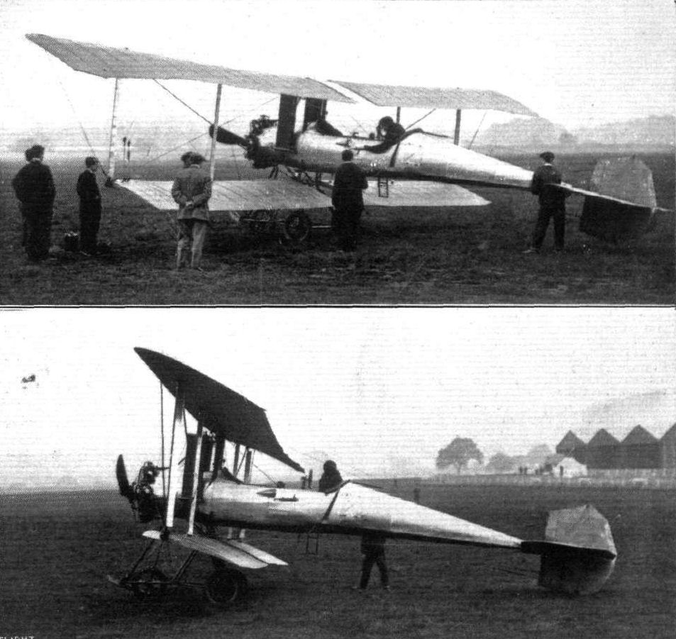
Two views of the Breguet biplane, fitted with a 90-h.p. Canton Unne engine, on which M. Richet has been making some successful flights up at the Hendon Aerodrome.
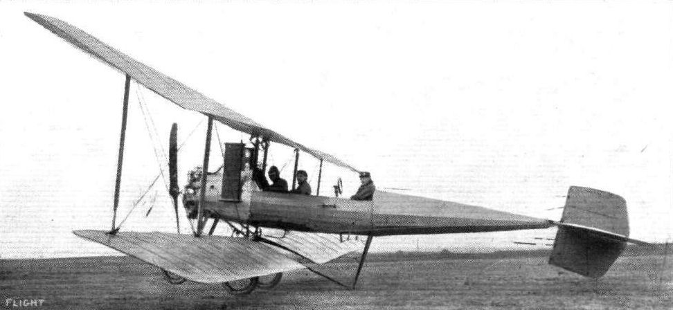
One of the latest Breguet biplanes which differs from its predecessors in the central steel tube being replaced by a framework of steel tubes tapering to the tail. It is also fitted with a brake operated by a lever under the pilot's seat. The engine is a 110 h.p. 9 cyl. Canton-Unne.
Gustav Hamel, on his Bleriot, and M. Richet, on the Breguet, during the race at Hendon for the Aero Show Trophy.
Mr. Norman Spratt on the Breguet (below) and Mr. Marcus D. Manton on the Grahame-White biplane, flying for the Shell Trophy at Hendon on Saturday last.
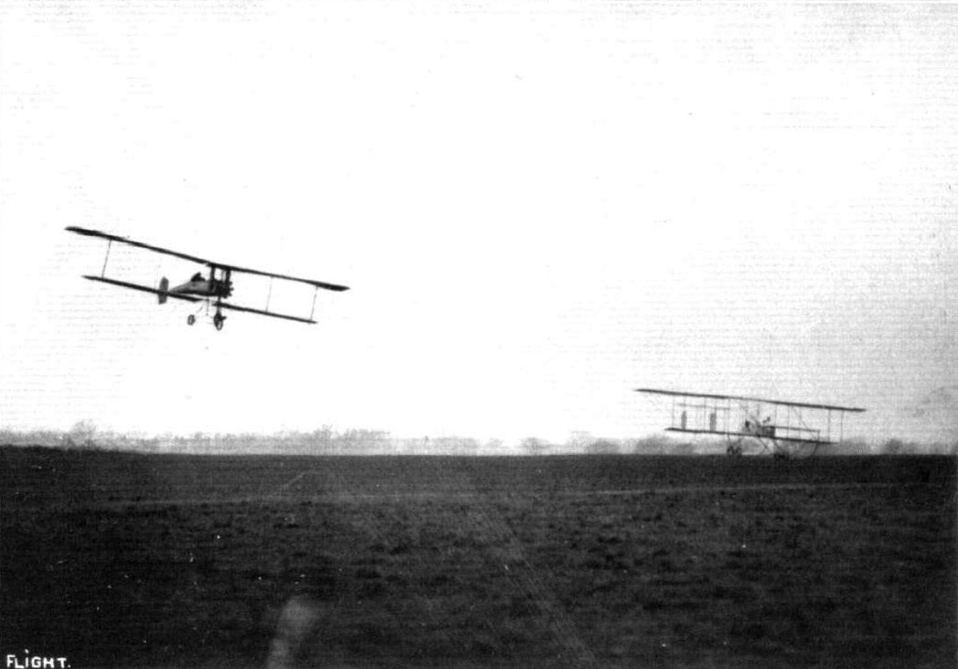
A DEAD HEAT AT HENDON. - An exciting finish at the Easter Monday Meeting, when Verrier, on a Maurice Farman, and Collardeau, on a Breguet, crossed the line at the same time in the Grand Speed Handicap, Verrier being on the right quite low.
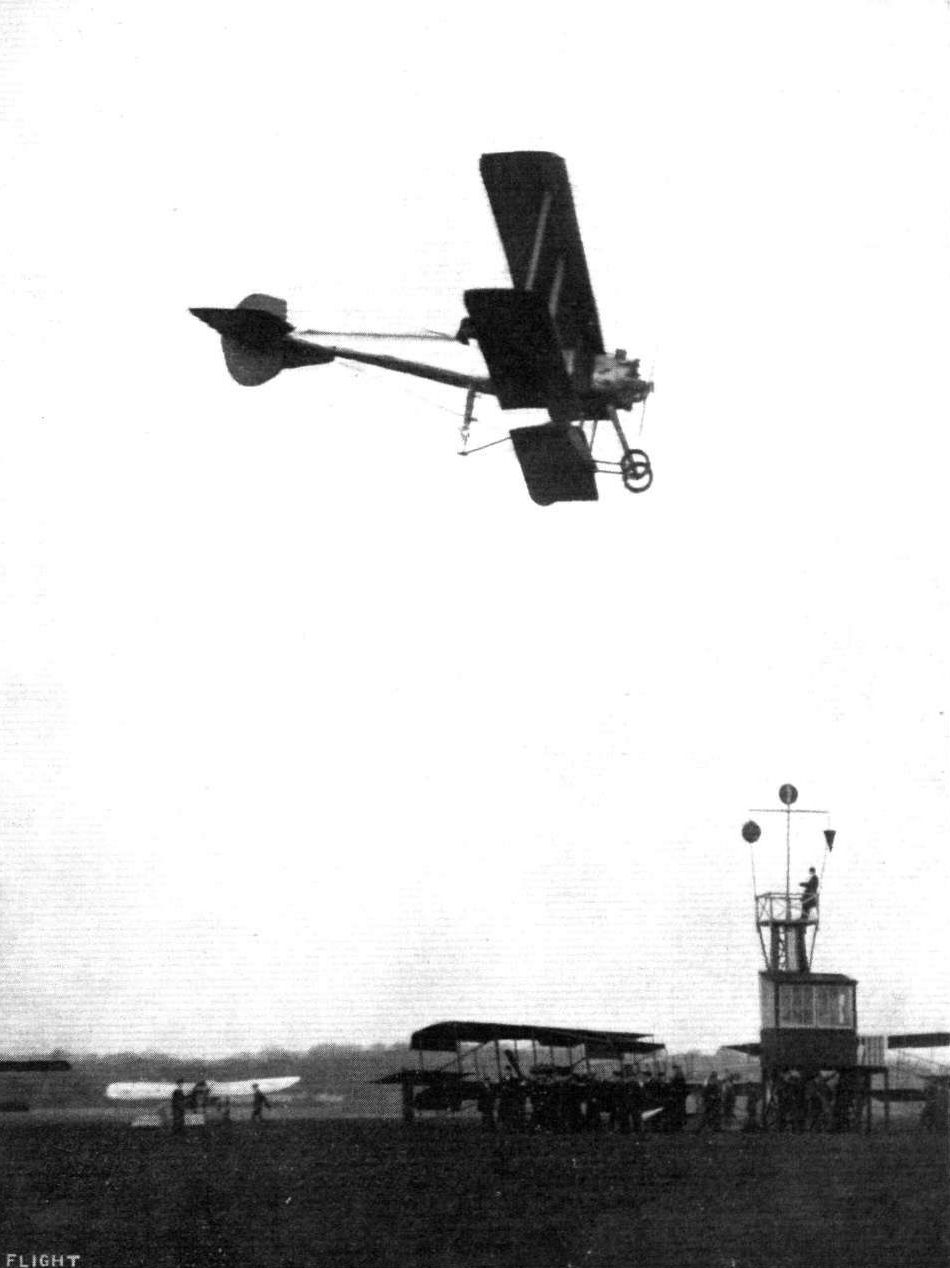
Mr. Norman Spratt flying the Breguet biplane at Hendon aerodrome.
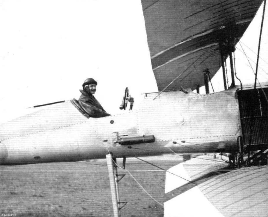
M. A. Debussy in the pilot's seat of the Breguet biplane with which he came to grief on Saturday last.
M. A. Debussy on the Breguet, overtaking Carr (below), on the Grahame-White biplane, in a speed handicap at Hendon.
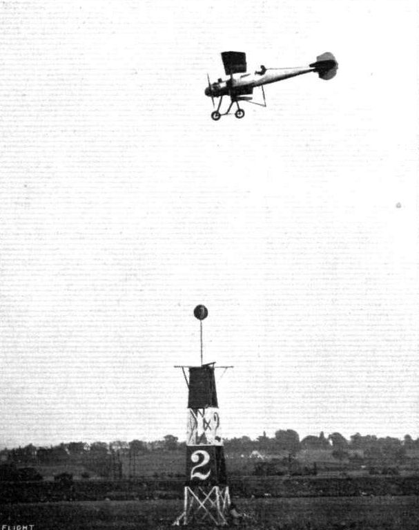
M. A. Debussy flying the Breguet biplane at Hendon prior to his cross-country flight to Farnborough on Saturday last.
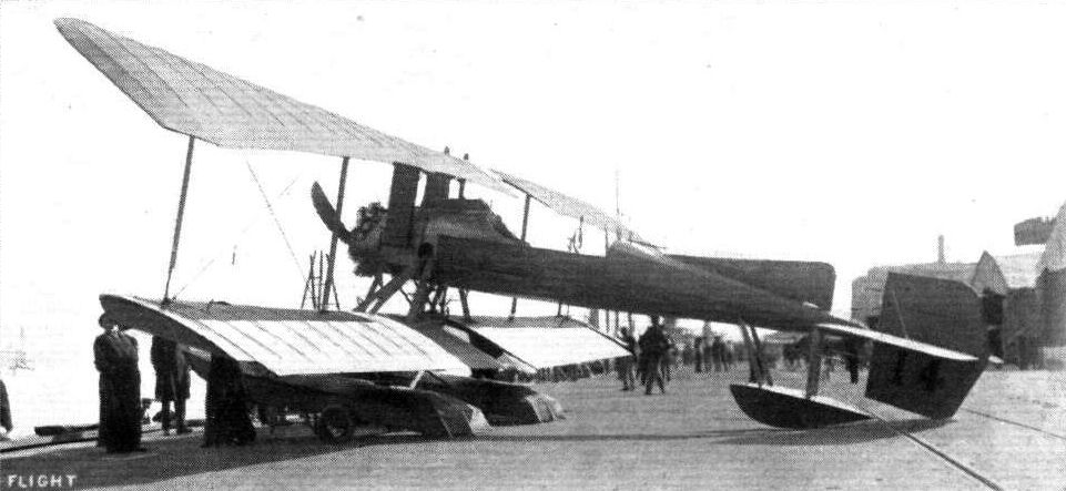
A Breguet waterplane of the same type that Bregi has been flying at Brighton daily. This machine is fitted with a 130 h.p. Canton-Unne motor and with compressed air self-starting arrangement. Bregi has been taking up two and three passengers at a time.

A Breguet getting ready to rise.
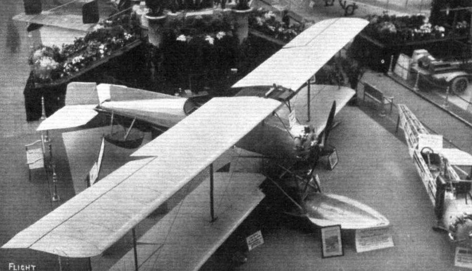
The Breguet biplane at the Paris Salon.
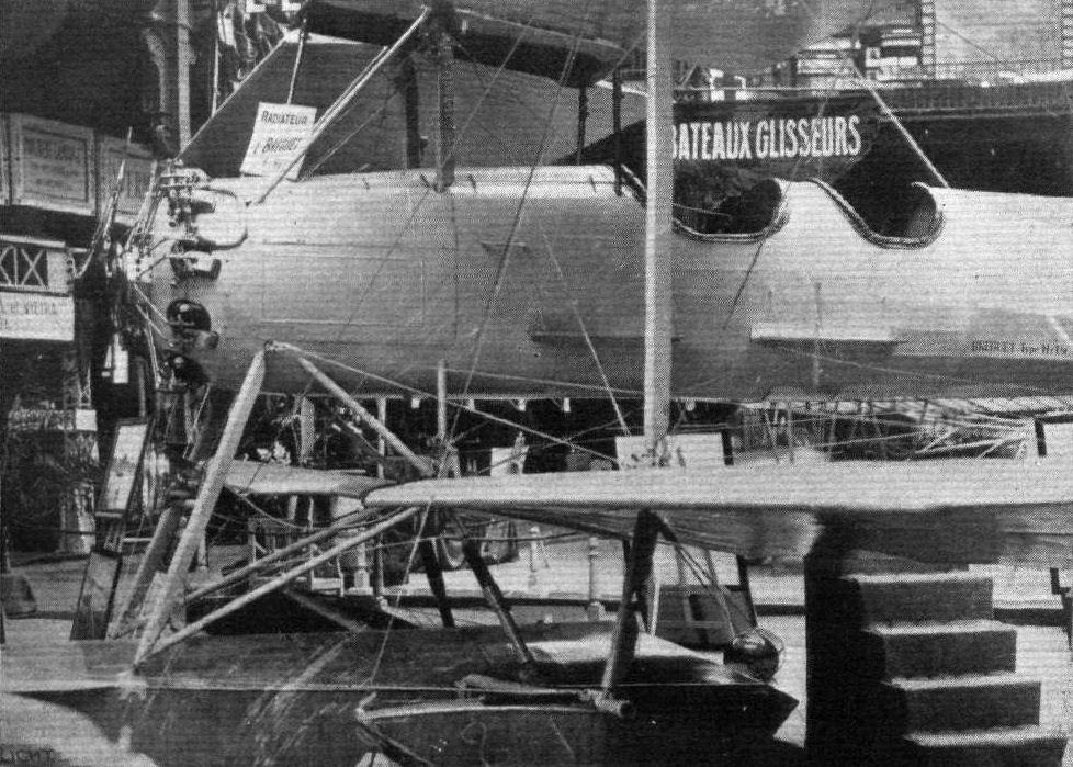
The Breguet hydro-biplane.

Observer's seat and wireless installation on the Breguet.

Main float of Breguet hydro.
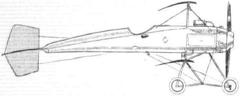
The 85-h.p. Breguet biplane.
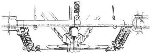
Flexible suspension of the front pair of steerable wheels of the Breguet biplane.
A study in tails.
Flight, February 8, 1913.
WHAT THERE WILL BE TO SEE AT OLYMPIA.
THE MACHINES.
The W. H. Ewen Aviation Co., Ltd.
This well-known firm, with centres at Hendon, Lanark, and Glasgow. Will be showing two machines on their stand No. 47, a monoplane and a biplane. Originally they had made arrangements to exhibit a 50-h.p. Gnome-engined single-seater monoplane, and a 35-h.p. Y-type Anzani biplane, both brand-new and of Caudron design and manufacture. However, such has been the demand, that they have sold both these machines, the monoplane to a well-known English customer, and the biplane to Mr. A. W. Jones, who has despatched it to Australia, where Mr. Jones holds the agency for Caudron machines. Thus the Ewen firm have had to fall back on machines that they had already in stock, and for that the exhibit will be none the less interesting. In place of the 50-h.p. Gnome-Caudron monoplane, they will show the 45 h.p. Anzani-engined single-seater, of which Mr. Ewen took delivery at Crotoy and flew back to England in the early part of last year. On this same machine too, M. Guillaux flew in connection with the Aerial Derby last year. Although comparatively low-powered, such was the machine's speed that that excellent pilot would have probably won the race had he not, when quite near the finishing point, lost his way, and then run out of petrol. The monoplane is especially interesting for the fact that it is one of the smallest and speediest successful monoplanes built.
For the biplane, Mr. Ewen is making an attempt to get delivery from the French Caudron works of a new 35-h.p. biplane. If he cannot get delivery in time, his firm will exhibit their brevet biplane, on which, at Hendon, something like 15 tickets have been taken inside seven months. Naturally it will not be a show-finished machine; it will be shown, taken direct from strenuous school work, in its natural oil and mud-bespattered condition.
In addition, the Ewen Co. will have on their stand samples of Kelvin compasses, which have a reputation for being the most deadbeat instruments of their kind ever constructed. They will also be showing a range of Gremont propellers and a type of petrol motor of quite revolutionary design.
Flight, February 15, 1913.
<...>are hinged to the body of the machine by a steel joint that is shown in one of our sketches.
The landing gear carries two rolling wheels which are mounted on axles radiating on either side from the centre V of the chassis. Each axle is sprang at a point near the wheel by rubber cord which passes under a crutch formed at the junction of two ash struts in V. The illustrations we publish will make this point clear. A small tail skid is fitted. There is a curious point regarding the "set" of the rolling wheels. Their axles are set back at a small angle behind the line at right angles to the rolling path, a feature, it is claimed, by which any tendency of the machine to veer, when rolling, to either side of its straight path, is removed.
The tail has an area of 29 sq. ft., and is clamped to the fuselage by several U bolts. Its rear portion is flexible, and it is that portion that controls the attitude of the monoplane when in flight. The rudder is mounted wholly above the tail surface.
The pilot sits quite low in the body of the machine, so that his head alone emerges from the well-padded sides of the cockpit. He controls the elevation and warping by a centrally arranged universally-jointed lever. The rudder is manipulated by a pivoted foot bar.
Flight, September 20, 1913.
THE AERIAL DERBY.
PILOTS AND HOW TO RECOGNISE THE MACHINES.
No. 14. The Caudron Monoplane
somewhat resembles the Morane-Saulnier monoplanes, but differs from those machines in several respects. The body is of a different form and the elevator and tail plane is much larger.
THE MACHINES, WITH SOME DETAILS.
No. 14. The 45 h.p. Anzani-Caudron monoplane. - This is the same monoplane that Mr. Ewen flew over from France early in 1912. It is astonishingly small, and, considering the comparatively low engine power, surprisingly swift. The span is 25 ft. 6 ins., and the wing construction is the same as that employed in the Caudron biplane. It is altogether a startlingly efficient monoplane, its diminutive size and graceful lines tending to conceal its truly wonderful turn for speed: it has attained a speed of 95 m.p.h.
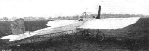
The Caudron monoplane.
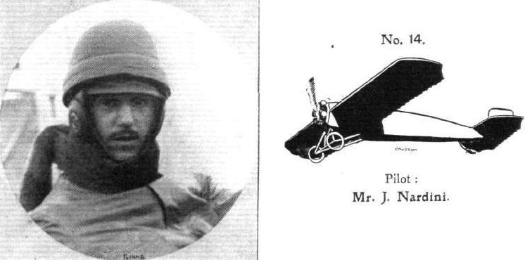
Pilot: Mr. J. Nardini.
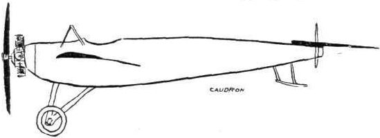
The 45-h.p. Caudron monoplane.
AT OLYMPIA. - A study in tail-skids.
A study in tails.
Flight, February 8, 1913.
WHAT THERE WILL BE TO SEE AT OLYMPIA.
THE MACHINES.
The W. H. Ewen Aviation Co., Ltd.
This well-known firm, with centres at Hendon, Lanark, and Glasgow. Will be showing two machines on their stand No. 47, a monoplane and a biplane. Originally they had made arrangements to exhibit a 50-h.p. Gnome-engined single-seater monoplane, and a 35-h.p. Y-type Anzani biplane, both brand-new and of Caudron design and manufacture. However, such has been the demand, that they have sold both these machines, the monoplane to a well-known English customer, and the biplane to Mr. A. W. Jones, who has despatched it to Australia, where Mr. Jones holds the agency for Caudron machines. Thus the Ewen firm have had to fall back on machines that they had already in stock, and for that the exhibit will be none the less interesting. In place of the 50-h.p. Gnome-Caudron monoplane, they will show the 45 h.p. Anzani-engined single-seater, of which Mr. Ewen took delivery at Crotoy and flew back to England in the early part of last year. On this same machine too, M. Guillaux flew in connection with the Aerial Derby last year. Although comparatively low-powered, such was the machine's speed that that excellent pilot would have probably won the race had he not, when quite near the finishing point, lost his way, and then run out of petrol. The monoplane is especially interesting for the fact that it is one of the smallest and speediest successful monoplanes built.
For the biplane, Mr. Ewen is making an attempt to get delivery from the French Caudron works of a new 35-h.p. biplane. If he cannot get delivery in time, his firm will exhibit their brevet biplane, on which, at Hendon, something like 15 tickets have been taken inside seven months. Naturally it will not be a show-finished machine; it will be shown, taken direct from strenuous school work, in its natural oil and mud-bespattered condition.
In addition, the Ewen Co. will have on their stand samples of Kelvin compasses, which have a reputation for being the most deadbeat instruments of their kind ever constructed. They will also be showing a range of Gremont propellers and a type of petrol motor of quite revolutionary design.
Flight, February 15, 1913.
<...>
The 35-h.p. Caudron Biplane is a machine that is becoming increasingly popular. The small model similar to the one shown at Olympia, is chiefly used for instruction work, although many similar ones are privately owned. They are quite inexpensive to buy, and are not by any means difficult to handle, as machines go. The French army own several of this type and use them for instruction purposes As well, of course, they have many of higher engine power, which are used for more serious work. There is at present under test at Farnborough one of these machines fitted with a 70-h.p. Gnome motor which we are inclined to believe has given very good results. In a wind they behave extremely well, for the rear portions of the planes are very flexible, thus allowing the machine to ride through a gusty wind with a certain smoothness, in the same manner as a well-sprung car may travel over rough road surface without the jars being particularly noticeable to those seated inside.
The planes span 30 ft. and 23 ft. 3 ins. respectively, and have a chord measurement of 4 ft. 6 ins. They are separated by 12 stanchions and braced strongly with piano wire. As in the monoplane, the main spars are placed only about 18 ins. apart. The ribs are cut from French poplar and overhang the rear spar nearly 3 ft., forming the flexible trailing edge that we have referred to above. Warping is employed to correct lateral equilibrium.
The body is a small coracle-shaped structure built up in the same manner as a monoplane fuselage. The front is capped by a steel plate, and to this the motor is bolted. Subsidiary supports, in the form of steel tubes support the front of the crank case. The remainder of the body is covered in by fabric to give it a fair streamline shape, and to help shelter the pilot from the wind. The body of the machine at Olympia is fitted with a superstructure that covers in the fuel tanks and acts as a very convenient wind shield. Seated comfortably inside, the pilot has between his knees a vertical jointed lever by which he controls the warping and elevation of the machine. The twin rudders are worked from a foot bar.
The tail is a flexible monoplane surface supported by ash outriggers. A peculiarity of this outrigger construction is, that the lower outrigger members continue forward underneath the machine to form the landing skids. While simplifying the construction considerably, this system has the advantage that these lower outriggers can be made to drag heavily along the ground at the completion of a flight, thus bringing the machine quickly to rest. Again, they are very useful for holding the machine back while the engine is tested, perhaps a minor point, but nevertheless one that is greatly appreciated by the mechanics that attend the machine. They merely have to stand on these outriggers and the outriggers themselves do the rest.
The landing gear is formed by strapping Farman-type wheel units over these outrigger members we have referred to above. Being quite low the chassis is very strong compared with its weight. It is a very ordinary affair - but what matters, it completed the greatly feared rolling test at Farnborough at the first time of asking, without any damage, and there are very few machines that can boast of having done that.
Flight, March 22, 1913.
TEACHING FLYING.
By LEWIS W. F. TURNER.
[These remarks, expressed in simple, everyday language by Mr. Lewis Turner, who through 1912 was one of our busiest flying instructors, will be found of great interest. Mr. Turner was attracted towards aviation in the early days, and first tasted the sensation of flying by going up as a passenger with Mr. Grahame-White, when the latter pilot was flying at the Bournemouth Aviation Meeting in 1910. Following up his enthusiasm, he decided to learn to fly, and, selling his motor business in Dorsetshire, he joined the Grahame-White School at Hendon. That was toward the end of February, 1911. He obtained his flying credencials on April 1st, having the distinction of being the first pilot in England to obtain his brevet after the new right-hand turn test regulations came into force. Thus qualified, he joined the sincedefunct Aeronautical Syndicate Flying School as Pilot Instructor, and flew Valkyrie monoplanes. Leaving that School in August, he went to Russia as Chief Pilot and Engineer to the Kennedy Aviation Company of St. Petersburg. Returning to England in January of last year, he was engaged by the Crahame-White Aviation Company as Chief Pilot and Instructor to the School. Throughout the season until November, when he left that firm, he flew practically every day in all sorts of weather, and had charge of the School instruction work, proving a most painstaking tutor, Mr. Turner it now engaged as Chief Pilot to the W.N. Ewen Aviation Co.'s Schools at Hendon and Lanark.-Ed.]
NOWADAYS it is safe in remark that any pupil who can keep a fairly clear head and who has quite an average amount of common sense can soon learn to fly. He does not need to be an expert at engineering, or particularly well versed in the aero dynamical considerations underlying the flight of an aeroplane. If he is an expert in both these subjects, so much the better, for with an engineer's knowledge he should have an engineer's instinct, and instinct plays a great part in the making of the future airman. A man, to be a good flyer, must necessarily have complete sympathy with his machine. He must not use it harshly, making violent movement with his controlling levers. He must use them gently, and almost you might say, persuasively. There is a great similarity between sailing a boat and flying an aeroplane. On a boat, in changing from one tack to another, you swing the rudder round gently but forcibly. If you were to throw it over suddenly, your boat would not answer her helm anywhere near as well. The same applies to an aeroplane, and personally I find that the best results are obtained by gentle and careful manipulations of the lever. Flying, in a gusty wind, sometimes you have to make harsh movements, but that scarcely concerns the pupil, as his work is confined mainly to flying in relatively calm air.
There is a distinction between putting through a pupil for his certificate and turning out a really efficient pilot who is capable of doing good, plain, straightforward flying without taking unnecessary risks. Some people have an idea that all you have to do to learn to fly is to sit to an aeroplane, have the engine started up, get off the ground, steer the machine about and keep on flying indefinitely as long as the engine remains running. If this were so, flying would indeed be easy. As a matter of fact, it is not difficult by any means, but apart from the actual handling of a machine in the air, there are such things to be learnt as the correct adjustment of controls and wires, the means whereby a sweetly running engine may be always obtained, and so on. There are such things as plugs, magnetos and carburettors, which must be under constant supervision to see that they are doing their work properly. There may be a faulty wire. An oil pipe may become choked. For all such things as these the pupil must be taught to keep a constant look out. As regards actual flying, the pupil who goes steadily, absolutely mastering the points of his first lesson before trying other things which are beyond him, is generally the one who will make the most rapid and thorough progress. Above all, he must pay particular attention to the advice of his instructor. A pupil who is over ambitious rarely gets through his tuition without a smash of some kind, which, although he may escape uninjured, often makes him nervous for some time after, thus, of course, checking his progress. If he does not actually have a smash he will probably come very near to it, and this, most often, has the same effect.
Another thing a pupil will do well to remember is to rely upon himself and his own capabilities, and never trust to luck. He should pay no attention to any superstitious nonsense which is often heard on an aerodrome. One popular superstition is, that when one smash occurs, two others are bound to follow during the day. There is such a thing as your subconscious mind having a reflex on your actions. If a pupil goes out to fly with the idea in his head that, according to superstition there ought to be two other smashes that day, he will probably suffer one of them.
Mascots are much in vogue with some aviators, and although they undoubtedly have some sentimental value, it is of course absurd to believe that they are of any material use in preventing accidents. Personally I have quite a large collection, in fact, if I were to wear them all, I should probably be taken for a Ludgate Hill toy hawker. But whether I wear any or not, my luck, or whatever you like to call it, is invariably the same.
A pupil's first knowledge of aviation is always to be gained in the hangar, where he can learn the working of the controls and become familiar with the different parts of his machine and their adjustments. Then he is taken up as a passenger by one of the school pilots, and this gets him used to being in the air, and to having an extremely noisy engine just in front or behind him. Incidentally, by keeping an eye on the pilot he will see just what movements are required to correct any variation in the attitude of the machine in the air. After a series of passenger flights he is allowed his first practical lesson, commonly termed "rolling." He is put on to a low-powered machine and is permitted to drive it across the aerodrome without leaving the ground. At first he may find a difficulty in keeping the machine on a straight course, but very soon he will pick up the "feeling" of his rudder and be able to run along the ground in a straight line without difficulty from one end of the aerodrome to the other. Having got to that stage, and still keeping up the passenger flight treatment, he is allowed to go out on a higher-powered machine. At first he keeps his engine throttled down and continues to roll until he gets used to being on a different machine. Then he is told to speed up his engine and is permitted to make short hops, using his elevator control gently to lift the machine from the ground and then immediately to return to it. In his early flying practice there is a most important point for the pupil to learn, and that is, never to switch off the motor should he find himself in a difficulty. On a motor car, if there is some difficulty ahead, it is usually right to throttle down the engine and throw out the clutch. But with an aeroplane it is the reverse, for the greater the difficulty you get into, the greater is the engine power necessary to get you out of it. Gradually the lengths of his hops increase, until he is capable of making straight flights the full length of the aerodrome, keeping a few feet off the ground. He is kept at this for some little while, increasing the height of his flights as he gains confidence. The pupil should not be hurried over this stage, because, above all, he is getting good practice at vol plane's, and landings, which are very important.
He is now ready for a left-hand turn, and is sent out to make half turns, using his rudder very slightly at first. He progresses, and eventually succeeds in flying a complete circuit. On reaching this stage he can consider himself well on the way to getting his much-coveted "ticket." Having had plenty of practice at turning to the left, he will attempt to turn to the right. This, in the past, was considered the most difficult task for the pupil, but familiarity has brought with it contempt, and now the right-hand turn is considered to be quite as easy as turning to the left. When proficient with the right-hand turn it is quite a simple matter to fly a figure of eight. With all the experience that he has had up to that point he will not feel any anxiety about flying up to a height of fifty metres, which is the altitude that a pupil must obtain before he can be granted his certificate.
By now the pupil has virtually come to the end of his school tuition, and all that remains to be done is to advise the Royal Aero Club of his readiness to be examined. In his tests he will be required to make two distance flights, each consisting of five figures of eight, flown round marking posts situated not more than 500 metres apart. He must also make an altitude flight as I have mentioned before, going up to fifty metres, but this may be included in one of the distance flights. On each occasion he must land within fifty metres of a predetermined point, and must not use his engine again after touching ground.
Providing he has satisfied the K.Ae.C. observers, he may consider himself a fully qualified pilot, and, in consequence, being pleased with himself and with everything in general, he will undoubtedly follow the usual course of running up to town and standing himself a very excellent dinner on the strength of it.
Another system of tuition is that of dual control. This method consists of the pupil taking numerous flights with an instructor on a machine that is fitted with two sets of controls, so that either may take charge of the machine in the air. Thus the instructor can correct any mistakes that the pupil may make. By this method of instruction a pupil can probably be put through his course of training in a little shorter time, but, in my opinion, it is apt to make him rely too much upon the capabilities of his instructor, thus robbing him of that self-confidence which is so necessary.
Concluding, let me say that the possession of a Royal Aero Club certificate does not necessarily mean that the holder is an expert pilot, for there is invariably a considerable amount to learn before he becomes one. The newly-qualified pilot has as yet only been allowed out in relatively calm weather, and has yet to know what it is to fly in a really bad wind. There are also to be mastered machines which fly somewhat faster than those he has learnt on. As a matter of fact, it is doubtful whether anyone really finishes his tuition, for no one is so wise that he cannot be taught something new, and the best pilots of to-day have still much to learn and many stiff problems to overcome.
Flight, June 28, 1913.
A MAN AND A MACHINE.
THINGS move with remarkable swiftness in aviation. It is speed everywhere. Aviation itself has come upon us with remarkable speed. Aerodromes crop up in the form of a field and a couple of sheds, and in a few short months, before we seem to have time to look round, we have a fashionable racecourse and "White City" combined. Pilots come and go. The pilot of to-day is the memory of to-morrow, and the learner of yesterday is the man of the moment. Only a few weeks ago and Chevilliard was making us catch our breath with his remarkable flying on the Henry Farman at Hendon, now it requires something of an effort to remember just exactly what it was he used to do. We have not forgotten him, of course, but other men have come along to hold our attention, and we are essentially creatures of the moment. I first saw Sydney Pickles at Salisbury, only last year - a pupil - a learner. Nobody seems to take any notice of pupils, but some of them have a way of coming along and forcing themselves into a position where we not only have to notice them, but admire them. They seem to slip from the embryo to the concrete in a few moments, without any intermediate stage, and Sydney Pickles is one of them.
After Salisbury, he next appeared at Brooklands, and all I noticed about him was that he still wore the same hat with the striped band, and seemed very earnest about it all, but did not do much. Then little bits of news began to filter through. "Pickles was flying this machine" or "that machine." Pickles seemed to be flying all machines, everywhere. Then he got to Hendon. A few days, and he had taken out the little Caudron monoplane, that fast little machine which nobody seems to care to tackle, and flown it to Brooklands and back, in what I believe to be record time for the out and home flight: 12 1/4 minutes out, and 17 minutes back over a course of 21 miles - 42 miles in 29 1/4 minutes, with, and against the wind, surely a fine flight. Then came the Caudron biplane, the Handley Page, the Bleriot, and now the Caudron again; and, Pickles, this is your machine in my opinion. It is very noticeable, as time moves on, how certain pilots take to certain machines, and stick to them. We have Hamel on the Bleriot, Pierre Verrier on the Maurice Farman, Chevilliard on the Henry Farman: pilots who fly those machines and no other; and this is, I think, as it should be, for no pilot flies every machine equally well. It is a combination of man and machine, and the men who are our greatest flyers - the men who earn the most money - the men whose names ring throughout the world, are the men who have found the machine to suit them, and stick to it; and for you, Sydney Pickles, it is the Caudron biplane, take my word for it. It has not been my pleasure to see other pilots of the Caudron outside this little isle, so I cannot say how they handle their machines; but I am sure that could our friend Rene Caudron have been at Hendon on Sunday week and have seen Pickles on the new Hewlett and Blondeau British-built 45 h.p. biplane, it would have done his heart good; it was wonderful.
Now as to the machine. It is the second of three built and building for Mr. Ewen, by Messrs. Hewlett and Blondeau, under licence from Caudron Brothers, and as a piece of workmanship leaves nothing to be desired, and could not have been beaten by Caudrons themselves. Could they see it, they would feel pleased and proud that the building of their machines in England had got into such good hands. I had a good look round it, and I had to admit that I had never seen a machine which surpassed it for the excellent way in which everything had been carried out. There is not one little part in the whole machine which one could point to and say that it might have been better done. It has been built, of course, exactly on Caudron lines, and coloured the "Caudron" blue, but owing to the slight yellow tint of the dope, in the air it assumes a pale green colour, and looks remarkably pretty. With the 45 h.p. Anzani engine now fitted, it is remarkably fast, and climbs like a rocket. I do not think I ever saw a biplane - with the possible exception of the Sopwith tractor - climb quite so rapidly. I should like, just as a sporting event, these two machines matched one day in an altitude contest, say, of five minutes' duration, which, taking into consideration that one is of 80 h.p. and the other only 45 h.p., should put up a most interesting event. I think little sporting matches of this description would create a deal of interest, and be very instructive.
And now for the machine and the man, as a combination. On the signal to let go, the machine ran a short, a very short, distance, and leapt into the air - simply leapt, there is no other word for it. In half a circuit of the aerodrome, Pickles had got her up to a great height, and in a very few minutes he was circling at an altitude of well over 3,000 ft. Then, right over the centre of the grounds, he commenced a spiral corkscrew dive of such small radius that from the ground it looked as though the machine was turning in very little over its own length, and diving at an angle that looked appalling. Round and down, down and round it came, accompanied every few seconds by those momentary little puffs from the engine, until when within less than a hundred feet of the ground she flattened out splendidly, and went sailing off round the aerodrome. Coming back to near number one pylon, at a height of only about fifty feet, Pickles now set her to climb at a most terrific angle, and held her to it for so long that we on the ground thought he must surely overdo it, particularly as he was flying against a very strong head-wind. He must have made that poor little 'bus climb at least three hundred feet in one great slanting run, before getting on to an even keel, and it looked too much, though Pickles says it was not, and that he could feel her pulling all the time. Several more flights of the same character completed that day's performance, surely one of the most sensational flying exhibitions put up at Hendon since Chevilliard left us, and gave us a chance to breathe again. A wonderful pilot - a wonderful machine! The Pickles-Caudron combination should not be separated.
H. E. S.
Flight, September 20, 1913.
THE AERIAL DERBY.
PILOTS AND HOW TO RECOGNISE THE MACHINES.
No. 3. The Caudron Biplane
is the smallest biplane entered, and is of the tractor type, i.e., the propeller is situated in front of the main planes. The twin rudders are placed on top of the tail plane.
THE MACHINES, WITH SOME DETAILS.
No. 3. The 60 h.p. Anzani-Caudron biplane is remarkable chiefly for its small size - the span of the upper and lower planes are respectively 30 and 23 ft. - and for the characteristic Caudron flexible trailing edge.
It is a very reliable and steady machine, and its comparatively small initial cost, together with its excellent flying qualities and small size, make it one of the most popular biplanes built.
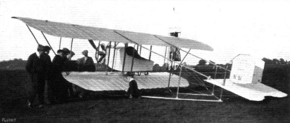
THE 45-H.P. CAUDRON BIPLANE. - Three-quarter back view of the new British built Caudron biplane, which the W. H. Ewen Aviation Co., Ltd., have sold to the War Office. The machine has been constructed for Mr. Ewen by Messrs. Hewlett and Blondeau at their Clapham works. The workmanship is extremely good and the machine is very neatly finished. A new type of cowl has been fitted, and several improvements have been effected in the 45-h.p- Anzani engine. The auxillary exhaust ports have been done away with and a new form of exhaust pipe fitted. The result is that the engine may now be throttled down to run very slowly indeed. Another advantage is that all the oil thrown off by the engine passes through the exhaust pipes and is carried away underneath the body.
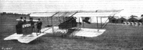
The Caudron biplane.
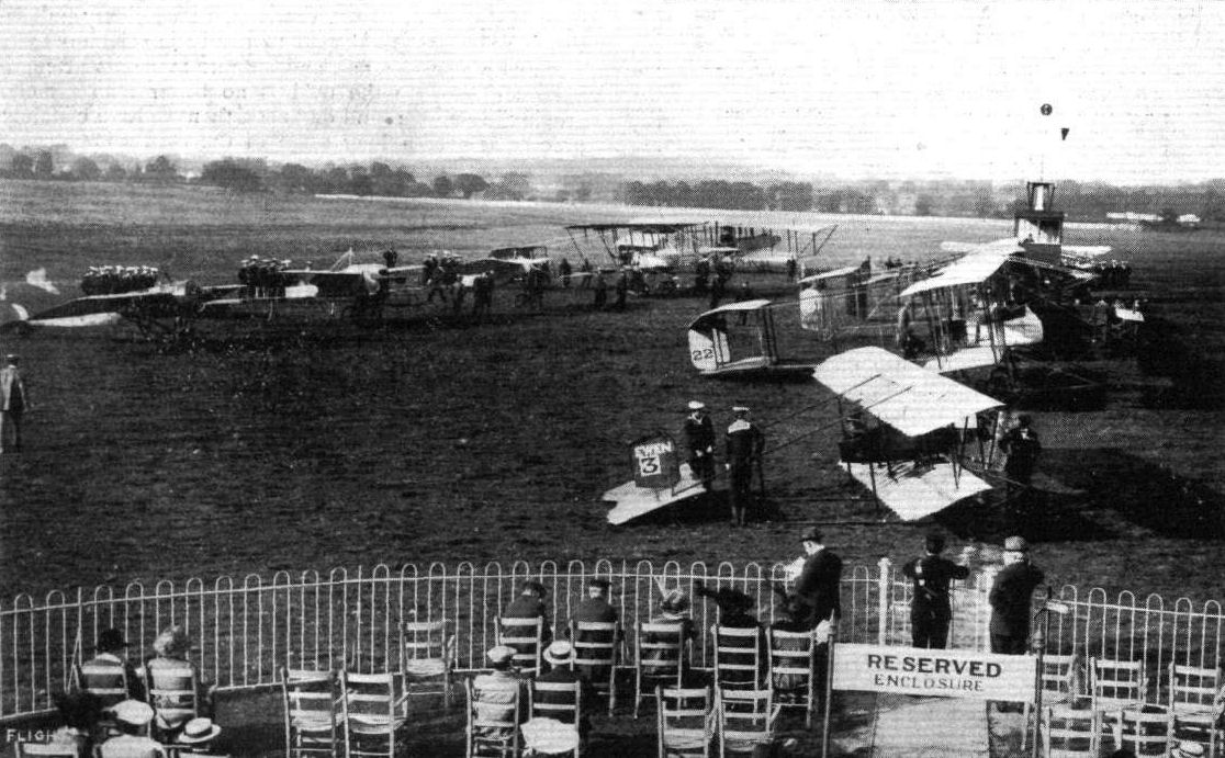
AT HENDON AERODROME. - Machines about to start for the military cross-country race. On the line are the biplanes and, ranged behind, the monoplanes waiting to take their place on the starting line after the biplanes have got away.
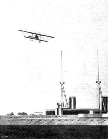
Mr. Sydney Pickles, on the British-built Caudron, over the "battleship" at Hendon.
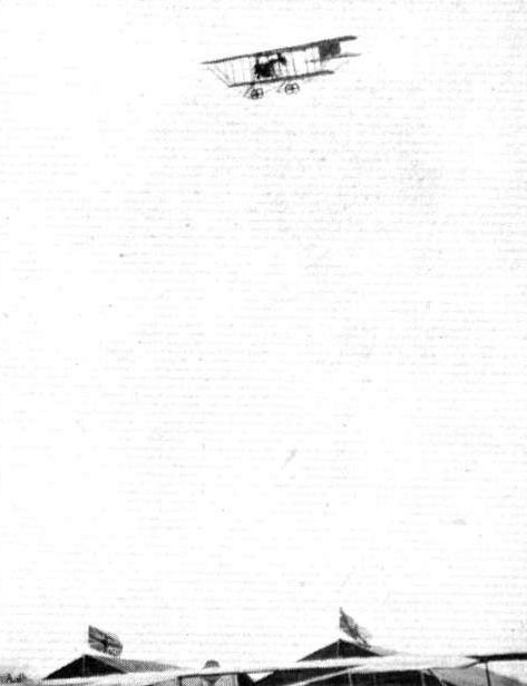
Mr. Sydney Pickles, on the British-built 45 h.p. Caudron, making a fine straight vol plane over the sheds at Hendon.
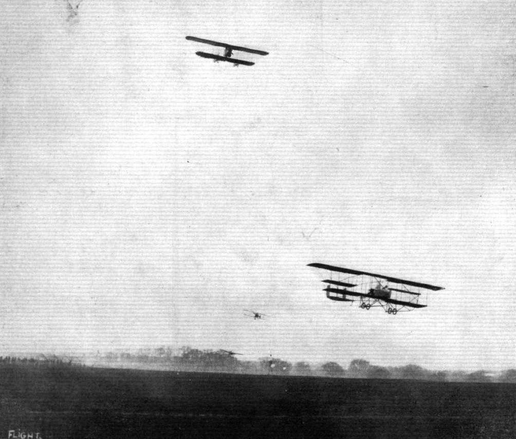
A speed handicap, with four in it, at Hendon aerodrome on Saturday, showing Turner's Caudron and Verrier's Maurice Farman, in front, during the first heat.
A REMINISCENCE OF HENDON FLYING MEETING. - A good race between Lewis Turner on the Grahame-White biplane and W. H. Ewen on the Caudron.
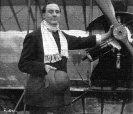
Mr. E. H. Lawford, who has just qualified at the W. H. Ewen School at Hendon on a 35-h.p. Caudron biplane. Mr. Lawford has been practising on a monoplane as well as a biplane.
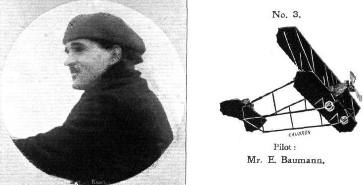
Pilot: Mr. E. Baumann.
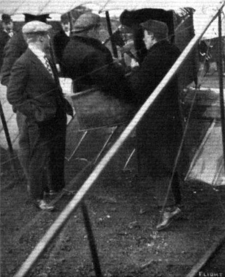
Mr. Lewis Turner explains the controls of the Caudron biplane to a new pupil.
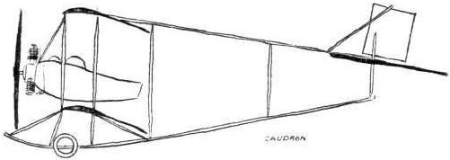
The 35-h.p. Caudron biplane.

The 35-h.p. Anzani-Caudron biplane.
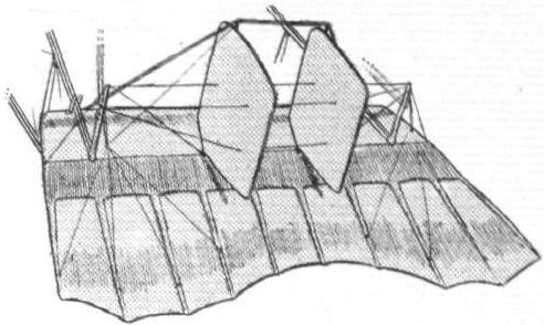
Tail of the Caudron biplane.
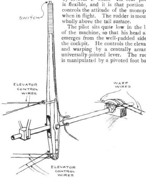
Sketch illustrating the control and its attachments on the Caudron biplane.
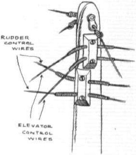
How control wires are led to the various tail organs through flexible guide tubes on the Caudron biplane.
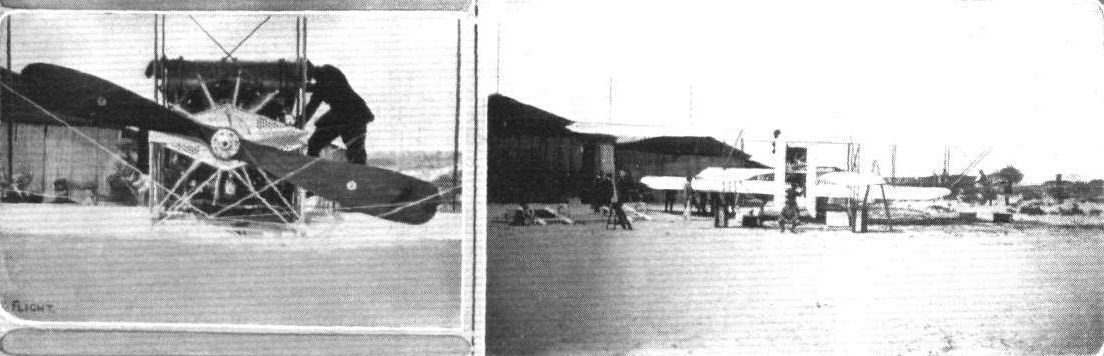
General view of Caudron Flying School at Le Crotoy showing their 200 h.p. Anzani hydroplane specially built for the Deauville competition. - On the left is a closer view of the machine, giving some idea of the size of the propeller and the situation of the cylinders on the 200 h.p. Anzani. This engine has a forced oil feed which is worked by two miniature propellers fixed on the lower plane. Our view is taken from the tail of the machine, and it should be noted that this machine is of the engine behind or pusher type.
Flight, February 8, 1913.
FOREIGN AVIATION NEWS.
Caudrons for China.
A DOZEN Caudron biplanes of the latest type have been ordered by the Chinese Government, some to be fitted with 50 h.p. and some with 80-h.p. engines. Obre has gone to China, where he will assist Lieut. Bon, of the French colonial forces, in organising an aviation centre at Pekin.
Flight, December 13, 1913.
THE STANDS AT THE PARIS AERO SHOW.
CAUDRON.
On the stand adjoining that of the Deperdussin, Caudron Brothers are showing two machines, one for work overland and the other a hydro-aeroplane. The land machine differs in constructional details only from those already known to our readers through illustrated descriptions in the columns of FLIGHT. The hydro-aeroplane is of the "pusher" type, and has a nacelle of somewhat different shape from those usually fitted. The floats are similar to those fitted on the tractor type of machine, the chassis possessing wheels as well as floats, so that the machine is really amphibious.
Flight, December 20, 1913.
THE PARIS AERO SALON - 1913.
CAUDRON
<...>
The other machine exhibited is a military two-seater land machine. It is driven by an 80 h.p. Gnome engine, mounted on the front of the usual type of Caudron fuselage. In the rear portion of the fuselage are the pilot's and passenger's seats, the pilot occupying the rear seat. The controls are as usual, consisting of a single lever for the warp and the elevator, and a foot-bar for the rudder. The chassis is of the familiar type, with the skids extended backwards to form the lower tail-booms. This machine is similar in every way to those now in use in this country, but one notices that all the strut sockets are now made of steel instead of aluminium as on earlier machines. This, we think, must be considered a distinct improvement as steel sockets are very much stronger, weight for weight, than aluminium sockets.
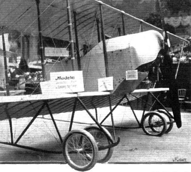
Chassis and fuselage of the Caudron military biplane.
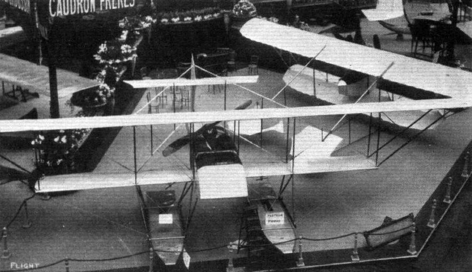
The Caudron stand at the Paris Salon.
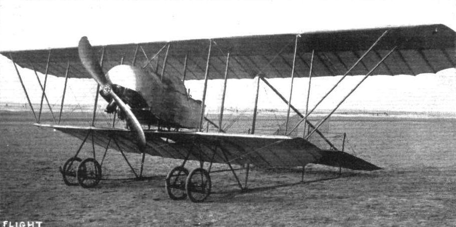
The latest Caudron Biplane, twelve of which have been ordered by the Chinese Government. It will be noticed that a cowl is now fitted over the engine, while the rudders are slightly different in shape. With 50-h.p. Gnome and 4 1/2 hours' supply of fuel and oil, the machine climbs 500 metres in 5 mins., and a speed of 100 k.p.h. is guaranteed. The dimensions are: Span, top plane, 9.80 metres; bottom plane, 5.70 metres; length, 6.90 metres.
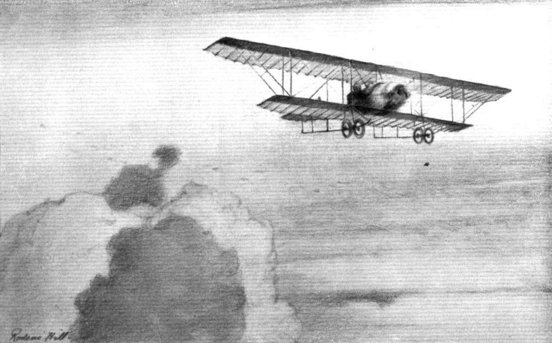
WITH THE ROAR OF 80-H.P. - Lieut. Malone carries a passenger on a Caudron at Hendon Aerodrome. From sketch by Roderic Hill.
Flight, July 5, 1913.
THE LEISURED AVIATOR.
By SYDNEY PICKLES.
As I ruminate over the doings of the past fortnight or so, I am certainly forced to the conclusion that flying nowadays is busy work. At any rate the period in question has been busy enough for me, and certainly not without interest withal. A few Saturdays ago, on June 14th to be precise, I flew for my superior certificate. This involved a preliminary test at Hendon, after which I left for Brighton about noon.
Steering for Brooklands, I soon came over the aerodrome, and there made a glide from 2,000 feet to within 20 feet of the track, round which I flew one circuit and thereupon re-ascended for a continuation of the journey to Brighton via Leatherhead.
At one period of the flight I entered a thick bank of fog and came down to about 800 feet, where I found the air currents exceedingly strong and difficult, and, familiar as I am with my trusty Caudron, the going at this part of the journey was far from simple.
Beyond the hills, however, the fog disappeared, and I was able to get up to 2,000 ft. again. Somehow or other I must have mistaken the railway track, for I came down at Littlehampton by mistake, and so had to re-ascend and fly along the coast to Shoreham, where I met with a very hospitable reception and an excellent lunch.
After lunch I flew down to Brighton, and appeared to amuse the holiday crowd considerably by a little low flying between the piers. I did not stop at Brighton tor any length of time, however, but started almost immediately for Hendon.
The return flight was in the teeth of a head wind, but although slow by comparison with the outward journey, it was entirely uneventful, except that just as I got over the sheds I found that I had run short of lubricating oil, and therefore had to make a somewhat hurried descent.
Having filled up, and still feeling very fresh, I thought it would be a good idea to fly in the second heat of the speed handicap that was just about to start. This event I won, but in the final Brock beat me. However, I had no reason to be dissatisfied with the day's doings.
On the following Tuesday I went down to the Isle of Grain, to put a new Caudron through its tests for the Admiralty. It was the first time I had ever flown a waterplane of any description, but I found no particular difficulty about it, and was confident enough to take up one of the officers as a passenger and subsequently to give my mother her first flight, which she enjoyed immensely. She thus has, I believe, the distinction of being the first Australian lady to fly in a waterplane.
On Saturday, the 21st, I went up to Dundee to give a flight in my Bleriot, and altogether had rather a poor time. The ground was small and rough, as are so many of these temporary aerodromes over which one is invited to disport oneself in flight. The wind was strong, and there were many obstacles. In themselves these things are not necessarily serious. It is only when one's engine gives trouble that they assume alarming proportions, and as bad luck would have it my engine must needs give trouble on this particular occasion.
The point at which it chose to fail was whilst I was flying in a bee-line towards a chimney, which ordinarily I should have cleared with any amount of room to spare. Instead, the machine sank, struck the chimney, and fell - with me inside it - from a height of 30 ft. Feeling the machine falling, I let go the control and gripped the seat firmly to avoid being thrown out. The machine turned over on its side, and assumed what in a "stunt" flight would be called a vertical bank. On this occasion there was no other word for it except disaster, and I must admit I thought my chances seemed exceedingly small.
The crash came, and I picked myself up undamaged. Not only was I uninjured, but I was free from so much as a scratch. The machine, needless to say, was fairly much of a wreck.
Having seen the remains of it packed up I took the night train to London, for I had an appointment in France at Crotoy on the Monday, and must needs travel on Sunday to get there.
Accordingly, I caught the 9 o'clock boat train from town, where I had made another appointment to meet a friend who was coming over with me in order to fly back as a passenger on a new Caudron of which I was taking delivery. My friend turned up with the news that he was unable to come, which disappointed me considerably, as I disliked the idea of a solitary journey to France followed by a solo flight back again.
My friend was accompanied by a companion, to whom, in no very hopeful spirit, I transferred the invitation at precisely four minutes prior to the time the train was due to start. He had never so much as been in an aeroplane in his life, but he was a sportsman all right; and having thought about it once and-a-quarter times, he rushed off to the ticket-office, and returned just in time comfortably to take his seat in the train with me as we steamed out of the station.
When we got to Crotoy on Monday morning, the new Caudron waterplane was ready and waiting on the beach. I took it up to 2,000 ft. for a preliminary canter, and flew around a little in order 10 satisfy myself that there was nothing amiss. At five minutes past five in the afternoon I set out from Crotoy with my passenger, and flying along the French coast to Cape Grisnez, which I reached at 6.40, I steered an easterly course across the Channel. Owing to haziness of the atmosphere I did not see land again until five minutes past seven. At eight o'clock I reached the English coast, still flying against a stiff wind.
Arriving at Margate, I alighted for fresh fuel supplies, and after restarting, I flew over to the Isle of Grain, which I reached about nine o'clock in the evening.
The journey was interesting to us both, but without incident that calls for any comment. It was flown, I may mention, without a map of any description, and it was my first flight across the Channel.
On the Wednesday following I put the machine through its Admiralty tests, and incidentally made a flight with Lieut. Boyce to the Eastchurch aerodrome, where we landed, and after lunch flew back again to the water. Such is the advantage of an amphibious machine like this.
MY FIRST FLIGHT.
BY A PASSENGER WHO FLEW 175 MILES AND CROSSED THE CHANNEL IN HIS FIRST JOURNEY.
To be invited four minutes before the departure of a Continental express to be the companion of a passenger whom one has come to see off is possibly not in itself such an unusual occurrence: to accept on the spot and board the train forthwith is, however, less of a commonplace incident, being, in fact, more closely related to the conventional episodes of some thrilling novel than to the prosaic course of real life.
Such, however, was the queer turn of the wheel which Fate had in store for me on a memorable Sunday morning two weeks ago. I went down to Charing Cross with a friend in order to meet Sydney Pickles, who was due to start for Crotoy, where he was to obtain a new Caudron waterplane with which he purposed flying back to England. My friend was to have been Pickles' companion on the voyage, but at the last moment was unable to go. My own interest in the matter, up to precisely four minutes to 9 a.m., was the purely passive one of a third party at a leave-taking of two.
Coming events, they say, cast their shadows before them, but it must have been a very ethereal shadow that was cast across my path that day, for it prepared me not one whit for the suddenness of the mental disturbance into which I was thrown when I found myself suddenly being invited to be Pickles' companion in lieu of my friend.
It was preposterous, of course, quite out of the question, in fact, that one could be expected to board the boat train at a mere beckoning, as one might clamber on board a passing 'bus.
But that was not how it appealed to me; the idea that gripped my mind as in a vice was centred upon one thought only - the forthcoming flight. I had never been in an aeroplane in my life, and here was a chance such as might never come again in my whole existence. It was not a mere "once round the aerodrome" circuit that was being offered me, but a real flight with a pilot who is, as I understand it, recognised as one of the best in England.
The fact that Crotoy is not exactly a suburb of London, that I had no travelling conveniences, that I should be away for more than an hour or so, in fact every one of those things that ordinarily would array themselves as insurmountable barriers to the spontaneous accomplishment of a suddenly conceived idea of this order, diminished their perspective until they seemed as nothing at all.
There was, indeed, little time in which to argue, and no time at all in which the seeds of objection could properly take root - far less put forth shoots and bloom - An a mind that already was the stronghold of another great desire. If I thought twice, it was the same way both times. In the one remaining minute of the time available I did that which, strictly speaking, was unnecessary - I went to the booking-office, and bought a ticket.
And so, before I had well had time to come to the full realization of the consequences of my action, I was already far from London, rushing smoothly over the metals in the boat express. But for the pleasant reality of the presence of Pickles, "always merry and bright," I might have fancied myself in a dream, out of which subsequently I should awake from some grotesque parody of a journey by air.
But it was no dream on the Channel, I can assure you, and anon in France it was no dream making the final stages of the journey to Crotoy, where we arrived on the Monday morning.
During the forenoon Pickles spent some of his time making a thorough inspection of the machine and putting it through a trial flight, but after lunch and the arrival of a telegram from England, it was decided to get under way, and preparations for the journey were commenced forthwith.
At five o'clock I donned overcoats, and such wraps as I could secure, and very gingerly accommodated myself in the seat of the Caudron "'bus." Then Pickles got aboard, and proceeded to start the engine from a handle, for all the would like a motor car. Waving "good bye" to our hosts, we moved across the sands, and started the flight at exactly five minutes past the hour.
Rising gently as we flew along the coast, we gradually climbed higher and higher until the ground lay 3,000 ft. below. It was glorious. At this height the country was one vast picture map. Still following the coast line we forged steadily through the air, and 55 mins. from the time of starting had reached Boulogne.
My word, it was cold up there. I had arranged with Pickles to write a log of the flight, but I shivered so much that I could scarcely hold the pencil. Noticing this, Pickles switched off for a glide to warmer levels. But it was only for a little while, for very soon we were fighting our way full speed through the wind again, and the shivering fits came on worse than ever.
It was horrible, there was no doubt about that. All the grandeur, all the glory of flying got frozen out of my soul by this beastly cold that I could neither control nor endure. My mind, my heart, were filled with one insatiable desire for a change of situation. And then suddenly, as I thought I had about reached the limit of my power to suffer such excessive discomfort, a change came over my feelings, and in some strange way I suddenly realised that the sensation that caused me so much agony a few moments ago was not only bearable, but that I looked upon its indefinite continuance as something still within reason.
And so we flew on against the wind to Cape Gris Nez, the name of which Pickles yelled at me through the hurricane draught as a reminder that, shivers or no, I must keep my log. Thence we headed out to sea, and I left behind with the land a heartfelt wish that we had alighted, if only for a moment or two, to ease the strain on my cramped, cold shivering body and limbs.
The idea of the non-stop flight was strong in the mind of the pilot, and he kept going. Clouds loomed thick ahead, and there was no sight of the coast. A steamer came into view on the water below and remained in sight for a minute or two ere it was blotted out by the mist. Presently Pickles switched off, and glided down from 4,000 ft., where we had been flying, to 2000 ft., where he switched on again.
In the distance I noticed a little black ball in the water, which, on closer inspection, turned out to be a fishing boat. There was still no sign of land, and the old feeling of unendurable discomfort returned to me. It seemed years since we started, and the memory of the French coast line had almost faded out of the sense of reality, so long did it seem since we had left it behind.
Occasionally, I noticed the machine would rock quite a lot, and then fly steadily again for a while, until it had another spasm. Ordinarily, I should have been much interested in the performance, and possibly a little alarmed. But, under the present circumstances, I think I was willing to accept anything that fate might ordain, were it only a change.
At seven o'clock in the evening, signs of land ahead were still absent; but, looking backwards, I could dimly discern the outline of France. Three minutes later, however, a tap on the back from Pickles caused me to strain my eyes against the blast. There, in the distance, I could just make out a narrow, dark excrescence on the horizon - the first glimpse of the shores of home.
Two steamers and a lightship that presently came into view gave an air of civilisation to the otherwise deserted space, and cheered my drooping spirits immensely. I rubbed my hands together with renewed vigour, so that I might hold the pencil with better effect, but it was a sorry business.
Keeping Dover well to the left, we made for the mouth of the Thames, and by 8 o'clock we came up with the coast line and followed it round to Margate. About this time, too, Pickles was beginning to get particularly interested in his petrol gauge, and as I obstructed the view in my normal position, I found myself once or twice summarily pushed out of the light.
At Margate, Pickles switched off and alighted on the sea alongside the pier, where the machine rocked about like a row-boat on the swell. From a passing motor boat Pickles, acting for the nonce as a gymnast balancing on one of the floats, secured an anchor and length of rope, with which he proceeded to effect a mooring, whilst the party in the motor boat very kindly went to fetch some petrol from the shore.
In an incredible short space of time we were surrounded by all manner of craft, at which Pickles lustily shouted injunctions against trespassing too close. More than curiosity, however, prompted the approach of the coastguard, to whom he shouted particulars from my log. Having satisfied him that we were just and proper people to enter England, and having filled up with petrol and oil, we once more ascended into the air, after considerable preliminary bumping over the rough surface of the water.
Dusk was now falling, for it was 8.43 when we passed Heme Bay pier. Presently came Sheerness, a prettier sight from above than below, with the lights of the town and the steamers, and the flashing buoys, making a scintillating picture. Suddenly three searchlights shot their beams across the water, and passing over a little bay, Pickles switched off, and made a smooth landing in the Med way precisely at 9 o'clock.
For me it was a memorable flight that thus finished, and not while I live shall I ever forget it. It does not fall to the lot of many people to make their first trip in an aeroplane on a journey of about 175 miles, with a Channel-crossing into the bargain. It was Pickles' first Channel-ciossing, too; and although I am in no way competent to give praise for piloting, I must say I was amazed at the way in which he kept to his pre-arranged route. Much of the time at Crotoy, Pickles spent with M. Caudron, drawing maps on the sand, and the course that he selected in that manner he adhered to throughout.
W.R.M.O.
Flight, August 2, 1913.
THE CAUDRON HYDRO-BIPLANE.
THE advantages of having aeroplanes capable of starting from, and alighting on, land or water with equal facility are too obvious to need enlarging upon, and aeroplane designers at home and abroad are constantly at work endeavouring to devise a machine capable of carrying out either manoeuvre. There may be said to have been three general types of chassis construction developed for the purpose of making the machines amphibious. The first type has "disappearing" wheels - that is to say, it has wheels which can be raised clear of the water when the machine is resting on that element; while, if it is desired to alight on land, the wheels can again be lowered so as to bring them below the level of the floats. In the second type - which has, perhaps, not been developed quite as much - the reverse procedure is followed, the floats, instead of the wheels, being raised and lowered.
In the third type, to which belongs the Caudron hydro-biplane of which we publish illustrations this week, neither wheels nor floats are made to "disappear," but are so arranged relatively to one another that the lower part of the wheels projects far enough below the bottom of the floats to permit of running along the ground without the floats touching, while when the machine is afloat the wheels are partially submerged.
It is yet early days to venture an opinion as to which of the three types will survive ultimately, but the success of the Caudron hydro-biplane serves to show the good qualities of the third system.
In its general appearance this machine resembles the land machines of the same make - with which our readers are already familiar through descriptions in FLIGHT - except, of course, for such alterations as have been necessitated by the purpose for which the machines are built.
Most notable among the innovations is naturally the chassis, which has been modified in order to accommodate floats as well as wheels. A very good idea of the arrangement of this structure may be gained from an examination of the accompanying scale-drawings and sketches. The floats, which are of the single-step type, are placed widely apart, thus making the machine very stable for taxiing on the water.
A rectangular opening is provided in the centre of each float for the accommodation of the wheels. These are not, as might have been expected, sprung from the float, but attached rigidly thereto, springing being effected by means of shock absorbers interposed between the floats and the chassis skids. The method of doing this is shown in one of our sketches. Three pairs of chassis struts carry at their lower extremities two skids placed sufficiently wide apart to allow the float to move between them. A steel tube connecting the forward ends of the skids to which it is fastened runs across the top of the float. Two steel clips bolted to the sides of the float serve as bearings, allowing the float to swivel round the tube. About half-way between the two rear pairs of struts, and secured to the float by steel clips, is a similar tube, the ends of which, however, pass over the skids from which it is sprung by means of rubber shock absorbers. It will thus be seen that the forward tube serves as a pivot for the float, whilst the rear tube acts as an anchorage for the shock-absorber. This construction provides springing of the undercarriage, whether the machine is used on land or water, so that in any case the shock of alighting is greatly minimised.
The main planes are of exactly similar construction to those on the land machines, having the same flexible trailing edge which has proved so successful. The boat-shaped body in which are the seats of the pilot and observer, arranged tandem fashion, carries on overhung bearings in the nose an 80 h.p. Gnome engine, driving directly a propeller of 8 ft. diameter. Control is by means of the usual Caudron central lever, a footbar operating the twin rudders. The tail outrigger differs from that of the land machines, in that the two lower tail booms are attached to the rear spar of the lower main plane instead of being continued forward to form the skids.
Like the rudders, the tail plane, which is fluxed for elevation and descent, and warped in conjunction with the main planes, is similar to those on the land machines of the latest type. Two floats of rather unusual design support the weight of the tail when the machine is resting on the water, and two small cylindrical floats are provided on the top of the lower main plane to protect the wing tips from contact with the water. These machines have been quite successful in France, where a large number have been sold to the Government, and the British Admiralty have bought several of them from the W. H. Ewen Aviation Co., Ltd., who hold the sole rights for Great Britain and Colonies. A machine of this type is now in course of construction at the Clapham works of Messrs. Hewlett and Blondeau.
OVER THE CHANNEL WITH MY SON.
By LILLIE PICKLES (Mrs. M. Pickles, of Australia).
MONDAY, July 21st, 1913, was indeed a wonderful day for me. On the previous evening, in response to a telegram from my son, I had left London, post haste, for Boulogne, in order that I might fly back with him the next day on a waterplane. Imagine, if you can, the intensity of my thoughts, which chased one another out of mind by their rapidity of inception, while the boat was making its way on that clear, moonlight night from Folkestone to Boulogne. Anticipation mingled with reminiscence, and while one minute I was wondering what it would be like to be up in the air over the sea, the next I was recalling incidents and escapades of my boy's career. One of those memories was a day soon after a new 40 h.p. S.P.A. had arrived, when, on answering the telephone, I was told by some kind friend that my boy, who was then but twelve years old, had been seen driving that big car all by himself along the Military Road near Sydney. Cars of 40 h.p. of that period were not quite the docile vehicles they are to-day, and yet he managed it all right. Then I thought of another time when he persuaded me to accompany him in our motor boat. At first it was delightful going about in the fairly quiet water near Manby, but this was hardly satisfying to him. He wanted a little more movement and suggested that we should steer up Sydney Harbour to Mosman's Bay. I consented, as I must confess that I am a kindred soul with my son, where daring is concerned. We started, but while crossing Sydney Heads a sudden storm came up, and there we were, tossing about like a cork on the water, but my boy sat there and kept that boat's head on to every wave, as cool and as calm as though we were on a mill pond, instead of expecting a watery grave every moment. Without hesitation the assistance of a pilot boat was declined, and at last we reached the smooth waters of Mosman's Bay none the worse for our adventure, and secretly I was glad. Had I not been given a glimpse of the strength and courage of my son? So it went on from year to year, but I must not weary you with these tales of the past, or I shall not have space to tell of my wonderful flight.
On the Monday morning, after seeing some friends off by the boat, we were quickly at the hangar making ready. The machine was one of the new water-planes which had been brought along the coast from Crotoy by Rene Caudron a few days previously. After spending about half an hour in going over the machine, to make sure that everything was in order, my son and I climbed into our seats. I think, without a doubt, this was the proudest moment of my life. But there was little time for sentiment. In a moment the propeller was buzzing away merrily, and, with a wave of the hand to the kindly French folk who had come to wish us bon voyage, we started for England. Up - up we climbed into the sky like a huge bird, and with one last glance at France - which was spread out beneath us like a beautiful picture, with its long beaches and green hills studded with quaint old buildings - we turned out over the Channel, not bothering to hug the coast to Cape Grisnez as is usually done. Gradually we found our range of vision being closed in until, after flying for some fifteen minutes, we could see nothing except for a glimpse of the water immediately beneath us. By the aid of the compass, however, and with an occasional anxious look at another instrument, which my son said was an altimeter, we were able to keep going, and five minutes later the monotony was varied by the dim outline of a steamer coming towards us. This my son recognised as the outward-bound steamer for Boulogne, and a minute or so later we caught up the inward-bound boat, which had our friends on board, making its way to Folkestone. Planing down a little we spiraled round the boat, and just as the circuit was completed the engine became fractious, and slowed up by some fifty revolutions per minute. No amount of coaxing would induce it to run at its proper speed, but instead, the indicator slowly but surely crept back until it stood at only 900 r.p.m. The "white cliffs of Old Albion" were, however, well in sight by this time, and my son, without hesitation, brought the machine down to the surface of the sea, and stopped the engine. He happened to have some spare sparking plugs and a spanner in his pocket, and so he climbed out on to the front float, and while the machine bobbed about in the choppy sea, he cleaned every one of the sparking plugs in the 9-cylinder 100 h.p. Gnome engine. To his satisfaction he found that the last one to be attended to was cracked, and naturally felt that he had located the seat of the trouble. The plug replaced, Sydney climbed back into his seat, but on starting up the engine found, to his disgust, that it was in no better mood than before, and so he accepted the situation and resolved to "taxi" the remainder of the distance to Folkestone - about five miles. Our little craft was buffetted about in a most extraordinary manner, and, to crown everything, the steamer by this time had caught us up and passed on, satisfied that our acknowledgment of our friends' greetings denoted that we were happy and comfortable. To such a pass has waterplaning already arrived! We enjoyed (!) their backwash, which sent our wing tips dipping beneath the water alternately. Steadying down once more, we continued to skim over the sea like a gigantic water fowl, and although I have had many exciting times both in motor car and motor boat in Australia, none equalled the exciting, although withal, enjoyable thrills which we experienced on our hundred horse power waterplane. In but a short time we were at Folkestone, the machine answering her "helm" beautifully as we steered round into the harbour and there made her secure, in time to get ashore and see our friends off to London. After the necessary arrangements had been made for the care of the machine, and the securing of mechanics to put the engine right, I boarded the London train, a tired but very happy woman. It isn't given to many mothers to fly with their own son, and the memory of my experience will be with me for all time. Truly Sydney has fulfilled the promise of his youth.
By way of a climax, it is now my one great desire to learn to fly, and I hardly anticipate any great difficulty as I have been driving motor cars for nine years. In fact, I was the first lady to drive in Australia, and so it is perhaps a pardonable aspiration which I have to be the first Australian lady aviator.

One of the new 80-h.p. Gnome-Caudron hydro biplanes supplied to the French Navy. The target-like devices painted below the lower plane are distinctive of machines belonging to the French maritime service.

AT DEAUVILLE. - The Caudron biplane just getting away from the starting stage in the French Government Waterplane tests.

Three-quarter front view of the Caudron hydro-biplane.

On left side, view of Caudron hydro, and on right the machine is just getting off.

Four views of the latest Caudron seaplane, taken at Leysdown on the occasion when Mr. Ewen himself delivered the machine at Grain Island some little time back. It is the same machine that Sydney Pickles flew across the Channel accompanied by his mother, and is fitted with the new 9-cyI. 100 h.p. Gnome.

Sketch of one of the main floats, showing method of springing.

View from underneath of main float, showing the protective keel.

One of the tail floats.

CAUDRON HYDRO-BIPLANE. - Plan, side and front elevation to scale.
Flight, December 13, 1913.
THE STANDS AT THE PARIS AERO SHOW.
CAUDRON.
On the stand adjoining that of the Deperdussin, Caudron Brothers are showing two machines, one for work overland and the other a hydro-aeroplane. The land machine differs in constructional details only from those already known to our readers through illustrated descriptions in the columns of FLIGHT. The hydro-aeroplane is of the "pusher" type, and has a nacelle of somewhat different shape from those usually fitted. The floats are similar to those fitted on the tractor type of machine, the chassis possessing wheels as well as floats, so that the machine is really amphibious.
Flight, December 20, 1913.
THE PARIS AERO SALON - 1913.
CAUDRON
Of the two machines exhibited on the Caudron stand, the hydrobiplane, is, perhaps, the more interesting, as it is less known to our readers than the land machines, of which so many are to be seen daily at the London Aerodrome. The hydro-biplane is of the "pusher" type, having the engine - a 100 h.p, 9-cylinder Gnome - mounted between double bearings in the rear end of the nacelle. It drives through a 2 to 1 reduction gearing the propeller, which has been mounted on a long shaft in order to clear the trailing edges of the main planes.
In the front portion of the nacelle are the pilot's and passenger's seats, arranged side by side, the pilot occupying the right-hand seat. In front of him are the controls, which consist of a single wooden lever which works the warp and elevator, whilst the rudder is actuated by a foot-bar. The outrigger, which carries the tail planes, consists of four steel tubes connected by spruce struts. The tail planes comprise a slightly cambered fixed tail plane, to which is hinged the divided elevator. The rudder is hinged to the vertical rudder-post which joins the rear extremities of the tail booms. A tail fin is provided in order to balance the side area of the floats. A small tail float is mounted on an extension of the vertical rudder-post, and protects the tail planes against contact with the water.
The main floats, of which there are two, are of the already well-known Caudron type, built by Mons. Tellier. The floats are pivoted round the lower extremities of the front chassis-struts, and are sprung from four short skids by means of rubber shock-absorbers at the rear. Mounted in an opening in the centre of the float is a wheel which projects slightly below the step of the float, so that the machine is really amphibious. The wheels are not sprung from the floats, but depend for their springing on the shock-absorbers, by means of which the rear part of the float is attached to the skids.
The main planes are of the usual Caudron type, having the two main spars fairly close together, and possessing the flexible trailing edge which characterises the land machines. The upper main plane has a considerable overhang, that is to say it has a much greater span than the lower plane. The main planes are connected by six pairs of vertical struts of hollow spruce, with the exception of the inner ones, which are made of ash. The thrust is transmitted from the nacelle to the wings by bolting the nacelle to the main spars of the lower plane and to the inner plane struts.
<...>
The Caudron stand at the Paris Salon.
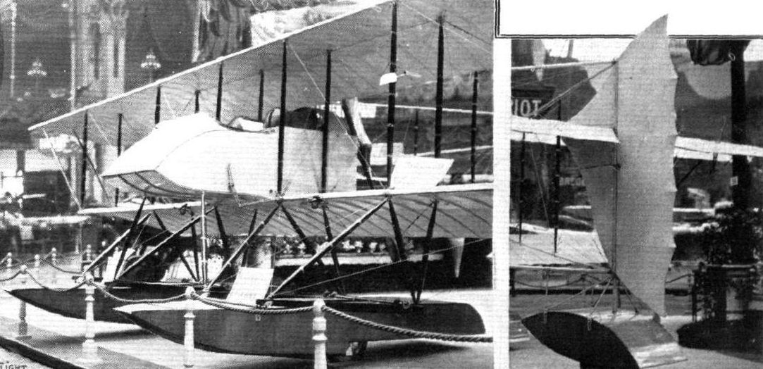
The Caudron hydro-biplane, and a view of the rudder and tall float.

The nacelle of the Caudron hydro.
Flight, April 19, 1913.
New Passenger Records.
AT Orleans, on Tuesday, Champel, on his enormous biplane, which has a 10-cyl. Anzani motor, beat the world's passenger records up to 250 kils., and set up a new duration record for pilot and four passengers of 3 hrs. 1 min. The new time records are 30 mins., 40 kils.; 1 hr., 82 kils.; 1 1/2 hrs., 122 kils.; 2 hrs., 165 kils; 2 1/2 hrs., 208 kils.; 3 hrs., 249 kils. The new speed records are: 50 kils. in 36 m. 31 s.; 100 kils, 1 h. 13 m. 1 s.; 150 kils., 1 hr. 49 m. 11 s.; 200 kils., 2 h. 29 m. 2 s.; 250 kils., 3 h. 1 m. The new distance record is 250 kils. All these are world's passenger records for pilot and four passengers.
Also, on Tuesday, but at Crotoy, Marty, on a Caudron biplane, fitted with a 10-cyl. 100-h.p. Anzani, beat the height records for pilot and three and pilot and four passengers. The former he raised to 1,800 metres, during a trip of 35 mins., beating Chevillard's old record of 1,350 metres, made on a Henry Farman last February. In a second flight of 35 mins. duration, he took four passengers up to 1,450 metres, beating Gougenheim's record of 1,120 metres, also made on a H. Farman last February.
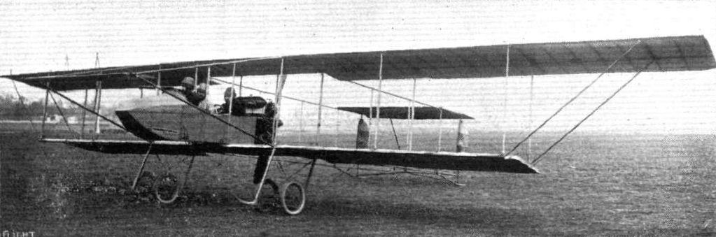
The biplane built by Champel, and with which he has been doing so much flying with passengers at Juvisy and elsewhere, and on which he made four new world's records for pilot and four passengers at Cercottes a little time back. The motive power, it may be recalled, is a 100-110 h.p. 10-cyl. Anzani engine.
The arrival of the Champel biplane flown by Mr. Sydney Pickles, with Mr. Lawford as passenger, at the Hendon Aerodrome, on Saturday, whilst the competitors in the Aerial Derby were absent on their race round the circuit. On the left is seen the Grahame-White 5-seater biplane, with a mechanic sitting on each wing tip.
Flight, May 3, 1913.
FOR THE POMMERY CUP.-MARVELLOUS FLYING.
Gulllaux's Record Flight.
GILBERT'S lead in the Competition only stood for four days, as on Monday Guillaux gained first place, and as his record was not beaten on Wednesday, he will probably be awarded the Cup. Starting from Biarritz, on the all-steel Clement-Bayard monoplane, which has a 70-h.p. Clerget engine and Integral propeller, at 4.42 a.m., Guillaux steered for Bordeaux and covered the 180 kiloms. in 1 hour 13 mins. After a forty-minutes' rest he started again and this time made a non-stop flight to Villacoublay, arriving there at 10.35, having taken four hours for the distance of 495 kiloms. This time a rest of two hours was indulged in before proceeding to Ath, in Belgium, where he arrived at 2 p.m., by which time he was 900 kiloms. from his starting point. Another two hours' rest was enjoyed and then the last stage commenced, the aeroplane after crossing the Zuyder Zee finally landing at Kollum, in Holland, at 7 p.m., his distance record then being 1,255 kiloms.
Some Integral Successes.
IT is interesting to note that of the many outstanding cross-country flights which have been made during the past few days quite a number have been accomplished by the aid of the Integral propeller. Guillaux used an Integral when flying on his Clement-Bayard monoplane from Biarritz to Holland, Gilbert's Morane was so fitted, and so was the Bleriot on which Hamel recently made his non-stop flight from Dover to Cologne.
Flight, October 25, 1913.
AEROPLANE TYPES.
THE CLEMENT-BAYARD MONOPLANE.
GUILLAUX'S remarkable flight some little time back from Savigny to Paris, when he travelled at a speed of 144 miles per hour, naturally centres one's attention on the Clement-Bayard monoplane, which was the make of machine he flew on this occasion. The main point of interest in the Clement-Bayard monoplanes lies in their steel construction. With the exception of the wing spars and skids, nickel steel tube is employed throughout. The fore part of the fuselage is pentagonal in section, whilst behind the pilot's seat the fuselage is triangular. In front of the pilot, windows are let into the sides of the fuselage in order that a clear view under the wings may be obtained, The wing spars are of channel-section steel, the attachment to the fuselage being such that the wings can easily and quickly be removed or attached. The rear spar is situated very nearly along the centre of the wing, so that there is a large proportion of trailing edge. In this way a very effective warp is obtained which makes the machine sensitive in control. Another interesting feature with the Clement-Bayard machine is the landing chassis, which is extremely strong. It consists of a pyramid-like structure of steel tubes, the apex of which is attached to the nose of the fuselage, whilst the base is connected to two skids carrying at their rear ends sprung running wheels. Two steel struts also extend from the rear of the pyramid to the sides of the fuselage. Both single and two seater models are made, and 50 h.p., 70 h.p., or 80 h.p. Gnome engines are employed. The principal dimensions of the 70 h.p. Military single-seater are as follows :- Span 9.200 m., length 7.500 m., supporting area 16 sq. m., weight (empty) 320 kilogs., speed 120 k.p.h.
"VEE JAY."
Flight, December 13, 1913.
THE STANDS AT THE PARIS AERO SHOW.
CLEMENT-BAYARD.
On the Clement-Bayard stand are shown two all-steel monoplanes - a single-seater and a two-seater. The only parts which are made of wood are the chassis struts. The lift cables are attached to the lower member of the fuselage, so that should the chassis struts, which are the weakest part of the machine, break, there is still a chance of keeping the lift wires intact.
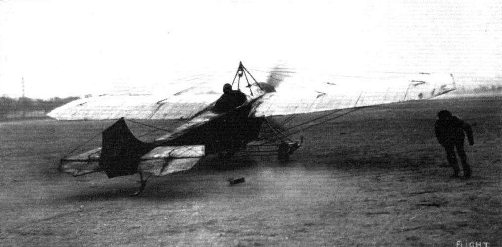
Guillaux just getting away on his military all-metal Clement-Bayard monoplane in his successful try for the Coupe Pommery, when he covered approximately 1,400 kiloms. by flying from Biarritz to Kollum in the day.
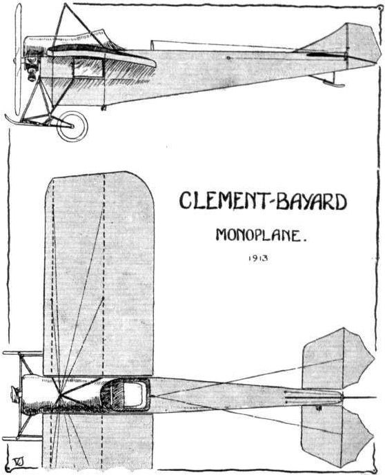
Flight, December 27, 1913.
THE PARIS AERO SALON - 1913.
CLEMENT BAYARD.
The Clement Bayard firm are showing two machines, of which one is a high-speed single-seater monoplane, while the other is a tandem two-seater. Both machines are very much alike, and are both built of steel practically throughout.
The single-seater is driven by an 80 h.p. Gnome engine, mounted on overhung bearings, and entirely covered in by the engine cowl. The air passes in between the hemispherical shield on the propeller boss and the fixed portion of the cowl, and is allowed to escape through openings in the rear. The fuselage, which is built up of steel tubes, is of pentagonal section in the front portion, while the rear part is triangular in section. On a dash in front of the pilot are mounted the various instruments, and the machine is controlled by means of a single tubular lever, which carries at its upper end a small fixed wheel, which does not rotate but simply forms a convenient handle. A to-and-fro movement of this lever operates the elevator, while the wings are warped by swinging the lever from side to side. The rudder control is effected by means of a foot-bar.
The wings, of which the trailing edge is longer than the leading edge in order to make the warp more efficient, have been cut away near the fuselage to give the pilot a better view of the ground below. The main spars fit into sockets on the side of the fuselage, and the wings are stayed with cables running to a cabane on top and to the low member of the fuselage respectively, while the warp wires pass over pulleys which are also mounted on the keel of the fuselage.
The chassis, which consists of four struts of ash, connected with steel tubes, is illustrated by one of the accompanying sketches, which needs no explanation.
The tail planes of both machines are alike, and are remarkable chiefly on account of the fact that there is no fixed tail plane and that both elevator and rudder are balanced, so that the machine must be very sensitive to the controls. A very simple pivoted ash skid protects the tail planes against contact with the ground.
The two-seater machine is very similar to the single-seater, front which it differs in dimensions only. It is lined with an 80 h.p. Clerget engine mounted on overhung bearings. The pilot's and passenger's seats are arranged in tandem, the passenger occupying the rear seat, from where he has an excellent view in all directions.
The workmanship of these machines, as is to be expected from the Clement Bayard firm, is of the very highest quality, and although the steel construction undoubtedly makes them slightly heavy, the excellent performances put up by Guillaux in his recent flights have amply demonstrated the good qualities and enormous strength under all conditions of these excellent machines.

The Clement-Bayard stand at the Paris Salon.
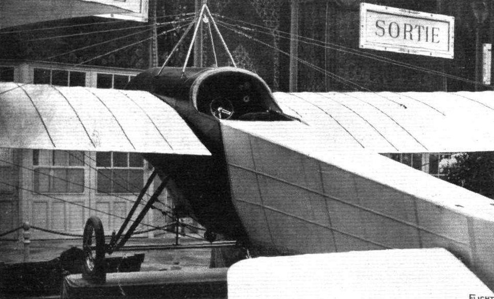
Clement-Bayard monoplane.
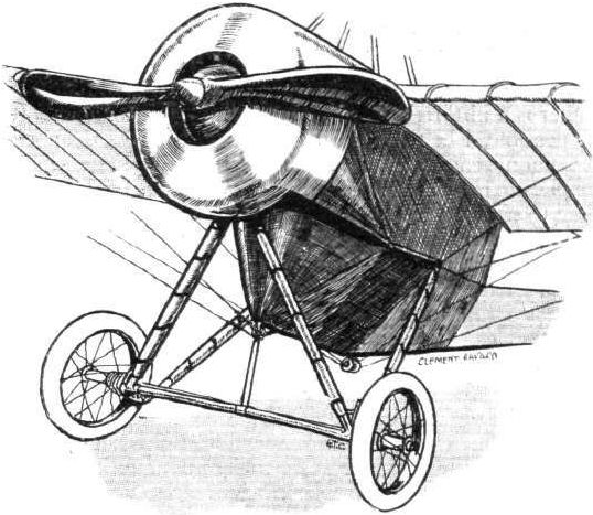
Chassis and engine housing of Clement-Bayard monoplane.
Flight, May 3, 1913.
REFLECTIONS ON THE MONACO MEETING.
Artois.
The Artois aeroplane, which was so ill-fated as to cause the death of Gaudart, also possessed one of these dolphin-like boat bodies. According to eye-witnesses who observed the accident, it demonstrated unmistakable signs of longitudinal instability after rising with considerable facility from the surface of the water. Being an experiment, the accident may in some measure be classed with that resulting in the death of Fenwick on the Mersey monoplane during the military trials on Salisbury Plain last year. And it is because of these things that designers are, as we have mentioned elsewhere, very diffident about departing from methods of construction in which they feel the confidence of long experience. In the Artois biplane, an 80-h.p. Gnome engine drove a four-bladed propeller by means of a chain. The wings were built upon single spars, separated, of course, by a single row of struts in the gap.
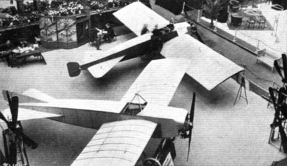
The Ratmanoff (in the foreground) and the De Beer monoplanes at the Paris Salon.
Flight, May 3, 1913.
REFLECTIONS ON THE MONACO MEETING.
De Marcay.
It is a pity that the De Marcay monoplane did not demonstrate its flying abilities in a more pronounced manner during the Monaco Meeting, for there is no doubt that those interested in its method of wing bracing would have felt greater confidence in the design by becoming more accustomed to the view from beneath. The wings of this machine are arranged to fold back against the body in order that it may ride more securely at anchor. A useful purpose is potentially served by this provision, and the method of achieving the desired end thus becomes of moment. On the De Marcay, the wing structure appears to be more or less in accord with common practice, but the attachment of the wings to the body is altogether unusual. Each wing is carried by a tubular steel mast that slopes obliquely backwards and outwards from the bottom to the top. The mast passes through the trailing corner of the wing shoulder, and to the top and bottom of the mast all the bracing wires are carried. Owing to the slope of the mast, the backward rake of the lower wires is less than is the case with the upper wires, but the disposition in both instances is sufficiently unusual to arrest the attention. The drag on the wing is resisted by the steel cable controlling the position of the wing, and this same control serves the purpose of swinging the wing to and fro slightly in flight, as a means of lateral balance in lieu of warping.
Flight, January 18, 1913.
SOME EXPERIENCES OF FLYING IN CENTRAL AMERICA.
By G. M. DYOTT.
[ROUGHLY a year ago it will be remembered that Mr. G. M. Dyott and the late Capt. Patrick Hamilton bought two Deperdussin monoplanes, a 60-h.p. two-seater and a 28-h.p. single, and took them over to the United States to complete a tour of exhibition flying. After a period of successful flying at the Nassau Boulevard and other aerodromes, they went down South to fill an engagement in Mexico. Below Mr. Dyott relates some of his impressions of flying in that district].
Taking it on the whole, I did not find flying down in Central America anywhere nearly so comfortable as flying in the North. In all the hot countries in which I have flown, the calmest and most inspiring mornings, I soon learned were the most treacherous, and, in fact, almost dangerous. There might not be a breath of air stirring, yet the air would be riddled with heat eddies and down trends in every direction. Add to this a very gentle wind, and you have the only condition that could be worse, as this caused whirlwinds' of a local character, which would swing even a moderately fast machine 30 or 40 degrees out of its course. Being caught in one of these whirlwinds I found the best way out was to dive the machine with motor stopped, at the same time turning head on to wind, if that were possible. A very curious condition of things existed in the Valley of Mexico. The valley is circular and surrounded on all sides by high mountains. At certain times during the day I found that I could make a complete circle one mile in diameter, having a following wind the whole way round. Up to 1,000 ft. the air would be steady, above that impossible.
Towards 4 p.m. on a cloudless day the heat eddies became less local in character, with the result that the entire atmosphere seemed to be rising. On the other hand a partly clouded afternoon was always bad, and the effect of passing from sunshine to shadow, or vice versa, was always accompanied by a sudden rise or fall of the machine. Another observation I made was that, while heat eddies would rise vertically in an absolute calm, a wind would incline them over at an angle, and under these conditions, flying with the wind, the disturbances would be more noticeable than flying against it. It seemed that the small local whirlwinds, dust devils as they were called, would originate about one of these air chimneys. One day I was flying near Puebla, 8,000 ft. above sea-level, with my 60-h.p. passenger-carrying Deperdussin. For several days I had been flying there, carrying passengers with success, when, about seven days after my arrival, I had an extraordinary experience. I had taken up a passenger, and after flying with him some 20 minutes, started to return to the aerodrome. Somehow the machine seemed to lose power, in spite of the fact that the speed indicator of my motor gave the proper number of revolutions per minute. A row of tall trees was between me and the aerodrome, and I was surprised to find myself almost, as I thought, on top of them. Naturally I elevated, but with no effect except the lowering of the tail. I cleared the trees by about 70 ft. or 80 ft., but at the same time a gust of wind caught me and the machine heeled over to one side. I warped immediately, but the warp seemed to have not the slightest effect. We got so far over that my passenger started to crawl up the higher wing. Then I nosed the machine downwards suddenly, a manoeuvre which sent him flying back into his seat. Finally we landed safely.
This incident set me thinking, and I did not fly for a couple of days pending some explanation. What was wrong I could not conceive. The controls had not jammed and I thought it impossible for a remousto have such an effect upon a machine in good flying condition. Here again the machine was apparently in good condition, for I had flown with her every day for a week, carrying passengers without the slightest trouble. The speed indicator was conclusive proof that the motor was not at fault; so what was wrong? After thinking the matter over for some time, the final analysis showed me that the only difference between this and my other flights was that it had been made after the sun had gone behind the mountains, a trifling difference to be sure, yet nevertheless the keynote of the whole situation. Subsequently I tried the machine in straight away flights with a passenger, when the sun was shining, when it was cloudy, and when it had sunk below the horizon. To my great satisfaction I found that in bright sunlight the machine would lift easily; but once let the sun get behind the clouds, passenger carrying was only carried out by working the machine above the safety limit.
Having determined this fact, the next thing was to experiment with the little three-cylinder Anzani Deperdussin single seater we had out there, which my friend, the late Capt. Hamilton, had not yet attempted to fly, owing to the aerodrome being so high above sea-level. Here the same phenomenon was apparent. The machine would not fly after 5 p.m. Unlike the two-seater it could fly in the morning when the heat eddies were still local in their effect, whereas the two-seater could not carry a passenger until the eddies had become uniform over the whole field.
To fly the small Deperdussin was a source of considerable interest. A run would be made over the ground, tail well in the air, making no attempt to get off. The first heat eddy encountered would lift the machine bodily off the ground like a balloon, some 30 or 40 feet. A slight effort would be made to check the rise until the disturbance had been passed through, then the elevator would be returned to a position of gentle descent, allowing the machine to gradually lose altitude until the next air "chimney" was encountered, when the same performance would be repeated. In this manner altitude could be gained according to the frequency of the heat eddies encountered, it being quite possible to get up to 1,000 ft. in 15 minutes. Towards three and four o'clock in the afternoon the periods of lift would not be as pronounced, as the whole atmosphere would then be rising. The minute the sun went behind the mountains flying was impossible unless the pilot weighed less than 130 lbs. Later observations showed that when the buzzards were soaring well up in the air the small machine would fly and the two-seater carry a passenger. If these birds were flying low and had to do much flapping, the air was only good enough for the two-seater to fly with the pilot alone. This point was soon to be brought home both to poor Capt. Hamilton and myself rather forcibly. We had been invited to pay a visit to the Country Club, some 16 miles from Mexico City. I suggested that we both go over on the two-seater, then, if we were detained till sunset I could fly back alone. Hamilton was rather anxious to put the little machine through its paces, and he decided to make the attempt on that, while I flew over alone on the two-seater. We set out at 2.30 p.m., the little Deperdussin climbing easily and well, and we both arrived safely. After a game of tennis, and some tea, it began to cloud over, and it was 5 before Hamilton started back. I rather urged him not to make the attempt, but he thought he could manage it, so off he went, disappearing over some high trees with 80 ft. or so to spare. He thought he could not clear them, and was trying to force the machine up, when a side gust caught him, turned the monoplane completely over, and it described a vol plane on its back, Hamilton with his knees under the control bridge, still hanging on inside. It landed, breaking everything but the wheels and Hamilton, who then dropped out unhurt - a marvellous escape.
It was an expensive break, but it served to confirm absolutely what we had already supposed, and we were obliged to chalk it up to experience, our fund of which was increasing much more rapidly than our banking account.
While speaking of heat eddies, I might mention an incident at Santa Rita, where I flew over a forest fire of considerable magnitude. Above the smoke region the hot air rose very rapidly, and as soon as the machine entered it, it would rise almost vertically. The first experience came so suddenly and with such alarming force that I felt sure something must have gone wrong, and I was not long in getting back to earth to think the matter over, a habit of mine. It was some time before I could persuade myself to try it again; however, when I did, the effect was the same, and once the cause of it was definitely determined it was rather a source of amusement to me and spectacular for the onlookers.
At this same place I had the disagreeable experience of being lost for an hour and a half. Outside of a few Indian huts and their occupants there was not a single soul within a radius of 30 miles. My mechanics and I ran the machines off two flat railway cars early that morning, and we spent a hard day erecting them in the hot sun. They were ready for action at four o'clock in the afternoon, and the machines were run out on to our improvised aerodrome, a patch some 900 ft. by 500 ft. which we had had burnt off and which was as black as a cinder. To be sure I could see it very plainly from above, so I took no particular care to take any bearings, but here I was mistaken as it turned out afterwards. I started off for the mountains and 15 minutes later by my clock swerved round and headed back again, but where was that little black patch of ground? Nowhere to be seen. Look as I would there was absolutely no trace of it. Imagine my feelings flying over a wild uninhabited country, tropical forests, jungles and swamps, everything but a good landing ground. The next thing I knew was the sight of the ocean looming up ahead of me, and as I knew I had started from a point about 50 miles inland, I turned back again and headed for Mount Orizaba. Back I went, making repeated vol planes to get a better look at the country below, my anxiety increasing at every revolution of the propeller. At last, in the gathering darkness, I caught sight of the flicker of a flame, and, making a beeline for it, found to my great satisfaction that it was our encampment. That night, as I lay awake under the wings of the good old Dep., I wondered what might have happened had I not caught sight of that flame. Once more I mentally chalked up a few figures to my fund of experience, reflecting that things as viewed from above do not necessarily appear as they do from the ground.
On one ground in Yucatan I could not fly unless at least 10 miles an hour of wind were blowing, as the field was too small to lift from without a head wind. Returning to earth was still more ticklish an operation, and I conceived the idea of spreading sand along the far end. It worked excellently, and pulled the two-seater up almost at once.
Flying out there late on in the day a curious feeling of drowsiness very often came over me. The peaceful surroundings, the dim light, the steady hum of the motor, and the uniform rush of the air seemed to induce a semi-hypnotic state which it was difficult to shake off. For this reason I never flew unless I was in good physical condition and had had plenty of rest.
Flight, August 23, 1913.
ARE THESE WING-SPARS BENDING?
WE published last week a very remarkable photograph of Mr. N. Spratt flying the 60-h.p. Deperdussin monoplane in a speed handicap at Hendon. The central portion of that picture we reproduce herewith, and on it we have drawn a series of converging lines. The point of interest is to know whether the photograph is evidence of bending in the wing-spars, or is merely photographic distortion.
The photograph was taken with a focal plane shutter and a Goerz lens in first-class condition. It was a swung photograph, that is to say the operator followed the flight of the machine, which accounts for the background being blurred. That the swinging was successful is obvious from the clearness of the detail in the engine and other small parts. The aperture was probably about F.5, and the exposure probably about one-thousandth of a second.
Ordinarily, the distortion that one obtains with a focal plane shutter, when taking a picture of a racing motor car with a fixed camera, results in an elliptical wheel. Similar distortion in respect to a flying machine would have put the wings on the slant, so that one wing tip would have appeared much further forward than the other. Again, if the distortion of the near wing tip were regarded as due to lack of focus, one would expect the outline to spread itself over the plate, so as to make the front edge concave to the direction of flight instead of convex, as it appears at present.
Actually, when the machine is at rest, the wing spars are straight, and the front edge is straight. There is no dihedral angle. In the photograph the front edge appears curved in both wings, and the row of attachments by which the upper wires are fastened to the spars also lie in a curved line.
The photograph was taken from a pylon and the near wing tip is within about three yards of the lens. The wing tips are more than an inch from the edge of the negative, so that the machine may be regarded as thoroughly in the centre of the plate. At the moment the photograph was taken, the pilot was commencing to recover from his bank, and judging by the position of his hands on the control wheel, he had just warped the near wing tip down in order to increase its angle of incidence.
If the curvature in the photograph represents bending in the wing, the amount is probably about 3 or 4 ins. at the tip on the actual machine, allowing for the difference in scale. We should like to hear the views of constructors, pilots, and photographic experts on the points raised in connection with the picture.
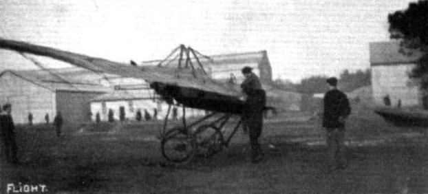
Mr. H. M. Brock on the Dep. off for a flight on Farnborough Common.
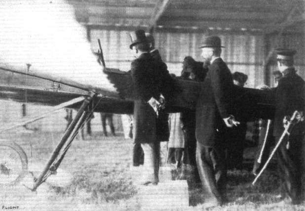
Mr. G. M. Dyott explaining to President Madero of the Mexican Republic, how the controls of his monoplane work. Shortly afterwards the President went for a trip with Mr. Dyott, remaining up for about 16 mins.
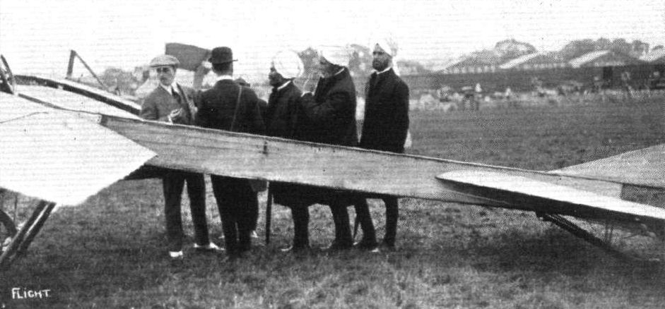
Capt. Tyrer explaining some points of the Deperdussin monoplane to the King's Indian Orderly Officers at Hendon.
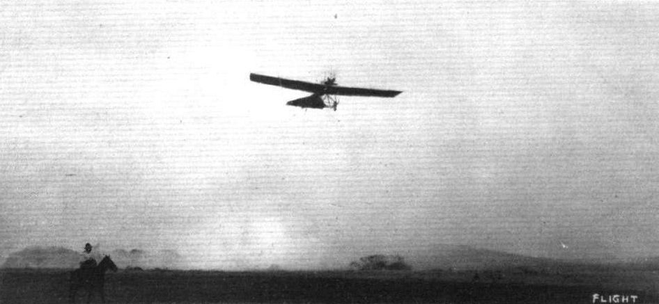
Mr. G. M. Dyott, on his 60-h.p. Aazani-Deperdussin, flying over forest fires in Central America.
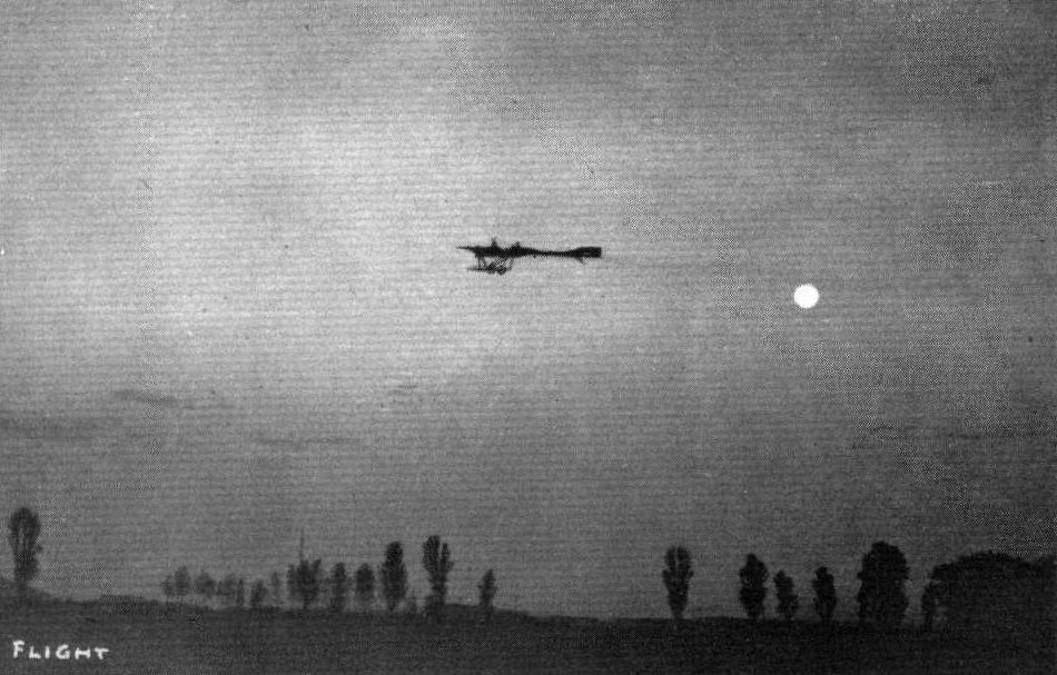
"And all the air a solemn stillness holds, Save where the beetle wheels his droning flight." Flying by moonlight in the tropics on a 60-h.p. Deperdussin.
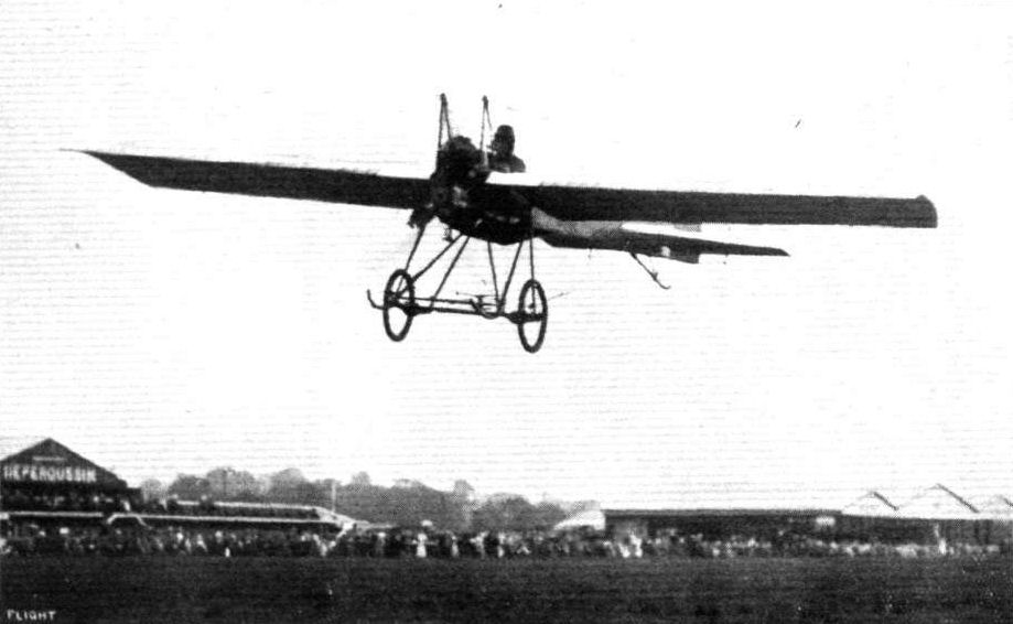
Mr. Brock on the 35 h.p. Deperdussin, entering the last lap - heat one - in the speed handicap at Hendon.
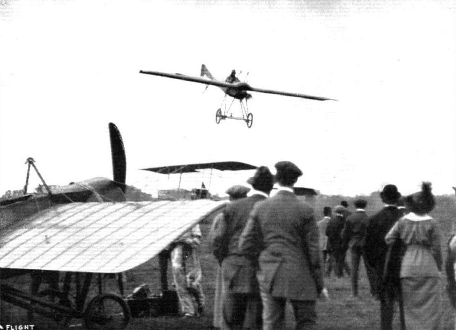
Jules Nardini "steeplechasing" over some of the machines at Hendon on Saturday on the Deperdussin.
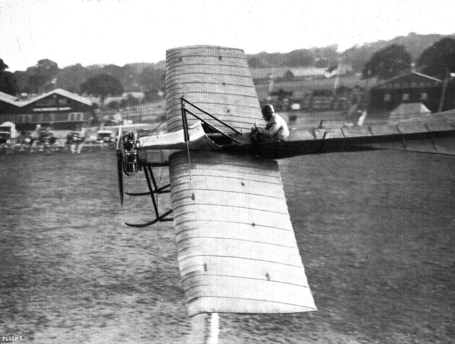
MR. N. SPRATT FLYING THE 60 H.P. DEP. IN THE SPEED HANDICAP AT HENDON ON SATURDAY. - This very unique photograph was taken from No. 1 pylon on the race course.
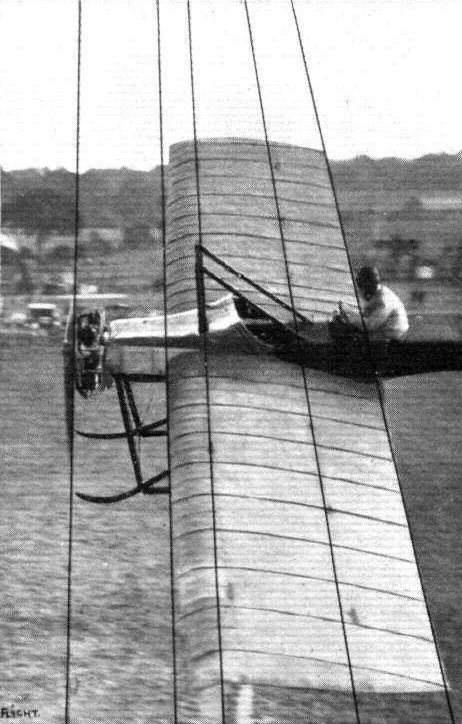
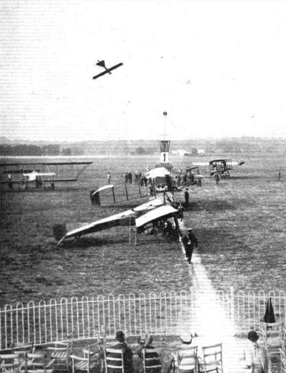
READY FOR THE NEXT RACE AT HENDON AERODROME. - In the air is Spratt on the Deperdussin.
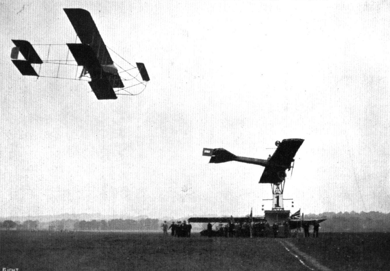
A close finish for second place between Verrier and Nardini in last Saturday's speed handicap at Hendon Aerodrome. Nardini overtook and passed Verrier almost upon the finishing line.
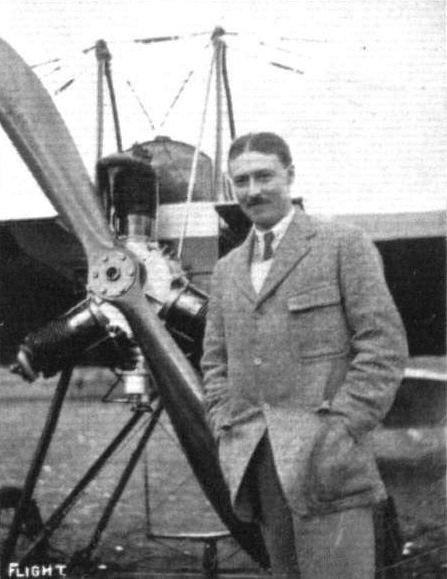
Lieut. L. C. Hordern, Lancashire Fusiliers, who has just passed for his brevet on a Deperdussln monoplane at Hendon.
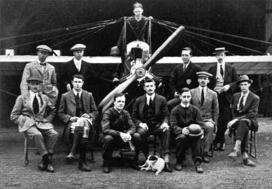
Some pupils and pilots at the British Deperdussin Monoplane School at Hendon. Reading from left to right: (seated) Messrs. R. Jaques, N. C Spratt (pilot). J. G. Barron, Capt. J. C. Halahan (School Manager) E. B Bauman, Col. N. M. Smyth, V. C., E. R. Whitehouse; (standing) Lieut. H. le M. Brock (R. Warwickshire Regt), Messrs Denis Ware, D. G. Murray, W. D. Thompson (Sec, British Dep. Co. ), and in the pilot's seat Mr. W. Breck (pilot).
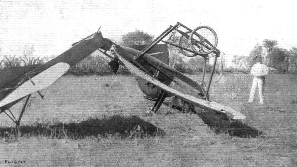
THE RESULT OF FLYING AFTER SUNSET AT MEXICO CITY. - The machine turned completely over and vol planed down on its back. Everything was smashed except the wheels and the pilot # the unfortunate Capt. Patrick Hamilton, who met his death not long since during the Army manoeuvres.
Flight, January 11, 1913.
"SOLDIER AND AVIATOR - A TRIBUTE."
"WHAT a long time ago Easter Day, 1911, seems! That was the day my brother Patrick came home from India on leave. In a letter received from him just before, he wrote: 'I have a great scheme in my mind, and want you to help me.'"
These are the opening words of a little volume written by Miss Ethel Hamilton, sister of the late Capt. Patrick Hamilton, who was killed by the fall of his monoplane during the Army manoeuvres in September last - a little volume in which the authoress reveals something of the inner feelings of one brother who met his end in the service of his King.
Every page of this simply-written memoir has a pathetic interest. It tells of the good nature of the brother, the courage of the soldier, and the enthusiasm of the aviator. And it touches the heart all the more when, in her closing words, Miss Hamilton gives the names of her brothers, "who counted not their lives dear unto themselves," but gave them at the call of King and country. They were :-
Alastair, Royal Irish Fusiliers
Kenneth, Ceylon Contingent
Ernest, Bethune Mounted Infantry
Killed in South Africa.
Patrick, Royal Flying Corps.
Killed on manoeuvres.
The "great scheme" her brother Patrick had in his mind, Miss Hamilton goes on to tell, was that he would learn to fly. At first he was persuaded not to, but his mind was made up, and nothing would deter him. Yes, there was one thing that would have influenced him. Had his mother asked - but that was not her way, for "she said that no one's personal feelings ought ever to interfere with any man's career provided it was an upright and honourable one to follow." Was not the mother as courageous as the aviator in thus expressing her opinion?
Readers will remember the late Capt. Hamilton learning to fly, how he met Mr. G. M. Dyott, and how they decided to go over to America to fly, taking with them two Deperdussin monoplanes, a 60-h.p. two-seater, and a little 28-h.p. single. During his tuition he had the misfortune to hurt his knee, and it was hardly well again when the time arrived for him to sail.
Recalling his departure in the boat-special from King's Cross, Miss Hamilton writes: "It wrung my heart to see him, such a slight, solitary figure he looked on his two sticks, being pushed and hustled by a noisy American crowd; but even there I saw him help some woman with her parcels," - a little incident which beautifully illustrates the kindly trait in his character.
Some few months after his arrival, it will be remembered, he had an accident while flying in Mexico, which might easily have cost him his life, for on the little single-seater he was caught in an eddy which turned him completely over and brought him down 100 ft. heavily to the ground. Writing to his sister after the accident he said: "Don't be alarmed, as I have not so much as a scratch, but I have had about the limit in smashes." He went on to describe the details that led up to the fall. Later he resumed: "The propeller was not even good for matchwood, the tip of the skids went like paper. One wing is as good as a sick headache and the other we can repair. When we struck my legs were caught in the bridge (the control bridge) and luckily kept me there, and I watched the oil and petrol pouring out of the tank, and wondered if it was going to fire, but nothing happened, and by the time I realized I was not in another world, I crawled out and started looking over the wreck. Then I began to realise I'd had about the most wonderful escape anyone could possibly have."
His only fear was that, following on such an accident, he might be afraid. Anyone who has personal acquaintance with a pilot will readily understand this. But he found himself not afraid. All the time he seemed to realise the importance of military aviation in a serious way, thinking it necessary strength for our nation. He said "It has got to come, and we have got to do it."
For his keenness, it is but necessary to recall a remark he once made. "If I have to go absolutely broke," he said, "I am going to take out a machine to India."
Returning to London from America, an article in the Daily Mail attracted his notice, and caused him to reconsider his decision to go to India. He would be more use, he thought, in England with his machine. And eventually he was able to get the necessary permission from the Foreign Office to stay in England.
It is a curious point that right up to this time the late Capt. Hamilton had not taken his certificate. He immediately set out to obtain it, and passed for his credentials on March 16th.
The story goes on to tell how he had his machine, which was at Southampton, overhauled and reinforced; how eventually he obtained his flying orders from the War Office and how he flew over to South Farnborough from the Beaulieu aerodrome, to which flying ground he had had his monoplane taken. This was the same machine - a 6o-h.p. Deperdussin - that he used for so long at Lark Hill, Salisbury Plain. He took his superior brevet on July 13th, being the sixth to qualify.
"On the 13th August my brother came home for the last time."
"It was during this visit that I asked him if he was at all afraid of death. He seemed quite surprised and replied 'Why should I be?' It made me feel almost ashamed of having asked. Indeed why should he be? There was no reason that could possibly cause him to fear. We little thought death was so near. I asked him what he thought came after this life, and he said he had no idea, except he was sure it was something better. And now he knows! He had such a wonderfully beautiful mind."
"Pat left us on 18th August with a light heart, perfect confidence, and no fear. His joy was in his duty, and he hoped he might help to demonstrate the use of aeroplanes in the manoeuvres. He laughingly remarked the last day, 'Now look out for machine No. 158, because that will be mine, and with any luck, perhaps even the King may hear my name mentioned.' And, indeed, this came true in a way we little thought of." His last letter here ran:
"My dear Ethel.
"Many thanks for yours. I am off to Wallingford about 5.30 a.m. (September 3rd). The 100 Gnome-Dep. is going very strong. She is a wonderful machine, climbs like a rocket. Yours in haste. Love to all,
"Pat."
The machine he referred to was the one that Prevost had successfully flown in the Military Trials. Four days later, Capt. Hamilton and his passenger Lieut. Wyness-Stuart were killed on that machine, falling from 1,500 ft. near Graveley. For the machine on which he learnt to fly he had previously mentioned in a letter - "...I hope never to fly any other machine except a Deperdussin. They are absolutely marvellous."
He never did fly any other machine. He met his end on that machine. But it was not the machine's fault, nor yet his own.
So he went to his rest - a soldier and a man of whom we were always proud. And we are prouder still now we have read the little memoir his sister has given us.
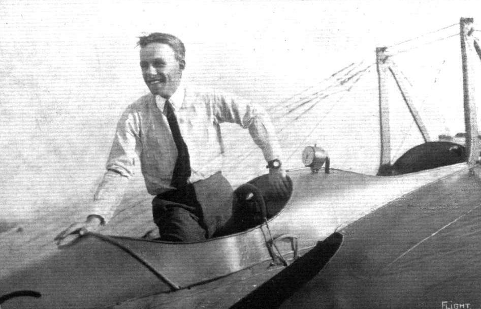
MR. JOHN GUY GILPATRIC, PILOT No. 171 OF THE AERO CLUB OF AMERICA. - Mr. Gilpatric is the holder of the American altitude record with passenger, which he secured at Los Angeles, California, in November last. When he made this record he was only sixteen years of age, and flies one of the French-built Deperdussin monoplanes with very great effect. He holds the position of chief pilot for one of the largest aeroplane companies in America. Many of our readers will be interested to learn, and will remember, that a few years ago Mr. Gilpatric used to correspond with FLIGHT, at that time he being only a youngster in "shorts".
Flight, February 8, 1913.
WHAT THERE WILL BE TO SEE AT OLYMPIA.
THE MACHINES.
The British Deperdussin Aeroplane Co., Ltd.,
Will be showing two monoplanes, a two-seater hydro-monoplane, fitted with one of the new 10-cyl. 100-h.p. Anzani motors and a 50-h.p. Gnome engined single-seater monocoque. The former of these two machines is British-built. It is at the present time nearing completion under the supervision of Lieut. J. C. Porte and M. Koolhoven, at the firm's excellently equipped works at Highgate, N. The machines chief peculiarity is that the wings are braced, not in the manner usually associated with monoplanes, but similarly to the Etrich monoplane that Lieut. Bier flew in connection with the Daily Mail Round Britain prize. Each wing is built up of two sections, the entering section, perfectly rigid, braced with a steel tubular understructure, and the trailing section, extremely flexible, which is hinged to it, and which is alone used for warping. The body of the monoplane is of the monocoque type; really it should be termed a bicoque because the shell is made in two sections, an upper and a lower, which are afterwards joined together.
<...>
Flight, April 26, 1913.
REFLECTIONS ON THE MONACO MEETING.
Deperdussin.
The Deperdussin monoplane at Monaco was constructed on similar lines to the land machines, with the exception, of course, of the under-carriage portion by which the body was attached to the floats. Two floats were employed, and the attachment was rigid. Massive limber struts passed from the shoulders of the body to the middle of the decks on the floats, and lateral stiffness was obtained for this fastening by bracing the sides of the floats to the heads of the struts by steel wires. Tubular steel struts were also inserted diagonally from the sides of the floats to the middle of the principal struts.
Although several Deperdussin monoplanes were to be seen at Monaco, that piloted by Prevost was principally in evidence. It had a 160-h.p. 14-cyl. Gnome, and a minor detail of interest was the presence of a longitudinal air intake-pipe for the carburettor situated beneath the body with its orifice facing into the propeller draught.
Flight, May 10, 1913.
THE DEP. HYDRO-MONOPLANE.
AT the time of the last Aero Show at Olympia we gave a short description of the hydro-monoplane exhibited by the British Deperdussin Aeroplane Co,, Ltd. Since then this machine has been put through an extended series of trials over the Blackwater, near Osea Island and his, we understand, proved very successful.
One of the most interesting features of this machine is the immensely strong wing-bracing, effected by an understructure of steel tubing. It will be remembered that the Etrich monoplane, flown by Lieut. Bier in the Circuit of Britain, had a somewhat similar system of bracing, but the girder of the Etrich machine only partly supplanted the ordinary triangulation bracing, whereas in the "Seagull," as this latest Dep. hydro-monoplane has been named, this structure has been made of sufficient depth to do away with all overhead bracing.
One objection which might be urged against this system of construction is that it would appear to offer head resistance, but the designers claim that it offers no more head resistance than the usual wire bracing, which, as is well known, vibrates considerably, when the machine is flying, and the fact that this machine flies at about 65 miles per hour would seem to indicate that their claim is justified. This method of wing bracing certainly has several advantages, for it gives a structure of almost equal strength to that obtained in biplanes, and greatly minimises the compression in the spars.
It will be easily understood, that with this method of wing construction there are several difficulties which militate against the use of the warping system of control, and these have been overcome by fitting ailerons similar to those employed on some of the earlier Bleriot monoplanes, and later on the Goupy biplanes, to the wing tips. They have been found to work quite well, and this method does away with the weakening of the wing through constant deformation.
The fuselage is of the monocoque type and is very interesting, for it is constructed of wood veneer without any longerons, struts and cross-members or diagonal wiring of any kind. It is built in two halves, each half being built on formers, from narrow strips of tulip wood. Three layers of this wood are used, the strips of the two first layers running at right angles to each other. The different layers are glued together and the whole covered with two layers of strong fabric.
At the rear of the fuselage is carried the empennage, of very neat design. The tail plane - cambered top and bottom, and set at a positive angle of incidence - is secured to the fuselage by steel bands passing underneath the body.
The elevators are pivoted around a steel tube running along the trailing edge of the tail plane, and the levers operating them are accommodated inside the body and the tail fin respectively. The control wires to the rudder are enclosed in a similar way, so that in no instance are the control wires exposed to the effect of the air or sea water.
When at rest the tail is supported by a float situated some six feet in front of the rudder post. This float is built of 3-ply wood, covered with fabric, and painted with boat varnish, and is of such a section that it will support its own weight in flight.
Two main floats support the machine on the water, but a similar machine, which is now going through the works, will be equipped with one large central float, as the designers contend that a single float has several advances especially in a rough sea, and they have fitted this machine with two floats for experimental purposes only. Three-ply wood is the material used in the construction of the floats, which are connected to the body by two U-shaped frames of multi-ply wood. The floats are flat-bottomed, that is to say they have no step, the designers maintaining that the wings of a hydro-aeroplane should perform the functions of steps in raising the machine when sufficient speed is acquired. Inside the body, very comfortable accommodation is provided for the pilot and observer, the latter occupying the front seat. From here he has an excellent view of the sea beneath, as he is situated well forward in the body, and the wings have been cut away near the body from the leading edge to the front spar. In front of him is a starting handle, by means of which he can start the engine without leaving his seat.
Just behind the engine-plate and inside the body is a service tank, divided longitudinally by a partition, the two compartments containing oil and petrol respectively. A small pump, driven by a miniature propeller situated outside the body, and working in the slip-stream of the propeller, feeds petrol to the service tank from a main tank inside the body under the pilot's cockpit. By means of gauges on the Elliott instrument-board, the observer is always able to ascertain if petrol is being pumped up regularly. Should one of these gauges become broken, they can be instantly put out of action, so as to avoid an escape of petrol. Filling up the main tank is done from the outside through a filler in the side of the fuselage, so that there is no possible danger of spilling any petrol inside the body, where it might be accidentally ignited.
Underneath the mica wind screen in front of the pilot, and almost level with his eyes, is a compass, made by Kelvin and James White, Ltd. The pilot does not watch the compass card itself, but its reflection in a glass prism, which shows an enlarged view of a small part of the card.
Control of the machine is effected in the usual Dep. fashion by means of a hand wheel mounted on an inverted LJ shaped frame. From a drum on the hand wheel cables run to one arm of the bell-cranks situated on the chassis members. From the other arm of the bell-cranks cables pass through the streamline casing on the boom of the wing structure, around pulleys on the outer end of the boom and to the trailing edge of the aileron. Another cable, running from the leading edge of an aileron around pulleys on the boom and across to the other wing, interconnects the two ailerons so that when the angle of incidence is increased on one, it is correspondingly decreased on the other. The ailerons are pivoted around a steel tube which is secured inside the wings, roughly half-way between the two main spars.
A 100-h.p. 10-cyl. Anzani engine is bolted on to a steel capping plate on the nose of the machine. It drives directly a Rapid propeller of 8 ft. 6 ins. diameter.
Flight, July 5, 1913.
THE HOME OF THE "SEAGULL."
"COME down to Osea Island and see the 'Seagull,'" said Mr. Santoni to me a few weeks ago, and the invitation was no sooner extended than it was accepted. I might explain that although much has been learnt in the past from studying the ways of the gull, this particular visit had no connection with bird life, its purpose being to see that fine water-plane which was so much in evidence on the stand of the British Deperdussin Co. at the February Aero Show at Olympia. Having accepted the invitation, it was immediately arranged that the visit should take place on the following Sunday, and it may not lie uninteresting to readers of FLIGHT if I set down some of the incidents that befel us on that memorable trip.
On Sundays there is only one train goes that way, and it leaves Liverpool Street at eight-twenty-five ante, change at Witham for Maldon East, where on arriving the fun commences. Outside the station were a number of "flys." Why in the world they were ever so called we could not make out. (I have looked it up in the dictionary since and find "Fly: to shun, to avoid," so perhaps there is something in a name after all.) Certainly they are far remote from flying, though we had to take one to get there. The great trouble we had was to make a choice, but shutting our eyes we picked out one that had been - in about the mid-Victorian era - called a victoria. There really wasn't much wrong with it, provided one was easily pleased. A victoria was originally designed (good word) to accommodate three, including the driver. We were three inside and an equal number on the box, including the little daughter of our coachman, who was a lady "coachman." The footboard of the box had all disappeared except one small board, and as the child promptly went to sleep, our "coachman's" time was equally divided between trying to slip in the top gear when the horse wasn't looking, and preventing her offspring from slipping through the place where the floor ought to have been. That horse, by-the-bye, must have had a slipping clutch, judging by the way he took the hills. A three-mile drive, without exceeding the speed limit, got us safely to Millbeach, a village of two houses, one of which is an inn, where, as the tide was up, we had to wait for the motor launch to come from the island, about three miles away, to fetch us. When the tide is out it is no good waiting for the launch because there is no water, and the only way to get to the island is to walk or drive across a primitive causeway - the hard-staked out with seaweed covered posts in the bed of the creek, which, incidentally, is dangerous to undertake once the tide has turned, for it comes in with extraordinary rapidity, and flowing round the island attacks from both sides.
While waiting for our craft, we were much amused at the antics of a dog that is an expert at fishing. This sagacious canine will creep along the shore "speering" for plaice or soles, and having located one he springs in and catches it with almost unerring aim. We saw him catch two nice-sized fish in less than ten minutes, and I managed to secure a snap of him on his second attempt just as he lifted his head out of the water.
Climbing into the launch was quite exciting, as owing to the sloping shore one could not get close up, and one had first to step into a dinghy about the size of a cocked hat, and from that into the launch. As we were rather a large family, I had the pleasure of being towed behind in this cockle-shell, and as the wind was against the tide, with the help of the propeller they made things lively for me. However, from my position I was able to get a photograph of my tug, showing her churning away with Lieut. Porte guiding her destinies. On arriving at the island we found the mechanics busy fitting various little things to the waterplane, which is one of the most business-like jobs I have seen. It is no joke, however, if any special thing is wanted on Osea Island. By way of example: During the morning it was found necessary to send the motor launch to Heybridge, about four miles away, to fetch a small piece of steel from the local blacksmith. For me it was not so bad, as it enabled me to have another trip, this time not in the dinghy. Arrived at Heybridge we left the launch out in the tideway in charge of Mr. H. M. Brock - the plucky Hendon pilot who recently flew the baby Dep. from Hendon to Brooklands in a fifty-mile wind - and made for the shore in the dinghy. Having secured our cockleshell to a ring in the sloping wall, we started out to find the blacksmith, who we discovered, not under the proverbial spreading chestnut tree, but in his little weather-board cottage, surrounded by his hives of industry in the shape of various workshops. For this blacksmith is not of the common or garden variety. He, like those of his brotherhood, shoes horses and puts on cart wheel tyres, but he does not stop there. Far from it. In addition he is a boat-builder, a fitter of ships' and yachts' cabins, a constructor of portable houses, anything, in fact, from a hangar to a dog-kennel. Above all, he is the resident chief electrician of his own electric light generating plant, which, originally erected to supply his own workshops, has since been extended to light the houses of his fellow villagers. Having obtained what we wanted, on arriving back at the place where we had left the water, we found it had all run out and left our dinghy hanging by the nose half-way up the wall, and no water within yards of her. Being so small, however, we simply lifted our craft off the wall and my companion carried her in his arms, like a child, to the edge of the stream, and so back to the launch, where we found friend Brock supremely contented, stretched restfully out in the sun. The water had by this time run out as though somebody had made a hole in the bottom of the creek, and it was a race against time to get back to the island before we got left high and dry on the mud. Our engine was of 12 h.p., and having such a tide we slipped along pretty fast, our "crew" sounding the depth every few minutes with the boat-hook. It seemed most strange to be out on a stretch of water nearly two miles wide, and be able to touch bottom at 3 ft. or thereabouts. Halfway back we had only a little over 2 ft., and I began to wonder what it would be like to be stuck on the mud for twelve hours, and at the same time it came to my mind that there was only one solitary train back to London, and that at 7.14. However, we just managed to get back to the island with our screw stirring up the mud. Shortly afterwards the "Seagull" was wheeled by many willing hands down to the deep channel on the south side, where there is always plenty of water, and got afloat.
A waterplane on land has always struck me as being somewhat of an ugly duckling, with its big floats which raise it so far from the ground, but on the water I think a more graceful object it would be hard to find, and this one has a particularly pleasing appearance, looking for all the world like a huge grey swan.
With Lieut. Porte in the pilot's seat, the 100 h.p. Anzani was cranked up, and away she skimmed with seemingly a human sense of pride and joy at being in her native element.
Unfortunately, time and the Great Eastern Railway wait for no man, and we had to be content with a few trips, especially as we wanted to walk back over the ground, or, rather, mud, to Millbeach, just to see what it was like to tramp in the bed of the sea, like Pharaoh of old. At Millbeach we were picked up by our friend the antediluvian chariot and whirled back, at some ghastly speed hearing 3 to 4 m.p.h., to Maldon East. A change again at Witham, with a one-stop run to Liverpool Street, and we were back in the hub of the universe, after a most enjoyable day.
H.E.S.
Flight, December 13, 1913.
THE STANDS AT THE PARIS AERO SHOW.
DEPERDUSSIN.
Great interest naturally attaches to the Deperdussin exhibit mainly, perhaps, on account of the tremendous speeds which these machines have put up. It would seem that in the monocoque type the Deperdussin firm have found an entirely satisfactory fuselage construction, for the three machines exhibited on their stand are all of this type. Two machines for use over land are shown, one being the actual machine flown by Gilbert in his flight from Paris to the Baltic Sea (Rutnitz), a distance of 1,050 kilometres, which he covered in 5 hrs. and 11 mins., or at an average speed of over 200 kilometres per hour. The other land machine shown is the machine flown to victory by Prevost in this year's Gordon-Bennett race, and which was described in FLIGHT for November 22nd. A hydro-aeroplane, also of the monocoque type, completes the very interesting exhibit of the Deperdussin firm.

The British-built Deperdussin war hydro-aeroplane.
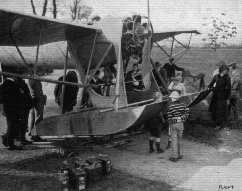
View of the front floats and mounting of the "Seagull."

British Deperdussin Seagull of 1913 on test on the River Blackwater, as seen on the water from behind.
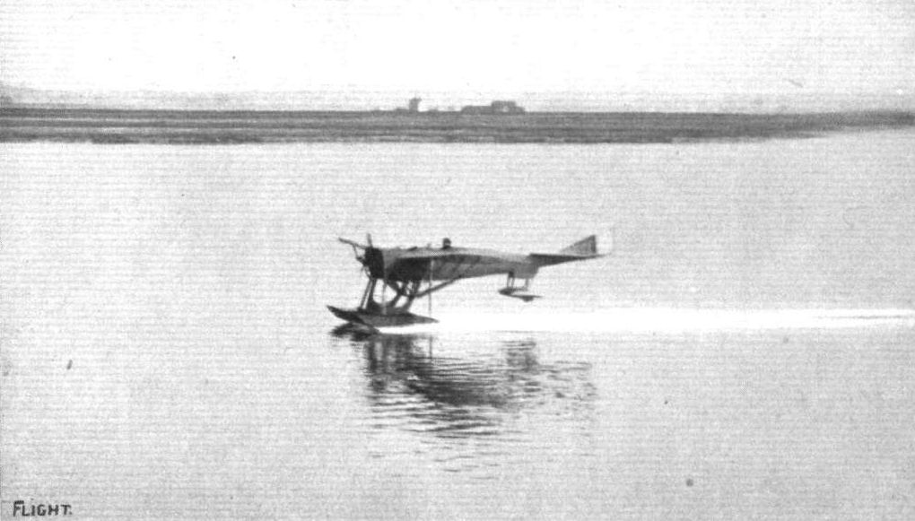
The "Seagull" just about to rise from the water.
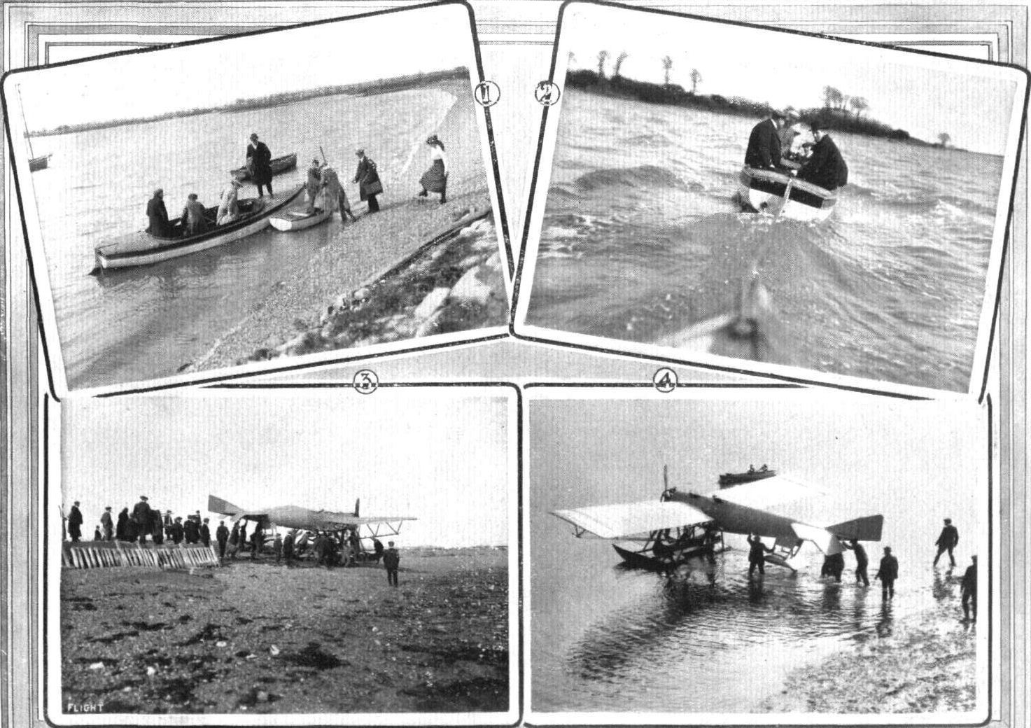
1. Getting aboard for Osea Island. 2. In tow. 3. All hands down the beach. 4. Launching the "Seagull."
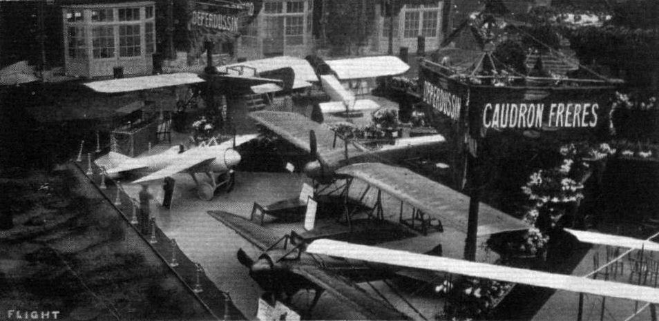
THE DEPERDUSSIN STAND AT THE PARIS SALON. - In the left-hand corner is Prevost's small monocoque.

The 100-h.p. Anzani-Deperdussin hydro-monoplane.
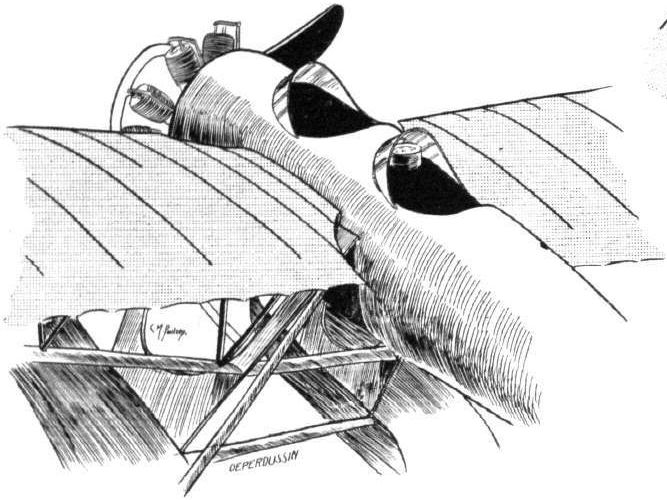
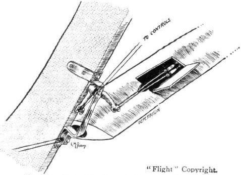
Sketch showing how the movement of the wing-tips is geared up by means of a bell-crank, inspection door in the streamline casing.

Three-quarter back view of the Empennage.
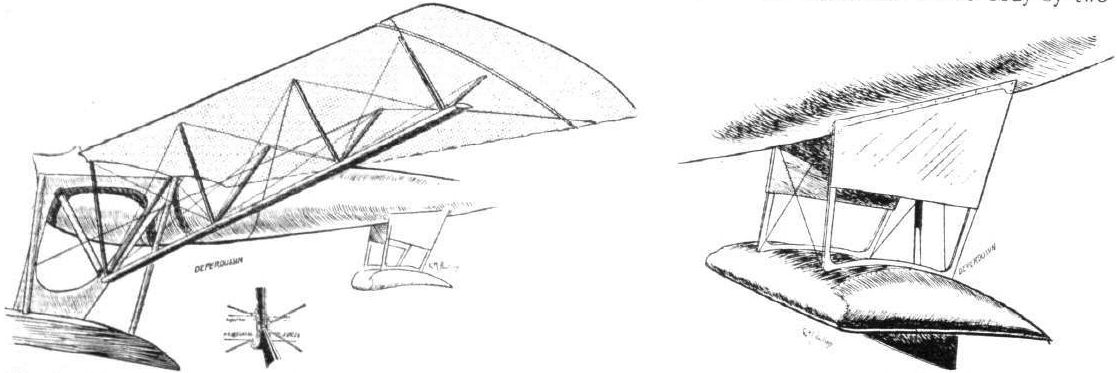
Sketch of the wing bracing on the "Seagull." Inset is shown the method of attaching bracing wires. On the right is the tall float.
HYDRO-AEROPLANES. - Fig. 5. - Types of Aeroplanes.

THE "SEAGULL." - Plan, side and front elevation to scale.
Flight, February 8, 1913.
WHAT THERE WILL BE TO SEE AT OLYMPIA.
THE MACHINES.
The British Deperdussin Aeroplane Co., Ltd.,
Will be showing two monoplanes, a two-seater hydro-monoplane, fitted with one of the new 10-cyl. 100-h.p. Anzani motors and a 50-h.p. Gnome engined single-seater monocoque.
<...>
The 50-h.p. single-seater monoplane that will also be shown is a French-built monocoque, a great deal on the lines of the speed creation with which Vedrines carried off last year's Gordon-Bennett trophy. It will come to Olympia direct from Brussels where it has been on exhibition. Besides these two monoplanes, the British Deperdussin Co. will have miscellaneous specimens of their workmanship showing, such as an uncovered wing, and perhaps a landing chassis unit.
Flight, February 22, 1913.
SOME MORE AEROPLANES AT OLYMPIA.
<...>bottom of the fuselage and a neat little carriage-built body for the protection of the occupants to the top. The passenger sits in front, just behind the motor, and by looking over the leading edges of the wings, he is able to obtain a very good view nearly vertically downwards. The pilot, if anything, has a still better view, for the wings on either side of his cockpit are cut away up to the rear spar for a short distance along the wing.
The landing chassis is somewhat different from the type that was standard a few months back. The wheels are now mounted on two laminated sweeps of wood which, in essence, combine the functions of skids and chassis struts. So that they may not be so liable to split, these chassis sweeps are covered over with canvas. There is no change in the manner in which the axle of the landing wheels is strapped by rubber cords to the rigid chassis structure.
The wings are of the usual design. Indeed, the only innovation noticeable is that the leading edge of the upper surface is, for some nine inches or so back, covered in by three-ply wood to that it may be more capable of retaining its correct shape, and that the wing construction in that part may be correspondingly strengthened.
There has been a change made in the manner in which the wing warping is operated. In earlier machines, the warping cables were carried to a rocking bridge mounted in the centre of the chassis. Now they are taken to bell-crank levers mounted to the rear of the chassis supports on either side, a system which was first put into practice on the terribly high-powered monocoque of this make which took Vedrines to victory in the 1912 Gordon-Bennett race held at Chicago.
Flight, September 20, 1913.
THE AERIAL DERBY.
PILOTS AND HOW TO RECOGNISE THE MACHINES.
No. 13. The Deperdussln Monoplane
is peculiar in that the wings are narrower (i.e., have a smaller chord) at the root than at the tips, and should also be easily identified by its characteristic landing chassis.
THE MACHINES, WITH SOME DETAILS.
No. 13. The 110 h.p. Anzani-Deperdussin monoplane - also a fast machine, is of the well-known Dep. type. The wings have a greater chord at the tips than at the roots, so as to give increased warping efficiency. The fixed tail planes are comparatively large, and there is a vertical stabilising fin in front of the rudder.
Flight, November 22, 1913.
THE 160 H.P. DEPERDUSSIN RACING MONOPLANE.
130 M.P.H. sounds incredible, even in these days of speed, and to have dared to prophesy such speeds only a little while back would have been simply to call down ridicule. Yet this is the speed of the Deperdussin monoplane, of which we publish illustrations this week, and which, it will be remembered, won this year's Gordon-Bennett Race at Rheims, piloted by that daring aviator, Prevost.
When considering such speeds the first questions asked naturally are: How is it done? What makes it possible? In the case of the Dep. the answer must be: Firstly, high engine power, and, secondly, reduction to a minimum of head resistance. The latter may again be divided into two, i.e., wing resistance and body resistance. The first has been reduced partly by having a very short span and partly by having very flat and very thin section wings. The reduction in body resistance has been obtained by paying the minutest attention to the best possible streamline form in connection with a chassis which offers a minimum of resistance. A glance at the accompanying illustrations will show what form this attempt has taken, and the result proves with what success.
As for the actual construction of the machine, the body is of the same construction as that which characterises all the modern French Deps., i.e., it is of the monocoque type, which was, we believe, originated by the Deperdussin firm. The procedure of building this coque is as follows: Three layers of thin stringers of tulip wood are glued together over the detachable form on which the coque is built, tulip wood being particularly suitable for this sort of work. When the glue has set, the underlying form is taken down, thus leaving a shell composed of a great number of strips running across one another, and thus affording the maximum of strength. The thickness of this shell is about 4 mm. or roughly 1/8 of an inch. The coque is now covered inside and out with fabric, which is glued on and varnished, and the finished result is a shell combining great strength with comparatively small weight, and possessing a very good streamline form. On this shell are then secured the different members, such as engine bearers, wing compression struts, and the anchorage for the chassis and empennage.
The wings, which are very flat and very thin in cross section, are built up of spars of hickory and ash with ribs of pine, and the whole is covered with strong linen cloth doped with Emaillite. The upper and lower bracing wires are secured to the cabane and to the front of the chassis respectively, whilst the upper warping wires pass round pulleys in the cabane, and the lower ones are taken to a drum on the transverse rocking lever situated on the rear cross-member of the chassis. An inspection of the front view of the machine will show that owing to the short span and the fairly deep chassis, the angle of the bracing cables is particularly good.
At the rear of the fuselage are mounted the tail planes, which consist of a fixed damper plane, which is slightly cambered and lightly loaded, to the trailing edge of which is hinged the divided elevator. A small vertical fin is fitted on top of the fuselage, and to this is hinged the rudder. The controls are of the standard Dep. type. A bridge-like member resembling an inverted U carries a rotatable hand wheel, the forward and backward movement of which operates the elevator, while rotation of the wheel actuates the warp. A transverse foot bar controls the rudder.
A chassis of the type known to most of our readers from the British-built Deps. supports the machine when on the ground. It consists of two U-shaped members of three-ply wood attached at the top to the fuselage, and carrying at their lower extremities the tubular wheel axle which is sprung in the usual way by means of rubber shock-absorbers.
Mounted on steel engine bearers in the nose of the fuselage is the 160 h.p. Gnome engine which furnished the power in the Gordon-Bennett Race, but it is worth noticing that the machine will fly with a 50 h.p. Gnome engine. An aluminium shield encloses the engine on the sides, while cooling is obtained by leaving a sufficiently large open space between the engine cowl and the hemispherical cap which is fitted over the boss of the propeller in order to provide a good entry for the air. It will be noticed that even the pilot's head has been "streamlined." The weight of the machine fully loaded is 1,350 lbs. Her speed round a course is 125 m.p.h, and in a straight line she does about 130 m.p.h.
Flight, December 13, 1913.
THE STANDS AT THE PARIS AERO SHOW.
DEPERDUSSIN.
Great interest naturally attaches to the Deperdussin exhibit mainly, perhaps, on account of the tremendous speeds which these machines have put up. It would seem that in the monocoque type the Deperdussin firm have found an entirely satisfactory fuselage construction, for the three machines exhibited on their stand are all of this type. Two machines for use over land are shown, one being the actual machine flown by Gilbert in his flight from Paris to the Baltic Sea (Rutnitz), a distance of 1,050 kilometres, which he covered in 5 hrs. and 11 mins., or at an average speed of over 200 kilometres per hour. The other land machine shown is the machine flown to victory by Prevost in this year's Gordon-Bennett race, and which was described in FLIGHT for November 22nd. A hydro-aeroplane, also of the monocoque type, completes the very interesting exhibit of the Deperdussin firm.
THE DEPERDUSSIN STAND AT THE PARIS SALON. - In the left-hand corner is Prevost's small monocoque.
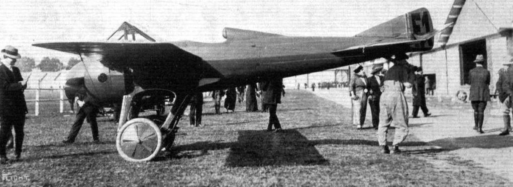
Prevost's Deperdussin, the winner of the Gordon-Bennett Trophy, competed for this year at Rheims. Prevost's average speed was over 124 miles per hour.
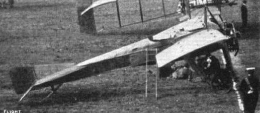
The Deperdussin.

Another close-range photograph of a machine in flight taken from Pylon No. 1 at the Hendon Aerodrome. - The monoplane is a 100 h.p. "Dep.," which has been flown with such effect by Lieut. J. C. Porte, R.N. In the Speed Handicap on a recent Saturday, his winning finish, after a neck-to-neck race with the Morane monoplane, was one of the finest sights that the Hendon Aerodrome has ever provided its enthusiastic spectators. The Dep. was flying so low that twice its wing-tip scraped the grass at the corners. These photographs form quite an unique study of aeroplanes in flight, for they show the pilot at very close quarters and under perfectly normal conditions. The above machine is travelling at about 80 m.p.h., and the wing-tip is within about 12 ft. of the camera.
A close finish for second place in the "Shell" Handicap at Hendon on Saturday between Lieut. Porte on the Deperdussin and Mr. R. Slack on the Blerlot.
AERIAL FLORAL FETE AT HENDON AERODROME. - The first heat of the Speed Handicap. Manton, on the Grahame-White biplane, completing his first lap, with Brock and Verrier still waiting to take up their start in the race.
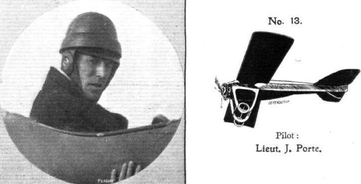
Pilot: Lieut. J. Porte.

BROCK FLIES THE 110 H.P. ANZANI DEPERDUSSIN AT HENDON IN A RAINSTORM. - From an original drawing by Roderic Hill.

The front portion of the Deperdussin racer.

The warping crank of the 80-h.p. Deperdussin monoplane.
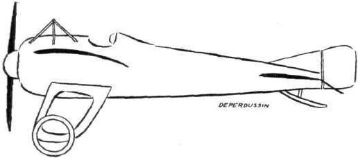
The 50-h.p. Deperdussin monocoque.
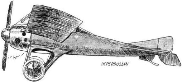
Sketch showing the racing Deperdussin from the side.
AT OLYMPIA. - A study in tail-skids.
A study in tails.
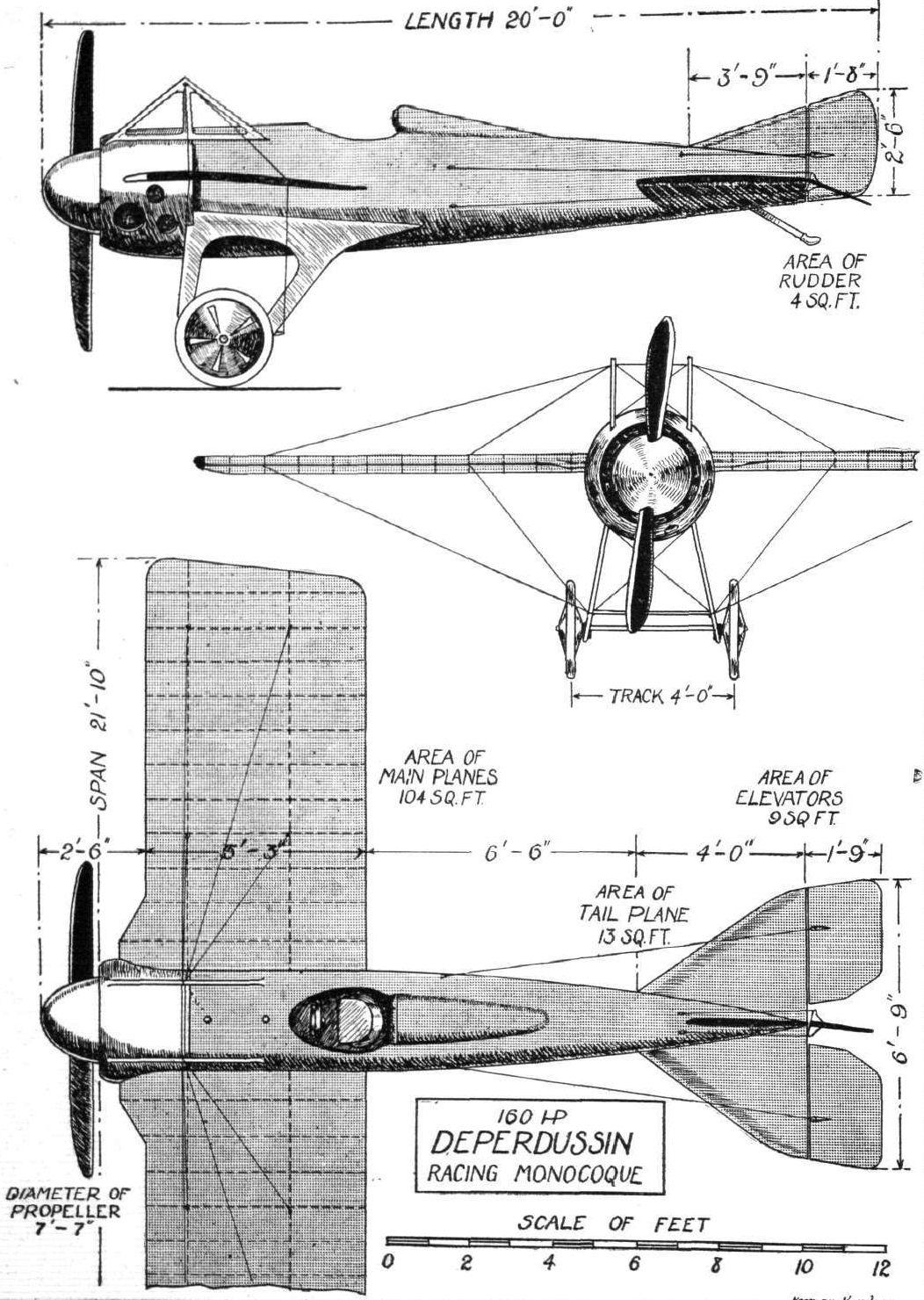
Flight, February 8, 1913.
BRITISH-BUILT DONNET-LEVEQUE MACHINES.
THE representatives of the Donnet-Leveque Hydro-aeroplane Company in England, Aeros, Ltd., of St. James's Street, W., are, we learn, forming a company to manufacture these well-known water flying machines over here. On the Continent they have met with a considerable measure of success, as is evident by the fact that, not long since, eight of these machines were ordered by the Austrian Government. One was delivered some few months ago to the British Admiralty. From the number of machines built for water flying that will ultimately be required for the defence of our country's coast we feel inclined to think that the proposed company should enjoy good business in a craft of this nature. When all details have been settled we hear that they intend to commence operations by establishing works and a flying school at Shoreham.
Our sketch gives an idea of the general arrangement of the Donnet-Leveque hydro-biplane. The float, which supports the machine on the water, is extended right back to the tail, so fulfilling the double purpose of float and fuselage. It is built throughout of mahogany, and, inside it is divided into a number of watertight compartments in order that, should the coque become punctured by coming into contact with any hard obstacle it will not become flooded out with sea water. A peculiarity in the construction of the coque is that the hydroplane surface is concave on the under side, a feature which makes it particularly efficient as a skimmer over smooth water. The planes of the machine are built up cellule fashion and are mounted above the body at about one-third of its length from the nose. High up between them the engine is mounted, driving direct a propeller which, mounted in that position runs no risk of being broken by spray thrown up by the passage of the machine over the water. A special magneto and starting handle are fitted to the motor, so that it may be started by the passenger without any necessity for him to leave his seat in the cockpit. In order that the machine may be capable of landing on land as well as on water a special form of disappearing wheelbase is fitted, which, after the machine has left the ground may be wound up out of action by a handle operating a drum, arranged conveniently within reach of the passenger. Although the machine is strongly constructed, yet it is of quite light weight, for the 50-h.p. model does not weigh more than 682 lbs., while the 80-h.p. machine turns the scale at only 836 lbs.
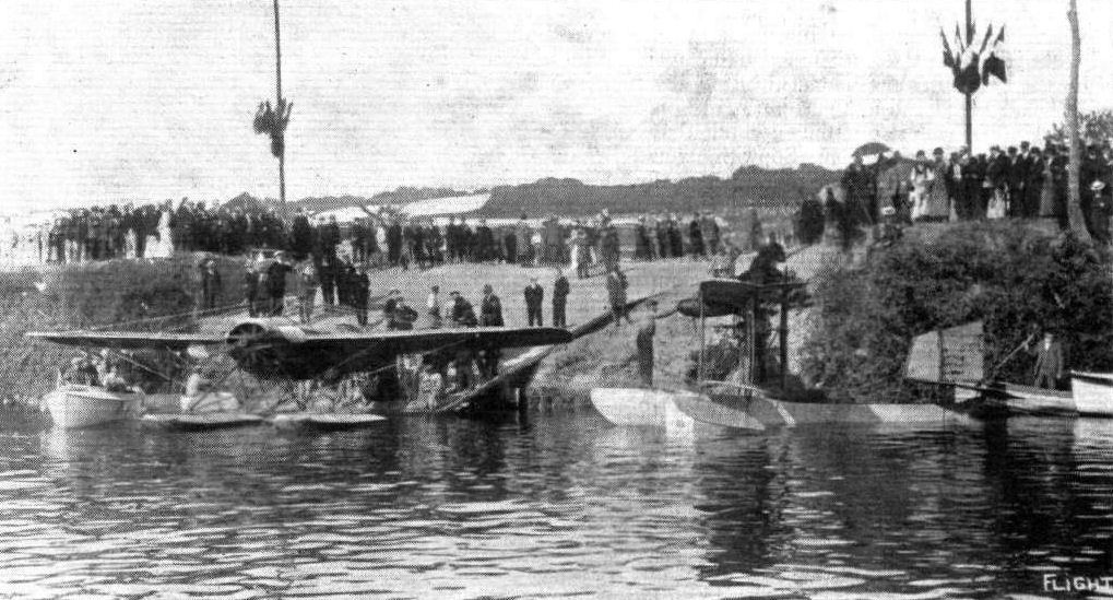
THE PARIS-DEAUVILLE WATERPLANE RACE. - General scene at the start from Paris.
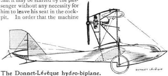
The Donnet-Leveque hydro-biplane.
HYDRO-AEROPLANES. - Fig. 5. - Types of Aeroplanes.
Flight, January 18, 1913.
HYDRO-AEROPLANES.
By V. E. JOHNSON, M.A.
<...>
Later on, in France in 1905, Archdeacon and Bleriot made, with Gabriel Voisin, experiments with hydro-aeroplanes, towed by a rapid motor boat. One of the earliest motored aeroplanes constructed by Bleriot was mounted on floats, and experiments were made with it on Lake Enghien; he was not, however, able to rise from the water, this method of launching requiring too much motive power. It was Henri Fabre who constructed the first successful machine (see Fig. 3), and it rose from the water for the first time on May 21st, 1910, in the Bay of Martigues, near Marseilles, when it made a flight of 500 metres at a height of about two metres above the water. The machine used was a type of Canard monoplane, with wings carried on a specially constructed girder and the surfacing was so arranged that it could be "clewed up" in order that less surface should be offered to the wind when floating on the water.
<...>

Fig. 3. - Fabre's machine.
HYDRO-AEROPLANES. - Fig. 5. - Types of Aeroplanes.
Flight, September 27, 1913.
MR. PEMBERTON BILLING WINS A WAGER.
LAST week, as most people know, Mr. Pemberton Billing made a most remarkable demonstration of how it is possible to learn to fly and secure a pilot's certificate within the space of a few hours. Subsequent to the feat we saw Mr. Pemberton Billing, whose account of his experiences was as follows :-
"The flight was the outcome of a wager made at Hendon when Handley Page stated that on his automatically stable machine anyone could learn to fly in a very short time - twenty-four hours, to use his own expression. I stated, in reply, I did not believe in automatic stability, but I did believe in the skilful handling of a machine, and that any man who had enough sense to come in out of the wet could learn to fly a known flying machine in one summer's day. The result was that I made a wager with Mr. Page that he, as the inventor and constructor of his own machine, could not learn to fly it in the time he stated, and I made another wager that I would take any aeroplane that he could secure and would not only learn to fly but obtain the Royal Aero Club's certificate within twenty-four hours of sitting on the machine, the terms of the wager being L500. This attempt was to start at dawn on Wednesday morning, and the ticket was to be completed before dawn on Thursday morning. As I found it impossible to hire a machine for the purpose, I had to buy a machine eventually, to be able to carry out the conditions. At a quarter to six on Wednesday morning, in drizzling weather, I started at Brooklands on the Henry Farman biplane which I had acquired, which is a fac-simile of the one that Paulhan flew to Manchester. Mr. Page was to make his try at Hendon. Mr. Barnwell, chief pilot of the Vickers school, volunteered to come up as passenger and verbally instruct me, I taking the pilot's seat and controls. After four minutes taxying Mr. Barnwell gave the sign to shove her up in the air. I did so, and we attained a height of 200 ft. flying steadily. Mr. Barnwell accompanied me for about 20 to 25 mins. in the passenger seat, during which time I succeeded in doing some dozen circuits of the aerodrome. Several figure eights, two or three vol plants, landings, and some landing under power were carried out, and as it was raining and the machine was sodden and sluggish in consequence of carrying two 13-stone men, this made the landing rather speedy and much more difficult in consequence. At the end of 25 mins. Mr. Barnwell left me, and told me to get up and get on with it. I immediately started away without any taxying, rose straight in the air at an exceedingly dangerous angle, amid the yells and shrieks of the spectators. I did a half circle and landed successfully, got up again immediately and did a circle and landed successfully, and then rose again and did five circuits. It was my intention to do twelve, but the petrol running out brought me down, the idea of coming trouble dawning upon me by the missing of the engine and the frantic waving of petrol cans by agitated spectators below. The rain had then set in so heavily that I was obliged to put the machine away for half an hour, at the termination of which time the machine was brought out again, and Mr. Barnwell went once again as passenger for three or four minutes to test my right-hand turns before allowing me to essay the figure eight alone. Immediately on descending, Mr. Barnwell jumped out of the machine, and I took her up at once, doing three successful eights. During the right-hand turns of these I managed to execute the most alarming banks, and, from inexperience, startled by the angle at first hung on to the struts. When I had descended from this stunt, on Mr. Barnwell's orders I proceeded to practise vol planing from an altitude of about 100 ft., with the engine cut off, which experience I found about the most arduous of all. While I was performing my gyrations in the air Mr. Barnwell thought it about time to send for Mr. Ranee, the Royal Aero Club official observer. There was some delay in finding him, as the weather, which was puffy and wet, never led him to believe anyone would want his services on such a morning. Eventually he was found, and kindly consented to observe, notwithstanding the short notice given. Incidentally this entailed a loss of an hour or more in the time in which it would have been possible for me to have taken my ticket, because it stands to reason that if I was capable of doing the test at a quarter past nine I was quite as capable of doing it at a quarter to eight, so I was practically waiting during that time to go through the regulation tests. Although Mr. Ranee expressed himself as exceedingly dubious about the advisability of attempting, he consented to act in his official capacity. I then rose in a very steep climb to a height of about 250 ft., so as to make sure of the altitude test once and for all. Then I came round with a left-hand bend, and proceeded on my first five figure eights. The five, so I was told afterwards, were good sound flying of an experienced airman, although the fifth right-hand turn proved an alarming one. I was flying over the paddock, where my wife was watching very anxiously, and to give her confidence I waved my hand to her, taking my attention off the elevating plane for the moment. The machine, as machines will on right-hand turns, shot up, throwing me back on my seat. The position was rendered more hopeless, undoubtedly, by my grabbing hold of the 'joy stick' to recover myself, which caused her to stand on her tail. She stopped dead in the air, about 200 ft. up, and then fell about 100 ft. tail first. From the looseness of the control, caused by the machine being stationary, I jumped to the conclusion that the wires were broken, and tried to save the position by throwing all my weight forward, with the result that when about 50 ft. from the ground the machine righted itself and dived head first. This, of course, was not attributable so much to my throwing my weight forward as to the fact that with me also came the joy stick, bringing the elevator down and causing the machine to dive, which immediately tightened up the controls. I instantly realised that I had the control of the machine again, and, thinking I would be disqualified for this stunt, saved her from landing about 20 ft. from the ground, climbed up again to 160 ft. and did an extra figure eight to make sure. Then followed a vol plane landing, and after listening with some impatience to Mr. Barnwell's illuminating and very forcible remarks on right-hand turns, I started off for the last half of the test, which was accomplished most successfully, finishing off with a vol plane from 100 ft. with the engine cut off, and brought the machine to rest without switching on again, with the elevating plane over the heads of the observers, thus succeeding in obtaining my pilot's certificate before breakfast on the morning when I had for the first time in my life sat in a flying machine that flew."
Of course, it will be remembered by all those who were in aviation in its pioneer days that Mr. P. B. built three machines of his own, and the last attempt he made, when he smashed the machine up, is a matter of record. He dug the engine out of the ground, and did his right arm and leg a lot of good at the time. Afterwards the tracks of the wheels of the machine were examined with a magnifying glass, and it was found that 60 ft. immediately preceding the smash there were no wheel marks in the ground, which we believe constitutes a record for being the first all-British machine to get off the ground.
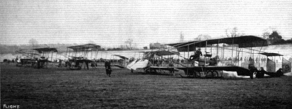
The start at Brooklands for the Easter Aero Handicap, which was secured by Mr. T. Alcock on Mr. Ducrocq's H. Farman biplane.

Mr. J. Alcock winning the Easter Aeroplane Handicap at Brooklands on Monday on Mr. Ducrocq's H. Farman.

SHOREHAM HARBOUR AS SEEN FROM ABOVE. - From a photograph taken by Mr. Clarence Winchester from Mr. Eric Pashley's biplane.
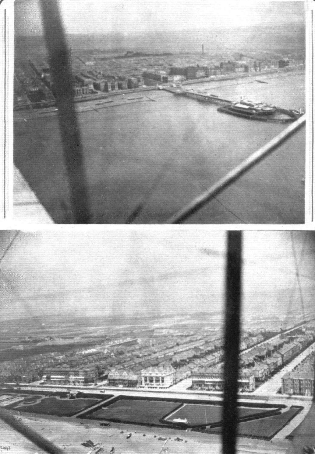
WEST BRIGHTON AND THE WEST PIER, BRIGHTON. - Photographs by Mr. Clarence Winchester from Mr. Eric Pashley's biplane.
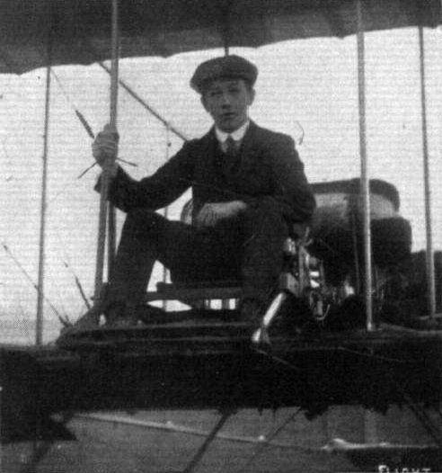
Mr. H. Macandrew, who, at the Maurice Ducrocq School at Brooklands, on the 14th instant, passed for his brevet on the little Farman belonging to the Ducrocq School.
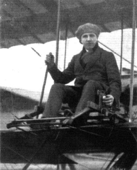
Mr. John Alcock, who has been doing so much good flying work at the Maurice Ducrocq flying school at Brooklands. Mr. Alcock has put up a lot of cross-country work, both with and without passengers, and has secured several wins in the competitions at the Weybridge aerodrome.
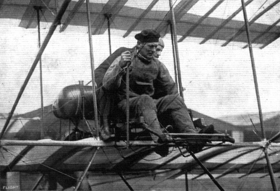
Mr. Pemberton Billing, in the pilot's seat, receiving instructions from his tutor and passenger, Mr. Barnwell.

MR. PASHLEY FLYING THE FARMAN MACHINE AT SHOREHAM AERODROME. - From an original drawing by Roderic Hill.
Flight, January 25, 1913.
AVIATION IN WAR.
WE have received from Messrs. Farman Freres the following interesting account of flights and reconnaissances, which was sent them by an aviator serving in the Greek army, at the Balkan theatre of war. The account covers a period of twenty days.
It has often been said that aviation, in the Balkan War, has not given all the results that were expected of it. And this is in some manner true, for the Balkan States had made little preparation. They had no spare parts, few experienced pilots, and no organisation. However that may be true for the general run of aeroplanes out there, it is far from being the case with their Farman machines, which, in spite of what has been said above regarding the lack of preparation of the Balkan States, have rendered the greatest service.
Even quite inexperienced pilots have been able to use them, and to report to their Commander-in-Chief observations of value. Their construction is such that in spite of the extremely rough ground where they had to operate, flights and landings were able to be made with very little breakage. We are of opinion that perhaps the best way to convey an idea of the services these machines have rendered to the Greek Government, is to relate the day-to-day flights made by Henry and Maurice Farman biplanes. This simple diary will be more eloquent than the more or less highly-coloured accounts that have been sent from the scene of hostilities.
This short diary simply concerns the period from December 10th to January 1st.
In Macedonia.
There were seven Henry Farman biplanes in Macedonia - six with 50-h.p. Gnome motors and one fitted with an 80. Three of them remained unused for there were no pilots to fly them. The principal flights during this campaign were :-
Lieut. Camberos, on the 80-h.p. Gnome-Henry Farman, made a reconnaissance from Larissa to Cosani, about 85 kiloms., at a height of 1,600 metres, reporting information of the greatest value.
Lieuts. Moutoussis and Notaras together made a scouting flight of more than 140 kiloms., on a 50 Gnome-Henry Farman biplane, at an altitude of between 1,100 and 1,200 metres, flying above opposing troops whose position they were able to reveal. In making short scouting flights two 50-Gnome biplanes were slightly damaged by landing on very bad ground, but repairs were effected easily.
Lieut. Moutoussis on a 70-h. p. Maurice Farman biplane, flew above Salonica at a height of between 1,200 and 1,500 metres. That machine was ordered to be dismantled, and sent to the Epirus.
In Epirus.
The central aviation camp in Epirus was on the Plain of Nicopolis, 6 kiloms. from Preveza. The Chief of the flying squad was Capt. Bares, a French military pilot, having under him two Greek Lieut, pilots, Camberos and Notaras, who went through their tuition in France at the Farman school. On December 10th, Capt. Bares and Lieut. Camberos tested the Farman biplane that had been assembled and made flights above Preveza. The following day, the 11th , Notaras flew over Preveza, and in the afternoon Camberos left with a passenger for Philippias, 47 kiloms. from Preveza, and afforded interesting observations. On the 14th, Camberos was transferred to the Artillery, and on the following day Lieut. Moutoussis arrived. Two days later he tested the Maurice Farman biplane that had been erected in the meantime, and flew over Preveza. The next day at 1 p.m. Moutoussis left to make a flight above Janina and landed at Amin Aga Han, 75 kiloms. from Preveza. The distance between Preveza and Janina was 106 kiloms. During this flight, flying at over 1,600 metres, he threw down bombs, creating a veritable panic amongst the Turkish troops. Many hostile bullets tore the fabric, but the machine continued its flight unaffected.
Capt. Bares, on the return of Lieut. Moutoussis, used the same machine, and flew back over Janina, 2,300 metres up. Again several bullets pierced the fabric, but the machine returned to camp unaffected, except for a slight break that happened in landing on rough ground. That same day a new Maurice Farman biplane arrived, and erection was immediately proceeded with. On the 20th, Moutoussis flew over Preveza on the Maurice Farman, and made interesting reports. He continued his flights the next day. He made a second reconnaissance over Janina on a Maurice Farman on the 22nd inst., flying over the town at 2,100 metres, and throwing bombs, which, as on the previous occasion, had considerable effect. Several hostile bullets reached him, breaking a longeron, but without affecting the machine's flying qualities. He landed at Philippias. Next day he left that town for Nicopolis. On the 24th, Nolaras made flights with a passenger above Preveza. Between then and the 27th, when a new machine arrived and was erected, the two lieutenants continued their scouting flights on their respective Farman biplanes. A Greek army pilot officer, Adamides, joined the corps on the 28th. A very excellent reconnaissance flight was made by Lieut. Notaras above the fort of Bisani and the town of Janina on New Year's Day. He flew at about 2,300 metres. Leaving the aerodrome at Nicopolis at 10.20 a.m., he returned at 12.18, reporting observations concerning the garrison and the fortification, which were considered of the highest importance by the Greek commanding officer.
During this campaign of twenty days only three machines suffered damage, and what damage was done was easily repaired.
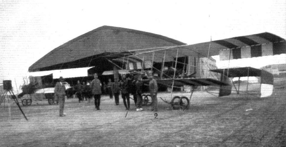
WAR AEROPLANES IN GREECE. - The above photograph has been received from M. Kimon Stratigopoulos (No. 2 in photo), who is at present under flying orders with Lieut. Moutoussis (No. 1 in photo).
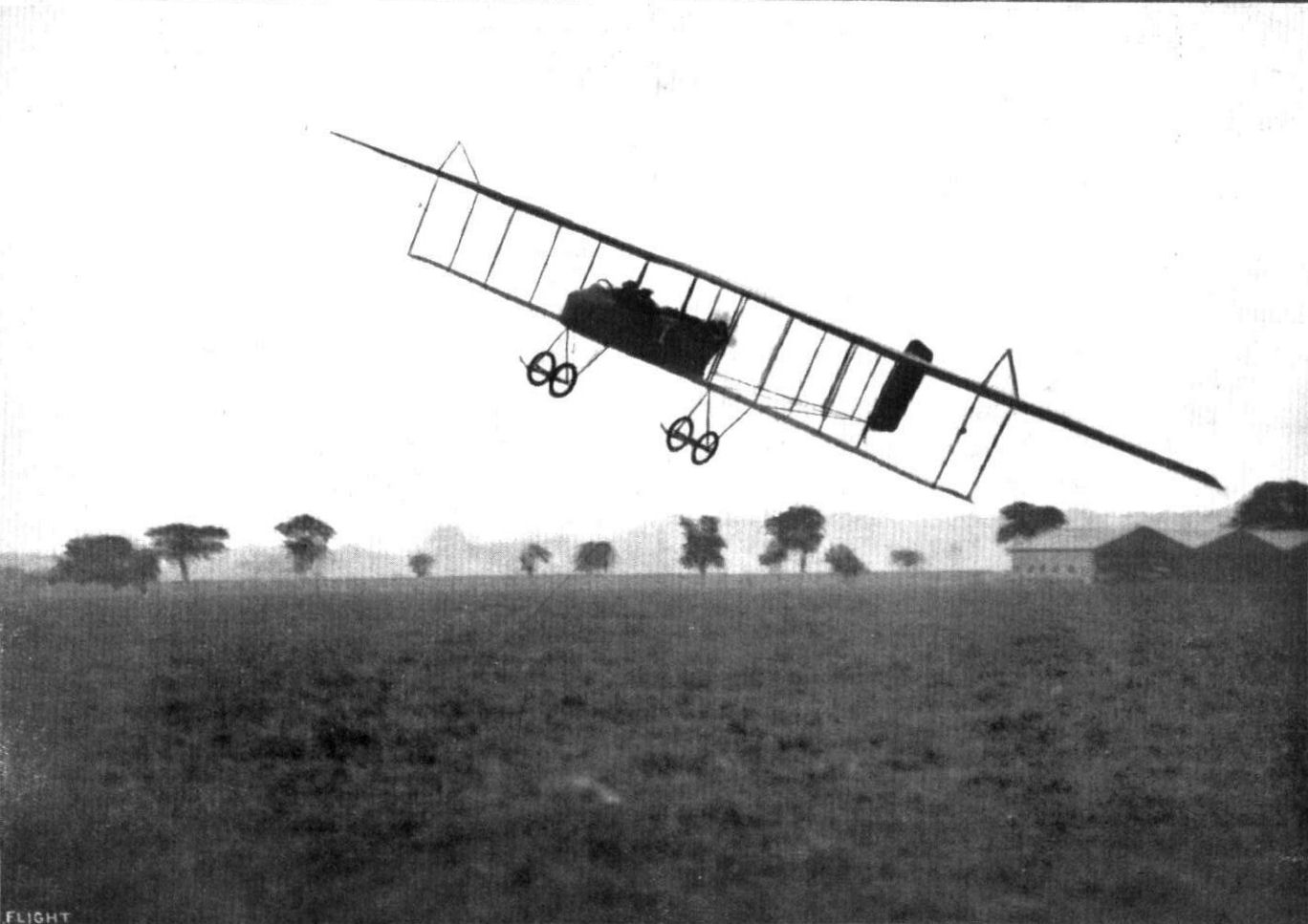
A fine bit of banking by Mr. Claude Grahame-White on the Henry Farman at the Hendon Aerodrome.
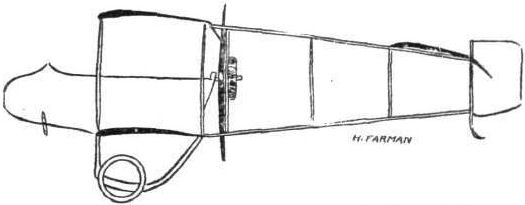
The 80-h.p. Henry Farman biplane.
AT DEAUVILLE. - Commandant Felix flying on the Dunne biplane over the sands. Below in the foreground is a Henry Farman waterplane. and in the distance other waterplanes taking part in the French Government Waterplane Trials.
HYDRO-AEROPLANES. - Fig. 5. - Types of Aeroplanes.
Flight, February 8, 1913.
WHAT THERE WILL BE TO SEE AT OLYMPIA.
THE MACHINES.
The Aircraft Manufacturing Co., Ltd.
Constructors of British-built Henry and Maurice Farman biplanes, will be showing a machine of each type. Their British-built Maurice Farman biplane, equipped with the 70-h.p. Renault motor, flown so well by officers in the Royal Flying Corps, and by Verrier at Hendon, is too well known to need any description here. The Henry Farman biplane that will be shown, we are not so closely acquainted with. In its general lines it will greatly resemble the 80-h.p. H. Farman owned by the Grahame-White Aviation Co., and flown at Hendon by Louis Noel. Its chassis, however, will be different, and its body will be of a more modern type. It will be fitted with an 80-h.p. Gnome motor.
<...>
Flight, February 22, 1913.
SOME MORE AEROPLANES AT OLYMPIA.
THE AIRCRAFT MANUFACTURING CO., LTD.
In our last issue of FLIGHT we described and gave sketches of the 70-h.p. Maurice Farman biplane shown on their stand. At the time of going to press with that issue the 80-h.p. Henry Farman machine that they are also showing was not available for review, so it could not be included in the report of the Aircraft Manufacturing Co.'s stand. Since then, however, we have been able to examine the machine, and we are able to set forth its chief characteristics here below.
The 80-h.p. Henry Farman Biplane. - Remembering the comparative crudity of construction of these machines some three years or so back, the excellence of the workmanship that the Farman firm put into their machines now is a revelation. And perhaps it is not surprising, since they have, at Billancourt, what are probably the best organised and largest aeroplane works in the world. The machine at Olympia on the stand is an ordinary everyday sample of their good work. It has been taken from stock, to use a rather inaccurate expression, since the demand for these machines is so great that they can keep no stock.
Plane construction. - Its planes span 45 ft- and 25 ft. respectively, their chord measurement is 5 ft. in the centre bay, from which they taper to the tips. They are separated by struts 4 ft. 9 ins. in length. There are twelve of these struts separating the two planes, half of them being of hollow ash, and the remaining ones of hollow spruce, the ash ones being those immediately on either side of the engine, and the four that brace the cellule above the point of attachment of the landing gear. The spars, both front and rear, are of ash, and the front one is bullet nosed, as it forms the entering edge of the plane. The 10 ft. extensions that are fitted to the top plane on either side of the machine are braced in posit ion by king posts and piano wire in a manner identical to that of a monoplane wing. Double acting ailerons, for balancing, are hinged to the rear spars of these extensions.
The landing chassis. - The ordinary type of Farman chassis is employed, but in its working out there are many detail improvements. The two short ash skids are spaced 9 ft. 9 ins. apart, and each support the machine through a single rank of three steel tubular struts on either side. There is a sketch printed in connection with this description which shows the neat manner in which the radius rods are universally hinged to the skid by a ball joint. In former types of the Farman under-carriage, steel compression springs were fitted over the axles between the central bobbin carrying the shock absorbers, and the wheel hub, to assist the chassis to track correctly. These have been dispensed with now, and the elastic cord which provides a flexible suspension of the wheels, is now bound under the skids and over the axles.
The body, a rectangular section girder, built up with ash longerons and ash cross-members, accommodates the pilot and passenger in tandem, and serves as a mounting for the motor and tanks. Its sides and bottom are enclosed, and a wind shield in front assists in keeping some of the draught off the occupants. This front is constructed in rather a neat manner. The skeleton of that portion is of oval section steel tubing, and the vertical members separating the top and bottom sweeps are of the same material. The joints are acetylene welded. Just behind the wind shield there is a very comfortable seat, with a high back of sheet aluminium for the pilot. He controls the rear elevator and the compensating ailerons by means of a vertical universally jointed lever, greatly refined from the crude form of lever that was employed on the early Henry Farman biplanes. The passenger has a seat, perhaps not quite so comfortable, just behind the pilot. The Gnome motor, at the back, is overhung. It is mounted with two flanged steel plates on one side of the crank case, and the fuselage in that vicinity is cross-braced by 3/8-in. steel tubing, to give it the necessary rigidity and strength. By the way, a new type of carburettor is fitted, whereby the engine may be made to run slowly, a condition which is difficult to obtain with the ordinary type of Gnome injector carburettor.
The tail is cambered, and is supported by outriggers which proceed from the cellule on either side of the engine and which meet at the rudder post. At rest, the tail is supported by a small flexibly sprung skid, which is fitted with a serrated spade, designed to dig into the ground on landing, and so bring the machine quickly to rest.
There is a further interesting exhibit on this stand - a travelling repair-shop fitted on a 28-h.p. Dennis chassis. The aviation department of the French army possess a large number of these vehicles, which are used to accompany flights of aeroplanes, so that if any of them suffered damage, quick and efficient repairs can be made on the spot. It will be remembered that quite a number of them were exhibited at the last Paris Aero Show. The chassis of the repair-shop shown on the Aircraft Company's stand is a 2-ton lorry chassis, specially designed to pass the British Government transport test. Inside the body, the sides of which are arranged to hinge down and rest on exterior supports to give greater floor space, are a complete set of machine tools, sufficient (may be, more than sufficient) for the accomplishment of aeroplane repairs "on the road." There are installed a drilling machine and a Drummond lathe, both electrically driven by motors which obtain their current from a dynamo driven off the engine shaft. An anvil, a forge, and a convenient bench with a useful-sized vice are also carried.
Flight, April 19, 1913.
BRITISH NOTES OF THE WEEK.
A Mishap at Queenborough.
IT was very hard luck that Capt. Risk, after making a splendid flight from Farnborough on a biplane on the 11th inst., should have met with disaster when so near his destination. The machine was for the naval wing of the Royal Flying Corps, and had been tested at Farnborough. Everything went well until the machine had passed over Sheerness Harbour, when apparently the carburetor froze up owing to the intense cold. Capt. Risk attempted to plane down to the marshes near Queenborough, but when near the ground the machine capsized, both pilot and the passenger, Chief Artificer Susans, being thrown out. Both were taken to Sheerness Hospital, when it was found that their injuries were not very serious, and Susans, in fact, is now out of hospital.
Flight, September 20, 1913.
THE AERIAL DERBY.
PILOTS AND HOW TO RECOGNISE THE MACHINES.
No. 5. The Henry Farman Biplane
resembles the Grahame-White 5-seater in that it has no front elevator, but it may be easily distinguished from that machine as it is much smaller, and has only one tail plane and a single rudder.
THE MACHINES, WITH SOME DETAILS.
No. 5. The 80 h.p. Gnome-Henry Farman, whose upper and lower planes span 45 ft. and 25 ft. respectively, is somewhat similar to the Maurice Farman, except that it has no front elevator and that the tail is of the monoplane type with its one tail plane level with the upper main plane. It has a single rudder.
The Gnome engine is situated in its usual position behind the passenger's seat, which is, in turn, behind that of the pilot.
Flight, September 20, 1913.
Fine Flight by an Italian Officer.
A SPLENDID trip was made last week on a 70 h.p. Farman by Lieut. Bailo, the chief instructor at the Pordenone Military Aviation School. Starting from San Francesco he arrived at Comina, a distance of 450 kiloms. in 5 hours 20 mins. without a stop, passing over en route Vigebano, Abbiategrasso, Crema, Verona, Vincenza, Conegliano. Throughout, Bailo maintained an altitude of about 1,500 metres, and encountered a very strong contrary wind when passing over the Lake of Gorda.
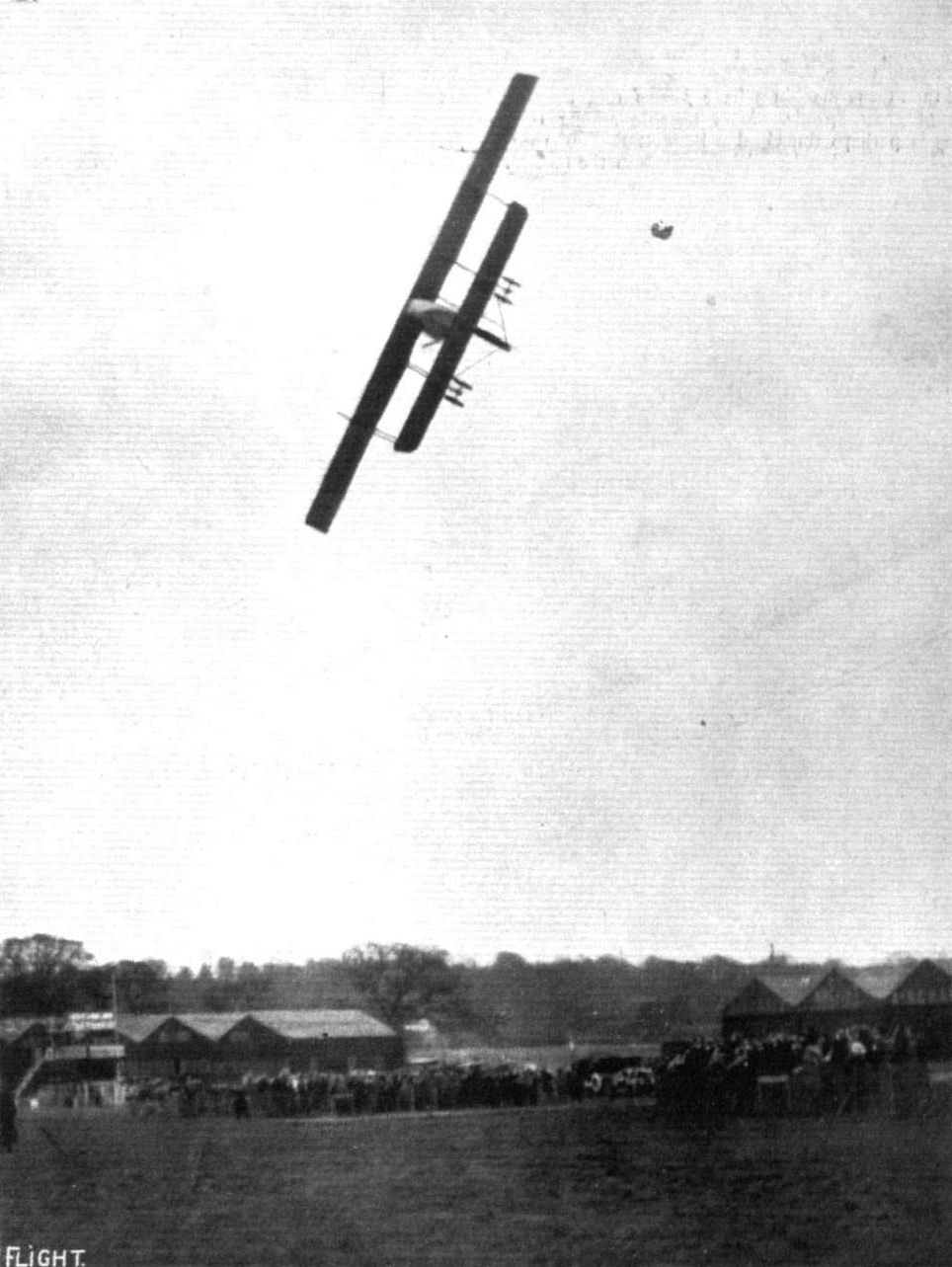
One of Chevillard's marvellous banks, with passenger, on the Farman biplane at Hendon Aerodrome.
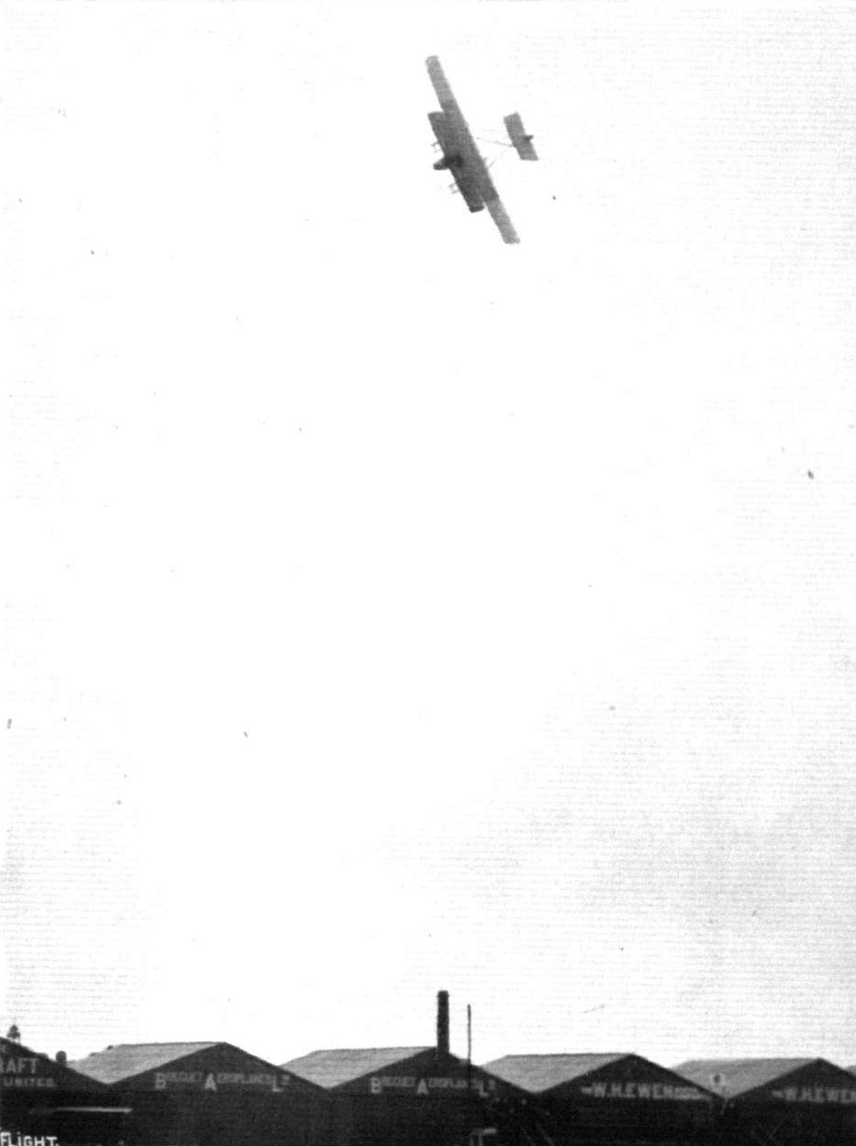
The week before last we gave a photograph showing the remarkable banking of Chevillard on the Farman machine, as seen when approaching the spectator. Above, another bank is seen during one of his dives, and in this the view shows the tops of the planes and the inside of the nacelle, with pilot and passenger.
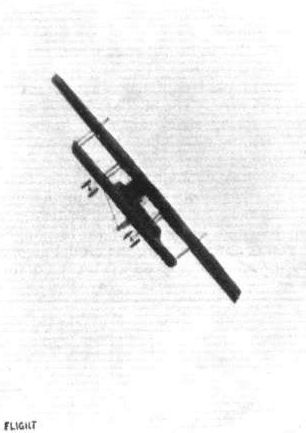
Chevillard, on his Farman, in the air at the Mirafiore Racecourse, Turin, commencing one of his steep banks, being watched by the spectators below.
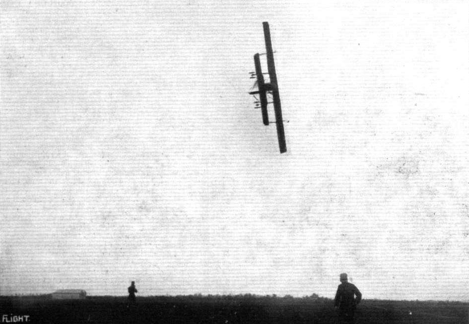
CHEVILLARD IN ITALY. - At Pordenone Chevillard repeated his wonderful banking exhibitions on the Henry Farman, and the above sample of his work there, with Mr. Santoni as a passenger, has been sent us from Italy.
Not a swallow chasing a fly, but the Handley Page and a Henry Farman over the sheds at Hendon.
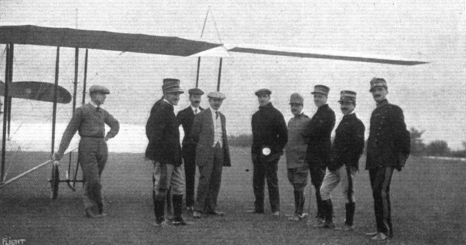
A group of Italian officers at Pordenone, with M. Chevlllard and Mr. Lawrence Santoni, Managing Director of the "Savoia" Co. who are the Farman licensees in Italy, alter the reception of the Farman machines for the Government.
AIRCRAFT ON LAFFAN'S PLAIN FOR THE "FLY PAST" ON THE KING'S BIRTHDAY THIS WEEK. - In the parade there were four BE type, six Maurice Farmans, and two Henry Farmans.
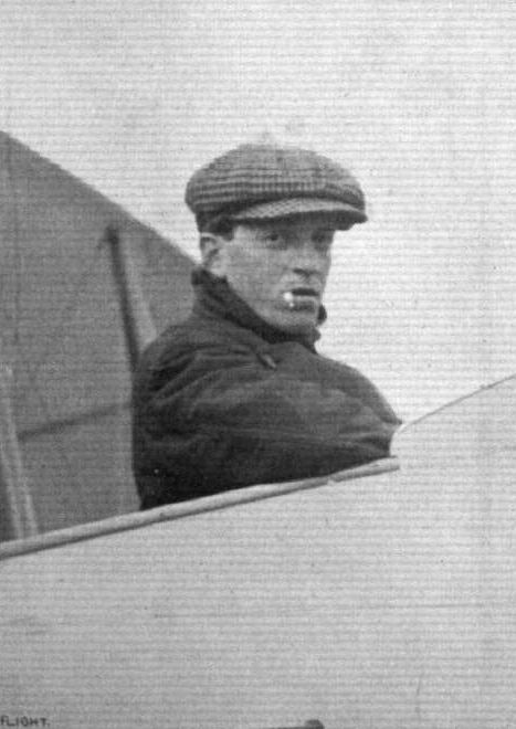
M. Chevillard, who has been making such sensational flights on the Farman machines at Hendon.
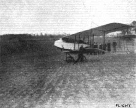
Capt. C. E. Risk, R.M.L.I., and Artificer Frank Susans, with the Farman biplane, landed in a ploughed field at Sanderstead last Friday. Capt. Risk afterwards rose easily. It being subsequent to this that, through engine trouble, the machine was wrecked at Queenborough.

LORD MAYOR'S DAY AT HENDON AERODROME. - A race impression of Chevillard and Verrier by Roderick Hill.
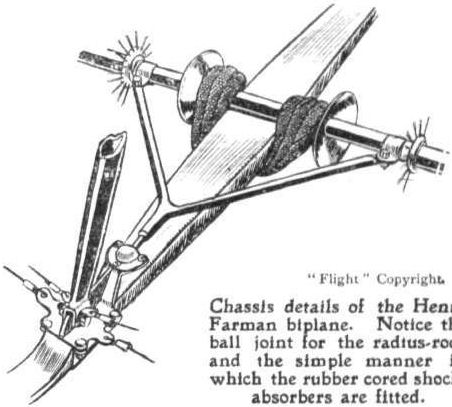
Chassis details of the Henry Farman biplane. Notice the ball joint for the radius-rods and the simple manner in which the rubber cored shock-absorbers are fitted.
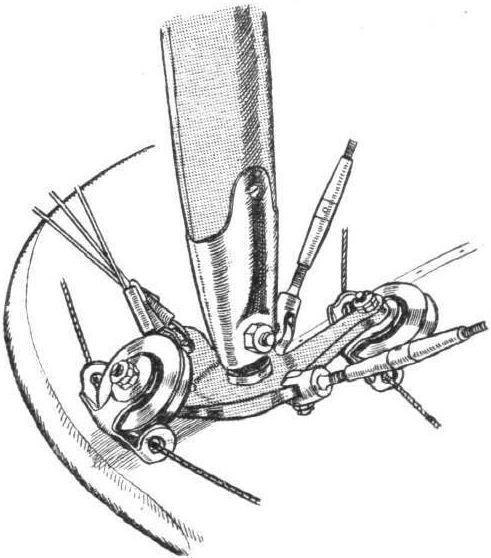
Plane strut fitting, showing the warping wire pulleys on the H. Farman biplane.
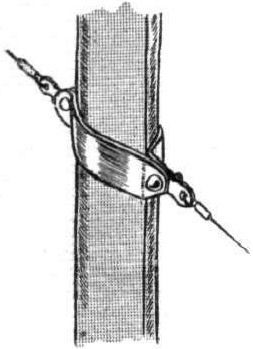
How oblique stay wires are carried past struts on the H. Farman biplane.
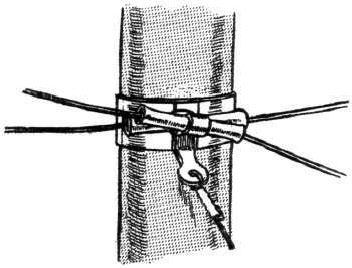
How the tail control wires are guided at the side of a strut on the Henry Farman biplane.
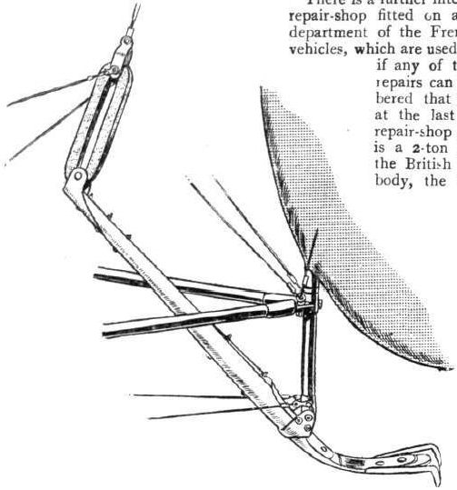
The Henry Farman tail-skid.
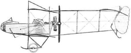
The 80-h.p. Henry Farman biplane.
AT OLYMPIA. - A study in tail-skids.
A study in tails.

The latest Henry Farman hydro-aeroplane in flight at the Monaco Meeting.
Flight, December 13, 1913.
THE STANDS AT THE PARIS AERO SHOW.
FARMAN.
On the Farman stand are shown two complete machines, one is a M. Farman hydro-aeroplane without the front elevator. This machine has tail outriggers of a similar type to those of the land machine, of which illustrations were published in the columns of FLIGHT a short time ago. The other is a H. Farman of quite novel design, being what the Germans call a one and a half plane. The top plane and tail planes are similar to those of the standard type H. Farman, but the nacelle is placed immediately under the top plane, whilst a quite small lower plane is placed down almost on top of the chassis wheels. It will be interesting to see what this machine will do, as one imagines that it would have a very high centre of gravity, and thus be very sensitive to the controls, to say the least.
Flight, December 20, 1913.
THE PARIS AERO SALON - 1913.
FARMAN.
Although only two finished machines are exhibited this year by the Farman Brothers, their stand is nevertheless one of the most interesting at the Show, for so many alterations have been made and so many novelties are to be found that the lack of quantity is more than made up for. Of the two machines, the Henry Farman is the one which first attracts one's attention on entering the stand, for it is a much greater departure from previous types than is the M. Farman hydro biplane.
In plan view, as seen from the gallery, the new H. Farman does not differ materially from the earlier type, but when seen from the floor the two main alterations become at once apparent. The first consists in the raising of the nacelle until that structure is immediately below the upper plane. As a matter of fact the nacelle is slung from the upper main plane by bolting it to the main spars, and the trailing edge has been cut away to clear the engine - a 100 h.p. Gnome - which projects some distance above the upper plane. The nacelle is of the usual H. Farman type, and is built up of four longerons of ash, on the rear ends of which are carried the engine bearers, and which converge in the front to form a good streamline entry for the air. The struts and cross-members are also of ash, and diagonal cross wiring gives rigidity to the whole structure. The nacelle is covered with thin oxydized sheet metal, which gives it a very business-like appearance. Inside the nacelle and immediately under the top plane which entirely covers them are the oil and petrol tanks. In order to facilitate the filling of the tanks a short length of tube projects forward and upwards until the filler cap is in line with the leading edge of the upper plane. One little point in connection with the mounting of the tanks illustrates the forethought and attention paid to details in the Farman machines. In order to prevent the tanks from springing a leak should the machine make a rough landing, these are sprung from the nacelle by means of rubber cushions or buffers introduced in the steel straps by which the tanks are attached to the nacelle.
The seating arrangement, as well as the controls are of the usual H. Farman type. A single central tubular column operates the ailerons and the elevator, whilst the rudder is actuated by a pivoted foot-bar. The lower plane is of so short a span that one is a little in doubt whether to call the machine a biplane or a monoplane. Perhaps in time a word will be coined which expresses this type of machine. The Germans already have a word for it: Anderthalbdecker (one-and-a-half-decker). Four pairs of ash struts connect the two planes, the outer pairs being vertical, while the inner pairs slope downwards and outwards from the joint of the nacelle to the upper main spars.
The extensions of the upper main planes are supported when the machine is on the ground, by wires passing over cabanes on top of the plane. The tail plane and elevator are of the same type as those on the ordinary H. Farman biplane, but the shape of the rudder as well as the tail skid have been slightly modified.
The chassis, which is really one of the most interesting features of the machine, consists of two stub axles pivoted at their upper ends from the point of attachment of the inner plane struts to the main spats, and working in a slot in the two guide tubes, which form the chassis struts. The wheel track is very wide - 4 metres, to be exact - and one is inclined to think, that whilst a track of this width will of course prevent the machine from turning over on the ground, it will be found to render the machine practically unmanageable on a very rough surface, as in case of one of the wheels getting into a rut, the machine would have a tendency to spin around it. From an observer's point of view - the purpose for which it was designed - the machine leaves nothing to be wished for, as it would be difficult to imagine a freer and more unrestricted view in all directions than that afforded from the nacelle of this new H. Farman.
<...>
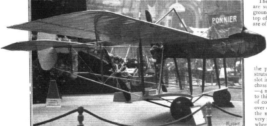
The Henry Farman military machine.
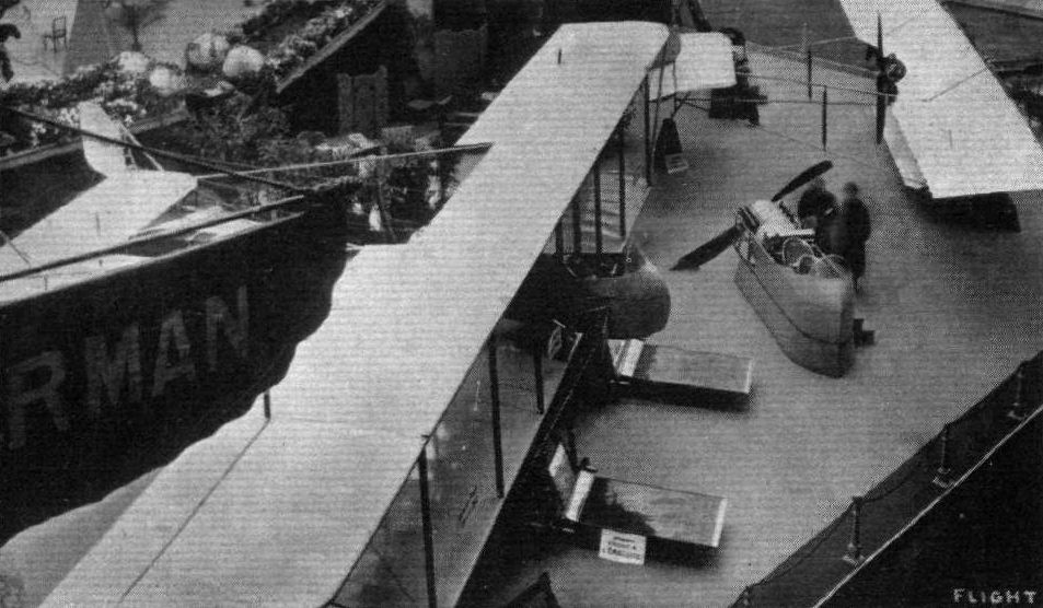
The Farman machines at the Paris Salon.
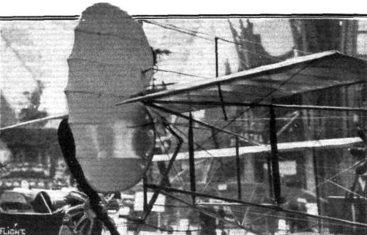
Tail planes of the Henry Farman.

Maurice and Henry Farman nacelles.
Flight, December 13, 1913.
THE STANDS AT THE PARIS AERO SHOW.
F.B.A.
The newly-formed Franco British Aviation Co., Ltd., are showing two hydro-aeroplanes, both of which are of the Donnet-Leveque type. One of the machines, which is shown complete, is driven by a 9-cyl. 100 h.p. Gnome motor. The other, of which only the boat and the inner part of the cellule is shown, has a Salmson motor of 130 h.p.; this is the actual machine which won the 250-mile race at Deauville. A Curtiss flying boat is expected in a few days, but had not arrived at the time of writing these notes.
Flight, December 27, 1913.
THE PARIS AERO SALON - 1913.
THE FRANCO-BRITISH AVIATION CO., LTD.
are exhibiting the only two flying boats to be seen at the Show. One of them, of which only the boat and the centre portion of the wings is shown, is the actual machine which won the long-distance prize at Deauville. It is fitted with a 130 h.p. Salmson engine. The other is a new type fitted with a 9-cyl. 100 h.p. Gnome. A comparison of the two machines soon shows that the new machine is a great improvement on the older one, which undoubtedly was very good in its time, but so swift is the progress in aviation that the type of yesterday is antiquated to-day. The boat is the most interesting part of the 100 h.p. machine, and constructionally it is built up of a framework of ash, which is covered with a skin of three-ply wood. The front portion of the boat is of rectangular section, and has a step which occurs roughly under the centre of pressure of the main planes. The upper longerons converge towards the rear, where the upturned stern of the boat becomes triangular in section, with the apex of the triangle turned upwards. The boat is divided by bulkheads into eight watertight compartments, each fitted with a small inspection door, which allows of examination of the interior. In front the deck is extended on each side of the pointed bow of the boat to form a splashboard, while further protection is afforded the pilot and passengers by a screen in front of the cockpit. The pilot's and passengers' seats are situated just in front of the leading edge of the lower main planes, the passengers' seats being formed by the petrol pressure tank. The pilot controls the machine by means of a single column on which is mounted a hand-wheel. This, however, does not rotate, but simply forms a convenient handle. A to-and-fro movement of the lever actuates the elevator, and a side-to-side movement operates the ailerons. The rudder is controlled by means of a pivoted foot-bar.
The engine is mounted on strong steel bearers just below the upper plane and drives directly the propeller, which is situated just behind the rear spar. The trailing edge of the upper plane has been cut away in the centre to provide sufficient clearance for the propeller. A petrol service tank is mounted in front of the engine just below the upper plane, and petrol is forced from the main tank to this service tank by means of a presiure-pump. The weight of the extensions of the upper main plane when the machine is at rest is taken by two tubes running from the lower extremities of the outer plane struts. Two small floats carried on a light structure of steel tubes prevents the wing tips from diving under the water should the machine heel over.
The tail planes are supported on a framework of steel tubes from the upturned rear portion of the boat. To the trailing edge of the fixed tail plane, which is of semicircular shape, is hinged the elevator which is undivided, as the rudder is situated wholly on top of the tail plane. A small flat tail skid or plate protects the rear portion of the boat against contact with the ground.
The machine shown was not actually fitted with landing wheels, but there was on the stand an exhibit of the F.B.A. system of disappearing wheels, the fitting of which would render the machine amphibious. By the F.B.A. system the pilot can raise or lower the wheels at will during flight so that starting and alighting may be effected from either land or water.
It will be interesting to watch the progress of the F.B.A. Co., Ltd., for the flying boat exhibited appears to be capable of good performances and the firm possesses a very able and experienced manager and pilot in Lieut. Jean Conneau, who is better known to our readers under the name of Andre Beaumont, and who won the circuit of Great Britain in 1911.
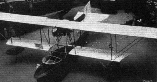
AT THE PARIS SALON. - The F.B.A. flying boat.
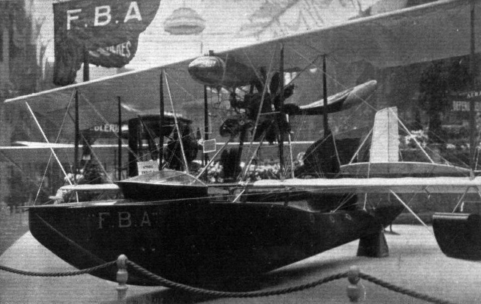
The 100 h.p. Gnome-engined flying boat of the Franco-British Aviation Co.
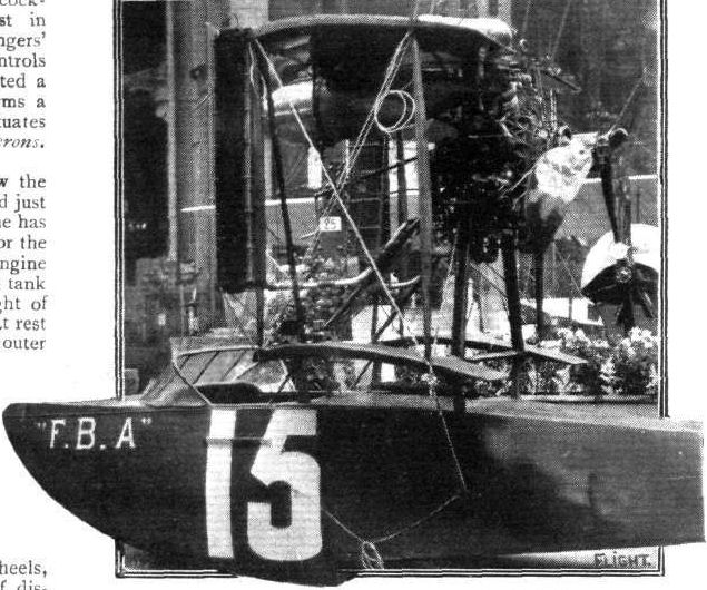
The F.B.A. flying boat - type Deauville - fitted with 130 h.p. Salmson engine.

Tail of the F.B.A. flying boat.
Flight, December 13, 1913.
THE STANDS AT THE PARIS AERO SHOW.
GOUPY.
Two Goupy biplanes are exhibited this year - a tandem two-seater and a smaller single-seater. Neither of the two machines appears to have been altered to any great extent from previous models, but one notices that both machines are fitted with ailerons hinged to the rear spar instead of the pivoted wing tips employed on earlier machines of this make.
Flight, February 1, 1913.
FLYING THE ALPS.
AFTER waiting over three weeks, and almost deciding to give up his attempt to cross the Alps, at any rate for the present, Bielovucic was confronted with a favourable opportunity on the 25th ult., and immediately took advantage of it. During the previous night and early morning there had been heavy falls of snow, but the conditions overhead were good, and so preparations were made for the start. The snow was cleared away to provide a getting-away ground, and the Hanriot machine, the slight damage sustained a fortnight previous having been made good, was thoroughly looked over. Satisfactory reports as to the weather in the Pass and at Domo d'Ossola were received, and at 12 o'clock "Bielo" had started from Brigue. Ascending spirally to a great height, he disappeared in the direction of the Simplon, passing over the Saltine ravine. He was continuing to rise, and there was an anxious moment when the engine suddenly stopped. Fortunately it started again, and in a few minutes the machine was over the Hospice. In fourteen minutes he had passed Simplon Village, and shortly after he was in sight of his goal. Carefully avoiding the dreaded Gondo Valley, he passed over the Monscera mountain and then vol planed down to within a hundred yards or so of the monument to his countryman, Chavez. He had taken 26 minutes for the trip for the distance of between 12 and 13 miles. The Hanriot machine which was used was equipped with an 80-h.p. Gnome driving a Chauviere propeller.
A Hanriot monoplane arriving at Hendon from Brooklands to take part in a competition while one of its future competltors - a Bleriot - is in the air.
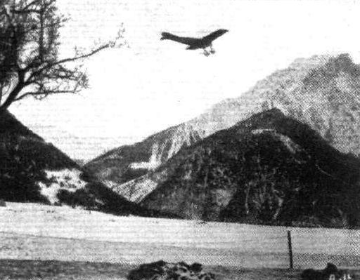
BIELOVUCIC AND HIS ALPINE FLIGHT. - The aviator in the air, with his machine, over the Reidberg, in the distance being seen the Simplon.
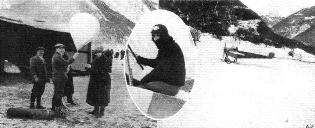
BIELOVUCIC AND HIS ALPINE FLIGHT. - In the centre Bielovucic ready for the start; on the left the aviator and M. Brisset testing the air currents by free ballonettes; and on the right Bielovucic landing in the snow after one of his preliminary trials.
Flight, September 13, 1913.
AEROPLANE TYPES.
THE PONNIER-PAGNY BIPLANE.
SPECIAL interest is attached to this biplane owing to the fact that last week, in France, Bielovucic carried out some successful tests with an 80 h.p. two-seater model built for the War Office.
Although in general appearance similar to the Henry Farman biplane, this machine has several very distinctive features, viz. :- tubular steel construction, Constantin wing section with blunt entering edge, and the arrangement of the plane-struts, of which there are six pairs. The two central pairs are arranged in the form of a V and extend below the front and rear spars of the lower plane. The apex of the front V joins the axle, and that of the rear V joins the lower tail outrigger; both are connected by a central strut. The outer plane-struts slope outwards from the lower to the upper spars. Pilot and power plant are carried in a nacelle situated between the main planes and extending well forward. The tail plane, to which are hinged two elevator flaps, is non-lifting and set at a negative angle of incidence, and is mounted on two upper outriggers secured to the rear spar of the top plane. Lateral control is obtained by warping the main planes (ailerons have also been employed), by means of a wheel mounted on a rocking column, a to-and-fro movement of which operates the rear elevators for longitudinal control. The directional rudder is operated by a horizontal foot-bar.
The principal dimensions of the two-seater model are as follows :- Span - (Upper plane) 12,500 m.; (lower plane) 5,500 m. Length - 7,200 m. Chord - 1,700 m. Gap - 1,600 m. Supporting area - 30 sq.m. Weight - (Empty) 350 kilogs.; (useful load) 300 kilogs. Speed - 115 kiloms. Engine - 80 h.p. Gnome.
VEE JAY.

Flight, March 29, 1913.
FOREIGN AVIATION NEWS.
Giant Hydro-Aeroplane Tested.
THE great hydro-aeroplane built by Maurice Jeannson, in collaboration with. Colliex, was tested at Triel on the Seine on the 29th ult. and made one or two short flights on subsequent days, Colliex being the pilot. The machine is said to have attained a speed of 62 miles an hour when carrying three passengers and during one test it carried a useful load of 1,600 lbs.
Flight, May 31, 1913.
FOREIGN AVIATION NEWS.
Testing the Maurice Jeansson Machine.
ON the 21st the Maurice Jeansson 400-h.p. tandem biplane was tested by Colliex at Triel, and flew a distance of about 12 kiloms. Three persons were on board, and the speed of the machine was said to be in the neighbourhood of 100 k.p.h.
FOREIGN AVIATION NEWS.
Giant Hydro-Aeroplane Tested.
THE great hydro-aeroplane built by Maurice Jeannson, in collaboration with. Colliex, was tested at Triel on the Seine on the 29th ult. and made one or two short flights on subsequent days, Colliex being the pilot. The machine is said to have attained a speed of 62 miles an hour when carrying three passengers and during one test it carried a useful load of 1,600 lbs.
Flight, May 31, 1913.
FOREIGN AVIATION NEWS.
Testing the Maurice Jeansson Machine.
ON the 21st the Maurice Jeansson 400-h.p. tandem biplane was tested by Colliex at Triel, and flew a distance of about 12 kiloms. Three persons were on board, and the speed of the machine was said to be in the neighbourhood of 100 k.p.h.
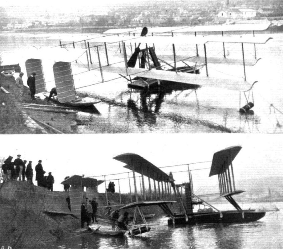
HYDRO-AEROPLANES FOR MONACO. - The enormous double monoplane built by Jeansson and Colliex. The span is 24 metres, length 16 metres. It is mounted upon a 7-metre Despujols hull, and in flying order weighs 4,300 kilogs. Two 6-cyl. 230-h.p. Chenu motors are fitted, giving a speed of over 100 k.p.h.
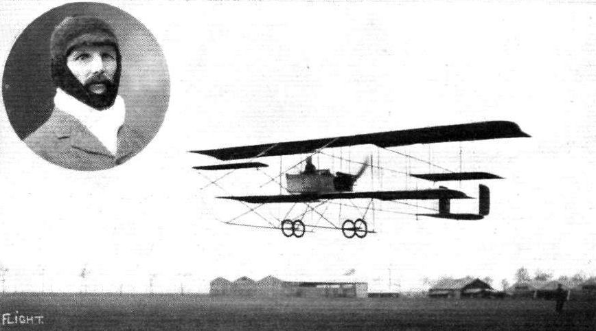
Mr. J. Welby Madeley, M.A.M. Inst C.E., who passed for his pilot's certificate on August 22nd at the Farman School, Etampes, France. The Maurice Farman, with Mr. Madeley in the pilot's seat, is also seen above. He intends continuing his training, and is taking back in September a Maurice Farman to Madras where Mr. Madeley is Special Engineer to the Corporation of that city.
Flight, February 8, 1913.
WHAT THERE WILL BE TO SEE AT OLYMPIA.
THE MACHINES.
The Aircraft Manufacturing Co., Ltd.
Constructors of British-built Henry and Maurice Farman biplanes, will be showing a machine of each type. Their British-built Maurice Farman biplane, equipped with the 70-h.p. Renault motor, flown so well by officers in the Royal Flying Corps, and by Verrier at Hendon, is too well known to need any description here. The Henry Farman biplane that will be shown, we are not so closely acquainted with. In its general lines it will greatly resemble the 80-h.p. H. Farman owned by the Grahame-White Aviation Co., and flown at Hendon by Louis Noel. Its chassis, however, will be different, and its body will be of a more modern type. It will be fitted with an 80-h.p. Gnome motor.
<...>
Flight, September 20, 1913.
Fournv's Daily Flights Terminate.
WITHOUT a break from day to day, Fourny maintained his extraordinary series of flights in connection with the Coupe Michelin on the Etampes-Gidy course, until Monday night of this week, when he had covered 15,686 kiloms. Fourny had the intention of finishing at 20,000 kiloms., but this was not to be. On Sunday last the weather was extremely trying, but, in spite of violent rains and wind, Fourny continued on and seemed none the worse for the bad experience of the day, whilst his machine was running, if anything, better than ever.
On Tuesday, after 23 days' flying, Fourny had at last to confess himself beaten by the all conquering wind, which was blowing hard from the start in the morning, regaining double vigour after the first hour or two. He managed, however, to complete four tours of the circuit even under these circumstances, but retired in the fifth, after having struggled valiantly to add to his total. The exact distance covered by him was 16,090.800 kiloms., but only I5,990.8 kiloms. will count for the Cup as the fifth circuit was not actually completed.
All honour to Fourny, the Maurice Farman, Renault engine and Chauviere propeller for the magnificent series of flights over 23 consecutive days.
Flight, November 1, 1913.
MEN OF MOMENT IN THE WORLD OF FLIGHT.
PIERRE VERRIER.
PILOT.
ONE of the most popular pilots at Hendon, and recognized as a past master of the Maurice Farman biplane is Pierre Verrier. Previous to his coming to England in the middle of last year, his flying had not brought him prominently into the public eye. As a matter of fact he qualified for his pilot's certificate on a Voisin biplane at Juvisy at the end of 1910, but it was not until the following February that he actually got his ticket. It is numbered 390 - a multiple of 13, but Verrier is not superstitious - and it is one of a batch of 49 which were issued by the Aero Club of France at its monthly meeting on Feb. 3rd, the names of the other pilots including John Weston, Gustav Hamel, Rene Hanriot, Andre Debuissy, Prince de Nissolles, Maurice Chevillard, Pierre Gougenheim, Georges Boillot, and Jules Goux, the last two of whom did not continue in aviation, but returned to motor car racing.
Early in 1911 he joined the Maurice Farman school and did a good deal of piloting of the ordinary type. He demonstrated his qualities as a cross-country flyer when, in January of last year, he flew one of the Maurice Farmans, which had taken part in the French military aeroplane trials, from Rheims to Buc. Upon the Aircraft Manufacturing Co. taking over the control of the Farman machines for Great Britain, he was engaged by them and made his first public appearance at Hendon on June 1st, 1912. Regular visitors to the popular London aerodrome will remember that his debut was a notable one, his steep climbs and very long glides creating quite a sensation, while the way in which he varied the speed of the machine by throttling the engine, was a revelation. Verrier took part in the speed handicap on this occasion, and had an easy win, albeit he lost a little time through touching No. 6 pylon; he noticed the fault, and banking the machine steeply, made a complete circuit of the pylon.
Verrier is a good cross-country flier, and frequently flies from Hendon to Farnborough with machines purchased by the Government; in fact, he often makes this journey twice a week. On the occasion of Mr. C. Grahame-White's wedding he flew over to Chelmsford, and gave a fine display on the Maurice Farman for the entertainment of the guests assembled for the wedding. Lately he has done some flying on the Henry Farman machine, and it will be remembered that his mount in the Aerial Derby was of this type. Verrier is very popular with passengers and never lacks a companion when he makes an ascent. This is perhaps the greatest compliment which one could pay to his careful flying.
"THE HAWK."
AIRCRAFT ON LAFFAN'S PLAIN FOR THE "FLY PAST" ON THE KING'S BIRTHDAY THIS WEEK. - In the parade there were four BE type, six Maurice Farmans, and two Henry Farmans.
AT HENDON AERODROME. - Machines about to start for the military cross-country race. On the line are the biplanes and, ranged behind, the monoplanes waiting to take their place on the starting line after the biplanes have got away.
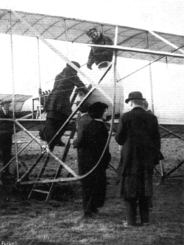
Mrs. Moore, one of the Daily Express free lady passengers, getting Verrier's Farman biplane for her joy ride.
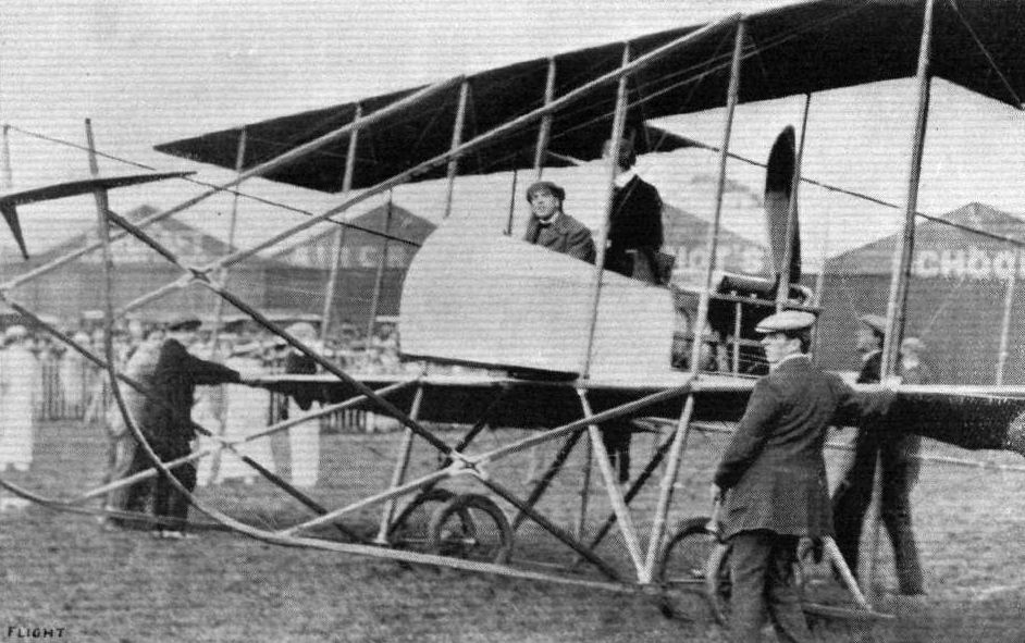
Mr. Claude Grahame-White makes a trial flight on his new Maurice Farman at Hendon Aerodrome.

Prince Axel of Denmark, who is a certified pilot, explaining the controls of the Maurice Farman biplane to King Christian X of Denmark.
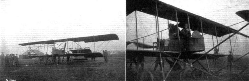
Lieut Waldron with Lieut. Bowden Smith as passenger, in the Army Maurice Farman No. 216, about to start from Hounslow Heath for Farnborough recently. In the right-hand photograph, it will be noticed, the propeller is just being swung.
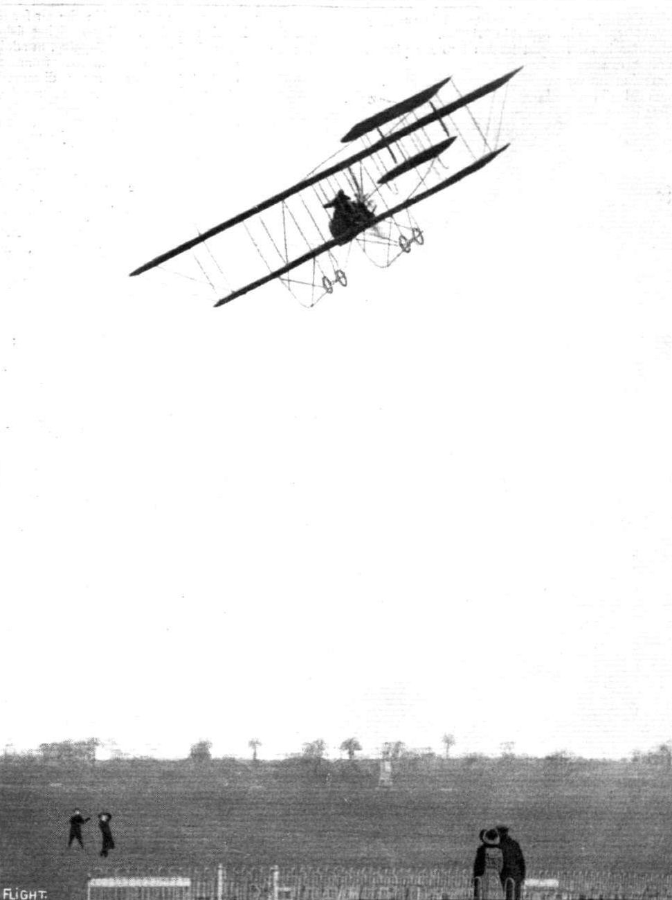
A fine piece of banking by Pierre Verrier, with a passenger, on a Maurice Farman at Hendon Aerodrome.
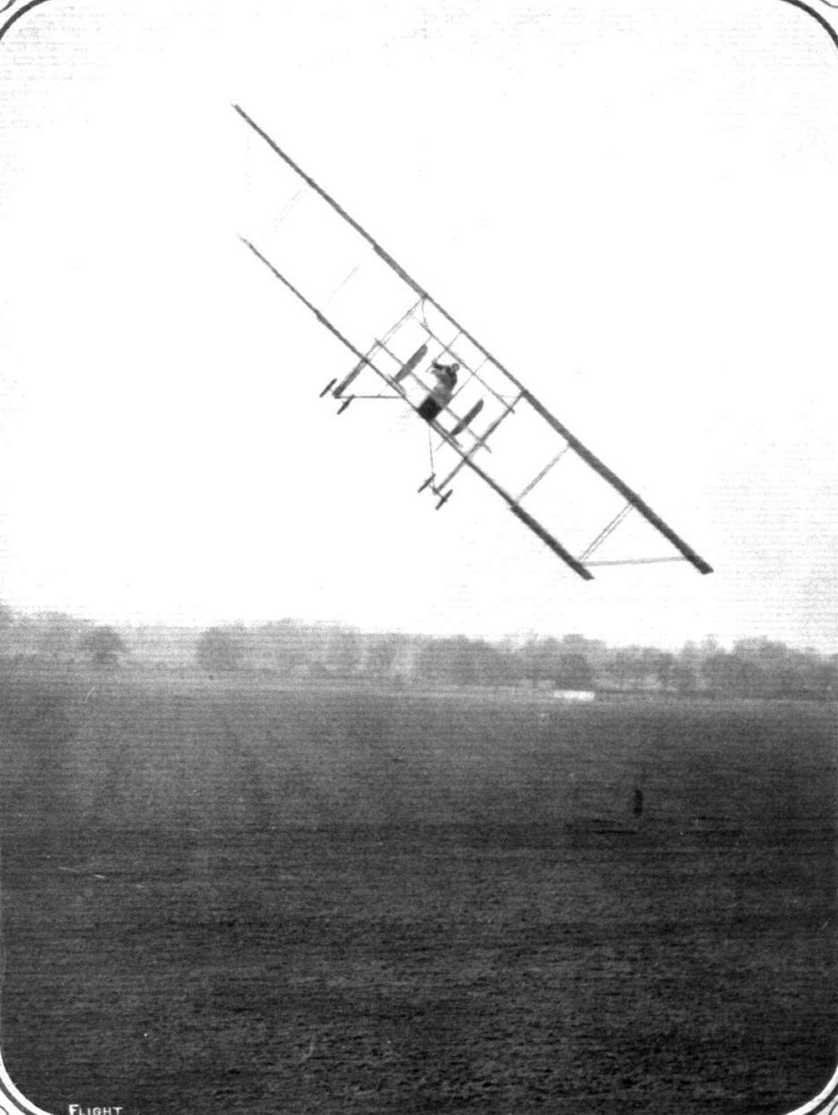
Another line bank by Pierre Verrier, with a passenger on board, on the Maurice Farman at Hendon.

A demonstration of the stability of the Maurice Farman biplane at Hendon Aerodrome. - Pierre Verrier and his passenger standing up and holding their hands above their heads, meantime the machine being entirely uncontrolled.
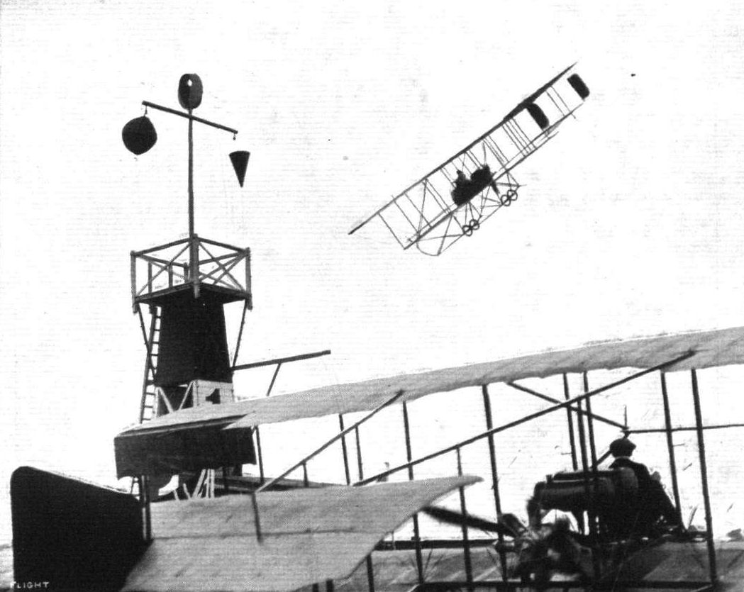
A banked turn with a passenger round No. 1 Pylon at Hendon by Pierre Verrier on the Maurice Farman.
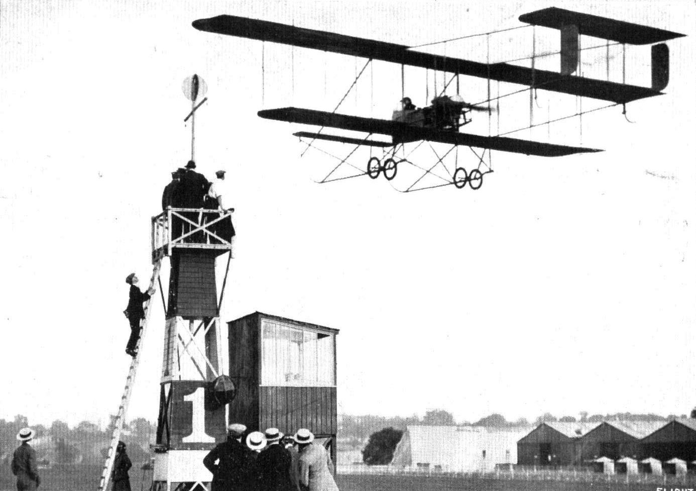
AN EXHIBITION OF VERRIER'S EXPERT STEERING. - Seeing how close he can fly his Maurice Farman to No. 1 pylon at Hendon Aerodrome. Upon one occasion recently his extension support actually touched and moved the disc race indicator at the top. Note the habiyues watching the performance.
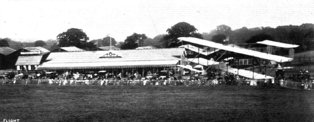
Pierre Verrier flying low, on the Aircraft Co.'s Maurice Farman, past the enclosure at Hendon.
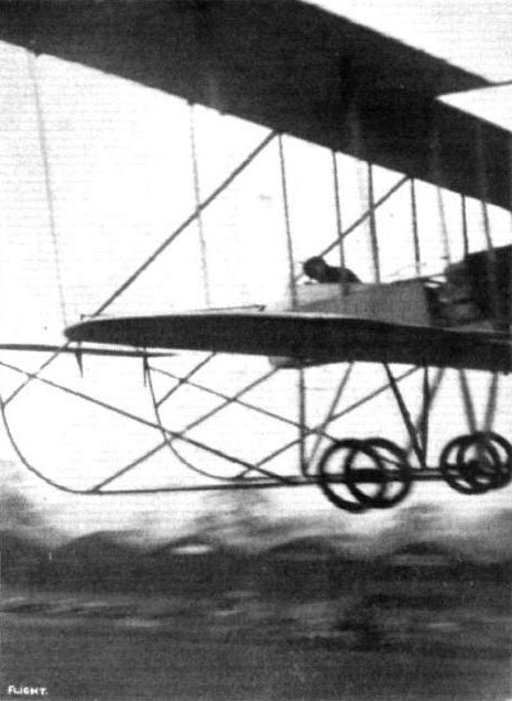
SPEED. - Pierre Verrier, well under the windscreen, flying past No. 1 pylon at Hendon on his Maurice Farman.

Pierre Verrier making a passenger flight at sunset on the Maurice Farman biplane at Hendon Aerodrome.

THE FINISH OF THE HENDON-BRIGHTON-HENDON RACE, NOVEMBER 8th. - Pierre Verrier, the winner, returning to Hendon late in the evening.
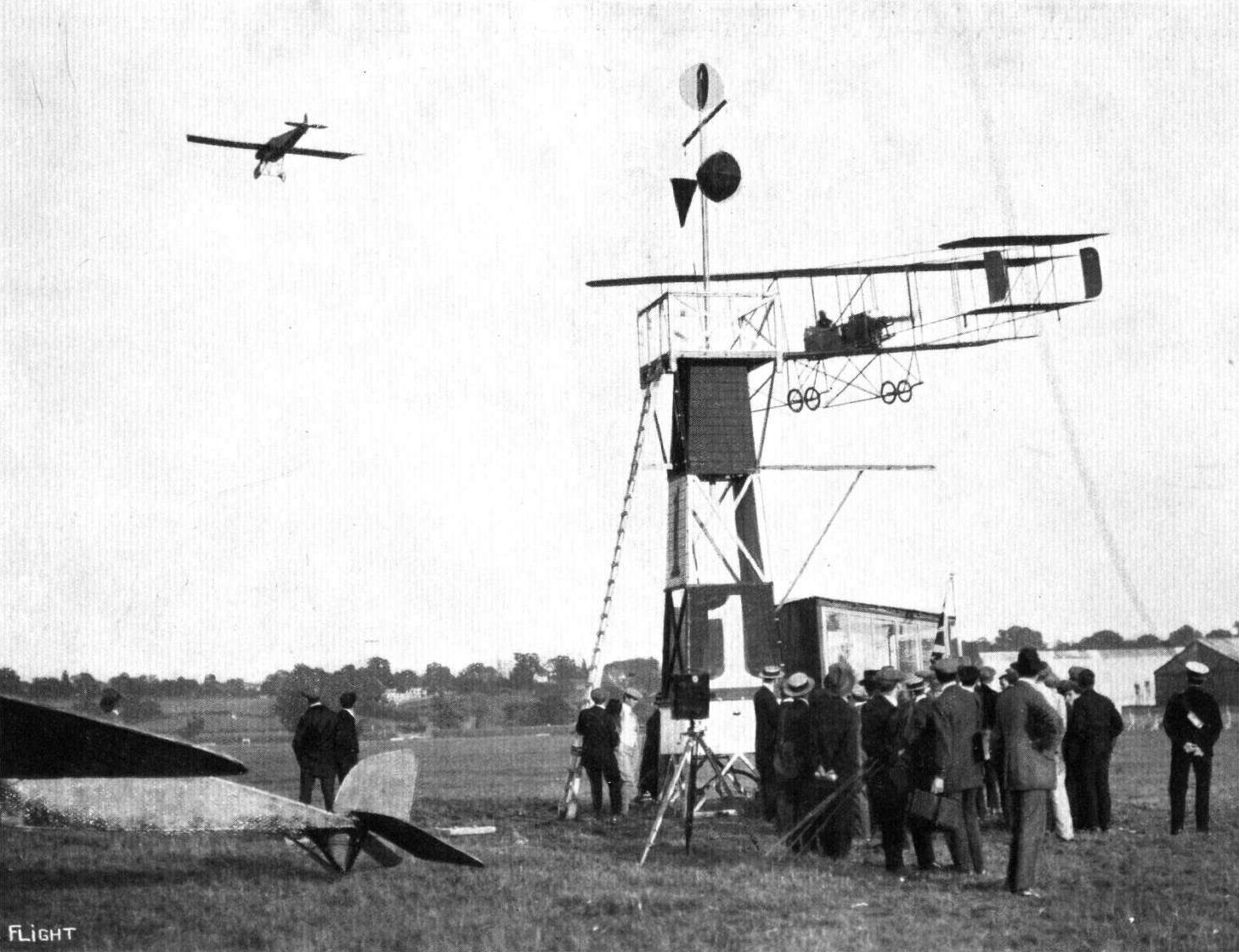
ROUND PYLON ONE. - Verrier, on the Maurice Farman biplane, and Slack, above, on the Morane-Saulnier.
A speed handicap, with four in it, at Hendon aerodrome on Saturday, showing Turner's Caudron and Verrier's Maurice Farman, in front, during the first heat.
A DEAD HEAT AT HENDON. - An exciting finish at the Easter Monday Meeting, when Verrier, on a Maurice Farman, and Collardeau, on a Breguet, crossed the line at the same time in the Grand Speed Handicap, Verrier being on the right quite low.
A close finish for second place between Verrier and Nardini in last Saturday's speed handicap at Hendon Aerodrome. Nardini overtook and passed Verrier almost upon the finishing line.
A FINE FINISH AT HENDON. - Marty, Verrier and Manton finishing in the order given in the first heat of the Speed Handicap on "Motor Cycle Day."
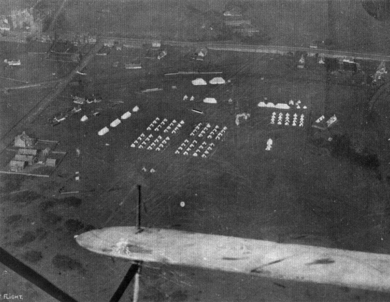
The camp of the 3rd Gordons at Montrose, taken from a Maurice Farman machine.
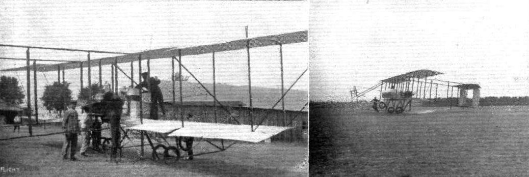
FOURNY'S GREAT FLIGHT OF 15.990 KILOMS. - On the left, fixing up his engine with oil and petrol at the completion of one of the circuits, and on the right, Fourny crossing the finishing line on his Maurice Farman at the end of one of his circuits for the Coupe Michelin.
AERIAL FLORAL FETE AT HENDON AERODROME. - The first heat of the Speed Handicap. Manton, on the Grahame-White biplane, completing his first lap, with Brock and Verrier still waiting to take up their start in the race.
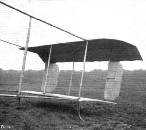
The new tail of the Maurice Farman biplane.

MONS. PIERRE VERRIER. - The popular Maurice Farman pilot.

"I've won a flight!" A breezy snap at the London Aerodrome, Hendon, on Theatrical Aviation Sunday, when a ballot was taken for two flights by members of the theatrical profession. The passenger is Miss Margaret Swallow, who is about to take her flight with M. Verrier on the Maurice Farman.
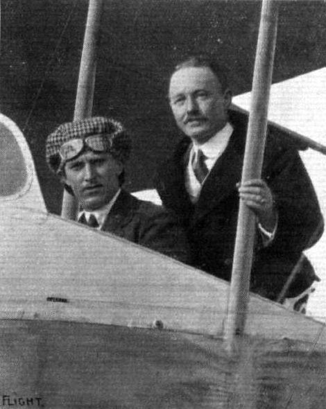
Mr. H. A. Vernon, President of the National Association of Millers, about to have a flight at Hendon with Verrier in a Maurice Farman.
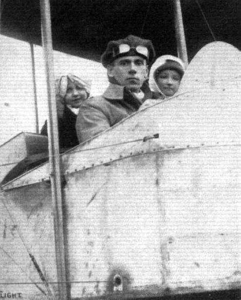
AN INCIDENT AT HENDON LAST WEEK-END. - Two little children, aged 5 and 8 years respectively, were so fascinated with the flying that their parents arranged to gratify their wish for a practical experience - something under "half-price" being charged. Our photo shows Mr. Louis Noel on the M. Farman 'bus just about to start with his precious freight.
LORD MAYOR'S DAY AT HENDON AERODROME. - A race impression of Chevillard and Verrier by Roderick Hill.
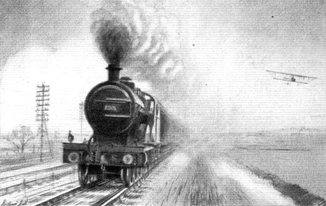
STEAM AND PETROL. - Pierre Verrier and a passenger pass a Midland express on the Maurice Farman at Hendon Aerodrome, May 3rd, 1913. From a sketch by Roderic Hill.

NIGHT FLYING, NOVEMBER 5TH, AT HENDON. - Claude Grahame-White flying a Maurice Farman biplane. From a drawing by Mr. Roderic Hill.
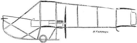
The 70-h.p. Maurice Farman biplane.
AT OLYMPIA. - A study in tail-skids.
A study in tails.
Flight, December 13, 1913.
THE STANDS AT THE PARIS AERO SHOW.
FARMAN.
On the Farman stand are shown two complete machines, one is a M. Farman hydro-aeroplane without the front elevator. This machine has tail outriggers of a similar type to those of the land machine, of which illustrations were published in the columns of FLIGHT a short time ago. The other is a H. Farman of quite novel design, being what the Germans call a one and a half plane. The top plane and tail planes are similar to those of the standard type H. Farman, but the nacelle is placed immediately under the top plane, whilst a quite small lower plane is placed down almost on top of the chassis wheels. It will be interesting to see what this machine will do, as one imagines that it would have a very high centre of gravity, and thus be very sensitive to the controls, to say the least.
Flight, December 20, 1913.
THE PARIS AERO SALON - 1913.
FARMAN.
<...>
The other complete machine exhibited on the Farman stand is a M. Farman hydro-biplane Deauville type, fitted with a 70 h.p. Renault engine.
The nacelle, which has been raised considerably until the centre of thrust is now roughly half way between the planes, is of the ordinary M. Farman type as are also the pilot's and passenger's seats and the controls. It is bolted to the inner plane struts, which have a small ledge cut in them to act as support for the nacelle. The chassis consists of two sets of struts which in the front view resemble the letter W. Four short skids are attached to these struts, two to each set, and each float is slung from its two skids by rubber shock absorbers. The floats themselves are of the plain non-stepped type, and the whole chassis gives one the impression of being an immensely strong piece of work. The advantages of springing the floats have been pointed out in these columns so often, that repetition is unnecessary.
The tail planes, which now consist of a single fixed tail plane to which is hinged the elevator, and two rudders mounted wholly on top of the tail plane, are carried on an outrigger formed by four straight booms of spruce connected by hollow spruce struts. The angle of incidence of the fixed tail plane can be adjusted by means of a lock-nut working on a thread cut on the vertical tube which connects the upper and lower tail booms. Two tail floats support the tail planes when the machine is on the water, and the method of mounting these floats is shown in one of the accompanying sketches. Needless to say, the workmanship and finish is of the best quality, as is to be expected from so well known a firm as the Farman Brothers.
The Farman machines at the Paris Salon.
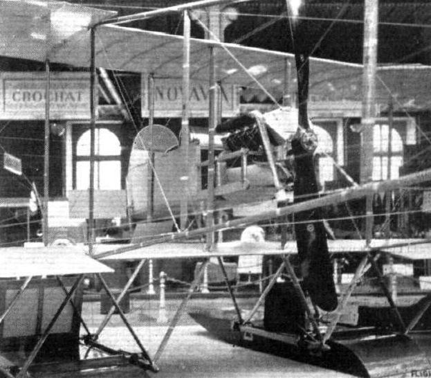
Nacelle and floats of the M. Farman hydro-biplane.
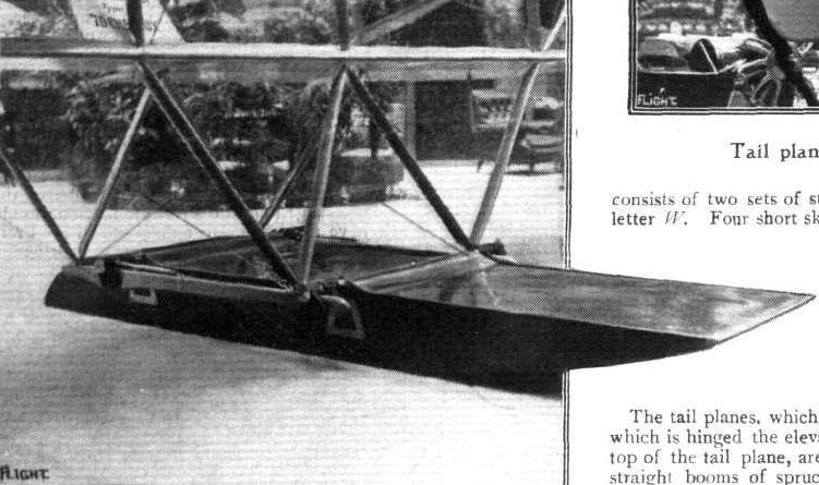
One of the main floats of the M. Farman hydro.
Maurice and Henry Farman nacelles.
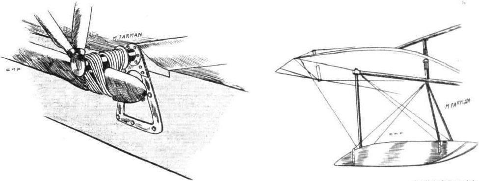
Attachment of main float on M. Farman hydro. On the right one of the tall floats.
Flight, November 29, 1913.
A NEW MAURICE FARMAN BIPLANE.
SINCE Maurice Farman first brought out his now famous biplane very few alterations have been made until quite recently. Some time ago it will be remembered we published illustrations of a new M. Farman biplane, which was then flying at Hendon, and which had no front elevator. In other respects, however, this machine was similar to the standard type. Now a new machine has made its appearance in France; in this not only is there no front elevator, but several new features have been introduced. It will be noticed from our sketch that the tail outrigger is of an altogether different form to that of the standard M. Farman type. The tail plane of this machine is of the monoplane type, and the two rudders are placed wholly on top of the tail plane. Two swiveling skids protect the tail planes against contact with the ground.
The nacelle has been raised considerably, so that the centre of thrust is now approximately half way between the upper and lower main planes. The skids have been shortened, but still carry at their rear extremities the steel springs which act as very effective brakes when the machine is landing. The two pairs of wheels are sprung from the skids by means of rubber shock absorbers in the usual way. An 80 h.p. air-cooled Renault engine, driving the propeller at half engine speed, gives the machine a speed of about 65 m.p.h.
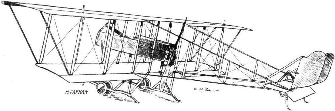
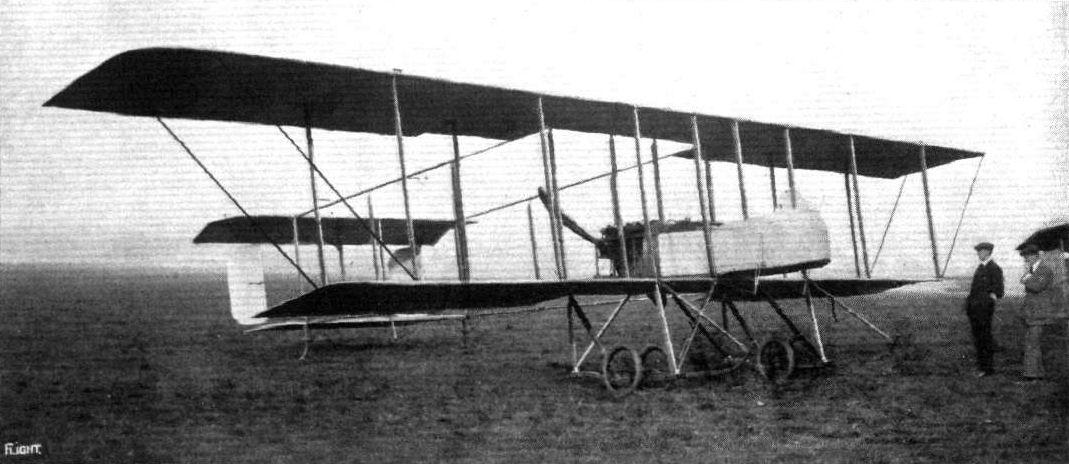
The new Maurice Farman biplane without front elevator which arrived at Hendon Aerodrome last week.
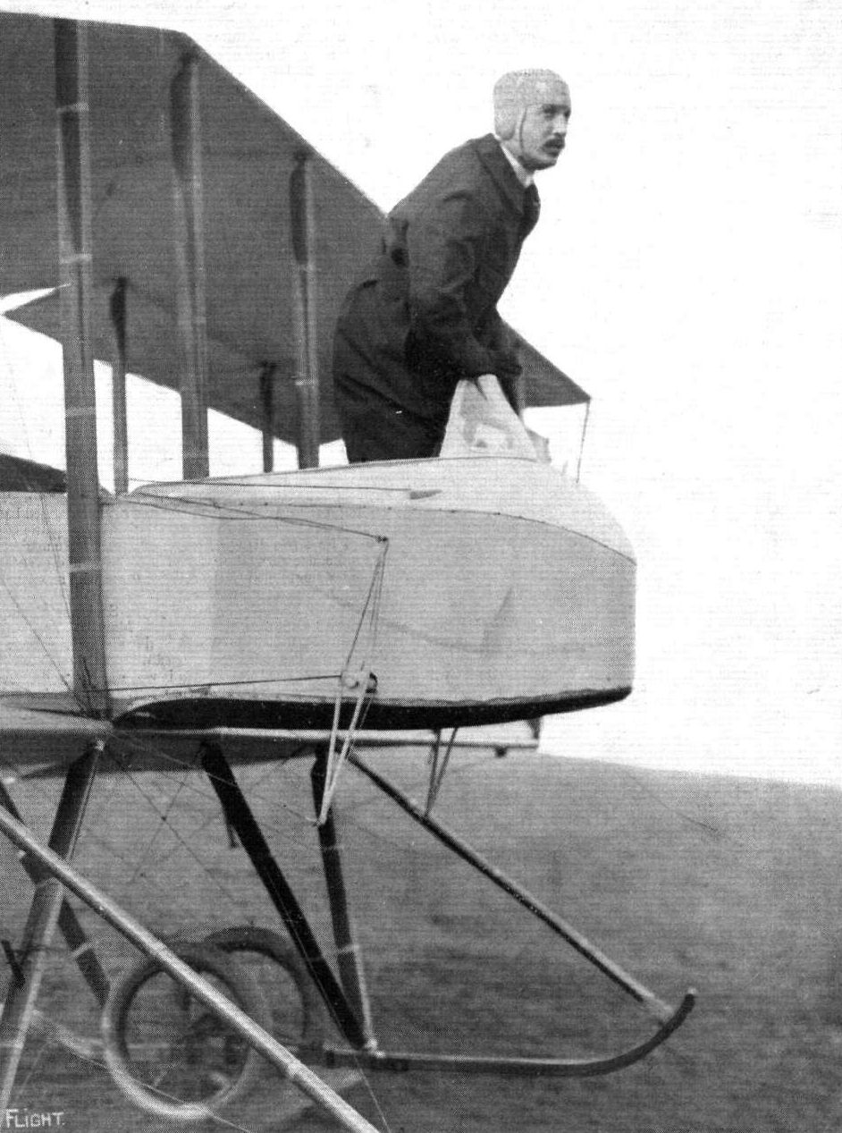
The Marquis LarientyTholozan a nephew of the Marquis De Dion and a well-known aviator in France, was flying on Saturday last at the Hendon Aerodrome on his new Farman biplane fitted with a 120 h.p. 8-cyl. De Dion Bouton engine. Although the Marquis had never previously taken his seat in this machine, without a hitch, after the propeller had been given its usual spin, he was up in the air and made two circuits of the aerodrome.
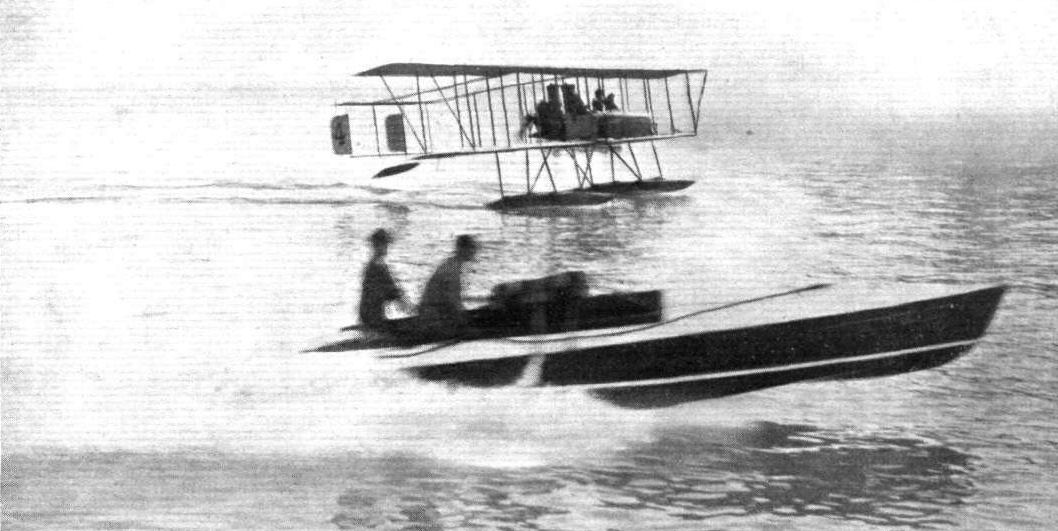
WELL MATCHED. - A Maurice Farman avion versus motor boat.
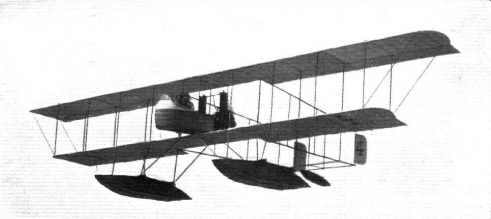
A Maurice Farman Navyplane in the air.
Flight, May 24, 1913.
THE LATEST MORANE-SAULNIER MONOPLANE.
THE machine with which M. Brindejonc des Moulinais arrived at Hendon on Whit-Sunday from the Continent is quite one of the most interesting that has visited the aerodrome for a long time, and it is all the more interesting to know that Messrs. Grahame-White are arranging to construct duplicates in England in their capacity of sole concessionaires for Britain.
In the hands of such an expert pilot, it formed a centre of attraction during the Whitsuntide meeting, and its flying was certainly something out of the ordinary, and exceedingly well worth watching. But, it was not only in the air that this machine interested those who had an opportunity of seeing it on the ground at close quarters, for its structural detail was full of originality.
This Morane-Saulnier monoplane is, in fact, one of the neatest designs we have seen, but it is impossible to convey an adequate impression of its meritorious points save by illustration, and even sketches and photographs are often an indifferent substitute for an actual inspection.
To some extent the clean appearance of the machine is emphasised by the compactness of its size, for it is far from being a large monoplane. The span is only 30 ft., and the overall length is considerably less. The supporting area is about 160 sq. ft., and the weight of the machine empty is about 680 lbs.
The most striking feature of its design is the undercarriage. Viewed from the side, it is a simple V. Viewed from in front, it represents the letter M. To the inverted apex of the central triangle the divided axle is hinged, and the extremities of the axle are free to rise and fall in slots provided in the lower extremities of the outside limbs of this chassis structure. Rubber shock absorbers are fitted. The entire structure is made of flattened tubular steel work, with brased joints.
Another neat feature is the method in which the main stay wires to the wing spars are carried down to the point of the central V and terminate in adjustment bolts. This also forms the subject of one of our sketches.
The upper pylon is as neat in its conception and execution as the undercarriage, for it is a simple /\ hinged at its two feet to the sides of the body and stayed by a wire cable passing over a pulley, against the pull of the warp wires which pass over a corresponding pulley on the other side. It is, in fact, a simple strut in a system of wire bracing, and when the wires are removed by dismantling the wings for transport, the cabane itself folds down very neatly against the body.
The cockpit is roomy, but the seating accommodation is peculiar, for the passenger sits quite close up to the pilot and has, in fact, to spread his legs in order that the pilot may sit down at all. The control is of the simple vertical lever type in which a to-and-fro movement operates the elevator, while a sideways motion controls the warp. The lever itself is attached to a rock shaft that runs a little way down the body until it comes vertically over the pillar supporting the warp wires. The rudder is controlled as usual by foot. The rudder and warp wires are enclosed in the body of the machine except for a very short length near the extremity, where they are attached to their respective organs.
A peculiarity of the tail is the absence of a fixed horizontal plane, the movable elevator being the only horizontal member. This elevator belongs to what is known as the balanced type, that is to say, its axis of rotation is situated more or less in the position of the usual centre of pressure, so that there is never a very great couple reacting upon the pilot's hand. The rudder is balanced in the same way.
The machine is driven by an overhung 80-h.p. Gnome engine, which is fitted with an 8 ft. Integrale propeller. Two tanks are arranged in the nose of the machine, one containing 14 gallons of petrol, and the other about 5 gallons of oil. A subsidiary petrol tank holding 8 gallons of spirit is located behind the passenger's seat, and there is a hand pump attached to it in a convenient position for transferring its contents to the service tank while in flight.
A Bosch magneto firing Oleo plugs forms the ignition equipment of the engine, while a Tell revolution indicator, a barograph, a compass, and a map-holder are fittings in front of the pilot on the dashboard.
The body of the machine is surfaced with fabric, but its interior structure is of the usual girder type. Ash booms are employed, and ash struts and cross-members are used in the first three bays, pine being employed for the struts further aft.
The wings have no dihedral angle, as the designers object to this feature. The wing spars are of ash, and the leading and trailing edges are fitted with pine stretchers. An internal bracing of piano wire is provided to stay the wing against drift.
Both front and rear spars are hinged to the body, the former by a vertical bolt, and the latter, as usual, by a horizontal bolt to facilitate warping. With the exception of the internal wires, stranded cable is employed throughout for the wing bracing and control.
Flight, May 24, 1913.
FIRST PROSECUTION UNDER AERIAL ACTS.
M. BRINUEJONC DES MOULINAIS, of 206, Boulevard Periere, Paris, appeared before Mr. Dickinson at Bow Street Police Court on the 15th inst., to answer two summonses charging him, as a person in control of an aeroplane, with having, before commencing a journey to the United Kingdom, failed to send notice to the Home Office stating the proposed landing place, the approximate time of arrival, and his name and nationality; further with contravening the orders made by the Home Secretary under the Aerial Navigation Acts, 1911 and 1913, by navigating a certain aircraft, coming from a place outside the United Kingdom, over part of the United Kingdom, viz., the County of London, without having first landed in one of the officially prescribed areas. The defendant pleaded "guilty" and elected to be dealt with summarily.
Mr. Muskett, who appeared on behalf of the Home Office, said invite the magistrate not to take a very serious view of it, and not to impose any penalty unless he thought that the circumstances impelled him to do so. The defendant, who was a young man of about twenty years of age, was a Belgian subject. The Act under which he was summoned provided for a maximum punishment of six months' imprisonment, or a fine of L200, or both imprisonment and a fine. The first Act of Parliament dealing with aeroplanes, was passed in June, 1911, and gave the Secretary of State power, for the purpose of protecting the public from danger, to make orders prohibiting the navigation of aircraft over certain areas. It was found that that Act was insufficient for the purpose, and in the early part of this year another Act was passed which largely extended the powers of the Home Secretary. By virtue of such powers he made an Order, dated March 1st, prohibiting the navigation of aircraft from outside the United Kingdom over the whole of the coast line, except certain prescribed portions. One of these areas was between Margate and Walmer, another between Hove and Bognor, and so on, the area in each instance extending to 5 geographical miles from the coast. From information which had been kindly supplied by Mr. Richard Gates, the general manager of the Hendon aerodrome, it appeared that they were interested in the exploitation of a particular make of aeroplane, and had arranged for the defendant to fly from Bremen to Hendon on Friday last, for the purpose of demonstrating the flying capacities of the machine. Defendant left Bremen on Friday, but descended at Brussels on Saturday, owing to bad weather. He left Brussels on Sunday morning last and flew to Calais, where he descended for lunch. Afterwards, he continued his journey to Hendon, passing over Dover, which was a prohibited area, the magazines at Purfleet, and the Woolwich Arsenal. He was observed to pass over the arsenal at a height of 3,000 ft. and at a tremendous pace. Eventually he arrived at Hendon at 3.15 p.m. on Sunday, having no doubt, accomplished a very marvellous performance. No notice had been given of his intention to fly to this country, and he did not land at either of the prescribed areas. The defendant had intended to return to Bremen on his aeroplane on Monday last. There was no reason to think that he had erred other than through ignorance, and having regard to all the circumstances and to the fact that the defendant had placed no difficulties in the way of the prosecution, as he might have done, he asked the magistrate to exercise the utmost indulgence.
The defendant, in broken English, said that during the last two months he had flown in many countries, having crossed Spain, Belgium, Holland, Germany, and England, and he found it impossible to make himself thoroughly acquainted with the laws of every country. If he had known of this Act he would not have flown within the prohibited areas, as it would have made very little difference to him if he had descended on the coast. He would undertake to observe the law the next time he visited England. He had asked the Aero Club of France, of which he was a member, to advertise the laws of different countries in the newspapers, so that aviators might make themselves acquainted with them.
The magistrate said that we in this country were glad to welcome a brave and clever airman. On the other hand the regulations that had been made for the safety and defence of this realm must be observed. Those regulations had only been in force a short time, and he could quite believe that the defendant had not had an opportunity of studying them. In those circumstances the Government were only too glad to make an exception in this case, but it would be absolutely necessary to observe these rules in future. The defendant would be bound over in his own recognisances in 1,000 francs to come up for judgment if called upon within twelve months.
Flight, July 5, 1913.
PARIS TO LONDON.
EVER since man started to place another element under his subjection by flying and thus conquering the air, it has been one great struggle for mastery, and many a fierce fight has been waged, man sometimes securing the victory, and occasionally having to admit defeat. As time creeps on, however, we are gradually becoming more assured that, as the principles of flight are better understood, man will conquer here, with all reasonable safety, as he has previously conquered the earth and the sea. In writing this article, illustrative of the flight of Robert Slack from Paris to London on the Wednesday of last week on a Morane-Saulnier monoplane, I have in my mind more the showing of how man will win through against fearful odds, than the belittling of any previous Channel flight, of which there have been many, every one of which, in this comparatively early history of flight, deserves to be writ in letters of gold on the scroll of honour, commencing with that memorable flight of Bleriot himself, which, under the conditions then prevailing as to the efficiency of machines, was probably the most wonderful.
Slack went over to Villacoublay to fly the Morane-Saulnier to Hendon, which, knowing Slack, meant that he would arrive, somehow.
On Wednesday, Aerial Fete Day, I was at the Aerodrome at Hendon, when our friend, the megaphone man, announced that Slack had left Folkestone at 10.15, and might be expected to arrive at Hendon during the morning. The wind at this time was blowing half a gale from the north-west, dead against anyone coming to Hendon from the direction of Folkestone, and when I heard the announcement, I said to Capt. Tyrer, who happened to be standing near, "He will surely come down, he couldn't get here against this wind." His reply was, "Bobby won't come down, he'll get here, don't bother." And he did. Before long, we saw him in the distance, buffeted about like a cork in a rough sea, and in a very short time he was safe and sound in the aerodrome, very dirty, very deaf, and very happy.
Slack arrived at Villacoublay on the Monday, but his machine was still in the hands of the constructors; as a matter of fact, it was not finished till late on Tuesday afternoon, when Slack made a trial flight, and decided to set out soon after daybreak on Wednesday morning.
The morning broke wet and stormy, and gave promise of anything but a flying day, but towards five o'clock the rain ceased, and Slack decided to start. A few minutes after five and he was on the wing. He had travelled but a very few miles when once more the rain started, and came down in torrents, and continued to do so all the way to Cape Oris Nez. So bad was the rain, and so low were the clouds, that he saw practically nothing of France as he passed over it, having to fly by the compass all the time, and was out over the Channel without knowing it; in fact his first glimpse of the water was when he was within a mile or so of the English coast, when, whilst flying at a height of about 3,000 ft., he saw through a break in the clouds the waters of the Channel, with the town of Folkestone right ahead. A few minutes previously he had commenced what was really under the circumstances a fight for life.
On the top of the forward tank, and out of reach of the pilot, is a small glass inspection cap, through which the petrol can be seen when being pumped under pressure from the reserve tank into the main one. This cup was evidently cracked when he started, and during the voyage had lost a piece out of the front, and the rush of wind getting in had turned the cup round in its seating till the broken part faced the pilot. It had become necessary when a few miles from Folkestone to pump petrol into the forward tank, which was now nearly empty.
Slack pumped for his life, but the result was that most of the petrol came out through the broken glass and was blown back into his face, very little indeed going in to feed the engine. I have never had the experience of being drenched with petrol myself, but Slack tells me it is not nice and that he was nearly blinded in spite of his goggles, and eventually nearly suffocated owing to the evaporation of the spirit, and at last the worst happened. The engine stopped.
Up to this time Slack had not seen the sea, and had not much idea as to his whereabouts, and it was at this moment Fate was kind and allowed him to see that he was nearing Folkestone, as he slid down the wind.
When a pilot is over a strange town and his engine has stopped "for keeps," he has not much time to waste in finding somewhere to land, and makes for the first piece of green he can see, which in this case was not very large but looked all right from above. Closer inspection, however, showed that it was not ideal. The ground sloped downwards, and had a ridge in the middle like the roof of a house, and parallel to the direction of flight, which meant that he would either have to land downhill on the edge of a slope, or turn round and land uphill with the wind. By this time he was very near the the ground and without power, but judged he had just time to make a sharp turn, which he did, and landed without mishap, the machine coming to rest just before topping the ridge, at 8.40. Three hours and forty minutes to cover roughly 170 miles. A plucky flight. Here he had to send for some more petrol and some tape to bind up the broken glass with, and at 10.15 he was once more off, having got out of a small field without the help of skilled mechanics to give him a start.
From Folkestone the course was direct to Kempton Park, where an almost right-angle turn would have to be made for Hendon. The rain had now commenced again, and it was so misty that at a height of only 1,000 feet it was not possible to see the earth. As flying even so low as that had no advantage, Slack decided to get higher, out of danger, and once more trust to his compass. After flying for about two hours, with occasional dives to try and get a nearer sight of Mother Earth, he decided that he must have overshot the mark, and came down to ascertain his whereabouts, to find that he was still some twelve miles short of Kempton, though flying in the right direction. In two hours he had only covered 65 miles, although the machine can fly 80 miles an hour; such was the strength of the wind.
Here he bought some more petrol, and after a stop of about thirty minutes - meanwhile it having left off raining - set out once more for Hendon, where he arrived at 1.41 p.m., having been actually in the air for 6 hrs. 36 mins. to fly about 260 miles. Bravo, Slack! a very fine flight!
Flight, July 26, 1913.
FOREIGN AVIATION NEWS.
The Match at Juvisy.
JUVISY, on Sunday last, was the scene of a three-cornered match between Brindejonc des Moulinais, Audemars, and Guillaux. The first contest was for speed, and in the first heat Audemars on a Morane beat Guillaux on his Clement-Bayard, the former's time for the 20 kiloms. being 10 mins. 46 3/5 secs. In the second heat, Brindejonc, also on a Morane, beat Guillaux, his time being the same as Audemais. Audemars then beat Brindejonc, but in the final, Bindejonc turned the tables on his rival, and by covering the 20 kiloms. in 10 mins. 16 2/5 secs., won the match. During an interval, Champel improved the shining hour by taking up two and three passengers at a time on his great biplane with 100 h.p. Anzani motor. The last event was an altitude contest, the maximum time being half an hour. Audemars went highest, 3,800 metres, but as he stayed up 35 mins. he had to be disqualified, and the prize awarded to Brindejonc, who went up 3,000 metres in 28 mins 57 secs. Guillaux was second with 1,320 metres.
Flight, September 20, 1913.
THE AERIAL DERBY.
PILOTS AND HOW TO RECOGNISE THE MACHINES.
No. 10. The Morane-Sauinler Monoplane.
The main planes of this machine are characteristic in that the trailing edge is longer than the leading edge. The landing chassis is not provided with any skids, and the fuselage is covered throughout its entire length.
No. 11. The 80 h.p. Morane-Saulnier Monoplane
This machine differs from No. 10 only in engine power, and the number on the wings will have to be depended upon for purposes of identification.
No. 15. Morane-Saulnier.
Similar to Nos. 10 and 11.
THE MACHINES, WITH SOME DETAILS.
Nos. 10, 11 and 15. The Morane-Saulnier monoplane has leapt into public favour in a remarkable manner during the last few months; its popularity in England dating, perhaps, from the visit to Hendon of the world-famous Brindejonc des Moulinais.
They are very swift monoplanes, their speed varying, of course, with the engine power, from about 75 m.p.h. in the 50 h.p. model to about 85 m.p.h., or even more, in the 80 h.p. model.
The whole machine is quite small - the span is about 30 ft., and there is no dihedral angle. The tail is extremely small, and is characterised by the absence of fixed tail-planes.
Flight, December 13, 1913.
THE STANDS AT THE PARIS AERO SHOW.
MORANE-SAULNIER.
Of the machines on the Morane-Saulnier stand, the one which attracts most attention is the "Parasol" monoplane, which has the wings mounted some distance above the fuselage. This arrangement has, of course, the very great advantage that an excellent view of the country is obtained, as the planes are above the pilot's head, and he thus has an unrestricted view in a downward direction. This machine is a tandem two-seater, the pilot occupying the front seat. Inside the fuselage, and behind the observer's seat is situated a special camera, which is pointed straight downward, so that photographs may be taken while the machine is in flight. The camera is operated from the observer's seat by means of a single string, which serves the double purpose of actuating the shutter and the plate-changing mechanism. Mounted on a slanting support, which gives it the appearance of doing a right-hand spiral, is a replica of the machine in which M. Garros made his famous flight across the Mediterranean, from Tunis to Rome. A third standard type two-seater, having the seats placed immediately behind one another, completes the Morane-Saulnier exhibit. The snowy white fabric with which these machines are covered, in connection with the black metal work and edgings, makes this exhibit one of the most graceful at the show.
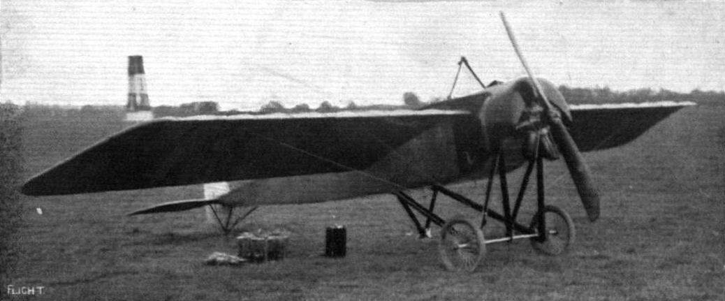
THE 80-H.P. MORANE-SAULNIER MONOPLANE. - A three-quarter view from the front.
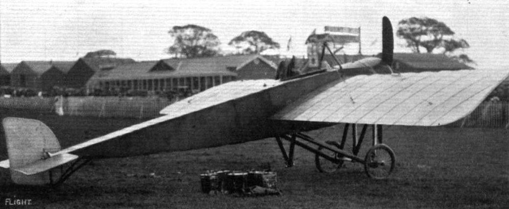
THE 80-H.P. MORANE-SAULNIER MONOPLANE. - A three-quarter view from the back.
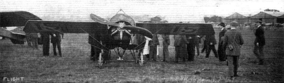
GUSTAV HAMEL'S MORANE-SAULNIER ON THE STARTING LINE FOR THE AERIAL DERBY ON SATURDAY. - In this photograph the small wing span of this racing machine can be appreciated.
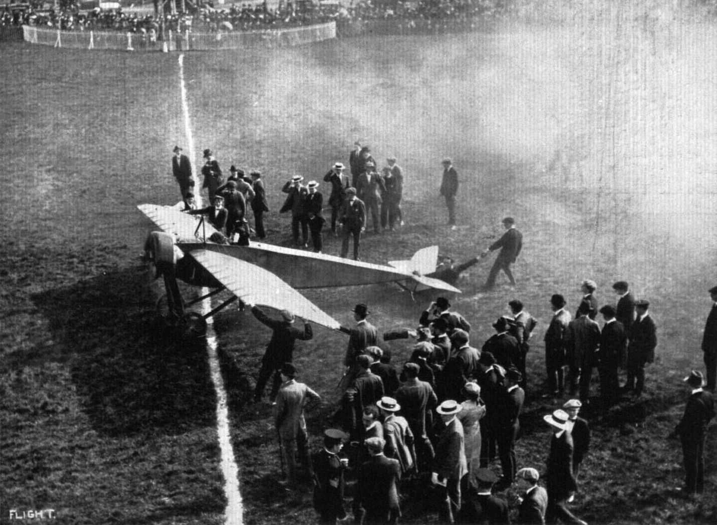
Brindejonc des Moulinais and his lady passenger on the Morane-Saulnier just starting for his attempt to beat the English altitude record at Hendon on Saturday last.
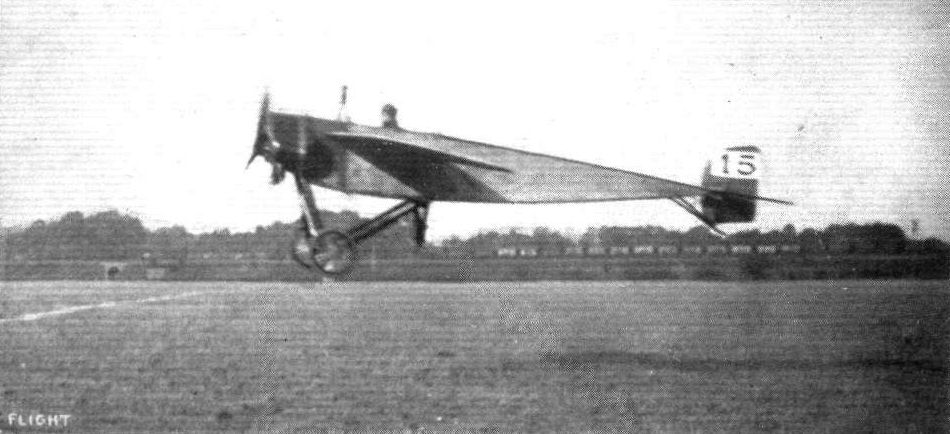
Hamel, the winner of the Aerial Derby, just getting away from Hendon Aerodrome.

M. Brindejonc des Moulinais giving an exhibition flight riendon on Saturday on the Moraoe-Saulnier.

A couple of snaps at the Audemars, Brindejinc and Guillaux match at Juvicy, showing some banking by Brindejonc des Moulinais.
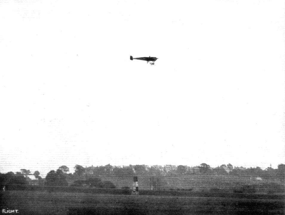
Gustav Hamel finishing and winning the Second Aerial Derby at Hendon on Saturday, Sept. 20th, 1913, on his Morane-Saulnier monoplane.
ROUND PYLON ONE. - Verrier, on the Maurice Farman biplane, and Slack, above, on the Morane-Saulnier.
A remarkable photographic record of an incident in the International contest at Hendon on Saturday. - Brock on the Bleriot winning by a few feet only from Marty on the Morane-Saulnier, who flew underneath him as they crossed the line.
A FINE FINISH AT HENDON. - Marty, Verrier and Manton finishing in the order given in the first heat of the Speed Handicap on "Motor Cycle Day."
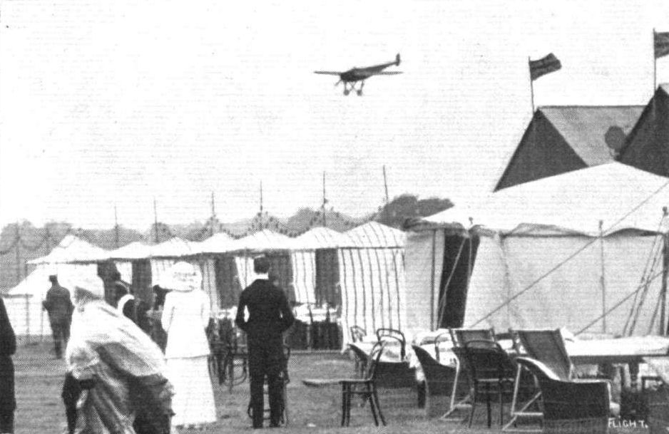
Mr. Robert Slack arriving at the London Aerodrome on the Morane-Saulnler after his magnificent flight from Paris.
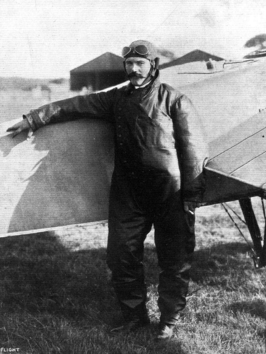
MR. ROBERT B. SLACK.
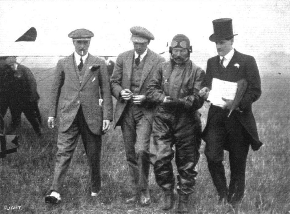
PARIS TO LONDON FLIGHT. - Mr. Robert Slack being escorted across the aerodrome immediately after his arrival at Hendon, by Capt. Tyrer and Mr. R. T. Gates.

Mr. Robert Slack flying the Morane-Saulnier at Hendon after his flight from Paris last week.
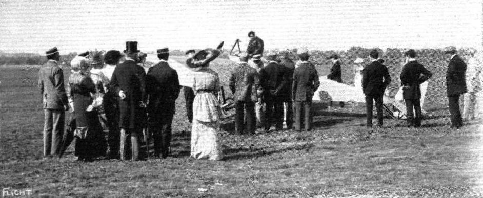
Gilbert just taking his seat in the Morane-Saulnier monoplane, ready for his start back to Paris on Sunday last.
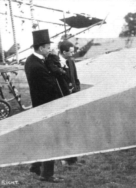
Mr. George Grossmith at the Aerial Fete at Hendon last week, showing his little son the Morane-Saulnier in which Robert Slack flew from Paris.
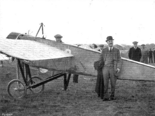
Mr. Gustav Hamel, the winner of the Aerial Derby, in his Morane-Saulnier. Standing by the machine is Mr. "Shell" Cates, through whom the splendid cup and prizes were given for the sealed handicap.
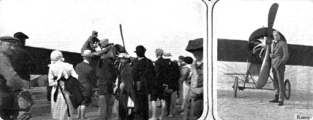
Lord Carbery and his 80 h.p. Gnome Morane-Saulnier at Le Crotoy, where he landed, having lost his bearings, upon the occasion of his recent flight across the Channel. Mr. Oddey, to whom we are indebted for these snaps, proved of considerable value to Lord Carbery, he being the only Englishman on the spot conversant with the journey, he having, it will be remembered, made the Cross-Channel journey with Mr. Sydney Pickles, as recorded in these pages. On the left Lord Carbery is seen filling up at Crotoy prior to his restart for England.

The tail of the Morane-Saulnier monoplane, showing the very neat arrangements of the rudder and elevator wires and levers.
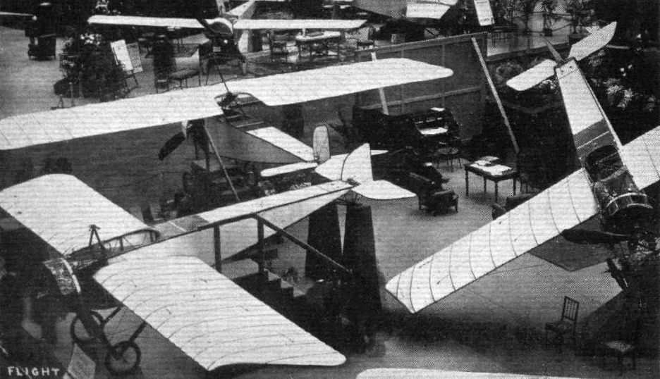
The Morane-Saulnier stand at the Paris Salon.
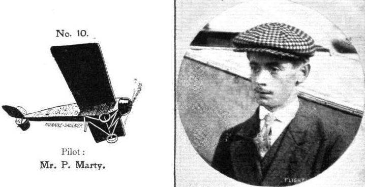
Pilot: Mr. P. Marty.
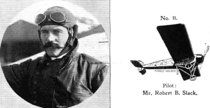
Pilot: Mr. Robert B. Slack.
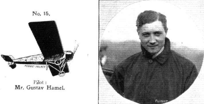
Pilot: Mr. Gustav Hamel.
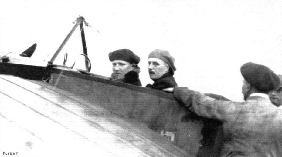
M. Brindejonc des Moulinais and Capt. Tyrer on the Morane-Sauinier machine at Hendon on Saturday, just about to start for a flight after M. Brindejonc des Moulinais' arrival from the Continent.
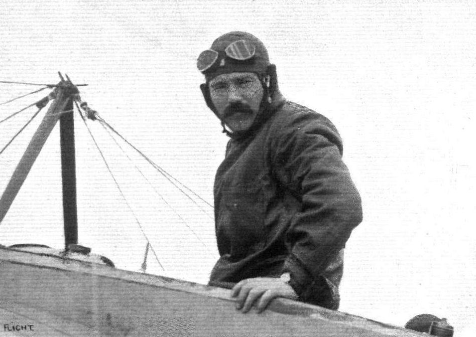
Mr. Robert Slack, who brought the Paris Daily Mails from Paris to Hendon last week.

"AGAINST THE REGULATIONS." - An impression of Brindejonc des Moulinais' Morane-Saulnier crossing the City - St. Paul's in the foreground. Time about 2,50 p.m. Sunday. Note: The unusual prospective is caused by the spectator looking upwards at the monoplane.
"LADIES DAY" AT HENDON AERODROME. - The Morane-Saulnier and Bleriot circling round each other. From an original drawing by Roderlc Hill.
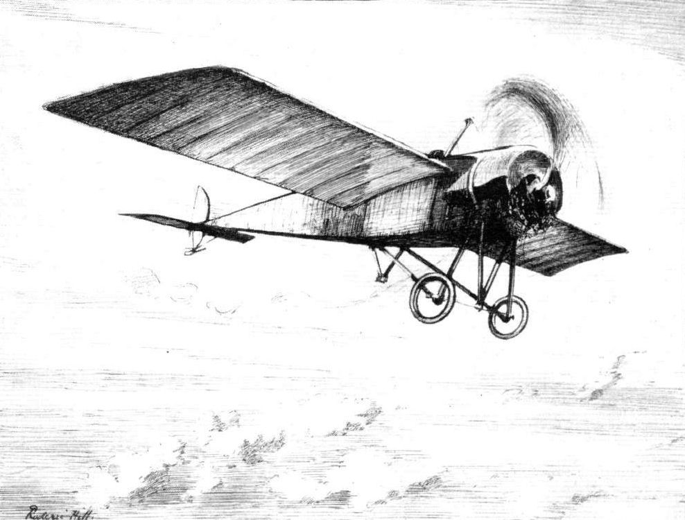
An impression of Mr. Claude Grahame-White flying a Morane-Saulnier monoplane at Hendon in the first week of this month. From an original drawing by Mr. Roderic Hill.
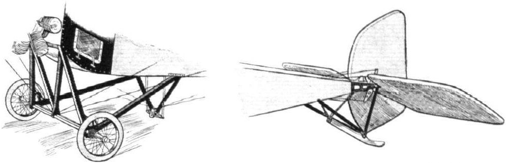
The extremely simple landing chassis of the Morane-Saulnier monoplane. On the right, sketch of the tail planes.
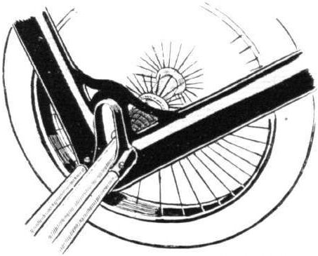
Detail of Chassis.

Sketch showing the very neat attachment of the shock absorbers to chassis members.
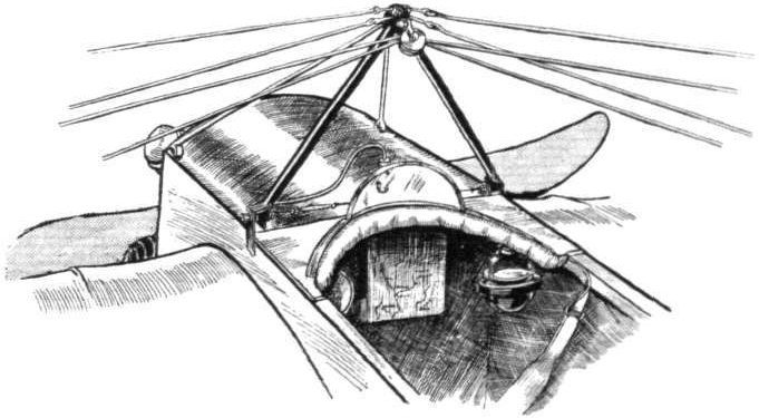
The cockpit and dash. Note the method of pivoting the top pylon to upper longerons.
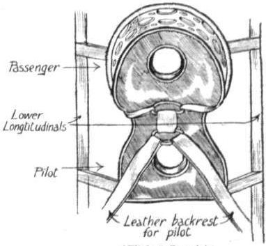
The rather unusual seating arrangement.
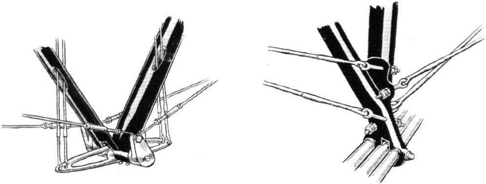
Lower pylon and its fittings, and on the right, sketch showing method of anchoring lift cables to the chassis members.
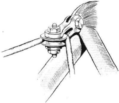
Detail of top pylon. The forward bracing wires are carried round a pulley.
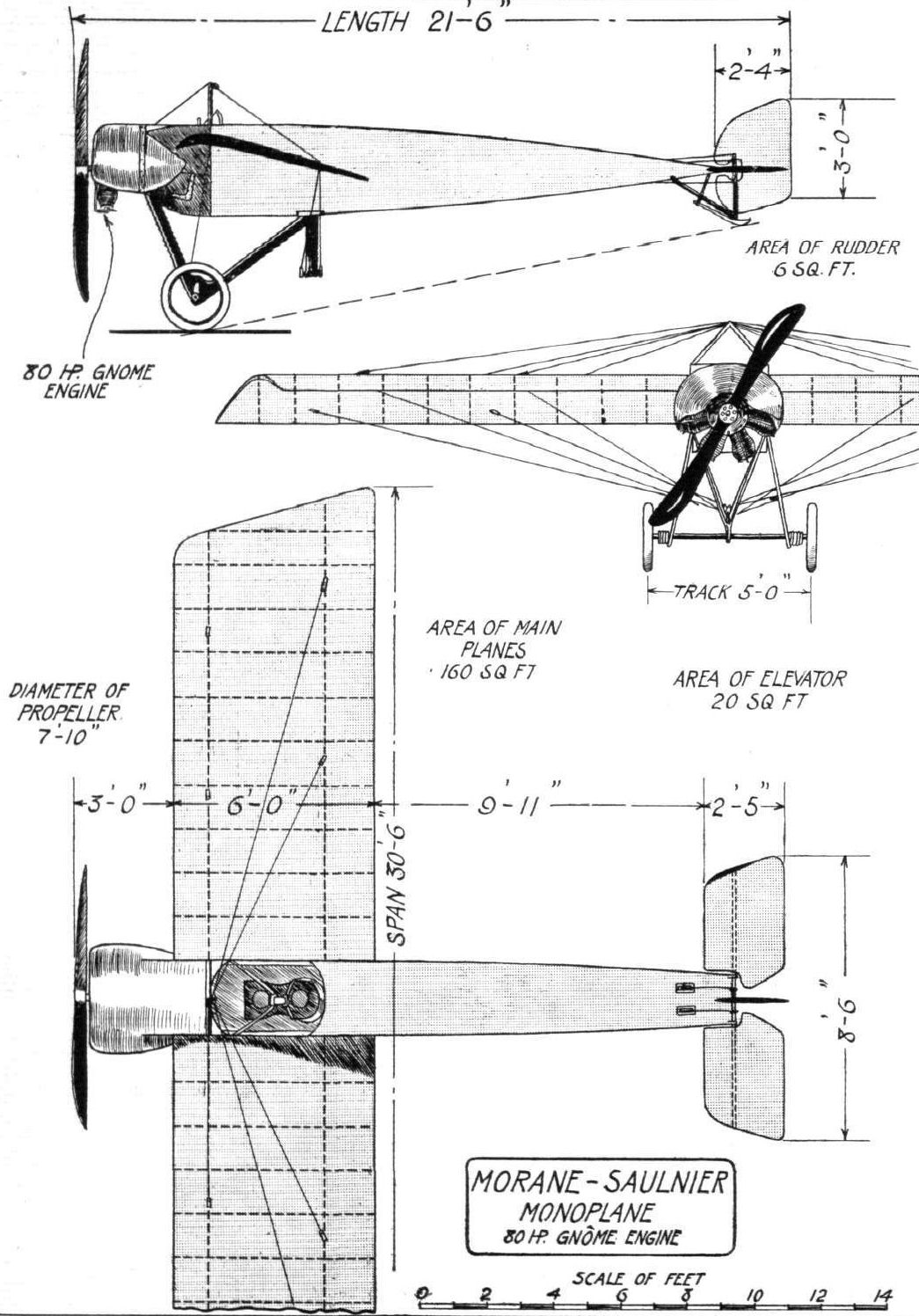
THE 80-H.P. MORANE-SAULNIER MONOPLANE. - Plan and side and front elevation to scale.
Flight, May 3, 1913.
REFLECTIONS ON THE MONACO MEETING.
Morane-SauInier.
The Morane-Saulnier biplane is essentially of the Farman type. The machine at Monaco had an 80-h.p. Rhone rotary engine, which differs from the Gnome in having mechanically-operated inlet-valves served by external radial induction-pipes.
Rigid floats are employed, and the two floats are tied together by a cross bracing of wire lying in a horizontal plane on the same level as the deck of the float. When navigating, this wire bracing seems liable to be immersed.
Many excellent flights were made by Garros on the Morane-Saulnier monoplane, which, however, was not entered for the Grand Prix.

RESTRAINING AN AERIAL SEA MONSTER. - The Morane-Saulnier just getting away for the water.

Mr. Claude Grahame-White, on a Morane-Saulnier waterplane, flying off Newhaven Harbour towards Brighton during the past summer. From an original drawing by Roderic Hill.
Flight, October 4, 1913.
FOREIGN AVIATION NEWS.
The Latest Santos-Dumont Machine.
Not only has M. Santos-Dumont been taking lessons at the Morane school, but he has designed a new machine which has been built in the Morane-Saulnier works. The machine as regards the fuselage, etc., is similar to the Morane machines, but the main plane is in one piece, and is fixed about 80 centimetres above the top of the fuselage. In its trials at Villacoublay the new Santos-Dumont monoplane has given good results.
Flight, December 13, 1913.
THE STANDS AT THE PARIS AERO SHOW.
MORANE-SAULNIER.
Of the machines on the Morane-Saulnier stand, the one which attracts most attention is the "Parasol" monoplane, which has the wings mounted some distance above the fuselage. This arrangement has, of course, the very great advantage that an excellent view of the country is obtained, as the planes are above the pilot's head, and he thus has an unrestricted view in a downward direction. This machine is a tandem two-seater, the pilot occupying the front seat. Inside the fuselage, and behind the observer's seat is situated a special camera, which is pointed straight downward, so that photographs may be taken while the machine is in flight. The camera is operated from the observer's seat by means of a single string, which serves the double purpose of actuating the shutter and the plate-changing mechanism. Mounted on a slanting support, which gives it the appearance of doing a right-hand spiral, is a replica of the machine in which M. Garros made his famous flight across the Mediterranean, from Tunis to Rome. A third standard type two-seater, having the seats placed immediately behind one another, completes the Morane-Saulnier exhibit. The snowy white fabric with which these machines are covered, in connection with the black metal work and edgings, makes this exhibit one of the most graceful at the show.
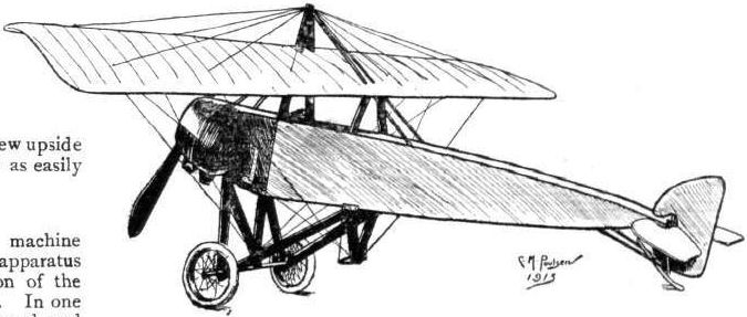
Sketch of the Morane monoplane built to the order of M. Santos-Dumont, who is again taking up flying. - Evidently M. Santos-Dumont is still in favour of a comparatively low centre of gravity as, it will be noticed, he has had the wings raised a considerable distance above the fuselage, so that the pilot sits under instead of between the wings. It will be interesting to see how this machine compares with the usual Morane monoplane as regards stability, as the only alteration appears to be the raising of the wings.
Flight, October 4, 1913.
The Bonnet "Stability" Prize Won by Moreau.
ALTHOUGH the winning of the Bonnet prize by M. Moreau, on the 24th ult., at Melun, may be taken as a good example of compliance with the rules governing the contests for such prizes, it is hardly correct to describe the performance as a demonstration of the complete automatic stability of the machine. The conditions called for a flight of 20 kiloms. in a wind blowing 15 m.p.h. without the pilot touching the control lever with his hands. Nothing was stipulated with regard to the use of the rudder and apparently during the above performance the pilot kept his feet very busy on the rudder bar, judging from a signed report furnished by M. Charles Lafon, the official observer. He says :- "Le pilote vola vingt-cinq minutes les bras croises. Ah! certes, le probleme de la stabilisation automatique n'est pas resolu, car Moreau travailla dur avec ses pieds, non settlement pour faire les virages, mais aussi pour corriger."
It would appear to be highly desirable that when the Ligue Nationale Aerienne are again drawing up rules for such prizes as this they should seek a little expert advice. At the same time, we must congratulate M. Moreau on securing the prize although in doing so he appears to have given the observer who had to accompany him a pretty busy time.
Flight, December 13, 1913.
THE STANDS AT THE PARIS AERO SHOW.
MOREAU.
On the Emaillite stand is shown the Moreau monoplane of which so much has been heard through the winning of the Bonnet stability prize. This machine, it will be remembered, is made automatically stable longitudinally by having the pilot's seat slung pendulum fashion underneath the wings. These are - on this particular machine - covered with a transparent Emaillite preparation which is expected to render the machine practically invisible when flying at a good height, as the spars and ribs and the nacelle will be the only objects which can be seen.

M. Moreau's monoplane, on which the stability tests took place last week.
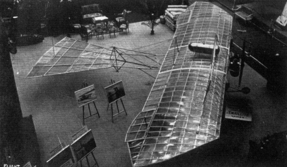
The Moreau Aerostable at the Paris Salon on the Emaillite stand.
Flight, February 8, 1913.
WHAT THERE WILL BE TO SEE AT OLYMPIA.
THE MACHINES.
Societe Anonyme des Etablissements Nieuport.
The well-known French Nieuport firm, who are represented in this country by M. Marc Bonnier, will be exhibiting a 100-h.p. Gnome-engined hydro-monoplane - the identical "Hydravion" that was to be seen on the Nieuport stand at the last Paris Aero Show. Since that function, by the way, this same machine has been on show at the Brussels Exhibition, and it will be coming direct from that show to Olympia. Four similar machines have been acquired by the French Navy, and within the last fortnight three identical models have been supplied to the Japanese Navy. These latter machines were, it may be interesting to remark, tested on behalf of the Japanese Government by M. Bonnier.
In its design there is no great difference from the Nieuport monoplanes for overland work with which we are familiar in this country, excepting, of course, that the "Hydravion" is fitted with floats in place of its usual wheelbase. These floats - there are two main catamaran floats and an egg-shaped small float for the tail - are constructed to the designs of Lieut. Delage of the French Navy, and are peculiar in that each main float is fitted in front with miniature wings that prevent the nose of the float burying itself in the water and which assist in keeping spray clear of the propeller. The 100-h.p. Nieuport hydro-monoplane seats three - the pilot in front and his two passengers side by side behind. A self-starting device is fitted.
Flight, February 15, 1913.
SOCIETE ANONYME DES ETABLISSEMENTS, NIEUPORT.
ON exhibition on their stand, this well-known French firm of monoplane constructors have a 100 h.p. Gnome-engined hydro-monoplane, the identical machine that was shown at the last Paris Aero Show. As we remarked in last week's issue four machines similar to this one have been supplied to the French Navy and three to the Japanese Navy. This model has been very successful at various hydro-aeroplane meetings. At the St. Malo concours M. Weymann, flying one of these machines gained the Grand Prix of the meeting by his flight from St. Malo to Jersey and back. It also holds, we believe, the record for having flown the longest distance over water. At the close of the Tamise meeting in Belgium, Weymann flew his mount to Vernon in France, touching at Antwerp, Calais, and Le Havre en route.
The 100-h.p. Nieuport Hydro-monoplane. - In its general build this machine is not a great deal unlike the various Nieuport monoplanes that are at present flying in this country, excepting, of course, that it has floats in place of a wheeled undercarriage.
The body is 29 feet in length and of an approximate streamline shape, viewed from the side. In its construction it is slightly different from the bodies that are used on land machines, in that, whereas the bodies of the latter type are constructed entirely of wood, the body of the hydro-monoplane uses steel struts for the vertical members of the lattice girder. In front, mounted on triple bearers is the 100-h.p. Gnome motor direct coupled to an Integral propeller which has armoured tips to prevent it smashing if struck by spray. Immediately behind the motor sits the pilot, who controls the machine by a system of levers similar to those used on all Nieuport machines. The rudder and elevator arc operated by a single vertical central lever, while the wing warping is controlled by the feet. Before him, on a dashboard, is mounted a complete set of instruments useful in cross-sea work. Lower down in the cockpit there is a starting handle by which the pilot may put the motor in operation without exterior help. Behind the pilot are seats for two observers arranged side by side.
The alighting gear, designed by Lieut. Delage of the French Navy, consists of two main floats below and slightly forward of the centre of gravity and a small elongated egg-shaped float which supports the tail. Cypress is the wood used for the construction of the main floats, the tops of them being covered in with Willesden canvas. On either side of the nose of each main float, a curiously-shaped tin projects. They are designed to prevent the float burying in a heavy sea and also to assist in keeping spray clear of the propeller. The main floats have a single step which occurs about half way along their length. They support the body through a structure of steel tubing of streamline section.
The tail of the machine is of the usual Nieuport type, with the exception that, presumably to counterbalance the extra resistance to a side wind offered by the floats, two small vertical tail fins have been added, one above the stabilizer and the other below. There is no need to describe the wings in detail for, except that they span 40 ft., they are standard in every respect. The machine, without fuel or passengers weighs 1,230 lbs., travels at 65 miles an hour, and can be bought for L2,000.
Flight, April 19, 1913.
THE NIEUPORT HYDRO-AEROPLANE.
When the Nieuport monoplane was exhibited for the first time in England, at the 1911 Aero Show, it aroused great interest, chiefly, perhaps, on account of the extraordinary speeds it was said to h we attained with an engine of only 30-h.p.
Since then these machines have proved that they are capable of great speeds. Most notable among their successes is perhaps the Gordon-Bennett Race of 1911, when a Nieuport, piloted by Weymann, won the race for America.
The Nieuport brothers, whose tragic deaths within so short intervals is a great loss to the science of aviation, were quick in realizing the possibilities of the hydro-aeroplane, and it was only to be expected that they would be successful when they turned their attention to this branch of aviation.
At St. Malo, Weymann, piloting one of these machines, won the Grand Prix of the meeting by flying from St. Malo to Jersey and back. Later he created a record for the longest over-sea flight in a hydro-aeroplane, by flying from Belgium to Vernon in France, also on a Nieuport.
In its general appearance the hydroplane, which was exhibited at the last Olympia Show, resembles the land machines, with which our readers are familiar, excepting, of course, the chassis, which has been modified to accommodate floats instead of wheels. The two main floats, which have a single step about half way along their length, are set widely apart and support the body through a structure of steel tubes of streamline section. On either side of the rounded nose of each main float is a small metal wing, set at a comparatively great angle of incidence, the object of which is to keep the float from diving under in a rough sea. The material used in the construction of the main floats is cypress, the top of them being covered with canvas. Under the tail of the machine is a single, small egg-shaped float, connected to the fuselage by steel tubes.
The power plant consists of a 14-cylinder 100-h.p. Gnome engine, driving directly an Integral propeller of 8 ft. 6 in. diameter, which has armoured tips in order to prevent splitting in case of water sprays hitting the blades.
Behind the engine is the pilot's seat, which is of the bucket type. The machine is controlled by the usual Nieuport control system, which differs from most others in that the action of warping is carried out with the feet. A rocking shaft, sloping from the floor of the machine down to the lower extremities of the rear chassis struts, carries at its upper end a cross-bar on which the pilot rests his feet, and from a small crank lever on the lower end of the rocking shaft, warping cables are taken to the rear spar. When the machine tilts to the left the pilot presses the cross-bar down with his right foot, thereby pulling down the trailing edge of the left-hand wing.
A to and fro movement of the centrally pivoted hand lever operates the elevators, while a sideways motion actuates the rudder.
On a dashboard in front of the pilot's seat is a complete set of instruments, while lower down in the cockpit is a starting handle, which enables the pilot to start the engine without the help of a mechanic. Behind the pilot seats are provided for two passengers sitting side by side. The fuselage is of the same shape as that which characterises the land machines, the section around the cockpit being very deep and tapering to a knife's edge at the rear, where are attached the tail planes, which are of the usual Nieuport type, as are also the main planes.
Flight, May 3, 1913.
REFLECTIONS ON THE MONACO MEETING.
Nieuport.
It is extremely difficult to formulate an opinion on the relative advantage of the Nieuport triple step keel float, when such a pilot as Weymann is at the wheel. Nevertheless, these machines unquestionably possess a special interest on account of this feature, and it seemed to us that the Nieuport did actually show to advantage when it came to a question of really skimming the water.
The subject of float construction and the use of steps is one that involves much study, and in our opinion hydro-aeroplane constructors will be wise if they call upon the experience of the boat builders who have been specially engaged upon hydroplane work. There are several enthusiasts in motor boating circles who could probably give waterplane constructors many a useful hint. The problem is evidently one of no mean difficulty, and if, as is likely, the waterplane built upon a boat-like foundation becomes a prominent experimental type, then there is no question as to the importance of regarding the subject from the boat builder's point of view.
The hydroplane, which is distinguished from the ordinary flat-bottomed racing boat by the presence of one or more steps in the boat bottom, was invented as long ago as 1782 by a clergyman named Ramus. Having been regarded at the Admiralty from the standpoint of large ships, it was deemed impracticable as a method of construction, owing to the speed that would have been required to have ensured the hydroplaning principle coming into action. It was only when high-speed motor boat racing had shown the possibility of unheard of speeds with short boats, that a serious effort was made still further to improve upon the high velocity qualities of racing craft. Curious little box-like hydroplanes were built by Lelas in France, and used to bounce over the water in a most exhilarating way, but it was Sir John Thornycroft who most seriously tackled the problem of building a hydroplane boat of reasonable weatherliness and more than nominal passenger accommodation.
Anyone who has been at speed in a hydroplane will have acquired an immense respect for the hardness of the water and the force of the blow that it can deal against the bottom of a high-speed boat. Indeed, it is amazing that any structure withstands the apparent strain. To lift the hydroplane out of the water on wings would be a highly desirable mode of continuing the journey, and the experiments of Curtiss and others suggest that this type of craft may play a prominent part in future development. On such machines there is small doubt that the stepped bottom will be a feature of design, but the question of using steps on comparatively small floats is less readily answered in the absence of experiment, and that is why the Nieuport monoplane at Monaco had an especial interest to us, for it was the only machine there with stepped floats.
Flight, July 12, 1913.
FROM PARIS TO LONDON IN A NIEUPORT WATERPLANE.
By JULIEN LEVASSEUR.
AT three o'clock on Wednesday morning last week, on the banks of the Seine at Meulan, my passenger Rougerie and myself were giving the finishing touches to our 100 h.p. Nieuport waterplane, getting ready for the start at 4 o'clock.
A thick haze covered the river, and there was indication of a fog in the air, but this did not deter us in any case from starting, as we thought it would lift up pretty soon.
While surveying the filling of our tanks with 140 litres of petrol and 40 litres of castor oil, we were disturbed by a gentleman, whom we afterwards found to be a chemist in the town, and who, without any preliminaries, insisted upon our giving him testimonials to the effect that his tonic wine had been found very beneficial by us. In generous mood, we gave him a testimonial, without thinking that we had never tasted his wine, and, thanking us for the letter, he also in generous mood went so far as to promise to send us each a bottle of the famous wine upon our safe return.
We ultimately got ready, and started in fog at five minutes past four.
We climbed to about 3,000 ft. in a short time, and found that although we were above the fog, we could not distinguish the river at all, and had to plane down repeatedly to find our course following the river. When we reached Havre we hugged the coast until we got to decamp, where my brother was waiting for us and had seen that all the arrangements were made for replenishing our tanks.
The trip to Fecamp took us 1 hr. and 55 mins. We were at Fecamp 45 mins., and left at 10 mins. to 7. From thence we flew on to Calais, where a mechanic was waiting for us in charge of the petrol and oil arrangements, and where we had a much-needed rest from 9.5 until 10.35. The wind over the Seine and along the coast was extremely strong, and blowing in gusts, which called for continual work on my part. Fortunately, we left the fog behind at Havre, and the weather was beautiful when we left Calais, with a strong wind blowing across.
We took the long sea passage from Calais, and headed direct over to Margate. For over an hour we flew over the sea, and then went along the river Thames, and while doing so, innocently committed several offences in flying over prohibited areas, the first news of which we learnt when we reached our friends in London, as we had not the least idea that there was any trouble to be expected in flying over from France to England.
Descending at Woolwich - as we knew we should not fly over London, and there our knowledge of the law ended - we skimmed along, until we got to Blackwall, our Nieuport and Gnome working perfectly, and tried to moor along the pier, where we were helped by the River Police, to whom our thanks are due for the care with which they assisted us in mooring our machine.
We left our Nieuport there, and took a taxi with an inspector to help us find the way to our friends, Messrs. Picard and Worms in the City, where we arrived looking very disreputable, covered as we were with oil from head to foot. We hurriedly had some refreshments, bought new clothes, and came out of our hotel looking once more respectable.
Our friends were then rung up by the Thames Police, who had actually taken charge of the machine, asking us to help them to moor it to a safer place, as there was danger of the barges, going into the docks near by, fouling our craft.
We got down to lovely Blackwall through the East End at 10.30 p.m., and for two hours tried to manoeuvre with a dinghey between the crafts to moor the machine, which we towed into the Blackwall Thames Police Enclosure where it was protected on every side, and where it actually lies at the time of writing.
After a consultation at the Royal Aero Club with Mr. H. Perrin, whose courtesy we very much appreciate, we decided that, having broken several regulations which we did not know of, we would call and tender our apologies to the Home Office, which we did the first thing next morning. Although we think that the spirit in which our apologies were offered was appreciated, the same afternoon I received two summonses to appear the next day at Bow Street, where Sir John Dickinson emphasised strongly to me the meaning of these Aerial Navigation Acts, my friend Mr. Max Worms acting as interpreter of the words of the magistrate, and I had to pay the costs of the prosecution, and was bound over to come up for judgment if called upon within 12 months in the sum of 1,000 francs.
Thus ended my uneventful journey from Paris to London with my friend and passenger Rougerie.
After the night we had both of us for some hours afterwards the buzz of the engine in our ears. This was an obsession with both Rougerie and myself, so that while we wire lying in bed, tired and half asleep, it seemed to us that we were still flying and the engine was not missing, and the flight was progressing satisfactorily...
I have nothing but praise for the Nieuport machine which carried us, and which answered admirably upon any and every occasion, whether for rising from the water or landing, and we had, moreover, no trouble whatever with the Gnome engine from beginning to end.
As regards this latter point, we find that some daily papers had fanciful reports to the effect that we were obliged to come down owing to trouble with the engine, and afterwards disappeared.
To these reports, needless to say, we wish once again to give a most emphatic denial.
THE PARIS-DEAUVILLE WATERPLANE RACE. - General scene at the start from Paris.
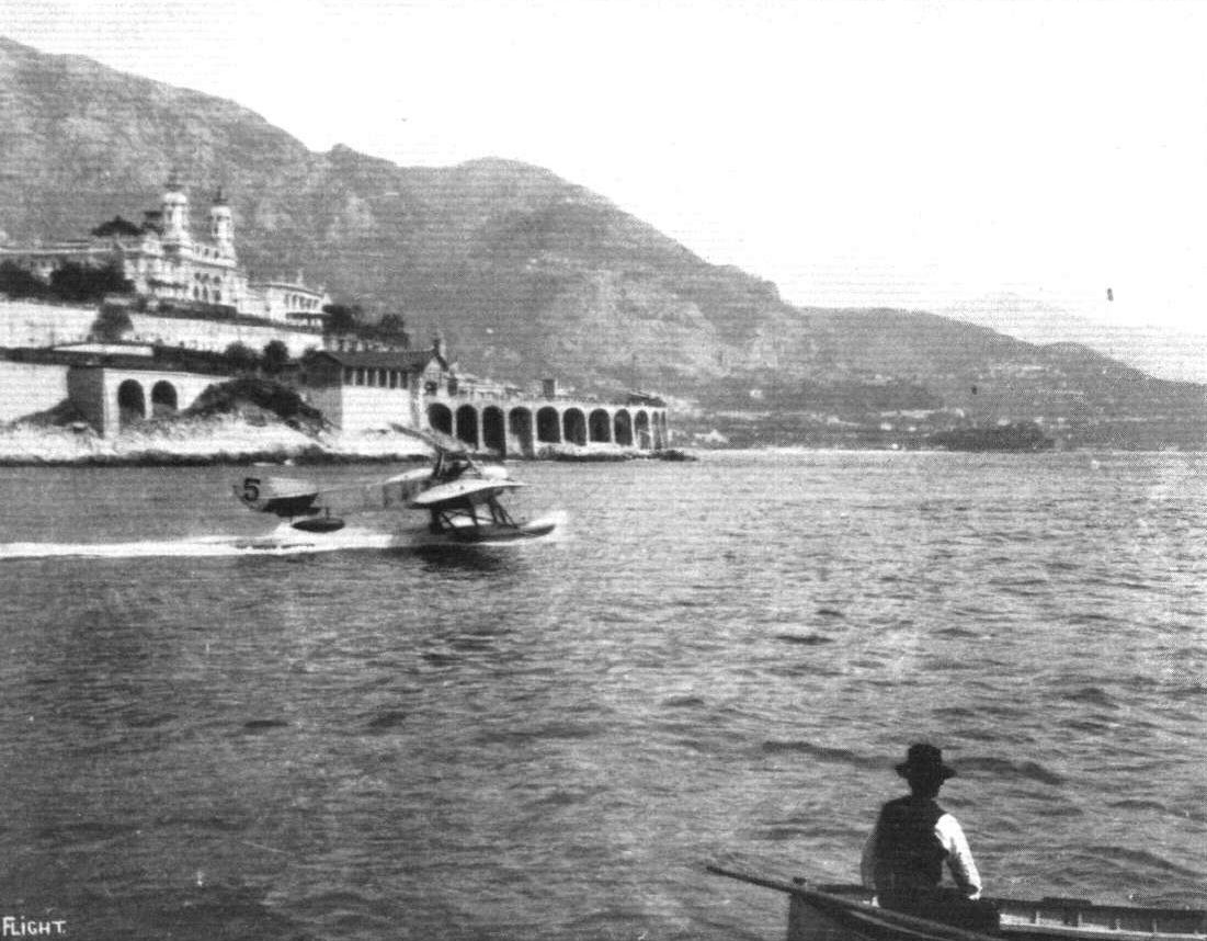
The Nieuport hydro-monoplane showing its paces at Monaco during the recent meeting.
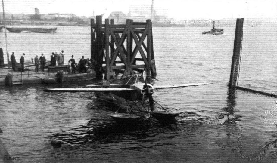
M. LEVASSEUR'S NIEUPORT "IN CUSTODY" AT THE THAMES POLICE STATION, BLACKWALL. - On the pier are the pilot, M. Levasseur, his passenger, M. Rougerie, Mr. Harold E. Perrio, Secretary of the Royal Aero Club, &c.
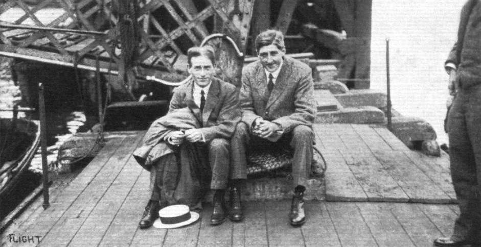
M, Levasseur (on the right), and his passenger, M. Rougerie, on the pier of the Thames Police Station at Blackwall, cogitating over their fate for having infringed the British air regulations.
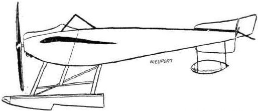
The 100-h.p. Nieuport hydro-monoplane.
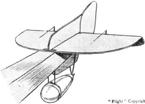
The tail of the 100-h.p. Nieuport Hydravion.
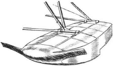
Details of the front of the Nieuport float, showing the peculiar fin-like projections in front which prevent the float from burying itself in rough water.

Side elevation of the Nieuport float.
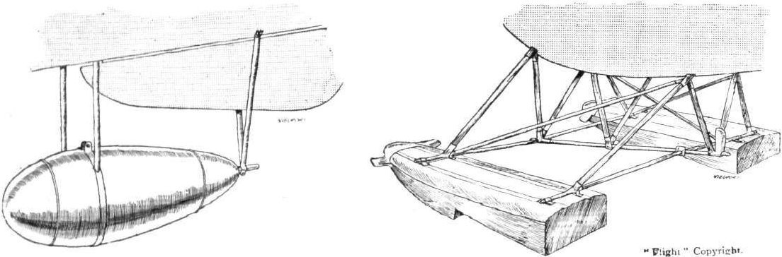
Attachment of main floats (on right) and (on left) the tail float on the Nieuport hydro-aeroplane which was at the last Olympia Show. The machines at Monaco have a three stepped keel float.
HYDRO-AEROPLANES. - Fig. 5. - Types of Aeroplanes.
A study in tails.

The Nieuport machines at the Paris Salon.
Flight, November 22, 1913.
THE PONNIER MONOPLANE.
ALTHOUGH the Ponnier monoplane did not succeed in winning the Gordon-Bennett race it is none the less interesting, for it is probably as fast as the winner, and the difference in speed is accounted for by the fact that the pilot, M. E. Vedrines, did not cut his corners so sharply as did M. Prevost. In its general appearance the Ponnier follows the lines of its predecessor, the well-known Hanriot monoplane.
The fuselage, which is very deep and wide in the front portion, is of rectangular cross section, and is built up in the usual way of four longerons of ash connected by struts and cross members, the whole being made rigid by means of diagonal cross wiring. In the nose of the machine the longerons converge abruptly in an upward and downward direction to meet the front engine bearers. An aluminium shield covering in the greater part of the engine, and running back to form a wind screen in front of the pilot, prevents any oil from being blown back into the pilot's face. The landing chassis fitted to this machine is evidently meant for racing purposes only, for it has been reduced to the simplest possible form, and does not even provide any springing of the wheels, so that it would not be very suitable for landing on anything but the smoothest of surfaces. For the purpose for which it was designed, however, it was doubtless quite good, and, as our readers may be aware, the chassis usually fitted to these machines is of the wheel and skid type, which combination has proved very satisfactory.
The wings are of the standard Ponnier type with a Philip's entry, and a very pronounced wash out to the trailing edge. The spars are of rectangular section, hollowed out for lightness. The number of lift wires has been reduced to a minimum, there being only two wires - one top and one bottom - to each spar. The lower wires are not carried to the lower extremities of the chassis, which is the usual procedure, but have been secured to the lower longeron of the fuselage, the reason probably being, that should the chassis be damaged on landing the fuselage will have a chance to escape serious injury, while the lift wires will remain intact. The resultant angle of the lift wires does not appear any too good, but presumably the designers of the machine have such confidence in the strength of the internal wing construction that one lift wire to the under side of each spar has been deemed sufficient.
The power plant of this machine is the same as that of the Dep., i.e., a 160 h.p. Gnome engine driving directly an Integral propeller of 6 ft. 10 ins. diameter. Wholly on top of the rear portion of the fuselage is mounted a fixed tail plane which is of the flat, non-lifting type, to the trailing edge of which are hinged the elevators. A rudder projecting upwards above the body is hinged to the stern post of the fuselage. A tail skid of the simplest form, consisting of an elliptical leaf spring, protects the tail planes against contact with the ground.
Flight, December 13, 1913.
THE STANDS AT THE PARIS AERO SHOW.
PONNIER.
On the Ponnier stand are shown two monoplanes, which resemble in their general arrangement the one illustrated in the columns of FLIGHT a fortnight ago, which was flown by Emile Vedrines in the Gordon-Bennett Race. One of the machines is fitted with a rigid chassis similar to that employed on the afore-mentioned racing monoplane, whilst the other has a chassis of more orthodox type, in which the wheels are sprung in the usual way by means of rubber shock absorbers.
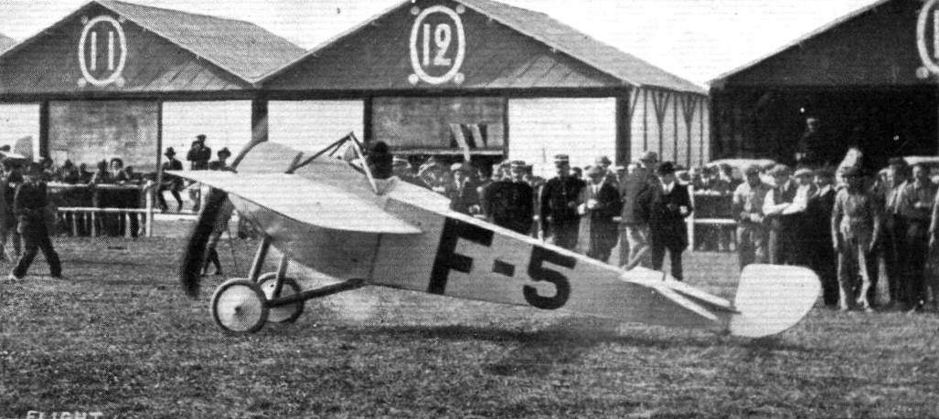
M. E. Vedrines' 160 h.p. Gnome-Ponnier racing monoplane.
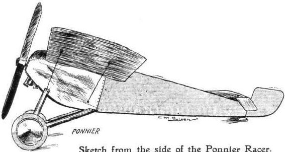
Sketch from the side of the Ponnier Racer.
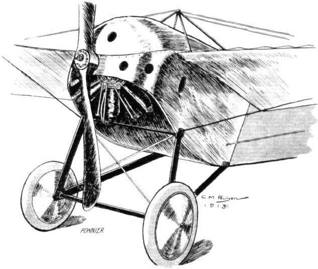
The front portion of the Ponnier racing monoplane.

THE PONNIER RACING MONOPLANE. - Plan, front and side elevations to scale.
The Ratmanoff (in the foreground) and the De Beer monoplanes at the Paris Salon.
Flight, December 13, 1913.
THE STANDS AT THE PARIS AERO SHOW.
R.E.P.
On the R.E.P. firm's stand are to be seen one complete machine - a single-seater monoplane - and the fuselage of a tandem two-seater. These machines are constructed throughout of steel tubes, and have the appearance of being immensely strong. The fuselage exhibited has been left uncovered, so that it is possible to inspect the construction. On the left-hand side of the fuselage is mounted a specially constructed aero camera, by means of which the observer can take photographs of the country over which he is flying.

The R.E.P. at the Paris Salon.
HYDRO-AEROPLANES. - Fig. 5. - Types of Aeroplanes.
HYDRO-AEROPLANES. - Fig. 5. - Types of Aeroplanes.
Flight, July 5, 1913.
THE PIONEERS.
<...>
It was at this earlier period, too, that the names of Archdeacon, Bleriot, Santos Dumont, and Esnault Pelterie were first prominent, but this progress was spasmodic in the extreme, mainly because everyone found an exceeding great difficulty in selecting a suitable place for full-scale research. It was one thing to be interested in the idea of flying, but quite another to find anywhere that one could safely attempt to practise the art of flight.
Santos Dumont, always an enthusiast for new things, and at that time still enamoured of the small dirigible, built an aeroplane of the tail-first type, with which he succeeded in winning the first flight prize for a glorified jump exceeding 25 metres, which he performed on October 23rd, 1906.
<...>
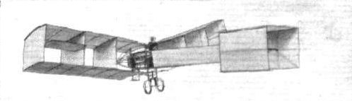
Santos Dumont's tall-first biplane, with which he won the first flight prize on October 23rd, 1906, by flying a distance exceeding 25 metres.
Flight, December 13, 1913.
THE STANDS AT THE PARIS AERO SHOW.
PAUL SCHMITT.
Societe Anonyme des Aeroplanes "Paul Schmitt" are exhibiting a very interesting machine - a tractor biplane, with variable angle of incidence. It is built almost entirely of steel and gives one the impression of being immensely strong. The advantages of being able to alter the angle of incidence, and thereby the speed while the machine is in flight, are too obvious to need enlarging upon, and the manner in which this operation is carried out appears to be a mechanically sound piece of work.
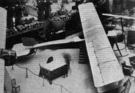
AT THE PARIS SALON. - The Paul Schmitt biplane.
Flight, July 5, 1913.
THE PIONEERS.
<...>
Very few people either appreciated or really realised what the Wright brothers had done, for they invited no publicity and most of their achievements were, in fact, unseen. It was, therefore, in France during the year 1907 that the new art first publicly attracted the notice of the man in the street.
Henry Farman and Leon Delagrange were the central figures of this period in the history of aviation, and it is curious, but none the less a fact, that no one at that time gave much thought or credit to the Voisin brothers who had designed and constructed the machines that these pilots were using.
Gabriel Voisin was in fact one of the earliest experimenters in aviation, and some of his most exciting experiences were concerned with the flying of a glider as a kite while it was being towed by a fast motor boat over the Seine.
It was at this earlier period, too, that the names of Archdeacon, Bleriot, Santos Dumont, and Esnault Pelterie were first prominent, but this progress was spasmodic in the extreme, mainly because everyone found an exceeding great difficulty in selecting a suitable place for full-scale research. It was one thing to be interested in the idea of flying, but quite another to find anywhere that one could safely attempt to practise the art of flight.
Santos Dumont, always an enthusiast for new things, and at that time still enamoured of the small dirigible, built an aeroplane of the tail-first type, with which he succeeded in winning the first flight prize for a glorified jump exceeding 25 metres, which he performed on October 23rd, 1906.
As we have remarked, however, serious public interest was not really aroused until 1907, when Delagrange and Farman acquired their machines from Messrs. Voisin, who had established the first aeroplane factory on the outskirts of Paris. Permission had been obtained from the authorities by Henry Farman to practise on the parade ground at Issy, and it was apparent from the first that aviation was about to enter upon a new era.
France has ever justified herself as a great society of encouragement, for new arts have seldom lacked the enthusiastic patronage of the rich in that country. In aviation there had already been established, through the generosity of MM. Deutsch and Archdeacon, a prize of 50,000 francs for whosoever should first complete a circular flight of 1 kilometre in length; nothing could well have been better suited to encourage progress. The conditions were simple and straightforward, yet they comprised a crucial test. It was apparent that the mere ability to keep the machine off the ground for a period while it wended its way more or less in a straight line, did not constitute flying. In order to fly properly, one must be able to turn, and it was while turning that the machine was most potent to cause trouble.
Henry Farman won this Deutsch-Archdeacon prize, which was called the Grand Prix de l'Aviation, on January 13th, 1908. On October 31st of that year, he flew across country from Chalons to Rheims, a distance of 27 kilometres.
<...>

The Voisin biplane with which Henry Farman won the Deutsch-Archdeacon prize of 50,000 francs on January 13th, 1908, by being the first to fly, under official observation, a circular course of 1 kilom. in length.
HYDRO-AEROPLANES. - Fig. 5. - Types of Aeroplanes.

A NEW SWISS-BUILT MONOPLANE - THE 60-H.P. OERLIKON-ROSSIER. - This machine has been under the pilotage of Kunkler, who has been flying at the Dubendorf Aerodrome. It is now to be fitted with floats and tested for water work.