P.Lewis British Aircraft 1809-1914 (Putnam)
Pilcher Hawk
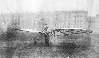
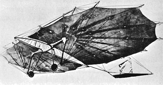
The fourth and last of Percy Pilcher's hang gliders was the Hawk. This was constructed during 1896 at Eynsford, Kent, and was made from bamboo with a covering of fabric. The pilot's weight was borne by bolsters under the armpits, control being effected by the shifting of his body, which hung through the open centre-section of the wings. The tail unit was made to fold over the wings for storage purposes, and a wheeled undercarriage was fitted.
The Hawk was a very successful glider, and was flown many times by Pilcher at Eynsford during 1896 and 1897, towed take-offs being made with a fishing-line into a light wind, from which glides of 200 yds. were achieved. On 30th September, 1899, Pilcher was giving a demonstration on the machine at Stanford Hall, Lord Braye's home near Rugby, and was being towed into the air by a team of horses when the bamboo tail support snapped. He crashed to the ground from about 30 ft. and died from his injuries two days later on 2nd October, 1899. The Hawk was later repaired by T. W. K. Clarke of Kingston-on-Thames and was shown at the Travel Exhibition at Olympia held in 1909. Its final resting-place is in the Royal Scottish Museum with a replica in the National Aeronautical Collection housed in the Science Museum at South Kensington, London.
At the time of his death Pilcher had a biplane nearly ready for an attempt at powered flight, in which he proposed to install a 4 h.p. oil engine of his own construction, which was intended to drive a 4 ft. diameter pusher propeller mounted behind the pilot.
SPECIFICATION
Description: Single-seat monoplane glider. Wooden structure, fabric covered.
Manufacturer: Percy S. Pilcher, Eynsford, Kent.
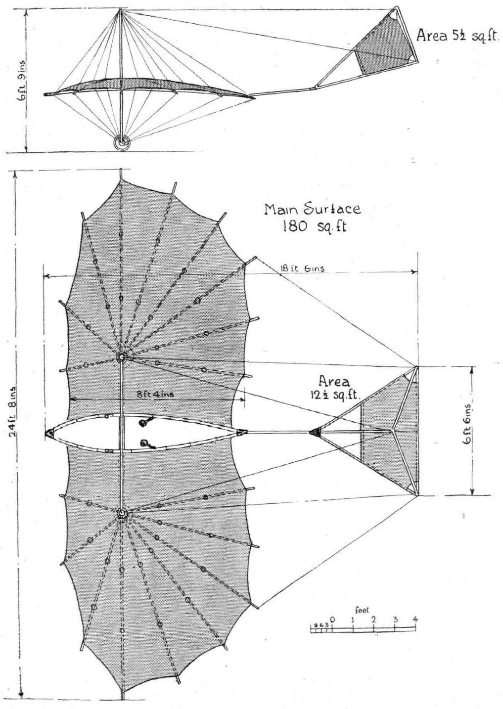
Dimensions: Span, 24 ft. 8 ins. Length, 18 ft. 6 ins. Height, 6 ft. 9 ins. Wing area, 180 sq. ft.
Weights: Empty, 50 lb. Loaded, 195 lb.
Показать полностью
M.Goodall, A.Tagg British Aircraft before the Great War (Schiffer)
Deleted by request of (c)Schiffer Publishing
PILCHER Hawk glider
Work began on the fourth glider towards the end of 1895, which was to be of smaller wing area than the Gull, and thus more manageable. The move to London involved Pilcher with other activities, which included the design and construction of a large exhibit, to be shown at an International Exhibition at the Imperial Institute, South Kensington. This was a lifting platform for launching gliders, and the Hawk was also displayed alongside it, under the names of Maxim and Pilcher, 32 Victoria St., London SW. The exhibition lasted four months so it was towards the end of 1896, before the Hawk was available to test. By the end of the year Pilcher had flown distances up to 100 yards and at least 150 yards had been achieved at a public demonstration in July 1897 at Eynsford.
The Pilcher gliders had been housed in Maxim's large shed on property owned by the reorganized Vickers company, who now required the removal of the shed by the end of the year, with the consequent loss of gliding facilities. Thereafter the Hawk, which was not flown at all in 1898, was used as an exhibit at lectures, until the final demonstration at which Pilcher was killed.
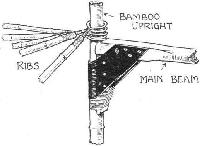
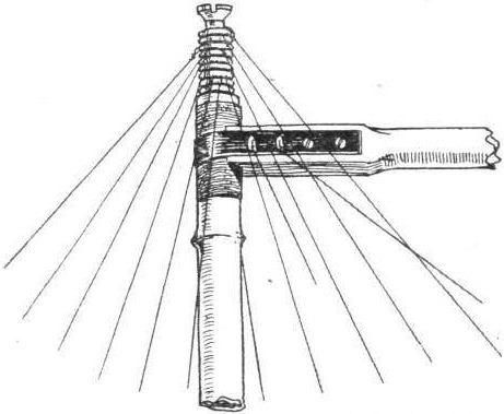
The center structure consisted of two curved bamboo members, joined at front and rear by cast metal fittings, the latter also providing a mounting for a hinged bamboo member to carry the tailplane, which was designed to pivot upwards only; a fin was added later.
A spar, clamped to the center structure, terminated in the uprights, which served as bracing kingposts and pivots for the axles of a pair of sprung wheels, a new feature. The wings, as before, were built with radial ribs designed to fold back fanwise; these were of bamboo and heavily cambered. The pilot stood in the center with his arms in sleeves, resting on the bamboo members.
Pilcher's intention to power the Hawk, as with his earlier gliders, was covered by patent No.9144 /1896, but this was never realized.
The Hawk still exists as an exhibit at the Royal Scottish Museum. At least six reproductions have been made for films and for display purposes, and include examples at Stanford Hall and the Science Museum in London.
Показать полностью
A.Andrews. The Flying Machine: Its Evolution through the Ages (Putnam)
Pilcher had been a Royal Navy cadet at the age of 13, but retired at 19 to concentrate on engineering. When he was 27 he became assistant lecturer in Naval Architecture and Marine Engineering at Glasgow University. Almost immediately the current newspaper detail and photographs of Lilienthal’s activities injected him with the fever to fly. He built one glider, the Bat, a monoplane with a vertical fin aft but no tailplane, the wings showing sharp dihedral; and during his summer vacation of 1895 he went to Lilienthal in Berlin in order to be taught to fly. He came back to test the Bat on the slopes of the Clyde valley and speedily followed Lilienthal’s advice and added a tailplane for stability. In two subsequent models he increased the wing area and greatly mitigated the dihedral angle, which he had found was making his gliders almost unmanageable in strong winds; they plunged out of control before recovering stability from the effect of gusts. This seems a small point, but it is a very clear example of the application of experience to modify what had become to some designers almost a religious theory, mainly propagated because none of them had ever been called on to control an aeroplane with the stipulated dihedral.
In 1896 Pilcher came south to join Hiram Maxim, who had not yet wholly abandoned work on his biplane test-rig and had other plans in mind. In the summer of that year Pilcher built his best designed hang-glider, the Hawk, with cambered canopy wings having an area of 180sq ft, undercarriage wheels braced by stiff spiral springs, and an attachment for a new towing technique for efficient take-off. In the same year Pilcher took out a patent for a powered flying machine with a 4hp petrol engine driving a pusher propeller. After failing to find a suitable engine, he began to build one. At the same time he set himself, in partnership with Maxim, to develop a projected helicopter; and still he continued to develop his gliding and modify his gliders. But on 2 October 1899 he died after falling 30ft in the Hawk during a towed take-off, when the sudden load imposed by two horses over-active on the tow-rope broke up the tail unit of the machine.
Показать полностью
Журнал Flight
Flight, June 12, 1909.
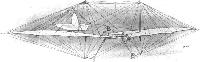
THE PILCHER GLIDER.
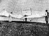
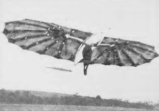
Two very interesting photographs are reproduced on this page of the glider upon which the late Mr. Pilcher met his death, while experimenting in 1899. By the courtesy of Mr. T. O'B. Hubbard, we are able to publish these, together with the measurements given below.
The machine has been recently repaired by Mr. Clarke. The following are the dimensions: -
Extreme width 24 ft. 8 ins.
Overall length 18 ., 6 "
Main surface, extreme fore and aft 10 ,, 0 ,,
Area of main surface about 240 sq. ft .
Distance between main and tail surfaces 5 ft. 6 ins.
Area of horizontal tail 5 sq. ft.
Area of vertical tail 2 1/4 ,,
Extreme breadth of horizontal tail 6 ft. 6 ins.
Fore and aft of horizontal tail 2 " 10 "
Height of vertical tail 2 " 10 "
Flight, January 1, 1910
THE LILIENTHAL AND PILCHER GLIDERS COMPARED.
<...>
The Pilot's "Seat" and its Consequences.
Although Pilcher was doubtless inspired to his work by Lilienthal's example, it is apparent that he brought an original mind to bear in the constructive details of his task, whatever bias he may have been under to follow his leader's methods in their general lines. Constructionally the two gliders are as different as they can well be for machines of such similarity in size and purpose. But Pilcher and Lilienthal had this much in common, that they both employed the same method of riding their machines, by hanging upon them, and from such experience as has since been collected by the Brothers Wright, there is little doubt that the custom was at the bottom of many of their difficulties, if not actually the cause of Lilienthal's death. One consequence of deciding to use a glider as Lilienthal and Pilcher used theirs is the necessity of designing a machine of small weight, for the pilot has to be prepared to carry the load both when launching and landing. Pilcher, it is true, fitted a small chassis to his glider consisting of two spring-suspended wheels, but this addition was no more than a compromise, as its purpose was mainly to enable him to bring the machine more easily into position, and to take some of the initial shocks of landing. In flight Pilcher's body hung suspended beneath the wings, only his head and shoulders projecting above, his weight was borne upon two bolsters fitting under the armpits. Lilienthal was perhaps even more beneath his machine than Pilcher, for his arms rested in sockets beneath the wings, and the bolsters which supported his shoulders were about on a level with the upper surface.
Stability and Control.
The greater part of their weight being thus suspended beneath the supporting surfaces caused the centre of pressure to be considerably above the centre of gravity, and although this is often thought to be conducive to automatic stability by constituting a kind of natural pendulum, as a matter of fact, the inertia of such a system very naturally complicates the control, which in both cases was carried out by the shifting of the pilot's body in whatever direction might be required to restore balance. Pilcher had quite satisfied himself upon this point before he came to the end of his experiments, and another matter upon which he became convinced was that the upward slanting of the wings # or the principle of the dihedral angle # resulted in diminished stability in sidewings.
Leading Dimensions.
Of the two machines there is little to choose in weight, as they were both supposed to be in the order of 45 to 50 lbs. when actually in use. Lilienthal's glider has the smaller amount of supporting surface, and even that machine must have been one of the largest he constructed, for he was inclined at first to build gliders having barely 110 sq. feet of deck. The span of 22 feet for the Lilienthal machine is 2 ft. 8 ins. less than the Pilcher, and the overall length is 2 ft. shorter. The height is proportionally much less than that in the Pilcher glider, owing to a different system of staying the surfaces and to the absence of a chassis.
The Tail.
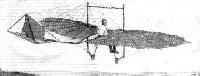
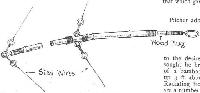
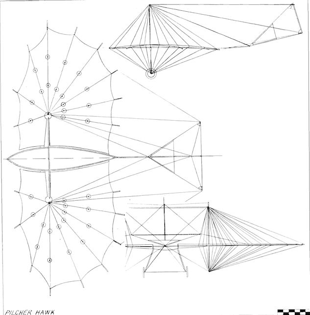
Both gliders were fitted with tails of similar type although different in shape, the tail in each case consisting of one vertical plane and one horizontal plane, the latter being set at a negative angle, and being also free to rise unrestricted if subjected to any pressure from beneath. It will be distinctly noticed from the accompanying drawings that the stay wires for the horizontal planes are only arranged so as to resist pressure from above. The vertical tail plane is nominally rigid, although, in the Pilcher glider, it happens to be mounted upon the horizontal member, and thus moves with it. In the Lilienthal machine the horizontal plane is hinged separately to the vertical plane, which is attached rigidly to the main frame. It was Pilcher's object in designing the tail of his machine as shown, to make it as compact as possible for storage, and with this end in view the tail was arranged to fold over on to the main planes.
(To be concluded.)
Flight, January 8, 1910
THE LILIENTHAL AND PILCHER GLIDERS COMPARED.
Willow and Bamboo.
THERE is a subtle difference in the construction of these two gliders, otherwise so much alike, which is directly attributable to the difference in the materials employed, for where Lilienthal used willow sticks, Pilcher adopted bamboo. Both had, it will be seen, sufficiently awkward materials to deal with, but Pilcher, it must be confessed, made a far more engineering-looking job of his work than Lilienthal, whose constructive methods are somehow reminiscent of bent-wood furniture. Both designers embodied the principle of folding-wings in their machines, and thus both were under the same necessity of adapting their construction to suit the special requirements imposed by this important condition. At the same time, however, both had to provide their wings when finished with an artificial camber, and it is particularly interesting to compare the two methods by which these details were accomplished.
The Folding of the Wings.
Pilcher, who was working with bamboo, fitted the inner extremities of the ribs of his wings with wooden plugs, to which he lashed a loop of iron wire so as to form a ring. These rings he subsequently strung over the central standard, around which each wing spread out like an open umbrella. In order to close the wings, it was only necessary to unlash the attachment between the front edge and the main frame, when the ribs would then all swing round one above the other into any convenient position.
Lilienthal obtained much the same effect, but in his case the ribs folded up side by side, being hinged to a central bracket into which their wedge extremities normally fitted like the spokes of a wheel.
In this machine the hinge centres are 6 ft. apart, and in the Pilcher machine the same points are separated by a distance of 7 ft. 6 ins. In both cases the hinges are joined by a wooden beam, but whereas in the Pilcher glider this member consists of a simple rectangular piece of wood, in the Lilienthal machine it is a built-up structure in the form of the letter X; which system was adopted in order to enable the staying of the wings to be conveniently accomplished. It would doubtless have been better had Pilcher attached more importance to the strains on the main beam of his machine, because it was that which gave way during his last glide.
Pilcher and His Wire.
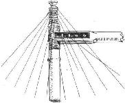
Pilcher adopted a very different method of bracing his wings to that employed by Lilienthal, in fact, it is in this respect that the two machines are most unlike. He relied entirely upon the use of piano-wire for cambering the surfaces of his wings to the desired shape, and in order to get the effect sought he braced each to a central hinge pin consisting of a bamboo pole some 6 ft. in height, which stood up 3 ft. above the deck and projected 3 ft. beneath it. Radiating from the top and bottom ends of this pole are a number of wires, for the most part there are three wires attached above and beneath each rib, only the two front ribs in each wing having less than this number. There are nine ribs in each wing, and altogether 50 wires were required to stay them.
How Pilcher managed to retain all these wires properly taut is a matter for conjecture, but he must have been a man of great patience if he really gave proper attention to each of the 100 wires on which the camber of his surfaces depended. It is no easy matter to adjust wires used for such a purpose, as no sooner is a slack wire tightened up a little too much, than it relieves the strain upon two or three other wires, which become slack in turn. And Pilcher, it must be remembered, worked before the days of those very pretty little wire strainers which commonly form a feature in the bracing of modern flyers, and his method of adjustment must have been as tedious as it was effective. Each of his wires he fitted with a curtain-ring - Pilcher was very fond of curtain-rings - and on the rib he fastened a wire eye. The wires were cut to a fixed length in advance, and calculated to allow about an inch between the ring and the eye when in place. This gap was filled up by a piece of string, passed several times through each member to give the required strength, and by pulling on one end of the string a very minute adjustment could be made in the tension. More curtain-rings were employed for fastening the other ends of the wires to the vertical bamboo poles, so that the wings could be folded without twisting the wires.
Another little device for which Pilcher's construction is peculiar is his method of plugging his bamboo rods with wood. The wood plugs were glued into the hollow ends of the bamboo, which were then carefully lashed with string. Pilcher was very careful about lashing the ends of his bamboo poles as he evidently fully appreciated their liability to split. His use of wire eyes as lugs is another neat detail well worthy of attention, and these little fittings he would also lash in place.
Lilienthal's Stiffening Ribs.
Lilienthal, who very possibly had a natural objection to the use of a lot of wires, hit upon a very ingenious method of doing away with some of them, for he maintained the camber of his wings by the use of detachable supplementary ribs, of which there were four placed fore and aft above the deck. These ribs were strips of wood having an inverted T section, and they were cut to shape so as to serve as templates. As their permanence would have interfered with the folding of the wings, they were fitted in such a manner as to be detachable, and the method of doing this was to fasten small steel clamps on to the primary ribs of the wings, through which the flange of the template could slide. As the wings were naturally flexible there was no difficulty in sliding the curved templates in place from one end, and once in position these members were fastened by little clips. Their purpose was primarily to give the wings the desired camber, although they would of course tend to increase the rigidity of the structure; by their use, the necessity for employing a large number of wires was obviated, in fact, there were only two tie-wires radiating from each of the vertical posts mounted above the hinge plates. Beneath the wings, however, there was a wire to every rib, but even in this respect Lilienthal contrived to do without some 78 wires which Pilcher found necessary.
Relative Cambering.
It may be remarked that the number of ribs in each of the two machines is identical, viz., 18, but the camber and arching of the wings themselves is distinctly different in the two cases. Pilcher employed an umbrella-like form, in which the camber may be described as being of a uniform character. Lilienthal, on the other hand, flattened the extremities of his wings to such an extent that the curvature of some of the ribs was virtually reversed. The maximum camber on the Lilienthal glider, as on the Pilcher machines, occurs at the hinge of the wing, which on the former is situated 18 ins., and on the latter 2 ft. 6 ins. behind the leading edge. At this point the camber is deeper on the Lilienthal than on the Pilcher glider, but on the Lilienthal machine the camber is almost confined to this point alone, and is far more concentrated, if the term may be used, than in Pilcher's construction.
It is known that Lilienthal experimented with cambers of considerable height in proportion to the chord, and he has stated that the maximum versine (camber) of the wing curvature should be less than 1/12 of the chord, and preferably only 1/18 to 1/15 for considerations of stability.
Both machines had the surface material attached above the ribs.
The Framework.
Having compared the wings and supplementary surfaces, it is of interest to consider the main frames of the two machines, by which we imply that central structure to which the whole is braced, and on which the pilot supports his weight. In the Lilienthal glider this member is of somewhat peculiar form, and is best observed by reference to the accompanying plan; it bears in a marked degree that bent-wood furniture appearance to which we have already drawn attention. One of the principal members is an approximately circular hoop of willow, across which pass in a fore and aft direction two willow rods that ultimately converge at a point where the bamboo tail rod emerges from the wing surface. Transversely across the hoop passes the main beam to which reference has already been made, and immediately behind this an orifice is provided in the surface to accommodate the upper part of the pilot's body. Two small bolsters attached to the frame rest under the pilot's shoulders, and the pilot's arms pass through rests provided for them in the corners of the X-shaped main beam. Just in front of this beam is another transverse rod which the pilot can grip with his hands, and in front of the main hoop member is another bent-wood construction lashed in place with wicker, the object of this device being to act as a fender in the event of collision.
On Pilcher's glider the main frame consists of two bamboo rods spaced 18 inches apart above the main transverse beam, to which they were lashed in a cradle. Fore and aft these members converge, and are joined together in metal sockets, that at the rear carrying a bamboo extension to the tail. The entire space occupied by the two frame members was left open in the Pilcher machine, in which respect it differs from Lilienthal's glider, where every possible square inch is covered in. The pilot on Pilcher's glider was supported by two small bolsters fitting under the armpits, which bolsters were attached to the ends of short rods projecting obliquely from the sides of the main frame. Thus supported, the pilot's forearms would rest along the frame-members, and flat pieces of wood are lashed in place at these points to give greater comfort. At the ends of these armrests two handles project for the pilot to grip.
Both machines are more or less similarly braced as regards the wings to the frame and the tail to the frame; but in the Pilcher glider a transverse wooden strut is provided between the bamboo uprights in addition to the diagonal tie-wires which alone sufficed in the Lilienthal machine. Underneath the frame on Pilcher's glider two bamboo rods project obliquely outwards and carry wooden extensions on which the chassis wheels were mounted. The hollow bamboo is here made use of to contain a spring, and the wooden extension, once more fitted in the form of a plug, in this case became a plunger.
Flight, July 5, 1913.
THE PIONEERS.
<...>
Among those who took great interest in Lilienthal's experiments was Pilcher, then a young English engineer whose name was associated with the firm of Wilson and Pilcher, at one time well known in the automobile industry before their cars were taken over by Messrs. Armstrong, Whitworth. He designed gliders of his own, more or less on Lilienthal lines, and at one time went over to Germany in order to discuss the subject with Lilienthal himself. If anything, he adopted an even more dangerous procedure than the German pioneer, for in order to avoid the necessity of finding a suitable hill as an aerodrome, he would attain the initial altitude necessary for a gliding flight by having his machine towed like a kite. An accident during one of these experiments resulted in his death, and thereby deprived England of a most promising student who, had he lived, might have done much to give this country pre-eminence from the first.
<...>
Показать полностью