Книги
Putnam
P.Lewis
British Aircraft 1809-1914
408
P.Lewis - British Aircraft 1809-1914 /Putnam/
Aerial Manufacturing Company Monoplane
Aerial Manufacturing Company's monoplane was built at Finsbury, London, during 1909 and was powered by a 50 h.p. engine. Control was several auxiliary horizontal stabilizing planes, and the machine made a number of short hops of between 200 and 250 yds. at Rye, Sussex, when it was tested there by Alec Ogilvie during 1909. Span, 44 ft. Length, 44 ft.
Aerial Manufacturing Company's monoplane was built at Finsbury, London, during 1909 and was powered by a 50 h.p. engine. Control was several auxiliary horizontal stabilizing planes, and the machine made a number of short hops of between 200 and 250 yds. at Rye, Sussex, when it was tested there by Alec Ogilvie during 1909. Span, 44 ft. Length, 44 ft.
Aerial Wheel Monoplane
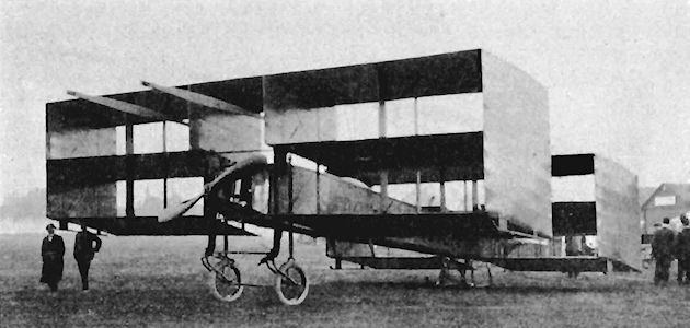
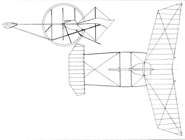
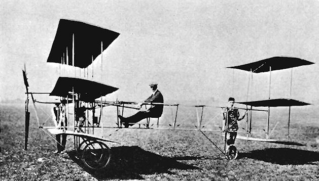
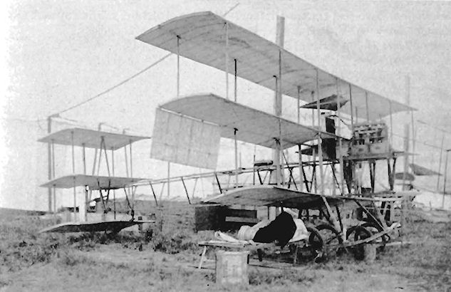
The Aerial Wheel was one of the most unorthodox of the machines entered for the 1912 Military Trials at Salisbury Plain, it was given the entry number 18 and arrived at Larkhill for the contest, but did not take part in the tests and remained hidden in its shed.
A side-by-side two-seat canard tractor monoplane, it was powered by a 50 h.p. N.E.C. engine, the crew being seated at the leading-edge of the swept-back wings. The designers were Ralph Platts and George Sturgess and the machine was built at Birmingham by the Aerial Wheel Syndicate Ltd., of Mablethorpe, Lines.
Aeroplane Building and Flying Society Glider
A Farman-type biplane glider was built during 1911 by the Society, whose members experimented with it at Kensal Rise, London. As their flying-ground was without sufficient natural slope for easy launching, they developed an artificial launching track of parallel ropes, along which ran a trolley down a gradient of about 1 in 6, the glider being mounted upon the trolley.
A Farman-type biplane glider was built during 1911 by the Society, whose members experimented with it at Kensal Rise, London. As their flying-ground was without sufficient natural slope for easy launching, they developed an artificial launching track of parallel ropes, along which ran a trolley down a gradient of about 1 in 6, the glider being mounted upon the trolley.
Anderson and Singer Glider
The Anderson and Singer Glider was built by Anderson and Singer of Aberdeen, Scotland, in 1911 and was flown successfully.
The Anderson and Singer Glider was built by Anderson and Singer of Aberdeen, Scotland, in 1911 and was flown successfully.
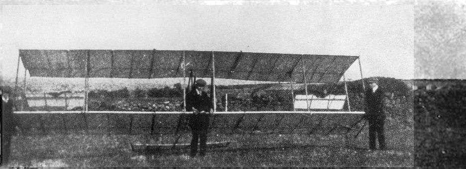
Anderson & Singer glider. A 1911 amateur-built Chanute-type glider. Flight 21 October 1911 (p.923).
Aeronautical Syndicate Ltd. Valkyrie Monoplanes
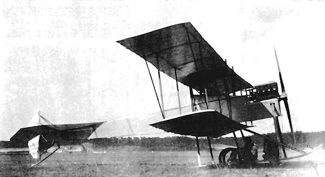
The Valkyrie canard pusher monoplanes originated during early 1909 on Salisbury Plain, where Horatio Barber formed his Aeronautical Syndicate Ltd. during June to promote his designs. The very first A.S.L. Monoplane was an unsuccessful tractor type powered by a 50 h.p. Antoinette engine, and possessed the unorthodox feature of reciprocating wings mounted on an all-steel fuselage.
The tractor monoplane was soon followed by the first of the pusher series. This was built by Howard T. Wright and was fitted with a 60 h.p. Green driving an 8 ft. 2 ins. diameter propeller. The 42 ft. span wings tapered from a root chord of 10 ft. to 6 ft. at the tips; the noseplane was 12 ft. in span, the outer 3 ft. on each side being pivoted for use as elevators. The 31 ft. long machine seated two in tandem and flew several hundred yards in tests by B. Woodrow over Salisbury Plain at the beginning of 1910. This design, also, was known as the A.S.L. Monoplane, the appellation Valkyrie first coming into use with the next of Barber's products.
<...>
Aeronautical Syndicate Ltd. Valkyrie Monoplanes
<...>
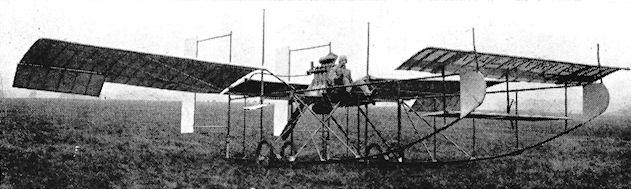
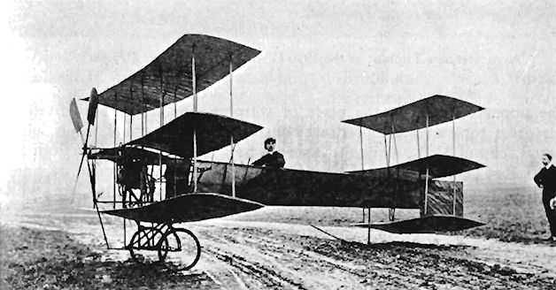
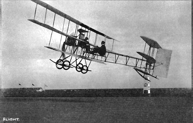
The Valkyrie A appeared in 1910 and was a single-seater fitted with a four-cylinder 35 h.p. Green engine, turning its 7 ft. 3 ins. diameter propeller in an opening cut in the leading-edge of the wings between the longerons. The airframe was constructed almost throughout of Honduras mahogany, the flying surfaces receiving a single surface of fabric covering. The elevator was mounted below the noseplane and to the rear of the nose-plane's trailing-edge. Lateral control was by ailerons, with the twin rudders hinged at the ends of the fuselage frames in line with the trailing-edge of the wings.
During September, 1910, the Aeronautical Syndicate moved its scene of operations to Hendon Aerodrome and leased three of the eight hangars belonging to the Bleriot Company. Within a few weeks of his arrival, Horatio Barber took his Royal Aero Club Aviator's Certificate No. 30 on 22nd November, using his own Valkyrie Monoplane for the tests.
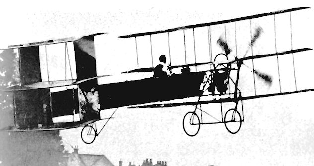
The following year saw the appearance of the Valkyrie B, retaining the same general lay-out of the earlier design, but of lighter weight, since it was produced as a racer. The machine was able to carry two passengers on the power of a 50 h.p. Gnome, and was used on 4th July, 1911, to transport the first cargo by air in Britain. This consisted of a box of Osram lamps, which was flown by Barber from Shoreham along the coast to the lawns at Move. The next month, Barber flew Miss Trehawke Davies, an early enthusiast of Hendon flying, on the Valkyrie B from Hendon to Brighton, making the return trip on the following day. Although the machine was of smaller span than the Valkyrie A, the overall length was increased owing to the placing of the rudders on booms to the rear of the wings to improve directional control. Several examples of the Type B were built, and the unusual tail-first Valkyries soon became a familiar sight in the skies around Hendon, their occupants perched bravely on the edge of the wings amid the numerous struts and various flying and control surfaces and the forest of wires which went to make up the aircraft.
During November, 1910, the Valkyrie C made its entry on the busy Hendon scene. This was a three-seater which carried its passengers side-by-side in front of the leading-edge of the wings; the power was a 60-h.p. Green, and at least four of the type were constructed. Another Valkyrie, this time with the lower power of a 35 h.p. Green, was produced during December, 1910.
Although they were considered to be tricky to fly, the Valkyrie pushers were employed very successfully at Hendon for training. Several pilots used them to gain their certificates, including No. 130 E. W. C. Perry on 12th September, 1911, No. 154 Capt. E. B. Loraine on 7th November, 1911, and No. 168 C. F. M. Chambers on 12th December, 1911.
SPECIFICATION
Valkyrie Type A.
Description: Single-seat canard pusher monoplane. Wooden structure, fabric covered.
Manufacturers: Aeronautical Syndicate, Ltd., Salisbury Plain, Wilts.
Power Plant: 35 h.p. Green.
Dimensions: Span, 34 ft. Length, 22 ft. Wing area, 190 sq. ft.
Weights: Empty, 520 lb.
Valkyrie Type B.
Description: Single/two-seat canard pusher racing monoplane. Wooden structure, fabric covered.
Manufacturers: Aeronautical Syndicate Ltd., Hendon, London, N.W.9.
Power Plant: 50 h.p. Gnome.
Dimensions: Span, 31 ft. Length, 26 ft. Wing area, 168 sq. ft.
Weights: Empty, 550 lb.
Performance: Maximum speed, 70 m.p.h.
Price: ?920.
Valkyrie Type C.
Description: Three-seat canard pusher monoplane. Wooden structure, fabric covered.
Manufacturers: Aeronautical Syndicate Ltd., Hendon, London, N.W.9.
Power Plant: 60 h.p. Green.
Dimensions: Span, 39 ft. Length, 29 ft. 9 ins. Wing area, 302 sq. ft.
Weights: Empty, 800 lb.
Price: ?1,000.
<...>
The Valkyrie A appeared in 1910 and was a single-seater fitted with a four-cylinder 35 h.p. Green engine, turning its 7 ft. 3 ins. diameter propeller in an opening cut in the leading-edge of the wings between the longerons. The airframe was constructed almost throughout of Honduras mahogany, the flying surfaces receiving a single surface of fabric covering. The elevator was mounted below the noseplane and to the rear of the nose-plane's trailing-edge. Lateral control was by ailerons, with the twin rudders hinged at the ends of the fuselage frames in line with the trailing-edge of the wings.
During September, 1910, the Aeronautical Syndicate moved its scene of operations to Hendon Aerodrome and leased three of the eight hangars belonging to the Bleriot Company. Within a few weeks of his arrival, Horatio Barber took his Royal Aero Club Aviator's Certificate No. 30 on 22nd November, using his own Valkyrie Monoplane for the tests.
The following year saw the appearance of the Valkyrie B, retaining the same general lay-out of the earlier design, but of lighter weight, since it was produced as a racer. The machine was able to carry two passengers on the power of a 50 h.p. Gnome, and was used on 4th July, 1911, to transport the first cargo by air in Britain. This consisted of a box of Osram lamps, which was flown by Barber from Shoreham along the coast to the lawns at Move. The next month, Barber flew Miss Trehawke Davies, an early enthusiast of Hendon flying, on the Valkyrie B from Hendon to Brighton, making the return trip on the following day. Although the machine was of smaller span than the Valkyrie A, the overall length was increased owing to the placing of the rudders on booms to the rear of the wings to improve directional control. Several examples of the Type B were built, and the unusual tail-first Valkyries soon became a familiar sight in the skies around Hendon, their occupants perched bravely on the edge of the wings amid the numerous struts and various flying and control surfaces and the forest of wires which went to make up the aircraft.
During November, 1910, the Valkyrie C made its entry on the busy Hendon scene. This was a three-seater which carried its passengers side-by-side in front of the leading-edge of the wings; the power was a 60-h.p. Green, and at least four of the type were constructed. Another Valkyrie, this time with the lower power of a 35 h.p. Green, was produced during December, 1910.
Although they were considered to be tricky to fly, the Valkyrie pushers were employed very successfully at Hendon for training. Several pilots used them to gain their certificates, including No. 130 E. W. C. Perry on 12th September, 1911, No. 154 Capt. E. B. Loraine on 7th November, 1911, and No. 168 C. F. M. Chambers on 12th December, 1911.
SPECIFICATION
Valkyrie Type A.
Description: Single-seat canard pusher monoplane. Wooden structure, fabric covered.
Manufacturers: Aeronautical Syndicate, Ltd., Salisbury Plain, Wilts.
Power Plant: 35 h.p. Green.
Dimensions: Span, 34 ft. Length, 22 ft. Wing area, 190 sq. ft.
Weights: Empty, 520 lb.
Valkyrie Type B.
Description: Single/two-seat canard pusher racing monoplane. Wooden structure, fabric covered.
Manufacturers: Aeronautical Syndicate Ltd., Hendon, London, N.W.9.
Power Plant: 50 h.p. Gnome.
Dimensions: Span, 31 ft. Length, 26 ft. Wing area, 168 sq. ft.
Weights: Empty, 550 lb.
Performance: Maximum speed, 70 m.p.h.
Price: ?920.
Valkyrie Type C.
Description: Three-seat canard pusher monoplane. Wooden structure, fabric covered.
Manufacturers: Aeronautical Syndicate Ltd., Hendon, London, N.W.9.
Power Plant: 60 h.p. Green.
Dimensions: Span, 39 ft. Length, 29 ft. 9 ins. Wing area, 302 sq. ft.
Weights: Empty, 800 lb.
Price: ?1,000.
Valkyrie A

Valkyrie C No.4
A half side view of the new 3-seater "Valkyrie" at Hendon with Horatio Barber.
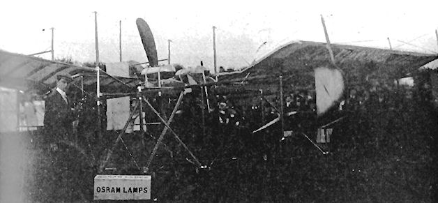
The Valkyrie with which Horatio Barber flew the first aerial cargo, a consignment of Osram lamps for Page and Miles Ltd., of Brighton, on 4th July, 1911, from Shoreham to Hove.
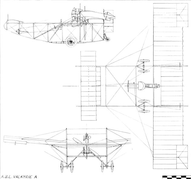
A.S.L. Valkyrie A
Aeronautical Syndicate Ltd. Viking 1
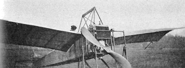
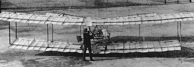
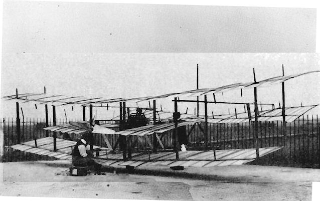
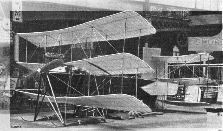
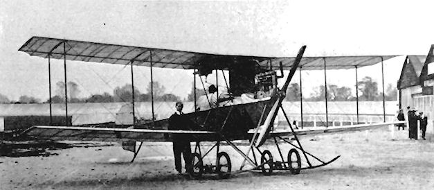
The Viking 1 was designed by Horatio Barber and built by his Aeronautical Syndicate Ltd. at Hendon at the beginning of 1912. The machine was another attempt at producing an aeroplane with two propellers driven from a single fuselage-mounted engine by chains. Power was provided by a 50 h.p. Gnome which was fitted in the nose and which was connected to a pair of large-diameter 8 ft. 6 ins. propellers placed half-way between the wings and about 14 ft. apart. This arrangement necessitated the use of long chains of light weight to transmit the power.
The fuselage was a simple structure of rectangular section with a curved upper decking over the nose portion from the engine back to the cockpit with its side-by-side seating for the two passengers. Parallel-chord wings of three-bay type were used and the fuselage was suspended between them. Several other unusual features were evident in the design, and among them were the 8 ft. 6 ins. x 2 ft. ailerons, which were mounted mid-way between the planes across the three outermost rear interplane struts. The fin was fixed below the rear of the fuselage, and above it was the rudder of almost equal area. Behind the vertical tail surfaces came the one-piece elevator. When on the ground, the Viking was maintained in a near-horizontal position by the long tailskid fitted below the fin. Protection for the nose was provided by a similarly-sprung skid mounted on struts below the engine bay, while smaller skids at the wing-tips served to prevent damage to the propellers in a heavy landing.
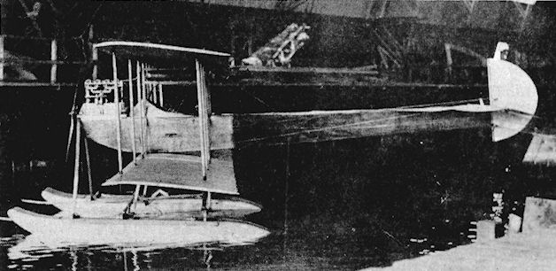
The Viking, known to its designers and others as "Mrs. Grundy", flew well although the twin-propeller arrangement was not a very practical one. It was the last of Barber's designs as, in April, 1912, he decided to retire from active designing and building owing to the cost of keeping up with the rate of progress being made in aviation. He became an aeronautical consultant at 59 Pall Mall, London, S.W.I, and the Aeronautical Syndicate was wound-up, the Viking being sold to Hamilton Ross, the Manager of the Chanter Flying School at Shoreham. On arrival there, it was fitted with floats and the two propellers were replaced with one mounted direct on to the engine in the nose.
SPECIFICATION
Description: Two-seat tractor biplane. Wooden structure, fabric covered.
Manufacturers: Aeronautical Syndicate Ltd., Hendon, London, N.W.9.
Power Plant: 50 h.p. Gnome.
Dimensions: Span, 31 ft. Length, 26 ft. Height, 10 ft. Wing area, 310 sq. ft.
Weights: Empty, 800 lb.
Performance: Cruising speed, 55 m.p.h. Endurance, 6 hrs.
The Viking 1 was designed by Horatio Barber and built by his Aeronautical Syndicate Ltd. at Hendon at the beginning of 1912. The machine was another attempt at producing an aeroplane with two propellers driven from a single fuselage-mounted engine by chains. Power was provided by a 50 h.p. Gnome which was fitted in the nose and which was connected to a pair of large-diameter 8 ft. 6 ins. propellers placed half-way between the wings and about 14 ft. apart. This arrangement necessitated the use of long chains of light weight to transmit the power.
The fuselage was a simple structure of rectangular section with a curved upper decking over the nose portion from the engine back to the cockpit with its side-by-side seating for the two passengers. Parallel-chord wings of three-bay type were used and the fuselage was suspended between them. Several other unusual features were evident in the design, and among them were the 8 ft. 6 ins. x 2 ft. ailerons, which were mounted mid-way between the planes across the three outermost rear interplane struts. The fin was fixed below the rear of the fuselage, and above it was the rudder of almost equal area. Behind the vertical tail surfaces came the one-piece elevator. When on the ground, the Viking was maintained in a near-horizontal position by the long tailskid fitted below the fin. Protection for the nose was provided by a similarly-sprung skid mounted on struts below the engine bay, while smaller skids at the wing-tips served to prevent damage to the propellers in a heavy landing.
The Viking, known to its designers and others as "Mrs. Grundy", flew well although the twin-propeller arrangement was not a very practical one. It was the last of Barber's designs as, in April, 1912, he decided to retire from active designing and building owing to the cost of keeping up with the rate of progress being made in aviation. He became an aeronautical consultant at 59 Pall Mall, London, S.W.I, and the Aeronautical Syndicate was wound-up, the Viking being sold to Hamilton Ross, the Manager of the Chanter Flying School at Shoreham. On arrival there, it was fitted with floats and the two propellers were replaced with one mounted direct on to the engine in the nose.
SPECIFICATION
Description: Two-seat tractor biplane. Wooden structure, fabric covered.
Manufacturers: Aeronautical Syndicate Ltd., Hendon, London, N.W.9.
Power Plant: 50 h.p. Gnome.
Dimensions: Span, 31 ft. Length, 26 ft. Height, 10 ft. Wing area, 310 sq. ft.
Weights: Empty, 800 lb.
Performance: Cruising speed, 55 m.p.h. Endurance, 6 hrs.
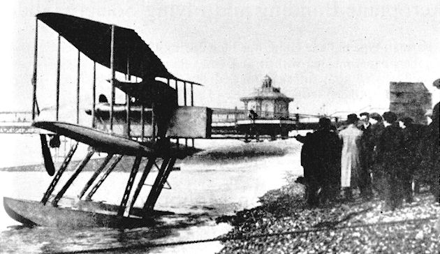
Viking 1 modified with floats and single propeller.
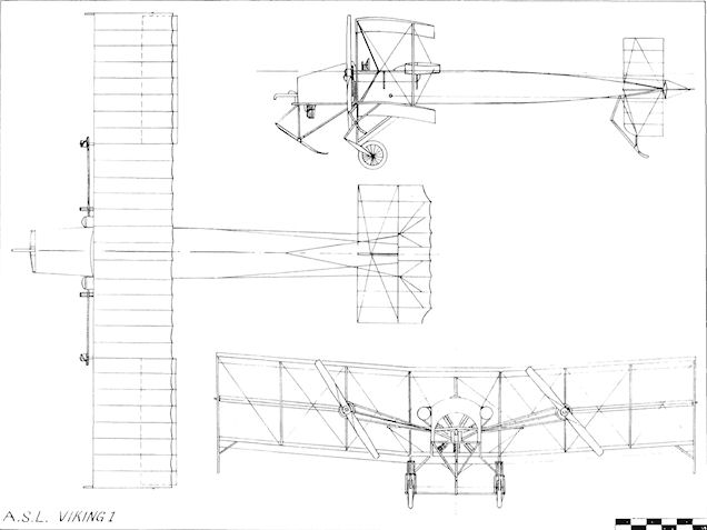
A.S.L. Viking 1
Astley Monoplane
H.J.D. Astley's monoplane was a single-seat tractor built at Willesden in 1909. lt was powered by a four-cylinder 40 h.p. N.E.C. engine and carried small triangular ailerons at each wing-tip. Span, 24 ft. Length, 24 ft.
H.J.D. Astley's monoplane was a single-seat tractor built at Willesden in 1909. lt was powered by a four-cylinder 40 h.p. N.E.C. engine and carried small triangular ailerons at each wing-tip. Span, 24 ft. Length, 24 ft.
Avro Biplane 1
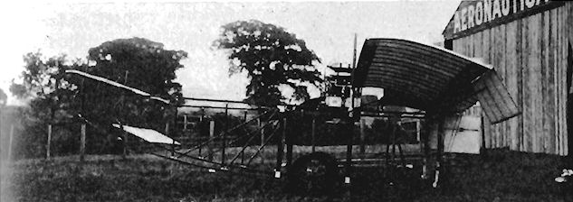
A. V. Roe's first full-size aeroplane was a canard pusher biplane which was built with the ?75 prize money won by his 8 ft. span model at the Alexandra Palace Daily Mail model contest held during March, 1907. A scaled-up version of the model, it was constructed during the summer of 1907 at Putney to compete for the ?2,500 prize offered for the first flight around the Brooklands track before the end of the year. The machine was fitted with a 9 h.p. J.A.P. engine and originally had a four-bladed propeller which was not used and which was replaced by a two-bladed shovel type built up with sheet aluminium. No rudder was fitted, but the front elevator could be inclined as a whole or warped differentially by the control wheel. Six wheels were fitted first of all for the undercarriage, together with skids, but the number was reduced later to four.
The aeroplane was underpowered, and by May, 1908, a 24 h.p. Antoinette engine with a two-bladed propeller had been substituted for the original J.A.P., and small horizontal surfaces were installed at mid-gap in the inner bays of the two-bay single-surfaced wings. Tests were made at Brooklands in June, 1908, by towing behind a car, and the machine also made short hops under its own power along the finishing straight. Span, 30 ft. Length, 23 ft. Loaded weight, 600 lb.

A. V. Roe and his first aeroplane in his hed at Brooklands in 1908.
Avro Biplane I with 9 h.p. J.A.P. at Brooklands.
A. V. Roe working on the Roe I biplane after it had been fitted with a 24 h.p. eight cylinder Antoinette engine. AV Roe may have flown on this, his first machine, after fitting an Antoinette engine in 1908, but not officially.
Avro Triplanes 1, 2, 3 and 4
Lack of success with his 1908 biplane forced Alliott Verdon-Roe to consider a different form of machine to fulfil his ambition to fly successfully. At a time when the pusher lay-out was followed with few exceptions in Britain he pioneered the tractor type and started to construct a triplane. He had the assistance of a partner in the work of building the machine, which had a fuselage of rectangular section, together with triplane wings and a triplane tail. It was to have had a 35 h.p. air-cooled engine with a geared-down propeller, but the partnership was dissolved before the aeroplane could be completed. The fuselage, wings and undercarriage formed the subject of the first aeroplane auction when they were sold by Friswell for ?5 10s.
At the beginning of 1909 Roe went into partnership with his brother Humphrey. Forced finally to leave his shed at Brooklands, he transferred to a railway-arch workshop at Lea Marshes, Hackney, and began experimenting with his new No.1 Triplane, which was named The Bullseye after the men's trouser braces made by Humphrey's firm Everard and Co., whose money financed the project. The tail unit was of the lifting type, and the machine's longitudinal control was through the variable incidence of the mainplanes; this was operated in conjunction with the wing-warping by a system of levers and rods to the wings, connected at about 5 ft. from the centre line of the aircraft. The wings themselves folded at the same point for ease of transport.
A triangular section was employed for the wire-braced fuselage, and the mainplanes and tail unit were covered with yellow-cotton oiled paper. Fixed vertical surfaces were at first used between the tailplanes, but they were discarded later and a tailskid was substituted for the original wheel. Bicycle wheels were fitted to the sprung main forks, and the entire triplane was made as light as possible so as to achieve flight on the 9 h.p. of its J.A.P. engine, which replaced the 6 h.p. J.A.P. installed originally in the machine. Roe was assisted during his tests by R. L. Howard Flanders and E. V. B. Fisher, and after short hops during May and on 5th June he finally succeeded in flying for about 100 ft. the following month on 13th July, 1909, making the first powered flight in Great Britain in an all-British aeroplane. The longest distance achieved was 900 ft. ten days later on 23rd July, and short hops were made at the October, 1909, meeting at Blackpool after a 24 h.p. Antoinette engine was fitted to the machine. Later in the year Roe transferred his activities to a better ground at Wembley, making several good flights before crashing while turning on 24th December. The machine survived and has been on show for many years in the National Aeronautical Collection at South Kensington, London, S.W.7.
After acquiring an eight-cylinder 35 h.p. J.A.P. engine Roe built a new, larger Triplane No. 2 to accommodate it with a span of 32 ft., and showed the aircraft without its engine at the Travel Exhibition at Olympia in July, 909. The machine had managed a flight of some 600 ft. at Wembley when the Brooklands management changed their policy towards aviators and Roe returned there in February, 1910. Three more of the 20 ft. span triplanes were constructed, using J. A.P. engines of 9 h.p., 20 h.p. and 35 h.p. respectively. The 9 h.p. version was sold to the Rangie Cycle Co.
Yet another Avro triplane, the Mercury two-seater with wood-covered fuselage, was shown at the 1910 Olympia Aero Show. It was tested at Brooklands in March, 1910, and used a 35 h.p. Green engine. The incidence of the 26 ft. span wings was variable from 4° to 11°, the price quoted being ?600.
<...>
SPECIFICATION
AVRO 1
Description: Single-seat tractor triplane. Wooden structure, paper covered.
Manufacturers: A. V. Roe & Co., Brownsfield Mills, Manchester.
Power Plant: 6 h.p. J.A.P., 9 h.p. J.A.P., 24 h.p. Antoinette.
Dimensions: Span, 20 ft. Length, 23 ft. Wing area, 320 sq. ft.
Weights: Empty, 200 lb. Loaded, 400 lb.
AVRO 2
Description: Single-seat tractor triplane. Wooden structure, fabric covered.
Manufacturers: A. V. Roe & Co., Brownsfield Mills, Manchester.
Power Plant: 35 h.p. J.A.P.
Dimensions: Span, 32 ft. Length, 32 ft. Wing area, 650 sq. ft.
Weights: Empty, 650 lb. Loaded, 800 lb.
AVRO 2
Description: Single-seat tractor triplane. Wooden structure, fabric covered.
Manufacturers: A. V. Roe & Co., Brownsfield Mills, Manchester.
Power Plant: 9 h.p. J.A.P., 20 h.p. J.A.P., 35 h.p. J.A.P.
Dimensions: Span, 20 ft. Length, 23 ft. Wing area, 320 sq. ft.
Weights: Empty, 500 lb.
AVRO MERCURY
Description: Two-seat tractor triplane. Wooden structure, fabric covered.
Manufacturers: A. V. Roe & Co., Brownsfield Mills, Manchester.
Power Plant: 35 h.p. Green.
Dimensions: Span, 26 ft. Length, 24 ft. 6 ins. Wing area, 246 sq. ft.
Weights: Empty, 450 lb. Loaded, 550 lb.
Performance: Maximum speed, 40 m.p.h.
Avro No. I Triplane with 9 h.p. J.A.P.
A.V.Roe flying his No.1 Triplane at Lea Marshes in 1909.

Avro Bullseye Triplane at 1909 Blackpool Meeting.
Avro No. I Triplane with 24 h.p. Antoinette at Wembley.
OLYMPIA, 1910. - The first Roe II triplane "Mercury" at the Olympia Aero Show, London, in March 1910 in its initial form with warping wings. The main planes and the tail planes are pivoted so that the pilot can alter their angles of incidence in flight.
Avro Triplanes 1, 2, 3 and 4
<...>
The next design by A. V. Roe and Co., the firm having been formed early in 1910, was the No. 3 Triplane, six of which were constructed in the Everard Brownsfield Mills. The new version was capable of carrying two passengers in tandem on 35 h.p. from either a J.A.P. or a Green engine and was more substantially built than the previous machines. Ailerons on the upper wings took the place of warping, the wings were fixed and elevators took over longitudinal control. The two upper wings had an equal span of 31 ft., while the lowest were shorter at 20 ft. On 26th July, 1910, Roe gained his Royal Aero Club Aviator's Certificate No. 18 on one of his triplanes at Brooklands. The first machine was sold to Capt. Walter Windham and the second and third, after testing at Brooklands, were loaded at Weybridge for transport by rail to the three weeks flying meeting at Blackpool due to begin on 28th July, 1910. The Green-engined machine crashed several times during its testing at Brooklands, but Roe thought that the J.A.P.-powered version was the best triplane that he built. However, both were destroyed on the train by fire before reaching Blackpool. Another, equipped with a Green engine, was assembled hurriedly in four days at Manchester from spare parts, and differed in having its ailerons on the middle wings. Roe took the replacement into the air at Blackpool and managed to collect ?75 in prize money.
The fourth production machine had been ordered by the Harvard Aeronautical Society and was due to be delivered at the Society's Flying Meeting being held from 3rd to 13th September, 1910, at Boston. Mass., U.S.A. Soon after the meeting opened Roe crashed his own triplane - the fifth one of the batch - and on his return from hospital took off in the Harvard aircraft. This crashed also, the Society receiving finally a triplane assembled from the remains of the two crashes. The engine was run up and the machine handed over before it was flown. The sixth and final No. 3 Triplane was built for Cecil Grace.
<...>
SPECIFICATION
AVRO 3
Description: Two-seat tractor triplane. Wooden structure, fabric covered.
Manufacturers: A. V. Roe & Co., Brownsfield Mills, Manchester.
Power Plant: 35 h.p. Green, 35 h.p. J.A.P.
Dimensions: Span, 31 ft. Length, 23 ft. Wing area, 362 sq. ft.
Weights: Loaded, 750 lb.
<...>
The next design by A. V. Roe and Co., the firm having been formed early in 1910, was the No. 3 Triplane, six of which were constructed in the Everard Brownsfield Mills. The new version was capable of carrying two passengers in tandem on 35 h.p. from either a J.A.P. or a Green engine and was more substantially built than the previous machines. Ailerons on the upper wings took the place of warping, the wings were fixed and elevators took over longitudinal control. The two upper wings had an equal span of 31 ft., while the lowest were shorter at 20 ft. On 26th July, 1910, Roe gained his Royal Aero Club Aviator's Certificate No. 18 on one of his triplanes at Brooklands. The first machine was sold to Capt. Walter Windham and the second and third, after testing at Brooklands, were loaded at Weybridge for transport by rail to the three weeks flying meeting at Blackpool due to begin on 28th July, 1910. The Green-engined machine crashed several times during its testing at Brooklands, but Roe thought that the J.A.P.-powered version was the best triplane that he built. However, both were destroyed on the train by fire before reaching Blackpool. Another, equipped with a Green engine, was assembled hurriedly in four days at Manchester from spare parts, and differed in having its ailerons on the middle wings. Roe took the replacement into the air at Blackpool and managed to collect ?75 in prize money.
The fourth production machine had been ordered by the Harvard Aeronautical Society and was due to be delivered at the Society's Flying Meeting being held from 3rd to 13th September, 1910, at Boston. Mass., U.S.A. Soon after the meeting opened Roe crashed his own triplane - the fifth one of the batch - and on his return from hospital took off in the Harvard aircraft. This crashed also, the Society receiving finally a triplane assembled from the remains of the two crashes. The engine was run up and the machine handed over before it was flown. The sixth and final No. 3 Triplane was built for Cecil Grace.
<...>
SPECIFICATION
AVRO 3
Description: Two-seat tractor triplane. Wooden structure, fabric covered.
Manufacturers: A. V. Roe & Co., Brownsfield Mills, Manchester.
Power Plant: 35 h.p. Green, 35 h.p. J.A.P.
Dimensions: Span, 31 ft. Length, 23 ft. Wing area, 362 sq. ft.
Weights: Loaded, 750 lb.
Avro No. 3 Triplane at 1910 Boston Harvard Meeting.
A. V. Roe carrying a passenger last week flying his No. 3 Triplane at the 1910 Blackpool Meeting.
Avro Triplanes 1, 2, 3 and 4
<...>
The last of the early Avro triplanes appeared also in 1910 and was the No. 4, a single-seater fitted with a 35 h.p. Green engine driving an 8 ft. 6 ins. propeller. It was used for instruction at Brooklands. Wings with an aspect ratio of over nine were provided, and a return was made to warping on the uppermost planes. The wings were fixed and the non-lifting monoplane tail carried a normal pair of hinged elevators. The triangular-section wooden fuselage was retained, the forepart being aluminium-covered.
SPECIFICATION
AVRO 4
Description: Single-seat tractor triplane. Wooden structure, fabric covered.
Manufacturers: A. V. Roe & Co., Brownsfield Mills, Manchester.
Power Plant: 35 h.p. Green.
Dimensions: Span, 42 ft. Length, 30 ft. Wing area, 294 sq. ft.
Weights: Empty, 650 lb.

Roe IV Triplane. The last of AV Roe's triplanes first flew in September 1910.
Avro D
Early in 1911 the Avro D two-seat biplane appeared, as a result of Roe's reluctant conclusion that the triplane was not to offer further very successful development in the face of the undeniable performances being put up by biplanes.
The new machine was a direct adaptation in form of the No. 4 Triplane, and incorporated once again the weight-saving triangular-section fuselage. Two-bay, unstaggered wings of equal span were fitted, with warping conferring lateral control. The engine was a 35 h.p. Green, and the Type D was quite a successful and consistent flyer, being flown at Brooklands by Lt. W. D. Beatty, C. Gordon Bell, F. Conway Jenkins, Lt. Wilfred Parke, R.N., and C. Howard Pixton. Pixton piloted a Type D in the Brooklands-to-Brighton cross-country race on 6th May, 1911, but lost his way and finished last. In November of the same year a Viale-engined version appeared at Brooklands and was tested by F. P. Raynham, who had joined the firm recently as a test pilot. On this machine also, Sidney V. Sippe performed his Royal Aero Club Certificate No. 172 tests on 9th January, 1912. The Viale engine installation was carried out by Maurice Ducrocq and by his apprentice Jack Alcock. Yet another Type D was powered by the 60 h.p. E.N.V. "F" and differed also in having strut-braced extensions to the upper wings which brought the span to 33 ft., that of the lower wings being 23 ft. Both sets of wings were made up of sections 5 ft. each in length, the idea being to ease replacement in the event of damage in an accident and also to facilitate packing for transport. A non-lifting tail was incorporated, with extensions forward along the fuselage decking, the whole machine possessing a cleaner appearance than that of the earlier examples. Flown by Ronald Kemp, this machine crashed at the start of the 1911 Circuit of Britain race. The streamlining process was taken a step further in another model of the D which was given a 35 h.p. Green, complete with aluminium cowling. In this machine the forward tailplane extensions were discarded, although it retained the extra panels on the upper wing-tips. Another alteration in the quest for better performance was the installation of smaller pairs of landing wheels of 14 ins. diameter in place of the heavier ones used previously.
An Avro D formed the subject of the first trials of a British seaplane when, in mid-1911, the prototype with a 35 h.p. Green engine was bought by Commander Oliver Schwann. R.N., and officers of H.M.S. Hermione, and fitted with a pair of floats of Schwann's design which were made by the Navy. The machine was taken to Cavendish Dock, Barrow-in-Furness, for testing in September, 1911. The trials were not particularly successful, but after several changes of floats a short flight was made eventually on 18th November, 1911, when the seaplane rose to 20 ft. and was damaged in landing after making the first British take-off from water. A new pair of floats made from duralumin by the Vickers Company proved to be better than those fitted earlier, and the machine made satisfactory flights at Barrow in April, 1912, piloted by S. Y. Sippe and by Commander Schwann.
SPECIFICATION
Description: Two-seat tractor biplane. Wooden structure, fabric covered.
Manufacturers: A. V. Roe & Co., Brownsfield Mills, Manchester.
Power Plant: 35 h.p. Green, 60 h.p. E.N.V. "F".
Dimensions: Span, 31 ft. Length, 31 ft. Wing area, 279 sq. ft.
Weights: Empty, 800 lb.
Performance: Maximum speed, 48-5 m.p.h.
Avro D at Brooklands with F. P. Raynham in the cockpit and S. V. Sippe alongside.
W. D. Beatty, with Conway Jenkins as passenger, in the Avro D during March, 1911.
Modified Avro D at Brooklands flown by Ronald Kemp in 1911 Circuit of Britain.

The first Avro D Hydro-biplane equipped with original floats at Barrow for seaplane trials.
Avro D Hydro-biplane at Cavendish Dock with replacement floats by Vickers.

Avro D
Burga Monoplane
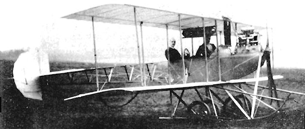
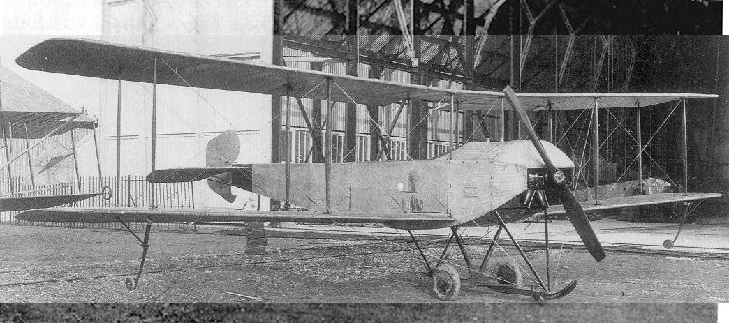
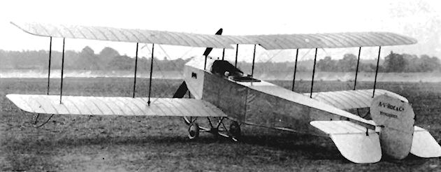
A Peruvian naval officer, Lt. R. Burga, designed this two-seat tractor monoplane, which was built during 1912 by A. V. Roe and Co. The machine incorporated several unusual features, including wings with variable camber and a unique form of lateral control, consisting of two additional rudders mounted one above and one below the fore-fuselage. The engine was a 50 h.p. Gnome, the sole aircraft built being tested at Shoreham in November, 1912.
A Peruvian naval officer, Lt. R. Burga, designed this two-seat tractor monoplane, which was built during 1912 by A. V. Roe and Co. The machine incorporated several unusual features, including wings with variable camber and a unique form of lateral control, consisting of two additional rudders mounted one above and one below the fore-fuselage. The engine was a 50 h.p. Gnome, the sole aircraft built being tested at Shoreham in November, 1912.
Avro E 500
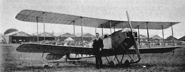
The development of the Avro biplane was carried a step further with the delivery of a single-seater in September, 1911, to S. R. Duigan, an Australian pilot staying in England. An Alvaston engine was fitted to the machine, which was flying at Huntingdon in the following December. The triangular-section fuselage of the earlier Avro products was replaced by one of rectangular section and which was fully covered. The new machine represented a great improvement over the D Biplane, and a slightly larger two-seater version with dual control appeared shortly afterwards at the beginning of 1912. This was fitted with a 60 h.p. E.N.V. "F" for power, and after testing at Brooklands was intended to be used by Lt. W. Parke, R.N., to compete for the Mortimer Singer Naval Prize.
The tandem cockpits were set several feet apart, the front one being just behind the leading-edge and the rear one at the trailing-edge. A pair of radiators were disposed one on each outer side of the front cockpit, and the comparatively heavy four-wheeled, twin-skid undercarriage of the D type was replaced by a simple form with a pair of wheels on an axle braced to the fuselage by a vee-strut, and incorporating a central skid supported similarly fore and aft.
<...>
SPECIFICATION
Description: Two-seat tractor biplane. Wooden structure, fabric covered.
Manufacturers: A. V. Roe & Co., Brownsfield Mills, Manchester.
Power Plant: 60 h.p. E.N.V. "F"
Dimensions: Span, 36 ft. Length, 30 ft. 6 ins. Wing area, 330 sq. ft.
Weights: Empty, 1,100 lb. Loaded, 1,650 lb.
Performance: Maximum speed, 61 m.p.h. Climb, 440 ft./min. Endurance, 2.5 hrs.
Price: ?950.

Avro E 500 prototype
Avro E 500
<...>
Three more 500s were built to a War Office order and were fitted with 50 h.p. Gnomes, the fuselage floors embodying celluloid panels for observation during cross-country flying. The first was delivered to Farnborough from Brooklands on 9th May, 1912, by Lt. Parke and was exhibited on the ground during an inspection of the Military Wing of the R.F.C. by H.M. King George V. Two of the three R.F.C. 500s were fitted with larger rudders than were considered to be necessary by both Roe and Parke, while the third retained its original tail.
Later in the year a fourth Gnome-engined 500 was bought by Portugal out of the Portuguese National Fund, and was handed over on 16th October, receiving the name Republica. The following day the machine experienced engine failure while being demonstrated by Copland Perry, and landed in the River Tagus. The R.F.C. were so satisfied with their acquisition that four more 500s were ordered in December, 1912, and another five in January, 1913, after the formation of the private limited company of A. V. Roe. The 7.5 aspect-ratio, unstaggered two-bay wings had their original warping control replaced on later versions by constant-chord, and also by inversely-tapered, ailerons.
An improved model was displayed at the 1913 Olympia Aero Show, with the Gnome fully enclosed. The Avro Flying School at Shoreham took the E.N.V.-engined prototype on to its strength, but, on 29th June, 1913, it crashed with fatal results to the solo pupil-pilot, Richard N. Wright. Other Gnome-powered 500s were supplied to L. Davis of Forest Hill and J. L, Hall, and Humphrey Verdon-Roe was taught to fly on one at Brooklands by F. P. Raynham at the end of 1913. In addition to being used by No. 3 Squadron, R.F.C., the 500 was employed for training at the C.F.S. and by the R.N.A.S., Chingford.
SPECIFICATION
Description: Two-seat tractor biplane. Wooden structure, fabric covered.
Manufacturers: A. V. Roe & Co., Brownsfield Mills, Manchester.
Power Plant: 50 h.p. Gnome, 40 h.p. Viale.
Dimensions: (Gnome) Span, 36 ft. Length, 29 ft. Wing area, 330 sq. ft.
Weights: (Gnome) Empty, 900 lb. Loaded, 1,360 lb.
Performance: Maximum speed, 61 m.p.h. Climb, 440 ft./min. Endurance, 2-5 hrs.
Price: ?950.
Avro Type E (500) with Gnome engine, wheels on outriggers at wingtips and alternative rudder. March 1913..
F. P. Raynham at Hendon with Avro 500 fitted with inversely-tapered ailerons.
Avro 500 with 50 h.p. Gnome.

Avro 500 fitted with twin skids and large wheels.
Avro F
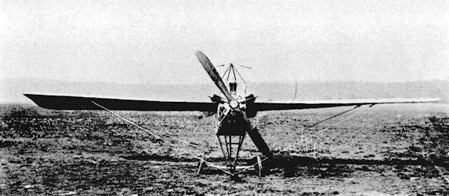
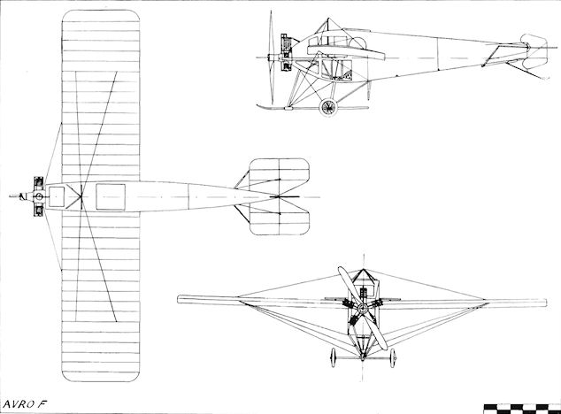
The Avro F was a typical example of A. V. Roe's foresight and inventiveness. Designed in 1911 and assembled at Brooklands in April, 1912, the first Avro monoplane constituted a great advance in design with its completely enclosed cabin for the crew, and was the first machine in the world to embody such an innovation.
The fuselage was of excellent streamline form for the period, reflecting in no uncertain manner its designer's appreciation of the value of reduction of head-resistance and drag. Other features were the mid-fuselage position for the wings and the liberal amount of celluloid window glazing which was used on the top, sides and underneath of the fore-body. Open circular ports were made to the rear of the side windows in case of misting-up, and access to the cabin was through a trap-door in the roof of the fuselage. The undercarriage consisted of a pair of wheels on a leaf-spring axle which was attached to the fuselage by two pairs of steel-tube vee struts, combined with a central skid.
Lateral control was applied by warping of the parallel-chord wings. The engine chosen for the Avro F was the five-cylinder 40 h.p. Viale, which was mounted uncowled and had previously been installed in an Avro 500.
After preliminary ground testing, Lt. Wilfred Parke took the machine into the air at Brooklands in May, 1912, becoming the first pilot to fly, and subsequently to demonstrate, a totally enclosed cabin aeroplane.
SPECIFICATION
Description: Two-seat tractor monoplane. Wooden structure, fabric covered.
Manufacturers: A. V. Roe & Co., Brownsfield Mills, Manchester.
Power Plant: 40 h.p. Viale.
Dimensions: Span, 29 ft. Length, 23 ft. Wing area, 160 sq. ft.
Weights: Empty, 550 lbs. Loaded, 800 lb.
Performance: Maximum speed, 65 m.p.h.
Wing-warping illustrated by the Avro F.
Avro G
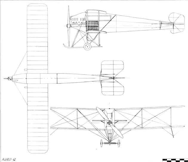
The 1912 Military Trials on Salisbury Plain brought forth diverse designs in two-seat aeroplanes for Army use. The Avro G Biplane was unique among them as the only one with an enclosed cabin. Two examples were built: No. 6 with a four-cylinder 60 h.p. Green engine, and No. 7, which was to have had an eight-cylinder 60 h.p. A.B.C. fitted. Lt. Wilfred Parke, R.N., was selected to fly No. 6 in the Trials, and R. L, Charteris, of the All-British Engine Company, was the pilot chosen for No. 7. When the time came the A.B.C. engine of Charteris's machine was not ready, and Parke's Green-engined aircraft was the only one of the pair of Avros to take the field. Its Trials No. 6 was replaced by its companion's No. 7.
The Avro G featured a slender 2 ft. 3 ins. wide fuselage which was deep enough at the cabin section to support both upper and lower wings without needing centre-section struts. The wings themselves were of unstaggered two-bay type with 18 ins. warping movement at the tips for lateral control. The Green-engined G was fitted with radiators on each side of the cabin, the pair of which comprised 600 ft. of 3/16 in. tubing, and the engine itself was fully cowled. The lower part of the rudder was shod with iron and was used as a tailskid, an idea which imparted undesirable loads to the hinges of the control surface although a vertical spring movement was incorporated.
In the Trials the machine won the quick assembly test in 14.5 minutes and came first also in that for fuel consumption. Simple, speedy assembly by means of unit construction was incorporated in Avro aircraft from the beginning. On 25th August, after completing his 3 hrs. qualifying flight, Parke found himself in a spin and managed to recover when only 50 ft. from the ground. He was the second British pilot lucky enough to extricate himself from a spin, about which little was then known, being preceded by F. P. Raynham on an older type of Avro biplane. Parke was unfortunate in crashing the machine while landing downwind during one of the tests. Despite rebuilding during one week, the G Biplane was without sufficient power to prove a success in the Trials. During the competition H. V. Roe became the first to use a typewriter in the air, typing on a Monarch machine while Parke flew him in the G from Salisbury Plain to Upavon.
The Green-engined machine was afterwards put to good use at the Avro School at Shoreham from October onwards. Raynham used it for an attempt on the British Michelin Cup No. 1 and stayed aloft for 3 hrs. 50 mins., but this time was bettered during a second attempt on 24th October, 1912, when the G Biplane set up a new British endurance record of 7 hrs. 31.5 mins.
SPECIFICATION
Description: Two-seat tractor biplane. Wooden structure, fabric covered.
Manufacturers: A. V. Roe & Co., Brownsfield Mills, Manchester.
Power Plant: 60 h.p. Green, 60 h.p. A.B.C.
Dimensions: Span, 35 ft. 3 ins. Length, 28 ft. 6 ins. Wing area, 310 sq. ft.
Weights: Empty, 1,191 lb. Loaded, 1,700 lb.
Maximum speed: 62 m.p.h.
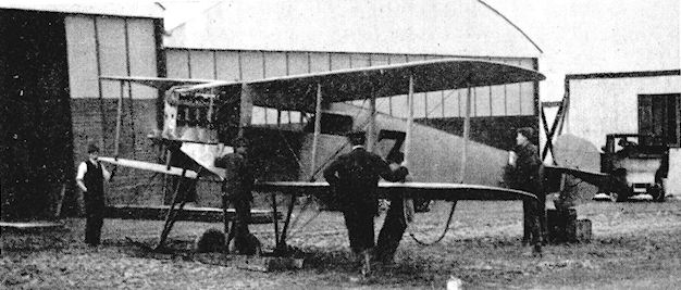
Avro G being tuned up following rebuilding during the Military Trials.
Avro Hydro-biplane
The Avro company delivered one two-seat tractor biplane, built to an Admiralty order, to Eastchurch during December, 1912, for testing by H. Stanley-Adams. The machine was fitted with a single large central float which had been designed by Oscar T. Gnosspelius; wheels were attached to it to form an amphibian. The engine was the 100 h.p. Gnome. Span, 47 ft. Length, 33 ft. Wing area, 478 sq. ft. Weight empty, 1,740 lb. Weight loaded, 2,700 lb. Maximum speed, 55 m.p.h. Duration, 6 hrs.
The Avro company delivered one two-seat tractor biplane, built to an Admiralty order, to Eastchurch during December, 1912, for testing by H. Stanley-Adams. The machine was fitted with a single large central float which had been designed by Oscar T. Gnosspelius; wheels were attached to it to form an amphibian. The engine was the 100 h.p. Gnome. Span, 47 ft. Length, 33 ft. Wing area, 478 sq. ft. Weight empty, 1,740 lb. Weight loaded, 2,700 lb. Maximum speed, 55 m.p.h. Duration, 6 hrs.
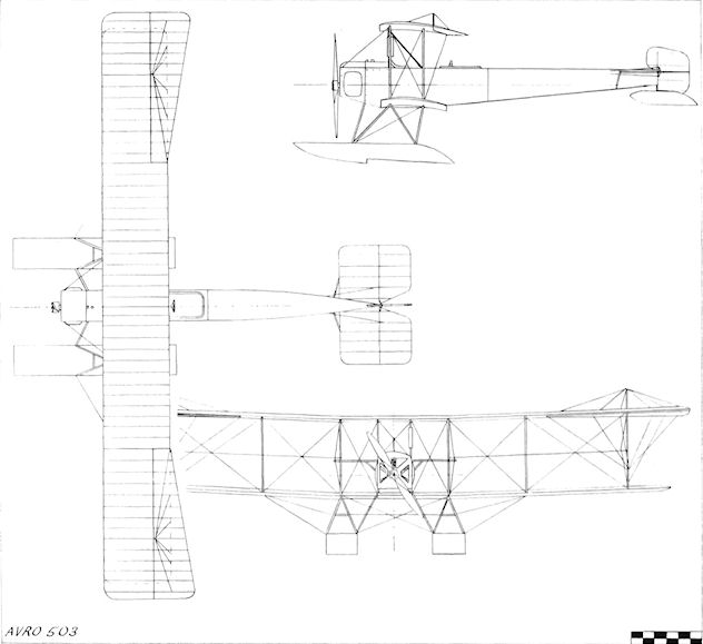
Avro H 503
In May, 1913, the prototype of the first Avro production seaplane appeared at Shoreham for testing by Jack Alcock and F. P. Raynham. The new machine was based on the successful 500, but was fitted with greater power for water operations in the form of the 100 h.p. Gnome. Wings of 50 ft. span and 567 sq. ft. area were fitted to provide sufficient lift to overcome the drag of the water when taking-off; the stubs of the lower wings were built as an integral part of the fuselage for a distance of 9 ft. out, the outer panels being readily detachable. Inversely-tapered ailerons were hinged to the upper wings. The two main floats were of Avro design with a single step each and were 14 ft. long and 2 ft. 6 ins. wide, being set with a 6 ft. 6 ins. gap between them. The unstepped tail float was mounted on the underside of the rudder.
The 503 was very successful in its trials on the South Coast, taking off in 180 ft. in a calm. Raynham was accompanied by an anonymous German officer, Capt "X", during the test flights, at the end of which the prototype was bought by Germany. The machine was dismantled in June, 1913, and sent to its new owners. Two months later, on 6th September, Leutnant Langfeld flew the 503 from the German coast to Heligoland. One machine was supplied to a British private owner and a few went to the R.N.A.S. One of these seaplanes was converted to a landplane for training at Eastchurch Naval Air Station, flying there as No. 16, and was given extra strut bracing to the upper wing-tip extensions.
SPECIFICATION
Description: Two-seat tractor hydro-biplane. Wooden structure, fabric covered.
Manufacturers: A. V. Roe & Co. Ltd., Brownsfield Mills, Manchester.
Power Plant: 100 h.p. Gnome.
Dimensions: Span, 50 ft. Length, 33 ft. 6 ins. Height, 12 ft. 6 ins. Wing area, 567 sq. ft.
Weights: Loaded 2,200 lb.
Performance: Cruising speed, 48 m.p.h.
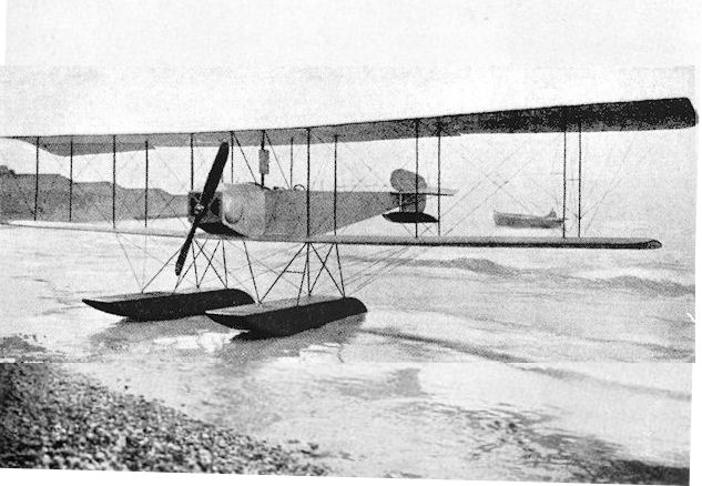
Avro Type 503 seaplane at Shoreham in 1913 (at Brighton after acceptance tests in June, 1913 ???).
Powered by a 100hp Gnome, the Avro Type H, or 503, derived from the Avro 501 floatplane and made its first flight on 28 May 1913. Ironically this particular machine was bought by the German Navy and is seen undergoing their acceptance trials at Worthing, Sussex in June 1913. An additional three examples were built, all for the British Admiralty. Top level speed of this two-seater floatplane was 64mph at sea level. Incidentally, many of the Type H's features were to find their way into the later Gotha WD-1.
Powered by a 100hp Gnome, the Avro Type H, or 503, derived from the Avro 501 floatplane and made its first flight on 28 May 1913. Ironically this particular machine was bought by the German Navy and is seen undergoing their acceptance trials at Worthing, Sussex in June 1913. An additional three examples were built, all for the British Admiralty. Top level speed of this two-seater floatplane was 64mph at sea level. Incidentally, many of the Type H's features were to find their way into the later Gotha WD-1.
Avro 503
Avro 504
When A. V. Roe designed the 504, there was no idea in his mind that he was embarking on a project which was to result in one of the most outstandingly successful and significant British aircraft ever built. In fact, it is recorded that he considered that the firm would be fortunate if half-a-dozen were ordered. Nevertheless, the machine proved itself to be a fine design from the start.
Construction commenced in April, 1913, and when the prototype 504 emerged for testing at Brooklands in the following July it was seen to be a handsome, well-proportioned and sturdier development of the earlier 500. Wings of the same 36 ft. equal span were used, but stagger was introduced for the first time on an Avro biplane. The two-bay formula was retained, but a very unusual feature of the prototype was the use of strut-connected, inversely-tapered, warping ailerons on the four wing-tips. The outboard ends were warped by cables, while the innermost ends were fixed to the wings. It was not long before this rather queer arrangement was altered to one of normal fully-hinged, constant-chord ailerons. Compared with the 500, the 504 received additional refinement in the form of a shallow, curved top-decking to the fuselage, and also extra power from its 80 h.p. Gnome. The width of the fuselage nose was not quite sufficient to accommodate the diameter of the Gnome, and necessitated the fitting of bulges in the aluminium square-section cowling.
In the undercarriage the previous Avro practice of using a leaf-spring axle was discarded, its place being taken by a rigid axle carried on legs sprung by means of vertical rubber cord shock-absorbers. The central skid, however, was retained and mounted on fore-and-aft vee-struts. A change was made also in the 504 to an independent, sprung tailskid, relieving the rudder of this jarring duty. The wing-tips of the prototype were protected in landing by short vertical, strut-braced skids. No fin was fitted and a new rudder of completely curved outline was mounted at the tail. When the revised ailerons were installed the fuselage lines were improved at the nose by a circular cowling with attendant side fairings.
On 20th September, 1913, the 504 was flown into fourth place in the second Aerial Derby at 66-5 m.p.h. by F. P. Raynham, and in the following month, on 2nd October, Raynham, with H. V. Roe as his passenger, piloted the machine against Blackburn's monoplane flown by Harold Blackburn with its owner, Dr. M. G. Christie, as passenger in the 100-miles cross-country "War of the Roses" race for the Yorkshire Evening News Challenge Cup. The course was from Leeds over York, Doncaster, Sheffield and Barnsley, the race being abandoned by the 504 at Barnsley owing to bad visibility.
Official tests were to be made of the machine at Farnborough, and it was flown there by Raynham on 24th November, passing its trials very successfully. At the beginning of 1914, a 504 with an Armstrong Whitworth-built A.B.C. eight-cylinder engine was tested at Brooklands. On 4th February, 1914, Raynham flew from Brooklands to Hendon and took the 504 to an unofficially-observed British height record of 15,000 ft. A few days later, on 10th February, with MacGeah Hurst as passenger, he reached 14,420 ft. to set up a new official record. At the March, 1914, Olympia Aero Show the company exhibited a new version on floats. In the spring of 1914 the prototype 504 was bought by the aviation-conscious Daily Mail to be flown on tour on wheels, and then on floats from one coastal resort to another, in a further effort to promote British air-mindedness. In addition to its new landing-gear, the machine was given a replacement engine with the installation of an 80 h.p. Monosoupape Gnome. Although nominally of the same power, the new engine was thought to give more than the original 80 h.p. Gnome, which was considered to produce just over 60 h.p. in reality. F. P. Raynham and George Lusted were engaged to pilot the 504 around the country, but Raynham was forced to crash-land it owing to engine failure during its delivery flight when it was commandeered on die outbreak of war.
So ended the career of the original 504, but the sixteen months of its existence served its creators well, for it brought in the orders which truly set the Avro Company on its feet. The first of these came at the beginning of the summer of 1914, when twelve 504s were placed on order by the War Office together with one for the Admiralty. An alteration in the upper longerons was made in the production 504s so that they sloped down at the rear instead of being straight as in the original machine. A further difference between those built for the R.F.C. and those for the R.N.A.S. was that the naval aircraft were given wing spars of slightly greater cross section. Only a few of the 504s on order had been delivered by the time that war came on 4th August, 1914, and the type subsequently made its great name as a trainer.
SPECIFICATION
Description: Two-seat tractor biplane. Wooden structure, fabric covered.
Manufacturers: A. V. Roe & Co. Ltd., Clifton Street, Miles Platting, Manchester.
Power Plant: 80 h.p. Gnome, 80 h.p. Monosoupape Gnome.
Dimensions: Span, 36 ft. Length, 29 ft. 5 ins. Height, 10 ft. 5 ins. Wing area, 330 sq. ft.
Weights: Empty, 924 lb. Loaded, 1,550 lb.
Performance: Maximum speed, 80 9 m.p.h. Cruising speed, 70 m.p.h. Landing speed, 43 m.p.h. Climb, 1.75 mins. to 1,000 ft., 7 mins. to 3,500 ft. Endurance, 4.5 hrs.
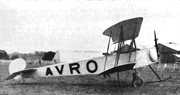
Avro 504 prototype which F. P. Raynham flew into fourth place at 66,5 mph during second Aerial Derby on 20th September, 1913, shown at Hendon with inversely-tapered, warping ailerons.

Avro 504 prototype flown in modified form in 1914 Daily Mail tour.

Avro 504 prototype
Avro 508
The Avro 508 Military Biplane was a two-seat pusher fighter which was exhibited at the 1914 Olympia Aero Show. The machine was fitted with the Avro Safety-belt and was powered with the 80 h.p. Gnome. Span, 44 ft. Length, 26 ft. 9 ins. Wing area, 468 sq. ft. Weight empty, 1,000 lb. Weight loaded, 1,800 lb. Maximum speed, 65 m.p.h. Landing speed, 35 m.p.h. Endurance, 4.5 hrs.
The Avro 508 Military Biplane was a two-seat pusher fighter which was exhibited at the 1914 Olympia Aero Show. The machine was fitted with the Avro Safety-belt and was powered with the 80 h.p. Gnome. Span, 44 ft. Length, 26 ft. 9 ins. Wing area, 468 sq. ft. Weight empty, 1,000 lb. Weight loaded, 1,800 lb. Maximum speed, 65 m.p.h. Landing speed, 35 m.p.h. Endurance, 4.5 hrs.
Avro 510
Entry number 7 in the 1914 Daily Mail Circuit of Britain race for seaplanes was a comparatively large and rather clumsy-looking Avro biplane. F. P. Raynham was chosen to pilot the machine in the contest.
A Sunbeam engine of 150 h.p. was fitted, being fully enclosed in its cowling and given a large integral exhaust stack. The 63 ft. span upper wings possessed long tip extensions overhanging the 38 ft. lower wings, the cellules themselves being set at a fairly pronounced dihedral angle. The main floats were secured to the fuselage by a particularly strong strut system made to withstand the rigours of rough-water operation, with shock-absorbing by rubber cord. The prototype 510 did not embody a fin, having a balanced rudder only. A fin was fitted, however, to the production machines for the R.N.A.S., which used the 510 for patrol work from coastal air stations in 1914.
SPECIFICATION
Description: Two-seat tractor biplane seaplane. Wooden structure, fabric covered.
Manufacturers: A. V. Roe & Co. Ltd., Clifton Street, Miles Platting, Manchester.
Power Plant: 150 h.p. Sunbeam.
Dimensions: Span, 63 ft. Length, 37 ft. 6 ins. Wing area, 564 sq. ft.
Weights: Empty, 2,080 lbs. Loaded, 2,800 lb.
Performance: Maximum speed, 70 m.p.h. Climb, 15 mins. to 3,000 ft. Endurance, 4.5 hrs.
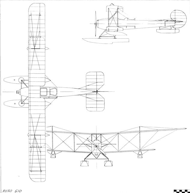
Avro 510
Avro 511 Arrowscout
During the year before the start of the 1914-18 conflict the idea of a specialized type for use as a fast scout in war had taken firm root in the minds of several designers, among them A. V. Roe, who had by this time given up most of his active flying and was concentrating upon design. His thoughts upon the subject appeared in the form of the Arrowscout, the new machine being shown on the Avro stand at the 1914 Olympia Aero Show, where it was seen to embody a number of original and advanced ideas.
A single-bay biplane layout was adopted, considerable sweep-back being used on the wings, the lower surfaces of which were flat. Slight dihedral was incorporated, and the upper and lower wings were connected by single, close-set pairs of light-weight interplane struts which were faired between with fabric to form "I" struts. "N" centre-section struts formed the rest of the wing-supporting structure. Another unusual feature was the lifting of air-brakes at the lower rear wing roots, consisting of rectangular trailing-edge surfaces which were hinged at their centre lines to stand vertically across the airflow, the Arrowscout thus qualifying as one of the earliest aeroplanes to be fitted with them, lateral control was provided by cable-connected ailerons on all four wing-tips. The rest of the airframe was strongly reminiscent of the 504 on a reduced scale. Power was provided by an 80 h.p. Gnome mounted within a cowling which proved to be too closely fitted for adequate cooling. Yet another feature of the 511 was the Avro system of unit construction which conferred quick dismantling and re-erection within a few minutes. The pilot also had the benefit of the Avro Safety-belt.
After two flights the Arrowscout made its first flying appearance in public at Hendon on 23rd May, 1914, with Freddy Raynham in the cockpit. After its first flights, modifications were made to the machine in preparation for the 1914 Third Aerial Derby. Straight, instead of swept-back, wings were fitted and the sturdy original undercarriage was replaced by a light-weight streamlined arrangement without springing. This was, not surprisingly, unequal to the task and collapsed when Raynham was testing the Arrowscout at Brooklands the day before the race, inevitably resulting in its withdrawal from the contest.
SPECIFICATION
Description: Single-seat tractor biplane. Wooden structure, fabric covered.
Manufacturers: A. V. Roe & Co. Ltd., Clifton Street, Miles Platting, Manchester.
Power Plant: 80 h.p. Gnome.
Dimensions: Span, 26 ft. Length, 22 ft. 9 ins. Wing area, 236 sq. ft.
Weights: Empty, 675 lb. Loaded, 1,165 lb.
Performance: Maximum speed, 100 m.p.h. Landing speed, 40 m.p.h.

F. P. Raynham taking-off at Hendon in the Avro Arrowscout on 23rd May, 1914.
Baden-Powell Quadruplane
The Baden-Powell Quadruplane was designed by Major B. F. S. Baden-Powell and built during 1909, appearing at the Dagenham flying-ground in the same year. It was basically a biplane, with the addition of large extra wings fore and aft. The engine was the 50 h.p. Antoinette. Span, 22 ft. Length, 24 ft.
The Baden-Powell Quadruplane was designed by Major B. F. S. Baden-Powell and built during 1909, appearing at the Dagenham flying-ground in the same year. It was basically a biplane, with the addition of large extra wings fore and aft. The engine was the 50 h.p. Antoinette. Span, 22 ft. Length, 24 ft.
Baden-Powell Scout
The Scout or Midge single-seat pusher monoplane was built at Barking in 1909 and was designed by Major B. F. S. Baden-Powell. A three-cylinder 12 h.p. Buchet engine provided the power for the 5 ft. 6 ins. diameter propeller. The machine was exhibited at the Olympia Aero Show of 1909 and again at the Stanley Show of 1910. Span, 22 ft. Wing area, 90 sq. ft. Weight empty, 170 lb.
The Scout or Midge single-seat pusher monoplane was built at Barking in 1909 and was designed by Major B. F. S. Baden-Powell. A three-cylinder 12 h.p. Buchet engine provided the power for the 5 ft. 6 ins. diameter propeller. The machine was exhibited at the Olympia Aero Show of 1909 and again at the Stanley Show of 1910. Span, 22 ft. Wing area, 90 sq. ft. Weight empty, 170 lb.
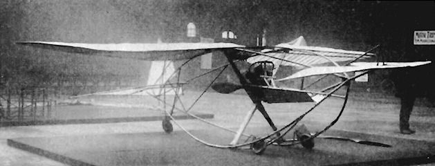
Baird Monoplane
The single-seat tractor Baird Monoplane was constructed during 1909 at Rothesay, Bute, Scotland, by A. B. Baird, a blacksmith. Span, 29 ft. Wing area. 180 sq. ft. Weight empty, 380 lb.
The single-seat tractor Baird Monoplane was constructed during 1909 at Rothesay, Bute, Scotland, by A. B. Baird, a blacksmith. Span, 29 ft. Wing area. 180 sq. ft. Weight empty, 380 lb.
Barnes Monoplane
The Barnes Monoplane was a single-seat tractor, designed and built by G. A. Barnes, a well-known racing motor-cyclist, at Abbey Wood, Kent, during 1909. It was powered by the 20 h.p. J.A.P. engine, and when tested during October of the same year at Abbey Wood, flew low over the ground for about 1.5 miles.
The Barnes Monoplane was a single-seat tractor, designed and built by G. A. Barnes, a well-known racing motor-cyclist, at Abbey Wood, Kent, during 1909. It was powered by the 20 h.p. J.A.P. engine, and when tested during October of the same year at Abbey Wood, flew low over the ground for about 1.5 miles.
Barnwell Brothers Glider
The Barnwell Brothers Glider was built by F. S. and R. H. Barnwell.
Barnwell Brothers Light Biplane
Built by the brothers Frank S. and Richard H. Barnwell during 1908, their single-seat light-weight pusher biplane was powered by the 7 h.p. Peugeot engine but was unable to fly, and the design was abandoned.
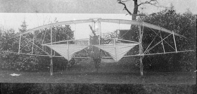
The Barnwell brothers built this unsuccessful biplane in 1908.
Barnwell Brothers Biplane
The Barnwell Brothers Biplane was a single-seat canard pusher designed by Frank S. and Richard H. Barnwell during 1909, and built by the Grampian Motor and Engineering Co., of Stirling. A Hurnber Tourist Trophy car engine was used to drive a pair of pusher propellers, and the machine was tested by Richard Barnwell at Stirling on 10 September, 1909, when it flew for about 80 yards but was damaged in a heavy landing. Span, 48 ft. Weight empty, 1,568 lb.
The Barnwell Brothers Biplane was a single-seat canard pusher designed by Frank S. and Richard H. Barnwell during 1909, and built by the Grampian Motor and Engineering Co., of Stirling. A Hurnber Tourist Trophy car engine was used to drive a pair of pusher propellers, and the machine was tested by Richard Barnwell at Stirling on 10 September, 1909, when it flew for about 80 yards but was damaged in a heavy landing. Span, 48 ft. Weight empty, 1,568 lb.
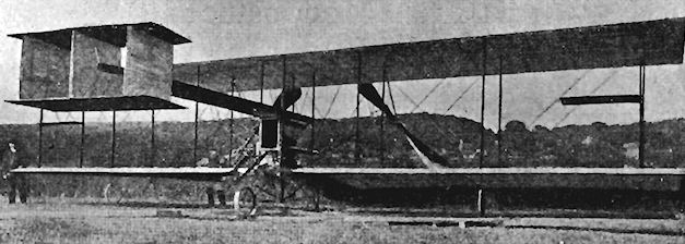
Barnwell 1911 Monoplane
The first wholly successful all-Scottish aeroplane was a single-seat tractor monoplane designed by Richard H. Barnwell and built by the Grampian Engineering and Motor Co. Ltd., of Stirling, ft was fitted with a 40 h.p. Grampian two-cylinder horizontally-opposed engine, and had a very clean appearance, with comparatively few external wires and an airframe which was completely fabric-covered. On 30th January, 1911, at Causeway Head, Barnwell used the machine to win the ?50 prize presented by J. R. K. Law for a flight by a member of the Scottish Aeronautical Society.
The first wholly successful all-Scottish aeroplane was a single-seat tractor monoplane designed by Richard H. Barnwell and built by the Grampian Engineering and Motor Co. Ltd., of Stirling, ft was fitted with a 40 h.p. Grampian two-cylinder horizontally-opposed engine, and had a very clean appearance, with comparatively few external wires and an airframe which was completely fabric-covered. On 30th January, 1911, at Causeway Head, Barnwell used the machine to win the ?50 prize presented by J. R. K. Law for a flight by a member of the Scottish Aeronautical Society.
Bartelt Ornithopter
The Bartelt Ornithopter was designed by F. T. Bartelt, J.P., of Corston Lodge, Brislington, Bristol, who was the chairman of the Polysulphin Co. Ltd. The machine was shown at the 1911 Olympia Aero Show, and was powered by a 40 h.p. engine mounted between the lower pair of wings. Chain-drive imparted 50-60 revolutions per minute to the two pairs of movable wings which were superimposed upon each other, acting alternately with a rotary action horizontally. On the upward movement, the wings deflated; when flapping downward, they inflated. The Ornithopter was expected to be able to move backwards or forwards by means of a reversing gear. Each pair of half-wings was 13 ft. in span, with the chord tapering from 12 ft. at the roots to 7 ft. at the tips. Radiators were mounted horizontally on the frames beside the twin seats, behind which was a pusher propeller.
The Bartelt Ornithopter was designed by F. T. Bartelt, J.P., of Corston Lodge, Brislington, Bristol, who was the chairman of the Polysulphin Co. Ltd. The machine was shown at the 1911 Olympia Aero Show, and was powered by a 40 h.p. engine mounted between the lower pair of wings. Chain-drive imparted 50-60 revolutions per minute to the two pairs of movable wings which were superimposed upon each other, acting alternately with a rotary action horizontally. On the upward movement, the wings deflated; when flapping downward, they inflated. The Ornithopter was expected to be able to move backwards or forwards by means of a reversing gear. Each pair of half-wings was 13 ft. in span, with the chord tapering from 12 ft. at the roots to 7 ft. at the tips. Radiators were mounted horizontally on the frames beside the twin seats, behind which was a pusher propeller.
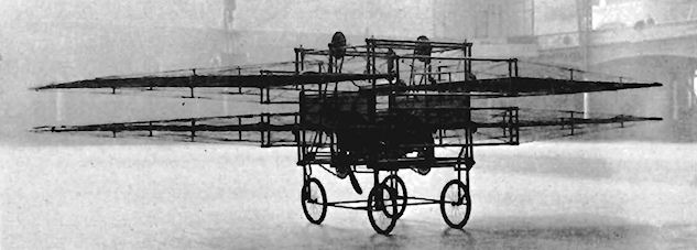
Barton-Rawson Hydro-multiplane
During 1905 Dr. F. A. Barton, his son Dudley and F. L. Rawson constructed at St. Helens. Isle of Wight, an all-bamboo floatplane with sets of multiple wings. The floats were 20 ft. long, 10 ins. wide and 4 ins. deep. The machine was scheduled to have a 7 ft. propeller driven by a 35 h.p. engine, but the designers were unable to obtain a power unit weighing less than 500 lbs.
Tests were carried out without an engine by towing as a kite over the sea behind a launch on 26th September, 1905. The tow ropes kept breaking and the aircraft finally turned over in the water but was salvaged. Span, 34 ft. Length, 36 ft. Height, 9 ft. Wing area, 1,200 sq. ft. Weight empty without engine or propeller, 240 lb.
Batchelor Monoplane
The Batchelor single-seat tractor monoplane was built at Rochester, Kent, by Albert Batchelor in 1910. A two-cylinder horizontally-opposed 35 h.p. Alvaston engine provided the power. The machine combined the warping wings, lifting tail and castoring undercarriage of the BIeriot with the under-slung pilot's position of the Demoiselle, and was equipped with a Cochrane patent propeller. The wing and tail surfaces were covered with Dunlop rubberized fabric. Span, 28 ft. Length, 26 ft. Weight empty, 480 lb.
The Batchelor single-seat tractor monoplane was built at Rochester, Kent, by Albert Batchelor in 1910. A two-cylinder horizontally-opposed 35 h.p. Alvaston engine provided the power. The machine combined the warping wings, lifting tail and castoring undercarriage of the BIeriot with the under-slung pilot's position of the Demoiselle, and was equipped with a Cochrane patent propeller. The wing and tail surfaces were covered with Dunlop rubberized fabric. Span, 28 ft. Length, 26 ft. Weight empty, 480 lb.
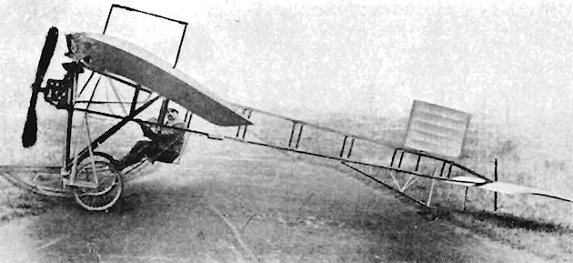
Beer Glider
The Beer Glider was constructed at Cardiff by H. Beer during 1912. It was a biplane of 33 ft. span, whose controls consisted of a fore-elevator and a rudder at the rear.
The Beer Glider was constructed at Cardiff by H. Beer during 1912. It was a biplane of 33 ft. span, whose controls consisted of a fore-elevator and a rudder at the rear.
Bellamy Biplane
The Bellamy Biplane was constructed early in 1907 at Weybridge by M. Bellamy. It was a single-seat pusher/tractor built of bamboo and canvas, and was powered by an engine set between the wings. Two propellers were fitted, one fore and one aft of the four-cylinder power plant.
The Bellamy Biplane was constructed early in 1907 at Weybridge by M. Bellamy. It was a single-seat pusher/tractor built of bamboo and canvas, and was powered by an engine set between the wings. Two propellers were fitted, one fore and one aft of the four-cylinder power plant.

Bellamy Monoplane
M. Bellamy's second attempt at flight was with his single-seat tailless tractor monoplane on 18th August, 1908, in Petersham Meadows. It taxied well, but failed to take off.
M. Bellamy's second attempt at flight was with his single-seat tailless tractor monoplane on 18th August, 1908, in Petersham Meadows. It taxied well, but failed to take off.

Billing Biplane
The Billing Biplane, known also as the "Oozeley Bird", was a single-seat tractor built by Eardley Billing during 1911 from C. A. Moreing's discarded Voisin. Billing was, at that time, in charge of the Lane Gliding School at Brooklands. The engine was a 40 h.p. E.N.V. "D" and the machine was used by N. S. Percival at Brooklands on 1st. August, 1911, to complete the tests for his Royal Aero Club Aviator's Certificate No. III. The fuselage was covered with fabric after the machine had been flown at first with it uncovered.
The Billing Biplane, known also as the "Oozeley Bird", was a single-seat tractor built by Eardley Billing during 1911 from C. A. Moreing's discarded Voisin. Billing was, at that time, in charge of the Lane Gliding School at Brooklands. The engine was a 40 h.p. E.N.V. "D" and the machine was used by N. S. Percival at Brooklands on 1st. August, 1911, to complete the tests for his Royal Aero Club Aviator's Certificate No. III. The fuselage was covered with fabric after the machine had been flown at first with it uncovered.
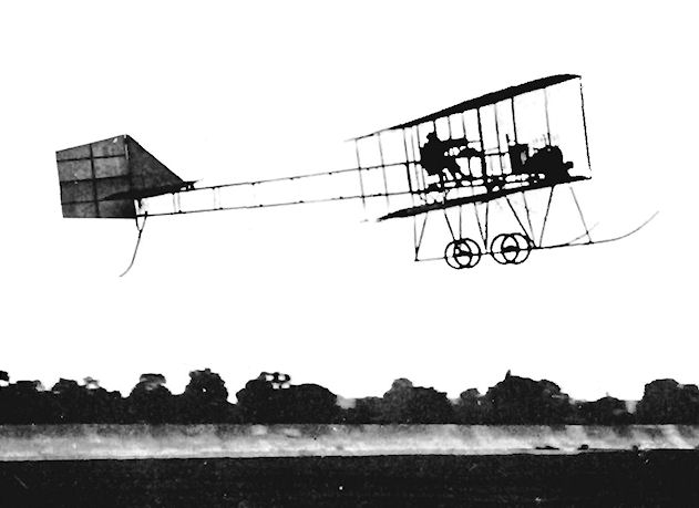
Eardley Billing's biplane in flight at Brooklands.
Birmingham Aero Club Gliders
Several gliders were built by the Birmingham Aero Club during 1911, including a canard monoplane and a biplane designed by G. Haddon Wood based on data published in The Aero. This biplane was named Haddon I. Another biplane glider was flown in two forms, one with the upper wing-tips turned up and the other with the lower wing-tips turned up, for investigations into automatic lateral stability. This last version was developed as the Haddon 2 and was still being flown in 1913. Particulars of the Haddon 2 were: Span. 32 ft. Length, 20 ft. Wing area, 416 sq. ft. Weight loaded. 288 lb. Maximum speed, 25 m.p.h.
Several gliders were built by the Birmingham Aero Club during 1911, including a canard monoplane and a biplane designed by G. Haddon Wood based on data published in The Aero. This biplane was named Haddon I. Another biplane glider was flown in two forms, one with the upper wing-tips turned up and the other with the lower wing-tips turned up, for investigations into automatic lateral stability. This last version was developed as the Haddon 2 and was still being flown in 1913. Particulars of the Haddon 2 were: Span. 32 ft. Length, 20 ft. Wing area, 416 sq. ft. Weight loaded. 288 lb. Maximum speed, 25 m.p.h.
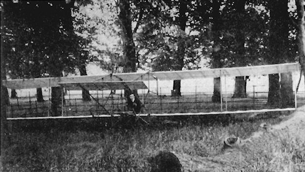
Blackburn Heavy Type Monoplane
The sight of Wilbur Wright flying at Issy in 1908 encouraged Robert Blackburn to leave his work with a firm of civil engineering consultants in Rouen, and to devote his life to aeronautics. His first aircraft was designed in Paris and, when the lay-out was complete, the plans were brought to England for the machine to be constructed in a workshop in Leeds, two mechanics being employed to assist in the work at the Benson Street premises.
A high-wing monoplane was the type chosen, and the whole aircraft was built very substantially, thus earning its later distinguishing name of the Heavy Type Monoplane. The wings were of straightforward construction with parallel chord and square tips, but without any dihedral. They were mounted on top of a simple open fuselage of wire-braced rectangular section. The unusually deep front portion housed the 35 h.p. Green engine, behind which was seated the pilot in a wicker garden seat, the movement of which was adjustable on a fore-and-aft track for the correction of the centre of gravity. The engine transmitted its power to the overhead broad-bladed propeller by means of a chain drive, the petrol supply being contained in a cylindrical tank suspended above the head of the pilot. Cooling was effected by a radiator mounted above the engine in the upper fuselage structure on either side of the propeller shaft. The whole machine was supported on a three-wheeled undercarriage which incorporated rubber springing and drag skids. A fixed tailplane was mounted on the upper longerons, at the rear of which came the triangular rudder. The elevators were not hinged to the tailplane, but, instead, were fixed on either side of the centre of the rudder to share its movements on a universal joint. All three control surfaces, including the lateral wing-warping, were operated by a car type of steering-wheel behind the engine, and the original intention was to fit a patent stability device.
On completion, the Heavy Type Monoplane was taken for testing to the sands between Marske and Saltburn on the Yorkshire coast. With Robert Blackburn at the controls, the machine managed to rise from the beach on 24th May, 1910, but was wrecked when one of the landing wheels was caught in a hole in the sand during a slideslip from an attempted turn.
SPECIFICATION
Description: Single-seat high-wing tractor monoplane. Wooden structure, fabric covered.
Manufacturers: Blackburn Aeroplane Co., Benson Street, Leeds, Yorkshire.
Power Plant: One 35 h.p. Green.
Dimensions: Span, 30 ft. Length, 26 ft. Wing area, 170 sq. ft.
Weights: Empty, about 800 lb.
Performance: Maximum speed, 60 m.p.h.
Price: ?700.
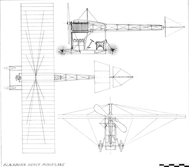
Blackburn Heavy Monoplane
Blackburn Mercury Monoplanes
Although his first essay at designing an aircraft was not an all-round success, Robert Blackburn was undeterred and set about achieving flight by a different approach. New premises were acquired in Balm Road in Leeds, and the construction of a lighter type of monoplane than the first was commenced in 1910. The Demoiselle lay-out utilized in the Heavy Type machine was abandoned. In appearance the Mercury was reminiscent of the successful Antoinette type, and also incorporated a fuselage of triangular section, a feature of all subsequent Blackburn monoplanes up to the 1914 L Biplane.
Acquaintance with R. J. Isaacson, designer of the Manning Wardle Engine Company of Leeds, resulted in the decision to use the 40 h.p. Isaacson radial engine, a very unusual and original design in that it was of a stationary type at a time when the rotary form used by the Gnome was most popular. The Isaacson engine also employed pushrod-operated overhead valves and incorporated a 2 : 1 reduction gear drive to the propeller.
It was hoped that the machine would fly at the August, 1910, meeting at Blackpool to which it was taken. However, difficulties with the engine prevented the Mercury from taking part, and it was not until March, 1911, that B. C. Hucks managed to take it into the air at Filey Sands. After reaching a height of 30 ft., and a speed of 30 m.p.h., the aircraft caught one wing-tip in the ground while turning and damaged the undercarriage. Following repair, Hucks used it subsequently to gain his Royal Aero Club Aviator's Certificate No. 91 at the same place on the following 30th May.
As soon as the single-seat Mercury had proved itself, a two-seat version was constructed early in 1911 for use by Hucks at the Blackburn Flying School at Filey. It was on display at the 1911 Olympia Aero Show and was seen to have a wing of tapered form compared with the parallel chord used on the first Mercury. To avoid straining the wing structure through the warping control, the wings were pivoted about the rear spar. The controls for the flying surfaces consisted of handwheels, leaving the feet free for operating (he engine acceleration by a foot pedal, although a hand lever was used also for speed control of the 50 h.p. Isaacson radial. Ash was employed for most of the lattice girder framework, the forepart of the fuselage being wood covered. The strong undercarriage was made up from ash struts and incorporated rubber shock absorbers and steel springs on the axle.
Two improved Mercurys were designed to compete in the Daily Mail Circuit of Britain race of July, 1911. One was for B. C. Hucks and the other for Conway Jenkins. Each was fitted with a 50 h.p. Gnome in a circular metal cowling. Neither achieved any success in the contest: Hucks damaged his machine on reaching Luton and had to retire, while Jenkins crashed at the starting-point at Brooklands. However, in August, 1911, Hucks took his Mercury on a very successful tour of the West of England, making two crossings of the Bristol Channel and demonstrating wireless telephony in September at Cardiff at 50 m.p.h. from 700 ft. in conjunction with H. Grindell Matthews on the ground. Early in 1912, Hucks's Mercury was at Shoreham in the hands of Lt. Walter Lawrence, 7th Essex Regiment, who intended to make a cross-Channel flight with the society hostess, Mrs. Leeming. On 23rd March, 1912, on its way to Dover, the machine was badly damaged when Lawrence overturned it at Eastbourne. The projected flight was abandoned and the Mercury was rebuilt for instruction and exhibition use at the Blackburn Flying School at its new home at Hendon, where it carried the number 33. Among the minor alterations made during reconstruction was the addition of a scuttle dash for greater comfort of the crew. Unified wheel control was fitted for the rudder, elevators and wing warping. The entire fuselage bracing was carried out with wood, to the exclusion of tie-wires, and the fore-part was aluminium covered. In April, 1913, Harold Blackburn flew No. 33 into third place in the Aero Show Trophy race at Hendon.
Among other variants of the Mercury were at least two fitted with 60 h.p. Renault engines, one of which was ready at Filey in November, 1911, and was expected to lift three passengers. The machine took off fully-loaded in 30 yds., had an endurance of 4 hrs. and was flown in the moonlight at 1 a.m. by Hubert Oxley in December, 1911. On 6th December, Oxley and his passenger R. Weiss were killed at Filey when the machine crashed from 50 ft. before landing. The total of approximately eleven Mercury light monoplanes is believed to have included a version powered by a 50 h.p. Anzani engine.
SPECIFICATION
Description: Single- and two-seat high-wing tractor monoplane. Wooden structure, fabric covered.
Manufacturers: Blackburn Aeroplane Co., Balm Road, Leeds, Yorkshire.
Power Plant: 40 h.p. Isaacson, 50 h.p. Isaacson, 50 h.p. Gnome, 60 h.p. Renault.
Dimensions
(50 h.p. Isaacson two-seater): Span, 38 ft. 4 in. Length, 33 ft. Wing area, 290 sq. ft.
(50 h.p. Gnome single- and two-seater): Span, 36 ft. Length, 32 ft. Wing area, 220 sq. ft.
Weights: Empty, about 800 lb.
Price (40 h.p. Isaacson single-seater): ?550.
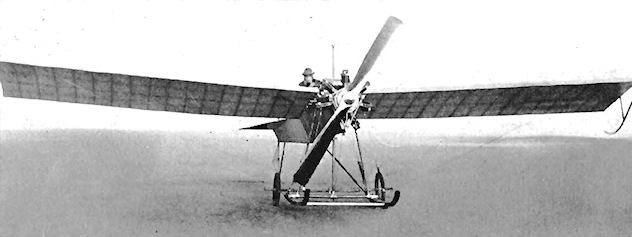
"MERCURY," THE SINGLE-SEATER MONOPLANE OF THE BLACKBURN AEROPLANE CO., LEEDS. - These machines are now at work at the Blackburn Flying School, Filey, under the supervision of Mr B C Hucks, who has been With Mr. Grahame-White for nearly a year, and was with him on his American tour. Mr. Hucks has been making some excellent flights on this particular machine.
The Second Blackburn Monoplane at Filey in 1911 with 40 h.p. Isaacson, wing tip skids and the second undercarriage modification.
The Second Blackburn Monoplane at Filey in 1911 with 40 h.p. Isaacson, wing tip skids and the second undercarriage modification.
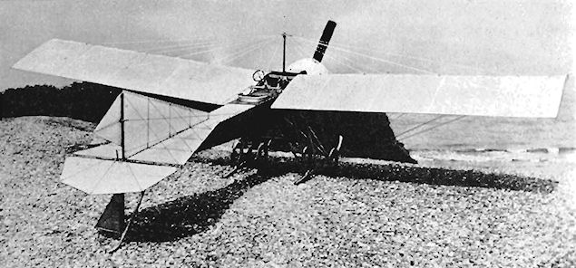
50 h.p. Gnome Blackburn Mercury at Filey, showing full-chord wing-roots.
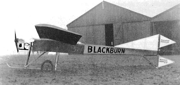
Third place in the Aero Show Trophy race at Hendon on 22 February, 1913, was gained by Harold Blackburn with the Blackburn Mercury used as No. 33 at the Blackburn Flying School at Hendon.
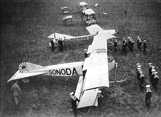
Aeroplane at Hendon during the Naval and Military Aviation Day held on 28th September, 1912.
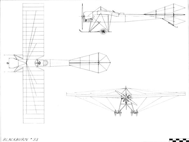
Blackburn 33
Blackburn Single-seat Monoplane
The evolution of the Blackburn series of monoplanes was carried a stage further with the building in 1912 of a single-seater for Cyril Foggin, who qualified for his Royal Aero Club Aviator's Certificate No. 349 on a Bleriot Monoplane at Eastbourne on 29th October, 1912. The general layout of the Mercury was retained in the new machine, but the appearance and performance were improved in many ways. A wooden airframe covered with fabric was used, apart from the front portion of the triangular fuselage, which was sheeted in aluminium as far aft as the rear wall of the cockpit. One of the most noticeable of the alterations was the change to a one-piece rudder and divided elevators. The low aspect-ratio fin was braced strongly to the tailplane and through to the fuselage. A two-wheel main landing-gear was adopted and mounted on a simpler arrangement than hitherto of wooden struts and hooked skids. Wings of parallel chord were fitted, with warping rather than ailerons still favoured for lateral control.
After taking delivery early in 1913, Foggin, accompanied by Harold Blackburn, gave exhibition flights in the Leeds area at Easter. The under-carriage was modified shortly afterwards so that the hooked skids were replaced by a straight pair with simple upturned ends. The cowling over the 50 h.p. Gnome engine was extended so that it reached down to the thrust-line, affording better protection to the pilot from the oil and exhaust gases blown back from the engine than did the original very small covering. Fabric covers were a refinement added to the wheel spokes. The machine then passed into the hands of Montague F. Glew, who had taken h is Royal Aero Club Aviator's Certificate No. 410 on a Blackburn monoplane at
Hendon on 4th February, 1913. He crashed his acquisition on his father's farm at Wittering, Lincs., and it was stored there until it was acquired by the Shuttleworth Trust in 1937. The machine was rebuilt, and is now housed with the Collection at Old Warden Aerodrome, Beds. It is still capable of flying nearly fifty years after it was constructed, and is occasionally seen in the air at flying shows.
SPECIFICATION
Description: Single-seat tractor monoplane. Wooden structure, fabric covered.
Manufacturers: Blackburn Aeroplane Co., Balm Road, Leeds, Yorkshire.
Power Plant: 50 h.p. Gnome.
Dimensions: Span, 35 ft. 8 ins. Length, 26 ft. 3 ins. Height, 8 ft. 9 ins. Wing area, 236 sq. ft.
Weights: Empty, 550 lbs. Loaded, 800 lb.
Performance: Maximum speed, 60 m.p.h. Endurance, 2.5 to 3 hrs.
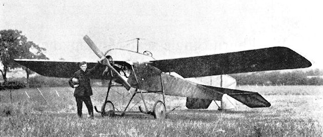
M. F. Glew with the 1912 Blackburn Single-seat Monoplane.

1912 Blackburn Single-seat Monoplane rebuilt and photographed at Brough in 1953.
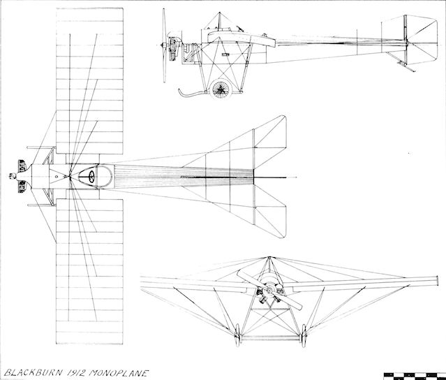
Blackburn 1912 monoplane
Blackburn E
When the announcement was made of the forthcoming Military Trials to be held on Salisbury Plain during August, 1912, the Blackburn concern set about the designing and building of two entries based upon the successful Mercury monoplane. The machines were given the designation Type E and were known as all-steel monoplanes, by virtue of the fact that steel tubing was used for their triangular fuselages, which were among the earliest British examples of such construction. A curved decking as far aft as the tail improved the appearance and conferred greater comfort upon the two passengers.
The first machine was fitted with a 60 h.p. Renault engine and the second received a Green of similar power, both of which, were enclosed in neat cowlings. Wings of parallel chord were used, warping being employed for lateral control, while the one-piece elevator moved between the upper and lower rudder surfaces. The sturdy undercarriage was fitted with four wheels and a pair of skids as used on the Mercury series. A tapered cylindrical auxiliary fuel tank was suspended below the fuselage between the undercarriage struts.
Although the first of the all-steel monoplanes arrived for testing at Filey in April, 1912, and subsequently left the ground in 30 yds. with a full load, neither of the machines was ready to take part in the Military Trials when August arrived.
SPECIFICATION
Description: Two-seat high-wing tractor military monoplane. Steel and wooden structure, fabric covered.
Manufacturers: Blackburn Aeroplane Co., Balm Road, Leeds, Yorkshire.
Power Plant: 60 h.p. Renault, 60 h.p. Green.
Dimensions: Span, 38 ft. Wing area, 290 sq. ft.
Performance: Endurance, 4 hrs.
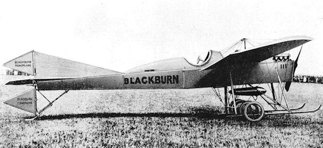
Blackburn Type E. Military monoplane of 1912.
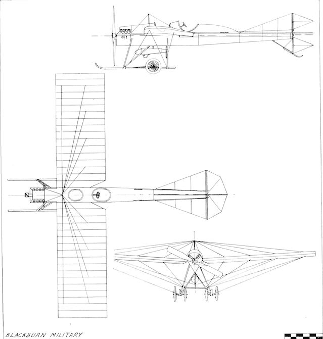
Blackburn Military
Blackburn I
During August, 1913, there appeared a two-seat version of the single-seat monoplane supplied to Cyril Foggin earlier in the year. The Type I, as it was called, was built for touring to the order of Dr. M. G. Christie. To carry the extra passenger, the span was increased by 5 ft. 11 ins. to 38 ft., the length being brought up to 28 ft. A corresponding increase in power was made with the installation of an 80 h.p. Gnome, which turned a 9 ft. propeller of Blackburn make. The favourite Blackburn triangular-section fuselage was constructed of wood and was sheeted with aluminium forward of the rear cockpit former.
The engine was almost completely cowled except for an opening in the lower portion, and this, together with the scuttle dash fitted, was designed to keep undesirable exhaust fumes and oil away from the occupants. Comfortable separate cockpits were installed, the passenger's seat being in front and over the centre of gravity, so that the machine could be flown from the rear cockpit solo or as a two-seater without alteration of balance. Warping of the parallel-chord wings was still used, and generous cut-outs at the rear roots gave a good view downwards from the pilot's seat. The same style of undercarriage was retained as that on the single-seater, springing being carried out by rubber cord over the axle.
On completion, the machine was tested by Harold Blackburn, who took it to 7,000 ft. in 10 mins. and established that it possessed a speed range of 40-70 m.p.h. Soon afterwards, the same pilot flew Dr. Christie on an extensive tour of Yorkshire towns during August and Septetnber, 1913. The following month, on 2nd October, Harold Blackburn and Dr. Christie raced the Type I against F. P. Raynham and H. V. Roe in the prototype Avro 504 biplane and upheld the name of Yorkshire to win the "War of the Roses" Challenge Cup presented by the Yorkshire Evening News for a contest over a course of 100 miles. The machine was flown intensively from the Lime of its debut, and by the end of 1913 had covered about 1,800 miles and had carried over 120 passengers.
At the Olympia Aero Show held in March, 1914, an improved Type I monoplane was exhibited on the Blackburn stand. Of the same size, and powered again by an 80 h.p. Gnome, the new version embodied modified engine bearers and a simplified, neater nose. The tandem seating arrangement was unaltered, but was arranged in a single cockpit without a bulkhead or decking between the pilot and passenger.
SPECIFICATION
Description: Two-seat high-wing tractor monoplane. Wooden structure, fabric covered.
Manufacturers: Blackburn Aeroplane Co., Balm Road, Leeds, Yorkshire.
Power Plant: 80 h.p. Gnome.
Dimensions: Span, 38 ft. Length, 28 ft. Wing area, 241 sq. ft.
Weights: Empty, 900 lb. Loaded, 1,500 lb.
Performance: Maximum speed, 70 m.p.h. Landing speed, 40 m.p.h.
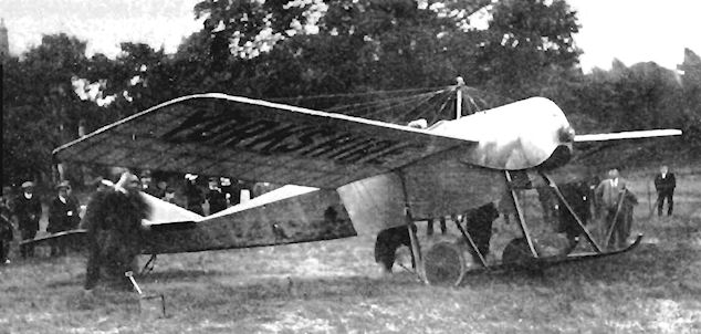
Dr. Christie's Blackburn I two-seater monoplane, winner on 2 October, 1913, of the Yorkshire Evening News "War of the Roses" race.
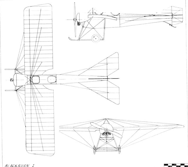
Blackburn I
Blackburn L
For the 1914 Circuit of Britain Race organized by the Daily Mail, the Blackburn Company broke away from its predilection for the monoplane and built its first biplane. The necessity for providing adequate support for the lower wings, and also a strong anchorage for the float struts, brought about a further departure from the traditional Blackburn triangular fuselage and resulted in a normal rectangular section being used. This was of fairly broad aspect, to give smooth lines to the fuselage by accommodating the diameter of the 130 h.p. Salmson (Canton-Unne) radial engine which was chosen to power the machine. Although the engine was a radial, it was water-cooled, and the accompanying radiators were mounted in an upright position on each side of the front cockpit.
Wire tie-bracing was omitted, its place being taken by diagonal wooden members. The two-bay wings were of comparatively broad span, and the upper extensions were strut-braced to the bases of the outer pairs of inter-plane struts. Yet another departure from earlier Blackburn practice was the provision of long-span ailerons, instead of warping, which were fitted to the upper wings. Two main floats, incorporating two steps each and set well apart, and a plain tail float, comprised the landing-gear.
The Type L was entered as No. 8 in the Circuit of Britain contest, and the well-known pilot Sydney Pickles was selected to fly the machine in the race. The imminence of war brought about the abandonment of the competition and when the conflict broke out on 4th August, 1914, the seaplane in common with several other aircraft was taken over by the Admiralty and was taken to Scarborough, remaining there for about six weeks. A machine-gun was fitted to it, but the end of the sole Type L came when it was flown into a cliff by W. Rowland Ding early in 1915, subsequently being abandoned as irreparable.
SPECIFICATION
Description: Two-seat tractor biplane seaplane. Wooden structure, fabric covered.
Manufacturers: Blackburn Aeroplane Co. Ltd., Olympia, Leeds.
Power Plant: 130 h.p. Salmson (Canton-Unne).
Dimensions: Span, 49 ft. 6 ins. Length, 32 ft. 6 ins. Wing area, 481 sq. ft.
Weights: Empty, 1,717 lb. Loaded, 2,475 lb.
Performance: Maximum speed, 81 m.p.h. Landing speed, 45 m.p.h. Endurance, 5.5 hrs.
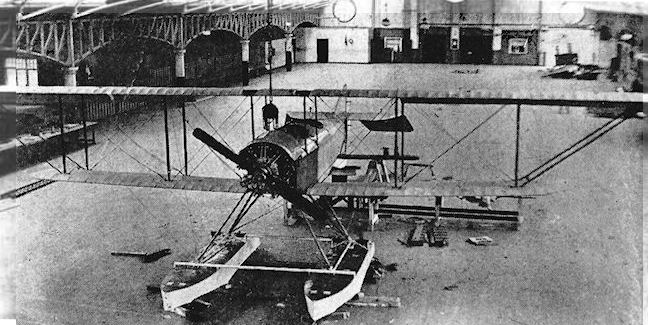
The Type L seaplane under construction in the disused skating rink which was to become the great Olympia Works.
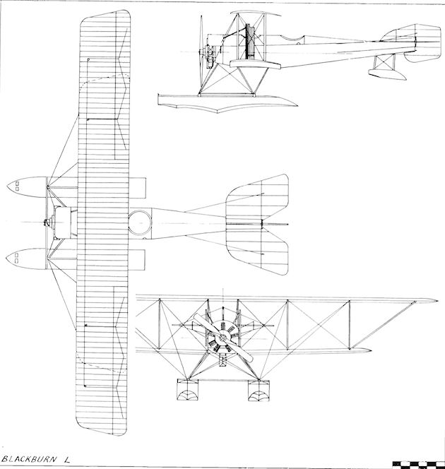
Blackburn L
Bland Mayfly
One of the earliest exponents of flying in Ireland was Miss Lilian E. Bland of Carnamoney, near Belfast, whose Mayfly of 1910 was the first biplane to be constructed in the country. After making many experiments and tests with large-scale model gliders, Miss Bland, assisted by S. Girvany of Ballymore, built the Mayfly early in 1910 first as a glider. The landing-wheels were omitted and the machine was tested by towing it off the ground on its skids to assess its stability and characteristics. The glider was launched also in free flight, and, upon being satisfied that the general design would be suitable for the installation of a power unit, Miss Bland proceeded to redesign the airframe to take an engine. Rounded wing-tips were introduced, ailerons were mounted on the outer pair of rear inter-plane struts and different tail units were tried out. This new version was also tested by towing before the undercarriage wheels and the two-cylinder horizontally-opposed 20 h.p. Avro engine and 6 ft. 6 ins. Avro propeller were fitted.
The airframe was constructed of wood with fabric covering, bamboo being employed for the outriggers carrying the front elevators and the tail unit at the rear.
The Mayfly was completed early in 1911, and Miss Bland started to teach herself to fly at Carnamoney. Her enterprise and resourcefulness were amply rewarded by the success of her creation, which flew quite well. Through the publicity given to her experiments, Miss Bland's courage and ingenuity came to the attention of a Canadian from Vancouver, whither she removed after her marriage to him at the end of 1911, thus bringing her flying to an end without gaining her Aviator's Certificate.
SPECIFICATION
Description: Single-seat pusher biplane. Wooden structure, fabric covered.
Manufacturer: Miss L. E. Bland, Carnamoney, Belfast.
Power Plant: 20 h.p. Avro.
Dimensions: Span, 27 ft. 7 ins. Length, 23 ft. Wing area, 250 sq. ft.
Weights: Empty, 200 lb. (glider).
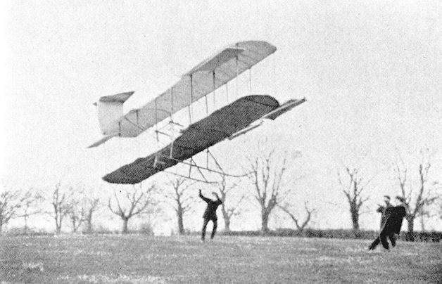
The "Mayfly" in its original form as a glider, soaring in a 12,m.p.h. breeze.
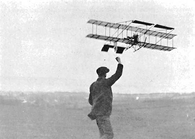
Modified Bland Mayfly being tested by towing as a glider.
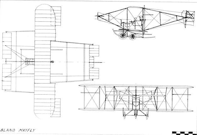
Bland Mayfly
Bonnard Biplane
The Bonnard Biplane was designed by L. H. Bonnard and constructed during 1910 by the International Aero Co. of Huntingdon. The machine was a single-seat pusher with a span of 26 ft. and a wing area of 221 sq. ft.
The Bonnard Biplane was designed by L. H. Bonnard and constructed during 1910 by the International Aero Co. of Huntingdon. The machine was a single-seat pusher with a span of 26 ft. and a wing area of 221 sq. ft.
Smith and Mateyka Biplane
The Smith and Mateyka Biplane was built during 1910, and featured wings in which the upper planes were straight and the tips of the lower planes curved upwards to meet the upper tips. The machine was a canard with a biplane elevator at the front. The design was based on the successful performance of several small competition rubber-powered models made by G. P. Bragg Smith.
The Smith and Mateyka Biplane was built during 1910, and featured wings in which the upper planes were straight and the tips of the lower planes curved upwards to meet the upper tips. The machine was a canard with a biplane elevator at the front. The design was based on the successful performance of several small competition rubber-powered models made by G. P. Bragg Smith.
Bristol Boxkite
While Sir George White, the chairman of the Bristol Tramway and Carriage Company, was on holiday at Cannes at the beginning of 1910 the sight of some French aeroplanes flying there was responsible for his decision to enter the aircraft industry, which was then in its first stages in Great Britain.
The first machine assembled at the Filton, Bristol, works, after the formation of the British and Colonial Aeroplane Co. Ltd., was a Gabriel Voisin-designed Zodiac Biplane imported from France. It was given the works number 1, was fitted with a 50 h.p. Darracq engine and was exhibited at the 1910 Olympia Aero Show. The machine was afterwards taken to Brooklands, where efforts to persuade it to fly were made from 30th April until 15th June, 1910. Despite alterations in the camber of the wings, to the tail surfaces and the substitution of a 50h.p. Gregoire engine, all attempts were unsuccessful and, after damaging the undercarriage when the final attempt was made, the Zodiac was abandoned together with the construction of a further five machines of the same type.
The firm decided to design its own aircraft in future, and appointed G. H. Challenger as chief engineer and designer. The first product from his drawing-board was based on the Henri Farman pusher biplane. Nicknamed The Boxkite, assembly of the machine was completed at Larkhill, Salisbury Plain, on 29th July, 1910, and it made its first flight on the following day. It received the works number 7, numbers 2-6 having been allocated to the unfinished Zodiacs, and was fitted with a 50 h.p. Gnome, although the Gregoire was installed temporarily for a short comparative trial. The second Boxkite, number 8, was powered initially by a 60 h.p. E.N.V. "F" engine, and was later also re-engined with a 50 h.p. Gnome. Fifteen Standard Boxkites were built with the works numbers 7, 8, 9, 10, If, 12a, 14, 34, 43, 49, 55, 62, 63, 65 and 66.
The type proved to be an eminently successful and popular flying machine, and was soon busy on instructional work at the newly-formed Bristol Flying School at Brooklands, where it operated under Mons. Edmond. Boxkites formed the equipment of another Bristol school which was opened at Larkhill, and two were entered at the flying meeting held at Lanark from 6th until 13th August. Boxkite number 8 appeared at Lanark with its L.N.V. engine, and differed from No. 7 and subsequent Boxkites in possessing wings with double surfaces and a rear elevator with a straight trailing-edge instead of the usual scalloped curve. These components may have been salvaged from the Zodiac No. 1 in its finally modified state.
The usefulness of the Boxkite as an aid to the military was demonstrated on 21st September, 1910, when Captain Bertram Dickson flew one at the British Army Manoeuvres which were attended by Lord Kitchcner, Lord Roberts, General Sir John French and Mr. Winston S. Churchill. A few days later, on 26th September, air-to-ground wireless transmission was accomplished over Salisbury Plain from a Boxkite. By the end of 1910, sixteen of the type had been constructed, and the company's design staff, encouraged by the success of their first effort, proceeded to develop and improve the basic airframe.
<...>
SPECIFICATION
Description: Single- or two-seat pusher training and racing biplane. Steel tubing/wooden structure, fabric covered.
Manufacturers: The British and Colonial Aeroplane Co. Ltd., Filton, Bristol.
Power Plant: 50 h.p. Gregoire, 60 h.p. E.N.V. "F”, 50 h.p. Gnome
Dimensions: Span, 33 ft.; Length, 38 ft. 6 ins. Height, 11 ft. Wing area, 457 sq. ft.;
Weights: Loaded, 900 lb.
Performance: Maximum speed, 40 m.p.h.
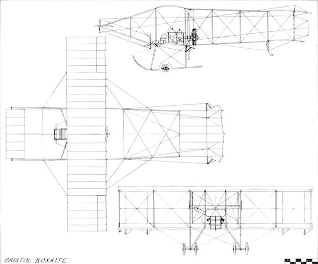
Bristol Boxkite
Bristol Glider
A single-seat biplane glider, similar to the classic Wright Brothers type, was designed by G. H. Challenger and built early in 1911. On completion it was presented by Sir George White to the Bristol and West of England Aero Club, of which he was the president. The glider was used for primary training on a hillside at Keynsham, near Bristol.
A single-seat biplane glider, similar to the classic Wright Brothers type, was designed by G. H. Challenger and built early in 1911. On completion it was presented by Sir George White to the Bristol and West of England Aero Club, of which he was the president. The glider was used for primary training on a hillside at Keynsham, near Bristol.
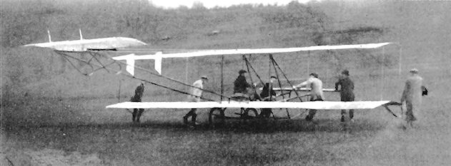
The Glider of the Bristol and West of England Aero Club in practice on the Club's gliding hill.
Bristol Boxkite
<...>
Numbers 12, 15, 16, 17 and 18 were fitted with extensions to the upper wing-tips, which increased the span from 33 ft. to 46 ft. 6 ins. The 50 h.p. Gnome engine was used except for No. 16, which was fitted with an E.N.V. engine and was prepared specially as an entrant for the Manville prize.
With an eye to increased business, the company arranged demonstration tours abroad. In December, 1910, a mission arrived in India with three extended-type Boxkites under the leadership of Farnall Thurston. Mons. Henri Jullerot undertook the piloting and, during the next month, Major W. Sefton Brancker made his first flight when, with Jullerot, he carried out, at manoeuvres held during the mission's stay, the first aerial reconnaissance to be asked for by a British Army commander. The Standard Boxkite, also, was sent on tour to Australia in the hands of J. J. Hammond, Leslie F. MacDonald and Sydney E. Smith, and its general success as a trainer was such that it soon was flying in several different countries as well as being used in Britain by private owners, including the extended version by Claude Grahame-White.
Eight Boxkites with the 70 h.p. Gnome, works numbers 20-26 inclusive and 30, were ordered during February 1911, by Russia; and to this batch was added number 32, the machine exhibited at St. Petersburg in the following April. In March, 1911, an order for four was received from the British War Office to form the equipment of the Air Battalion of the Royal Engineers, which came into being the next month. The Boxkite was seen by a broad section of the British public when it was displayed at the 1911 Olympia Aero Show. In production, it was built as both a single- and a two-seater. From January, 1911, until October, 1914, the Military Boxkite was manufactured for the War Office, the Admiralty and for school training with increased tankage and the 50 h.p. Gnome engine. At first three rudders were incorporated, but after a short time the centre one was discarded. Works numbers for these machines were 19, 27, 28, 29, 37, 38, 40, 41, 47, 48, 67, 93, 99, 119, 124-129 inclusive, 133-139 inclusive, 203, 204, 207, 222, 226, 231, 347 and 394-399 inclusive.
An alteration in power was made in the pair of War Office Boxkites Nos. 39 and 42, both of which received water-cooled 60 h.p. Renault engines. The Boxkite was in use with the Royal Flying Corps from May, 1912, and one machine was on the strength of No. 3 Squadron, R.F.C. Among the improvements made from time to time was the fitting of a nacelle to the three 70 h.p. Gnome-engined numbers 31, 60 and 79 for greater crew comfort. The first of this improved military type was shown at the Olympia Aero Show of 1911, and the other two were exported to Spain.
In addition to the Boxkites produced for civilian, War Office, Admiralty and export orders, several developed versions were constructed as racers during 1911. Mons. Tetard assisted G. H. Challenger in the design of number 44 single-seater fitted with the 50 h.p. Gnome, which was Tetard's mount in the 1911 Circuit of Europe event. The single-seater number 45 was fitted also with the 50 h.p. Gnome, and was a new type somewhat resembling the Maurice Farman. It was flown in the same contest by Mons. Maurice Tabuteau, whose recommendations were incorporated in the design. Four generally similar single-seaters were entered for the 1911 Daily Mail Circuit of Britain, and Captain Bertram Dickson collaborated with Challenger in their design, the machines being designated Improved Type T. Numbers 51, 52 and 53 were powered by 70 h.p. Gnomes, while number 54 received the 60 h.p. Renault. The racing biplanes differed in several respects from the standard and military Boxkites. Light wood and fabric structures formed the nacelles, twin rudders and hooped rattan tailskids were fitted, the ailerons on the lower wings were deleted, and the ailerons on the upper wing extensions were each in one piece. A more powerful Improved Type T single-seater, to be fitted with the 100 h.p. Gnome, and numbered 78, was not completed. A further racing variant, using standard Boxkite wings but with the nose elevator and booms deleted and the landing-gear reduced in height, was designed by Gabriel Voisin and allotted number 69. It had a 50 h.p. Gnome and was completed in February, 1912, but appears not to have been flown.
Seventy-five standard Boxkites and seven racing versions were constructed, and the British and Colonial Aeroplane Company's first design proved itself to be a great success from its inception. Besides putting its creators on a firm business footing, it was responsible for a good proportion of the trained British pilots available for service when war came in 1914.
SPECIFICATION
Description: Single- or two-seat pusher training and racing biplane. Steel tubing/wooden structure, fabric covered.
Manufacturers: The British and Colonial Aeroplane Co. Ltd., Filton, Bristol.
Power Plant: 70 h.p. Gnome, 60 h.p. Renault, 100 h.p. Gnome.
Dimensions: Span, 46 ft. 6 ins. Length, 38 ft. 6 ins. Height, 11 ft. Wing area, 517 sq. ft.
Weights: Loaded, 900 lb.
Performance: Maximum speed, 40 m.p.h.
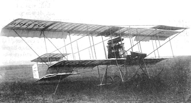
Extensions to the upper wings were fitted to the Bristol Boxkite No. 16 with 60 h.p. E.N.V., flown by C. H. Pixton in conjunction with an Avro D to win the 1911 Manville Prize.

Bristol Boxkite No.44 with single-bay wings. One of several variants built for racing.
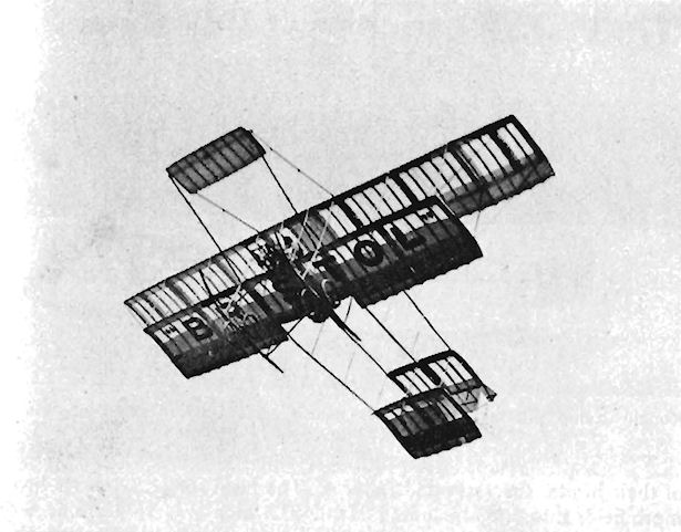
E.C.Gordon England flying a Bristol Boxkite at Ventnor, Isle of Wight, following his trip from Shoreham on 5th July, 1911.
Bristol Monoplane
Two single-seat tractor monoplanes, works numbers 35 and 36, were built during 1911. They were powered by the 50 h.p. Gnome engine, the upper halves of which were cowled. Number 35 was shown at the Olympia Aero Show in March, 1911, and number 36 was shown at St. Petersburg a month later. Divided rudders were mounted above and below the one-piece elevator, and warping was used for the wings. Span, 33 ft. 6 ins. Length, 31 ft. 6 ins. Wing area, 215 sq. ft. Weight empty, 580 lb. Price, ? 1,000.
Two single-seat tractor monoplanes, works numbers 35 and 36, were built during 1911. They were powered by the 50 h.p. Gnome engine, the upper halves of which were cowled. Number 35 was shown at the Olympia Aero Show in March, 1911, and number 36 was shown at St. Petersburg a month later. Divided rudders were mounted above and below the one-piece elevator, and warping was used for the wings. Span, 33 ft. 6 ins. Length, 31 ft. 6 ins. Wing area, 215 sq. ft. Weight empty, 580 lb. Price, ? 1,000.
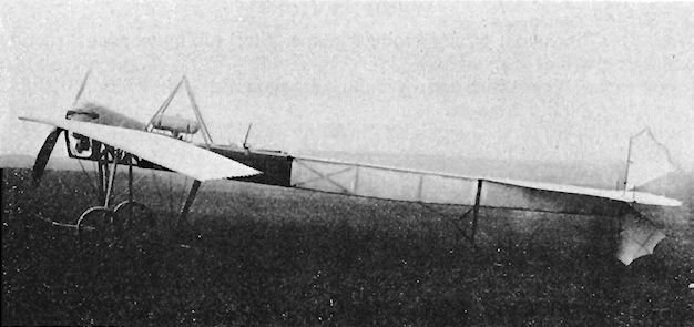
Bristol Prier Monoplanes
Among the top-ranking pilots of all nationalities attracted to the "Bristol" living-schools at Brooklands and Larkhill was Mons. Pierre Prier. During 1911, the Filton factory built his P.I single-seat monoplane for training at their schools, of which Prier was appointed chief flying instructor.
The Prier Monoplane represented a considerable advance in design and comfort over the Boxkite then in use, and possessed a far better performance on the same 50 h.p. Gnome rotary engine. The first P.I built was works number 46, and two further examples, 56 and 57, were intended to participate in the 1911 Circuit of Britain. All, however, were converted for school flying and had their Gnome engines replaced by 35 h.p. three-cylinder Anzanis. Number 56 was powered temporarily with a 40 h.p. Isaacson radial, thus turning it into an all-British machine to enable James Valentine to fly it in the contest for the 1911 British Michelin Cup No. 2. Another proposed power plant was the flat-twin 40 h.p. Clement-Bayard, but this installation was abandoned before completion.
Mons. Prier's monoplane was of straightforward construction with a wooden airframe covered with fabric. Warping was used on the wings, and the tail unit comprised rudder and one-piece elevators without a fixed fin or a tailplane. Metal cowling panels were fitted to the nose as far to the rear as the cockpit area, and the curved hooks on the front of the undercarriage skids were sprung to absorb shocks. A further eleven examples, works numbers 58, 71, 72, 73, 74, 75, 76, 83, 84, 90 and 94, were built as tandem two-seaters with 50 h.p. Gnome engines. Number 75 was bought by the War Office, and several of the batch went to Italy and Spain. Number 73 was fitted with aerials mounted above the fuselage and took part in wireless experiments at Hendon in 1912.
In collaboration with Captain Bertram Dickson, Prier redesigned the two-seater with a longer fuselage and a fixed tailplane. Eight of the new version were built, works numbers 82, 85, 87, 89, 91, 130, 155 and 156, with 91 going to the War Office as Army aircraft 261. The machines used the 50 h.p. Gnome as power, but two further examples, works numbers 86 and 88, were constructed for Turkey. They were the same as 82, but were given the extra power of the 70 h.p. Gnome. No. 75 was later rebuilt to the same standard as No. 91 and became Army aircraft 256.
A pair of Prier School single-seaters, numbers 95 and 96, based on 57 and equipped with the 35 h.p. Anzani, were supplied to Italy. Three additional single-seat Prier School monoplanes, works numbers 97, 98 and 102, with 35 h.p. Anzanis and otherwise the same as numbers 95 and 96 except that they had fixed tailplanes, were delivered to the school at Larkhill. At the 1911 Paris Aero Show a Bristol Prier monoplane was the sole representative from the United Kingdom.
The final variant of the Prier monoplane design was the Sociable side-by-side two-seater, of which three were produced in 1913 for export to Germany. Designed by Prier and Dickson and based on number 82, they were given works numbers 107, 108 and 109 and used the 50 h.p. Gnome.
Although the Prier monoplanes were used successfully at the constructor's flying-schools and also abroad, they were not adopted by the War Office owing to the prevailing prejudice against the supposedly weak monoplane brought about by several accidents at that time. Thirty-three Prier monoplanes of all types were constructed.
SPECIFICATION
Description: Single- or two-seat tractor training monoplane. Wooden structure, fabric covered.
Manufacturers: The British and Colonial Aeroplane Co. Ltd., Filton, Bristol.
Power Plant: 50 h.p. Gnome, 35 h.p. Anzani, 70 h.p. Gnome, 40 h.p. Isaacson, 40 h.p. Clement-Bayard.
Dimensions: Span (Standard), 30 ft. 2 ins.; (Military), 34 ft. Length, 24 ft. 6 ins. Height, 9 ft. 9 ins. Wing area (Standard), 166 sq. ft.; (Military), 200 sq. ft.
Weights: Empty, 640 lb. Loaded, 1,080 lb.
Performance: Maximum speed, 68 m.p.h.
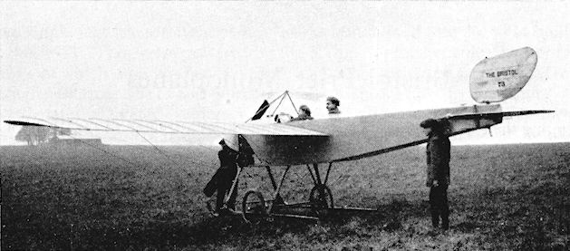
Short fuselage Bristol Prier Monoplane No. 73 with C. H. Pixton in rear cockpit.
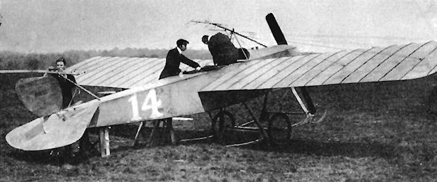
Bristol Prier Monoplane No. 73 used in wireless experiments at Hendon during 1912.
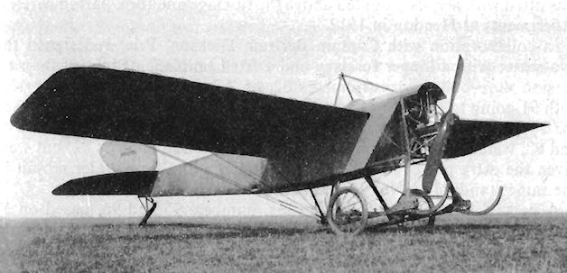
Single-seat Bristol Prier Monoplane used at the Larkhill school.
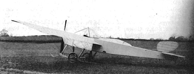
Bristol Prier Sociable Monoplane.
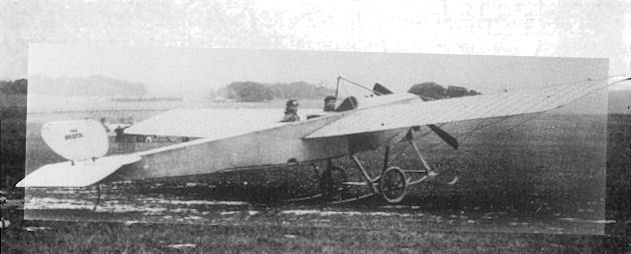
Bristol-Prier-Dickson Monoplane long fuselage two-seater No. 82 with fixed tailplane.
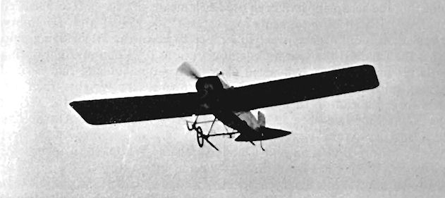
James Valentine piloting a Bristol Prier Monoplane.
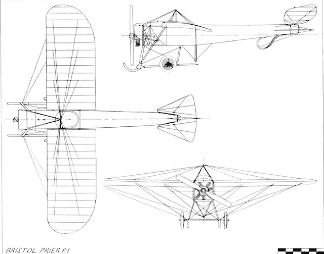
Bristol Prier P.1
Bristol Grandseigne Racer
Once the Boxkite was firmly established, the next type to be produced by the British and Colonial Aeroplane Company was considered, the choice falling upon a single-seat biplane for racing. In the design work, G. H. Challenger was assisted by Mons. R. Grandseigne, after whom the machine was known. The ubiquitous 50 h.p. seven-cylinder Gnome rotary was selected as the power plant, and the aeroplane which was evolved to house it demonstrated its designers' grasp, at an early stage in their vocation, of the value of an uncluttered, streamlined airframe.
Designed and built at the beginning of 1911 under works number 33, the Grandseigne was one of the earliest British tractor biplanes and, as such, was of advanced conception for its day. Weldless steel tubing, combined with wood, formed the fuselage structure, which was totally enclosed with fabric. Metal cowling panels covered the engine bay, which was left open at the front, and the undercarriage was a sturdy unit of steel tubing equipped with twin skids. The vertical tail surfaces comprised a rudder only, while the tailplane and divided elevators were of unusually large area. The single-bay wings used warping for lateral control, and received main spars of weldless steel tubing. Double surface covering was used, and the planes were supported on single centre-section and interplane struts, the overhang at the tips being similarly braced with thin tubing. The fuel was carried in tanks mounted in the open in front of the cockpit.
After being displayed on the Company's stand at the 1911 Olympia Aero Show, the Racer was taken to the flying school at Larkhill, but was crashed by Mons. Grandseigne on its first flight in April, 1911, and was never able to show its paces in a race.
SPECIFICATION
Description: Single-seat tractor racing biplane. Steel tubing/wooden structure, fabric covered.
Manufacturers: The British and Colonial Aeroplane Co. Ltd., Filton, Bristol.
Power Plant: 50 h.p. Gnome.
Dimensions: Span, 27 ft. Length, 25 ft. Wing area, 210 sq. ft.
Weights: Empty, 570 lb. Price: ?1,000.
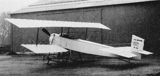
The Bristol Grandseigne racing biplane which was wrecked on its first flight at Larkhill in April 1911.
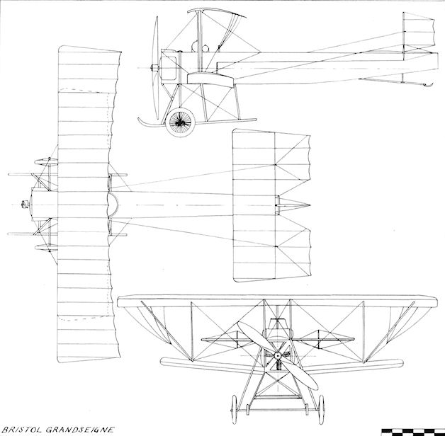
Bristol Grandseigne
/Bristol Boxkite
<...>
The single-seater number 45 was fitted also with the 50 h.p. Gnome, and was a new type somewhat resembling the Maurice Farman. It was flown in the same contest by Mons. Maurice Tabuteau, whose recommendations were incorporated in the design. Four generally similar single-seaters were entered for the 1911 Daily Mail Circuit of Britain, and Captain Bertram Dickson collaborated with Challenger in their design, the machines being designated Improved Type T. Numbers 51, 52 and 53 were powered by 70 h.p. Gnomes, while number 54 received the 60 h.p. Renault. The racing biplanes differed in several respects from the standard and military Boxkites. Light wood and fabric structures formed the nacelles, twin rudders and hooped rattan tailskids were fitted, the ailerons on the lower wings were deleted, and the ailerons on the upper wing extensions were each in one piece. A more powerful Improved Type T single-seater, to be fitted with the 100 h.p. Gnome, and numbered 78, was not completed. A further racing variant, using standard Boxkite wings but with the nose elevator and booms deleted and the landing-gear reduced in height, was designed by Gabriel Voisin and allotted number 69. It had a 50 h.p. Gnome and was completed in February, 1912, but appears not to have been flown.
<...>
Bristol Challenger-England Biplane
Designed by E. C. Gordon England, the experimental single-seat tractor biplane number 59 was built in 1911 and was a conversion of one of Challenger's Type T pushers using the 60 h.p. E.N.V. "F" engine. It incorporated an ingenious fuel system in which several tanks in the nacelle were pressurized by an air pump so as to supply petrol to a small header tank, which fed the engine by gravity so that air bubbles in the carburettor were eliminated. One only was built, and this overturned at Larkhill after running into a crowd of spectators on 19th May, 1912. Span, 35 ft.
<...>
The single-seater number 45 was fitted also with the 50 h.p. Gnome, and was a new type somewhat resembling the Maurice Farman. It was flown in the same contest by Mons. Maurice Tabuteau, whose recommendations were incorporated in the design. Four generally similar single-seaters were entered for the 1911 Daily Mail Circuit of Britain, and Captain Bertram Dickson collaborated with Challenger in their design, the machines being designated Improved Type T. Numbers 51, 52 and 53 were powered by 70 h.p. Gnomes, while number 54 received the 60 h.p. Renault. The racing biplanes differed in several respects from the standard and military Boxkites. Light wood and fabric structures formed the nacelles, twin rudders and hooped rattan tailskids were fitted, the ailerons on the lower wings were deleted, and the ailerons on the upper wing extensions were each in one piece. A more powerful Improved Type T single-seater, to be fitted with the 100 h.p. Gnome, and numbered 78, was not completed. A further racing variant, using standard Boxkite wings but with the nose elevator and booms deleted and the landing-gear reduced in height, was designed by Gabriel Voisin and allotted number 69. It had a 50 h.p. Gnome and was completed in February, 1912, but appears not to have been flown.
<...>
Bristol Challenger-England Biplane
Designed by E. C. Gordon England, the experimental single-seat tractor biplane number 59 was built in 1911 and was a conversion of one of Challenger's Type T pushers using the 60 h.p. E.N.V. "F" engine. It incorporated an ingenious fuel system in which several tanks in the nacelle were pressurized by an air pump so as to supply petrol to a small header tank, which fed the engine by gravity so that air bubbles in the carburettor were eliminated. One only was built, and this overturned at Larkhill after running into a crowd of spectators on 19th May, 1912. Span, 35 ft.

Collyns P.Pizey leaving the cockpit of the Bristol Improved Type T No. 52 racing biplane at Hendon during the 1911 Daily Mail Circuit of Britain.
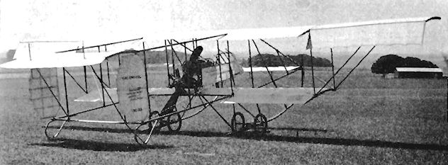
Bristol Boxkite Improved Type T No. 52 for 1911 Daily Mail Circuit of Britain.
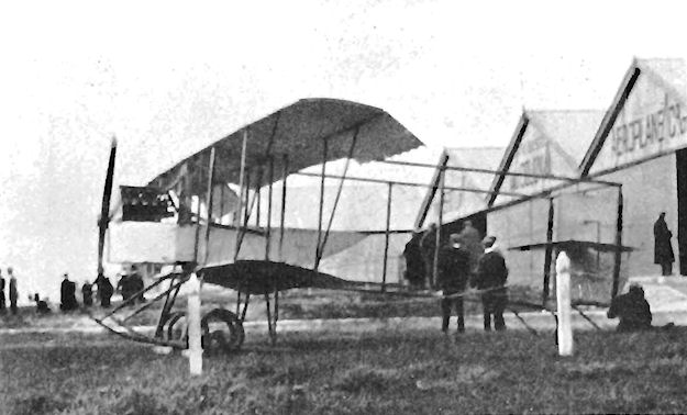
Bristol Burney X.1, X.2 and X.3
During October, 1911, following several over-water flights made from Hayling Island, Hants., with C. Howard Pixton in a Boxkite fitted with flotation bags beneath its lower wings' centre-section. Lt. Charles Dennistoun Burney, R.N., submitted proposals to the British and Colonial Aeroplane Company for the construction of an aircraft fitted with hydrofoils.
The idea arose from his investigations into the experiments made by the Italians Forlanini and Guidoni with a view to increasing the speed of fast motor-boats by enabling them to reduce water friction through planing on hydrofoils. The hydrofoil principle appeared to have great possibilities in assisting naval aircraft, in which the Admiralty was considerably interested, off the water quickly with their loads when at sea. The Admiralty agreed that the idea should be developed, and the firm set up a special design office for the purpose at 4 Fairlawn Avenue, Filton. The whole project was treated as highly secret, the section being designated X Department.
In December, 1911. Frank S. Barnwell was placed in charge as experimental designer and, working with Lt. Burney, prepared plans for a revised version of the Gordon England G.E.I biplane converted into a hydrofoil seaplane. In X. 1, as the project was known, the 50 h.p. Clerget engine was supplanted by the eight-cylinder 60 h.p. E.N.V. Type "F", which gave the extra power required. A shaft between the vee-form cylinder banks was fitted at each end with a Hele-Shaw clutch. A conventional tractor propeller was connected to the front clutch; the rear clutch was incorporated in a bevel gearbox. From this gearbox were taken a pair of shafts through downwards-extending tubes on the exteriors of which were fitted sets of superimposed hydrofoils. A second bevel gear at the lower end of each of these tubes was connected to a propeller which was submerged when the X.1 was in the water. A third hydrofoil-equipped tube, without any propeller, was mounted vertically under the after end of the fuselage, the name "hydropeds" being given to the tubes complete with their hydrofoils. Five airbags of streamline shape were intended to support the X.1 on the water, with the actual planing being performed by the hydrofoils. Initial movement in the water was to be provided by the engagement of the underwater propellers, with the flying propeller being engaged by its clutch once the X.1 had raised itself sufficiently out of the water upon its hydrofoils.
Before the X.1 could be built, Barnwell and his assistant designer Clifford W. Tinson, who had joined him in the project in January, 1912, had second thoughts about the entire scheme, and a radical new concept was put forward. The biplane lay-out was discarded and was replaced by that of a monoplane, again a tractor, whose wings, including the ailerons, were to be inflatable. The profile of the wing section was to be filled by eight rubberized-canvas airbags of different diameters, with their length running from tip to tip. The wing section was to be maintained by external flat spruce ribs, joined by bicycle spokes between the upper and lower booms with hinged joints at the leading and trailing edges. Normal external wire bracing was proposed and, besides providing buoyancy on the water and making fewer under-fuselage floats necessary, the wings could be deflated for stowage aboard ship. However, the inflatable wings feature was too far ahead of its time to be practical with the heavy and comparatively weak rubberized-canvas then available.
During the following month, in February, 1912, the project was revised completely once again under the designation X.2, works number 92. The fuselage was built as a waterproof hull, covered with thin mahogany, over which was varnished sailcloth, the intention being that this should rest in the water without the aid of separate floats. The engine used was the water-cooled 80 h.p. Canton-Unne, coupled to the clutch and hydropeds designed for the preceding X.1. The three struts carrying the hydrofoils were of streamlined section and the thrust-line of the flight propeller was set high in the fuselage for maximum clearance. The tailplane and elevators were mounted on the upper longerons and the vertical surfaces consisted of a rudder only. The wings were modified into a simpler conventional type with ribs built up around three spars, but were still designed to be buoyant; small, rectangular-section floats were attached later by short struts towards the wing-tips when it was found that the tips kept submerging owing to the lateral instability of the hydropeds. The cockpit was provided with side-by-side seats and dual controls.
In just over two months the X.2 was complete and ready for tests, which were to be conducted at Dale, near Milford Haven, it was taken there on board the lighter Sarah, loading being carried out at Avonmouth on 9th May, 1912. Some minor leaks were encountered when the machine was put into the water, but, after they had been attended to, attempts were made to taxi with the under-water propellers operating. Tests were made also by towing behind a naval torpedo-boat and, as a result of these practical experiments, alterations were made to the hydrofoil system to improve stability in the water. As a further aid to this, under-water rudders were fitted and a controllable water elevator was added to the hydroped at the rear. Despite these refinements, trouble was still experienced with the machine heeling over when the water propellers were clutched in under tow. Later in the year, in September, the decision was taken to commence the first air tests but still to rely upon towing. To ascertain the X.2's airborne characteristics the Canton-Unne was taken out, of the nose and 500 lbs. of ballast was inserted in its place.
Towing commenced on 21st September, 1912, with Lt. G. Bentley Dacre, R.N., in control of the aircraft. When a towing speed of 12 knots was reached the X.2 left the water in a steep climb and, before Lt. Dacre could level out, the line was released from the boat. The machine stalled immediately, and side-slipped into the water and was damaged, but Lt. Dacre was unhurt.
The project was still considered worthy of continuation, and the Admiralty sanctioned further work on it. A new version, designated X.3, with works number 159, was designed by Barnwell and Tinson. The machine was larger than the X.2, and consideration was at first given to powering it with a pair of Renault engines of 80 h.p. each. The Admiralty offered to lend a 200 h.p. Canton Unne, and it was then decided to take advantage of the greater power thus provided. After being constructed at Filton, the framework of the hull was sent to Cowes, Isle of Wight, where S. F. Saunders covered it with their Consula system of plywood sewn with copper wire. The X.3's wings were fitted with ailerons, and small hydrofoils were embodied under the floats at the wing-tips. An attempt to eliminate torque reaction from the water propellers was made by installing them back-to-back on a central pylon separate from the hydropeds, and rotating in opposite directions. The work took nearly a year to complete and the X.3 arrived at Dale in August, 1913, for the resumption of the experiments. Behaviour under power was found to be very good, apart from a tendency for the nose to dip when the flight propeller was engaged. Barnwell designed an elevator, to be controlled by the flight clutch and mounted in front of the wings, which it was hoped would eliminate the fault.
The modification was not given a chance to prove itself, as before it could be incorporated the X.3 was wrecked on a sandbank during taxying trials. Thereafter, as increased financial support from the Admiralty was not forthcoming, the hydrofoil project was dropped to enable full concentration of resources upon seaplanes of a more conventional type.
SPECIFICATION
Description: Two-seat tractor hydro-monoplane. Wooden structure, fabric covered.
Manufacturers: The British and Colonial Aeroplane Co. Ltd., Filton, Bristol.
Power Plant: (X.2) 80 h.p. Canton Unne. (X.3) 200 h.p. Canton Unne.
Dimensions: (X.2) Span, 55 ft. 9 ins. (X.3) Span, 57 ft. 10 ins. (X.2) Length, 30 ft. 8 ins. (X.3) Length, 36 ft. 8 ins. (X.2) Wing area, 480 sq. ft. (X.3) Wing area, 500 sq. ft.
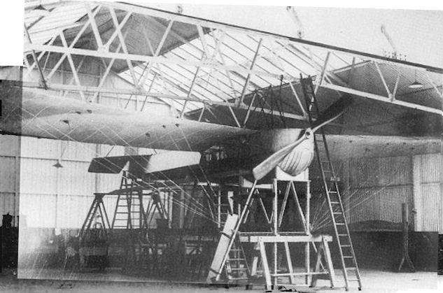
Original version of Bristol Burney X.2 monoplane Works No.92 of 1912 being constructed at Hilton.
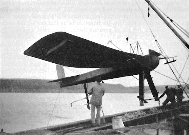
Modified Bristol Burney X.2 slung from derrick at Dale.
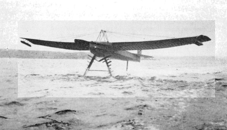
Stimulated by work in Italy Lt C. D. Burney, R.N., persuaded the British and Colonial Aeroplane Co..Ltd. to undertake a design and development programme for aircraft havIng hydrofoil undercarriages. In the picture the Bristol Burney X.2 in modified form hydroplaning under tow at Dale.
Bristol Coanda Monoplanes
Early in 1912 Mons. Henri Coanda, a Roumanian, produced the first of his machines to be built by the British and Colonial Aeroplane Company since he joined the firm as a designer. A monoplane intended for school use, it featured a steel-tubing chassis made in the style of the 1911 Grandseigne Racer.
Well proportioned and strongly built, it seated two in tandem and was powered by the 50 h.p. Gnome. The strong undercarriage was fitted with an additional small wheel at the forward end of each of the skids. The landing wires were supported at a comparatively shallow angle by short streamlined pylons above the fuselage, the wings possessing a warping movement of 3 ft. at the tips. No fin was installed and the elevator was in one piece. Foot pressure on the rudder-bar operated the band-brakes with which the undercarriage was equipped - an advanced feature at the time. The passenger occupied the front seat, which was placed over the centre of gravity so that the balance was not disturbed when the machine was flown solo. The airframe was fabric-covered, except for the fore-part of the fuselage, which received metal panels.
Six Coanda School Monoplanes were built with works numbers 77, 132, 185, 186, 188 and 189. A side-by-side variant of number 77 was built as number 80, and was crashed by a pupil while under instruction by F. Warren Merriam in January 1914.
With the Military Trials in prospect in August, 1912, the company decided to enter a pair of Coanda Monoplanes as well as their two G.E.2 Biplanes, and two military versions were constructed The 80 h.p. Gnome conferred extra power in place of the standard 50 h.p. engine. The span and wing area were reduced slightly, but the overall length was increased.
The empty weight rose by 230 lb. The machines were built under works numbers 105 (Military Trials 14) and 106 (Military Trials 15), and were flown respectively by Harry Busteed and James Valentine in the competition, gaining third place in the British-built section, although Valentine was unfortunate in crashing his aircraft during the tests on the first day. After repairs it was taken over by C. H. Pixton, as he had abandoned his G.E.2. Number 105 was fitted with a fixed fin in front of a rudder of smaller area which had been moved forward on the fuselage, this arrangement being arrived at after tests with various rudders before the Trials commenced.
The crash of a Coanda Military Monoplane on 10th September, 1912, at Wolvercote, Oxford, in which Lts. C. A. Bettington and E. Hotchkiss were killed, was responsible for the decision of the War Office to ban the use of all monoplanes in the Military Wing of the R.F.C. after several fatal accidents had occurred also with other types of monoplane. The Admiralty, however, continued to allow the Naval Wing of the R.F.C. to fly monoplanes, and the Coanda was exported to Bulgaria, Germany, Italy and Roumania. The export version for Italy and Roumania was fitted with the Grandseigne type of steel undercarriage skids and was built under works numbers 110, 164, 165, 166, 176 and 177. The production model of the Military Trials Monoplane 105 was revised with the wingspan increased from 40 ft. to 42 ft. 9 ins. and received a larger rudder. It was known as the Improved Coanda Military, of which numbers 118, 121, 122, 123, 131, 142-154 inclusive, and 196 were produced and were sold to Germany, Italy and Roumania. All of the Military Coandas were equipped with 80 h.p. Gnome engines, but a further experimental example, number 111, was built with the 70 h.p. Daimler taken from Gordon England's G.E.2 Biplane 104, which had flown as No. 13 in the Military Trials of 1912. The chassis of number 111 was of welded steel tubing, and its Daimler engine increased the machine's length to 30 ft. 9 ins.
SPECIFICATION
Description: Two-seat tractor training monoplane. Wooden structure, fabric covered.
Manufacturers: The British and Colonial Aeroplane Co. Ltd., Filton, Bristol.
Power Plant: 50 h.p. Gnome.
Dimensions: (Works number 80). Span, 41 ft. 3 ins. Length, 27 ft. Wing area, 275 sq. ft.
Weights: (Works number 80). Empty, 770 lb.
Description: Two-seat military monoplane. Wooden structure, fabric covered.
Manufacturers: The British and Colonial Aeroplane Co. Ltd., Filton, Bristol.
Power Plant: 80 h.p. Gnome.
Dimensions: (Works number 118). Span, 42 ft. 9 ins. Length, 29 ft. 2 ins. Wing area, 280 sq. ft.
Weights: (Works number 118). Empty, 1,050 lb. Loaded, 1,775 lb.
Performance: (Works number 118). Maximum speed, 71 m.p.h. Endurance, 4 hrs.
Price: ?1,400.
Description: Two-seat military monoplane. Wooden structure, fabric covered.
Manufacturers: The British and Colonial Aeroplane Co. Ltd., Filton, Bristol.
Power Plant: 80 h.p. Gnome.
Dimensions: (Works number 105, Military Trials No. 14). Span, 40 ft. Length, 28 ft. 3 ins. Wing area, 242 sq. ft.
Weights: (Works number 105, Military Trials No. 14). Empty, 1,000 lbs. Loaded, 1,710 lb.
Performance: (Works number 105, Military Trials No. 14). Maximum speed, 73 m.p.h. Endurance, 7 hrs.
Description: Two-seat experimental tractor monoplane. Wooden structure, fabric covered.
Manufacturers: The British and Colonial Aeroplane Co. Ltd., Filton, Bristol.
Power Plant: 70 h.p. Daimler.
Dimensions: (Works number 111). Span, 39 ft, 4 ins, Length, 30 ft, 9 ins, Height, 7 ft, 1 in. Wing area, 260 sq. ft.

Bristol Coanda Improved Military Monoplane.
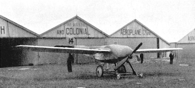
Bristol Coanda Military Trials Monoplane without fin.
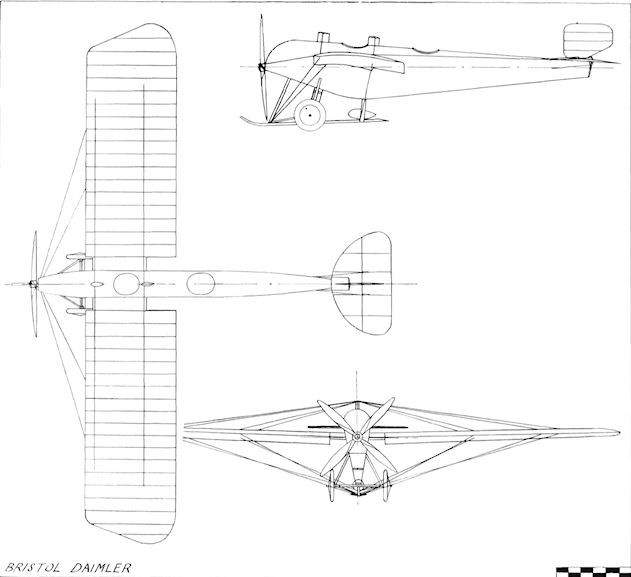
Bristol Daimler
Bristol G.E.I
The G.E.I military biplane was designed by E. C. Gordon England and was built during 1912. One machine, works number 64, was constructed and was a side-by-side two-seater powered by the four-cylinder in-line 50 h.p. Clerget engine with chain drive to the propeller. In its original form, the lower wings passed below the fuselage but rested against the longerons. Later, fairings were added to blend the wings smoothly into the underside of the machine, the fin was removed and the rudder was modified in shape to resemble that of the later G.E.2, the area of the radiator at the nose was reduced, and wing-tip skids were added.
The G.E.I was designed to be dismantled easily for transport and was demonstrated to both Army and Naval authorities. Lt. C. D. Burney, R.N., made it the basis of a design study for a seaplane, the X.1, to be carried on a warship, but eventually the aircraft itself was sold to Germany. Span, 33 ft. 8 ins. Length, 29 ft.
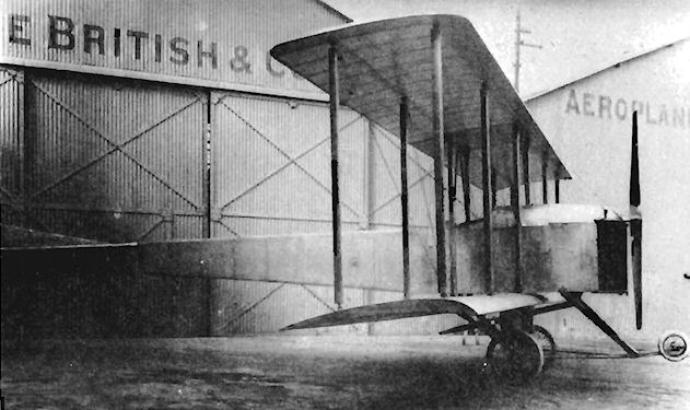
Bristol G.E.I with original fin and rudder.
Bristol G.E.2
In addition to the pair of Coanda Military Monoplanes entered in the Military Trials held during August, 1912, the British and Colonial Aeroplane Company constructed two biplanes designed by E. C. Gordon England and designated G.E.2. They were basically more powerful developments of the earlier G.E.I design; both were side-by-side two-seaters with dual controls. Their engines differed, as works number 103 (Military Trials No. 12) was fitted with the fourteen-cylinder 100 h.p. Gnome, while works number 104 (Military Trials No. 13) was equipped with the less-powerful four-cylinder 70 h.p. Daimler.
In the Trials number 12 was piloted by C. Howard Pixton, while Gordon England flew number 13. Unfortunately, although they appeared in April, both were found to be under-powered for their size and were withdrawn from the tests. Extraordinary stability was displayed by Gordon England's machine when he took off with the elevators locked and flew for one and a half hours before discovering the fact. During the flying at Salisbury Plain the undercarriage of number 13 was damaged.
Both G.E.2s were two-bay non-staggered biplanes with their fuselages suspended between the wings. Rounded decking was fitted above and below the fuselage. No fin was fitted and the tailskid was mounted direct on to the rudder post. Twin nose-wheels were incorporated in the main undercarriage, and skids were fitted below the wing-tips. The metal panels over the nose of the fuselage were removable to facilitate access to the cowled engine. The Daimler engine installed in number 104 was removed later and was used to power the experimental Coanda Monoplane number 111.
SPECIFICATION
(Works number 103, Military Trials No. 12)
Description: Two-seat tractor military biplane. Wooden structure, fabric covered.
Manufacturers: The British and Colonial Aeroplane Co. Ltd., Filton, Bristol.
Power Plant: 100 h.p. Gnome.
Dimensions: Span, 40 ft. Length, 31 ft. Wing area, 400 sq. ft.
Weights: Loaded, 1,474 lb.
Performance: Maximum speed, 60 m.p.h.
(Works number 104, Military Trials No. 13)
Description: Two-seat, tractor military biplane. Wooden structure, fabric covered.
Manufacturers: The British and Colonial Aeroplane Co. Ltd., Filton, Bristol.
Power Plant: 70 h.p. Daimler.
Dimensions: Span, 40 ft. Length, 31 ft. Wing area, 400 sq. ft.
Weights: Loaded, 1,650 lb.
Performance: Maximum speed, 57 m.p.h.
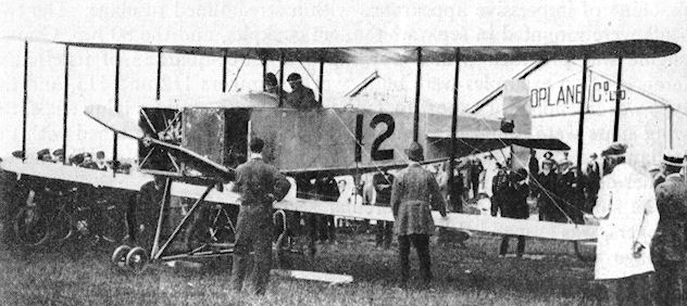
Bristol G.E.2 being prepared for flight at Larkhill.
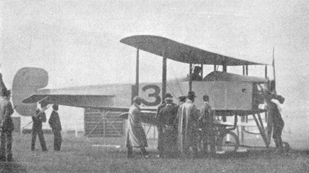
Bristol G.E.2 flown by E. C. Gordon England in the 1912 Military Trials.

Bristol G.E.2
Bristol G.E.3
The third Gordon England biplane design to appear during 1912 was a machine of impressive appearance with a streamlined fuselage. The two seats were mounted in separate tandem cockpits, and the 80 h.p. Gnome engine was provided with a cowling over three-quarters of its circumference. Two examples were built, works numbers 112 and 113, and the type was intended for export to Turkey. However, during flying trials, the wing spars were found to be unduly flexible and this, combined with the Italian successes against the Turks in Tripoli, frustrated the sale and no further development was undertaken.
The slim fuselage, with its circular section conferred by formers and stringers, was suspended between the pairs of two-bay wings. The undercarriage was a very strong unit on which the machine was mounted through a sturdy central pylon passing into the fuselage. Twin nose-wheels were also a part of the design, and the unusually long tailskid kept the G.E.3 in an almost horizontal position for take-off and landing. Warping of the wings was used for lateral control, and skids were fitted at the tips. In common with the earlier Gordon England biplanes there was no fixed fin.
SPECIFICATION
Description: Two-seat tractor military biplane. Wooden structure, fabric covered.
Manufacturers: The British and Colonial Aeroplane Co. Ltd., Filton, Bristol.
Power Plant: 80 h.p. Gnome.
Dimensions: Span, 40 ft. Length, 26 ft. 3 ins. Wing area, 387 sq. ft.
Weights: Empty, 1,096 lb. Loaded, 1,996 lb.
Performance: Maximum speed, 65 m.p.h.

Bristol G.E.3

Bristol G.E.3
Bristol B.R.7
In view of the opposition to the monoplane by the Royal Flying Corps, the British and Colonial Aeroplane Company was reluctantly compelled to concentrate its production on biplanes.
Some six months after the monoplane ban, the B.R.7 Biplane appeared and was displayed at the 1913 Olympia Aero Show. Basically, it consisted of the Coanda Military Monoplane's fuselage, undercarriage and tail unit, which had been fitted with two-bay unstaggered biplane wings. A refinement on the undercarriage was the installation of wheel brakes. Warping was used for lateral control, and the eight-cylinder vee Renault engine of 70 h.p. was fully enclosed apart from cooling vents at the front and sides. This engine was chosen at the request of the Spanish Government, who already used it in their Maurice Farman Biplanes, but, in the final event, the B.R.7 was not sold to Spain but remained at the Company's flying-school at Larkhill, seven being constructed with works numbers 157, 158, 160, 161, 162, 163 and 178.
SPECIFICATION
Description. Two-seat tractor training biplane. Wooden structure, fabric covered.
Manufacturers: The British and Colonial Aeroplane Co. Ltd., Filton, Bristol.
Power Plant: 70 h.p. Renault.
Dimensions: Span, 38 ft. Length, 27 ft. 5 ins. Wing area, 440 sq. ft. Weights: Empty, 946 lb. Loaded, 1,826 lb.
Performance: Maximum speed, 63 m.p.h. Landing speed, 33 m.p.h. Climb, 1,000 ft. in 4 mins.
Price: ?1,800.
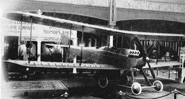
Bristol Coanda B.R.7 at 1913 Olympia Aero Show.
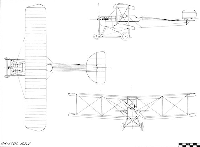
Bristol B.R.7
Bristol Coanda Hydro-biplane
The Coanda Hydro-biplane was designed by Mons. Henri Coanda and built during 1913. It seated two in tandem cockpits in a streamlined, circular-section fuselage which was suspended between the wings. One large central float, augmented by a small pair at the wing-tips, supported the machine on the water. The first main float of Gnosspelius design (illustrated) proved to be too heavy and was replaced by a lighter one of the same size made by S. E. Saunders of Cowes on their Consuta system. The engine was the 80 h.p. Gnome, and an extra rudder was mounted below the tail to balance the additional side area of the float. The machine was given works number 120. It was wrecked when the float collapsed during a landing being made on 15th April, 1913, off Cowes by Harry Busteed. Span, 40 ft. (approx.). Length, 30 ft. (approx.). Wing area, 500 sq. ft.
Bristol T.B.8 Hydro-biplane
As a quick replacement for number 120, in the summer of 1913 one of the 1912 Improved Coanda Military Monoplanes, works number 121, was converted direct into a T.B.8 Hydro-biplane and was tested in July at Larkhill with a landplane undercarriage. Twin floats were then made for it by employing the simple expedient of taking the unsuccessful original Gnosspelius single float of the Coanda Hydro-biplane number 120 and cutting it down the centre-line to make two. Wing-tip and tail floats were not used, but fins above and below the fuselage were added, together with a small rudder on the underside of the tail.
The machine first flew successfully from the water at Dale, Pembrokeshire, on 20th September, 1913. Some three months later, in December, it was returned to Filton and reconstructed under works number 205, during which time the wing-warping control was replaced by ailerons. Number 205 was then delivered on 2nd January, 1914, to the Admiralty at Calshot as naval aircraft 15. Throughout these changes, the machine retained the 80 h.p. Gnome engine.
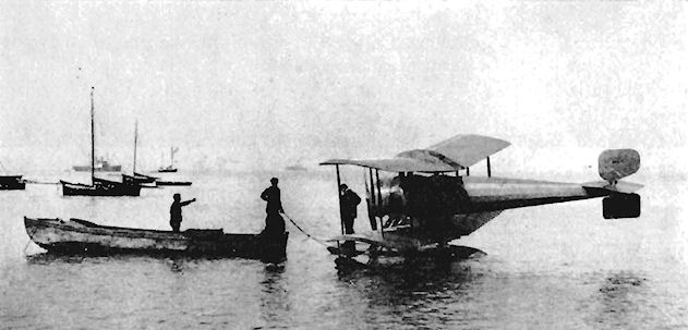
The Bristol Coanda Hydro-biplane floating off Cowes in March, 1913.
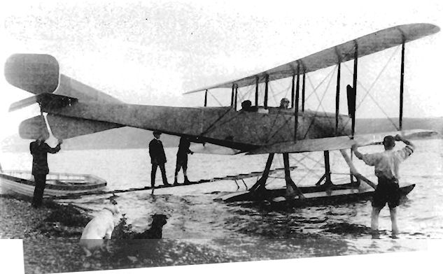
Bristol T.B.8 Hydro-biplane shown at Dale during July, 1913, in its original form. The prototype converted to a seaplane.
Bristol T.B.8
The sole aeroplane representing Great Britain at the 1913 Paris Aero Show was theT.B.8 Biplane, works number 153. It had been developed by Mons. Henri Coanda from the military monoplane and embodied refinements and modifications suggested from experience of the Coanda machines employed during the Balkan War of the previous year. Twelve bombs could be carried inracks under the fuselage, signal lamps were fitted and an additional item of equipment was a drift sight for calculating the ground speed. Number 153 was one of ten Improved Coanda Military Monoplanes which had been returned to Filton from the Naval Wing of the R.F.C. and from Roumania for conversion to biplanes, the others being works numbers 118, 143, 144, 147, 148, 149, 151, I 52 and 196. Wing warping was retained on the batch, as also was the 80 h.p. Gnome engine for power.
A further pair of 80 h.p. Gnome T.B.8s were built for the Admiralty under works numbers 197 and 198, becoming naval aircraft 916 and 153 respectively. Yet another biplane conversion carried out was on the side-by-side Coanda Military Monoplane number 177, which became T.B.8 School number 218 and was in use in 1914 at the Larkhill School. Two further T.B.8s were supplied to the Admiralty by rebuilding the War Office T.B.8s army aircraft 144 (works number 225) and 153 (works number 227), which then flew as naval aircraft 43 and 917 respectively. Another T.B.8, works number 228, as number 197 for the War Office, was supplied to Breguet, who undertook the manufacture of the type in France.
A final production batch of T.B.8s, of improved type with ailerons, was ordered for the R.N.A.S. and was delivered after the outbreak of the 1914-18 War. Thirty-six of these were built, works numbers 331-342 inclusive, and 870-893 inclusive. The T.B.8 was used by No. 1 Squadron, R.N.A.S., and by the Roumanian Army, total production of all versions of the type being fifty-two.
SPECIFICATION
Description: Two-seat tractor training and reconnaissance biplane. Wooden structure, fabric covered.
Manufacturers: The British and Colonial Aeroplane Co. Ltd., Filton, Bristol.
Power Plant: 80 h.p. Gnome.
Dimensions: Span, 37 ft. 8 ins. Length, 29 ft. 3 ins. Wing area, 450 sq. ft.
Weights: Empty, 970 lb. Loaded, 1,665 lb.
Performance: Maximum speed, 75 m.p.h. Climb, 3,000 ft. in 11 mins. Endurance, 5 hrs.
Bristol G.B.75
An improved version of the T.B.8, designated G.B.75, works number 223, was designed by Mons. Henri Coanda and Frank Barnwell and was exhibited at the Olympia Aero Show of 1914. The engine was the seven-cylinder 75 h.p. Monosoupape Gnome fitted with a large shallow spinner which blended into the circular engine cowling and which incorporated radial louvres for the entry of cooling air. Other alterations from the basic T.B.8 included the addition of rounded deckings above and below the fuselage, a fixed fin and wing-tip skids. The G.B.75 was bought by the War Office and was employed by the R.F.C. as No. 610. Span, 37 ft. 8 ins. Wing area, 420 sq. ft. Weight empty, 970 lb. Weight loaded, 1,665 lb. Maximum speed, 62 m.p.h. Landing speed, 33-5 m.p.h. Endurance, 5 hrs.

Bristol T.B.8

Bristol Improved T.B.8 with ailerons for R.N.A.S.
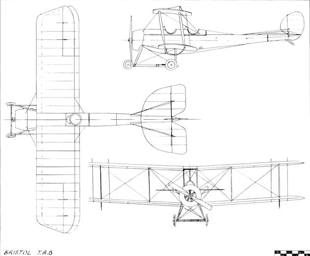
Bristol T.B.8
Bristol S.B.5
During 1913, once it had become apparent that the aeroplane had reached a state of development whereby it could be of use in warfare, several firms initiated design work on single-seat scouts. Among them, was the British and Colonial Aeroplane Company, one of whose designers, Mons. Henri Coanda, produced a tractor monoplane known as the S.B.5. An 80 h.p. Gnome engine was specified and construction was started under works number 183. The War Office's disapproval of monoplanes had its effect on the project, however, and the building of the S.B.5 was brought to a halt at an early stage. The parts were used later in the Scout A.
Bristol Scout A and B
During 1913, Frank Barnwell set to work to produce a single-seat scout in the form of a biplane, and the resultant Scout A was built under works number 206. The partly-completed airframe of the abandoned S.B.5 was converted for use in the Scout A, the design of which was assisted by Harry Busteed. The power plant was the 80 h.p. Gnome partly cowled, the lower portion being left open. Single-bay wings of a comparatively small span of 22 ft. were used, together with cable-connected ailerons on upper and lower tips. The wooden fuselage consisted of a slab-sided structure, surmounted by a former and stringer decking, and metal cowling panels extended to the rear of the cockpit. The Scout was not provided with a fixed fin. The undercarriage was a simple, neat arrangement of a pair of vee-struts, with the wheels of fairly generous diameter mounted on a transverse axle with rubber cord shock-absorbers, the unit being devoid of unsightly, drag-inducing skids and their attendant struts and wires. All of the control wires were duplicated for safety, and the pilot's seat was adjustable for height.
Upon completion, the Scout A was taken to Larkhill, where, piloted by Harry Busteed, it was flown for the first time on 23rd February, 1914. Test flights were very successful, and the machine was displayed at the 1914 Olympia Aero Show held during the following month. It was decided to fit larger wings to the prototype, and it reappeared on 2nd April, 1914, with an increased span measuring 24 ft. 7 ins. The cowling also was modified to a fully circular type. A practical demonstration of its speed was given at Easter, when Busteed flew it from Larkhill to Brooklands in 20 minutes. On 14th May, 1914, Harry Busteed put the Scout A through its A.I.D. tests and recorded a top speed of 97 m.p.h. and a climb of 800 ft. per minute. The machine was entered for the third Aerial Derby due to be held on 23rd May, but which, owing to bad weather, had to be postponed until 6th June. S. V. Sippe was the pilot nominated to fly it in the race, but he was forced to withdraw as the visibility was too poor. Two days after the contest, on 8th June, 1914, the Scout A was flown by Lord John Carbery. He was so impressed by the prototype's performance that he was allowed to buy the bare airframe, in which he installed the 80 h.p. le Rhone from his Morane Saulnier Monoplane, the work being completed in time for him to fly it under racing number 12 in the Hendon-to-Manchester and return race flown on 20th June. Lord Carbery damaged the undercarriage when he nosed over upon landing at Birmingham and was forced to retire from, the event. Repairs were soon effected and extra fuel tanks were installed to increase the Scout"s range for the London-to- Paris and return race flown on 11th July, 1914. Lord Carbery was the pilot but on the return lap he ran out of petrol in mid-Channel, owing to a mistake in refuelling in Paris; the resulting engine failure forced him to land in the water. Luckily he was picked up by a passing tramp steamer, but the Scout could not be salvaged and it sank.
Prior to the outbreak of war, two additional improved 80 h.p. Gnome Scouts, designated Scout B and given works numbers 229 and 230, were supplied to the R.F.C., flying as 633 and 634 respectively. The Scout was produced later in quantity for the R.F.C. and the R.N.A.S., and gave extensive service during the 1914-18 War under its designations Scouts C and D. When the numbered system of Bristol types was applied retrospectively in 1923 the Scout C was chosen to start the range as Type I.
SPECIFICATION
Description: Single-seat racing and reconnaissance biplane. Wooden structure, fabric covered.
Manufacturers: The British and Colonial Aeroplane Co. Ltd., Filton, Bristol.
Power Plant: 80 h.p. Gnome. 80 h.p. le Rhone.
Dimensions: {Scout A) Span, 22 ft. (later 24 ft. 7 ins.). Length, 19 ft. 9 ins. Wing area, 161.5 sq. ft. (later 198 sq. ft.). (Scout B) Span, 24 ft. 7 ins. Length, 20 ft. 8 ins. Height, 8 ft. 6 ins. Wing area, 198 sq. ft.
Weights: (Scout A) Empty, 617 lb. Loaded, 957 lb.
Performance: (Scout A) Maximum speed, 97 m.p.h. Landing speed, 47 m.p.h. Climb, 800 ft. min. Endurance, 3 hrs.

Bristol Scout A prototype on display at the 1914 Olympia Aero Show.
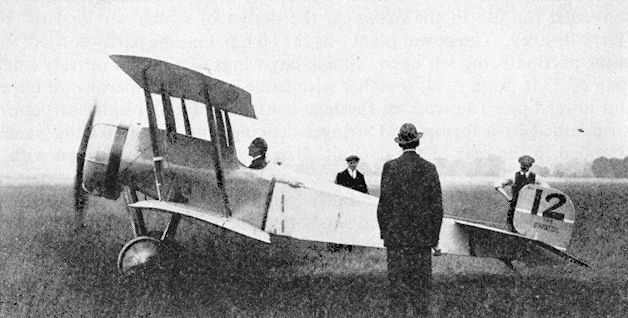
Lord John Carbery's Bristol Scout A prototype, fitted with 80 h.p. le Rhone, at the start of the London-Paris-London Race on 11th July, 1914.
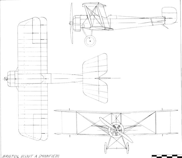
Bristol Scout A (modified)
Bristol P.B.8
The P.B.8 Scout was an experimental two-seat pusher biplane gun-carrier designed by Mons. Henri Coanda and built during 1913 under works number 199. The engine was the 80 h.p. Gnome, but the machine was not flown after completion at Brooklands. At the outbreak of war in August, 1914, the engine was requisitioned by the Admiralty. Span, 27 ft. 6 ins. Length, 27 ft. 6 ins.
The P.B.8 Scout was an experimental two-seat pusher biplane gun-carrier designed by Mons. Henri Coanda and built during 1913 under works number 199. The engine was the 80 h.p. Gnome, but the machine was not flown after completion at Brooklands. At the outbreak of war in August, 1914, the engine was requisitioned by the Admiralty. Span, 27 ft. 6 ins. Length, 27 ft. 6 ins.
Bristol S.S.A.
Built for the Breguet concern, the S.S.A. was a single-seat armoured scout designed by Mons. Henri Coanda under works number 219. It was a tractor biplane powered by the 80 h.p. Clerget, and crashed at Filton during 1914 while being flown by Harry Busteed. The S.S.A. featured a large spinner with an annular cooling slot between itself and the cowling. The whole of the front fuselage was built as a sheet-steel riveted monocoque enclosing the engine mounting, fuel and oil tanks and the pilot's seat, earning the machine its nickname of "The Bath". The two-wheel undercarriage incorporated a pair of skids lengthened at the rear so as to dispense with a tailskid; an early attempt to provide castoring wheels for cross-wind landings was also made.
Built for the Breguet concern, the S.S.A. was a single-seat armoured scout designed by Mons. Henri Coanda under works number 219. It was a tractor biplane powered by the 80 h.p. Clerget, and crashed at Filton during 1914 while being flown by Harry Busteed. The S.S.A. featured a large spinner with an annular cooling slot between itself and the cowling. The whole of the front fuselage was built as a sheet-steel riveted monocoque enclosing the engine mounting, fuel and oil tanks and the pilot's seat, earning the machine its nickname of "The Bath". The two-wheel undercarriage incorporated a pair of skids lengthened at the rear so as to dispense with a tailskid; an early attempt to provide castoring wheels for cross-wind landings was also made.
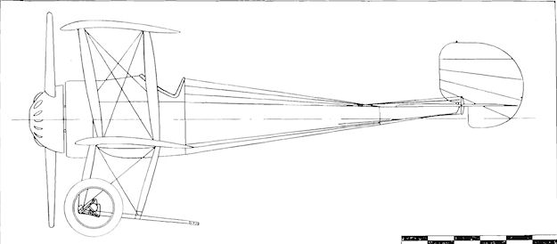
Bristol S.S.A.
Bush Gliders
Between 1909 and 1912 seven biplane gliders were designed and built by the three brothers Bush of Keynsham, Bristol. At the start of their experiments the eldest, Eldon, was seventeen years old, the second, named Gilbert, was sixteen, while the youngest of the trio was thirteen.
The first machine was of the Wright type, and was constructed of ash, covered with calico, which was doped with a paste made from sago. It proved to be too heavy when completed. Their second glider was the No. 1 with its ash framework shaved down, and was rigged with piano wire. It was tested both with and without a pilot and was found to lack stability longitudinally. No. 3 (illustrated) was built in 1910 and resembled the Curtiss biplane, except that the ailerons were hinged from the trailing edges of the lower wings. It had a single tailplane and was made as light as possible. The span was 30 ft., length 24 ft. and wing area was 260 sq. ft. It managed to fly for a few yards. The next machine, the No. 4, was built at Cambridge by Eldon while he was a student at university there during 1910. It was a more ambitious biplane of Farman pattern, and was fitted with a wheeled undercarriage for auto-towing. Construction was of hickory with fabric-covered wings. Nos. 5, 6 and 7 were further modifications of the No. 4, in which the fore-elevator was omitted and in which parts of previous machines were embodied. The final glider, the No. 7, was of simple but strong construction, and featured Bleriot-type elevators and single-spar wings. Named The Chocolate Soldier, it performed successfully under tow by car, but smashed its undercarriage while being flown in this way.

Bush glider No.3 of 1910 built by the three Bush brothers.
Bush Motorplane
The Motorplane was built at Bath, Somerset, in 1912 by Eldon and Gilbert Bush following the proficiency which they gained with their own gliders and upon professionally-built aircraft. The machine was a single-seater somewhat resembling the Caudron tractor biplane. In its original form, as the Bush No. 8, the nacelle was of small cross-section and it was intended to fit an in-line engine. When it proved impossible to obtain an engine of this type at a reasonable price the Bush brothers accepted the loan of a 50 h.p. Gnome rotary, the nacelle being widened accordingly to accommodate it. The machine was then re-designated the Bush No. 9, and it was planned that Eldon Bush should demonstrate it at Hendon. However, while on test at Keynsham the propeller shaft broke and it was not possible to secure a replacement engine before he had to go to Canada on business. On his return in 1915, Eldon Bush joined the R.N.A.S. and was killed while flying on anti-submarine patrol from Fishguard during 1917. The youngest of the three Bush brothers became a pilot in the R.F.C. in 1916 and survived a severe crash in France in 1917.
The Motorplane was built at Bath, Somerset, in 1912 by Eldon and Gilbert Bush following the proficiency which they gained with their own gliders and upon professionally-built aircraft. The machine was a single-seater somewhat resembling the Caudron tractor biplane. In its original form, as the Bush No. 8, the nacelle was of small cross-section and it was intended to fit an in-line engine. When it proved impossible to obtain an engine of this type at a reasonable price the Bush brothers accepted the loan of a 50 h.p. Gnome rotary, the nacelle being widened accordingly to accommodate it. The machine was then re-designated the Bush No. 9, and it was planned that Eldon Bush should demonstrate it at Hendon. However, while on test at Keynsham the propeller shaft broke and it was not possible to secure a replacement engine before he had to go to Canada on business. On his return in 1915, Eldon Bush joined the R.N.A.S. and was killed while flying on anti-submarine patrol from Fishguard during 1917. The youngest of the three Bush brothers became a pilot in the R.F.C. in 1916 and survived a severe crash in France in 1917.

Bush Motorplane No.9 a two-seater version of No.8 which did not fly.
Campbell Briton
Named Briton, the Campbell Monoplane was a single-seat tractor built at Bromley, Kent, during 1910 by Malcolm Campbell, later to achieve world fame as a record-breaker with cars and motor-boats. The fuselage was of triangular section, and power was provided by an air-cooled two-cylinder vee engine. The Briton made two short flights at Orpington, Kent, in 1910.
Named Briton, the Campbell Monoplane was a single-seat tractor built at Bromley, Kent, during 1910 by Malcolm Campbell, later to achieve world fame as a record-breaker with cars and motor-boats. The fuselage was of triangular section, and power was provided by an air-cooled two-cylinder vee engine. The Briton made two short flights at Orpington, Kent, in 1910.
Candler Stella
The Stella Monoplane was a single-seat tractor of the Bleriot type built at the beginning of 1910 by the Farnborough Aviation Works. Kent, for H. A. Wagstaff Candler of London. Span,36ft. Length, 26 ft. Wing area, 247 sq.ft. Weight empty, 250 lb.
Alderson Monoplane
The Alderson Monoplane was built during 1910 by the Farnborough Aviation Works, Kent.
Carter Biplane
The single-seat Carter Biplane was built during 1910, and tested on Salisbury Plain in January, 1911. The engine was an eight-cylinder 60 h.p. Nonpareil made by the Nonpareil Fitting Co. of Birmingham.
The single-seat Carter Biplane was built during 1910, and tested on Salisbury Plain in January, 1911. The engine was an eight-cylinder 60 h.p. Nonpareil made by the Nonpareil Fitting Co. of Birmingham.
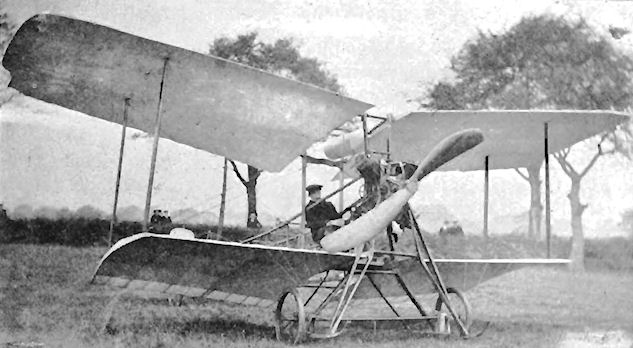
The biplane, with which Mr. Carter has been experimenting at Salisbury Plain during the last fortnight, as seen from in front.
Cayley 1809 Glider
Following his experiments with models and the consequent establishment of a practical form of man-carrying aircraft, Sir George Cayley had by 1809 constructed a full-size glider. The area of the lifting surfaces was 300 sq. ft. and, with a loaded weight of 140 lb., this gave a wing-loading of just under 1/2 lb. sq. ft. Tests at Brompton Hall demonstrated that the machine was quite stable and that it would glide downhill in any direction dictated by its rudder. These trials were unmanned, but Cayley claimed that, when anyone ran forward with it at full speed into a gentle breeze, the glider's lift was so strong that it would often rise and bear the runner aloft for several yards at a stretch. Before further investigations could be carried out with the machine, it was accidentally broken.
Cayley 1849 Glider
Forty years elapsed between the building of Sir George Cayley's full-size unmanned glider of 1809 and his man-carrying glider of 1849. In the interim, many varied ideas for the advancement of the science of flight passed through his fertile mind and were committed to paper in his notebooks.
The details of the form of this later machine are the sole known particulars to have survived of the earliest aircraft constructed with the express intention of carrying a man. An examination of the glider reveals immediately the remarkably high level of practical aerodynamic knowledge which had been reached as a result of his work. The machine was a triplane with a total wing area of 338 sq. ft., the surfaces being set with dihedral to assist lateral stability. The boat-shaped nacelle was suspended below the wings by struts and was braced with wires. The glider rested on an undercarriage of three tension wheels, two of which were at the front, while the third was at the rear. Longitudinal stability was ensured by a fixed tail plane and fin, the complete unit being mounted at the trailing-edge of the centre wings and adjusted in incidence by cords from the nacelle. Control in flight was effected by a duplicate combined elevator and rudder mounted below the upper unit and pivoted at the rear of the nacelle, operation being by the pilot's hand on the lever to which it was attached. Two levers, fitted vertically in front of the pilot, were connected to a pair of smaller flapping wings, each of 6 ft. span, which Cayley designed for the purpose of observing their effect on the gliding angle.
During 1849, the triplane glider was flown at Brompton Hall unmanned in ballast, and also succeeded in gliding several yards downhill with a ten-year-old boy on board on two occasions. In his notes made a few years after the event, Cayley refers to the machine as "the old flyer”. Weight empty, about 130 lb.
Cayley 1853 Glider
Sir George Cayley's glider of 1853 represented the culmination of some sixty years investigation into the realm of flight, which earned for him recognition as the inventor of the aeroplane in the form in which it finally evolved. The exact details of this machine remain to be determined, but it is understood to have been not a monoplane but either a biplane or a triplane, with the triplane the likeliest layout for the wings. The rest of the airframe is believed to have followed closely that of the 1849 glider, and to distinguish the later aircraft from the earlier, it is referred to in the Cayley notes as "the new flyer '.
In 1853 Cayley persuaded his coachman to make the first known manned gliding flight, which covered a distance of some 500 yards across the small valley at Brompton Hall, the family seat near Scarborough, Yorks. Weight empty, about 165 lb.

Sir George Cayley's 1849 triplane glider flown briefly with light loads.
A sketch made by Cayley in 1853, depicting his boy-carrying triplane glider. Note the propulsive flappers and the pilot-operated cruciform tail unit aft of the car. The tail unit attached to the wings was not moveable.
A sketch made by Cayley in 1853, depicting his boy-carrying triplane glider. Note the propulsive flappers and the pilot-operated cruciform tail unit aft of the car. The tail unit attached to the wings was not moveable.
Chanter Monoplane
The single-seat tractor Chanter Monoplane was designed and built during 1911 by M. Chanter at his flying-school at Hendon. It was a small machine of neat appearance, based on the Nieuport design, with a very good view from the cockpit, which was situated near the nose. The engine was the three-cylinder 35 h.p. Anzani. The Chanter Monoplane was used for training at Shoreham, Sussex, when the school was transferred there.
The single-seat tractor Chanter Monoplane was designed and built during 1911 by M. Chanter at his flying-school at Hendon. It was a small machine of neat appearance, based on the Nieuport design, with a very good view from the cockpit, which was situated near the nose. The engine was the three-cylinder 35 h.p. Anzani. The Chanter Monoplane was used for training at Shoreham, Sussex, when the school was transferred there.
Chittenden-Robinson Biplane No. 1
The Chittenden-Robinson No. I was a single-seat pusher canard biplane built by J. P. Chittenden and L. H. Robinson at Chiswick in 1909. A tricycle undercarriage unit was fitted, together with biplane control surfaces at the front.
The Chittenden-Robinson No. I was a single-seat pusher canard biplane built by J. P. Chittenden and L. H. Robinson at Chiswick in 1909. A tricycle undercarriage unit was fitted, together with biplane control surfaces at the front.
Chittenden-Robinson Biplane No. 2
The second biplane built by J. P. Chittenden and L. H. Robinson was a single-seat tractor constructed during 1910 and powered by a 30 h.p. Alvaston engine. Span. 30 ft.
The second biplane built by J. P. Chittenden and L. H. Robinson was a single-seat tractor constructed during 1910 and powered by a 30 h.p. Alvaston engine. Span. 30 ft.
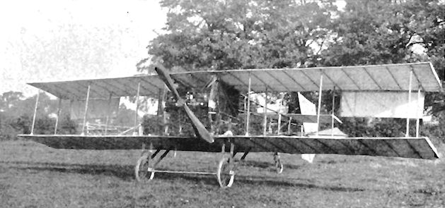
Chittenden-Robinson Monoplane
The Chittenden-Robinson Monoplane was built at Chiswick, London, during 1910 by J. P. Chittenden and L. H. Robinson for A. W. Seymour of Rugby. The machine was a single-seat tractor powered by the four-cylinder 35 h.p. Lascelles engine.
The Chittenden-Robinson Monoplane was built at Chiswick, London, during 1910 by J. P. Chittenden and L. H. Robinson for A. W. Seymour of Rugby. The machine was a single-seat tractor powered by the four-cylinder 35 h.p. Lascelles engine.
Clarke Glider
During 1910, T. W. K. Clarke and Co., of Kingston-on-Thames, built a biplane glider with wings of equal span, and which was equipped with single elevators carried aft. It is now part of the National Aeronautical Collection at South Kensington, London, S.W.7.
During 1910, T. W. K. Clarke and Co., of Kingston-on-Thames, built a biplane glider with wings of equal span, and which was equipped with single elevators carried aft. It is now part of the National Aeronautical Collection at South Kensington, London, S.W.7.
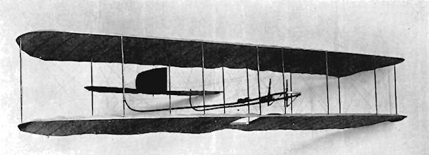
Clarke-Wright Glider
To enable Alec Ogilvie to obtain some practice before taking delivery of the Short-Wright Biplane which was being built for him by Short Brothers, in partnership with T. P. Searight he ordered a Wright-type glider from T. W. K. Clarke and Company of Kingston-on-Thames, Surrey.
The machine was based on the Wright No. 3 Glider, but was fitted with a biplane elevator in front and with a seat to enable the pilot to sit upright. The two-bay wings were double-surfaced and had an aspect-ratio of 6.5. Controls consisted of warping wings, the front elevator and the rear rudder; a fixed fin was incorporated between the elevator surfaces.
The glider took four weeks to construct and was completed at the end of August, 1909. Launching was by means of a weight and derrick, and many fine flights were made on the South Coast at Eastbourne, the longest distance covered by Ogilvie being 343 yards.
SPECIFICATION
Description: Single-seat biplane glider. Wooden structure, fabric covered.
Manufacturers: T. W. K. Clarke and Co., 14 Union Street, Kingston-on-Thames, Surrey.
Dimensions: Span, 32 ft. 8 ins. Length, 18 ft. Wing area, 318 sq. ft.
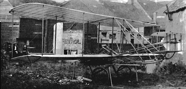
Clarke-Wright Glider.
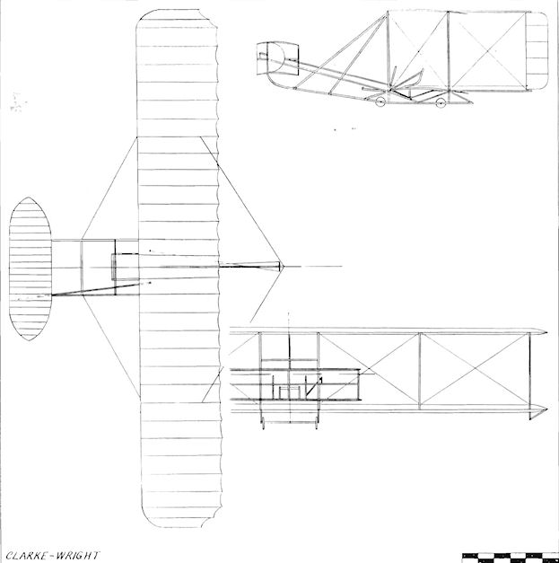
Clarke-Wright
Cleveland Biplane
The Cleveland Biplane was designed and built during 1910 by J. Cleve Jones of Newcastle-on-Tyne, and T. Taylor of Pelaw, Co. Durham. The machine was powered by the 35 h.p. Thames engine. Span, 30 ft. Length, 26 ft. Weight empty, 800 lb.
The Cleveland Biplane was designed and built during 1910 by J. Cleve Jones of Newcastle-on-Tyne, and T. Taylor of Pelaw, Co. Durham. The machine was powered by the 35 h.p. Thames engine. Span, 30 ft. Length, 26 ft. Weight empty, 800 lb.
Cody Glider
Samuel Franklin Cody's single-seat biplane glider was built at Farnborough during 1905. In its original form, narrow-chord diamond-shaped ailerons were mounted on slim fins below the leading-edges of the lower wings. They functioned also as elevators, but were supplemented later by an elevator at the rear of the aircraft. Several pilots made successful glides with the machine at Farnborough and at the Crystal Palace. Span, 51 ft. Wing area, 807 sq. ft. Weight empty, 116 lb.
Cody Powered Kite
After the experiments with his glider of 1905, S. F. Cody's next step towards powered flight was the fitting in 1907 of a 15 h.p. Buchet engine to one of his man-lifting kites. Stabilizing surfaces were added in front of and behind the main planes, together with a wheeled undercarriage. Free pilotless flights of up to 4.5 mins. duration were accomplished over Farnborough Common.
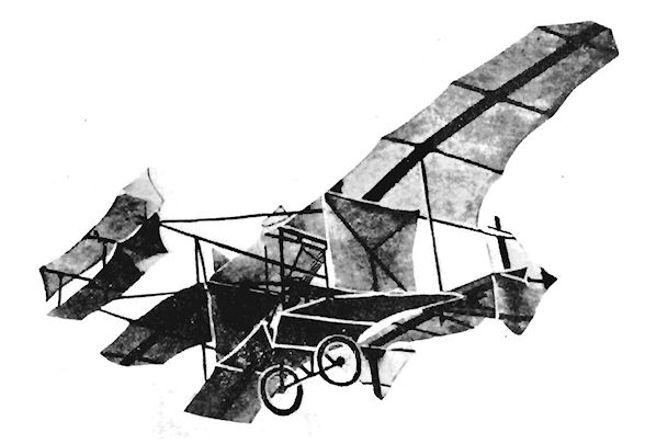
Cody British Army Aeroplane No. 1
At the same time as the trials of the Dunne tailless biplane were under way at Blair Atholl, S. F. Cody, the Royal Engineers' kiting instructor at the Army Balloon Factory and a colleague of Lt. Dunne, was developing the Factory's idea of a man-carrying powered aircraft.
Construction of the British Army Aeroplane No. 1, as it was soon designated, was initiated towards the end of 1907 and under conditions of secrecy equalling those surrounding the Dunne activities. Strenuous efforts were made to keep prying eyes from the area of the Factory at Farnborough, but, once the machine had to be brought into the open for ground testing as a preliminary to flight, it was hopeless to attempt to conceal it any longer. Particularly was this brought home, as the extent of the Factory's land was, at that time, comparatively small. Rumours that an aeroplane was being built had been circulating in the Press at the same time as the reports of the poor progress being made with the airship Nulli Secundus 1.
When the Cody machine was revealed finally it was seen to be mainly Wright-derived in its general lay-out, but exhibited several features of its own. The biplane wings had a span of 52 ft., a chord of 7 ft 6 ins. and were set with an 8 ft. gap between them. The controlling elevator was borne ahead of the mainplanes by booms, while further booms carried the rudder at the rear; a small additional rudder was fitted at the centre-line above the upper wings. The entire aeroplane was supported on the ground by a pair of main wheels, augmented by a smaller wheel aft and one mounted on short struts ahead of each lower wing-tip. Ailerons were fitted initially on the front outer interplane struts, well down in the gap, and were transferred afterwards to the rear of the tips. Perhaps the most unusual feature of the aircraft was its horizontal, fantail-shaped surface of unstiffened canvas which stretched from near the mid-way point of the upper trailing-edges to the top of the rear rudder-post.
Col. J. E. Capper's original intention was that Cody should use for power a 50 h.p. Panhard-Levassor engine which was available in March, 1908, but which broke down on test. Shortage of funds precluded the acquisition of any new engines, and Cody was forced to wait until the eight-cylinder 50 h.p. Antoinette, which had been used in the Nulli Secundus 1, was made available to him. This happened at the beginning of September, 1908, following the abandonment of the Nulli Secundus 2, to which the Antoinette had been transferred. The airframe was complete and, with the engine installed in the front of the nacelle, all was ready for the trials of the British Army Aeroplane No. 1 to commence. Twin propellers mounted between the wings were driven by flat belts, the pilot being seated in the nacelle behind the engine. It: was possible for the camber of the wings to be altered on the ground by means of a screw adjustment.
On Saturday, 19th September, 1908, the machine was hauled to Jersey Brow, a small plateau West of the Factory. The site was too small for flight to be attempted, but quite suitable for engine running, which was carried out at dusk. Two days later, on 21st September, Cody commenced to taxi, reaching 15-20 m.p.h. before the biplane was slightly damaged in a minor collision. After a break for three days, the machine made four or five taxying tests on Laffan's Plain on 24th September and described small circles on Farnborough Common on 28th of the same month. On 29th September the wheels left the ground for a short hop of 234 ft., and a pause then ensued for several alterations to be made. Two weeks passed, during which the ailerons were discarded, as Cody considered them to be unnecessary, the canvas fantail was increased again in area following an earlier reduction in size, and the original vee-shaped radiator was divided into two slim separate panels set vertically one on each side of the engine. The landing-gear received an addition in the form of a single raised wheel at the front. The lower outriggers, which extended forward to the elevator, were removed and a pair of booms were substituted from the lower planes' leading-edges at the front of the nacelle upwards to meet at the elevator.
On 13th October Press photographers were admitted within the Factory precincts to photograph and describe the machine. The day after, on 14th October, the aeroplane was brought out again and, during the three or more tests which ensued on Farnborough Common, Cody managed on one of them to cover 200 ft. at an altitude of 10 ft. Finding himself so high in the air, he felt it wise to terminate the test and brought the machine down quickly to the ground.
Another day passed until, on Friday, 16th October, 1908, conditions were considered to be good enough for an attempt at a real flight. After several trial runs, during which he left the ground for about 150 ft. while taxying uphill to Swan Inn Plateau on Farnborough Common, Cody took off to make the first recognized powered and sustained flight in Great Britain, covering a distance of 1,390 ft. at a height of 30 ft. in 27 sees, at a speed of 25-30 m.p.h. The biplane sustained some damage when it crashed on landing at the end of the flight; the remaining weeks of the year were spent in repairs and important alterations.
In the reconstruction the same 52 ft. span wings were used, but the gap was increased to 9 ft. The booms carrying the main control surfaces were extended so that the rear rudder was 12 ft. to the rear and the 20 ft. elevator was 12 ft. ahead of the mainplanes. The upper rudder was brought down from the top wing to a new position behind the elevator. Lateral control was revived in the form of two independently-operating ailerons which were added one on each side of the elevator, and also in auxiliary wing- warping. The ailerons were supported by additional struts from each wing- tip. The fantail horizontal surface was dispensed with completely and the radiators were moved back to the rear inboard struts. The wheels on the wing-tips were mounted direct on to the ends of the leading-edges, and a pair of larger propellers utilized the Antoinette's power.
The British Army Aeroplane No. 1 reappeared on Farnborough Common on 6th January, 1909. In order to observe the airflow, a number of ribbon streamers were attached to the airframe at various points and the aircraft again flaunted a Union Jack between the rear booms. A trial run on the ground proved satisfactory, but the tests were suspended by high winds until 9th January when a short hop of 60 ft. was made but which was sufficient to indicate faulty balance. This was rectified by moving the radiators forward in front of the rear inboard struts. The ailerons were brought back from their forward position to a new place midway up the rearmost outer interplane struts.
At 11 a.m. on 20th January, 1909, Cody took off and flew in the direction of the Balloon Factory for about 1,200 ft. at 25 ft. height, but crashed from 10 ft. after making a sharp turn. He was unhurt and the aircraft underwent some more alterations, which comprised the complete removal of the ailerons and the addition of a biplane tail in front of the rear rudder. After nearly a month in the Factory, the machine came out again on 18th February for a short flight of a few hundred yards. Upon landing, a tyre burst and a wire snapped, but, after repairs, successful flights of 600 ft. and 1,200 ft. were achieved at a height of 10 ft. on 22nd February.
Once again, alterations were made when the biplane tail was discarded, the ailerons were re-installed on outriggers behind the wing-tips at mid-gap, the front rudder was mounted on top of the fore-elevator and was coupled to the new twin side-by-side rear rudders, and the radiators were set behind the front inboard struts.
During April, 1909, the aeroplane was presented to Cody by the War Office when he decided to leave the Balloon Factory.
14th May, 1909, was a notable day, as Cody managed to fly over one mile from Laffan's Plain to Danger Hill at a height of 30 feet, thus setting up the first British records for duration and for distance in a straight line. Later the same day, while trying to repeat the performance before the Prince of Wales, the machine crashed and broke its tail when avoiding some troops. Further changes were decided upon. The radiators were moved forward so that they were in front of the front inboard struts, a single rear rudder took the place of the twin surfaces, and the rear landing wheel was replaced by a long, curved wooden skid.
Another flight was made on 18th June, with Cody covering 1.5 miles over Laffan's Plain at 25 m.p.h. and making three turns on the way. On 21st July, he completed a circular flight of 4 miles, but considered that extra power was required and installed accordingly a 60 h.p. E.N.V. "F" engine. At the same time, the pilot's seat was moved forward so thai it was in front of the new engine, and the ailerons were mounted mid-way between the wing-tips on the outer interplane struts.
On 11th August, 1909, Cody flew for 3 miles and on 13th August completed several long flights. The machine was now flying successfully, and its pilot had gained sufficient experience and control with it to consider taking passengers, so, on Saturday, 14th August, Col. J. E. Capper, the Balloon Factory Superintendent, was taken for a 2-mile flight. On the same day, Mrs. Cody was taken up for a 3-mile flight to gain the honour of being the first woman in Great Britain to leave the ground in an aeroplane. Cody was now well into his stride, making four cross-country flights and a circuit of Aldershot at 100 feet. On 8th September, 1909, he covered over 40 miles in a trip around Laffan's Plain which took 63 minutes and reached a height of 600 feet. The following day, on 9th September. Cody took up separately five passengers, including Capt. P. W. L. Broke-Smith, R.E.. Capt. A. D. Carden, R.E., and Capt."King.
A further alteration was made with the mounting of the radiator above the E.N.V. engine. On 11th September, the machine was demonstrated before the Empress Eugenie, and three clays later, on 14th September, there was a slight mishap when Cody was thrown from the seat during a landing. On 27th September. Mrs. J. E. Capper became the first British woman to fly in an aeroplane when Cody took her for a long flight over Laffan's Plain.
During the following month, Cody's biplane appeared at the flying meeting held at Doncaster from 15th until 23rd October, 1909. In the course of the meeting Cody became a British subject and decided to enter at once for the ?1.000 Daily Mail prize for the first all-British circular flight of one mile. He was unlucky to run into a patch of sand which caused the machine to nose over, so, for the rest of the meeting he made short, straight flights along the course before the grandstand. Some two months later, on 29th December, 1909, Cody attempted to win the prize of ?1,000 offered by Sir John Hartley for a flight from Liverpool to Manchester but was forced down by fog at Eccleston after covering 13 miles in 19 minutes.
SPECIFICATION
Description: Two-seat pusher biplane. Wooden structure, fabric covered.
Manufacturers: Army Balloon Factory, South Farnborough, Hants.
Power Plant: 50 h.p. Antoinette, 60 h.p. E.N.V. "F".
Dimensions: Span, 52 ft. Wing area, 790 sq. ft.
Weights: Empty, 2,260 lb. Loaded, 2,540 lb.
Performance: Maximum speed, 40 m.p.h.
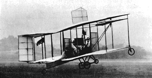
Cody British Army Aeroplane No. 1 in its early form.

Cody British Army Aeroplane No. 1 with biplane tail and without ailerons.
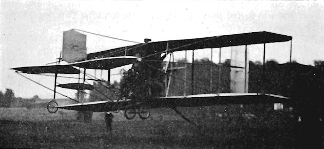
Cody British Army Aeroplane No. 1 with ailerons and with front rudder in foremost position.
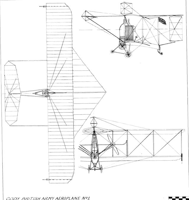
Cody British Army Aeroplane No. 1
Cody Michelin Cup Biplane
After over a year's experience with the British Army Aeroplane No. 1, S. F. Cody produced a new biplane in 1910 which also combined the knowledge gained from the earlier machine.
A 60 h.p. Green engine was chosen to power the aircraft, which was a pusher on the general lines of its predecessor. Three-bay unstaggered wings of equal span were fitted, the engine being mounted in the centre-section of the lower set and connected to the two-bladed propeller by a chain-drive. Two seats were mounted in tandem, and the Green's radiator was carried above the engine. In front, two bamboo booms bore the large two-piece elevator, and connection to it was by means of bamboo push-rods from the control-wheel. In its original form the machine was without a fixed tail-plane, but a small horizontal surface was fixed later mid-way up the rudder following trials. Ailerons of very generous area were incorporated for lateral control and were mounted in the first instance on the outermost interplane struts, but were subsequently moved inwards and to the rear so that they were carried by the outer pair of struts at the trailing-edge. These modifications were made during the rebuilding of the machine after a crash at Laffan's Plain during June, 1910, after Cody had qualified for Royal Aero Club Aviator's Certificate No. 9 on 7th June, flying the same aeroplane. A change of engine was made from the Green to a 60 h.p. E.N.V. "F", and the radiator was moved forward so that it was positioned between the front bamboo booms which supported the elevators.
Cody was going to make an attempt on the ?4,000 prize offered by Baron de Forest for the longest flight into Europe from Britain, but finally did not compete. The contest for the British Empire Michelin Cup No. 1 and its attendant cash prize of ?500 appealed, however, to Cody sufficiently for him to enter to set up the longest distance over a closed-circuit before the finishing date for 1910. His first effort resulted in a flight of 94.5 miles around Laffan's Plain in 2 hrs. 24 mins. and set up new all-British distance and duration records. This was, however, beaten by T. O. M. Sopwith, and Cody tried again during the last week of September, covering 115 miles in 2 hrs. 50 mins. in a 20 m.p.h. wind before being forced to the ground from 35 ft. by a gust. The machine was saved from damage by its sturdy undercarriage of twin main wheels, twin nose wheels and long, sprung skid. Cody's last attempt on the Michelin Prize won it for him and was made on 31st December, 1910, the last day of the contest. For his victory he flew for 4 hrs. 47 mins. over a distance of 185.46 miles, at the same time setting up new British records for duration and distance over a closed circuit.
SPECIFICATION
Description: Two-seat pusher biplane. Wooden structure, fabric covered.
Manufacturer: S. F. Cody, Laffan's Plain, Farnborough, Hants.
Power Plant: 60 h.p. Green, 60 h.p. E.N.V. "F".
Dimensions: Span, 46 ft. Length, 38 ft. 6 ins. Wing area, 540 sq. ft.
Weights: Empty, 2,200 lb. Loaded, 2,950 lb.
Performance: Maximum speed, 65 m.p.h. Ceiling, 3,000 ft. Range, 200 miles.
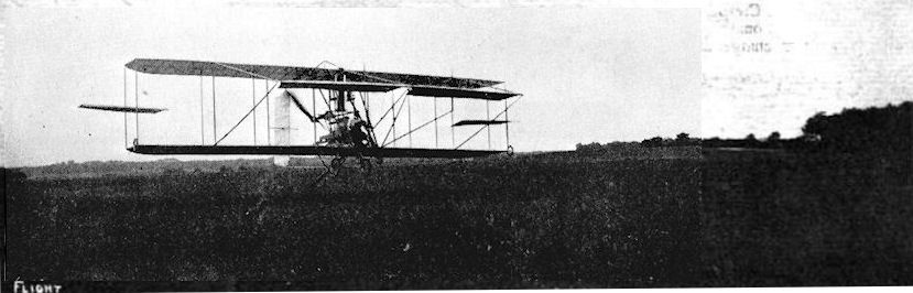
Mr. S. F. Cody flying over Laffan's Plain on his modified biplane last week, before the serious accident which befel him later. Mr. Cody, who uses a Green engine, employs only one propeller now.
Cody Michelin Cup Biplane in its first form with 60 h.p. Green.
Cody Michelin Cup Biplane in its first form with 60 h.p. Green.
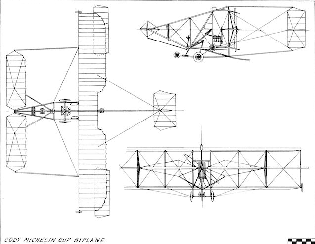
Cody Michelin Cup Biplane
Cody Circuit of Britain Biplane
The biplane flown by S. F. Cody during 1911 was basically a modification of his 1910 design and utilized the reliable 60 h.p. Green engine. The most obvious difference in appearance from his 1910 machine was the change to twin rudders, each of which was carried on a pair of bamboo tail booms. Small fixed tailplanes were fixed half-way up on each side of the rudders, which were themselves of lower aspect-ratio than the single surface employed on the previous machine. The rudders were arranged to fold sideways on their booms. The machine was entered in the Daily Mail ?10,000 Circuit of Britain, which started from Brooklands on 11th July, 1911, and extended over a course of 1,010 miles. After several minor hold-ups on the way Cody finished fourth, and his was the only British aircraft to complete the course. The machine came second in the 1911 contest for the Manville prize with a time of 3 hrs. 16 mins., and won the British Michelin Cup No. 2 and ?400 on 11th September, 1911, with a time of 3 hrs. 6.5 mins. after covering the 125 miles cross-country circuit at 40 m.p.h., being the sole competitor to complete the course. On 29th October, 1911, Cody won the British Empire Michelin Cup No. 1 and ?500 by flying for 261.5 miles over a 7-miles closed-circuit course at Laffan's Plain in 5 hrs. 15 mins. at the same time creating a new British record for duration. He later made a flight with two passengers standing on the lower wings and, on 27th January, 1912, covered a distance of 7 miles at Laffan's Plain at a height of 100 ft. with four passengers in addition to himself, a total load of 738 lb. which was made possible by the fitting of a 120 h.p. Austro-Daimler engine. The machine was entered for the races held at Hendon during April, 1912, but Cody was unable to participate owing to severe injuries received while flying as a passenger with his pupil, Lt. Fletcher, who crashed into some trees. At Whitsun, 1912, Cody flew from Farnborough to Hendon for the meeting there, but withdrew from the main 44-miles cross-country race owing to a disagreement over his handicap. Span, 40 ft. Length, 30 ft. Wing area. 450 sq. ft. Weight empty, 1,750 lb. Weight loaded. 2,500 lb. Maximum speed, 58 m.p.h. Ceiling, 5,000 ft. Range, 350 miles.
The biplane flown by S. F. Cody during 1911 was basically a modification of his 1910 design and utilized the reliable 60 h.p. Green engine. The most obvious difference in appearance from his 1910 machine was the change to twin rudders, each of which was carried on a pair of bamboo tail booms. Small fixed tailplanes were fixed half-way up on each side of the rudders, which were themselves of lower aspect-ratio than the single surface employed on the previous machine. The rudders were arranged to fold sideways on their booms. The machine was entered in the Daily Mail ?10,000 Circuit of Britain, which started from Brooklands on 11th July, 1911, and extended over a course of 1,010 miles. After several minor hold-ups on the way Cody finished fourth, and his was the only British aircraft to complete the course. The machine came second in the 1911 contest for the Manville prize with a time of 3 hrs. 16 mins., and won the British Michelin Cup No. 2 and ?400 on 11th September, 1911, with a time of 3 hrs. 6.5 mins. after covering the 125 miles cross-country circuit at 40 m.p.h., being the sole competitor to complete the course. On 29th October, 1911, Cody won the British Empire Michelin Cup No. 1 and ?500 by flying for 261.5 miles over a 7-miles closed-circuit course at Laffan's Plain in 5 hrs. 15 mins. at the same time creating a new British record for duration. He later made a flight with two passengers standing on the lower wings and, on 27th January, 1912, covered a distance of 7 miles at Laffan's Plain at a height of 100 ft. with four passengers in addition to himself, a total load of 738 lb. which was made possible by the fitting of a 120 h.p. Austro-Daimler engine. The machine was entered for the races held at Hendon during April, 1912, but Cody was unable to participate owing to severe injuries received while flying as a passenger with his pupil, Lt. Fletcher, who crashed into some trees. At Whitsun, 1912, Cody flew from Farnborough to Hendon for the meeting there, but withdrew from the main 44-miles cross-country race owing to a disagreement over his handicap. Span, 40 ft. Length, 30 ft. Wing area. 450 sq. ft. Weight empty, 1,750 lb. Weight loaded. 2,500 lb. Maximum speed, 58 m.p.h. Ceiling, 5,000 ft. Range, 350 miles.


S. F. Cody flying his 1911 Circuit of Britain Biplane at Hendon.
Cody Monoplane
In his entry No. 30 for the 1912 Military Trials, S. F. Cody forsook the biplane for a new monoplane design in which comfort and streamlining were given greater consideration than hitherto in his aeroplanes. The crew of two were seated side-by-side at the trailing-edge of the wings, with which their heads were on the same level. Their view was enhanced further by the fitting of transparent windows in the fuselage on each side of the cockpit, and their seats consisted of Cody's favourite agricultural implement type.
The main forward section of the fuselage provided an anchorage for the low-set 120 h.p. Austro-Daimler engine which drove the two-bladed 11 ft. 6 ins. diameter Chauviere propeller by a chain. Four bamboo pole extensions to the rear were employed to carry the tail unit and were faired with fabric. The tail surfaces comprised a pair of superimposed, interconnected elevators which were operated by a long bamboo control-rod to the lower surface. Twin rudders were cable-connected to the control-column, which was placed centrally between the seats for use by either occupant and also acted as the combined control for the wing warping, elevators and rudders. The cabane over the upper decking consisted of inverted vee struts at the front and a single vertical post at the rear. The tricycle landing-gear combined heavy coil springs with curved hickory struts for additional shock-absorbing.
The Cody Monoplane was destined never to compete in the famous Military Trials for, in July, 1912, it crashed and was wrecked when it collided with a cow while making a landing on Laffan's Plain.
SPECIFICATION
Description: Two-seat tractor monoplane. Wooden structure, fabric covered.
Manufacturer: S. F. Cody, Laffan's Plain, Farnborough, Hants.
Power Plant: 120 h.p. Austro-Daimler.
Dimensions: Span, 43 ft. 6 ins. Length, 37 ft. Height, 12 ft. 6 ins. Wing area, 260 sq. ft.
Weights: Empty, 2,400 lb. Loaded, 3,100 lb.
Performance: Maximum speed, 83 m.p.h. Cruising speed, 70 m.p.h.
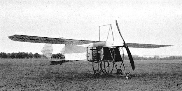
CODY MONOPLANE. - Three-quarter view from the front.
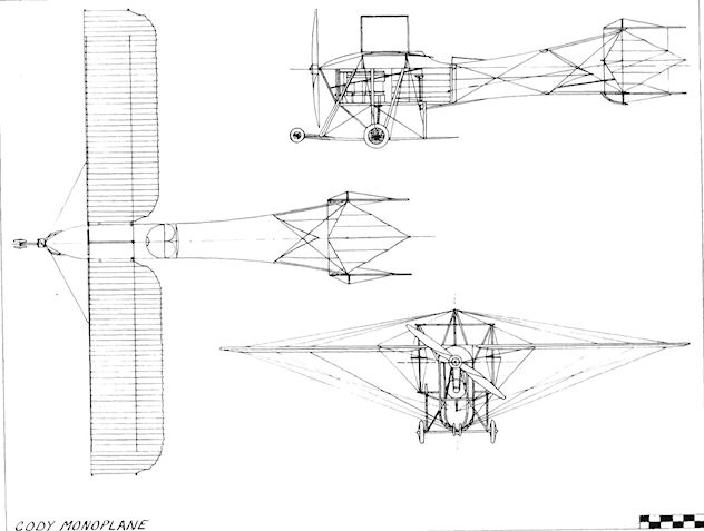
Cody Military Trials Biplane
After the crash of his monoplane, Cody removed its 120 h.p. Austro-Daimler engine and installed it in a biplane which was then entered as No. 31 in the Military Trials held on Salisbury Plain during August, 1912.
The machine differed little in appearance from previous Cody biplanes, but featured tapered rudders with small, fixed pairs of horizontal tail surfaces on each side of them. The large six-cylinder engine occupied most of the lower wings' centre-section and drove a propeller 10 ft. 8 ins. in diameter. Four seats were fitted, the pilot occupying the front one with one passenger behind him, the two remaining seats being placed on the lower wings, one on each side of the engine. No ailerons were employed, and wing-warping was used for lateral control. The twin front elevators were carried on bamboo outriggers, with bamboo push-rods controlling them from the enclosed pilot's position. All flying controls were on the single-wheeled column, a foot pedal being used for acceleration of the engine.
After the numerous tests had been carried out, the Cody biplane was declared the winner of the 1912 Military Trials and was awarded ?5,000 prize money. Its next success was in the contest for the 1912 British Empire Michelin Cup No. 2 and ?600, for which the Austro-Daimler engine was removed and replaced by a 100 h.p. Green to bring the machine into the all-British category to comply with the regulations of the competition. There were no other comers, and Cody won the event for the third year in succession by covering about 220 miles of the cross-country circuit in 3 hrs. 26 mins.
Dihedral was incorporated later in the wings, and Lt. L. C. Rogers-Harrison, R.F.C., was trained specially to be able to handle the difficult machines, of which two had been ordered for the Royal Flying Corps. On 28th April, 1913, he crashed at Farnborough in the second of them and was killed. The machine differed in having a slight increase in the dihedral, elevators which were mounted slightly higher and rudders which were moved closer together so as to be in the slipstream of the propeller. Both of the R.F.C. aircraft were fitted with 120 h.p. Austro-Daimler engines, and one was shown at the 1913 Olympia Aero Show which had flown for 7,000 miles, afterwards being handed over to the R.F.C. to be used first by No. 2 Squadron and then by No. 4 Squadron.
SPECIFICATION
Description: Two/four-seat pusher biplane. Wooden structure, fabric covered.
Manufacturer: S. F. Cody, Laffan's Plain, Farnborough, Hants.
Power Plant: 120 h.p. Austro-Daimler, 100 h.p. Green.
Dimensions: Span, 43 ft. Length, 37 ft. 9 ins. Wing area, 430 sq. ft.
Weights: Empty, 1,850 lb. Loaded, 2,850 lb.
Performance:
(120 h.p. Austro-Daimler) Maximum speed, 72.5 m.p.h. Climb, 288 ft. in 1 min., 1,000 ft. in 3.5 mins. Ceiling, 6,00 ft. Range, 336 miles.
(100 h.p. Green) Maximum speed, 70 m.p.h. Range, 500 miles.
Price: ?1,500.
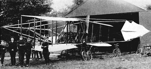
Cody Military Trials Biplane.
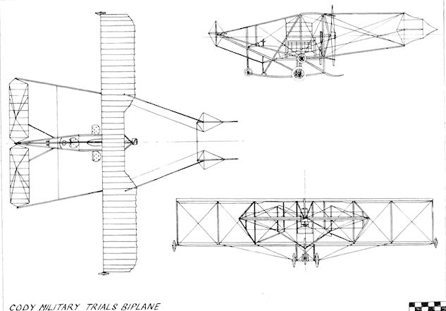
Cody Hydro-biplane
The last and biggest of the Cody aeroplanes was designed and constructed for participation in the 1913 Circuit of Britain for the Daily Mail ?5,000 prize. As the race was around the coast, the machine was fitted with floats, a large one with three steps being mounted centrally accompanied by a smaller pair inboard below the lower wings.
Three-bay unstaggered wings of the usual Cody type were used, the upper set being slightly greater in span than the lower. Warping provided lateral control, and a one-piece frontal elevator of generous area was operated by a bamboo push-rod. The tail surfaces comprised the rudder, which was pivoted between the booms, and a small horizontal tailplane fixed to it. Tandem seats were used for the pilot and passenger and were, as usual in Cody's aeroplanes, of the metal farm-machinery type. The pilot's control-column and wheel operated all of the control surfaces; his feet were used for the ignition and accelerator pedals.
Cody chose the reliable 100 h.p. Green engine to propel the machine, and fitted it with a four-bladed Garuda propeller of 10 ft. 8 ins. diameter driven by a chain.
The machine was completed by the middle of July, 1913, and underwent its flotation tests on the Basingstoke Canal at Mytchett, Hants. In order to give it thorough flight trials, the floats were removed and a wheel and skid undercarriage was installed. On 7th August, 1913, Britain lost one of its greatest and most courageous flying pioneers when Cody and his passenger, W. H. B. Evans, were killed when they were flung out of the aircraft following an airframe breakage in mid-air.
SPECIFICATION
Description: Two-seat pusher hydro-biplane. Wooden structure, fabric covered.
Manufacturer: S. F. Cody, Laffan's Plain, Farnborough, Hants.
Power Plant: 100 h.p. Green.
Dimensions: Span, 59 ft. 6 ins. Length, 40 ft. 9 ins. Wing area, 770 sq. ft.
Performance: Maximum speed, 70 m.p.h. approx.
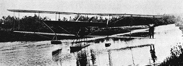
Cody Hydro-biplane.
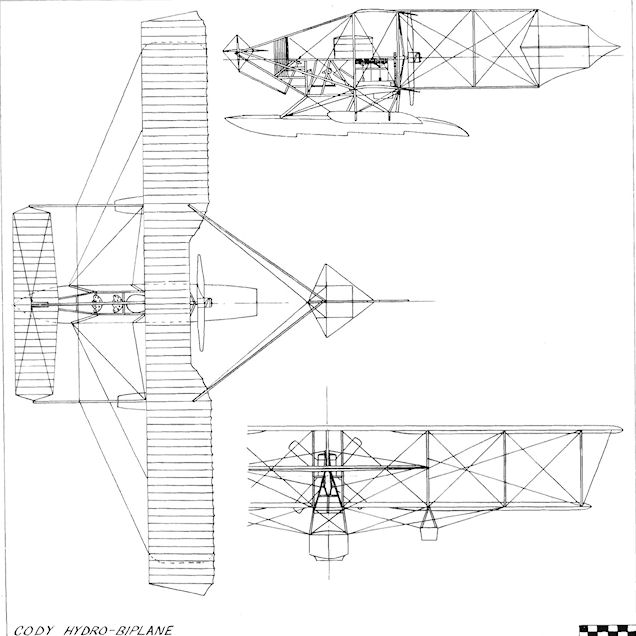
Cole Tandem Monoplane
The Cole Tandem Monoplane was exhibited at the 1911 Olympia Aero Show by W. Cole and Sons Ltd., 92 High Street. Kensington, W. 14. It was fitted with two mainplanes of equal span set at the same level and separated by a horizontal gap equal to the chord, the pilot's seat being installed between them. It was proposed to fit an engine of 120 h.p. mounted low down, with a chain drive to a longitudinal shaft carrying an airscrew at each end, respectively forward of the front plane and aft of the rear plane. An elevator for longitudinal control was located under the pilot's seat, and a lifting tailplane and single rudder were carried on tail booms. The outer portions of the mainplanes were arranged to fold upwards to reduce storage space. The machine was exhibited at Olympia in an unfinished state and did not fly subsequently.
The Cole Tandem Monoplane was exhibited at the 1911 Olympia Aero Show by W. Cole and Sons Ltd., 92 High Street. Kensington, W. 14. It was fitted with two mainplanes of equal span set at the same level and separated by a horizontal gap equal to the chord, the pilot's seat being installed between them. It was proposed to fit an engine of 120 h.p. mounted low down, with a chain drive to a longitudinal shaft carrying an airscrew at each end, respectively forward of the front plane and aft of the rear plane. An elevator for longitudinal control was located under the pilot's seat, and a lifting tailplane and single rudder were carried on tail booms. The outer portions of the mainplanes were arranged to fold upwards to reduce storage space. The machine was exhibited at Olympia in an unfinished state and did not fly subsequently.
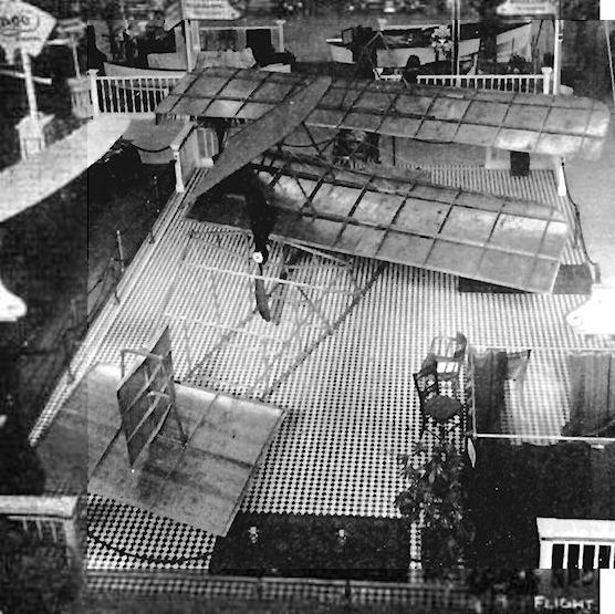
View of the partially finished Cole tandem monoplane, showing one of the wings folded.
Collier Brothers Monoplane
The Collier Brothers Monoplane was a single-seat tractor based on the Bleriot type and was completed early in 1910 by H. A. and C. R. Collier, who were well-known as motor-cycle racers and later as manufacturers of the "Matchless". It was fitted with the four-cylinder 25 h.p. J.A.P. engine, and flew for \ mile at Plumstead Marches on 7th March, 1910. Span, 30 ft. Length, 26 ft. Weight loaded, 650 lb.
The Collier Brothers Monoplane was a single-seat tractor based on the Bleriot type and was completed early in 1910 by H. A. and C. R. Collier, who were well-known as motor-cycle racers and later as manufacturers of the "Matchless". It was fitted with the four-cylinder 25 h.p. J.A.P. engine, and flew for \ mile at Plumstead Marches on 7th March, 1910. Span, 30 ft. Length, 26 ft. Weight loaded, 650 lb.
Collyer England Biplane
The single-seat tractor Collyer-England Biplane was built during 1911 and was fitted originally with a 30 h.p. Alvaston engine. The two-bay wings were equipped with ailerons on each tip, and the fuselage was of triangular section. New skids of different shape were substituted later on the under¬carriage, and the Alvaston was replaced by a 35 h.p. Green. The machine was tested at Shoreham, but was not very successful and was damaged there on 3rd April, 1912.
The single-seat tractor Collyer-England Biplane was built during 1911 and was fitted originally with a 30 h.p. Alvaston engine. The two-bay wings were equipped with ailerons on each tip, and the fuselage was of triangular section. New skids of different shape were substituted later on the under¬carriage, and the Alvaston was replaced by a 35 h.p. Green. The machine was tested at Shoreham, but was not very successful and was damaged there on 3rd April, 1912.
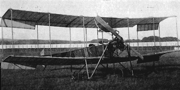
Collyer-England Biplane in 1911 with 30 h.p, Alvaston.
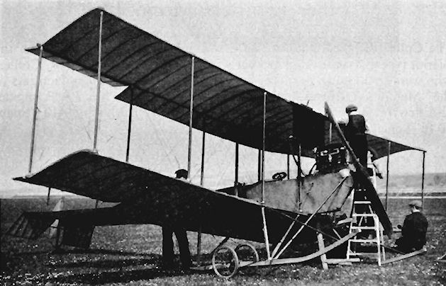
Collyer-England Biplane with 35 h.p. Green and modified undercarriage, at Shoreham on 3rd April, 1912.
Collyer-Lang Monoplane
The Collyer-Lang Monoplane was a single-seat pusher which appeared at Brooklands during November, 1910. The pilot sat in front of the wings, the 20 h.p. J.A.P. engine being mounted to the rear between the triangular tail booms. ]ts performance was erratic, and although nicknamed "Otasell", it was more generally called "The Hellhound".
The Collyer-Lang Monoplane was a single-seat pusher which appeared at Brooklands during November, 1910. The pilot sat in front of the wings, the 20 h.p. J.A.P. engine being mounted to the rear between the triangular tail booms. ]ts performance was erratic, and although nicknamed "Otasell", it was more generally called "The Hellhound".
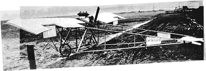
CoIIyer-Lang monoplane. Collyer's first machine of 1910 before he teamed up with BH England.
Conisborough Glider No. 1
The Conisborough Glider No. J was flown by the Conisborough and District Aero Society, Yorks., during 1911. It was a biplane of 42 ft. span, presented to the Society by the Sheffield Aero Club. In this form it carried its pilot to a height of 20 ft. when towed by hand into a light breeze. This was evidently thought to be too risky, and the span was reduced later to 24 ft. for training purposes.
The Conisborough Glider No. J was flown by the Conisborough and District Aero Society, Yorks., during 1911. It was a biplane of 42 ft. span, presented to the Society by the Sheffield Aero Club. In this form it carried its pilot to a height of 20 ft. when towed by hand into a light breeze. This was evidently thought to be too risky, and the span was reduced later to 24 ft. for training purposes.
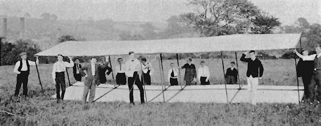
Cooper Glider No. 1
Charterhouse School was the scene of the construction of a biplane glider by G. T. Cooper which was started in February, 1911, and finished in July of the same year. Tests of the machine were carried out under tow. Span, 24 ft. Length, 18 ft.
Cooper Glider No. 2
The second Cooper Glider was a biplane constructed in Scotland at Edinburgh during 1911 by G. T. Cooper. The fuselage and wings were of ash, while bamboo formed the tail unit. The machine was presented to the East of Scotland Aero Club. Span, 22 ft. Length, 18 ft.
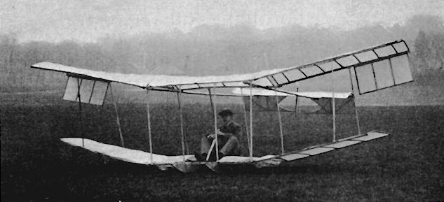
Cooper Glider No.2
Coventry Ordnance Works Biplanes
During 1911, the Warwick Wright concern was absorbed by the Coventry Ordnance Works, Ltd., and its designers, Howard T. Wright and W. O. Manning, joined the new parent company. The decision was taken to enter the Military Trials scheduled for August, 1912, and two biplanes were designed by Wright and Manning and were constructed in the old Warwick Wright workshops under the railway bridge arches at Battersea.
Most of the metal components were fabricated at the main Coventry Ordnance Works plant, and the first machine, nicknamed "The Wombus", entered as No. 10 in the Trials and fitted with the fourteen-cylinder 100 h.p. Gnome engine, was ready for testing at Brooklands at the end of April, 1912. It differed in several respects from No. 11, its 110 h.p. Chenu-powered counterpart. The Gnome-engined No. 10 was given a broad fuselage which seated two side-by-side and which was untapered in the plan view. The side elevation, however, was of good streamlined form. The large 11 ft. 6 ins. two-bladed propeller was driven at 600 r.p.m. through a 2 : 1 reduction gear and Hans Renold chain, resulting in a high thrust-line, with the boss incorporating the refinement of a spinner. The twin rudders were mounted on fairly small fins, and were given upper and lower horn balances, the same balancing being applied to the elevators. The lower wings were joined to the fuselage through the medium of two pairs of struts and of a streamlined fairing which embodied the petrol tank. No centre-section struts were used, and the upper wings were borne solely by the four pairs of interplane struts, the unusually large gap of 8 ft. appearing between upper and lower planes to bestow a remarkably good field of view from the cockpits. Warping was used for lateral control, the control pulleys were faired, and sliding aluminium panels facilitated inspection of the wings. King-posts and wire-bracing supported the considerable overhang of the upper wing-tips. No springing was incorporated in the undercarriage; all shock-absorbing was undertaken by the large, soft, 6 ins. thick tyres.
The second machine, No. 11, carried its two occupants in tandem cockpits and consequently possessed a narrower fuselage than that of its companion. Between the rear cockpit head fairing and the tail, the fuselage was shortened by 2 ft. and it was set higher above the lower wings than that of No. 10, with a deeper support beneath it. The Chenu engine was water-cooled, its radiators being carried on each side of the cockpits. The tail unit differed also in having a single fin and rudder of unusual "shark's-fin" outline, and the main undercarriage was given extra vertical struts at the rear of each unit. No. 11's upper wings were 5 ft. shorter in span than those of No. 10, and the lower tips were fitted with skids. A four-bladed propeller was formed by superimposing a pair of two-bladed propellers.
No. 10 was flying very successfully at Brooklands for about two months before the Trials, for the purpose of which T. O. M. Sopwith had been appointed as the pilot of both machines. In the event, neither aircraft distinguished itself. No. 10 suffered from trouble with its large propeller, and the Chenu engine in No. 11 proved refractory, the machine flying very little.
After the fiasco of the Military Trials, the Gnome-engined No. 10 was rebuilt during the latter part of 1912. The original tapered wings were replaced by a new larger set with parallel chord and three bays provided by eight pairs of interplane struts. The unequal span was retained and, again, centre-section struts were not included. In its new form the C.O.W. biplane proved quite successful, and was flown at Brooklands during early 1913 by F. P. Raynham, who was able to land it at under 20 m.p.h.
SPECIFICATION
Description: Two-seat tractor biplane. Wooden structure, fabric covered.
Manufacturers: Coventry Ordnance Works, Ltd., Coventry, Warks., and at Battersea, S.W.II.
Power Plant: 100 h.p. Gnome (No. 10); 110 h.p. Chenu (No. 11).
Dimensions: Span, 40 ft. (No. 10); 35 ft. (No. 11). Length, 33 ft. 3 ins. (No. 10); 31 ft. 3 ins. (No. 11). Wing area, 350 sq. ft. (No. 10); 325 sq. ft. (No. 11).
Weights: Empty, 1,200 lbs. (No. 10); 1,300 lbs. (No. 11). Loaded, 2,000 lbs. (No. 10); 2,100 lbs. (No. 11).
Performance: Maximum speed, 60 m.p.h.

COW biplane No.11. The second machine for the Military Trials with the unsatisfactory Chenu engine.

C.O.W. Military Trials No. 10
Creese-Dederich Monoplane
The single-seat tractor Creese-Dederich Monoplane was designed by A. G. Creese and appeared at the 1909 Blackpool Aviation Meeting. The engine was the three-cylinder 30 h.p. Anzani. Unorthodox features were the telescopic wings, which contained outwards-sliding panels which operated during banking to add area to the wing which was depressed, and also the system of compressed-air shock-absorbers fitted to the undercarriage. Span, 25 ft. (extending to 28 ft.). Length, 24 ft. Wing area, 168 sq. ft. Weight empty, 450 lb. Maximum speed, 30 m.p.h.
The single-seat tractor Creese-Dederich Monoplane was designed by A. G. Creese and appeared at the 1909 Blackpool Aviation Meeting. The engine was the three-cylinder 30 h.p. Anzani. Unorthodox features were the telescopic wings, which contained outwards-sliding panels which operated during banking to add area to the wing which was depressed, and also the system of compressed-air shock-absorbers fitted to the undercarriage. Span, 25 ft. (extending to 28 ft.). Length, 24 ft. Wing area, 168 sq. ft. Weight empty, 450 lb. Maximum speed, 30 m.p.h.
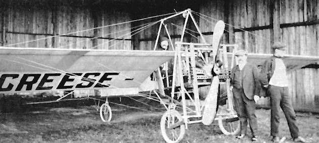
Creese-Dederich monoplane at Blackpool in 1909. Creese in the cockpit and Dederich by the propeller.
Crompton Monoplane
The Crompton Monoplane was designed and built during 1911 by H. D. Crompton of Walton-on-the-Hill, Surrey. It was of the single-seat pusher type and was powered by the 30 h.p. Alvaston engine. Span, 30 ft. Length, 28 ft. Wing area, 160 sq. ft. Weight loaded, 600 lb.
The Crompton Monoplane was designed and built during 1911 by H. D. Crompton of Walton-on-the-Hill, Surrey. It was of the single-seat pusher type and was powered by the 30 h.p. Alvaston engine. Span, 30 ft. Length, 28 ft. Wing area, 160 sq. ft. Weight loaded, 600 lb.
Davidson Gyropter
The Davidson Gyropter was designed by G. L. O. Davidson and was under construction at Amerden Bank, Taplow, Berks., during 1911. Two 26 ft. 10 ins. diameter rotors were mounted between the biplane wings and rotated in opposite directions. They were driven by two 50 h.p. Stanley steam engines, the empty weight of the machine being 15,600 lb.
The Davidson Gyropter was designed by G. L. O. Davidson and was under construction at Amerden Bank, Taplow, Berks., during 1911. Two 26 ft. 10 ins. diameter rotors were mounted between the biplane wings and rotated in opposite directions. They were driven by two 50 h.p. Stanley steam engines, the empty weight of the machine being 15,600 lb.
Davies Gliders
The Davies Glider No. 1 was built during 1911 by Walter Davies of Dudley, Worcs. The span of the upper wings was 30 ft. and that of the lower was 20 ft. A later version, designated Davies No. 2 and built in 1913, had a span of 30 ft. 1 in., a length of 20 ft. I in., a wing area of 285 sq. ft. and a loaded weight of 285 lb. Illustrated is No. I.
The Davies Glider No. 1 was built during 1911 by Walter Davies of Dudley, Worcs. The span of the upper wings was 30 ft. and that of the lower was 20 ft. A later version, designated Davies No. 2 and built in 1913, had a span of 30 ft. 1 in., a length of 20 ft. I in., a wing area of 285 sq. ft. and a loaded weight of 285 lb. Illustrated is No. I.
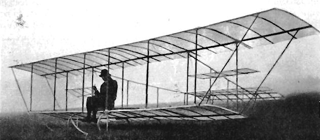
Davies glider No.l built in 1911 at Dudley.
Dawson Glider
The Dawson Glider was built during 1911 by Mulliner Coachworks, Ltd., of Long Acre, London, and Northampton, to the design of Charles E. Dawson of Naphill for the use of his wife Gertrude Robins, the actress.
The Dawson Glider was built during 1911 by Mulliner Coachworks, Ltd., of Long Acre, London, and Northampton, to the design of Charles E. Dawson of Naphill for the use of his wife Gertrude Robins, the actress.
Day Monoplane
The single-seat, tractor Day Monoplane was designed and built at Gosport, Hants., in 1910 by F. Day. Span, 35 ft. Length, 22 ft. Wing area, 220 sq. ft.
The single-seat, tractor Day Monoplane was designed and built at Gosport, Hants., in 1910 by F. Day. Span, 35 ft. Length, 22 ft. Wing area, 220 sq. ft.
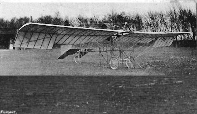
Day monoplane built by a member of the Hampshire Aero Club in 1909-1910.
De Havilland No. 1
In 1908, Geoffrey de Havilland started to build his first aeroplane, and was assisted in both the design and construction by his friend F. T. Hearle. The machine was completed in a shed at Fulham during early 1910, and was powered by a four-cylinder, horizontally-opposed engine which developed 45 h.p. Owing to the lack of suitable aero engines of light weight, de Havilland designed his own power-plant and engaged the Iris Motor Company of Willesden to construct it. Water-cooling was employed, the radiator being mounted in the centre-section of the upper wings.
The lay-out adopted was that of a pusher biplane, with an adjustable tailplane and movable rudder at the rear and elevators at the front. The non-staggered three-bay wings, with a 6 ft. gap, were fitted with inverse-tapered ailerons on the upper tips. The fuselage consisted of an uncovered, wooden-girder structure, braced with wire, in which was mounted the engine behind the pilot's seat. Two aluminium propellers of adjustable pitch were mounted between the wings, and transmission to them was effected through shafts and bevel gearing.
Upon completion, the de Havilland No. 1 was taken to Crux Easton, Hants., for testing. The first test flight was made early in April, 1910, with Geoffrey de Havilland as pilot. The machine left the ground, but after flying for about 35 yds. the port wings collapsed and the aircraft crashed, fortunately without harm to its pilot.
SPECIFICATION
Description: Single-seat canard pusher biplane. Wooden structure, fabric covered.
Manufacturers: G. de Havilland and F. T. Hearle, Fulham, London, S.W.
Power Plant: 45 h.p. Iris.
Dimensions: Span, 36 ft. Length, 29 ft. Wing area, 408 sq. ft.
Weights: Empty, 850 lb.
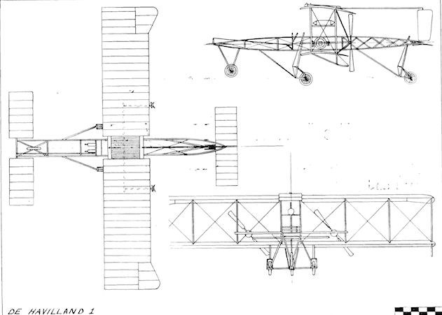
De Havilland 1
De Havilland No. 2/F.E.I
Geoffrey de Havilland's second aeroplane was a single-seat pusher biplane designed and built during 1910. It was powered by a 45 h.p. Iris engine which also was de Havilland-designed and was constructed by the Iris Motor Company of Willesden, London. N.W. On completion, the machine was taken to Litchfield, Hants., for its trials and then to Newbury, Berks., where its owner taught himself to fly on it, his first take-off being accomplished on 10th September, 1910.
Upon de Havilland's appointment in December, 1910, as assistant designer and test pilot at the Army Balloon Factory, the War Office bought the aeroplane for ?400, and it was then housed at Farnborough. There it became the F.E.I, being the first aeroplane to receive an official Factory designation. The F.E.I was flown successfully by de Havilland from its new home during January, 1911, and subsequently by several other pilots until it was crashed during the summer of the same year by Lt. Theodore J. Ridge, the Assistant Superintendent of the Factory. Span, 33 ft. Length. 40 ft. Wing area, 340 sq. ft. Weight loaded. 1,100 lb. Maximum speed, 37 m.p.h.
Ding-Sayers Monoplane
The Ding-Sayers single-seat canard monoplane was built during 1911 and was tested at Brooklands. The engine was a 50 h.p. Gnome, and the design was based on the successful model biplane designed by W. H. Sayers which won first prize at the 1911 Olympia Aero Show.
The Ding-Sayers single-seat canard monoplane was built during 1911 and was tested at Brooklands. The engine was a 50 h.p. Gnome, and the design was based on the successful model biplane designed by W. H. Sayers which won first prize at the 1911 Olympia Aero Show.
Dixon Nipper No. 1
The single-seat Nipper No. 1 canard pusher monoplane was designed and built during 1911 by H. S. Dixon. The engine fitted was the four-cylinder 25 h.p. Advance. The machine was tested at Acton, but was wrecked in an accident. Span, 26 ft. Length, 20 ft. Wing area, 210 sq. ft.
The single-seat Nipper No. 1 canard pusher monoplane was designed and built during 1911 by H. S. Dixon. The engine fitted was the four-cylinder 25 h.p. Advance. The machine was tested at Acton, but was wrecked in an accident. Span, 26 ft. Length, 20 ft. Wing area, 210 sq. ft.
Druiff-Neate Cyclo-aeroplane
The Druiff-Neate Cyclo-aeroplane was constructed in 1909 by C. G. Spencer and Sons, of Highbury. London, N., and was a single-seat monoplane with a 4 ft. diameter pusher propeller driven by pedals. It was proposed that an engine should be fitted later to the machine. Span, 20 ft. Wing area, 100 sq. ft. Weight empty, 50 lb.
The Druiff-Neate Cyclo-aeroplane was constructed in 1909 by C. G. Spencer and Sons, of Highbury. London, N., and was a single-seat monoplane with a 4 ft. diameter pusher propeller driven by pedals. It was proposed that an engine should be fitted later to the machine. Span, 20 ft. Wing area, 100 sq. ft. Weight empty, 50 lb.
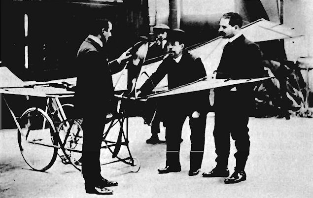
Dunne D.1 and D.4
An interest in the problems of successful flight was aroused in Lt. John William Dunne, son of Lt.-General Sir John Dunne, during 1900 after he was invalided home from the Boer War, in which he had served as an officer of the Wiltshire Regiment. His friendship with Sir Hiram Maxim and H. G. Wells brought the encouragement of both of these scientific visionaries.
Dunne's first thoughts on the subject turned towards the helicopter as a means of leaving the ground, but in 1904 he concentrated his studies on achieving a fixed-wing aeroplane of inherently stable lay-out. Practical experiments were conducted for nearly two years with paper models until, in 1905, he felt that the time had come to enlist official support to enable his ideas to be put into full-size form. At that time, Dunne's official position was that of a designer of man-lifting kites at H.M. Balloon Factory, South Farnborough, Hants., a task which he shared with S. F. Cody, the kiting instructor. Sufficient interest was aroused in the War Office by Col. J. E. Capper for Dunne to start construction of his first aircraft in the Balloon Factory. Security measures were stringent from the outset. The work was carried out in complete secrecy behind locked doors, and Dunne himself was not allowed to wear his uniform, being shown in the Army List as an invalided officer on half-pay. A condition of War Office assistance was that he should be paid half a guinea a day "when actually at work".
Dunne's automatically-stable lay-out was centred around vee-shaped swept-back wings of parallel chord, a pair of which were superimposed and connected by interplane struts to form a biplane in which the tips were washed-out at negative incidence to ensure maximum stability. The D.I, as it was named, was constructed first as a glider, the intention being to fit engine power once the general design had demonstrated its feasibility.
The project had the support of R. B. Haldane, the Secretary of War, who to ensure that the flying tests also were conducted in secret requested the Marquis of Tullibardine, the heir to the Duke of Atholl, to allow the use of his estate among the mountains at Blair Atholl in Perthshire, Scotland, for the purpose. The Marquis agreed, and a wooden shed was built on a lonely grouse moor at Glen Tilt to house the aircraft, which was taken there and assembled by a small party of men in plain clothes, consisting of Lt. Dunne, Lt. Westland, three other officers, two N.C.O.s of the Royal Engineers and a few servants. In addition to the aircraft's deal shed, eight tents were set up 4 mile away to house the men in a self-contained camp. In spite of the measures taken to prevent news of the work becoming public, something of what was being done leaked out, and Glen Tilt was besieged by newspaper reporters and German spies, the Duke of Atholl's private army of gillies being kept busy warding off the intruders. In order to conceal the details of the machine as much as possible from prying eyes, the subterfuge of camouflage was resorted to. This was applied by painting chordwise thin white stripes and irregular outlines across the dark upper surfaces of the wings.
Tests of the glider were conducted in 1907 by Col. J. E. Capper, the Superintendent of the Balloon Factory, as Dunne's health made it unwise for him to attempt to fly it. Repairs were necessary following a crash into a wall during a brief flight, and the machine was next fitted with a pair of Buchet engines whose total combined output was 15 h.p., but although the War Office contended that 15 h.p. was sufficient for the use of the Army, the D.1 was under-powered and failed completely to take-off. The undercarriage consisted of skids on both the glider and the powered D.1, and a four-wheeled platform was employed finally to get the D.1 to fly by launching it down an inclined plankway built a few feet above the ground level. When the carriage was started down the track the rubber-tyred wheels climbed the curb fitted to the edge of the plankway, and it fell over the side, carrying the aeroplane with it. The D.1 was damaged too badly for it to be repaired in time for any further experiments before the winter snows were expected.
By mid-1908, the D.1 had been rebuilt and at the same time modified in an attempt to make a success of it. Redesignated D.4 it was now a more practical machine fitted with a 25 h.p. R.E.P. engine driving a pair of propellers by crossed flat belts over drums, and an enclosed nacelle for the pilot which was embodied on the underside of the lower wings' centre-section. Below this there was attached to the tubing chassis a sprung, four-wheeled undercarriage in place of the original skids. Vertical fins were added to the extremities of the wings. Once again, the upper surfaces were disguised with the thin white lines and designs. Lt. Lancelot D. L. Gibbs, of the Royal Field Artillery, undertook the testing of the D.4 for the War Office in the Lower Park at Blair Atholl during the autumn of 1908. The R.E.P. engine could not be persuaded to develop enough power to take the machine fully into the air, but it did manage to leave the ground on the level for short hops without an accidents occurring. Eight of these brief flights were accomplished between 16th November and 10th December, a distance of 40 yds. being covered on the last date.
Finally, in 1909, the War Office decided that, after spending ?2,500 on the experiments without any significant results being achieved, it would have to discontinue its sponsorship of the project. Lt. Dunne severed his connection with the Balloon Factory and the D.4 was presented to him when he left.
Dunne D.2
The D.2 designation was given to a small glider version of the Dunne-Huntington Triplane, which was proposed but not built.
Dunne D.3
The D.3 was a smaller glider version of the D.4 and was built at H.M. Balloon Factory. It was fitted with a twin-skid undercarriage, launching being carried out from a four-wheeled trolley. As with the D.1 and the D.4, camouflage was applied in white stripes and linear patterns to break up the continuity of the dark upper surfaces.
The D.3 was tested during September and October, 1908, at Glen Tilt, Blair Atholl, Perthshire, by Col. J. E. Capper, who rose to about 15 ft. height sitting in it, and also by Lt. L. D. L. Gibbs, who flew the machine for a distance of 44 yds. on 9th October, 1908, before crashing it a little later.
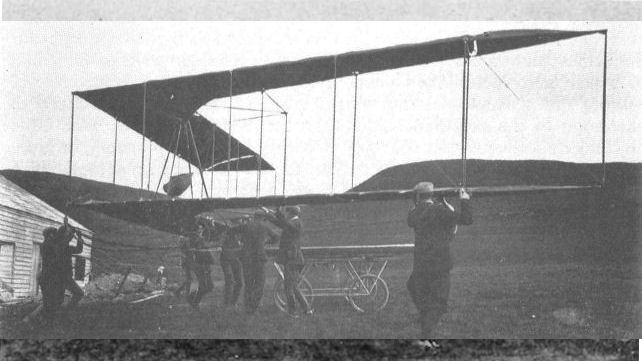
The inherently stable Dunne D1A glider at Blair Atholl in the Scottish highlands being manhandled onto the launching trolley (being prepared for flight at Glen Tilt in 1907).
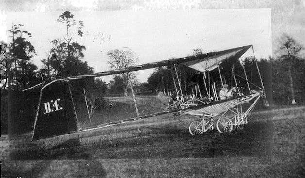
Dunne D.4 at Blair Atholl in 1908. The Dunne D4 biplane was built by mounting the D1 glider on a four-wheeled chassis which also incorporated the pilot's position.
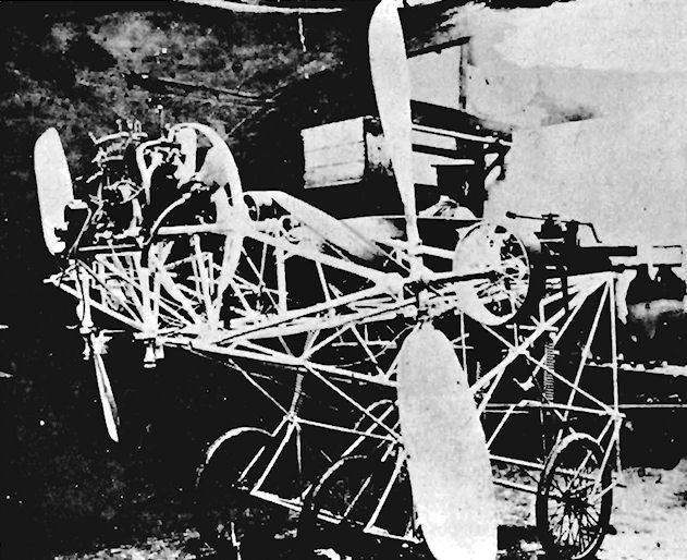
The steel tubing chassis constructed in the Army Balloon Factory during September, 1907, shown complete with 25 h.p. R.E.P., and used to convert the D.1 into the D.4.
Dunne D.5
After Lt. J. W. Dunne left the Balloon Factory, he continued his work on his automatically-stable aircraft under the aegis of the Blair Atholl Aeroplane Syndicate Ltd., of 1 Queen Victoria Street, London, E.C., which was formed during 1910 by the Marquis of Tullibardine to sponsor the design.
The first outcome of this arrangement was the D.5, which was built during 1910 by Short Brothers in their works at Leysdown, Isle of Sheppey, Kent, using Dunne's design, but employing the constructor's own discretion in the selection of materials and fittings to be used in the airframe.
The machine was a two-seat tailless biplane with four-bay wings, the outer ends of which were enclosed by vertical fins with tip-skids below them. The first engine fitted was an eight-cylinder E.N.Y. "F" of 60 h.p., but this was changed to a 60 h.p. Green, the power being taken by chain-drive to a pair of outrigged 7 ft. diameter propellers, both of which turned in the same direction. The engine was housed in the centre of the boat-shaped nacelle, the nearest interplane struts to it carrying the cooling radiators. The pilot and passenger were seated in tandem, in the nose of the machine. A pair of sprung front wheels formed the main undercarriage, augmented by a third smaller wheel and two close-set skids to the rear. Flying controls consisted of ailerons on the tips of the upper wings. They could operate by independent cockpit control either as rudders or as elevators, and automatic stability under varying conditions was promoted by wash-out at the tips of the wings.
On completion, the D.5 was taken to the Short Brothers flying-ground at Eastchurch and was tested there throughout 1910. By April, the machine was flying well, and in May it completed a flight of 2.25 miles, its stability being such that it was able to maintain a straight and level course without attention to the controls. At the end of 1910, on 20th December, the machine's capabilities were demonstrated in flight by Lt. Dunne himself before Griffith Brewer and Orville Wright. During its trials at Eastchurch, the D.5 showed that it possessed perfect stability, and it fully vindicated its inventor's theories. Flying of the D.5 continued the following year until it was wrecked completely when it was crashed by Dr. F. A. Barton's son. The remains were salvaged and the machine was reconstructed, to emerge in 1912 as the single-engined D.8.
SPECIFICATION
Description: Two-seat tailless pusher biplane. Wooden structure, fabric covered.
Manufacturers: Short Brothers, Leysdown, Isle of Sheppey, Kent.
Power Plant: 60 h.p. E.N.V. "F", 60 h.p. Green.
Dimensions: Span, 46 ft. Length, 20 ft. 4 5 ins. Wing area, 527 sq. ft.
Weights: Loaded, 1,550 lb.
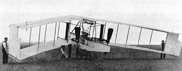
Dunne D5 showing the shape of the swept wing.
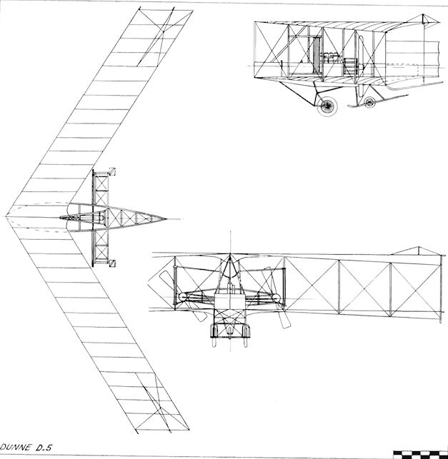
Dunne D.5
Dunne D.6, D.7 and D.7bis
Following the successful flights at Eastchurch of his D.5 tailless pusher biplane in 1910, Lt. J. W. Dunne embarked upon the design of a new tailless monoplane. The wings were set high in the parasol position, and the D.6, as it was designated, was derived from the model monoplane which Dunne had submitted in support of his original proposals to the War Office in 1905. These were refused, and he was persuaded to adopt, instead, the biplane form, a decision which, he stated many years later, he felt to be correct in the light of subsequent experience.
The same form of sweptback wings was employed as in the earlier aircraft built, but some minor modifications were incorporated. The degree of sweepback was increased slightly, and an interesting innovation was the alteration of the camber of the wing section which changed continuously from the leading-edge at the roots to the trailing-edge at the tips. Also in the interests of inherent stability, the wing-tips were the subject of pronounced wash-out, and their final few feet curved sharply downwards outboard of the centre of the ailerons to provide side area in the absence of fins or rudders. The wings were above an open wooden framework which formed an uncovered fuselage carrying the single seat at the front, with the 60 h.p. Green engine and its 7 ft. 3 ins. diameter propeller at the rear. The water radiator was fitted vertically above the centre-section in an effort to keep the centre of gravity as high as possible. The entire machine was supported in a horizontal position on an undercarriage comprising two pairs of wheels combined with long, curved skids, at the rear of which were fitted shorter, sprung, shock-absorbing tail-skids. The ailerons, which operated either as elevators or rudders, were controlled independently by two levers from the pilot's position.
The D.6 was built by Short Brothers under the sponsorship of the Blair Atholl Aeroplane Syndicate, and the test flying was carried out by Dunne himself, who concentrated on the experimental flight trials of the D.6, the D.7 and the D.7bis from 1911 until mid-1913, surviving four major crashes during the process. N. S. Percival made two attempts to fly the D.6, but was not successful with it.
Col. J. E. Capper was interested in the design and ordered for himself a slightly smaller 50 h.p. Gnome-engined single-seat version, which was designated the D.7 Auto-Safety and was ready for display at the 1911 Olympia Aero Show. The span was 35 ft. and the wing area totalled 200 sq. ft. Empty and loaded weights were 1,050 lb. and 1,409 lb. respectively, and a 60 m.p.h. maximum speed was achieved. During June, 1911, the D.7 was put through its tests at Eastchurch, Isle of Sheppey, and on 12th January, 1912. Dunne flew the machine before Alec Ogilvie and T. O'B. Elubbard without, for a period, using either his hands or feet on the controls.
In 1912, the original D.6 single-seater was converted into the D.7bis two-seater and was given the extra power of the 70 h.p. Gnome engine to cope with the additional weight. The wing was remodelled to match that of the D.7, with a span of 35 ft. and an area of 200 sq. ft. The machine weighed 1,200 lb. empty and 1,728 lb. loaded, and had a maximum speed of 60 m.p.h.
SPECIFICATION
(D.6)
Description: Single-seat tailless pusher monoplane. Wooden structure, fabric covered.
Manufacturers: Short Brothers, Leysdown, Isle of Sheppey, Kent.
Power Plant: 60 h.p. Green.
Dimensions: Span, 36 ft. Length. 21 ft. Wing area, 230 sq. ft.

Dunne D.7
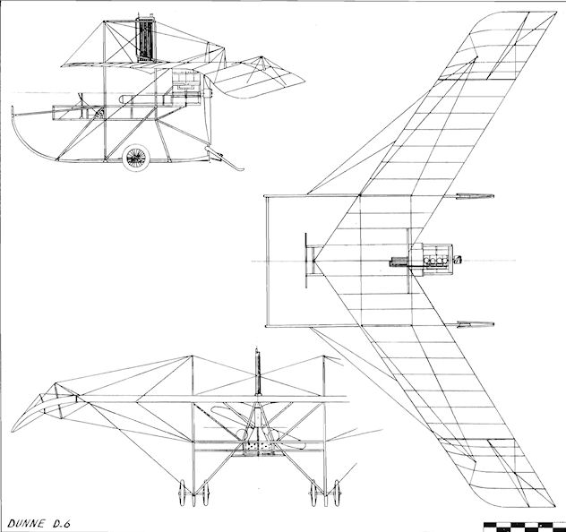
Dunne D.6
Dunne D.8 and D.10
Lt. J. W. Dunne's final designs for the Blair Atholl Aeroplane Syndicate reverted to the biplane form in his D.8 and D.10 two-seaters built by Short Brothers at Leysdown, Isle of Sheppey, Kent, during 1911-12.
The D.8 was a single-engined conversion of the crashed D.5 of 1909-10, and used the same wings of 45 ft. span, with a chord of 6 ft. and a similar sweepback angle of 30°. The wing-tips were enclosed by fixed vertical fins, the flying controls consisting of split ailerons extending across the trailing-edges of the two outermost bays on the four planes. They were operated independently of each other as rudders for turning, or they could be employed as elevators using both flap sections on each side in unison for "up" or "down". The wings of the D.8 demonstrated in a pronounced way the Dunne method of obtaining stability by changing the camber of the wing section continuously across the span from the leading-edge at the roots to the trailing-edge at the tips.
The nacelle was mounted between the lower wings, the pilot sitting at the front, with his passenger towards the rear and just ahead of the fuel tanks. Both flyers could handle the machine, as dual control levers were installed. The undercarriage was a fairly complex but successful unit designed specially to allow the D.8 to operate without fear of damage from the comparatively rough aerodromes in use. The front strut system and sprung skid were of wood, while the rear sprung chassis carrying the twin wheels was composed of steel tubing. Long sprung skids supported the tips of the wings on the ground.
In the D.8, twin propellers were abandoned in favour of the simplicity of a single one, 8 ft. 2 ins. in diameter, driven direct by a 50 h.p. Gnome engine at the rear of the nacelle. On 18th June, 1912, the D.8 was used at Eastchurch by Capt. A. D. Carden, who possessed one hand only, to gain his Royal Aero Club Aviator's Certificate No. 239. The machine was flown by N. S. Percival from the summer of 1912 until 1913. Early in 1913, the French Astra Company had shown sufficient interest in producing the machine in France to send their pilot Mons. Montmain over to lest it. However, the project lost its appeal for Astra, and the firm of Nieuport sent Commandant Felix to assess the D.8 for them at Eastchurch. During 11th and 12th August he flew it from Eastchurch to Villacoublay, and demonstrated it during the same month before the French Aeronautic Corps. Felix took the D.8 to a week's flying meeting being held at Deauville, where he astonished the spectators by leaving the cockpit while flying solo and walking out on to the lower wings. Another highlight of his tour with the machine was his flight in it over Paris on 20th August, 1913, and at the 1913 Paris Aero Show a version built by Nieuport was on display with a simplified landing-gear.
The D. 10 was another two-seater built during 1912. It was fitted with an 80 h.p. Gnome and was converted later to a D.8. The span was 45 ft., with a wing area of 448 sq. ft. and a loaded weight of 2,202 lb. Maximum speed was 50 m.p.h., a drop of 5 m.p.h. from the 55 m.p.h. of the first D.8, which was brought about by the increase of weight. After the conversion, Percival flew the second D.8 to pass its War Office tests successfully, the machine proving to be the best of the series. The result was that an order for two for the R.F.C. was placed during March, 1913, one being constructed at Eastchurch, with the other being built at Flendon. Both were reported as overdue in delivery during the following August, and were still being completed in September, 1913.
Another version of the D.8, with a 60 h.p. Green engine, was produced during 1913; in this the loaded weight was increased from the 1,900 lb. of the original D.8 to 2.1 14 lb., the span of 46 ft. and the wing area of 552 sq. ft. remaining the same.
The American Burgess Company built three Burgess-Dunne single-float seaplane variants. These were the two-seat BD with a 100 h.p. Curtiss OXX2 engine, a span of 46 ft. and a top speed of 69 m.p.h., the BDH two-seater powered by a 140 h.p. engine, with a span of 46.6 ft. and a maximum speed of 70 m.p.h., and the BDI, which was a single-seater. A three-seat flying-boat was constructed by Burgess during 1916 and was designated the BDF. A 100 h.p. Curtiss OXX2 provided the power for the 53 ft. span machine, which had a top speed of 68 m.p.h.
SPECIFICATION (D.8)
Description: Two-seat tailless pusher biplane. Wooden structure, fabric covered.
Manufacturers: Short Brothers, Leysdown, Isle of Sheppey, Kent.
Power Plant: 50 h.p. Gnome, 60 h.p. Green, 80 h.p. Gnome.
Dimensions: Span, 46 ft. Wing area, 545 sq. ft.
Weights: Empty, 1,400 1b. Loaded, 1,900 lb.
Performance: Maximum speed, 55 m.p.h.
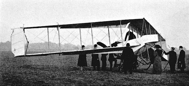
Dunne D.8 with 80 h.p. Gnome.

Dunne D.8
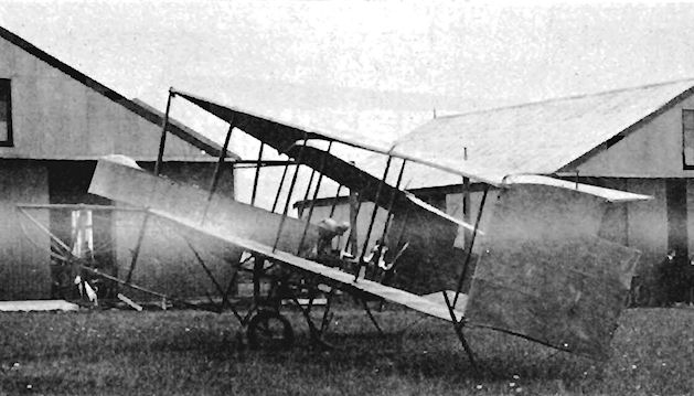
Dunne D.8 with 50 h.p. Gnome
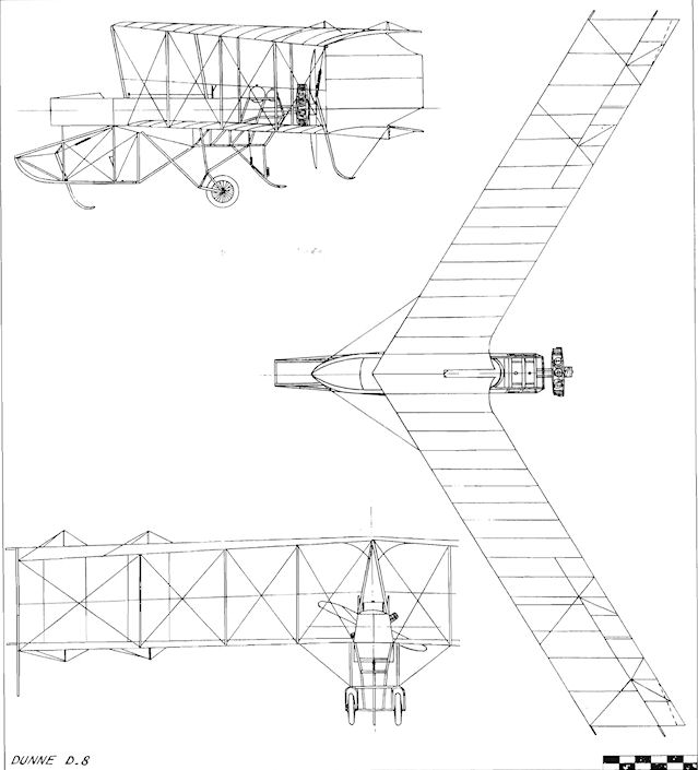
Dunne D.8
Dunne D.9
The D.9 was a tailless sesquiplane of somewhat complicated form designed by Dunne during 1913, with the assistance of C. R. Fairey in the stress calculations. The machine was not completed.
James Monoplane
The James Monoplane was built during 1913 by Levis Ltd., at Stechford, Warks., and was designed by a Mr. James in conjunction with Lt. J. W. Dunne. It was powered by the 35 h.p. five-cylinder in-line Levis two- stroke engine, which was designed by H. Newey, who was associated with the Levis Company, formed in 1909 by William and Arthur Butterfield as Butterfield Brothers. The engine was mounted inverted in the nose of the single-seat fuselage, on either side of which were the triangular-shaped wings with their leading-edges sharply swept back, resulting almost in a delta plan-form. The wing was braced from a cage-like cabane structure which acted also as a crash-pylon.
The original name of Mayfly was changed to Leonie, and the machine was to have had floats fitted for testing on Edgbaston Reservoir. Instead, however, it was equipped with a land undercarriage consisting of wheels and skids, and was taken to Castle Bromwich playing-fields, where it caught one wing-tip on a goal-post during its first take-off and was wrecked.
Dunne-Huntington Triplane
While the Blair Atholl experiments of 1906-9 were being undertaken, Lt. J. W. Dunne prepared sketches of a powered aircraft of a different lay-out from his sweptback tailless designs. The drawings were made during the winter of 1907-8, permission being granted by the War Office for them to be transferred, together with the patent, to Professor A. K. Huntington, under an agreement that he should prepare the final working drawings and then construct the machine immediately.
Professor Huntington received the designs from Dunne in the spring of 1908, and the aircraft was completed early in 1910. The upper wings were of straight planform, while the lower pair were positioned to the rear and were sweptback. Outboard of the interplane fins, the lower tips were given sharp anhedral with their rear triangular portions hinged to provide flying controls. The fore-planes were mounted in line with the lower wings, being braced to the rear wings and fitted on the nose of the open fuselage. The twin propellers were borne on shafts extending forwards from the lower rear wings, and were driven by chains from the water-cooled engine set behind the pilot, who was seated in an opening in the centre of the fore-planes. The engine's radiator was installed mid-way along the fuselage, and the undercarriage comprised a pair of coil-sprung main wheels with a third wheel at the rear of the machine.
Professor Huntington started testing the aircraft at Eastchurch during April, 1910, and although he managed to get it to take-off, the performance was not altogether satisfactory. For the next three years, during his spare time from his work in metallurgy at Kings College, London, he continued to experiment, altering the rear wings and changing the engine to a 70 h.p. Gnome rotary, so that by April, 1913, the Dunne-Huntington was flying well. Maximum speed, 43 m.p.h.
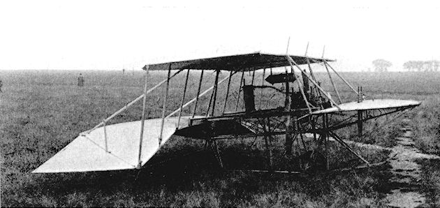
Dunne-Huntington Triplane. The first version at Eastchurch in 1910 with Wolseley engine, four wheels and skid undercarriage.
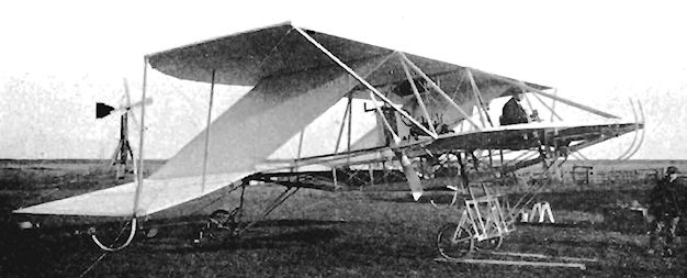
Dunne-Huntington Triplane with revised three-wheel undercarriage and interplane fins.
Dyott Monoplane
Among the most successful of the early monoplanes was the Dyott, at the same time one of the neatest-looking of the practical aeroplanes of the period. The elegant little 50 h.p. Gnome-engined machine took its name from that of its owner. G. M. Dyott, to whose specification it was made. Its originator, who gained his Royal Aero Club Aviator's Certificate No. 114 on 17th August, 1911, on a Bleriot at Hendon, decided during the following year to construct a machine of his own design for cross-country flying. The work was entrusted to the Hewlett and Blondeau Company, the aircraft being built in their works at Clapham and completed early in 1913.
After successful test flights, the Dyott monoplane was taken without delay by its owner on an extensive six-months tour of the U.S.A. From April, 1913, until the following October, the machine flew for some 2.000 miles, giving exhibition flights as far West as California. Reports reaching Britain from George Dyott were most enthusiastic about its reliability and lively performance. Writing from New York he claimed that it went "like a rocket", was taking off in 40 yds., and was reaching a top speed of 75 m.p.h.
In November, 1913, the Dyott was flying again at Hendon and was entered in the London-to-Brighton Handicap, which was flown on the 8th of the month. Starting from Hendon, the nine British, French and American entrants had first to fly to Harrow Church and then set course for the Palace Pier at Brighton, the finishing-point for the first half of the contest. After flying westwards along the coast, they were to land at Shoreham, refuel and fly back to the Palace Pier, there to continue the race home to Hendon. The powerful wind blowing at the time from the West caused a miscalculation in drift, carrying the Dyott over Eastbourne, where a landing was made on Beachy Head. The machine alighted successfully, but was unfortunate enough to be blown over on to its back by a gust, leaving no option but withdrawal from the race. A projected flight to be made to India with the aircraft did not finally materialize.
Features of the Dyott were the mid-wing and the lack of ailerons, lateral control being effected by warping of the tips. One rather undesirable aspect of the design was that the flying wires were attached direct to the undercarriage, thus subjecting the wings to the strain of landing loads. In addition to the usual flight instruments of tachometer, oil gauge, compass, petrol gauge and altimeter, the cockpit contained a special graphic recorder, designed by George Dyott, which noted by means of three pointers on a revolving drum the different movements of the controls for elevators, rudder and warping. Replacement of parts of the airframe was facilitated by a system of joining the components together with nuts and bolts. In addition to the 8 galls, oil and the main 8 galls, petrol tanks, an auxiliary of 10 galls, petrol was carried behind the pilot, giving enough fuel for 3 hrs. duration.
SPECIFICATION
Description: Single-seat mid-wing tractor sporting monoplane. Wooden structure, fabric covered.
Manufacturers: Hewlett and Blondeau Ltd., Omnia Works, Clapham Junction, London. S.W.
Power Plant: 50 h.p. Gnome.
Dimensions: Span, 29 ft. Length, 23 ft. Wing area, 148 sq. ft.
Performance: Maximum speed, 75 m.p.h. Landing speed, 45 m.p.h. Endurance, 3 hrs.
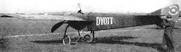
The Dyott Monoplane.
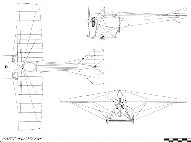
Dyott Monoplane
Eastbourne Aviation Company Monoplane
The E.A.C. Monoplane was the first of four designs to be built by the Eastbourne Aviation Company of Eastbourne, Sussex, which was founded by F. B. Fowler, who took his Royal Aero Club Aviator's Certificate No. 175 on 16th January, 1912, flying one of his own flying-school's Bleriots. On 29th October, 1912. Mons. E. L. Gassier, a Swiss pupil of the school, passed the tests for his certificate No. 350 using a Bleriot also.
An interest in designing led Emile Gassier to join the Company and, assisted by Fowler, he drew up a single-seat tractor monoplane which was built during 1913. The engine chosen was the three-cylinder 35 h.p. Anzani radial, which was mounted on the nose of a rectangular-section fuselage, the deep belly of which tapered to a horizontal knife-edge at the tail, and which was metal-covered as far back as the rear of the cockpit.
A one-piece elevator was fitted, operating below the cut-out in the rudder, which was strut-braced to the top of the fuselage in the absence of a fixed fin. The parallel-chord wings were mounted just below the upper longerons, and were unusual in that inter-connected ailerons were embodied in place of the warping more commonly employed in monoplanes at that time, and this eliminated the twisting strains inherent in the warping system. The result was a great improvement in flying characteristics. The flying wires were connected to an under-fuselage cabane, relieving the undercarriage of such additional stresses, while the landing loads were taken by the wires supported by the struts in front of the cockpit. Springing of the undercarriage axle was devised by allowing it to move vertically in slots cut in the vee-struts against rubber cord in tension. The Anzani engine drove a Rapid propeller of 7 ft. diameter. The machine was very pleasant to fly; anticipated private orders were prevented by the War.
SPECIFICATION
Description: Single-seat tractor monoplane. Wooden structure, fabric covered.
Manufacturers: Eastbourne Aviation Co. Ltd., Eastbourne, Sussex.
Power Plant: 35 h.p. Anzani.
Dimensions: Span, 29 ft. 2 ins. Length, 21 ft. Wing area, 135 sq. ft.
Performance: Cruising speed, 50 m.p.h.
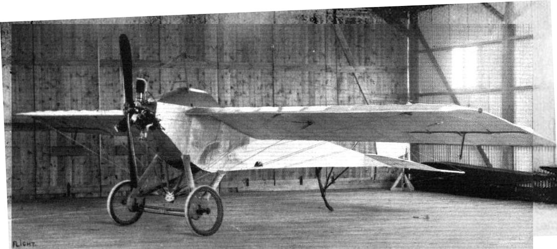
A three-quarter view of the E.A.C monoplane from the front.
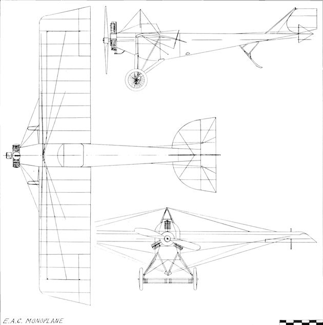
E.A.C. Monoplane
Eastbourne Aviation Company Biplane
The E.A.C. Biplane was designed by Mons. E. L. Gassier and built by the Eastbourne Aviation Company to the order of Lt. R. E. B. Hunt, a pupil of the school who took his Royal Aero Club Aviator's Certificate No. 715 on 22nd December, 1913, while flying the E.A.C. Monoplane. It was a single-seater, fitted with the 50 h.p. Gnome, and was completed in February, 1914. The machine was intended for exhibition flying, and was flown also by F. B. Fowler who found it extremely pleasant to handle. It was taken away from Eastbourne by Hunt just before the outbreak of the 1914-18 War. Cruising speed, 65 m.p.h.
The E.A.C. Biplane was designed by Mons. E. L. Gassier and built by the Eastbourne Aviation Company to the order of Lt. R. E. B. Hunt, a pupil of the school who took his Royal Aero Club Aviator's Certificate No. 715 on 22nd December, 1913, while flying the E.A.C. Monoplane. It was a single-seater, fitted with the 50 h.p. Gnome, and was completed in February, 1914. The machine was intended for exhibition flying, and was flown also by F. B. Fowler who found it extremely pleasant to handle. It was taken away from Eastbourne by Hunt just before the outbreak of the 1914-18 War. Cruising speed, 65 m.p.h.
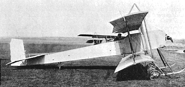
The 50 h.p. Gnome tractor biplane built by the Eastbourne Aviation Co., Ltd., to the order of Mr. R. E. B. Hunt, who is seen in the pilot's seat. This machine was designed by Mr. E. L. Gassier and has been flown both by Mr. Hunt and by Mr. Gassier.
Eastbourne Aviation Company Circuit Seaplane
Entered as No. 5 in the 1914 Daily Mail Circuit of Britain contest for seaplanes, the Eastbourne Aviation Company's machine was an ambitious design which incorporated a 100 h.p. Green engine mounted inside the fuselage between the wings, driving a pair of 8 ft. 6 ins. diameter tractor propellers through inclined shafts and bevel gearing.
The head of the Company, F. B. Fowler, was scheduled to fly the big 54 ft. span seaplane in the event, which did not, however, take place owing to the outbreak of the 1914-18 War. The crew occupied side-by-side seats in the nose of the fuselage, which swept upwards towards the tail. The sides were flat, but curved deckings were added above and below, and the fuselage terminated in a rudder post, as sufficient side area was built, into the rear of the machine to enable a fixed fin to be dispensed with.
The wings were of parallel chord with three bays and no stagger. Ailerons were incorporated in the four wing-tips, and the lower wings were given dihedral while the upper planes were flat. The entire aeroplane was supported when on the water by a pair of long floats, which had one step towards the rear and which were set 12 ft. apart so that wing floats were unnecessary. The length of the main floats also rendered a tail-float superfluous, but the last bay in the fuselage contained a water-tight tank in case the tail should become immersed.
The principle of having the engine buried inside the fuselage, with either shaft or chain drive to outrigged propellers, was one which appealed to many designers for several years but which never proved to be fully satisfactory in practice. The struts which carried the propellers on the Circuit Seaplane were inclined to distort when full power was applied, and the machine, which was being modified when War broke out, was finally dismantled.
SPECIFICATION
Description: Two-seat tractor biplane seaplane. Wooden structure, fabric covered.
Manufacturers: Eastbourne Aviation Co. Ltd., Eastbourne, Sussex.
Power Plant: 100 h.p. Green.
Dimensions: Span, 54 ft. Length, 31 ft. Wing area, 700 sq. ft.
Weights: Empty, 1,850 lb. Loaded, 2,809 lb.
Performance: Maximum speed, 65 m.p.h. Landing speed, 45 m.p.h. Endurance, 7 hrs.
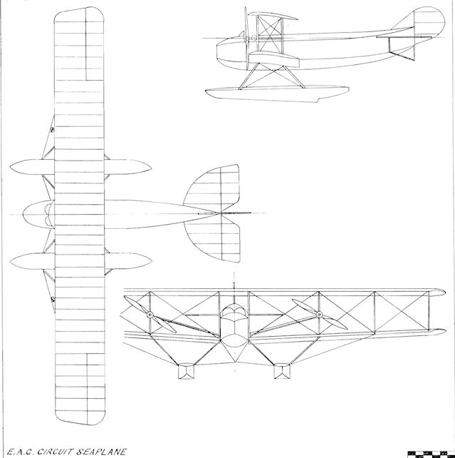
E.A.C. Circuit Seaplane
Eastbourne Aviation Company Military Biplane
At the Olympia Aero Show of 1914, Mons. E. L. Gassier's excursion into the realm of military aircraft on behalf of the Eastbourne Aviation Company was displayed in the form of the E.A.C. Military Biplane.
The machine was a two-seater with tandem cockpits incorporated in a fuselage of rectangular section and straightforward construction. A well-cowled 80 h.p. Gnome engine turned a propeller of 8 ft. 6 ins. diameter, and the neat undercarriage incorporated short, forwards-projecting skids, the axle being sprung by means of rubber cord.
Wings of unequal span were fitted, with the lower pair shorter than the upper. Their plan-form was unusual in that slight taper was incorporated in the leading-edges outboard of the inner interplane struts of the two-bay cellules. To improve crew visibility, the lower wing roots and the upper centre-section were left open. The wing section employed for the machine possessed a fairly deep camber, the chord being comparatively narrow, while the gap between the planes was generous. The centre-section struts were of inverted-vee type, raked fore and aft at sharp angles, and ailerons were fitted to the upper tips. To make starting the engine easier when the aircraft was being flown solo, the refinement of a starting-handle in the pilot's cockpit was part of the equipment.
SPECIFICATION
Description: Two-seat military tractor biplane. Wooden structure, fabric covered.
Manufacturers: Eastbourne Aviation Co. Ltd., Eastbourne, Sussex.
Power Plant: 80 h.p. Gnome.
Dimensions: Span, 34 ft. 6 ins. Length, 25 ft. Wing area, 245 sq. ft.
Weights: Empty, 950 lb.
Performance: Maximum speed, 75 m.p.h. Landing speed, 50 m.p.h.
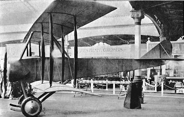
EAC military biplane of 1914 was exhibited at Olympia.
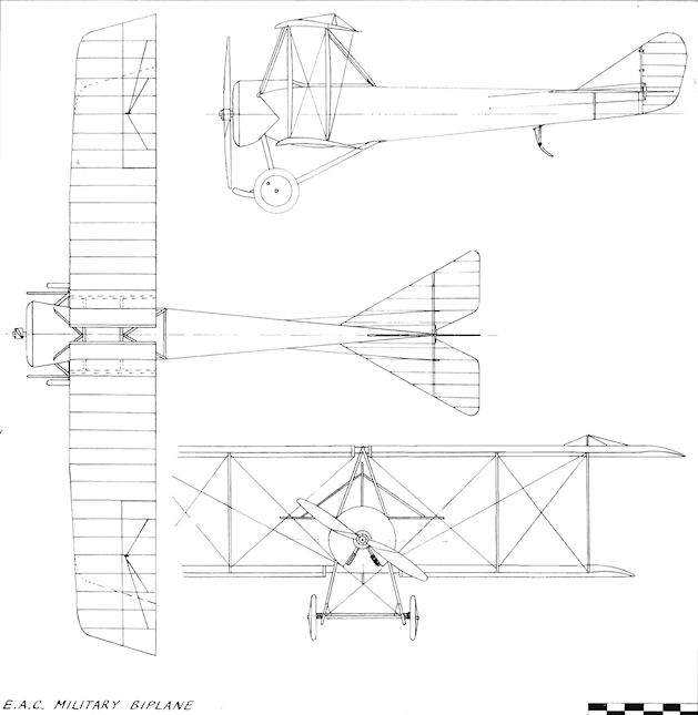
E.A.C. Military Biplane
Edgar Glider
Norman W. Edgar's biplane glider was built during 1913 and flown by the Bristol and West of England Aero Club. Span, 26 ft. Length, 21 ft. Wing area, 170 sq. ft.
Norman W. Edgar's biplane glider was built during 1913 and flown by the Bristol and West of England Aero Club. Span, 26 ft. Length, 21 ft. Wing area, 170 sq. ft.
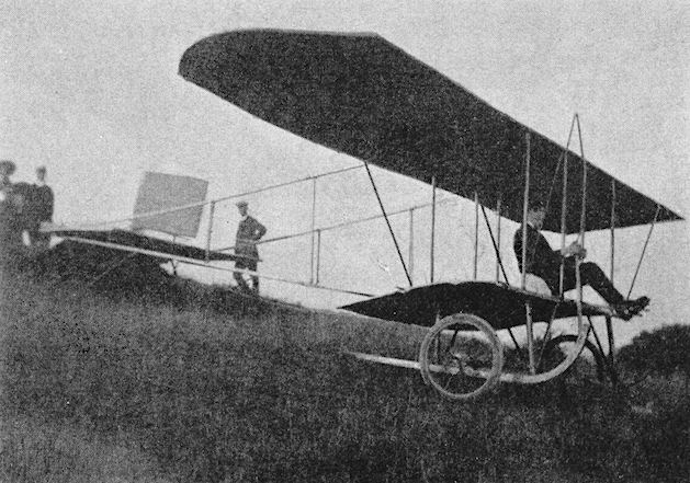
Edgar glider built in 1913 by Norman Edgar of the Bristol and West of England Aero Club.
Edwards Rhomboidal
The extremely unorthodox Rhomboidal was tested at Brooklands during 1911. It was an annular biplane in principle, but less refined in execution than the Lee-Richards Biplane. The two main planes, both of which were of the same size and shape, were composed of single fabric surfaces having curved ribs in pockets, similar to the battens of a sailing-yacht, lying parallel to the direction of flight. The "spars" of these surfaces were tension cables stretched between the ends of two central longitudinal compression girders, with pin-jointed struts extended laterally so that the whole of the wings' plan-form was that of a hollow diamond, the rear surfaces having three times the chord of those forward. The trailing-edges also were cables, but these were less strained and permitted a considerable degree of flexibility, with the intention of equalizing the air loads throughout the surface. The upper and lower wings were connected by vertical struts, and the whole machine was rigged with a dihedral angle of about 8°.
The 50 h.p. Humber engine was mounted on the lower main girder in the centre of the hollow of the wings and drove a pair of tractor propellers through chains. The pilot sat farther aft on the same girder and was provided with orthodox single elevator and single rudder controls; as the rudder was mounted above the upper wings and was out of the slipstream it can hardly have been effective. The machine rested on a chassis of two skids, each of which carried a pair of wheels in the Farman fashion, with a single castoring wheel at the front of the lower wings and a spring skid at the back. There is no record of the Rhomboidal having left the ground, and it is possible that it was wrecked and abandoned in favour of the more orthodox Walton and Edwards Colossoplane. Span 38 ft. Length, 48 ft. Wing area. 1.200 sq. ft. Weight empty, 1,600 lb.
Eggleton Gliders
R. H. Eggleton, an apprentice at the London and South-Western Railway Carriage Works at Eastleigh. Hants., built three gliders during 1911, 1912 and 1913. The first was a parasol monoplane with a small nacelle, control being by ailerons, elevator and rudder of conventional pattern. The second machine also was a monoplane, but was of canard type, somewhat similar to the A.S.L. Valkyrie. The pilot sat above the wings and a wheeled undercarriage was provided. The span was 28 ft. and the length was 24 ft.
<...>
Eggleton Gliders
R. H. Eggleton, an apprentice at the London and South-Western Railway Carriage Works at Eastleigh. Hants., built three gliders during 1911, 1912 and 1913.
<...>
The third glider was a biplane with a small nacelle for the pilot and was flown successfully during 1913 (illustrated).
R. H. Eggleton, an apprentice at the London and South-Western Railway Carriage Works at Eastleigh. Hants., built three gliders during 1911, 1912 and 1913.
<...>
The third glider was a biplane with a small nacelle for the pilot and was flown successfully during 1913 (illustrated).

Elsworth Monoplane
The Elsworth Monoplane was designed and built during 1910 by Oswald Elsworth, and was fitted with a 25 h.p. engine.
The Elsworth Monoplane was designed and built during 1910 by Oswald Elsworth, and was fitted with a 25 h.p. engine.
Fletcher Monoplane
The Fletcher Monoplane was a single-seat tractor type with features of the Antoinette and the Bleriot. It was designed by C. A, Fletcher of Manchester and built during 1909. The engine was a five-cylinder Empress rotary. First tests were made on 29th December, 1909, at Heaton Park, Manchester, and the machine flew during the following month. Wing area, 345 sq. ft. Weight empty, 365 lb.
The Fletcher Monoplane was a single-seat tractor type with features of the Antoinette and the Bleriot. It was designed by C. A, Fletcher of Manchester and built during 1909. The engine was a five-cylinder Empress rotary. First tests were made on 29th December, 1909, at Heaton Park, Manchester, and the machine flew during the following month. Wing area, 345 sq. ft. Weight empty, 365 lb.
Fletcher Biplane
The second machine built by C. A. Fletcher of Manchester was a pusher biplane of the Farman type, constructed during 1910. The engine was an Empress rotary, and the aeroplane was tested on Manchester Racecourse at Castle Irwell on 8th August, 1910.
The second machine built by C. A. Fletcher of Manchester was a pusher biplane of the Farman type, constructed during 1910. The engine was an Empress rotary, and the aeroplane was tested on Manchester Racecourse at Castle Irwell on 8th August, 1910.
Evans Monoplane
A small Bleriot-type monoplane was built by a Mr. Evans, a miner of Doe Lea, Derbyshire, in sixteen months spare time during 1910 and 1911. It was powered by a 12 h.p. Madison motor-cycle engine which proved insufficient for flight. Span, 26 ft. Length, 24 ft.
A small Bleriot-type monoplane was built by a Mr. Evans, a miner of Doe Lea, Derbyshire, in sixteen months spare time during 1910 and 1911. It was powered by a 12 h.p. Madison motor-cycle engine which proved insufficient for flight. Span, 26 ft. Length, 24 ft.
Everett Edgcumbe Monoplane
One of the earliest British tractor monoplanes was that designed in 1908 by E. I. Everett and constructed by Everett Edgcumbe and Co. Ltd., of Colindale, London, N.W.9.
The machine was reminiscent of the Bleriot Monoplane in lay-out, and was a single-seater powered by a four-cylinder 35 h.p. J. A.P. engine which drove a 6 ft. diameter propeller. The framework was of wood with fabric covering overall; the flying surfaces were double-covered. Warping was used for lateral control, and this was operated by turning the hand-wheel on the control column, the fore-and-aft movement of which actuated the elevators. Foot pedals controlled the rudder. The wings were given a generous dihedral angle, and at their tips were mounted end-plates.
In the course of tests, various alterations were made to the machine. The original undercarriage skids were curved along their length, the wheels' axle being sprung by the rear part of the skids. The arrangement of the supporting struts was altered to provide a more rigid fixing, with the transverse axle moved to mid-way on the new pair of skids' straight portion. The engine was water-cooled, its radiator being carried at an angle under the nose of the fuselage.
Tests of the Everett Edgcumbe Monoplane were carried out in a field at Colindale which was to become part of the London Aerodrome at Hendon. The wooden shed built to house the machine was used by Louis Paulhan for his Farman during his epic race with Grahame-White for the Daily Mail London-to-Manchester prize. The nickname "The Grasshopper" was applied to the monoplane, as it failed to fly properly and succeeded only in making hops from the ground during trials made on 6th and 7th December, 1910, by Bernard Clutterbuck and again during January, 1911, by E. I. Everett.
SPECIFICATION
Description: Single-seat tractor monoplane. Wooden structure, fabric covered.
Manufacturers: Everett Edgcumbe and Co. Ltd., Colindale Works, Colindeep Lane, Hendon, London, N.W.9.
Power Plant: 35 h.p. J.A.P.
Dimensions: Span, 25 ft. Length, 16 ft. Height, 9 ft. 6 ins. Wing area, 140 sq. ft.
Performance: Maximum speed, 30 m.p.h.
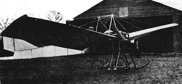
Everett Edgcumbe Monoplane with original undercarriage.
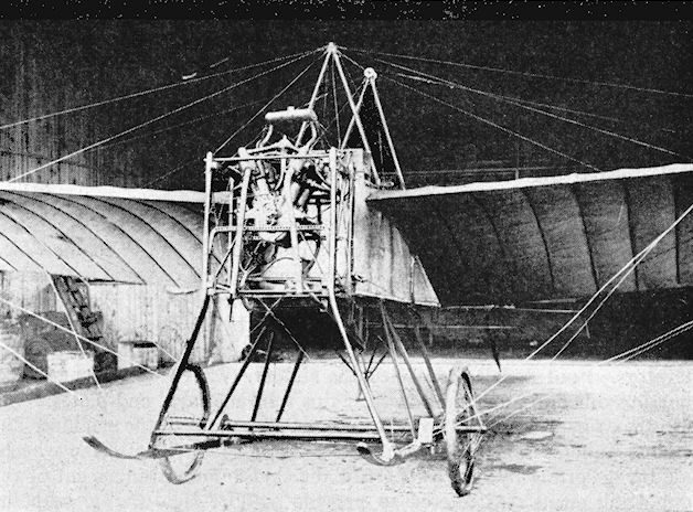
Everett Edgcumbe Monoplane after modification of undercarriage.
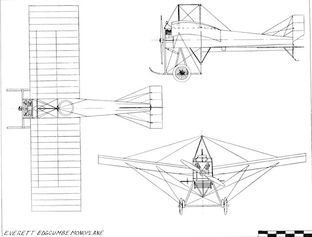
Everett Edgcumbe Monoplane
Evershed Biplane
In 1910 a small tractor biplane was built at Burton-on-Trent, Staffs., by Sydney Evershed. He attempted to fly it at Netherseal in June, 1910, using an engine of 10 h.p. Span, 25 ft.
In 1910 a small tractor biplane was built at Burton-on-Trent, Staffs., by Sydney Evershed. He attempted to fly it at Netherseal in June, 1910, using an engine of 10 h.p. Span, 25 ft.
Fay-Wilkinson Tandem Biplane
The Fay-Wilkinson Tandem Biplane of 1910 was built at Withernsea. Hull, Yorks., and had two pairs of biplane cellules, the outer portions of both pairs being controllable. A six-cylinder 70 h.p. water-cooled engine drove by chains four propellers, which were mounted on a pair of shafts, two before the front wings and two aft of them. The undercarriage incorporated eight wheels, and the monoplane tail had tip elevators working in unison with the front outer wings.
The Fay-Wilkinson Tandem Biplane of 1910 was built at Withernsea. Hull, Yorks., and had two pairs of biplane cellules, the outer portions of both pairs being controllable. A six-cylinder 70 h.p. water-cooled engine drove by chains four propellers, which were mounted on a pair of shafts, two before the front wings and two aft of them. The undercarriage incorporated eight wheels, and the monoplane tail had tip elevators working in unison with the front outer wings.
Ferguson Monoplane
The Ferguson Monoplane was designed by Harry G. Ferguson and was built by J. B. Ferguson and Co. Ltd., of Belfast, being completed in its original form during December, 1909. It was a two-seater and was powered by the eight-cylinder 35 h.p. J.A.P. engine driving a Beedle propeller which was later superseded by a Cochrane. First tests were carried out on 31st December, 1909, at Lord Downshire's Park at Hillsborough, where the machine flew for 130 yds. in a 25 m.p.h. wind, this constituting the first flight of an all-Irish aircraft. During June, 1910, Ferguson made a flight of 2.5 miles at 30-40 ft. over Magilligan Strand at Lough Foyle, Co. Derry, and further successful flights were made at Newcastle, Co. Down, in July, August and October, 1910. Late in December, 1910, it was damaged in landing and was subsequently rebuilt in a modified form, the wingspan and the fuselage being shortened. Fabric was used to cover the fuselage completely. With this machine Ferguson made several excellent flights in June, 1911, before coming to grief by landing on a soft mud-bank. Undeterred, he once again reconstructed the monoplane, which was extensively damaged, and replaced the skid by a nosewheel. This third version was an excellent flyer and was flown regularly at Magilligan Strand in 1912 by Ferguson and again in February, 1913, by O. G. Lywood. Harry Ferguson was an early member of the Automobile Association and mounted a large A. A. badge on the cabane of his monoplane for its 1910 flights. He later became world-famous as the inventor and manufacturer of a lightweight agricultural tractor of revolutionary design. Span, 34 ft. Length, 30 ft. Wing area, 192 sq. ft. Weight empty, 620 lb. Weight loaded, 760 lb.
The Ferguson Monoplane was designed by Harry G. Ferguson and was built by J. B. Ferguson and Co. Ltd., of Belfast, being completed in its original form during December, 1909. It was a two-seater and was powered by the eight-cylinder 35 h.p. J.A.P. engine driving a Beedle propeller which was later superseded by a Cochrane. First tests were carried out on 31st December, 1909, at Lord Downshire's Park at Hillsborough, where the machine flew for 130 yds. in a 25 m.p.h. wind, this constituting the first flight of an all-Irish aircraft. During June, 1910, Ferguson made a flight of 2.5 miles at 30-40 ft. over Magilligan Strand at Lough Foyle, Co. Derry, and further successful flights were made at Newcastle, Co. Down, in July, August and October, 1910. Late in December, 1910, it was damaged in landing and was subsequently rebuilt in a modified form, the wingspan and the fuselage being shortened. Fabric was used to cover the fuselage completely. With this machine Ferguson made several excellent flights in June, 1911, before coming to grief by landing on a soft mud-bank. Undeterred, he once again reconstructed the monoplane, which was extensively damaged, and replaced the skid by a nosewheel. This third version was an excellent flyer and was flown regularly at Magilligan Strand in 1912 by Ferguson and again in February, 1913, by O. G. Lywood. Harry Ferguson was an early member of the Automobile Association and mounted a large A. A. badge on the cabane of his monoplane for its 1910 flights. He later became world-famous as the inventor and manufacturer of a lightweight agricultural tractor of revolutionary design. Span, 34 ft. Length, 30 ft. Wing area, 192 sq. ft. Weight empty, 620 lb. Weight loaded, 760 lb.
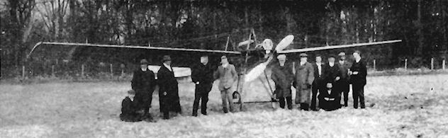
MR. H. G. FERGUSON'S IRISH-BUILT MONOPLANE. - This photograph was taken in Masserene Park, Antrim, on the shores of Lough Neagh, after a successful essay by Mr. Ferguson. It will be noticed that the Automobile Association's well-known "A.A." badge adorns the prow of the machine. The four central figures are, from left to right, Mr. John Brown, the first Irishman to own and run a motor car in Ireland; Mr. H. Ferguson, the builder of the machine Mr. T. C. Percy, J.P.; and Mr. Francis Wilde, the Assistant Secretary of the A.A.
Flanders F.2 and F.3
R. L. Howard Flanders was one of A. V. Roe's earliest assistants, having joined him when the triplane pioneer was making his first flights at Lea Marshes during the summer of 1909. Flanders afterwards accompanied Roe to the 1909 Blackpool Meeting, together with E. V. B. Fisher, and then teamed up with John V. Neale at Brooklands, designing the tiny Pup monoplane for him.
The following year, on 1st August, 1910, he started to draw up plans for his own monoplane to carry the powerful 120 h.p. A.B.C. engine. Construction of the airframe was started on 1st October and continued until 26th May, 1911, when work stopped owing to the non-arrival of the specified engine.
<...>
Flanders F.2 and F.3
R. L. Howard Flanders was one of A. V. Roe's earliest assistants, having joined him when the triplane pioneer was making his first flights at Lea Marshes during the summer of 1909. Flanders afterwards accompanied Roe to the 1909 Blackpool Meeting, together with E. V. B. Fisher, and then teamed up with John V. Neale at Brooklands, designing the tiny Pup monoplane for him.
The following year, on 1st August, 1910, he started to draw up plans for his own monoplane to carry the powerful 120 h.p. A.B.C. engine. Construction of the airframe was started on 1st October and continued until 26th May, 1911, when work stopped owing to the non-arrival of the specified engine.
The day after, on 27th May, a new design was commenced, based upon the four-cylinder 60 h.p. Green. Construction started on 6th June, 1911, and the machine was finished two months later on 6th August, making its first flight on 8th August, 1911. Testing of the F.2 was carried out at Brooklands by Ronald C. Kemp.
The F.2 was a single-seater of sound construction and of graceful appearance, and was flown for the next two months until, in October, it was reconstructed for participation in the contests for the British Empire Michelin Cups Nos. 1 and 2, in both of which it was piloted by Kemp, but was unable to register any success. The machine was redesignated the F.3, and alterations included the installation of a second cockpit to carry a passenger in front of the pilot, and also the provision of larger wings of 42 ft. span and 200 sq. ft. area. The same 60 h.p. Green engine was retained, and it drove an 8 ft. diameter Regy propeller. A silencer was fitted, and the pair of radiators operated on each side of the front cockpit. The F.3 was flown at first without a fin, but a small fixed surface was added after testing was carried out by Ronald Kemp and by E. V. B. Fisher.
Following several months of flying, the F.3's career came to a tragic end when it crashed at Brooklands on 13th May, 1912, killing both the pilot, Fisher, and his American passenger Victor Mason.
SPECIFICATION
Description: Single/two-seat tractor monoplane. Wooden structure, fabric covered.
Manufacturers: L. Howard Flanders, Ltd., Richmond and Brooklands, Surrey.
Power Plant: 60 h.p. Green.
Dimensions:
(F.2) Span, 35 ft. Length, 31 ft. 9 ins. Wing area, 200 sq. ft.;
(F.3) Span, 42 ft. Length, 31 ft. 9 ins. Wing area, 240 sq. ft.
Weights: (F.2) Empty, 1,000 lb.; (F.3) Empty, 1,100 lb.
Performance: (F.2) Maximum speed, 60 m.p.h.; (F.3) Maximum speed, 65 m.p.h.
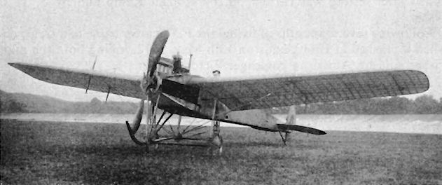
Flanders F.2
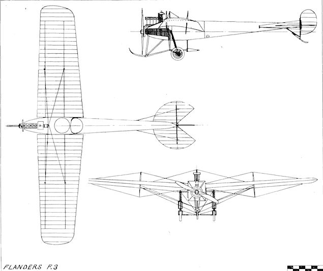
Flanders F.3
Flanders B.2
A tractor biplane design was drawn up by R. L. Howard Flanders for participation in the 1912 Military Trials. The power plant chosen was the eight-cylinder 100 h.p. A.B.C., coupled to an 8 ft. 6 ins. diameter Regy propeller. The machine possessed pleasingly clean lines, and was characterized by the depth of its fuselage about the cockpit area and by the shortness of its undercarriage, which was brought about by the high thrust-line, all of which combined to give a very low-set appearance on the ground. The fore-portion of the fuselage was of pentagon section, surmounted by a curved decking; mid-way along the body, the section changed from rectangular to triangular as the fuselage tapered towards the tail. The deep cockpits made the machine very comfortable, as the heads only of the occupants were exposed; the pilot sat in the rearmost of the pair of tandem seats.
The wing bays were unconventional in that they were formed by upper and lower wings connected by four pairs of parallel interplane struts, centre-section struts being omitted. Dihedral also was lacking, but washout was applied at the tips, and prominent king-posts supported the overhang of the 43 ft. span upper wings.
The undercarriage supported the machine in a near-horizontal position on the ground, shock-absorbing being taken by vertical movement of the neat coil springs on the main upright legs. The wheels were mounted on a transverse axle, and a curved skid afforded protection to the propeller.
F. P. Raynham was nominated to fly the Flanders Biplane at the Trials, in which it was entry No. 16, but was unable to do so, as the machine arrived without its engine owing to delay in delivery of the eight cylinder 100 h.p. A.B.C. with which it was to be fitted. After one short hop at the Trials it was taken back to Brooklands, where, some four months later, a 40 h.p. A.B.C. was installed on 21st December, 1912. On 22nd of the month the aircraft was test-flown by Raynham, who also coaxed it into the air quite happily with A. Dukinlield-Jones and C. Lavzell-Apps on board at the same time. A week later, on 29th December, the biplane ran into a fence and damaged its wings. Its designer had already decided to replace them by an improved set, and this was done accordingly.
The new wings were of a shorter upper span of 41 ft. and were reduced in area from 400 sq. ft. to 395 sq. ft. The upper tips had their outward rake reduced, while the lower wings' square-cut tips were tapered inwards. The interplane struts were altered to splay outwards at the top, and although ailerons had been scheduled in place of warping to reduce spar fatigue, warping was still embodied in the design.
Raynham continued to fly the machine during the spring of 1913, and for a short time early in the year an experimental rudder was fitted which was divided vertically into two surfaces hinged to the post, both halves being opened from the cockpit sideways across the airflow so that they operated as air-brakes. The scheme was not successful, and the original rudder was re-installed.
It was decided that the biplane could use extra power, so, in October, 1913, the A.B.C. was removed and its place was taken by a seven-cylinder 60 h.p. Isaacson radial driving an 8 ft. 6 ins. diameter Lang propeller. Maximum speed was increased by nearly 10 m.p.h. from 56 m.p.h. with the 40 h.p. A.B.C. to 65 m.p.h. with the new engine. A. Dukinfield-Jones often piloted the machine at Brooklands. and found it to be a very pleasant aeroplane to handle.
In May, 1914, Lt. R. E. B. Hunt was reported to have bought the Flanders B.2, and in June of the same year another change of engine was made when yet more power was added with the fitting of the seven-cylinder 70 h.p. Gnome rotary complete with a cowling. The tail unit was revised to incorporate a fin. In this form, the Flanders B.2 was bought by the Admiralty at the commencement of the 1914-18 War, and was used as No. 918 at Great Yarmouth by the R.N.A.S.
SPECIFICATION
Description: Two-seat tractor biplane. Wooden structure, fabric covered.
Manufacturers: L. Howard Flanders, Ltd., Richmond and Brooklands, Surrey.
Power Plant: 100 h.p. A.B.C., 40 h.p. A.B.C., 60 h.p. Isaacson, 70 h.p. Gnome.
Dimensions:
(40 h.p. A.B.C.) Span, 43 ft. Length, 31 ft. 6 ins. Wing area, 400 sq. ft.;
(60 h.p. Isaacson) Span, 41 ft. Length, 31 ft. 10 ins. Wing area, 395 sq. ft.;
(70 h.p. Gnome) Span, 40 ft. Length, 31 ft. Wing area, 390 sq. ft.
Weights:
(40 h.p. A.B.C.) Empty, 670 lb. Loaded, 1,100 lb.;
(60 h.p. Isaacson) Empty, 1,000 lb. Loaded, 1,571 lb.;
(70 h.p. Gnome) Empty, 1,050 lb. Loaded, 1,650 lb.
Performance:
(40 h.p. A.B.C.) Maximum speed, 56 m.p.h. Landing speed, 38 m.p.h.;
(60 h.p. Isaacson) Maximum speed, 65 m.p.h. Landing speed, 40 m.p.h.;
(70 h.p. Gnome) Maximum speed, 68 m.p.h. Landing speed, 40 m.p.h. Endurance, 4*5 hrs.

Flanders B.2 with 60 h.p. Isaacson.
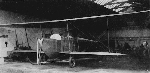
Flanders B.2 as built for 1912 Military Trials and awaiting its A.B.C. engine.
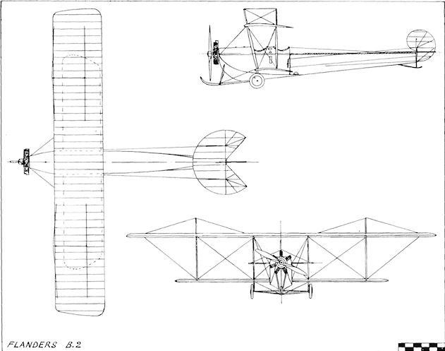
Flanders B.2
Flanders F.4
During 1912, the Flanders concern produced four monoplanes for the Military Wing of the R.F.C. to an order from the War Office. The design, designated F.4, was a development of the F.3 Monoplane. Three of the machines, Nos. 265, 281 and 422, were given tapered wings, while the fourth aircraft, No. 439, received a pair with constant chord. Although based on the 1911 monoplane, the new design was a great improvement in many ways, especially in the coil-spring undercarriage, which was completely revised and made far stronger to enable it to withstand the rigours of military usage.
Two wicker seats in tandem were fitted and the engine installed was the eight-cylinder 70 h.p. Renault. The four-bladed propeller was made up by simply superimposing two standard pairs of Regy blades on the same shaft. Conventional controls were used, with warping of the wings, the rudder being hinged to a vertical post without a fixed fin.
The first of the monoplanes was ready at the end of June, 1912, and the batch of four were put through their tests by F. P. Raynham before their acceptance by the R.F.C. Performance was found to be very good indeed, with a speed range of 26.2 m.p.h., a figure which was better than any of those attained by the various designs officially entered in the 1912 Military Trials.
The Flanders Monoplanes were unable to show their worth in service, as the ban on monoplane flying by the Military Wing of the R.F.C. came into force during the following October. However, at the Naval and Military Aviation Day held at Hendon on 28th September, 1912, a modified Renault-engined Flanders Monoplane was present, in which a single upright support was used for the cabane, and whose undercarriage utilized horizontal struts from the sides of the fuselage to carry the shock-absorbing struts of the undercarriage,
SPECIFICATION
Description: Two-seat tractor military monoplane. Wooden structure, fabric covered.
Manufacturers: L. Howard Flanders, Ltd., Richmond and Brooklands, Surrey.
Power Plant: 70 h.p. Renault.
Dimensions: Span, 40 ft. 6 ins. Length, 31 ft. 6 ins. Wing area, 240 sq. ft.
Weights: Empty, 1,350 lb. Loaded, 1,850 lb.
Performance: Maximum speed, 67.2 m.p.h. Landing speed, 41 m.p.h. Climb, 1,000 ft. in 3.5 mins., 1,500 ft. in 5.5 mins., 2,000 ft. in 8 mins.
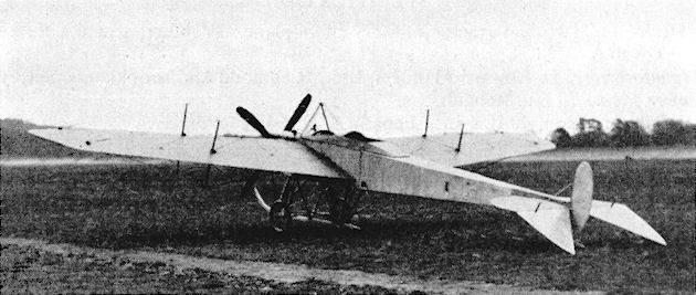
Prototype of Flanders F.4 Military Monoplane.
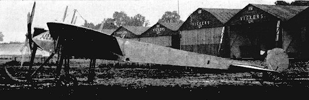
Flanders F.4 with 70 h.p. Renault at Brooklands.
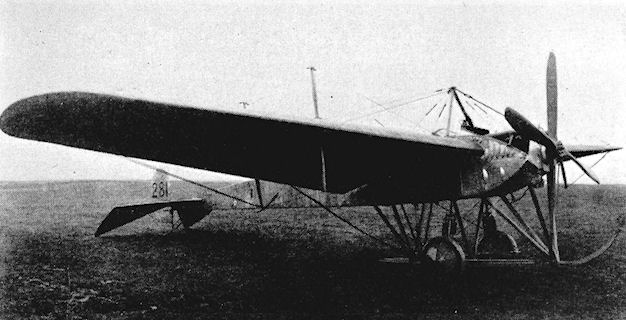
Flanders F.4 No. 281 with tapered wings for R.F.C.
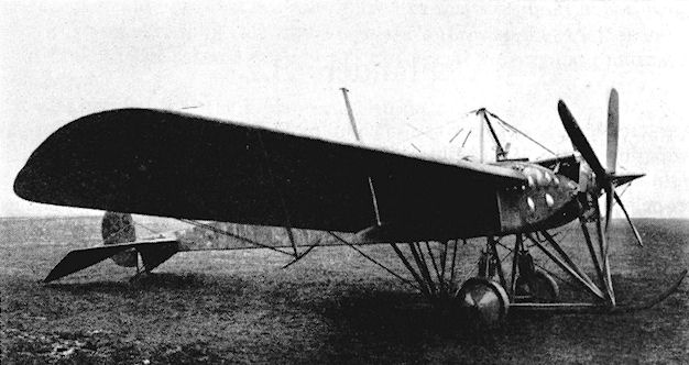
R.F.C. Flanders F.4 No. 439 with constant-chord wings.
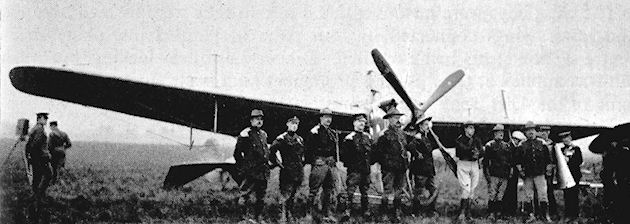
Modified Flanders F.4 at Hendon Naval and Military Aviation Day on 28th September 1912.
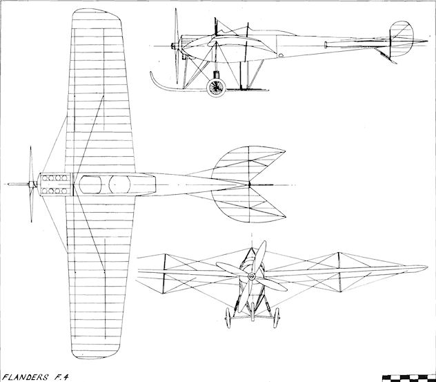
Flanders F.4
Forbes and Arnold Monoplane
Victor F. Forbes and Arthur J. Arnold built their single-seat tractor monoplane at Leigh-on-Sea, Essex, in 1909. It was of extremely unconventional design, intended to secure natural stability, as described in their Patent No. 20846 of 1909. Although successful flights were claimed with models of this design, there is no record of any full-scale flying being accomplished. Span, 16 ft. Length, 24 ft. Height, 10 ft. Wing area, 350 sq. ft. Weight loaded, 450 lb.
Victor F. Forbes and Arthur J. Arnold built their single-seat tractor monoplane at Leigh-on-Sea, Essex, in 1909. It was of extremely unconventional design, intended to secure natural stability, as described in their Patent No. 20846 of 1909. Although successful flights were claimed with models of this design, there is no record of any full-scale flying being accomplished. Span, 16 ft. Length, 24 ft. Height, 10 ft. Wing area, 350 sq. ft. Weight loaded, 450 lb.

Messrs. Forbes and Arnold's full-sized machine which they have built as the result of successful experiments with their models.
Franklin Tandem Biplane
The Franklin Biplane was constructed in the Chiltern Hills during the early part of 1909 by Cambridge undergraduates H. H. Franklin. H. W. Holt, A. E. Lowy and C. M. Spielmann. Tandem biplane wings were mounted one behind the other. Twin propellers, rotating in opposite directions, were fitted behind the rear wings and were driven by a continuous chain from the 12 h.p. air-cooled twin-cylinder Buchet engine. Biplane elevators were installed in front, the rudder being at the rear between the propellers. The flying controls were operated by a pole suspended vertically. Springing of the landing-gear was effected by compressed air. Brief trials of the Franklin Biplane were carried out on the ground.
The Franklin Biplane was constructed in the Chiltern Hills during the early part of 1909 by Cambridge undergraduates H. H. Franklin. H. W. Holt, A. E. Lowy and C. M. Spielmann. Tandem biplane wings were mounted one behind the other. Twin propellers, rotating in opposite directions, were fitted behind the rear wings and were driven by a continuous chain from the 12 h.p. air-cooled twin-cylinder Buchet engine. Biplane elevators were installed in front, the rudder being at the rear between the propellers. The flying controls were operated by a pole suspended vertically. Springing of the landing-gear was effected by compressed air. Brief trials of the Franklin Biplane were carried out on the ground.
Fritz Monoplane
The Fritz single-seat tractor monoplane of 1910 was designed by Fritz Goetze and constructed by Oyler and Co. Ltd., of London, W.1. It displayed considerable French influence, having the general layout of the Demoiselle while possessing an undercarriage in the Bleriot style.
A 40 h.p. eight-cylinder E.N.V. "D" engine was mounted just in front of the leading-edge of the wings and turned a propeller of 7 ft. 10 ins. diameter. Three longerons of bamboo were employed to form the main structure of the open fuselage, the upper member being arched as in the Bleriot XIII to carry the wings, which were given a graceful form of "gull" dihedral. Rounded tips completed the rectangular plan of the planes, and warping was employed for lateral control. A rudder formed the sole vertical surface at the extreme rear, and the horizontal tail comprised a fixed tailplane with pivoted tips performing as elevators. The fuel tank and the radiator were mounted side-by-side above the centre-section, and in between them were the king-posts for the support of the wings, similar posts assisting the bracing of the fuselage from the upper longeron towards the tail.
SPECIFICATION
Description: Single-seat tractor monoplane. Wooden structure, fabric covered.
Manufacturers: H. and D. J. Oyler & Co. Ltd., London, W.1.
Power Plant: 40 h.p. E.N.V. "D".
Dimensions: Span, 32 ft. Length, 29 ft. Wing area, 210 sq. ft.

Fritz Monoplane
Frost Ornithopters
Two of E. P. Frost's ornithopters are among the earliest flapping-wing machines to survive until the present day. The larger, weighing 650 lb. and intended to lift a man, was powered by a steam engine and is preserved by the Shuttleworth Trust. It was made in 1900, and the wings were constructed of cane and silk, with hundreds of natural feathers attached to form a close replica of a pair of bird's wings.
The smaller, of similar construction, was made in 1903 and was 16 ft. in maximum span. Power was by a single-cylinder 3 h.p. B.A.T. petrol engine. This machine is exhibited in the National Aeronautical Collection at the Science Museum. South Kensington, S.W.7 (illustrated).
Neither of these devices succeeded in rising from the ground, but they marked the culmination of more than ten years study of bird flight and a series of ingenious attempts to imitate it by mechanical means.
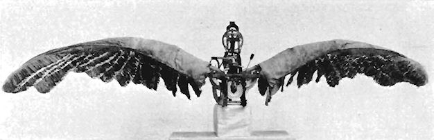
Fulford Monoplane
The diminutive monoplane designed by W. H. Fulford was built during 1909 by Mills-Fulford. lt was of the Demoiselle tractor type and was fitted with a forward elevator. The wings were of very small span and low aspect ratio. The fuselage was constructed of steel tubing, and the engine was a four-cylinder F.N. motor-cycle type which drove the propeller by a chain.
The diminutive monoplane designed by W. H. Fulford was built during 1909 by Mills-Fulford. lt was of the Demoiselle tractor type and was fitted with a forward elevator. The wings were of very small span and low aspect ratio. The fuselage was constructed of steel tubing, and the engine was a four-cylinder F.N. motor-cycle type which drove the propeller by a chain.
Gaskell-Blackburn Biplane
The remains of three old aeroplanes, the Champel, the Parsons and the Pashley Brothers' Sommer, were incorporated in the biplane designed and built at Brooklands early in 1914 by V. Gaskell-Blackburn, who had gained his Royal Aero Club Aviator's Certificate No. 617 on 10th September, 1913, flying a Bristol at the same aerodrome. The machine was a tractor and was powered by a four-cylinder 40 h.p. A.B.C. engine.
The remains of three old aeroplanes, the Champel, the Parsons and the Pashley Brothers' Sommer, were incorporated in the biplane designed and built at Brooklands early in 1914 by V. Gaskell-Blackburn, who had gained his Royal Aero Club Aviator's Certificate No. 617 on 10th September, 1913, flying a Bristol at the same aerodrome. The machine was a tractor and was powered by a four-cylinder 40 h.p. A.B.C. engine.
Gaunt Biplane No. 1
The Gaunt No. 1 was a pusher biplane fitted with a two-cylinder Alvaston engine of 30 h.p. which drove twin propellers. The tail unit was of triangular form. The machine was tested at Apperley Bridge, Bedford, during May. 1910. Wing area, 200 sq. ft.
Gaunt Biplane No. 2
The second Gaunt Biplane was of tractor layout. It was built during 1911 and was fitted with a two-cylinder 30 h.p. Alvaston engine. It was flown in September, 1911, at Southport, Lanes., by the Hon. W. S. Leveson-Gower, R.N.
George and Jobling Biplane
The George and Jobling Biplane was designed by A. E. George and was built by George and Jobling at Newcastle in 1910. The machine was a single-seat pusher with a four-cylinder 60 h.p. Green engine which drove a 9 ft. propeller mounted on a fixed shaft above the engine, to which it was chain-geared. Exhibited at the Olympia Aero Show of 1910, other unusual features embodied in the design were the hollow struts and spars, balancers for lateral control mounted mid-way between the wing-tips and the sharp angle at which the skids on the undercarriage and wings were mounted to enable the aeroplane to clear ditches and other obstructions on the ground. Control surfaces comprised a forward elevator, mid-gap Curtiss-type ailerons and a single rudder mounted below a fixed tailplane. The machine made several successful flights at Gosforth during the summer of 1910. Span, 30 ft. Length, 31 ft. Wing area, 325 sq. ft. Weight empty, 662 lb. Weight loaded, 862 lb. Maximum speed, 48 m.p.h.
The George and Jobling Biplane was designed by A. E. George and was built by George and Jobling at Newcastle in 1910. The machine was a single-seat pusher with a four-cylinder 60 h.p. Green engine which drove a 9 ft. propeller mounted on a fixed shaft above the engine, to which it was chain-geared. Exhibited at the Olympia Aero Show of 1910, other unusual features embodied in the design were the hollow struts and spars, balancers for lateral control mounted mid-way between the wing-tips and the sharp angle at which the skids on the undercarriage and wings were mounted to enable the aeroplane to clear ditches and other obstructions on the ground. Control surfaces comprised a forward elevator, mid-gap Curtiss-type ailerons and a single rudder mounted below a fixed tailplane. The machine made several successful flights at Gosforth during the summer of 1910. Span, 30 ft. Length, 31 ft. Wing area, 325 sq. ft. Weight empty, 662 lb. Weight loaded, 862 lb. Maximum speed, 48 m.p.h.
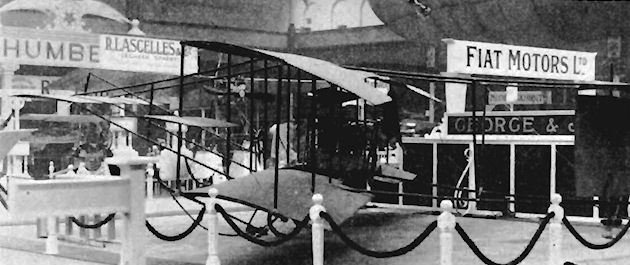
Gibson Biplane No. 1
The single-seat pusher Gibson Biplane No. 1 was designed by J. and G. T. Gibson, and constructed by the Caledonian Motor and Cycle Works of Leith, Scotland, during 1909. The engine was a two-cylinder horizontally-opposed 30 h.p. Alvaston, with radiators mounted vertically on each side behind the pilot.
Gibson Biplane No. 2
The Gibson Biplane No. 2 was a modification produced in 1910 of the Gibson No. 1 of the previous year. The same power plant, the 30 h.p. Alvaston, was used, but the airframe differed in several respects. A biplane fore-elevator was fitted in place of the monoplane type of the No. 1, and the undercarriage skids were extended upwards in a curve to provide additional support for it. The original monoplane tail-unit was replaced by biplane surfaces, with a pair of rudders set side-by-side between them, and the tail booms were lowered towards the rear so that the machine was in a horizontal position on the ground. Alterations were made also in the undercarriage struts. The Gibson No. 2 was flown in August, 1910. Span, 29 ft. Length, 30 ft.
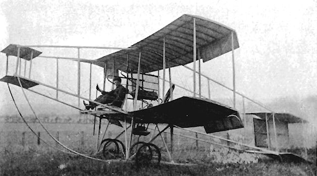
Gloucester Aeroplane Company Monoplane
The G.A.C. Monoplane was designed by J. A. Barnet and Campbell A. Ping. It was built by the Gloucester Aeroplane Company of Barton St., Gloucester, being completed during August, 1910, and was a single-seat tractor fitted with the 24 h.p. Phoenix rotary engine. Span, 32 ft. Weight empty, 305 lb.
The G.A.C. Monoplane was designed by J. A. Barnet and Campbell A. Ping. It was built by the Gloucester Aeroplane Company of Barton St., Gloucester, being completed during August, 1910, and was a single-seat tractor fitted with the 24 h.p. Phoenix rotary engine. Span, 32 ft. Weight empty, 305 lb.
Gnosspelius Hydro-monoplane No. 1
The Gnosspelius Hydro-monoplane No. 1 was designed by Oscar T. Gnosspelius and constructed during 1910 by Borwick and Sons, Bowness-on-Windermere, Westmorland. It was a twin-float single-seat tractor monoplane on the lines of a Bleriot and was powered by a two-cylinder 20 h.p. Alvaston engine. The pair of catamaran hydroplane-type floats fitted originally proved to be too small, and the engine developed insufficient power for flight. A single Borwick-built hydroplane type of float, 14 ft. long and 4 ft. wide, replaced the inadequate pair, but still the machine would not take-off.
The Gnosspelius Hydro-monoplane No. 1 was designed by Oscar T. Gnosspelius and constructed during 1910 by Borwick and Sons, Bowness-on-Windermere, Westmorland. It was a twin-float single-seat tractor monoplane on the lines of a Bleriot and was powered by a two-cylinder 20 h.p. Alvaston engine. The pair of catamaran hydroplane-type floats fitted originally proved to be too small, and the engine developed insufficient power for flight. A single Borwick-built hydroplane type of float, 14 ft. long and 4 ft. wide, replaced the inadequate pair, but still the machine would not take-off.
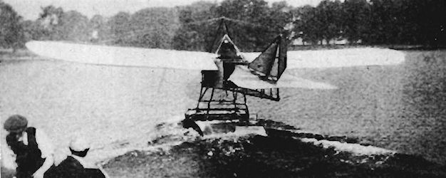
Gnosspelius Hydro-monoplane No. 2
The second Gnosspelius single-seat tractor hydro-monoplane was designed by Oscar T. Gnosspelius at the end of 1910 and was built for him by Borwick and Sons at Bowness-on-Windermere. It was powered by the four-cylinder in-line 50 h.p. Clerget engine, and was supported on the water by a single broad float, 12 ft. long and 5 ft. wide, which was augmented by small wing-tip and tail floats. Tested during the summer of 1911, the machine toppled forwards in the water on to its back. Salvaged and rebuilt with the first Gnosspelius hydro-monoplane's 14 ft. by 4 ft. float, it left the water on 13th February, 1912, piloted by Gnosspelius. Subsequent flights were made by Ronald Kemp and Lt. J. F. A. Trotter, the machine still flying successfully in the spring of 1914. Wing area. 190 sq. ft. Weight empty, 650 lb.
The second Gnosspelius single-seat tractor hydro-monoplane was designed by Oscar T. Gnosspelius at the end of 1910 and was built for him by Borwick and Sons at Bowness-on-Windermere. It was powered by the four-cylinder in-line 50 h.p. Clerget engine, and was supported on the water by a single broad float, 12 ft. long and 5 ft. wide, which was augmented by small wing-tip and tail floats. Tested during the summer of 1911, the machine toppled forwards in the water on to its back. Salvaged and rebuilt with the first Gnosspelius hydro-monoplane's 14 ft. by 4 ft. float, it left the water on 13th February, 1912, piloted by Gnosspelius. Subsequent flights were made by Ronald Kemp and Lt. J. F. A. Trotter, the machine still flying successfully in the spring of 1914. Wing area. 190 sq. ft. Weight empty, 650 lb.
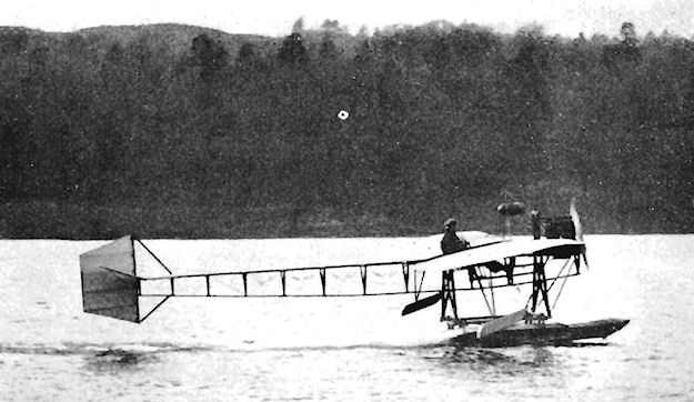
Ronald Kemp piloting Oscar Gnosspelius's second hydro-monoplane on Lake Windermere.
Gnosspelius Hydro-biplane
The Gnosspelius two-seat tractor hydro-biplane was designed by Oscar T. Gnosspelius and was built during 1913. It was powered by the 100 h.p. Green engine with which it flew at Lake Windermere in September, 1913, piloted by Lt. J. F. A. Trotter. The machine was found to be underpowered during testing.
The Gnosspelius two-seat tractor hydro-biplane was designed by Oscar T. Gnosspelius and was built during 1913. It was powered by the 100 h.p. Green engine with which it flew at Lake Windermere in September, 1913, piloted by Lt. J. F. A. Trotter. The machine was found to be underpowered during testing.

Gnosspelius hydro-biplane was flown for a short time only in 1913.
Goodden Monoplane
Frank Widdenham Goodden built his single-seat tractor monoplane at Wolvercote, Oxford, during 1912. It was powered by the eight-cylinder 35 h.p. J.A.P. engine and flew at Port Meadow Aerodrome, from mid-1912 until 1913. Frank Goodden later became Chief Test Pilot of the Royal Aircraft Factory, Farnborough, where he was killed flying the prototype S.E.5 in January, 1917. Span, 30 ft. Length, 25 ft. Wing area, 168 sq. ft. Maximum speed, 60 m.p.h.
Frank Widdenham Goodden built his single-seat tractor monoplane at Wolvercote, Oxford, during 1912. It was powered by the eight-cylinder 35 h.p. J.A.P. engine and flew at Port Meadow Aerodrome, from mid-1912 until 1913. Frank Goodden later became Chief Test Pilot of the Royal Aircraft Factory, Farnborough, where he was killed flying the prototype S.E.5 in January, 1917. Span, 30 ft. Length, 25 ft. Wing area, 168 sq. ft. Maximum speed, 60 m.p.h.
Gould Biplane
The Gould Biplane was of the pusher type, and was built at Exeter during 1910.
Gould Monoplane
The Gould Monoplane was built at Exeter during 1910, and was of the Bleriot tractor type.
The Gould Biplane was of the pusher type, and was built at Exeter during 1910.
Gould Monoplane
The Gould Monoplane was built at Exeter during 1910, and was of the Bleriot tractor type.
Grahame-White Biplane
The Grahame-White Biplane of 1910 was built for a projected flight from London to Paris. It was a pusher with a single propeller, and was designed on the lines of the Wright Brothers' biplanes. The elevator was mounted in front of the wings.
The Grahame-White Biplane of 1910 was built for a projected flight from London to Paris. It was a pusher with a single propeller, and was designed on the lines of the Wright Brothers' biplanes. The elevator was mounted in front of the wings.
Grahame-White Baby and New Baby
The Grahame-White Baby was a two-seat pusher biplane produced for training and flown during 1910. The design of the machine followed that of other successful boxkites of the period, and in 1911 an improved version known as the New Baby appeared. It was on display at the 1911 Olympia Aero Show, and was claimed to be inherently stable and to be steady in flight in winds gusting up to 30 m.p.h. Portability for transport by land was a feature of the design of the New Baby, the wings of which were made in three sections for the purpose. Construction was of ash and silver spruce, with fittings of steel. An improved rigid undercarriage with greater strength was fitted to the machine to provide extra safety in operation. The biplane tail unit was supplemented by a forward elevator, and ailerons were fitted on both upper and lower wings. A 50 h.p. or 70 h.p. Gnome engine was installed.
Early in March, 1911, the managements of Hendon and Brooklands, as part of their campaign to establish both aerodromes as popular centres of flying, offered prizes for the best times set up in return flights from Hendon to Brooklands. During the month, J. V. Martin flew the New Baby there in 37 mins. 26 secs., but lost his way on the return trip in fog, the prize for the first contest being won by Gustav Hamel in 58 mins. 38 secs, in his Bleriot.
SPECIFICATION
Description: Two-seat pusher biplane. Wooden structure, fabric covered.
Manufacturers: Grahame-White Aviation Co. Ltd., Hendon, London, N.W.9.
Power Plant: 50 h.p. Gnome, 70 h.p. Gnome.
Dimensions: Span, 27 ft. Length, 32 ft. 3 ins. Height, 8 ft. 6 ins. Wing area, 235 sq. ft.
Weights: Empty, 420 lb. Loaded, 655 lb.
Performance: Maximum speed, 55 m.p.h. Endurance, 3-4 hrs.
Price: ?950 (50 h.p. Gnome), ?1,050 (70 h.p. Gnome).
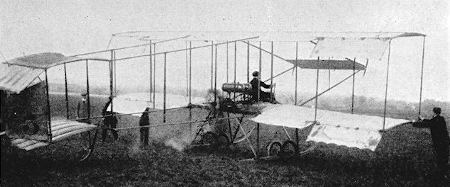
C. Compton Paterson about to take off on his Grahame-White Baby.
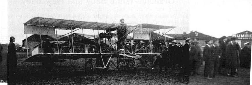
HENDON-BROOKLANDS-HENDON. - Mr. Martin getting ready for his return to Hendon. A fresh "arrival" - just in sight - momentarily stops operations.
J. V. Martin standing in the Grahame-White Baby at Brooklands on 11 March, 1911 before flying back to Hendon during the return race staged between the two aerodromes.
J. V. Martin standing in the Grahame-White Baby at Brooklands on 11 March, 1911 before flying back to Hendon during the return race staged between the two aerodromes.
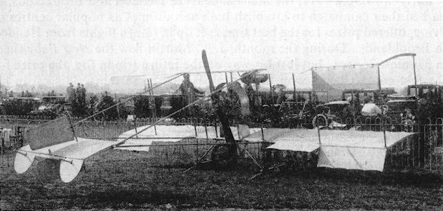
Grahame-White Baby modified with simplified tail, single undercarriage wheels, revised tail booms, engine cowling ring and without fore-elevator.
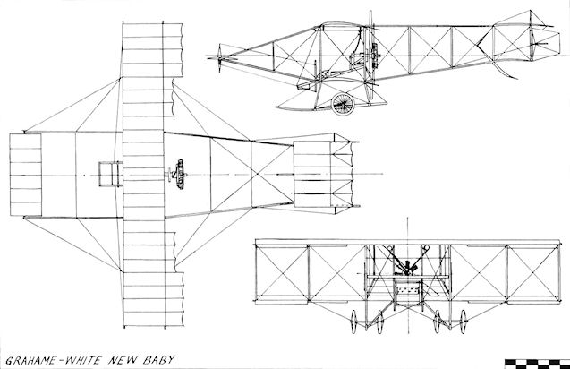
Grahame-White New Baby
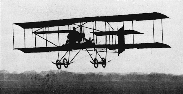
Grahame-White Boxkite.
Grahame-White Type 9
The Type 9 was a single-seat tractor monoplane designed by W. Rowland Ding and completed during September, 1912. It was tested on the 7th of the same month by Marcel Desoutter at Hendon. Its first engine was a 35 h.p. Anzani, but this was changed later to a 50 h.p. Gnome. Span, 31 ft. Length, 24 ft. Endurance, 4 hrs.
The Type 9 was a single-seat tractor monoplane designed by W. Rowland Ding and completed during September, 1912. It was tested on the 7th of the same month by Marcel Desoutter at Hendon. Its first engine was a 35 h.p. Anzani, but this was changed later to a 50 h.p. Gnome. Span, 31 ft. Length, 24 ft. Endurance, 4 hrs.
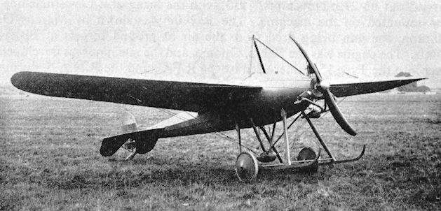
Grahame-White Lizzie
In addition to the normal everyday work of training which was carried on there, the weekly flying displays and special events were a great feature of the early days at Hendon Aerodrome. With greater experience of general flying and increased reliability, exhibitions of aerobatics became more and more popular.
A Grahame-White tractor biplane was built specifically for the purpose in 1913, and was composed mainly of the fuselage from a Morane Saulnier monoplane, which was combined with the upper and lower wings of a Popular pusher biplane. The rather quaint-looking result of these machinations was christened Lizzie and known also as "The Teatray". The machine retained the Morane type of tail unit and was without fixed fin and tailplane. The front of the fuselage was covered with plywood, fabric being used over the rest of the airframe. The gap between the wings was the unusually large one of 6 ft. 3 ins., and contributed to the oddity of Lizzie's appearance. The substantial overhang of the upper wings of the Popular was another feature of the design. The engine was a semi-cowled 50 h.p. Gnome which turned a 7 ft. 6 ins. diameter propeller.
Lizzie's debut at Hendon was made with success on 22nd November, 1913, when Louis Noel flew it to win the 16 miles cross-country handicap race, and the machine continued to give exhibitions in the hands of Louis Strange and Reginald Carr. For Carr's demonstrations of looping, modifications were carried out early in 1914. The lower wings were extended until they were nearly as great in span as the upper surfaces, and outer pairs of interplane struts were added to transform the wings from single-bay into two-bay cellules. Although the large gap remained, the alterations did much to make Lizzie's appearance more conventional.
SPECIFICATION
Description: Single-seat tractor biplane. Wooden structure, fabric covered.
Manufacturers: Grahame-White Aviation Co. Ltd., Hendon, London, N.W.9.
Power Plant: 50 h.p. Gnome.
Dimensions: Span, 28 ft. 6 ins. Length, 21 ft. 10 ins. Wing area, 220 sq. ft.
Weights: Loaded, 850 lb.
Performance: Maximum speed, 65 m.p.h.
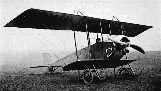
Grahame-White Lizzie with R. Carr.
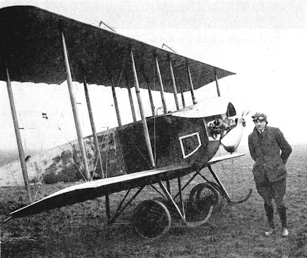
L. A. Strange with the Grahame-White Lizzie in 1914 after the extended lower wings had been fitted.

The start of a race at Hendon.

Grahame-White Lizzie
Grahame-White Boxkite
The two-seat pusher Boxkite was built during 1912 for training, and, by virtue of its pair of rudders, was known as the "Bi-rudder Bus". It was employed extensively at Hendon in several modified versions. Tests were carried out on 27th November, 1913, with the firing of a Lewis machine-gun mounted on the machine. The Boxkite was flown by Marcus D. Manton, the gun being fired from the air at ground targets at Bisley, Hants. The engine was the 50 h.p. Gnome, and the machine was developed later into the Type 15 trainer used by the R.F.C. and the R.N.A.S, during the 1914-18 War.
The two-seat pusher Boxkite was built during 1912 for training, and, by virtue of its pair of rudders, was known as the "Bi-rudder Bus". It was employed extensively at Hendon in several modified versions. Tests were carried out on 27th November, 1913, with the firing of a Lewis machine-gun mounted on the machine. The Boxkite was flown by Marcus D. Manton, the gun being fired from the air at ground targets at Bisley, Hants. The engine was the 50 h.p. Gnome, and the machine was developed later into the Type 15 trainer used by the R.F.C. and the R.N.A.S, during the 1914-18 War.

Grahame-White Boxkite with twin rudders.
Grahame-White Type 6
J. D. North designed the Type 6 Military Biplane which was exhibited at the 1913 Olympia Aero Show. The tail was supported on three booms, the uppermost of which was used as a bearer for the propeller, with the control wires for the tail passing through the centre of the propeller boss. This arrangement originated with Horatio Barber. The 120 h.p. Austro-Daimler scheduled for the machine was not fitted at the Show, its place being taken by the 90 h.p. Austro-Daimler. This was mounted at the front of the deep nacelle, an extension shaft passing to the rear to drive the propeller by a chain. The Colt machine-gun in the nose had a 50° vertical and 180° horizontal field of fire. In addition to the pilot, two passengers were carried at the front of the nacelle and were accommodated on sprung seats over the tool boxes on each side of the engine. The controls were mounted on ball-bearings. Span, 42 ft. 6 ins. Length, 33 ft. 9 ins. Wing area, 440 sq. ft. Weight empty, 2,200 lb. Weight loaded, 2,950 lb. Maximum speed, 70 m.p.h. Landing speed, 50 m.p.h. Endurance, 6 hrs.
J. D. North designed the Type 6 Military Biplane which was exhibited at the 1913 Olympia Aero Show. The tail was supported on three booms, the uppermost of which was used as a bearer for the propeller, with the control wires for the tail passing through the centre of the propeller boss. This arrangement originated with Horatio Barber. The 120 h.p. Austro-Daimler scheduled for the machine was not fitted at the Show, its place being taken by the 90 h.p. Austro-Daimler. This was mounted at the front of the deep nacelle, an extension shaft passing to the rear to drive the propeller by a chain. The Colt machine-gun in the nose had a 50° vertical and 180° horizontal field of fire. In addition to the pilot, two passengers were carried at the front of the nacelle and were accommodated on sprung seats over the tool boxes on each side of the engine. The controls were mounted on ball-bearings. Span, 42 ft. 6 ins. Length, 33 ft. 9 ins. Wing area, 440 sq. ft. Weight empty, 2,200 lb. Weight loaded, 2,950 lb. Maximum speed, 70 m.p.h. Landing speed, 50 m.p.h. Endurance, 6 hrs.
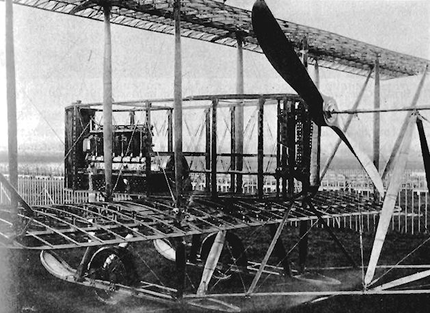
This photograph ot the 90-h.p. Grahame-White Type 6 military biplane gives a good idea of the intricacy of its internal construction. The finely-constructed framework showing the extension shaft from the engine to the propeller chain drive, and the upper tail-boom through which passed the tail-unit control wire.
Grahame-White Type 7 Popular
Claude Grahame-White devoted a great deal of his time towards popularising flying and, to this end, asked J. D. North to design a small, cheap and easy-to-produce aeroplane. North set to work and, in January, 1913, there appeared the Type 7 Popular for use as a school machine and for sporting flying.
The Farman-style pusher layout was followed, and the prototype was equipped with the 35 h.p. three-cylinder Anzani engine. Effective lateral control was ensured by the fitting of 7 ft. long ailerons, extending from the tail booms to the tips of the upper wings. The lower wings were of very short span, being but 14 ft. compared with the upper span of 28 ft., and the sole bracing for the long overhang of the upper wings was provided by king-posts and wire. Tandem seating for two was provided in the enclosed nacelle, and a one-piece elevator was fitted at the rear. The Type 7 was not fitted with a tail-skid, take-off and landing being effected on the main wheels and their laminated skids.
The production version of the Popular was given increased power in the form of the 50 h.p. Gnome, and this engine was fitted to both the single-seat and two-seat models. At the time at which the Popular was built, the majority of aeroplanes cost about ?1,000. Its own price of under ?400 was a praiseworthy attempt to place on the market a machine at a reasonable price without compromising standards of safety, economy and comfort.
SPECIFICATION
Description: Two-seat pusher biplane. Wooden structure, fabric covered.
Manufacturers: Grahame-White Aviation Co. Ltd., Hendon, London, N.W.9.
Power Plant: 35 h.p. Anzani, 50 h.p. Gnome.
Dimensions: Span, 28 ft. Length, 23 ft. 6 ins. Wing area, 205 sq. ft.
Performance: Maximum speed, 50 m.p.h. Endurance, 4 hrs.
Price: Under ?400.
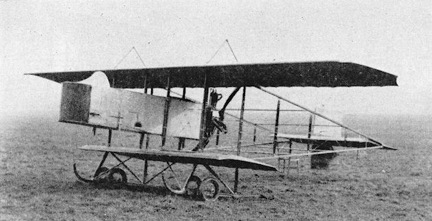
THE 35-h.p. GRAHAME-WHITE BIPLANE. - Three-quarter front view.
GW Type VII was acquired for the RFC as No.283 in 1913.
GW Type VII was acquired for the RFC as No.283 in 1913.
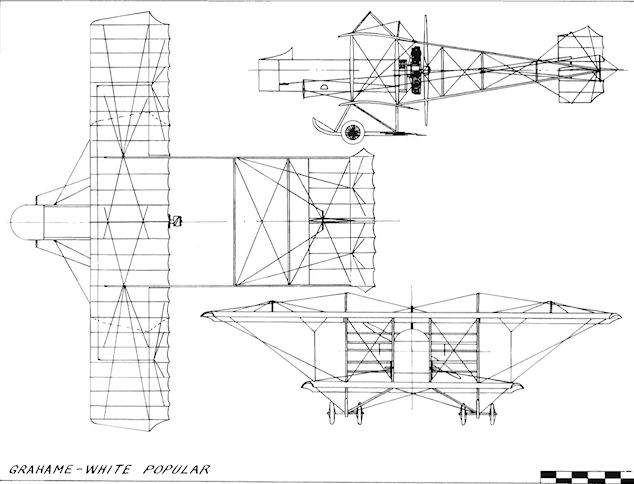
Grahame-White Popular
Grahame-White Type 8
The Type 8 Hydro-biplane was designed for cheap operation from water by the private-owner and sporting pilot. The floats were given air-scoops which led to outlets just aft of the steps to assist with unsticking. The machine carried two, the passenger sitting in the front cockpit separated from the pilot at the rear by the fuel tank between them. The view was exceptionally good from the comfortable seats, and the Type 8 was flown also as a landplane. Both the 60 h.p. Anzani and the 80 h.p. Gnome were fitted. Span, 42 ft. 6 ins. Length, 25 ft. Wing area, 335 sq. ft. Weight empty, 850 lb. Weight loaded, 1,300 lb. Maximum speed, 55 m.p.h. Endurance, 4 hrs.
The Type 8 Hydro-biplane was designed for cheap operation from water by the private-owner and sporting pilot. The floats were given air-scoops which led to outlets just aft of the steps to assist with unsticking. The machine carried two, the passenger sitting in the front cockpit separated from the pilot at the rear by the fuel tank between them. The view was exceptionally good from the comfortable seats, and the Type 8 was flown also as a landplane. Both the 60 h.p. Anzani and the 80 h.p. Gnome were fitted. Span, 42 ft. 6 ins. Length, 25 ft. Wing area, 335 sq. ft. Weight empty, 850 lb. Weight loaded, 1,300 lb. Maximum speed, 55 m.p.h. Endurance, 4 hrs.
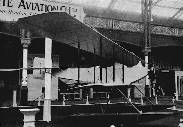
Grahame-White Type 10 Charabanc
After Hendon Aerodrome was opened to the public on 1st October, 1910, the demand for passenger flights increased rapidly to such an extent that the usual two-seat aeroplanes available were found to be inadequate for the purpose. During 1913, it was considered by the Grahame-White company that a machine capable of carrying several passengers during normal operations, and not just as a stunt, would help to meet the situation. The big Type 10 Charabanc was evolved, therefore, by J. D. North, being completed at the end of the summer and tested by Mons. Louis Noel, the chief pilot of the Grahame-White organization.
The Charabanc proved to be very successful indeed, and commenced a useful career of passenger flying at Hendon by setting up a world record on 22nd September, 1913, when Noel took off with seven others on board and remained aloft for 17 mins. 25.4 secs. Just over a week later, on 2nd October, the same pilot bettered this achievement by cramming nine passengers into the nacelle and staying airborne for 19 mins. 47 secs. A 120 h.p. Austro-Daimler engine was used in the machine to provide adequate power for weight lifting, but. for the purpose of making an attempt on the 1913 Michelin Cup No. 1 and to achieve all-British status, this was replaced later in the month by the 100 h.p. six-cylinder Green from the biplane in which Cody crashed fatally. The modification proved worthwhile for, on 6th November, R. H. Carr won the Cup and its accompanying ?500 prize by covering the minimum 300 miles stipulated flying to and fro between Hendon and Brooklands. Six months afterwards, on 9th May, 1914, the Charabanc was used by W. Newell to take him up over Hendon when he made the first parachute descent in Great Britain from an aeroplane. R. H. Carr again piloted the aircraft, while the intrepid parachutist perched on the port undercarriage skid, clutching his parachute in his arms. When the time came to jump he was pushed off by the foot of F. W. Goodden, who was sitting above him on the lower wing.
With its span of 62 ft. 6 ins. and a loaded weight of 3,100 lb., the Charabanc was one of the largest British aeroplanes built before the 1914-18 War. Seated in the prow of the long nacelle, the pilot had an excellent view. The passengers were accommodated behind him side-by-side on two rows of wicker seats. The engine was fitted with an effective silencer and, in keeping with its character, the Charabanc was equipped with a motor horn which could be heard from the ground when the machine was in flight.
SPECIFICATION
Description: Five-seat pusher biplane. Wooden structure, fabric covered.
Manufacturers: Grahame-White Aviation Co. Ltd., Hendon, London, N.W.9.
Power Plant: 120 h.p. Austro-Daimler, 100 h.p. Green.
Dimensions: Span, 62 ft. 6 ins. Length, 37 ft. 6 ins. Wing area, 790 sq. ft.
Weights: Empty, 2,000 lb. Loaded, 3,100 lb.
Performance: Maximum speed, 51 m.p.h. Cruising speed, 45 m.p.h. Landing speed, 30 m.p.h.
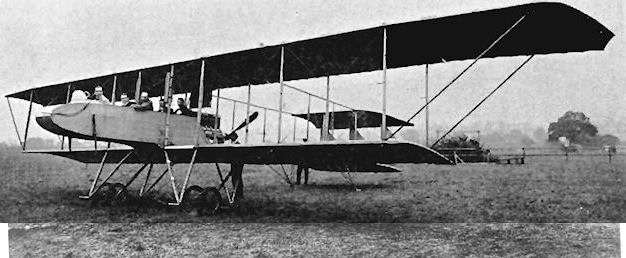
The Grahame-White Charabanc fitted with Austro-Daimler engine at Hendon with Claude Grahame-White in the front cockpit and the machine's designer, J. D. North, second from the left.
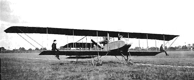
Mechanic taking a ride on the lower wings of the Grahame-White Charabanc being taxied by Louis Noel at Hendon.
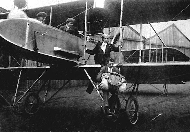
W. Newell about to ascend in the Grahame-White Charabanc for a parachute jump over Hendon.
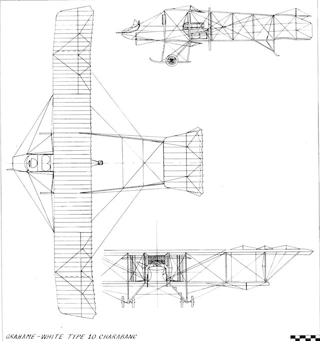
Grahame-White Type 10 Charabanc
Grahame-White Type 11 Warplane
The Warplane of 1914 was another of J. D. North's designs for Grahame-White, and was on the company's stand at the 1914 Olympia Aero Show. A handsome two-seat pusher biplane, it was powered by the 100 h.p. Monosoupape Gnome engine, turning a four-bladed Integral propeller made by butt-jointing two two-bladed propellers together.
Two-bay wings were fitted, their outer panels incorporating slight sweep-back. Large ailerons connected by cables were used, the outer interplane struts being set closer together than the inner pair. The engine was fully cowled at the rear of the covered nacelle, in which the gunner occupied the front seat. Four steel-tubing booms carried the tail unit, which consisted of a tailplane and elevators and a well-rounded rudder pivoted between the upper and lower booms. Tests were made with the addition of a slim fixed fin above the horizontal tail.
The undercarriage was a very sturdy unit of three main legs with the wheels mounted on a transverse axle, a sprung tailskid supporting the rear. The Warplane was designed to be easily converted into a seaplane.
The first tests were carried out at Hendon by Louis Noel during May, 1914, with the pilot occupying the front cockpit for the purpose of the trials. Owing to the rather short tail moment arm, longitudinal stability was not found to be particularly good and, despite its advanced features, fine appearance and clean design for its period, the Warplane was not a success and did not go into production.
SPECIFICATION
Description: Two-seat pusher biplane. Wooden and metal structure, fabric covered.
Manufacturers: Grahame-White Aviation Co. Ltd., Hendon, London, N.W.9.
Power Plant: 100 h.p. Monosoupape Gnome. Dimensions: Span, 37 ft. Wing area, 358 sq. ft.
Weights: Empty, 1,000 lb. Loaded, 1,550 lb.
Performance: Maximum speed, 80 m.p.h. Landing speed, 42 m.p.h. Endurance, 5 hrs.
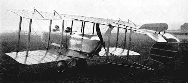
Grahame-White Type 11 Warplane.
Grahame-White Type 13 Circuit Seaplane/Scout
Entry number 4 in the 1914 Daily Mail Circuit of Britain race for seaplanes was the Type 13 built by the Grahame-White concern. The machine was designed by J. D. North and was scheduled to be Claude Grahame-White's mount in the contest. It possessed a neat and workmanlike appearance, with the two seats in tandem and the wings of heavily-staggered, single-bay lay-out. The 100 h.p. Monosoupape Gnome was cowled in aluminium and blended into the fuselage, whose rear end tapered in side elevation to a horizontal knife-edge in the Morane-Saulnier manner. The Type 13 was devoid of a tailplane, utilizing elevators only, also a typical Morane-Saulnier feature. An idea in advance of its time was the addition of an extra strut between each main interplane pair, which connected the upper rear spar to the lower front spar, thus constituting a very early example of the later widely-used N struts. These struts were very strong, comprising steel tubing covered with wood fairings. Decalage was incorporated in the wings' incidence settings, 5° being used in the upper and 3° in the lower. Ailerons were fitted to the upper wings only, and the lower wing roots were given generous cut-outs at the trailing-edge to aid visibility.
The machine was fitted with its floats, and water trials commenced. The floats proved, however, to be too short forward of the engine, and upon the throttle being opened up the seaplane nosed over. The Type 13 was not considered worth developing as a seaplane and was consequently abandoned as the Grahame-White entry for the Circuit of Britain. A land undercarriage was devised and fitted to the machine, which became known as the Scout. In this form it was planned to use it for reconnaissance, but, again, the design was not found successful for the purpose, and the Scout is believed to have been employed as a trainer for the R.N.A.S. at Hendon, where it was flown by Marcus D. Manton.
SPECIFICATION
Description; Two-seat tractor biplane. Wooden structure, fabric covered.
Manufacturers: Grahame-White Aviation Co. Ltd., Hendon, London, N.W.9.
Power Plant: 100 h.p. Monosoupape Gnome.
Dimensions: Span, 27 ft. 10 ins. Length (Circuit Seaplane) 27 ft. 3 ins.; (Scout) 26 ft. 6 ins. Wing area, 290 sq. ft.
Weights: (Scout) Empty, 1,040 lb. Loaded, 1,800 lb.
Performance: Maximum speed, 85 m.p.h. Endurance, 5.5 hrs.
The start of a race at Hendon.
Gratze Daisy
The single-seat tractor Daisy or Dirigoplane monoplane was designed and built in 1909 by Eugene V. Gratze. It was powered by the eight-cylinder 40 h.p. J.A.P. engine, and was fitted with elevators mounted above the wings and with balancing flaps on the leading-edges towards the wing-tips. The wings were attached to the fuselage by universal joints which permitted variable incidence and variable dihedral. The propeller was mounted on a universal joint and was interconnected with the tail unit to facilitate turning. The Daisy first flew in November, 1909, and in June, 1910, was at Canewdon, near Southend, Essex, for further testing. Span, 40 ft. Length, 28 ft. 6 ins.
The single-seat tractor Daisy or Dirigoplane monoplane was designed and built in 1909 by Eugene V. Gratze. It was powered by the eight-cylinder 40 h.p. J.A.P. engine, and was fitted with elevators mounted above the wings and with balancing flaps on the leading-edges towards the wing-tips. The wings were attached to the fuselage by universal joints which permitted variable incidence and variable dihedral. The propeller was mounted on a universal joint and was interconnected with the tail unit to facilitate turning. The Daisy first flew in November, 1909, and in June, 1910, was at Canewdon, near Southend, Essex, for further testing. Span, 40 ft. Length, 28 ft. 6 ins.
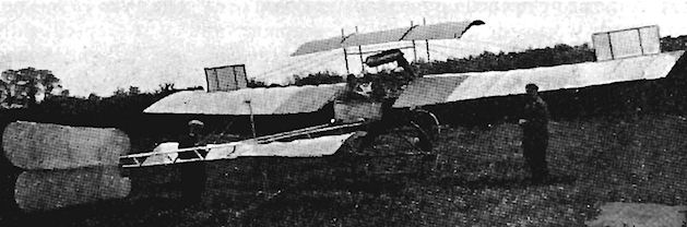
Rear view of Mr. Eugene Gratze's Machine. - The elevating is done by the central portion of the small upper plane in conjunction with the balancing flaps on the front edge of the main plane.
Grose and Feary Monoplane
A. M. Grose and N. A. Feary designed their tractor monoplane during 1909, for construction by Capt. W. G. Windham at his Windham Detachable Motor Body Co., of Clapham Junction, London, S.W.11. It was finished in April, 1910, at Oakington, Cambs. The machine was a single-seater and was powered by a four-cylinder 25 h.p. Advance engine. The wings were equipped with a patented lateral stability device. Span, 26 ft. Length, 25 ft. Wing area, 160 sq. ft.
A. M. Grose and N. A. Feary designed their tractor monoplane during 1909, for construction by Capt. W. G. Windham at his Windham Detachable Motor Body Co., of Clapham Junction, London, S.W.11. It was finished in April, 1910, at Oakington, Cambs. The machine was a single-seater and was powered by a four-cylinder 25 h.p. Advance engine. The wings were equipped with a patented lateral stability device. Span, 26 ft. Length, 25 ft. Wing area, 160 sq. ft.

Grose and Feary monoplane, built by apprentices at Windham's works at Clapham Junction, was tested at Oakington, Cambridgeshire, in 1910.
Grove Glider
The Grove Glider was designed and built by Arthur T. M. Grove of Haslemere, Surrey, during 1909. It was a biplane, with a fore-elevator and rear rudder, and was mounted on a twin-wheeled undercarriage. The machine was smashed at Henley-on-Thames before it flew. Span, 25 ft. Length, 22 ft.
The Grove Glider was designed and built by Arthur T. M. Grove of Haslemere, Surrey, during 1909. It was a biplane, with a fore-elevator and rear rudder, and was mounted on a twin-wheeled undercarriage. The machine was smashed at Henley-on-Thames before it flew. Span, 25 ft. Length, 22 ft.
Guillon and Clouzy Biplane
The prone-piloted single-seat Guillon and Clouzy Biplane was powered by a four-cylinder vee-type 20 h.p. engine with a 5 ft. diameter aluminium propeller, lt was tested on 11 th April, 1907, by Mons. Guillon on Epsom Downs, Surrey, and in the course of six trials reached 20 m.p.h. on the ground but could not be made to take-off. Weight empty, 370 lb.
The prone-piloted single-seat Guillon and Clouzy Biplane was powered by a four-cylinder vee-type 20 h.p. engine with a 5 ft. diameter aluminium propeller, lt was tested on 11 th April, 1907, by Mons. Guillon on Epsom Downs, Surrey, and in the course of six trials reached 20 m.p.h. on the ground but could not be made to take-off. Weight empty, 370 lb.

Hamble River, Luke H.L.1
The H.L.1 was built by Hamble River, Luke and Co., of Hamble, Hants., and was shown in an unfinished state at the 1914 Olympia Aero Show. It was a two-seat pusher seaplane designed by F. Murphy, who had worked previously as a designer with the British and Colonial Aeroplane Co., at Bristol. The machine featured a finely-finished cigar-shaped nacelle, at the rear of which was mounted a 150 h.p. N.A.G. six-cylinder German-designed and British-built engine, the radiators being fitted to the inter-plane struts on each side of the nacelle. The construction was of wood and fabric, and the wings were equipped with ailerons. The float structure was redesigned while the H.L.1 was being completed, and the machine was test-flown by E. C. Gordon England. Span. 60 ft. Wing area, 678 sq. ft. Weight empty, 1,600 lb. Weight loaded, 2.550 lb. Maximum speed. 65 m.p.h. Landing speed, 32 m.p.h.
The H.L.1 was built by Hamble River, Luke and Co., of Hamble, Hants., and was shown in an unfinished state at the 1914 Olympia Aero Show. It was a two-seat pusher seaplane designed by F. Murphy, who had worked previously as a designer with the British and Colonial Aeroplane Co., at Bristol. The machine featured a finely-finished cigar-shaped nacelle, at the rear of which was mounted a 150 h.p. N.A.G. six-cylinder German-designed and British-built engine, the radiators being fitted to the inter-plane struts on each side of the nacelle. The construction was of wood and fabric, and the wings were equipped with ailerons. The float structure was redesigned while the H.L.1 was being completed, and the machine was test-flown by E. C. Gordon England. Span. 60 ft. Wing area, 678 sq. ft. Weight empty, 1,600 lb. Weight loaded, 2.550 lb. Maximum speed. 65 m.p.h. Landing speed, 32 m.p.h.
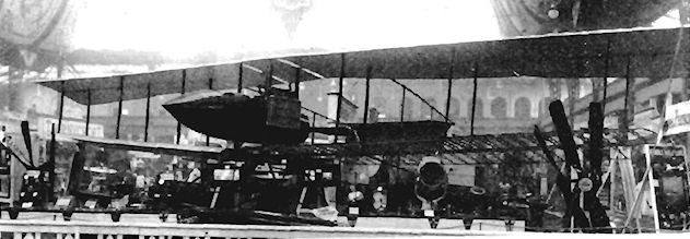
Hammond Biplane
The single-seat pusher Hammond Biplane was built at Brooklands during 1910 by E. V. Hammond.
The single-seat pusher Hammond Biplane was built at Brooklands during 1910 by E. V. Hammond.
Hammond Triplane
The Hammond Triplane was designed by E. V. Hammond and appeared at Brooklands in February, 1911. The pair of tractor propellers were belt-driven from the engine and the machine, which was tested by C. Howard Pixton, possessed a fore-elevator and ailerons of very broad chord on the upper wings.
The Hammond Triplane was designed by E. V. Hammond and appeared at Brooklands in February, 1911. The pair of tractor propellers were belt-driven from the engine and the machine, which was tested by C. Howard Pixton, possessed a fore-elevator and ailerons of very broad chord on the upper wings.
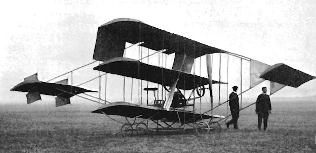
Hammond triplane. This was Hammond's second attempt at flight at Brooklands in 1911.
Hammond Monoplane
E. V. Hammond's Monoplane was built at Brooklands during the summer of 1913. It was a single-seat tractor and was powered with a water-cooled four-cylinder vee 30 h.p. Advance engine which had been modified for the purpose. Cheapness was a prime consideration behind the design of the machine; the fuselage consisted simply of a pair of steel tubes bet parallel with each other.
E. V. Hammond's Monoplane was built at Brooklands during the summer of 1913. It was a single-seat tractor and was powered with a water-cooled four-cylinder vee 30 h.p. Advance engine which had been modified for the purpose. Cheapness was a prime consideration behind the design of the machine; the fuselage consisted simply of a pair of steel tubes bet parallel with each other.
Hampshire Aero Club Glider
The Hampshire Aero Club, whose president was Patrick Y. Alexander, was formed in April, 1910, and constructed a biplane glider without control surfaces which was flown as a man-lifting kite at Fort Grange, near Gosport, Hants.
The Hampshire Aero Club, whose president was Patrick Y. Alexander, was formed in April, 1910, and constructed a biplane glider without control surfaces which was flown as a man-lifting kite at Fort Grange, near Gosport, Hants.
Handley Page Glider
Frederick Handley Page's Glider of 1908 was fitted with a pair of monoplane wings of crescent shape based on the theories of automatic stability propounded by Jose Weiss. The sole control surface was the fore-plane with variable incidence, and the undercarriage was of the tricycle type. The aircraft was tested from the top of a dyke at the Handley Page works at Barking, Essex.
Frederick Handley Page's Glider of 1908 was fitted with a pair of monoplane wings of crescent shape based on the theories of automatic stability propounded by Jose Weiss. The sole control surface was the fore-plane with variable incidence, and the undercarriage was of the tricycle type. The aircraft was tested from the top of a dyke at the Handley Page works at Barking, Essex.
Handley Page A / H.P.1
The H.P.1 was a single-seat tractor monoplane built at Barking during the late summer of 1909. Its engine was the 25 h.p. four-cylinder air-cooled vee Advance which drove a two-bladed 6 ft. 6 ins. propeller. The tail unit comprised cruciform rudder and elevators pivoted together on one universal joint. The undercarriage axle was of specially selected very flexible ash in place of springs, with splayed wheels on strong 12 ins. hubs. The machine was named Bluebird on account of the blue-grey colour of its rubberized-fabric covering. Owing to being under-powered, the H.P.1 was not a success, but it rose from the ground for a few short hops on 26th May, 1910. Span, 32 ft. 6 ins. Length, 20 ft. 6 ins. Wing area, 150 sq. ft. Weight empty, 300 lb. Weight loaded, 450 lb. Maximum speed at sea-level. 35 m.p.h. Price, ?375.
Handley Page C / H.P.3
The H.P.3 single-seat tractor monoplane was built during 1910 and was fitted with a 25 h.p. two-cylinder horizontally-opposed Alvaston engine. The cruciform tail unit combining rudder and elevators was mounted at the rear of the fuselage on one universal joint. The machine was displayed at the Olympia Aero Show of 1910. Later the 65 h.p. Isaacson radial engine was installed. Span, 30 ft. Length, 21 ft. Wing area, 150 sq.ft. Weight empty, 250 lb.
Handley Page B H.P.2
The designation H.P.2 was given by Handley Page to their model B Biplane which was constructed during 1909 for W. P. Thompson, to be developed as the Planes, Ltd., Biplane.
Planes Ltd. Biplane
The Planes Ltd. Biplane was the second powered aeroplane to be built by Handley Page at Barking, and was known by its makers as the H.P.2 B. The machine was a single-seater constructed to the special order and design of W. P. Thompson, a Lancashire patent agent who formed Planes Ltd. as the company to undertake development of the design. A 60 h.p. Green engine provided the power for two pusher propellers, which were mounted behind the lower wings. All weight, including the pilot, was concentrated below the wings in an effort to prove the theory of automatic pendulum stability. In addition to a biplane tail with two rudders, a fore-plane was carried also.
After completion in October, 1909, unsuccessful tests were carried out at Barking, and the machine was smashed when its shed blew down. It was then rebuilt and transported to Freshfield Aerodrome, Liverpool, during 1910 and reconstructed; a single propeller took the place of the original pair fitted with chain-drive, the rear tail surfaces were lightened and ailerons supplanted the wing-warping of the upper surfaces. It was flown by R. C. Fenwick, who used it to take his Royal Aero Club Aviator's Certificate No. 35 on 29th November, 1910. He crashed the machine during December, 1910, after which it was rebuilt and flown successfully by the same pilot over the shore at Formby, Lanes.
Handley Page D H.P.4
Wings of crescent form with upturned washed-out tips combined with reverse camber for automatic stability were a feature of the H.P.4 Monoplane of 1911. The machine was a single-seat tractor, the first version exhibited at the 1911 Olympia Aero Show having a monocoque rear fuselage made up of thin, highly-varnished mahogany panels. It was fitted with a borrowed 40 h.p. Green engine and was priced at ?450, with free flying tuition to purchasers, but remained unsold. The H.P.4 was then re-engined with a 60 h.p. Isaacson and was due to be flown in the 1911 Daily Mail Circuit of Britain race by R. C. Fenwick, but was crashed by him at Fairlop on the Saturday before the contest.
A second example was built with an Isaacson engine and with a plain fabric-covered rear fuselage, but was not ready in time to take part in the 1911 Circuit of Britain. The H.P.4 was nicknamed Antiseptic or Yellow Peril because of the bilious colour of the special dope coating used on it. Span, 32 ft. Length, 22 ft. Wing area, 156 sq. ft. Weight empty, 420 lb.
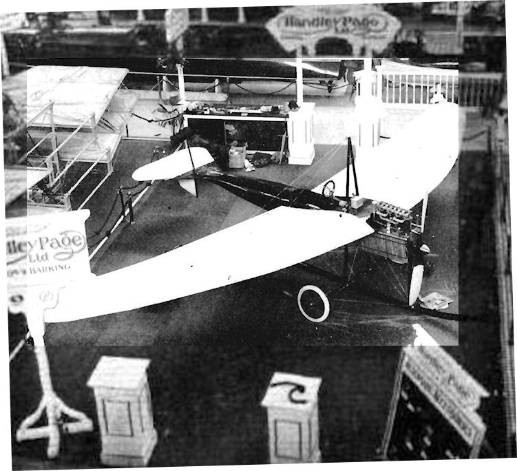
View showing the fish-like body on the Handley Page monoplane.
Handley Page E H.P.5
The H.P.5 two-seat tractor monoplane may be termed the first really successful Handley Page aeroplane. It was built at Barking in 1911, making its first flight towards the end of 1911 at Fairlop in the hands of Edward Petre, otherwise known as Peter the Painter.
The machine owed a great deal of its stability to the perseverance of Frederick Handley Page with the principle, pioneered by Jose Weiss, of the curved, swept-back wing plan-form, combined with wash-out at the tips. Warping of the flexible tips was used for lateral control, the wings being strongly braced from the central cabane and the outboard kingposts. The fuselage was of good streamline form with a deep forward belly to house the crew, who received additional protection against the 50 h.p. Gnome's oil and exhaust from the well-shaped cowling over the upper part of the engine. A very sturdy unit with a long central skid comprised the undercarriage. The H.P.5 was given a pleasing colour scheme of blue fuselage and tailplane, together with wings, elevators, fin and rudder of white rubberized canvas.
In attempting a flight from Fairlop to Barking the H.P.5 crashed, and was afterwards rebuilt. At the same time, several alterations were made to the airframe, including the substitution of a fin of curved shape in place of the original rectangular form. Edward Petre then used the machine to qualify at Fairlop on 24th July, 1912, for his Royal Aero Club Aviator's Certificate No. 259. In the same year the H.P.5 distinguished itself by becoming the first aeroplane to fly over London, a feat accomplished by Petre when he flew it from Fairlop to Brooklands in 55 minutes. Later in 1912 it was flown at Hendon by Lt. Wilfred Parke, R.N., who managed to take two passengers aloft in it. He was very enthusiastic about the machine's fine, stable flying qualities, and so was Sydney Pickles who flew the H.P.5 at Hendon during February, 1913, prior to its display again at the Olympia Aero Show of that year.
Further changes were made to the monoplane, and included the deletion of the rear cockpit and the extension rearwards of the front cockpit so that both seats were housed in it. One of the most significant of these alterations was the abandonment of the warping system of the wings and the fitting in its place of ailerons at the tips. The separate pairs of inverted-vee cabane struts were modified to a pyramid structure over the front of the cockpit. The single central skid of the undercarriage was abandoned in the new unit fitted which incorporated twin skids; the tailskid also was modified.
During the summer of 1913, Sydney Pickles and E. Ronald Whitehouse flew the machine on a very successful tour around the Provinces, on its own and in conjunction with W. Rowland Ding's Scientific and Instructive Aviation Co. Ltd., of St. Albans, Herts.
SPECIFICATION
Description: Two-seat tractor monoplane. Wooden structure, fabric covered.
Manufacturers: Handley Page Ltd., Barking, Essex.
Power Plant: 50 h.p. Gnome.
Dimensions: Span, 42 ft. 3 ins. Length, 29 ft. 2 ins. Height, 9 ft. 4 ins. Wing area, 240 sq. ft.
Weights: Empty, 750 lb.
Performance: Maximum speed, 60 m.p.h. Endurance, 3 hrs. Price: ?850.
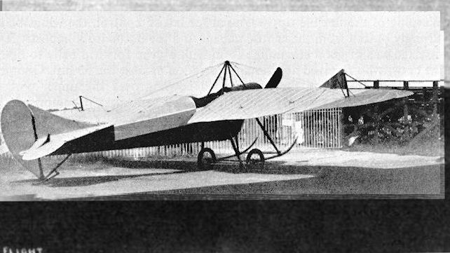
The Handley Page monoplane which has been partly reconstructed for the use of pupils at the Beatty Flying School, Hendon. Note the new type chassis which has taken the place of the original central skid type with which the machine was previously fitted. Another alteration has been effected by shortening the fuselage.
The reconstructed Handley Page H.P.5 E, piloted by E. R. Whitehouse to win the Marquis of Anglesey Cup at Burton-on-Trent on 5 August, 1913.
The reconstructed Handley Page H.P.5 E, piloted by E. R. Whitehouse to win the Marquis of Anglesey Cup at Burton-on-Trent on 5 August, 1913.
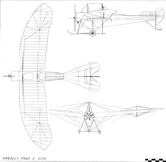
Handley Page E / H.P.5
Handley Page F / H P. 6
The H.P.6 was a two-seat side-by-side tractor monoplane built for the 1912 Military Trials and flown in them as No. 28 by Edward Petre in place of his brother Henry A. Petre, who was scheduled originally as the pilot. The machine made only one official Trials flight, and later was forced to withdraw from the competition after landing downwind with engine trouble. It was rebuilt with new wings to replace the damaged pair and finally flew well, making a flight early in December, 1912, from Brooklands to Hendon.
The Admiralty was interested in placing an order for the type after receiving favourable reports of it from Lt. Wilfred Parke, R.N., but the aircraft crashed on a golf course at Wembley on 15th December, 1912, owing to a faulty engine after taking-off from Hendon for Oxford, and killed the crew of Lt. Parke and the Handley Page Manager Arkell A. Hardwick. The engine fitted was the 80 h.p. Gnome. Span, 43 ft. 6 ins. Length, 30 ft. 2 ins. Height, 10 ft. 6 ins. Weight empty, 850 lb. Weight loaded, 1,450 1b. Maximum speed, 55 m.p.h. Price, ?1,050.

Handley Page G H.P.7
In 1913, George R. Volkert, the Handley Page designer, applied the Company's experience of the automatically stable, curved, swept-back wing to a biplane, the model G. The machine was first announced as a hydro-biplane, but appeared finally with a land undercarriage. The firm's test pilot, E. Ronald Whitehouse, took the H.P.7 into the air for the first time at Hendon early in November, 1913, and on the following 11th December he put it through the official tests at Farnborough, recording a speed range of 35 m.p.h. Stability was so outstanding that, at the end of the same month, Whitehouse demonstrated the machine at Hendon without its tailplane, flying with elevators only for longitudinal control.
The fuselage was suspended between the wings by stout centre-section struts, and consisted of a slim framework of rectangular section, fitted with full-length upper coaming and with a bulged lower portion for the accommodation of the passengers. The upper portion of the ten-cylinder 100 h.p. Anzani radial engine was cowled. Ailerons were installed on the upper wings only and the overall colour was a light brown.
On 21st May, 1914, Princess Ludwig of Lowenstein-Wertheim chartered the H.P.7 to fly her from Hendon to Calais in order to keep an urgent engagement in Paris. W. Rowland Ding was her pilot, and he flew the biplane back on the following day. Its ability to operate successfully from small fields appealed to Lindsay Bainbridge, who bought the machine for exhibition flying by the Northern Aircraft Co., of Lake Windermere, a syndicate which he ran with Ding and other directors. During June and July, 1914, the H.P.7 was taken on a provincial tour by Ding, who crashed it at the end of the second month.
In the course of reconstruction, several changes were made. The twin-skid undercarriage was altered to one with a pair of simple vee struts, the bulge below the fuselage was extended towards the rear, and the fin was reduced in area by cutting back the leading-edge. An efficient silencer was fitted to the engine also.
When the 1914-18 War commenced, the H.P.7 was taken over by the Admiralty as No. 892, being used for training at Hendon and Chingford, with Home Defence as another of its duties. Lindsay Bainbridge was killed during 1915, and the machine provided one of the rare instances of an aeroplane being mentioned in a will, as he bequeathed it to Rowland Ding. The H.P.7's career came to an end in the same year after a ground accident.
SPECIFICATION
Description: Two-seat tractor biplane. Wooden structure, fabric covered.
Manufacturers: Handley Page Ltd., 110 Cricklewood Lane, London, N.W.2.
Power Plant: 100 h.p. Anzani.
Dimensions: Span, 40 ft. Length, 26 ft. Wing area, 384 sq. ft.
Weights: Empty, 1,130 lb. Loaded, 1,775 lb.
Performance: Maximum speed, 73 m.p.h. Climb, 300 ft./min. Endurance, 4 hrs.
Price: ?1,500.
Handley Page L/200 H.P.8
The H.P.8 was a two-seat tractor biplane designed by George R. Volkert for an attempt on the Daily Mail prize of ?10,000 for a flight across the Atlantic to be made by Princess Ludwig of Lowenstein-Wertheim. The engine was to have been the 200 h.p. Salmson, and the aircraft was an enlarged version of the H.P.7 biplane. It was under construction during 1914, but was not completed owing to the declaration of war.
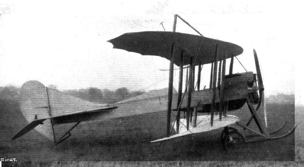
Handley Page G in ils early form with undercarriage skids and with single cockpit for tandem seats.

Mr. W. Rowland Ding in the pilot's cockpit of the modified Handley Page G at Hendon.
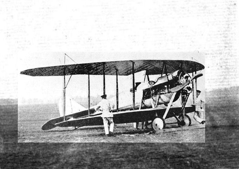
Handley Page G in 1914 with extended fairing under fuselage.
QUALIFYING FOR ROYAL AIR SERVICE AT HENDON. - An Anzani-engined Handley-Page in waiting.
QUALIFYING FOR ROYAL AIR SERVICE AT HENDON. - An Anzani-engined Handley-Page in waiting.
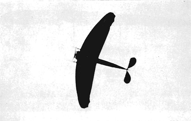
Handley Page G demonstrating its stability by flying without a tailplane.
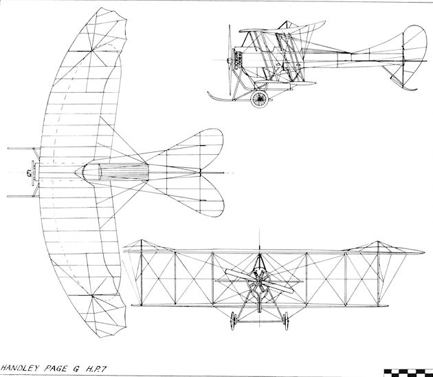
Handley Page G / H.P.7
Hewitt Ornithopter
An ornithopter monoplane was constructed by S. R. Hewitt in 1908, its wings consisting of planes 32 ft. in span with a main chord of 5 ft. and an additional flexing portion 2 ft. wide at the trailing-edge, making a total chord of 7 ft. The machine was mounted on a tricycle undercarriage.
An ornithopter monoplane was constructed by S. R. Hewitt in 1908, its wings consisting of planes 32 ft. in span with a main chord of 5 ft. and an additional flexing portion 2 ft. wide at the trailing-edge, making a total chord of 7 ft. The machine was mounted on a tricycle undercarriage.
Higgins Glider
The Higgins Glider was designed and built by H. Higgins of Cheltenham, Glos., during 1910, and was a single-seat canard monoplane. It was tested in the same year at Cleeve Hill, Cheltenham. Span, 26 ft. Length, 20 ft. Wing area, 160 sq. ft. Weight empty. 94 lb.
Higgins Monoplane
During 1911 Henry Higgins revised his glider of 1910 and turned it into a tail-first pusher monoplane by the addition of a two-cylinder engine of 10-12 h.p. This was mounted below the trailing-edge of the wings and drove a propeller of 7 ft. 2 ins. diameter. Unsuccessful tests were conducted at Cleeve Hill, Cheltenham. Wing area, 196 sq.ft. Weight empty, 240 lb.
Hill Monoplane
The Hill Monoplane was a single-seater built during 1911 by Hill and Co., of Bury, Lanes., and was based upon the Bleriot XI design.
The Hill Monoplane was a single-seater built during 1911 by Hill and Co., of Bury, Lanes., and was based upon the Bleriot XI design.
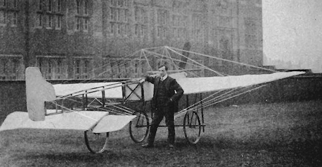
Hill monoplane built by a firm in Bury, Lancashire, was based on the Bleriot XI.
Hornstein Biplanes Nos. 1 and 2
Two Hornstein-designed biplanes were constructed during 1910 by the Thames Bank Wharf Company. Both were light-weight pushers, but had different engines. No. 1 was fitted with the eight-cylinder 20 h.p. J.A.P.; No. 2 had the four-cylinder 35 h.p. Green. No. I crashed at the end of March, 1910, while under test at Halliford, Shepperton-on-Thames. Span. 32 ft. 9 ins. Wing area, 430 sq. ft. Weight loaded, 888.5 lb.
Two Hornstein-designed biplanes were constructed during 1910 by the Thames Bank Wharf Company. Both were light-weight pushers, but had different engines. No. 1 was fitted with the eight-cylinder 20 h.p. J.A.P.; No. 2 had the four-cylinder 35 h.p. Green. No. I crashed at the end of March, 1910, while under test at Halliford, Shepperton-on-Thames. Span. 32 ft. 9 ins. Wing area, 430 sq. ft. Weight loaded, 888.5 lb.
Howard Wright 1908 Biplane
Built for Malcolm Seton-Karr in 1908 and shown at the Olympia Aero Show in 1909 before going to Fambridge for testing, the Howard Wright Biplane was powered by a four-cylinder 50 h.p. Metallurgique water-cooled engine. It represented one of the earliest examples of the use of contra-rotating, co-axial propellers, the front pair of blades being of greater area than the rear pair. Another advanced feature was the enclosed nacelle; welded steel tubing was used extensively in the construction, some of it being of streamline section. Tandem single wheels formed the main undercarriage, supported by one under each wing-tip. After a few short straight hops had been achieved at Fambridge, the biplane was taken to Rye Harbour, Sussex, for further tests. Span, 40 ft. Length, 43 ft. Height, 10 ft. 6 ins. Wing area, 620 sq. ft. Weight empty. 1,600 lb. Maximum speed. 35 m.p.h. Price, ?1,200.
Built for Malcolm Seton-Karr in 1908 and shown at the Olympia Aero Show in 1909 before going to Fambridge for testing, the Howard Wright Biplane was powered by a four-cylinder 50 h.p. Metallurgique water-cooled engine. It represented one of the earliest examples of the use of contra-rotating, co-axial propellers, the front pair of blades being of greater area than the rear pair. Another advanced feature was the enclosed nacelle; welded steel tubing was used extensively in the construction, some of it being of streamline section. Tandem single wheels formed the main undercarriage, supported by one under each wing-tip. After a few short straight hops had been achieved at Fambridge, the biplane was taken to Rye Harbour, Sussex, for further tests. Span, 40 ft. Length, 43 ft. Height, 10 ft. 6 ins. Wing area, 620 sq. ft. Weight empty. 1,600 lb. Maximum speed. 35 m.p.h. Price, ?1,200.

Howard Wright 1909 Monoplane
The Howard Wright single-seat tractor monoplane of 1909 was designed by Howard T. Wright and constructed at Battersea, London, S.W.11. The engine was the four-cylinder 35 h.p. Lascelles. Warping was applied to the wings and the elevators were pivoted at the ends of the tailplane. Span, 28 ft. Length, 27 ft. Weight empty, 480 lb.
Lascelles Ornis
The Ornis single-seat tractor monoplane was designed by Howard Wright and built by Warwick Wright for R. Lascelles and Co. Ltd., of 13 Greek Street, London, W. 1, on whose stand it was exhibited at the 1910 Olympia Aero Show. It was powered by the four-cylinder semi-radial 35 h.p. Lascelles engine. Span, 28 ft. Length, 26 ft. Wing area, 150 sq. ft. Weight empty, 450 lb. Weight loaded, 600 lb. Cruising speed, 30 m.p.h. Price, ?450.
Howard Wright Co-axial Monoplane
The Howard Wright two-seat tractor monoplane of 1909 was built by Warwick Wright Ltd., for Horatio Barber. It was powered by a 50 h.p. Antoinette engine which drove two co-axial propellers. These were replaced later by a single propeller. The design was characterized by long condenser radiators for the steam-cooled Antoinette, which were carried on both sides of the fuselage, and by the wide separation between the passenger, whose seat was in the centre of the wings, and the pilot, who was half-way between the wings and the tail. The tail plane had Bleriot-type end elevators, and the castoring landing-gear also followed early Bleriot practice. Span, 32 ft. Length, 27 ft. Wing area, 200 sq. ft. Weight loaded, 1,000 lb.
Cooke Monoplane
The Cooke Monoplane was a two-seat tractor designed by W. F. Cooke of the Burnley Motor Bus Co., of Burnley, Lanes., and built by Howard Wright. The machine was powered by a 50 h.p. engine and was completed in September, 1909. Wing area, 200 sq. ft. Weight empty, 750 lb.
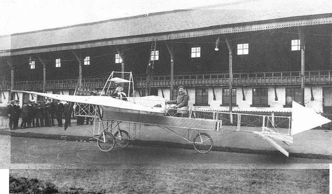
Howard Wright's first monoplane of 1909, built for W.E. Cooke of Burnley, Lancashire, was not a success. W. E. Cooke and daughter seated in the monoplane on the race track at Brunshaw, BurnIe, before its first public demonstration.
Howard Wright Avis
The Avis Monoplane was designed by Howard T. Wright for the Scottish Aeroplane Syndicate of 166 Piccadilly, London, W. Four were constructed during 1909-10 at the Battersea railway arches workshop of his brother. Warwick Wright. The 30 h.p. three-cylinder Anzani-engined prototype, known as The Golden Plover, flew early in 1910 at Brooklands. The Avis was exhibited at the Olympia Aero Show of the same year and was flown by the Hon. Alan R. Boyle at the 1910 Wolverhampton Aviation Meeting for 5 miles at a height of 40 ft.
The other Avis Monoplanes received 40 h.p. eight-cylinder J.A.P. engines and were flying successfully during 1910 at Brooklands, piloted by R. F. Wickham and J. H. Spottiswoode. After using his Avis No. 3 to gain his Royal Aero Club Aviator's Certificate No. 13 at Brooklands on 14th June, 1910, Boyle was unfortunate enough to wreck it at the great flying meeting held at Bournemouth from Nth to 16th July, 1910, and sustained concussion.
In general appearance the machine resembled the Bleriot XI design, combined with a Demoiselle-style tail unit. The rudder and elevators were of cruciform type and were mounted on a universal joint at the extreme rear of the fuselage. The rest of the Avis was quite conventional for the time at which it was built, with the rear of the wire-braced wooden-girder fuselage left uncovered. Warping was used for lateral control by means of pedals, the wings being braced from a high cabane above the cockpit. The undercarriage was a sturdy and simple arrangement of splayed struts, combined with skids across which the two pairs of wheels were mounted on their axles, which incorporated rubber shock-absorbing. A sprung tailwheel completed the landing-gear of a design which was among the first of the successful British monoplanes.
SPECIFICATION
Description: Single-seat tractor monoplane. Wooden structure, fabric covered.
Manufacturers: Warwick Wright, Ltd., 110 Marylebone High Street, London, N.W.I, and Battersea, S.W.11.
Power Plant: 30 h.p. Anzani, 40 h.p. J.A.P.
Dimensions: Span, 28 ft. Length, 27 ft. Wing area, 160 sq. ft.
Weights: Empty, 430 lb. Loaded, 630 lb.
Performance: Maximum speed, 40 m.p.h.
Price: ?370-?490.
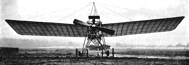
AVIS MONOPLANE. - View from in front.
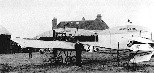
Hon. A. R. Boyle's Howard Wright Avis at the 1910 Bournemouth Meeting.
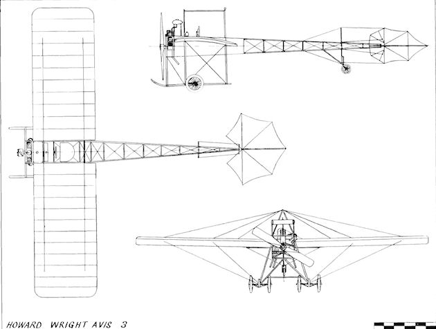
Howard Wright Avis 3
Howard Wright 1910 Monoplane
A revised version of the 1909 Avis Monoplane was shown at Olympia in 1910. Priced at ?630. it was fitted with an eight-cylinder 40 h.p. E.N.V. "D" engine which had its radiators mounted full chord at the wing-roots and drove a 6 ft. propeller. In the place of the earlier Demoiselle-type tail, one on Bleriot lines was used, with a rectangular rudder and with elevators pivoted at the ends of the tail plane. Span, 27 ft. Length, 29 ft. Wing area, 160 sq. ft. Weight empty, 440 lb. Weight loaded, 605 lb. Landing speed, 35 m.p.h.
A revised version of the 1909 Avis Monoplane was shown at Olympia in 1910. Priced at ?630. it was fitted with an eight-cylinder 40 h.p. E.N.V. "D" engine which had its radiators mounted full chord at the wing-roots and drove a 6 ft. propeller. In the place of the earlier Demoiselle-type tail, one on Bleriot lines was used, with a rectangular rudder and with elevators pivoted at the ends of the tail plane. Span, 27 ft. Length, 29 ft. Wing area, 160 sq. ft. Weight empty, 440 lb. Weight loaded, 605 lb. Landing speed, 35 m.p.h.
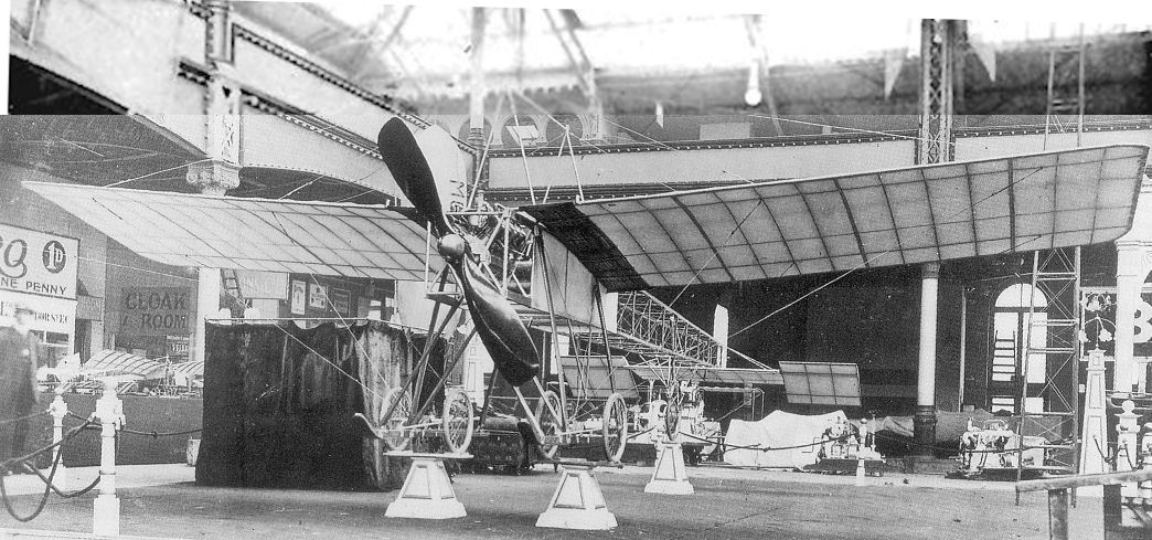
Warwick Wright's Monoplane at the 1910 Olympia Aero Show. Howard Wright monoplane 1910 type had a Bleriot-type tail and ENV engine.
Howard Wright 1910 Biplane
The Howard Wright Biplane gained considerable prominence in the hands of T. O. M. Sopwith, following its debut during 1910. The design reflected conventional two-seater pusher practice of the period, with the pilot and passenger exposed to the elements from their seats in front of the engine and over the leading-edge of the lower wings. Two elevators were used, one fore and one aft, and they were interconnected in their operation. Four booms carried the monoplane tail, similar supports being used to take the nose-elevator well forward of the wings. Ailerons were mounted on all four wing-tips, except on the version shown at Olympia in April, 1911, which was without them on the lower wings.
The 50 h.p. Gnome was at first specified as the standard engine, but Sopwith's machine differed in having a water-cooled 60 h.p. E.N.V. "F". Later his machine was also given extensions to the upper wing-tips, together with additional wire bracing to strengthen them. Separate split ailerons completed the extra wing area on his special version. On 22nd October, 1910, Sopwith startled the spectators at Brooklands by taking his newly-acquired aeroplane into the air on its first test flight without having flown before. He crashed, but was unhurt, and took his Royal Aero Club Aviator's Certificate No. 31 a month later on 21st November. For this, he used a new machine of the same type, teaching himself to fly on the same day as that of his test. Just over three weeks later, he entered for the Baron de Forest's £4,000 prize for the longest all-British flight before the end of 1910 from England into Europe. This he won with a distance of 169 miles from Eastchurch to Thirimont in 3.5 hours.
After this fine performance, Sopwith straightaway decided to try to improve upon his earlier attempt upon the 1910 British Empire Michelin Cup and £500 prize, for which he was in the lead with a time of 3 hrs. 20 mins. and a distance of 107 miles, both of which had constituted new British records. On 31st December, the last day of the contest, he improved on these figures by flying for 4 hrs. 7 mins. 17 secs, and covering 150 miles 246 yds. However, this extra effort was in vain, as it was beaten by S. F. Cody during the last few hours. On 1st February, 1911, Sopwith flew his Howard Wright from Brooklands to Windsor Castle to be received by H.M. King George V, afterwards taking it on a successful tour in the U.S.A. Another E.N.V.-powered Howard Wright biplane was flown at Rangoon by W. C. England in the summer of 1912.
SPECIFICATION
Description: Two-seat pusher biplane. Wooden structure, fabric covered.
Manufacturers: Warwick Wright Ltd., 110 Marylebone High Street, London, N.W.I, and Battersea, S.W.11.
Power Plant: 50 h.p. Gnome, 60 h.p. E.N.V. "F".
Dimensions: Span, 36 ft. Length, 36 ft. 6 ins. Wing area, 415 sq. ft.
Weights: Loaded, 1,200 lb.
Performance: Maximum speed, 45 m.p.h. Endurance, 5 hrs.
Price: £1,000.
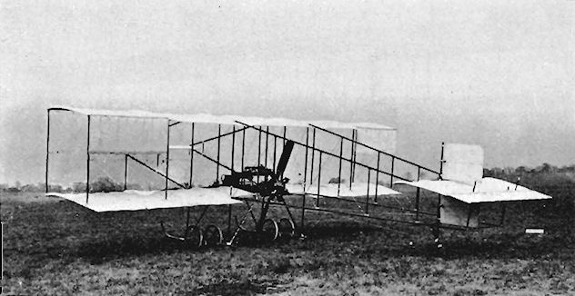
Howard Wright Biplane with 50 h.p. Gnome and broad-chord ailerons.
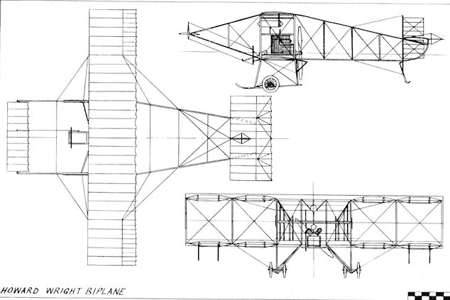
Howard Wright Biplane
Howard Wright Helicopter
Howard T. Wright served an engineering apprenticeship in his father's firm, Joseph Wright and Co., of Tipton, Staffs., and in 1889 sold the works to Hiram Maxim, whom he assisted in the construction of the rotary "flying-machine" erected at the Crystal Palace, initially for the purpose of aerodynamic experiments and later surviving, as a sophisticated form of roundabout, as the nucleus of the Amusement Park.
In 1907, Howard Wright and his brother Warwick set up a small aircraft and coach-building factory in a railway arch at Battersea, where he designed and built a helicopter to the order of Signor Capone of Naples. The machine was a framework of steel tubes with two two-bladed lifting rotors of 26 ft. in diameter driven by a 30 h.p. Antoinette engine, which drove also two small four-bladed propellers. Generous fixed and movable horizontal surfaces were provided to relieve the lifting rotors in translational flight; to some extent the design foreshadowed the Rotodyne principle. The helicopter was tested at Norbury Golf Links in February, 1908, and succeeded in lifting a total weight of 1,250 lb. while tethered. It was then taken to Naples for further tests, but these were unsuccessful. Howard Wright designed a second helicopter for Signor Capone and an ornithopter also, before he abandoned the moving-wing principle. The steel tubes used in the helicopter were supplied by Accles and Pollock Ltd.
Humber Tractor Biplane
At the 1910 Olympia Aero Show, Humber Ltd., of Coventry, exhibited, together with the le Blon and the Lovelace Monoplanes, a three-seat tractor biplane designed specifically for tuition purposes. The engine was mounted on the lower wings, the pilot being seated on the trailing-edge, with a pupil's seat on each side; triple controls were provided, with means for the instructor to override the pupil's movements. The mainplanes were made in three sections for easy dismantling, and all spars and struts - with the exception of the tail booms - were of steel tubing. A simple twin-wheeled undercarriage was located under the mainplanes, with a single tailwheel supporting the empennage, which was similar to that of the Humber Lovelace Monoplane. Lateral control was by wing-warping. The engine was a 50 h.p. Humber which drove a 7 ft. diameter propeller. Span, 41 ft. 6 ins. Length. 36 ft. Wing area, 482 sq. ft. Estimated speed, 50 m.p.h. Price, ?1,100.
At the 1910 Olympia Aero Show, Humber Ltd., of Coventry, exhibited, together with the le Blon and the Lovelace Monoplanes, a three-seat tractor biplane designed specifically for tuition purposes. The engine was mounted on the lower wings, the pilot being seated on the trailing-edge, with a pupil's seat on each side; triple controls were provided, with means for the instructor to override the pupil's movements. The mainplanes were made in three sections for easy dismantling, and all spars and struts - with the exception of the tail booms - were of steel tubing. A simple twin-wheeled undercarriage was located under the mainplanes, with a single tailwheel supporting the empennage, which was similar to that of the Humber Lovelace Monoplane. Lateral control was by wing-warping. The engine was a 50 h.p. Humber which drove a 7 ft. diameter propeller. Span, 41 ft. 6 ins. Length. 36 ft. Wing area, 482 sq. ft. Estimated speed, 50 m.p.h. Price, ?1,100.
Humber-Sommer Biplane
A British-built version of the Roger Sommer biplane was produced in small numbers by Humber Ltd., of Coventry, during 1910. One was sent to India, where, at the end of February, 1911, it carried the first official air mail in a service operated from the exhibition grounds at Allahabad to the post office at Baini on the opposite side of the Jumna River, lt was flown by Capt. W. G. Windham and Mons. Pecquet, who carried over 5,000 letters in one day with it. The four-cylinder 50 h.p. water-cooled Humber engine was fitted with a 7 ft. propeller, and the machine was a composite structure of wood and steel covered with fabric. The example exhibited at the 1911 Olympia Aero Show was a copy of the Allahabad aerial post aircraft and was fitted experimentally with sloping side surfaces between the wing-tips outboard of the ailerons. Span, 45 ft. 8 ins. Length. 40 ft. Wing area, 506 sq. ft.
A British-built version of the Roger Sommer biplane was produced in small numbers by Humber Ltd., of Coventry, during 1910. One was sent to India, where, at the end of February, 1911, it carried the first official air mail in a service operated from the exhibition grounds at Allahabad to the post office at Baini on the opposite side of the Jumna River, lt was flown by Capt. W. G. Windham and Mons. Pecquet, who carried over 5,000 letters in one day with it. The four-cylinder 50 h.p. water-cooled Humber engine was fitted with a 7 ft. propeller, and the machine was a composite structure of wood and steel covered with fabric. The example exhibited at the 1911 Olympia Aero Show was a copy of the Allahabad aerial post aircraft and was fitted experimentally with sloping side surfaces between the wing-tips outboard of the ailerons. Span, 45 ft. 8 ins. Length. 40 ft. Wing area, 506 sq. ft.

The Humber biplane, with the sloping panels to give improved lateral stability. These panels can be controlled by wires to steer and balance the machine.
Humber-Bleriot Monoplane
The Humber Monoplane was a British-built version of the Bleriot XI produced during 1910 by Humber Ltd., at Coventry. The machine was a single-seater, and was powered by the three-cylinder 30 h.p. Humber semi-radial engine. It was flown successfully by several notable British pilots of the period, including G. A. Barnes, who gained his Royal Aero Club Aviator's Certificate No. 16 with a Humber Monoplane on 21st June, 1910, at Brooklands.
The Humber Monoplane was a British-built version of the Bleriot XI produced during 1910 by Humber Ltd., at Coventry. The machine was a single-seater, and was powered by the three-cylinder 30 h.p. Humber semi-radial engine. It was flown successfully by several notable British pilots of the period, including G. A. Barnes, who gained his Royal Aero Club Aviator's Certificate No. 16 with a Humber Monoplane on 21st June, 1910, at Brooklands.
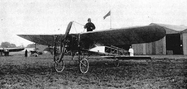
Humber-Le Blon Monoplane
At the 1910 Olympia Aero Show, Humber Ltd., of Coventry, exhibited a single-seat tractor monoplane designed by Mons. Hubert le Blon, who had been chief mechanic to Leon Delagrange. The machine incorporated several innovations, among them variable-camber wings and a fuselage which resembled the body of a dragonfly. This was of tapering circular section and consisted of a hollow wooden boom bound externally with tape. The engine was the three-cylinder 30 h.p. Humber, with a propeller of 7 ft. diameter. The very simple landing-gear consisted of a steel-tube frame carrying two wheels mounted on laminated springs. Span, 29 ft. 2 ins. Length, 24 ft. Wing area, 186 sq. ft. Weight empty. 495 lb. Price, ?480.
At the 1910 Olympia Aero Show, Humber Ltd., of Coventry, exhibited a single-seat tractor monoplane designed by Mons. Hubert le Blon, who had been chief mechanic to Leon Delagrange. The machine incorporated several innovations, among them variable-camber wings and a fuselage which resembled the body of a dragonfly. This was of tapering circular section and consisted of a hollow wooden boom bound externally with tape. The engine was the three-cylinder 30 h.p. Humber, with a propeller of 7 ft. diameter. The very simple landing-gear consisted of a steel-tube frame carrying two wheels mounted on laminated springs. Span, 29 ft. 2 ins. Length, 24 ft. Wing area, 186 sq. ft. Weight empty. 495 lb. Price, ?480.
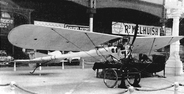
Friswell Monoplane
The Friswell Monoplane, designed by Capt. T. T. Lovelace, was constructed during 1909 by Friswell (1906) Ltd. It resembled a Bleriot and was finally sold at an auction.
Humber Lovelace Monoplanes
Two monoplanes designed by Captain T. T. Lovelace were exhibited by Humber Ltd.. of Coventry, at the Olympia Aero Show of 1910. Both were single-seat tractors, but differed in their size and in the engines fitted. That equipped with the three-cylinder 30 h.p. Humber had a span of 33 ft., and a length of 26 ft. 6 ins. It was priced at ?750. The four-cylinder 50 h.p. Humber-engined machine had a span of 29 ft., a length of 26 ft. and a wing area of 192 sq. ft. Its empty weight was 500 lb. Price, ?775. Both machines were of the modified Bleriot type, having a central skid fitted to the undercarriage and a fixed fin and a pointed end to the rudder.
Humphreys Waterplane
The single-seat pusher Humphreys Waterplane was designed by Jack Humphreys and built by Forrestt during 1908. The machine was a sesquiplane of very low aspect-ratio mounted on a coracle-style hull. The engine was an eight-cylinder 35 h.p. J.A.P. which drove twin propellers. The triangular tailplane was universally pivoted and incorporated flexible surfaces, having an effective dihedral angle when neutrally loaded. Fin and rudder were absent but triangular ailerons were fitted to the wing-tips. It was intended to display the Waterplane at the 1909 Olympia Aero Show, but it could not be manoeuvred through the entrance into the hall. When tested in April, 1909, on the River Colne at Wivenhoe, Essex, the hull filled with water and the machine sank at its moorings. It was salvaged intact and later attained 10 knots on the water when taxying, but never flew. Span, 45 ft. Length, 13 ft.
The single-seat pusher Humphreys Waterplane was designed by Jack Humphreys and built by Forrestt during 1908. The machine was a sesquiplane of very low aspect-ratio mounted on a coracle-style hull. The engine was an eight-cylinder 35 h.p. J.A.P. which drove twin propellers. The triangular tailplane was universally pivoted and incorporated flexible surfaces, having an effective dihedral angle when neutrally loaded. Fin and rudder were absent but triangular ailerons were fitted to the wing-tips. It was intended to display the Waterplane at the 1909 Olympia Aero Show, but it could not be manoeuvred through the entrance into the hall. When tested in April, 1909, on the River Colne at Wivenhoe, Essex, the hull filled with water and the machine sank at its moorings. It was salvaged intact and later attained 10 knots on the water when taxying, but never flew. Span, 45 ft. Length, 13 ft.
Humphreys Monoplane
The single-seat tractor monoplane built by Jack Humphreys in 1909 at Wivenhoe, Essex, was a large machine fitted with a 60 h.p. Green engine. It was wrecked in a ditch at Wivenhoe during October, 1909, while making an attempt on the Daily Mail prize of ?1,000 for the first British circular flight of 1 mile. In the following month the machine was moved to a better ground at Colchester, and then to Brooklands, where it was rebuilt by October, 1910, and tested during 1911 by C. Gordon Bell. The machine, known as "The Elephant", lifted so well that Bell found that it would take off at half throttle with three people on board. Span, 48 ft.
The single-seat tractor monoplane built by Jack Humphreys in 1909 at Wivenhoe, Essex, was a large machine fitted with a 60 h.p. Green engine. It was wrecked in a ditch at Wivenhoe during October, 1909, while making an attempt on the Daily Mail prize of ?1,000 for the first British circular flight of 1 mile. In the following month the machine was moved to a better ground at Colchester, and then to Brooklands, where it was rebuilt by October, 1910, and tested during 1911 by C. Gordon Bell. The machine, known as "The Elephant", lifted so well that Bell found that it would take off at half throttle with three people on board. Span, 48 ft.
Hutton and Wilson Monoplane
Built by two Irishmen, Hutton and Wilson, their 35 h.p. Alvaston-engined tractor monoplane was at Filey, Yorks., during August, 1910, for testing.
Built by two Irishmen, Hutton and Wilson, their 35 h.p. Alvaston-engined tractor monoplane was at Filey, Yorks., during August, 1910, for testing.
J.A.P.-Harding Monoplane
The J.A.P.-Harding Monoplane was constructed by J. A. Prestwich and Co. Ltd., of Tottenham, London, N., for the designer H. J. Harding, a racing-cyclist. It was an adaptation of the Bleriot Monoplane and was fitted with the eight-cylinder 40 h.p. J.A.P. engine. In its early state, it had rectangular wings with large ailerons, but very soon these were abandoned in favour of warping wings of the standard Bleriot pattern. The machine was first flown at Tottenham marshes on 10th April, 1910, and later at the Blackpool Aviation Meeting and in France by Harding; it is now part of the National Aeronautical Collection of the Science Museum, London, S.W.7. Span, 30 ft. Length, 27 ft. Wing area, 230 sq. ft. Weight empty, 510 lb. Maximum speed, 50 m.p.h.
The J.A.P.-Harding Monoplane was constructed by J. A. Prestwich and Co. Ltd., of Tottenham, London, N., for the designer H. J. Harding, a racing-cyclist. It was an adaptation of the Bleriot Monoplane and was fitted with the eight-cylinder 40 h.p. J.A.P. engine. In its early state, it had rectangular wings with large ailerons, but very soon these were abandoned in favour of warping wings of the standard Bleriot pattern. The machine was first flown at Tottenham marshes on 10th April, 1910, and later at the Blackpool Aviation Meeting and in France by Harding; it is now part of the National Aeronautical Collection of the Science Museum, London, S.W.7. Span, 30 ft. Length, 27 ft. Wing area, 230 sq. ft. Weight empty, 510 lb. Maximum speed, 50 m.p.h.
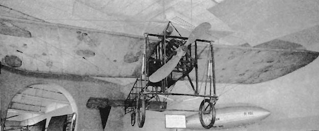
Jezzi 1910 Biplane
Early in 1909 P. G. Leo Jezzi, a City business man with a spare-time passion for aeronautics and mechanics, started to construct his first aeroplane. He was ridiculed by his acquaintances, but was assisted by an old school friend, Arthur Cooper, in building it in a shed at Shawfield Park, Bromley, Kent. An eight-cylinder 35 h.p. J.A.P. engine drove a pair of propellers between the trailing-edges of the wings by chains, an additional small propeller being mounted in front of the engine for cooling. The wings were warped for lateral control. The machine was completed in December, 1909, and was taken to Eastchurch in January, 1910, where, after several months of trial-and-error testing, it finally flew well on 10th August, 1910. In the following October the machine was converted into the tractor type when, to improve the cooling, the engine and its pair of main propellers were moved forward. The third smaller propeller was retained to help with the cooling, and the pilot was installed behind the engine. On 31st December, 1910, Leo Jezzi gained his Royal Aero Club Aviator's Certificate No. 44 with it at Eastchurch. The following year the machine was dismantled and the engine was used in Jezzi's new tractor biplane then being built.
Early in 1909 P. G. Leo Jezzi, a City business man with a spare-time passion for aeronautics and mechanics, started to construct his first aeroplane. He was ridiculed by his acquaintances, but was assisted by an old school friend, Arthur Cooper, in building it in a shed at Shawfield Park, Bromley, Kent. An eight-cylinder 35 h.p. J.A.P. engine drove a pair of propellers between the trailing-edges of the wings by chains, an additional small propeller being mounted in front of the engine for cooling. The wings were warped for lateral control. The machine was completed in December, 1909, and was taken to Eastchurch in January, 1910, where, after several months of trial-and-error testing, it finally flew well on 10th August, 1910. In the following October the machine was converted into the tractor type when, to improve the cooling, the engine and its pair of main propellers were moved forward. The third smaller propeller was retained to help with the cooling, and the pilot was installed behind the engine. On 31st December, 1910, Leo Jezzi gained his Royal Aero Club Aviator's Certificate No. 44 with it at Eastchurch. The following year the machine was dismantled and the engine was used in Jezzi's new tractor biplane then being built.
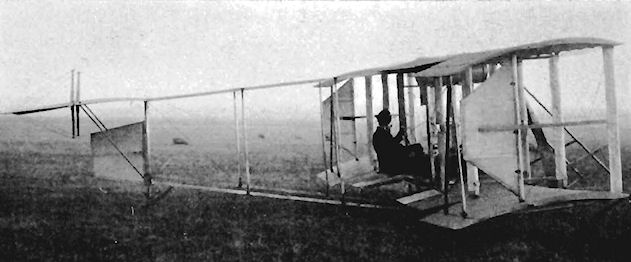
Jezzi 1911 Biplane
Leo Jezzi's second biplane appeared during 1911 and was built at his home in Bromley, Kent. It was a two-seater powered by the eight-cylinder 35 h.p. J.A.P. engine used originally in the Jezzi Pusher Biplane of 1909.
Spruce was employed throughout for the airframe, all of which was very square-cut and angular in appearance and yet of pleasing proportions. The pair of deep-chord, streamlined centre-section struts extended from the upper wings, through the fuselage and the lower wings and downward to carry the undercarriage. English ash was used for the skids, and all struts were faired and of streamlined section to reduce head-resistance. Warping was employed on the wings whose upper planes had a span of 27 ft. 7 ins., while the lower set were 14 ft. from tip to tip. The considerable overhang above was supported by compression struts, but these were removed and their work undertaken by kingposts and wires. Auxiliary skids were fitted midway on the underside of the wings and twin skids supported the tail on the ground. It was then decided that the lower wings should be increased in span to match the upper pair, thereby converting them into two-bay cellules, and the kingposts were removed at the same time.
When it was ready, the machine was taken to Jezzi's shed at Eastchurch on the Isle of Sheppey and assembled there in 1912. It proved to be a very successful flyer with a brisk performance on its 35 h.p. and was able to carry a heavy passenger in addition to the pilot.
SPECIFICATION
Description: Two-seat tractor biplane. Wooden structure, fabric covered.
Manufacturer: P. G. L. Jezzi, Bromley, Kent.
Power Plant: 35 h.p. J.A.P.
Dimensions: Span, 27 ft. 7 ins. Length, 24 ft. 6 ins. Wing area, 220 sq. ft.
Performance: Maximum speed, 65 m.p.h.
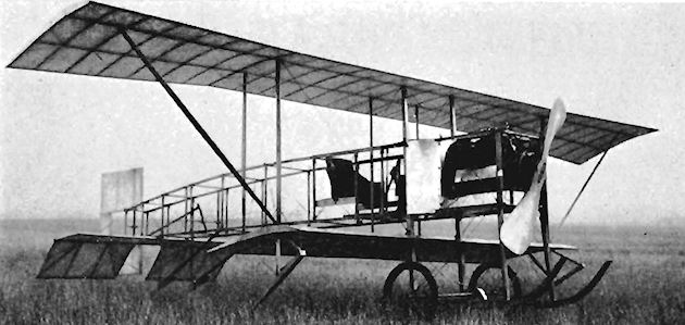
Jezzi biplane No.2 as first flown uncovered and as a sesquiplane.
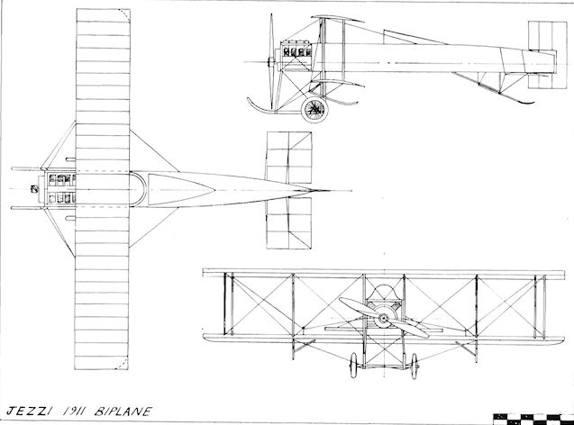
Jezzi 1911 Biplane
Jobling Monoplane
The Jobling Monoplane was designed by Charles Jobling and built during 1910. It was of the single-seat pusher type and was without elevators, tail-plane or rudder, control being by the flexible, curved, rearward-extending tips of the parallel-chord wings. The engine was a 45 h.p. de Havilland-designed Iris. The machine was at Eastchurch in September, 1910, and crashed the following month on 19th October. Span 60 ft.
The Jobling Monoplane was designed by Charles Jobling and built during 1910. It was of the single-seat pusher type and was without elevators, tail-plane or rudder, control being by the flexible, curved, rearward-extending tips of the parallel-chord wings. The engine was a 45 h.p. de Havilland-designed Iris. The machine was at Eastchurch in September, 1910, and crashed the following month on 19th October. Span 60 ft.
Keith-Weiss Aviette
The Aviette of 1912 was the result of the co-operation between Alexander Keith, an elderly Scotsman with a medical background who had made a special study of the muscular operation of birds' wings, and Jose Weiss. Together they constructed an ornithopter in which foot-pedals operated the mechanism for actuating the wings with a beat of 3 ft. The machine was tested with its wings supported on slings between two trees and reached the stage of free-flight trials under ballast in launches from Amberley Mount in Sussex. Span, 23ft. Length, 19 ft. Wing Area, 80 sq. ft. Weight empty, 95 lb. Weight loaded, 230 lb. Estimated speed, 30 m.p.h.
The Aviette of 1912 was the result of the co-operation between Alexander Keith, an elderly Scotsman with a medical background who had made a special study of the muscular operation of birds' wings, and Jose Weiss. Together they constructed an ornithopter in which foot-pedals operated the mechanism for actuating the wings with a beat of 3 ft. The machine was tested with its wings supported on slings between two trees and reached the stage of free-flight trials under ballast in launches from Amberley Mount in Sussex. Span, 23ft. Length, 19 ft. Wing Area, 80 sq. ft. Weight empty, 95 lb. Weight loaded, 230 lb. Estimated speed, 30 m.p.h.
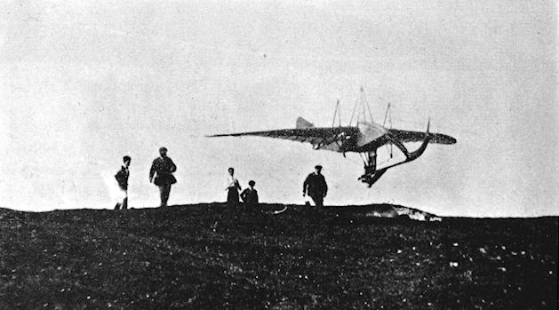
Lee-Richards Annular Biplane
The principle of the annular wing was the subject of a patent by G. J. A. Kitchen of Lancaster which was bought by Cedric Lee from Kitchen. Lee was joined late in 1910 by G. Tilghman Richards as an engineer on the project, which was built during 1911 as a single-seat tractor biplane with superimposed annular wings and was powered by the 50 h.p. Gnome engine. The machine was taken to Famine Point at Heysham for its trials, which were not particularly satisfactory, and the aeroplane and its hangar were wrecked during a gale on 4th-5th November, 1911.
The principle of the annular wing was the subject of a patent by G. J. A. Kitchen of Lancaster which was bought by Cedric Lee from Kitchen. Lee was joined late in 1910 by G. Tilghman Richards as an engineer on the project, which was built during 1911 as a single-seat tractor biplane with superimposed annular wings and was powered by the 50 h.p. Gnome engine. The machine was taken to Famine Point at Heysham for its trials, which were not particularly satisfactory, and the aeroplane and its hangar were wrecked during a gale on 4th-5th November, 1911.
Lee-Richards Annular Glider
The Lee-Richards annular wing biplane glider was constructed by Cedric Lee and G. Tilghman Richards and is shown in flight at Kirby Lonsdale on I I th November. 1912.
The Lee-Richards annular wing biplane glider was constructed by Cedric Lee and G. Tilghman Richards and is shown in flight at Kirby Lonsdale on I I th November. 1912.
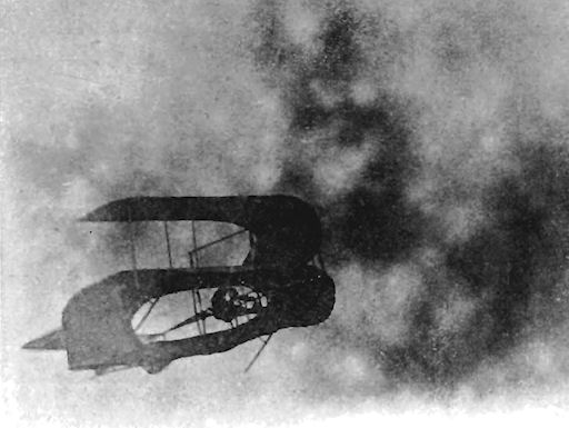
Lakes Seabird
The Seabird hydro-biplane was built during 1912 by the Lakes Flying Company for use at their flying-school at Lake Windermere. The machine was a two-seat tractor powered by a 50 h.p. Gnome engine, and displayed a considerable likeness to the Avro biplanes. This was brought about mainly by the fact that the machine's fuselage and tail unit came from the single-seat Avro tractor biplane which was delivered to the Australian pilot J. R. Duigan in September, 1911, and which subsequently crashed.
Three-bay, parallel-chord, warping wings were fitted to the fuselage and were of fairly high aspect-ratio of 8.5. The upper half of the engine was covered by a neat cowling, and the pilot and passenger were seated in tandem in the fuselage. The single, broad, central float was equipped with two steps and was constructed with a wooden frame which had duralumin sides, an aluminium bottom and a top of Willesden canvas. It was divided into eight water-tight compartments and was mounted underneath a pair of skids fixed to the four streamlined undercarriage struts. Rubber shock cord was used to provide the necessary springing between the float and the skids. This simple and practical arrangement enabled the Seabird to be converted quickly to a land undercarriage if required. Inflated air-bags with springboards underneath them were fitted at the wing-tips and the tail, and a water rudder connected to the air rudder was installed behind the main float to facilitate taxying on the water.
H. Stanley-Adams piloted the Seabird on many flights and joy-trips over Lake Windermere, and the machine was modified later by fitting it with a pair of broad floats in place of the original single central one and by discarding at the same time those at the wing-tips.
SPECIFICATION
Description: Two-seat tractor hydro-biplane. Wooden structure, fabric covered.
Manufacturers: Lakes Flying Company, Cockshott, Lake Windermere, West-morland.
Power Plant: 50 h.p. Gnome.
Dimensions: Span, 39 ft. 4 ins. Length, 29 ft. 4 ins. Wing area, 175 sq. ft.
Performance: Maximum speed, 62 m p.h.
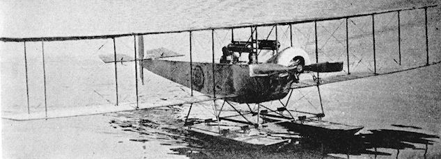
Lakes Seabird was later fitted with twin floats.
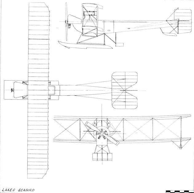
Lakes Seabird
Lakes Hydro-monoplane
The Lakes Hydro-monoplane was another of the aircraft flown so successfully from Lake Windermere by the Lakes Flying Company. A two-seat pusher, it was designed for Captain E. W. Wakefield by Oscar T. Gnosspelius and was built during 1913 by Borwick and Sons, of Bowness-on-Windermere. An 80 h.p. Gnome was used and the machine, flown initially by Rowland Ding, continued in useful employment by the Northern Aircraft Company - as the Lakes Flying Company became later - until 1916 for the training of R.N.A.S. pilots. When it first appeared the aircraft was equipped with a wide central float and two smaller wing-tip floats. These were afterwards exchanged for a pair of main floats only.
The Lakes Hydro-monoplane was another of the aircraft flown so successfully from Lake Windermere by the Lakes Flying Company. A two-seat pusher, it was designed for Captain E. W. Wakefield by Oscar T. Gnosspelius and was built during 1913 by Borwick and Sons, of Bowness-on-Windermere. An 80 h.p. Gnome was used and the machine, flown initially by Rowland Ding, continued in useful employment by the Northern Aircraft Company - as the Lakes Flying Company became later - until 1916 for the training of R.N.A.S. pilots. When it first appeared the aircraft was equipped with a wide central float and two smaller wing-tip floats. These were afterwards exchanged for a pair of main floats only.
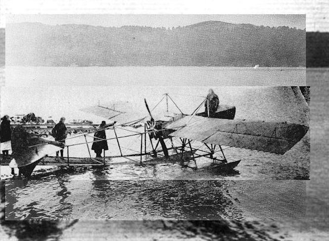
The Lakes (NAC) monoplane with twin floats and other changes.
Waterplane of the Northern Aircraft Co. at their school on Lake Windermere. The N.A.C. "Pusher" monoplane, Mr. Rowland Ding being seen standing in the nacelle.
Waterplane of the Northern Aircraft Co. at their school on Lake Windermere. The N.A.C. "Pusher" monoplane, Mr. Rowland Ding being seen standing in the nacelle.
Lakes Waterbird
The Waterbird was a two-seat pusher hydro-biplane of unequal span built during the summer of 1911 by A. V. Roe and Co., for Captain E. W. Wakefield of the Lakes Flying Co., Lake Windermere, Westmorland. A Curtiss-type float with three steps was fitted, and consisted of a fabric-covered frame of mahogany; the float was made by Borwick and Co., of Windermere. The ailerons were hinged from the trailing-edge of the upper wings and were inset from the wing-tips. The engine used was a 50 h.p. Gnome.
Prior to the fitting of the floats, the machine was tested at Brooklands during May, 1911, with a land undercarriage. The Waterbird was flown from Lake Windermere on 25th November, 1911, and afterwards by H. Stanley-Adams, earning for itself the distinction of being the first entirely successful British seaplane designed as such.
Lakes Waterhen
The Waterhen was constructed early in 1912 and was the outcome of Captain E. W. Wakefield's studies made at the flying-schools at Brooklands and Hendon. His conclusions were that it was safer to crash into water than on unyielding ground, especially after witnessing the crashes at the 1909 Blackpool Meeting, and also that an aircraft with a comparatively slow operating speed gave greater safety and comfort for the crew. The machine was intended as an improved version of the 1911 Waterbird, which had been built by A. V. Roe for training at Wakefield's Lakes Flying Company school at Cockshott, Lake Windermere, and which had proved itself to be a successful trainer.
Oscar T. Gnosspelius was the designer of the new hydro-biplane, which was a two-seat pusher with the crew seated in tandem on seats set at an angle. Gnosspelius paid particular attention in the design to ensuring a good take-off at low speeds and, with this end in view, the wings-which were made by A. V. Roe and Co. - incorporated a deep camber for their high-lift section. Bamboo out-riggers fore-and-aft carried the control surfaces, a bamboo pole connected to the top of the joy-stick operating the front elevator. Split ailerons of constant-chord were replaced later by one-piece surfaces.
A single central stepped float, much broader than that of the Waterbird, was fitted on a flexible suspension system of rubber shock cord and was provided with an aluminium bottom, duralumin sides and a top of Willesden canvas. Air-sacks, fitted with spring-board protectors underneath, functioned as wing-tip floats. The engine fitted was the ubiquitous 50 h.p. Gnome rotary, driving a two-bladed propeller, 8 ft. 6 ins. in diameter and made by A. V. Roe and Co.
The Waterhen was tested by H. Stanley-Adams on 30th April, 1912, and commenced its flying career with the Lakes Flying Company on 3rd May, 1912, after which it was making trips daily over Windermere. During the first seven months it completed some two hundred and fifty flights and carried over one hundred different passengers on joy-trips piloted by Stanley-Adams. On 12th November, 1912, Lt. J. F. A. Trotter gained Royal Aero Club Aviator's Certificate No. 360 with the machine at Lake Windermere after training with the Lakes Company; the firm later changed its name to the Northern Aircraft Company.
After a considerable amount of very successful flying had been carried out, the Waterhen was modified. Enclosed seating for the crew was provided by fitting a nacelle for them, and the single float was replaced by twin floats, which, at the same time, resulted in the removal of the air-bags under the wings. In this form the machine continued in use after the outbreak of the 1914-18 War and gave good service as a trainer at Windermere for the R.N.A.S.
SPECIFICATION
Description: Two-seat pusher hydro-biplane. Wooden structure, fabric covered.
Manufacturers: Lakes Flying Company, Cockshott, Lake Windermere, Westmorland; wings by A. V. Roe and Co., Manchester; floats by Borwick and Sons, Cockshott, Lake Windermere.
Power Plant: 50 h.p. Gnome.
Dimensions: Span, 42 ft. Length, 36 ft. 5 ins. Wing area, 365 sq. ft.
Weights: Empty, 780 lb. Loaded, 1,130 lb.
Performance: Maximum speed. 45 m.p.h. Landing speed, 33 m.p.h. Ceiling, 800 ft.

Lakes Waterhen was later fitted with twin floats and a nacelle.
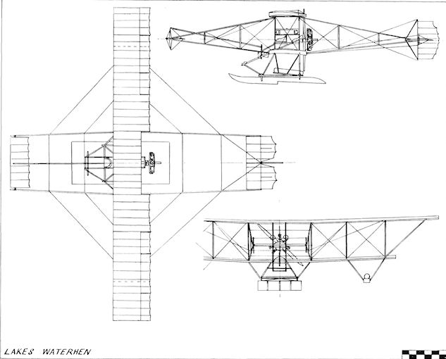
Lakes Waterhen
Laking Biplane
The Laking Biplane was designed by Guy Francis Laking, the son of Sir Francis Laking, Physician to H.M. King Edward VII, and was built during 1909 by T. W. K. Clarke of Kingston-on-Thames, Surrey. It was fitted with a 12 h.p. J.A.P. engine.
Laking Monoplane
The Laking Monoplane was built during 1909 by Filch and Son, Motor Engineers of Clacton-on-Sea, Essex, to the designs of G. F. Laking.
Lamplough Orthopter
Designed and built by Lamplough and Son Ltd. at Albany Works, Willesden Junction, London, N.W.10, the Orthopter was exhibited at the Olympia Aero Show of 1909. Designed to operate on the principles of bird flight, the machine consisted of two pairs of biplane wings moving with a swaying motion in a figure-of-eight between a pair of similar fixed wings. Biplane elevators, complete with attendant rudders, were fitted fore and aft for control, forward motion being imparted to the ash structure by two pusher propellers. Span, 20 ft. Wing area, 945 sq. ft. Weight loaded, 950 lb. Price, ?1,000 with guarantee of flight.
Lamplough Lifterplane
The Lifterplane was built during 1910 by Lamplough and Son Ltd., of Albany Works, Willesden Junction, London, N.W. 10. It was a biplane ornithopter with wings actuated by a 25 h.p. engine, and is believed to have been the Orthopter modified.
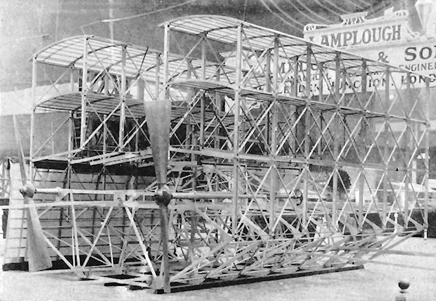
Lamplough ornithopter appeared incomplete at the Olympia Aero Show in March 1909.
Lane Biplane
The Lane Biplane was a single-seat pusher constructed by Charles Lane in 1910. Biplane tail surfaces and a single fore-elevator were fitted, together with ailerons at the four wing-tips.
The Lane Biplane was a single-seat pusher constructed by Charles Lane in 1910. Biplane tail surfaces and a single fore-elevator were fitted, together with ailerons at the four wing-tips.
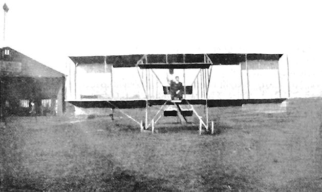
A LANE-FARMAN BIPLANE FOR A MAHARAJAH. - The above machine has been taken out to India by Mr. C. W. Bowles for His Highness the Maharajah of Patiala. Writing from Port Said, en route, Mr. Bowles says: "After taking lessons at Lane's Flying School at Brooklands, I have purchased the above Lane-Farman, with 60-80-h.p. E.N.V. engine, for His Highness the Maharajah of Patiala. The photo was taken at its first trials with myself up in the pilot's seat.
Lane Glider
The Lane Glider was a single-seat biplane designed by Charles Lane and used during 1910 at Brooklands for instruction in gliding. It was fitted with twin vertical tail surfaces and carried ailerons on the upper wing-tips. In the photograph is shown Mrs. Gavin, who made a number of flights in the machine down the slope at the aerodrome.
The Lane Glider was a single-seat biplane designed by Charles Lane and used during 1910 at Brooklands for instruction in gliding. It was fitted with twin vertical tail surfaces and carried ailerons on the upper wing-tips. In the photograph is shown Mrs. Gavin, who made a number of flights in the machine down the slope at the aerodrome.
Lane Single-seat Monoplane
The Lane single-seat tractor monoplane was designed by Charles Lane and built during 1910 by Lane's British Aeroplanes Ltd., of 31 Foley Street, London, W. It was exhibited at the 1910 Olympia Aero Show, and after testing at Brooklands early in the year by Wilfred Foulis, a well-known Edinburgh motorist, was taken to Edinburgh during February for further trials and was found to fly well. In appearance, the Lane Monoplane resembled a Bleriot, but was fitted with a biplane tail consisting of a fixed tailplane with elevators above it. Variants built included one with a three-cylinder 25 h.p. Anzani engine and a Bleriot-style undercarriage. Alternative engines used were the four-cylinder 25 h.p. supercharged N.E.C. and the eight-cylinder 40 h.p. E.N.V. "D". Span, 30 ft. Length, 22 ft. Wing area, 160 sq. ft. Weight empty, 425 lb. Weight loaded, 650 lb. Cruising speed, 30 m.p.h. Price, ?500 with 25 h.p. N.E.C.
Lane Two-seat Monoplane
The Lane two-seat monoplane was designed by Charles Lane and was constructed by Lane's British Aeroplanes Ltd., 31 Foley Street, London, W. In some respects it resembled the Bleriot XIII and was on display at the Olympia Aero Show of 1910. The engine was the six-cylinder 60 h.p. N.E.C. which drove the 10 ft. 6 ins. propeller above it by a chain. The crew sat behind the engine and below the trailing-edge of the wings. A long dorsal fin extended along the top of the fuselage from the wings to the rudder, and the elevators were mounted separately from the tailplane, which was fixed a little way ahead below the fuselage. Span, 32 ft. Length, 22 ft. Wing area, 180 sq. ft. Weight empty, 760 lb. Weight loaded, 970 lb. Cruising speed, 30 m.p.h. Price, ?800.

Lee-Richards Annular Monoplane
Undeterred by the failure of their first attempt at the design of a powered annular-wing aeroplane, Cedric Lee and G. Tilghman Richards continued their experiments with gliders and with wind-tunnel research at East London College. Negotiations with the Blackburn Aeroplane Co., of Leeds, for the construction of a full-size monoplane fell through, but James Radley undertook the work at Shoreham-by-Sea, Sussex, assisted by E. C. Gordon England as works manager and test pilot. Wind-tunnel tests at the National Physical Laboratory had given very good results, indicating that the annular wing was without a "burble" point and could be expected to lift at angles of incidence of up to 30°. The stall was gentle, and the span of the wings could be half of that of the conventional type. The machine was built with a normal tractor fuselage, incorporating an enclosed 80 h.p. Gnome engine, with the annular wings braced from a pylon before the front cockpit. The second cockpit was set towards the tail, which incorporated conventional rudder and elevators. The monoplane was flown for the first time on 23rd November, 1913, by Gordon England, who found, after a very fast take-off, that it was tail heavy. It stalled and fell some 150 feet into telegraph wires, but without injury to the pilot, who suffered only from shock.
After rebuilding, the machine was flown by C. Gordon Bell and N. S. Percival, but was crashed and reconstructed once again. Modifications were made to the design, and the excessive stability found in the early tests was eradicated in the final version, which proved to be a successful flyer. It its final form, additional strut-braced elevators were added at the top of the rudder post, forming a biplane tail. Some 1,000 miles distance was covered by the three versions, with about 128 hours flying time being reached. The design was found to be easy to fly and control, with a good view for the pilot, and would leave the ground at about 30 m.p.h. with a full load.
Two new annular monoplanes were being built during April, 1914, for the Gordon Bennett race, and the original machine was flown continually until September, 1914. After the 1914-18 War, Tilghman Richards attempted to arouse Air Ministry interest in the design, but was unsuccessful. Span, 22 ft. Length, 23 ft. 3 ins. Wing area, 280 sq. ft. Weight loaded as two-seater, 1,680 lb. Weight loaded as single-seater, 1,500 lb. Maximum speed, 85 m.p.h. Landing speed, 45 m.p.h. Climb, 400 ft. min. Endurance, 3-5 hrs.
Locke Glider
The Locke Glider was built during 1910 by J. C. Locke of Chingford and was tested at Barking on 26th July, 1910. Span, 37 ft.
The Locke Glider was built during 1910 by J. C. Locke of Chingford and was tested at Barking on 26th July, 1910. Span, 37 ft.
Long Monoplane
The Long Monoplane was designed by J. B. D. Long and was built during 1911. A tractor single-seater, it was powered by the four-cylinder 35 h.p. Lascelles semi-radial engine, and was tested at the Acton Aviation Grounds.
The Long Monoplane was designed by J. B. D. Long and was built during 1911. A tractor single-seater, it was powered by the four-cylinder 35 h.p. Lascelles semi-radial engine, and was tested at the Acton Aviation Grounds.
Lumb Monoplane
The Lumb Monoplane was designed and constructed by J. Lumb during 1909, and appeared at the meeting held in the same year at Blackpool. The engine was a 50 h.p. J.A.P.
The Lumb Monoplane was designed and constructed by J. Lumb during 1909, and appeared at the meeting held in the same year at Blackpool. The engine was a 50 h.p. J.A.P.
Macfie Monoplane
Robert Francis Macfie was born in San Francisco, California, U.S.A., on 11th November, 1881, and became interested in the problems of flight while in Chicago from 1902 until 1904. Some five years later he came to England and started the construction of his own aeroplane at Fambridge, Essex, on 2nd August, 1909.
The machine was a single-seat tractor monoplane, of which the fuselage consisted of an open, wire-braced wooden structure of triangular section. An unusual method of building the framework was used. The longerons were connected by cross-pieces, which were butt-jointed to them direct without the use of mortice joints, the system comprising steel angle plates, which were lashed and glued with fine Irish linen tape to keep the members in place. The fuselage was strong and was built quickly.
Parallel-chord wings with curved tips at the rear were mounted on the pair of upper longerons, which also provided the anchorage for the pivot of the elevators in the absence of a fixed tailplane. There was no fixed fin, the rudder forming the extreme rear of the machine. Lateral control was by the popular system of warping. The undercarriage was a simple but sturdy steel tubing unit on the lines of the Bleriot, with a sprung tail-skid supporting the rear of the monoplane. An eight-cylinder air-cooled 35 h.p. J.A.P. engine had been ordered and was delivered on 5th September, a 6 ft. 6 ins. propeller being fitted to use its power.
After six weeks work the machine was completed on 16th, September, having been almost completely hand-built. Trials commenced at Fambridge on the same day and continued for a month until 19th October. Successful flights were achieved after various alterations had been made, following four crashes on the unsuitable field. From 20th October until 10th November, Macfie searched for a better flying ground in Essex and Lincoln, finally selecting Maplin Sands at Shoeburyness, Essex. The monoplane was removed there on 11th November, 1909, and from that date the story of his attempts to fly the machine is one of bad luck and frustration, despite his unfailing determination to succeed with it. Bad weather set in and the aircraft crashed twice; the final blow was dealt by the War Office, who ordered the pioneer off the Sands. During the night of 28th-29th November, the crossing was made from Foulness Island in continuous rain, the machine being deposited in the Kursaal at Southend-on-Sea.
Still undaunted, Macfie set off once again to search for a suitable flying-ground, touring Hampshire, Kent, Surrey, Lincolnshire and the Midlands without success from 1st until 14th December. France appeared to be more receptive to flyers, and he decided to go to Pau, receiving confirmation on 14th December, on which day the machine left Southend for the London Docks, arriving there the following day. Pau was reached on 22nd December, but, on arrival, Macfie was refused permission to fly there.
After a few days rest over Christmas he left for Croix d'Huis, where he stayed from 27th December, 1909, until 3rd January, 1910, but found that the ground was useless for his purpose. On 19th January Macfie returned to London after spending two weeks searching for a suitable flying-field in France, having found either the grounds or the terms imposed for their use unsuitable for his requirements. While awaiting the arrival of the monoplane, he tried once again from 20th until 30th January to find a ground in England, to be told at the end of the month that the machine had been lost in transit in the floods in Paris. It eventually arrived at Blackfriars on 2nd February, 1910, but was by then a complete wreck.
SPECIFICATION
Description: Single-seat tractor monoplane. Wooden structure, fabric covered.
Manufacturer: R. F. Macfie, Fambridge, Essex.
Power Plant: 35 h.p. J.A.P.
Dimensions: Span, 28 ft. 6 ins. Length, 23 ft. 6 ins. Wing area, 164 sq. ft. Weights: Empty, 680 lb.
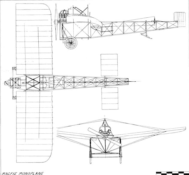
Macfie Aeroplane
Macfie Empress Biplane
In spite of his unhappy experiences with his monoplane, during 1909 and the beginning of 1910, Robert F. Macfie determined to continue with his experiments. From 3rd until 28th February, 1910, he travelled the provinces looking for a flying-ground and searched London for a suitable constructor of a new single-seat pusher biplane which he had designed. At the same time he made arrangements for the supply of a 60 h.p. J. A.P. engine for the machine. W. H. Tothill undertook the work of fabricating the parts for the Empress, spending just over three weeks on the job, from 21st March until 15th April. During this time, Macfie managed to obtain the use of a shed at Portholme, Hunts., and the parts of the biplane were sent there on 15th April, 1910, for assembly. Yet another disappointment for Macfie was the non-appearance of the engine on order, and he had to resort to using the 35 h.p. J. A.P. salvaged from the wreck of the old 1909 monoplane. Short flights were made with the Empress on 12th May, but, on the same day. Lord Sandwich withdrew permission to use Portholme owing to trouble with the Promoting Company. Macfie was determined to try the machine once again before moving, and was in the air making straight flights the next morning at 3.20 a.m.
On 11th June, 1910, he left for Brooklands, the biplane arriving on 16th June. It was re-erected straight away, and on 18th June was flying straight and managing quarter turns, but its lack of power precluded really successful flights. James Radley was interested in taking the Empress to Wolverhampton for the meeting being held there, and it was hurriedly altered into a Farman type in time for him to take it there on 27th June, the day on which the event opened. The meeting continued until 2nd July, but by then the Empress had been damaged by the weather, and it arrived back at Brooklands on 6th July.
Further damage was caused by burning, but rebuilding started on 9th July to Macfie's original specification. By then Macfie had gone into partnership with James Valentine, and went to Paris from 1st until 18th September in order to obtain a 50 h.p. Gnome for the machine. It was hoped that the extra power would give the aircraft a chance to show its capabilities. Other modifications included attention to the tail booms, which were made shorter; the undercarriage was much lower, and two large rudders were fitted instead of the former single small one. The performance was greatly improved when, from 18th September until 9th November, 1910, circular flights were being made at Brooklands. The machine was so successful that Valentine was enabled to gain his Royal Aero Club Aviator's Certificate No. 47 with it on 17th January, 1911, while Macfie used it to obtain Certificate No. 49 a week later on 24th January. Oscar Morison, a Bleriot pilot at Brooklands, used the machine for his first experience of biplane flying, but landed it in the infamous sewage farm near the aerodrome. After salvage it was sold to Herbert Spencer, who rebuilt it once more on Farman lines and flew it successfully in the spring of 1912.
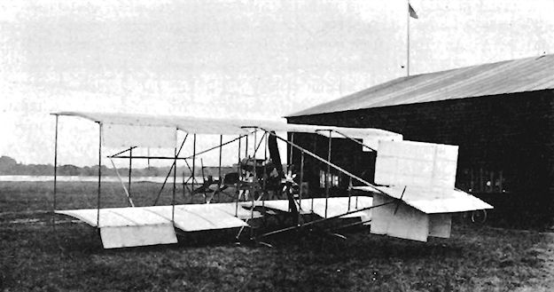
Macfie Circuit Biplane
A small, fast, single-seat tractor biplane was built by Robert F. Macfie in three weeks as his entry in the 1911 Circuit of Britain event. Its 100 h.p. A.B.C. engine was not ready in time, and a 50 h.p. Gnome was substituted. The 26 ft. span wings were swept back in a vee and were of very narrow chord, which tapered from 3 ft. 6 ins. at the centre to 2 ft. 3 ins. at the tips. Triple fins were fitted. The racer was tested at Brooklands in July, 1911. Wing area, 130 sq. ft. Weight loaded, 600 lb.
A small, fast, single-seat tractor biplane was built by Robert F. Macfie in three weeks as his entry in the 1911 Circuit of Britain event. Its 100 h.p. A.B.C. engine was not ready in time, and a 50 h.p. Gnome was substituted. The 26 ft. span wings were swept back in a vee and were of very narrow chord, which tapered from 3 ft. 6 ins. at the centre to 2 ft. 3 ins. at the tips. Triple fins were fitted. The racer was tested at Brooklands in July, 1911. Wing area, 130 sq. ft. Weight loaded, 600 lb.
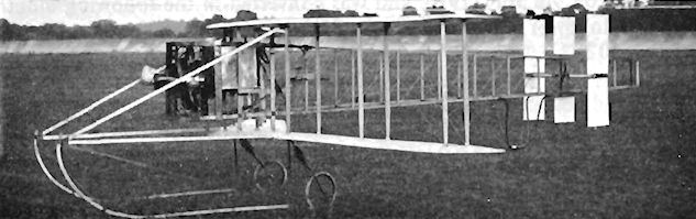
Mackensie-Hughes Triplane
The Mackensie-Hughes Triplane Britannia of E. S. B. Mackensie-Hughes was designed by A. W. Smith of Barking and constructed during 1910. The engine was the four-cylinder 20 h.p. J. A.P., which drove two propellers by chains; the propellers were phased 90° apart, and their blades inter-meshed where their swept discs overlapped. The triplane wings were back-staggered, as were the triplane horizontal tail surfaces. The centre wings were of broad chord, while those above and below were of narrow chord, and lateral control was by means of ailerons on the centre wings. The machine's appearance gave rise to its nickname of "The Staircase". It was tested on 9th July, 1910, and was converted in the following month into the Molesworth Triplane. Span, 23 ft. Wing area, 250 sq. ft. Weight empty, 600 lb.
The Mackensie-Hughes Triplane Britannia of E. S. B. Mackensie-Hughes was designed by A. W. Smith of Barking and constructed during 1910. The engine was the four-cylinder 20 h.p. J. A.P., which drove two propellers by chains; the propellers were phased 90° apart, and their blades inter-meshed where their swept discs overlapped. The triplane wings were back-staggered, as were the triplane horizontal tail surfaces. The centre wings were of broad chord, while those above and below were of narrow chord, and lateral control was by means of ailerons on the centre wings. The machine's appearance gave rise to its nickname of "The Staircase". It was tested on 9th July, 1910, and was converted in the following month into the Molesworth Triplane. Span, 23 ft. Wing area, 250 sq. ft. Weight empty, 600 lb.
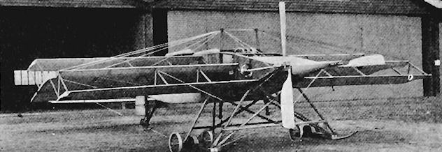
Mann and Overtons Monoplane
The Mann and Overtons Monoplane was designed and built by Mann and Overtons Ltd., coachbuilders of 15 Commercial Road, Pimlico, S.W.I, and was a diminutive single-seater reminiscent of the Demoiselle. It was displayed at the Olympia Aero Show of 1910, and was fitted with the 35 h.p. Anzani engine. The open fuselage was of steel tubing. The machine was tested late in 1910 at the Midland Aero Club's grounds at Dunstall Park, Wolverhampton, but was unsuccessful. Span, 18 ft. 4 ins. Length, 20 ft. Wing area, 128 sq. ft. Weight loaded, 536 lb. Maximum speed, 45 m.p.h. Price, ?300.
The Mann and Overtons Monoplane was designed and built by Mann and Overtons Ltd., coachbuilders of 15 Commercial Road, Pimlico, S.W.I, and was a diminutive single-seater reminiscent of the Demoiselle. It was displayed at the Olympia Aero Show of 1910, and was fitted with the 35 h.p. Anzani engine. The open fuselage was of steel tubing. The machine was tested late in 1910 at the Midland Aero Club's grounds at Dunstall Park, Wolverhampton, but was unsuccessful. Span, 18 ft. 4 ins. Length, 20 ft. Wing area, 128 sq. ft. Weight loaded, 536 lb. Maximum speed, 45 m.p.h. Price, ?300.
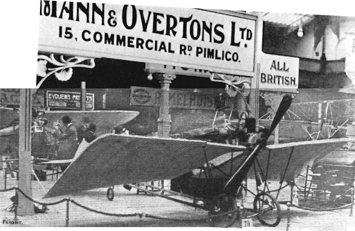
OLYMPIA, 1910. - A light-weight monoplane of the Santos Dumont "Demoiselle" type exhibited by Mann and Overton.
Martin-Handasyde No. 1
George H. Handasyde, a native of Edinburgh, started his career in a drawing-office in the same city, working later with the Maldevic Motor Carriage Company, the Leith shipping firm of Ramage and Ferguson and with the engineers Bertrams of Edinburgh. In 1906 he designed his first vehicle - a motor car - and then moved South to London, where during 1908, as an experienced automobile engineer, he formed a partnership with H. P. Martin, of Trier and Martin, the manufacturers of carburettors, to design and construct aeroplanes. Their first product was a single-seat tractor monoplane which was built in a derelict ball-room near the Old Welsh Harp at Hendon. A four-cylinder Beeston Humber 10-12 h.p. car engine tuned to give 22 h.p. was installed, together with a three-bladed propeller. Upon completion, the machine was taken for testing into a nearby field, but, on running-up, the propeller disintegrated and the engine tore itself away from the nose. The aircraft was not considered worth developing, and was thereupon abandoned. Span, 22 ft. Weight loaded, 580 lb.
George H. Handasyde, a native of Edinburgh, started his career in a drawing-office in the same city, working later with the Maldevic Motor Carriage Company, the Leith shipping firm of Ramage and Ferguson and with the engineers Bertrams of Edinburgh. In 1906 he designed his first vehicle - a motor car - and then moved South to London, where during 1908, as an experienced automobile engineer, he formed a partnership with H. P. Martin, of Trier and Martin, the manufacturers of carburettors, to design and construct aeroplanes. Their first product was a single-seat tractor monoplane which was built in a derelict ball-room near the Old Welsh Harp at Hendon. A four-cylinder Beeston Humber 10-12 h.p. car engine tuned to give 22 h.p. was installed, together with a three-bladed propeller. Upon completion, the machine was taken for testing into a nearby field, but, on running-up, the propeller disintegrated and the engine tore itself away from the nose. The aircraft was not considered worth developing, and was thereupon abandoned. Span, 22 ft. Weight loaded, 580 lb.
Martin Handasyde No. 2
The second Martin-Handasyde monoplane was a larger version of the No. 1 and was constructed during 1909. A 35 h.p. J.A.P. engine was fitted and the machine occupied the first hangar to be built at Brooklands, where it was flown subsequently by H. P. Martin.
Martin-Handasyde No. 3
During May, 1910, Martin and Handasyde completed their No. 3 Monoplane at Brooklands. In appearance there was a very strong resemblance to the successful French Antoinette design, and the newcomer was as equally refined and elegant a product. The machine was a single-seater and was fitted with the 65 h.p. Antoinette engine. Weight and head resistance were kept to the minimum by the provision of a very slim fuselage, whose strength was maintained by the use of wood covering. A triangular section was used, the pilot's position being very exposed owing to the slenderness of the fuselage. His view, however, from his seat at the rear of the trailing-edge was comparatively good. Protection from the slipstream was provided by the rather clumsy expedient of fitting a vertical shield at the top of the control column, thus destroying at the same time some of the streamline properties of the machine which the designers had striven to achieve.
The undercarriage was a very strong unit carried mainly on a stout central support through the fuselage. Warping lateral control was fitted, and the tail unit consisted of the normal rudder and split elevators attached to fixed fin and tailplane.
H. P. Martin accomplished several good straight flights at Brooklands on the machine during November, 1910, and the No. 3 Monoplane became a very successful flyer in D. Graham Gilmour's hands. The Antoinette engine was succeeded by a 40 h.p. J.A.P. in 1911, and a 35 h.p. Green was also installed temporarily, but was removed in favour of the J.A.P. The No. 3 finally took Gilmour to his death on 17th February, 1912, when it broke up in the air and crashed while flying over Richmond Park at 400 ft. in bumpy weather.
SPECIFICATION
Description: Single-seat tractor monoplane. Wooden structure, fabric covered.
Manufacturers: Martin and Handasyde Ltd., Trinity Works, Camberwell.
Power Plant: 65 h.p. Antoinette, 40 h.p. J.A.P., 35 h.p. Green.
Dimensions: Span, 32 ft. Length, 28 ft. Wing area, 175 sq. ft.
Weights: Empty, 560 lb.
Performance: Maximum speed, 60 m.p.h.
Martin-Handasyde No. 4B
The 4B tractor monoplane was a two-seat version of the No. 3 and was built to the order of T. O. M. Sopwith, being displayed at the 1911 Olympia Show. Named Dragonfly, it was powered by the 50 h.p. Gnome engine, which was mounted in a triangular fuselage covered with three-ply wooden panels. Other engines fitted were the 40 h.p. J.A.P., the 40 h.p. Clerget and the 65 h.p. Antoinette. The machine was flown successfully at Brooklands by Sopwith and also by D. Graham Gilmour and C. Gordon Bell. Span, 37 ft. Length, 33 ft. Wing area, 240 sq. ft. Weight empty, 800 lb. Maximum speed, 60 m.p.h. Price, ?1,100.
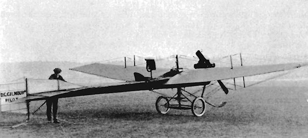
Martin-Handasyde No. 3.
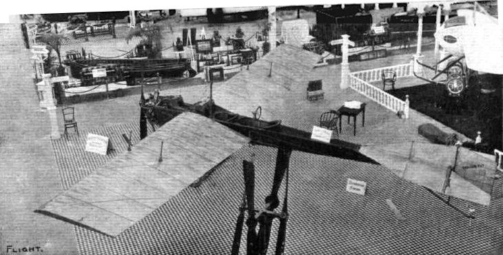
The Martin-Handasyde 4B monoplane. A typical example of the Antoinette type, but full of original detail in design.
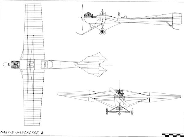
Martin-Handasyde 3
Martin-Handasyde Military Monoplane
During 1912 the War Office ordered four examples of a new military monoplane from Martin and Handasyde. Two were delivered, but neither was flown after receipt. The machine was of the two-seat tractor type and was powered by the eight-cylinder 65 h.p. Antoinette engine. The firm regarded the Antoinette as a good power plant, and returned to using it after testing the Gnome and J.A.P. units in their other designs. The machine still embodied typical features of the 1909 type of Antoinette monoplane some two years after such a style had been in its heyday.
The triangular-section fuselage accommodated its crew in tandem in one undivided cockpit. The engine was cooled through the medium of aluminium tubing condensers, 13 ft. 6 ins. in length and nearly 70 sq. ft. in area, which were mounted on the sides of the fuselage. A steel tube of large diameter, incorporated in the fuselage just forward of the C.G., formed the central support for the strong undercarriage unit. The main tube carried inside it the rubber shock-absorbing system. The engine was given an aluminium cowling, which fitted it closely, and the rest of the fuselage was plywood-covered for strength over its four longerons. A great improvement over the previous Martin-Handasyde designs was the provision of a coaming about the cockpit area, bestowing reasonable protection for the occupants. Warping lateral control was applied to the wings, the tips of which were also washed-out for better automatic stability.
An improved version of the type, fitted with the more powerful eight-cylinder 80 h.p. Laviator engine, was exhibited at the 1913 Aero Show at Olympia.
SPECIFICATION
Description: Two-seat tractor monoplane. Wooden structure, fabric covered.
Manufacturers: Martin and Handasyde Ltd., Trinity Works, Camberwell.
Power Plant: 65 h.p. Antoinette, 80 h.p. Laviator.
Dimensions: Span, 42 ft. 6 ins. Length, 35 ft. 4 ins. Wing area, 290 sq. ft.
Weights: Empty, 1,100 lb. Loaded, 1,760 lb.
Performance: Maximum speed, 70 m.p.h. Cruising speed, 64 m.p.h.
Price: ?1,350.
Martin-Handasyde Military Trials Monoplane
The Military Trials Monoplane of 1912 was entered as No. 17 and was similar in appearance to the military monoplane produced for the War Office. The machine seated two in tandem in separate cockpits and was fitted at first with an 80 h.p. Dansette-Gillet engine, which was replaced by the 90 h.p. Chenu for the Trials, during which C. Gordon Bell was the pilot. The next engine used was a 65 h.p. Antoinette, and this was followed in 1913 by a 120 h.p. Austro-Daimler, which gave a top speed of 75 m.p.h. On 13th June, 1913, the machine was crashed by Bell at Brooklands during low flying, killing the passenger, Lt. J. R. B. Kennedy. Span, 42 ft. Length, 38 ft. Weight empty, 1,250 lb. Weight loaded, 1,800 lb. Maximum speed, 75 m.p.h.
Martin-Handasyde 1913 Monoplane
Similar in appearance to the 1912 Military Trials two-seater, this machine was completed at Brooklands in August, 1913, being tested during the following month by R. H. Barnwell and taking second place in the second Aerial Derby on 20th September, 1913. The engine was the 120 h.p. Austro-Daimler, and the machine was flown by Barnwell in the London- Brighton-London race of 8th November, 1913. At the end of the year it was modified with a pair of small wheels on the front of the undercarriage skid. The centre undercarriage pylon was faired to a streamline section. Early in 1914 the machine was being flown at Brooklands by 2nd Lt. Vincent Waterfall, who had gained his Royal Aero Club Aviator's Certificate No. 461 on 22nd April, 1913, on a Vickers at Brooklands. A speed of 97 m.p.h. was recorded with the aircraft in a test carried out at Farnborough. In February, 1914, it was involved in an accident when the small front wheels of the undercarriage came off and smashed the propeller.
Martin-Handasyde Waterbus
The Waterbus Monoplane was reported to be under construction by Martin and Handasyde at Brooklands during 1913.
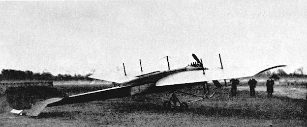
Martin-Handasyde Military Monoplane.

Martin-Handasyde Military Trials Monoplane with 90 h.p. Chenu.
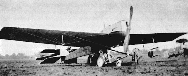
Martin-Handasyde Military Trials Monoplane re-engined with 120 h.p. Austro-Daimler.

Martin-Handasyde 1913 Monoplane
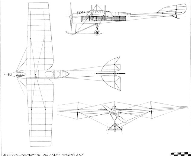
Martin-Handasyde Military Monoplane.
Martin-Handasyde Pusher Biplane
This unusual venture for Martin-Handasyde was built during 1914 and used a 65 h.p. Antoinette engine; the fuselage structure was formed from steel tubing. The machine was entered for the 1914 Aerial Derby, in which it was to have been flown by J. Blatherwick, but was not ready in time to take part in the race.
This unusual venture for Martin-Handasyde was built during 1914 and used a 65 h.p. Antoinette engine; the fuselage structure was formed from steel tubing. The machine was entered for the 1914 Aerial Derby, in which it was to have been flown by J. Blatherwick, but was not ready in time to take part in the race.
Martin-Handasyde Transatlantic Monoplane
One of the most promising of the contenders for the ?10,000 Daily Mail transatlantic prize was the Martin-Handasyde design. A side-by-side two-seater, it followed the general lines of previous designs by the same firm. A four-bladed propeller, 12 ft. in diameter, was fitted to its twelve-cylinder 225 h.p. Sunbeam engine. To enable the machine to float, should it be forced to descend on to the sea, the fuselage was provided with a waterproof compartment which extended rearwards for 14 ft. from the engine bulkhead. Another aid to survival was provided by a telescopic signalling mast which was stowed in the fuselage.
Load-carrying requirements necessitated the use of a wing of broad span and large area, and this was mounted at shoulder level on the upper longerons. Surprisingly, in such an advanced design, wing-warping was preferred to the use of ailerons, the wing panels being braced with kingposts and wire. Upon take-off the two-wheeled undercarriage was to be released, landing being effected on the long, fixed skid.
The machine was being constructed at Brooklands during May, 1914, and it was intended that Gustav Hamel should pilot it for the projected West-to-East crossing from Newfoundland to Ireland. These plans received a tragic and abrupt setback when Hamel disappeared while flying the English Channel on 23rd May, 1914. The Martin-Handasyde Transatlantic was one of the most advanced, largest and most powerful designs to have been attempted in its time; financial backing for it was obtained from the Scottish-Canadian financier and sportsman, MacKay Edgar.
SPECIFICATION
Description: Two-seat tractor monoplane. Wooden structure, fabric covered.
Manufacturers: Martin and Handasyde Ltd., Hendon, London, N.W.9.
Power Plant: 225 h.p. Sunbeam.
Dimensions: Span, 66 ft. Length, 45 ft. Wing area, 770 sq. ft.
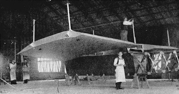
Martin-Handasyde Transatlantic under construction at Brooklands.
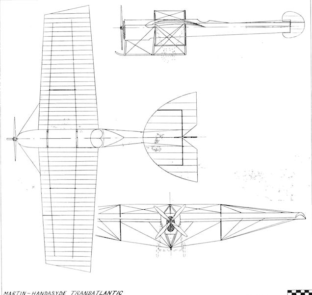
Martin-Handasyde Transatlantic
Maxfield Monoplane
The Maxfield Monoplane was designed and constructed at Birmingham by Alfred P. Maxfield, a motor engineer. The engine fitted was an air-cooled twin-cylinder Garrard-Maxfield which drove twin propellers. A biplane elevator was carried in front of the wings, with a biplane tail to their rear. The undercarriage wheels were steerable. The machine was flown successfully by Maxfield on 30th September, 1909.
The Maxfield Monoplane was designed and constructed at Birmingham by Alfred P. Maxfield, a motor engineer. The engine fitted was an air-cooled twin-cylinder Garrard-Maxfield which drove twin propellers. A biplane elevator was carried in front of the wings, with a biplane tail to their rear. The undercarriage wheels were steerable. The machine was flown successfully by Maxfield on 30th September, 1909.
Maxim 1894 Biplane
Designed on a grand scale, construction of Hiram S. Maxim's first biplane commenced in 1891, and the enormous machine was completed in 1894. Power for the pair of 17.83 ft. diameter propellers was provided by two light-weight compound steam engines, which gave a total of 360 h.p. 320 lb./sq. in. steam was supplied by a Thorneycroft marine boiler fired by naphtha, total thrust being 2,100 lb.
Testing was carried out at Baldwyn's Park, Bexley, Kent, on a 9 ft. wide steel railway track 1,800 ft. in length, equipped with check rails of Georgia pine 35 ft. apart. With pilot and three passengers aboard, the machine took off after a run of 200 yds., when it reached 40 m.p.h., but broke the check rails and came to a halt. The measured lift was 4,000 lb. Owing to the illness of the inventor, and the fact that the grounds at Baldwyn's Park were required for use as a public institution, the whole project was abandoned. Span, 104 ft. Length, 120 ft. Wing area, 3,875 sq. ft. Weight loaded, 8,000 lb.
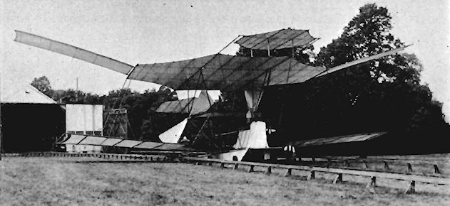
Maxim 1910 Biplane
After a lapse of some fifteen years Sir Hiram Maxim produced his second aeroplane design. In the intervening period since his huge biplane of 1894 was built, powered flight had become a reality in several countries and, in the light of the experiences of others, his new machine displayed a rather more realistic approach to the problem.
Construction of the three-seater pusher biplane was undertaken by Wolseley at Crayford, (Cent, and was completed in 1910. Steel tubing was employed for the fuselage framework, and the three seats were arranged abreast at the leading edge of the lower wings, the pilot sitting in a central nacelle. Power was provided by a four-cylinder Maxim engine of 80 h.p., which was coupled to three pusher propellers, the central one of 5 ft. diameter being driven direct by the crankshaft, while the pair of 11 ft. 4 ins. diameter revolved around the steel-tubing upper tail booms and were connected to the engine through a rope drive tensioned by jockey pulleys.
The wings were of wood, covered with rubber-proofed Jap silk, and were of rectangular plan-form with straight centre-section and gull dihedral on the outer panels. Warping, operated by foot pedals, was employed for lateral control and the twin tail-wheels were coupled to the rudders for control on the ground.
Pre-flight testing by tethering with wires to a steel mast in the centre of a circular track was proposed, and this was prepared early in 1910. The track consisted of tar and sand, and was 25 ft. wide, with a circumference of 2,200 ft. A gyroscopic control mechanism was under development for the machine, but was not required, as the biplane never took to the air in free-flight. Span, 44 ft. Length, 35 ft. 6 ins. Wing area, 572 sq. ft. Endurance, 2 hrs.
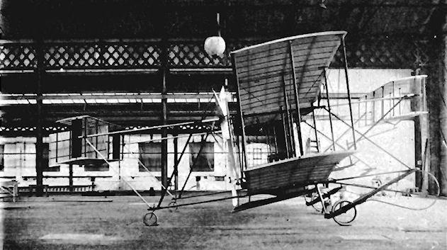
Megone Biplane
The Megone Biplane was designed and built by W. B. Megone at Hawkinge, Kent, in 1912. The machine was a two-seat pusher with several unorthodox features. The 60 h.p. Green engine was mounted at the front of the nacelle, the 10 ft. diameter propeller being chain-driven through an extension shaft with a Hele-Shaw clutch. The control wires to the tail were taken through the hollow boss of the propeller in the same manner as in the Grahame-White Type 6 and the F.E.3. The passenger was seated behind the pilot, who had a rising seat, and both of them were able to obtain a good downward view by means of celluloid windows provided in the lower wings of the sesquiplane. Wing area, 440 sq. ft.
The Megone Biplane was designed and built by W. B. Megone at Hawkinge, Kent, in 1912. The machine was a two-seat pusher with several unorthodox features. The 60 h.p. Green engine was mounted at the front of the nacelle, the 10 ft. diameter propeller being chain-driven through an extension shaft with a Hele-Shaw clutch. The control wires to the tail were taken through the hollow boss of the propeller in the same manner as in the Grahame-White Type 6 and the F.E.3. The passenger was seated behind the pilot, who had a rising seat, and both of them were able to obtain a good downward view by means of celluloid windows provided in the lower wings of the sesquiplane. Wing area, 440 sq. ft.
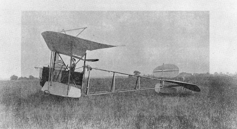
The longspan version of the Megone biplane in 1913-1914.
Mersey Military Trials Monoplane
The design of the Mersey Military Trials Monoplane originated with Planes Ltd., of Freshfield, Liverpool, and was developed after May, 1912, by the Mersey Aeroplane Co., of R. C. Fenwick and S. T. Swaby, for the Military Trials held on Salisbury Plain during the following August. In its original form, with a smaller rudder and no vertical surface below the elevator, it flew at Freshfield for the first time late in 1911. Designed and flown by Fenwick, the machine was somewhat of a freak. The seven-cylinder 45 h.p. Isaacson radial engine was mounted in the nose, and the propeller was fitted behind the wings, being driven by an extension shaft which passed between the seats of the two side-by-side passengers. 2 : 1 reduction gearing was employed, and the tail unit was supported by a pair of steel-tubing booms, an arrangement which proved to be very weak and unstable longitudinally. As No. 19. the machine crashed at the Trials on 13th August, 1912, with fatal results to Fenwick. Span, 35 ft. Length, 24 ft. Wing area, 220 sq. ft. Weight empty, 750 lb. Weight loaded, 1,150 lb. Maximum speed, 55 m.p.h. Endurance, 6 hrs.
The design of the Mersey Military Trials Monoplane originated with Planes Ltd., of Freshfield, Liverpool, and was developed after May, 1912, by the Mersey Aeroplane Co., of R. C. Fenwick and S. T. Swaby, for the Military Trials held on Salisbury Plain during the following August. In its original form, with a smaller rudder and no vertical surface below the elevator, it flew at Freshfield for the first time late in 1911. Designed and flown by Fenwick, the machine was somewhat of a freak. The seven-cylinder 45 h.p. Isaacson radial engine was mounted in the nose, and the propeller was fitted behind the wings, being driven by an extension shaft which passed between the seats of the two side-by-side passengers. 2 : 1 reduction gearing was employed, and the tail unit was supported by a pair of steel-tubing booms, an arrangement which proved to be very weak and unstable longitudinally. As No. 19. the machine crashed at the Trials on 13th August, 1912, with fatal results to Fenwick. Span, 35 ft. Length, 24 ft. Wing area, 220 sq. ft. Weight empty, 750 lb. Weight loaded, 1,150 lb. Maximum speed, 55 m.p.h. Endurance, 6 hrs.
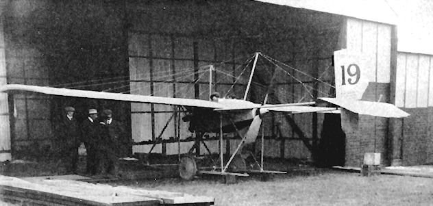
Metzgar and Leno Monoplane
The Metzgar and Leno Monoplane of 1911 was a single-seat pusher built at Clapham, London, S.W. The engine also was built by Metzgar and Leno and transmitted its power through a chain-drive. In general appearance, the machine resembled strongly the A.S.L. Valkyrie; tests were conducted at the end of the year at Shoreham.
The Metzgar and Leno Monoplane of 1911 was a single-seat pusher built at Clapham, London, S.W. The engine also was built by Metzgar and Leno and transmitted its power through a chain-drive. In general appearance, the machine resembled strongly the A.S.L. Valkyrie; tests were conducted at the end of the year at Shoreham.
Mines Biplane
Nicknamed the "Coffee-Stall", the freakish Mines Biplane appeared at the 1909 Doncaster Flying Meeting and was the creation of Edward Mines. The machine was a single-seat pusher with wings of 14 ft. span and of 6 ft. chord. No tail was fitted, and control was by means of a rudder at each wing-tip hinged to the front outer interplane struts, and by a strut-operated elevator on the leading-edge of the upper wings. The lower wing-tips were also adjustable. The engine was an air-cooled vee-twin of about 10 h.p. with chain-drive to the propeller shaft. The Mines Biplane was not successful and did not fly.
Nicknamed the "Coffee-Stall", the freakish Mines Biplane appeared at the 1909 Doncaster Flying Meeting and was the creation of Edward Mines. The machine was a single-seat pusher with wings of 14 ft. span and of 6 ft. chord. No tail was fitted, and control was by means of a rudder at each wing-tip hinged to the front outer interplane struts, and by a strut-operated elevator on the leading-edge of the upper wings. The lower wing-tips were also adjustable. The engine was an air-cooled vee-twin of about 10 h.p. with chain-drive to the propeller shaft. The Mines Biplane was not successful and did not fly.

The Mines biplane was present at the Blackpool Meeting in October 1909 but did not achieve flight.
Mitchell Hydro-biplane
The Mitchell Hydro-biplane was constructed at Gillingham, Kent, during the early part of 1914 by the three Mitchell brothers. The machine was a tractor powered by a Mors automobile engine of 100 h.p. The undercarriage consisted of two main floats, augmented by another at the tail. During testing the aircraft nosed over in the water. Span, 37 ft. Weight empty, 1,050 lb.
The Mitchell Hydro-biplane was constructed at Gillingham, Kent, during the early part of 1914 by the three Mitchell brothers. The machine was a tractor powered by a Mors automobile engine of 100 h.p. The undercarriage consisted of two main floats, augmented by another at the tail. During testing the aircraft nosed over in the water. Span, 37 ft. Weight empty, 1,050 lb.
Molesworth Triplane
The Mackensie-Hughes Triplane was redesigned during August, 1910, and rebuilt by H. B. Molesworth as the Molesworth Triplane, retaining its name Britannia. A 60 h.p. E.N.V. "F" engine was installed in a forward position, following experience of power-loss and over-heating in the machine's original form. One two-bladed propeller with direct drive was fitted, and a new monoplane horizontal tail was mounted on top of the upper longerons, the rudder being transferred to the rear.
The Mackensie-Hughes Triplane was redesigned during August, 1910, and rebuilt by H. B. Molesworth as the Molesworth Triplane, retaining its name Britannia. A 60 h.p. E.N.V. "F" engine was installed in a forward position, following experience of power-loss and over-heating in the machine's original form. One two-bladed propeller with direct drive was fitted, and a new monoplane horizontal tail was mounted on top of the upper longerons, the rudder being transferred to the rear.

The Molesworth-Hughes triplane was modified from the Mackenzie-Hughes Britannia but failed to fly on test at Brooklands in 1911.
Moon Moonbeam
The Moonbeam was a single-seat tractor monoplane designed and built during 1910 by Rowland Moon of Southampton, Hants. It resembled the Demoiselle, and was fitted with tapering wings mounted on a fuselage of steel tubing. The engine was a four-cylinder 20 h.p. J.A.P. with a 6 ft. propeller. Span, 24 ft. Weight empty, 260 lb.
The Moonbeam was a single-seat tractor monoplane designed and built during 1910 by Rowland Moon of Southampton, Hants. It resembled the Demoiselle, and was fitted with tapering wings mounted on a fuselage of steel tubing. The engine was a four-cylinder 20 h.p. J.A.P. with a 6 ft. propeller. Span, 24 ft. Weight empty, 260 lb.
Moore-Brabazon Biplane
J. T. C. Moore-Brabazon's first aeroplane was a single-seat pusher biplane built during 1907. The framework was of ash and bamboo covered with varnished balloon fabric. The control surfaces comprised a frontal elevator, together with a pair of "balancers" mounted vertically on the rear interplane struts. The original intention was that landing skids should be incorporated, with the four-wheeled undercarriage being dropped on takeoff, but this was finally made a fixture.
After its eight-cylinder 12 h.p. Buchet engine had been fitted, the machine was taken from London to Brooklands early in 1908 for its trials, which, however, proved unsuccessful. During its tests the biplane refused to leave the ground, and the design was abandoned as a power-driven type.
Moore-Brabazon Glider
After its unsuccessful trials at Brooklands in 1908 the Moore-Brabazon Biplane's Buchet engine was removed. The aircraft was then transported to grounds near Chelmsford, Essex, where it was tested as a glider by towing with rubber cord; once again, the results were not particularly satisfactory.
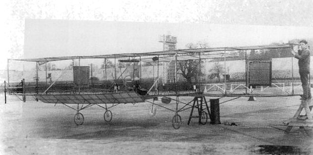
Moore-Brabazon biplane. The glider was modified and fitted with an engine by Howard Wright. The undercarriage failed on test on the Finishing Straight at Brooklands.
Mortimer and Vaughan Safety Biplane
The Safety Biplane was built during 1910 by Mortimer and Vaughan of Edgware, Middlesex. It was fitted with two pairs of semi-circular wings, and crashed and burned on a test flight. The following year a second modified version was built.
The Safety Biplane was built during 1910 by Mortimer and Vaughan of Edgware, Middlesex. It was fitted with two pairs of semi-circular wings, and crashed and burned on a test flight. The following year a second modified version was built.
Moya Balloonoplane
The Balloonoplane was an unsuccessful combination of a monoplane suspended below a balloon. It was built during 1910, and suffered from steering trouble.
The Balloonoplane was an unsuccessful combination of a monoplane suspended below a balloon. It was built during 1910, and suffered from steering trouble.
Mulliner 1 Monoplane
The first monoplane built by the Mulliner Coachworks Ltd., of Long Acre, London, and Northampton, was designed by Gordon Stewart and was exhibited at the 1910 Olympia Aero Show. It was a single-seat tractor, fitted with the eight-cylinder 35 h.p. J.A.P. engine driving a 6 ft. 3 ins. Spencer propeller. Warping lateral control was incorporated in the wings. Span, 33 ft. Length, 27 ft. Wing area, 220 sq. ft. Weight empty, 420 lb. Weight loaded, 605 lb. Maximum speed, 40 m.p.h. Price, ?450.
The first monoplane built by the Mulliner Coachworks Ltd., of Long Acre, London, and Northampton, was designed by Gordon Stewart and was exhibited at the 1910 Olympia Aero Show. It was a single-seat tractor, fitted with the eight-cylinder 35 h.p. J.A.P. engine driving a 6 ft. 3 ins. Spencer propeller. Warping lateral control was incorporated in the wings. Span, 33 ft. Length, 27 ft. Wing area, 220 sq. ft. Weight empty, 420 lb. Weight loaded, 605 lb. Maximum speed, 40 m.p.h. Price, ?450.
Mulliner 2 Knyplane
The Knyplane was the second tractor monoplane built by the Mulliner Coachworks Ltd., of Long Acre, London, and Northampton, and was designed by E. Cecil Kny - of later D.F.W. fame - and constructed in the Mulliner works at Vardens Road, Clapham Junction, London, S.W. It was seen at the 1911 Olympia Aero Show, and was unusual in that the incidence of the wings could be altered in flight, together with their camber, which could be increased by drooping the leading-edge. Both operations could be carried out synchronously or independently of each other. A feature of the finely-shaped, boat-like fuselage with its metal fore-part, was that the open cockpit could be enclosed by the addition of a detachable conning-tower. The engine was a 60 h.p. E.N.V. "F", which drove a Normale propeller. Span, 39 ft. Length, 36 ft. Wing area, 300 sq. ft. Weight loaded, 1,250 lb.
The Knyplane was the second tractor monoplane built by the Mulliner Coachworks Ltd., of Long Acre, London, and Northampton, and was designed by E. Cecil Kny - of later D.F.W. fame - and constructed in the Mulliner works at Vardens Road, Clapham Junction, London, S.W. It was seen at the 1911 Olympia Aero Show, and was unusual in that the incidence of the wings could be altered in flight, together with their camber, which could be increased by drooping the leading-edge. Both operations could be carried out synchronously or independently of each other. A feature of the finely-shaped, boat-like fuselage with its metal fore-part, was that the open cockpit could be enclosed by the addition of a detachable conning-tower. The engine was a 60 h.p. E.N.V. "F", which drove a Normale propeller. Span, 39 ft. Length, 36 ft. Wing area, 300 sq. ft. Weight loaded, 1,250 lb.
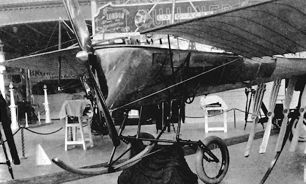
The boat-like body of the Kny aeroplane, built by Mulliner's of Long Acre and Northampton. Apart from this characteristic feature the most important structural detail is the method of swivelling the wings and depressing the leading edge so as to alter their attitude and camber simultaneously.
Mumford Helicopters 1 and 2
In 1906 Edwin H. Mumford and J. Pollock Brown, of Wm. Denny & Brothers, Dumbarton, who were in charge of the firm's experimental tank and had studied the theory of ships' propellers, designed a direct-lift aircraft based on the results of their researches. I t comprised a tubular framework of rectangular plan-form carrying six large two-bladed rotors of 25 ft. diameter and 19 ft. pitch, whose axes were inclined outward and forward at 10° from the vertical. The first rotors were constructed of silk stretched over a framework and braced by wires from a central king-post. The propeller frames were made first in bamboo - which soaked up water and rotted - and then of steel tubes. These, however, were found to be too flexible, but, finally, the elm frames used in 1909 were satisfactory for the purpose. The three rotor shafts on each side were parallel to each other and were driven through bevel gearboxes by a longitudinal shaft, the two side shafts in turn being geared to inclined cross-shafts driven by the centrally-mounted engine. The first engine, a 25 h.p. Buchet, was replaced in 1909 by a four-cylinder two-stroke N.E.C. of 25 h.p., and this in turn gave way in 1911 to a V-4 N.E.C. of 40 h.p. The pilot sat behind the engine, and the control surfaces provided were an elevator above the pilot's head and a vertical rudder at the rear of the machine. The helicopter rested on two long wooden skids. The structure and transmission shafts were of aluminium tubing, and the complete aircraft weighed originally 886 lb. with the pilot. As modifications were made, the weight increased until it reached 1,580 lb. in flying condition.
The gearboxes were of exceptionally efficient design, and very few transmission difficulties arose. Tests were made first with an electric motor on the ground and, in 1912, tethered flights to 10 ft. were achieved successfully with the V-4 engine installation, in January, 1913, a side shaft broke and caused two adjacent rotors to foul, with the conseqent wrecking of the machine.
Experiments were resumed in 1914, when a second helicopter of generally similar design, but with much detail improvement, was built in Denny's Leven yard. This version was more compact and of stiffer construction and was mounted on long parallel floats. The same power unit and transmission as before were used, but the aluminium struts were replaced by composite tubes manufactured from paper, wood and fabric. In this form the machine weighed 1,508 lb. empty. In the autumn of 1914 it was launched on the River Clyde and made a successful flight of 300 ft. at a height of 10 ft., during which it lifted a total weight of 1,600 lb. and achieved a forward speed of about J 5 knots. It was then returned to the slipway because of an approaching gale, by which it was wrecked completely later that night. War had already broken out, and it was not possible to undertake any further helicopter experiments.
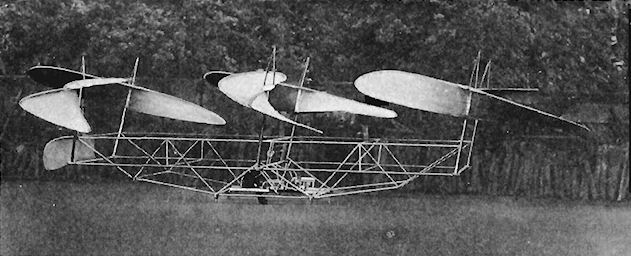
Mumford helicopter built at Denny Bros, shipyard achieved tethered flight in 1913.
Neale Pup
The Pup single-seat tractor monoplane was designed by J. V. Neale and constructed in 1909, appearing at Dagenham during the same year. It had a biplane tail, each plane of which could have its incidence controlled independently of the other. Very large ailerons were featured, and the wing-tips incorporated vertical end plates. A two-cylinder,9 h.p. J.A.P. engine drove a 6 ft. 6 ins. diameter propeller through 3 : 1 reduction gearing. The landing-gear comprised three bicycle wheels in standard forks, the two at the front being carried on the ends of a horizontal transverse bamboo pole. Span, 18 ft. Weight loaded, 420 lb.
The Pup single-seat tractor monoplane was designed by J. V. Neale and constructed in 1909, appearing at Dagenham during the same year. It had a biplane tail, each plane of which could have its incidence controlled independently of the other. Very large ailerons were featured, and the wing-tips incorporated vertical end plates. A two-cylinder,9 h.p. J.A.P. engine drove a 6 ft. 6 ins. diameter propeller through 3 : 1 reduction gearing. The landing-gear comprised three bicycle wheels in standard forks, the two at the front being carried on the ends of a horizontal transverse bamboo pole. Span, 18 ft. Weight loaded, 420 lb.
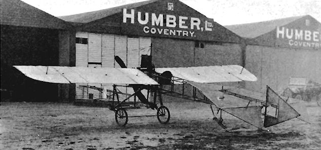
Neale monoplane at Brooklands in 1910. This was much changed from the Blackpool version and made a number of straight flights in December 1909 and later.
Neale 6 Monoplane
The Neale 6 Monoplane was designed and built by J. V. Neale, and appeared in its original form at the 1909 Blackpool Aviation Meeting. It was a single-seat tractor powered by a 24 h.p. E.N.V. "H" engine. During 1910 it was crashed at Brooklands on 21st May, and was rebuilt by Edward and Henry Petre and R. L. Howard Flanders. Several changes were made at the same time, and included the fitting of a 20 h.p. J. A.P. engine, the covering of the hitherto open fuselage, the substitution of a tailwheel for the skid, and a completely new tail unit comprising a biplane tailplane and a forward-set fin.
The Neale 6 Monoplane was designed and built by J. V. Neale, and appeared in its original form at the 1909 Blackpool Aviation Meeting. It was a single-seat tractor powered by a 24 h.p. E.N.V. "H" engine. During 1910 it was crashed at Brooklands on 21st May, and was rebuilt by Edward and Henry Petre and R. L. Howard Flanders. Several changes were made at the same time, and included the fitting of a 20 h.p. J. A.P. engine, the covering of the hitherto open fuselage, the substitution of a tailwheel for the skid, and a completely new tail unit comprising a biplane tailplane and a forward-set fin.
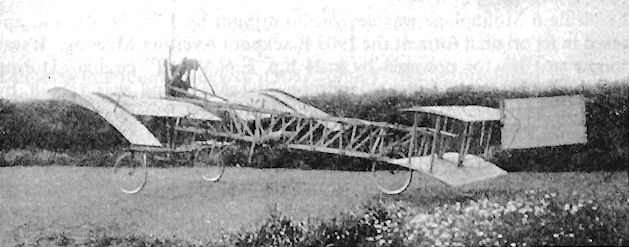
Neale 6 Monoplane in original form with 24 h.p. E.N.V.
Neale VI monoplane flown at Brooklands in 1910 was reconstructed from the earlier machine.
Neale VI monoplane flown at Brooklands in 1910 was reconstructed from the earlier machine.
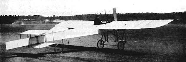
Neale 6 Monoplane rebuilt and fitted with 20 h.p. J.A.P.
Mr. J. V. Neale's new monoplane with which he is at present practising at Brooklands.
Mr. J. V. Neale's new monoplane with which he is at present practising at Brooklands.
Neale 7 Biplane
Following his monoplanes of 1909, John V. Neale produced in 1910 a single-seat pusher biplane with a patented special system of lateral control. At that time Wilbur and Orville Wright were taking legal action against infringements of their system of patented wing warping, and the Neale Biplane was designed with particular attention to its lateral controls to avoid any trouble arising from litigation.
Apart from its controls, the machine was a straightforward design of the popular and successful - if rather uncomfortable - boxkite type. A four-cylinder 35 h.p. Green engine supplied its power to a two-bladed propeller of very generous area. Elevators were provided in front of and behind the main planes, but the usual type of centrally-disposed vertical rudder was replaced by one at each wing-tip, hinged to an additional interplane strut set just inside that on the front at the tip. Ailerons also were incorporated on the upper wings. The machine's undercarriage consisted of the normal combination of two pairs of wheels with their attendant skids.
The first flight of the Neale 7 was made on 1st August, 1910, testing being carried out by Neale and Bertie Rippin. During the trials at Brooklands the unusual wing-tip rudders were found to be so effective that the ailerons were discarded. It was claimed that a deflection of 5° of the rudders was sufficient to turn the aircraft in its own length, the theory behind the new system being that a conventional rear-mounted rudder tended to force the nose into wind, while side rudders could undertake the functions of both steering and lateral control.
SPECIFICATION
Description: Single-seat pusher biplane. Wooden structure, fabric covered.
Manufacturers: Neale's Aeroplane Works, Baker Street, Weybridge, Surrey.
Power Plant: 35 h.p. Green.
Dimensions: 33 ft. Length, 41 ft.
Weights: Empty, 800 lb.
Performance: Maximum speed, 41 m.p.h.
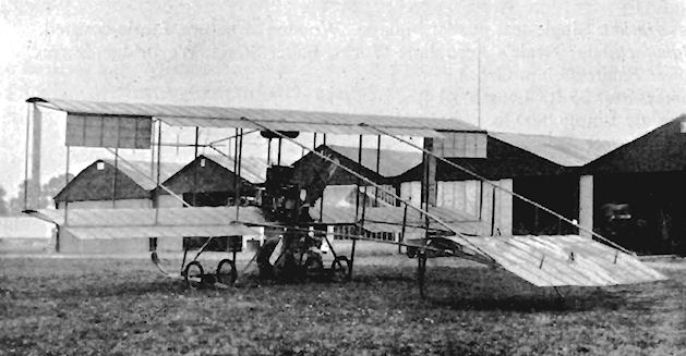
Neale 7 Biplane at Brooklands.
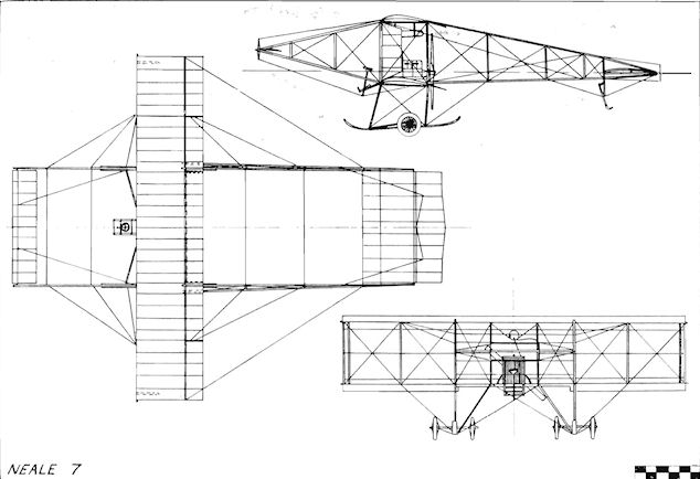
Neale 7
Nicholson Monoplane
The single-seat tractor Nicholson Monoplane was constructed for B. H. Nicholson by the coachbuilders Holland and Holland and was displayed at the 1910 Olympia Aero Show. It was an adaptation of the Bleriot Monoplane and was powered by the four-cylinder 25 h.p. N.E.C. engine. Span, 32 ft. 6 ins. Length, 32 ft. Wing area, 227 sq. ft. Weight loaded, 800 lb. Price, ?550.
The single-seat tractor Nicholson Monoplane was constructed for B. H. Nicholson by the coachbuilders Holland and Holland and was displayed at the 1910 Olympia Aero Show. It was an adaptation of the Bleriot Monoplane and was powered by the four-cylinder 25 h.p. N.E.C. engine. Span, 32 ft. 6 ins. Length, 32 ft. Wing area, 227 sq. ft. Weight loaded, 800 lb. Price, ?550.
Nottingham Monoplane
The Nottingham Monoplane was a two-seat tractor built by Searby, Allen and Searby of Nottingham in 1911, and was powered by a 30 h.p. Alvaston engine.
The Nottingham Monoplane was a two-seat tractor built by Searby, Allen and Searby of Nottingham in 1911, and was powered by a 30 h.p. Alvaston engine.
Nyborg Monoplane
T. G. Nyborg was the designer of the Nyborg Monoplane, which was being built in Newcastle-on-Tyne, Northumberland, during 1909.
T. G. Nyborg was the designer of the Nyborg Monoplane, which was being built in Newcastle-on-Tyne, Northumberland, during 1909.
Wyllie Helicopter
The Wyllie Helicopter was constructed during 1911, but was not successful.
The Wyllie Helicopter was constructed during 1911, but was not successful.
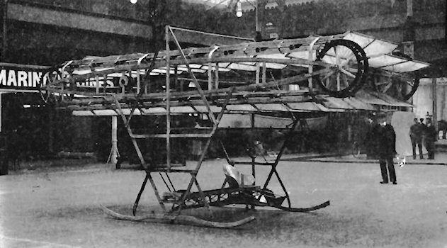
Ottino & Wyllie direct lift machine was exhibited at Olympia in March 1910.
Parkes Biplane No. 1
The first Parkes Biplane, designed by C. H. Parkes, was a single-seat pusher constructed during 1909. The propeller was driven by foot-pedals, the airframe of the machine being mounted on a bicycle undercarriage. A biplane front elevator was fitted. A speed of 9 m.p.h. was reached on the level, and the machine left the ground for a yard or two when running down a slope.
Parkes Biplane No. 2
C. H. Parkes's second biplane was also built in 1909 as a single-seat pusher and was fitted with a two-cylinder 4 h.p. engine. A single front elevator was used and the machine was equipped with a tricycle undercarriage. Hops of 10-40 ft. were achieved. Weight loaded, 350 lb.
Parkes Monoplane
The third design of C. H. Parkes to be built during 1909 was a single-seat canard tractor monoplane which was constructed by the carriage works of T. Preece and Co., Monmouth. Its two-cylinder 20 h.p. engine was mounted before the wings, the pilot being seated behind them, A front elevator was fitted, with the tailplane and the rudder at the rear. Ailerons were used for lateral control. The machine first flew on 7th July, 1910. Span, 28 ft. 3 ins. Length, 28 ft. 3 ins. Wing area, 200 sq. ft. Weight empty, 500 lb.
The third design of C. H. Parkes to be built during 1909 was a single-seat canard tractor monoplane which was constructed by the carriage works of T. Preece and Co., Monmouth. Its two-cylinder 20 h.p. engine was mounted before the wings, the pilot being seated behind them, A front elevator was fitted, with the tailplane and the rudder at the rear. Ailerons were used for lateral control. The machine first flew on 7th July, 1910. Span, 28 ft. 3 ins. Length, 28 ft. 3 ins. Wing area, 200 sq. ft. Weight empty, 500 lb.
Parsons Biplane
The Parsons Biplane was designed and built by P. M. Muller specially to make use of an automobile engine the greater weight of which, compared with the light-weight aero engines, normally militated against its use in an aeroplane, where every pound was a consideration.
A two-seat tractor constructed early in 1913, the Parsons Biplane was fitted with the four-cylinder 40 h.p. Aster car engine, which had been lightened slightly and which drove an 8 ft. 2 ins. diameter Normale propeller.
The design embodied several original features in the hope that stability would thereby be improved. Among them was the extended flexible trailing-edge of the upper wings with considerable overhang of the lower planes. Another was that the fore-part only of the fuselage was covered, in support of the theory that the open framework at the rear would render the rudder more effective. The interplane struts were set close together towards the leading-edge of the wings, thus helping towards the flexing of the rear portion of the chord in the supposed interests of lateral stability. The undercarriage was a straightforward unit of a pair of wheels and twin skids.
The machine was tested at Brooklands by John Alcock and Jack Humphreys, making a cross-country flight at 2,000 ft. from the aerodrome during May, 1913, when piloted by Alcock.
Another odd device tried out on the biplane was the J. G. Parsons Pendulum Stabilizer, which consisted of a pair of paddle-wheels, one being suspended in the gap between each pair of wing-tips. The Aster engine installation was not found to be successful and was replaced by a conventional aero engine, the 70 h.p Gnome. In September, 1913, the Parsons Biplane was bought by Noel Pemberton Billing, some of its components forming later part of the Gaskell-Blackburn Biplane of 1914.
SPECIFICATION
Description: Two-seat tractor biplane. Wooden structure, fabric covered.
Manufacturer: P. M. Muller.
Power Plant: 40 h.p. Aster, 70 h.p. Gnome.
Dimensions: Span, 39 ft. 6 ins. Length, 26 ft. 4 ins. Wing area, 295 sq. ft.
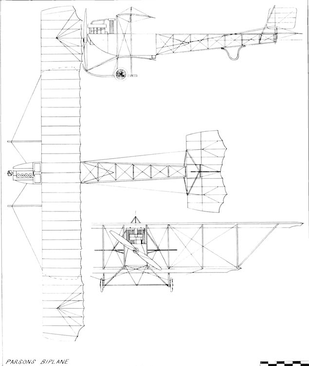
Parsons Biplane
Pashley Brothers Biplane
The Pashley Brothers Biplane was designed and constructed by Cecil Lawrence Pashley and Eric Clowes Pashley at Shoreham, and was completed in July, 1914. The machine was able to carry two passengers on the power of its 50 h.p. Gnome engine. Ailerons were fitted on upper and lower wing-tips. Piloted by Eric Pashley, it won the Brighton Cup and ?70 prize money in a race held in July. Rebuilding was scheduled to include the installation of a 100 h.p. Monosoupape Gnome, and the substitution of a revised vee-type two-wheel undercarriage for reduction of head-resistance and improved performance. The machine was employed as a trainer at Shoreham. Weight empty, 800 lb. Maximum speed, 61 m.p.h.
The Pashley Brothers Biplane was designed and constructed by Cecil Lawrence Pashley and Eric Clowes Pashley at Shoreham, and was completed in July, 1914. The machine was able to carry two passengers on the power of its 50 h.p. Gnome engine. Ailerons were fitted on upper and lower wing-tips. Piloted by Eric Pashley, it won the Brighton Cup and ?70 prize money in a race held in July. Rebuilding was scheduled to include the installation of a 100 h.p. Monosoupape Gnome, and the substitution of a revised vee-type two-wheel undercarriage for reduction of head-resistance and improved performance. The machine was employed as a trainer at Shoreham. Weight empty, 800 lb. Maximum speed, 61 m.p.h.
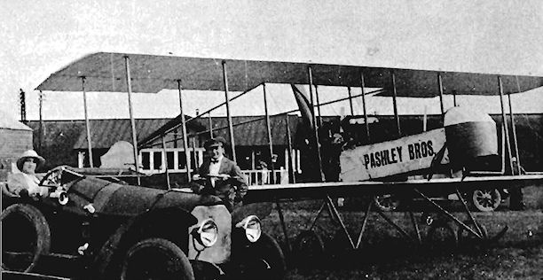
Passat Ornithopter
Monsieur H. J. B. Passat built his ornithopter at Wimbledon and completed it towards the end of 1910. The single-seat fuselage possessed excellent streamline form and was of welded steel tubing construction, in which the designer was assisted by Mons. Martiniere. A two-cylinder 4-5 h.p. Werner motor-cycle engine actuated the flapping rear wings through reduction gear and cranks, and was connected also to the single rear wheel by a chain so that, for two revolutions of the wheel on the ground, the wings made one complete flap of 10 ft. The smaller pair of front wings were for lateral balance and were non-flapping, but were controllable in incidence to act as elevators. The rear of the bird-like fuselage terminated in a tailplane shaped like a bird's tail.
The ornithopter was tested by Mons. Passat on Wimbledon Common during 1912, and after taking off at less than 15 m.p.h. flew successfully for 120-150 yds. before its passage was arrested by a tree. Span, 24 ft. Length, 20 ft. Weight empty, 300 lb.
Paterson No. 1
The Paterson Biplane No. 1 was designed on Curtiss lines by Compton C. Paterson and built for him during 1910 by the Liverpool Motor House Ltd., of Liverpool, Lanes. The machine was a pusher powered by the three-cylinder 35 h.p. Anzani engine, construction being of bamboo, wood and fabric. A tricycle undercarriage was fitted, and a feature of the machine was that it was built of easily dismantled units to facilitate transport.
Tests were made on Southport Sands, and the machine made its first flight on 14th May, 1910, when it flew for half a mile along Freshfield Sands, Lanes. In 1911 it was modified and re-engined with a 50 h.p. Gnome, and sold to G. Higginbotham, who operated a flying-school at Freshfield. He used it to run a private air-mail service between Freshfield and Southport. Span, 34 ft. 4 ins. Length, 31 ft. Weight empty, 600 lb. Maximum speed, 41 mp.h.
Pemberton Billing P.B.7
Noel Pemberton Billing's P.B.7 flying-boat was one of the most elegant aircraft displayed at the 1914 Olympia Aero Show. It was built by his Supermarine works at Woolston, Hants., under the Supermarine number P.B. I, and was powered by the 50 h.p. Gnome driving a Pemberton Billing three-bladed propeller. The single-seat cockpit was installed in the after section of the 200 lb. finely-constructed, cigar-shaped hull, through the upper part of which the lower wings passed in one piece. The thrust-line was set at a considerable angle of up-thrust by pointing the nacelle downward towards the tail-unit, in support of a theory that the machine would rise quickly from the water. This idea was discarded, however, and the lay-out was revised so that the engine was mounted in the hull behind the pilot, with a pair of pusher propellers driven by chains.
The P.B.7 was tested during May, 1914, on Southampton Water, but, owing to the unsatisfactory propellers, only a short hop was possible. Among the detail refinements of the design were the sprung outer floats and the buoyant pilot's seat, which was detachable in the event of an accident in the water. The P.B.7. was intended to be the predecessor of the proposed Supermarine P.B.7 flying-boat, whose hull was to have been a boat unit complete with under-water propeller, on which was to be mounted a removable aircraft unit of wings and tail so that the lower section could be converted into a high-speed motor-boat. Span, 28 ft. Wing area, 293 sq. ft. Weight empty, 750 lb. Weight loaded, 970 lb. Maximum speed, 50 m.p.h.
Perry-Beadle Biplane
The Perry-Beadle Biplane was a small tractor machine built during early 1914 by Perry, Beadle and Co., of Twickenham, Middlesex. It was powered by a 45 h.p. Anzani engine and was at Brooklands for testing in May. During June, 1914, it was being flown by M. F. Glew; its undercarriage was wrecked in an accident at the end of the same month. The machine was flown also by A. Dukinfield-Jones.
The Perry-Beadle Biplane was a small tractor machine built during early 1914 by Perry, Beadle and Co., of Twickenham, Middlesex. It was powered by a 45 h.p. Anzani engine and was at Brooklands for testing in May. During June, 1914, it was being flown by M. F. Glew; its undercarriage was wrecked in an accident at the end of the same month. The machine was flown also by A. Dukinfield-Jones.
Perry-Beadle Flying-boat
Perry, Beadle and Co.'s exhibit at the 1914 Olympia Aero Show was a small two-seat biplane flying-boat of good workmanship and neat appearance. Several unusual features were incorporated in the design, including the mounting of the eight-cylinder 60 h.p. E.N.V. "F" engine in the bows, whence its power was transmitted to the pair of outboard Integral propellers through chains and sprockets. The hull was made by S. E. Saunders and Co., of Cowes, on their Consuta system of two skins of mahogany sewn together with copper wire. The tailplane and fin were made integrally with the hull, and the tailplane and the mahogany-covered lower wings rested in the water to support the machine when at rest. Such unorthodox innovations in design did not prove to be very practical and, after unsuccessful tests on Lake Windermere, the machine was broken up. Span, 35 ft. Wing area, 285 sq. ft. Weight empty, 950 lb. Maximum speed, 64 m.p.h.
Perry, Beadle and Co.'s exhibit at the 1914 Olympia Aero Show was a small two-seat biplane flying-boat of good workmanship and neat appearance. Several unusual features were incorporated in the design, including the mounting of the eight-cylinder 60 h.p. E.N.V. "F" engine in the bows, whence its power was transmitted to the pair of outboard Integral propellers through chains and sprockets. The hull was made by S. E. Saunders and Co., of Cowes, on their Consuta system of two skins of mahogany sewn together with copper wire. The tailplane and fin were made integrally with the hull, and the tailplane and the mahogany-covered lower wings rested in the water to support the machine when at rest. Such unorthodox innovations in design did not prove to be very practical and, after unsuccessful tests on Lake Windermere, the machine was broken up. Span, 35 ft. Wing area, 285 sq. ft. Weight empty, 950 lb. Maximum speed, 64 m.p.h.
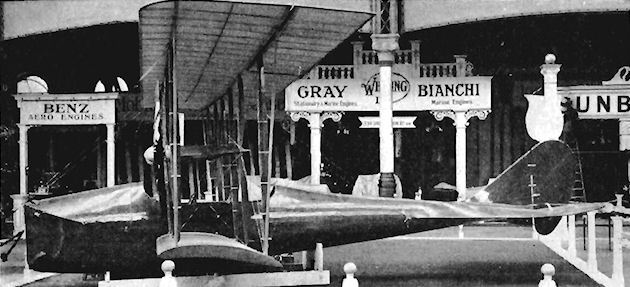
Petre Monoplane
The Petre Monoplane was built at the end of 1909 by the brothers Edward and Henry A. Petre, known to the flying fraternity of that time as Peter the Painter and Peter the Monk, respectively. It was at the 1910 Olympia Aero Show in its uncovered state, but was completed later at Brooklands. The machine was a single-seater, with the pilot's cockpit in front of the wing and with the four-cylinder 35 h.p. N.E.C. engine buried in the fuselage at the trailing-edge. A 16 ft. long, hollow, 2 ins. diameter steel extension shaft drove the 7 ft. propeller, which was at the extreme end of the fuselage behind the tail unit. Radiators for cooling the engine were mounted on each side of the nose, and the incidence of the wings was adjustable in flight. The fuselage, including its diagonal tie-pieces, was entirely of wood, with longerons of L-section and with spacers ofT-section, the whole being screwed together. Lateral control was by means of ailerons.
The Petre Monoplane was damaged on 23rd July, 1910, after taking-off at Brooklands and crashing with Henry Petre piloting. Span, 30 ft. Length, 29 ft. Wing area, 195 sq. ft. Weight empty, 540 lb. Weight loaded, 740 lb. Maximum speed, 30 m.p.h. Price, ?800.
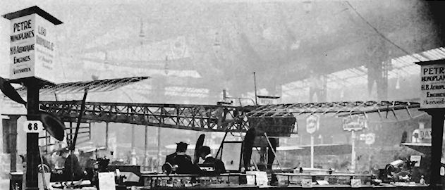
Phillips 1904 Multiplane
Horatio F. Phillips's Multiplane of 1904 put into full-size practice his theory of the venetian-blind arrangement of superimposed wings of very narrow chord which had been demonstrated on his steam-driven model of 1893. Twenty unstaggered surfaces formed the wings of the machine, which was fitted with a cruciform tail unit, the whole being mounted on an undercarriage of three wheels. The engine was of 22 h.p. driving a tractor propeller. When tested, the Multiplane was found to be unstable longitudinally and was not successful. Weight loaded, 600 lb.
Horatio F. Phillips's Multiplane of 1904 put into full-size practice his theory of the venetian-blind arrangement of superimposed wings of very narrow chord which had been demonstrated on his steam-driven model of 1893. Twenty unstaggered surfaces formed the wings of the machine, which was fitted with a cruciform tail unit, the whole being mounted on an undercarriage of three wheels. The engine was of 22 h.p. driving a tractor propeller. When tested, the Multiplane was found to be unstable longitudinally and was not successful. Weight loaded, 600 lb.
Phillips 1907 Multiplane
1907 saw the appearance of Horatio F. Phillips's most unusual Multiplane, which embodied four frames containing a total of some two hundred very narrow chord wings of venetian-blind formation. The machine was without a tail unit and was mounted on tandem main wheels, smaller auxiliary wheels being fitted at the wing-tips on the second frame from the front. A two-bladed 7 ft. diameter tractor propeller of very generous area was turned by a 22 h.p. engine.
The Multiplane was tested at Streatham during mid-1907 and is claimed to have taken off in a 30 m.p.h. wind, to have been stable longitudinally, and to have flown a distance calculated to be about 500 ft.; thus giving Horatio Phillips a strong claim to the honour of being the first person to make a flight under power in Great Britain. Span, 20 ft. Length, 15 ft. Height, 10 ft. Weight empty, 500 lb. Weight loaded, 650 lb.
Pickering and Willoughby Glider
The tail-first Pickering and Willoughby Glider was built by Charles Leigh Pickering and Norman Dean Willoughby at Knutsford, Cheshire, during 1911. Span, 26 ft. Length, 20 ft.
The tail-first Pickering and Willoughby Glider was built by Charles Leigh Pickering and Norman Dean Willoughby at Knutsford, Cheshire, during 1911. Span, 26 ft. Length, 20 ft.
Pickersgill Monoplane
J. T. Pickersgill's Monoplane was built at Keighley, Yorks, during 1909. It was tested on the ground at the end of the year, on 16th December.
J. T. Pickersgill's Monoplane was built at Keighley, Yorks, during 1909. It was tested on the ground at the end of the year, on 16th December.
Piffard Biplane
The single-seat Piffard Biplane was a pusher design by an artist, H. H. Piffard. and was constructed at Ealing during 1909. The engine was the eight-cylinder E.N.V. "D" of 40 h.p., arranged to slide on its mounting for the adjustment of the C.G. The machine was destroyed by a gale in December of the same year, but was rebuilt at Shoreham. Sussex, using the same engine, and was brought out again for tests on 3rd May, 1910.
Following another crash, it was reconstructed once again and reappeared on 23rd June, but did not fly. Some good short flights were achieved on 10th July. 1910, but the machine's development was abandoned by the end of the year after several other crashes had occurred. Floats also were tried out on it. and the Piffard Biplane could be readily dismantled for packing into a pantechnicon. Span. 34 ft. Length, 31 ft. Wing area, 510 sq. ft. Weight loaded, 850 lb.
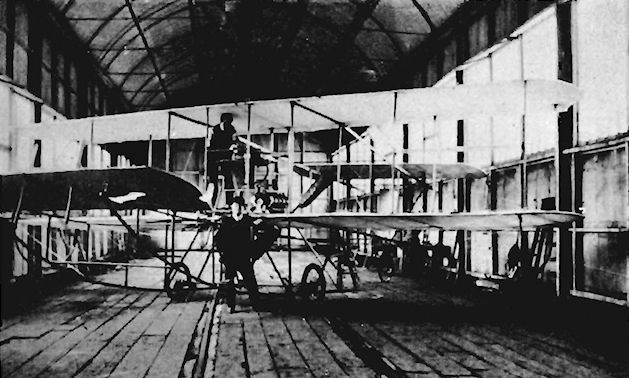
Piffard Hydro-biplane
The Piffard Hydro-biplane was a single-seat pusher designed and built by H. H. Piffard at Shoreham, Sussex, in 1912. It was equipped with twin main floats, and the wing-tips were fitted with strut-braced upper extensions. The engine was the eight-cylinder 40 h.p. E.N.V. "D".
The Piffard Hydro-biplane was a single-seat pusher designed and built by H. H. Piffard at Shoreham, Sussex, in 1912. It was equipped with twin main floats, and the wing-tips were fitted with strut-braced upper extensions. The engine was the eight-cylinder 40 h.p. E.N.V. "D".
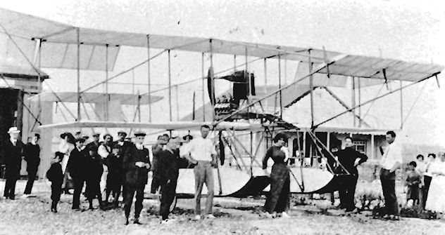
Piggott Biplane
The first aeroplane built by Piggott Brothers and Co. Ltd., of 220-224 Bishopsgate, London, E.C., was designed by S. C. Parr and was constructed during 1910. lt was a two-seat pusher biplane, designated No. J, and was equipped with a four-cylinder 80 h.p. engine which turned a pair of co-axial contra-rotating four-bladed propellers. Differential gearing and a multiple-disc clutch were employed with a flexible-coupling propeller shaft on which were mounted the sheet aluminium hollow propeller blades, those at the front being 13 ft. 6 ins. in diameter, while the smaller set at the rear measured 8 ft. 4 ins. The shaft carrying the smaller propeller was extended so that the blades revolved some 4 ft. 6 ins. behind the front set of blades. The main framework was composed of aluminium, and all flying and control surfaces were of elliptical form. The elevator was carried at the front and the tailplane at the rear, the rudder being hinged between the upper and lower booms. Ailerons were mounted mid-way between the wing-tips. The Piggott Biplane was tested at Hendon during 1912, but is not believed to have flown. Span, 60 ft. Length, 34 ft. Wing area, 568 sq. ft, Weight loaded, 1,150 lb. Maximum speed, 48 m.p.h.
The first aeroplane built by Piggott Brothers and Co. Ltd., of 220-224 Bishopsgate, London, E.C., was designed by S. C. Parr and was constructed during 1910. lt was a two-seat pusher biplane, designated No. J, and was equipped with a four-cylinder 80 h.p. engine which turned a pair of co-axial contra-rotating four-bladed propellers. Differential gearing and a multiple-disc clutch were employed with a flexible-coupling propeller shaft on which were mounted the sheet aluminium hollow propeller blades, those at the front being 13 ft. 6 ins. in diameter, while the smaller set at the rear measured 8 ft. 4 ins. The shaft carrying the smaller propeller was extended so that the blades revolved some 4 ft. 6 ins. behind the front set of blades. The main framework was composed of aluminium, and all flying and control surfaces were of elliptical form. The elevator was carried at the front and the tailplane at the rear, the rudder being hinged between the upper and lower booms. Ailerons were mounted mid-way between the wing-tips. The Piggott Biplane was tested at Hendon during 1912, but is not believed to have flown. Span, 60 ft. Length, 34 ft. Wing area, 568 sq. ft, Weight loaded, 1,150 lb. Maximum speed, 48 m.p.h.
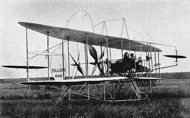
Piggott Monoplane
The Piggott Monoplane was built by Piggott Brothers and Co. Ltd., 220-224 Bishopsgate. London, E.C., and was exhibited at the Olympia Aero Show of 1911. It was remarkably well streamlined, with the pilot and passengers completely enclosed in the fabric-covered fuselage. Slits were provided for their vision, and doors gave access to the cabin. The four-cylinder 80 h.p. Vivinus engine was concealed within the nose, with its attendant radiator mounted above and shaped to fit the contours of the fuselage. The four main wheels of the undercarriage were mounted in line abreast, with a further wheel at the rear under the tail. All control wires were duplicated in case of failure.
The machine did not fly in its original form, and was modified late in 1911 to have an open cockpit. In November, 191 I, it was tested at Hendon by S. C. Parr, and left the ground after a short run at high speed but damaged the undercarriage upon landing. Early in 1912 the landing-gear was rebuilt and strengthened. Span, 30 ft. 6 ins. Length. 24 ft 6 ins. Weight empty, 850 lb. Weight loaded, 1,400 lb.
Piggott Military Biplane
As their entry for the Military Trials of 1912, Piggott Brothers and Co. Ltd., 220-224 Bishopsgate, London, E.C., built a small two-seat biplane with two cockpits in tandem. It was No. 29 in the contest, and was piloted by S. C. Parr, who qualified for his Royal Aero Club Aviator's Certificate No. 184 on 20th February, 1912, with a Bleriot at Hendon. The engine was the 35 h.p. Anzani, driving a 7 ft. Normale propeller, and the three-bay wings of only 100 sq. ft. area had single interplane struts. The pilot was seated above the upper wings, but the machine was too small to lift two occupants, and was unable even to take-off with only the pilot aboard. Span, 25 ft. 6 ins. Length, 17 ft. 6 ins. Wing area, 100 sq. ft. Weight empty, 300 lb. Weight loaded, 400 lb. Maximum speed, 55 m.p.h.
As their entry for the Military Trials of 1912, Piggott Brothers and Co. Ltd., 220-224 Bishopsgate, London, E.C., built a small two-seat biplane with two cockpits in tandem. It was No. 29 in the contest, and was piloted by S. C. Parr, who qualified for his Royal Aero Club Aviator's Certificate No. 184 on 20th February, 1912, with a Bleriot at Hendon. The engine was the 35 h.p. Anzani, driving a 7 ft. Normale propeller, and the three-bay wings of only 100 sq. ft. area had single interplane struts. The pilot was seated above the upper wings, but the machine was too small to lift two occupants, and was unable even to take-off with only the pilot aboard. Span, 25 ft. 6 ins. Length, 17 ft. 6 ins. Wing area, 100 sq. ft. Weight empty, 300 lb. Weight loaded, 400 lb. Maximum speed, 55 m.p.h.
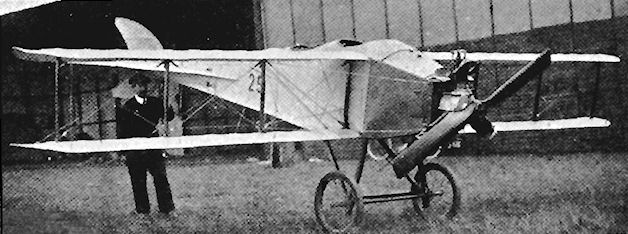
Pilcher Bat
Percy S. Pilcher was born in 1866 and, after serving in the Royal Navy, turned to civil engineering and became a lecturer at Glasgow University. His first glider, the Bat, was a monoplane and was constructed early in 1895. Before making any flights with it, Pilcher went to Berlin to watch Otto Lilienthal, and then made his first glides with the Bat at Cardross on the banks of the River Clyde during June, 1895. Pronounced dihedral was a feature of the wings and the machine was without a horizontal tail although a fin was fitted. After the first tests, Pilcher decided to follow Lilienthal's advice and added a tailplane, thereafter making many successful flights with the Bat. Wing area, 150 sq. ft. Weight empty, 45 lb. Weight loaded. 190 lb.
Pilcher Beetle
The Beetle was the second monoplane glider designed by Pilcher and was built during 1895. Wing area, 170 sq. ft. Weight empty, 80 lb. Weight loaded, 225"lb.
Pilcher Gull
Pilcher's third glider was constructed during 1896 and was named the Gull. Considerably larger monoplane wings of 300 sq. ft. area were fitted, compared with those of his first and second gliders, and were found to have too much lift. Weight empty. 55 lb.
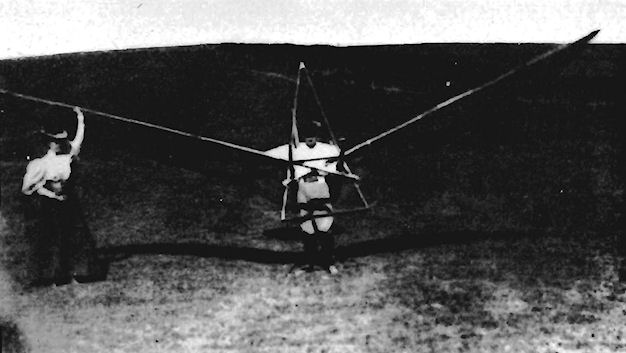
Pilcher Bat

Pilcher Beetle
Pilcher Hawk
The fourth and last of Percy Pilcher's hang gliders was the Hawk. This was constructed during 1896 at Eynsford, Kent, and was made from bamboo with a covering of fabric. The pilot's weight was borne by bolsters under the armpits, control being effected by the shifting of his body, which hung through the open centre-section of the wings. The tail unit was made to fold over the wings for storage purposes, and a wheeled undercarriage was fitted.
The Hawk was a very successful glider, and was flown many times by Pilcher at Eynsford during 1896 and 1897, towed take-offs being made with a fishing-line into a light wind, from which glides of 200 yds. were achieved. On 30th September, 1899, Pilcher was giving a demonstration on the machine at Stanford Hall, Lord Braye's home near Rugby, and was being towed into the air by a team of horses when the bamboo tail support snapped. He crashed to the ground from about 30 ft. and died from his injuries two days later on 2nd October, 1899. The Hawk was later repaired by T. W. K. Clarke of Kingston-on-Thames and was shown at the Travel Exhibition at Olympia held in 1909. Its final resting-place is in the Royal Scottish Museum with a replica in the National Aeronautical Collection housed in the Science Museum at South Kensington, London.
At the time of his death Pilcher had a biplane nearly ready for an attempt at powered flight, in which he proposed to install a 4 h.p. oil engine of his own construction, which was intended to drive a 4 ft. diameter pusher propeller mounted behind the pilot.
SPECIFICATION
Description: Single-seat monoplane glider. Wooden structure, fabric covered.
Manufacturer: Percy S. Pilcher, Eynsford, Kent.
Dimensions: Span, 24 ft. 8 ins. Length, 18 ft. 6 ins. Height, 6 ft. 9 ins. Wing area, 180 sq. ft.
Weights: Empty, 50 lb. Loaded, 195 lb.
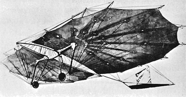
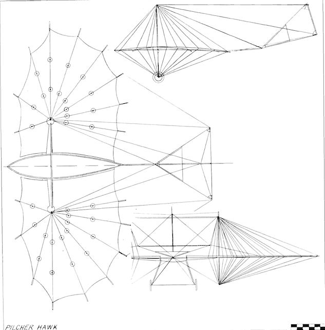
Porte and Pirie Biplane
The Porte and Pirie Glider was a two-seat side-by-side biplane designed and built during 1908 by Lts. J. C. Porte and W. B. Pirie, two naval officers of the submarine depot at Haslar. Intended to be fitted later with a J. A.P. engine, the machine was tested first as a glider at Portsdown Hill, Portsmouth, Hants., on 17th August, 1909. After running down the hill on its wheeled carriage the glider pitched forward, turning over and throwing the occupants out. The biplane wings were very heavily staggered, with the leading-edge of the lower in line vertically with the trailing-edge of the upper.
The Porte and Pirie Glider was a two-seat side-by-side biplane designed and built during 1908 by Lts. J. C. Porte and W. B. Pirie, two naval officers of the submarine depot at Haslar. Intended to be fitted later with a J. A.P. engine, the machine was tested first as a glider at Portsdown Hill, Portsmouth, Hants., on 17th August, 1909. After running down the hill on its wheeled carriage the glider pitched forward, turning over and throwing the occupants out. The biplane wings were very heavily staggered, with the leading-edge of the lower in line vertically with the trailing-edge of the upper.
Porter Helicopter
J. Robertson Porter was an exponent of the direct-lift aircraft, and his first machine was shown at Cordingley's Motor Car Exhibition held from 21st until 28th March, 1908, at the Agricultural Hall, Islington, London. A ducted fan system consisting of 5 ft. diameter propellers and eight vanes drew air downwards through a cone structure with an upper opening of 5 sq. ft. Drive from the air-cooled two-cylinder 6 h.p. J.A.P. engine was by means of a clutch and belt transmission over pulleys. It was displayed again in July, 1909, at the Travel Exhibition held at Olympia. Height, 14 ft. Weight empty, 200 lb.
J. Robertson Porter was an exponent of the direct-lift aircraft, and his first machine was shown at Cordingley's Motor Car Exhibition held from 21st until 28th March, 1908, at the Agricultural Hall, Islington, London. A ducted fan system consisting of 5 ft. diameter propellers and eight vanes drew air downwards through a cone structure with an upper opening of 5 sq. ft. Drive from the air-cooled two-cylinder 6 h.p. J.A.P. engine was by means of a clutch and belt transmission over pulleys. It was displayed again in July, 1909, at the Travel Exhibition held at Olympia. Height, 14 ft. Weight empty, 200 lb.
Porter Gyropachute
Known as the Gyropachute and designed by J. Robertson Porter of 9 Grays Inn Square, London, E.C., the Porter single-seat direct-lift gyroscopic parachute was exhibited at the 1913 Olympia Aero Show. Power was provided by the 50 h.p. Gnome engine. Diameter, 14 ft. Height. 1 1 ft. Parachute area, 400 sq. ft. Weight empty, 350 lb.
Known as the Gyropachute and designed by J. Robertson Porter of 9 Grays Inn Square, London, E.C., the Porter single-seat direct-lift gyroscopic parachute was exhibited at the 1913 Olympia Aero Show. Power was provided by the 50 h.p. Gnome engine. Diameter, 14 ft. Height. 1 1 ft. Parachute area, 400 sq. ft. Weight empty, 350 lb.
Portway Monoplane
The single-seat Portway Monoplane was of modified Demoiselle type, and was built during the first half of 1910 by A. P. Portway and his brother of Bromley, Kent. The main structure was of bamboo with silk covering, and the engine was the four-cylinder 35 h.p. Lascelles. H succeeded in making short flights, but was constantly undergoing repairs to its inadequate landing-gear. Span, 25 ft. Wing area, I 50 sq. ft. Weight empty, 350 lb.
The single-seat Portway Monoplane was of modified Demoiselle type, and was built during the first half of 1910 by A. P. Portway and his brother of Bromley, Kent. The main structure was of bamboo with silk covering, and the engine was the four-cylinder 35 h.p. Lascelles. H succeeded in making short flights, but was constantly undergoing repairs to its inadequate landing-gear. Span, 25 ft. Wing area, I 50 sq. ft. Weight empty, 350 lb.
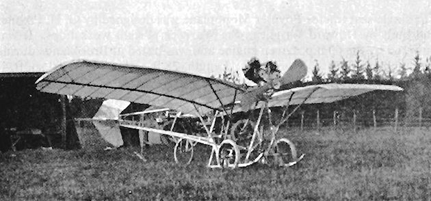
The Portway monoplane of 1910 was a Demoiselle variant built at Bromley.
Poynter Monoplane
The single-seat tractor Poynter Monoplane was designed by G. H. Poynter and built by Howard Wright in the Warwick Wright workshops. It was powered by the 60 h.p. Green engine and was tested at Brooklands during the summer of 1910. Span, 45 ft. Length, 28 ft. Wing area, 300 sq. ft.
The single-seat tractor Poynter Monoplane was designed by G. H. Poynter and built by Howard Wright in the Warwick Wright workshops. It was powered by the 60 h.p. Green engine and was tested at Brooklands during the summer of 1910. Span, 45 ft. Length, 28 ft. Wing area, 300 sq. ft.
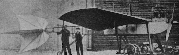
Pupin Motoplane
The Pupin Motoplane appeared at Hendon in November, 1910, and was a pusher with a pair of propellers driven from an engine which was mounted mid-way in the fuselage. It was a tandem monoplane of unorthodox design, having two equal mainplanes forward with a large vertical fin above them, and a large tailplane and small rudder at the rear. The Motoplane does not appear to have left the ground.
The Pupin Motoplane appeared at Hendon in November, 1910, and was a pusher with a pair of propellers driven from an engine which was mounted mid-way in the fuselage. It was a tandem monoplane of unorthodox design, having two equal mainplanes forward with a large vertical fin above them, and a large tailplane and small rudder at the rear. The Motoplane does not appear to have left the ground.
R.A.S. Monoplane
The R.A.S. Monoplane was a single-seat tractor built during 1910 by the R.A.S. Aeroplane Co., of Gosport, Hants, its engine was the four-cylinder 35 h.p. Lascelles, which drove a 7 ft. diameter propeller. An unusual feature was the fin which was mounted below the triangular-section fuselage and underneath the pilot's seat. Span, 32 ft. 4 ins. Length, 28 ft. 6 ins. Wing area, 210 sq. ft. Weight empty, 700 lb.
The R.A.S. Monoplane was a single-seat tractor built during 1910 by the R.A.S. Aeroplane Co., of Gosport, Hants, its engine was the four-cylinder 35 h.p. Lascelles, which drove a 7 ft. diameter propeller. An unusual feature was the fin which was mounted below the triangular-section fuselage and underneath the pilot's seat. Span, 32 ft. 4 ins. Length, 28 ft. 6 ins. Wing area, 210 sq. ft. Weight empty, 700 lb.
Radley-England Waterplane 1
The Waterplane No. 1 was an ambitious and unorthodox design by James Radley and E. C. Gordon England, intended to compete in the 1913 Daily Mail Circuit of Britain event. Construction was undertaken at Portholme, Hunts., where, although the machine was a floatplane, flight-testing was carried out by Gordon England by the expedient of fitting a temporary wheeled undercarriage to the undersides of the floats.
The very original layout of the Waterplane included a pair of flat-bottomed punt-like floats, each of which was large enough to accommodate three passengers. The pilot sat in the front of the starboard float with two seats side-by-side behind him, the same seating arrangement being installed in the opposite float. Both nacelles were suspended by struts beneath the four-bay parallel-chord wings, of which the upper pair possessed slightly greater span than the lower. Mahogany, pine and oak were employed in the construction of the floats, each of which contained two water-tight compartments. Adequate lateral control was ensured by the provision of large ailerons on the upper planes. Twin rudders and the monoplane horizontal tail surfaces were carried on booms, the elevator area being very large compared with that of the tailplane.
Perhaps the most unusual feature of the Waterplane was the power plant. This consisted of three 50 h.p. Gnome rotary engines mounted in line one behind the other just above the lower wings' centre-section. The four-bladed 9 ft. 10 ins. diameter propeller was mounted on a long overhead shaft set above the engines midway in the wing gap, and connection to the power units was made by three Coventry roller chains. This unorthodox arrangement proved to be a very practical one during the trials, in which the machine performed satisfactorily, after which the Waterplane was transported to Shoreham for its final water tests, which were conducted from the River Adur by Gordon England. Making a demonstration flight with a news reporter, however, he was unlucky enough to rip the bottom of the starboard float when he ran over a buoy during the landing run. The Waterplane half-sank in shallow water about a hundred yards from the shore, but was salvaged for rebuilding.
SPECIFICATION
Description: Six-seat pusher hydro-biplane. Wooden structure, fabric covered.
Manufacturers: J. Radley and E. C. Gordon England, Portholme, Hunts.
Power Plant: Three 50 h.p. Gnomes.
Dimensions: Span, 45 ft. 4 ins. Length, 29 ft. 3 ins. Wing area, 505 sq. ft.
Weights: Empty, 1,400 lb.
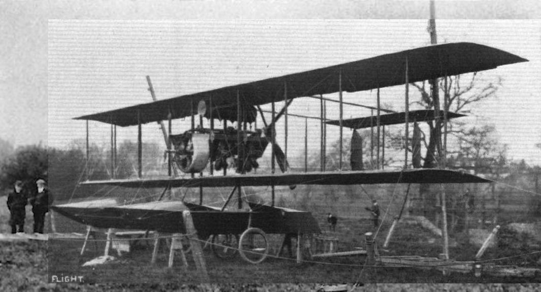
Radley-England Waterplane 1 on temporary wheel undercarriage at Portholme.
Embodying several novel features, the Radley-England Waterplane of 1913 had twin hulls and was powered by three 50hp Gnome rotaries with chain drives to a single overhead propeller shaft.
Embodying several novel features, the Radley-England Waterplane of 1913 had twin hulls and was powered by three 50hp Gnome rotaries with chain drives to a single overhead propeller shaft.
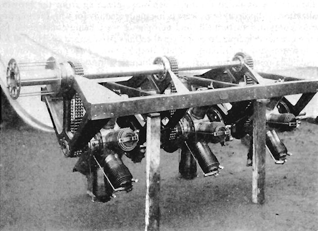
The power plant designed by E.C.Gordon England for the Radley-England Waterplane I, consisting of three 50 h.p. Gnome engines coupled to a single shaft.
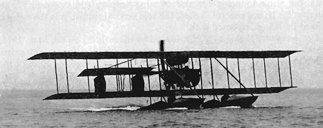
E.C.Gordon England in the Radley-England Waterplane I off the South Coast.
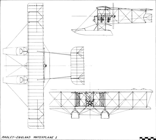
Radley-England Waterplane 1
Radley-England Waterplane 2
Following its unfortunate crash at Shoreham, the Waterplane No. 1 was rebuilt during 1913 and redesignated the No. 2. Several important changes were made in the machine, although the general conception remained the same.
The floats were replaced completely by a new pair of clinker-built type which were made by the South Coast Yacht Agency. They were very much stronger and less liable to leak, and were made from cedar. Three watertight compartments were incorporated in them, a reduction in seats being made from six in the No. 1 to four in the No. 2. The new floats were longer than the original pair, with two tandem seats in each. The pilot occupied the same position in the front of the starboard float, while the rear cockpits were set towards the rear and under the lower wings. At the same time the gap between the floats was reduced slightly.
In the rebuilt Waterplane the three 50 h.p. Gnome engines were replaced by a single eight-cylinder vee-type 150 h.p. Sunbeam which drove a 9 ft. 6 ins. diameter Lang propeller direct. A very large petrol tank holding sufficient fuel for 10 hours flight was installed immediately in front of the engine, and the rectangular radiator was mounted just in front of the leading-edge of the wings.
The wing area was increased by enlarging the span of the upper planes from 45 ft. 4 ins. to 51 ft. 7.5 ins, The tail surfaces were virtually unaltered.
SPECIFICATION
Description: Four-seat pusher hydro-biplane. Wooden structure, fabric covered.
Manufacturers: James Radley and E. C. Gordon England, Shoreham, Sussex, and the South Coast Yacht Agency, Sussex.
Power Plant: 150 h.p. Sunbeam.
Dimensions: Span, 51 ft. 7-5 ins. Length, 29 ft. 9 ins. Wing area, 560 sq. ft.
Weights: Loaded, 2,500 lb.
Performance: Cruising speed, 60 m.p.h. Endurance, 10 hrs.
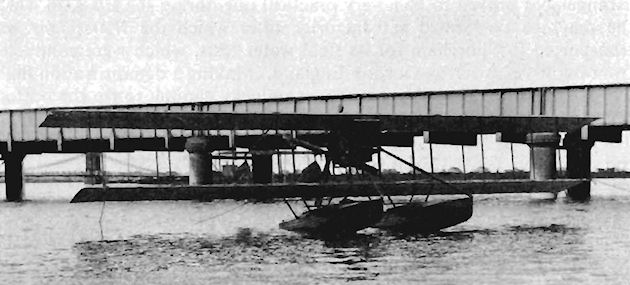
Radley-England Waterplane 2 at Shoreham.
Radley Monoplane
The Radley Monoplane was a tractor designed by James Radley and constructed during 1911. The engine was a 50 h.p. Gnome, and the machine featured elegant gull-dihedral wings mounted on a fuselage of circular section.
The Radley Monoplane was a tractor designed by James Radley and constructed during 1911. The engine was a 50 h.p. Gnome, and the machine featured elegant gull-dihedral wings mounted on a fuselage of circular section.
Radley-Moorhouse Monoplane
The Radley-Moorhouse Monoplane was an adaption of the Bleriot XI built for racing by James Radley and W. B. Rhodes-Moorhouse. It was flown by Rhodes-Moorhouse in the first Aerial Derby, which took place from Hendon on 8th June, 1912, and came in third. The rear fuselage and the wheels were fabric-covered to reduce drag, and the engine was a 50 h.p. Gnome.
The Radley-Moorhouse Monoplane was an adaption of the Bleriot XI built for racing by James Radley and W. B. Rhodes-Moorhouse. It was flown by Rhodes-Moorhouse in the first Aerial Derby, which took place from Hendon on 8th June, 1912, and came in third. The rear fuselage and the wheels were fabric-covered to reduce drag, and the engine was a 50 h.p. Gnome.
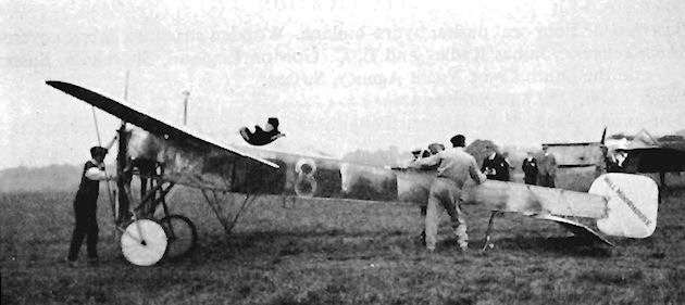
B.E.1
Shortly after it embarked upon the building of the S.E.1 from the Bleriot wreck early in 1911, the Army Aircraft Factory was given another opportunity in April to put its own design ideas into practical form. A Voisin pusher biplane, which had been presented to the War Office by the Duke of Westminster, arrived for repair. Still no funds were available to the Factory for the construction of new aircraft, so the Voisin also was seized upon as an excuse for reconstruction and an exercise in the B.E. (Bleriot Experimental) sphere. The result was a tractor biplane designated the B.E.1, the new machine utilizing the Voisin's 60 h.p. Wolseley engine, with which it was so quiet that it was called "The Silent Aeroplane". Under the supervision of Mervyn O'Gorman, the design of the B.E.1 was carried out by F. M. Green and Geoffrey de Havilland, who, between them, created the fore-runner of what was to be one of the most widely used aeroplanes of the 1914-18 War.
The fuselage consisted of a normal wooden box-girder complete with a rounded top-decking. No fin was fitted, the rudder being supported by a post. The view forward was obscured to some extent by the large rectangular radiator for the water-cooled Wolseley being mounted across the fuselage between the front centre-section struts. This was removed when it was rendered superfluous upon the installation in 1912 of a 60 h.p. Renault air-cooled engine, and other modifications were made following testing by Lt. de Havilland towards the end of 1911.
In January, 1912, the B.E.1, flown by de Havilland with Capt. H. P. T. Lefroy, R.E., as his passenger, conducted the first aerial wireless-controlled artillery observation which was held on Salisbury Plain and also took part, in experiments in wireless transmission. The B.E.1 is also notable as being the first British aeroplane to be granted a certificate of airworthiness, which it received on 14th March, 1912. The machine was handed over to the Air Battalion, R.E., as No. 201 during the same month, later flying with No. 2 Squadron, R. F.C., and at Netheravon. The B.E.1 was finally written off in January, 1915, after three years of flying on valuable experimental work.
SPECIFICATION
Description: Two-seat tractor biplane. Wooden structure, fabric covered.
Manufacturers: Army Aircraft Factory, Farnborough, Hants.
Power Plant: 60 h.p. Wolseley, 60 h.p. Renault.
Dimensions: Span, 38 ft. 7.5 ins. Length, 29 ft. 6.5 ins.
Performance: Maximum speed, 59 m.p.h. Climb, 3 mins. 52 secs, to 600 ft.
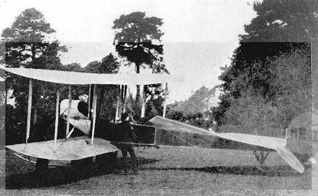
B.E.1
S.E.1
In December, 1910, a crashed Army Bleriot monoplane, known as "The Mankiller", was sent from Larkhill to the Balloon Factory at Farnborough for repair. At that time the funds allocated to the Factory did not extend to the building of new aircraft, and the arrival of the Bleriot presented an excellent opportunity to eager technicians. Authorization for reconstruction was soon forthcoming and was given in January, 1911. The work was carried out under Mervyn O'Gorman, the design being drawn up by Geoffrey de Havilland and F. M. Green, a team which was seen to have no qualms about putting its own ideas into practice when the S.E.1 saw the light of day. The aeroplane which had gone into the Factory as a tractor monoplane reappeared as a single-seat canard pusher biplane. The Bleriot's 60 h.p. E.N.V. "F" engine was used again, but in every other respect the machine was completely different and was the only aeroplane built in the S.E. (Santos Experimental) category.
A long nacelle projected forward of the unstaggered two-bay wings. At its rear the E.N.V. turned a large propeller in cut-outs at the trailing-edges: on the front of the nacelle was mounted a split elevator of fairly generous area. Fixed fins and tailplane were not used, the twin rudders being borne on short booms behind the main-planes. Lateral control was by means of wide-chord ailerons on the upper wings. Cooling of the engine was carried out by radiators mounted on each side of the cockpit. The undercarriage comprised a single pair of wheels whose axle was bound with rubber shock cords across the twin skids, which, in turn, were connected to the fuselage by three pairs of struts. The final member of the landing-gear was the long nose-mounted vertical skid which maintained the machine in a level attitude on the ground.
The S.E.1, however different it may have been in appearance from the Bleriot, inherited its forebear's death-dealing characteristics and crashed on 18th August, 1911, killing Lt. Theodore J. Ridge, the Assistant Superintendent at the Factory.
SPECIFICATION
Description: Single-seat canard pusher biplane. Wooden structure, fabric covered.
Manufacturers: H.M. Balloon Factory, Farnborough, Hants.
Power Plant: 60 h.p. E.N.V. "F"
Dimensions: Span, 38 ft. 6 ins. Length, 29 ft. Height, 11 ft. 6 ins. Wing area, 400 sq. ft.
Weight loaded, 1,200 lb.
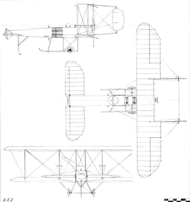
S.E.1
B.E.2, B.E.2a and B.E.2b
The success of the B.E.1 was instrumental in the decision of the Army Aircraft Factory to proceed with further development of the B.E. category. The result was an improved version of the original machine, and was designated B.E.2. Edward Tcshmaker Busk played a great part in the test-flying and subsequent development of the machine at Farnborough upon its completion early in 1912, concentrating his efforts towards making as stable an aircraft as possible.
The prototype B.E.2 received wings of unequal span, a 60 h.p. Renault engine, and was without decking between the tandem cockpits. Subsequent examples differed in detail, but generally were fitted with equal-span 35 ft. 0 1/2 in. wings, a 70 h.p. Renault, and had better passenger protection conferred by inter-cockpit coamings. B.E.2 No. 205 flew experimentally with a 60 h.p. E.N.V. "F" engine.
On 12th August, 1912, Lt. Geoffrey de Havilland took Major F. H. Sykes, Commandant of the Military Wing of the R.F.C., to a record height of 10,560 ft. in 45 mins., carrying a useful load of 450 lb. At the 1912 Military Trials on Salisbury Plain, de Havilland flew the B.E.2 in the various tests to obtain comparative performance figures. The machine could not compete officially for a War Office order as it had been built at the Army Aircraft Factory, but its performance at the Trials established its undoubted superiority compared with its contemporaries. The B.E.2 climbed to 10,000 ft. at 365 ft. min., came fifth in the gliding test with a gliding angle of 1 in 6.25, was sixth in maximum speed at 70 m.p.h. and flew at a minimum of 40 m.p.h. On 13th February, 1913, No. 2 Squadron, R.F.C., started on its move by air from Farnborough to Montrose, Scotland. Two B.E.2s were piloted by Capts. C. A. H. Longcroft and J. H. W. Becke, flying North in company with three Maurice Farmans. Several landings had to be made en route owing to bad weather and engine trouble, the unit finally arriving at the new base on the 26th of the month.
Late in 1912 another modification of the basic B.E.2 design appeared in the form of the B.E.2a. Alterations included wings of equal span, together with the addition of decking behind the 70 h.p. Renault and the installation of a revised fuel system. Among other changes were undercarriage skids ending in hooks at the front, and a version was tested with oleo legs. Flying characteristics with a fixed fin at the tail were investigated, while No. 601 flew with a pair of triangular fins above the centre section of the upper wings, a modified tailplane fitted with a centre bracing post, and a large windscreen for the pilot's rear cockpit. Several subcontractors were called upon during 1912 to supply the B.E.2a to both Military and Naval Wings of the R.F.C.
During 1913 a number of outstanding flights were made with the type. On 19th August, Capt. C. A. H. Longcroft of No. 2 Squadron, R.F.C., flew Col. F. H. Sykes from Farnborough to Montrose in one day. The distance of 287 miles to Alnmouth, at which the only stop was made, constituted a new British non-stop point-to-point record with passenger. On 22nd November, Capt. Longcroft flew 445 miles non-stop from Montrose to Portsmouth in B.E.2a No. 218, and then on to Farnborough to make a total distance covered of 650 miles in 7 hrs. 20 mins. Tanks carrying enough fuel for 8 hrs. flying were fitted, and the Jast performance won for the pilot the Britannia Trophy presented by Horatio Barber for the best flight of the year. On 13th December, Capt. J. M. Salmond flew a B.E.2a from Upavon to a new British solo altitude record of 13,140 ft. Another distinction fell to the B.E.2a at 8.20 a.m. on 13th August, 1914, when No. 347 of No. 2 Squadron, R.F.C., piloted by Lt. H. D. Harvey-Kelly, landed at Amiens, thereby becoming the first British aircraft to land on the Continent during the 1914-18 War.
A further modification of the B.E.2a, designated B.E.2b, was produced during early 1914. This incorporated a redesigned fuselage with greater crew comfort bestowed by deeper cockpit coamings. Rudder and elevators of revised shape were fitted also, and in some cases a plain vee-type under-carriage replaced the skid type. In its final form the B.E.2b was equipped with ailerons instead of the warping control fitted to all previous models of the B.E. series.
Prior to the outbreak of war, the B.E.2 was supplied to Nos. 2, 4, 6 and 7 Squadrons, R.F.C., and to the Eastchurch Squadron of the R.N.A.S.; the B.E.2a to Nos. 2, 3, 4 and 6 Squadrons, R.F.C., and to the Eastchurch Squadron of the R.N.A.S.; and the B.E.2b to Nos. 4 and 6 Squadrons, R.F.C. The type was used also for training at the C.F.S.
SPECIFICATION (B.E.2)
Description: Two-seat tractor biplane. Wooden structure, fabric covered.
Manufacturers: Army Aircraft Factory, Farnborough, Hants. Sub-contracted by Handley Page Ltd., Cricklewood, N.W.2; Hewlett & Blondeau Ltd., Omnia Works, Clapham Junction, S.W.; Vickers Ltd., Knightsbridge, S.W.I.
Power Plant: 70 h.p. Renault, 60 h.p. E.N.V. "F".
Dimensions: Span, 38 ft. 7.5 ins. (later 35 ft. 0.5 in.). Length, 29 ft. 6 5 ins. Wing area, 374 sq. ft. (later 352 sq. ft.).
Weights: Empty, 1,274 lb. Loaded, 1,600 lb.
Performance: Maximum speed, 70 m.p.h. Climb, 360 ft./min. Service ceiling, 10,000 ft. Endurance, 3 hrs.

B.E.2 with undivided cockpits.
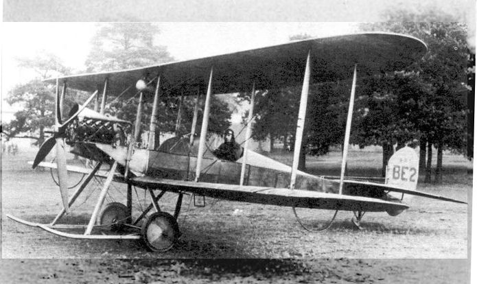
B.E.2 with Geoffrey de Havilland in the cockpit.
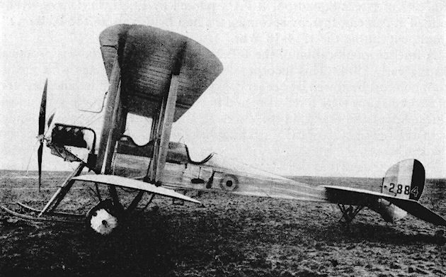
The B.E.2b, the second Royal Aircraft Factory type to be built at Gosforth.

B.E.2a
B.E.3, B.E.4, B.E.5, B.E.6, B.E.7
During 1912 an off-shoot of the B.E.2 series appeared from the Royal Aircraft Factory in the guise of the B.E.3. The machine was the first of several to be built incorporating Gnome rotary engines of varying power, receiving for itself the 50 h.p. version. The B.E.3 was numbered 203, and also had bestowed upon it "The Goldfish" as a nickname.
Two-bay staggered wings were fitted with the fuselage suspended between them. The engine was fully cowled and one large cockpit encompassed the pair of tandem seats. Lateral control was by wing-warping and a fin was dispensed with, directional control being by rudder alone. A single pair of wheels and twin skids, supported by two pairs of struts, formed the undercarriage. The general lines of the aircraft were quite pleasing to the eye. The B.E.3 was flown on the strength of No. 3 Squadron, R.F.C., which likewise received in 1912 the 80 h.p. Gnome B.E.4 No. 204. This was similar in appearance to the B.E.3 except that a four-bladed propeller was fitted instead of the earlier machine's two blader. No. 417 was a second example of the B.E.3/4 design with minor modifications incorporated and dual controls.
The B.E.4 was followed in the same year by the fourteen-cylinder, two- row 140 h.p. Gnome-powered B.E.5 No. 408. Both the B.E.4 and B.E.5 were tested during the summer of 1912 at Farnborough by Geoffrey de Havilland. The 140 h.p. Gnome was fitted to two further examples, the B.E.6 - No. 416 and the B.E.7 - No. 438, which appeared in 1913. The B.E.6 was fitted with a vertical tail reminiscent of that of the H.R.E.2.
The designations B.E.3 to B.E.7 were not at first representative of a class comprising several aeroplanes under each number, but were given separately to the single machine constructed under each one.
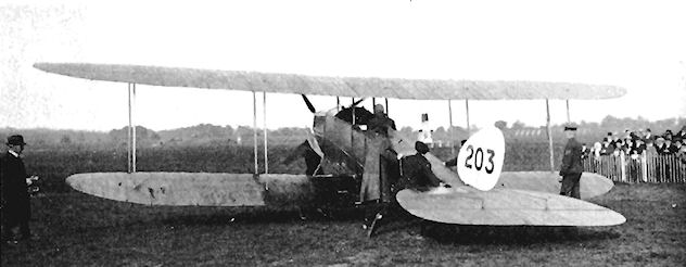
Making the B.E3 ready at Hendon after handover to the RFC for Lt. A.G.Fox's take-off on 21st September, 1913.

Lt. A. G. Fox taking-off at Hendon in the B.E.3 on 21st September, 1913.

RAF B.E.4 No. 204 was structurally identical to the B.E.3.

B E.4 No. 417.
F.E.2 - 1911
Rebuilding of the crashed F.E.1 took place during September, 1911, and a 50 h.p. Gnome was installed in place of the original iris engine. Several other changes were made at the same time, including the discarding of the front elevator - which resulted in a reduction in overall length from 40 ft. to 28 ft. - the fitting of a revised tail unit, an alteration to the wing section and the installation of dual controls in a two-seater nacelle. All-up weight was consequently increased to 1,200 lb., and the rebuilt F.E.1 was redesignated F.E.2.
For the next year the F.E.2 was flown extensively and was used for experimental purposes on several occasions, among them the fitting of a free-firing Maxim machine-gun on a crude mounting in the nose of the nacelle. Tests were conducted also as a seaplane from Fleet Pond, the land undercarriage being replaced by a central float. Span, 33 ft. Length, 28 ft. Wing area, 340 sq. ft. Weight loaded, 1,200 lb. Maximum speed, 47-5 m.p.h.
F.E.2 - 1913
Early in 1913, the F.E.2 went into the workshops again for complete rebuilding as a two-seat gun-carrier, serving as the prototype of the F.E. (Fighting Experimental) series. New outer wings of the same planform as those of the B.E.2a were fitted, resulting in an increase of span to 42 ft. The loaded weight went up by 50%, and the new engine installed was a 70 h.p. Renault. At the same time, the gun in the nose was given an improved mounting. After a further year of life, the F.E.2 was finally written off when it crashed near Wittering on 23rd February, 1914, owing to insufficient fin area being embodied to balance the increase in side area which took place at the nose with the installation of the nacelle. The pilot at the time of the accident was Ronald Kemp, whose passenger. E. T. Haynes, was killed. Span, 42 ft. Length, 30 ft. Wing area. 425 sq. ft. Weight loaded. 1.865 lb. Maximum speed. 67 m.p.h. Climb, 330 ft./min. Ceiling, 5.500 ft.
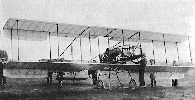
The F.E.2 in its original condition with biplane tail and unbalanced ailerons after reconstruction of F.E.1.
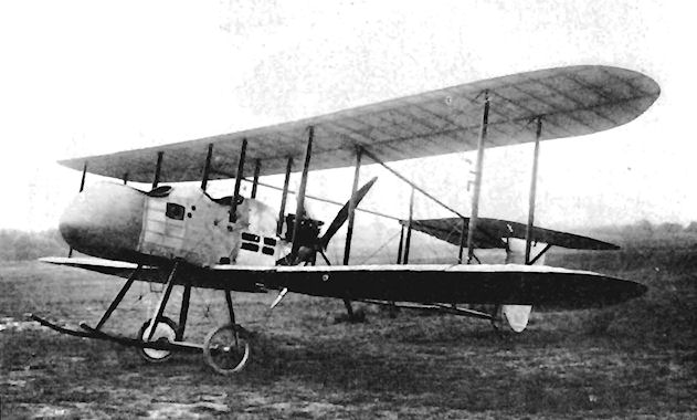
B.E.8
The B.E.8, built in 1912 and equipped with the 80 h.p. Gnome, was the only version of the rotary-engined B.E. series to achieve quantity production. Known as "The Bloater", three prototypes were built at the Royal Aircraft Factory during 1912 and 1913, production being undertaken by sub-contractors British and Colonial Aeroplane Co. and Vickers, six coming from the first-named company. The Factory B.E.8s were without fins and without decking between the seats, innovations which were introduced on the production machines. Warping was employed for lateral control, and the lower wings were fastened to the fuselage direct without a gap.
The B.E.8 was employed at the C.F.S. as a trainer from 1912, and by the lime that war broke out on 4th August, 1914, one was in use with No. 7 Squadron, R.F.C. The final variant of the B.E.8 was the B.E.8a, built by the Coventry Ordnance Works and which, produced as a trainer early in 1915, featured new wings with a span of 37 ft. 8.5 ins. and also utilized ailerons.
SPECIFICATION (B.E.8)
Description: Two-seat tractor biplane. Wooden structure, fabric covered.
Manufacturers: Royal Aircraft Factory, Farnborough, Hants. Sub-contracted by British & Colonial Aeroplane Co., Filton, Bristol; Vickers Ltd., Knightsbridge, S.W.I.
Power Plant: 80 h.p. Gnome.
Dimensions: Span, 39 ft. 6 ins. Length, 27 ft. 3 ins.
Performance: Maximum speed, 70 m.p.h. Climb, 10.5 mins. to 3,000 ft.
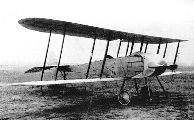
B.E.8
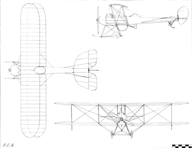
B.E.8
S.E.2/S.E.2a/B.S.1/B.S.2
During 1912 the Royal Aircraft Factory at Farnborough drew up plans of its own conception of a single-seat scouting biplane, the first example anywhere of such a type. Designed by Geoffrey de Havilland, it was designated B.S.I and was built early in 1913. Originally the scheduled power plant was a fourteen-cylinder two-row 140 h.p. Gnome, but when the machine appeared it was fitted with a ten-cylinder two-row 100 h.p. Gnome. The experience gained by the Factory with the B.E.I and the S.E.I was used to produce a single-bay staggered biplane of advanced aerodynamic practice and with a fine, streamlined appearance.
The fuselage consisted of a circular wooden monocoque shell into which the engine was faired with a close-fitting cowling. External bracing was by streamlined Raf-wires. No fin was fitted, the tail unit being similar in shape to that used on the B.E.3; the elevator was in one piece.
The B.S.I was tested by Lt. de Havilland in March, 1913, and crashed after a fast, measured-course run at 91.4 m.p.h., the pilot sustaining a broken jaw. A speed range of 51-92 m.p.h. had been established during the tests. The cause of the crash was attributed to incorrect balance of side areas, an aspect of design about which comparatively little was known at the time, the machine going into a slow flat spin.
<...>
SPECIFICATION
Description: Single-seat tractor biplane scout. Wooden structure, fabric covered.
Manufacturers: Royal Aircraft Factory, Farnborough, Hants.
Power Plant: 100 h.p. Gnome.
Dimensions: Span, 27 ft. 6 ins. Length, 22 ft.
Weights: Loaded, 1,232 lb.
Performance: Maximum speed, 92 m.p.h. Landing speed, 51 m.p.h. Climb, 900 ft./min. Endurance, 3 hrs.
F.E.3/A.E.1
The F.E.3, known also as the A.E.1, was an experimental two-seat pusher gun-carrier built by the Royal Aircraft Factory in 1913. The propeller revolved around the single metal tubular boom which was intended later to be the sole support for the tail unit. The 80 h.p. Chenu engine was cooled through the circular opening in the nose of the nacelle. The F.E.3 was used for armament trials during the summer of 1913, equipped with the 1 1/2- pounder C.O.W. gun which fired through the nose opening. Span, 48 ft. Length, 33 ft. Wing area. 480 sq. ft. Weight loaded. 2,100 lb. Maximum speed, 75 m.p.h. Climb, 350 ft./min. Ceiling, 5,000 ft.
The F.E.3, known also as the A.E.1, was an experimental two-seat pusher gun-carrier built by the Royal Aircraft Factory in 1913. The propeller revolved around the single metal tubular boom which was intended later to be the sole support for the tail unit. The 80 h.p. Chenu engine was cooled through the circular opening in the nose of the nacelle. The F.E.3 was used for armament trials during the summer of 1913, equipped with the 1 1/2- pounder C.O.W. gun which fired through the nose opening. Span, 48 ft. Length, 33 ft. Wing area. 480 sq. ft. Weight loaded. 2,100 lb. Maximum speed, 75 m.p.h. Climb, 350 ft./min. Ceiling, 5,000 ft.
R.E.1
A two-seat tractor biplane built in 1913 by the Royal Aircraft Factory as an improvement of the B.E. design for reconnaissance use, the R.E.1 provided an early example of the use of models and mathematical calculations to ensure stability, an inherent quality of the design to which a great deal was contributed by E. T. Busk's test flying.
Both of the R.E.1s built had warping wings, but No. 608 had a longer fuselage than No. 607. No. 607 was subsequently revised with wings of reduced stagger, with ailerons instead of warping and with a smaller fin. No. 608 had its fin removed and was fitted with a larger balanced rudder. It was flown for a time with four small vertical fins installed above the upper wings. Both fuselages were of welded steel tubing, unusual at a time when wooden structures were favoured. The R.E.1 design was very stable, recovering automatically from dives and banks. No. 2 Squadron, R.F.C., used one R.E.1 on the Western Front during the 1914-18 War. A 70 h.p. Renault engine was fitted, and wing-warping was employed in the design. Maximum speed, 78 m.p.h. Climb, 600 ft./min.
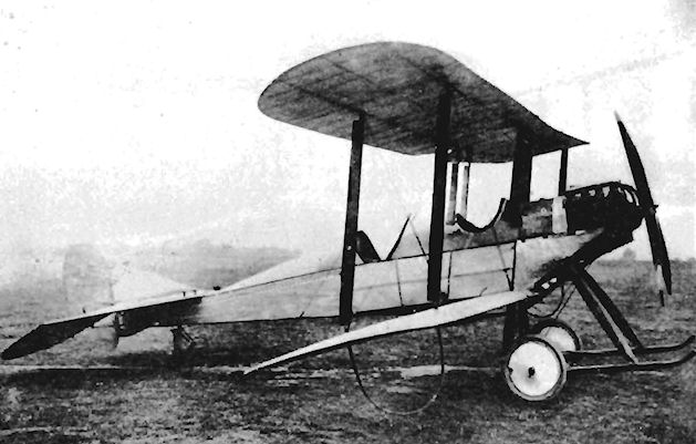
R.E. I No. 607 in its original form.
R.E.2/H.R.E.2
The R.E.2 was designed and built by the Royal Aircraft Factory to a specification of the Air Department of the Admiralty which called for a two-seat reconnaissance hydro-biplane to be used by the Naval Wing of the R.F.C. The R.E.2 was first flown on 1st July, 1913, as a landplane with a 70 h.p. Renault engine, warping wings, one-piece tailplane and elevators, and was without a fin, the rudder resembling that of the B.E.3.
For tests as the H.R.E.2 on floats, the engine was changed for a 100 h.p. Renault, and a triangular fin and a taller rudder were fitted. The coaming in front of the rear cockpit was extended also for extra protection. Trials on Fleet Pond were unsuccessful, as the H.R.E.2 turned over and wrecked its floats. It reverted to the R.E.2 landplane and was given new wings, complete with ailerons. The 100 h.p. Renault was retained, and the machine was used in August, 1914, by the R.N.A.S. as No. 17. Span, 45 ft. 3-5 ins. Length, 32 ft. 3 ins. Height, 12 ft. 2 ins.
R.E.3
The R.E.3 was built at the Royal Aircraft Factory during 1914 as a two-seat tractor reconnaissance biplane. One only was built, with the same design of airframe as that of the R.E.2, using the R.E.2's final form of vertical tail surfaces. Greater power was provided by the 120 h.p. Austro-Daimler fitted. Span, 45 ft. 3.5 ins.
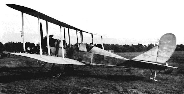
R.E.2 No. 17 after reversion to landplane from H.R.E.2.
S.E.2/S.E.2a/B.S.1/B.S.2
<...>
The lack of sufficient rear vertical area was rectified when the machine was rebuilt, and small fins were mounted above and below the fuselage, together with a new larger rudder and divided elevators. A lower-powered nine-cylinder 80 h.p. Gnome took the place of the original engine, and the propeller was replaced by one of smaller diameter and finer pitch. For a short time the rebuilt B.S.1 was designated the B.S.2. It was then renamed S.E.2, the S.E. signifying Scouting Experimental in place of the earlier Santos Experimental. The S.E.2, known also as "The Bullet", was a better flying machine, but the lower power naturally resulted in a reduced performance, the top speed falling to 85 m.p.h.
Later in 1913 the S.E.2 was taken into the workshops to be modified once again. In its final form as the S.E.2a, a new rear fuselage of fabric-covered stringer type was incorporated in place of the monocoque. Once more the fin and rudder were increased in size, but the original wings with their warping lateral control were retained, together with the two-wheel undercarriage and its pair of skids.
In January, 1914, the S.E.2a, as No. 609, was taken on to the strength of No. 5 Squadron, R.F.C. During the following October it was sent to France to be used operationally by No. 3 Squadron, R.F.C., on the Western Front, its armament consisting of the pilot's .45 cal. revolver and a rifle mounted on each side of the fuselage to clear the propeller. In March, 1915, the S.E.2a's employment against the enemy came to an end with its return to England. A further modification of the design to be known as the S.E.3 was not proceeded with.
SPECIFICATION
Description: Single-seat tractor biplane scout. Wooden structure, fabric covered.
Manufacturers: Royal Aircraft Factory, Farnborough, Hants.
Power Plant: 80 h.p. Gnome.
Dimensions: Span, 27 ft. 6 ins. Length, 22 ft.
Weights: Loaded, 1,232 lb.
Performance: Maximum speed, 85 m.p.h. Landing speed, 47 m.p.h. Climb, 700 ft./ min.
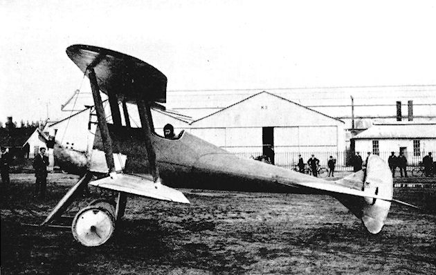
The S.E.2 on the edge of Farnborough Common, with Geoffrey de Havilland in the cockpit.
B.E.2c
The B.E.2c represented the culmination of E. T. Busk's two years of practical experimenting devoted to developing the machine into a stable aeroplane, as a result of which it was ordered in quantity for the R.F.C. and the R.N. A.S. At the time of its appearance in June, 1914, the B.E.2c's role in war was envisaged as that of reconnaissance, and the decision to order it in numbers appeared to be justified. In the event, however, its lack of manoeuvrability which went with such an exceptionally highly-developed stability brought about its downfall in the skies of battle, where it was, perforce, pressed into carrying out duties for which it was not designed.
The B.E.2c was a direct development of the B.E.2b, but several distinctive changes had been made. Most prominent among these were the adoption of staggered wings, the addition of a triangular tail fin, a revised tailplane of rectangular shape and new wing-tips. At first, the 70 h.p. Renault was given lengthy exhaust pipes which extended along the lower fuselage, but these were shortened in later versions.
In June, 1914, the prototype was flown from Farnborough to Netheravon by Major Sefton Brancker, who left his starting-point at 2,000 ft. and arrived over his destination at 20 ft. without using the controls, his hands being occupied with writing a reconnaissance report during the flight. When war broke out on 4th August, 1914, this machine was the only B.E.2c flying. The sub-contractors asked to produce the design found, on examination of the plans, that the structure was a comparatively complicated one and was not simple to build. Three months after war was declared, Edward Busk, the person who had done most to develop the machine into a successful flyer, was killed when his B.E.2c crashed on 5th November on Laffan's Plain.
SPECIFICATION
Description: Two-seat tractor biplane. Wooden structure, fabric covered.
Manufacturers: Royal Aircraft Factory, Farnborough, Hants.
Power Plant: 70 h.p. Renault.
Dimensions: Span, 37 ft. Length, 27 ft. 3 ins. Height, 11 ft. 15 ins. Wing area, 371 sq. ft.
Weights: Empty, 1,370 lb. Loaded, 2,142 lb.
Performance: Maximum speed, 75 m.p.h. Service ceiling, 10,000 ft. Endurance, 3.25 hrs.
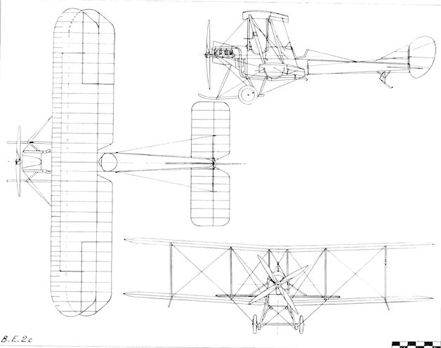
B.E.2c
R.E.5
The R.E.5 first appeared early in 1914 and was a two-seat tractor reconnaissance biplane designed and built by the Royal Aircraft Factory. In appearance it was a larger version of the R.E.1, being larger and heavier. Two-bay wings of equal span were fitted, and ailerons gave lateral control to a very stable design. Long range was a feature of the R.E.5, which was equipped to carry a bomb load of 500 lb. and W/T. At the end of March. 1914, a special high-altitude, single-seat version, No. 380, with upper-wing strut-braced extensions and a two-bladed propeller made its appearance, and was taken to 17,000 ft. in the following June by Capt. J. H. W. Becke. Norman Spratt reached 18,900 ft. in one, and the R.E.5 went into production as the first of the Factory designs to be produced in quantity.
An initial batch of twenty was built at Farnborough from ?25,000 allocated to the War Office from Admiralty funds made available when the Navy took over the development of airships from the Army at the beginning of 1914. Two or three of the first batch were in use with the R. F.C. at the outbreak of war. Some of the early R.E.5s were fitted with original Austro-Daimler engines of 120 h.p., later examples receiving Beardmore-built versions. The machine was used by R.F.C. Squadrons Nos. 2, 6, 7, 12 and 16, and one found its way to the R.N.A.S. An experimental R.E.5 was tested with air-brakes. Maximum speed, 78 m.p.h.

R.E.5 with 120 h.p. Austro-Daimler.
S.E.4
Following the S.E.2, the S.E.4 was the Royal Aircraft Factory's next essay in Scouting Experimental. The machine was designed by H. P. Folland, whose ideas were to influence the shapes of British fighters for so many years afterwards. The new scout was completed in June, 1914, and was even cleaner in concept than its predecessor. The S.E.4 represented the most advanced aerodynamic thought at the time of its appearance, and the care taken over reduction of drag, coupled with the power from its fourteen-cylinder two-row 160 h.p. Gnome, gave a top speed of 135 m.p.h., making it the world's fastest aircraft in its day.
Among unusual features were the four wings' full-span ailerons, which could be depressed to act as landing flaps. The fuselage consisted of a circular wooden monocoque, and the engine was fully enclosed in a tight-fitting cowling. Inadequate cooling resulted in scorching of the metal panels and the consequent adoption of a cooling slot and a fan inside the spinner. The original undercarriage was in the form of an inverted triangular pyramid of struts which carried a transverse leaf-spring axle for the wheels. This arrangement led, not surprisingly, to uncontrollable rolling while taxying, and was soon replaced by the more usual pair of vee struts. Another alteration was the discarding of the moulded celluloid cockpit canopy fitted originally, as no pilot would agree to fly beneath it.
A high-speed section was used for the wings which were connected by single "I" interplane struts and braced with streamlined Raf-wires.
The S.E.4 was given the number 628, and among its pilots were Lt. Norman Spratt and Major J. M. Salmond, who found the aircraft's speed and climb very good. The 160 h.p. Gnome proved a troublesome and unpopular engine, bringing about the premature end of its production. That installed in the S.E.4 was removed and its place was taken by a 100 h.p. Monosoupape Gnome, the top speed thereby being reduced to 92 m.p.h. After some further flying, damage in a landing accident resulted in the abandonment of the development of the S.E.4.
SPECIFICATION
Description: Single-seat tractor biplane scout. Wooden structure, fabric covered.
Manufacturers: Royal Aircraft Factory, Farnborough, Hants.
Power Plant: 160 h.p. Gnome, 100 h.p. Monosoupape Gnome.
Dimensions: Span, 27 ft. 6 ins. Length, 21 ft. 4 ins. Height (tripod u/c) 9 ft.; (vee u/c) 9 ft. 10-5 ins. Wing area, 188 sq. ft.
Performance: Maximum speed (160 h.p. Gnome) 135 m.p.h.; (100 h.p. Monosoupape Gnome) 92 m.p.h. Landing speed, 52 m.p.h. Climb (160 h.p. Gnome) 1,600 ft./min. Endurance, 1 hr.
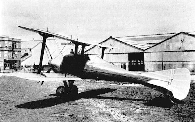
The S.E.4 with its original tripod undercarriage outside the Factory compound.
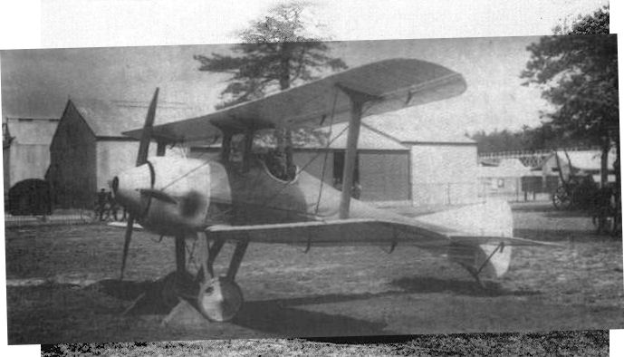
The S.E.4 with its later vee undercarriage.
Ridley Glider
A simple Chanute-type biplane glider was built early in 1910 by Cyril Ridley of Thames Ditton, Surrey, while a pupil at Arundel House School. The school founded an Aero Club in 1908, and its members included Reginald Mann and Robert Grimmer, who afterwards collaborated in the design and construction of the Mann and Grimmer M.1 Biplane of 1915. Cyril Ridley made a number of satisfactory gliding flights in Sandown Park, and his success encouraged others to emulate him. Span, 18 ft. Length, 14 ft. Wing area, 165 sq. ft.
A simple Chanute-type biplane glider was built early in 1910 by Cyril Ridley of Thames Ditton, Surrey, while a pupil at Arundel House School. The school founded an Aero Club in 1908, and its members included Reginald Mann and Robert Grimmer, who afterwards collaborated in the design and construction of the Mann and Grimmer M.1 Biplane of 1915. Cyril Ridley made a number of satisfactory gliding flights in Sandown Park, and his success encouraged others to emulate him. Span, 18 ft. Length, 14 ft. Wing area, 165 sq. ft.
Ryley Glider
L. G. Ryley built himself a canard biplane glider with which he made a number of short hops during the autumn of 1914.
L. G. Ryley built himself a canard biplane glider with which he made a number of short hops during the autumn of 1914.
Sanders Biplane No. 1
The Sanders Type 1 was a single-seat canard pusher biplane which was designed during 1909 by Capt. Haydn A. Sanders of the London Aeroplane and Aerial Navigation Company of Croydon, Surrey. The company was formed to promote the design, and the machine was constructed at Benacre Down, Kessingland, Suffolk, with the help of the designer's brother Kempton and F. L. Rawson. The engine, a marine type, was a four-cylinder 30 h.p. Brooke, which drove two 8 ft. 6 ins. diameter propellers by long chains. The wings were of equal span and had down-curved tips. Fixed horizontal and vertical stabilizing surfaces were carried at the front, control surfaces consisting of elevators mounted on both upper and lower wings across the trailing-edges at the centre-section, together with a single rudder at the rear and ailerons between the wings.
The first flight of the Type 1 was made during October, 1909, and the machine continued to develop successfully with the assistance of the makers of the engine until, at 8 a.m. on Sunday, 13th February, 1910, in the course of a flight over Benacre Down it struck a coastguard telephone pole and crashed, a total wreck. Reconstruction took place as the Type 2 with major modifications.
Sanders Biplane No. 2
After its crash on 13th February, 1910, at Benacre Down, Suffolk, the Sanders Type 1 was removed to Beccles, where it was rebuilt, being drastically altered at the same time.
Strength was a prime consideration, and the machine was constructed of steel tubing and wood; special attention was paid to the safety of the pilot. The curved tips were retained on the upper wings, while the lower pair were shorter in span than the upper set. The fuselage framework was uncovered and incorporated the tricycle landing-gear, the rear wheels of which were retracted upwards into the fuselage by a trip device once the machine was airborne. Landing was effected on the skids alone to give a quick stop, as on the Short No. 3. A motor-car type of steering wheel on a universal joint operated the biplane fore-elevator, the ailerons, which were carried on the outer rear interplane struts, and the three slim rudders at the rear. Engine power was increased by fitting a 50 h.p. Alvaston in place of the Brooke. Further testing of the machine was done for the rest of 1910 until it was modified once again.
In its final form the Sanders Biplane was redesignated Type 2 and appeared at the 1911 Olympia Aero Show. Yet another change of engine had been made with the installation of an eight-cylinder 60 h.p. E.N.V. "F". The twin propellers had been abandoned and a single 9 ft. diameter Sanders-built flywheel-driven propeller was fitted. To provide sufficient clearance for it, the rear tail booms were moved outwards at their fixing points on the trailing-edges of the wings, which themselves were hinged to fold forward for storage.
SPECIFICATION
Description: Single-seat canard pusher biplane. Steel-tubing and wooden structure, fabric covered.
Manufacturers: Sanders Aeroplane Co., The Common, Beccles, Suffolk, and London Aeroplane and Aerial Navigation Co., 23 Blenheim Park Road, Croydon, Surrey.
Power Plant: 50 h.p. Alvaston, 60 h.p. E.N.V. "F".
Dimensions: Span, 40 ft. Length, 31 ft. 6 ins. Wing area, 444 sq. ft.
Weights: Empty, 1,100 lb.
Price: ?1,000.
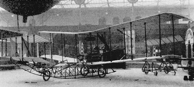
Sanders Biplane 2
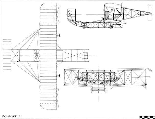
Sanders 1
Saul Quadruplane No. 1
The Saul Quadruplane No. 1 was designed by G. P. Deverall Saul and was built during 1909 by Handley Page Ltd., of 36 William Street, Woolwich, London, S.E. The machine was a single-seater, driven by a two-bladed pusher propeller of 4 ft. diameter which was fitted to an air-cooled engine of 8-12 h.p. The four wings, of 20 ft. span and 3 ft. chord, were arranged to fold.
The Quadruplane was shown at a meeting held at Dagenham in 1909 and was tested by Frederick Handley Page, when it lifted several times from its trolley. Later, it performed quite well when flown as a kite. Wing area. 240 sq. ft. Weight empty, 160 lb. Maximum speed, 30 m.p.h. Price, ?250.
Saul Quadruplane No. 2
The Quadruplane No. 2 was a two-seat version of the No. 1 and was designed during 1909. It was a pusher also, power being provided by an engine of 20-25 h.p. Price, ?550.
Saunderson Monoplane
The Saunderson Monoplane was built by H. P. Saunderson of Elstow, Beds. It was a single-seat tractor, powered by a Saunderson three-cylinder engine, and appeared at the 1909 Blackpool Flying Meeting.
The Saunderson Monoplane was built by H. P. Saunderson of Elstow, Beds. It was a single-seat tractor, powered by a Saunderson three-cylinder engine, and appeared at the 1909 Blackpool Flying Meeting.
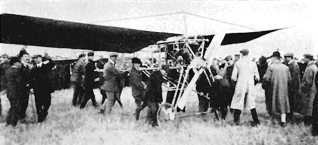
Scottish Aviation Company Caledonia
The single-seat Caledonia Monoplane was built during 1911 by the Scottish Aviation Co., 185 Hope Street, Glasgow, and was designed by F. Norman. A 35 h.p. J.A.P. engine was mounted in the nose of the triangular-section fuselage, and the undercarriage consisted of four wheels abreast together with a pair of skids. The machine was flying in November. 1911, piloted by R. W. Philpott, at Barrhead flying-school.
The single-seat Caledonia Monoplane was built during 1911 by the Scottish Aviation Co., 185 Hope Street, Glasgow, and was designed by F. Norman. A 35 h.p. J.A.P. engine was mounted in the nose of the triangular-section fuselage, and the undercarriage consisted of four wheels abreast together with a pair of skids. The machine was flying in November. 1911, piloted by R. W. Philpott, at Barrhead flying-school.
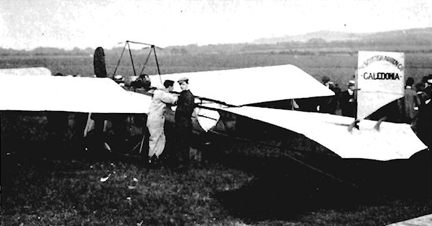
Scottish Aviation Co. Caledonia monoplane flown at Barrhead near Glasgow in 1911.
Scottish Aviation Company Dart
The single-seat Dart was constructed late in 1911 by the Scottish Aviation Co., of 185 Hope Street, Glasgow, and was an adaptation of the Bleriot XI monoplane having an extensively revised undercarriage. An eight-cylinder 35 h.p. J.A.P. engine provided the power.
The single-seat Dart was constructed late in 1911 by the Scottish Aviation Co., of 185 Hope Street, Glasgow, and was an adaptation of the Bleriot XI monoplane having an extensively revised undercarriage. An eight-cylinder 35 h.p. J.A.P. engine provided the power.
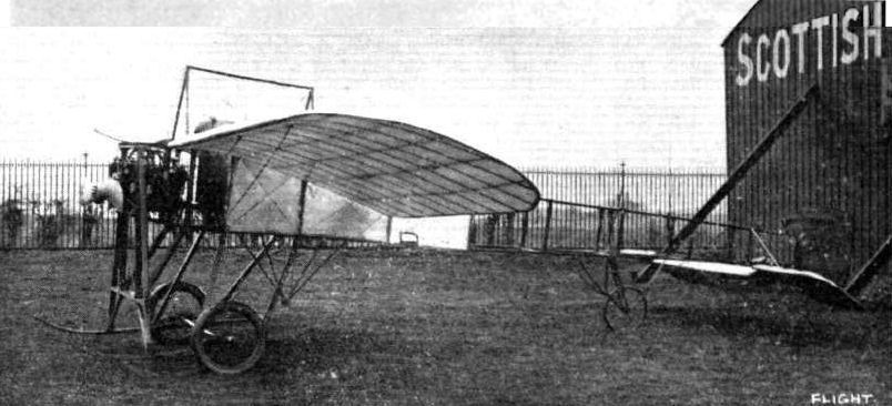
Bleriot type Caledonia monoplane at the Scottish Aviation Co.'s Barrhead flying grounds.
Seddon Biplane
The Seddon Biplane, nicknamed "Mayfly", was a design by Lt. J. W. Seddon, R.N., and A. G. Hackett, built by Accles and Pollock at Oldbury, Worcs., in 1910. A six-seat tandem biplane, it was a fantastic structure of 2,000 ft. of steel tubing arranged as intersecting hoops or geodetics, and was powered by two 65 h.p. N.E.C. engines which drove a pair of Beedle tractor propellers. Frontal biplane elevators conferred longitudinal control, a pair of rudders being mounted between both fore and aft sets of wings.
The machine, at that time the world's largest aeroplane, was tested late in 1910 at the Dunstall Park Wolverhampton, flying-ground of the Midland Aero Club, but was not a success and was broken up without flying. Wing area, 1,000 sq. ft. Weight empty, about 2,600 lb.
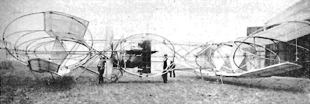
Seddon tandem biplane with a structure of tubular rings at Wolverhampton in 1910. The machine was too heavy and did not fly.
Short No. 1
The Short No. 1 was built to the order of F. K. McClean, construction being started at Battersea in January, 1909. ]t was shown in an incomplete state at the 1909 Olympia Aero Show and was finally finished at the Short Leysdown, Isle of Sheppey, works during the summer of the same year. The original power plant was the Nordenfeld engine from McClean's car. This was unsuccessful, and the machine finally flew with a 60 h.p. Green, but is believed to have left the ground prior to this with a Bariquand and Marre engine. Twin rudders were fitted on rear extensions between the wing-tips on each side, elevator control being by means of biplane surfaces in front. Span, 41 ft.
The Short No. 1 was built to the order of F. K. McClean, construction being started at Battersea in January, 1909. ]t was shown in an incomplete state at the 1909 Olympia Aero Show and was finally finished at the Short Leysdown, Isle of Sheppey, works during the summer of the same year. The original power plant was the Nordenfeld engine from McClean's car. This was unsuccessful, and the machine finally flew with a 60 h.p. Green, but is believed to have left the ground prior to this with a Bariquand and Marre engine. Twin rudders were fitted on rear extensions between the wing-tips on each side, elevator control being by means of biplane surfaces in front. Span, 41 ft.

Short No. 2
Built during August, 1909, for J. T. C. Moore-Brabazon, the Short No. 2 was used by him to win the Daily Mail ?1,000 prize for the first all-British circular flight of 1 mile on 30th October, 1909, at Shellbeach, Isle of Sheppey. When first flown in September the machine was fitted with a 30 h.p. Vivinus engine, but this was replaced with a 60 h.p. Green for the attempt on the prize. In 1910 a single propeller was substituted for the original pair, which were driven by chains. Span, 35 ft. 2 ins. Wing area, 450 sq. ft. Maximum speed, 45 m.p.h. Price, ?1,500.
Short No. 3
Following the successful performance of J. T. C. Moore-Brabazon's Short No. 2, a modified and improved version was ordered by the Hon. C. S. Rolls. The new pusher was ready for display at the 1910 Olympia Aero Show and, to the Short brothers' gratification, five were ordered before the exhibition was opened.
The No. 3 was still on original Wright brothers' lines, but differed in several important respects, incorporating alterations dictated by the operating experience of the previous year at Shellbeach and Eastchurch. Although smaller and lighter than its predecessors, the No. 3 was very strongly built. To enable it to take-off without the aid of a starting rail, retractable wheels were fitted, one of the earliest examples of such a device. On being tripped by the pilot they were withdrawn above the lower skid level by springs, the machine landing on the skids. The two chain-driven propellers used on previous Shorts were superseded by a single Short-built propeller of 7 ft. 6 ins. diameter, driven by a 35 h.p. Green engine. Control was effected by biplane elevators in front, with the rudder immediately behind them. A fin and tailplane were carried some distance aft of the wings, and balancers acting as ailerons were mounted on each side between the upper and lower wing-tips.
SPECIFICATION
Description: Single-seat pusher biplane. Wooden structure, fabric covered.
Manufacturers: Short Brothers, Eastchurch, Isle of Sheppey, Kent. Power Plant: 35 h.p. Green.
Dimensions: Span, 31 ft. 8 ins. Span (including balancers), 35 ft. 2 ins. Length, 31 ft. Wing area, 282 sq. ft.
Weights: Empty, 657 lb. Loaded, 857 lb.
Price: ?650.

Short No. 2 with enlarged empennage (inscribed ‘J. T. C. Moore-Brabazon No. 5’) at Eastchurch early in 1910.
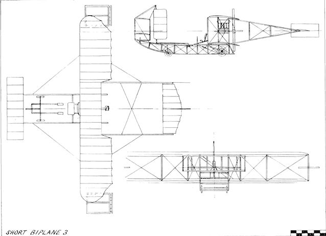
Short Biplane 3
Short-Wright Glider
After Eustace Short witnessed Wilbur Wright flying at Le Mans in 1908 he decided that the most promising future of aeronautics lay in the heavier-than-air sphere. He and his brother Oswald were engineers and balloon makers to the Aero Club, and they prevailed upon the third brother, Horace, to relinquish his work on experimental steam turbines with the Hon. C. A. Parsons in Newcastle and to join them at Battersea. Their first product was a glider version of the Wright Biplane, completed in 1908 and tested successfully by Alec Ogilvie and by Hon. C. S. Rolls, who is shown flying the machine.
After Eustace Short witnessed Wilbur Wright flying at Le Mans in 1908 he decided that the most promising future of aeronautics lay in the heavier-than-air sphere. He and his brother Oswald were engineers and balloon makers to the Aero Club, and they prevailed upon the third brother, Horace, to relinquish his work on experimental steam turbines with the Hon. C. A. Parsons in Newcastle and to join them at Battersea. Their first product was a glider version of the Wright Biplane, completed in 1908 and tested successfully by Alec Ogilvie and by Hon. C. S. Rolls, who is shown flying the machine.
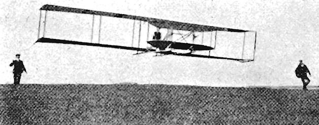
Short-Wright Biplane
In 1909 Short Brothers started to build the Short No. 1, their first powered aeroplane, at Battersea. However, while it was under construction, an order was received for six Wright Biplanes to be produced under licence at a cost of ?8,400. Their No. 1 was put aside for the time being, and work proceeded on the Wright machines, enabling the firm to claim to be "The First Manufacturers of Aircraft in the World". The contract called for a French-built Wright engine, the 30 h.p. Leon Bollee, to be fitted. This engine was not forthcoming, and its place was taken alternatively by the 40 h.p. E.N.V. "D", 60 h.p. Green and 40 h.p. N.E.C.
The Short-Wright proved very successful, the first going to the Hon. C. S. Rolls, with others being sold to F. K. McClean, the Hon. Maurice Egerton, Cecil Grace and Alec Ogilvie. Early in November, 1910, Rolls covered 1.5 miles in his machine, and on another occasion flew 15 miles across-country to Eastchurch after repairs had been made at Short Brothers' Leysdown works. On 2nd June, 1910, Rolls flew his Short Wright across the English Channel from England to France and returned without landing, thereby becoming the first to do so in each case and also the first British pilot to make the crossing. On 12th July, 1910, he was killed at Bournemouth while flying the same aeroplane, and his second machine of the same type, fitted with an N.E.C. engine, was bought by Alec Ogilvie, who flew it from Camber Sands at Rye in Sussex, making many good flights, including one of 139-75 miles in 3 hrs. 55 mins., in 1910. Span, 41 ft. Length, 29 ft. Wing area, 515 sq. ft. Weight empty, 885 lb. Maximum speed, 50 m.p.h.
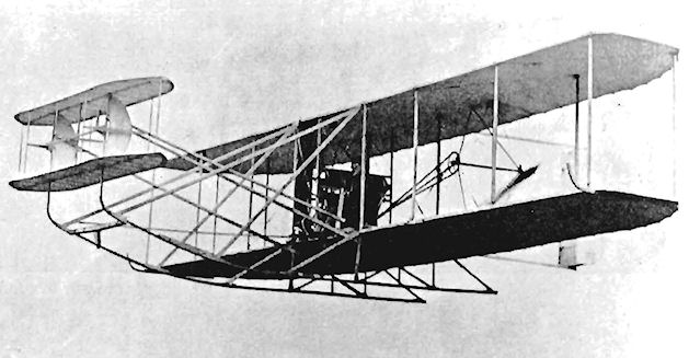
Hon. C. S. Rolls making a cross-country flight from Shellbeach to Eastchurch on 21st December, 1909, with the first Short-Wright Biplane.
Short S.27
The completion at Eastchurch of the S.27 for Cecil S. Grace in May, 1910, was an abrupt breakaway from previous Short Wright-type biplanes, and conformed to the successful Farman-style boxkite then proving popular. Several were built and were powered by the 40 h.p. "D" and 60 h.p. "F" E.N.V. engines, various modifications being made as experience was gained with the type.
Grace quickly became proficient on his S.27, and flew it at the Wolverhampton Aviation Meeting held from 27th June until 2nd July, 1910, at Dunstall Park by the Midland Aero Club. Six months later, he disappeared while flying the English Channel on 22nd December, using the 60 h.p. E.N.V. version of the same machine. The endurance of the S.27 was good, seven hours being attained on twenty gallons of petrol.
The type proved itself to be a useful and practical flying machine and, as the modified S.27, it was altered in succeeding versions, upper wing-tip extensions bringing the span to 46 ft. Other variants of the basic design were built, the engine being changed to the 50 h.p. Gnome. The occupants were protected by being seated in a nacelle instead of being exposed in the open as hitherto.
The modified S.27 to achieve greatest fame was No. 38 of the Admiralty. This was fitted with three air-filled torpedo-shaped flotation bags attached to the undercarriage and the tail, and on 1st December, 1911, was flown by Lt. A. M. Longmore, R.N., from Eastchurch and landed on the River Med way. It afterwards flew back to Eastchurch. Just over a month later, on 10th January, 1912, Lt. C. R. Samson, R.N., performed the feat of taking-off in the same machine from a staging built over the forepart of H.M.S. Africa, the ship remaining at anchor in Sheerness Harbour. Lt. Samson used No. 38 to do the same from H.M.S. Hibernia on 9th May, 1912, at the Naval Review at Weymouth while the ship was steaming at 15 knots. The long-suffering machine was modified once again during 1912 to take the 70 h.p. Gnome, and the wing span was increased to 52 ft. A covered-in nacelle was installed, the aeroplane becoming one of the first to be fitted with wireless. Armament experiments were carried out, also, by fitting a gun for the observer's use. By the time that all of the alterations had been incorporated, in October, 1912, the modified S.27 No. 38 had become virtually the prototype for the S.38/T.2.
Two S.27s belonging to F. K. McClean were used at Eastchurch for training the first naval pilots, Lts. R. Gregory, A. M. Longmore and C. R. Samson, R.N., and Lt. E. L. Gerrard, R.M.L.I. Under G. B. Cockburn for flying tuition and Horace Short for technical instruction, they started their course on 2nd March, 1911, and received their Royal Aero Club Aviators' Certificates after a few weeks. Samson and Longmore were awarded Nos. 71 and 72 respectively on 25th April, and Gregory and Gerrard Nos. 75 and 76 respectively on 2nd May. Six months later, in October. 1911, the Admiralty bought the S.27s from McClean and set up at Eastchurch what was to become the well-known naval flying-school. During 1912 the S.27 type was given the naval designation T.1.
On 10th August, 1912, McClean created a sensation when he flew his S.27 up the River Thames, passing between the spans of Tower Bridge and under the rest of the bridges to Westminster.
SPECIFICATION
Description: Two-seat pusher training biplane. Wooden structure, fabric covered.
Manufacturers: Short Brothers, Eastchurch, Isle of Sheppey, Kent.
Power Plant: 40 h.p. E.N.V. "D", 60 h.p. E.N.V. "F", 50 h.p. Gnome, 70 h.p. Gnome.
Dimensions:
(S.27) Span, 34 ft. 2 ins. Length, 40 ft. 6 ins.
(Mod. S.27) Span, 46 ft. 5 ins. Length, 42 ft. 1 in. Wing area, 517 sq. ft.
Weights: (Mod. S.27) Empty, 1,100 lb., with 50 h.p. Gnome; 1,150 lb., with 70 h.p. Gnome.
Performance: (Mod. S.27) Maximum speed, 39 m.p.h., with 50 h.p. Gnome; 48 m.p.h., with 70 h.p. Gnome. Endurance, 4 hrs., with 50 h.p. Gnome; 5 hrs., with 70 h.p. Gnome.
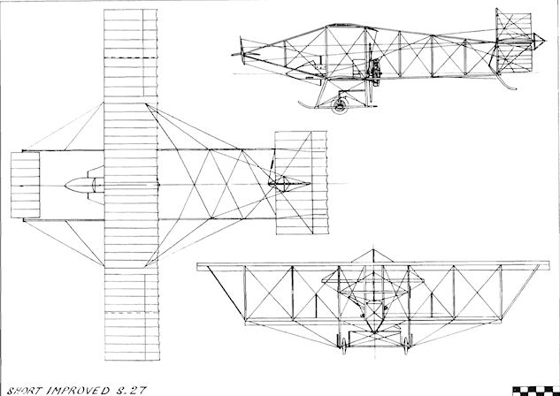
Short Improved S.27
Short Tandem Twin
The Tandem Twin of 1911 was known colloquially as the "Vacuum Cleaner", owing to the draught created by its pair of 50 h.p. Gnomes, or the "Gnome Sandwich", because the side-by-side pilot and passenger were seated between the engines. The tractor-pusher machine was Short No. 17 and was built for F. K. McClean, who gave it his private number 11. The Tandem Twin and Triple Twin were the outcome of Horace Short's belief in obtaining plenty of power for his aeroplanes by employing more than one engine. In essence, they were direct developments of the S.27 design and were the first multi-engined machines built in Great Britain and probably the first in the world. The Tandem Twin was bought daring late 1911 by the Admiralty and was used for training naval pilots at the Eastchurch flying-school under its Admiralty number 27. Span, 50 ft. Length, 45 ft. Wing area, 500 sq. ft. Weight loaded, 2,100 lb. Maximum speed, 55 m.p.h.
Short T.3 Triple Twin
Together with the Tandem Twin, the Triple Twin was one of Horace Short's experiments in multi-engined aeroplanes. It was built during mid-1911 for F. K. McClean, who tested it at Eastchurch in September of the year. In the case of the Triple Twin, the front 50 h.p. Gnome engine drove two tractor propellers by means of long chains, while the rear 50 h.p. Gnome acted as a single pusher. All three propellers were of 8 ft. 6 ins. diameter. The machine seated two. In its original form the wings had an equal span of 34 ft. They were soon increased by extensions to an upper span of 50 ft., resulting at the same time in an increase in area from 435 to 500 sq. ft. At the end of 1911 the Triple Twin was used for the training of naval pilots at Eastchurch, and was later given the designation T.3.
SPECIFICATION
Description: Two-seat tractor-pusher biplane. Wooden structure, fabric covered.
Manufacturers: Short Brothers, Eastchurch, Isle of Sheppey, Kent.
Power Plant: Two 50 h.p. Gnomes.
Dimensions: Span, 34 ft. (later 50 ft.). Length, 45 ft. Wing area, 435 sq. ft. (later 500 sq. ft.).
Performance: Maximum speed, 55 m.p.h.
Short Tractor-pusher Monoplane
The second Short monoplane was constructed during 1912 and was nicknamed the "Double Dirty". Two 70 h.p. Gnome engines were fitted, one in front of the pilot and the other behind him. The machine was fitted w ith inflatable flotation bags to enable it to alight on water, and was tested for the Admiralty in September, 1912, by Cdr. C. R. Samson. R.N.

Early form of Short Triple Twin.
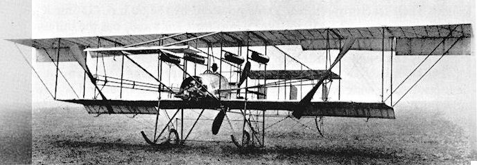
Short S.39 Triple Twin with extended upper wings.
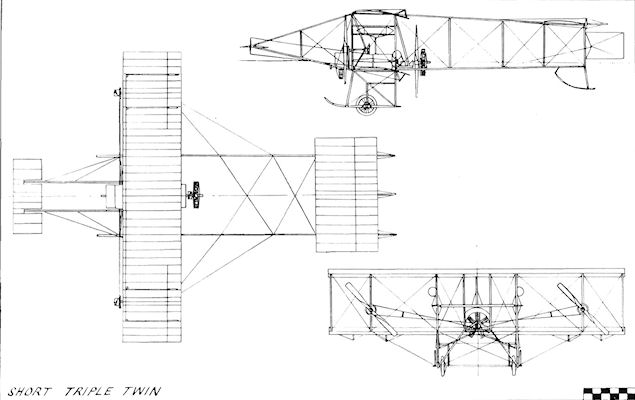
Short Triple Twin
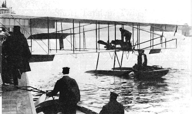
F. K. McClean's modified Short S.33 (a dual control seaplane version of the S.27 type) at the Thames Embankment after his flight up the river on 10th August, 1912. S.43-S.44 were similar but landplanes.
Short T.5 Tandem Tractor
The First Short tractor biplane was designed for C. S. Grace in 1910, but was not proceeded with after his disappearance during a flight across the English Channel on 22nd December, 1910. After seeing the design drawings in the autumn of 1911, F. K. McClean decided to have the machine built for himself. It was completed at the end of the year, having been converted from an S.27, and was tested during January, 1912, by Cdr. C. R. Samson, R.N. and Capt. E. L. Gerrard, R.M.L.I. The McClean Tandem Tractor had an uncovered rear fuselage, but when the type was adopted by the Admiralty as the T.5 it was covered with fabric.
The T.5 appeared during the spring of 1912 and was soon fitted with a central float for tests as a seaplane. These were successful and marked the start of Short Brothers' long association with floatplanes. The Admiralty version had a slightly shorter span through the omission of the outermost rib bay on both upper and lower wings, the ends of which were also altered by the fitting of flat end ribs in place of those with camber. The landplane T.5 was given wing-tip skids fixed to the front outer interplane struts, and was in service by May, 1912. Powered by a 70 h.p. Gnome engine, it was used as a two-seat trainer.
SPECIFICATION
Description: Two-seat tractor biplane. Wooden structure, fabric covered.
Manufacturers: Short Brothers, Eastchurch, Isle of Sheppey, Kent.
Power Plant: 70 h.p. Gnome.
Dimensions: Span, 42 ft. Length, 35 ft. 6 ins.
Weights: Empty, 850 lb.
Performance: Maximum speed, 56 m.p.h. Endurance, 5 hrs.
Short S.45
The S.45 was produced during 1913 as a two-seat trainer, and was an improved version of the earlier T.5. The design was generally cleaner than that of its forerunner, and the gap between the wings was reduced, bringing the lower wings nearer to the bottom of the fuselage. The sides of the cowling for the 70 h.p. Gnome engine were flat, with bulges for the cylinder-heads. The lift struts to the upper wing-tip extensions were discarded, bracing being by king-posts and wires. The lower wings were given skids at their tips, and adequate decking on the fuselage gave protection to the cockpits. Span, 42 ft. Length, 35 ft. 6 ins. Weight empty, 1,080 lb. Maximum speed, 60 m.p.h. Endurance, 5 hrs.

Prototype Short T.5 in January, 1912, with Capt. E. L. Gerrard in the front cockpit and Oswald Short in the rear.

Short T.5, flown by Lt. S. D. A. Grey, taking-off at Margate on 30th May, 1912.

Short T.5 with single float.
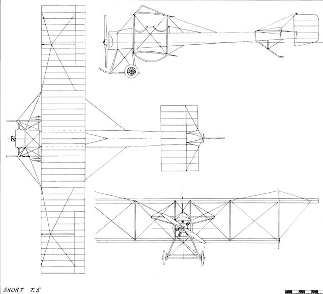
Short T.5
Short S.38/T.2
The pilot and passengers of the early pusher aeroplanes received no protection from the elements until a little thought was finally given to improving their comfort. The obvious answer was to provide some form of shield, and this was done by enclosing the controls and the seats within a nacelle.
Short Brothers' popular S.27 was modified in this way late in 1912, the front elevator being mounted on outriggers in front of the nacelle. Biplane S.38 gave its number as the title of the new series of enclosed type of pushers; minor modifications were introduced as experience was gained. These included the removal of the front elevator. The two seats were in tandem and the engine was the 80 h.p. Gnome.
The S.38 went into service with the Naval Wing of the R.F.C. during 1913 as the T.2 for training, and was used at R.N.A.S. Chingford and Eastchurch. It also took part in coastal patrols from Great Yarmouth during the early months of the 1914-18 War. The S.38 was one of the earliest machines to carry a machine-gun aloft and was employed also for experiments with wireless.
SPECIFICATION
Description: Two-seat pusher biplane. Wooden structure, fabric covered.
Manufacturers: Short Brothers, Eastchurch, Isle of Sheppey, Kent.
Power Plant: 80 h.p. Gnome.
Dimensions: Span, 52 ft. Length, 35 ft. 6 ins.
Weights: Empty, 1,050 lb.
Performance: Maximum speed, 58 m.p.h. Endurance, 5 hrs.
Short Admiralty No. 3
The Admiralty No. 3 was acquired by the Naval Wing of the R.F.C. during 1913. It was a two-seat pusher biplane and was powered by the 80 h.p. Gnome engine. One only was built, and it took its designation from the number allotted to it on entering service. The No. 3 was employed for training pilots at Eastchurch, but, in October, 1914, it was sent out to join Cdr. C. R. Samson's Eastchurch Squadron of the R.N.A.S. in France.

Short S.38.
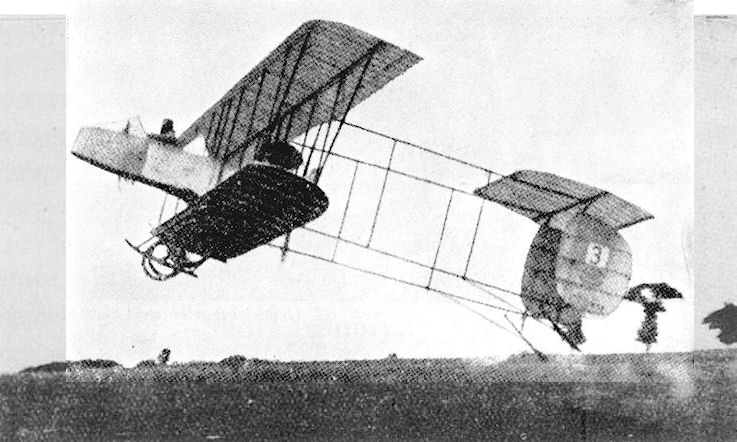

Short S.38
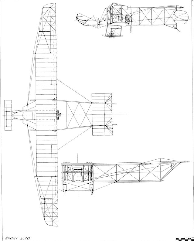
Short S.70
Short S.41 Hydro-biplane
The S.41 was a two-seat tractor hydro-biplane produced by Short Brothers in 1912. The original machine appeared early in the year as a landplane, but was soon fitted with twin floats and was tested successfully by Cdr. C. R. Samson, R.N. The machine was the progenitor of the numerous types of Short twin-float tractor seaplanes which were later to render such valuable service in the conflict which lay only two years ahead.
The prototype S.41 was fitted with single-step twin main floats, and three smaller auxiliary floats of the air-bag type were mounted on the wings and at the tail. As the machine was without a fin, the balanced rudder was braced to the fuselage by a forward strut. All of the flying surfaces were of very square-cut appearance, and the lower centre-section was left uncovered. The fuselage was mounted part of the way up the centre-section struts, leaving a gap between itself and the lower wings. The fuselage was a simple structure of rectangular section, and was without the refinement of decking along the top surface.
The machine was demonstrated at the Review of the Fleet held at Weymouth on 8th May. 1912, and was flown extensively by Cdr. C. R. Samson, who used it in June of that year to transmit wireless messages from the air to the ground, achieving a range of up to 10 miles. Late in 1912 the serial number 10 was bestowed upon the original S.41.
In the light of experience with No. 10 the next two S.41s were altered in several respects, and reached the Naval Wing of the R.F.C. during 1913. As with the original S.41, the new versions were fitted with the 100 h.p. Gnome engine. They were given the numbers 20 and 21, the former going into service in May. Double-acting ailerons replaced the former single-acting type, and king-posts and wire-bracing were used instead of struts to the upper-wing extensions. The new floats were without steps, and the wing floats had been moved outboard to the tips from their mid-wing position. In addition to the pilot, it was possible to carry two passengers in the rear cockpit.
During its first month of operation No. 20 was equipped with the lightweight Rouzet wireless transmitter and was flown by Sub.-Lt. J. T. Babington, R.N., in experiments from the Isle of Grain. Difficulty had been experienced in beaching seaplanes without damaging their floats, and Lt.-Cdr. R. Gregory, R.N., Eng.-Lt. E. W. Riley, R.N., and Mr. White, an official employed at Chatham Dockyard, set to work to devise a suitable method of obviating the trouble. Their remedy consisted of releasable pairs of wheels on the main floats together with a single wheel on the tail float, which enabled the aircraft to taxi into the water and out of it again when the wheels were in position. The originators used their initials to name the apparatus the G.R.W. wheel float attachment. The S.41 No. 20 was employed to test the gear early in 1914. During their service with the Naval Wing of the R.F.C. the S.41s operated from the Naval Air Stations at Great Yarmouth and Eastchurch.
SPECIFICATION
Description: Two-seat tractor hydro-biplane. Wooden structure, fabric covered.
Manufacturers: Short Brothers, Eastchurch, Isle of Sheppey, Kent.
Power Plant: 100 h.p. Gnome.
Dimensions: Span, 50 ft. Length, 39 ft. Height, 11 ft. 9 ins.
Weights: Empty, 1,100 lb.
Performance: Maximum speed, 60 m.p.h. Endurance, 5 hrs.
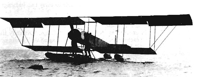
Early version of Short S.41.
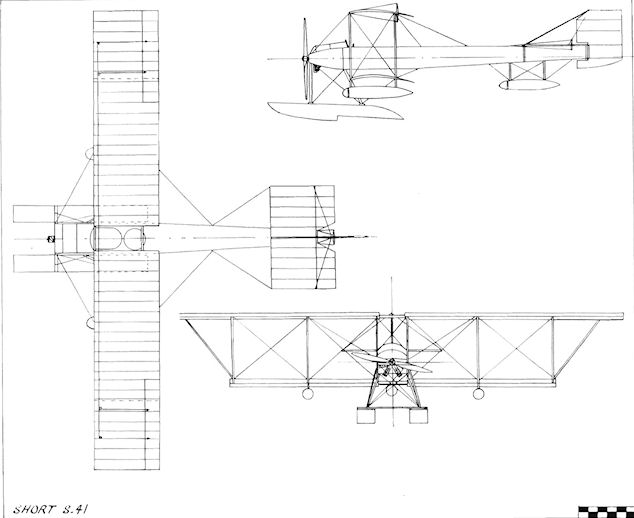
Short S.41
Short Tractor Monoplane
During 1911, Short Brothers decided to explore the possibilities of the monoplane lay-out and, in November of the year, started to build a machine which resembled very closely indeed the standard Bleriot XI design. Their tractor monoplane was powered by the 50 h.p. Gnome and was a single-seater. The Bleriot-type wings were followed, but the tail unit was very square-cut in comparison. The main undercarriage was changed completely in design, with the main struts being mounted direct on to the upper longerons and without the characteristic springing arrangement of the Bleriot. The wings were warped in the usual manner for lateral control, and a fairly deep coaming was fitted to the front part of the upper fuselage before the cockpit.
The monoplane was completed early in 1912 and was tested at Eastchurch during February by Commander C. R. Samson, R.N. Two months later it took part in the Naval Manoeuvres held in May, and bore the designation M2 on its rudder.
SPECIFICATION
Description: Single-seat tractor monoplane. Wooden structure, fabric covered.
Manufacturers: Short Brothers, Eastchurch, Isle of Sheppey, Kent.
Power Plant: 50 h.p. Gnome.
Dimensions: Span, 29 ft. 3 ins. Length, 25 ft. Wing area, 165 sq. ft.
Performance: Maximum speed, 55 m.p.h. Endurance, 5 hrs.
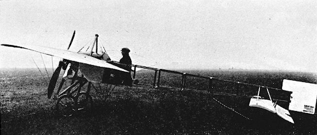
Short Monoplane in 1911.

Short Monoplane
Short S.47/T.4 Triple Tractor
The Triple Tractor biplane of 1912 was another Short Brothers' experiment in multi-engine lay-out. The machine was basically an S.41 with an extended cowling 16 ft. in length, under which were concealed two 50 h.p. Gnome engines. The front one drove a direct-coupled tractor propeller, while the rear was connected by chains to a tractor propeller mounted mid-way between the wings on each side of the fuselage. The engines were fitted in tandem in the fuselage, while the pilot and passenger had side-by-side seats in the cockpit. The Triple Tractor was flown during July, 1912, but so much heat was generated under the cowling that it became known as the "Field Kitchen". Span, 48 ft. Length, 41 ft.
The Triple Tractor biplane of 1912 was another Short Brothers' experiment in multi-engine lay-out. The machine was basically an S.41 with an extended cowling 16 ft. in length, under which were concealed two 50 h.p. Gnome engines. The front one drove a direct-coupled tractor propeller, while the rear was connected by chains to a tractor propeller mounted mid-way between the wings on each side of the fuselage. The engines were fitted in tandem in the fuselage, while the pilot and passenger had side-by-side seats in the cockpit. The Triple Tractor was flown during July, 1912, but so much heat was generated under the cowling that it became known as the "Field Kitchen". Span, 48 ft. Length, 41 ft.
Short Admiralty No. 42
At the 1913 Olympia Aero Show Short Brothers exhibited a new hydro-biplane. It resembled the S.41, but was improved in several ways. The lower wings were mounted direct on to the fuselage, and the tailplane was fitted below the upper longerons. Steel tubing was employed for the float struts, and the passenger's seat in the front of the undivided cockpit slid to the right to make room for a second passenger. A self-starter and petrol-injector were fitted. During 1912 Cdr. C. R. Samson, R.N., had flown the machine with two aboard in addition to himself.
The Admiralty bought the Show machine and, as No. 42 and fitted with a triangular fin, it flew at the 1913 Fleet Manoeuvres. Later, it operated as a landplane from Montrose and went to France with Samson's Eastchurch Squadron. Its end came when Samson wrecked it on 28th September, 1914. The engine was the 80 h.p. Gnome. Span, 48 ft. Length, 35 ft. Wing area, 390 sq. ft. Weight empty, 1.200 lb. Weight loaded, 1,971 lb. Maximum speed, 65 m.p.h.
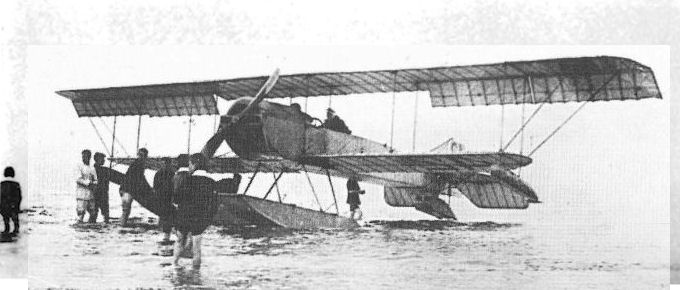
RNAS 42 at Leven, Fifeshire, in July 1913.
Short S.70
In 1913 F. K. McClean decided to attempt a tour of Egypt by air by using a seaplane to be flown along the River Nile, and Horace Short was asked to design the machine. In appearance, it was reminiscent of the S.38, but the span of the wings was increased to 70 ft. 6 ins., making it, in this respect, the largest successful aeroplane built in the United Kingdom before the 1914-18 War. Three and a half bays were used in the wings, the upper tip extensions of which were braced by struts, an unusual feature being the provision of small additional ailerons set between the centre section and the main ailerons. These main ailerons were of considerable length and extended from mid-way of the upper span to the tips. The nose of the nacelle carried a small elevator mounted on outriggers as an auxiliary to that hinged to the rear of the tailplane. The engine fitted at the back of the nacelle was the 160 h.p. Gnome, the most powerful version available.
The S.70 was finished towards the end of the year and was tested at Eastchurch with a land undercarriage. On 19th November, 1913, although built as a three-seater, it took off from the same aerodrome in the course of its proving flights with five passengers - Lt. I. T. Courtney. R.N., F. K. McClean, Alec Ogilvie, Cdr. C. R. Samson, R.N., and Horace Short. The machine was then dismantled and packed for transporting by ship to Alexandria, where it was reassembled for the expedition. Frank McClean was accompanied by Alec Ogilvie as additional pilot and by A. Smith, who was the mechanic. The floats for the Nile landings consisted of a large pair at the front of the S.70 and two more fitted at the rear under the tail side-by-side.
The trip up the Nile started on 3rd January, 1914, Cairo being reached in 2 hrs. 55 mins. Unfortunately, the engine subsequently gave considerable trouble and the floats were damaged on several occasions. The tourists pressed on with their flight and reached Khartoum on 23rd March, having covered about 1,400 miles. They then decided that they had travelled far enough, and the S.70 was accordingly taken to pieces and returned home to England with its crew by ship.
SPECIFICATION
Description: Three-seat pusher hydro-biplane. Wooden structure, fabric covered.
Manufacturers: Short Brothers, Eastchurch, Isle of Sheppey, Kent.
Power Plant: 160 h.p. Gnome
Dimensions: Span, 70 ft. 6 ins. Length 35 ft. 6 ins. Wing area, 725 sq. ft.
Weights: Empty, 1,050 lb.
Performance: Maximum speed, 58 m.p.h. Endurance, 5 hrs.
Short S.81 Gun-carrier
The S.81 Gun-carrier was designed by A. Camden Pratt and built by Short Brothers during 1913. The machine was a two-seat hydro-biplane developed specially for experiments with armament, and was the last Short pusher floatplane. Three-bay folding wings were fitted, with extensions on the upper planes braced by struts. Twin floats were used at the front and also at the tail. The nacelle was strong enough to withstand the recoil of the Vickers 1-5-pounder gun with which it was tested at Great Yarmouth "Naval Air Station. During 1915 the Davis 6-pounder gun was mounted for trials in the S.81. The sole example constructed was numbered 126, and was powered by the 160 h.p. Gnome.

Short S.38 with G.R.W. wheel-float beaching gear.
Short Folder Seaplane
During 1913 Horace Short devised a method of folding the wings of the firm's seaplanes by hinges on the rear spar and bayonet joints on the front spar for locking when open. The first example was No. 81, which went into service in the summer of 1913, to be followed soon after by No. 82. Both were two-bay biplanes, but they were similar in appearance to the Type 74, which they preceded in use. No. 81 was attached to the seaplane carrier H.M.S. Hermes for the 1913 Fleet Manoeuvres. It was equipped with Rouzet wireless and made two successful reconnaissance flights on 21st June, 1913. Nearly six weeks later, on 1st August, Cdr. C. R. Samson, R.N., was forced to land No. 81 in the North Sea, and the floats were wrecked.
Later production Folders were given three-bay wings which could be folded from the cockpit. Exhaust gases were collected by a funnel-type stack and deflected over the upper wings. A Folder flown by Sqn. Cdr. A. M. Longmore made the first drop of a torpedo from the air in Great Britain on 28th July, 1914, with one of 14 ins. diameter and 810 lb. in weight. A 160 h.p. fourteen-cylinder Gnome engine powered the Folder. Span (two-bay), 56 ft.: (three-bay), 67 ft. Length, 39 ft. Weight empty (two-bay). 2.000 lb.; (three-bay), 3,040 lb. Maximum speed (three-bay), 78 m.p.h. Endurance, 5 hrs.
Short Admiralty Type 74
The Admiralty Type 74 took its designation from the serial number of the first of the type's production batch. Although known by Short Brothers as the Improved S.41, there was little connection between the two machines except for the fact that both used the 100 h.p. Gnome engine. The Type 74 was far closer in appearance to the Admiralty No. 42, but had three-bay wings.
After its debut in 1913 the Type 74 went into use the following year with the R.N.A.S. and took part in the Spithead Naval Review held in July, 1914. It was flown later on coastal patrols from Calshot, Dundee, Isle of Grain and Leven. Illustrated is No. 76 afloat at Gravesend piloted by Cdr. C. R. Samson, with Winston Churchill as his passenger.
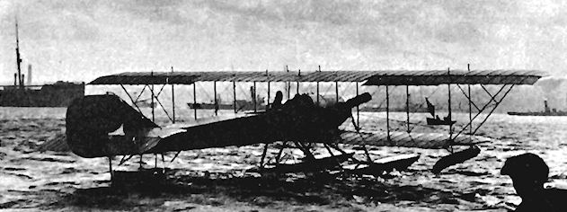
Short Admiralty Type 135
Designed at the end of 1913, the folder seaplane Admiralty Type 135 was a two-seater with two-bay wings fitted with strut-braced upper extensions. The upper planes carried single-acting ailerons, which were made in two parts and had inverse taper. A rounded top decking ran the whole length of the fuselage, and the 135 h.p. Salmson engine was cooled by a large rectangular radiator mounted in front of the cockpits.
No. 135 entered service just before the outbreak of the 1914-18 War and was followed in September, 1914, by a second example, which was powered by the 200 h.p. Salmson. It was numbered 136 (illustrated) and was based on the Isle of Grain. Span, 54 ft. 6 ins. Length, 39 ft. Height, 12 ft. 6 ins. Weight loaded, 3,700 lb. Maximum speed, 65 m.p.h. Endurance, 4 hrs.
Short Admiralty Type 166
A further development of the folder seaplane, intended specifically for torpedo-dropping, was an enlarged version of Admiralty No. 136, from which it differed chiefly in having pylon-braced upper wings of increased span and a still larger fin. The first to be built, early in 1914, bore the Short works number S.90 and received the Admiralty serial number 161. Unlike its successors, its 200 h.p. Salmson engine was uncowled. There were six aircraft in the initial batch, and the Admiralty chose to identify the type by the number of the last of these - 166 - which subsequently served at Salonika on board H.M.S. Ark Royal. Span, 57 ft. 3 ins. Length, 40 ft. 7 ins. Height, 14 ft. 1 in. Weight loaded, 4,580 lb. Maximum speed, 65 m.p.h.
A further development of the folder seaplane, intended specifically for torpedo-dropping, was an enlarged version of Admiralty No. 136, from which it differed chiefly in having pylon-braced upper wings of increased span and a still larger fin. The first to be built, early in 1914, bore the Short works number S.90 and received the Admiralty serial number 161. Unlike its successors, its 200 h.p. Salmson engine was uncowled. There were six aircraft in the initial batch, and the Admiralty chose to identify the type by the number of the last of these - 166 - which subsequently served at Salonika on board H.M.S. Ark Royal. Span, 57 ft. 3 ins. Length, 40 ft. 7 ins. Height, 14 ft. 1 in. Weight loaded, 4,580 lb. Maximum speed, 65 m.p.h.
Sim Glider
The Sim Glider was built during 1909 at Sundridge Park, Kent, by A. Sim, and was modified at the end of the year by the addition of a front elevator. Span, 21 ft. Length, 17 ft. 4 ins. Wing area, 253 sq. ft.
Sim Biplane
The two-seat Sim Biplane was constructed by A. Sim of Sundridge Park, Kent, during 1909, and was composed of bamboo and fabric.
Sippe Monoplane
The Sippe Monoplane was a single-seat tractor built at Beckenham, Kent, during 1910 by S. V. and A. H. Sippe and James Jensen, and was tested at Addington, Surrey, towards the end of the year. The fuselage was of welded steel tubing in front with a bamboo tail boom; a four-cylinder air-cooled engine of 20 h.p. - believed to have been a Henderson - was installed.
The Sippe Monoplane was a single-seat tractor built at Beckenham, Kent, during 1910 by S. V. and A. H. Sippe and James Jensen, and was tested at Addington, Surrey, towards the end of the year. The fuselage was of welded steel tubing in front with a bamboo tail boom; a four-cylinder air-cooled engine of 20 h.p. - believed to have been a Henderson - was installed.
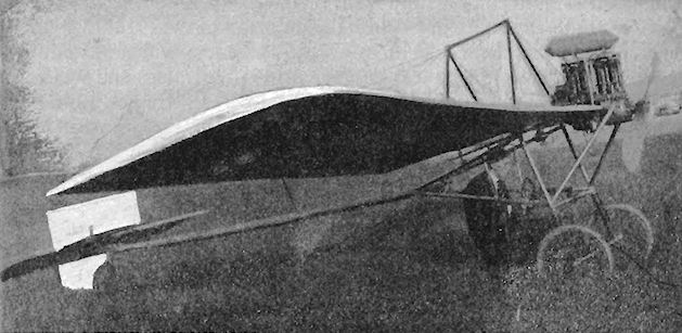
Skinner Monoplane
The Skinner Monoplane was constructed during 1911 by Mulliner Coachworks Ltd., at their works at Vardens Road,,Clapham Junction, London, S.W., to the requirements of a Mr. Skinner. The engine was the eight-cylinder 60 h.p. E.N.V. "F", and the single-seat machine was modelled on the lines of the Antoinette. A sturdy twin-skid undercarriage was fitted, and the controls consisted of wing-warping, together with a cruciform tail unit in which the rudder and elevators were pivoted at one point. The Skinner Monoplane was at Brooklands for testing during August, 1911.
The Skinner Monoplane was constructed during 1911 by Mulliner Coachworks Ltd., at their works at Vardens Road,,Clapham Junction, London, S.W., to the requirements of a Mr. Skinner. The engine was the eight-cylinder 60 h.p. E.N.V. "F", and the single-seat machine was modelled on the lines of the Antoinette. A sturdy twin-skid undercarriage was fitted, and the controls consisted of wing-warping, together with a cruciform tail unit in which the rudder and elevators were pivoted at one point. The Skinner Monoplane was at Brooklands for testing during August, 1911.
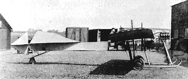
Sonoda Biplane
Handley Page Ltd. constructed the two-seat tractor biplane which was designed by T. Sonoda of Japan and embodied his system of lateral control. The engine was the 60 h.p. Green. The machine made its first appearance in July, 1912, at Hendon, and was tested there on the following 7th September by Cyril W. Meredith. It was on display on the occasion of the Naval and Military Aviation Day held at Hendon on 28th September, 1912, but was crashed shortly after in October at the same aerodrome by Meredith following engine failure. The colouring was duck-egg blue overall, with the rudder emblazoned with the Japanese national flag in red and white.
Handley Page Ltd. constructed the two-seat tractor biplane which was designed by T. Sonoda of Japan and embodied his system of lateral control. The engine was the 60 h.p. Green. The machine made its first appearance in July, 1912, at Hendon, and was tested there on the following 7th September by Cyril W. Meredith. It was on display on the occasion of the Naval and Military Aviation Day held at Hendon on 28th September, 1912, but was crashed shortly after in October at the same aerodrome by Meredith following engine failure. The colouring was duck-egg blue overall, with the rudder emblazoned with the Japanese national flag in red and white.
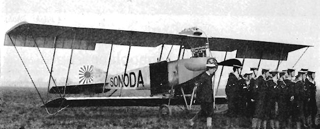
Aeroplane at Hendon during the Naval and Military Aviation Day held on 28th September, 1912.
Sopwith Hybrid Biplane
During 1912 there emerged from the Sopwith workshops a tractor biplane which constituted the first product of the firm 's design staff. The wings of a Wright machine and a Farman's undercarriage were fitted to a new fuselage with uncovered rear portion, the whole being powered by a 70 h.p. Gnome engine which drove a 9 ft. 6 ins. diameter Chauviere propeller. The machine was a three-seater with its pair of passengers sitting side-by-side in front of the pilot.
After a minor crash at Brooklands the machine was rebuilt and given a totally enclosed fuselage and a single pair of wheels in place of the twin pairs at first fitted. On one occasion three passengers were taken up in addition to the pilot. Span, 44 ft. Length, 26 ft. 4 ins. Wing area, 520 sq. ft. Weight empty, 950 lb. Maximum speed, 55 m.p.h.
Sopwith-Wright Biplane
Early in the summer of 1911 T. O. M. Sopwith shipped his Howard Wright Biplane to the U.S.A. and proceeded to make a very successful tour, during which he gave exhibitions at several of the principal cities, including Philadelphia, Chicago, Boston and New York. He won several thousands of dollars in prize money, out of which was bought a Wright Brothers Biplane for further use in the tour. The machine was one of those built under licence by the Burgess Company, in which Farman-style elevator-lever and rudder-bar controls were installed in place of the original Wright form. The engine was a 50 h.p. Gnome.
In 1912 the machine was reconstructed in Sopwith's works, the Gnome being replaced by a 40 h.p. A. B.C. with chain drive to the pair of 8 ft. 6 ins. propellers. The engine and its tank were offset to port on the lower wing, and the comfort of the pilot seated to starboard was improved by the addition of a small nacelle. The Sopwith-Wright was used by H. G. Hawker on 24th October for his successful attempt to capture the 1912 British Empire Michelin Cup No. I and ?500, when he remained in the air for 8 hrs. 23 mins., at the same time setting up a new British duration record.
SPECIFICATION
Description: Single-seat pusher biplane. Wooden structure, fabric covered.
Manufacturers: Sopwith Aviation Co. Ltd., Kingston-on-Thames, Surrey.
Power Plant: 40 h.p. A.B.C.
Dimensions: Span, 38 ft. 9 ins. Length, 29 ft. 6 ins. Wing area, 475 sq. ft.
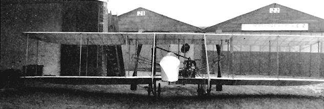
Sopwith-Wright Biplane.
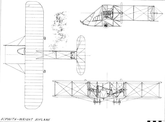
The Sopwith-Wright biplane.
Sopwith Bat Boat 1 and 1a
Alongside their Three-seater at the 1913 Olympia Aero Show, the Sopwith company exhibited another advanced design, the Bat Boat, significant as the first successful British flying-boat. When it first appeared the machine was fitted with a 90 h.p. Austro-Daimler engine turning an 8 ft. 6 ins. Levasseur propeller. The elegantly-proportioned hull was planked with cedar, and was the product of S. E. Saunders & Co., of East Cowes. The cockpit was just ahead of the lower wings, and it seated two in side-by-side seats. The remainder of the airframe was built in the Sopwith works at Kingston-on-Thames, where the complete Bat Boat was assembled. The unstaggered two-bay wings were mounted above the hull, and attached to it by two pairs of struts. Lateral control was by wing-warping, and a single rudder was fitted. In addition to the normal rear tailplane and elevators, an auxiliary elevator was mounted at first on the extreme nose of the hull.
To enable it to compete for the Mortimer Singer £500 prize for amphibians, the Bat Boat was re-engined with a 100 h.p. Green to bring it into the all-British category, and a pair of forward-retracting wheels allowed it to operate as a landplane. The propeller diameter was increased to 11 ft. to absorb the extra power, and twin rudders were fitted in association with a one-piece elevator. A pair of strong struts from the engine-mounting to the fore-hull replaced the earlier wire bracing between these points, and the hull was faired into the lower wings around its attachment struts. A further refinement was the provision of cable-connected ailerons on upper and lower surfaces. On 8th July, 1918, H. G. Hawker flew the machine successfully to win the Mortimer Singer award, and the Bat Boat was then delivered to the Admiralty.
The 90 h.p. Austro-Daimler engine was put back into the Bat Boat, and the wheeled undercarriage was removed; other modifications included the addition of small triangular fins in front of the rudders, and the installation of a powerful electric searchlight in the bows.
This Bat Boat was used by the R.N.A.S. at Calshot, and numbered 118. It took part in the July, 1914, Spithead Naval Review, and after the outbreak of war was flown on patrol from Scapa Flow from 24th August until it was wrecked by a gale on 21st November, 1914.
A second Bat Boat, supplied to the R.N.A.S. as number 38, retained the original design of empennage with divided elevators and single rudder, the only modification being the addition of a triangular fin underneath the tailplane.
SPECIFICATION
Description: Two-seat pusher hydro-biplane. Wooden structure, fabric covered.
Manufacturers: Sopwith Aviation Co. Ltd., Kingston-on-Thames, Surrey.
Power Plant: 90 h.p. Austro-Daimler. 100 h.p. Green.
Dimensions: Span, 41 ft. Length, 30 ft. 4 ins. Wing area, 428 sq. ft.
Weights: Empty, 1.200 lb. Loaded, 1,700 lb.
Performance: Maximum speed, 65 m.p.h. Endurance, 4-5 hrs.
Price: £1,500.
Sopwith Bat Boat 2
Ready in time for the 1914 Aero Show at Olympia was an enlarged and improved version of the 1913 Bat Boat. Engine power was doubled by the use of a fourteen-cylinder 200 h.p. Salmson, which was cooled through a large rectangular radiator mounted in front between the centre-section struts. The same general arrangement as that of the earlier machine was retained, with an overall increase in size.
An extra half-bay was added to the wings, together with strut-braced upper wing-tip extensions, which increased the span by 14 ft. to 51 ft. Slight stagger was also introduced into the new wings, and the original type of cylindrical wing floats were replaced by a pair of rectangular section. The upper wings which carried ailerons were straight, while the lower pair were set with dihedral. The wings of the new Bat Boat were mounted on to the revised and strengthened hull, which was built in the Sopwith factory together with the rest of the airframe, the whole being of the best construction and finish. A further refinement was the installation in the cockpit of a compressed-air starter for the engine.
For the 1914 Daily Mail Circuit of Britain contest, Sopwith produced yet another version of the Bat Boat. C. Howard Pixton was named as the pilot of the new machine, which was powered with a 225 h.p. Sunbeam engine. The Circuit Bat Boat reverted to the former practice of mounting the wings above the hull, and increased tankage gave an endurance of 5 hrs. War prevented the Daily Mail race from taking place; before the start of hostilities, one Bat Boat fitted with the 200 h.p. Salmson engine was delivered to Germany and used later in the Baltic.
SPECIFICATION
Description: Two-seat pusher hydro-biplane. Wooden structure, fabric covered.
Manufacturers: Sopwith Aviation Co. Ltd., Kingston-on-Thames, Surrey.
Power Plant: 200 h.p. Salmson, 225 h.p. Sunbeam.
Dimensions: Span, 55 ft. Length, 36 ft. Wing area, 600 sq. ft.
Weights: Empty, 2,300 lb. Loaded, 3,180 lb.
Performance: Maximum speed, 70 m.p.h. (200 h.p. Salmson). Maximum speed, 75 m.p.h. (225 h.p. Sunbeam). Endurance, 4.5 hrs. (200 h.p. Salmson). Endurance, 5 hrs. (225 h.p. Sunbeam).
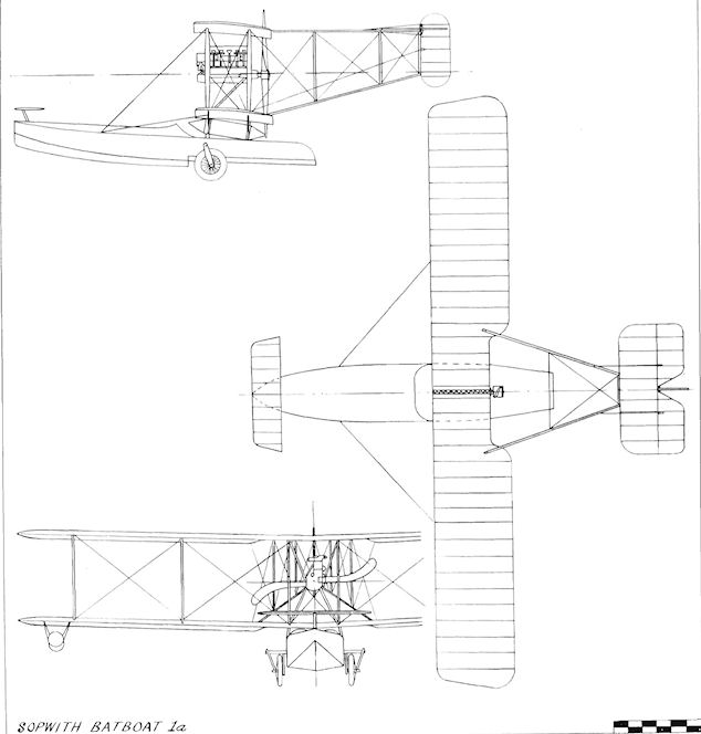
Sopwith Batboat 1a

Sopwith Batboat 2
Sopwith 1913 Circuit Seaplane
Among the entries for the Daily Mail Circuit of Britain race, held from 16th to 30th August, 1913, was a tractor seaplane of the Sopwith company. The machine was a large four-bay biplane powered by a six-cylinder 100 h.p. Green engine and was flown in the £5,000 contest by H. G. Hawker and H. Kauper. The Sopwith was the only machine to take-off finally in the event, the other three entries having withdrawn. The rules of the trial stipulated that the distance of 1,540 miles was to be completed in three days from the start.
The slim, upright engine permitted a clean, tapered nose compared with the blunt front of the landplane version with its 80 h.p. Gnome, but the power plant gave continual trouble during the race. After two starts, Hawker managed to cover two-thirds of the course, but finally had to give up and was awarded a special personal prize of £ 1,000 for his determination and display of fine airmanship.
The radiators for the water-cooled Green were mounted on each side of the fuselage, and the centre section of the wings was left uncovered to offer easy egress for the crew in the event of a crash.
SPECIFICATION
Description: Two-seat tractor biplane seaplane. Wooden structure, fabric covered.
Manufacturers: Sopwith Aviation Co. Ltd., Kingston-on-Thames, Surrey.
Power Plant: 100 h.p. Green.
Dimensions: Span, 49 ft. 6 ins. Length, 31 ft. Wing area, 500 sq. ft.
Weights: Loaded, 2,400 lb.
Performance: Cruising speed, 65 m.p.h.
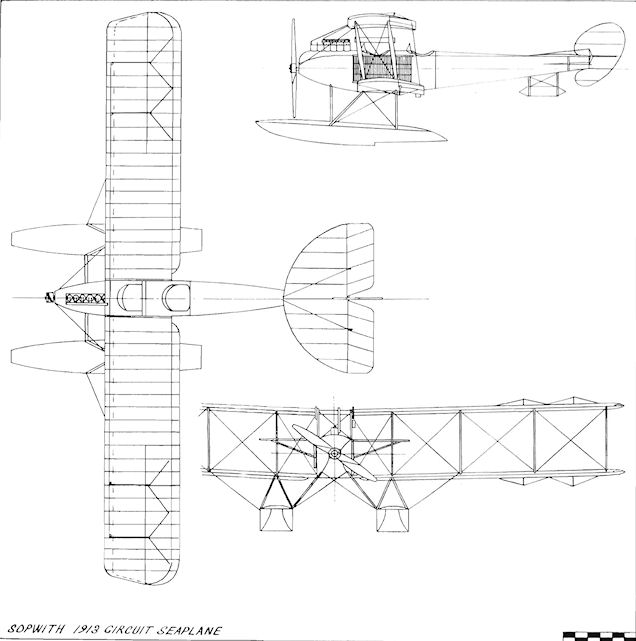
Sopwith 1913 Circuit Seaplane
Sopwith Tractor Seaplane
During July, 1913, three two-seat tractor seaplanes, Nos. 58, 59 and 60, powered by 100 h.p. Anzani engines, were supplied to the Naval Wing of the R.F.C., and one was flown at the Naval Manoeuvres of the same year.
During July, 1913, three two-seat tractor seaplanes, Nos. 58, 59 and 60, powered by 100 h.p. Anzani engines, were supplied to the Naval Wing of the R.F.C., and one was flown at the Naval Manoeuvres of the same year.
Sopwith Tabloid
Following the current trend of attempts to produce small fast tractor biplane scouts, T. O. M. Sopwith and F. Sigrist embodied their own ideas in the Tabloid, which was built in secret for racing and demonstration by their test pilot, H. G. Hawker, who also made some contribution at the design stage. First trials were made during the autumn of 1913 at Brooklands and, upon completion, they were followed by official tests at Farnborough on 29th November. These disclosed that the Tabloid possessed the unusually wide speed-range of 55T m.p.h. Later the same day, Hawker flew the machine from Farnborough to Hendon, arriving over the aerodrome while one of the popular Saturday meetings was in progress. He showed the new Sopwith off to the competitors and 50,000 spectators by completing two low, fast circuits of the field at 90 m.p.h.
The two-seat prototype was scheduled to appear at the 1914 Paris Aero Show, but, instead, Hawker took the machine on demonstration to his native Australia in an effort to arouse the Government's interest in the type. While it was away, the Tabloid was modified and, on its return to England on 6th June, 1914, was seen to have had the fabric of the rear fuselage removed and a new undercarriage with simple vee-struts fitted. The original machine was built without a fin, and the single cockpit housed its two occupants side-by-side.
Early in 1914 the Tabloid was put into production as a single-seat scout for both the Military and Naval Wings of the R.F.C. The length of the production version was increased by 4 ins. to become 20 ft. 4 ins.; a fin was added to the tail unit and ailerons replaced wing-warping.
<...>
SPECIFICATION
Description: Single- and two-seat tractor biplane. Wooden structure, fabric covered.
Manufacturers: Sopwith Aviation Co. Ltd., Kingston-on-Thames, Surrey.
Power Plant: 80 h.p. Gnome, 100 h.p. Monosoupape Gnome.
Dimensions: Span, 25 ft. 6 ins. Length (prototype), 20 ft. Length (production), 20 ft. 4 ins. Height, 8 ft. 5 ins. Wing area, 241.3 sq. ft.
Weights: Prototype. Empty, 670 lb. Loaded 1,060 lb. Production. Empty, 730 lb. Loaded, 1,120 1b.
Performance: Maximum speed, 92 m.p.h. Landing speed, 36.9 m.p.h. Climb, 1,200 ft./min. Endurance, 3.5 hrs.
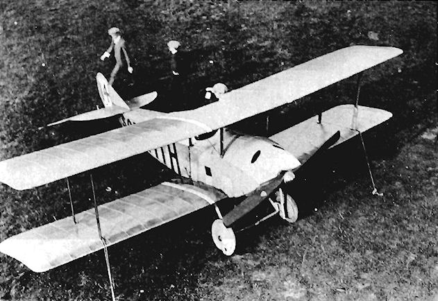
Sopwith Tabloid with modified undercarriage for racing.
Sopwith Three-seater
Outstanding among the new aeroplanes exhibited at the 1913 Olympia Aero Show was the Three-seater, the first of the long series of Sopwith tractor biplanes. Designed by T. O. M. Sopwith and F. Sigrist, the machine represented a distinct advance towards rational and practical aircraft and, together with its Avro and Bristol contemporaries, played its part in establishing the classic British formula which was adhered to for the next two decades.
The Three-seater carried its complement of two passengers side-by-side in the front cockpit below the centre-section of the wing, the pilot occupying a separate cockpit immediately to the rear. A praiseworthy feature of the design was the provision, on each side of the fore-fuselage, of three large celluloid panels for improved downward vision. The main undercarriage consisted of a pair of normal vee-struts combined with two skids embodying a small wheel at the front of each. Unusual was the fitting of twin tail-skids the width of the fuselage apart. The two-bay wings were slightly staggered and had warping tips, but no fin was installed.
After its emergence, the 80 h.p. Gnome Three-seater was straightaway demonstrated at flying meetings by H. G. Hawker, Sopwith's test pilot. On Whit-Monday, 1913, the machine came first in the Cross-country Race at Brooklands and was then taken by Hawker to a height of 7,500 ft. in 15 mins. Thereafter, the same pilot proceeded to demonstrate the aircraft's capabilities with several record-breaking climbs. At Brooklands on 31st May, 1913, he went to a new British solo height of 11.450 ft. Two weeks later, on 16th June, Hawker took one passenger up to 12,900 ft., and later on the same day reached 10,600 ft. with two passengers on board. On 27th July, 1913, Hawker and three passengers ascended to 8,400 ft. Later in the year he used a modified version fitted with a 100 h.p. Green engine for attempts on the British Michelin Cups Nos. 1 and 2, but without success.
The Three-seater was ordered by the R.F.C., followed by the R.N.A.S., a total of nine being delivered for Service use. These were normally flown as two-seaters only, some of them being aileron-equipped, and the small wheels on the skids were omitted on a few. The Service machines differed also in having rudders of a modified outline. Before the outbreak of war, No. 5 Squadron, R.F.C., was flying Three-seaters, and they were employed later by Commander Samson's Eastchurch Squadron and for coastal patrol from Great Yarmouth.
SPECIFICATION
Description: Three-seat tractor biplane. Wooden structure, fabric covered.
Manufacturers: Sopwith Aviation Co. Ltd., Kingston-on-Thames, Surrey.
Power Plant: 80 h.p. Gnome, 100 h.p. Green.
Dimensions: Span, 40 ft. Length, 29 ft. Wing area, 365 sq. ft. Weights: Empty, 1,000 lb. Loaded, 1,750 lb.
Performance: Maximum speed, 70 m.p.h. Climb, 500 ft./min. Ceiling, 12,900 ft. Endurance 4.5 hrs.
Price: ?1,185.
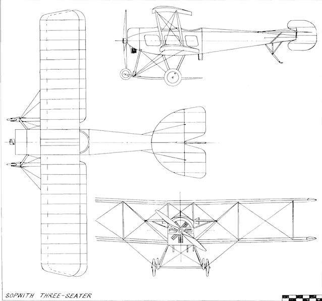
Sopwith Three-seater
Sopwith 1914 Circuit and Admiralty Type 807 Seaplanes
The Sopwith entry in the 1914 Daily Mail Circuit of Britain contest consisted of a two-seat biplane which was an enlarged Tabloid in general appearance. It was allotted race number 1, with Victor Mahl chosen as the pilot.
The two-bay wings were of equal span and were staggered, with ailerons of inverse taper fitted to all four tips. View from the pilot's rear cockpit was assisted by the 12 ins. stagger and by cut-outs in both upper centre-section and lower wing-roots. The Circuit entry was flown first at Brooklands as a landplane before the installation of the stepless floats. These were spaced well apart and were pivoted at the front, leaf springs providing shock-absorbing at the rear. At the same time the fin and rudder area was increased to balance the addition of forward side area.
While the Circuit seaplane was being prepared, a production batch was being built for the Navy, and this version became known as the Admiralty Type 807 from the serial number of the first machine constructed. The same 100 h.p. Monosoupape Gnome engine was used in the production 807s, but the Admiralty seaplane differed in several respects. The Short patent wing-folding device was incorporated, and the 807 wings were without stagger to simplify the operation. The upper wings were increased in span and the extensions were braced by wires and king-posts. The lower wings were shortened slightly, and the pilot occupied the rear seat, with his observer in the front cockpit. Delivery of the 807 to the Admiralty was made in July, 1914, just before the start of hostilities. Twelve, at least, are believed to have entered service, to be used subsequently with the R.N.A.S. at Calshot, Great Yarmouth, the Dardanelles, in East Africa and in the seaplane-carrier H.M.S. Ark Royal.
SPECIFICATION
Description: Two-seat tractor biplane seaplane. Wooden structure, fabric covered.
Manufacturers: Sopwith Aviation Co. Ltd., Kingston-on-Thames, Surrey.
Power Plant: 100 h.p. Monosoupape Gnome.
Dimensions: (1914 Circuit of Britain) Span, 36 ft. 6 ins. Length, 30 ft. 9.5 ins.
Wing area, 340 sq. ft. Weights: Empty, 1,310 lb. Loaded, 1,950 lb.
Performance: Maximum speed, 80 m.p.h. Landing speed, 60 m.p.h. Endurance, 3.5 hrs.

Sopwith 1914 Circuit Seaplane
Sopwith Gordon Bennett Racer
Two examples of these single-seat tractor biplanes were constructed during 1914 for the Gordon Bennett Race of that year, and were improved versions of the Tabloid with circular fuselages. The power was provided by a 50 h.p. Gnome, enclosed in a long-chord cowling. Both were taken into service by the Admiralty on the outbreak of the 1914-18 War for intended use as high-speed scouts, and were given the serials 1214 and 1215. Maximum speed, 105 m.p.h.
Two examples of these single-seat tractor biplanes were constructed during 1914 for the Gordon Bennett Race of that year, and were improved versions of the Tabloid with circular fuselages. The power was provided by a 50 h.p. Gnome, enclosed in a long-chord cowling. Both were taken into service by the Admiralty on the outbreak of the 1914-18 War for intended use as high-speed scouts, and were given the serials 1214 and 1215. Maximum speed, 105 m.p.h.
Sopwith Gunbus
The Gunbus was a landplane adaptation of the Greek Seaplane, six of which were due for delivery to the Greek Naval Air Service when the 1914-18 War commenced, but which were commandeered by the War Office. The original 100 h.p. Anzani engine was discarded, and its place was taken by the 100 h.p. Monosoupape Gnome, the Gunbus thereafter being employed for training at Hendon. A further production batch was put in hand, several modifications being made at the same time to the original design.
Instead of being connected direct to the nacelle's sides, the lower wings were made in one piece and passed below the nacelle, which itself was improved and strengthened. The power available was increased by the installation of the 150 h.p. Sunbeam engine. The tail unit was revised also, the earlier typical Sopwith curved type of tailplane giving way to one of rectangular shape, while the rudder was balanced and increased in area. A two-wheel undercarriage was fitted, with two skids and with rubber-cord shock-absorbers for the axles. Armament consisted of one Lewis gun mounted in the nose of the nacelle.
The operational use made of the Gunbus is obscure, but the type is believed to have flown at Dunkirk with Commander C. R. Samson's R.N.A.S. Squadron.
SPECIFICATION
Description: Two-seat pusher biplane gun-carrier. Wooden structure, fabric covered.
Manufacturers: Sopwith Aviation Co. Ltd., Kingston-on-Thames, Surrey.
Power Plant: 100 h.p. Monosoupape Gnome, 150 h.p. Sunbeam.
Dimensions: Span, 50 ft. Length, 32 ft. 6 ins. Wing area, 474 sq. ft.
Performance: Maximum speed, 80 m.p.h.
Sopwith Greek Seaplane
During 1913 one dual-control pusher seaplane trainer with a 100 h.p. Anzani engine was supplied to the Greek Naval Air Service. Six additional operational aircraft were ordered in March, 1914, without dual-control and fitted with a machine-gun in the nose, but were taken over by the Admiralty on the declaration of war. Span, 50 ft.
During 1913 one dual-control pusher seaplane trainer with a 100 h.p. Anzani engine was supplied to the Greek Naval Air Service. Six additional operational aircraft were ordered in March, 1914, without dual-control and fitted with a machine-gun in the nose, but were taken over by the Admiralty on the declaration of war. Span, 50 ft.
Sopwith Tabloid
<...>
A special single-seat Tabloid was prepared to represent Great Britain for the first time in the Schneider Trophy contest due to be held at Monaco on 20th April, 1914. The race was for seaplanes, and a single wide central float was built for the machine, which was powered by the latest type of 100 h.p. Monosoupape Gnome, the engine being specially tuned by Victor Mahl for the event. C. Howard Pixton was chosen to fly the Schneider Tabloid, but, on taxying out at Hamble for testing, the machine turned over in the water, and it was returned to the Kingston works. Twin floats were then quickly made by adopting the simple expedient of cutting the original large float down the centre-line. After test-flying from the River Thames on 8th April the Schneider contender was sent straightaway to Monaco. Minor modifications were made, and a new propeller was fitted on 19th April to good effect, for, on the following day, Pixton triumphed over the hitherto superior French pilots and aircraft and became the first to win the Schneider Trophy for Great Britain. The tiny seaplane covered the 300 km. course in 2 hrs. 9 mins. 10 secs, at an average speed of 86.75 m.p.h., and capped this fine performance by continuing around the course for two extra laps at 92 m.p.h. to set up a new world speed record for seaplanes.
On its return to England the victorious Tabloid was converted at Kingston to a landplane with a vee-strut undercarriage and was prepared for R. H. Barnwell to fly it in the 1914 Aerial Derby. On the day of the contest, however, bad visibility forced Barnwell to abandon the race, and thereafter the Tabloid design demonstrated its prowess by carrying out scouting missions for the R.F.C. and R.N.A.S. during the opening months of the 1914-18 War.
Sopwith Sociable
The dual-control side-by-side two-seat Sociable was initially fitted with an 80 h.p. Gnome engine, and made its first flight at Hendon on 23rd February, 1914, piloted by C. Howard Pixton, who later in the same day flew the machine with Lt. Spenser Grey, R.N., as passenger. A more powerful Gnome of 100 h.p. subsequently replaced the original engine, the aircraft afterwards being flown regularly by Lt. Spenser Grey at Hendon, where it was used for training, fulfilling the same role also at Eastchurch. The then First Lord of the Admiralty, Mr. Winston S. Churchill, flew in the Sociable, which was No. 149 and gained for itself the nickname "Tweenie".
The dual-control side-by-side two-seat Sociable was initially fitted with an 80 h.p. Gnome engine, and made its first flight at Hendon on 23rd February, 1914, piloted by C. Howard Pixton, who later in the same day flew the machine with Lt. Spenser Grey, R.N., as passenger. A more powerful Gnome of 100 h.p. subsequently replaced the original engine, the aircraft afterwards being flown regularly by Lt. Spenser Grey at Hendon, where it was used for training, fulfilling the same role also at Eastchurch. The then First Lord of the Admiralty, Mr. Winston S. Churchill, flew in the Sociable, which was No. 149 and gained for itself the nickname "Tweenie".

The sole side-by-side two seat Sopwith Trainer, serial no 149 of 1914, reputedly built specifically for the young, air-minded First Lord of the Admiralty, Winston S. Churchill. Powered by an 80hp Gnome, later replaced by a 100hp rotary of the same make, this aircraft has been referred to in various Sopwith records as being both the Sociable and the Churchill.
Sopwith Torpedo Seaplane
The Torpedo Seaplane Type C was built in 1913 for the specialised task of torpedo dropping. Strut-connected ailerons were fitted to each wing-tip, and the power was provided by the 200 h.p. Salmson engine cooled by radiators on each side of the fuselage.
The Torpedo Seaplane Type C was built in 1913 for the specialised task of torpedo dropping. Strut-connected ailerons were fitted to each wing-tip, and the power was provided by the 200 h.p. Salmson engine cooled by radiators on each side of the fuselage.
Spencer Biplane
The Spencer Biplane was a typical example of the successful type of two-seat pusher and was built during 1910 by Herbert Spencer of 40 Sackville Street, London, W. A 50 h.p. Gnome engine provided the power for the machine, which was tested at Brooklands in November, 1910. Ailerons were fitted to the four wing-tips, with extra surfaces hinged to the strut-braced extensions of the upper planes.
The Spencer Biplane was a typical example of the successful type of two-seat pusher and was built during 1910 by Herbert Spencer of 40 Sackville Street, London, W. A 50 h.p. Gnome engine provided the power for the machine, which was tested at Brooklands in November, 1910. Ailerons were fitted to the four wing-tips, with extra surfaces hinged to the strut-braced extensions of the upper planes.
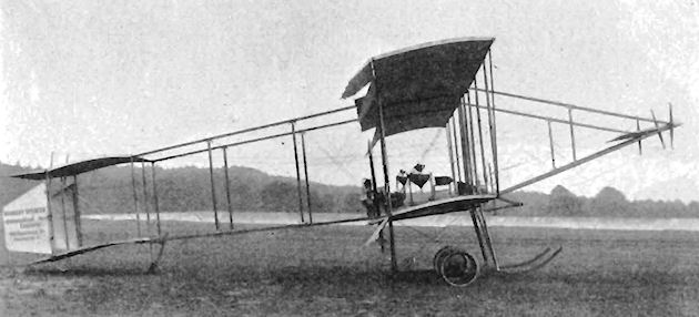
Spencer-Stirling Biplane
The Spencer-Stirling Biplane was basically a French Sommer boxkite, powered by the 40 h.p. British Aeroplane Syndicate R.H. engine taken from the Spencer-Stirling Monoplane. It was flown by Herbert Spencer at Brooklands for tuition purposes during 1911.
The Spencer-Stirling Biplane was basically a French Sommer boxkite, powered by the 40 h.p. British Aeroplane Syndicate R.H. engine taken from the Spencer-Stirling Monoplane. It was flown by Herbert Spencer at Brooklands for tuition purposes during 1911.
Spencer-Stirling Monoplane
The Spencer-Stirling Monoplane was built by C. G. Spencer and Sons and was shown at the 1910 Aero Show at Olympia. A tractor monoplane designed by Herbert Spencer and W. Stirling, it was powered by the four-cylinder 40 h.p. British Aeroplane Syndicate R.H. engine, which drove by chains two propellers of 6 ft. 6 ins. diameter mounted on the leading-edges of the wings. A reverse gear was incorporated in one propeller bracket for opposite rotation. The fuselage was of the "A"-frame type. The machine was tested at Brooklands. Span, 34 ft. Length, 27 ft. Wing area, 200 sq. ft. Weight empty, 650 lb. Weight loaded, 850 lb. Maximum speed, 40 m.p.h. Price, ?650.
The Spencer-Stirling Monoplane was built by C. G. Spencer and Sons and was shown at the 1910 Aero Show at Olympia. A tractor monoplane designed by Herbert Spencer and W. Stirling, it was powered by the four-cylinder 40 h.p. British Aeroplane Syndicate R.H. engine, which drove by chains two propellers of 6 ft. 6 ins. diameter mounted on the leading-edges of the wings. A reverse gear was incorporated in one propeller bracket for opposite rotation. The fuselage was of the "A"-frame type. The machine was tested at Brooklands. Span, 34 ft. Length, 27 ft. Wing area, 200 sq. ft. Weight empty, 650 lb. Weight loaded, 850 lb. Maximum speed, 40 m.p.h. Price, ?650.
Star Monoplane
The Star Monoplane was designed by Granville E. Bradshaw and built at the beginning of 1910 by the Star Engineering Company of Wolverhampton, and was among the exhibits at the Olympia Aero Show of the same year. The single-seat tractor monoplane's design was based generally upon that of the Antoinette, but embodied modifications, particularly in the tail unit.
A fuselage of triangular section was used, to which were attached non-warping, parallel-chord wings which were wire-braced to a single, tall pylon mounted in the centre section. In the nose was fitted a Star engine of 30 h.p., coupled to a Clarke propeller of 6 ft. 8 ins. diameter. The tail unit was unusual in that it incorporated all of the flying controls within its surfaces of four planes, which operated with a helicoidal movement, each turning at once in an opposite direction to the other to impart a twisting action. Twin skids and wheels formed the main undercarriage, which, combined with the very long tailskid, poised the machine nearly horizontally on the ground.
The Star Monoplane was tested at Dunstall Park, Wolverhampton, in October, 1910, but the radical control system was found to be impractical.
<...>
SPECIFICATION
Description: Single-seat tractor monoplane. Wooden structure, fabric covered.
Manufacturers: Star Engineering Co., Wolverhampton, Staffs.
Power Plant: 30 h.p. Star.
Dimensions: Span, 42 ft. Length, 32 ft. 6 ins. Wing area, 290 sq. ft.
Weights: Empty, 876 lb. Loaded, 950 lb.
Performance: Cruising speed, 36 m.p.h.
Price: ?450.
Star Biplane
The Star Biplane of 1910 was constructed by the Star Engineering Company of Wolverhampton, Staffs., and was a pusher machine on the lines of the Farman type. It was ready for testing in November, 1910.
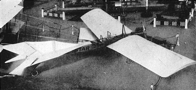
Star Monoplane as originally constructed.
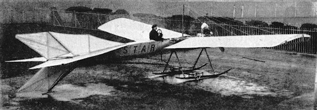
Star Monoplane in its early form.
Star Monoplane
<...>
During 1911 the machine was altered extensively. The triangular-section fuselage made in two halves for ease of transport was retained, but a more powerful four-cylinder Star engine, giving 50 h.p., was installed. The original wing span of 42 ft. was reduced to one of 37 ft., with a consequent lowering of area from 290 to 231 sq. ft.; rounded wing-tips replaced the earlier square-cut type, and the tip skids were discarded. The tail unit was revised completely, elevators and rudder operating normally replacing the previous complex arrangement. The fixed fin, however, was removed without a substitute being fitted. At the same time the undercarriage was strengthened and the height of the wing-bracing pylon reduced.
SPECIFICATION
Description: Single-seat tractor monoplane. Wooden structure, fabric covered.
Manufacturers: Star Engineering Co., Wolverhampton, Staffs.
Power Plant: 30 h.p. Star, 50 h.p. Star.
Dimensions: Span, 37 ft. Length, 32 ft. 6 ins. Wing area, 231 sq. ft.
Performance: Cruising speed, 36 m.p.h.
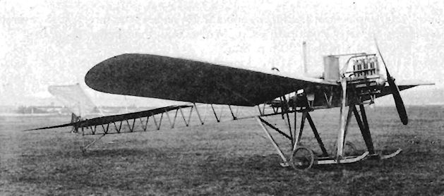
Star Monoplane in its final form.

Star Monoplane
Steward Monoplane
The Steward single-seat monoplane was built during 1910 and was tested at Cuffley, Herts., in January, 1911. The engine was the two-cylinder 20 h.p. Alvaston. The wings were of only 75 sq. ft. area, with a span of 16 ft. The length of the machine was 15 ft.
The Steward single-seat monoplane was built during 1910 and was tested at Cuffley, Herts., in January, 1911. The engine was the two-cylinder 20 h.p. Alvaston. The wings were of only 75 sq. ft. area, with a span of 16 ft. The length of the machine was 15 ft.
Swann Monoplane
The Reverend Sydney Swann, Rector of Crosby, Ravensworth Shap, Westmorland, designed and built his single-seat tractor monoplane in 1909. The machine was based on the Demoiselle type and was powered by the eight-cylinder 40 h.p. E.N.V. "D" engine. It was not successful and, at the end of the year, was converted into a biplane.
After a year's testing and hops of about 30 yds., the Reverend Swann gave up his attempts to fly when the machine hit a sheep. The following measurements apply to the biplane conversion. Span, 36 ft. Length, 27 ft. Wing area, 500 sq. ft. Weight loaded, 1,000 lb.
Talbot Waterplane
The Talbot Waterplane was a pusher hydro-biplane built at Fambridge, Essex, during early 1914. Both upper and lower wings were joined together by curved tips, and booms carried the biplane elevators at the front and the tailplane at the rear. The complete unit was mounted by means of struts to the boat-shaped float which contained the cockpit. The rear elevators were inter-connected to those at the front and twin rudders were set side-by-side between the rear booms. Ailerons were fitted at mid-gap between the wing-tips. The machine was powered by a water-cooled engine, flanked by vertical radiators, but was unable to rise from the water despite repeated attempts.
The Talbot Waterplane was a pusher hydro-biplane built at Fambridge, Essex, during early 1914. Both upper and lower wings were joined together by curved tips, and booms carried the biplane elevators at the front and the tailplane at the rear. The complete unit was mounted by means of struts to the boat-shaped float which contained the cockpit. The rear elevators were inter-connected to those at the front and twin rudders were set side-by-side between the rear booms. Ailerons were fitted at mid-gap between the wing-tips. The machine was powered by a water-cooled engine, flanked by vertical radiators, but was unable to rise from the water despite repeated attempts.
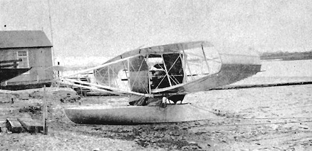
Teasdale-Buckell Helicopter
The Teasdale-Buckell Helicopter was built during 1910 and was fitted with a 30 h.p. engine. Basically a small high-wing canard monoplane, with vertical panels below the wing-tips and intermediately, it obtained direct lift from a pair of rotating "helix-planes", which comprised inclined helical planes arranged cylindrically and mounted on the propeller shafts. These "helix-planes" were driven by chains from the central engine. The propellers were of special design, based on Sir John Thorneycroft's marine experiments. The machine was claimed to have lifted vertically during tests. Span, 14 ft. Length, 18 ft. Wing area, 166 sq. ft. Estimated maximum speed, 70 m.p.h. Weight empty, 500 lb.
The Teasdale-Buckell Helicopter was built during 1910 and was fitted with a 30 h.p. engine. Basically a small high-wing canard monoplane, with vertical panels below the wing-tips and intermediately, it obtained direct lift from a pair of rotating "helix-planes", which comprised inclined helical planes arranged cylindrically and mounted on the propeller shafts. These "helix-planes" were driven by chains from the central engine. The propellers were of special design, based on Sir John Thorneycroft's marine experiments. The machine was claimed to have lifted vertically during tests. Span, 14 ft. Length, 18 ft. Wing area, 166 sq. ft. Estimated maximum speed, 70 m.p.h. Weight empty, 500 lb.
Thiersch Monoplane
The Thiersch Monoplane was a single-seat tractor type built by Alexander Thiersch during 1910. The wings, which were constructed by Handley Page Ltd., were of triangular shape and carried elevating planes at their forward extremities. Successful flights were made at Erith Marshes on 26th May, 1910.
The Thiersch Monoplane was a single-seat tractor type built by Alexander Thiersch during 1910. The wings, which were constructed by Handley Page Ltd., were of triangular shape and carried elevating planes at their forward extremities. Successful flights were made at Erith Marshes on 26th May, 1910.
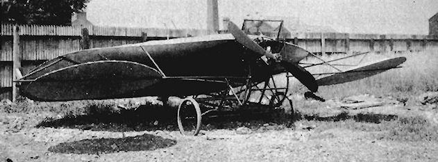
MR. ALEXANDER THIERSCH'S EXPERIMENTAL MONOPLANE. - The planes have been constructed by Mr. Handley Page to the design of Mr. Thiersch. The propellers are of French make.
Thiersch monoplane was partly built by Handley Page and was tested on Erith Marshes in 1910.
Thiersch monoplane was partly built by Handley Page and was tested on Erith Marshes in 1910.
Tinline Biplane
J. D. Tinline designed the Tinline Biplane of 1910. lt was tested at Eastchurch, but suffered from trouble with its engine.
J. D. Tinline designed the Tinline Biplane of 1910. lt was tested at Eastchurch, but suffered from trouble with its engine.
Twining Biplane No. 1
The Twining No. 1 was a canard biplane exhibited at the Olympia Aero Show of 1910. The wings were fitted with ailerons, and the engine was a two-cylinder 20 h.p. Phoenix rotary, driving a 6 ft. 3 ins. propeller. The machine was constructed by the Twining Aeroplane Co., of Hanwell, Middlesex. Span, 28 ft. Length, 14 ft. 7 ins. Wing area, 252 sq. ft. Weight empty, 450 lb. Weight loaded, 605 lb. Cruising speed, 35 m.p.h. Price, ?350.
Twining Biplane No. 2
The Twining No. 2 was a pusher biplane built by the Twining Aeroplane Co. during 1910. ft was powered by a two-cylinder horizontally-opposed 30 h.p. engine. It featured tilting ailerons mounted at mid-gap, and had twin rudders and elevators forward, with a fixed tailplane aft. Span, 37 ft. Length, 29 ft. Wing area, 372 sq. ft. Weight loaded, 580 lb.
Twining Glider
The Twining Glider was a biplane built during 1910 at Hanwell by the Twining Aeroplane Co., and was designed by E. W. Twining, who also created many model gliders and aeroplanes, some of which were marketed by toyshops as late as 1920. He was an artist and a draughtsman of exceptional skill, and in later life settled in Bristol, where he designed stained-glass windows. During the Second World War he made a brief return to aviation as a project draughtsman with the Bristol Aeroplane Co., whence he retired in 1946.
The Twining Glider was a biplane built during 1910 at Hanwell by the Twining Aeroplane Co., and was designed by E. W. Twining, who also created many model gliders and aeroplanes, some of which were marketed by toyshops as late as 1920. He was an artist and a draughtsman of exceptional skill, and in later life settled in Bristol, where he designed stained-glass windows. During the Second World War he made a brief return to aviation as a project draughtsman with the Bristol Aeroplane Co., whence he retired in 1946.
Universal Aviation Company Birdling
The Birdling single-seat tractor monoplane was adapted from the Bleriot design and was built during 1911 by the Universal Aviation Co. Ltd., of Brooklands. It was powered by the 50 h.p. Gnome engine, and was flown by H. J. D. Astley in the 1911 Daily Mail Circuit of Britain Race, but retired at Harrogate. The Birdling was bought later by F. K. McClean.
The Birdling single-seat tractor monoplane was adapted from the Bleriot design and was built during 1911 by the Universal Aviation Co. Ltd., of Brooklands. It was powered by the 50 h.p. Gnome engine, and was flown by H. J. D. Astley in the 1911 Daily Mail Circuit of Britain Race, but retired at Harrogate. The Birdling was bought later by F. K. McClean.
Vickers Monoplanes Nos. 1 to 8
An interest in the possibilities of business in aviation had been aroused in the armament manufacturers Vickers, Sons and Maxim following their experience of building the Royal Navy's first rigid airship, the R.1. The airship was a failure, but a strong belief in the heavier-than-air machine sent Capt. Herbert F. Wood, late of the 12th Lancers and the holder of the early Royal Aero Club Aviator's Certificate No. 37, to France to investigate the R.E.P. Monoplane built by Robert Esnault Pelterie. In consequence of Capt. Wood's appraisal and approval of the machine, and the further recommendation by Capt. Murray F. Sueter, R.N., who had acted as the Admiralty overseer at Barrow-in-Furness while the R.l was being built, Vickers negotiated the manufacturing rights of the design for the United Kingdom and the British Colonies.
At that time the R.E.P. Monoplane could be considered an advanced design by virtue of its steel-tubing airframe and its patented control system, which comprised a single control-column for the elevators and the wing-warping, and pedals or a bar to operate the rudder.
The first Vickers aeroplane, designated No. 1, was built early in 1911 at the Vickers works at Erith in Kent, the design work being carried out by A. R. Low and G. H. Challenger and the construction by a small, relatively inexperienced team supervised by H. F. Field. The machine followed closely the original French lay-out, using the rear part of the R.E.P., which was combined with a redesigned front fuselage and undercarriage. The engine fitted was the five-cylinder fan-shaped 60 h.p. R.E.P. radial with a 7 ft. 11 ins. diameter propeller, and this power unit, either British- or French-built, was used also on the succeeding Monoplanes Nos. 2, 3, 4 and 5, although other engines were tried experimentally.
Capt. Wood, who had been appointed Manager of Vickers Aviation Department, flew the Monoplane No. 1 for the first time in July, 1911, from a new private aerodrome which had been laid out below the level of the River Thames near the Long Reach Tavern at Joyce Green, Dartford, Kent. The machine was bought by Dr. Douglas Mawson for the use of the 1912 Australian Antarctic Expedition and was shipped to Australia. On arrival there, it was tested by Lt. H. E. Watkins, who crashed it at Adelaide. The fuselage was taken to Cape Denison, Antarctica, where an unsuccessful attempt was made to use it as a propeller-driven sledge, and the remains of the abandoned steel-tubing fuselage are said to survive there still.
<...>
SPECIFICATION (No. 1)
Description: Two-seat tractor monoplane. Steel tubing structure, fabric covered.
Manufacturers: Vickers, Sons and Maxim Ltd., Erith, Kent.
Power Plant: 60 h.p. R.E.P.
Dimensions: Span, 47 ft. 6 ins. Length, 36 ft. 5 ins. Wing area, 290 sq. ft.
Weights: Empty, 1,000 lb.
Performance: Maximum speed, 56 m.p.h.
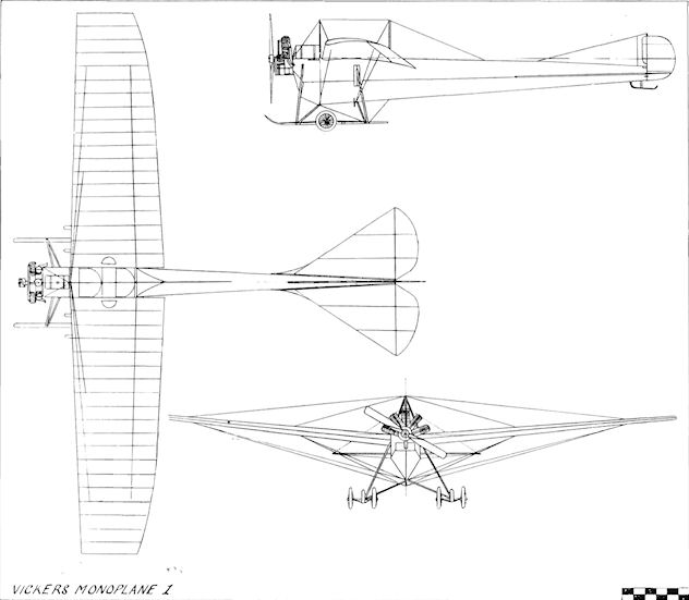
Vickers Monoplane 1
Vickers Hydravion
A large four-seat pusher biplane, No. 14, was built by Vickers during 1912 and named the Hydravion. It was powered by the 100 h.p. two-valve Gnome engine. A seaplane version was fitted with floats made at the Dartford works, but crashed at Dartford in the course of an early test flight. Span, 72 ft. 8 ins. Length, 43 ft. Height, 12 ft. 2 ins. Wing area, 819 sq. ft. Weight loaded, 2,400 lb. Maximum speed, 51.5 m.p.h.
A large four-seat pusher biplane, No. 14, was built by Vickers during 1912 and named the Hydravion. It was powered by the 100 h.p. two-valve Gnome engine. A seaplane version was fitted with floats made at the Dartford works, but crashed at Dartford in the course of an early test flight. Span, 72 ft. 8 ins. Length, 43 ft. Height, 12 ft. 2 ins. Wing area, 819 sq. ft. Weight loaded, 2,400 lb. Maximum speed, 51.5 m.p.h.
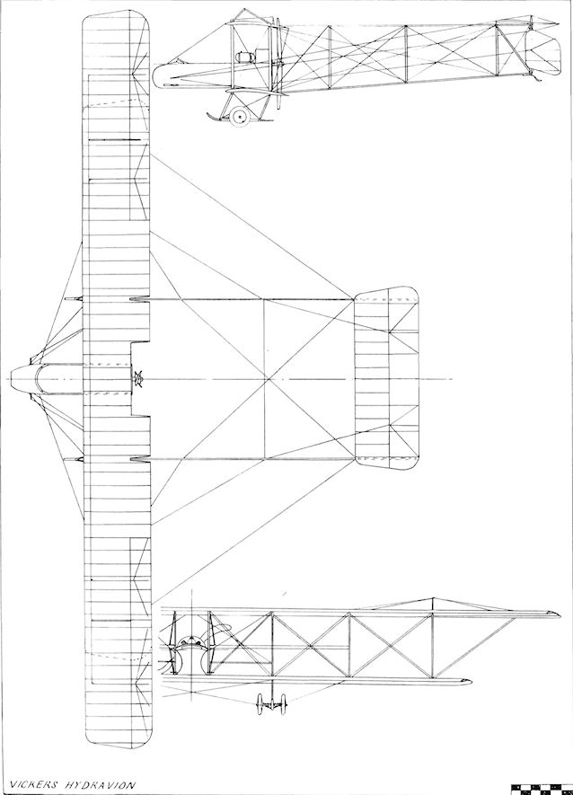
Vickers Hydravion
Vickers Monoplanes Nos. 1 to 8
<...>
Monoplane No. 2 was similar to No. 1, and Monoplanes Nos. 3, 4 and 5 complied fairly closely with the R.E.P. specification, but incorporated experimental differences in the depth of the fore-fuselages and in the undercarriages and also in the tail units. Steel tubing with built-up tubular joints was employed for the fuselage in place of the original R.E.P. system of brazing. Wire formed the bracing, and the covering was of fabric. In each of the machines the two occupants were seated in tandem, and in No. 3 extra room for them was conferred by changing the triangular area around the cockpits to a rectangular section. A tail unit and four-wheeled undercarriage similar to No. 1 were employed, but wings of a new plan-form with straight leading- and trailing-edges were fitted. The same cabane as No. 1 was retained, consisting of front inverted-vee struts and a single one at the rear. No. 5 showed several distinct differences from its predecessors. The fuselage was modified greatly with a deep fore-belly of rectangular section to provide lower seating for the two passengers. Towards the tail, the side elevation of the fuselage was tapered sharply. The cabane consisted of two pairs of inverted-vee struts, joined at the top by a further horizontal member. A fixed fin of revised shape was provided, together with a well-rounded rudder. The four-wheel undercarriage and its attendant skids were of the same type as before, and the wings followed the same pattern as those of No. 3.
Monoplanes Nos. 2, 3, 4 and 5 were on the strength of the Vickers School of Flying at Brooklands in 1912 as instructional aircraft, but proved to be rather heavy for this type of work.
Yet another Vickers Monoplane was the No. 7, which appeared in 1913. This reverted to the tandem-seat lay-out and, with its 100 h.p. two-valve Gnome engine and three-bladed propeller, was the most powerful of the monoplanes. Rather oddly, the early form of four-wheel, twin-skid under-carriage was revived for it. Further changes were made in the empennage, which incorporated a fixed fin.
<...>
<...>
Monoplane No. 2 was similar to No. 1, and Monoplanes Nos. 3, 4 and 5 complied fairly closely with the R.E.P. specification, but incorporated experimental differences in the depth of the fore-fuselages and in the undercarriages and also in the tail units. Steel tubing with built-up tubular joints was employed for the fuselage in place of the original R.E.P. system of brazing. Wire formed the bracing, and the covering was of fabric. In each of the machines the two occupants were seated in tandem, and in No. 3 extra room for them was conferred by changing the triangular area around the cockpits to a rectangular section. A tail unit and four-wheeled undercarriage similar to No. 1 were employed, but wings of a new plan-form with straight leading- and trailing-edges were fitted. The same cabane as No. 1 was retained, consisting of front inverted-vee struts and a single one at the rear. No. 5 showed several distinct differences from its predecessors. The fuselage was modified greatly with a deep fore-belly of rectangular section to provide lower seating for the two passengers. Towards the tail, the side elevation of the fuselage was tapered sharply. The cabane consisted of two pairs of inverted-vee struts, joined at the top by a further horizontal member. A fixed fin of revised shape was provided, together with a well-rounded rudder. The four-wheel undercarriage and its attendant skids were of the same type as before, and the wings followed the same pattern as those of No. 3.
Monoplanes Nos. 2, 3, 4 and 5 were on the strength of the Vickers School of Flying at Brooklands in 1912 as instructional aircraft, but proved to be rather heavy for this type of work.
Yet another Vickers Monoplane was the No. 7, which appeared in 1913. This reverted to the tandem-seat lay-out and, with its 100 h.p. two-valve Gnome engine and three-bladed propeller, was the most powerful of the monoplanes. Rather oddly, the early form of four-wheel, twin-skid under-carriage was revived for it. Further changes were made in the empennage, which incorporated a fixed fin.
<...>
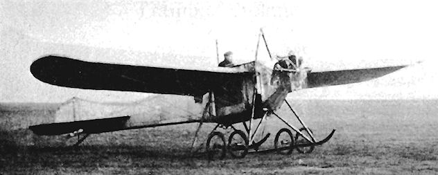
Vickers No. 3

Vickers No.5
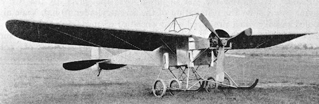
Three-quarter front view of No. 7 monoplane with three-bladed propeller.
Vickers Monoplanes Nos. 1 to 8
<...>
Monoplanes Nos. 2, 3, 4 and 5 were on the strength of the Vickers School of Flying at Brooklands in 1912 as instructional aircraft, but proved to be rather heavy for this type of work. A new design was therefore evolved which displayed a fairly definite breakaway from the previous machines. To comply with the requirements of the 1912 Military Trials for an equally good forward view for both of the crew, the Monoplane No. 6 featured side-by-side seats. Dual controls formed part of the equipment, and in plan view the wider, rectangular-section fuselage was untapered, the parallel sides finally splaying outwards to blend into the tailplane. A desirable increase in power over that given by the R.E.P. engine was met by the installation of the seven-cylinder 70 h.p. Viale air-cooled radial, which produced a top speed of 63 m.p.h. A fixed fin was dispensed with, a pleasingly-shaped rudder forming the vertical tail surfaces. Wings of 35 ft. span were braced from a cabane consisting of a pair of side-by-side inverted-vee struts. The earlier rather complex type of undercarriage was discarded; in its place was a simple unit of twin wheels on leaf springs and with a single central skid.
The Monoplane No. 6 was dubbed The Sociable and was flown in the Trials as entry No. 3, piloted by L. F. MacDonald. A troublesome engine reduced the machine's chances in the tests, and it was fitted later with a Viale of greater power. A 70 h.p. Gnome rotary finally replaced the Viale, and was covered over its upper portion by a neat cowling which blended into the lines of the fuselage. An improvement in the visibility of the crew was brought about by the addition of side windows in the fuselage.
<...>
The final variant of the first series of Vickers monoplanes was No. 8, which was built also in 1913 and was shown at the Olympia Aero Show of the same year. It was the earlier No. 6 in a new guise, fitted with the 70 h.p. or 80 h.p. Gnome engine. Minor modifications in detail had been made, including the revision of the horizontal tail surfaces to a fish shape. The machine had been flown for over 500 miles by L. F. MacDonald and R. H. Barnwell at the Erith field before it appeared at Olympia.
Vickers Tractor Biplane
A two-seat tractor biplane with a wooden airframe, driven by the 70 h.p. Gnome engine, was completed in December, 1912. It crashed into the River Thames at Erith on a flight from Joyce Green on 13th January, 1913, while piloted by Leslie F. MacDonald, who, together with his passenger, Harold England, was drowned.
<...>
Monoplanes Nos. 2, 3, 4 and 5 were on the strength of the Vickers School of Flying at Brooklands in 1912 as instructional aircraft, but proved to be rather heavy for this type of work. A new design was therefore evolved which displayed a fairly definite breakaway from the previous machines. To comply with the requirements of the 1912 Military Trials for an equally good forward view for both of the crew, the Monoplane No. 6 featured side-by-side seats. Dual controls formed part of the equipment, and in plan view the wider, rectangular-section fuselage was untapered, the parallel sides finally splaying outwards to blend into the tailplane. A desirable increase in power over that given by the R.E.P. engine was met by the installation of the seven-cylinder 70 h.p. Viale air-cooled radial, which produced a top speed of 63 m.p.h. A fixed fin was dispensed with, a pleasingly-shaped rudder forming the vertical tail surfaces. Wings of 35 ft. span were braced from a cabane consisting of a pair of side-by-side inverted-vee struts. The earlier rather complex type of undercarriage was discarded; in its place was a simple unit of twin wheels on leaf springs and with a single central skid.
The Monoplane No. 6 was dubbed The Sociable and was flown in the Trials as entry No. 3, piloted by L. F. MacDonald. A troublesome engine reduced the machine's chances in the tests, and it was fitted later with a Viale of greater power. A 70 h.p. Gnome rotary finally replaced the Viale, and was covered over its upper portion by a neat cowling which blended into the lines of the fuselage. An improvement in the visibility of the crew was brought about by the addition of side windows in the fuselage.
<...>
The final variant of the first series of Vickers monoplanes was No. 8, which was built also in 1913 and was shown at the Olympia Aero Show of the same year. It was the earlier No. 6 in a new guise, fitted with the 70 h.p. or 80 h.p. Gnome engine. Minor modifications in detail had been made, including the revision of the horizontal tail surfaces to a fish shape. The machine had been flown for over 500 miles by L. F. MacDonald and R. H. Barnwell at the Erith field before it appeared at Olympia.
Vickers Tractor Biplane
A two-seat tractor biplane with a wooden airframe, driven by the 70 h.p. Gnome engine, was completed in December, 1912. It crashed into the River Thames at Erith on a flight from Joyce Green on 13th January, 1913, while piloted by Leslie F. MacDonald, who, together with his passenger, Harold England, was drowned.
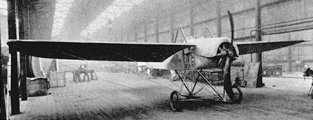
Vickers No.VIII monoplane in the works at Erith. It had side-by-side seating and a 70 or 80hp Gnome engine.
Vickers Gunbus E.F.B.1 to F.B.6
Designed by A. R. Low and G. H. Challenger, the Gunbus series of two-seat pusher biplanes originated from an Admiralty contract received on 19th November, 1912, for an experimental biplane to carry a machine-gun for offensive operations. In the absence of a suitable interrupter gear, the pusher lay-out was selected to provide as wide a field of fire as possible for the belt-fed Vickers-Maxim gun.
The prototype E.F.B.1 (Experimental Fighting Biplane No. 1) No. 18 Destroyer was ready in time to be displayed on the company's stand at the 1913 Olympia Aero Show. The gun was mounted in the nose of the duralumin-covered nacelle and moved in a slot which allowed 60° vertical and horizontal sweeps. The two-bay, unequal-span wings carried the nacelle on the lower planes, the monoplane tail unit with its rectangular tailplane being borne on tubular steel booms to the rear. The wings were staggered and were warped for lateral control. The upright struts in the booms were raked forward, and this applied to the rudder also. The engine installed was the eight-cylinder 80 h.p. Wolseley air-cooled vee with water-cooling for the valves.
The E.F.B.1 is believed to have crashed on its first test flight, but, as the design was considered promising, development proceeded into the E.F.B.2.
<...>
SPECIFICATION (E.F.B.1)
Description: Two-seat pusher fighter biplane. Wood and steel structure, fabric covered.
Manufacturers: Vickers Ltd., Imperial Court, Knightsbridge, London, S.W.I.
Power Plant: 80 h.p. Wolseley.
Dimensions: Span, 40 ft. Length, 27 ft. 6 ins. Wing area, 385 sq. ft.
Weights: Empty, 1,760 lb. Loaded, 2,660 lb.
Performance: Maximum speed, 70 m.p.h. Landing speed, 40 m.p.h. Climb, 450 ft./min. Endurance, 4.5 hrs.
Price: ?1,800.
Vickers Gunbus E.F.B.1 to F.B.6
<...>
The E.F.B.1 is believed to have crashed on its first test flight, but, as the design was considered promising, development proceeded into the E.F.B.2. This was given extra power with the installation of the nine-cylinder 100 h.p. Monosoupape Gnome in a nacelle which had been shortened at the rear, compared with that of the E.F.B.1. Another great difference between the two machines was the abandonment in the E.F.B.2 of the "all-staggered" look of its predecessor by the use of unequal-span unstaggered wings and of vertical struts and rudder. A tailplane with a curved leading-edge took the place of the rectangular one of the first machine, and crew vision was improved with a pair of large celluloid windows let into each side of the nacelle. Testing of the E.F.B.2 was carried out at Brooklands during October, 1913, by R. H. Barnwell.
Second thoughts about the Gunbus design were apparent in the E.F.B.3 No. 18b exhibited at the Olympia Aero Show of 1914. Strut-connected ailerons were introduced on the four wing-tips and the mainplanes were of equal span. The propeller cut-out in the upper centre section was deleted, as the engine had been moved a little towards the rear. Another omission was that of the side windows in the nacelle.
Following the E.F.B.3 came the E.F.B.4, which differed in detail. The sides of the nacelle were covered with fabric, and the gun was taken out of the trunnion mounting to be raised on to a pillar mounting to fire over the coaming for better sighting and manipulation. The oil tank was resited over the nacelle for improved control of the C.G. and the ailerons were connected by cables instead of struts. The interplane, centre-section and undercarriage struts, and the uprights between the tail booms, were made of wood in place of the metal struts used on the earlier machines of the series. The undercarriage also was revised by increasing the distance between the uprights and by lengthening the pair of skids.
<...>
<...>
The E.F.B.1 is believed to have crashed on its first test flight, but, as the design was considered promising, development proceeded into the E.F.B.2. This was given extra power with the installation of the nine-cylinder 100 h.p. Monosoupape Gnome in a nacelle which had been shortened at the rear, compared with that of the E.F.B.1. Another great difference between the two machines was the abandonment in the E.F.B.2 of the "all-staggered" look of its predecessor by the use of unequal-span unstaggered wings and of vertical struts and rudder. A tailplane with a curved leading-edge took the place of the rectangular one of the first machine, and crew vision was improved with a pair of large celluloid windows let into each side of the nacelle. Testing of the E.F.B.2 was carried out at Brooklands during October, 1913, by R. H. Barnwell.
Second thoughts about the Gunbus design were apparent in the E.F.B.3 No. 18b exhibited at the Olympia Aero Show of 1914. Strut-connected ailerons were introduced on the four wing-tips and the mainplanes were of equal span. The propeller cut-out in the upper centre section was deleted, as the engine had been moved a little towards the rear. Another omission was that of the side windows in the nacelle.
Following the E.F.B.3 came the E.F.B.4, which differed in detail. The sides of the nacelle were covered with fabric, and the gun was taken out of the trunnion mounting to be raised on to a pillar mounting to fire over the coaming for better sighting and manipulation. The oil tank was resited over the nacelle for improved control of the C.G. and the ailerons were connected by cables instead of struts. The interplane, centre-section and undercarriage struts, and the uprights between the tail booms, were made of wood in place of the metal struts used on the earlier machines of the series. The undercarriage also was revised by increasing the distance between the uprights and by lengthening the pair of skids.
<...>

Vickers E.F.B.2
Vickers Pumpkin
The Pumpkin of 1913 was the Vickers version of the Hewlett and Blondeau-built Farman two-seat pusher biplane and was constructed for school work at Brooklands. Side-by-side seats were fitted in a long covered nacelle, which carried at its rear end a seven-cylinder radial engine of 50 h.p. which was built by Vickers to designs by Mons. Boucier.
The Pumpkin of 1913 was the Vickers version of the Hewlett and Blondeau-built Farman two-seat pusher biplane and was constructed for school work at Brooklands. Side-by-side seats were fitted in a long covered nacelle, which carried at its rear end a seven-cylinder radial engine of 50 h.p. which was built by Vickers to designs by Mons. Boucier.
Vickers Gunbus E.F.B.1 to F.B.6
<...>
The E.F.B.5 formed the prototype of the production F.B.5, but, strangely enough, reverted to steel struts while retaining the equal-span wings and curved tailplane. Foreseeing the likelihood of war, the Vickers Company decided to put the Gunbus into production in advance of official orders, and the machine was revised to become the F.B.5. A return was made to the wooden struts of the E.F.B.4; the curved tailplane was replaced by the rectangular type, which was simpler to produce, and well-curved vertical tail surfaces were fitted. The armament comprised a drum-fed Lewis gun, which proved lighter and far handier than the Vickers-Maxim weapon. The F.B.5 underwent official tests at Farnborough in July, 1914, and subsequently proved a useful addition to the strength of the R.F.C. Fifteen were used also by the R.N.A.S.
<...>
<...>
The E.F.B.5 formed the prototype of the production F.B.5, but, strangely enough, reverted to steel struts while retaining the equal-span wings and curved tailplane. Foreseeing the likelihood of war, the Vickers Company decided to put the Gunbus into production in advance of official orders, and the machine was revised to become the F.B.5. A return was made to the wooden struts of the E.F.B.4; the curved tailplane was replaced by the rectangular type, which was simpler to produce, and well-curved vertical tail surfaces were fitted. The armament comprised a drum-fed Lewis gun, which proved lighter and far handier than the Vickers-Maxim weapon. The F.B.5 underwent official tests at Farnborough in July, 1914, and subsequently proved a useful addition to the strength of the R.F.C. Fifteen were used also by the R.N.A.S.
<...>
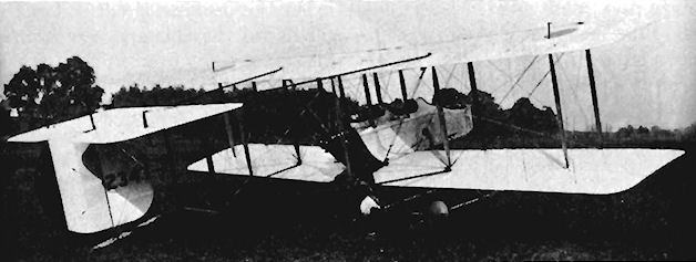
Production Vickers F.B.5 with rectangular tailplane.
Vickers Gunbus E.F.B.1 to F.B.6
<...>
A single experimental F.B.6 appeared in July, 1914, and was fitted with unequal-span wings, the considerable overhang of which was supported by king-posts and wires. The machine utilized the curved tailplane and the rudder had a straight trailing-edge.
The Gunbuses were pleasant and easy machines to fly after the early unreliability of their 100 h.p. Monosoupape Gnomes had been attended to, and the type was notable as a pioneer among gun-carrying aeroplanes.
Vickers Scout
In addition to showing their pusher E.F.B.3 Gunbus at the 1914 Olympia Aero Show, Vickers unveiled a two-seat tractor biplane scout. The machine was powered by the 100 h.p. Monosoupape Gnome driving a Levasseur propeller. Equal-span, single-bay staggered wings of low thickness/chord ratio were fitted, and the tailplane was of the lifting type. The airframe was of wood, covered with fabric. Span, 25 ft. Length, 20 ft. 7 ins. Wing area, 270 sq. ft. Weight empty, 600 lb. Weight loaded, 1,200 lb. Maximum speed, 100 m.p.h. Landing speed, 45 m.p.h. Endurance, 4.5 hrs.
In addition to showing their pusher E.F.B.3 Gunbus at the 1914 Olympia Aero Show, Vickers unveiled a two-seat tractor biplane scout. The machine was powered by the 100 h.p. Monosoupape Gnome driving a Levasseur propeller. Equal-span, single-bay staggered wings of low thickness/chord ratio were fitted, and the tailplane was of the lifting type. The airframe was of wood, covered with fabric. Span, 25 ft. Length, 20 ft. 7 ins. Wing area, 270 sq. ft. Weight empty, 600 lb. Weight loaded, 1,200 lb. Maximum speed, 100 m.p.h. Landing speed, 45 m.p.h. Endurance, 4.5 hrs.
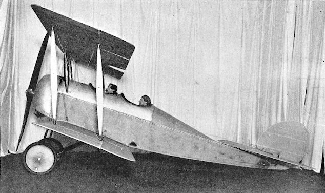
Vickers 1914 tractor scout biplane, a clean design, but abandoned in favour of Gunbus development.
Wallbro Monoplane
The Wallbro Monoplane was a single-seat tractor constructed during 1909.
The Wallbro Monoplane was a single-seat tractor constructed during 1909.
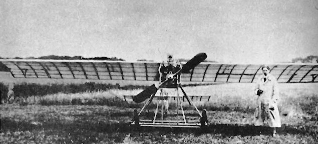
Walton Edwards Colossoplane
Known also as the Elephantoplane, the Walton Edwards Colossoplane two-seat tractor biplane was flying at Brooklands in October, 1911. The engine was the 100 h.p. Clerget, and an unorthodox feature of the machine was that the balance could be adjusted by sliding the engine and the seats fore and aft. Warping was used for lateral control, but was applied to the leading-edges of the wings instead of to the trailing-edges. A biplane tail with single elevator carried a single triangular rudder between the tail-planes, and two similar but larger rudders were mounted half-way along the tail booms.
Known also as the Elephantoplane, the Walton Edwards Colossoplane two-seat tractor biplane was flying at Brooklands in October, 1911. The engine was the 100 h.p. Clerget, and an unorthodox feature of the machine was that the balance could be adjusted by sliding the engine and the seats fore and aft. Warping was used for lateral control, but was applied to the leading-edges of the wings instead of to the trailing-edges. A biplane tail with single elevator carried a single triangular rudder between the tail-planes, and two similar but larger rudders were mounted half-way along the tail booms.
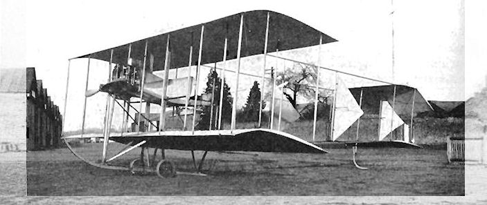
Walton-Edwards Colossoplane. This huge biplane made mainly straight flights at Brooklands towards the end of 1911.
Watkins Monoplane
The Watkins single-seat tractor monoplane was designed and built during 1909 by C. Horace Watkins of Wales. Watkins constructed every part of the machine himself, including the three-cylinder 40 h.p. engine which was also of his own design and used castings made in a local foundry to his patterns. Orthodox wooden construction with wire bracing was employed for the airframe, the undercarriage consisting of cycle tubing with brazed joints. Originally a tailwheel was fitted, but this was replaced by a tailskid after the first tests. Many ingenious features were incorporated in the design, among them being three positions for the attachment of the undercarriage. The first of these was immediately below the engine so that the front fuselage could be used as an engine test-bed; the second position was one bay to the rear of the first position, which permitted taxying under full power without risk of taking-off or of nosing-over; the third position was two bays behind the first position and incorporated the undercarriage just forward of the C.G. and in the normal flight location. The aerofoil-section oil tank was mounted in front of the centre cylinder of the engine for maximum cooling. Flight instruments comprised a spring-loaded vane-type indicator for air speed which was mounted on top of the cabane, a caged-ball form of inclinometer to indicate the degree of bank applied, and a vertical wind-vane to show side-slip or yaw. The tachometer consisted of a 4 volt D.C. dynamo which was driven by the engine and was connected to a voltmeter to register up to about 1,200 r.p.m.
Watkins found that when tests were made in broad daylight they drew sight-seeing crowds who damaged the gates and hedges of the land from which he had permission to fly, so he had to confine his activities to the periods before dawn or after sunset. To facilitate landing under these conditions of half-light, he devised a height indicator. This was made up of two vertical tubes in the cockpit, through which were trailed cords of different lengths with weights on their ends. Each was suspended from a light spring which was connected to a pair of switch contacts. When coming in to land, the weight on the longer cord - about 12 feet in length - would touch the ground first, the drag causing a green light to show in the cockpit. The machine would then be flattened out until the shorter cord, which was about 6 feet in length, touched the earth and lighted up a red light. The ignition was then cut off and the machine brought in to land from about 4 feet up at 25 m.p.h. The Watkins Monoplane is still in existence in Cardiff. Span, 32 ft. Length, 21 ft. 6 ins. Height, 8 ft. Weight loaded, 390 lb. Maximum speed, 70 m.p.h. Landing speed, 25 m.p.h. Range, 180 miles (estimated).
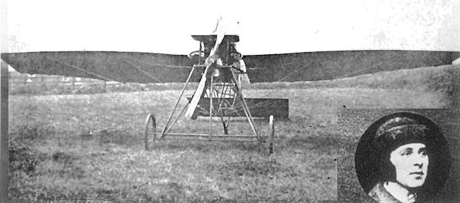
Watkins monoplane built in 1908-1909 flew successfully for a number of years and still survives in a museum in Wales.
Watson Biplane No. 1
An unusual form of lateral control was originated by Preston A. Watson, an early Scottish flying enthusiast, who incorporated it in his biplane, which was built in either late 1908 or early 1909. The upper wings were arranged to rock sideways by means of a hanging control stick, and this was expected to help the machine to maintain its equilibrium. A four-cylinder horizontally-opposed Dutheil-Chalmers engine was fitted before the aircraft was dismantled and reconstructed during 1910 as a glider for the Dundee Aero Club.
An unusual form of lateral control was originated by Preston A. Watson, an early Scottish flying enthusiast, who incorporated it in his biplane, which was built in either late 1908 or early 1909. The upper wings were arranged to rock sideways by means of a hanging control stick, and this was expected to help the machine to maintain its equilibrium. A four-cylinder horizontally-opposed Dutheil-Chalmers engine was fitted before the aircraft was dismantled and reconstructed during 1910 as a glider for the Dundee Aero Club.
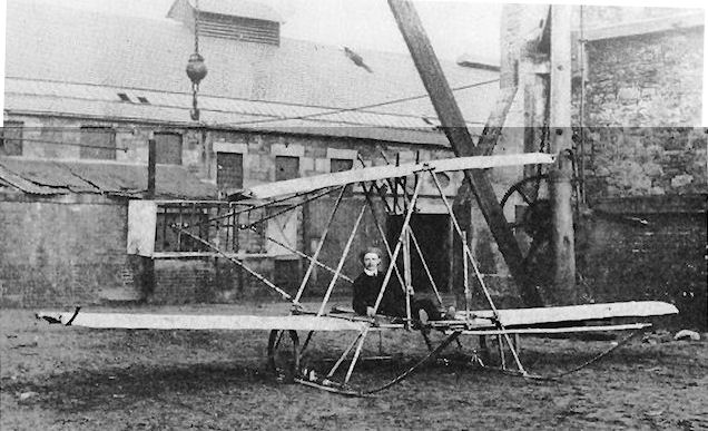
Watson No.I biplane with rocking wing for lateral control. Built at Dundee in 1908-1909.
Watson Biplane No. 2
The second biplane designed by Preston Watson to incorporate his tilting upper wings appeared in 1910 and was fitted with a three-cylinder Humber engine of 30 h.p. It was an improved version of the first machine, and was fitted with a four-wheel undercarriage and bracing struts to the tips of the lower wings' underside. Further modifications were made, which consisted of fitting a new monoplane horizontal tail without end fins, side area at the rear being embodied by filling in between the booms at the rear. In this form the Watson No. 2 was flying at Errol, Perthshire, during 1912.
The second biplane designed by Preston Watson to incorporate his tilting upper wings appeared in 1910 and was fitted with a three-cylinder Humber engine of 30 h.p. It was an improved version of the first machine, and was fitted with a four-wheel undercarriage and bracing struts to the tips of the lower wings' underside. Further modifications were made, which consisted of fitting a new monoplane horizontal tail without end fins, side area at the rear being embodied by filling in between the booms at the rear. In this form the Watson No. 2 was flying at Errol, Perthshire, during 1912.
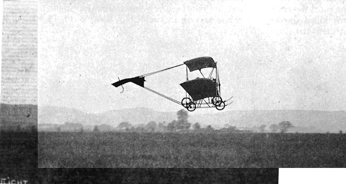
Modified Watson No. 2 in flight at Errol, Perthshire, 1912.
Watson Biplane No. 3
Preston Watson's third powered aeroplane also was fitted with the lifting upper wings, and was built during 1913. A six-cylinder 45 h.p. Anzani engine provided the power and was mounted immediately in front of the wicker nacelle. Steel-tubing struts were used for the framework and were streamlined by covering them with detachable plywood fairings. The monoplane tail unit was carried by a pair of metal-tubing booms fixed to the lower wings.
In 1914 the machine was taken to Buc, France, where it took part in the Concours de la Securite en Aeroplane. The Watson No. 3 managed to fly for short distances, but was not conspicuously successful. Its originator was killed during 1915 while serving in the R.N.A.S. as a Flt. Sub-Lieutenant.
Weaver Ornithoplane
The Weaver Ornithoplane was designed by A. Weaver and constructed during 1910 by Weaver and Morton of Coventry, Warks. The machine was a large ornithopter of 45 ft. span and was powered by a 20 h.p. engine. The framework was built of bamboo and aluminium tubing covered with fabric. It was tested on 17th May, 1910, and was claimed to have flown for a quarter of a mile.
The Weaver Ornithoplane was designed by A. Weaver and constructed during 1910 by Weaver and Morton of Coventry, Warks. The machine was a large ornithopter of 45 ft. span and was powered by a 20 h.p. engine. The framework was built of bamboo and aluminium tubing covered with fabric. It was tested on 17th May, 1910, and was claimed to have flown for a quarter of a mile.
Webb-Peet Tandem Monoplane
The Webb-Peet Tandem Monoplane was designed by the brothers Scott and built during 1910 by Webb-Peet and Co., of Gloucester. It was a two-seat canard tractor with a pair of propellers on the leading-edge of the wings. The mainplane was 40 ft. in span and the front elevating plane 25 ft., both being curved to a gull shape with flexible trailing edges. There were two small rudders at the tail. The engine was a Webb-Peet rotary. The machine did not succeed in flying. Total wing area. 410 sq.
The Webb-Peet Tandem Monoplane was designed by the brothers Scott and built during 1910 by Webb-Peet and Co., of Gloucester. It was a two-seat canard tractor with a pair of propellers on the leading-edge of the wings. The mainplane was 40 ft. in span and the front elevating plane 25 ft., both being curved to a gull shape with flexible trailing edges. There were two small rudders at the tail. The engine was a Webb-Peet rotary. The machine did not succeed in flying. Total wing area. 410 sq.
Weiss 1909 Glider
Jose Weiss was a French engineer and painter domiciled in England who, at the turn of the century, was fascinated by the challenge of flight. After several years of experiments carried out between 1902 and 1907, during which about two hundred models were made, he evolved his formula for automatic stability of a tailless monoplane with curved, swept-back wings. To prove his theories he constructed a full-size aeroplane, a single-seat glider based on one of his large models, incorporating the qualities of natural stability found in the shapes of birds which Weiss believed of fundamental importance in the design of man-carrying aircraft. His answer to the problem was demonstrated in the curvature of the wings, the section of which was thick at the roots, but which tapered outwards until the tips were flexible. The positive incidence at the fuselage was decreased until, at the tips, a negative incidence was produced by wash-out and by turning the trailing-edge upwards. Hinged elevators extended from the wing-roots to part of the way along the trailing-edge to provide experience with control surfaces. The glider was christened Olive after one of Weiss's daughters, and was tested at Amberley, Sussex, during 1909 by E. C. Gordon England, Graham Wood (shown in cockpit) and others. Successful flights as a glider led to the installation of a J. A.P. engine, succeeded by an Anzani. The machine was taken to Fambridge, Essex, for powered experiments there, but it failed to leave the ground.
Jose Weiss was a French engineer and painter domiciled in England who, at the turn of the century, was fascinated by the challenge of flight. After several years of experiments carried out between 1902 and 1907, during which about two hundred models were made, he evolved his formula for automatic stability of a tailless monoplane with curved, swept-back wings. To prove his theories he constructed a full-size aeroplane, a single-seat glider based on one of his large models, incorporating the qualities of natural stability found in the shapes of birds which Weiss believed of fundamental importance in the design of man-carrying aircraft. His answer to the problem was demonstrated in the curvature of the wings, the section of which was thick at the roots, but which tapered outwards until the tips were flexible. The positive incidence at the fuselage was decreased until, at the tips, a negative incidence was produced by wash-out and by turning the trailing-edge upwards. Hinged elevators extended from the wing-roots to part of the way along the trailing-edge to provide experience with control surfaces. The glider was christened Olive after one of Weiss's daughters, and was tested at Amberley, Sussex, during 1909 by E. C. Gordon England, Graham Wood (shown in cockpit) and others. Successful flights as a glider led to the installation of a J. A.P. engine, succeeded by an Anzani. The machine was taken to Fambridge, Essex, for powered experiments there, but it failed to leave the ground.

Weiss glider 'Olive' was built and tested at Amberley in 1908-1909.
Weiss Pusher Monoplane
In the same year as the Weiss Glider, a power-driven single-seat tailless monoplane designed on the same principles was built during 1909 by Weiss himself and was exhibited by Handley Page at the 1909 Olympia Aero Show, together with a notice stating that a second example was being built by Handley Page for the Weiss Aeroplane and Launcher Syndicate Ltd. The Weiss type of wing plan-form, with its curved, swept-back leading-edge, was used on the Handley Page Glider, the H.P.1, H.P.3, H.P.4, H.P.5 and H.P.6 Monoplanes and also on the H.P.7 Biplane. A short nacelle was mounted below the wings, and contained a three-cylinder Anzani developing 12 h.p. which was installed behind the pilot. Gearing and chain-drives linked the power unit to a pair of 6 ft. diameter propellers which were recessed in the trailing-edge of the wings, the elevators being fitted immediately behind them, level with the thrust-line. Bamboo was used in the structure of the fabric-covered fuselage. The landing-gear consisted of skids, but the machine took off from a jettisonable four-wheel carriage which, it was claimed, would face the wind automatically. A guarantee of flight was offered with the price of ?500, but the machine, named Madge after one of Weiss's five daughters, never managed to leave the ground. Span, 34 ft. Wing area, 226 sq. ft. Weight empty, 360 lb. Weight loaded, 500 lb.
In the same year as the Weiss Glider, a power-driven single-seat tailless monoplane designed on the same principles was built during 1909 by Weiss himself and was exhibited by Handley Page at the 1909 Olympia Aero Show, together with a notice stating that a second example was being built by Handley Page for the Weiss Aeroplane and Launcher Syndicate Ltd. The Weiss type of wing plan-form, with its curved, swept-back leading-edge, was used on the Handley Page Glider, the H.P.1, H.P.3, H.P.4, H.P.5 and H.P.6 Monoplanes and also on the H.P.7 Biplane. A short nacelle was mounted below the wings, and contained a three-cylinder Anzani developing 12 h.p. which was installed behind the pilot. Gearing and chain-drives linked the power unit to a pair of 6 ft. diameter propellers which were recessed in the trailing-edge of the wings, the elevators being fitted immediately behind them, level with the thrust-line. Bamboo was used in the structure of the fabric-covered fuselage. The landing-gear consisted of skids, but the machine took off from a jettisonable four-wheel carriage which, it was claimed, would face the wind automatically. A guarantee of flight was offered with the price of ?500, but the machine, named Madge after one of Weiss's five daughters, never managed to leave the ground. Span, 34 ft. Wing area, 226 sq. ft. Weight empty, 360 lb. Weight loaded, 500 lb.
Weiss Tractor Monoplane No. 1
Named Elsie after another of Jose Weiss's daughters, the first tractor monoplane was adapted from the tailless glider with which Weiss joined E. C. Gordon England and Noel Pemberton Billing for a while at Fambridge, Essex, during 1909. Originally a single straight skid with twin wheels formed part of the undercarriage, but this was changed later for a pair of curved skids. The engine was a three-cylinder 25 h.p. Warren-Simpson. During mid-1910 the machine was at Brooklands and was tested there by Gerald Leake, following unsatisfactory trials at Littlehampton, Sussex. Leake was a commercial artist, attracted also by the possibility of flight.
Named Elsie after another of Jose Weiss's daughters, the first tractor monoplane was adapted from the tailless glider with which Weiss joined E. C. Gordon England and Noel Pemberton Billing for a while at Fambridge, Essex, during 1909. Originally a single straight skid with twin wheels formed part of the undercarriage, but this was changed later for a pair of curved skids. The engine was a three-cylinder 25 h.p. Warren-Simpson. During mid-1910 the machine was at Brooklands and was tested there by Gerald Leake, following unsatisfactory trials at Littlehampton, Sussex. Leake was a commercial artist, attracted also by the possibility of flight.

Weiss Tractor Monoplane No. 2
The second of Jose Weiss's tractor monoplanes, Sylvia, was slightly larger than the first, and following earlier trials at Littlehampton, appeared at Brooklands during 1910 for testing by E. C. Gordon England. The main difference between the two machines was that the second was fitted with a normal monoplane type of tail unit, complete with fixed fin and a rudder. The engine employed was the eight-cylinder 40 h.p. E.N.V. "D", which had its attendant radiator mounted underneath the fore-part of the fuselage.
The fuselage itself consisted mainly of a bamboo framework which had its joints lashed together with twine, the engine being carried on a steel-tubing structure at the front. A fixed undercarriage was used and comprised two main wheels augmented by a smaller pair carried at the front of the twin skids. The remainder of the landing-gear consisted of a curved skid to support the tail.
Gordon England managed to make some successful flights at Brooklands with the machine, but eventually, on 22nd December, 1910, it was landed in the notorious sewage farm near by which claimed so many unwilling victims at the time; breakage of the wing bracing struts had caused loss of control.
SPECIFICATION
Description: Single-seat tractor monoplane. Wooden structure, fabric covered.
Manufacturer: Jose Weiss, Amberley, Sussex.
Power Plant: 40 h.p. E.N.V. "D".
Dimensions: Span, 34 ft. Length, 23 ft. Wing area, 164 sq. ft.
Weights: Loaded, 750 lb.
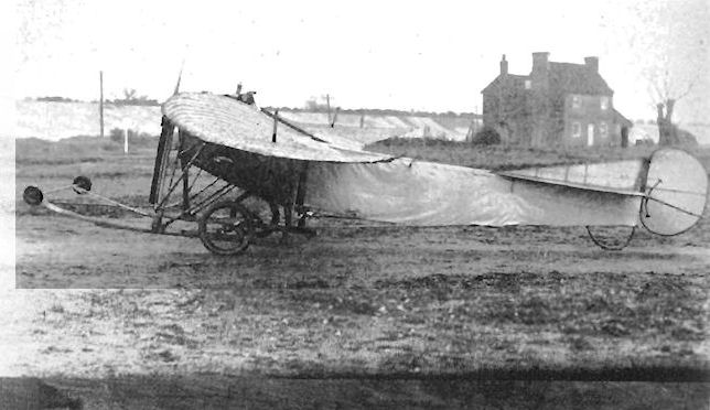
Weiss tractor monoplane No.2 'Sylvia' was tested at Brooklands in 1910-1911.
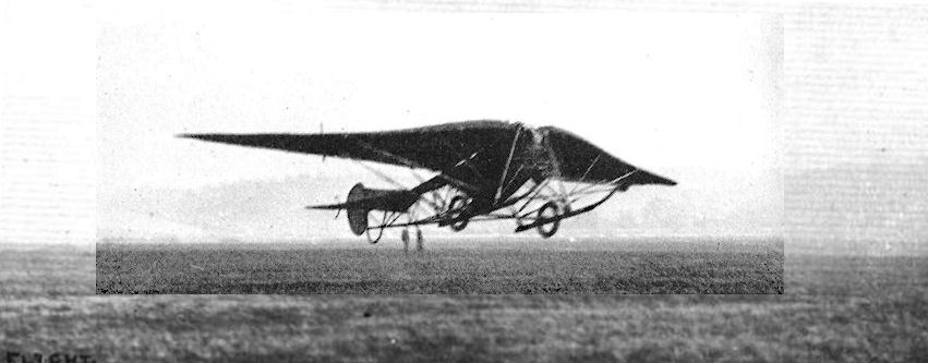
The Weiss Tractor Monoplane No. 2 in flight at Brooklands under the pilotage of Mr. Eric England (E. C. Gordon England) last Saturday.
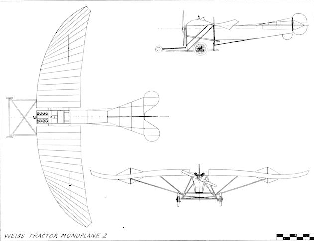
Weiss Tractor Monoplane 2
Weiss 1911 Glider
At the same time that he was engaged in his experiments with powered aeroplanes, Jose Weiss built and tested in 1911, at Amberley Mount, Sussex, another tailless glider which was christened Joker after the nickname given to one of his sons.
At the same time that he was engaged in his experiments with powered aeroplanes, Jose Weiss built and tested in 1911, at Amberley Mount, Sussex, another tailless glider which was christened Joker after the nickname given to one of his sons.

Weiss glider 'Joker' of 1911-1912 was tested at Amberley and later given to the Polytechnic Gliding and Flying Society.
Welford Monoplane
The Welford Monoplane was a single-seat tractor built during 1910 at Mansion House, North Hylton, Sunderland, by Robert Welford, assisted by his sons George and C. Welford. It was constructed of bamboo, ash and spruce, and was a blend of Antoinette and Bleriot features. The wings were fitted with ailerons for lateral control. The machine, equipped with an air-cooled four-cylinder engine, was tested at Boldon Flats, Northumberland, flying in May, 1910. Span, 26 ft. Weight empty, 430 lb.
The Welford Monoplane was a single-seat tractor built during 1910 at Mansion House, North Hylton, Sunderland, by Robert Welford, assisted by his sons George and C. Welford. It was constructed of bamboo, ash and spruce, and was a blend of Antoinette and Bleriot features. The wings were fitted with ailerons for lateral control. The machine, equipped with an air-cooled four-cylinder engine, was tested at Boldon Flats, Northumberland, flying in May, 1910. Span, 26 ft. Weight empty, 430 lb.
Wenham Glider
F. H. Wenham was one of the earliest scientific aeronautical experimenters in Great Britain. He built and tested his multiplane glider during 1858-59. It consisted of five superimposed wings of fairly high aspect-ratio, with the pilot occupying a prone position. Despite the soundness of the theories behind the design the glider was not a success, but it laid the foundations for the aeroplanes which were to follow in later years.
F. H. Wenham was one of the earliest scientific aeronautical experimenters in Great Britain. He built and tested his multiplane glider during 1858-59. It consisted of five superimposed wings of fairly high aspect-ratio, with the pilot occupying a prone position. Despite the soundness of the theories behind the design the glider was not a success, but it laid the foundations for the aeroplanes which were to follow in later years.
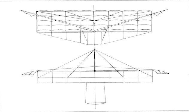
Westlake Monoplane
A. Westlake, of Clacton-on-Sea, Essex, was an automobile engineer by profession, but was one of the pioneers among workers in aeronautical research in Great Britain. He started his experiments during 1904 and finally designed his own aeroplane, which was built in 1913 by the East Anglian Aviation Co. Ltd., of Clacton.
The machine was a single-seat tractor monoplane of comparatively clean appearance but of rather low power. The engine was constructed by Westlake from four de Dion air-cooled cylinders, which he mounted horizontally-opposed on the crankcase, with a resulting output of 18 h.p.
The front portion of the fuselage was given a section of pentagon form, which changed to triangular aft of the wings. Mid-way to the tail the upper pair of longerons were splayed outwards to form the leading-edge of the tailplane, to the rear of which was fixed a one-piece elevator of generous area.
The wings were of parallel-chord outline, with large ailerons fitted at an angle across the tips. In a projected later version wing-warping was proposed, together with variable incidence. The wings were braced to a sturdy cabane and the wide-track undercarriage was sprung with rubber cord for absorbing shocks. No fin was fitted, the rudder alone providing the vertical tail area.
The Westlake Monoplane made successful straight flights, but its performance was limited severely by the low power obtainable from the engine.
SPECIFICATION
Description: Single-seat tractor monoplane. Wooden structure, fabric covered.
Manufacturers: East Anglian Aviation Co. Ltd., Clacton-on-Sea, Essex.
Power Plant: 18 h.p. Westlake.
Dimensions: Span, 34 ft. Length, 23 ft. 6 ins. Wing area, 175 sq. ft.

Westlake Monoplane
Weston-Hurlin Biplane
The Weston-Hurlin Biplane was constructed during 1911 by Weston-Hurlin and Co., of Paddington, London. The swept-back main wings were mounted on top of the fuselage, with the Webb-Peet rotary engine set on the leading-edge and the pilot at the trailing-edge. The upper wings of 16 ft. span were straight and were mounted above the 30 ft. span lower vee-shaped wings on four struts. The elevators were mounted at the front, a normal tail unit being carried at the rear.
Harper Monoplane
The two-seat tractor Harper Monoplane was designed by A. M. Harper and was built during 1912 by Weston-Hurlin and Company of Paddington. It was entered in the Military Trials held in August on Salisbury Plain, but did not take part in them. Its engine was the four-cylinder 60 h.p. Green. Span, 35 ft. Length, 27 ft. Maximum speed, 60 m.p.h.
308
White and Thompson No. 1
The publication of F. W. Lanchester's Aerodynamics in 1907 aroused considerable interest for the subject in Norman A. Thompson, an electrical engineer by profession, who was, at that time, manager of the Clyde Valley Electrical Power Company. The appearance of Aerodonetics by the same author during the following year was responsible in 1908 for Thompson's decision finally to enter the field of aviation, as he felt that the time had arrived for practical engineering experience to be applied to the theory of flight. Thompson met Lanchester in March, 1909, and enlisted his services as a designer and adviser to White and Thompson, a partnership which he had formed with Dr. Douglas White, a friend of substantial means and with varied interests. Dr. White agreed to finance experiments, not for profit but to help to ensure that Great Britain remained in the forefront of progress.
Lanchester's first design for the partnership was planned originally as a single-seat machine with one engine, but was then revised as a two-seater with two 50 h.p. Gnomes, coupled to each other by a crossed belt in case of failure of one of them. Construction was placed in the hands of the Daimler Motor Company of Coventry, who had started the fuselage and engine installation when, in the summer of 1910, the work was transferred to the White and Thompson premises at Middleton-on-Sea, near Bognor, Sussex. A shed and offices had been set up with a staff of ten under Dr. White and Norman Thompson as joint managers, and the site was chosen because of the fine stretches of sand along the shore between Bognor and Littlehampton which were very suitable for testing. The surface, however, was changed greatly by a heavy storm before the firm completed the Daimler-built chassis. The No. 1 emerged finally as a pusher biplane with Warren-girder braced, all-metal wings which were covered with 23 s.w.g. aluminium, and mounted on a fuselage consisting of an ash frame clad with sheet steel. Dihedral was incorporated in the lower wings only, and biplane tail surfaces were combined with four fixed fins, construction being similar to that of the wings, while movable surfaces comprised a nose-mounted rudder and split elevators. The sturdy four-wheel undercarriage was of the pneumatic type. Conforming with Lanchester's ideas, the machine was designed for high-speed flight by fitting small wings and opposite-rotating narrow, three-bladed propellers of only 5 ft. 2 ins. diameter.
Tests were carried out along the shore by Norman Thompson and by Captain Wilmot Nicholson, R.N., with employees of the firm chasing the Grey Angel, as the aircraft was called, with planks to be placed under the wheels to prevent it sinking into the sand when it stopped rolling. Owing to the meagre wing area provided and insufficient thrust available, the machine could not be persuaded to take off, and many detail modifications were made, including the fitting of new propellers, each with four wide blades, and of larger wheels and tyres. The White and Thompson No. 1 was too complex and advanced in conception for its time to be successful. It finally rose from the sands on one occasion, but development was abandoned ultimately when, during testing by Captain Nicholson, the undercarriage collapsed and the machine overturned after running into the water. Span, 25 ft. Wing area, 100 sq. ft. Weight empty. 1.200 lb.
White and Thompson No. 2
In June, 1912, the partnership of White and Thompson was constituted as a limited company under the title of White and Thompson, Co. Ltd. Their second product was a side-by-side two-seat pusher biplane designed by Norman A. Thompson and constructed during 1913. The 120 h.p. A.B.C. engine was mounted in the centre of the all-steel chassis, and drove a three-bladed propeller through an extension shaft. An unusual feature of the No. 2 was that the ailerons on the upper wings were made of sheet fibre.
The machine was flown in turn by Flt. Lt. E. R. Whitehouse, R.N., Lt. R. L. Charteris, R.F.C., and Lt. J. C. Porte, R.N., and proved to be quite successful, taking off well and flying fairly fast. Norman Thompson flew it also until it was overturned by Lt. Porte early in 1914. Owing to the company's pre-occupation with the Curtiss type of flying-boat for which White and Thompson had secured the exclusive rights in Great Britain, it was decided that the No. 2 was not worth rebuilding.

White and Thompson Single-engine Flying-boat
Among the nine entrants in the 1914 Daily Mail Circuit of Britain Contest, the two White and Thompson machines were unique as flying-boats, the remainder being floatplanes.
Entered as No. 6 in the race, for piloting by Captain Ernest C. Bass, the single-engined flying-boat was designated Seaplane No. 2 by the Company and was fitted with a 120 h.p. Beardmore-built Austro-Daimler on loan, which was mounted as a pusher. The design was based broadly on the American Curtiss type of flying-boat, for which White and Thompson had been granted the rights in the United Kingdom. Various modifications were made to the original Curtiss design, and among the less obvious of these was a change in wing section to one close in profile to R.A.F.6.
The two-bay wings were mounted on a hull 24 ft. long which was constructed by S. E. Saunders Ltd., at Cowes, Isle of Wight, and consisted of an ash and spruce frame covered with their Consuta skin composed of mahogany plywood sewn with copper wire. The crew of two were seated side-by-side, and the fuel was pumped to the engine from a tank situated in the hull. A cut-out was made in the upper wings to accommodate the four-bladed propeller, and the lower wings carried rectangular-section tip floats fitted with springboard protectors. Lateral control surfaces consisted of ailerons on the upper planes, on the centre section of which was fixed a single central fin which was carried in addition to the main tail fin which extended forward well along the hull. The rudder was metal-covered at its base and was used in the water for taxying.
The advent of the 1914-18 War caused the cancellation of the Circuit of Britain for which the machine was intended, but the flying-boat was completed and flown successfully on 9th August, 1914, proving that it possessed a brisk performance and good flying qualities. Few subsequent modifications were called for, and the prototype was bought by the Admiralty, later production versions seeing service with the R.N.A.S. as the White and Thompson No. 3, armament consisting of a Lewis gun for the observer. On the first production batch of six, the single fin above the wings was replaced by a pair of surfaces of lower aspect ratio which were mounted above the inboard interplane struts. On the next batch, these two fins were moved outboard so that they were over the outer wing-struts.
SPECIFICATION
Description: Two-seat pusher biplane flying-boat. Wooden structure, fabric covered.
Manufacturers: White and Thompson, Co. Ltd., Middleton-on-Sea, Bognor, Sussex.
Power Plant: 120 h.p. Beardmore-built Austro-Daimler.
Dimensions: Span, 45 ft. Length, 27 ft. 6 ins. Wing area, 400 sq. ft.
Weights: Empty, 1,600 lb. Loaded, 2,400 lb.
Performance: Maximum speed, 85 m.p.h. Endurance, 6 hrs.
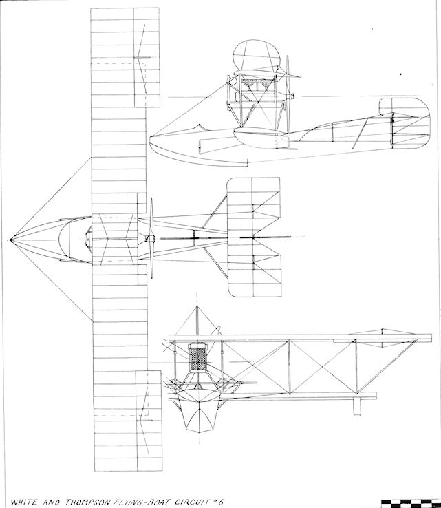
White and Thompson Flying-boat Circuit N 6
White and Thompson Twin-engine Flying-boat
The second of the White and Thompson flying-boats for the 1914 Daily Mail Circuit of Britain was entered as No. 9, with Lt. A. Loftus Bryan scheduled as the pilot.
Based, as was its companion, on the Curtiss design, the machine was powered by two eight-cylinder vee Austin-built Curtiss OX engines of 90 h.p. each, driving three-bladed pusher propellers of adjustable pitch, and was larger and heavier than No. 6. Side-by-side seating was provided again in the hull, which was constructed at Littlehampton, Sussex, by Williams and Co., a subsidiary of White and Thompson. The fore-part of the hull was given a cross-section of rectangular form, which changed to circular towards the rear. The same form of long tail fin extended along the top of the hull, but No. 6's type of extra fore-fin was not included. The engines' radiators were carried at the front of the bearers, and below the wing-tips the deep rectangular-section floats were mounted.
The twin-engined White and Thompson flying-boat was completed just after the outbreak of the 1914-18 War, but the design was not developed. The prototype made one flight only, and was then taken back to the works for alterations which were not finally carried out.
SPECIFICATION
Description: Two-seat pusher biplane flying-boat. Wooden structure, fabric covered.
Manufacturers: White and Thompson, Co. Ltd., Middleton-on-Sea, Bognor, Sussex.
Power Plant: Two 90 h.p. Curtis OX-5.
Dimensions: Span, 52 ft. Length, 32 ft. 3 ins. Wing area, 500 sq. ft.
Weights: Empty, 2,000 lb. Loaded, 3,000 lb.
Performance: Endurance, 6 hrs.
Wight Double-camber No. 1 Seaplane
During 1912 Howard T. Wright joined J. Samuel White and Co., of East Cowes, Isle of Wight, and his first design for them was the Mo. 1 Seaplane, which appeared in 1913. The machine was a conventional pusher mounted on twin floats, and seated two in tandem in the nacelle. Its unusual feature was the designer's original wing section with a "double-camber". Ailerons of the Curtiss type were fitted between the wings, and the engine was the two-row 160 h.p. Gnome.
During 1912 Howard T. Wright joined J. Samuel White and Co., of East Cowes, Isle of Wight, and his first design for them was the Mo. 1 Seaplane, which appeared in 1913. The machine was a conventional pusher mounted on twin floats, and seated two in tandem in the nacelle. Its unusual feature was the designer's original wing section with a "double-camber". Ailerons of the Curtiss type were fitted between the wings, and the engine was the two-row 160 h.p. Gnome.

Wight Double-camber No. 2 Navyplane
The production of Howard T. Wright's designs by J. Samuel White and Co. marked the entry of the boat-building firm into marine aviation. Their exhibit at the 1913 Olympia Aero Show was a development of the No. 1 seaplane and incorporated the "double-camber" wing section invented by Howard Wright. This possessed a deep depression in the centre of the upper profile of the section, and bestowed a wide speed range with small centre of pressure travel for wide variations in incidence. Very long floats were fitted, incorporating three steps and water rudders. The engine was the two-row 160 h.p. Gnome driving a 9 ft. 2 ins. Integral propeller. The machine was intended as a two-seat trainer and reconnaissance seaplane for the R.N.A.S., and was tested during September, 1913. by E. C. Gordon England. It was tried out also with a land undercarriage. Span, 44 ft. Length, 30 ft. Wing area, 500 sq. ft. Weight empty,"l ,350 lb. Weight loaded, 2,000 lb. Maximum speed, 70 m.p.h. Landing speed, 30 m.p.h. Price, ?2,500.
The production of Howard T. Wright's designs by J. Samuel White and Co. marked the entry of the boat-building firm into marine aviation. Their exhibit at the 1913 Olympia Aero Show was a development of the No. 1 seaplane and incorporated the "double-camber" wing section invented by Howard Wright. This possessed a deep depression in the centre of the upper profile of the section, and bestowed a wide speed range with small centre of pressure travel for wide variations in incidence. Very long floats were fitted, incorporating three steps and water rudders. The engine was the two-row 160 h.p. Gnome driving a 9 ft. 2 ins. Integral propeller. The machine was intended as a two-seat trainer and reconnaissance seaplane for the R.N.A.S., and was tested during September, 1913. by E. C. Gordon England. It was tried out also with a land undercarriage. Span, 44 ft. Length, 30 ft. Wing area, 500 sq. ft. Weight empty,"l ,350 lb. Weight loaded, 2,000 lb. Maximum speed, 70 m.p.h. Landing speed, 30 m.p.h. Price, ?2,500.
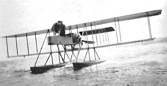
Wight 1914 Double-camber Navyplane
At the 1914 Olympia Aero Show, J. Samuel White and Co. showed their latest version of the Double-camber Navyplane designed by Howard T. Wright. The new machine was larger than that of the previous year, and was fitted with the more powerful 200 h.p. Canton Unne radial engine which drove a White propeller and was water-cooled through radiators situated on each side of the rear of the two-seat nacelle. The 1914 Navyplane embodied the results of considerable development-flying carried out with the earlier machine. The "double-camber" idea had proved to be so successful that it was incorporated also in the section used in the propeller, which proved to be superior to the normal types tried with the Canton Unne.
The machine flew for the first time on 7th April, 1914, and several were ordered by the Admiralty, being delivered by May, 1914. The R.N.A.S. production aircraft were made so that their five-bay wings folded, and strut-braced extensions were added to the upper wing-tips. The connecting cables between the four ailerons of the prototype were replaced in the production machines by struts. One example was delivered to Germany. Span, 63 ft. Wing area, 735 sq. ft. Weight empty, 2,600 lb. Weight loaded, 3,500 lb. Maximum speed, 78.9 m.p.h. Landing speed, 35 m.p.h.
Ellis-Williams Monoplane
The Ellis-Williams single-seat tractor monoplane was designed by W. Ellis-Williams, assistant lecturer in physics at the University College of North Wales, and was built during 1910 as a design study by the Engineering Department of Bangor College. It was powered by a six-cylinder 40 h.p. engine. Span, 32 ft. Wing area, 200 sq. ft. Weight empty, 700 lb.
Ellis-Williams Biplane
The Ellis-Williams Biplane of 1910 was another design study by the Engineering Department of Bangor College under W. Ellis-Williams, and was of the pusher type.
Wilson Monoplane
The Wilson Monoplane of 1909 was designed by Edgar Wilson. It was fitted with a 25 h.p. engine built by David J. Smith and Co., of London, which drove two pusher propellers mounted behind the wings. A three-wheeled undercarriage was fitted and the tips of the wings flexed for steering.
The Wilson Monoplane of 1909 was designed by Edgar Wilson. It was fitted with a 25 h.p. engine built by David J. Smith and Co., of London, which drove two pusher propellers mounted behind the wings. A three-wheeled undercarriage was fitted and the tips of the wings flexed for steering.
Wilson-Gibson Monoplane
The Wilson-Gibson Monoplane was a single-seat tractor designed by W. B. Wilson and W. E. Gibson, and built during 1910 by Wilson Brothers and Gibson, of the Motor Repair Company, Twickenham, Middlesex. It was constructed for the use of Allan Knight and Co., as a practice machine at the London Aviation Grounds at Ealing. The airframe was of camphor wood, and ailerons were incorporated in the wings. The engine was the 60 h.p. N.E.C. Span. 46 ft. 6 ins. Length, 40 ft." Wing area, 356 sq. ft. Weight loaded, 950 lb.
The Wilson-Gibson Monoplane was a single-seat tractor designed by W. B. Wilson and W. E. Gibson, and built during 1910 by Wilson Brothers and Gibson, of the Motor Repair Company, Twickenham, Middlesex. It was constructed for the use of Allan Knight and Co., as a practice machine at the London Aviation Grounds at Ealing. The airframe was of camphor wood, and ailerons were incorporated in the wings. The engine was the 60 h.p. N.E.C. Span. 46 ft. 6 ins. Length, 40 ft." Wing area, 356 sq. ft. Weight loaded, 950 lb.
Windham Glider
The Windham Glider was a biplane constructed for Capt. W. G. Windham during 1909 by H. D. Cutler, de Guerin, A. M. Grose and N. A. Feary. Span, 18 ft. 6 ins. Wing area, 180 sq.ft.. Weight empty, 60 lb.
The Windham Glider was a biplane constructed for Capt. W. G. Windham during 1909 by H. D. Cutler, de Guerin, A. M. Grose and N. A. Feary. Span, 18 ft. 6 ins. Wing area, 180 sq.ft.. Weight empty, 60 lb.
Windham Tandem Monoplane
The Windham Tandem Monoplane was designed by Captain W. G. Windham and was built during 1909 at Wembley Park, Middlesex. It was a tractor with tandem triangular wings of flexible bamboo mounted on a bamboo fuselage. The engine fitted in August, 1909, was a 35 h.p. Dutheil-Chalmers. The machine did not fly. Span, 24 ft. Length, 50 ft. Weight empty, 125 lb.
The Windham Tandem Monoplane was designed by Captain W. G. Windham and was built during 1909 at Wembley Park, Middlesex. It was a tractor with tandem triangular wings of flexible bamboo mounted on a bamboo fuselage. The engine fitted in August, 1909, was a 35 h.p. Dutheil-Chalmers. The machine did not fly. Span, 24 ft. Length, 50 ft. Weight empty, 125 lb.
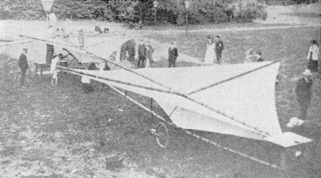
Windham Tractor Monoplane
Captain Windham's second monoplane was a Bleriot-type tractor of orthodox though flimsy construction. It was powered by a 35 h.p. Dutheil-Chalmers engine driving a Beedle propeller. The open fuselage was triangular in section. The machine was brought out at the Doncaster Aviation Meeting in October, 1909, where it achieved transient notoriety by collapsing while its owner was sitting in it to be photographed. After repairs, it was involved in a collision with a car while taxying, and this finally wrecked it. Span, 30 ft. Length, 25 ft.
Captain Windham's second monoplane was a Bleriot-type tractor of orthodox though flimsy construction. It was powered by a 35 h.p. Dutheil-Chalmers engine driving a Beedle propeller. The open fuselage was triangular in section. The machine was brought out at the Doncaster Aviation Meeting in October, 1909, where it achieved transient notoriety by collapsing while its owner was sitting in it to be photographed. After repairs, it was involved in a collision with a car while taxying, and this finally wrecked it. Span, 30 ft. Length, 25 ft.
Windsor Model and Gliding Club Gliders
The Windsor Model and Gliding Club was concerned mainly with model aircraft, but members built two successful full-size biplane gliders in 1913, in the second of which they hoped eventually to have installed a 25 h.p. Anzani engine.
The Windsor Model and Gliding Club was concerned mainly with model aircraft, but members built two successful full-size biplane gliders in 1913, in the second of which they hoped eventually to have installed a 25 h.p. Anzani engine.
Wokingham Flyer
The Wokingham Flyer was built at Wokingham, Surrey, during 1909 and was fitted with an 80 h.p. engine. The cigar-shaped fuselage was 140 ft. in length and could be reduced to 60 ft. The wings were telescopic, and their span of 20 ft. altered to 14 ft. The height of the machine was changeable from 31 ft. to 16 ft. Accommodation was provided for the pilot and several passengers, and the machine was equipped with electric lighting, hammocks and a lavatory. The Flyer was not successful.
The Wokingham Flyer was built at Wokingham, Surrey, during 1909 and was fitted with an 80 h.p. engine. The cigar-shaped fuselage was 140 ft. in length and could be reduced to 60 ft. The wings were telescopic, and their span of 20 ft. altered to 14 ft. The height of the machine was changeable from 31 ft. to 16 ft. Accommodation was provided for the pilot and several passengers, and the machine was equipped with electric lighting, hammocks and a lavatory. The Flyer was not successful.
Wong Tong Mei
The Tong Mei or Dragon Fly was a single-seat tractor biplane designed by a Chinese, Tsoe K. Wong, and built and tested at Shoreham during the early part of 1913. Two-bay wings were fitted, with inverse taper on the outer panels outboard of the inner interplane struts. The intention was for the machine to be produced later by Wong in China. A four-cylinder 40 h.p. A.B.C. engine provided the power for the 8 ft. 6 ins. diameter propeller. Span, 30 ft. Length, 30 ft. Wing area, 304 sq. ft. Weight empty, 504 lb. Endurance, 3.5 hrs.
Wong Two-seat Biplane
The Wong two-seat tractor biplane was a development of the single-seat Tong Mei and was constructed in 1914 by Tsoe K. Wong. The engine was a 100 h.p. Anzani. During December, 1913, the company of T. K. Wong Ltd. was formed with T. K. Wong, W. F. Skene and E. H. Lawford as directors.

Wong Tong Mei
Wood Glider
The Wood Glider of 1912 was constructed by B. Graham Wood and was a small and unorthodox triplane ornithopter with a pronounced stagger.
The Wood Glider of 1912 was constructed by B. Graham Wood and was a small and unorthodox triplane ornithopter with a pronounced stagger.
Woods Glider
The Woods Glider was designed and built during 1912 by Frederick Woods of Fleetwood, Lanes. The machine was a biplane and was fitted with a front elevator and a rear rudder. Span, 30 ft.
The Woods Glider was designed and built during 1912 by Frederick Woods of Fleetwood, Lanes. The machine was a biplane and was fitted with a front elevator and a rear rudder. Span, 30 ft.
Worswick Monoplane
The Worswick Monoplane was designed and built during 1909 at Gathurst, Wigan, Lanes., by Alfred Worswick. It was fitted with an eight-cylinder 20 h.p. engine which drove two pusher propellers behind the wings by means of rods and universal joints. The circular-section fuselage was constructed of ash and was covered with aluminium. The cruciform tail unit was movable as whole and was controlled from a triple steering-wheel consisting of three wheels mounted, one behind the other, on one shaft. Span, 33 ft. Wing area, 200 sq. ft. Weight loaded, 600 lb.
The Worswick Monoplane was designed and built during 1909 at Gathurst, Wigan, Lanes., by Alfred Worswick. It was fitted with an eight-cylinder 20 h.p. engine which drove two pusher propellers behind the wings by means of rods and universal joints. The circular-section fuselage was constructed of ash and was covered with aluminium. The cruciform tail unit was movable as whole and was controlled from a triple steering-wheel consisting of three wheels mounted, one behind the other, on one shaft. Span, 33 ft. Wing area, 200 sq. ft. Weight loaded, 600 lb.
Conisborough Glider No. 2
A monoplane glider of Demoiselle type was built at Doncaster in the autumn of 1911 by two members of the Conisborough and District Aero Society, F. J. Wright and G. N. Wilton.
A monoplane glider of Demoiselle type was built at Doncaster in the autumn of 1911 by two members of the Conisborough and District Aero Society, F. J. Wright and G. N. Wilton.
Wynn Monoplane
The Wynn Monoplane of 1909 was constructed by the brothers Charles and William Lea Wynn of Buckinghamshire. The wings of 26 ft. span and 8 ft. chord were mounted on top of a Peugeot racing motor-cycle whose engine drove two propellers mounted fore and aft of the machine. Front and rear elevators and a rear rudder formed the control surfaces.
The Wynn Monoplane of 1909 was constructed by the brothers Charles and William Lea Wynn of Buckinghamshire. The wings of 26 ft. span and 8 ft. chord were mounted on top of a Peugeot racing motor-cycle whose engine drove two propellers mounted fore and aft of the machine. Front and rear elevators and a rear rudder formed the control surfaces.
Yates Monoplane
The Yates Monoplane was designed and built during 1911 by Victor Yates of Wilmington, Eastbourne, Sussex. The machine was a tractor and was powered by a 35 h.p. engine. Steel tubing was used in the construction of the fuselage. Span, 35 ft. Length, 25 ft.
The Yates Monoplane was designed and built during 1911 by Victor Yates of Wilmington, Eastbourne, Sussex. The machine was a tractor and was powered by a 35 h.p. engine. Steel tubing was used in the construction of the fuselage. Span, 35 ft. Length, 25 ft.
Batson Monoplane
The Batson Monoplane was designed by Captain Arlington Batson at Maidstone and completed in September, 1910.
Batson Flying House
The Flying House was constructed during 1913 by Captain Arlington Batson for a proposed transatlantic flight. Twelve wings were fitted, and the fuselage contained a sitting-room and bedrooms for the crew.
Comment from https://www.britishaviation-ptp.com
Peter Lewis alludes to two aircraft built in Britain by Captain Arlington Batson.
The first is given as a monoplane built in Maidstone in 1910. This author can find no further evidence of such a machine and, in light of the following, must conclude that it did not exist under the name Batson.
The second is given as the Batson Flying House, constructed in 1913. However, per William E. Scarborough, The Batson Aero Yacht was the inspiration of Matthew A. Batson (1866-1917) of Anna, Illinois, a retired Army captain. In 1912, Batson came up with a design for an aircraft that he envisioned could hold ten men and fuel for several days, fly at a speed of 100 m.p.h., and make transatlantic flights to Liverpool, England. He then formed the Batson Air Navigation Company and relocated to Dutch Island in Savannah, Georgia to begin manufacturing his aircraft. Construction on the first aircraft began in April 1913 by a crew of locally hired workers. The first prototype was completed by November 1913, but technical and mechanical malfunctions took place with every test run and the Batson Aero Yacht never made it out of Savannah. As a result, the Batson Air Navigation Company faced financial troubles and was liquidated and ultimately sold at auction in July 1915.
However, illustrations of the 'Aero Yacht' and the 'Flying House' show these to be one and the same, so one must conclude the aircraft had no association with British aviation.
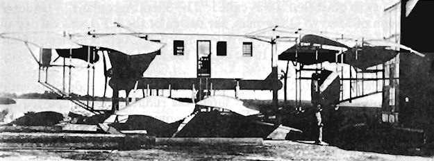
The American Burgess Company built three Burgess-Dunne single-float seaplane variants. These were the two-seat BD with a 100 h.p. Curtiss OXX2 engine, a span of 46 ft. and a top speed of 69 m.p.h., the BDH two-seater powered by a 140 h.p. engine, with a span of 46.6 ft. and a maximum speed of 70 m.p.h., and the BDI, which was a single-seater.
A three-seat flying-boat was constructed by Burgess during 1916 and was designated the BDF. A 100 h.p. Curtiss OXX2 provided the power for the 53 ft. span machine, which had a top speed of 68 m.p.h.
Windham Biplane
Captain W. G. Windham's pusher biplane is depicted at the 1909 Olympia Aero Show, and was constructed for him in France by Pischoff-Koechlin. The machine embodied a number of his own design features and was modified after the Aero Show by the lengthening of the nose and the tail booms to improve stability. The four-wheel undercarriage was augmented by the addition of a single wheel at each wing-tip, and a single rudder was fitted aft within the fixed biplane tail. Twin propellers were driven by a twin-cylinder 35 h.p. Dutheil-Chalmers engine; in further examples of the biplane, intended to be built in Britain, a four-cylinder engine was scheduled to be used.
Captain W. G. Windham's pusher biplane is depicted at the 1909 Olympia Aero Show, and was constructed for him in France by Pischoff-Koechlin. The machine embodied a number of his own design features and was modified after the Aero Show by the lengthening of the nose and the tail booms to improve stability. The four-wheel undercarriage was augmented by the addition of a single wheel at each wing-tip, and a single rudder was fitted aft within the fixed biplane tail. Twin propellers were driven by a twin-cylinder 35 h.p. Dutheil-Chalmers engine; in further examples of the biplane, intended to be built in Britain, a four-cylinder engine was scheduled to be used.
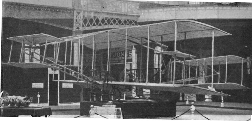
AERO SHOW AT OLYMPIA. - Captain Windham's Pischoff flyer seen from in front. One of the righting planes, which are mounted midway up the outside stays, is clearly visible. The rudder, which should be between the planes of the rear tail, is not shown.
Wilkes Biplane
The Wilkes Biplane was built during 1910 and was equipped with a 50 h.p. Gladiator engine. Wing area, 533 sq. ft.
The Wilkes Biplane was built during 1910 and was equipped with a 50 h.p. Gladiator engine. Wing area, 533 sq. ft.
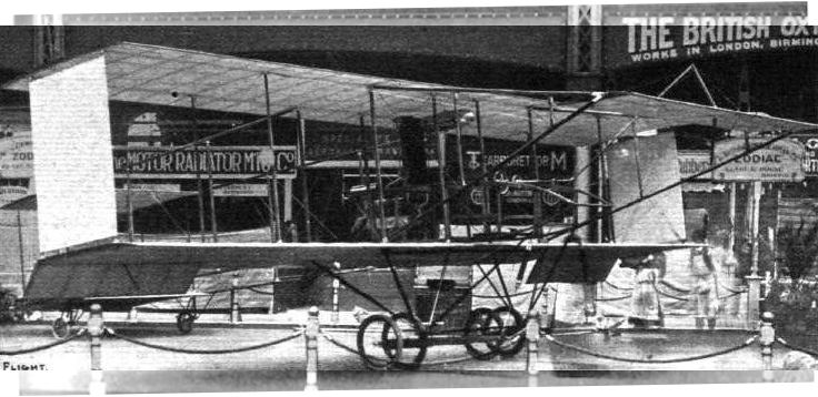
OLYMPIA, 1910. - A characteristic feature of the Zodiac biplane, exhibited by the British and Colonial Aeroplane Co., is the flatness of the camber in the main decks.
The sole Zodiac Biplane completed by the British and Colonial Aeroplane Company and shown at the Olympia Aero Show.
The sole Zodiac Biplane completed by the British and Colonial Aeroplane Company and shown at the Olympia Aero Show.
De Bolotoff Triplane
Prince Serge de Bolotoff completed his large Voisin-type tractor triplane at Brooklands towards the end of 1913. The engine was a 120 h.p. four-cylinder Panhard which drove a two-bladed propeller. The tailwheel was augmented by a pair of short skids, and further skids were mounted at the tips of the wings and of the unusually large tail unit. Taxying tests were made at Brooklands in November, 1913, where the machine was damaged by a gust of wind while on the ground.
Prince Serge de Bolotoff completed his large Voisin-type tractor triplane at Brooklands towards the end of 1913. The engine was a 120 h.p. four-cylinder Panhard which drove a two-bladed propeller. The tailwheel was augmented by a pair of short skids, and further skids were mounted at the tips of the wings and of the unusually large tail unit. Taxying tests were made at Brooklands in November, 1913, where the machine was damaged by a gust of wind while on the ground.