P.Lewis British Aircraft 1809-1914 (Putnam)
Flanders F.2 and F.3
R. L. Howard Flanders was one of A. V. Roe's earliest assistants, having joined him when the triplane pioneer was making his first flights at Lea Marshes during the summer of 1909. Flanders afterwards accompanied Roe to the 1909 Blackpool Meeting, together with E. V. B. Fisher, and then teamed up with John V. Neale at Brooklands, designing the tiny Pup monoplane for him.
The following year, on 1st August, 1910, he started to draw up plans for his own monoplane to carry the powerful 120 h.p. A.B.C. engine. Construction of the airframe was started on 1st October and continued until 26th May, 1911, when work stopped owing to the non-arrival of the specified engine.
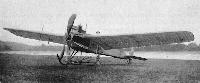
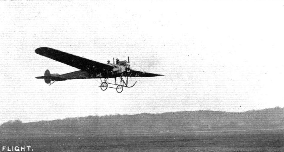
The day after, on 27th May, a new design was commenced, based upon the four-cylinder 60 h.p. Green. Construction started on 6th June, 1911, and the machine was finished two months later on 6th August, making its first flight on 8th August, 1911. Testing of the F.2 was carried out at Brooklands by Ronald C. Kemp.
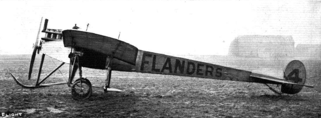
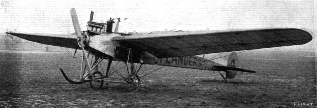
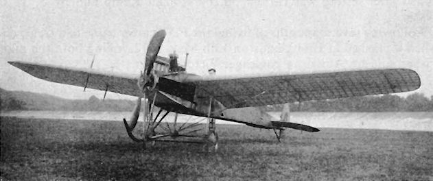
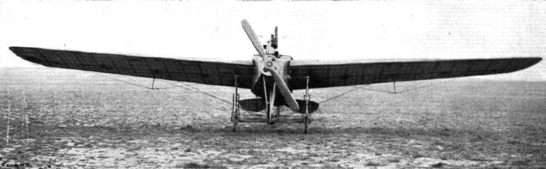
The F.2 was a single-seater of sound construction and of graceful appearance, and was flown for the next two months until, in October, it was reconstructed for participation in the contests for the British Empire Michelin Cups Nos. 1 and 2, in both of which it was piloted by Kemp, but was unable to register any success. The machine was redesignated the F.3, and alterations included the installation of a second cockpit to carry a passenger in front of the pilot, and also the provision of larger wings of 42 ft. span and 200 sq. ft. area. The same 60 h.p. Green engine was retained, and it drove an 8 ft. diameter Regy propeller. A silencer was fitted, and the pair of radiators operated on each side of the front cockpit. The F.3 was flown at first without a fin, but a small fixed surface was added after testing was carried out by Ronald Kemp and by E. V. B. Fisher.
Following several months of flying, the F.3's career came to a tragic end when it crashed at Brooklands on 13th May, 1912, killing both the pilot, Fisher, and his American passenger Victor Mason.
SPECIFICATION
Description: Single/two-seat tractor monoplane. Wooden structure, fabric covered.
Manufacturers: L. Howard Flanders, Ltd., Richmond and Brooklands, Surrey.
Power Plant: 60 h.p. Green.
Dimensions:
(F.2) Span, 35 ft. Length, 31 ft. 9 ins. Wing area, 200 sq. ft.;
(F.3) Span, 42 ft. Length, 31 ft. 9 ins. Wing area, 240 sq. ft.
Weights: (F.2) Empty, 1,000 lb.; (F.3) Empty, 1,100 lb.
Performance: (F.2) Maximum speed, 60 m.p.h.; (F.3) Maximum speed, 65 m.p.h.
Показать полностью
M.Goodall, A.Tagg British Aircraft before the Great War (Schiffer)
Deleted by request of (c)Schiffer Publishing
FLANDERS F.2 monoplane
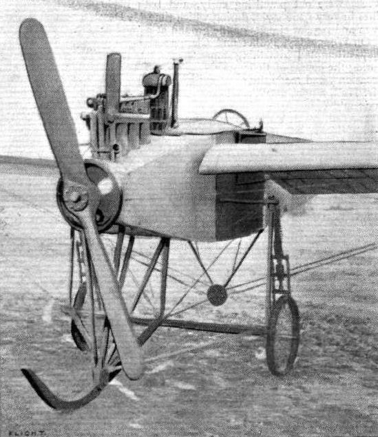
Flanders' first aeroplane to be completed was a single-seater tractor monoplane of conventional layout. The fuselage was based on a central structure incorporating two heavy ash members in the forward fuselage, which supported the engine and pilot and included front and rear spar sections, to which the wings were attached. Also included were the main kingpost and a beam, to which the upright members of the undercarriage were attached. The external shape of the fuselage was in the form of a conventional box girder, with plywood covering at the front and fabric at the rear end. The center structure was tapered and extended aft to integrate with the box girder.
The wings were tapered and braced by steel tapes from the front spar to the undercarriage structure, and to a post above the fuselage. The rear spar bracing cables also operated the warping control. The undercarriage had a central skid, the radius members being sprung and attached to the horizontal beam in the primary structure. Horizontal springs were fitted to realign the wheels, which could deflect under side loads. The tail unit had no fin.
The Green engine was fitted with a flywheel behind the propeller. Cooling was catered for by two radiators, positioned on either side of the front fuselage partly below the wings. The machine was flown initially by E.V.B. Fisher on 31 July 1911.
Power: 60hp Green four-cylinder inline, water-cooled driving a 8ft diameter Regy propeller.
Data
Span 34ft 6in
Chord 7ft tapering to 5ft 6in
Area 200 sq ft
Length 29ft 6in
Dihedral 4 degrees
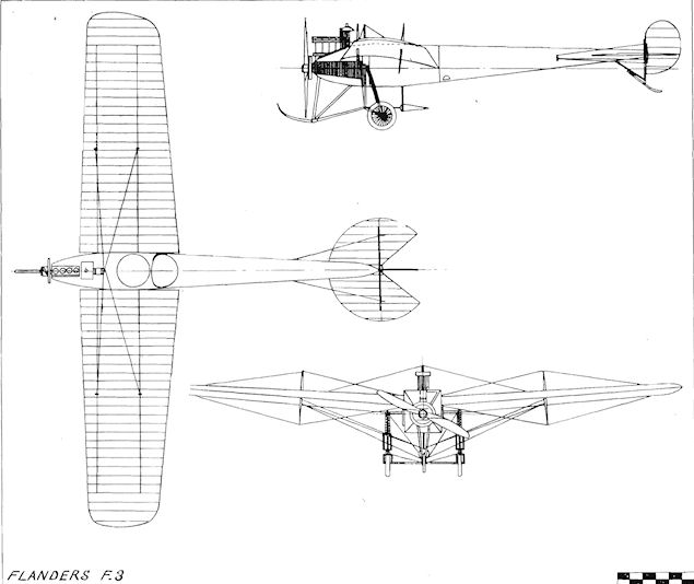
FLANDERS F.3 monoplane
This was the F.2 converted to a two-seater with increased length and wing area. The second cockpit was positioned in front of the pilot. The warping control cables were transferred to a post below the fuselage, separate from the undercarriage structure, and the pulley was enclosed in a streamlined casing. The side mounted radiators were taller and shorter, and positioned further back in the gaps between the wing and the fuselage. An additional small radiator, with header tank, was fitted behind the engine, which also carried an exhaust silencer. A small fin was also added.
The F.3 was first reported flying with a passenger on 22 November 1911 and continued in use until 15 May 1912, when it crashed killing the pilot, E.V.B. Fisher, and his passenger.
During its relatively short career the F.3 was used by Marconi at Brooklands for his ground to air wireless experiments.
Power: 60hp Green four-cylinder inline, water-cooled driving a 8ft 6in diameter propeller.
Data
Span 41ft (also 42ft reported)
Chord 7ft 8in tapering to 5ft 8in
Area 240 sq ft
Area tailplane 22 sq ft
Length 31ft 9in
Area elevators 13 sq ft
Area rudder 6.5 sq ft
Height 8ft 9in (tail down)
Показать полностью
Журнал Flight
Flight, September 23, 1911.
AIR EDDIES.
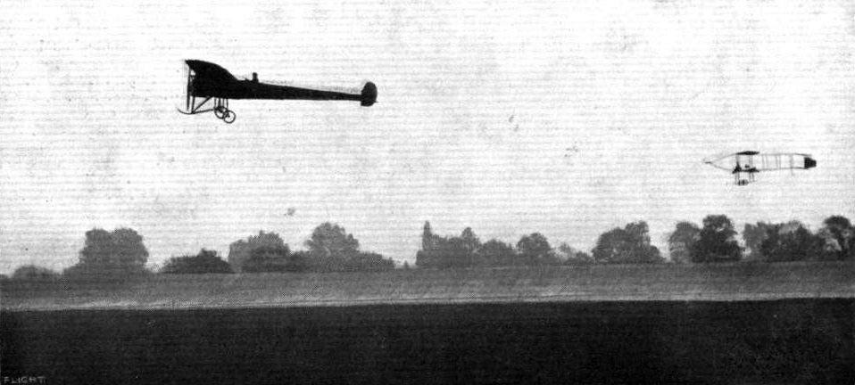
In my opinion, it would be well nigh impossible to find a constructor possessing a more complete grasp of his subject than does Howard Flanders of Brooklands. Indeed the way in which his monoplane carries passengers with the 60-h. p. Green seemingly at half-throttle is sufficient evidence of his worth as a designer. I should have thought that he would have made an attack on the Michelin prize ere now, but apparently he is not yet quite satisfied with its running, as he intends to spend another week or two in adjustments.
Awfully particular chap, Flanders!
Flight, October 21, 1911.
AIR EDDIES.
The Flanders monoplane, which has earned for itself a very enviable reputation down Brooklands way, has retired to its hangar pending preparations for an early attempt on the Michelin prize for duration. For three days preceding the closing of the cross-country Michelin competition, Ronald Kemp had been patiently awaiting an opportunity of putting up a good performance in this connection, but the weather conditions put cross-country work out of the question. The Flanders should make its reappearance in a few days' time.
Flight, March 23, 1912.
THE FLANDERS MONOPLANE.
To Mr. L. Howard-Flanders must be given the credit of having produced a distinctive and highly original monoplane. Although in general appearance it does not differ a great deal from its contemporaries of the same type, a closer study reveals so many features of real interest that the machine may almost be termed an encyclopaedia of constructional methods for the aeroplane builder. Further, it is characterised by gracefulness of outline that would be difficult to excel, and this carries much weight with the lay observer, beside being also to the credit of the designer, for no one would wish to build an ungainly object to perform such a graceful art as aviation. It is in England that Mr. Flanders has obtained the whole of his experience in connection with aeroplane construction, but it is evident that he has, nevertheless, relied more on the creative power of his own mind for inspiration in his work than on the published descriptions of well-known foreign machines. Undoubtedly the most notable feature about the Flanders monoplane is the method of assembly of its respective sections. Up to the present, constructors have, in this type of machine, employed a girder-like body as the backbone of the machine, to which all other organs, such as wings and landing chassis have been directly attached.
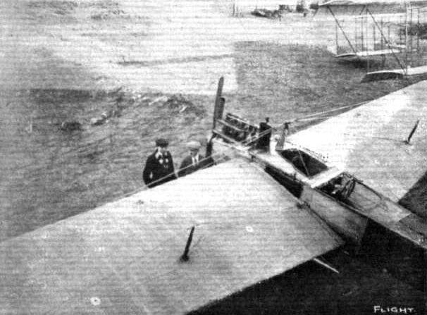
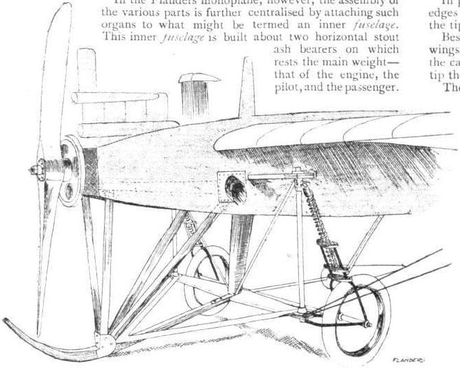
In the Flanders monoplane, however, the assembly of the various parts is further centralised by attaching such organs to what might be termed an inner fuselage. This inner fuselage is built about two horizontal stout ash bearers on which rests the main weight - that of the engine, the pilot, and the passenger. To it the landing chassis is directly attached, so that the weight may be supported direct, and not via the main body of the machine. This system seems so fundamentally sound and eminently simple that it is rather surprising no one has adopted it before.
Mounted nearly vertically at a point mid-way between the motor and the pilot and forming a unit with the engine bearers is a massive wooden mast, from each end of which the wings are braced, from the bottom to take the weight of the machine in flight, from the top to support the wings when at rest. Thus the functions of the main body, relieved of most of the stresses resulting from flying and landing, are merely those of forming a stream-line casing to contain as many of those parts as can conveniently be located in its interior and of serving as a support for the tail unit. It is entirely covered in by fabric and shaped to a fair stream-line form. Of the customary box girder type of construction, its longitudinal members are of hickory in the front section of the machine and of a lighter wood, Honduras mahogany, to the rear.
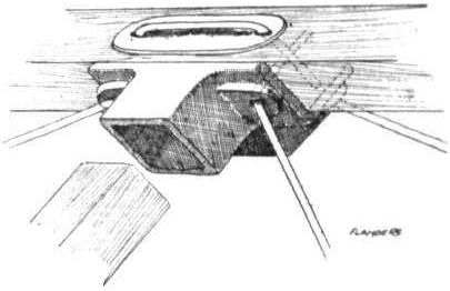
The transverse struts are of ash in the region of the engine and the tail, and between these two points silver spruce is employed. Quite original is the method of wire bracing as can be seen from one of our sketches. The method is almost analogous to sewing the structure together.
The body is perfectly symmetrical about its longitudinal axis, which is dead level in flight, and has a maximum depth of 3 ft. just in advance of the pilot's seat.
In plan form the wings are trapezoidal, both entering and trailing-edges tapering from 7ft. 8ins, at the wing root to 5 ft. 8ins, at the tip.
Besides diminishing in chord measurement towards the tip, the wings also diminish in camber and angle of incidence. At the root the camber is pronounced, and the angle of incidence is 7. At the tip the camber is nil, and the angle of incidence is similarly nil.
The workmanship evident in the wing construction is of the highest order. Both front and rear spars are fashioned from English ash and are of H section. They are set parallel in the wing skeleton and united by thirteen 1 in. solid whitewood ribs, flanged top and bottom by strips of ash 1 in. by 3/16in. Besides these solid ribs a large number of false ribs and longitudinal stringers of silver spruce are employed to give the fabric an efficient support.
The dihedral angle is 3.
In flight the weight is sustained from each wing by three steel ribbons proceeding from the landing chassis to the front spar and by three stranded steel cables connected to the rear spar. These latter also operate the warping for lateral balance, a maximum deflection of 9 in. of the rear spar being allowed.
The landing-chassis is of the wheel-and-central-skid type. The wheels are mounted to the steel columns forming the sides of the rectangular chassis skeleton by tubular-steel forks, comprising two sides of a deformable triangle of which the column is the third. The pair of forks representing the longest side are rendered flexible by the interposition of steel compression-springs. Two-and-a-half-inch tyres are employed on the 26-in. wheels. A central skid proceeding from the centre point of the chassis extends below and in front of the propeller to protect it and the machine should an obstruction tend to cause it to tip towards the nose.
The shape of the tail in plan form may be represented by a circle of 4 ft. radius, from which a 90 sector has been subtracted to provide the space for the directional rudder to operate.
Although the stabilising tail is purely of the floating type, it is not flat, but to give rigidity it is cambered equally on both top and bottom surfaces.
Just lately a small vertical fin has been added to the tail to improve the equilibrium of the machine in a side-wind. A small flexibly-sprung skid insulates the tail from ground contact.
The controlling gear is very similar to that adopted by the Deperdussin firm, and comprises a rotatable hand-wheel mounted in the centre of an inverted U-shaped bridge of steel tubing. Lateral equilibrium is corrected by rotating the hand-wheel, and a to-and-fro motion controls the elevation. The steering is operated by a footbar, pivoted centrally.
Provision is made for a passenger in a capacious cockpit, just in front of the pilot's seat. A 60-80-h.p. Green engine, which has been effectively silenced by the fitting of a miniature muffler of stream-line section, has all along proved an eminently satisfactory power plant. It drives a direct-coupled Regy propeller of 8 ft. diameter and 6 ft. pitch.
Показать полностью