
Книги
Журнал
Flight за 1912 г.
748
Журнал - Flight за 1912 г.
Flight, April 6, 1912.
AVIATION IN AUSTRALIA AND PIONEERS.
By J. R. DUIGAN.
I WAS very interested to see in FLIGHT of March 16th an article on "Aviation in Australia and Pioneers," and as the subject is evidently of interest I am sending you a brief account with photos of my own early efforts.
1st attempt, 1909. A pair of wings only. Result, not a success.
2nd effort, early 1910. 1/2-size Wright glider (Photo enclosed). Flown in strong winds, anchored to 120 yards of fencing wire. Left ground successfully and rose 4 or 5 ft.
<...>
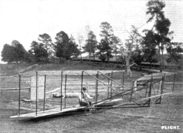
AVIATION IN AUSTRALIA. - Mr. J. R. Duigan and his Wright-type glider, built 1909, started in 1908.
Flight, April 6, 1912.
AVIATION IN AUSTRALIA AND PIONEERS.
By J. R. DUIGAN.
I WAS very interested to see in FLIGHT of March 16th an article on "Aviation in Australia and Pioneers," and as the subject is evidently of interest I am sending you a brief account with photos of my own early efforts.
1st attempt, 1909. A pair of wings only. Result, not a success.
2nd effort, early 1910. 1/2-size Wright glider (Photo enclosed). Flown in strong winds, anchored to 120 yards of fencing wire. Left ground successfully and rose 4 or 5 ft.
3rd effort. This machine was commenced beginning of 1910, and was on Farman lines, built entirely by myself and fitted with a 4-cyl. vertical air-cooled engine, 20 h.p., built in Melbourne by J. E. Tilly. After sundry experiments on July 16th, 1910, I did, amongst others, a hop of 24 ft. Various improvements, such as chain drive in place of belt, water-cooled heads, higher compression, and finally larger cylinders gradually increased the length of flights till at the end of September, 1910, I managed flights of about 100 yards (see Melbourne Leader, October 1st). On October 7th, 1910, before half-adozen spectators, I successfully covered a distance of 196 yards, rising about 12 it. high (Melbourne Argus, October 8th, 1910). These flights, as far as I know, were the first to be made in Australia by an Australian-built machine. They were published in various papers practically all over Australia as such and were never contradicted. Public opinion may be judged from the fact that I received an offer of L100 to make a flight from the Melbourne Cricket Ground in December on the day of a big cycle meeting. This I was forced to refuse, the ground being totally unsuitable. M. Cugnet, as mentioned in your article, agreed to make the attempt, but owing to the ground and want of power, it ended disastrously.
On January 25th, 1911, I gave a short exhibition flight for the benefit of the Sporting Editor and the Photographer of the Melbourne Argtis. This flight was evidently appreciated, as they gave five columns and photos in the next Saturday's issue, January 28th, 1911. In April, at the Bendigo Easter Fair, I exhibited the machine, and on the last day showed it running in the arena, a ground 160 yards long, in a hollow, and surrounded by tents and buildings. Although there was a 12-14 m.p.h. wind side on, I just managed to get off the ground, land, and pull up without damaging anything. Shortly afterwards May 3rd, at the Bendigo Race-course where there was more room. I did several flights, straights and semicircles of about three-quarters of a mile before about 1,000 spectators. These were the first flights ever seen in Bendigo and it was also the first time I ever had more than 400 or 500 yards of descent ground. These flights paid me very well, and covered the cost of a good bit of experimenting.
Last exhibition flight was on May 31st, when before Mayor Hedges, representing the Defence Department, Mr. W. F. Marshall, Hon. Sec, Aerial League of Australia (Victorian Section), and others at Mia Mia, I did several flights of about half a mile. My brother also flew the machine about 600 yards at 10 or 12 ft., this being only the tecond time he was ever on it. Wind 12-15 miles per hour by anemometer.
All these flights, judged by present-day performances, seem of course very puny, but considering the many difficulties, that all the work was done single-handed, and that total breakages were only a buckled wheel, a wing tip leading edge, and an upright broken, the results were I think encouraging. Anyway, it was, in the words of the great poet, "A small thing but mine own."

AVIATION IN AUSTRALIA. - Mr. Duigan pancaking at Bendigo Race Course on May 3rd, 1911, after doing about three-quarters of a mile. He had to steer between two trees, hence his proximity to the one seen.
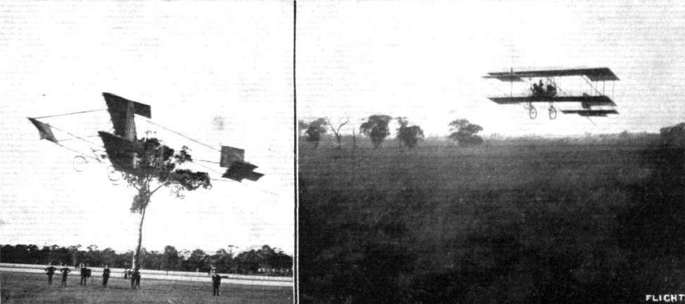
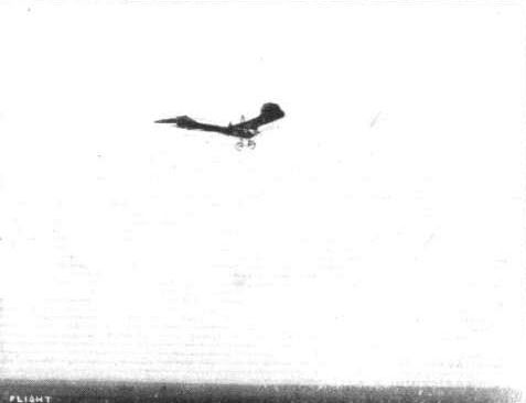
AVIATION IN AUSTRALIA. - On the left, Mr. J. R. Duigan flying over Bendigo Race Course on May 3rd, 1911. The machine had been in the air for about 200 yards when photograph was taken, and the crowd are facing the machine, out of the picture. On the right, Mr. Duigan is seen flying at second attempt in 12 m.p.h. wind on May 31st, when he landed safely.
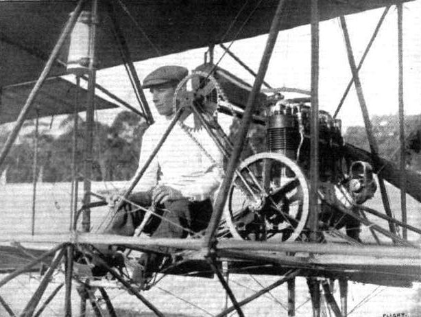
Mr. J. R. Duigan on his machine, which he designed, built, and piloted himself.
Lieut. Gregory, R.N., testing the new Etrich monoplane at the Royal Aero Club's Eastchurch flying grounds.
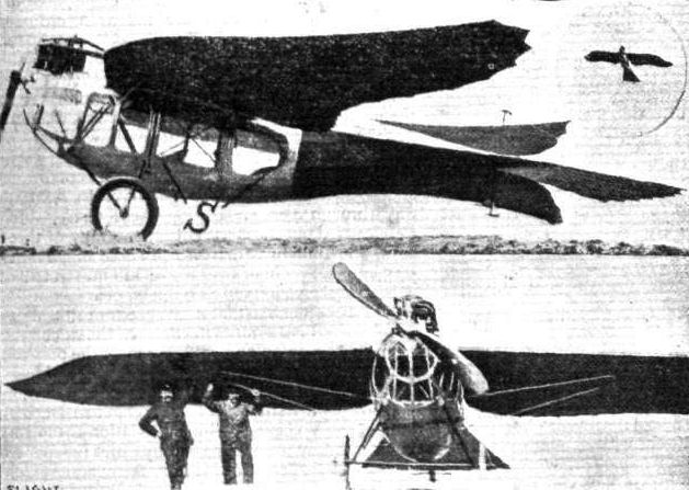
The Etrich 1912 military monoplane, from the side and front. Inset the machine is seen in flight. One of the Etrich machines has just been acquired by the British Government.
Flight, July 13, 1912.
AIR EDDIES.
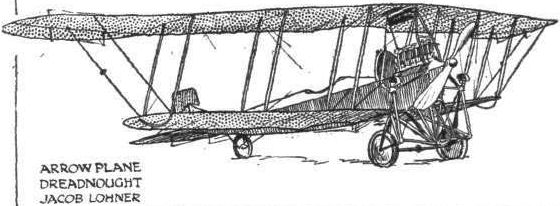
Messrs. Jacob Lohner and Co. is an Austrian firm with works at Vienna, where they produce Etrich monoplanes and machines of their own design. They are entering a tractor biplane, known over there as the Arrow-Plane Dreadnought, equipped with a 120-h.p. Austro-Daimler motor. It was on an identical machine that Lieut. Von Blaschke broke the world's altitude record with passengers at the Vienna flying meeting last month by taking two besides himself up to 3,500 metres, and by taking one single passenger to a height of 4,260 metres.
Lieut. Von Blaschke himself is probably going to fly the machine at the competitions at Salisbury.
Flight, July 20, 1912.
THE MILITARY COMPETITION - THE MACHINES.
THE LOHNER ARROWPLANE DREADNOUGHT (ARMY TYPE).
THIS interesting entrant from Germany is termed "Arrow-plane" from the fact that, when flying overhead, its silhouette resembles closely the form of an arrow. Its wings, set back Dunne fashion, might be the arrow's head, its fuselage the shaft.
Of the machine, two main types are made at the Vienna works of Messrs. Jacob Lohner and Co. - an "Army type " and a "Navy type." They may readily be distinguished from one another, in that the Army type has a direct coupled tractor; the tractor of the Navy type is centred some distance above the motor, and withal, geared down.
It is a biplane of the former type that will be flown in the Military Competition at Salisbury. To Lieut, von Blaschke will be entrusted the piloting. Besides the photographs we print, we have been able to glean from Mr. Cecil E. Kny, who represents the manufacturers here in England, a few details.
The upper plane spans nearly 53 ft., and by virtue of its shape is designed to give the machine an excellent modicum of stability - both in a lateral and longitudinal sense. Its large span, however, does not make it too unwieldly for military service, for the extensions of the top plane, each 10 ft. in length, may be folded down, allowing the biplane to be conveniently housed in a shed just over 33 ft. wide. An entirely covered-in streamline fuselage forms the backbone of the machine. In it are located the three that the machine is designed to carry - the mechanic directly behind the motor (a 120-h.p. Austro-Daimler), and the pilot and observer-passenger some distance behind the planes, where their view is clearest. The fuel tanks are arranged between. Terminating the fuselage is the tail, the shape and general arrangement of which can be gathered from our photographs. Like the greater part of German machines, it is provided with a land brake at the tail to decelerate it quickly on landing.
In addition to its abilities for climbing - the machine holds world's records in passenger altitude, as we recalled last week - it has a very excellent gliding angle. For a biplane its speed is unusually high. It is estimated to average 70 m.p.h.
Main characteristics:-
Motor 120-h.p. Austro-Daimler
Span 53 ft. nearly
Overall length 31 ft.
Weight, empty 1,540 lbs.
Useful load 600 lbs.
Speed 70 m.p.h.
AIR EDDIES.
Messrs. Jacob Lohner and Co. is an Austrian firm with works at Vienna, where they produce Etrich monoplanes and machines of their own design. They are entering a tractor biplane, known over there as the Arrow-Plane Dreadnought, equipped with a 120-h.p. Austro-Daimler motor. It was on an identical machine that Lieut. Von Blaschke broke the world's altitude record with passengers at the Vienna flying meeting last month by taking two besides himself up to 3,500 metres, and by taking one single passenger to a height of 4,260 metres.
Lieut. Von Blaschke himself is probably going to fly the machine at the competitions at Salisbury.
Flight, July 20, 1912.
THE MILITARY COMPETITION - THE MACHINES.
THE LOHNER ARROWPLANE DREADNOUGHT (ARMY TYPE).
THIS interesting entrant from Germany is termed "Arrow-plane" from the fact that, when flying overhead, its silhouette resembles closely the form of an arrow. Its wings, set back Dunne fashion, might be the arrow's head, its fuselage the shaft.
Of the machine, two main types are made at the Vienna works of Messrs. Jacob Lohner and Co. - an "Army type " and a "Navy type." They may readily be distinguished from one another, in that the Army type has a direct coupled tractor; the tractor of the Navy type is centred some distance above the motor, and withal, geared down.
It is a biplane of the former type that will be flown in the Military Competition at Salisbury. To Lieut, von Blaschke will be entrusted the piloting. Besides the photographs we print, we have been able to glean from Mr. Cecil E. Kny, who represents the manufacturers here in England, a few details.
The upper plane spans nearly 53 ft., and by virtue of its shape is designed to give the machine an excellent modicum of stability - both in a lateral and longitudinal sense. Its large span, however, does not make it too unwieldly for military service, for the extensions of the top plane, each 10 ft. in length, may be folded down, allowing the biplane to be conveniently housed in a shed just over 33 ft. wide. An entirely covered-in streamline fuselage forms the backbone of the machine. In it are located the three that the machine is designed to carry - the mechanic directly behind the motor (a 120-h.p. Austro-Daimler), and the pilot and observer-passenger some distance behind the planes, where their view is clearest. The fuel tanks are arranged between. Terminating the fuselage is the tail, the shape and general arrangement of which can be gathered from our photographs. Like the greater part of German machines, it is provided with a land brake at the tail to decelerate it quickly on landing.
In addition to its abilities for climbing - the machine holds world's records in passenger altitude, as we recalled last week - it has a very excellent gliding angle. For a biplane its speed is unusually high. It is estimated to average 70 m.p.h.
Main characteristics:-
Motor 120-h.p. Austro-Daimler
Span 53 ft. nearly
Overall length 31 ft.
Weight, empty 1,540 lbs.
Useful load 600 lbs.
Speed 70 m.p.h.
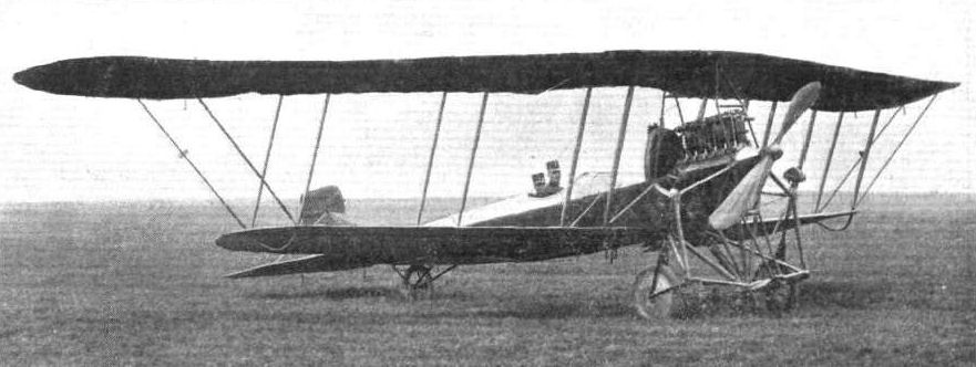
THE MILITARY COMPETITION MACHINES. - Three-quarter front view of the Arrow-plane Dreadnought, the biplane entered by Messrs. Jacob Lohner and Co., of Vienna. It is rumoured that great things may be expected of this machine.

THE MILITARY COMPETITION MACHINES. - Rear view of the Arrow-plane Dreadnought, the biplane entered by Messrs. Jacob Lohner and Co., of Vienna.
Flight, January 20, 1912.
"VIKING I."
"VIKING I" is a biplane, the first of that type to materialise from the ever-active brain of Mr. H. Barber. Although he has been so long connected with the single-deck type, the germ of this conception was sown long since in the days before he left Salisbury Plain to continue his experimental work in the north of London.
That he should have seen fit to produce such a machine at the present time is yet more evidence of the clearness with which he grasps the ever-changing aspect of the development of aviation in this country, for it is evident to all students that the leading constructors of the world are now concentrating their attention on the development of two types of aeroplanes rather than identifying themselves with a single speciality.
"Viking I" differs from his previous productions in that it flies head first, also it is characterised as a biplane, by the possession of a definite fuselage or covered-in body, which has the engine in front and the pilot's seat just between the main planes. In its detail construction there is that same careful attention to minor matters and sound principle that has given the workmanship of the Aeronautical Syndicate, Ltd., who carry out all Mr. Barber's constructive work in addition to that of their numerous other clients, a leading place in the industry of aeroplane construction. Nor can two opinions exist as to the soundness of the design, whether viewed from the purely aerodynamical standpoint, whether examined in the light of ability to comply with the exacting requirements, or whether considered from the point of view of the pilot's safety.
Consequent with the adoption of the fuselage is the distinctly sound practice of disposing the engine in front of the pilot, a system which was originated in this country and the advantages of which are just becoming apparent to our foreign confreres.
The main body is constructed throughout of silver spruce excepting in the region of the engine, where, in view of the extra strains that are placed upon it, ash is employed. Mounted at its forward extremity, with its inlet pipe extending towards the direction of advance, is the motor, a 50-h.p. Gnome. By means of a short propeller shaft and twin chains arranged Wright-fashion the power is transmitted to the two A.S.L. tractors, that transform into effective thrust the rotary motion of the engine.
A well formed torpedo front of sheet aluminium is arranged over the engine and this together with a slanting screen of the same material at the rear, protects the pilot and passenger from any oil or exhaust fumes thrown off by the motor. Apart from being used for these screens and for the construction of the novel balancers with which the machine is equipped, aluminium has been absolutely discarded as a medium of construction, its place being taken by sheet steel. Throughout its whole length the fuselage is covered in, at the forward end by the metal torpedo front and at the rear by fabric, so that its passage through the air may give rise to a minimum of disturbance.
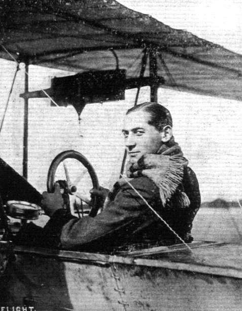
Directly underneath the top surface is the cock-pit, about four feet in length by three feet in width, where are accommodated side by side, the pilot and passenger. The former, who sits on the right-hand side, has before him a vertical wheel, mounted on a vertical column which latter is pivoted at its base so that it can be moved away from or towards the operator. Rotation of the wheel laterally controls the inter-connected balancers on either side, and a to-and-fro movement of the column as a whole controls the attitude of the aeroplane in flight. Placed forward and on either side of the control column is a pair of pedals operating the vertical rudder. In full view of both pilot and passenger is a dashboard where are arranged an altimeter, a compass, a revolution indicator, a watch, and oil and petrol gauges to aid in cross-country work, while, convenient to the right-hand of the pilot are the engine controls. On the control wheel itself is a subsidiary switch by which the engine may be cut off or started again.
Not the least feature of note regarding this section of the machine is the comfort that is afforded the human complement. Constructors, in the midst of abstruse calculations and constructional problems, are apt to overlook such secondary points as this. Not so the Viking engineer, he provides the most comfortable of bucket seats, and completes the snug appearance of the cock-pit by upholstering it in leather, and covering the floor with a square of Turkey carpet.
Tanks for the storage of enough fuel to keep the Gnome motor in operation for six hours are arranged on either side of the body, and glass gauges proceeding from them into the interior keep the pilot well informed as to the actual state of his supply. Feed is by gravity.
At the rear end of the body is disposed the tail-unit whereby control over the machine in the two dimensions of direction and altitude is maintained. Hinged to the rear of a horizontal surface of streamline section, 9 ft. in span by 2 ft. 9 in. in width, is a flap, that serves the function of elevator.
A noticeable feature regarding the design of the tail is that the elevator may be removed by the mere unscrewing of a nut and locknut, and the withdrawal of a single thin steel rod that serves as a common core to the several hinges from which this organ depends. Each side of the flat tail surface is applied to the body much in the same fashion as a monoplane wing, its two booms fitting into sockets, while it is held in correct position by four steel wires. This system commends itself in that the whole of the tail unit can, when necessary, be dismantled in a minimum of time with a minimum of trouble.
Mounted at right angles to the horizontal tail surface is the directional rudder, half above and half below the fuselage. This is pivoted at its average centre of pressure and is operated by means of a crank arranged in the interior of a covered-in body. A small wooden skid, swivelling about the base of the rudder mast and connected to the body at its upper end by means of a shock absorber affords protection for the tail unit against contact with the ground.
The cellule, 31 ft. in span is composed of two super-imposed single-surfaced planes, separated by a gap of 5 ft. 3 ins. Viewed from the front, its centre section, of 6 ft. span, is horizontal, while the two end sections, each of 12 ft. 6 ins. in span are given a characteristic arched dihedral angle, the horizontal end projection of which is approximately nine inches. Two triangular skeletons of steel tubing, securely mounted between the planes and braced thereto by steel tension wire, support the two tractors, their centres being separated by a distance of 14 ft.
Both planes are perfectly rigid except for a small degree of flexibility that is allowed the trailing edge by virtue of its overhang. Probably the most novel and interesting feature of the machine is the system of balancing employed. The balancers, being arranged at ever-changing angles of incidence, according to the will of the pilot and the conditions of the machine in flight, automatically and simultaneously assume a camber best suited to the angle of incidence at which they are at the moment working. The surfaces of these organs are formed of an aluminium alloy reinforced with spring steel ribs, a clever but simple sliding arrangment allowing for the alteration in the length of the top surface according to whether it is concave or convex. Its conception is so extremely simple that until one remembers that it is usually the most simple things that are the most difficult to discover, one is surprised that it has not been thought of before. The advantages that this system possesses on the score of its efficiency are undoubted. As regards the undercarriage, not only is it of novel design but possesses the attributes of simplicity, adaptability and strength, combined with a low factor of head resistance. Each wheel, as can be seen from one of the photographs, is mounted between a pair of cantilevers, constructed from heavy gauge sheet and channel steel. These latter are universally jointed at their centres to an enormously strong forged steel fitting, to which are assembled the ash chassis struts proceeding from the lower plane. The upper end of each cantilever is anchored to the body of the machine by a pair of rubber shock absorbers. Uniting the two wheels is a tie rod, and diagonal wires carrying miniature shock absorbers are intoduced to keep them parallel to the geometrical axis of the machine. To prevent any damage resulting from too steep a landing a skid is fitted to the extreme nose of the body and two similar skids, but of smaller dimensions, are arranged at each end of the cellule to protect the wing tips. These are allowed universal motion and are governed by shock-absorbers.
Weighing 800 lbs., the machine has been designed for a speed of 55 miles per hour, and to carry its double human load for a non-stop flight of six hours. In the matter of speed, the intentions of the designer have been more than realised, for in practical tests that have recently taken place, this 55 miles has been handsomely exceeded. The Viking biplane undoubtedly represents a considerable advance en the admittedly sound work of the A.S.L. establishment, and if sheer merit goes for anything these days, it should pave the way for an exceedingly prosperous business year.
"VIKING I."
"VIKING I" is a biplane, the first of that type to materialise from the ever-active brain of Mr. H. Barber. Although he has been so long connected with the single-deck type, the germ of this conception was sown long since in the days before he left Salisbury Plain to continue his experimental work in the north of London.
That he should have seen fit to produce such a machine at the present time is yet more evidence of the clearness with which he grasps the ever-changing aspect of the development of aviation in this country, for it is evident to all students that the leading constructors of the world are now concentrating their attention on the development of two types of aeroplanes rather than identifying themselves with a single speciality.
"Viking I" differs from his previous productions in that it flies head first, also it is characterised as a biplane, by the possession of a definite fuselage or covered-in body, which has the engine in front and the pilot's seat just between the main planes. In its detail construction there is that same careful attention to minor matters and sound principle that has given the workmanship of the Aeronautical Syndicate, Ltd., who carry out all Mr. Barber's constructive work in addition to that of their numerous other clients, a leading place in the industry of aeroplane construction. Nor can two opinions exist as to the soundness of the design, whether viewed from the purely aerodynamical standpoint, whether examined in the light of ability to comply with the exacting requirements, or whether considered from the point of view of the pilot's safety.
Consequent with the adoption of the fuselage is the distinctly sound practice of disposing the engine in front of the pilot, a system which was originated in this country and the advantages of which are just becoming apparent to our foreign confreres.
The main body is constructed throughout of silver spruce excepting in the region of the engine, where, in view of the extra strains that are placed upon it, ash is employed. Mounted at its forward extremity, with its inlet pipe extending towards the direction of advance, is the motor, a 50-h.p. Gnome. By means of a short propeller shaft and twin chains arranged Wright-fashion the power is transmitted to the two A.S.L. tractors, that transform into effective thrust the rotary motion of the engine.
A well formed torpedo front of sheet aluminium is arranged over the engine and this together with a slanting screen of the same material at the rear, protects the pilot and passenger from any oil or exhaust fumes thrown off by the motor. Apart from being used for these screens and for the construction of the novel balancers with which the machine is equipped, aluminium has been absolutely discarded as a medium of construction, its place being taken by sheet steel. Throughout its whole length the fuselage is covered in, at the forward end by the metal torpedo front and at the rear by fabric, so that its passage through the air may give rise to a minimum of disturbance.
Directly underneath the top surface is the cock-pit, about four feet in length by three feet in width, where are accommodated side by side, the pilot and passenger. The former, who sits on the right-hand side, has before him a vertical wheel, mounted on a vertical column which latter is pivoted at its base so that it can be moved away from or towards the operator. Rotation of the wheel laterally controls the inter-connected balancers on either side, and a to-and-fro movement of the column as a whole controls the attitude of the aeroplane in flight. Placed forward and on either side of the control column is a pair of pedals operating the vertical rudder. In full view of both pilot and passenger is a dashboard where are arranged an altimeter, a compass, a revolution indicator, a watch, and oil and petrol gauges to aid in cross-country work, while, convenient to the right-hand of the pilot are the engine controls. On the control wheel itself is a subsidiary switch by which the engine may be cut off or started again.
Not the least feature of note regarding this section of the machine is the comfort that is afforded the human complement. Constructors, in the midst of abstruse calculations and constructional problems, are apt to overlook such secondary points as this. Not so the Viking engineer, he provides the most comfortable of bucket seats, and completes the snug appearance of the cock-pit by upholstering it in leather, and covering the floor with a square of Turkey carpet.
Tanks for the storage of enough fuel to keep the Gnome motor in operation for six hours are arranged on either side of the body, and glass gauges proceeding from them into the interior keep the pilot well informed as to the actual state of his supply. Feed is by gravity.
At the rear end of the body is disposed the tail-unit whereby control over the machine in the two dimensions of direction and altitude is maintained. Hinged to the rear of a horizontal surface of streamline section, 9 ft. in span by 2 ft. 9 in. in width, is a flap, that serves the function of elevator.
A noticeable feature regarding the design of the tail is that the elevator may be removed by the mere unscrewing of a nut and locknut, and the withdrawal of a single thin steel rod that serves as a common core to the several hinges from which this organ depends. Each side of the flat tail surface is applied to the body much in the same fashion as a monoplane wing, its two booms fitting into sockets, while it is held in correct position by four steel wires. This system commends itself in that the whole of the tail unit can, when necessary, be dismantled in a minimum of time with a minimum of trouble.
Mounted at right angles to the horizontal tail surface is the directional rudder, half above and half below the fuselage. This is pivoted at its average centre of pressure and is operated by means of a crank arranged in the interior of a covered-in body. A small wooden skid, swivelling about the base of the rudder mast and connected to the body at its upper end by means of a shock absorber affords protection for the tail unit against contact with the ground.
The cellule, 31 ft. in span is composed of two super-imposed single-surfaced planes, separated by a gap of 5 ft. 3 ins. Viewed from the front, its centre section, of 6 ft. span, is horizontal, while the two end sections, each of 12 ft. 6 ins. in span are given a characteristic arched dihedral angle, the horizontal end projection of which is approximately nine inches. Two triangular skeletons of steel tubing, securely mounted between the planes and braced thereto by steel tension wire, support the two tractors, their centres being separated by a distance of 14 ft.
Both planes are perfectly rigid except for a small degree of flexibility that is allowed the trailing edge by virtue of its overhang. Probably the most novel and interesting feature of the machine is the system of balancing employed. The balancers, being arranged at ever-changing angles of incidence, according to the will of the pilot and the conditions of the machine in flight, automatically and simultaneously assume a camber best suited to the angle of incidence at which they are at the moment working. The surfaces of these organs are formed of an aluminium alloy reinforced with spring steel ribs, a clever but simple sliding arrangment allowing for the alteration in the length of the top surface according to whether it is concave or convex. Its conception is so extremely simple that until one remembers that it is usually the most simple things that are the most difficult to discover, one is surprised that it has not been thought of before. The advantages that this system possesses on the score of its efficiency are undoubted. As regards the undercarriage, not only is it of novel design but possesses the attributes of simplicity, adaptability and strength, combined with a low factor of head resistance. Each wheel, as can be seen from one of the photographs, is mounted between a pair of cantilevers, constructed from heavy gauge sheet and channel steel. These latter are universally jointed at their centres to an enormously strong forged steel fitting, to which are assembled the ash chassis struts proceeding from the lower plane. The upper end of each cantilever is anchored to the body of the machine by a pair of rubber shock absorbers. Uniting the two wheels is a tie rod, and diagonal wires carrying miniature shock absorbers are intoduced to keep them parallel to the geometrical axis of the machine. To prevent any damage resulting from too steep a landing a skid is fitted to the extreme nose of the body and two similar skids, but of smaller dimensions, are arranged at each end of the cellule to protect the wing tips. These are allowed universal motion and are governed by shock-absorbers.
Weighing 800 lbs., the machine has been designed for a speed of 55 miles per hour, and to carry its double human load for a non-stop flight of six hours. In the matter of speed, the intentions of the designer have been more than realised, for in practical tests that have recently taken place, this 55 miles has been handsomely exceeded. The Viking biplane undoubtedly represents a considerable advance en the admittedly sound work of the A.S.L. establishment, and if sheer merit goes for anything these days, it should pave the way for an exceedingly prosperous business year.
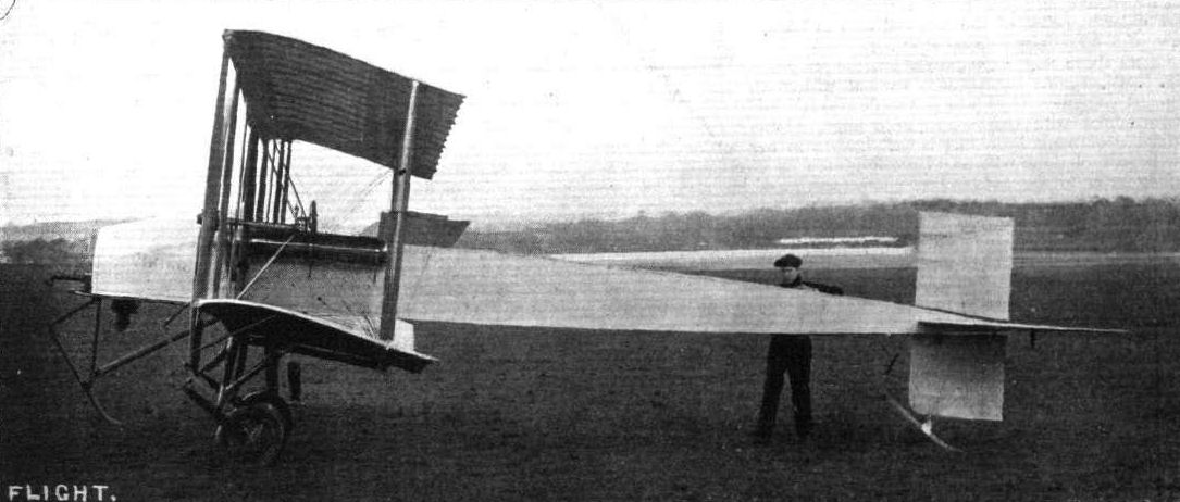
THE VIKING BIPLANE. - Side view, showing the covered-in body and arrangement of the tall.

THE VIKING BIPLANE. - Half-side view, giving an idea of its general arrangement. Horatio Barber's last design before the company closed in 1912.

The Viking biplane, as seen from the front.
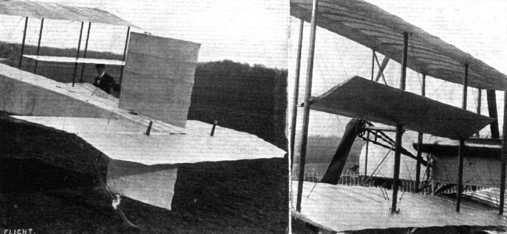
THE VIKING BIPLANE. - The illustration on the left is that of the tail unit; on the right that of the novel metal warping balancers with which the machine is furnished.
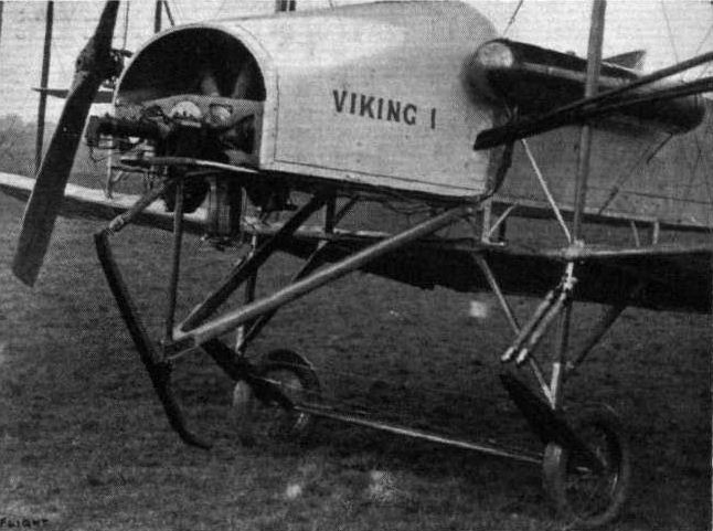
Detailed view of the front of the new Viking biplane. - The mounting of the Gnome motor, the details of the landing gear, of the forward skid, and of one of the twin tractors are clearly shown.

DETAILS OF THE VIKING BIPLANE. - On the left the arrangement of the controls in the pilot's cockpit. Note the petrol gauge in the interior of the body. The photograph on the right illustrates the details of the landing gear.
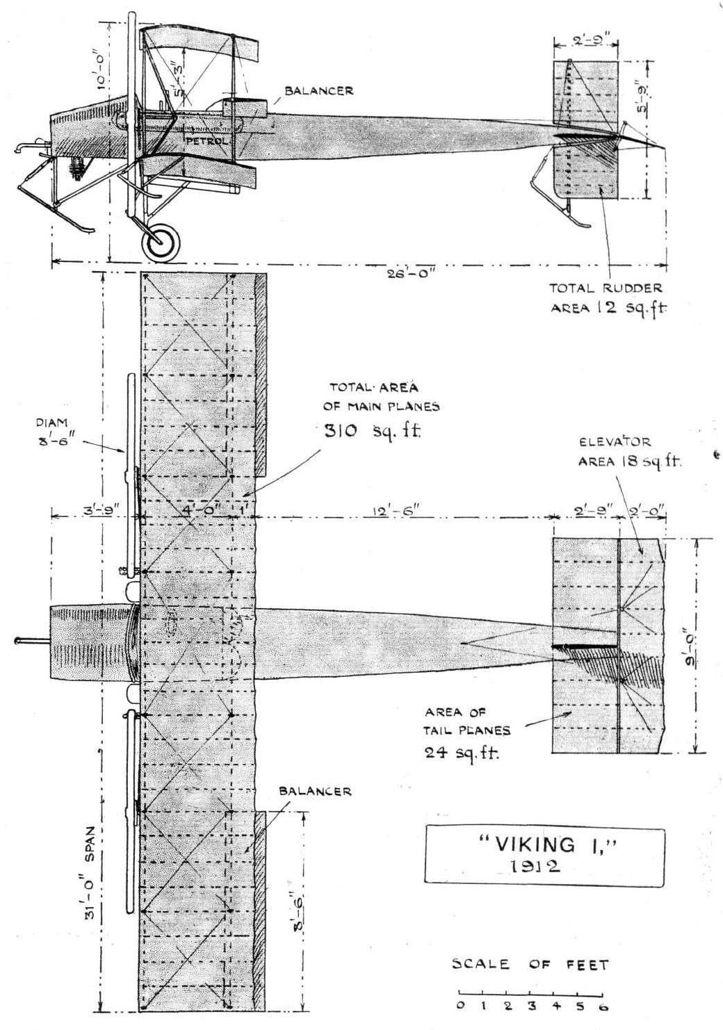
"VIKING I" BIPLANE. - Plan and elevation to scale.
Flight, April 13, 1912.
AIR EDDIES.
Sippe is getting on very nicely with the experiments with Commander Schwann's AVRO hydro-biplane, tests of which he is superintending at Barrow. On Tuesday of last week he had the machine out and made several short flights. The machine has now been fitted with floats of Duralumin at Messrs. Vickers works. Sippe's chief trouble seems to be to know how to avoid the propeller becoming chipped through contact with the spray thrown up. The ends of the propeller have been bound, but this precaution is not apparently quite satisfactory.
Flight, April 20, 1912.
AIR EDDIES.
When one comes to weigh up matters, one cannot but agree that the results obtained by Sippe on the Avro hydro-biplane constitute something of a record, of which we Britishers should be proud. The machine is the result of British brainwork, it, including the engine, all-British throughout, and is being flown by a British pilot under the direction of a British officer, who is, out of patriotism, financing the tests himself. It compares very favourably with foreign aquaplanes when a British biplane that has already seen much service, of 310 square feet of supporting surface, and fitted with an engine nominally rated at 35-h.p., but giving more by virtue of drilling auxiliary ports, can get off the water after a run of under a hundred yards. Sippe was up 200 feet on Friday of last week, in spite of his engine temporarily missing fire somewhat badly.
AIR EDDIES.
Sippe is getting on very nicely with the experiments with Commander Schwann's AVRO hydro-biplane, tests of which he is superintending at Barrow. On Tuesday of last week he had the machine out and made several short flights. The machine has now been fitted with floats of Duralumin at Messrs. Vickers works. Sippe's chief trouble seems to be to know how to avoid the propeller becoming chipped through contact with the spray thrown up. The ends of the propeller have been bound, but this precaution is not apparently quite satisfactory.
Flight, April 20, 1912.
AIR EDDIES.
When one comes to weigh up matters, one cannot but agree that the results obtained by Sippe on the Avro hydro-biplane constitute something of a record, of which we Britishers should be proud. The machine is the result of British brainwork, it, including the engine, all-British throughout, and is being flown by a British pilot under the direction of a British officer, who is, out of patriotism, financing the tests himself. It compares very favourably with foreign aquaplanes when a British biplane that has already seen much service, of 310 square feet of supporting surface, and fitted with an engine nominally rated at 35-h.p., but giving more by virtue of drilling auxiliary ports, can get off the water after a run of under a hundred yards. Sippe was up 200 feet on Friday of last week, in spite of his engine temporarily missing fire somewhat badly.

HYDRO-AEROPLANE EXPERIMENTS AT BARROW. - On the left Commander Schwann's machine, an Avro hydrobiplane, leaving its dock, with Sidney V. Sippe at the lever. On the right the machine is seen skimming the water just prior to taking the air, with its tail well up and the elevators just moved in the position for ascent.

Sippe well up on the Avro hydro-biplane over Cavendish Dock, Barrow.
Sydney V. Sippe, who has just secured his certificate on an Avro biplane.
Flight, November 23, 1912.
AIR EDDIES.
Quite an interesting machine has made its appearance at the Shoreham aerodrome. It is a monoplane which has been built to the designs of Lieut. R. Burga of the Peruvian Navy by Messrs. A. V. Roe and Co., whose flying school, it will be remembered, took up its quarters there some time since. From the photograph of the machine we are able to reproduce this week, it will be noticed that it is novel in having two vertical rudders, one above and the other below the fuselage, just forward of the pilot's cockpit. It is to these rudders that the maintenance of the craft's lateral stability has been entrusted, for no provisions have been made so that the pilot can control this by wing warping. The wings themselves are constructed on a principle that enables them to vary their camber according to the speed at which it is desired the machine should fly. With Lieut. Burga's permission we hope to be able to review this machine in a future issue.
It is of unusual interest to hear that Mr. H. Barber, whose opinions on matters relating to aviation are so highly valued, left suddenly for Constantinople a week ago yesterday.
Flight, November 30, 1912.
AIR EDDIES.
Since last week the new Burga monoplane at Shoreham has been undergoing its preliminary tests. It has proved very fast, and from the extremely short run that it takes before leaving the ground, it seems that the specially shaped wings are, in practical test, giving the efficiency that they exhibited when tested in miniature in the laboratory. The peculiar rudders above and below the fuselage that our last week's photograph showed are only a temporary measure for obtaining stability, for a device will be embodied in the design whereby stability will be controlled automatically
AIR EDDIES.
Quite an interesting machine has made its appearance at the Shoreham aerodrome. It is a monoplane which has been built to the designs of Lieut. R. Burga of the Peruvian Navy by Messrs. A. V. Roe and Co., whose flying school, it will be remembered, took up its quarters there some time since. From the photograph of the machine we are able to reproduce this week, it will be noticed that it is novel in having two vertical rudders, one above and the other below the fuselage, just forward of the pilot's cockpit. It is to these rudders that the maintenance of the craft's lateral stability has been entrusted, for no provisions have been made so that the pilot can control this by wing warping. The wings themselves are constructed on a principle that enables them to vary their camber according to the speed at which it is desired the machine should fly. With Lieut. Burga's permission we hope to be able to review this machine in a future issue.
It is of unusual interest to hear that Mr. H. Barber, whose opinions on matters relating to aviation are so highly valued, left suddenly for Constantinople a week ago yesterday.
Flight, November 30, 1912.
AIR EDDIES.
Since last week the new Burga monoplane at Shoreham has been undergoing its preliminary tests. It has proved very fast, and from the extremely short run that it takes before leaving the ground, it seems that the specially shaped wings are, in practical test, giving the efficiency that they exhibited when tested in miniature in the laboratory. The peculiar rudders above and below the fuselage that our last week's photograph showed are only a temporary measure for obtaining stability, for a device will be embodied in the design whereby stability will be controlled automatically
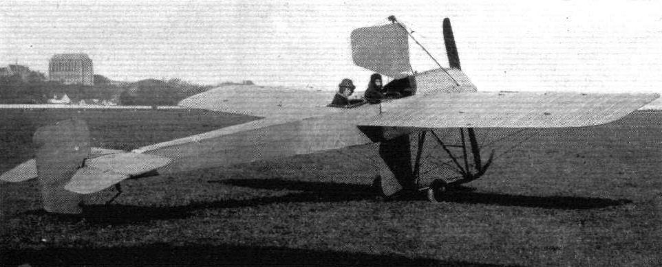
A NEW MONOPLANE AT SHOREHAM. - This machine, which incorporates a new idea in obtaining stability, has been built to the designs of Lieut. R. Burga by Messrs. A. V.Roe and Co. Further reference to it will be found in the "Eddies."
The Burga Monoplane at Shoreham in November 1912 with H. R. Simms in the rear cockpit and Lt Burga in the front.
The Burga Monoplane at Shoreham in November 1912 with H. R. Simms in the rear cockpit and Lt Burga in the front.
Flight, March 30, 1912.
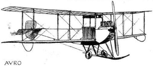
THE NEW AVRO BIPLANE.
EXCEPTING that the general disposition of its respective parts is the same, the new Avro biplane can hardly be recognised as a modification of the little machine on which Pixton attained his early successes and demonstrated the practicability of carrying a passenger cross-country with an engine of as low horse-power as 35.
Although it is in effect an original model to most of those who keenly follow the trend of design in this country, it is, in reality, several months old, for it was an almost identical machine that the Avro firm supplied to Mr. J. Duigan in September last. The only points of difference in the two machines are that, this present machine being a two-seater, a more powerful motor is installed, and dimensions are slightly increased throughout.
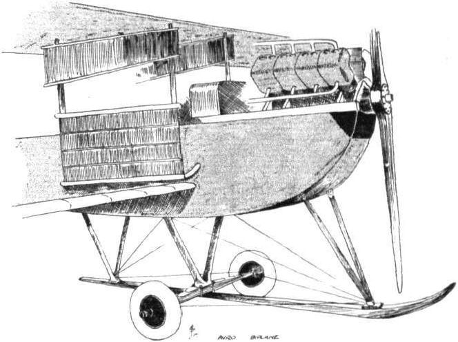
The triangular section body of the early machine has been superseded by one of rectangular section, built to an approximate streamline form, and so deep in the region of the cockpit that much head resistance and much personal discomfort of the pilot and passenger are avoided by virtue of the fact that only their heads emerge from its depths through the well-padded openings on top. Other advantages does this deep form of fuselage possess. The lower plane may be attached to it in a manner very similar to the attachment of monoplane wings; the chassis struts may be considerably shortened, thus making for more robustness in the landing gear. To facilitate transport the body may be dismantled into two sections. The crossbracing of the fuselage - it is of the ordinary girder type - is the same standard Avro system that has already been explained and illustrated in these columns.
A point worth mentioning in connection with the body is that its top surface is flat, and when the machine is in level flight is, theoretically, horizontal. To preserve its lines it is covered in by metal sheeting in the front, and by fabric to the rear.
The undercarriage needs little description, for it must be admitted that except for the central skid, and the front pair of struts fashioned from wood, and the steel disc wheels employed, it is identical with the Nieuport chassis. Rubber cushions are introduced between the struts and the central skid to further assist in deadening landing shocks.
When the machine first appeared at Brooklands there were some doubts as to whether this type of chassis would "stand up to its work" fitted to a passenger-carrying biplane. However, as far as the tests have gone it has proved eminently satisfactory. So doubts may, for the time being, be dispelled.
The main planes are rectangular, and have an aspect ratio of over 7 1/2, a feature which, coupled with the modified form of Phillips' cross-section employed, must have a most beneficial effect on their efficiency. In their bracing only eight struts are employed, these being fitted and riveted into welded steel sockets. Warping is employed for the maintenance of lateral balance.
In cross-section the planes have little curvature on the under surface, and have the peculiarity that the underside of the trailing-edge is horizontal in flight. Provisions have been made so that in quite a short space of time the machine may be turned into a monoplane. Virtually a double-purpose machine, it will be able to serve either as a weight carrier or a speedy scout. And speed it does exhibit - it must average at least 60 m.p.h.
Steel tubing is solely employed in the construction of the skeleton of the tail. This organ is purely directional, while elevation and depression is regulated by a pair of hinged flaps, operated through levers made from sheet steel.
Control is maintained by universal levers by either pilot or his passenger, the latter of whom is seated well forward in the body at the centre of gravity, so that his extra weight need not interfere with the balance of the machine.
Two little celluloid windows have been let into the floor boards in order that both will be able to see what is directly beneath them.
A 60-80 h.p. E.N.V. motor direct coupled to a 10-ft. Avro propeller provides the forward thrust.
Altogether the new Avro biplane is a decided advance on anything their works have hitherto produced. As for its efficiency it is only necessary to mention that on test on Saturday last it attained an altitude of 1,000 feet, in a little over live minutes. 2,000 feet was reached, with a heavy passenger aboard, in 13 minutes.
Flight, August 10, 1912.
THE MILITARY AEROPLANE COMPETITION - THE MACHINES.
THE AVRO BIPLANE.
THIS machine is one of the most remarkable of those flying at Salisbury, for the fact that it is the only one of the competition machines that allows the pilot and passenger to be totally enclosed and so completely protected from the rush of air. It is an interesting fact with this new Avro biplane that, with the side windows open the only wind felt is one which comes from the side when turning and banking. As will be seen by the photographs we publish this week, the fuselage completely fills the gap between the main planes. It is approximately streamline in side elevation, and its section may be represented by a tall vertical panel. The body is surprisingly narrow. Where the pilot and passenger sit it is only sufficiently wide to give them free movement. At the extreme front it is only 15 inches wide, a dimension which is obtainable by the use of a 60-h.p. vertical Green engine. The planes are identical with those fitted to the machine already supplied to the War Office. On the "all enclosed" biplane one deck is fitted to the extreme top of the fuselage, and the other to a point near the bottom. The warping wires pass from the top plane through slots in the lower, round a phosphor bronze four-grooved pulley attached to the end of the skid. It has been so arranged that a warp of eighteen inches at the wing tip is possible.
The landing gear is admittedly of Nieuport pattern, but it has the refinements that rubber blocks are interposed between the skid and the chassis struts, and that the transverse leaf springs are fitted to the wheels in an improved manner. The military authorities, recognising this latter improvement, are, by the way, now fitting this type of spring attachment to their Nieuport monoplanes.
Access to the interior of the body is obtained through triangular doors. A dashboard, on which are fitted all the instruments necessary for cross-country flying, is arranged to fill the whole space between the planes in front of the occupants. The latter are provided with safety belts.
The rudder serves a double purpose. By being shod with iron and by being arranged to slide vertically up and down the rudder post against the action of a spring, it is made to serve as a rear skid, as well as to perform its usual function of directing the course of the machine.
Main characteristics:-
Overall length 30 ft.
Weight without complement or fuel 1,250 lbs.
Span 35 ft. 8 ins.
Speed 65 m.p.h.
Flight, November 2, 1912.
AVIATION IN PORTUGAL.
FROM some particulars which have been sent us by Mr. H. V. Roe, it is evident that Portugal is now taking aviation very seriously. Several of the prominent newspapers are collecting for the national subscription, and the shops prominently display aviation books and postcards. Out of the National Fund the Avro biplane and Maurice Farman biplane, and a Voisin hydro-aeroplane have already been bought, while some Brazilian officers have presented a Deperdussin to the Government. The Avro was officially handed over to the Minister of War on October 16th, when a crowd of about 20,000 people assembled to witness Mr. Copland Perry make some exhibition flights before the President. The flying ground is at Pedroucos, some 4 miles or so from Lisbon, between Belem and Algers, but it makes a very difficult aerodrome, as it is only about 300 yards long by 200 yards wide and is bounded on two sides by trees, on the third by some gas-holders, while the fourth is more or less open, as it adjoins one of the military rifle ranges. It is in that direction that Mr. Perry nearly always steered, and his favourite trip was up the river to Lisbon, over the town and the Avenida returning over the River Tagus, the round taking between 10 and 15 mins. The day after the machine had been handed over to the Portuguese Government Mr. Perry started off with a passenger intending to survey the country with a view to finding a permanent aerodrome. They disappeared in the direction of the town and were away for about an hour after which they continued flying in the opposite direction. Unfortunately when coming back the engine showed signs of giving up and the pilot decided, as it would be impossible to get back to the aerodrome, to bring the machine down into shallow water, about 50 yards from the shore, that being the only suitable place. Row boats were quickly to the rescue and the machine was hauled ashore little the worse for its bath. It is now called "Republica" the name being painted in red on both sides of the body and al;o in green underneath the wings, while a couple of little Republican flags are mounted on the outside struts. A good many flights have also been made by M. Trescarte on the Maurice Farman biplane. The Voisin machine is rapidly being erected, but the Deperduisin monoplane has not yet arrived, although it is expected shortly.
THE NEW AVRO BIPLANE.
EXCEPTING that the general disposition of its respective parts is the same, the new Avro biplane can hardly be recognised as a modification of the little machine on which Pixton attained his early successes and demonstrated the practicability of carrying a passenger cross-country with an engine of as low horse-power as 35.
Although it is in effect an original model to most of those who keenly follow the trend of design in this country, it is, in reality, several months old, for it was an almost identical machine that the Avro firm supplied to Mr. J. Duigan in September last. The only points of difference in the two machines are that, this present machine being a two-seater, a more powerful motor is installed, and dimensions are slightly increased throughout.
The triangular section body of the early machine has been superseded by one of rectangular section, built to an approximate streamline form, and so deep in the region of the cockpit that much head resistance and much personal discomfort of the pilot and passenger are avoided by virtue of the fact that only their heads emerge from its depths through the well-padded openings on top. Other advantages does this deep form of fuselage possess. The lower plane may be attached to it in a manner very similar to the attachment of monoplane wings; the chassis struts may be considerably shortened, thus making for more robustness in the landing gear. To facilitate transport the body may be dismantled into two sections. The crossbracing of the fuselage - it is of the ordinary girder type - is the same standard Avro system that has already been explained and illustrated in these columns.
A point worth mentioning in connection with the body is that its top surface is flat, and when the machine is in level flight is, theoretically, horizontal. To preserve its lines it is covered in by metal sheeting in the front, and by fabric to the rear.
The undercarriage needs little description, for it must be admitted that except for the central skid, and the front pair of struts fashioned from wood, and the steel disc wheels employed, it is identical with the Nieuport chassis. Rubber cushions are introduced between the struts and the central skid to further assist in deadening landing shocks.
When the machine first appeared at Brooklands there were some doubts as to whether this type of chassis would "stand up to its work" fitted to a passenger-carrying biplane. However, as far as the tests have gone it has proved eminently satisfactory. So doubts may, for the time being, be dispelled.
The main planes are rectangular, and have an aspect ratio of over 7 1/2, a feature which, coupled with the modified form of Phillips' cross-section employed, must have a most beneficial effect on their efficiency. In their bracing only eight struts are employed, these being fitted and riveted into welded steel sockets. Warping is employed for the maintenance of lateral balance.
In cross-section the planes have little curvature on the under surface, and have the peculiarity that the underside of the trailing-edge is horizontal in flight. Provisions have been made so that in quite a short space of time the machine may be turned into a monoplane. Virtually a double-purpose machine, it will be able to serve either as a weight carrier or a speedy scout. And speed it does exhibit - it must average at least 60 m.p.h.
Steel tubing is solely employed in the construction of the skeleton of the tail. This organ is purely directional, while elevation and depression is regulated by a pair of hinged flaps, operated through levers made from sheet steel.
Control is maintained by universal levers by either pilot or his passenger, the latter of whom is seated well forward in the body at the centre of gravity, so that his extra weight need not interfere with the balance of the machine.
Two little celluloid windows have been let into the floor boards in order that both will be able to see what is directly beneath them.
A 60-80 h.p. E.N.V. motor direct coupled to a 10-ft. Avro propeller provides the forward thrust.
Altogether the new Avro biplane is a decided advance on anything their works have hitherto produced. As for its efficiency it is only necessary to mention that on test on Saturday last it attained an altitude of 1,000 feet, in a little over live minutes. 2,000 feet was reached, with a heavy passenger aboard, in 13 minutes.
Flight, August 10, 1912.
THE MILITARY AEROPLANE COMPETITION - THE MACHINES.
THE AVRO BIPLANE.
THIS machine is one of the most remarkable of those flying at Salisbury, for the fact that it is the only one of the competition machines that allows the pilot and passenger to be totally enclosed and so completely protected from the rush of air. It is an interesting fact with this new Avro biplane that, with the side windows open the only wind felt is one which comes from the side when turning and banking. As will be seen by the photographs we publish this week, the fuselage completely fills the gap between the main planes. It is approximately streamline in side elevation, and its section may be represented by a tall vertical panel. The body is surprisingly narrow. Where the pilot and passenger sit it is only sufficiently wide to give them free movement. At the extreme front it is only 15 inches wide, a dimension which is obtainable by the use of a 60-h.p. vertical Green engine. The planes are identical with those fitted to the machine already supplied to the War Office. On the "all enclosed" biplane one deck is fitted to the extreme top of the fuselage, and the other to a point near the bottom. The warping wires pass from the top plane through slots in the lower, round a phosphor bronze four-grooved pulley attached to the end of the skid. It has been so arranged that a warp of eighteen inches at the wing tip is possible.
The landing gear is admittedly of Nieuport pattern, but it has the refinements that rubber blocks are interposed between the skid and the chassis struts, and that the transverse leaf springs are fitted to the wheels in an improved manner. The military authorities, recognising this latter improvement, are, by the way, now fitting this type of spring attachment to their Nieuport monoplanes.
Access to the interior of the body is obtained through triangular doors. A dashboard, on which are fitted all the instruments necessary for cross-country flying, is arranged to fill the whole space between the planes in front of the occupants. The latter are provided with safety belts.
The rudder serves a double purpose. By being shod with iron and by being arranged to slide vertically up and down the rudder post against the action of a spring, it is made to serve as a rear skid, as well as to perform its usual function of directing the course of the machine.
Main characteristics:-
Overall length 30 ft.
Weight without complement or fuel 1,250 lbs.
Span 35 ft. 8 ins.
Speed 65 m.p.h.
Flight, November 2, 1912.
AVIATION IN PORTUGAL.
FROM some particulars which have been sent us by Mr. H. V. Roe, it is evident that Portugal is now taking aviation very seriously. Several of the prominent newspapers are collecting for the national subscription, and the shops prominently display aviation books and postcards. Out of the National Fund the Avro biplane and Maurice Farman biplane, and a Voisin hydro-aeroplane have already been bought, while some Brazilian officers have presented a Deperdussin to the Government. The Avro was officially handed over to the Minister of War on October 16th, when a crowd of about 20,000 people assembled to witness Mr. Copland Perry make some exhibition flights before the President. The flying ground is at Pedroucos, some 4 miles or so from Lisbon, between Belem and Algers, but it makes a very difficult aerodrome, as it is only about 300 yards long by 200 yards wide and is bounded on two sides by trees, on the third by some gas-holders, while the fourth is more or less open, as it adjoins one of the military rifle ranges. It is in that direction that Mr. Perry nearly always steered, and his favourite trip was up the river to Lisbon, over the town and the Avenida returning over the River Tagus, the round taking between 10 and 15 mins. The day after the machine had been handed over to the Portuguese Government Mr. Perry started off with a passenger intending to survey the country with a view to finding a permanent aerodrome. They disappeared in the direction of the town and were away for about an hour after which they continued flying in the opposite direction. Unfortunately when coming back the engine showed signs of giving up and the pilot decided, as it would be impossible to get back to the aerodrome, to bring the machine down into shallow water, about 50 yards from the shore, that being the only suitable place. Row boats were quickly to the rescue and the machine was hauled ashore little the worse for its bath. It is now called "Republica" the name being painted in red on both sides of the body and al;o in green underneath the wings, while a couple of little Republican flags are mounted on the outside struts. A good many flights have also been made by M. Trescarte on the Maurice Farman biplane. The Voisin machine is rapidly being erected, but the Deperduisin monoplane has not yet arrived, although it is expected shortly.
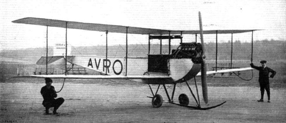
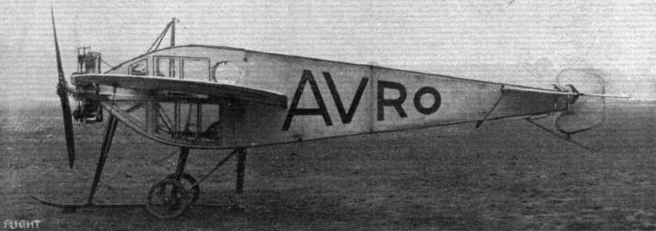
The Avro Type E prototype with 60 h.p. E.N.V. engine after change to radiators.
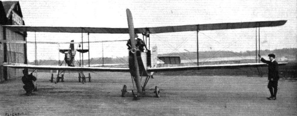
THE NEW AVRO BIPLANE. - View from the front.
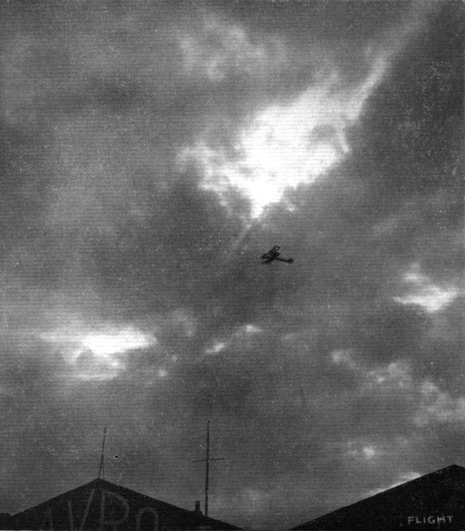
Leut. Parke flying the new Army Avro biplane over the sheds at Brooklands recently.

Mr. Copland Perry's mishap on the Tagus, when the engine petered out on the Avro biplane, and he came gently to rest on the water. Making the towing hawser fast; and, on the right, towing in the machine.
The front section of the new Avro biplane.

Sketch of the Avro biplane tail.
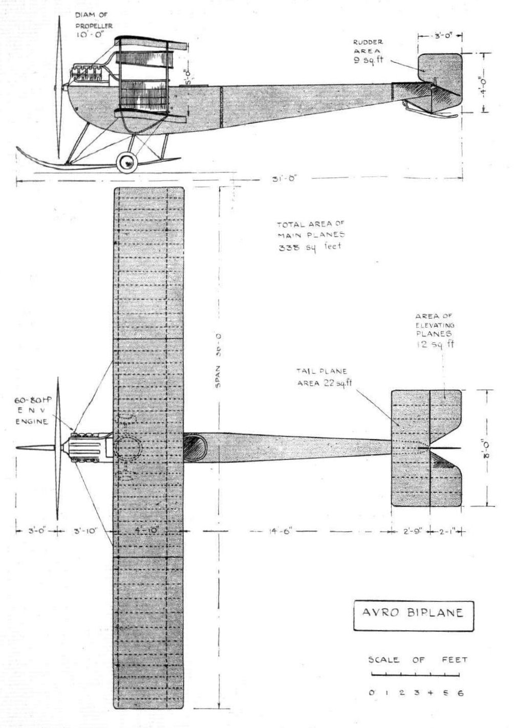
THE NEW AVRO BIPLANE. - Plan and elevation to scale.
Flight, April 13, 1912.
FROM THE BRITISH FLYING GROUNDS.
Brooklands Aerodrome.
<...>
A new comer during the week was the Avro monoplane, which is now in course of erection. This is a highly original machine, about which there is bound to be great divergence of opinion. The rectangular fuselage is very deep, the pilot being completely enclosed, and obtaining his view of the outside world through a number of windows covered with non-inflammable celluloid. The motor, a 50-h.p. Viale, is supported in front outside the covering. The pilot climbs in through a trap-door in the roof, and in the case of an upside down landing makes an emergency exit through the side with a pair of wire cutters.
Flight, October 2, 1912.
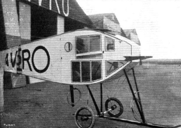
THE AVRO MONOPLANE.
NOT SO very many months ago we all, more or less, looked on the all-enclosed aeroplane as a dream of the future. But things move quickly in the aviation world these days, and already Messrs. A. V. Roe and Co. and Lieut. Wilfred Parke, R.N., the clever pilot who flies their machines, have shown us the practicability of this type of craft. This monoplane is entered through an aluminium trapdoor in the top of the body, for all the world as if it were a submarine that was being boarded instead of a flying machine. Inside, the pilot is comfortably seated with his elevation and warping lever between his knees, and his rudder lever at his feet. His switch, throttle, and spark advance levers are to his right hand, and his various other instruments - his altitude recorder, his compass, his revolution indicator, his watch, his map holder, and his level indicator - a very important instrument to use with this type of machine, we should think - are arranged conveniently around him. He takes his bearings, and sees what is going on around him through non-inflammable celluloid windows let into the front of the fuselage. A window sunk into the floor shows him the ground directly beneath him. Those to right and to left reveal the surroundings on either side.
When the machine first arrived at Brooklands it was generally thought - the habitats of that aerodrome invariably sit in solemn conclave on any new arrival - that, with the respiration of the pilot inside, and the fine spray of oil thrown out with the exhaust of the Viale motor, the windows would soon become clouded over, and render clear vision impossible after a few minutes' running. After his longest trip, the underneath window was the only one that showed much mistiness, and the fitting of exhaust pipes leaving the exhaust clear of the windows would undoubtedly cure the trouble, for in the Viale engine there are no auxiliary ports drilled in the cylinder walls to scatter the oil far and wide. Flying through heavy rain might make things rather difficult for the pilot, but then, as a safeguard, there is an open round hole in the body casing on each side through which he can thrust his head if necessary.
We believe there is only one other all enclosed aeroplane in existence as yet, and that is the Rumpler monoplane shown at the last Berlin Aero Exhibition. In this machine the covering for the pilot and passenger is merely a superstructure applied to an apparently standard machine. The fuselage was not especially designed for that purpose as is that of the Avro monoplane.
Two other enclosed body machines have been built, but they can scarcely come under the same category - the 100-h.p. Bleriot berline, for the pilot was accommodated outside the four-seated carriage-built body, and the Piggott monoplane, a British machine, for the fact that it has since the Aero Show of 1911 been modified, so that the pilot's head is outside the body of the machine. Thus, distinction attaches to those responsible for the monoplane under review, to the Avro firm for being the first to produce a machine of this type to prove itself successful in appreciably long flights, and to Lieut. Parke for having done the demonstration work.
The body is, as far as construction is concerned, identical with the later ones manufactured by this firm. The only difference it presents is that the ash longerons are reinforced by the application of triangular lengths of three-ply wood. This point is shown by one of our sketches. Its shape, viewed from one side, is approximately streamline, and exactly symmetrical about its longitudinal axis. In section it is rectangular. At the pilot's seat a section of the body may be represented by a vertical panel, so high that there is about 8 ins. of clearance between the top of the pilot's head and the roof of the fuselage. This measurement concerns the machine's present pilot, and would naturally vary with the overall height, in a sitting posture, of whoever may pilot a similar machine in the future. It is quite conceivable, following up this line of thought, that we shall one of these days be having our aeroplanes "made to measure."
A steel cap embraces the four longitudinal body members in front, and to this the motor - a 35-h.p. 5-cyl. radial air-cooled Viale - is bolted. Further support is provided by two stout ash bearers, which extend horizontally, one on each side, from the front of the body. At the rear end is the tail, but for this organ no description is necessary, for in construction and arrangement it is similar to those we have described in the past in connection with other Avro productions. One point, though, is noticeable - that the tail-skid is sprung in a manner that saves space and reduces the overall height of that section of the machine.
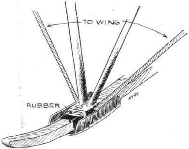
The landing gear, as in the case of the later Avro biplanes is a version of the Nieuport idea. The central skid supports the body through steel struts arranged V fashion - the front ones oval and the rear ones round in section. In both cases they slant forward to take the "drift" of landing. The laminated axle of spring steel is clipped to the skid. For the wings, except that the front spar of I section is built up instead of being hollowed out from the solid, the only point of more than usual originality is the manner in which the rear spars, in warping rock together with the single strut forming the upper and lower cabane, as one unit. This, perhaps, can better be conveyed by the accompanying sketch. The way of operating the warping that this same sketch shows is also highly interesting. Quite a sound point in connection with the engine controls - the main wing and tail controls are, as can be seen, standard Avro - is that they are mounted, the switch, the throttle, and the spark advance lever in a line together. Further, the levers operate in the same direction - that is, both spark and throttle levers are pushed forward to increase engine speed. The advantages of this system as against fitting the levers unsystematically, is too apparent to need dwelling on here.
FROM THE BRITISH FLYING GROUNDS.
Brooklands Aerodrome.
<...>
A new comer during the week was the Avro monoplane, which is now in course of erection. This is a highly original machine, about which there is bound to be great divergence of opinion. The rectangular fuselage is very deep, the pilot being completely enclosed, and obtaining his view of the outside world through a number of windows covered with non-inflammable celluloid. The motor, a 50-h.p. Viale, is supported in front outside the covering. The pilot climbs in through a trap-door in the roof, and in the case of an upside down landing makes an emergency exit through the side with a pair of wire cutters.
Flight, October 2, 1912.
THE AVRO MONOPLANE.
NOT SO very many months ago we all, more or less, looked on the all-enclosed aeroplane as a dream of the future. But things move quickly in the aviation world these days, and already Messrs. A. V. Roe and Co. and Lieut. Wilfred Parke, R.N., the clever pilot who flies their machines, have shown us the practicability of this type of craft. This monoplane is entered through an aluminium trapdoor in the top of the body, for all the world as if it were a submarine that was being boarded instead of a flying machine. Inside, the pilot is comfortably seated with his elevation and warping lever between his knees, and his rudder lever at his feet. His switch, throttle, and spark advance levers are to his right hand, and his various other instruments - his altitude recorder, his compass, his revolution indicator, his watch, his map holder, and his level indicator - a very important instrument to use with this type of machine, we should think - are arranged conveniently around him. He takes his bearings, and sees what is going on around him through non-inflammable celluloid windows let into the front of the fuselage. A window sunk into the floor shows him the ground directly beneath him. Those to right and to left reveal the surroundings on either side.
When the machine first arrived at Brooklands it was generally thought - the habitats of that aerodrome invariably sit in solemn conclave on any new arrival - that, with the respiration of the pilot inside, and the fine spray of oil thrown out with the exhaust of the Viale motor, the windows would soon become clouded over, and render clear vision impossible after a few minutes' running. After his longest trip, the underneath window was the only one that showed much mistiness, and the fitting of exhaust pipes leaving the exhaust clear of the windows would undoubtedly cure the trouble, for in the Viale engine there are no auxiliary ports drilled in the cylinder walls to scatter the oil far and wide. Flying through heavy rain might make things rather difficult for the pilot, but then, as a safeguard, there is an open round hole in the body casing on each side through which he can thrust his head if necessary.
We believe there is only one other all enclosed aeroplane in existence as yet, and that is the Rumpler monoplane shown at the last Berlin Aero Exhibition. In this machine the covering for the pilot and passenger is merely a superstructure applied to an apparently standard machine. The fuselage was not especially designed for that purpose as is that of the Avro monoplane.
Two other enclosed body machines have been built, but they can scarcely come under the same category - the 100-h.p. Bleriot berline, for the pilot was accommodated outside the four-seated carriage-built body, and the Piggott monoplane, a British machine, for the fact that it has since the Aero Show of 1911 been modified, so that the pilot's head is outside the body of the machine. Thus, distinction attaches to those responsible for the monoplane under review, to the Avro firm for being the first to produce a machine of this type to prove itself successful in appreciably long flights, and to Lieut. Parke for having done the demonstration work.
The body is, as far as construction is concerned, identical with the later ones manufactured by this firm. The only difference it presents is that the ash longerons are reinforced by the application of triangular lengths of three-ply wood. This point is shown by one of our sketches. Its shape, viewed from one side, is approximately streamline, and exactly symmetrical about its longitudinal axis. In section it is rectangular. At the pilot's seat a section of the body may be represented by a vertical panel, so high that there is about 8 ins. of clearance between the top of the pilot's head and the roof of the fuselage. This measurement concerns the machine's present pilot, and would naturally vary with the overall height, in a sitting posture, of whoever may pilot a similar machine in the future. It is quite conceivable, following up this line of thought, that we shall one of these days be having our aeroplanes "made to measure."
A steel cap embraces the four longitudinal body members in front, and to this the motor - a 35-h.p. 5-cyl. radial air-cooled Viale - is bolted. Further support is provided by two stout ash bearers, which extend horizontally, one on each side, from the front of the body. At the rear end is the tail, but for this organ no description is necessary, for in construction and arrangement it is similar to those we have described in the past in connection with other Avro productions. One point, though, is noticeable - that the tail-skid is sprung in a manner that saves space and reduces the overall height of that section of the machine.
The landing gear, as in the case of the later Avro biplanes is a version of the Nieuport idea. The central skid supports the body through steel struts arranged V fashion - the front ones oval and the rear ones round in section. In both cases they slant forward to take the "drift" of landing. The laminated axle of spring steel is clipped to the skid. For the wings, except that the front spar of I section is built up instead of being hollowed out from the solid, the only point of more than usual originality is the manner in which the rear spars, in warping rock together with the single strut forming the upper and lower cabane, as one unit. This, perhaps, can better be conveyed by the accompanying sketch. The way of operating the warping that this same sketch shows is also highly interesting. Quite a sound point in connection with the engine controls - the main wing and tail controls are, as can be seen, standard Avro - is that they are mounted, the switch, the throttle, and the spark advance lever in a line together. Further, the levers operate in the same direction - that is, both spark and throttle levers are pushed forward to increase engine speed. The advantages of this system as against fitting the levers unsystematically, is too apparent to need dwelling on here.
THE TOTALLY ENCLOSED AVRO MONOPLANE. - Slde view.
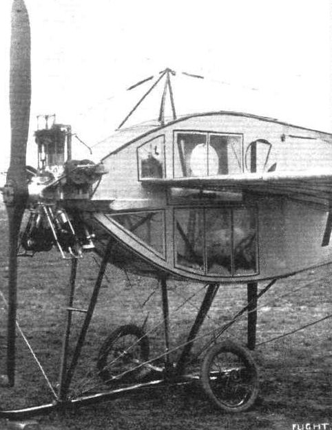
THE AVRO MONOPLANE. - Detailed view of the landing gear, engine mounting, and the non-inflammable celluloid windows through which the pilot sees what is going on around him.
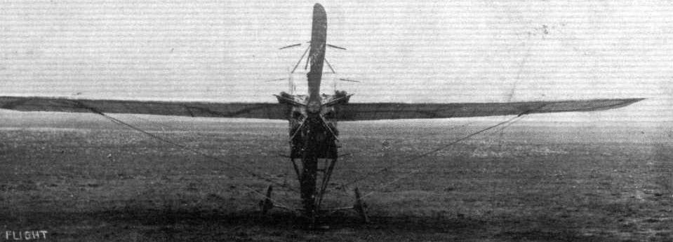
The Avro monoplane, as seen from the front.
THE NEW AVRO MILITARY PATTERN ENCLOSED-TYPE MACHINE. - View of the chassis and front part of the fuselage.
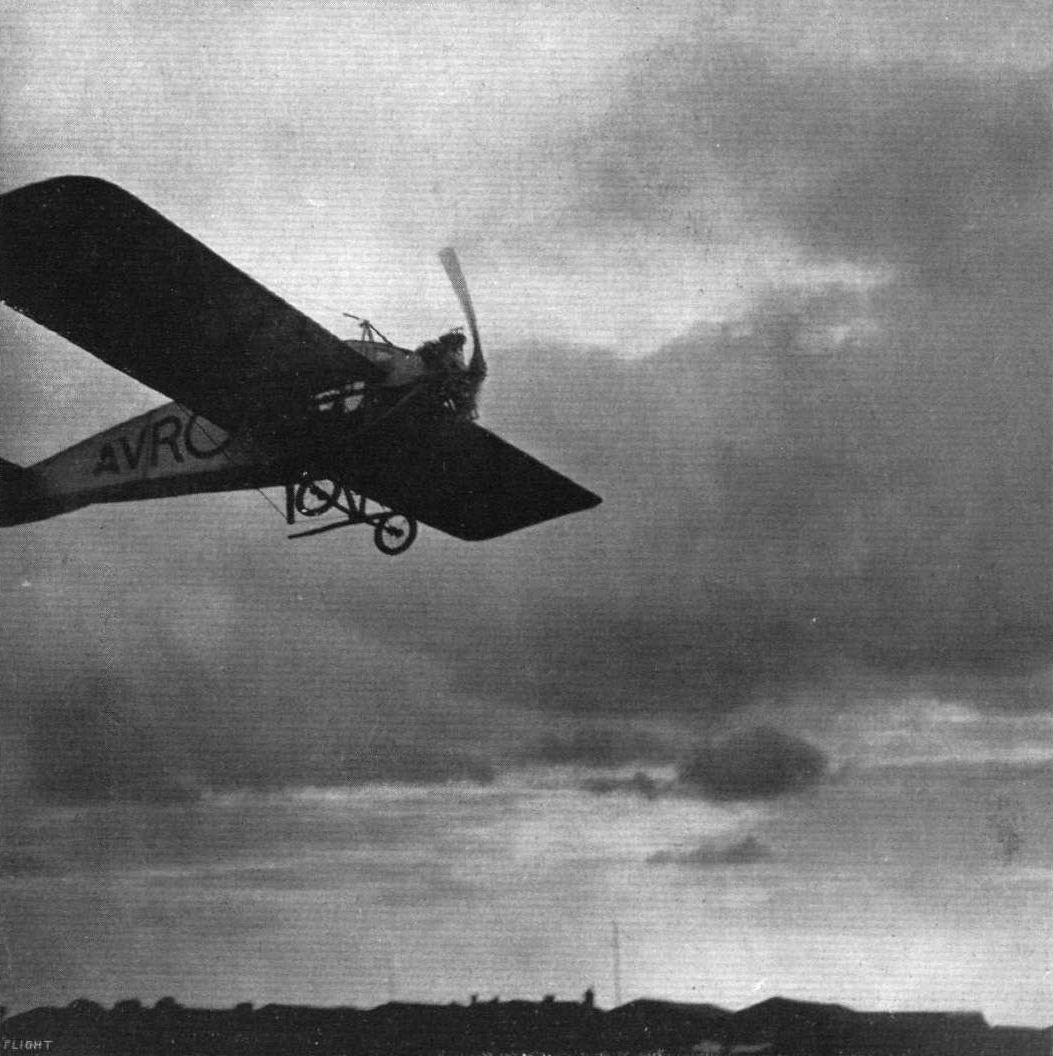
AN IMPRESSION OF SPEED. - A genuine photograph of the new enclosed Avro monoplane, which was recently flying at Brooklands, secured by FLIGHT photographer in one-thousandth part of a second.
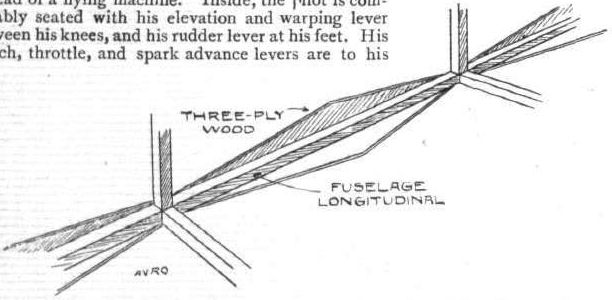
Showing how the fuselage longerons are strengthened by the application of three-ply wood on the Avro monoplane.
Details of the Avro Skid Attachment. - A rubber insert is arranged between the skid and the tubular steel struts supporting it.
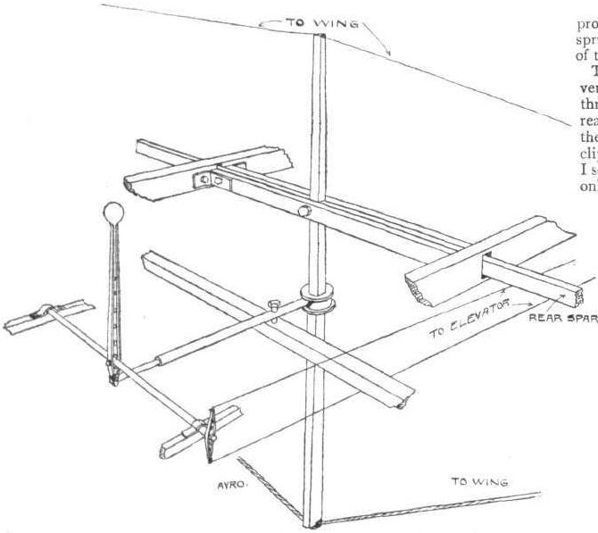
DETAILS OF THE CONTROL OF THE AVRO MONOPLANE. - The whole of the rear wing spars, together with the upper and lower cabane strut, rocks in a single unit.
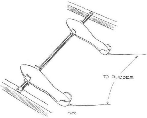
The Avro foot pedals by which the rudders are controlled.
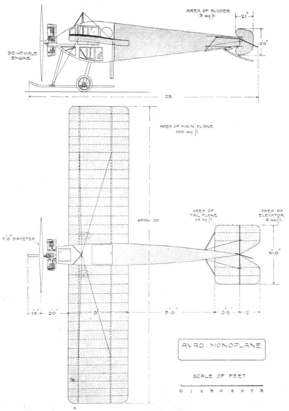
THE AVRO MONOPLANE. - Plan and elevation to scale.
Flight, August 10, 1912.
THE MILITARY AEROPLANE COMPETITION - THE MACHINES.
THE AVRO BIPLANE.
THIS machine is one of the most remarkable of those flying at Salisbury, for the fact that it is the only one of the competition machines that allows the pilot and passenger to be totally enclosed and so completely protected from the rush of air. It is an interesting fact with this new Avro biplane that, with the side windows open the only wind felt is one which comes from the side when turning and banking. As will be seen by the photographs we publish this week, the fuselage completely fills the gap between the main planes. It is approximately streamline in side elevation, and its section may be represented by a tall vertical panel. The body is surprisingly narrow. Where the pilot and passenger sit it is only sufficiently wide to give them free movement. At the extreme front it is only 15 inches wide, a dimension which is obtainable by the use of a 60-h.p. vertical Green engine. The planes are identical with those fitted to the machine already supplied to the War Office. On the "all enclosed" biplane one deck is fitted to the extreme top of the fuselage, and the other to a point near the bottom. The warping wires pass from the top plane through slots in the lower, round a phosphor bronze four-grooved pulley attached to the end of the skid. It has been so arranged that a warp of eighteen inches at the wing tip is possible.
The landing gear is admittedly of Nieuport pattern, but it has the refinements that rubber blocks are interposed between the skid and the chassis struts, and that the transverse leaf springs are fitted to the wheels in an improved manner. The military authorities, recognising this latter improvement, are, by the way, now fitting this type of spring attachment to their Nieuport monoplanes.
Access to the interior of the body is obtained through triangular doors. A dashboard, on which are fitted all the instruments necessary for cross-country flying, is arranged to fill the whole space between the planes in front of the occupants. The latter are provided with safety belts.
The rudder serves a double purpose. By being shod with iron and by being arranged to slide vertically up and down the rudder post against the action of a spring, it is made to serve as a rear skid, as well as to perform its usual function of directing the course of the machine.
Main characteristics:-
Overall length 30 ft.
Weight without complement or fuel 1,250 lbs.
Span 35 ft. 8 ins.
Speed 65 m.p.h.
Flight, August 31, 1912.
PARKE'S DIVE.
Salisbury Plain, Sunday, August 25th.
HERE is the true story of one of the worst experiences in mid-air from which any pilot has extricated his machine in absolute safety, and as the circumstances precisely represent the hypothesis of the most debated problem among pilots at the present time, the following particulars should be studied with the closest attention by all.
At four minutes past six this morning Lieut. Parke, R.N., accompanied by Lieut. Le Breton, R.F.C., as observer, started on the Avro biplane (60-h.p. Green engine) from Salisbury Plain for the three hours' qualifying flight in the Military Trials. At ten minutes past nine, having more than completed the required duration, he was returning from the direction of Upavon for the express purpose of alighting in front of the sheds.
The direction of flight was practically towards due south; the wind was blowing approximately from the south-west, with a tendency to back southwards. He was, therefore, flying virtually up wind. The speed of the wind was estimated about 10-15 m.p.h. by the pilot, and the maximum air speed of the machine with the present propeller is about 60 m.p.h., as tested over the measured distance yesterday. The engine was pulling well, and the machine in perfect trim. There was bright sunshine and some clouds.
Throughout the flight an altitude of between 600 and 700 ft. was maintained, and the pilot, observing that he was still at this height, decided that he had sufficient room for a spiral glide. At the point A, in the diagram, he closed the throttle without switching off (which kept the engine just turning) and immediately proceeded to glide round down wind. At the point B, having completed a half spiral, Parke thought the machine was in an unnecessarily steep attitude, and was insufficiently banked for the turn he was making. He therefore elevated, and believes that he may also have given a momentary touch to the warp, which two operations were for the purpose of reducing the steepness of the descent and increasing the bank respectively.
The machine at once started a spiral nose-dive.
At the point C, Parke opened the throttle full out, in the hope that the propeller might pull the nose up, for he was aware (and had also confirmed the fact during this flight) that the machine was slightly nose-heavy with the throttle closed. The engine responded instantly, but failed to produce the desired effect on the machine; it may or may not have accelerated the descent, but the fall was already so rapid that the maximum engine speed was unlikely even to be equal to it.
Also at the point C, he drew the elevator lever hard back against his chest and put the rudder hard over to the left with his foot so as to turn the machine inwards, this latter being the principle of action that is accepted as proper in cases of incipient side-slip, and, therefore, naturally to be tried in an emergency such as this. The warp was normal, i.e., balanced with the control wheel neutral. These operations failed utterly to improve the conditions.
From C to D the machine was completely out of control, diving headlong at such a steep angle that all spectators described it as vertical and stood, horror stricken, waiting for the end. According to Parke, the angle was very steep, but certainly not vertical; he noticed no particular strain on his legs, with which he still kept the rudder about half over to the left (about as much as is ordinarily used for a turn), nor on his chest, across which he was strapped by a wide belt to his seat. His right hand he had already removed from the control wheel in order to steady himself by grasping the body strut forming an upright between the windows of the enclosed body. This he did, not for support against the steepness of the descent, but because he felt himself being thrown outwards by the spiral motion of the machine, which he describes as "violent." The absence of pressure on the legs and arms appears to me, however, to be evidence that the machine was falling as fast as the pilot, who was, therefore, unstable on his seat, and without a fulcrum until he fastened himself to the framework by the grip of his hand.
It was his recognition, through this forcible effect, of the predominating influence of the spiral motion, as distinct from the dive, that caused him to ease off the rudder and finally push it hard over to the right (i.e., to turn machine outwards from the circle), as a last resource, when about 50 feet from the ground.
Instantly, but without any jerkiness, the machine straightened and flattened out - came at once under control and, without sinking appreciably, flew off in perfect attitude. Parke made a circuit of the sheds in order to get into position for landing in a good place up wind, and proceeded to alight in the usual way without the least mishap. Thus did he and his observer, who, having no belt and rather cramped accommodation, was thrown up against the front wall of the cabin, escape at the last moment from what looked like certain death and effect a perfect landing with the machine none the worse for its severe straining save for a slight stretching of some of the lift-wires under the main planes.
Like the majority, I was at breakfast when the dive occurred; for, having watched the Avro during the earlier part of its flight and up to the end of its second hour, its uniform behaviour inspired a confidence that one was not loathe to translate into an excuse for leave. Very soon afterwards, however, I saw Lieut. Parke on the field, and, together with G. de Havilland and F. Short, of the R.A.F., adjourned to the competitors' mess, where we held an informal, but extremely close, enquiry into the whole affair. It was so obvious to all that the problems of the accident were so near to having to be discussed under the shadow of the pilot's absence, that the opportunity of recording on the spot the essential facts and impressions as he understood them was not only unique, but of the utmost consequence to aviation. His own anxiety to facilitate this work for the benefit of others, and the fact that he retained his presence of mind from first to last in the emergency - although admittedly terribly alarmed - so that he was conscious of each operation and the effect produced serves to give to the aviation world at least one definite experience of an extreme character for its guidance.
The seriousness of the situation there is no denying. Parke himself stared death in the face; most of the spectators sickened for the crash, and among them were those who were also furious in the belief that he had attempted a "stunt" and failed. There was some reason for this belief, because the machine behaved throughout in a perfectly smooth, normal manner, despite its extremely exaggerated attitude, and when it flattened out so nicely at the last moment even those who had been convinced they were witnessing an accident were left in doubt, whether, after all, it had not been intentional.
If disaster had followed, all manner of "explanations" would have been forthcoming, and, among them, de Havilland would have given it as his opinion that the control had become jammed, having regard to the fact that there was no excuse otherwise for a pilot of such experience to get himself into that position. With this latter observation Parke himself heartily agrees; but it happened all the same. He was not tired after his flight, but he was naturally pleased at its successful termination after all the previous misfortunes that the Avro firm had borne in such good spirit, and had in mind merely the finishing of the flight safely, but in good style.
Of the many important and interesting aspects of the case, one is obviously related to the value of flying high. But for the room available for the fall, disaster was unavoidable. For the first 100 ft. the descent was normal, but, afterwards, acceleration to something in the order of 90 m.p.h. (speed suggested by de Havilland) took place, and the machine fell about 450 ft. whilst more or less out of control - which is a lesson those who have not yet learnt would do well to bear in mind.
The next and most important point is that affecting the popular discussion on the proper method of recovering from side-slip in the air, particularly with reference to ruddering inwards and ruddering outwards in emergency. In the first place it is necessary to differentiate between the present circumstances and a side-slip in the incipient stage as ordinarily understood. A side-slip (which means the machine slips inwards), is caused, fundamentally, by over banking, insufficient speed and a cabre attitude (tail down), may be incidental to the occurrence. Ruddering inwards in such an emergency, brings the machine on to its accidental line of motion in a flying attitude (instead of sideways), and promotes a dive, from which the pilot obtains both the position and the velocity necessary to recovery.
In Parke's dive, the machine was not side slipping in the above sense (even supposing that the term could properly be applied to any phase of the occurrence) when ruddering outwards proved so marvellously effective. It was flying on a true helix of an excessively steep pitch, and to obtain a proper understanding of the effects produced it is necessary to have a clear mental picture of the tail in its line of flight. It is illustrated diagrammatically in the sketch. The elevator is hard up and the rudder hard over to the pilot's left. In common with the rest of the machine the tail as a whole has a spiral motion downwards through space, but leans inwards somewhat towards the centre of the vertical path in such a way as might produce a side-slip if the machine lacked velocity.
The present position of the rudder (to the pilot's left) supports the tail, and as the speed increases tends to make it cruise round outwards after the nose of the machine, thus turning the machine still more about its vertical pivot, increasing the steepness of the dive, and also, by maintaining the outer wing at its high velocity, accentuating the bank.
By throwing the rudder over to the right, this accentuation of the centrifugal action of the tail is checked, and a virtual acceleration of the inside main wing tip takes place in consequence, so that the machine tends to change its spiral direction of motion into a straight line, and at the same time to recover its lateral trim. These conditions at once release the elevator from the neutralising influences that have rendered it inoperative, and being already hard up it brings the machine on to an even keel at that high speed with extreme rapidity. The warp was not used consciously at this time; the wheel could have been turned with one hand, but Parke thinks he did not do so; i.e., the entire phenomenon is related to elevator and rudder action only.
Such is the gist of the explanation as we argued it on this occasion, and I believe the others who were party to the discussion are in agreement therewith, unless I have misunderstood their meaning on any point. There was a question as to whether the draught off the rudder being directed on to one half of the divided elevator could have exercised an appreciable torque through the backbone of the machine, first to increase the bank and afterwards to reduce it, but there seemed absolutely no evidence one way or the other on the subject. Later, it was suggested that the machine might have made an automatic recovery, such as models do when launched vertically from the hand, but here it seems necessary to remember that a model is in the process of picking up its flying speed, whereas in this case the phenomenon is related to an occurrence that took place when the flying speed had been far exceeded. If it were it would have been a most extraordinary coincidence, for the response of this machine to the right-hand swing of the rudder was instantaneous and indeed with only 50 ft. to go, it would have been quite useless otherwise.
Yes, on the whole I think we may consider it a genuine practical lesson in aeroplane control, and one, moreover, of the most important order. There has been endless discussion on this very subject and much conflicting opinion, but no one is voluntarily going to risk losing control of his machine in mid-air for the sake of demonstrating the facts. Now that it has happened to Lieut. Parke by accident, and he is safely through it to tell the tale, let no one forget the rule to "rudder outwards from a spiral dive that has already acquired a high velocity."
In conclusion, a word to the credit of the Avro biplane and Green engine. That the machine withstood the strain of flattening out at 90 m.p.h., or thereabouts, is no more than any pilot has a right to expect of any machine. Nothing must break in midair, and nothing did break. That it recovered in the long run is at least evidence in support of the design. The tail is the same on Parke's machine as on the Avro biplanes supplied to the Army, which are fitted with Gnome engines; but two of those machines have been refitted, by instruction, with larger tails than the designers and pilot consider necessary, although they see no objection to their use. One of the Army Avros still has the original tail.
By the courtesy of the firm, a scale drawing of the machine is reproduced on another page.
From this drawing the general lines of the machine and proportions of the surfaces are self-evident. The fuselage at backbone is entirely surfaced and rectangular; its sides narrow to a knife edge at the rudder-post, and present a considerable vertical surface to the wind. It appears, however, that this fin effect is balanced on either side of the vertical pivot about which the machine naturally swings in space, because Lieut. Parke has found no tendency for it to be slewed off its course either into or out of the wind.
This is an important consideration, because the large extent of the surface thus presented by the backbone, which is most easily arranged this way as a natural extension of the cabin-body, was thought to be a possible source of trouble in windy weather. Under normal conditions the machine takes a natural bank when turning; its wings have a large dihedral angle and are quite rigid in the ribs. Equal-sized spars are used.
In winds the machine appears to be very steady and weatherly.
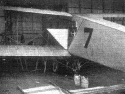
The Avro biplane in its shed after a flight in the Military Aeroplane Trials, showing the cabin door open through which access to the pilot's seat is obtained.
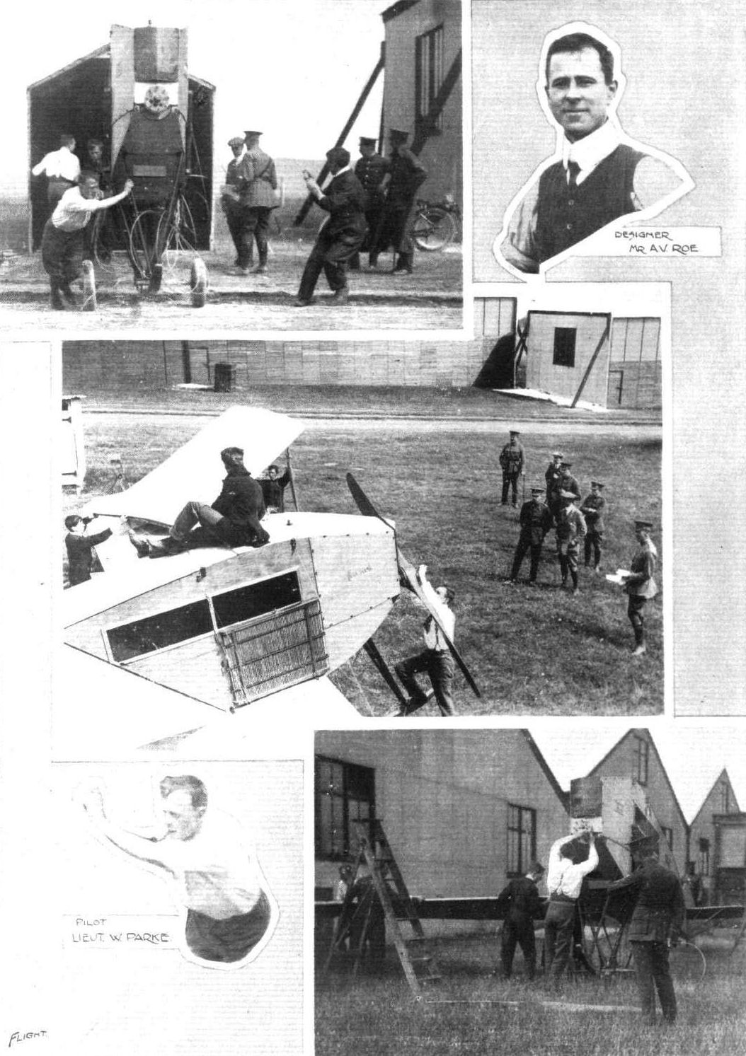
THE MILITARY AEROPLANE COMPETITION. - The Avro biplane being assembled. This machine won the Assembling Test by being prepared for flight in 14 mins. 30 secs. Inset are the designer and pilot.

Taking home the wreckage of the Avro biplane to Manchester, where Messrs. A. V. Roe and Co. tackled the "problem," and had it on its way back to Larkhill by Wednesday evening. The Avro firm need not be Included in the "Wake up England" admonition!
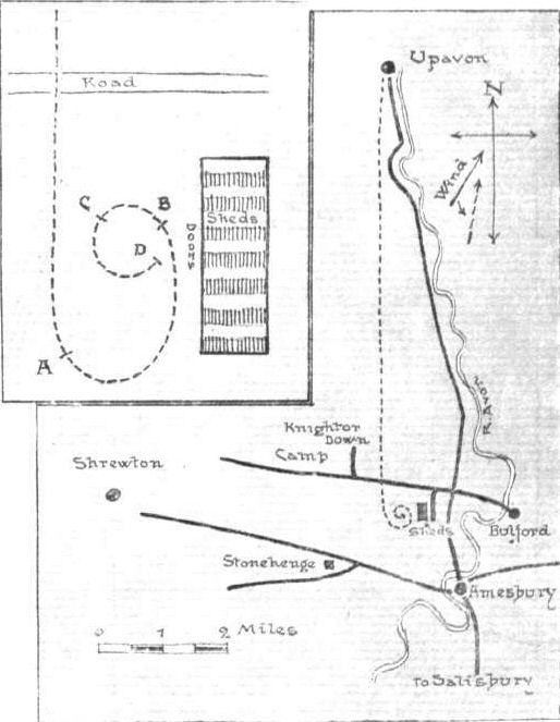
Key map illustrating the flight of the Avro biplane which terminated in the spiral dive. Inset on a larger scale is a lettered diagram of the dive to which reference is made in the text.

The above sketch was drawn from a paper model of a monoplane, as it is exceedingly difficult to convey an impression of a spiral path and banking in one view, and at the same time to show the position of the controls. In Parke's dive, the machine was an Avro tractor biplane. The elevator was hard up, and the rudder hard over to the pilot's left at first and eased off half way later. As a last resource, within 50 ft. of the ground the pilot ruddered hard over in the opposite direction, i.e., outwards, which instantly brought the machine on to a level keel and in lateral trim. The engine was working on open throttle all the time and the warp was normal. The pilot had one hand only on the control (the other being placed on the body strut to steady himself), which was drawn right back against his chest to elevate, and although he could have warped by turning the wheel with one hand, he did not consciously do so.
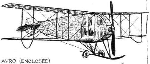
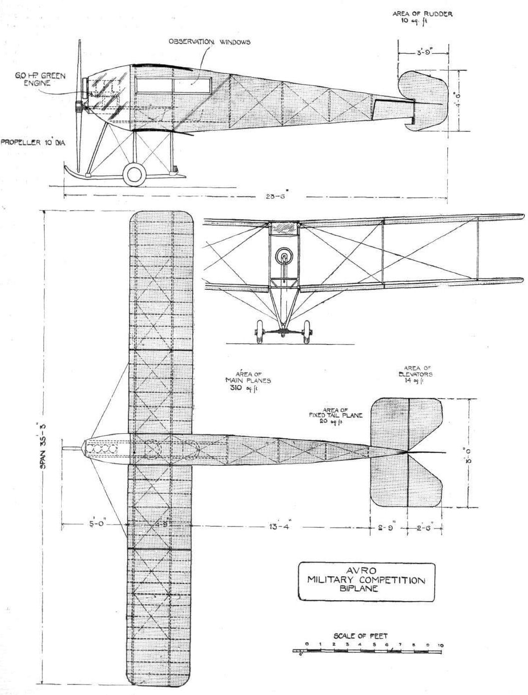
THE AVRO MILITARY BIPLANE. - Plan and Elevation to Scale.
Flight, January 13, 1912.
Natural Stability.
In view of the correspondence on the above subject, which has been recently appearing in your columns, the enclosed photograph may, perhaps, be of interest, as showing that the "triangular duct" was introduced between the dihedral planes on one of the hydro-aeroplanes, which I, in conjunction with Mr. F. L. Rawson, made and experimented with at the Isle of Wight.
The machine rested on the water on light pontoons 26 ft. long, and weighing only 20 lbs. each, and in addition to the dihedral wings, had on each side two main horizontal planes in front and two at the rear, all moveable. Total lifting and bearing surface =1,200 sq. ft.
Two vertical fixed planes and a small flying jib were placed in the bows to assist the action of the rudder in the stern.
The engine and 7 ft. propeller was arranged for on the steering deck, which was low down on the pontoons just behind the main planes.
The photo, which is somewhat faded, shows the machine just being lifted out of the water after a trial on the open sea on September 26th, 1905.
London Wall Buildings, E.C. F. ALEX. BARTON.
Flight, February 24, 1912.
AIR EDDIES.
The next aspirant for cross-Channel honours is Lieut. Walter Lawrence, of the 7th Essex Regiment, who is at the Shoreham Aerodrome awaiting an .opportunity to effect the crossing on his Blackburn monoplane, taking with him Mrs. Leeming, a well known Society hostess, as passenger. The machine on which he intends to accomplish the flight is the identical monoplane with which Bentfield Hucks carried out his "missionary" work in the West Country at the close of last season. Lieut. Lawrence is, by the way, the first Territorial officer to master the intricacies of both monoplane and biplane.
Flight, March 2, 1912.
AIR EDDIES.
Talking with Mr. R. Blackburn the other day, I learnt that, of the new Blackburn Military monoplanes now in the process of construction at his Leeds works, there is not a single component part that is not capable, under actual test, to withstand a stress of at least ten times that which it is likely to be called upon to bear under normal flying conditions. The Blackburn is still doing good work with Lieut. Spencer Grey at Eastchurch, and Lieut. Laurence at Shoreham. During last week the latter flew over to Eastbourne to pay a visit to Mr. F. B. Fowler, of the Eastbourne Aviation Co., completing a flight of 28 miles within the half hour, in spite of a head wind.
On Thursday last he had intentions of flying on to Dover, and it is more than likely that his projected Channel crossing may be a fait accompli by the time these lines appear in print.
Flight, November 16, 1912.
THE BLACKBURN SCHOOL MONOPLANE.
FOR a long time the Blackburn Aeroplane Co. has been working steadily and scientifically up at Leeds and Filey, where they have produced the machines with which they have from time to time made so many excellent flights. It is only comparatively recently, however, that they have established a London centre at the Hendon Aerodrome, and although this may seem to make the Blackburn monoplane somewhat more in evidence than hitherto it has been to Londoners, it will not necessarily bring it more to the fore with readers of FLIGHT who have the advantage of being equally in touch with all centres of aviation. It is a British-built machine of British origin and as such has particular claim on the attention of most of our readers, some of the points of design being of special merit.
And, as a complete aeroplane it is well worthy of study, the more so, perhaps, because it is exceedingly simple, and at a first glance represents all that one expects to see as characteristic of monoplane construction. As the eye looks longer at its slim lines, however, the position of the engine well out in front of the wings strikes one as a departure from the conventional, and as one goes closer little points in the chassis construction attract the attention, and notably the method of supporting the wings from a mast, which rises from the floor of the body and which is strutted then by diagonal members of ash to the main chassis skid. It only needs a glance at the elevation of the machine, which is the subject of one of our full page illustrations, to see very clearly that the designer is seeking to overcome the inherent difficulty of providing external drift wires in monoplane construction. By balancing his machine with the engine well forward he has been able to arrange a point of attachment of the wing wires to the chassis skid, which is well forward of the position that ordinarily would be occupied by the engine, and therefore within the zone of interference by the propeller.
It is unnecessary and also to small purpose to go through the construction of the Blackburn monoplane piece by piece; much of what is interesting therein, but not all that is deserving of notice, forms the subject of our detail sketches which convey to the eye at a glance far more than can be communicated to the brain through a column of print. It is only of importance to draw attention to one or two matters that might otherwise escape notice, as for instance that the triangular section lattice girder backbone is trussed entirely with ash, no wire being used in its construction. The forward part of the fuselage, forming the body, is surfaced with aluminium and the after part with fabric. Tubular steel main spars filled with timber are now used as the principal wing members, and the details of their attachment to the body are well shown in the sketches. The rear spar is hinged, and when the wings are warped the ribs swivel around it so as to impose no twisting strain. The ribs are made of cotton wood and are prevented from sliding along the spars by the intervention of ash distance pieces. The wing surfacing consists of Irish linen treated with Emaillite. The control is a very interesting feature of Blackburn design, but being one with which all readers of FLIGHT ought to be very well familiar by now, we need only draw attention to the sketch in which this detail is illustrated. A single wheel serves for steering the rudder, while the elevator is operated by a vertical movement of the inclined steering column; moving the same sideways, warps the wings. On the school machine, from which these illustrations were made, the power plant consists of a 50 h.p. Gnome engine driving a Blackburn propeller.
AIR EDDIES.
The next aspirant for cross-Channel honours is Lieut. Walter Lawrence, of the 7th Essex Regiment, who is at the Shoreham Aerodrome awaiting an .opportunity to effect the crossing on his Blackburn monoplane, taking with him Mrs. Leeming, a well known Society hostess, as passenger. The machine on which he intends to accomplish the flight is the identical monoplane with which Bentfield Hucks carried out his "missionary" work in the West Country at the close of last season. Lieut. Lawrence is, by the way, the first Territorial officer to master the intricacies of both monoplane and biplane.
Flight, March 2, 1912.
AIR EDDIES.
Talking with Mr. R. Blackburn the other day, I learnt that, of the new Blackburn Military monoplanes now in the process of construction at his Leeds works, there is not a single component part that is not capable, under actual test, to withstand a stress of at least ten times that which it is likely to be called upon to bear under normal flying conditions. The Blackburn is still doing good work with Lieut. Spencer Grey at Eastchurch, and Lieut. Laurence at Shoreham. During last week the latter flew over to Eastbourne to pay a visit to Mr. F. B. Fowler, of the Eastbourne Aviation Co., completing a flight of 28 miles within the half hour, in spite of a head wind.
On Thursday last he had intentions of flying on to Dover, and it is more than likely that his projected Channel crossing may be a fait accompli by the time these lines appear in print.
Flight, November 16, 1912.
THE BLACKBURN SCHOOL MONOPLANE.
FOR a long time the Blackburn Aeroplane Co. has been working steadily and scientifically up at Leeds and Filey, where they have produced the machines with which they have from time to time made so many excellent flights. It is only comparatively recently, however, that they have established a London centre at the Hendon Aerodrome, and although this may seem to make the Blackburn monoplane somewhat more in evidence than hitherto it has been to Londoners, it will not necessarily bring it more to the fore with readers of FLIGHT who have the advantage of being equally in touch with all centres of aviation. It is a British-built machine of British origin and as such has particular claim on the attention of most of our readers, some of the points of design being of special merit.
And, as a complete aeroplane it is well worthy of study, the more so, perhaps, because it is exceedingly simple, and at a first glance represents all that one expects to see as characteristic of monoplane construction. As the eye looks longer at its slim lines, however, the position of the engine well out in front of the wings strikes one as a departure from the conventional, and as one goes closer little points in the chassis construction attract the attention, and notably the method of supporting the wings from a mast, which rises from the floor of the body and which is strutted then by diagonal members of ash to the main chassis skid. It only needs a glance at the elevation of the machine, which is the subject of one of our full page illustrations, to see very clearly that the designer is seeking to overcome the inherent difficulty of providing external drift wires in monoplane construction. By balancing his machine with the engine well forward he has been able to arrange a point of attachment of the wing wires to the chassis skid, which is well forward of the position that ordinarily would be occupied by the engine, and therefore within the zone of interference by the propeller.
It is unnecessary and also to small purpose to go through the construction of the Blackburn monoplane piece by piece; much of what is interesting therein, but not all that is deserving of notice, forms the subject of our detail sketches which convey to the eye at a glance far more than can be communicated to the brain through a column of print. It is only of importance to draw attention to one or two matters that might otherwise escape notice, as for instance that the triangular section lattice girder backbone is trussed entirely with ash, no wire being used in its construction. The forward part of the fuselage, forming the body, is surfaced with aluminium and the after part with fabric. Tubular steel main spars filled with timber are now used as the principal wing members, and the details of their attachment to the body are well shown in the sketches. The rear spar is hinged, and when the wings are warped the ribs swivel around it so as to impose no twisting strain. The ribs are made of cotton wood and are prevented from sliding along the spars by the intervention of ash distance pieces. The wing surfacing consists of Irish linen treated with Emaillite. The control is a very interesting feature of Blackburn design, but being one with which all readers of FLIGHT ought to be very well familiar by now, we need only draw attention to the sketch in which this detail is illustrated. A single wheel serves for steering the rudder, while the elevator is operated by a vertical movement of the inclined steering column; moving the same sideways, warps the wings. On the school machine, from which these illustrations were made, the power plant consists of a 50 h.p. Gnome engine driving a Blackburn propeller.
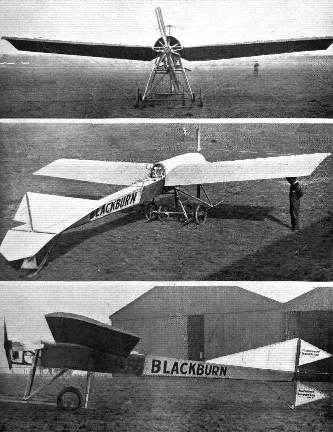
Three views of the Blackburn School monoplane.
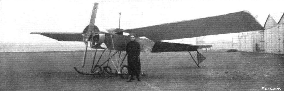
Lieut. Walter Lawrence, of the 7th Essex Regiment, and the 50-h.p. Blackburn monoplane with which he intends shortly to cross the Channel with Mrs. Leeming, a well-known Society hostess, as passenger. He is at present at Shoreham.

TO FLY THE CHANNEL. - Lieut. Lawrence in the pilot's seat of his Blackburn monoplane with Mrs. Leeming, who will accompany him as passenger when he makes his trip across the Channel as referred in FLIGHT recently.
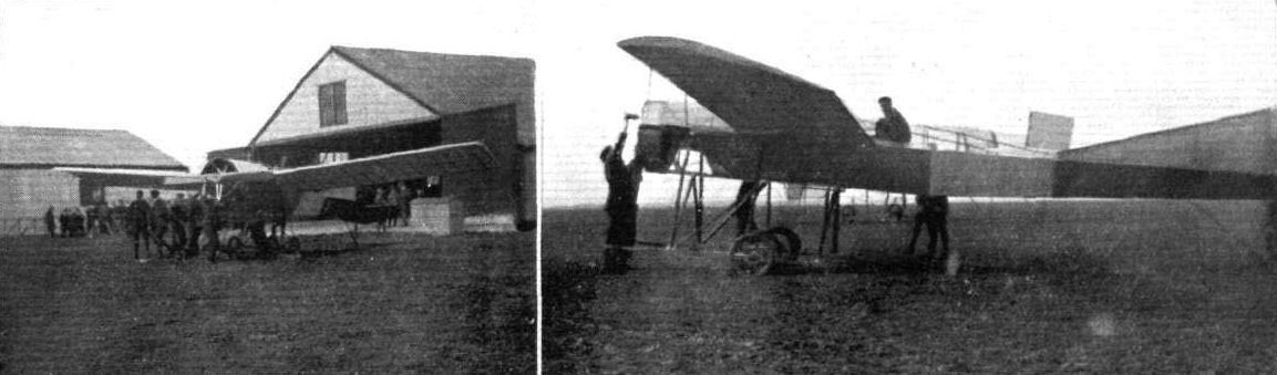
Lieut. Spencer Grey and the Blackburn monoplane, with which he has been carrying out exceedingly successful flights at Eastchurch. On the left, the monoplane being brought from the hangar. On the right, the engine being primed preliminary to starting.
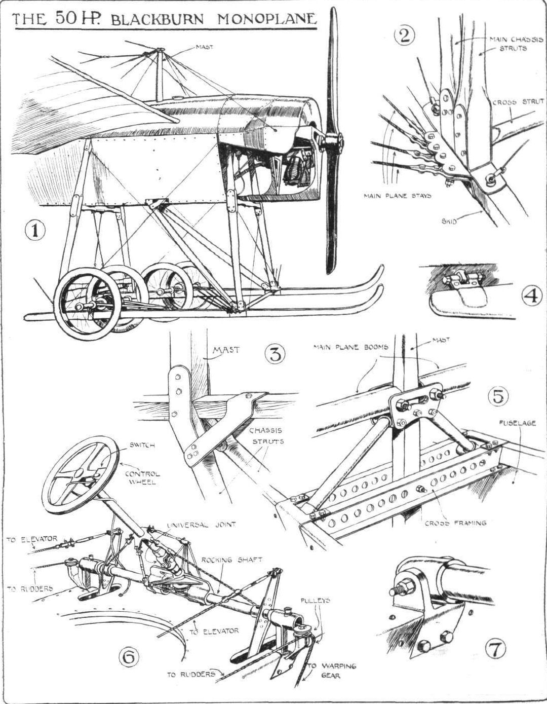
Sketches illustrating interesting constructional details in the 50-h.p. Blackburn monoplane, which is used as a practice machine at their school at the London Aerodrome. 1. The landing-chassis; also showing the mast of the cabane. 2. Joint between the front chassis-struts and the skid; the position of the joint is seen clearly in 1. 3. Joint between the base of the mast and the diagonal chassis-struts. 4. Hinge between the elevator and the backbone. 6. Details of the wing attachment to the body. 6. General view of the control system. 7. Joint of the back-wing spar to the body.
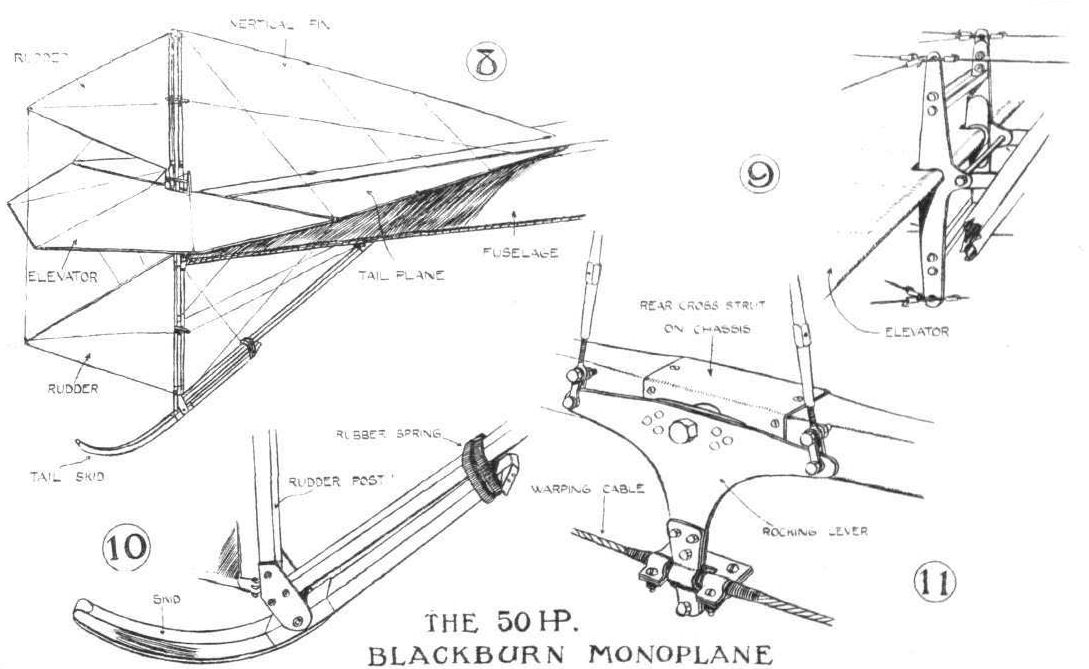
MORE SKETCHES OF BLACKBURN MONOPLANE DETAILS. - 8. General view ol the tail, showing the elevator and rudder-flaps, which form extensions of fixed fins. 9. The levers by which the control-wires are attached to the elevator. 10. The trailing-skid under the rudder-post, showing the rubber spring. 11. The rocking-lever of the warp, showing the attachment of the wires.
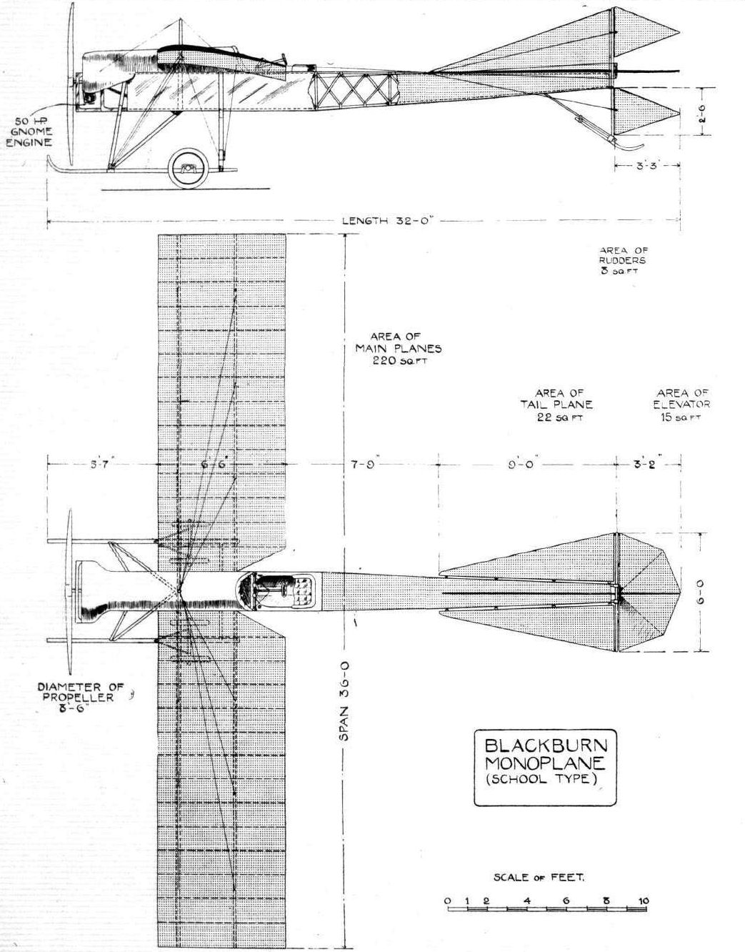
Flight, April 27, 1912.
AIR EDDIES.
The new Blackburn all steel monoplane has arrived at Filey, where it is to be put through its tests.
AIR EDDIES.
The new Blackburn all steel monoplane has arrived at Filey, where it is to be put through its tests.
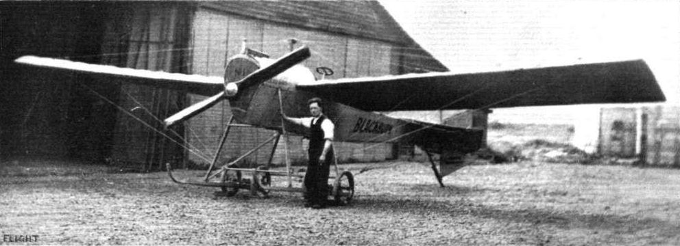
The all-steel Blackburn monoplane that has recently arrived at Brooklands aerodrome.
Flight, January 20, 1912.
AUSTRALIA'S OWN AVIATOR.
A FEW particulars are just to hand of the fine cross-country flight made by Mr. W. E. Hart on November 18th from Penrith to Sydney. Mr. Hart is the first Australian to go through the tests in his native land necessary to qualify for a certificate of the Aero Club, the tests being observed by Lieut. Taylor, Major Rosenthal, Captain Stowe and Captain Vernon of the Aerial League of Australia. They were made at Penrith on a Bristol biplane, and during the last test Mr. Hart carried as passenger Master Rosenthal. On his first circular flight Mr. Hart took his brother for a trip to their home at Parramatta covering the distance of nineteen miles in as many minutes.
In the flight from Penrith to Sydney, Mr. Hart covered the 47 miles in 55 minutes, and rose to a height of 6,000 ft. The landing was a difficult one, as, apart from the fact that the Royal Agricultural Society's show ground is small, the approach to it was impeded by flag-poles and scoring-boards. Cleverly dodging these, however, and veritably "jumping" over the scoring-board, Mr. Hart landed safely.
Three days later the aviator again took the air, and after a flight over the suburbs of Sydney, made another successful descent into the grounds.
Mr. Hart has arranged to fly from Sydney to Melbourne if the assistance of the intervening towns can be obtained, and it is hoped the Government will take up the subject. Exhibition flights will also probably be given in Brisbane and Tasmania, after which schools will be opened in Sydney and Melbourne, the machine for the latter being built by Mr. Hart and his staff in Australia.
Flight, March 16, 1912.
AVIATION IN AUSTRALIA AND PIONEERS.
MR. G. W. WHATMORE of Melbourne sends a communication, which we give below, in regard to pioneer aviation work in Australia, Mr. Whatmore writes as follows:
"Some misconception appears to exist as to the actual history of aviation in this country. In fairness to Mr. Hammond, I trust that you may see your way to publish the information contained in the enclosures to put your readers into possession of the actual history of aviation in so far as it applies to Australia.
"For this purpose I forward you some photographs of actual flights made in Melbourne, and in one of which you will observe Hammond on the point of starting with two passengers, and another just alighting with Mrs. Hammond, it being the first occasion of a lady passenger being carried in Australia.
"The following is a brief history of aviation in Australia :-
"Some two years ago, Mr. A. L. Adamson sent Mr. Defries to England and France for the purposes of introducing aviation into Australia, a Bleriot monoplane and a Wilbur Wright biplane being the outcome. On arrival, however, of these machines, though they in themselves were perfect, there was unfortunately at that time no pilot capable of manipulating same, and although several attempts were made by Mr. Defries, yet in every instance they ended unsuccessfully, not on any occasion had either machine left the ground.
"The fate of the machines was ignominious. They were introduced under bond with an exorbitant duty, payable in the event of their being retained permanently in the Commonwealth, the upshot being that they were eventually dismantled of their engines, and the remaining parts shipped to "Davy Jones' Locker," in other words, cast into the sea.
"The next attempt was made by Gaston Cugnet on a Bleriot monoplane. Excepting for one occasion no successful flights were made, and even this one only of seven minutes duration. On landing, however, he bumped into a cow with more damage to the machine than the cow. Mons. Cugnet next attempted to fly from the Melbourne Cricket Ground in the presence of 25,000 spectators, but had not sufficient run to obtain the necessary elevation, with the consequence that the tail of the monoplane fouled the pallisading round the cricket ground, and the machine was gathered up in fragments. This was in January, 1911.
"Mr. Houdini, with a Bleriot monoplane, next essayed an attempt at Rose Hill Racecourse, in Sydney, N.S.W., but on two occasions on which he flew he was only in the air a few minutes, and this at an altitude of only 150 ft.
"The next attempt which brought aviation before the Australian public in a manner worthy of the name, giving an example of the extraordinary performances in England and the Continent, was made by Mr. J. J. Hammond, the accredited pilot of the Bristol Co.
"The succession of successful flights made by Mr. Hammond in the chief cities of the Commonwealth became the sole topic of conversation at the time of their taking place. In reality they were the first and only successful flights witnessed in Australia.
"Starting in Perth, West Australia, in December, 1911, to the bewilderment of the inhabitants of that city, Mr. Hammond flew from Belmont Race Course over the city, across King Park and back to the starting place, a distance of 20 miles. He even flew down the Swan River and back again to the city on another occasion, a 35 miles flight. After several other flights in Perth, the Bristol biplane was then shipped to Melbourne where the success was again repeated. The first flight being to Geelong, 45 miles, returning the next day, a total of 90 miles. The most sensational flight in Victoria was made over the city of Melbourne, where at an altitude of 7,000 ft. Mr. Hammond flew all over the city and suburbs, over the dome of the Exhibition, round Government House tower and across the broad area of Hobson's Bay alighting at Altona Bay, his starting place, after having covered a distance of 35 miles. He made upwards of 20 successful flights whilst in Melbourne, and was the first aviator to carry a passenger in Australia. The honour of being the first lady passenger falling to the lot of his wife, followed by Mrs. Harvey Patterson, Mrs. Cecil Lebin and Mrs. Edwards, whilst Mr. M. H. Baillie was the first gentleman passenger, subsequent passengers being Messrs. Knox, Bick, H. V. McKay (Sunshine Harvester), Hugh McKay, junior, and Edwards of the Continental Tyre Co., and the representatives of the leading daily journals.
"Mr. Hammond also on one occasion took his two mechanics, Messrs. McDonald and Coles, on a short flight. The machine was then taken to Sydney where the successful Victorian flights were repeated to the astonishment of the inhabitants of the latter city. Amongst the passengers there being Col. Anthill (A.D.C. to General Gordon), whilst a military officer, Capt. Niechy, was carried from Sydney to the military encampment at Liverpool, a distance of 25 miles, landing in the presence of the Governor-General, Lord Dudley and the Officer Commanding, General Gordon, on which occasion Mr. Hammond received an ovation. Mr. Hammond then resigned charge of the Bristol biplane and his place was filled by Mr. McDonald, who made some very successful flights, but it will be clearly seen that the honour of being the first successful aviator in Australia is due to Mr. Hammond."
Flight, March 30, 1912.
AVIATION IN INDIA.
FROM Mr. Edwin Struckett, B Coy, 2nd North Staffs., Peshawur, comes an interesting note and photograph of Lieut. Harford's flying in India. With the assistance of Major Benwell, who also learnt to fly a Bristol some time ago, and his mechanic, Lieut. Harford put the machine together in his spare time at the Artillery Camp at Kotri, near Hyderabad, and made several cross-country flights accompanied by a fellow officer, who made notes of the country flown over. Mr. Struckett writes:
"I herewith enclose you a photograph of the aeroplane Lieut. H. H. Harford of the 94th Battery, R.F.A., has been flying at Peshawur. He has made some splendid flights here, also taking up passengers. It is the first time the natives had seen an aeroplane in the Punjab, and he has caused no little sensation on the frontier, natives having come miles on foot to see him fly. They call him the #Bird God.# But I regret to state that while he was flying from Peshawur to Jalozai to take part in manoeuvres, the motor mis-fired and in making a vol plane he caught some trees which threw him heavily to the ground, breaking his left leg. He was picked up unconscious and conveyed to Peshawur hospital by motor car, where he underwent an operation and he is now progressing favourably.
"The photo was taken the morning of the accident by myself, and Lieut. Harford's mechanic as standing by the Bristol machine."
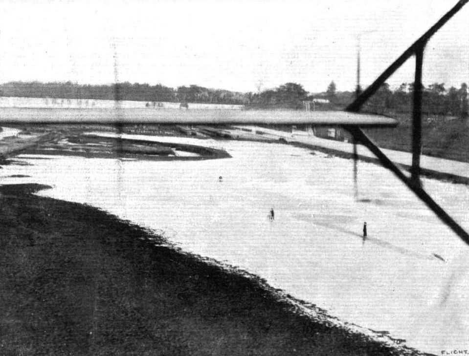
A view of Brooklands during the skating spell which has been in force recently, showing the flooded meadows reaching right up to the paddock sheds. This picture was taken from Pizey's Bristol biplane last week.
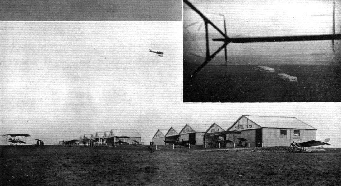
FROM TERRA FIRMA AND FROM ON HIGH. - The "Bristol" aviation schools at Salisbury Plain, with a Bristol two-seater monoplane in flight; and inset is a view of the same scene from a Bristol biplane.
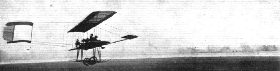
Pizey, of the Bristol School at Brooklands, making a clean landing after a tuition flight with a pupil.

The two photos sent by Mr. G. W. Whatmore, showing Mr. Hammond just alighting on his machine, and ready to start with Mrs. Hammond, the first occasion of a lady passenger being carried in Australia.
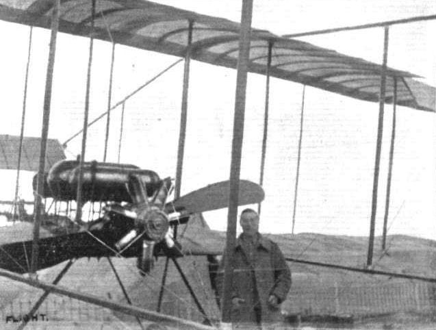
Lieut. H. H.Harford's Bristol biplane at Peshawur, in India. Lieut. Harford's mechanic is standing by the machine.
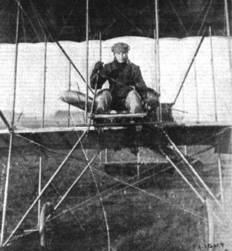
Second Lieut. Hotchkiss who was killed in company with Lieut. Bettington on Tuesday.
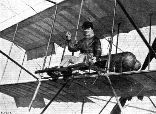
W. E. Hart, the Australian aviator who recently made a flight of 47 miles from Penrith to Sydney, accomplishing the distance in 55 mins.
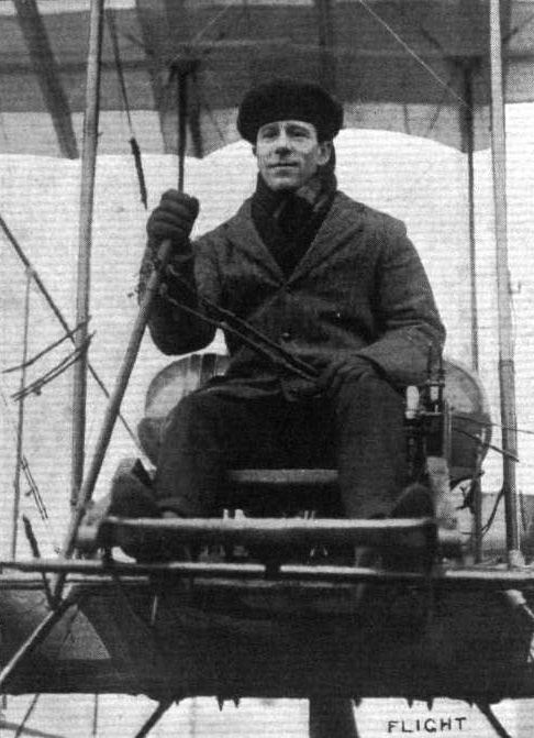
Mr. F. Warren Merriam, who has just obtained his brevet on a Bristol biplane at Brooklands.
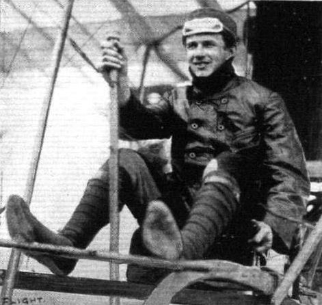
Mr. J. J. Hammond, the Australian aviation pioneer.
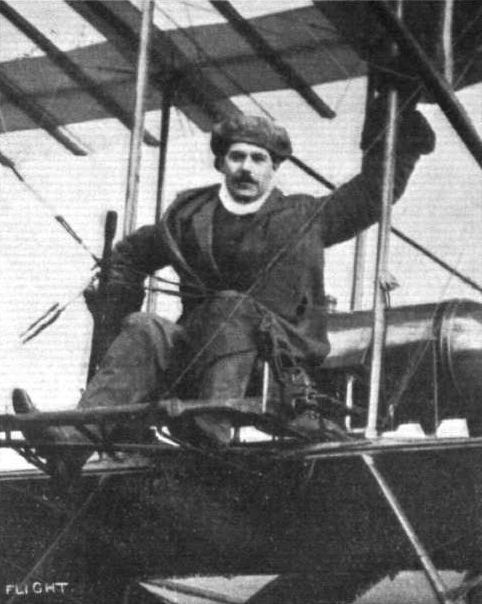
Mr. Fielding, another pilot who has just obtained his brevet on a Bristol biplane at Brookiands.
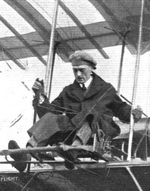
Lieut. Longcroft, an old pupil of the Bristol School, at the control of one of that school's biplanes.

Mr. Collyns Pizey, of the Brookiands Bristol School, and his cousin, Mr. C. H. Pizey, in the passenger's seat.
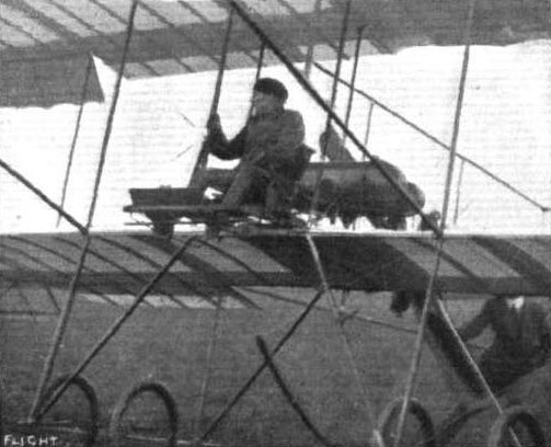
C. Lindsay-Campbell starting for his brevet altitude test on a Bristol biplane at Salisbury Plain.
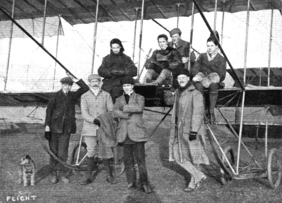
AT THE BRISTOL FLYING SCHOOL AT BROOKLANDS. - Some aviators and pupils. From left to right, top row Lieut. Smith, Mr. Collyns Pizey, head of the Bristol School at Brooklands, Mr. Carfrae, and Mr. Lane. In the bottom row Mr. Merriman, and Capt. Weeding are standing to the right of the picture.
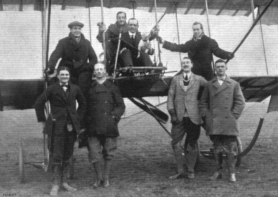
AT BROOKLANDS AERODROME - A FEW PUPILS AT THE BRISTOL SCHOOL. - Reading from left; (top row) Mr. W. Bendall (instructor), Hon. Lieut. Boyle (passenger seat and who has just obtained his certificate), Capt. Pigot (in front seat, who has also just obtained his brevet), Mr. F. W. Merriam (chief instructor); (bottom row) Lieut. Empson, Major Forman, Lieut. Kitson, and Lieut. Rodwell.

ALL BRITSH. - A snap group at the Bristol School, Lark Hill, Salisbury Plain. From left to right (on the machine) : E. Harrison (pilot instructor, Australian), V. P. Taylor (recently passed pilot, Australian), Geoffrey England (pilot instructor, English). Standing: H. Busteed (pilot instructor, Australian), and C. P. Pizey (pilot instructor, the school manager, and Lieut. in the R.F.C.).
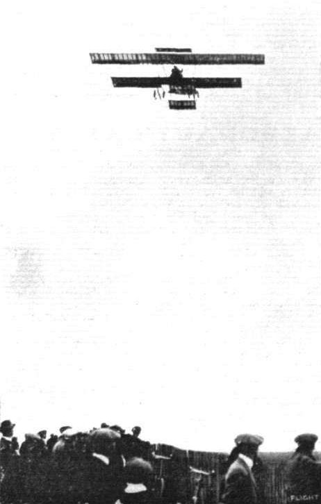
Pizey and Game on the Bristol biplane in a handicap race at Brooklands.
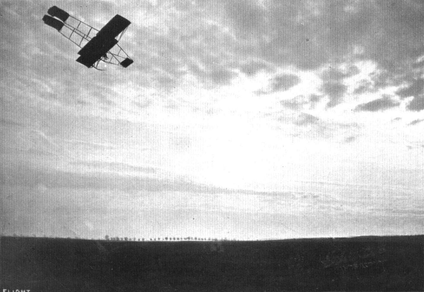
A German-built Bristol biplane at Halberstadt piloted by Mr. E. Harrison of the Bristol Co.
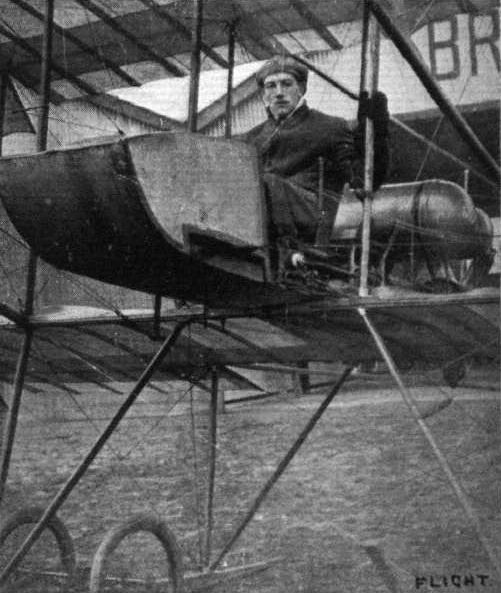
Lieut. Eric Mackay Murray, who secured his brevet at Salisbury on January 24th on a Bristol military extension biplane.
Flight, April 20, 1912.
Brooklands to Salisbury on Bristol Monoplane.
MR. C. H. PIXTON has shown himself as clever a pilot of a monoplane as he is of a two-decker machine, and his flight from Brooklands to Salisbury on Friday of last week still further emphasizes his capabilities as a cross-country flyer. Leaving Brooklands at 5.30 on a Bristol two-seater monoplane, and accompanied by a pupil, Mr. Lane, he set off in the direction of Salisbury, taking his course by the railway line. He arrived at Salisbury at half past six and the distance covered in the hour was a little over sixty miles, the railway being a little further than going straight. Mr. Pixton who was somewhat impeded by a cross wind, maintained an altitude of about 3,000 ft. during his flight.
Flight, May 25, 1912.
MODELS.
Messrs. Rolfe Bros. Models.
We give this week two illustrations of models made by the above firm. The makers state that the Bristol-type model has made over 100 flights. Also that the other model illustrated is the identical machine which won the Flight Golf Competition in a gale at Coventry last July, and that it has flown in all weathers (rain, hail and snow). Also that the propellers (distinctive type) of bentwood have not in any way lost their shape - a fact which the makers attribute to the special method of making them.
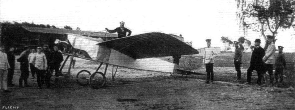
BRITISH AEROPLANES ON THE CONTINENT. - A two-seater Bristol monoplane in Germany in charge of Mr. Jullerot.

FAMILIAR OBJECTS ON SALISBURY PLAIN. - A couple of the double-seater Bristol monoplanes.
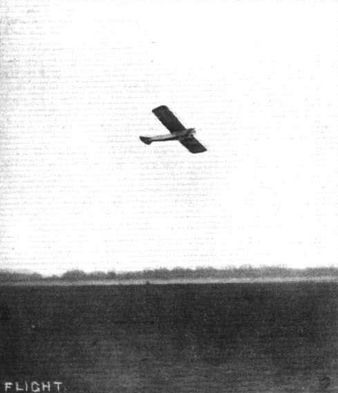
The single-seater Bristol monoplane making a banked turn at Brooklands, piloted by Pizey. This machine, which is making fine way, is fitted with a 35-h.p. Anzani engine, and has a speed of about 58 m.p.h.
FROM TERRA FIRMA AND FROM ON HIGH. - The "Bristol" aviation schools at Salisbury Plain, with a Bristol two-seater monoplane in flight; and inset is a view of the same scene from a Bristol biplane.
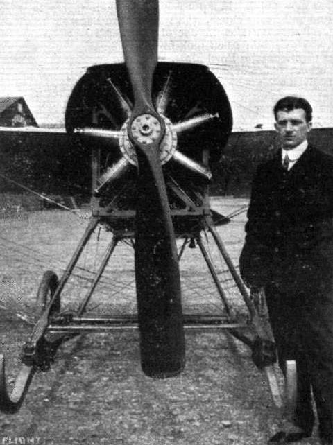
Mr. Arthur, who took his brevet last week at Brooklands at the Bristol school.
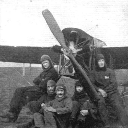
The "Terrible Five," being some prominent aviation men at Salisbury. From left to right: Messrs. England, Barnwell, Lindsay Campbell, Grelg and Sydney Pickles (Australian monoplane pupils), and the machine they fly.

Lieut. Reynolds, R.E., at the pilot's seat on his Bristol two-seater monoplane.

A PROMISING AVIATOR. - Mr. Sydney Pickles, an Australian, on the single-seater Bristol monoplane, which he has been flying at Brooklands. He has also flown the two-seater, of same make, exceedingly well, doing figures of 8 on it, &c. Extremely enthusiastic and the makings of a fine flyer.

Mr. F. Warren Merriam, the very able manager of the Bristol Co. at Brooklands Aerodrome, just going for a flight to test one of the Bristol monoplanes for Prince Cantacuzene.
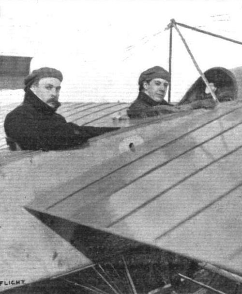
Messrs. Howard Pixton and his pupil, Harold Lane, on the two-seater Gnome-Bristol monoplane, on which they flew on Thursday morning of last week from Brooklands to Salisbury, a distance of over 60 miles in one hour.
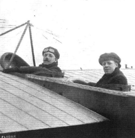
A couple of flying Australians at Lark Hill, Salisbury Plain. - Mr. Vincent P. Taylor (well known in the balloon world as "Captain" Penfold) in front on the two-seater Military Bristol, and on the right Mr. Eric Harrison, one of the Bristol Co.'s instructors.
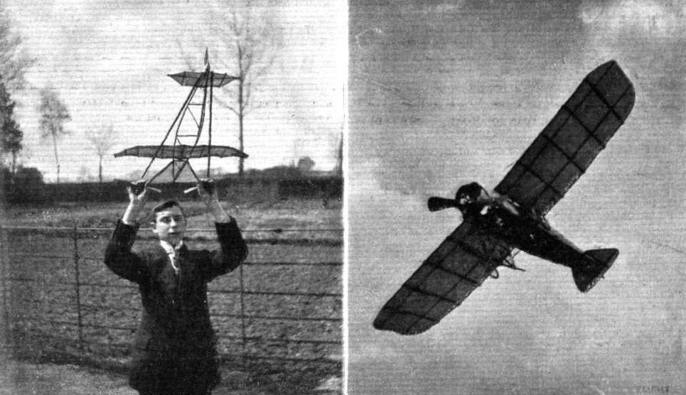
MESSRS. ROLFE BROTHERS' MODELS. - On the left their distinctive type model, and on the right their Bristol type.
Flight, July 27, 1912.
THE MILITARY COMPETITION - THE MACHINES.
THE BRISTOL AEROPLANES.
OF the four machines entered by the British and Colonial Aeroplane Co., two will be tractor biplanes of the type designed by Mr. E. C. Gordon England, and the remaining two will be monoplanes of the well-known military type. The tractor biplanes will be flown by Messrs. C. H. Pixton and Gordon England, the monoplanes by Messrs. H. Busteed and James Valentine. Truly, with such a display of excellent machines and expert pilots, they should be successful in carrying off some of the more important awards. Next week we hope to publish photographs and complete descriptions of each machine. For the present, however, we must be content to mention their main characteristics : -
Main characteristics:-
Bristol Military Monoplanes.
Motor 7-cyl. 80-h.p. Gnome
Length 28 ft. 4 in.
Span 40 ft. 3 ins.
Area of wings 242 sq. ft.
Weight 792 lbs.
Speed 70 m.p.h.
Propeller diameter 8 ft.
Pilots Messrs. H. Busteed and James Valentine
Flight, August 10, 1912.
THE MILITARY AEROPLANE COMPETITION - THE MACHINES.
THE BRISTOL MONOPLANES.
THE monoplanes representing the Bristol firm in the Military Trials probably look more warlike than any other machines flying just now on Salisbury Plain. Their disc wheels and the amount of aluminium sheathing used in covering the front part of the machines gives them an armoured appearance, and the two little streamline stay-masts above, like miniature funnels complete the impression. Everything exposed to the relative wind has been shaped to decrease resistance. When flying they both have the appearance of four-seaters, owing to the resemblance, at a distance, of the streamlined stay-masts to passengers' heads.
The body is of the lattice girder type, flat at the sides but belled out top and bottom with curved formers over which aluminium sheathing is applied. Pilot and passenger sit in tandem and are both provided with controls. In both cases an 80-h.p. Gnome motor of the Grand Prix type is fitted under an aluminium cowl which is designed to reduce the head resistance that the engine, unshielded, would cause. The efficient cooling of the engine is, apparently, not interfered with in the slightest.
The wings are quite different in shape from those used on the former "Prier" type of Bristol monoplane. In the present machines the rear spar is longer than the front, a system that many constructors have resorted to of late by virtue of the fact that it is thus possible to obtain a more powerful warp. In the case of the Bristol monoplanes this is increased, owing to the flexible construction of the wings. The spars are virtually steel tubes filled with wood, and the ribs, instead of being directly connected to them, are threaded thereon. A new wing camber has also been adopted. The one at present used has a Nieuport type of entering edge, and a slightly turned-up trailing edge. On each side of the pilot's seat a section of the wing to the rear of the back spar has been cut away to allow of a better view being obtained. The warping wires are carried to and operated from a single mast beneath the fuselage. This mast is carefully shaped to avoid resistance, and the warping pulleys are similarly protected. The Bristol firm have, in these monoplanes, departed from their practice of employing a completely movable empennage. They now use a fixed stabilising plane with elevator flaps hinged to its rear edge.
The landing gear strikes one as being particularly solid and efficient. Four exceedingly strong vertical struts connect the two horizontal skids to the body. At the rear these skids are laminated to form flexible extensions, which may assist the machine in coming to rest after landing. The struts themselves are not rigidly attached to the skids, but are joined thereto by a form of joint which relieves the fuselage of any kind of twisting strain which may result in landing. At the front ends of these straight skids are fitted short tusk-shaped organs, which carry a miniature pair of wheels, Cody fashion.
Main characteristics:-
Overall length 28 ft.
Weight without complement or fuel 792 lbs.
Span 40 ft.
Area 242 sq. ft.
Propeller Bristol
Motor 80-h.p. Gnome
Flight, October 26, 1912.
MILITARY FLYING IN ROUMANIA.
THE Roumanian Government are going ahead with the equipment of their army with aeroplanes, and their latest purchases are a number of 80-h.p. Bristol monoplanes. On one of them the other day, Lieut. Protopopescu made a flight of upwards of an hour to the south of Bucharest, then returning to his starting point. He had made his first flight on the machine only three days previously. Roumania is a splendid country for aviation as it is dead level and unobstructed by trees. The fields are, however, cut up by small dykes, so that great care has to be taken when landing or rolling and they tend to make the atmosphere disturbed at times. Being of very plucky character and able to keep a cool head in an emergency the Roumanians make splendid flyers, and should they be drawn into the war they will doubtless make full use of the new arm. Apart from the Bristol machines the Roumanian Army, at its school at Bucharest, has several Henry Farman machines, a couple of Bleriots, a Nieuport and a Morane.
Flight, November 2, 1912.
THE PARIS AERO SALON.
Bristol.
ON this stand is a monoplane similar in almost every particular to the one that carried off L1,000 in prizes at the British Military Aviation Trials at Salisbury Plain. The stand was surrounded with people all day long, and they stand and look as if not being able to credit that a firm of British conductors could turn out such a notably fine example of aeroplane construction. No wonder the Bristol people go to the Paris show when they number amongst their foreign customers such as the Ministers of War of Russia, Germany, Italy, Spain, Turkey, Roumania and Bulgaria.
The machine has somewhat the lines of a submarine with wings. The blunt metallic snout over the Gnome motor and the funnel-like upper cabanes tend to carry out the impression. Throughout it is well and conscientiously built, in perfect keeping with their usual work.
The fuselage is of square section and built up on the lattice girder principle. Its sides are flat throughout its entire length, but the top and bottom are bellied out by;the application of aluminium sheeting. An 80-h.p. Gnome motor protrudes from the front, half covered by an aluminium cowl that keeps oil from the pilot and passenger, and that reduces the head resistance of an otherwise unprotected revolving engine. The chassis is at the same time simple, clean and effective, merely two horizontal skids supporting the body by four strong hollow streamlined struts, with a pair of wheels strapped across them by elastic bands. Tusk-like projections extend in front of the skids and carry another pair of wheels, but quite miniature ones, which protect the propeller from damage. The tail is of conventional design. Its disposition may be seen from the little accompanying sketch. Control is arranged in duplicate so that either pilot or passenger, sitting in tandem, may take charge of the machine in flight.
As was announced last week Italy has ordered a batch of twenty of these excellent machines. The latest news here is that the order is more than likely to be considerably increased.
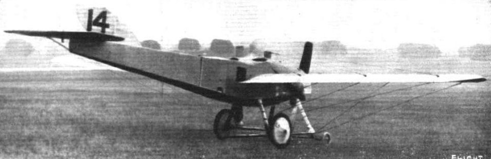
Bristol Coanda Military Trials Monoplane with fin which secured a third prize of L500 in the Military Trials.

THE MILITARY COMPETITION MACHINES. - The Bristol monoplane. Two machines of this type have been entered. One will be flown by Mr. James Valentine, and the other fay Mr. H. Busteed.
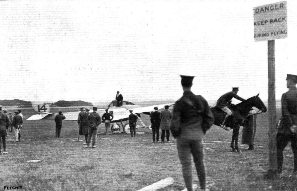
THE MILITARY AVIATION TESTS. - Busteed preparing to start off for a trial spin on one of the Bristol military monoplanes.
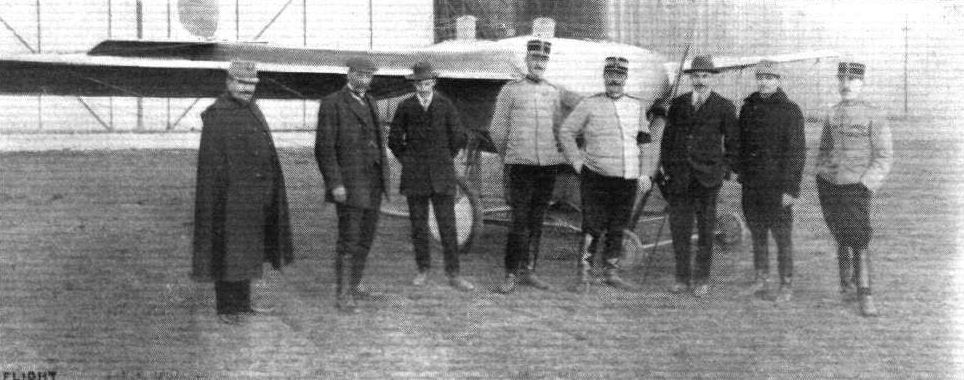
BRISTOLS IN ROUMANIA. - A snapshot at the Bucharest Military Aerodrome. Standing in front of the 80-h.p. Bristol monoplane, from right to left: Lieut. Protopopescu (who on Thursday week, after only three days' tuition, made a flight of an hour, getting up to 2,000 ft.), another Lieutenant (who acted as observer in the official trials), Mr. C. H. Pixton, Major Macree (in command of the Flying Corps), beside whom is a Lieutenant (who is now being taught by Lieut. Protopopescu), and the two mechanics who accompanied Mr. Pixton to Roumania.
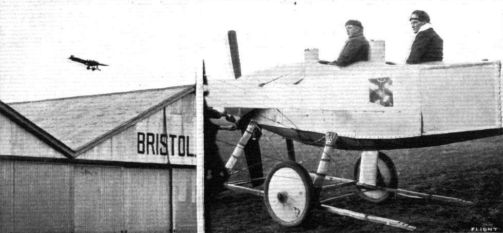
Messrs. Busteed (in the pilot's seat) and Harrison, snapped just before starting away in a 31-15 m.p.h. wind for a flight on the new military Bristol monoplane. The picture on the left shows the machine in flight.

THE BRISTOL MILITARY MACHINES IN FLIGHT. - In the centre the monoplane, and on either side the tractor biplane.

THE BRISTOL MONOPLANE. - One of the two British representatives at the Salon.
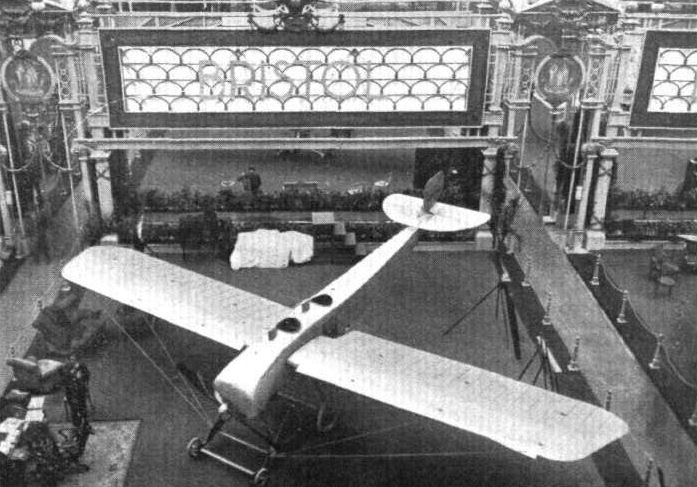
Representative stand at the Salon - the Bristol.
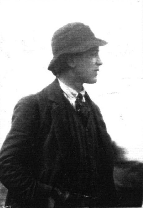
M. Coanda, the designer of the Bristol monoplane, which did so well in the various tests in the British Military Aeroplane Trials.
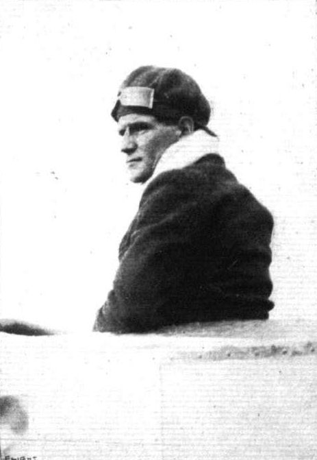
Mr. Busteed, the pilot of the Bristol monoplane No. 14, which obtained one of the L600 third prizes for British aeroplanes in the Military Trials.
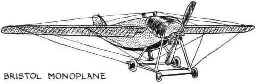
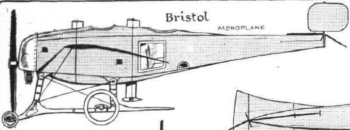

Details of one of the front wheels of the Bristol.
Flight, July 27, 1912.
THE MILITARY COMPETITION - THE MACHINES.
THE BRISTOL AEROPLANES.
OF the four machines entered by the British and Colonial Aeroplane Co., two will be tractor biplanes of the type designed by Mr. E. C. Gordon England, and the remaining two will be monoplanes of the well-known military type. The tractor biplanes will be flown by Messrs. C. H. Pixton and Gordon England, the monoplanes by Messrs. H. Busteed and James Valentine. Truly, with such a display of excellent machines and expert pilots, they should be successful in carrying off some of the more important awards. Next week we hope to publish photographs and complete descriptions of each machine. For the present, however, we must be content to mention their main characteristics : -
Main characteristics:-
Bristol Military Tractor Biplanes.
Motor 14-cyl. 100-h.p. Gnome
Span 40 ft.
Length 31 ft.
Area of main planes 400 sq. ft.
Weight 1,474 lbs.
Speed 60 m.p.h.
Propeller diameter 9 ft. 6 ins.
Pilot Mr. C. H. Pixton
Motor 4-cyl. 70-h.p Daimler-Mercedes
Length 31 ft.
Span 40 ft.
Area of main planes 400 sq. ft.
Weight 1,650 lbs.
Speed 57 m.p.h.
Propeller diameter (4-bIaded)
Pilot Mr. E. C. Gordon England
Flight, August 3, 1912.
THE MILITARY AEROPLANE COMPETITION.
THE MACHINES.
THE BRISTOL TRACTOR BIPLANE.
EARLIER in the year it will be remembered that the Bristol Co. modified their policy, as far as biplanes went, of adhering to a standard design of this type of machine. They introduced a tractor biplane, built from the designs of Mr. E. C. Gordon England, who, previous to turning designer-constructor, had served that firm most excellently as one of their pilots. The machine was characterized by its marked originality, and certainly did extremely good flying with the relatively low horse-powered engine, a 45-h. p. Clerget, with which it was fitted. The two biplanes that the Bristol Co. have entered for the trials are, really speaking, simply enlargements and refinements of the original design. In the early machine the fuselage was square in section. In the machines entered for the trials the fuselage is belled out on top and below by wooden formers over which the fabric is applied. It is sufficiently wide to seat pilot and passenger side by side, and, the body being arranged approximately midway between the two main planes, they are enabled to have a very good view of things going on below. The body has the further advantage of being deep, so that those seated inside may suffer no discomfort from the force of the relative wind when undertaking a long flight. As will be gathered from one of our photographs, duplicate control is fitted.
The landing chassis is perhaps one of the most interesting features of the machine. A single central skid is attached to the fuselage by hollow struts. These are inclined forwards to take the "drift" of landing, as well as the weight of the machine. To this skid are hinged a pair of axles, to the extremities of which wheels are fitted. Interposed between the body of the machine and points on the axle near the wheels, are compression springs, which not only absorb vertical shocks, but provide for strains resulting from landing in a side wind.
The constructional details of the machine are remarkably good throughout.
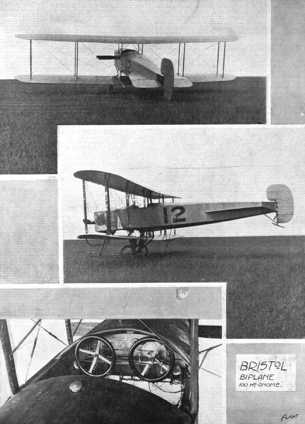
THE MILITARY COMPETITION MACHINES. - The Bristol tractor biplane. The machine seen in the photographs has a 100-h.p. Gnome engine, and will be flown by Mr. H. Pixton. The other is equipped with a 70-h.p. Mercedes engine, and will be piloted by Mr. E. C. Gordon England, its designer. Inset are shown the details of the dual control.
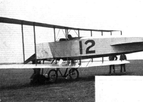
THE MILITARY AEROPLANE COMPETITION. - Gordon England setting out for a flight on his Bristol biplane.
THE BRISTOL MILITARY MACHINES IN FLIGHT. - In the centre the monoplane, and on either side the tractor biplane.
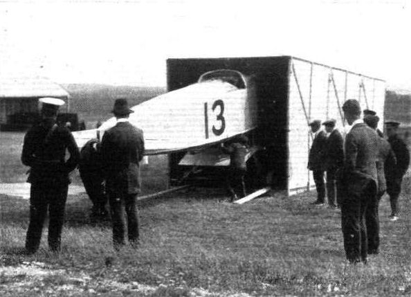
THE MILITARY AEROPLANE COMPETITION. - Pixton's Bristol being run out of its crate.
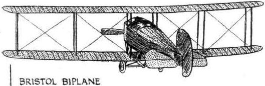
Flight, November 30, 1912.
NOTES ON THE WORK OF GORDON ENGLAND, DESIGNER OF THE LATEST BRISTOL BIPLANE.
GORDON ENGLAND has terminated his connection with the Bristol Co., but will not actually leave Filton until be has completed the tests of the two new tractor biplanes that are his latest design. When these are finished, however, he intends to widen his experience of the world of flight, which is his sole reason for leaving the Company, with which he parts on the best of terms. Gordon England, as our readers will remember, has had a varied experience already, and he commenced his acquaintance with the air long before most modern pilots knew what it was like to be aloft. He had the termrity to practise gliding in the little man-carriers made by that early pioneer, Jose Wiess, who was and still is a strong advocate of the inherent stability of the bird-like wing, with crescent shaped entry, retreated up-turned tip, and a variable camber from shoulder to tip.
Jose Wiess made hundreds of models down in the country far removed from observation, and at last he succeeded in bringing his knowledge of the subject to a point at which he could be sure of building a model and so loading it that it could glide quite airworthily in any wind. Sometimes, when the wind was strong, he would launch his models which weighed several pounds, and they would soar upwards and backwards in the air-currents blowing up the side of the hill that served as his aerodrome. When he had reached this point, he obtained the most complete confidence in his system, and so, too, apparently, did Gordon England, for when Wiess made a machine large enough to carry a man Gordon England never hesitated about being the pilot. He just sat in the little cockpit, which would hardly hold him, and was pushed off down the steep slope. Nothing happened for a little while, and there was a precipitous drop in view straight ahead if nothing continued to happen indefinitely. Before the unpleasant alternative could occur, however, the little machine had gathered enough speed for flight, and proceeded to glide off through the air. Very soon it was some 20 or 30 feet above the ground and Gordon England had no controls of any sort to guide or control it. He could regulate the position of the centre of gravity a little by leaning forwards or backwards, but if the machine couldn't fly he could do little or nothing to make it, and if it were not inherently stable it was a sure thing that he would be tossed out sooner or later. Although he made many such glides, however, and on some occasions actually soared in strong winds he never met with any mishap. These facts are even more interesting now than they were considered to be at the time. Indeed, at the time, comparatively few people either knew about the work that was done, or appreciated its significance.
M. Eiffel has also been making some experiments recently on surfaces of double curvature, and he has even expressed surprise at the results, for he found a tendency for the lift to drift ratio to improve with speed, and for the movements of the centre of pressure with changes of angle to be restricted to a much smaller zone than is common with wings of single curvature. The double curvature wing has long since been the subject of experimental research by Mr. W. Turnbull, in Canada, and he also drew attention to certain merits of the shape. The connection between this work and that of Wiess, and other experimenters like Etrich and Handley Page, lies in the tendency to give the so-called bird-like wings a reversal of curvature in the run. Sometimes this takes place all along the trailing edge and sometimes it is confined more particularly to the extremity, but there is no doubt that one way and another considerable interest attaches to the feature.
Gordon England's work as a designer has, of course, necessarily been confined within the limits of the conventional, so far as general lines are concerned, and although he might doubtless like to have the opportunity of getting unfettered expression to his ideas, nevertheless the success that he had achieved with what may be described as the commercial type of machine is only all the more to his credit on that account. We publish two illustrations of his latest biplane, two of which have been built by the British and Colonial Aeroplane Co., and are at present undergoing tests.
The wings span 12 metres, and have a chord of 1.55 metres, so that the aspect ratio is nearly 8. The gap is 2 metres, which is 1.3 times the chord, and considerably greater than usual. Recent experiments apparently tend to show that the practice of making the gap equal to the chord is equivalent to curtailing the effective area by as much as 17 per cent. On the other hand, there are difficulties about a high gap, which not only adds weight and resistance in extra strut lengths, but also to localise a centre of resistance at a considerable leverage from the pitching "pivot" that might under certain circumstances tend to disturb the longitudinal equilibrium of the machine. In these machines, however, the longitudinal equilibrium appears to be as stable as in the preceding biplanes which Gordon England designed for the Bristol Co. Although those particular machines were under-powered for the Trials conditions, and were withdrawn from official test on that account, they were frequently flown during that period, and on one occasion Gordon England flew for nearly an hour and a half with the elevator wires actually tied up so that they could not move. It is extraordinary, but nevertheless a fact, that he was unaware of the fault, which was due to an oversight on the part of a mechanic who had been making an adjustment to some other part of the machine. The circumstance of the flight might lack significance from the mere length of its duration but for the fact that it took place at the very time when Fenwick was killed, and the gust that capsized the Mersey monoplane also rocked the Bristol biplane into an excessively steep bank. During the whole of the flight, England was very busy with his warp, but he never had any occasion to use his elevator, otherwise, of course, he would have noticed that it was out of action. Even when descending, he merely switched off one half of the 100-h.p. Gnome and allowed the machine to plane down in its natural attitude. When nearing the ground, however, he wanted to use his elevator and found that it was absolutely jammed, but he alighted safely by a judicious use of the switch.
The present machines have an overall length of 8 metres and a fixed tail plane spreading 30 sq. ft. in area. To this is attached an elevator flap spreading 15 sq. ft. and having 5.8 metres leverage over the centre of gravity of the machine. The main planes are set at 5° incidence to the line of propeller thrust, and the tail area is calculated to be sufficient to counteract the retrogression of the centre of pressure on the main planes when their incidence to the line of flight is 4 1/2°. This correction is independent of the action of the elevator, and Gordon England has found in actual practice that it is distinctly possible to feel the correcting tendency of the fixed tail when the elevator is first used on these machines for the purpose of initiating a steep descent. The elevator and the wing warping are operated by a central lever control. The rudder, which is carried at the extremity of the tapered cylindrical fuselage, has 94 sq. ft, of surface.
The area of the wings is 387 sq. ft., the weight of the machine empty is 1,096 lbs., and it carries 900 lbs. useful load in normal flight. The 80-h.p. Gnome with which it is equipped develops 75 effective h.p. Thus, the weight per h.p., W1, is 26.6 lbs., and the weight per square foot or wing loading, is 5.15 lbs.
Applying this wing loading to the graph of the hypothetical aeroplane developed in FLIGHT from the Military Trials, the appropriate wing-speed is given by the expression V = Sqrt(900*W2), where W2 is the loading and V is the speed in miles per hour. In this case, the wing-speed would be 68 m.p.h., and the assumption of the hypothesis is that the design of the machine is such that it experiences a resistance of 1 in 6 at that speed. A resistance of 1 in 6 with a load, W1, of 26.6 lb. per h.p. is represented by a thrust of 4.45 lb. per h.p., and this at 68 m.p.h. represents 80 per cent, efficiency, which is higher than any propeller so far tested in model form has given.
The propeller on this machine is 8 ft. in diameter, which represents 67 sq. ft. of disc area per h.p. The thrust over the disc area is thus 6.65 lb. per sq. ft. and, so far as can be judged from the results of the Military Trials, this is a high value for the best efficiency at a speed in the order of 68 m.p.h. In fine, we should be inclined to consider that the propeller is rather small. Allowing 73 per cent, efficiency, and assuming that small variations in power produce speed changes proportional to the square rout of the power, then the speed corresponding to 73 per cent, efficiency will be 65 m.p.h. At the speed and efficiency the power will be equal to maintaining a thrust of 4.2 lbs. per h.p., but if 4.2 lbs. per h.p. is to suffice for the propulsion of 26.6 lbs. per h.p. it is clear that the inclusive resistance must not exceed an equivalent grade of 1 in 6.2. In fine, the machine has to justify itself as a low resistance biplane.
It will be interesting to learn in due course what maximum speed this machine does attain fully leaded, but it happens that the designer expects to realise 65 m.p.h.
The engine, an 80-h.p. Gnome, is overhung in front, and the under-carriage is very close to the lower plane which limits the propeller diameter.
The body stands some little way above the lower plane and beneath the body project two tubular vertical struts of unequal length, one of which stands immediately above the axle, while the other stops short just under the main plane and is joined to the former by a diagonal. The axle ends are attached to the body by crutch-like diagonal struts, as can be seen by a close examination of the photographs.
The rudder, of 9 1/2 sq. ft. area, is operated by two pedals, instead of a pivotted bar.

Two views of the latest Bristol biplane designed by Gordon England. Two similar machines of this class, built by the British and Colonial Aeroplane Co, are now under test.
Flight, January 6, 1912.
FROM THE BRITISH FLYING GROUNDS.
Brighton-Shoreham Aerodrome.
LAST week-end has seen the successful completion of two machines - the Collyer-England tractor biplane and the Chanter monoplane. The first-named made straight flights on Saturday and Monday, with Dowland in control, and was put through a fair amount of rolling by both England and Dowland. Mr. M. Chanter took his new monoplane out on Monday, and was in the air with her shortly after leaving the shed. On Tuesday, she was out again, Tinder the pilotage of her owner, and gave still better results. Ross, Gassier, Kent and Davies, were out on the Chanter school Bleriots.
Flight, January 13, 1912.
FROM THE BRITISH FLYING GROUNDS.
Brighton-Shoreham Aerodrome.
MR. M. CHANTER continued the tests of his new monoplane, and put one of the Bleriots through its paces on Wednesday last week. At day-break the following morning, De Villiers was in the air with some good straight flights, and on Tuesday Mr. Chanter was testing a 40-h.p. Anzani-Bleriot which has been undergoing a complete overhaul; while Gassier and De Villiers were putting in more useful practice.
<...>
FROM THE BRITISH FLYING GROUNDS.
Brighton-Shoreham Aerodrome.
LAST week-end has seen the successful completion of two machines - the Collyer-England tractor biplane and the Chanter monoplane. The first-named made straight flights on Saturday and Monday, with Dowland in control, and was put through a fair amount of rolling by both England and Dowland. Mr. M. Chanter took his new monoplane out on Monday, and was in the air with her shortly after leaving the shed. On Tuesday, she was out again, Tinder the pilotage of her owner, and gave still better results. Ross, Gassier, Kent and Davies, were out on the Chanter school Bleriots.
Flight, January 13, 1912.
FROM THE BRITISH FLYING GROUNDS.
Brighton-Shoreham Aerodrome.
MR. M. CHANTER continued the tests of his new monoplane, and put one of the Bleriots through its paces on Wednesday last week. At day-break the following morning, De Villiers was in the air with some good straight flights, and on Tuesday Mr. Chanter was testing a 40-h.p. Anzani-Bleriot which has been undergoing a complete overhaul; while Gassier and De Villiers were putting in more useful practice.
<...>
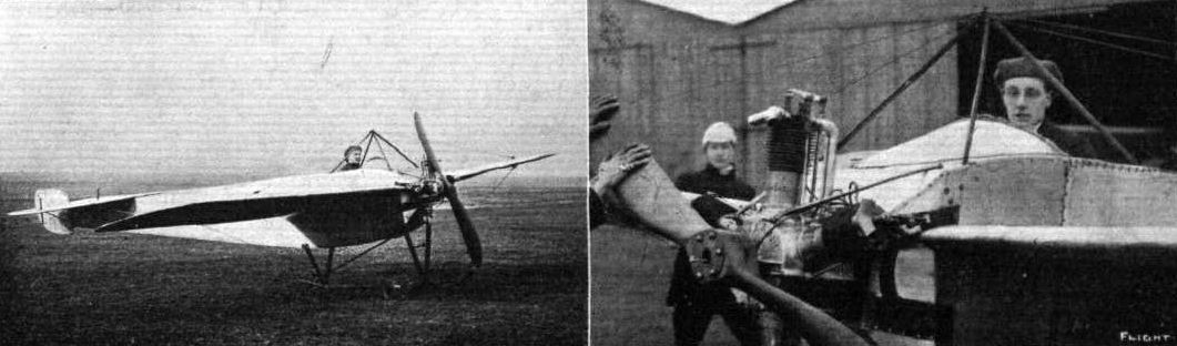
Chanter monoplane built at Hendon but soon destroyed in a hangar fire at Shoreham in February 1912. The Chanter-Nieuport-type monoplane, equipped with 35-h.p. Anzani motor. On the right Mr. M. Chanter at the lever of this 35-h.p. monoplane.
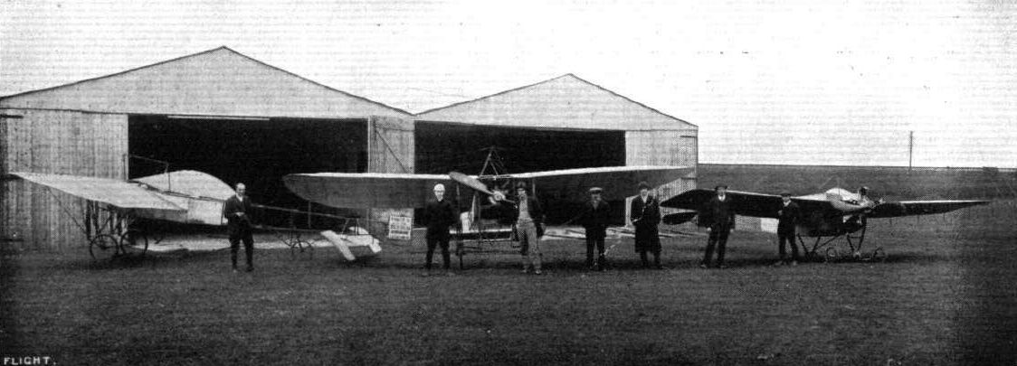
The Chanter Flying School at Shoreham, with their two Anzani-Bleriots and their 35-h.p. monoplane modelled on Nieuport lines. At the left-hand side is Mr. M. Chanter, the Director of the school. To the right are Messrs. De Villlers, Gassier, Kent, Ross, and two of the school mechanics.

Fig. 6. - Cody Biplane.
Flight, February 3, 1912.
AIR EDDIES.
CONGRATULATIONS to Mr. S. F. Cody on his splendid flight on Saturday last, when he carried four passengers on his five-seated biplane. About 7 miles were covered, during which the height was mostly about 100 ft. A photograph of the "crew" appears on p.108.
Flight, March 16, 1912.
AEROPLANE UNDERCARRIAGES.
By G. DE HAVILLAND.
Cody Biplane.- The undercarriage of this machine is chiefly constructed of wood, and has a central-skid between the main rolling-wheels; on the front end of this skid are fixed two smaller wheels. The rear-skid is a comparatively short distance behind the main-wheels, thus giving the machine a short base of support; but, owing to the high centre of thrust, the rear-skid carries little or no weight after the first few yards. The main-wheels have a track of about 3 feet, and support the machine through two spiral springs, which give a maximum travel of about 10 inches. The propeller is placed comparatively high up, and advantage is taken of the fact of the bottom pane being correspondingly low by keeping the wheel-track narrow, and providing small wheels at the end of the lower main-planes. These are normally clear of the ground, but come into action if the machine is canted over sideways.

Mr. S. F. Cody taking a turn round Hendon Aerodrome in his biplane on Saturday last.

Mr. S. F. Cody and his freight of four passengers, Miss Buckoke and Messrs. Haves, Dackett, and Frank Cody, totalling to 738 lbs., with whom be flew last Saturday afternoon at Aldershot at a height of about 70 to 80 ft. on his new 'bus for a distance of about 7 miles.

Mr. S. F. Cody just after arrival at the Hendon Whitsun Meeting on his biplane, with fingers numbed with cold. Mr. Grahame White is just explaining he also suffers from cold hands, but, needless to add, both know nothing about "cold feet." On the right, Mr. Cody in the seat of his machine just before starting a flight.

Flight, June 29, 1912.
THE CODY MONOPLANE.
IT will come as no surprise to our readers that that skilful designer and intrepid pilot Mr. S. F. Cody, has built a monoplane, as his work in this direction was announced recently in these pages. Now that the new machine has been tested in "occasional jumps," in the words of Mr. Cody himself, there is no need any longer to withhold information concerning it from the public ken, and so by the aid of the accompanying photographs and brief description, we proceed to place before readers of FLIGHT the main essentials of this very interesting piece of work.
A description of the new machine is easier said than done, for there is none other like it to which it may readily be compared. Mr. Cody has always been original, and he remains original even in this, the most stereotyped, perhaps, of all types of flying machines. And this designer's originality is the originality of the inventor rather than of the mere improver. It is a fact that he had never even seen an aeroplane before he had built and flown the first great biplane that was associated with his name. For all the evidence that exists in the new flyer now under consideration, he might never have seen a monoplane either. In so far as the new machine gives evidence of influence in its design, the influence is that of his experience with biplane construction; the wings are similar to the biplane type, so, too, is the undercarriage - of course. The body is altogether new and consists of two distinct sections, the forward part accommodating the engine and pilot, while the after portion consists of bamboo booms with surfacing material stretched between them to form dihedral planes, thus making this after portion look very much like the tail of a paper dart. At its extremities are the tail members proper.
Certain characteristic features worthy of special note include the relative positions of the engine, pilot and wings, the engine is low and the wings are high, the pilot sits behind the engine and has an outlook under the trailing edges of the wings. Coupled with the strong and massive undercarriage there is sufficient evidence of a low centre of gravity. The propeller shaft on the other hand is placed higher up and is driven by a vertical chain.
The machine has an overall length of 37 ft., a span of 46 ft. 6 in. and an overall height of 12 ft. 6 in. that can be reduced to 8 ft. 6 in. in a few minutes for transport by folding down the cabane. Similarly, by dismantling the tail the overall length is reduced to 31 ft. These transport facilities have been influenced by the War Office Competition rules, in which event we hope to see the Cody monoplane figure prominently. The engine is a 120-h.p. Austro-Daimler motor and the transmission chain a Brampton. The propeller is a British-built Chauviere, 11 ft. 6 in. in diameter and pitch. In construction, it has 10 laminations of walnut.
It runs at two-thirds engine speed, for there are 24 sprockets on the crankshaft wheel and 16 on the propeller wheel. The static thrust from this combination Mr. Cody estimates to be something in the neighbourhood of 800 lbs. Aft of the engine is the cockpit for the accommodation of the pilot and passenger. They are seated side by side and the control is arranged in the central position so that both may be able to handle it with equal facility. As regards this, the Cody control is especially convenient for all three controlling movements of the rudder, the elevator, and the warping are operated from the one column. A movement of the column to and from the operator actuates the twin elevators by means of a long bamboo connecting rod. Warping is done by swinging the column from side to side. To steer, the handwheel is rotated. The type of seat that Cody provides for the pilot and passenger are fully recognised as Cody seats. Otherwise, the same style of thing is used very frequently on agricultural machinery. Nevertheless, for comfort they leave nothing to be desired.
Those aboard the machine are protected from the rush of air by a bulkhead that separates the motor from the cockpit. The magnetos - there are two - however, protrude through this bulkhead, as also does the rear end of the crank-shaft. To this a chain-wheel is keyed for it was intended to fit a starting handle so that the engine could be set in motion by the pilot without any need of him having to leave his seat. But Bosch dual ignition, Mr. Cody finds, answers its purpose quite well, so the extra weight of a cranking device has been saved.
On either side of the cockpit transparent windows of non-inflammable celluloid give the pilot a clear view of what is going on beneath him.
A type of bonnet extends back from the propeller to a point just in front of the pilot. Under this bonnet are arranged the fuel tanks. Those at present fitted are of small capacity, just sufficient for testing purposes, but a petrol tank holding something like 68 gallons and an oil tank to correspond are being put through. These will replace the existing reservoirs when the preliminary trials are finished.
Below these is the silencer, also fitted inside the cockpit. It exhausts through a large diameter pipe on the right-hand side.
The landing gear will be quite familiar to those who have studied Cody's previous machines. The only innovation is that the four pairs of hickory struts supporting the body from the central skid are curved. By curving them in this fashion a great deal of springiness is introduced between the skid and the body, and should the landing wheels spring up far enough for the skid to come very forcibly into contact with the ground, there would be far less likelihood of damage resulting than if straight struts were used.
Regarding the wings, the same type of construction is employed as is used in the planes of the Cody biplane. Each is stayed from above by six 12-gauge wires and from below by twelve stays, each composed of a pair of 12-gauge wires.
Quite a feature of the machine is the ease and surety with which it may be "taxied" about. Mr. Cody gave us a demonstration of this, and turned figures of eight on the ground in surprisingly little space.
From the tests that have already taken place, the machine has shown itself to have exceptional powers at climbing. Its speed is not certainly known at present, but somewhere very near and possibly more than seventy miles per hour is about the figure. The weight is 1,400 lbs. without passengers or fuel.
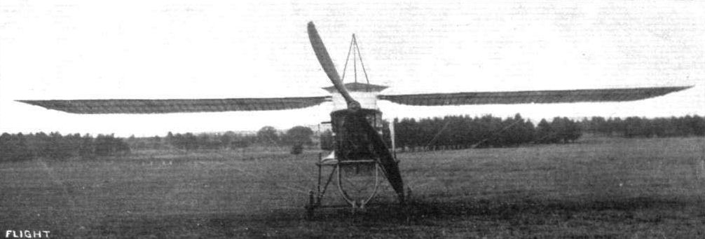
CODY MONOPLANE. - View from in front.
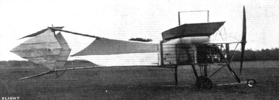
CODY MONOPLANE. - Side view.
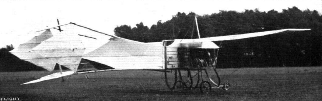
CODY MONOPLANE. - Three-quarter view from behind.

CODY MONOPLANE. - View from behind.
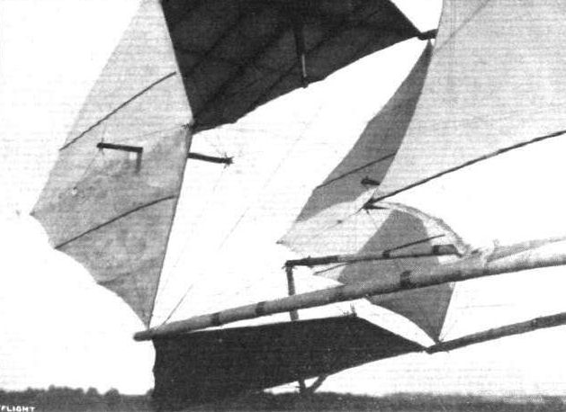
Enlarged view of the tail members of the Cody monoplane.
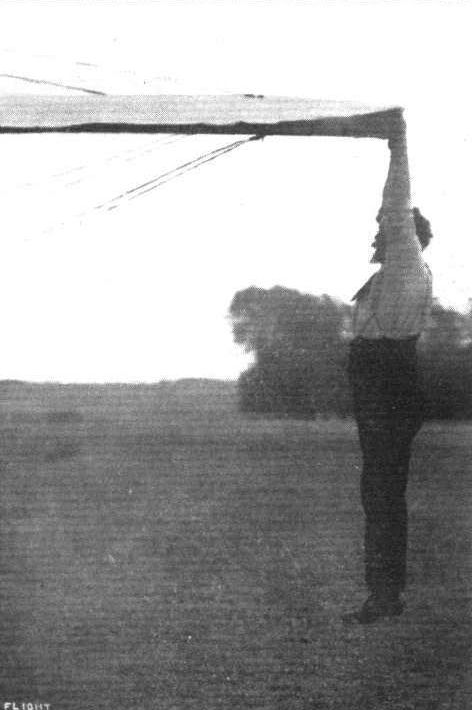
S. F Cody gives a slight test of the strength of the top bracing ot his monoplane by hanging his 200 lbs. weight on to the extreme tip of one of the wings.
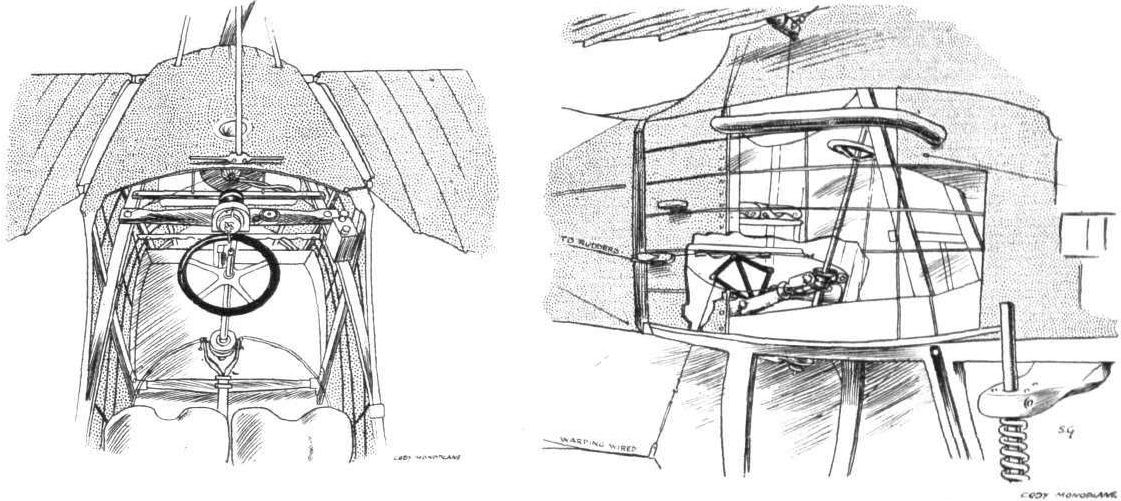
Sketch of the inside of the cockpit of the Cody monoplane, showing the two seats and the centrally-disposed control column. It also gives a good idea of the extent of view that is obtainable from the machine, not only through the transparent covering of the cabin, but over the side of the body. On the right is a sketch from the outside of the cockpit. The covering is suggested as being cut away in order to make clear details of the warping control.
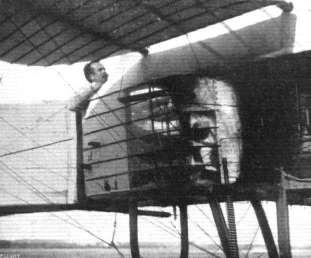
S. F. Cody in the cabin of his new monoplane, showing the control-levers through the windows.
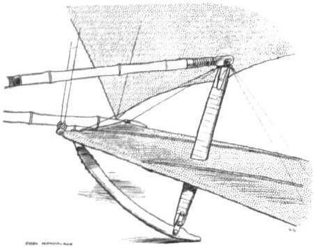
Showing how the rear elevators are operated by the long bamboo connecting-rods, and how the rear skid is attached.
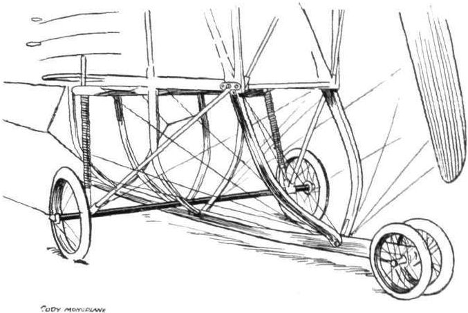
The landing chassis of the Cody monoplane.
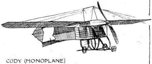
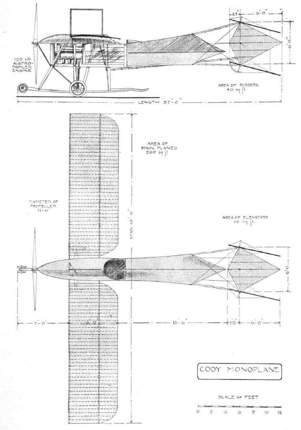
THE CODY MONOPLANE. - Plan and elevation to scale.
Flight, September 7, 1912.
CODY AND HIS "CATHEDRAL".
RECOGNITION has come to Cody at last, after many years of hard, up-hill work; seldom has success been better earned than his. In spite of apparently insurmountable obstacles, but with the enthusiasm of the true pioneer, he has persistently toiled to overcome an endless succession of difficulties. Cody's success is all the more creditable because his work is so entirely original; original, yet not freakish. What he does is his own thought, and mostly his own handiwork too. From the first he determined to build a big machine; a natural impulse, for there is nothing small about Cody, even his compass looks twice the size of what one generally imagines to be suitable for aeroplane work, and when, incidentally, I asked him the time, I was not in the least surprised to see him pull out a watch reminiscent of the days of our grandfathers.
As in his earlier machine, there is a free simplicity about the constructive detail that appeals mightily to the common sense, though it may at times offend the susceptibilities of the standardized engineering mind. Similarly too, there remains that great, perhaps the greatest, feature of Cody design, to wit, the divided elevator, which is worked in unison with the warping of the main planes for the maintenance of lateral balance. Steering is accomplished by twin rudders, independently mounted on twin outriggers of bamboo. There is no rear elevator, but fixed transversely to each rudder is a very small horizontal damper plane. The control differs from that of most other machines in that the steering is effected by a horizontal wheel arranged as in a motor car, except that the steering column itself has a universally pivoted support for the purpose of warping and elevating. In the Cody machine the feet are, therefore, left free from the control, and very naturally Cody has of late adopted the pedal accelerator, which makes the driving of the Cody "bus" still more like the driving of a car.
In the construction of the machine silver spruce is used for the spars and struts, American hickory for the landing chassis and engine bearers, and stout bamboo poles bound with tape for the outriggers that carry the elevator and rudders. Pegamoid is used for covering the planes, and I understand that the fabric has withstood three years' wear and tear.
The landing chassis is practically the same as that of the earlier machine, and includes a central skid that carries a pair of small buffer wheels in front and a kangaroo-like tail of laminated wood behind. An ingenious dodge on this tail, which gave Cody much pleasure and some profit in the trials, is a length of chain (rather like a Parson's non-skid for a motor car tyre) that could be drawn up out of the way by a string. On landing, the string was released so that the vibration of the tail could shake the chain rings that encircled it down into contact with the ground, where they acted as very effective brakes. Two wheels, mounted on vertical telescopic tubes with powerful coil spring shock absorbers, support the weight of the machine at starting, while in the air these same springs pull upon the main lift wires under the lower planes. The wheel track is only 3 ft. 6 in., and small wheels are, therefore, fitted as fenders to the wing tips. Indeed, these latter may be regarded as part and parcel of the chassis arrangement, as they come frequently into use.
The pilot's seat is now partly covered in, and immediately behind it is one passenger seat, from which a beginner first obtains tuition by handling an extension of the control lever over the pilot's shoulder. Subsequently the positions are reversed. On either side of the pilot's seat, but outside the nacelle, are two other seats, the position of which gives an absolutely unrivalled opportunity for observation, but is not everybody's choice in a "joy ride" all the same. From the purely patriotic view one cannot but lament the fact that Cody was unable to secure a British engine to meet his requirements, not that there is anything but praise for the Austro-Daimler, which is unique of its kind and behaved splendidly, but I hope to see the Cody absolutely all British-built yet.
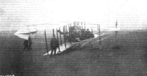
The Cody biplane about to start on the official test in the Military Aeroplane Trials.
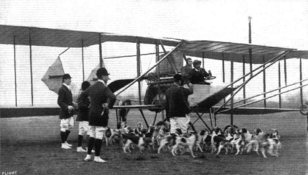
Last week Mr. S. F Cody made a sporting flight in connection with the Aldershot Beagles at Eelmcor Bridge Laffans Plain, when he accompanied the meet for a short period after the start. In our picture Mr. Cody is being greeted by the Master, Capt. Sankey, before the start.
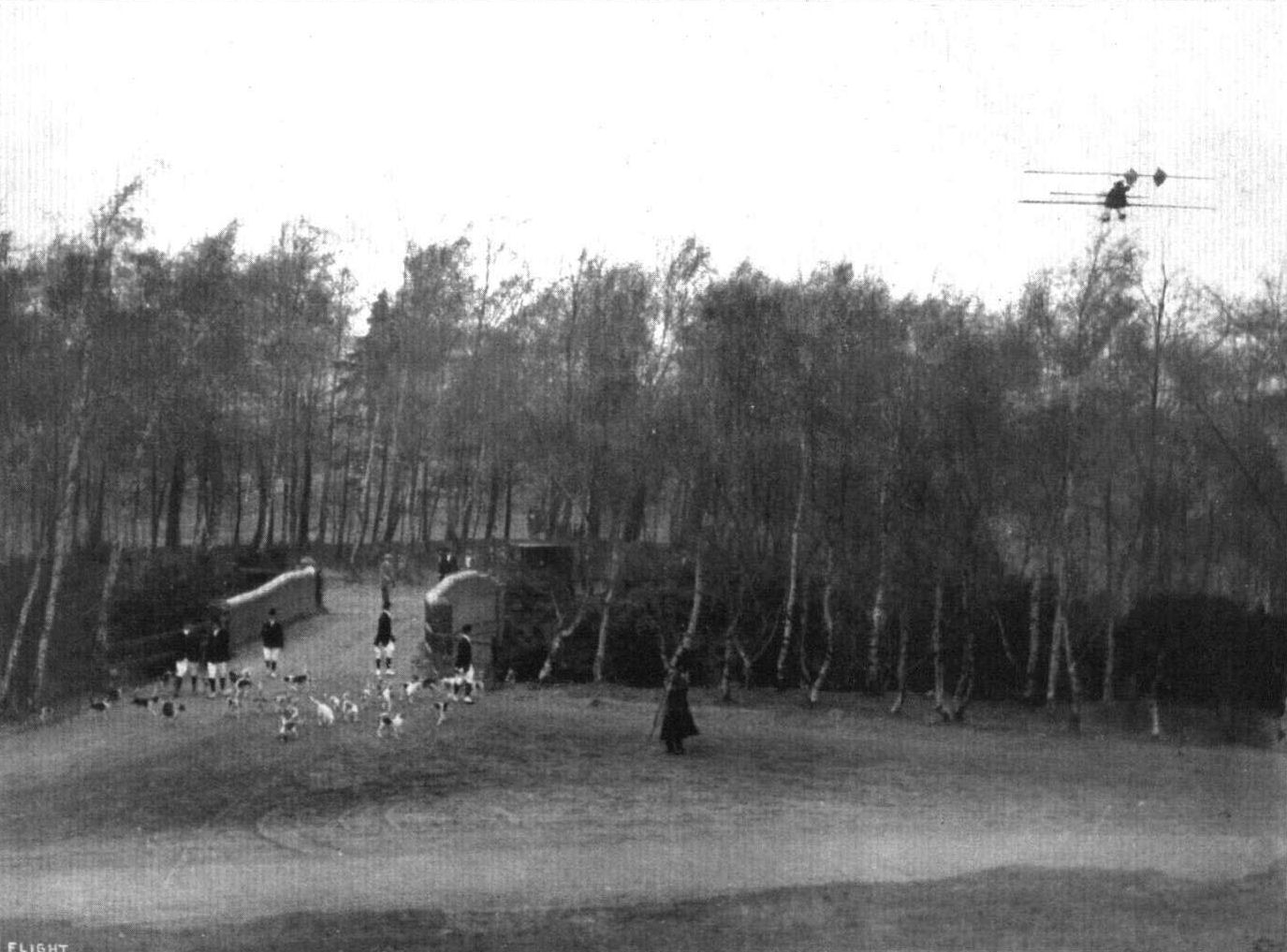
Col. S. F. Cody, on the Cody biplane, flying at the meet of the Aldershot Beagles at Eelmoor Bridge, Laffan's Plain.
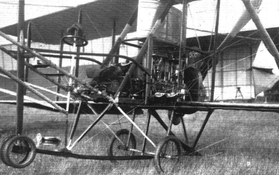
The centre portion of the Cody biplane which won the L5,000 in prizes in the Military Trials.

THE MILITARY AEROPLANE COMPETITION. - Assembling the Cody biplane before the judges. Mr. S. F. Cody, ever active, assists in the operations. The photograph on the right shows the central part of the machine. The passenger seat, projecting from the side of the engine-bed, is worthy of note.
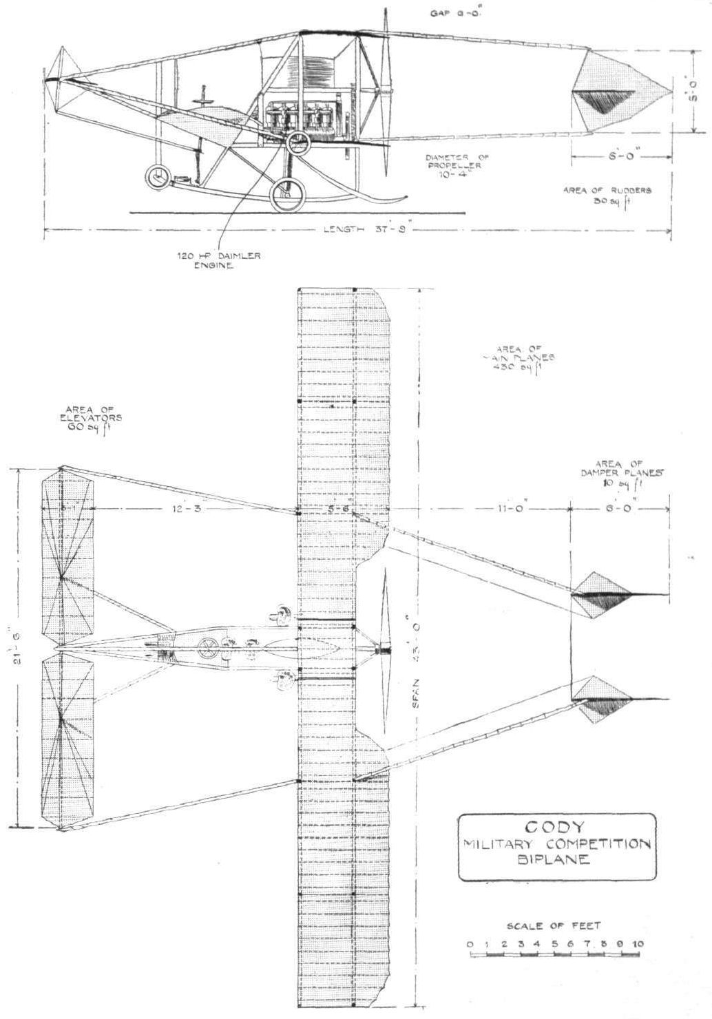
PLAN AND ELEVATION OF THE CODY BIPLANE, which won the first prize open to the world, and also the first prize open to British machines only, in the Military Aeroplane Trials. The above drawing represents the machine exactly as it finished the trials.
Flight, May 18, 1912.
THE COVENTRY ORDNANCE BIPLANE.
THE first impressions one gets of the New Coventry Ordnance Biplane are its marked originality, its excellence of design and construction, and its businesslike - more than that - its warlike appearance. It has a certain atmosphere about it that brands it as a machine intended for harder and more serious service than mere aerodrome work.
It was designed jointly by Mr. W. O. Manning and Mr. Howard Wright to fulfil War Office requirements. And from the tests that have already been carried out - it has lifted with perfect ease two passengers over its full complement, four persons in all, and that with the ignition of its 100-h.p. Gnome motor very much retarded, and with its extra passengers standing outside on the cellule, where they each were absorbing a considerable power in extra head resistance - we think we can safely predict that it will have no very great difficulty in showing itself to advantage in the military competitions.
Second impressions single out for notice the large gap of 8 ft. between the main supporting surfaces, the hugeness of the propeller, it measures eleven and a half feet from tip to tip, and the neatness of the landing gear, unsprung except for the resiliency that its large six-inch tyres afford.
A factor of safety of 12 has been worked to throughout, and probably it was the consideration of how to obtain that safety factor without having to resort to too much weight of material that influenced the designers in deciding to make their machine a double-decker.
It was built throughout at Howard Wright's original works at Battersea, with the exception of most of the metal work. This was turned out at the Coventry works.
The total area of supporting surface is, roughly, 350 square feet, this lifting its total load of about 2,000 lbs. all on, at its flying speed of 60 miles per hour - a loading of approximately 5 1/2 lbs. to the square foot. The upper and lower surfaces span 40 ft. and 20 ft. respectively, the chord in both cases diminishing from 6 ft. in the centre to 5 ft. at the tips. The extra span of the upper surface is made up by an extension on each side. These extensions are virtually complete monoplane wings braced to the rigid plane structure by king posts and steel cable on top, and by stranded steel cable below. They are arranged to warp for the correction of lateral balance. Both their tips and the tips of the lower plane are finished off like those of the Borel wing in order to obtain a very powerful warp. The warping is operated by stout stranded steel cables passing from the rear boom of one extension under stream-line pulleys on the lower plane, straight through to the pulley on the opposite side and up to the other extension. The operating-wires from the control-wheel are "tapped" on to this main cable, for by this arrangement the movements and jerkings that are produced in the main warping cable by the action of wind gusts on each warping surface, are communicated direct to the opposite wing-tip and not, as in many cases, via the control-wheel. This feature should also materially lessen the fatigue of the pilot when flying in anything of a strong wind. The warp-compensating wires on top pass over rocking king posts and down again under pulleys fixed just above the rear wing-spar.
For a biplane, the spars, of ash, are of very generous dimensions. They are 3 inches in depth and over an inch thick in both cases. The ribs are of spruce, and solid, except for the drilling in each to allow the internally fitted drift cables to pass. These drift cables are, by the way, of the same size solid core stranded steel cables as are used for taking the main lift.
The 8 ft. vertical struts separating the main planes are of silver spruce. Although they arc of a goodly size from front to back they are relatively quite thin. But this is compensated for by the fact that they are braced together in two sets of four. They fit into steel lugs where the cross-bracing cables are also assembled.
The planes are built and attached in sections, the attachments being arranged internally where they are accessible, and where they may be systematically inspected through neat aluminium sliding doors. There are eight of these - one against each strut socket.
The main body - wide enough to seat pilot and passenger side by side - is essentially a wedge-shaped box girder, flattening horizontally towards the rear. In its construction ash is employed for the main booms and spruce for the cross-members. Viewed from above its sides are parallel from stem to stern. Thus it is sufficiently wide at the tail to provide a good damping surface, a point which reduces the extra tail surface necessary. These surfaces are flat, and have a purely floating action in flight. In shape they are quarter elliptical. At the extreme rear, the sides of the fuselage extend above and below the top and bottom surfaces, forming small fins, to the back edge of which the vertical rudders are hinged. They, similarly to the elevators, are balanced in their action. A bent cane skid takes the weight of the after section of the machine when at rest on the ground. The main chassis wheels are so placed that there is only about 40 lbs. of weight at the extreme tail - a joy to its attendant mechanics - they most probably in their time have had to deal with machines tremendously tail-heavy when on the ground.
The engine mounting is decidedly interesting. The four body booms in front are assembled in a pressed steel housing, which accommodates both the motor - a 100-h.p. 14-cylinder Gnome - and the propeller shaft. The Gnome is slung low down in the housing and, keyed to its nose is a chain wheel, from which the drive is taken by a Hans-Renold chain - this alone weighs something like 25 lbs. - to the propeller shaft above. There is a reduction of 2 to 1 in the transmission. The propeller shaft is mounted, together with the engine in ball bearings, and two ball thrust washers are fitted - the larger to accommodate the propeller thrust and the smaller to take the negative thrust caused by the head resistance on the slow running or stationary propeller during a vol plane.
A peculiarity about the engine - we say peculiarity because we have never previously seen this system applied to a rotary motor - is that it is equipped with Bosch dual ignition, by which it may be started from the pilot's seat. Another refinement is the drip-catching funnel arranged beneath the carburettor, by which any overflow of petrol is collected and led through a copper pipe to the exterior of the body, where it is out of harm's way. A covering, similar to a Sizaire car bonnet cases in the motor and propeller-shaft housing. It is cut from sheet aluminium, and kept in place by ordinary car-hood fasteners.
The propeller is a colossal structure of teak with nine laminations. It is 11 ft. 6 ins in diameter, and rotates at 600 revs, per minute. It is noteworthy that, from the boss to a point 18 ins. along the blade it is designed to give no thrust, but merely for that section to travel through the air, causing as little head resistance and absorbing as little power as possible. In defence of this notion the designers ask two questions. - Firstly, why should the pilots sit in more draught than can be avoided? and secondly, what is the use of projecting that 3 ft. diameter column of air rearwards to impinge directly on the fuselage where it would cause a drag equal to or in excess of the thrust obtained from projecting it?
Regarding the landing gear we must certainly say that its simplicity appeals to us a great deal more than the weird and wonderful shock-absorbing devices that we occasionally see. It consists of a pair of 30-in. wheels - 6-in. tyres are employed - mounted on a common axle, which supports the machine through short struts of Honduras mahogany. No sideways movement of the machine on landing is provided for. Two wheels only are used. Three or more, if rigidly attached, would cause trouble, such as was experienced with the Astra triplane, if a landing were made on anything but the smoothest of grounds.
A single skid of hickory proceeds forward, supported by two struts in V of Honduras mahogany, to protect the propeller and front section of the machine.
From the cockpit the pilot and his passenger obtain a very clear view of the country directly beneath and all round them. The short span of the lower plane helped in this respect to a great extent.
Before the pilot is a wheel, mounted at the top of a vertical column. Warping is operated by twisting the wheel laterally, and the altitude is varied by rocking the column to and fro. A foot lever commands the twin rudders; at present only single control is fitted, but this will be duplicated shortly se that the passenger as well can take charge.
In front is a dashboard where are located the engine controls and the various gauges and instruments common to present-day aeroplanes.
The oil tank, holding 22 gallons, and an auxiliary gravity feed petrol tank, holding 10 gallons, are arranged just in front of the dashboard. The main petrol tank, containing 40 gallons of fuel, is stored away in the streamline well beneath the cockpit.
Flight, July 13, 1912.
THE MILITARY COMPETITION - THE MACHINES.
THE COVENTRY ORDNANCE BIPLANE.
As mentioned in our issue of last week, the Coventry Ordnance Works, Ltd., are entering a pair of machines for the War Office aeroplane competition. One of these has already been described in FLIGHT; the other is of the same type, but is fitted with a 110-h.p. Chenu motor in place of the 100-h.p. Gnome; it has 5 ft. less of wing span, and it is some 2 ft. shorter in overall length. Details and photographs of this latter machine we are not yet able to publish. In the meantime, however, let us briefly recapitulate the main characteristics of the 100-h.p. Gnome-engined machine that has been flying at Brooklands for some two months past. We print in this issue a series of photographs illustrating this highly interesting and original biplane. Its design is jointly due to Mr. Howard Wright and Mr. W. O. Manning, A.F.Ae.S. For its construction, most of the building was carried out at Mr. Howard Wright's works at Battersea, the metal work being done at the Coventry works.
Incorporating the fuselage as a feature of construction, it is a biplane of the tractor type. The body, of lattice-girder construction, flattening toward the rear, is sufficiently wide to seat pilot and passenger side by side. Its sides are parallel. In front, the four longerons are assembled into a specially designed pressed-steel housing, in which both the motor and the propeller-shaft are mounted. The drive to the propeller-shaft is by a Hans Renold chain, it being so arranged that the speed of rotation of the propeller is half that of the engine. The propeller itself is strikingly large, for it measures 11 ft. 6 in. from tip to tip, while in its construction nine laminations of teak are employed. It has the peculiarity that, from the boss to a point some 18 ins. down the blade, it is designed to give no forward thrust, but merely to revolve in air, causing as little resistance and absorbing as little power as possible. For this and other reasons, when the machine is flying, those in the cockpit notice comparatively little rush of air. As an advance on accepted practice, particularly relating to Gnome engines, the motor on this machine has been equipped with Bosch dual ignition in order that it may, when necessary, be started from the pilot's seat.
The main supporting surfaces are double surface, are unequal in span and are separated by a gap of 8 ft. The upper plane spans 40 feet, the lower 24 ft. 8 in. The chord in measurement diminishes from 6 ft. at the centre of the wings to 5 ft. near the tip. Both end sections of the top plane, each 10 ft. in length, are constructed so that they may be warped for the correction of lateral balance. As for the cross sections of the plane, the designers have made use of one that has been experimented with by M. Eiffel, for, data relating to its behaviour being available, it has been thought more advantageous to have something definite to work upon than to employ a section the virtues of which might be problematical. The landing gear is about as simple a conception as one could possibly cite. No shock absorbers have been introduced, all the shock absorbing necessary being done by large diameter 6 in. tyres. Protection is afforded against damage to the propeller by a turned up hickory skid, which proceeds forward and which is connected to the nose of the machine by a pair of struts of Honduras mahogany arranged V fashion.
A good idea of the tail is conveyed by one of our photographs. Tanks for the storage of fuel and oil are located under the bonnet. Here there is a tank for oil holding 32 gallons and one for petrol holding 10; the main balk of the petrol, however, is carried in a large tank arranged in the streamline well below the fuselage. From there to the auxiliary tank under the bonnet it is fed by pressure.
Main characteristics:-
Motor 14-cyl. Gnome, 100-h.p. rotary
Overall length 33 ft. 3 in.
Span 40 ft., 24 ft. 8 in.
Area 350 sq.ft.
Average chord 5 ft. 6 in.
Weight, all on 2,000lbs.
Speed 60m.p.h.
Flight, August 10, 1912.
THE MILITARY AEROPLANE COMPETITION - THE MACHINES.
THE CHENU-ENGINED COVENTRY ORDNANCE BIPLANE.
THIS machine differs very little from the 100-h.p. Gnome-engined biplane that we described in these columns quite recently. The main point of difference, besides the fact that a 110-h.p. water-cooled Chenu motor is fitted instead of a 100-h.p. Gnome, is that the fuselage is much narrower, being designed to accommodate the pilot and passenger in tandem. The main dimensions, too, are considerably smaller. A four-bladed propeller is employed.
Main characteristics:-
Overall length 32 ft.
Speed 68-70 m.p.h.
Span 32 ft.
Weight without complement or fuel 1,250 lbs.
Area 300 sq. ft.
THE COVENTRY ORDNANCE BIPLANE.
THE first impressions one gets of the New Coventry Ordnance Biplane are its marked originality, its excellence of design and construction, and its businesslike - more than that - its warlike appearance. It has a certain atmosphere about it that brands it as a machine intended for harder and more serious service than mere aerodrome work.
It was designed jointly by Mr. W. O. Manning and Mr. Howard Wright to fulfil War Office requirements. And from the tests that have already been carried out - it has lifted with perfect ease two passengers over its full complement, four persons in all, and that with the ignition of its 100-h.p. Gnome motor very much retarded, and with its extra passengers standing outside on the cellule, where they each were absorbing a considerable power in extra head resistance - we think we can safely predict that it will have no very great difficulty in showing itself to advantage in the military competitions.
Second impressions single out for notice the large gap of 8 ft. between the main supporting surfaces, the hugeness of the propeller, it measures eleven and a half feet from tip to tip, and the neatness of the landing gear, unsprung except for the resiliency that its large six-inch tyres afford.
A factor of safety of 12 has been worked to throughout, and probably it was the consideration of how to obtain that safety factor without having to resort to too much weight of material that influenced the designers in deciding to make their machine a double-decker.
It was built throughout at Howard Wright's original works at Battersea, with the exception of most of the metal work. This was turned out at the Coventry works.
The total area of supporting surface is, roughly, 350 square feet, this lifting its total load of about 2,000 lbs. all on, at its flying speed of 60 miles per hour - a loading of approximately 5 1/2 lbs. to the square foot. The upper and lower surfaces span 40 ft. and 20 ft. respectively, the chord in both cases diminishing from 6 ft. in the centre to 5 ft. at the tips. The extra span of the upper surface is made up by an extension on each side. These extensions are virtually complete monoplane wings braced to the rigid plane structure by king posts and steel cable on top, and by stranded steel cable below. They are arranged to warp for the correction of lateral balance. Both their tips and the tips of the lower plane are finished off like those of the Borel wing in order to obtain a very powerful warp. The warping is operated by stout stranded steel cables passing from the rear boom of one extension under stream-line pulleys on the lower plane, straight through to the pulley on the opposite side and up to the other extension. The operating-wires from the control-wheel are "tapped" on to this main cable, for by this arrangement the movements and jerkings that are produced in the main warping cable by the action of wind gusts on each warping surface, are communicated direct to the opposite wing-tip and not, as in many cases, via the control-wheel. This feature should also materially lessen the fatigue of the pilot when flying in anything of a strong wind. The warp-compensating wires on top pass over rocking king posts and down again under pulleys fixed just above the rear wing-spar.
For a biplane, the spars, of ash, are of very generous dimensions. They are 3 inches in depth and over an inch thick in both cases. The ribs are of spruce, and solid, except for the drilling in each to allow the internally fitted drift cables to pass. These drift cables are, by the way, of the same size solid core stranded steel cables as are used for taking the main lift.
The 8 ft. vertical struts separating the main planes are of silver spruce. Although they arc of a goodly size from front to back they are relatively quite thin. But this is compensated for by the fact that they are braced together in two sets of four. They fit into steel lugs where the cross-bracing cables are also assembled.
The planes are built and attached in sections, the attachments being arranged internally where they are accessible, and where they may be systematically inspected through neat aluminium sliding doors. There are eight of these - one against each strut socket.
The main body - wide enough to seat pilot and passenger side by side - is essentially a wedge-shaped box girder, flattening horizontally towards the rear. In its construction ash is employed for the main booms and spruce for the cross-members. Viewed from above its sides are parallel from stem to stern. Thus it is sufficiently wide at the tail to provide a good damping surface, a point which reduces the extra tail surface necessary. These surfaces are flat, and have a purely floating action in flight. In shape they are quarter elliptical. At the extreme rear, the sides of the fuselage extend above and below the top and bottom surfaces, forming small fins, to the back edge of which the vertical rudders are hinged. They, similarly to the elevators, are balanced in their action. A bent cane skid takes the weight of the after section of the machine when at rest on the ground. The main chassis wheels are so placed that there is only about 40 lbs. of weight at the extreme tail - a joy to its attendant mechanics - they most probably in their time have had to deal with machines tremendously tail-heavy when on the ground.
The engine mounting is decidedly interesting. The four body booms in front are assembled in a pressed steel housing, which accommodates both the motor - a 100-h.p. 14-cylinder Gnome - and the propeller shaft. The Gnome is slung low down in the housing and, keyed to its nose is a chain wheel, from which the drive is taken by a Hans-Renold chain - this alone weighs something like 25 lbs. - to the propeller shaft above. There is a reduction of 2 to 1 in the transmission. The propeller shaft is mounted, together with the engine in ball bearings, and two ball thrust washers are fitted - the larger to accommodate the propeller thrust and the smaller to take the negative thrust caused by the head resistance on the slow running or stationary propeller during a vol plane.
A peculiarity about the engine - we say peculiarity because we have never previously seen this system applied to a rotary motor - is that it is equipped with Bosch dual ignition, by which it may be started from the pilot's seat. Another refinement is the drip-catching funnel arranged beneath the carburettor, by which any overflow of petrol is collected and led through a copper pipe to the exterior of the body, where it is out of harm's way. A covering, similar to a Sizaire car bonnet cases in the motor and propeller-shaft housing. It is cut from sheet aluminium, and kept in place by ordinary car-hood fasteners.
The propeller is a colossal structure of teak with nine laminations. It is 11 ft. 6 ins in diameter, and rotates at 600 revs, per minute. It is noteworthy that, from the boss to a point 18 ins. along the blade it is designed to give no thrust, but merely for that section to travel through the air, causing as little head resistance and absorbing as little power as possible. In defence of this notion the designers ask two questions. - Firstly, why should the pilots sit in more draught than can be avoided? and secondly, what is the use of projecting that 3 ft. diameter column of air rearwards to impinge directly on the fuselage where it would cause a drag equal to or in excess of the thrust obtained from projecting it?
Regarding the landing gear we must certainly say that its simplicity appeals to us a great deal more than the weird and wonderful shock-absorbing devices that we occasionally see. It consists of a pair of 30-in. wheels - 6-in. tyres are employed - mounted on a common axle, which supports the machine through short struts of Honduras mahogany. No sideways movement of the machine on landing is provided for. Two wheels only are used. Three or more, if rigidly attached, would cause trouble, such as was experienced with the Astra triplane, if a landing were made on anything but the smoothest of grounds.
A single skid of hickory proceeds forward, supported by two struts in V of Honduras mahogany, to protect the propeller and front section of the machine.
From the cockpit the pilot and his passenger obtain a very clear view of the country directly beneath and all round them. The short span of the lower plane helped in this respect to a great extent.
Before the pilot is a wheel, mounted at the top of a vertical column. Warping is operated by twisting the wheel laterally, and the altitude is varied by rocking the column to and fro. A foot lever commands the twin rudders; at present only single control is fitted, but this will be duplicated shortly se that the passenger as well can take charge.
In front is a dashboard where are located the engine controls and the various gauges and instruments common to present-day aeroplanes.
The oil tank, holding 22 gallons, and an auxiliary gravity feed petrol tank, holding 10 gallons, are arranged just in front of the dashboard. The main petrol tank, containing 40 gallons of fuel, is stored away in the streamline well beneath the cockpit.
Flight, July 13, 1912.
THE MILITARY COMPETITION - THE MACHINES.
THE COVENTRY ORDNANCE BIPLANE.
As mentioned in our issue of last week, the Coventry Ordnance Works, Ltd., are entering a pair of machines for the War Office aeroplane competition. One of these has already been described in FLIGHT; the other is of the same type, but is fitted with a 110-h.p. Chenu motor in place of the 100-h.p. Gnome; it has 5 ft. less of wing span, and it is some 2 ft. shorter in overall length. Details and photographs of this latter machine we are not yet able to publish. In the meantime, however, let us briefly recapitulate the main characteristics of the 100-h.p. Gnome-engined machine that has been flying at Brooklands for some two months past. We print in this issue a series of photographs illustrating this highly interesting and original biplane. Its design is jointly due to Mr. Howard Wright and Mr. W. O. Manning, A.F.Ae.S. For its construction, most of the building was carried out at Mr. Howard Wright's works at Battersea, the metal work being done at the Coventry works.
Incorporating the fuselage as a feature of construction, it is a biplane of the tractor type. The body, of lattice-girder construction, flattening toward the rear, is sufficiently wide to seat pilot and passenger side by side. Its sides are parallel. In front, the four longerons are assembled into a specially designed pressed-steel housing, in which both the motor and the propeller-shaft are mounted. The drive to the propeller-shaft is by a Hans Renold chain, it being so arranged that the speed of rotation of the propeller is half that of the engine. The propeller itself is strikingly large, for it measures 11 ft. 6 in. from tip to tip, while in its construction nine laminations of teak are employed. It has the peculiarity that, from the boss to a point some 18 ins. down the blade, it is designed to give no forward thrust, but merely to revolve in air, causing as little resistance and absorbing as little power as possible. For this and other reasons, when the machine is flying, those in the cockpit notice comparatively little rush of air. As an advance on accepted practice, particularly relating to Gnome engines, the motor on this machine has been equipped with Bosch dual ignition in order that it may, when necessary, be started from the pilot's seat.
The main supporting surfaces are double surface, are unequal in span and are separated by a gap of 8 ft. The upper plane spans 40 feet, the lower 24 ft. 8 in. The chord in measurement diminishes from 6 ft. at the centre of the wings to 5 ft. near the tip. Both end sections of the top plane, each 10 ft. in length, are constructed so that they may be warped for the correction of lateral balance. As for the cross sections of the plane, the designers have made use of one that has been experimented with by M. Eiffel, for, data relating to its behaviour being available, it has been thought more advantageous to have something definite to work upon than to employ a section the virtues of which might be problematical. The landing gear is about as simple a conception as one could possibly cite. No shock absorbers have been introduced, all the shock absorbing necessary being done by large diameter 6 in. tyres. Protection is afforded against damage to the propeller by a turned up hickory skid, which proceeds forward and which is connected to the nose of the machine by a pair of struts of Honduras mahogany arranged V fashion.
A good idea of the tail is conveyed by one of our photographs. Tanks for the storage of fuel and oil are located under the bonnet. Here there is a tank for oil holding 32 gallons and one for petrol holding 10; the main balk of the petrol, however, is carried in a large tank arranged in the streamline well below the fuselage. From there to the auxiliary tank under the bonnet it is fed by pressure.
Main characteristics:-
Motor 14-cyl. Gnome, 100-h.p. rotary
Overall length 33 ft. 3 in.
Span 40 ft., 24 ft. 8 in.
Area 350 sq.ft.
Average chord 5 ft. 6 in.
Weight, all on 2,000lbs.
Speed 60m.p.h.
Flight, August 10, 1912.
THE MILITARY AEROPLANE COMPETITION - THE MACHINES.
THE CHENU-ENGINED COVENTRY ORDNANCE BIPLANE.
THIS machine differs very little from the 100-h.p. Gnome-engined biplane that we described in these columns quite recently. The main point of difference, besides the fact that a 110-h.p. water-cooled Chenu motor is fitted instead of a 100-h.p. Gnome, is that the fuselage is much narrower, being designed to accommodate the pilot and passenger in tandem. The main dimensions, too, are considerably smaller. A four-bladed propeller is employed.
Main characteristics:-
Overall length 32 ft.
Speed 68-70 m.p.h.
Span 32 ft.
Weight without complement or fuel 1,250 lbs.
Area 300 sq. ft.

THE COVENTRY ORDNANCE BIPLANE. - Side view.

The Coventry Ordnance biplane, as seen from in front.

The Coventry Ordnance biplane from the rear.
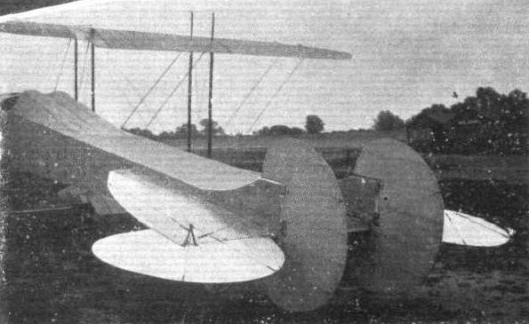
THE MILITARY COMPETITION MACHINES. 5. The arrangement of the tail.

Details of the front section of the machine, showing the engine mounting, the main hickory skid, and the unsprung landing gear.

Details of the front part of the machine, showing the housing for the 100-h.p. Gnome and the chain transmission.
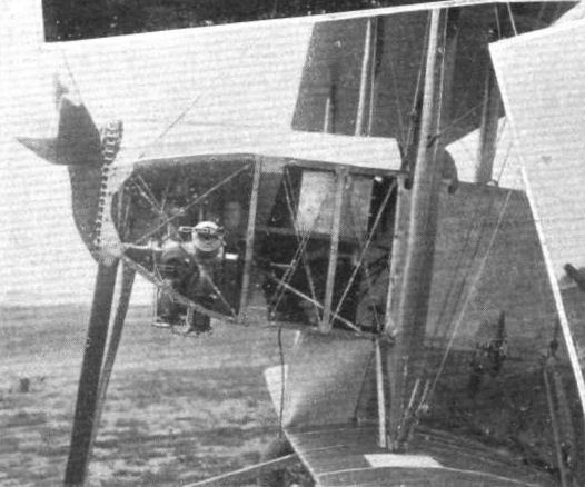
THE MILITARY COMPETITION MACHINES. 7. The body with side casing removed, showing the 100-h.p. Gnome motor.
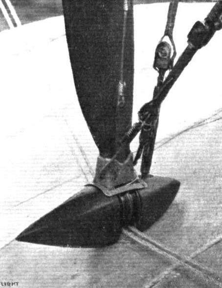
The stream-line encased warping pulley for the Coventry Ordnance biplane.

Detail of the Coventry Ordnance landing chassis, showing the small hickory skid intended to protect the chassis should anything happen to the wheels. The wheel is omitted to avoid complication.

One of the aluminium inspection doors fitted to the planes of the Coventry Ordnance biplane. The sketch shows the method employed for the joining of the wing sections. Inset is the quick release pin. These are used throughout the machine to minimise the time necessary (or dismantling and erection.


THE COVENTRY ORDNANCE BIPLANE. - Plan and elevation to scale.
Flight, June 22, 1912.
THE DUNNE MACHINES IN FLIGHT.
WE publish this week, two or three photographs taken by Miss Dunne of her brother's machines at the Royal Aero Club's Eastchurch flying grounds. Everyone will rejoice to hear that Mr. Durme has recovered from his very serious illness, and is now back at work again. Not only is Mr. Dunne himself flying at Eastchurch, but Capt. Carden, R.E., as our readers know, has been making the best sort of progress, passing for his brevet last week, and Capt. Carden, as some of our readers may not know, has the misfortune to have lost an arm, wherefore his practice with the Dunne machine is worthy of very special attention.
Two of the photographs show the biplane in flight, and both illustrate very clearly the V plan of the wings, from which, in conjunction with the peculiar variation in camber from shoulder to tip, is derived the high degree of natural stability that this flyer has always claimed to possess. It has flaps at the extremities of the main planes, but these are for the purpose of steering and elevation only; they are independently operated by separate levers, one on each side of the pilot, which adds to the significance of Capt. Carden's performances.
The monoplane, which is illustrated with Mr. Dunne in the pilot's seat, is built on the same principle as the biplane, but the absence of the lower plane gives it a very extraordinary appearance. We have heard other pilots describe the flying of this machine as revolutionary, and certainly it may be taken for granted that the Astra Co. of France would not have taken up the French rights and be making preparations for building these machines in their own country if they did not think a great deal of them. In the early days of motor cars, it will be remembered, all the good things came from France in the first instance, but the tide turned at last. Let us hope that it may do so in aviation, and long may men like J. W. Dunne, who are devoting the best of their lives to the cause, be spared fully to achieve the ends they have in view.
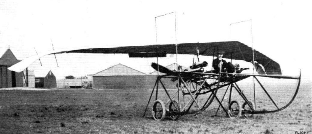
J.W. Dunne in the D7bis monoplane at Eastchurch in 1912 where the reconstruction from D6 was carried out.
J. W. Dunne on his monoplane at Eastchurch, where, having recovered from his illness, he has been fiying again most successfully. The Astra Co, have taken up the rights for manufacturing the Dunne machines in France.
J. W. Dunne on his monoplane at Eastchurch, where, having recovered from his illness, he has been fiying again most successfully. The Astra Co, have taken up the rights for manufacturing the Dunne machines in France.
Flight, June 22, 1912.
THE DUNNE MACHINES IN FLIGHT.
WE publish this week, two or three photographs taken by Miss Dunne of her brother's machines at the Royal Aero Club's Eastchurch flying grounds. Everyone will rejoice to hear that Mr. Durme has recovered from his very serious illness, and is now back at work again. Not only is Mr. Dunne himself flying at Eastchurch, but Capt. Carden, R.E., as our readers know, has been making the best sort of progress, passing for his brevet last week, and Capt. Carden, as some of our readers may not know, has the misfortune to have lost an arm, wherefore his practice with the Dunne machine is worthy of very special attention.
Two of the photographs show the biplane in flight, and both illustrate very clearly the V plan of the wings, from which, in conjunction with the peculiar variation in camber from shoulder to tip, is derived the high degree of natural stability that this flyer has always claimed to possess. It has flaps at the extremities of the main planes, but these are for the purpose of steering and elevation only; they are independently operated by separate levers, one on each side of the pilot, which adds to the significance of Capt. Carden's performances.
The monoplane, which is illustrated with Mr. Dunne in the pilot's seat, is built on the same principle as the biplane, but the absence of the lower plane gives it a very extraordinary appearance. We have heard other pilots describe the flying of this machine as revolutionary, and certainly it may be taken for granted that the Astra Co. of France would not have taken up the French rights and be making preparations for building these machines in their own country if they did not think a great deal of them. In the early days of motor cars, it will be remembered, all the good things came from France in the first instance, but the tide turned at last. Let us hope that it may do so in aviation, and long may men like J. W. Dunne, who are devoting the best of their lives to the cause, be spared fully to achieve the ends they have in view.
THE DUNNE MACHINES IN FLIGHT.
WE publish this week, two or three photographs taken by Miss Dunne of her brother's machines at the Royal Aero Club's Eastchurch flying grounds. Everyone will rejoice to hear that Mr. Durme has recovered from his very serious illness, and is now back at work again. Not only is Mr. Dunne himself flying at Eastchurch, but Capt. Carden, R.E., as our readers know, has been making the best sort of progress, passing for his brevet last week, and Capt. Carden, as some of our readers may not know, has the misfortune to have lost an arm, wherefore his practice with the Dunne machine is worthy of very special attention.
Two of the photographs show the biplane in flight, and both illustrate very clearly the V plan of the wings, from which, in conjunction with the peculiar variation in camber from shoulder to tip, is derived the high degree of natural stability that this flyer has always claimed to possess. It has flaps at the extremities of the main planes, but these are for the purpose of steering and elevation only; they are independently operated by separate levers, one on each side of the pilot, which adds to the significance of Capt. Carden's performances.
The monoplane, which is illustrated with Mr. Dunne in the pilot's seat, is built on the same principle as the biplane, but the absence of the lower plane gives it a very extraordinary appearance. We have heard other pilots describe the flying of this machine as revolutionary, and certainly it may be taken for granted that the Astra Co. of France would not have taken up the French rights and be making preparations for building these machines in their own country if they did not think a great deal of them. In the early days of motor cars, it will be remembered, all the good things came from France in the first instance, but the tide turned at last. Let us hope that it may do so in aviation, and long may men like J. W. Dunne, who are devoting the best of their lives to the cause, be spared fully to achieve the ends they have in view.
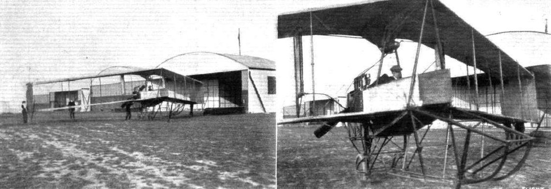
A couple of new pilots on the Dunne biplane at the Royal Aero Club's Eastchurch flying grounds. On the left M. Montmain, and on the right Mr. Perceval.
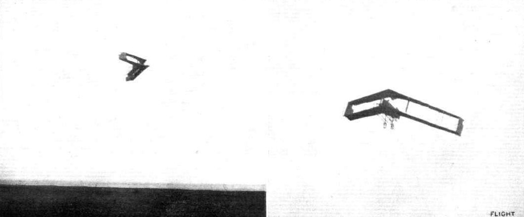
Capt. Carden practising for his brevet on the Dunne biplane.
Flight, February 17, 1912.
Home Made Gliders.
Normally engaged as an apprentice in the London and South-Western carriage works at Eastleigh, nevertheless I have in my spare time been able to do a fair amount of work on gliders during last year, and the accompanying photographs may perhaps interest other readers of FLIGHT. The span of my latest machine is 28 ft., and the length overall 24 ft. Balance is obtained by ailerons coupled up to pedals, while a hand wheel operates the rudder and the elevator. The experimental work so far has been entirely obtained by towing the glider until it rises to a sufficient height. My previous model gave me some excellent sport over the 300 yards stretch that I have available. A club is being formed which I hope will do good work, and the country hereabouts is also an excellent flying ground for full-sized machines.
24, Cranbury Road, Eastleigh, Hants. R. EGGLETON.
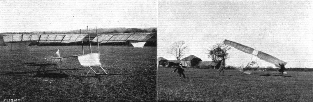
Eggleton No.l glider built at Eastchurch. - On the right the "sporty" start for the first towed flight.
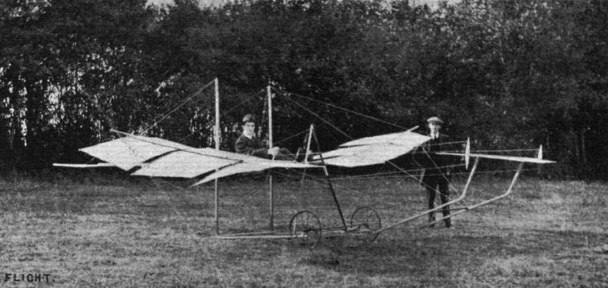
Mr. R. Eggleton in the seat of his No. 2 glider, Mr. J. Moran standing by.
Flight, March 23, 1912.
THE FLANDERS MONOPLANE.
To Mr. L. Howard-Flanders must be given the credit of having produced a distinctive and highly original monoplane. Although in general appearance it does not differ a great deal from its contemporaries of the same type, a closer study reveals so many features of real interest that the machine may almost be termed an encyclopaedia of constructional methods for the aeroplane builder. Further, it is characterised by gracefulness of outline that would be difficult to excel, and this carries much weight with the lay observer, beside being also to the credit of the designer, for no one would wish to build an ungainly object to perform such a graceful art as aviation. It is in England that Mr. Flanders has obtained the whole of his experience in connection with aeroplane construction, but it is evident that he has, nevertheless, relied more on the creative power of his own mind for inspiration in his work than on the published descriptions of well-known foreign machines. Undoubtedly the most notable feature about the Flanders monoplane is the method of assembly of its respective sections. Up to the present, constructors have, in this type of machine, employed a girder-like body as the backbone of the machine, to which all other organs, such as wings and landing chassis have been directly attached.
In the Flanders monoplane, however, the assembly of the various parts is further centralised by attaching such organs to what might be termed an inner fuselage. This inner fuselage is built about two horizontal stout ash bearers on which rests the main weight - that of the engine, the pilot, and the passenger. To it the landing chassis is directly attached, so that the weight may be supported direct, and not via the main body of the machine. This system seems so fundamentally sound and eminently simple that it is rather surprising no one has adopted it before.
Mounted nearly vertically at a point mid-way between the motor and the pilot and forming a unit with the engine bearers is a massive wooden mast, from each end of which the wings are braced, from the bottom to take the weight of the machine in flight, from the top to support the wings when at rest. Thus the functions of the main body, relieved of most of the stresses resulting from flying and landing, are merely those of forming a stream-line casing to contain as many of those parts as can conveniently be located in its interior and of serving as a support for the tail unit. It is entirely covered in by fabric and shaped to a fair stream-line form. Of the customary box girder type of construction, its longitudinal members are of hickory in the front section of the machine and of a lighter wood, Honduras mahogany, to the rear.
The transverse struts are of ash in the region of the engine and the tail, and between these two points silver spruce is employed. Quite original is the method of wire bracing as can be seen from one of our sketches. The method is almost analogous to sewing the structure together.
The body is perfectly symmetrical about its longitudinal axis, which is dead level in flight, and has a maximum depth of 3 ft. just in advance of the pilot's seat.
In plan form the wings are trapezoidal, both entering and trailing-edges tapering from 7ft. 8ins, at the wing root to 5 ft. 8ins, at the tip.
Besides diminishing in chord measurement towards the tip, the wings also diminish in camber and angle of incidence. At the root the camber is pronounced, and the angle of incidence is 7. At the tip the camber is nil, and the angle of incidence is similarly nil.
The workmanship evident in the wing construction is of the highest order. Both front and rear spars are fashioned from English ash and are of H section. They are set parallel in the wing skeleton and united by thirteen 1 in. solid whitewood ribs, flanged top and bottom by strips of ash 1 in. by 3/16in. Besides these solid ribs a large number of false ribs and longitudinal stringers of silver spruce are employed to give the fabric an efficient support.
The dihedral angle is 3.
In flight the weight is sustained from each wing by three steel ribbons proceeding from the landing chassis to the front spar and by three stranded steel cables connected to the rear spar. These latter also operate the warping for lateral balance, a maximum deflection of 9 in. of the rear spar being allowed.
The landing-chassis is of the wheel-and-central-skid type. The wheels are mounted to the steel columns forming the sides of the rectangular chassis skeleton by tubular-steel forks, comprising two sides of a deformable triangle of which the column is the third. The pair of forks representing the longest side are rendered flexible by the interposition of steel compression-springs. Two-and-a-half-inch tyres are employed on the 26-in. wheels. A central skid proceeding from the centre point of the chassis extends below and in front of the propeller to protect it and the machine should an obstruction tend to cause it to tip towards the nose.
The shape of the tail in plan form may be represented by a circle of 4 ft. radius, from which a 90 sector has been subtracted to provide the space for the directional rudder to operate.
Although the stabilising tail is purely of the floating type, it is not flat, but to give rigidity it is cambered equally on both top and bottom surfaces.
Just lately a small vertical fin has been added to the tail to improve the equilibrium of the machine in a side-wind. A small flexibly-sprung skid insulates the tail from ground contact.
The controlling gear is very similar to that adopted by the Deperdussin firm, and comprises a rotatable hand-wheel mounted in the centre of an inverted U-shaped bridge of steel tubing. Lateral equilibrium is corrected by rotating the hand-wheel, and a to-and-fro motion controls the elevation. The steering is operated by a footbar, pivoted centrally.
Provision is made for a passenger in a capacious cockpit, just in front of the pilot's seat. A 60-80-h.p. Green engine, which has been effectively silenced by the fitting of a miniature muffler of stream-line section, has all along proved an eminently satisfactory power plant. It drives a direct-coupled Regy propeller of 8 ft. diameter and 6 ft. pitch.
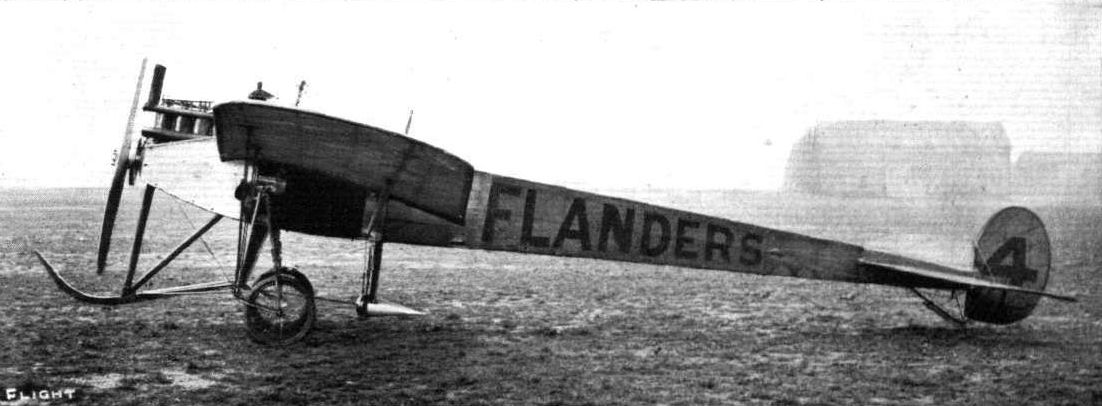
The Flanders monoplane, as seen from the side, giving an idea of the stream-line form of the body.
The Flanders F.3 monoplane raced by R. C. Kemp at Brooklands during 1912.
The Flanders F.3 monoplane raced by R. C. Kemp at Brooklands during 1912.

The Flanders monoplane, as seen from behind.
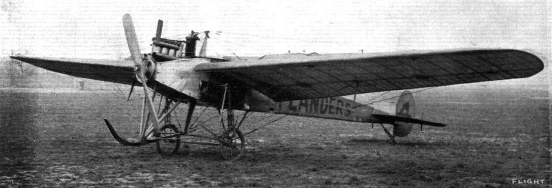
The Flanders monoplane, three-quarter front view. The general arrangement of the landing chassis is clearly seen.
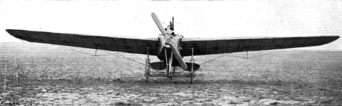
The Flanders monoplane, front view.
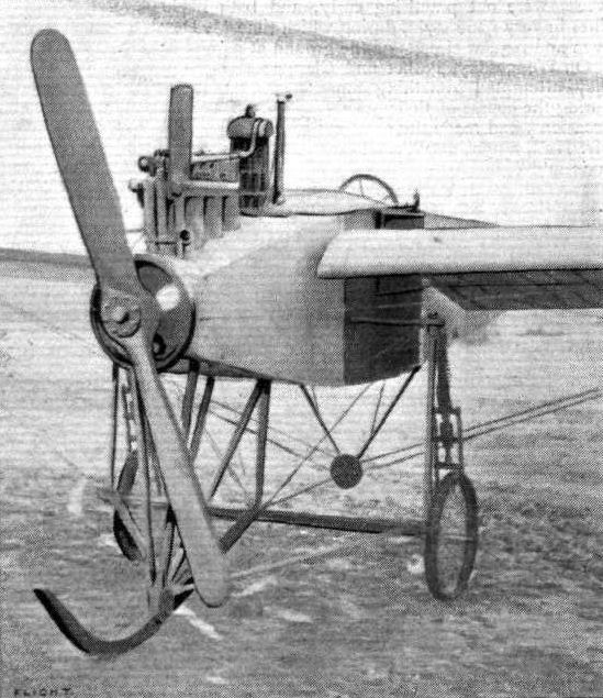
The Flanders Monoplane, showing modifications since reconstruction. Note the silencer to the 60-b.p. Green engine. Also the position of the radiators between the planes and the cabane. The apparent slenderness of the struts of this is due to their being of stream-line section.
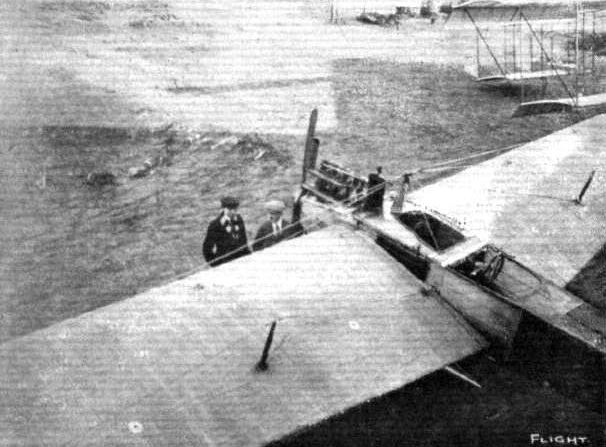
A REMINISCENCE. - The Flanders monoplane at Brooklands, as seen from the roof of its hangar. In conversation before it are Mr. E. V. B. Fisher, the pilot in the muffler, and Mr. Dukinfield-Jones.
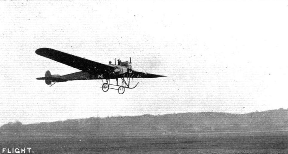
The Green-engined Flanders monoplane getting off smartly with a passenger at Brooklands.
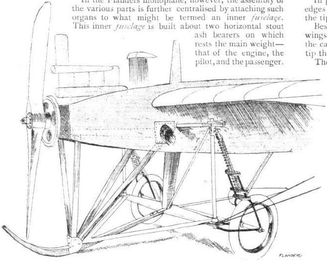
Sketch showing general arrangement of the front section of the Flanders monoplane.
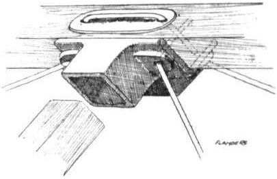
Sketch illustrating the Flanders method of cross bracing.

THE FLANDERS MONOPLANE. - Plan and elevation to scale.
Flight, August 3, 1912.
THE MILITARY AEROPLANE COMPETITION.
THE MACHINES.
THE FLANDERS BIPLANE.
A BIPLANE built by one of our manufacturers who has hitherto been known only by monoplanes of his construction must of necessity be interesting. Although in details it bears some resemblance to the monoplanes, in general ideas it is naturally dissimilar.
The first feature one would notice is the fuselage. This, in the front, is of great depth, extending down to the axle of the landing gear. In shape it is rather difficult to describe, consisting of a square whose topside is converted into a semi-circle, and on whose bottom side there stands a triangle. This section continues until about half way to the tail, when it is simply triangular. In front the semi-circular portion is, of course, cut away into gaps, from which the pilot's and passenger's heads protrude. The end of the lower triangular portion is coincident with the continuation of the front skid, which is of great length and extends half-way down the fuselage. The bottom of the square portion acts as a floor for the interior of the machine.
The planes, of which the top one is the larger (42 ft. as against 27 ft.), are decale or staggered, but for no aerodynamic reasons. The planes have been so arranged from purely constructional motives. Amongst other reasons is the fact that it enables one of the inter-plane struts to be continued as a vertical strut for the landing-chassis, and it also means that the passenger has an excellent view of the ground beneath him.
The pilot and passenger sit in tandem, and as regards width of fuselage there is no reason why there should not be two passengers if occasion arose.
Both planes are capable of being warped, though the higher one has the greater effect, both because it is of greater span, and because in its plan form it is longer at the trailing edge than it is at the leading edge.
The tail and empennage, as can be seen from the photograph, are the same as those previously employed in the monoplanes, consisting of a non-lifting tail, cambered on the top surface, and a balanced rudder.
The landing chassis is of the simplest kind, consisting as it does of a long skid extending far back, a pair of internal vertical struts, and another pair of vertical struts beyond the fuselage and adjacent to the propeller. The cross axle carries a pair of wheels with tyres of a large size, and is pivoted to the middle of the skid. Sideways and vertical movement is corrected by a pair of compression springs. When these are strained to the maximum there is still a clearance of twelve inches between the lower plane and the top of the wheel. The engine is a 100-h.p. A.B.C. If this engine does as well as its smaller prototype (the 40-h.p. on the Burgess-Wright) the whole machine should be a great success.
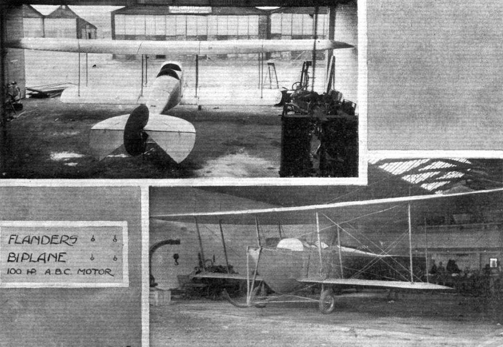
THE MILITARY COMPETITION MACHINES. - The 100-h.p. Flanders biplane, which will be flown by Mr. Raynham. The photographs were taken on Monday last in the A.B.C. engine shops, where the machine was having its motor installed.
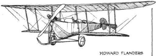
Flight, December 21, 1912.
THE FLANDERS MONOPLANE.
SOME few months since, we devoted an article to describing this extremely interesting monoplane in full. Changes in its design have taken place since then, but as they have affected the detail of the machine more than the general ensemble, let us confine ourselves more particularly to its new features.
Of the Flanders monoplanes, readers may recall, the War Office ordered four. Two of these have been delivered to the Royal Flying Corps at South Farnborough; one is, at the time of writing, at Brooklands, being tested and adjusted prior to being flown over to Farnborough; and the fourth has yet to emerge from the firm's works at Richmond.
The main point of difference of this present 70-h.p. Renault engined monoplane from the 60-h.p. Green engined machine we have previously described lies in the landing gear. The early machine was fitted with a central front skid and swivelling wheels that were supported by a deformable triangle of steel tubing, the resiliency being provided by a compression spring which formed the longest side of the triangle. This chassis, although serviceable enough for landing on and taking off from quite rough surfaces, did not satisfactorily withstand the severe rolling test that is imposed by the War Office on machines before they are handed over to the Royal Flying Corps Landing on and rising from a ground is rather different from rolling over it at, say, 20 miles an hour, for whereas the old type of Flanders chassis could alight on and take off quite comfortably from the test ground on Laflan's Plain, when it came to rolling moderately slowly, the peculiar surface set the machine bouncing so lustily that eventually it gave out. The fault of that chassis, for that particular test, was its extreme resiliency.
The present chassis, however, has been found to be more serviceable, for not only is it stronger, but it is sprung in a manner that does not make the machine tend to bounce to the extent that the old type of landing gear did. Briefly, the undercarriage is composed of a long central skid of hickory - an excellent wood to use by reason of its tough fibrous nature - supporting the body through four V set pairs of ash compression struts. Further strength at the skid is provided by two more pairs of steel tubular struts, which run to the skid, and which are there with the primary object of supporting the warping gear. For the skid itself, it is protected in front on the underside by a steel plate, and at its rear the overhang is sawn longitudinally into three laminations, for that part needs to be flexible on account of its being adjusted to touch ground, and take some of the work from the light tail skid. On either side are the wheels revolving on axles that are hinged to the central skid, and which support the body by a clever form of compression-spring.
In designing a compression-spring of this "single-tube" type, which derives its ability to withstand compression by means of elastic shock absorbers in tension, the chief difficulty has been to overcome the weakness caused by having to split one of the tubes to allow for the travel of the crosspiece to which the tensional springs are attached. This Mr. Flanders arrives at by arranging a third tube over the section where the long slot is cut. If reference be made to one of our accompanying sketches, this detail will undoubtedly be more readily understood.
The wheels are 26 ins. in diameter, and are furnished with 4 in. tyres. Up to the present these wheels have been "disced in" with fabric, but in future models discs of aluminium sheeting are to be employed, as they make a much neater job.
For designers, especially, it is interesting to notice that Mr. Howard Flanders is gradually abandoning his highly original and workmanlike notion of constructing his machine about a central unit distinct from the fuselage. To this unit the wheel-base was attached. On it the main weight of the engine, pilot, and passenger rested, and to it the wings were braced.
The changes that he has made in the landing gear have no doubt given him cause to reconsider the usual plan of making the fuselage serve as the unit of assembly of all parts of the machine, and not merely as a streamline shield for the occupants and as a support for the tail.
In the machine under review, the fuselage is considerably stronger than in the earlier Flanders machines. The longerons are of ash, and they are built up to form a box girder by transverse and vertical members of spruce fitting into aluminium sockets.
Each crossbracing wire in the body is tightened by an ordinary strainer. A great deal of extra strength in the fuselage is arrived at by applying curved strips of three-ply wood to the longerons. These strips are screwed on, and not only strengthen the longerons in the bay between each pair of transverse struts, but render the fuselage much more rigid against torsion.
Regarding the wings, it is most noticeable how the thickness of the wing, the camber, and the angle of incidence diminish uniformly from the root to the tip. At the extreme tip the wing is practically flat and has no incidence. The advantages gained by this special formation, Mr. Flanders claims, are increased efficiency, increased stability, and a warp so well balanced that it renders it unnecessary to rudder when the wings are being flexed to readjust the machine's lateral balance.
From a service point of view, one of the advantages of the Flanders monoplane is its unusually large speed variation.
The second Flanders monoplane delivered to the Royal Flying Corps showed a variation of from 41 to 67 miles an hour. The advantage of being able to land and leave ground at 41 miles an hour and to maintain flight at 67 is too apparent to need any enlarging upon.
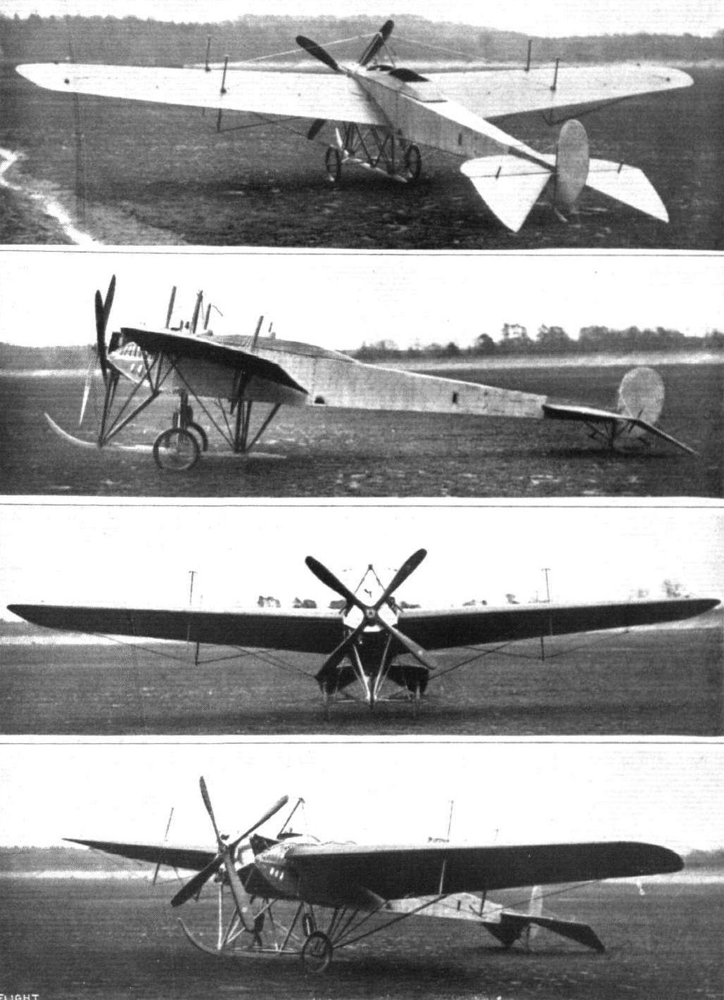
The Flanders monoplane from different points of view.
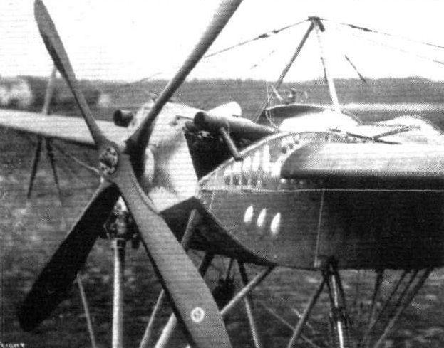
The front section of the Flanders monoplane, showing the mounting and shielding of the 70-h.p. Renault motor.
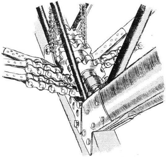
WARPING GEAR ON THE FLANDERS MONOPLANE. - The sprockets taking the stout warping chains are machined from Duralumin.
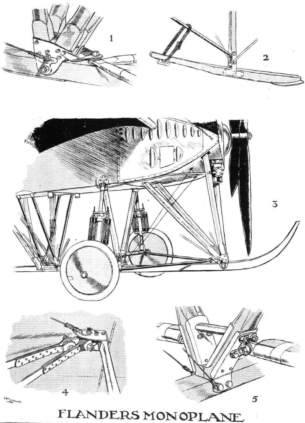
DETAILS OF THE FLANDERS MONOPLANE. - 1. The steel fitting for the assembly of the front two pairs of chassis struts to the skid, and the attachment of the radlus-rods. 2. The light tail skid. 3. General sketch of the front of the Flanders monoplane, showing the disposition of the chassis. 4. The king-post attachment. 5. The fitting to which the axles are hinged.

DETAILS OF THE FLANDERS MONOPLANE. - 6. The Flanders steel ribbon strainer. 7. The automatic pump arranged in the slip stream of the propeller, which supplies compressed air for feeding the petrol from the main tank, low down in the fuselage, to the carburettor. 8. The fitting by which the chassis compression springs are attached to the fuselage. 9. General view from above, showing pilot and passenger's seats and double control. 10. The clever compression strut. 11. The attachment of the compression strut to the axle. 12. The neat skid that protects each rear king-post from contact with the ground.

THE FLANDERS MONOPLANE. - Plan, front, and side elevations to scale.
Flight, April 20, 1912.
A Flight over Windermere.
ON Saturday last Mr. Gnosspelius made a fine flight on his single-decker aquaplane over Lake Windermere. Starting from Mr. Wakefield's headquarters, South of Bowness, the machine flew down the lake to Lakeside, then up to the Beech Hill Hotel, back again to Lakeside, and then back to the hangar. It was in the air for some twenty minutes and although it did not rise very high it flew very steadily.
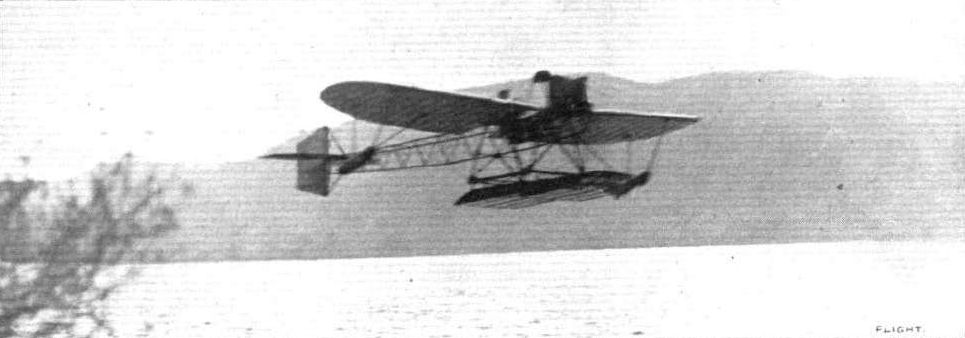
The Gnosspelius hydro-monoplane on Lake Windermere during a 12-mile flight under the pilotage of Mr. Kemp last week.
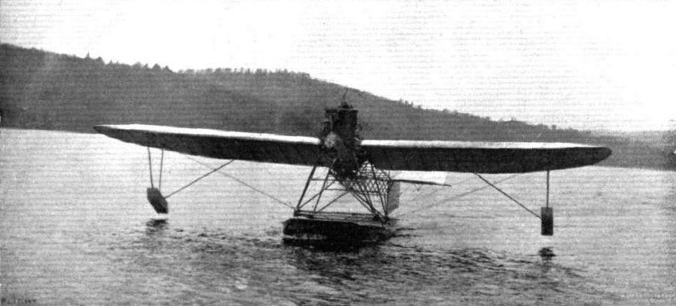
THE GNOSSPELIUS HYDRO-MONOPLANE ON LAKE WINDERMERE. - View from the front after alighting on the water.
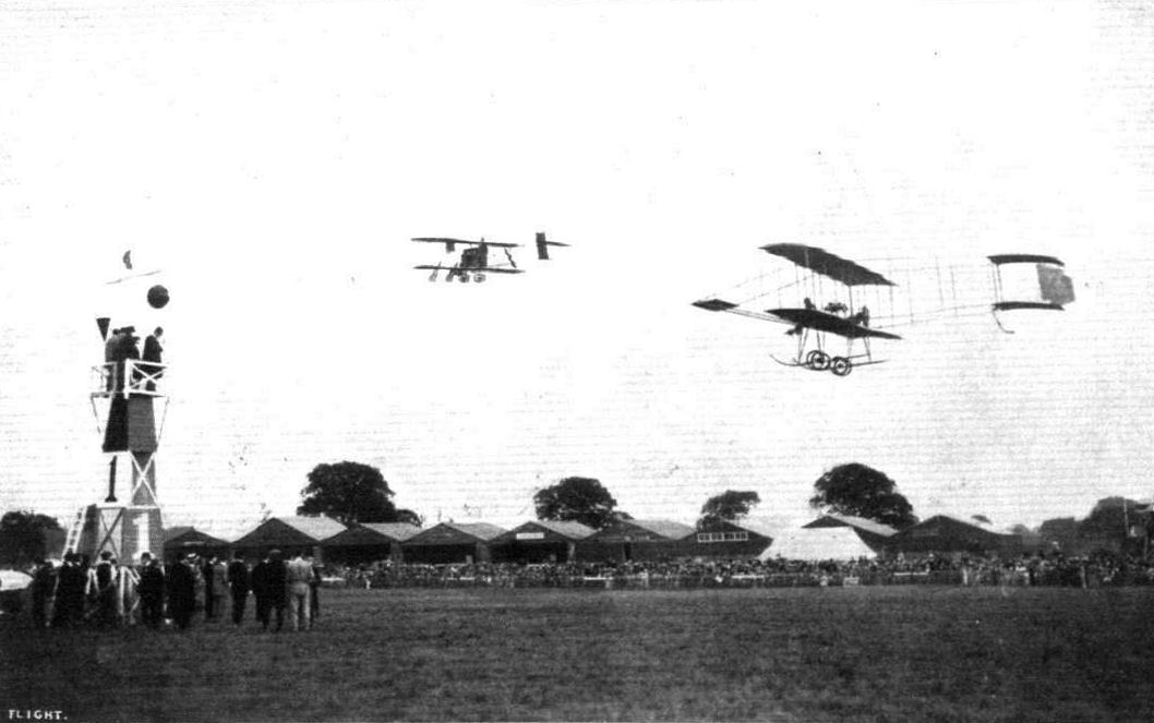
Raynham, on the Burgess-Wright and Lewis Turner putting up a fine finish in the order named for the "Shell" Speed Contest at Hendon on Aerial Derby Day.
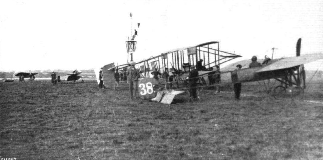
READY FOR THE FIRST HEAT IN THE SPEED COMPETITION AT HENDON ON SATURDAY LAST. - Messrs. Hall, Lewis Turner, and Louis Noel ranged up to the taklng-off line.
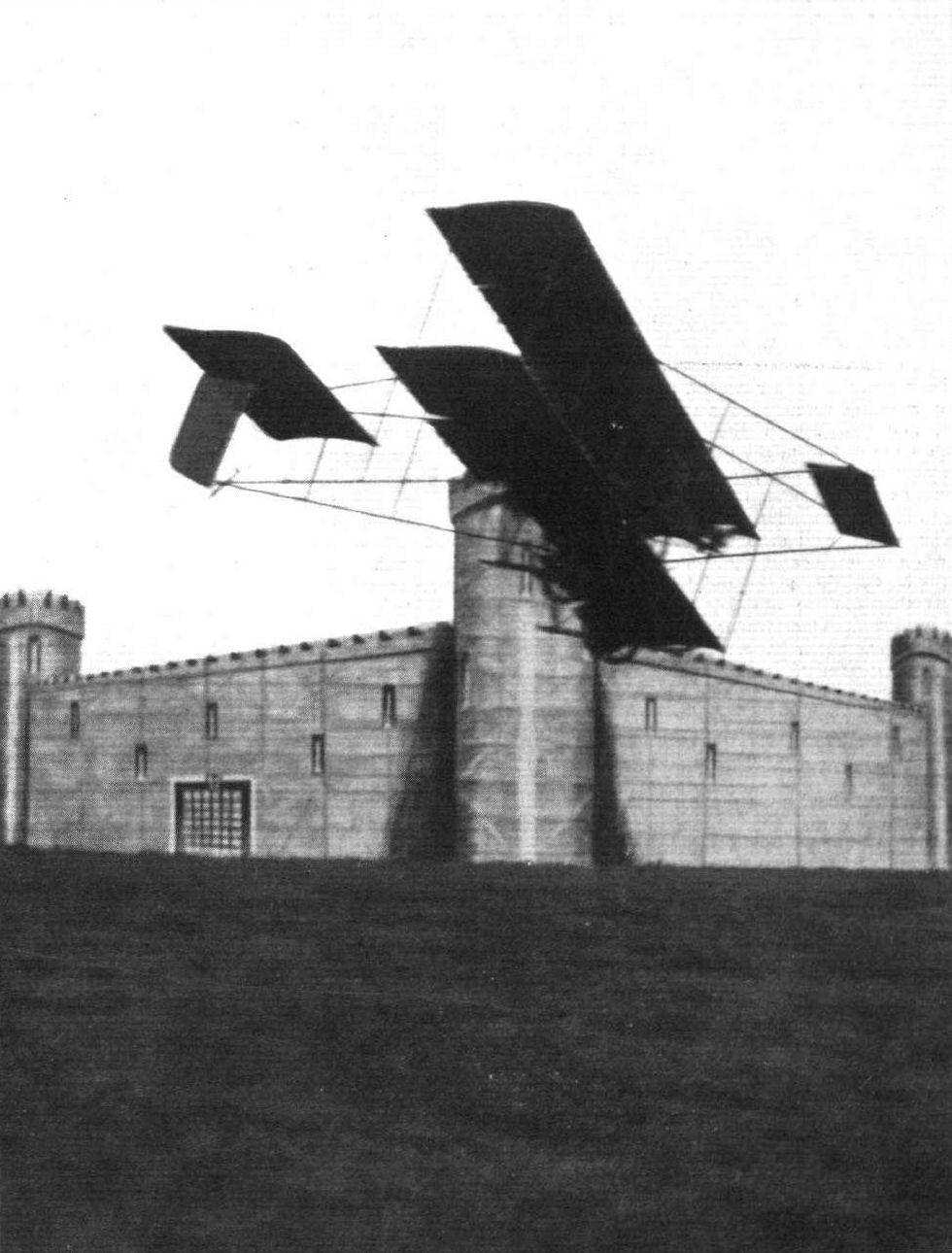
Mr. R. T. Gates, on the Grahame-White biplane, flying adjacent to the "fort", which was one of the features of the demonstration on Saturday at the Hendon aerodrome.
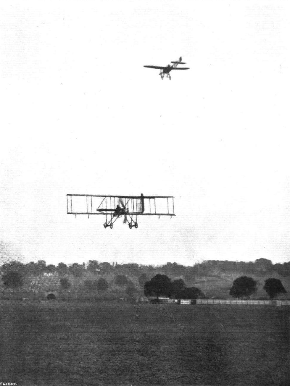
MONOPLANE VERSUS BIPLANE AT THE LONDON AERODROME, HENDON. - Mr. Lewis Turner on the Grahame-White 'bus and Mr. Hall on a Bleriot monoplane.
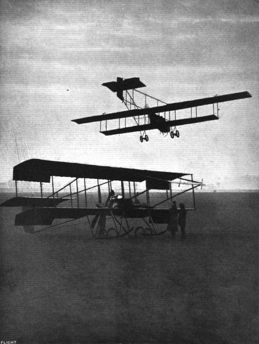
A MISTY EVENING AT HENDON. - Mr. Claude Grahame-White flying a Henry Farman in the rising haze at Hendon Aerodrome. On the ground is seen the Grahame-White biplane.
Flight, October 26, 1912.
THE HANDLEY PAGE MONOPLANE.
AMONG the disappointments of the Military Trials was the limited opportunity that they afforded for appreciating the proper merit of the Handley Page monoplane. The machine entered therein was one specially built to satisfy the conditions, as the firm's standard model, which had been flying quite well before the trials, was not suited to the requirements laid down by the tests. The trials machine, however, was unfortunately delayed in construction, and when at length it "got going" towards the end of the trials, a forced landing down wind damaged a wing, which put it out of action again for the few remaining days of the event. We thought then, and we think now, that it was particularly unfortunate that the machine in question was thus prevented, by a series of natural handicaps that are incidental to business of this sort, from performing in public and especially under the eye of the military observer, for although we have no cause to express an opinion one way or the other as to the probable military qualities of the machine, the fact remains that Mr. Handley Page has been bold enough to design on lines that are out of the ordinary, and has had the courage of his convictions to keep at work on the same main principle from the day that he first went into the industry.
Moreover, that principle is related to the problem of stability inherent in design, and the question of natural security in the air is one of even greater importance to aviation at large than is the evolution of a military aeroplane to the nation in particular. For these reasons, therefore, we consider that there is good cause to regard the virtual absence of the H.P. monoplane from the military trials both as a disappointment and a misfortune.
Since that event, however, the latest machine, which we illustrate by a series of photographs, sketches, and scale drawings, has been doing extremely good work at Hendon, whither the firm has transferred its flying headquarters from the secluded aerodrome at Barking where the pioneer days were spent. Probably all our readers are aware, and if they were not hitherto aware they will at least have observed already from a mere glance at the pictures, that the characteristic feature of the Handley Page monoplane is the crescent-shaped plan form of the leading edge of its wings. The crescent plan form is, however, not everything, for there are two other characteristics less easily illustrated in general views, which are of even greater importance to the stability, that it is the object of the design to obtain. One of these is the reversal of curvature of the wing section as it approaches the trailing edge, and the other is the graded camber from shoulder to tip, whereby the wing section measures some seven or eight inches deep where it is adjacent to the body, while the positive camber is entirely washed out at the upturned extremities.
These features - the crescent entering edge, the reversed curvature of the trailing edge, and the graded camber of the wing section from shoulder to tip - are all associated with the general problem of conferring on this machine a degree of inherent stability, which is its whole object and raison d'etre. The reversed curvature of the trailing edge introduces the principle of the fore and aft dihedral on a very short base; that is to say, while it tends to neutralise the retrogression of the centre of pressure, its lack of fore and aft length probably handicaps it in damping out any oscillation that has once commenced. Although it is claimed that the plane, as such, is naturally stable, the Handley Page monoplane in particular is fitted with a tail in order to enhance the natural damping tendency and to provide the pilot with adequate means of exaggerating the effect when necessary.
The lateral stability of the machine is associated with the graded loading and the retreated tip, and on this point Mr. Handley Page has a theory of his own, which we explained in FLIGHT some time ago, but of which we give another brief outline now for the benefit of our readers who have not studied the question previously. His argument is that the graded loading tends to produce a diagonally outward flow of the relative air stream under the wing tips. The effect of a side gust, according to the designer, is to change this diagonal outflow into a flow parallel to the body and so to diminish the relative velocity as illustrated by the vector thus produced in the triangle of velocities. Thus, Mr. Page argues that instead of increasing the relative velocity on the near wing that it is, in fact, reduced by a side gust, and that in consequence the near wing does not tend to tilt up.
The subject of lateral inherent stability and the theories properly to be associated with designs like the Handley Page is one that lends itself to extensive discussion, and some of our readers might with advantage take the matter up in our correspondence columns, for we feel sure that they would derive much interest therefrom. We are none too certain that a satisfactory explanation of the true theory in this matter has yet been advanced, and it is indeed unlikely that it should be until we know more about the nature and dimensions of a gust. For the time being, however, it is good mental exercise to picture possible effects on a broad scale, and to devise simple theories to suit the cases. Mr. Handley Page's theory belongs to this category, and should serve as a basis on which to open a discussion. Particularly, for example, would it be interesting to consider the influence of the change of effective chord length on the argument in question, for it will be obvious that when the relative wind blows obliquely across a wing, it suffers a different downward acceleration as compared with the conditions obtaining when it flows straight along the normal chord. It might well be, for instance, that a change of direction from an oblique to a fore and aft direction might actually increase the downward acceleration, and, therefore, the lift, in spite of the fact that the new velocity vector in the horizontal plane has been diminished. These considerations apart, however, the fact remains that many of those who have especially studied the question of inherent stability have come round to the view that the crescent entry and graded loading, carried to the point of a negative angle at the tips, are the principles that offer the greatest opportunities for a successful issue to their practical application. Jose Weiss was one of the first to experiment in this country with bird-like models - and you have only to look at a bird to see that the crescent entry, fixed shoulder and thin tip are characteristic features of many natural wings in flight - with which he attained a measure of success that has never received the recognition that is its due. Gordon England, as readers of FLIGHT will recollect, was the very courageous pilot who ventured to glide in these small man-carriers, which were devoid of all sort of mechanical control. Etrich is another well-known name associated with monoplane construction along these lines; while Dunne, who claims to have started his experiments with models of this description before anyone, is convinced that the true solution of inherent stability in wings that are not under muscular control lies in a modification of designs such as the Handley Page, whereby the entering edge is caused to dip more and more as it approaches the tip of the wing. Especial interest attaches to this idea, in view of the observations of Dr. Hankin, whose articles on bird flight will be fresh in the minds of our readers. It will be remembered that Dr. Hankin put it on record that the birds under his observation in India were in the habit of making stabilising and directional movements by turning down the leading edges of their wings. Wishing to confirm his observation by anatomical evidence of its possibility, he made a dissection, from which he found that muscular arrangement of birds' wings not only permitted of the movement described but were incapable of making any other movement that could possibly be mistaken for it. Arguing on broad lines, therefore, one may say of the Dunne that it is a wing with a permanently down-turned extremity in order to secure a constant "attitude" of stability so that it may be safe in emergency at the expense of, perhaps, some efficiency in normal flight.
It is hardly necessary for us to add any lengthy remarks on constructive detail of the H.P. monoplane, seeing that what is specially interesting forms the subject of sketches that are far clearer than words, while points that have not been sketched are not readily to be otherwise described. The whole design lends itself to a substantial and straightforward construction, the only difficult matter being the building of the first pair of new wings, which, as they have no two ribs alike, does involve some considerable labour and expense in the first instance. Once correctly proportioned, however, there is no difficulty in reproducing duplicates in the ordinary way. It is interesting to observe that the grading of the camber of the wings is effected almost entirely on the top surface, which permits of an exceptionally deep front spar and, at the same time, facilitates a gradual tapering thereof towards the extremities so that it can be built more in accordance with the principles of cantilever construction than is possible with a wing section uniform throughout and shallow enough at that.
Ash is the principal timber used in the construction, and the backbone of the machine, which is built of it, consists of a rectangular lattice girder that is entirely enclosed by fabric. Externally, this fuselage does not show its rectangular section, as the fabric is carried to a lower boom so as to provide a V section keel, and is also stretched over light formers above the girder so as to provide a kind of turtle-back deck.
Now that our readers have had an opportunity of studying the details of the machine more closely and of realising from the explanations of the designer himself what constitutes its raison d'etre in the world of flight, they will doubtless follow with especial interest its progress as recorded in the ordinary course of events in the news columns of FLIGHT, and they will doubtless feel with us that the firm well deserves success after its strenuous efforts to "get there." These efforts and the great expense that they have inevitably involved have been well worth while in any case. It is the price paid by the pioneer, and although the man who foots the bill may get little credit for his sporting determination to win, he can at least lay the flattering unction to his soul that he is none the worse off for the lack of it - if a material award does come later it will be doubly sweet on that account. Such quiet persistence is of the kind of which the flight industry is in the greatest need. Continual effort, and still more effort on the top of that, is the only thing that will put England uppermost in the air and it is the men who keep on doing it without worrying about immediate results who are building up to a pinnacle of future supremacy that we only trust they may live to see and enjoy.

The Handley Page monoplane.
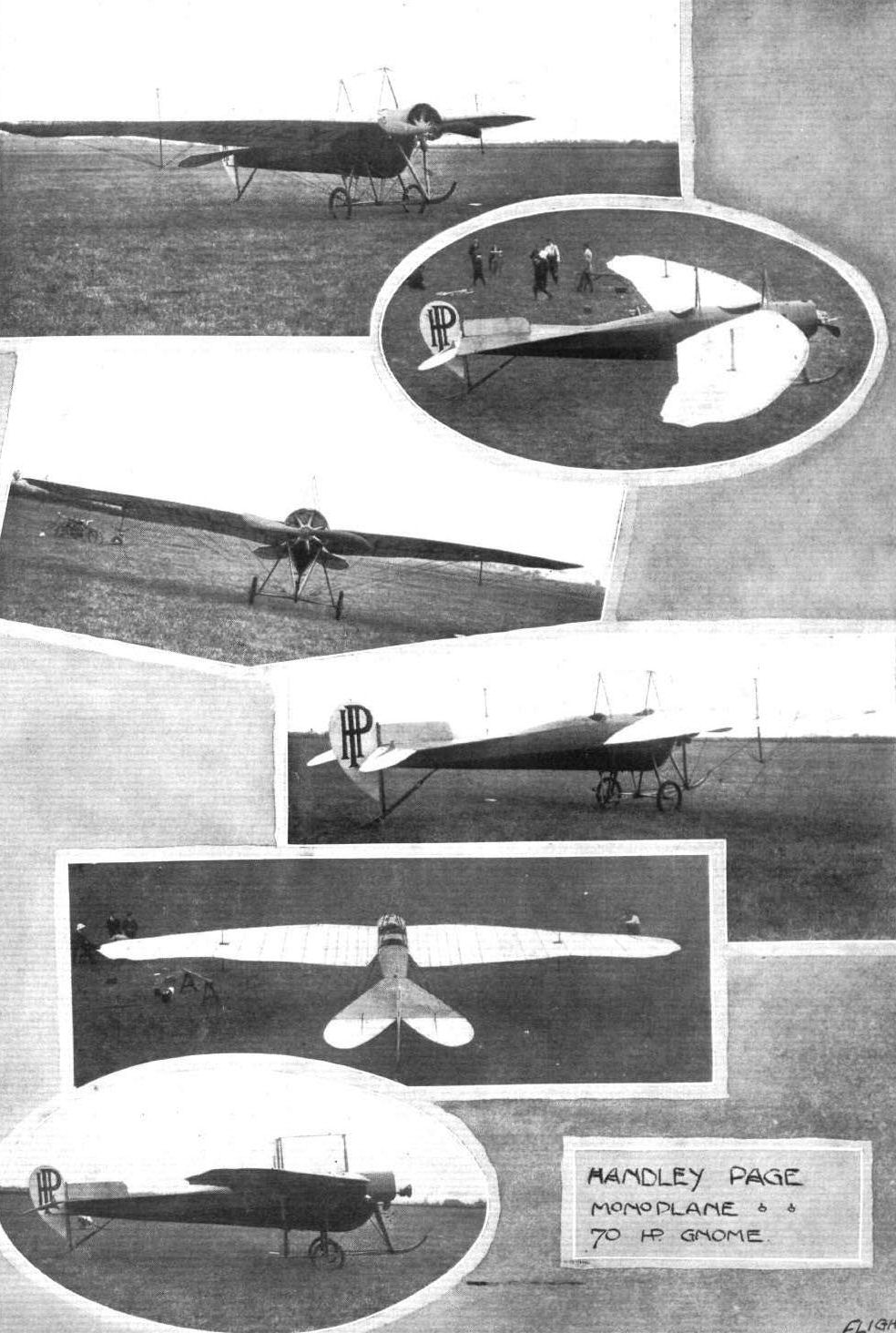
THE MILITARY COMPETITION MACHINES. - It is a similar machine to the above that Messrs. Handley Page are entering in the trials. The main differences of the Military machine from the one appearing in the above photographs are that pilot and passenger sit side by side, and the tail is somewhat changed.
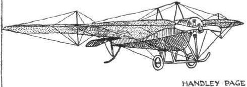
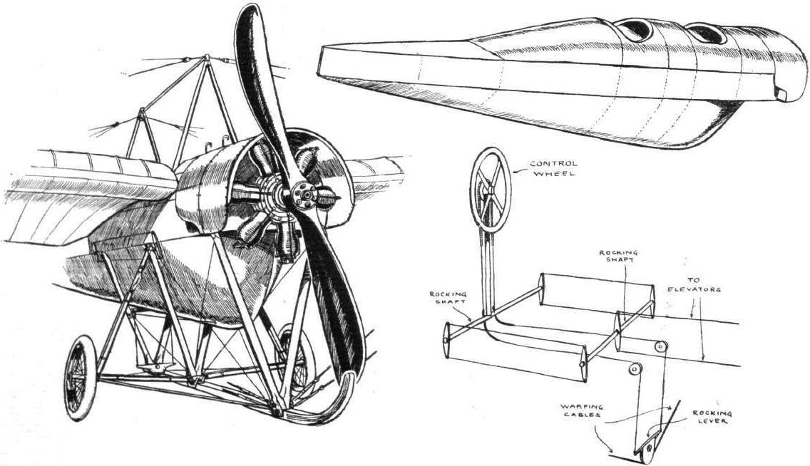
The Handley Page monoplane, showing, on the left, general view of the chassis, & c; top right, diagrammatic view of the fuselage; and, beneath, diagram of controls, the rudder bar not being shown.
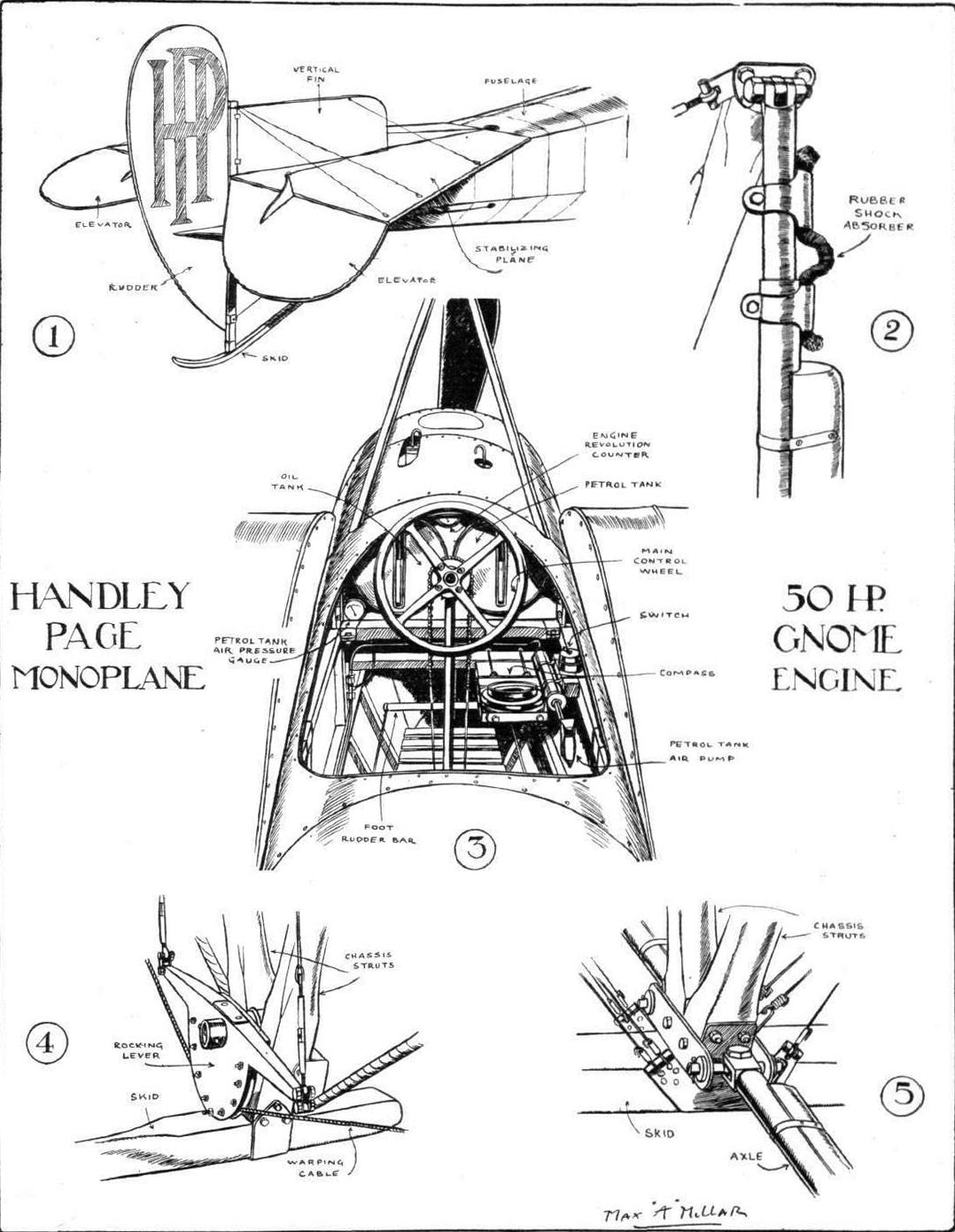
HANDLEY PAGE MONOPLANE. - 1. General view of empennage. 2. Rebound shock-absorber on chassis vertical wheel struts. 3. General view of pilot's cockpit. 4. Warping gear details on chassis. 5. Fitting of axles to chassis-strut
joints.
joints.
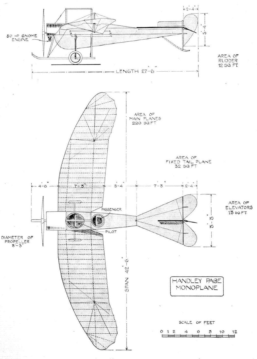
THE HANDLEY PAGE MONOPLANE. - Plan, and elevation to scale.
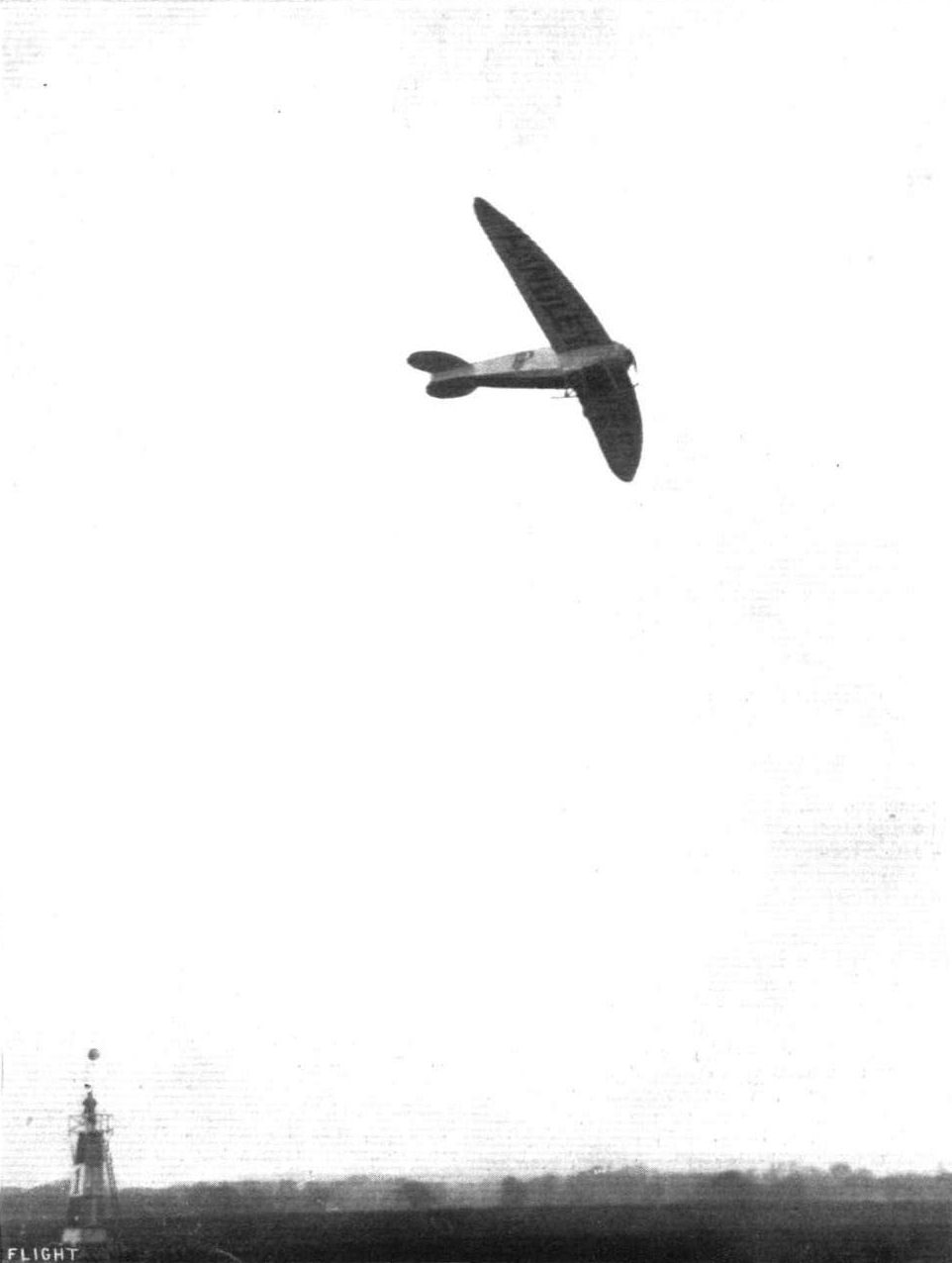
The graceful Handley Page monoplane in flight at the London Aerodrome last week-end.
Flight, June 22, 1912.
OUR FRIENDS ABROAD.
From Rangoon, Burma, comes the following letter from Mr. W. C. England, of the Burma Motor and Engineering Company. Mr. England, it will be remembered, graduated at the Grahame-White School at Hendon, and took back to Rangoon with him the Howard Wright biplane fitted with a 40-h.p. E.N.V. engine. He says, "I might say I have experienced considerable difficulty in getting the engine to pull up to its maximum power owing to the difference in carburation in this hot country, and not until I received a new carburettor from England which could be adjusted could I get the machine to rise off the ground. I find that the air is much lighter here than in England, and you require to obtain a far greater speed in order to reach a decent altitude.
"A day or two ago I had the machine out at Mingaladon on the golf club grounds there, and made a short flight. We did better, however, on the following Saturday morning. We had her out of the shed soon after half past five, and made several flights. On Sunday morning, too, we had her out again for trial, there being a number of the members of the Rangoon Golf Club and their friends present. Returning to the shed 1 had the misfortune to run into a rather large ant heap and snap a wire, which caught in the propeller and pulled the right half of the landing chassis out by the roots. However, I have spares, and I don't think it will take very long to repair the damage.
"On one of my trials I reached 150 ft., which is the best I have been able to get on this machine up to the present, it being a Howard Wright biplane fitted with only a 40-h.p. E.N.V. engine. Another great drawback I have had to contend with is, being unable to get a suitable aerodrome, the ground being so hard in the dry weather, and in the wet weather it is so cut up by the cattle. You must remember we get six months' continuous rain, and the ground gets very soft that the cattle cut it up terribly. Then six months' sun comes along and bakes it, so that it is just like running over a brick field.
"This year's rain is just about to start, and I intend, near the end of the wet season, to roll the ground in order to get a good surface for next year. I am just waiting to see the results of this trial flight, and if the public come forward, as I expect them to, I will try and get out a more powerful machine for passenger carrying and cross-country flights.
"I am enclosing a photograph of my machine on the ground.
"I may say that some time ago I read in your columns of a gentleman from India stating that he has had a lot of trouble with ants in eating away the wood. This I have not had happen here in Burma, my machine having stood in my hangar for over six months now, and there is absolutely no sign of their interference, bar that anthill I came to grief over.
"This machine was absolutely dismounted at the Hendon aerodrome before I left England, taking all the planes into sections, also stripping off all the old canvas. I have completely reconstructed it here, and instead of re-covering it with single canvas with pockets for the ribs, I covered it double. This, I think, has greatly improved the machine's flying and stability, as I can assure you I never sat in a more comfortable machine. It rises from the ground absolutely without the slightest use of the ailerons."
Flight, July 20, 1912.
AIR EDDIES.
ONE of our photographs this week illustrates well the curious accident that overtook Lewis Turner when flying the Grahame-White School Howard Wright biplane over to "Hylands" some three weeks ago. It was misty, and he had to descend near Harlow. Starting again, he rose above the trees, but was blown down below their tops. He could have landed on a limited space between them, when some people crossed in front of him. In avoiding them he struck the trees about 30 ft. from the ground. He was thrown forward, but managed to clutch an armful of small branches, and so saved himself from falling to the ground. The machine fell - but with little damage. He merely climbed down, little the worse for it all.
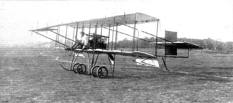
Mr. W. C. England on his E.N.V.-englned Howard Wright biplane at Rangoon, Burma, where he has been introducing aviation at the Rangoon Golf Club at Mingaladon.
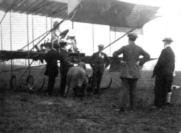
Mrs. Stocks just before starting for a flight in the Howard Wright biplane at Hendon last week-end is introduced to the Daily Mirror's "Baby Jumbo," but unfortunately (?) Mrs. Stocks already had the passenger seat occupied, and Jumbo therefore was not invited for a spin.
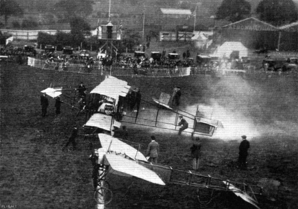
THE WEEKLY FLYING MEETINGS AT HENDON. - Mr. Lewis Turner on the Howard Wright just getting away in the cross-country handicap.
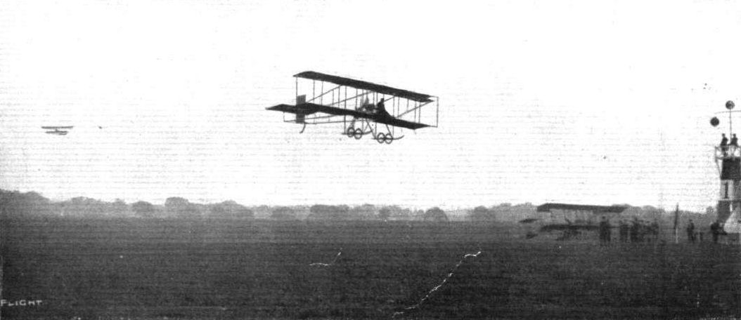
Mr. Lewis Turner finishing first and Mons. Verrier second in the second heat of the Speed Handicap at Hendon on Saturday last.
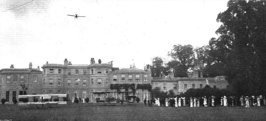
Guests at Mr. Claude Grahame-White's wedding at Sir Daniel Gooch's residence, "Hylands," watching Mr. B. C. Hucks flying on his Bleriot during the afternoon. On the ground in front of the mansion is Mr. Grahame-White's Howard Wright biplane on which he flew over, and on the right is the Aircraft Co.'s Maurice Farman biplane on which M. Verrier during the afternoon gave some remarkable exhibitions in a strong wind.
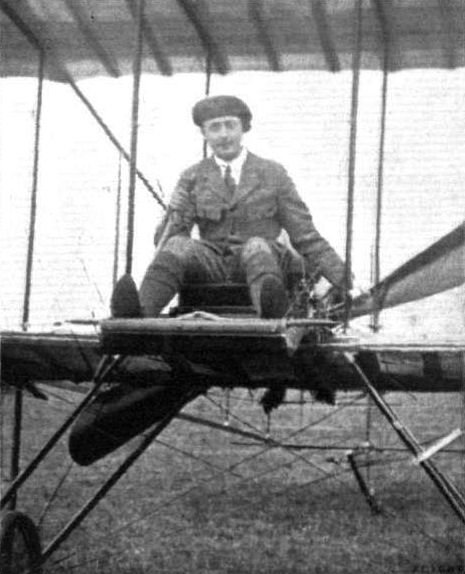
Lieut. B. T. James, who qualified for his pilot's certificate on a Howard Wright at Hendon on June 1st after the fourth day only in an aeroplane.
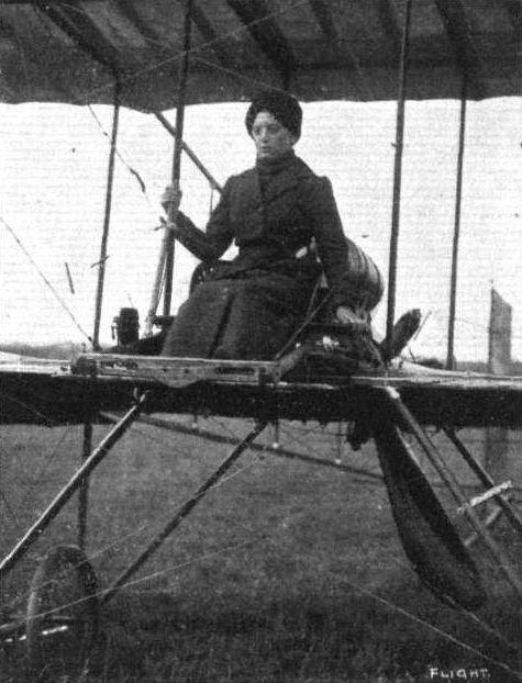
Baroness Schenk, one of the lady aviators who are practising at Hendon Aerodrome.
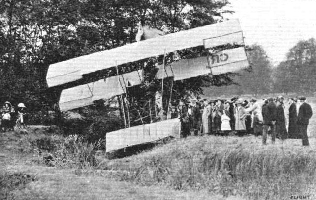
How Grahame-White's School Howard Wright biplane appeared after it had dashed into trees. Apart from the broken elevator, splintered propeller, two or three ribs smashed, and a damaged tail tip, no further damage was done.
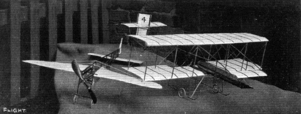
MR. C. HEMIN'S BLERIOT AND HOWARD WRIGHT MODELS. - The latter is fitted with a compressed-air motor with which some good flights have been obtained.
Flight, December 14, 1912.
A VISIT TO THE JEZZI CAMP AT EASTCHURCH.
IT was horribly cold and wet and, taking it all round, an unusually miserable prospect when I rolled out of my bed at half-past seven in the morning. Even getting that far was something of an accomplishment, I thought. There did not seem much use in going down to Eastchurch that day. Eastchurch, with its perfectly wonderful train service, is quite a sufficient handful on a fine, warm day. But it was no use meditating on things in general, for an appointment is an appointment whatever the weather may be like. And so it was that three shivering mortals - I had been, meantime, joined by two of my colleagues - turned out of the lethargic little train that occasionally runs from one end of Sheppey Island to the other, and made their way as cheerfully as the weather conditions would permit towards the flying ground.
Everything was shut down and not a soul was in sight, as might have been expected. A buzz from Messrs. Short, Bros.' works, however, told that there was plenty going on inside.
We found Mr. Jezzi quite alone in overalls, with a scarf round his neck and carpet slippers on his feet, busy in his shed. He was hard at it, fitting wind deflectors between the two V-set rows of cylinders of his J.A.P. engine so that it would keep cooler when running. And perhaps the old motor deserves it, for it has seen Mr. Jezzi through a hard two years of experimenting. It was formerly fitted to Mr. Jezzi's first machine, a biplane somewhat similar to a Wright machine, but driven by two tractors in front, which were supplemented to some extent in their efforts by a third, a miniature one in front of the motor, whose main duty was to keep the engine cool.
The machine did a lot of flying in its time before it was scrapped to give place to the interesting little machine that Mr. Jezzi has been experimenting with for the past nine months. On it, the old machine, Mr. Jezzi passed the tests for his pilot's certificate, and his friend, Mr. Arthur Cooper, who has cycled down to Eastchurch most week ends, lending invaluable help during the whole time Mr. Jezzi has been there, would have done so, too, for he used to handle the machine extremely well in the air, had it not been for a series of minor mishaps.
The present machine is a most attractive-looking miniature biplane. It was built in its entirety by Mr. Jezzi himself in a workshop adjoining his private house, south of London. That he should have been able to complete it at all is rather a wonder, for a city man has not, as a rule, much time to devote to a hobby. But notwithstanding strenuous days in the city, Mr. Jezzi has put in equally strenuous evenings, and more often nights, in his workshop following out his fascination for aviation. Week-ends and business holidays are the only periods when he can get away to his shed at Eastchurch. I recall that I felt rather a hero rolling out of my bed at 7.30 a.m. This impression collapsed somewhat when it came out in the course of conversation that Mr. Jezzi had turned out, in pitch darkness, before six that day, and had come down all the way by road on his 2 3/4-h.p. Douglas - and on such a morning!
But it is not often that business will allow him to get down to Eastchurch so early. It is usually after lunch time that he arrives at his shed. About 10 feet of one side of his hangar is partitioned off into a living and two sleeping rooms, and these are invariably inhabited by Mr. Jezzi and his friends from Saturday midday till Sunday night; then it is a case of getting back to town in readiness for business next day. Thus work proceeds and has proceeded for the past two years.
And the outcome? Amongst many things, a tremendous fund of constructional and flying experience, a constitution hardened and made perfectly lit as the result of the open-air life that practical experimenting such as this offers - and an extremely promising biplane. And so we gather round the machine, admiring its many neat points. Meanwhile, Mr. Jezzi returns to his work on the motor. At last the wind deflectors are fitted, and he proceeds to test the engine. Shutters at the end of the shed behind the machine are taken down - otherwise they might be blown down by the propeller slip-stream as soon as the engine is started. A Navy man pulls over the propeller and the motor roars into its note. The place gets full of blue smoke, and with the draught we all get well nigh frozen.
It was with some amount of satisfaction, therefore, that we heard the cry of "Tea's ready!" coming from the little living room.
Inside there was a small stove packed to its uttermost capacity with white hot coke. The effect on our spirits was remarkable. The blinds were drawn across the windows, and the four oil lamps were made to shed a comfortable light on the scene.
There were two sheets of newspaper on the table for a tablecloth, and on it were arranged enamel cups, and knives and teaspoons enough for a party of five, for Mr. Arthur Cooper had by then arrived, bringing with him his contribution towards the "stores" - two big loaves of bread and a pound of butter. In addition, Mr. Jezzi had produced from his larder - a propeller box nailed to the wall - liberal supplies of lovely preserved ginger and jam.
Let us draw the curtain over the picture of a party, exhibiting enormous appetites, rapidly becoming cheery under the comforting influence of honest bread, butter and jam and steaming tea, for it is all in a day's march when you are learning the gentle art of aviation.
The Machine.
The present Jezzi biplane is a machine that has been designed to fly at a high speed with comparatively little power. The biplane's normal speed with the motor pulling moderately well is about 65 m.p.h., which is no mean achievement with an engine power of 35-h.p., especially as the machine's capabilities do not alone lie along the line of speed. It is a common occurrence for Mr. Jezzi to take a passenger of 12 stone for a trip round the ground, while on one occasion he actually flew with a 16 stone passenger, although on this occasion the heavy load did make the machine drag its tail somewhat.
To obtain this efficiency Mr. Jezzi has endeavoured to cut away as much head resistance as is possible. There we find that there is only one rank of struts - carefully stream-lined ones at that - between the planes, and that there are few cross bracing cables. The body of the machine, too, is covered in throughout its whole length with fabric, and is sufficiently wide against the tail to allow of the levers operating the rudder and elevators to be disposed inside.
The planes were, until quite recently, of 28 ft. and 14 ft., span respectively for the upper and lower spreads. Just lately, however, extensions have been fitted to the lower plane to bring it to the same span as the upper surface. Their maximum camber is relatively small, just 1 1/2 ins., their maximum thickness 2 ins., and their incidence to the relative wind in flight from 4 to 5.
In the construction of the machine ordinary but particularly clean spruce has been made use of almost exclusively. Indeed, the only other wood that is used, and the only section of the machine in which it appears, is English ash for the landing skids. For the landing gear our sketches show its chief characteristics, and little need be said, except that it is very solidly built and has given no trouble whatsoever, although it has had to take landings in some of the roughest parts of the Eastchurch ground. The control of the biplane is, perhaps, the simplest system that is in use at the present day. It had a vertical lever, universally jointed, which controls the elevators and the wing warping, and a pivoted foot bar that operates the rudder.
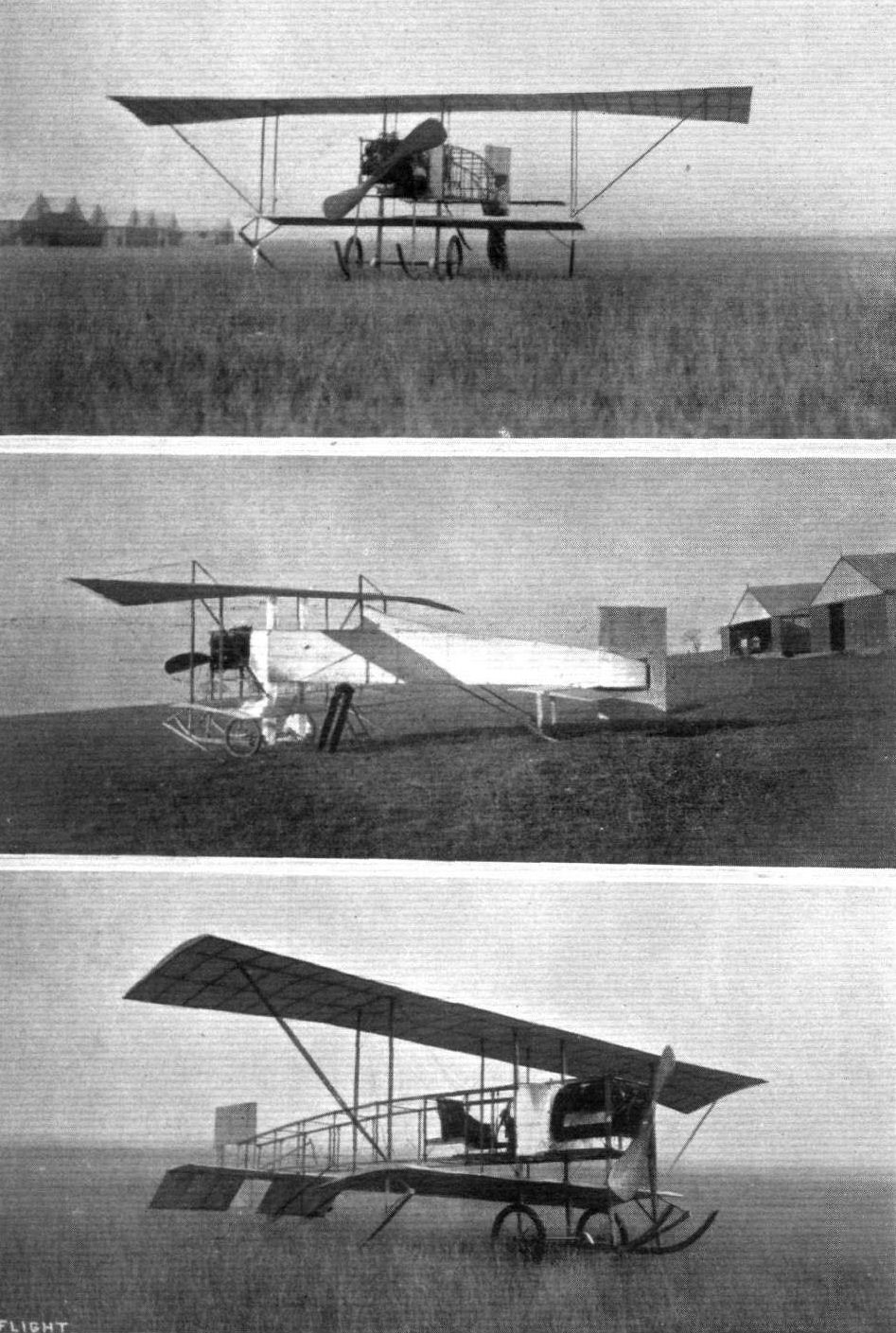
THE JEZZI BIPLANE. - The top and bottom photographs of the above set of three were taken in the early part of this present year. The central photograph was obtained a month or two later when the body had been covered in with fabric, and king posts and wire bracing arranged to support the top plane extensions in place of the compression struts that were originally used. Within the last fortnight extensions have been fitted to the lower plane as well, bringing it to tbe same span as the top one.
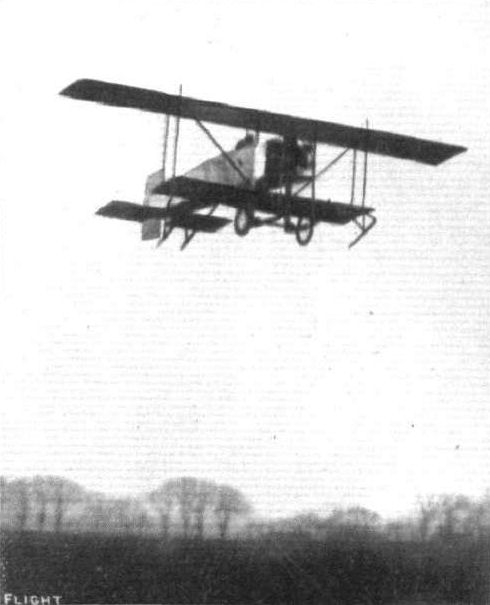
The attractive Jezzi biplane in flight - a photograph secured some two months since, before the extensions were added to the lower planes.
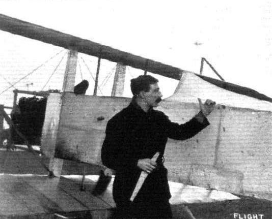
The machine and its constructor, Mr. Leo Jezzi.
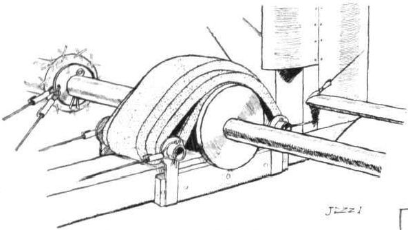
Details of the Jezzi landing gear.
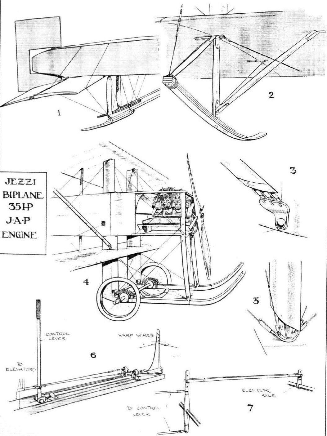
THE DETAILS OF THE JEZZI BIPLANE. - 1. The tail; it is so constructed that the levers operating the rudder and the elevators may be arranged inside, so saving wind resistance. 2. The laminated wing skid. 3. The attachment to the fuselage of the wires that take the main lift; they are of ten-gauge material, and it will be noticed that they are carefully enclosed in a stream-line casing of aluminium. 4. General sketch of the front of the machine. 5. One of the strut attachments. 6. Sketch showing the arrangement of the elevator and warping control. 7. Detail of the control, showing how adjustments of the elevator is effected.
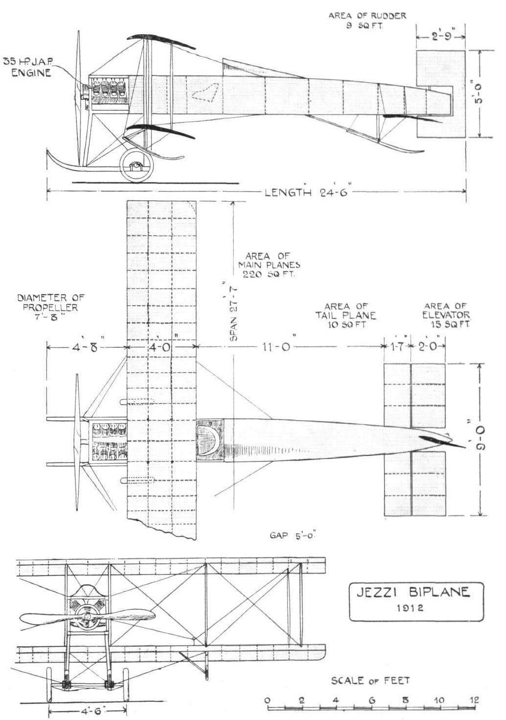
THE JEZZl BIPLANE. - Plan, side, and front elevations to scale.
Flight, June 8, 1912.
Good Progress with the "Water Hen."
LAST week some very fine flights were made by Mr. Stanley Adams on Mr. Wakefield's hydro-biplane over Lake Windermere, and regular passenger trips are now being carried out On Monday week seven passengers, including two ladies, paid their fees, and were carried for trips over the lake. Although the wind was gusty on Tuesday and Wednesday, further passenger voyages were carried out, and on Thursday Mr. Adams made a solo flight to Bowness and Waterhead, alighting on the water at the latter point. A stop was also made at Henholme, on the way back to Hill of Oaks. The visit to Bowness was arranged in connection with the annual sports, and the spectators were greatly interested in the evolutions of the "Water Hen" over the lake. About 22 miles were covered altogether.
Flight, December 7, 1912.
THE "WATER HEN".
THIS interesting hydro-biplane, which has been flying almost daily throughout the past year over Lake Windermere, may be said to have originated at Blackpool way back in 1909. This, perhaps, seems rather curious, since as far as our mind takes us back, power-driven flying machines to rise from water were scarcely even dreamt of at that time. It happened in this way. Most of those who now constitute the Lakes Flying Company were present at that memorable meeting. One of their number, Mr. E. W. Wakefield was more than usually struck by the amount of damage that was done through a machine, its pilot, or both, hitting solid ground. It occurred to him that if a machine could be made to rise from and alight on water and remain for the whole time over that liquid element, the chances of fatalities arising from accidents could be most effectively and materially reduced.
But at that time everyone was sceptical. The whole thing was impossible! It stood to reason that the friction and resistance of a hydroplane-float skimming over water would be infinitely greater than that of wheels running over ground. Further than that, as soon as the motor was started, would not the thrust of the propeller, necessarily high up between the planes threaten to push the nose of the float under water?
But, nothing daunted by general adversity of opinion, Mr Wakefield and a few of his personal friends decided, at any rate, to make a sporting effort at producing a successful water flying-machine. The experiments of M. Henri Fabre, at Monaco, with his extraordinary hydro-monoplane, and those of Glen Curtiss, in the United States of America, with his float-equipped biplane, were closely followed, and they taught many lessons. Then, again, Mr. Oscar Grosspelius had constructed a Bleriot-type monoplane on a broad float, which, being underpowered, had not, at that time, been successful in getting off the water. From it also many invaluable lessons were learnt, and so, having collected and tabulated a goodly collection of data by the summer of 1911, Mr. Wakefield commissioned Messrs. A. V. Roe and Co. to build for him a biplane of the Curtiss type. This was fitted with a single narrow float, much after the same style and shape as that fitted to the Curtiss machines in America. It, however, embodied several improvements that had resulted from the independent experiment.
Although, unfortunately, the machine itself was not quite as efficient a flyer as it was hoped, it nevertheless succeeded admirably as far as things went. It was flying freely during November, 1911, and had the distinction of being the first successful British hydro-aeroplane.
Meantime, representatives of the Company had been studying how things went on at Brooklands and Hendon, and, having picked up as many tips in construction as they could assimilate in the time, they returned to headquarters. As a result the biplane that we are describing in this issue came into existence. It was purposely designed to be a slow-flying machine in order that it might lift from the water at a low speed and be more comfortable for passenger carrying. The float fitted was of a new type, much broader and was stepped. The intended results were achieved at the first trial, and the machine has remained practically unaltered from that day to this.
During the seven odd months it has been in use over Windermere, it has made about 250 flights, and has carried over 100 different passengers.
As can be remarked from the photographs and sketches that accompany this brief description, the machine does not depart, in any great respect, from what is nowadays considered conventional practice. It has a Farman type of cellule, but the camber of its wings is considerably more marked than in that machine in order that it may lift all the more readily at slow speeds. The tail at the rear and the elevator in front are supported by triangular bamboo outriggers, and these surfaces are controlled from the pilot's seat by a typically Farman universal lever. Balancing is also carried out by the Farman system of aileron flaps.
The biplane has a speed range of from 33 miles to 45 miles per hour.
Undoubtedly the most interesting part of the whole machine is the gear that enables it to land and start off from water, for it must be remembered that at the time the machine was constructed, very little exterior knowledge of the subject was available. Unlike most water flying machines of to-day a flexible suspension is provided so that the float itself will not form too solid an abutment against the hammering of the waves. One of our sketches shows this point clearly. The float is built upon a latticed skeleton of silver spruce having three longitudinal bulkheads. Aluminium covers the bottom of the float, duralumin the sides, and Willesden canvas the top.
It may fairly be asked whether this type of float and undercarriage is equally well adaptable to aeroplanes other than of the type that it was originally designed for.
The Lakes Flying Company maintain that, excepting for minor modifications, their design of undercarriage can in every case be successfully used to convert a land flying machine into a water flyer. This, to some extent, they have themselves proved, for similar floats fitted to a monoplane and a tractor biplane have given every satisfaction in use. They had a share in producing, we believe, the first hydro-monoplane to lift passengers.
With a single float, balance naturally became necessary. Following on numerous tests, the "Water Hen" was fitted with simple air sacks mounted on springboards, and they have proved so serviceable that there has been no reason to change them.
Mr. Wakefield is characteristically modest when talking about the machine he has developed throughout these past three years. He claims that if the machine has done nothing else, it has at least proved his contention that it is better to get a ducking than to get badly smashed up. But, although he does not make a song about it, we know he has gone considerably farther than that.

HYDRO-AEROPLANES AND LAKE WINDERMERE. - Mr. E. W. Wakefield's Avro machine just rising from the waters of Lake Windermere.
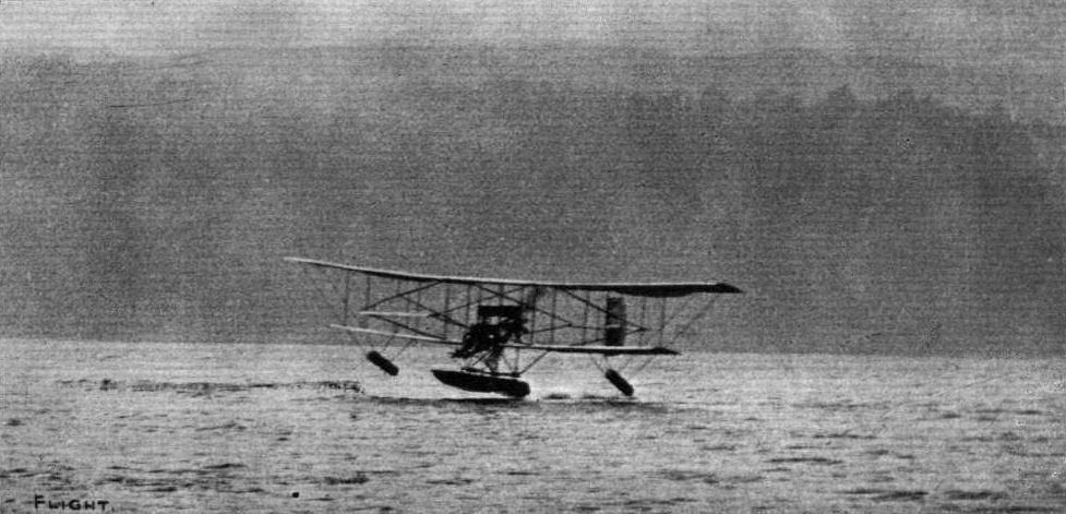
HYDROAEROPLANES AND LAKE WINDERMERE. - Mr. E. W. Wakefield's Avro biplane at the moment of alighting on the water of Lake Windermere after a long flight.

HYDRO-AEROPLANES AND LAKE WINDERMERE. - Above is a photopraph of Mr. E. W. Wakefield's hydroaeroplane in flight across this great lake, the floats being well seen from underneath. The aeroplane is the construction of Messrs. A. V. Roe and Co., and the float and balancers of Messrs. Borwick and Son of Bowness.
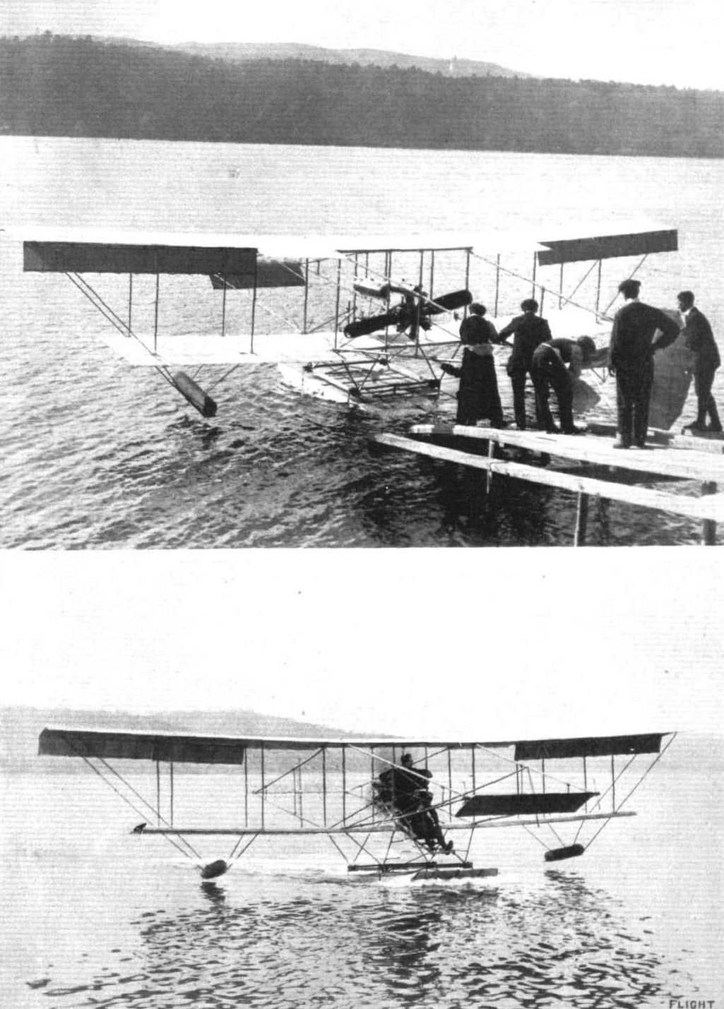
THE "WATER HEN" ON LAKE WINDERMERE. - Above, the machine being launched from the slipway that leads down to the water from the hangar. Below may be seen the machine, with a passenger up, just about to leave the water.

Mr. Stanley Adams bringing a passenger home in the "Waterhen," under her own power, on Lake Windermere. This hydro-biplane, with the exception of the propeller, which is an Avro, and the 50-h.p. Gnome engine, has been entirely designed and constructed at Lake Windermere by the Lakes Flying Co., of which Mr. E. W. Wakefield is the moving spirit.
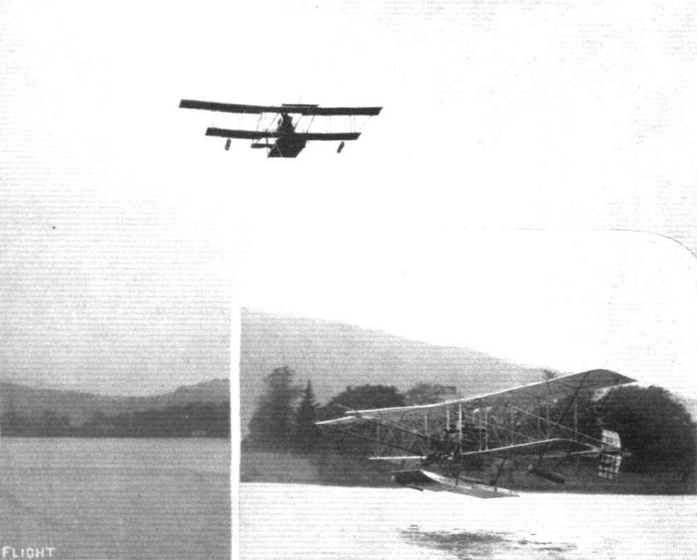
THE "WATER HEN" WELL UP OVER LAKE WINDERMERE. - Inset, the machine just after leaving the water.
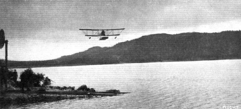
The "Waterhen" flying with passenger over Windermere.
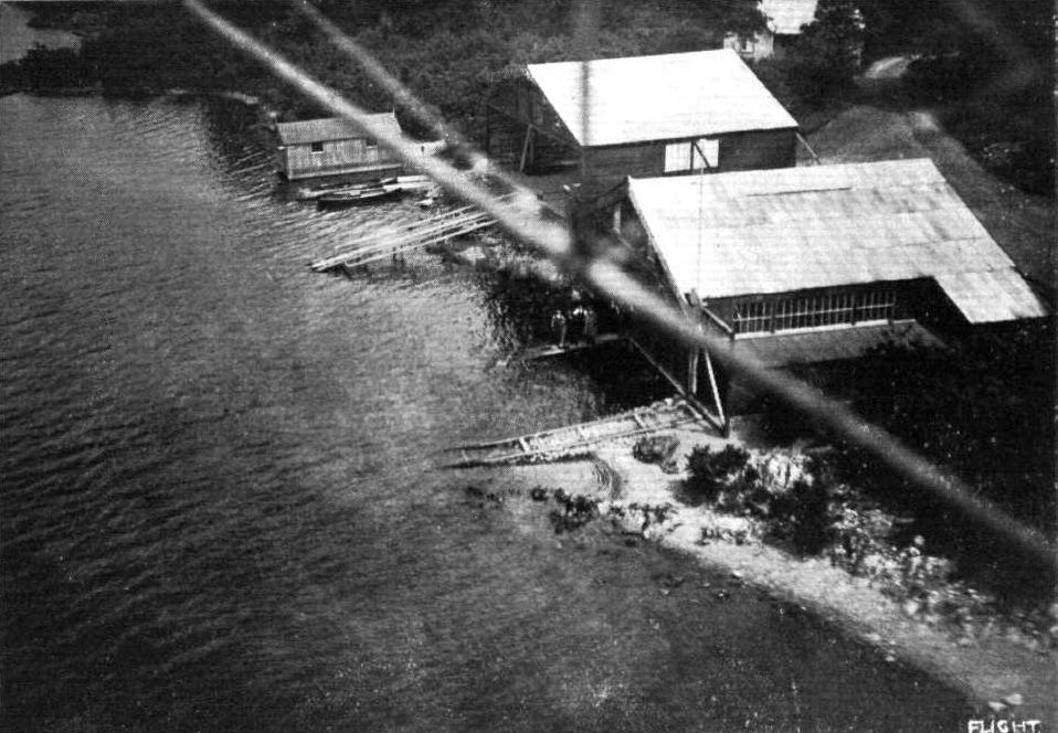
A snap of the Hill of Oaks aviation sheds at Lake Windermere, taken from Mr. E. E, Wakefield's hydro-aeroplane "Waterhen" when in flight.
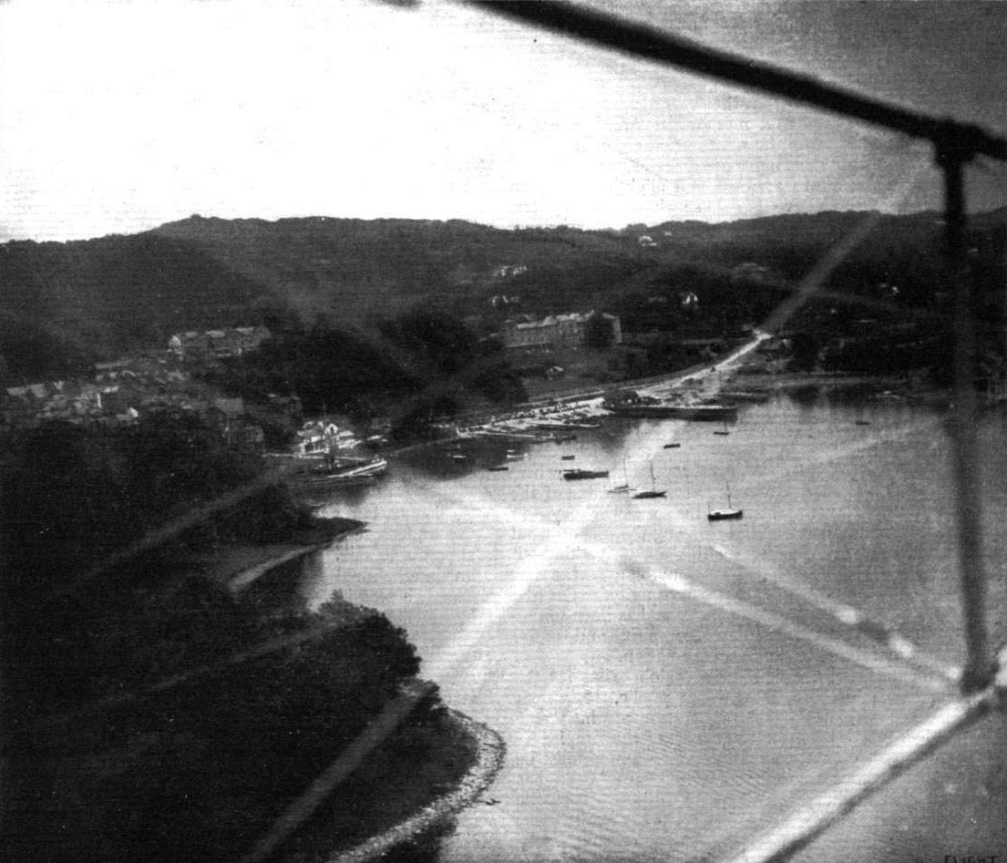
Bowness and the Belsfield Hotel, Lake Windermere, taken from the Lakes Flying Co.'s 50-h.p. Gnome-engined " Waterhen."
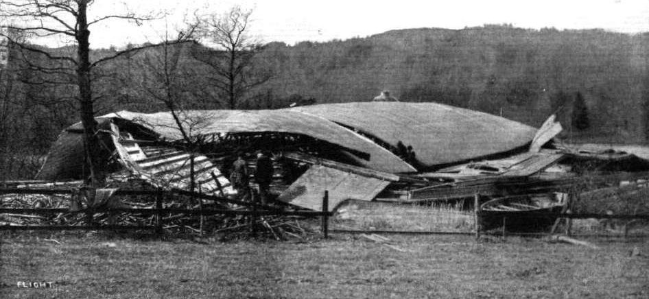
The gale which swept the country on Friday and Saturday accounted for the demolition of the hangar sheltering Captain E. W. Wakefield's two hydro-aeroplanes on Lake Windermere. In its collapse both machines were damaged, part of one of the planes being seen in our photograph of the wreckage protruding from the side. This incident, we presume, will be regarded as a score in their favour by the anti-aeroplanists of Windermere.
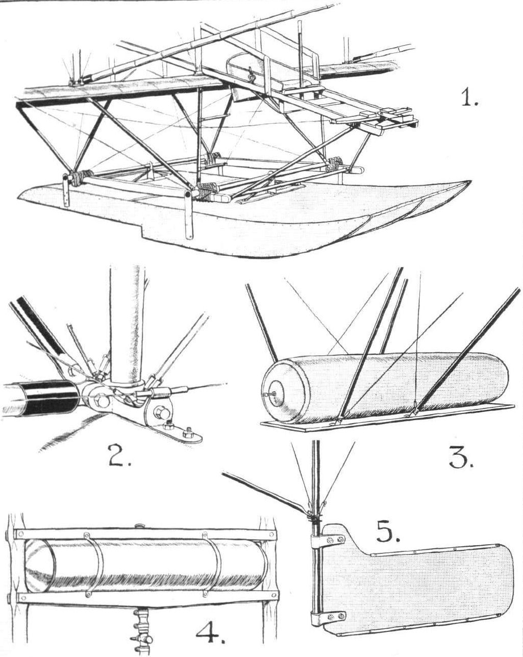
DETAILS OF THE "WATER HEN". - (1) The front section of the machine, showing the float ant its flexible connection to the cellule. (2) One of the outrigger fittings. (3) A balancer, an air sack mounted on a spring board. (4) Mounting of the oil tank. (5) Water rudder, working in con junction with the air rudder so that the biplane may be readily steered at slow speeds on water.
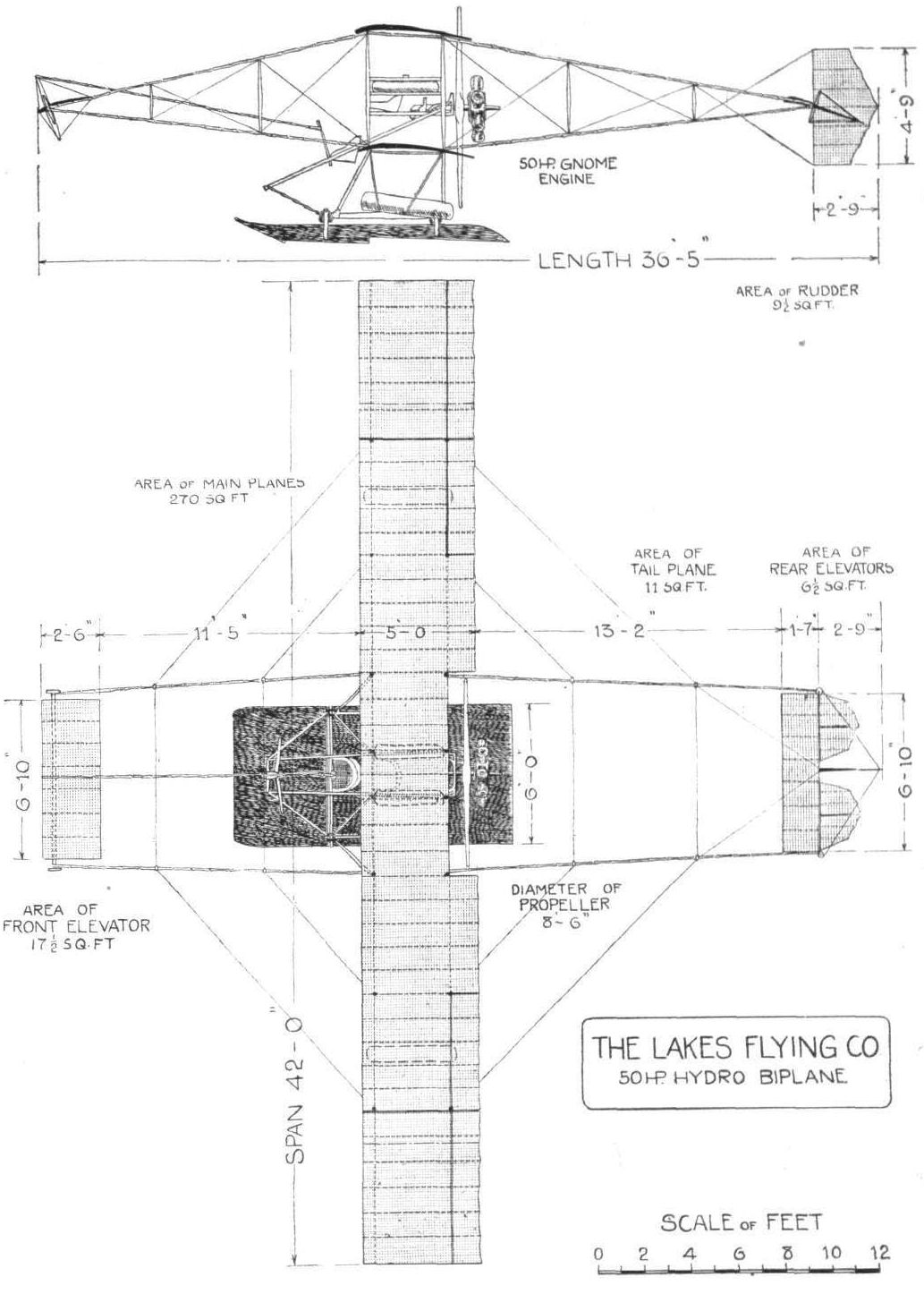
THE LAKES FLYING CO.'S HYDRO-BIPLANE "WATER HEN." - Plan and elevation to scale.
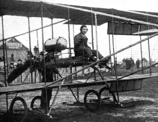
Mr. Herbert Spencer, who took part in the handicap races at Brocklands on the machine which he has re-constructed from the Macfie biplane.
Flight, February 24, 1912.
THE LATE MR. GRAHAM GILMOUR.
SATURDAY last, February 17th, was a day of mourning for the entire aviation industry, for just before noon on that day Douglas Graham Gilmour, one of our foremost English pilots, was claimed a victim to the triumphal progress of aviation. Enthusiastic, skilful, active, daring, but with his daring always tempered with a certain caution, he was one of those pilots whom the science and practice of heavier-than-air locomotion could little afford to lose. The details embracing this tragic incident are briefly these. Shortly after 11 o'clock he started away from Brooklands on the Antoinette-engined Martin-Handasyde monoplane, with the intention of making a cross-country flight. That he did not intend to fly to Hendon or down the river is rather borne out by the fact that he gave his mechanics to understand he would return within the hour. Passing over the Old Deer Park at Richmond at a height of what is generally estimated to be 400 ft., the machine, apparently without any warning, suddenly failed, and with its occupant was dashed to earth, a tangled mass of wreckage. Poor Gilmour, as we all know, was killed instantaneously. At the inquest, which was held on the following Tuesday morning, a verdict of "accidental death " was recorded, coupled with the remark that the jury were of the opinion that something must have happened to the machine to have caused the accident, although the evidence was not sufficient to show what. Eye-witnesses gave evidence to the effect that the left wing broke in the air, but that all truss-wires were found intact when the wreckage was examined rather casts a doubt upon this theory. At the same time, knowing Mr. Graham Gilmour's ability at the lever, and even taking into consideration that he had recently complained of a certain giddiness when flying, it seems difficult to connect the cause of the accident to any failing on the part of the pilot. The theory that the accident was due to the peculiar internal condition of the air on Saturday appears to be the most tenable, and this would account, if the failing of the wing explanation is entertained, for the abnormal strain that would be necessary to rupture so strongly and conscientiously constructed a wing as those with which the Martin-Handasyde machine was equipped. In every part of the south of England where flying was indulged in on Saturday last, this extraordinary condition of the atmosphere was noticed. At Brooklands flying was abandoned for a considerable time for that reason. At Hendon, Ewen, while flying his Deperdussin about mid-day, met with a "pocket," which, although he was turning to the right, had the effect of banking his machine heavily in the opposite sense to that necessary for the turn. With full warp and full rudder, and diving steeply, the dangerous cant of his machine was not corrected until he had dropped, in his estimation, 200 ft. At Eastchurch, Lieut. Longmore, at a height of 2,000 ft., met with a "pocket" of so serious a nature that he asserts he has no desire for a repetition of the experience. Lieut. Lawrence at Shoreham had noticed a similar state of affairs. The accident that Capt. Gilbert de Winckels sustained at Salisbury Plain has also been attributed to these abnormal conditions in the air.
If this theory that the wing broke in the air is entertained, we can but cite the occurrence as an appalling example of bad luck, for to us it is altogether unnatural to connect structural failures with a machine so thoroughly well designed, and so carefully and conscientiously constructed as the one on which poor Gilmour met his end.
We voice the feelings of all those interested in aviation, not only in England, but in the whole world, in extending our heartfelt and sincere sympathies to the relatives of the lamented pilot, and to the constructors of his machine.
Mr. Giimour's portrait appeared, it will be remembered, as a Flight Pioneer in these pages on October 29th, 1910.
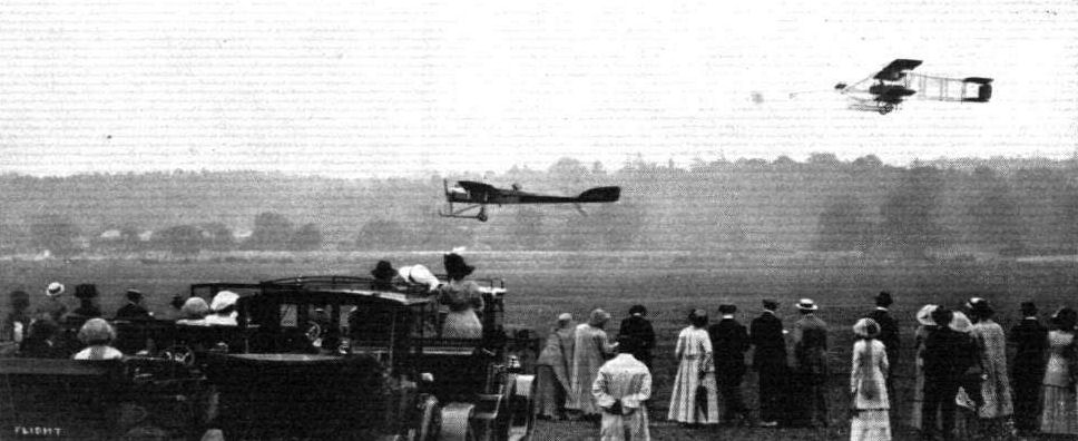
THE THIRD AEROPLANE HANDICAP AT BROOKLANDS, SATURDAY LAST. - Capt. H. Wood on his Vickers monoplane and P. Verrier on his Maurice Farman biplane getting away from the start.
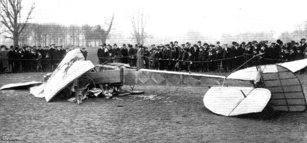
MR. GRAHAM GILMOUR'S FATAL ACCIDENT. - General view of the monoplane after the disaster.
Flight, August 10, 1912.
THE MILITARY AEROPLANE COMPETITION - THE MACHINES.
THE MARTIN HANDASYDE MONOPLANE.
IN general outline this machine has much in common with the well-known but now almost extinct Antoinette monoplane. At Salisbury it has created a very good impression, for not only are its general lines extremely pleasing to the eye, but the materials and workmanship used in its construction are of the very first order. Its main body, in appearance, is slim, but of its strength there is not the slightest doubt. Its section is that of a triangle with its apex clipped. Above the body in front is applied a streamline superstructure for the protection of pilot and passenger, and for the reduction of the head resistance that they would otherwise cause. A section of this superstructure is formed by the radiator which fits saddle fashion across the top of the body. Totally enclosed an front is mounted the 75-h.p. Chenu engine, driving a Chauviere propeller. Each wing is built about two spars, which are hollow box girders formed of ash and three-ply wood, screwed and glued together. Where clips are applied the hollow spar is filled solid, to give greater strength at these important points. There is very little camber in the wings, and from root to tip the camber diminishes regularly - it washes out as Brooklands people say. That section of the wing by the side of the pilot's seat is cut away to allow the pilot a good view directly beneath him. King posts, carefully moulded to an approximate streamline with aluminium sheeting, brace the wings. The lower chassis mast is streamlined in the same fashion, and to further decrease resistance, disc wheels are fitted to the landing gear. This section of the machine resembles closely that employed by the Antoinette. Its action, however, is quite different. The two landing wheels are carried one at each end of a pair of axles which meet together and are pivoted at the main chassis mast. Considering one half of the chassis, the axle and the chassis mast form two sides of a triangle, of which the third side is formed by a unit which resists compression. This unit is composed of a pair of tubes one sliding inside the other. One end of the lower tube is pivoted to the axle, the upper end of the top tube is pivoted to the chassis mast, and the two free ends connected by rubber shock-absorbers. Two radius rods of Duralumin are provided to take the landing "drift."
Main characteristics:-
Overall length 38 ft.
Speed 75 m.p.h.
Span 42 ft.
Weight of machine without cornplement or fuel 1,350 lbs.
Area 310 sq.ft.
Flight, October 26, 1912.
THE MARTIN-HANDASYDE AT BROOKLANDS.
THAT very striking full-page picture in last week's issue of FLIGHT, showing a monoplane crossing above the winning post at Brooklands during the course of motor cycle racing on the track, was a Martin-Handasyde machine, arid we tender our apologies to this firm and to Messrs. Vickers, Ltd., whose name was mentioned in the inscription, for the mistake. As a matter of fact, our photographer, who happened to be taking pictures of the motor racing for our sister journal the Auto, had seen a Vickers monoplane pass several times above his head, but so placed with respect to the light that he could not photograph it. A little later on, however, a machine came into the view that is recorded by the illustration and our photographer, without noticing that it was not the same machine as before, recorded it as a Vickers in his notes, and, unfortunately, the slip was not noticed until too late.
The Martin-Handasyde monoplanes have been flying exceedingly well again down at Brooklands, as they did before the Military Trials, and it was just one of those several disappointments of the month on Salisbury Plain that, at the very time when the eyes of the world of flight were ready to take a particular interest in everything British, the Martin-Handasyde monoplane, itself one of the best of British constructions, should have been hopelessly let down by the chronic weakness of a French engine. There is no doubt that the Martin-Handasyde machine is deserving of the serious consideration of anyone who is in a position to purchase aeroplanes, for not only is it beautifully constructed but it is a splendid machine in the air. Gordon Bell, who came over from France especially to fly the Martin-Handasyde in the Military Trials, did so more because the machine was a pleasure to handle than from any other reason, and on the few occasions when the engine permitted him to stay off the ground, his flying was superb. In the wind tests he led the field under conditions that were distinctly courageous, and his fine performance inspired others to successful simulation when they might have been less anxious to act the pioneer.
Among monoplanes it is a machine of comparatively large area, and among flying machines of all types it is easily one of the most graceful and beautiful objects to see in flight. More important than these facts is the interest that attaches to the machine as an engineering structure, especially in these days of the ban on monoplanes. The trussing of the wing spars is characterised by the presence of king posts, which are absent in a similar capacity from any other monoplane with which we are familiar. The object of a king post is to enable the lift wires to be carried at a reasonable slope so that they do not impose a big compression strain on the spars, and another point of importance on the Martin-Handasyde machines is that the wires in question are anchored to the foot of a very substantial mast, which is carried vertically through the body and forms the apex of the overhead cabane. The divided axle of the landing chassis is hinged to the mast, which is protected by a skid, and a very well thought out rubber spring suspension, having an abutment against the floor of the body, also relieves the mast of shock. The object of this arrangement is to avoid attaching vital wires like the warp wires to members of the undercarriage that are likely to get bumped about or strained against the ground when landing. It is a necessity of monoplane design that the warp wire attachments should project below the level of the body work of the machine and thus be exposed to accidental damage, so it is all the more credit to the designers of the Martin-Handasyde that they should have recognised this natural limitation and have produced a sound engineering solution to the problem. We give this week a couple of detail sketches of the Martin-Handasyde machine entered for the Military Trials, which were made by our artist at Salisbury Plain, but have not hitherto been published. They will serve to accompany, if we may use the expression, the excellent photograph of the machine in flight over Brooklands that was published on page 933 of our last issue.
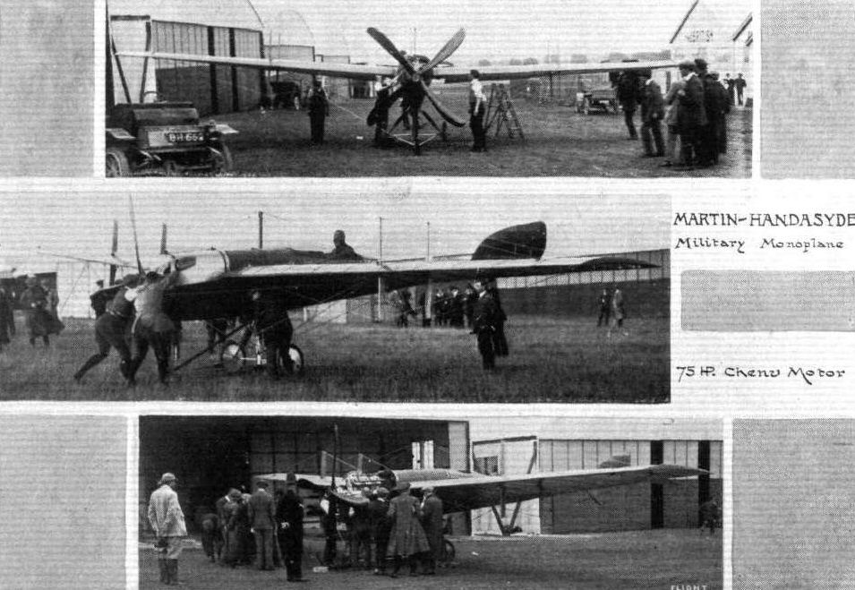
Three views of the 75-h.p. Chenu-motored Martin-Handasyde mono, in the Army Competitions.
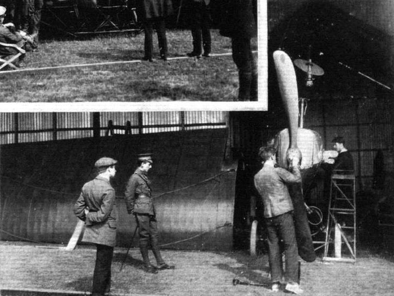
THE MILITARY AVIATION TESTS. - Assembling machines under observation. The Martin Handasyde being assembled.
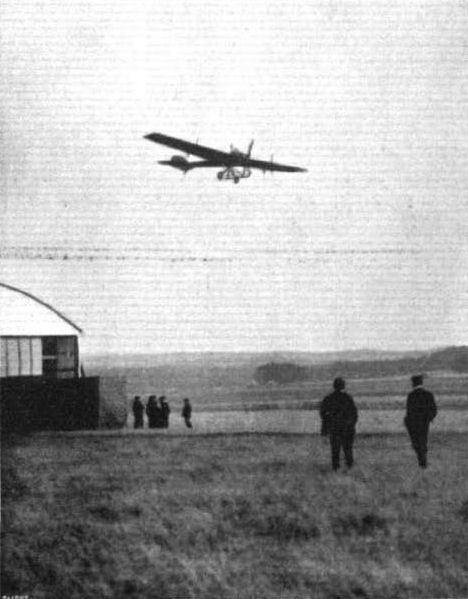
Gordon Bell piloting the Martin-Handasyde mono, at Lark Hill, Salisbury Plain.
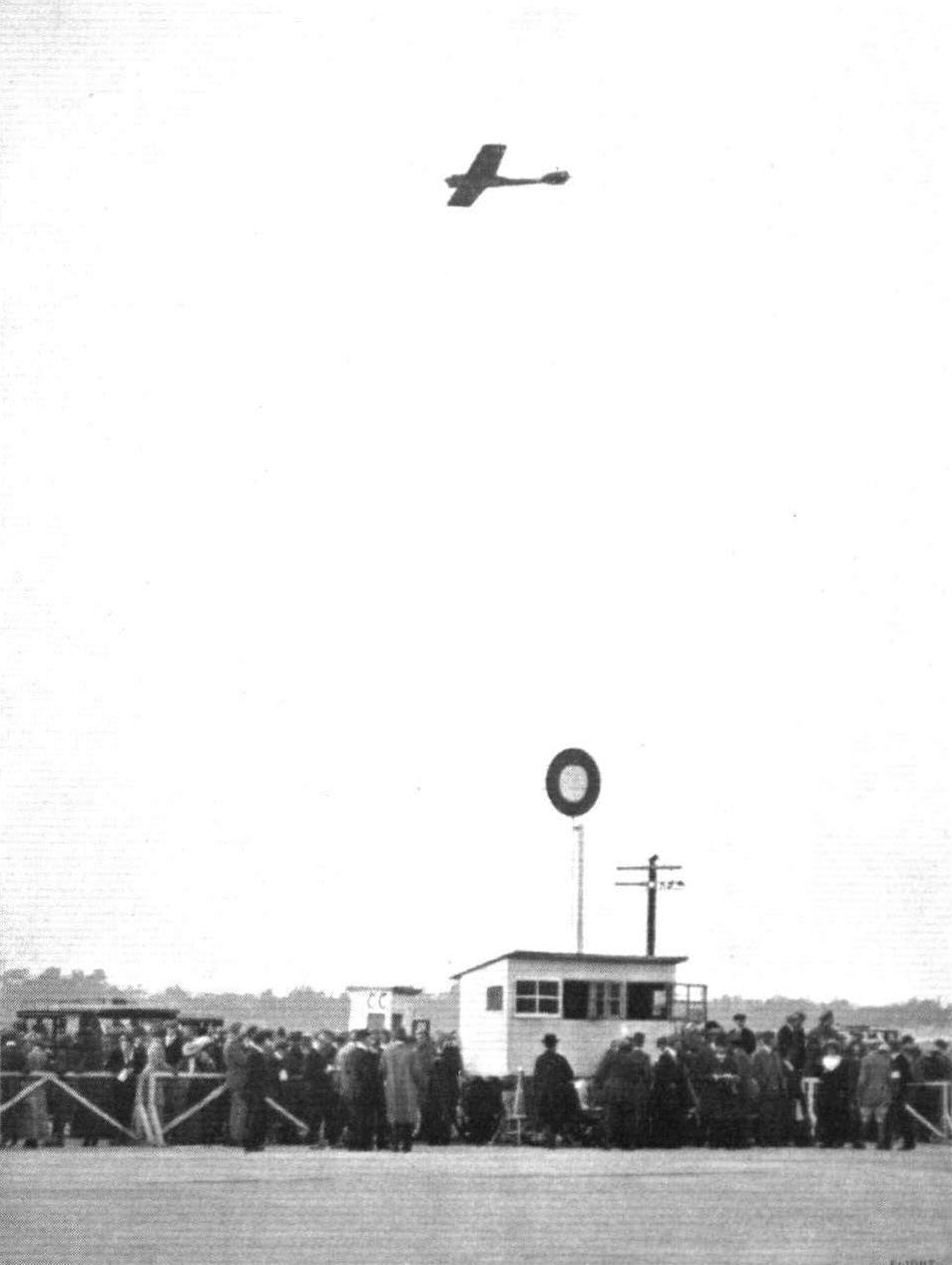
The Vickers (Martin-Handasyde!!!) monoplane making a demonstration flight at Brooklands Aerodrome during the British Motor Cycle Racing Club's Meeting on Saturday last.

The Martin-Handasyde monoplane, with Petre in charge, over Brooklands. In the distance is Sopwlth's biplane, with Hawker up, having a try for the Michelin Cup.
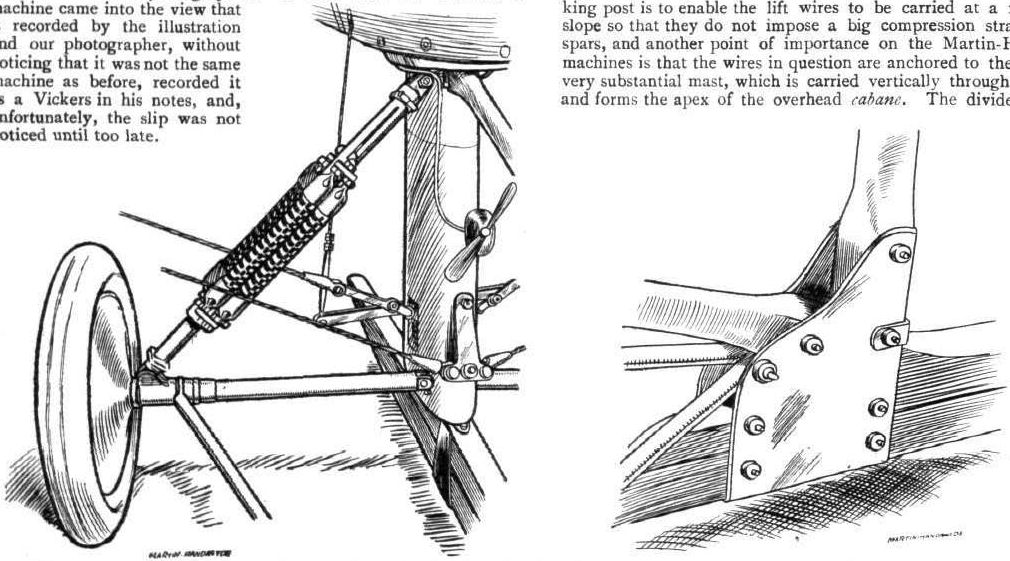
The shock-absorbing device (on the left) on the Martin-Handasyde monoplane, showing the base of the central rigid mast to which the warp-wires are attached. The construction of the under-carriage is such that this mast is protected from landing shocks, which do not, therefore, derange any of the vital cable connections. On the right is a sketch illustrating the attachment of the supporting-struts to the front end of the skid, an example of simple yet sound construction.
Flight, December 21, 1912.
A NOVEL BIPLANE.
AN interesting biplane has made its appearance at Hawkinge, near Folkestone, where Mr. W. B. Megone has been experimenting for some time past. His present machine is the outcome of several different types of heavier-than-air craft that he has constructed and discarded in reaching the type that he has at present arrived at. It will be seen from the accompanying photograph that while the engine is in front of the passenger, the propeller is driven by means of a shaft behind, and for this reason the machine has considerable interest from the military point of view, for it would be possible to mount an automatic gun in front of the passenger which would have an unhindered range in all directions forward. The machine has not yet been flown, but we understand it is to be put through its tests as soon as its constructor returns from abroad after the holidays. As a biplane its construction is rather different from what is regarded as conventional in this type of craft. Each plane is braced as a monoplane wing, and there are no compression struts between them. The upper plane, it will be noticed, is stiffened by king-post bracing. The machine has an area of 440 sq. ft., not reckoning the tail, which is slightly lifting and which has an area of 54 sq. ft. The tail is supported by a fuselage, triangular in section, over the top member of which revolves the propeller. The two lower members continue forward below the machine to form landing skids. Propulsion is derived from a 60-h.p. Green motor mounted in front of, and on a lower level than, the pilot. It transmits its power through a steel shaft and a Hele-Shaw clutch to the 10-ft. propeller at the rear. The passenger, in this particular machine, sits behind the pilot, and his seat is such that he may raise it at will during flight, so that he may be able, if he needs it, to obtain a better view from the machine. He is able to get a good view of what is passing below him through Cellon windows let into the lower plane on either side. It is a curious feature that the control wires to the tail pass through the propeller boss.
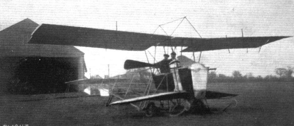
Mr. W. B. Megone's interesting biplane photographed outside its hangar at Hawkinge, Folkestone.
Flight, July 13, 1912.
AIR EDDIES.
That entered by the Mersey Aeroplane Co. is a monoplane of particularly clever design. Pilot and passenger sit side by side in a racy little body which has a 45-h.p. Isaacson motor clamped to the front and the propeller, shaft driven, at the rear. The wing span is 35 ft. and overall length 24 ft.
Flight, August 17, 1912.
THE MERSEY MONOPLANE.
THIS extremely interesting monoplane, which, unhappily, was wrecked at Salisbury Plain on Tuesday evening last and which was contributory to the sad death of its designer and constructor, Mr. R. C. Fenwick, was purely an experimental machine, and had passed through a variety of modifications. The keystone of the design was that the propeller had been arranged behind the pilot and passenger while the engine had been retained in front. In this manner it rendered the machine particularly applicable to military use, for the absence of the propeller in front made observation much more easy and rendered possible the use of a gun pointing forwards. In our opinion it embodied the germ of an idea that was well worthy the time spent to evolve it, but in some ways we considered the constructive details to be a little of the makeshift order, especially as regards the tail trussing. This was a point that we had discussed with Mr. Fenwick a few days previously. He told us that he had tested the strength of that section of the machine, by hanging a man to the extreme end of the tail and lifting him clear of the ground.by the manipulation of the elevator in the slip stream from the propeller. It had withstood that test perfectly, but he was not entirely satisfied and meant to modify it in his next machine. This, however, by the way, for the direct cause of the accident has not yet been definitely established.
The central section of the design was a bluff streamline body 7 ft. in length, in which the pilot and passenger sat side by side. Between them ran the propeller-shaft that connected the motor, a 45-h.p. Isaacson, bolted to the front of the body, to the propeller at the rear. The propeller revolved at half engine speed. The chord dimension of the wings was also 7 ft., and they proceeded outwards from each side of the body without any dihedral angle, spanning 35 feet. Steel spars were used in their construction, and they were braced in the usual manner to the cabane above and the skids below. The body lay wholly below the wings - although the pilot looked out over the top of them - in order to bring the centre of thrust of the propeller on the line of the centre of resistance. The under-carriage, as will be seen from the sketch, was of the wheel and skid type, and the skids continued far in front of the machine to obviate any chance of the machine, when landing on bad ground, turning on to its nose. The landing gear was exceptionally high. This undoubtedly lowered considerably the centre of resistance and was expected to do so by the designer. The tail, with its elevator and rudder, were carried by an outrigger consisting of two tubular steel booms stayed by single piano wires top and bottom to the overhead mast and the undercarriage. On the previous Sunday evening it had flown very satisfactorily, and under none too pleasant conditions. It has carried, in addition to its pilot (Mr. Fenwick) and its passenger (Mr. H. Petre), a load of fuel sufficient to keep it in the air for six hours. It rose and flew exceptionally well with all that weight, considering it was equipped with such a relatively low-powered motor as the 45-h.p. Isaacson.
FATAL ACCIDENT TO MR. R. C. FENWICK.
IT is a matter of supreme regret when any aviator should lose his life in the cause, but it is especially to be deplored that the military aeroplane trials should thus have been marred by a fatal accident. Mr. R. C. Fenwick, designer, constructor and pilot of the Mersey monoplane, took his machine out for the third time on Tuesday evening, about a quarter past six, and flew off in the direction of Stonehenge. About a mile and a half from the sheds the machine was noticed to fly unsteadily, and the end of this unhappy effort was, by all accounts, a nose dive to earth at the termination of which Mr. Fenwick was killed and the aeroplane wrecked.
Few people, apparently, saw, or were in a position to see exactly, what happened, but from observations it was noted that the anemometer registered a sudden increase in gustiness about the time the machine started off on its last journey, while Busteed, who was flying the Bristol monoplane in that vicinity just previously, is similarly reported to have stated that the remous thereabouts were very bad. The why and wherefore of the accident, however, it is the proper purpose of the Public Safety and Accidents Investigation Committee of the Royal Aero Club to investigate, the debris having been thoroughly inspected by responsible persons before it was destroyed by fire. It is, however, to be hoped in this connection that in all cases of disasters of this character, discretion will be used as to the time when the wreckage may be turned into a bonfire, seeing that when a pilot loses his life the least that those living can do in his honour is to profit in all reverence by the lessons of his misfortune.
In all the principal aviation centres, representatives of the safety committee have been appointed by the Royal Aero Club and it is to be hoped that the military authorities, police and aerodrome managers will assist them in efficiently carrying out their work, and will at any rate, as we have suggested, avoid any wanton destruction of invaluable evidence for the sake of hypocritical sentiment.
The aviation world suffers a great loss by Mr. Fenwick's death; he was a clever designer and an able pilot, which combination is none so common that we can afford to lose even one of any we have. The Mersey aeroplane on which the fatal accident occurred was No. 19 in the trials and had made only two previous ascents.

The Mersey monoplane, fitted with a 45-h.p. Isaacson engine, at the Army Competitions.
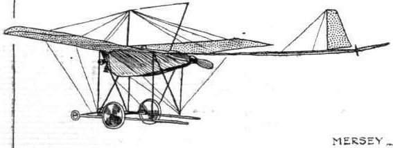

THE MERSEY MONOPLANE. - Sketch of the front central section of the machine.
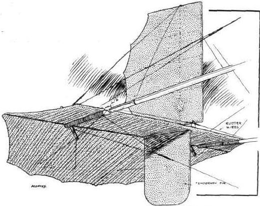
THE MERSEY MONOPLANE. - The tail of the Mersey monoplane.
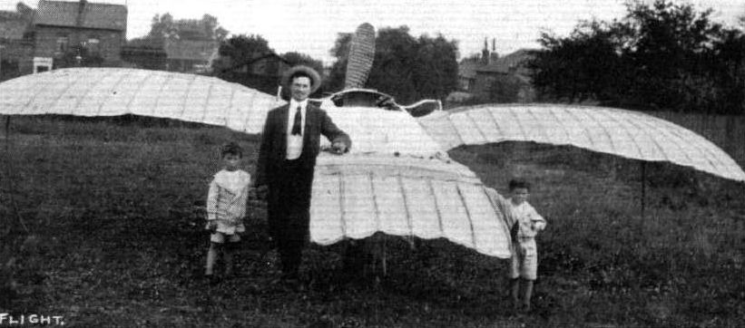
M. B. Passat and his monoplane "Sea-gull," which was tried at Brooklands last summer, and since then, owing to engine trouble, experiments have been delayed. He expects to take the machine to Brooklands again soon to resume his attempts at flight. The wings can be closed in five minutes ready for transit. M. Passat's ambition Is to bring out a machine which will hover for long distances with the engine stopped.
Flight, February 24, 1912.
FLIGHT IN SOUTH AFRICA.
SINCE the African Aviation Syndicate, Ltd., whose more active members are C. Compton Paterson, E. F. Driver, and Capt. Guy Livingston, commenced their operations at Cape Town, little news has leaked through to England as to their actual doings in that colony. As regards the accident that Compton Paterson suffered at the Green Point Track, while flying that excellent little biplane of his own construction, many and varied have been the causes of that mishap put forward by correspondents of the daily journals. It is therefore more than interesting to hear from the pilot himself what actually occurred. Mr. Paterson under date January 31st, writes as follows:-
"By now you will have heard of my smash - pretty bad one too. What really happened was that owing to the machine having been exposed to the weather ever since it was put together, and during the time our tent was being made, the fabric became, during wet weather, very tight, and then when exposed to the sun became terribly slack. This sort of thing going on from day to day evidently did not do the tail any good. The day before the smash I flew from Kenilworth, which is eight miles from Cape Town, over Table Bay and all round Three Anchor Bay, then landed in the Green Point track ready for the next day's demonstrations. During this flight, which was really the most interesting I have made yet, I had to fly through and sometimes over huge rain clouds and naturally got soaked to the skin - likewise the machine. I think this last soaking must have split the fabric on the front boom of the tail, because as soon as I left the ground for my next flight the tail simply opened out horizontally, and the top fabric forming a bag forced the tail down until the machine travelled straight up and eventually turned completely over.
"I hope you can understand from the enclosed sketches just what happened. I was absolutely powerless to do anything, so at about 20 feet switched off the engine and hung on to the elevator for a downward movement.
"Had 2 weeks in hospital, then another 2 weeks on crutches but now able to get about almost as if nothing whatever had happened. Am reconstructing the machine, and on the 17th prox. am giving an exhibition with Driver at Johannesburg.
"Previous to the smash both Driver and I were putting up some pretty good work. Both got up over 4,000 feet. My machine lifts anything you care to put on board and climbs almost the same as a 50-h.p. Bleriot. Surprised Driver beyond measure.
"Freddy Lewin, as I suppose you know, is in Cape Town and has been up with me on several occasions.
"Driver and Guy have already gone to Johannesburg, and I and Turner - our engineer - follow with the biplane in a very few days.
"Flying round and about Cape Town is rather dangerous on account of the air currents caused by Table Mountain and the other mountains surrounding the district. Am hoping flying up country will be easier work.
"Driver and I were presented with beautiful silver cups and gold medals from the citizens of Cape Town. Guy also got a medal for hard work. I think he deserved it too.
"We all wish you every success, and wish also to be remembered to the flying world at large."
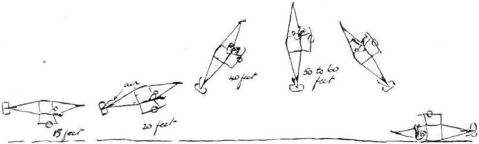
C. Compton-Paterson's humorous "re-construction" of his mishap at Green Point track.

The Piggott Biplane, at Salisbury Plain, entered for the Military Aeroplane Trials. - This is the smallest machine of its class yet built. It has a span of 25 ft. 6 ins., and an area of 100 sq. ft. to support 300 lbs. weight, exclusive of pilot, fuel and oil. It is a beautifully made little machine, but obviously quite a miniature in actual size. There is accommodation for pilot and passenger, both of whom look out over the main planes.
Piggott biplane was an unsuitable machine for military use although entered for the trials of 1912.
Piggott biplane was an unsuitable machine for military use although entered for the trials of 1912.


Mr. Will Moorhouse in his monoplane at Brooklands.
Flight, January 6, 1912.
NEW ARMY AIRCRAFT FACTORY AEROPLANE.
THE painstaking but very energetic research that progresses at the Army Aircraft Factory, under the superintendence of Mr. Mervyn O'Gorman, has resulted in another experimental aeroplane taking the air. The machine - from what we are allowed to see of it at the polite distance of a spectator among the casual public that frequents the Plain on the "off chance" - is a large biplane with an absolutely silent engine. It has been said that it is a remodeled version of the Duke of Westminster's old Voisin, but it seemed to us that there was more remodelling than anything else, and everything that one could see about the machine was of singular interest. In the control, the entire wing surfaces seem to be warped, which appears to give exceedingly powerful balancing action for the maintenance of lateral equilibrium. The detail construction also gives evidence of extreme care, and the application of the principle of streamline form together with the complete absence of visible rigging wires in the tail are both points worthy of comment. The engine is evidently a Wolseley, and has the propeller in front. A rough guess at the speed would place this figure at about 60 m.p.h. The gliding angle seems to be very fine too, as far as one can judge of these things by the eye. The propeller is of the four-bladed type; and, apart from the silence of the power-plant, another feature of especial importance is the fact that the engine can be started from on board. Mr. G. de Havilland has been acting as pilot with great success, and among the passengers has been the superintendent of the factory, whose object in this aeroplane construction work, it may be as well to emphasize once more, is research, not competitive manufacture. In fact, we believe the inclination of the officials is to give British constructors who are building military machines access to the information obtained by means of this research work.
Flight, January 20, 1912.
BRITISH NOTES OF THE WEEK.
Both British Army Aeroplanes Out.
ON Friday last the two aeroplanes built in the Army Aircraft Factory at Aldershot were flying, Mr. de Havilland being at the helm of the "silent" machine, while the other was piloted by Lieut. Fox. Both solo and passenger flights were made, one of the passengers being Capt. Lefroy, chief of the wireless telegraph station, who was doubtless obtaining information regarding the proposal to fit up the machines with wireless apparatus.
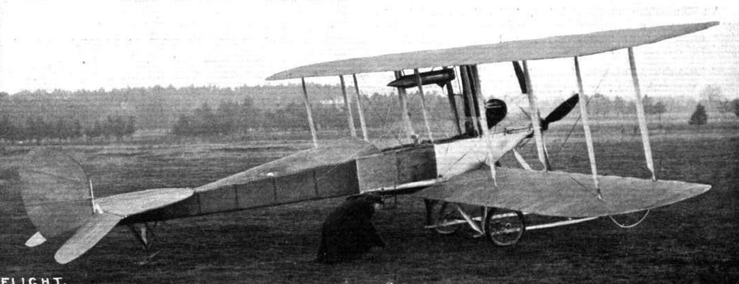
The new product of the Army Aircraft Factory at Farnborough, a decided advance on the previous machine as constructed by that body.
RAF BE.1 December 1911 saw the first flight of this Geoffrey de Havilland design of which many variants were built for the RFC and RNAS.
Geoffrey de Havilland crouches to examine the B.E.l's undercarriage.
RAF BE.1 December 1911 saw the first flight of this Geoffrey de Havilland design of which many variants were built for the RFC and RNAS.
Geoffrey de Havilland crouches to examine the B.E.l's undercarriage.
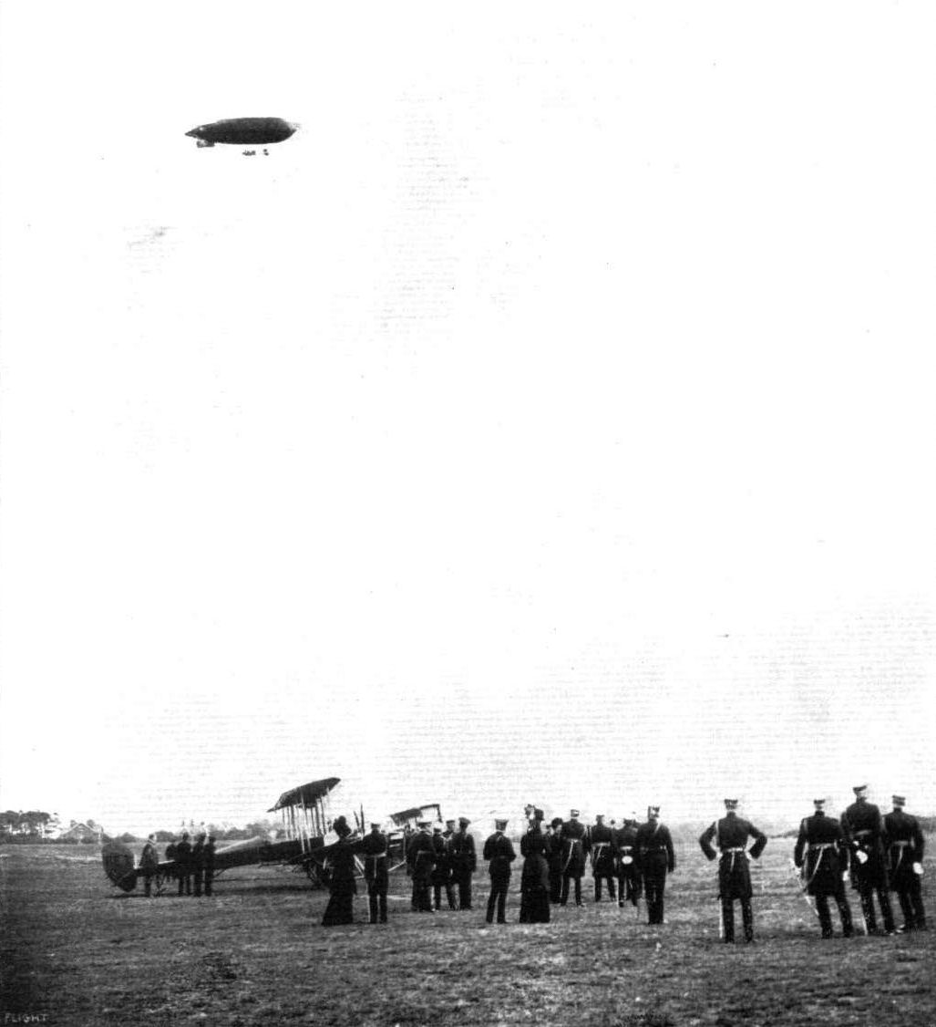
The King and Queen at the aviation grounds at Aldershot, watching the Army airship in flight. On the ground can be seen clearly B.E.I, one of the new four-bladed-propeller Army biplanes built at the Royal Aircraft Factory.
Flight, August 17, 1912.
THE MILITARY COMPETITIONS.
By Our Technical Editor.
SOME NOTES ON, AND A RECORD BY THE ROYAL AIRCRAFT FACTORY'S BIPLANE "BE 2" AT SALISBURY.
A GROUP of people ran madly across a ploughed field and I beat Coanda, designer of the Bristols, by a short head and a twisted foot at the last hole. The excitement is due to the sight of an approaching aeroplane, Prevost on the French "Dep." being expected to lead off in the landing test of the Military Competition on Salisbury Plain. The sheds are three or four miles away, and the plough is an isolated spot with its little band of enthusiastic spectators, who collect together in a great grass hollow in the centre of the field, which, surrounded by warning flags, constitutes a safe vantage point in the very heart of the danger zone. Someone with binoculars, or perhaps Strickland with his telescope - which is a much more useful instrument for this sort of work, having so well combined the three qualities of magnification, field and light - finds out that it is not the "Dep." that is skimming towards us out of the lower sky, but a non-competitor, to wit, de Havilland, on the Royal Aircraft Factory's tractor biplane BE 2.
On board is Major Sykes - secretary to the meeting, an indefatigable worker, and a friend to journalists and other importunate people generally - who has come over to inspect the ground. Like a bird, the machine alights gracefully in an adjacent field, those aboard take a glance in our direction; and like a bird again, the aeroplane hops over the fence and alights with equal ease and safety on the plough, just as if it were running light instead of carrying the regulation 350 lbs. of load in addition to fuel and oil for 4 1/2 hours. Then it taxies round to get into position and rises out of the harrow up wind and once more goes over the fence into the next field so as to be out of the way while Prevost, on the French Dep., who has now approached, slips into the furrow in a cloud of dust and comes gently and safely to rest. A moment's halt and he is off again up wind, with a wire fence less than 150 yards in front of him; it is a close thing, for a ploughed field is slow going on wheels, but with a final sprint the aeroplane springs lightly up into the air and is off through distant space.
And there stands BE 2 quietly on the grass in the next field, inviting a ride. "Will you take me back to the sheds, de Havilland, while Major Sykes is busy talking to Gen. Henderson?" I ask, and "Yes, certainly, but you may find it bumpy," says G. de H., putting on his flying cap and goggles, while I clamber into the front seat, a wicker basket affair that seems uncommonly comfortable. Going to the propeller de Havilland gives it a pull round, as one would start a motor-car engine, and the 70-h.p. Renault gets gently into action. No one holds the machine as the pilot calmly walks round to the back and gets into his seat, for the engine is throttled down to a speed at which the propeller draught exerts but an insignificant thrust compared with that which is presently to come.
Opening the throttle a little we turn round into position, for at first the machine was within a few feet of the fence, and accelerate down wind. Not a bump of any description comes to indicate whether or no we are still in contact with the earth, but it is quite certain a moment later that we are flying as with a quiet but determined stride the machine steps up into the air. And then the ascent continues and the ground that used to be in front of one's eyes lays itself down like a carpet to be looked upon and walked over with fairy-like footsteps from above.
It is already difficult, these days of things that are facts, and children coming to a knowledgable age who have never known the air without its engine-driven birds, to remember the romance of flying and a little of its mystery. Up aloft there on the magic carpet I tried to think of it so, and something of the mental atmosphere appropriate to the thought clouded the mind for awhile, so that the whirr of the engine and the draught from the screw wove themselves into a dreamland, where I walked upon air, and felt like a god in the realm of space looking at the world and her little men tied to the earth below. And the novelty of the situation - for to dream that one is flying is not uncommon - is to find that the dream is true; true, that is to say, so far as the reality of being up in the air is concerned; but as to the feeling of omnipotence appropriate to the rest of the analogy - well, that depends a little on the temperature of the toes. "Cold feet" would be a poor thing to suffer from on BE 2, with de Havilland at the mushroom-topped control-lever; and my shoes were on the exhaust-pipe, anyway, as I only discovered when the leather had ceased to be useful any more as a non-conductor of heat.
As for the going of the machine, we were running with the wind at anything between 75 and 80 miles an hour and it seemed as steady as a rock. Once there was a little drop such as a small boat might give in a "lop" and once a little heave as we passed through a choppy sea. And now the sheds are just in front, so de Havilland puts round into the wind on a small bank and we glide downwards with a smooth easy motion that appeals to me as the most exhilarating part of a flight and one least associated in my mind with any feeling of nervousness, notwithstanding that the ground approaches with an amazing rapidity. At the last moment, a skilful movement of the elevator flattens out the machine so that it flies parallel to the ground and a second later the wheels touch the grass and we come to rest on terra firma once more.
Of all the events in the trials, none have impressed me more than this simple flying to and fro. Neither the intricate manoeuvring of the Deperdussin by Prevost, the "flat gliding" by Verrier on the Maurice Farman, the rocket-like ascent of Bielovucic on the Hanriot, the wind riding by Bell on the Martin Handasyde, nor the several performances of other excellent machines have quite served to bring home the utility of the aeroplane as did the simple assurance with which de Havilland used BE 2 in the service of those who had occasion to go from place to place.
One of the neatest biplanes ever built, and one moreover that impresses the engineering sense with an immediate satisfaction in the quality of its design, BE 2 demonstrates the value of scientifically practical research at its every flight. It is never flown save with a purpose, and few flights fail to bring some factor of utility to the store of knowledge possessed by the R.A.F.
Its main planes are of practically equal span, the upper being slightly the longer. Their area is 372 sq. ft., the weight of the machine is 1,050 lbs., and it flies at about 1,600 lbs. under the conditions of the Military Trials. The struts, two pairs on each wing, are flexibly mounted and cross-braced with steel wire. The rear bracing consists of the warping wires, which pass over pulleys set on a level with the planes. The body, which also forms a backbone to carry the tail, accommodates pilot and passenger in tandem, the latter being in front and having an excellent view in all directions, for the engine, a 70-h.p. V-type Renault is well forward and does not obstruct the view at all. The engine is carried on tubular steel extensions of the upper boom of the backbone, which also serve excellently as points from which drift wires can be taken to the upper and lower planes and to the chassis.
It is the best stayed machine in this respect that I have seen. Guy wires are also carried from the extremities of the middle front struts to the backbone, joining it at a point about two-thirds of the way to the tail, and from the top of the front struts that stand out of the body to a point on either side of the pilot's seat. Beneath, from these points, wires go to the chassis skids, from which spring wires to the inner sides of the lower planes. Thus there are two lift wires from beneath the centre of each front spar to the ends of the skids, and two fore and aft diagonals to stiffen the backbone against side shocks from above the same point.
It is a most scientifically-stayed machine, for a very complete system of trussing has been effected with few wires, and certainly the apparent head resistance is small.
By these wires, body, undercarriage and wings are formed into a composite unit that ought to have an immense rigidity notwithstanding the slender grace that is such a characteristic of the machine's appearance. Not always is it evident that aeroplane designers pay sufficient regard to the fact that the backbone makes a very powerful lever wherewith to strain itself out of alignment with the planes in times of great stress and shock. Or, the importance of the stay wires enumerated above, may be regarded from the point of view of the necessity for steadying the wings in both directions in their own plane. Drift wires are none too common, and wires that oppose the drift wires are still less often to be seen. The combination of the two is a simple and excellent method of giving lateral rigidity to the backbone and of ensuring the maintenance of the proper alignment of the wings with this member.
The tail has a large semi-circular fixed plane with a slight top camber. This is fastened to the top of the backbone, which from this point has a turtle deck as far as the pilot's seat, in order to give a fair streamline run. The elevating-flaps are together almost as large as the tail, while the rudder is a little smaller than one of the elevator-members, and seems well proportioned to the size of the machine. A simple pivoted skid, with spring attachment, supports the tail on the ground.
The undercarriage consists of six struts and two skids, arranged on a modified plan of the A-frame principle. The skids project well forwards, but are not much curved. The axle lies across them near the rear, and two struts spring upwards and apart from each heel to carry the body. A third strut rises from near the toe to stay the engine-bearers.
It is difficult to explain in words the precise quality in the design of this machine that calls forth the admiration of the engineer, and it is certainly not in any way due to smart finish of superficial details, for although the workmanship is excellent, the hand of the experimenter is on it still. The fact remains, that for a well-designed tractor- biplane, BE 2 of the R.A.F. is hard to beat, and some points in it might well be worth copying by those in search of Army orders.
On Monday, August 12th, at about 5 o'clock in the morning, de Havilland made a splendid altitude ascent on BE 2 which must be very nearly, if not actually, a record. The barograph registered 9,500 feet when he came down three hours later and the starting point to which the zero of the instrument was set is already about 400 feet or more above sea level. Roughly speaking, therefore, BE 2 in ordinary touring trim with pilot and passenger (Major Sykes), all its fuel, oil, instruments and other odd "gadgets" went up to the region of 10,000 feet above sea level. It was flying, in fact, under trial conditions and with no special preparation other than is proper to the keeping of an aeroplane, or any other machine, in going order. Weighed immediately after the descent the machine alone scaled 1,274 lbs., of which 30 lbs. rested on the weighbridge under the tail skid. To this must be added the fuel and oil used on the three hours' trip, the pilot and passenger, who scaled 315 lbs. together. At starting, the weight in flight was therefore probably in the order of 1,750 lbs.
The first 1,000 ft. was timed by Major Sykes at 2 mins. 55 secs., i.e., at 344 ft. per minute. This represents an expenditure of about 18-h.p or 25.5 per cent, of its rated power, which is very high, is an indication of general efficiency, and some evidence of a very useful narrow 4-bladed screw. The 7,000 ft. level was reached in 35 mins., but from 6,000 ft., upwards, the rate of climbing was very slow, owing to the rarefied atmosphere at these altitudes. The barometer hereabouts reads only in the neighbourhood of 20 ins. of mercury, so that there is a very great decrease in the mass of air deflected by the planes at a given speed. In the end, the lift diminishes so much that there is no surplus for further ascent and the machine stops climbing. This happened at 9,500 ft. with BE 2, because de Havilland tried for half-an-hour to get higher, but was unable to do so.
In climbing at great altitudes, pilots always keep a steady angle of inclination and de Havilland sets BE 2 until her flight speed is down to 47 m.p.h. If there is no change in the barograph after a reasonable time under these conditions, the ascent is finished, it is impossible to go higher and it is generally time to come down. The descent is at first more rapid than normal in the region of reduced pressure. No trouble with the carburettor was experienced from start to finish and no adjustment was made; nor did either pilot or passenger experience inconvenience save from the cold.
Two strata of clouds were passed through, and the land was shut out from sight; their whereabouts on descending was quite unknown to either de Havilland or Major Sykes. Sighting a railway station, they flew close to it, and were able to read the name Hermitage, and following the line south to Newbury, they branched off to Andover and followed the main road to Amesbury, where they descended in front of the sheds after a most interesting trip.
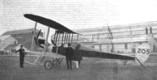
THE ARMY BIPLANE AT FARNBOROUGH. - Lieut. Mackworth in the pilot's seat prior to an early morning trip over the Common.
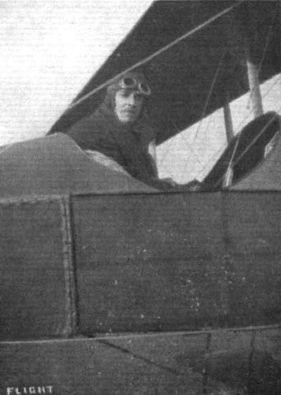
Mr. de Havilland in the pilot's seat of BE 2 at Farnborough.
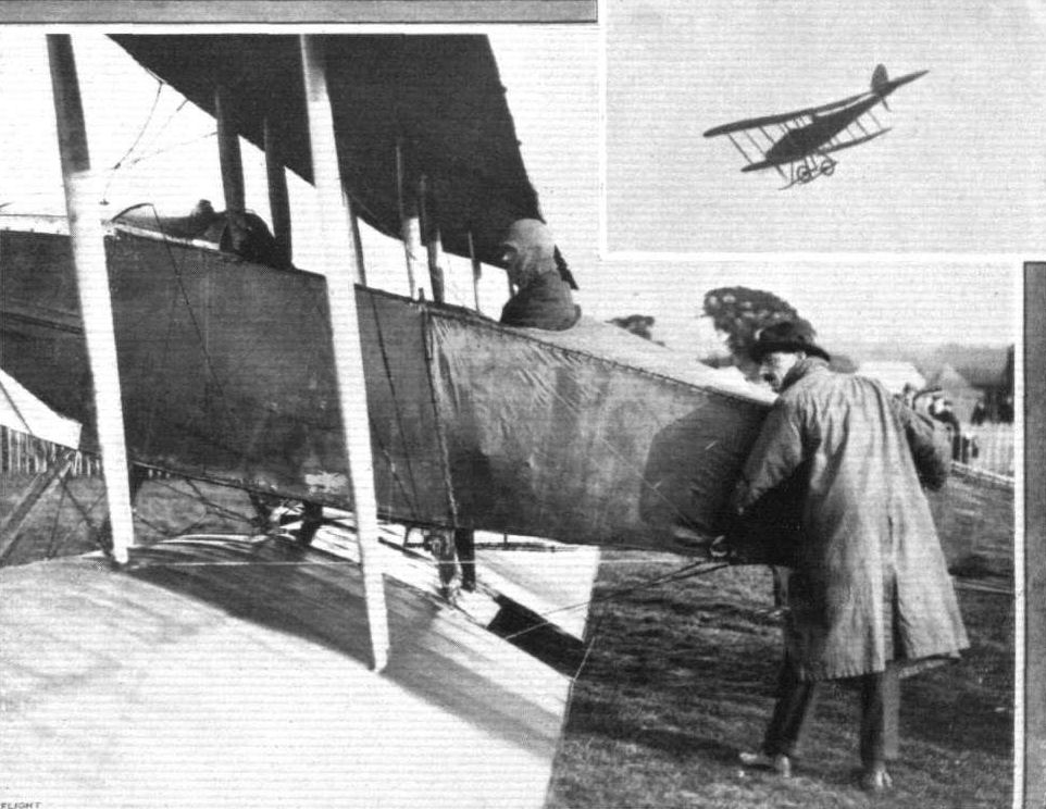
Lieut. Fox, on Army biplane No. 203, just about to start for a flight at the London Aerodrome, Hendon, last week-end. Inset the same machine is seen in flight.
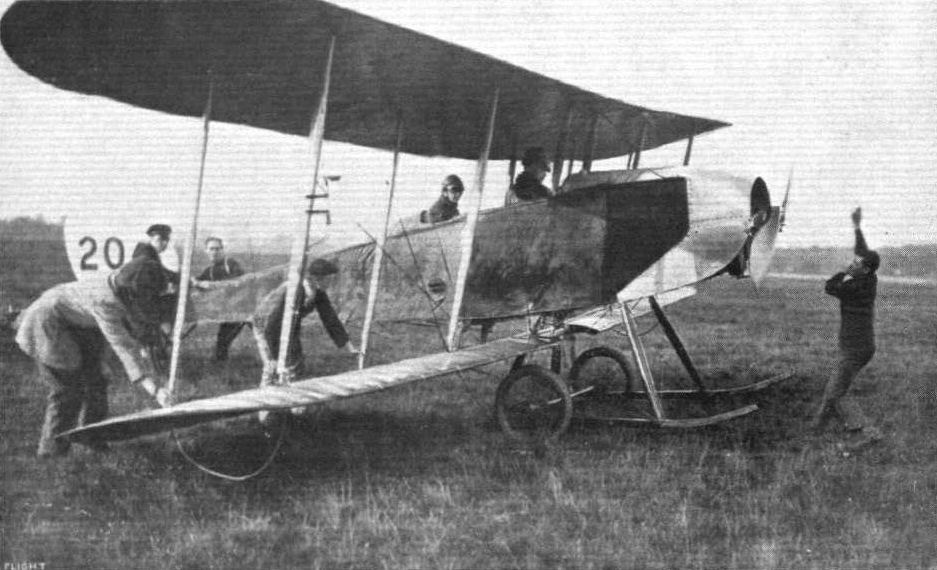
Lieut. Gordon Bell, on Army biplane No. 204, with Capt. Dawes as passenger, just at the moment before leaving the London Aerodrome, Hendon, on Saturday last en route for Farnborough. Note the mechanic in front, who has just swung the propeller.
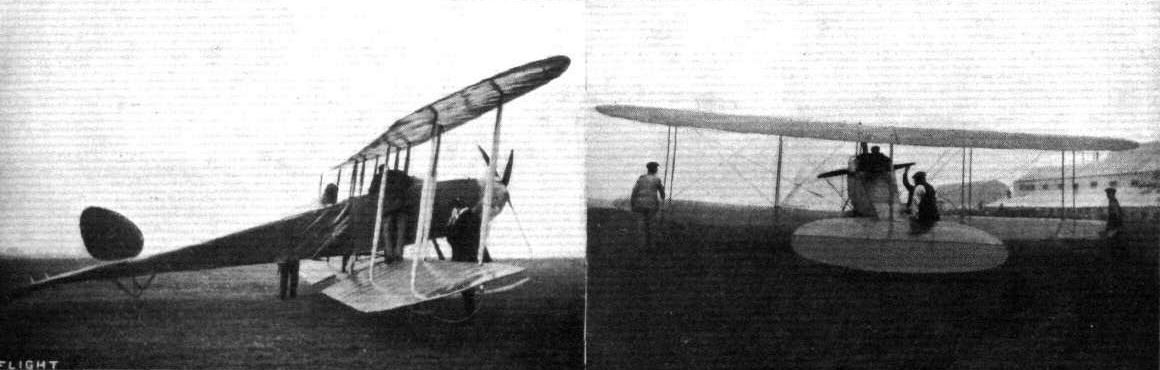
A couple of snapshots of Mr. de Havilland and one of the Army biplanes, BE 4, showing the machine from the side and from behind.
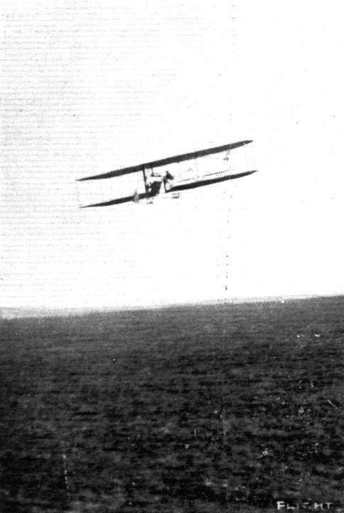
Mr. Alec Ogilvie flying his N.E.C.-engined Wright biplane at the Royal Aero Club's Eastchurch grounds last week.
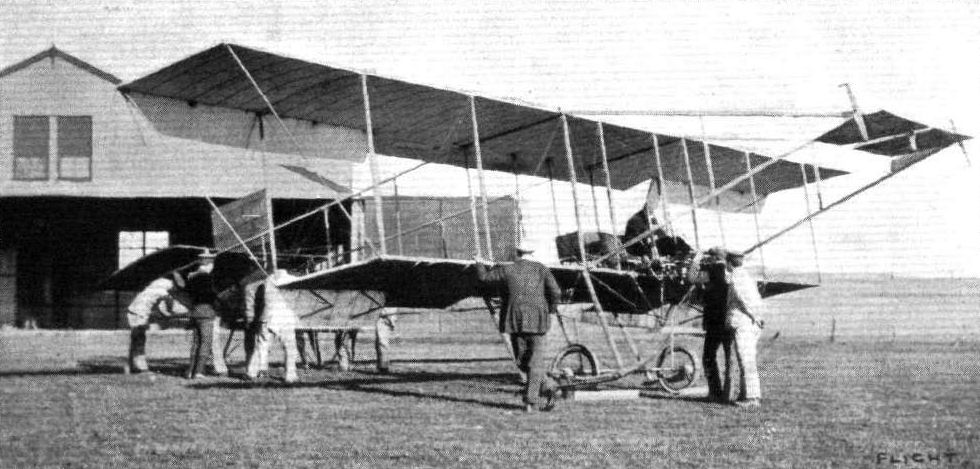
Territorials at the Royal Aero Club's Eastchurch flying grounds practising with "Short" biplane, No. 32.
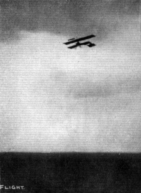
Lieut. A. V. Barrington-Kennett qualifying for his pilot's certificate on the Short dual control biplane at the Royal Aero Club's Eastchurch flying grounds.
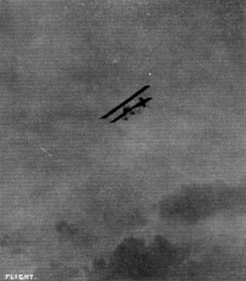
Commander Samson, R.N., making a spiral vol plane at Eastchurch recently on one of the Short biplanes.
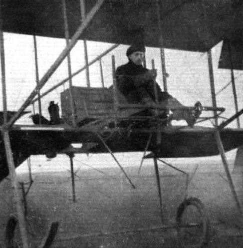
Mr. Cutler on the Short biplane.
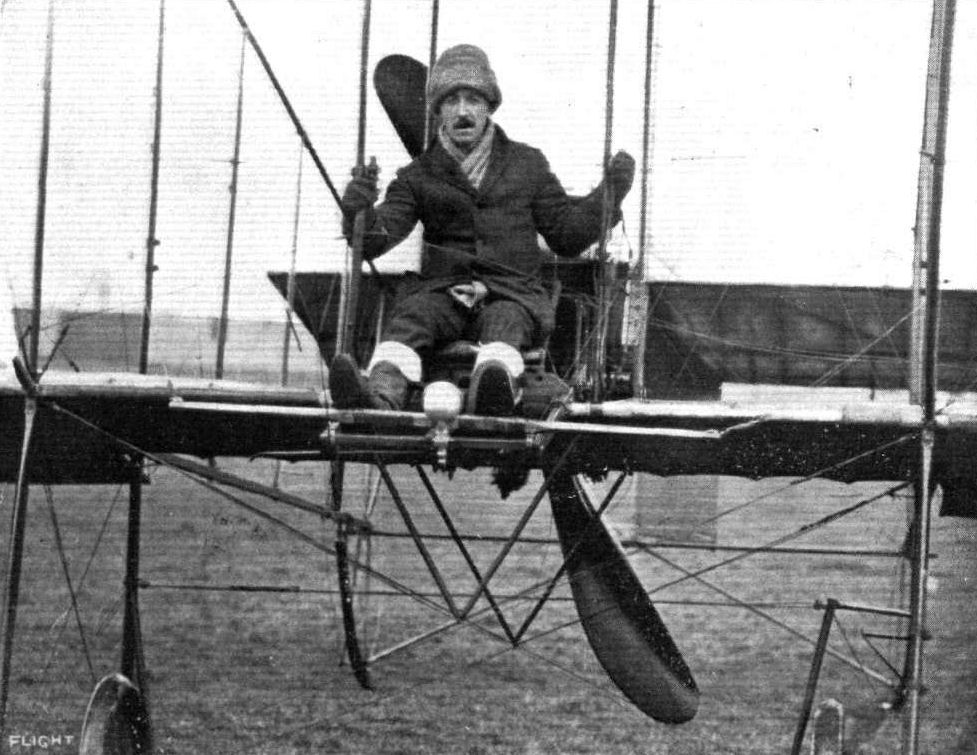
Capt. Gordon at Eastchurch flying grounds, another competitor for the Mortimer Singer Naval and Military Aviation Competition.
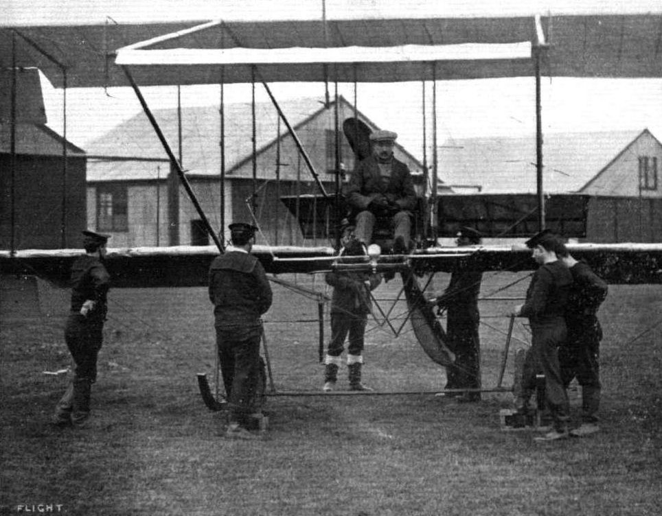
Capt Gerrard on his Short biplane at Eastchurch, where he is one of the foremost competitors for the Mortimer Singer Aviation Prize for Naval and Military Officers.

Engineer Lieut. Briggs, R.N., with Leading Seaman Russell, on Short biplane No. 34, upon which he took his pilot's certificate on July 27th.
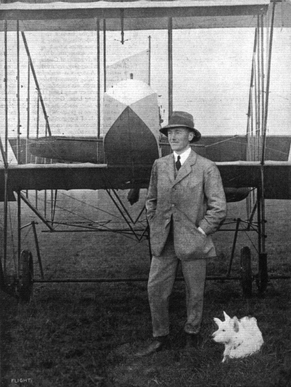
LIEUT. A. M. LONGMORE, R.N., Winner of the Mortimer Singer Navy Aviation Prize by his 172-miles flight at Eastihurch on March 11th, on a 70-h.p. Gnome-engined Short tractor biplane.
Flight, May 11, 1912.
Naval Aeroplanes at the Review.
THE battleship "Hibeinia," which, as we mentioned in our last issue had been fitted in the bows with a launching platform and had four aeroplanes on board, duly arrived at Portland to act as mother ship to the aquaplanes during the Naval Review. Three of the machines were landed on the 3rd inst., and Commander Samson immediately tested "H.M.S. 'Amphibian,'" officially supplied as Short No. 41, which had been fitted with three torpedo-shaped floats thus converting it into a hydro-biplane. He got away from the beat-slip in front of the hangar at Portland, circled round the Fleet at anchor, and then returned to his starting point. He made three trips on the following day on this machine, in one of which he was accompanied as passenger by Admiral Callaghan's daughter, when Capt. Gerrard and Lieuts. Grey and Longmore were also flying over Ike Fleet. Lieut. Grey was up over two hours on the Deperdussin.
On Monday, the ships in the harbour moved out to meet the remainder of the Fleet so that they might all come in together and as a preliminary to the flight to be carried out late in the week, Commander Samson flew out on his hydroaeroplane to escort them in. The fleet was met about twelve miles out at sea, and Commander Samson then returned to Portland, circling over the harbour once or twice before alighting on the water, just by his shed. Earlier in the morning he had been flying the Short monoplane at Lodmoor, where the other naval aviators had been practising. Besides the Short machines there is also a Deperdussin and a Nieuport. In the afternoon Lieut. Gregory made a long flight over the Fleet on an ordinary Short biplane.
Flight, May 18, 1912.
THE NAVAL REVIEW AND THE AVIATORS.
THE feats performed by the naval aviator, during the King's review of his ships, must have convinced the Naval authorities, if they needed any convincing, of the practical stage attained by aviation, and also that the Navy does not lack officers who are quite competent to rank with any aviators in the world. Although the conditions were far from ideal, yet the flyers were able to carry out their arrangements, even although other portions of the programme had to be abandoned. As soon as word was received on Wednesday of last week, that the Royal yacht was within a dozen miles of Admiral Callaghan's flagship, intimation was given to Commander Samson and the other aviators, and all four at once set off to find the "Victoria and Albert," Commander Samson starting from Portland on H.M.S. "Amphibian," and Lieut. Gregory on the Short biplane, Lieut. Longmore on the Deperdussin and Captain Gerrard on the Nieuport, followed one another in quick succession from Lodmore. All were quickly swallowed up in the fog, and the first to actually find the Royal Yacht was Commander Samson who, after circling above it, returned to his headquarters, having been in the air about an hour. Lieut. Gregory, Lieut. Longmore, and Capt. Gerrard also circled above the yacht, the first named during a flight which lasted 1 hr. 10 mins.
A further display was given in the afternoon, when Commander Samson took up a naval officer tearing a letter for the King. The waterplane came down on the sea alongside the Royal Yacht, and the messenger was taken off in a dinghy. Alter the machine had been resting on the sea for some time, it was restarted and carried out several manoeuvres before returning to its shed. In the meantime, Lieut. Gregory appeared at a safe distance from the Royal Yacht and discharged a dummy bomb, weighing 300 lbs. from a height of 500 ft. While manoeuvring over H.M.S. "Neptune," Lieut. Gregory detected a submarine which was submerged to its periscope, and, by way of diversion, suddenly swooped down until he was within 20 ft of the sea, a manoeuvre which created a good deal of speculation. Lieut. Longmore and Capt. Gerrard were likewise out on their machines in the afternoon, and Mr. Grahame-White on a Nieuport, and Mr. Hucks on a Bleriot, both of whom had brought machines down specially, were also flying over the Bay. On the following day the fog made havoc of the arrangements, and the only flying accomplished was in the evening, when Commander Samson on the Short biplane, which had been piloted by Lieut. Gregory, took off from the special launching platform erected on H.M.S. "Hibernia." The machine rose easily, and flew round the bay before landing at Lodmore. On Friday the operations were concluded by Commander Samson making a trip round the fleet on a waterplane, while Lieut. Gregory flew the other Short biplane. On returning to Lodmore this machine was run down to the beach and placed on a raft, which was towed to the "Hibernia."
Lieut. Longmore, on the other hand, forthwith set out to fly the Deperdussin back to Brooklands, while Capt. Gerratd's Nieuport had its wings taken oft and packed up to be returned to Eastchurch.
Commander Samson had the honour of being included among the naval officers who dined with the King on the Royal Yacht in the evening.

WITHIN SIGHT OF ST. PAUL'S. - Mr. Frank K. McClean on his Short hydro-aeroplane on Sunday last. Mr. McClean, on his machine, is seen passing the point on the Thames at St. Paul's Cathedral, he keeping to the surface of the water owing to the restrictions of the police authorities, to which special regulations must, in a measure, be attributed the mishap which Mr. McClean suffered when, lower down the Thames, he endeavoured to take to the air at the point indicated by the police authorities.
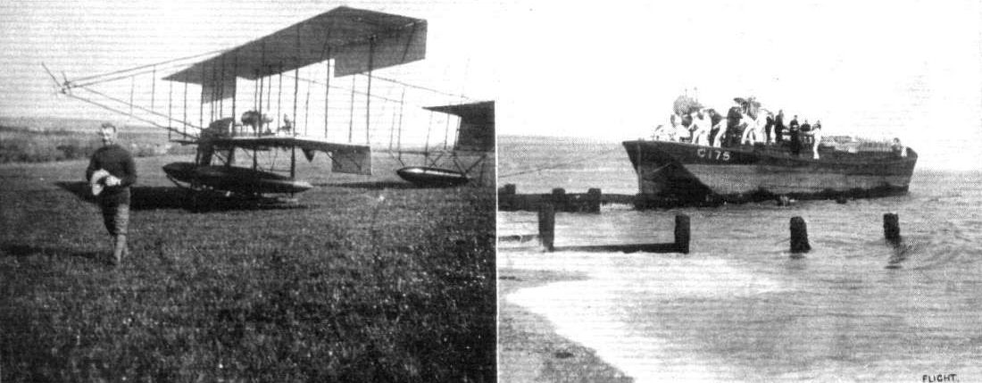
THE NAVY HYDRO-AEROPLANES. - Landing the Short monoplane and the Deperdussin machine in a lighter from the "Hibernia" at Lodmore. On the left Commander Samson after a flight on "S 38" on Lodmore ground.
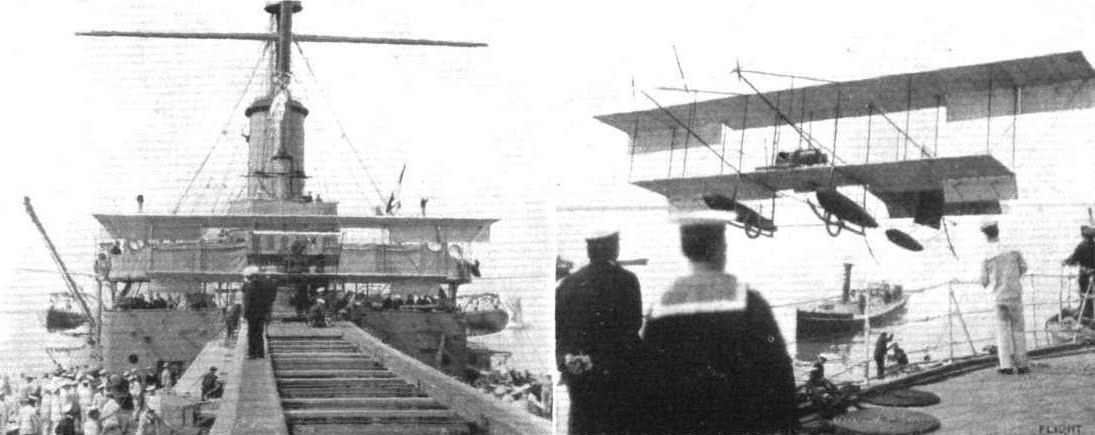
THE NAVAL HYDRO-AEROPLANES AS SEEN FROM THE "HIBERNIA." - Hoisting "S.38" on to the "Hibernia," and on the left the machine in place on the special platform.

A front view of the hydro-aeroplane mother vessel, "Hibernia," with the Fleet at Weymouth, showing the Navy aeroplanes in place on the special launching platform.
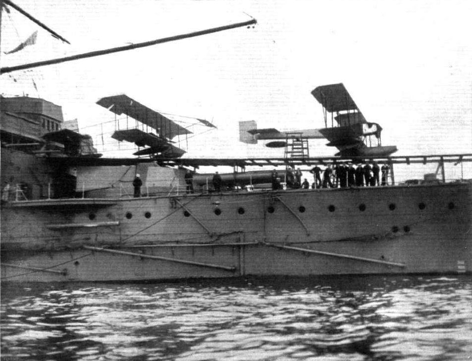
The NAVY HYDRO-AEROPLANES. - A side view of the "Hibernia" showing the two hydro-aeroplanes on the launching platform especially constructed for this purpose.

Commander Samson, on "S 38," in flight for Lodmore after launching from the deck of the "Hibernia," when travelling at 15 knots an hour. Weymouth is seen in the distance.
Flight, June 8, 1912.
Mr. McClean Flies Over Dover Harbour,
WHILE the naval pilots stopped at Ramsgate on the 30th ult., Mr. F. K. McClean, on his Short Tractor biplane, took a passenger on to Dover and at a height of about 2,000 ft. circled over Dover Castle and the National Harbour, returning to Eastchurch without alighting after a trip of an hour and a-half.
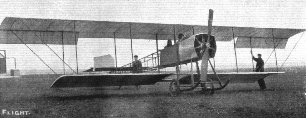
The Short tractor biplane, constructed by Messrs. Short Bros, for Mr. Frank K. McCiean, which has been doing successful work at Eastchurch recently.

A near view of Mr. McClean's 70-h.p. Short tractor machine ready for a flight. With Mr. McClean is Miss Lucas as passenger.
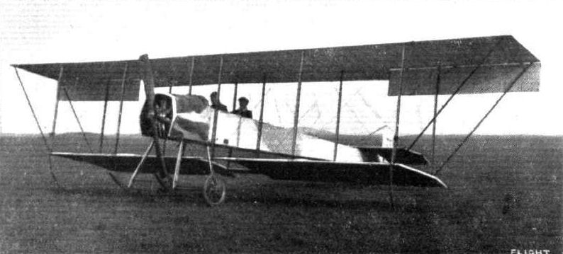
Lieut. Spencer Grey, R.N., with Assistant Paymaster Frewin, R.N., on the new naval 70-h.p. Short tractor biplane at the Royal Aero Club's Eastchurch flying ground.
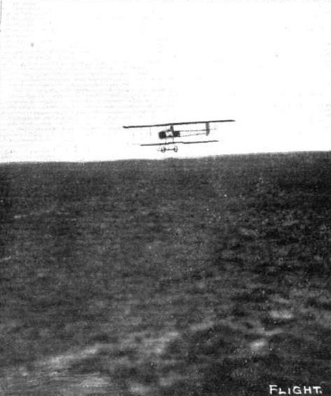
Mr. Frank McClean in flight at the Royal Aero Club's Eastchurch flying grounds on his Short tractor biplane.
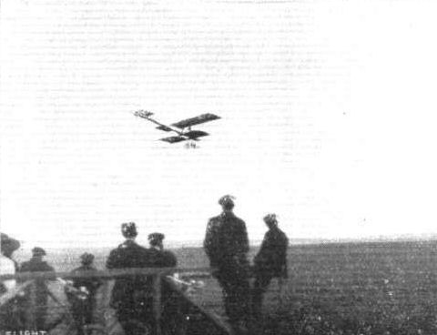
Mr. Frank McClean making a vol plane on his 70-h.p. Short tractor at the Royal Aero Club's Eastchurch flying grounds.
Flight, May 11, 1912.
Naval Aeroplanes at the Review.
THE battleship "Hibeinia," which, as we mentioned in our last issue had been fitted in the bows with a launching platform and had four aeroplanes on board, duly arrived at Portland to act as mother ship to the aquaplanes during the Naval Review. Three of the machines were landed on the 3rd inst., and Commander Samson immediately tested "H.M.S. 'Amphibian,'" officially supplied as Short No. 41, which had been fitted with three torpedo-shaped floats thus converting it into a hydro-biplane. He got away from the beat-slip in front of the hangar at Portland, circled round the Fleet at anchor, and then returned to his starting point. He made three trips on the following day on this machine, in one of which he was accompanied as passenger by Admiral Callaghan's daughter, when Capt. Gerrard and Lieuts. Grey and Longmore were also flying over Ike Fleet. Lieut. Grey was up over two hours on the Deperdussin.
On Monday, the ships in the harbour moved out to meet the remainder of the Fleet so that they might all come in together and as a preliminary to the flight to be carried out late in the week, Commander Samson flew out on his hydroaeroplane to escort them in. The fleet was met about twelve miles out at sea, and Commander Samson then returned to Portland, circling over the harbour once or twice before alighting on the water, just by his shed. Earlier in the morning he had been flying the Short monoplane at Lodmoor, where the other naval aviators had been practising. Besides the Short machines there is also a Deperdussin and a Nieuport. In the afternoon Lieut. Gregory made a long flight over the Fleet on an ordinary Short biplane.
Flight, May 18, 1912.
THE NAVAL REVIEW AND THE AVIATORS.
THE feats performed by the naval aviator, during the King's review of his ships, must have convinced the Naval authorities, if they needed any convincing, of the practical stage attained by aviation, and also that the Navy does not lack officers who are quite competent to rank with any aviators in the world. Although the conditions were far from ideal, yet the flyers were able to carry out their arrangements, even although other portions of the programme had to be abandoned. As soon as word was received on Wednesday of last week, that the Royal yacht was within a dozen miles of Admiral Callaghan's flagship, intimation was given to Commander Samson and the other aviators, and all four at once set off to find the "Victoria and Albert," Commander Samson starting from Portland on H.M.S. "Amphibian," and Lieut. Gregory on the Short biplane, Lieut. Longmore on the Deperdussin and Captain Gerrard on the Nieuport, followed one another in quick succession from Lodmore. All were quickly swallowed up in the fog, and the first to actually find the Royal Yacht was Commander Samson who, after circling above it, returned to his headquarters, having been in the air about an hour. Lieut. Gregory, Lieut. Longmore, and Capt. Gerrard also circled above the yacht, the first named during a flight which lasted 1 hr. 10 mins.
A further display was given in the afternoon, when Commander Samson took up a naval officer tearing a letter for the King. The waterplane came down on the sea alongside the Royal Yacht, and the messenger was taken off in a dinghy. Alter the machine had been resting on the sea for some time, it was restarted and carried out several manoeuvres before returning to its shed. In the meantime, Lieut. Gregory appeared at a safe distance from the Royal Yacht and discharged a dummy bomb, weighing 300 lbs. from a height of 500 ft. While manoeuvring over H.M.S. "Neptune," Lieut. Gregory detected a submarine which was submerged to its periscope, and, by way of diversion, suddenly swooped down until he was within 20 ft of the sea, a manoeuvre which created a good deal of speculation. Lieut. Longmore and Capt. Gerrard were likewise out on their machines in the afternoon, and Mr. Grahame-White on a Nieuport, and Mr. Hucks on a Bleriot, both of whom had brought machines down specially, were also flying over the Bay. On the following day the fog made havoc of the arrangements, and the only flying accomplished was in the evening, when Commander Samson on the Short biplane, which had been piloted by Lieut. Gregory, took off from the special launching platform erected on H.M.S. "Hibernia." The machine rose easily, and flew round the bay before landing at Lodmore. On Friday the operations were concluded by Commander Samson making a trip round the fleet on a waterplane, while Lieut. Gregory flew the other Short biplane. On returning to Lodmore this machine was run down to the beach and placed on a raft, which was towed to the "Hibernia."
Lieut. Longmore, on the other hand, forthwith set out to fly the Deperdussin back to Brooklands, while Capt. Gerratd's Nieuport had its wings taken oft and packed up to be returned to Eastchurch.
Commander Samson had the honour of being included among the naval officers who dined with the King on the Royal Yacht in the evening.
Naval Aeroplanes at the Review.
THE battleship "Hibeinia," which, as we mentioned in our last issue had been fitted in the bows with a launching platform and had four aeroplanes on board, duly arrived at Portland to act as mother ship to the aquaplanes during the Naval Review. Three of the machines were landed on the 3rd inst., and Commander Samson immediately tested "H.M.S. 'Amphibian,'" officially supplied as Short No. 41, which had been fitted with three torpedo-shaped floats thus converting it into a hydro-biplane. He got away from the beat-slip in front of the hangar at Portland, circled round the Fleet at anchor, and then returned to his starting point. He made three trips on the following day on this machine, in one of which he was accompanied as passenger by Admiral Callaghan's daughter, when Capt. Gerrard and Lieuts. Grey and Longmore were also flying over Ike Fleet. Lieut. Grey was up over two hours on the Deperdussin.
On Monday, the ships in the harbour moved out to meet the remainder of the Fleet so that they might all come in together and as a preliminary to the flight to be carried out late in the week, Commander Samson flew out on his hydroaeroplane to escort them in. The fleet was met about twelve miles out at sea, and Commander Samson then returned to Portland, circling over the harbour once or twice before alighting on the water, just by his shed. Earlier in the morning he had been flying the Short monoplane at Lodmoor, where the other naval aviators had been practising. Besides the Short machines there is also a Deperdussin and a Nieuport. In the afternoon Lieut. Gregory made a long flight over the Fleet on an ordinary Short biplane.
Flight, May 18, 1912.
THE NAVAL REVIEW AND THE AVIATORS.
THE feats performed by the naval aviator, during the King's review of his ships, must have convinced the Naval authorities, if they needed any convincing, of the practical stage attained by aviation, and also that the Navy does not lack officers who are quite competent to rank with any aviators in the world. Although the conditions were far from ideal, yet the flyers were able to carry out their arrangements, even although other portions of the programme had to be abandoned. As soon as word was received on Wednesday of last week, that the Royal yacht was within a dozen miles of Admiral Callaghan's flagship, intimation was given to Commander Samson and the other aviators, and all four at once set off to find the "Victoria and Albert," Commander Samson starting from Portland on H.M.S. "Amphibian," and Lieut. Gregory on the Short biplane, Lieut. Longmore on the Deperdussin and Captain Gerrard on the Nieuport, followed one another in quick succession from Lodmore. All were quickly swallowed up in the fog, and the first to actually find the Royal Yacht was Commander Samson who, after circling above it, returned to his headquarters, having been in the air about an hour. Lieut. Gregory, Lieut. Longmore, and Capt. Gerrard also circled above the yacht, the first named during a flight which lasted 1 hr. 10 mins.
A further display was given in the afternoon, when Commander Samson took up a naval officer tearing a letter for the King. The waterplane came down on the sea alongside the Royal Yacht, and the messenger was taken off in a dinghy. Alter the machine had been resting on the sea for some time, it was restarted and carried out several manoeuvres before returning to its shed. In the meantime, Lieut. Gregory appeared at a safe distance from the Royal Yacht and discharged a dummy bomb, weighing 300 lbs. from a height of 500 ft. While manoeuvring over H.M.S. "Neptune," Lieut. Gregory detected a submarine which was submerged to its periscope, and, by way of diversion, suddenly swooped down until he was within 20 ft of the sea, a manoeuvre which created a good deal of speculation. Lieut. Longmore and Capt. Gerrard were likewise out on their machines in the afternoon, and Mr. Grahame-White on a Nieuport, and Mr. Hucks on a Bleriot, both of whom had brought machines down specially, were also flying over the Bay. On the following day the fog made havoc of the arrangements, and the only flying accomplished was in the evening, when Commander Samson on the Short biplane, which had been piloted by Lieut. Gregory, took off from the special launching platform erected on H.M.S. "Hibernia." The machine rose easily, and flew round the bay before landing at Lodmore. On Friday the operations were concluded by Commander Samson making a trip round the fleet on a waterplane, while Lieut. Gregory flew the other Short biplane. On returning to Lodmore this machine was run down to the beach and placed on a raft, which was towed to the "Hibernia."
Lieut. Longmore, on the other hand, forthwith set out to fly the Deperdussin back to Brooklands, while Capt. Gerratd's Nieuport had its wings taken oft and packed up to be returned to Eastchurch.
Commander Samson had the honour of being included among the naval officers who dined with the King on the Royal Yacht in the evening.

The land station of the Naval Air Fleet at Portland during the manoeuvres of the Fleet last week.
The NAVY HYDRO-AEROPLANES. - A side view of the "Hibernia" showing the two hydro-aeroplanes on the launching platform especially constructed for this purpose.
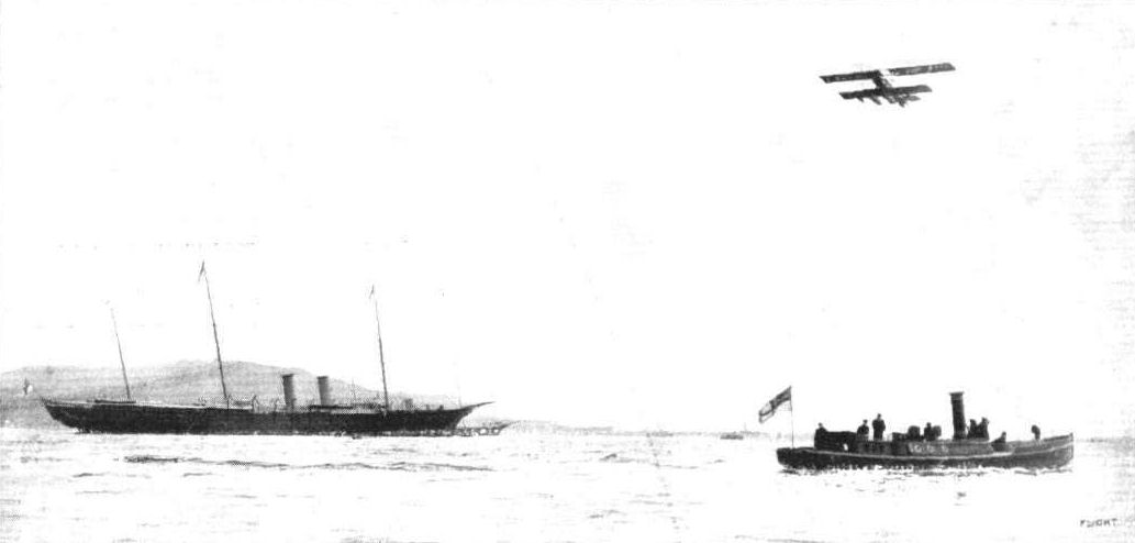
Commander Samson flying on his naval hydro-aeroplane over the King's yacht at Portland last week.
Flight, March 2, 1912.
AIR EDDIES.
Messrs. Short Brothers, who have hitherto only been associated with machines of the biplane class, have constructed a monoplane which was tested for the first time on Saturday morning last, by Commander Samson. That it should fly satisfactorily at the first attempt and need no subsequent adjustments, is testimony enough of the remarkable excellence displayed by that firm in both design and construction. This new machine, which, superficially has much in common with the Bleriot, we hope to describe fully next week.
Flight, March 9, 1912.
THE SHORT MONOPLANE.
WHEN a firm have been so conspicuously and successfully associated with biplane construction as have Messrs. Short Brothers, it is a little difficult to suddenly attune the mind to the idea of a Short monoplane. Difficult or not, however, a monoplane has lately issued from those excellent workshops at Eastchurch, and although its design admittedly owes much to a prototype that has served as a basis for more than one successful flyer, it has just as much of the Short originality as have those other typical aircraft with which the firm's name is associated. Strength and solidity, undoubtedly, were the chief points in the minds of the designers in the preparation of this new machine, and these features, too, are precisely those that the whole aviation world expects to see exemplified in any Short product.
The main body is little different from that employed on the Bleriot, and the same system of bracing is used. At the front end, however, it is different, being arranged for the mounting of the engine without any support between the propeller and crank case, and for the application of the new type of undercarriage with which the machine is equipped. This latter is of the wheel and skid type. Two sturdy ash struts extend downwards and forwards from the points at which the main wing spars join the fuselage and are joined at their lower extremities by a horizontal planche. To this the two skids are applied, their rear ends being supported by subsidiary struts from the bottom of the main body. Diagonal struts further strengthen the structure.
In common with other forms of landing gear of the same type, especially amongst those exhibited at the last Aero Show in Paris, the skids show signs of suppression. In many of the French machines referred to, the skids had grown so small that, were the wheels to fail, they could scarcely be relied on to provide that easy run over the ground necessary for the safety of the machine. In the Short chassis, however, this extreme is avoided.
At the front end of the body is mounted the motor, direct coupled to a Chauviere type propeller, a hood being arranged above it so as to afford protection for the pilot against oil and exhaust products thrown off by it while in operation. The wings, much of the same size and shape as those of the Bleriot, are trussed to the landing chassis by eight strong stranded steel cables, four to each wing. So strong is the wing staying, that structural failure in this section of the machine would seem almost an impossibility. In their internal construction, too, pains have been taken to prevent the ribs having a tendency to split at the webs left by the drilling-out process. Warping is relied on to maintain lateral equilibrium, the rear spars being deflected by eight wires, four to each, proceeding from an inverted tower of steel tubing applied below the body. The weight of each wing, when the machine is stationary, is supported by four wires from a tubular cabane.
Arranged before the pilot, so as to form a type of scuttle dash, are the fuel-tanks. These terminate in an inclined dashboard, where are fitted the switch, the petrol-gauge, and the oil feed-gauges, all well within reach of the pilot. A rectangular cambered surface, to the back of which is hinged a flap cambered in the reserve sense and serving as elevator, comprise the tail unit. This is supported clear of the ground, by a long universally-jointed skid attached to the body at the forward end by elastic bands. Both the rudder and the elevator are actuated by wires from the controlling organs attached to pressed-steel cranks. The controls themselves are almost identical with the original Bleriot system, a pivoted foot-bar operating the rudder and a universally-jointed vertical pillar, surmounted by a small hand-wheel, governing the machine's attitude and the wing warping. Indeed, the only difference noticeable is that the typical aluminium dome of the Bleriot control is replaced by simple steel cranks. Its flying speed is approximately 60 miles an hour.
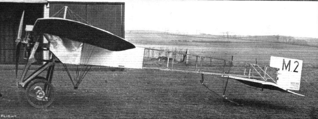
Short S.42 tractor monoplane similar to the Bleriot XI. It became RNAS No.8.

The Short monoplane, front view.
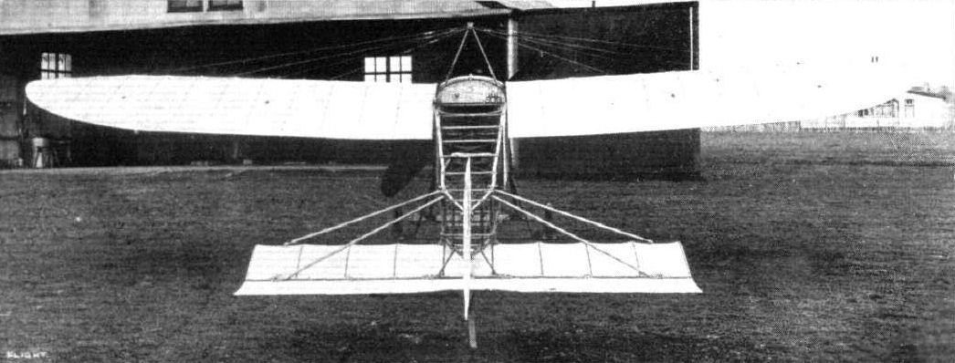
The Short monoplane, back view.
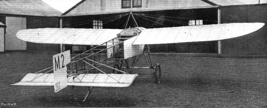
Short monoplane M2 at Eastchurch in 1912.

Detailed photograph of the front section of the Short monoplane, showing details of the landing carriage and the mounting of the Gnome engine.
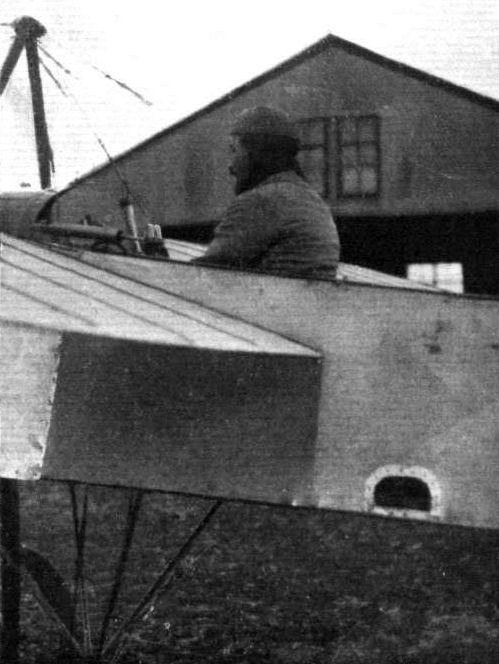
Commander Samson at the lever of the new Short monoplane, on which he carried out successful tests on Saturday morning last.
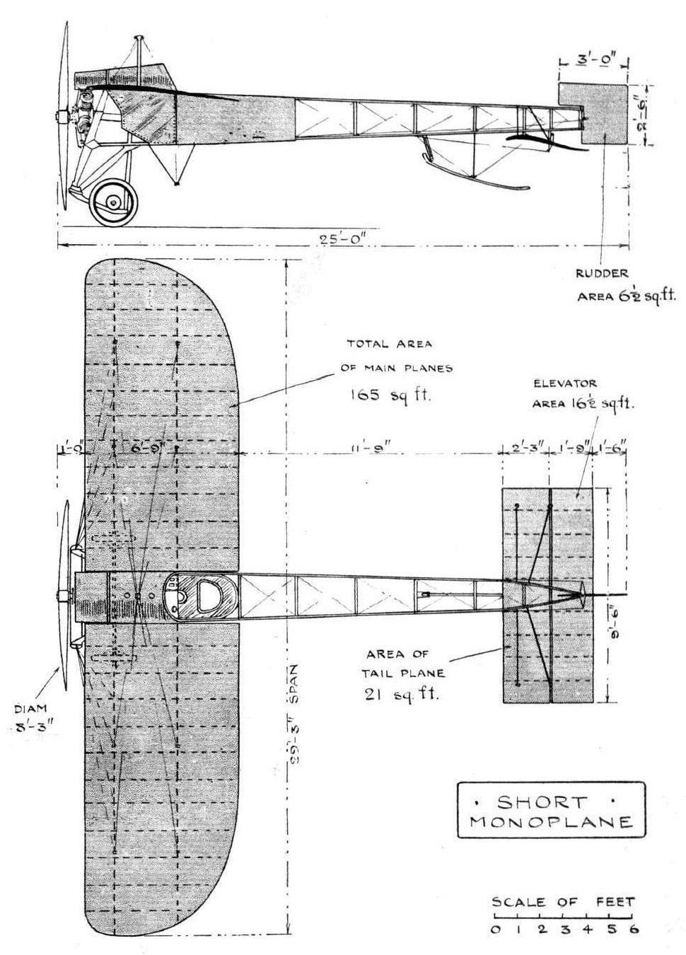
THE SHORT MONOPLA.NE. - Plan and elevation to scale.
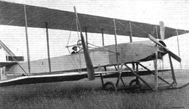
The new Short twin-engined triple-tractor biplane. General view distinctly showing the position of the three tractor screws.
Flight, November 23, 1912.
THE SOPWITH-WRIGHT BIPLANE.
THAT excellent performance of Hawker recently with the Sopwith-Wright biplane in his flight for the British Michelin No. 1 draws attention both to a man and a machine comparatively little known. We say little known, because the pilot at any rate is a newcomer among the men whose names have been prominent in the front rank, and although the machine bears the most famous name in the world of flight, nevertheless, the Wright design is by no means so familiar to English students of aeroplane construction as ought to be the case, having regard to the pre-eminence of its originator.
This particular example of the Wright design, as modified by Sopwith, himself among the foremost British pilots, possesses the peculiarity of having a Farman instead of a Wright control, and for this reason alone an especial interest attaches to it and demands that it should find an early place in our gallery of machines even were the present occasion less opportune than it is.
It was during last year that Sopwith had the original of this machine made for him in America by Burgess, the well-known boat builders, who are constructing Wright biplanes under licence. He had the Farman lever and rudder bar control, with which he was already familiar, fitted to the machine instead of the Wright interconnected warp and rudder control with which the Wright machines are ordinarily supplied, and he also was the first we believe to place a Gnome rotary engine on this type of aeroplane. As now flying, however, the Gnome rotary is replaced by the splendidly successful British-built A B C engine, which drives the twin propellers made by the Bristol Co. through the usual pair of chains, one of which is crossed.
In the present machine, there is nothing, we believe, of the original aeroplane as purchased by Sopwith, the whole of it having been reconstructed in his own factory. It has, as our illustrations show very clearly, a small nacelle, somewhat resembling in appearance the familiar sidecar with which so many motor bicycles are nowadays provided. Behind this little shield the pilot is protected from the wind, which is especially a point of importance in the Wright machine seeing that ordinarily every inch of the pilot's body is exposed, and flying any machine in winter weather is a bitterly cold job at the best.
With the exception of the features that have just been mentioned, the reconstructed machine serves as an example of standard Wright practice; it has the same type of main planes with their front spars forming the leading edges and their struts mounted on flexible joints, which from the first has been a characteristic feature of the Wright design.
Diagonal wires turn the whole structure into a box girder, but the arrangement of wires between the rear spars differs from that in front, because the extremities of the rear spar are flexed in the process of wing warping.
The tail, which is carried on a light box girder outrigger, consists of a twin rudder mounted on a common pivot and the fixed horizontal plane with a flexing trailing edge that serves as an elevator. With the Farman system of control on this machine, elevating is performed by moving the control lever forward, while wing warping results from moving it sideways. The rudder is operated independently by foot. In the standard Wright control, the rudder is operated by a movement of the handle of the warping lever, which is hinged to the lever itself so that the rudder can be operated independently from, or simultaneously with the warp. The elevator in the Wright system is under independent lever control.
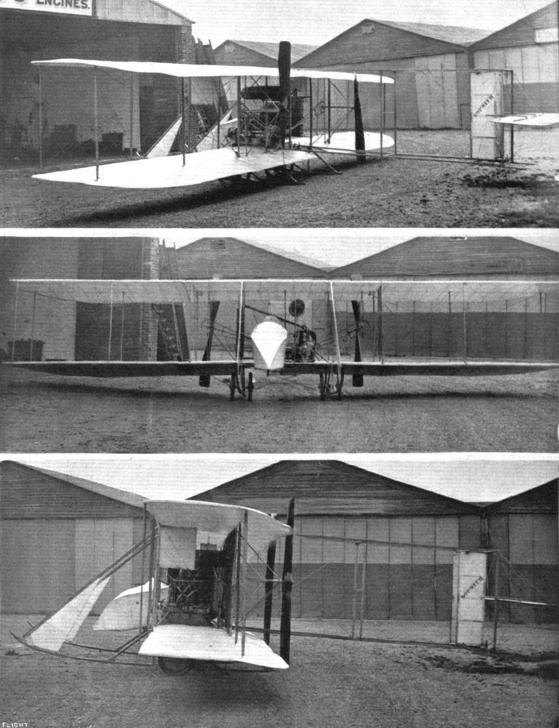
The Sopwith-Wright biplane.
The Martin-Handasyde monoplane, with Petre in charge, over Brooklands. In the distance is Sopwlth's biplane, with Hawker up, having a try for the Michelin Cup.
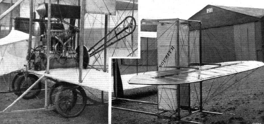
Views showing the British-built A B C engine and the tail of the Sopwith-Wright biplane. - The twin rudder is mounted on a single pivot at each end, the horizontal tail plane is fixed, and has a flexible trailing edge for use as an elevator.
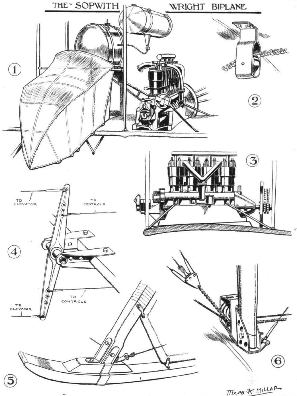
THE SOPWITH-WRIGHT BIPLANE. - Sketches illustrating various constructional details: 1. The nacelle, which protects the pilot from the wind. 2. Portion of the short length of chain which is used as a link in the warp wires where they pass over the pulleys. 3. Method of mounting the engine on the lower plane. 4. Pivoted lever for gearing up the elevator to the control lever. 5. The toe portion of one of the skids. 6. Another sketch showing how the warp wires are carried round their pulleys.
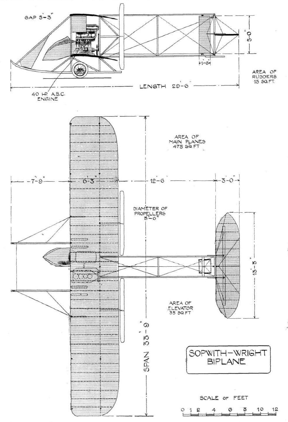
Elevation and plan of the Sopwith-Wright biplane.
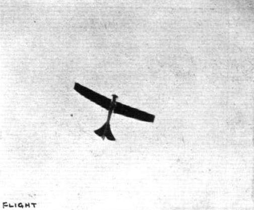
The Vickers monoplane in flight at Brooklands.
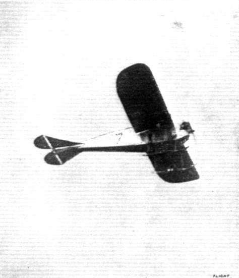
The Vickers monoplane, with Mr. C. MacDonald at the wheel, flying in a cross-country handicap at Brooklands at Whitsun.
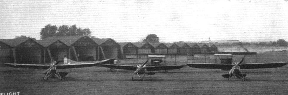
A trio of Vickers monoplanes at the Vickers Brooklands School.
Flight, August 24, 1912.
THE VICKERS MONOPLANE.
LIKE the previous productions of this firm, Vickers monoplane No. 6, is essentially a steel-built structure. The body is wedge-shaped, pointed in front and flattening away horizontally towards the rear. Unlike the general run of monoplane bodies, it is wider than it is deep in order to seat pilot and passenger side by side. In plan view the body does not taper towards the tail, so in retaining its extreme width it serves in the capacity of a stabiliser, and renders unnecessary the application of any fixed horizontal surface to perform that function. The attitude of the machine in flight is varied by two balanced elevators. To the front of the body is bolted a 70-h.p. radial air-cooled Viale motor, which drives direct a Chauviere propeller. Inside the cockpit the occupants are each provided with controls, which are in the form of universally jointed vertical levers operating the elevators and the wing warping, and pivoted foot-bars for steering. Great ingenuity is displayed in the design of the undercarriage. Its type is distantly related to that of the Nieuport. It is exceptionally strong and flexible, and has the additional advantage of offering little head-resistance. A single central skid is attached to the body by means of two pairs of struts in Vs. The bases of the V's are not rigidly attached to the central skid, but are joined flexibly thereto by the interposition of two laminated steel springs, an idea that, we believe, was first originated by the designers of the German Albatross biplane, one of the cleverest exhibits at the last Paris Aero Show. The way in which the wheels are mounted is shown in one of our sketches. Shocks are absorbed in the same manner as on the R.E.P. monoplane. The oblique compression strut from the wheel is attached to a sliding collar which moves vertically up and down one of the vertical members of the fuselage. Movement of this collar is opposed by rubber springs in tension. Some 6 inches above the skid, and parallel to it, is arranged a long rotating tube which carries two sets of cranks. The set at the rear operates the wing warping, those in front are connected to the controlling levers. The wings are, outwardly, of more or less conventional type of construction, and span 34 ft.
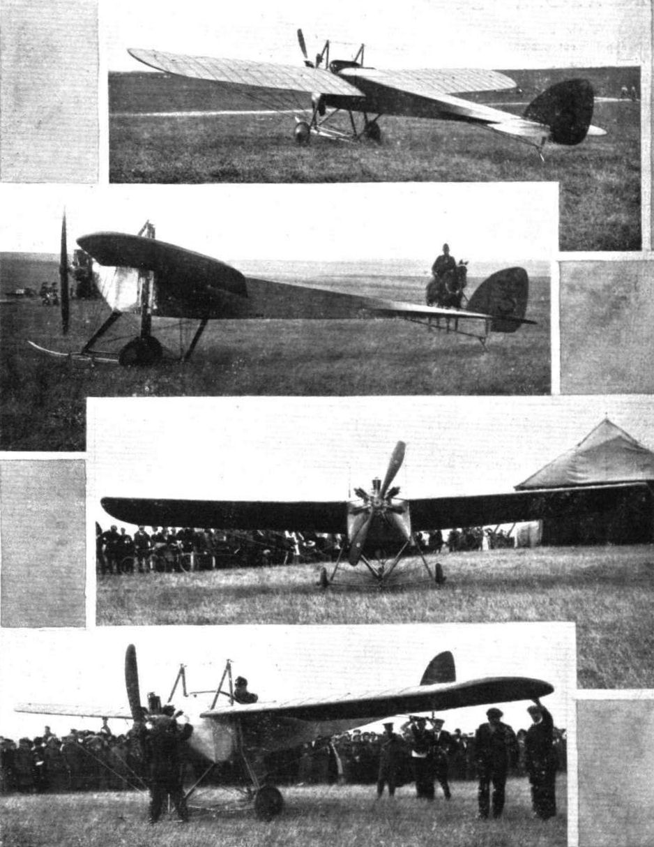
The Vickers monoplane, fitted with 70-h.p. Viale engine, piloted by Macdonald in the Army Aeroplane Competition on Salisbury Plain.
A trio of Vickers monoplanes at the Vickers Brooklands School.
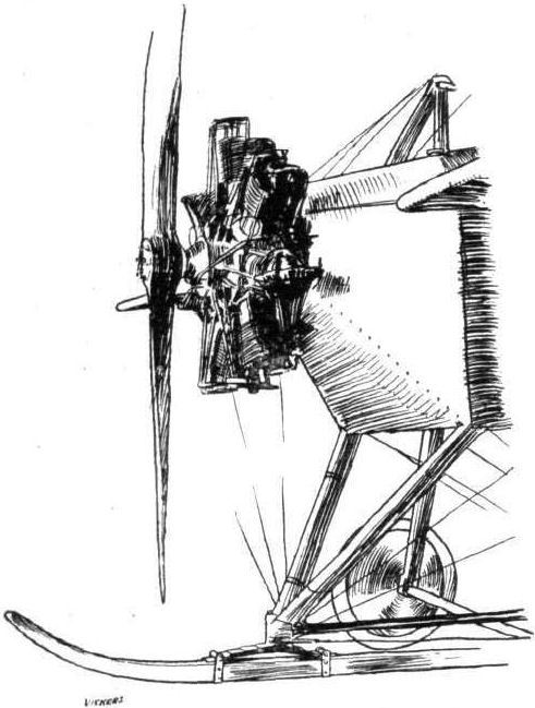
THE VICKERS MONOPLANE.-Sketch showing the engine-mounting and landing-skid.
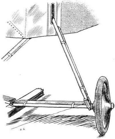
THE VICKERS MONOPLANE. - The landing-chassis.
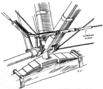
THE VICKERS MONOPLANE. - Showing how the front chassis-struts are connected to the central landing-skid, and insulated therefrom by a laminated steel spring.

THE VICKERS MONOPLANE. - The mechanism that operates the wing-warping. Note the laminated steel spring that insulates the chassis-strut from the skid.
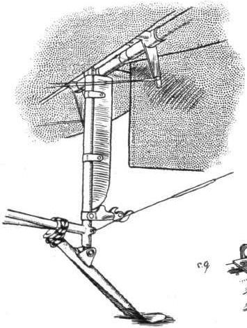
THE VICKERS MONOPLANE. - Details of the tail, showing the tailskid and release-catch.
Flight, November 2, 1912.
German Hydro-Aeroplane Meeting.
THREE hydro-aeroplanes took part in competitions at Putzig on October 25th, when all the events were won by Thelen on an Albatross, which was eventually purchased by the Government. In the speed test he covered the ten kilometres in 12 mins. 12 secs. The other competitors were Fischer (Aviatik) and Gorrissen (Ago).
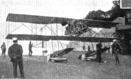
HYDRO-AEROPLANES AT THE HEILIGENDAMM MEETING. - Von Gorissen on then Ago biplane.

A series of German aeroplanes at Johannisthal from photographs kindly sent to us by the Hon. Lady Shelley. - Albatross biplane.
Flight, January 6, 1912.
PARIS AERO SHOW.
Albatross.
THIS interesting biplane is of the engine-in-front type, and altogether one of the finest examples of workmanship in the Salon. Its fuselage is covered throughout the whole of its length with a thin veneer of wood, the radiator being disposed under the front, below the engine, where it does not interfere with the graceful outline of the machine, and where it is in a position to receive the maximum amount of cooling draught from the propeller. Its main planes are trussed by a system of wooden-compression struts, no wire bracing being employed. The top main-plane is slightly longer in span than the lower one, and its extremities are turned back and given a negative angle of incidence, much after the same manner as that employed by the Etrich machines. Its landing gear is easily the soundest and strongest of all those present at the Salon. In its main outline it has much in common with the ordinary Farman chassis, but possesses the extra advantage that the struts supporting the fuselage are not directly attached to the skids, but applied flexibly thereto by the interposition of laminated steel springs. The horizontal stabilizing surface is triangular in plan form, and extends backwards from a point level with the rear of the pilot's seat. This surface continues behind the end of the fuselage, and is flexed for the purpose of giving the machine an upward or downward direction.
Principal dimensions, &c.:-
Length 34 ft.
Span 44 ,,
Area 440 sq. ft.
Weight 925 lbs.
Speed 55 m.p.h.
Motor 100-h.p. Argus
Price L1,200.
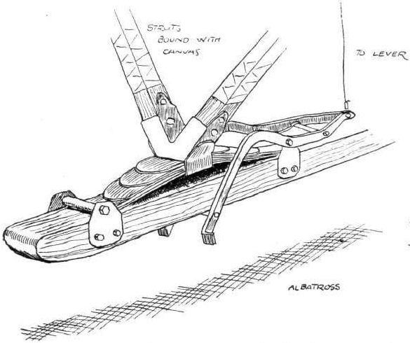
Sketch showing flexible attachment of skids by means of laminated steel springs, and landing-brake on the Albatross biplane.

The Albatross engine-in-front type biplane.
Flight, December 28, 1912.
SOME GERMAN MACHINES.
By G. B.
<...>
In the review of the 1911 Paris Salon reference was made to the splendid workmanship of the Albatross biplane, which was also distinguished by the use of diagonal compression struts, thus obviating the use of wire bracing. This system is continued in the latest machine, and is well illustrated in the three sketches herewith, which also show the strong landing chassis employed. Another characteristic feature is pronounced dihedral angle of the lower planes. In last year machines a flexing tail was employed, but this has now been replaced by an elevator. In the Mars biplane ailerons are only fitted to the upper planes. The fuselage and landing chassis of this machine is exactly the same as on the monoplane turned out by the same manufacturers, and, except for the wings of course, the various parts of the machines are interchangeable.
<...>
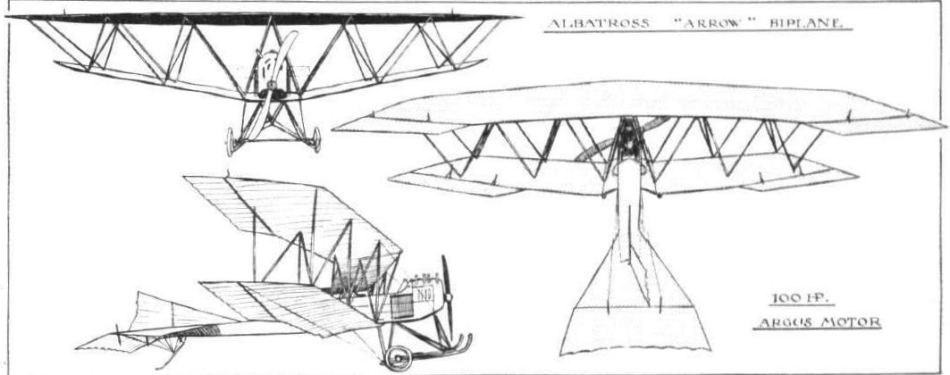
Three sketches showing the latest developments of the Albatross "Arrowplane," one of the foremost German biplanes. The chassis and triangular system of struts remains the same as on the machine exhibited at the Paris Salon in 1911, but the planes now have a flattened V form, with ailerons, instead of being of the Etrich type.
Flight, November 2, 1912.
German Hydro-Aeroplane Meeting.
THREE hydro-aeroplanes took part in competitions at Putzig on October 25th, when all the events were won by Thelen on an Albatross, which was eventually purchased by the Government. In the speed test he covered the ten kilometres in 12 mins. 12 secs. The other competitors were Fischer (Aviatik) and Gorrissen (Ago).
German Hydro-Aeroplane Meeting.
THREE hydro-aeroplanes took part in competitions at Putzig on October 25th, when all the events were won by Thelen on an Albatross, which was eventually purchased by the Government. In the speed test he covered the ten kilometres in 12 mins. 12 secs. The other competitors were Fischer (Aviatik) and Gorrissen (Ago).

HYDRO-AEROPLANES AT THE HEILIGENDAMM MEETING. - View of the Albatross from behind.

HYDRO-AEROPLANES AT THE HEILIGENDAMM MEETING. - Slipway and protecting breakwater.
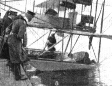
HYDRO-AEROPLANES AT THE HEILIGENDAMM MEETING. - The forward floats of the Albatross..
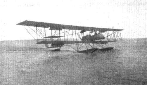
HYDRO-AEROPLANES AT THE HEILIGENDAMM MEETING. - Thelen in the Albatross.
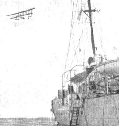
HYDRO-AEROPLANES AT THE HEILIGENDAMM MEETING. - The Albatross biplane flying round the cruiser "Munchen."
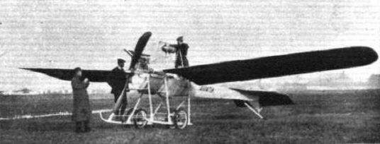
A series of German aeroplanes at Johannisthal from photographs kindly sent to us by the Hon. Lady Shelley. - Jeannins (Aviatik ???) monoplane.
Flight, November 2, 1912.
German Hydro-Aeroplane Meeting.
THREE hydro-aeroplanes took part in competitions at Putzig on October 25th, when all the events were won by Thelen on an Albatross, which was eventually purchased by the Government. In the speed test he covered the ten kilometres in 12 mins. 12 secs. The other competitors were Fischer (Aviatik) and Gorrissen (Ago).
German Hydro-Aeroplane Meeting.
THREE hydro-aeroplanes took part in competitions at Putzig on October 25th, when all the events were won by Thelen on an Albatross, which was eventually purchased by the Government. In the speed test he covered the ten kilometres in 12 mins. 12 secs. The other competitors were Fischer (Aviatik) and Gorrissen (Ago).
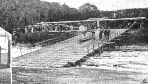
HYDRO-AEROPLANES AT THE HEILIGENDAMM MEETING. - Buchner on his Aviatik biplane on the slipway.
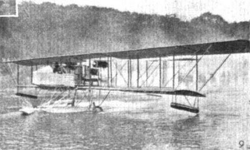
HYDRO-AEROPLANES AT THE HEILIGENDAMM MEETING. - Buchner afloat on his Aviatik biplane.
Flight, July 13, 1912.
THE MILITARY COMPETITION - THE MACHINES.
THE MARS MONOPLANE.
FLYING under the official number 23 in the Military Aeroplane Trials will be a machine called the Mars, entered by Mr. C. E. Kny, and constructed in the Deutsche Flugzeug Werke at Leipzig.
As the photograph shows, this monoplane is of interesting and original design. It has a completely covered body, in which two cockpits are provided for the pilot and passenger; the latter, who in a military aeroplane would be the observer, has a position in front of the pilot, and a clear outlook over the wings. Both pilot and passenger have the appearance of being seated very high in the machine, and, similarly, the wings seem to be low-pitched; but in reality this is mainly due to the protective covering that arches over the top of the boat-shaped body.
The engine, a 100-h.p. Mercedes, is situated in the extreme front, and short exhaust pipes discharge the gases below the level of the wings. The wings themselves are built somewhat on the lines of the Etrich, at least, they have the characteristic Etrich upturned tips. The elevator and rudder are situated in the tail, which, by the way, is braced by long diagonal wires to the triangular mast above the cockpit. Corresponding wires pass downwards beneath the body to the main struts of the undercarriage, which is especially worthy of close examination as an interesting feature of construction. In all probability, Lieut. Bier, who is at the wheel in our photograph, will fly this machine; it has already attained a speed of 80 m.p.h. when fully loaded with passenger and fuel for four hours. The weight of the machine is about 1,170 lbs. The span is 53 ft. and overall length just under 45 ft.; the supporting surface is 350 sq. ft.
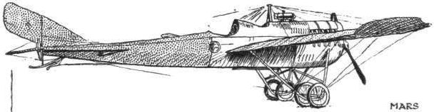
Flight, December 28, 1912.
SOME GERMAN MACHINES.
By G. B.
<...>
Generally speaking, it may be said that while the French designers have been striving mainly for speed the Germans have paid a great deal more attention to the question of lateral stability. This will be obvious front a study of the accompanying photographs, which we are enabled to reproduce by the courtesy of our contemporary Flugsport. In monoplane design the influence of Grade and also of Etrich has been very marked, many machines having the underslung position of the pilot of the former, while the bird-shaped plane, evolved by the latter in a modified form, is quite common. When the Etrich monoplane assumed a practical form in Austria in 1910, arrangements were at once made for it to be manufactured in Germany, and under the name of Rumpler-Taube or Pigeon, it has proved very successful in competition, and has also been favourably received by the military authorities. With regard to biplanes, the Albatross Co. exhibited at the 1911 Paris Salon one of their machines in which the tips of the upper plane were arranged somewhat on the Etrich plan. Since then, however, this firm have abandoned this system in favour of main planes with a flattened V form similar to the "Lohner" arrow-plane," entered for the British military trials. The Mars biplane is on more or less the same general lines.
<...>
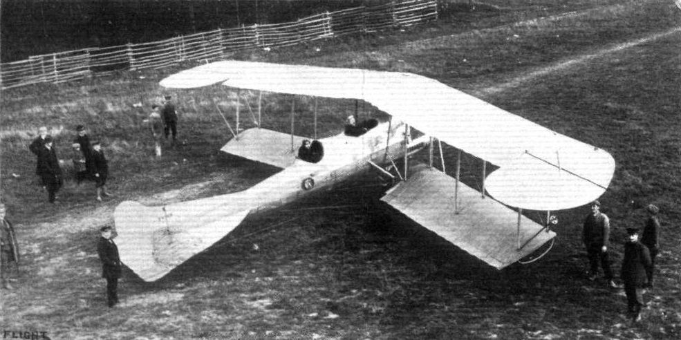
The Mars biplane, the fuselage and landing chassis of which are exactly similar to that of the Mars monoplane.
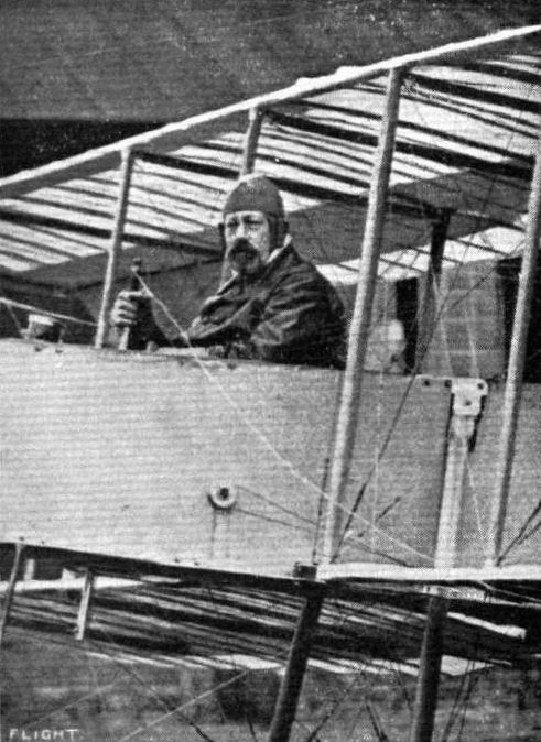
"A flying machine is neither an open grave nor a toy for children." Such is the expression to which Prince Henry of Prussia, certified aviator, has subscribed his signature as above for his portrait on the Euler biplane on which he qualified for his pilot's certificate.
Flight, December 7, 1912.
The Woman's Height Record. .
AT Johannisthal, on the 22nd ult., the Russian aviatress, Mdlle. Galanschikoff, took a Fokker monoplane up to a height of 2,400 metres, which, it is claimed, is a record for a lady pilot.
The Woman's Height Record. .
AT Johannisthal, on the 22nd ult., the Russian aviatress, Mdlle. Galanschikoff, took a Fokker monoplane up to a height of 2,400 metres, which, it is claimed, is a record for a lady pilot.
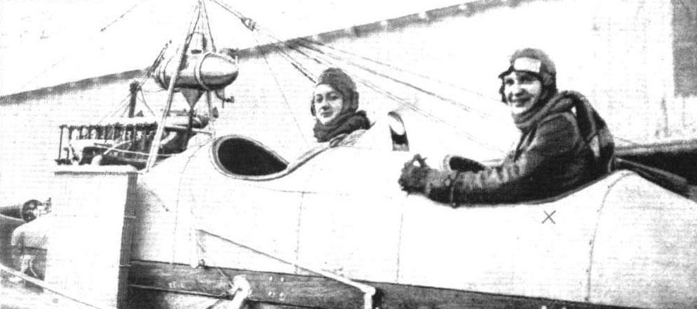
Miss L. Galanschikoff (X), the Russian aviatress who, on November 22nd, at Johannisthal, on a 100-h.p. Fokker monoplane, made a world's altitude record for lady flyers with 2,400 metres. The previous record was to the credit of Miss Melly Beese with 820 metres.
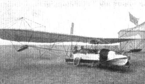
HYDRO-AEROPLANES AT THE HEILIGENDAMM MEETING. - The Goedecker monoplane with its boat-shaped body.
Flight, December 28, 1912.
SOME GERMAN MACHINES.
By G. B.
<...>
The photograph of one of the latest military type Grade monoplanes shows that the design, in its general lines, has been very little altered from the original machine, what changes there have been being mainly in the nature of detail improvements.
<...>
SOME GERMAN MACHINES.
By G. B.
<...>
The photograph of one of the latest military type Grade monoplanes shows that the design, in its general lines, has been very little altered from the original machine, what changes there have been being mainly in the nature of detail improvements.
<...>
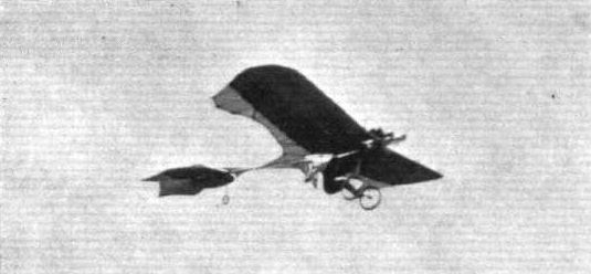
A series of German aeroplanes at Johannisthal from photographs kindly sent to us by the Hon. Lady Shelley. - Grade monoplane.
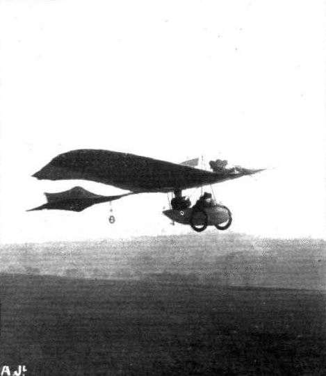
One of the newest Grade, military-type, monoplanes.
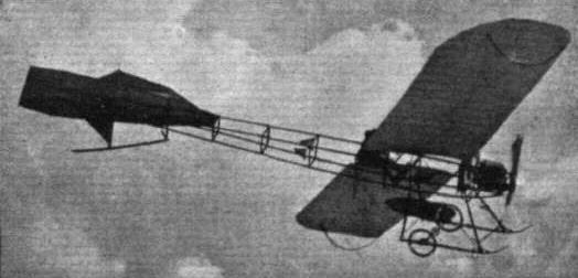
A series of German aeroplanes at Johannisthal from photographs kindly sent to us by the Hon. Lady Shelley. - Harlan monoplane.
Flight, December 28, 1912.
SOME GERMAN MACHINES.
By G. B.
<...>
A machine which has achieved success, not only in its own country, but elsewhere, is the Harlan, a number of which were supplied recently to the Turkish Army.
<...>
SOME GERMAN MACHINES.
By G. B.
<...>
A machine which has achieved success, not only in its own country, but elsewhere, is the Harlan, a number of which were supplied recently to the Turkish Army.
<...>
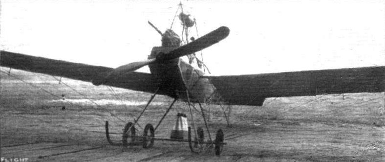
One of the latest military-type Harlan monoplanes recently delivered to the Turkish Army.
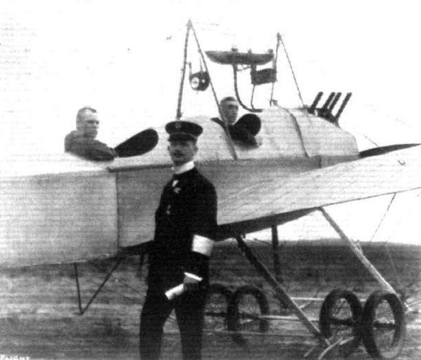
Lieut. Krieget and Lieut. Friedensburg on their Harlan military-type monoplane, which was awarded first prize in the recent contest for flying round Berlin.
Flight, December 28, 1912.
SOME GERMAN MACHINES.
By G. B.
<...>
The Jeannin follows very much on Hanriot lines.
<...>
SOME GERMAN MACHINES.
By G. B.
<...>
The Jeannin follows very much on Hanriot lines.
<...>
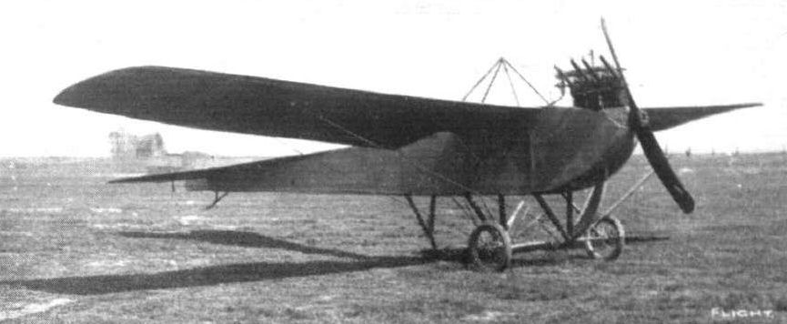
The Jeannin monoplane in its latest form, as seen at the Johanntsthal flying ground near Berlin.
Flight, December 28, 1912.
SOME GERMAN MACHINES.
By G. B.
<...>
In another photograph is seen a "canard" monoplane, with four rudders arranged under the main plane, with which Professor Reissner has been carrying out experiments at Johannisthal. Another somewhat unusual feature is that the planes are of special corrugated formation.
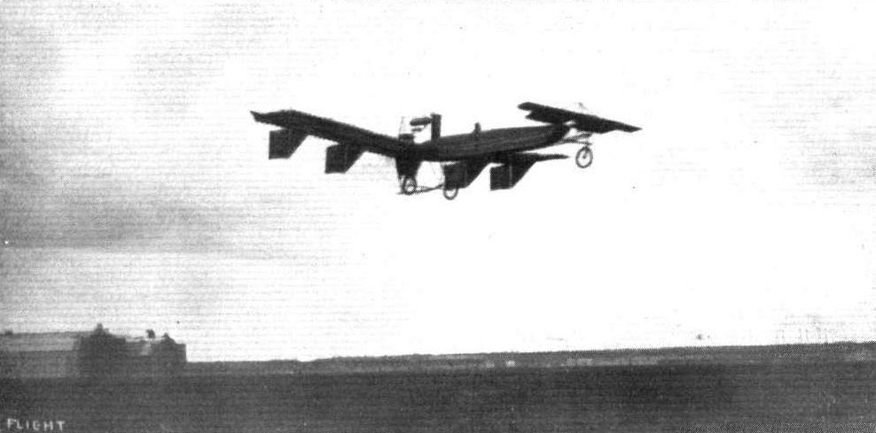
The experimental "canard" monoplane of Prof. Reissner, with four rudders under the main plane. This was flying recently at Johannisthal.
Flight, December 28, 1912.
SOME GERMAN MACHINES.
By G. B.
<...>
The Schulze monoplane, which we illustrate, has been built mainly for school work, and the design is a little reminiscent of the Train machine in France.
<...>
SOME GERMAN MACHINES.
By G. B.
<...>
The Schulze monoplane, which we illustrate, has been built mainly for school work, and the design is a little reminiscent of the Train machine in France.
<...>
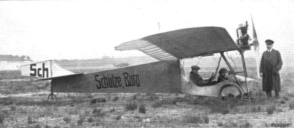
A Schulze monoplane, specially built for school work.
Flight, November 23, 1912.
EDDIES.
Jules Nardini, too, is intending to go abroad, and in all probability will be in Venice by the time these lines appear in print. It is to test a new hydro-monoplane that has been designed and built by Lieut. Calderara, that he is going there. In its design, so I learnt during a chat with Nardini on Tuesday last, it is unlike any machine flying to-day, in that a platform is provided, so that the four passengers the machine has been designed to carry may promenade to their heart's content. For its wings, they are not merely coupled up to the body of the machine by steel cable triangulation, but are braced on the open girder system that characterized the Bleriot test aerobus that the late Lemartin flew at Pau last year. A 100-h.p. Gnome is fitted which can be started by a mechanic on board the machine. Already some considerable amount of success has been met with during tests that have been carried out at Spezzia, where the machine was built. It has remained in the air for periods up to one and a half hours.
o o o
Lieut. Calderara is the most experienced flying man Italy possesses. His acquaintance with the art dates back to the early part of 1909, when he was learning to fly under the tuition of the late Wilbur Wright. He was that pioneer's first Italian pupil. He had a very serious smash away back in those early days, but fortunately he recovered sufficiently to enable him to compete in the Brescia meeting in the September of 1909, where he won L1,440 in prize money, and carried off the King's cup. From the biplane he turned his attention to the speedier single-decker, and did a great deal of flying. He was recently appointed instructor to the hydro-aeroplane pupils undergoing tuition at the Italian Government School at Venice.
Flight, April 27, 1912.
AVIATION IN NEW ZEALAND.
MR. F. O'CONNELL writes from 218, Peterbouragh Street, Christchurch, New Zealand, enclosing the two photographs reproduced below :-
He says: "I have much pleasure in forwarding you photos of a glider taken during trials at our ground. The machine is of Chanute type, built by two members, Messrs. Bolt and Angus. Great success was attained in towed flights with passengers, about fifty trips through the air being indulged in before a bad smash through faulty towing put an end to experiments for a week or so. Among the many passengers carried was a lady, the wife of Mr. Johnassen, Club Engineer."
Mr. O'Connell is the Hon. Secretary of the Canterbury Aero Club, which will extend a hearty welcome to representatives of clubs in the old country who may contemplate visiting New Zealand.
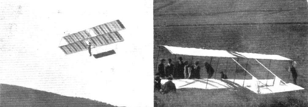
The Canterbury (New Zealand) Aero Club glider in flight, and on the right is seen a group of members repairing the damage after the smash.
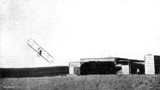
An example of a banking by Lincoln Beachey at Los Angeles not to be imitated. With this sort of circus performance it is hardly surprising to hear of so many sudden death from America.
Flight, February 17, 1912.
FOREIGN AVIATION NEWS.
Hugh Robinson gets a Ducking.
WHILE flying the Curtiss hydro-aeroplane at Nice on the 10th inst., Hugh Robinson was pitched from his machine into the sea. Although the wind was very strong, Robinson decided to make a trial, and after a short glide along the sea rose to a good height and circled twice over the bay. He then attempted to alight, but just as the floats touched the sea, a gust of wind seemed to catch the machine and overturn it. The pilot was thrown from the machine but was easily able to keep afloat until assistance arrived. Our photographs in this issue are unique of this incident.
On the previous day, while giving an exhibition flight over the bay, Robinson dropped an invitation to dinner to Admiral Moreau on to the deck of the ironclad "Justice."
Flight, March 9, 1912.
FOREIGN AVIATION NEWS.
Paulhan Wins the Aspremont Cup.
AT Nice on the 1st inst., Paulhan succeeded in fulfilling the conditions stipulated and won the Aspremont Cup. He rose from the surface of the sea at Juan-les-Pins on the Curtiss hydro-aeroplane and flew to the California Aerodrome, where he landed after covering the 25 kiloms. in 15 minutes. Starting up again from the aerodrome he passed down in front of the Palais de la Jetee on to the surface of the sea and then rising again flew back to the California ground. An hour later he rose once more and returned to his headquarters at Juan-les-Pins.
FOREIGN AVIATION NEWS.
Hugh Robinson gets a Ducking.
WHILE flying the Curtiss hydro-aeroplane at Nice on the 10th inst., Hugh Robinson was pitched from his machine into the sea. Although the wind was very strong, Robinson decided to make a trial, and after a short glide along the sea rose to a good height and circled twice over the bay. He then attempted to alight, but just as the floats touched the sea, a gust of wind seemed to catch the machine and overturn it. The pilot was thrown from the machine but was easily able to keep afloat until assistance arrived. Our photographs in this issue are unique of this incident.
On the previous day, while giving an exhibition flight over the bay, Robinson dropped an invitation to dinner to Admiral Moreau on to the deck of the ironclad "Justice."
Flight, March 9, 1912.
FOREIGN AVIATION NEWS.
Paulhan Wins the Aspremont Cup.
AT Nice on the 1st inst., Paulhan succeeded in fulfilling the conditions stipulated and won the Aspremont Cup. He rose from the surface of the sea at Juan-les-Pins on the Curtiss hydro-aeroplane and flew to the California Aerodrome, where he landed after covering the 25 kiloms. in 15 minutes. Starting up again from the aerodrome he passed down in front of the Palais de la Jetee on to the surface of the sea and then rising again flew back to the California ground. An hour later he rose once more and returned to his headquarters at Juan-les-Pins.
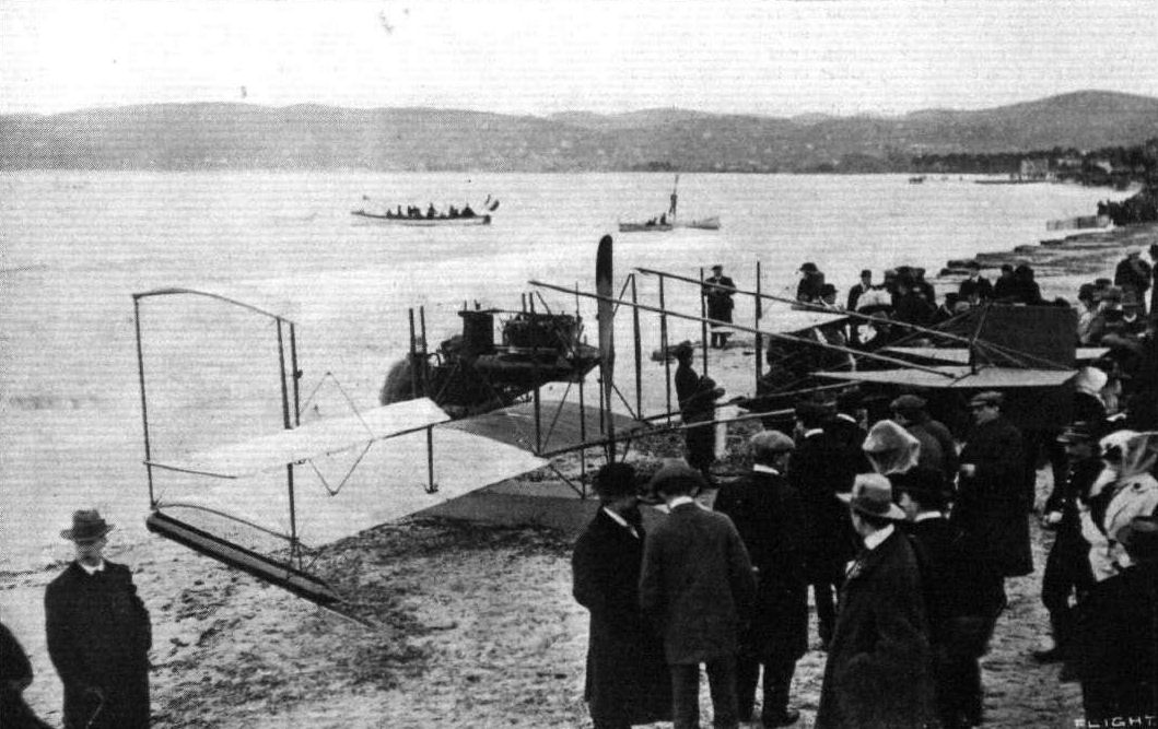
HYDRO-AEROPLANING AT NICE. - The start and the finish of one of Hugh Robinson's flights over the sea on a Curtiss "triad." Below is the machine on the beach ready for a demonstration.

THE CURTISS HYDRO-AEROPLANE AT NICE. - Our picture shows very clearly the arrangement of the elevator, the main float, and the position of the pilot's seat, engine, &c. This is the machine which, under the direction of Mons. Paulhan, has been flown by Hugh Robinson, and of which the two photographs appeared in a recent issue, showing the machine in connection with the flight when Robinson was pitched into the sea.

A souvenir postcard from M. L. Paulhan, sent to Mr. Holt Thomas, of his hydro-aeroplane work by which be has iust secured the Coupe d'Aspremont.
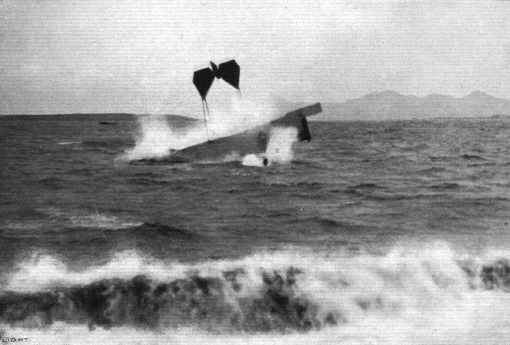
HYDRO-AEROPLANING AT NICE. - The start and the finish of one of Hugh Robinson's flights over the sea on a Curtiss "triad." Above is a remarkable "snap" at the moment when it struck the water.
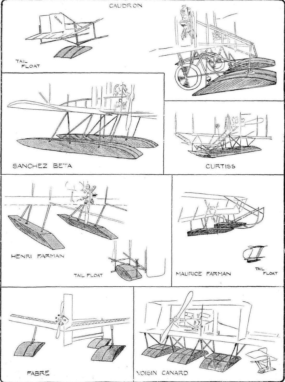
Hydro-aeroplanes, illustrating the paper by Mr. Holt Thomas.
Flight, June 8, 1912.
A.C. OF AMERICA AERO SHOW.
By LIEUT. GUY HILHOUSE, R.N.
<...>
Perhaps the most interesting exhibit is an entirely new and novel design Gallaudet monoplane, which although not yet perfected, has had several trials. It is fitted with a 14-cylinder, 120-h.p. Gnome, and has frequently attained a speed of 105 miles per hour. It was built and designed by two brothers, Gallaudet, at Norwich, Connecticut, and is of great strength. A hollow Vanadium steel tube of 34 in. diameter, and 3/16 in. thick runs clear through the centre of each wing and right across the fuselage. In addition, the wings are exceptionally strongly stayed against upward or downward pressures. There is an original device for altering the angle of incidence of the wings from the driver's seat, so variable speed can be obtained with an even keel. The whole landing chassis body and fuselage are built up of hollow 3 per cent, nickel-steel tubing, and are entirely enclosed with sheer aluminium and silk covering. The Gnome engine is in the usual place in front, but a 3-bladed "Paragon" propeller is placed right behind the stern rudders giving the whole machine a flying-fish-like appearance. Lateral balance is secured by warping, the arrangement being inside the wing and controlled through pedals, or it may be left to the automatic action of the cross-connections and the machine's fundamental stability, the tail and the rudder are operated by a single hand lever. All machines are designed to carry two persons and have double controls, and the whole machine is built of steel.
It will take part in the Gordon Bennett race at Chicago this year, which experts here confidently assert it will win.
<...>

Three views of the Gallaudet racing monoplane, which has a 3-bladed propeller at the rear. The wings are 32 ft. span, and they have a chord of 8 ft. Wing-warplng is fitted, the mechanism being built into the planes.
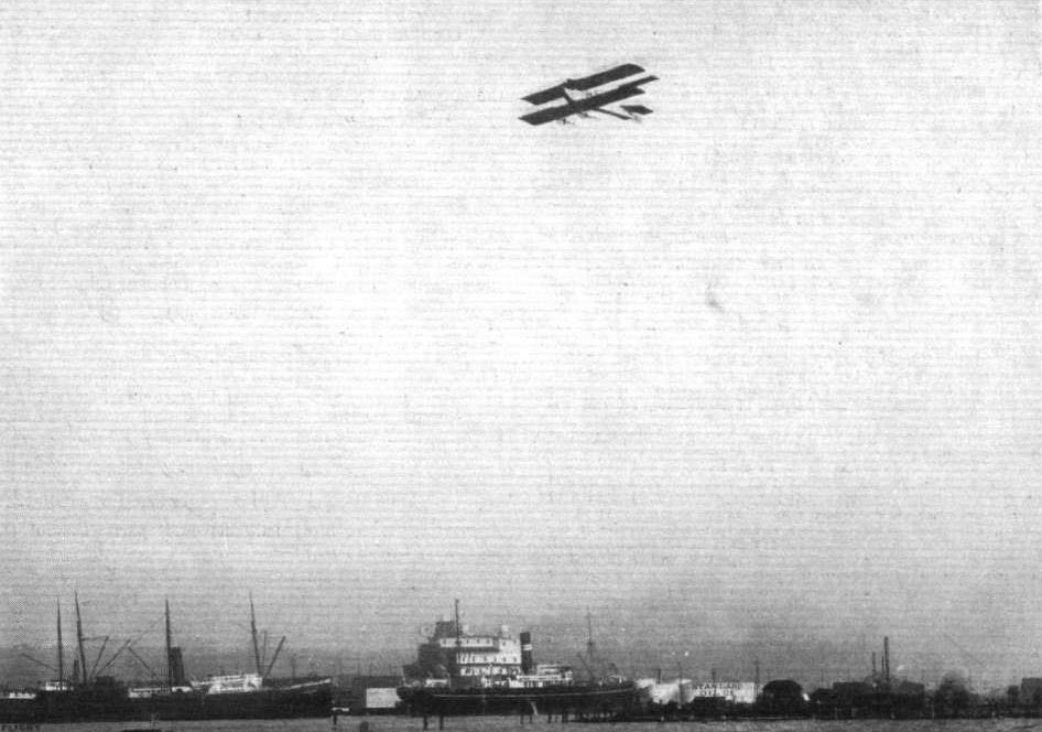
Capt. James V. Martin, one time associated with the Grahame-White School, in his latest Martin type tractor biplane, over Seattle Harbour, U.S A., July 2nd last. The above photograph has reached us from Mr. Martin with kind regards from himself and Mrs. Martin.
Flight, January 13, 1912.
PARIS AERO SHOW.
The Sloan Biplane.
IT will be remembered that at the last Aero Show in Paris appeared a biplane of the engine-in-front type of which the top plane was considerably arched. In the machine that the Sloan firm are exhibiting this year this arching of the upper planes is much less pronounced, and its extremities are not carried down to meet the lower planes, as was the case with last year's models. The central unit of construction of the machine takes the form of a fuselage built on the conventional box-girder principle, at the front end of which is disposed the power unit - a 100-h.p. Gnome engine and Chauviere propeller. The fuselage in the region of the pilot's and passenger's seats is covered over with a thin veneer of bird's-eye maple. For the rest of its length it is uncovered. Lateral balance is arrived at by the use of ailerons, which are fitted to the top plane only, which has a span of 43 ft. The lower plane spans a little under 30 ft. As regards this landing chassis, that fitted is of the Farman type, consisting of two skids, each of which is furnished with a pair of flexibly-sprung swiveling wheels. For the past year trials of the earlier type of machine have been taking place both at Issy and Juvisy, and it is on the result of these tests that the design of the present machine is based.
Principal dimensions, &c. :-
Length 32 ft.
Span 43 ft.
Area 540 sq. ft.
Weight 1,200 lbs.
Speed 58 m.p.h.
Motor 100-h.p. Gnome
Price L1.400.
Flight, November 16, 1912.
THE PARIS AERO SALON.
Sloan.
THIS is a tractor biplane which does not seem to have changed in any respect from last year's machine excepting in that a 150-h.p. Laviator engine is fitted in place of last year's 100-h.p. Gnome, and that the peculiar curvature of the main planes is less accentuated. Its main points are that it has a box girder fuselage of wood, cross braced with wire, that its tail is of conventional lifting type with rear flap elevators protected from the ground by a bent skid, that its main planes are braced in the ordinary manner with two ranks of struts, and that its landing carriage is of a type descendant from the Henry Farman.
Flight, March 9, 1912.
AEROPLANE UNDERCARRIAGES.
By G. DE HAVILLAND.
Types of Undercarriage.
The Wright aeroplane is chiefly interesting from the fact that it was the first practical machine in which a rigid framework was provided beneath the planes in place of the flexibly mounted undercarriages adopted by the French constructors at about the same period, the outcome of these two systems being the combination of skids and wheels in later types of machines.
The chief advantage of this system is, that it provides a rigid structure to which the main lifting-wires may be fixed, these wires also being effective in taking any side-strains imposed on the undercarriage itself.
Flight, April 13, 1912.
Fatal Accident to Rodgers.
ALTHOUGH only scanty details are as yet to hand it would appear that the fatal accident to Galbraith Rodgers, who made a name for himself by flying across the United States from New York to California, was largely due to recklessness. He had been giving exhibition flights at Long Beach, California, on the 4th inst., and had been amusing himself by scattering a flock of gulls by diving into them. In the last dive the machine apparently failed to answer the controls and crashed to the beach 100 ft. below. The pilot had his neck broken and must have been killed instantly.
Flight, November 2, 1912.
BRITISH NOTES OF THE WEEK.
British Duration Records.
FLYING for the British Michelin Cup No. 1 on the 24th ult., at Brooklands.on the Sopwith-Wright biplane fitted with a 40-50-h.p. A.B.C. engine, Mr. H. G. Hawker made a non-stop trip of 8 hrs. 23 mins., the flight only being terminated by the gathering darkness. Subject to the confirmation of the Royal Aero Club Committee, this performance secured the Cup to Mr. Hawker for this year as his time was unbeaten when the competition closed on Thursday last. A Bosch magneto was fitted, and the A.B.C. engine ran without a single misfire. Shell spirit was used and Wakefield's Castrol "R" was depended on for lubricant. Mr. Hawker started at 9.15 a.m. while Mr. F. P. Raynham was still going steadily round and round on the Avro enclosed military biplane, fitted with 60-h.p. Green engine. Raynham started at daybreak and remained in the air for 7brs. 3l?mins., the flight being terminated by the lubricant giving out. Last year's record for the cup was 5 hrs. 15 mins. by Col. Cody.
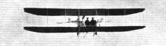
A series of German aeroplanes at Johannisthal from photographs kindly sent to us by the Hon. Lady Shelley. - German Wright Biplane.

FLYING AT BROOKLANDS. - Raynham, with a passenger, making a fine turn on the Burgess-Wright biplane on Sunday at Brooklands.
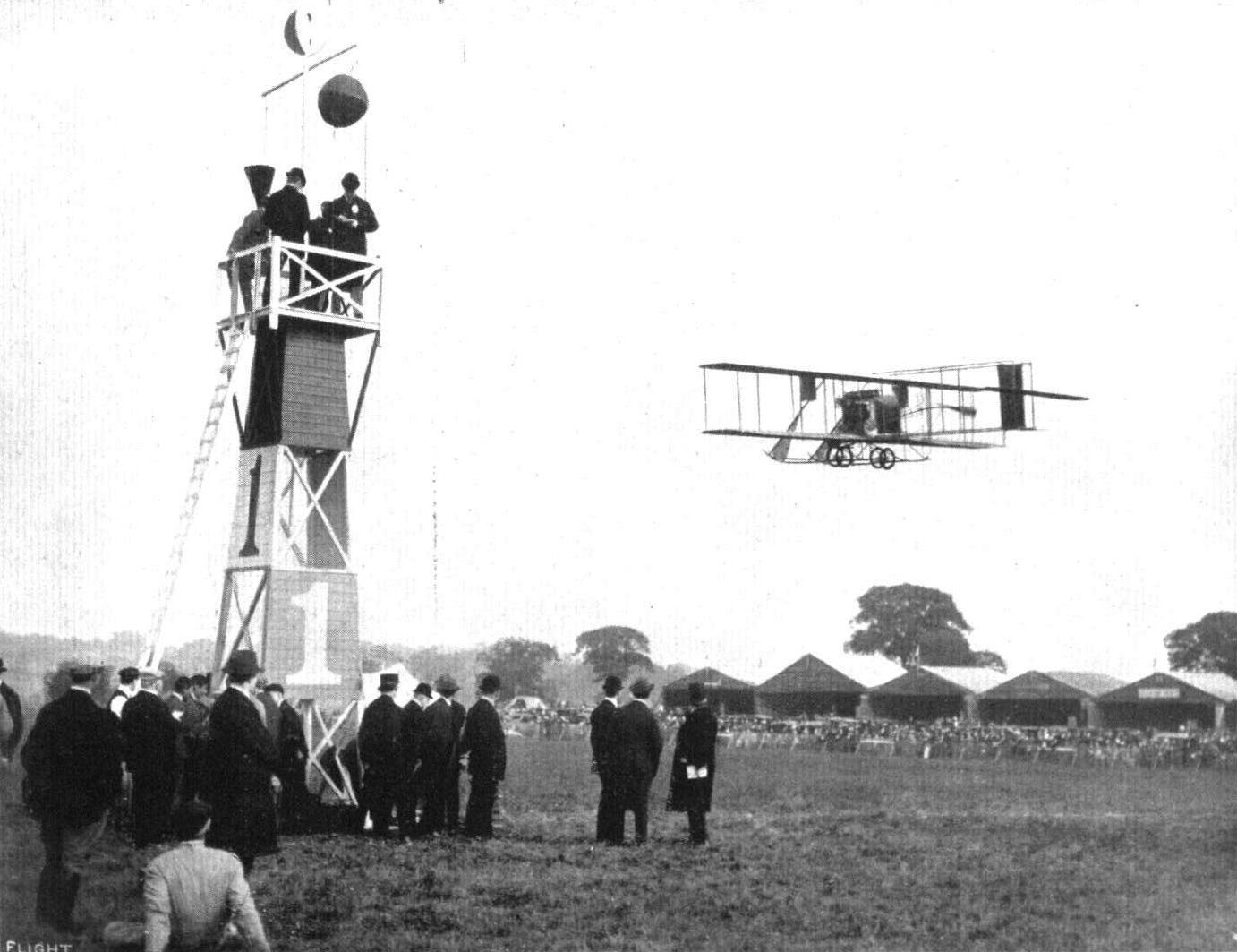
A snap of Rayham flying on the Burgess-Wright in connection with one of the contests - the Shell - at Hendon Aerodrome during the past season.
Raynham, on the Burgess-Wright and Lewis Turner putting up a fine finish in the order named for the "Shell" Speed Contest at Hendon on Aerial Derby Day.

An incident between two biplanes in the recent race for the "Shell" Spirit Prize at Hendon. - Lewis Turner on Farman, and Raynham on the Burgess-Wright, travelling down the aerodrome.
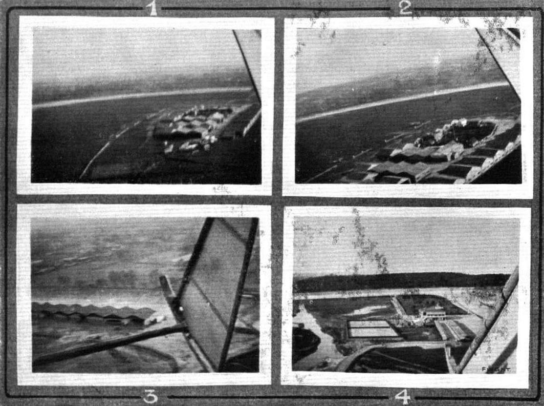
A selection of photographs of the Brooklands flight colony secured by Mr. P. Raynham, piloting a Burgess-Wright biplane. - 1. The sheds as seen from above the sewage farm. 2. As they appear from above the railway straight. 3. The sheds against the Byfleet banking. 4. The Club House, paddock, and tennis courts.
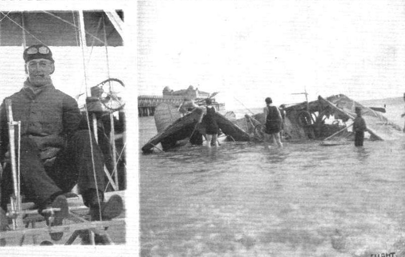
Cal Rodgers, the first American cross-Continental aviator, who was killed at Long Beach on April 22nd. On the right is a photograph of the wrecked machine showing where it fell to the edge of the surf.

Miss Katherine Stinson, a lady pilot who recently obtained her brevet in America at Cicero Field, where she passed for her certificate on a Wright biplane.
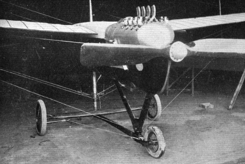
In their new military monoplane, "La Triplette," the Antoinette firm have made use of an altogether new form of landing chassis. The motor, an 8-cyl. Antoinette of 60-h.p., is covered by a shield, as on the Martin-Handasyde monoplane, to reduce head resistance.
Flight, November 16, 1912.
THE PARIS AERO SALON.
Astra.
THE main differences in this year's Astra machine as compared with the one that figured at last year's Salon, are that it is equipped for water-flying and that steel has been employed largely in its construction. Wood is, in fact, very little used, for only the ribs of the main planes and the floats are constructed of it. The main body as before, is of triangular section, but, this year, it is built up of steel tubes, acetylene welded and braced with piano wire. To it in front are attached by more steel tubes, two massive wooden floats of Tellier construction. In the wings, large diameter steel tubes have replaced the old pattern wood spars, and over them the ribs are loosely jointed in such a manner that the warping works with extraordinary freedom. The old system of Wright wing flexing and strut attachment is retained. There are seats for three, the front one being for the observer, and the two to the rear being for pilots, each of whom is provided with controls. Fitted with a 12-cylinder Renault engine of 100-h.p., it looks a machine for serious work. M. Maurice Herbster, who was kind enough to explain its various paints to us, gave out a hint that the British Admiralty were considering ordering quite a number.
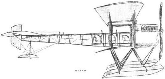
The 100-h.p. Astra hydro-biplane.
Flight, November 16, 1912.
THE PARIS AERO SALON.
Bertin.
M. Bertin's machine is a monoplane which follows in its general design conventional practice. Its main body, pentagonal in section, is a girder of wood and steel wire. In front is mounted an 8-cyl. 100-h.p. engine of M. Bertin's own design and constiuction. The tail has fixed vertical and horizontal surfaces, to which are hinged respectively the rudder and the elevators. Its chassis built up entirely of steel tubing, and although not highly original, is, nevertheless, extremely neat and effective. Its flexibility is derived from steel compression springs enclosed in the outer oblique chassis struts, the vertical centre ones acting purely as guides.
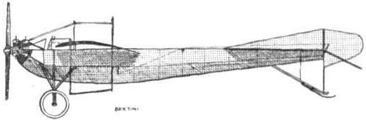
The 100-h.p, Bertin monoplane.

The landing-gear of the Bertin monoplane,
Flight, January 13, 1912.
PARIS AERO SHOW.
Besson Monoplane.
THIS interesting monoplane, in which most of the weight is disposed below the supporting surfaces, is of the tail first or "canard " type, so constructed in order to make it more suitable for the attachment of floats for hydro-aeroplane work. The pilot is seated in the fuselage below and slightly in advance of the wings, in which position he can gain a good view of what is beneath him and if necessary drop explosives with a considerable degree of accuracy. Ailerons are employed for lateral balance, these being governed from a control almost identical with that of the Voisin Canard. The motor, an Aviatic Rossel of 70-h.p., is arranged to the rear of the machine on a level slightly below that of the wings, and drives a Chauviere propeller of 2m. 50 diameter and 2m. 45 pitch.
Principal dimensions, &c. :-
Length 25 ft. Weight 725 lbs.
Span 38 ,, ; Speed 55 m.p.h.
Area 286 sq. ft. Motor 70-h.p. Aviatic Rossel
Flight, November 16, 1912.
THE PARIS AERO SALON.
Besson.
ALTHOUGH its general design remains the same, this machine has changed somewhat in its appearance since it made its debut at the last Paris Show. Then, the side elevation of the machine in the neighbourhood of the pilot's seat was such a curious one, and in fact so was the entire nature of the machine, that many were the questions asked as to the direction in which it flew. Further, it was rather humorous that after about three days of this there appeared on the stand large boards on which were painted equally large arrows to indicate the required direction. This, at any rate put an end to the exasperating questioning. But we digress. The appearance of the machine as it now stands can be gathered from one of our sketches. It may be seen that it has a triangular fuselage constructed entirely of steel tubing, acetylene welded. This, in fact, is a system on which the whole machine is constructed even to the wings. The balance of the machine laterally is to a certain extent effected naturally by the turned up wing tips, and by the flexible construction of the trailing edge, but so that lateral equilibrium may not altogether be out of the hands of the pilot, ailerons are fitted. The machine exhibited is in reality a three-seater and has been designed to fly with an 80-h.p. Gnome engine. At the Show it was temporarily fitted with a similar engine, but of only 50-h.p.

The Besson "canard."
Flight, January 6, 1912.
Spirited Contest for Coupe Femina.
THE closing days of the Old Year saw a keen duel between Mdlle. Helene Dutrieu and Mdme. Jane Herveu for the Coupe Femina, which was held during the year, with a record of 167.2 kiloms. Mdme. Herveu had been practising under Legagneux's guidance on a Bleriot monoplane at Compiegne, and on the 28th ult. she covered 97 kiloms. in 1h. 4m. 50s., then having to come down owing to rain, while on the 30th she covered 151 kiloms. in 1h. 44m. 23s., only to be brought down by a broken petrol pipe. Her best performance was on the last day of the Old Year, when 248 kiloms. (154 miles) were covered in 2 hrs. 41 mins. This, however was not sufficient to win the cup. At the same time Mile. Dutrieu was flying on her Farman biplane at Etampes, and covered 254.12 kiloms. (158 3/4 miles) in 2 hrs. 58 mins., and this, for the third time, secured the prize for her. On the previous day she made a flight of 140 kiloms.
BRITISH NOTES OF THE WEEK.
An Ingenious Aeroplane Trolley.
IN the accompanying photograph is seen the method employed by the Eastbourne Aviation Co. for conveying their machines by road. The trolley was specially constructed by them for the purpose, and consists of the front and back wheels of an ancient Oldsmobile, fixed to an ash framing made of 3 in. by 2 in. timber. The under-carriage of the machine is firmly bolted to this framing, and the wings are carried in a felt-lined trough fixed on either side. A tow-bar of the usual type is used to attach the trolley to the car.
The aeroplane, a 25 h.p. Anzani-Bleriot, seen on the trolley in our photograph, had just come a distance of 110 miles, over which an average speed of 15 m.p.h. was maintained. The total length of the car and trolley when the machine is mounted on it, is about 43 ft., but we understand that no difficulty was experienced, even in negotiating right-angle corners.
AIR EDDIES.
It would be difficult to imagine a country where an aerial mail scheme would be more advantageous than in South Africa. To E. F . Driver, who with Compton Paterson, is engaged on an exhibition tour, belongs the credit of having inaugurated the first aeroplane delivery of letters in that part of the Empire, on Wednesday, of last week, by flying in his Bleriot monoplane with a load of correspondence from Kenilworth to False Bay.
Flight, December 14, 1912.
Monoplane on a Suburban Roof.
PALMER'S GREEN literally had aviation biought to it's - roof, on Friday of last week when Mr. J. B. Manio, in endeavouring to complete his flight from Paris to Hendon, found himself in difficulties with his engine, and was forced to land on the roof of a house. Continuing his journey from Sittingbourne, where, as mentioned in last week's FLIGHT, his journey was temporarily stopped through motor trouble he had, on the 5th inst., restarted, but lost his way in the thick mist, and found himself over the heart of the City. Realising his position he turned, and making his way back to Parking, effected a landing in order to get directions. He set off again, but once more getting off his course, and landing in the Park of Sir George Faudel Phillips, at Balls Fark. Hertford, owing to shortage of lubricant, decided to stop for the night. The next afternoon he again set out for Hendon, but the strong west wind carried him to the east of his proper course, and when the machine was over Palmer's Green the engine again began to give trouble. Mr. Manio endeavoured to get down into Bloomfield Park, but finding this impossible, tried to rise again. The machine, however, did not respond and settled down with a crash on the roof of 75, Derwent Road. Both the roof and the machine were considerably damaged, but the pilot remained in his seat and was eventually rescued by means of a ladder, little the worse for his experience. Firemen assisted to tie the machine down securely for the night, and the next day it was removed piecemeal from the house by the Grahame-White Aviation Co.
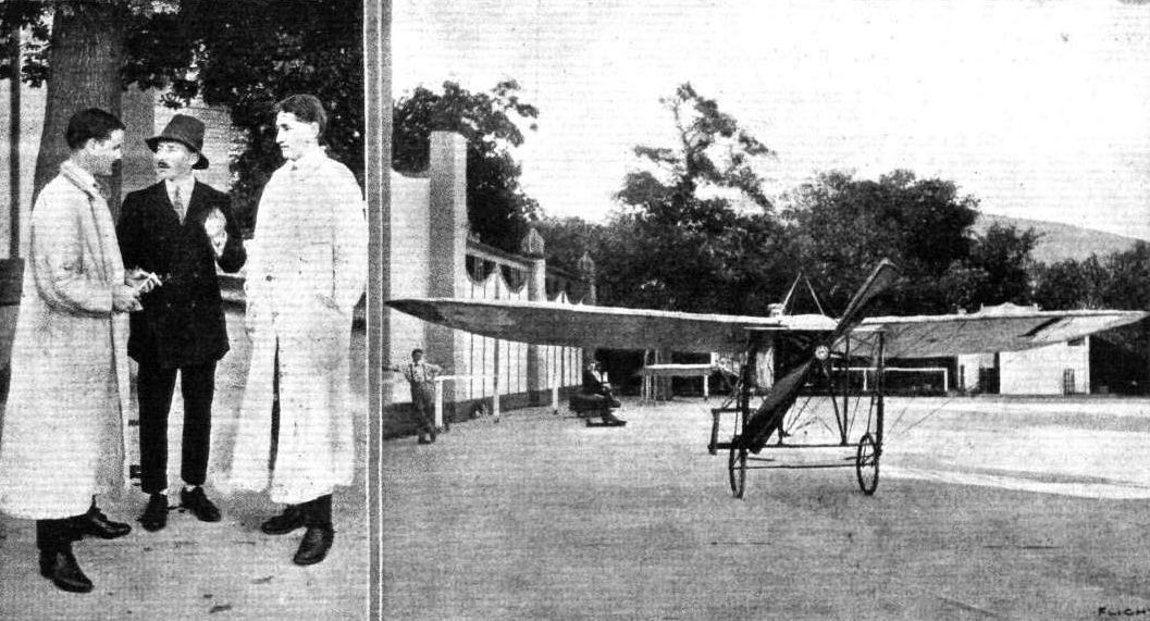
AVIATION IN SOUTH AFRICA. - On the left Mr. Compton-Paterson and Mr. Driver in the Good Hope Gardens with Captain Livingstone (in centre), who is associated with this aviation enterprise. On the right Mr. Driver ready for a start on his Bleriot.
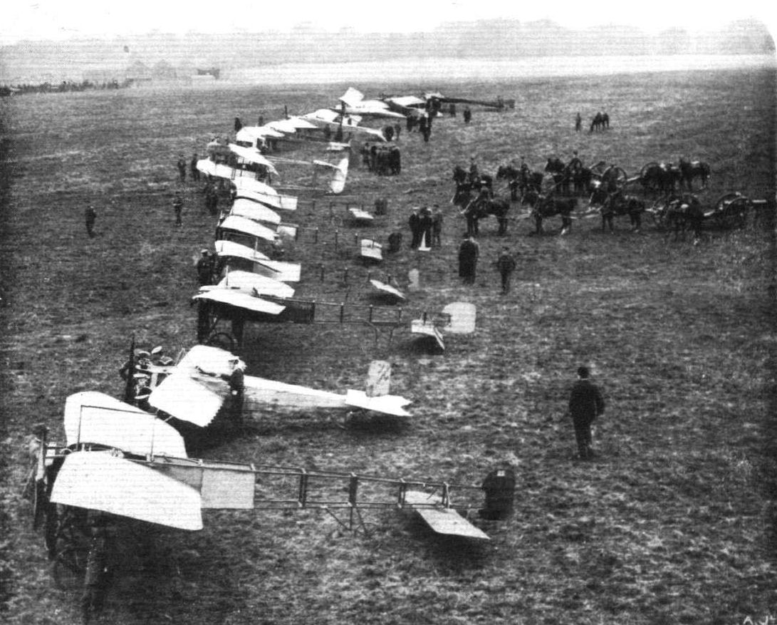
Review of the machines at the London Aerodrome, Hendon, at the Naval and Military Meeting last Saturday. - General view of the aeroplanes lined up.
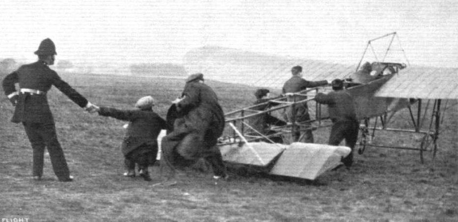
Robert, as a handy man at the London Aerodrome, giving some weighty help to Desoutter when about to start on his Bleriot for an exhibition flight.
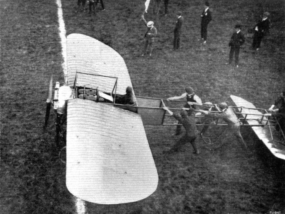
Waiting the signal to start in the cross-country handicap at Hendon, as seen from the Judges' box. Mr. B. C. Hucks on his Bleriot awaiting the dropping of the flag.

Mrs. Stocks flying on the Bleriot monoplane at Hendon on Ladies' Day, and winning the Daily Mirror prize.
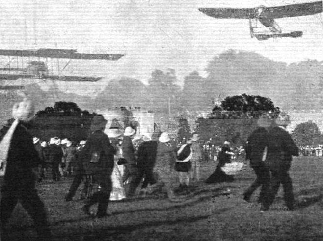
FLYING IN INDIA. - A curious effect from a double exposure of a negative whereby the two machines at Tollygunj were apparently flying at the same time. Note the excitement of the natives in following the evolutions of the machines.
The Chanter Flying School at Shoreham, with their two Anzani-Bleriots and their 35-h.p. monoplane modelled on Nieuport lines. At the left-hand side is Mr. M. Chanter, the Director of the school. To the right are Messrs. De Villlers, Gassier, Kent, Ross, and two of the school mechanics.
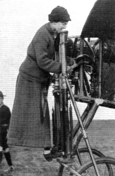
Miss Dorothy Prentice attending to the motor of the machine In which she practises at Hendon Aerodrome.

MDME. JANE HERVEU, Who, in competition for "La Coupe Femina," put up a flight at the Compiegne Aerodrome on December 31st, on a Bleriot monoplane, of 248 kiloms. in 2 hrs. 41 mins.
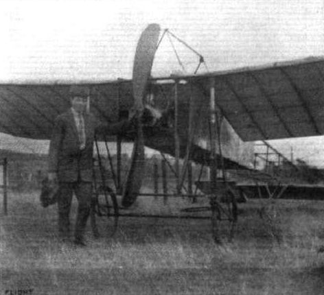
Cyril Foggin, who has just passed for his brevet at Fowler's School, Eastbourne, and the machine on which he bad his safety helmet experience recently.

The special trolley which has been devised by the Eastbourne Aviation Co. for the purpose of conveying their aeroplanes by road, and for use as a breakdown vehicle.

Miss Dorothy Prentice, of the Ewen School, being initiated into the Bleriot control.
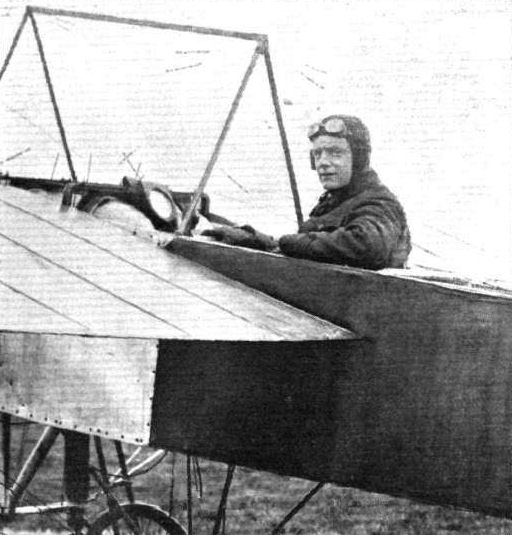
SOME OF THE HENDON PILOTS. - Mr. B. C. Hucks on the 50-h.p. Bleriot.
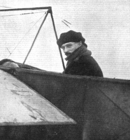
Lewis Turner, chief pilot of the Grahame White School, is learning to fly the Bleriot.
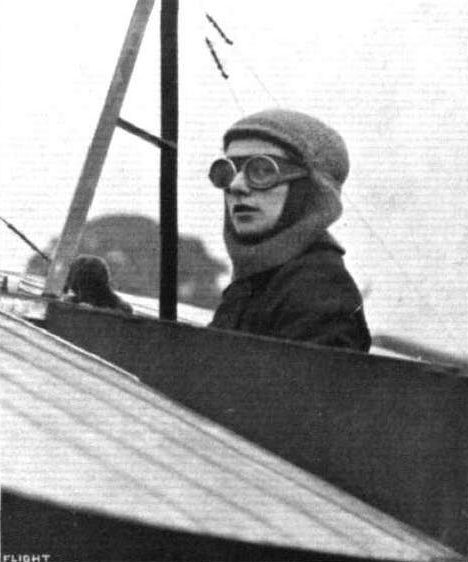
Mrs. Stocks just about to start for a flight on her Bleriot monoplane at the Hendon Aerodrome.
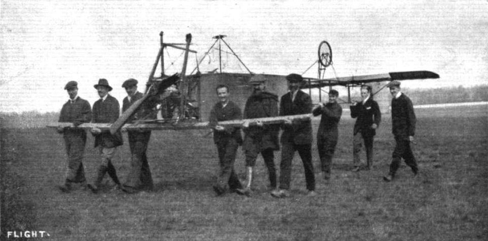
BRINGING BACK THE BITS. - A reminiscence of last summer at Hendon. On the left Messrs. W. Gibson, Clutterbuck, and S. Henderson, an old pupil at the Bleriot school. On the right, in front, H. Salmet and P. Prier, both of Paris-London-Paris fame, and poor Petitpierre, who was shot by the lunatic Hanot last autumn. Supporting the tail are Frank Champion on the left and George Dyott, both of whom have been doing much good flying in the States, the former on a Gnome-Bleriot, the latter on a two-seater Anzani-Deperdussin. Frank Champion, as mentioned in this week's "Eddies," is now in bed suffering from a smashed leg, the result of the accidental discharge of a gun held by Gibson, who figures on the extreme left of the picture, while the two were out shooting rabbits at the Dominguez aerodrome, Southern California. Gordon Jones, of model fame, is walking alongside, bringing back a handful of propeller fragments.
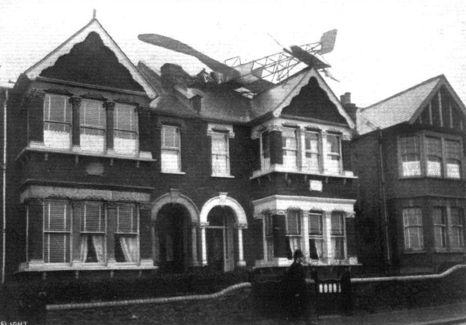
A flying visit to Palmer's Green, showing M. Manio's monoplane after it bad settled down on the roof of one of the houses in Derwent Road, Palmer's Green, through engine trouble during his attempt to reach Hendon last week. It is a remarkable fact that the pilot was not injured, although his machine was damaged and a considerable hole made in the roof. M. Manlo ultimately regained terra firma by means of a ladder.
MR. C. HEMIN'S BLERIOT AND HOWARD WRIGHT MODELS. - The latter is fitted with a compressed-air motor with which some good flights have been obtained.

FLYING IN INDIA. - A native poster, in Urdu, announcing the flights in Bangalore. This is chiefly interesting from the fact that it calls attention to the legend that according to the Sacred Vedas the end of things mundane will take place a thousand years after a man has come flying. We are indebted to Mr. Ernest Esdaile for being able to reproduce this poster, who has presented a copy to the Royal Aero Club.
Flight, April 27, 1912.
FLYING THE IRISH CHANNEL.
Now that well over a week has passed since Mr. D. Leslie Allen set out from Holyhead at about seven o'clock in the morning of Thursday of last week, to cross the Irish Channel, and no news of his whereabouts have come to hand, it certainly seems that it is our sad lot to mourn another British life, sacrificed - we think again quite unnecessarily - in the practising of the sport. It was on the previous day, the Wednesday, that he with Mr. Corbett Wilson, set out from Hendon to fly in company to Dublin. There was no wager between them as to who should get there first, as has been generally seated. They simply had a feeling that they would like to visit their native island by the new method of locomotion, and they both started off in friendly rivalry to fly there together. At that time it was thought by those at the aerodrome that the flight was an unusually risky one for such comparatively inexperienced pilots to attempt. Further, so hastily had the trip been arranged that no precautions were made against the possibility of having to descend in the sea. They both left Hendon soon after half-past three p.m. on Wednesday, and Allen, following the London and Northwestern Railway line, arrived at Chester about half-past six in the evening, after landing some ten miles the other side of Crewe to ascertain his whereabouts, Corbett Wilson landed the same evening at Almeley, about fifteen miles northwards of Hereford.
Just after six on the following morning Allen started from Chester and passing over Holyhead an hour afterwards, flew out to sea. He has not been seen or heard of since. His friend, Corbett Wilson, left Almeley at half-past four that afternoon and was forced to land some few miles further on at Colva in Radnorshire. On Sunday morning early he set off again and this time reached Fishguard, leaving again at six o'clock on the following morning, Monday, and flying across St. George's Channel in the direction of Wexford.
One hour and forty minutes was occupied in crossing the Channel and a landing was made at Crane, two miles from Enniscorthy, the trip being the first occasion that the strip of water separating Ireland from the main land has been entirely crossed by aeroplane. It will be remembered that Mr. Loraine's attempt in 1910 failed by some 300 yards.
Mr. Vivian Hewitt also has the intention of attempting the crossing to Ireland, but his route is to be from Holyhead to Dublin across the Irish Sea. At the time of writing he is waiting at Holyhead for favourable weather. He left Rhyl at 5 a.m. on Sunday morning and after remaining up for an hour and twenty minutes was forced to land at Plas in Anglesey. His flight was made at an average of quite 5,000 ft., for he says he could distinctly see over Snowdon. The wind was boisterous in the extreme and he testifies to the fact that had he remained up much longer he would undoubtedly have been ill, so much was he tossed about. The section from Plas to Holyhead was flown on Monday morning, starting from the former place at about 9.30. Mr. Vivian Hewitt has his machine in Lord Sheffield's grounds and will continue his flight as soon as conditions prove favourable.
Flight, May 4, 1912.
THE IRISH SEA FLIGHT.
MR. VIVIAN HEWITT is to be congratulated upon his excellent flight across the Irish Sea on Friday last, when his exact time from taking off at Holyhead until his landing in Phoenix Park, near the Hibernian Monument, was 1 hr. 15 min. Mr. Hewitt wisely guarded against undue risks by providing himself with a safety belt, &c., in case he should fall short of his destination. Again one further record has been established in regard to crossing the open sea, this following on last week's announcement of St. George's Channel being flown by Mr. Corbett Wilson. This week we give Mr. Vivian Hewitt's portrait as a "Flight Pioneer" and the following is Mr. Hewitt's own version of his trip and the days preceding the actual flight:-
"I started from Rhyl at 5 a.m. last Sunday morning and flew off over the sea in the direction of Holyhead. After rounding the Great Orme at Llandudno I made for a point of land running out to sea. I could see Holyhead Harbour by this time, but the wind started blowing half a gale and I found it impossible to get there. I was up an enormous height, and could distinctly see over Snowdon. The wind blew me right down the coast and I had to put the nose of the machine down and let my engine out, otherwise I should have been blown out to sea. I landed eventually at a place called Plas, in Anglesey, at 6.20. I felt very sick, as I had been tossed about all over the place. The machine was roped down and next day I started for Holyhead at 9.30 and landed in Lord Sheffield's grounds 20 minutes later, it being out of the question to attempt flying the Channel owing to a dense fog. From Monday till Friday morning I was held up at Holyhead owing to wind which was blowing at about 35 miles an hour in the wrong direction. On Friday morning I started off at 10.30. There was a good deal of wind at the time and a lot of haze, and when I passed the Stack I was blown down Channel about 5 miles. I managed to work into it, however, and got my true course from the breakwater. I lost sight of land after ten minutes and about five minutes after I sighted the Mail Packet coming from Kingstown. I passed right over her from stem to stern and lost her smoke about three minutes after in the haze. Although all the boats had been informed, and the Mail Packet was looking out for me, they never saw a thing, showing what a great height I was.
"After leaving the Packet I saw nothing more for fifty minutes, and steered by the sun whenever I could. I ran into dense banks of fog, and at times I could not see the wing tips. After about fifty minutes I saw the Wicklow Mountains, and passed over Kingstown Harbour very high up. I passed over Dublin about 2,000 ft. up, and when planing down experienced the worst air-currents that I have ever come across. I was all but upset twice, and the machine dropped 500 ft. I managed to land safely in the 15 acres in Phoenix Park and was treated very kindly by everyone. The machine I used was my 50 Gnome-Bleriot."
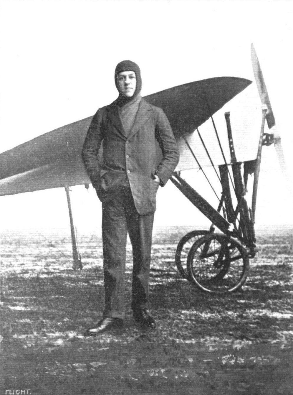
MR. VIVIAN HEWITT, Who, on Friday, April 26th, flew over the Irish Sea from Holyhead to Dublin on his 50-h.p. Gnome-engined Bleriot in 1 hr. 15 mins.
Flight, March 2, 1912.
Mr. Hewitt has a Rough Landing.
ON Saturday last Mr. Vivian Hewitt started on a flight with his Gnome-Bleriot from the Foryd Aerodrome, Abergele but when only about 100 feet up the petrol pipe broke and the engine stopped. He was just leaving the aerodrome at the time and had no chance to turn into it. The machine did a tail slide, then pancaked and afterwards started gliding. By that time he was only about 30 feet up and after hitting a ditch and bouncing along frightfully uneven ground the machine pulled up at the edge of another ditch. Fortunately nothing was broken, but it was necessary to dismantle the machine to get it back to the aerodrome.
Flight, March 16, 1912.
MY PARIS FLIGHT.
By HENRI SALMET, Chief Instructor of the Bleriot School, Hendon.
FOR some time past I have wanted to fly to Paris and back in one day, and also, as I should like to see M. Bleriot in Paris about business matters. I think, it being fine, on Thursday the 7th, I will go. The night before I paint on the wings of my Bleriot some varnish that keep the fabric tight and make it waterproof, and later I telegraph to the coastguard at Eastbourne to telephone me in the morning if the weather is good. Next morning early the message arrive. The coastguard say the Channel is clear of fog, so I get ready. The fuselage of my Bleriot had already been covered in with fabric and waterproofed so as to make a float and keep me up if my engine fail and I go in the water. Round me I put an inner tyre from one of the school machines which I blow up. I run my engine and it go very well, so I wave my hand and I am away.
When I left here it was exactly 7.45, with little wind behind me. The wind increased, and after about a quarter of an hour the wind was much more stronger, and my speed was about half as much again. At Eastbourne I was 1,200 metres high and about 2 miles over the sea, but the wind was too gusty. I came back, and I took 3,000 ft. more high, and that took me 13 mins. After that, I started again on my way to Paris, and I flew for 1 hr. 40 mins. without seeing anything other than the clouds. The sight at that height was most marvelous - I think absolutely the best something I have seen in my life. At that height the clouds were more like big snowy mountains, and flying through them was the most curious experience that could happen to anyone. A glance behind showed my wake in a swirl of fog disturbed by the propeller and the passage of the machine. So cold was it in the clouds, that I had constantly to increase my high so that I could get above them. This brought me to a height of between 6,000 and 7,000 ft., and as I could not see the sea, steering had to be entirely done by compass. This was hard to do, for the wind, although fairly steady, set the monoplane rolling slowly, and the compass needle kept swinging continually about ten degrees each side of the true line. This had to be accounted for. From points that I had recognised over English soil, I calculated that my speed was something over 130 kiloms. an hour, and from the time I got my last glimpse of the earth, I flew for 1 hr. 40 mins., and then from my speed calculated just about where I ought to find myself. Here I thought I ought to descend, as I wanted to make sure that my compass was guiding me correctly, and that I was on my right way.
For a long time I see nothing but the wings of my machine. I came down to 200 metres in order to distinguish points that I wanted to find. Then I flew round in big circles for 17 minutes, at last recognising a castle that I had marked on my map. Picking up the adjacent railway line, I reached Gisors. Here it was clearer, and I gradually elevated to 2,000 metres. Although it was possible to distinguish land marks, I did not look down once as I was so occupied in fighting the gusty wind that I did not trouble to do so, knowing full well my compass was steering me correctly. I saw the Eiffel Tower after a long struggle, and the sight gave me very big pleasure because it is the first cross-country flight I have make. I see Issy from 1,500 metres, and commenced my vol plane.
To battle against the remous caused by the big houses, I have to descend very steep to keep up my speed. Gusts rapidly struck me from below, and had I not gripped the cabane with all my might deserted because I arrived before my telegram. On landing I took from my machine the little can of paraffin I always carry, and washed over the engine - my good engine, which had brought me all the way from London without any trouble. All the more pleasure because I myself look after the engine, no one else touch it. Then I go to find someone, and I find a guardian of the aerodrome with a mechanic from the Astra Company, and I asked him "Where are the Bleriot hangars?" and he say "Opposite there." As I turned to go to the sheds he say to me "Can you tell me any news of the English aviator who should fly from London to Paris?" and I say "The English aviator is me." Then we shake hands. Then he say "If you are the English aviator you speak French very well indeed. What is your name?" and I said "Henri Salmet of the Bleriot School in England." Then I go to the Bleriot sheds and get the mechanics to fetch my machine and put it safe in the hangar. I ask for M. Bleriot's telephone number to ring him up and tell him I arrived. I telephone and he speak himself, and he say "Why do you not send a telegram?" At that moment the telegraph boy must have come into his office, for he say "the telegram has just arrived now." I say "When can I see you M. Bleriot?" and he say "I see you about three or four " but I reply "I shall be far off by then." He say "Why?" I say "Because I want to get back to London to-day." Then he came down to Issy in a car with M. Leblanc, and some reporters.
M. Bleriot seem very please. He say "Bon jour, Salmet. Toutes mes relicitations! Par on avez vous passe." I say that I had come by the way I had chosen, and that I had tell him some time before. He is very happy that I do cross the channel at the wide part, from Eastbourne to Dieppe - thing that had not been done since aviation existed. In his great joy he grasp my both hands, and squeeze so hard that he hurt much. And M. Leblanc also. Then we have lunch at the Cafe Syndicat des Aviateurs. They say to me, there is too much wind, and you cannot return. But I did not pay attention to that, as no matter what the struggle I had big confidence in my Bleriot, my Gnome, and my wonderful Levasseur propeller, which give so much pull and runs so smoothly. It is the best I have try. With my three faithful friends, my machine, my motor, my propeller, the wind have no fear for me. So at 2.15 with the anemometre at 34 kilometres to the hour, I start once more. The start is not alone, because the ground is used by the soldiers, but I go to ask at the Commandant to let me start. He say "Yes, with pleasure," and he took his soldiers in a good place to give me plenty of room, and I go. I start straight on my line, but the ground is not much large and when I am over the houses I am very low, and the wind put me sometime in very bad situation. I am very long to take my high, because sometime I am 200 metres up, and then I come down again with the wind.
After I have crossed the Seine I have less remous, and I go more high. Since this time the wind is much more regular, but so strong that I take nearly four hours to make 220 kiloms. I am very cross against the weather, because I am obliged to land at Berck Plage with my petrol tank nearly empty.
As soon after my landing I start to find petrol. That take me too long time, and after that it is too late to start. I had wanted very much to sleep on English ground that night. A friend help me find petrol and oil, and after filling the tanks, I go to take something to eat with him. As he knew I wanted to start early next morning, he locked me in my bedroom that night, so that I should not go without him seeing me. At five o'clock he come in my room and give me a good cup coffee. I took it, and soon after I go with him to where the machine is tied up. I give a little exhibition fly, and land on the shore. Then before they let me go I have to sign many postcards, and many people take photographs of the machine.
Starting again just before ten, the wind was blowing about 32 kiloms., and was a little foggy. I fly for two miles, and my engine start missing. My magneto is wrong. I put it right, and I start again at 10.12. Then I go across the Channel from Cap Grisnez to Folkestone very fast indeed. I am across the other side in fifteen minutes, and there the wind come more badly. Having no map, and as the compass rock very badly, I keep over the main road. The wind and rain beat very hard in my face. I don't like to land because I like to put my machine in my shed at Hendon before landing anywhere. But the wind and rain coming always more strong, I think it more wise to land than to continue. It take me a quarter of an hour to go four miles. Then, seeing a good landing ground on my left, I come down, and find I am at Chatham. If I am very cross against the weather I meet there the best people I have ever met. All people is ready to help me for anything. They all want to give me something to eat. I go with Mr. Sills, who has a room where I can be quiet, for I am very tired after the struggle. The schoolmaster there makes a meeting in my honour, and I go there in the evening, and they give me a big tri-colour bouquet, and after much shouting I have to sign many postcards.
The next morning I start at 6.15 in a very bad wind towards London. My cloche is always moving; but all is well until I fly into some fog. I remember the Regent's Park happening, and I think it better to descend than to continue and land in some place where the Aero Club would not like it. Near Maidstone I have to land in a champ labore, and I break a piece off my propeller. My good friends from Hendon soon bring me another one, and we put it on. The weather is not favourable to start, but I am so hurry to come to Hendon that I look with a bad eye at those who say the weather is too bad. I go on again; but soon after my motor stopped, and I have to descend in a football field near Beckton gasworks. I land very deep from 800 metres, because ground is small. I see I am going to hit a goal-post, so I pull lack my cloche to clear it. My speed slackens as I rise, and a gust comes and blows me right over. I am sad, for it is the first smash I have ever had since I started to learn to fly. To me the smash itself was nothing, but to think that it should happen after those days of struggling grieved me much. However, the smash was done properly; and so disgusted was I at not being able to get to Hendon, that I walked away without looking to see my machine. There I found friends who were very amiable to me, principally William Marsh, whom I shall not forget. The smash did not hurt me, for here I am, with only a little cut on my knuckle. Then - Mais c'est tout! Voila la fin de mon pauvre et triste voyage!'
LONDON-PARIS RECORD FLIGHT.
SALMET'S magnificent flight on Thursday of last week from the Hendon aerodrome to Paris, in a wind averaging the whole way a velocity of 30 miles an hour, brands him as one of the foremost airmen of the day - a second Vedrines. His aim was to effect the return journey between the two capitals in one day, and to shorten his course he elected to cross the channel at its widest part, from Eastbourne to Dieppe - a feat which has hitherto never been accomplished. For nearly two hours he was obliged to steer by his compass alone, being above the clouds. That he succeeded in maintaining his true course under such difficult conditions is indeed eloquent testimony of his ability as a pilot. From the time he left Hendon to the time he landed at the parade ground of Issy-les-Moulineaux near Paris, 3 hours 16 mins. elapsed. Of this time 13 minutes was occupied at Eastbourne in gaining altitude, and for 17 minutes he had to circle near Gisors in order to determine his whereabouts. Subtracting these 30 minutes from his total time, his true time for the direct flight was 2 hours 46 mins. His real average speed between the two capitals, a distance of 220 miles, in direct flight was therefore 79 miles an hour - a truly wonderful speed when one takes into consideration the fact that it was Salmet's first cross-country journey.
Starting on his return journey from Issy-les-Moulineaux at 2.15, he fought his way against wind and rain to the coast, but, through lack of petrol, had to descend at Berck Plage at 5.55. Here he thought it advisable to remain the night, in spite of his determination to reach English soil if possible that day. The following morning he set off once more, and following the French coast line to Cap Grisnez, which he reached at eleven o'clock, he steered towards the English coast, effecting the crossing of the Channel in 15 mins. Continuing on, he was obliged to descend at Chatham, owing to the violent wind and rain. Early on the following morning he started again, but at Maidstone was forced to descend through encountering a bank of fog. In landing, the tip of his propeller, a Levasseur, was damaged, and another one had to be obtained from Hendon. Once more he started, but before he had got far his motor suddenly stopped, and he was obliged to plane down into a football field not more than a few hundred yards from the Royal Albert Docks. To land in such a small ground necessitated a steep vol plane. To avoid a goal post he had to elevate sharply, and in consequence lose speed to such an extent that the wind got the better of him, and his monoplane came heavily to earth. It was considerably damaged, but happily, barring the shock, Salmet was little the worse.
Elsewhere in this issue will be found an account of this trip to Paris from the pen of the aviator, M. Henri Salmet, himself.
Flight, April 20, 1912.
MISS QUIMBY FLIES THE CHANNEL.
ALTHOUGH Miss Harriet Quimby has made an enviable reputation for herself as a capable pilot in America, her native country, she has not been very well-known on this side of the Atlantic, and no doubt few of our readers who read the announcement in FLIGHT a week or so back that she was coming to Europe, looked for her so soon to make her mark by crossing the Channel. Contrary to what one would expect, the feat was carried through without any fuss or elaborate preparations, and only a few friends, including Mr. Norbet Chereau and his wife and Mrs. Griffith, an American friend, knew that the attempt was being made and were present at the start. Miss Quimby had ordered a 50-h.p. Gnome-Bleriot, which arrived from France on Saturday, and was tested on Sunday by Mr. Hamel. On Tuesday morning, as previously arranged, after Mr. Hamel had taken the machine for a preliminary trial flight, Miss Quimby, who had been staying at Dover under the name of Miss Craig, took her place in the pilot's seat, and at 5.38 left Deal, rising by a wide circle and steering a course, by the aid of the compass, for Cape Grisnez. Dover Castle was passed at a height of 1,500 feet, and by the time the machine was over the sea, it was at an altitude of about 2,000 feet. Guided solely by compass, Miss Quimby arrived above the Grisnez Lighthouse a little under an hour later, and making her way towards Boulogne she came down at Equihen by a spiral vol plane not far from the Bleriot sheds.
To Miss Quimby, therefore, belongs the honour of being the first of the fair sex to make the journey, unaccompanied, across the Channel on an aeroplane; and, appropriately enough, as the first crossing of an aeroplane by a "mere man" was on a Bleriot machine, her mount was of that type. Miss Trehawke Davies, it will be remembered, was the first lady to cross the Channel in an aeroplane, but she was a passenger with Mr. Hamel on his Bleriot monoplane.
Flight, April 27, 1912.
FLYING THE IRISH CHANNEL.
Now that well over a week has passed since Mr. D. Leslie Allen set out from Holyhead at about seven o'clock in the morning of Thursday of last week, to cross the Irish Channel, and no news of his whereabouts have come to hand, it certainly seems that it is our sad lot to mourn another British life, sacrificed - we think again quite unnecessarily - in the practising of the sport. It was on the previous day, the Wednesday, that he with Mr. Corbett Wilson, set out from Hendon to fly in company to Dublin. There was no wager between them as to who should get there first, as has been generally seated. They simply had a feeling that they would like to visit their native island by the new method of locomotion, and they both started off in friendly rivalry to fly there together. At that time it was thought by those at the aerodrome that the flight was an unusually risky one for such comparatively inexperienced pilots to attempt. Further, so hastily had the trip been arranged that no precautions were made against the possibility of having to descend in the sea. They both left Hendon soon after half-past three p.m. on Wednesday, and Allen, following the London and Northwestern Railway line, arrived at Chester about half-past six in the evening, after landing some ten miles the other side of Crewe to ascertain his whereabouts, Corbett Wilson landed the same evening at Almeley, about fifteen miles northwards of Hereford.
Just after six on the following morning Allen started from Chester and passing over Holyhead an hour afterwards, flew out to sea. He has not been seen or heard of since. His friend, Corbett Wilson, left Almeley at half-past four that afternoon and was forced to land some few miles further on at Colva in Radnorshire. On Sunday morning early he set off again and this time reached Fishguard, leaving again at six o'clock on the following morning, Monday, and flying across St. George's Channel in the direction of Wexford.
One hour and forty minutes was occupied in crossing the Channel and a landing was made at Crane, two miles from Enniscorthy, the trip being the first occasion that the strip of water separating Ireland from the main land has been entirely crossed by aeroplane. It will be remembered that Mr. Loraine's attempt in 1910 failed by some 300 yards.
Mr. Vivian Hewitt also has the intention of attempting the crossing to Ireland, but his route is to be from Holyhead to Dublin across the Irish Sea. At the time of writing he is waiting at Holyhead for favourable weather. He left Rhyl at 5 a.m. on Sunday morning and after remaining up for an hour and twenty minutes was forced to land at Plas in Anglesey. His flight was made at an average of quite 5,000 ft., for he says he could distinctly see over Snowdon. The wind was boisterous in the extreme and he testifies to the fact that had he remained up much longer he would undoubtedly have been ill, so much was he tossed about. The section from Plas to Holyhead was flown on Monday morning, starting from the former place at about 9.30. Mr. Vivian Hewitt has his machine in Lord Sheffield's grounds and will continue his flight as soon as conditions prove favourable.
Flight, June 1, 1912.
HOW TO OPERATE A BLERIOT MONOPLANE.
By EARLE L. OVINGTON, BLERIOT PILOT.
THE following article, published in the columns of our American contemporary, Aero, is from the pen of one who has probably flown a greater distance over American soil in a Bleriot monoplane than any other pilot. He graduated at the Bleriot school at Pau, in the south of Prance, and amongst his successes was the winning of the L2,000 prize offered by the Boston Globe for the fastest crosscountry flight over a course embracing three States :-
"The systems of control of almost all practical aeroplanes are essentially the same. In other words actual flying machines of the present day employ a vertical rudder to steer in the horizontal plane, one or more elevators to steer in the vertical plane and some form of manually operated lateral control device. To be sure one machine may steer by means of a cross-bar operated by the feet, while another will operate through a wheel, as in an automobile. For lateral stability one manufacturer prefers to use one contrivance, while another employs a different one. The fundamental principle, however, of all machines is practically the same.
"The principal thing in operating an aeroplane of any description, is to become so acquainted with the control that the manipulation of the machine in actual flight is absolutely intuitive or instinctive on the part of the aviator.
"Psychologists tell us that we have two minds, our objective and our subjective mind. The objective part of our mental make-up is that which is used in ordinary everyday life; we might term it our reasoning mind. It takes time for this part of our mentality to work.
"Our subjective mind is that part of our mind which is ordinarily beyond the control of the individual. Some designate the operation of the subjective mind as intuition, while others say that it is instinctive. At any event, operations controlled by the subjective mind are usually performed without any conscious thinking on the part of the individual.
"Unquestionably the best aviators of the present day are subjective flyers; that is, they do not stop to think every time they re the control levers of their aeroplane. And the whole object of training is to so educate the student that the movement of his control levers is absolutely instinctive, requiring no conscious effort.
"I shall describe the operation of a Bleriot monoplane, because it is the machine with which I have had the most experience, although at many of the meets during the past season, I have flown the Curtiss biplane. In justice to the Curtiss machine, I will say that it is the most instinctive form of control with which I am acquainted, for none of the movements of the control are at a variance with what one would naturally do under the circumstances. However, if a man can fly a ticklish monoplane, he can fly about anything with a little additional practice.
"One of our photographs shows a detail view of the cock-pit of my Bleriot monoplane. This machine is driven by a 70-h.p. seven cylinder Gnome rotating motor, and is of the latest racing type. Its speed in still air is more than 70 miles per hour.
"Seated comfortably upon a little chair-like seat, fitted with a four-inch hair cushion, my feet rest upon a cross-bar to which are attached the steel wires running to the vertical rudder at the tail of the machine. If I wish to go to the left, a pressure on the left foot is all that is required, on the other hand, if I wish to turn to the right, it is only necessary for me to press the right foot. Certainly this is not very difficult.
"The lever which you see in the picture, surmounted by a small wheel, is the lever to which the wires are attached that run to the elevator immediately in front of the rudder at the tail of the machine. Wires also run from this lever to the wings so that wing-warping may be introduced to obtain lateral stability. Although there is a wheel at the top of this lever, it does not turn, but simply forms a convenient method of grasping this lever with either one hand or the other or both.
"Racing across the ground it is only necessary for me to pull the lever towards me, after the speed has increased sufficiently, for the machine to rise rapidly. Placing the lever in a vertical position the machine flies horizontally. If I wish to descend I push the lever forward, which process elevates the tail, and down I come. Neither operation is very difficult.
"The most dangerous part of controlling an aeroplane of the present day is in maintaining what is called lateral stability, that is, keeping the aeroplane on an even keel. In the Bleriot this is accomplished by wing-warping. If my machine tips to the left, I push the control over to the right, which process increases the angle of incidence on the low wing and decreases the angle of incidence on the high wing, with the result that the lift on the low wing is greater than on the high wing, and there is a force introduced which tends to bring the machine back to its horizontal position. To operate the lateral control mechanism is what takes practice.
"Often, in emergency cases, all three controls must be actuated at once. For instance, assume I am flying horizontally and strike a so-called 'air-hole,' which tilts me towards the left at a dangerous angle. I do three things. First, I rush the rudder over with my right foot to increase the speed, and hence the lift of my left or lower wing. Incidentally, the speed of the right wing is lessened and its lift consequently decreased. Second, I put my lateral control lever hard over to the right. Third, I push my elevator control forward to make the machine drop. The resulting increase of speed gives my controls greater effect. In active practice, the vertical lever actuating the lateral stability and elevator devices is moved diagonally forward and to the right, thus incorporating the two movements into one.
"It is necessary for those who wish to learn to operate any aeroplane to do considerable 'grass-cutting' at first, in order that they may be thoroughly acquainted with the control of their machine and also become accustomed to rushing through space at a high velocity. It may seem easy to steer a machine on the ground, from one point to another, but until you have tried it in a monoplane, you do not realize how difficult it is. Even to an experienced operator, it is more difficult to steer a straight course on the aerodrome, when the machine is rolled along the ground than when flying. This is due to the fact that the rudder is designed for operation at a mile a minute, and not for slower speed on the ground; hence the surface is not very great. Incidentally a machine flying in the air offers very much less resistance to turning than one wheeling along the ground.
"After one has become thoroughly acquainted with the machine, he may venture to take hops into the air.
"The principal thing about which I wish to warn embryo aviators is not to make sudden movements of their control. In order to rise, for instance, it is not necessary to pull the control towards you six or eight inches, as usually one or two inches is all that is necessary. I have seen so many students get into a machine, give the control-lever a pull towards them, and then practically stand the machine on end in mid-air. This results in a bad tail-slide, and the machine is often reduced to toothpicks and the aviator seriously injured. Be particularly careful, therefore, to try out the various controls carefully, moving them only a short distance at a time until the desired result is accomplished.
"After the student is able to make hops and keep his machine level, he is then ready to make a more extended flight. And now I wish to give another word of warning.
"Before I ever went off the ground in any of my flights, however rushed I was, or however impatient was the audience, I always took plenty of time to tune up and examine my machine. First, I looked at my big Gnome motor. I turned it over slowly, and felt of the play of each exhaust-valve. I examined carefully the bolts which held the main supporting steel strips to the landing-chassis and the wings, in order to see that these fastenings were perfectly secure. The tension of these strips is also important, and should be practically uniform. Very often a distortion of the wings makes one of these strips tight and the other loose. There is only one thing to do, and that is to make the tension uniform before venturing into the air. Don't forget to glance at the upper supporting wires, as often a turnbuckle may become loosened; and although these wires do not support the weight when the machine is in the air, still they are of great importance.
"The leading edge of the wings should be absolutely parallel with the trailing edge. Squat down behind each wing and glance along these edges, and if they are not parallel adjust the upper or lower wires until they are. This is of the utmost importance for the machine will not be on an even keel when the control is at a central position unless the two wings are adjusted perfectly equal. Don't forget to take a look at the tail and see that the supports holding it in position are firm, and the nuts on the bolts secure.
"After you have learned actually to fly, get up in the air a good height and stay there. Remember it is not falling that injures an aviator, but the sudden stop and his contact with Mother Earth. That saved my life a good many times and I've had some side slips where I fell 500 ft. or more. I would not be here, talking to the readers of this journal if I had not been flying pretty high. Personally, I have always been of the opinion that high flying is the safest, although many aviators do not agree with me. It always made me nervous to see a man taking the sparrows off the trees or brushing the cobwebs from the chimneys of surrounding houses. I never felt right until I was up from 2,000 to 5,000 ft., and the higher I got the better I felt. Don't forget the higher you are the better chance you will have of making a safe landing, if your motor stops accidentally. When you're flying low, the chances are there is going to be a smash if your motor ceases to operate in the air.
"Speaking of the motor stopping, just remember that as soon as it ceases to operate, you must bring in the force of gravity to keep up your flying speed. In other words, point the nose of your machine down instantly; never mind how high you are or what you will bump into." [In view of the disclosure M. Bleriot made recently, it is clear that the action of pointing the nose of the machine downwards too violently, should the engine stop, is not advisable on account of the reversal of pressure set up in the wing surfaces. We would rather it read, "point the nose of your machine down surely but not too suddenly."]
"You don't gain anything by keeping the machine in a horizontal plane, for it will fall anyhow, and it is much better to have it fall on the glide than to have it fall vertically. In the latter case, the use of the control is lost, and a serious accident will result.
"Be very careful in rising that you do not stall the machine. Remember that it is the rapid speed forward which supports your aeroplane, and enables your control to operate properly, just as soon as you try to climb at too steep an angle the resistance becomes so great that your speed drops off quickly, and soon a point is reached when your controls go out of commission almost entirely. If you are near the ground you make a pancake landing, in which case, your machine must go into the hangar for a long job of repairs. I always had an inclinometer, which is simply a spirit lever, to tell at what angle I was climbing. I found by experience the angle which I could employ in order to climb the fastest, and however excited I was, or however important it was for me to climb rapidly, I never exceeded this angle. Several times I have been sorely tempted to do so, but in each case have resisted the temptation.
"Remember that in banking a monoplane on a turn, it always tends to hank too much unless an extremely short turn is made. In other words in turning to the left, for instance, a slight pressure on the left foot serves to throw you around in that direction. Immediately the speed of your left wing decreases, while the speed of your right wing increases, and the machine banks. In order to correct this and not to bank too much, you must move your vertical control to the right, or as the French term it - cloche, meaning bell in French, owing the bell-shaped portion at the bottom of the lever. Banking is absolutely necessary to take a turn properly, but be careful that you do not bank too much for the inward component of the lift of your plane will be greater than the centrifugal force and a side-slip to the inside of the circle will result.
"Speaking of side-slips, you've got to look out for them in a monoplane. A biplane does not have a tendency to side-slip anywhere near as badly as a monoplane. Let a high-speed monoplane get side-slipping badly and you're going to have your hands full in bringing it up to an even keel. The trick is - do not let it get too far over, but apply your corrective the instant the machine tilts to an undesirable angle.
"There are exceptions when an experienced aviator can disobey this rule. For instance, in taking one of the turns at Chicago, these turns were very short indeed, we had to throw the machines up to 60 or 70 bank in order to get around them in good shape. Ordinarily this would be a dangerous process, but if the aviator remembers to let his machine fall - that is point the elevator downward, while taking the turn - it is comparatively safe.
"Never bank on a rise and never bank deeply unless you let the machine glide down. The latter rule is not absolutely necessary, but always safe.
"A monoplane is far more sensitive than a biplane, and hence extreme care is necessary in its control, but after it is thoroughly mastered I believe that a monoplane is no more dangerous than a biplane, and is much more fun to operate. Incidentally if you're going into it from an exhibition standpoint, it is faster than a biplane and hence your chances for winning first place are greater. If I had had a biplane only to depend upon, during the past season, I probably should have lost money, rather than made it. As it was, I have no complaint to make, for in five months I made enough to keep me going for a while without serious worry as to where my next slice of bread is coming from.
"I have often been asked during the past season to what I owe my success. In the first place, I had what I consider the best machine made for my purpose of exhibition flying. In the second place, I hired two of the best mechanics that money could buy, and I gave them all the tools that they could work with, never hurrying them on an important job, however impatient my manager might be or the waiting public. I never went out on a flight until I had carefully inspected the machine, and I did not let curious people bother me with questions so as to distract my attention when I performed this important operation.
"I will not say that I did not take fool chances, for every aviator that does exhibit flying has got to fly when the time comes. I believe in 'playing the game' and when you don't want to play it give it up. I have never yet disappointed an audience. A man that goes into exhibition flying must go in with his eyes open and realize what he is up against. However, I always had my machine perfect before it left the ground, and I could, therefore, rely on it ninety-nine cases out of a hundred. And my reasoning must have been correct, for I made more than one hundred flights and have never broken one stick in the machine.
"To sum up therefore, my advice to young aviators is to - first, get the best machine you can; second, give it the very best care and attention. If you are not in a position to do so yourself hire someone who can. Thirdly, carefully inspect the machine before every flight. Fourth, don't let the machine get very far from its normal position, but correct any tendency to tilt or side-slip instantly. Fifth, never come anywhere near stalling the machine in mid-air. Sixth, if the motor stops come down to your natural gliding speed instantly, and then think about where you're going to land. Don't look around for a landing place first and then try to operate your aeroplane, for by that time it may be beyond your control."
Flight, June 13, 1912.
FOREIGN AVIATION NEWS.
Resistance Tests with Bleriot Machines.
IN our last issue we briefly referred to some tests made by the French Military authorities with a view to ascertaining the strength required for various aeroplane parts, and in this issue we are able to give a couple of photographs illustrating the method of carrying out the tests. A special train was fitted up by the Compagnie du Nord, and on this a Bleriot monoplane was mounted in such a manner that while the train was in motion the machine could take all possible positions which are taken in ordinary flight.
By this method no risk of accident to the pilot was entailed. With Capt. Charet and Lieut. Maillot alternately taking the pilot's seat, the monoplane was made to assume the different positions of ascent, descent, and warping as quickly and roughly as it could possibly be done in an endeavour to realise the very worst conditions under which the machine might have to fight its way through a gale. During these tests, which were carried out during the early morning of three days, the train was driven at a speed of 72 miles (115 kiloms.) an hour over a five kilom. stretch of railway in the vicinity of Survilliers, near Chantilly. It will be observed that the speed of 72 miles (115 kiloms.) is 12 miles in excess of the calculated speed of the aeroplane, and of course the pressure increases very considerably under such conditions. The tests were carried out under the supervision of Lieut. Col. Estienne, of the Technical Department of the Vincennes Military Aviation Establishment, and they were witnessed by Col. Hirschauer, Permanent Inspector of Military Aeronautics, Col. Bouttieaux, Director of Military Aeronautics at Chalais Meudon and many other military officers and aviators. All parts of the Bleriot machine stood the test perfectly, as was afterwards testified by the military officers present.
THE KING AND AVIATION.
RANELAGH CLUB, on the afternoon of last Tuesday, was the setting for another demonstration of the practical interest that His Majesty King George V is graciously taking in the progress of aviation. There, after a display of piloting worthy of his reputation of being one of the most popular of our British pilots, Gustav Hamel was presented to the King by Sir Sidney Greville. It had been arranged that Hamel, flying his new 70-h.p. two-seater Bleriot monoplane, with Capt. Mark Kerr, R.N., as passenger, should arrive on the famous polo ground at a quarter to five. He kept well to schedule time, for he came in sight at the moment when Their Majesties and Princess Mary drove into the club grounds in the Royal car. Hamel appeared at about 3,000 ft. up. Ten minutes had elapsed since his start from Hendon. Landing there on the polo grounds is not an exceptionally easy matter at any time, for trees and buildings are numerous, the turf is very smooth and "fast," and the two greens convenient for landing are terminated by, in the case of the first green, a steep bank some 8 ft. in height, and in the case of the second a neat little hangar that was erected some two years ago to accommodate Grahame-White's machine when he was giving his splendid exhibitions there. The wind, too, as on Tuesday last, was also to be reckoned with. Hamel made a wide circuit over Barnes Common, returned and flew over the Club grounds, manoeuvred at the far end in preparation for alighting, and landed neatly. Before the machine came to rest both Hamel and his passenger were standing up in the machine changing their flying kit for something more suitable to the environment at Ranelagh. His Majesty had meanwhile proceeded to the Royal pavilion by the main polo ground, where the finals for the Aldershot day contests were in progress. Soon after six o'clock, the ground was cleared and Hamel, rising from the adjacent green, interested the King by a series of spectacular evolutions. For fifteen minutes he held the spectators spellbound, then alighted, touching ground just in front of the Royal pavilion and coming to rest further on. He was summoned by the King, who congratulated him and conversed with him for some few minutes on matters aeronautic.
Flight, June 29, 1912.
MY FLIGHT WITH A PASSENGER FROM PARIS TO LONDON.
WE - that is Mr. Harold Barlow and myself - tried out our new machine - a 70-h.p. two-seater Bleriot of the latest type - at Issy les Moulineaux early on Sunday morning of last week. There was very little wind about, but as it was foggy and drizzly it was out of the question to attempt a start for London.
On the first trip I did not take a passenger, but to compensate we strapped an equivalent load of lead to the back seat. Nothing very much happened, except that perhaps to the onlookers there may have appeared more wind than there really was. This was owing to the comparative strangeness of the controls, after having been used to a Bleriot of only 50-h.p., and of much earlier type. On the new machine the controls are undoubtedly more sensitive, the warp particularly having a much greater effect than on the 50-Gnome. Consequently the movements I made rather overdid the controlling, and the machine wobbled a bit more than it really should have. However, it was only about a one-minute's job to get the hang of the feeling of the cloche. We also took another little stunt round later on, this time with a passenger aboard in the person of M. Baffier, Bleriot's representative down there. Steering towards the Eiffel Tower, we had reached to within about a hundred yards of it when suddenly we ran into a dense cloud, which was not very cheering, by reason of the possibility of hitting the structure. I turned round sharp at right angles, and in a few seconds we were in clear air again, only, however, to run into another. This time I switched off suddenly and did a steep vol plane to get out of it as quickly as possible. This process rather unnerved M. Bather, I am afraid, for I had promised faithfully not to dive the machine down steeply without giving him very complete and due warning. He was a bit excited when we landed at Issy, but I believe he thoroughly enjoyed it all the same.
The weather did not seem to improve a great deal, and as under the military regulations all the flying done at Issy must take place before 10 in the morning, we reckoned on having to wait until the next day.
Next morning we were down there again very early. It did not get good enough to start until after breakfast at about half-past eight. We very soon had the tanks filled, and obtained the necessary permission from the commanding officer of the troops drilling there to start. We got away at 9.15. Looking back now, that part of the whole flight, from Issy to Meru, a point about twenty miles north of Paris, was undoubtedly the most difficult, for there seemed to be nothing from which one could take one's true direction.
Not until you get to Beauvais have you any landmarks you can use with any degree of certainty. From Beauvais onwards for some little way the conditions settled down. There was hardly any wind, it was perfectly clear, and we went spinning along merrily to Amiens about 3,000 ft. up. From that place to Abbeville the way is comparatively easy to find, for you follow the railway, on each side of which is a consistent stretch of swampy land. In spite of the altitude, we began getting remous, owing to these swamps. Bumps occurred now and again, and suddenly the machine would wobble, and take a little dive. This sort of thing got so frequent that I had quite a difficulty in maintaining pressure in the petrol tank. These remous and bumps would come so unexpectedly that it was quite a difficult job to pump with one hand and control the machine with the other. It was a sort of patting-one-knee-and-rubbing-the-other type of movement. One had to wait for lulls in the wind to carry out this business. From Abbeville to the coast line it got steadily rougher, and we kept getting into sea fogs. The machine began to feel it a good deal. Pumping here became very intermittent indeed - but it was done, weather and other circumstances permitting.
Owing to the description I had had given me of Hardelot when I left, I went clean over that place and missed it, because I was told that Hardelot itself, a little hamlet, was three miles from the shore, that there was a vast expanse of sand, and that the Bleriot hangar stood out prominently. I saw what appeared to be about twelve houses on the shore with absolutely no sand at all, and thought it could not be Hardelot. I continued on until I got within a mile of Boulogne, and discovered that the beach then turned into cliffs, so I knew we must have gone by. In turning back we seemed to get right in amongst the clouds, and had a terrible buffeting about. There was not much beach to land on at Hardelot, for the tide was right up. Just on landing a gust took her up about 30 feet, and if I had not switched on should have had a thorough smash, because the wind was terrible, coming up from the shore and striking the plage. The second attempt at landing was ideal, for we got down practically without a bump.
Tremendous excitement was caused at Hardelot. Everyone seemed to stop work and take a half-day off. Some labourers that were working on a building near by immediately downed tools as soon as the machine came in sight, and as far as I can remember they did not return to their job for the rest of the day. What surprised me most on landing was the strength of the wind. The foam was flying up, and the grass was lying quite flat. I should think it was doing quite forty, and I thought for a moment what sort of time one would have flying over England in a wind of that speed. We had covered the journey of 168 miles in 145 minutes. It blew strong there the rest of the day, and did not quieten down until about six o'clock on the next evening. I considered the conditions were good enough to make a start on Tuesday night. We had the machine filled up, and got as far as Boulogne, but the clouds were so low, not more than 500 ft., that before we had gone five or six minutes we were clean in them. It was a very curious sort of feeling, for the only indication of the attitude of the machine was the note of the engine, and, of course, the revolution indicator. Naturally this sort of thing was not good enough for Channel flying, so we turned back to Hardelot again. I spent the rest of the evening giving passenger flights to the people staying at the hotel. Amongst them was Mr. St. John Harmsworth, Lord Northcliffe's brother, who, through a motor accident some few years ago, had had the sad misfortune to lose nearly all the use of his limbs. He was lifted out of his bath chair by attendants, and placed in the passenger's seat. I think we managed to give him a good flight, for he came back absolutely bubbling with enthusiasm. To my remark that he was wonderfully plucky to take the trip, he replied, "Well, I have been smashed up in a motor car, and don't see why I should mind the risk of the same thing happening in an aeroplane."
We went to bed early, leaving the machine fit for starting oft in the morning. Turned out at four o'clock, and most of the servants of the hotel also turned out to see us off. The "boots" started us up. Had been doing it all the previous evening. He was a very hefty youth. Altogether the hotel waiters and "boots" did very well, for they held the machine back and behaved excellently. At 4.15 we were off, and the conditions were absolutely ideal. Over the Channel it was beautiful, for from Gris Nez I could easily see the English shore, while, at any moment, had anything happened, I could have planed down near a boat, for the Channel seemed literally dotted over with craft of different kinds. The only thing that kept me from going to sleep was my catching sight of my passenger's shadow on the wing. He seemed to be getting rather restless, and was bobbing up and down. It occurred to me that he was probably trying to find a place that wasn't windy, so I did not trouble a great deal. The actual time over the Channel was 19 minutes.
As we were getting near Eastchurch I noticed a peculiar sort of vibration setting up in the engine. The gauges and things which had all been steady began to vibrate, showing that something in the engine was amiss. We reckoned on going straight for Hendon, but about two miles to the west of Eastchurch, without any warning, the engine stopped. However, within a second it took up its running again, but having lost 300 or 400 revs, per minute. Managed to plane down on to the Eastchurch ground, where the engine was taken in hand by one of Mr. Horace Short's Gnome experts. He found four inlet valve-springs out of the seven were broken. The naval men there were somewhat disappointed with our appearance, for they had been expecting their new Breguet over that morning, and hearing the buzz of an engine approaching, naturally thought it was their machine coming over by way of the air. Eventually we got away from Eastchurch at about a quarter past seven, and followed a course due west from Sheppey, keeping about ten miles south of the river. Over the Crystal Palace the clouds were passing overhead like a black curtain, and we seemed to be so near them that one could almost put one's hand out and clutch a handful of cloud. Just on the fringe of Richmond Park we branched off at right angles, crossed the river at Putney and got back to Hendon by the usual route that one covers in flying there from Brooklands. We landed at 8.40.
As for cross-country flying itself, I reckon it puts aerodrome flying in a seat very much to the rear. It really shows up the utility of the aeroplane, and then of course you have the personal satisfaction of having accomplished something. Besides that, it is after all the cheapest way of shipping an aeroplane from place to place. For the monoplane and the way she behaved I have nothing but the highest praise.
Flight, July 20, 1912.
THE MILITARY COMPETITION - THE MACHINES.
THE BLERIOT TYPE XI 2. (SEATS IN TANDEM).
ONE of the Bleriot monoplanes entered for the military competitions at Salisbury we described last week; the other, which we now describe, bears a closer resemblance to the type XI single-seater monoplane, excepting that it is of increased dimensions, of greater engine power, and that provision is made for the accommodation of a passenger some three feet or so behind the pilot. Its tail, too, is slightly different, for in plan form it is roughly triangular, but with a clipped apex. A further innovation is the new form of tail skid that is employed: instead of the rattan cane skid that has characterized previous models, this particular machine, as will be seen from our photograph, employs a long bent skid of silver spruce. On the older machines the skid was fitted immediately under the tail; on this machine it is mounted just to the rear of the passenger's seat, in which position it has a much greater dragging action, and is effective in bringing the monoplane quickly to a standstill after landing.
The landing gear has also undergone slight modification to strengthen it and to provide an extra support for the motor, which, on this machine, protrudes further forwards. To effect this, two extra struts are added in front of the chassis. A further improvement is that, by a simple form of locking lever, the shock absorbers may be detached from the collar that slides up and down the main chassis tube, so allowing the machine to be lowered, as it were, on to its knees to facilitate the fixing of the wings, attending to the motor, and to reduce as much as possible its overall height for transportation. Beyond recalling that the wings are built up of two ash booms united by pine ribs, and stating that they span 31 ft. 8 in., it would be redundant to describe them further, for they possess the same characteristics as those of previous models. They are, of course, warped for balancing.
Under a protecting cowl in front, is fitted the 7-cylinder Gnome motor, type Gamma, rated at 70-h. p. The control is essentially the same as on the other Bleriot entered for the trials.
One of this machine's many advantages, from a military point of view, is the ease with which it may be packed away in what is, relatively, quite a small space. The inside dimensions of the case that can contain the machine when dismantled are :- Length, 24 ft. 8 in.; width, 5 ft. 7 in.; height, 7 ft. 6 in. From one of these cases it can be unpacked and assembled ready for flight by four mechanics in 25 minutes.
Main Characteristics. - Motor, 7-cylinder Gnome, 70-h. p., rotary; overall length, 27 ft. 4 in.; span, 31 ft. 8 in.; overall height, 8 ft. 3 in.; supporting surface, 198 sq. ft.; weight, empty, 704 lbs.; useful load, 500 lbs.; speed without passenger, 70 miles an hour; speed with a passenger, 60 miles an hour.
Flight, August 17, 1912.
Mr. Slack's 1,000 Miles Tour Concluded.
ON Sunday afternoon habitue's of Hendon were rather a little exercised to see a strange monoplane approaching. It turned out to be Mr. Robert Slack, on his I.C.S. Bleriot monoplane, who had flown over from Rugby by way of concluding his 1,000 miles flying tour round England on behalf of the International Correspondence Schools. He had covered the 70 miles from Rugby in 60 mins. And thus carried out what the I.C.S. undertook to do when he was sent off from Hendon in June. The machine seemed to be little the worse for its arduous work of the past few weeks.
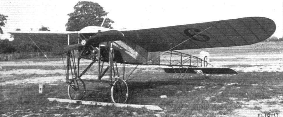
The Bleriot monoplane of M. Garros upon which he won the Anjou Circuit.
READY FOR THE FIRST HEAT IN THE SPEED COMPETITION AT HENDON ON SATURDAY LAST. - Messrs. Hall, Lewis Turner, and Louis Noel ranged up to the taklng-off line.
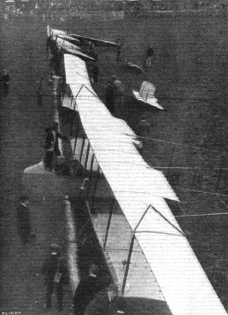
Competitors ready for the second heat of the Speed Contest at Hendon last Saturday. - Reading from front to back: Messrs. Grahame-Whlte and R. Gates (H. Farman), Sydney Pickles (Caudron), Marcel Desoutter (Bleriot), and Sabelli (Hanriot).
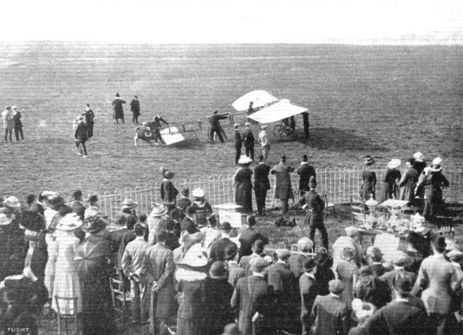
Mr. B. C. Hucks getting away for an exhibition flight on Saturday last at Hendon.
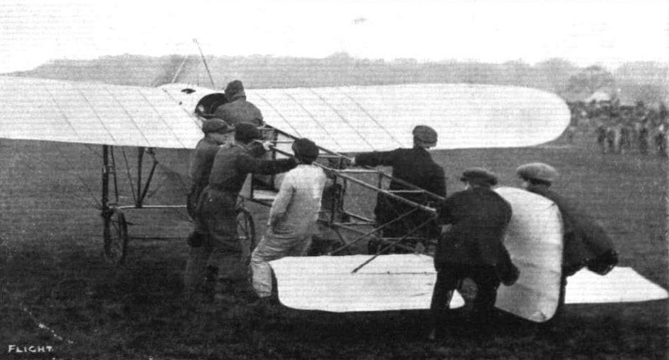
Gustav Hamel just off on his 50-h.p. Bleriot for his great altitude flight.
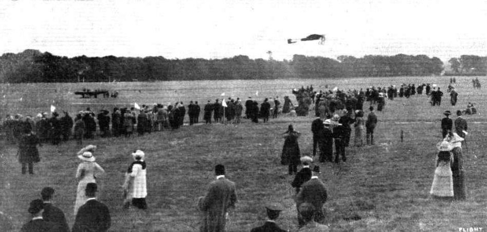
THE DUBLIN-BELFAST AEROPLANE CONTEST. - Mr. H. J. D. Astley getting away on his 70-h.p. Bleriot from Leopardstown, Dublin.
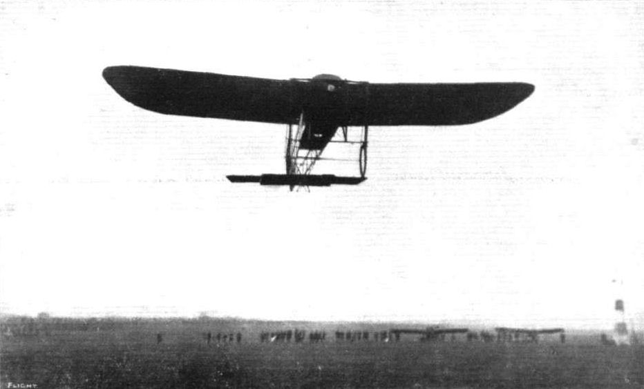
Mr. B. C. Hucks getting off on the Gnome-BIeriot at Hendon on Saturday.
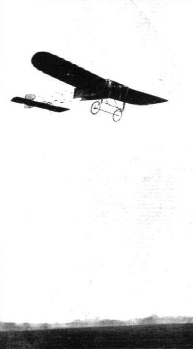
IN THE AIR DURING THE EASTER FLYING MEET AT HENDON. - Mr. B. C. Hucks on his 50 h.p. Bleriot

Mr. B. C. Hucks in his Bleriot passing the Judges' box on the first circuit in the Hendon cross-country handicap last Saturday week.
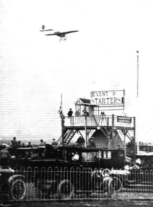
Mr. B. C. Hucks, on a Gnome-Blerlot, passing before the Judges' box at Hendon on Saturday last.
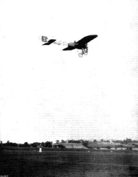
Mr. Gustav Hamel on his Bleriot in the cross-country contest at Hendon last Saturday.

Hamel, on his Bleriot, leaving Epping behind in his flight in the First Aerial Derby, as photographed from the top of Epping Tower.

Marcel Desoutter flying at the London Aerodrome, Hendon.

In the above picture the single-seater Bleriot appears to be standing on the ground. As a fact, it is Mr. Gustav Hamel on his new single-seater flying quite low at a speed of between 50 and 60 miles an hour past No. 1 pylone.
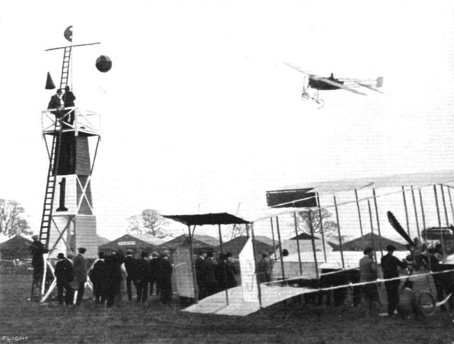
Gustav Hamel rounding pylone No. 1 during a race at Hendon Spring Meeting.
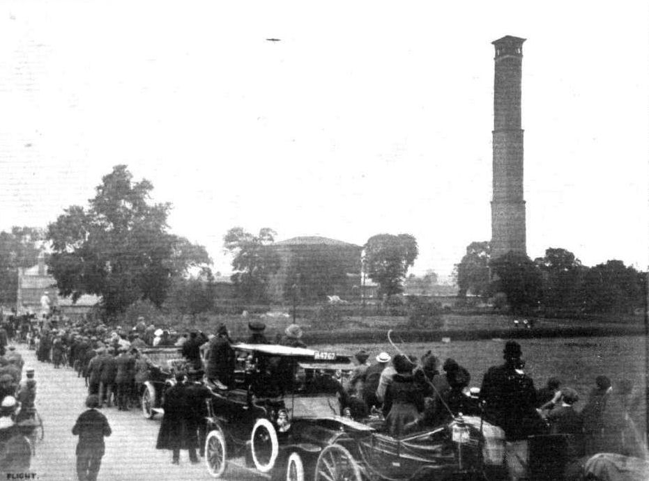
THE FIRST AERIAL DERBY. - At Kempton Park turning point, showing Sopwith's Bleriot passing round the big shaft at Kempton Park which marked the limit of the course. The congestion of traffic with sightseers watching the flyers, as seen in the photograph, was practically the same completely around the entire course.
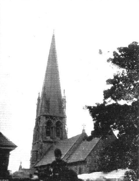
Mr. B. C. Hucks, on his 70-h.p. Bleriot, circling round the steeple of Widford Church on Thursday last week, and dropping confetti as Mr. Claude Grahame-White and his bride were leaving the church after the ceremony.
Guests at Mr. Claude Grahame-White's wedding at Sir Daniel Gooch's residence, "Hylands," watching Mr. B. C. Hucks flying on his Bleriot during the afternoon. On the ground in front of the mansion is Mr. Grahame-White's Howard Wright biplane on which he flew over, and on the right is the Aircraft Co.'s Maurice Farman biplane on which M. Verrier during the afternoon gave some remarkable exhibitions in a strong wind.
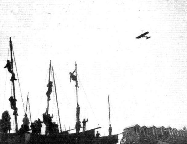
Brighton youths determined to get a good view of Salmet during his flights in his Bleriot monoplane at Brighton recently. During all the visits of the aviators to various places, no point of vantage has ever been left vacant by the watchers of the entertainment.
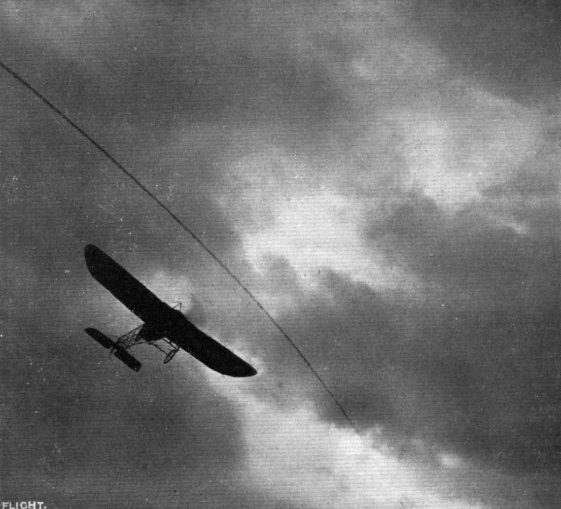
A SUNSET FLYING EPISODE AT HENDON. - Hamel on his Bleriot.
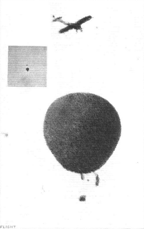
The incident of Mr. Gustav Hamel flying at Hendon Aerodrome round one of the balloons which had just before started from Hurlingham in connection with the Royal Aero Club balloon race for the Hedges Butler cup. This photograph was secured at about two miles distance, and by way of comparison, inset is a contact print from the original negative, the enlargement being untouched.
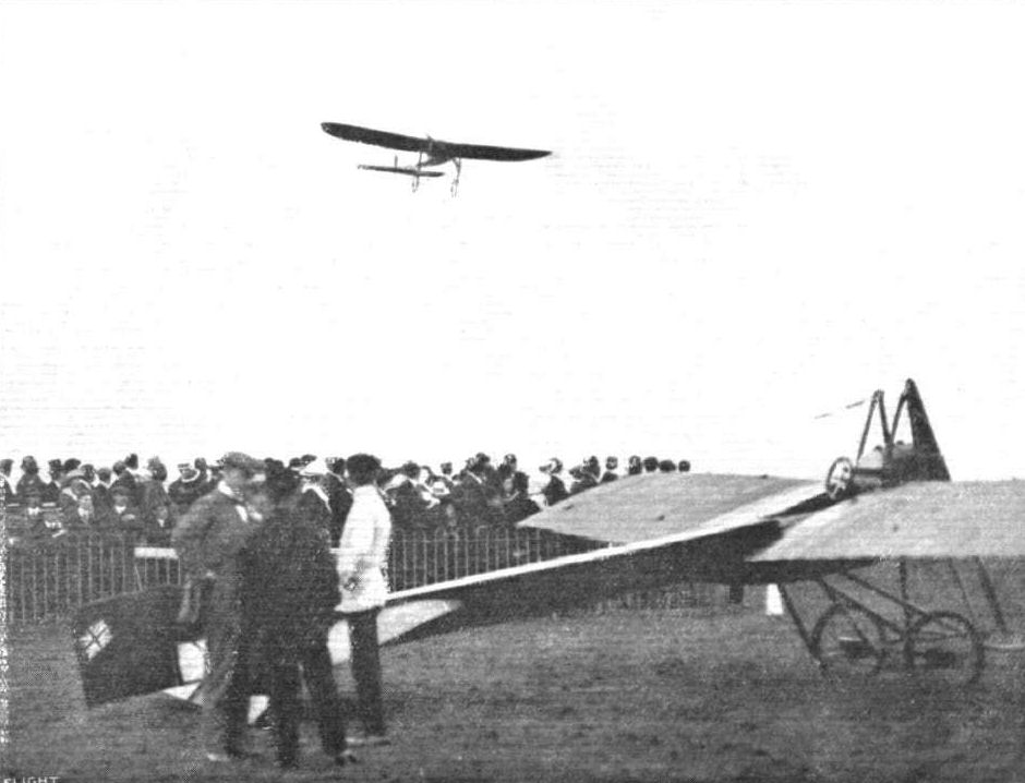
Marcel Desoutter piloting No. 6 Bleriot in the Hendon Aerodrome competitions.
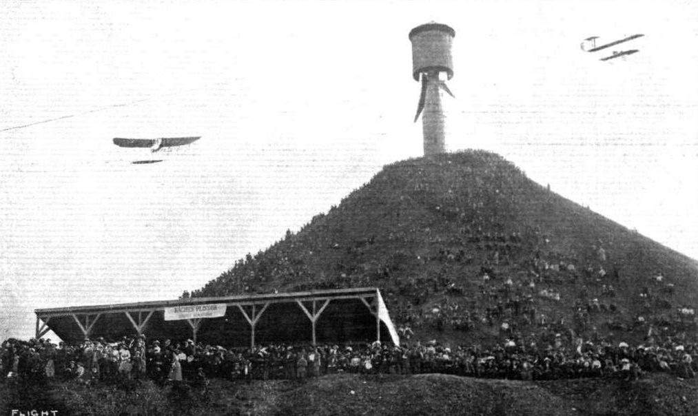
FLYING AT THE NANCY AVIATION FETE. - A fine natural grand stand. Kuhling on his Bleriot monoplane, and Loridan on a Henry Farman machine, are seen in flight.
MONOPLANE VERSUS BIPLANE AT THE LONDON AERODROME, HENDON. - Mr. Lewis Turner on the Grahame-White 'bus and Mr. Hall on a Bleriot monoplane.
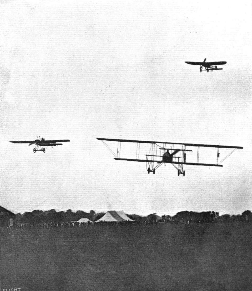
Remarkable flying was seen in the Speed Handicap at Hendon on Saturday. Our photograph shows, on the left, Jules Nardini on the Deperdussin, on the right Pierre Verrier on the Maurice Farman, and above, Marcel Desoutter, on the Bleriot, just about to enter on the last lap.
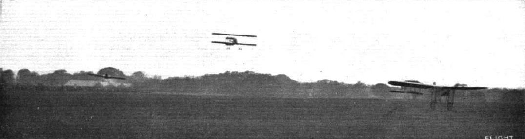
A TRIO. - Finish of first heat of the Speed Handicap at Hendon, Saturday, the competitors being Mr. Gustav Hamel, Mr. J. L. Travers, and Mr. Sabelli in the order named.

The return en vol plane to the Hendon aerodrome by Mr. Hamel and Miss Trehawke Davies, after winning the Altitude Competition at the Whitsun Meeting.
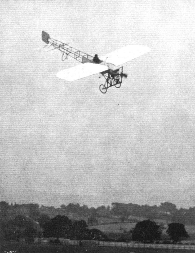
Mr. Gustav Hamel executing one of his very impressive vol planes at Hendon.
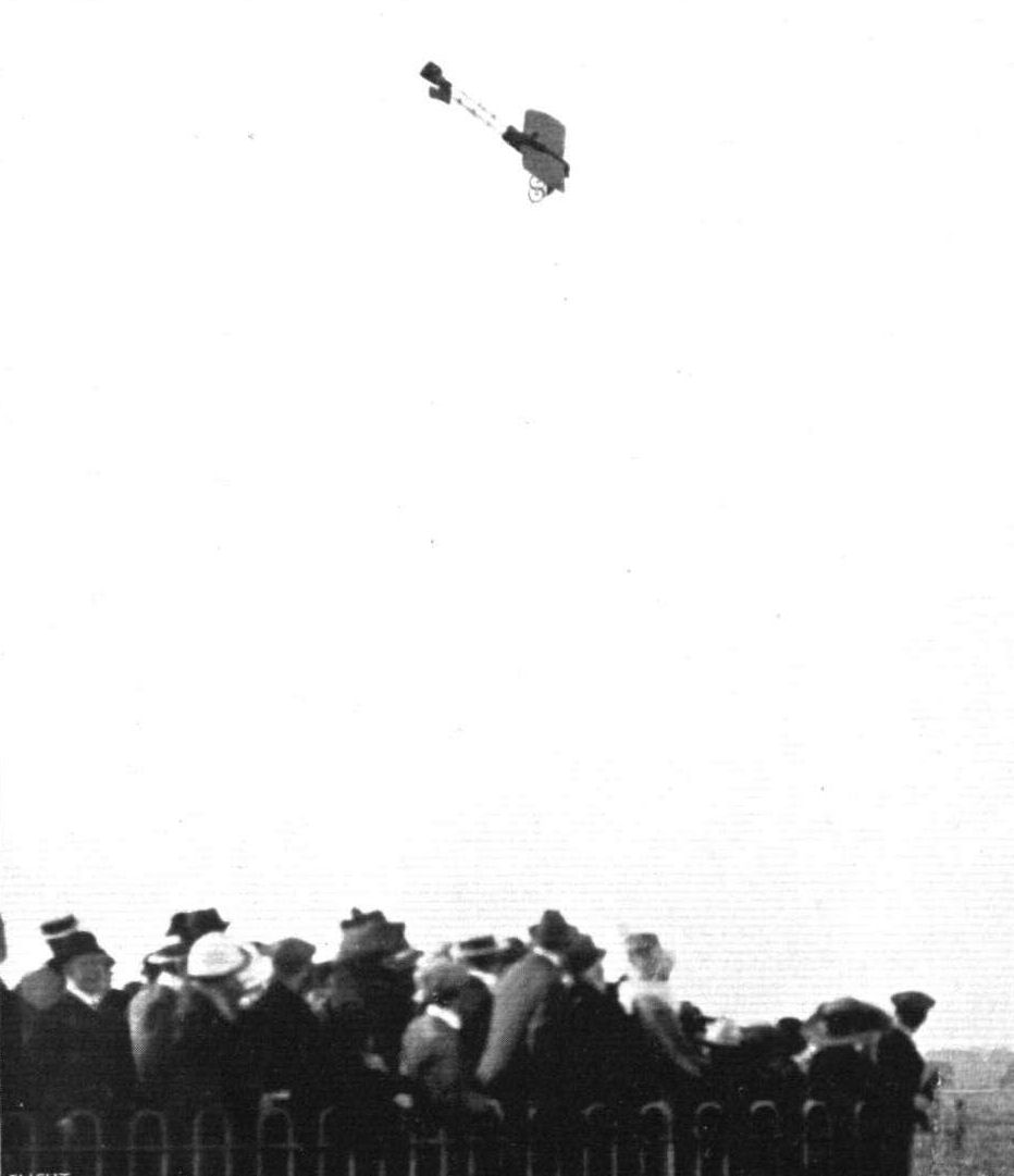
MR GUSTAV HAMEL BACK AGAIN AT HENDON. - In our picture he is seen on his Bleriot executing one of his halr-raising corkscrew vol planes at last Saturday's meeting at the London Aetodrome.
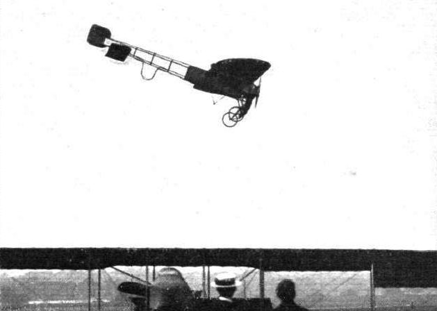
Mr. H. J. D. Astley finishing a straight vol plane from a height of about 2,000 ft. at Hendon on Saturday last.

Mr. B. C. Hucks, on his Blerlot, landing after making an altitude record for this year of 6,850 ft. at Hendon Aerodrome.
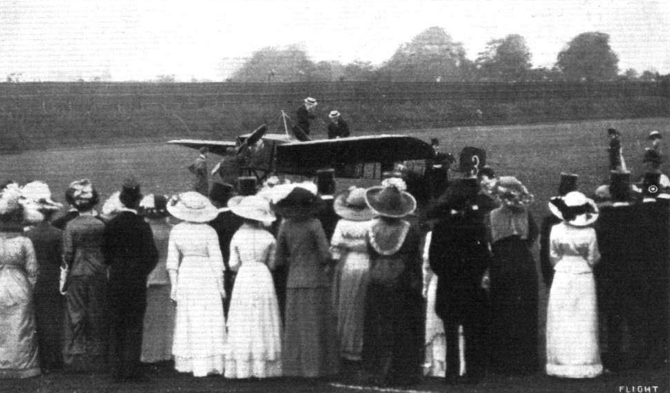
THE KING AND AVIATION. - Mr. Gustav Hamel and Capt. Mark Kerr, R.N., immediately after their arrival at Ranelagh last week, when Mr. Hamel flew before the King and Queen. Mr. Hamel and his passenger are seen, before actually alighting from the machine - a Bleriot - in which they flew over from Hendon, using it as a "dressing room" by shedding their flying rig in favour of more suitable attire for the occasion.
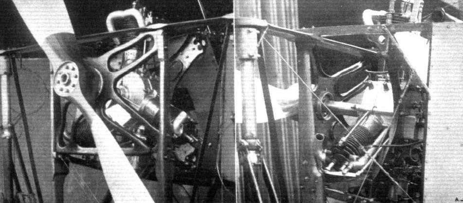
Showing the method of mounting one of the new 35-h.p. Y-type Anzani motors in a Bleriot monoplane. The photographs are of Mr. Prenseill's Bleriot at Hendon,
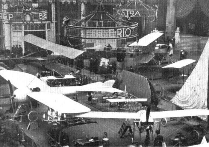
Representative stand at the Salon - the Bleriot.
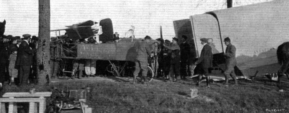
A military aeroplane dismantled ready for transportation in tne special aviation wagon which has been constructed for military manoeuvres in France. This wagon, immediately the aeroplane is safely housed, is in a few minutes attached to a fore-carriage, and is then ready to be hauled anywhere by the horses.
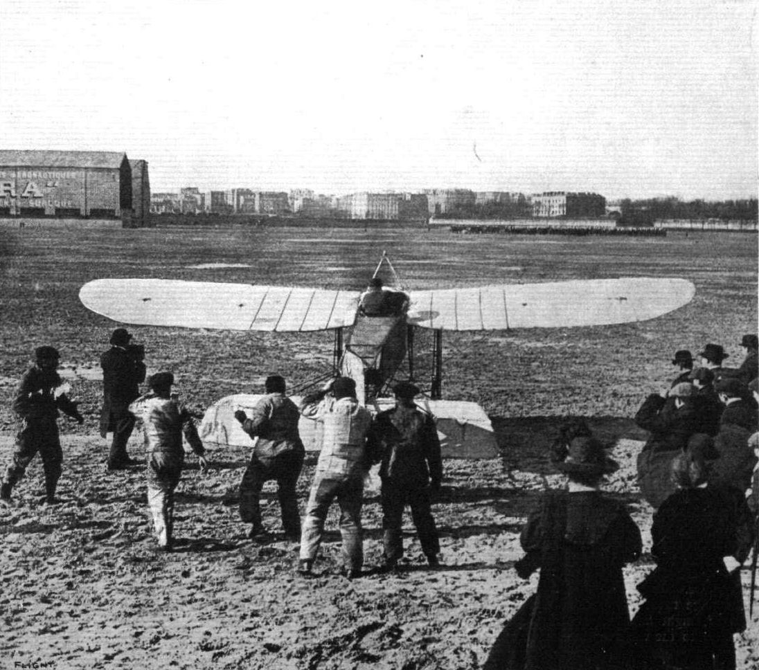
THE RECORD NON-STOP HENDON TO PARIS FLIGHT OF MR. SALMET. - Mr. Salmet, on his Bleriot monoplane, at the moment of being released at Issy grounds, for the return journey to London, after his remarkable flight from Hendon in a little over three hours.
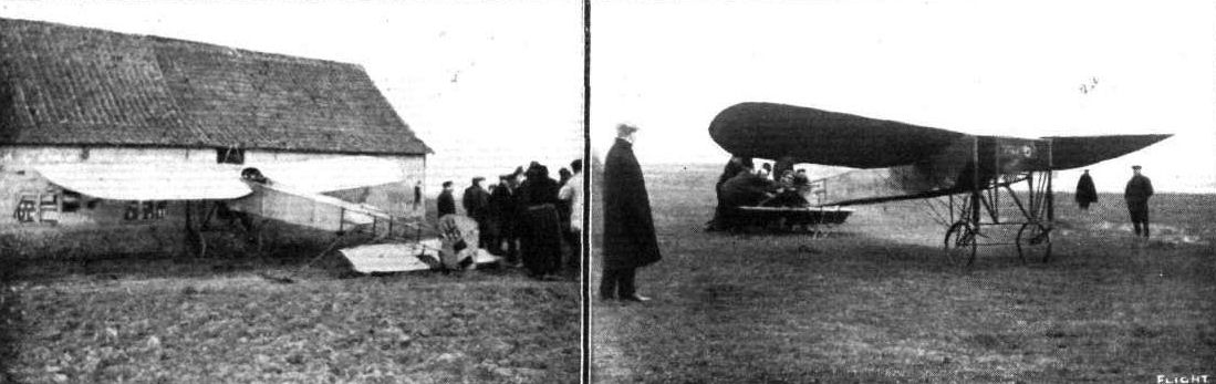
SALMET'S PARIS FLIGHT. - On the left his Bleriot monoplane pegged down for the night at Berck Plage, near Dieppe. Note the cut-away wings, the covered-in fuselage forming a float, and the Entente Cordiale emblem on the rudder. On the right is seen the moment of his start from Berck Plage the following morning.
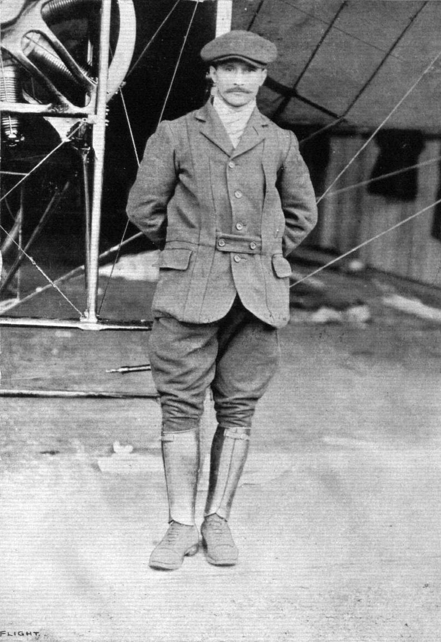
MR. HENRI SALMET, The chief instructor of the Bleriot School at Hendon, who made the record nonstop flight from Hendon to Paris on March 7th on a 50-h.p. Gnome-engined Bleriot monoplane, his time being 3 hrs. 16 mins.
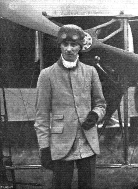
Mr. H . J. D. Astley, one of our finest English aviators, who has recently been again flying so splendidly.

Mr. Robert Slack, the I.C.S. pilot, in front of his Bleriot machine, upon which he on Sunday completed at Hendon his 1,000 miles tour through the Midlands.
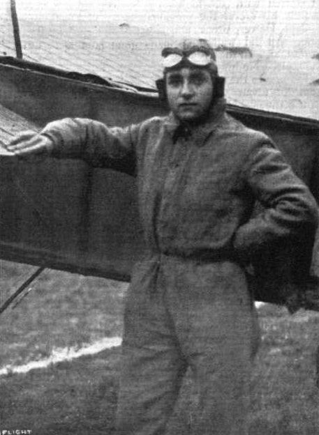
M. Marcel Desoutter, one of the crack flyers at the London Aerodrome, Hendon.
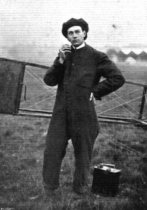
Mr. J. L. Hall, who is putting in such good work on his Bleriot at Hendon, and who has just obtained his pilot certificate at the Bleriot School.
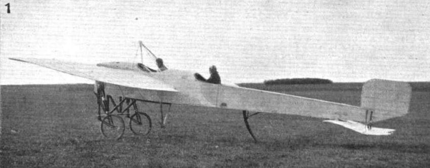
THE MILITARY COMPETITION MACHINES. - One of the actual Bleriots that will take part int he trials.
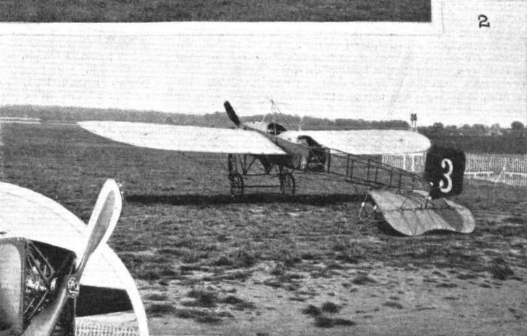
THE MILITARY COMPETITION MACHINES. - Three-quarter rear view of Hamel's 70-h.p. 2-seater Bleriot, an almost identical machine.
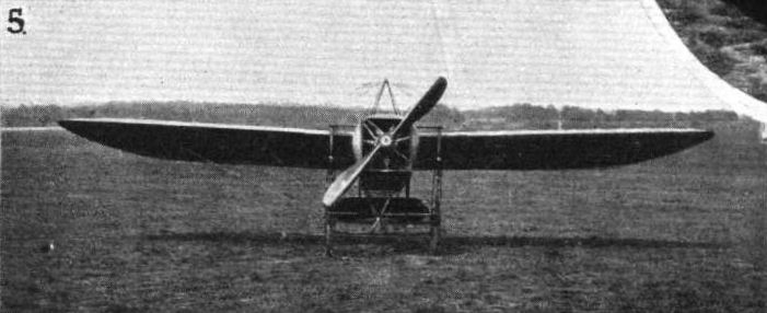
THE MILITARY COMPETITION MACHINES. - The machine as seen from in front.

THE MILITARY COMPETITION MACHINES. - Detailed view of the chassis and front section of the machine.
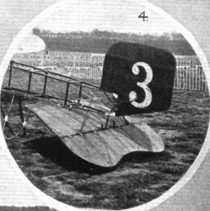
THE MILITARY COMPETITION MACHINES. - The tail.
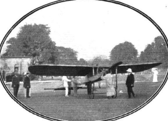
FLYING IN INDIA. - Jules Tyck starting for the first flight in India at the Tollygunj Golf Club.
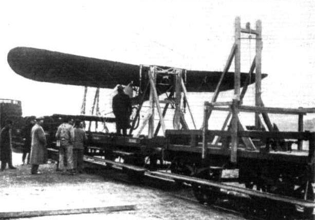
The Bleriot under test, seen from in front.

The Bleriot under test, on the railway.
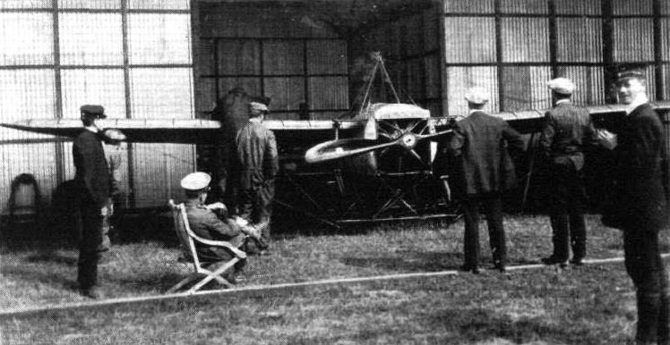
THE MILITARY AVIATION TESTS. - Assembling machines under observation. One of the Bleriot monoplanes being put together.
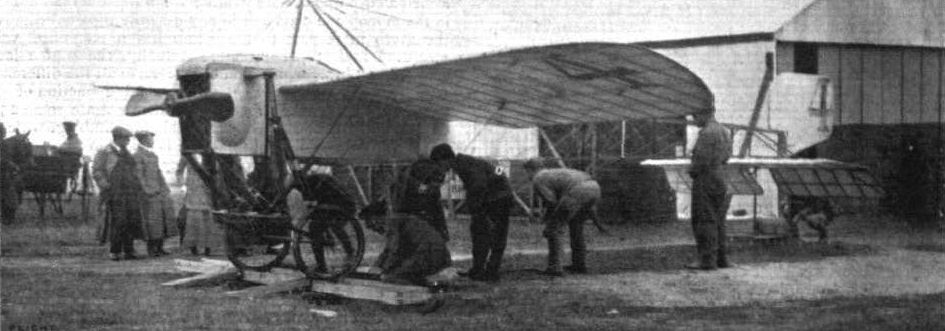
WEIGHTING THE MACHINES IN THE ARMY TESTS. - The aeroplane undergoing the operation is No. 4, a Bleriot.
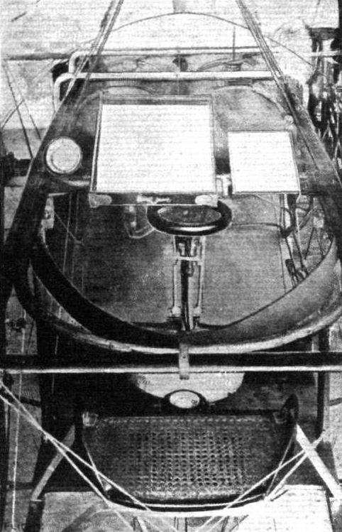
View of the controls on Ovington's Bleriot monoplane.
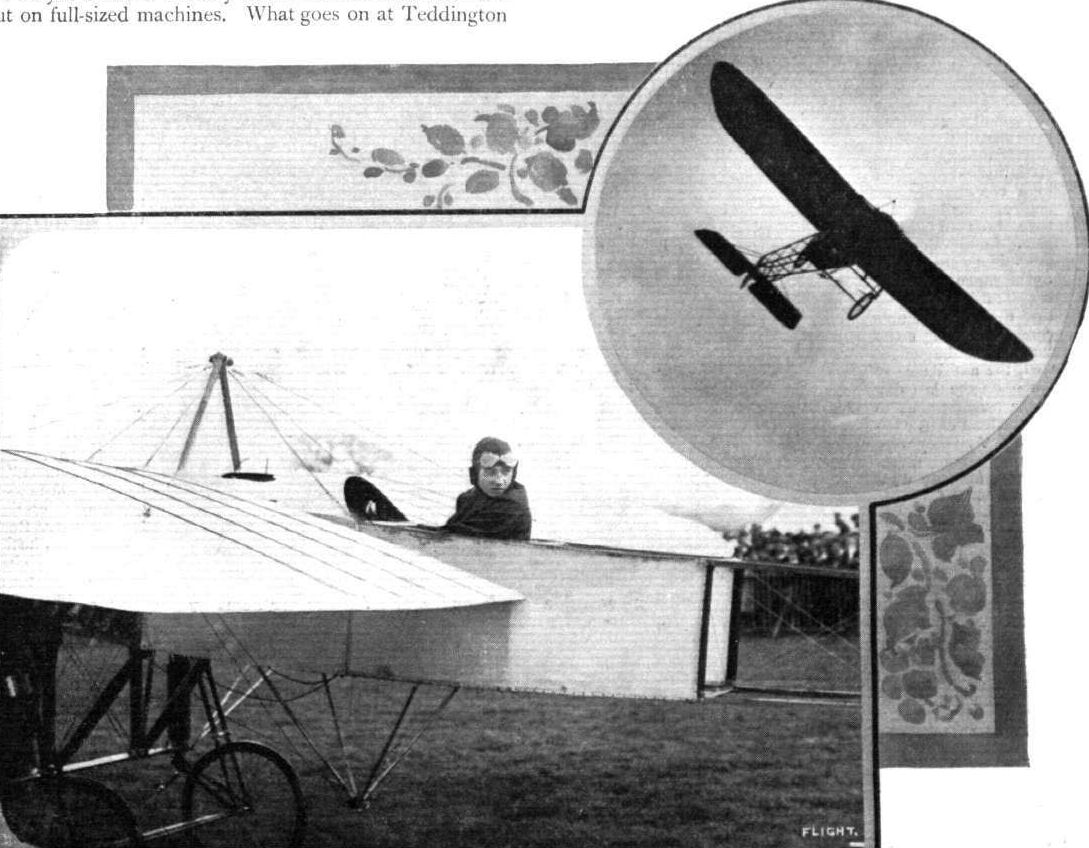
Mr. Gustav Hamel at the wheel of his 70-h.p. Bleriot with which he made his splendid altitude flight at Hendon. Inset Mr. Hamel is seen during one of his fine bankings.
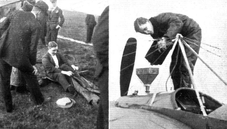
Mr. Hamel preparing for his altitude flight on the Blerlot at the Hendon Whitsun Meeting by donning his new leather overalls and replenishing his tank.
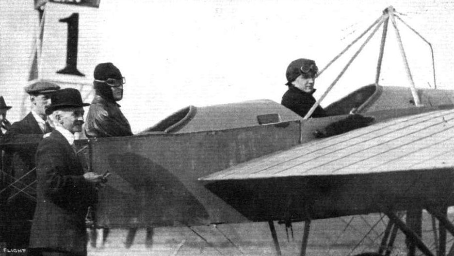
Mr. Hamel and Miss Trehawke Davies in the two-seater Bleriot at the Hendon Meeting, ready for the Altitude Competition. Standing on the left is Mr. N. Chereau, the British chief of Bleriots.

Miss Trehawke Davies, who has done so much crosscountry flying with Mr. Hamel, crossing the flying ground at Hendon at the Whitsun Meeting for Mr. Hamel's flight in the Altitude Competition. On the right, Miss Davies is in the passenger's seat of the Bleriot.
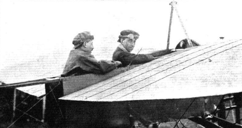
SOME OF THE HENDON PILOTS. - At the top Mr. T. O. M. Sopwith and Mr. Sasscon on Mr. Sopwith's 70-h.p. Bleriot.

Mr. T. O. M. Sopwith, the winner of the flying handicap on Sunday from Brookiands to Chertsey Bridge and back, with his lady passenger who accompanied him.
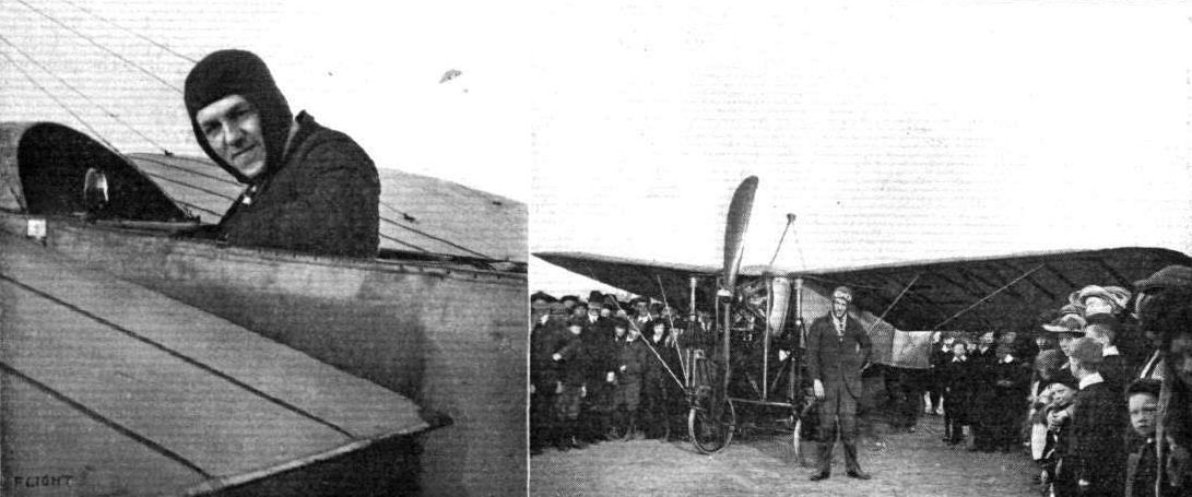
Mr. Vivian Hewitt and his Bleriot monoplane on the shore at Foryd, North Wales, where he has been making his fine flights for the past few months. Mr. Hewitt, at the time of writing, is waiting in the hope of flying the lrish Channel.
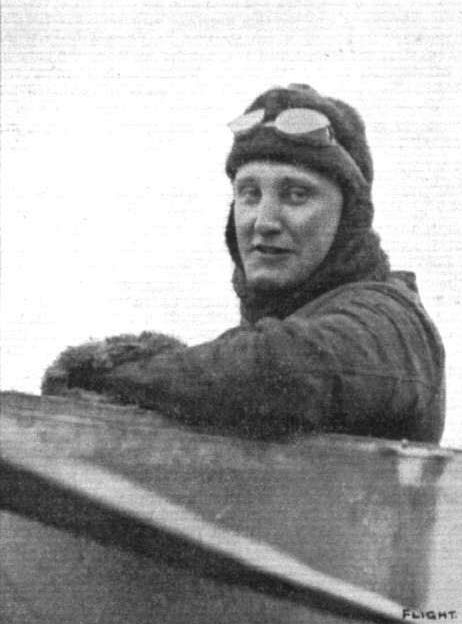
Mr. D. L. Allen, the aviator who has been missing since last week, when he started upon his attempt to fly the Irish Channel.

Mr Allen, on his Bleriot, tuning up at Hendon last week before hts start for the Irish Channel flight, which has ended so mysteriously.
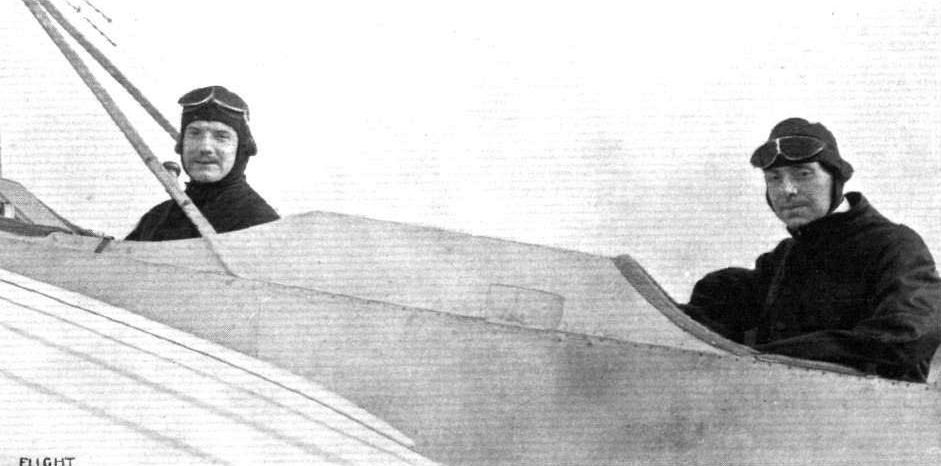
A snapshot of Hucks and his passenger, Mr. Harold Barlow, seated to the right, taken on Monday morning of last week just before they set out from Issy to fly to London on their new two-seater Bleriot.
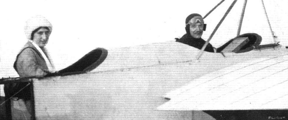
Mr. B. C. Hucks and Mrs. Craig off for a flight at Hendon on the former's fast Bleriot.
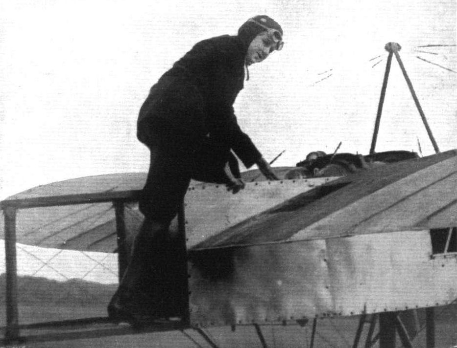
Miss Bernetta Miller, an American aviatress, who has been flying a monoplane in America recently.
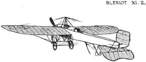

Landing chassis and tall skid of Mr. Hucks' Bleriot, with which he has been making the Daily Mail flights so successfully.

The New Bleriot Chassis. - The fitting to which the front wing spars are stayed.
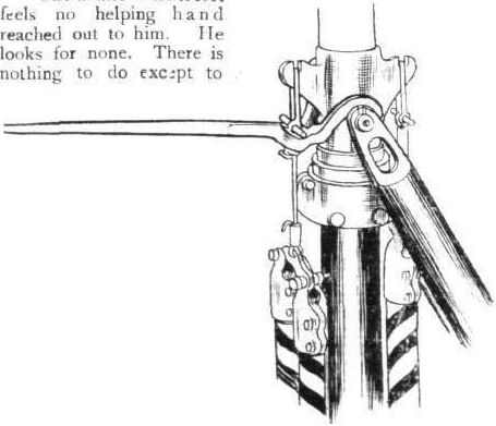
A detail of the Bleriot military monoplane, showing the means whereby, using a special lever, the shock-absorbers can be disconnected, allowing the machine to be lowered on to its knees, as it were.
Flight, March 9, 1912.
AEROPLANE UNDERCARRIAGES.
By G. DE HAVILLAND.
Types of Undercarriage.
Bleriot Monoplane. - The two main rolling-wheels have a track of about 6 feet, and are allowed a vertical travel of 12 in., the suspension being by rubber cable. The wheels are arranged to swivel through about 45°, and are held in the normal position by light rubber cables. The tail of the machine is supported by a skid of bent cane, which carries a comparatively light load. The absence of any kind of front skid makes this type of undercarriage unsuitable for use on very uneven ground, as there is nothing to prevent the machine turning over should the wheels be suddenly retarded by an obstruction, or by sinking into soft ground.
Whether swivelling wheels as adopted by Bleriot are desirable, is a very debatable point. When flying in a side wind, the machine naturally has a lateral motion relatively to the ground and, unless it can be brought head to the wind when landing, the undercarriage and wheels are subjected to severe side strains. Swivelling wheels obviate this trouble, but are attended by certain disadvantages which probably outweigh their useful feature. These are - extra weight, head-resistance, and complication, and also difficulty in steering on the ground because, if it is anything but level, the machine always tends to run down hill. The more useful practice of making wheels with wide hubs sufficiently strong to withstand side strains and do away with swivelling devices enables the machine to be steered on the ground with certainty, and makes for a cleaner and lighter design. It is interesting to note that in the latest type of Bleriot the undercarriage has been greatly simplified by the adoption of non-swivelling wheels. These are shown in the sketch. The head-resistance and weight are both rather high in the early types.
Flight, July 13, 1912.
THE MILITARY COMPETITION - THE MACHINES.
THE BLERIOTS.
OF the two monoplanes for the War Office competitions entered by L. Bleriot one is of the same type as that which first appeared in England at the time of the last Aero Exhibition at Olympia, in March, 1911. In this machine pilot and passenger sat side by side. The other machine is a replica of that with which both Hucks and Hamel have done much flying of late in England. Accommodation in this latter machine is provided tandem fashion. For the present it is to the former machine that we propose to devote a few lines.
Its fuselage serves a double purpose; not only, as in other monoplanes, is it used as the backbone of the machine, but its after portion is splayed out horizontally, and covered with fabric forming a fan-shaped tail. To the rear is hinged a semi-elliptic flap, which governs the machine for ascent and descent. The fuselage itself is of the customary box-girder type, cross-braced in conventional Bleriot fashion. It is covered in with fabric throughout its whole length, to improve its ability to penetrate the air with little disturbance.
In front, under a cowl specially designed to protect the pilot from oil, is the motor, a 70-h.p. Gnome, slung on both sides of the crankcase.
The landing gear is essentially the same as that which was fitted to the first Bleriot monoplane that startled the world by its flight across the English Channel. One slight peculiarity it has, however, that the top horizontal wooden member of the chassis-frame is, in the machine under review, applied to the base of the fuselage instead of to the top, as in previous machines. By this means the overall height of the chassis is considerably lowered, and this contributes to give it increased robustness. Although the chassis is considerably reduced in height, yet this method of applying it to the fuselage allows the front section of the machine to be lifted well above the ground, thus providing clearance for a propeller of ample dimensions and giving the wings, when at rest, a large angle of incidence, a feature which materially helps the machine in stopping within a reasonable distance after landing. The tail is supported by a double bent skid of rattan cane.
Well forward in the body, so near to the leading edge of the wings that they may obtain a clear view of the ground below and in front of them, are the seats for pilot and passenger arranged side by side. The pilot sits on the right-hand side, and it is in front of him that the controls are arranged. The passenger, too, may take control of the machine, for at his feet he has a foot-bar working in duplicate with that of the pilot by which he can operate the rudder. He has merely to lean to his right and to grip the cloche to obtain control of the whole machine. Below the aluminium scuttle-dash in front of them are arranged two fuel-tanks which feed down to the engine by gravity. A third tank, of much greater capacity, is stored away below the seats, from which position it is fed under pressure to the other tanks. The wings are of customary Bleriot shape and construction, and span 36 ft. 4 ins. Each wing does its share of supporting the fuselage through three stranded steel cables running from the front spar to the base of the chassis, and by three further cables, which also actuate the wing warping, running from the rear spar to the lower pylone. Steering is effected by a balanced fin-shaped rudder mounted above the tail.
Chief characteristics:-
Motor 7-cyl. Gnome, 70-h.p. rotary
Net weight 770 lbs.
Useful load 550 lbs
Overall length ... 27 ft. 3 in.
Capacity of petrol tank 24 1/2 galls.
Span 36 ft. 4 in.
Capacity of oil tank 7 3/4 galls.
Area Approx. 275 sq. ft.
Speed 60 m. p. h.
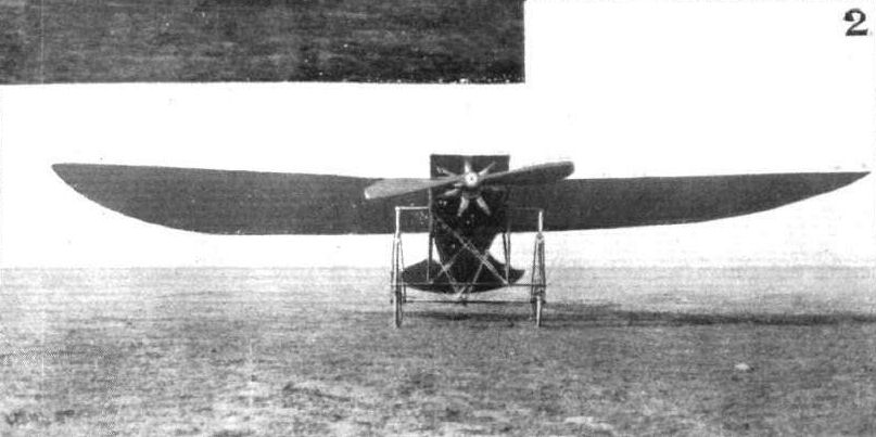
THE MILITARY COMPETITION MACHINES. 1 and 2. How the military Bleriot two-seater monoplane (Type XXI) appears from the side and from the front.
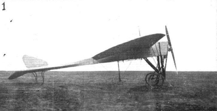
THE MILITARY COMPETITION MACHINES. 1 and 2. How the military Bleriot two-seater monoplane (Type XXI) appears from the side and from the front.
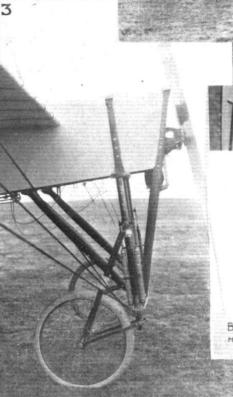
THE MILITARY COMPETITION MACHINES. 3. Details of the landing gear.
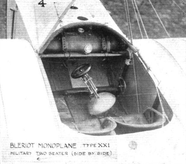
THE MILITARY COMPETITION MACHINES. 4. The interior of the cockpit showing the typical cloche which is used for controlling.
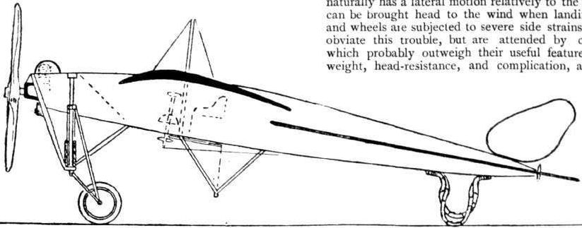

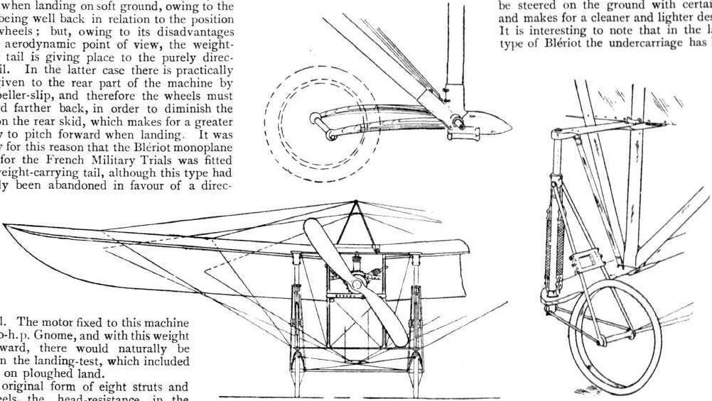
Fig. 3. - Bleriot Monoplane.
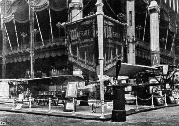
The Bleriot stand at the Paris Aero Salon, showing the extremely neat 50 h.p. Gnome-englned racer in the centre. The clean design of the landing chassis is the chief feature of this machine.
Flight, December 14, 1912.
FOREIGN AVIATION NEWS.
Testing the Bleriot Canard.
ON Monday, M.Bleriot was at Buc personally superintending the tests of his new Canard machine. In rising from the ground, climbing, descending and landing, the machine proved to be very good, and some turnings were made in the air with the machine very steeply banked. During some of the tests M. Bleriot occupied the passenger's seat besides Perreyon, who was the pilot.
Flight, December 21, 1912.
AIR EDDIES.
Louis Bleriot has again been experimenting with a canard type of monoplane. This one, however, is a good deal different from the one he was testing at Hardelot some months ago. It is larger, for one thing, being built as a two-seater, and is fitted with a 70-h.p. Gnome motor, The fuselage is perhaps the most curious part of the machine. For about three-quarters of the total length of the fuselage it is a pure box-girder; the other quarter is formed by a pole, either of steel tubing or of the composite cork paper and linen construction that he used for the fuselage of this new machine at the Paris Show. This pole supports the forward "tail," which in design is similar to those with which the old "Crosschannel" type of monoplane were fitted. In the chassis, Bleriot has discarded his transverse leaf-spring idea in favour of his usual system of swivelling wheels mounted on deformable triangular supports. On this new canard, too, he has taken the rudder from the front of the machine and supported it on outriggers behind the propeller.
Flight, December 28, 1912.
FOREIGN AVIATION NEWS.
Tests with Bleriot Canard.
ON the 17th inst. Col. Bouttieaux paid a visit to Bile and made a trip with Perreyon on the new Bleriot Canard monoplane. He also had another flight on the following day and then expressed his satisfaction at the way the plane behaved in the air. The machine, which has a 80-h.p. Gnome motor is said to have a speed of 120 k.p.h.
FOREIGN AVIATION NEWS.
Testing the Bleriot Canard.
ON Monday, M.Bleriot was at Buc personally superintending the tests of his new Canard machine. In rising from the ground, climbing, descending and landing, the machine proved to be very good, and some turnings were made in the air with the machine very steeply banked. During some of the tests M. Bleriot occupied the passenger's seat besides Perreyon, who was the pilot.
Flight, December 21, 1912.
AIR EDDIES.
Louis Bleriot has again been experimenting with a canard type of monoplane. This one, however, is a good deal different from the one he was testing at Hardelot some months ago. It is larger, for one thing, being built as a two-seater, and is fitted with a 70-h.p. Gnome motor, The fuselage is perhaps the most curious part of the machine. For about three-quarters of the total length of the fuselage it is a pure box-girder; the other quarter is formed by a pole, either of steel tubing or of the composite cork paper and linen construction that he used for the fuselage of this new machine at the Paris Show. This pole supports the forward "tail," which in design is similar to those with which the old "Crosschannel" type of monoplane were fitted. In the chassis, Bleriot has discarded his transverse leaf-spring idea in favour of his usual system of swivelling wheels mounted on deformable triangular supports. On this new canard, too, he has taken the rudder from the front of the machine and supported it on outriggers behind the propeller.
Flight, December 28, 1912.
FOREIGN AVIATION NEWS.
Tests with Bleriot Canard.
ON the 17th inst. Col. Bouttieaux paid a visit to Bile and made a trip with Perreyon on the new Bleriot Canard monoplane. He also had another flight on the following day and then expressed his satisfaction at the way the plane behaved in the air. The machine, which has a 80-h.p. Gnome motor is said to have a speed of 120 k.p.h.
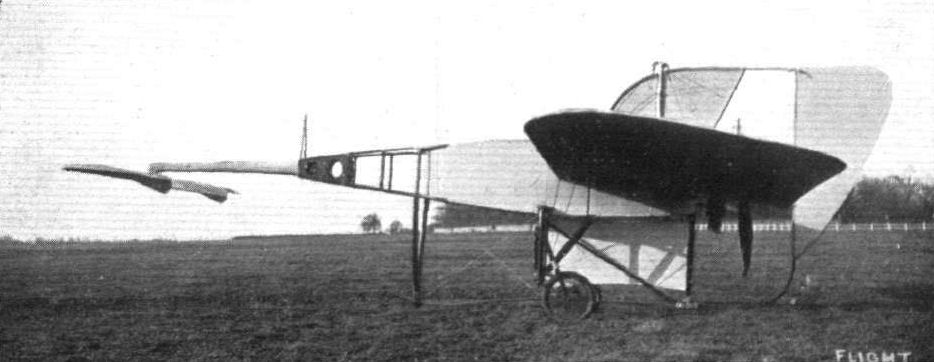
THE NEW 70-H.P. GNOME-BLERIOT "CANARD." - Side view.
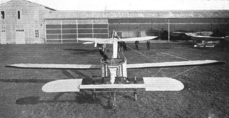
The "Blue Canard" Type XXXIII, second version. - In the backhand is the new BIeriot monoplane which was at the Paris Salon.
Flight, November 2, 1912.
THE PARIS AERO SALON.
Bleriot.
Louis BLERIOT is showing three models and his 50-h.p. Gnome single-seater, his 70-h.p. Gnome tandem two-seater, and a new model that has not yet been tried out.
This new machine is of a particularly clear design. The fuselage is of torpedo form, circular in cross section, and sufficiently wide near the front to seat pilot and passenger side by side.
The construction of the fuselage is extremely interesting. It is of the monocoque type and made on a "forme" in the same manner as a boot is made on a last. Over the "forme" paper is applied and over that pieces of sheet cork.
The whole is well glued up together, then covered with fabric and well pasted to prevent the ingress of water. The thickness when completed of this composite skin of paper, cork and fabric is roughly 6 mm. In front, where greater strength is required to withstand the Strains of the rotaiy 80-h.p., the composite skin gives way to chrome steel sheeting. A Levasseur propeller is used.
As we have already said, the chassis has undergone an entire change. The new one, as the sketch shows, is of the single skid variety, preferable because of its low head resistance. It is carried out in steel tubing and the wheels are sprung by oleo-pneumatic springs of special design. From the efficiency of a similar spring, mounted in a stand of its own for demonstration purposes, we should think that no great amount of trouble will be experienced with the suspension. Bleriot, too, has, on this machine, made use of the floating tail with hinged elevators. The rudder is shaped like a fish tail, and the levers and cables actuating both are carried inside the fuselage. There is no back skid, for the weight of the tail is carried by the rear end of the main skid. A tripod cabane above the cockpit supports the wings through strong steel cables when the machine is stationary, and, when in flight, so Bleriot has told us, it sometimes come in for a bit of top pressure. The wings are of conventional Bleriot design and span 12.25 with a chord dimension of 2 m. 25. The supporting area of this new machine is 25 sq. metres, and its weight, without oil and fuel or passengers, is 375 kilos.
The other two machines on the stand need no description, for those that follow things pretty closely in England know their main characteristics.
There is another object of interest on the stand, and that is the Bleriot aeroyacht, a light four-wheeled chassis fitted with a leg-o'-mutton sail which Bleriot primarily designed for the amusement of his family when staying at his place at Hardelot plage.
Representative stand at the Salon - the Bleriot.
THE NEW BLERIOT CANARD, SEEN FROM IN FRONT. - In the backhand is the new BIeriot monoplane which was at the Paris Salon.
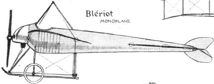
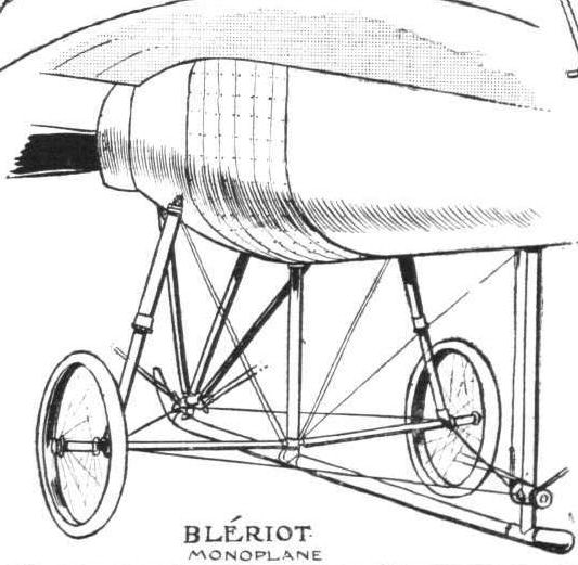
SOME LANDING CHASSIS. - The all-steel chassis of the new 80-h.p. Bleriot monoplane.
Flight, November 2, 1912.
THE PARIS AERO SALON.
Borel.
BOREL'S exhibit of three monoplanes, one of them fitted for water flying, is one of the most interesting in the Show. He has a 50-h.p. Gnome single-seater, a racing monocoque with an 80-h.p. Gnome and the hydro monoplane equipped with a similar motor. We may put aside the single-seater machine for, except for detail improvements here and there, it is no different from the one that Vedrines brought so much into the limelight by his magnificent flying during the earlier part of 1911.
<...>
The third machine of Borel's is the monocoque, inspired probably by Deperdussin's. Its fuselage is built up in a similar manner to that of the latter machine - in three-ply wood. But whereas the Dep. has no framework inside, the shell of the Borel is supported by six longerons, united by circular formers. In front, the 80-h.p. Gnome revolves under a dome, of which a quarter segment is cut away to allow for the sufficient cooling of the motor. Its wings, in which little curvature and little angle of incidence are noticeable, are of the papillon type - they are smaller in chord at the root than at the tip. For the chassis, it consists of two V's of streamlined steel tubing, to the base of which the axle uniting the two disc wheels is strapped by elastic bands. The tail, like the two-seater Morane-Saulnier machine, has no fixed stabilizing surface; it merely has elevators rocking about their approximate centres of pressure. A small vertical fin precedes the rudder. Each wing is stayed on the underside by only two cables, a double one running from one side of the chassis to the opposite wing, and one staying the rear-spar and actuating the warping.
The monocoque has not yet flown, and when it does - which will be as soon as the machine can be got away from the Salon - speeds of over 90 miles an hour are expected.
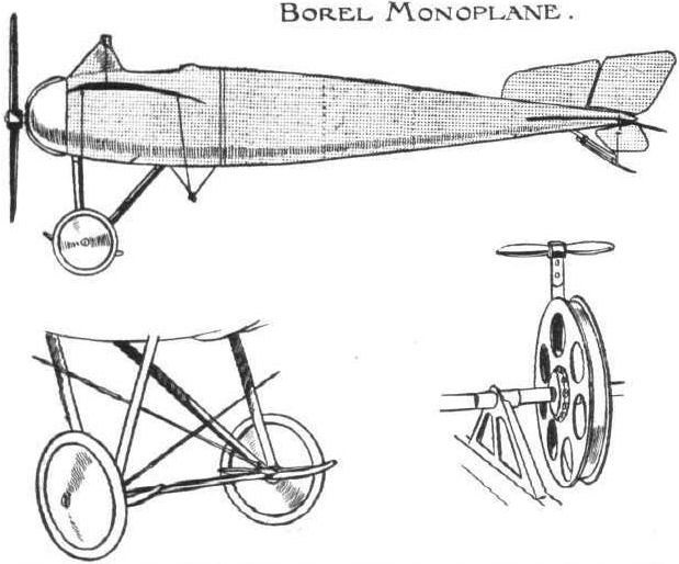
BOREL DETAILS. - Above, diagrammatical sketch of the 80-h.p. Borel "monocoque." Below, on the left, shows how the wings are braced from the chassis. The detail on the right is the starting device employed on the Borel hydro.
Flight, September 28, 1912.
The Belgian Hydro-aeroplane Meeting.
THE final official results of the hydro-aeroplane meeting at Tamise show that Chemet (Borel) secured the first place in the general classification with 166.88 points, and he is therefore awarded the cup offered by the Belgian Colonial Minister. Benoist (Sanchez-Besa) was second with 161.5 points, and Rennux (M. Farman) third with 154.2 points. Beaumont (Donnet-Leveque) was fourth with 138.6 points, and he is awarded the King's Cup.
Flight, November 2, 1912.
THE PARIS AERO SALON.
Borel.
BOREL'S exhibit of three monoplanes, one of them fitted for water flying, is one of the most interesting in the Show. He has a 50-h.p. Gnome single-seater, a racing monocoque with an 80-h.p. Gnome and the hydro monoplane equipped with a similar motor. We may put aside the single-seater machine for, except for detail improvements here and there, it is no different from the one that Vedrines brought so much into the limelight by his magnificent flying during the earlier part of 1911.
The hydro-monoplane, too, is nothing but an enlarged version of the same machine and fitted with floats. But it has some interesting details. The rear float pivots with the rudder and so comes in useful for steering over the water at slow speed. There is a clever starting arrangement so that the passenger can get the motor going without leaving his seat. From a half-speed engine sprocket extends a shaft which terminates in a wheel just between the passenger's knees. Attached to this wheel is a steel band which, if sharply pulled up, sends the engine through to about three-quarters of a revolution, enough, in most cases, to start it oft. This wheel, of course, is fitted with a free-wheel attachment.
Another interesting point is, that alongside each float are to be provided fittings so that a pair of oars may be carried. Rowlocks are to be fitted, too, so that, getting into port, pilot and passenger may clamber down out of their seats, sit themselves on the front of the floats and row up to the landing slip.
<...>
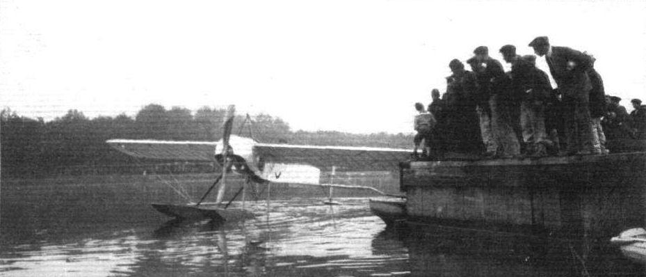
The Borel hydroaeroplane, which took part in the St. Malo competition.
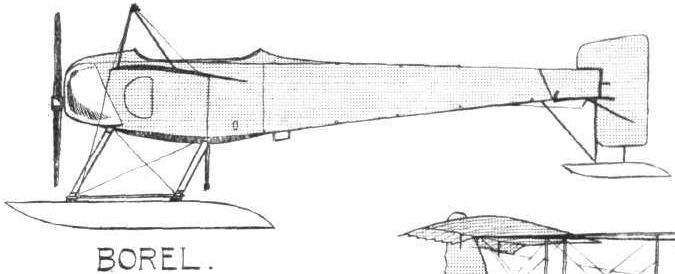

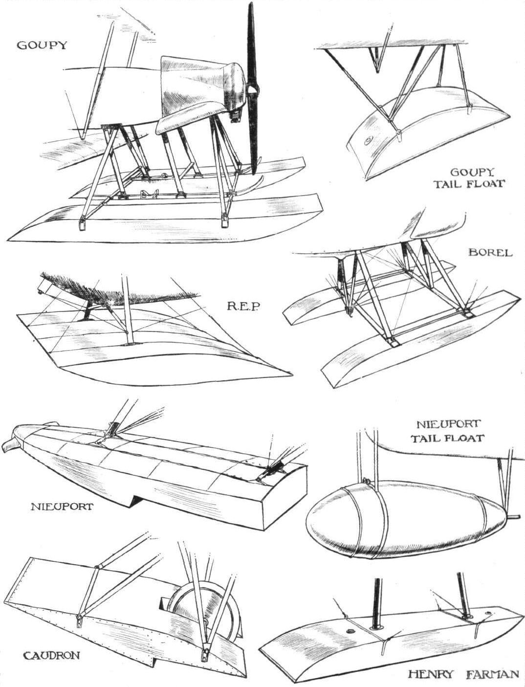
Some of the types of float used on present-day hydro-aeroplanes, as seen at the Paris Aero Salon.
Flight, January 6, 1912.
PARIS AERO SHOW.
Breguet.
AMONGST the biplanes present at the Salon there is no doubt that the productions of the Breguet firm must be given pride of place by virtue of the excellence of their performances of the various military trials of the past year. One of the machines on view was the identical machine with which the pilot Moineau obtained second place in the final classification of the machines at the French military trials at Rheims. The machine with which Bregi carried out his flights in Morocco from Casa Blarica to Fez, which machine was previously used by de Montelant at Brooklands in beating the British height record with passenger, was given a place of honour in the gallery. The third was a standard type biplane fitted with a 75-h.p. six-cylinder Chenu motor, driving through reduction gearing a three-bladed Breguet-Regy propeller. In order to preserve more effectively the natural torpedo-like outline of the Breguet fuselage, the engine is covered in by a neat housing of sheet steel. Further improvements had also been made in the bodywork itself, a miniature side-entrance door and light steel ladder being provided to facilitate ingress and egress.
Principal dimensions :-
Length 30 ft. Weight 1,430 lbs.
Span 45 ,, Speed 55 m.p.h.
Area 363 sq. ft. Motor 75-h.p. Chenu.
Price L1,400.
Flight, March 16, 1912.
AEROPLANE UNDERCARRIAGES.
By G. DE HAVILLAND.
Breguet Biplane.- The Breguet undercarriage is a distinct departure from the ordinary type. In this machine the designer has successfully provided a real shock-absorbing device in place of the usual rubbers or springs. The rolling wheels are only 15 in. diameter, with 3 1/2 in. tyres, and therefore well adapted to withstand side strains, at the same time they are comparatively light. No skid is fitted to the rear part of the machine, but the rudder is designed to perform this function should it come in contact with the ground. The weight is normally taken by the two rolling wheels, which are placed under the centre of gravity, and the propeller thrust is sufficient to pull the machine on to the single front wheel, which is steerable, and is coupled up to the hand wheel that operates the rear rudder. By this device the machine can easily be manoeuvred on the ground. This undercarriage has a very short wheel base, and, as might be expected, this does not make for easy rolling on uneven ground. Reference will be made to the Breguet shock absorber later on.
Flight, July 20, 1912.
THE MILITARY COMPETITION - THE MACHINES.
THE BREGUET BIPLANE.
THOSE who attended the flying at the London Aerodrome on Saturday last were treated to a splendid display by Moineau on a machine that is relatively an uncommon one in England - a Breguet. This particular biplane is furnished with a 14-cylinder 100-h.p. Gnome, and drives two two-bladed propellers - virtually a four-bladed one - through pinion reducing gear. As it is the machine that will probably represent the Breguet firm in the forthcoming military trials a brief description will not be amiss.
The photographs we publish give some idea of its appearance; the frontispiece this week shows the machine flying with Moineau as its pilot.
In its design, the greatest ingenuity has been displayed in establishing a machine that will be to a great extent automatically stable, easy to control and transport from place to place, speedy and strong, that will lift much weight, and that will afford the pilot a large degree of safety. All these desiderata, and many more that, perhaps, are not so important as the above, M. Louis Breguet has provided for in the biplane that bears his name.
In the first place, it is a tractor biplane, and for that the pilot may reassure himself with the thought that a lot has to "go" before any of the effects of an assumed smash reach him, that is, if he is suitably strapped to his seat. Again, this system of construction lends itself extremely well to facility of dismantling. A most noticeable point about the cam planes is the small number of vertical struts employed in bracing them. Only four very stout ones are used, and they are arranged in a single rack. In this present machine two extra struts are used to support the top plane extensions. The planes themselves are built about a single tubular spar of steel disposed at the average centre of pressure of the surface - about one-third of the chord from the leading edge. By the Breguet system of fastening the ribs to the spars a very supple supporting surface is formed - a feature which accounts for the remarkable steadiness of the machine in flight and for the ease with which it may be handled in a strong wind. Being so enormously strong, the steel framework needs but little wire bracing, and what there is is calculated to withstand ten times the strain it is likely to be called upon to bear. The body is of torpedo form, constructed of steel tubing, steel girders and ash, the whole covered in by fabric to reduce head resistance to the lowest possible degree.
Here we might mention that wood plays very little part in the construction. It only appears to a very limited extent in the wing and tail skeletons, in the body, and in the landing gear. This latter is formed of three wheels - each protected by a skid. The two main wheels support the body of the machine through oleo pneumatic springs of special design, and they are disposed as near as possible under the centre of' gravity. The forward wheel, spring suspended, is rotatable in conjunction with the rudder, so that when the propeller thrust pulls it into contact with the ground, it may be used for steering on the ground, as one would a motor car.
All three dimensions of control are centred on one column, surmounted by a vertical hand wheel. Rocking it to and fro controls the elevation, from side to side the warping and rotating the hand-wheel governs the rudder. Into all control wires steel coil springs are introduced, to make movements less harsh in action.
The tail is an enormous cruciform organ mounted to the rear point of the fuselage by a massive universal joint.
An idea of the ease with which a Breguet may be got ready for flight is conveyed by the fact that some time since at the La Brayelle aerodrome a machine was completely folded in five minutes and rendered ready for flight in another eight.
Flight, August 10, 1912.
THE MILITARY AEROPLANE COMPETITION - THE MACHINES.
THE BREGUET BIPLANES.
Both the Breguet biplanes met with misfortune in being got to Salisbury Plain. The one flown over by Moorhouse met with a contretemps at Ashford in Kent. The other started from London on Tuesday, July 30th, being conveyed on a trolley drawn by a steam tractor. At both Basingstoke and Andover, wheels gave out, while some time later one of the axles broke. These accidents, of course, occurred to the trolley, and when the biplane was examined at Lark Hill it was found not to be damaged in any way. The delay, however, had prevented it from being present while the assembling tests were in progress.
Neither machine presents any very great difference from the customary Breguet design, excepting that the motors are fitted in a horizontal position, instead of a vertical, as heretofore.
The drive to propeller, instead of being direct, has therefore to operate through a bevel which is geared down 1 to 1.8. The propeller speed is about 720 revs, per minute.
A point to notice is the system whereby the pilot may, if necessary, disconnect the passenger's control while in flight by means of a foot pedal.
Brakes to assist in pulling up after landing are fitted. They are also operated by a foot pedal.
It is possible to start the engine from the passenger's seat.
Main characteristics :-
Overall length 34 ft.
Speed 72 m.p.h.
Span 47 ft.
Weight without complement or fuel 1,300 lbs.
Area 400 sq. ft.
Flight, November 16, 1912.
THE PARIS AERO SALON.
British Breguet.
As we mentioned earlier in our reports, two British firms recognised the wisdom or were in a position to avail themselves of the wisdom, of exhibiting their goods at the Paris Salon. One firm was the Bristol Co., the other Breguet Aeroplanes, Ltd., of 1, Albemarle Street, Piccadilly, W. Under the direction of M. Gamier, the latter firm exhibited a beautifully constructed Breguet three-seater warplane, equipped with one of the new 110-h.p. horizontal Canton-Unne motors. In its main features it is a machine very similar to that which the British Breguet firm sent to Salisbury to compete, last August, in the Military competition there. But as regards its landing gear there is a change, for the single front steerable wheel has been replaced by a pair of wheels mounted on a short axle which is connected to a heavy gauge steel tube extending downwards from the nose of the fuselage by means of a transverse laminated steel spring. We print a sketch to illustrate this point. The rear pair of wheels of the chassis remain as they were formerly, supporting the main weight of the machine through heavy oleo-pneumatic springs of patented design. The body of this machine is covered in entirely with aluminium sheeting, and a very warlike looking job it makes. However, in future machines they intend to cover the fuselage with "Durehide," a type of "synthetic" leather. This material, as a matter of fact, is used on the present machine to bind the leading edge of the planes, in place of the aluminium sheeting that was formerly employed. One of the most noticeable features of this excellent biplane is the care with which the fuselage has been designed and shaped to avoid as much head resistance as possible. This is the chief reason for the setting of the engine in a horizontal position. Another interesting exhibit on the stand was a clever system of dual control, the subject of a patent held by the British Breguet Co. It is so arranged that while the pilot and the observer may have control of the machine, either separately or in unison, the pilot always has command of the situation. By means of a small hand lever he is able at any moment, if the observer is driving, to deprive him of the use of his controls. Further, it is arranged, that should the pilot, in action, be killed or so seriously wounded as to render it impossible for him to continue in charge of the machine, the observer may, by reaching behind him and altering the position of the hand lever, transfer the entire control of the machine to his own column.
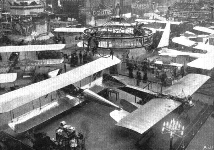
Representative stand at the Salon - the Breguet-R.E.P.
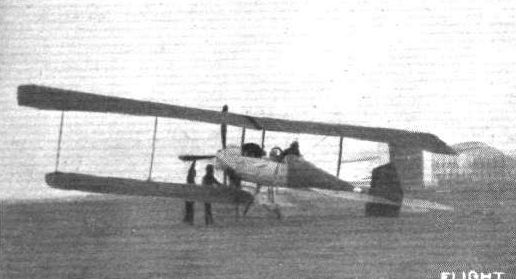
THE ARMY BIPLANE AT FARNBOROUGH. - Capt. Rayleigh in the pilot's seat prior to an early morning trip over the Common.
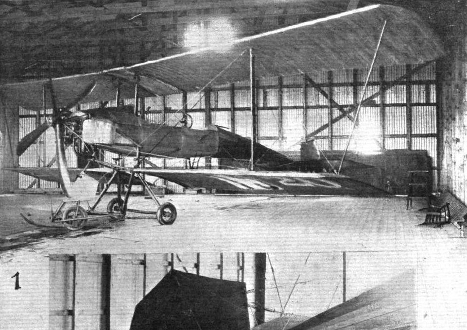
THE MILITARY COMPETITION MACHINES. The 100-h.p. Breguet biplane that Moineau will probably fly at Salisbury next month.
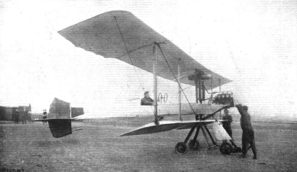
Lieut. Hynes at Salisbury Plain, just about to start on a Breguet machine in connection with the Army work. Lieut. Hynes is, we believe, the first Englishman to fly a Breguet in this country.
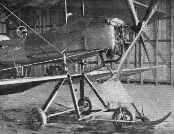
THE MILITARY COMPETITION MACHINES. The front part of the 100-h.p. Breguet biplane, showing the engine mounting, the reduction-gear to the 4-bladed propeller, and the landing chassis.

A NEWCOMER AT HENDON AERODROME. - The big Breguet warplane flying under the pilotage of M. Moineau.
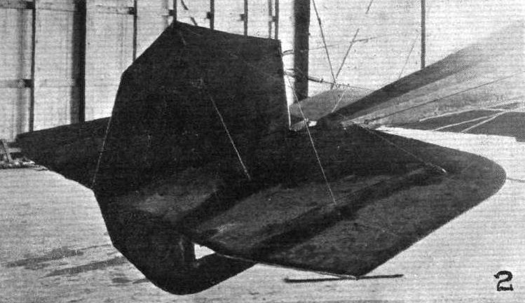
THE MILITARY COMPETITION MACHINES. Detailed view of cruciform tail.
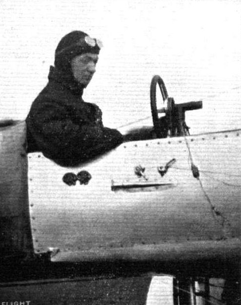
M. Moineau, the clever pilot who is flying the new Breguet warplane.
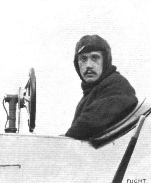
M. Richet, the pilot who was flying the new Breguet at Hendon Aerodrome.
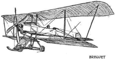
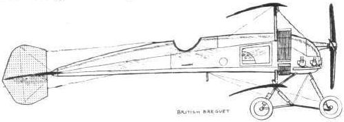
The 110-h.p. British Breguet biplane.
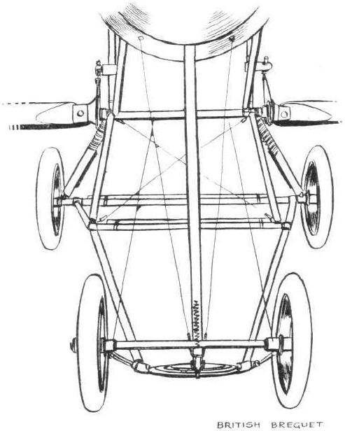
The new form of chassis fitted to the British Breguet biplane.
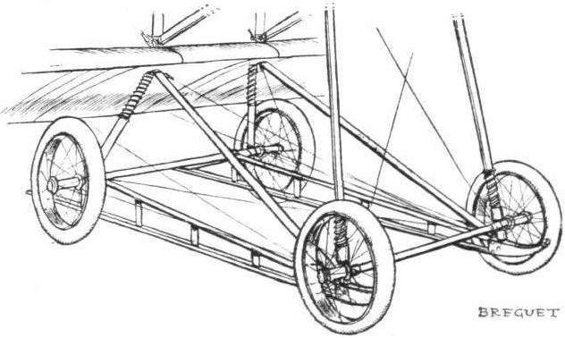
The new form of landing gear that the French Breguet firm are adopting.
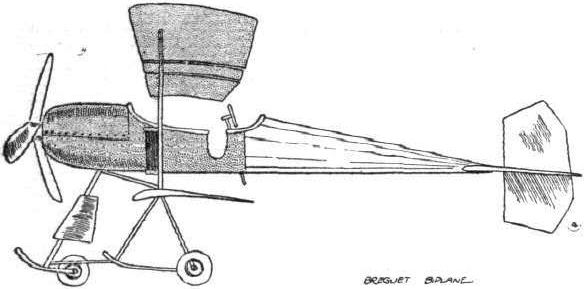
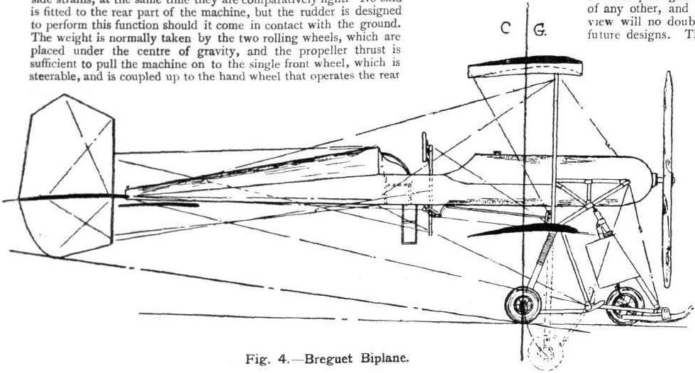
Fig. 4. - Breguet Biplane.
Flight, November 16, 1912.
THE PARIS AERO SALON.
Breguet Hydro-monoplanes.
HIGH above the stand of the French Minister of War, at the top of the flights of steps leading to the gallery, rested this novel machine - Breguet's version of what a sea-going hydro-monoplane should be. A glance at our sketch will be sufficient to convey to the reader that it is no ordinary machine.
Its body, short and bluff in relation to the span of the wings, is built of steel tubing, and rests on a huge wooden hydroplane float of rectangular section.
The main novelty of the float is that on either side project auxiliary floats, somewhat of the same shape as those that Fabre constructs, arranged so, to improve the lateral stability of the machine when floating on its liquid element.
In the front of the body is mounted the motor, a horizontal Canton-Unne engine of 110-h.p., which drives, through an upwardly inclined steel shaft, a four-bladed tractor screw, mounted in front of all. Behind the engine sit the two pilots, side by side, each of them being provided with controls. On either side stretch the wings, of customary Breguet design, and behind all, at the end of the rapidly tapering body, is a huge cruciform tail.
Although the work of the machine has not yet been estimated by practical test, it is already the property of the French Navy.
We should imagine that most interesting results will be obtained as soon as experiments are started upon.

The peculiar Breguet hydro-monoplane.
Flight, May 11, 1912.
THE CAUDRON MONOPLANE.
LOOKING at this diminutive monoplane, it seems really difficult to believe that such a tiny construction of wood, steel, fabric and wire could take Ewen through the air from Crotoy to Cap Grisnez at a speed of not less than ninety-five miles per hour, and could bring him safely across the Channel. Yet it did so. Compared with some monoplanes with which we are more familiar, the machine seems almost absurdly small, for each wing, detached, looks more like a spare tail than a major sustaining surface. But it has proved itself to be capable of doing the work, and so we can only look at it, marvel, and write down Caudron a very clever constructor.
Its main body is totally enclosed with fabric, and for its length is unusually roomy. To avoid or minimise the edge disturbance that a purely rectangular body is known to set up when travelling through the air, each side of the body is belled out by light longitudinal formers of French poplar, over which the fabric is stretched. The fuselage proper is that type of structure now almost universally employed - a simple lattice girder of ash and steel wire, braced up together in exactly the same fashion as a Bleriot body. Capping the front end is a sheet steel plate to which the motor is bolted, a type of mounting which, both for rotary and stationary motors, has come into quite general use of late. As a subsidiary support steel tubes are carried from the fuselage to the front of the crank case. While on the subject of the engine, it may be interesting to mention that the motor fitted to this particular monoplane is the first of its type - a six-cylinder radial air-cooled engine of 45-h.p. - to leave the Anzani works. According to the pilot's testimony, the machine never faltered throughout the whole trip, and ran singularly free from vibration. The magneto and oil pump - the latter feeding the oil to the motor via glass inspection cap similar to those in the Gnome equipment - are fitted to the back of the steel engine plate; where they may easily be reached through an inspection door covering the front section of the left-hand side of the body.
A 6-ft, 8-in. propeller of Messrs. Caudron's own manufacture, direct coupled to the engine crank-shaft, provides the thrust. It is cut from a single piece of wood on lines very like the Normale, but unlike that well-known make it is not covered with canvas.
The landing gear, of ash and steel, must be immensely strong. It certainly is simple enough, effective enough, and presents little head resistance. It consists of two pairs of stout ash struts arranged V-fashion on either side. A steel bar unites the apexes of the two V's, and an inverted V of steel tubing completes the structure. The rods on which the wheels are mounted are hinged to the centre of the chassis, and extend to right and left-hand on either side. They pass under crutches integral with the bases of the two V's, and support the weight of the machine through rubber shock absorbers. A better grasp of this detail can be obtained from the accompanying sketch than could possibly be drawn from a mere word description.
A curious point in connection with the wheels, a point on which, we are assured, Messrs. Caudron have been granted a patent, is that they are arranged slightly splay footed - if we may use a colloquial term. Both axles slope back slightly from the line at right angles to the rolling path - a feature which, it is claimed, renders the machine immune from a tendency to suddenly turn to right and left of its true path when rolling. Whether it does so or no is for practical tests to decide. We should think the tyre wear would be rather excessive if the machine were used for much school rolling practice.
On the new military monoplanes that the Caudron firm are now turning out an all-steel chassis is employed, while some of those in commission over the sands of Crotoy are not provided with any shock-absorbing apparatus at all. It seems to us that, even for the rougher work that the machine will have to undergo in Britain, the shock-absorbing device - although excellent - could very well be suppressed if its place were taken by extra large diameter tyres. At the most, only two inches of upward travel is provided by the rubber shock absorbers, and this could very well be afforded by a tyre of increased dimensions. Not only for this reason should larger tyres be recommended - they would, in such a small machine as this one, help to a great extent to keep it afloat should it at any time have to alight on water. Two tyres of a tubular diameter of six inches, and of a rim diameter of 26 inches, will support something like 180 lbs.
A peculiarity of the wing construction is that, roughly, two-thirds of the wing chord is extremely flexible. The two booms in front - they are essentially stout steel tubes, wood filled - are united by strong solid ash ribs and steel wire cross-bracing to form a girder of immense strength. The flexible trailing edge is formed by continuation of the ash strips applied to the underneath of the solid ribs. These are whittled away to round section, where they leave the back spar, and are enclosed, over the flexible portion, by fabric covering on the single surface principle. Double surfacing is used on the front section of the wing, and to further strengthen it to withstand the intensity of suction that must occur over that part in a wing travelling at something like 85 miles per hour, a wide strip of aluminium sheeting is applied. Both booms are accommodated by sockets in the side of the fuselage, the front one being quite a tight fit and, withal, pinned, while the rear one is a loose fit to allow for the warping deflection.
So great a faith have the constructors in the strength of the girder construction of the wings, that they fit no drift wires. Two stout stranded steel cables on either side take the lift in flight, and the weight of the wings when stationary is supported by quite stout cables on top. So strong are they that they would absolutely preclude any suspicion of the wing failing through momentary top pressure. By the way, it would be interesting to know the effect of top pressure on the rear flexible portion of the wing. The warping, cables and their attachments are quite as stout as those taking front weight, for under ordinary level flying they must take almost as great a share of the load as those in front, while when in a climbing attitude it is quite conceivable that they may take more. One of our photographs shows the details of the warping control.
Clamped to the rear of the fuselage by U bolts, and braced there by steel wire, is the horizontal tail surface. It is purely directional, and its rear two-thirds flexes on the same principle as the main planes. In addition to flexing up and down for elevation and depression, it, similarly to the tail of the Caudron biplane, warps laterally in conjunction with the wings. Direction control in a horizontal plane is obtained by a vertical rectangular rudder, balanced and mounted entirely above the fuselage. A small skid, the flexibility of which is provided by its laminated construction of wood, protects the tail.
An interesting detail in connection with the control - all control wires are of Bowden inner cable, fitted everywhere in duplicate, and guided at necessary points by Bowden outer sheathing. Only in one point is this rule transgressed, and that is where the top warp compensating wires pass over the upper pylone. Here they slide through copper tubes, Nieuport fashion.
The pilot sits extremely low in the body - just four inches off the floor, so that only his head emerges above the well-padded sides, lie grasps a single ash vertical lever that controls the elevation and warping, and operates the rudder with his feet. All his engine control and his instruments for cross-country flying are quite handy, and altogether he is very comfortably installed in a very excellent little machine.
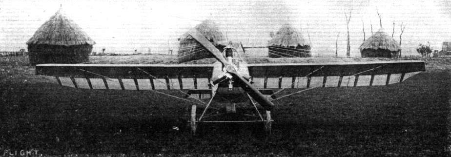
The new Caudron monoplane which is characterised by its extreme simplicity of construction and the attention that has been paid to the reduction of head resistance. Equipped with one of the new 35-h.p. Y-type Anzani motors, it has attained a speed of over 65 miles per hour, a good performance for both motor and machine.
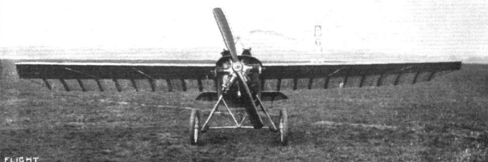
The Caudron monoplane, front view.
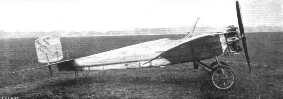
The Caudron monoplane, side view.
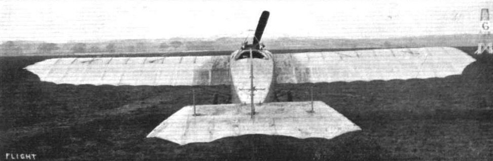
The Caudron monoplane, view from behind.
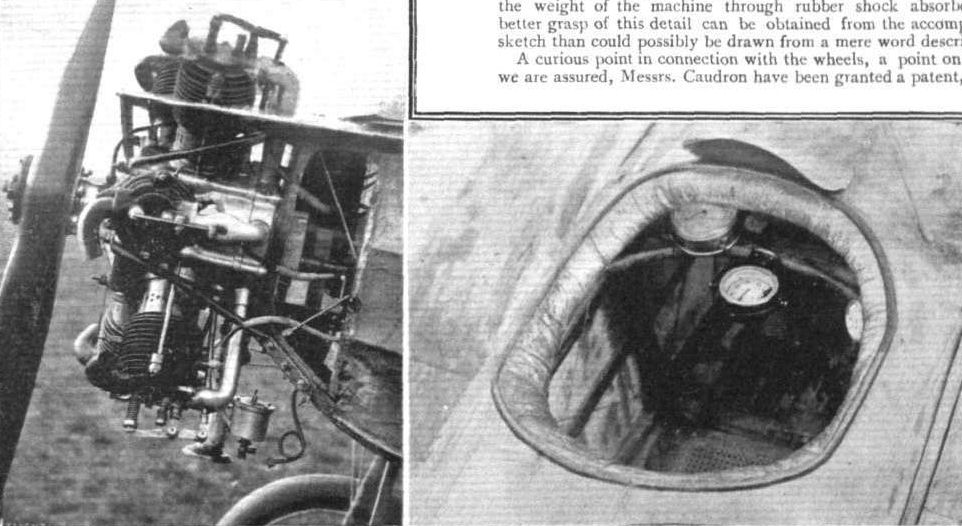
DETAILS OF THE CAUDRON MONOPLANE. - On the left the mounting of the 45 h. p. Anzani motor, showing the magneto and oil-pump to the rear of the mounting plate. On the right the interior of the cockpit.
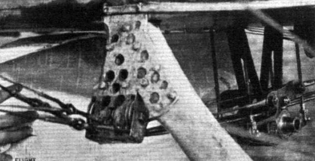
Details of the warping mechanism of the Caudron monoplane.
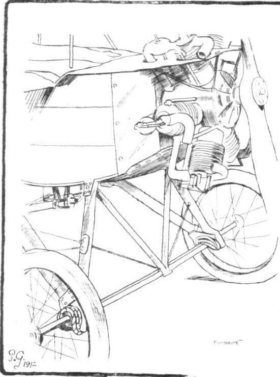
THE CAUDRON MONOPLANE. - Details of the landing chassis and engine mounting.
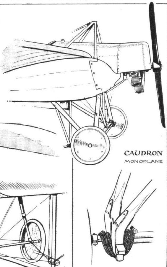
SOME LANDING CHASSIS. - Chassis of the Caudron, with detailed pictures showing how the suspension is effected.
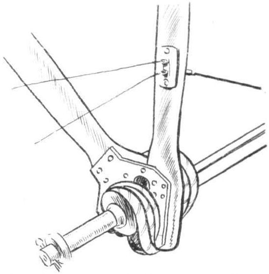
Details of the Caudron shock-absorbing arrangement. - The wheel is omitted for the sake of clearness.
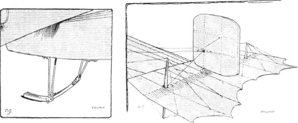
The tall of the Caudron monoplane, and on the left details of the tail skid.
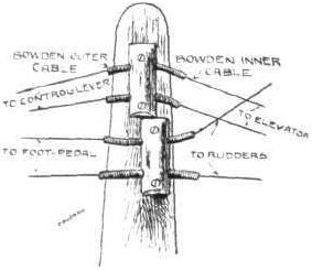
The method adopted on the Caudron monoplane of guiding control wires.
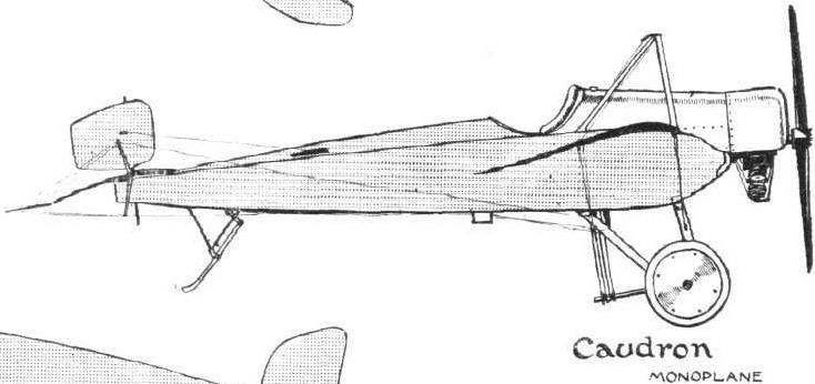

THE CAUDRON RACING MONOPLANE.- Plan and elevation to scale.
Flight, November 30, 1912.
THE CAUDRON BIPLANE.
IT is difficult sometimes to follow with quite the closeness that one could wish the line of thought that the designer has pursued in the evolution of the latest product of his brain. But with a machine like the Caudron there is at least the inspiration of an unusual appearance to stir the mind's curiosity to the point of inquiry. You look, for example, at one of those little biplanes that has been doing such good service in the Ewen School at Hendon, and you observe that peculiar little coracle-like body that is so curtailed by comparison with the corresponding member of the ordinary tractor-driven machine. It is at once a point of interest, and one is impelled to ask, why is it built as it is? Its mere presence is a clear indication that the designer appreciates the advantage of protecting the pilot and also of stream-lining his body as a means of reducing head resistance. The reason for curtailing the extension that ordinarily forms the backbone to such machines, however, may be due either to one of two causes, either the designer has a prejudice against the exposure of a backbone, and particularly a surfaced backbone, to the wind, or the reason may be found in the desire to demonstrate some particular principle in connection with the tail of the machine, which does not lend itself so well to the backbone type.
In the Caudron biplane, this latter assumption is more reasonable because the tail is quite one of the most interesting features of its construction at the same time that it is also one of the most simple. The tail of the machine is large; it spans 10 ft. and has a chord of 5 ft. 3 ins. More important than this is the fact that it is designed to warp in unison with the main planes for the purpose of lateral control, and the warping arrangements are facilitated by the outrigger type of support, by means of which the tail-member in the Caudron biplane is attached to the forward part of that machine.
Glancing for a moment at the composite page of sketches that accompany this article, the drawing (5) in the centre thereof illustrates the simple vertical lever that is arranged in front of the pilot, and by means of which he controls the machine in flight. Moving the lever to the left or to the right from its neutral vertical position rocks a shaft that carries the main wing warping-wires attached to it by means of quadrants illustrated in an adjacent sketch (4). At the same time that the handle of the lever moves over, say to the right, the lower extremity of the lever, which projects below the shaft, moves over to the left, and the wires that are attached thereto pass rearwards to the tops of a pair of upright masts that stand at each end of the transverse boom running through the middle of the tail plane. The wires are guided through flexible tubes attached to the mast-heads in the simple manner illustrated in another sketch (3), and terminate by attachment to the flexible trailing-edge of the tail.
When the lever is moved over as mentioned, the lateral displacement of its lower extremity tends to slacken the wires leading to one of the tail-masts and to pull the others taut. In this way one corner of the tail plane warps upwards while the other is deflected downwards; and the action is positive in both respects, because, as another glance at Fig. 5 will show, there is another set of wires running from a higher point on the lever to the underside of the tail plane for this purpose.
These same wires, which are used in the above described manner for warping the tail for lateral balance - in which action the movement of the tail harmonises with the movement of the main wings - also serve to flex the trailing edge of the tail plane upwards and downwards as a whole when it is to be used as an elevator. This action is accomplished by moving the control lever to and fro in the usual way.
Speaking of the flexing of the tail plane naturally attracts attention to the peculiar construction of the plane itself, which is similar, except for an absence of permanent camber in the ribs, to the construction of the main wings. The peculiarity lies in the extent of the trailing edge, which is a little more than one half of the chord in length. As a consequence of this, the main spars are unusually close together, but that portion of the planes which lies between the main spars is of the orthodox rigid construction and is double surfaced. The long trailing edge has its flexible ash ribs enclosed in pockets that are sewn on to a single thickness of fabric.
This combination is extremely interesting, and indeed the machine in every respect deserves study, as the illustrations of it that we reproduce herewith very clearly show.
It is significant of what a remarkably efficient machine the 35-h.p. Anzani-Caudron biplane is, for it has been found that it can fly quite well, even if the motor is only firing on two of its three cylinders. With the motor developing its full power, it can lift a passenger, as Rene Caudron demonstrated when his first biplane came to Hendon. M. Caudron himself can be of no mean weight, and the fact that his passenger sat outside on the cellule did not render the test any too easy to accomplish.
The two-seater Caudron biplane is almost identical with the 35-h.p. single-seater, both as regards its dimensions and its details. It has, however, the difference that its nacelle is designed for two, and that a more powerful motor - a 60-h. p. Anzani - is fitted.
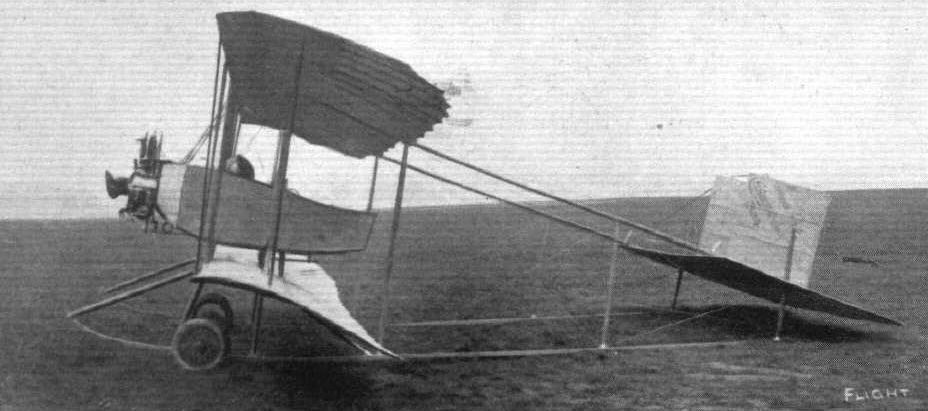
Side view of the Caudron biplane.
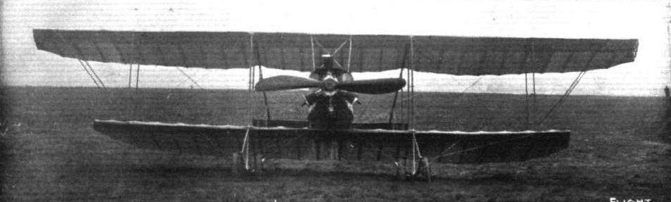
Front view of the Caudron biplane.
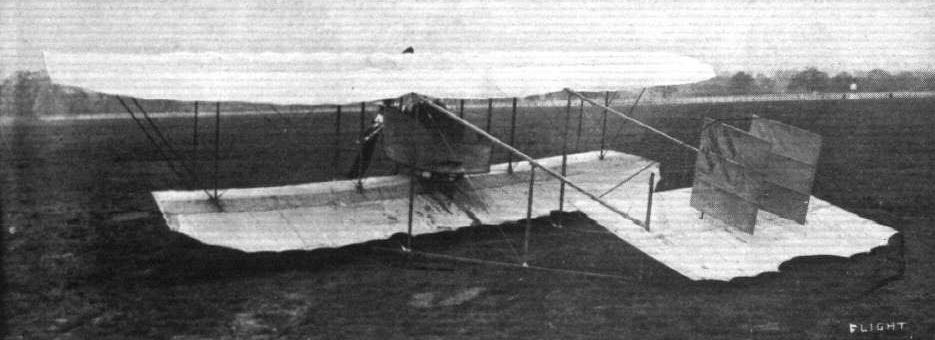
Rear view of the Caudron biplane.
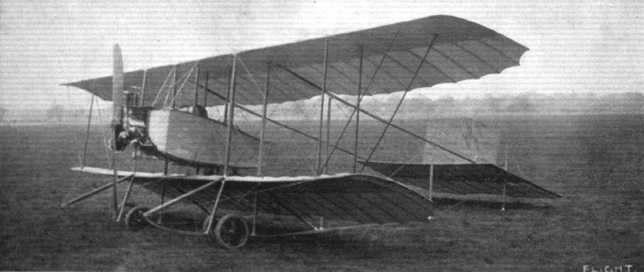
General view from in front of the Caudron biplane.
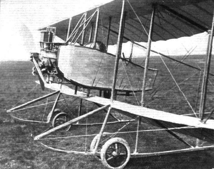
The body and undercarriage of the Caudron biplane.
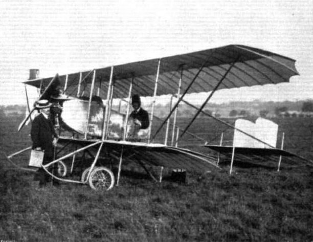
W. H. Ewen, "the Flying Scot," who is flying in the North in connection with the educative tour of the Daily Mail, in the pilot's seat of his new Caudron biplane. It was this same machine on which Gulilaux flew over from Paris on Saturday, with Mr. A. M. Ramsay as passenger.
Competitors ready for the second heat of the Speed Contest at Hendon last Saturday. - Reading from front to back: Messrs. Grahame-Whlte and R. Gates (H. Farman), Sydney Pickles (Caudron), Marcel Desoutter (Bleriot), and Sabelli (Hanriot).
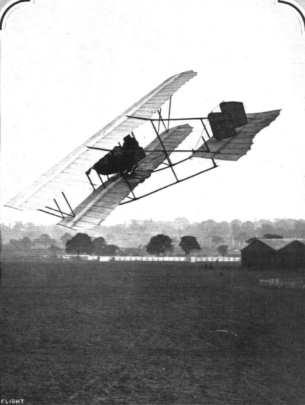
A fine banked turn by Mr. Sydney Pickles on the Caudron biplane at the Hendon aerodrome.
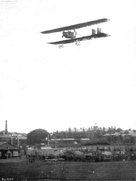
W. H. Ewen on the little Caudron at the Hendon Meeting.

Not a new form of weathercock, but Ewen, on his Caudron, passing behind pylone No. 2 at the First Spring Meeting at the London Aerodrome on Saturday last.
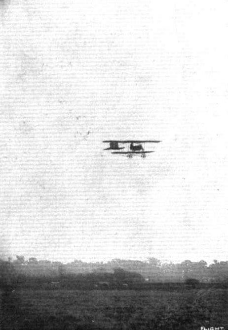
Dr. D. Edmund Stodart flying the 35-h.p. Caudron biplane at Hendon, the machine on which he passed his brevet tests at the W. H. Ewen School of Flying, Hendon.
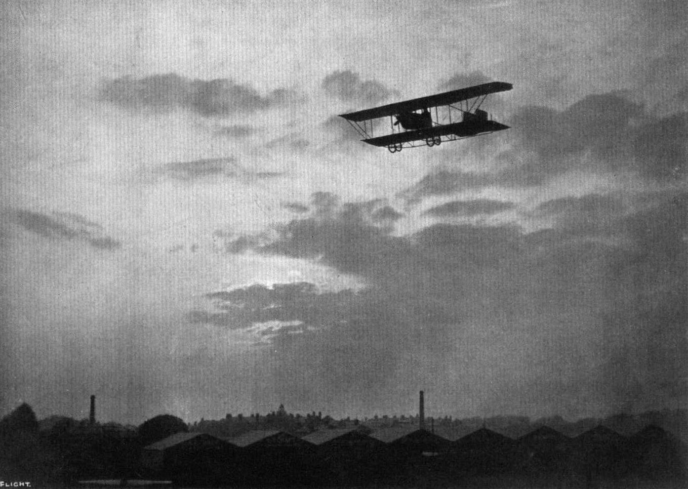
FLYING AT DUSK AT HENDON. - Mr. Sydney Pickles taking a late turn on the Caudron biplane.

Rene Caudron flying his biplane "hands off."
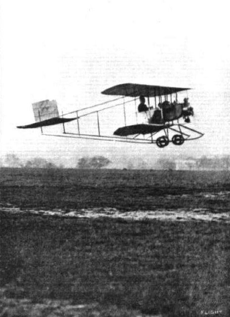
A new method of testing the abilities of a machine, and incidentally of carrying a passenger. The latter is seated, as can be seen from the photograph, inside the cellule on the right-hand side of the body. On the left-hand wing tip may be distinguished a bag, into which a few heavy tools were thrown, which was attached to equalise the weight. This test was made on Friday of last week at Hendon by M. Rene Caudron.
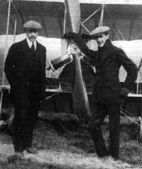
M. Rene Caudron, one of the two brothers to whom the designs of Caudron aeroplanes are due, and Mr. W. H. Ewen who has taken over the British agency.
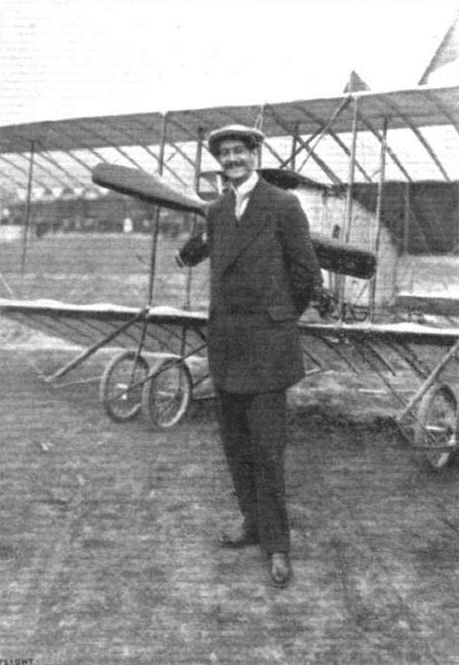
The tallest aviator in the world, Eugene Galy, the new pilot of the little Caudron at Hendon.
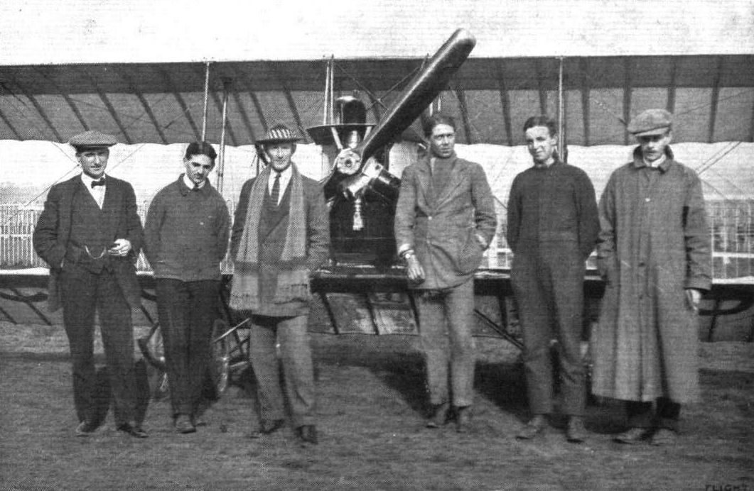
A group at the Ewen School, Hendon, standing in front of the Caudron with 35-h.p. Anzani. - From right to left: Capt. Chamier, M. Baumann (the assistant instructor), Lieut. Eric Conran, Mr. Sydney Pickles (the instructor), Mr. H. H. James, and Mr. A, C. Hunter, the manager of the school. The three pupils qualified for brevets about a fortnight ago.
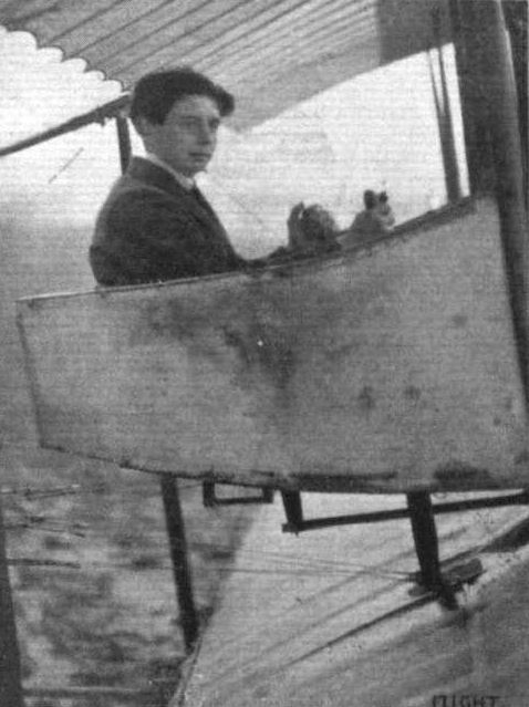
Mr. J. H. James, the 18-year old I.C.S. student who last week got his R.Ae.C. certificate at the Ewen School at Hendon. Incidentally, he collects the cash prize of L100 offered by the International Correspondence Schools for their first pupil to gain his brevet. Mr. James was with his brother, who is also a pupil at the Ewen School, connected with Webb, Peet and Co., of Gloucester, where they both had valuable experience with the Webb-Peet rotary engine. Curiously enough, the ticket was taken quite in "International" style, as the conditions include a Scotchman's school in England and a Welsh pupil on a French biplane.

Mr. Ewen's Caudron after the mishap at Hendon in the tricky wind which turned his machine completely over, with, fortunately, no serious consequences to himself.
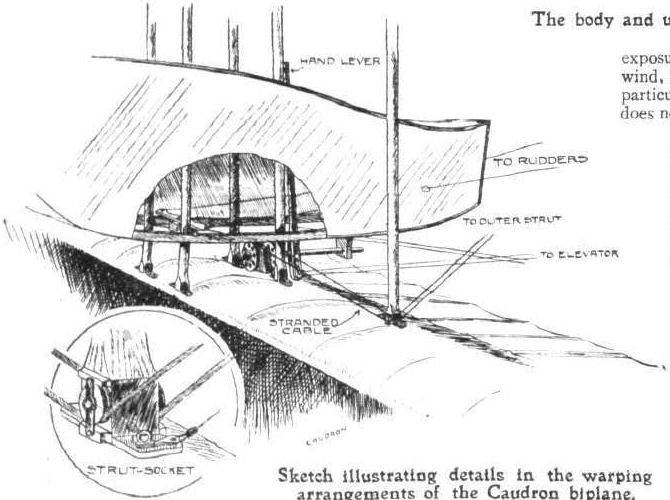
Sketch illustrating details in the warping arrangements of the Caudron biplane.
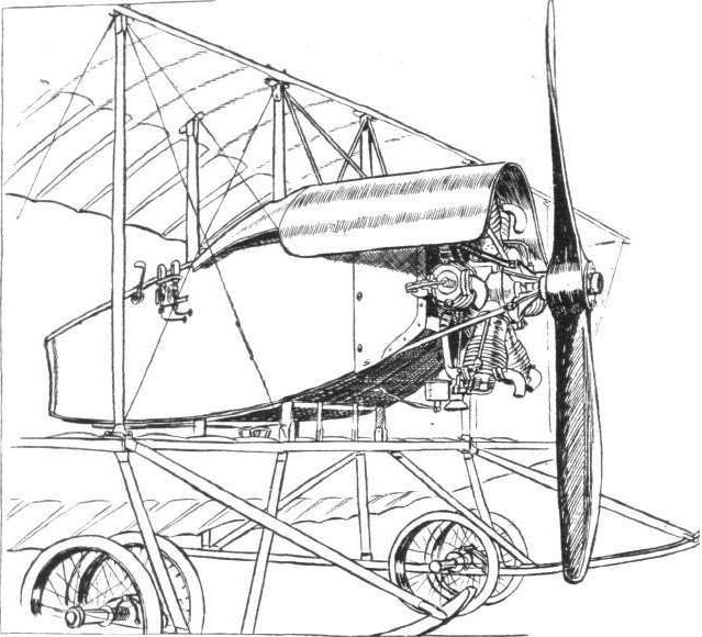
Sketch illustrating the body and undercarriage of the Caudron biplane.
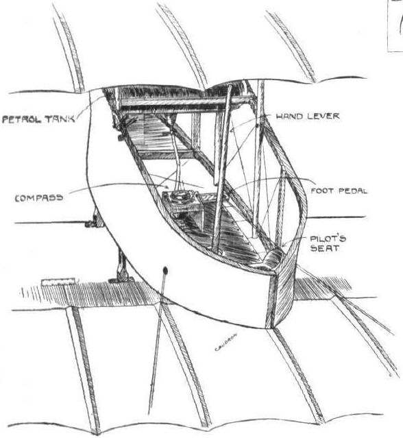
Sketch illustrating the interior of the cockpit on the Caudron biplane,
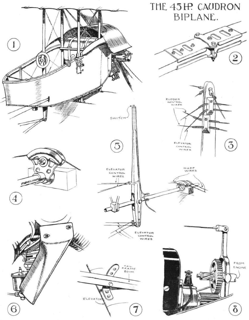
SKETCHES ILLUSTRATING DETAIL CONSTRUCTION IN THE CAUDRON BIPLANE. - 1. The cockpit, containing the pilot's seat, control gear, and petrol tank. 2. Method of fastening the tall outrigger booms by detachable joints that facilitate dismantling for transport. 3. Method of attaching the control wires to the masts over the tail by means of flexible guide tubes. 4. Method of attaching the warping wires to the control shaft. 5. The control lever and its attachments. 6. Wind shield to protect the carburettor from the propeller draught, which otherwise tends to promote freezing. 7. Method of adjusting the angle of incidence of the tail plane. 8. Method of timing the ignition by sliding a gear-wheel on a spiral key.
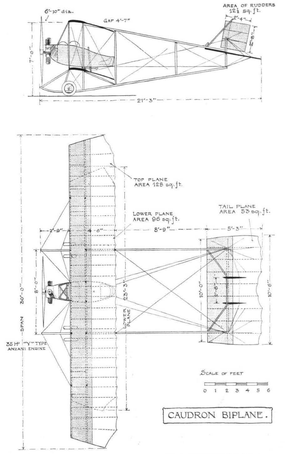
Elevation and plan to scale of the Caudron biplane.
Flight, November 2, 1912.
THE PARIS AERO SALON.
Caudron.
LITTLE need be said of the Caudron exhibit for the monoplane is, except for minor details, exactly the same as the one Ewen has at Hendon, and which has already been described in these columns.
The hydro-biplane shown is of the combined wheel and float type that has been adopted by the French Minister of War for use in their Colonies. The machine itself is the property of the French Government, for it is stamped with their official seal on every part. It has much the same characteristics as the Caudrons we have been used to seeing at Hendon, except that the lower tail outriggers have nothing to do with the chassis but are taken from the lower rear wing boom. The rudders too are larger, there being auxiliary rudders below the tail plane. MM. Rene and Gaston Caudron hold a patent in their combined landing gear. The essence of it is the arrangement of the wheel to the rear of the step in the float in which position, they claim, the water does not touch it once the machine is in progress over the surface. There is no springing in the chassis at all - the floats are rigid and the only resiliency at the wheels is that provided by the fat pneumatic tyres. The monoplane, as we have already said, is essentially the same except for the changes in the engine cowl and chassis. These are better conveyed by sketches than by words.
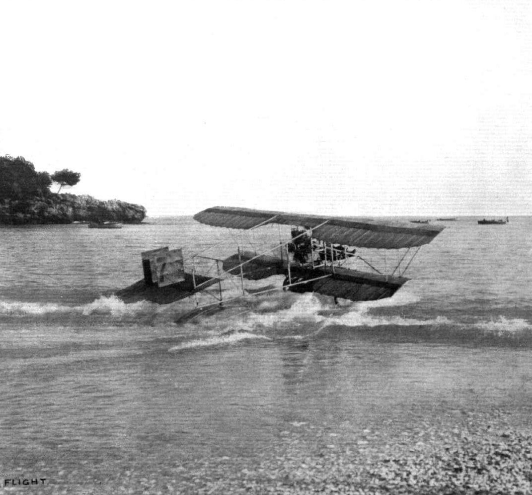
A hydro-aeroplane - the Caudron - taking off from the shore in one of the tests at Monaco.
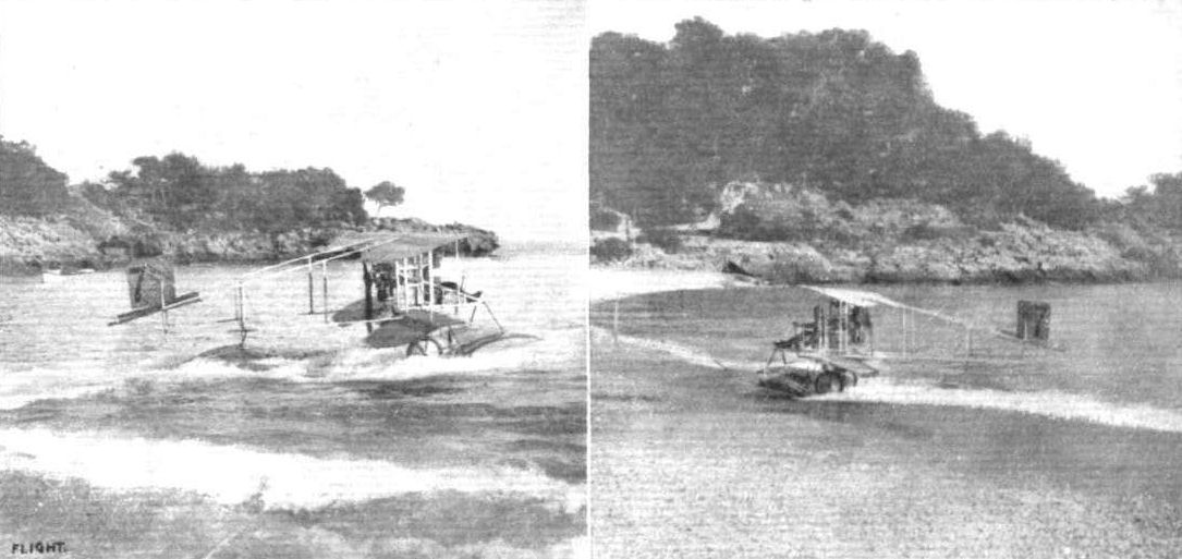
THE CAUDRON HYDRO-BIPLANE AT MONACO. - On the left she is entering the water. In France it is termed "a true aero-amphibian," for, by virtue of its combined wheel-and-float undercarriage, it can rise from and land on both land and water. On the right, the Caudron hydro-biplane landing after a flight. It is interesting that this machine requires no help other than that of its own engine to come back to land after running over the sea.
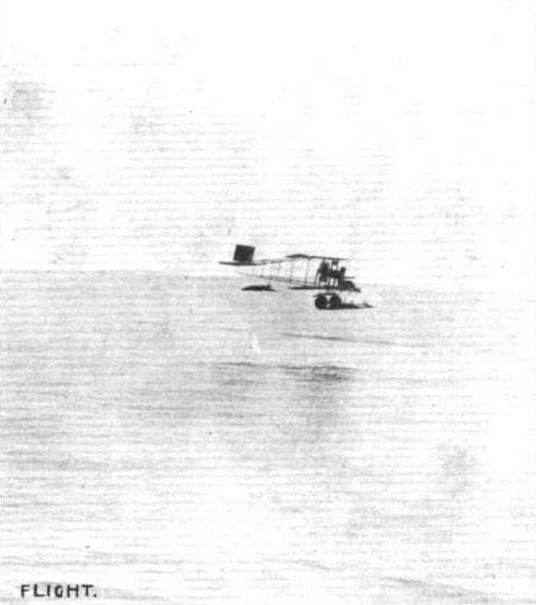
The Caudron hydro-biplane in flight.
Hydro-aeroplanes, illustrating the paper by Mr. Holt Thomas.
Some of the types of float used on present-day hydro-aeroplanes, as seen at the Paris Aero Salon.

The Caudron floats.

Flight, January 13, 1912.
PARIS AERO SHOW.
Clement Bayard.
THE all-steel two-seater biplane that was on view at the Clement-Bayard stand is a direct descendant of the monoplane with which they have been carrying out successful experiments for some time past, and which caused quite a sensation by its appearance in flight over the Grand Palais on one of the days when the Salon was in progress.
The main body of the machine is roughly of torpedo shape, being of pentagonal section in front and in the region of the pilot's and passenger's seats, and from that point to the tail dwindling to triangular section. It is covered in throughout its whole length by metal sheeting in front, and by fabric at the tail end.
The main planes, of modified Nieuport cross-section, are attached and braced to a central tower of steel tubing, constructed integral with the fuselage, from which they may be readily detached to facilitate terrestrial transportation of the machine from place to place. The top plane is longer in span than the lower one by about 6 ft., and lateral balance is maintained by warping them synchronously. Steel is chiefly employed for the construction of the landing gear - wood being only used for the two main skids, and for the smaller skid protecting the tail unit. The latter is built up of a number of laminae of ash, and supported from the fuselage by two steel tubes. The tail unit comprises a horizontal stabilising surface, to the back edge of which is hinged the elevator.
A small triangular fin precedes the unbalanced rudder.
Control in the three dimensions of elevation, balance and direction is operated from a universally jointed upright column surmounted by a wheel. A to-and-fro motion governs the ascent and descent of the machine, rocking the column laterally manipulates the warping, and rotation of the wheel effects the steering to right and left.
The location of the three controls on one column and the fact that all control wires are carried from a point below the fuselage, has the effect of giving the interior of the pilot's cockpit an unusually clean appearance.
Other interesting exhibits on this stand were an extremely well constructed nacelle for a dirigible balloon, fitted with a pair of water-cooled Clement-Bayard motors and a clever apparatus for measuring the permeability of balloon fabric.
Principal dimensions, &c.:-
Length 32 ft.
Span 36 ft.
Area 308 sq. ft.
Weight 880 lbs.
Speed 56 m.p.h.
Motor 50-h.p. Clement-Bayard.
Price L1,120
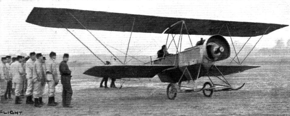
The Clement Bayard biplane, equipped with a Gnome engine, under test at Issy-les-Moulineaux. One of the principal characteristics of this machine is that it can be transformed, in the space of a few minutes, into a monoplane.

The Clement-Bayard tractor biplane.
Flight, November 9, 1912.
THE PARIS AERO SALON.
Clement-Bayard.
THEIR monoplane is one of the prettiest jobs in the whole Salon. Hardly the same can be said of the biplane they are exhibiting, for, although good throughout as concerns both design and workmanship, it seems considerably more complicated about the chassis than it need be. The monoplane is a single-seater fitted with 50-h.p. Gnome motor, and betrays traces of R.E.P. influence in its design. Its body, for instance, is almost identical with that of the machine we mention; also, at first sight, is the chassis, but on closer examination it will be seen that it works on a different principle. Its two running wheels are mounted on a common axle that is strapped down by rubber springs to a horizontal tubular member, which unites the basis of two "V's" extending downward from the fuselage. One of our sketches shows this point well, and in the same drawing may be seen how the fixed horizontal member and the movable axle are connected as a precaution against an extensive smash occurring should the rubbers break. Altogether, it is the neatest and, we should think, the most efficient chassis this year's Salon has brought forth. On the machine shown the wings are constructed chiefly of wood, but have tubular spars of steel. We were informed, however, that wings with an all-metal skeleton had been made for the monoplane, and, in fact, they would be fitted to the machine before the Show closes. Its tail is a lifting organ, and singularly pretty in outline. It is kept clear of the ground by a neat skid built up of laminations of bent wood.
The large three-seated biplane has a fuselage which only differs from that of the monoplane as regards size. Its tail organs, too, are identical. The main points of difference lie in its landing gear, and in the fact that it has two spreads of wing instead of one. Its chassis is a rather mote complicated version of that which was shown on their biplane last year. It consists of two horizontal wooden skids united to the fuselage by a structure of steel tubing. At the rear extremity of each skid is hinged a steel fork in the form of a triangle, which supports a pair of wheels. The shock absorbers are fitted horizontally between the front of the skid and the base of the fork, so that, should there be a shock on landing, the wheels may give in a vertical direction. Behind the two main skids, and attached to the base of the fuselage, is a third skid with wheels, which, in that position, does away with the necessity of fitting a tail skid. The planes of the biplanes are so designed as regards their attachment to the fuselage that they may be dismantled in a minimum of time. A triangular construction of steel tubing surrounds the body in the neighbourhood of its centre of gravity, and to this structure the planes are assembled. Their cross bracing is rather interesting, and this we illustrate by means of a sketch, for this system does away with a good deal of strutting and wiring, and materially reduces the head resistance of that part of the machine. Inside the body room is provided for two passengers sitting side-by-side in advance of the pilot.
On the stand we had the good fortune to renew our acquaintance with M. Robert Grandseigne, who was a year or so ago connected with the English Bristol Company. He is now engaged in experiments for the Clement-Bayard firm, with a miniature hydro-monoplane, having more or less the characteristics of the little Santos Dumont Demoiselle, which this firm used to construct in days gone by. It is to be quite an inexpensive and popular model, priced somewhere m the neighbourhood of L400, and fitted with the same type of horizontal opposed two-cylinder motor as those with which the Demoiselles were equipped. Already considerable success has been achieved by this model, and now it only remains to standardize the machine. We may expect its official appearance in about two months time, when M. Grandseigne has promised us we may be able to give our readers a complete illustrated description of this interesting machine. Further, he informs us, the Clement-Bayard works have under construction an enormous biplane driven by an engine of 500-h.p. and capable of lifting a minimum load of twelve passengers. As the controls for a machine of this size would be necessarily difficult to operate by manual power alone, power relays driven by compressed air, are being designed to perform this function at the will of the pilot.
It is interesting that whereas last year the greater part of the Clement-Bayard stand was occupied with a nacelle for a dirigible this year there is nothing on the stand that would give one to imagine that the proprietars ever had anything to do with motor balloon construction.
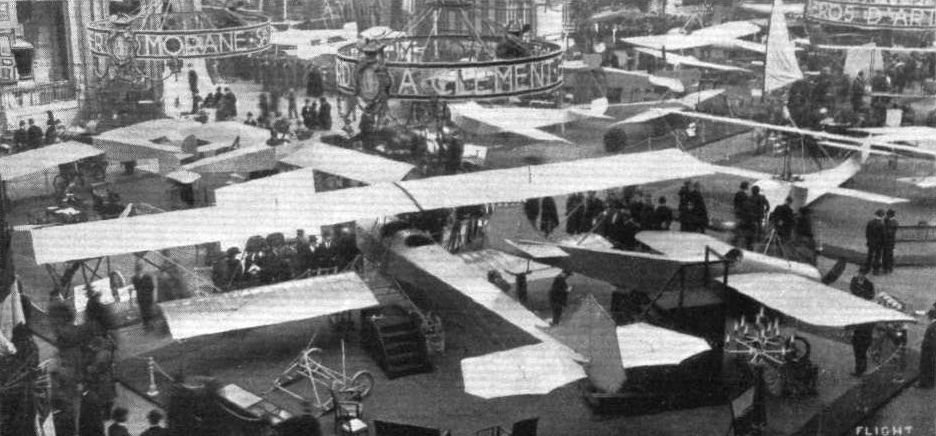
PARIS AERO SALON. - The Clement Bayard stand.
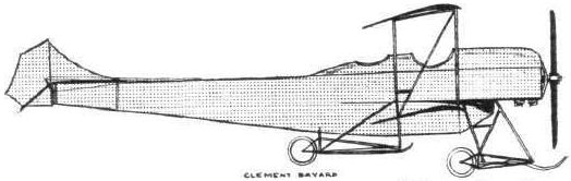
The 100-h.p. three-seater Clement-Bayard biplane.
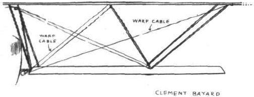
How the planes of the Clement-Bayard biplane are braced.
Flight, November 9, 1912.
THE PARIS AERO SALON.
Clement-Bayard.
THEIR monoplane is one of the prettiest jobs in the whole Salon. Hardly the same can be said of the biplane they are exhibiting, for, although good throughout as concerns both design and workmanship, it seems considerably more complicated about the chassis than it need be. The monoplane is a single-seater fitted with 50-h.p. Gnome motor, and betrays traces of R.E.P. influence in its design. Its body, for instance, is almost identical with that of the machine we mention; also, at first sight, is the chassis, but on closer examination it will be seen that it works on a different principle. Its two running wheels are mounted on a common axle that is strapped down by rubber springs to a horizontal tubular member, which unites the basis of two "V's" extending downward from the fuselage. One of our sketches shows this point well, and in the same drawing may be seen how the fixed horizontal member and the movable axle are connected as a precaution against an extensive smash occurring should the rubbers break. Altogether, it is the neatest and, we should think, the most efficient chassis this year's Salon has brought forth. On the machine shown the wings are constructed chiefly of wood, but have tubular spars of steel. We were informed, however, that wings with an all-metal skeleton had been made for the monoplane, and, in fact, they would be fitted to the machine before the Show closes. Its tail is a lifting organ, and singularly pretty in outline. It is kept clear of the ground by a neat skid built up of laminations of bent wood.
The large three-seated biplane has a fuselage which only differs from that of the monoplane as regards size. Its tail organs, too, are identical. The main points of difference lie in its landing gear, and in the fact that it has two spreads of wing instead of one. Its chassis is a rather mote complicated version of that which was shown on their biplane last year. It consists of two horizontal wooden skids united to the fuselage by a structure of steel tubing. At the rear extremity of each skid is hinged a steel fork in the form of a triangle, which supports a pair of wheels. The shock absorbers are fitted horizontally between the front of the skid and the base of the fork, so that, should there be a shock on landing, the wheels may give in a vertical direction. Behind the two main skids, and attached to the base of the fuselage, is a third skid with wheels, which, in that position, does away with the necessity of fitting a tail skid. The planes of the biplanes are so designed as regards their attachment to the fuselage that they may be dismantled in a minimum of time. A triangular construction of steel tubing surrounds the body in the neighbourhood of its centre of gravity, and to this structure the planes are assembled. Their cross bracing is rather interesting, and this we illustrate by means of a sketch, for this system does away with a good deal of strutting and wiring, and materially reduces the head resistance of that part of the machine. Inside the body room is provided for two passengers sitting side-by-side in advance of the pilot.
On the stand we had the good fortune to renew our acquaintance with M. Robert Grandseigne, who was a year or so ago connected with the English Bristol Company. He is now engaged in experiments for the Clement-Bayard firm, with a miniature hydro-monoplane, having more or less the characteristics of the little Santos Dumont Demoiselle, which this firm used to construct in days gone by. It is to be quite an inexpensive and popular model, priced somewhere m the neighbourhood of L400, and fitted with the same type of horizontal opposed two-cylinder motor as those with which the Demoiselles were equipped. Already considerable success has been achieved by this model, and now it only remains to standardize the machine. We may expect its official appearance in about two months time, when M. Grandseigne has promised us we may be able to give our readers a complete illustrated description of this interesting machine. Further, he informs us, the Clement-Bayard works have under construction an enormous biplane driven by an engine of 500-h.p. and capable of lifting a minimum load of twelve passengers. As the controls for a machine of this size would be necessarily difficult to operate by manual power alone, power relays driven by compressed air, are being designed to perform this function at the will of the pilot.
It is interesting that whereas last year the greater part of the Clement-Bayard stand was occupied with a nacelle for a dirigible this year there is nothing on the stand that would give one to imagine that the proprietars ever had anything to do with motor balloon construction.
THE PARIS AERO SALON.
Clement-Bayard.
THEIR monoplane is one of the prettiest jobs in the whole Salon. Hardly the same can be said of the biplane they are exhibiting, for, although good throughout as concerns both design and workmanship, it seems considerably more complicated about the chassis than it need be. The monoplane is a single-seater fitted with 50-h.p. Gnome motor, and betrays traces of R.E.P. influence in its design. Its body, for instance, is almost identical with that of the machine we mention; also, at first sight, is the chassis, but on closer examination it will be seen that it works on a different principle. Its two running wheels are mounted on a common axle that is strapped down by rubber springs to a horizontal tubular member, which unites the basis of two "V's" extending downward from the fuselage. One of our sketches shows this point well, and in the same drawing may be seen how the fixed horizontal member and the movable axle are connected as a precaution against an extensive smash occurring should the rubbers break. Altogether, it is the neatest and, we should think, the most efficient chassis this year's Salon has brought forth. On the machine shown the wings are constructed chiefly of wood, but have tubular spars of steel. We were informed, however, that wings with an all-metal skeleton had been made for the monoplane, and, in fact, they would be fitted to the machine before the Show closes. Its tail is a lifting organ, and singularly pretty in outline. It is kept clear of the ground by a neat skid built up of laminations of bent wood.
The large three-seated biplane has a fuselage which only differs from that of the monoplane as regards size. Its tail organs, too, are identical. The main points of difference lie in its landing gear, and in the fact that it has two spreads of wing instead of one. Its chassis is a rather mote complicated version of that which was shown on their biplane last year. It consists of two horizontal wooden skids united to the fuselage by a structure of steel tubing. At the rear extremity of each skid is hinged a steel fork in the form of a triangle, which supports a pair of wheels. The shock absorbers are fitted horizontally between the front of the skid and the base of the fork, so that, should there be a shock on landing, the wheels may give in a vertical direction. Behind the two main skids, and attached to the base of the fuselage, is a third skid with wheels, which, in that position, does away with the necessity of fitting a tail skid. The planes of the biplanes are so designed as regards their attachment to the fuselage that they may be dismantled in a minimum of time. A triangular construction of steel tubing surrounds the body in the neighbourhood of its centre of gravity, and to this structure the planes are assembled. Their cross bracing is rather interesting, and this we illustrate by means of a sketch, for this system does away with a good deal of strutting and wiring, and materially reduces the head resistance of that part of the machine. Inside the body room is provided for two passengers sitting side-by-side in advance of the pilot.
On the stand we had the good fortune to renew our acquaintance with M. Robert Grandseigne, who was a year or so ago connected with the English Bristol Company. He is now engaged in experiments for the Clement-Bayard firm, with a miniature hydro-monoplane, having more or less the characteristics of the little Santos Dumont Demoiselle, which this firm used to construct in days gone by. It is to be quite an inexpensive and popular model, priced somewhere m the neighbourhood of L400, and fitted with the same type of horizontal opposed two-cylinder motor as those with which the Demoiselles were equipped. Already considerable success has been achieved by this model, and now it only remains to standardize the machine. We may expect its official appearance in about two months time, when M. Grandseigne has promised us we may be able to give our readers a complete illustrated description of this interesting machine. Further, he informs us, the Clement-Bayard works have under construction an enormous biplane driven by an engine of 500-h.p. and capable of lifting a minimum load of twelve passengers. As the controls for a machine of this size would be necessarily difficult to operate by manual power alone, power relays driven by compressed air, are being designed to perform this function at the will of the pilot.
It is interesting that whereas last year the greater part of the Clement-Bayard stand was occupied with a nacelle for a dirigible this year there is nothing on the stand that would give one to imagine that the proprietars ever had anything to do with motor balloon construction.

A fine vol plane by Bobba over the Grand Stand in the Paris-Amiens flying race.
PARIS AERO SALON. - The Clement Bayard stand.
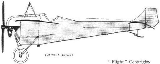
The 50-h.p. Clement-Bayard monoplane.
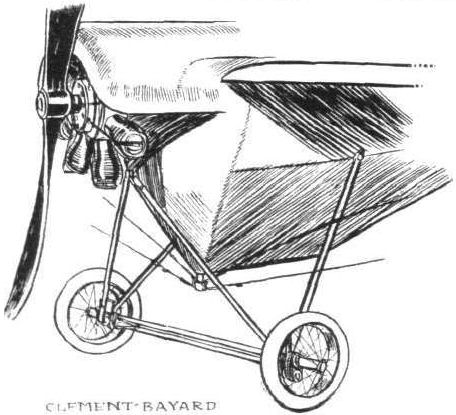
Example of the type of landing carriage that is being adopted by many aeroplane constructors in France. Shown is the running gear of the Clement-Bayard monoplane.
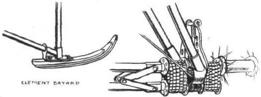
Two details of the Clement-Bayard. On the left the rear skid, on the right the system of shock absorbers employed in the chassis.
Flight, November 9, 1912.
THE PARIS AERO SALON.
d'Artois.
THE name is a new one, and so are the machines, but the firm that is producing them was one of the earliest to enter the arena of aeroplane construction in France - the Tellier firm to wit. During 1910 the Tellier monoplane came into considerable prominence in the hands of Emile Dubonnet, but since he discontinued flying the firm seems to have altogether dropped constructing, until now that they are re-opening operations with the assistance of MM. Louis Gaudartland Schreck. They are showing two machines, one a rather novel biplane and the other a hydro-biplane, which follows to a certain extent the lines of the Donnet-Leveque. The first of these machines is of the "torpille" type, that is, it is driven by a propeller arranged at the tail end of the machine. M. Louis Gaudart is responsible for its design, and he will be remembered as the pilot that carried out the initial tests of the Paulhan-Tatin aero-torpille, one of the most notable exhibits at last year's show. Differing from this machine, the d'Artois torpille biplane has a simple fuselage of rectangular section constructed for the best part of wood. Only in the neighbourhood of the engine, a 50-h.p. rotary Gnome, is steel used. Excepting in that part, too, the body is covered in with fabric. The landing gear is an extremely simple construction of steel tubing and is of a type that seems to be finding many adherents among French constructors. The main planes are built about a single tubular spar arranged at the approximate centre of pressure. They are united to the fuselage in so simple a manner that it needs but the removal of a bolt or two to dismantle them. Apart from the presence of the propeller, which is driven by a hollow steel shaft of 40 mm. external and 34 mm. internal diameter, the tail is of purely conventional design, consisting of a flat stabilising surface with elevators hinged to its rear edge. As in the Tatin torpille, whipping of the shaft is prevented by a number of ball bearings arranged at equal distances between the motor and the propeller.
For the hydro biplane, its central unit of construction is a coque, which serves the double function of fuselage and float. Near the front it is of rectangular section, but aft of the main planes the two top longitudinals merge into one, giving the after portion a triangular section. The pilot sits low down in the body in advance of the planes. Behind him is the motor, a 50-h.p. Gnome, driving, by chain transmission, a four-bladed propeller mounted high up between the planes. Like other hydro-aeroplanes, a starting-handle is fitted. The supporting surfaces are in every respect identical with those of their torpille biplane.
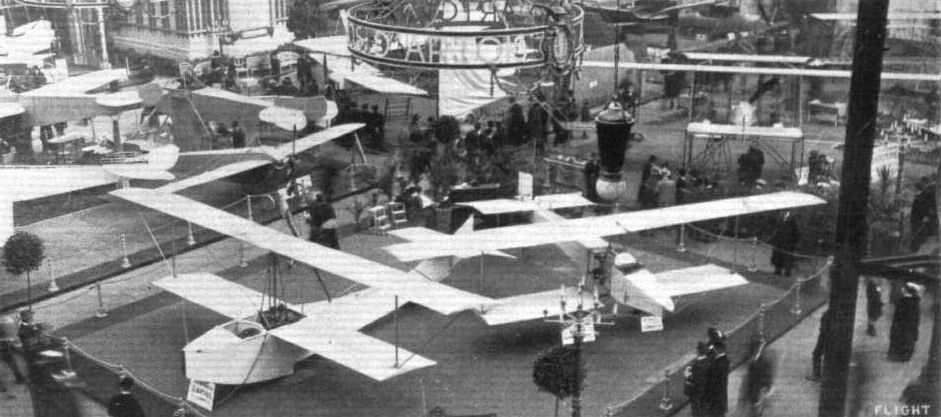
PARIS AERO SALON. - The d'Artois exhibit.
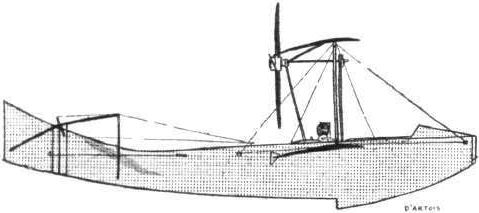
The d'Artois hydro-biplane.
Flight, November 9, 1912.
THE PARIS AERO SALON.
d'Artois.
THE name is a new one, and so are the machines, but the firm that is producing them was one of the earliest to enter the arena of aeroplane construction in France - the Tellier firm to wit. During 1910 the Tellier monoplane came into considerable prominence in the hands of Emile Dubonnet, but since he discontinued flying the firm seems to have altogether dropped constructing, until now that they are re-opening operations with the assistance of MM. Louis Gaudartland Schreck. They are showing two machines, one a rather novel biplane and the other a hydro-biplane, which follows to a certain extent the lines of the Donnet-Leveque. The first of these machines is of the "torpille" type, that is, it is driven by a propeller arranged at the tail end of the machine. M. Louis Gaudart is responsible for its design, and he will be remembered as the pilot that carried out the initial tests of the Paulhan-Tatin aero-torpille, one of the most notable exhibits at last year's show. Differing from this machine, the d'Artois torpille biplane has a simple fuselage of rectangular section constructed for the best part of wood. Only in the neighbourhood of the engine, a 50-h.p. rotary Gnome, is steel used. Excepting in that part, too, the body is covered in with fabric. The landing gear is an extremely simple construction of steel tubing and is of a type that seems to be finding many adherents among French constructors. The main planes are built about a single tubular spar arranged at the approximate centre of pressure. They are united to the fuselage in so simple a manner that it needs but the removal of a bolt or two to dismantle them. Apart from the presence of the propeller, which is driven by a hollow steel shaft of 40 mm. external and 34 mm. internal diameter, the tail is of purely conventional design, consisting of a flat stabilising surface with elevators hinged to its rear edge. As in the Tatin torpille, whipping of the shaft is prevented by a number of ball bearings arranged at equal distances between the motor and the propeller.
<...>
PARIS AERO SALON. - The d'Artois exhibit.
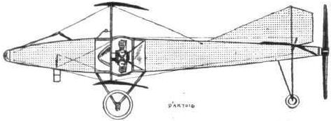
The d'Artois torpille biplane.

Example of the type of landing carriage that is being adopted by many aeroplane constructors in France. Shown is the running gear of the d'Artois torpille biplane.
Flight, January 6, 1912.
PARIS AERO SHOW.
Marcay-Moonen.
THIS interesting monoplane, illustrations of which appeared in FLIGHT for December 9th, 1911, constructed to the designs of M. Henri Chazal, is interesting for the fact that its wings are pivoted, by which system their angle of incidence may be varied at the will of the pilot while in flight, and on landing they may be folded back against the fuselage by the mere turning of the wheel on the right of the pilot. To effect this each wing is mounted on and braced to a mast, which is attached at an angle to the fuselage. The adjustment of the wings for balancing purposes is made from the pilot's control wheel. Supposing the machine to be dipping on the left-hand side, the control wheel will be rotated towards the right, which action advances the axis of the left wing, and retards the axis of the right wing a similar amount. It is by virtue of the oblique mounting of the masts that the advancing or retarding of the wings causes their angle of incidence to be increased or diminished respectively.
The convenience of this method of wing-mounting is amply demonstrated by the fact that the machine was towed through the streets of Paris from its hangar at Issy-les-Moulineaux to the Grand Palais without being dismantled; and its re-erection at the latter place merely consisted of about a dozen rotations of the wing operating-wheel. To further assist the ease with which the machine may be steered over the ground, the rudder is made to work in conjunction with a pair of pivoting wheels, situated under the tail. The landing-chassis is identical with that of the Zodiac biplane, except that no provision is made for the accommodation of any sideway's movement in landing. Its propulsive group consists of a Gnome engine and a Chauviere propeller. Accommodation is provided for a passenger, and to lend a little realism to the assertion of the Marcay-Moonen people that their machine has been designed purely for military work, this latter's cockpit was equipped with a quick-firing gun and a wireless telegraphy installation.
Principal dimensions, &c. :-
Length 40 ft. Weight 990 lbs.
Span 45 ft. Speed 55 m.p.h.
Area 440 sq. ft. Motor 50-h.p. Gnome.
Flight, April 6, 1912.
Testing the Marcay Moonen Monoplane.
ON the 27th ult. the Marcay Moonen monoplane, which has its wings pivotted so that they may be folded back, was tested at Issy and apparently gave very good results. It was piloted by Aerremans.
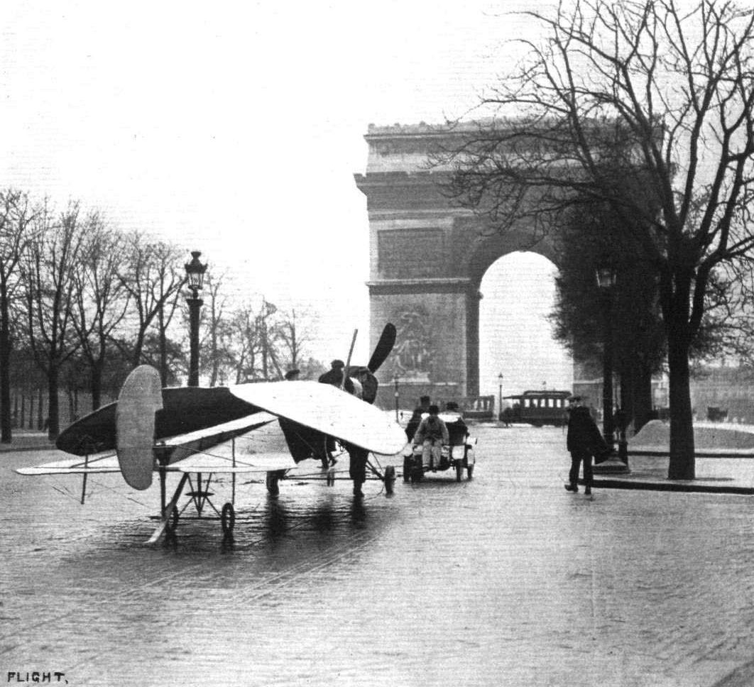
The de Marcay-Moonen monoplane returning to its hangar at Issy-les-Moulineaux after the finish of the Paris Aero Salon. By virtue of its original system of wing mounting its dismantling in all probability occupied less time than any other machine at the Salon, it consisting merely of about a dozen rotations of a wheel mounted at the right-hand side of the pilot. The pair of wheels under the tail are rotatable in order to facilitate driving it along the ground.
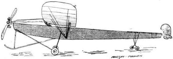
The Marcay-Moonen monoplane, with pivoting wings.
Flight, January 6, 1912.
PARIS AERO SHOW.
De Poix et de Roig.
THIS two-seater monoplane presents little difference from standard practice, and consequently a few words will suffice to describe it. Its fuselage, 30 ft. in length, is a skiff-like structure much after the same idea as that originated by Hanriot. The motor, which is mounted in front of the body, is a 100-h.p. water-cooled Clerget, and drives a large diameter Rapid propeller. Its landing chassis is of the customary A-type wheel and skid class, having a track of just over six feet. Balancing is carried out by means of warping the main wings, which latter have a span of 37 feet, and this action is controlled from the steering-wheel that is mounted in an exactly similar fashion to that of the Deperdussin. The tail unit is almost identical with that of the Hanriot with which we are all familiar, a flat plane acting as a stabiliser, while to its rear edge are hinged two small planes serving as elevators.

The de Poix-de Rolg monoplane, recalling, in a general way, Hanriot practice,
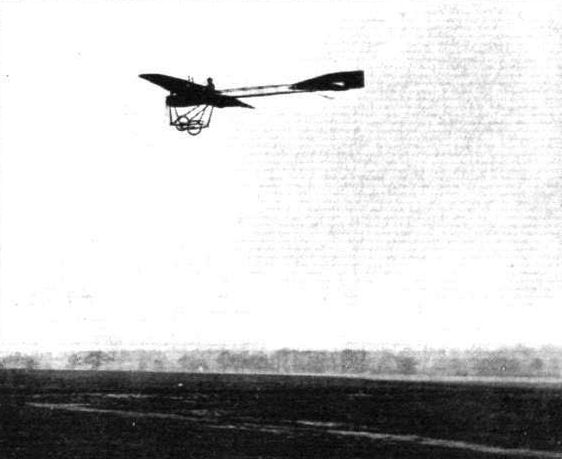
IN THE AIR DURING THE EASTER FLYING MEET AT HENDON. - Mr. W. H. Ewen on his Deperdussin.
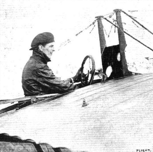
SOME OF THE HENDON PILOTS. - Mr. W. H. Ewen on his Deperdussin.
Flight, April 20, 1912.
AIR EDDIES.
Signor Sabelli, who has been doing a lot of good flying at Brooklands recently, is really one of the best pilots our English schools have turned out for many a long day. His machine, too, a 28-h.p. Anzani-Deperdussin, must come in for a share of the honours, for never before, to our recollection, have we seen such a low-powered machine remain in the air for such a long time as when Sabelli kept circling over Brookland's track at a height of 1,500 ft. for 1 hr. 8 m. on Sunday last. Pierre Prier, when he was with Bleriot's at Hendon, kept up for over an hour on an Anzani-engined machine, but I don't seem to think he beat Sabelli's time.
Flight, April 27, 1912.
AIR EDDIES.
Mr. G. M. Dyott, who, as recorded in these columns from time to time, has been doing a lot of excellent exhibition work out in America, returned to England on Sunday last on the "Oceanic." He did not, however, remain in England long, for on the following evening he set off for Paris, where he intends to spend the week in selecting and obtaining delivery of a couple of machines to take back with him to America, for his second season's work. This he figures on getting done in time to sail for America to-day.
Dyott reminded me that after all he did fly at Yucatan, although the conditions were such that he had little desire to repeat the performance. The ground was so badly situated that had there not been a forty-mile-an-hour wind blowing at the lime it would have been impossible to get away from it. Even at that, flying head to wind, it was an extremely risky undertaking. Landing there, too, was little better, and Dyott had to arrange for sand to be put down on the ground in order to bring the machine quickly to a standstill.
AIR EDDIES.
Signor Sabelli, who has been doing a lot of good flying at Brooklands recently, is really one of the best pilots our English schools have turned out for many a long day. His machine, too, a 28-h.p. Anzani-Deperdussin, must come in for a share of the honours, for never before, to our recollection, have we seen such a low-powered machine remain in the air for such a long time as when Sabelli kept circling over Brookland's track at a height of 1,500 ft. for 1 hr. 8 m. on Sunday last. Pierre Prier, when he was with Bleriot's at Hendon, kept up for over an hour on an Anzani-engined machine, but I don't seem to think he beat Sabelli's time.
Flight, April 27, 1912.
AIR EDDIES.
Mr. G. M. Dyott, who, as recorded in these columns from time to time, has been doing a lot of excellent exhibition work out in America, returned to England on Sunday last on the "Oceanic." He did not, however, remain in England long, for on the following evening he set off for Paris, where he intends to spend the week in selecting and obtaining delivery of a couple of machines to take back with him to America, for his second season's work. This he figures on getting done in time to sail for America to-day.
Dyott reminded me that after all he did fly at Yucatan, although the conditions were such that he had little desire to repeat the performance. The ground was so badly situated that had there not been a forty-mile-an-hour wind blowing at the lime it would have been impossible to get away from it. Even at that, flying head to wind, it was an extremely risky undertaking. Landing there, too, was little better, and Dyott had to arrange for sand to be put down on the ground in order to bring the machine quickly to a standstill.
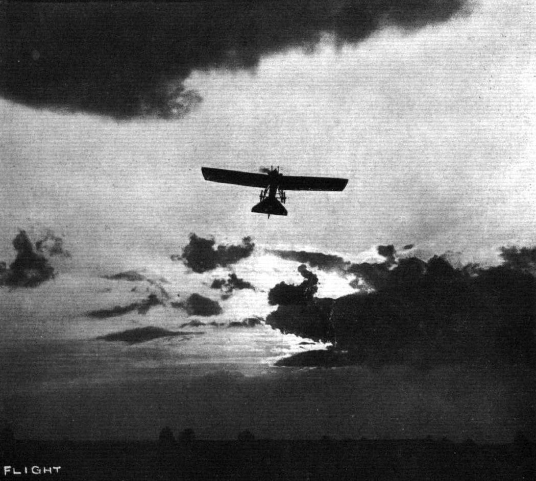
Mr. Dyott, who has been doing much good Flying Work in America, piloting one of the small Deperdussins. - A remarkable sunset picture secured at Rheims last year.

A fine bank by Valentine on the Deperdussin round No. 2 pylon at Hendon in the cross-country handicap.
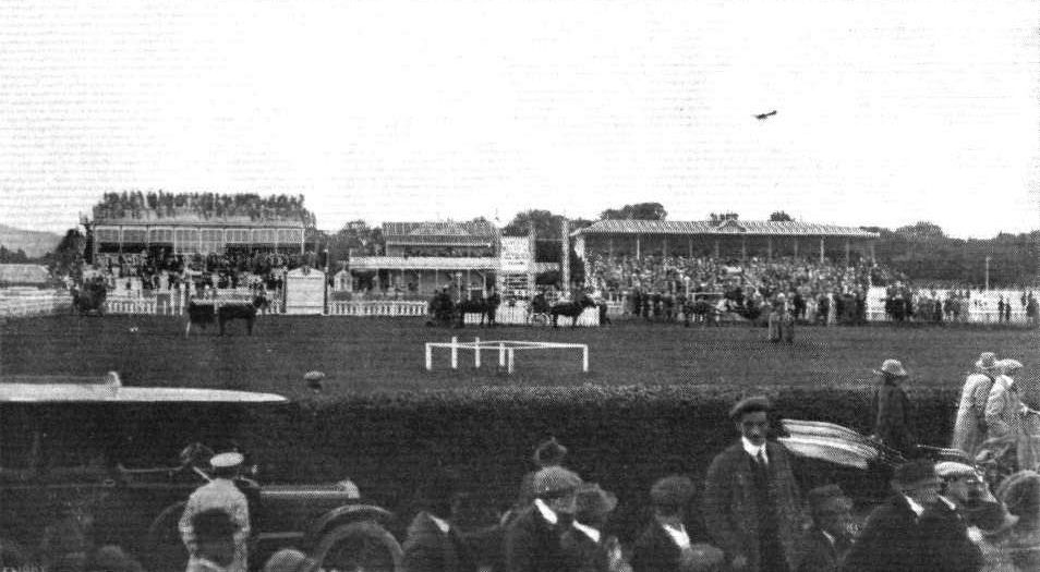
THE DUBLIN-BELFAST AEROPLANE CONTEST. - Mr. J. Valentine flying over the grand stand, Leopardstown racecourse, Dublin, on his 60-h.p. Deperdussin.
Remarkable flying was seen in the Speed Handicap at Hendon on Saturday. Our photograph shows, on the left, Jules Nardini on the Deperdussin, on the right Pierre Verrier on the Maurice Farman, and above, Marcel Desoutter, on the Bleriot, just about to enter on the last lap.
A TRIO. - Finish of first heat of the Speed Handicap at Hendon, Saturday, the competitors being Mr. Gustav Hamel, Mr. J. L. Travers, and Mr. Sabelli in the order named.
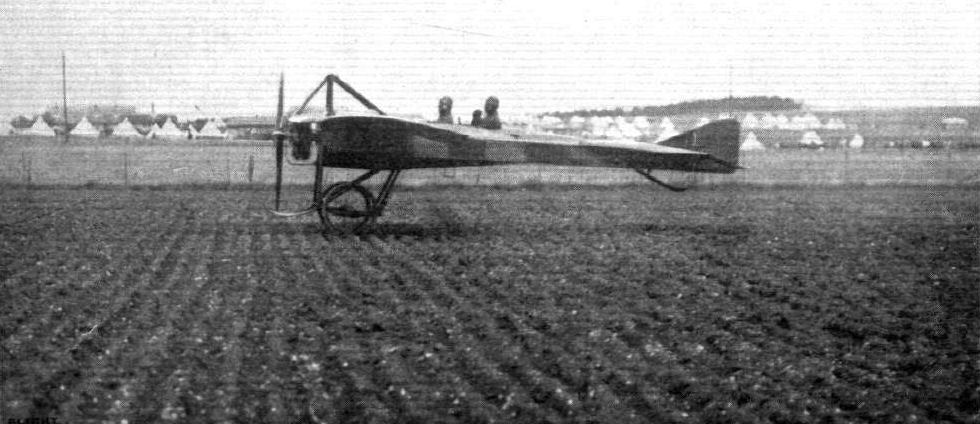
Prevost and his observer in the French Deperdussin, just landed in the ploughed field test in the Army competitions.

The French Deperdussin monoplane which secured the second prize of L2,000 in the Military Trials.
Marcel Desoutter piloting No. 6 Bleriot in the Hendon Aerodrome competitions.

Giovanni Sabelli and the 30-h.p. Anzani-engined military Deperdussin racing monoplane. Signor Sabelli is the first Italian to secure his brevet at Brooklands. His vol planes are executed in exceptionally fine style.
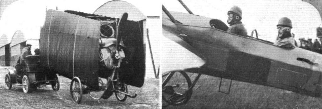
THE MILITARY COMPETITIONS AT SALISBURY. - On the left the French Deperdussin monoplane completing the transport test. On the right Prevost and Capt. Dawes starting out for a flight on the same machine.
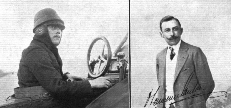
M. Prevost, on the left, and his passenger, Mr. D. Lawrence Santoni, Manager of the British Deperdussin Aeroplane Syndicate, who, on Saturday of last week, flew from Issy les Moultneaux to Eastchurch on a 70-h.p. Gnome-Deperdussin, delivering the machine to the Naval Aviation Section there.
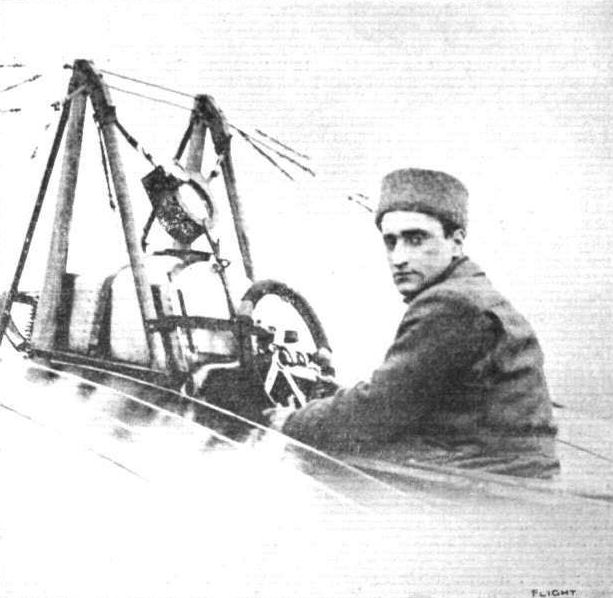
Sabelli at the wheel of his Deperdussin monoplane after he made a flight of 1h. 8m. at an altitude of about 1,500 feet on Sunday last at Brooklands.
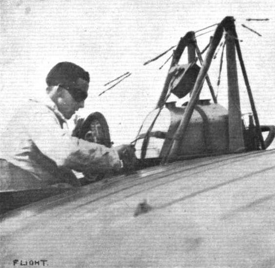
Mr. H. Petre, of the Brooklands Deperdussin School, starting off for a flight on the brevet machine.
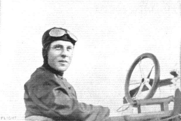
G. M. Dyott, who has been exhibition flying in America, and whose "adventures" were referred to in Eddies recently. Mr. Dyott has returned to England on a flying visit.
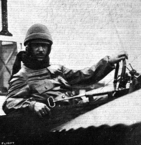
Sig. Jules Nardini, who is now well known through his fine flying at Hendon.
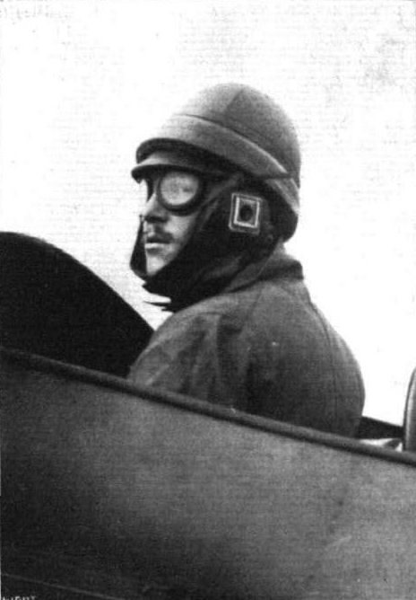
M. Prevost, who piloted the French Deperdussin monoplane which secured the second prize, open to the world. In the Military Aeroplane Trials.

Mr. H. M. Brock in the pilot's seat of the Deperdussin mono at Hendon.
Flight, April 20, 1912.
AEROPLANE DELIVERY TO NAVY BY AIR.
FIRST PASSENGER FLIGHT FROM PARIS TO EASTCHURCH.
PARIS TO ENGLAND IN ONE DAY.
IT was a happy thought that prompted Mr. Lawrence Santoni, Manager of the British Deperdussin Aeroplane Co., Ltd., to decide to deliver the new 70-h.p. two-seater Gnome-Deperdussin destined for the Navy, by way of the air. The machine itself was the first to be turned out from the Deperdussin works, of a batch of ten that were being constructed to special design for the French Government. Our Admiralty must indeed be congratulated on obtaining the most up-to-date type of this make of monoplane that could be secured. The fact that the machine should yet be at the Deperdussin works in Paris receiving its finishing touches on the Friday morning of last week, be tested for the first time in the air at four o'clock on the same day, be safely delivered to the British Admiralty via the air soon after mid-day the following day, and two hours afterwards should be flying a thousand feet up under the sole control of Lieut. Longmore, who had never previously flown this type of machine, is a performance of which both the English and French Deperdussin firms in England have a just right to be proud. As an illustration of the practicability of the aeroplane at the present day it could scarcely be bettered.
Following the disclosures that have recently been made regarding the trussing of monoplane wings, particularly relating to the upper guy-wires, special attention has been paid to this most important point, and although in the past Deperdussin machines have never exhibited weakness in their upper bracing, yet, to completely comply with the edict lately issued by the French military authorities, this section of the machine has been still further strengthened.
On Thursday of last week Lieut. Longmore, one of our most excellent Navy pilots, was sent by the Admiralty to witness the resistance tests on the wings of this particular machine, as required by the naval authorities, they being loaded up with 2,500 lbs. of sand, as depicted in one of our photographs. Throughout the following morning the machine was yet at the Deperdussin factory receiving its final finish to the paint-work before being dispatched to Issy les Moulineaux later on in the day to be tested in the air. Prevost carried out this operation. He took the machine out soon after 4 o'clock, in spite of a wind so strong as to prevent any of the other aviators on the ground from bringing their machines from their sheds. After a flight of about 10 minutes' duration, at about a 1,000 ft. level, he descended to take up, Mr. Santoni, and the two flew away at a height of 2,000 ft. over Paris, circling the Eiffel Tower, and returning down wind at a terrific speed to the testing ground. M. Armand Deperdussin, his chief engineers, MM. Bechereau and Papa, and Capt. Ludmann, the Breguet pilot, as representative of the French War Office, were present to witness this splendid exhibition.
It was the machine's third trip in the air, when on Saturday morning, at 7 o'clock, it rose from the Issy grounds, with Prevost at the control and Mr. Santoni in the passenger's seat. Their destination was known by none on the ground with the exception of two or three friends, although from the fact that both wore life-saving jackets it must have been generally surmised that it was a cross-sea trip that was proposed. There was a strong northerly wind blowing, and over Paris was a fairly dense mist, which disappeared as the open country was reached. Amiens, 80 miles from Paris, was passed at 8.20, at an altitude of over 2,200 feet. It was Prevost's original intention to follow the route to Amiens, on to Abbeville, to strike the coast near Berck and to follow it to Calais, but as slight fog was experienced he thought it advisable to keep away from the coast line, and to maintain a course direct over land from Amiens to Calais. At Arrhes, ten miles from Calais, a descent was made at 9-45, to clean a sparking plug. So cold had the trip been that both were numbed; Prevost was bleeding from the lips, and Mr. Santoni's moustache had frozen stiff. The descent was made in a corn-patch, scarcely ten yards wide. Crowds of peasants gathered round, and after everything had been put in order, some of the local talent was made use of to cling on to the tail of the machine, Mr, Santoni swung the propeller, quickly clambered into his seat, and a re-start was made at 10.45. A short circle, meanwhile rising to about 1.000 ft., and the pair set out for Calais, where they landed at eleven o'clock. Prevost had arranged for his mechanic to meet him at the old European circuit aerodrome, but things had been so changed since, all the sheds having been taken down and the ground divided into various portions, that he could not recognize it. After circling for some time in a vain endeavour to discover the missing aerodrome, a descent was made in a very narrow stretch of ground.
At Calais, M. Prevost and Mr. Santoni replenished their own vitality and that of the machine with food and petrol respectively. In spite of a warning of a thick mist in the Channel, they decided to proceed, trusting to their Monodep compass to lead them aright, and possibly to be guided by catching a sight of the midday boat crossing Dover to Calais. A start was made at 12 o'clock, and by the time the coast was reached the machine had attained a height of 2,000 ft., an altitude which it maintained throughout its trip over the water. The wind, which had caused some small amount of discomfort overland, entirely disappeared over the sea, and the machine maintained a plumb steady course. half-way across the Channel, closed in all around by a wall of white fog, and when Mr. Santoni was probably wondering if the course were true and feeling anxious for the safe delivery of his machine, a white light, as if reflected from a mirror, appeared below and in front of them. It proved to be Channel boat of which they had anticipated catching sight. Maintaining a course slightly to the east of his wake, they regained the cost over Deal, sighting Dover Harbour away to the left. The land regained, the wind was again felt, and the type of English wind was of a very noticeably different character from that encountered over French soil. Passing Canterbury to their left they caught sight of Sheppey island and were soon heading over the strip of water that divides it from the mainland. Here, as some of our Eastchurch pilots may well have expected, they came across a most malignant type of air-pocket, which caused the machine to drop with startling suddenness, and to unseat both pilot and passenger. They landed before their shed at 12.45. Commander Samson, Lieuts. Longmore and Gregory, Mr. Frank McClean and the rest of the Eastchurch pilots, with Mr. Harold Perrin, were there to greet them, and were no doubt surprised to find who the occupants were and from where they had come. Especially so was Lieut. Longmore, who had a difficulty in crediting that the machine he had seen descend was the identical one on which he had seen wing tests carried out in Paris two days previously. In Paris, witnessing the tests, he had anxiously enquired when he would get his machine delivered, and was rather uneasy at not seeing a packing case ready to receive it. Within two hours of the voyagers' arrival he himself was flying the machine over the Royal Aero Club's, flying grounds taking up with him Lieut. Spencer Grey as passenger, and afterwards flying solos at a height of 3,500 feet nearly an hour.
Flight, May 4, 1912.
Gordon Bell at Constantinople.
ON Sunday last, Mr. Gordon Bell was at Constantinople and made a fine flight over the Turkish capital and also over the troops which were being reviewed. The flights were, of course, carried out with a R.E.P. machine, several of which have been ordered by the Turkish Government in connection with their project for the establishment of an aerial corps. Starting from San Stefano, he followed the coast at a good height, passing over the Palace of Seven Towers, turning at Seraglio Point, and then along the Bosphorus. He returned to the Golden Morn, and so on to the Plain where the troops were being reviewed by the Sultan.
Flight, May 18, 1912.
Progress at R.E.P. School.
THE fine flying of Gordon Bell has been greatly missed at the R.E.P. School at Buc during his absence in Turkey, but some variety has been given to the daily doings by the Turkish officers, who are being taught to fly. On the 10th inst., Granel, the chief pilot, was flying over Versailles, and Lieut. Precardin made a flight of an hour and a-half's duration.
Flight, June 15, 1912.
Two Turkish R.E.P. Pilots.
Two Turkish officers Capt. Refik and Lieut Nouri, who have been studying aviation at the R.E.P. school at Buc, have now qualified for their certificates.
Flight, July 27, 1912.
THE MILITARY COMPETITION - THE MACHINES.
THE DEPERDUSSINS.
BY courtesy of Mr. Lawrence Santoni, managing director of the British Deperdussin Aeroplane Co., Ltd., we were able some days ago to secure a few advance photographs of the Deperdussin machines entered for the military trials now in course of construction. At the time of writing, however, they stand practically complete in the Company's excellently equipped works at Highgate. To-day will probably see one of them - the one fitted with the 100-h.p. Anzani motor - tested in flight at one of our large flying grounds.
There are two British-built Deperdussins entered for the tests, the one of which we have just spoken, and another very similar machine fitted with a 14-cylinder Gnome of 100-h.p. Broadly speaking, they are of the same dimensions throughout. They may, however, readily be distinguished from each other, in that the Anzani machine has wings of "butterfly pattern," i.e., the wings are wider at the tip than at the shoulder - as were the wings of Vedrines' 100-h.p. Deperdussin racer, a machine we reviewed some few months since - whereas the wings of the 100-h.p. Gnome Deperdussin have parallel leading and trailing edges. There are one or two other minor differences. For example, the Gnome machine boasts regulation hockey-stick-like skids projecting in front. Those of the Anzani-engined monoplane are cut off short. The mountings of the motors, and the cowls that cover them, too, differ slightly. The 10-cyl. Anzani being nonrotary is very easily and conveniently fixed in place by bolting the crank-case direct to a vertical plate that caps the front of the fuselage. Through a large diameter circular hole cut in this plate, the oil pump and magneto of the motor project into the body, where they may be reached through aluminium inspection doors. The carburetor - a G. and A. - is fitted outside the body, directly under the crank-case, where, if it likes, it can drip petrol all day long without causing any very serious danger of fire. With an interior fitted carburettor, the regulation semi-cylindrical hull of the Deperdussin monoplane forms a much too convenient sump for stray petrol than is to our complete liking. This, of course, can easily be obviated, and is so in most cases, by the fitting of a funnel to collect the drips and conducting them away by a tube. Stray lubricating oil does not matter, except for the mess it makes.
After noticing the massive carburettors with which Renault engines are fitted, this little G. and A. seems remarkably tiny, and rather causes one to wonder how it can efficiently atomise sufficient petrol to keep the motor turning at 100-h.p. That it does so, however, there is not the slightest doubt. More than that, this particular engine gave a full 130-h.p. when tested on the bench for the first time at Anzani's Courbavoie works.
One or two points about the general construction may be new to most of our readers in this country. The tail surface, in this machine, is applied to the top of the fuselage instead of to each side, and is held there by four bolts and by two tubes that brace the rear. These tubes also serve to take the lift and depression of the elevators, which, by the way, are of very ample area to provide a sensitive control over a machine so short in overall length. The length of the fuselage is only 24 ft. as compared with its 41 1/2 ft. span of wing. A noticeable point regarding the tail is that the levers operating the elevator flaps and rudders are built up of ten laminations of wood. So strong are they that there is no necessity to brace these organs further with wire. Quite an appreciable amount of head resistance is avoided in this way.
Pilot and passenger sit in tandem. They are protected against the rush of air by a neat little coachbuilt body that is fitted to the top of the fuselage. It is made of three-ply wood, roughly to stieamline form, and only weighs about 8 lbs. The "run-off" of the body, behind the pilot's back, is used as a locker, in which may be stored away spare parts, a Thermos flask, or any accessories of a mechanical or personal kind that he may choose to carry.
A large petrol tank, holding 20 gallons, forms the pilot's windscreen - a 10-gallon oil tank protects the passenger. More petrol, 40 gallons in all, is stored away in tanks below the seats, from which place it is supplied by pressure to the main container.
One of our photographs illustrates this point well. Another shows how the trailing edge of the wings on each side of the body is cut away so that the pilot may see right down below him. The passenger is so far forward that he can see down over the leading edge and obtain a good view of all that is going on below him.
The control is fitted in duplicate and operates the elevators through a secondary shaft that does away with the necessity of passing the elevator wires round pulleys. This shaft is mounted some little distance behind the pilot, one of our pictures showing this clearly. The landing chassis and wings are perfectly standard. As for the unusual shape of the wings, the designers claim that it lends greater efficiency to the machine, and makes the warp much more powerful in action. Moreover, they say that it renders the warp to a very great extent automatic, at any rate, much more so than on machines, the wings of which taper towards the tips.
Main characteristics:-
Motors-
14-cyl. 100-h.p. Gnome (rotary)
10-cyl. 100-h.p. Anzani (radial)
Average chord 6 ft. 9 ins.
Useful load 800 lbs.
Area 270 sq. ft. approx.
Length 24 ft.
Speed 70 m.p.h.
Span 41 ft. 6 ins.
Flight, September 7, 1912.
THE "DEP."
IN the familiar abbreviation by which the Deperdussin monoplanes are known throughout the British world of flight, there is a great amount of friendly appreciation of their good qualities. Down at Salisbury Plain, Prevost on the "Dep." was the man of the moment when, with the full support of Mr. Santoni's organisation, he pushed his machine through the whole of the tests in such a businesslike style that he finished days in advance of the others, and thereby caused the public at large, which gathered its information indiscriminately, to remark, "I hear a French machine has won all the prizes." And when the army "also flew," as someone with an unconscious humour once remarked of the persistent and fine performances of the officers of the Royal Flying Corps, it was Capt. Hamilton on the "Dep." who did the lion's shate of the "also."
The "Dep." monoplane, which is now made in England as well as in France, the works at Highgate being under the management of M. Koolhoven, is a machine of the utmost grace in appearance. Its design and construction leave nothing to be desired in their proportions and finish. The scale drawing, which accompanies this brief note on the second prize winner, shows the latter better than words, while the little sketch illustrating the fastening of the tail plane to the machine's backbone will serve as a characteristic example of the former remark. The backbone of the machine is surfaced from head to tail, and the tail plane itself is let in flush with the upper surface of the rectangular girder, an arrangement that certainly adds to the smooth finish of the whole. The "Dep." tail plane, moreover, is one of its most interesting features, being heavily cambered, of large area, and intended to carry its share of the weight. On the ground the position of the chassis wheels is such that the machine is extremely tail heavy, three men having to exert much force to lift it. In flight, of course, there would not be this disproportion in the balance, but, in any case, before rising the tail plane cum elevator have to lift the tail into its flying attitude. Incidentally, the weight on the tail skid when landing causes that member to serve effectively as a brake, for on soft turf the pressure is sufficient to gouge out quite a deep rut.
The undercarriage is an interesting example of A frame construction, in which the side panels are braced by diagonal struts that in some machines are extended to form "hockey stick " skids under the propeller. The wing spars are trussed above and below by six wires to each, a seventh wire being carried from the back of the undercarriage to the extremity of each front spar in order to provide, between them, for a lift-resisting component in a truly vertical plane. The presence of the chassis wheels, which are spanned by these wires, to some extent limits their position, but in any case the duplication of the wire in question makes for rigidity, by the triangular arrangement of the truss system.
The camber of the wings, although somewhat greater near the shoulder than elsewhere, is still well maintained at the tip, but although not very clear to see, it is probable that some degree of "wash-out" is obtained from a slight elevation of the rear wing-spar. That the wing itself does not flatten in flight, however, is obvious to anyone who watches the flying of these machines, the well-cambered profile of the wing-tip being quite a marked feature of them when seen in certain aspects.
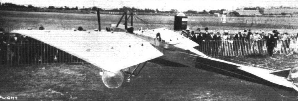
View of the British Deperdussin monoplane which secured a L500 prize in the Military Trials.
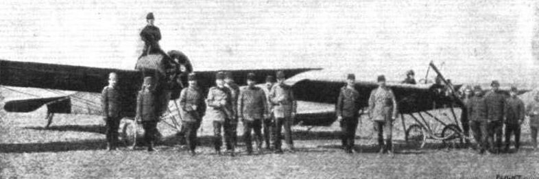
THE FIRST MONOPLANES FOR THE TURKISH ARMY. - Standing in the pilot's seat of the R.E.P. (left-hand machine) is Commander Fessa Bey, the first Turkish military pilot. In front the Turkish Military Commission is seen, the fifth from the left being Gen. Mabmud Schefket Pasha, the Turkish War Minister. On the right is a British pilot, who has been engaged, with his R.E.P. monoplane, by the Turkish Army as instructor.

The Deperdussin monoplane escadrille at the great French aeroplane review at Villacoublay last week.
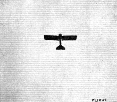
The British-built two-seater 60-h.p. Anzani Deperdussin for the Military Trials in flight from Hendon to Farnborough last Saturday, piloted by Lieut. Porte.
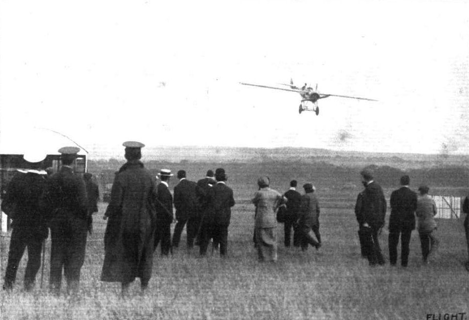
THE MILITARY AVIATION TESTS. - Vedrines coming to earth en vol plane, after a test flight on the 100-h.p. Gnome-engined British-built Deperdussln monoplane.

The identical 70-h.p. Deperdussin two-seated monoplane on which M. Prevost and Mr. Lawrence Santoni flew from Issy les Moulineaux to Eastchurch on Saturday the 13th, being tested on Thursday evening, prior to leaving the works, with a load of 2,500 lbs. of sand, in the presence of Lieut. Longmore, as the representative of the British Admiralty.
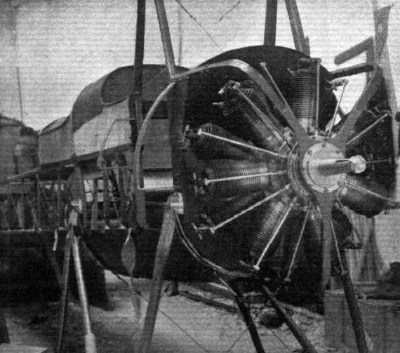
THE MILITARY COMPETITION MACHINES. The mounting of the 100-h.p. Gnome engine in the Deperdussin monoplane that will represent the British Deperdussin Co. in the War Office trials.

THE MILITARY COMPETITION MACHINES. Detailed views of the 100-h.p. Anzani-Deperdussin monoplane that will be flying at Salisbury next month. Lieut. J. C. Porte will be the pilot.

THE MILITARY COMPETITION MACHINES. - The 100-h.p. Anzani-engined British-built Deperdussin monoplane, which will be piloted by Lieut. J. C. Porte, who is standing at the left of the above group of aviators. On the right of the group is Mr. D. Lawrence Santoni, Joint Managing Director with Lieut. Porte, of the British Deperdussin Co. In the centre is M. Koolhoven, Chief Engineer and Works Manager of their Highgate works.
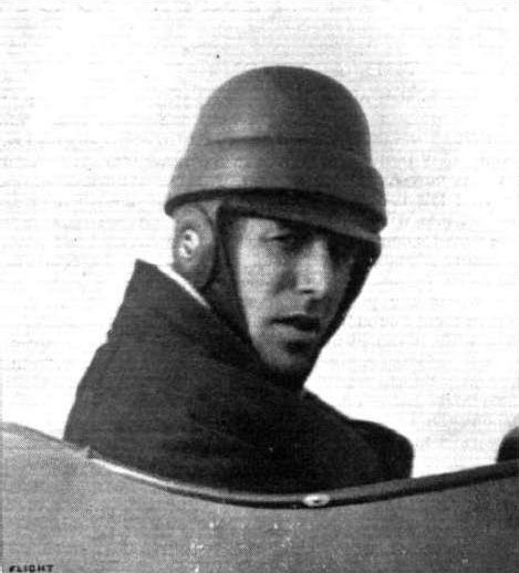
Lieut. J. C. Porte, R.N., in the seat of the British-built Deperdussin monoplane.

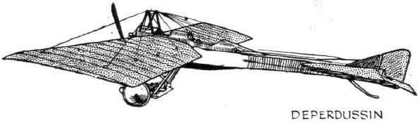
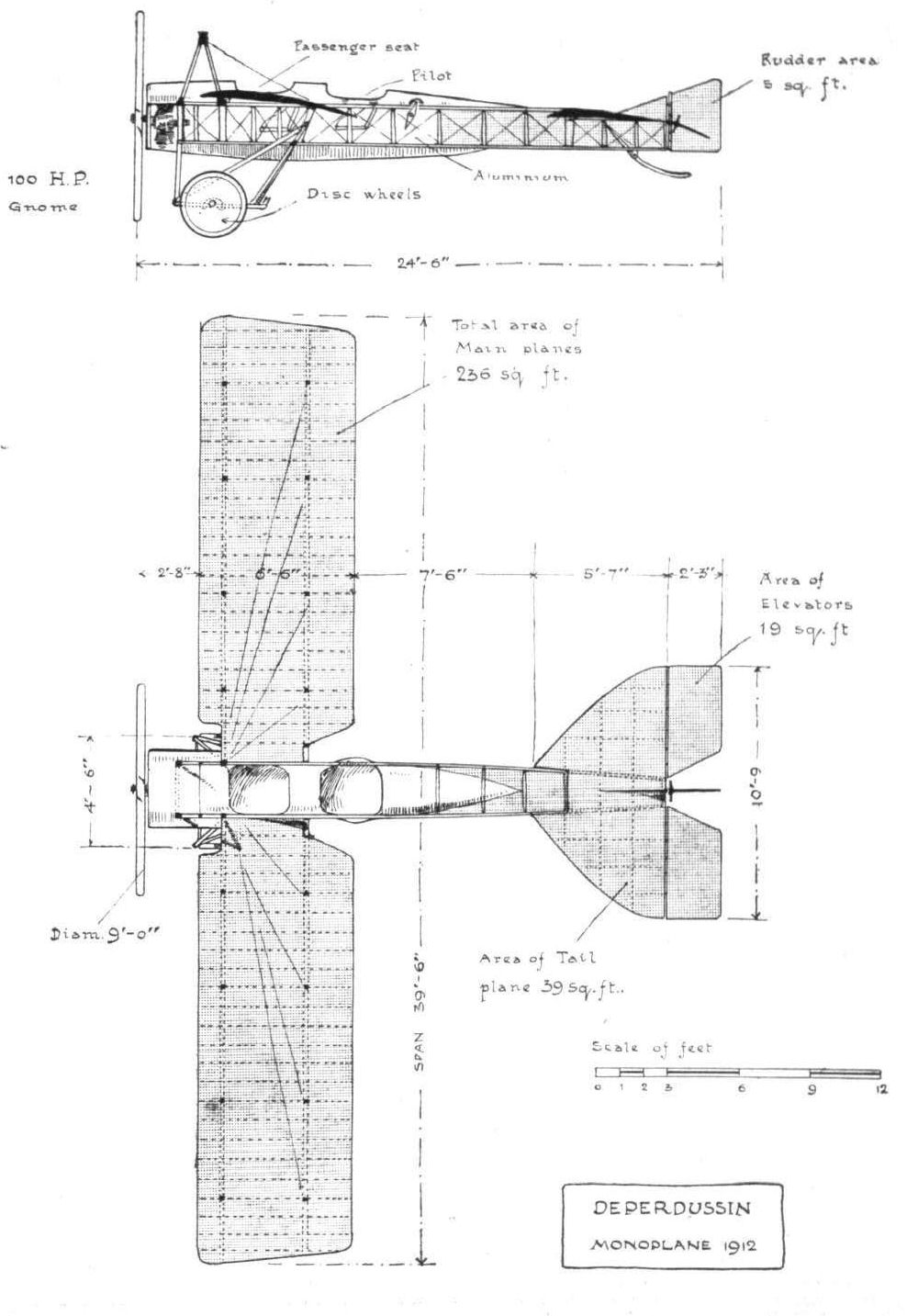
PLAN AND ELEVATION OF THE DEPERDUSSIN MONOPLANE. - The above drawings were prepared at the Highgate works of the British company, and illustrate the British design. In the French design, the passenger sits behind the pilot, and the machine has a larger effective; supporting surface.
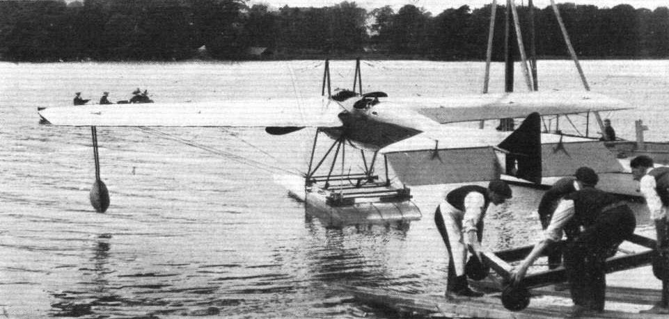
One of the Admiralty Deperdussin monoplanes which was flown to Lake Windermere, where it has been converted for hydro-aeroplane work. - In the photo it is seen just launched from its hangar after fitting the floats.
Flight, February 10, 1912.
THE 100-H.P. DEPERDUSSIN RACING MONOPLANE.
THE performance of that magnificent pilot, Vedrines, mounted on this new product of the Deperdussin firm, in establishing a new set of world's speed records from 5 to 150 kiloms., is yet another fact in support of our oft-repeated assertion that the organisation of Armand Deperdussin is one of the most enterprising and vigorous among the French industry. The machine with which this feat was accomplished has for some considerable time past been the special study of their chief engineer, M. Bechereau, one who has earned considerable respect in France, and even on this side of the Channel, by his most original and sound ideas. In order to arrive at the phenomenal speeds of which this machine has proved itself capable, the designer has in no way sacrificed any of its inherent qualities of safety in order to achieve his end. He has sought to attain the solution of the problem by reducing the head resistance of the machine as a whole to a minimum and by special study of the wings, rather than by any such inadvisable expedient as reducing the supporting surface.
The growing trend of opinion in favour of the torpedo type of body has gained another adherent, for in the machine at present under review this feature has been incorporated for the first time in the Deperdussin design. The main body proper consists of a lattice girder which tapers towards the rear, of exactly the same type as, but of more generous dimensions than, that employed on the ordinary type of machine. Throughout its whole length this girder is encased by a shell of three-ply wood, enough being cut away on a level with the back of the wings, in order to accommodate the pilot.
The form of the wings is rather peculiar in view of the general acceptance of the tapering tip. In the case of this machine, however, the wing tapers from the tip to the root, butterfly-like, a system which has some points to commend it, in that the chord is least where the relative current of air is strongest, and that the enlarged ends of the wings are better able to counteract the tendency of the engine torque reaction to interfere with its natural balance. One thing is certain, that is, that it is possible to get a much more powerful warp than if the wings tapered in the opposite sense. As a further advantage it is claimed that the span may be reduced without interfering with its flying qualities. In cross section the wings exhibit a very slight camber, and this, combined with the fact that they are set at an angle of only five degrees incident to the relative wind no doubt chiefly accounts for the remarkable speed this machine has shown. The trailing edge is of flexible construction so that any temporary increase of pressure beneath one wing may be automatically released. Hickory is employed for the spars, and the ribs are of I section, constructed from pine and ash. These same materials are used to form the framework of the stabilizing surface at the rear, and in both cases three-ply wood is made use of to form the leading edge. The fabric covering of the wings is treated, as is customary in the Deperdussin workshops, by several successive coatings of special varnish which renders it impervious to water, oil and petrol. Stranded steel cables are provided to take the weight of the machine in flight.
Despite the amount of criticism that was applied to the Deperdussin-type of landing gear at the time of its first appearance at the Paris Aero Show over a year ago, and has been applied at occasional intervals since then, this section of the machine has not, even in this latest model, where landing is effected at speeds in the neighbourhood of 90 miles an hour, undergone the slightest change. This, in our opinion, is sufficient evidence of the soundness of its design. Quite novel is the fitting of the rear skid. Only that part which rubs on the ground emerges from the fuselage, the remainder, together with the elastic cord attachment which endows this organ with flexibility, is disposed in its interior, a feature making for lessened head resistance and cleanness of design. The tail has been particularly low built in relation to the front part of the machine, in order that it may leave the ground more quickly, and pull up in a shorter time on landing.
As regards the tail, the arrangement of this organ is essentially the same as on the firm's less speedy machines, excepting that the surfaces are applied without the use of bracing wires or strainers. The controlling arrangements are absolutely identical with those on the standard types of this firm's productions - a wheel mounted vertically at the centre of an inverted U-shaped sweep of wood being pulled towards and pushed away from the pilot to effect elevation and depression, while rotating it laterally actuates the warping. One difference is evident, however, that the control is, in this machine, totally enclosed in the fuselage. The rudder is operated from a pivoted foot-bar.
Tractive force is derived from a 14-cylinder 100-h.p. Gnome engine direct coupled to a rapid propeller of 8 ft. 3 ins. in diameter. The main support of the engine is at the rear, but there is also a subsidiary support in front composed of three steel tubes arranged Y fashion. A thin shield of aluminium covering the motor effectively prevents any oil from being thrown in the direction of the pilot.
Flight, November 9, 1912.
THE PARIS AERO SALON.
Deperdussin.
PERHAPS no firm can be said to have made more progress than has the Deperdussin concern in France. Two years ago they had a small stand in a more or less insignificant position in the gallery, where they showed quite a neat and promising monoplane, which had the peculiarity that it was driven by a six-bladed propeller. By last year they had grown to be one of the chief monoplane manufacturing concerns in France, and this year they come to the Salon with the Gordon-Bennett Cup to their credit. On their stand they exhibit the machine with which Vedrines achieved this honour - a monocoque miniature in everything except the engine, which is a colossal rotary Gnome of 140-h.p. Naturally, as it is a speed machine - its flying speed is well over 100 m.p.h. - everything possible has been done to cut down head resistance to a minimum. Thus the body is of perfect streamline form, and of sufficient girth to totally enclose the pilot, leaving only the upper half of his head exposed. The wings are practically flat, and their average chord measurement cannot be more than 4ft., while they do not span more than 22 ft.
Over the front of the rotary motor is applied a semi-spherical dome through which the propeller of an unusually coarse pitch projects. This dome closely follows the bluff lines of the front of the fuselage, but there is sufficient clearance between it and the oil shield to admit air. Scarcely anything simpler than the racing, version of the Deperdussin chassis can be imagined. It is constructed of multiple-ply wood bound with canvas. Disc wheels are used.
There is shown on the same stand a very similar model, a single-seater with an 80-h.p. motor. But this has no cowl over the front of the engine.
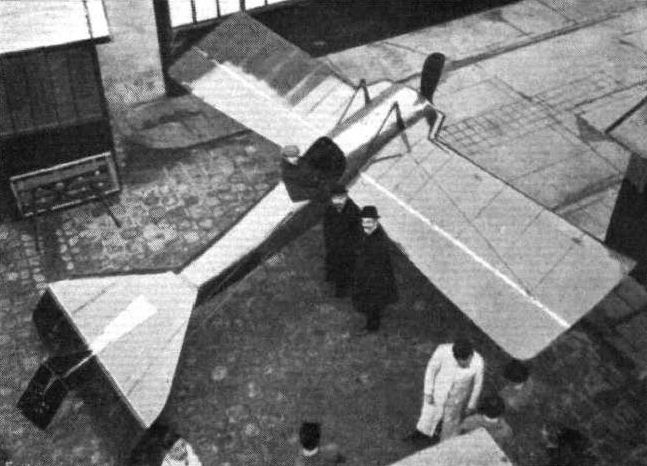
The 100-h.p. Deperdussin racing monoplane viewed from above, showing the pronounced butterfly-shape of the wings. Vedrines is seen seated in the cockpit, and to his right is M. Bechereau, chief engineer of the Deperdussin firm, to whom the design of this machine is due.
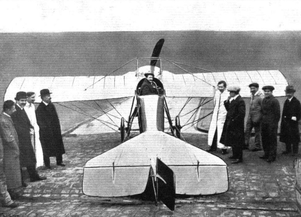
The 100-h.p. Gnome-engined racing Deperdussin monoplane, as seen from behind. In the pilot's seat is Vedrines, who, flying this machine, beat the existing world's speed records up to 150 kiloms. at Pau on January 13th, 1912.
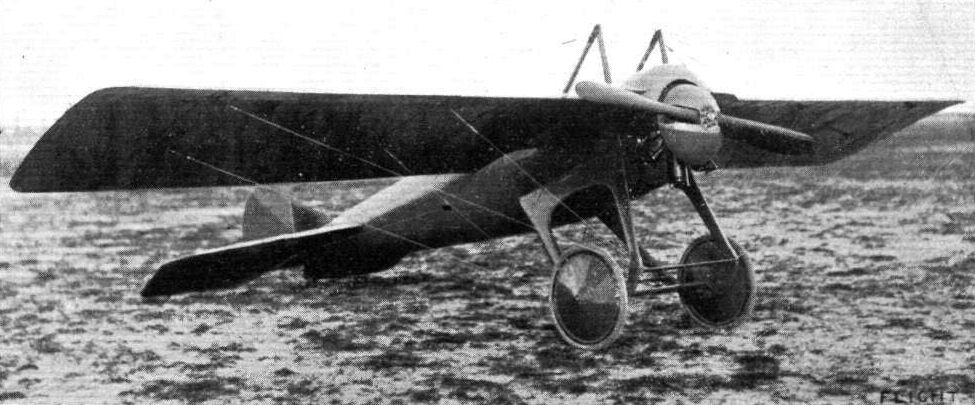
The latest form of the Deperdussin monoplane, as seen at the Anjou Circuit. Note the special shield over the engine and the substantial chassis.
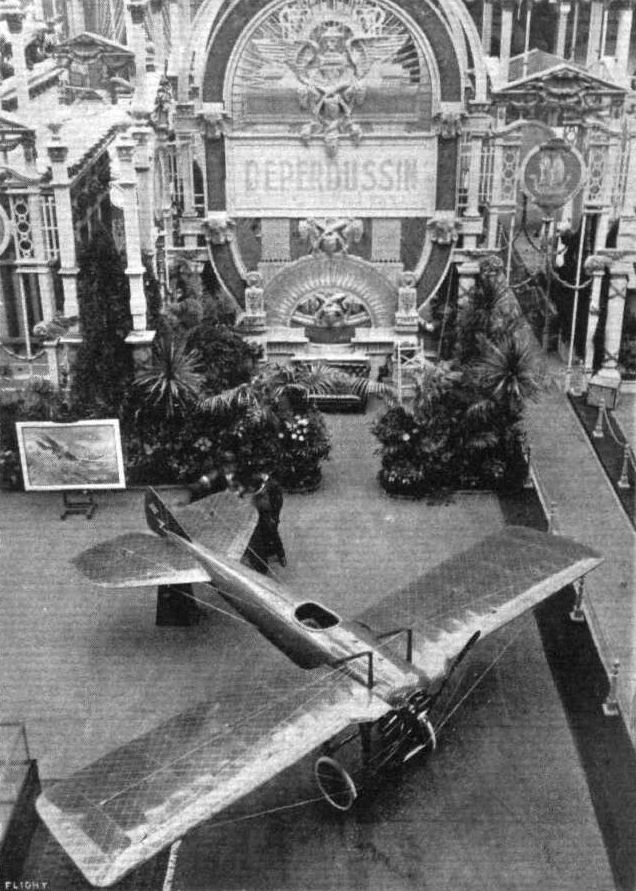
Part of the Deperdussin stand, showing one of their 80-h.p. Gnome monocoques. The picture gives a good idea of the elaborate scheme of decoration that was adopted at the Salon.

NEW FORMS OF LANDING CHASSIS. - The front of the latest Deperdussin monoplane, the "Monocoque." The spun cowl over the motor is to further reduce head resistance.
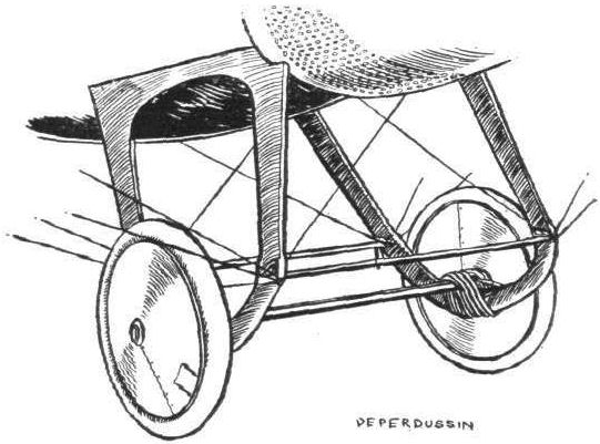
The landing chassis of the Deperdussin monococque.
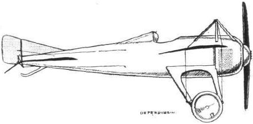
The Gordon-Bennett winner - the 140-h.p. Dep. monocoque.
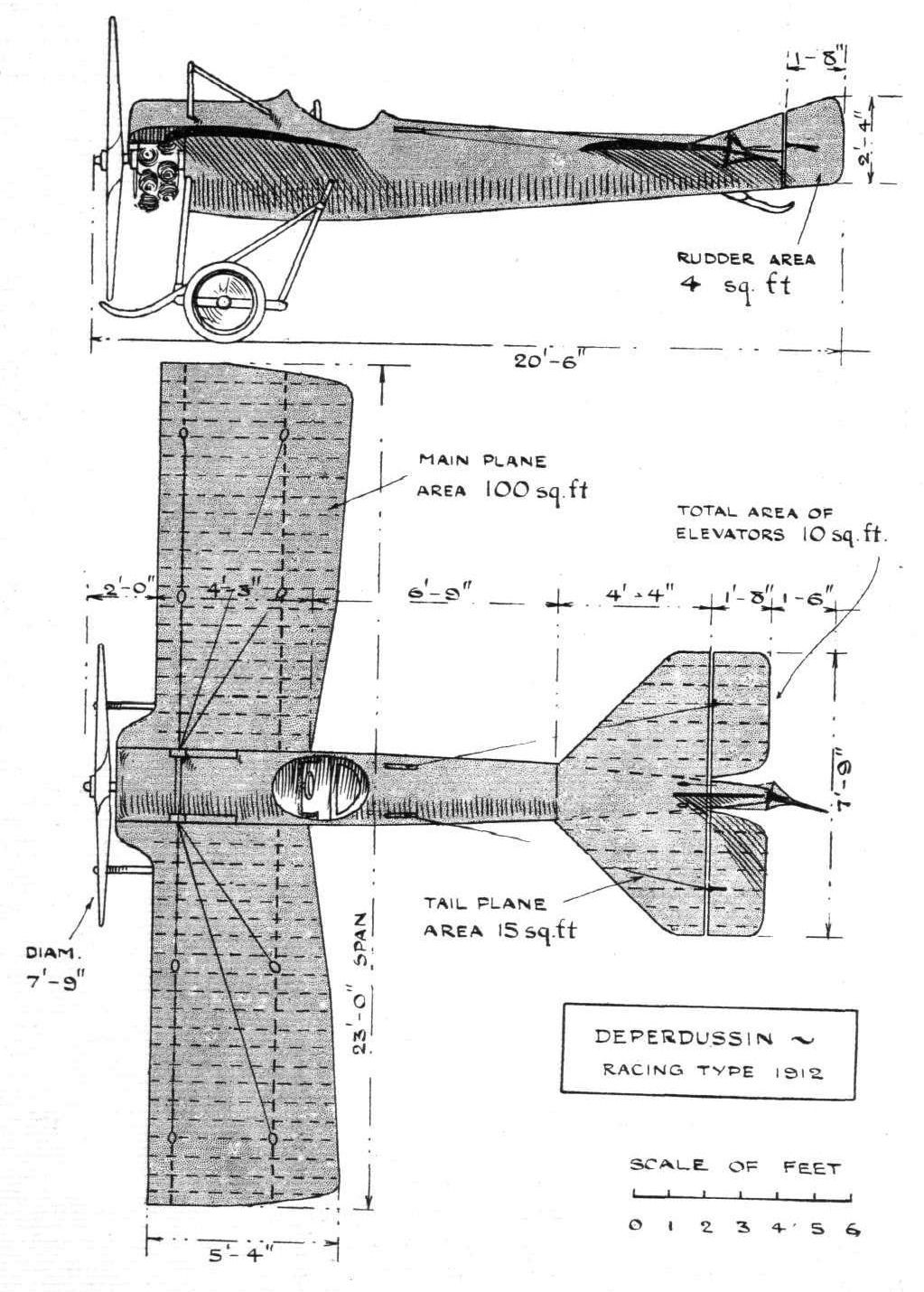
THE 100-H.P. RACING DEPERDUSSIN MONOPLANE. - Plan and elevation to scale.
Flight, August 3, 1912.
BRITISH NOTES OF THE WEEK.
Paris to London in a Hydro-Aeroplane.
ON the Donnet Leveque hydro-aeroplane Capt. Conneau, better known by his nom de vol of Andre Beaumont, started off from Juvisy on Friday last on a projected trip from Paris to London. He followed the Seine to Bezons, where he came down on the water after covering 36 miles. He intended to continue his journey along the Seine to Havre, cross the Channel, then keep round the English coast and up the Thames to Westminster, but the bad weather of the week-end has intervened and prevented any progress being made with this part of the programme.
Flight, August 17, 1912.
BRITISH NOTES OF THE WEEK.
Disaster Overtakes M. Beaumont.
AFTER waiting for several days at Berons, a suburb six miles west of Paris, "Beaumont," otherwise Capt. Conneau, was able to make a start for London on the 9th inst. His Donnet-Leveque hydro-aeroplane was wheeled down to the water, and at 4.30 a.m. it rose from the Seine for a trial run. Everything was working in good order, so the pilot did not return but set his course along the Seine for Havre. Passing Meulan, Mantes, Vernon, Gaillon and Caudebec, the machine reached Quillebceuf at 6.40, where a stop was made for replenishments. A quarter of an hour later it was in the air again, and Havre was reached at five minutes to nine, the machine alighting in front of the Casino. The mechanics, hearing of the stop at Quillebceuf, had gone there, so that M. Beaumont had to rely on amateur help at Havre. Some slight damage was done through the machine colliding with the shore, but everything was in order after lunch when at 2 p.m. a re-start was made for Boulogne, to which a non-stop run of 1 hr. and 55 mins., without the slightest incident, ensued.
At Boulogne the enthusiastic fishermen came out to render what assistance they could, but their zealous but unprofessional efforts only resulted in one of the floats being damaged, so that no further progress could be made that day. Repairs were, however, executed over night and on Saturday afternoon M. Beaumont prepared for the cross-Channel trip. The wind buffetted the machine very considerably and after making a circuit the pilot had to bring his machine down to the water, which was very choppy. Suddenly the biplane was caught by a very strong squall and completely overturned. The pilot was able to swim clear and superintended the towing of the wrecked machine back to the shore. It is to be repaired and M. Beaumont will then make another attempt to fly to London.
Flight, November 16, 1912.
THE PARIS AERO SALON.
Donnet-Leveque.
The hydro-biplane shown on this stand is of rather more interest than usual, for it was one of the first machines of its type to meet with a measure of success, and for the fact that the British Admiralty have bought one of them. The one shown is of quite light build and is arranged as a two-seater, driven by a 50-h.p. Gnome. That supplied to our Navy was of much stronger and heavier build, equipped with an 80-h.p. Gnome and intended more for open sea work than for service on river or lake, or stretches of water where the surface does not get unduly disturbed. So that it may be used for atterrissage as well as amerrissage, it is fitted with a clever type of disappearing chassis which may be hauled up clear of the water by releasing a catch and turning a handle mounted at the rear of pilot's head. Perhaps our sketch will make this point clearer than would be possible by word description. The coque is built throughout of mahogany, which wood also enters into the construction of the tail in those parts which are likely to get splashed with or immersed in water. In front the section of the coque is rectangular, but aft of the main planes it takes on a section represented by a triangle standing on its base. There is a step in the float at a point just below the entering edge of the main planes. At the side of the body it is about 6 inches deep but in the centre it is considerably less, for the bottom of the hydroplane has the peculiarity that it is concave. Naturally there is no tail float in the accepted sense of the term for the coque itself acts in that capacity. There is, however, a small wooden plane, shaped more or less like a penguin's tail, which assists in getting the tail off the water when starting off. Inside, the coque is divided into watertight compartments, to eliminate the chance of it becoming completely flooded should it strike any hard obstacle and become punctured. Small egg-shaped floats are fitted to the tip of the lower planes to steady the machine on water. The engine is mounted in a position about two-thirds up the gap between the main planes, and provision is made so that the pilot may start it without leaving his cockpit.
BRITISH NOTES OF THE WEEK.
Paris to London in a Hydro-Aeroplane.
ON the Donnet Leveque hydro-aeroplane Capt. Conneau, better known by his nom de vol of Andre Beaumont, started off from Juvisy on Friday last on a projected trip from Paris to London. He followed the Seine to Bezons, where he came down on the water after covering 36 miles. He intended to continue his journey along the Seine to Havre, cross the Channel, then keep round the English coast and up the Thames to Westminster, but the bad weather of the week-end has intervened and prevented any progress being made with this part of the programme.
Flight, August 17, 1912.
BRITISH NOTES OF THE WEEK.
Disaster Overtakes M. Beaumont.
AFTER waiting for several days at Berons, a suburb six miles west of Paris, "Beaumont," otherwise Capt. Conneau, was able to make a start for London on the 9th inst. His Donnet-Leveque hydro-aeroplane was wheeled down to the water, and at 4.30 a.m. it rose from the Seine for a trial run. Everything was working in good order, so the pilot did not return but set his course along the Seine for Havre. Passing Meulan, Mantes, Vernon, Gaillon and Caudebec, the machine reached Quillebceuf at 6.40, where a stop was made for replenishments. A quarter of an hour later it was in the air again, and Havre was reached at five minutes to nine, the machine alighting in front of the Casino. The mechanics, hearing of the stop at Quillebceuf, had gone there, so that M. Beaumont had to rely on amateur help at Havre. Some slight damage was done through the machine colliding with the shore, but everything was in order after lunch when at 2 p.m. a re-start was made for Boulogne, to which a non-stop run of 1 hr. and 55 mins., without the slightest incident, ensued.
At Boulogne the enthusiastic fishermen came out to render what assistance they could, but their zealous but unprofessional efforts only resulted in one of the floats being damaged, so that no further progress could be made that day. Repairs were, however, executed over night and on Saturday afternoon M. Beaumont prepared for the cross-Channel trip. The wind buffetted the machine very considerably and after making a circuit the pilot had to bring his machine down to the water, which was very choppy. Suddenly the biplane was caught by a very strong squall and completely overturned. The pilot was able to swim clear and superintended the towing of the wrecked machine back to the shore. It is to be repaired and M. Beaumont will then make another attempt to fly to London.
Flight, November 16, 1912.
THE PARIS AERO SALON.
Donnet-Leveque.
The hydro-biplane shown on this stand is of rather more interest than usual, for it was one of the first machines of its type to meet with a measure of success, and for the fact that the British Admiralty have bought one of them. The one shown is of quite light build and is arranged as a two-seater, driven by a 50-h.p. Gnome. That supplied to our Navy was of much stronger and heavier build, equipped with an 80-h.p. Gnome and intended more for open sea work than for service on river or lake, or stretches of water where the surface does not get unduly disturbed. So that it may be used for atterrissage as well as amerrissage, it is fitted with a clever type of disappearing chassis which may be hauled up clear of the water by releasing a catch and turning a handle mounted at the rear of pilot's head. Perhaps our sketch will make this point clearer than would be possible by word description. The coque is built throughout of mahogany, which wood also enters into the construction of the tail in those parts which are likely to get splashed with or immersed in water. In front the section of the coque is rectangular, but aft of the main planes it takes on a section represented by a triangle standing on its base. There is a step in the float at a point just below the entering edge of the main planes. At the side of the body it is about 6 inches deep but in the centre it is considerably less, for the bottom of the hydroplane has the peculiarity that it is concave. Naturally there is no tail float in the accepted sense of the term for the coque itself acts in that capacity. There is, however, a small wooden plane, shaped more or less like a penguin's tail, which assists in getting the tail off the water when starting off. Inside, the coque is divided into watertight compartments, to eliminate the chance of it becoming completely flooded should it strike any hard obstacle and become punctured. Small egg-shaped floats are fitted to the tip of the lower planes to steady the machine on water. The engine is mounted in a position about two-thirds up the gap between the main planes, and provision is made so that the pilot may start it without leaving his cockpit.
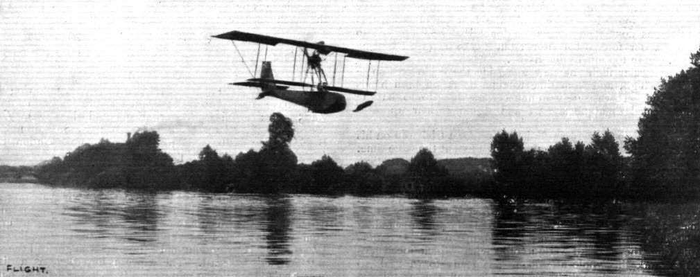
Capt. Conneau (Beaumont) on his "Donnet-Leveque" in full flight over the Seine in connection with his Paris to London river and sea flight.
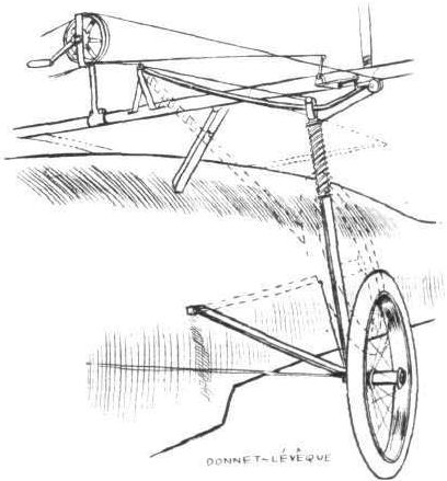
The disappearing landing-chassis of the Donnet-Leveque hydro-biplane.
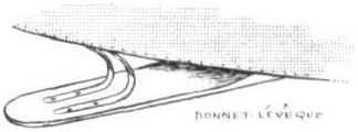
The water-skid at the tail of the Donnet-Leveque hydro-biplane.
Flight, November 16, 1912.
THE PARIS AERO SALON.
Doutre.
HERE there is a biplane which is practically an exact copy of a Maurice Farman as regards its general appearance. Hardly the same, unfortunately, can be said as regards its workmanship. It is fitted with the well-known Doutre system of ensuring longitudinal stability, an explanation of which device appeared in these pages some few months since.
Flight, November 16, 1912.
THE PARIS AERO SALON.
Drzeweicki.
ON the Ratmanoff stand, in addition to "Normale " propellers, is exhibited a peculiar type of double monoplane, constructed to the designs of M. Drzeweicki, under whose licence, by the way, those excellent propellers are constructed. Its central unit of construction is a totally covered-in fuselage of rectangular section, at either end of which are arranged the wings. Those in front are of smaller dimensions than those behind, but meet the air at a greater angle of incidence. They, in addition to sustaining a portion of the weight of the machine, control its altitude in flight. Some little distance behind them sits the pilot, and at his back is the engine, a Labor-Aviation, which drives a propeller at the extreme rear end of the machine through a steel shaft. Steering is effected by vertical rudders pivoted to the tips of the rear wings. Each end of the machine is provided with a landing chassis of its own. In front there are two wheels whose flexibility is controlled by pneumatic springs extending along the base of the body. There is also a nose skid, but it seems to be placed too high to be of much service. The chassis at the rear of the machine is a combination of wheels and skids, the disposition of which can be gathered from one of our sketches. The wheels are sprung by laminated steel springs, such as were used on the new Bleriot racer shown at last year's Salon. The machine has not yet flown.

The Drzeweicki double monoplane.
Hydro-aeroplanes, illustrating the paper by Mr. Holt Thomas.
Flight, March 9, 1912.
AEROPLANE UNDERCARRIAGES.
By G. DE HAVILLAND.
Types of Undercarriage.
Farman Biplane.-Farman was the first to combine wheels with skids, and this type of undercarriage has found favour with a large number of constructors. Ash is chiefly used, and the machine is supported from the skids by four or more struts, which are wired-up rigidly to the main planes. The skids are 9 feet apart, and each carries a pair of rolling-wheels, which are attached by rubber bands. A short radius-rod allows the wheels a certain amount of lateral motion. The maximum vertical travel of the wheels is about 8 inches, but it is seldom that the skids come in contact with the ground. It is certainly not advisable that they should do so, as the shocks transmitted to the whole machine would be excessive. The rear skid carries a weight of about 200 lbs., but owing to the propeller slip stream passing over the lifting-tail planes, the skid leaves the ground in a few yards. A machine which has a weight-carrying tail-plane has the advantage of not tending to pitch forward when landing on soft ground, owing to the weight being well back in relation to the position of the wheels; but, owing to its disadvantages from an aerodynamic point of view, the weight-carrying tail is giving place to the purely directional tail. In the latter case there is practically no lift given to the rear part of the machine by the propeller-slip, and therefore the wheels must be placed farther back, in order to diminish the weight on the rear skid, which makes for a greater tendency to pitch forward when landing. It was probably for this reason that the Bleriot monoplane entered for the French Military Trials was fitted with a weight-carrying tail, although this type had previously been abandoned in favour of a directional tail. The motor fixed to this machine was a 140-h.p. Gnome, and with this weight well forward, there would naturally be trouble in the landing-test, which included alighting on ploughed land.
In its original form of eight struts and our wheels, the head-resistance in the Farman type was excessive, but in the latest models the number of struts has been halved.
Flight, March 16, 1912.
Fatal Accident to an Aviatress.
APPARENTLY the fatal accident to Mdlle. Bernard a girl of nineteen years of age at Etampes on the 10th inst. must be put down to the pilot's inexperience, although she had been practising for some time, first at Chalons and then at Etampes. She was making her third test flight for her brevet and tried to make a turn when rising with the result that the biplane slipped sideways from a height of 60 metres. The aviatress sustained such injuries that she died within a few minutes without regaining consciousness.
MODELS.
I am sending you a photograph of a 1/12th scale racing Farman which I have constructed. The framework throughout is of Spanish chestnut, and I advise any model maker who wants a tough pliable wood of medium weight to try it.
This wood behaves splendidly under the influence of steam, and he would be a clumsy workman indeed who split the wood in making an ordinary bend. In this model the longitudinal struts connecting the elevator with the tail are in four pieces only - two to each side running the whole length of the machine. The ailerons and elevators are all worked from levers on the pilot's seat in front, and the whole thing differs only in size and a few very minor details from the real machine.
Chalford. A. D. LEGGE-WILKINSON.
Flight, March 23, 1912.
AIR EDDIES.
Quite a flying family are the Lewins, especially the younger representative of the family, officially known as Stanley Guy Lewin, called by the Daily Mail "the air-boy," and known locally at the aerodrome as "The Winkle." Grahame-White and this young enthusiast frequently take trips together. "Claude" turns round, and, finding the youngster always ready, says - "Come on, sportsman! Where shall we go?" And they fly off to find some new spot around Hendon. "Winkle" and his pilot are well portrayed in our photograph this week.
Flight, April 13, 1912.
HENDON AVIATION MEETINGS.
Monday, April 8th.
The wind on Easter Monday was something colossal, having risen from about 8 o'clock the previous evening, and been steadily increasing in force throughout the night. Across the fields, on the foot-path leading from the bottom of Hendon Hill to the aerodrome gates, the wind was so strong that on foot it was difficult to make any headway against it. Hats went spinning in all directions. In the aerodrome the strength of the wind can well be judged by the fact that a tent hangar had its roof ripped off, and that one of the mark posts, quite a .massive structure of wood, had been toppled completely over. In spite of the very unsuitable conditions all roads leading to the aerodrome were black with visitors, and although people intending to enter the aerodrome were warned that under no circumstance could flight be guaranteed, the enclosures were soon comfortably filled. And Grahame-White did not mean to disappoint them. At half past three it was announced from the Judges' box that he would "parade" a Farman biplane. The machine in question was brought out with Grahame-White in the pilot's seat and held down to the ground by two mechanics at each wing-tip and two near the skids. Even at that, the machine threatened to blow over. To run the machine over the ground against the wind the engine had to be kept going all out the whole time, and even then the machine did not exceed the running pace of the mechanics who kept it from leaving the ground. In one of these runs up the aerodrome it really seemed as if the machine lifted all seven off the ground for a moment. After parading the machine before the enclosures in order to give the public an opportunity of grasping the nature of an aeroplane at close quarters, Grahame-White decided to attempt a short flight. With his chief engineers Carr and Law standing one on each skid, he started up into the wind, and flew for about 200 yards at a height of 10 ft. Even for this short distance he seemed to be in the air for quite one minute, so the speed of the wind can be readily estimated. Two more flights of the same order did he make. At the termination of his third the wind caught him, and made him bump rather heavily from about 10 ft., an incident which made it evident that there is more strength in the Farman chassis than is at first apparent. As regards this section of the machine the only replacement necessary was one rubber shock-absorber. In his exertions to keep the machine on an even keel, Grahame-White had smashed up the pilot's seat and considerably bent his foot rudder-bar. An interval was called while these were being replaced, and then, with Lewis Turner sitting on the cellule to his right, and Carr to his left, he taxied the machine over to the far side of the ground, in order to get in a longer flight. He turned up into the wind and got off the ground. When he was about 10 ft. up, a gust caught him under the left side of the cellule, and no amount of manipulation of the levers could bring the machine back to the horizontal. It slipped down on to its right tip, and on to the right hand corner of the elevator, and blew right over. Grahame-White and Turner jumped clear, and the machine passed right over their heads. Carr being on the side that was rising, hung on for his life and went right over with the machine, eventually crawling out from underneath the wreckage, his face wreathed in smiles. After all, there was really not much danger in the incident, for the wind was about equal to the flying speed of the machine, and its speed relative to the ground at that moment was practically nil. Of the three, Grahame-White was the only one who suffered anything apart from stiffness, and that only to the extent of a sprained ankle, from which he had recovered the following day.
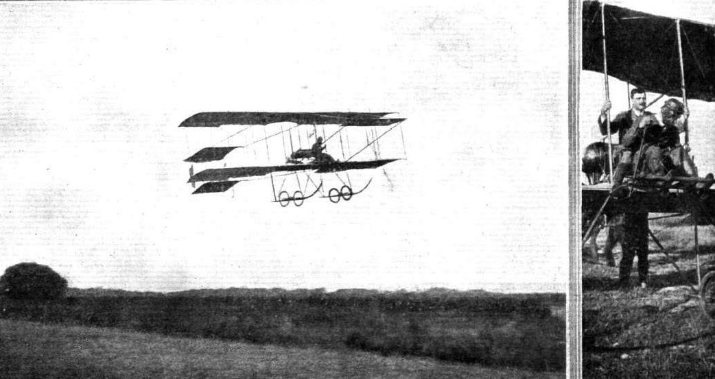
MESSRS COMPTON-PATERSON AND DRIVER IN SOUTH AFRICA. - Mr. Paterson giving an exhibition flight at the Kenilworth Racecourse, and on the right he is seen with Mr. Fred Barling ready for his first passenger flight.
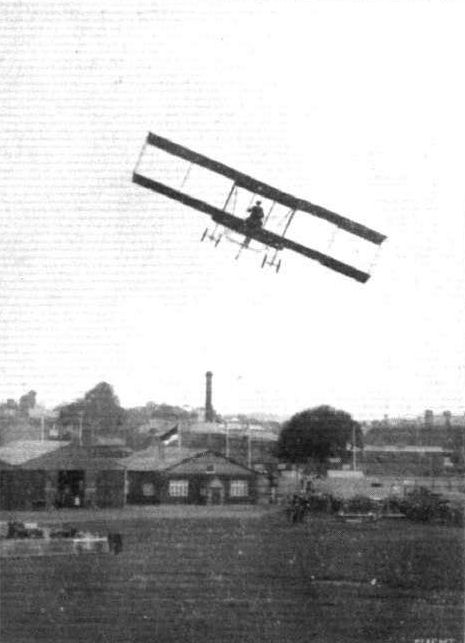
Mr. Claude Grahame-White doing a turn over the hangars at the London Aerodrome on the school Farman 'bus during one of the regular week-end meetings at Hendon,
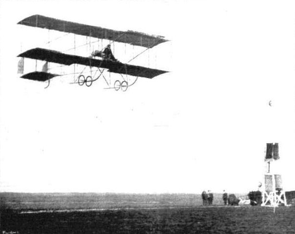
Mr. Lewis Turner flying the Grahame-White Farman in the Figure of Eight Competition.

IN THE AIR DURING THE EASTER FLYING MEET AT HENDON. - Mr. Lewis Turner giving an exhibition on the Henry Farman.
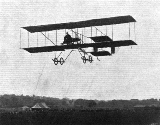
Mr. Richard T. Gates flying at Hendon on the school Farman.
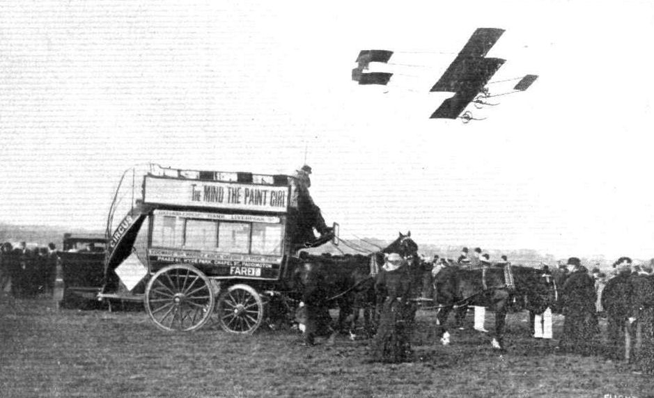
MR. LEWIS TURNER FLYING AT HENDON ON SATURDAY. - Note, in contrast, the ancient 'bus relic.

An exhibition flight at Hendon by Mr. Grahame-White in the Farman 'bus, as seen from outside the entrance to the aerodrome. Note one of the 3-horses conveyances which are now regularly flying for passengers to and from the meeting.
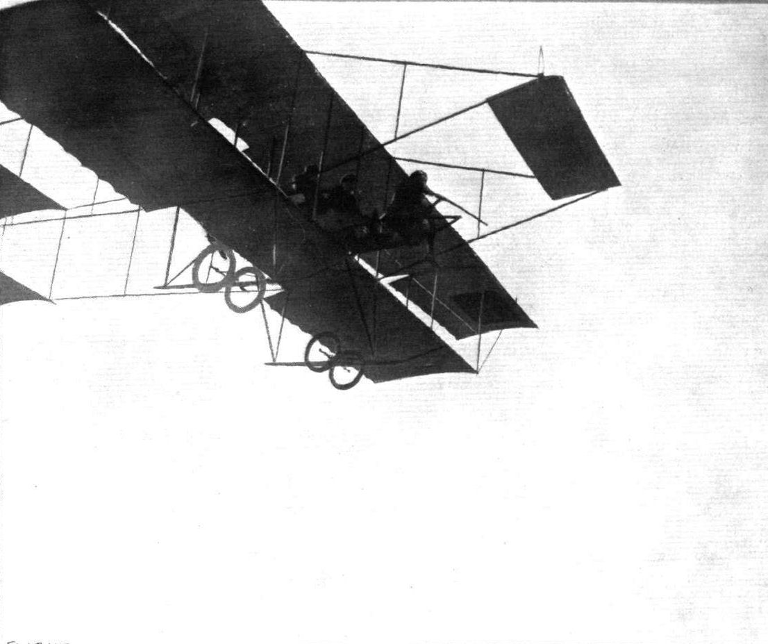
HARE SHOOTING BY AEROPLANE. - Recently at Corbeaulieu those "heavenly twins," Martinet and Legagneux, have been amusing themselves by shooting hares and partridges from one of their Farman biplanes. The above photograph depicts Martinet, sitting astride the nacelle, taking his aim, while behind him are Legagneux, at the lever, and another fellow sportsman in the rear passengers seat.
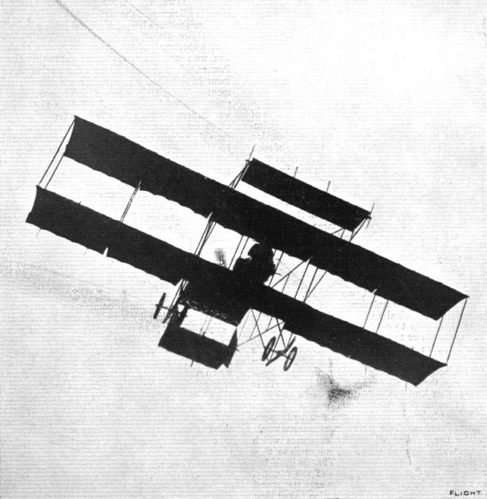
Mr. J. L. Travers making a fine banking on the Farman biplane at the London Aerodrome, Hendon.
FLYING AT THE NANCY AVIATION FETE. - A fine natural grand stand. Kuhling on his Bleriot monoplane, and Loridan on a Henry Farman machine, are seen in flight.
An incident between two biplanes in the recent race for the "Shell" Spirit Prize at Hendon. - Lewis Turner on Farman, and Raynham on the Burgess-Wright, travelling down the aerodrome.
FLYING IN INDIA. - A curious effect from a double exposure of a negative whereby the two machines at Tollygunj were apparently flying at the same time. Note the excitement of the natives in following the evolutions of the machines.
A TRIO. - Finish of first heat of the Speed Handicap at Hendon, Saturday, the competitors being Mr. Gustav Hamel, Mr. J. L. Travers, and Mr. Sabelli in the order named.
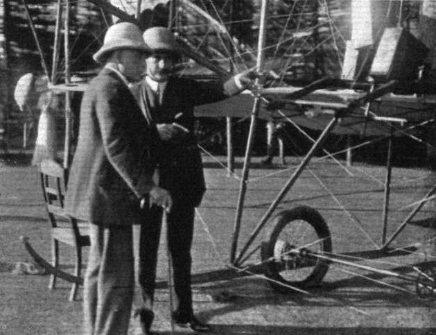
FLYING IN INDIA IN 1910. - Sir Moore O'Creagh, the Commander-in-Chief of the Indian Army, mastering details of the Farman under the guidance of Baron de Caters,
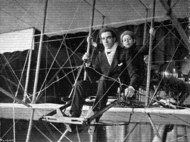
Mr. Claude Grahame-White and a favourite passenger of his, Master S, Guy Lewin, another promising aviation son of Mr. F. Guy Lewin, so well known in the motor world.
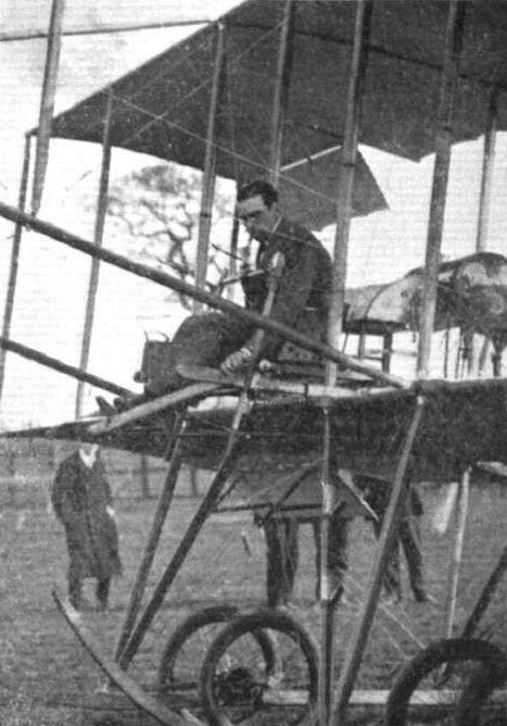
Mr. Grahame-White about to start an exhibition flight at Hendon last Saturday in remembrance of the second anniversary of the great Manchester flight.

Mrs. C. Stocks, the clever aviatress who was amongst those who flew at Hendon during the Easter Meeting.
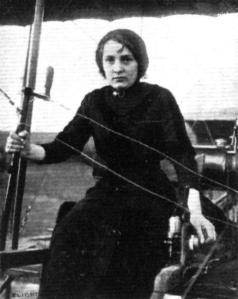
Mdlle. Bernard, the young aviatress who, in endeavouring to obtain her Aero Club of France certificate for flying, was unfortunately fatally injured at Etampes last week-end. Mdlle. Bernard is reported to have endeavoured to rise when making a turn.
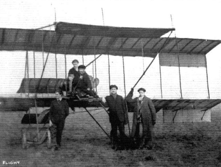
THE GRAHAME-WHITE SCHOOL AT HENDON. - Photograph of five members of the Grahame-White establishment at work on Monday morning last. In the pilot's seat Mr. Lewis Turner, with Mr. Ramsay seated behind him. Standing, from left to right, Messrs. Manton, Fowler and Biard.
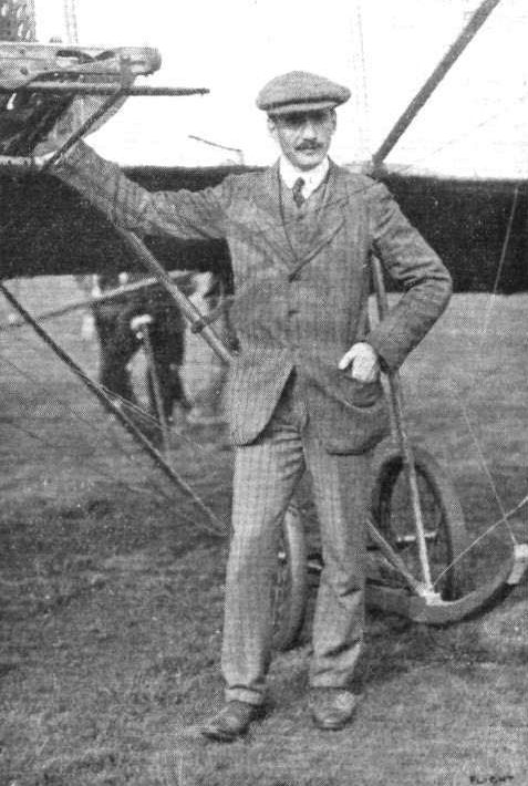
Mr. J. L. Travers, who is now flying so well at Hendon.
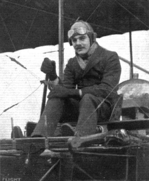
Mr. Marcus Manton, who has just secured his pilot's brevet and made his debut in exhibition flying for the Grahame-White Co. at Hendon on October 5th.
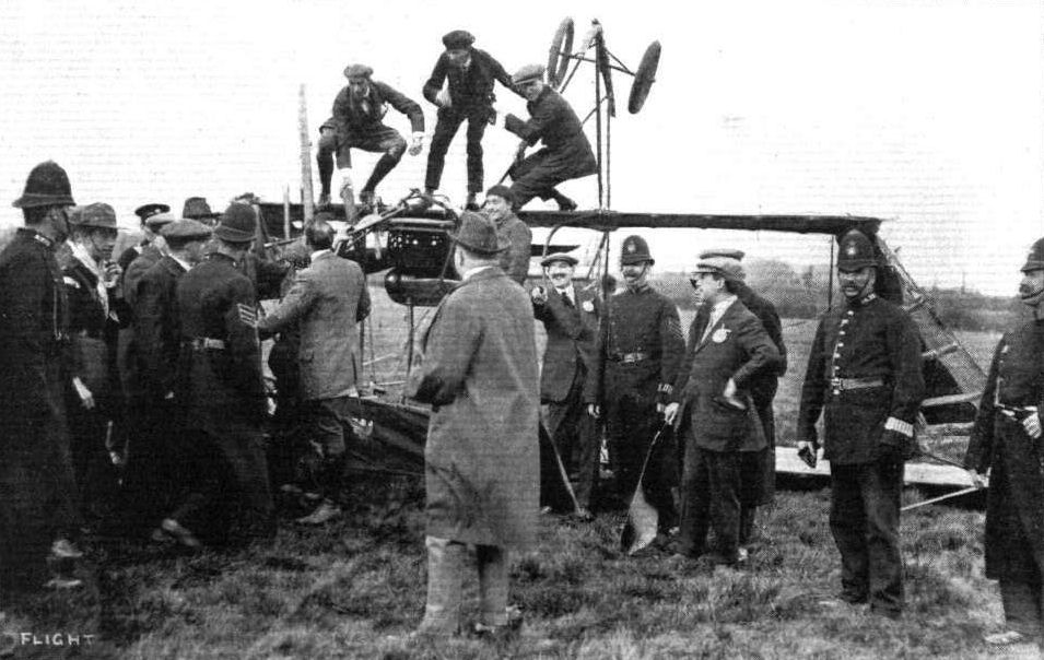
AFTER THE MISHAP IN THE GALE TO GRAHAME-WHITE'S BIPLANE AT HENDON ON EASTER MONDAY. - On the top of the overturned machine are seen Messrs. Grahame-White, Lewis Turner, and Hamel.
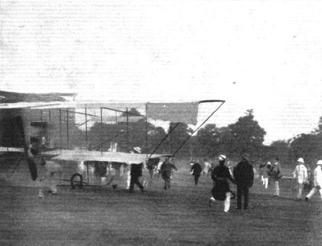
FLYING IN INDIA. - The Farman machine has a little mishap from a backfire igniting the petrol. Fortunately there was plenty of sand on the Tollygunj golf course with which to save the machine before much damage was done.
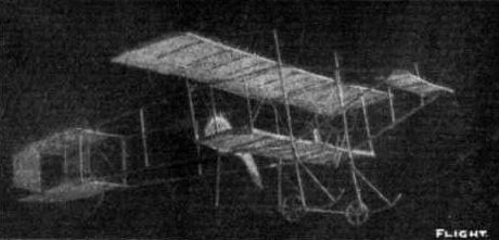
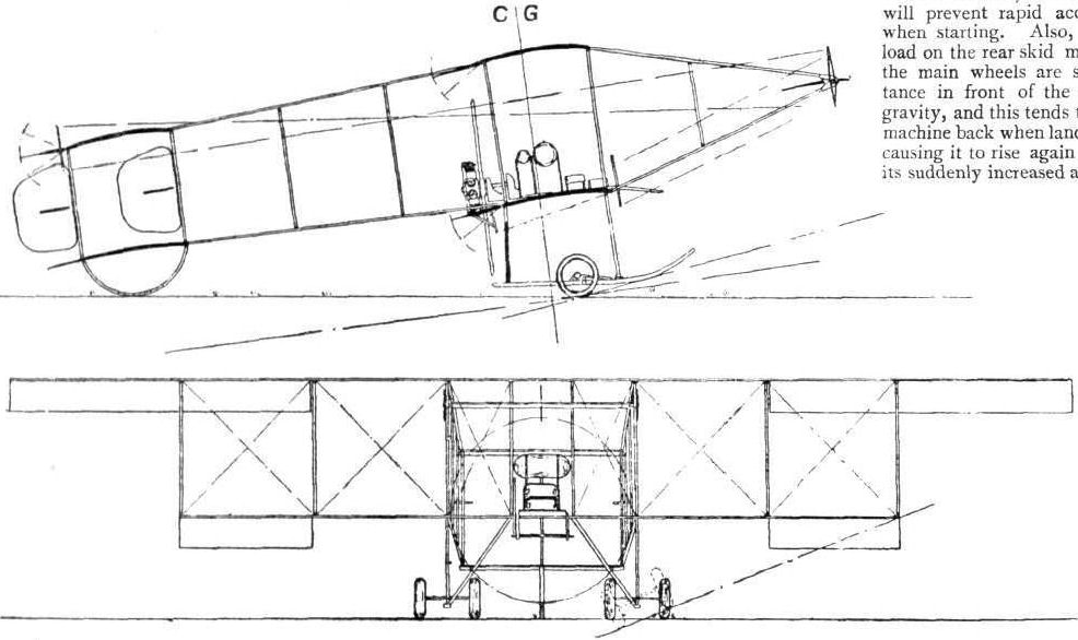
Fig. 2. - Farman Biplane.
Flight, October 19, 1912.
A NEW HENRY FARMAN BIPLANE.
ACCESSORIES such as lamps and hooters, which form a by no means insignificant feature of the modern motor car, have as yet been absent from the aeroplane, but there is a machine down at Hendon just now belonging to the Grahame-White Co. which attracts considerable attention in its possession of these fittings, and among the sketches we give this week are two or three showing the aforementioned etceteras. As a matter of fact, however, they are of comparatively minor interest on a machine like the Henry Farman, notwithstanding that it has long been one of the most universally well-known flyers in existence. This particular model, as it happens, is a new design to the extent of having one of the latest 80-h.p. Gnome engines, and although built on the same lines is much smaller in size than the 70-h.p. biplane that has been doing such good missionary work in the country with its "Wake Up England" motto. It is designed for a speed somewhere in the order of 60 miles an hour, and, constructionally, it is characterised by the great superiority of the span of the upper plane as compared with the lower. Indeed, the upper plane is almost twice the span of the lower plane. Its ailerons or balancing flaps, too, occupy the whole length of the trailing edges of the upper main plane extensions.
At the rear, a slight modification will be noticed in the shape of the rudder, which has a curved entering edge, carried forward of the rudder post. Near the engine, a little detail of interest is the very neatly-arranged combined petrol and oil-tank, which has a capacity for 15 gallons of fuel and 7 gallons of castor oil. This feature forms the subject of one of our sketches, as also does one of the nicely-made joints in the control wires.
Henry Farman Biplane.
Metres,(ft. in.)
Upper main plane-
Span 13.50(45 0)
Chord 1.90 ( 6 0)
Lower main plane-
Span 7.50 (24 7)
Chord 1.45 (4 9)
Distance between
main planes 1.40 (4 7)
Ailerons-
Length 3.0 (19 10)
Chord 0.42 (1 4 1/2)
Fixed tail plane-
Span 3.50 (11 5)
Chord 1.0 (3 6)
Elevators-
Length 1.75(5 9)
Chord 0.52 (2 0)
Rudder-
Height 1.85 (6 4)
Chord 0.80 (2 7 1/2)
Propeller-
Diameter 2.6 (8 0)
Pitch 1.90 (6 0)
Weight (with pilot, fuel, and oil, but without passengers) 900 lbs
Flying speed 62 m.p.h.
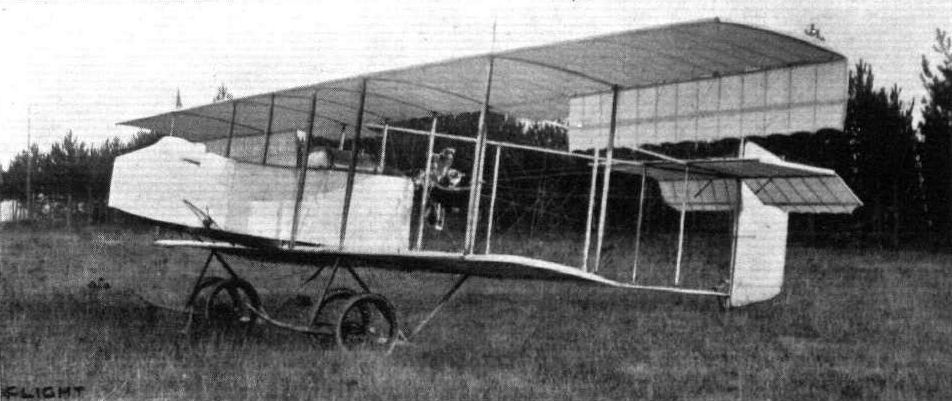
THE NEW HENRY FARMAN BIPLANE. - Extensive changes have been made in the construction of this new machine, the top and bottom pairs of tail outriggers being arranged in triangular form, and the tail surface itself being purely a monoplane type of organ with single vertical rudder. The position of the engine has also been changed and by virtue of its present position midway between the planes the constructors have been enabled to reduce the height of the landing chassis, thus contributing to its robust construction.
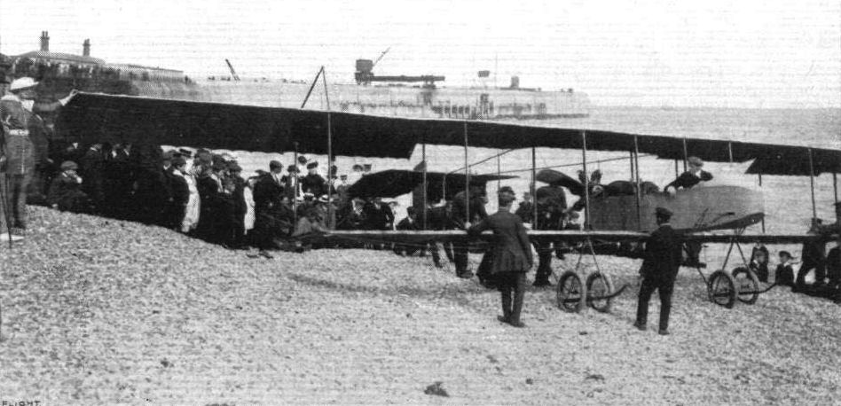
Mr. Grahame-White, on his new Henry Farman biplane, about to start from the beach at Folkestone for his flight to Hendon. Mrs. Grahame-White is standing on the extreme left of the picture. Note the shingly beach for getting off from.
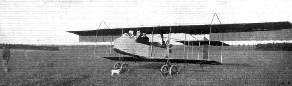
Two Henry Farman military type aeroplanes last week very successfully passed every test required by the British War Office bsfore taking over the machines, the tests finishing up with a vol plane with the motor stopped from 4,500 ft. Our photograph shows one of the machines on the ground.
READY FOR THE FIRST HEAT IN THE SPEED COMPETITION AT HENDON ON SATURDAY LAST. - Messrs. Hall, Lewis Turner, and Louis Noel ranged up to the taklng-off line.
Competitors ready for the second heat of the Speed Contest at Hendon last Saturday. - Reading from front to back: Messrs. Grahame-Whlte and R. Gates (H. Farman), Sydney Pickles (Caudron), Marcel Desoutter (Bleriot), and Sabelli (Hanriot).
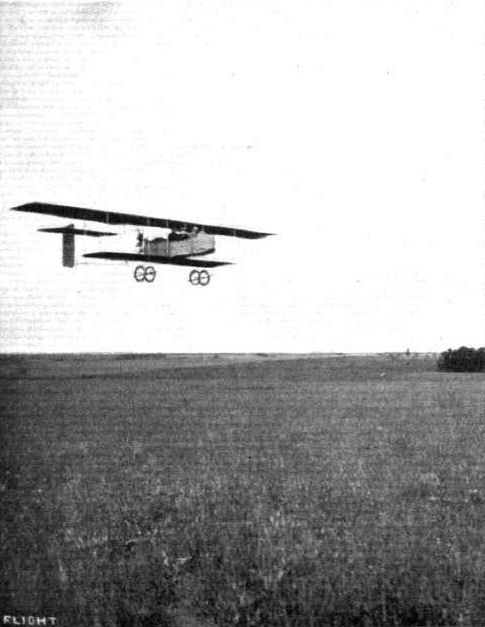
One of the Henry Farman military biplanes, just taken over by the British War Office, in flight.
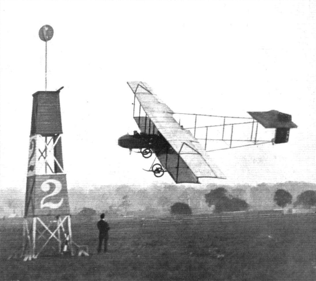
Mr. Claude Grahame-White, with Mr. Richard Gates as passenger, rounding pylon No. 2 "all out" during Saturday's Speed Contest at Hendon Aerodrome.
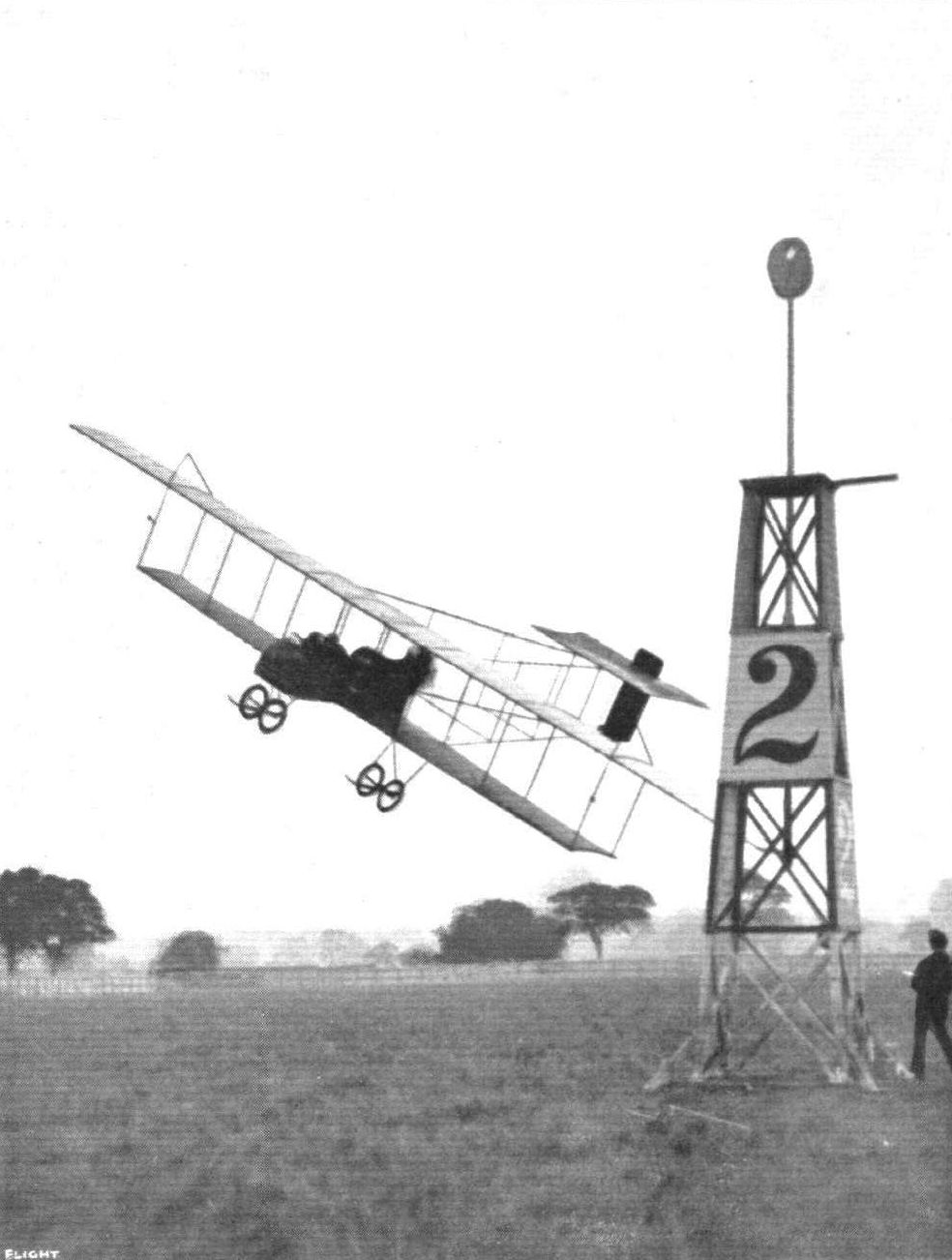
A fine bit of banking by Mr. Claude Grahame-White on the Henry Farman, with Mr. R. T. Gates as passenger, round No. 2 pylon at the Hendon Aerodrome during a speed contest.
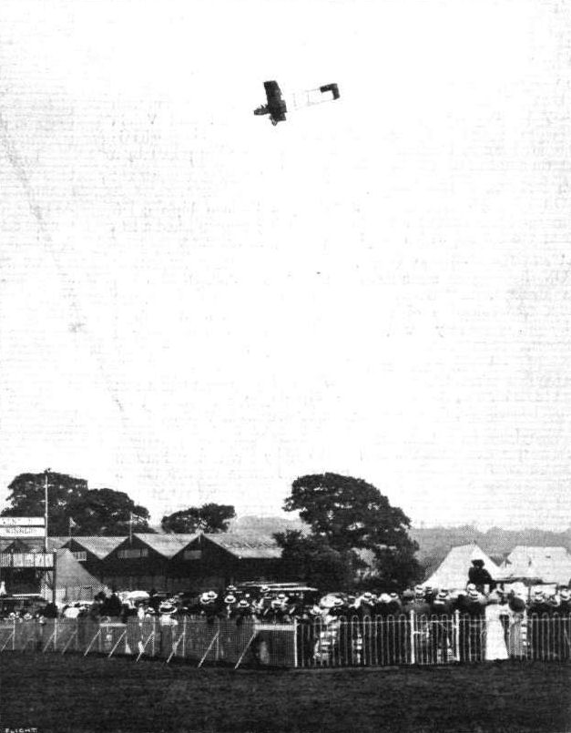
Mr. Claude Grahame-White flying his Henry Farman at Hendon, with Mr. Richard Gates as passenger. Note the distinctness of the two passengers seen in the photograph.
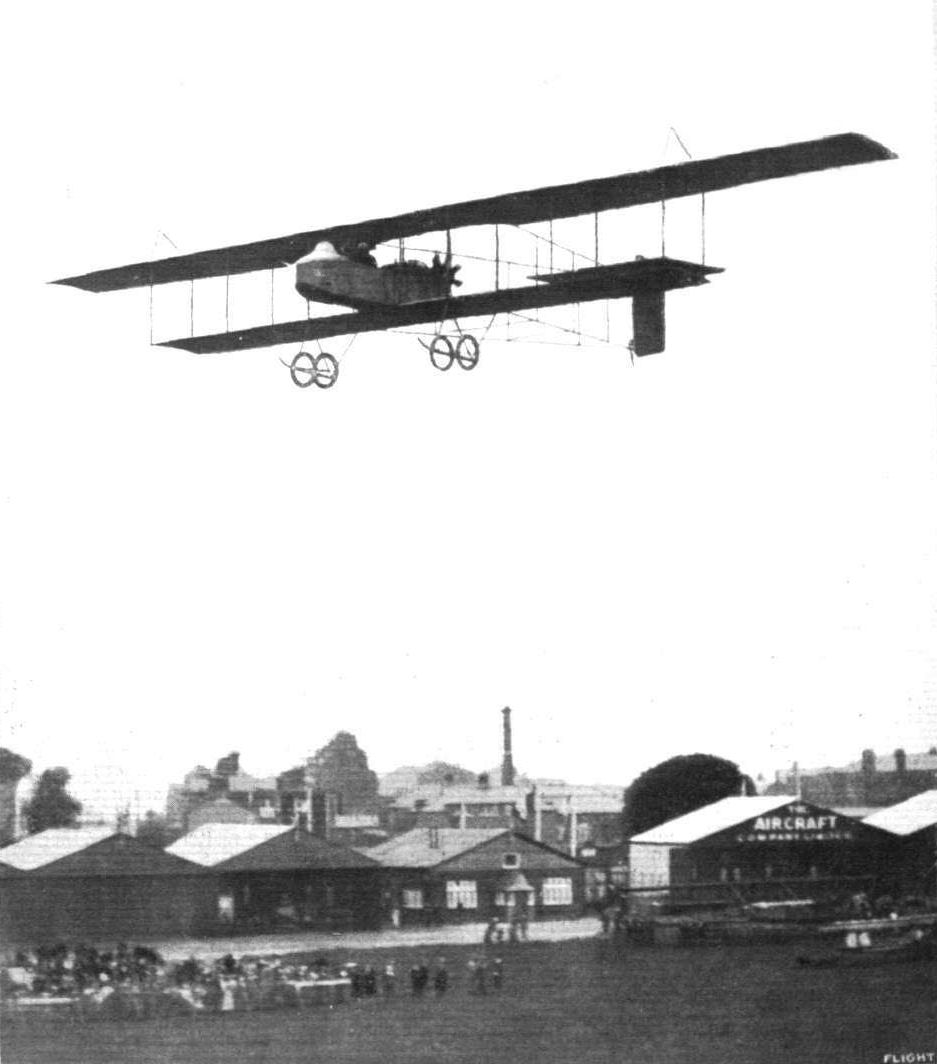
Mr. Grahame-White's "Wake Up England!" Henry Farman machine back at Hendon Aerodrome. In our photograph Mr. Noel, with Mrs. Stocks as passenger, is flying in the speed handicap last week-end.
A MISTY EVENING AT HENDON. - Mr. Claude Grahame-White flying a Henry Farman in the rising haze at Hendon Aerodrome. On the ground is seen the Grahame-White biplane.

Mr. Grahame-Whlte in the seat of his n ew Henry Farman biplane, with Mr. Gates, the popular aerodrome manager, as his passenger.
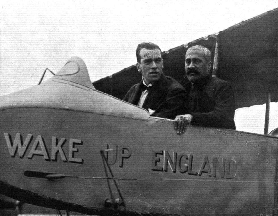
Mr. Claude Grahame-White, in his Henry Farman, about to take up as passenger, one of the King's Indian orderly officers, at the London Aerodrome, Hendon.
Flight, July 13, 1912.
The Daily Mail Hydro-Aeroplane Tour.
THE Farman hydro-aeroplane ordered by the Frank Hucks Waterplane Co. successfully carried out its tests at the hands of Fischer on Wednesday of last week. It was afterwards handed over to its owners. It made an hour's flight with a passenger, and afterwards several other shorter tests were made with passengers. No flying was possible on the two following days, but on Sunday M. Fischer flew the machine to Southsea, made a dozen flights with passengers from the beach, and in the evening returned to the Hamble river. The fortunate passengers who took trips had a splendid view of the fleet at anchor.
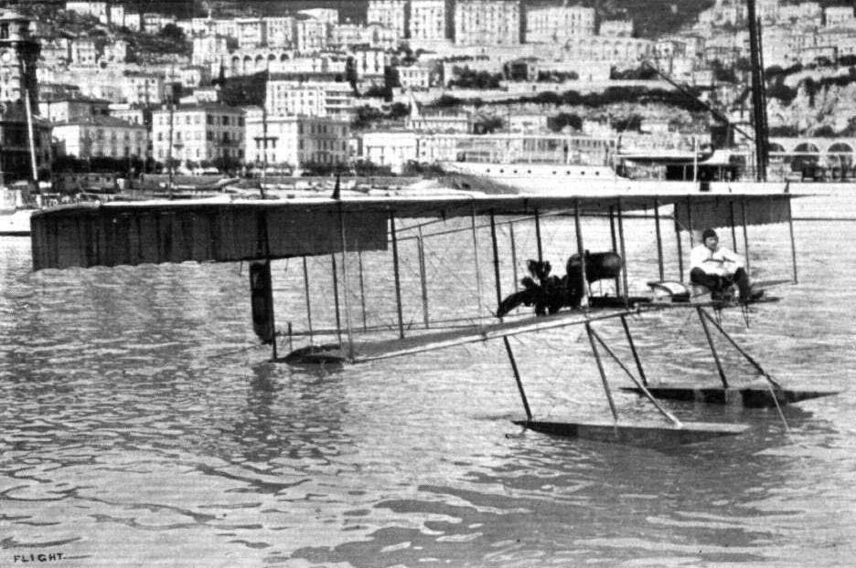
THE HYDRO-AEROPLANES AT MONACO. - The Henry Farman biplane, piloted by Fischer, at the starting line. This machine, carrying two on board, secured the leading position in the first day's competition.
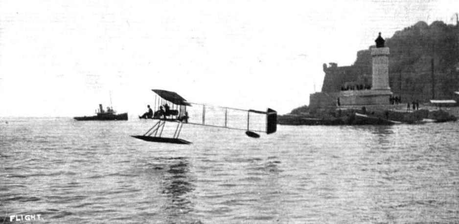
Fischer, with two passengers, on the Henry Farman hydro-aeroplane at Monaco. It is one of these very successful machines which has been acquired on behalf of the British Government.

THE WINNING HYDRO-AEROPLANE AT MONACO. - Fischer on the Farman machine with his three passengers, two of whom travel on the forward floats.
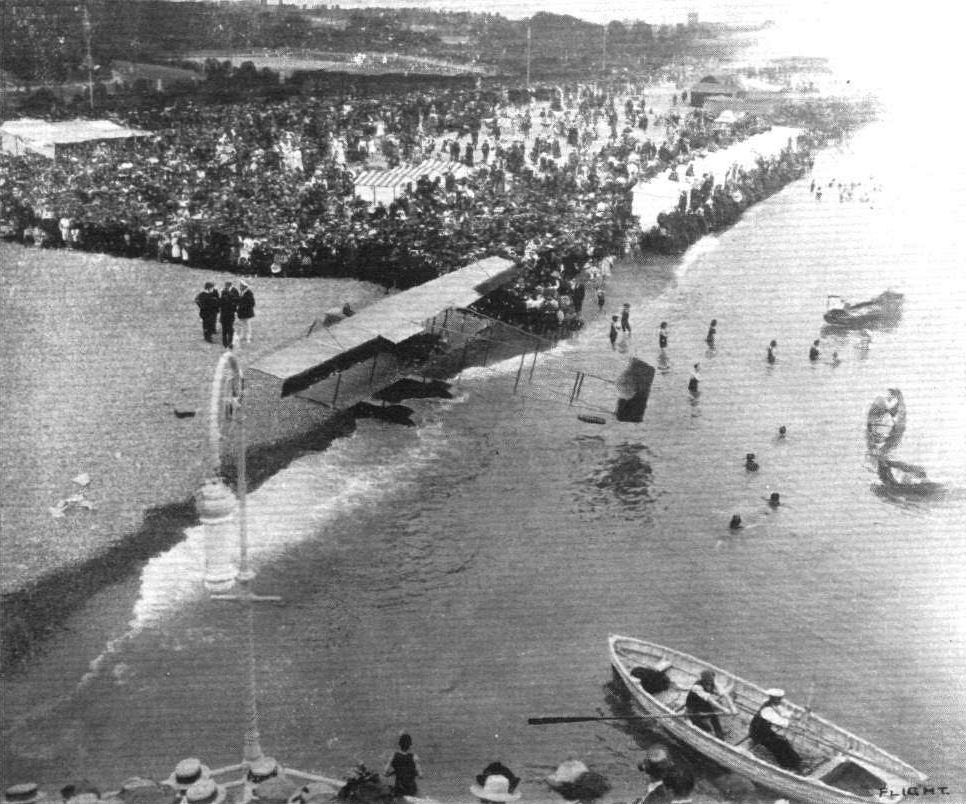
NAVAL REVIEW AT SPITHEAD. - One of the Farman hydro-aeroplanes after its arrival on the beach at East Southsea.
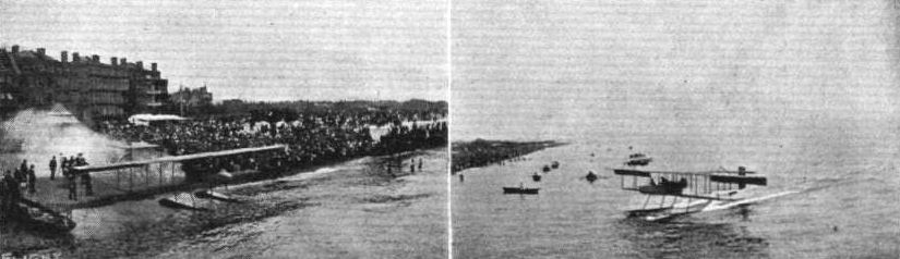
THE HENRY FARMAN HYDRO-AEROPLANE AT SOUTHSEA. - A couple of snaps taken with a vest pocket Kodak by Horace J. Everett.
Hydro-aeroplanes, illustrating the paper by Mr. Holt Thomas.
Flight, November 2, 1912.
THE PARIS AERO SALON.
Henry and Maurice Farman.
THEIR workmanship is excellent, and their designs too. The brother Maurice has on his stand a biplane similar in nearly every respect to those that are handled in England by the Aircraft Manufacturing Co., Ltd., of Hendon, and flown by Verrier. It only differs in two points, a more elaborate and highly finished nacelle is fitted, presumably because it is Show time, and the rear part of the landing skids are bent downwards to pull the machine up quickly on landing. These two points we illustrate.
Henry Farman's hydro-biplane is easily the prettiest machine of its type in the Salon. It looks good and it is good. And the workmanship throughout would stand examination through a microscope. It maintains the same lines as the biplane of his that we reviewed in these columns a week or two ago, but it is considerably smaller, and is fitted with a Gnome engine of only 50-h.p. It is indeed an efficient machine if it succeeds in lifting two persons clear of the water with an engine of such low horsepower. The floats, constructed by Tellier, are just plain narrow pontoons with no step in them, and for them it is claimed that they are considerably more effective in rough seas than those of the wider and shorter variety. Each float is connected to the body of the machine by two simple steel struts, and held rigidly in position by steel bracing. The chassis is not so high and of course considerably stronger than his earlier ones. Two little port and starboard lights are provided, for they are essential, if the machine is going to be kept out on her moorings all night. Inside the body the pilot and passenger can make themselves as comfortable as they could in their own club's smoking-room. All the upholstery is of leather, and a floor covering of thick carpet complete the snug appearance.
Sitting in front, the passenger has a magnificent view all around him. Before him in this particular machine is mounted a mitrailleuse. Behind sits the pilot controlling the machine with a lever, not such as were fitted to Farman's a year or two back, but a thoroughly neat one, with all its wire connections tucked away inside its mounting out of the way. On a little dashboard in front of him are all his instruments and a pad on which he can scribble down notes.
Contrary to Henry Farman's early practice, the ailerons, which are of large aspect ratio and fitted to the top plane only, are interconnected, so that when one is pulled down the other one rises.
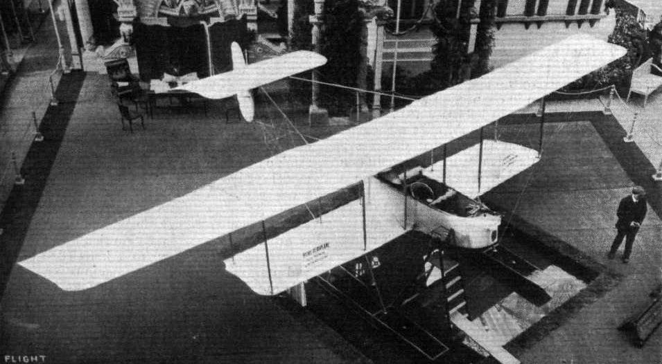
A novel way of exhibiting a hydro-aeroplane. Henry Farman's machine resting in its turf-edged water tank.
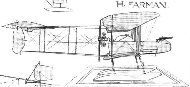
Some of the types of float used on present-day hydro-aeroplanes, as seen at the Paris Aero Salon.
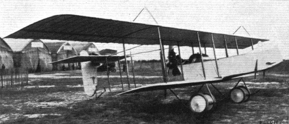
Several modifications were apparent in the Henry Farman biplanes seen at the Anjou meeting some time ago. The rear plane was quite flat and on a level with the top main plane. The lifting area amounted to 40 sq. metres.
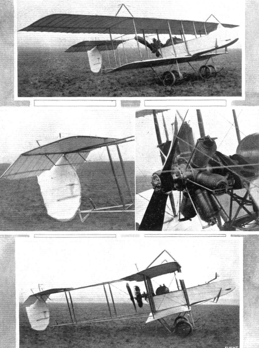
The 80-h.p. Henry Farman biplane, showing in detail the tail formation and engine mounting.
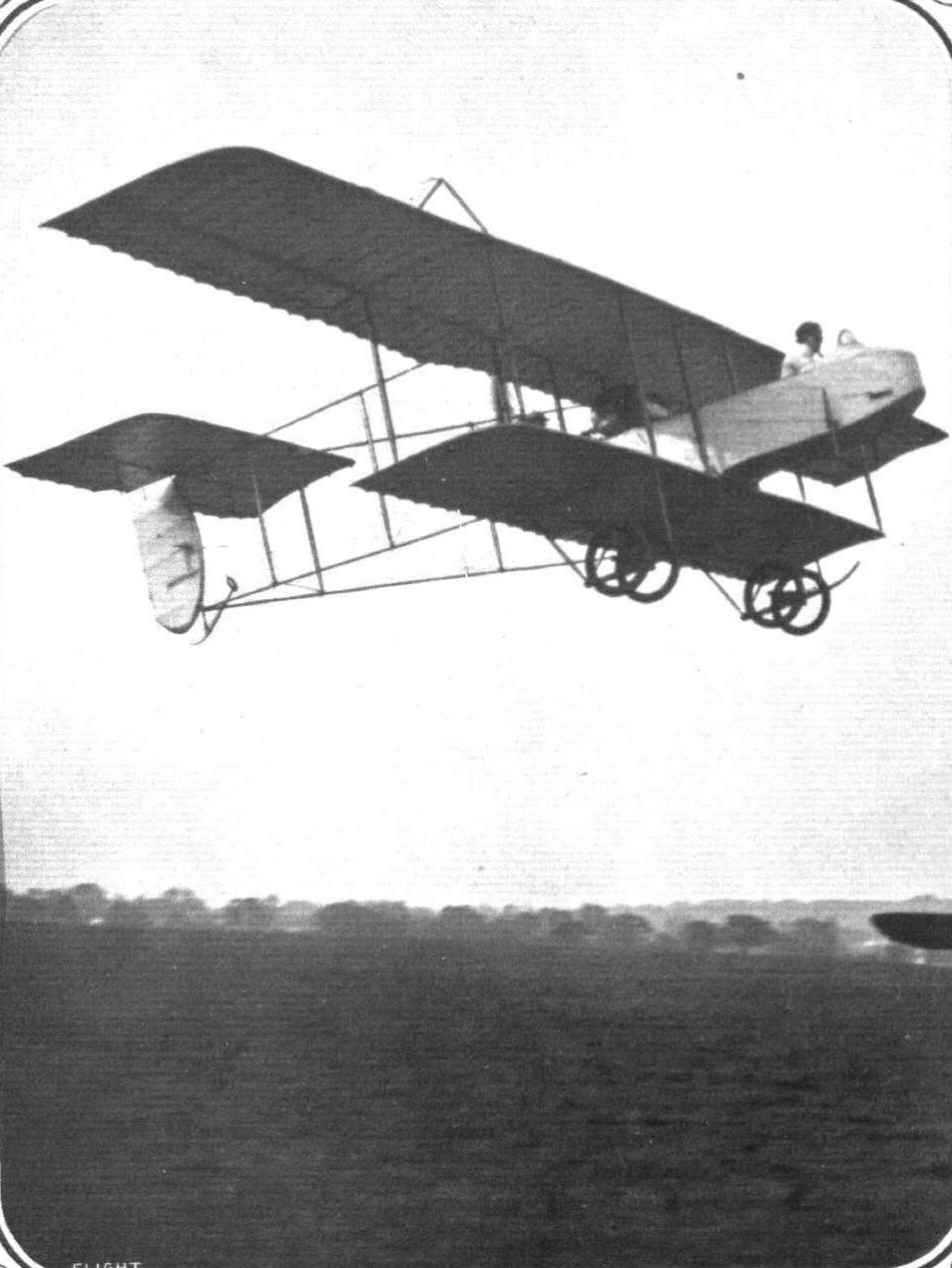
Mr. L. Noel on tbe Henry Farman at the Hendon Aerodrome.
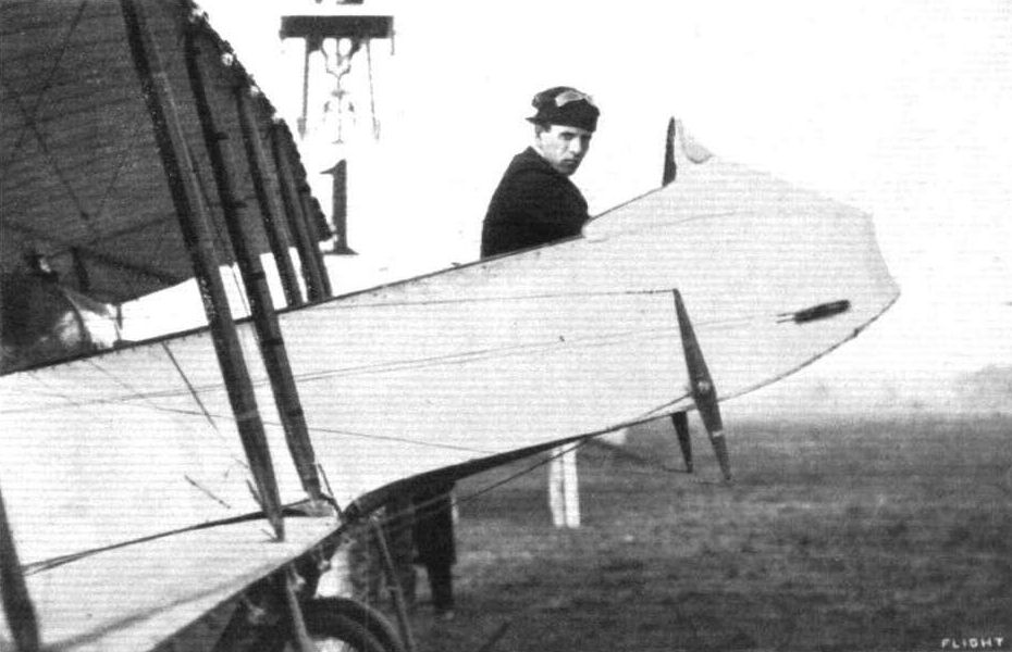
Mr Louis Noel, who has made such splendid flights at Hendon, in the pilot's seat of the Henry Farman, ready to get away in the first heat for the Speed Handicap at Hendon last week.
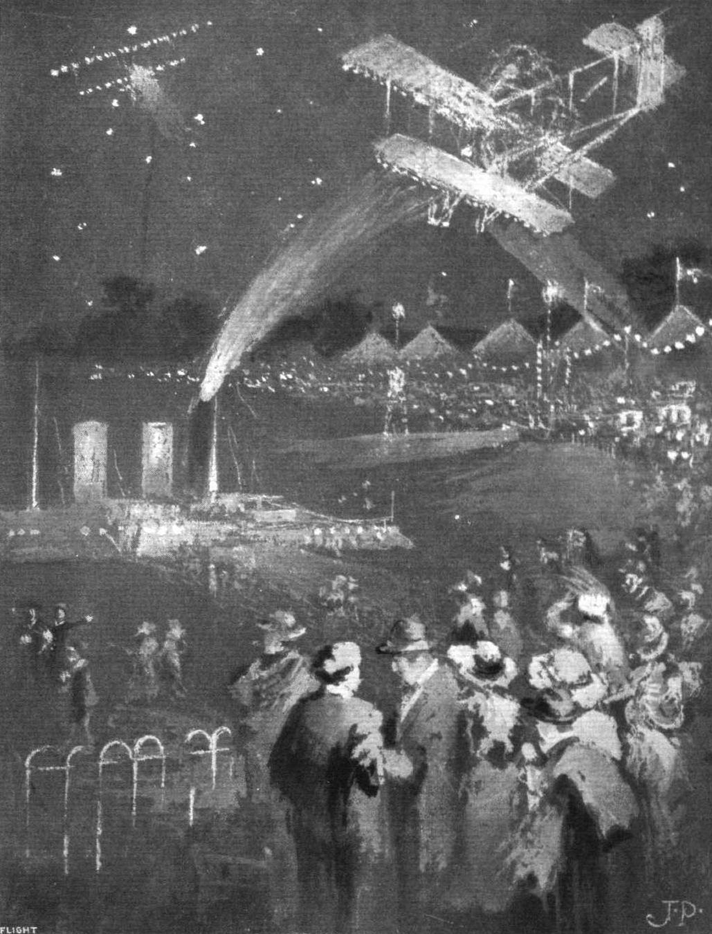
A post impression of Thursday week's Illuminated Flying Meeting at the London Aetodrome, Hendon. - Capt. Tyrer, as a passenger on a Henry Farman biplane, throws bombs on a dummy battleship. Another biplane, its leading edge starred with lights, forms a new "constellation" at the left top corner.
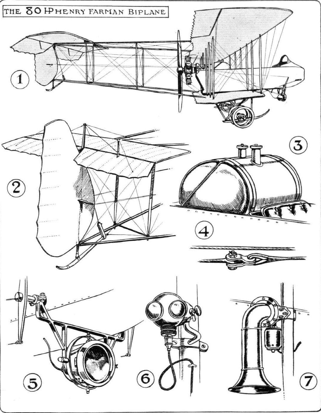
The 80-h.p. Henry Farman biplane and its electric light and Klaxon horn fittings. - Fig. 1. - Side view. Fig. 2. - Empennage, showing the new rudder shape. Fig. 3. - Petrol and castor oil tanks. Fig. 4. - Control cable joint. Fig. 5. - Electric searchlight. Fig. 6. - Electric side lights. Fig. 7. - Klaxon electric horn.

HENRY FARMAN BIPLANE. - Plan and elevation to scale.
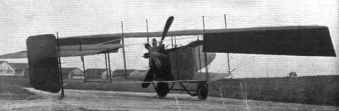
THE LATEST HENRY FARMAN BIPLANE. - This view, taken from the rear, shows very clearly the general arrangement of the new machine. Note the short lower plane, the large ailerons and the arrangement of the central portion of the machine. The outer sections of the main plane can easily be taken off so that the machine can then be towed along the road. The pilot and passenger are seated in the body which projects from the front of the machine and is easily detachable. The photograph also shows the new system of undercarriage to which reference has already been made in FLIGHT.
Flight, January 6, 1912.
PARIS AERO SHOW.
Goupy.
ALTHOUGH in its general appearance the Goupy biplane, as exhibited at the Salon, differs little from the machine with which readers of FLIGHT are familiar, through its appearance at the last Doncaster meeting, one or two important changes have been made, with the result that it now no longer bears such a close resemblance to the Bleriot. Besides adopting a monoplane tail in place of the biplane unit previously employed, the operation of the controls is no longer brought about from a single vertical column, but has, in this latest machine, been divided, the steering to right and left being operated from a pivoted foot-lever. The essentially Bleriot-type of landing-gear has also disappeared in favour of a Sommer-type wheel-and-skid combination.
Principal dimensions :-
Length 23 ft.
Span 23 ft.
Area 242 sq. ft.
Weight 550 lbs.
Speed 55 m.p.h.
Engine 50-h.p. Gnome
Price L1,120.
Flight, November 9, 1912.
THE PARIS AERO SALON.
Goupy.
HERE is shown a hydro-biplane, built to seat three, and driven by an 80-h.p. Gnome engine. In no special point does it differ from the Goupy that was shown last year excepting, of course, in the landing gear which, in the present machine, consists of two-pontoon-like floats, constructed by Tellier, supporting the body through steel compression struts.
As a side issue, M. Goupy is making a speciality of a new system of positive control termed the C. A.D. control. For it, it is claimed that, while it may be fitted with the simplicity of the Bowden system, it has the added advantage that it can transmit compression as well as tension.
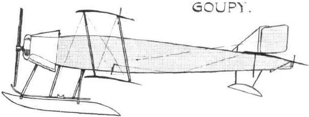
Some of the types of float used on present-day hydro-aeroplanes, as seen at the Paris Aero Salon.
Flight, January 6, 1912.
PARIS AERO SHOW.
Aviatik.
CONSIDERING that only three weeks elapsed between the commencement of the construction of this handsome monoplane and its appearance in all the glory of its resplendent nickel fittings on the opening day of the Salon, it must be observed that the ability to accomplish such a performance speaks well for the excellence of personnel and organisation at the Aviatik works.
Although built under Hanriot licence, there is little to acquaint a casual observer of the fact except that the general disposition of its respective parts is very similar, and that the design of the tail is nearly identical.
The main body is constructed like the hull of a racing skiff, and at its forward extremity is disposed the motor - an Aviatik of 100-h.p. Petrol is fed by pressure from a tank under the passenger seat to an auxiliary tank slung from the cabane, and from this point the feed is by gravity. The landing gear is closely allied to the Henry Farman design, but has the peculiarity that all four wheels are mounted on one common axle. The struts supporting the skids are hollow, with the exception of the front pair. It is a noticeable feature that both German machines at the Salon, the Albatross and the one at present under review, are equipped with hand-brakes in order that they may be brought to rest as soon after landing as possible. In cross-section the wings closely resemble those of the Nieuport. Mounted directly in front of the pilot is the control wheel, which is arranged vertically at the upper end of a pivoted vertical column. The elevation is governed by a to-and-fro movement, warping by rotating the wheel laterally.
Principal dimensions, &c. :-
Length 31 ft.
Span 41 ,,
Area 275 sq.ft.
Weight 990 lbs.
Speed 70 m.p.h.
Motor 100-h.p. Aviatik.
Price L1,000.
Flight, March 9, 1912.
AIR EDDIES.
Illustrative of the difference of meaning one small word can effect in a sentence, is the inscription that appeared last week under the photograph depicting the landing chassis of the new Hanriot-Pagny monoplane. By a slight slip on the part of the compositor the phrase "modelled on pronounced Nieuport lines" was made to refer to the chassis in question, instead of to the machine itself. As a matter of fact the landing gear is really the only section of the machine that differs a great deal from contemporary Nieuport practice.
Flight, April 27, 1912.
FOREIGN AVIATION NEWS.
A New Fast Hanriot Monoplane.
ANDRE FREY has been carrying out, at the Hanriot School at Rheims, some tests with a new Hanriot monoplane built for speed. After a cross-country trip on the 13th inst., the machine was timed to cover a kilometre in 25 seconds, giving a speed of 138 k.p.h.
Flight, May 25, 1912.
AIR EDDIES.
Sydney Sippe is now definitely engaged as chief pilot to Hanriot (England) Limited, and, as one who knew him when aviation here in England was quite a little infant, I must indeed congratulate him on his appointment. He will not be back over here just yet. He plans to stay at Rheims for another week or so to get more practice on the new machine. When that is over he reckons to bring the new monoplane with him, maybe by air.
Sippe Doing Well at Rheims.
ON the 15th inst. at Rheims, Sydney V. Sippe was trying one of the new Hanriot machines and made a trip of 50 kiloms. at a height of 400 metres. On Saturday he also made a good flight at a height of about 600 metres.
Flight, April 27, 1912.
FOREIGN AVIATION NEWS.
Marcel Hanriot a Superior Pilot.
ON the 18th inst. Marcel Hanriot completed his qualifying flights in order to obtain a French superior brevet. Leaving the Betheny ground at Rheims at 6.7 p.m. he turned at Vitry-le-Francois at 6.44 and was back at Rheims at 7.23 p.m. During the outward journey he was at a height of 1,500 metres and coming back his speed was well over 120 k.p.h. He had made a similar flight on the previous day.
Flight, June 15, 1912.
Testing a New Hanriot.
BIELOVUCIE, on the 7th inst., was testing at Rheims the new 80-h.p. three-seater Hanriot built for the Ae.C.F. Grand Prix. With a pilot weighing 70 kilogs. and a load of 170 kilogs., including oil and petrol for two hours, the machine climbed 360 metres in 4 mins. 30 secs.
Flight, July 13, 1912.
A Fast Run Home.
AFTER the opening ceremony at the Bar-le-Duc Aerodrome, Lieut. Marlin started up on his Hanriot monoplane, and flew back to Rheims, covering the 100 kiloms. in 65 mins.
Flight, August 31, 1912.
BRITISH NOTES OF THE WEEK.
Sabelli Flies to Salisbury Plain.
ON Thursday, last week, Sabelli on a 50-h.p. Hanriot, made an excellent flight from Brooklands to Salisbury Plain where the Army Trials are in operation. In spite of a strong wind averaging about 25 m.p.h., Sabelli steered a straight course for his destination.
Flight, October 19, 1912.
THE HANRIOT MONOPLANE.
IT is not surprising that the new Hanriot monoplane has a great deal in common with the Nieuport, for the reason that its designs are due to M. Pagny, who had collaborated with M. Edouard Nieuport in producing the latter's monoplane. There are refinements of design noticeable throughout in the new Hanriot, but the main differences are centred at the landing chassis - the shape of the stabilizer, and the operation of the controls. Let us therefore deal with these first. Recognising the difficulty that not a few pilots have experienced in using the Nieuport chassis, the Hanriot firm have been most wise in adopting a form of landing gear that is, we might almost say "fool proof." It consists simply of an orthodox pair of skids with an orthodox pair of wheels strapped down to them by elastic bands. But even in such a much used form of chassis there has been introduced a very useful refinement. In place of the usual plain types of radius rod, a system of tie rods is used, whereby the axle carrying the landing wheels may travel, when the wheels encounter a bump, in a straight vertical path. With the ordinary type of radius rod the axle travels along an arc of a circle, a movement which is none too kind to the rubber straps employed. One of our sketches illustrates this point.
Another advantage this chassis has is that it extends sufficiently far back to enable the rear struts to serve as a point from which the wing warping may be operated. In this manner the more or less customary form of lower cabane is done away with - and the head resistance that it would give rise to also.
One of our sketches shows one of the two bell cranks, one on either side, through which the warping is actuated. It is rather noticeable that the warp is geared up, for the arm taking the control wire is shorter than the other.
As for the wings, they are, to outside appearance, so exactly like those of the Nieuport that there is little need to describe them. They have the refinement that provision is made whereby they may be folded, for convenience sake, along the side of the fuselage.
The upper cabane has a very good point about it. The top wires from the wings pass through a fitting which may be adjusted in relation to the cabane skeleton. By this system the top wires can be dismantled very easily and their tautness can as simply be varied. The stabilizer is made so that it may fold down readily in two halves. Each half is hinged to a tube running parallel to, and on a level with each top member of the fuselage at the rear. It is kept up in place by wires when in use. The rudder, too, folds in neatly.
Naturally, when a new machine makes its appearance, everyone who has anything to do with aeroplanes makes it his business to "quizz around," criticise and communicate the result of his inspection to anyone who may be similarly interested.
Everyone on the Plain had a good look round the Hanriot, but, for once, no criticism reached our ears. But there, perhaps, we are wrong - we heard one of the official passengers in the three hours' duration test relate that his neck had got seriously out of truth through having to resist, for such an extended period, the pressure of the relative wind. The 100-h.p. Hanriot monoplane averages a speed of about 73 m.p.h.
Main characteristics :-
Length 24 ft.
Span 41 ft. 9 ins.
Weight without complement or fuel 981 lbs.
Motor 100-h.p. Gnome
Propeller, Chauviere 2.55 m.diam.
The Hanriot School at Rheims.
TESTING a new 50-h.p. Hanriot monoplane sold to Italy, Bielovucie, on Saturday, mounted 1,500 meters in 9 mins., the machine carrying a load of 160 kilogs. Ponnier on the machine, with Rossel-Peugeot motor, put up a flight of two hours-duration. Ranlet and Favre also did good work on a new machine with a 60-h.p. Anzani motor. Two days previously "Bielo" took a passenger for a round trip: Rheims-St. Quentin-Compiegne-Rheims.
Flight, October 26, 1912.
Two Hours on a Hanriot.
PONNIER made a two-hour trial on the Hanriot monoplane with Rossel-Peugeot motor, on the 18th inst., and Bielovucie took up 160 kilogs. of ballast on a 50-h.p. military machine, 1,101 metres in 11 mins. "Bielo" and Frey afterwards tested four machines before handing them over to the French Army. Four more were delivered on Sunday.
Flight, November 9, 1912.
THE PARIS AERO SALON.
Hanriot.
THESE machines are in general outline a great deal like the Nieuport. The main difference lies in the chassis, which, m the Hanriot, is a particularly neat and robust wheel and skid construction. M. Pagny, who is responsible for its design, gave us a most thorough demonstration of all its fine points. To start with, the workmanship throughout is superb, and that is not only confined to show machines. The machines they turn out in the ordinary course of things are just as finely made.
First of all, the propeller. Most of those who have had anything to do with Gnome-engined monoplanes know what a delicate job it is to remove a propeller that has become stuck on its taper. Unless a special tool is used, a good deal of jarring has to be resorted to, and many good Gnome noses have not been improved by the treatment. Pagny sees this, and obviates it by running a thread at the wider end of the taper, and putting on a screw ring before the coupling is placed in position. Thus, if it is at all tiresome to remove, just a turn or two of the screw ring will bring it off. Then, as previously mentioned, the motor may be taken out of the machine, carlingues and all, in almost no time. One of our sketches shows this detail well. Each side of the front carlingue is formed as a hinge, the core of which can be removed by knocking out the key that keeps it locked in its place.
The back-plate of the Gnome is treated in the same fashion. There is an interesting fitting, at the cabane on top. All the upper wing cables pass through this fitting, and the whole fitting, cables and all, can be taken clear by unscrewing a nut and lock nut. Thus there is no necessity to disconnect these cables when transporting the machine from place to place, for the wings may be fixed horizontally along the side of the fuselage in special fittings provided for that purpose. The tail is built up of steel tubing acetylene welded. That, too, is made to fold down alongside the fuselage by merely removing a bolt or two. Another of our sketches shows the cockpit and its assortment of cross-country instruments. It also shows the tool box conveniently arranged just behind the pilot's seat. A point of failing about the Hanriot monoplanes that figured in the British Military Trials was that observation was rather difficult. In the 100-h.p. Gnome two-seater shown the passenger's seat is much further forward, and allows of a view almost directly beneath the machine. Another Hanriot monoplane is shown on the Rossel-Peugeot stand. It is an all-metal product and wonderfully made.
As for weight, there is a considerable saving on this machine, for whereas a machine of a similar type in wood weighs, all on, 660 lbs., this model complete turns the scale at only 550 lbs. So that the wings may warp without permanently deforming the wing skeleton, each rib, which only weighs 8 1/2 ozs., is jointed loosely at its four points, the leading edge, the front and rear spars, and the trailing edge. A 50-h.p. Rossel-Peugeot motor is installed in this machine, and, Pagny says, it is giving excellent results. We sometimes wonder why more of this engine has not been heard in the past. It is an excellent job throughout, easily one of the best specimens of rotary engine construction at present on the market, and, by the way, there are quite a number now. It has been in existence something like two years, and yet no one seems to have used it. But perhaps their time is coming now. This, however, scarcely concerns the Hanriot monoplane. All praise to them!
Flight, December 7, 1912.
WHERE AEROPLANES ARE BUILT.
A Visit to the Works of Messrs. Hewlett and Blondeau.
You enter, and there, at the nearer end of the main shop, which covers a floor space of, roughly speaking, 150 ft. by 60 ft., is a magnificent specimen of a 50-h.p. single-seater Hanriot monoplane, standing fully assembled and completed, and waiting simply for the attention of the dismantler and packer to see it away on its journey to Rheims. Once there it will be tested in flight, and then handed over to a foreign government. For the French Hanriot firm have so many orders on hand that they have a difficulty in keeping pace with the demand for their machines. Three aeroplanes altogether have they instructed Messrs. Hewlett and Blondeau to build for them, this Gnome-engined single-seater, another single-seater with a 45-50 h.p. Rossel-Peugeot motor, and a 80-h.p. Gnome two-seater. And what better tribute to British workmanship, and more particularly to the workmanship of the firm we are considering at the moment, could be paid, than by the mere fact that these machines are being constructed to the order of a concern that has such a high international reputation for excellence in every branch of its work.
Down to the smallest detail, with the exception of some few of a special type of wire strainer that are obtained from France, these machines are entirely British built. But let us turn to the works itself, and to the system under which the turning of the crude materials into complete aeroplanes proceeds.
In dealing with aeroplanes the raw material falls into three classifications - wood, fabric and metal.
So we find that three sections of Messrs. Hewlett and Blondeau's works have been set apart for dealing solely with these three materials. At the near end the wing covering is done. All the wood working machinery is arranged to the left, the metal working machine tools to the right, and in the open space between, the assembling of the finished parts is carried on. Let us trace the works system, beginning with the assumption that the blue prints for the machine to be built have arrived. They are first scrutinized by the works manager who notes the materials and the quantities of it that are required to see the work safely through. Orders are written for the material that does not happen to be in stock, and the blue prints are sent on to the pattern shop where all the jigs, patterns and special tools that will be required for the work in hand are made. These are probably completed by the time the material ordered has been delivered. As delivery takes place so the material is sorted. Raw material, such as sheet steel and planks of wood, passes into the general store; finished material, such as piano wire, nuts, bolts, and wire strainers being sent to the finished-parts store. From the pattern shop, the blue prints are handed luck to the Works manager, who passes them on to the foreman who has charge of the various departments in which the work appropriate to the several drawings is carried out. They in their turn pass them on to their workmen, and the actual work of construction commences.
Material is obtained from the stores, which are presided over by one whose duty it is to keep an account of every scrap of metal, wood, or fabric that leaves his department. To facilitate his work, every part that goes to make up a complete aeroplane is allotted a number, and whatever materials are "requisitioned" from the store for the making of that part are booked down to that number. Thus the storekeeper can tell, from reference to his books, the exact cost of the material that has been used in the production of any one part.
But this does not give the total cost of the part, for labour must be taken into account. The manner adopted by Messrs. Hewlett and Blondeau is to send out with the drawings for each fitting a card which bears the same number as the fitting, and which always accompanies it, no matter whose hands it passes through in the process of manufacture. On this card all those men who have anything to do with the manufacture of that part write down the time they have spent on it. Take, for example, the case of a gross of welded steel strut sockets to be manufactured. The material has already been taken from the store and with it a time card. The first operation is to stamp out the steel base-plates and he who carries this out makes a note on the card to the effect that workman such and such a number - every workman bears a number, as well as each fitting - has spent so much time on that part. While this is being done, we will say that three lads are busy cutting off short lengths of streamline steel tubing for the sockets. They, too, make a note on the same card as to how long they have taken over their section of the job. Then comes the welder, and after him the finisher. By the time the gross of sockets is completed, the cards bears the numbers of all those who have worked on the job, and the respective times they have spent on it. Thus the total cost for labour in the production of that particular gross of sockets is established.
But even that, added to the cost of material, does not give the total cost, for a proportion of the general works and office expenses, such as rent, rates, lighting, &c, must be added.
When the part is finished, it is taken into stock in the finished part store. In this manner the whole of the parts that go to the making of the complete aeroplane, or the batch of them, are finished and stocked away in their proper place.
When all the parts are ready, assembling is commenced. In assembling, too, a similar system of material and labour recording is observed, so that by the time the machine is ready for the aerodrome its total cost, even down to the last nut, may be determined.
Such then, in its broad outlines, is the system governing aeroplane construction in the works of Mrs. Maurice Hewlett, our first British airwoman, and her partner, Mr. Blondeau, also a certified pilot. They have established a works wherein they may, unoccupied by the consideration of any machine of their own type, construct aeroplanes on a large scale at a correspondingly low cost, to the designs of their clients. And their example is one that should be a lesson in many ways, and should dispose of much misconception as to the real source of profit in aeroplane construction. This firm is certainly exceptionally well placed for doing well for themselves, as their plant is most complete, their workmen thoroughly experienced and well chosen, and their stores well stocked with everything that could possibly be required in aeroplane construction. In their finished-part store we saw an enormous stock of Gnome engine spare parts, for in these, we understand, Messrs. Hewlett and Blondeau do a considerable trade.
One of their chief features is oxy-acetylene welding work, not only for steel but for all metals. Mr. Blondeau told us that he had no fewer than ten men on probation before he decided which one to select to place in charge of that department.
"Remember you have a man's life depending on how you do your work" runs the shop's motto. The men have the seriousness of their work at heart.
Flight, December 28, 1912.
TESTING A 100-H.P. MONOPLANE.
A REMINISCENCE By SIDNEY V. SIPPE.
Il est quatre heures, Monsieur, et il n'v a pas de vent!
There was a tired night porter bending over me turned over sleepily, and gradually roused myself "Four o'clock, is it?" and then it suddenly dawned across my sleepy brain that I must be up and doing, for way out at the Aerodrome de la Champagne was a new type of monoplane that I had to go and test that morning. Although so early, the sun was already beginning to make itself felt, which was perhaps as well, for the previous night had been so stifling that my friends and I had taken our mattresses and bed trappings out on to the balcony and had turned in there. Dressing did not take long, and within a few minutes we were a merry and thoroughly awake party, settled more or less comfortably in a car that had been sent down from the aerodrome to carry us there. With the exception of ourselves and a party of revellers from a cafe opposite, who were making a noisy departure after carrying their celebrations so far into the morning, no one was astir. We sped through the deserted cobbled streets of the town as rapidly as possible, considering the nature of their surface. We were impatient to get to the aerodrome, and had no eyes to appreciate the beautiful gardens and well laid-out flower-beds that we passed. Striking the Neufchatel road, a quarter of an hour brought us to the flying ground, by which time the sun, intent on providing another stifling day, had almost cleared the atmosphere.
This was the celebrated Rheims aerodrome, stretching away perfectly flat in all directions as far as the eye could reach. Dotted here and there one could discern the several pylons that marked out the 10-kilom. course, over which the Gordon-Bennett Eliminating Trials were to be run. Away to the left, about a mile and a half distant, was a battery of 40 hangars, owned and used exclusively by one well-known monoplane firm. Here, I thought, was activity with a vengeance. In England, forty sheds are as many as we get in an average aerodrome, occupied, perhaps, by twenty or more different firms or individuals. Our interest was centred around one of our line of hangars, whose shutters were being rapidly taken down by four mechanics. They ran out two machines, the big 100-h.p. passenger-carrier that I was destined to test, and a miniature racing monoplane. There was something like father and son about the two machines, so alike were they, but so different in size. Although there was little to do to my machine, since all preparations had been made and fuel tanks filled overnight, the mechanics were bustling around in a typically vigorous fashion. It is a peculiarity of French mechanics that, even if there is little or nothing to be done, they seem bent on making a brave exhibition of excited activity. And this is infinitely more noticeable when the designer, the business manager, or the works' manager happens to be near. It was so in this case, for the man whose clever brain had evolved the machine was here, there, and everywhere, pulling at the cables, examining fastenings, drumming the fabric, and thoroughly examining everything. Personally I had no preparations to make, except to have a glance round the machine, tread into my overalls, put on a helmet, and get my goggles ready.
My feelings were rather difficult to analyse, and I stood there waiting for the machine to be pronounced ready, badgered the while by well meaning, but fearfully annoying friends, who kept up a running fire of advice as to how best to contend with the peculiarities of a powerful high-speed monoplane, and more especially what to be prepared for when turning to the right with such a high-powered rotary motor. None of them appeared to me as if they had ever flown a yard, let alone a machine of that power. My feelings were very similar to those I had experienced in my schooldays when waiting outside the schoolroom to be admitted in five minutes' time to undertake the answering of a dozen or so unknown questions. It was not nervousness - it was a vague feeling of wonder as to what would happen.
The machine now stood ready, and I clambered up, and got comfortably installed in the spacious cockpit. The arrangement of the controls was exactly the same as on the lower horse-powered monoplanes of the same type that I had previously flown. There only remained to waggle the lever and the rudder-bar to see that the warping, rudders, and the elevator were working properly. In front one of the mechanics was priming up the engine with petrol. Two of his fellows were lying full length under the fuselage, gripping the wheels, two more were hanging on to the wing tips, and the rest of them were clinging to the tail. "Contact," said he in front, and I switched on. He gave the propeller a lusty swing. The motor spluttered and got into its stride. Fourteen cylinders spitting fire, oil and smoke and emitting a deep rhythmic roar, for all the world like a low Bourdon organ note. It is infinitely more plowing to the ear than the staccato of the 50-h.p. Gnome. Tin oil is coming through and pulsating in the gauges; I try the petrol-tap and the switch and find them working properly, so I wave to the mechanics to release their hold. Frankly, I must admit to being rather paralysed at the speed with which the big monoplane bounded away over the ground. Very gingerly I pulled the lever back, and sat there holding on tight and waiting for something dreadful to happen. A few seconds passed - to me they seemed an eternity. Nothing terrible had happened so far - perhaps nothing terrible would happen. My muscles subconsciously relaxed, and I settled down to think things out quietly. Here I was, sitting in a big machine, rushing through space at nearly 80 miles an hour in a relative wind which threatened, so it seemed, to blow my head clean off my shoulders. There was nothing to do, and gradually it dawned upon me that this was quite the simplest machine I had ever flown. The sense of security was remarkable, indeed. I was perfectly convinced by this time that nothing dreadful could possibly happen. I might have been sitting in a Dreadnought, so steadily and solidly did the machine force its way through the air. I began to look around. The ground was about a thousand feet below, and the machine was still rising, although the inclinometer showed that the machine must have been doing so on a perfectly even keel. Another curious point was that the engine seemed somehow not to be pulling. The revolution indicator, however, showed that it was doing, if anything, a trifle over its normal 1,200 revolutions a minute. It was the evenness and smoothness of the turning of these fourteen cylinders that gave rise to this delusion. Surely about time I turned; so putting the nose of the machine down a few degrees, I pushed the rudder-bar over to the left. The big monoplane banked slightly, and the ground below, sheds, bushes, hedges, and everything, revolved through 180". I was now heading for the sheds, feeling perfectly comfortable, and enjoying myself immensely. Now that they were directly below me, and, forgetting all that my friends had told me about the terrors of a right hand turn with a big engine, I pushed my right foot forward, and swung round. Not until I was right round did I realise that I had accomplished a supposedly difficult manoeuvre. I straightened the machine out to get a clear run down to the ground in front of the sheds, and putting the elevator slightly forward, cut off the petrol. Immediately there was silence, except for the gentle hum from the propeller and wing cables as I planed down. The machine touched ground, ran along, rapidly losing speed, bumped twice, and stood still. Almost before I had time to look round the machine was surrounded by a crowd of mechanics, all firing off questions in rapidly spoken French. I had little or no idea what they were talking about, but my stock phrase, "Ca marche bien," seemed to please them well enough. In fact, we were all very pleased; the designer because another of his machines had proved eminently successful, the mechanics because they had followed the machine right through the works from crude steel and wood, and myself because I had done what little I had done.
* * * *
Just outside the aerodrome there is a little inn named, appropriately enough, "Le Progres de l'Aviation." Anyone passing might have remarked a noisy group of oily-looking individuals sitting around one of the tables outside. Nothing short of "fizz" that morning!
AIR EDDIES.
Illustrative of the difference of meaning one small word can effect in a sentence, is the inscription that appeared last week under the photograph depicting the landing chassis of the new Hanriot-Pagny monoplane. By a slight slip on the part of the compositor the phrase "modelled on pronounced Nieuport lines" was made to refer to the chassis in question, instead of to the machine itself. As a matter of fact the landing gear is really the only section of the machine that differs a great deal from contemporary Nieuport practice.
Flight, April 27, 1912.
FOREIGN AVIATION NEWS.
A New Fast Hanriot Monoplane.
ANDRE FREY has been carrying out, at the Hanriot School at Rheims, some tests with a new Hanriot monoplane built for speed. After a cross-country trip on the 13th inst., the machine was timed to cover a kilometre in 25 seconds, giving a speed of 138 k.p.h.
Flight, May 25, 1912.
AIR EDDIES.
Sydney Sippe is now definitely engaged as chief pilot to Hanriot (England) Limited, and, as one who knew him when aviation here in England was quite a little infant, I must indeed congratulate him on his appointment. He will not be back over here just yet. He plans to stay at Rheims for another week or so to get more practice on the new machine. When that is over he reckons to bring the new monoplane with him, maybe by air.
Sippe Doing Well at Rheims.
ON the 15th inst. at Rheims, Sydney V. Sippe was trying one of the new Hanriot machines and made a trip of 50 kiloms. at a height of 400 metres. On Saturday he also made a good flight at a height of about 600 metres.
Flight, April 27, 1912.
FOREIGN AVIATION NEWS.
Marcel Hanriot a Superior Pilot.
ON the 18th inst. Marcel Hanriot completed his qualifying flights in order to obtain a French superior brevet. Leaving the Betheny ground at Rheims at 6.7 p.m. he turned at Vitry-le-Francois at 6.44 and was back at Rheims at 7.23 p.m. During the outward journey he was at a height of 1,500 metres and coming back his speed was well over 120 k.p.h. He had made a similar flight on the previous day.
Flight, June 15, 1912.
Testing a New Hanriot.
BIELOVUCIE, on the 7th inst., was testing at Rheims the new 80-h.p. three-seater Hanriot built for the Ae.C.F. Grand Prix. With a pilot weighing 70 kilogs. and a load of 170 kilogs., including oil and petrol for two hours, the machine climbed 360 metres in 4 mins. 30 secs.
Flight, July 13, 1912.
A Fast Run Home.
AFTER the opening ceremony at the Bar-le-Duc Aerodrome, Lieut. Marlin started up on his Hanriot monoplane, and flew back to Rheims, covering the 100 kiloms. in 65 mins.
Flight, August 31, 1912.
BRITISH NOTES OF THE WEEK.
Sabelli Flies to Salisbury Plain.
ON Thursday, last week, Sabelli on a 50-h.p. Hanriot, made an excellent flight from Brooklands to Salisbury Plain where the Army Trials are in operation. In spite of a strong wind averaging about 25 m.p.h., Sabelli steered a straight course for his destination.
Flight, October 19, 1912.
THE HANRIOT MONOPLANE.
IT is not surprising that the new Hanriot monoplane has a great deal in common with the Nieuport, for the reason that its designs are due to M. Pagny, who had collaborated with M. Edouard Nieuport in producing the latter's monoplane. There are refinements of design noticeable throughout in the new Hanriot, but the main differences are centred at the landing chassis - the shape of the stabilizer, and the operation of the controls. Let us therefore deal with these first. Recognising the difficulty that not a few pilots have experienced in using the Nieuport chassis, the Hanriot firm have been most wise in adopting a form of landing gear that is, we might almost say "fool proof." It consists simply of an orthodox pair of skids with an orthodox pair of wheels strapped down to them by elastic bands. But even in such a much used form of chassis there has been introduced a very useful refinement. In place of the usual plain types of radius rod, a system of tie rods is used, whereby the axle carrying the landing wheels may travel, when the wheels encounter a bump, in a straight vertical path. With the ordinary type of radius rod the axle travels along an arc of a circle, a movement which is none too kind to the rubber straps employed. One of our sketches illustrates this point.
Another advantage this chassis has is that it extends sufficiently far back to enable the rear struts to serve as a point from which the wing warping may be operated. In this manner the more or less customary form of lower cabane is done away with - and the head resistance that it would give rise to also.
One of our sketches shows one of the two bell cranks, one on either side, through which the warping is actuated. It is rather noticeable that the warp is geared up, for the arm taking the control wire is shorter than the other.
As for the wings, they are, to outside appearance, so exactly like those of the Nieuport that there is little need to describe them. They have the refinement that provision is made whereby they may be folded, for convenience sake, along the side of the fuselage.
The upper cabane has a very good point about it. The top wires from the wings pass through a fitting which may be adjusted in relation to the cabane skeleton. By this system the top wires can be dismantled very easily and their tautness can as simply be varied. The stabilizer is made so that it may fold down readily in two halves. Each half is hinged to a tube running parallel to, and on a level with each top member of the fuselage at the rear. It is kept up in place by wires when in use. The rudder, too, folds in neatly.
Naturally, when a new machine makes its appearance, everyone who has anything to do with aeroplanes makes it his business to "quizz around," criticise and communicate the result of his inspection to anyone who may be similarly interested.
Everyone on the Plain had a good look round the Hanriot, but, for once, no criticism reached our ears. But there, perhaps, we are wrong - we heard one of the official passengers in the three hours' duration test relate that his neck had got seriously out of truth through having to resist, for such an extended period, the pressure of the relative wind. The 100-h.p. Hanriot monoplane averages a speed of about 73 m.p.h.
Main characteristics :-
Length 24 ft.
Span 41 ft. 9 ins.
Weight without complement or fuel 981 lbs.
Motor 100-h.p. Gnome
Propeller, Chauviere 2.55 m.diam.
The Hanriot School at Rheims.
TESTING a new 50-h.p. Hanriot monoplane sold to Italy, Bielovucie, on Saturday, mounted 1,500 meters in 9 mins., the machine carrying a load of 160 kilogs. Ponnier on the machine, with Rossel-Peugeot motor, put up a flight of two hours-duration. Ranlet and Favre also did good work on a new machine with a 60-h.p. Anzani motor. Two days previously "Bielo" took a passenger for a round trip: Rheims-St. Quentin-Compiegne-Rheims.
Flight, October 26, 1912.
Two Hours on a Hanriot.
PONNIER made a two-hour trial on the Hanriot monoplane with Rossel-Peugeot motor, on the 18th inst., and Bielovucie took up 160 kilogs. of ballast on a 50-h.p. military machine, 1,101 metres in 11 mins. "Bielo" and Frey afterwards tested four machines before handing them over to the French Army. Four more were delivered on Sunday.
Flight, November 9, 1912.
THE PARIS AERO SALON.
Hanriot.
THESE machines are in general outline a great deal like the Nieuport. The main difference lies in the chassis, which, m the Hanriot, is a particularly neat and robust wheel and skid construction. M. Pagny, who is responsible for its design, gave us a most thorough demonstration of all its fine points. To start with, the workmanship throughout is superb, and that is not only confined to show machines. The machines they turn out in the ordinary course of things are just as finely made.
First of all, the propeller. Most of those who have had anything to do with Gnome-engined monoplanes know what a delicate job it is to remove a propeller that has become stuck on its taper. Unless a special tool is used, a good deal of jarring has to be resorted to, and many good Gnome noses have not been improved by the treatment. Pagny sees this, and obviates it by running a thread at the wider end of the taper, and putting on a screw ring before the coupling is placed in position. Thus, if it is at all tiresome to remove, just a turn or two of the screw ring will bring it off. Then, as previously mentioned, the motor may be taken out of the machine, carlingues and all, in almost no time. One of our sketches shows this detail well. Each side of the front carlingue is formed as a hinge, the core of which can be removed by knocking out the key that keeps it locked in its place.
The back-plate of the Gnome is treated in the same fashion. There is an interesting fitting, at the cabane on top. All the upper wing cables pass through this fitting, and the whole fitting, cables and all, can be taken clear by unscrewing a nut and lock nut. Thus there is no necessity to disconnect these cables when transporting the machine from place to place, for the wings may be fixed horizontally along the side of the fuselage in special fittings provided for that purpose. The tail is built up of steel tubing acetylene welded. That, too, is made to fold down alongside the fuselage by merely removing a bolt or two. Another of our sketches shows the cockpit and its assortment of cross-country instruments. It also shows the tool box conveniently arranged just behind the pilot's seat. A point of failing about the Hanriot monoplanes that figured in the British Military Trials was that observation was rather difficult. In the 100-h.p. Gnome two-seater shown the passenger's seat is much further forward, and allows of a view almost directly beneath the machine. Another Hanriot monoplane is shown on the Rossel-Peugeot stand. It is an all-metal product and wonderfully made.
As for weight, there is a considerable saving on this machine, for whereas a machine of a similar type in wood weighs, all on, 660 lbs., this model complete turns the scale at only 550 lbs. So that the wings may warp without permanently deforming the wing skeleton, each rib, which only weighs 8 1/2 ozs., is jointed loosely at its four points, the leading edge, the front and rear spars, and the trailing edge. A 50-h.p. Rossel-Peugeot motor is installed in this machine, and, Pagny says, it is giving excellent results. We sometimes wonder why more of this engine has not been heard in the past. It is an excellent job throughout, easily one of the best specimens of rotary engine construction at present on the market, and, by the way, there are quite a number now. It has been in existence something like two years, and yet no one seems to have used it. But perhaps their time is coming now. This, however, scarcely concerns the Hanriot monoplane. All praise to them!
Flight, December 7, 1912.
WHERE AEROPLANES ARE BUILT.
A Visit to the Works of Messrs. Hewlett and Blondeau.
You enter, and there, at the nearer end of the main shop, which covers a floor space of, roughly speaking, 150 ft. by 60 ft., is a magnificent specimen of a 50-h.p. single-seater Hanriot monoplane, standing fully assembled and completed, and waiting simply for the attention of the dismantler and packer to see it away on its journey to Rheims. Once there it will be tested in flight, and then handed over to a foreign government. For the French Hanriot firm have so many orders on hand that they have a difficulty in keeping pace with the demand for their machines. Three aeroplanes altogether have they instructed Messrs. Hewlett and Blondeau to build for them, this Gnome-engined single-seater, another single-seater with a 45-50 h.p. Rossel-Peugeot motor, and a 80-h.p. Gnome two-seater. And what better tribute to British workmanship, and more particularly to the workmanship of the firm we are considering at the moment, could be paid, than by the mere fact that these machines are being constructed to the order of a concern that has such a high international reputation for excellence in every branch of its work.
Down to the smallest detail, with the exception of some few of a special type of wire strainer that are obtained from France, these machines are entirely British built. But let us turn to the works itself, and to the system under which the turning of the crude materials into complete aeroplanes proceeds.
In dealing with aeroplanes the raw material falls into three classifications - wood, fabric and metal.
So we find that three sections of Messrs. Hewlett and Blondeau's works have been set apart for dealing solely with these three materials. At the near end the wing covering is done. All the wood working machinery is arranged to the left, the metal working machine tools to the right, and in the open space between, the assembling of the finished parts is carried on. Let us trace the works system, beginning with the assumption that the blue prints for the machine to be built have arrived. They are first scrutinized by the works manager who notes the materials and the quantities of it that are required to see the work safely through. Orders are written for the material that does not happen to be in stock, and the blue prints are sent on to the pattern shop where all the jigs, patterns and special tools that will be required for the work in hand are made. These are probably completed by the time the material ordered has been delivered. As delivery takes place so the material is sorted. Raw material, such as sheet steel and planks of wood, passes into the general store; finished material, such as piano wire, nuts, bolts, and wire strainers being sent to the finished-parts store. From the pattern shop, the blue prints are handed luck to the Works manager, who passes them on to the foreman who has charge of the various departments in which the work appropriate to the several drawings is carried out. They in their turn pass them on to their workmen, and the actual work of construction commences.
Material is obtained from the stores, which are presided over by one whose duty it is to keep an account of every scrap of metal, wood, or fabric that leaves his department. To facilitate his work, every part that goes to make up a complete aeroplane is allotted a number, and whatever materials are "requisitioned" from the store for the making of that part are booked down to that number. Thus the storekeeper can tell, from reference to his books, the exact cost of the material that has been used in the production of any one part.
But this does not give the total cost of the part, for labour must be taken into account. The manner adopted by Messrs. Hewlett and Blondeau is to send out with the drawings for each fitting a card which bears the same number as the fitting, and which always accompanies it, no matter whose hands it passes through in the process of manufacture. On this card all those men who have anything to do with the manufacture of that part write down the time they have spent on it. Take, for example, the case of a gross of welded steel strut sockets to be manufactured. The material has already been taken from the store and with it a time card. The first operation is to stamp out the steel base-plates and he who carries this out makes a note on the card to the effect that workman such and such a number - every workman bears a number, as well as each fitting - has spent so much time on that part. While this is being done, we will say that three lads are busy cutting off short lengths of streamline steel tubing for the sockets. They, too, make a note on the same card as to how long they have taken over their section of the job. Then comes the welder, and after him the finisher. By the time the gross of sockets is completed, the cards bears the numbers of all those who have worked on the job, and the respective times they have spent on it. Thus the total cost for labour in the production of that particular gross of sockets is established.
But even that, added to the cost of material, does not give the total cost, for a proportion of the general works and office expenses, such as rent, rates, lighting, &c, must be added.
When the part is finished, it is taken into stock in the finished part store. In this manner the whole of the parts that go to the making of the complete aeroplane, or the batch of them, are finished and stocked away in their proper place.
When all the parts are ready, assembling is commenced. In assembling, too, a similar system of material and labour recording is observed, so that by the time the machine is ready for the aerodrome its total cost, even down to the last nut, may be determined.
Such then, in its broad outlines, is the system governing aeroplane construction in the works of Mrs. Maurice Hewlett, our first British airwoman, and her partner, Mr. Blondeau, also a certified pilot. They have established a works wherein they may, unoccupied by the consideration of any machine of their own type, construct aeroplanes on a large scale at a correspondingly low cost, to the designs of their clients. And their example is one that should be a lesson in many ways, and should dispose of much misconception as to the real source of profit in aeroplane construction. This firm is certainly exceptionally well placed for doing well for themselves, as their plant is most complete, their workmen thoroughly experienced and well chosen, and their stores well stocked with everything that could possibly be required in aeroplane construction. In their finished-part store we saw an enormous stock of Gnome engine spare parts, for in these, we understand, Messrs. Hewlett and Blondeau do a considerable trade.
One of their chief features is oxy-acetylene welding work, not only for steel but for all metals. Mr. Blondeau told us that he had no fewer than ten men on probation before he decided which one to select to place in charge of that department.
"Remember you have a man's life depending on how you do your work" runs the shop's motto. The men have the seriousness of their work at heart.
Flight, December 28, 1912.
TESTING A 100-H.P. MONOPLANE.
A REMINISCENCE By SIDNEY V. SIPPE.
Il est quatre heures, Monsieur, et il n'v a pas de vent!
There was a tired night porter bending over me turned over sleepily, and gradually roused myself "Four o'clock, is it?" and then it suddenly dawned across my sleepy brain that I must be up and doing, for way out at the Aerodrome de la Champagne was a new type of monoplane that I had to go and test that morning. Although so early, the sun was already beginning to make itself felt, which was perhaps as well, for the previous night had been so stifling that my friends and I had taken our mattresses and bed trappings out on to the balcony and had turned in there. Dressing did not take long, and within a few minutes we were a merry and thoroughly awake party, settled more or less comfortably in a car that had been sent down from the aerodrome to carry us there. With the exception of ourselves and a party of revellers from a cafe opposite, who were making a noisy departure after carrying their celebrations so far into the morning, no one was astir. We sped through the deserted cobbled streets of the town as rapidly as possible, considering the nature of their surface. We were impatient to get to the aerodrome, and had no eyes to appreciate the beautiful gardens and well laid-out flower-beds that we passed. Striking the Neufchatel road, a quarter of an hour brought us to the flying ground, by which time the sun, intent on providing another stifling day, had almost cleared the atmosphere.
This was the celebrated Rheims aerodrome, stretching away perfectly flat in all directions as far as the eye could reach. Dotted here and there one could discern the several pylons that marked out the 10-kilom. course, over which the Gordon-Bennett Eliminating Trials were to be run. Away to the left, about a mile and a half distant, was a battery of 40 hangars, owned and used exclusively by one well-known monoplane firm. Here, I thought, was activity with a vengeance. In England, forty sheds are as many as we get in an average aerodrome, occupied, perhaps, by twenty or more different firms or individuals. Our interest was centred around one of our line of hangars, whose shutters were being rapidly taken down by four mechanics. They ran out two machines, the big 100-h.p. passenger-carrier that I was destined to test, and a miniature racing monoplane. There was something like father and son about the two machines, so alike were they, but so different in size. Although there was little to do to my machine, since all preparations had been made and fuel tanks filled overnight, the mechanics were bustling around in a typically vigorous fashion. It is a peculiarity of French mechanics that, even if there is little or nothing to be done, they seem bent on making a brave exhibition of excited activity. And this is infinitely more noticeable when the designer, the business manager, or the works' manager happens to be near. It was so in this case, for the man whose clever brain had evolved the machine was here, there, and everywhere, pulling at the cables, examining fastenings, drumming the fabric, and thoroughly examining everything. Personally I had no preparations to make, except to have a glance round the machine, tread into my overalls, put on a helmet, and get my goggles ready.
My feelings were rather difficult to analyse, and I stood there waiting for the machine to be pronounced ready, badgered the while by well meaning, but fearfully annoying friends, who kept up a running fire of advice as to how best to contend with the peculiarities of a powerful high-speed monoplane, and more especially what to be prepared for when turning to the right with such a high-powered rotary motor. None of them appeared to me as if they had ever flown a yard, let alone a machine of that power. My feelings were very similar to those I had experienced in my schooldays when waiting outside the schoolroom to be admitted in five minutes' time to undertake the answering of a dozen or so unknown questions. It was not nervousness - it was a vague feeling of wonder as to what would happen.
The machine now stood ready, and I clambered up, and got comfortably installed in the spacious cockpit. The arrangement of the controls was exactly the same as on the lower horse-powered monoplanes of the same type that I had previously flown. There only remained to waggle the lever and the rudder-bar to see that the warping, rudders, and the elevator were working properly. In front one of the mechanics was priming up the engine with petrol. Two of his fellows were lying full length under the fuselage, gripping the wheels, two more were hanging on to the wing tips, and the rest of them were clinging to the tail. "Contact," said he in front, and I switched on. He gave the propeller a lusty swing. The motor spluttered and got into its stride. Fourteen cylinders spitting fire, oil and smoke and emitting a deep rhythmic roar, for all the world like a low Bourdon organ note. It is infinitely more plowing to the ear than the staccato of the 50-h.p. Gnome. Tin oil is coming through and pulsating in the gauges; I try the petrol-tap and the switch and find them working properly, so I wave to the mechanics to release their hold. Frankly, I must admit to being rather paralysed at the speed with which the big monoplane bounded away over the ground. Very gingerly I pulled the lever back, and sat there holding on tight and waiting for something dreadful to happen. A few seconds passed - to me they seemed an eternity. Nothing terrible had happened so far - perhaps nothing terrible would happen. My muscles subconsciously relaxed, and I settled down to think things out quietly. Here I was, sitting in a big machine, rushing through space at nearly 80 miles an hour in a relative wind which threatened, so it seemed, to blow my head clean off my shoulders. There was nothing to do, and gradually it dawned upon me that this was quite the simplest machine I had ever flown. The sense of security was remarkable, indeed. I was perfectly convinced by this time that nothing dreadful could possibly happen. I might have been sitting in a Dreadnought, so steadily and solidly did the machine force its way through the air. I began to look around. The ground was about a thousand feet below, and the machine was still rising, although the inclinometer showed that the machine must have been doing so on a perfectly even keel. Another curious point was that the engine seemed somehow not to be pulling. The revolution indicator, however, showed that it was doing, if anything, a trifle over its normal 1,200 revolutions a minute. It was the evenness and smoothness of the turning of these fourteen cylinders that gave rise to this delusion. Surely about time I turned; so putting the nose of the machine down a few degrees, I pushed the rudder-bar over to the left. The big monoplane banked slightly, and the ground below, sheds, bushes, hedges, and everything, revolved through 180". I was now heading for the sheds, feeling perfectly comfortable, and enjoying myself immensely. Now that they were directly below me, and, forgetting all that my friends had told me about the terrors of a right hand turn with a big engine, I pushed my right foot forward, and swung round. Not until I was right round did I realise that I had accomplished a supposedly difficult manoeuvre. I straightened the machine out to get a clear run down to the ground in front of the sheds, and putting the elevator slightly forward, cut off the petrol. Immediately there was silence, except for the gentle hum from the propeller and wing cables as I planed down. The machine touched ground, ran along, rapidly losing speed, bumped twice, and stood still. Almost before I had time to look round the machine was surrounded by a crowd of mechanics, all firing off questions in rapidly spoken French. I had little or no idea what they were talking about, but my stock phrase, "Ca marche bien," seemed to please them well enough. In fact, we were all very pleased; the designer because another of his machines had proved eminently successful, the mechanics because they had followed the machine right through the works from crude steel and wood, and myself because I had done what little I had done.
* * * *
Just outside the aerodrome there is a little inn named, appropriately enough, "Le Progres de l'Aviation." Anyone passing might have remarked a noisy group of oily-looking individuals sitting around one of the tables outside. Nothing short of "fizz" that morning!
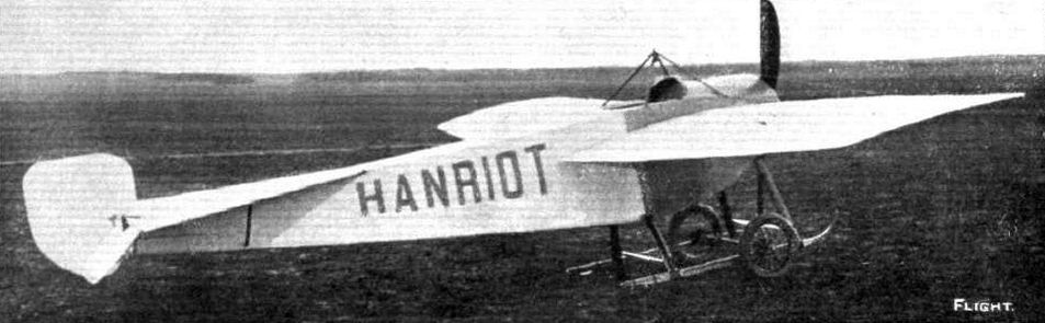
The latest Hanriot monoplane which is now being constructed in England under the guidance of Mr. Maurice Ducrocq. Side view, showing the rakish lines of this fast machine.
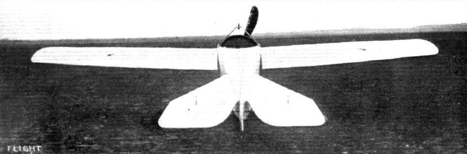
View, from behind, of the latest Hanriot speed monoplane.
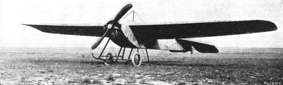
The Hanriot two-seater monoplane which has been entered for the British Military Competition,
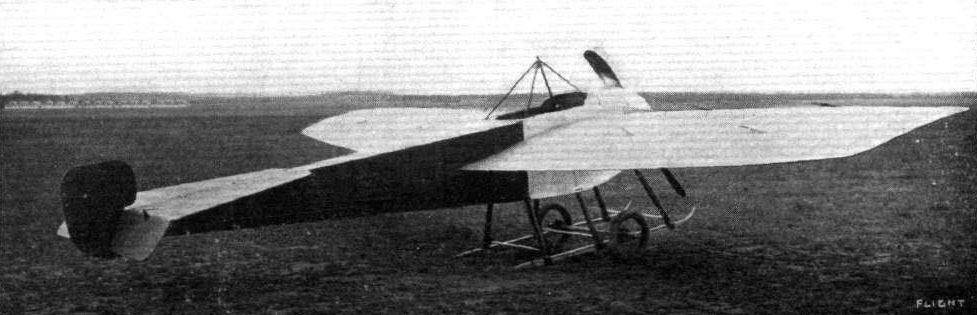
The latest 3-seater Hanriot monoplane.
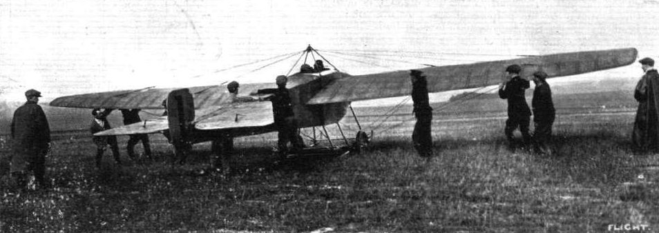
THE MILITARY AVIATION TESTS. - One of the Hanriot monoplanes flown by Bielovucie starting off with Major Brooke-Popham as passenger.
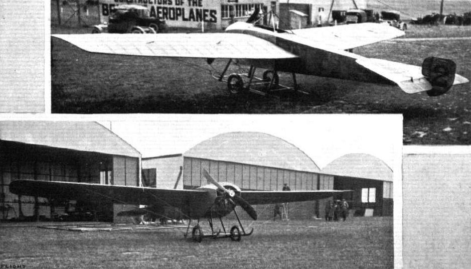
Two views of the 100-h.p. Hanriot monoplane.
Competitors ready for the second heat of the Speed Contest at Hendon last Saturday. - Reading from front to back: Messrs. Grahame-Whlte and R. Gates (H. Farman), Sydney Pickles (Caudron), Marcel Desoutter (Bleriot), and Sabelli (Hanriot).
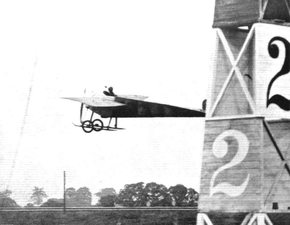
Mr. Sabelli rounding a pylon on the Hanriot at Hendon.
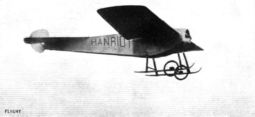
Side view of the Hanriot monoplane in flight.
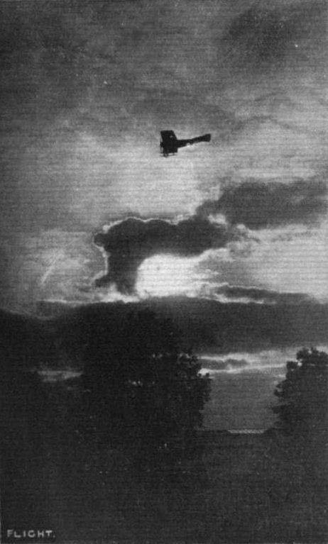
A sunset flight by S. V. Sippe on the Hanriot monoplane on May 17th at Rheims. - Passing over the Hanriot sheds.
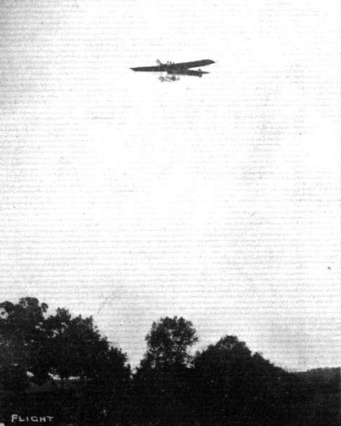
The latest 3-seater Hanriot monoplane in flight. - In this picture the three heads of the occupants are plainly visible.
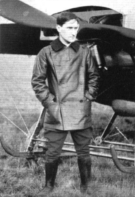
Mr. Sabelli, who has been doing such splendid flying at Hendon and round the country recently.
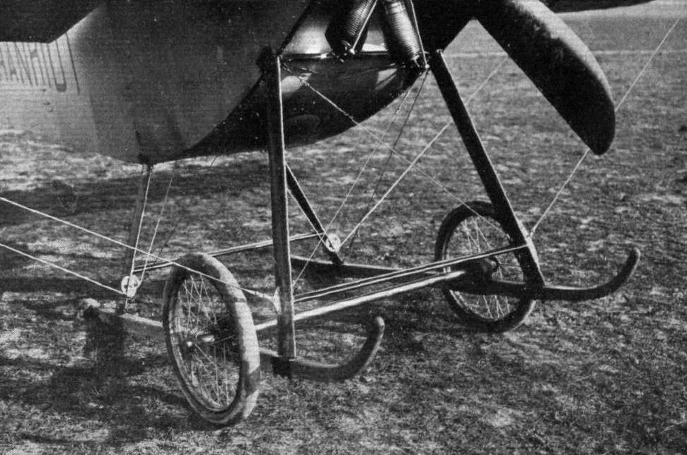
The landing chassis of the Hanriot-Pagny monoplane is modelled on pronounced Nieuport lines. The skids project backwards, Bristol fashion, so that, on depressing the tail, they rub along the ground, and so bring the machine to a standstill after a minimum of run.
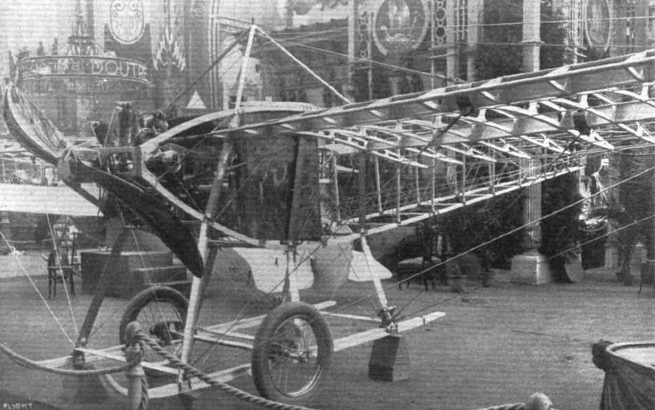
The beautifully-finished 100-h.p. two-seater monoplane shown in skeleton on the Hanrlot stand.
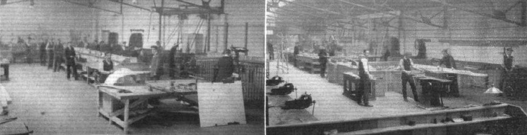
VIEWS AT MESSRS, HEWLETT AND BLONDEAU'S WORKS. - On the left, where the metal working, on the right, where the wood working is done.
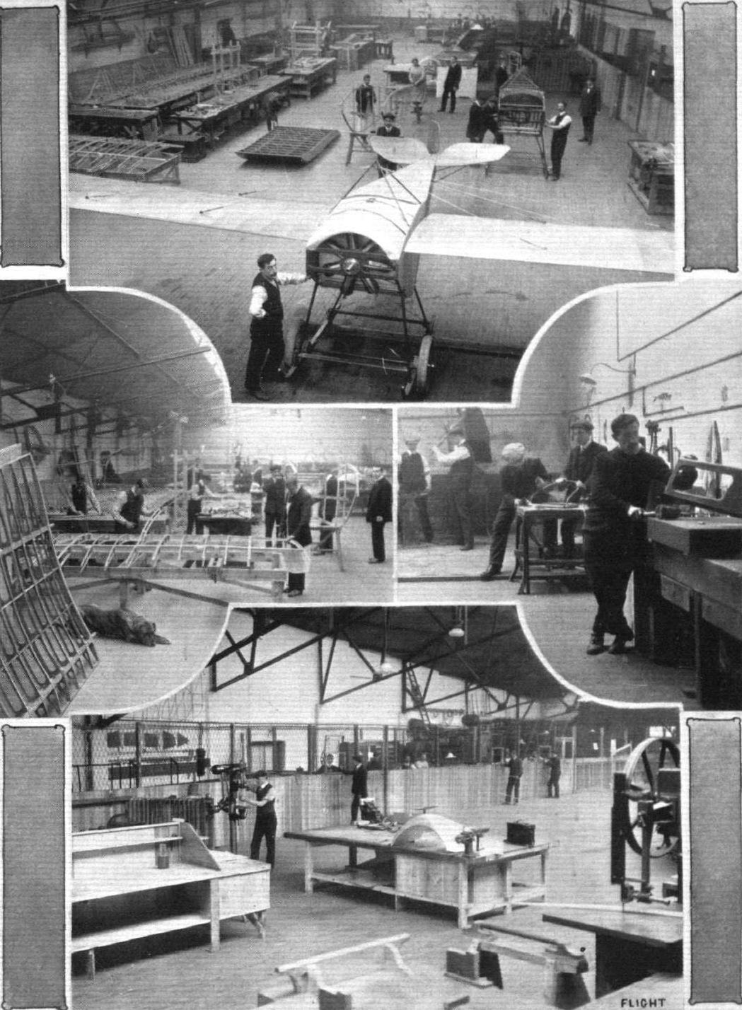
MESSRS HEWLETT AND BLONDEAU'S WORKS AT CLAPHAM JUNCTION. - Above, the main assembly shop; in the centre, to the left, where the wings are made, covered, and doped; to the right, a section of the metal working shop. Below, a section of the works, showing the pittern shop and the store.
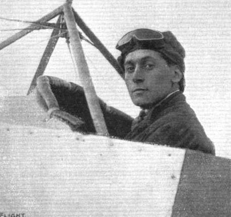
S. V. Sippe in the pilot's seat of the new Hanriot, of Hanriot (England), Ltd., which he will be shortly flying at Brooklands.
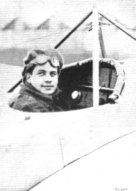
Marcel Hanriot, the youngest fully qualified pilot - not yet being 18 years old - who is now due in England, where he is likely to be flying the Hanriot Monoplane, of which he is a perfect master. His fine work has already been demonstrated in France, Switzerland, Italy, Spain, Turkey, Austria, Belgium, and S. Russia.

Lieut. Marlin, who recently flew on a Hanriot from Rheims to Bar-le-duc, covering 100 kiloms. in 45 mins.
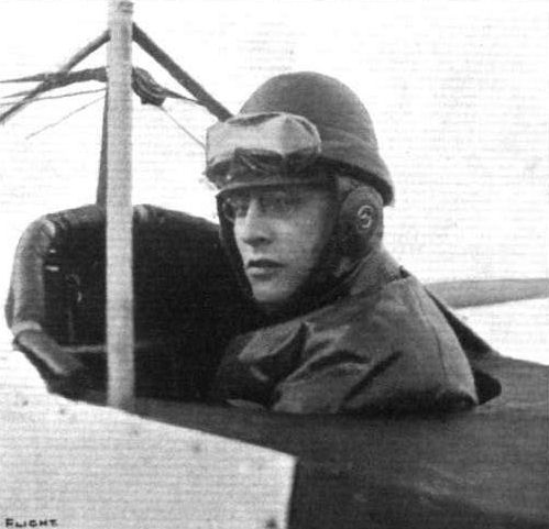
M. A. Ponnier, one of the Directors of the Hanriot Co., and a very fine practical flyer,
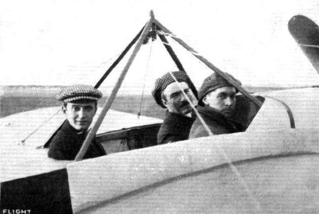
THE LATEST MILITARY 3-SEATER HANRIOT MONO. - Bielovucie is in the pilot's seat, and in front are Marcel Guillemin and Sydney V. Sippe.
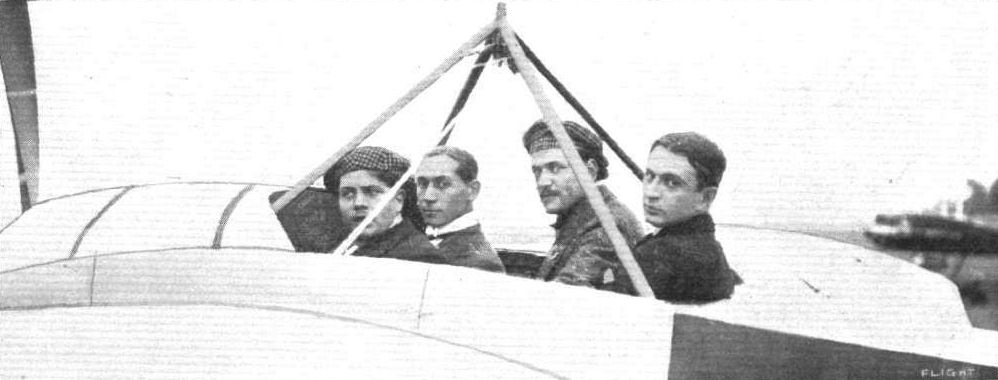
A FREIGHT OF FOUR IN THE MILITARY HANRIOT MONOPLANE. - From left to right: Messrs. Hanriot, jun. Sippe, Frey and Bielovucie.
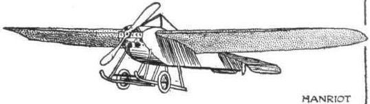

The Hanriot monoplane.

Sketch showing how the warping is geared up by means of a bell crank on the Hanriot monoplane. It also shows the type of socket by which the chassis-struts are assembled to the landing-skids.
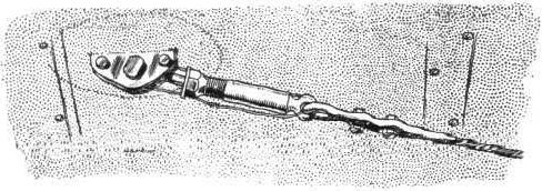
The method of attaching the wing-cables on the Hanriot monoplane.

The clever double-crank radius-rods of the Hanriot chassis, showing the neat unit they form with the shock-absorbers.
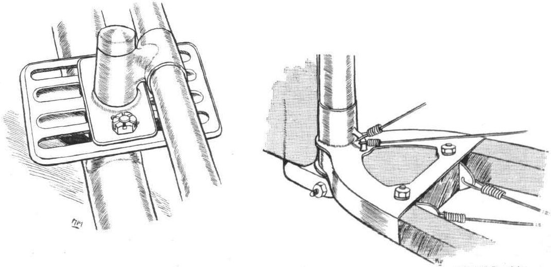
Two interesting details sketched from the Hanriot monoplanes in the course of construction at Messrs Hewlett and Blondeau's works On the left the clever rudder-bar fitting that may be adjusted to suit the length of the pilot's legs. On the right, the rudder post, a good example of acetylene welding.

DETAILS OF THE HANRIOT MONOPLANE. - 1. The fitting by which the aluminium side-plates are clipped to the fuselage. 2. An Interesting fitting by which the fuselage may be divided so that it can fold in two. To dismantle or re-erect the fuselage takes no longer than the time required to operate the bolt of a rifle. 3. Showing how the rear parts of the main skids are shod with steel and punched out to act as a brake. 4. The pilot's cockpit, showing his instruments, the fuel-tank, and his chest of spare parts and fuel. 5. The cross-bracing socket, stamped from sheet steel. 6. One of the four bolts which, being removed, allow the engine, together with its carlingues, to come clear of the machine. 7. The method of attaching the wing wires to the main spars.
Flight, January 6, 1912.
PARIS AERO SHOW.
Kauffmann.
THE Kauffmann monoplane, while in its broad outline it has much in common with the general run of monoplanes, is chiefly remarkable for the size and shape of its wings. These are arched and turned up at the tips and are only a matter of 2 ft. in chord measurement.
The method of staying them is also interesting.
Four-stranded steel cables, two to each wing, take the weight of the machine in flight, and at a suitable distance from the wing these cables split up into a number of smaller wires, each of which is attached to its corresponding rib in the wing structure. By this system, although the head-resistance of the machine as a whole is increased, a great measure of security is obtained; in fact the constructors claim a safety factor of 25.
The main body is of the ordinary box-girder type, cross-braced with steel wire, and covered in in the front with aluminium sheeting and to the rear with fabric. A 50-60-h.p. radial Anzani motor, direct coupled to a Centrale propeller, is installed at the forward end of the fuselage. The tail is triangular in plan form, and does some of the share of the lifting. Hinged to it is the elevator, and the whole is protected from ground contact by a large flexible skid of malacca cane.
Warping is employed for lateral balance, this being operated, together with the elevating surface, from a central lever in the pilot's cockpit.
Principal dimensions, &c. : -
Length 24 ft. 8 ins. Weight 572 lbs.
Span 35 ft. Speed 85 m.p.h.
Area 154 sq. ft. Engine 50-60-h.p. Anzani.
Price L800.
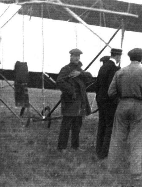
M. Pierre Verrier, of the Aircraft Co., in front of his Maurice Farman biplane. He made his first appearance at Hendon Aerodrome last Saturday with the M. Farman machine, and gave some remarkable demonstrations of his qualities as a skilful pilot.
Flight, July 13, 1912.
Hendon to Shoreham on M. Farman Biplane.
FLYING against a 25 m.p.h. wind, Verrier on the Maurice Farman biplane went from Hendon to Shoreham on Sunday afternoon the trip of about 55 miles taking 1h. 18m. On Tuesday the machine took a Daily Mirror photographer to Spithead, and after obtaining views of the fleet brought him back to London
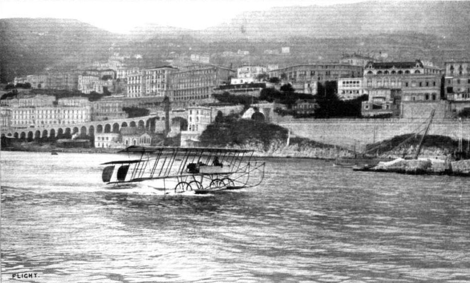
THE HYDRO-AEROPLANES AT MONACO. - The Maurice Farman making a trial flight.
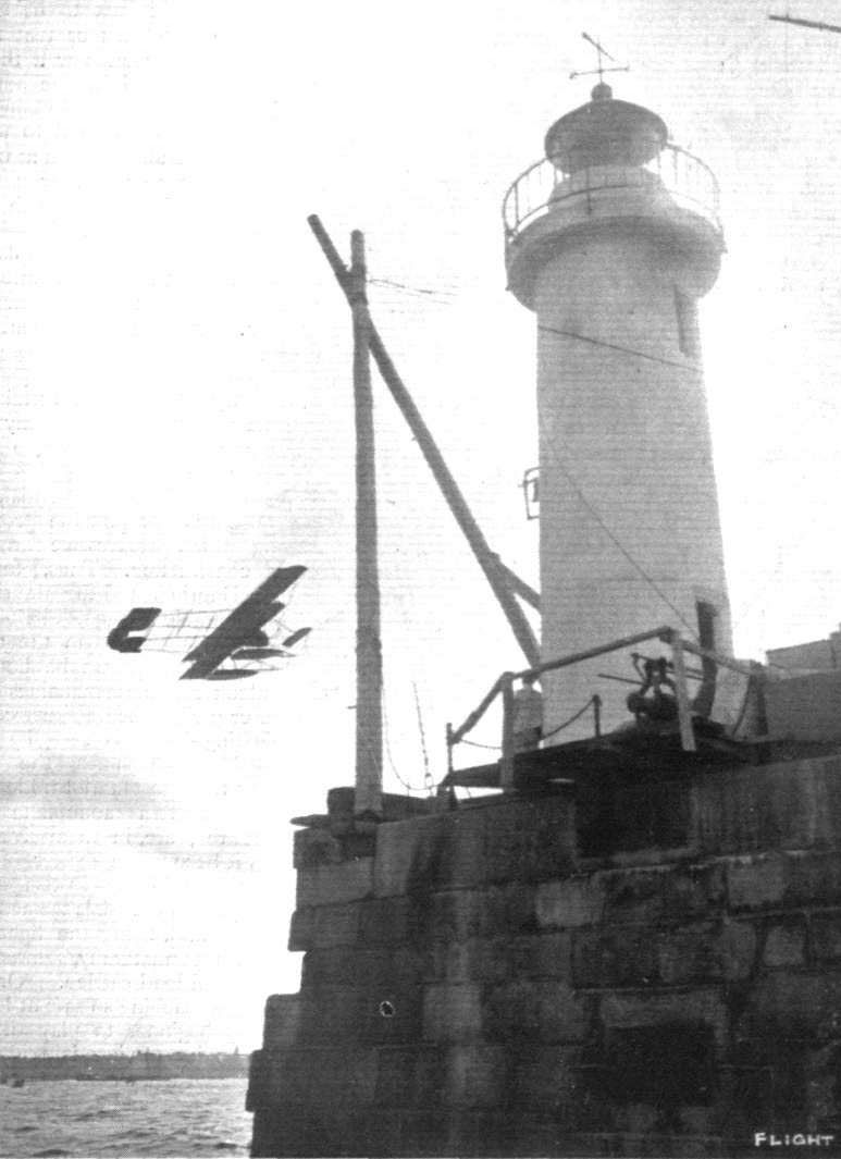
ST. MALO-JERSEY HYDRO-AEROPLANE RACES. - Renaux, on the Farman biplane, rounding the St. Malo lighthouse.
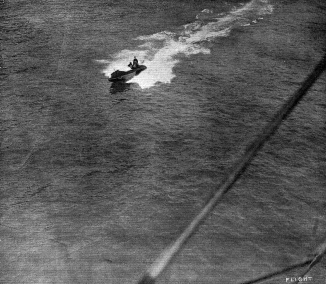
MOTOR BOAT RACING AT MONACO AS SEEN FROM RENAUX'S FARMAN BIPLANE. - A snap of "Sigma III" the racing craft which made such splendid time in the Omnium Race.
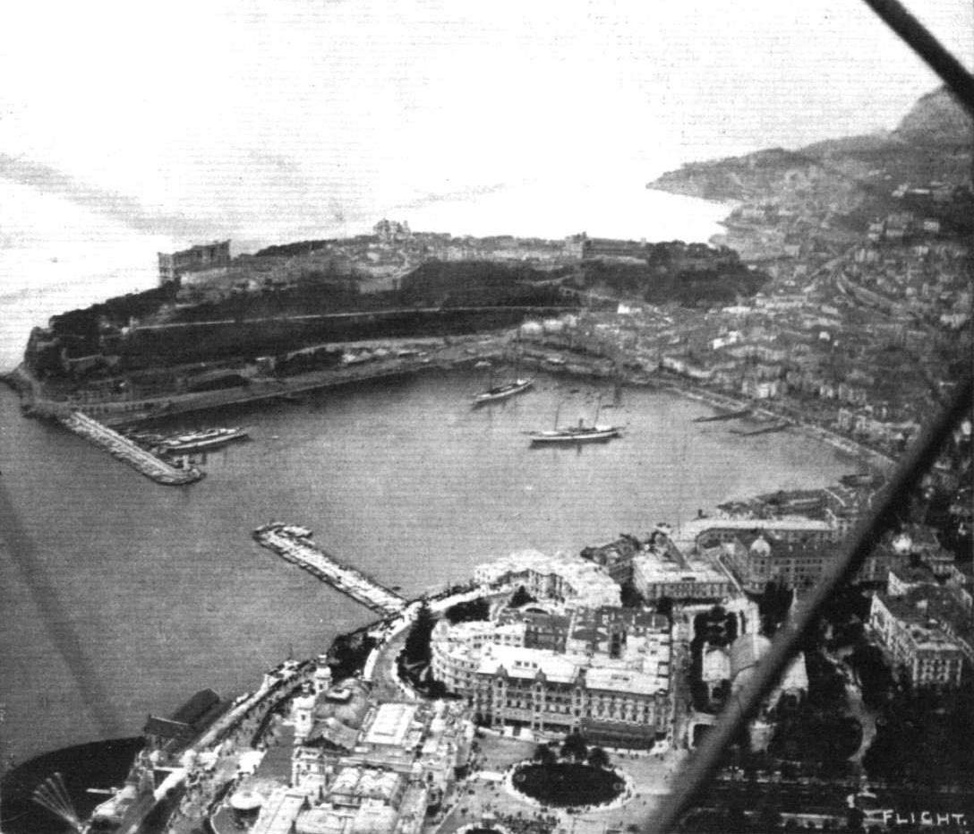
A bird's-eye view of Monaco Harbour and surroundings taken from Renaux's Maurice Farman aquaplane during the recent motor boat and hydro-aeroplane meeting.
Hydro-aeroplanes, illustrating the paper by Mr. Holt Thomas.
Flight, July 6, 1912.
THE MAURICE FARMAN BIPLANE.
SEEING the new machine of this make flying at Hendon, one unconsciously looks upon it as one of the most modern of military biplanes. So, actually, it is; and yet is not the main design of that machine already two years old? For quite two years Maurice Farman has had a machine that, almost unaltered, still ranks to-day among the best, more than which it would be difficult to say to the credit of any designer.
The machines' chief forte is its ability to lift weight. It was simply its capabilities in this, direction that enabled Fourny to capture the world's record for duration in one of these biplanes on September 2nd, 1911, a distinction that he has held unchallenged for ten months. Fourny remained in the air, grinding round a ten kilometre circuit for 11h . 1m. 29s. To keep his motor in operation for that length of time he carried with him 100 gallons of petrol and 11 gallons of lubricating oil, altogether a weight of close on 800 lbs. in fuel alone. Then in the French Military trials the Farmans - both Henry and Maurice - were bent on more weight lifting honours for their three machines that fulfilled the whole of the conditions - and there were only seven all told that survived - carried out the final test, weight carrying across country, loaded up with a useful weight of 990 lbs. in place of the 660 lbs. stipulated in the conditions. Even then the speeds of the machines were not very seriously reduced, for Barra covered the 300 kiloms. averaging 47 1/2 m.p.h., cross-country, while Fischer, on the Henry Farman, was some few miles per hour faster.
The points that impress themselves upon one, seeing the machine flying, are its rapidity at climbing and its remarkably fine gliding angle. Regarding the former, it has been timed, in England and quite recently, to climb, fully loaded, to 1,000 ft. inside of 5 mins. Some week or two ago, in France, Mr. Holt Thomas tells us one machine climbed to 7,000 ft. in 25 mins.
But let us review its construction, briefly - for a description of the machine has already appeared in FLIGHT. The main cellule is composed of two double-surfaced planes, unequal in span, braced together to form a box girder. Ailerons are employed for lateral balance, but they differ from those of the Henry Farman type in that they are interconnected, so that when those on one side are lowered those on the other are raised a corresponding amount. This provision does much to eliminate the necessity of using the rudder when operating them. The struts separating the two planes are hollow, except for those immediately on either side of the engine-bed. These are of solid ash; those directly above the landing-chassis are of ash but, as we have said, hollow, and the remaining cellule struts are shaped from silver spruce. Indeed, most of the woodwork on the machine seems to be hollow. Even the struts supporting the machine on its chassis are fashioned on this principle to save weight.
The landing gear itself is quite characteristic. Two long skids, shaped from solid cleft ash, proceed from below the machine until they meet the front elevator. They are attached to the main frame cellule by a forward structure of silver spruce, and across each skid is strapped, in typical Farman fashion, a pair of landing wheels. The tail needs no description, for apart from being of a different shape and doubled surfaced it presents very little difference from the Henry Farman tails, with which all are familiar. But there is the peculiarity that the tail outriggers, of silver spruce, are hollow.
The control is, to English observers, more novel. A double handgrip of pressed steel is mounted on a vertical column, which is arranged to swing longitudinally. Rocking it to and fro adjusts the forward elevator, by means of a steel tie-rod, for ascent or descent respectively. Lateral balance is controlled by rocking the handgrip laterally. Two wooden pedals control the steering. Pilot, passenger, and motor are located in a boat-shaped fuselage, constructed of ash and covered in with fabric.
The motor is a 70-h.p. 8-cylinder Renault, air-cooled by the customary Renault practice of forced ventilation. It drives a Chauviere propeller of 2 in go diameter and 1 in 90 pitch, at 900 r.p.m. The normal engine speed is 1,800 r.p.m., for the drive is taken from the reinforced cam-shaft.
A noticeable point about the machine at present flying at Hendon is that it has no oil-tank. All the oil necessary for a four-hours' run - some 15 litres - is stored in the engine sump, and unless longer periods of running are required there is no necessity for one to be fitted.
Now that the real Farman machines are about to be built extensively in this country by the Aircraft Co., we may expect to see rapid and far-reaching increase in the practical interest that English pilots have always taken in these machines, which have been so thoroughly and deservedly successful in France.
Flight, July 27, 1912.
THE MILITARY COMPETITION - THE MACHINES.
THE MAURICE FARMAN BIPLANE.
THE Aircraft Co. of St. Stephen's House, Westminster, have entered for the forthcoming Military Trials at Salisbury one Farman biplane. It is the identical machine that Verrier has been flying at Hendon these last two or three months that will represent them. This in itself is remarkable. Many, we might almost say most, of the constructors entering for the Trials have designed and built special machines to comply with the published requirements. So great a faith have the English representatives of the Farmans in the product under the design of the brother Maurice that they are supplying a machine, as it were from stock, to uphold their reputation. All the more honour to them if they do well. It would be unnecessary to recall at length the characteristics of this machine, for we described it fully as recently in the issue of July 6th. The photographs we publish, together with a resume of its main features, will suffice.
Main characteristics:-
Motor 8-cyl. 70-h.p. Renault
Area: main planes 552 sq. ft.
Area: tail 120 ft.
Area: elevator 28 sq. ft.
Length 39 ft. 10 ins.
Span: upper 50 ft. 6 ins.
Span: lower 37 ft.
Speed 55 m.p.h.
Total area 700 sq. ft. approx.
Useful load 800 lbs.
THE MAURICE FARMAN BIPLANE.
SEEING the new machine of this make flying at Hendon, one unconsciously looks upon it as one of the most modern of military biplanes. So, actually, it is; and yet is not the main design of that machine already two years old? For quite two years Maurice Farman has had a machine that, almost unaltered, still ranks to-day among the best, more than which it would be difficult to say to the credit of any designer.
The machines' chief forte is its ability to lift weight. It was simply its capabilities in this, direction that enabled Fourny to capture the world's record for duration in one of these biplanes on September 2nd, 1911, a distinction that he has held unchallenged for ten months. Fourny remained in the air, grinding round a ten kilometre circuit for 11h . 1m. 29s. To keep his motor in operation for that length of time he carried with him 100 gallons of petrol and 11 gallons of lubricating oil, altogether a weight of close on 800 lbs. in fuel alone. Then in the French Military trials the Farmans - both Henry and Maurice - were bent on more weight lifting honours for their three machines that fulfilled the whole of the conditions - and there were only seven all told that survived - carried out the final test, weight carrying across country, loaded up with a useful weight of 990 lbs. in place of the 660 lbs. stipulated in the conditions. Even then the speeds of the machines were not very seriously reduced, for Barra covered the 300 kiloms. averaging 47 1/2 m.p.h., cross-country, while Fischer, on the Henry Farman, was some few miles per hour faster.
The points that impress themselves upon one, seeing the machine flying, are its rapidity at climbing and its remarkably fine gliding angle. Regarding the former, it has been timed, in England and quite recently, to climb, fully loaded, to 1,000 ft. inside of 5 mins. Some week or two ago, in France, Mr. Holt Thomas tells us one machine climbed to 7,000 ft. in 25 mins.
But let us review its construction, briefly - for a description of the machine has already appeared in FLIGHT. The main cellule is composed of two double-surfaced planes, unequal in span, braced together to form a box girder. Ailerons are employed for lateral balance, but they differ from those of the Henry Farman type in that they are interconnected, so that when those on one side are lowered those on the other are raised a corresponding amount. This provision does much to eliminate the necessity of using the rudder when operating them. The struts separating the two planes are hollow, except for those immediately on either side of the engine-bed. These are of solid ash; those directly above the landing-chassis are of ash but, as we have said, hollow, and the remaining cellule struts are shaped from silver spruce. Indeed, most of the woodwork on the machine seems to be hollow. Even the struts supporting the machine on its chassis are fashioned on this principle to save weight.
The landing gear itself is quite characteristic. Two long skids, shaped from solid cleft ash, proceed from below the machine until they meet the front elevator. They are attached to the main frame cellule by a forward structure of silver spruce, and across each skid is strapped, in typical Farman fashion, a pair of landing wheels. The tail needs no description, for apart from being of a different shape and doubled surfaced it presents very little difference from the Henry Farman tails, with which all are familiar. But there is the peculiarity that the tail outriggers, of silver spruce, are hollow.
The control is, to English observers, more novel. A double handgrip of pressed steel is mounted on a vertical column, which is arranged to swing longitudinally. Rocking it to and fro adjusts the forward elevator, by means of a steel tie-rod, for ascent or descent respectively. Lateral balance is controlled by rocking the handgrip laterally. Two wooden pedals control the steering. Pilot, passenger, and motor are located in a boat-shaped fuselage, constructed of ash and covered in with fabric.
The motor is a 70-h.p. 8-cylinder Renault, air-cooled by the customary Renault practice of forced ventilation. It drives a Chauviere propeller of 2 in go diameter and 1 in 90 pitch, at 900 r.p.m. The normal engine speed is 1,800 r.p.m., for the drive is taken from the reinforced cam-shaft.
A noticeable point about the machine at present flying at Hendon is that it has no oil-tank. All the oil necessary for a four-hours' run - some 15 litres - is stored in the engine sump, and unless longer periods of running are required there is no necessity for one to be fitted.
Now that the real Farman machines are about to be built extensively in this country by the Aircraft Co., we may expect to see rapid and far-reaching increase in the practical interest that English pilots have always taken in these machines, which have been so thoroughly and deservedly successful in France.
Flight, July 27, 1912.
THE MILITARY COMPETITION - THE MACHINES.
THE MAURICE FARMAN BIPLANE.
THE Aircraft Co. of St. Stephen's House, Westminster, have entered for the forthcoming Military Trials at Salisbury one Farman biplane. It is the identical machine that Verrier has been flying at Hendon these last two or three months that will represent them. This in itself is remarkable. Many, we might almost say most, of the constructors entering for the Trials have designed and built special machines to comply with the published requirements. So great a faith have the English representatives of the Farmans in the product under the design of the brother Maurice that they are supplying a machine, as it were from stock, to uphold their reputation. All the more honour to them if they do well. It would be unnecessary to recall at length the characteristics of this machine, for we described it fully as recently in the issue of July 6th. The photographs we publish, together with a resume of its main features, will suffice.
Main characteristics:-
Motor 8-cyl. 70-h.p. Renault
Area: main planes 552 sq. ft.
Area: tail 120 ft.
Area: elevator 28 sq. ft.
Length 39 ft. 10 ins.
Span: upper 50 ft. 6 ins.
Span: lower 37 ft.
Speed 55 m.p.h.
Total area 700 sq. ft. approx.
Useful load 800 lbs.
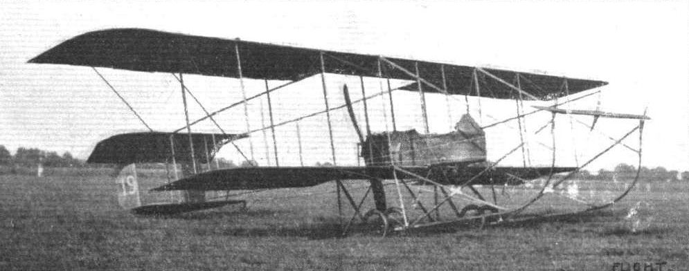
MAURICE FARMAN BIPLANE. - Three-quarter view from in front.
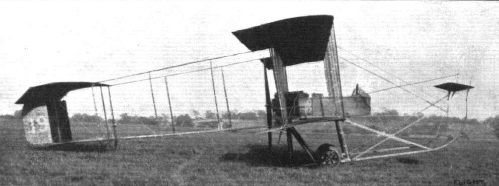
MAURICE FARMAN BIPLANE. - Side view.
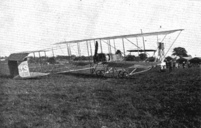
THE MILITARY COMPETITION MACHINES. General view of the Maurice Farman biplane figuring in the trials.
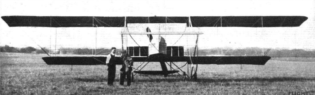
MAURICE FARMAN BIPLANE. - View from in front.
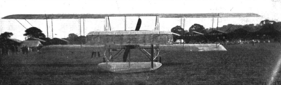
MAURICE FARMAN BIPLANE. - View from behind.
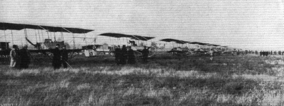
THE GREAT FRENCH AEROPLANE REVIEW AT VILLACOUBLAY LAST WEEK. - General view of the Maurice Farman escadrille.

The visit of Mr. Maurice Farman to Hendon Aerodrome last Sunday, for the purpose of testing some of the machines built by the Aircraft Co. to his design, created a considerable amount of interest. He made several trial flights, and our picture shows him discussing points with Mr. Holt Thomas, with interested mechanics, &C, prior to one of his flights.
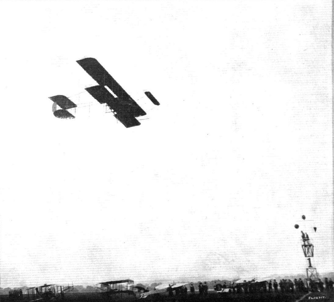
AERIAL DERBY DAY AT HENDON AERODROME. - Pierre Verrier flying on the Maurice Farman biplane.
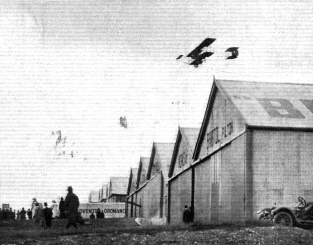
FLYING AT THE ARMY COMPETITIONS IN A 25-MILE WIND. - Verrier, on the Aircraft Co.'s Maurice Farman, passing over the sheds.
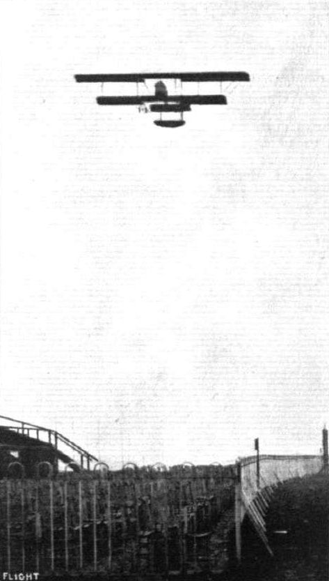
A test flight by Mr. Maurice Farman at Hendon in the British-built machine of his own design.

OFF TO BRIGHTON. - M. Pierre Verrier, with his mechanic as passenger, leaving the Hendon aerodrome for his trip to Brighton on Sunday.
THE THIRD AEROPLANE HANDICAP AT BROOKLANDS, SATURDAY LAST. - Capt. H. Wood on his Vickers monoplane and P. Verrier on his Maurice Farman biplane getting away from the start.
Mr. Lewis Turner finishing first and Mons. Verrier second in the second heat of the Speed Handicap at Hendon on Saturday last.
Remarkable flying was seen in the Speed Handicap at Hendon on Saturday. Our photograph shows, on the left, Jules Nardini on the Deperdussin, on the right Pierre Verrier on the Maurice Farman, and above, Marcel Desoutter, on the Bleriot, just about to enter on the last lap.
Guests at Mr. Claude Grahame-White's wedding at Sir Daniel Gooch's residence, "Hylands," watching Mr. B. C. Hucks flying on his Bleriot during the afternoon. On the ground in front of the mansion is Mr. Grahame-White's Howard Wright biplane on which he flew over, and on the right is the Aircraft Co.'s Maurice Farman biplane on which M. Verrier during the afternoon gave some remarkable exhibitions in a strong wind.
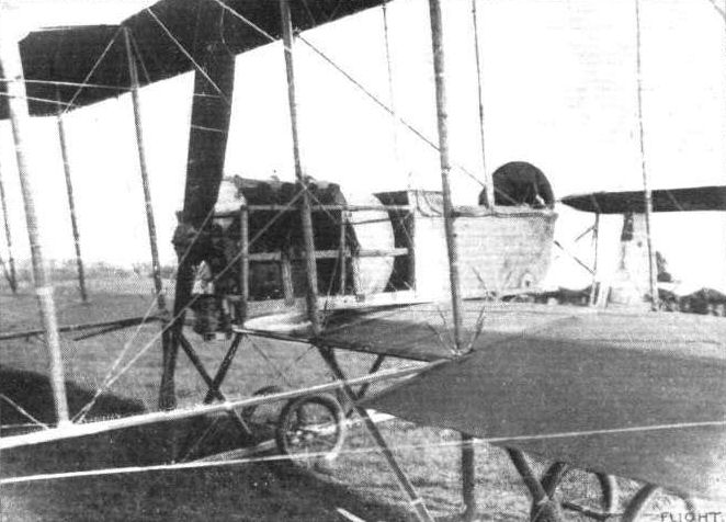
MAURICE FARMAN BIPLANE. - Near view from behind, showing the pilot's seat, position of engine, &c.
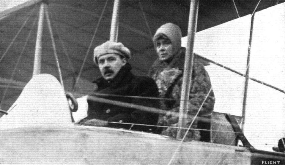
Mr. Maurice Farman, accompanied by Mrs. Holt Thomas as passenger, about to start for a Aerodrome on Sunday last in the British-built Maurice Farman machine.
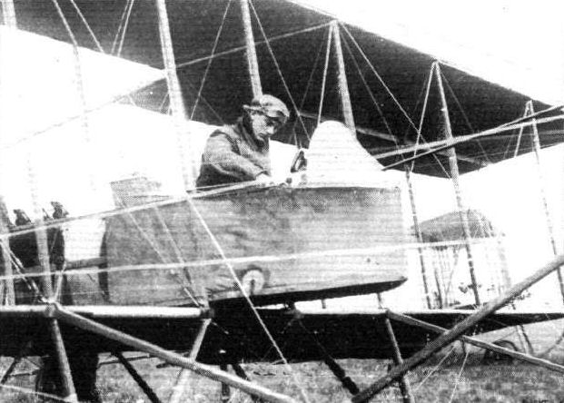
M. Pierre Verrier, who has been giving some fine exhibitions of the capabilities of the Maurice Farman biplane before a number of British military and naval officials at Hendon, in the pilot's seat of his machine.

Details of the control of the Maurice Farman biplane sketched from the passenger's seat.

DETAILS OF THE MAURICE FARMAN. - Above, the new form ol nacelle, showing the windows provided to give the pilot a clearer view of what is beneath him; below, shows how the rear ends of the main skids are turned down to form landing-brakes.
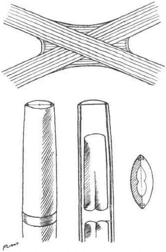
Constructional details of the Maurice Farman biplane. - On top a diagrammatical sketch of a joint in the landing chassis. The two struts are half-lapped and strengthened with wooden angle-pieces; the whole is then bound securely and strengthened with steel plates. Below is a sketch of a hollow strut.
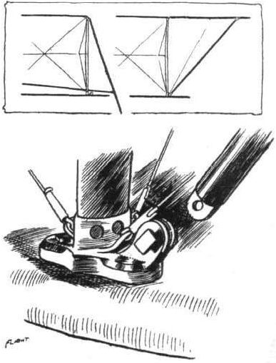
The combined steel socket and extension fitting.
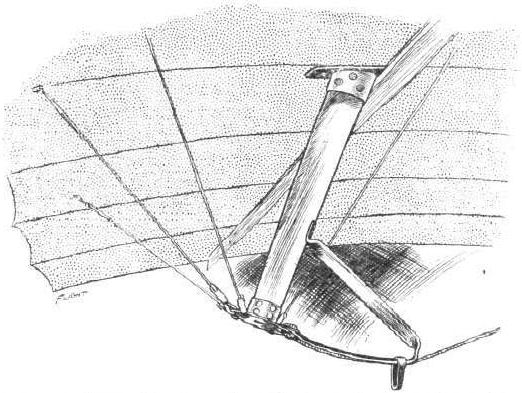
Showing how the control cord is applied to the aileron lever of the Maurice Farman biplane.
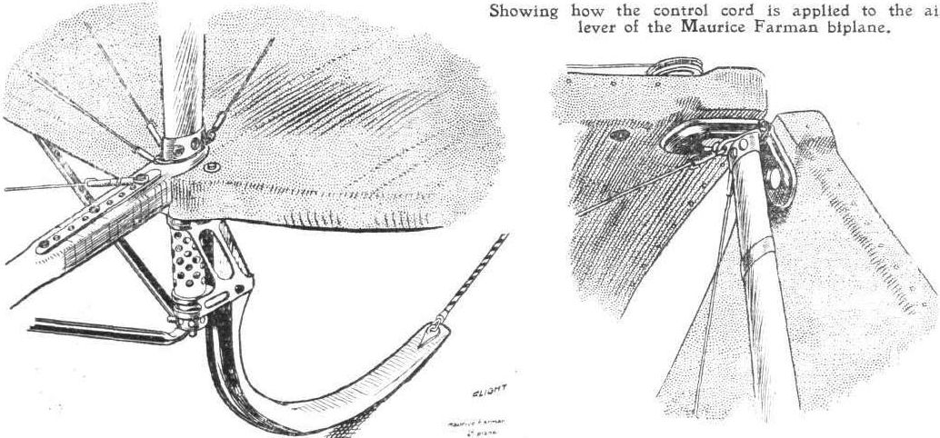
DETAILS OF THE MAURICE FARMAN BIPLANE. - On the left one of the tail skids. On the right the fitting by which the extension may be folded down to reduce overall dimensions.
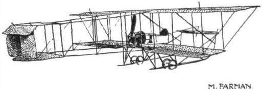
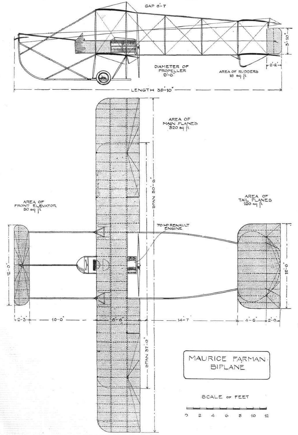
MAURICE FARM AN BIPLANE. - Plan and elevation to scale.
Flight, January 6, 1912.
PARIS AERO SHOW.
Borel Monoplanes.
BOTH the monoplanes shown on the Borel stand, a 50-h.p. single-seater and a 70-h.p. military two-seater, are identical so far as their general outlines are concerned, with the machine with which Vedrines made such a good performance in connection with the Daily Mail Circuit of Britain. On this account a lengthy description is scarcely necessary. The main features evident in the machine are the absence of dihedral angle between the wings, the simple and neat landing gear, the port-a-faux mounting of the Gnome engine, a system which lends itself to great neatness of design and accessibility, and the lightness of the construction throughout.
Borel monoplane.
Principal dimensions :-
Length 23 ft.
Span 30 "
Area 154 sq. ft.
Weight 550 lbs.
Speed 70 m.p.h.
Motor 50-h.p. Gnome.
Price L880.
Two-seater military :-
Length 26 ft.
Span 40 ,,
Area 220 sq. ft.
Weight 600 lbs.
Speed 60 m.p.h.
Engine 70-h.p. Gnome.
Price L1,020.
Flight, May 4, 1912.
THE ACCIDENT TO VEDRINES.
IT came as a great shock to most followers of aviation on Monday to hear that Vedrines, the popular idol of France, had met with a serious accident. He had announced his intention of flying from Brussels to Madrid in one day, but as he incidentally wished to compete for the Coupe Pomeroy - for the longest flight in a straight line - and the condition for that cup calls for a start from French soil, he eventually decided to make a beginning from Douai. He intended to stop at Villacoublay, Poitiers, Bordeaux, Biarritz and Burgos, and starting from Douai at 5.15, he expressed the hope of being in the Spanish capital by 6 o'clock. He started off at a great speed from Douai, following the railway line to Paris. He was at a good height when passing St. Denis and St. Quentin, but when over Enghien at about a quarter past six, it was observed that his motor was not firing regularly. At Epinay he seemed to prepare to come down, but when a short distance from the ground, the aeroplane capsized and fell on to the railway line. A level crossing keeper at once notified the signalman, with the result that an express train which was practically due was stopped, while another train which just previously Vedrines had been racing pulled up just by the wreck. The aviator, who it was feared at first was dying, was placed in the train and taken to Paris to the Lari boisiere Hospital. There the doctors found that, although there were no bones broken, the injuries were so severe that it was feared at first there was no hope of recovery. Later bulletins, however, are slightly more hopeful.
As to the cause of the accident this is at present a mystery, but it is thought that in view of motor troubles Vedrines intended to land at Epinay, and it might be that he selected a landing place, but after vol planing down and finding that it was a field of long grass, he tried to rise again. He then probably got into difficulties owing to his motor not re-starting, and he may have been caught by one of the telegraph wires bordering the railway. It is still hoped, however, that the aviator, by the skill of the doctors, will recover completely and then maybe the mystery will be cleared up.
It would appear that Vedrines' injuries might not have been so serious had he yielded to the advice of M. Deperdussin and worn a safety helmet, but he was so confident that he preferred to do without one. Immediately on hearing of the accident, the French Minister of War, M. Millerand, put Vedrines' name forward for the Legion of Honour.
Flight, July 20, 1912.
THE MILITARY COMPETITION - THE MACHINES.
THE BOREL MONOPLANE.
WE are able to publish this week two photographs of the aeroplane that the Societe Anonyme des Aeroplanes Borel are entering for the War Office Competitions. The pilot Chambenoit has been engaged to fly it at Salisbury.
In the machine, except that it is slightly larger all round in order to account for the extra weight of and accommodation for the passenger, there is little evidence of difference from the single-seater model which, with that master pilot Vedrines at the lever, carried everything before it in the events of 1911. That machine was undoubtedly a very good one, being designed by M. Saulnier. It was then called the Morane monoplane. Some time later its style was changed to the Morane-Borel monoplane. Another period, and a split occurred in the firm, Leon Morane and M. Saulnier branching off, forming their own company and creating the Morane-Saulnier monoplanes. So the name of the monoplane changed again - now it is the Borel monoplane.
But throughout all these changes of administration the design of the machine remained practically unaltered, and so it remains to-day. To the more or less casual observer, about the only point at which this two-seater Borel differs, except as regards size and passenger accommodation, from Vedrines' machine in the Circuit of Britain, is in the design of the tail. On this present monoplane, the elevators are formed by balanced flaps hinged to the rear edge of the stabilizer. But even this is not a totally original point. It has been standard practice with the Borel monoplane for the past few months. In its general outline the monoplane follows the design of the Bleriot to a very great extent. Its only fundamental points of difference from that monoplane are that its landing gear is of the wheel and skid type, its wings have no dihedral angle, and that they are reversed in shape to the Bleriot. By this latter statement we mean that the Borel wings possess the same characteristic rounded tips as the Bleriot, but they fly with the bigger curve leading. In flight, the wings are somewhat analogous to a Chauviere propeller-blade, and score on two points - this form of tip reduces to a great extent "end losses," and a very powerful correcting warp is obtained. The present monoplane is equipped with one of the new 12 litre 80-h.p. Gnome engines, protruding from the front of the fuselage without any bearing between crank-case and propeller. The seats are arranged in tandem.
Main characteristics :-
Motor 7-cyl. 80-h.p. Gnome; rotary
Span 34 ft.
Overall length 23 ft.
Area 165 sq. ft. approx.
Speed 70m.p.h.

THE MILITARY COMPETITION MACHINES. THE 80-H.P. GNOME-BOREL MONOPLANE. - Three-quarter view.

THE MILITARY COMPETITION MACHINES. THE 80-H.P. GNOME-BOREL MONOPLANE. - Front view.
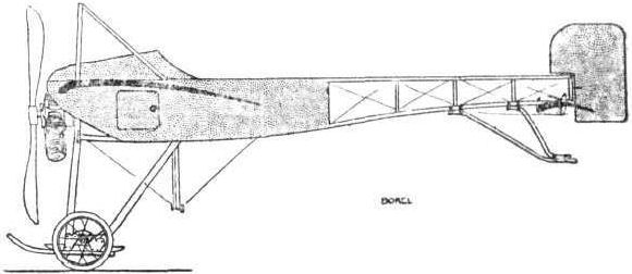

Flight, January 6, 1912.
PARIS AERO SHOW.
Morane-Saulnier.
THE exhibit on this stand consisted of four monoplanes, a school type, a military two-seater, a racing type, and an uncompleted all-steel monoplane. Both the little Anzani-engined school type machine, and the 70-h.p. military are identical as far as their general outline is concerned, the only difference in the two models being the slightly increased size of the more powerful machine. The fuselage in both cases is of the customary box-girder type, being fairly deep in the neighbourhood of the pilot's seat and tapering off from that point towards the tail where its termination may be represented by a horizontal line. In the case of the two-seater machine the 70-h.p. Gnome engine with which it is equipped is almost totally enclosed in a large oil-shield, an idea of which may be gained from the accompanying sketch. This feature is naturally omitted in the school machine, as this is fitted with a stationary air-cooled engine for the proper operation of which a maximum volume of air-cooling draught is imperative. Both are equipped with a Henry Farman type of landing gear, the only difference being that the skids, not being up-turned in front, are apparently not intended to come into action when landing, and the wheels are mounted in a slightly different manner. The fuel tanks are arranged under the steel wind-screen, which latter is heavily padded along its rear edge in order to prevent any personal damage to the pilot should he be thrown forward from his seat as the result of a heavy landing. The main body is covered in throughout its whole length to reduce head-resistance.
In its main characteristics the Morane-Saulnier racer is identical with the two machines already described, its only difference lying in the design of its under-carriage. This latter being entirely constructed of oval section steel tubing, to which are attached the two landing-wheels. As no attempt has been made to endow the chassis with any degree of flexibility, it is doubtful whether it will prove successful under the pilotage of any but the most expert pilots at landing, and even then the ground would have to be of an almost billiard-table-like surface. The wings, in plan form, are similar to those on the Borel machine, and they are stayed by means of stranded steel cable to the middle point of the chassis. Control of the wing warping and the rear elevator is maintained from a vertical universally-jointed lever, of which the action is identical with the Bleriot cloche.
The fuselage of the all-steel war monoplane, which is exhibited in an uncompleted stage, is of torpedo form and constructed throughout of sheet steel. From its blunt nose, which is ventilated, and which encloses the motor, to a point to the rear of the pilot's seat, this steel body is of circular section, but from that point to the tail it flattens out horizontally. Even the skeletons of the wings and the rear controlling surfaces are carried out very cleverly in metal.
Principal dimensions, &c.
School type-
Length 20 ft.
Span 30 ,,
Area 154 sq. ft.
Weight 575 lbs.
Speed 55 m.p.h.
Motor 35-h p. Anzani.
Price L680.
Racer type-
Length 20 ft.
Span 30 ,,
Area 120 sq. ft.
Weight 630 lbs.
Speed 75 m.p.h.
Motor 50-h.p. Gnome.
Price L920.
Military type-
Length 20 ft.
Span 30 ,,
Area 154 sq. ft.
Weight 686 lbs.
Speed 54 m.p.h.
Motor 50-h.p. Gnome.
Price L960.
Flight, February 3, 1912.
THE MORANE-SAULNIER RACING MONOPLANE.
IT is a common opinion among those who had the good fortune to attend the last Aviation Salon in Paris, that the Morane-Saulnier stand was showing machines above the ordinary. In all four types exhibited - a school machine, a two-seater military monoplane, a racer, and a veritable monoplane man-o'-war - were incorporated very excellent and very practical ideas, more especially in the latter two.
So short a time elapsed between the separation of Messieurs Leon Morane and R. Saulnier from the Borel firm and the production of their first machine, the one at present under review, that we must confess we were most agreeably surprised, when this racer was first tested at Villacoublay, to see Vedrines, without any preliminary tuning-up process, take the machine up to over 1,000ft., and fly for 20 mins. at the extraordinary speed of 78 m.p.h., this with a motor of only 50 h.p.
Identical with the endeavours of almost every constructor at the present time, the chief aim of the designer has been the minimisation of head-resistance, an all-important point when high speeds are to be considered. The main body, enclosed throughout its complete length by a covering of fabric, possesses a fairly accurate stream-line form, and is deep enough in the front to accommodate the pilot so that his head alone protrudes above the cockpit, his body being protected from that rush of air which would otherwise have such an adverse effect on his own personal comfort and on the facility of the machine to cleave the air with a minimum of disturbance.
As regards the motor, a Gnome of 50 h.p., the same point has received consideration, and by means of a roughly stream-line casing, which also forms a shield to prevent any lubricating oil and exhaust products being thrown off in the direction of the pilot, much of the resistance presented to forward advance by the rapidly-revolving motor has been avoided, not, as some might imagine, at the expense of efficient cooling.
The motor is mounted port-a-faux, that is, it protrudes from the front of the main body, and is not supported on both sides of the crank-case.
Almost revolutionary is the design of the landing-gear, as, in order to obtain the simplest and strongest arrangement possible, means for shock absorbing, other than that provided by the resilience of the pneumatic tyres with which the wheels are shod, have been excluded from the scheme. One of our photographs well illustrates how this section is constructed from hollow-steel tubing of oval section. If the machine had not originally been devised for the use of experts only, we should have held that the omission of any shock-absorbing device was simply courting trouble. Even with an "expert" at the lever, we can quite imagine wheels buckling, and perhaps tubes bending, if a landing is tried on any but the most smooth of surfaces.
In plan form the wings are almost analogous to a blade of a Chauviere propeller; the entering-edge is shorter than the trailing-edge. It is claimed that the strain felt at the tips is in a great measure reduced by this design, and also that it is possible by this means to obtain a more powerful warp for correcting balance.
The tail is reminiscent of a cross-Channel Bleriot, a fixed monoplane surface playing the part of stabilizer, while rotatable ailerons on either side govern the attitude of the machine. A balanced rudder, operated from the pilot's seat by a pivoted foot-bar, effects the lateral steering. Control over the machine is maintained from a Bleriot-type central lever.
Flight, November 2, 1912.
THE PARIS AERO SALON.
Morane Saulnier.
THERE are three models shown. Two of them are two-seaters, and one has an 80-h.p. Gnome installed and the other a 70-h.p. Renault. The third monoplane is a single-seater scouting machine fitted with the ever popular 50-h.p. Gnome. In main outline all three are the same and not a great deal different from the single-seater model, with a rigid chassis that was shown last year. There the past year, the necessity of fitting some form of springing to the wheels, although, perhaps, they might have got over their difficulty quite well by merely fitting pneumatic tyres of such greater diameter than these on last year's rigid chassis. In detail the two-seaters are a great improvement on those shown twelve months back. For instance, the observer on the 80-h. p. Gnome machine has a most complete view both below him, through a hole in the floor, and on either side through windows of triplex glass. In the machine exhibited dummies occupy the pilot's and passengers' seats. The front dummy, supposedly the observer, is posed with a rifle.
Let us briefly run through the main features. The fuselage is a box girder flattening to a horizontal line at the rear which is the axis on which the elevators turn. On the two-seaters there is no fixed stabilizer surface - simply balanced elevators. That part of the machine is kept clear of the ground by a neat little tail skid. There is no change as regards the wings, they retain the notion of having the trailing longer than the leading edge. An improvement in the 80 Gnome 'bus is that the passenger has before him a starting handle so that the machine may be got going without his leaving his seat. He'll probably have to get out once or twice to inject petrol, unless he has a mechanic to do it and then the mechanic might as well, while he were about it, give him a "turn over." Still, at times the starting handle will come in quite useful.
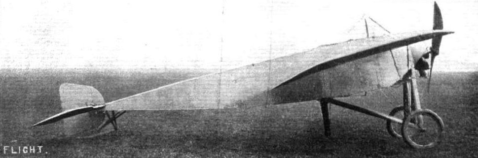
The Morane-Saulnier racing monoplane, as seen from one side, showing the approximate stream-line shape of the body.

The Morane-Saulnier racing monoplane, as it appears from front.
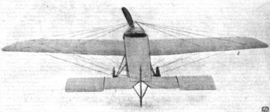
The Morane-Saulnier racing monoplane, as it appears from rear.
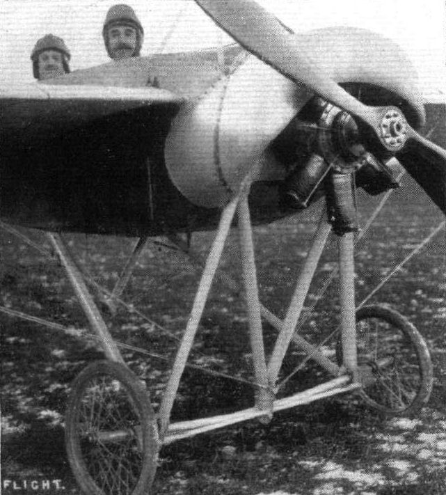
THE NEW MORANE-SAULNIER TWO-SEATER. - In our article the week before last on the Morane racing monoplane, we made mention of the difficulties likely to be met with in connection with its rigid landing chassis. However, improvements have been made, and in the chassis of the machine depicted above, which bears a very close resemblance to the racer, the designers have arrived at a very neat and efficient method of ensuring a good factor of resilience without increasing the head resistance of that organ.
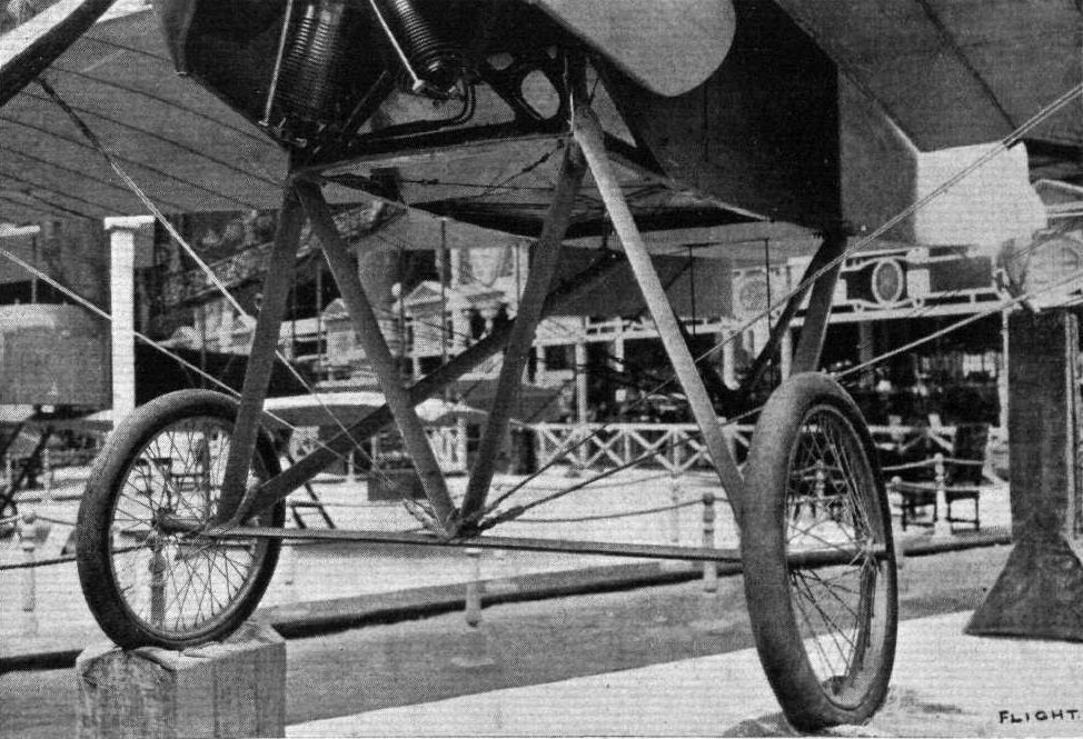
The all-steel rigid landing chassis of the Morane-Saulnier racer. Notice the staying of the wings from the apex of the central inverted triangle - a good point.
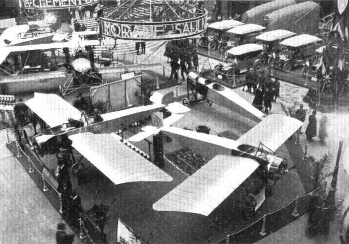
Representative stand at the Salon - the Morane-Saulnier.
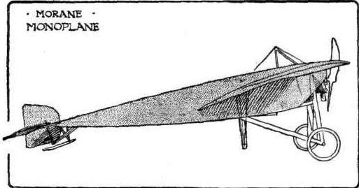
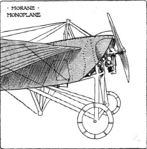
The all-steel tubular landing chassis of the Morane-Saulnier monoplane, in which no flexible suspension is provided.
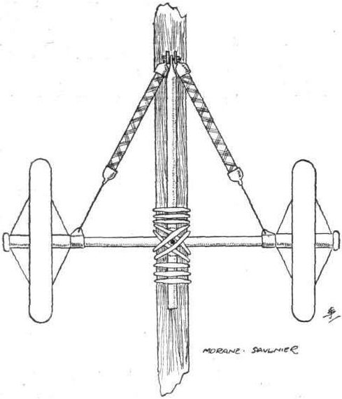
Diagrammatic sketch of the Morane-Saulnier landing gear.
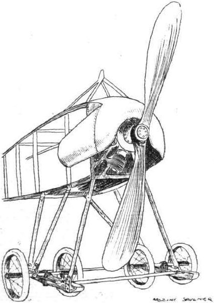
Front of the Morane-Saulnier two-seater monoplane, showing arrangement of landing gear and of the oil-shield over the motor.
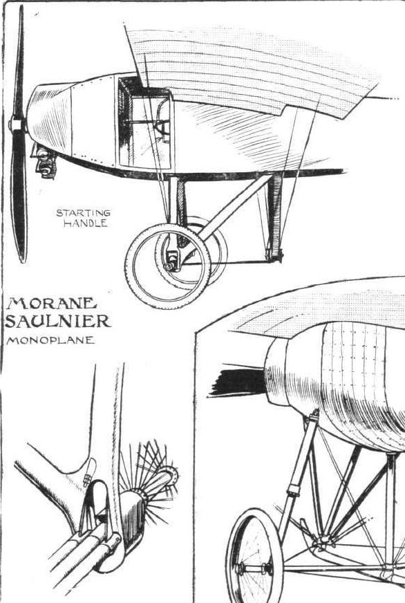
SOME LANDING CHASSIS. - Chassis of the Morane-Saulnier, with detailed pictures showing how the suspension is effected.

MORANE-SAULNIER MONOPLANE. - Plan and Elevation to Scale.
Flight, January 6, 1912.
PARIS AERO SHOW.
Morane-Saulnier.
THE exhibit on this stand consisted of four monoplanes, a school type, a military two-seater, a racing type, and an uncompleted all-steel monoplane. Both the little Anzani-engined school type machine, and the 70-h.p. military are identical as far as their general outline is concerned, the only difference in the two models being the slightly increased size of the more powerful machine. The fuselage in both cases is of the customary box-girder type, being fairly deep in the neighbourhood of the pilot's seat and tapering off from that point towards the tail where its termination may be represented by a horizontal line. In the case of the two-seater machine the 70-h.p. Gnome engine with which it is equipped is almost totally enclosed in a large oil-shield, an idea of which may be gained from the accompanying sketch. This feature is naturally omitted in the school machine, as this is fitted with a stationary air-cooled engine for the proper operation of which a maximum volume of air-cooling draught is imperative. Both are equipped with a Henry Farman type of landing gear, the only difference being that the skids, not being up-turned in front, are apparently not intended to come into action when landing, and the wheels are mounted in a slightly different manner. The fuel tanks are arranged under the steel wind-screen, which latter is heavily padded along its rear edge in order to prevent any personal damage to the pilot should he be thrown forward from his seat as the result of a heavy landing. The main body is covered in throughout its whole length to reduce head-resistance.
In its main characteristics the Morane-Saulnier racer is identical with the two machines already described, its only difference lying in the design of its under-carriage. This latter being entirely constructed of oval section steel tubing, to which are attached the two landing-wheels. As no attempt has been made to endow the chassis with any degree of flexibility, it is doubtful whether it will prove successful under the pilotage of any but the most expert pilots at landing, and even then the ground would have to be of an almost billiard-table-like surface. The wings, in plan form, are similar to those on the Borel machine, and they are stayed by means of stranded steel cable to the middle point of the chassis. Control of the wing warping and the rear elevator is maintained from a vertical universally-jointed lever, of which the action is identical with the Bleriot cloche.
The fuselage of the all-steel war monoplane, which is exhibited in an uncompleted stage, is of torpedo form and constructed throughout of sheet steel. From its blunt nose, which is ventilated, and which encloses the motor, to a point to the rear of the pilot's seat, this steel body is of circular section, but from that point to the tail it flattens out horizontally. Even the skeletons of the wings and the rear controlling surfaces are carried out very cleverly in metal.
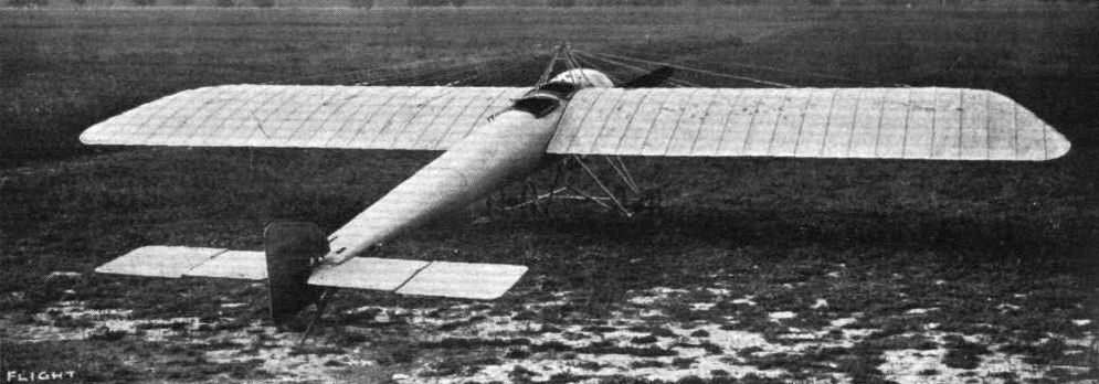
The new 100-h.p. Gnome-engined Morane-Saulnier two-seated (tandem) military monoplane. - It is constructed throughout of steel. The all-steel fuselage of this machine, it will be remembered, was one of the clous of the last Paris Aero Salon.
Flight, November 2, 1912.
THE PARIS AERO SALON.
Morane Saulnier.
THERE are three models shown. Two of them are two-seaters, and one has an 80-h.p. Gnome installed and the other a 70-h.p. Renault. The third monoplane is a single-seater scouting machine fitted with the ever popular 50-h.p. Gnome. In main outline all three are the same and not a great deal different from the single-seater model, with a rigid chassis that was shown last year. There the past year, the necessity of fitting some form of springing to the wheels, although, perhaps, they might have got over their difficulty quite well by merely fitting pneumatic tyres of such greater diameter than these on last year's rigid chassis. In detail the two-seaters are a great improvement on those shown twelve months back. For instance, the observer on the 80-h. p. Gnome machine has a most complete view both below him, through a hole in the floor, and on either side through windows of triplex glass. In the machine exhibited dummies occupy the pilot's and passengers' seats. The front dummy, supposedly the observer, is posed with a rifle.
Let us briefly run through the main features. The fuselage is a box girder flattening to a horizontal line at the rear which is the axis on which the elevators turn. On the two-seaters there is no fixed stabilizer surface - simply balanced elevators. That part of the machine is kept clear of the ground by a neat little tail skid. There is no change as regards the wings, they retain the notion of having the trailing longer than the leading edge. An improvement in the 80 Gnome 'bus is that the passenger has before him a starting handle so that the machine may be got going without his leaving his seat. He'll probably have to get out once or twice to inject petrol, unless he has a mechanic to do it and then the mechanic might as well, while he were about it, give him a "turn over." Still, at times the starting handle will come in quite useful.
Representative stand at the Salon - the Morane-Saulnier.
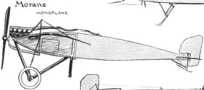
Flight, November 16, 1912.
THE PARIS AERO SALON.
Moreau.
HERE stands a 70-h.p. two-seater monoplane, interesting in that its longitudinal stability is arrived at by automatic means. It has two seats side by side built up in the form of a cage, which is swung pendulum fashion from the top member of the fuselage. It is connected to the tail, a plane surface shaped like a triangle with its apex clipped by a system of steel rods. The main idea of this system is that when the pendulum seat is hanging perpendicularly relative to the line of flight, the tail is in a position which makes for a horizontal flight path. Should the machine tend to climb, the pendulum seat changes its position relative to the rest of the machine and in doing so automatically readjusts the tail to restore the machine to normal level flight. Should the machine dip the same thing occurs, only of course in the opposite sense. Employing a system of this type it is, of course, necessary to have supplementary elevator controls to carry out such manoeuvres as ascending and descending. This, on the Moreau machine, is effected by an auxiliary lever to the right of the pilot. The machine's lateral stability is to a certain extent natural owing to the design of the wings, but further control is maintained by a lever projecting downward from the framework above, operating ailerons. By M. Moreau's system it is possible to cut the automatic device out of action and maintain control simply by the use of the levers. Improvements have been made on the first model with which M. Moreau experimented. He found that, should the engine stop in mid-air, the pilot's seat swung forward with its own inertia and set the tail for ascent - a very uncomfortable position to find oneself in with one's engine stopped. On the present machine he has fitted a device which detects any tendency on the part of the pendulum seat to swing forward by virture of its inertia, and which immediately locks the pendulum seat, thus preventing the machine from getting cabre owing to engine stoppage. He has found, too, that if the machine encounters a strong gust head on there is a similar tendency for the monoplane to assume a cabre attitude. To obviate this, a small aluminium plate is fitted in front of the body normally to the relative wind, which plate detects any sudden gust and locks the pendulum seat. From a constructional point of view the machine does not possess a great deal of interest, excepting in its chassis which is extremely flexible. The skids themselves are mounted so that they may give fore and aft, parallel to the bottom members of the body, against the restraint of shock absorbers.
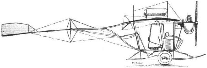
M. Moreau's automatic stability monoplane.
Flight, June 8, 1912.
MODELS.
A Successful Scale Nieuport Model.
WE give this week illustrations and particulars of a type of model which we would like to see far more in evidence than it is - a type which one can really call a model as opposed to a "flying-stick." The model was designed and constructed by Mr. J. W. Burghope (Brighton and District Model Aero Club), it took three months to build, and is the result of over three years' experience, and the outcome of innumerable and miserable failures.
The model rises from the ground (hangar wood floor) after a run of 30 ft., and will then fly for 70 yards. Hand launched, 124 yards has been done combined with a duration of 14 secs., and an altitude of from 35 to 40 ft.
<...>
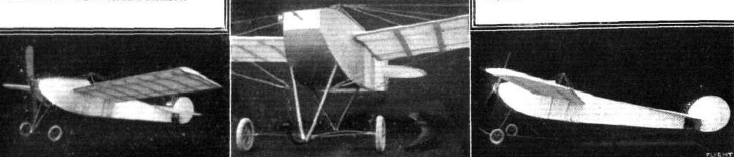
Mr. Burghope's flying scale model Nieuport - a fine piece of workmanship.
Flight, January 6, 1912.
PARIS AERO SHOW.
Nieuport.
OCCUPYING one of the central stands in the Grand Palais were three Nieuport monoplanes, a 28-h.p. twin-cylinder school-type machine, and two 50-h,p. two-seater military machines. One of these latter was the identical machine on which the celebrated pilot Helen won the Coupe Michelin. No new features are evident in the machines on exhibition, they being similar in every respect to the models which have competed so successfully in all the contests of the past year.
Principal dimensions :-
School-type monoplane-
Length 24 ft.
Span 28 ,,
Area 176 sq.
Weight 550 lbs.
Speed 70 m.p.h.
Motor 28-h.p. Nieuport
Price L720.
Two-seater military -
Length 26 ft.
Span 36 "
Area 250 sq. ft.
Weight 700 lbs.
Speed 70 m.p.h.
Motor 50-h.p. Gnome
Price L1,040.
Flight, February 17, 1912.
242 Miles by Barrington-Kennett.
STARTING from Bulford Camp, Salisbury, on Wednesday, Lieut. Barrington-Kennett, on his Nieuport monoplane, more than doubled his previous record for the Mortimer-Singer Army prize by covering 242 miles. He was accompanied by Corporal Ridd.
Flight, March 16, 1912.
AEROPLANE UNDERCARRIAGES.
By G. DE HAVILLAND.
Nieuport Monoplane.-As the keynote of this machine is high aerodynamic efficiency, the design of the undercarriage has naturally been governed by the same principle, therefore head resistance has been reduced to a minimum. This is accomplished by the use of oval steel struts rigidly fixed to a centre steel tube skid, while the wheels are mounted at the end of a transverse laminated spring, which is attached to the skid in a position well forward of the centre of gravity. The result is a very rigid construction, while tie wires are almost entirely dispensed with, and the various parts likely to be damaged can easily be replaced. The wheels are fairly small in diameter, and have a comparatively narrow track, and this sometimes causes the machine to cant over laterally until the wing tip comes into contact with the ground. The ends of the wings, however, are constructed to withstand these strains, and therefore, materially assist the duty of the undercarriage, without adding extra head resistance or weight. The after end of the central skid takes the place of the more usual tail skid, but carries a large proportion of the total weight. A short base of support is generally to be discouraged, as it does not make for good fore and aft stability on uneven ground, but in this case some advantage is gained by the breaking effect given by the heavily loaded skid when pulling up after landing. When starting away, the propeller thrust is sufficient to take most of the weight off the skid, so that the speed is not seriously damped. As regards simplicity and cleanness of design, the Nieuport gear is probably ahead of any other, and from this point of view will no doubt have influence on future designs. The use of the wings themselves as lateral skids may also lead to development in further simplifying the main under carriage.
The efficiency of its primary function as a landing gear has often been doubted, but from practical results it would seem to be better than usually supposed. I have to thank Lieut. Barrington-Kennett, of the Air Battalion, R.E., for some of the notes on this machine.
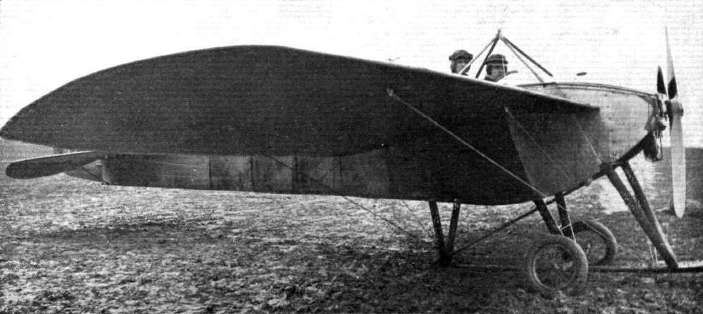
Lieut. H. B. Barrington-Kennett, of the Air Battalion, and his passenger, Corpl. Ridd, R.E., taking olf on Wednesday of last week at Salisbury Plain for the Mortimer Singer Prize, when he covered 249 miles 840 yds in 4 hrs 51 mins.

Capt. Gerrard on the military Nieuport at the Royal Aero Club's Eastchurch flying ground.
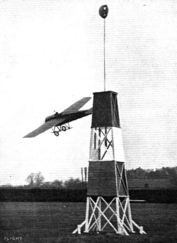
A fine piece of steering round a mark tower, at 67 miles per hour, by Mr. Grahame-White on his Nieuport monoplane.
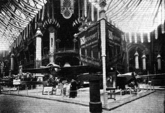
The Nieuport stand.
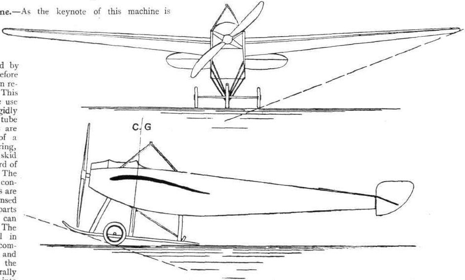
Flight, November 9, 1912.
THE PARIS AERO SALON.
Nieuport.
FOUR machines are shown on this stand - a standard 28-h.p. Nieuport monoplane of the school type, a standard 70-h.p. two-seater, a new racing model, and a 100-h.p. "Hydravion," similar in every respect to the one that hangs suspended from the roof above the exhibit of the French Minister of War. No special description of the first two models is necessary. They are quite standard; and, for that matter, very little need be said of the latter two, for in the case of the racing model the machine is simply a smaller edition of the standard machine with changes in the chassis, and, for the Hydravion, it is but the ordinary 100-h.p. three-seater model with a float chassis instead of a wheeled one.
<...>
As regards the Hydravion, it has three floats. Two-stepped floats, supporting the body through a construction of steel tubing, form the main landing organs, and a miniature egg-shaped float supports the tail. For the construction of the main floats cypress wood is employed. A peculiarity about these are the small fin-like projections that extend laterally from the front ends of each float. They are so designed for a double purpose - to prevent the floats burying in a heavy sea, and to protect the propeller from spray. The propeller, by the way, is further armoured at the tips. A change has been made in the building of the fuselage to strengthen it to withstand the heavier strains that landing in the water calls upon it to bear. In this machine, the vertical struts in the body are of steel tubing, although the longitudinals and other portions of the body are still made of wood.
Two passengers can be accommodated in a wide seat immediately behind the pilot. He, the pilot, has before him, in addition to his controls and instruments, a starting-handle, by which he can put the motor in motion without exterior help.

The latest Nieuport hydro-aeroplane, which is being put through experiments at Meuian under the direction of Lieut. Delage. Note the special construction of the front floats and the tall-sustaining float.

The 100-h.p. Nieuport hydro-monoplane.
Some of the types of float used on present-day hydro-aeroplanes, as seen at the Paris Aero Salon.
Flight, November 9, 1912.
THE PARIS AERO SALON.
Nieuport.
FOUR machines are shown on this stand - a standard 28-h.p. Nieuport monoplane of the school type, a standard 70-h.p. two-seater, a new racing model, and a 100-h.p. "Hydravion," similar in every respect to the one that hangs suspended from the roof above the exhibit of the French Minister of War. No special description of the first two models is necessary. They are quite standard; and, for that matter, very little need be said of the latter two, for in the case of the racing model the machine is simply a smaller edition of the standard machine with changes in the chassis, and, for the Hydravion, it is but the ordinary 100-h.p. three-seater model with a float chassis instead of a wheeled one.
Let us first deal with the racing model. To attain high speed the designer has not resorted to high engine power. He has kept to the 50-h.p. Gnome, and to increase the speed has aimed at still further increasing the efficiency of the machine by cutting down head resistance.
This is chiefly noticeable in the landing gear, which, as a light construction having little head resistance, is perhaps good. But, as a landing gear, pure and simple, we doubt if anything more treacherous has ever been designed. As long as it is used only on smooth ground, it may stand up to its work all right - that is, if it were in the hands of a skilful pilot. What would happen over rough ground we dread to imagine. The chassis is all of steel, and there are only two laminations in the transverse spring.
There being no horizontal skid it is impossible to arrange the warping as heretofore. On this machine it is operated by bell cranks just below the fuselage, worked by the feet as usual. To cut down some of the head resistance of the Gnome engine, a dome is fitted over the front, a quarter segment of it being cut away to admit sufficient air for cooling. The wings only span 23 ft. and they have noticeably less curvature and incidence than previous models. They are each stayed on the underside by four cables - two to each spar.
<...>
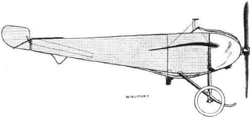
The 50-h.p. Nieuport racer.
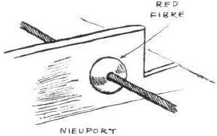
The neat control wire guide on the Nieuport monoplanes.
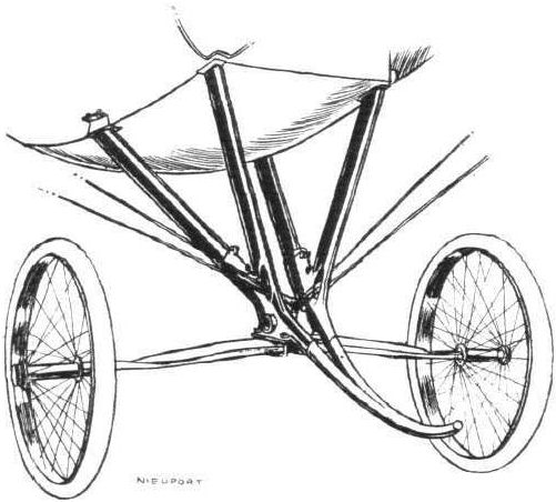
The chassis of the 50-h.p. Nieuport racer.
Flight, November 9, 1912.
THE PARIS AERO SALON.
Nieuport.
FOUR machines are shown on this stand - a standard 28-h.p. Nieuport monoplane of the school type, a standard 70-h.p. two-seater, a new racing model, and a 100-h.p. "Hydravion," similar in every respect to the one that hangs suspended from the roof above the exhibit of the French Minister of War. No special description of the first two models is necessary. They are quite standard; and, for that matter, very little need be said of the latter two, for in the case of the racing model the machine is simply a smaller edition of the standard machine with changes in the chassis, and, for the Hydravion, it is but the ordinary 100-h.p. three-seater model with a float chassis instead of a wheeled one.
Let us first deal with the racing model. To attain high speed the designer has not resorted to high engine power. He has kept to the 50-h.p. Gnome, and to increase the speed has aimed at still further increasing the efficiency of the machine by cutting down head resistance.
This is chiefly noticeable in the landing gear, which, as a light construction having little head resistance, is perhaps good. But, as a landing gear, pure and simple, we doubt if anything more treacherous has ever been designed. As long as it is used only on smooth ground, it may stand up to its work all right - that is, if it were in the hands of a skilful pilot. What would happen over rough ground we dread to imagine. The chassis is all of steel, and there are only two laminations in the transverse spring.
There being no horizontal skid it is impossible to arrange the warping as heretofore. On this machine it is operated by bell cranks just below the fuselage, worked by the feet as usual. To cut down some of the head resistance of the Gnome engine, a dome is fitted over the front, a quarter segment of it being cut away to admit sufficient air for cooling. The wings only span 23 ft. and they have noticeably less curvature and incidence than previous models. They are each stayed on the underside by four cables - two to each spar.
<...>
THE PARIS AERO SALON.
Nieuport.
FOUR machines are shown on this stand - a standard 28-h.p. Nieuport monoplane of the school type, a standard 70-h.p. two-seater, a new racing model, and a 100-h.p. "Hydravion," similar in every respect to the one that hangs suspended from the roof above the exhibit of the French Minister of War. No special description of the first two models is necessary. They are quite standard; and, for that matter, very little need be said of the latter two, for in the case of the racing model the machine is simply a smaller edition of the standard machine with changes in the chassis, and, for the Hydravion, it is but the ordinary 100-h.p. three-seater model with a float chassis instead of a wheeled one.
Let us first deal with the racing model. To attain high speed the designer has not resorted to high engine power. He has kept to the 50-h.p. Gnome, and to increase the speed has aimed at still further increasing the efficiency of the machine by cutting down head resistance.
This is chiefly noticeable in the landing gear, which, as a light construction having little head resistance, is perhaps good. But, as a landing gear, pure and simple, we doubt if anything more treacherous has ever been designed. As long as it is used only on smooth ground, it may stand up to its work all right - that is, if it were in the hands of a skilful pilot. What would happen over rough ground we dread to imagine. The chassis is all of steel, and there are only two laminations in the transverse spring.
There being no horizontal skid it is impossible to arrange the warping as heretofore. On this machine it is operated by bell cranks just below the fuselage, worked by the feet as usual. To cut down some of the head resistance of the Gnome engine, a dome is fitted over the front, a quarter segment of it being cut away to admit sufficient air for cooling. The wings only span 23 ft. and they have noticeably less curvature and incidence than previous models. They are each stayed on the underside by four cables - two to each spar.
<...>
Flight, January 6, 1912.
PARIS AERO SHOW.
Les Fils de Regy Freres.
THE most prominent exhibit on this stand was the aero torpedo of Paulhan and Tatin. This interesting machine, of which photographs have appeared from time to time in FLIGHT, is a sincere attempt on the part of the designers to gain greater speed and greater stability by the cutting down of as much head resistance as possible. The body itself is of excellent stream-line form, the fabric covering, which extends right from end to end, being supported on circular wooden hoops, which are applied over the fuselage proper of ordinary box-girder construction. The main peculiarity about the machine is that the propeller, a Regy Freres, is disposed at the extreme rear end of the main body, and is driven by means of a tubular steel shift by a Gnome engine of 50-h.p., situated just to the rear of the pilot. This shaft is not universally jointed, but rigid from motor to propeller. Very little camber and very little angle of incidence is evident in the wings, which are of an approximate elliptical plan form, and which are up-turned at the tips in order to endow the machine with a modicum of natural stability. It is interesting to note that no warping of the wings or any other method of maintaining lateral balance, other than by the inherent effect of the up-turned tips, is provided for, and this fact almost leads one to believe that Paulhan had in his mind visions of litigation with the Wright brothers, on which, by the way, he is at present engaged in the States. The tail surfaces consist of a horizontal flat plane, to the rear edge of which is hinged a pair of flaps, one on each side of the main body, which perform the function of elevators, while steering to the right and left is brought about by a vertical-balanced rudder mounted above the horizontal surface. Protection is afforded against damage to the propeller by a very high tail-skid.
The landing chassis is a very unique conception, and while being extremely strong and simple has the extra advantage of presenting little resistance to forward advance. The common axle connecting the two pneumatic-tyred disc wheels is rigidly attached to two roughly semi-circular sweeps of ash. These sweeps are hinged to the main body at their forward ends, and at their rear ends are connected by a piece of wood which in turn is strapped down to a reinforced fuselage cross-member with rubber cord. In this manner the shock-absorbing device is arranged in the interior of the fuselage, and in addition to resistance being reduced on this account, the system lends itself to extreme neatness and clearness of design.
As evidence of the advantages which are to be gained by the reduction of head resistance, it is interesting to mention that speeds of 88 miles per hour have been attained, presumably in still air, by this monoplane, and this with an engine of only 50 h.p. Besides this interesting monoplane, a full selection of beautifully constructed Regy Freres' propellers is exhibited on this stand.
Principal dimensions, &c. :-
Length 28 ft. Weight 800 lbs.
Span 28 ft. Speed 88 m.p.h.
Area 140 sq. ft. Motor 50-h.p. Gnome.
Price L 1,000.
Flight, February 17, 1912.
THE PAULHAN-TATIN AERO-TORPEDO.
IT is a universally recognised fact that, among the various machines that have come to light during the past year, none can lay claim to a greater measure of real sound originality than can the Aero-Torpedo of M. Victor Tatin. Throughout the whole machine there is an atmosphere indicating the extent of painstaking thought that must have been devoted to the development of each individual part and to the embodiment in sound constructional form of those purely aero-dynamical desiderata which up to the present constructors have avoided in view of the complications involved. Having faith in his convictions and ignoring the comments of "Freak," which greeted his enterprise when the rough details of the new machine he was constructing leaked out for the first time, he has proceeded with his experiments and produced a machine, which, by virtue of its excellent performances and extreme novelty, was the centre of interest at the last Paris Salon. Although the machine expresses so many novel ideas in aeroplane design, it is nevertheless a fact that its whole conception, excepting as regards the arrangement of the propeller, was established in the brain of M. Tatin as long ago as 33 years.
The most notable feature that becomes evident on first inspection is that, opposed to conventional monoplane practice the propeller, such in the true sense of the word, is arranged at the extreme rear end of the torpedo shaped body, where driven by a shaft some 20 ft. long, it revolves in the region of air disturbance that follows the passage of the machine and is so enabled to work with greater efficiency. The notion of placing the propeller at the rear occurred to Tatin something like twenty years since.
Apart from the number of craft of the genus canard in which this arrangement of the propeller is much more easily attainable, some few attempts have been made to effect this disposition in the past in connection with monoplane design, but as these experiments were in every case soon abandoned, it may be assumed that to Tatin belongs the credit of being the first to obtain any measure of success with this system. In England the enterprising Petre Brothers exhibited a monoplane incorporating this feature at the Olympia Aero Show in 1910, but the tests which followed had to be brought to a conclusion in view of the difficulties in the way of its successful application. At about the same time another monoplane of the canard type, but with its propeller shaft driven from the engine, situated in front of the pilot, made its appearance in France. Curiously enough it was the result of M. Armand Deperdussin's entrance into the arena of aeroplane construction, and in its production he had collaborated with M. Feure. For some time this machine was exhibited, suspended in the Central Hall of the famous Louvre Stores in Paris. Little was heard of its subsequent tests, and M. Deperdussin sought another solution to the problem of producing a successful and efficient monoplane. That he has succeeded in doing so is borne out by the popularity his machines at present enjoy.
First and foremost, in the design of the Aero-Torpedo, has been the aim to achieve efficiency by suppressing to as great an extent as possible, those individual parts of the machine which present resistance to forward advance and so absorb power without turning it to any practical advantage. The body itself, covered throughout its whole length by fabric is as near true stream-line form as can conveniently be obtained, and in its interior is mounted the engine, a Gnome, of 50 h.p. The pilot himself is seated so low in the body that only his head emerges.
An effort has been made to arrange as many organs as possible, which, in other machines present head resistance, in the interior of the fuselage. Thus the shock absorbing section of the landing chassis is disposed inside and the bottom pylone from which on most other machines the warping wires are taken, has been suppressed. What little warp is provided is operated by flat steel bands proceeding from the base of the body.
Everything exterior to the body has been most carefully shaped to stream-line form. The chassis itself, while being extraordinarily strong is extremely simple, and sections of it in the plane of flight are in every case very approximating to stream-line. The spun steel discs applied to the landing wheels and the belled-out aluminium cone which effects the final "run-off" of the propeller boss are indicative of the care which has been devoted even to lesser details to avoid head resistance losses.
The fabric covering of the main body is supported on light wooden hoops which surround the body proper, a lattice girder of the customary type, rectangular in section. So well has the workmanship been carried out that tests at the Arts et Metiers Institution have revealed its great strength to resist both torsional and flexional strains. Proving so rigid in this respect the constructors have abandoned the pair of universal joints with which the propeller shaft on the first model was furnished, and have adopted a simple tube for the purpose of connecting engine with the propeller. In order to prevent any "whip" in the shaft, it is slung at intervals along its length by six ball-bearings, each of them being strung in position by steel wires. Immediately behind the pilot, who sits in advance of the wings is mounted the motor, and the fabric covering of the fuselage in its vicinity is substituted by a louvred metal shield. This is made detachable so that the accessibility of the engine may not be interfered with. While the idea of the engine being arranged inside the fuselage is a very excellent one, we have some misgivings that in the case of air-cooled engines, trouble through over-heating is likely to be experienced, even with those of the rotary variety. The bench tests to which every engine leaving the Gnome works are subjected, fully demonstrate the capacity of the motor to keep perfectly cool by virtue of its revolution in still air and independent of any relative cooling draught due to forward motion. But in this case it would be working under entirely different conditions, and being enclosed to such an extent, with such little provision for ventilation, it is to be feared that it would soon attain a temperature not consistent with its efficient operation. However, we are assured that up to the present the engine has run with every satisfaction. At any rate, as far as the pilot is concerned, its proximity can be reckoned upon to afford him some measure of creature comfort on long distance flights in cold weather, although perhaps, its nearness would not be so appreciated should a heavy nose-landing happen.
In plan form, the wings may be represented by an ellipse with its tips cut away by lines parallel to its minor axis. In front elevation they have the appearance of an ellipse which has been cut by a line parallel to and below the major axis. This special wing shape is held by the designer to endow considerable natural lateral stability, and so convinced is he of its effectiveness that little or no warping has been provided for. While these upturned tips would certainly give the required result in calm weather, it is doubtful whether they will prove a sufficient guarantee of stability in disturbed air. In cross section they exhibit very little curvature, and what small amount of curvature is present bears a certain resemblance to that of the Nieuport wing. Similarly their angle of incidence is extremely small. Two double flat steel ribbons on each side of the body alone support the weight of the central unit in flight, the rear ribbon also serving to operate the wing warping.
At the rear end of the main body is arranged the tail, an organ almost identical in plan form with the wings. A purely directional flat surface plays the part of stabilizer and behind it is hinged the elevator, a pair of simple flaps operated by a crank arranged in the interior of the body. Mounted vertically above this surface is the directional rudder, balanced and approximately rectangular in shape. At the extreme rear is the propeller, a Regy Freres of 8 ft. pitch, which is protected against contact with the ground by a high skid. We should imagine that, it being impossible to lower the tail any appreciable amount, some difficulty would be met with in getting the machine to leave the ground quickly on attempting a flight. Conversely, it seems as though the machine, especially as it is credited with such high speed as 88 miles per hour would require an enormous length of ground in which to come to rest after landing. To modify this we would favour the adoption of some form of braking device, for the chances of always finding large spaces to alight on are scarcely to be relied upon.
The landing chassis is, as we have already remarked, one of extreme strength and simplicity. The common axle uniting the two wheels is attached to two arcs of hickory, a most suitable wood to use. At their forward extremity these arcs are hinged to the fuselage and at their rear end they are united by a strong piece of wood, which, in its turn, is strapped by means of cotton-covered rubber cord to a reinforced cross member of the lattice girder body. The cross bracing of the chassis can scarcely be accused of offering a great deal of head resistance for, to impart rigidity only six wires, they really should be termed light rods, are used; these passing through the arcs and tightened, Valkyrie fashion, by means of nuts and lock nuts on the outside. In common with a great many other machines to-day, especially those of modern origin, no attempt has been made to provide for the accommodation for a bodily sideways movement of the machine on landing.
Constituting, as this machine really does, a decided advance in aeronautical design it will be interesting to notice what effect these many innovations will have on future practice.

THE AERO TORPEDO OF PAULHAN AND TATIN. - With this monoplane speeds up to 140 klloms. per hour have been obtained.
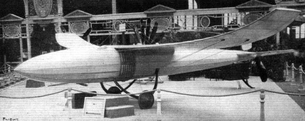
The Paulhan-Tatin monoplane at the Paris Aero Show.
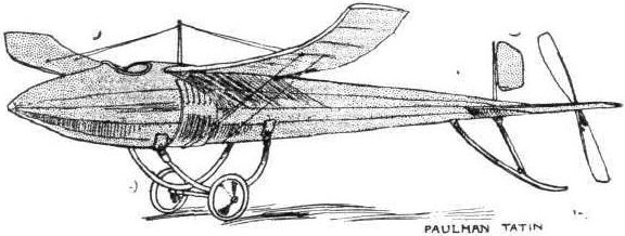
The aero torpedo, the result of the collaboration of Messrs. Victor Tatin and Louis Paulhan.

Tail-unit and propeller - Paulhan-Tatin monoplane.
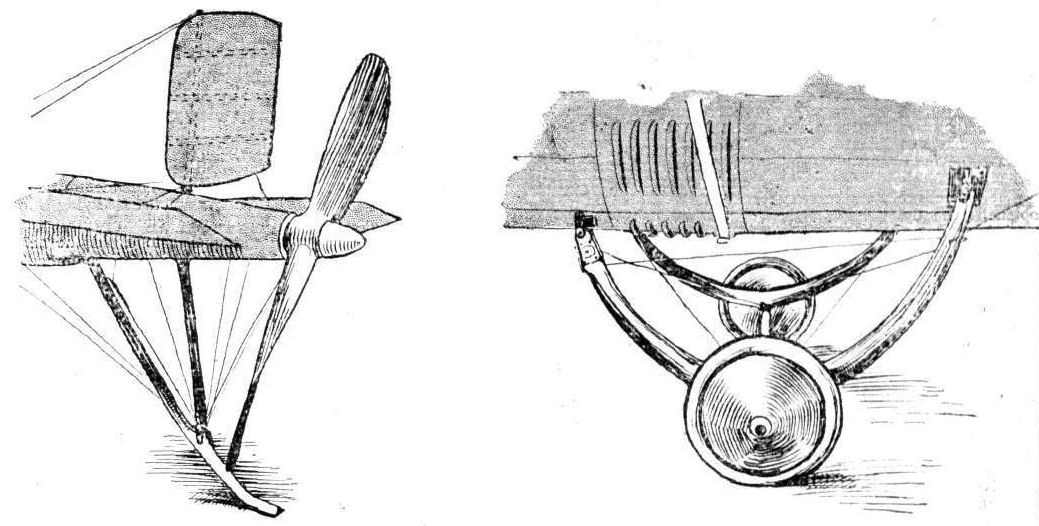
DETAILS OF THE AERO-TORPEDO. - The sketch on the left shows the arrangement of the tail unit and propeller. On the right is the landing carriage, showing the disc wheels and the louvred metal shield surrounding the motor.
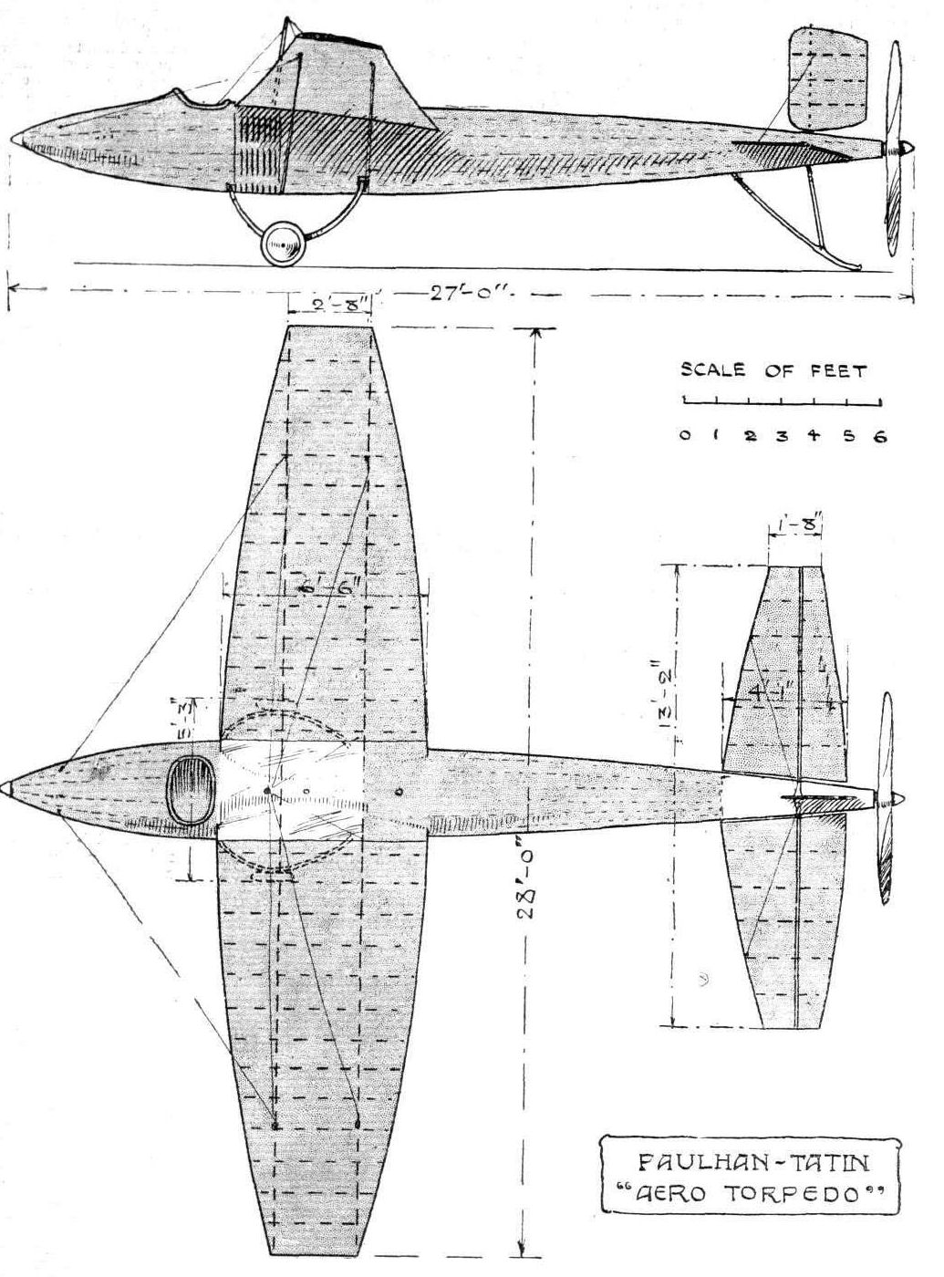
THE PAULHAN-TATIN MONOPLANE. - Plan and elevation to scale.
Flight, January 13, 1912.
PARIS AERO SHOW.
Ponche and Primard.
ALL-METAL construction is the chief feature of the interesting monoplane exhibited on Stand No. 10. A single steel tube, about 3 ins. in diameter, extends from the nose to the tail, and forms the backbone of the machine. Coupled to this tube, to form a structure of triangular section by means of shorter steel tubes, are long ash skids, which run from end to end.
These skids as can be seen from the accompanying sketch, extend for a considerable distance in front, thus eliminating any possibility of turning over on landing.
Both pilot and engine are located beneath the wings in a little body, which has all the appearance of a small runabout without wheels.
The wings are essentially novel, being constructed throughout of metal. Both front and rear booms are of steel tubing and on these are strong formers of 1 mm. steel aluminium. These are surfaced on the underneath with aluminium sheet 1/2-inch thick.
No surfacing has as yet been applied to the top surface for the reason that it is thought that the gain in the efficiency of the wings would not be sufficient to compensate for the extra weight involved. The rear wing booms are assembled in an aluminium casting which pivots about the main longitudinal tube of the fuselage. The propeller, too, revolves about this tube, being driven from the engine at reduced speed by means of chain transmission.
The tail comprises a rectangular lifting plane with two semicircular elevators hinged to its back edge and a semi-circular unbalanced directional rudder, the whole unit being constructed from aluminium sheeting.
Principal dimensions, &c. :-
Length 27 ft. 6 ins.
Span 32 ft.
Area 220 sq. ft.
Weight 660 lbs.
Speed 48 m.p.h.
Motor 35-h.p. Labor-Aviation.
Price L640.
Flight, November 2, 1912.
THE PARIS AERO SALON.
Tubavion.
ALTHOUGH more or less the same in outline, as the model shown by Messrs. Ponche and Primard last year, the Tubavion all-metallic monoplane has undergone several minor changes. The monoplane showing at present is a two-seater with a 70-h.p. Gnome installed. Their last year's machine was a single-seater which had its engine, a 45-h.p. Labor Aviation, if we remember correctly, mounted in the underslung body in front of the pilot, whence the drive to the propeller was by shaft and chain. The motor, this year, is back behind the wings and mounted concentrically with the top tube of the fuselage. The skids, almost the only wooden part of the machine, used to run from end to end. They now only extend for the front half.
Messrs. Ponche and Primard do not, for some reason, believe in soudure autogene. They prefer to use aluminium sockets to assemble their steel construction work. One of the points in last year's machine was that, while the under surface of the wings was covered with aluminium sheeting, the top surface was left uncovered, allowing such necessary parts as spars to offer untold head resistance. They have changed this by covering the top of the wings with fabric. During the past few months they have had one of their monoplanes flying with a 50-h.p. Gnome motor - almost an identical machine. They obtained a speed of 105 kms. an hour with it. The estimated speed of the two-seater model - it has not yet been tried - is 130 k.p.h. It weighs about 700 lbs.
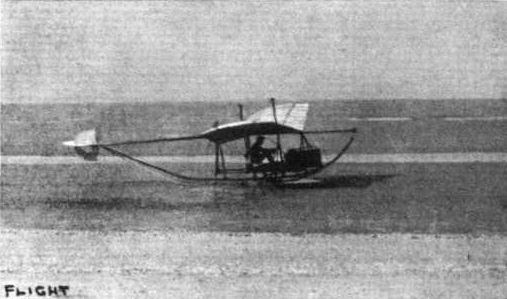
The "Tubavion" monoplane, the unique all-metal machine shown by Messrs. Ponche and Primard at the Paris Aero Salon, undergoing tests with M. Marie in the pilot's seat.
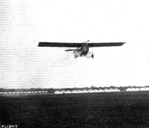
The Tubavion monoplane in flight.
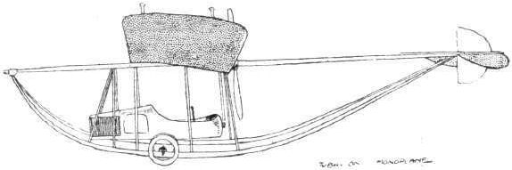
The Tubavion monoplane constructed by Messrs. Ponche and Primard. The chief characteristic of the machine is that it is constructed entirely of metal, with the exception of the landing skids.
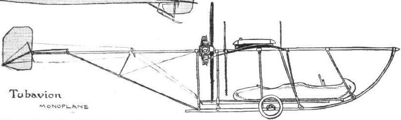
Flight, February 24, 1912.
FOREIGN AVIATION NEWS.
Long Flights by Gordon Bell.
ON Monday, at Buc, Gordon Bell was flying on one of the European Circuit-type R.E.P. machines for forty minutes, and then changing over to another one, fitted with one of the new 7-cylinder motors, he was flying on it for an hour. Afterwards he took Luzzalo, an Italian aviator, for a trip on the machine. On the 13th inst., he was flying for an hour at a height of 800 metres, and afterwards made two cross-country trips, one over Villacoublay to Issy, returning via St. Cyr; and the other above Rambouillet. On the same day Amerigo was flying for three-quarters of an hour, at an altitude mostly in the neighborhood of 1,000 metres.
Flight, March 2, 1912.
More R,E.Ps. for French Army.
LAST Saturday Gordon Bell at Buc was testing several new R.E.P. machines constructed for the French army. Among them was a two-seated machine fitted with a 70-h.p. motor, on which, accompanied by Lieut. Campagne, he made a fine flight over St. Cyr. He was engaged in similar work on the 21st ult., when on a three-seater, fitted with a 7-cylinder R.E.P., he was up at a height of 1,200 metres above St. Cyr and the neighbourhood.
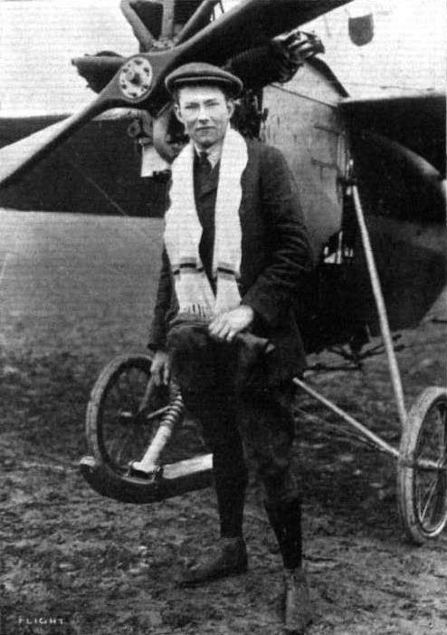
Mr. Gordon Bell standing in front of one of the R.E.P. monoplanes on which he has been making such splendid flights during the past few weeks over Buc and the surrounding country.
THE FIRST MONOPLANES FOR THE TURKISH ARMY. - Standing in the pilot's seat of the R.E.P. (left-hand machine) is Commander Fessa Bey, the first Turkish military pilot. In front the Turkish Military Commission is seen, the fifth from the left being Gen. Mabmud Schefket Pasha, the Turkish War Minister. On the right is a British pilot, who has been engaged, with his R.E.P. monoplane, by the Turkish Army as instructor.
Representative stand at the Salon - the Breguet-R.E.P.
Flight, November 9, 1912.
THE PARIS AERO SALON.
R.E.P.
AMONGST the hydro-monoplanes there is little doubt but that the R.E.P. two-seater is the favourite, partly because of its attractive appearance, but mainly because of the excellence that is shown in its construction and design throughout. When resting on the water its main weight is sustained by one large Fabre float 10 ft. wide, and measuring 8 ft. from front to back. A single float seems to harmonise with the general appearance of a monoplane a great deal better than a pair of pontoon-like floats such as most of the other constructors fit. In assembling this float to the fuselage the same system of flexible suspension is made use of that is employed on the standard land machine. It is the only hydroaeroplane shown at the Salon in which provision is made for the absorption of any shock that may be caused by landing suddenly upon the water. In addition to this, the construction of the Fabre float materially assists in deadening the shock. This, in fact, is M. Henri Fabre's chief claim for his floats, that they are flexible and give to a certain extent under the hammering influence of the waves. The bottom of his floats are covered with three-ply wood 5 mm. in thickness. There are no transverse struts to support this, except one at the leading edge, for, were they fitted, it would render the float too solid for M. Fabre's liking. The top of the float is covered in with strong fabric, tested to withstand a tension of 7,000 kilos, per square metre.
As for the remainder of the machine, it is purely standard in every respect, and remains one of the most notable examples of monoplane construction existing. It is interesting to mention that the machine shown on this stand is the identical one with which Molla carried off the first speed prize at the Tamise hydro-aeroplane meeting in Belgium some time since. It is equipped with an 80-h.p. Gnome engine.
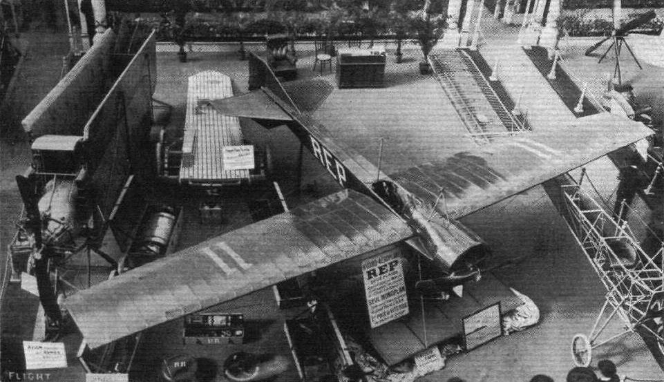
The 80-h.p. R.E.P. hydro-monoplane, with its single main float. To the left is a R.E.P. Avion packed ready for road transport.

The 80-h.p. R.E.P. hydro-monoplane.
Some of the types of float used on present-day hydro-aeroplanes, as seen at the Paris Aero Salon.
Flight, June 8, 1912.
FOREIGN AVIATION NEWS.
Along the Seine In an Hydro-Aeroplane.
ON the Sanchez Besa hydro-biplane, Benoit on the 30th ult. flew from St. Germain to Issy, following the course of the River Seine, and covering 50 kiloms. in 35 minutes.
FOREIGN AVIATION NEWS.
Along the Seine In an Hydro-Aeroplane.
ON the Sanchez Besa hydro-biplane, Benoit on the 30th ult. flew from St. Germain to Issy, following the course of the River Seine, and covering 50 kiloms. in 35 minutes.
Hydro-aeroplanes, illustrating the paper by Mr. Holt Thomas.
Flight, November 16, 1912.
THE PARIS AERO SALON.
Sanchez Besa.
THE biplane they are exhibiting shows, in its methods of construction and the design of its details, an extraordinary amount of Voisin influence. But we can scarcely think that the general design is of the same origin. Primarily it seems that the machine has been designed as a hydro-biplane of the Donnet-Leveque type, for it has a fuselage somewhat of the same type as the coque of that machine, and its main planes are arranged wholly above it. A 75-h.p. Renault is used, which is stowed away in the fuselage and which drives by chain transmission a propeller set practically level with the top plane. The landing gear with which it is fitted is purely Voisin. If the machine were a hydro-aeroplane we could probably understand why this disposition had been adopted, but as the machine shown is purely one for use over land, it would be rather interesting to know why the designer has departed so radically from what is recognised as the best possible arrangement of such factors as centres of gravity, of head resistance, and of thrust.

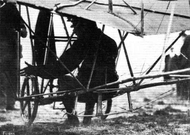
A REMINISCENCE OF AUDEMARS AT BOURNEMOUTH. - A silhouette of Audemars in the pilot's seat of his Demoiselle which he then flew. Note the rod which runs up to his shoulder blades at the back. This was secured in a strap round his chest, and by means of body movements he was able to warp the wings.
Flight, January 13, 1912.
PARIS AERO SHOW.
Savary.
THE solid-looking biplane, representing the Savary firm, possessed an enhanced interest on the score that it was one of the machines to fulfil the difficult conditions of the military trials at Rheims. Its cellule has a span of 46 ft., and apart from the fact that the stanchions are of steel tubing, this section of the whole machine presents little departure from standard practice. The surfacing is treated with some kind of wax preparation. Propulsion is obtained from two tractors, driven by a single chain in opposite direction by a 70-h.p. Labor-Aviation motor.
The importance of the single-chain transmission can be readily seen, for should it by any misfortune break, both tractors would be thrown out of action at the same time. Indeed, the writer was informed at the stand, that the system had been tested by breaking the chain in mid-air with no uncomfortable results; although the information as to exactly how this was effected while in flight was not forthcoming.
The landing arrangements consist of a central skid of ash, rigidly supported from the cellule by struts of steel tubing and a pair of wheels, disposed on either side of this skid. These wheels are hinged to the body of the machine at the upper extremities of the forks, to which they are attached, and under the influence of a landing shock, disappear towards the rear, each against the action of four shock absorbers arranged "in parallel."
At the tail end of the machine are disposed two roughly-pentagonal superimposed flat surfaces, flying point foremost, which serve the double purpose of stabilizer and elevator. There is no directional rudder in the tail unit, this function being performed by a system of two vertical panels arranged at each end of the cellule. In straight-line flight these fly out and give no resistance, but when a turning movement is required they are swung round and closed up on the side to which the desired turn is to be made. Balancing laterally is effected by ailerons. A boat-shaped body accommodates pilot and passenger, the former of which has control of the lever, a vertical column with a horizontal wheel arranged at its upper end. Control is manipulated in exactly the same manner as that in force on the Clement-Bayard biplane.
Principal dimensions, &c. :-
Length 36 ft.
Span 46 "
Area 572 sq. ft.
Weight 1,320 lbs.
Speed 62 m.p.h.
Motor 70-h.p. Labor Aviation.
Price L1.040.
Flight, May 18, 1912.
Wireless Missages from an Aeroplane.
ONE of the most successful tests of transmitting messages by wireless telegraphy from an aeroplane in flight was made at Chartres on the 7th inst. In conjunction with the military authorities represented by Lieut. Cheutin and Ensign Fournier, the "Radio Electricite" Co. has been conducting experiments for a long time and have at length evolved a transmitter which weighs 32 kilogs. and may easily be fitted to an aeroplane. One was fitted to a Savary biplane, and with Frantz at the tiller and M. Rouzet, the inventor, at the transmitter, a cross-country flight of 125 kiloms. was made. During the whole of the trip messages were successfully sent to the receiving station at Chartres even from 50 kiloms. away.
Flight, November 9, 1912.
THE PARIS AERO SALON.
Savary.
SINCE last year this firm do not seem to have changed their methods at all, and they remain almost the only firm of biplane manufacturers that have not been influenced by the monoplane trend in biplane design. Their present machine is fitted with a 75-h.p. Renault which is mounted in a rather neater manner than the engine on last year's machine. This point we illustrate. They are also showing, in a semi-finished state, a hydro-monoplane, the chief peculiarities of which are that it has a metal torpedo body and that the wings are stayed from the floats by an haubannage of steel tubing.

The Savary biplane, showing the landing gear and the disposition of the two tractors.
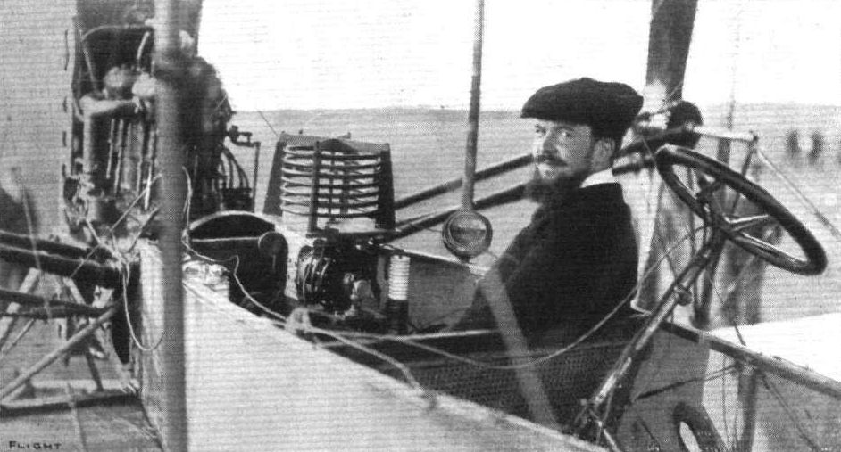
WIRELESS TELEGRAPHY AND AEROPLANES. - The wireless telegraphy installation on the military Savary biplane.

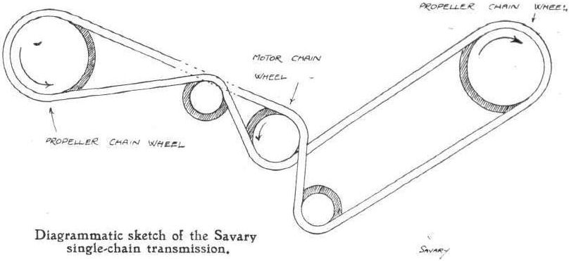
Diagrammatic sketch of the Savary single-chain transmission.
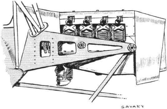
Showing the method of mounting the 75-h.p. Renault motor on the Savary biplane.
Flight, November 16, 1912.
THE PARIS AERO SALON.
Sommer.
SOMMER is showing two machines - a 75-h.p. Renault engine biplane and a 50-h.p. Gnome-engine monoplane. In neither case, we regret to say, do the machines show any advance on the types that were shown twelve months ago. For the biplane, a good deal of steel is used in its construction, although not nearly to the same extent as was evident in the extremely neat and promising biplane with the single bank of struts between the planes, that Sommer exhibited on his stand last year. The skeletons of the main planes, the tail and the front elevator, and the strutting of the cellule are of wood. The tail outriggers, elevator outriggers and chassis are of steel tubing. Sommer has abandoned his original idea of mounting his pair of landing wheels on a long common axle. In his new form of chassis each wheel is sprung from a pair of supports in such a manner that if the machine landed in any sort of a side wind, they could do nothing but collapse. From one of each pair of supports on either side of the machine, long curved tubular skids extend forward to meet the front elevator. They, too, seem of little use, for the steel tube must be insufficiently solid to avoid a smash should the machine land nose down, a contingency for which skids of this type were originally designed.
The main novelty in the monoplane is a new system of control whereby the surface that ordinarily constitutes the fixed lifting tail, may be varied in attitude according to the degree of deflection that the rear elevating flaps are given. From the diagrammatic sketch we print can be gathered an idea of how this movement is effected. Presumably the object of this system is to provide a more powerful control, and we can but remark that, if this is indeed the case, the designer could have achieved his object without resorting to such complicated means.
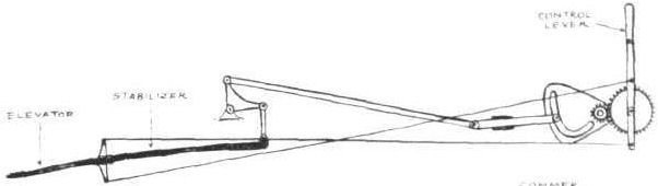
Diagrammatic sketch of the new form of control fitted to the Sommer monoplane.
Flight, January 27, 1912.
THE SOMMER ALL-STEEL BIPLANE.
FOR quite a long time after Sommer gave up his business as felt manufacturer, and entered the arena of aeroplane construction, it cannot be said that his productions earned any great name for excellence of general finish.
Nevertheless they were, indeed, practical vehicles, as his list of successes prove.
That the life of an aeroplane in those days was reckoned as not being much longer than two months is, perhaps, some excuse for his not devoting a great amount of attention to the point of finish. Today, however, engines are indefinitely more reliable, pilots have gained greater experience, and design generally has advanced, and concurrent with the increased length of life that these factors produce comes the desirability for higher-class detail workmanship.
Roger Sommer, indeed, has not lagged behind in this respect, and for the excellence that his new all-steel biplane exhibits as regards its general design, its detail work, and its standard of finish, we can forgive him much of the crudeness that characterised his earlier models.
Comparing his latest biplane with his former ones, it is noticeable that the cellular method of bracing the main planes has been discarded in favour of that originated by Breguet. The two main planes, unequal in span, are each built about a single boom of steel tubing passing through their respective approximated centres of pressure. These booms are separated by four steel stanchions arranged in a single row, and trussed together by stranded steel cable. In order to avoid the tendency for the booms to twist at the points to which the vertical stanchions are applied, these latter are made double, being each constructed from two parallel tubes of different diameters united by short lengths of the same material welded thereto. The planes are double-surfaced with green-rubbered fabric.
For the maintenance of lateral stability, the extensions of the top plane are so constructed that they can pivot about their main booms, and so take different angles of incidence, according to the discretion of the pilot.
They are interconnected, so that an increase in the angle of incidence of one is accompanied by an equal decrease in the angle of incidence of the other. In normal flight they both are incident to he relative wind at the same angle as the remainder of the top surface, and thus constitute purely sustaining planes. By virtue of the simplicity of this system of bracing, the supporting surfaces can readily be dismantled for transport from place to place, a feature that is being devoted an ever-increasing amount of attention among French constructors.
The tail consists of a fixed cambered monoplane surface mounted some distance behind the main planes on a pair of outriggers made solely from steel tubing. Behind this fixed surface is hinged a flap, which is connected to the front elevator and to the pilot's lever, and whereby the attitude of the machine in flight is governed. Two vertical rudders immediately beneath the tail provide the means of steering laterally. They are operated in the customary way by means of a pivoted foot lever.
The engine bed is formed by two tubular beams, representing the sides, united by cross-members of steel tubing, the whole being rigidly braced by steel wire. At its rear is mounted the 50-h.p. Gnome motor, direct coupled to an Integrate propeller. Two seats are provided, that for the pilot being about 2 feet in advance of the main planes, that for the passenger being in the same vertical plane as the centre of gravity. The chassis is quite an interesting feature, in that it is illustrative of the latest phase in the metamorphosis of the original Farman-type of landing gear. In common with other machines at the Paris salon, the skids have been entirely suppressed, and in this case a short piece of steel tubing, to which the common axle uniting the two landing wheels are flexibly strappd by rubber cord, is all that remains to remind one of their former existence.
On each side the chassis is supported by one main tube and two subsidiary ones, the main one proceeding from the base of one of the central cellule stanchions, the two smaller ones being directly attached to the engine bed.
Radius-rods are no longer provided, and the axle itself is not trussed, as formerly, to enable it to withstand the tendency for it to bend by virtue of the overhang of the wheels. Now a pair of simple tension wires are provided to limit the amount of possible flexion of the axle.
Mounted in advance of the pilot's seat, on a pair of single tubular outriggers, is a pivoting monoplane surface, roughly elliptical in shape, which is connected to the control lever, and which presumably is intended to act as a forward elevator. As such, however, it really must be of little use, by comparison with the superior area and leverage of the rear-elevating flap. Indeed, the only apparent reason for its presence there is that it forms a constantly visible indicator of the attitude of the machine, and that its outriggers constitute a very convenient point from which to brace the main planes against drift strains.
Weighing 638 lbs., the machine has been designed to lift a useful load of 500 lbs., and maintain a speed of 60 miles an hour.
Flight, November 16, 1912.
THE PARIS AERO SALON.
Sommer.
SOMMER is showing two machines - a 75-h.p. Renault engine biplane and a 50-h.p. Gnome-engine monoplane. In neither case, we regret to say, do the machines show any advance on the types that were shown twelve months ago. For the biplane, a good deal of steel is used in its construction, although not nearly to the same extent as was evident in the extremely neat and promising biplane with the single bank of struts between the planes, that Sommer exhibited on his stand last year. The skeletons of the main planes, the tail and the front elevator, and the strutting of the cellule are of wood. The tail outriggers, elevator outriggers and chassis are of steel tubing. Sommer has abandoned his original idea of mounting his pair of landing wheels on a long common axle. In his new form of chassis each wheel is sprung from a pair of supports in such a manner that if the machine landed in any sort of a side wind, they could do nothing but collapse. From one of each pair of supports on either side of the machine, long curved tubular skids extend forward to meet the front elevator. They, too, seem of little use, for the steel tube must be insufficiently solid to avoid a smash should the machine land nose down, a contingency for which skids of this type were originally designed.
<...>
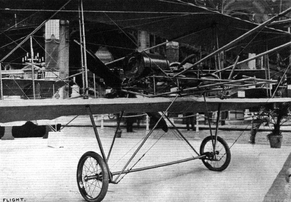
THE SOMMER ALL-STEEL BIPLANE. - Detailed view showing landing carriage, method of bracing the main planes, and steel engine bed.
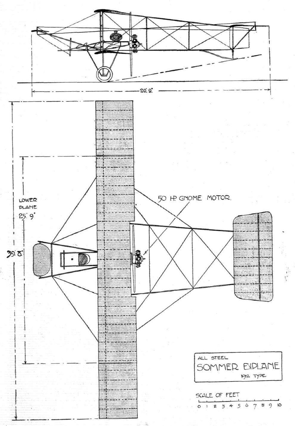
THE NEW ALL-STEEL SOMMER BIPLANE. - Plan and elevation to scale.
Flight, October 19, 1912.
Sommer Biplanes for Bulgaria.
SEVERAL Sommer biplanes of a new type, fitted with 70-h.p. Renault engines, have been ordered by the Bulgarian Army. Testing one of them on Sunday, Burri flew from Mourmelon to Mouzan, via Rheiras, Charleville and Sedan, at a speed of 93 k.p.h. The machine carried a load of 400 kilogs., and kept at a height of 1,000 metres. Some Bulgarian officers are being trained by Tetard at Mourmelon.
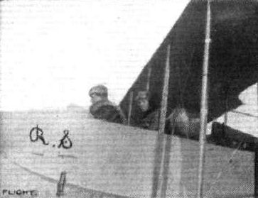
Lieut. Michele Mittieff, of the Bulgarian cavalry, together with Lieut. Stoyanoff, of the Bulgarian infantry, in the seat of their specially-built and armoured Sommer biplane, with which they last week left Mourmelon for the purpose of getting to the front and taking part in the present war.
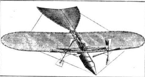
THE FORERUNNER OF THE "AERO-TORPEDO." - The model, driven by compressed air, with which Tatin experimented at Chalais-Meudon in 1870.
Thirty-eight years of endeavour span Victor Tatin’s major productions of aircraft design. His practical 6ft wing-span twin-screw model monoplane of 1879 was powered by compressed air contained in the barrel forming the fuselage. Having flown for 15m, it probably represents Tatin’s most undisputed achievement in his long aeronautical career.
Thirty-eight years of endeavour span Victor Tatin’s major productions of aircraft design. His practical 6ft wing-span twin-screw model monoplane of 1879 was powered by compressed air contained in the barrel forming the fuselage. Having flown for 15m, it probably represents Tatin’s most undisputed achievement in his long aeronautical career.
Flight, November 16, 1912.
THE PARIS AERO SALON.
Vinet.
A 50-h.p. Gnome-engined monoplane is exhibited here. Like many more machines in the Show, it does not seem to have changed one whit. Since last year, its main peculiarity is that its body, totally enclosed with fabric, is slung below the wings, the engine, however, being mounted on a level with their leading edge.
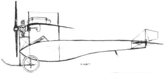
The 50-h.p. Vinet monoplane.
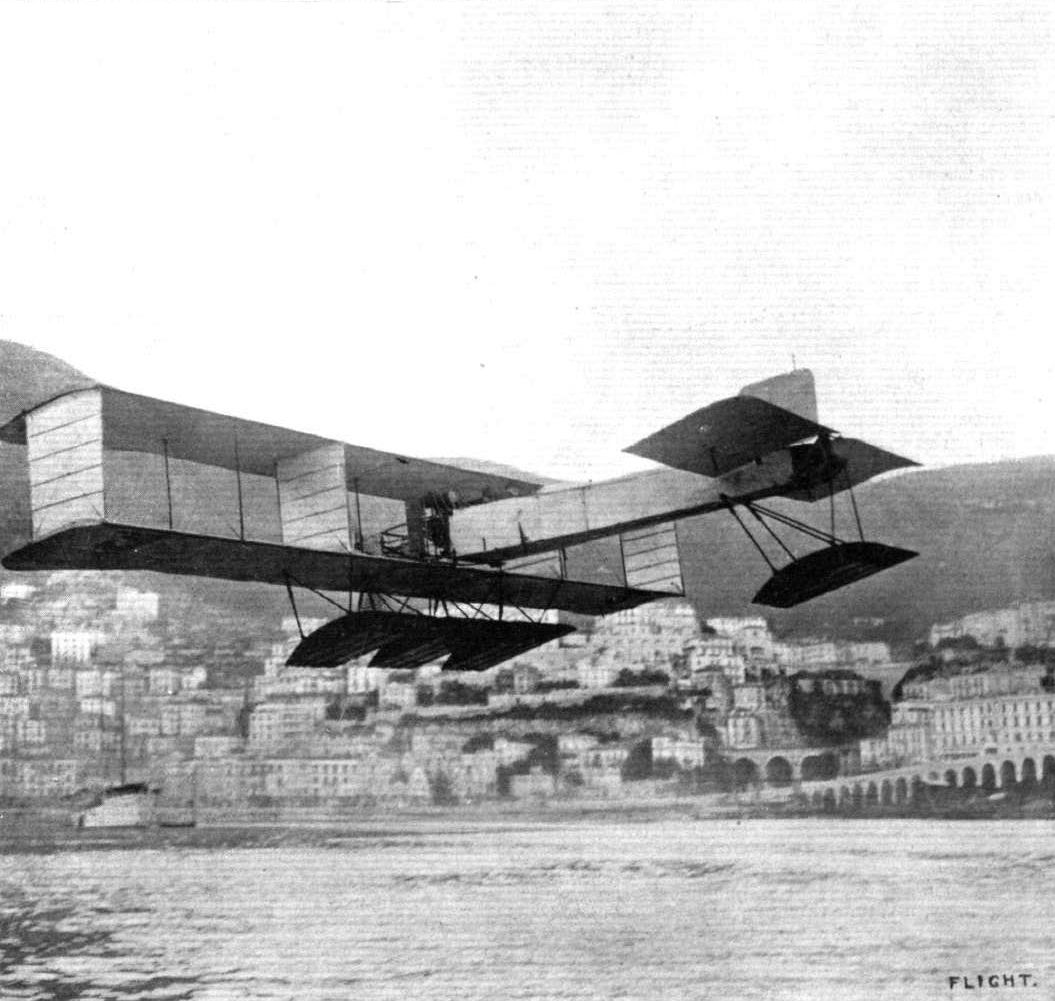
THE HYDRO-AEROPLANES AT MONACO. - The Voisin Canard well up in a flight over the course.
Fabre floats were adopted for several types of aircraft. This Voisin 'canard' had no fewer than four.
Fabre floats were adopted for several types of aircraft. This Voisin 'canard' had no fewer than four.
Hydro-aeroplanes, illustrating the paper by Mr. Holt Thomas.
Flight, April 6, 1912.
FOREIGN AVIATION NEWS.
M. Deutsch Orders an Aerial Yacht.
ALTHOUGH he has not so far made any great use of his aerial limousine, M. Deutsch (de la Meurthe), no doubt inspired by the success of the hydro-aeroplanes at Monaco, has decided to order one of these machines, capable of accommodating several persons and able to arise from and alight on the water.
Flight, November 30, 1912.
FOREIGN AVIATION NEWS.
The Deutsch Aero Yacht Files.
WITH Rugerc at the wheel, the hydro-aeroplane built by M. Gabriel Voisin for M. Deutsch de la Meurthe was tested at Issy on Saturday last. With six passengers and a pilot on board it rose from the ground in 70 yds., but in landing the chassis was somewhat buckled. It is said that the machine, which is fitted with a 200-h.p. Clerget motor driving a four-bladed propeller, attained a speed of 110 k.p.h. The span is 22.5 metres and the length 12 metres.
FOREIGN AVIATION NEWS.
M. Deutsch Orders an Aerial Yacht.
ALTHOUGH he has not so far made any great use of his aerial limousine, M. Deutsch (de la Meurthe), no doubt inspired by the success of the hydro-aeroplanes at Monaco, has decided to order one of these machines, capable of accommodating several persons and able to arise from and alight on the water.
Flight, November 30, 1912.
FOREIGN AVIATION NEWS.
The Deutsch Aero Yacht Files.
WITH Rugerc at the wheel, the hydro-aeroplane built by M. Gabriel Voisin for M. Deutsch de la Meurthe was tested at Issy on Saturday last. With six passengers and a pilot on board it rose from the ground in 70 yds., but in landing the chassis was somewhat buckled. It is said that the machine, which is fitted with a 200-h.p. Clerget motor driving a four-bladed propeller, attained a speed of 110 k.p.h. The span is 22.5 metres and the length 12 metres.
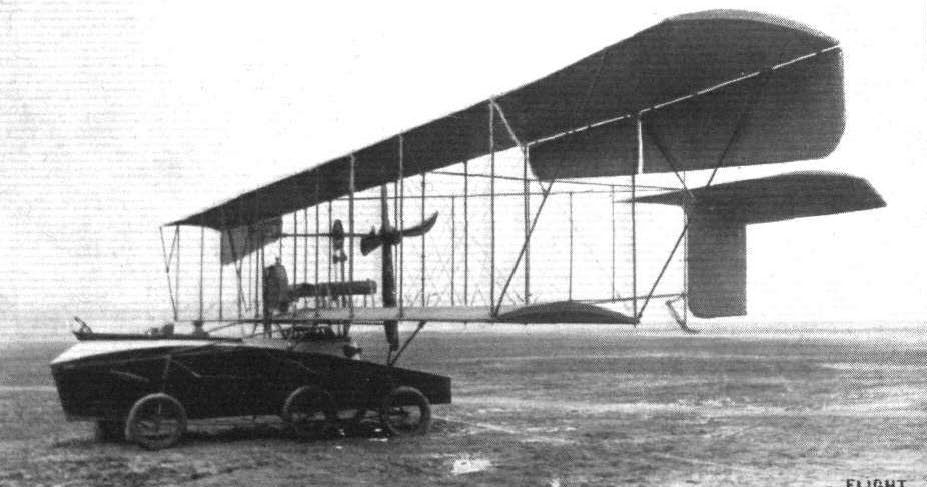
The 200-h.p. "Hydro-aerobus" that has lately been turned out of the Voisin works to the order of M. Henri Deutsch de la Meurthe. Its Clerget motor drives a 4-bladed propeller at 600 revs. per min. It has a wing spread of no less than 74 ft., and has been designed to carry 6 people!
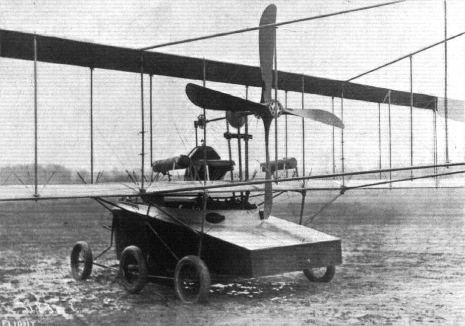
The coque of the Voisin hydro-aerobus, as seen from behind. Incidentally it may be noticed that the landing gear does not seem any too happy.
Flight, July 13, 1912.
New World's Records.
ON the 5th inst. at Compiegne, Legagneaux beat the world's passenger speed records from 10 to 150 kiloms. He used a Zens monoplane with an 80-h.p. Gnome motor. The new records are :-
10 kiloms. 4 m. 45 4/5 s.
20 ,, 9 m. 32 s.
30 ,, 14m. 21 2/5 s.
40 kiloms. 19 m. 9 s.
50 ,, 23m. 59s.
100 kiloms. 48 m.3 2/5s.
150 ,, 1h. 13m. 4s.
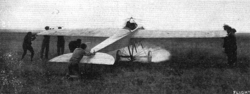
Legagneaux, on his Zens monoplane, just getting away at Compiegne for his passenger-carrying records when he covered 150 kiloms. in 1h. 13m. 4s.
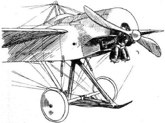
NEW FORM OF LANDING CHASSIS. - That of the new Zens monoplane, which has a single skid to which is strapped, by rubber bands, the axle joining the two landing wheels. The body of the machine is surported by a single rank of chassis struts, and is steadied by two shock-absorbers in tension, one on either side.
Flight, January 13, 1912.
PARIS AERO SHOW.
Zodiac.
THE Societe Zodiac is yet another of those firms who have, during the past year, adopted the fuselage and the engine-in-front position on their biplanes. In its superficial appearance, their machine closely resembles the Antoinette, with the exception that a staggered biplane cellule is employed for sustaining in place of the latter's single spread of wing. Throughout its whole length the main body is of rectangular section, being constructed on the conventional lattice-girder principle, and is covered in with fabric.
At its rear end is arranged a horizontal empennage, the elevator flaps, and the directional rudder. Even as regards its landing chassis, the machine preserves its resemblance to the Antoinette. In its springing, however, it employs a different principle. From the axle uniting the two wheels proceeds a vertical mast of steel tubing, which is further stayed thereto by diagonal tubes on either side. From the upper extremity of this mast, the remainder of the aeroplane, consisting of the main body and the sustaining surfaces, is virtually slung, this being carried out by means of a series of brass-capped cotton-covered shock-absorbers. A substantial skid, shaped like a hockey stick, extends forward to protect the propeller. Balancing is controlled by the employment of ailerons.
Principal dimensions, &c. :-
Length 38 ft.
Span 50 ft.
Area 352 sq. ft.
Weight 990 lbs.
Speed 60 m.p.h.
Motor 50-h.p. Gnome.
Price L1.120.
Flight, November 9, 1912.
THE PARIS AERO SALON.
Zodiac.
THE Zodiac biplane has made no visible change at all since last year, except for the addition of a transparent shield above the pilot's and passengers' seats. Our sketches show this point, and also give a general idea of the machine.
It must be a wonderfully efficient biplane, for it must be no mean weight, and it does all sorts of passenger-carrying work with a 50-h.p. Gnome engine. The high aspect ratio of its planes must be responsible for this, as well as the saving in head resistance of a neat and clean chassis. One thing, by the way, we must mention; it is extremely welcome - after having had explained a dozen or so machines in rapid French - to come across one who speaks such excellent English as M. J. Labouchere, who flies the Zodiac, and who is looking after the firm's interest at the Salon.
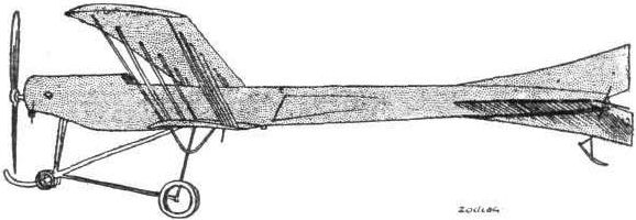
Side view of the Zodiac biplane.
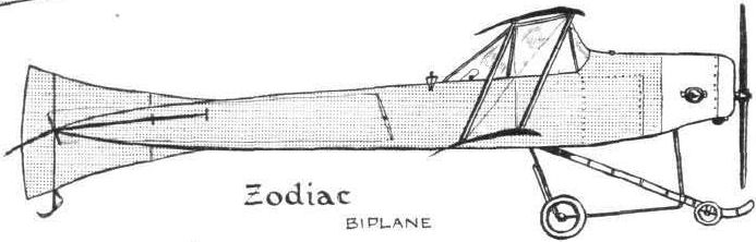

The pilot's seat of the Zodiac biplane, covered in with non-inflammable celluloid to protect the occupant from the rush of wind.
Flight, March 2, 1912.
FOREIGN AVIATION NEWS.
Grandjean Wins a Prize.
ON the morning of the 21st February, M. Rene Grandjean won a prize of 1,000 francs offered by Davos for a flight above the town visible from the Shatzalp and circling round the church of Johannaux-Platz. First making a circle above the Lake at a height of 300 metres Grandjean rose about 130 metres higher and made the necessary circuit quite easily.
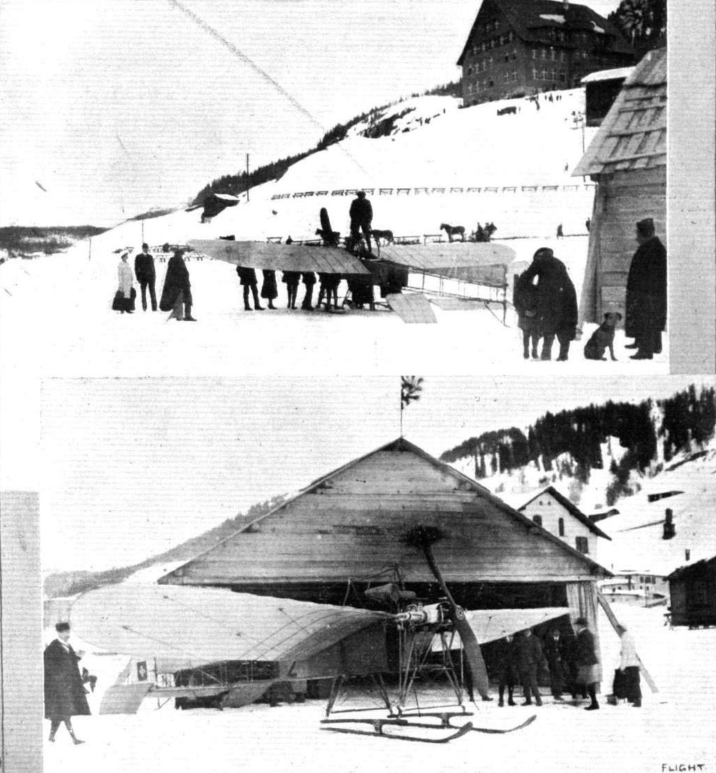
AVIATION AT DAVOS PLATZ. - The first aviator to fly a monoplane at Davos Platz is M. Grandjean, our photograph showing the machine and its shed at this famous resort. Moreover, M. Grandjean has entirely put the machine together on the spot by himself. Note the special skis attached for landing purposes.
Flight, March 2, 1912.
AIR EDDIES.
Those who have personal recollections of Lieut. O. Dahlbeck, of the Swedish Navy, while he was undergoing instruction at the Grahame-White school, will be interested to learn that he has lately been flying the Swedish naval two-seater Bleriot-type monoplane at Stockholm, carrying out his experiments over ice, which, he says, makes the most excellent aerodrome imaginable, although the intense cold makes things none too pleasant at times. He has also been indulging in night flying. With the Bristol biplane he is shortly going to use he expects to get much better results, as his present machine is not a genuine Bleriot. Both the Swedish passenger-carrying and duration records already stand to his credit, so, when he gets delivery of his new machine, there ought to be "somethin' doin'."
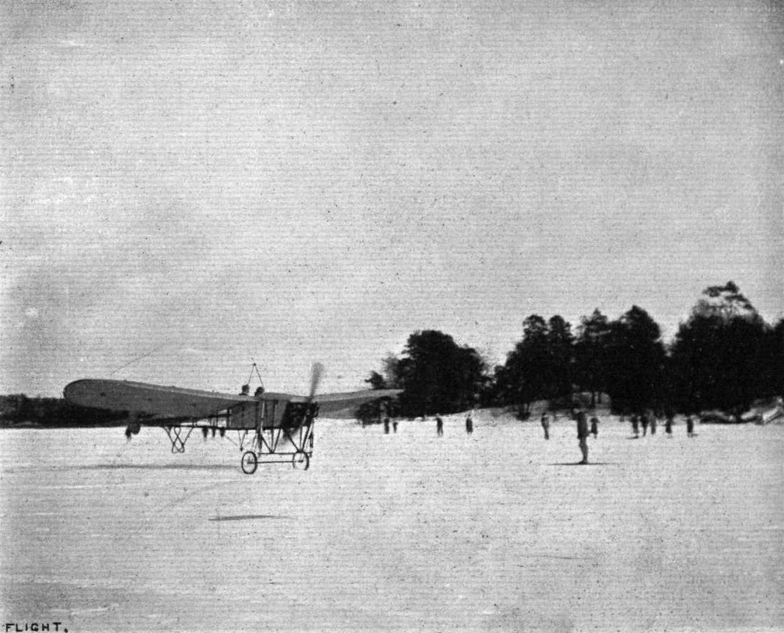
Lieut. Dahlbeck, of the Royal Swedish Navy, on his monoplane on the ice at Stockholm. - Lieut. Dahlbeck has been doing some good work in starting and landing on the ice with and without passengers. Lieut Dahlbeck, it will be remembered, graduated in flying at the Grahame-White School at Hendon.
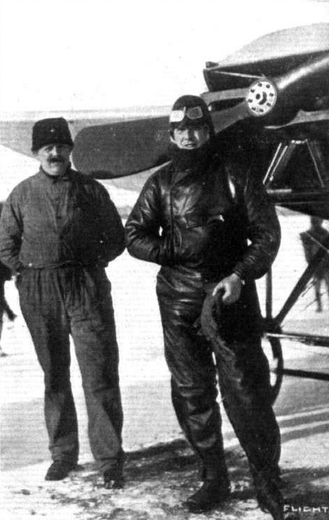
Lieut. Dahlbeck, of the Royal Swedish Navy, who is practising flying at Stockholm on the ice, both with a Swedish-built Blerlot-type monoplane and his Bristol biplane, the latter machine, he holding, being one of the best he knows.