P.Lewis British Aircraft 1809-1914 (Putnam)
Star Monoplane
<...>
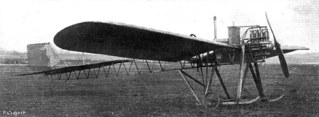
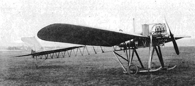
During 1911 the machine was altered extensively. The triangular-section fuselage made in two halves for ease of transport was retained, but a more powerful four-cylinder Star engine, giving 50 h.p., was installed. The original wing span of 42 ft. was reduced to one of 37 ft., with a consequent lowering of area from 290 to 231 sq. ft.; rounded wing-tips replaced the earlier square-cut type, and the tip skids were discarded. The tail unit was revised completely, elevators and rudder operating normally replacing the previous complex arrangement. The fixed fin, however, was removed without a substitute being fitted. At the same time the undercarriage was strengthened and the height of the wing-bracing pylon reduced.
SPECIFICATION
Description: Single-seat tractor monoplane. Wooden structure, fabric covered.
Manufacturers: Star Engineering Co., Wolverhampton, Staffs.
Power Plant: 30 h.p. Star, 50 h.p. Star.
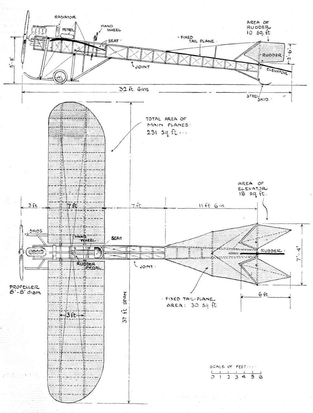
Dimensions: Span, 37 ft. Length, 32 ft. 6 ins. Wing area, 231 sq. ft.
Performance: Cruising speed, 36 m.p.h.
Показать полностью
M.Goodall, A.Tagg British Aircraft before the Great War (Schiffer)
Deleted by request of (c)Schiffer Publishing
STAR monoplane (Star Engineering Co., Frederick St., Wolverhampton)
<...>
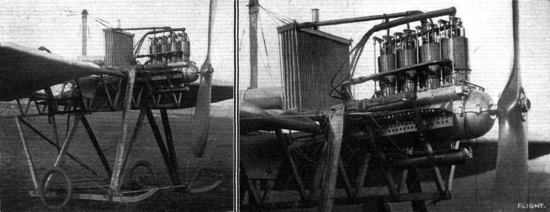
By November, the original car type engine had been replaced with a lighter engine, designed for aircraft use, and the long tubular radiators alongside the fuselage replaced by a block radiator behind the engine.
When the machine appeared in 1911 and was described by Flight, the wings had been reduced in span and had rounded tips and warping for lateral control. The differential control of the tail unit was abandoned, together with the lower rudder, and the top rudder was reshaped with a square trailing edge outline. The original divided elevators were retained, as was the tailplane, but without the differential movement of the elevators. A steel spring tail skid was fitted. The undercarriage reverted to a twin skid type, much strengthened with additional struts to the lower longerons and a cross axle with two wheels. The wing bracing and warp wires were carried to a single post.
The new Star aero engine, which replaced the car type engine, was reported to weigh 100 lb. less. The aircraft flew for the first time with this engine on 10 November 1910 at Dunstall Park. Bradshaw and Joseph Lisle, the son of the proprietor, Edward Lisle, are both believed to have flown the machine. The monoplane was transferred to Brooklands Shed 11 during November, and Bradshaw flew it there for the first time on 2 December 1910, intending to use it to obtain his certificate. It was flown again on 22 December 1910 and 10 January 1911 by J. Valentine and thereafter there were no further reports. The directors of the Star company had become disillusioned with aviation, and Bradshaw parted company with the firm. He remained at Brooklands where, in association with R.L. Charteris, the ABC Engine Co. was formed and began its operations.
The Star engine survived after the monoplane was dismantled, and was adapted for use in an unidentified ornithopter. It remains on exhibition in the RAF Museum at Hendon.
Power:
30-40hp Star four-cylinder inline water-cooled driving a 6ft 8in diameter Clarke propeller.
Data Second Version
Span 37ft
Chord 7ft
Area 231 sq. ft
Area tailplane 30 sq. ft
Area elevators 18 sq. ft
Area rudder 10 sq. ft
Length 32ft 6in
Показать полностью
Журнал Flight
Flight, July 1, 1911.
THE STAR MONOPLANE.
AMONG the many interesting features in the way of aeroplane design brought to light at the Olympia Show of last year, one of the most striking, it will be remembered, was the Star monoplane, and although as yet this machine has no very extended flights to its credit this can be partly accounted for by the fact that the designers, instead of adopting at once accepted methods with regard to tail construction and control, were desirous of evolving a tail that, besides performing the usual functions of elevator and rudder, would also be capable of maintaining lateral stability.
To this end experiments were carried out with a cross tail having four movable members of diamond shape, two being pivoted vertically on the stern post and two on a horizontal spar at right angles to it. When either pair of planes were deflected in unison, the effect was of course precisely that of a rudder or elevator respectively. But the control system was such that one plane of each pair could be operated in the opposite direction to its fellow, and it was hoped by this means to create a twisting action along the longitudinal axis of the machine and thereby to correct those lateral deviations, for which recourse is ordinarily made, in monoplanes, to wing warping. Actual experiment, however, has led to the substitution for this system of the simple rudder and elevator control. Two of the diamond-shaped planes are retained but they now work permanently together and constitute the elevator, as shown in the illustrations.
Though the Star monoplane in its present form may not show any marked difference in general appearance from many successful machines at the present day, it nevertheless displays, on closer inspection, so much originality of construction as well as of sound workmanship that a short description will doubtless be of interest.
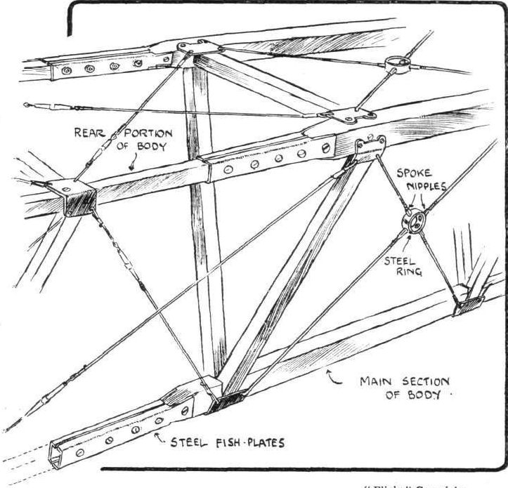
For the body of the machine a triangular girder form of construction has been adopted. This has also been made in two sections, so that the machine can be taken to pieces for transport; the joints occur some 3 ft. behind the main planes. An accompanying sketch shows the construction of this joint in detail; it consists of channelled fish-plates fixed permanently to the fore part of the girder, which constitutes the body proper of the machine. These fish-plates thus provide a kind of socket for the reception of the small spars of the aft portion of the frame. The diagonal bracing of the main section of the body is particularly neat and worthy of notice, for the wires, which are of substantial gauge, are cut in the centre of each panel and their threaded ends engage with a small steel ring. The nipples on the ends of the wires thus serve as a means by which tensional adjustment can easily be made.
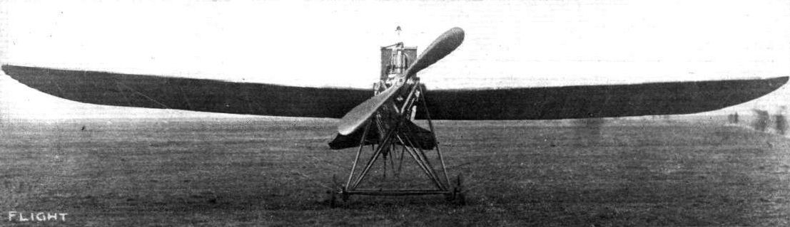
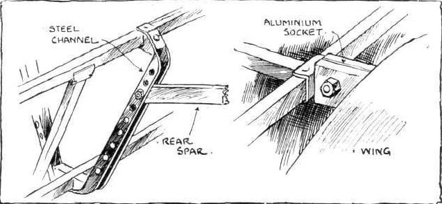
The main spars of the wings, which are set at a slight dihedral angle, are rather unusual in that they are not solid, but are built up of two lengths of American white wood placed one over the other and separated by a few inches. On the inner end of the leading spar an aluminium socket is fitted, which receives and is bolted to a rectangular lug of the same metal attached to the main girder. The rear spar is hinged to a strong steel channel, which being fixed at both ends to the body, incidentally contributes to its rigidity.
The main planes are double-surfaced and in plane form resemble those of the Bleriot. Their span is 37 ft. and their maximum camber approximately 5 ins. The span of the tail is 7 ft. 4 ins. across the maximum dimension, and is of the flat non-lifting type. It will be noticed, on reference to the plan of the machine, that the tail plane is recessed to admit the triangular fore parts of the diamond-shaped elevating planes. The arrangement of these planes in this way is presumably intended to place the members in question more or less in equilibrium about their axes of support. It would be interesting, however, to know something more of the effect of an entering edge of this form and also of the effect of the orifice in the tail plane through which the air deflected by the fore part of the elevator necessarily has to flow.
The control system of the machine is, as may be observed from one of our sketches, commendably free from complication; a lever is pivoted on the lower member of the body immediately in front of the pilot's seat. At its upper end this lever carries a hand-wheel, by rotating which the wings may be warped through the agency of a small sprocket-wheel, chain, and suitably arranged wires. Moving the control-lever as a whole forwards or backwards operates the elevator. There is no sideways movement to this lever, the operation of the rudder being obtained by the control of a pivoted cross bar supporting the pilot's seat.
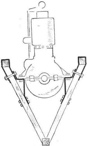
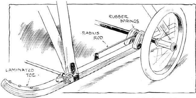
A 4-cyl. 40-h.p. Star engine, weighing 182 lbs., and driving a 6 ft. 8 in. Clarke propeller, constitutes the power plant. Pressed steel bearers of a special channel section support the engine and are bolted to the forward struts of the body. The consequent strain on these members, however, is considerably reduced by an ingeniously arranged series of small clips embracing the upper spars at the strut joints. Reference to an accompanying sketch will show how these clips really constitute a sling-mounting of considerable strength, but very small weight. The ash under-carriage is built up on the A principle and is a very rigid construction. It carries, a light axle, by means of which the machine is supported on two pneumatic-shod wheels. The ends of the skids of the under-carriage are laminated to give greater flexibility in the event of an awkward landing. The axle itself is attached. to the skids by rubber springs and light steel tubular radius-rods. At the base of the rudder-post a short length of flat steel spring is fitted to form a simple tail skid. It is pivoted so as to facilitate the tail movement when manoeuvring the machine on the ground.
Показать полностью