P.Lewis British Aircraft 1809-1914 (Putnam)
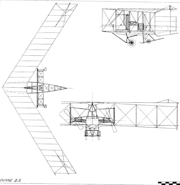
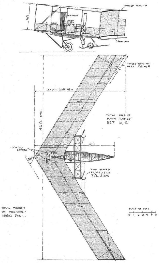
Dunne D.5
After Lt. J. W. Dunne left the Balloon Factory, he continued his work on his automatically-stable aircraft under the aegis of the Blair Atholl Aeroplane Syndicate Ltd., of 1 Queen Victoria Street, London, E.C., which was formed during 1910 by the Marquis of Tullibardine to sponsor the design.
The first outcome of this arrangement was the D.5, which was built during 1910 by Short Brothers in their works at Leysdown, Isle of Sheppey, Kent, using Dunne's design, but employing the constructor's own discretion in the selection of materials and fittings to be used in the airframe.
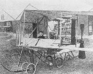
The machine was a two-seat tailless biplane with four-bay wings, the outer ends of which were enclosed by vertical fins with tip-skids below them. The first engine fitted was an eight-cylinder E.N.Y. "F" of 60 h.p., but this was changed to a 60 h.p. Green, the power being taken by chain-drive to a pair of outrigged 7 ft. diameter propellers, both of which turned in the same direction. The engine was housed in the centre of the boat-shaped nacelle, the nearest interplane struts to it carrying the cooling radiators. The pilot and passenger were seated in tandem, in the nose of the machine. A pair of sprung front wheels formed the main undercarriage, augmented by a third smaller wheel and two close-set skids to the rear. Flying controls consisted of ailerons on the tips of the upper wings. They could operate by independent cockpit control either as rudders or as elevators, and automatic stability under varying conditions was promoted by wash-out at the tips of the wings.
On completion, the D.5 was taken to the Short Brothers flying-ground at Eastchurch and was tested there throughout 1910. By April, the machine was flying well, and in May it completed a flight of 2.25 miles, its stability being such that it was able to maintain a straight and level course without attention to the controls. At the end of 1910, on 20th December, the machine's capabilities were demonstrated in flight by Lt. Dunne himself before Griffith Brewer and Orville Wright. During its trials at Eastchurch, the D.5 showed that it possessed perfect stability, and it fully vindicated its inventor's theories. Flying of the D.5 continued the following year until it was wrecked completely when it was crashed by Dr. F. A. Barton's son. The remains were salvaged and the machine was reconstructed, to emerge in 1912 as the single-engined D.8.
SPECIFICATION
Description: Two-seat tailless pusher biplane. Wooden structure, fabric covered.
Manufacturers: Short Brothers, Leysdown, Isle of Sheppey, Kent.
Power Plant: 60 h.p. E.N.V. "F", 60 h.p. Green.
Dimensions: Span, 46 ft. Length, 20 ft. 4 5 ins. Wing area, 527 sq. ft.
Weights: Loaded, 1,550 lb.
Показать полностью
Журнал Flight
Flight, June 4, 1910
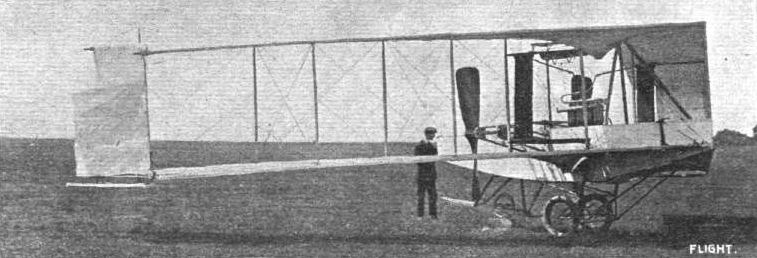
LIEUTENANT DUNNE'S "AUTOMATIC STABILITY" MACHINE.
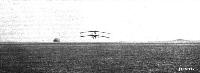
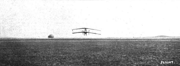
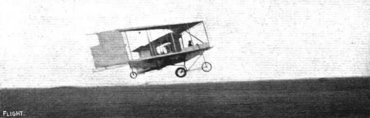
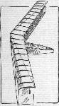
ON Friday of last week Lieut. J. W. Dunne made a highly successful trip on his cleverly designed biplane. Starting from Eastchurch, and rising to a height of 20 ft., Lieut. Dunne flew for two miles in a bee-line for Leysdown, and during this part of the flight the machine was left to take care of itself. This it did in masterly style, the aviator not requiring to make any adjustment of the elevating levers until Capel Hill was reached. It was then decided to pass over this, but Lieut. Dunne misjudged the distance and could not rise high enough in time. He therefore flew in a circular direction for about a third of a mile, and landed on the top of the hill. The skids were slightly damaged in landing.
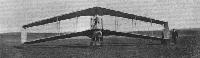
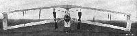
Photos of the machine in flight appeared in our issues of April 9th and 30th, and our readers will remember that the planes are in the form of an arrow, sloping backwards slightly. They have an area of 560 sq. ft., and during the above flight a load of 1,700 lbs. was carried. The speed over the ground was 29 miles an hour, and as this was against a ten-mile wind, the speed of the machine was estimated at 39 miles an hour. The engine is a 50-h.p. Green.
Flight, June 18, 1910
THE DUNNE AEROPLANE.
ONE of the most important items recently chronicled in FLIGHT was that recording the achievement of Lieut. J. W. Dunne, who, at Eastchurch in the Isle of Sheppey, flew a distance of 2 1/4 miles on a machine of his own design, which displayed so much natural stability as to render the use of the control levers totally unnecessary except so far as they were required for the purpose of directing the course. There is no doubt that this flight marks an important period in the development of the aeroplane, and although the outcome of it can only be vaguely surmised, this in no way detracts from its present importance, and should increase, rather than otherwise, the amount of interest in the machine itself.
When a man pursues a line of thought for nine years and proceeds to evolve a system of construction from data collected in ceaseless experiment; when, having built not the first, nor the second, nor third, not even the fourth, but the fifth machine, the inventor thereof flies at the first attempt under conditions that vindicated, at least so far as was possible on that occasion, the accuracy of his deductions, it is something for him to be proud of, and something for his country to be proud of, too. Lieutenant Dunne pursued his investigations of the problem of natural stability in the true spirit of science. He did not start with an idea and try to prove it; in fact, he has had very little time in which to evolve abstract theories that will fit in with the why and wherefore of every part of his machine. His is the sort of practice on which theory is founded. He set himself to observe. He made models and he watched them fly. He studied the works of others and he compared notes. As a result, he would tentatively adopt some general idea, such as, for instance, that in any stable flying machine, of which the main supporting surfaces are cambered aerofoils, the correct overall fore and aft length is very largely dependent upon that of the span. It is for this reason, among others, that the wings of the Dunne aeroplane slope backwards from the body to the extremities. The machine has no tail, as ordinarily understood, but it has a very considerable fore and aft length beyond that represented by the mere chord of the supporting surfaces.
Another general principle that he was forced to adopt, as a result of his own experiments and those of others, was that the tail plane and the main planes of a naturally stable aeroplane should make a dihedral angle with one another. Now, there is no tail plane on the Dunne machine, but the wings themselves are twisted so that the angle of incidence at the tips is less than at the centre, wherefore the principle of the dihedral angle is, as will be seen, adhered to, although the form of it is so extraordinary as to suggest, at first sight, that there is no such comparison. As for the why and wherefore of innumerable other points of interest it would be almost impossible for anyone, even the inventor himself, to say; they have just been arrived at by a long painstaking series of trials, such as are within the means of anyone to carry out, but conducted always in an atmosphere of strictly scientific observation. There is a reason for everything on this machine, but the reasons themselves have been evolved step by step with the design; they are not mere ideas, but careful deductions based on past experience. It was perhaps a little unfair to offer such a simple explanation of the reason for two of the outstanding features of the Dunne aeroplane, for it rather suggests that those features were tried in their present form from the first, whereas, on the contrary, the general lines as well as details are the result of gradual development.
It has been necessary thus to introduce the subject at some length in order to emphasise the point of view from which the Dunne aeroplane is most properly regarded, for in a mere description of the machine itself it is impossible to adequately imply the sort of appreciation that ought to be given to a design that is evolved in this fashion.
The Dunne aeroplane is a biplane, and was constructed by Short Brothers at Shellbeach to the designs of Lieut. J. W. Dunne, who is responsible for all the calculations concerned therewith, while Short Bros, themselves were given a free hand in the choice of material and fittings. As far as the actual construction itself is concerned, therefore, it is not necessary to say much in detail, for the machine is a typical example of the substantial and high-class workmanship with which that firm have already made a name, and with which our readers are already familiar. At first glance the observer is impressed with the solidity of the machine, and although there is no doubt that the weight could be considerably reduced in the commercial manufacture of duplicates, such robustness is by no means to be despised in an experimental apparatus even if the desired characteristic of the machine itself does happen to be complete natural stability.
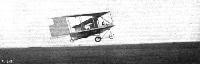
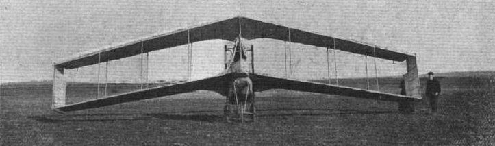
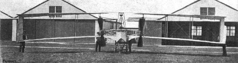
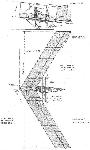
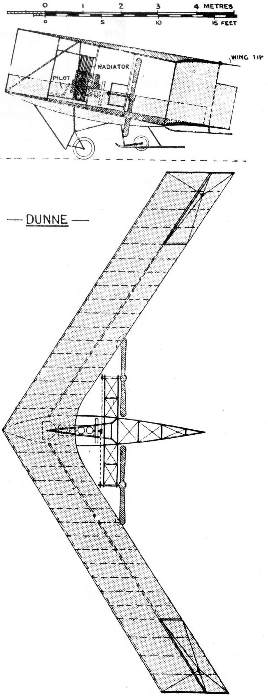
The outstanding feature of the Dunne biplane is the arrangement of the main planes, V fashion, as viewed from above. In plan the machine is like an arrow head, the main planes sloping sharply backwards from the centre where they join the body. Their extremities lie a little behind the rear end of the body, and thus the wings themselves constitute the greatest fore and aft dimension as well as the greatest span. The leading edge of each wing is straight, but the gap narrows a little along the leading edge towards the extremities, so as to give an expanding passage to the air. This is another of those details that have been evolved from experiment, and for which the precise reason, from an aerodynamic standpoint, is not at present clear.
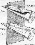
The main planes are cambered in a very peculiar way, for the camber varies at every point from the centre to the tips. In order to understand what this camber is like, the only accurate procedure is to construct a simple paper model, which may be done in the following manner. In the first place, cut a strip of paper to represent one of the wings, then roll another sheet of paper into a cone after the fashion of a foolscap. The piece of paper that is cut to represent one of the wings must be a rhomboid instead of a rectangle in order to allow for the slope back when one of the short edges is joined to the side of the body of the machine. Taking this strip of paper, it is laid on the cone so that its longest diameter is in contact with the surface of the cone from the apex to the base. The corner of the paper should coincide with the apex of the cone. The short edge of the sheet of the paper representing the wing, which is adjacent to the base, is then bent down to touch the surface of the cone, while the short edge adjoining the apex is allowed to stick out tangentially behind. Thus arranged, the sheet of paper represents one of the wings of the Dunne aeroplane, only the camber will, of course, be much exaggerated owing to the scale on which such a paper model would probably be constructed. It will be observed that the initial contact line with the cone runs diagonally from the leading edge where the wing joins the body to the trailing edge at the outer extremity. Near the body, therefore, the wings of the Dunne aeroplane are not much curved, whereas near the extremities they are curved for the greater part of the chord. At first sight this will suggest that the extremities are much more cambered than any other part of the wings, but it must be remembered that the radius of the curvature also increases towards the wing tip, for the centre from which it is struck lies on the axis of a cone, and not on that of a cylinder. If, therefore, less of the rib is actually curved in the vicinity of the body, that part which is curved has a more abrupt and consequently relatively greater deflection.
(To be concluded.)
Flight, June 25, 1910
THE, DUNNE AEROPLANE.
(Concluded from page 462.)
IT has been said above that the wing is flat where it joins the body, but actually this is not the case, for although the wings are undoubtedly made up on the above-mentioned principle, which would give a flat section in the place indicated, a secondary consideration introduces the necessity for a certain form of curvature in this particular part of the wing, which, as a matter of fact, is extremely cambered at that point and for about two feet from the body. Here again, however, the camber is not uniform, and it is obtained entirely by deflecting the trailing edge. Its purpose, which has nothing whatever to do with the general action of the machine, nor with the general principle on which the wings as a whole are designed, will be referred to later.
By the aid of the little paper model it is easy to appreciate that most important salient feature of the wings on the Dunne aeroplane, viz., that the angle of incidence becomes less towards the outer extremity of the wing. With a certain normal attitude it will even change its algebraic sign, being positive in the vicinity of the body, zero somewhere in the middle of the wing, and negative at the tip. If the angle of incidence at the tip is positive, then the angle of the whole wing will be positive, and conversely if the angle at the root is negative then the angle of the entire wing will also be negative. Insufficient experience has been obtained to show what is exactly the normal flying attitude of the Dunne aeroplane. Lieut. Dunne himself imagined that it would be such as to reverse the algebraic sign of the angle of incidence somewhere in the vicinity of the outer extremity of the wing, but some of those who were eye-witnesses of the flight declare that the datum line to which the trailing portion of the wing is parallel, was horizontal in flight, which would mean that the entire wing was flying with a negative angle of incidence.
It may be mentioned that the entire machine is constructed to a datum line, which is carefully laid off in the body. The upper part of the body framework lies parallel to this line, and thus affords an easy mark of observation in flight. That portion of each wing which does not follow the surface of the cone, but juts out tangentially from the diagonal, is constructed so as to lie in the plane of the datum line, and consequently whatever may be the observed angle of the datum line in flight, that also is the angle of the tangential trailing portion of each wing. The angle of incidence represented by the chord between the leading edge and the trailing edge will of course be less than this, so that if the datum line is observed to have zero angle (i.e., be horizontal) in flight, it necessarily follows that the angle of incidence is everywhere negative. On this subject of the negative angle of incidence we have already had some discussion in FLIGHT, and we expect to have still more ere the mathematics of the cambered aeroplane is properly understood.
Reference has been made above to the extreme depression of the trailing edge of the wings adjacent to the body. This feature was introduced as the result of some early model experiments that showed it to be necessary to stability for the extreme case in which a model was let fall vertically bow first. It is to be hoped that no experience of this sort may befall the full-sized machine in flight, but Lieut. Dunne decided to retain the feature for what it was worth.
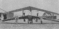
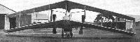
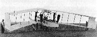
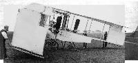
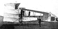
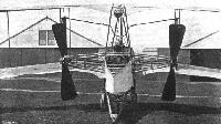
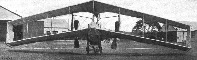
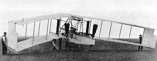
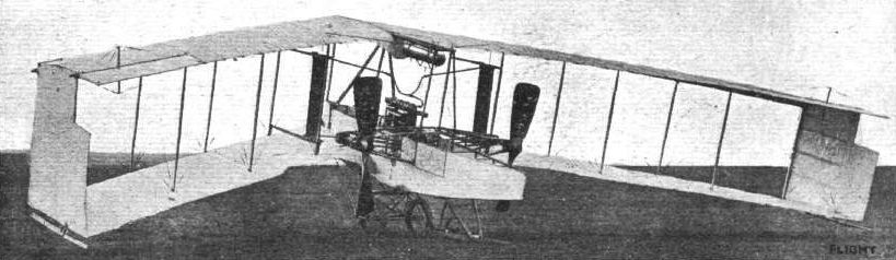
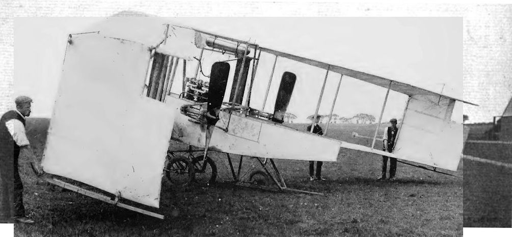
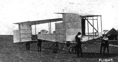
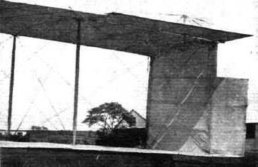
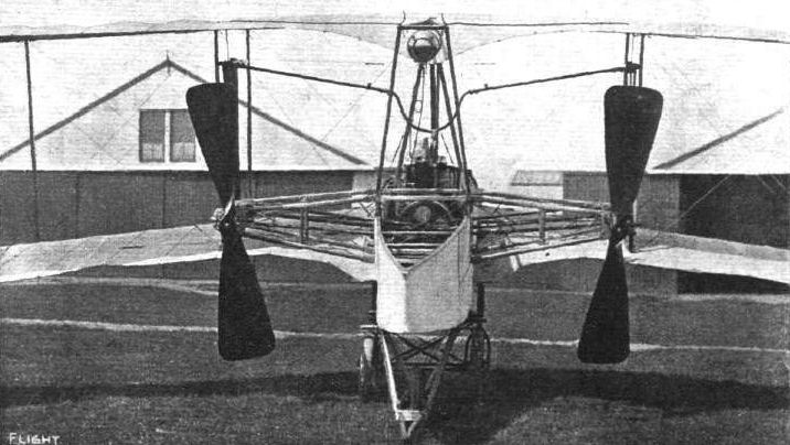
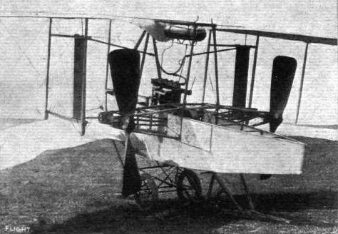
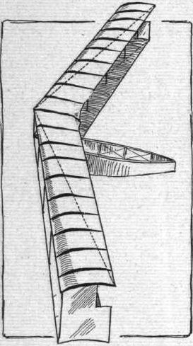
Coupled with the above description, the accompanying photograph ought to render the general arrangement and leading details of construction of the wings of the Dunne aeroplane sufficiently comprehensive. Incidentally it may be remarked that this machine is one of the most difficult to illustrate by photographs of any that we have seen. Any one view, taken by itself, almost invariably leads to a wrong impression with anyone who is not familiar with its actual features. The view from in front is apt to suggest that the machine is nothing but an arched biplane, whereas, in fact, the amount of arching that actually exists, for constructional convenience rather than as a principle of design, only amounts to a few inches. In order to overcome the difficulty we have taken photographs of the machine from almost every point of the compass, so that by comparing one with another our readers may elucidate for themselves any feature on which they are in doubt. These photographs, too, are extremely well worth studying in detail, for every one of them shows some characteristic feature of this most interesting machine.
The wings are double surfaced, and built up on two main spars that are reinforced with numerous shaped ribs; the upper surface was regarded as the more important curve. The upper deck is supported above the lower deck by struts and diagonal wire bracing, the attachment of the struts and spars being effected by means of the steel ferrule joint adopted by Short Brothers. Vertical panels are fitted to the extremities of the wings, principally because it is thought that their presence tends to increase the lifting efficiency of the planes by preventing too much leakage at the extremities. In the trailing edge of the upper deck a hinged flap is inserted at the extremities in order to afford a means of steering the machine. These flaps are coupled up by wires to a pair of levers, one of which is situated on either side of the pilot. The flaps are thus independently controlled, and can be used either as rudders or as an elevator. When steering to the right the right-hand lever is drawn backwards, and the left-hand lever simultaneously pushed forwards. These actions result in the flap on the pilot's right having its trailing edge elevated, while the flap on the pilot's left has its trailing edge depressed. For ascending both levers are simultaneously pulled backwards, which raises the trailing edges of both flaps.*
* For an explanation of the aerodynamic reactions accompanying these actions, see Lieut. J. W. Dunne's letter in Correspondence.
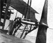
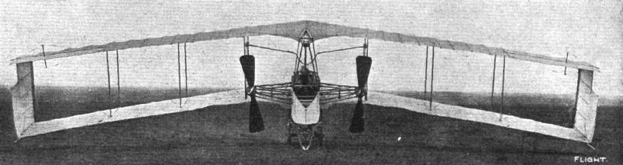
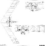
The pilot's seat is situated in the bows of the machine, the seat being formed inside the principal longitudinal girder, which is a lattice-work construction of timber and strip steel, shaped somewhat on the lines of a flat-bottomed boat. The bows and the stern come to a sharp edge, but in the centre there is sufficient beam to accommodate the 50-h.p. Green engine that drives the twin screws. The pilot sits a little in front of the engine, and there is just room for a passenger behind the pilot. The sides as well as the bottom of the girder are covered in, so that the pilot's head is alone exposed, lieut. Dunne is of opinion that this surfacing of the girder and the almost complete enclosing of such principal masses as the engine and pilot is of very great importance, not so much on account of the advantage of stream line form in respect to minimizing head resistance, as because of the locality of those masses in respect to the supporting surfaces. A large mass situated above the supporting surface gives rise to disturbances in the air currents similar to those that would be created by a vertical plane set at right angles to the supporting surface, which in turn might be represented by an equivalent cambered aerofoil of inverted position, for the air current would, in effect, disregard the right angle by conforming to an upwardly curved path. Arguing on these lines, it seems that the relative position of the principal masses has considerable importance from an aerodynamic point of view, and might possibly affect the resultant centre of pressure in a way that would be serious on a machine like the Dunne aeroplane, which is designed for a high degree of natural stability. It is in order to avoid any tendency to reverse the direction of the air stream that the girder of the Dunne machine is so carefully surfaced.
The twin propellers that drive the machine are carried on the extremity of a light transverse lattice-work beam, and are driven by chains from the crank-shaft. The propellers are 7 ft. in diameter, and have a pitch of 7 ft 6 in. Both revolve in the same direction; the torque is balanced by a lead weight attached to one of the skids that protect the extremities of the wings. The propellers were constructed by Short Brothers to the designs of Capt. Carden. Their bosses are fitted with twenty-tooth sprockets, and the sprocket on the crankshaft has twelve teeth. The engine runs at about 1,100 r.p.m.
The petrol tank is carried immediately above the engine on a light frame, and the radiators are mounted in the gap between the main planes, where they are supported upon bearers attached to the vertical struts.
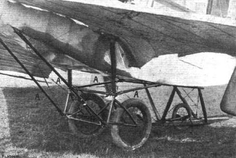
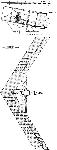
The chassis upon which the machine is mounted is also an interesting piece of construction, although naturally its present form is not essential to the machine; it was, however, designed at a time when the wheeled chassis was the only device in practical use, and it should be judged accordingly. Compared with the original Voisin chassis, it possesses some interesting modifications that it is only proper to recognise as improvements. The hubs of the two wheels are universally-jointed to an axle that holds them at the required distance apart. They are carried in a double fork that is attached by a couple of radius-rods to the girder member of the machine. The arrangement of these radius-rods is such that they are always in tension, which is a far more suitable stress for tubular work of this description than a compressed strain. The accompanying illustrations show how the helical springs are arranged to give the requisite suspension. The rear end of the girder is supported by an independent single-wheel chassis that combines a skid, and the nose of the machine is also fitted with a single wheel, which, however, is not shown in our photographs. This latter member is so placed that when it makes contact with the ground the aeroplane is in its running position. This facilitates starting, because it prevents the machine from being tilted too far over, and yet it avoids the necessity of trying to get under way with too great an angle of incidence.
THE DUNNE AEROPLANE CONTROL.
In considering the control of our machine, it is essential to remember that the wing tips are not normally inclined at a positive angle to the trajectory, as is the case in every other machine. Actually they are at a negative angle.
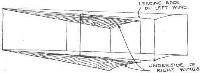
When we want to steer to the right we pull back the right-hand lever, thereby elevating the trailing edge of the right-hand flap. In an ordinary system, regarding the tip as normally positively inclined, you would say, "The angle of incidence of the right-hand extremity is thereby reduced." This is incorrect. The angle of incidence, which is negative is thereby increased, and the drift, one might almost call it the negative drift, is increased. This wing, therefore, tends to hang back, at the same time, owing to the increased negative inclination, this side is depressed. One could steer by this movement alone, were it not that the flap, situated behind the centre of gravity, is an elevator, and when it depresses the right wing tip it depresses the rear of the machine as a whole. In order to counteract this elevator effect, we simultaneously push forward the left-hand lever, thereby lowering the trailing edge of the left-hand flap. This does not "increase" the angle of incidence on that side, but decreases the previous negative angle of incidence of that side. This left side then has more lift than it had before, and balances the elevator effect of the right-hand flap. At the same time, owing to the decrement in the negative angle, this left tip has less resistance than formerly, and so travels faster than before, thus aiding the turning movement slightly. Since the right tip is depressed and the left tip raised, the machine is banked with the right side lower than the left.
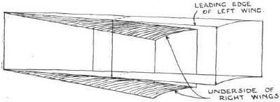
Possibly some may imagine that this banking is the reverse of that usually done in rounding a corner with an aeroplane, as there appears to be some confusion in aeronautical literature on this point. Most people seem to argue that when a machine is circling to the right, the left side, which travels faster than the other, rises, tending to capsize the machine, and that ailerons or warping have to be used to keep the right side up. The problem is really a purely quantitative one. The effect of any rudder action is primarily to point the machine's head in the new direction. Then you have the centrifugal tendency of a machine of, in our case, 1.700 lbs. to contend with. Is the banking which occurs owing to the outer wing moving faster than the inner sufficient to overcome centrifugal movement (which is of course a sort of side-slip) or not? The answer obviously depends on the mass, the speed, the radius of the circle, and the design of the machine. In a machine with a big dihedral surface forward, like the Antoinette, or big vertical surfaces well forward and above the centre of gravity like the Voisin, the centrifugal motion, which occurs as soon as the bow is diverted from its previous course, produces reactions on the underside of the dihedral wing, or on the vertical panels, tending to cant up the outer side considerably, quite apart from the lift it might get owing to its relatively faster movement. In our own machine the immediate effect of this centrifugal side-slip would be to depress the outer wing. You will see this if you look at the machine from the side in one of your photographs. Thus, the machine is turning to the right, and the centrifugal movement, which we are assuming for the moment to be unbalanced, causes it to skid to the left. The rough sketch above shows the position, the machine skidding towards the spectator. Notice that the left-hand surfaces appear as a comparatively thin edge, while a very broad expanse of the under surfaces of the right-hand side is exposed. The right-hand side is thus lifted and the left depressed. This is more than sufficient to counteract the tendency of the left to rise owing to its relatively faster motion. Therefore our controls are arranged so as to cause the outer side to rise and the inner side to fall. As a matter of fact this machine can bank up on a sharp turn to over 45 without any centripetal movement being apparent.
J. W. DUNNE.
[The above very lucid explanation of the steering of the Dunne aeroplane was sent in reply to an editorial letter on the subject, and as we feel that our readers would prefer to have Lieut. Dunne's description in his own words, we are publishing the letter itself simultaneously with our article on the machine.-ED.]
Показать полностью