S.Ransom, R.Fairclough English Electric Aircraft and their Predecessors (Putnam)
Howard Wright 1909 Biplane
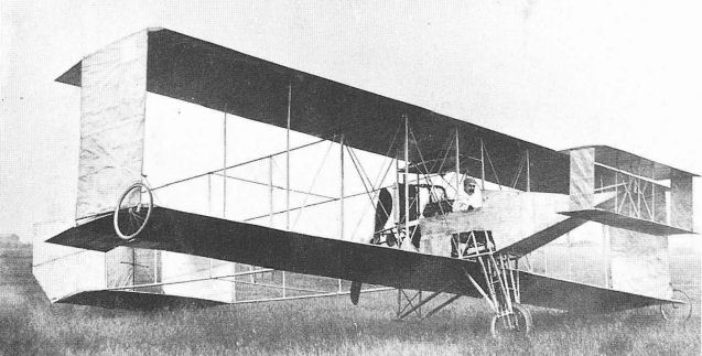
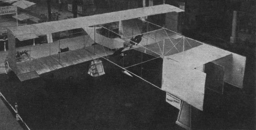
In December 1908, Malcolm H. Seton-Karr placed an order with Howard Wright for a biplane. Construction of the machine started immediately and it was completed in time for exhibition at the 1909 Olympia Aero Show, where it was acclaimed for its outstanding workmanship. The aircraft was noteworthy, also, for its strikingly clean appearance, indicating that contemporary aerodynamic theory had been applied with a degree of success, particularly by the introduction of a number of refinements to reduce drag. Clearly, this biplane was in advance of its time.
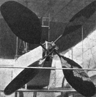
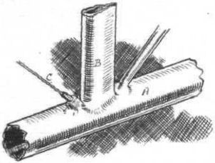
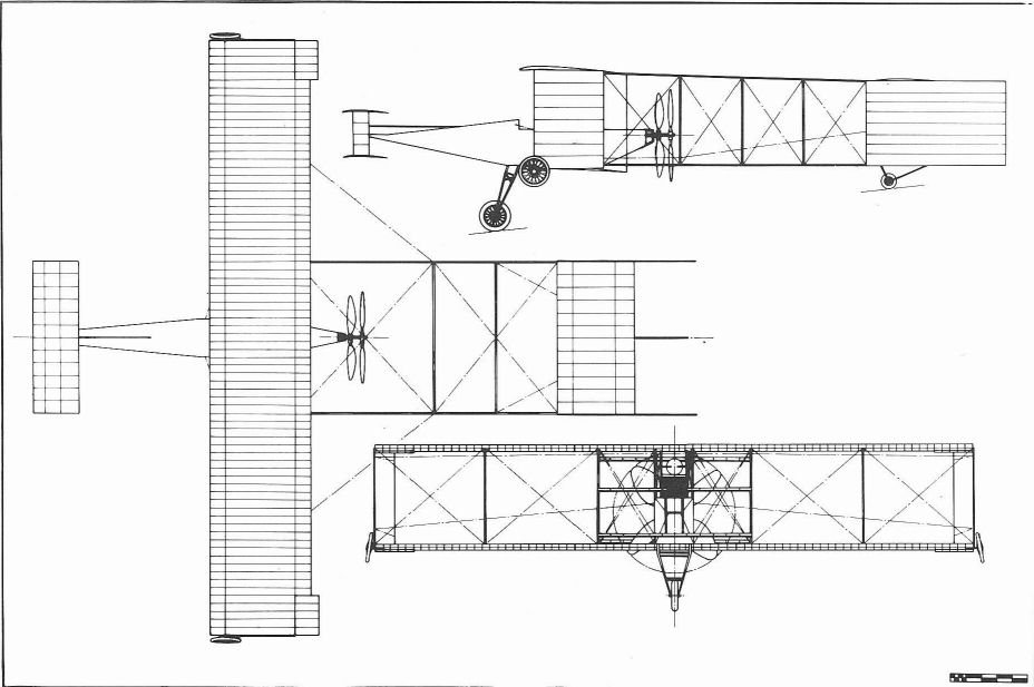
The biplane shown at Olympia followed Voisin lines but incorporated a streamlined nacelle for the comfort of the pilot. The nacelle was made of steel tubes welded together without sockets - a technique perfected in the course of constructing Capone's helicopters - and covered with silver doped fabric. At the aft end of the nacelle, a Belgian Metallurgique engine of 50 hp drove contra-rotating co-axial propellers through a patented 3:1 reduction gear, the forward propeller having blades of larger chord than the rear. A theoretical efficiency of 73 per cent was claimed for the propeller arrangement. The blades, which were made with constant incidence over their length, were of wood attached to steel shanks clamped offset to the propeller shaft. Petrol was gravity fed to the engine from a 15 Imp gal streamlined tank carried, like the radiator, between the interplane struts supporting the wing centre-section. The wings each had two ash spars reinforced with flitches of strip steel, and closely pitched ribs of spruce. The upper and lower surfaces of both wings were covered with fabric tautened with clear dope. No internal wing bracing was fitted, reliance being placed on spar stiffness. External bracing wires, streamlined interplane struts and fabric-covered end-plates maintained the wings in position. Construction of the forward elevator and fixed tailplane was similar to the wing, although the former dispensed altogether with bracing wires. The tail surfaces were carried on light tubular-steel booms braced with streamlined struts and wires. In addition to the forward elevator, operated by an irreversible screw from the cockpit, the biplane was controlled by four small wingtip ailerons connected through a closed-loop system of cables and struts joining corresponding pairs of ailerons, and a rudder mounted midway between the tailplane end-plates. The biplane was fitted with a monowheel undercarriage, based on the French REP monoplane, supplemented by wingtip wheels and a small tailwheel, this arrangement being considered to assist novice pilots to master the aircraft's controls before attempting flight. On the ground the biplane naturally rested on one of its wingtip wheels, in which state it remained until it had reached about 8 mph, when the machine would right itself onto an even keel. At 15 mph the tail was expected to lift, enabling the pilot to manoeuvre the biplane in any direction on its mainwheel so that he could familiarise himself with the controls without leaving the ground. Only when the pilot felt himself in control was he expected to increase his speed to about 30 mph for take-off.
After the Show the biplane was taken to Fambridge aerodrome, Essex, where Howard Wright had erected a shed to house it. The journey was not without mishap, however, for the dismantled biplane was badly damaged on two occasions when the waggon carrying the wings was driven into a railway bridge by an inattentive carter, and, later, when the tail booms of the fuselage were broken in manhandling the machine across a ditch on to the flying ground. Then the shed was blown down in a gale.
By the begining of May 1909, the biplane had been repaired and all was ready for engine tests. No trouble was experienced in starting the engine but, on warming up, it inexplicably gained speed to such an extent that the propeller shaft sheared and fragments of blades were hurled in all directions, even through the iron roof of the shed, buckling and breaking the tail booms yet again. Repairs were put in hand immediately and the middle of June saw the biplane at last being tested under the direction of W.O. Manning. As might have been foreseen, Seton-Karr experienced considerable difficulty with the undercarriage for it necessitated taxi-ing the machine to a speed higher than estimated to put it on an even keel, whilst keeping it on a straight course. These problems were overcome with perseverance and by the end of the month short hops of about 30 ft were achieved. The rough nature of the ground at Fambridge was not conducive to further success and the biplane was taken for more trials, to Camber Sands near Rye in Sussex, where it was still flying in November 1909.
Sometime during the course of repairs at Fambridge the biplane was modified to incorporate two small bogey wheels just aft of the main wheel and it was possibly the use of these wheels which led to achieving short hops with the aircraft. Other modifications included additional bracing of the mainwheel, the removal, along a diagonal, of the bottom rear corners of the tailplane end-plates as they were liable to damage during taxi-ing and the replacement of the contra-rotating propellers by a single pusher propeller.
More than one source of information suggests that Howard Wright built another biplane along similar lines to carry a pilot and two passengers. It may have been an aircraft like this which W.E. Cooke contemplated buying in September 1909 before finally ordering a monoplane from Howard Wright.
Span 40 ft; length 43 ft; height 10 ft 6 in; wing chord 6 ft 6 in; gap 6 ft 6 in; propeller diameter 8 ft; total surface area 620 sq ft.
Weight empty 1,100 lb; weight loaded 1,600 lb.
Cruising speed 35 mph.
Price ?1,200.
Howard Wright Glider
At the Battersea workshops, in June 1909, Howard Wright constructed a biplane glider which the technical press considered ideal for training purposes.
No detailed description of the glider or its subsequent history can be traced.
Показать полностью
M.Goodall, A.Tagg British Aircraft before the Great War (Schiffer)
Deleted by request of (c)Schiffer Publishing
HOWARD WRIGHT aircraft (Howard T. Wright Bros. Ltd., Belgravia Chambers, 72 Victoria St., SW1. Works at Prince of Wales Rd., Battersea)
Howard Wright became involved in aeronautical work when working for Hiram Maxim, between 1899 and 1904. In July 1905, together with his brothers Warwick and Walter, the above company was formed, which included the goodwill of Maxim's company. An enquiry from an Italian inventor, Federico Capone, intended for the defunct Maxim company, was received in early 1907 for a helicopter to Capone's own design. The order was concluded and was the start of manufacture of flying machines by Howard Wright.
The manufacture of the helicopter began in November 1907 at the premises of Warwick Wright Ltd. at 110 High St., Marylebone, but was transferred to Battersea under railway arch No.80. Growth of aviation work necessitated further premises and arches Nos.79 and 82 were rented later. The ground used for testing conventional aircraft was Brooklands, where Shed No.9 was in use throughout 1911, until the business was closed. Howard Wright then became the manager of the Coventry Ordnance Works Aviation Dept at the beginning of the following year.
In addition to aircraft of his own design, Howard Wright produced others, bearing their owner's or designer's name, notably the Barber, ASL and Poynter monoplanes. Apart from responsibility for the actual construction, Howard Wright was no doubt involved with some design aspects of these, and probably bore most of the design responsibility in the case of the Cooke, Lascelles and Scottish Aeroplane Syndicate monoplanes. In the five years of its existence the company built approximately thirty-five aircraft, Howard Wright being joined in December 1908 by W.O. Manning, who from then on undertook much of the design responsibility.
HOWARD WRIGHT gliders
A triplane glider was reported in October 1908 and a biplane glider in course of construction in June 1909 at Battersea. No information on these is available.
HOWARD WRIGHT biplane 1909 type
A machine constructed early in 1909, to the order of M.H. Seton-Karr, was shown at Olympia in March. It was damaged in transit to Fambridge, Essex, where it was taken for trials after the show. Further damage occurred during the trials, resulting from the propeller bursting and also the shed collapsing. Short hops of some 30ft in length were achieved by the end of May on the unsatisfactory ground. Later trials were transferred to Camber Sands, where flight was achieved, the machine continuing in use until the end of the year.
Another machine of the same type, already constructed, was reported to have been ordered by WE. Cooke of Burnley in September 1909. This was not delivered to Cooke, who received the first Howard Wright monoplane instead.
This rather ungainly pusher biplane, although well constructed and incorporating advanced features at the time, was not a great success.
The structure of the nacelle and tail booms was of welded light gauge steel tube, some of streamlined section; the nacelle was fabric covered and accommodated two persons. The machine had a single track undercarriage, consisting of one main wheel and a smaller tailwheel, supplemented by large wheels at the wingtips, on one of which the machine normally rested.
The wings were of wooden construction, fabric covered. The gap was maintained by three pairs of interplane struts, the outboard pair covered by fabric side curtains. Small ailerons, extending slightly beyond the trailing edge, were fitted to top and bottom wings.
The front elevator was a biplane structure with side curtains and the whole unit pivoted on the nose of the nacelle. The tail unit consisted of a fixed biplane structure with side curtains and central rudder.
During the course of the trials the lower corners of the side curtains of the tail were cut away to provide ground clearance. The members of the undercarriage, for the single main wheel, were strengthened and an additional pair of small wheels were fitted on a new mounting, below the rear of the nacelle. These wheels were intended to aid the leveling process on take off, as this did not take place at a sufficiently low speed.
The power was transmitted through a reduction gearbox to contra-rotating propellers, the front blades of which were of greater chord, and intended to absorb two thirds of the power. The blades were of wood on tubular steel shanks, but after the propeller disintegrated at Fambridge a single wooden propeller was fitted.
Power: 60hp Metallurgique four-cylinder inline, water-cooled driving through a 3 to 1 reduction gearbox a patented, contra-rotating 5ft diameter pusher propeller
Data
Span 40ft
Chord 6ft 6in
Gap 6ft 6in
Area 520 sq ft
Length 43ft
Weight allup 1,600lb
Weight 1,100lb
Speed 35mph
Price ?1,200
Показать полностью
P.Lewis British Aircraft 1809-1914 (Putnam)
Howard Wright 1908 Biplane
Built for Malcolm Seton-Karr in 1908 and shown at the Olympia Aero Show in 1909 before going to Fambridge for testing, the Howard Wright Biplane was powered by a four-cylinder 50 h.p. Metallurgique water-cooled engine. It represented one of the earliest examples of the use of contra-rotating, co-axial propellers, the front pair of blades being of greater area than the rear pair. Another advanced feature was the enclosed nacelle; welded steel tubing was used extensively in the construction, some of it being of streamline section. Tandem single wheels formed the main undercarriage, supported by one under each wing-tip. After a few short straight hops had been achieved at Fambridge, the biplane was taken to Rye Harbour, Sussex, for further tests. Span, 40 ft. Length, 43 ft. Height, 10 ft. 6 ins. Wing area, 620 sq. ft. Weight empty. 1,600 lb. Maximum speed. 35 m.p.h. Price, ?1,200.
Показать полностью
Журнал Flight
Flight, March 27, 1909
FLYERS AT OLYMPIA.
Howard-Wright (HOWARD T. WRIGHT).
The biplane designed by Mr. Howard T. Wright and built at his factory has several original features, of which perhaps the most important is the entire use of steel tubes in the construction of the framework. These tubes are of special steel, and are specially drawn to different sections, those forming the main longitudinal members being tubular, while those which form the struts between the two decks have a pear-shaped section in accordance with the accepted theories of air - resistance. Other tubes again are oval in section, so that in the whole construction no trouble and expense has been spared to combine strength with lightness. Throughout, the joints are rigid, and in most cases have been formed by the oxy-acetylene welding process, which has even been used for securing the staples to which the tie-wires are attached. In other places flanged joints are used, but everywhere the work has been executed with the same care, so that the machine has a particularly neat, not to say delicate appearance, the latter effect being given to it by the small section of the steel tubing of the main framework.
In its general lines the Howard-Wright biplane belongs to the Voisin type, inasmuch as it has a box-kite tail. This member encloses a vertical rudder, and there is also a biplane elevator in front. The mounting of the machine is unusual, for there is but one wheel for it to run on beneath the central chassis and another under the tail. On the extremities of the lower deck there are, however, two small wheels of the bicycle type. The idea involved is that the embryo aviator will be able to learn something of the control of the machine without leaving terra firma by driving it about over the ground on two wheels only; in this way it is anticipated that he will learn to steer and balance the machine. Inset into the rear edges of the main planes at both ends and on both decks are small righting planes, which are used for restoring lateral stability.
The motive power is derived from a 50-h.p. Metallurgique aero-motor, and a special feature of the system of propulsion is the use of a pair of compensated two-bladed propellers mounted in tandem. At first sight it appears as if there is but one four-bladed propeller in position, but, as a matter of fact, each pair of blades are separate, and revolve in opposite directions. They are interconnected by means of a differential-gear - similar to that used on a motor car - one member of which is driven direct by the engine. The propeller nearest the motor has much larger blades than that behind it, and absorbs two-thirds of the power, but the speeds of the propellers are equal: each runs at one-third the engine speed. Mr. Howard Wright's object in arranging his propellers so that they revolve in opposite directions is to neutralise their gyroscopic effect; the torque of the engine is not balanced by this system, as might at first appear, to be the case. The surfaces of the flyer are made of linen, coated with a specially smooth glossy varnish. The car or chassis of the machine is also entirely covered with fabric, and the pilot sits almost immediately over the front edge of the lower deck.
Показать полностью