Описание
Страна: Италия
Год: 1916
Бомбардировщик
Варианты
- Caproni - Ca.4 (Ca.40 - Ca.43) - 1916 - Италия
- Caproni - Ca.48 - 1918 - Италия
- В.Кондратьев Самолеты первой мировой войны
- А.Шепс Самолеты Первой мировой войны. Страны Антанты
- R.Abate,G.Alegi,G.Apostolo Aeroplani Caproni: Gianni Caproni and His Aircraft, 1910-1983
- O.Thetford British Naval Aircraft since 1912 (Putnam)
- J.Davilla Italian Aviation in the First World War. Vol.2: Aircraft A-H (A Centennial Perspective on Great War Airplanes 74)
- Журнал Flight
-

J.Davilla - Italian Aviation in the First World War. Vol.2: Aircraft A-H /Centennial Perspective/ (74)
Caproni Ca.4, Demonstrator
-

-

R.Gentilli - Italian Aviation Units in the First World War. Vol.4 /Aeronaut/ (4)
Caproni Ca.4, 182a Squadriglia, Summer 1918
-

R.Gentilli - Italian Aviation Units in the First World War. Vol.4 /Aeronaut/ (4)
Caproni Ca.4, 181a Squadriglia, Summer 1918
-

J.Davilla - Italian Aviation in the First World War. Vol.2: Aircraft A-H /Centennial Perspective/ (74)
Caproni Ca.4 '10', 182a Squadriglia
-

J.Davilla - Italian Aviation in the First World War. Vol.1: Operations /Centennial Perspective/ (73)
Caproni Ca.4 #5374, 181a Squadriglia, Autumn 1918
-

А.Шепс - Самолеты Первой мировой войны. Страны Антанты
Тяжелый бомбардировщик Капрони Ca-42 ВВС Италии (1917г.)
-

-

В.Кондратьев - Самолеты первой мировой войны
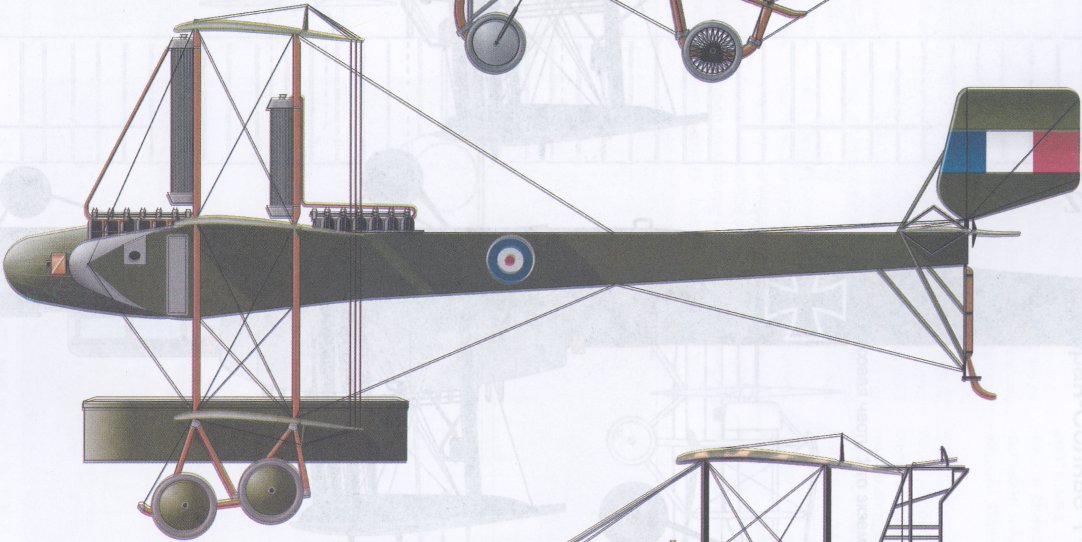
Caproni Ca-4, 6 крыло Королевской Военно-морской Авиации Великобритании, 1918г.
-

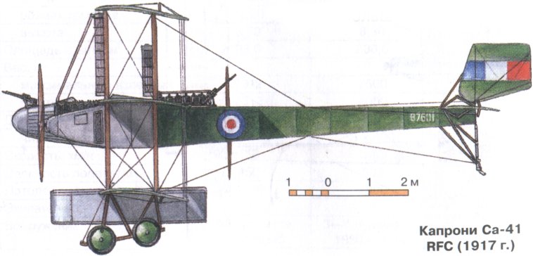
А.Шепс - Самолеты Первой мировой войны. Страны Антанты
Капрони Ca-41 RFC (1917г.)
-

-
R.Abate, G.Alegi, G.Apostolo - Aeroplani Caproni: Gianni Caproni and His Aircraft, 1910-1983
Further developing the multiengine multiplane theme, in 1916 Caproni conceived the Ca.4. This enormous triplane, powered by tre Fiat A.12bis engines, sacrificed everything to its load carrying possibilities. Tested in July 1916, it was ordered in production the following January.
-
R.Abate, G.Alegi, G.Apostolo - Aeroplani Caproni: Gianni Caproni and His Aircraft, 1910-1983
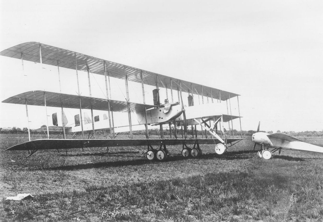
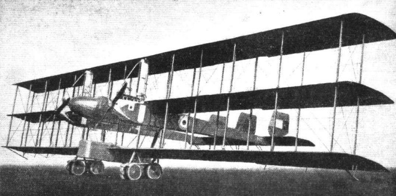
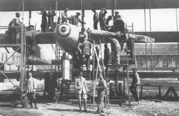
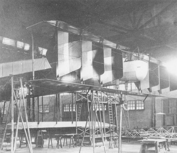
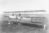
This visual comparison between the Ca.4 (redesignated Ca.40 after the war) and the 1914 Ca.20 illustrates the rapid strides in aviation technology brought about by the war. While the structural parts of the both aircraft were quite similar, before the war a project of the Ca.4's size would have been inconceivable.
Другие самолёты на фотографии: Caproni Ca.20 - Италия - 1914
-
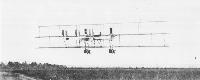
Jane's All The World Aircraft 1919 /Jane's/
A 1,000 h.p. Caproni Triplane, of 1917, nose to nose with a 100 h.p. Caproni Monoplane of 1915 type.
Другие самолёты на фотографии: Caproni Ca.20 - Италия - 1914
-

R.Abate, G.Alegi, G.Apostolo - Aeroplani Caproni: Gianni Caproni and His Aircraft, 1910-1983
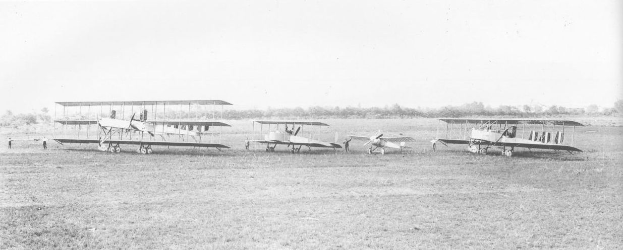
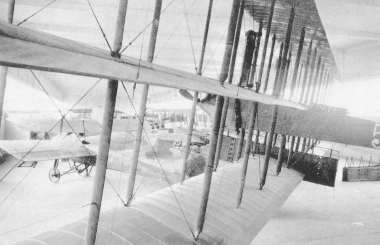
This photo, taken at Vizzola Ticino in late 1916 or early 1917, summarizes wartime Caproni production. Left to right: the Ca.4 prototype, the unique Ca.37 and Ca.20, and Ca.300 serial 1173.
Другие самолёты на фотографии: Caproni Ca.1 - Ca.3 (Ca.30 - Ca.36) - Италия - 1914Caproni Ca.20 - Италия - 1914Caproni Ca.37 - Ca.38 - Италия - 1916
-

R.Gentilli - Italian Aviation Units in the First World War. Vol.4 /Aeronaut/ (4)
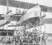
The first production Caproni triplane, 5347. Caproni chief test pilot Emilio Pensuti is fifth from the left, standing.
-
R.Abate, G.Alegi, G.Apostolo - Aeroplani Caproni: Gianni Caproni and His Aircraft, 1910-1983
The preseries batch, later called Ca.40, had the prototype’s angular fuselage with a clear frontal section added for the observer.
-

J.Davilla - Italian Aviation in the First World War. Vol.2: Aircraft A-H /Centennial Perspective/ (74)
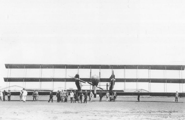
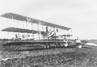
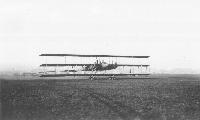
THE 600 H.P. ITALIAN CAPRONI TRIPLANE. - This huge machine, the size of which may be judged by the man standing just in front, is equipped with three 200 h.p. engines, and has a speed of about 80 m.p.h.
Caproni Ca.4 triplane heavy bomber. -

R.Gentilli - Italian Aviation Units in the First World War. Vol.4 /Aeronaut/ (4)
A British commission at the Caproni works on October 1917. Behind them, a Ca.4 and the only Ca.53 single engine bomber triplane.
Другие самолёты на фотографии: Caproni Ca.53 - Италия - 1917
-

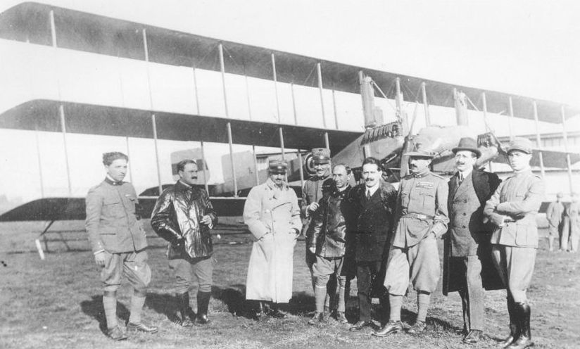
R.Abate, G.Alegi, G.Apostolo - Aeroplani Caproni: Gianni Caproni and His Aircraft, 1910-1983
Gianni Caproni, fourth from left, with pilots and associates in front of a production Ca.4. This version, built from January 1918 onwards and later identified as Ca.41, incorporated several improvements suggested by experience with the first four machines. Together with the possibility of replacing the Fiat A.12 engines with Isotta Fraschini V.5 units, production Ca.4 sported a new, partially enclosed pilots’ nacelle whose rounded lines betrayed a Ca.5 origin.
-
R.Abate, G.Alegi, G.Apostolo - Aeroplani Caproni: Gianni Caproni and His Aircraft, 1910-1983
Six Liberty-engined triplanes, retroactively called Ca.42, were briefly operated from Taranto-Pizzone by the British Royal Naval Air Service with serials N526-N531. The Caproni Flight, as the new unit was called, was led by Squadron Commander R. Whitehead. The increased power cut climbing times in half while adding 500 kg of payload and raising the top speed by 15 km per hour.
-

J.Davilla - Italian Aviation in the First World War. Vol.2: Aircraft A-H /Centennial Perspective/ (74)
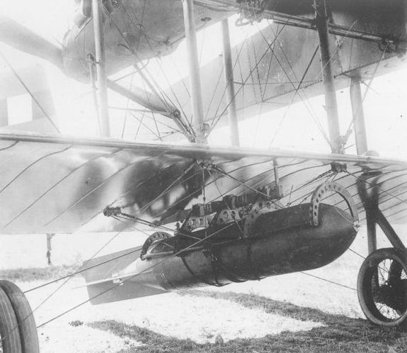
Caproni Ca.4 heavy bomber. The structure below the central nacelle is a bomb container.
-

J.Davilla - Italian Aviation in the First World War. Vol.2: Aircraft A-H /Centennial Perspective/ (74)
Caproni Ca.4 triplane bomber with bomb container
-

-

J.Davilla - Italian Aviation in the First World War. Vol.2: Aircraft A-H /Centennial Perspective/ (74)
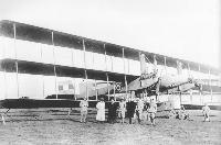
Lineup of Caproni Ca.4 heavy bombers in British service.
-

J.Davilla - Italian Aviation in the First World War. Vol.1: Operations /Centennial Perspective/ (73)
Surviving photographs suggest that the Caproni Ca.4 triplanes were completed in two separate batches, in groups of two and four each. This photograph shows the four machines of the second sub-batch (if one can call it so) lined up at Taliedo. The Ca.4 carried a heavy bombload but was slow, cumbersome, and vulnerable to fighters. Caproni Family via Paolo Miana
-

R.Gentilli - Italian Aviation Units in the First World War. Vol.4 /Aeronaut/ (4)
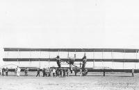
A line of four Caproni Ca.4s made an impressive sight.
-

R.Gentilli - Italian Aviation Units in the First World War. Vol.4 /Aeronaut/ (4)
Old Bill, returning from a mission at the end of October 1918, landed at San Nicolo airfield, Venice, drawing a lot of interest.
-

В.Кондратьев - Самолеты первой мировой войны
"Капрони" Са.4 итальянской морской бомбардировочной эскадрильи.
-

R.Gentilli - Italian Aviation Units in the First World War. Vol.4 /Aeronaut/ (4)
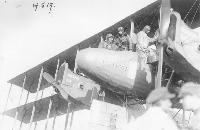
Ca.4 5374 with its crew, bombed up for a mission. A cover has been added to protect the front gunner.
-

J.Davilla - Italian Aviation in the First World War. Vol.2: Aircraft A-H /Centennial Perspective/ (74)
Caproni Ca.4 triplane bomber with bomb container.
-

R.Gentilli - Italian Aviation Units in the First World War. Vol.4 /Aeronaut/ (4)
Caproni Ca.4 5374 served with the 181a Squadriglia.
-

J.Davilla - Italian Aviation in the First World War. Vol.2: Aircraft A-H /Centennial Perspective/ (74)
Caproni Ca.4 triplane bomber with ground crew that show the size of the aircraft.
-
R.Abate, G.Alegi, G.Apostolo - Aeroplani Caproni: Gianni Caproni and His Aircraft, 1910-1983
The war’s end did not spell the end of the great triplanes: in June 1919 aircraft 14664, used by 181st squadriglia during the war, made a promotional tour of northern Europe. It is seen here on Bruxelles-Haren airport, where on June 14 it carried King Albert of Belgium.
-

Jane's All The World Aircraft 1919 /Jane's/
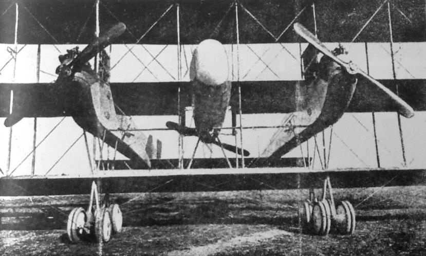
Front View of a Caproni Ca 4 type Triplane bomber of 1917.
-

R.Abate, G.Alegi, G.Apostolo - Aeroplani Caproni: Gianni Caproni and His Aircraft, 1910-1983
The photo, taken in 1940, shows the Ca.4 dominating the display.
-

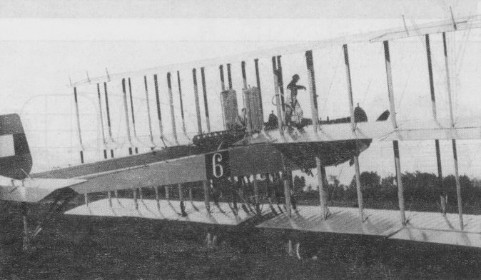
R.Gentilli - Italian Aviation Units in the First World War. Vol.4 /Aeronaut/ (4)
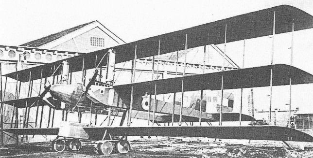
Caproni Ca.4 ready for action, rails with little trolleys were used to move them out of the hangar.
-

O.Thetford - British Naval Aircraft since 1912 /Putnam/
The Caproni Ca 42, powered by three 400hp Isotta-Fraschini, or Libertys, was the last and the heaviest of the Caproni triplane bombers to be produced. Delivered in early 1918, these five-man machines carried up to 3.910lb of bombs in a central housing attached to the lower wing. Top level speed of the Ca 42 was 87mph at 6.560 feet, while its defensive armament consisted of five Ravelli machine guns. Over 20 of these mammoth triplanes were built, the machine seen here carrying the British serial no N 527, being the second of six Ca 42s operated by the RNAS for a period during 1918.
-

Журнал - Flight за 1919 г.
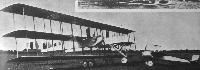
This three-engined 1,200 h.p. Caproni triplane, has a span of about 103 ft., and carries a useful load of several tons
-

-

J.Davilla - Italian Aviation in the First World War. Vol.2: Aircraft A-H /Centennial Perspective/ (74)
Caproni Ca.4 heavy bomber. The structure below the central nacelle is a bomb container.
-

J.Herris - Weird Wings of WWI /Centennial Perspective/ (70)
Caproni Ca.4 triplane bomber with bomb container. It could carry a large bombload but was too slow and unweildy to withstand fighter interception, so missions were limited to areas without effective fighter opposition.
-

J.Davilla - Italian Aviation in the First World War. Vol.2: Aircraft A-H /Centennial Perspective/ (74)
Caproni Ca.4 triplane bomber with bomb container.
-

R.Gentilli - Italian Aviation Units in the First World War. Vol.4 /Aeronaut/ (4)
Two Caproni Ca.4, the first one 5374, with frontal radiators, probably at Ghedi.
-
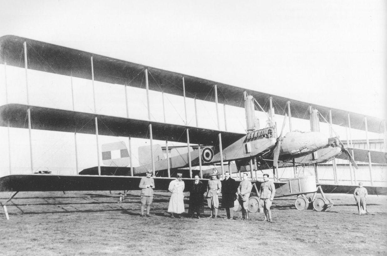
R.Abate, G.Alegi, G.Apostolo - Aeroplani Caproni: Gianni Caproni and His Aircraft, 1910-1983
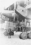
The people in this photo lend scale to the Ca.4’s considerable dimensions. Among other conspicuous details are the bomb harnesses on the lower central gondola, the twin wheels and night landing lights on the wing’s trailing edge.
-
R.Abate, G.Alegi, G.Apostolo - Aeroplani Caproni: Gianni Caproni and His Aircraft, 1910-1983
The war’s end did not spell the end of the great triplanes: in June 1919 aircraft 14664, used by 181st squadriglia during the war, made a promotional tour of northern Europe. It is seen here on Bruxelles-Haren airport, where on June 14 it carried King Albert of Belgium.
-

R.Gentilli - Italian Aviation Units in the First World War. Vol.4 /Aeronaut/ (4)
Ca.4 14664 of the 181a Squadriglia. Behind the serial there is an insignia of the Caproni firm, of which a clear version has not been found yet.
-

R.Gentilli - Italian Aviation Units in the First World War. Vol.4 /Aeronaut/ (4)
Ca.4 5370 of the 181a Squadriglia carries a good-luck charm on its nose, a doll with wings.
-

R.Gentilli - Italian Aviation Units in the First World War. Vol.4 /Aeronaut/ (4)
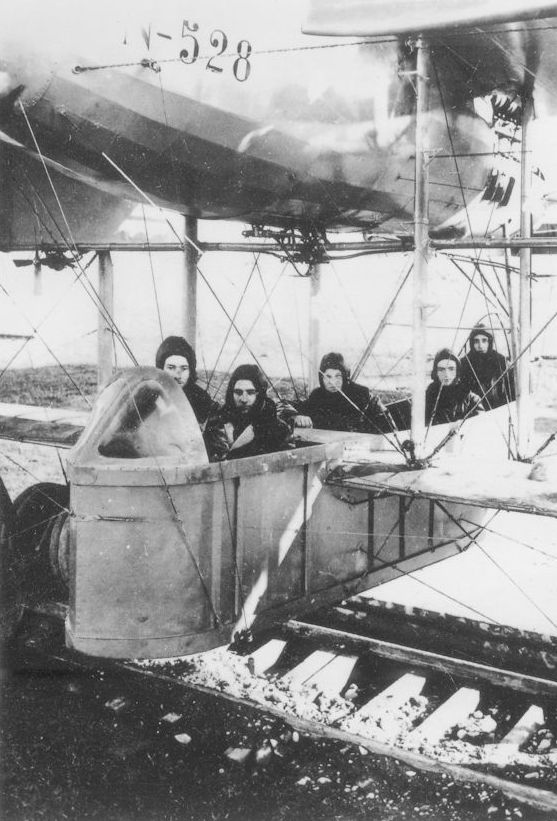
N-528, here still with British airmen, had the cartoon character Old Bill painted on its nose and sides. (Archive Peter Selinger)
-

R.Gentilli - Italian Aviation Units in the First World War. Vol.4 /Aeronaut/ (4)
The Caproni triplanes for the Royal Navy Air Service were not used, and were turned over to the Italians. N-526 has on its nose a scary face with wings.
-

R.Gentilli - Italian Aviation Units in the First World War. Vol.4 /Aeronaut/ (4)
Ca.4 N-526 at Ghedi, on 9 May 1918, together with a SVA, to emphasize its large dimensions.
Другие самолёты на фотографии: Ansaldo SVA.2/3/4/5 - Италия - 1917
-

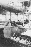
J.Davilla - Italian Aviation in the First World War. Vol.1: Operations /Centennial Perspective/ (73)
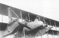
RNAS Personnel of the 'Northern Squadron' posing with Caproni Ca.4 N-526, at Vizzola Ticino. The caption reads that the two aviators in the nacelle are F/SL B.G.H. Keymer and LM L.A. Comes.
-
R.Abate, G.Alegi, G.Apostolo - Aeroplani Caproni: Gianni Caproni and His Aircraft, 1910-1983
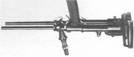
Despite the limited production run, the Ca.4 sported a large number of individual differences. British machines, for instance, carried twin Lewis guns in the nose, with the gunners position partially protected by a sort of collapsible screen. The photo also shows a large individual insignia and, less visible, a small eagle on the nose of N526.
-

-

J.Davilla - Italian Aviation in the First World War. Vol.1: Operations /Centennial Perspective/ (73)
Caproni Ca.42 bomber and load.
-

R.Abate, G.Alegi, G.Apostolo - Aeroplani Caproni: Gianni Caproni and His Aircraft, 1910-1983
Removing the lower gondola allowed heavier weights to be carried, such as the 500 kg bomb shown in the top right photo. This version was later called Ca.52.
-

R.Gentilli - Italian Aviation Units in the First World War. Vol.4 /Aeronaut/ (4)
Two Caproni triplanes at Poggio Renatico. The one on the left has the number 16 and a chevron on the fuselage, the one on the right a roundel. (Archives Caliaro)
-

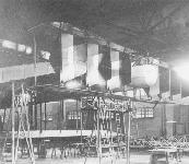
R.Gentilli - Italian Aviation Units in the First World War. Vol.4 /Aeronaut/ (4)
A Ca.4 triplane at Poggio Renatico. A large quantity of steel girders were imported from America to build hangars for a huge fleet of bombers.
-
R.Abate, G.Alegi, G.Apostolo - Aeroplani Caproni: Gianni Caproni and His Aircraft, 1910-1983
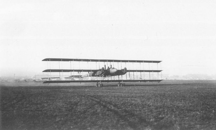
A Navy Ca.4 at take-off. This aerial giant served with the 181st and 182nd naval squadriglie.
-
R.Abate, G.Alegi, G.Apostolo - Aeroplani Caproni: Gianni Caproni and His Aircraft, 1910-1983
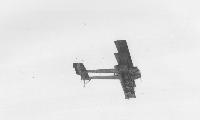
An airborne Ca.4. Photos cannot record the impression the Ca.4’s majestic size and power made in its day.
-
R.Abate, G.Alegi, G.Apostolo - Aeroplani Caproni: Gianni Caproni and His Aircraft, 1910-1983
A Ca.4 just after unsticking.
-

Журнал - Flight за 1917 г.
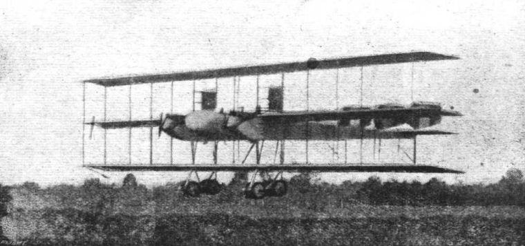
Another view of the 600 h.p. Italian Caproni triplane, which has been doing such good raiding work on the Italian front. The machine is seen returning from a flight.
-

R.Gentilli - Italian Aviation Units in the First World War. Vol.4 /Aeronaut/ (4)
At Taliedo, Milan, a Caproni Ca.4 has received new markings for an aviation exhibition in New York City, January 1919.
Caproni Ca.4 triplane bomber with bomb container and "CAPRONI" painted under the bottom wing. This was a Ca.4 that was shipped to New York for an exhibition in early 1919.
Caproni also built a large triplane bomber that was used operationally in small numbers by Italy and Britain. It combined the twin nacelle, tri-motor configuration with a large triplane wing cellule that enabled carrying a heavy bomb load due to the large wing area. The bombs were carried in the streamlined housing below the main nacelle. The extensive struts and bracing created a lot of drag, ensuring it was slow. The triplane configuration made fighters too slow but could enable a lot of wing area for bombers and flying boats with a reasonable wing span. -

R.Abate, G.Alegi, G.Apostolo - Aeroplani Caproni: Gianni Caproni and His Aircraft, 1910-1983
The cockade on this Ca.4’s nose indicates examination by the US Army’s Bolling commission.
-

R.Gentilli - Italian Aviation Units in the First World War. Vol.3 /Aeronaut/ (3)
Italian aircraft were exhibited in New York in 1919; an Ansaldo Balilla, an SVA, and a Caproni Ca.4 triplane can be seen.
Другие самолёты на фотографии: Ansaldo A.1 Ballila - Италия - 1917Ansaldo SVA.2/3/4/5 - Италия - 1917
-
R.Abate, G.Alegi, G.Apostolo - Aeroplani Caproni: Gianni Caproni and His Aircraft, 1910-1983
British Ca.4 N528 fitted with a passenger gondola replacing the more usual bom nacelle.
-

-

R.Gentilli - Italian Aviation Units in the First World War. Vol.4 /Aeronaut/ (4)
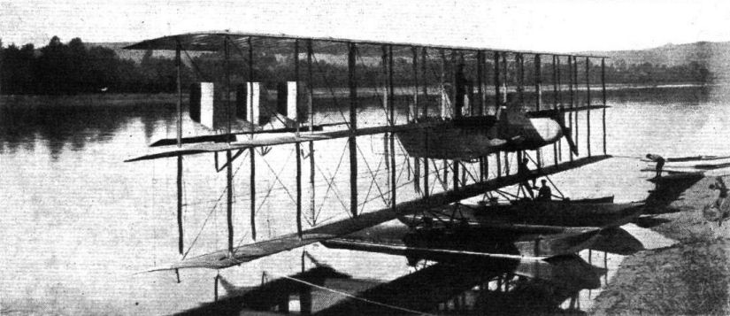
Caproni Ca.4 5353 was converted into a floatplane.
-
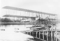
R.Abate, G.Alegi, G.Apostolo - Aeroplani Caproni: Gianni Caproni and His Aircraft, 1910-1983
In 1920 Ca.4 5353 was converted into seaplane by adding a pair of floats not unlike those designed by Guidoni for the Ca.47. It was also experimentally equipped with two underwing torpedo harnesses. This version was indicated as Ca.43 in the postwar system.
-

Журнал - Flight за 1919 г.
A TRI-MOTORED CAPRONI HYDRO-TRIPLANE: It has a span of 31 metres, and the useful load is 2 1/2 to 3 tons. It can be fitted with three 300 h.p. Flat or Liberty engines, and the speed is 140 kiloms. per hour.
-

J.Davilla - Italian Aviation in the First World War. Vol.2: Aircraft A-H /Centennial Perspective/ (74)
Caproni Ca.4 triplane bomber airframe, this is a variant of the Ca.4, later called Ca.51, with biplane tail, a gunner position in the tail, and Fiat A14 engines
-
R.Abate, G.Alegi, G.Apostolo - Aeroplani Caproni: Gianni Caproni and His Aircraft, 1910-1983
A final Ca.4 derivative was the Ca.51, easily recognized by its biplane horizontal tail. The rear gunner’s position can be made out amidst the six rudders.
-

R.Gentilli - Italian Aviation Units in the First World War. Vol.4 /Aeronaut/ (4)
The crash of Ca.4 14665 on 17 July 1918; four airmen died and two were wounded.
-

R.Gentilli - Italian Aviation Units in the First World War. Vol.4 /Aeronaut/ (4)
Ca.4 N-526 written off in an accident at San Pelagio on 23 May 1918. (Archive Longhi)
-

R.Gentilli - Italian Aviation Units in the First World War. Vol.4 /Aeronaut/ (4)
Ten. Amerigo Contini, a veteran Caproni pilot, was an artist whose paintings and postcards are remarkable for accuracy and realism.
-

Журнал - Flight за 1919 г.
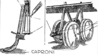
Two detail sketches of the Caproni CA-4 Triplane. On the left one of the tail skids, and on the right one of the under-carriage units.
-

-

-

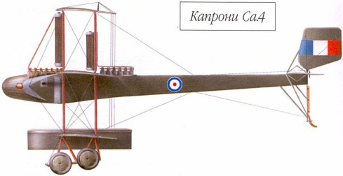
В.Кондратьев - Самолеты первой мировой войны
"Капрони" Са.4
-

-

-

-

В.Кондратьев Самолеты первой мировой войны
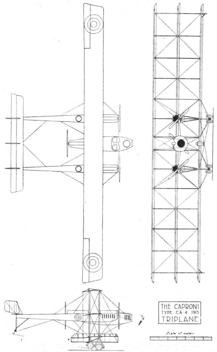
КАПРОНИ Ca.4 / CAPRONI Ca.4
В конце 1916-го Капрони создал, пожалуй, наиболее экстравагантный аэроплан 1-й Мировой войны. Задавшись целью резко увеличить бомбовую нагрузку машины, он установил на очередную модификацию своего бомбардировщика более мощные, 200-сильные, моторы "Фиат". А чтобы компенсировать возросший взлетный вес, добавил третье крыло.
Напомним, то был период всеобщего увлечения трипланами, но Капрони - единственный, кто сумел разработать и, главное, "довести до ума" тяжелый многомоторный самолет подобной схемы. Все остальные проекты так и не вышли за стадию прототипов, а гигантский триплан Ca.40 выпускался серийно и участвовал в боевых вылетах.
Конструкция Ca.40 в целом была та же, что и у предыдущих машин Капрони: деревянный каркас с полотняной обшивкой. Новинкой стали восьми колесные тележки шасси и крупногабаритный бомбовый контейнер, размещенный в центре нижнего крыла подфюзеляжной гондолой. Бомбы в нем подвешивались вертикально. Экипаж - 5 человек: 2 пилота и 3 стрелка.
В начале 1917-го появился слегка улучшенный образец Ca.41 с более узкой, обтекаемой гондолой и тандемным расположением пилотов. Вершиной развития типа стал Ca.42, на который Капрони установил самые мощные на тот момент 400-сильные американские двигатели. "Либерти", По величине бомбовой нагрузки этот самолет не имел себе равных в авиации союзников. В 1917-м построили лишь 3 серийных бомбардировщика-триплана и еще 20 - в следующем году.
Высокая грузоподъемность Ca.42 (военное обозначение - Ca.4) привлекла внимание английского морского командования. Для авиации ВМФ Великобритании было закуплено 6 машин, которые состояли на вооружении до конца 1918-го. Остальные применялись двумя итальянскими бомбардировочными эскадрильями. Поскольку огромный тихоходный самолет представлял отличную мишень для вражеских зениток, Ca.4 почти всегда летали на задания ночью.
Кроме уже упомянутых, выпускалось и еще несколько модификаций двухбалочных трипланов Капрони: торпедоносец Са:43, Ca.51 с бипланным оперением, а также Ca.48, Ca.52, Ca.58 и Ca.59 - транспортные самолеты без вооружения. Всего было построено свыше 40 аэропланов семейства Ca.4.
ДВИГАТЕЛИ
3 "Фиата" по 200 л.с. или 3 "Либерти" по 400 л.с.
ВООРУЖЕНИЕ
Носовая двухпулеметная турель в гондоле и еще две - в хвостовых балках за крыльями.
Ca.4 с двигателями "Фиат" поднимал 1200 кг бомб, с двигателями "Либерти" - 1950 кг.
ЛЕТНО-ТЕХНИЧЕСКИЕ ХАРАКТЕРИСТИКИ
Ca-42, 1916г.
Размах, м 29,90
Длина, м 15,10
Высота, м 6,30
Площадь крыла, кв.м 200,0
Сухой вес, кг 4000
Взлетный вес, кг 7500
Двигатель: "Либерти"
число х мощность, л. с. 3x400
Скорость максимальная, км/ч 140
Дальность полета, км 600
Продолжительность полета, час, мин 5,0
Время набора высоты, мин/м 26/3000
Потолок, м 4900
Экипаж, чел. 5
Вооружение 3-6 пулеметов
1950 кг бомб
Описание: