
Книги
Putnam
G.Swanborough, P.Bowers
United States Navy Aircraft since 1911
75
G.Swanborough, P.Bowers - United States Navy Aircraft since 1911 /Putnam/
De Havilland DH-4 Series
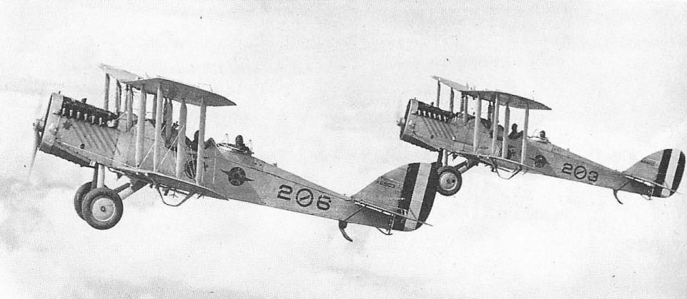
The two-seat De Havilland 4 'Liberty Plane' was the only American-made landplane to see service with US Naval forces in France in World War I. An American adaptation of the original British D.H.4 day bomber of 1916, the Liberty Plane was the major war-time product of the United States military aircraft programme. In spite of the really amazing rate of production achieved after the initial redesign and manufacturing problems were overcome, few DH-4s reached France, and their effectiveness was practically nil.
All of the scandals of politics in procurement, deficiencies in design and armament, suicidal war missions, and even the 'Billion Dollar Bonfire' in which most DHs overseas were piled and burned rather than being returned to the States after the Armistice, were directed at the Aircraft Production Board and the War Department. Historians have virtually ignored the fact that 51 of 145 Liberty Planes built by Dayton-Wright, and transferred from the Army to the Navy, served with US Navy and Marines in France. Most of these were with the 9th and 10th Marine Squadrons of Northern Bombing Wing based at Dunkirk. Independent American operations with DH-4s were initiated against German installations in Belgium on October 14, 1918.
The original Liberty Plane had many shortcomings, and an improved version, the DH-4B, which borrowed many features of the later British D.H.9, notably the relocation of the pilot's cockpit and the main fuel tank to lessen the chance of pilot fatality in even a minor crash, was in production by the war's end. The fuselage, mostly fabric-covered on the Liberty Plane, was completely covered with plywood on the DH-4B. Forty-two DH-4Bs were transferred to the Navy from the War Department and an additional 80 were rebuilt as DH-4Bs from surplus Liberty Planes by the Naval Aircraft Factory. A further improved version, the DH-4B-1, had the fuel capacity increased from 96 to 118 US gal and other minor refinements. Fifty of this model were also transferred from the War Department to the Navy.
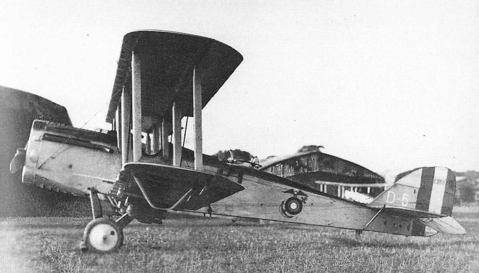
In 1923 the Army instigated the use of welded steel-tube fuselage construction for more rebuilt DHs to be known as the DH-4M, for DH-4 Modernized. The initial work under this programme was accomplished by the Boeing Airplane Company, which used a new arc-welding process that it had developed. Thirty of these DH-4M1s, as they were known to distinguish them from the later Atlantic-Fokker DH-4M2s with gas-welded fuselages, were released from the Army contract and made available to the Navy, which bought them for the US Marine Corps. Although the Navy normally identified older aircraft by the designations in use before the adoption of standardized Naval designations in 1922, the DH-4M1s were given a new designation, O2B-1, to identify them as observation types built by Boeing. An earlier OB-1 amphibian was not reassigned. The O2B-1s delivered in 1925 were indistinguishable from the DH-4Bs except by a return to fabric covering on the fuselage and a more forward location of the landing wheels.
The postwar Navy-Marine DH-4Bs and Ms were initially used in the observation and day bomber roles and were gradually down-graded to training and utility work. A degree of late fame was achieved by these aircraft in the US Marine Corps action against the Nicaraguan bandits in 1927. A few remained in service with the Marines into 1929. The last Army models were not retired until 1932.
TECHNICAL DATA (DH-4B-1)
Manufacturer: Dayton-Wright Company, Dayton, Ohio; Standard Aircraft Corporation, Patterson, NH; Fisher Body Division of General Motors, Cleveland, Ohio; Naval Aircraft Factory, Philadelphia, Penn; Boeing Airplane Company, Seattle, Washington (O2B).
Type: Observation, day bomber and general purpose biplane.
Accommodation: Pilot and observer in tandem.
Power plant: One 400 hp Liberty.
Dimensions: Span, 42 ft 5 1/2 in; length, 30 ft 1 3/4 in; height, 10 ft 6 in; wing area, 440 sq ft.
Weights: Empty, 2,647 lb; gross, 4,214 lb.
Performance: Max speed, 122.5mph at sea level; initial climb, 6.8min to 5,000ft; service ceiling, 14,000 ft; range, 550 st miles.
Armament: Two fixed forward-firing 0.30-in guns; two flexible 0.30-in guns on Scarff ring.
Serial numbers:
DH-4B (War Department): A5809-A5814; A5834-A5839; A5870-A5884; A5982-A6001.
DH-4B (NAF): A6113-A6192; A6514.
DH-4B-1: A6352-A6401.
O2B-1: A6898-A6927.
The two-seat De Havilland 4 'Liberty Plane' was the only American-made landplane to see service with US Naval forces in France in World War I. An American adaptation of the original British D.H.4 day bomber of 1916, the Liberty Plane was the major war-time product of the United States military aircraft programme. In spite of the really amazing rate of production achieved after the initial redesign and manufacturing problems were overcome, few DH-4s reached France, and their effectiveness was practically nil.
All of the scandals of politics in procurement, deficiencies in design and armament, suicidal war missions, and even the 'Billion Dollar Bonfire' in which most DHs overseas were piled and burned rather than being returned to the States after the Armistice, were directed at the Aircraft Production Board and the War Department. Historians have virtually ignored the fact that 51 of 145 Liberty Planes built by Dayton-Wright, and transferred from the Army to the Navy, served with US Navy and Marines in France. Most of these were with the 9th and 10th Marine Squadrons of Northern Bombing Wing based at Dunkirk. Independent American operations with DH-4s were initiated against German installations in Belgium on October 14, 1918.
The original Liberty Plane had many shortcomings, and an improved version, the DH-4B, which borrowed many features of the later British D.H.9, notably the relocation of the pilot's cockpit and the main fuel tank to lessen the chance of pilot fatality in even a minor crash, was in production by the war's end. The fuselage, mostly fabric-covered on the Liberty Plane, was completely covered with plywood on the DH-4B. Forty-two DH-4Bs were transferred to the Navy from the War Department and an additional 80 were rebuilt as DH-4Bs from surplus Liberty Planes by the Naval Aircraft Factory. A further improved version, the DH-4B-1, had the fuel capacity increased from 96 to 118 US gal and other minor refinements. Fifty of this model were also transferred from the War Department to the Navy.
In 1923 the Army instigated the use of welded steel-tube fuselage construction for more rebuilt DHs to be known as the DH-4M, for DH-4 Modernized. The initial work under this programme was accomplished by the Boeing Airplane Company, which used a new arc-welding process that it had developed. Thirty of these DH-4M1s, as they were known to distinguish them from the later Atlantic-Fokker DH-4M2s with gas-welded fuselages, were released from the Army contract and made available to the Navy, which bought them for the US Marine Corps. Although the Navy normally identified older aircraft by the designations in use before the adoption of standardized Naval designations in 1922, the DH-4M1s were given a new designation, O2B-1, to identify them as observation types built by Boeing. An earlier OB-1 amphibian was not reassigned. The O2B-1s delivered in 1925 were indistinguishable from the DH-4Bs except by a return to fabric covering on the fuselage and a more forward location of the landing wheels.
The postwar Navy-Marine DH-4Bs and Ms were initially used in the observation and day bomber roles and were gradually down-graded to training and utility work. A degree of late fame was achieved by these aircraft in the US Marine Corps action against the Nicaraguan bandits in 1927. A few remained in service with the Marines into 1929. The last Army models were not retired until 1932.
TECHNICAL DATA (DH-4B-1)
Manufacturer: Dayton-Wright Company, Dayton, Ohio; Standard Aircraft Corporation, Patterson, NH; Fisher Body Division of General Motors, Cleveland, Ohio; Naval Aircraft Factory, Philadelphia, Penn; Boeing Airplane Company, Seattle, Washington (O2B).
Type: Observation, day bomber and general purpose biplane.
Accommodation: Pilot and observer in tandem.
Power plant: One 400 hp Liberty.
Dimensions: Span, 42 ft 5 1/2 in; length, 30 ft 1 3/4 in; height, 10 ft 6 in; wing area, 440 sq ft.
Weights: Empty, 2,647 lb; gross, 4,214 lb.
Performance: Max speed, 122.5mph at sea level; initial climb, 6.8min to 5,000ft; service ceiling, 14,000 ft; range, 550 st miles.
Armament: Two fixed forward-firing 0.30-in guns; two flexible 0.30-in guns on Scarff ring.
Serial numbers:
DH-4B (War Department): A5809-A5814; A5834-A5839; A5870-A5884; A5982-A6001.
DH-4B (NAF): A6113-A6192; A6514.
DH-4B-1: A6352-A6401.
O2B-1: A6898-A6927.
De Havilland DH-4 in France, 1918, with US Marine Corps insignia.
Boeing-built DH-4Ms delivered to the US Marine Corps as O2B-1s in 1925.
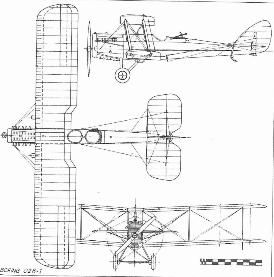
Boeing O2B-1
DE HAVILLAND D.H.9A
Among the British aircraft supplied to the US Navy for use by the Northern Bombing Group in France in 1918 were 54 D.H.9A two-seat bombers powered by 400 hp American Liberty engines. These were not assigned regular US Navy serial numbers, but flew with American roundels being painted over the British on the wings, and the fuselage roundel being painted out and replaced by station markings. Span, 42 ft 5 in; length, 30 ft; gross weight, 4,645 lb; max speed, 114 mph at 10,000 ft.
Among the British aircraft supplied to the US Navy for use by the Northern Bombing Group in France in 1918 were 54 D.H.9A two-seat bombers powered by 400 hp American Liberty engines. These were not assigned regular US Navy serial numbers, but flew with American roundels being painted over the British on the wings, and the fuselage roundel being painted out and replaced by station markings. Span, 42 ft 5 in; length, 30 ft; gross weight, 4,645 lb; max speed, 114 mph at 10,000 ft.
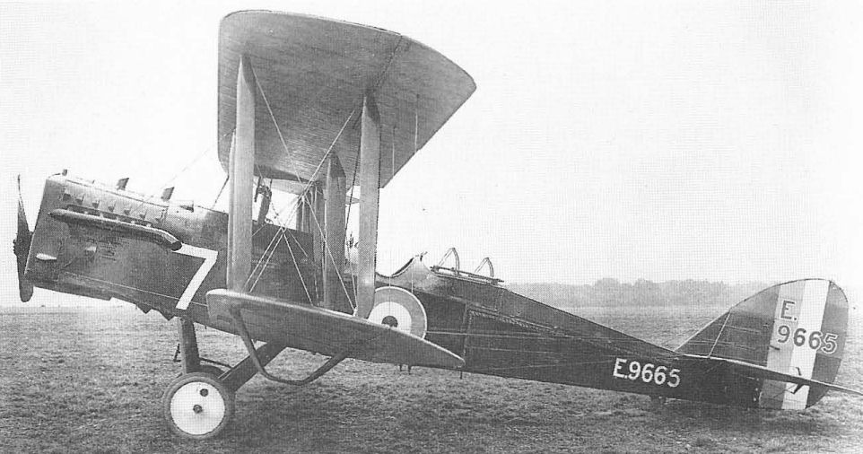
A de Havilland 9A as used by the Navy in France.
PARNALL PANTHER
Two of these British carrier-based fighters were purchased by the Navy in 1919 (A5751-A5752). Powered by the 230hp Bentley BR.2 rotary, they had hydrovanes and flotation gear. Span, 29 ft 6 m; length, 25 ft; gross weight, 2,550 lb; max speed, 114mph.
Two of these British carrier-based fighters were purchased by the Navy in 1919 (A5751-A5752). Powered by the 230hp Bentley BR.2 rotary, they had hydrovanes and flotation gear. Span, 29 ft 6 m; length, 25 ft; gross weight, 2,550 lb; max speed, 114mph.

A US Navy Parnall Panther with Grain flotation gear.
R.A.F. S.E.5A
British-built S.E.5A fighters were among the foreign types acquired by the US Navy in 1918 in France. They served in original British colours, with the RAF roundels overpainted in American colour sequence and at least one S.E.5A in these markings operated off a turret on the USS Mississippi after the end of the War. Power plant, one 200hp Hispano-Suiza. Span, 26 ft 7 1/2 in; height, 20 ft 11 in; gross weight, 2,058 lb; max speed, 123 mph.
British-built S.E.5A fighters were among the foreign types acquired by the US Navy in 1918 in France. They served in original British colours, with the RAF roundels overpainted in American colour sequence and at least one S.E.5A in these markings operated off a turret on the USS Mississippi after the end of the War. Power plant, one 200hp Hispano-Suiza. Span, 26 ft 7 1/2 in; height, 20 ft 11 in; gross weight, 2,058 lb; max speed, 123 mph.

An S.E.5A with British serial number but US Navy markings.
SOPWITH BABY SEAPLANE
An unspecified number of British Sopwith Baby seaplanes, including Gnome- and Clerget-powered versions, were obtained by the US Navy in Europe in 1917-18 for training. Four (A869-A872) were sent to the States for evaluation. Those remaining in Europe continued to operate under their British serial numbers. The single-seat seaplane scout design, with a 110 hp Clerget engine, was investigated by a few American manufacturers, but the type was not accepted for service. Span, 25 ft 8 in; length, 22 ft 10 in; gross weight, 1,580 lb; max speed, 92 mph.
An unspecified number of British Sopwith Baby seaplanes, including Gnome- and Clerget-powered versions, were obtained by the US Navy in Europe in 1917-18 for training. Four (A869-A872) were sent to the States for evaluation. Those remaining in Europe continued to operate under their British serial numbers. The single-seat seaplane scout design, with a 110 hp Clerget engine, was investigated by a few American manufacturers, but the type was not accepted for service. Span, 25 ft 8 in; length, 22 ft 10 in; gross weight, 1,580 lb; max speed, 92 mph.
SOPWITH 1 1/2-STRUTTER
Among the Navy's British purchases during World War I were two-seat Sopwith 1 1/2-Strutters, widely used as observation and training types by both France and Britain. The one example shipped to the States received serial A5660. An additional 21 obtained from the US Army after the war became A5725-A5728 and A5734-A5750. These were used as light observation types. Power plant was a 130 hp Clerget. Span, 33 ft 6 in; length, 25ft 3in; gross weight, 2,150 lb; max speed, 100 mph.
Among the Navy's British purchases during World War I were two-seat Sopwith 1 1/2-Strutters, widely used as observation and training types by both France and Britain. The one example shipped to the States received serial A5660. An additional 21 obtained from the US Army after the war became A5725-A5728 and A5734-A5750. These were used as light observation types. Power plant was a 130 hp Clerget. Span, 33 ft 6 in; length, 25ft 3in; gross weight, 2,150 lb; max speed, 100 mph.
A Sopwith 1 1/2-Strutter at Guantanamo, with hydrovanes for emergency water alighting.
SOPWITH CAMEL
The Sopwith Camel was one of the most successful British fighters of 1917-18, and numbers were supplied to both the US Army and Navy for use in France. Mounting two 0.303-in machine guns, the Camel was powered by the 130 hp Clerget rotary engine. After the Armistice, the Navy operated six (A5658-A5659, A5721-A5722, A5729-A5730), sometimes from platforms built over the forward turret guns of battleships. Span, 28 ft; length, 18 ft 9 in; gross weight, 1,453 lb; max speed, 113 mph at 6,500 ft.
The Sopwith Camel was one of the most successful British fighters of 1917-18, and numbers were supplied to both the US Army and Navy for use in France. Mounting two 0.303-in machine guns, the Camel was powered by the 130 hp Clerget rotary engine. After the Armistice, the Navy operated six (A5658-A5659, A5721-A5722, A5729-A5730), sometimes from platforms built over the forward turret guns of battleships. Span, 28 ft; length, 18 ft 9 in; gross weight, 1,453 lb; max speed, 113 mph at 6,500 ft.
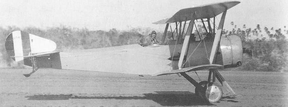
FOKKER D.VII
After the Armistice, the Army brought 142 Fokker D.VIIs into the United States. These were the finest German fighters in service at war's end, and were used in numbers throughout the Air Service as trainers for several years. Twelve were to have been transferred to the Navy for use by the Marine Corps, but only six (A5843-A5848) were used. These remained in the training role at Quantico, Virginia, until 1924. The first influence of the D.VII on subsequent US Naval aircraft design was to be noted in the Boeing FB-1 of 1925. Power plant was a 180hp Mercedes or 185 hp BMW. Span, 29 ft 3 in; length, 23 ft; gross weight, 1,993 lb; max speed, 124 mph.
After the Armistice, the Army brought 142 Fokker D.VIIs into the United States. These were the finest German fighters in service at war's end, and were used in numbers throughout the Air Service as trainers for several years. Twelve were to have been transferred to the Navy for use by the Marine Corps, but only six (A5843-A5848) were used. These remained in the training role at Quantico, Virginia, until 1924. The first influence of the D.VII on subsequent US Naval aircraft design was to be noted in the Boeing FB-1 of 1925. Power plant was a 180hp Mercedes or 185 hp BMW. Span, 29 ft 3 in; length, 23 ft; gross weight, 1,993 lb; max speed, 124 mph.
FOKKER C.I
In 1921 the Navy purchased three Fokker C.Is from the Dutch Fokker factory. Actually, these had been built in Germany at the close of World War I and had been taken into Holland when Fokker returned to his native land and established a new company. The C.I was essentially a D.VII with slightly lengthened fuselage and wings, and a 185 hp BMW. The C.Is (A5887-A5889) were used by the US Marines at Quantico. Span, 34 ft 10 in; length, 23 ft 8 in; gross weight, 2,576 lb; max speed, 112 mph.
In 1921 the Navy purchased three Fokker C.Is from the Dutch Fokker factory. Actually, these had been built in Germany at the close of World War I and had been taken into Holland when Fokker returned to his native land and established a new company. The C.I was essentially a D.VII with slightly lengthened fuselage and wings, and a 185 hp BMW. The C.Is (A5887-A5889) were used by the US Marines at Quantico. Span, 34 ft 10 in; length, 23 ft 8 in; gross weight, 2,576 lb; max speed, 112 mph.
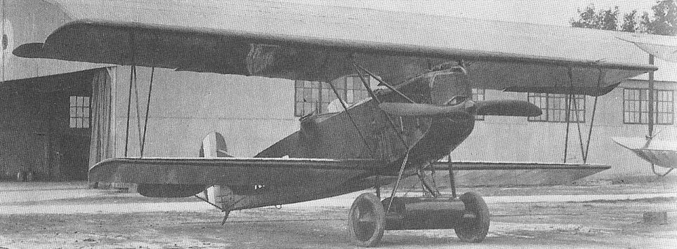
Fokker C.I at Quantico in 1922, one of the three Fokker C.Is that were delivered to the U.S. Navy after the war.
CAPRONI Ca-44
In 1918 the Navy procured 19 Italian-built Caproni Ca-44 bombers for use by the Northern Bombing Group. This organization had been trained by the British, and its members had obtained operational experience in British squadrons. The first independent action of the group was with Capronis on August 15, 1918, when they were used against German installations at Ostend. The unique twin-fuselage Caproni was typical of several similar models then in production, but the Ca-44 was powered with six-cylinder Fiat engines that proved to be especially troublesome and seriously handicapped operations. Span, 76 ft 10 in; length, 41ft 2 in; gross weight, 12,350 lb; max speed, 103mph.
In 1918 the Navy procured 19 Italian-built Caproni Ca-44 bombers for use by the Northern Bombing Group. This organization had been trained by the British, and its members had obtained operational experience in British squadrons. The first independent action of the group was with Capronis on August 15, 1918, when they were used against German installations at Ostend. The unique twin-fuselage Caproni was typical of several similar models then in production, but the Ca-44 was powered with six-cylinder Fiat engines that proved to be especially troublesome and seriously handicapped operations. Span, 76 ft 10 in; length, 41ft 2 in; gross weight, 12,350 lb; max speed, 103mph.
MACCHI M.5
During its operations from the Italian base of Porto Corsini from July 1918 until the Armistice, the US Navy operated at least eight single-seat Italian Macchi M.5 fighter flying-boats. These were used to escort bombers and with the French Hanriots were the only seaplane fighters flown in combat by American pilots in either of the World Wars. One M.5 had been sent to the US for evaluation in 1917. Power plant, 160 hp Isotta-Fraschini V-4B. Span, 39ft; length, 26ft 2in; gross weight, 2,266 lb; max speed, 118 mph.
During its operations from the Italian base of Porto Corsini from July 1918 until the Armistice, the US Navy operated at least eight single-seat Italian Macchi M.5 fighter flying-boats. These were used to escort bombers and with the French Hanriots were the only seaplane fighters flown in combat by American pilots in either of the World Wars. One M.5 had been sent to the US for evaluation in 1917. Power plant, 160 hp Isotta-Fraschini V-4B. Span, 39ft; length, 26ft 2in; gross weight, 2,266 lb; max speed, 118 mph.
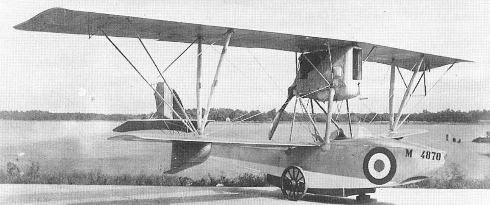
The Italian Macchi M5 was the fastest flying boat fighter of the war and had good maneuverability. It was also flown by a small number of US Naval Aviators in Italy.
A Macchi M.5 during tests at Hampton Roads, Va, in 1917.
A Macchi M.5 during tests at Hampton Roads, Va, in 1917.
MACCHI M.8
At least eight Italian Macchi M.8 two-seat light bombing flying-boats were used by US Naval forces operating from Porto Corsini on the Adriatic sea, which became an inactive station in July 1918. These two-seaters were used several times for bombing raids against the Austrian bases at Pola and were highly successful in this little-known phase of Naval aviation history. Power plant, 160hp Isotta-Fraschini V-4B. Span, 45 ft 5 in; length, 29 ft 7 in; gross weight, 3,100 lb; max speed, 103 mph.
At least eight Italian Macchi M.8 two-seat light bombing flying-boats were used by US Naval forces operating from Porto Corsini on the Adriatic sea, which became an inactive station in July 1918. These two-seaters were used several times for bombing raids against the Austrian bases at Pola and were highly successful in this little-known phase of Naval aviation history. Power plant, 160hp Isotta-Fraschini V-4B. Span, 45 ft 5 in; length, 29 ft 7 in; gross weight, 3,100 lb; max speed, 103 mph.
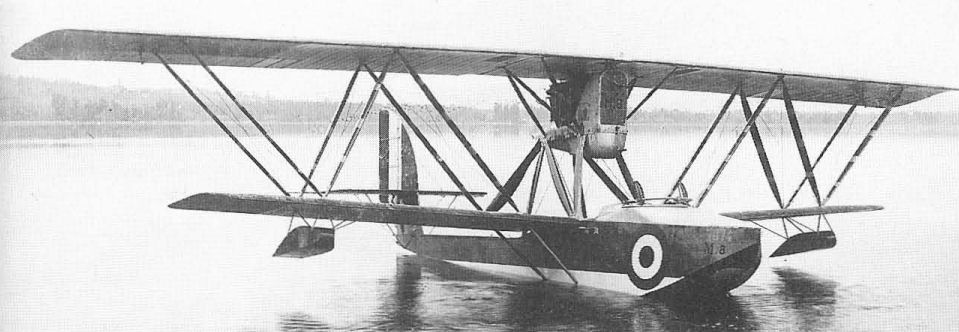
A Macchi M.8 flying-boat as used by the Navy in Europe.
Aeromarine 39-A, 39-B
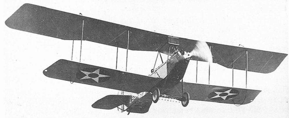
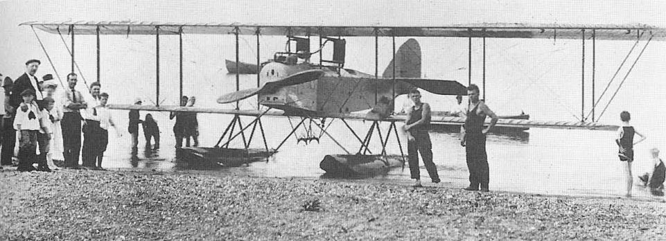
In 1917 the Navy placed with the Aeromarine Plane and Motor Company of Keyport, NJ, what was at that time the largest single order for Navy aircraft - 50 of the Model 39-A and 150 39-B trainers. These were conventional two-bay wood and fabric biplanes and could be fitted with wheels or floats. The 39-As used the four-cylinder Hall-Scott A-7A engine of 100 hp and the seaplane versions had twin wooden floats. The 39-B was powered by the 100 hp Curtiss OXX-6 engine, the seaplanes having the single main pontoon with small wingtip floats for stability which the Navy preferred for its training and service seaplanes and was to retain until seaplane trainers were dropped from the inventory in 1960.
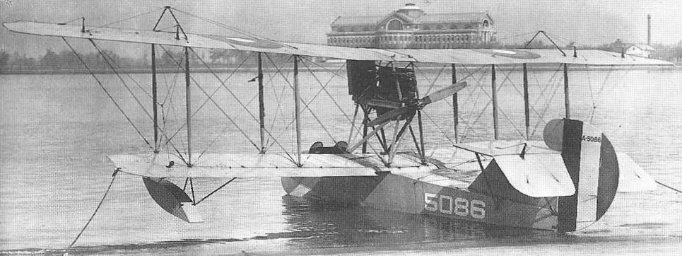
A number of the 39-Bs survived World War I, and two were used for the Navy's early experiments in deck landing. Various types of arrester gear were tried on a dummy carrier deck at Langley Field, Virginia, in 1921. The aeroplane was fitted with the forerunner of the modern hook that engaged the cross-deck arrester cables, while alignment hooks were fitted to the undercarriage to engage longitudinal wires on the deck to keep the machine running straight. In anticipation of forced landings at sea in the course of later operations from shipboard, a hydrovane was fitted ahead of the wheels to prevent nosing over on alighting.
On October 26, 1922, a 39-B piloted by Lt Cdr Geoffrey DeChevalier, Naval Aviator No.7, made the first landing on the deck of the Navy's first aircraft carrier, the USS Langley, a converted collier. This was nine days after the first take-off had been made in a Vought VE-7.
TECHNICAL DATA (Aeromarine 39-A)
Manufacturer: Aeromarine Plane and Motor Company, Keyport, NJ.
Type: Training biplane.
Accommodation: Two pilots.
In 1917 the Navy placed with the Aeromarine Plane and Motor Company of Keyport, NJ, what was at that time the largest single order for Navy aircraft - 50 of the Model 39-A and 150 39-B trainers. These were conventional two-bay wood and fabric biplanes and could be fitted with wheels or floats. The 39-As used the four-cylinder Hall-Scott A-7A engine of 100 hp and the seaplane versions had twin wooden floats. The 39-B was powered by the 100 hp Curtiss OXX-6 engine, the seaplanes having the single main pontoon with small wingtip floats for stability which the Navy preferred for its training and service seaplanes and was to retain until seaplane trainers were dropped from the inventory in 1960.
A number of the 39-Bs survived World War I, and two were used for the Navy's early experiments in deck landing. Various types of arrester gear were tried on a dummy carrier deck at Langley Field, Virginia, in 1921. The aeroplane was fitted with the forerunner of the modern hook that engaged the cross-deck arrester cables, while alignment hooks were fitted to the undercarriage to engage longitudinal wires on the deck to keep the machine running straight. In anticipation of forced landings at sea in the course of later operations from shipboard, a hydrovane was fitted ahead of the wheels to prevent nosing over on alighting.
On October 26, 1922, a 39-B piloted by Lt Cdr Geoffrey DeChevalier, Naval Aviator No.7, made the first landing on the deck of the Navy's first aircraft carrier, the USS Langley, a converted collier. This was nine days after the first take-off had been made in a Vought VE-7.
TECHNICAL DATA (Aeromarine 39-A)
Manufacturer: Aeromarine Plane and Motor Company, Keyport, NJ.
Type: Training biplane.
Accommodation: Two pilots.
Aeromarine 39-B making the first landing on USS Langley on October 26, 1922.
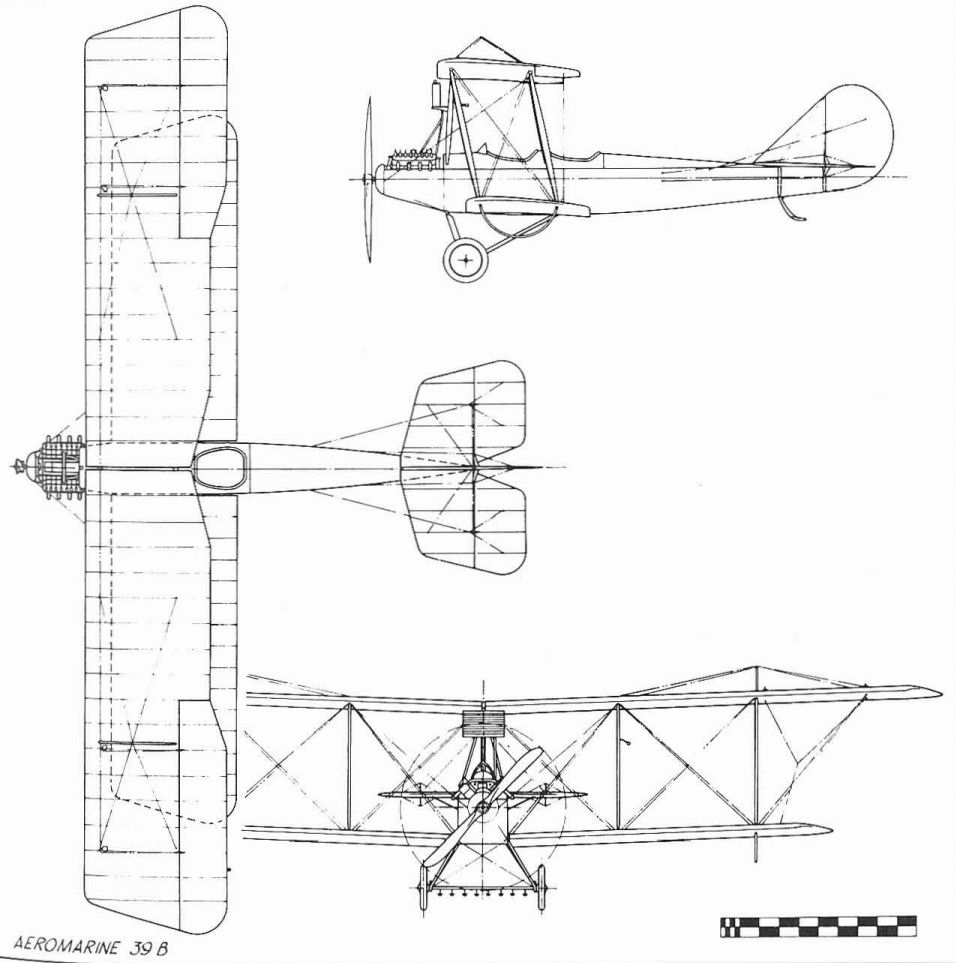
Aeromarine 39 B
AEROMARINE 700
The Navy ordered four Model 7 seaplanes from the Aeromarine Plane & Motor Company during 1917, but accepted delivery of only the first two (A142, A143). Powered by a 90hp Aeromarine six-cylinder engine, one of these was used for the first US experiments in the dropping of torpedoes from aircraft. The twin floats were carried on independent structures to allow the torpedo to be dropped between them from the belly rack. Because of the limited payload of the Model 700 (700 lb) only a lightweight dummy torpedo could be used.
The Navy ordered four Model 7 seaplanes from the Aeromarine Plane & Motor Company during 1917, but accepted delivery of only the first two (A142, A143). Powered by a 90hp Aeromarine six-cylinder engine, one of these was used for the first US experiments in the dropping of torpedoes from aircraft. The twin floats were carried on independent structures to allow the torpedo to be dropped between them from the belly rack. Because of the limited payload of the Model 700 (700 lb) only a lightweight dummy torpedo could be used.
The Aeromarine 700 used ror early torpedo-dropping tests in the US.
AEROMARINE 40
In 1918 the Navy ordered 200 Aeromarine Model 40F flying-boats to supplement the ageing Curtiss Fs and the improved MFs then on order. The Aeromarines, powered with 100 hp Curtiss OXX-6 engines, were conventional two-seat training flying-boats of the period, with the pilot and student seated side by side in a single open cockpit in the wooden hull. The Armistice caused cancellation of the majority of the order, and only the first 50 (A5040-A5089) were delivered. Since most deliveries did not take place until after the Armistice, the 40Fs saw little service in the training schools. Span, 48 ft 6 in; length, 28 ft 11 in; gross weight, 2,592 lb; max speed, 180 mph.
In 1918 the Navy ordered 200 Aeromarine Model 40F flying-boats to supplement the ageing Curtiss Fs and the improved MFs then on order. The Aeromarines, powered with 100 hp Curtiss OXX-6 engines, were conventional two-seat training flying-boats of the period, with the pilot and student seated side by side in a single open cockpit in the wooden hull. The Armistice caused cancellation of the majority of the order, and only the first 50 (A5040-A5089) were delivered. Since most deliveries did not take place until after the Armistice, the 40Fs saw little service in the training schools. Span, 48 ft 6 in; length, 28 ft 11 in; gross weight, 2,592 lb; max speed, 180 mph.
An Aeromarine 40.
Boeing C, C-1F
The sixth and seventh Boeing aeroplanes built, designated C-5 and C-6 by the manufacturer, were submitted to the Navy early in 1917 for test as primary trainers. The design was a slight modification of the C-4, incorporating an unusual degree of stagger and dihedral on the wings to achieve inherent stability. On the basis of the tests, the Navy ordered 50 production models that established the tiny Boeing Airplane Company as a 'major' manufacturer. The production versions were still called Model C by Boeing, and individual machines were identified by appending the Navy serial number to the designation, the whole lot thus being identified as C-650 through C-699. Although not a naval aircraft, an additional Model C built for Mr William E. Boeing in 1918 was called C-700 simply because it followed the last of the Navy machines through the factory.
An unusual feature of the Model C, apart from the amount of stagger to the wings, was the absence of a fixed horizontal tail plane. This last feature became a point of controversy between the pilots, who insisted there should be one, and the designer, who maintained that because of the stability imparted by the stagger, a stabilizer was not necessary and performance was increased by the weight saving.
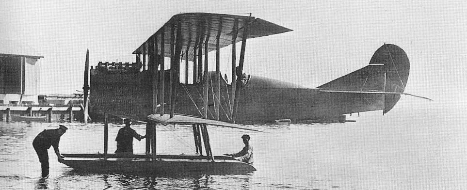
Otherwise a conventional twin-float seaplane, the Model C was not used at Naval training schools after delivery because of the extremely poor performance of the Hall-Scott A-7A engine. Most of the Cs were sold as surplus after the war, still in their original packing crates. The Army had similar experience with the Hall-Scott, and grounded its Standard Model J primary trainers, which used the same engine.
Recognizing the deficiencies of the Hall-Scott, the Navy ordered an additional Model C, powered with the 100 hp Curtiss OXX-6 engine, under the designation of C-1F, meamng a C with one main float instead of the usual two.
TECHNICAL DATA (Boeing Model C)
Manufacturer: Boeing Airplane Company, Seattle, Washington.
Type: Training seaplane.
Accommodation: Two pilots.
Power plant: One 100 hp Hall-Scott A-7A.
Dimensions: Span, 43 ft 10 in; length, 27 ft; height, 12 ft 7 in; wing area, 495 sq ft.
Weights: Empty, 1,898 lb; gross, 2,395 lb.
Performance: Max speed, 72.7 mph at sea level; cruising speed, 65 mph at sea level; climb, 23.5 min to 5,000 ft; service ceiling, 6,500 ft; range, 200 st miles.
Serial numbers: C: A147-A148, A650-A699. C-1F: A4347.
The sixth and seventh Boeing aeroplanes built, designated C-5 and C-6 by the manufacturer, were submitted to the Navy early in 1917 for test as primary trainers. The design was a slight modification of the C-4, incorporating an unusual degree of stagger and dihedral on the wings to achieve inherent stability. On the basis of the tests, the Navy ordered 50 production models that established the tiny Boeing Airplane Company as a 'major' manufacturer. The production versions were still called Model C by Boeing, and individual machines were identified by appending the Navy serial number to the designation, the whole lot thus being identified as C-650 through C-699. Although not a naval aircraft, an additional Model C built for Mr William E. Boeing in 1918 was called C-700 simply because it followed the last of the Navy machines through the factory.
An unusual feature of the Model C, apart from the amount of stagger to the wings, was the absence of a fixed horizontal tail plane. This last feature became a point of controversy between the pilots, who insisted there should be one, and the designer, who maintained that because of the stability imparted by the stagger, a stabilizer was not necessary and performance was increased by the weight saving.
Otherwise a conventional twin-float seaplane, the Model C was not used at Naval training schools after delivery because of the extremely poor performance of the Hall-Scott A-7A engine. Most of the Cs were sold as surplus after the war, still in their original packing crates. The Army had similar experience with the Hall-Scott, and grounded its Standard Model J primary trainers, which used the same engine.
Recognizing the deficiencies of the Hall-Scott, the Navy ordered an additional Model C, powered with the 100 hp Curtiss OXX-6 engine, under the designation of C-1F, meamng a C with one main float instead of the usual two.
TECHNICAL DATA (Boeing Model C)
Manufacturer: Boeing Airplane Company, Seattle, Washington.
Type: Training seaplane.
Accommodation: Two pilots.
Power plant: One 100 hp Hall-Scott A-7A.
Dimensions: Span, 43 ft 10 in; length, 27 ft; height, 12 ft 7 in; wing area, 495 sq ft.
Weights: Empty, 1,898 lb; gross, 2,395 lb.
Performance: Max speed, 72.7 mph at sea level; cruising speed, 65 mph at sea level; climb, 23.5 min to 5,000 ft; service ceiling, 6,500 ft; range, 200 st miles.
Serial numbers: C: A147-A148, A650-A699. C-1F: A4347.
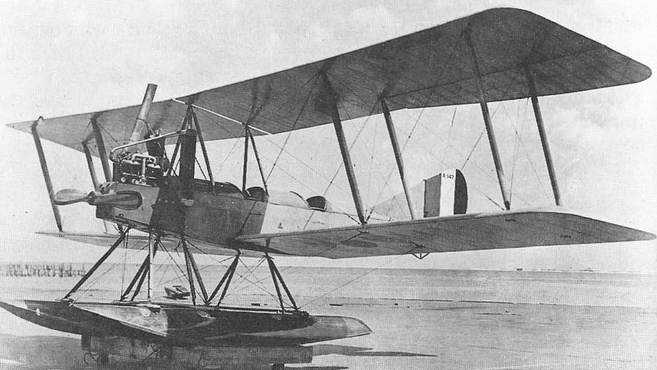
Boeing Model 3, the C-5 seaplane tested by the US Navy, before purchase of the Model Cs in quantity, with clear-doped finish and the new 1917 military tail striping. Compare larger radiators, modified centre section struts, and vertical tail size to Model 2.
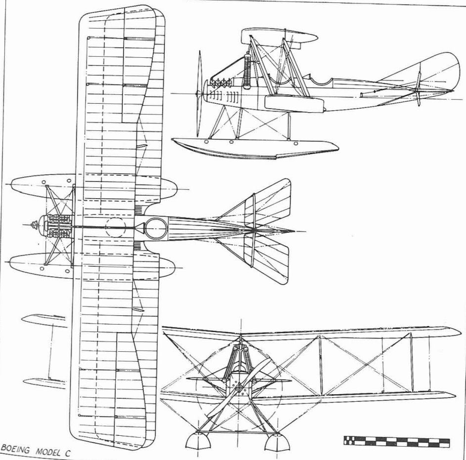
Boeing Model C
BURGESS L
The Burgess Company, sometimes called Burgess & Curtis because of the prominence of Greely S. Curtis (no relation to Glenn L.) in its affairs and also called Burgess-Wright because of its manufacture of aircraft under the Wright's patents, produced several training designs for the Navy before becoming a Division of Curtiss Aeroplane & Motor Company in 1917. These included six Model S seaplanes (A70-A75), two HT-B (A155, A156), six HT-2 (A374-A379) and six U-2 (A380-A385). The 125 hp Hall-Scott powered Model S illustrated was number AH-25 before being reserialled A70.
The Burgess Company, sometimes called Burgess & Curtis because of the prominence of Greely S. Curtis (no relation to Glenn L.) in its affairs and also called Burgess-Wright because of its manufacture of aircraft under the Wright's patents, produced several training designs for the Navy before becoming a Division of Curtiss Aeroplane & Motor Company in 1917. These included six Model S seaplanes (A70-A75), two HT-B (A155, A156), six HT-2 (A374-A379) and six U-2 (A380-A385). The 125 hp Hall-Scott powered Model S illustrated was number AH-25 before being reserialled A70.
A Burgess S seaplane in October 1916.
BURGESS-DUNNE AH-7, 10
Manufacturing rights to the British Dunne tailless aircraft were licensed to the Burgess Company of Marblehead, Mass, which built two seaplane versions (AH-7, AH-10) in 1916. Longitudinal stability was achieved by extreme sweepback (30 degrees). The Navy's first experiments in aerial gunnery were conducted with these pushers. Power plant, 100 hp Curtiss OXX-2. Span, 46 ft 6 in; max speed 69 mph.
Manufacturing rights to the British Dunne tailless aircraft were licensed to the Burgess Company of Marblehead, Mass, which built two seaplane versions (AH-7, AH-10) in 1916. Longitudinal stability was achieved by extreme sweepback (30 degrees). The Navy's first experiments in aerial gunnery were conducted with these pushers. Power plant, 100 hp Curtiss OXX-2. Span, 46 ft 6 in; max speed 69 mph.
The Burgess-Dunne AH-10 tailless biplane.
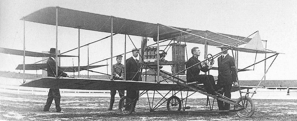
Naval Aviator No 1, Lt T.G. Ellyson, in a Curtiss Pusher at San Diego, January 1911 prior to purchase of Navy s first aeroplane.
Early Curtiss Pushers
Identifying the various Curtiss pushers supplied to the US Navy from 1911 through 1913 by either a factory or Navy model number is impossible. Curtiss had no firm designation system at the time and the Navy system was very general, applying originally only to manufacturer and sequence of procurement. This was soon changed to a basic type as aeroplane and to subtype, as hydroplane or flying-boat. The first Navy aeroplane was a Curtiss pusher seaplane designated A-1. This was a waterborne version of the basic Curtiss pusher that had been in production since 1909 and which had been developed into the world's first consistently successful seaplane. After several unsuccessful float configurations were tried Glen Curtiss made his first seaplane flight at San Diego, California, on January 26, 1911. It was this ability to operate from water, plus a visit by Curtiss in his seaplane to the battleship USS Pennsylvania anchored off San Diego from a shore station on February 17, 1911, that crystallized the Navy's existing interest in aeroplanes and led to the purchase of the A-1 in July 1911. Earlier, the Navy co-operated with Curtiss in the operation of Curtiss-owned aeroplanes from ships of the fleet. On November 14, 1910, the Curtiss pilot Eugene Ely flew a pusher from a platform rigged on the aft deck of the cruiser USS Birmingham anchored in Hampton Roads, Virginia. Later (on January 18, 1911) he landed aboard and took off from a similar platform built on the battleship USS Pennsylvania anchored in San Francisco Bay.
Lt Theodore G. Ellyson, who had been an official naval observer at Curtiss' first seaplane flight, was sent to the Curtiss Flying School at Hammondsport, NY, to receive flight instruction that qualified him as Naval Aviator No. 1. After the A-1 was test hopped by Curtiss on July 1, 1911, Curtiss took Ellyson up on a familiarization flight after which Ellyson made two more flights alone. After acceptance by the Navy, the A-1 figured prominently in early Naval aircraft developments. One experiment consisted of converting the A-1 to an amphibian, called the Triad, by adding retractable wheels to the float.
Launching methods were given high priority. On September 7, 1911, Ellyson was able to take off in the A-1 from an inclined wire. Directional control was maintained by a groove in the float through which the wire ran. Later, experiments were conducted in which the A-1 was to be launched by a compressed-air catapult based on the successful torpedo launchers then in use by the Navy. The initial trials, undertaken on a dock at Annapolis, Maryland, ended in failure due to the A-1 not being properly restrained. It lifted off from the carriage without control as soon as it gained forward speed. The first successful catapult launch was made by Ellyson in the A-3 at the Washington Navy Yard. The A-1, meanwhile, being the only aeroplane that the Navy had, set an Impressive number of records merely by exceeding its previous performance. With Lt John H. Towers as passenger, Ellyson flew 112 miles from Annapolis, Maryland, to Milford Haven, Virginia, in 122 minutes. The A-1 was the first Navy aeroplane to carry a radio, although without success, and established a seaplane altitude record of 900ft on June 21,1912.
The Curtiss A-1 had a 75 hp Curtiss V-8 engine for most of its 285 flights.
TECHNICAL DATA (A-1)
Manufacturer: Curtiss Aeroplane and Motor Co, Inc, Hammondsport, NY.
Type: pusher biplane, landplane or seaplane.
Accommodation: Pilot and passenger.
Power plant: One 75 hp Curtiss V-8.
Dimensions: Span, 37 ft; length, 28 ft 7 1/8 in; height, 8 ft 10 in; wing area, 286 sq ft.
Weights: Empty 925 lb; gross, 1,575 lb.
Performance: Max speed, 60 mph.
Serial numbers: None.

Curtiss A-1 Triad resting on its wheels in shallow water. Both sets of elevators are 'down'.
The forward elevator had been eliminated from Curtiss landplane and seaplane pushers alike by the time lhe US Navy bought the AH-13. Curtiss AH-13 two-seater bearing the legend 'U.S.N. AH-13' on the rudder.
The A-2 was delivered to the Navy on July 13, 1911, in landplane configuration. As a seaplane, it remained in the air for 6 hr 10 min on October 6, 1912. By October 1912, the A-2 had been converted to a flying-boat by the simple expedient of building a superstructure from the pontoon deck upward to enclose the crew. Retractable tricycle landing gear similar to that of the Triad was fitted, and the designation of the modified machine was changed to E-1. This was also called the OWL for Over Water and Land and was briefly known as the AX-1.
The next two Navy aeroplanes, designated A-3 and A-4 were also single-float Curtiss pushers with minor differences in detail. A-3 achieved a degree of fame on June 13, 1913, by establishing an American seaplane altitude record of 6,200 ft. By the time the Navy was ready to order additional Curtiss pusher seaplanes, the designation system had been changed and the aeroplanes were known as AH for Airplane, Hydro, followed by a sequence number. The first two procured under the new system were AH-8 and AH-9, both of which were referred to as Type AH-8 in the manner of naval ships, where the first of a new class or design gave its name to the entire group. The AH-8s were followed by five more, starting with AH-11. These were followed by a further three that Navy records refer to as AH-8 type.
Further designation changes took place within the procurement period of the Curtiss pushers, the last 11 being ordered under a system whereby each Navy aeroplane was identified by a consecutive serial number, which was prefixed by the letter A-for-Airplane. The Navy had wisely decided to designate its aeroplanes by the manufacturer's own name and model number, but since the Curtiss aircraft had no firm number at the factory, the remaining 11 of the basic design (A60-A62, A83-A90) were again designated as Type AH-8. A83 was the AH-9 rebuilt, and A84-A90 may have been similarly reassigned.
The original AH-8, meanwhile, had been turned over to the US Army. It survived World War I, still in Army hands, and was put in storage. It was resurrected in 1928 and flown briefly by Capt Holden C. Richardson, Chief of Design and Materiel Division, Bureau of Aeronautics, and Naval Aviator No. 13, on February 10.
The A-2, flown 575 times before becoming the E-1, had an 80 hp engine eventually, earlier units rated at 60 hp and 75 hp being fitted. Span, 37 ft 1 in; length, 27 ft 2 in; gross weight, 1,547lb; speed 60 mph.
Curtiss C-1 flying boat (later AB-1), with Cmdr T.G.Ellyson in the cockpit.
Curtiss A-2 with built-up superstructure above pontoon. This aircraft later became the E-1 (later AX-1) when wheels were added.
Curtiss F-Boat
The Curtiss model F was an early development of the original Curtiss pusher flying-boat of 1912, the world's first successful f1ying-boat. Designation of the US Navy models is confusing because procurement of the basic design bridged the changeover from the original Navy system of designating aircraft by code letters for the manufacturer and type to the use of the manufacturer's own model designation. Also, there was enough change between early consecutive production examples of a single basic design to make the rigid application of an all-inclusive model number somewhat unrealistic. The designation was confused further by the later adoption of the British F (for Felixstowe) symbol for later developments of the twin-engine Curtiss H series, and the practice of using F as a type letter applied to small single-engine pusher flying-boats developed by other manufacturers.
The major production version of the Curtiss F used a hull built up of laminated wood veneer strips which were shaped and glued up in a jig before being applied to the wooden hull frame. The student and his instructor sat side by side in a single cockpit ahead of the wings. Wing shape varied during the production life of the F, which continued into 1918. Some had equal-span wings with ailerons mounted between the panels, and some had the ailerons built into the upper wing. Overhang was added to the upper wing to increase lifting area on some models. Early models had fabric stretched between front and rear struts just outboard of the engine to serve as anti-skid vanes; later models had fabric applied between the kingposts that braced the upper wing overhang to serve the same purpose.
The first five Navy F-boats, all differing in detail, were procured as Navy models C-1 through C-5. In March 1914 these machines were redesignated AB-1 through AB-5, the letter A designating Curtiss as the first manufacturer of aircraft for the Navy and the letter B identifying the type of the machine as a flying-boat. As ABs, these machines contributed much to early Navy aeronautical development. In December 1912 one boat, believed to have been the C-1 at the time, was launched from a catapult mounted on a dock at the Washington Navy Yard. AB-2 was later catapulted from a barge moored at the Pensacola Naval Air Station in Florida and on November 5,1915, Lt Cdr H. C. Mustin, Naval Aviator No. 11, made the first Navy catapult launch from a ship when he successfully left the battleship USS North Carolina in the AB-2. The ship was at anchor at the time and the catapult was directed straight astern.
Several of the ABs accompanied the Navy to Vera Cruz, Mexico, in April 1914. Carried aboard the USS Mississippi, AB-3 was flown from the water by Lt (Jg) P.N. L. Bellinger in the first operation of US military aircraft against another country. The first flight, made on April 25, was for observation purposes and to look for mines in the harbour. The second, made on April 28, was a photographic mission. Upon its return to the United States, AB-3 had its wings shortened and finished its career as a non-flying 'penguin' trainer.
At least 144 additional trainer flying-boats were ordered from Curtiss under the F designation. More show up in Navy serial number listings, but these are mixed among the later Curtiss MF models that began replace the Fs in 1918 and Fs built to Curtiss' or their own design by other manufacturers. The Burgess Company of Marblehead, Mass., was to have built Curtiss Fs under licence but was switched to the production of Curtiss N-9s, and produced only one Curtiss F (A2281).
TECHNICAL DATA (F-Boat)
Manufacturer: Curtiss Aeroplane and Motor Co, Inc, Hammondsport, and Buffalo, NY.
Type: Flying-boat trainer.
Accomodation: Pilot and instructor side by side.
Pover plant: One 100 hp Curtiss OXX.
Dimensions: Span, 45 ft 1 3/8 in.; length, 27 ft 9 3/4 in; height, 11 ft 2 3/4 in; wing area, 387 sq ft.
Weights: Empty, 1,860 lb; gross, 2,460 lb.
Performance: Max speed, 69 mph at sea level; initial climb, 10 min to 2,300 ft; service ceiling 4,500 ft; endurance, 5.5 hrs.
Serial numbers (known):A145; A146; A386; A387; A390-A393; A408; A752-A756; A2279-A2281; A2295-A2344; A3328-A3332; A4079-A4108; A4349-A4402; A5258.
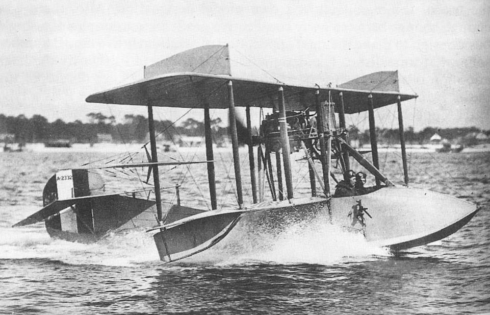
The Model F of 1913 became the standard Navy flying-boat trainer and remained in production into 1918. Increased upper wing span and Deperdussin controls were the principal changes. All-grey Curtiss F flying-boat in 1918 colouring, showing overhanging top wing and ailerons between the wings.
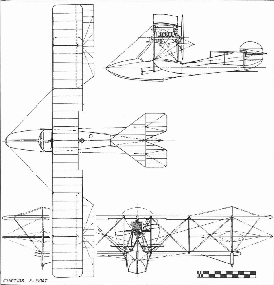
Curtiss F-boat
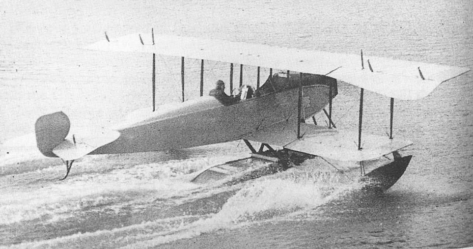
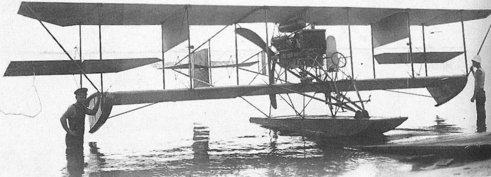
Curtiss JN-1S seaplane, first Navy single-engined Jenny. When the Model J was tried as a seaplane, the span of the upper wing was increased to carry the added weight of the floats.
Curtiss JN Series
The Curtiss JNs, particularly the JN-4 model, are widely known throughout the world as the Jenny, a logical expression of the model designation JN, which covered the result of combining the best features of the Curtiss Models J and N. In addition to being the most widely used trainers of the US Army and the Royal Canadian Air Force in World War I, the Jenny and its Canadian equivalent, the Canuck, embarked upon an entirely new career in the post-war years when cheap war-surplus models came into the hands of private owners. While over 4,000 aircraft in the JN series were built, with most going to the US Army, the RCAF and the RAF, a respectable number, 261, was used by the US Navy from 1916 until the early 1920s.
The design originated in England. B. Douglas Thomas, who had been an engineer with Avro and later with Sopwith, was engaged by Glenn Curtiss while still in England to develop a new tractor-type trainer to replace the Curtiss pushers that were then finding great disfavour with both the US Army and Navy training schools. Since Europe had the lead in tractor design at the time, Curtiss sought to save valuable time by hiring an engineer already experienced in this layout, which was as yet unfamiliar to American practice. Thomas's design became the Model J, an equal-span biplane built in the Curtiss plant at Hammondsport, New York. Initial flights were made with the fuselage uncovered. This design was tried both as a landplane and a single-float seaplane. A very similar Model N, differing mainly in the aerofoil used, followed. The J design was discontinued upon development of the JN, but the N model remained in production and was developed to the N-9 by war's end. Some of the Navy JN-4s were obtained on direct purchase from Curtiss, but others were obtained by exchanges of aircraft with the US Army, which had occasion to use aircraft developed originally for the Navy.
The first Navy JN was an oddity, compared with the rest of the line, in that it was a twin-engine design using major JN components. Rather than being given an entirely new model designation by the manufacturer, it was simply called Twin JN; the Navy serial number was A93. This was evaluated as a landplane and as a twin-float seaplane, but was not ordered into production for the Navy, although the Army used a total of ten.
The first genuine Navy Jennies were two JN-1Ws (A149, A150), single-float seaplane versions of the Army JN-1. In spite of the relatively modern lines of this model compared with the open-air Curtiss pushers that it replaced, the old shoulder-yoke type of aileron control was retained. This survived in the contemporary N series through the N-8. One additional JN-1 (A198), fitted out as a gunnery trainer, was obtained later.
Subsequent procurement of Navy Jennies was not in strict sequence of model development, due partly to the exchanges with the Army. Three JN-4Bs, late 1916 versions of the JN-1 but fitted with improved vertical tail surfaces and the wheel-type Deperdussin control, were obtained ahead of five JN-4As. These were followed by six additional JN-4Bs in 1918.
A major design change took place with the JN-4H, an advanced trainer fitted with the 150 hp Wright-Hispano engine, popularly called the Hisso. The letter H in the designation identified the engine and was not a reflection of model development. Thirty of the Hs were procured for advanced pilot training in 1918 and were followed by 90 gunnery trainers designated JN-4HG. Further minor changes resulted in the JN-6, which could be distinguished from the JN-4H mainly in being fitted with ailerons on both wings. A total of ten was procured, some of which were designated JN-6HG-I to identify them as gunnery trainers powered with the 150 hp Wright-Hispano Model I engine. Frequently this latter designation is misquoted as JN-6HG-1.
Procurement continued into the early post-war years, an additional 113 JN-4H landplane trainers being used by the Navy and Marines.
TECHNICAL DATA (JN-4H)
Manufacturer: Curtiss Aeroplane and Motor Co, Inc, Garden City, LI, and Buffalo, NY.
Type: Trainer.
Accommodation: Two in tandem.
Power plant: One 150 hp Wright-Hispano.
Dimensions: Span, 43 ft 7 3/8 in; length, 27 ft 4 in; height, 9 ft 10 1/2 in; wing area, 352.6 sq ft.
Weights: Empty, 1,467 lb; gross, 2,017 lb.
Performance: Max speed, 93 mph at sea level; climb, 10 min to 4,350 ft; service ceiling, 10,525 ft; range, 268 st miles.
Serial numbers:
JN-4A: A388; A389; A995-A997.
JN-4B: A157-A159; A4l12-A4117.
JN-4H: A3205-A3234; A6193-A6247; A6271-A6288.
JN-4HG: A4128-A42l7.
JN-6H: A5470-A5471; A5581-A5586; A5859.
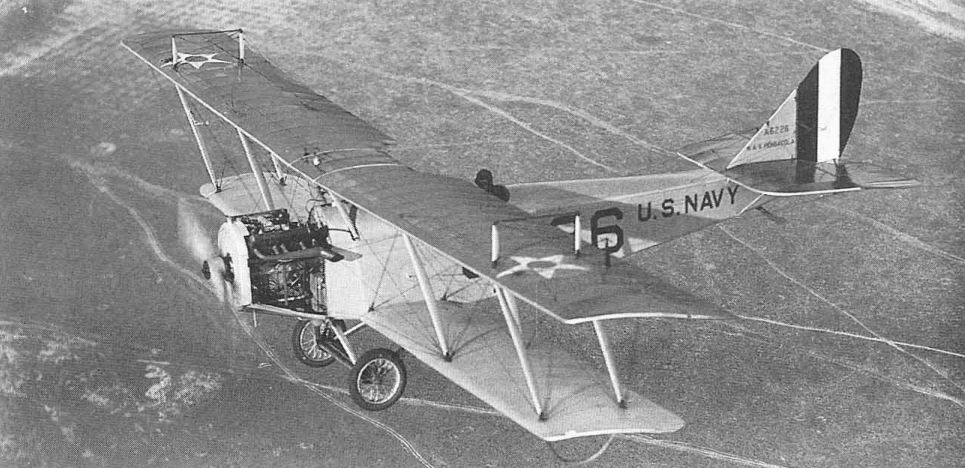
Curtiss JN-4H A6226 serving at NAS Pensacola, showing the yellow colouring ror top or upper wing adopted in February 1924.
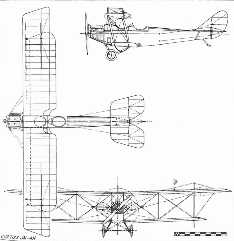
Curtiss JN-4H
Curtiss R-3, R-6, R-9
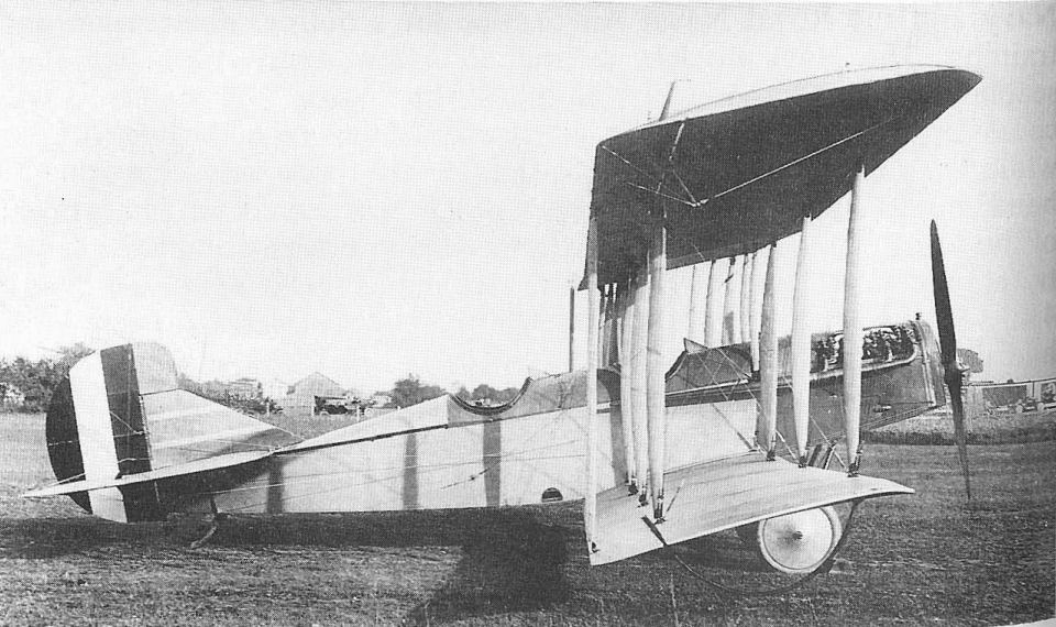
The Curtiss R series of 1915-18 was widely used by the US Army and Navy and the Royal Naval Air Service for scouting, observation and training. The Navy models, as well as a few Army, were twin-float seaplanes originally powered with the 150hp Curtiss V-X engine As was common practice at the time, the pilot occupied the rear of the two cockpits while the observer sat in the front, although his vision was consequently handicapped by the wings. The basic design was merely an enlargement of the J and N models that had become standard Army observation and training models. The Army R-4 landplane model had a wing span of 48 ft 4 in, with two bays, but the Navy R-3 model, of which two were built, had the span increased to 57 ft 1 in in order to carry the weight of the floats. This was accomplished by building a wider centre section for the upper wing, in the manner of the N-9, and fitting an additional section between the standard-sized bottom wings and the fuselage.
The R-6 was an improved R-3 with a 200 hp Curtiss V-X-X engine and dihedral on the wings. A few of the Curtiss-powered R-6s were converted to R-9s, the main change being relocation of the pilot to the front cockpit. The last 40 of the Curtiss-powered R-6s were converted to R-6L in 1918 by the installation of the 360-400 hp V-12 engine, and an additional 40 R-9s were ordered as such. R-6s were the first US built aircraft to serve overseas with US armed forces in World War I, a squadron being based at Ponta Delgada in the Azores for anti-submarine patrols from January 17, 1918.
After the Armistice, R-6Ls were modified to carry naval torpedoes. The Navy had tried this on August 14, 1917, but the experiment was not successful. Such late adoption of the torpedo-carrier was rather ironic for the US Navy, as it had been an American admiral, Bradley A. Fiske, who had proposed such an aircraft before the outbreak of World War I. British and German forces both used torpedo-carriers successfully during that war, but the overall weight of the weapon cut down on the amount of explosive to such an extent that the torpedo was a less effective weapon than the standard aerial bomb.
TECHNICAL DATA (R-6L)
Manufacturer: Curtiss Aeroplane and Motor Co, Inc, Buffalo, NY.
Type: Observation, scouting and training.
Accommodation: Two in tandem.
Power plant: One 400hp Liberty V-12.
Dimensions: Span, 57 ft 1 1/4 in; length 33 ft 5 in; height 14 ft 2 in; wing area, 613 sq ft.
Weights: Empty, 3,325 lb; gross, 4,500 lb.
Performance: Max speed, 100 mph at sea level; climb 10 min to 6000 ft; service ceiling 12,200 ft; range, 565 st miles.
Serial numbers:
R-3: A66-A67.
R-6: A162-A197; A873-A994.
The R-3 was a seaplane version of the R-2 with longer wings to carry the added weight of the twin floats. The blue anchor on the rudder and under the lower wingtips was the first US Navy aeroplane insignia. The figures 62 were part of Navy aeroplane designation AH-62, later changed to A-66.
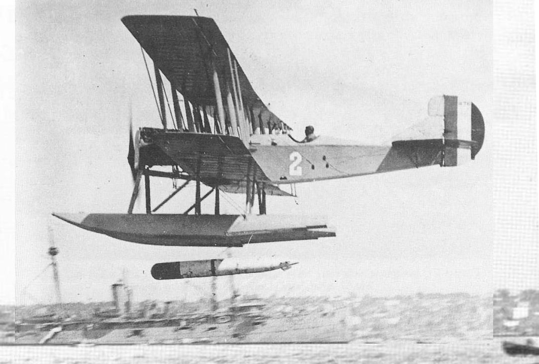
Most US Navy Curtiss R-6s were converted to R-6Ls by the installation of Liberty engines and were used as torpedoplanes after the war.
Curtiss R-6 landplane with Curtiss V-X-X engine.
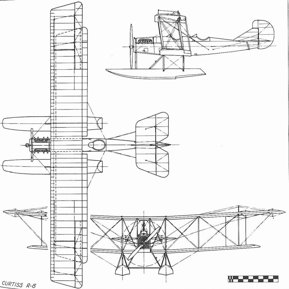
Curtiss R-6 (Model 2A).
Curtiss H-12, H-16
In 1914 Curtiss developed a then giant flying-boat to the special order of Mr Rodman Wanamaker, who planned to use it for a transatlantic flight. The outbreak of war cancelled these plans and the aeroplane, which had been named America, was sold to the Royal Naval Air Service. Under the factory designation Model H, sister ships with improved 150 hp engines were also sent to England, where as a class they were called Americas.
The original America was a daring design concept at the time, and left a permanent mark on subsequent large flying-boat development. Its effects could be seen on biplane designs that remained in production right up to World War II. The America, fitted with two 90hp Curtiss OX engines, did not have the power to carry enough fuel for the trip, so a third engine was mounted above the wing. Earlier, flotation difficulties had been encountered when power was applied to the engines for take-off; because of their high location, they exerted a considerable downward push on the nose that tended to drive it under water. This was corrected by adding more flotation volume to the nose in the form of auxiliary structures called sponsons that were built on to the lower portion of the hull from the bow to the step. This was to remain a feature of many flying-boats built into the 1930s.
In 1916 the Navy ordered an improved version of the America under the designation H-12. This featured the laminated wood veneer hull of the prototype, longer wings, and 200 hp Curtiss V-X-X engines. Equivalent models sold to Britain were called Large Americas. The initial Navy order was followed by another for 19 production versions. In 1918 some of these were converted to H-12L by the installation of the new Liberty engine.
A further improved model was introduced early in 1917 as the H-16, still powered with the 200 hp V-X-X. Many were sold to Britain in knockdown condition, still as Large Americas. They were then assembled and test flown in England, fitted with British engines. Commander Porte of the Royal Navy, who had assisted in the design of the original America, developed an improved hull design for the H-16, and the British versions were built at RNAS Felixstowe as F.2, F.3 and F.5.
By the time the US Navy became interested in production of the H-16, the Liberty engine was in the offing and was specified for the Navy's H-16s. However, in spite of the engine change there was no need to designate the production version as H-16L because there were no Curtiss-powered Navy models to require distinction. Because of the commitment of most of its production facilities to other war-time models, Curtiss could not meet the Navy's demand for H-16s, so the Navy undertook H-16 manufacture on its own at the Naval Aircraft Factory. This version was originally designated Navy Model C, as the third design built by Navy shops. This was the first aeroplane built by the new Naval Aircraft Factory, and the first example was completed on March 27, 1918. The original Curtiss designation was finally used.
In continuing attempts to improve the design, Curtiss built one H-16 with the engines turned around to drive pusher propellers. Because the engines had to be moved aft to get the propellers behind the wing, it became necessary to sweep the wings back slightly to relocate the centre of lift to match the new centre of gravity position. The Navy built 150 H-16s, and Curtiss built 124 for the Navy, some of which remained in service until 1928.
Serial numbers:
H-12: A152; A765-A783.
Curtiss H-12L in overall grey finish with 1918 roundels on wings.

Curtiss H.12
Curtiss H-12, H-16
<...>
A further improved model was introduced early in 1917 as the H-16, still powered with the 200 hp V-X-X. Many were sold to Britain in knockdown condition, still as Large Americas. They were then assembled and test flown in England, fitted with British engines. Commander Porte of the Royal Navy, who had assisted in the design of the original America, developed an improved hull design for the H-16, and the British versions were built at RNAS Felixstowe as F.2, F.3 and F.5.
By the time the US Navy became interested in production of the H-16, the Liberty engine was in the offing and was specified for the Navy's H-16s. However, in spite of the engine change there was no need to designate the production version as H-16L because there were no Curtiss-powered Navy models to require distinction. Because of the commitment of most of its production facilities to other war-time models, Curtiss could not meet the Navy's demand for H-16s, so the Navy undertook H-16 manufacture on its own at the Naval Aircraft Factory. This version was originally designated Navy Model C, as the third design built by Navy shops. This was the first aeroplane built by the new Naval Aircraft Factory, and the first example was completed on March 27, 1918. The original Curtiss designation was finally used.
In continuing attempts to improve the design, Curtiss built one H-16 with the engines turned around to drive pusher propellers. Because the engines had to be moved aft to get the propellers behind the wing, it became necessary to sweep the wings back slightly to relocate the centre of lift to match the new centre of gravity position. The Navy built 150 H-16s, and Curtiss built 124 for the Navy, some of which remained in service until 1928.
TECHNICAL DATA (H-16)
Manufacturer: Curtiss Aeroplane and Motor Co, Inc, Garden City, LI and Buffalo, NY; and Naval Aircraft Factory, Philadelphia, Pennsylvania.
Type: Patrol/bomber flying-boat.
Accommodation: Crew of four.
Power plant: Two 400 hp Liberty 12s.
Dimensions: Span, 95 ft 0 3/4 in; length, 46 ft 1 1/2 in; height, 17 ft 8 5/8 in; wing area, 1,164 sq ft.
Weights: Empty, 7,400 lb; gross, 10,900 lb.
Performance: Max speed, 95 mph at sea level; initial climb, 10 min to 4,700 ft, service ceiling, 9,950 ft; range, 378 st miles.
Armament: Five-six flexible 0.30-in Lewis machine guns. Four 230 lb bombs.
Serial numbers:
H-16 (Curtiss): A784-A799; A818-A867; A1030-A1048; M039-M078.
H-16 (NAF): A1049-A1098; A3459-A3558.
Curtiss F-5L
Production of the F-5L in 1918 put Curtiss in the odd position of building an improved foreign version of one of its own designs. A number of Curtiss H-12s and H-16s, developed from the original America flying-boat of 1914, had been sold to Britain in 1915-16. These designs had been improved upon by the Royal Naval Air Station at Felixstowe, and were put into large-scale production as F (for Felixstowe) -2, -3 and -5, powered with British engines. The wings and tail were essentially Curtiss, but the major improvement was in hull design, which permitted quicker take-off under heavy load and stood up better on the surface of the rough North Sea.
Although Curtiss was producing later versions of the H-16, roughly equivalent to the British F-3, late in 1917, the Navy decided to adapt the F-5 to American manufacture and power it with the new Liberty engine. In addition to the Naval Aircraft Factory and Canadian Aeroplanes, Ltd, Curtiss was selected as a manufacturer and built 60. Canada built 30 and the NAF built 137, the last two of which were completed as improved versions, F-6L.
The principal feature distinguishing the F-5L from the Liberty-powered H-16 was the use of ailerons with parallel leading and trailing edges instead of the distinctively tapered trailing edges of those on the earlier boats. Balance area was also added to the F-5L rudder, but this area was set into the fin beneath the horizontal tail and was not noticeable. After the war all the F-5Ls in service were fitted with much larger vertical tails of entirely new design, which the Navy had developed on the two F-6Ls.
The F-5L was considered to be a US Navy design rather than a Curtiss, and when the new designating system of 1921 was adopted, the F-5L was assigned the designation PN-5 while the F-6L became PN-6. However, in practice the new designations were not used for designs in production before adoption of the new system, and the F-5Ls were called such until their retirement in 1928. Improved versions, in which newer wings and engines were fitted to the basic F-5L hull, did use the new designations, starting with the PN-7.
The wooden-hulled F-5Ls, along with the near-duplicate H-16s, remained the standard patrol boats of the Navy until replaced by production versions of the NAF PN-12 built by Douglas, Martin an Keystone in the late 1920s.
TECHNICAL DATA (F-5L)
Manufacture: Curtiss Aeroplane and Motor Co, Inc, Garden City, LI, and Buffalo, NY; Canadian Aeroplanes Ltd, Toronto; Naval Aircraft Factory, Philadelphia, Pennsylvania.
Type: Patrol flying-boat.
Accommodation: Crew of four.
Power plant: Two 400 hp Liberty 12As.
Dimensions: Span 103ft 9 1/4 in; length 49ft 3 3/4in; height, 18ft 9 3/4 in; wing area, 1,397 sq ft.
Weights: Empty 8 720 lb; gross 13 600 lb.
Performance: Max speed, 90 mph at sea level; initial climb, 2,200 ft in 10 min; service ceiling, 5,500 ft; range, 830 st miles.
Armament: Six to eight flexible 0'30-in machine guns. Four 230 lb bombs.
Serial numbers:
F-5L (Canadian): A3333-A3362; A3363-A3382 (cancelled).
F-5L (NAF): A3559-A4038 (of which 343 were cancelled).
F-5L (Curtiss): A4281-A4340.
F-6L (NAF): A4036-A4037.
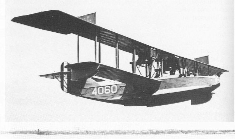
The H-16, with swept trailing edge of ailerons, twin Liberty engines and enclosed pilot's cabin, which distinguish this model from the F-5L, was the final Curtiss H-Model. Also built under licence by the Naval Aircraft Factory.
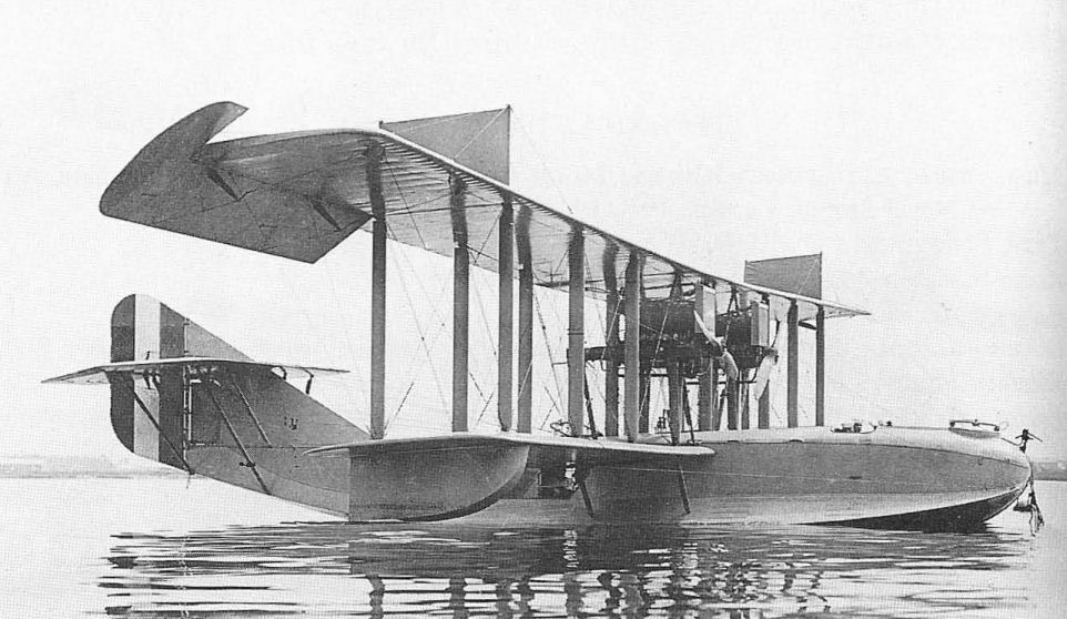
The first F-5-L built by the NAF, A-3559. The machine is Navy Grey overall. The original recessed rudder balance may be seen under the horizontal tailplane. Reported as 50% complete in July 1918 and 100% complete the following month it was ready on 11th of that month. If flew from the NAF to Hampton Roads on 28 August and was still there on 30 November when it alighted due to a heavy squall. As the wind died down the pilot tried to reach Hampton Roads before dark. Ran into heavy rain such that it was impossible to tell which direction seaplane was heading as compass could not be read. Absence of windscreens made it additional difficulty so the pilot attempted to land but could not see water due to the rain. He levelled off too high and side slipped to right. Hull began to fill and the crew took refuge on tail. Recommended be stricken, cause held to be the improper placing of the windscreens and light compass. On 17 September this was carried out. Another source indicates that this may not have been carried out immediately as it has the machine still at Hampton Roads in November. (AHT AL1171-046)
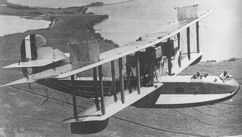
A 1924 photograph of a Curtiss F-5L with modified fin and rudder.
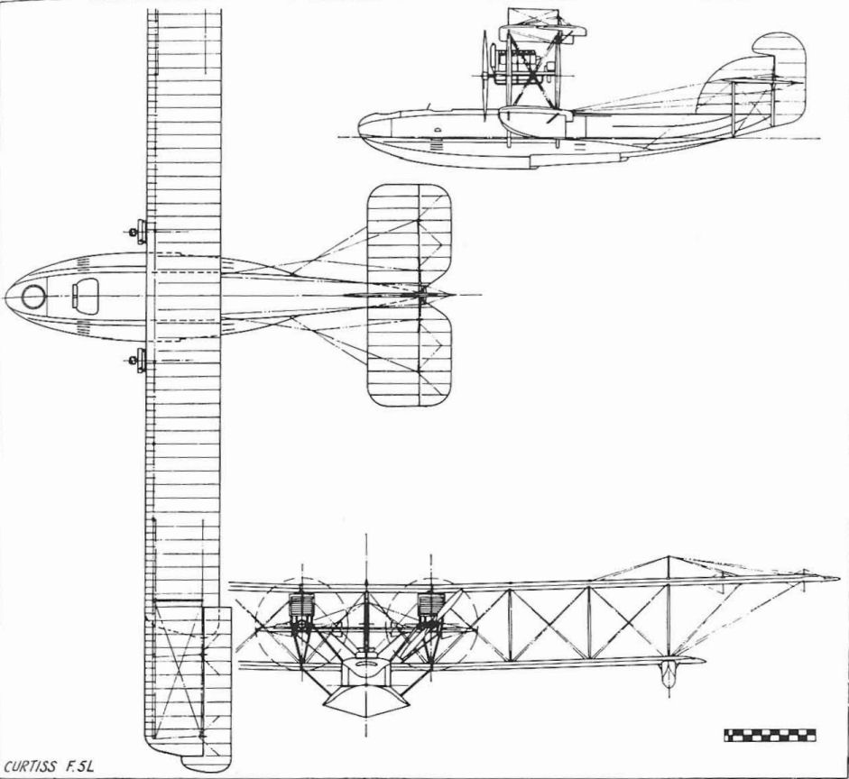
Curtiss F.5L
Curtiss HS Series
The Curtiss HS-1 was a single-engine pusher flying-boat that was essentially a scaled-down version of the earlier twin-engine H models. In fact, the designation letters stood for 'H, Single engine'. Actually, the new H-boat stood about half-way between the smaller F and the larger H-12.
The original power plant of the HS-1, which was introduced early in 1917, was the 200 hp Curtiss V-X-X, a watercooled V-8. On October 21, 1917, the HS-1 was used as the test-bed for the first flight of the new twelve-cylinder Liberty engine, which in its original form developed 375 hp and was destined to become the major American aeronautical contribution to World War I and one of the world's great aircraft engines. In its later versions, this engine produced 420 hp, but was generally referred to as a 400 hp power plant.
Following the successful marriage of the HS-1 airframe and the Liberty engine, the Navy ordered the HS-1 into large-scale production as the Navy's standard coastal patrol flying-boat. The numbers required were beyond the capacity of the Curtiss plants, so additional manufacturers were asked to produce the boats under licence from Curtiss. The original Curtiss order was for 664 machines. The Standard Aircraft Corporation was given an order for 250, of which the last 50 were cancelled; Lowe, Willard and Fowler was given an order for a total of 200, but 50 were cancelled. (This firm later rebuilt one of its own HS-boats, A1171, which was then given the new serial number A5630.) The Gallaudet Aircraft Corporation produced 60, the Boeing Airplane Company built 25 of an original order for 50, and the Loughead Aircraft Corp. (known today as Lockheed) built two. The Boeing versions could be distinguished from all the others in that they were fitted with horn-balanced ailerons only on the upper wing. The others had ailerons on both wings.
After the HS-1s, by this time designated HS-1L to identify installation of the Liberty engine, had entered service, it had been found that the standard 180 lb depth-bomb was ineffective against submerged submarines. Since two of these were all that the HS-1L could carry, it was decided to increase the wing span so that heavier 230 lb bombs could be carried. The modification was quite simple, an additional 6-ft panel was fitted between the centre section and the regular outer wing panels, increasing the overall span from 62 to 74 ft. This modification, which resulted in a new designation of HS-2L, was made to the majority of aircraft still on order, and there is no distinction in serial numbers between HS-1Ls and the HS-2Ls.
HS-1s were the first American-built aircraft received by the US Naval forces in France, eight arriving by ship at the US Naval base at Pauillac on May 24, 1918. The first flight was made on June 13. Records indicate that 182 HS-1Ls and HS-2Ls were distributed among 10 of the 16 Naval Air Stations in France. Of the total, only 19 can be confirmed as HS-2Ls.
The HS-2L remained the standard single-engine patrol and training flying-boat in the post-war years, examples remaining in the inventory until 1926. An additional 24 HS-2Ls were obtained in the post-war years by assembling accumulated spare parts at various Naval Air Stations and assigning new serial numbers to the complete aircraft. The serials were assigned as follows:
A5564/5569 NAS Miami, Florida
A5615/5619 NAS Hampton Roads, Virginia
A5787 NAS Key West, Florida
A5808 NAS Anacostia, Maryland
A6506 NAS Coco Solo, Canal Zone
A6507/6513 Naval Aircraft Factory, Philadelphia, Pa.
A6553/6556 NAS San Diego, California
The HS-3 was an improved model with revised hull lines under development at war's end. Curtiss built five (A5459-A5462) and the Naval Aircraft Factory two (A5590-A5591). After the war, many surplus HS-2Ls were acquired by civil owners who used them for passenger carrying and even scheduled airline operations. A few were still in use as survey planes in Canada in the early 1930s.
TECHNICAL DATA (HS-2L)
Manufacturer: Curtiss Aeroplane and Motor Co, Inc, Garden City, LI, and Buffalo, NY; Standard Aircraft Corporation, Elizabeth, NJ; Lowe, Willard and Fowler, College Point, LI; Gallaudet Aircraft Corporation, East Greenwich, Conn; Boeing Airplane Company, Seattle, Wash; Loughead Aircraft Corporation, Santa Barbara, California.
Type: Patrol flying-boat.
Accommodation: Crew of two or three.
Power plant: One 350 hp Liberty 12.
Dimensions: Span, 74 ft 0 1/2 in; length, 39 ft; height, 14 ft 7 1/4 in; wing area, 803 sq ft.
Weights: Empty, 4,300 lb; gross, 6,432 lb.
Performance: Max speed, 82.5 mph at sea level; initial climb, 10min to 2,300ft; service ceiling, 5,200 ft; range, 517 st miles.
Armament: One flexible 0'30-in Lewis gun. Two 230lb bombs.
Serial numbers:
HS-1L/2L (Curtiss): A800-A815; A1549-A2207.
HS-2L (Standard): A1399-A1548 (50 cancelled).
HS-2L (LWF): A1099-A1398 (50 cancelled).
HS-2L (Gallaudet): A2217-A2276.
HS-2L (Loughead): A4228-A4229.
HS-2L (Boeing): A4231-A4255.
HS-2L (NAS): A5564-A5569; A5615-A5619; A5787; A5808; A6506-A6513; A6553-A6556.
HS-3 (Curtiss): A5459-A5462.
HS-3 (NAF): A5590-A5591.
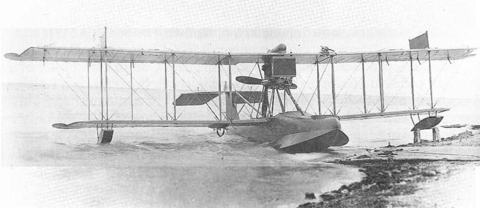
The HS-1L was the production version of the Model HS, with the letter L identifying the use of the Liberty engine.
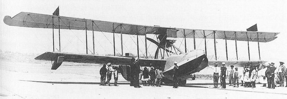
Boeing-built Curtiss HS-2L, distinguished by absence of lower-wing ailerons.
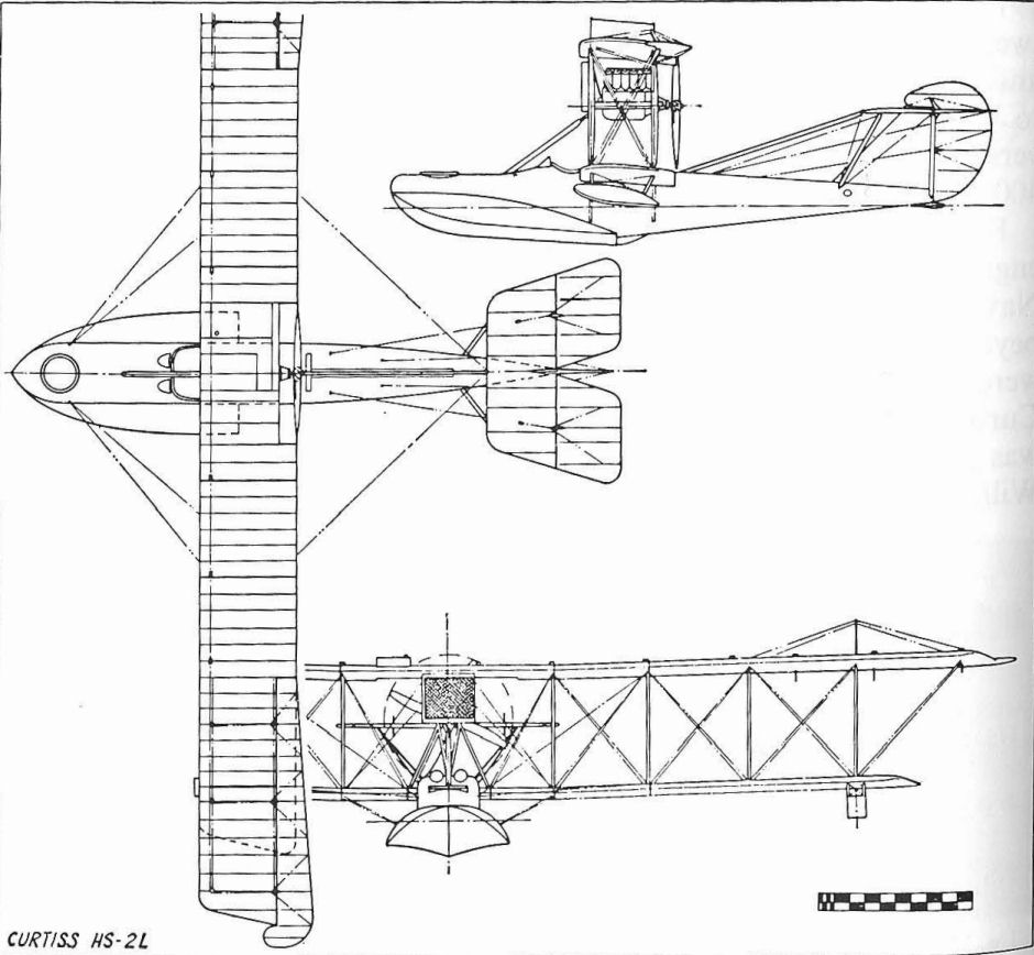
CURTISS HS-2L
Curtiss N-9
The Curtiss N-9, originally powered with a 100 hp Curtiss OXX-6 engine, was the standard Navy primary and advanced seaplane trainer of World War I. It was developed as a private venture by Curtiss as a seaplane version of the JN-4B landplane trainer then in production. The N-8 landplane model was almost identical to the JN-4, having only minor differences in the aerofoil section and the control system, and evolution into the N-9 was simple. Intended from the beginning as a seaplane, the N-9 was faced with the weight problem of the heavy central float and the stabilizing tip floats. The extra 10 hp of the OXX-6 engine over the standard OX-5 was not enough, so additional wing area was obtained by increasing the span of each wing by 10ft. Instead of building longer panels, a wider centre section was built for the upper wing and an extra 5-ft panel was fitted between the fuselage and standard-size lower panels.
N-9s entered service with the Navy even before the United States entered the war in April 1917. The Army bought 14 N-9s at this time, too, since it conducted relatively extensive seaplane operations. In the primary training role, the 100 hp N-9 was satisfactory, but more performance was required for such advanced operations as bombing and gunnery training. To satisfy this requirement, Curtiss replaced the OXX-6 with the 150 hp Hispano-Suiza Model A then being manufactured in the United States by the Simplex Division of the Wright-Martin Company. This improved model was designated N-9H.
Five hundred and sixty N-9s were built for the Navy during World War I and the type remained in service as late as 1926. Of this total, only 100 were built by Curtiss, the majority being produced under licence by the Burgess Company of Marblehead, Mass. An additional 50 N-9Bs were created by the Navy in the postwar years by the practice of assembling available spare parts and engines into entirely new airframes.
TECHNICAL DATA (N-9H)
Manufacturer: Curtiss Aeroplane and Motor Co, Inc, Garden City, LI, and Buffalo NY and the Burgess Company, Marblehead, Mass.
Type. Training seaplane.
Accommodation: Two in tandem.
Power plant: One 150 hp Wright-Hispano Model A.
Dimensions: Span, 53 ft 3 3/4 in; length,30 ft 10 in; height, 10 ft 8 ? in; wing area 496 sq ft.
Weights: Empty, 2,140 lb; gross, 2,765 lb.
Performance: Max speed, 80mph at sea level;' climb 10min to 4450ft; service ceiling, 9,850 ft; range, 179 st miles.
Serial numbers:
N-9 N-9H (Curtiss): A60-A65; A85-A90; A96-A125; A201-A234; A294-A301; A342; A373; A2285-A2290.
N-9/N-9H (Burgess): A409-A438; A999-A1028; A2351-A2572; A2574-A2650.
N-9H (NAS Pensacola): A6528-A6542; A6618-A6632; A6733-A6742; A7091-A7100.
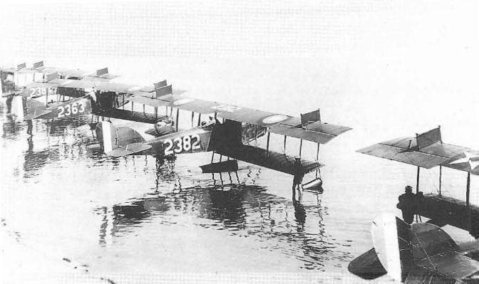
The insignia change of January 1918, resulted in some interesting mixtures when stored components carrying old markings were installed on newer aeroplanes. Number 2363 at left has correct markings; 2382 has the order of tail stripe colours reversed, as in 1917, and the grey-painted aircraft extreme right has the 1917 star insignia on the wings but 1918 tail stripes.
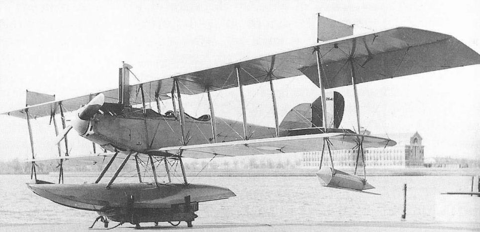
An N-9H with 150 hp American-built (as the Wright Model A) Hispano·Suiza engine and unique tower radiator. Burgess built N-9s under licence and the US Navy assembled many others from spare parts.
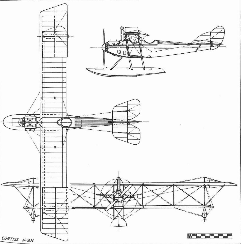
Curtiss N-9H
Curtiss 18-T
Although the Navy had only two Curtiss 18-Ts, which the manufacturer named Wasp, they set numerous records and had a significant effect on subsequent designs. The two were ordered on March 30, 1918, and were intended as two-seat fighters. Unusually clean design was achieved in spite of triplane configuration by the fact that the fuselage was a beautifully streamlined structure built up of cross-laminated strips of wood veneer formed over a mould and then attached to the inner structure of longerons and formers. This method was well-established in Germany during the World War I years by such manufacturers as Roland and Pfalz, but had been used only on a limited scale in the United States, most notably by Lowe, Willard and Fowler (L.W.F.). Curtiss had previous experience with similar construction in the hulls of the Model F flying-boats and the early H-boats, and this feature was to reappear in several subsequent Curtiss designs, most notably the Pulitzer and Schneider racers of the early 1920s.
At a time when equivalent American military designs were being planned round the Liberty engine, the 18-T used an entirely new power plant, the Curtiss K-12, developed for Curtiss by the well-known engine designer Charles Kirkham. The aircraft and the engine were designed for each other, and because of this, the 18-T and its equivalent biplane version, the 18-B Hornet for the Army, were often referred to as Curtiss-Kirkhams. The compact power plant, which produced 400 hp, developed into the famous Curtiss D-12 (V-1150) of the 1920s and the larger V-1570 Conqueror of the 1930s, some examples of which remained in use until World War II. The K-12 enabled the 18-T to set an official world's speed record of 163 mph with full military load on August 19, 1918. On July 25, 1919, Curtiss test pilot Roland Rholfs established an American altitude record of 30,100ft, later raising it to an official world record of 34,610ft on September 19.
In its original form the 18-T, which first flew on July 5, 1918, had single-bay unswept wings of 31 ft 11 in span. Because of tail heaviness resulting from the heavy wood construction, five degrees of sweepback were built in to move the centre of lift aft. The Navy loaned the first modified 18-T, A3325, to the Army for test, after which the Army ordered two examples of its own for comparison with the biplane version then under construction. In order to improve the altitude capability of the design and accommodate the additional weight of floats, longer two-bay wings were built and installed, the short-wing version becoming 18-T1 and the long-wing 18-T2.
While never ordered into production as a service type, the 18-Ts' performance was such that they were both kept on hand by the Navy as racers. In the short-wing landplane configuration, both were entered in the 1920 Pulitzer Race, but dropped out before the finish with engine trouble. They were inactive as racers in 1921 because the Navy withdrew from racing that year, but reappeared as short-wing seaplanes for the 1922 Curtiss Marine Trophy Race, one of the events in the 1922 National Air Races held at Detroit, Michigan. Lt R. Irvine, flying A3325, which had been painted bright green for identification purposes, dropped out in the fifth lap. Lt L. H. Sanderson, flying the yellow-painted A3326, was leading the field in the last lap with an average speed of 125.3 mph round the 20-mile triangular course when he ran out of fuel and was forced to land short of the finishing line, damaging the plane in the process. A3326 was returned to the Naval Aircraft Factory for repair, along with its sister ship. Both were reconverted to landplanes and appeared at the 1923 National Air Races held in St Louis, Missouri. A3325 crashed during a preliminary trial flight. A3326 piloted by Lt L. G. Hughes, broke a crankshaft during the Liberty Engine Builders Trophy race and was destroyed in the resulting crash.
TECHNICAL DATA (Curtiss 18-T1)
Manufacturer: Curtiss Aeroplane and Motor Co, Inc, Garden City, LI, NY
Type: Fighter.
Accommodation: Crew of two.
Power plant: One 400 hp Curtiss K-12.
Dimensions: Span, 31ft 10 in; length, 23ft 4in; height 9ft lO 3/4 in; wing area, 309 sq ft.
Weights: Empty, 1,980 lb; gross, 3,050 lb.
Performance: Max speed, 160mph at sea level; initial climb, 10 min to 12500ft; service ceiling, 23,000 ft; endurance, 5.9 hrs.
Armament: Two fixed forward-firing 0.30-in Marlin guns; two 0,30-in Lewis guns on flexible mount in rear cockpit.
Serial numbers: A3325-A3326.
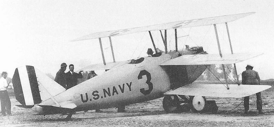
Curtiss 18-T1 serial A3326 as flown in the 1923 National Air Races.
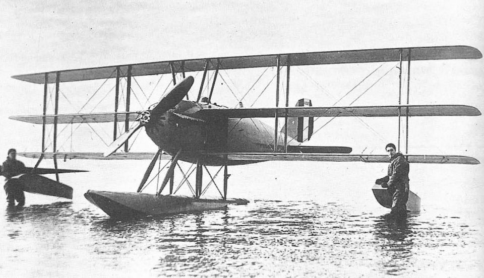
The long-span Curtiss 18-T2 used for a seaplane altitude record flight in 1919.
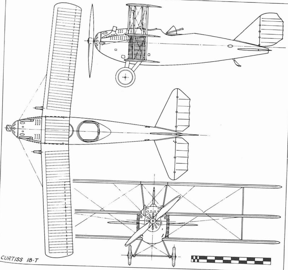
Curtiss Model 18T Wasp.
CURTISS HA DUNKIRK FIGHTER
The HA was designed to serve as a two-seat escort and air superiority fighter for the Dunkirk-Calais area. Powered with the 400 hp Liberty, the prototype HA (A2278) flew on March 21, 1918, but soon crashed. Two modified versions were then ordered as HA-1 (A4110) which included salvageable parts of A2278, and the longer-winged HA-2 (A4111). Following the war's end, both were used for miscellaneous testing, and a landplane variant of HA-2 was developed for the Post Office department as a mailplane. Span, 36 ft (HA-2 span, 42 ft); length, 30 ft 9 in; gross weight, 4,012 lb; max speed, 132mph.
The HA was designed to serve as a two-seat escort and air superiority fighter for the Dunkirk-Calais area. Powered with the 400 hp Liberty, the prototype HA (A2278) flew on March 21, 1918, but soon crashed. Two modified versions were then ordered as HA-1 (A4110) which included salvageable parts of A2278, and the longer-winged HA-2 (A4111). Following the war's end, both were used for miscellaneous testing, and a landplane variant of HA-2 was developed for the Post Office department as a mailplane. Span, 36 ft (HA-2 span, 42 ft); length, 30 ft 9 in; gross weight, 4,012 lb; max speed, 132mph.
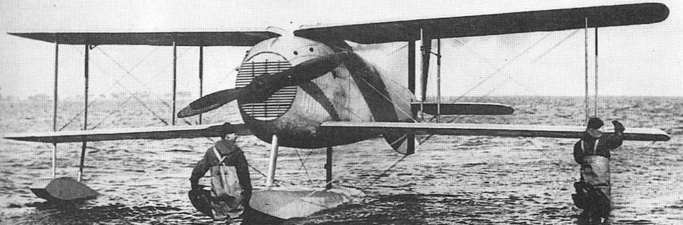
The Curtiss HA-1 single-float fighter.
Curtiss MF
The Curtiss MF was an improved 1918 model flying-boat that was intended to replace the venerable F model that had been on hand since 1912. While the letters of the designation stood for Modified F there was no detail resemblance between the two other than the general configuration of a wooden-hulled pusher flying-boat. The MF drew upon the later design experience of the H-boats and the F-5Ls and used a flat-sided hull with additional forward buoyancy provided by sponsons added to the sides. The initial order to Curtiss was for six machines. This was followed by a production order for 47, but because of the Armistice, only the first 16 were delivered. An additional 80 were ordered into production at the Naval Aircraft Factory after the war.
Curtiss, meanwhile, quickly brought out a civil version of the MF under the name Seagull. Some of these, fitted with Wright-Hispano engines of 150 hp, or the new Curtiss K-6s of 150-160 hp were modified to carry as many as four people. Curtiss even tried an amphibious version in its quest to capture the sportsman-pilot market in the face of competition from cheap war-surplus machines, but the Seagull in its different versions was not a commercial success.
Navy interest in an amphibious version was reflected by a contract given to the Elias brothers aircraft company, Buffalo, NY, for the conversion of one of the NAF MFs (A5484) to an amphibian. As the MFs, both Curtiss and Navy-built, became surplus to the needs of the service, they were bought up by the Cox-Klemm Aircraft company College point, Long Island, and modified for civil use.
TECHNICAL DATA (MF-Boat)
Manufacturer: Curtiss Aeroplane and Motor Co, Inc, Garden City, LI, and Buffalo, NY; and Naval Aircraft Factory, Philadelphia, Pennsylvania.
Type: Flying-boat trainer.
Accommodation: Pilot and instructor side by side.
Power plant: One 100hp Curtiss OXX.
Dimensions: Span, 49 ft 9 in; length, 28 ft 10 in; height 11ft 7 in, wing area, 402 sq ft.
Weights: Empty, 1,850 lb; gross, 2,488 lb.
Performance: Max speed, 72 mph at sea level; initial climb, 10min to 2,400ft; service ceiling, 4,100 ft; range 345 st miles.
Serial numbers: A2345-A2350; A4403-A4449 (last 31 cancelled); A5483-A5562 (by NAF)
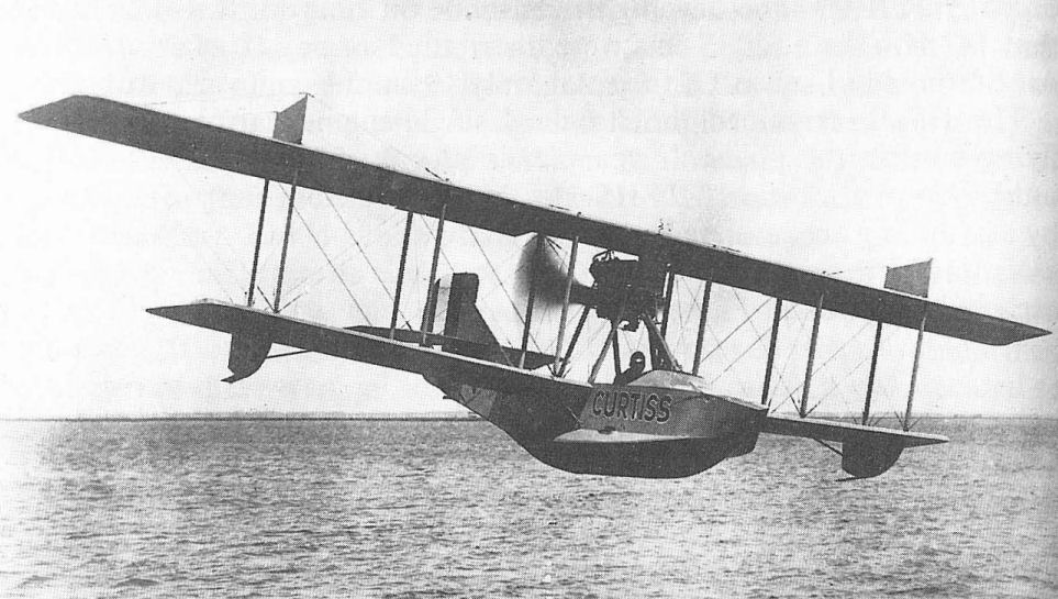
Curtiss MF training flying-boat.
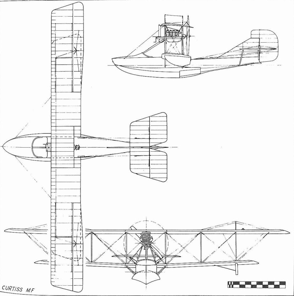
Curtiss MF
Navy/Curtiss NC Boats
The Navy/Curtiss boats which were to achieve undying fame as the first to complete a crossing of the Atlantic by air (albeit in stages) owed their origin to the successful German U-boat campaign of 1917. As British and American shipping losses mounted drastically, the call went out for more patrol aircraft to provide an umbrella over the Atlantic. Since many of the flying-boats then serving with the Royal Navy were built in America, that source was appealed to. In response to the urgency of the situation, the US Navy Department drew up plans in September 1917, for a new flying-boat to carry the war to the U-boat. The essential requirement was that this boat should be able to fly across the Atlantic-since shipping space was at a minimum-and be able to take on a U-boat immediately upon arrival.
Such a machine would need an endurance of 15-20 hours, which in turn meant that it would have to be very large, necessarily multi-engined, and of sufficiently rugged construction to be able to endure forced landings at sea. Alone among American manufacturers, Curtiss had the large aircraft experience and the shop facilities that would allow it to build such a mammoth. In reply to the Navy's detailed proposal for a transatlantic flying-boat using a unique new Navy hull design, Curtiss quickly produced plans for a suitable three-engine 28,000 lb biplane. The principal point of departure from traditional design was the Navy's new hull. While using the established Curtiss laminated wood veneer construction, it was very short - only 45 ft - with the tail surfaces carried clear of the water on a superstructure of spruce struts. This arrangement minimized hull weight and gave, as required, an uninterrupted field of fire straight to the rear for machine gunners in the rear of the hull. Because of the joint design effort involved, the new boats were designated NCs for Navy and Curtiss. The first four, built by Curtiss at its experimental plant in Garden City, New York, and assembled at the Naval Air Station at nearby Rockaway, were given the separate designations of NC-1 through NC-4, a departure from established model designation procedure. The NC-1, which first flew on October 4, 1918 had all three Liberty engines installed as tractors, with the pilot and co-pilot located in the centre nacelle behind the engine. A ladder was provided for the pilots and other crew members to move about in flight. On November 25, the NC-1 carried 51 persons aloft to establish a new world's record for passengers carried.
Testing proved that three engines were inadequate for the transatlantic mission, so the remaining aircraft were redesigned for four. NC-2, which first flew on April 12, 1919, was completed with two tandem pairs, with the pilots in a third nacelle between the engine pairs. NC-3, which flew on April 23rd, and NC-4 reverted to the three tractor engine arrangement of NC-1 but added the fourth engine as a pusher in the middle nacelle. The pilots were removed to the hull ahead of the wing on NC-3 and NC-4 and NC-1 was modified to the same pattern.
Although the NC boats were not completed in time to see war service, it was decided to fly them across the Atlantic anyhow, as a race was developing between England and America for the honour of being the first across by air. In preparation for this mission, the NCs were redesignated NC-TA, for Transatlantic. Only three gathered at Trepassy Bay, Newfoundland, for the May 16, 1919, start. The engine arrangement of NC-2 had been declared unsatisfactory for the mission, and NC-2's wings were removed and installed on NC-1 to replace the originals which had been damaged in a storm. Under the command of Cdr (later Admiral) John H. Towers, Naval Aviator No.3, the three boats took off on the 1,400-mile flight to the Azores. NC-4 achieved it by air, and later completed the voyage, reaching Plymouth on May 31 via Lisbon. NC-1 and NC-3 were both forced down at sea short of the Azores. NC-1 sank after the crew was rescued by a ship, but NC-3, with Towers aboard, managed to taxi the remaining 200 miles to the Azores.
Six additional boats, NC-5 through NC-10, were built after the war at the Naval Aircraft Factory, with NC-5 and NC-6 in trimotor configuration having the centre engine installed as a pusher. The others were four-engined in the NC-3/4 pattern. After the adoption of the new designating system in 1922, the surviving NC boats were redesignated P2N for the second Navy-designed patrol model, but the term was not actually applied. Following the transatlantic flight, NC-4 made a publicity tour of eastern and southern coastal cities and flew up the Mississippi river to St Louis before being handed over to the Smithsonian Institution.
TECHNICAL DATA (NC-TA)
Manufacturer: Curtiss Aeroplane and Motor Company, Garden City, LI, NY, and Naval Aircraft Factory, Philadelphia, Pennsylvania.
Type: Long-range patrol flying-boat.
Accommodation: Two pilots; navigator/nose gunner; radio operator, two flight engineers.
Power plant: Four 400 hp Liberty 12s.
Dimensions: Span, 126 ft; length, 68 ft 3 in; height, 24 ft 6 in; wing area, 2,380 sq ft.
Weights: Empty, 15,874 lb; gross, 26,386 lb.
Performance: Max speed, 85 mph; initial climb, 1,050 ft in 5 min; service ceiling, 4,500 ft; range, 1,470 st miles.
Armament: Machine guns in bow and rear hull cockpits.
Serial numbers:
NC-1/4: A2291-A2294. NC-5/10: A5632-A5635; A5885; A5886.
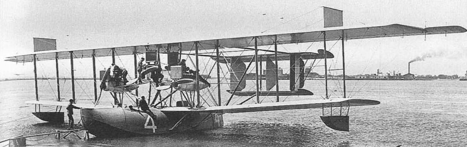
Curtiss-built NC-4, designed by the NAF and used for the transatlantic flight in 1919.

The NAF-designed, Curtiss-built NC-4 on first stage of transatlantic flight, May 8, 1919.
GALLAUDET D-1, D-4
One of the most unusual designs in the Navy inventory was the Gallaudet D-series, produced by the Gallaudet Engineering Company, Norwich, Conn. This featured the power plant amidships driving a geared-down propeller mounted on a ring encircling the fuselage. The D-1 (A59) was powered with two 150 hp Dusenberg engines mounted side by side. Following delivery of the D-1 in January 1917, the firm reorganized as Gallaudet Aircraft Corporation, and moved to Greenwich, Rhode Island. Two D-4s, powered with single Liberty engines, were then produced for the Navy (A2653, A2654). D-1 specifications: span, 48 ft; length, 33 ft; gross weight, 4,604 lb; max speed, 90 mph.
One of the most unusual designs in the Navy inventory was the Gallaudet D-series, produced by the Gallaudet Engineering Company, Norwich, Conn. This featured the power plant amidships driving a geared-down propeller mounted on a ring encircling the fuselage. The D-1 (A59) was powered with two 150 hp Dusenberg engines mounted side by side. Following delivery of the D-1 in January 1917, the firm reorganized as Gallaudet Aircraft Corporation, and moved to Greenwich, Rhode Island. Two D-4s, powered with single Liberty engines, were then produced for the Navy (A2653, A2654). D-1 specifications: span, 48 ft; length, 33 ft; gross weight, 4,604 lb; max speed, 90 mph.
Loening M Series
The Loening monoplanes were a daring innovation in their day, since the field of military aviation in 1918 was dominated almost entirely by biplane-minded pilots, engineers and procurement personnel. Grover C. Loening, who had acquired an aeronautical engineering degree from Columbia University in 1911 by virtually inventing the course, was able to see the inherent speed and structural simplicity advantages of the monoplane and had the tenacity to fight for his beliefs against adamant opposition. Loening got his chance in 1918, by which time he was a thoroughly experienced engineer, having worked for the Wright Brothers, been chief engineer of the Army Flying School in San Diego, and then chief engineer of the Sturtevant Aeroplane Co. After forming his own company in 1918, Loening was asked to design a two-seat fighter that would out-perform the famous British Bristol Fighter. The result was the M-8, a strut-braced high-wing monoplane built around the new 300 hp Hispano-Suiza engine just then going into production in the United States as the Wright H-3.
In addition to being a monoplane in a biplane's world, the M-8 had a number of advanced features. One was the radiator installation, which was mounted in a tunnel beneath the engine instead of surrounding the propeller shaft or being a separate bolted-on item outside the fuselage lines, as was customary. This feature was widely adopted by other high-performance military aircraft in the post-war years.
The parallel lift-struts connecting the wing to the lower longeron were fitted with wide fairings of aerofoil section that were expected to contribute lift. This feature was to become a trademark of the famous Bellanca monoplanes of 1925-40. With the upper longerons at the level of the wing, the rear gunner had an excellent field of fire for his twin 0.30-in Lewis guns. The pilot, of course, had the same unobstructed view above for fighting and could also see under the wing through windows below the longerons. The performance of the M-8 was such that a contract for 5,000 was placed, but the wholesale cancellations that followed the Armistice kept production models from being built for the Army.
The Navy, having taken a low-cost sample of Loening's basic monoplane design with three ultra-light Kittens (A442-A444) that were designed as ships' planes and were considered for quick disassembly and stowage aboard submarines, took an interest in the full-size fighter design after the war and ordered a single naval version as the M-8-0 (sometimes written as M-80). This was followed by orders for 46 production models designated M-8-0 and M-8-1 (M-81) which, although designed as fighters, were used for observation purposes. An additional six were ordered as M-8-1S twin-float seaplanes, and at least one of these was tested as an amphibian with wheels built into the bottoms of the floats.
Three practically identical models, designated LS for Loening seaplane, were also ordered, but the last two were cancelled. The single LS (A5606) was used to test the unique Richardson Pontoon which was in effect a standard float of somewhat greater than standard width split along the centreline. These halves were then moved apart to standard twin-float positions beneath the seaplane. The vertical inside face of each separate float was supposed to improve the water-handling characteristics of the combination, but nothing seems to have come of it and the experiment was dropped.
The Navy attempted to capitalize on the loudly proclaimed speed advantages of the monoplane by fitting one M-81 (A5791) with a special set of small wings for its entry in the 1920 Pulitzer race. Span was reduced by nearly 5ft, the chord was reduced by 2 ft, and the wide lifting-struts were replaced by thin streamlined steel tubes. The racer, flown by Lt B. G. Bradley of the US Marine Corps, developed a water leak early in the race which forced it out in the last lap after achieving a speed of 160mph around the closed course. It was ironic for Loening that after this misfortune the Navy pinned its racing hopes on biplanes and even kept a pair of triplanes in service for such purposes through the 1923 season. He was able to sell a handful of monoplane fighters and racers to the Army in the years 1920-2, but had to fall back on the traditional biplane in order to win significant orders and did not introduce another monoplane for over a decade.
TECHNICAL DATA (M-8-0)
Manufacturer: Loening Aeronautical Engineering Company, New York.
Type: Observation monoplane.
Accommodation: Pilot and observer.
Power plant: One 300hp Hispano-Suiza.
Dimensions: Span, 32 ft 9 in; length, 24 ft; height, 6 ft 7 in; wing area, 229 sq ft.
Weights: Empty, 1,623lb; gross, 2,068 lb.
Performance: Max speed, 145 mph; climb, 10 min to 13,900 ft; service ceiling, 22,000 ft; endurance 5.5 hrs.
Armament: Two flexible 0.30-in Lewis guns.
Serial numbers:
M-8: A5631.
M-8-1: A5701-A5710; A5761-A5786.
M-8-0: A5637-A5646.
M-8-1S: A5788-A5793.
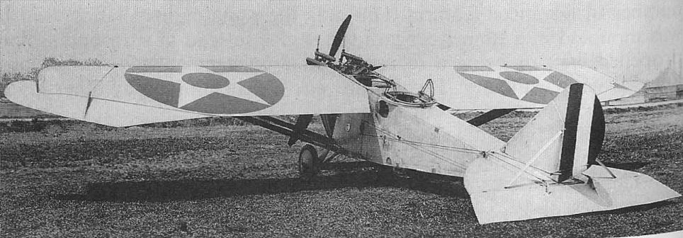
Loening M-81 land plane, illustrating the unusual ailerons at the wingtips.
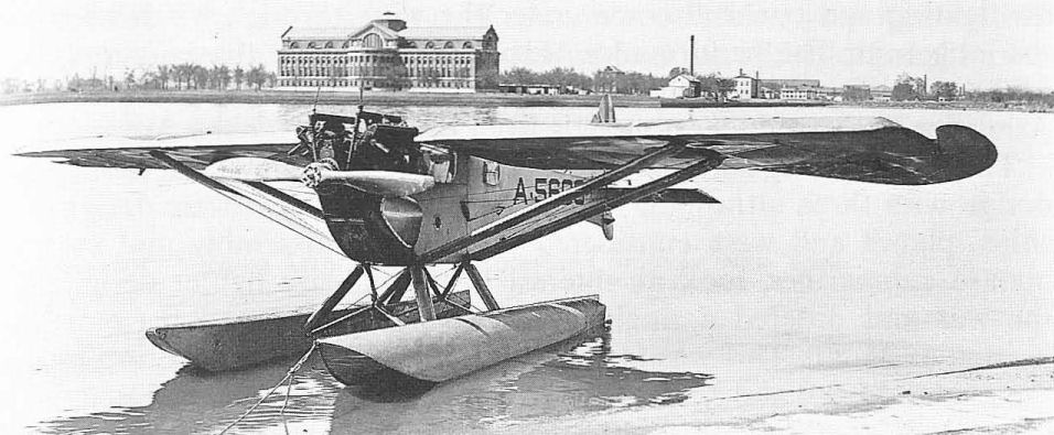
Loening LS-1 seaplane with the unusual Richardson floats which had flat inner faces.
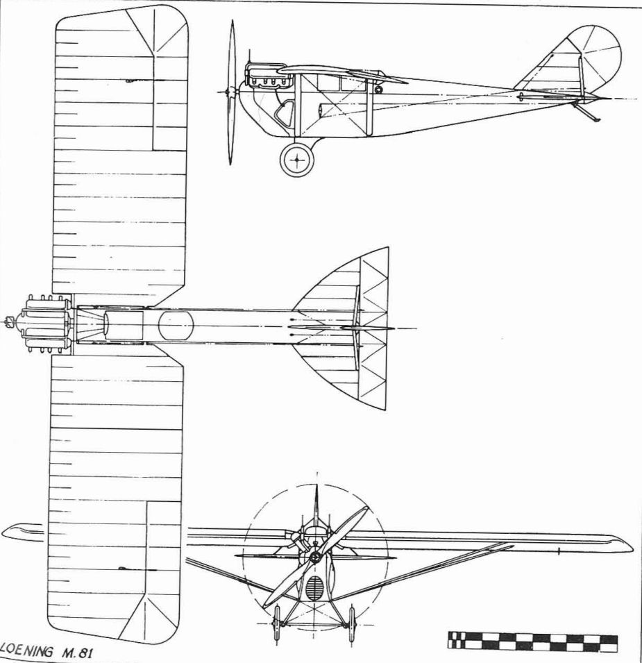
Loening M-81
MARTIN S SEAPLANE
Glenn L. Martin was one of the first successful American aeroplane designers and manufacturers. In 1915 the Army bought six Model S seaplanes fitted with 125 hp Hall-Scott A-5 engines and the Navy bought one as AH-19 to replace the rejected Wright Aeroboat AH-19. When the Navy Martin was re-serialled A69, a second was bought as A70. Span, 46 ft 5 in; length, 29 ft 7 in; gross weight, 2,600 lb; max speed, 82 mph.
Glenn L. Martin was one of the first successful American aeroplane designers and manufacturers. In 1915 the Army bought six Model S seaplanes fitted with 125 hp Hall-Scott A-5 engines and the Navy bought one as AH-19 to replace the rejected Wright Aeroboat AH-19. When the Navy Martin was re-serialled A69, a second was bought as A70. Span, 46 ft 5 in; length, 29 ft 7 in; gross weight, 2,600 lb; max speed, 82 mph.
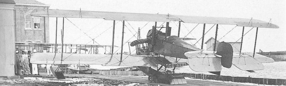
The Martin S seaplane A69 (originally AH-19).
MARTIN MBT/MT
The Martin MB-1 was a revolutionary bomber built for the Army in 1918. The Navy bought two duplicates in 1920 as MBT (A5711-A5712) for Martin Bomber-Torpedo. Eight improved versions (A5713-A5720) were designated MT for Martin Torpedo. Used by the US Marines, the MTs were MB-1s with the longer wings of the Army MB-2. MT data: power plant, two 400 hp Liberty. Span, 71 ft 5 in; length, 45 ft 8 in; gross weight, 12,098Ib; max speed, 109 mph.
The Martin MB-1 was a revolutionary bomber built for the Army in 1918. The Navy bought two duplicates in 1920 as MBT (A5711-A5712) for Martin Bomber-Torpedo. Eight improved versions (A5713-A5720) were designated MT for Martin Torpedo. Used by the US Marines, the MTs were MB-1s with the longer wings of the Army MB-2. MT data: power plant, two 400 hp Liberty. Span, 71 ft 5 in; length, 45 ft 8 in; gross weight, 12,098Ib; max speed, 109 mph.
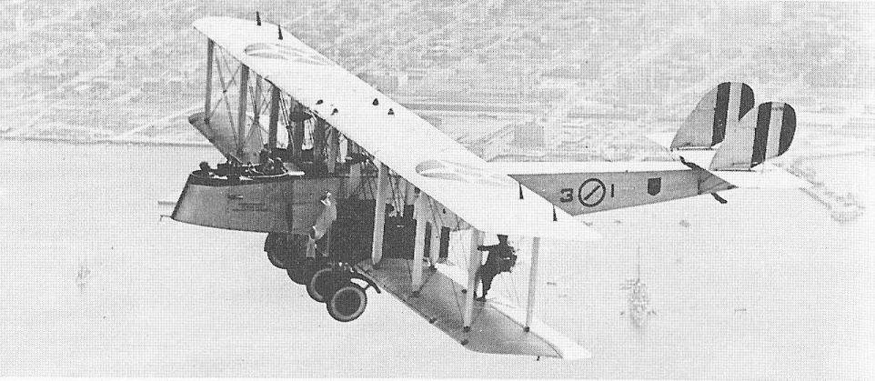
A Martin MT biplane about to drop paratroops over North Island, San Diego.
STANDARD H-4-H
The Standard Aero Corporation was formed in 1916 in anticipation of America's eventual participation in World War I. First products at the company's Plainfield, NJ, plant were Model H-3 reconnaissance-trainers derived from earlier Sloan Aircraft models designed by Standard's chief engineer, Charles H. Day. First sales by Standard to the Navy were three Improved H-4-H seaplane trainers (A137-A139) delivered in 1917. Power plant, 125 hp Hall-Scott A-5.
The Standard Aero Corporation was formed in 1916 in anticipation of America's eventual participation in World War I. First products at the company's Plainfield, NJ, plant were Model H-3 reconnaissance-trainers derived from earlier Sloan Aircraft models designed by Standard's chief engineer, Charles H. Day. First sales by Standard to the Navy were three Improved H-4-H seaplane trainers (A137-A139) delivered in 1917. Power plant, 125 hp Hall-Scott A-5.
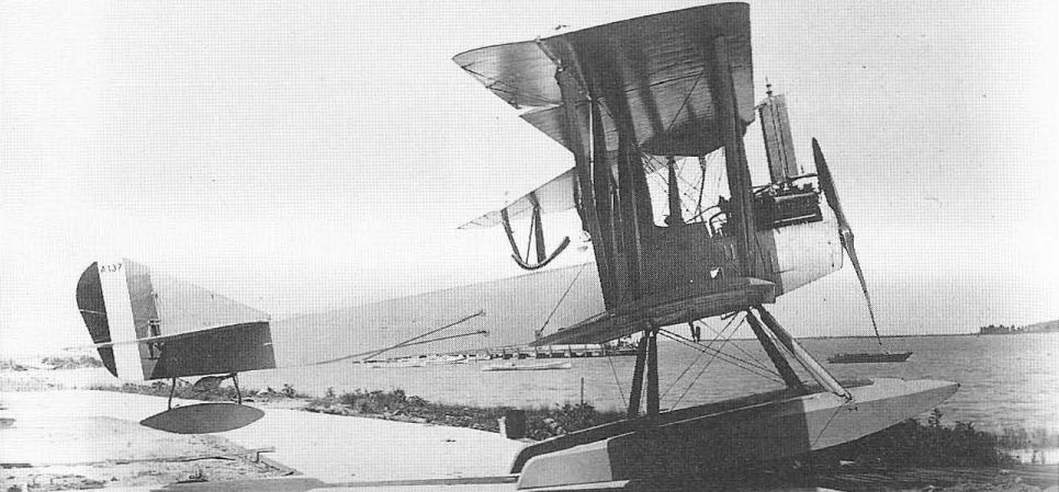
A Standard H-4-H at Langley Field, Hampton, Va.
STURTEVANT S
The Sturtevant S, built by the Sturtevant Aeroplane Company, Boston, Mass., was a two-seat seaplane with all-steel frame, powered by a 150 hp Sturtevant 5-A engine. One was bought in 1916 as AH-24. When this was redesignated A76, five others were ordered as A77-A81. These were followed by another order for six (AI28-A133). Because of the standardization of designs brought about by World War I, Sturtevant, along with other small manufacturers, ceased to develop its own designs and concentrated on building sub-assemblies for the major manufacturers. Span, 48 ft 7t in; other data unavailable.
The Sturtevant S, built by the Sturtevant Aeroplane Company, Boston, Mass., was a two-seat seaplane with all-steel frame, powered by a 150 hp Sturtevant 5-A engine. One was bought in 1916 as AH-24. When this was redesignated A76, five others were ordered as A77-A81. These were followed by another order for six (AI28-A133). Because of the standardization of designs brought about by World War I, Sturtevant, along with other small manufacturers, ceased to develop its own designs and concentrated on building sub-assemblies for the major manufacturers. Span, 48 ft 7t in; other data unavailable.
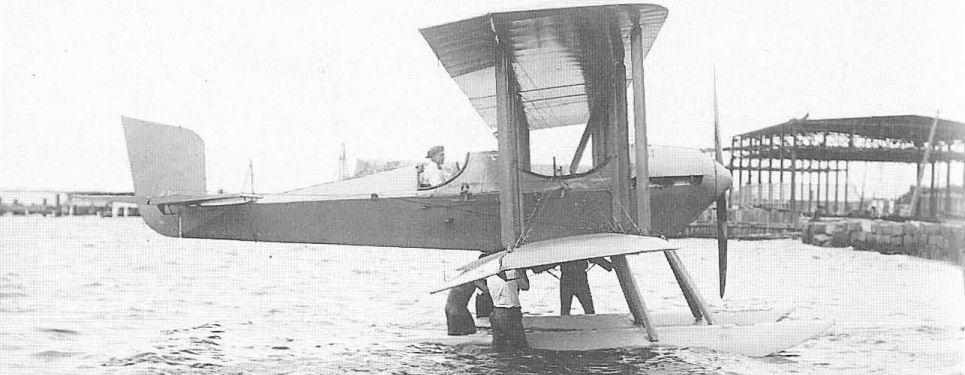
The Sturtevant S seaplane, serial number A81.
THOMAS-MORSE SH-4
The SH-4 was one of the first aircraft obtained by the Navy that had practical military experience behind its design, several predecessor models having been sold to Britain in 1915-16 by the Thomas Aeroplane Co before its merger with Morse Chain Company to form Thomas-Morse. Fourteen SH-4s (A134-A136, A396-A406), powered with 100 hp Thomas engines, were bought by the Navy as observation and trainer types in 1917. Span, 44 ft; length, 29 ft 9 in. Performance not available.
The SH-4 was one of the first aircraft obtained by the Navy that had practical military experience behind its design, several predecessor models having been sold to Britain in 1915-16 by the Thomas Aeroplane Co before its merger with Morse Chain Company to form Thomas-Morse. Fourteen SH-4s (A134-A136, A396-A406), powered with 100 hp Thomas engines, were bought by the Navy as observation and trainer types in 1917. Span, 44 ft; length, 29 ft 9 in. Performance not available.
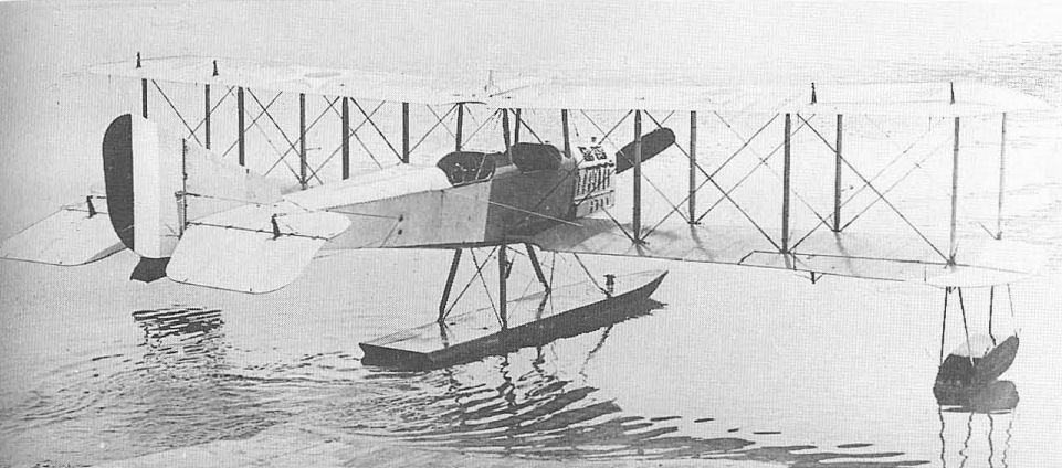
A Thomas-Morse SH-4 observation seaplane.
THOMAS-MORSE S-4B, S-4C
The S-4s were the Army's standard single-seat advanced trainers in 1917-18. The S-4B used the 100hp American-built Gnome rotary engine while most of the later S-4Cs used the more reliable 80 hp Le Rhone. Principal recognition feature was the use of sweptback ailerons on the S-4B. The Navy's use of ten S-4Bs (A3235-A3244) and four S-4Cs (A5855-A5858) was for fighter-pilot training, and armament was principally a camera gun. S-4C: span, 26 ft 6 in; length, 19 ft 10 in; gross weight, 1,330 lb; top speed, 97 mph.
The S-4s were the Army's standard single-seat advanced trainers in 1917-18. The S-4B used the 100hp American-built Gnome rotary engine while most of the later S-4Cs used the more reliable 80 hp Le Rhone. Principal recognition feature was the use of sweptback ailerons on the S-4B. The Navy's use of ten S-4Bs (A3235-A3244) and four S-4Cs (A5855-A5858) was for fighter-pilot training, and armament was principally a camera gun. S-4C: span, 26 ft 6 in; length, 19 ft 10 in; gross weight, 1,330 lb; top speed, 97 mph.

A Thomas-Morse S.4C serving with the Navy in September 1920, with camera gun, carrying original Army serial number but in Navy grey finish.
THOMAS-MORSE S-5
The six S-5s (A757-A762) were seaplane versions of the S-4B trainers built for the army and were delivered in 1917 to the Navy in Army olive drab colouring. The arrangement of the three wooden floats was copied from the British Sopwith Baby, which the S-5 closely resembled. Single-seat scout seaplanes did not work well for the Navy and further development was abandoned. Power plant, 100 hp American-built Gnome rotary engine. Span, 26 ft 6 in; length, 22 ft 9 in; gross weight, 1,500 lb; max speed, 95 mph.
The six S-5s (A757-A762) were seaplane versions of the S-4B trainers built for the army and were delivered in 1917 to the Navy in Army olive drab colouring. The arrangement of the three wooden floats was copied from the British Sopwith Baby, which the S-5 closely resembled. Single-seat scout seaplanes did not work well for the Navy and further development was abandoned. Power plant, 100 hp American-built Gnome rotary engine. Span, 26 ft 6 in; length, 22 ft 9 in; gross weight, 1,500 lb; max speed, 95 mph.
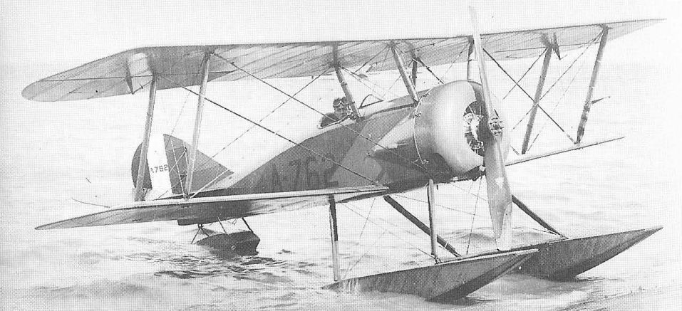
One of the six Thomas-Morse S-5 seaplanes, serial A762, in June 1918 used by the US Navy at Dinner Key, Miami.
THOMAS-MORSE MB-3
The MB-3, designed in 1918, was to be America's fighter contribution to World War 1. The Army ordered 50 examples from the designing company Thomas-Morse in 1919 and 200 improved MB-3As from Boeing in 1920. Eleven more MB-3s were built on an Army contract (as 64374-64384) for transfer to the Navy in 1921 and use by the USMC as advanced trainers (A6060-A6070). Power plant, 300 hp Wright-Hispano. Span, 26 ft; length, 20 ft; gross weight, 1,818 lb; max speed, 152 mph.
The MB-3, designed in 1918, was to be America's fighter contribution to World War 1. The Army ordered 50 examples from the designing company Thomas-Morse in 1919 and 200 improved MB-3As from Boeing in 1920. Eleven more MB-3s were built on an Army contract (as 64374-64384) for transfer to the Navy in 1921 and use by the USMC as advanced trainers (A6060-A6070). Power plant, 300 hp Wright-Hispano. Span, 26 ft; length, 20 ft; gross weight, 1,818 lb; max speed, 152 mph.
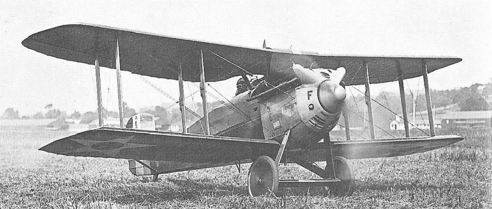
One of eleven Thomas-Morse MB-3As used by Marine Corps.
Vought VE-7, VE-9
The VE-7, product of the new Lewis & Vought Corporation, appeared in the summer of 1918 after the Aircraft Production Board urged American industry to turn out new original designs for the war programme instead of trying to adapt European designs, as had been the previous policy. Vought was asked to develop an advanced trainer to use the 150hp French Hispano-Suiza Model A engine, then in production by the Simplex Automobile Division of the Wright-Martin Company. (When Wright-Martin broke up, Wright became the Wright Aeronautical Corporation and concentrated its major efforts on engines until merging with Curtiss in 1929 to form Curtiss-Wright. After the war, Lewis & Vought was renamed Chance Vought Corporation after its founder, the famed aircraft designer Chance M. Vought.)
The VE-7 proved to be an excellent design that generally resembled a slightly scaled-down British de Havilland D.H.4 with the nose of a French Spad. Large orders were soon placed, and additional manufacturers were lined up to assist in production. However, the VE-7 did not go into production during the war. This was due to an economy and time-saving measure that resulted in the same 150 hp Wright-Hispano engine being installed in the existing 90 hp Curtiss JN-4D primary trainer, making it the JN-4H for advanced training duties. After the war, the Navy became interested in a version of the VE-7 fitted with the 180 hp Wright-Hispano E engine. The naval versions were built by Vought and by the Naval Aircraft Factory to a total of 128, which was really large-scale production for the early 1920s.
Procured originally for training purposes, the performance of the VE-7 was such that it was used for a great variety of work under a number of sub-designations:
VE-7 - Standard two-seat trainer.
VE-7G - Armed VE-7 with flexible 0.30-in Lewis machine gun in the rear cockpit and a synchronized Vickers gun forward.
VE-7GF - VE-7G with emergency flotation gear.
VE-7H - Trainer or unarmed observation hydroplane (seaplane).
VE-7S - Single-seat fighter with one synchronized Vickers (later Browning) gun.
VE-7SF - VE-7S with flotation gear.
VE-7SH - VE-7S with VE-7H floats.
In the observation models, the observer rode in the forward cockpit, a reversion to early World War I practice when the disposable load of lightweight aircraft was carried right at the centre of gravity. Service experience proved the VE-7s (and later UO-1s) to be notoriously tail-heavy. In spite of its relatively large wingspan, however, the VE-7 made a nimble single-seat fighter, a role in which it served as first-line equipment until 1926, with the pilot occupying the former rear cockpit.
VE-7 landplanes operating over water were frequently fitted with emergency flotation gear of a design developed at the RAF Experimental Station on the Isle of Grain during World War I. Although this feature had been tested on earlier experimental US Navy aircraft, the VE-7s were the first US service models to be so equipped. To prevent nosing over when alighting on water, a Grain-developed hydrovane was installed ahead of the wheels. The seaplane versions were the standard observation and scouting aircraft of the fleet in the early post-war years, being carried aboard battleships and cruisers and launched by catapult. A larger vertical fin was frequently installed on the seaplane versions and was sometimes left in place when the aeroplane was temporarily converted to a landplane.
The VE-9 was identical with the VE-7 except for minor details and the improved E-3 version of the 180 hp Wright-Hispano engine. The Navy ordered 21 as observation models, most being the unarmed VE-9H for use with battleships and cruisers. Two experimental VE-9Ws, to have been fitted with the new 200hp Lawrance J-1 air-cooled radial engine, were cancelled after it was decided to fit the new Vought UO-1 then on order with the radial instead of the higher-powered water-cooled engine for which it had been designed.
TECHNICAL DATA (VE-7SF)
Manufacturer: Lewis & Vought Corporation, Long Island City, NY, and Naval Aircraft Factory, Philadelphia, Pennsylvania.
Type: Fighter.
Accommodation: Pilot only.
Power plant: One 180hp Wright E-2.
Dimensions: Span, 34 ft l3/8 in; length, 24 ft 5 1/8 in; height, 8 ft 7 in; wing area, 284.5 sq ft.
Weights: Empty, 1,505 lb; gross, 2,100 lb.
Performance: Max speed, 117 mph at sea level; climb, 5.5 min to 5,000 ft; service ceiling, 15,000 ft; range, 291 st miles.
Armament: Two fixed forward-firing Vickers 0.303-in or Browning 0.30-in guns.
Serial numbers:
VE-7 (Vought): A5661-A5700; A5912A5941; A6021-A6030.
VE-7 (NAF): A5942-A5969; A5971; A6011-A6020; A6436-A6444.
VE-9 (Vought): A6461-A6481.
VE-9 (NAF): A5970.
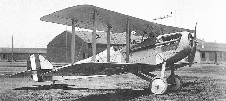
A Vought VE-7, as produced for the Navy after the end of World War I.
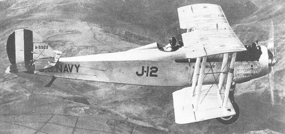
Vought VE-7S, the single-seat fighter version of the design, built by Lewis & Vought.
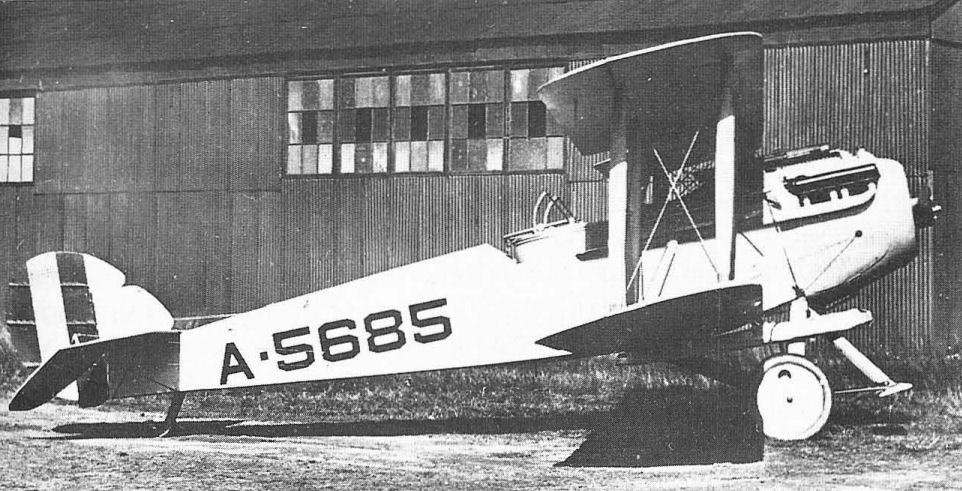
A Vought VE-7GF, built by the NAF, showing flotation gear and hydrovanes for emergency use.

A Vought VE-9H of Navy squadron VO-6 in December 1924.
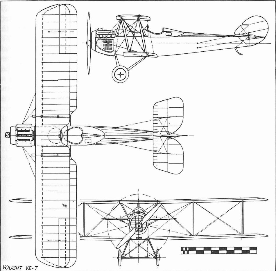
Vought VE-7
WRIGHT SEAPLANES
While the Wright Brothers had invented the first practical aeroplane and were able to maintain a lead over other fliers for nearly seven years, they clung stubbornly to their original aerodynamic and structural concepts and soon found themselves passed by competitors who had adopted more advanced ideas. Orville Wright carried on the business after the death of Wilbur in 1912 and was able to sell three two-seat Model C-H seaplanes to the Navy, which identified them as B-1 to B-3 (later AH-4 to AH-6). These were similar to the open Model B of 1911, with chain-drive to two pusher propellers from a single 60 hp Wright engine, and were sometimes flown as landplanes to improve their marginal performance. C-H data: span, 38 ft; length, 29 ft 9 in; gross weight, 1,610 lb; max speed approx 50 mph.
While the Wright Brothers had invented the first practical aeroplane and were able to maintain a lead over other fliers for nearly seven years, they clung stubbornly to their original aerodynamic and structural concepts and soon found themselves passed by competitors who had adopted more advanced ideas. Orville Wright carried on the business after the death of Wilbur in 1912 and was able to sell three two-seat Model C-H seaplanes to the Navy, which identified them as B-1 to B-3 (later AH-4 to AH-6). These were similar to the open Model B of 1911, with chain-drive to two pusher propellers from a single 60 hp Wright engine, and were sometimes flown as landplanes to improve their marginal performance. C-H data: span, 38 ft; length, 29 ft 9 in; gross weight, 1,610 lb; max speed approx 50 mph.
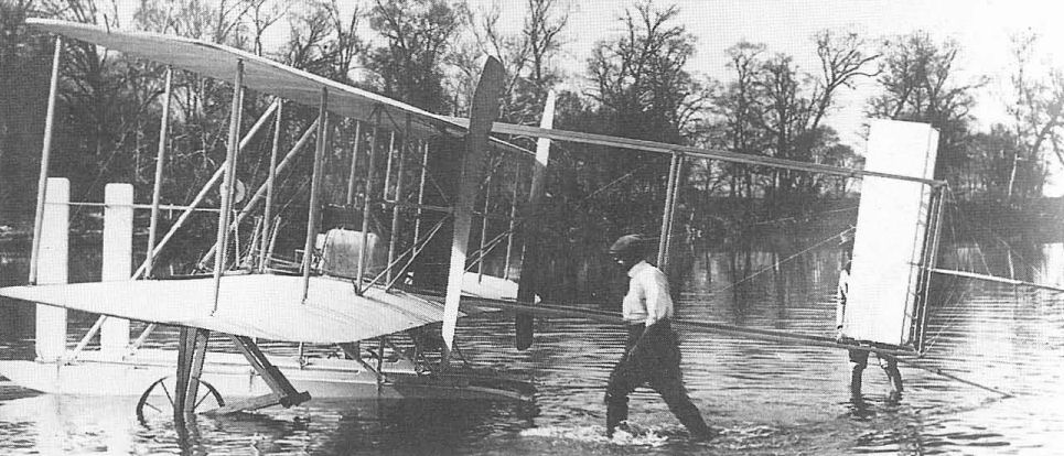
A Wright Model C Seaplane operated by the Navy as its B series.
One 1914 Wright Model G Aeroboat was tested by the Navy as AH19, but was rejected for poor performance. The last Wright purchased from the original company was the full-fuselage Model K tractor seaplane (AH-23, later A51), still with chain-drive and warping wings.
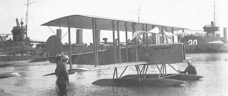
The Wright Model K, serial A51, with chain-drive to propellers.
WRIGHT-MARTIN R
In September 1916 the Glenn L. Martin Company and the Wright interests combined with the Simplex Automobile Company and the General Aeronautical Corporation to form the Wright-Martin Company. Wright was not building aeroplanes at the time, but current Martin designs were delivered as Wright-Martin. Three Model R seaplanes (A288-A290), powered with 150 hp Hall-Scott A-5A engines, were delivered to the Navy in 1917. Span, 50 ft 7 in; length, 27 ft 2 in; gross weight, 2,888 lb; max speed, 86 mph.
In September 1916 the Glenn L. Martin Company and the Wright interests combined with the Simplex Automobile Company and the General Aeronautical Corporation to form the Wright-Martin Company. Wright was not building aeroplanes at the time, but current Martin designs were delivered as Wright-Martin. Three Model R seaplanes (A288-A290), powered with 150 hp Hall-Scott A-5A engines, were delivered to the Navy in 1917. Span, 50 ft 7 in; length, 27 ft 2 in; gross weight, 2,888 lb; max speed, 86 mph.
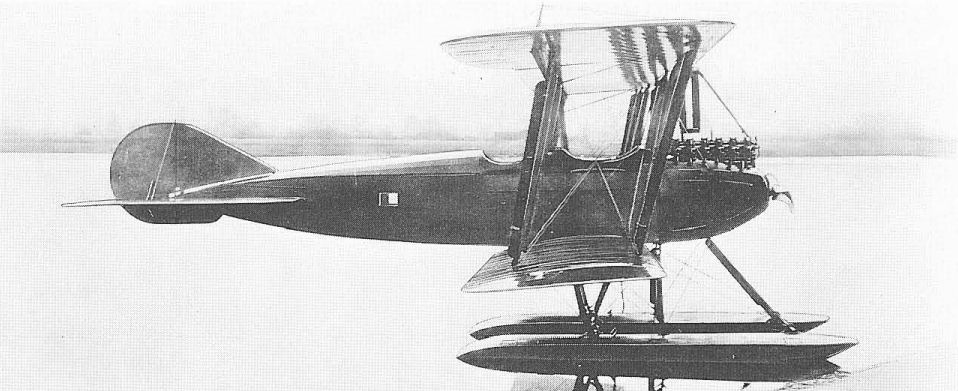
The Wright-Martin R with Hall-Scott A-5A engine.
DONNET-DENHAUT FLYING-BOAT
US Navy patrol operations along the coast of France in World War I initiated with Tellier flying-boats, were supplemented by larger quantities of French Donnet-Denhaut flying-boats, which were directly comparable designs with 200 hp Hispano-Suiza pusher engines, wooden hulls, and accommodation for two or three crew members. Out of a total of 58 Donnets procured by 1918, two were sent to the US, where they acquired Navy serial numbers A5652 and A5653. Span, 53 ft 7 in; length, 35 ft 5 in; gross weight, 3,860 lb; max speed, 72 mph.
US Navy patrol operations along the coast of France in World War I initiated with Tellier flying-boats, were supplemented by larger quantities of French Donnet-Denhaut flying-boats, which were directly comparable designs with 200 hp Hispano-Suiza pusher engines, wooden hulls, and accommodation for two or three crew members. Out of a total of 58 Donnets procured by 1918, two were sent to the US, where they acquired Navy serial numbers A5652 and A5653. Span, 53 ft 7 in; length, 35 ft 5 in; gross weight, 3,860 lb; max speed, 72 mph.

A Donnet-Denhaut flying-boat in the US.
FBA TYPE H
The Navy operated 11 FBA (Franco-British Aviation) flying-boats, of French manufacture, from its bases in France in 1918 and at least six others of Italian manufacture from its base at Porto Corsini, Italy. These were three-seat reconnaissance and light bomber aircraft with 180 hp Hispano-Suiza engines. Span, 47 ft 7 in; length, 33 ft 2 in; gross weight, 3,218 lb; max speed, 90 mph.
The Navy operated 11 FBA (Franco-British Aviation) flying-boats, of French manufacture, from its bases in France in 1918 and at least six others of Italian manufacture from its base at Porto Corsini, Italy. These were three-seat reconnaissance and light bomber aircraft with 180 hp Hispano-Suiza engines. Span, 47 ft 7 in; length, 33 ft 2 in; gross weight, 3,218 lb; max speed, 90 mph.
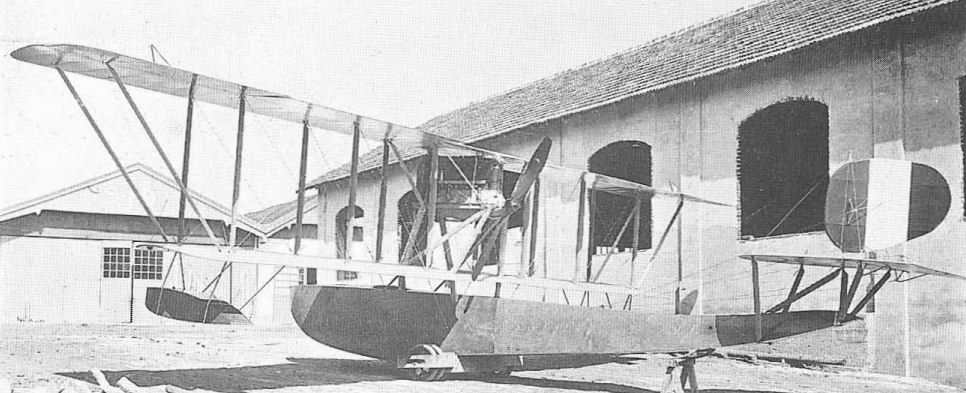
An Italian built FBA Model H.
HANRIOT HD-1, 2
The Navy acquired 26 French Hanriot HD-2 seaplane fighters for use in Europe during World War 1. Except for the 130 hp Clerget engine and a large rudder, these were seaplane versions of the well-known Hanriot HD-1 (for Hanriot-Dupont) landplane. After the Armistice, 10 HD-2s were shipped to the US Naval Aircraft Factory for reconditioning and conversion to HD-1 landplanes, and were assigned serials A5620-A5629. Fitted with flotation bags and hydrovanes ahead of the wheel undercarriage, they were flown from battleships. Span, 28 ft 6 in; length, 19 ft 8 in; gross weight, 1,521Ib; max speed, 115 mph.
The Navy acquired 26 French Hanriot HD-2 seaplane fighters for use in Europe during World War 1. Except for the 130 hp Clerget engine and a large rudder, these were seaplane versions of the well-known Hanriot HD-1 (for Hanriot-Dupont) landplane. After the Armistice, 10 HD-2s were shipped to the US Naval Aircraft Factory for reconditioning and conversion to HD-1 landplanes, and were assigned serials A5620-A5629. Fitted with flotation bags and hydrovanes ahead of the wheel undercarriage, they were flown from battleships. Span, 28 ft 6 in; length, 19 ft 8 in; gross weight, 1,521Ib; max speed, 115 mph.
LEVY-LEPEN HB-2
The Navy operated 12 French two/three seat Levy-Lepen HB-2 reconnaissance flying-boats from its Le Croisac base in France in 1918. These were in operation from June 7, 1918, until the Armistice. Three were brought to the US and were assigned Navy serial numbers A5650, A5651 and A5657. Power plant, 300 hp Renault. Span, 60 ft 8 in; length, 40ft 8 in; gross weight, 5,181lb; max speed, 93 mph.
The Navy operated 12 French two/three seat Levy-Lepen HB-2 reconnaissance flying-boats from its Le Croisac base in France in 1918. These were in operation from June 7, 1918, until the Armistice. Three were brought to the US and were assigned Navy serial numbers A5650, A5651 and A5657. Power plant, 300 hp Renault. Span, 60 ft 8 in; length, 40ft 8 in; gross weight, 5,181lb; max speed, 93 mph.
NIEUPORT 28
Although a fighter of French manufacture and widely used by the AEF, the Nieuport 28 was not used by US Naval forces in France during World War 1. Twelve were obtained in August 1919, however, from the supply that the Army had brought back to the US, and assigned serials A5794-A5805. These were assigned to the fleet and flew from platforms built over the forward turrets of battleships, eight of which were so equipped. Flotation bags were fitted, along with hydrovanes to prevent nosing over in case of a landing at sea. Power plant was a 160 hp Gnome. Span, 26 ft 3 in; gross weight, 1,625 lb; max speed, 122 mph.
Although a fighter of French manufacture and widely used by the AEF, the Nieuport 28 was not used by US Naval forces in France during World War 1. Twelve were obtained in August 1919, however, from the supply that the Army had brought back to the US, and assigned serials A5794-A5805. These were assigned to the fleet and flew from platforms built over the forward turrets of battleships, eight of which were so equipped. Flotation bags were fitted, along with hydrovanes to prevent nosing over in case of a landing at sea. Power plant was a 160 hp Gnome. Span, 26 ft 3 in; gross weight, 1,625 lb; max speed, 122 mph.
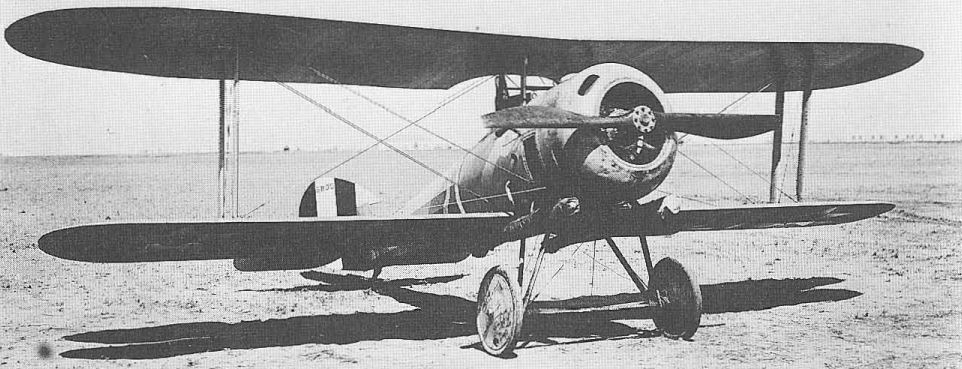
A 1920 photo of a Nieuport 28 with British Grain flotation gear installed.
TELLIER FLYING-BOAT
Using some of the 34 French-built Tellier flying-boats, the Navy began patrol operations from Le Croisac, France, on November 18, 1917. With the 200 hp Hispano-Suiza engine, these aircraft were operated with French serial numbers and only the one example sent to the US for evaluation received a Navy serial number, A5648. Span, 51ft 3in; length, 38ft 10 in; gross weight, 3,745 lb; max speed, 75 mph.
Using some of the 34 French-built Tellier flying-boats, the Navy began patrol operations from Le Croisac, France, on November 18, 1917. With the 200 hp Hispano-Suiza engine, these aircraft were operated with French serial numbers and only the one example sent to the US for evaluation received a Navy serial number, A5648. Span, 51ft 3in; length, 38ft 10 in; gross weight, 3,745 lb; max speed, 75 mph.
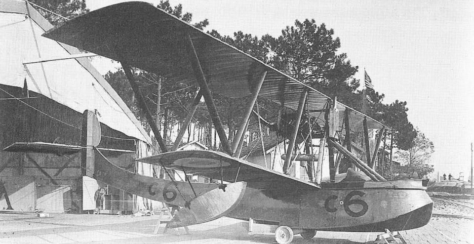
A Tellier flying-boat in France.