
Книги
Putnam
G.Duval
British Flying-Boats and Amphibians 1909-1952
52
G.Duval - British Flying-Boats and Amphibians 1909-1952 /Putnam/
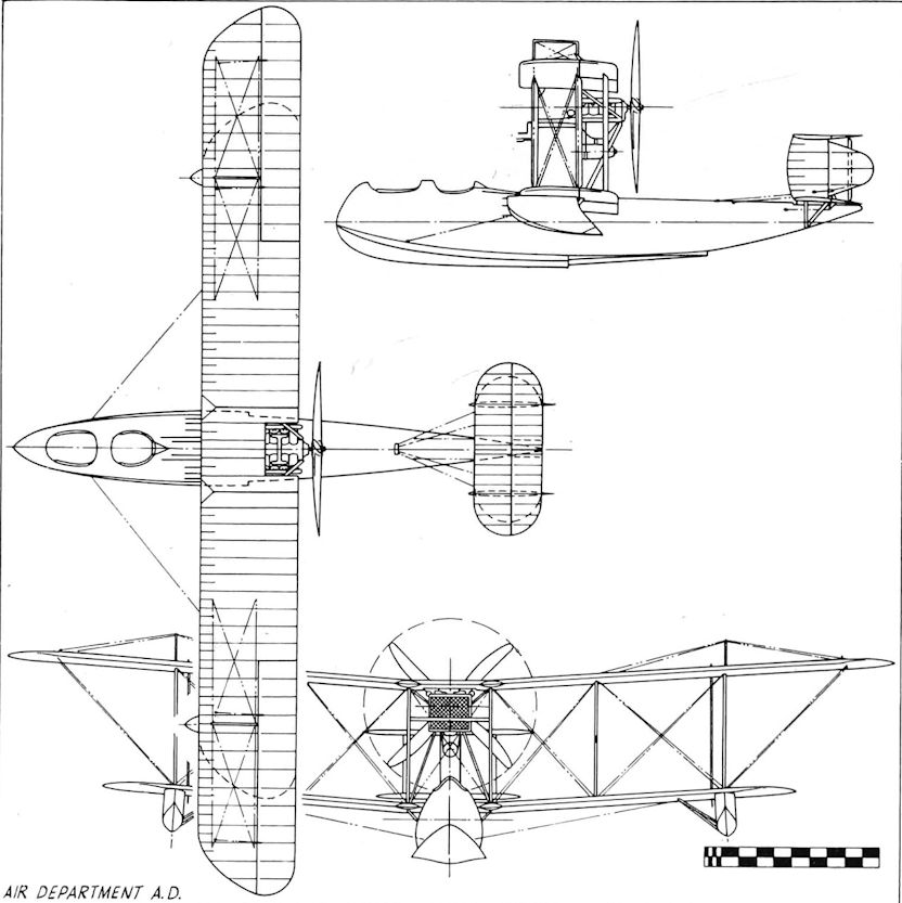
A.D. Flying-boat (1915/17)
The A.D. Flying-Boat was built to a design of the Air Department of the Admiralty as a patrol and reconnaissance machine to Specification N.2A. The design team consisted of Harold Yendall, Harold Bolas, Clifford Tinson, and Lt.-Col. Linton Hope, the latter responsible for the construction layout of the monocoque hull. Construction of two prototypes commenced in October 1915, the serials allocated being No. 1412 and No. 1413, contracts having been placed with Pemberton-Billing, Ltd, for the superstructure, and with May, Harden and May, for the hulls. A two-seater biplane, the A.D. boat was of mixed wooden construction, fabric covered and wire braced, with the mainplanes arranged to fold forward for shipboard stowage. A biplane tail unit was fitted, with twin fins and rudders, the lower plane made as a watertight unit as it was awash during taxying. The upper tailplane had an inverted aerofoil and a negative angle of incidence, to prevent a tail-heavy trim change when the engine was throttled back. In its original form, the first prototype, No. 1412, was powered by a pusher Sunbeam Nubian engine of 150 h.p. driving a 10-foot diameter four-bladed propeller, and with this power unit No. 1412 underwent its first trials in the summer of 1916. The results were not promising, for the machine suffered from porpoising and poor rudder control, and the design weight had already been exceeded by 500 pounds. At the suggestion of Sqdn. Comm. Travers, the step was moved 2 feet aft to improve water handling, but this had little effect, and as a result of porpoising trials held at Southampton in August 1916, by a Seaplane Research Team under G. S. Baker, o.b.e., a trials report stated that the machine was unsatisfactory, further trials being cancelled by the Air Department. Work continued on the machine throughout the winter of 1916, the most obvious changes being the installation of a 200 h.p. Hispano-Suiza engine, shorter span ailerons, and greatly enlarged wing-tip floats. In this form, No. 1412 was tested at Southampton on 12 and 15 March, 1917, and performed satisfactorily. Production was soon under way, and on 5 September, 1917, the first production machine, N1520, was the subject of a satisfactory trials report from the Isle of Grain.
However, engine trouble proved to be the main reason for the A.D. boat’s eventual downfall, apart from the fact that it was not an easy machine to handle both in water manoeuvring and on take-off. The geared Hispano- Suiza engine, French-built, was vibrating and failing in flight, the same faults that were giving cause for anxiety with the S.E.5a. In July 1917, No. 1412 was fitted with a 150 h.p. direct-drive Hispano-Suiza engine in an attempt to remedy the situation, but with this power unit the performance was impaired. February 1918 saw No. 1412 fitted with a 200 h.p. Sunbeam Arab, but this engine performed no better in the A.D. boat than in other aircraft to which it had been fitted, and it, too, was shelved. In mid-1918, a production machine, N1525, was fitted with a Wolseley Python engine of 211 h.p., and later with a 200 h.p. Wolseley Viper, neither installation being satisfactory. Most of the A.D. boats produced other than those mentioned went into storage, with the exception of N1719 and N1712 which were allocated to the Isle of Grain for experimental purposes. In 1921, Harry Busteed and G. Bentley Dacre, both by now senior R.A.F. officers, used N1719 for successful hydrofoil experiments. The total A.D. boat production consisted of the two prototypes and twenty-seven production machines, and the type was declared obsolete in the late autumn of 1918. In June 1919, ten A.D. boats were re-purchased by Supermarines, lately Pemberton-Billing, Ltd, and after fitment of a 160 h.p. Beardmore engine and some modification became civilianised as the Supermarine Channel, the first Channel being a conversion of N1529. Further purchases of A.D. boats were made later, to a total of some nineteen machines in all.
SPECIFICATION
Power Plant:
150 h.p. Sunbeam Nubian
200 h.p. Hispano-Suiza
150 h.p. Hispano-Suiza
200 h.p. Wolseley Python
200 h.p. Wolseley Viper
200 h.p. Sunbeam Arab
Span: 50 feet 4 inches. Folded: 14 feet
Length: 30 feet 7 inches. Folded: 42 feet 3 inches
Weight Loaded:
2,880 pounds (No. 1412) (200 h.p. Hispano-Suiza)
3,388 pounds (N1525) (200 h.p. Wolseley Python)
Total Area: 479 square feet
Max. Speed: 87,5 - 100 m.p.h., depending upon loaded weight and engine installed
Endurance: 3,5 - 5 hours, as above
Armament:
Production - one .303-inch Lewis gun
Type 54A wireless set fitted
Air Department A.D.
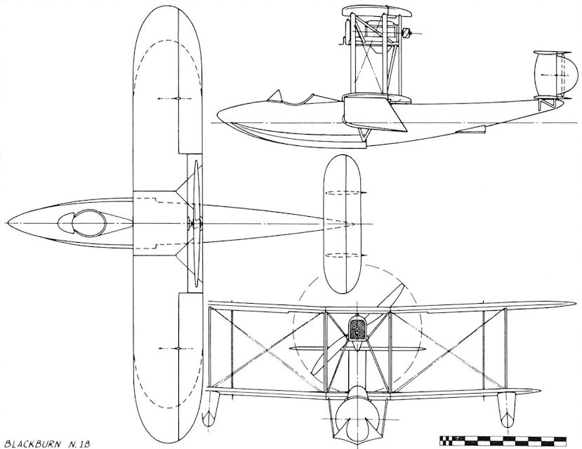
Blackburn N.IB (1918)
Designed to the same Air Board Specification as the Supermarine Baby, work commenced on the Blackburn N.1B at the Leeds factory in mid-1918. The hull, of Linton Hope design, was similar to the Baby, being of the usual monocoque construction with external side fins, which extended aft to the main step amidships, and having a small auxiliary step mid-way towards the stern. The bows were longer and more pointed than those of the Baby, however, and the rear part of the hull had a distinctive upward curve towards the stern. The complete machine was to be a single-seat single-bay biplane, the lower mainplane mounted on the hull top and braced from the main step by Vee-struts. A 200 h.p. Hispano-Suiza pusher engine, driving a two-bladed propeller was to be mounted on struts high up in the centre section. The tail unit design was of biplane layout, with twin rudders, the upper plane of inverted camber as on the A.D. Boat and the Supermarine Baby. Large wingtip floats were to be attached directly to the lower wing undersurface. Some difficulties were encountered during hull construction; the American elmwood required was late in delivery, and eventually other woods had to be be used. The hull was then found to require extra stiffening, and eventually, although good progress was made, the coming of the Armistice brought the development to a halt. The completed hull was put into storage. In 1923, an inspection found it still in good condition, and fitted with a new engine and flight structure it was entered for the Schneider Trophy as the Blackburn Pellet.
SPECIFICATION
Power Plant: One 200 h.p. Hispano-Suiza
Span: 34 feet 10 inches
Length: 28 feet 3 1/2 inches
Weight Loaded (estimated): 2,390 pounds
Total Area: 376 square feet
Max. Speed (estimated): 114 m.p.h.
Endurance (estimated): 3 hours
Armament: One free-mounted Lewis gun
Serials Allotted: N56-N58
Blackburn N.1B
Burney X.1, X.2, and X.3 (1911-1913)
In the summer of 1911, Lieut. Charles Burney, r.n. (later Sir Charles Burney, of Airship R.100 fame) obtained Admiralty sanction for the British and Colonial Aeroplane Company to undertake design of a ship-borne aircraft employing hydrofoils to achieve take-off and landing on rough water. Burney had studied the works of the Italian pioneers Foriannini and Guidoni on the application of hydrofoils to improve the performance of fast motor boats, and was convinced that the hydrofoil had applications to the design of marine aircraft. Experiments began in the autumn of 1911, when Burney co-operated with Howard Pixton in a series of over-water flights from Hayling Island in a Bristol Boxkite equipped with flotation bags. In December, Frank Barnwell was appointed experimental designer for the project, taking up his duties in a private house at Filton which became known as ‘X’ Department, and was shrouded in secrecy.
X.1
In collaboration with Burney, Barnwell produced the first design study, known as the X.1 This was a modification of the Gordon England biplane (G.E.1). The original 50 h.p. Clerget engine was to be replaced by a more powerful eight-cylinder E.N.V., driving a shaft between the cylinder banks with a Hele-Shaw clutch at each end. The front clutch was to drive a normal tractor propeller, while the rear clutch drove a bevel gearbox from which two shafts extended downwards inside tubular undercarriage legs fitted with groups of hydrofoils. At the bottom of each leg there was a further bevel drive to a water propeller. A third strut, also equipped with hydrofoils, was fitted under the rear fuselage. These grouped hydrofoils were called ‘hydropeds’. The idea was that, when driven by the water propellers, the craft would rise out of the water on the hydropeds until there was sufficient clearance for the flight propeller to be clutched in, and take-off would then be made. While at rest on the water, the aircraft would have floated on five torpedo-shaped air bags, which were not, however, intended to act as planing surfaces.
In January 1912, Barnwell, now joined by an assistant, Clifford Tinson, proposed that the biplane arrangement should give way to a monoplane wing of startling ingenuity. This was to be pneumatic, formed of eight span-wise air bags arranged to fit into a suitable wing section and capable of inflation to high pressure. The aerofoil profile would be maintained by flat spruce strips, forming ribs, and hinged at leading and trailing edges, with bicycle spokes acting as tension members between the upper and lower strips. Externally braced, the wing was to be fitted with ailerons, also inflatable. Storage would be simplified by deflation of the entire wing structure. Unfortunately, the rubberised canvas of the day proved to be too weak and too heavy for the demands made upon it, and the idea had to be shelved.
X.2
In February 1912, a new design, the X.2, was produced, and construction commenced. In this, the flotation bags were eliminated, and the fuselage was built as a proper hull, planked with mahogany and covered with varnished sailcloth, a normal monoplane wing being fitted. This craft, Works No. 92, was built in the experimental shop at Filton, and equipped with side-by-side dual controls. The clutches and hydropeds developed for X.1 were used, but the engine was a water-cooled radial Canton-Unne of 80 h.p. On 9 May, 1912, X.2 was put aboard the lighter Sarah at Avonmouth, and taken to Dale, near Milford Haven. After overcoming initial leakages, taxying under power from the water screws was attempted, and later the craft was towed behind a torpedo boat. Despite modification, it proved impossible to prevent the machine from heeling over when the water screws were clutched in during towing. Eventually, in September 1912, it was decided to rely upon towing for the preliminary air tests. The engine was replaced by 500 lb of ballast, and on 21 September, X.2 was towed into a 30-knot wind with Lieut. G. Bentley Dacre, R.N., in the cockpit. At an airspeed of 42 knots, it rose clear of the water in a climbing attitude, but premature release by the towline party caused it to stall and crash, though without injury to Dacre.
X.3
The Admiralty agreed to continue the experiments, and work commenced on an improved design, the X.3. The engine fitted was a 200 h.p. Canton-Unne, and although similar to X.2 in most respects, this machine had wingtip floats with small hydrofoils under them. The hull frame, constructed at Filton, was then transported to Saunders at Cowes for covering with their patent ‘Consuta’ sewn plywood. To overcome torque reaction, the water screws were mounted back to back on a central pylon, so that they rotated in opposite directions. This machine, Works No. 159, was shipped to Dale in August 1913, and towing tests were very satisfactory. The nose dipped when the flight propeller was clutched in, - so to overcome this Barnwell designed an elevator, located in front of the mainplane and linked to the propeller clutch control. However, before the device could be fitted, X.3 came to grief while taxying, when it was wrecked on a sandbank.
With this mishap, the experiments came to an end, but the principle of the hydrofoil was employed by Burney in his invention of the paravane for minesweeping. In 1930, the Piaggio Pegna P.C.7 racing seaplane project utilised an almost identical layout to X.3, but also was a failure due to mechanical problems with the water screw.
SPECIFICATION
Power Plant:
X.1 (project) - 60 h.p. E.N.V. Vee-eight engine
X.2 - 80 h.p. Canton-Unne water-cooled radial engine
X.3 - 200 h.p. Canton-Unne engine
Span:
X.1 - 34 feet
X.2 - 55 feet 9 inches
X.3 - 57 feet 10 inches
Length:
X.1 - 30 feet
X.2 - 30 feet 8 inches
X.3 - 36 feet 8 inches
Wing Area:
X.1 - 325 square feet
X.2 - 480 square feet
X.3 - 500 square feet
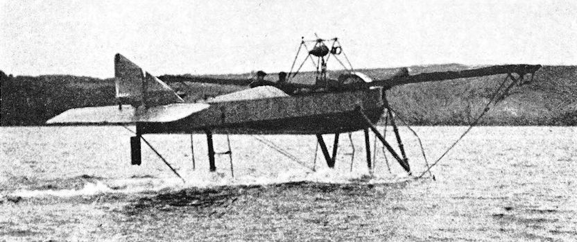
Burney X.3 taxying on hydrofoils.
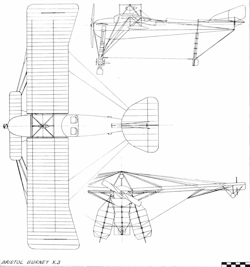
Bristol Burney X.3
Porte/Felixstowe F.1 (1915)
<...>
Early in 1915, Porte was stationed at Felixstowe, and flew the H.4 operationally, being therefore well qualified to understand its shortcomings. In the spring of 1915, he began a series of experiments, officially approved, with the aim of producing a seaworthy and operationally useful flying-boat. This involved re-designing and fitting of completely new hulls to four H.4s, Nos. 950, 1230, 3545, and 3569, culminating in the modification of H.4 No. 3580 with a new hull incorporating all the structural and hydrodynamic features developed to high efficiency in the preceding experiments. This hull, built at Felixstowe, was named the Porte 1, the complete machine being designated F.1, the first of the line of Felixstowe ‘F’ boats. The wings and tail unit of the F.1 were standard H.4 components, but its chief interest lay in the hull construction, which differed little from the fuselages of most contemporary landplanes. Of strong cross-braced box girder configuration, it was fitted with an external vee-shaped planing bottom and long side fins. Overall, the hull was 36 feet 2 inches in length, with a maximum beam of 8 feet, and unlike its predecessors, possessed open cockpits. Originally the hull had only one step, but performance requirements were not met, so a second and finally a third step were added. The machine was powered by two 150 h.p. Hispano-Suiza engines driving tractor propellers.
SPECIFICATION
Power Plant:
F.1 - Two 150 h.p. Hispano-Suiza
H.4 - Two 90 h.p. Curtiss, or two 100 h.p. Anzani
Span: F.1 and H.4 - 72 feet
Length:
F.1 - 39 feet 2 inches
H.4 - 35 feet
Weight Loaded:
H.4 - 4,983 pounds
Total Area: F.1 and H.4 - 842 square feet
Max. Speed:
F.1 - 85 m.p.h.
H.4 - 75 m.p.h.
Endurance: Not available
Armament: F.1 and H.4 - One or two Lewis guns, light bombs only
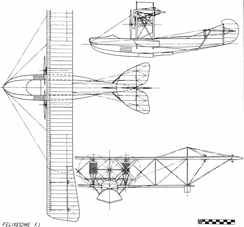
Felixstowe F.1
Porte/Felixstowe F.2 and F.2A (1917)
As a result of the shortcomings of the Curtiss H.4 regarding long-range patrol work, Porte requested Glenn Curtiss to develop a larger flying-boat with greater range and load-carrying capacity, and an order for fifty such machines was placed in 1915, the first being delivered in July 1916. This was the Curtiss H.8, or ‘Large America’, powered by two 160 h.p. Curtiss engines. These engines proved to be unsatisfactory, however, and Porte had them replaced by two 250 h.p. Rolls-Royce units, the modified machines being designated Curtiss H.12. They performed quite well, but suffered from weak, unseaworthy hulls, and poor fields of fire for the defensive armament. Encouraged by the excellent results obtained for the Porte 1 hull, Porte decided to redesign the hull of the H. 12, ably assisted by his Chief Technical Officer, Lieut, (later Major) J. D. Rennie. The new hull used the same construction method as the Porte 1 and measured 42 feet 2 inches from bow to stern, with two steps, and side fins 30 feet in length. Fitted with the mainplanes of an H.12, two 250 h.p. Rolls-Royce engines and a new tail unit, the machine, serialled No. 8650, was designated F.2 and proved vastly superior in performance to the standard H.12, taking off smoothly and easily at a loaded weight of 10,500 pounds. After some structural modifications were made in the light of operational experience, quantity production was authorised, the production version designated F.2A. Fitted with the more powerful Marks of the Rolls-Royce Eagle, the F.2A had a range and endurance more than adequate for defensive and offensive patrols, and a formidable armament consisting of two 230-pound bombs and up to five Lewis guns with excellent fields of fire. The fuel system, however, gave a lot of trouble, mainly due to its layout. A 409-gallon tank situated in the hull fed a 26-gallon gravity tank in the upper mainplane centre section by means of wind-driven pumps, the fuel then passing to the engines by gravity. Blocked pipes and filters, and fuel pump failures caused many forced alightings, and a contemporary report stated that ‘our real enemy is our own petrol pipes’. This situation led to the adoption of bizarre colour schemes for F.2A hulls, using red, white, and yellow paint, so that stricken machines could be readily spotted and towed home. Production F.2As began to appear late in 1917, a sub-contract having been arranged with Short Brothers, of Eastchurch. These machines had a two-stepped hull, only slightly differing from that of the F.2. In the bows, the front gunner’s cockpit was equipped with twin Lewis guns on a Scarff ring-mounting, while the rear gunner was positioned aft of the lower mainplane with similar armament. Some aircraft also had single guns, fired from side-hatches in the hull. The first and second pilots, the latter acting as front gunner, were partially enclosed in a glazed cabin, although this was often removed to improve visibility and performance. Engine control was simplified by the employment of an engineer-gunner, positioned in an internal compartment and controlling engine starting and inflight temperatures. The fourth crew member was usually a rigger-gunner. This crew arrangement tended to make the boats less dependent on their bases for servicing and minor repairs, and was standard in all large R.N.A.S. flying-boats. The F.2A power units were two Rolls-Royce Eagle VI Ils, developing 346 h.p. at 1,800 r.p.m. and driving four-bladed tractor propellers, the revolutions of which were reduced to 1,080 r.p.m. by epicyclic gearing. Some of the early F.2As had fabric decking to their hulls, but the ravages of wind and weather soon indicated its weakness and later machines had plywood decking. Production was greatly facilitated by the fact that the relatively simple hull construction did not call for highly skilled labour, and also by the availability of H.12 components, but demands for Rolls-Royce engines so far exceeded the supply that the total number of F.2As on charge never reached official requirements. To offset this situation several H.12s were rebuilt with Porte hulls and F.2A tail units, these modifications rendering them indistinguishable from F.2As.
Together, the F.2As and H.12s rendered great service in the critical year of 1917, when U-boat warfare was at its height. The first success came on 20 May, when the H.12 commanded by Fit. Sub-Lieut. Morrish destroyed submarine UC-36, and by the end of the year the flying-boats had sighted sixty-seven U-boats and had attacked forty-four. The Zeppelins, too, came in for attention, and on 14 May, 1917, L.22 fell to the guns of H.12 No. 8666, captained by Fit. Lieut. Galpin. In June, L.43 was destroyed by H.12 No. 8677, and a year later an F.2A from Killingholme, flown by Captains Pattinson and Munday, was responsible for the destruction of L.62 over the Heligoland minefields. All this activity took place in the face of strong German opposition, mainly from seaplanes under the command of the German Naval ‘ace’, Christiensen, and many combats took place, culminating in a pitched battle on 4 June, 1918. On that day, Capt. Robert Leckie led a force of four F.2As and a single H.12 on an offensive patrol towards the Haaks Light Vessel, three hours flying time from Felixstowe. After two-and-a-half hours, one of the F.2As was forced down by a broken petrol feed pipe, and its pilot, Capt. R. F. L. Dickey, had no choice but to taxi to the Dutch coast. On the way, five German seaplanes made a half-hearted attack upon the crippled machine, losing one of their number to its gunners, the rest breaking off the action, hotly pursued by the H.12, while the three F.2As formed a protective circle over Dickey’s machine. Soon afterwards, a formation of ten more German seaplanes arrived and Leckie charged them head-on, losing his wireless aerial on the upper wing of the enemy leader and splitting up the formation. The battle which followed lasted forty minutes, during which time the flying-boats shot down two Germans and probably destroyed four more without loss to themselves, although one F.2A went down on the Zuider Zee with a broken petrol pipe during the action. This was repaired by the engineer, however, and the machine rejoined the others. On the way back to Great Yarmouth, Capt. J. Hodson’s aircraft had an engine failure, flight being maintained on half-power while repairs were effected. Two flying-boats had been lost, for the H.12 force-landed in Dutch waters also, and both crews were interned. In 1918 the range of the flying-boats was extended by the use of special lighters designed by Porte, the machines being floated on to the fighters and towed by destroyers to a launching point off the German coast, returning after reconnaissance flights to be towed home. This system had its limitations, but several successful operations were completed. Another method of extending range was the carriage of extra fuel in cans, and by this means flights of over nine hours’ duration were made, pilot fatigue being minimised by the fitting of dual control to the F.2A.
Two illustrations are on record to prove the strength of the F.2A; in one, a machine was actually looped over Killingholme by an aggrieved American trainee, and in the other a single-engined approach aimed at Leeds Reservoir was misjudged and terminated in a ploughed field, the only damage incurred being strained bracing wires.
SPECIFICATION
Power Plant:
F.2 and H.12 - Two 250 h.p. Rolls-Royce Eagle I
F.2A - Two 345 h.p. Rolls-Royce Eagle VIII
Span: F.2, F.2A, and H.12 - 95 feet 7 1/2 inches
Length:
H.12 - 46 feet 6 inches
F.2 and F.2A - 46 feet 3 inches
Weight Loaded:
H.12 - 10,650 pounds
F.2 - 10,000 pounds
F.2A - 10,978 pounds
Total Area: F.2, F.2A, and H.12 -1,133 square feet
Max. Speed:
H.12 - 85 m.p.h.
F.2 - 95 m.p.h.
F.2A - 95-5 m.p.h.
Endurance: F.2, F.2A, and H.12 - 6 hours (normal)
Armament:
H.12 - Up to four Lewis guns on flexible mountings in bow and pilot’s cockpit. Four 100-pound or two 230-pound bombs
F.2 - Experimental gun installations for F.2A, max. bomb load of 460 pounds
F.2A - Four to seven Lewis guns on flexible mountings, two 230-pound bombs
Porte/Felixstowe F.2C (1917)
An experimental version of the F.2A, the F.2C did not pass beyond the prototype stage. It was fitted with a modified hull of lighter construction, having alterations to the front gun position, an open cockpit for the pilots, and no hull side hatches. The F.2C power units were initially 275 h.p. Rolls-Royce Eagle Ils, later replaced by the 322 h.p. Eagle VI. Official trials took place on 23 June, 1917, the machine showing a slightly better performance than the F.2A, but the margin was too small to justify interference with the F.2A production programme. However, the F.2C, serialled N65, saw active service with the R.N.A.S. at Felixstowe and on 24 July, 1917, flown by Wg. Cmdr. Porte, released two of the five 230-pound bombs which sank submarine UC-1. Some time later the machine was fitted with experimental pneumatic bomb-release gear which chose to be temperamental at the worst possible moment resulting in a surfaced U-boat escaping unscathed.
SPECIFICATION
Power Plant: Two 275 h.p. Rolls-Royce Eagle II or 322 h.p. Eagle VI
Span: 95 feet
Length: 46 feet
Weight Loaded: 10,240 pounds
Total Area: 1,136 square feet
Max. Speed: 98-5 m.p.h.
Endurance: 6-5 hours
Armament: Two Lewis guns, two 230-pound bombs
Porte/Felixstowe F.5 (1918)
Intended as an improvement upon the F.3, the F.5 appeared in early 1918. Externally similar to its predecessors, and employing the standard Porte hull construction, it embodied a number of refinements developed as a result of experience with the previous designs. The top decking of the hull was deeper than before, and the pilots were seated in an open cockpit, while the gun positions were of the same arrangement as the F.3. Four 230-pound bombs could be carried in the standard underwing racks. The wing structure was entirely new, with a span greater than the F.3 and a modified section, also constant-chord ailerons. A broad-chord tailplane projected ahead of the fin leading edge, the rudder, and the ailerons, being horn-balanced. Serialled N90, the prototype was powered by two 350 h.p. Rolls-Royce Eagle VIIIs driving four-bladed tractor propellers, and on its official trials it displayed a much better performance than the F.3, even under conditions of overload. Unfortunately, the prototype F.5 fell foul of economics, for the large F.3 construction programme did not readily permit the introduction of a new type. A compromise was reached with the extensive modification of the F.5 to incorporate as many F.3 components as possible, resulting in a machine not wholly satisfactory, but nevertheless put into production. The hull of the modified machine was similar to that of N90, but its overall covering of plywood, with only the top decking of fabric, added considerably to the weight, which, in the completed aircraft, exceeded that of N90 by more than 1,000 pounds. The wing structure was that of the F.3, modified to take constant-chord ailerons, and the tail unit was identical to that of the prototype, although later F.5s had horn-balanced elevators. The slightly greater wing span of the F.5 as compared to the F.3 was accounted for by the ailerons, which extended beyond the wing-tips. Official test figures show that the performance of the production F.5 was inferior to that of the F.3, and in some instances this was further impaired by the fitting of lower powered engines, the 325 h.p. Rolls-Royce Eagle VII.
Too late for operational service, the type was adopted as the R.A.F.’s standard post-war flying-boat and remained in service until replacement by Southamptons in 1925. In the summer of 1919, an early production F.5, N4044, toured Scandinavia to demonstrate the capabilities of flying-boats, covering 2,450 miles in 27 days and returning to Felixstowe fully serviceable. Another equally successful tour took place in 1923, when two F.5s commanded by Air Commodore Bigsworth completed a cruise to Gibraltar, Malta, Bizerta, and Oran without mishap.
Before the Armistice, F.5 production had started in Canada at the factory of Canadian Aeroplanes Ltd to the order of the United States Air Board. These machines were fitted with the Liberty 12 engine of 400 h.p. and equipped the U.S. Naval Air Service in 1918. A series of structurally modified F.5s was also built by the U.S. Naval Aircraft Factory at Philadelphia; these too had the Liberty engine and were designated F.5L. The F.5L could carry 1,000 pounds of bombs and up to eleven machine-guns, and some mounted a Davis quick-firing gun in the bows. These machines gave years of service to the U.S. Navy,both in the Atlantic and the Pacific Fleets, later versions having a greatly enlarged fin and a horn-balanced rudder. Also in America, two converted F.5Ls formed the equipment of one of the first airlines to operate flying-boats, Aeromarine West Indies Airways, Inc., in 1920. In 1921, the Japanese company, Aichi of Nagoya, obtained a licence to build F.5s and produced fifteen machines which served with the Imperial Japanese Naval Air Service and made several notable long-distance flights, recording durations of over nine hours in some cases. In this country, the F.5 was used for a number of experiments, among which were the trial of auxiliary aerofoil aileron balances on N4838, and the fitting of a special hollow-bottom Saunders hull to N178. In 1924, Short Brothers produced an F.5, N177, with an all-metal hull, the first military flying-boat in the world to be so fitted. The F.5 formed the equipment of eight R.A.F. squadrons, a ninth, No. 230, being renumbered No. 480 Flight at the end of 1922 and forming the training establishment for flying-boats at Calshot.
SPECIFICATION
Power Plant:
Prototype - Two 350 h.p. Rolls-Royce Eagle VIII
Production - Two 350 h.p. Rolls-Royce Eagle VIII or two 325 h.p. Rolls-Royce Eagle VII
Canadian F.5s and American F.5Ls - Two 400 h.p. Liberty 12
Span: 103 feet 8 inches
F.5L-103 feet 9 inches
Length : 49 feet 3 inches
Prototype - 49 feet 6 inches
Weight Loaded: 12,682 pounds
Prototype - 12,268 pounds
F.5L - 13,000 pounds
Total Area: 1,409 square feet
F.5L - 1,397 square feet
Max. Speed:
Prototype - 102 m.p.h.
Production - 88 m.p.h.
F.5L - 87 m.p.h.
Endurance: 7 hours (normal)
F.5L - 7-9 hours
Armament:
Four Lewis guns, four 230-pound bombs
Canadian machines could have up to eight Lewis guns
F.5L - maximum armament of one Davis gun, eleven Lewis guns. Normal armament was one Davis gun, four Lewis guns, and four 230-pound bombs or two 500-pound bombs
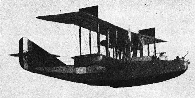
F.2A (N4297) on North Sea Patrol.

N4839, a production F.5, was visually similar to the prototype but the performance suffered due to official interference in the design. N4839 was from a batch of 50 boats ordered from Short Brothers Ltd. It made its first flight at Short's, Rochester, on 23 March 1920. Served with the Development Flight at Grain in 1922 and was still with the Marine Aircraft Experimental Establishment in June 1923.
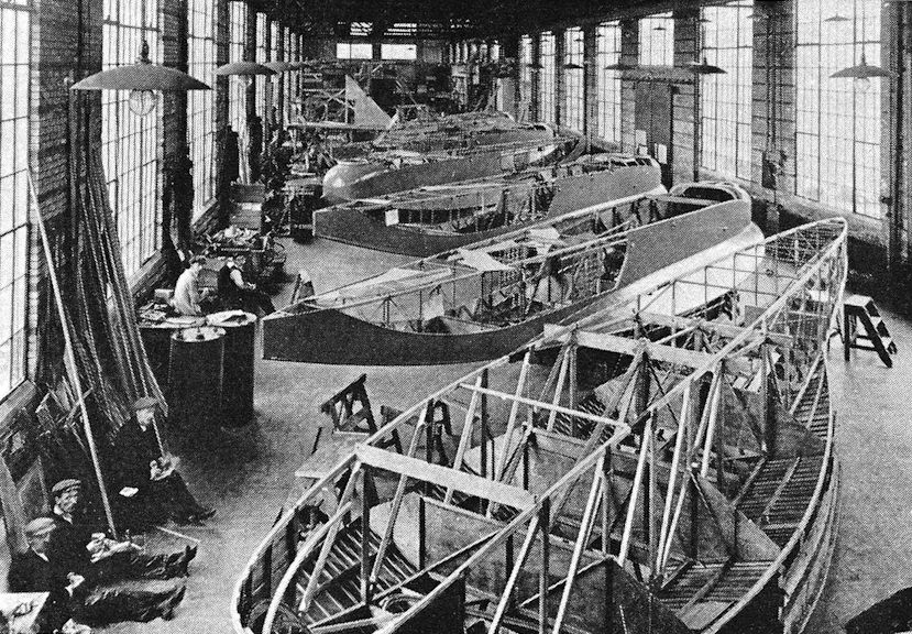
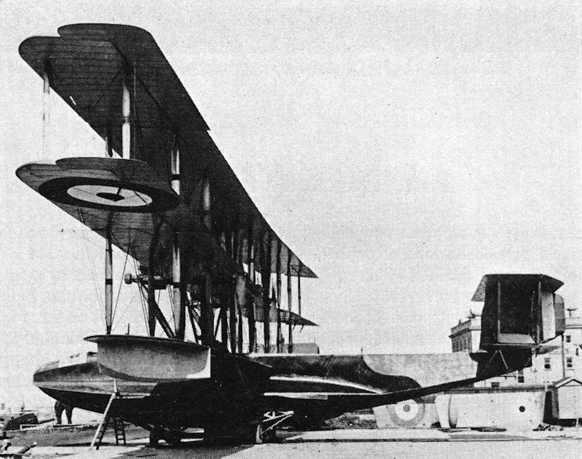
Porte/Felixstowe F.5s in production. The Porte method of hull construction is clearly shown.

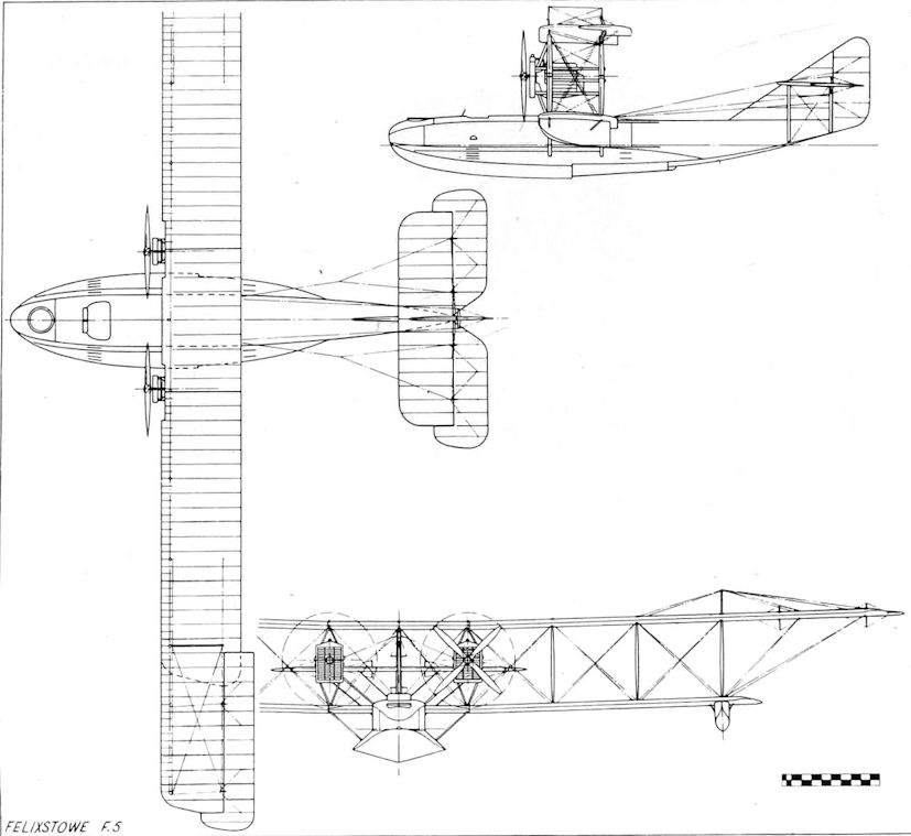
Felixstowe F.2A
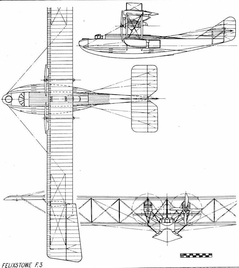
Felixstowe F.3
Felixstowe F.5
Porte/Felixstowe Fury (1918)
John Porte’s last Felixstowe production was a huge triplane flying-boat, the largest British machine of its day, powered by no fewer than five 334 h.p. Rolls-Royce Eagle VII engines. The Fury was probably inspired by a large Curtiss triplane flying-boat which had been assembled and flown at Felixstowe in 1916, the Curtiss-Wanamaker, serialled No. 3073. This machine was the first delivered of an order for twenty, but even with its original four 250 h.p. Curtiss engines replaced by Rolls-Royce power units, official tests showed that the performance did not measure up to requirements and the order was cancelled. At the time, Porte had little opportunity and insufficient resources to deal with the redesign of the Curtiss-Wanamaker, but it is certain that as an advocate of the large flying-boat he did not forget it, and when the Fury appeared in 1918 several features of the Curtiss machine were embodied. Known to all at Felixstowe as the Porte Super Baby, the Fury was planned for an engine installation of three of the new 600 h.p. Rolls-Royce Condors but was completed before the Condor became available, so the engine mountings were modified to take five Rolls-Royce Eagles arranged as a central pusher flanked by two outboard pairs of pusher and tractor. The hull, basically employing a similar construction and profile to the other Felixstowe boats and 60 feet in length, was regarded as the best of all the Porte hulls. The top and central mainplanes were of equal span, the latter carrying the engines, while the lower mainplane was one bay shorter. The tail unit resembled that of the Curtiss-Wanamaker, with a biplane tailplane fitted with twin rudders mounted upon a central fin. The Fury design incorporated power-operated controls, using servo-motors, and it was almost certainly the first aircraft in the world to fly with these in operation although actually the Fury proved to be remarkably light on all controls and so the weighty servos were dispensed with. The machine’s designed loaded weight was 24,000 pounds, this being gradually increased during testing without adverse effect upon take-off or seaworthiness until it reached the figure of 33,000 pounds, at which enormous weight Porte himself coaxed the great machine into the air from Harwich Harbour. On another occasion, Major T. D. Hallam, d.s.C., flew the Fury with 24 passengers, fuel for seven hours, and 5,000 pounds of ballast. The tail unit was later modified to a more conventional assembly of biplane layout with triple rudders between the tailplanes, and the hull tested in model form in the Froude Tank at the National Physical Laboratory, some of the recommended modifications resulting from this testing being applied to the full-sized aircraft. Never used operationally, the Fury continued experimental flying after the Armistice, powered in its final form by five Rolls-Royce Eagle VIII engines of 365 h.p. each. A few months after Porte and Rennie were demobilised, the Fury stalled and crashed on take-off, possibly due to incorrect loading, the pilot and two crew members losing their lives.
In August 1919, Porte joined the Gosport Aviation Co. Ltd., as chief designer, to work with an old friend, Herman Volk, who had become manager of the company. A number of designs was produced but none was built due to the post-war slump in orders. In October 1919 John Porte died at Brighton. He was thirty-five years old.
SPECIFICATION
Power Plant: Five 334 h.p. Rolls-Royce Eagle VII, or five 365 h.p. Rolls- Royce Eagle VIII
Span: 123 feet
Length: 63 feet 2 inches
Weight Loaded: 25,253 pounds (medium), 33,000 pounds (max. test)
Total Area: 3,108 square feet
Max. Speed: 97 m.p.h. at 2,000 feet
Endurance: 7 hours (medium). In excess of 12 hours with max. fuel load
Armament: Four Lewis guns and heavy bomb load

Fury on initial trials, with original tail surfaces. Its hull was the best developed by Porte and threw up less water than previous hulls.
Fury with modified 'tail assembly.'
Wyvenhoe Flier (1909)
Historically important as the first serious attempt to produce a flying-boat in Britain, work commenced upon the Wyvenhoe Flier in October 1908, supervised by its designer, Mr J. E. Humphreys, construction being carried out in a small hangar between Forrestt’s boatyard at Wyvenhoe and the river bank opposite Rowhedge, in Essex. Humphreys, a dental surgeon, was by no means an amateur regarding aerodynamics, having experimented with bird flight and structure since 1902, and had actually flown two of his own gliders from the cliffs at Fowey, Cornwall.
The Flier was built by local skilled marine craftsmen, with the co-operation of Mr (later Sir James) Bird, managing director of Forrestts.
In many ways advanced for its time, the machine was a biplane, with the wings mounted above the hull and the engine and propellers in mid-gap, thus anticipating a design layout for flying-boats that endured for a quarter of a century. For the first time in aviation history, extensive metal skinning was employed, both mainplanes being covered with light-gauge aluminium sheet. The coracle-type hull had a double skin of thin cedar planking, with varnished silk interposed, with a small scuttle in the bows serving as protection for the pilot. No water rudder was fitted. The lower wing was secured to the hull gunwales, its multiple spars as extensions of the hull ribs and curved downwards to the tips, which formed full-chord ‘air boxes’ for lateral stability on the water. A wheeled undercarriage consisting of two pairs of cycle-type wheels mounted in tandem on bamboo poles, and arranged to make use of the natural spring thereof, was designed to fit up under the lower wing, but was never used in practice. The upper wing, supported upon tubular steel interplane struts and wire braced, had large drooping tip extensions of triangular shape built up of long narrow sections covered with strips of rubber-impregnated cotton silk. These extensions were similar in function and appearance to the wing-tip feathers of a bird. Strut-mounted on the lower wing trailing edge was a bird-like tailplane/rudder, universally jointed, and of the same ‘feather’ construction as the wing tips. The control surfaces were completed by a triangular elevator, carried forward of the hull and wing structure on outriggers. Elevator and tailplane were both operated by a single control.
A 35 h.p. J.A.P. Vee-eight air-cooled engine was transversely mounted on steel tubular bearers in mid-gap behind the pilot, driving two 8-foot diameter metal pusher propellers through shafts, bevel gears, and centrifugal clutches. The propeller blades were curved rearwards towards the tips, with the idea of concentrating the slipstream into a ‘jet wake‘ to assist thrust.
The first launching was made on 3 April, 1909, in rather marginal conditions of wind and tide. Inevitably, a gust canted the machine, and it sank. Humphreys, aboard at the time, extricated himself from the numerous bracing wires with some difficulty. The Flier was salvaged at midnight, and returned to its shed. Repairs having been completed, the second launching took place on 15 April. Again bad fortune attended, for one of the propeller drive gears sheared. At a third launching on the 18th, everything appeared to be in order, and the machine was towed down river by steam tug to a point between the Alresford and Fingringhoe Banks, cast off, and the engine started. It was immediately apparent that the wing-tip air boxes created impossible water drag, and that with the engine stopped, directional control was nil. The machine was towed back for alterations to be made, these consisting of canoeshaped wing-tip floats with controllable water rudders at the stern.
In the evening of 14 May, 1909, the Flier was towed to the swing bridge at Alresford Creek, and started up. This time, directional control proved excellent, the Flier skimming the water beautifully at a speed of 10 to 12 knots, but resisting all Humphreys’ efforts to ‘unstick’.
Financial considerations precluded further development, and the Flier was abandoned. Its engine finally did take to the air, being sold to Mr E. T. Willows, who used it to power his little dirigible airship on her memorable flight from Cardiff to London.
SPECIFICATION
Power Plant: One 35 h.p. J.A.P. Vee-eight air-cooled engine, with Bosch magneto
Span:
Main metal-clad wing section - 21 feet
Wing-tip extensions - 10 feet 6 inches each
O.A. Span - 42 feet
Length, O.A.: 26 feet (Hull - 17 feet)
Height: 12 feet
Weight Loaded: 1,750 pounds
Total Area: 1,100 square feet
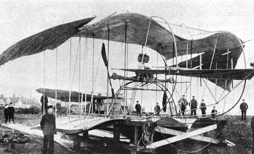
Wyvenhoe Flier on launching chassis.
Norman Thompson N.T.4 and N.T.4A (1915)
On 4 October, 1915, the White and Thompson Company changed its name to the Norman Thompson Flight Company, Ltd, with F. P. H. Beadle as chief designer. The first machine to appear under the new name was the N.T.4. A development of the twin-engined Round Britain Race entrant of 1914, the N.T.4 was ordered for R.N.A.S. use, becoming known as the ‘America’ flying-boat, and later, with the introduction of the Curtiss H.12, as the ‘Small America’ although there was little resemblance between the Norman Thompson and Curtiss machines. It should be noted that at this time there was a confusing tendency to class all flying-boats as ‘Americas’, regardless of type or manufacture.
A biplane, with twin 150 h.p. Hispano-Suiza pusher engines driving two- bladed propellers, the N.T.4 had two side-by-side seats in an enclosed cabin. The hulls were made by S. E. Saunders at Cowes. The first production machine of a batch of six, No. 8338, was experimentally fitted with a two-pounder Davis gun mounted horizontally above the cabin roof. This gun was subsequently removed, not having been used operationally. Commencing with the second production batch, the N.T.4s had modified cabin windows to give better vision, and were fitted with 200 h.p. Hispano-Suiza engines. With these modifications the machines were designated N.T.4A, the first one, No. 9061, being stationed at Calshot. A total of over fifty machines of both versions served with the R.N.A.S. at seven coastal stations, where they were employed for patrols, and later for training duties.
SPECIFICATION
Power Plant:
N.T.4 - Two 150 h.p. Hispano-Suiza engines
N.T.4A - Two 200 h.p. Hispano-Suiza engines
Span: 78 feet 7 inches
Length: 41 feet 6 inches
Loaded: N.T.4A-6,469 pounds
Total Area: 936 square feet
Max. Speed: N.T.4A-95 m.p.h.
Endurance: 4 hours
Armament: Light bombs, .303-inch Lewis gun in cabin roof
Norman Thompson N.2C (1918)
The Norman Thompson N.2C was a 1918 development of the N.T.4A. The wings and tail unit were standard N.T.4A components, but unlike the previous boat-built hulls characteristic of this company, the N.2C had a hull built on the Porte principle. Norman Thompson had been contractors for F.2A hulls since the spring of 1917, and so were familiar with the Porte-type construction. The power units were two pusher Sunbeam Arab engines of 200 h.p. each, driving four-bladed propellers. Construction of two prototypes commenced in January 1918. These were officially serialled N82 and N83, but the machines, designed for patrol work and equipped with Lewis guns, bombs, and wireless, arrived too late for production or service, being scrapped due to post-war economy upon the take-over by Handley Page, Ltd.
SPECIFICATION
Power Plant: Two 200 h.p. Sunbeam Arab
Span: 78 feet 7 inches
Length: Not available
Weight Loaded: 6,700 pounds
Total Area: 936 square feet
Armament: One or two Lewis guns, light bombs
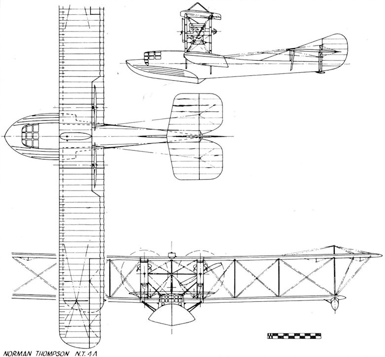
Norman Thompson N.T.4A
Norman Thompson N.1B (1917)
The Air Board Specification N.1B called for a high-performance single-engined flying-boat of the fighting scout category. Several companies produced designs in accordance with this specification in the last two years of the war, including Norman Thompson.
The Norman Thompson N.1B, built in early 1917, retained several features of earlier designs, notably the boat-built hull with the characteristic narrow after-part, with the wing-tip floats attached directly to the undersurface of the lower wing, but the usual dorsal fin was replaced by a more normal fin and rudder of generous area, and the machine was smaller than its predecessors. The crew of two were housed in separate open cockpits, and the wings were arranged to fold forward. The machine was powered by a 200 h.p. Hispano-Suiza pusher engine, driving a four-bladed propeller, a portion of the upper wing trailing edge being cut away to clear the propeller. Launched in September 1917, the N.1B performed well on initial test flights, but on its service trials at R.N.A.S. Isle of Grain its performance was not judged to show any great advance on existing types, and it was not adopted.
SPECIFICATION
Power Plant: One 200 h.p. Hispano-Suiza
Span: 34 feet 3 inches
Folded - 13 feet 2 inches
Length: 26 feet 5 inches
Folded - 32 feet 8 inches
Weight Loaded: 2,673 pounds
Total Area: 357 square feet
Max. Speed: 93 m.p.h.
Endurance: 3 1/2 hours
Armament: One free-mounted .303-inch Lewis gun
Norman Thompson N.T.2B (1916)
A development of the White and Thompson No. 3 Boat of 1914, the N.T.2B was powered initially by the 160 h.p. Beardmore pusher engine. The crew of two were enclosed in a cabin fitted with side-by-side seating and dual control, and in common with other machines produced by this company, the after part of the hull was extremely narrow with a long dorsal tail fin, while the wing-tip floats were attached directly to the undersurface of the lower wing. Accepted by the Admiralty, the N.T.2B was ordered into production, some of the first batch of fifty machines being fitted with the 150 h.p. Hispano- Suiza engine, examples of this being N2555 and N2561. The machine proved to be a great success, and the production requirements soon outstripped the capability of the Norman Thompson works alone, so construction contracts were opened with S. E. Saunders at Cowes, and with Supermarine at Woolston, Southampton. Late in 1917, it was decided to fit the 200 h.p. Sunbeam Arab engine, which, owing to its greater torque, had to be mounted slightly starboard of centre. An example of the Arab-powered N.T.2B was machine N2294. This engine, however, fell short of requirements, and the ultimate production version was fitted with the 200 h.p. Hispano-Suiza, the torque problem in this case being dealt with by slewing the engine mounting. The first 200 h.p. machine was N2569.
Altogether, more than one hundred and fifty machines were built, remaining the standard training type for flying-boat pilots until the Armistice, supplemented by smaller numbers of other machines. They served with the R.N.A.S. at Calshot, Lee-on-Solent, and Felixstowe.
No further development took place, owing to the fact that Norman Thompson was absorbed by Handley Page, Ltd. The latter company sent two machines to Peru in 1919, for air transport work. These were N2284 and N2293. One N.T.2B was on the civilian register as G-EAQO.
SPECIFICATION
Power Plant:
Prototype/early production - 160 h.p. Beardmore
Some early production - 150 h.p. Hispano-Suiza
Trial installation, 1917 - 200 h.p. Sunbeam Arab
Late production - 200 h.p. Hispano-Suiza
Span: 48 feet 4 3/4 inches
Length: 27 feet 4 1/2 inches
Weight Loaded: Sunbeam Arab - 3,169 pounds
Total Area: 453 square feet
Max. Speed: Sunbeam Arab - 85 m.p.h.
Endurance: Not available
Armament: Nil
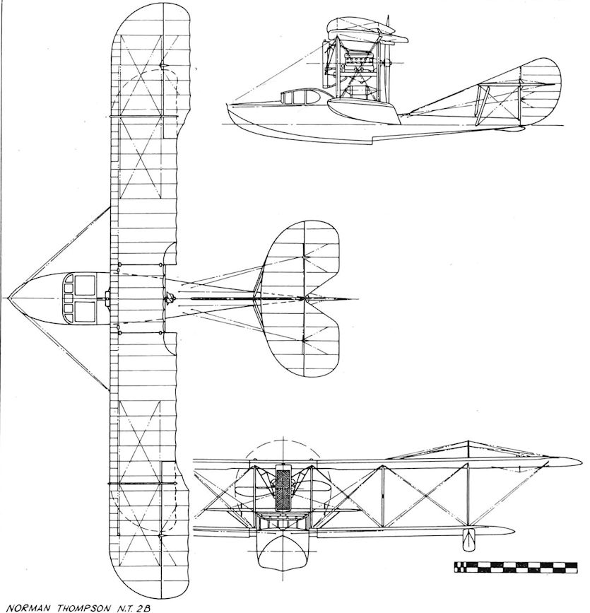
Norman Thompson N.T.2B
Pemberton-Billing Flying-boats (1913/1914)
The first product of this company, formed in 1913 by Noel Pemberton-Billing, was a small flying-boat, the P.B.1. Exhibited at the 1914 Aero Show, the machine attracted much attention by virtue of its advanced design and clean lines. A single-seater biplane, the P.B.1 had a wing span of only 28 feet, and a loaded weight of a mere 970 pounds. The hull, cigar-shaped and beautifully streamlined by a skin of moulded plywood, had external planing surfaces in the form of longitudinal fins attached to the hull sides, with the cockpit placed well aft of the wing trailing edges. Lateral water stability was obtained by cylindrical wing-tip floats. The power unit, a 50 h.p. Gnome rotary, drove a three-bladed tractor propeller, and was enclosed in a streamlined nacelle mounted high in the centre section, with the thrust fine inclined above the horizontal to assist take-off. In common with several other early flying-boats, the P.B.1. fell victim to the twin problems of low power and water drag, and did not fly.
<...>
SPECIFICATION
P.B.1
Power Plant: One 50 h.p. Gnome
Span: 28 feet
Weight Loaded: 970 pounds

Perry-Beadle at Olympia Aero Show.
Pemberton-Billing Flying-boats (1913/1914)
<...>
Undeterred by failure, Pemberton-Billing’s reference to his marine aircraft as ‘not aeroplanes which float, but boats which fly’ was borne out by his next flying-boat project, the P.B.7, of 1914. In this design, the forward part of the hull consisted of a cabin cruiser motor boat, powered by a 225 h.p. Sunbeam engine, while the after part, including wings, propellers, and tail unit, was detachable. In the assembled state, extended drive linkage connected the Sunbeam to the twin pusher propellers. The P.B.7 layout was intended to eliminate the problem of docking a large flying-boat by loading the motor boat at a pier, then connecting up with the flight structure at a convenient offshore mooring. In emergency, the flight structure could be jettisoned on the water, leaving the seaworthy motor boat to proceed alone and unhindered. A batch of P.B.7s were on order for the German Navy, and at the outbreak of war several motor boats of this type were complete and ready to have the flight structure fitted. Work on them was stopped and the design adapted into the S.S.1 military flying-boat.
The S.S.1 project consisted of a scaled-down version of the P.B.7, equipped with folding wings. Intended for launching from a surfaced submarine, the machine would jettison its flight structure after action, returning to base as a fast motor launch. In the event, it was not built, partly because Pemberton-Billing had joined the R.N.A.S. and was planning the anti-Zeppelin raid on Friedrichshaven, and partly because the company now had priority wartime contracts to fulfil. Eventually the company was transferred to the capable hands of Hubert Scott-Paine, retaining the original description of its marine aircraft, ‘Supermarines’, as the company name.
SPECIFICATION
P.B.7
Power Plant: One 225 h.p. Sunbeam
Span: 57 feet 6 inches
Length: 34 feet
Weight Loaded: 3,950 pounds
Total Area: 558 square feet
Max. Speed: 70 m.p.h. (estimated)
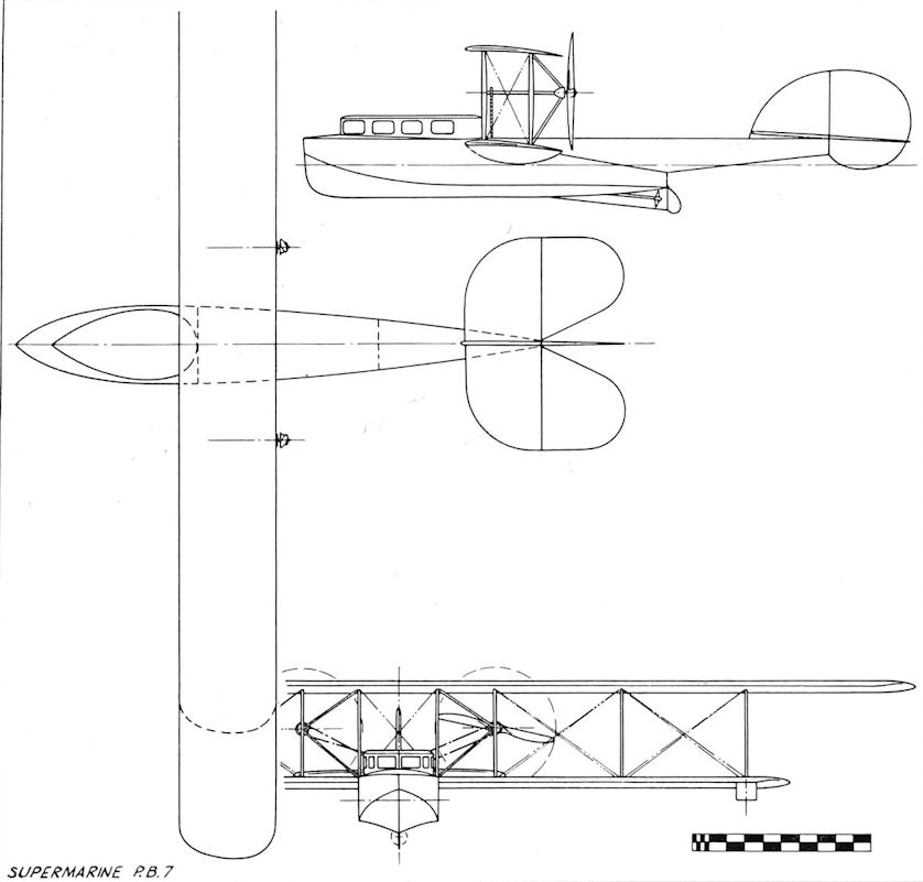
Supermarine P.B.7
Perry-Beadle Flying-boat (1913)
In an attempt to emulate the success of the Sopwith Bat Boat, the Perry-Beadle machine was built by F. P. Hyde Beadle and Copland Perry at their Twickenham works in late 1913, with the hull sub-contracted to Saunders of Cowes.
Generally of conventional layout, the machine had an unusual power arrangement which followed a design theory of the time that future flyingboats would have engines and crew accommodated within the hull. A 60 h.p. E.N.V. eight-cylinder Vee-type engine was totally enclosed in the bows, with tube-shrouded chain transmission to twin tractor propellers carried on mid-span interplane struts. Hull decking over the engine was removable for maintenance. The hull itself was beautifully streamlined to a fish-like profile, the monocoque rear section with integral fin and tailplane merging into a deep forward section which embodied the planing bottom and a perpendicular bow. A single step was formed by the junction of the rear monocoque and forward sections. The entire hull and tail surfaces were covered by Saunders ‘Consuta’ copper-sewn plywood. The upper wing was of normal wooden construction, equipped with ailerons and fabric covered. The lower wing was covered with ‘Consuta’ and of unusual airfoil section, in that the point of maximum camber lay at fifty per cent of the 4-foot chord. No wing-tip floats were fitted, reliance for lateral water stability being placed upon the watertight wing itself. Control surfaces were operated by external wires from the wheeled control column, and from rudder pedals.
The Perry-Beadle was exhibited at the 1914 Aero Show at Olympia, but then the outbreak of war intervened, and flight trials could not be arranged until 1915. At this time, an association known as the Lakes Flying Company was operating with marine aircraft on Lake Windermere, an ideal locale with calm water and few wartime restrictions. The machine was transported there in July 1915, and after assembly, flotation tests were made. The results were not promising, for the machine lay so low in the water that the lower wing trailing edge and rudder base were submerged. This fact, combined with the fish-like hull, quickly earned it the local sobriquet of‘Jonah’s Whale’. Flight trials were attempted by Mr Stanley Adams of the Lakes Company, but he failed to get the machine off the water, due to the high drag set up by the immersed lower wing. The Perry-Beadle remained at Windermere, and, after removal of the engine, was finally broken up.
SPECIFICATION
Power Plant: One 60 h.p. E.N.V. Vee-eight engine
Span: 35 feet
Length: 26 feet
Height: 9 feet
Weight Loaded: 1,600 pounds
Total Area: 290 square feet
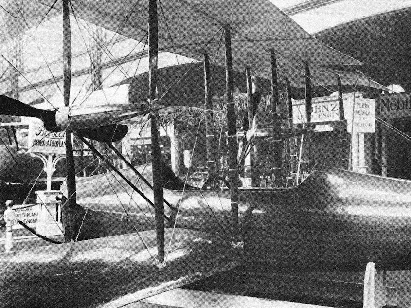
Perry-Beadle at Olympia Aero Show.
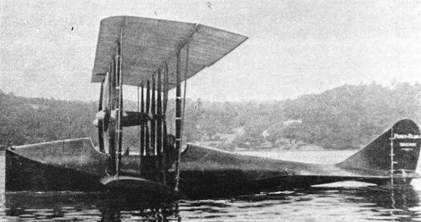
Perry-Beadle Flying-boat on Lake Windermere.
Phoenix P.5 Cork (1918)
In 1917, while recognising the proven efficiency of the Porte-designed flyingboats, the Admiralty decided to evaluate fully the Linton Hope monocoque hull by using it in the design of a new flying-boat of similar size/weight ratio to the Felixstowe boats. This type of hull had not been extensively used, because it required skilled labour, and was therefore unsuited to mass-production, but its success with the 1917 A.D. Boat helped to convince the Air Department that it was capable of further development. Specification N.3B was drawn up for the new machine, authorisation being granted for the construction of two prototypes. The hulls were built by May, Harden and May, of Southampton Water, and the contract for the flight structure and final assembly given to the Phoenix Dynamo Manufacturing Co. Ltd, of Bradford. The two hulls were not identical; one had a true planing bottom extending to the rear step, while the other was of similar profile to the Supermarine Baby and Blackburn N.1B, with the main planing bottom terminating amidships at the main step, and a small auxiliary external step fitted towards the stern. The hulls were completed and sent to Bradford in April 1918, where, for some reason of policy, only the one with the full planing bottom was utilised. This hull had a bow gunner’s cockpit, two separate cockpits for the pilots, and just forward of the rear spar was a hatch for the flight engineer. There was a waist gunner’s hatch on either side of the hull aft of the lower wing trailing edge. The first machine, N86, assembled at the Brough seaplane base, was complete on 7 August, 1918. The power units were two 352 h.p. Rolls-Royce Eagle VIIIs, driving four-bladed tractor propellers. After satisfactory maker’s trials, N86 reached the Isle of Grain for official trials on 24 August. There, some trouble was experienced with the wing fabric, for a new type of varnish used was a failure and the fabric became dangerously soggy. The second prototype was now under construction, with its wings treated with normal dope, so these wings were sent to be fitted to N86, the originals being returned to Bradford for re-covering. Experience with N86 indicated that the wings were set too low, consequently the second aircraft, N87, was modified to have the lower wing centre section carried above the hull on a shallow faired pylon. N87’s hull was similar to that of its predecessor but the rear step was further aft. Other differences were a larger rudder, and two ‘dustbin’ gunner’s cockpits built into the upper wing trailing edges, outboard of the centre section. The original wings of N86 were fitted, but the use of an incorrect type of dope again caused delay, and N87 did not reach Brough until March 1919.
After the Armistice, the large numbers of Felixstowe boats available precluded any possibility of the Cork attaining full production status, but the two existing machines remained in use for several years, proving beyond doubt the durability of the Linton Hope hull. N87 was eventually fitted with two 450 h.p. Napier Lion engines, with a revised system of struts supporting the engine bearers, and N86 acquired the larger rudder, being also equipped for night flying, although there is no record of this being practised.
SPECIFICATION
Power Plant:
Two 352 h.p. Rolls-Royce Eagle VIII
N87 - later, two 450 h.p. Napier Lion
Span: 85 feet 6 inches
Length: 49 feet 2 inches
Weight Loaded: (Normal) 11,600 pounds (N86)
Total Area: 1,273 square feet
Max. Speed: (Normal load) 106 m.p.h. (N86)
Armament:
N86 - five Lewis guns, and maximum bomb load of two 520-pound bombs
N87 - bomb load as N86, with seven Lewis guns

Cork Mk III N87 on the apron at Felixstowe together with the Short Cromarty before their departure with the Flying-Boat Development Flight to the Scilly Isles in August 1922.
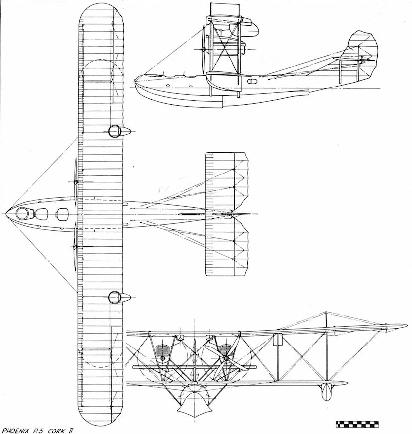
Phoenix P.5 Cork II
Porte/Felixstowe Baby (1916)
During the H.4 hull experiments, work had commenced on the construction of a very large three-engined flying-boat designed by Porte, now in command of the Felixstowe air station. This machine’s official designation was submerged by Naval humour, and ‘Baby’ it remained. The prototype, No. 9800, had a boat-built hull, plywood covered with a single step. Equipped with an enclosed cabin, the hull measured 56 feet 10 inches from bow to stern, having a maximum beam over the side fins of no less than 14 feet. The power units were three 250 h.p. Rolls-Royce engines, the prototype of the later Eagle, and were disposed as a centrally mounted pusher and two outboard tractors. After initial tests the bows were lengthened by 3 feet to improve seaworthiness, but the machine proved rather slow and underpowered. Twenty Babies were ordered, at least ten being completed by May, Harden and May, of Southampton Water. Some of these machines had a 260 h.p. Green engine as the central unit, and all had modified outboard engine mountings consisting of single interplane struts, which replaced the original diamond-shaped arrangement. Performance was later improved by fitting more powerful Rolls-Royce engines, including the Eagle VIII of 360 h.p., but the design of the Baby did not lend itself to the installation of effective armament, the structure providing a multitude of ‘blind spots’. No. 9800 was experimentally fitted with a large-calibre Davis gun in the bows,'but this was not used operationally. Some machines had a Scarff ring-mounted Lewis gun in the bow cockpit, but the majority were armed with Lewis guns fired through windows and ports from within the hull.
The Porte Baby flying-boats were flown on oversea patrols from Felixstowe and Killingholme, taking part in the efficient ‘Spider Web’ patrol centred on the North Hinder Light Vessel. It was here, on 1 October, 1917, that the Baby captained by Flight Commander N. Sholto Douglas fought a gallant but unequal action with three German aircraft, during which two of the flyingboat’s engines were hit and stopped, forcing it to alight on the sea where a further attack caused more damage and wounded one of the crew. Undaunted, the others effected temporary repairs to the machine, and after taxying for nine long hours made landfall on the Suffolk coast, from where the Baby was towed back to Felixstowe. As a result of this action, the Babies were never again used in areas where they ran the risk of meeting enemy aircraft. Although one machine had been flown on torpedo trials, with two 14-inch missiles slung below the wings, the most interesting experiment in which a Baby participated was the remarkable composite flight made in May 1916, with the object of developing a method of attacking Zeppelins. A Bristol Scout ‘C’, No. 3028 of H.M.S. Vindex, was mounted upon the upper wing centre section of a Baby fitted with Rolls-Royce Eagle engines, the Scout’s wheels resting in shallow troughs and a pair of forward-facing crooks engaging the axle. The tail-skid was secured by a quick-release catch operated by the Scout pilot. On 17 May, 1916, the Baby, with the smaller aircraft attached, took-off from Felixstowe under the command of Porte, who had Flt. Lieut. Hope and two crew aboard. In the Bristol was Flt. Lieut. M. J. Day, of H.M.S. Vindex. At a height of 1,000 feet over Harwich, Day slipped the tailskid release, climbing away and landing safely at Martlesham Heath. A contemporary report has it that Day started his engine before release, but as the Bristol was fitted with a rotary power unit which was quite liable to catch fire if switched on after ‘windmilling’, it may well be that the Scout’s engine was running during the take-off and climb. Although a complete success, this experiment was never repeated. Two Babies remained on charge with the R.A.F. at the end of the war, while the stripped hull of a third ended its days in the grounds of a women’s hostel, a door cut in its side, electric light laid on, and four W.R.N.S. motor drivers in residence.
SPECIFICATION
Power Plant:
Three 250 h.p. Rolls-Royce
Three 345 h.p. Rolls-Royce Eagle
Two 250 h.p. Rolls-Royce and one 260 h.p. Green
Three 360 h.p. Rolls-Royce Eagle VIII
Span: 124 feet
Length: 63 feet
Weight Loaded: 18,600 pounds
Total Area: 2,364 square feet
Max. Speed: 87-5 m.p.h.
Endurance: 7 hours
Armament: Four Lewis guns, six-pounder Davis on prototype. Details of bomb load not known
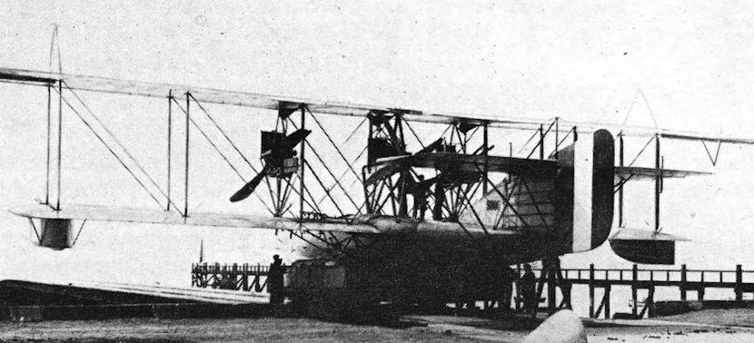
Baby prototype (No. 9800) on slipway.
Radley-England Waterplane (1913)
Built at Huntingdon at the beginning of 1913, the Waterplane was the result of a design study by James Radley, modified and elaborated by E. C. Gordon England. Bold in concept, it was designed from the start to carry six persons, the limiting factor of contemporary low-powered engines being overcome by coupling no less than three power units to a single pusher propeller shaft. This arrangement also disposed of the offset thrust problems usually associated with a multi-engined aircraft.
The superstructure consisted of a biplane with the tail surfaces carried on outriggers, twin rudders and an unusually large elevator being fitted. Lateral control was by ailerons, attached to the top wing rear spar. For maximum stability in water handling, the designers used twin hulls, the superstructure being supported above these on extensions of the interplane struts, and extensively wire-braced. Each hull seated three persons, with the pilot positioned on the front seat of the starboard hull. The seats were arranged singly at the front, with a double bench-type seat at the rear.
The engine arrangement was most unusual, making the machine the world’s first three-engined aircraft. Three 50 h.p. Gnome rotary engines were placed one behind the other upon a common crankshaft, about which they revolved like ‘three Catherine wheels on one pin’. The end plate of each crankcase was machined into a sprocket, which connected to a long countershaft above the engines via chain drives. The propeller was bolted to the aft end of the countershaft. With this layout, flight could be maintained without offset thrust should one engine fail. Each engine could be independently controlled from the pilot’s seat by a separate petrol cock and switch, with a master switch on the control column to cut out all three power units. Engine and flight control cables were brought down to the pilot’s position through copper fairleads. Tanks, mounted above the propeller shaft, carried 21 gallons of petrol and 10 1/2 gallons of oil.
Initial flight tests commenced in the spring of 1913, using a simple wheeled undercarriage under the hulls to check the machine’s performance before marine operation. The tests were satisfactory, the wheels removed, and Gordon England made the first off-water flight without difficulty. The Waterplane was operated from Volk’s Seaplane Base at Brighton in the early summer of 1913, many demonstration flights being given. Finally, with a local newspaper reporter on board, England accidentally ran over a marker buoy, which ripped out the bottom of one hull and sank the machine, fortunately without injury to either occupant.
<...>
SPECIFICATION
Power Plant:
First version - Three 50 h.p. Gnome rotaries
Second version - One 150 h.p. Sunbeam
Span: (Second version in brackets) 45 feet 4 inches (51 feet 7) inches)
Length: 29 feet 3 inches (29 feet 9 inches)
Loaded: 1,800 pounds (2,500 pounds)
Total area: 505 square feet (560 square feet)
Max. Speed: Both versions - 60 m.p.h.
Endurance: 5 hours (10 hours)
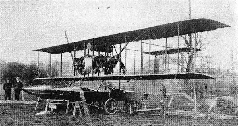
Waterplane. First version, rotary-powered.
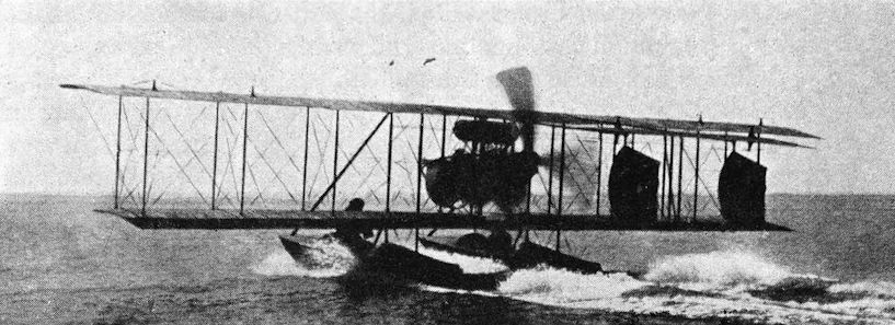
The Waterplane taking off at Brighton in 1913, piloted by Gordon England.
Radley-England Waterplane (1913)
<...>
With the aid of local boatmen, England salvaged the damaged machine, and set about rebuilding and modifying it for entry in the Daily Mail Round Britain Race, to be held in August 1913. To meet the exacting conditions of the race, the first components of the Waterplane to receive attention were the hulls. The originals were replaced by a stout pair of clinker-built fully decked boats, having three watertight compartments each, with two cockpits, and built locally by the South Coast Yacht Agency. The unique Gnome engine installation was discarded, replaced by a single 150 h.p. Vee-type Sunbeam. Petrol capacity was increased to 82 gallons, giving an endurance of ten hours, and to cope with the increased weight the wing span was extended, its section being modified to one of greater camber. Two long struts from hull bows to engine bearers strengthened the structure, and improvements to the bracing wire system were made. Unfortunately, the engine change proved to be the machine’s downfall, for trouble with the Sunbeam caused a last-minute withdrawal of the Race entry. Gordon England became test pilot to White and Thompsons, and the Waterplane was abandoned.
SPECIFICATION
Power Plant:
First version - Three 50 h.p. Gnome rotaries
Second version - One 150 h.p. Sunbeam
Span: (Second version in brackets) 45 feet 4 inches (51 feet 7) inches)
Length: 29 feet 3 inches (29 feet 9 inches)
Loaded: 1,800 pounds (2,500 pounds)
Total area: 505 square feet (560 square feet)
Max. Speed: Both versions - 60 m.p.h.
Endurance: 5 hours (10 hours)
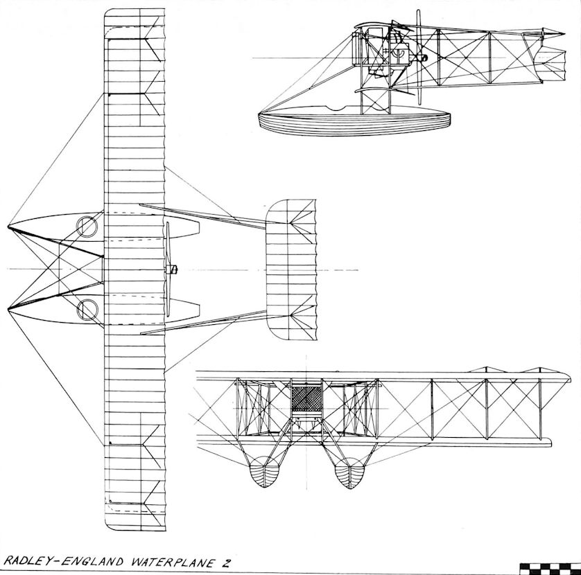
Radley-England Waterplane 2
Royal Aircraft Factory C.E.1 (1917)
With the introduction of unrestricted submarine warfare by the German navy in February 1917, the urgent requirement for suitable aircraft capable of long oversea patrols became acute. The big F.2A flying-boats had not yet appeared, and the limited numbers of Curtiss H.12s and H.4s were heavily engaged. In an attempt to ease the situation, the Royal Aircraft Factory, despite their limited experience of marine aircraft, set up a design team under Mr. W. S. Farren (now Sir William Farren, c.b., m.b.e., f.r.s.) to build a two- seater single-engined flying-boat, designated Coastal Experimental 1. Work commenced in June 1917, and such was the speed at which it proceeded that the first prototype was despatched to Hamble for trials six months later.
To cut design problems to a minimum, several features of proven Factory machines were utilised, and the flight structure with the tail surfaces supported on booms had obvious F.E.2B association, in fact, the wing spans were almost identical. Such an arrangement permitted a short lightweight hull to be used, with no aerodynamic function save side-area, a reversion to the highly efficient Sopwith Bat Boat formula. The hull, boat-built and planked with mahogany, weighed only 527 pounds. The two cockpits were arranged in tandem, the pilot occupying the rear seat, and extensive glazing surrounded both cockpits, with sliding side panels for entry and exit. Side fins gave the planing bottom a reasonable width back to the single step amidships, and there was a water rudder at the stern. Three gun mountings of the pillar type were provided, one at the bow and two between the cockpits, with an external bomb-sight to starboard of the front cockpit. Bomb racks were attached to the underside of the lower wing centre section. The wings were arranged to fold backwards, outboard of the tail boom junctions, and a large-area single fin and rudder was fitted. The power unit of the first C.E.l, N97, was a 230 h.p. R.A.F. 3a pusher engine driving a four-bladed propeller. N97 made its first flight at Hamble on 17 January, 1918, piloted by Mr Farren, and after some control surface and radiator modifications, arrived at the Isle of Grain for official trials in March 1918. By this time, the U-boats were by no means having things their own way, and the testing of the C.E.l took on a more leisurely pace. Its performance was inferior to the F.2A, and slightly better than the Short 184 seaplane, but it could carry two 230-pound bombs and fly for four-and-a-half hours, which fulfilled its required task. No longer required on operations, N97 became a research aircraft, and was used for comparing the results of full-scale tests with those obtained on models in the Froude Tank at the National Physical Laboratory, with particular reference to the problems of porpoising, which had caused the failure of the first A.D. Boat in 1916. A second machine, N98, was completed in March 1918, the power unit in this case being the 260 h.p. Sunbeam Maori, and the performance reported to be slightly better than A797. N98 was stationed at Westgate in June 1919. It is reasonable to suppose that both C.E.1s were scrapped in the post-war economy reduction of the forces.
SPECIFICATION
Power Plant:
N97 - One R.A.F. 3a of 230 h.p.
N98 - One 260 h.p. Sunbeam Maori
Span: 46 feet
Length: 36 feet 3 inches
Weight Loaded:
N97 - 4,912 pounds
N98 - 4,994 pounds
Total Area: 609 square feet
Max. Speed:
N97 - 88-5 m.p.h.
N98 - 92-5 m.p.h.
Endurance:
N97 - 4-5 hours
N98 - 3-75 hours
Armament: One Lewis gun, two 230-pound bombs
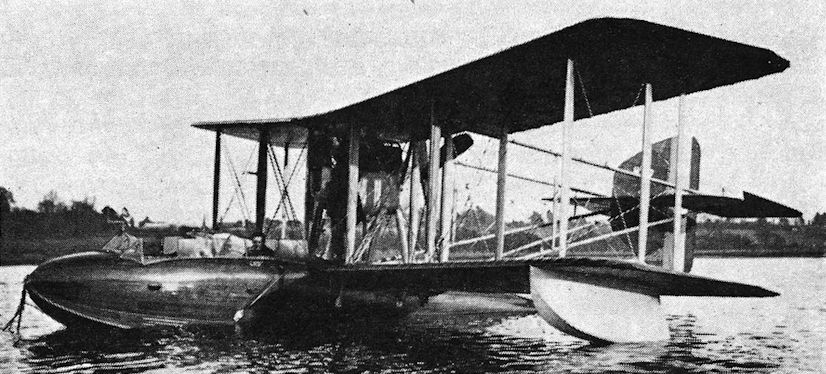
C.E.1 (N97).
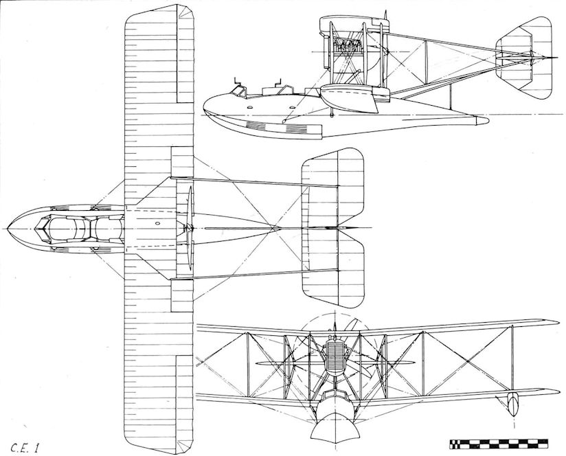
C.E.1
Sopwith Bat Boat No. 1 (1912)
Europe’s first successful flying-boat, and the world’s first practical amphibian, the Bat Boat was truly a flying-boat in every sense, for its designer, wishing to combine the sports of flying and motor boat racing, simply mounted a pusher-engined biplane upon the hull of a racing hydroplane boat. Its name was derived from an advertisement for a mythical flying machine featured in Rudyard Kipling’s book With the Night Mail.
The aircraft structure was built at Kingston on Thames by T. O. M. Sopwith and Fred Sigrist in late 1912, the work being carried out in a disused skating rink leased by Sopwith for the construction of earlier machines. Of conventional layout for the time, the machine was a pusher biplane, with the tailplane and single oval rudder carried aft on tail booms. The engine, a 90 h.p. Austro-Daimler, was mounted in mid-gap at the centre section, being braced to the hull by the long forward struts, with a gravity-feed fuel tank positioned above the engine bay. Cylindrical wing-tip floats were strut-mounted below the lower wing-tips. The hydroplane hull, built by Saunders of Cowes, had a single step, a two-seat side-by-side cockpit, with the outer skin formed of ‘ Consuta ’ copper-sewn plywood. External scoops were fitted to the hull sides for the purpose of admitting air to the hull step. An auxiliary elevator was mounted on the bows, but later removed. The controls were normal, column and handwheel for elevator and ailerons, with a pivoted foot bar for the rudder.
The flight trials, completed by Harry Hawker at the beginning of 1913, proved to be entirely satisfactory, and on 16 February, 1913, the Bat Boat was exhibited at the Olympia Aero Show, where it attracted much interest, notably that of Mr Winston Churchill, First Lord of the Admiralty. Shortly afterwards, the machine was purchased for the Naval Wing of the Royal Flying Corps, and consigned to the Experimental Station at Calshot. There, it became the favourite mount of the chief test pilot, Lieut. A. W. Bigsworth, who soon had some distinguished passengers in the persons of Mr Churchill and fellow M.P.s, visiting Calshot during week-ends spent aboard the Admiralty yacht Enchantress.
In the spring of 1913, the American sewing machine magnate, Mortimer Singer, put up a prize of £500 for British amphibian aircraft. The stipulated course consisted of six out-and-back flights from land to a water touch-down point five miles distant, and a five-hour time-limit was imposed. With the Naval Wing’s consent, Sopwith entered the Bat Boat for the prize. The Austro-Daimler engine was replaced by a 100 h.p. Green, to make the machine all-British, and a pair of retractable wheels was attached to either end of a stout tube running across the hull. Twin rudders were also fitted. On 8 July 1913, the machine took off from a field near Hamble, piloted by Hawker, with the Officer Commanding Calshot, Lieut. Spenser Grey, aboard as official observer. The water touch-downs were made in the Solent, and 3 hr 25 min later the prize was won. The only difficulty experienced was a reluctance of the undercarriage to lower, overcome by well-placed kicks from the boot of Spenser Grey. The Bat Boat, re-engined with the original Austro-Daimler, but retaining the twin rudders, was then returned to Calshot. There, it provided a great deal of research information, and a wealth of data on bomb aiming became available through the efforts of Sub-Lieut. J. L. Travers, who would fly with Bigsworth in the machine, armed with a bag of potatoes, a detail of naval ratings observing the fall of ‘shot’. Later, special darts and practice bombs replaced the vegetable missiles.
In July 1914, the Bat Boat was slightly modified by fitting a triangular fin in front of each rudder, and on the 16th of that month made the world’s first off-water night flight with Travers at the controls. Illumination was provided by a car headlight mounted in the bows, powered by accumulators. The following day, it took part in a flypast by machines of the newly constituted Royal Naval Air Service at the Spithead Naval Review. At the end of July, the Bat Boat took up its War Station at Scapa Flow, being employed on patrol work, and on 21 November, 1914, was destroyed there by a gale.
SPECIFICATION
Power Plant:
Prototype - One 90 h.p. Austro-Daimler engine
Mortimer Singer - One 100 h.p. Green
Span: 41 feet
Length: O.A. 32 feet
Weight Loaded: 1,700 pounds
Total area: 422 square feet
Max. Speed: 65 m.p.h.
Endurance: 5 hours
Armament: Light bombs only
Sopwith Bat Boat No. 2 (1914)
In the summer of 1913, the Daily Mail offered a prize of £5,000 for the winner of a Round Britain Race by marine aircraft. Four machines were entered, but the Cody had already crashed, killing its illustrious sponsor, and the Radley-England and Short entries were scratched. This left the Sopwith Tractor seaplane piloted by Hawker, who crashed after a gallant attempt to complete the course. Hawker received a consolation award, and the main prize was carried over to the next year. With this in mind, and fully aware of Bat Boat No. 1’s success, Sopwith set about building two improved Bat Boats, one for the 1914 Race, and one to be offered for sale.
The hulls of these machines were of stouter construction, covered by two diagonally opposed skins of mahogany. Positioned behind the two crew seats, a 70-gallon fuel tank fed a gravity tank over the engine by wind-driven pump, while beneath the seats lay two compressed air starters for the engine. Under the foredeck, a small motor cycle engine generated power for a wireless transmitter. One machine was powered by a 200 h.p. Salmson Canton-Unne pusher engine, and had the lower wing resting on the hull gunwales. The other, intended for the Round Britain Race, had a pusher Sunbeam engine of 225 h.p., with the lower wing supported above the hull on short struts, as in Bat Boat No. 1. Both machines featured a large balanced rudder of oval shape. The Sunbeam version had the original cylindrical wing-tip floats, but the Salmson machine was equipped with tip-floats profiled as miniature hulls, without steps. In both cases, the machines proved to be remarkably stable, and capable of level flight for long periods without the pilot touching the controls.
On 16 March, 1914, the Salmson-engined Bat Boat was exhibited at the Olympia Aero Show, being acquired for the German Navy by Von Pustau, their aircraft purchasing agent. In the light of subsequent events, this transaction may seem strange, but it should be remembered that little deterioration of business or diplomatic contact occurred between this country and Germany until a few weeks before a state of war existed. The German machine was delivered in June 1914, and put into service in the Baltic. It later appeared as the subject of a wartime propaganda photograph, titled ‘A captured British flying-boat’. The Sunbeam-engined Bat Boat, entered as Number 3 for the Round Britain Race, with C. Howard Pixton nominated as pilot, was, in the event, purchased for the R.N.A.S., and delivered to Calshot in May 1914, the race having been cancelled. With the R.N.A.S., it carried out experimental and training duties, being eventually written-off in 1915 due to unknown causes.
SPECIFICATION
Power Plant:
R.N.A.S. - One 225 h.p. Vee-type Sunbeam
German - One 200 h.p. Salmson Canton-Unne
Span: 55 feet (both machines)
Length: 35 feet (both machines)
Weight Loaded:
R.N.A.S. - 3,120 pounds
German - 3,180 pounds
Total Area: 600 square feet (both machines)
Max. Speed: 78 m.p.h. (both machines)
Endurance:
R.N.A.S. - 5 hours
German - 4-5 hours
Armament: Nil, or light bombs only
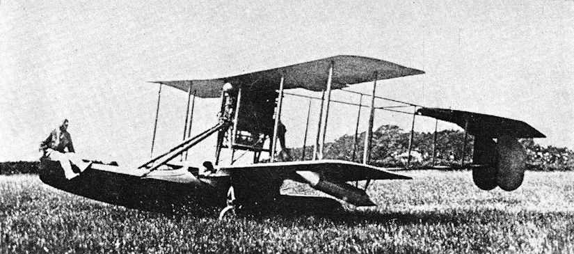
Bat Boat 1 after winning the Mortimer Singer Prize. Harry Hawker in cockpit, Spenser Grey on the bows.

A later type Bat boat with 200 h.p. Salmson engine.

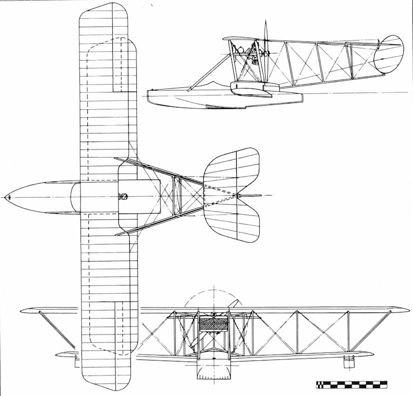
Supermarine Baby (1918)
One of the very few single-seater fighter flying-boats produced during the 1914/18 war, the Supermarine Baby was built to the Air Board Specification N.1B, which was aimed at the elimination of the efficient German Brandenburg fighter seaplanes over the North Sea patrol areas. Its performance compared favourably with contemporary landplane fighters, and had the war continued for a little longer it would have replaced the elderly float seaplanes at R.N.A.S. stations. Extremely small, the Baby had a wing span of just over 30 feet and was powered by a 150 h.p. Hispano-Suiza pusher engine driving a four-bladed propeller. The hull, of Linton-Hope design, was a monocoque structure covered by strips of polished mahogany, with an external planing surface from bows to the main step amidships, and a small auxiliary step fitted further aft. The wings were supported just above the hull by four struts, the wing-tip floats being directly attached to the undersurface of the lower wing and strut-braced for extra strength. The tailplane, carried above the fin and rudder by four struts, had an inverted camber, as on the A.D. Boat, and for the same reason, namely, to reduce the trim changes in the pitching plane caused by power alterations with a high thrust line. Ailerons were at first fitted to the upper mainplane only, later being fitted to both mainplanes. Two prototypes were built, serialled N59 and N60, the first flight taking place in February 1918, at the hands of Flt. Lt. Goodwin. Further testing indicated that the Baby was fast, light on the controls, with a good endurance. On 10 August, 1918, one of the machines was tested with a 200 h.p. Sunbeam Arab engine; the results of this test are not known. With the Hispano-Suiza, the Baby had a rate of climb of just under 1,000 ft/min, and a service ceiling of 10,700 feet. The Baby did not go into production, due to the Armistice and policy changes, but the two existing machines were flown on trial from a number of R.N.A.S./R.A.F. coastal stations before the war ended. Post-war, the design formed a basis for the successful Sea Lion series, of which the famous Walrus amphibian was a direct descendant.
SPECIFICATION
Power Plant: One 150 h.p. Hispano-Suiza, or one 200 h.p. Sunbeam Arab (experimental)
Span: 30 feet 6 inches
Length: 26 feet 4 inches
Weight Loaded: 2,326 pounds (2,508 pounds with Arab engine)
Total Area: 309 square feet
Max. Speed: 117 m.p.h. (115 m.p.h. with Arab engine)
Endurance: 3 hours
Armament: Provision for free-mounted Lewis gun in bows, and racks for light bombs under the wings
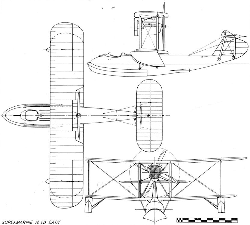
Supermarine N.1B Baby
Supermarine Channel (1919)
In 1919, the Supermarine Company re-purchased most of the A.D. flyingboats from the Air Ministry and converted them for civil use by replacing the original engines with the more economical 160 h.p. Beardmore, and by modifying the forward part of the hull to seat three passengers, one in a bow cockpit, two side-by-side in the main cockpit, with the pilot positioned just forward of the lower mainplane. The first machine to be converted was ex-A.D. Boat N1529, which became G-EAED in the civil register, and renamed as the Supermarine Channel. Three Channels, ’ED, ’EE, and ’EK, were the first commercial flying-boats to receive British certificates of airworthiness, dated 23 July, 1919. These three machines were used for pleasure flights along the South Coast from Bournemouth Pier and also for charter work, the delicate water handling required for such employment being provided by fitment of a long-overdue water rudder. On 28 September, 1919, the day after the British railway strike began, the Company started a regular service between Southampton and Le Havre with the Channels, inaugurated ceremonially by G-EAED. The venture lasted until the strike ended on 5 October and was a success, despite the fact that the underpowered Channels, with their lengthy take-off run, gave rise to a rumour that the service was mainly seaborne! Of all the sorties flown during this busy season, only one terminated in misfortune when ’EE crashed and sank during a pleasure flight.
In the same year the New Zealand Flying School purchased a Channel, which was assembled at Auckland and registered G-NZAI. The engine was the standard Beardmore, but its low power did not satisfy the New Zealanders and in 1920 they replaced it with a 240 h.p. Siddeley Puma extracted from a D.H.9. The improvement in performance was immediate, with a speed increase of some 20 m.p.h., and it is perhaps no coincidence that Supermarines made a similar engine change to a Puma at about the same time. The Company further modified the Channel by fitting strut-mounted wing-tip floats and watertight camera-hatch doors in the hull bottoms, also fitting some, but not all, machines with rudders of greater area. So modified, the machine became known as the Channel Mk. II. The last three machines of the original ex-A.D. Boat batch were shipped to Bermuda and used for pleasure flying with the Bermuda and Western Atlantic Aviation Co. Ltd, on an expendable basis, for shortage of spares ended their careers within a few months. However, one of the Bermuda Channels was shipped to Trinidad in March 1921, where it joined two Channel Mk. Ils employed on air photographic work for survey of the Orinoco Delta. This was satisfactorily completed and a further contract received for air photographs of the interior of British Guiana by one machine, during the course of which a new mountain range was discovered. Unfortunately, this Channel sank after striking driftwood in the River Essequibo. One Channel Mk. II flew photographic sorties in the Fiji Islands during July 1921, and the following year G-NZAI continued this work, having previously operated an experimental air mail service in the Auckland area. Three Channel Mk. Ils were taken to Japan in 1921 by the British Aviation Mission to the Imperial Japanese Navy, and one machine supplied to the Royal Swedish Navy, but the latter was soon written-off in a crash. In 1920, seven Beardmore-engined Channels had been sold to Norway, three going to the civil company, Det Norske Luftfartsrederi, and operating on the Stavanger-Bergen route as well as airmail services between Oslo and Christiansand. The other four machines, one of which had dual control, went to the Royal Norwegian Navy which subsequently re-engined two of them with the 240 h.p. Siddeley Puma. Possibly the last Channel to be sold overseas was a single Mk. II shipped to Chile in 1922. Some idea of the hard-wearing qualities of the Channel’s hull may be obtained from the fact that the hull of the New Zealand machine, G-NZAI, was still in use as a boat in 1943!
SPECIFICATION
Power Plant:
One 160 h.p. Beardmore
Mk.II - One 240 h.p. Siddeley Puma
Span: 50 feet 4 inches
Length: 30 feet 7 inches
Loaded: (Beardmore) 3,400 pounds
Total Area: 479 square feet
Max. Speed:
(Beardmore) 80 m.p.h.
Mk.II - 100 m.p.h.
Endurance:
(Beardmore) 3-75 hours
Mk.II - 3 hours

Channel Mk.II (G-EAWP) taking off at Fiji, July 1921. In addition to the Puma engine, the Channel Mk. II was fitted with strutted wing-tip floats.
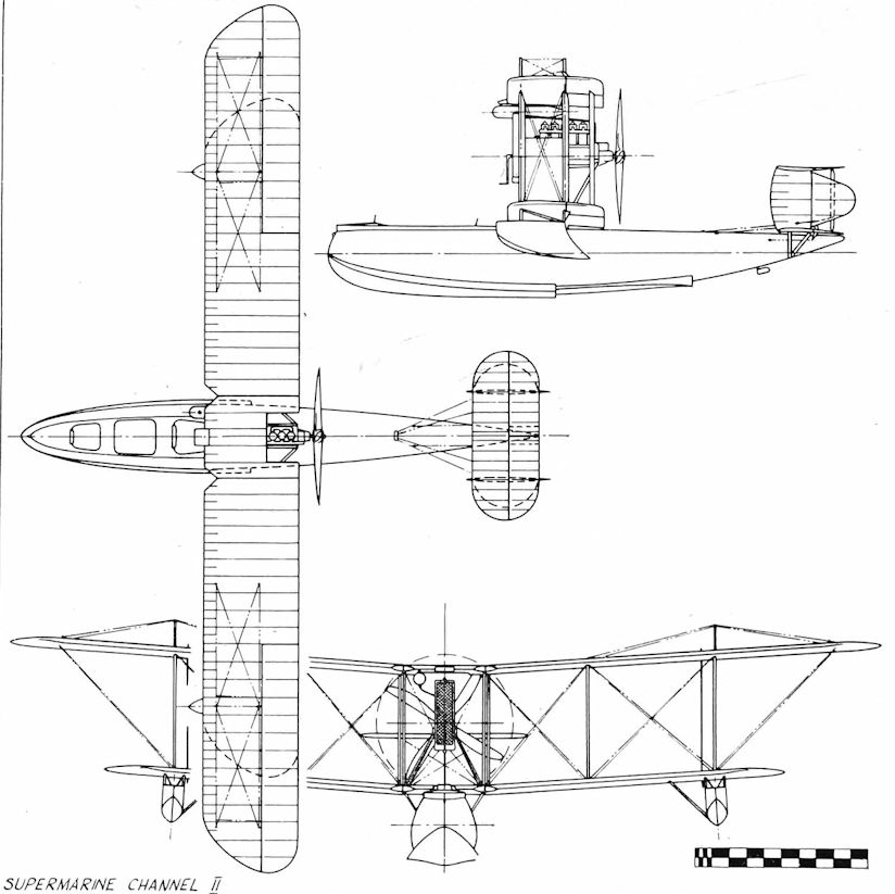
Supermarine Channel II
Supermarine Sea King I and II (1919)
When the First World War ended, the Supermarine Company survived the resultant financial slump due to brilliant leadership and sound business sense, and in the five years following the Armistice produced seven flying-boats and flying-boat amphibians, some of which were conversions of military machines and some new designs. Most of them proved successful, and the few that failed to secure orders initially were soon improved and modified until they, too, proved a financial asset to the Company. The two Sea Kings belonged to the latter category.
The Sea King I was a development of the Supermarine Baby, now rendered obsolete by Government policy, and was aimed at the civil market which showed increasing interest in amphibian machines. This first Sea King had the same wing span as the Baby, but the power unit was a pusher 160 h.p. Beardmore, and a fin and rudder of large area was fitted, with a combined water rudder/tail-skid at the rear end of the hull. The manually-operated undercarriage was arranged to swing upwards and outwards from the hull to its retracted position for water operation. The hull itself was generally identical to that of the Baby, but the single cockpit was moved slightly aft on a raised turtle-decking, and a padded headrest faired into the decking top. Completed in 1919, the Sea King I had a maximum speed of 109 m.p.h. at an all-up weight of 2,250 pounds, being advertised as a single-seat sporting amphibian. No orders were received, and the machine was retained by the company as a flying test bed, in which capacity it carried out flying tests fitted with the 240 h.p. Siddeley Puma, the eventual power unit of the Supermarine Channel.
The Sea King II was a development of the Mk. I, and also completed in 1919, powered by a 300 h.p. Hispano-Suiza engine. Built as an amphibian, this version had its wing span increased to 32 feet, retaining the Mk. I tail surfaces, and at an all-up weight of 2,850 pounds attained a speed of 125 m.p.h. Registered as G-EBAH, the Sea King II was fitted out as a military amphibian fighting scout. In 1921, when it was certain that no orders were forthcoming, the machine was rebuilt with wings of reduced chord, retaining the original span, and re-engined with a 450 h.p. Napier Lion engine, with the amphibian undercarriage removed. Thus modified, G-EBAH was renamed Sea Lion II, and subsequently won the 1922 Schneider Trophy Race.
SPECIFICATION
Power Plant:
Mk.I - One 160 h.p. Beardmore or one 240 h.p. Siddeley Puma
Mk.II - One 300 h.p. Hispano-Suiza.
Span:
Mk.I - 30 feet 6 inches
Mk.II - 32 feet
Length:
Mk.I - 26 feet 4 inches,
Mk.II - 24 feet 9 inches
Weight Loaded:
Mk.I - 2,250 pounds
Mk.II - 2,850 pounds
Total Area:
Mk.I - 309 square feet.
Mk.II - 352 square feet
Max. Speed:
Mk.I - 109 m.p.h.
Mk.II - 125 m.p.h.
Endurance: Both Marks - 3 hours
Armament: Mk. II - single .303-inch Lewis gun, provision for light bombs
Sea King Mk. I (prototype).
Supermarine Sea Lion I (1919)
After Great Britain’s victory in the 1914 Schneider Trophy race, the First World War intervened, and the contests were suspended until 1919 when the Royal Aero Club was charged with organising the contest on behalf of this country, as the Trophy holders. Bournemouth was chosen as the venue, with Cowes the headquarters for accommodation and servicing. Supermarine, in the advantageous position of having recent experience with small highspeed flying-boats and amphibians, and with the race virtually upon their doorstep, decided to enter a specially built racing flying-boat, and chose as the power unit the newly-developed Napier Lion engine of 450 h.p., hence the name - Sea Lion. Of slightly larger wing span than the Sea King and Baby, the Sea Lion was a mere 24 feet in length, the whole machine dominated by the large engine nacelle, strut-mounted high in the centre section, with the engine driving a four-bladed pusher propeller. The tailplane was mounted on the top of the single fin, and wing-tip floats attached directly to the undersurface of the short-span lower mainplane, which was carried over the hull top by short struts as in the Supermarine Baby. The designer was a brilliant young man named Reginald Joseph Mitchell, later designer of the immortal Spitfire. Registered G-EALP, the Sea Lion successfully passed its tests, and with Sqn. Ldr. Hobbs as pilot was prepared for the race. Unfortunately, the day chosen, 10 September, 1919, proved to be dull and misty, only four of the competitors attempting to complete the course. Hobbs was one of them, and had to alight in Swanage Bay to find his bearings, but without success, so he decided to return as best he could to Bournemouth. On taking off, he struck some object in the water, badly holing the Sea Lion’s hull. As a result, when an alighting was made between Christchurch and Boscombe, the machine began to sink. Both Hobbs and the Sea Lion were rescued, but the contest was abandoned. Following this, the Sea Lion was dismantled, its hull being loaned to the Science Museum for exhibition in 1921.
SPECIFICATION
Power Plant: One 450 h.p. Napier Lion IA
Span: 35 feet
Length: 24 feet
Weight Loaded: 2,900 pounds
Total Area: Not known
Max. Speed: 147 m.p.h.
Endurance: 2-3 hours
Supermarine Sea Lion II (1922)
The Schneider Trophy races of 1920 and 1921 were both won by Italy with no opposition, and a third win in the 1922 contest would have meant an outright victory and retention of the Trophy by that country. Fortunately for British prestige, Supermarine decided to enter one machine, the Sea Lion II, which, because of the non-appearance of the two French entries, became the sole challenger. The Sea Lion II was originally the single-seat Sea King II amphibian fighting scout of 1921, rebuilt as a flying-boat, with the 300 h.p. Hispano-Suiza engine replaced by a 450 h.p. Napier Lion. The Sea King mainplane structure was retained, the wing area being reduced by modification to a smaller chord, and to offset the greater torque the fin area above the tailplane was enlarged by a forward curvature. Apart from these modifications, the machine differed little from its original form, retaining the registration of G-EBAH. The actual contest, held at Naples on 10 and 12 August, 1922, was won by the Sea Lion, piloted by H. C. Biard, who employed airmanship and tactics of a high degree. During the preliminary trials, Biard had deliberately kept the Sea Lion throttled back, and banked somewhat clumsily on the turns, which lulled the three Italian competitors into a false sense of security. In the race itself, Biard was the first away, recording a first lap speed of over 150 m.p.h., and this was held for six laps. For the next few laps he nursed his engine, during which time the nearest Italian closed up to a mere 20 seconds behind. On the final lap, Biard gave the Sea Lion full throttle, crossing the finishing line one-and-a-half minutes ahead of his nearest rival, winning the Trophy for Great Britain at an average speed of 145-7 m.p.h. This victory was all the more noteworthy in that it was a private venture due to the individual enterprise of Mr Hubert Scott-Paine and Mr H. T. Vane of the Supermarine and Napier companies respectively. It also brought to public notice for the first time the name of R. J. Mitchell, by that time Supermarine’s chief engineer and designer and responsible for the Sea Lion.
SPECIFICATION
Power Plant: One 450 h.p. Napier Lion II.
Span: 32 feet
Length: 24 feet 9 inches
Weight Loaded: 2,850 pounds
Total Area: Not available
Max. Speed: Officially 125 m.p.h., but this was probably deliberately misleading for tactical reasons, as in the contest the machine attained a maximum speed of just under 160 m.p.h.
Endurance: 3 hours
Supermarine Sea Lion III (1923)
After the 1922 success, the seventh Schneider Trophy contest was held at Cowes, Isle of Wight, on 27 and 28 September, 1923. For the first time a government-sponsored team of three aircraft, all Curtiss floatplanes, was entered by the United States Navy as the principal challengers to Great Britain, who entered a team of three aircraft from the manufacturers.
The Italian teams and two of the British entries were victims of accidents and mechanical troubles, leaving just the Supermarine Sea Lion III to face the entire opposition, consisting of the Americans and a French machine.
The Sea Lion III was the original Sea Lion II rebuilt with two-bay mainplanes, and having vertical tail surfaces of similar profile to the Sea King II but of slightly larger area. Hull modifications increased the overall length to 27 feet 6 inches, and the wing-tip floats were now mounted upon struts. The power unit was a Napier Lion III of 450 h.p., driving a four- bladed pusher propeller.
The Sea Lion II registration, G-EBAH, was retained, and the racing number ‘7’ was allocated, the pilot being H. C. Biard. In the race, two of the Curtiss machines were the first to start, and their first lap speed indicated that unless mechanical trouble intervened the contest was a foregone conclusion. Outclassed, Biard and the Sea Lion nevertheless made a gallant effort, gaining third place at an average speed of 151-56 m.p.h. The Sea Lion III was transferred to the Royal Air Force on 4 December, 1923, receiving the serial N170.
SPECIFICATION
Power Plant: One 450 h.p. Napier Lion III
Span: 32 feet
Length: 27 feet 6 inches
Weight Loaded: 3,275 pounds
Total Area: Not available
Max. Speed: 165 m.p.h.
Endurance: 3 hours
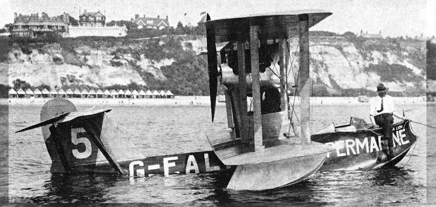
The Supermarine contender in the 1919 Schneider Trophy event - the Sea Lion I G-EALP flown by Sqn Ldr B. D. Hobbs.
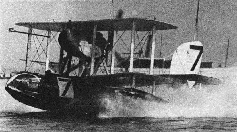
Sea Lion III (G-EBAH) taking off for Schneider Trophy Race, 1923.
Vickers Viking I (1918)
In 1918, the Vickers Company decided to make a radical departure from their usual landplane products in the construction of a flying-boat amphibian, the first British machine to be designed as such. Aimed at the post-war market and intended for world-wide operation in undeveloped areas, the machine was designed by R. K. Pierson and built at Weybridge in 1918 as the Vickers Type 54 Viking I. A two-bay biplane, with dihedral on the lower mainplanes only, the Viking was powered by a single Rolls-Royce engine of 275 h.p., the Falcon III, mounted high in the centre section on splayed struts and driving a four-bladed propeller. The hull, built by S. E. Saunders of Cowes, had vertical sides and two steps, with a distinctive concavity in the keel between the steps. The hand-retracted main undercarriage wheels were pivot-mounted to the hull sides below the lower mainplane, and an enclosed cabin was provided for the pilot and three passengers. A combined tail-skid/water rudder was attached to the rear step, the entire hull being covered by ‘Consuta’ copper-sewn plywood, a Saunders patent. The biplane tail assembly incorporated twin rudders and a central fixed fin. In October 1919 the Viking received the civil registration G-EAOV after successful testing, and took off for a flight to Paris on 18 December with Sir John Alcock of Atlantic flight fame at the controls. Some time later, a French farmer, the only witness, saw the Viking crash after flying through thick mist near Rouen. Tragically, Alcock died from his injuries.
SPECIFICATION
Power Plant: One pusher Rolls-Royce Falcon III of 275 h.p.
Span: 46 feet
Length: 32 feet
Weight Loaded: 3,600 pounds
Total Area: 505 square feet
Max. Speed: 104 m.p.h.
Vickers Viking II and III (1920)
Since the loss of the Viking I was attributed to weather conditions and not to technical failure, Vickers decided to begin the construction of two more Vikings in 1920 under the classification of Type No. 59. The first was the Viking II, similar to its predecessor but with open cockpits for the pilot and three passengers, a keel with less concavity between the steps, a wider wheelbase and a third rudder added in the centre of the tailplane gap. The engine fitted was a Rolls-Royce Eagle VIII of 360 h.p., and the hull constructed by Saunders of Cowes. Registered G-EASC, the Viking II was exhibited at Olympia in July 1920, and subsequently won the first prize at the Antwerp Seaplane Trials in August of the same year. It later crashed and was written-off. Its sister-ship, the Viking III, was produced with a slightly modified hull, to reduce spray, and a 450 h.p. Napier Lion IB engine which improved the performance but increased the all-up weight. To maintain the original wing loading, the wing area was increased, and the central fin and rudder made of larger area also.
Registered G-EAUK, the Viking III, flown by Capt. S. Cockerell, was entered for the Air Ministry Amphibian Competition held at Martlesham Heath and Felixstowe in September 1920, winning the first prize of £10,000. The machine was acquired by the Air Council in January 1921, the serial allocation of N147 being painted upon the central tail fin while the civilian registration was retained. Between February and April 1921, Cockerell flew the Viking III on a number of trial flights from Doulton’s Hard, on the Thames between Vauxhall and Lambeth Bridges, to the river Seine in central Paris, the object being to test the possibility of a regular inter-city service. This plan had to be abandoned owing to the frequent poor visibility in the city centres, and the fact that no amphibian was available at the time with the pay load capability to make the service an economic proposition. During the first trial alightings on the Thames, the Viking touched down at Westminster and was taxied ashore at the House of Commons for inspection by Members of Parliament, an event unique to this day. The Viking III was finally scrapped in 1925, after a long and useful life.
SPECIFICATION
Power Plant:
Mk.I - One 360 h.p. Rolls-Royce Eagle VIII
Mk.II - One 450 h.p. Napier Lion IB
Span: 46 feet
Length: 32 feet
Weight Loaded:
Mk.I - 4,545 pounds
Mk.II - 4,900 pounds
Total Area:
Mk.I - 505 square feet
Mk.II - 545 square feet (increased chord)
Max. Speed:
Mk.I - 110 m.p.h.
Mk.II - 121 m.p.h.
Endurance: 3 hours
Vickers Viking IV (1921)
A development of the earlier Vikings, the Viking IV had an increased wing span and length, being equipped to carry six persons including the pilot and powered by a single 450 h.p. Napier Lion engine. The majority of the total production of thirty-two Viking aircraft were variants of the Mk. IV, some of which were fitted with the 360 h.p. Rolls-Royce Eagle engine, and all but two machines found purchasers overseas. These two, with Lion engines and identified as Vickers Type 60, were registered in the United Kingdom as G-EBBZ and G-EBED. At the beginning of 1922, Sir Ross Smith and his brother, Keith, lately of the magnificent Vimy flight to Australia, began to plan a round-the-world flight, and Viking IV G-EBBZ was registered to Sir Ross for this purpose. On 13 April, 1922, ’BZ was air tested by Capt. Cockerell with Sir Ross and Lieut. Bennett as passengers, and after landing the machine, Cockerell got out, leaving Sir Ross to make a further trial flight. At a height of 1,000 feet the Viking commenced a turn, then went into a spin. Two attempts at recovery were seen to be made, but the machine was too low and crashed into some tall trees near the Brooklands aerodrome, both occupants being killed. Thus, by a tragic twist of fate, the two pilots who had gained fame and knighthoods on Vimy flights, Sir John Alcock and Sir Ross Smith, both lost their lives in a Viking.
The remaining British-registered Viking IV, G-EBED, after demonstration in Spain, was operated on a winter sports passenger service by Leslie Hamilton, flying between Croydon, St. Moritz and Nice in the first three months of 1926, being finally scrapped in December 1929. Ten machines, known as the Type 55, were purchased by the Royal Netherlands Indies Army Air Corps, eight being delivered on 20 January, 1922, and the final two a year later. Another batch, fitted with the 360 h.p. Rolls-Royce Eagle and known as the Type 73, were sold to the Argentine Navy. These had seating for four persons in two cockpits forward of the mainplanes, with gunner’s cockpits in the bows and aft of the mainplanes. A French-owned machine, registered F-ADBL, had a Lion engine and a cabin similar to the Viking I. The Viking IV was later built under licence in Canada, beginning a whole series of Canadian Vickers flying-boats, mostly designed for forest fire patrol and air survey work. The machine was also sold to the U.S.A., Japan, Spain, and Russia.
SPECIFICATION
Power Plant: One 450 h.p. Napier Lion, or one 360 h.p. Rolls-Royce Eagle
Span: 50 feet
Length: 35 feet
Weight Loaded: (Lion) 5,600 pounds
Total Area: 594 square feet
Max. Speed: 105 m.p.h. Cruising - 90 m.p.h.
Endurance: 4-75 hours at 90 m.p.h.
Armament: One or two machine-guns on military versions, with light bomb load.
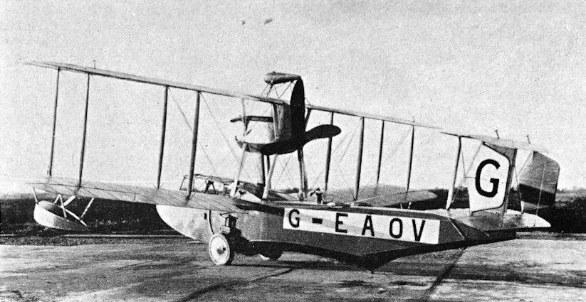
The prototype Viking Mk.I (G-EAOV) at Brooklands in October 1919.
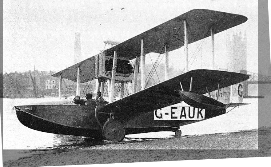
Viking Mk.III G-EAUK on the Thames at Westminster in February 1921.
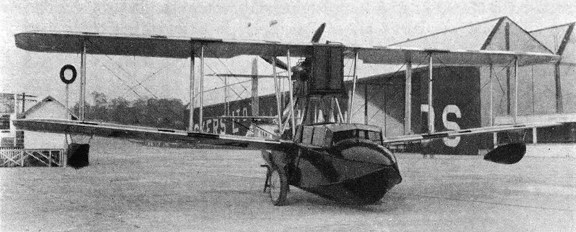
Viking IV (F-ADBL) with cabin and Napier Lion engine.
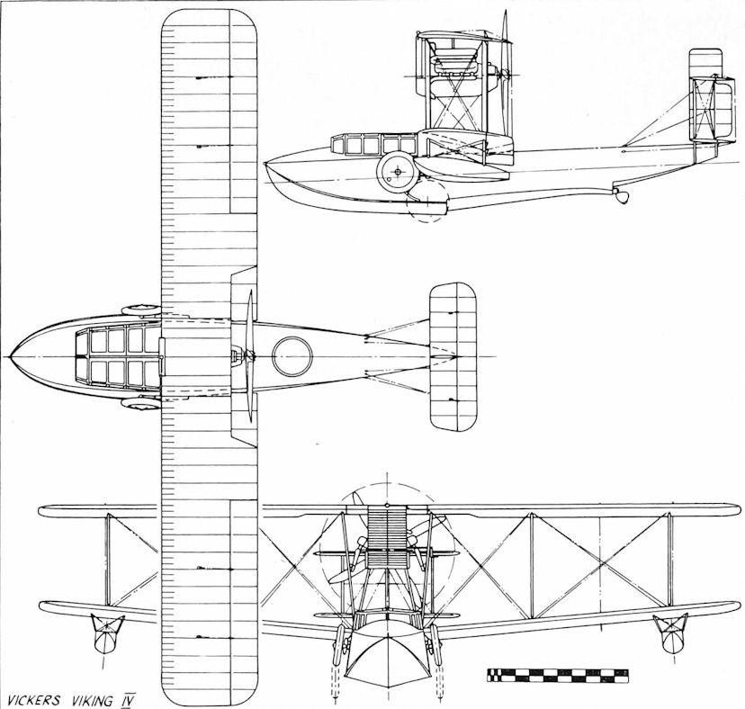
Vickers Viking IV
White and Thompson Twin-engined Boat (1914)
The second machine built by White and Thompson for the 1914 Round Britain Race was a large biplane flying-boat, powered by two 90 h.p. Curtiss OX engines arranged as pushers and driving three-bladed adjustable-pitch propellers. The hull was built by Williams and Co. of Littlehampton, and although the complete machine showed obvious traces of Curtiss influence, it was, like its single-engined companion, designed throughout by the British company. The crew of two were in a side-by-side cockpit and provided with dual control, and the machine carried 90 gallons of fuel, sufficient for six hours of flight. One test flight took place, revealing a need for modifications which were not, in the event, carried out, because the Round Britain Race was cancelled, and because of the preoccupation of the company with a Naval order for the single-engined ex-race machine. However, the twin-engined flying-boat eventually came into its own, for it formed a basis for the design of the successful Norman Thompson N.T.4 of 1915.
SPECIFICATION
Power Plant: Two Curtis 90 h.p. OX engines
Span: 52 feet
Length: 32 feet 3 inches
Weight Loaded: 3,000 pounds
Total Area: 500 square feet
Max. Speed: -
Endurance: 6 hours
Armament: Nil
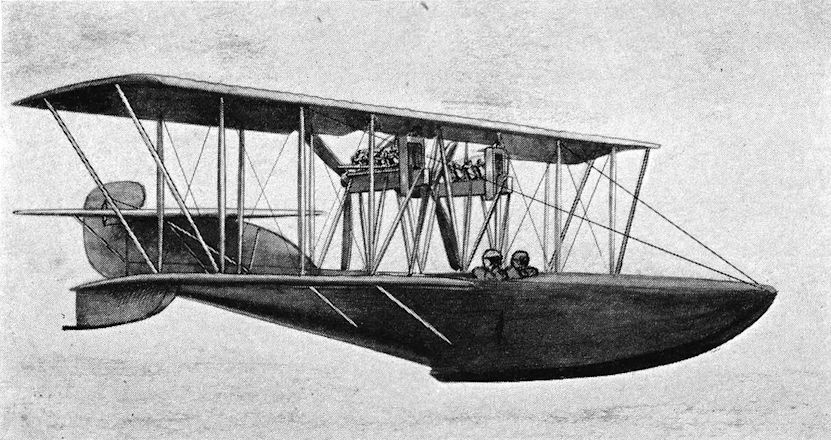
White and Thompson Twin-engine Flying-boat.
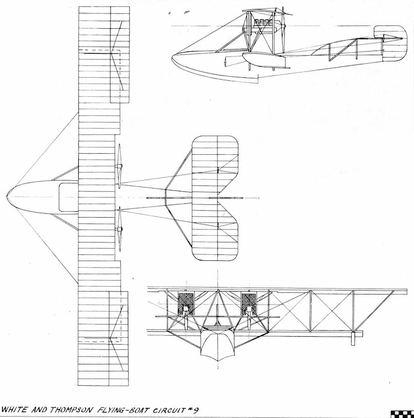
White and Thompson Flying-boat Circuit N 9
White and Thompson No. 3 Boat (1914)
In October 1913, the Curtiss flying-boat made its first appearance in this country, when Glenn Curtiss personally delivered one machine to Captain Ernest Bass. Housed at Volk’s Seaplane Base on Brighton beach, it was initially flown by Mr J. D. Cooper, a pupil of the Curtiss School. Maintenance for the machine was secured by commissioning the small aviation company operated by Norman Thompson and Douglas White at Bognor Regis. The company shortly afterwards acquired the exclusive British rights to build flying-boats to the basic Curtiss design, and obtained the services of E. C. Gordon England as test pilot. As a primary venture, White and Thompson decided to build two flying-boats for the 1914 Daily Mail Round Britain Race, one being powered with the 150 h.p. Beardmore, the other, larger, machine to be fitted with two 90 h.p. Curtiss OX engines. The single-engined machine, a two-seater, resembled the original Curtiss, but was designed throughout by the British company. Its hull was built by Saunders of Cowes, and covered with ‘Consuta’ copper-sewn plywood. Dual controls were fitted, and the rudder horn balanced. Flight testing on 9 August, 1914, was successful, and, the Round Britain Race having been cancelled, the machine went to the R.N.A.S. as No. 233. Six more examples were ordered, the production version becoming known as the White and Thompson No. 3 Boat. Eventually, eight or more were delivered, the 150 h.p. Beardmore being retained as the standard power unit, although one example had a 150 h.p. direct-drive Hispano-Suiza. The first machine was delivered to R.N.A.S. Dover, by Gordon England, accompanied by Douglas White. Used for coastal patrol work from Dover, the type was eventually armed with a Lewis gun, pillar-mounted on the port side of the cockpit.
SPECIFICATION
Power Plant:
One 150 h.p. Beardmore
One machine - 150 h.p. Hispano-Suiza
Span: Prototype - 45 feet
Length: 27 feet 6 inches
Weight Loaded: 2,400 pounds
Total Area: 400 square feet
Max. Speed:
Prototype - 70 m.p.h.
Production - 85 m.p.h.
Endurance: Prototype - 6 hours
Armament: Production - one .303-inch Lewis gun
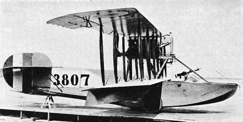
White and Thompson No. 3 Boat (No. 3807).

White & Thompson No.3
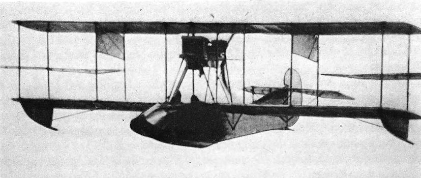
Curtiss 1913 flying-boat of the type sold to Captain Bass, and one of the earliest recorded air-to-air photographs.

Curtiss F boat
Porte/Felixstowe F.1 (1915)
John Cyril Porte was invalided out of the Royal Navy in 1911, a victim of pulmonary tuberculosis, which in those days meant severe disability and premature retirement. Porte, however, had other ideas. During his Service career he had been actively interested in aviation, and this he resolved to continue. On 28 July, 1911, he gained his aviator’s certificate with the Aero Club de France, flying a Deperdussin monoplane, shortly afterwards becoming a partner and test pilot of the newly formed British Deperdussin Company. This company broke up in 1913, by which time Porte had achieved a considerable reputation as a skilled pilot, notably by his demonstrations at the weekend Hendon air displays. In the autumn of 1913 he joined the White and Thompsons Company as test pilot, gaining his first experience of flying-boats in October, when, with Gordon England, he went to Volk’s Seaplane Base on Brighton beach to meet Glenn Curtiss and to be given demonstration flights in the Curtiss machine purchased by Captain Ernest Bass, an ex-member of the Deperdussin Company. Further experience followed soon after this, when White and Thompsons were commissioned to maintain the Curtiss machine and secured the British rights to build similar aircraft under licence.
In early 1914, Curtiss began work in America upon a large twin-engined flying-boat capable of flying the Atlantic, this project being financed by Rodman Wanamaker, and Porte was offered the honour of piloting the machine. He accepted immediately, sailing to America on the first available passage. The machine was completed in record time, being launched in June 1914 and named ‘America’. Initial tests were carried out on Lake Keuka and were quite successful, but when fully loaded its 90 h.p. engines were unequal to the task, and Porte could not coax it oif the water. Work began at once on its modification to take more powerful engines, but the outbreak of war intervened, and on 4 August, 1914, Porte sailed for England, being at once accepted into the R.N.A.S. on his arrival, despite his disability. Soon after, Porte saw Captain Murray Sueter, the Director of the Air Department of the Admiralty, and gave him details of the ‘America’ flying-boat. Captain Sueter, fully aware of the problems involved in countering U-boat and Zeppelin attacks, and already largely responsible for the purchase of the F.B.A. and Sopwith flying-boats, immediately obtained Admiralty sanction for the purchase of ‘America’ and one sister-ship. They were delivered in November 1914, serialled Nos. 950 and 951, and sent to Felixstowe for testing, where they received the official designation of Curtiss H.4. A favourable test report resulted in a further order for a small batch of the type, Curtiss delivering four, and eight being constructed under licence by the Aircraft Manufacturing Company in this country. However, the 90 h.p. Curtiss engines left much to be desired, as Porte had already discovered; consequently five H.4s were re-engined with 100 h.p. Anzani radials, which gave a reasonable performance.
<...>
SPECIFICATION
Power Plant:
F.1 - Two 150 h.p. Hispano-Suiza
H.4 - Two 90 h.p. Curtiss, or two 100 h.p. Anzani
Span: F.1 and H.4 - 72 feet
Length:
F.1 - 39 feet 2 inches
H.4 - 35 feet
Weight Loaded:
H.4 - 4,983 pounds
Total Area: F.1 and H.4 - 842 square feet
Max. Speed:
F.1 - 85 m.p.h.
H.4 - 75 m.p.h.
Endurance: Not available
Armament: F.1 and H.4 - One or two Lewis guns, light bombs only
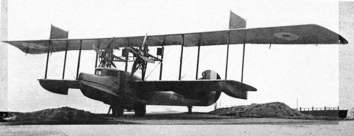
3592 was another of the Curtiss built Small Americas that served so well as flying boat trainers. This machine was at the Felixstowe Seaplane School by 29 September 1917, and was written off, together with 3584, 3586, 3591,3593, and 3594, in the week ending 29 August 1918.
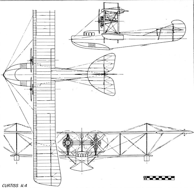
Curtiss H.4
F.B.A. Flying-boat (1912)
The Franco-British Aviation Company was formed in France, in 1912, by Lieut, de Conneau, his associate being Mr Shraeck, formerly of the French Wright Company. De Conneau, a French naval officer, had already achieved considerable fame and fortune as an aviator, using the nom de plume of ‘Beaumont’, and was an accomplished engineer and navigator. His company took up certain patents of the Curtiss-influenced Donnet Leveque flying-boat, and of an earlier design, the Artois, producing its first machine in the summer of 1912.
A two-seater biplane, the F.B.A. was powered by an 80 h.p. Gnome rotary pusher engine, and had an excellent performance that included a rate of climb in excess of 800 ft/min. The hull design featured a concave planing bottom, with its edges forming vertical fins as they joined the hull sides at the step. Aft of the step, the hull tapered into a triangular-sectioned tail boom carrying the tail surfaces upon its raised extremity. The mainplanes were supported above the hull on short struts, with rectangular-sectioned wing-tip floats mounted on struts below the lower wing. A refinement inherited from the Curtiss machines was an engine starting handle, projecting forward above the cockpit.
In production for the French Navy, the F.B.A. attracted the attention of the Admiralty, at that time seeking suitable aircraft for the Naval Wing in process of formation. By arrangement with the French Naval authorities, one machine was flown to Sheerness by de Conneau on 22 October, 1912, and the next day he demonstrated its capabilities, accompanied by Lieut. Howlett, r.n. The F.B.A. was approved, purchased, and sent to Calshot, the first flying-boat in British service. In the summer of 1913, de Conneau visited Volk’s Seaplane Base at Brighton with an F.B.A. machine, giving demonstration and passenger-carrying flights to the general public. After the outbreak of war, fifty-four more French-built F.B.A.s were ordered and delivered to the R.N.A.S. These were an improved version, having a modified bow, extended wing span with an extra wing bay, a larger area rudder, and powered by the 100 h.p. Gnome rotary which became standard for these R.N.A.S. machines. Transition to British construction commenced with the assembly by Norman Thompsons of twenty machines, followed by an all-British batch built by the Gosport Aviation Company. Although the F.B.A.s were mainly employed for training duties, a number was used for patrol work with a crew of two, armed with light bombs and a Lewis gun. One such patrol took place on 28 November 1915, during the course of which the machine flown by Fit. Sub.-Lieut. J. P. B. Ferrand, accompanied by Air Mech. G. T. Oldfield, attacked a German torpedo boat off Westende with bombs, shooting down one of its escorting seaplanes in the process. In September, 1916, an F.B.A. was used for rough water take-off and alighting trials at Calshot, the subsequent report stating that its performance was good, with a speed range from 38 to 60 m.p.h. at 2,000 pounds all-up weight. Four machines, fitted with the 160 h.p. Isotta Fraschini engine were built by the Italians and presented to R.N.A.S Otranto in 1917, and afterwards formed part of the equipment of No. 266 Squadron, R.A.F., at Malta, in April 1918.
SPECIFICATION
Power Plant:
Prototype - One 80 h.p. Gnome rotary
Production - One 100 h.p. Gnome rotary
Italian built - One 160 h.p. Isotta Fraschini
Span:
Prototype - 39 feet
Production - 45 feet
Length:
Prototype - 29 feet
Production - 30 feet
Loaded Weight:
Prototype - 1,258 pounds
Production - 2,000 pounds
Total area: Not available
Max. Speed:
Prototype - 68 m.p.h.
Production - 60 m.p.h.
Endurance: Production - 4 hours
Armament: Nil, or light bombs and one .303-inch Lewis gun

Lieutenant de Vaisseau Conneau, who flew under the pseudonym 'Beaumont', is seen here at Magnus Volk's Waterplane Station at Brighton with the Franco-British Aviation (FBA) Leveque flying boat which he had flown across the Channel to Newhaven, England, on 16 August 1913. He is holding the crank-handle of the aeroplane's 80hp Gnome rotary engine.
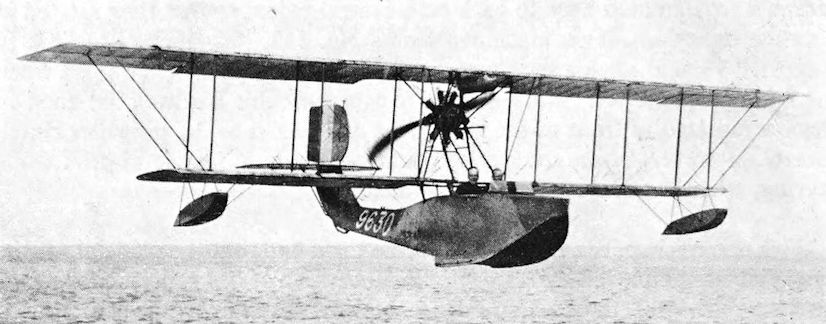
F.B.A. (No. 9630). Production version for R.N.A.S.