G.Swanborough, P.Bowers United States Military Aircraft Since 1909 (Putnam)
SLOAN/STANDARD H-2 & H-3
The Sloan H-2 of 1916 was a reconnaissance biplane designed by Charles Healey Day, formerly of Martin, and was distinguished by the 10-degree sweepback of the equal-span wings. The Army bought three (76/78), powered with 125 h.p. Hall-Scott A-5 engines. Nine improved versions known as H-3 (82/89 and one other) were bought for use on the Mexican border. When the Sloan Aircraft Co., Inc., became the nucleus of the Standard Aero Corporation, the aeroplanes in service became known as Standards. H-3: Span, 40 ft. 1 in.; length, 27 ft.; gross weight, 2,700 lb.; high speed, 84 m.p.h.
Показать полностью
Jane's All The World Aircraft 1919
Span 40' (both planes)
Chord 6'6''
Gap 6'6''
Length 27'
Dihedral 3
Sweep back 10
Stagger 1'3''
Area 491 sq.ft.
Aileron Both wings
Landing gear 2 wheels
Engine 140 h.p. Hall-Scott (Type A5a)
Weight with 1 hour's fuel
2700 lbs
Useful load 800 lbs
Показать полностью
R.Mikesh, A.Shorzoe Japanese Aircraft, 1910-1941 (Putnam)
Standard H-3 Trainer
In search of proven trainer aircraft, the PMBRA purchased two Standard H-3 Trainers from the US Army in May 1917. The H-3 was a two-bay biplane with large gap and 10-degree sweep back to the wings, and powered by 125hp Hall-Scott A-5 engines. Only nine were built, and the type had been carried over from the former Sloan Aircraft Co Inc that became the Standard Aero Corporation.
Three more of these aeroplanes were built in Japan, with the higher powered 150hp Hall-Scott engine. Production was limited because the aeroplane was considered dangerous. They were used for flying training from May 1917 to March 1918, beginning at Tokorozawa and later at the newly opened Kagamigahara Airfield. Fifteen pilot officers received training in them.
Single-engine tractor biplane trainer. All-wooden construction with fabric covering. Pupil and instructor in open cockpit.
150hp Hall-Scott L-4 six-cylinder inline water-cooled engine, driving a two-bladed wooden propeller.
Span 12.25m (40ft 1in); length 8.22m (27ft).
Loaded weight 1,225kg (2,700Ib).
Maximum speed 71 kt (82mph); endurance 6hr.
Three or more built.
Показать полностью
Журнал Flight
Flight, May 24, 1917.
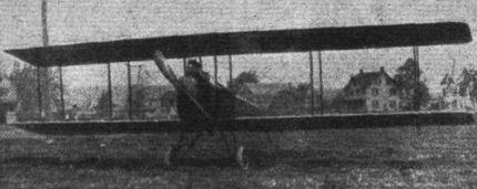
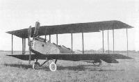
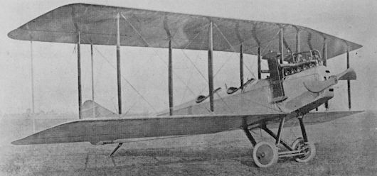
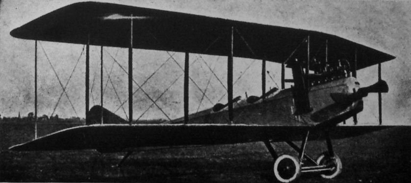
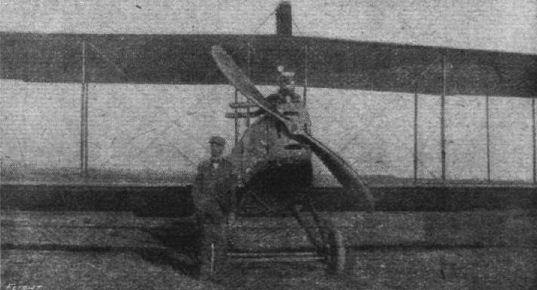
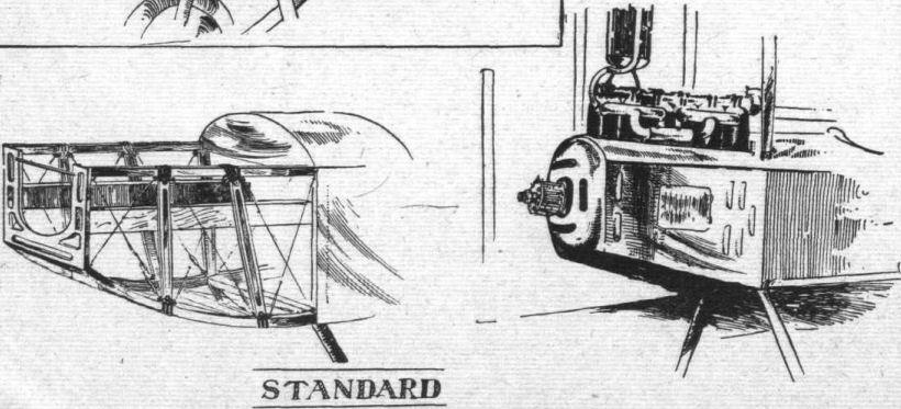
THE STANDARD H-3 TRACTOR BIPLANE
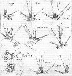
ONE of the recent successful military machines of our new ally, America, is the Standard model H-3 tractor biplane, a number of which are in use with the U.S. Army and Navy. From the accompanying scale drawings and illustrations it will be seen that the main characteristic of this machine lies in the swept-back planes. These, which have a span of 40 ft. 1 in. top and bottom, have a sweep back of 10°, as well as a forward stagger of 10°, or 1 ft. 3 in., and a dihedral angle of 3°. They are in sections, the two lower ones being attached direct to the fuselage, and the two top ones attached to a small central panel 2 ft. 8 1/2 in. wide. The main spars are of channel-section, spaced 3 ft. 9 in. apart, the front spar being 9 in. from the leading edge. The ribs, built up of spruce webs and battens mortised, glued and nailed together, are spaced 11 in. apart. Solid spruce compression ribs are located at the inter-plane strut attachments, as well as one between each of the inner and outer pair of struts. The wing frame is braced with steel piano wire, and the woodwork is shellaced and varnished before covering in order to prevent the absorption of moisture and consequent distortion. The covering is of unbleached Irish linen treated with four coats of dope and a finishing coat of spar varnish. Ailerons are mounted on both top and bottom planes, each having an area of 15 1/2 sq. ft. They are inter-connected as follows: two light spruce-struts connect each upper and lower aileron, and cables from the trailing edges of the top ailerons are led to the control via a pulley located at the lower end of the outer rear inter-plane strut fitting. The lower ailerons are connected by cables led to similar pulleys on the upper ends of the struts and running beneath the top plane.
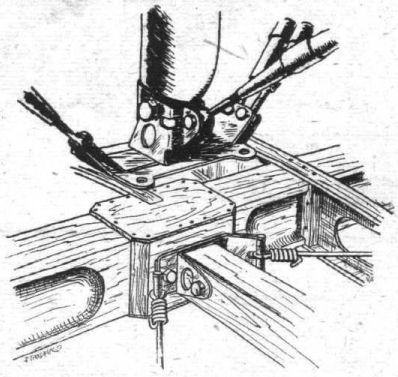
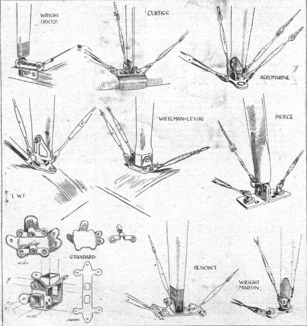
Two pairs of struts support the central panel of the top plane above the fuselage, and two pairs on each side of the latter separate the top and bottom planes. The ends of the struts are bronze tipped, secured by a single removable pin to the socket. The latter is bent to shape out of sheet steel, and is welded to a plate which is clamped by four bolts on the spar without piercing the latter. Anchorages for the bracing cables are formed on the fitting as shown in the sketch.
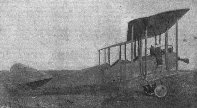
The fuselage is rectangular in section, tapering to a vertical knife-edge at the rear. It is 25 ft. long with a maximum width and depth of 2 ft. 9 in. and 3 ft. 6 in. respectively. The longerons are of ash, tapering rearwards from 1 in. square. The uprights are tapered and channeled, and are attached to the longerons by sheet metal clips. The pilot's cockpit is situated well aft of the planes, and the passenger's at the trailing edge. A 135 h.p. 6-cylinder vertical Hall Scott engine is installed in the nose of the fuselage, being supported by stout bearers, the forward ends of which are carried by a heavy-gauge steel plate forming the extremity of the fuselage. The engine portion of the fuselage is covered with sheet aluminium, and a rounded nose of the same material is mounted on the front. The rest of the fuselage is covered with fabric including the turtle deck, which is built up of spruce battens.
The control can be converted in a few minutes from the Dep type to the Curtiss type, the shoulder yoke operating the ailerons in the latter type being folded out of the way when not required. All control cables run over ball bearing bronze pulleys.
The tail planes consist of a non-lifting stabilising surface, to which are hinged two elevator flaps, a vertical fin and a nonbalanced rudder hinged to the fuselage stern post. The elevators are hinged to the stabilising plane in a semi-circular groove, which fits closely to the tubular leading edge of the elevator, so that no gap is formed. The rudder is similarly hinged.
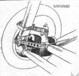
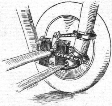
The landing chassis consists of two laminated ash U members upon which is sprung a tubular steel axle, having a streamline covering, carrying a pair of 26 in. x 5 in. disc wheels. The shock absorber acts on the pantagraph principle, the axle being bound to the U members by rubber cord, and anchored to the same by two shackle bars, one above the other. The axle is thus forced to move in a vertical path, thereby evenly distributing the strain on the rubber cord. Where the shackles are clamped to the forward part of the U member, the wood is protected by strips of sheet bronze.
The following are the principal dimensions of the Standard H-3 Span, 40 ft.; chord, 6 ft. 6 in.; gap, 6 ft. 6 in.; height, 10 ft. 7 in.; gliding angle, 1 in 8; weight empty, 1,700 lbs.; useful load, 800 lbs.; speed range, 46-84 m.p.h.; climbing speed, 3,500 ft. in 10 minutes.
Показать полностью