
Книги
Centennial Perspective
M.Schmeelke
Zeppelin-Lindau Aircraft of WW1
250
M.Schmeelke - Zeppelin-Lindau Aircraft of WW1 /Centennial Perspective/ (42)
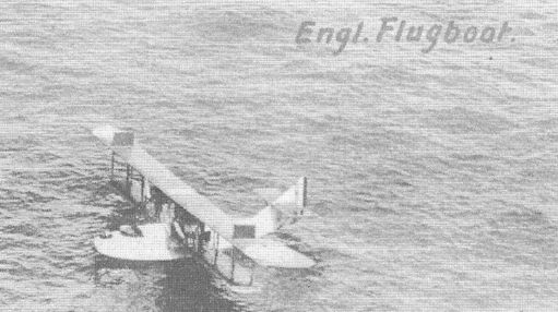
A Curtiss flying boat forced to land on the water by German seaplanes.
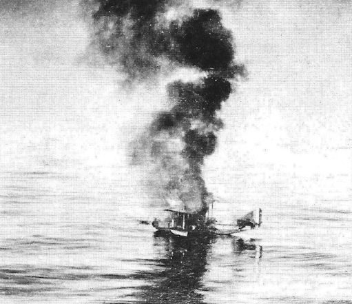
On July 31st 1918 a squadron from the naval air station base Zeebrugge sighted an enemy armored cruiser that was covered by a Curtiss flying boat and a land-based single-seat aircraft. The German squadron attacked both aircraft, downing the Curtiss.

A German airfield on the western front in early 1918. Even the light combat aircraft had to be placed on a platform of wooden planks to prevent them from sinking into the soft ground.
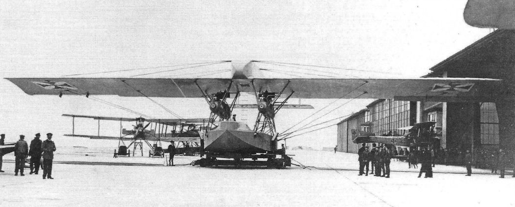
The Rs.III before she was brought into the hangar. In the background, a few FF 49c aircraft.
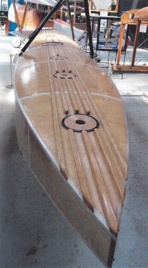
Wooden float from a Friedrichshafen FF 49c in the Danish Technical Museum.

The Junkers monoplane J1, whose first flight took place on December 12th, 1915. Due to its construction of steel and sheet iron only, the J1 proved to be too heavy, and therefore unsuitable for combat.
The Junkers J 1 (an internal company designation) was the first Junkers aircraft to fly. It was a two-seat testbed for Junker's all-metal structural technology, and the Junkers J 2/E.II fighter was developed from this aircraft.
The Junkers J 1 (an internal company designation) was the first Junkers aircraft to fly. It was a two-seat testbed for Junker's all-metal structural technology, and the Junkers J 2/E.II fighter was developed from this aircraft.

The Junkers J11 competed with the Zeppelin Cs.I. It used corrugated duralumin panels and was not the more advanced stressed skin structure of the Zeppelin Cs.I.

The Lubeck-Travemunde company also used the dural floats from ZWL for its F 4 aircraft.
Zeppelin (Ja) C.I / C.II
Due to the imminent reduction in airship orders beginning in 1917, Luftschiffbau Zeppelin management had to search for new products in order to utilize the company's full production capacity. In 1918, the Zeppelin company employed 11,500 workers in Friedrichshafen. The danger was that should these well-educated specialist workers be underemployed, they would he reassigned to the military or other companies, or simply leave. Some of this could be compensated by shifting workers to other operations; for example, the LZ foundry began to cast crankcases for the Maybach Motorenbau Mb IVa engine, or to the Lindau factory. In addition, Colsman planned an expansion of the aircraft business.
Two subsidiaries of LZ, the ZWL and the aircraft hangar in Staaken, had already successfully established themselves. Now Colsman wanted LZ's Friedrichshafen hangar to take a larger role in producing aircraft for the army and navy.
In the summer of 1917, Colsman assigned LZ engineer Paul Jaray to design a C-Type for the air force. Jaray, who was born in Vienna, had studied mechanical engineering in Vienna and Prague. He came to Friedrichshafen in 1912 as one of the first specialists in aerodynamics - a topic that would interest him his entire life. In 1914 he moved to LZ, where he participated in the construction of various airships, and could spend time intensely researching aerodynamics.
On June 30th, 1917, Paul Jaray began development of the Zeppelin C.I, a two-seater high-altitude surveillance aircraft. Within 14 days he had drafted a blueprint of a prototype. This two-seater biplane "showed the most consequential consideration of all new regulations to achieve most economical flight", as it was explained in the craft's description. In addition,
“[...] its use as a military and a passenger aircraft employs all of the characteristics of modern aircraft - speed, excellent climbing characteristics, comfortable, light handling, maneuverability, gliding potential, good visibility, and extraordinary safety with significant elasticity of the shock-absorbing parts. From the standpoint of aerodynamics and stability, the design is a fortunate combination of all the current aviation construction and light metal expertise. As a result, the overall value of this type (but also of its parts) is a leader among current aircraft. ”
The advertising and technical department of LZ did not exaggerate here. The Zeppelin-Jaray C-aircraft did indeed show extraordinary technical parameters for 1917, such as an altitude ceiling of 8,000 meters and a top speed of 210 kilometers per hour. The aircraft owed its speed to Jaray's aerodynamics research, which flowed into its design. On August 18th 1917, 30 workers began building the Zeppelin (Ja) C.I. However, the first two pre-serial construction fuselages in the hangar were made of wood. This two-seater biplane with a wingspan of 12 meters and a fuselage length of 6.9 meters was powered buy a 260 HP Maybach Mb IVa engine.
The fuselage, referred to internally as "Aircraft 1", was covered in wood veneer. Only Aircraft 2 was given fabric coverings over openings on the sides and top of the fuselage. In addition to the lower weight, these openings could be used as maintenance access for the fuselage. This was surely also changed on Aircraft 1 later. Since these two aircraft were primarily used for LZ's testing purposes, various cooling systems, exhaust collectors, and propellers were tested out on them. In addition, clear Cellon was tested on the upper wing to increase the pilot's upward visibility. Since these pre-serial aircraft carried no official designation, they cannot be tracked.
The wing and tail constructions, spars, ribs, and rudders of the prototypes were already made of duraluminum, which was produced at the ZWL in Reutin, and covered with fabric as was the usual case at the time. On October 17th, 1917, in a record time of two months, the Zeppelin (Ja) C.I took off for its maiden flight in Lowental. The company pilot Hausmann was satisfied with the fight characteristics, and with an operating weight of 1,500 kg (empty weight 1,000 kg) the C.I reached a top speed of 210 kilometers per hour. In the following days, Hausmann made several more test flights, focusing on the maneuverability of the aircraft as well as dives and spins.
At the same time the wooden aircraft were being constructed in the hangars of the LZ, Dornier's engineers in Lindau began to work on transferring Jaray's plans to build a metal fuselage. The all-metal aircraft was designated C.II.
The LZ hangar in Friedrichshafen was not able to begin serial construction - it could only be done in collaboration with the ZWL in Lindau. Colsman therefore assigned additional workers from Luftschiffbau to ZWL.
On December 8th, 1917, Luftschiffbau Zeppelin GmbH received a binding order for six test C-aircraft, three each of ZWL C.I and Zeppelin C.II, from IdFlieg's flight master:
“Subject: Delivery of test aircraft.
With the approval of the war ministry dated November 23rd, 1917, I issue the company with the order of the delivery of 3 - three - pieces test C-aircraft for 160 HP Mercedes engines and 3 - three - pieces test C-aircraft for 260 HP Maybach engines.
With complete accessories for aircraft and power plants, as well as installation of MGs.
The aircraft will carry the military designations C 15800 through 15805/17.
The installation of F.T. (??) - or photography equipment, the installation of the MG, the delivery of shell feeding equipment is included in the price. ”
On December 14th, 1917, LZ answered with the following letter:
“We confirm with thanks the receipt of the order to deliver 3 test C-aircraft with 260 HP Maybach engines. The confirmation of the 3 test C-aircraft with 160 HP Mercedes engines will follow from our Zeppelin Factory in Lindau. For the three test aircraft with 260 HP Maybach engines, we have noted the military designations of 15803/17, 15804/17 and 15805/17. We will assume delivery dates for the light metal aircraft of early, mid-, and end-February 1918.”
The partial assembly of the Zepp. (Ja) C.II military numbers 15803 through 15805/17 made of aluminum took place in Lindau Reutin. According to the description, the "fuselage was made of a duraluminum lattice. In the engine area as a rotation paraboloid towards the rear in a square cross-section with lightly curved side walls.
The wings, top 12 meters, bottom 11.6 meters (divided by the fuselage) were made of two duraluminum spars each, with riveted ribs, also of duraluminum. The elevator and the rudder as well as the tail skid were also of duraluminum.”
The construction description says that the engine was a Maybach Mb IVa engine, with LZ cooling system and Jaray propeller (LZ-Pi 61/62). The C.II (Ja) had a special starter that allowed the engine to start without external help. In anticipation of its use as a civilian aircraft as well, the surveillance seat as well as the MG mount could be replaced with a comfortable passenger seat.
All of the parts for Dornier's first serially produced aircraft were completed in Lindau-Reutin by March 1918. The assembly and fabric covering took place in Friedrichshafen at LZ. Less than five months after the prototype's first flight, on March 10th, 1918, the aircraft was flown in Lowental. On March 11th, 1918, IdFlieg approved and accepted it. An order for 20 combat-ready trial aircraft, with the military designations of C.5500 through 5519/18 followed. These aircraft were completed by the end of November at ZWL and LZ. Internally, the C.II airplanes were sequentially numbered (C.II/1 through C.II/20). But none of these made it to combat. C.II/2 was used as a test aircraft in Adlershof, and C.II/4 burst into flames upon landing at the Lilienthal airfield in Berlin.
In 1920, LZ purchased back the remaining aircraft from the German Army Peace Commission of the Weimar Republic. Through a mediator, 20 Zeppelin (Ja) C.II were sold to the Swiss Air Force, where they remained in service until October 1927. That means that at least three more Zeppelin (Ja) C.II were built before the construction ban as dictated by the Treaty of Versailles was instituted.
Three airplanes of Paul Jaray's final design, the Zeppelin C.IV, were also built: Military designations 12255 through 12257/18. The last remaining aircraft of this type, with the internal company number 01, was destroyed in a fire as a result of welding work in a hangar at the aviation museum at Le Bourget near Paris on May 17th, 1990.
Camouflage Painting of the Zeppelin (Ja) C.I / C.II
The Zeppelin Jaray prototype aircraft C.I and C.II received the usual airship fabric covering delivered by the company's own subsidiary Ballonhullengesellschaft mbH ("Balloon covering association") in Berlin Tempelhof.
For aerodynamic reasons, or for a smooth surface, the fabric had a protective covering of Cellon or stretching lacquer. It was mixed with iron oxide (1.5%) and aluminum powder (3%):
“[...] For the textile covering, one used varnished linen, which was sewn onto the ribs with a special technique. "
After the first two coats, it was smoothed by what was then called "glass paper", now known as sanding paper.
The duraluminum parts of the C.II, such as the engine cover, struts, and shafts, remained unpainted. The national emblems and other markings were applied according to the construction and delivery regulations of the army. Only the C.II series aircraft, which had the military designations 5500 through 5519/18, received the three-color camouflage coverings from the Ballonhullengesellschaft mbH.
Specifications of Zeppelin-Lindau Aircraft
Type Length, m Span, m Height, m Chord, m Propeller Manufact. Armament
(guns) Weight, kg Motor Crew
C.I 7.60 10.50 2.84 LZ-Jaray 1 fixed, 1 flex 696 Daimler D III 2
C.II 7.92 12.00 3.58 1.80 LZ-Jaray 1 fixed, 1 flex 1,000 Maybach Mb IVa 2
Military Numbers of Dornier-ZWL Aircraft
Military Designation Manufact. Type Class Engine Notes
15800-15802/17 ZWL (Do) C.I DIIIa
15803-15805/17 Zepp. C.II Mb IVa
5500-5519/18 C.II Mb IVa 20 aircraft sold to Switzerland
12255-12257/18 Zepp C.IV Last aircraft, burned in Paris 5/17/1990

Zeppelin C.II

Zeppelin C.II 15803/17

Zeppelin C.II 5507/18 in provisional 'bubble' camouflage.
Unfortunately, the colors used in the Zeppelin C.II 'bubble' camouflage are not known, so we offer these possibilities.
Unfortunately, the colors used in the Zeppelin C.II 'bubble' camouflage are not known, so we offer these possibilities.

Zeppelin C.II 5507/18 in provisional 'bubble' camouflage.
Unfortunately, the colors used in the Zeppelin C.II 'bubble' camouflage are not known, so we offer these possibilities.
Unfortunately, the colors used in the Zeppelin C.II 'bubble' camouflage are not known, so we offer these possibilities.

Zeppelin C.II 5507/18 in provisional 'bubble' camouflage.
Unfortunately, the colors used in the Zeppelin C.II 'bubble' camouflage are not known, so we offer these possibilities.
Unfortunately, the colors used in the Zeppelin C.II 'bubble' camouflage are not known, so we offer these possibilities.

Zeppelin C.II 808 in Swiss service postwar

Zeppelin C.II 811 in Swiss service postwar

Zeppelin C.II 811 in Swiss service postwar

The Zeppelin C.I aircraft number 1 in the LZ hangar in Friedrichshafen.

The Zeppelin (Ja) C.II (C.15803/17) at the airfield in Lowental.

Zeppelin C.II aircraft in German markings.

Designed by Paul Jaray: C.I reconnaissance aircraft. Two prototypes have been built. The improved serial type was the Zep C.II.
Zeppelin C.II in German markings.
Zeppelin C.II in German markings.

Zeppelin C.II in German markings with extended exhaust.

Zeppelin C.II in German markings.

A Zeppelin C.II in German markings.

View of a Zeppelin C.II in German markings. The aircraft has an extended exhaust.

View of a Zeppelin C.II in German markings.

Zeppelin C.II 5505/18 in 'bubble' camouflage in German service.


Zeppelin C.II in 'bubble' camouflage in German markings.

Zeppelin C.II 5507/18 in 'bubble' camouflage heads a lineup of C.II aircraft under production.

The Zeppelin C.II aircraft at the airfield in Dubendorf. Serial No. 811 is visible with Hanriot H.D.1 fighters in the background.
The Swiss allocated serial Nos. 801 to 812, and 814 to 820 to the 20 C.II biplanes it received. According to J. Uresh in the official The Aircraft of the Swiss Air Force since 1914 (1975 Verlag Th. Gut & Co, Switzerland, 1974), the C.II biplanes were purchased clandestinely from the German authorities. They had never been flown and were transported in secret from Friedrichshafen to central Switzerland in 1920. In the middle of 1920, they were purchased by the Swiss military and taken to Dubendorf. The machine proved sturdy and were initially used for reconnaissance and high-altitude flying training. No. 816 crashed in October 1927, killing the crew. Metal fatigue was found to be the cause and the remaining aircraft were scrapped.
The Swiss allocated serial Nos. 801 to 812, and 814 to 820 to the 20 C.II biplanes it received. According to J. Uresh in the official The Aircraft of the Swiss Air Force since 1914 (1975 Verlag Th. Gut & Co, Switzerland, 1974), the C.II biplanes were purchased clandestinely from the German authorities. They had never been flown and were transported in secret from Friedrichshafen to central Switzerland in 1920. In the middle of 1920, they were purchased by the Swiss military and taken to Dubendorf. The machine proved sturdy and were initially used for reconnaissance and high-altitude flying training. No. 816 crashed in October 1927, killing the crew. Metal fatigue was found to be the cause and the remaining aircraft were scrapped.

Zeppelin C.II aircraft in Swiss service.

Zeppelin C.II '808' in Swiss service.
This is one of the 19 Zeppelin C.II aircraft which were sold to Switzerland after the armistice.
This is one of the 19 Zeppelin C.II aircraft which were sold to Switzerland after the armistice.

Zeppelin C.II, perhaps '808', in Swiss service

Zeppelin C.II, perhaps '808', in Swiss service

Zeppelin C.II aircraft in the Hangar at Dubendorf. The Zepp.C.II with the Swiss ID 807 and 810 are in for maintenance, on the left of the photo one can recognize the frame of a C.II without the fabric covering.

Zeppelin C.II with the Swiss serial number 812 in flight.

Closeup of the Zeppelin C.II structure.

The wing of the Zeppelin C.II, military designation 15805/17, served for stress tests. Internally it was called aircraft number 4. The duraluminum structure of spars and ribs proved to be very stable.

Uncovered structure of a Zeppelin C.II.

Zeppelin C.II fuselage in storage at the Musee de l'Air in 1981 before fire destroyed the storage hangar where it was stored. It was originally obtained in 1921.

Zeppelin C.II in German markings after a rough landing; the limited damage shows the robustness of the metal structure.

Zeppelin C.II

Zeppelin C.II

Zeppelin C.II
Rs.I: The World's First Giant Flying Boat
The first buildings began to rise from the ground at the Seemoos compound in August 1914. In the beginning there was a small shed with two rooms for the design work, and a production hall, measuring 60 meters by 50 meters, and it had a height of about 30 meters. It was used for the production of parts and the assembly of the flying boats. To bring them into the water, a pully system was added, which led from the hangar into Lake Constance. The transportation car, mounted on rails, traveled about 100 meters into the lake. Initially the cable winch was hand-cranked, but later an electric motor was installed.
Until 1916, more and more buildings were erected in Seemoos, housing a mechanical workshop, a metal-working shop, storage, and technical offices.
While in August 1914 the Abt. Do team consisted of Claude Dornier, a designer, a master craftsman, and six workers, the department grew to 10 constructors and two designers by December. In the beginning of 1915 the workforce grew to 150 people.
As soon as the first buildings were complete, work began on the Rs.I and in January of the following year the construction of the giant flying boat began in earnest. Some of Claude Dornier's important colleagues included the engineers Rohrbach (boat), Ruleaux (cell), Schulte-Frohlinde (engines and controls), Klemm and Lupberger (aerodynamics), Schwengler (structural analysis), Messerschmitt (testing), and the workshop leaders Wild and Lenz.
Rs.I was designed to be a biplane with a wingspan of 43.5 meters, and the upper and lower wings were to be connected with eight V-struts. The wings' bracing was swivel-mounted, so that the pitch angle between the wings and the hull of the boat could be changed in order to generate additional lift. The complete but yet uncovered wing was a technical masterpiece, which also impressed Professor Baumann when he visited Seemoos. The wings would be covered in fabric. Small wooden strips were attached to the aluminum alloy ribs so that the fabric could be attached with brass nails. The 29-meter-long hull also had a metal ribcage. Dornier chose duraluminum to cover the fuselage. Only the top and back parts of the boat, which would not directly come into contact with water, were to be covered in fabric.
Rs.I did not receive a camouflage paint scheme, but instead had a sea cruiser finish in a shade of green to protect it from the corrosive sea water. The steel sheet rivets were sealed with strips of fabric soaked in black tar.
Three 240 horsepower HS engines from the neighboring Maybach Motorenwerke powered the flying boat. In its first iteration, one of the engines was built into a nacelle at the center of the boat, and directly drove the propeller. Two further Maybach engines were attached with engine mounts, on either side of the hull, and powered propellers via an extension shaft. The cooling units of both hull engines were attached to the upper side of the hull, while the nacelle engine had a front radiator.
Count Zeppelin followed the construction of Rs.I closely and with great interest, and wanted to know every detail. After all, his company carried the entire financial burden of the project since the Reichs Naval Office had not (yet) placed an order.
The first taxi tests, led by Hellmuth Hirth and naval pilot Erich Schroter on October 12th, 1915 on Lake Constance, showed the placement of the two side-mounted engines was problematic. On October 23rd, 1915 the backboard suspension in the hull broke, and the drive shaft was torn. The flapping propeller damaged the top wing so that Dornier was forced to mount all three engines in external nacelles between the upper and lower wings, so that they could propel the propellers with a direct drive.
This second iteration of the craft would allow the flying boat to reach a maximum taxi speed of 40-50 kilometers per hour during testing on Lake Constance, still 30-40 kilometers per hour slower than the calculated speed required for take-off.
Despite all their efforts, the 10.5 ton heavy flying boat did not rise out of the water. On the fifth try, on December 21st, 1915, a propeller broke. Heinrich Triller's report about the event reads:
“[...] The engines ran well, and the aircraft reached a high speed. I had the feeling it would take off from the water at any moment. After two minutes at full throttle, the middle Reschke Propeller snapped. I immediately stopped all three engines. The middle motor, including the nacelle, had already been torn from the structure. The split propeller had damaged the upper wing, including the starboard aileron and severely damaged the roof.
The reason the propeller broke was probably because the center engine's propeller was 50 centimeters longer than the others. This then bent during full throttle, swiped the mount, and likely caused the break. A motorboat towed the Rs.I to the shoreline. But here it could not be placed upon the carriage because earlier in the day, as the aircraft was being brought into the water, the carriage had jumped its tracks and rested two meters below the waterline. Despite all efforts, hindered by the ice-cold water and the high sea swells, it was not possible to return the carriage to the track that evening. The flying boat had to be anchored to a buoy on the lake. During the night, a foehn storm (a very windy, warm storm from the south) whipped up the waves to a meter high and more, which ripped the buoy from its anchorage and drove it and the craft toward land. The boat hit a rock, causing it to partially sink. The damage from the storm was so severe that it was impossible to even think of repairing it. Although the first experimental aircraft never actually made it into the air, it was still a groundbreaking design. The developers in Seemoos had learned a great deal and used that knowledge when they set out to build Rs.II.
Specifications of Zeppelin-Lindau Aircraft
Type Length, m Span, m Height, m Chord, m Propeller Manufact. Armament
(guns) Weight, kg Motor Crew
Rs.I 29.00 43.50 7.20 4.60 Garuda/Reschke 1 flexible 6,475 Maybach Mb IVa 240 hp 5
Rs.II 28.88 33.20 7.60 6.50 Lorenz 3.70 1 flexible 6,388 Maybach Mb IV/IVa 6
Rs.III 22.74 37.00 8.10 6.50 versch. 4 flexible 7,865 Maybach Mb IVa 6
Rs.IV 22.30 37.00 8.55 6.50 versch. 4 flexible 6,980 Maybach Mb IVa 6

The Rs.I in a handling dolly. (Airbus Group)
The sole, experimental long range Zeppelin-Lindau Rs I flying boat was wrecked in a storm on 21 December 1915 before it could be flight tested. This three 240hp Maybach Mb IV-engined craft was the first of a series of one-off giant flying boats made feasible through the extensive use of light alloys, a field in which their creator, Prof Dr Claudius Dornier, one of Count Zeppelin's brighter proteges, had specialised.
The sole, experimental long range Zeppelin-Lindau Rs I flying boat was wrecked in a storm on 21 December 1915 before it could be flight tested. This three 240hp Maybach Mb IV-engined craft was the first of a series of one-off giant flying boats made feasible through the extensive use of light alloys, a field in which their creator, Prof Dr Claudius Dornier, one of Count Zeppelin's brighter proteges, had specialised.

Close-up of the modified engine layout of the Dornier Rs.I. The Reschke propellers on the Rs.I were fitted with brass edges to protect them from water hammering. (Airbus Group)

The Rs.I in front of the hangar in Seemoos in October 1915. (Airbus Group).
The Dornier Rs.I was the first all-metal giant flying boat completed and provided valuable information for subsequent designs despite being wrecked in a storm after taxi trails but before first flight.
The Dornier Rs.I was the first all-metal giant flying boat completed and provided valuable information for subsequent designs despite being wrecked in a storm after taxi trails but before first flight.

The Rs.I on December 21st, 1915, before its final excursion into the water. (Airbus Group)

The modified Dornier Rs.I on the transportation wagon outside the hangar at Seemoos in December 1915.

The Rs.I after the modification of the propellers. The bulge of the hull was a stopgap measure to widen the fuselage to make room for the dual control cockpit where pilots sat next to each other. (Airbus Group)

The skeleton of the wings of the Rs.I. (Airbus Group)

The central strut, between the two workers, was used to change the pitch of the wings. (Airbus Group)

The engine mounts for the three Maybach engines for the direct drive. (Airbus Group)

The pilots'seats in the Rs.I, including steering wheels and operating levers. On the top of the fuselage there was an 80-centimeter wide space to attach an MG turret. (Airbus Group)

The nose of the Rs.I was covered with clear Cellon. (Airbus Group)

After the accident on October 23rd, 1915, the Rs.I is placed on the carriage. The top wing had been damaged by the propeller. (Airbus Group)

The original form of the Dornier Rs.I with two buried engines. The damage done to the upper wing trailing edge by the shattering of the port propeller can be seen. Photo taken 23 October 1915.

The wreck of the Rs.I after the foehn-storm. The engineer Lupberger oversaw dismantling the flying boat, as all usable parts and the engines were salvaged and re-used on the Rs.II. (Airbus Group)
Rs.II: The First Giant Flying Boat in the Air
The Rs.II was conceived as a biplane with a short lower wing, also known as a sesquiplane. Since April 1st 1916, when duraluminum profiles could be produced in large numbers, they were used for the Rs.II. As a result, the empty weight of the second flying boat was significantly lower than that of the first, at 6,169 kilograms. The Rs.I had weighed 7,500 kilograms.
Also, when covering the wings - the upper wing had a span of 32 meters, the lower wing 13.5 meters - Dornier tried a new approach. In order to attach the fabric to the metal airframe, grommets were built into the ribs so that the thread did not chafe, and they could be easily threaded with a needle or an awl. This simple but effective way of attaching fabric would also be used for later Dornier aircraft.
The three Maybach Mb IV engines could be salvaged from the wreck of the Rs.I. After a comprehensive manufacturer overhaul, Dornier initially placed them in the hull of the Rs.II. The power transfer, using shaft displacements and two gear drives on the pusher propellers, was similar to the Rs.I. The central configuration of the engines increased the aircraft's stability in the water and simplified the maintenance, but also caused a lot of problems that had also plagued its predecessor. The reason for this configuration, which was considered outdated, was likely the fact that design and construction on the Rs.II had already begun in 1915.
The boat entered the water of Lake Constance for its first tests on May 17th, 1916. The radiator, engines, and the boat were tested in a series of trial runs, where the speed never exceeded 26 km/h. Because the hull had been widened to 4.15 meters, it was no longer necessary to mount floats under the wings, thus creating the world's first inherently stable flying boat.
But it seemed that Dornier's second flying boat also did not want to leave the water.
Claude Dornier turned to Prof. Baumann in Gotha, since he had significantly more experience in building giant flying boats. He travelled to Gotha on May 30th, 1916 and Prof. Baumann wrote the following in a letter dated May 29th, 1916:
“[...] tomorrow Mr. Dornier will come from Friedrichshafen to get some advice, now, finally after he blew 1,000,000 Mark. His newest craft (Rs.II) travels at 20 km/h and is not even contemplating flying[...]”m
It's not clear how much Prof. Baumann could help Claude Dornier. But it was clear to all that with a flying boat of this size and design, Dipl.-Ing. Dornier was breaking completely new ground, and had to do a great deal of pioneering work first. Prof. Bauman's experience building giant aircraft such as the Gotha G-Types might be able to help.
Between May 20th and June 8th, the front of the fuselage step was laid, the redundant bomb bays were rebuilt and a spare radiator was inserted. The boat still did not take off. The elevator, including the box-shaped control unit which could be adjusted in flight, was also altered. In its final form, the vertical stabilizer was made of two movable rudders without a pre-stage, and an elevator fin.
On June 9th, the boat reached a speed of 65 km/h for the first time, rose out of the water to the step and was on the verge of lifting off for the first time. Encouraged by this progress, Dornier added one small additional aid to the hull in the middle of June. During another test on June 26th, the upper transmission bearing broke. The testing could continue after repairs were complete on June 30th. The empty weight of the aircraft had increased to 6,388 kilograms, and the take-off weight to 7,045 kilograms. Nevertheless, on this, the seventh attempt, the Rs.II lifted off from the water effortlessly, at 80 km/h.
“[...] On the third attempt, at 7:30am, the aircraft rose out of the water for the first time. It was a blissful and calm feeling as the steps got longer and longer and then ended. Finally!
We flew about three minutes, two meters above the water, and on the second flight we reached an altitude of about 25 meters, and flew for four minutes. ”
On July 1st four flights were carried out, although on the final flight of the day the starboard gear shaft broke, and the attached engine, which was running without load, blew out.
After the repairs, testing was able to begin again on July 17th. On the last flight the port propeller ruptured, and heavily damaged the other two propellers, the upper wing, the port flaps, as well as a girder in the tail section. Still, the pilot was able to glide the Rs.II to a safe landing.
The constant problems with the remote operator caused Dornier to switch to a direct drive. Instead of placing the three engines underneath the propellers, four 260 horsepower Maybach Mb IVa direct drive engines were built into the aircraft in a so-called tandem configuration. Two by two engines were placed behind each other in a single nacelle. These propellers' power unit, configured as one pull and one push propeller, proved to be significantly more efficient than a single propeller.
In order to test the tandem drive, a test facility was built behind the Seemoos hangar. The engines were placed on an iron frame, one end of which was able to be pivoted around the axis, while a scale was placed on the other end. The experiments and measurements showed that the tractor engine had only about 70% of the performance of the pusher engine. This reduction in performance stemmed from the drag created by the top of the engine and the nacelle. On the pusher engine the air could flow through unhindered. Claude Dornier had calculated the engines' output ahead of time, but still this one showed better flight performance. This was also in part due to the larger radiators from the Suddeutsche Kuhler Fabrik (SKF), which were flexibly mounted. In order to regulate the temperature, fabric curtains could be closed between the cooling surface and the engine room.
At the same time, the entire instrument panel was modernized, including four tachometers (Morell), eight temperature sensors (Morell), a circuit breaker for each of the four engines, and four signal lamps. The Bosch-built throttle, which had been salvaged from the Rs.I, was replaced by one that had been built in-house.
After the rebuild, Rs.II began flying again on November 6th, and following a short take-off run of 52 seconds, the boat took off. The craft was significantly faster following the modifications and the extra engine.
As the flying boat was brought back to shore, the stick was damaged when it collided with the landing pier. Repairs had to be completed quickly because in the meantime Lieutenant Colonel Mans and Lieutenant Tille had arrived in Seemoos to continue the flight testing.
The future of the giant flying boats from Seemoos depended on the assessment of these two gentlemen. Until that point, all of the cost had been carried by LZ alone.
It is easy to imagine the crew's nervousness as the Rs.II was brought into the water at 7:45am on November 11th. Pilot's mate Erich Schroter also surely felt it, since Lt. Tille seemed to be unhappy with the performance so far, although Schroter was a very experienced airman.
“[...] On November 11th in the morning, I took the first flight as a guest, with the company’s aviator Schroter. I saw, by virtue of the fact that the pilot was busying himself with what seemed to me completely unnecessary work during the short, straight flight, as well as his fear of heights, that he was in no way a master of the aircraft. After a few minutes I gave him the order to land so that I could take the controls. The duration of the entire flight was about 30 minutes. The flights were interrupted by failures of the unreliable engines (these were old testing engines). The machinists on board were sometimes able to correct the irregularities in flight.
Pilot Schroter was taken out of the cockpit and replaced by the Airman First Class Fritz Dauke. He had arrived in Seemoos on November 12th from Warnemunde and on the next day he completed his first flight in the giant flying boat under the command of Lt. Tille:
“[...] On Monday, November 13th, I introduced the aviator Dauke to the aircraft. After a training flight the airman first class, whom I consider one of the most spirited aviators in my acquaintance, was able to fly the aircraft alone. ”
Until then, Dauke had only flown single-engine B- and C- floatplanes, so Lt. Tille flew with him in the Rs.II and explained the aircraft. Dauke then completed a first solo flight of the Rs.II on his own with no problem. This also was a testament to the accomplished construction of the Rs.II, despite persistent technical problems.
In their reports for the RMA the naval master builder Schmedding and Lt. Tille concluded that the Rs.II “was not quits combat-ready ... But could, with some practice, be flown by an average aviator ... and could unquestionably be developed for some long-distance military reconnaissance missions (10 hours). ”
The development or rebuild would include modifications to the shape of the hull. The fuselage was to be lengthened, so that the tail boom could be shortened and placed higher. The tail had often touched the water upon takeoff. In addition, watertight bulkheads would be built into the hull. Lt. Tille did not consider the boat combat-ready in its current form.
In the following weeks, further Rs.II test flights were interrupted by engine defects, piston damage, valve breakage, and leaky lines.
On April 28th, 1917 the central strut of the tail construction broke upon landing, so that the entire tail boom was hanging on just four cables. The pilot had not noticed the break, and wanted to take off again. The craft lifted off but was immediately pushed back into the water because the tail had shifted down, creating a nose-heavy situation. During the rough landing two further cables snapped so that the entire tail was resting on the water surface. Following a redesign of the tail boom, the Rs.II was able to take flight again in June 1917.
After all of these improvements, the Rs.II could be easily maneuvered, despite its 9.2-ton weight. After about 20-30 seconds of acceleration, she easily lifted out of the water. The top speed in horizontal flight was 128 km/h, the highest altitude reached was 1,800 meters. Although the Rs.II always was a bit tail-heavy, the flying characteristics were mature enough that a naval commission approved the Rs.II in July 1917 in Seemoos.
An accident occurred during the approval and acceptance process, which foreman Heinrich Triller described in the Dornier Post in 1936:
“[...] our giant flying boat Fs.II [Rs.II] stood in the hangar, ready to be approved. The gentlemen of the commission, naval and flight officers, were all there. The hangar doors were open and I did a short test of the four Maybach engines. Everything was well: the engines ran at about 500 rpm, and I wanted to give the signal to transport the aircraft into the water, as one of our helpers ran up from behind on the port side and waved at me. Suddenly I stopped in surprise. The man climbed up on the craft from behind, and seemed to not be aware of the running propellers. I shouted, waved the man away and reached for the ignition switch but it was too late. The machine shuddered, as if someone had hit it with a hammer. I shut my eyes tightly so that I would not see the horrifying sight, because two years earlier one of our workers was decapitated on the test rig. I breathed a sigh of relief when the man stood next to me, healthy and happy, and looked at me in surprise. He had nothing more than a bump on his head. All he wanted to do was to bring me my protective glasses, and excused himself [...]”
After this accident, the final acceptance flight had to be delayed for a few days, until replacement propellers were delivered. The metal-covered wooden propeller had split along its entire length, the crack was about 10 millimeters wide. Low-quality fuel forced further delays. After the Rs.II's 23rd flight in July 1917, engine performance declined significantly, with each engine delivering 50-80 rpm less than normal, and it took an hour to reach an altitude of 2,000 meters. Since there was no technical defect on the flying boat structure or its engines, the fuel was tested in a laboratory. These tests confirmed the initial suspicion. Both LZ and Maybach had also received this inferior fuel. A test using 2/3 benzene and 1/3 gasoline did not improve the engine performance, causing immediate soot soiling. Many phone calls later, the Rhenania-Benzinwerke in Ludwigshafen was able to deliver appropriate fuel to Seemoos.
The combat readiness of the Rs.II would take place at the naval air station in Norderney. In order to simulate the flight to Norderney, Dipl.-Ing. Dornier ordered a six-hour test flight over Lake Constance on August 13th, 1917. The Rs.II would be fully armed, including a four-man crew, and outfitted as it would be in war. After 2 hours and 17 minutes of flight time, the aft port propeller, built and delivered by the company Behrend-Rugebrecht, broke. Flying parts smashed into the aft starboard propeller as well. Two struts on the tail boom were separated and spars and fabric covers were also damaged. The supports for the engine base as well as the trays of the rear engines were also torn open.
Despite this accident the pilot, Lt. Lech, was able to slowly glide and land the plane.
The heavy damage on the Rs.II prompted the Reichs Naval Department on August 21st, 1917 to order the craft to be scrapped, and to salvage the parts that could be re-used. The testing phase of the 1 1/2 year-old design was complete, and the development of the successor model, Rs.III, was already fairly advanced. Also, the obsolete lattice construction was finally retired. Engineers in Seemoos used parts of the Rs.II, such as spars, empennage and rudders for stress testing in order to gain knowledge for the new Rs.III. The SVK in Warnemunde used parts of the Rs.II, which the Navy had allocated the number 1433, such as the fuselage, for further testing. It was finally destroyed on June 3rd, 1918 during a stress test in Warnemunde.
In the meantime, the financial questions between ZWL and the Reichs Naval Department were cleared up and the purchase and development costs of 300,000 Reichs Mark were transferred to the Abt. Do. The RMA's decision to stop construction of the Rs.II likely included the consideration that the company-internal competitor, Zeppelin-Werke GmbH Staaken, had flown its Staaken L aircraft from Staaken to Potsdam for delivery on August 10th 1917. It was assigned the Naval number 1432. This naval R-aircraft was on the verge of acceptance. At the Potsdam hangar, its wheels were replaced with floats. The design of the aluminum floats was developed together with the ZWL and the naval master constructor Schmedding, and were built in the hangar in Staaken. The carriage upon which the 12-meter-long floats were fastened for ground transport was a special construction. The engineers Scholler and Welker designed a "float bay" which had air chambers and floated on the water surface. In this way the yokes could be pushed over the floats and tightened with bolts.
The first water take-off of the Staaken L was on September 5th from Lake Havel. The aircraft was to be transferred to Warnemunde on November 12th, 1917, but was forced to land on the Saaler Lagoon due to an engine failure. After the repairs, she was flown to Warnemunde on November 14th. As the craft was fastened to the buoy, the specially built carriage could be attached, despite winds of 8-10 meters per second, and the Staaken rolled onto land and into the hangar under its own power. This was proof that large aircraft with massive measurements and weight that had until now been unknown, could be stationed and employed at the front.
In the following weeks, the aircraft was equipped with a radio and mast for the antenna. Larger fuel tanks extended its range to 10 hours. In addition, a lighting and a heating system were added. The aircraft went through rigorous testing in Warnemunde in the months that followed. The focus of these were long-distance flights as well as landing performance in various sea conditions. The maximum flight range of 10 hours could be extended when one of the engines was shut off.
On June 3rd, 1918, the Staaken L crashed during a radio testing flight over land near Warnemunde, and the entire crew was killed.
Specifications of Zeppelin-Lindau Aircraft
Type Length, m Span, m Height, m Chord, m Propeller Manufact. Armament
(guns) Weight, kg Motor Crew
Rs.I 29.00 43.50 7.20 4.60 Garuda/Reschke 1 flexible 6,475 Maybach Mb IVa 240 hp 5
Rs.II 28.88 33.20 7.60 6.50 Lorenz 3.70 1 flexible 6,388 Maybach Mb IV/IVa 6
Rs.III 22.74 37.00 8.10 6.50 versch. 4 flexible 7,865 Maybach Mb IVa 6
Rs.IV 22.30 37.00 8.55 6.50 versch. 4 flexible 6,980 Maybach Mb IVa 6
Military Numbers of Dornier-ZWL Aircraft
Military Designation Manufact. Type Class Engine Notes
M.N.1433 LZ (Do) Rs.II RC4MG Mb IVa x 4 Destroyed in Sep. 1917

The Rs.II before its maiden flight on May 17th, 1916. (Airbus Group)
The single Zeppelin-Lindau Rs II giant, long range flying boat is seen here in its initial form with biplane tail. First flown on 30 June 1916 with its three 240hp Maybach Mb IVs buried within its short, broad-beamed hull, the problem of power losses in the transmission must have been serious, leading to the Rs II's beaching for modifications. Centred around the engines, this work saw the replacement of the three buried units by four similar engines, now mounted between the hull and the parasol wing in twin push/pull nacelles, with each engine driving its propeller directly. The opportunity was also taken, at this time, to modify the machine's tail unit. In this later form and known as the Rs IIb, the flying boat got airborne once more on 6 November 1916.
The single Zeppelin-Lindau Rs II giant, long range flying boat is seen here in its initial form with biplane tail. First flown on 30 June 1916 with its three 240hp Maybach Mb IVs buried within its short, broad-beamed hull, the problem of power losses in the transmission must have been serious, leading to the Rs II's beaching for modifications. Centred around the engines, this work saw the replacement of the three buried units by four similar engines, now mounted between the hull and the parasol wing in twin push/pull nacelles, with each engine driving its propeller directly. The opportunity was also taken, at this time, to modify the machine's tail unit. In this later form and known as the Rs IIb, the flying boat got airborne once more on 6 November 1916.

The struts of the Rs.II received a meta! fairing to improve the aerodynamics. (Airbus Group)

On May 17th, 1916, the Rs.II was lowered into Lake Constance for its first test. (Airbus Group)

The Rs.II on the dock in Seemoos. For the stability of the hull in the water, two assistive floats were attached to the lower wings. (Airbus Group)

Rs.II is towed by the yacht Wurttemberg.

After the first test run, vents were built into the hull. It had become almost impossible for the machinists to do their jobs due to the enormous heat of the engines located in the hull. (Airbus Group)

The propeller's power unit, through tubular shafts and angular gearboxes, stemmed from airship construction.

The Rs.II takes off after the modifications to the tandem engines on November 6th, 1916. The engine nacelles had not yet been installed, so that any problems in the cooling or fuel lines could be immediately repaired. (Airbus Group)

The Zeppelin Rs.II flies past the hangar in Seemoos in 1916 (Airbus Group).
The Zeppelin-Lindau Rs IIb, seen here in almost final form and only awaiting its four 240hp Maybachs to be encased in drag-reducing engine nacelles. Capable of reaching 81 mph top level speed at sea level, the Rs IIb had, by now, elicited sufficient naval interest to have been bought and issued with the serial 1433. Following flight testing, the machine was dismantled so that parts could be used in its successor, the Rs III.
The Zeppelin-Lindau Rs IIb, seen here in almost final form and only awaiting its four 240hp Maybachs to be encased in drag-reducing engine nacelles. Capable of reaching 81 mph top level speed at sea level, the Rs IIb had, by now, elicited sufficient naval interest to have been bought and issued with the serial 1433. Following flight testing, the machine was dismantled so that parts could be used in its successor, the Rs III.

First flight of a giant flying boat on June 30th, 1916. (Airbus Group)

Rs.II flies over Lake Constance at an altitude of 25 meters.

The Pilot Schroter warms up the Maybach Mb IVa engines before take-off. (Airbus Group)

Rs.II taxiing on Lake Constance on November 11th, 1916. (Airbus Group)

The Rs.II during testing by naval aviator Lt. Tille in mid-November 1916. He complained about the shape of the hull, which, in his opinion, caused too much drag. The tail construction was also criticized, because it touched the water during a steep take off.

The entire hull of the Rs.II was overhauled and prepared for the tandem engines. The aerodynamics were improved and it was painted grey-green. (Airbus Group)

The entire hull of the Rs.II was overhauled and prepared for the tandem engines. The aerodynamics were improved and it was painted grey-green. (Airbus Group)

The Rs.II after the modifications, on the turntable at Seemoos, November 1916. (Airbus Group)

Rear view of the Rs.II.

The giant flying boat Rs.II was also called Flugschiff-Seemoos (Fs.II).

After its completion, the upper wing was hung from the ceiling of the hangar so that it could be lowered later, and attached to the struts. With a wingspan of 32 meters and a width of 7 meters, this assembly step had to be planned carefully. (Airbus Group)

The LZ-built fuel tanks in the hull of the Rs.II could hold 220 liters.

The position of the Normal-Element radiator (NEK) over the fuselage of the Rs.II. Every cooling system had 10 components.

The position of the Maybach Mb IV engines in the boat hull. Above them, the radiators from the Norddeutscher Kuhler-Fabrik, with eight cooling fins each for the port and starboard engines, as well as two radiators with four fins each for the central engine, were mounted via flexible suspension. Later these were replaced with products from SKF with 10 fins each, since the engines tended to overheat already during taxi. (Airbus Group)

Detail views of the Rs.II

In addition to the water coolers, Rs.II also needed an oil cooling system.

For the modification of Rs.II to tandem propulsion, a testing rig was built behind the assembly hall. (Airbus Group)

On August 13th 1917 during the acceptance flight for the Navy propeller numbers 1 and 4 failed. The flying fragments broke the tail off, but pilot Lt. Lech was able to land the craft on Lake Constance. (Airbus Group)
Metal Aircraft for the Army
At the beginning of 1916, construction progress of Rs.II in Seemoos was sluggish. There were too many problems that needed to be overcome.
To prevent the production capacity from going to waste, in January 1916, the idea to build smaller metal aircraft for the army flying corps was born. It was probably Alfred Colsman, director at LZ, who floated the idea. It seemed that development and assembly were significantly smaller projects than that of the huge flying boats. Also combat pilots, who were regularly invited to visit the company, were enthusiastic about a single-seat combat aircraft made of metal.
The first design, called V1, emerged from the Seemoos hangar in September 1916.
This 1 1/2-wing design with a push-propeller, a teardrop-shaped fuselage, and lattice-work tail construction served as a test aircraft for Abt. Do. Importance was placed on a good climb rate and speed. To achieve these, Dornier chose a pusher drive train with a rear-facing propeller, creating a concentration of mass. The weight of the V1 with the 160-horsepower Maybach engine was 570 kilograms.
The basic construction of the V1 was likely influenced by the English DH2 and Fe 8 fighter aircraft. In the early summer of 1916, these aircraft known as "Pushers", along with French Nieuport 11s, had reestablished air supremacy on the western front. The German fighter aircraft, mostly Fokker E-types, were outclassed.
The V1 was built in Dornier's familiar metal construction, only the wings and the tail boom received a fabric covering. The power plant was a Maybach Mb III 160 horsepower engine, which was screwed onto a steel sheet frame. The attachments for the wings and the landing gear were also fastened to this frame. The SKF latticed radiator was positioned on the upper wing. For the first time the pilot's seat was adjustable. The front part of the duraluminum fuselage could be taken off the aircraft during maintenance work and to refuel. Upon completion, the V1 was transported to the airfield in Lowental and stored in the airship hangar there.
Hellmuth Hirth was to begin flying the craft in Lowental on November 13th, 1916. In addition to the builders, the LZ company leadership, as well as members of the flying corps, Count Zeppelin was also on hand at the airfield. But the pilot did not appear. So another pilot present, Oblt. Riechsfreiherr Hans Haller von Hallerstein, volunteered for the mission with the V1. Lt. Haller, a very experienced pilot from the giant aircraft department 500, had flown the giant aircraft VGO II (R.9/15) on the eastern front.
After he taxied for a short period, he went to full throttle. The aircraft lifted off the ground after about 10 meters and flew an undulating path. The craft then climbed almost vertically and crashed to the ground from about 30 meters' altitude. Pilot Haller von Hallerstein died in the wreckage.
Lt. Althoven of the Zentrale Abnahme Kommission (ZAK) (Central Acceptance commission) at Flugzeugbau Friedrichshafen wrote in his accident report:
“[...] Lieutenant Haller’s flight proceeded as follows: Upon my suggestion, he taxied with little thrust, then he turned around and gave full throttle. After about 10 meters of run-up, the airplane lifted off the ground, also about 10 meters, came down vertically towards the ground, von Haller turned off the gas, and then once again gave full throttle and climbed. The front of the aircraft went up again slightly only to drop again vertically to the ground. The machine bounced like a rubber ball, cartwheeled in the air and von Haller fell out or tried to jump out. The aircraft dropped to the ground a second time and stopped, in the direction it was flying, with its tail construction folded underneath.
Von Haller was not lying under the aircraft, but rather 3 meters away. In my opinion the aircraft was oversteered, but no one knows why. Von Haller was used to piloting large aircraft. Perhaps he just no longer had the feel of flying a small airplane like this one any more.”
The construction supervisory body of IdFlieg determined the official reason for the crash was oversteering. However, during ground-based taxi tests, company pilot Schroter had already criticized the V1 for its top-heaviness. After this catastrophe, the project of a push-propeller aircraft was abandoned.
<...>

Zeppelin V1 Prototype

The sole prototype Zeppelin-Lindau V-1 single seat fighter, completed during the summer of 1916, was not just Claudius Dornier's first attempts at a fighter, but one of his first on any type of aeroplane. Of workmanlike, rather than elegant appearance, the finished product showed the influences of Nieuport's sesquiplane wing layout, in a British-style pusher engined airframe. Using a 160hp Mercedes D III, the V-1, as to be expected of Dornier, employed an all-alloy structure. Sadly, someone had miscalculated the machine's dynamic, or in-flight balance. This was something the company's test pilot, Bruno Schroter, clearly suspected to be the case following his high speed taxying tests and he wanted nothing more to do with the V-1. The man found to make the the aircraft's maiden flight was Oblt Hallen von Hallerstein, a notable military flier, who had only recently completing the test flying of the giant Zeppelin-Staarken VGO III. Tragically, Schroter's prediction concerning the aircraft's tail-heaviness proved correct and on 13 November 1916, following lift-off, the V-1's nose continued to rise until the fighter stalled and fell to earth, von Hallerstein being killed in the crash.

The Zeppelin V1 was the first design for the Army. Engine was a 160 hp Maybach Mb.III.

The Zeppelin V1 was designed and built 1916 in Seemos. The structure had the typical Dornier's metal construction. The aircraft crashed fatally on its first flight end of 1916. The pilot had been flying the huge Staaken V.G.O.II which had heavy control forces and may have over-controlled the much smaller and more sensitive Zeppelin V1.

Zeppelin V1 under construction. (PM Grosz collection/STDB).

The Zeppelin V1 appears to have experienced a taxi accident before its maiden flight.

Zeppelin V1 crashed after its first flight. (PM Grosz collection/STDB).

Zeppelin V1

Zeppelin V1

Zeppelin V1
Zeppelin-Lindau C.I / CL.I
The General Director of LZ, Alfred Colsman, regularly visited the aviation operations headquarters in Adlershof for meetings. In October 1916 he had several of Dornier's drafts of a new C-type (two-seater combat biplane) with him. The head of the Flugmeisterei, Major Felix Wagenfuhr, was impressed and pushed to have these go into production as soon as possible. Colsman promised that upon receiving IdFlieg’s order, the company could produce 100 aircraft per month, though he likely did not confer with those who were actually responsible for the production. Later, in his autobiography, he clearly explained his optimism: “Upon receipt of a large order, I promised the delivery of 100 examples, beginning in the sixth month, and unfortunately I made a huge mistake. We first had to learn that metal construction of aircraft required much more detailed technical drawings and specifications than for airship or aircraft construction in wood, down to fractions of millimeters. Because these specific drawings for the two-seat biplane had yet to be created, the completion of the first series of these aircraft took more than a year [...]”
At Colsman's orders, the development and construction of the planes were to be completed with the collaboration of Flugzeug-Werft GmbH Staaken. In Staaken, Prof. Baumann's giant aircraft had already passed the development stage and in 1917 serial production of the Staaken R.VI began. Colsman surely hoped that this collaboration would mean a faster start of production of the C-type. Financial considerations also likely played a role, because Dorner's fundamental and basic research cost the company enormous amounts of money. Like much of his other research, of course Claude Dornier's pioneering work would not pay for itself in a short period of time.
In order to speed up development of the new C-aircraft, Colsman sent four of Dornier's engineer-developers to Prof. Baumann in Staaken. After five weeks they returned with development ideas. But these drafts were also unsuitable for metal construction. Claude Dornier wrote in the 1917 Annual Report:
“[...] Development and construction of the aircraft took pace in Seemoos. After completion, the aircraft showed several deficiencies which made a total redesign necessary. ”
Eventually Dornier was able to convince IdFlieg and Colsman of his own design of the C-Type. He began construction of this design in Seemoos with a small team of 25 employees, and continued in the new facility in Lindau-Reutin. The ZWL C.I was a modern, two-seater biplane built in all-metal monocoque construction. The wings were made of duraluminum struts with crossbars and superimposed ribs, with the usual fabric covering. The wings and the tail boom were covered with five-color camouflage fabric. The Iron Cross was painted on both the fuselage and the wings.
The Cs.I was powered by a 160 horsepower Mercedes D III / IIIa engine. The fuel tank was under the pilot's seat and in an emergency could be manually jettisoned. The aircraft was armed with a fixed IMG 08/15 which was fired through the propeller disk area. The observer used a movable MG on a swivel.
Dornier company pilot Vice Sargent Major Heinz Ruppert was set to take the aircraft number 1 for its maiden flight on November 3rd, 1917 at the former military exercise grounds in Lindau-Zech. In addition to the military-designated numbers, each LZ aircraft had its own internal numbering designation. After a few meters' run-up, the aircraft swerved 90 degrees to the right. Ruppert aborted the take-off. The reason was the undersized rudder and the unwieldy control stick. These issues were repaired by November 14th, and Ruppert tried again. Again, the aircraft threatened to veer to the right as soon as Ruppert reached take-off speed and the tail section lifted off the ground. Still, he was able to successfully launch the C.I.
After landing, the engineers closely inspected and recalibrated the landing gear, the engine brackets, and the wing bracings. The reason for the swerve was an uncontrolled airflow around the empennage. This was solved by lengthening the rear part of the fuselage through a rounded duraluminum body. During the next attempt on November 16th, the Daimler-Mercedes engine malfunctioned and a new one had to be ordered from Sindelfingen. But this replacement engine also did not perform up to expectations. Instead of 1,450 rpm, it only managed 1,280 rpm. Ruppert needed 40 minutes to reach an altitude of 4,000 meters. IdFlieg was informed about the delays, and ordered another new engine. A flight on November 22nd ended with a crash landing at the airfield in Zech. Dornier's stable metal construction proved itself even though the wings and the landing gear were heavily damaged. The aircraft was again ready to fly by November 24th and further test flights were carried out in the final days of November. On November 27th, the C.I reached an altitude of 3,600 meters in 18 minutes with an additional payload of 367 kilograms. On November 29th, at an altitude of 100 meters, a top speed of 190 kilometers per hour was measured. Similar C-aircraft such as the Halberstadt C.V, Rumpler C.IV, and LVG C. IV managed a maximum speed of just 170 km/hr.
The order for three C-type aircraft reached ZWL on December 8th, 1917. Their military designations were 15800 to 15802/17. The second and third prototype aircraft were completed at the end of 1917 and were transported to Berlin by train in early January 1918. The archives do not show which aircraft received which military number.
The acceptance flights of the C.I aircraft took place in Adlershof on January 10th through January 16th, 1918. Minimal modifications were made after these test flights. Pilot Kustner did not like the distance between the fuselage and the top wing, which limited the pilot's view. The solution: extending the wing struts by 10 centimeters. These problems were quickly taken care of and IdFlieg was informed of the completion.
This work was carried out in the hangar at Staaken, where the later serial production was planned. The location of the radiator, which was also criticized, could only be corrected on the successor model C.II. The cooling unit from the Teves St Braun company had been positioned in the center of the upper wing of the C.I. There were two problems with this: On the one hand, during maintenance work, the seat of the pilot was constantly soiled, on the other hand if the aircraft was shot at, hot radiator water would pour out onto the pilot below. With the second demonstration aircraft of the C.I type, IdFlieg also created a spec sheet with exact measurements, weights, and wing rigging instructions. In addition, stress tests were conducted. The designation "Cl" appears for the first time in IdFlieg’s type specification. Cl = lightened C-aircraft.
This aircraft was initially designed as an airplane whose primary mission was defense, meaning, as aerial escort for the working C-types of the air groups. The performance of the Cl was to be close to that of the combat aircraft. But over the course of the war the Cl types were primarily assigned to the battle squadrons, that is to say as direct support for the infantry.
According to a letter from February 6th, 1918 from the Flugmeisterei Adlershof, the type testing of the Zeppelin C.I (Dornier type) took place from February 9th to the 16th, 1918. At the concluding meeting it was decided that the Cl.I would be serial-produced in Staaken.
Unfortunately, on March 9th, 1918, Pilot Franz Kustner fell victim to a crash in a Cl.I on March 9th, 1918. The reason for the crash could not be determined. Kustner fell from a high altitude and even by examining the wreck it was impossible to draw conclusions about the reason. One theory was that there was an error in the heat treatment of the wing spar flanges, so that the mechanical strength of the part was no longer assured.
Following this accident, Claude Dornier decided that all of the modifications demanded by IdFlieg would be integrated into the Cl.Ia, which was later renamed Cl.II. It is not known what the Cl.I was used for within the air corps. Photos from the summer of 1918 show the series production of the aircraft in Staaken, and one can see 11 completed fuselages and four further fuselages in construction. One last fuselage shell belonged to the Deutsche Luftfahrtsammlung (German Aircraft Collection) in Berlin until 1945.
Military Numbers of Dornier-ZWL Aircraft
Military Designation Manufact. Type Class Engine Notes
1820-1849/18 ZWL (Do) CL.I DIIIa


The Zeppelin C.I prototype at Adlershof before camouflage fabric was applied to the fuselage. (PM Grosz collection/STDB)

The Zeppelin C.I prototype at Adlershof before camouflage fabric was applied to the fuselage.

The Zeppelin C.I prototype at Adlershof before camouflage fabric was applied to the fuselage. (PM Grosz collection/STDB)

The Zeppelin C.I prototype at Adlershof after camouflage fabric was applied to the wings. (PM Grosz collection/STDB)

The ZWL C.I, aircraft number 2, on the airfield in Zech before it was transported to Adlershof. The five-color camouflage from the wings was transferred to the fuselage as well. (Airbus Group)

After the take-off issues on November 3rd, 1917, a larger rudder was installed on the C.I. (Airbus Group).
Another of the losing designs for the the armour clad, ground attack requirement was this one-off Zeppelin-Lindau CL I. First flown on 3 March 1917, this 160hp Mercedes D III two seater was the brainchild of a design team headed by Claudius Dornier and used the light alloy construction he was pioneering with his series of giant flying boats. The Dornier CL I's top level speed was 102mph at sea level.
Another of the losing designs for the the armour clad, ground attack requirement was this one-off Zeppelin-Lindau CL I. First flown on 3 March 1917, this 160hp Mercedes D III two seater was the brainchild of a design team headed by Claudius Dornier and used the light alloy construction he was pioneering with his series of giant flying boats. The Dornier CL I's top level speed was 102mph at sea level.

Zeppelin-Werft-Lindau (ZWL) C.I machine 3, taken at the factory airfield at Staaken.The aircraft had army, five-color lozenge fabric covering on the wings and elevators.

The ZLW C.I, number 3, on the company's own airfield in Staaken.

The airflow, which initially caused problems at take-off, was improved by adding a small round duraluminum body onto the rear end of the fuselage. (R. Zankl)

The top wing of the C.I sat on four trumpet-shaped struts, which were riveted on to the fuselage. (Airbus Group)

Dornier's monocoque construction of the C.I fuselage. (Airbus Group)

The Deutsche Luftfahrtmuseum (German aircraft museum) in Berlin owned a shell of a Cl.I fuselage until 1945. (Airbus Group)

Stress test of C.I, number 1, in Seemoos in January 1918. (Airbus Group)

Front section of the fuselage after the stress test. The improved control stick was also installed on this aircraft. (Airbus Group)

Fuselage construction of the Cl.I in Staaken with the help of jigs. (Airbus Group)

Series production of the Cl.I in Staaken in the summer of 1918 (Airbus Group)

Engine and MG assembly in the completed fuselages of the Cl.I. (Airbus Group)

Wing assembly in the central hall at Staaken.

Crash landing of the C.I, number 1, on November 22nd, 1917 in Zech. Despite significant damage, the airplane could be repaired quickly and later served as a test aircraft for various propellers and engine exhaust designs.

Crash landing of the C.I, number 1, on November 22nd, 1917 in Zech. Despite significant damage, the airplane could be repaired quickly and later served as a test aircraft for various propellers and engine exhaust designs.

The fuel tank, which could hold 130 liters, under the seat of the pilot. He could dispose of it in the event of an emergency.

Zeppelin CL.I Drawing

Zeppelin CL.I

Zeppelin CL.I

Zeppelin CL.I
Metal Aircraft for the Army
<...>
Although Dornier's foray into ground-based aircraft construction with the V1 seemed to hold little promise of success, Colsman continued to seek out orders from the army air corps. IdFlieg, responsible for these purchases along with the aircraft maintenance department, had until 1915, purchased aircraft and engines as cheap as possible following requests from the troops. The fact that the war dragged on, as well as the raw material shortage toward the end of 1915, forced the authorities to reduce the open competition. A Beschaffungs-Abteilung ("Acquisition department") decided on the distribution of raw materials, and the construction of aircraft and engine models based on the wishes of the air corps. The maintenance works were led by Captain Wagenfuhr.
After Colman's presentation to Wagenfuhr in Adlershof in the late summer of 1916, IdFlieg ordered the subsidiary of LZ in Staaken to build a combat aircraft. This prototype, at the suggestion of IdFlieg, was to be built similar to an Albatros, but constructed of metal. The Albatros D.I, from the Albatros Werke GmbH, had been delivered to the air corps form August 1916. It was with this aircraft, especially with the later models D.II and D.III, that Germany was able to regain air superiority over the western front by Summer 1917.
The Project D-type aircraft was prepared in Staaken, and two test aircraft were built in 1917. The completion of the biplane in wood with free-standing wings was delayed because IdFlieg could not decide on which engine would be used. Then the leadership of LZ made a substantive decision: Small aircraft such as the C and D types were to be built in Reutin only. The hangars in Staaken (airplane and airship hangars) were working to absolute capacity on the airships and R-aircraft. Colsman would not endanger the parts of LZ that were still making good money. After the orders for airships drastically declined in August 1917, the army stopped using airships completely and the navy also reduced their reliance on the craft, production capacity in Staaken once again lay dormant. In order to make use of this free space as fast as possible, IdFlieg assigned the airship hangar repair contracts for 100 C and 20 G airplanes. In addition, the LZ hangar in Potstam took over the upgrading of tank pans for the infantry aircraft Junkers J.4 from the Junkers-Fokker-Werke. In 1918, Maybach Motorenwerke established a subsidiary for the Mb IVa in the Potsdam facility.
In February 1918 both Staaken hangers merged to form Zeppelin-Werke GmbH Staaken. The completion of the D-aircraft had been severely delayed due to LZ's overall planning problems as reported in the annual report of the Staaken facility. Company strategy changed yet again in October 1917. Now smaller aircraft were to be built in Lindau as well as in Staaken. After this, D-aircraft would once again be completed in Staaken. The wooden prototypes would be made of metal when the aircraft went into series production.
But Claude Dornier immediately recognized that this design would not be suitable for execution in metal. This shows how far ahead his thinking was regarding aircraft construction. Baumann's designs, which were easily carried out in wood, could in no way be realized in metal at this point in time.
Dornier's competing design for a fighter aircraft, the D.I, was very different from Bauman's drafts, and was a precursor to the aircraft designs we would see in the 1920's.

The prototype of a C-aircraft according to Professor Baumann's suggestions in Seemoos. The fuselage design followed a wood design and had nothing to do with Dornier's progressive monocoque construction. (Airbus Group)
Rs.III: The First Giant Flying Boat in Naval Service
The development of the third Dornier flying boat, the Rs.III, began in March 1917. Two months later, in April 1917, the monoplane was partially completed in the new factory in Lindau as well as at the hangar in Seemoos. The hull was 55 centimeters wider than that of the Rs.II, so that it was stable enough without the assistive floats.
The body of the Rs.III was made completely of duraluminum, and the floor was subdivided with steps (transverse and lengthwise). In the front portion, the 4.7-meter-wide hull housed the cockpit for the two pilots and the machine room. The craft had dual controls, and the cables ran through the struts from the hull to the empennage. The eight fuel tanks from Zeppelin-Luftschiffbau, each able to hold 400 liters, were located in the middle of the hull.
After the hull was completed in Lindau-Reutin, it was towed to Seemoos, where in the meantime the wings, the nacelles and the tail boom had been built. Assembly took place in Seemoos.
The three struts of the wings, 33 meters long and 6 meters wide, were made of hardened steel in the form of triangular supports. Steel profiles, specially developed in-house, were used for the cross beams. The ribs of the wings were made of lightweight metal profiles, which then carried the wing. Finally, the wing was covered with the usual fabric. In addition, the wings were supported by aerodynamically-formed profiles against the boat's hull.
In order to even out the huge forces at work on the ailerons, an invention by engineer Anton Flettner was employed for the first time. A small equalizing fin was attached to the top of each aileron. This balancing ruder would deflect air along with the rudder, and by virtue of its location in the airstream on the upper side of the wing, resulted in lower strain on the airframe.
To keep the tail free of splashing water, the empennage was detached from the hull and reattached at the height of the wing. This tail boom comprised of four cross braces, with struts made of duraluminum. In addition, the struts were held in place with steel cables. The tail boom was covered in fabric. The elevator was built in a box-like shape and the rudder was of a wedge design. The tail assembly, into which a VHF radio was also built, could be reached by climbing up a 3-meter rope ladder.
The power plant comprised of four 260 horsepower Maybach Mb IVa engines, which were housed in two aerodynamic nacelles. The nacelle cross section was constructed so that important parts of the engines could be observed or repaired during flight. Access to the nacelles was also via rope ladder. The radiators for the engines were mounted above the nacelles. Remote tachometers and temperature gauges allowed the health of each engine to be monitored from the cockpit as well as the machine room. The electric fuel gauges from the company Morell, originally slated to be placed inside the nacelles, were replaced by overflow glasses, to reduce the danger of fire.
In August 1917, together with an engineer from the ZWL, the configuration of the munitions, the high frequency technology (could this mean the radios?), seating arrangements, the instrument panel and control levers were defined.
The two-blade propellers, designed in a push- and pull-configuration, had metal edging for protection. Fully loaded, Rs.III could reach a top speed of 145 kilometers per hour.
On October 31st, Rs.III completed its first taxi tests. Four days later, on November 4th, Rs.III, with Navy pilot Ober-Flugmeister Weiss at the controls, lifted off for its maiden flight. In the following months, altogether 60 test flights over Lake Constance and under the command of various Navy pilots followed. On December 16th, after spending two days attached to a buoy, several hundred liters of water had entered the hull. The lower part of the hull was removed and re-sealed with felt strips between the rivet joints. At the same time one of the steps was brought forward to improve take off performance. The test flights required by the Navy and some minimal modifications on the hull were successfully completed by January 1918.
Dornier now pushed for delivery to the Navy. As long as the Navy had not taken possession of the aircraft, it would not be paid for. This was a situation that concerned the accountants at ZWL and LZ.
Due to their size, the Rs flying boats could not usually be stored in halls or hangars at the naval air stations on the front. Dornier suggested they be anchored on buoys in the open air. The Navy was informed in detail of the construction and maintenance requirements. In November 1917 a naval commission constituted purely for this purpose, flew along the entire North and Baltic Sea coasts to search out appropriate harbors for the giant flying boats. The commission suggested the giant flying boats should be stationed at Warnemunde in the Baltic Sea, and on the island of Norderney in the North Sea, because there were halls to suit the aircraft in these locations. In addition, it was possible to reconnoiter a large area of the sea from these locations. At both bases the Navy built slipways similar to the one in Seemoos to transport the 10-ton flying boat into the hangars.
The Rs.III was scheduled to fly from Friedrichshafen to the naval base at Norderney on February 19th, 1918. The crew was: Oberflugmeister Weiss, operations director Dipl.-Ing. Schulte-Frohlinde, machinist Heinzelmann, and flight master Triller. The seven-hour flight took the aircraft over the Black Forest, along the Rhine River to Duisburg, then over the lowlands of northern Germany to Norderney. To minimize the danger of being hit by friendly anti-aircraft fire, all anti-aircraft units were informed in writing ahead of time. Part of the Rs.III's journey could be reached by opposing forces' fighter aircraft so the flying boat was accompanied by the Kest from the Black Forest to Duisburg. Rs.III landed safely in Norderney that evening, where she was housed in a hangar prepared for this purpose. By April, further small additions such as a radio, a gyro, swivels, light, and heating were made while the craft was on Norderney.
The pilot, Oberflugmeister Weiss, trained other navy pilots to fly the aircraft, while Triller introduced the technical staff to the maintenance of the Rs.III.
On April 23rd, 1918, Lt. Hammer brought the flying boat to the Floatplane Experimental Command at Warnemunde. Here it was given the Navy number 1431, and was subject to further testing. The naval aviators were thrilled with the flight characteristics of the Rs.III. It took off after 20 seconds. When the engines were shut off at 1,500 meters it could still glide about 30 kilometers, and could fly on just two engines without losing altitude. The pilot could even take his hands off the controls in level flight, and the Rs.III did not change its flight attitude.
Apart from the great flight and gliding characteristics, the Rs.III showed excellent taxi attributes in rough seas (sea swells 3-4, wind speed 10-11 meters per second). On August 27th, the Rs.III was returned to Norderney for practical war testing.
After the end of the war, the Rs.III was one of the 100 German naval aircraft of the Nordsee-Flieger-Abteilung (North Sea Aviation Department), which searched for mines over the North and Baltic Seas. After this mission was complete, the Rs.III was mothballed in Norderney.
According to Flug-Maat Fritz Loose, the Naval Inter-Allied Commission of Control (NIACC) was scheduled to arrive at the Norderney base in December 1919. After the mainland signaled that the Commission was on its way to the base, the wings of the Rs.III were quickly cut from the fuselage with a welding torch. The Commission consisted of two British and one Italian officer. The Allied officers demanded the escort officer, Wolfgang von Gronau, only turn over the Rs.III. Although the Rs.III was practically destroyed, it still had to be given to Italy on November 4th, 1920 in Kufstein.
Specifications of Zeppelin-Lindau Aircraft
Type Length, m Span, m Height, m Chord, m Propeller Manufact. Armament
(guns) Weight, kg Motor Crew
Rs.I 29.00 43.50 7.20 4.60 Garuda/Reschke 1 flexible 6,475 Maybach Mb IVa 240 hp 5
Rs.II 28.88 33.20 7.60 6.50 Lorenz 3.70 1 flexible 6,388 Maybach Mb IV/IVa 6
Rs.III 22.74 37.00 8.10 6.50 versch. 4 flexible 7,865 Maybach Mb IVa 6
Rs.IV 22.30 37.00 8.55 6.50 versch. 4 flexible 6,980 Maybach Mb IVa 6
Military Numbers of Dornier-ZWL Aircraft
Military Designation Manufact. Type Class Engine Notes
M.N.1431 LZ (Do) Rs.III RC4MG Mb IV x 4 Given to Italy on Nov. 4, 1920

The Dornier Rs.III experimentally fitted with extended tail fin.
The Rs.III in front of the hangar in Seemoos. The workspace for the radio operator was in the empennage.
The Rs.III in front of the hangar in Seemoos. The workspace for the radio operator was in the empennage.

Many hands were required in order to bring the Rs.III into the hangar. Even the propellers were used for this.

Dornier Rs.III at the Norderney Seaplane Station on 28 August 1918 (March 1918 ???). It still wore early national insignia.
This R-Class flying-boat, 1431 was the only four-engined monoplane to see active duty with the Navy. Seen at Norderney after its delivery flight from Zeppelin-Werke Lindau at Seemos on Lake Constance on 19 February 1918, it was intended for long-range oversea reconnaissance but was not officially cleared for frontline use until 27 October 1918. A number of flights of over 10 hours' duration had been made by the time of the Armistice, and the machine served on mine-clearing operations after the war until broken up on Allied orders at the end of July 1921.
This R-Class flying-boat, 1431 was the only four-engined monoplane to see active duty with the Navy. Seen at Norderney after its delivery flight from Zeppelin-Werke Lindau at Seemos on Lake Constance on 19 February 1918, it was intended for long-range oversea reconnaissance but was not officially cleared for frontline use until 27 October 1918. A number of flights of over 10 hours' duration had been made by the time of the Armistice, and the machine served on mine-clearing operations after the war until broken up on Allied orders at the end of July 1921.

Dornier Rs.III at Norderney. The only seagoing R-plane to be flown operationally during the war.
After the Rs.III was delivered on February 19th, 1918, the flying boat was transported on the towing dolly for the first time.
After the Rs.III was delivered on February 19th, 1918, the flying boat was transported on the towing dolly for the first time.

Close-up of the nacelles and hull of the Dornier Rs.III. The hull of the Rs.III was made completely of duraluminum. (Airbus Group)

The Rs.III on the rails in Seemoos. (Airbus Group)

In March 1918, naval pilots brought the Rs.III to the SVK in Warnemunde, where observers marveled at her. (R. Zankl)
The Rs.III before she was brought into the hangar. In the background, a few FF 49c aircraft.

Naval pilots Ober-Flugmeister Weiss and Lt.Tille flew the Rs.III over Lake Constance for the first time on December 10th, 1917. Both told Dornier: "The aircraft 1431 has absolutely reliable characteristics."

In March 1918, naval pilots brought the Rs.III to the SVK in Warnemunde, where observers marveled at her. (Airbus Group)

In November 1917, the tail of the Rs.III was modified one more time. The vertical surfaces, which had initially been stretched forward, were shortened to remain behind the elevator unit tail surfaces. (Airbus Group)

The Rs.III took off on its maiden flight on November 3rd, 1917.

Film sequence of an Rs.III take-off.

Film sequence of an Rs.III take-off.

In March 1918, naval pilots brought the Rs.III to the SVK in Warnemunde, where observers marveled at her. She was brought onto the land from the water. (R. Zankl)

A set of rails and carriage was also built for the Rs.III in Warnemunde.

The last German naval aircraft, including the Rs.III with the Navy registration number N91, were destroyed at the base in Norderney or handed over to the Allies.

The Rs.III in the hangar in Norderney before she was given to Italy in January 1920.

The tachometers and the thermometers for the giant flying boats were delivered by the company Wilhelm Morell, Leipzig. The fittings were flexibly attached to the cockpit and the machine room.

Rs.III structural details.

Rs.III control run drawing.

Rs.III hull drawing.

Rs.III front and side drawings and airfoil drawing.

Rs.III plan drawing.
Zeppelin-Lindau CL.II
Work on the CL.II was delayed until the summer of 1918. The new flying boat, the Rs.IV, the single-seat D.I fighter, and the Zeppelin (Ja) C.II had priority. The most noticeable improvement on the ZWL CL.II was the front radiator for the Daimler D IIIa engine. The wingspan of the upper wings was widened by 10 centimeters in order to improve the aircraft's climbing performance. In addition, the entire empennage was once again reengineered. The pilot was provided with an additional MG. On August 17th, 1918, Vzfw. Ruppert took the CL.II on its maiden flight in Zech. He reached a top speed of 164 kilometers/hour. The climbing performance had improved dramatically over the Cl.I. In order to make it even better, over the following weeks, the engineers tested different propellers. During a test flight on August 21st, 1918, Ruppert reached a maximum altitude of 5,200 meters with an Axial propeller with a length of 2.76 meters. The propellers from the companies of Wolf, Bechstien, and Heine were less effective and the LZ propeller proved to be completely unsatisfactory. On August 21st, one even broke during a flight.
It is likely that just two CL.II aircraft were completed prior to the end of the war in November 1918. The photographs that survived show the aircraft's wings in various states of completion. Some had the 5-color printed camouflage fabric, others hand the 3-color hexagonal camouflage fabric of the navy. The location of the CL.II aircraft after the end of the war is unknown.
It is unclear why IdFlieg did not strongly support introducing Dornier's Cl aircraft. Apart from its overall excellent speed and climbing performance results, they were also weatherproof by virtue of the fact they were built of metal. The traditional aircraft of the era, made of wood and fabric, such as the Rumpler C.IV or LVG C.V, were significantly more susceptible to weather. The air wings had to move their bases frequently during the offensives and retreat battles of 1918, and therefore it was often impossible to find hangars or tents to store the aircraft. In addition, airfield conditions - which often included levelled farmers' fields or marshy meadows - were sometimes catastrophic.
Of course, the weather-resistant duraluminum also aged. A coat of paint acted as corrosion protection and prevented poor adhesion following the natural oxide rust and patina finish on the materials. Nevertheless, duraluminum was much more hardy and robust compared to traditional materials used for aircraft construction. This was obvious for example on the Zeppelin C.II aircraft, whose structure was made of duraluminum. These were used by the Swiss Air Force from 1919 until 1927. Only after about eight years did the first signs of material fatigue appear.
There was rarely a problem with the repair of the metal aircraft because there was enough metalworking expertise in every airwing department. The airfields were also equipped with full maintenance facilities. A hugely important and vital piece of equipment for the pilots and the observers of the ZWL C-aircraft was the detachable fuel tank. Enemy machine-gun strikes in the fuel tank usually meant a horrible and fiery death for the crew, because very few air squadrons had access to parachutes. Rumors about these new aircraft sporadically reached the front. Curt Muller, a pilot at the observers' school in Altenburg in March 1918, wrote a letter to his parents:
“[...] soon we are supposed to receive the incredible metal aircraft from Dornier. We are hearing the most amazing rumors about them [...]"
In the end, due to delays and bureaucracy, none of these modern aircraft reached the front during the First World War.
Specifications of Zeppelin-Lindau Aircraft
Type Length, m Span, m Height, m Chord, m Propeller Manufact. Armament
(guns) Weight, kg Motor Crew
CL.II 7.46 10.60 2.95 Axial 2 fixed, 1 flex 730 Daimler D IIIa 2
Military Numbers of Dornier-ZWL Aircraft
Military Designation Manufact. Type Class Engine Notes
1850-1899/18 ZWL (Do) CL.Ia/CL.II DIIIa Only 2 aircraft were built
1900-2019/18 ZWL (Do) ? Order cancelled

The Cl.II with a front radiator for the Daimler D IIIa engine. (Airbus Group)
Zeppelin C.II/CL.II shows its all-metal, semi-monocoque construction, the most common technology still used for airframes today. Tooling marks are visible on the metal fuselage. (Airbus Group).
Zeppelin C.II/CL.II shows its all-metal, semi-monocoque construction, the most common technology still used for airframes today. Tooling marks are visible on the metal fuselage. (Airbus Group).

The C.II/Cl.II aircraft number 2 on the airfield in Zech before its maiden flight.
On the Zeppelin CL.II the wing radiator was replaced by front radiator. The upper wing was slightly lifted in contrast to the CL.I.
On the Zeppelin CL.II the wing radiator was replaced by front radiator. The upper wing was slightly lifted in contrast to the CL.I.

The C.II/Cl.II aircraft number 2 on the airfield in Zech before its maiden flight. (Airbus Group)

The upper side of the wings as well as the horizontal tail surfaces of the Cl.II were covered in the tri-color camouflage of the navy. The fixed elements of the empennage, on the other hand, were covered with the five-colored camouflage of the army.

The C.II in the production hall in Reutin. The designation "C 2-1-200002" shows that this was the C.ll, number 1. The significance of 20002 is unknown, but could be a reference to the blueprint. (Airbus Group)

Zeppelin CL.II

Zeppelin CL.II

Zeppelin CL.II
Zeppelin-Lindau Cs.I
Toward the end of 1917 the Reichs Naval Department decided to introduce metal-sea-fighting two-seater aircraft in the class C3MG (Double seat with two fixed and one movable MG). At the time the only companies able to deliver these kind of metal airplanes in the foreseeable future were Junkers and Zeppelin Werft Lindau. As a result, the RMA ordered three aircraft from each company.
On December 1st 1917, the order from the Reichs Naval Department arrived in Reutin. Three sea-fighter aircraft were to be delivered to Warnemunde by February 10th, 1918.
The order specifically asked that the Dornier C3MG be built primarily from duraluminum.
Further RMA demands for the Dornier C-aircraft were "good fighting characteristics", meaning, superior maneuverability and visual freedom for the crew. In addition, a flight endurance time of 3.5 hours, as well as good maritime capabilities, to withstand at least wind force 3 (which is about 6-8 meters per second). In horizontal flight the aircraft must be able to reach 170 kilometers per hour.
Strong climbing properties and maximum altitude were secondary, because the naval fighter aircraft usually operated at low altitude.
In the RMA order, it was explicitly stated that Dornier's metal designs would complete comparison testing with traditionally-constructed aircraft, in wood and fabric, such as the Brandenburg W29, at SVK. The three Cs.I aircraft received the RMA Naval numbers 8501-8503.
In December, Dornier and his designers immediately went to work in Reutin. The designs that resulted were given the company designations of 10351/51 to 10351/53. Zeppelin-Lindau (Dornier) gave the aircraft the official name Cs.I. The development work and partial construction took place in Reutin, the assembly and testing were done at the hangar in Seemoos.
The hull, the floats, and the vertical stabilizer were made completely of metal. The hull was once again built upon the principle of self-supported monocoque construction around a main frame and a sheet metal skin. The spars of the wings and the negatively-formed elevator were made of steel, and the rib construction was finished in duraluminum and covered with fabric. Due to advanced metal building techniques, the Cs.I was almost completely constructed without tension cables. Only the wings of the low-wing aircraft were attached to the fuselage with tension wires.
RMA designated the power plant to be the newly developed Benz V8-engine (Bz IIIb) with 195 horsepower. The Benz Bz IIIb was, as was usually the case at the time, mounted in the front of the Cs.I hull on two spars and without vibration shock absorption. The engines were cooled with two side radiators mounted on the sides of the fuselage.
Dornier solved the problem of the RMA's demand that the observer MG had to have a free field of fire over the head of the pilot with a Hussmann MG ring. The support bracket could be swung vertically as well, so that there was free motion above the pilot. The weapon for the observer was a newly developed MG from the company of Vorwerk & Co., Barmen. The MG was named after its developer, Karl Gast: Gast Machine Gun Model 1917. It was possible to fire 1,800 shots per minute. For the pilot, two stationary Spandau IMG 08/15 (firing rate 500/minute) were installed in front of his fuselage cutout.
The maiden flight of the first Cs.I (Navy number 8510) took place on Lake Constance on May 11th, 1918. Ober-Flugmeister Weiss was the pilot and Eugen Jager acted as observer. Only about five months had passed from receipt of the order to first flight. This was surely an impressive achievement even though Dornier and his developers had previously gathered a great deal of experience in building aircraft with metal.
Structural testing was carried out on the Cs.I 8501 in June 1918 as the official RMA construction authorities watched. The cell and the wings were weighted down with bags of sand or lead rather than air. Required were five times the total weight. So, each wing was weighted with times the total weight of 1425 kilograms. Cs.I passed the tests with flying colors. Normally, aircraft were loaded until they broke, in order to determine the maximum load. But in Seemoos the engineers decided not to overload the craft, that is up to the six-fold additional weight, because the Cs.I had to continue testing on Lake Constance until the end of June.
In July 1918, Dornier gave the Cs.I number 8502 aircraft to the naval SVK in Warnemunde. There is no explanation in the files about the delayed delivery date however it was likely due to engine and radiator problems.
The single visible difference from the 8501 were the trim tabs on the ailerons. On August 1st 1918, a first meeting to discuss the test results of Cs.I 8502 was held in Warnemunde. Participants included engineers and naval pilots of the SVK, as well as ZWL engineers Schulte-Frohlinde and Ober-Flugmeister Weiss.
The main complaints were around the aircraft's insufficient longitudinal stability. The probable reason for this was the elevator, and for the third aircraft, number 8503, this was to be improved with a larger horizontal stabilizer. In addition, the Benz Bz IIIb was considered not fully developed.
A further point of criticism of the Cs.I 8502 were the aerodynamically unfavorable side coolers. The SVK wanted to ascertain as to whether or not this was the reason for the insufficient longitudinal stability by attaching a dummy cooling system to a Brandenburger single-decker aircraft. But in Reutin, engineers had already recognized the radiator problem. In March 1918, Dornier suggested attaching a front radiator to the 8503. The RMA approved this modification on July 11th 1918, under the condition that it also used a Benz Bz IIIb with planetary gear.
In the meeting on August 1st between the SVK and Dornier, participants decided that the deficiencies on the 8501 and 8502 would be rectified, so that these aircraft could serve in a training role. In addition to the engines and the cooling system, the floats were enlarged, and the bow section of the floats would be flattened. The angle of the floats had been too steep. In addition, the rear float strut had to be relocated to higher up on the fuselage in order to avoid cutting the water. Since the changes in the three Cs.I basically amounted to developing a new airplane, Dornier suggested to the SVK a follow-up order of three further airplanes. These would be put to work at the bases close to the front. It is not likely that the RMA gave this new order.
All of the technical revamps were signed into a contract on October 25th, and construction of 8503 could continue. The aircraft was complete in mid-November 1918 and began operations on Lake Constance.
The end of the war in November 1918 prevented the 8501 and the 8502 from ever receiving their modernizations. On January 20th 1920, the mothballed Cs.I 8502 fell victim to a fire in Warnemunde. After the end of the war, Cs.I 8501 and 8503 were shelved in Lindau, and later in Seemoos. After 1920, all trace of the two aircraft is lost.
Hugo Junkers, too, was unable to bring his J11 metal aircraft to combat-ready maturity before the end of the war. Although his J11 were due to receive Daimler-Mercedes D IIIa engines with 160 horsepower, he also had to deal with development issues. The metal paneling, typical for Junkers aircraft, proved to be too soft and warped, especially around the engine area. In addition, the unpainted sheet metal was susceptible to sea-water corrosion and had to constantly be cleaned with an oil-soaked rag to remove rust. The biggest problem were the floats, which Junkers purchased from Luftfahrzeuggesellschaft Bitterfeld. The front tips broke off during the first landing. The entire structure of the floats was incorrectly manufactured and/or sealed. Alone for reasons of prestige, Junkers could not use the duraluminum floats from ZWL, which, beginning in 1917, were also sold to several other companies including Flugzeugbau Friedrichshafen.
Camouflage Livery of the Zeppelin-Lindau Cs.I
All of the aircraft purchased by the Navy had to comply with the camouflage paint scheme requirements outlined in the Bau und Liefervorschrift ("Construction and delivery regulations") of the RMA from January 1916. Exceptions were made only for test aircraft that were not intended for combat.
ZWL also followed these regulations. While painting the Rs.I and Rs.II, the craftsmen in Seemoos had more or less free rein during the construction period 1915-1916. The hulls and wings were painted grey-green. Only the national emblems, the iron crosses, were required on these aircraft.
The tail covering of the Rs.III received its tricolor hexagonal camouflage fabric once it arrived in Warnemunde.
On March 28th, 1917, the regulations were amended, so that the seaplanes were required to be painted as follows:
“[...] all areas visible from the top, so the top side of the wings, the fuselage, the floats, the attenuation surfaces, and the elevator will be painted in three dark colors, grey-blue, grey-brown, and grey-violet, in regular hexagons where each side will be 15 centimeters long [...]"
The fabric coverings of the lower side of the wings and elevator would remain in the natural color. For the top and sides, one used the industrially printed tri-color hexagonal camouflage fabric, which the industry produced according to the regulation called Besondere Bedingungen fur Seeflugzeuge (Special conditions for seaplanes). The undersides of the wings and the elevator remained in "linen-natural" color and were only painted with a clear protective seal to shield against seawater.
The fuselage and the floats were not painted, since paint would not stick to the shiny duraluminum with the natural oxide layer. SVK tests also determined that tar paint also dissolved. Therefore, the aircraft whose duraluminum floats were painted with a tar varnish were stored out of the sun at the bases, since the varnish would drip off after a short time. The floats were to have the camouflage fabric attached only to the tops. The impermeability of the ZWL floats was sufficient because of the felt strips between the rivets.
The duraluminum rudder of the Cs.I was simply painted white several times.
Specifications of Zeppelin-Lindau Aircraft
Type Length, m Span, m Height, m Chord, m Propeller Manufact. Armament
(guns) Weight, kg Motor Crew
Cs.I 8.88 13.28 3.04 2.50 Heine 2.75 2 fixed, 1 flex 950 Benz Bz IIIb 195 bp 2
Military Numbers of Dornier-ZWL Aircraft
Military Designation Manufact. Type Class Engine Notes
M.N.8501 ZWL (Do) Cs.I C3MG Bz mb 1 x Bz IIIbo / 1 x Bz IIIbm
M.N.8502 ZWL (Do) Cs.I C3MG Bz IIIb 1 x Bz IIIbo / 1 x Bz IIIb
M.N.8503 ZWL (Do) Cs.I C3MG Bz mb 1 x Bz IIIbo / 1 x Bz IIIb
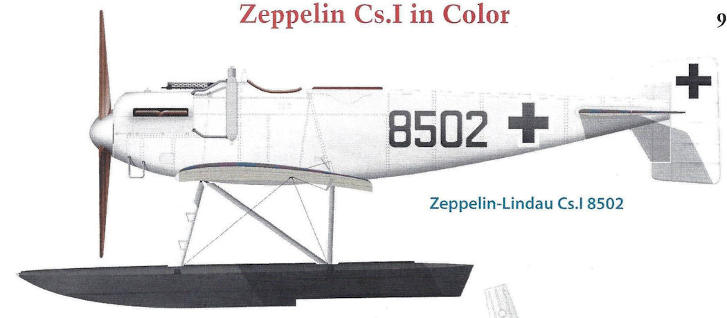
Zeppelin-Lindau Cs.I 8502
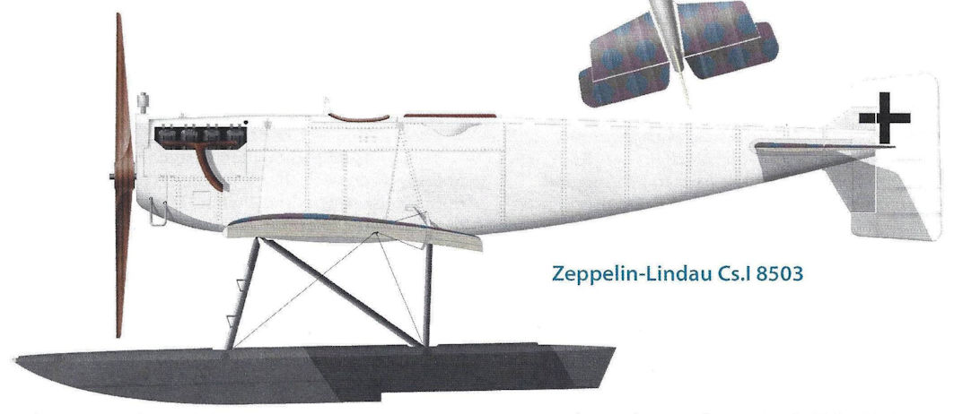
Zeppelin-Lindau Cs.I 8503
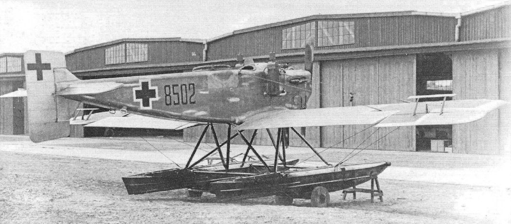
The ZWL Cs.I number 8502 with ear radiators and spinner. (PM Grosz collection/STDB)
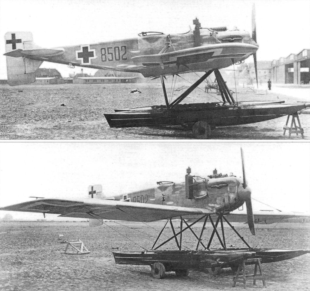
Zeppelin Cs.I with side radiators fitted to expedite flight testing. (1918)
The ZWL Cs.I number 8502 with ear radiators and spinner.
Dornier Cs.I Marine Number 8502 was the only one of the three airframes to fly.
The ZWL Cs.I number 8502 with ear radiators and spinner.
Dornier Cs.I Marine Number 8502 was the only one of the three airframes to fly.
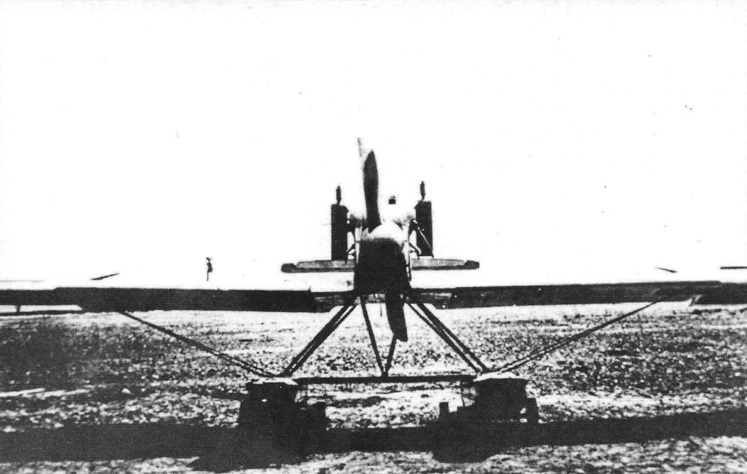
The ZWL Cs.I with ear radiators and spinner. (PM Grosz collection/STDB)
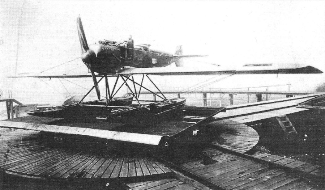
The ZWL Cs.I in front of the Seemoos hangar in spring 1918. The prototype of the Cs.I number 8501 served as a test aircraft for the engineers and was often modified. The elevator had a negative profile (that is, it had an inverted airfoil section). The rudder was attached so that the larger part was on the lower end, in order to ensure as free a line of fire as possible toward the top.
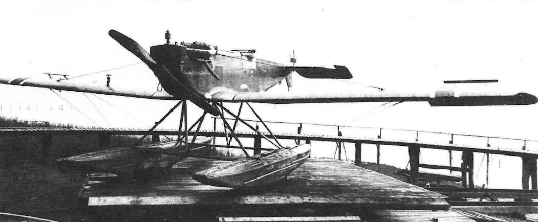
The Cs.I 8503 was outfitted with a front radiator and trim tabs. The 5.8 meter long duraluminum floats received an additional seal with paint. (Airbus Group)

Closeup of the ZWL Cs.I number 8503 with production nose radiator. (PM Grosz collection/STDB)
The CS.I was intended to use a nose radiator as seen here. This installation produced less drag than the ear radiators and enabled the CS.I to attain greater speed.
The CS.I was intended to use a nose radiator as seen here. This installation produced less drag than the ear radiators and enabled the CS.I to attain greater speed.
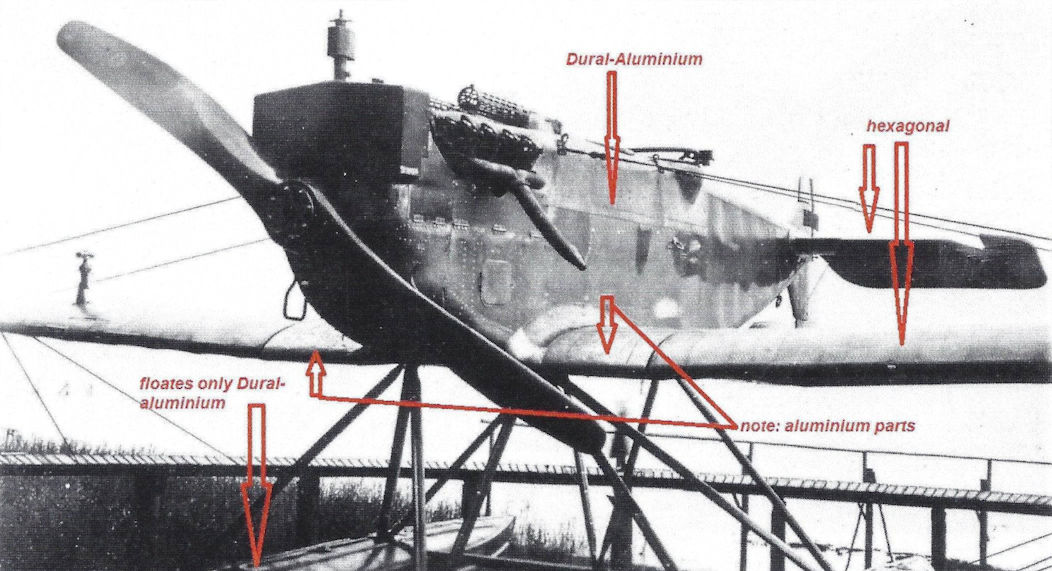
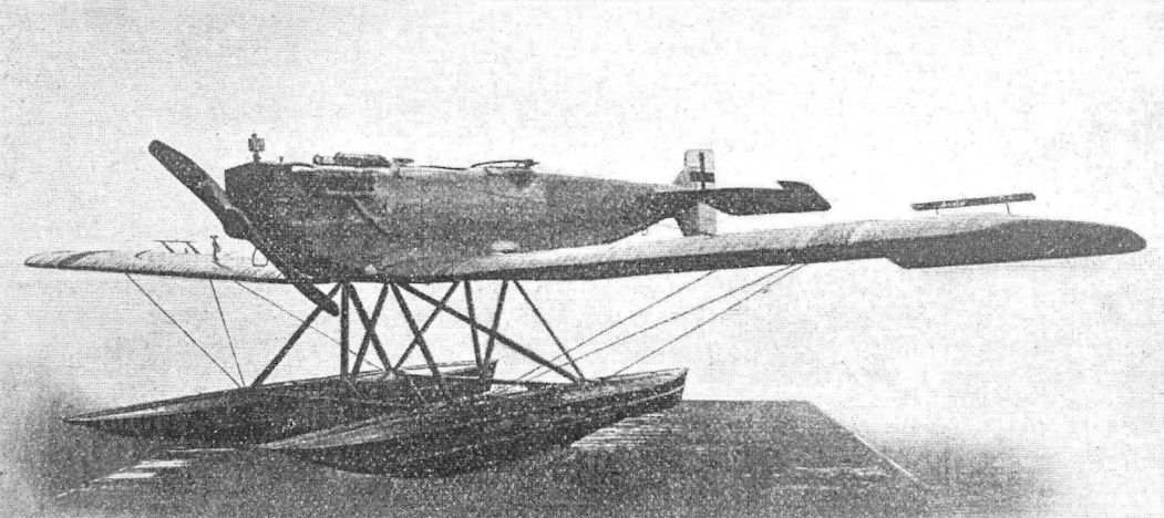
The ZWL Cs.I number 8503 with production nose radiator. (PM Grosz collection/STDB)
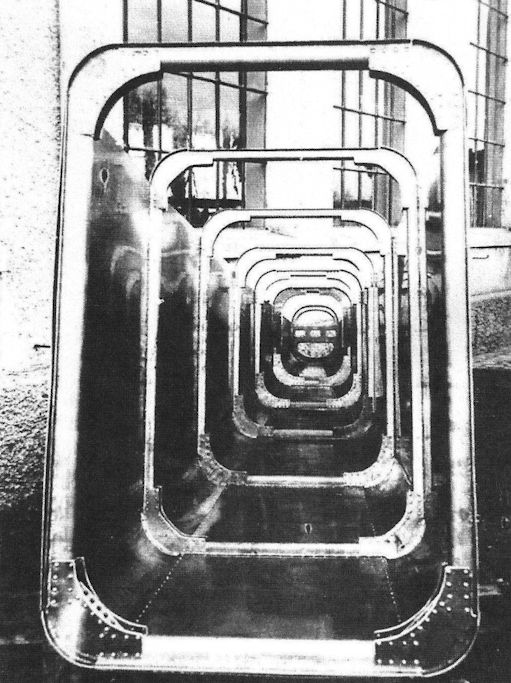
The self-supporting monocoque construction of Cs.I enabled a completely free interior fuselage without a structural frame or tension cables. (Airbus Group)
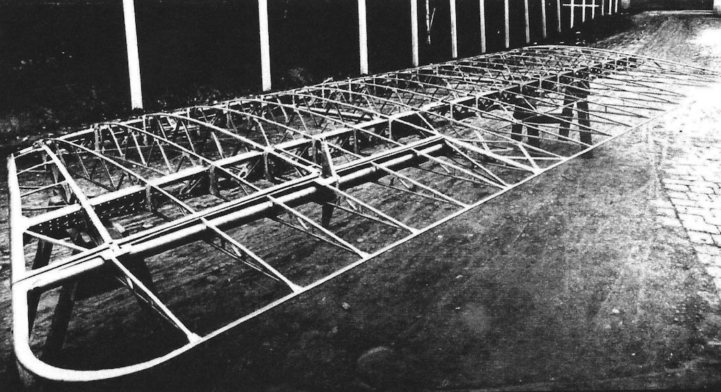
The wing construction of the Cs.I. (Airbus Group)
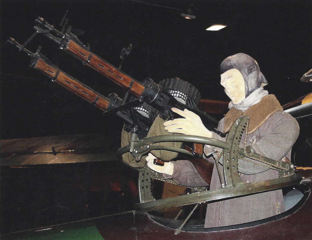
The Scarff-MG-Ring allowed the weapon to be swung around vertically and horizontally. This British invention was copied by the Germans and introduced as the Hussmann-Normal-MG-Ring, and its diameter was 75 centimeters. (Walter Werner)
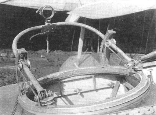
The Hussmann-Normal-MG-Ring.
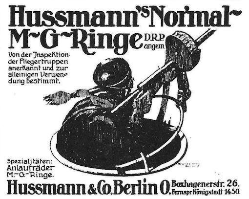
Period ad for the Hussmann's Normal M-G-Ringe.
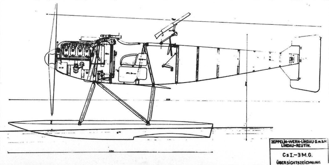
Drawings of the Cs.I 8501 and 8502. (Airbus Group)
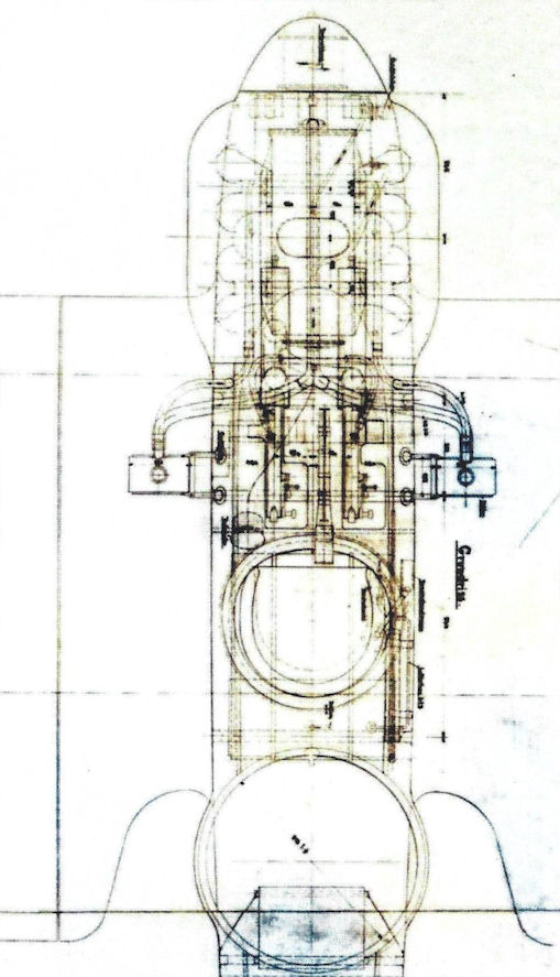
Technical drawing of the front of the fuselage of the Cs.I (Dornier Museum Friedrichshafen B2/623)? (Airbus Group)
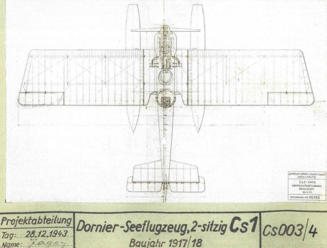
Drawing of the Cs.I 8501 and 8502. (Airbus Group)
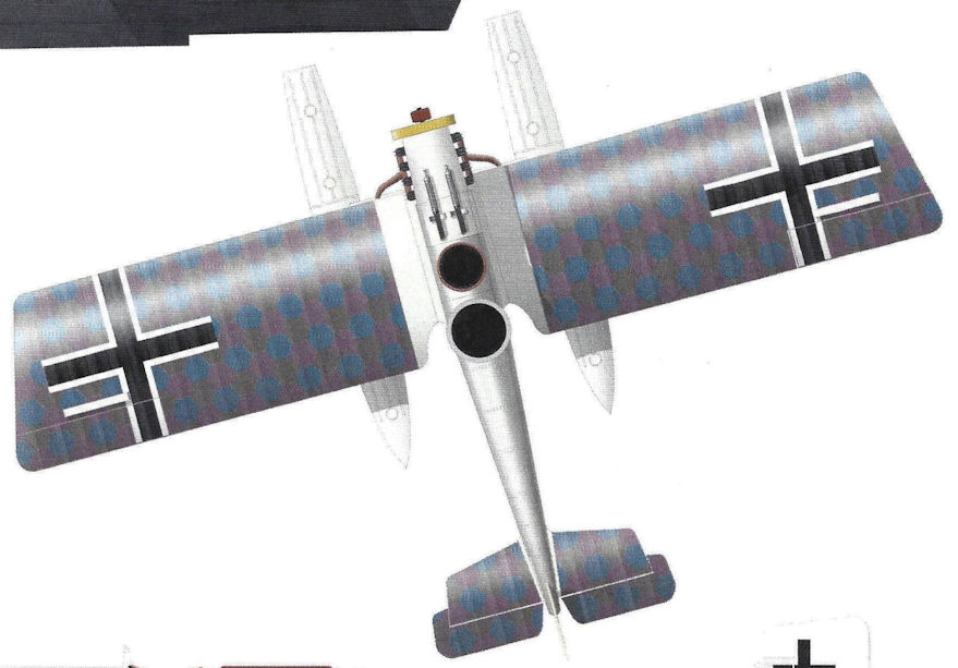
Zeppelin-Lindau Cs.I 8503
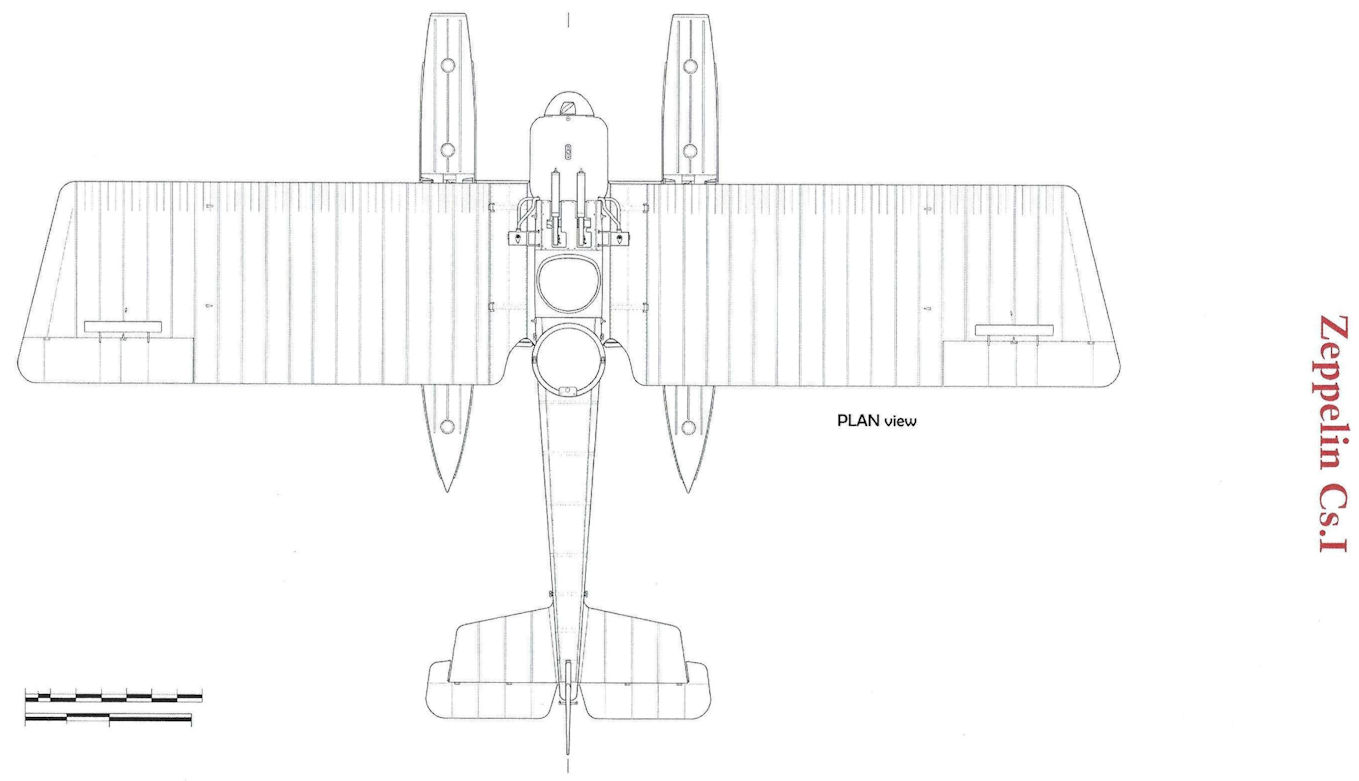
Zeppelin Cs.I
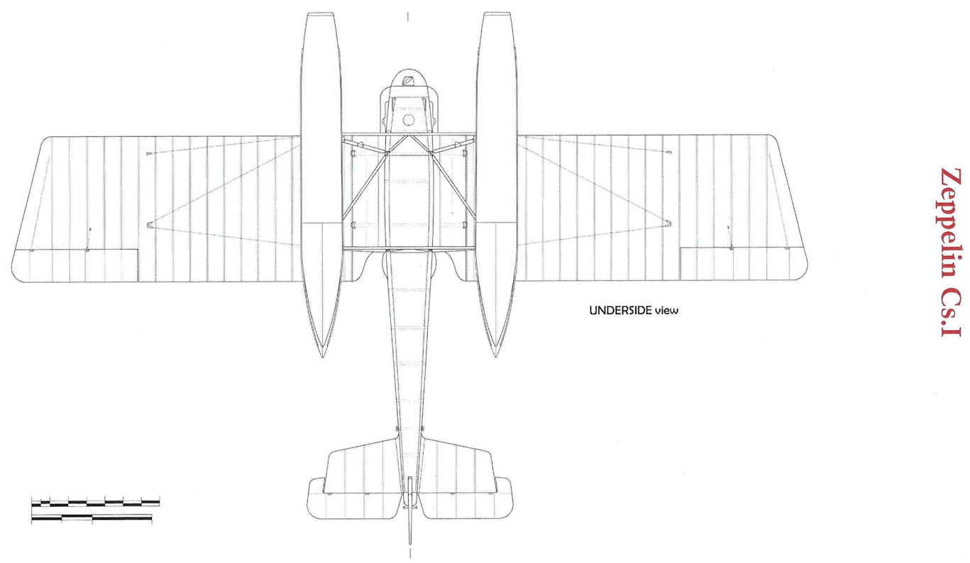
Zeppelin Cs.I
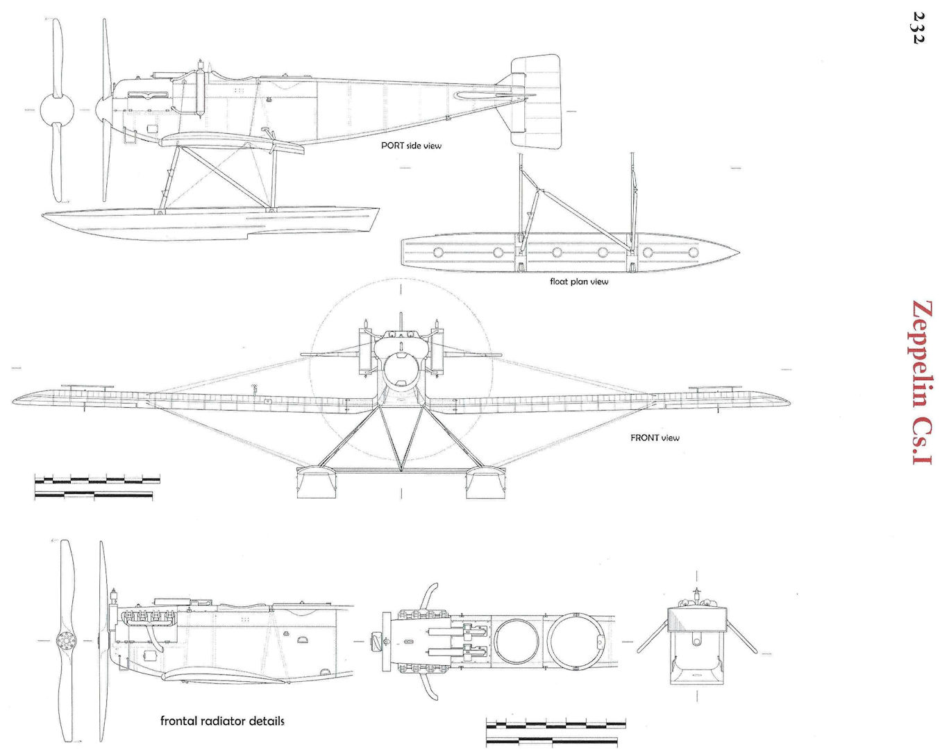
Zeppelin Cs.I
Zeppelin-Lindau D.I
On February 11th, 1918, Claude Dornier submitted an offer to IdFlieg for an all-metal fighter. This aircraft, a D-type (= single-seat biplane armed with two MGs), would be put into service at high altitudes since it would be able to fly at 8,000 meters.
After thorough deliberation within IdFlieg, ZWL received a preliminary agreement on February 28th, "for the delivery of six test aircraft."
The written confirmation arrived on March 11th, 1918. The order included the delivery of six ZWL all-metal D cantilever aircraft. Apparently, IdFlieg was not completely comfortable with Dornier's modern wing structure, without fabric coverings and purely made of metal. Included in the order was a set of wings with fabric covering. The D.I was to be powered with Daimler IIIa and Benz Bz IIIb engines.
The six aircraft received the military designations D.1750-D.1755/18. At the same time of the order, Daimler and Benz were instructed to each send an appropriate engine to Reutin. Benz also delivered a cooling system for its Bz.IIIa as well while IdFlieg prepared a cooler for the ED IIIa engine. The armament and the instruments and accessories including the instrument panel, seatbelts, and high-altitude oxygen system came from IdFlieg supplies.
Engineer Albert Presser led the development of the D.I, and Eugen Jager was a member of his staff. In the following weeks the first all-metal cantilever single-seat fighter came into being in Reutin, where the monocoque construction technique of the fuselage was also transferred to the wings. The supporting structure was made of continuous upper and lower wings. The design as a cantilever biplane enabled the wings to sit on the fuselage, connected only by four cabane struts. Struts and tension cables were unnecessary. The lower wing was connected to the fuselage at three places. All of the ribs were of equal length on the three-spar, rectangular wings. This led to a simple and economical construction style, which Dornier kept for many of the designs in the following 20 years. In addition to the duraluminum-planked wings, another set covered in fabric was also constructed, as per IdFlieg’s request. Later there was a compromise: half of the D.I's wing was covered in duraluminum, and half in fabric. For the parts covered in fabric, the workers in Reutin used the army's five-color camouflage (D.1752/18) and the three-color navy camouflage (D.1751/18) and 1753-1755/18), which was in ample supply because of the flying boats.
The pilot's seat could be adjusted up and down, as in the V1. The undercarriage consisted of two teardrop-shaped hollow bodies made of duraluminum that would serve as the legs, connected by a steel axle. The aircraft was armed with two LMG 08/15.
The streamlined main fuel tank, which could hold 80 liters (of which 20 liters were for reserves) hung under the fuselage so that it could be jettisoned to minimize the danger of fire. Similarly, the auxiliary tank, which was located under the pilot's seat, could also be thrown overboard in case of fire. The oil tank, which held 10 liters, was placed lower so that the oil was fed to the oil pump by the downward slope of gravity. Engineers built adjustable side flaps into the cooling system to regulate the temperature of the cold engine and the discharge of air during flight.
The D.I type's (D.1752/18) maiden flight took place on June 4th, 1918 in Zech; the pilot was Sergeant Ruppert. After a few taxi tests and short flights, he took the aircraft on a 20-minute flight at 1,500 meters where the aircraft showed good climbing and flying capabilities. After the flight, pilot Ruppert determined:
“[...] flies wonderfully, climbs excellently. Almost no vibration, elevator and rudder control are fine and impeccable engine (Mercedes). ”
While landing, Ruppert overlooked a ditch on the former military training ground and damaged the left landing gear.
“[...] Unfortunately, it was not all sheer joy. Our pilot had a small accident during the landing. While taxiing he rolled into a small ditch and the shock forced the left landing gear to buckle. The airfield was actually not an airfield, but rather a military exercise area and therefore scarred with trenches and dugouts. The aircraft was disassembled and transported back to the workshop in Reutin for repairs.”
In the workshop, a new engine, a 185 HP BMW IIIa, was installed in the repaired fuselage. The engine that had been planned for the aircraft, the Benz Bz IIIb, was eliminated from consideration due to the unsatisfactory results of that engine type in the Cs.I.
A new cooling unit from the Suddeutsche Kuhlerfabrik (Southern German Cooler Factory) was mounted for the more powerful BMW engine.
On June 15th, the first measurement flights were conducted with the second D.I, the 1751/18, which had been completed in the meantime. The measured take-off roll and landing roll were both less than 100 meters and the top speed was 195 km/h. This aircraft with the 160 HP D IIIa engine was immediately sent to Adlershof to take part in comparison flights for fighters. Time was of the essence because the competition had already begun on May 27th. Experienced combat pilots judged the various new designs the German aviation industry had to offer, and IdFlieg’s future orders would be heavily influenced by their verdicts.
Following the order and delivery requirements set out by IdFlieg, every participating aircraft must have already passed resistance testing. IdFlieg skipped these structural tests due to time constraints, with what turned out to be fatal results.
On July 3rd, First Lieutenant Hermann Goring climbed into the D.I at the airfield in Adlershof, flew a few circuits and landed without incident. Following his flight, Captain Kurt Schwarzenberger and Lieutenant Konstantin Krefft flew the aircraft. Then Captain Wilhelm Reinhardt, Commander of the Richthofen 'Flying Circus' (JG I) took his turn to fly the D.I.
Reinhardt climbed to 1,000 meters and then the airplane dropped into a steep nosedive. The strain was too much for the spars of the upper wing, which broke off. Captain Reinhardt died in the crash.
Ironically, a set of reinforced spars had already arrived in Adlershof, ready and prepared to be mounted to the aircraft. After the aircraft had been shipped from Reutin to the comparison flight program, the designers had also had some quiet doubts. Recalculations supported these doubts and reinforced spars were immediately constructed and sent to Adlershof. In addition, ZWL had requested the D.I be taken out of the comparison testing program until the modifications had been completed. It is unclear why those responsible at IdFlieg did not grant this request.
Employees of the company had been banned from approaching the aircraft after the comparison testing had begun. Despite this tragic accident, IdFlieg was still very interested in the D.I. The combat pilots, including a member of the Austro-Hungarian air corps, gave the aircraft a positive rating.
Between September 23rd and October 11th, 1918, structural tests were conducted on D.I 1750/18 in Adlershof. The only modifications that were requested were that the cabane struts were to be attached to the horizontal beam and a few insignificant improvements on the fuselage.
At the next comparison testing event that took place in Adlershof between October 15th and 31st 1918, two Zeppelin-Lindau aircraft were present: D.I 1751/18 E (for "Ersatz" - replacement) and 1752/18 with a BMW IIIa engine. The competition was being conducted to choose the combat aircraft for a planned spring offensive in 1919. Dornier's D.I achieved excellent results, including climbing 1,000 meters in 2.6 minutes, fully loaded with fuel, armed and outfitted with an oxygen system. The targeted ceiling of 8,400 meters was reached after 45 minutes. The range was 270 kilometers, and top speed was 200 km/h.
The only complaint was the pilot's limited visibility directly upward and downward. Cutouts in the upper wing at the height of the pilot's seat and at the roots of the lower wings remedied this. Combat pilots' lives rested on good visibility, especially in dogfights, and therefore this was an important assessment criterion in all new aircraft.
The ceasefire on November 11th, 1918 did not mean production within ZWL immediately ceased. Work in Lindau continued until the end of the year with a smaller staff. The company was still in possession of the D.I aircraft completed during this time, the 1753/18, in December 1918. In 1921 it was sold to the U.S. Navy for $9,000. The D.I 1754/18, after it was stored at the Riechs military airfield in Schliessheim from 1919, was also purchased by the U.S. Air Service, via arrangement through a Swiss company.
Members of the construction crew were able to hide the final specimen, D.I 1755/18, from the interallied military control commission. Later, it was a big attraction at the Dornier Museum in Manzell and in the Salzstadel in Friedrichshafen. During the Second World War, the museum was badly damaged by an allied bombing campaign, and the D.I was scrapped for its metal.
Although it is not likely that many ZWL (Do) D.I would have been used in the German air corps, this type of aircraft, along with the Siemens-Schuckert D.VI, were considered equal to the enemy French high-altitude fighter such as the Nieuport 29 (peak altitude 8,300 meters).
Dornier used the rich data from the D.I to move on to his new fighter airplane project at the end of 1921, the Dornier H Falke (Falcon).
Specifications of Zeppelin-Lindau Aircraft
Type Length, m Span, m Height, m Chord, m Propeller Manufact. Armament
(guns) Weight, kg Motor Crew
D.I 6.40 7.80 2.60 Heine 2.75 2 fixed 883 Daimler D IIIa/BMW IIIa 1
Military Numbers of Dornier-ZWL Aircraft
Military Designation Manufact. Type Class Engine Notes
1750/18 ZWL (Do) D.I
1751/18 ZWL (Do) D.I DIIIa
1751/18 E ZWL (Do) D.I BMW IIIa Replacement for the D.I crashed 7/3/18
1752/18 ZWL (Do) D.I D IIIa Mothballed in Adlershof
1753/18 ZWL (Do) D.I DHIa Sold to the USA in 1922
1754/18 ZWL (Do) D.I BMW IIIa Mothballed in Schleissheim 1919/1920
1755/18 ZWL (Do) D.I BMW IIIa Possibly Dornier Museum Friedrich.
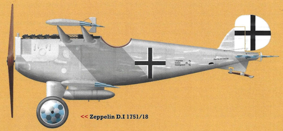
Zeppelin D.I 1751/18
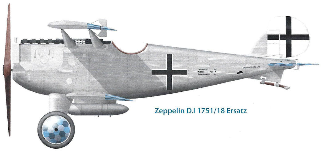
Zeppelin D.I 1751/18 Ersatz
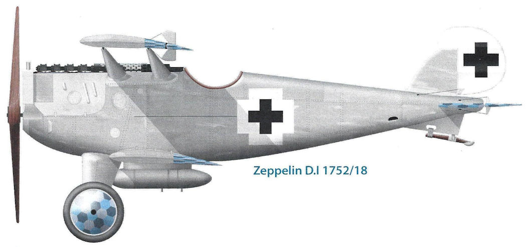
Zeppelin D.I 1752
/18
/18
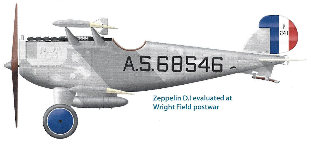
Zeppelin D.I evaluated at Wright Field postwar
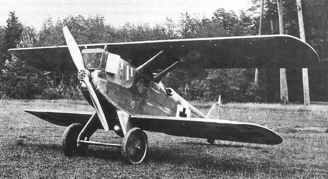
Despite carrying the Zeppelin-Lindau name, the division headed by Claudius Dornier the D.I, first flown on 4 June 1918, was designed by Adolph Rohrbach, head of the Zeppelin-Staaken division. Like its few Zeppelin-Lindau forebears, this latest single seat, biplane fighter used light alloy as its primary structural material. Externally, the 185hp BMW IIIa powered D.I was an exceptionally clean design, with fully cantilevered wings and tail unit, bereft of any external and, hence, drag-producing bracing struts or wires. Rushed through the design and assembly phases in order to compete in the second 1918 Adlershof fighter competitions, the disassembled D.I was dispatched by train immediately after its maiden flight. Reportedly, while still in transit, someone re-checking at the factory discovered that the upper wing attachment fittings were too weak and alerted Adlershof not to fly the aircraft until strengthened fittings could be rushed to them. Sadly, whether the information was not received, or simply ignored, the D.I was flown twice after re-assembly, Hermann Goring being the first service pilot to fly it, followed by Hptm Wilhelm Reinhardt, who lost his life after the upper wing detached in mid-air. At least two other D.Is were built, as two found their way to the US soon after the war, to be tested by the US Army and Navy, respectively. Earlier German testing had been critical of the aircraft's lack of speed, said to be 124mph at sea level, and general heaviness of the controls.
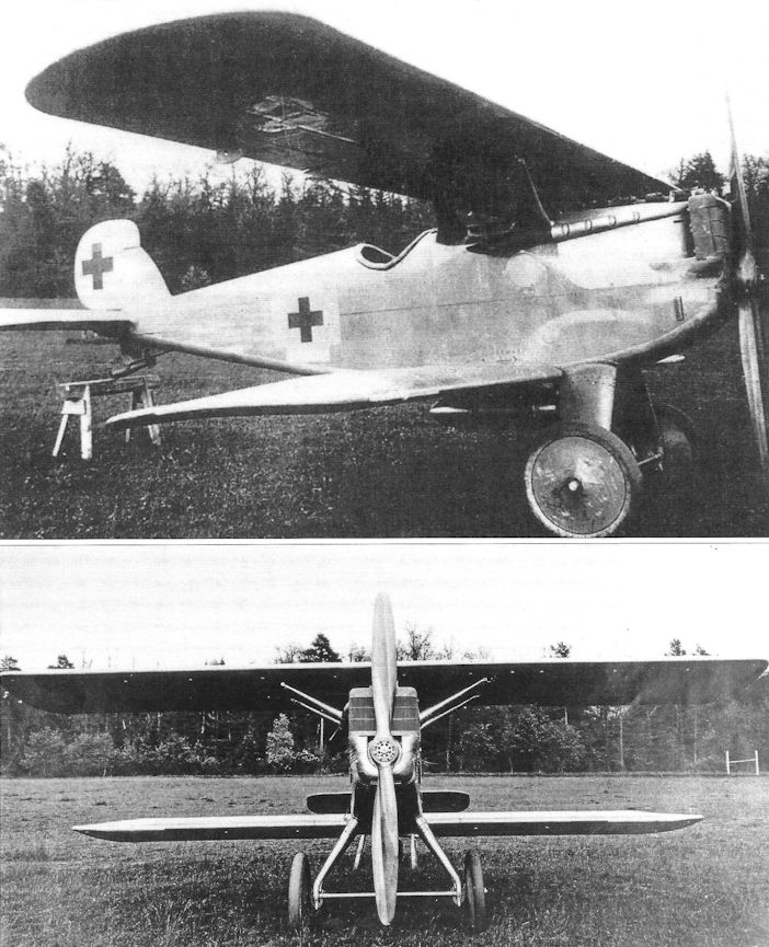
The D.I (D.1752/18) at the beginning of June 1918 with the 185 HP BMW IIIa engine. A larger radiator from the Suddeutscher Kuhlerfabrik had to be mounted for the more powerful BMW engine.
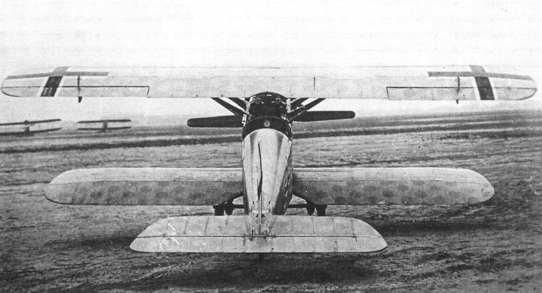
The D.I 1751/18 on the field in Zech prior to its transport to Adlershof. (Airbus Group)
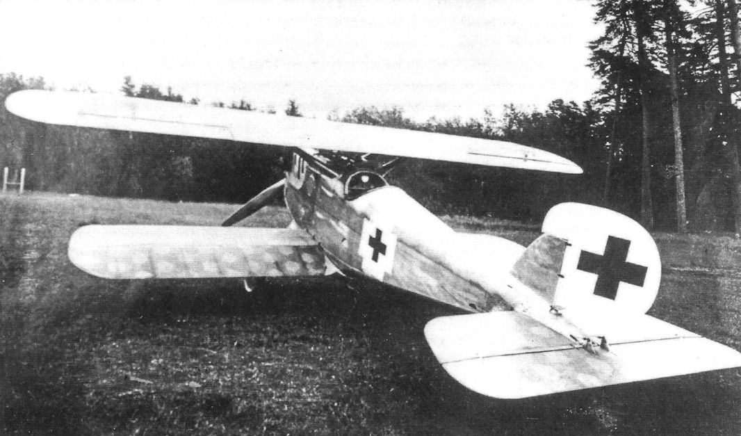
D.I (D.1752/18) prior to its maiden flight on June 4th, 1918.
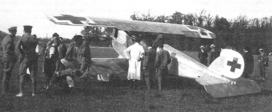
Preparing to start on the Zech field ahead of the D.I's (D.1752/18) maiden flight on June 4th, 1918. Pilot Sergeant Ruppert prepares for the flight in front of the left wing.
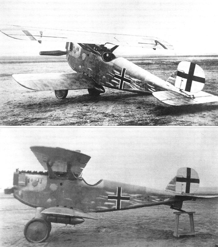
Zeppelin D.I 1751/18 Ersatz (replacement). The Zeppelin D.I had the most advanced airframe technology of any WWI aircraft. The metal monocoque construction it pioneered was used for decades thereafter.
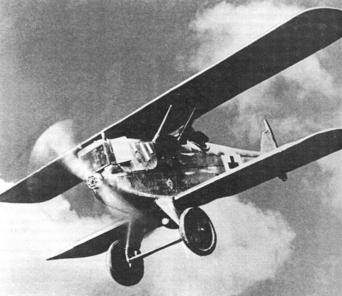
The ZWL D.I 1751/18 with a 160 HP D IIIa engine in flight. (Airbus Group)
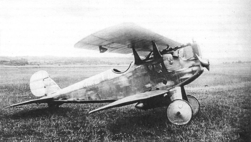
Zeppelin D.I in Germany before being shipped to the USA.
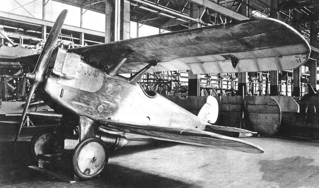
Zeppelin D.I in the USA postwar. This one was bought by the US Navy for research.
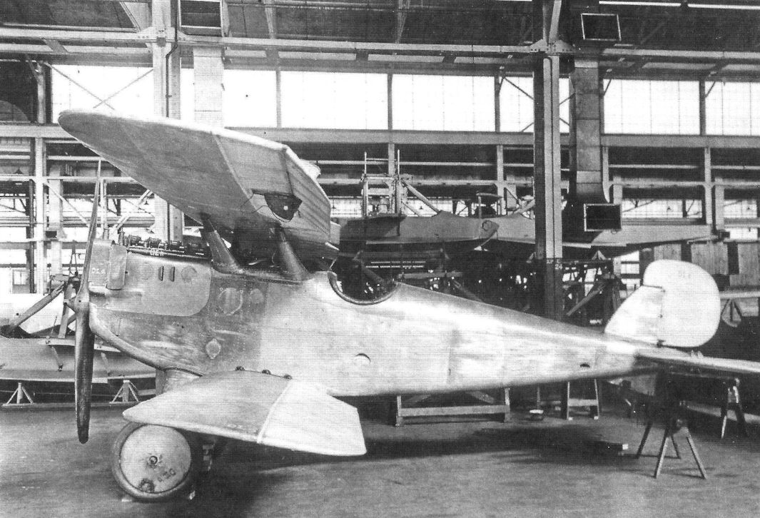
Zeppelin D.I in the USA postwar. The wings were metal covered in their front half and fabric covered aft.
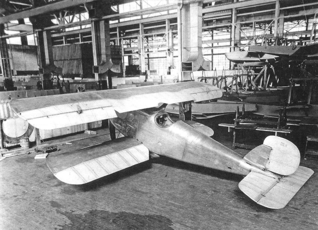
Zeppelin D.I in the USA in the Naval Aircraft Factory, Philadelphia. Curtiss MF-Boat hulls are stored in the background. The wings were metal covered in their front half and fabric covered aft.
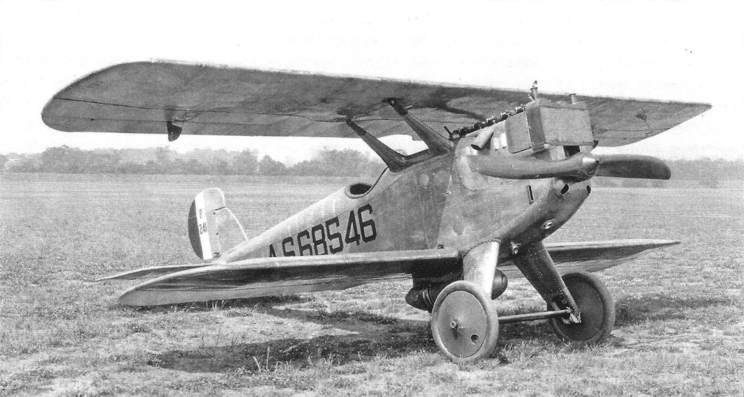
A Zeppelin D.I with 185 hp BMW.IIIa being tested by the U.S. Army at McCook Field in 1922. The all-metal Zeppelin D.I fighter had the most advanced structure of any WWI aircraft. Prototypes were powered by both the Mercedes D.IIIa and by the 185 hp BMW.IIIa. The surface of the wings aft of the box spar had fabric covering, as did the horizontal tail surfaces. This example was brought to the USA for testing after the war and is shown after re-assembly. Other than its biplane configuration, this was the preview of future propeller-driven fighters until the jet age; then early jets used similar structural technology. Postwar the Zeppelin D.I was often referred to as the 'Dornier D.I' in honor of its brilliant designer, Dipl-Ing. Claude Dornier, who later founded his own company, but Zeppelin D.I, the company name during the war (or Zeppelin-Lindau D.I after the division of the company), is what it was called when it was designed, built, and flown, and therefore is the correct designation. The fuel tank under the fuselage could be jettisoned in case of fire.
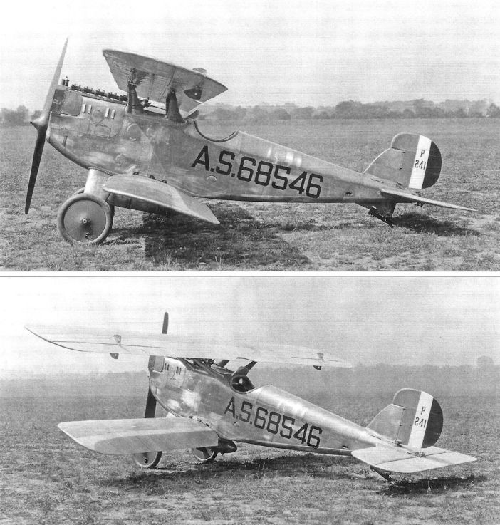
Zeppelin D.I in the USA postwar. It bears the Air Service serial No. 68546 and the McCook Field Number P-241.
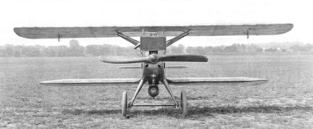
Zeppelin D.I in the USA postwar. It was designated A.S.68546. The radiator is large to keep the engine cool.
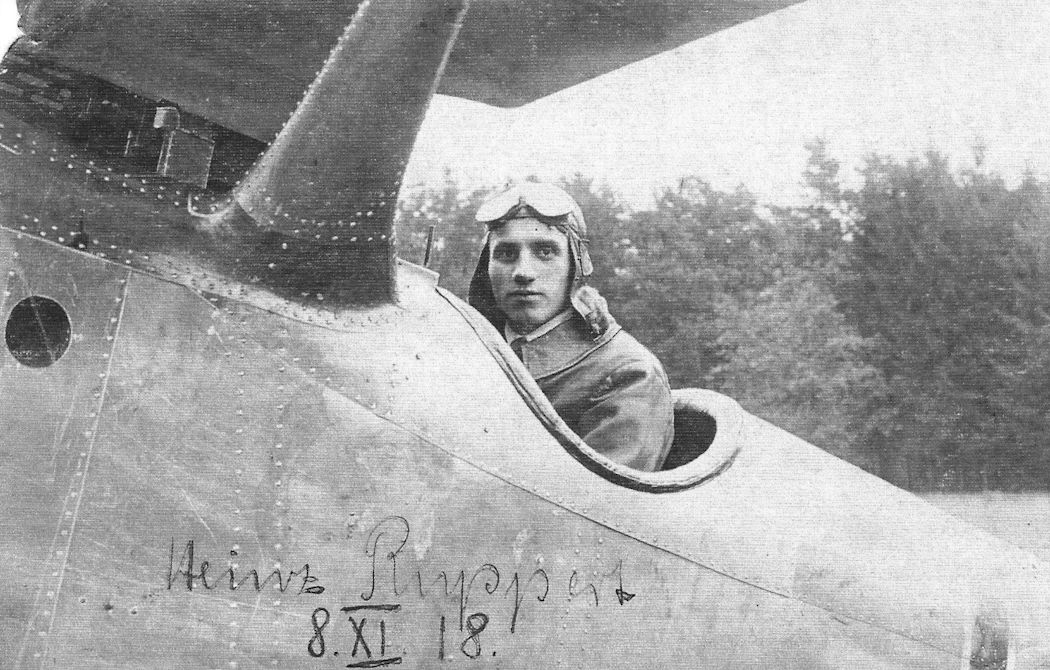
Vice Sargeant (Vizefeldwebel) Ruppert, a test pilot, here in the Zeppelin D.I., was instrumental to the success of the metal land aircraft. Photo dated Sep. 8,1918. (Reinhard Zankl)
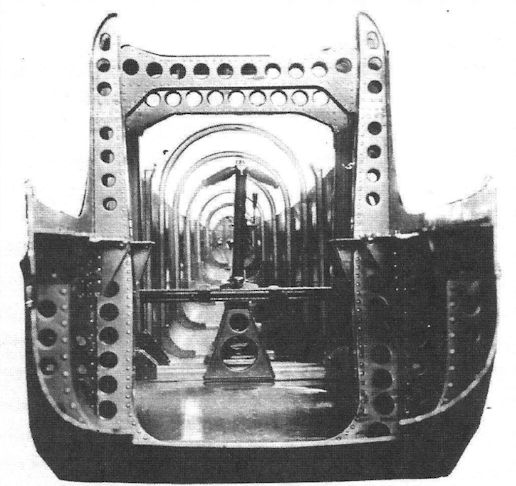
The fuselage construction of the D.I in monocoque construction. (Airbus Group)
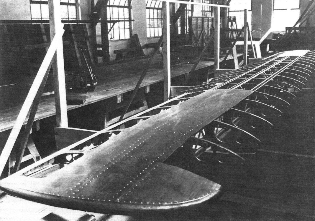
Monocoque construction was used for the wings for the first time.
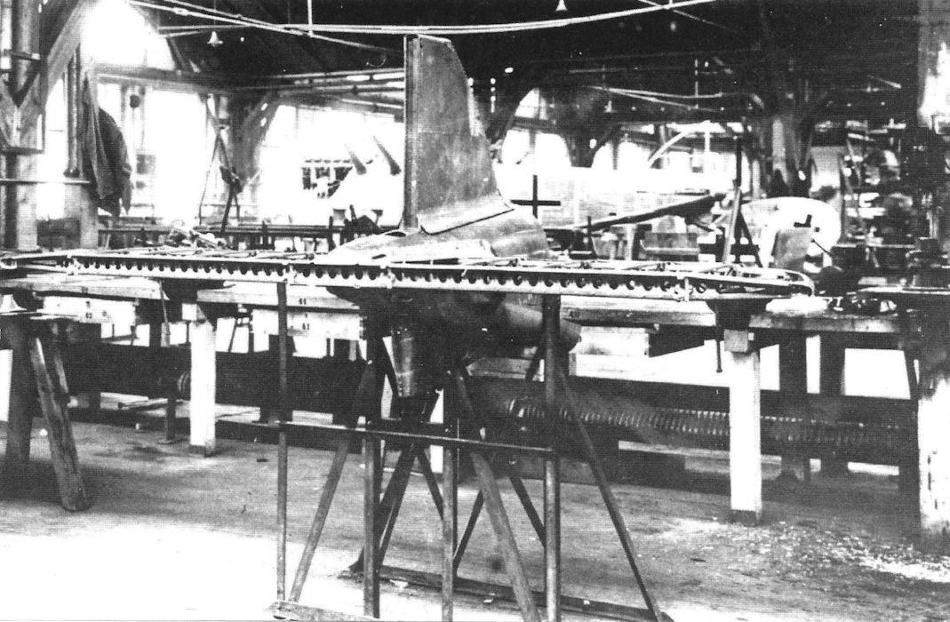
The tail assembly of the D.I in the hangar in Reutin. (Airbus Group)
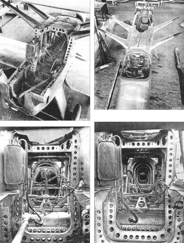
Zeppelin D.I in USA
These photos show stages in the destructive structural testing of the two Zeppelin D.I prototypes in the USA postwar.
These photos show stages in the destructive structural testing of the two Zeppelin D.I prototypes in the USA postwar.
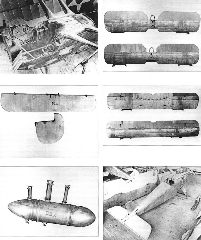
Zeppelin D.I in USA
The components of the two D.I fighters were marked D.I and D.II so that they could be assembled correctly on arrival in the USA.
The components of the two D.I fighters were marked D.I and D.II so that they could be assembled correctly on arrival in the USA.
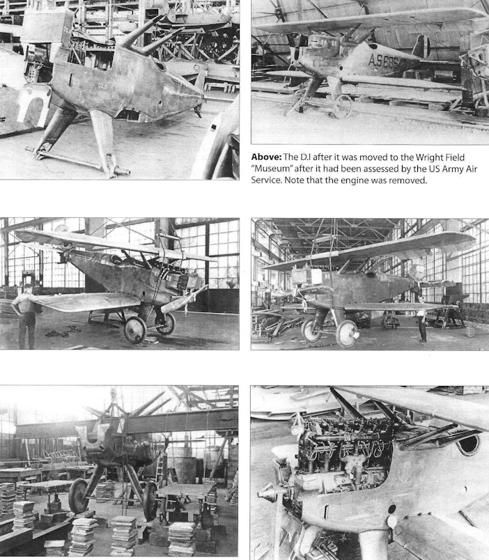
Zeppelin D.I in USA
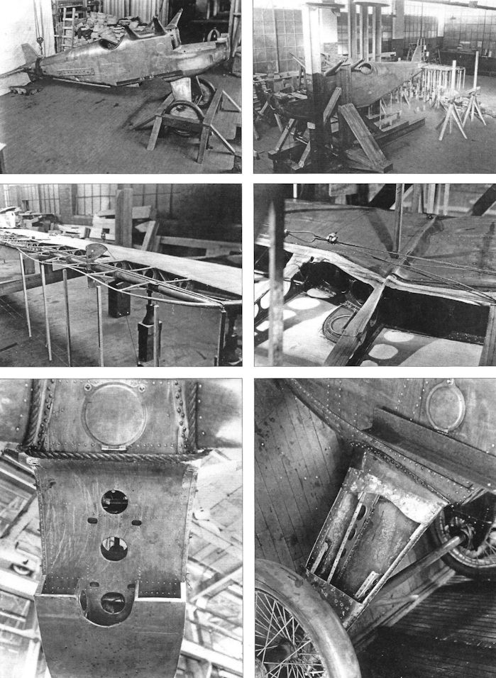
Zeppelin D.I in USA
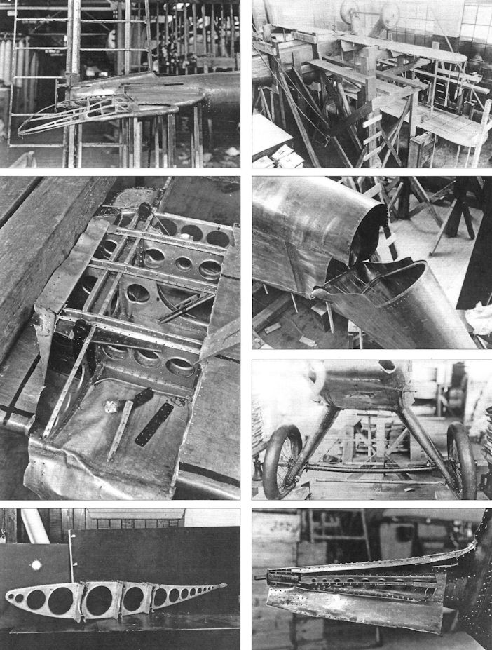
Zeppelin D.I in USA
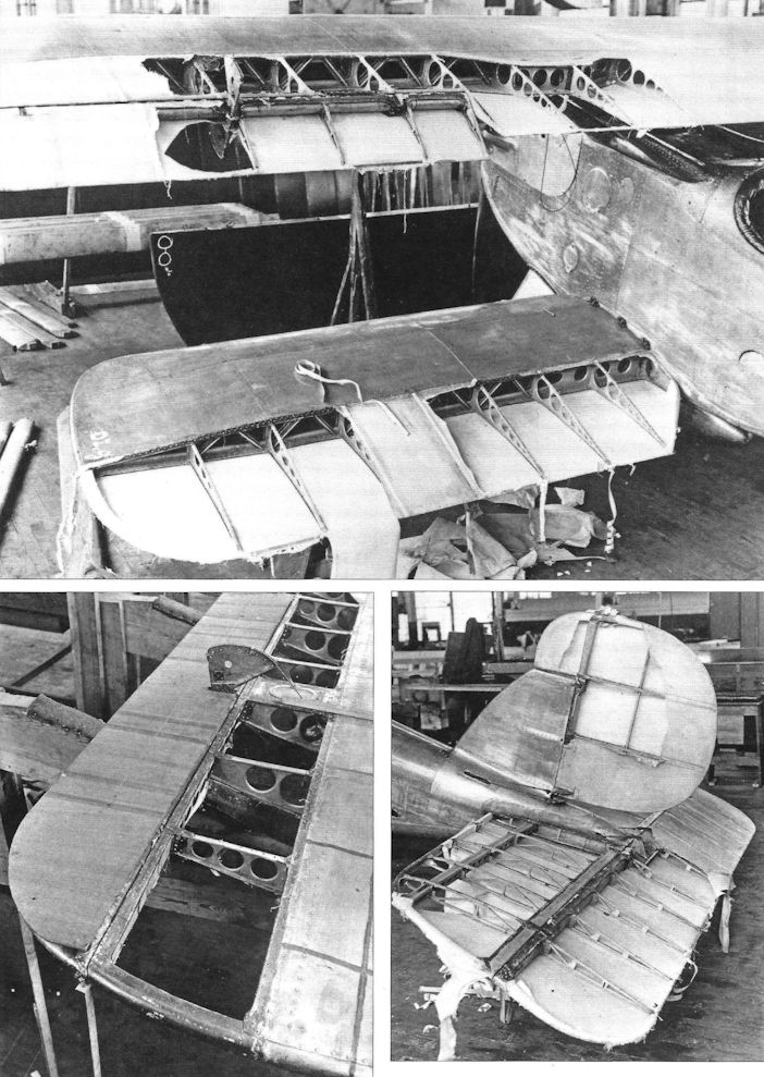
Zeppelin D.I in USA
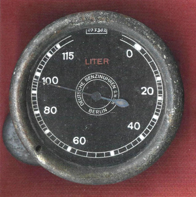
The fuel gauge of the ZWL D.I's droppable 100 liter tank, that was attached to the underside of the fuselage.
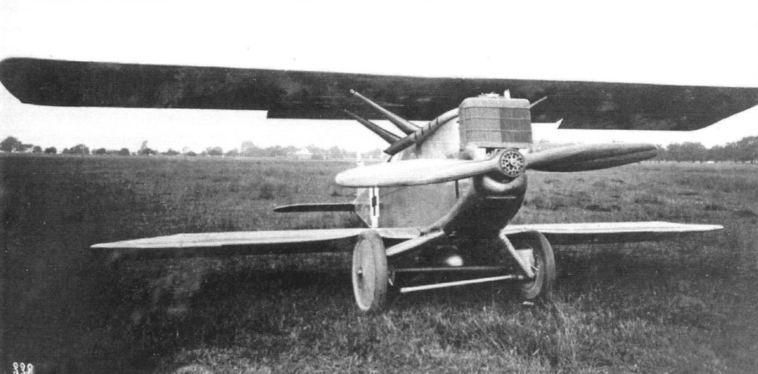
Broken landing gear of the D.I (1752/18) on June 4th, 1918 in Zech. After the accident upon landing, the duraluminum connecting tube was replaced with one made of reinforced steel. Despite some more hard landings in following flight tests, there were no more complaints. (Airbus Group)
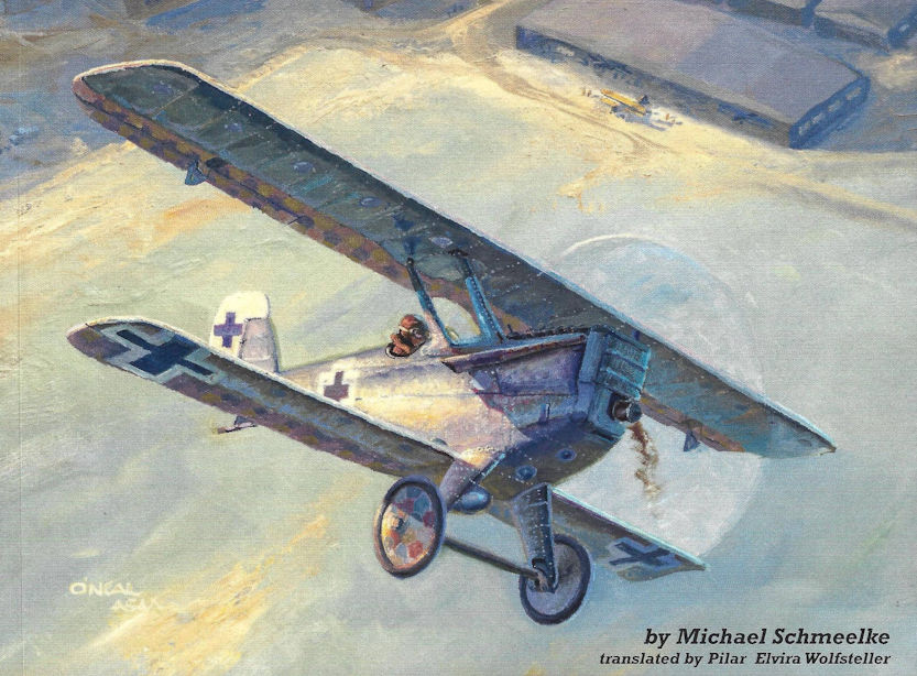
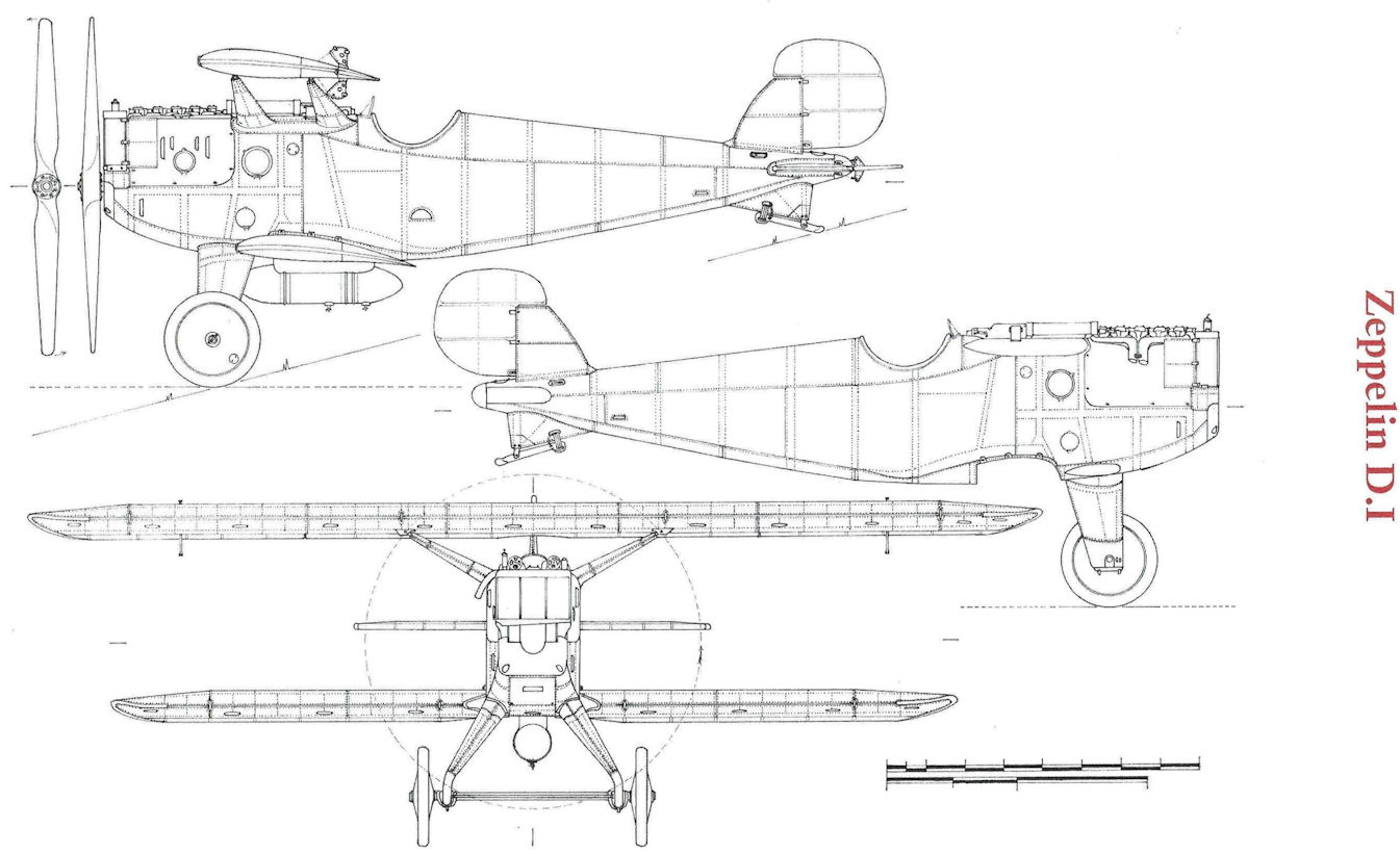
Zeppelin D.I
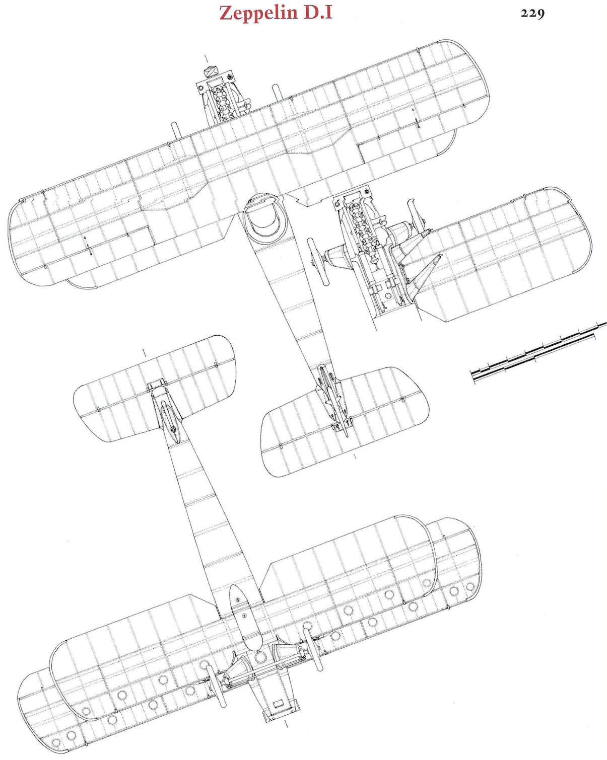
Zeppelin D.I
Military Numbers of Dornier-ZWL Aircraft
Military Designation Manufact. Type Class Engine Notes
M.N.8808 ZWL (Do) R Mb IVa x 4 Flying boat, cancelled 11/1/1918
M.N.8809 ZWL (Do) R Mb IVa x 4 Flying boat, cancelled 11/1/1918
Military Designation Manufact. Type Class Engine Notes
M.N.8808 ZWL (Do) R Mb IVa x 4 Flying boat, cancelled 11/1/1918
M.N.8809 ZWL (Do) R Mb IVa x 4 Flying boat, cancelled 11/1/1918
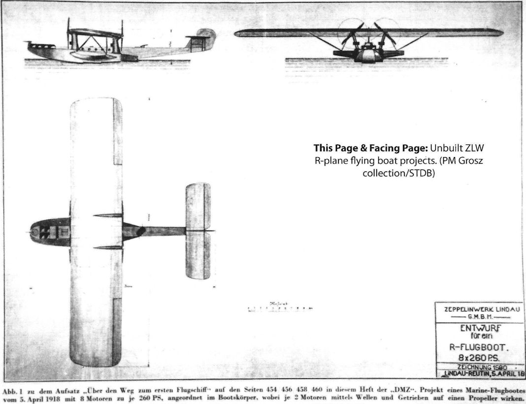
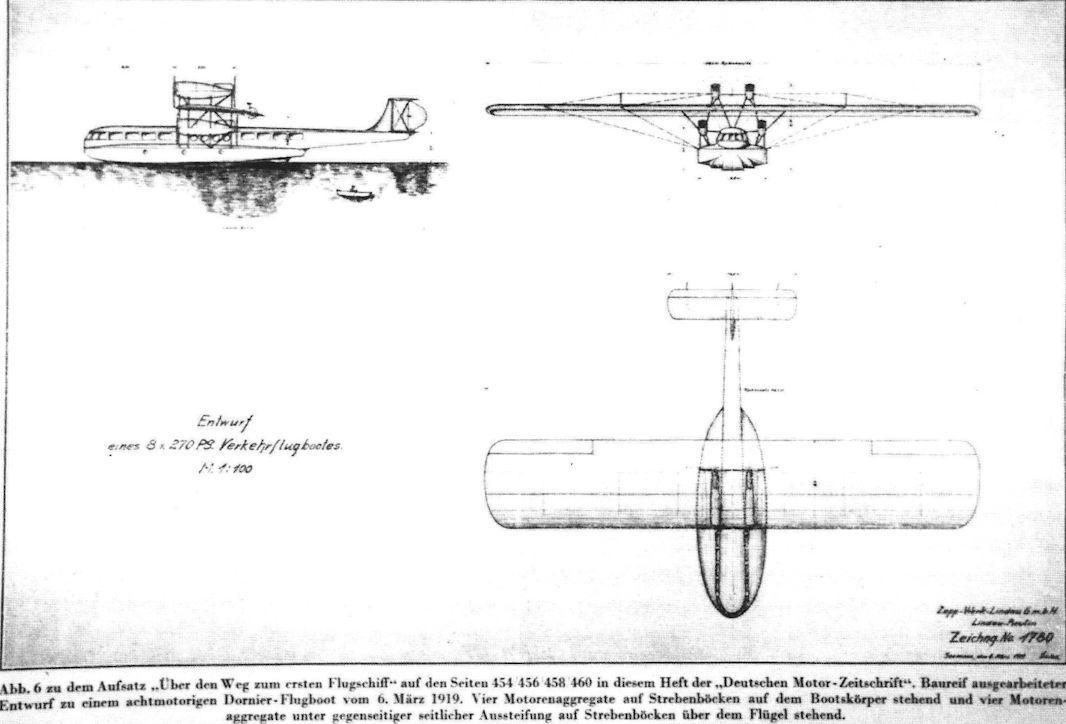
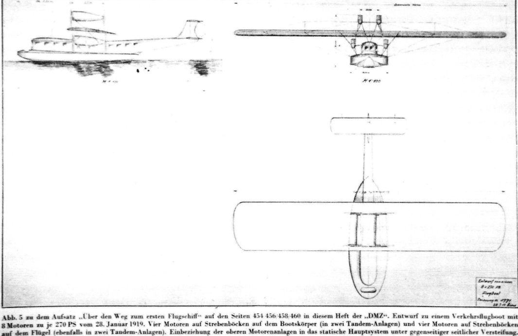
Unbuilt ZLW R-plane flying boat project (PM Grosz collection/STDB).
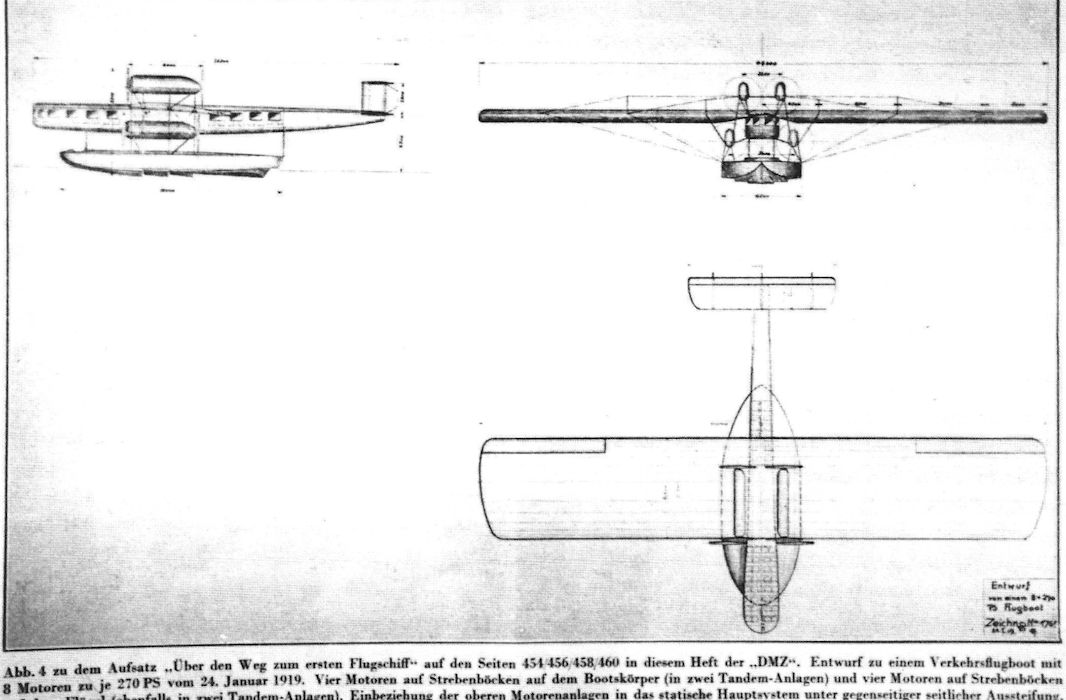
Rs.IV: The Last Giant Flying Boat of the First World War
On January 31st, 1918, the Zeppelin company received an order from the Reichs Naval Department for two giant flying boats with the designated numbers 8801 and 8802. Claude Dornier had had a meeting with representatives from the department on January 7th in Warnemunde. At this meeting he showed a drawing (Design number 1488) of his latest design, the Dornier Rs.IV.
But there were differences of opinion between Dornier and the RMA about the shape of the hull of the Rs.IV.
The controversy was about the newfangled sponsons attached to the hull. The SVK documents from January 1918 show that a final decision about this was still outstanding. The SVK itself took on the task of calculating the stability, the results of which would determine the shape of the hull that was to be built.
The SVK in Warnemunde began carrying out practical tests in May 1918. A Hansa Brandenburg C boat, Naval number 1329, was outfitted with wooden sponsons and at the same time, the wing floats were removed. After this series of tests with 1329, which was called W22 after the modifications, were successfully completed in the summer of 1918, decision-makers in the RMA re-thought their strategy. The sponsons gave Rs.IV increased stability in the water as well as in the air, and formed a single entity with the fuselage. The hull itself was only 3.6 meters wide, but including the sponsons, the total breadth was 8 meters.
In addition, the RMA pressured Dornier to move construction of the flying boats to Berlin or the Baltic Sea. Dornier refuted this by saying that the craft was still not being serially produced, and the LZ hangar in Potsdam was occupied with production by Staaken. The shift of production would mean a significantly longer building period and additional costs. In addition, the new flying boats could easily be flown from Lake Constance to the North Sea or the Baltic Sea.
The preparations for the design and construction of the high-wing Rs.IV with a wingspan of 37 meters had already begun in summer 1917. Production had to be halted for a few weeks though, due to lack of materials. On June 21st 1917 ZWL informed RMA:
“[...] We have to inform you that we do not have any materials in stock to continue work on the R boats. It is increasingly difficult to procure materials and this could take at least eight to ten weeks [...]"
Another reason Claude Dornier could only begin to realize his Rs.IV project in January 1918 was of a financial nature. The basic structure of the Rs.IV was similar to the Rs.III. The hull, the tail assembly, and the wing skeleton would again be built of metal. A fabric covering would only be used for the wings. Both ailerons would have trim tabs, as in the Rs.III. The tail boom would be built completely of duraluminum, using the newest developments in monocoque construction. The bow of the tail boom would be configured as a cockpit. Rs.IV could therefore be controlled from both the hull as well as the tail boom. The test flights would determine where the cockpit would be positioned. Windows in the front and on both sides of the tail boom, both made of cellon, gave the pilot a perfect view.
To power the Rs.IV, once again Maybach Mb IVa engines were built into two nacelles. Because of the narrow hull, the two nacelles were too close together. The propellers were staggered to allow enough latitude for the propeller discs, leaving 20 centimeters of space between them. The forward-facing cooling systems were brought to the middle of the engines and integrated into the cowling. In this way they formed an aerodynamic closure of the nacelle. On all four radiators of the Rs.IV, metal louvers, at the time called “Zuggardinen" ("traction curtains"), allowed the cooling to be regulated.
The main fuel supply, enough for 10 hours of flight, was stored in eight 400-liter light metal drums in the hull of the aircraft. The fuel was pumped through two Bosch Propeller cog pumps into the fuel tanks of the nacelles. The oil containers held 35 liters each.
The maiden flight took place on October 12th, 1918, piloted by Ober-Flugmeister Weiss and Ing. Schulte-Frohlinde. After 100 seconds of start-up, the 10.6-ton Rs.IV took off from Lake Constance at a speed of 95 kilometers per hour.
In the following days several pilots completed numerous test flights, in order to determine climbing performance, speed and additional cargo load capacity.
On November 9th, 1918 news that the emperor had abdicated and fled into exile in Holland reached Friedrichshafen. Two days later the German delegation in Compiegne signed the ceasefire agreement and thereby ended the hostilities. Despite this event, the testing of Rs.IV continued in Seemoos because according to a letter from the Reichs naval department from February 1918, the contract continued to be valid, irrespective of the end of the war. In early 1919, with the flying boats' naval service looking less and less likely, Dipl.-Ing. Claude Dornier decided to retrofit the aircraft for civilian use. The openings for the machine gun turrets in the hull and on the tail boom were closed. In the front portion of the empennage, a passenger cabin was installed.
After these modifications, the flying boat was used for sightseeing flights over Lake Constance. During one flight in the beginning of June 1919, the back third of the tail boom broke off during a normal landing. This damage could be quickly repaired by strengthening the interior wall of the hull and additional profiles.
Despite its planned civilian use, the Rs.IV was ordered to be destroyed by the Interallied Control Commission on April 17th, 1920. The finished parts of the second Rs.IV were also committed to this fate and were destroyed in Seemoos.
Specifications of Zeppelin-Lindau Aircraft
Type Length, m Span, m Height, m Chord, m Propeller Manufact. Armament
(guns) Weight, kg Motor Crew
Rs.I 29.00 43.50 7.20 4.60 Garuda/Reschke 1 flexible 6,475 Maybach Mb IVa 240 hp 5
Rs.II 28.88 33.20 7.60 6.50 Lorenz 3.70 1 flexible 6,388 Maybach Mb IV/IVa 6
Rs.III 22.74 37.00 8.10 6.50 versch. 4 flexible 7,865 Maybach Mb IVa 6
Rs.IV 22.30 37.00 8.55 6.50 versch. 4 flexible 6,980 Maybach Mb IVa 6
Military Numbers of Dornier-ZWL Aircraft
Military Designation Manufact. Type Class Engine Notes
M.N.8801 ZWL (Do) Rs.IV Mb IVa x 4 Destroyed in Seemoos per ILUK
M.N.8802 ZWL (Do) Rs.IV Mb IVa x 4 Destroyed in Nov. 1918, not completed
M.N.8803 ZWL (Do) Rs.IV/V R Mb VII x 4 Flying boat, cancelled 11/1/1918
M.N.8804 ZWL (Do) Rs.IV/V R Mb VII x 4 Flying boat, cancelled 11/1/1918
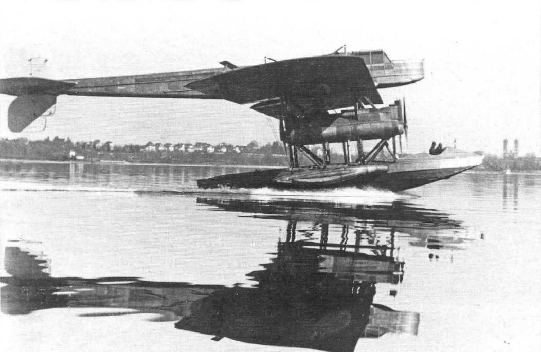
The Zeppelin Rs.IV was the final Giant flying boat design for the Navy. On October 12th, 1918, the Rs.IV took off on its maiden flight. (Airbus Group).
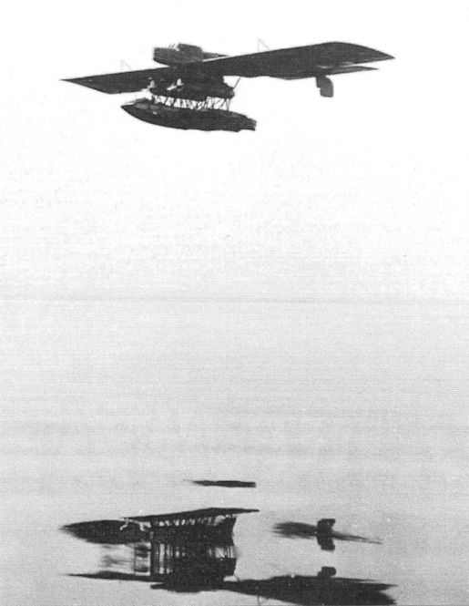
The Rs.IV over Lake Constance in the fall of 1918. (Airbus Group)
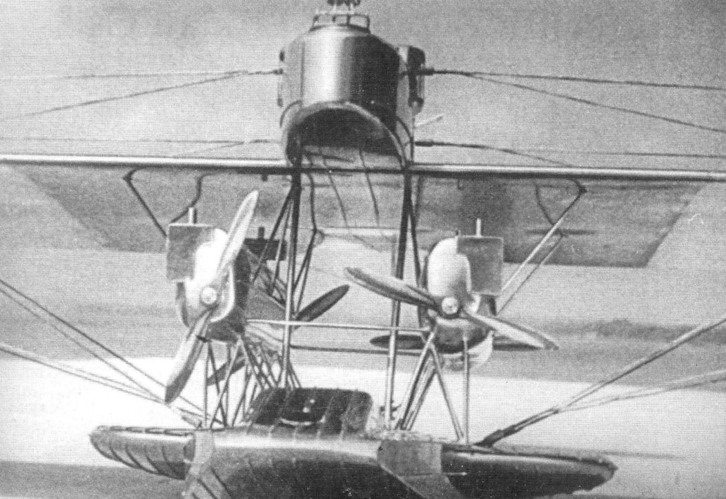
More views of the Rs.IV. The photo shows the overall configuration.
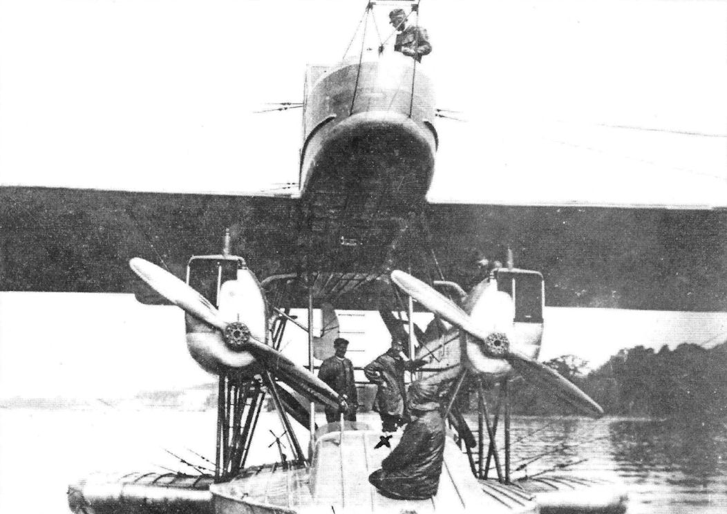
In the middle of April 1920, the Rs.IV was brought into the hangar at Seemoos and on April 17th it was destroyed at the direction of the Allies.
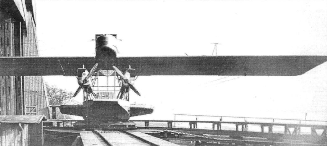
The actual hull was only 3.6 meters wide, but including the sponsons the total width was 8 meters.
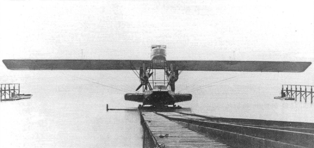
The Rs.IV on the transportation car in Seemoos in 1918.
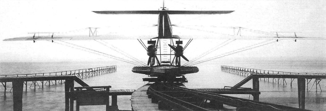
The crew could reach the tail boom during flight via a ladder. (Airbus Group)
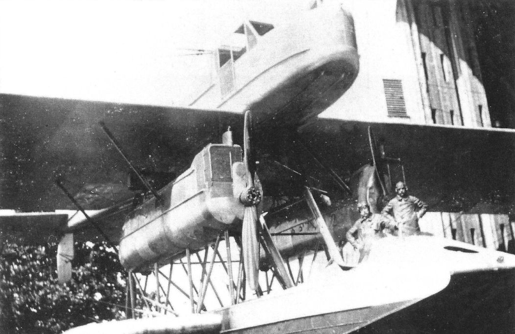
The Rs.IV in front of the Seemoos hangar. (Airbus Group)
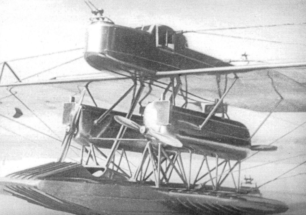
More views of the Rs.IV. The photo shows the overall configuration.
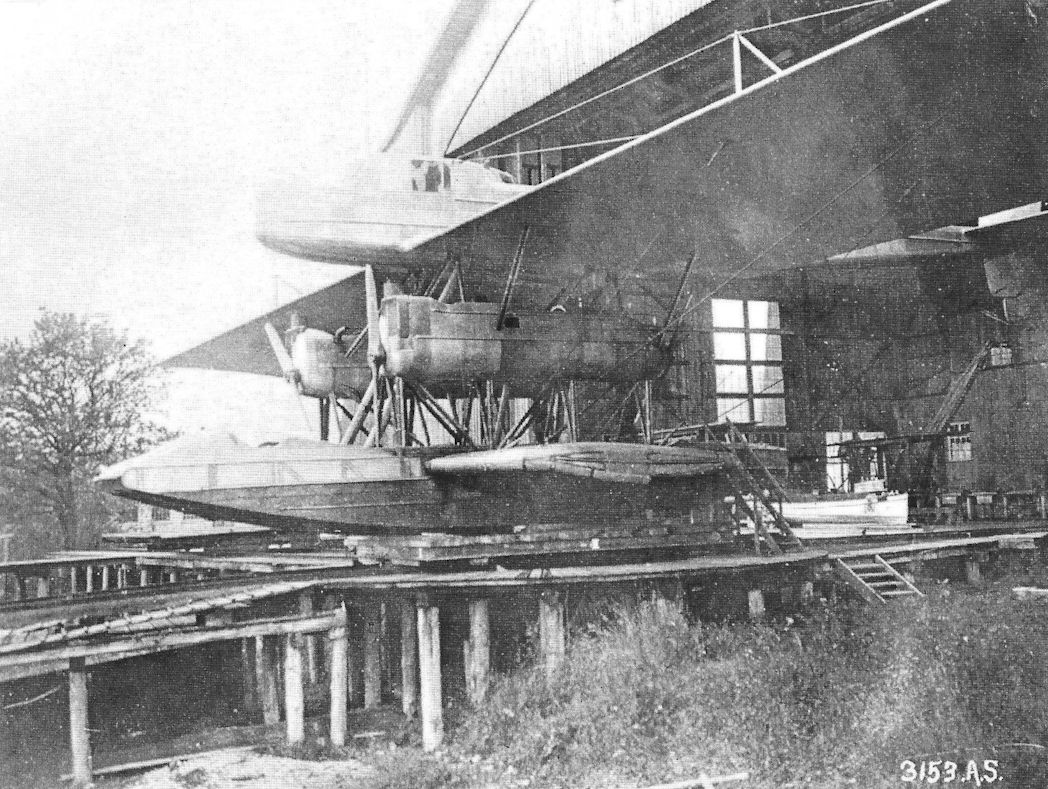
The sponsons on the hull of the Rs.IV remained a characteristic of the Dornier flying boats until well into the 1940s.
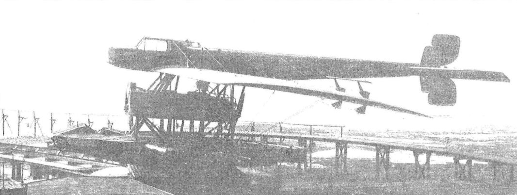
Rs.IV side view.
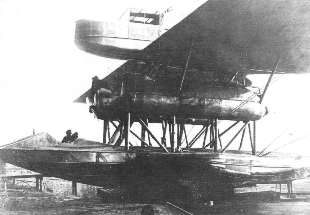
Rs.IV was modified for civilian use in May 1919, including a cabin in the tail boom with space for 6 passengers. (Airbus Group)
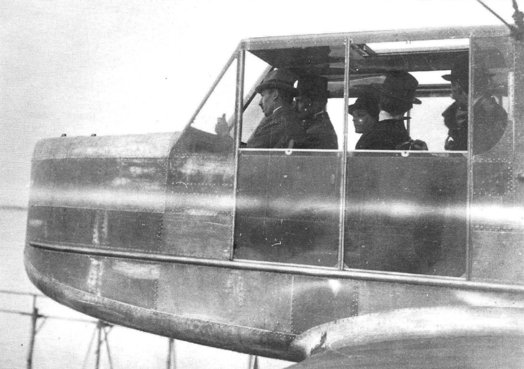
On May 25th, 1919, the Rs.IV took off with 13 passengers for a sightseeing flight over Lake Constance. (Airbus Group)
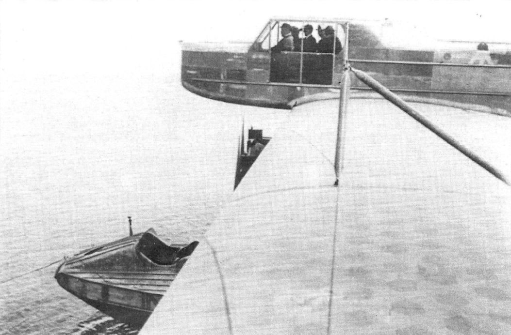
The photo shows the naval camouflage fabric used for the wing covering.
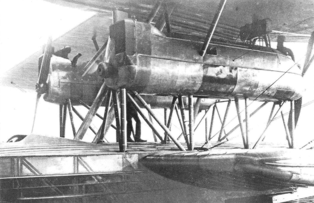
The metal-paneled nacelles were accessible for smaller repairs during flight. (Airbus Group)
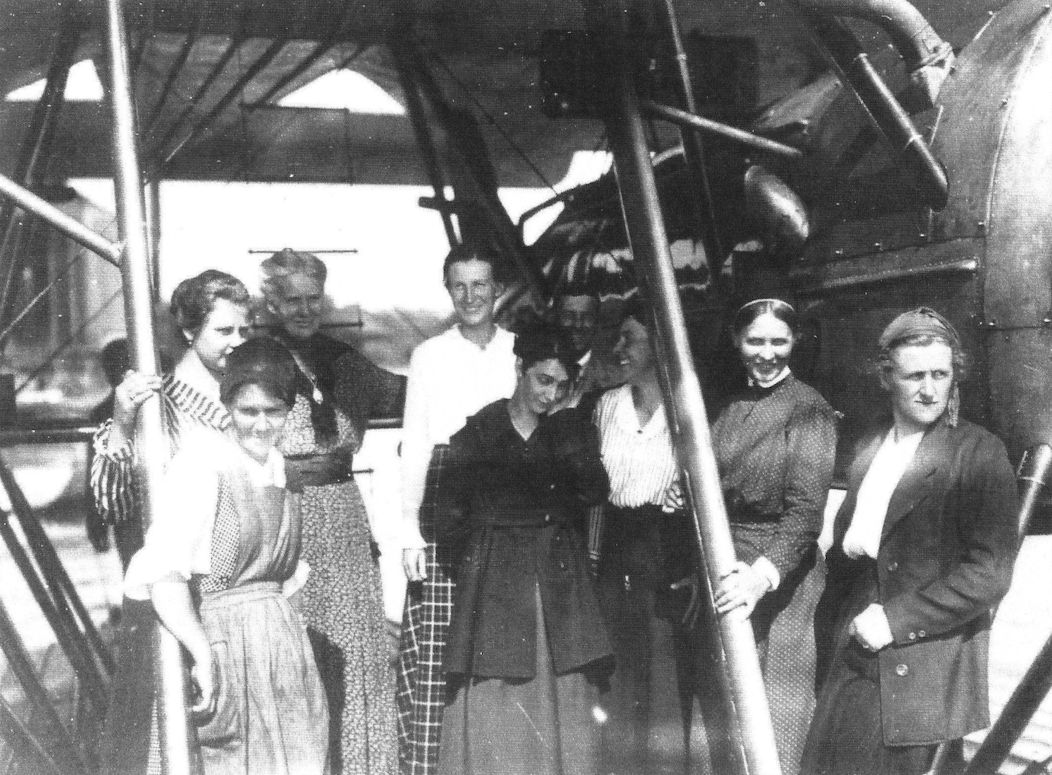
Female workers on the Rs.IV in Seemoos (Airbus Group).
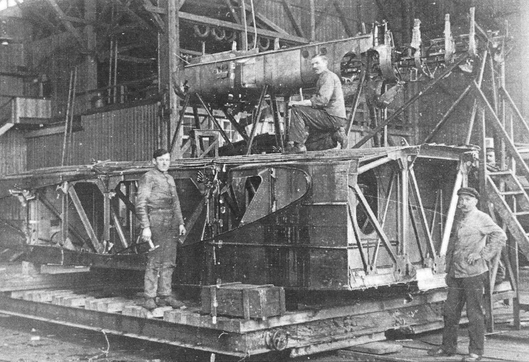
Workers in the Seemoos hangar while disassembling Rs.IV (Airbus Group).
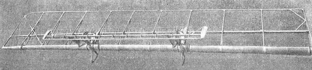
Rs.IV elevator structure
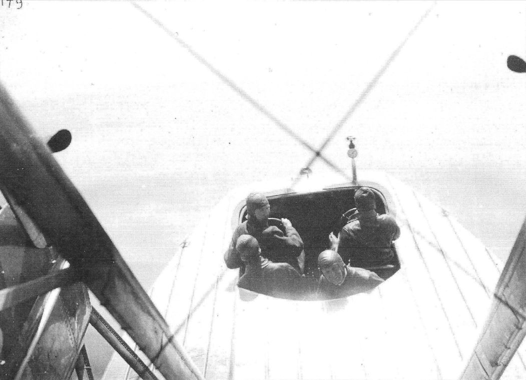
View onto the cockpit in the hull from the tail boom. (Airbus Group)
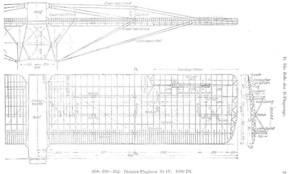
Rs.IV detail drawings.
Zeppelin-Werke-Lindau GS.I
In mid-1917, the RMA asked ZWL for a design of a two-engine armed reconnaissance aircraft, called a G-type. Marinebaurat Schmedding arrived in Reutin in the fall of 1917 to discuss this project personally with Claude Dornier. Dornier later wrote:
“[...] I received a visit from Marinebaurat Schmedding, with whom I discussed the Navy’s demands for the boat to be designed, and the fulfillment of the same. On my drawing board I had an early draft with all of the components of the later “Wal”. I had covered this with a piece of paper because I thought it was too early to subject it to governmental criticism. In the course of the discussion, Mr. Schmedding approached my drawing board and took away the piece of paper that I had affixed to protect my project. What could I do? Mr. Schmedding did not hold back on his criticism. He had nothing positive to say about it and strongly suggested I stop working on it. He especially hated the way the engine and the sponsons were placed. He wanted them replaced with the side floats. [...] I apparently defended my draft so well that the official criticism was so shaken, so that we agreed to take my revolutionary design to underlie the offer. It led to the order of three boats which would be designated “Gs.l” [...]”
This unusual and modern design (for 1917) had nothing to do with the common G-type versions from Gotha or Friedrichshafen. Therefore, this modern flying boat was received with everything from open criticism to complete rejection by the very conservative-thinking leaders of the RMA. In the end, though, Dornier's ingenious design won over the RMA, and in early 1918 it placed an order for three Gs.I large flying boats (sea). They were designated navy numbers 8805-8807.
In the waters of the North and Baltic Seas, the threat of enemy submarines was rising. The Rs- and G-types were designed to recognize and fight these U-Boats. The lighter G-aircraft were surely at an advantage due to their manoeverability in direct combat. In addition to the standard armament of the G-aircraft, with MG and light bombs, it also would carry a 2-cm Becker-gun. An effective strategy against the U-boats, meaning sinking them, could not be achieved with the MG 7.9-millimeter caliber guns alone. This was drastically proven when on July 8th, 1918, Hansa Brandenburg W12s and W29s stationed at the base in Zeebrugge, attacked the British submarines C25 and E51 in the English Channel. Although the W29s shot 5,000 rounds of ammunition and threw numerous 5-kilogram bombs, neither of the submarines was sunk. C25 was damaged, but was able to return safely to an English harbor.
In December 1916, the first tests with the fixed-mounted 2-centimeter Becker gun began at the SVK in Warnemunde. These tests, using a Gotha WD7, Naval number 676, were successfully completed in November 1917. Tests with a 3.7 centimeter aircraft gun from the Deutsche-Waffen- und Munitionsfabriken on a Gotha WD7, however, were not as positive. Often, the munitions feed failed, so that the project was ended on October 17th, 1917.
The head of the material and structural calculation department Ernst Rothenburg was responsible for the initial drafts of the Gs.I in 1917. After he moved to the Hansa-Brandenburg Werke, where he took charge of the development of metal fuselages as chief engineer, Lindau engineer Richard Vogt continued the work.
Construction commenced on the first Gs airplane, designated navy number 8805, as soon as the orders were placed. It was also customary that the RMA submitted a down payment along with the order. Based upon Vogt's drawings, blueprints for the completion of parts were prepared. All of the critical parts would be made of steel. To build the 15.3 meter-long and 2.5 meter-wide hull, as well as the non-critical parts of the wings, duraluminum would be used. The wingspan would be 21 meters. As in the Rs.IV, sponsons would also be used. Two Maybach Mb IVa engines in a tandem configuration would power the craft. The radiator for the front engine was conceived as a front closure for the entire engine system. For the back engine, the radiator was set upon the nacelle. The central placement of the engines had many advantages. If one failed, there would be no yaw moment to either the port or starboard sides. As a result, the vertical stabilizer could be kept relatively small because it only served for directional stability. This gave the Gs.I a great advantage in that it was very maneuverable, far better than all of the other G-types in the navy. The engine mechanic's spot was in the hull directly under the nacelle. The four fuel tanks, made by Luftschiffbau-Zeppelin, each held 215 liters and could easily be reached by the mechanic. Two oil tanks made of brass sheets held 35 liters each and they were placed in the nacelle.
The square rudder was, like the wings, double-sparred and covered in fabric.
The vertical and horizontal fins were balanced. The trimmable horizontal stabilizer was a conventional tail attached to the vertical stabilizer and supported by a spar on the fuselage. The trim was carried out through the rear spar and displayed visually for the pilot.
In the late summer of 1918, the construction of the Gs.I was further delayed. In addition to the lack of materials, the end of the war created unrest amongst the employees. Heinrich Triller wrote:
“[...] We were instructed to take over 200 soldier-prisoners from Munich to support our skilled workers in Lindau. These people did not have a productive time and therefore the completion of the parts was slow. Instead of a help, these people hindered our manufacturing process and also soiled our good employees with their radical thoughts. Deliveries of dural, steel, and further materials were delayed, sometimes for months. Under normal circumstances, our flying boat would have been ready to fly by the end of the summer 1918, since the Rs.II, an R-craft, at the time took just four months go from design to the water [...]”
Construction of the flying boat continued in Reutin after the war ended in November 1918. When the facility in Lindau closed, Triller took all Gs.I parts by ship to Seemoos, where the aircraft was completed. It was here that it also received the cabin structure for passenger operations at the front of the hull. After the Treaty of Versailles was signed, and all military aircraft construction was banned, Claude Dornier wanted to launch the Gs.I as a civilian aircraft. But time was racing. The ban took effect on January 10th, 1920, and the Gs.I had to find neutral customers outside of the country by that date. Eventually, the ban would be extended to the civilian sector, and lasted until 1926.
On July 31st, 1919, the Gs.I took off on its maiden flight, with naval aviator Weiss at the controls. Shortly thereafter, potential customers from Switzerland showed significant interest - Dornier's friendly contacts to the neighbor to the south surely helped. In August and September, 1919, Swiss Flight Lieutenant Ernst Frick tested the Gs.I several times in Seemoos. Frick was an experienced pilot, who had received his license in Johannisthal before the First World War. He spent the war years in Germany, working as a flight instructor and test pilot, and joined the Swiss Fliegertruppe (Air Force) after the end of the conflict. On September 20th, 1919, he founded the Gesellschaft Frick et Cie, Zurich. He offered sightseeing flights and flight displays. On October 2nd 1919, the Gs.I was lent to Frick & Cie and received the Swiss civil aviation identifier CH-8. It is unclear whether Frick used it solely for his own company or if he was a middleman for the "Schweizer Luftverkehrs Gesellschaft Ad Astra" ("Swiss aviation corporation Ad Astra"). According to a newspaper article in "Het Vliegveld" in December 1919, the company Ad Astra advertised the Gs.I for the route: Geneva - Lausanne - Zurich - Romanshorn - Friedrichshafen, with a connection to the airship "Bodensee" and further travel to Munich - Berlin - Stockholm.
The Gs.I (CH-8) was extensively tested in Switzerland for seven weeks, from October 17th until December 9th. During this time, the flying boat was never stored in a hangar, but rather between the flights it was moored on various Swiss lakes. Despite terrible weather with snow, rain, and storms, only the engines and the cockpit openings were covered with tarps. Maintenance was also kept to a minimum. Still, Gs.I remained operational throughout. Also, the inside of the hull remained mostly dry, as the Swiss test reports pointed out.
On December 10th, the Gs.I began a journey to Holland, designed to be a roadshow, now once again with a crew comprising ZWL employees. The aircraft still carried the Swiss designation. The crew stopped over in Norderney. It was there that Pilot Lesch received the first word that the allied forces were looking for Gs.I.
At the naval air base something happened that put the stable construction of the flying boat to the test. Heinrich Triller wrote:
“[...] At low tide, a strong gust of wind lifted the solidly anchored boat, raised it several meters in the air, and tossed it about 30 meters onto the beach without it sustaining any damage at all. This is proof that the aircraft is robust and stable [...]”
In the Dutch town of Schellingwoude near Amsterdam, Gs.I was scrutinized and then flown by civilian and military observers. It was here that the crew learned that the Naval Interallied Commission of Control (NIACC) was searching for the Gs.I. The planned continuation of the flight to Sweden was cut short in Kiel-Holtenau, in order to await instructions from Seemoos. A NIACC delegation had inspected the facilities in Lindau Reutin and Seemoos, and they took particular interest in the Gs.I. Therefore, company leadership decided to destroy the Gs.I, so that they would not have to deliver her to the victorious powers. The operations manager Schulte-Frohlinde wrote a telegram to the crew Karl Lesch and Adolf Marquard on April 24th, instructing them to dismantle the engines and the instruments. Following that, they were to prepare to secretly sink the boat. They were in danger not only from the Commission officers but also the members of the soldiers' councils, members of which were still at the naval bases and in the barracks. Karl Lesch wrote in the aircraft's logbook:
“[...] During the night of April 24th to 25th the front engine was disassembled and the airplane was prepared to be brought into the water. There was no one at the base that night. At about 5am a French warship dropped anchor near the base. We called to see which ships would be sent through the locks. Among those scheduled to pass was also the French ship. So, we had nothing to worry about and waited to open the hangar doors until after it had left. At 7 in the morning, with the help of some people we had told that the craft would be towed to Warnemunde, we brought it into the water. In the Kiel Bay there was light fog and rain. In addition, a relatively strong southwest wind. The weather allowed Marquard and I to tow the boat alone. I had to inform the duty officer and three duty NCOs of our plans. To tow the craft, we took the steam-powered pinnace. We first left the Kiel Bay completely. As we departed, the harbor police showed some interest. However, they let us pass when we told them that we were going to do some testing and would soon return. During the tow we prepared the aircraft for sinking. We destroyed all of the bulkhead walls. We cut through all of the lower sides of the fabric covering the wings once we were fairly far out of the bay. We had cut open the upper sides in the hangar already. Outside of the bay we experienced sea swells of 3-4. When we reached the Kiel I buoy, we turned from the channel toward the northwest. The water here had a depth of 18 meters. We turned the boat into the wind and the pinnace led the way. This is where the real work began. Three men, each armed with an ax, were also on board. They wrecked as much as they could in each section of the boat. The fuel tanks were also made unusable. The floats, which we opened, were the last pieces to be destroyed. After we did this, the boat was already sinking. We made sure that everything was filling with water, and left the boat. [...] At first the boat sank lengthwise, but after the fuselage filled with water, the tail sank faster than the bow. The aircraft disappeared at a 45 degree angle to the rear.
The construction of flying boats in Germany ended with the loss of Gs.I. Officially, the Gs.I was lost during towing testing outside of the Kaiser-Wilhelm Canal. The successor model, Gs.II, had to be scrapped in 1921 when it was only partially completed because NIACC had categorized it as a military aircraft. Claude Dornier had, in the meantime, rented production facilities in Marine di Pisa. Here, another Gs.I keel, which had all of the characteristics of the later Dornier Wal, was laid. The Wal, which was built in several versions, would become Dornier's most successful aircraft.
Specifications of Zeppelin-Lindau Aircraft
Type Length, m Span, m Height, m Chord, m Propeller Manufact. Armament
(guns) Weight, kg Motor Crew
Gs.I 15.28 21.00 4.7 4.30 Garuda 3.00 2 flex or 1 Becker 2 cm 3,000 Maybach Mb IVa 260 hp 3
Military Numbers of Dornier-ZWL Aircraft
Military Designation Manufact. Type Class Engine Notes
M.N.8805 ZWL (Do) Gs.I G Mb IVa Flying boat, completed
M.N.8806 ZWL (Do) Gs.I G Mb IVa
M.N.8807 ZWL (Do) Gs.I G Mb IVa

Zeppelin Gs.I prototype

The ZWL Gs.I in Swiss employment in 1919. The relationship to the later Dornier Wai is apparent. In the hull is Swiss Pilot Ernst Frick.

The ZLW Gs.I in Swiss civilian service postwar. The passenger cabin added to convert the Gs.I to civil service is prominent. The letters 'CH' indicate Swiss civil registration and '8' is on the fuselage side. (PM Grosz collection/STDB)

The ZLW Gs.I in Swiss civilian service postwar. (PM Grosz collection/STDB)


The Zeppelin Gs.I designed for the Navy was too late to serve in the war and was completed as a civil aircraft.
The GS.I (here postwar in Swiss civilian service) took of on its maiden flight on July 31th, 1919. The aircrew was still German. In 1920 the Gs.I was destroyed by the crew. After the engines and instruments were removed it sank in the Northern Sea. The photo shows the Gs.I on its last days in Norderney, when the Naval Interallied Commission of Control (NIACC) was already searching the machine.
The GS.I (here postwar in Swiss civilian service) took of on its maiden flight on July 31th, 1919. The aircrew was still German. In 1920 the Gs.I was destroyed by the crew. After the engines and instruments were removed it sank in the Northern Sea. The photo shows the Gs.I on its last days in Norderney, when the Naval Interallied Commission of Control (NIACC) was already searching the machine.

The 2-cm Becker gun shot 120-gram bullets without an explosive charge and with a rate of 350-400 bullets per minute.

The ammunition of the Becker Gun was shot from a 12-bullet magazine.

The wind tunnel model of the Gs.I in this military embodiment was outfitted with a 2-cm Becker gun in the bow and in the stern machine gun turret a twin MG was planned. (PM Grosz collection/STDB)


Zeppelin Gs.I

Zeppelin Gs.I

Zeppelin Gs.I

Aluminum float production for the Zeppelin R-aircraft in Lindau in 1918.
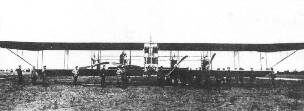
The first "giant aircraft" were built by Igor Sikorski in Russia in 1913.
Zeppelin D.I in the USA in the Naval Aircraft Factory, Philadelphia. Curtiss MF-Boat hulls are stored in the background. The wings were metal covered in their front half and fabric covered aft.
The Zeppelin C.II aircraft at the airfield in Dubendorf. Serial No. 811 is visible with Hanriot H.D.1 fighters in the background.