Описание
Страна: США
Год: 1917
Варианты
- Curtiss - H America - 1914 - США
- Curtiss - H.7 / H.10 Super America - 1915 - США
- Felixstowe - F.1 - 1916 - Великобритания
- Curtiss - H.12 Large America - 1917 - США
- Curtiss - H.16 Large America / F-5-L - 1917 - США
- Curtiss - HS - 1917 - США
- Felixstowe - F.2 - F.5 - 1917 - Великобритания
- Aeromarine - Aeromarine 75 - 1919 - США
- P.Bowers Curtiss Aircraft 1907-1947 (Putnam)
- G.Swanborough, P.Bowers United States Navy Aircraft Since 1911 (Putnam)
- J.Bruce British Aeroplanes 1914-1918 (Putnam)
- O.Thetford British Naval Aircraft since 1912 (Putnam)
- K.Molson, H.Taylor Canadian Aircraft since 1909 (Putnam)
- Jane's All The World Aircraft 1919
- C.Owers The Fighting America Flying Boats of WWI Vol.1 (A Centennial Perspective on Great War Airplanes 22)
- C.Owers The Fighting America Flying Boats of WWI Vol.2 (A Centennial Perspective on Great War Airplanes 23)
- Журнал Flight
-
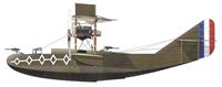
C.Owers - The Fighting America Flying Boats of WWI Vol.2 /Centennial Perspective/ (23)
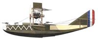
Curtiss H-16 of No.257 Sqdn, RAF assigned to NAS Dundee in September 1918.
-
C.Owers - The Fighting America Flying Boats of WWI Vol.2 /Centennial Perspective/ (23)
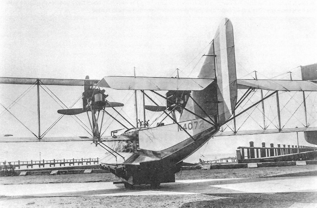
Curtiss H-16 N4072 of No.257 Sqdn, RAF assigned to NAS Dundee.
-
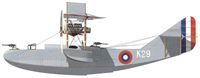
C.Owers - The Fighting America Flying Boats of WWI Vol.2 /Centennial Perspective/ (23)
Curtiss H-16 K-29 was recorded at Killingholme on 16 September 1918, when it made a test flight. It had problems and the first patrol appears to be that of 26 October when it made a convoy escort of 440 nautical miles under Ensigns Kunkle and Rumill. It was still at Killingholme on 22 November when it made a Practice Flight under Ensign Kunkle.
-

C.Owers - The Fighting America Flying Boats of WWI Vol.2 /Centennial Perspective/ (23)
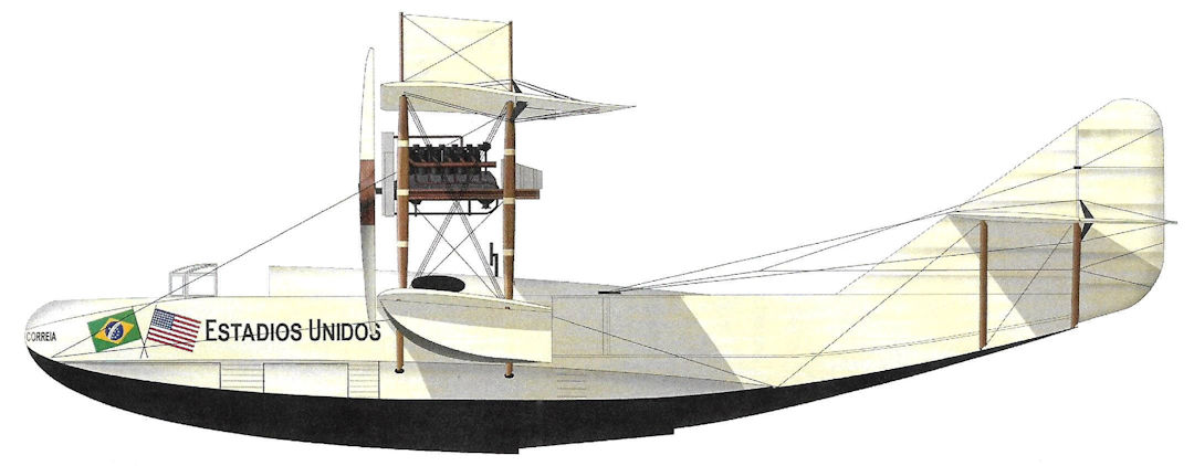
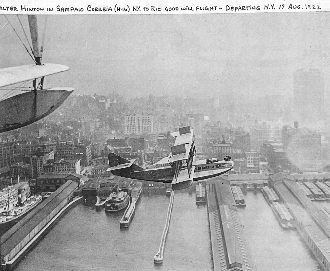
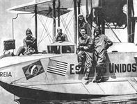
Curtiss H-16 Sampaio Correia, August 1922. In 1922 the New York World newspaper sponsored a flight from New York to Brazil by ex-US Navy pilot Walter Hinton. On 22 August 1922 Hinton misjudged a night landing in Guantanamo Bay, Cuba, wrecking Sampaio Correia. A replacement aircraft completed the trip.
-

C.Owers - The Fighting America Flying Boats of WWI Vol.2 /Centennial Perspective/ (23)
Curtiss H-16 N4060 assigned to Felixstowe; it had a balanced rudder and other control surfaces.
-
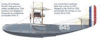
C.Owers - The Fighting America Flying Boats of WWI Vol.2 /Centennial Perspective/ (23)
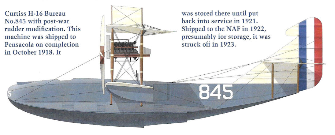
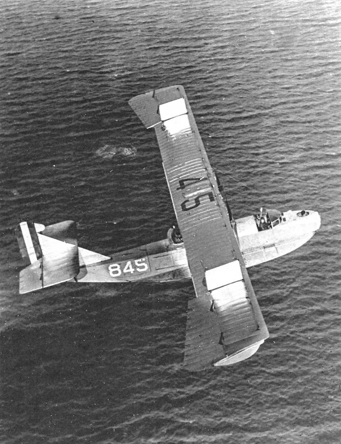
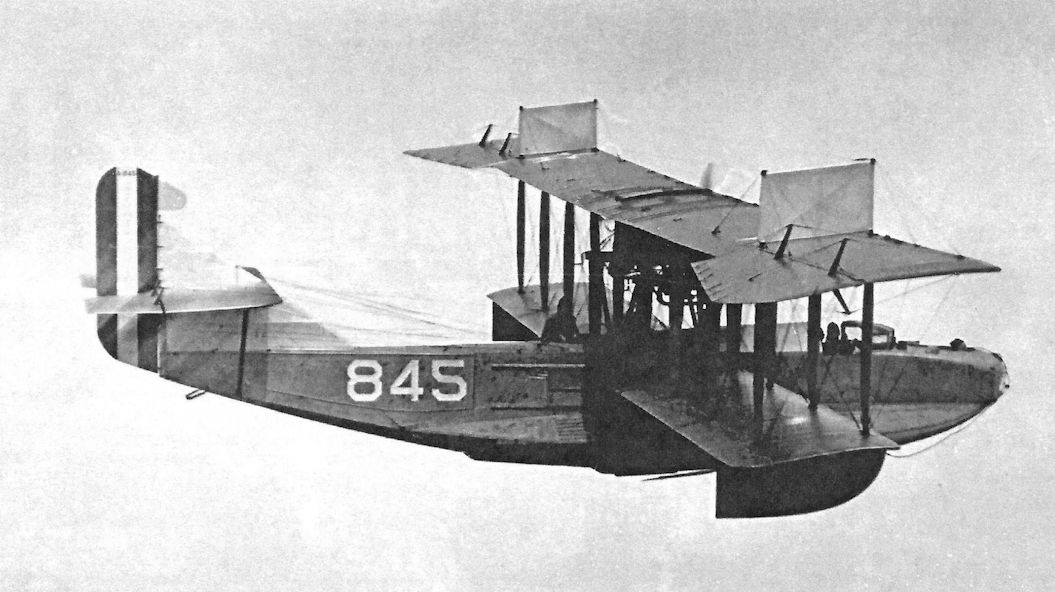
Curtiss H-16 Bureau No.845 with post-war rudder modification. This machine was shipped to Pensacola on completion in October 1918. It was stored there until put back into service in 1921. Shipped to the NAF in 1922, presumably for storage, it was struck off in 1923.
-

C.Owers - The Fighting America Flying Boats of WWI Vol.2 /Centennial Perspective/ (23)
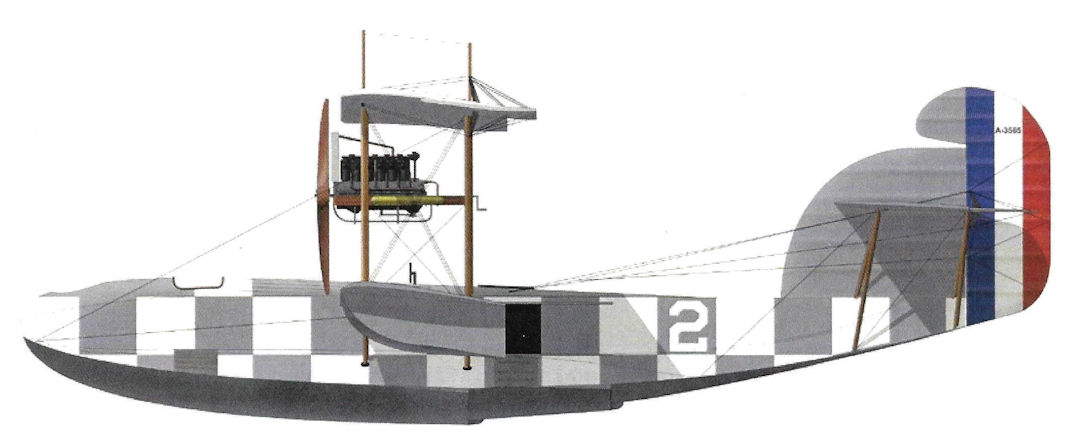
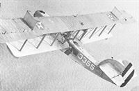
F-5-L A3565 of the U.S. Navy, circa 1922.
-
C.Owers - The Fighting America Flying Boats of WWI Vol.2 /Centennial Perspective/ (23)
F-5-L of the U.S. Navy.
-
C.Owers - The Fighting America Flying Boats of WWI Vol.2 /Centennial Perspective/ (23)
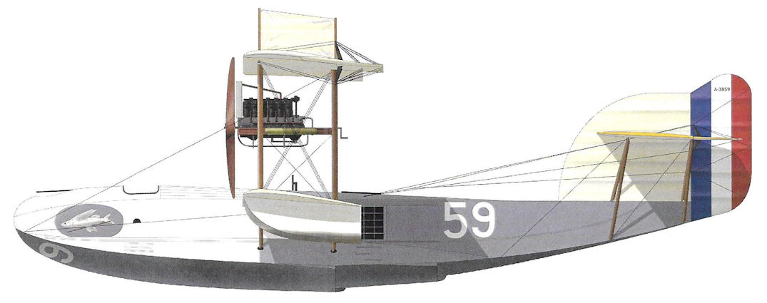
F-5-L A3859 assigned to NAS Guantanamo Bay in March 1920; it was deleted in August 1922. It was one of five F-5-L aircraft, the others being A3601, A3603, A3662, and A3665, that undertook a six-week cruise through the Caribbean in support of the fleet.
-
C.Owers - The Fighting America Flying Boats of WWI Vol.2 /Centennial Perspective/ (23)
F-5-L of the U.S. Navy.
-
C.Owers - The Fighting America Flying Boats of WWI Vol.2 /Centennial Perspective/ (23)
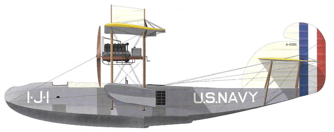
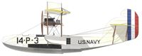
F-5-L A4281 assigned to Utility Sqdn 1 at NAS San Diego, 1926-1928.
-

C.Owers - The Fighting America Flying Boats of WWI Vol.2 /Centennial Perspective/ (23)
F-5-L assigned to Utility Sqdn 1, U.S. Navy.
-

C.Owers - The Fighting America Flying Boats of WWI Vol.2 /Centennial Perspective/ (23)
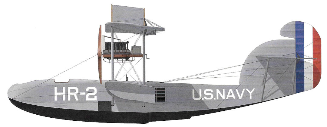
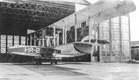
F-5-L of the U.S. Navy based at Hampton Roads NAS postwar as indicated by the "HR-2" on the bow.
-

C.Owers - The Fighting America Flying Boats of WWI Vol.2 /Centennial Perspective/ (23)
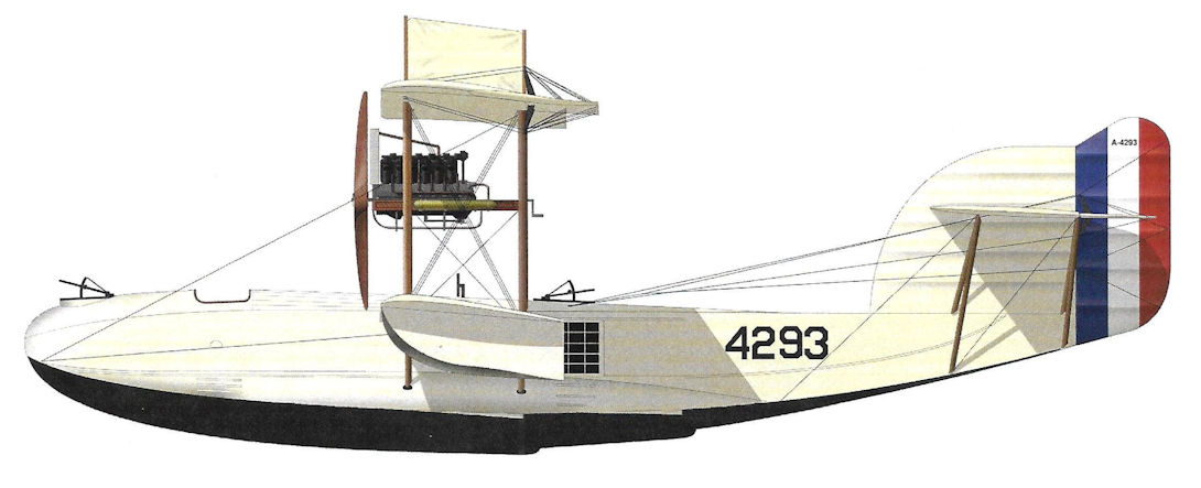
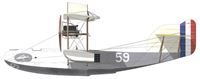
F-5-L A4293, U.S. Navy. The finish appears to be aluminum overall except for the bottoms of hull and floats.
-
C.Owers - The Fighting America Flying Boats of WWI Vol.2 /Centennial Perspective/ (23)
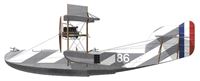
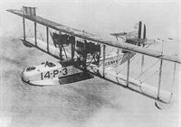
F-5-L assigned to Patrol Sqdn 14, USN.
-
C.Owers - The Fighting America Flying Boats of WWI Vol.2 /Centennial Perspective/ (23)
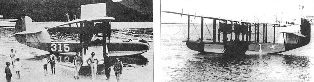
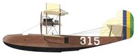
F-5-L 315 of the Brazilian Naval Air Service, mid-1920s. In 1923 Brazil acquired 14 F-5-Ls; these were given serials 1-5, 21-23, 311-316, and 321-326. They served until 1930. These colors are speculative.
-
C.Owers - The Fighting America Flying Boats of WWI Vol.2 /Centennial Perspective/ (23)
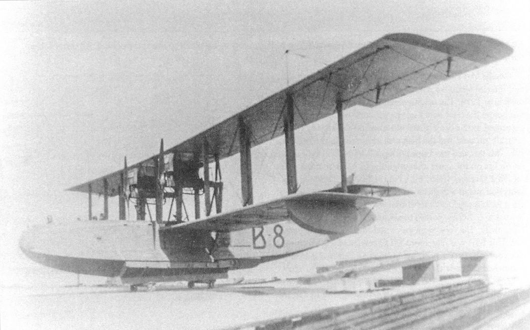
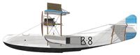
F-5-L B-8 of the Argentinian Air Service, circa 1922. In 1922 Argentina purchased eight F-5-Ls and gave them serials B-1 through B-8. They served until 1931 as operational aircraft, then as trainers until 1935. These colors are speculative.
-

C.Owers - The Fighting America Flying Boats of WWI Vol.2 /Centennial Perspective/ (23)
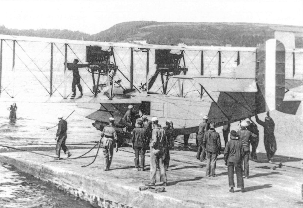
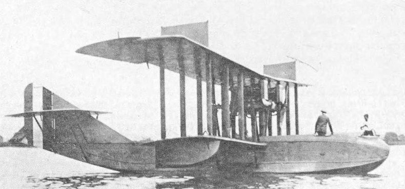
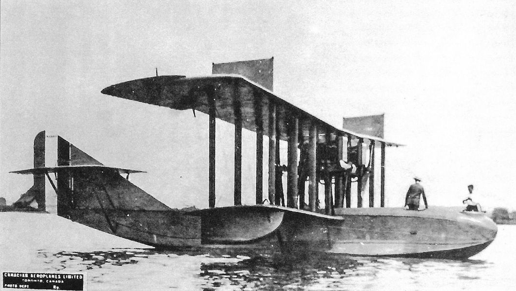
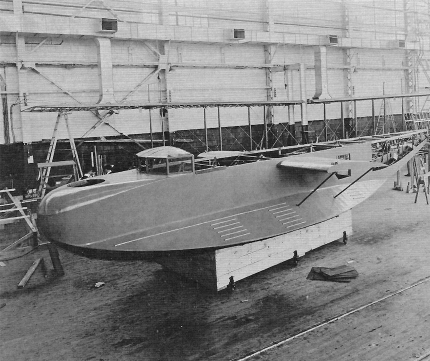
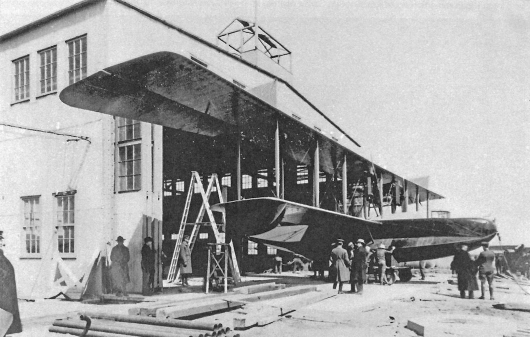
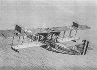
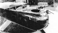
The first H-16 from the NAF is ready for launching. The early H-16 boats had a gooseneck spigot mount for the front Lewis gun. This was replaced by a Searff ring on the boats that went to Europe.
-
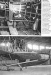
C.Owers - The Fighting America Flying Boats of WWI Vol.2 /Centennial Perspective/ (23)
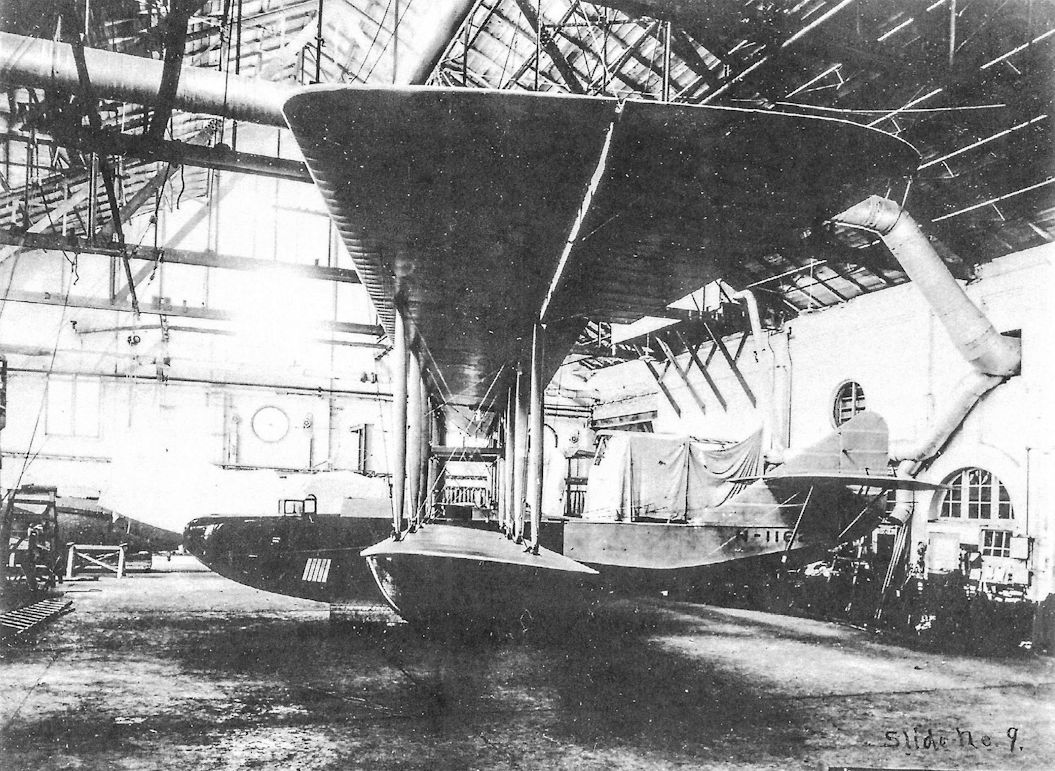
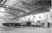
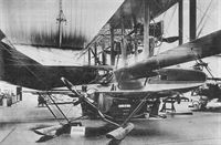
An H-16 under construction at Curtiss Aeroplane and Motor Corp at Buffalo, NY. Note the flap at the front of the aileron that folds back over the aileron gap when in flight. The fabric covered rear fuselage section is well illustrated. This would often break open in rough seas and was replaced by ply sheeting on many of the boats. The hull appears to be varnished on all wooden surfaces. According to Sir A. Robinson, the aluminium step treads on the walkways over the fins were a distinguishing feature of the H-16 on the ground. This is most probably N1162.
-
C.Owers - The Fighting America Flying Boats of WWI Vol.2 /Centennial Perspective/ (23)
N1162 in the same location. Note the flap in front of the aileron gap that closed with air pressure in flight. N1162 was not delivered as such. It is thought that the batch N1160-N1174 was delivered as N4060-N4074.
-

C.Owers - The Fighting America Flying Boats of WWI Vol.2 /Centennial Perspective/ (23)
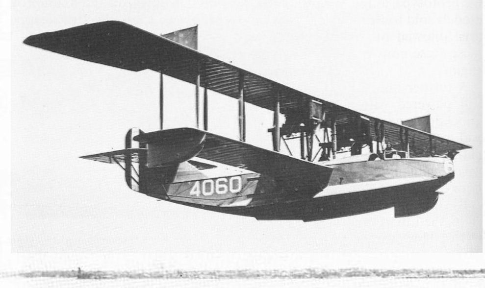
N4060 without a cockpit canopy. This was the first of a batch of 15 H-16 boats from Curtiss. It arrived at Felixstowe in March 1918 and was at the Isle of Grain for testing and experimentation from May. It then served with No.230 Squadron, RAF, and disappears from the records in January 1919.
-

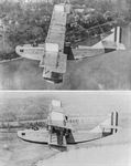
O.Thetford - British Naval Aircraft since 1912 /Putnam/
Curtiss H.16 Large America (No.4060).
-

C.Owers - The Fighting America Flying Boats of WWI Vol.2 /Centennial Perspective/ (23)
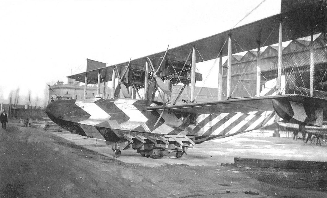
Dazzle painted H-16 N4060 "ready for patrol" at Felixstowe. (AHT AL0772-017)
-
C.Owers - The Fighting America Flying Boats of WWI Vol.2 /Centennial Perspective/ (23)
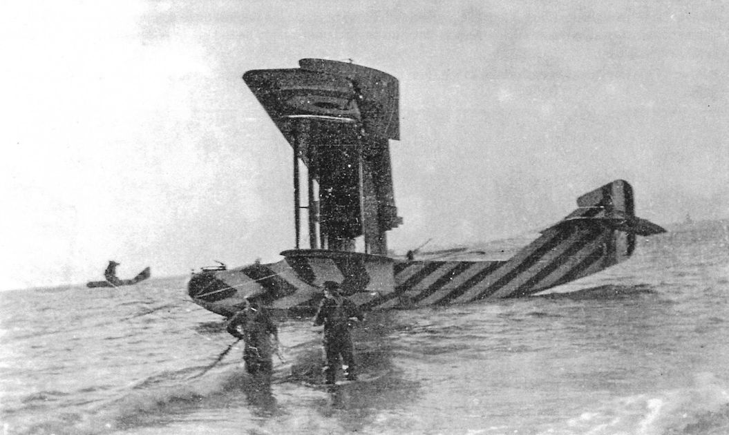
N4060 beached. Note the balanced rudder and ailerons. The under wing cockade does not carry over onto the aileron. Another dazzle painted boat is on the water behind N4060. This would indicate that the balanced ailerons were added in the UK.
-
C.Owers - The Fighting America Flying Boats of WWI Vol.2 /Centennial Perspective/ (23)
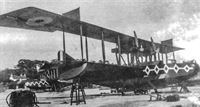
N4072 shows the fabric covered rear fuselage above the wash board well in this colour scheme. The rudder is unbalanced and a cockpit canopy is fitted. Note the walkway on the lower wing outboard of the engine support struts. These machines have a dark colour to the upper fabric surfaces of the hull and wings. The Colour that Curtiss used is unknown at this time but may have been the green that is stated to have been applied to the Large America boats.
-

C.Owers - The Fighting America Flying Boats of WWI Vol.2 /Centennial Perspective/ (23)
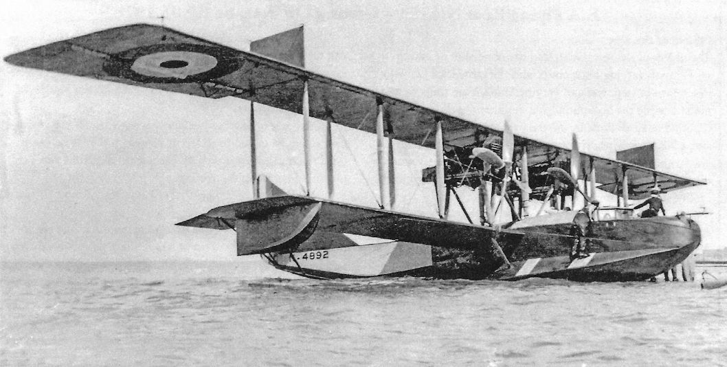
N4892 on the beach. This Curtiss H-16 appears to have had the ply painted the same dark colour as the fabric surfaces rather than being varnished British fashion, this dark colour continuing onto the hull bottom. Lack of documentation makes it difficult to make reliable assumptions as to the colours of these flying boats. Delivered in September 1918, N4892 was from a batch of 110 boats ordered from the USA but only N4890 to N4949 were received, the rest being cancelled.
-
C.Owers - The Fighting America Flying Boats of WWI Vol.2 /Centennial Perspective/ (23)
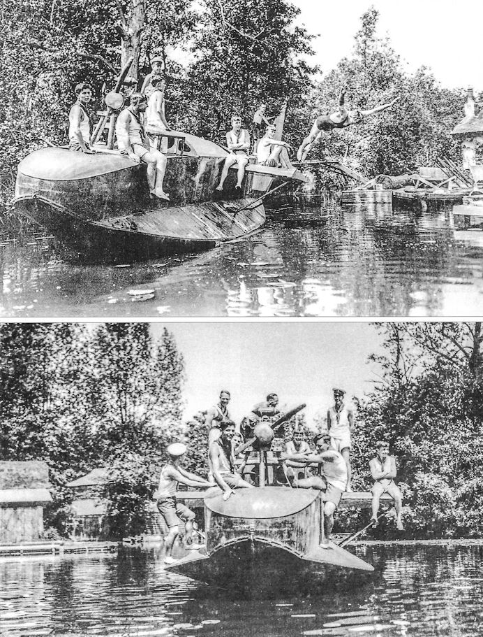
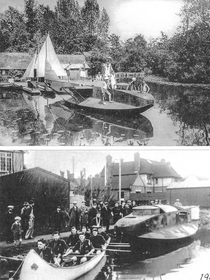
Curtiss H-16 N4934 ended up as a house boat for these Naval Cadets. N4934 was delivered into store at AAP Norwich on the week ending 3 October 1918 and later scrapped with so many other boats in this batch. It survived for a number of years. Flying boat hulls were sometimes saved and used for a houseboat but too many were left to rot before their historical value was recognised. The Supermarine Southampton hull in the RAF Museum, Hendon, was recovered as a houseboat and saved.
-

-
C.Owers - The Fighting America Flying Boats of WWI Vol.1 /Centennial Perspective/ (22)
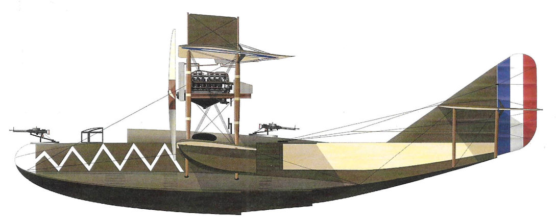
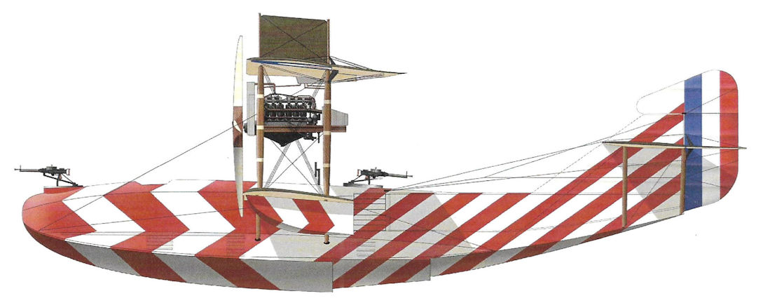
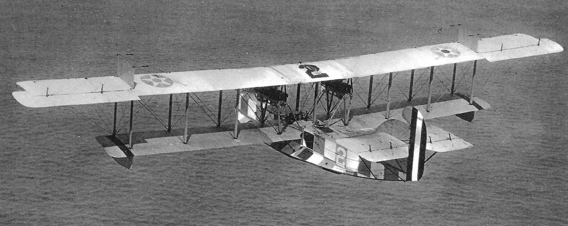
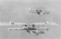
1918 saw the Flying boats adopt colourful markings as displayed by the two Large Americas illustrated here.
-
C.Owers - The Fighting America Flying Boats of WWI Vol.2 /Centennial Perspective/ (23)
British H-16 with zig-zag stripe to forward hull and light coloured nose. Note how the dark upper wing colour is carried around the leading edge of the wings.
-

C.Owers - The Fighting America Flying Boats of WWI Vol.2 /Centennial Perspective/ (23)
An H-16 at Queenstown, Ireland, 1918. (AHT AL-1171-018)
-

C.Owers - The Fighting America Flying Boats of WWI Vol.2 /Centennial Perspective/ (23)
Dazzle painted British H-16 with balanced rudder and ailerons and cockpit canopy removed. Note what appears to be a large weapon in the rear cockpit. Another dazzle painted boat rides at rest further out in the water.
-

C.Owers - The Fighting America Flying Boats of WWI Vol.1 /Centennial Perspective/ (22)
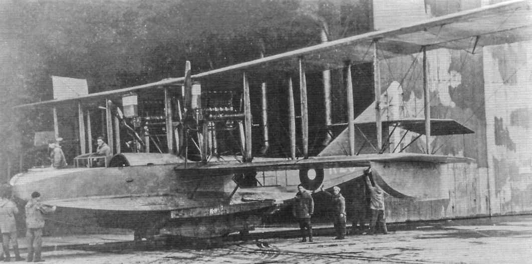
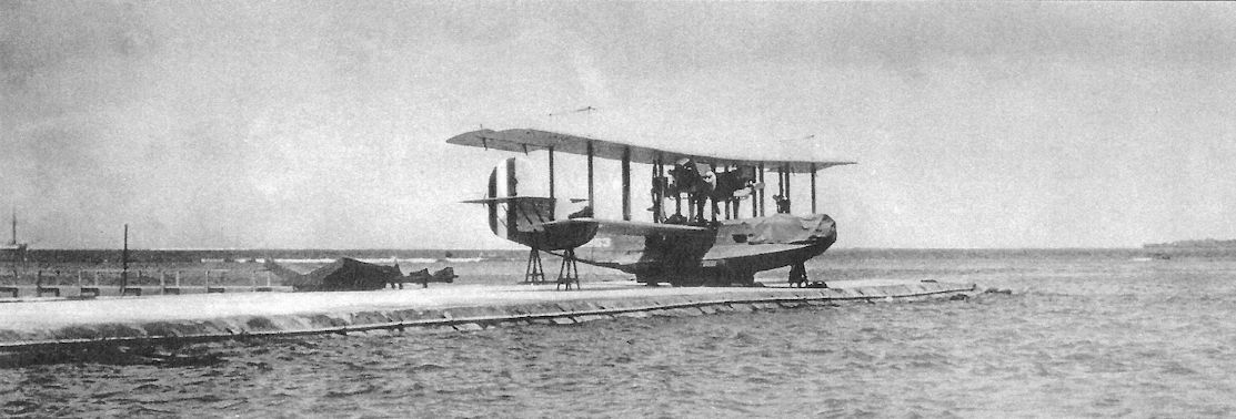
An USN Curtiss H-16 of Killingholme station. This machine bears the Station code "K"; the last numeral of the individual aircraft number cannot be positively identified. The machine is Navy Grey overall with US insignia. Note that the top of the radiators appear to be blanked off and the boat is on the cradle for K-11.
-
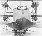
C.Owers - The Fighting America Flying Boats of WWI Vol.2 /Centennial Perspective/ (23)
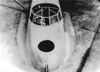
A front view of a Killingholme bombed up H-16, 24 October 1918.
-

C.Owers - The Fighting America Flying Boats of WWI Vol.2 /Centennial Perspective/ (23)
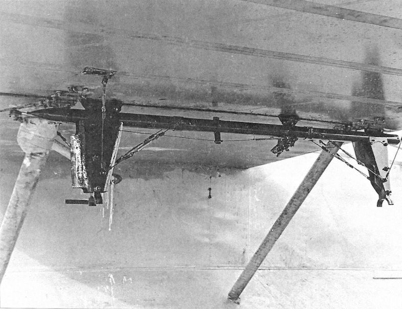
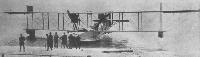
The H-16 did carry out patrols from stations in the UK. A rear view of K-11 from Killingholme shows the twin 520-lb bomb load of the type. 24 October 1918.
-

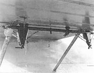
C.Owers - The Fighting America Flying Boats of WWI Vol.2 /Centennial Perspective/ (23)
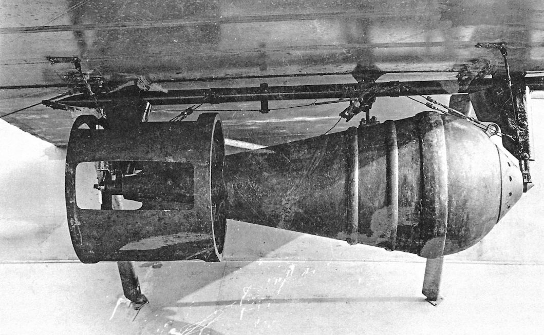
Detail of the Skeleton Tubular 520 Lb Mk.II(F) bomb carrier and an H.E.R.L. 530 lb Mk.1/N/a light case bomb on a Killingholme H-16, 24 October 1918. (The N indicated Naval use).
-
-
C.Owers - The Fighting America Flying Boats of WWI Vol.1 /Centennial Perspective/ (22)
A USN H-16 Bureau No. A-794. Reported as 100% complete in April 1918, A-794 was shipped overseas from New York on the Jason during the week ending 25 May. Assigned to Killingholme it was recorded at Killingholme on 13 August when it had to return from a convoy escort with engine trouble (Crew: Ens Ives; Ens Allen; CMM Lamont C. Fisher; E2c(r) Donald Phelps.). The machine was test flown throughout August with no patrols being recorded. As with so many of these flying boats it there is no record of its fate; not reported by any station; "Sent overseas not returned".
-
C.Owers - The Fighting America Flying Boats of WWI Vol.2 /Centennial Perspective/ (23)
H-16 A-836 on the ramp at Pensacola. It was usual to start the engines before lowering the boat into the water, and it is therefore likely that this photograph shows the recovery of the machine. Navy Grey overall. This boat was lost on 10 January 1921 at Pensacola. The crew were: CMM(A) J.W. Utley; CMM(A) J.E. Rawlings (student). Held to have been poor judgement in recovering from one engine turn resulting in a bad skid; landed with one wing low to a total wreck except for Engines 0988/2154 and 0751/1595 that were not damaged. Fortunately there was no injury.
-

C.Owers - The Fighting America Flying Boats of WWI Vol.2 /Centennial Perspective/ (23)
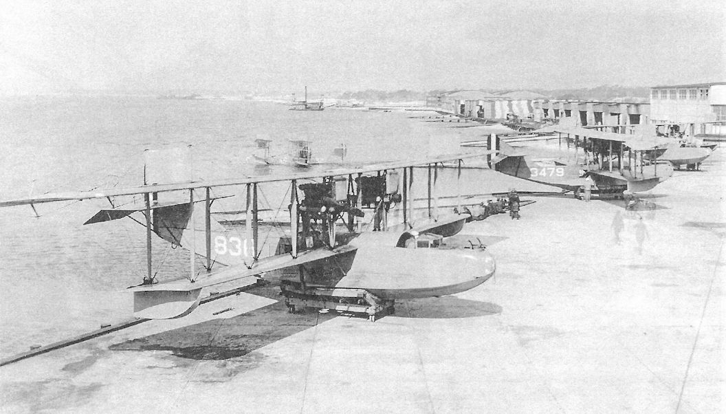
Curtiss H-16 boats A-836 and A-3479 on the hardstand.The Bureau Nos. marked on the hull sides indicates that these are US based H-16 boats, this photograph being taken at Pensacola Naval Air Station. Note how the last two numerals of the Bureau Nos. are painted on the bow. There appears to be two Curtiss HS-2L boats in the background but it is only one machine caught by the time exposure so that the Bureau No. A-2082 appears to be on the front and rear hull. This machine bears the "hat in the ring" insignia of one of the squadrons that operated from Pensacola. N-9 training biplanes are further to the rear. A-836 was delivered to Pensacola in September 1918 in a damaged condition thought due to the crates hitting overhead bridges on the Atlantic Coast rail line. It was stricken but obviously repaired and back in service by at least 9 December 1918. This boat was crashed to a total wreck on 10 January 1921. A-3479 was on NAS Pensacola on 4 November 1918, and survived to be written off due age and condition on 12 May 1922. A-2082 was on Station in October 1918, and was written off on 14 April 1924, due to condition due terms of service.
Другие самолёты на фотографии: Curtiss HS - США - 1917Curtiss N-9 / N-10 - США - 1917
-

C.Owers - The Fighting America Flying Boats of WWI Vol.2 /Centennial Perspective/ (23)
H-16 A-845 with aluminium doped wings and tail, and post-war insignia. The "45" is marked on the upper centre section and on the bow. Note the modified balanced rudder. Reported as 25% complete in June 1918, and 70% complete in August, A-845 was 100% complete in October and was assigned to Pensacola. It was assessed as too bulky to rail and was assembled at Hampton Roads and flown to Florida. Pensacola reported on 19 May 1921, that the boat was in storage and would be converted to dual when erected. This was to be done as there were not enough F-5-L boats on the station and although the policy was to replace the H-16 with the F-5-L, the H-16 boats were required to complete the station complement for training. A-8445 was in service by 15 December 1921 at least. It was in continuous service training until 10 June 1922 when it was transferred to the NAF by air, arriving on the 11 July. On 4 June 1923, the NAF reported that the machine had been in storage since manufacture for about 5 years, which was incorrect.The hull and surfaces showed signs of deterioration due to age, etc., and it was recommended that it be stricken. This was duly carried out in October 1923.
-

-

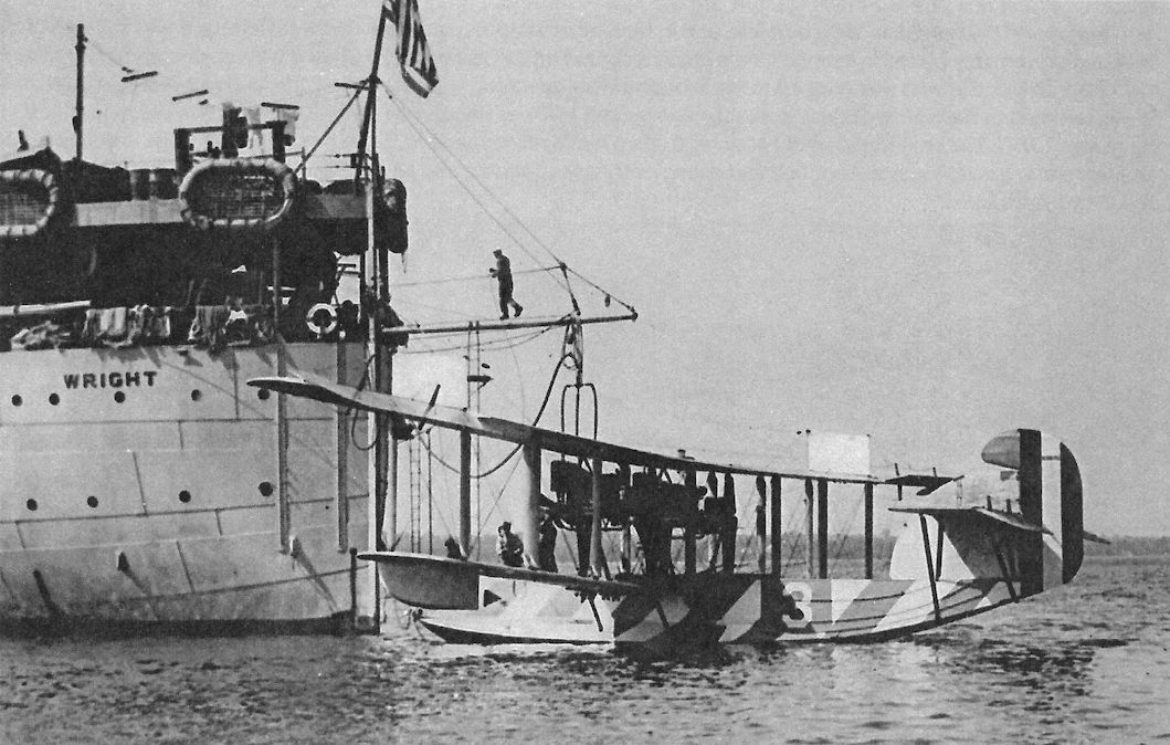
C.Owers - The Fighting America Flying Boats of WWI Vol.2 /Centennial Perspective/ (23)
A-867 was 100% complete in January 1919. On the 27th it was shipped to the NAF for storage, arriving in company with A-845. It was still in storage in July 1923 when it was noted as requiring reconditioning. In May 1925 it was allocated to the USS WRIGHT. On 14 August 1926, it was received back at the NAF. In March 1927 it was recorded as with VJ 1. On 3 May following year there were signs of rot on lower ends of the centreline, struts, etc., and the boat was to be stricken.This taking place on 27 June, with a TFT of 476.75 hrs. A-867 can be seen in the photograph to have all the late modifications to the type. The cockpit is the open type, there is a balanced rudder and the rear of the hull has ply sides with strengthening ribs. The Bureau No. is now carried in small numbers on the fin. The hull appears to be a colour other than Navy Grey.
-
C.Owers - The Fighting America Flying Boats of WWI Vol.1 /Centennial Perspective/ (22)
The USN proposed to use lighters to carry their Curtiss H-16 boats across the North Sea until they were in bombing range of the German submarine bases. The anti-submarine war had top priority for material and Liberty engines. This was to lead to the USN and Marine Corps undertaking land based bombing operations and caused conflict with the Army. This photograph was probably taken in the US as the Bureau No. is marked on the hull. The Bureau No. appears to be 3312 but this number was allocated to a US D.H.4. Note the lighter bears the stencil "USN-22"on its bow. The lower part of the radiators appear to be blanked off. (AHT AL0772-156)
-
C.Owers - The Fighting America Flying Boats of WWI Vol.2 /Centennial Perspective/ (23)
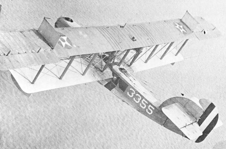
H-16 A-3479 shows the application of the last two numerals of the Bureau No. to the bow as the aircraft code number. This boat has the balanced rudder. A-3479 had a hull built by L.C. Seabury Co. This machine has a confusing history. A-3479 was reported as 100% complete in August 1918 and shipped to Pensacola on the same month by rail. Pensacola reported it on station on 4 November. It did not last long as on 5 December it was reported sinking off Town Point. A barge was dispatched but failed to tow the boat ashore before it sank. The cause was held to be due to landing on glassy water which crushed the hull bottom. There were no injuries in the incident. However, other sources state that it was railed to Pensacola on 9 December 1918, and was in service during 1921 and 1922. Given the colour scheme and markings in the photograph this seems most likely the correct history. Whether the original boat was recovered or the entry is incorrect is unknown at this time. A-3479 was eventually stricken on 16 June 1922, owing to general poor condition, the wing fabric being poor, the hull old and leaking.The engines, 02218WR/3388 and 05506WR/4761, were to be overhauled.
-
C.Owers - The Fighting America Flying Boats of WWI Vol.2 /Centennial Perspective/ (23)
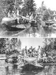
A-3500 being shown off to a couple of young ladies.
-

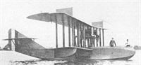
G.Swanborough, P.Bowers - United States Navy Aircraft since 1911 /Putnam/
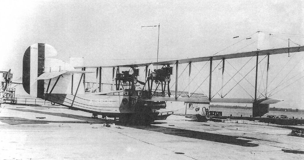
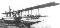
The H-16, with swept trailing edge of ailerons, twin Liberty engines and enclosed pilot's cabin, which distinguish this model from the F-5L, was the final Curtiss H-Model. Also built under licence by the Naval Aircraft Factory.
-

C.Owers - The Fighting America Flying Boats of WWI Vol.2 /Centennial Perspective/ (23)
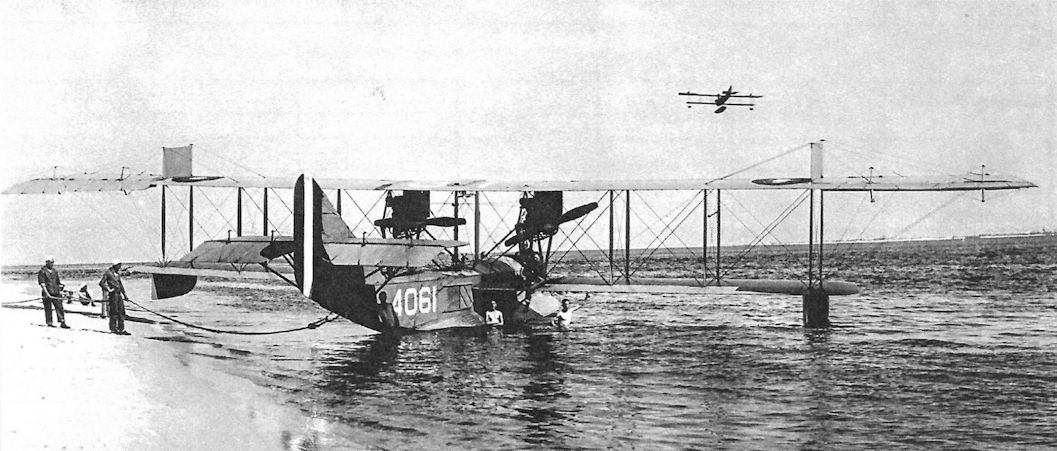
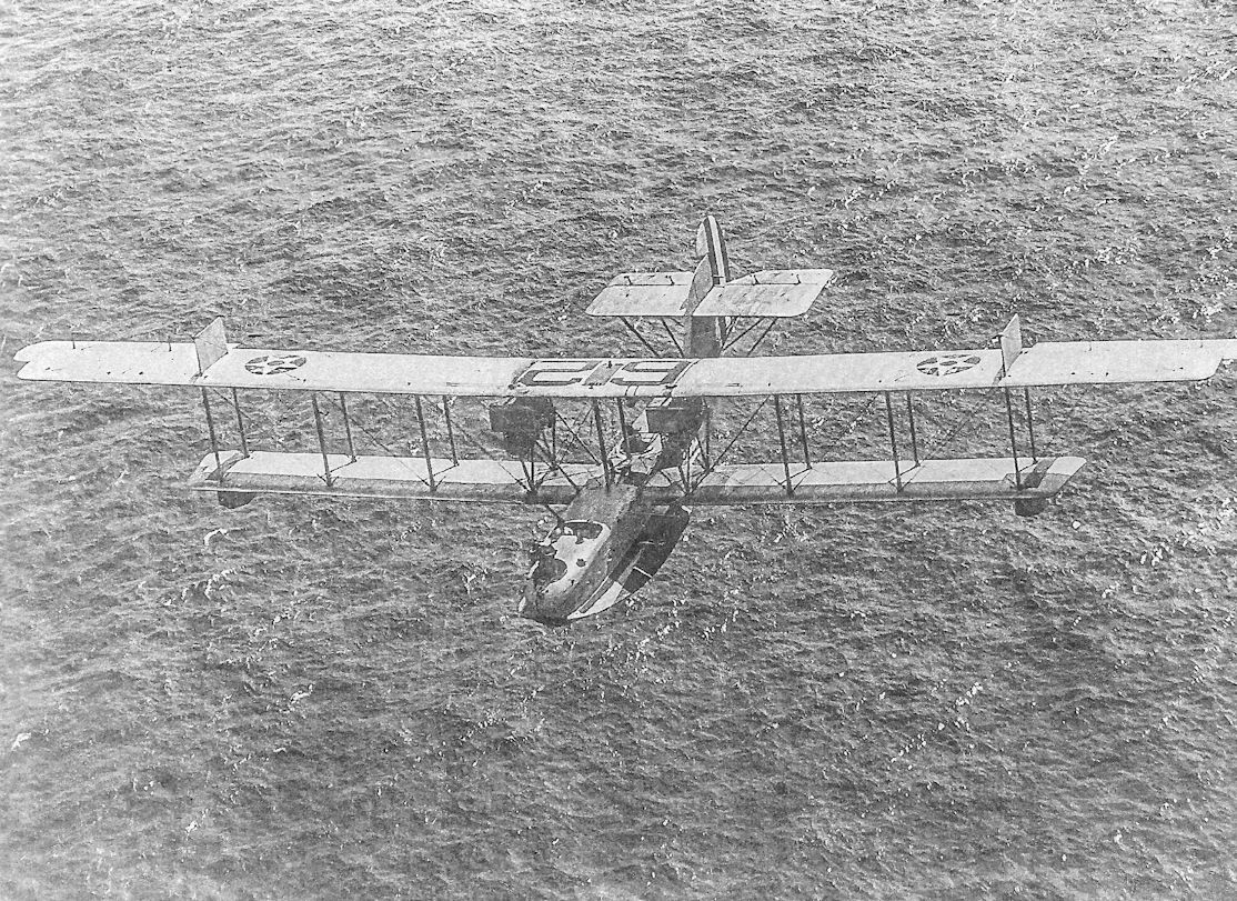
H-16 Bu No. A-4061 with a Curtiss N-9 trainer overhead. A-4061 was reported as 100% complete in October 1918 and shipped the 16th to the Brooklyn Naval Aviation Storehouse but was diverted to Pensacola with A832-836 and A4060-4062. On 24 December 1918, it was on an instruction flight from Pensacola and at 1,500 feet when the port airscrew shattered causing a forced alighting near entrance to East Bay. It drifted ashore and was secured. On 9 May 1919, on a return from Mobile, the boat flew over Pensacola base at low altitude. The crew was Ens W.H. Robrack (p); Ens M.D. Nolan (assist p); Ens B.L. Chase (navigator); Ens F. Lamb (passenger); MM1c T.A. Hudson. Robrack was suspended from flying for one week as a result. On 11 October 1920, the port engine was damaged when the insulation wiring burned away causing the distributor head to burn. The upper engine panel, intermediate panel and lower intermediate wing panels burned. The incident was caused by a broken gas lead causing the motor to back fire. The flying boat was overhauled and the engine repaired. On 26 April 1921, Pensacola reported that the condition of the hull was generally bad, with timbers water soaked and rotten in the bottom; planking was coming loose from the hull; interior fittings were very rusty. The damage was incident to service and it was recommended that a spare hull be substituted and minor repairs be carried out to the wing surfaces. Engines 0508/966 and 02247/3576 were to be overhauled. On 21 May it was reported with a new hull, and the minor repairs to wing surfaces were nearly complete.The following month the new hull suffered in a forced alighting. The upper left hand longeron was broken, and other damage caused by the failure of Engine No.308/572.The boat undertook a test flight at Pensacola on 24 September before being shipped by air to Hampton Roads with A-850 and A-3500. Hampton Roads reported on 12 January 1922, that A-4061 was in commission but was in excess of allowance, taking up manpower and space. A request to place the machine in storage was granted. On 1 October 1923, it was sold without engines or instruments for $45.
Другие самолёты на фотографии: Curtiss N-9 / N-10 - США - 1917
-
C.Owers - The Fighting America Flying Boats of WWI Vol.2 /Centennial Perspective/ (23)
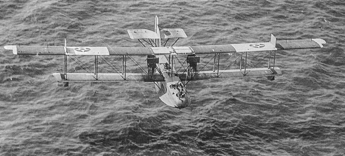
A-4062 in a spot of bother. It appears that the hull has sprung a leak and the machine has been beached. This does not look like the incident of 13 January 1919, when, with a crew of Ens Garrett B. Linderman Jr (p). Student officers CQM(A) Geroge Alfred Hero; CQM(A) Harry Cordery Moore & CQM(A) Robert Alston Brant; MM2c Orville Roy Bolton; MM1c Ivan Edward Quinlan, the boat crashed in Escambia Bay due to porposing and stalling to a total wreck. The cause was held to be glassy water. The boat was written off with 61:35 hours since 19 October.
-
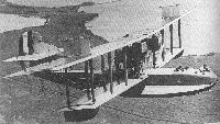
G.Loening - Takeoff into Greatness /Putnam/
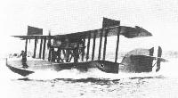
H-16 twin motor flying boat, used by the Navy in World War I.
-

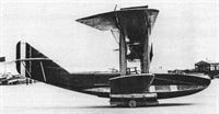
C.Owers - The Fighting America Flying Boats of WWI Vol.2 /Centennial Perspective/ (23)
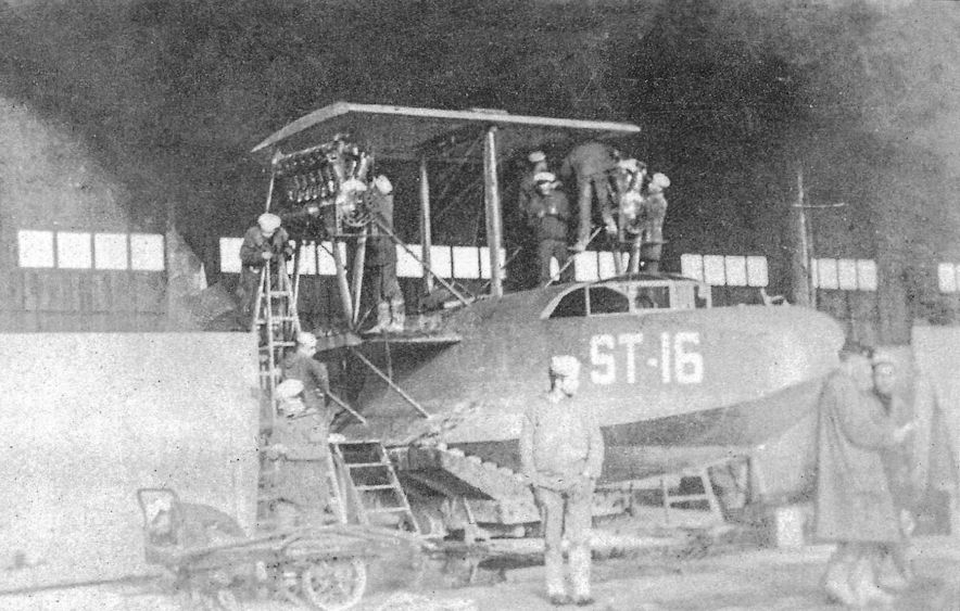
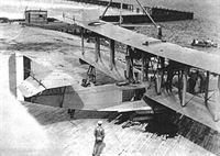
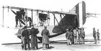
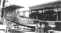
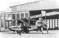
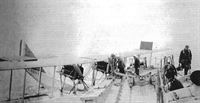
Assembling or disassembling an H-16 in France. The aircraft code ST-16 indicates it was assigned to Saint Trojan NAS. A far as can be ascertained from surviving documents no H-16 flew offensive patrols from French stations. (AHT AL0340-103)
-
C.Owers - The Fighting America Flying Boats of WWI Vol.2 /Centennial Perspective/ (23)
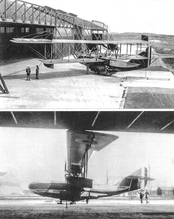
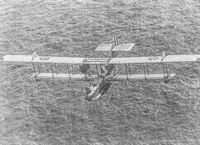
This H-16 N4060 was fitted with an experimental night landing stick. The device was lowered when coming down to alight and when it hit the water it levelled the boat out for a landing.The footsteps across the fins are of a different type to N4230. Note the small window above the W/T operator's position just behind the wing. This photograph of 5 September 1918, gives a good view of the engine installation.The fabric wrapped struts were probably Battleship Grey. (AHT AL917-010&011)
-

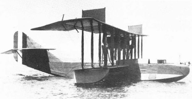
P.Bowers - Curtiss Aircraft 1907-1947 /Putnam/
The single H-16-1 was a standard H-16 with the engines installed as pushers.
-

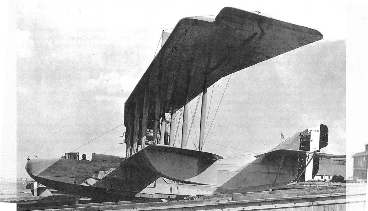
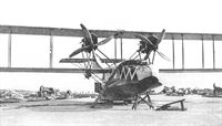
C.Owers - The Fighting America Flying Boats of WWI Vol.2 /Centennial Perspective/ (23)
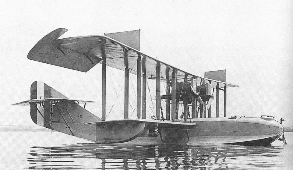
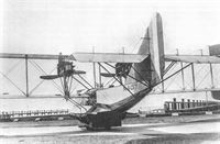
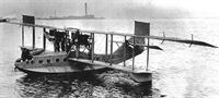
A-839 was built with its engines installed in pusher configuration and the wings were given a large sweepback. Also noteworthy are the stencils along the side of the walkways across the fins of this boat. Early US based H-16 boats appear to have had the gooseneck spigot mount for their front machinegun. Reported as 100% complete in October 1918 at the Curtiss Garden City plant. On 2 November underwent a preliminary trial when flown by Lt McCullough at Curtiss Garden City. It rose from water twice but only for short hops. Found to be slightly nose heavy the boat was taxing for a third flight when the propeller split damaging the port side walk panel and other panels. In December it was recorded as now ready for trials at NAS Rockaway. While there it was stored outside due to lack of space. Flown to Hampton Roads on 13 January 1919, it had special auxiliary rudders placed within streamline of the propellers as shown in the photo. In February it was laid up for repairs. On 26 October 1920, Hampton Roads recorded that the hull was rotten and beyond repair due to the length of service. The wings could not be used on the standard H-16, and it was recommended it be stricken. This was carried out in November. There appears to have been no advantage to the pusher configuration and the machine was little used.
-
K.Molson, H.Taylor - Canadian Aircraft since 1909 /Putnam/
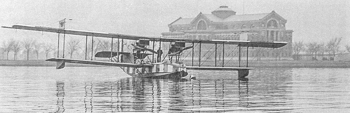
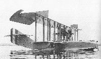
The CAL Felixstowe F-5-L prototype, A3333, before its first tests at the Naval Aircraft Factory at Philadelphia.
-
K.Molson, H.Taylor - Canadian Aircraft since 1909 /Putnam/
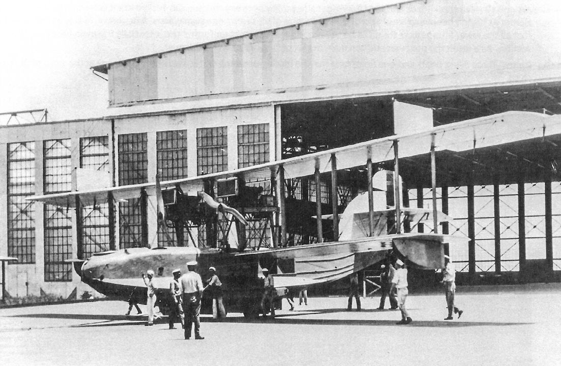
A CAL-built Felixstowe F-5-L fitted with the enlarged fin and rudder and enlarged wingwalkways for servicing. This aircraft was flying from the Pensacola Naval Air Station in Florida.
-
G.Swanborough, P.Bowers - United States Navy Aircraft since 1911 /Putnam/
The first F-5-L built by the NAF, A-3559. The machine is Navy Grey overall. The original recessed rudder balance may be seen under the horizontal tailplane. Reported as 50% complete in July 1918 and 100% complete the following month it was ready on 11th of that month. If flew from the NAF to Hampton Roads on 28 August and was still there on 30 November when it alighted due to a heavy squall. As the wind died down the pilot tried to reach Hampton Roads before dark. Ran into heavy rain such that it was impossible to tell which direction seaplane was heading as compass could not be read. Absence of windscreens made it additional difficulty so the pilot attempted to land but could not see water due to the rain. He levelled off too high and side slipped to right. Hull began to fill and the crew took refuge on tail. Recommended be stricken, cause held to be the improper placing of the windscreens and light compass. On 17 September this was carried out. Another source indicates that this may not have been carried out immediately as it has the machine still at Hampton Roads in November. (AHT AL1171-046)
-

C.Owers - The Fighting America Flying Boats of WWI Vol.2 /Centennial Perspective/ (23)
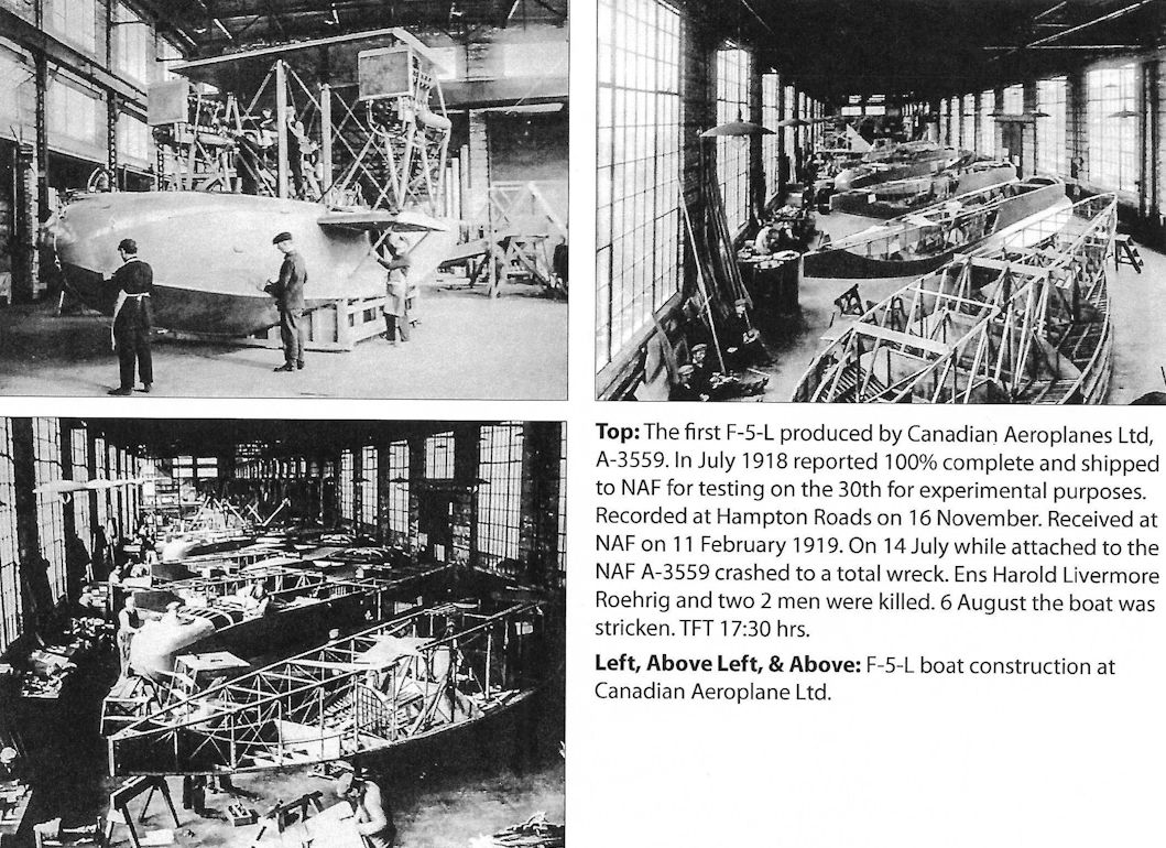
The first F-5-L produced by Canadian Aeroplanes Ltd, A-3559. In July 1918 reported 100% complete and shipped to NAF for testing on the 30th for experimental purposes. Recorded at Hampton Roads on 16 November. Received at NAF on 11 February 1919. On 14 July while attached to the NAF A-3559 crashed to a total wreck. Ens Harold Livermore Roehrig and two 2 men were killed. 6 August the boat was stricken. TFT 17:30 hrs.
-
C.Owers - The Fighting America Flying Boats of WWI Vol.2 /Centennial Perspective/ (23)
NAF constructed F-5-L A-3560 shows the same rear gun mount as on the H-16. It is not known if the ring could slide along the rails at the side of the large rectangular opening in the hull top decking. Note that the hard stand at the top of the slipway is timber planked. Reported "Ready. Loaded on car" on 28 August 1918, A-3560 was shipped to Hampton Roads by air on 9 September arriving the following day. On 12th it attempted to get off with a gross load of 13,094 Ibs for a test. On 18 September the hull was reported as crushed on right side covering an area about 2 sq ft. Wires were loosened on the tail. The aileron control fitting and pulleys were torn out of the center top plane. Entire upper left wing from the engine section out, including the overhang complete with aileron and fittings was damaged beyond repair (DBR).The machine was to be repaired on Hampton Roads station. Get away and propeller tests expected to continue on 8 October. On the 19th it had another accident. The right aileron and horn were DBR; the left aileron and horn were badly damaged; while the upper load wire fitting on the intermediate wing were broken when the plane collided with a light beacon while manoeuvring for pictures. Repaired it was with the Hampton Roads Experimental Department in January 1919 when it flew to Washington and return to test a radio transmitter. On 3 May 1919, as a result of alighting in a heavy sea the machine was lost but the engines were salvaged. A-3560 was stricken on 9 June with a TFT of 5:58 hours.
-
C.Owers - The Fighting America Flying Boats of WWI Vol.2 /Centennial Perspective/ (23)
A-3565 carried the individual aircraft number "2." ln this colour scheme the upper wing is a light colour (white), probably the same as the hull checks. This F-5-L was constructed at the NAF. As at 30 September 1918, A-3561 to A-3577 were reported as 65-100% complete. On 17 September the boat was loaded onto a car for shipment. In 1920 it was offered for sale at the NAF. In may have been in service by 21 January 1922, at Hampton Roads when a Maintenance Report was made. On 18 December 1922, it was flown from the NAF to Hampton Roads for the Atlantic Fleet. It was probably with the Fleet when the high visibility colour scheme was applied. During 1923 to 1925 it seems to have been assigned to Hampton Roads and the USS Wright alternating between the two. On 1 July 1925 it was reported by Pearl Harbor as having been recovered prior to the departure of VS 1 from Hawaiian waters. A Report of 15 December stated that all the lower fittings were found to be badly corroded and unfit for further use, especially the main fittings in the tank section. As a result the boat was stricken from the list of Navy aircraft on 28 January 1926.
-
C.Owers - The Fighting America Flying Boats of WWI Vol.2 /Centennial Perspective/ (23)
A-3601 on 30 December 1919, at Pensacola. Reported as 100% complete on 18 July 1919, A-3601 was selected as a replacement F-5-L for the Atlantic Fleet, and was assembled at the NAF and shipped to the Air Detachment, Atlantic Fleet during 27 September to 15 October 1919. In November it was recorded as operating with the USS Shawmut. As an Airboat, A-3601 had a colourful hull with white stripe separated by the code 01. The last two numerals of the Bureau No. were used as the aircraft codes and were usually also carried on the nose of the bow. This Airboat accompanied A-3859 on its 1920 cruise. On one occasion during the cruise a forced alighting was caused to A-3601 by the throttle wire cutting through on a sharp corner where the wire was secured by a sheave. The flying boat had to be towed in with a very heavy sea running which resulted in one wing being damaged, and it was undergoing repairs on the 11th for damage caused by this incident. On 4 August the boat was at Santa Cruz del Sur, Cuba when the camshaft lost two teeth causing the engine to be surveyed. On the 10th it was shipped from the Shawmut to the NAF presumably due to its condition as it was recommended to be stricken in the following December, that taking place on the 30th of the month.
-
C.Owers - The Fighting America Flying Boats of WWI Vol.2 /Centennial Perspective/ (23)
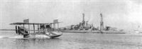
A-3859 powering to get onto the step for takeoff. The insignia on the bow is of a flying fish. In this photograph the machine appears to be in navy Grey overall. The aircraft number (the last two numbers of the Bureau No. is not present on the bow but carried under the hull. This machine appears to have the WWI style national insignia. Note the black walkways on the fins.
-

C.Owers - The Fighting America Flying Boats of WWI Vol.2 /Centennial Perspective/ (23)
The second photograph shows the machine in Guantanamo Bay, Cuba, with what appears to be a light (white) colour forward hull with the flying fish insignia in the oval. The wings may be aluminium doped. The horizontal tailplane upper surfaces are dark (chrome yellow) coloured. The cockpits and engines all have canvas covers.
-
C.Owers - The Fighting America Flying Boats of WWI Vol.2 /Centennial Perspective/ (23)
With canvas cover over the cockpits F-5-L A-3863 sits on the end of what appears to be a breakwater at Guam 1923. Note how the boat is supported at the wingtip floats and the rear hull. This boat was completed in early 1919 and may have been stored at the NAF as it was the subject of a maintenance report there in May 1922. It was allocated to the Atlantic Fleet Torpedo Squadron operating with the USS Sandpiper later that year. In 1923 it was assigned to the USS Wright and appears to have spent the time when it was not with the Wright at Hampton Roads. On 27 March 1924, Hampton Roads reported that the hull bottom planking needed replacing and recommended that the boat be stricken, the hull burnt and all useable material taken into store.This was carried out on 7 May 1925. The boat had a TFT of 399:40 hours at the time.
-
C.Owers - The Fighting America Flying Boats of WWI Vol.2 /Centennial Perspective/ (23)
A-3871 shows an anomaly in that the aircraft number "12" bears no relationship to the Bureau No. This may represent a replacement rudder from another aircraft, or a change in the way the aircraft numbers were allocated. This photograph was taken at St Louis Bay, Haiti, on 1 January 1924. The Squadron was on its way to Culebra, Puerto Rico. Note the gunnery pennant on the bow.
-
C.Owers - The Fighting America Flying Boats of WWI Vol.2 /Centennial Perspective/ (23)
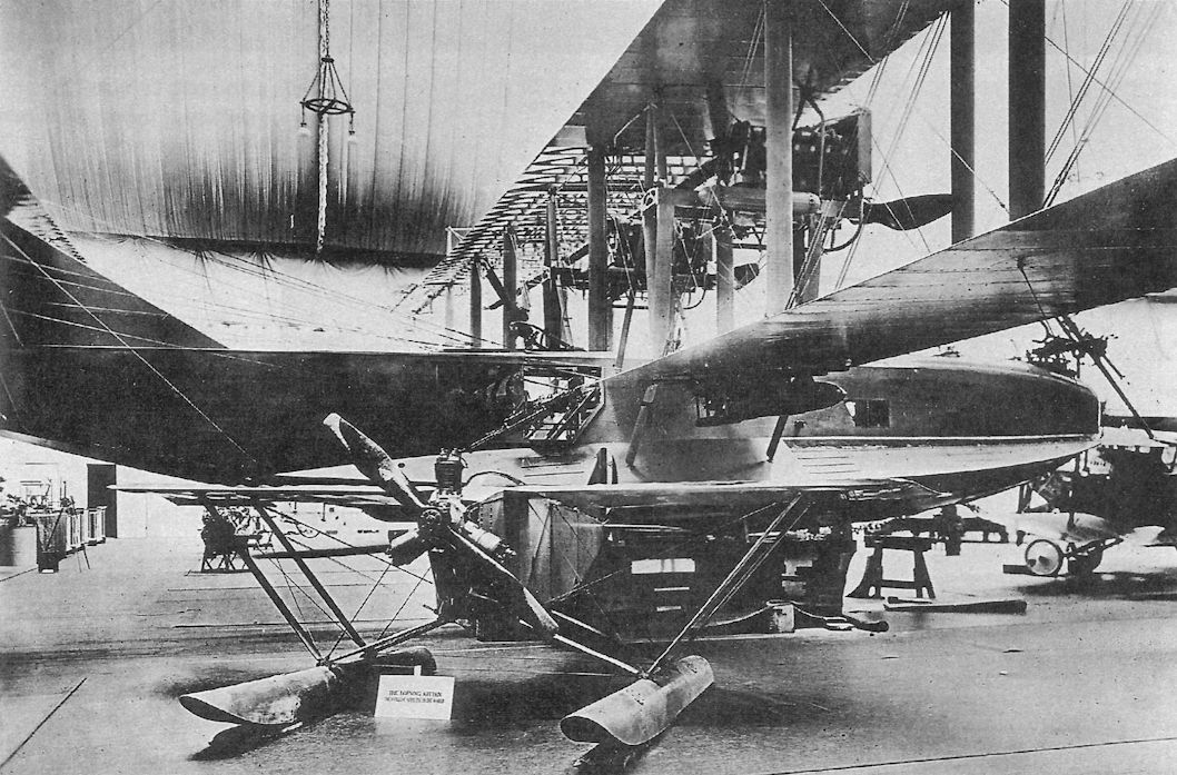
F-5-L A-3882 on display, most probably at the 1919 Aeronautical Exhibition, NY. The small floatplane is the Loening Kitten.
Другие самолёты на фотографии: Loening M-2 Kitten - США - 1918
-
C.Owers - The Fighting America Flying Boats of WWI Vol.2 /Centennial Perspective/ (23)
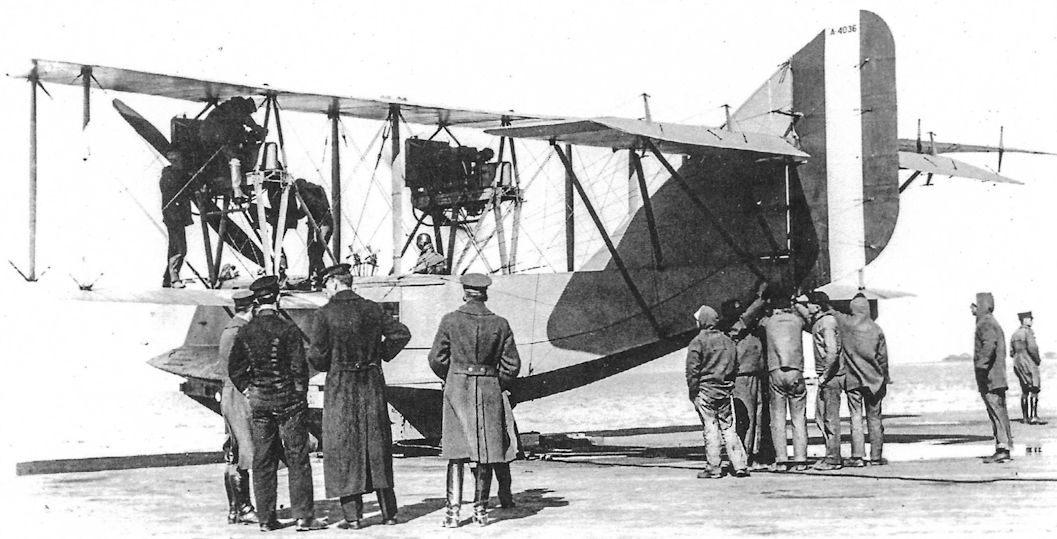
F-5-L Bureau No. A-4036 being prepared for launching down the slipway. Built at the NAF in September 1918 it wa reported as 20% complete, and 90% in November. On 17 January 1919, Ensigns Stillwell and Stinson flew the boat to Hampton Roads who reported that the starboard and port propeller stockings were badly damaged; the overhang load wire on the port wing was broken; the trailing edge on both upper wings and the lower port wing was badly warped; and there was considerable water in the hull that had to be pumped out and the bottom thoroughly cleaned inside and out. It would require two week to get ready for testing. On 12 February Hampton Roads reported that the machine had an enlarged vertical fin fitted for trial flights. On 10 April it was reported as damaged and on 9 June the boat was recommended to be stricken as "damaged", this taking place on 9 June. TFT was 18.39 hours.
-

C.Owers - The Fighting America Flying Boats of WWI Vol.2 /Centennial Perspective/ (23)
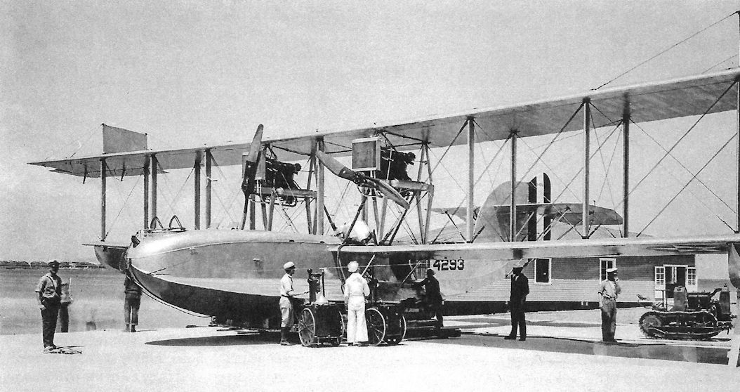
A-4293 appears to be aluminium coloured overall. The fin modification is present but not the balanced rudder. The machine is being refuelled. A small tractor for moving the boats is visible under the port wing, a saving in manpower when compared with the operations in WWI when many hands were required to shift these large flying machines. A4293 was was reported as 50% complete in November 1918. It was apparently stored at Buffalo until 2 April 1919, when it was shipped to Philadelphia, presumably to NAF for overhaul before being shipped to Coco Solo in January 1920. In June 1923 it was returned to the NAF arriving in September where it was recommended it be stricken. This occurred on 30 September 1927, with a TFT of 116:30 hours.
-

C.Owers - The Fighting America Flying Boats of WWI Vol.2 /Centennial Perspective/ (23)
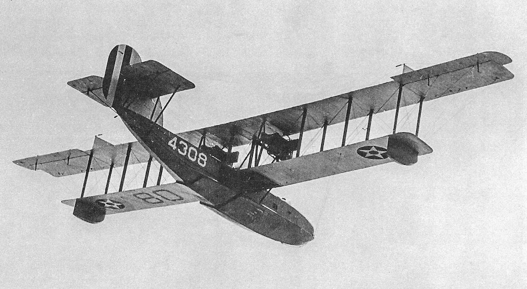
A-4308 displays the lower surface markings on a late F-5-L with the hull strengthening modifications.The hull is the same colour overall. Curtiss built A-4308 had a relatively long life. In November 1918 it was reported to be 40% complete and was therefore selected to be finished as were all the 50 machines of this order. Initially stored at Buffalo, NY, it was shipped to the NAF in March 1919, and was presumably overhauled before being shipped to the USS Shawmut for the Atlantic Fleet with Liberty engines Nos. 02772/3841 (stb); 03822/5424 (port) installed. On 30 December 1920, Shawmut reported that the bow was pushed in about 6-8 inches from a point above the waterline to the machine gun mount. The plane did not make any water and no other part of the hull was damaged. Skid fin on starboard wing was broken but the overhang was not broken. The boat was beached and the bow covered with canvas and the crew then proceeded on their journey. Four longerons and the main keel were broken; all fore and aft main ribs were broken, all to 2 feet aft of the bow. All cowling ribs were broken forward of gunner's cockpit. Both starboard and port sponson longerons were broken 2 feet aft of the bow. No mention of how this occurred is given in the report. (Another document gives the date of this accident as occurring in 1921.)
-
C.Owers - The Fighting America Flying Boats of WWI Vol.2 /Centennial Perspective/ (23)
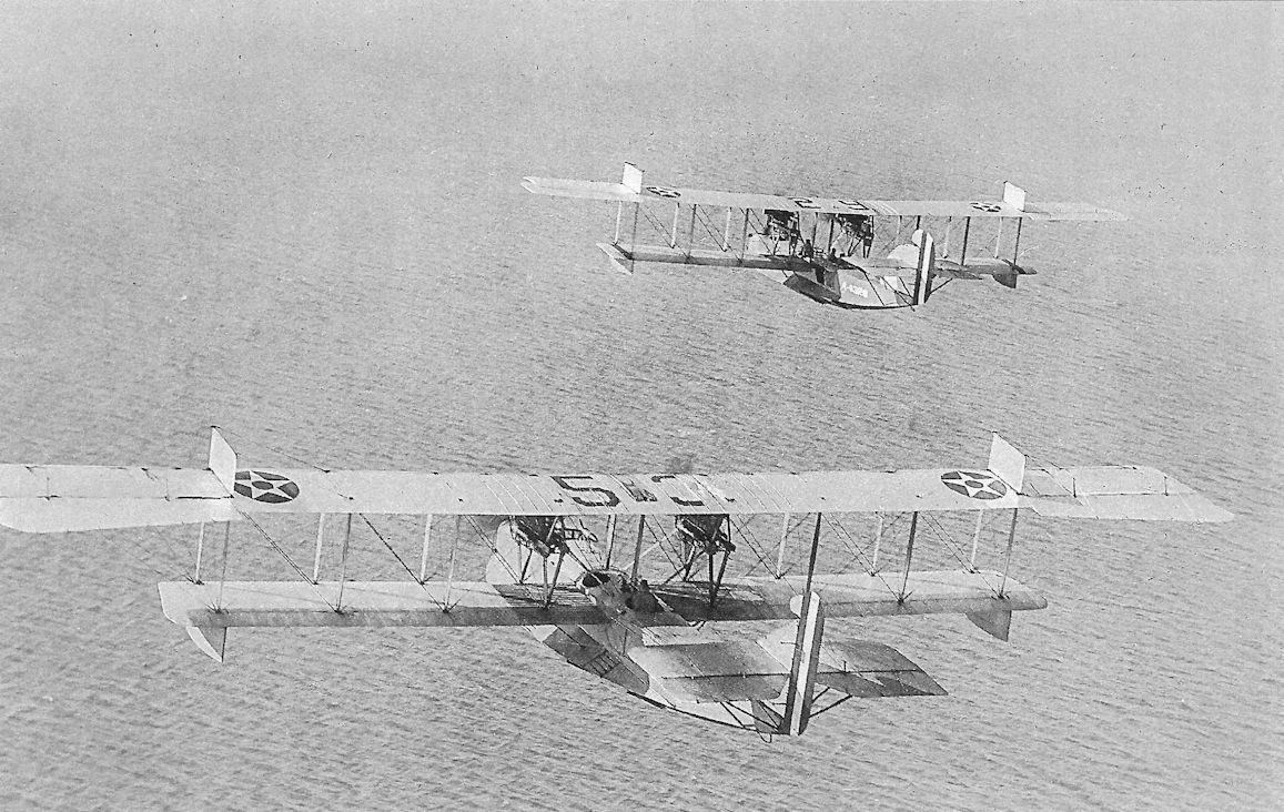
Two F-5-L boats in flight. The closer appears to be in aluminium overall while the other, A-4329, appears to have a Navy Grey hull. Both machines have the enlarged fm and balanced rudder and carry their last numerals of their Bureau Nos. on the centre section as the aircraft's code number. A-4329 was constructed by the Curtiss Aeroplane and Motor Corp as part of a batch for 50 that was allowed to stand after the Armistice. Originally estimated to be ready in December 1918, it was shipped on 13 March 1919 to Philadelphia, probably for storage at the NAF. On 20 November 1920 it was shipped to Pensacola, and the following year to Hampton Roads. A report of 20 November 1922 condemned the hull and the seaplane was stricken on 2 January 1923.
-

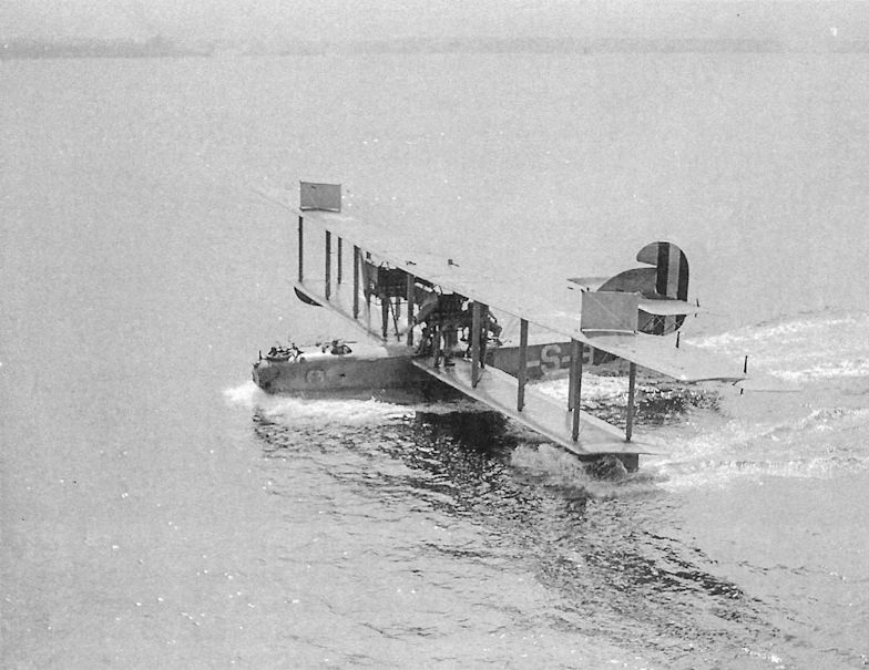
C.Owers - The Fighting America Flying Boats of WWI Vol.2 /Centennial Perspective/ (23)
In Navy Grey overall with codes "1-S-8" on the rear hull and an interesting insignia on the forward hull, this F-5-L was photographed in Newport Harbour, Rhode Island. The "8" was repeated on the bow of the boat.
-
C.Owers - The Fighting America Flying Boats of WWI Vol.2 /Centennial Perspective/ (23)
The codes on the upper surface of the top wing have been over-painted. This machine has the late hull modifications but early fin with balanced rudder. Note that the upper surface to the top wing and the horizontal tail surfaces have been doped chrome yellow.
-
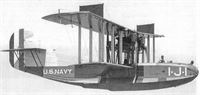
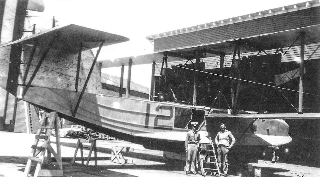
C.Owers - The Fighting America Flying Boats of WWI Vol.2 /Centennial Perspective/ (23)
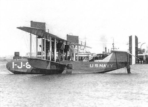
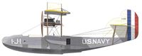
The upper wing of A-4281 is chrome yellow. This boat carried late markings and has all the modifications to the tail surfaces and hull. The hull markings"I-J-I"are thought to show that this machine was the first plane in Utility Squadron 1. In August 1918 reported as 30% complete, and in November as 100% complete. On 18 November it was shipped to the NAF and presumably placed in storage where it was recorded on 22 October 1920 when it was recommended for sale. On 17 April 1926, the boat was shipped to the Scouting Fleet operating with the USS Wright, and was received on 5 June. It was returned to the NAF in August, probably for overhaul as it was shipped on 11 September to San Diego to Utility Squadron 1, VJ-1. The boat lasted until 1 May 1928 when it was recommended that it be stricken. The hull lower edges of keelson under gas tank was discoloured and spongy, etc., due to service and age. On 27 June, with a TFT of 473.35 hours, A-4281 was stricken.
-
C.Owers - The Fighting America Flying Boats of WWI Vol.2 /Centennial Perspective/ (23)
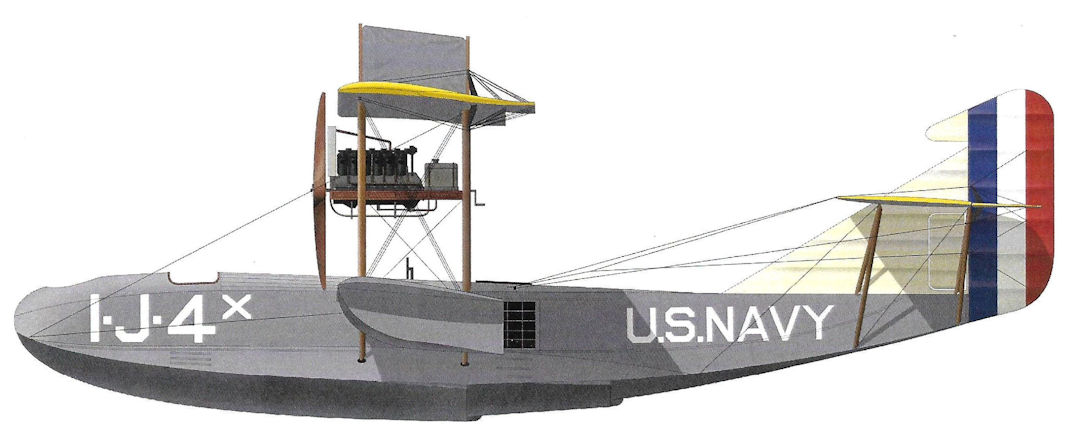
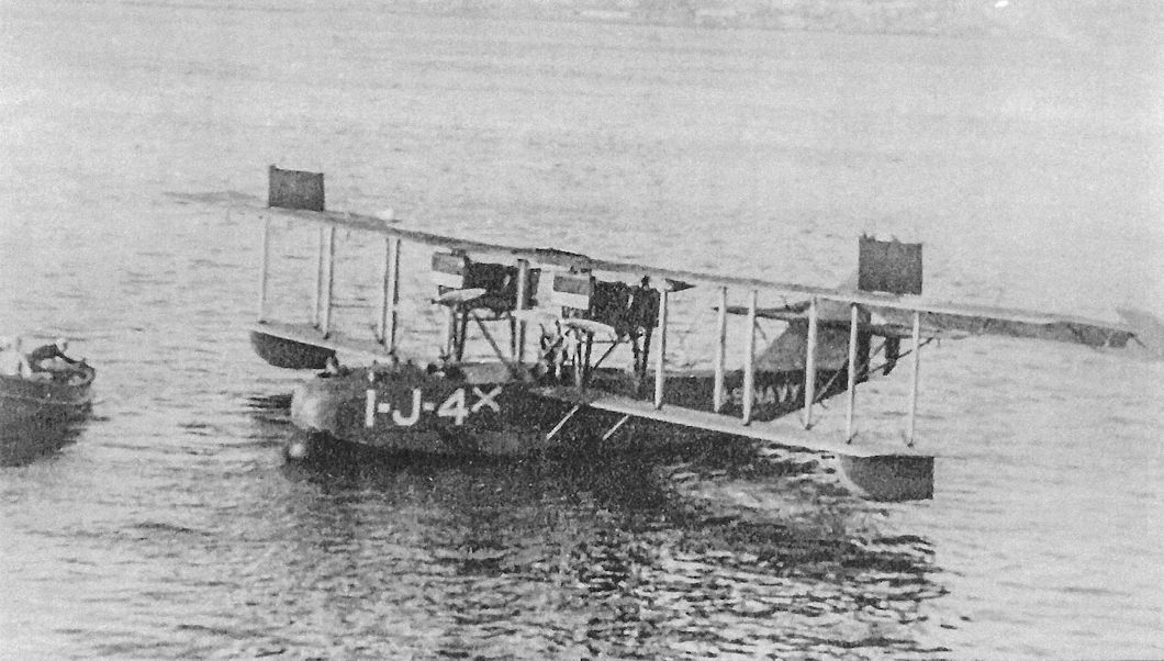
Although it bears late markings this F-5-L has the original fin with modified balanced rudder. The code is thought to indicate that this is the 4th plane in Utility Squadron One. The meaning of the "X" added to the code is not known. Note the bulge at the bow.
-
C.Owers - The Fighting America Flying Boats of WWI Vol.2 /Centennial Perspective/ (23)
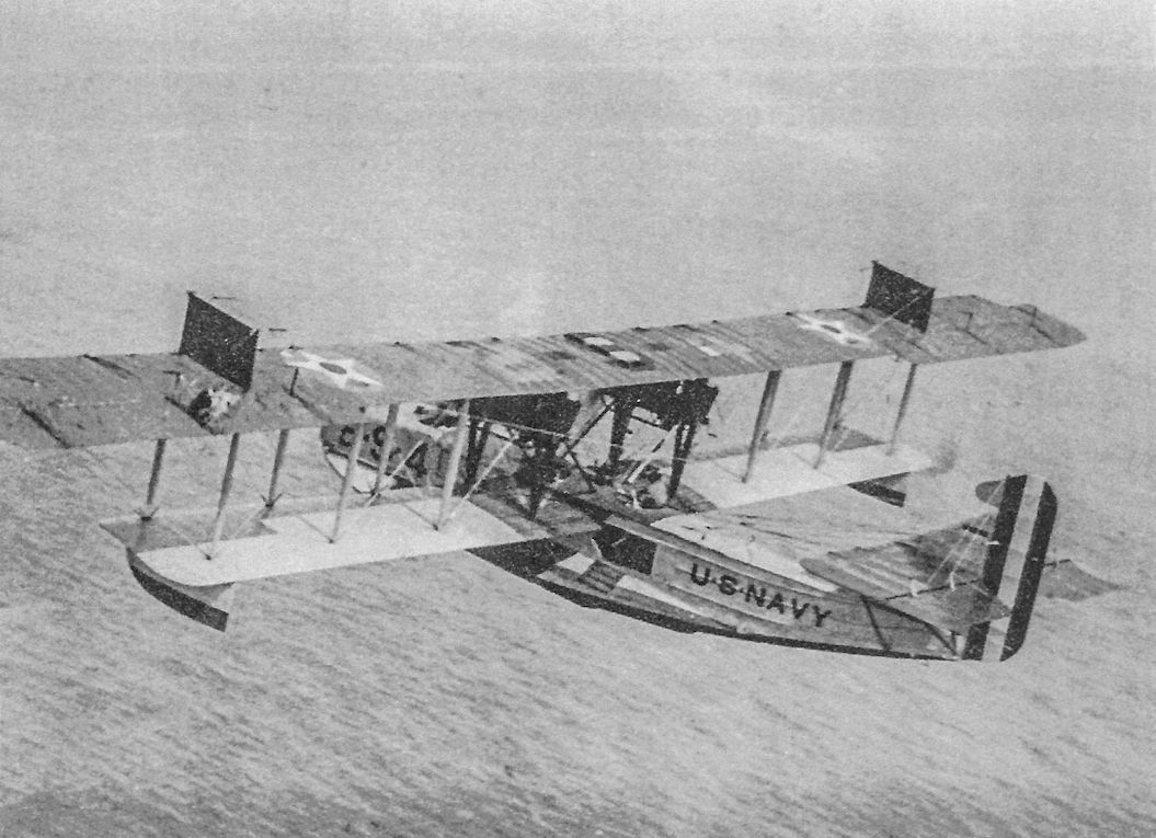
This F-5-L has all the modifications to the fin and rudder and hull. The station code is now carried on the hull and on the centre section of the chrome yellow coloured top wing. The "P" is thought to indicate "Patrol."
-
C.Owers - The Fighting America Flying Boats of WWI Vol.2 /Centennial Perspective/ (23)
The HR on the bow of this F-5-L denotes that it was assigned to Hampton Roads.
-
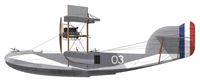
C.Owers - The Fighting America Flying Boats of WWI Vol.2 /Centennial Perspective/ (23)
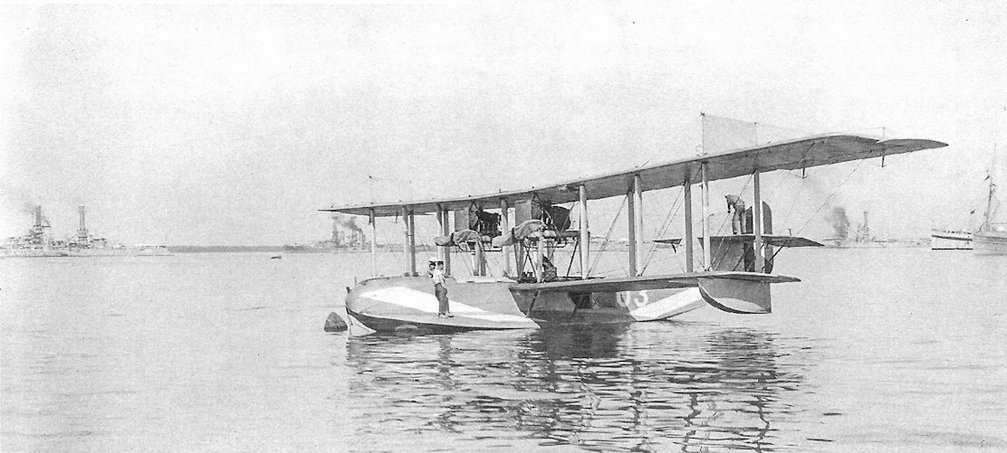
This F-5-L, machine "03" has a colourful hull. Note the canvas covers on the airscrews.
-

C.Owers - The Fighting America Flying Boats of WWI Vol.2 /Centennial Perspective/ (23)
The USS Wright was a flying boat depot ship. After launching in April 1920, the ship was converted to a lighter than an aircraft tender. The ship was commissioned at the New York Navy Yard on 16 December 1921. The ship had a balloon well built into the hull to enable a kite balloon to be carried by the ship. After discharging her kite balloon the ship acted as a seaplane tender.
-
C.Owers - The Fighting America Flying Boats of WWI Vol.2 /Centennial Perspective/ (23)
The fin and rudder of this F-5-L display a dirty appearance unlike the hull. Note the access ladder leading to the side gunner's position.
-
C.Owers - The Fighting America Flying Boats of WWI Vol.2 /Centennial Perspective/ (23)
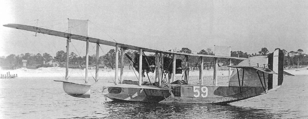
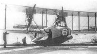
The purpose of the bulge at the front of this F-5-L boat's hull is unknown at this time. The aircraft number "61" is repeated under the lower port wing.
-
C.Owers - The Fighting America Flying Boats of WWI Vol.2 /Centennial Perspective/ (23)
This F-5-L with modified fin and rudder carries the late national insignia and bears the last two numerals of its Bureau No. on the upper wing. Compare this aluminium doped wing with those painted chrome yellow. Note the black stripes at the outer interplane struts.
-

C.Owers - The Fighting America Flying Boats of WWI Vol.2 /Centennial Perspective/ (23)
The top surface of the upper wing on this F-5-L has large chrome yellow patches. The aircraft code "83" is marked on the centre section but is not visible on the bow. Note the crewman standing in the front gunner's cockpit.
-

C.Owers - The Fighting America Flying Boats of WWI Vol.2 /Centennial Perspective/ (23)
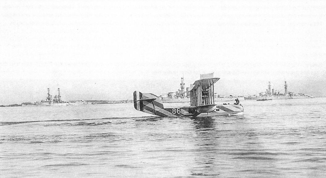
This F-5-L appears to have white stripes applied over the basic Navy Grey finish. Note the ships in the background. The dazzle painted boats were operated with the fleet.
-
C.Owers - The Fighting America Flying Boats of WWI Vol.2 /Centennial Perspective/ (23)
With a striped hull that appears to have different colours on the hull and fin over the standard Navy Grey finish, this F-5-L has the large fin but retains the unbalanced rudder. There are two occupants in the front gunner's cockpit.
-
C.Owers - The Fighting America Flying Boats of WWI Vol.2 /Centennial Perspective/ (23)
This F-5-L has the strengthened hull with ply sides. Although it cannot be seen clearly there are some numerals on the forward rudder stripe. The Bureau No. was normally carried on the central white rudder stripe.
-
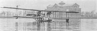
Jane's All The World Aircraft 1919 /Jane's/
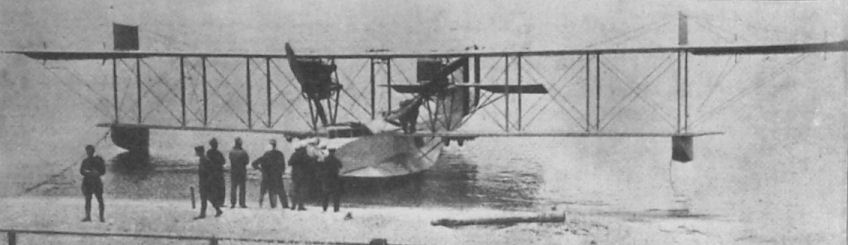
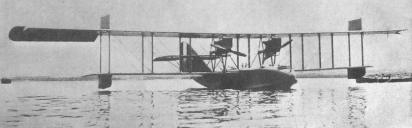
The U.S. Navy's F.5.L. type Flying Boat ashore.
-

C.Owers - The Fighting America Flying Boats of WWI Vol.2 /Centennial Perspective/ (23)
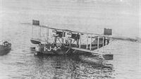
Capt Mustin, early USN aviator, leaving F-5-L No.4 in San Diego, March 1921, after Panama trip. Note the well worn hull painted a light colour on its upper surfaces.
-
C.Owers - The Fighting America Flying Boats of WWI Vol.2 /Centennial Perspective/ (23)
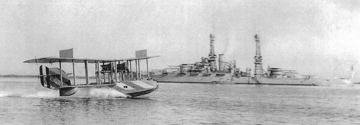
A colourful F-5-L of the Atlantic Fleet Scouting Squadron coming up to the stern of the USS Shawmut seaplane tender at Guantanamo, Cuba, February 1921. The dark colour to the upper wing is thought to be chrome yellow. The Atlantic Fleet boats were given colourful hulls for the same reason that dazzle painting was adopted by the British in late 1918.
-

C.Owers - The Fighting America Flying Boats of WWI Vol.2 /Centennial Perspective/ (23)
An F-5-L on a seaplane barge (lighter), Guantanamo Bay, Cuba, circa 1921. This machine has a colourful hull and the large fin post-war modification. Note the two men on the upper wing and the trousers hanging out to dry under the starboard wing.
-
C.Owers - The Fighting America Flying Boats of WWI Vol.2 /Centennial Perspective/ (23)
Another F-5-L in a colourful scheme. The upper wing has bands of light colour (white/aluminium dope?) and the skid fins have what appears to be an insignia on their outer side.
-
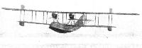
Jane's All The World Aircraft 1919 /Jane's/
Three-quarter front view of the U.S.A. Navy F-5-L flying-boat
-
H.Cowin - Aviation Pioneers /Osprey/
Essentially an improved version of the Curtiss H-16, via the John Cyril Porte developed Felixstowe F 5, the first Navy Aircraft Factory F-5-L made its maiden flight in late July 1918. Powered by two 420hp Liberty 12As, the four man F-5-L carried six .303-inch Lewis guns for its defence, along with up to four 230lb bombs for more aggressive purposes. Top level speed of the F-5-L was 90mph at sea level, with a range of 830 miles being attainable at its economic cruise speed. Besides being responsible for the design's 'Americanisation' in terms of its production engineering, the Navy Aircraft Factory went on to produce 138 of these flying boats, of which 33 had been completed at the time of the Armistice, or just over three months after the F-5-L's first flight. Clearly considered a priority naval programme, 60 more F-5-Ls were built by Curtiss, while a further 30 were completed in Canada before post-war contract cancellations took effect.
-
Журнал - Flight за 1919 г.
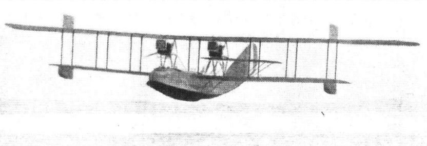
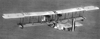
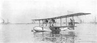
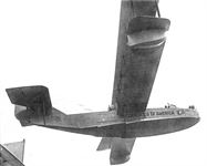
The F-5-L flying-boat in flight
-
C.Owers - The Fighting America Flying Boats of WWI Vol.1 /Centennial Perspective/ (22)
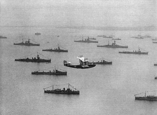
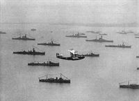
Post-war scene of a Felixstowe boat flying over the ships in Harwich Harbour.
-
C.Owers - The Fighting America Flying Boats of WWI Vol.2 /Centennial Perspective/ (23)
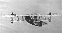
An early F-5-L in flight in WWI colour scheme.
-
C.Owers - The Fighting America Flying Boats of WWI Vol.2 /Centennial Perspective/ (23)
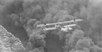
"In the enemy's smoke." This F-5-L is flying above a smoke screen laid down by the warships during the June 1922 Fleet manoeuvres. The hull is brightly painted and the fabric surfaces appear to be aluminium doped. The top surface of the upper wing is chrome yellow.
-
C.Owers - The Fighting America Flying Boats of WWI Vol.2 /Centennial Perspective/ (23)
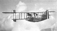
A late F-5-L in flight with the enlarged fin and balanced rudder and external stringers to the rear hull. This machine is in post-war colours with star in circle national insignia.The illegible Bureau No. is carried on the fin.
-
C.Owers - The Fighting America Flying Boats of WWI Vol.2 /Centennial Perspective/ (23)
F-5-L flying a Rear Admiral's staff flags attached to the interplane struts and marked with two stars on the forward hull. This is Rear Admiral Moffett's aircraft. The rear hull gunner's opening has been extended. While this machine has the late hull and rudder modifications it retains the early fin.
-
C.Owers - The Fighting America Flying Boats of WWI Vol.2 /Centennial Perspective/ (23)
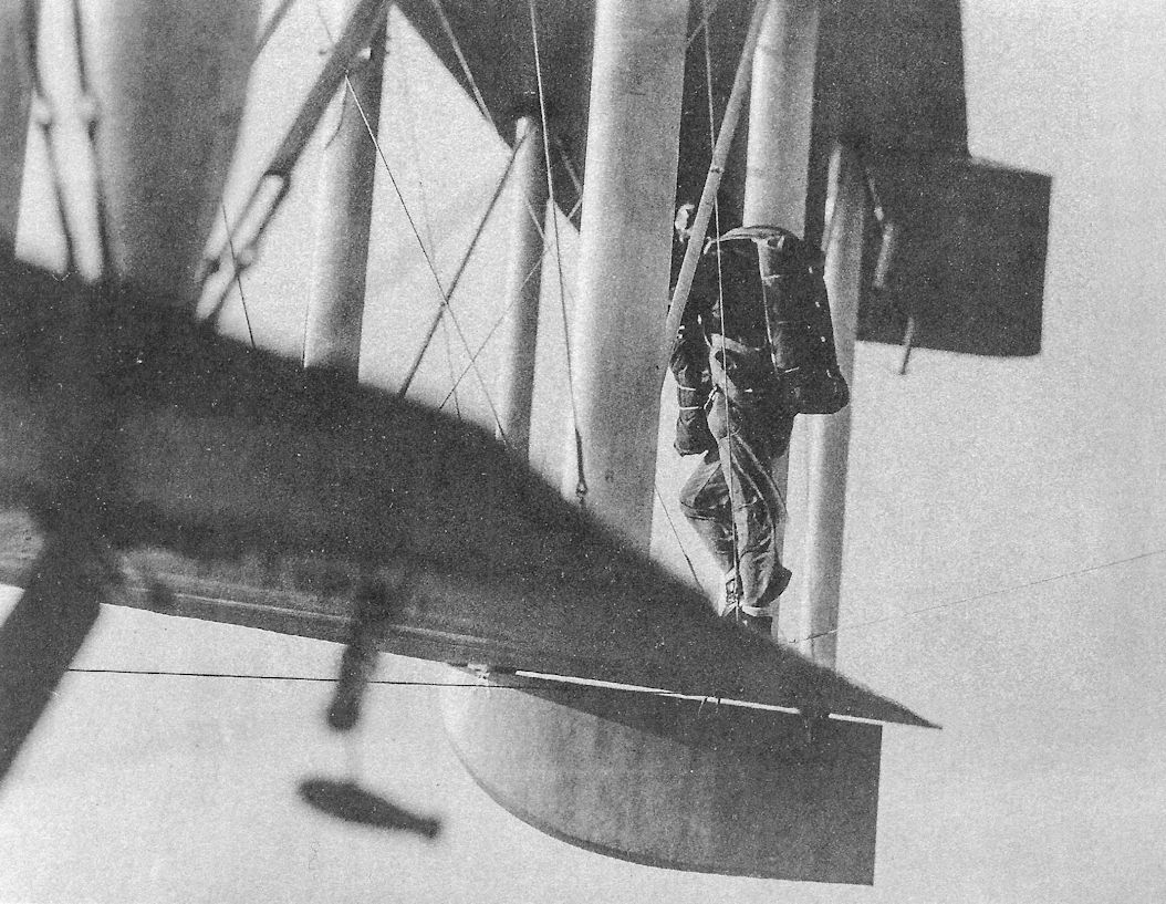
The F-5-L was used for parachute training as shown here (probably early 1920s). The fish shape is the weight for the wireless trailing aerial.
-
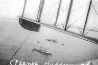
C.Owers - The Fighting America Flying Boats of WWI Vol.2 /Centennial Perspective/ (23)
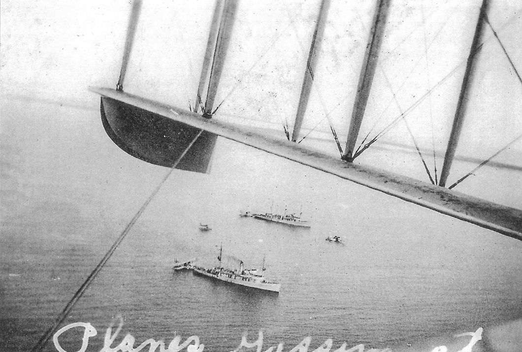
Three flying boats and one floatplane may be made out on the water. Two of the boats are at the stern of the two ships.
-
G.Swanborough, P.Bowers - United States Navy Aircraft since 1911 /Putnam/
A 1924 photograph of a Curtiss F-5L with modified fin and rudder.
-

C.Owers - The Fighting America Flying Boats of WWI Vol.2 /Centennial Perspective/ (23)
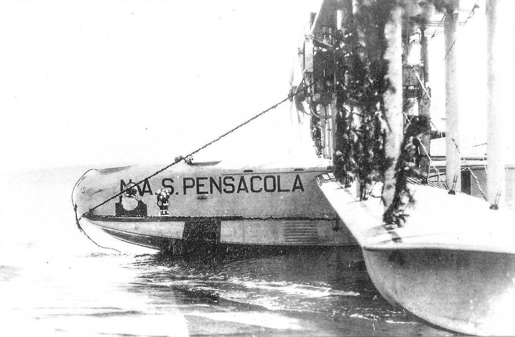
The station that this F-5-L came from is clearly marked on the hull along with the person who was using it for Christmas 1929. It would be interesting to know if it flew festooned as it is depicted here.
-

C.Owers - The Fighting America Flying Boats of WWI Vol.2 /Centennial Perspective/ (23)
Argentinean F-5-L serial B-8. Note markings under lower wing.
-

C.Owers - The Fighting America Flying Boats of WWI Vol.2 /Centennial Perspective/ (23)
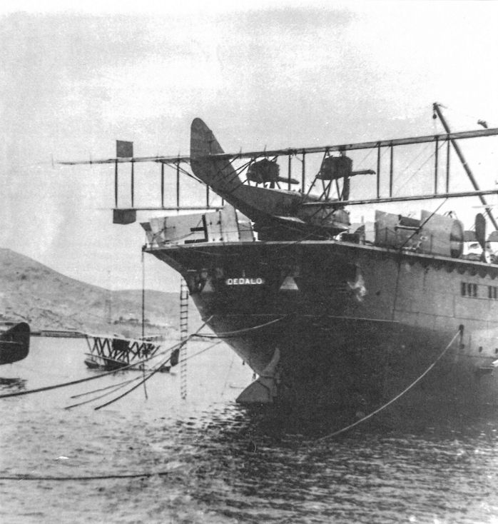
Argentinean F-5-L on board the Dedalo. Note the wing panels on the deck.
-

C.Owers - The Fighting America Flying Boats of WWI Vol.2 /Centennial Perspective/ (23)
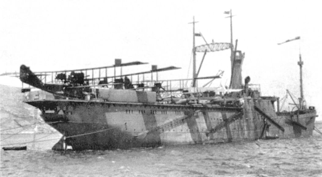
Argentinean F-5-L flying boats on board the Dedalo.
-

C.Owers - The Fighting America Flying Boats of WWI Vol.2 /Centennial Perspective/ (23)
Brazilian F-5-L boats.
-
P.Bowers - Curtiss Aircraft 1907-1947 /Putnam/
Curtiss installed tandem engines in one F-5L to test the concept before making modifications to the first two NC boats.
-
C.Owers - The Fighting America Flying Boats of WWI Vol.2 /Centennial Perspective/ (23)
F-5-L A-3864 with tandem engine installation. The rear engine has a four bladed propeller. Reported complete on 15 August 1919, by November A-3864 was undergoing tandem engine trials at the NAF. In June 1921 it was shipped to Hampton Roads where the trials were to continue. It was still with the Experimental Squadron on 27 April 1922, when it was awaiting propellers from the NAF. It is assumed that it was converted back to the normal engine installation as it was recorded with Scouting Squadron No.1 assigned to the USS Wright in May to November 1923. On 27 March 1924, Hampton Roads reported that the vertical keel and a large percentage of the thwart ships frames and longitudinals had deteriorated due to constant contact with water. All bottom planking was in need of replacement. It was recommended that the hull be reconditioned and placed in reserve. Another report on November 1925 stated that the boat had been erected in 1919 and used as a station plane until 1921.The vertical keel, etc., were rotten and the boat was in a deteriorated condition. On 27 February 1926 it was stricken from the list of naval aircraft.
-
C.Owers - The Fighting America Flying Boats of WWI Vol.2 /Centennial Perspective/ (23)
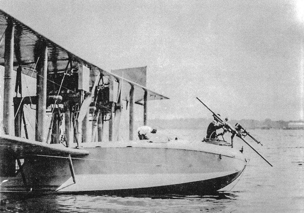
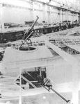
Davis recoilless gun fitted on an F-5-L.
-
C.Owers - The Fighting America Flying Boats of WWI Vol.2 /Centennial Perspective/ (23)
A-3882 on display at the Smithsonian. Note the Aeromarine floatplane in the background.
-

C.Owers - The Fighting America Flying Boats of WWI Vol.2 /Centennial Perspective/ (23)
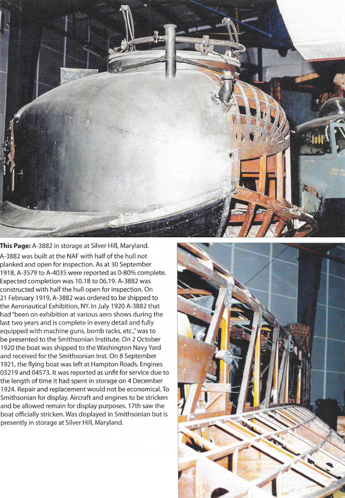
A-3882 in storage at Silver Hill, Maryland. A-3882 was built at the NAF with half of the hull not planked and open for inspection. As at 30 September 1918, A-3579 to A-4035 were reported as 0-80% complete. Expected completion was 10.18 to 06.19. A-3882 was constructed with half the hull open for inspection. On 21 February 1919, A-3882 was ordered to be shipped to the Aeronautical Exhibition, NY. In July 1920 A-3882 that had "been on exhibition at various aero shows during the last two years and is complete in every detail and fully equipped with machine guns, bomb racks, etc.,"was to be presented to the Smithsonian Institute. On 2 October 1920 the boat was shipped to the Washington Navy Yard and received for the Smithsonian Inst. On 8 September 1921, the flying boat was left at Hampton Roads. Engines 03219 and 04573. It was reported as unfit for service due to the length of time it had spent in storage on 4 December 1922. Repair and replacement would not be economical. To Smithsonian for display. Aircraft and engines to be stricken and be allowed remain for display purposes. 17th saw the boat officially stricken. Was displayed in Smithsonian but is presently in storage at Silver Hill, Maryland.
-
C.Owers - The Fighting America Flying Boats of WWI Vol.2 /Centennial Perspective/ (23)
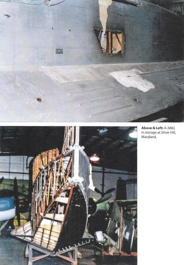
A-3882 in storage at Silver Hill, Maryland.
-
C.Owers - The Fighting America Flying Boats of WWI Vol.2 /Centennial Perspective/ (23)
A-3882 in storage at Silver Hill, Maryland.
-
C.Owers - The Fighting America Flying Boats of WWI Vol.2 /Centennial Perspective/ (23)
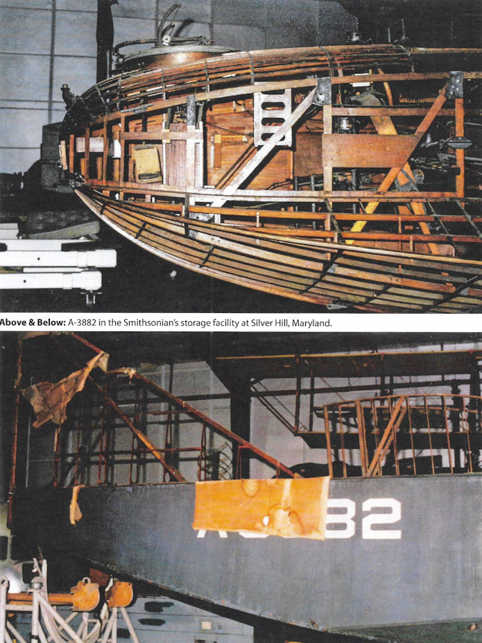
A-3882 in the Smithsonian's storage facility at Silver Hill, Maryland.
-

C.Owers - The Fighting America Flying Boats of WWI Vol.2 /Centennial Perspective/ (23)
The Sampaio Correia over New York on leaving for the flight on 17 August 1922.
-
-
C.Owers - The Fighting America Flying Boats of WWI Vol.2 /Centennial Perspective/ (23)
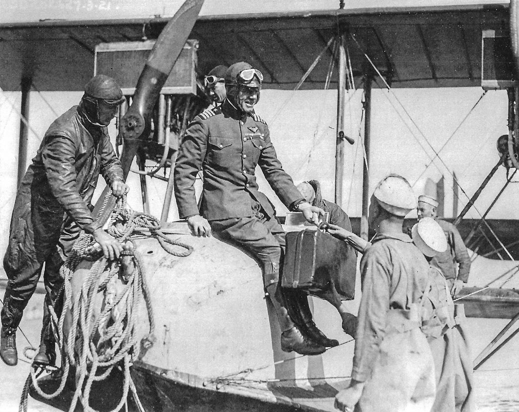
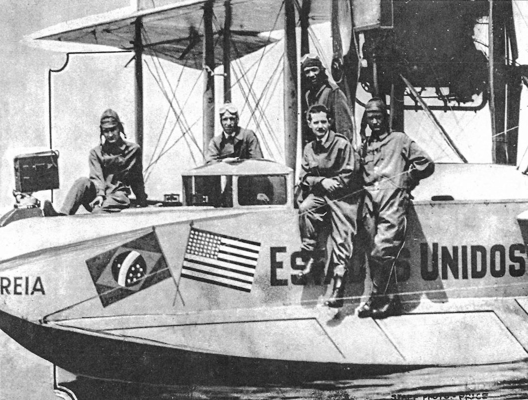
The crew of the Sampaio Correia. The H-16 was decorated with the US and Brazilian flags. Walter Hinton (second from the left) and his crew in New York on the day they left on their flight to Brazil.
-
C.Owers - The Fighting America Flying Boats of WWI Vol.2 /Centennial Perspective/ (23)
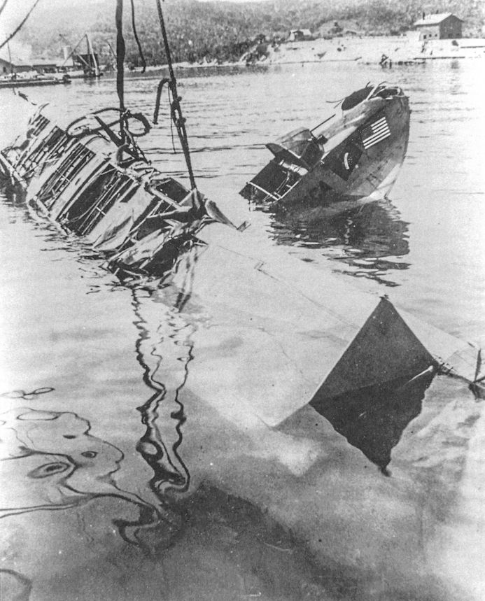
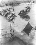
The sad end of the first Sampaio Correia.
-

C.Owers - The Fighting America Flying Boats of WWI Vol.2 /Centennial Perspective/ (23)
A-3600 the "Denby Ship" was converted to a passenger configuration at the NAF. Note the containers under the lower wings. In November 1918 this machine was reported as 60% complete. By 8 August 1921, this boat was converted to a passenger ship for the Secretary of the Navy and had been flown at the NAF with ten persons. On 20 September 1921, was shipped to Anacostia. On 30 December 1921, Lt F.H. Becker reported that controllability was bad and requested an investigation. In June 1922 Anacostia recommended it be replaced by a standard F-5-L as "its carrying capacity and controls are below that of standard F-5-L." It appears that it was placed in storage at the NAF and offered for sale in 1924. It was stricken on 2 July 1925. (G648)
-

C.Owers - The Fighting America Flying Boats of WWI Vol.2 /Centennial Perspective/ (23)
The cylinder under the wing of this converted F-5-L appears to be a storage container and while its purpose is unknown it appears to be the same as A-3600. (NAS Anacostia photographs 1922).
-

-
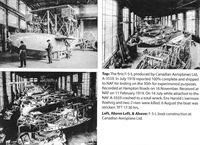
C.Owers - The Fighting America Flying Boats of WWI Vol.2 /Centennial Perspective/ (23)
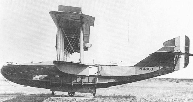
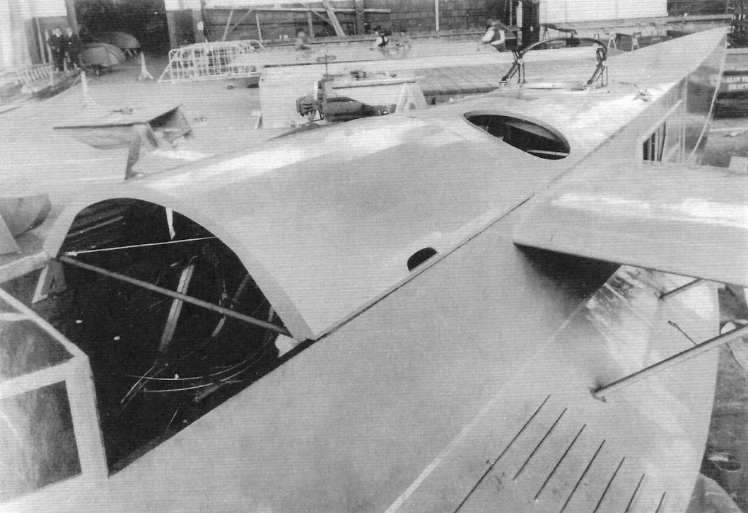
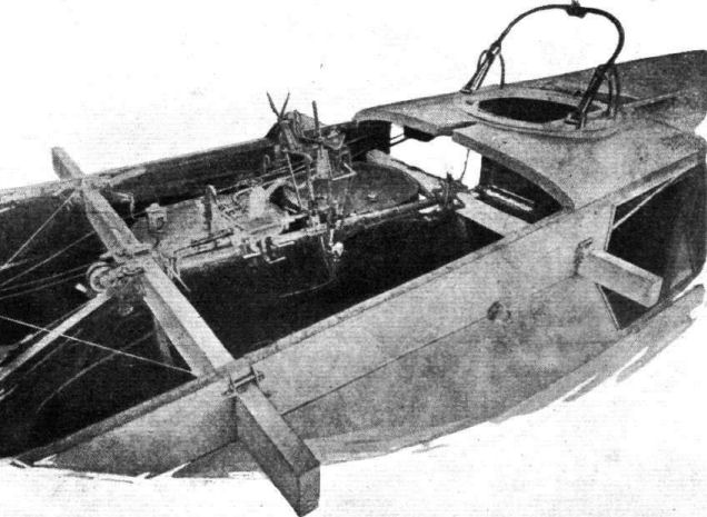
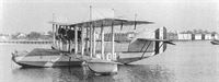
Postwar passenger conversion of an H-16. The pilot's cockpit was relocated between the wings and the entire forward hull converted to a passenger cabin.
This modification did away with the gunner's position in the nose replacing it with a hatch that opened for mooring. -
C.Owers - The Fighting America Flying Boats of WWI Vol.1 /Centennial Perspective/ (22)
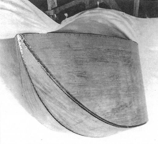
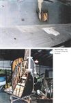
Close-up of the nose of an H-16 hull. The change in colour of the hull as it passes through each stage of construction should be noted.
-

C.Owers - The Fighting America Flying Boats of WWI Vol.1 /Centennial Perspective/ (22)
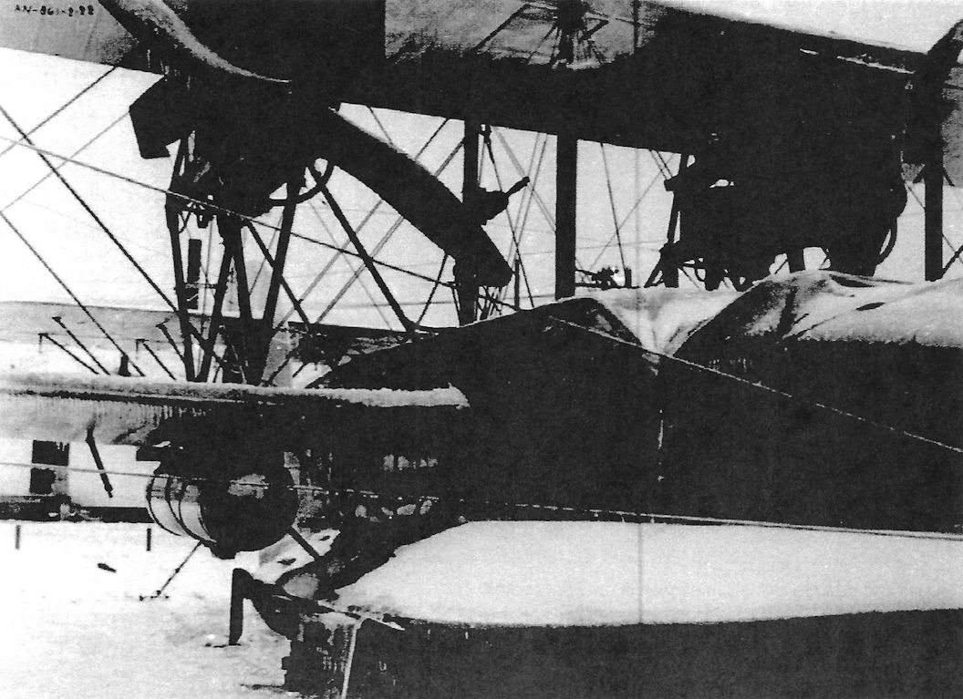
The gap between the cockpit canopy and the rear was a distinguishing feature of the H-16 in flight. The F.2A has a small window that was raised here.
-

C.Owers - The Fighting America Flying Boats of WWI Vol.1 /Centennial Perspective/ (22)
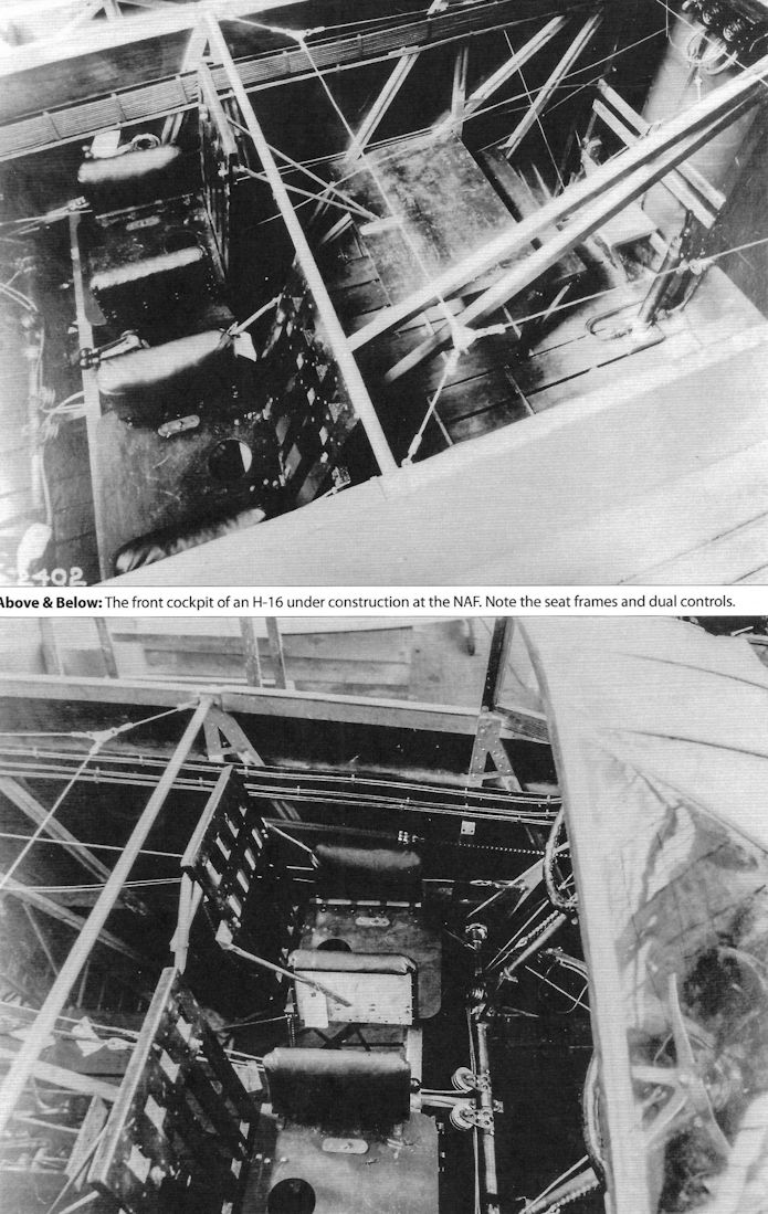
The front cockpit of an H-16 under construction at the NAF. Note the seat frames and dual controls.
-

C.Owers - The Fighting America Flying Boats of WWI Vol.1 /Centennial Perspective/ (22)
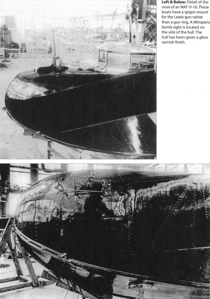
Detail of the nose of a n NAF H-16. These boats have a spigot mount for the Lewis gun rather than a gun ring. A Wimperis bomb sight is located on the side of the hull. The hull has been given a gloss varnish finish.
-
C.Owers - The Fighting America Flying Boats of WWI Vol.1 /Centennial Perspective/ (22)
The bomb sight is on the opposite side of this H-16. The instrument on the nose of this NAF built hull is unknown.
-

C.Owers - The Fighting America Flying Boats of WWI Vol.1 /Centennial Perspective/ (22)
An H-16 hull that still has to have the rear of the hull fabric applied appears to be in Navy Grey finish.
-

C.Owers - The Fighting America Flying Boats of WWI Vol.1 /Centennial Perspective/ (22)
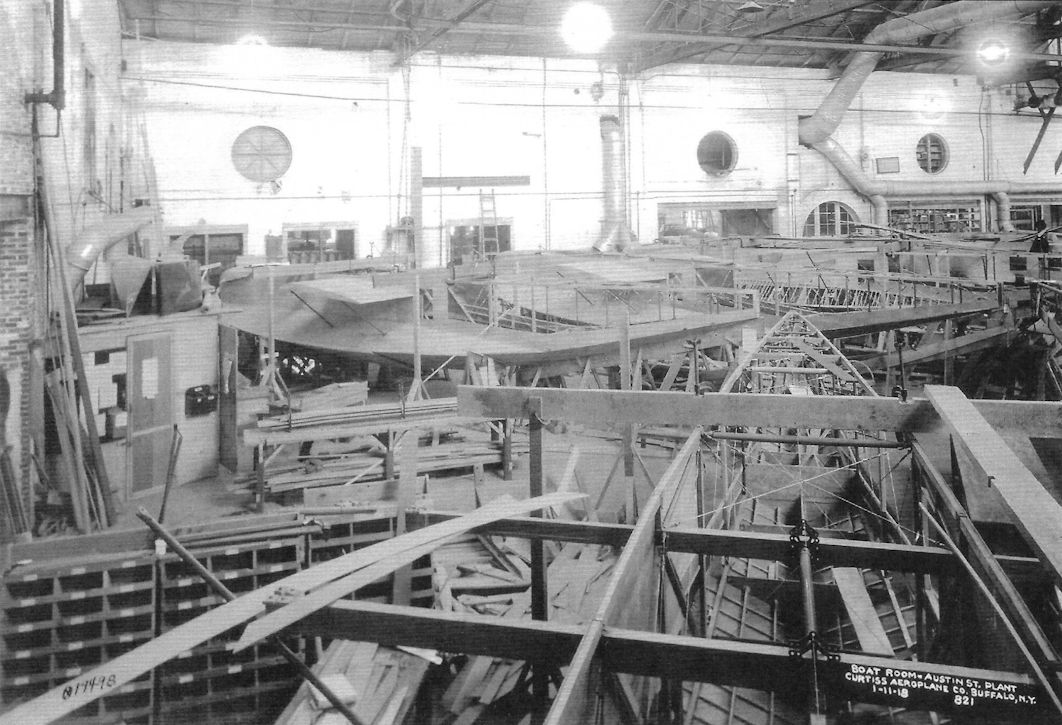
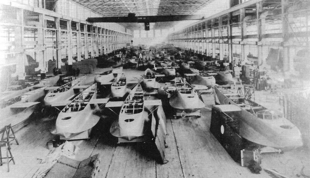
The Felixstowe F.2A was built in the USA as the Curtiss H-16 at the Curtiss Aeroplane Co, Buffalo, and at the Naval Aircraft Factory, Philadelphia.This photograph shows H-16 hulls at the Curtiss Austin St Plant's Boat Room. Photo No.821 dated 01.11.18.
-

C.Owers - The Fighting America Flying Boats of WWI Vol.1 /Centennial Perspective/ (22)
A view of the NAF shows less clutter. Each hull has been tagged with the boat's Bureau No.
-

C.Owers - The Fighting America Flying Boats of WWI Vol.1 /Centennial Perspective/ (22)
The hull frame is ready for skinning on the left and skinned hulls are coming back down the centre. Bureau No. A-1077 can be read on the visible tag.
-
-
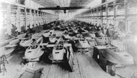
C.Owers - The Fighting America Flying Boats of WWI Vol.2 /Centennial Perspective/ (23)
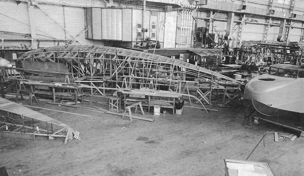
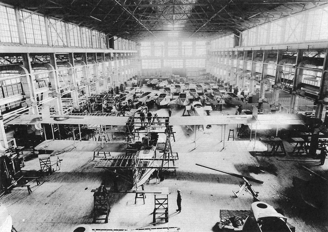
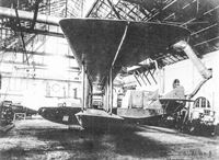
H-16 hulls in the NAF. This photograph gives some idea of the size of the USN's production program.
-

C.Owers - The Fighting America Flying Boats of WWI Vol.1 /Centennial Perspective/ (22)
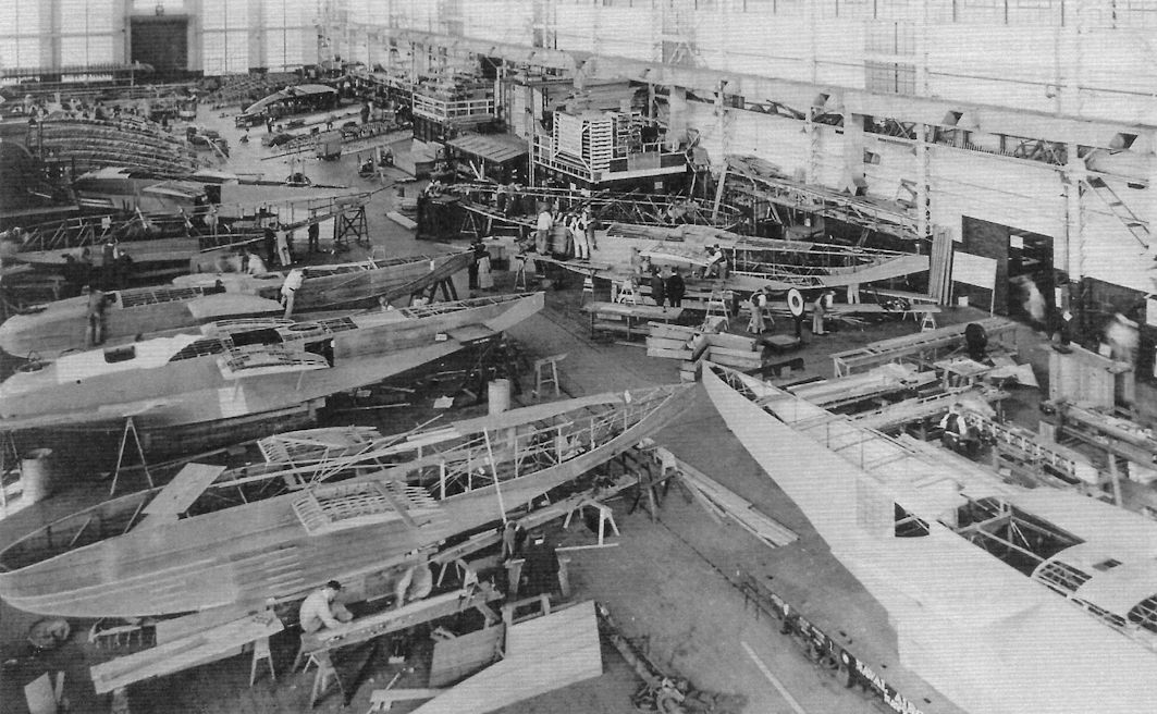
H-16 boats under construction.
-

C.Owers - The Fighting America Flying Boats of WWI Vol.1 /Centennial Perspective/ (22)
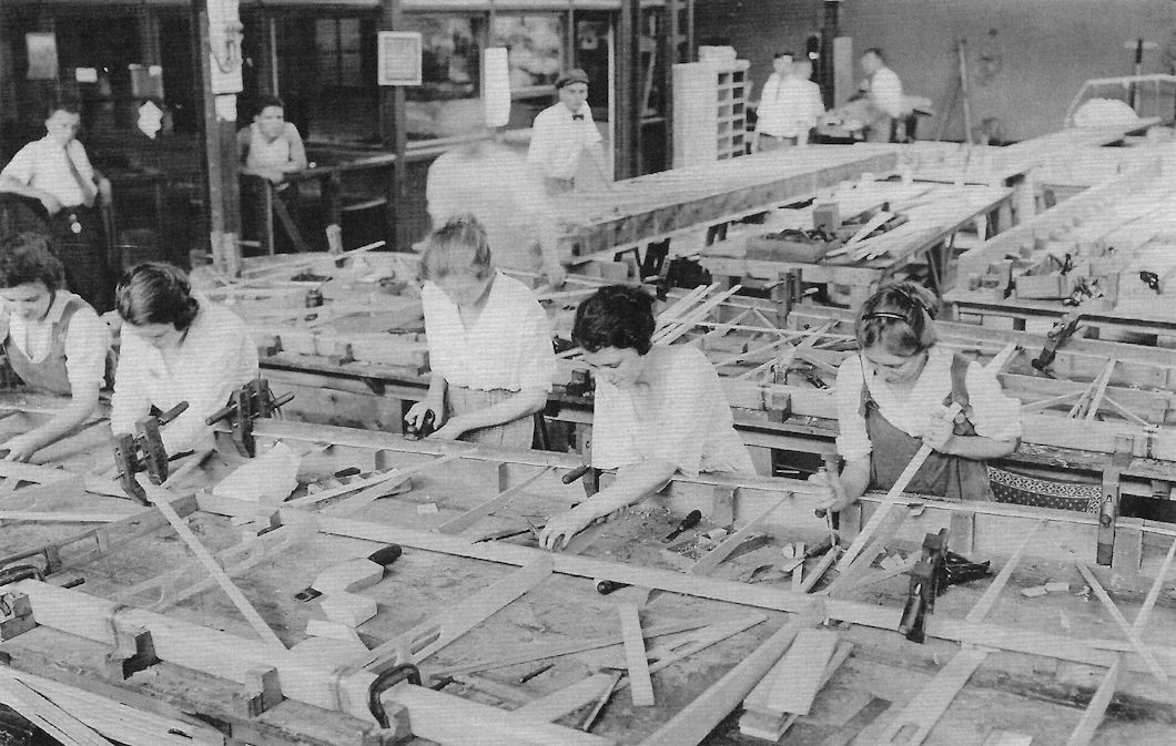
The NAF was proud of its employment of women in its construction program.
-
-

C.Owers - The Fighting America Flying Boats of WWI Vol.1 /Centennial Perspective/ (22)
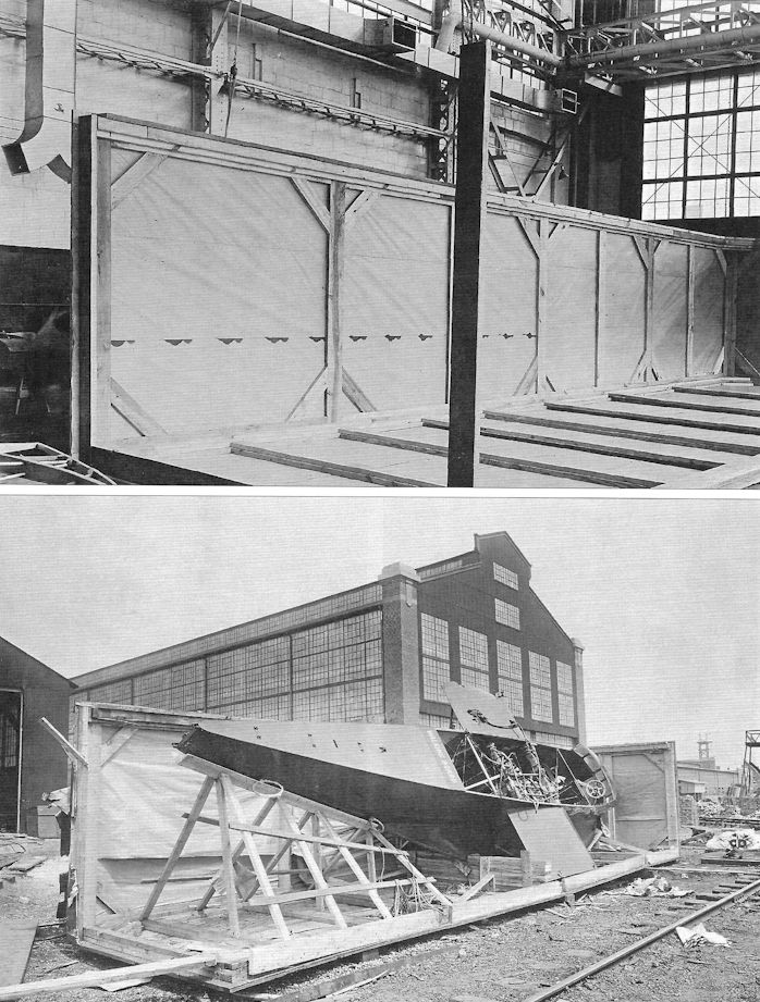
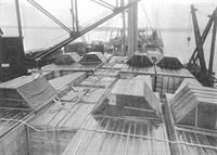
The job of packing these large flying boats for shipment was a task in and of itself. The hull was placed in on its side as shown. It is interesting in that this hull has only a single control wheel. Note the "Walking Board" stencil across the hull. It is not known if this was retained when the machines were assembled. The hulls were crated on their side as shown below.
-

C.Owers - The Fighting America Flying Boats of WWI Vol.1 /Centennial Perspective/ (22)
Loading a rail car with H-16 crated parts.
-

C.Owers - The Fighting America Flying Boats of WWI Vol.1 /Centennial Perspective/ (22)
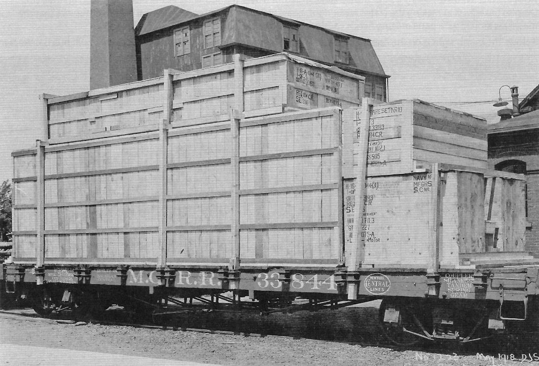
H-16 parts packed and ready to be shipped out. The stencils that can be read on the crate state that they are for H-16 Bureau Nos. A-1044 and A-1077. Curtiss Aeroplane and Motor Corp photo No.1223 dated May 1918.
-
C.Owers - The Fighting America Flying Boats of WWI Vol.1 /Centennial Perspective/ (22)
Crated H-16 on board a ship. The pyramid structure is over the sub-wing as the hulls are crated on their sides. Despite the efforts at making the crates water tight, boats arrived with water damage, but more serious was that the machines arrived with parts missing hence causing delays into moving the flying boats into service.
-
C.Owers - The Fighting America Flying Boats of WWI Vol.1 /Centennial Perspective/ (22)
A Liberty engine packed for shipment.
-
Журнал - Flight за 1919 г.
Detail view of the F-5-L flying-boat, showing the engines and rear "cabin"
-
C.Owers - The Fighting America Flying Boats of WWI Vol.2 /Centennial Perspective/ (23)
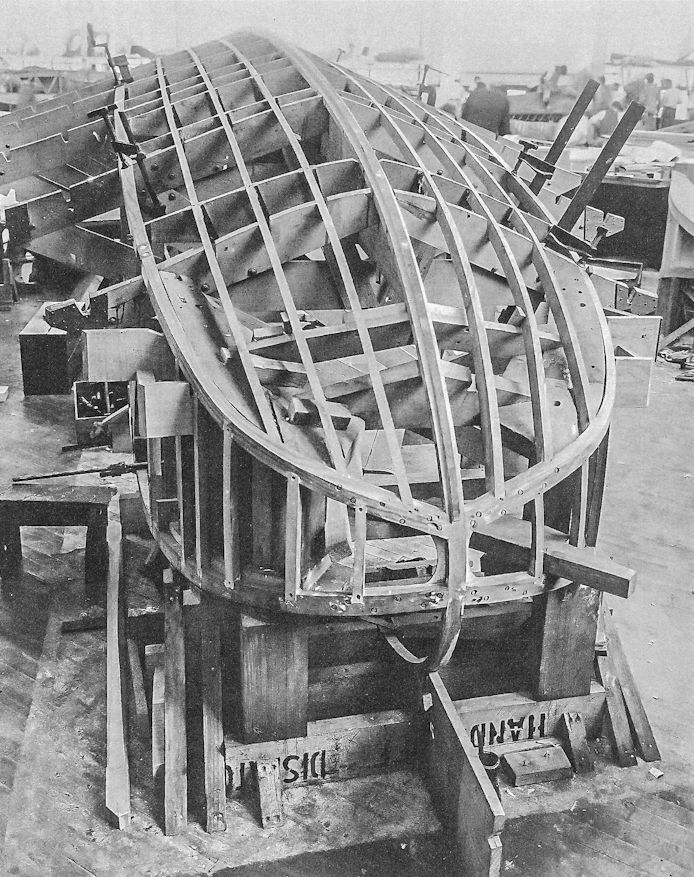
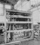
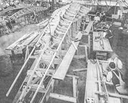
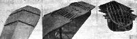
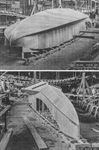
Construction of F-5-L hulls; progressing from right to left the stringers are added then the planking to the bottom of the hull.
-

C.Owers - The Fighting America Flying Boats of WWI Vol.2 /Centennial Perspective/ (23)
F-5-L hull construction at the NAF.
-
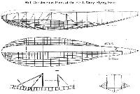
Журнал - Flight за 1919 г.
Three views showing the construction of the hull of the F-5-L flying-boat
-

C.Owers - The Fighting America Flying Boats of WWI Vol.2 /Centennial Perspective/ (23)
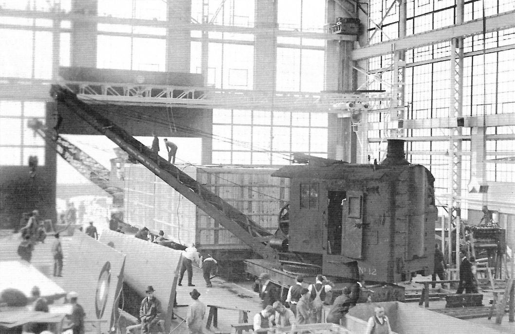
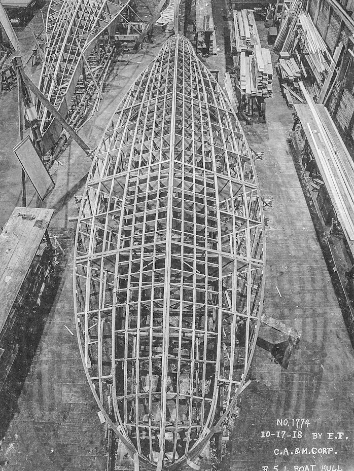
F-5-L hull construction at the Curtiss Aeroplane and Motor Corp, 17 October 1918.
-
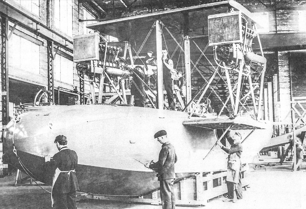
C.Owers - The Fighting America Flying Boats of WWI Vol.2 /Centennial Perspective/ (23)
Views of the planking and ply sides to an F-5-L hull at the Curtiss Aeroplane and Motor Co, 27 August 1918. The hull was constructed upside down. Note the US flag suspended in the factory, a common practice at the time. Also the large jigs and clutter in these early factories is very evident here.
-
C.Owers - The Fighting America Flying Boats of WWI Vol.2 /Centennial Perspective/ (23)
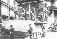
Tail surfaces added to the F-5-L hull.
-

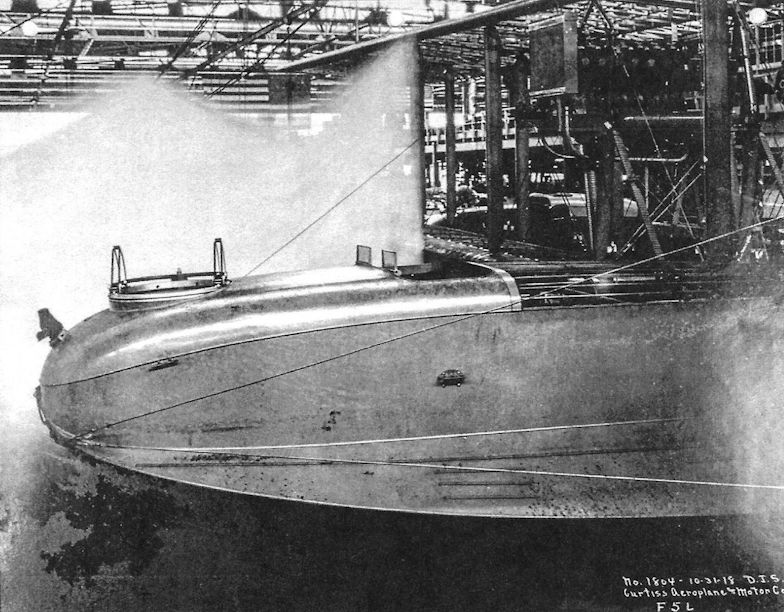
C.Owers - The Fighting America Flying Boats of WWI Vol.2 /Centennial Perspective/ (23)
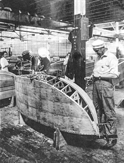
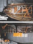
Close-up of nose of F-5-L under construction at the Curtiss Aeroplane & motor Co, 31 October 1918. The background has been eliminated on the original negative to show the forward section to advantage.
-
C.Owers - The Fighting America Flying Boats of WWI Vol.2 /Centennial Perspective/ (23)
F-5-L under construction.
-

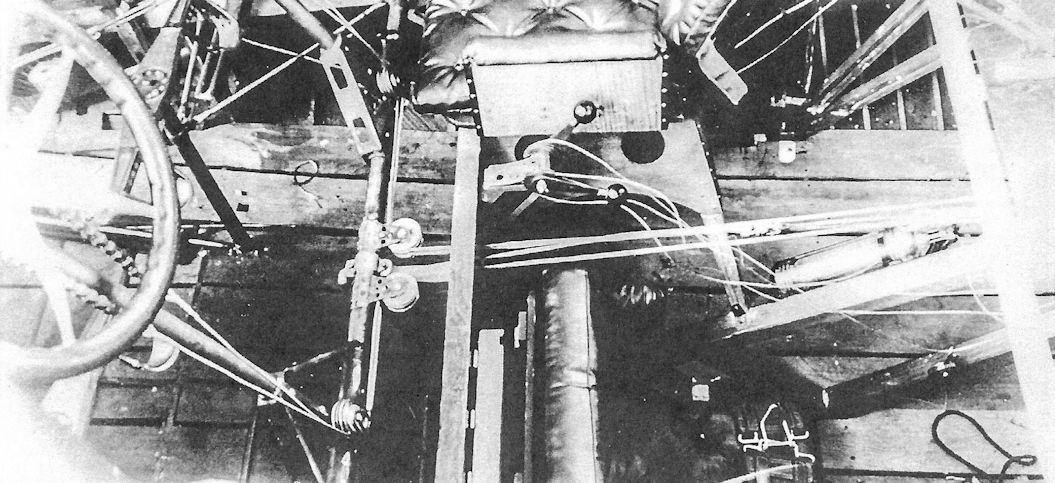
C.Owers - The Fighting America Flying Boats of WWI Vol.2 /Centennial Perspective/ (23)
View of the cockpit in an F-5-L hull under construction showing the left hand pilot's seat and controls.
-

C.Owers - The Fighting America Flying Boats of WWI Vol.2 /Centennial Perspective/ (23)
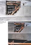
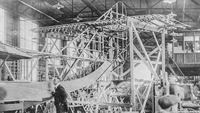
View inside an F-5-L hull under construction showing the complex structure of the centre hull at the wing roots.
-

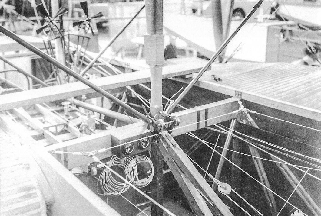
Журнал - Flight за 1919 г.
The petrol tanks and windmill pumps on the F-5-L flying-boat, which are located in the centre of the hull
-
C.Owers - The Fighting America Flying Boats of WWI Vol.2 /Centennial Perspective/ (23)
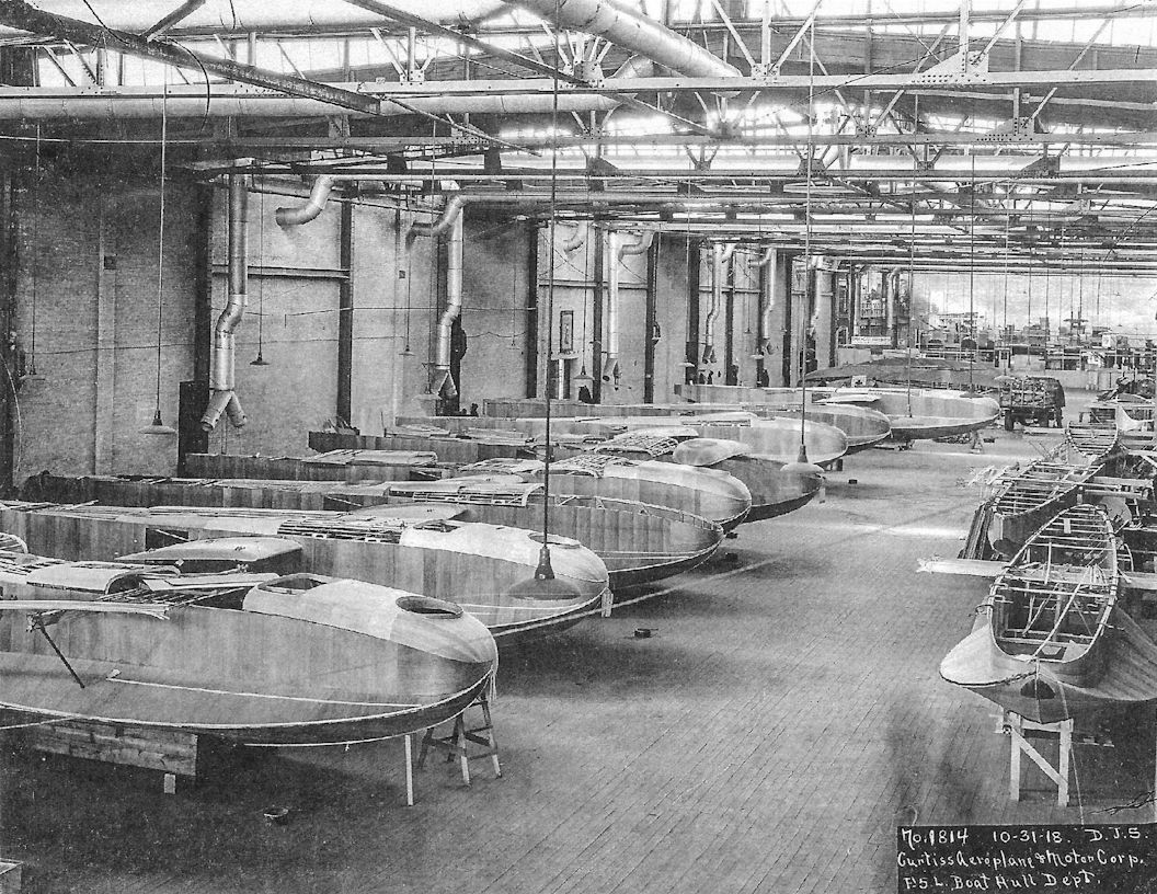
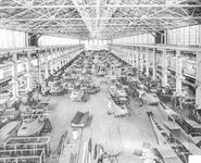
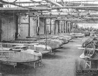
The Curtiss Aeroplane and Motor Corp's F5L Boat Hull Department, 31 October 1918. Twelve hulls in various stages of completion may be seen.
-
C.Owers - The Fighting America Flying Boats of WWI Vol.2 /Centennial Perspective/ (23)
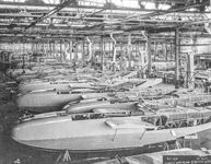
F-5-L hulls at the Curtiss Aeroplane & Motor Corp. As the hulls progress down the line the tail surfaces are added. Curtiss Photo No.1874.
-
C.Owers - The Fighting America Flying Boats of WWI Vol.2 /Centennial Perspective/ (23)
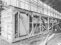
An F-5-L hull packed for shipment.
-

C.Owers - The Fighting America Flying Boats of WWI Vol.2 /Centennial Perspective/ (23)
Uncovered upper wing panels at the NAF. Note the large crate being constructed in the background.
-

C.Owers - The Fighting America Flying Boats of WWI Vol.2 /Centennial Perspective/ (23)
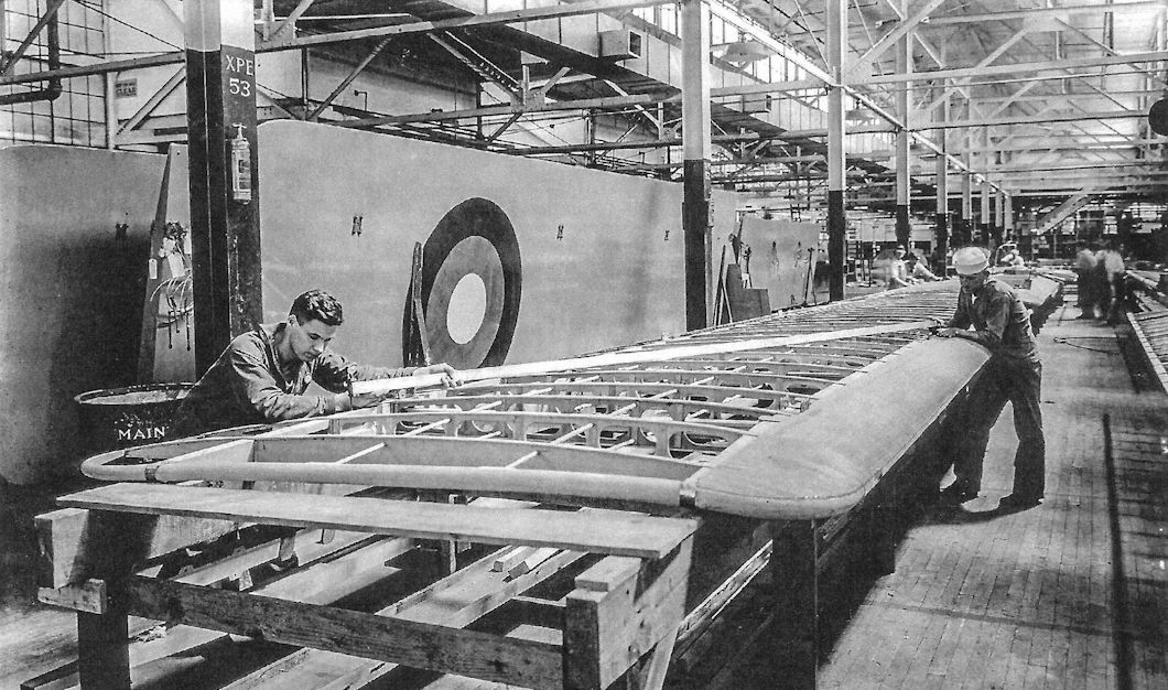
Above: Construction of a lower wing for an F-5-L at the Navy Aircraft Factory (NAF). The two men are laying a straight edge over the wing and checking the tolerances. Note the smooth finish of the covered wing in the background. Rib tapes are not visible.
-

C.Owers - The Fighting America Flying Boats of WWI Vol.2 /Centennial Perspective/ (23)
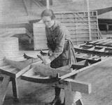
Constructing a wing-tip float for an F-5-L.
-

C.Owers - The Fighting America Flying Boats of WWI Vol.2 /Centennial Perspective/ (23)
A completed wing-tip float.
-
C.Owers - The Fighting America Flying Boats of WWI Vol.2 /Centennial Perspective/ (23)
F-5-L boat construction at Canadian Aeroplane Ltd.
-

C.Owers - The Fighting America Flying Boats of WWI Vol.1 /Centennial Perspective/ (22)
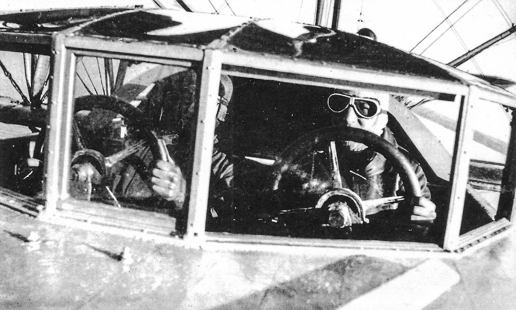
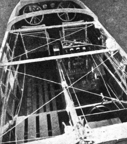
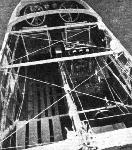
Internal view of the cockpit of an H-16 with dual control.
-

C.Owers - The Fighting America Flying Boats of WWI Vol.2 /Centennial Perspective/ (23)
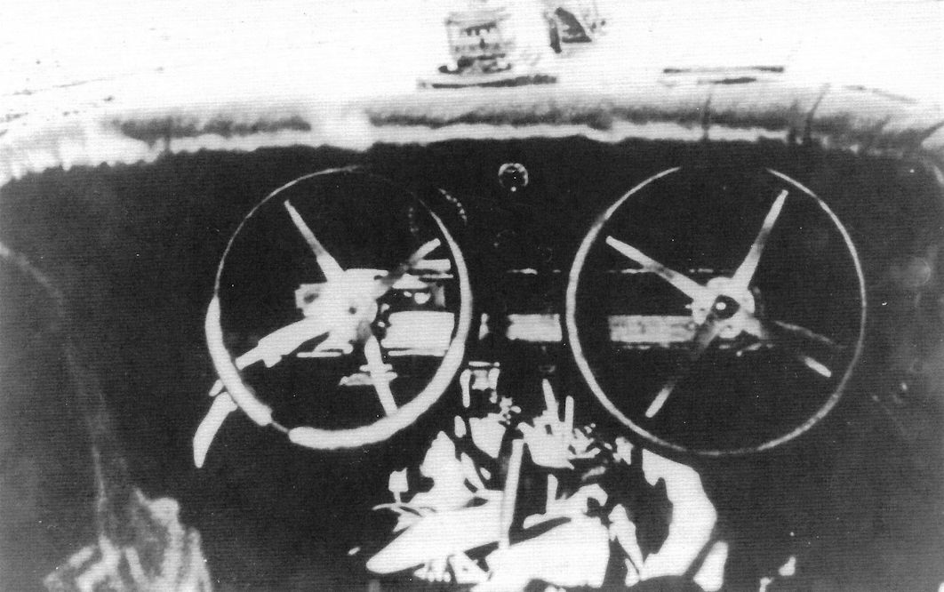
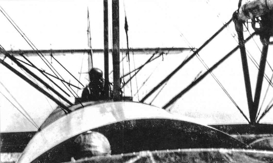
View taken on an H-16 in flight. The dual control wheels are visible through the cockpit canopy.
-
C.Owers - The Fighting America Flying Boats of WWI Vol.2 /Centennial Perspective/ (23)
The first H-16 from the NAF is ready for launching. The early H-16 boats had a gooseneck spigot mount for the front Lewis gun. This was replaced by a Searff ring on the boats that went to Europe.
-
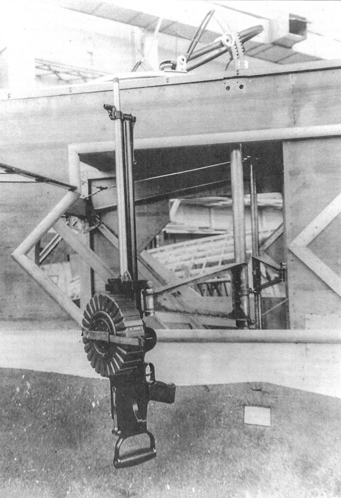
C.Owers - The Fighting America Flying Boats of WWI Vol.2 /Centennial Perspective/ (23)
The front gun position on an H-16 with US produced Scarff ring mount for the Lewis gun.
-
C.Owers - The Fighting America Flying Boats of WWI Vol.2 /Centennial Perspective/ (23)
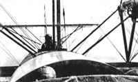
View taken on an H-16 in flight.
-

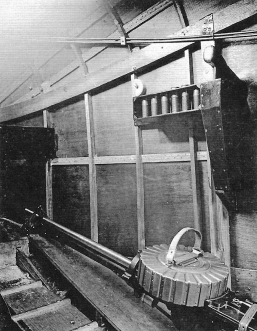
C.Owers - The Fighting America Flying Boats of WWI Vol.1 /Centennial Perspective/ (22)
Internal view showing the Lewis gun stowed on an H-16. Note the flare holder rail above the gun.
-

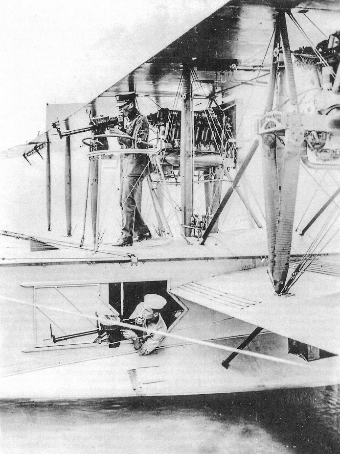
C.Owers - The Fighting America Flying Boats of WWI Vol.2 /Centennial Perspective/ (23)
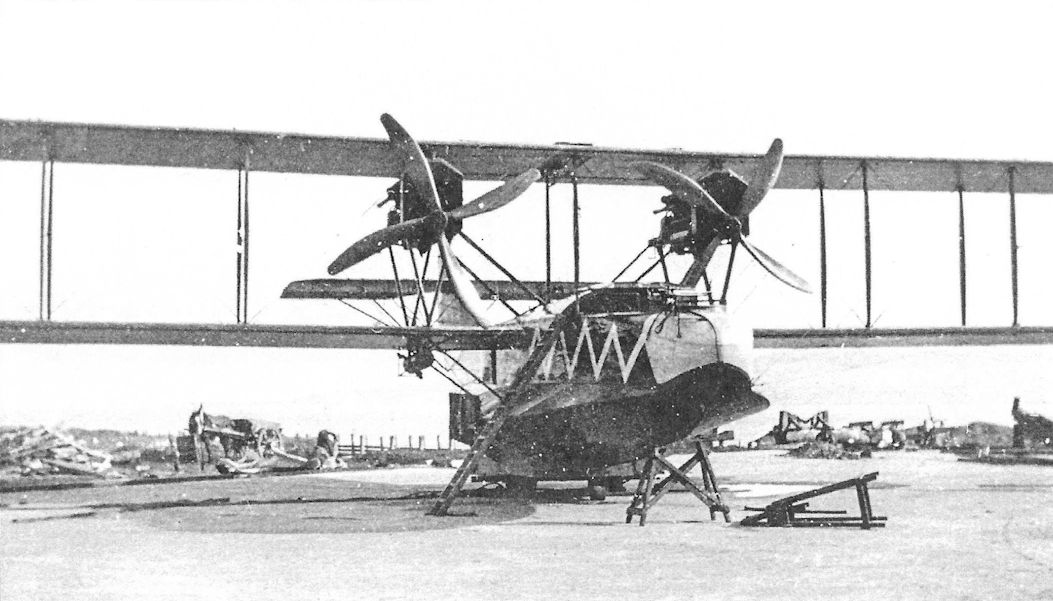
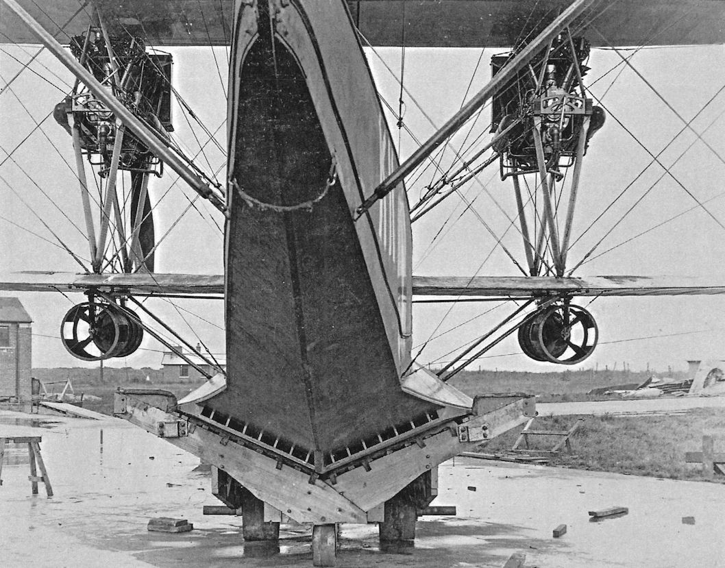
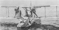
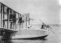
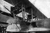
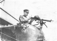
Ens W.A. Gus Read demonstrating an experimental machine gun mount on the rear of an H-16. The awkward gallows mount for rear protection is operated by the rating in the side window. The wing walks on the root of the lower wing and the cloth wrapped engine support struts are noteworthy.
-
C.Owers - The Fighting America Flying Boats of WWI Vol.2 /Centennial Perspective/ (23)
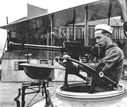
The rear armament on the F-5-L.
-

C.Owers - The Fighting America Flying Boats of WWI Vol.2 /Centennial Perspective/ (23)
Lewis guns on the Gallows outrigger mounts on an F-5-L.
-
Журнал - Flight за 1919 г.
View of the pilot's and wireless operator's quarters on the F-5-L flying-boat
-
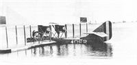
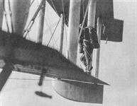
C.Owers - The Fighting America Flying Boats of WWI Vol.1 /Centennial Perspective/ (22)
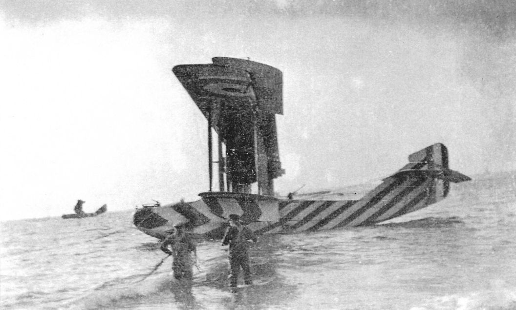
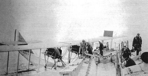
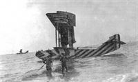
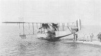
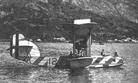
N4067 was one of the few Curtiss built H-16 that saw actual service in British hands. Delivered to Felixstowe in April 1918, this boat was sent to Killingholme in June where it was allocated to the USN. It crashed on the way to Dundee on 20 October 1918. It is assumed that this is the incident in the photograph. The first pilot and engineer are thought to have died in the accident; unfortunately, the names of the crew have not been located to date. (Ens Raymond L Atwood collection/Emil Buehler Library)
-

C.Owers - The Fighting America Flying Boats of WWI Vol.2 /Centennial Perspective/ (23)
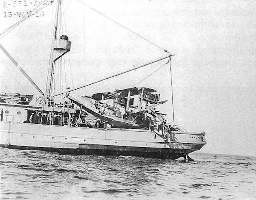
USS Sandpiper with remains of an F-5-L boat, 13 November 1920. The dazzle markings of this flying boat can just be made out on the rear hull.
-

C.Owers - The Fighting America Flying Boats of WWI Vol.1 /Centennial Perspective/ (22)
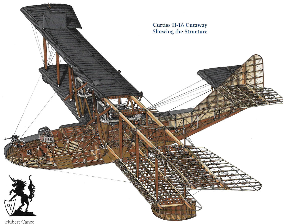
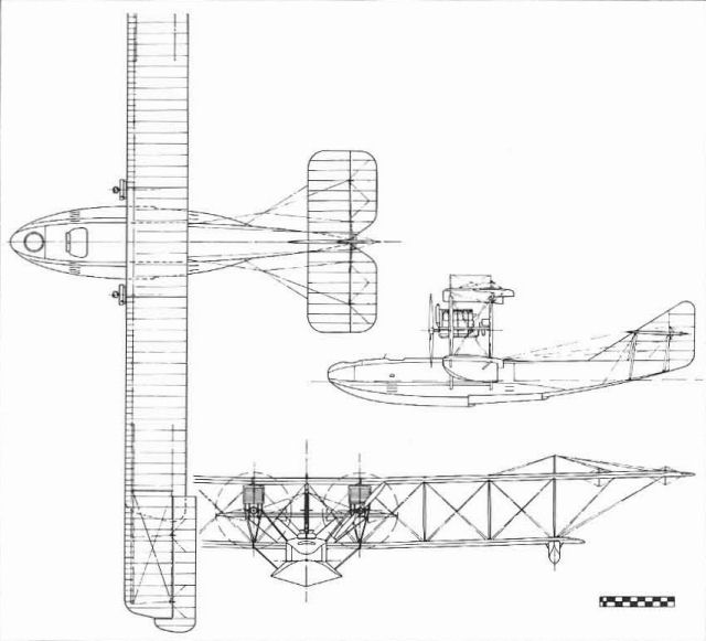
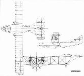
Curtiss H-16 Cutaway Showing the Structure
-
Журнал - Flight за 1919 г.
Diagrams of the fuel installation on the F-5-L flying-boat
-
C.Owers - The Fighting America Flying Boats of WWI Vol.2 /Centennial Perspective/ (23)
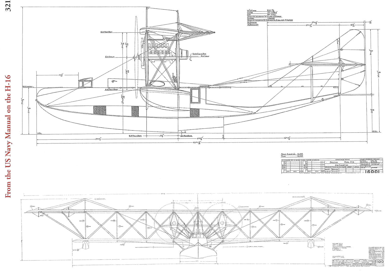
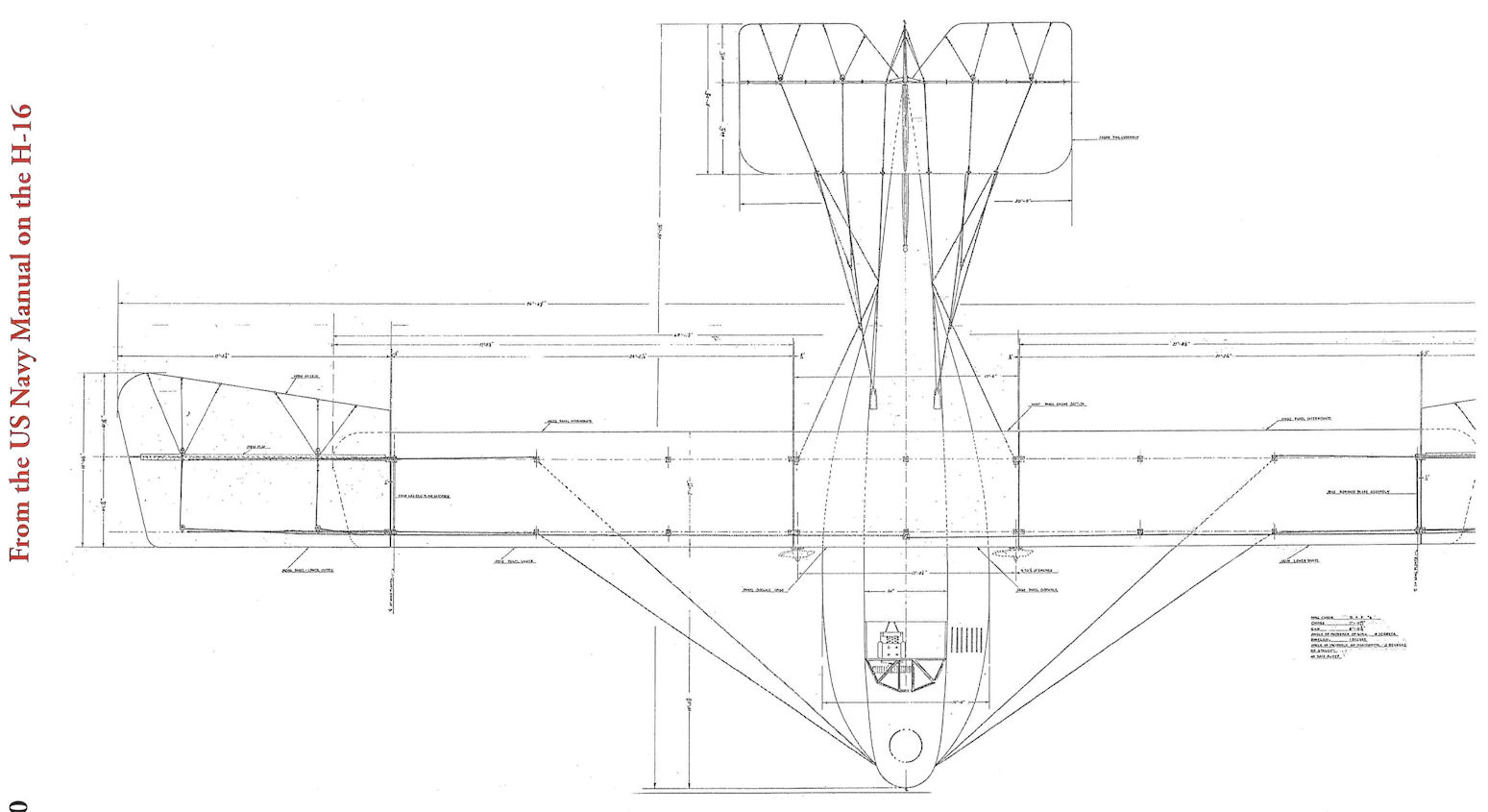
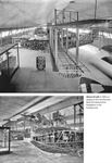
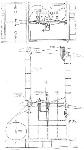
From the US NAVY Manual of the H-16
-
C.Owers - The Fighting America Flying Boats of WWI Vol.2 /Centennial Perspective/ (23)
From the US NAVY Manual of the H-16
-
-
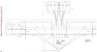
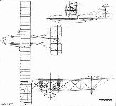
Журнал - Flight за 1919 г.
THE U.S.A. NAVY F-5-L FLYING-BOAT. - Drawings of the hull.
-
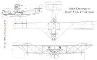
C.Owers - The Fighting America Flying Boats of WWI Vol.2 /Centennial Perspective/ (23)
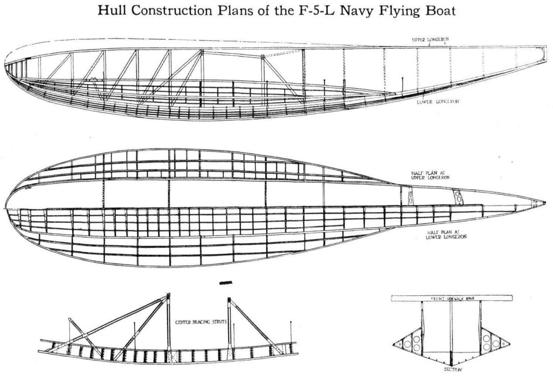
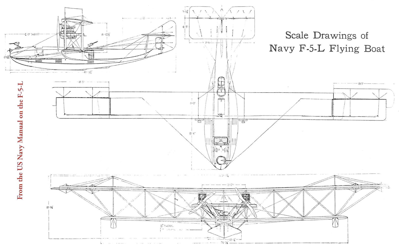
From the US Navy Manual on the F-5-L
-
P.Bowers - Curtiss Aircraft 1907-1947 /Putnam/
Model F-5L.
-
-
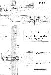
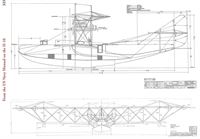
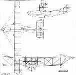
Журнал - Flight за 1919 г.
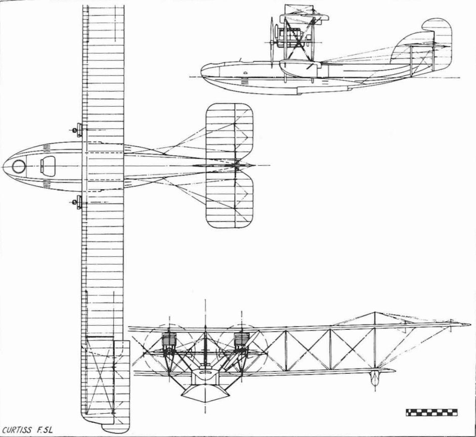
THE U.S.A. NAVY F-5-L FLYING-BOAT. Plan, front and side elevations to scale
P.Bowers Curtiss Aircraft 1907-1947 (Putnam)
H-16 (Model 6C) - The H-16 was the final model in the Curtiss H-boat line and was built in greater quantities than any or the other twin-engined Curtiss flying-boats.
It was a logical development of the H-12 and was originally intended to use the 200 hp Curtiss V-X-X engine. However, the Liberty became available before the first H-16 was completed so all 124 H-16 deliveries to the US Navy were made with the 360 hp low-compression Liberty. These were replaced by 400 hp Liberty 12As in postwar years. The sixty British versions were shipped without engines and were fitted with 345 hp Rolls-Royce Eagles on arrival in the United Kingdom.
In addition to 184 built by Curtiss, 150 H-16s were built at the Naval Aircraft Factory in Philadelphia. Originally, the Navy-built models were to be identified as Navy Model C, but all were operated as H-16s. The first Curtiss-built H-16 was launched on 22 June, 1918, while the first Navy-built model had come out of the factory on 27 March. H-16s were shipped overseas to US bases in Britain in 1918; H-16s remained in postwar service with the F-5Ls until May 1930. Prices for Navy-built H-16s ranged from $55,547 less engines for the first example down to $21,680 apiece for the last thirty.
Because of their great similarity, identification problems between the H-16 and the F-5L were inevitable. The distinctive features of the H-16 were originally the unbalanced ailerons with significant sweep back toward the tips as on the America and H-12, and the enclosed pilots' cockpit. The rudder was unbalanced, but could not be distinguished from early F-5L outlines because the balance area of the F-5L rudder was below the horizontal tail at that time. In postwar years, some H-16s were fitted with F-5L ailerons, had the pilots' enclosure removed, and were given added balanced area to the top or the rudder, further complicating the identity problem.
US Navy serial numbers: (Curtiss) A784/799 (16), A818/867 (50), A1030/1048 (19), A4039/4078 (40). (NAF) A1049/1098 (50), A3459/3558 (100).
RAF serial numbers: N4890/4949 (60) (4950/4999 cancelled).
H-16-1 - One H-16 had its engines turned around and was completed as a pusher. No advantage accrued; the adaptation proved to be excessively tail-heavy.
H-16-2 - A second pusher H-16 (A839) was produced by Curtiss with more consideration for the change of balance. Wings of slightly increased span were swept back 5 1/2 degrees. Straight-chord ailerons used with F-5L-type horn balance brought the revised span to 109 ft 7 in (33,27 m). The increased wing area required additional rudder area in the form of two auxiliary rudders mounted on the tailplane.
H-16
Patrol-bomber flying-boat. Four crew.
Two 400 hp Liberty 12A.
Span 95 ft 0 3/4 in (28,97 m); length 46 ft 1 1/2 in (14,05 m); height 17 ft 8t in (5,4 m); wing area 1.164 sq ft (108,13 sq m).
Empty weight 7,400 lb (3.356,58 kg); gross weight 10,900 lb (4.944,15 kg).
Maximum speed 95 mph (152,88 km/h); climb 4,700 ft (1,432 m) in 10 min; service ceiling 9,950 ft (3.03) m): range 378 miles (608 km).
Armament 5-6 flexible 0.30-in Lewis machine-guns, four 230 lb (104 kg) bombs.
Model F-5L
Although it clearly showed its ancestry in earlier Curtiss twin-engined flying-boats, the F-5L did not carry a Curtiss designation. Actually, it was not even a Curtiss design; it was one of several established European models chosen for production in the United States in 1917.
The F-5L evolved from the original America of 1914 after Lt Porte, one of its designers, returned to England after the war began. For the Royal Naval Air Service he developed improved versions of the America, the several H-boats called Small Americas, and the H-12 Large America that Curtiss supplied to the RNAS. The first of the production British-built developments was the F.2, the F standing for the government aircraft plant at Felixstowe.
The wings, empennage, and powerplant arrangement of the British F-boats were essentially Curtiss; Porte's principal contribution to the design was an improved hull. Porte's F.5 model was a parallel design to Curtiss's H-16. While the British F.5s used 345 hp Rolls-Royce Eagle engines, the American versions, redesigned to American standards by the US Navy, were built with Liberties, hence the letter L in the designation. The principal recognition points between the F-5L and the improved Liberty-engined H-16 was the horn-balanced parallel-chord aileron and balanced rudder of the former, and its noticeably different hull lines and open cockpits instead of the enclosed cabin of the H-16. Although the F-5L design belonged to the US Government, its well-known Curtiss ancestry, plus the fact that some were built by Curtiss, has caused it to be widely regarded as a Curtiss. Curtiss built sixty F-5Ls, Canadian Aeroplanes Ltd built thirty, and the US Naval Aircraft Factory built 138. After the war, redesigned vertical tail surfaces were introduced by the Navy on the two of the last three Navy-built F-5Ls which were redesignated F-6. These new tails were then retrofitted to all F-5Ls in service.
When the Navy adopted an aircraft designation system in 1922, aircraft already in service retained their original designations but the F-5Ls unofficially became PN-5 (P for Patrol, N for Navy, regardless of actual manufacturer). Two F-5L hulls were fitted with entirely new wings and 525 hp geared Wright T-2 engines in 1923 and became PN-7s. Duplicate models with the hull built of metal instead of wood were PN-8s. Further Navy-designed variants continued up to PN-12, with production versions of the PN-12 being built by Martin as PM-1 and -2, Douglas as PO-1, Keystone as PK-1, and Hall as PH-1, -2, and -3 in the late 1920s and early 1930s. The Halls served into 1943 to carry the direct descendants of the America through two World Wars.
Early in 1919 F-5L A3864 was modified by the Navy to a tandem-engine design to test the concept of one tractor and one pusher engine in a single nacelle for possible modification of the existing NC-1 and NC-2 three-engined flying-boats. This variant survived to March 1925.
A number of surplus F-5Ls were converted to 16/20-passenger transports by several overwater airlines in the 1920-24 era. Postwar price direct from the Navy was $12,400 while new prices for Navy-built F-5Ls ranged from $56,099 less engines for the first to $20,495 for the last.
F-5L
Patrol flying-boat. Four crew.
Two 400 hp Liberty 12A.
Span 103 ft 9 1/3 in (31,62 m); length 49 ft 3 3/4 in (15,03 m); height 18 ft 9 1/4 in (5,72 m); wing area 1,397 sq ft (129,78 sq m).
Empty weight 8,720 lb (3.955,3 kg); gross weight 13,600 lb (6.168,85 kg).
Maximum speed 90 mph (144,83 km/h); climb to 2,200 ft (670 m) 10 min; service ceiling 5,500 ft (1,676 m); range 830 miles (1,335 km).
Armament - 6-8 flexible 30-in machine-guns, four 230 Ib (104 kg) bombs.
Serial numbers: Canadian Aeroplanes - A3333/3362 (30); Naval Aircraft Factory A3559/4035, 4038 (343 of 480 cancelled); Curtiss - A4281/4340 (60); Naval Aircraft Factory F-6L - A4036,4037.
Описание: