Описание
Страна: Германия
Год: 1917
Бомбардировщик
Варианты
- Zeppelin-Staaken - R.XIV/R.XV - 1917 - Германия
- Zeppelin-Staaken - R.XVI - 1918 - Германия
- Zeppelin-Staaken - Type 8301 - 1918 - Германия
- В.Кондратьев Самолеты первой мировой войны
- O.Thetford, P.Gray German Aircraft of the First World War (Putnam)
- G.Haddow, P.Grosz The German Giants (Putnam)
- J.Herris Zeppelin-Staaken Aircraft of WW1. Vol 1: VGO.1 - R.IV R.29/16 (A Centennial Perspective on Great War Airplanes 47)
- J.Herris Zeppelin-Staaken Aircraft of WW1. Vol 2: R.VI R.30/16 - E.4/20 (A Centennial Perspective on Great War Airplanes 48)
- M.Dusing German Aviation Industry in WWI. Volume 2 (A Centennial Perspective on Great War Airplanes 85)
- Журнал Flight
-
-
-
J.Herris - Zeppelin-Staaken Aircraft of WW1. Vol 2: R.VI R.30/16 - E.4/20 /Centennial Perspective/ (48)
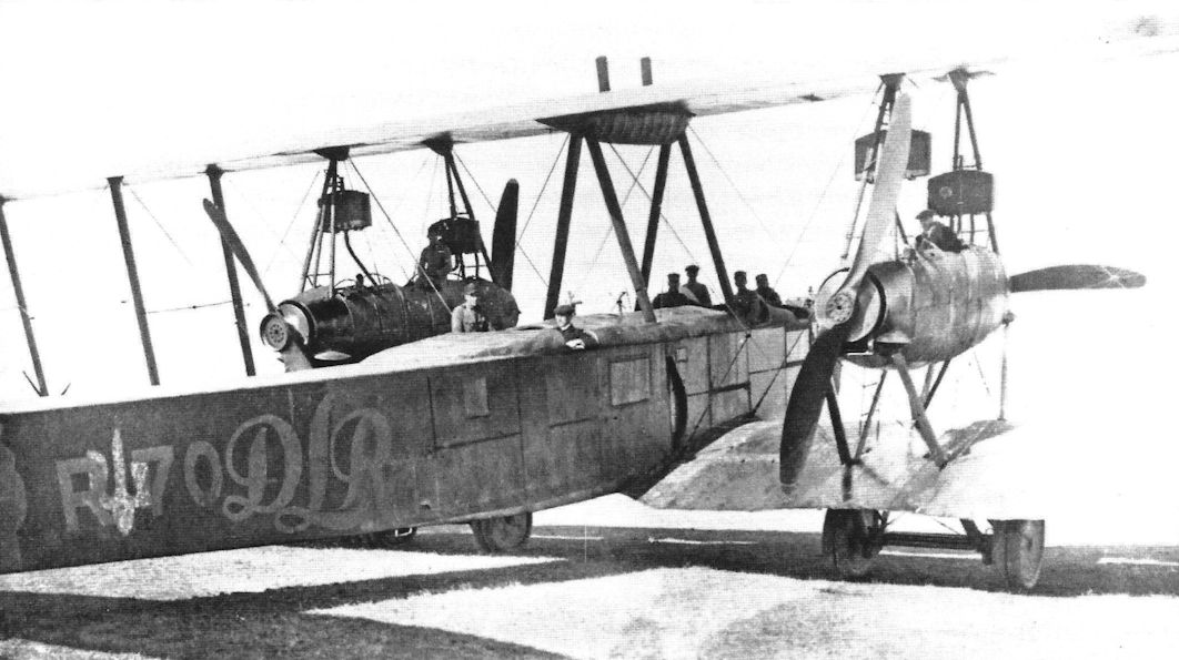
Staaken R.XIV R.70/17. Postwar Ukrainian Service
-
J.Herris - Zeppelin-Staaken Aircraft of WW1. Vol 2: R.VI R.30/16 - E.4/20 /Centennial Perspective/ (48)
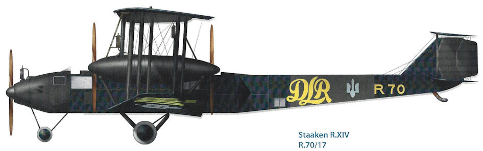
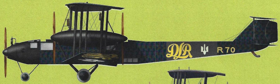
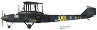
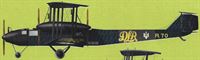
Staaken R.XIVa R.70 of the Deutsche Luft-Reederei in 1919. The aircraft was used to fly newly printed Ukrainian currency from Germany to help finance Ukraine’s war against Rumania and Poland.
-
J.Herris - Zeppelin-Staaken Aircraft of WW1. Vol 2: R.VI R.30/16 - E.4/20 /Centennial Perspective/ (48)
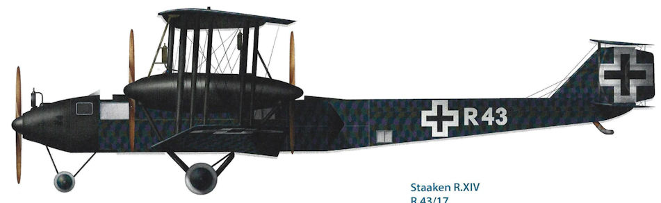
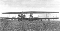
The Staaken R.XIV R.43/17 in its original configuration with four Austro-Daimler V-12 engines in push-pull configuration like the earlier R.VI. These engines were not ready for production and were replaced by 300 hp Basse & Selve BuS.IVa engines. These engines were not ready for production either and where in turn replaced. (Peter M. Grosz collection/STDB)
-
J.Herris - Zeppelin-Staaken Aircraft of WW1. Vol 2: R.VI R.30/16 - E.4/20 /Centennial Perspective/ (48)
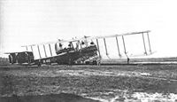
Zeppelin-Staaken R XIV R.43 as originally completed with four 350 hp Austro-Daimler V12 engines. These engines were not ready for use and R.43 was rebuilt with five 245 hp Maybach Mb.IVa engines. (1917)
-
G.Haddow, P.Grosz - The German Giants /Putnam/
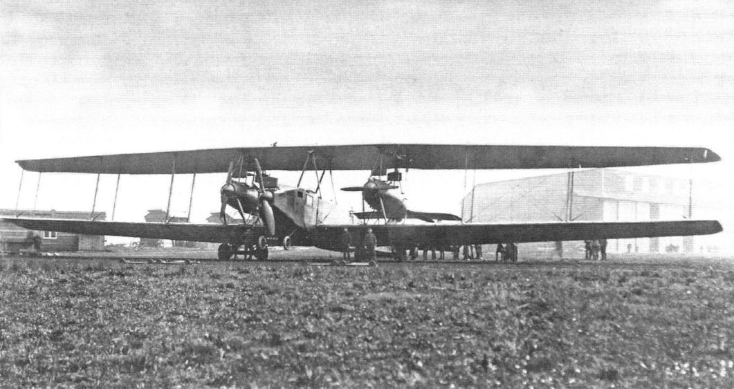
Staaken R.XIV 43/17 in its original form with four Austro-Daimler engines arranged similarly to the R.VI.
-
-
J.Herris - Zeppelin-Staaken Aircraft of WW1. Vol 2: R.VI R.30/16 - E.4/20 /Centennial Perspective/ (48)
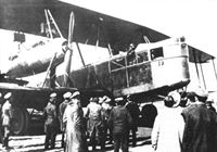
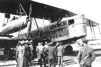
The Staaken R.XIV R.43 in its original configuration with four 350 hp Austro-Daimler V-12 engines. These engines were not fully developed and were not ready for production, so had to be replaced. The entire nose was glassed in and the nose gun position was raised. Here the R.43 has drawn an admiring crowd of VIPs. (Peter M. Grosz collection/ STDB)
-

-
J.Herris - Zeppelin-Staaken Aircraft of WW1. Vol 2: R.VI R.30/16 - E.4/20 /Centennial Perspective/ (48)
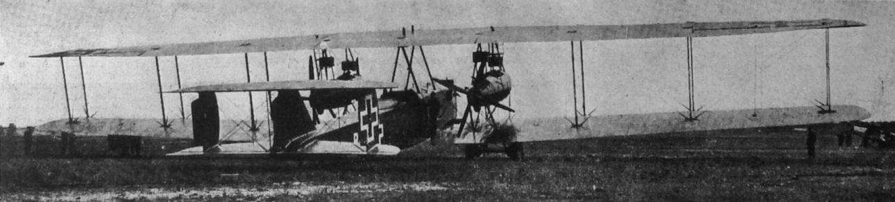
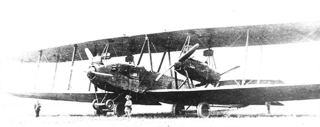
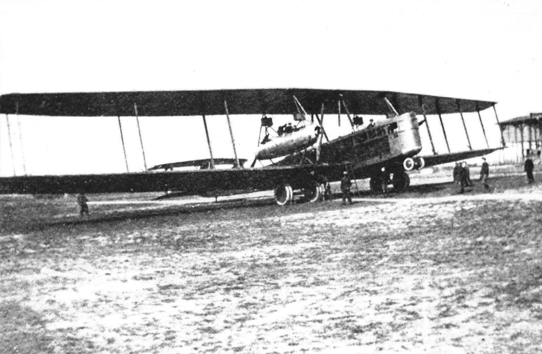
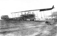
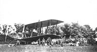
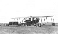
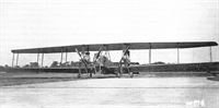
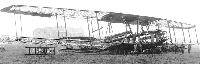
The next Staaken design to be built was the R.XIV. Originally designed with four 350 hp Austro-Daimler V-12 engines in the configuration of the R.VI, they had to be rebuilt with a fifth engine in the nose after the Austro-Daimler engines proved to be not developed enough for production. Here an R.XIV is shown after modification to five engines. (Peter M. Grosz collection/STDB)
The Staaken R.XIV was an improved version of the R.VI, with four 350hp Austro-Daimler engines. R43/17, the first of the type, flew in February 1918 and the few operational aircraft saw active service in late summer 1918. One aircraft, R43, was operating with RFa 501 on the night of 10/11 August when it was shot down. -

J.Herris - Zeppelin-Staaken Aircraft of WW1. Vol 2: R.VI R.30/16 - E.4/20 /Centennial Perspective/ (48)
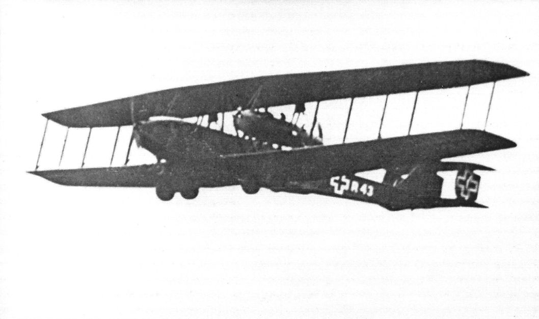
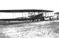
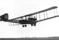
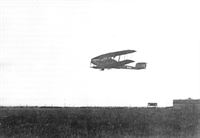
Staaken R.XIV R.43/17 taking off. (Peter M. Grosz collection/STDB)
-
J.Herris - Zeppelin-Staaken Aircraft of WW1. Vol 2: R.VI R.30/16 - E.4/20 /Centennial Perspective/ (48)
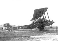
Staaken R.XIV R.43/17 taking off. On the night of 10/11 August 1918, R.43 was shot down by a Sopwith Camel nightfighter of No. 151 Sqdn, the first R-plane shot down by a fighter. (Peter M. Grosz collection/STDB)
-

J.Herris - Zeppelin-Staaken Aircraft of WW1. Vol 2: R.VI R.30/16 - E.4/20 /Centennial Perspective/ (48)
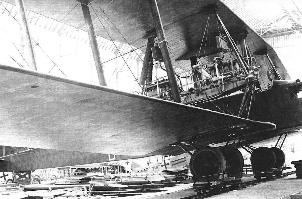
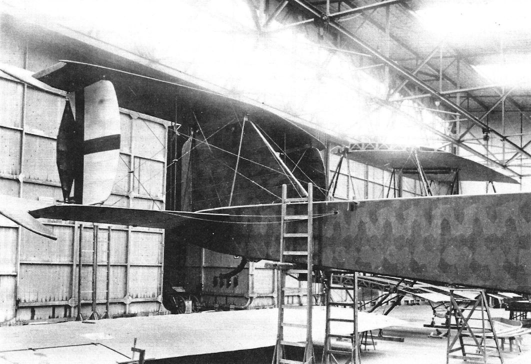
Staaken R.XIV under construction. The serial is partly obscured but appears to be R.43/17. (National Archives)
-
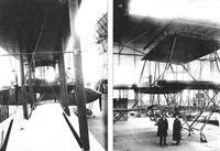
J.Herris - Zeppelin-Staaken Aircraft of WW1. Vol 1: VGO.1 - R.IV R.29/16 /Centennial Perspective/ (47)
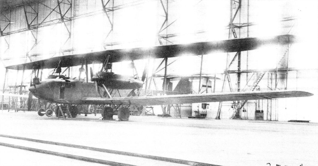
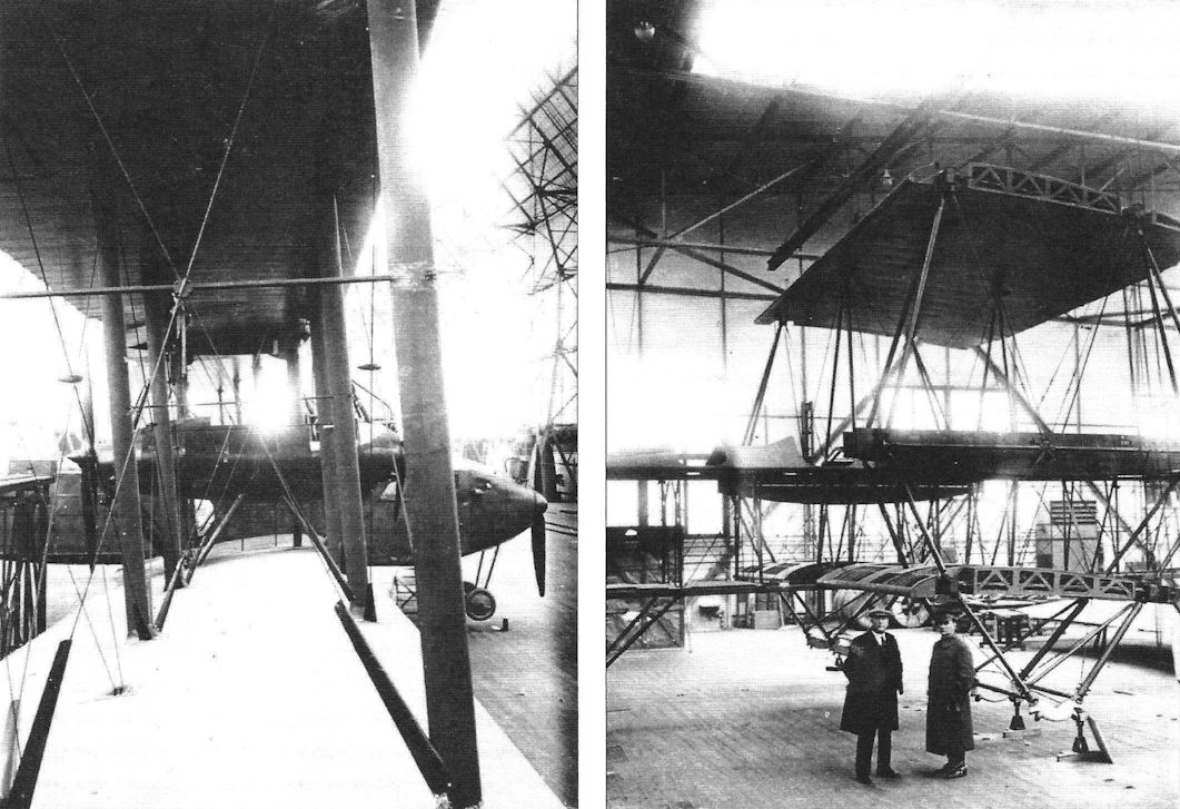
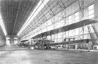
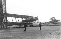
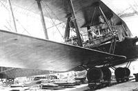
Staaken R.VI 30/16 being fitted with supercharger in the Staaken airship hangar. In the background is the Staaken R.XIV 43/17.
A Staaken R.VI R.30/16 under repair after an engine fire; Staaken R.XIV 43/17 is in the background without engines. Like other Staaken bombers, these types differed primarily by engine configuration; the R.VI had four engines in pusher/tractor configuration and the R.XIV added a fifth engine in the nose. (Michael Schmeelke)Другие самолёты на фотографии: Zeppelin-Staaken R.VI - Германия - 1917
-
J.Herris - Zeppelin-Staaken Aircraft of WW1. Vol 2: R.VI R.30/16 - E.4/20 /Centennial Perspective/ (48)
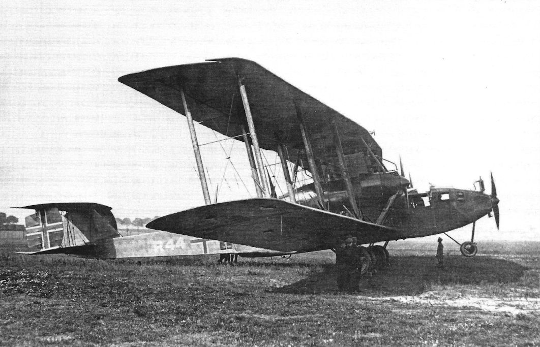
Staaken R.XIV R.44/17 was completed with five 245 hp Maybach Mb.IVa engines. (Peter M. Grosz collection/STDB)
-
J.Herris - Zeppelin-Staaken Aircraft of WW1. Vol 2: R.VI R.30/16 - E.4/20 /Centennial Perspective/ (48)
Staaken R.XIV R.44/17 taking off. (Peter M. Grosz collection/STDB)
-

J.Herris - Zeppelin-Staaken Aircraft of WW1. Vol 2: R.VI R.30/16 - E.4/20 /Centennial Perspective/ (48)
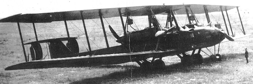
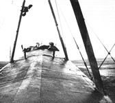
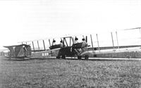
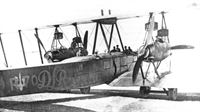
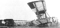
Staaken R.XIV 45/17 with the pilot's cockpit placed behind the wings.
-
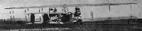
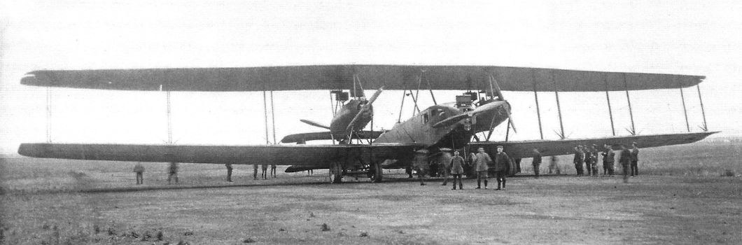
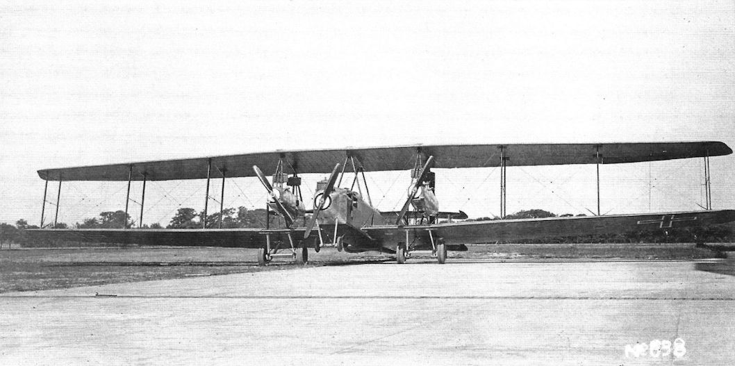
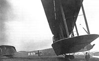
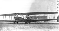
Jane's All The World Aircraft 1919 /Jane's/
Rear View of the Zeppelin "Giant" Biplane. (5-250 h.p. Maybach engines.)
-

J.Herris - Zeppelin-Staaken Aircraft of WW1. Vol 2: R.VI R.30/16 - E.4/20 /Centennial Perspective/ (48)
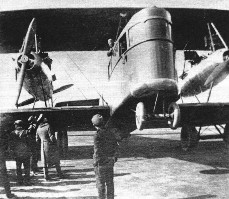
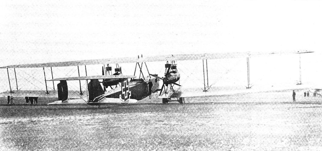
Staaken R.XIV with five 245 hp Maybach Mb.IVa engines being reviewed. (Peter M. Grosz collection/STDB)
-

J.Herris - Zeppelin-Staaken Aircraft of WW1. Vol 2: R.VI R.30/16 - E.4/20 /Centennial Perspective/ (48)
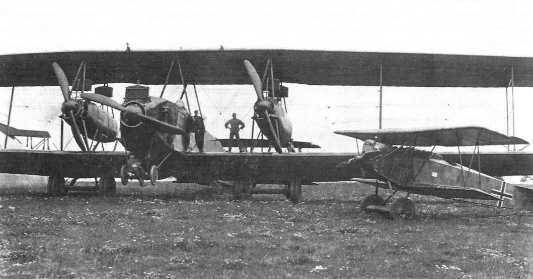
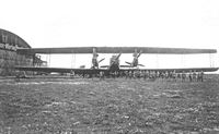
Staaken R.XIV with five 245 hp Maybach Mb.IVa engines. The Fokker D.VII at right both gives scale to the Staaken and indicates it is on an operational airfield. (Peter M. Grosz collection/STDB)
Другие самолёты на фотографии: Fokker D.VII / V11 / V18 / V22 / V24 - Германия - 1917
-

J.Herris - Zeppelin-Staaken Aircraft of WW1. Vol 2: R.VI R.30/16 - E.4/20 /Centennial Perspective/ (48)
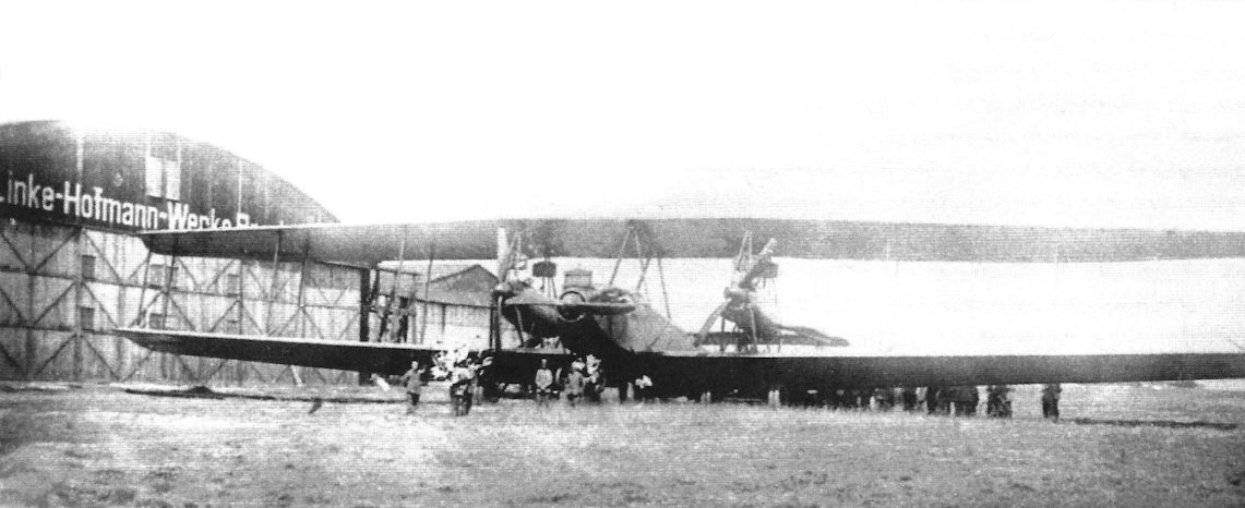
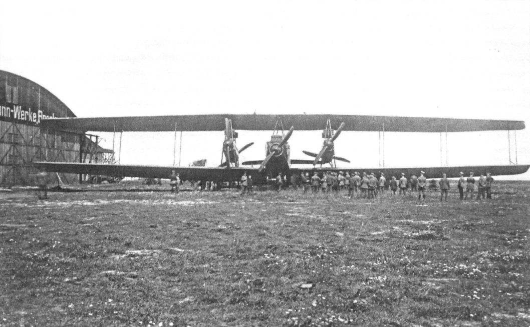
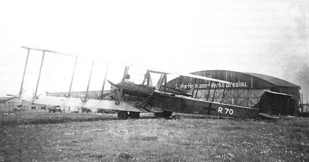
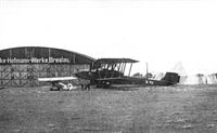
Staaken R.XIV with the Linke-Hofmann works in the background. Linke-Hofmann was also involved in R-plane development but only one, Linke-Hofmann R.I 40/16, was completed and flown. (Peter M. Grosz collection/STDB)
-
G.Haddow, P.Grosz - The German Giants /Putnam/
Staaken R.XIV.
-
J.Herris - Zeppelin-Staaken Aircraft of WW1. Vol 2: R.VI R.30/16 - E.4/20 /Centennial Perspective/ (48)
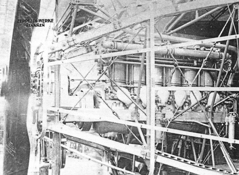
Staaken R.XIV engine installation. (Peter M. Grosz collection/STDB)
-
J.Herris - Zeppelin-Staaken Aircraft of WW1. Vol 2: R.VI R.30/16 - E.4/20 /Centennial Perspective/ (48)
In flight photo of a Staaken R.XIV. (Peter M. Grosz collection/STDB)
-
J.Herris - Zeppelin-Staaken Aircraft of WW1. Vol 2: R.VI R.30/16 - E.4/20 /Centennial Perspective/ (48)
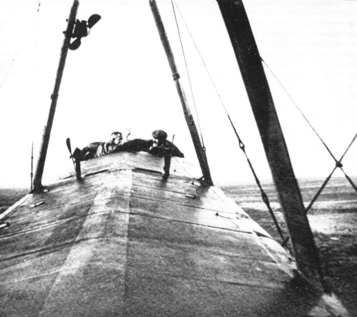
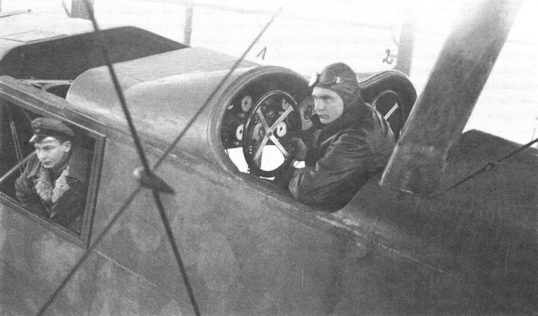
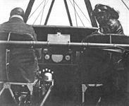
The cockpit of a Staaken R.XIV in flight. (Peter M. Grosz collection/ STDB)
-
J.Herris - Zeppelin-Staaken Aircraft of WW1. Vol 2: R.VI R.30/16 - E.4/20 /Centennial Perspective/ (48)
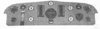
Staaken R.XIV instrument panel for controlling a five-engine version.
-
J.Herris - Zeppelin-Staaken Aircraft of WW1. Vol 2: R.VI R.30/16 - E.4/20 /Centennial Perspective/ (48)
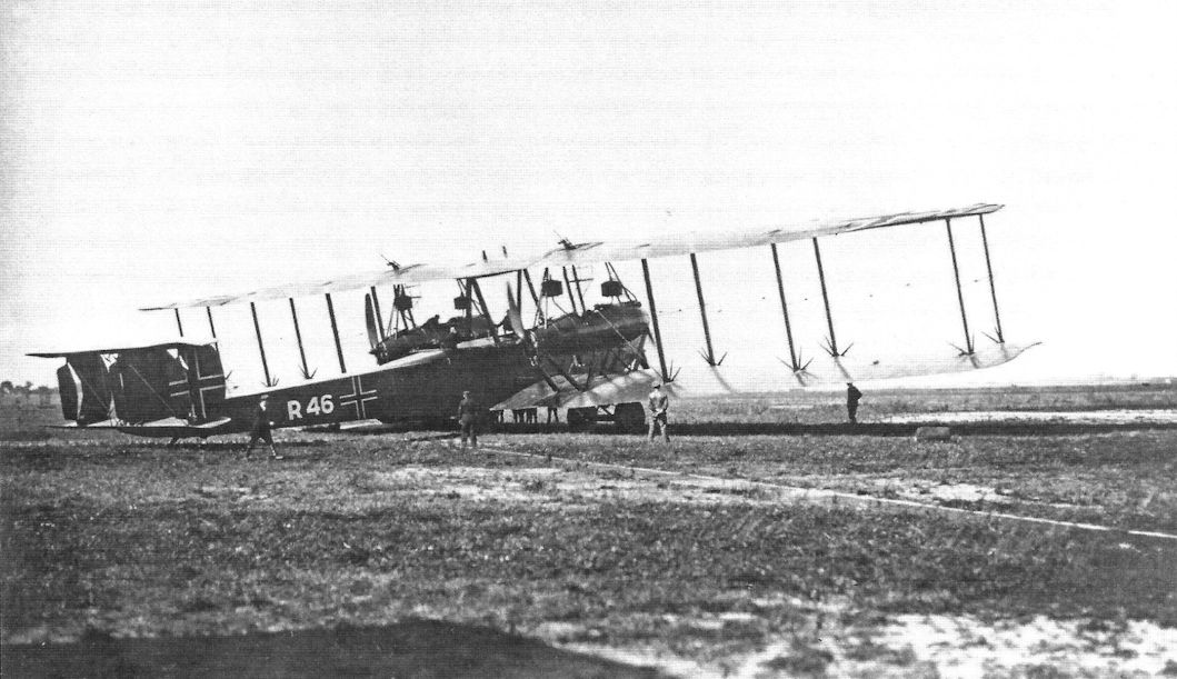
Staaken R.XV R.46/17 on the factory airfield. (Peter M. Grosz collection/STDB)
-
J.Herris - Zeppelin-Staaken Aircraft of WW1. Vol 2: R.VI R.30/16 - E.4/20 /Centennial Perspective/ (48)
Staaken R.XV R.46/17 on the factory airfield. (Peter M. Grosz collection/STDB)
-

J.Herris - Zeppelin-Staaken Aircraft of WW1. Vol 2: R.VI R.30/16 - E.4/20 /Centennial Perspective/ (48)
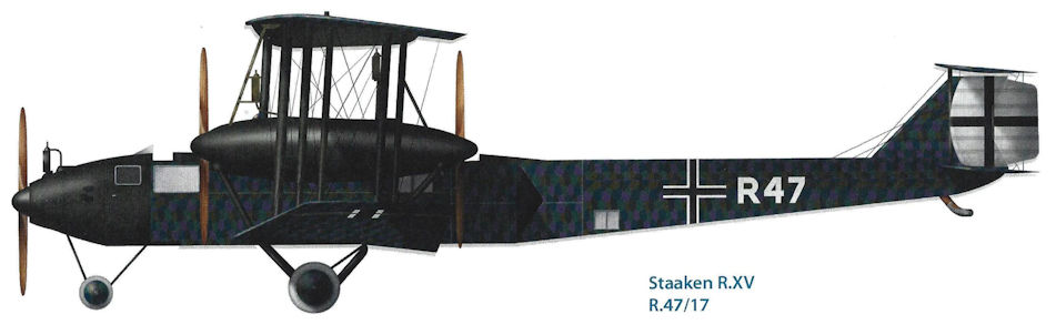
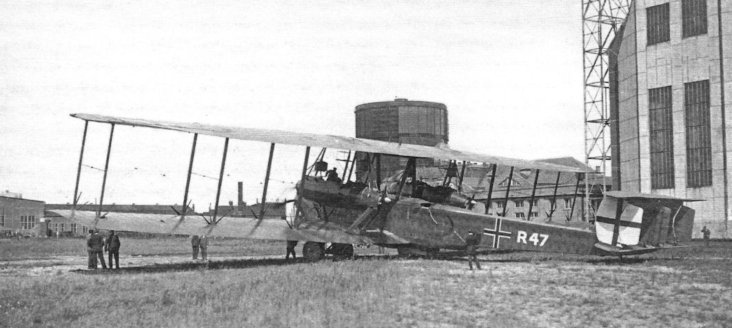
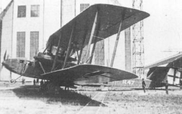
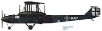
The Staaken R.XV R.47/17 on the factory airfield. (Peter M. Grosz collection/STDB)
-
J.Herris - Zeppelin-Staaken Aircraft of WW1. Vol 2: R.VI R.30/16 - E.4/20 /Centennial Perspective/ (48)
Staaken R.XV R.47/17 on the factory airfield. The white outline of the national insignia has been painted black for night operations. (Peter M. Grosz collection/STDB)
-
K.Delve - World War One in the Air /Crowood/
The German strategic bombing campaign against London continued into 1918. Zeppelin-Staaken RXV R47 was one of three of this variant to see operational service, the first, R46, having been delivered in August 1917.
-
J.Herris - Zeppelin-Staaken Aircraft of WW1. Vol 2: R.VI R.30/16 - E.4/20 /Centennial Perspective/ (48)
The Staaken R.XV was nearly identical to the earlier R.XIV. Its minor modifications were made to reduce weight. The nose was slightly refined. The IAACC found R.48/17 in the factory in 1919. Note the parachute bags (sewn under the fuselage canvas) and static lines for the dorsal gunners. (Peter M. Grosz collection/STDB)
-
J.Herris - Zeppelin-Staaken Aircraft of WW1. Vol 2: R.VI R.30/16 - E.4/20 /Centennial Perspective/ (48)
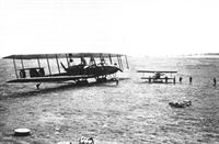
The Staaken 8301 at the factory in its original configuration for flight testing. (Peter M. Grosz collection/STDB)
Другие самолёты на фотографии: Zeppelin-Staaken Type 8301 - Германия - 1918
-

J.Herris - Zeppelin-Staaken Aircraft of WW1. Vol 2: R.VI R.30/16 - E.4/20 /Centennial Perspective/ (48)
The fuselage and parts of a Staaken R.XV in the factory. (Peter M. Grosz collection/STDB)
-
J.Herris - Zeppelin-Staaken Aircraft of WW1. Vol 2: R.VI R.30/16 - E.4/20 /Centennial Perspective/ (48)
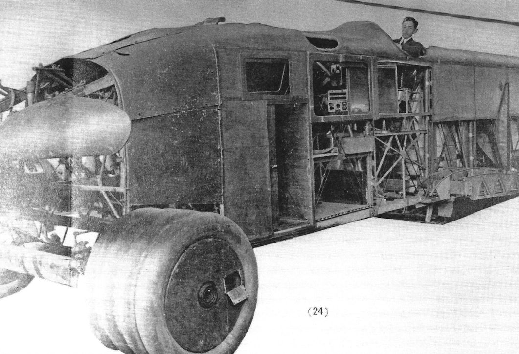
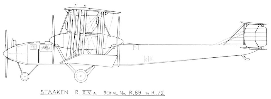
Staaken R.XIVa R69 at the factory. (Peter M. Grosz collection/STDB)
-
J.Herris - Zeppelin-Staaken Aircraft of WW1. Vol 2: R.VI R.30/16 - E.4/20 /Centennial Perspective/ (48)
Staaken R.XIVa R69 at the factory. (Peter M. Grosz collection/STDB)
-
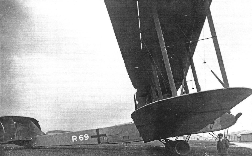
J.Herris - Zeppelin-Staaken Aircraft of WW1. Vol 2: R.VI R.30/16 - E.4/20 /Centennial Perspective/ (48)
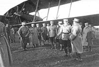
Staaken R.XIVa 69/18 with a visiting Argentine commission at Doberitz.
The R.XIVa was an improved R.XIV but the differences were not readily apparent from a photograph. Note the parachute bags seen just under the front of the cabin (sewn beneath the fuselage canvas) and static lines (Zugleine) for pilots. (Peter M. Grosz collection/STDB) -
J.Herris - Zeppelin-Staaken Aircraft of WW1. Vol 2: R.VI R.30/16 - E.4/20 /Centennial Perspective/ (48)
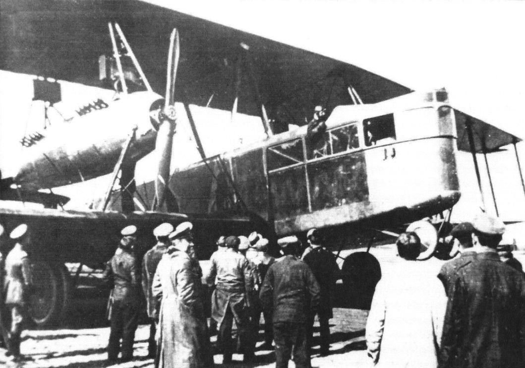
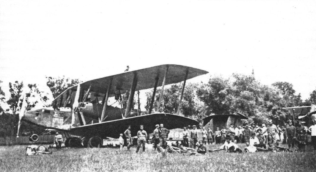
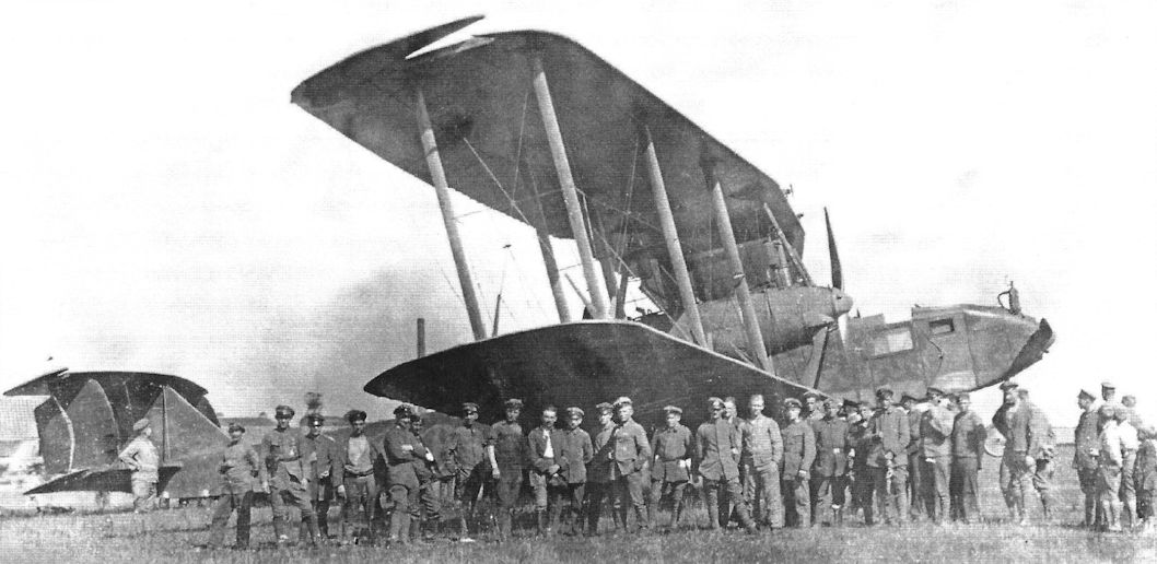
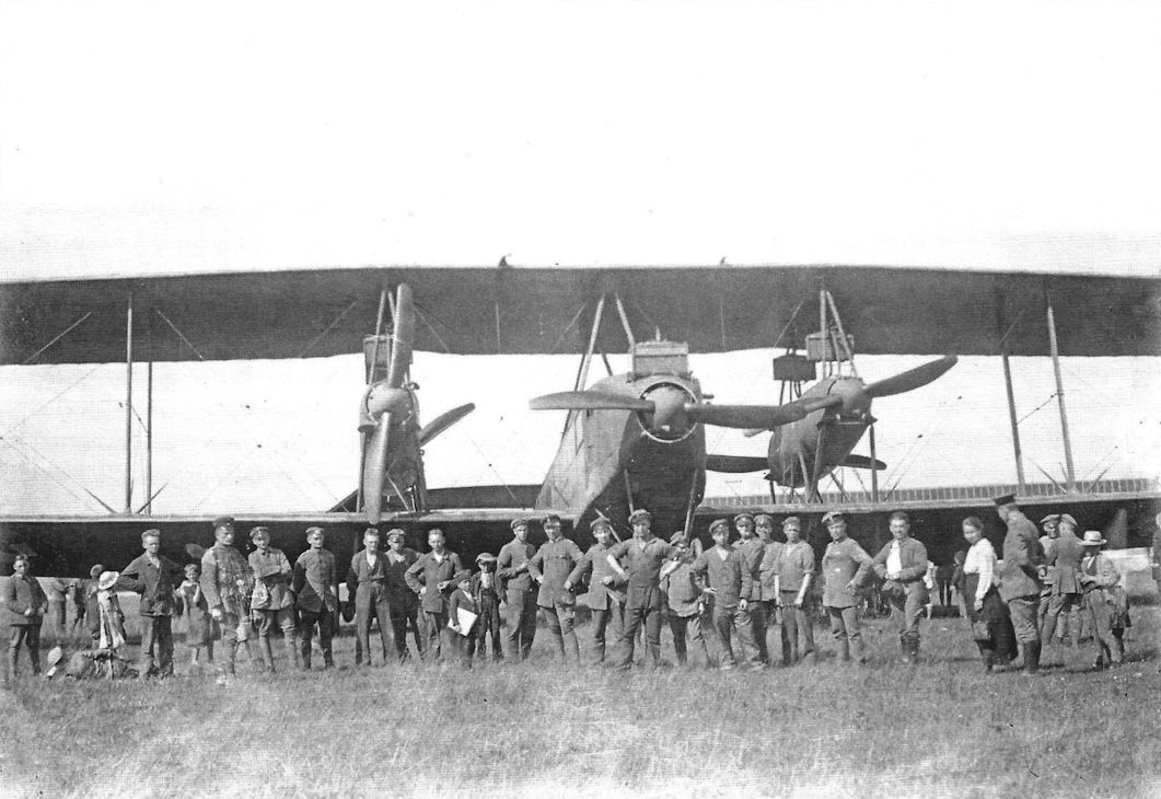
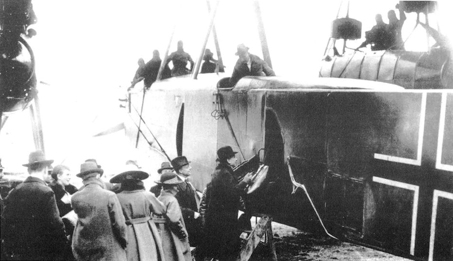
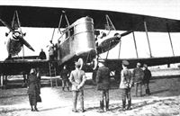
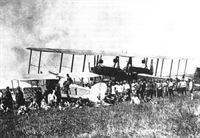
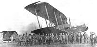
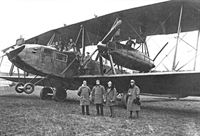
Staaken R.XIVa 69/18 draws a crowd after landing in the Ukraine. The R.XIVa was an improved R.XIV but used the same powerplants, five 245 hp Maybach Mb.IVa engines. (Peter M. Grosz collection/STDB)
-
J.Herris - Zeppelin-Staaken Aircraft of WW1. Vol 2: R.VI R.30/16 - E.4/20 /Centennial Perspective/ (48)
A Staaken R.XIVa draws a crowd after landing in the Ukraine. The R.XIVa was an improved R.XIV but used the same powerplants, five 245 hp Maybach Mb.IVa engines. (Peter M. Grosz collection/STDB)
-
J.Herris - Zeppelin-Staaken Aircraft of WW1. Vol 2: R.VI R.30/16 - E.4/20 /Centennial Perspective/ (48)
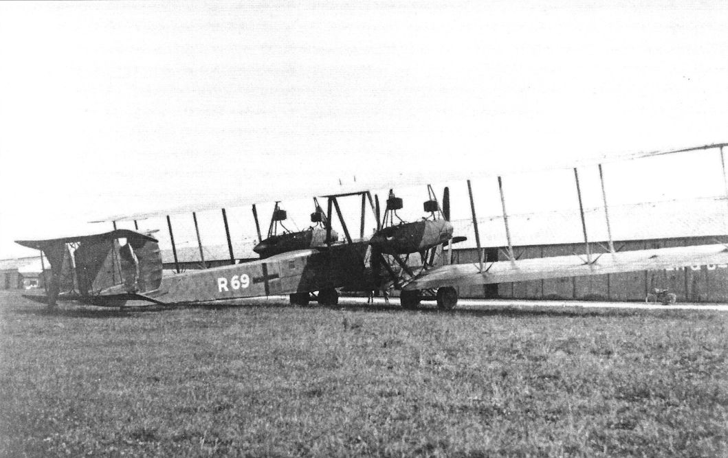
Staaken R.XIVa R69 postwar. The R.XIVa aircraft were not delivered in time for combat. (Peter M. Grosz collection/STDB)
-

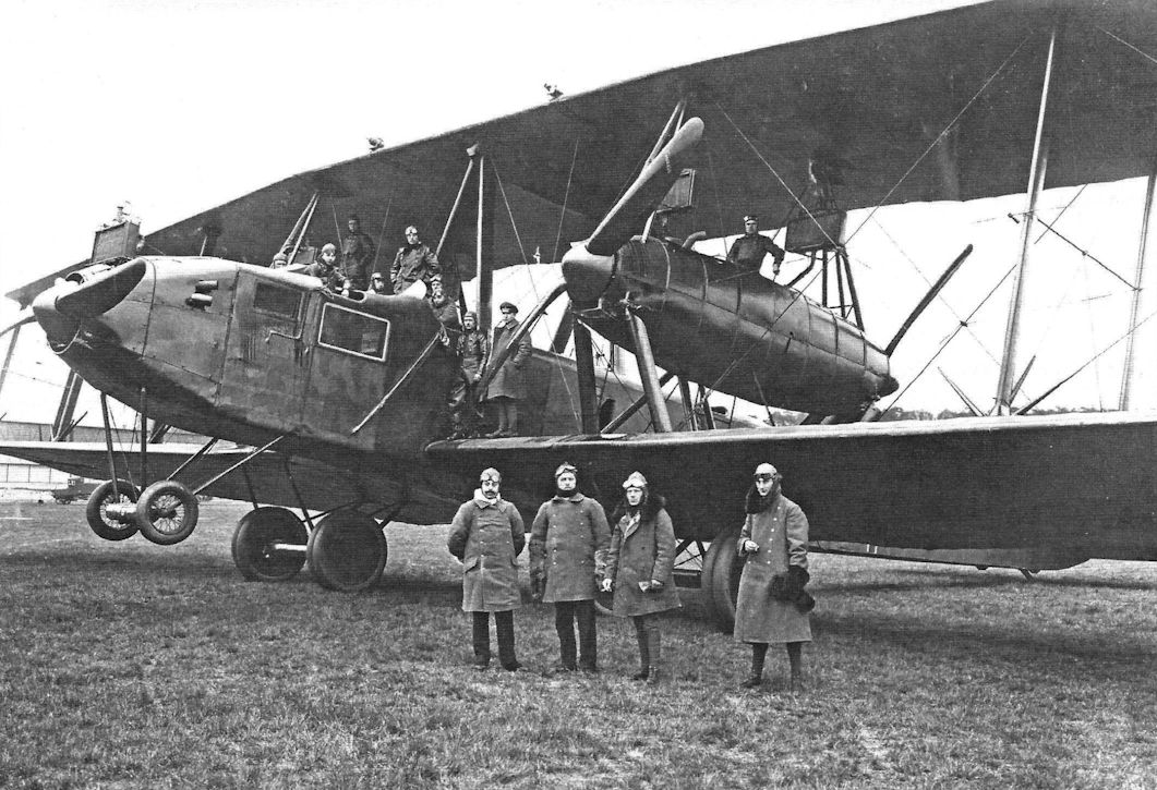
J.Herris - Zeppelin-Staaken Aircraft of WW1. Vol 2: R.VI R.30/16 - E.4/20 /Centennial Perspective/ (48)
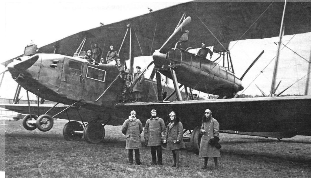
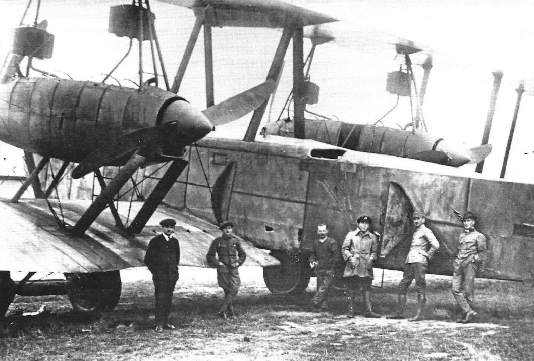
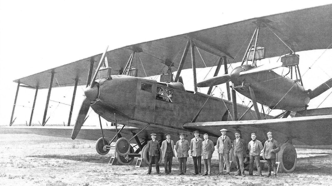
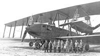
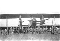
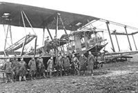
Zeppelin-Staaken R.XIVa with crew; it was powered by five 245 hp Maybach Mb.IVa engines.
-

M.Dusing - German & Austro-Hungarian Aero Engines of WWI. Vol.3 /Centennial Perspective/ (66)
Zeppelin-Staaken R XIVa(Schul) from Schutte-Lanz was powered by five 260 hp Maybach Mb.IVa engines.
-

G.Haddow, P.Grosz - The German Giants /Putnam/
Staaken R.XIVa 70/18, chartered by the Ukrainian Government. Photo dated 14 June 1919.
-
J.Herris - Zeppelin-Staaken Aircraft of WW1. Vol 2: R.VI R.30/16 - E.4/20 /Centennial Perspective/ (48)
Staaken R.XIVa R.70/18 under charter to the Ukrainian government (Peter M. Grosz collection/STDB)
-
J.Herris - Zeppelin-Staaken Aircraft of WW1. Vol 2: R.VI R.30/16 - E.4/20 /Centennial Perspective/ (48)
Staaken R.XIVa, perhaps R.70/18. (Peter M. Grosz collection/STDB)
-
J.Herris - Zeppelin-Staaken Aircraft of WW1. Vol 2: R.VI R.30/16 - E.4/20 /Centennial Perspective/ (48)
Staaken R.XIVa R.70 in civilian DLR markings. A Ukrainian marking has been applied. (Peter M. Grosz collection/STDB)
-
J.Herris - Zeppelin-Staaken Aircraft of WW1. Vol 2: R.VI R.30/16 - E.4/20 /Centennial Perspective/ (48)
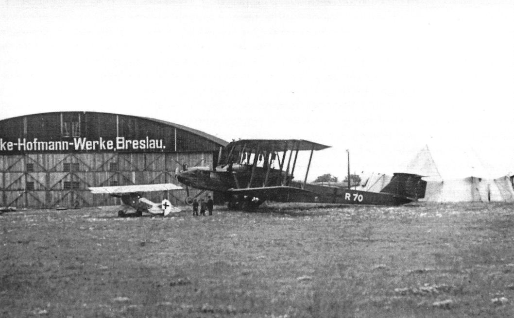
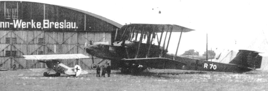
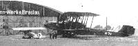
Staaken R.XIVa at Breslau.This may be another view of R.70. (Peter M. Grosz collection/STDB)
-

J.Herris - Zeppelin-Staaken Aircraft of WW1. Vol 2: R.VI R.30/16 - E.4/20 /Centennial Perspective/ (48)
Staaken R.XIVa R70 at the factory. R.70 displays the final form of national marking without the white outline for night operations. (Peter M. Grosz collection/STDB)
-
J.Herris - Zeppelin-Staaken Aircraft of WW1. Vol 2: R.VI R.30/16 - E.4/20 /Centennial Perspective/ (48)
Staaken R.XIVa R70 at Breslau. (Peter M. Grosz collection/STDB)
-
G.Haddow, P.Grosz - The German Giants /Putnam/
Staaken R.XIVa 70/18 on the Hundsfeld airfield near Breslau.
-

J.Herris - Zeppelin-Staaken Aircraft of WW1. Vol 2: R.VI R.30/16 - E.4/20 /Centennial Perspective/ (48)
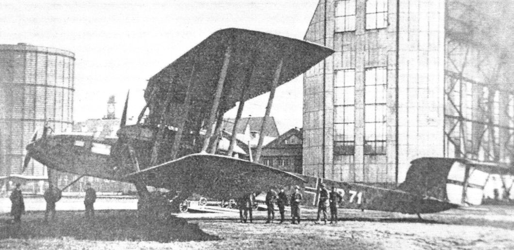
Staaken R.XIVa R71 at the factory before it crashed. R71 may have been the last R-plane built by Staaken; R72 was ordered but its completion is not confirmed and there are no photos of it. (Peter M. Grosz collection/STDB)
-
J.Herris - Zeppelin-Staaken Aircraft of WW1. Vol 2: R.VI R.30/16 - E.4/20 /Centennial Perspective/ (48)
Staaken R.XIVa(Schul) photographed in the factory.
The Staak R.XIVa, completed under license at Schutte-Lanz in Zeesen, had a total of 5 Maybach engines with a total power of 1300 hp. -

M.Dusing - German & Austro-Hungarian Aero Engines of WWI. Vol.3 /Centennial Perspective/ (66)
Zeppelin-Staaken R XIVa(SchuI) from Schutte-Lanz is shown here under construction; it was powered by five 245 hp Maybach Mb.IVa engines.
-
J.Herris - Zeppelin-Staaken Aircraft of WW1. Vol 2: R.VI R.30/16 - E.4/20 /Centennial Perspective/ (48)
Staaken R.XIVa (Schul) 84/18 prior to the fitting of propeller spinners.
Staaken R.XIVa(Schul) was built by Schutte-Lanz, which was given a contract for three aircraft, serial numbers R.84 to R.86. None were completed before the war ended. (Peter M. Grosz collection/STDB) -
J.Herris - Zeppelin-Staaken Aircraft of WW1. Vol 2: R.VI R.30/16 - E.4/20 /Centennial Perspective/ (48)
Staaken R.XIVa(Schul) on the factory airfield. (Peter M. Grosz collection/STDB)
-
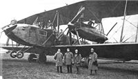
J.Herris - Zeppelin-Staaken Aircraft of WW1. Vol 2: R.VI R.30/16 - E.4/20 /Centennial Perspective/ (48)
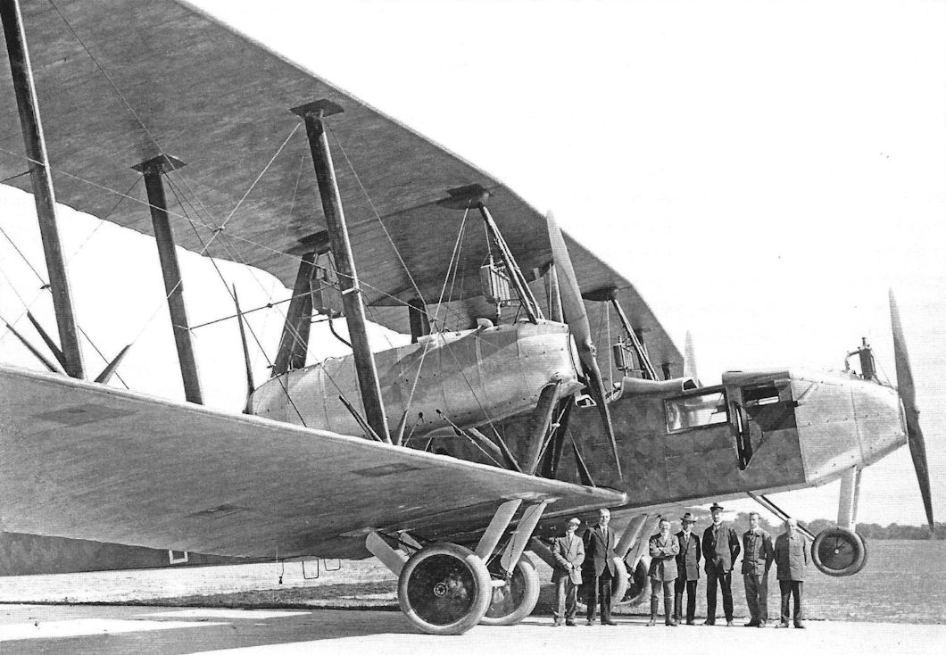
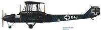
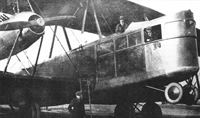
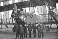
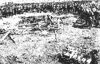
"Цеппелин-Штаакен" R-XIV, послевоенный снимок. На переднем плане - группа авиаконструкторов.
Staaken R.XIVa(Schul) R.84/18 with Schutte-Lanz factory staff. (Peter M. Grosz collection/STDB)
Staaken R XIVa R69/18 (???) was built by Schutte-Lanz and powered by five 260 hp Maybach Mb.IVa engines. -
J.Herris - Zeppelin-Staaken Aircraft of WW1. Vol 2: R.VI R.30/16 - E.4/20 /Centennial Perspective/ (48)
Staaken R.XIVa(Schul) is the background for a group portrait. (Peter M. Grosz collection/STDB)
-

J.Herris - Zeppelin-Staaken Aircraft of WW1. Vol 2: R.VI R.30/16 - E.4/20 /Centennial Perspective/ (48)
Staaken R.XIVa(Schul) photographed with factory staff. (Peter M. Grosz collection/STDB)
Example of decentralized power arrangement with five 245 h.p. Maybach Mb.IVa engines. -

M.Dusing - German Aviation Industry in WWI. Volume 2 /Centennial Perspective/ (85)
This detail view of a Staaken R.XIVa. A parachute static line (Zugleine) for the co-pilot is visible below the cockpit. (Peter M. Grosz collection/STDB)
Five Maybach engines in Zeppelin-Staaken R XIVa R69/18 from Schutte-Lanz in Vienna before seizure by Allies. -

J.Herris - Zeppelin-Staaken Aircraft of WW1. Vol 2: R.VI R.30/16 - E.4/20 /Centennial Perspective/ (48)
Staaken R.XIVa. (Peter M. Grosz collection/STDB)
-
J.Herris - Zeppelin-Staaken Aircraft of WW1. Vol 2: R.VI R.30/16 - E.4/20 /Centennial Perspective/ (48)
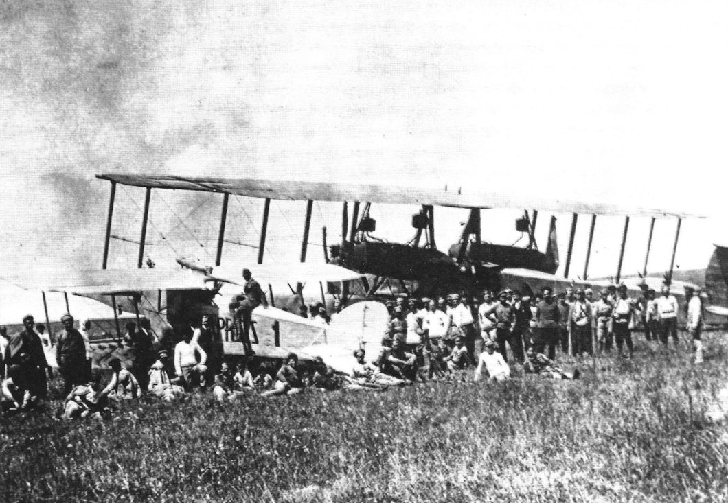
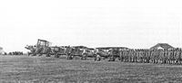
Staaken R.XIVa lined up with Nieuports and Breguets, probably in the Ukraine. In 1919 the German Government allowed DLR to charter a number of aircraft to the Ukraine Government for the transportation of new money for the young state [that the Germans were printing clandestinely]. The Ukraine was at war with Rumania and Poland and wanted to stimulate its economy by introducing a new currency. Some of the DLR aircraft were secretly transferred to the Ukraine and in addition the Ukraine Government chartered the three five-engine Staaken R.XIVa aircraft from DLR. These aircraft had serial numbers R.69, R.70, and R.71 and registration D.129, D.130, and D.131 respecitively. All three were lost. The first, R.69, was confiscated on 29 July by French troops on behalf of the IAACC at the airport of Wien, Aspern. R.71 crashed and burned on 4 August in Oberschlesien. The last Staaken R.XIVa, R.70, commanded by Captain Count Hans Wolf von Harah and with pilots Heinrich Smiltz and Henrig Tretken, was forced down due to fuel problems on 19 September on its way to Kamenets-Podolski. Upon landing the crew was captured by two soldiers of the Rumanian 37th Infantry Regiment. On board the Rumanians found 303 million Griverns (Ukraine roubles), issued 5,6, and 24 October 1918. The Ukraine passengers were sent to a Ukraine-controlled area on the other side of the river Dnestr, while the Germans were imprisoned. The aircraft was repaired by Rumanian aeronautical engineers and flown by Petre Macavei (Technical 1st Lieutenant) and other crew members to the capital of Rumania, Bucharest. On its way the engine caused more trouble, but in the end the aircraft managed to arrive safely. It never flew again, but was stationed at the airport for several years before it was dismantled. Its wooden propellers went to the military museum in Bucharest. Without aircraft, the DLR had to supply new aircraft and offered the Friedrichshafen G.IIIa for Ukraine operations. (Peter M. Grosz collection/STDB)
Другие самолёты на фотографии: Breguet Br.14 - Франция - 1917Nieuport Nieuport-17bis/24/27 - Франция - 1917
-
J.Herris - Zeppelin-Staaken Aircraft of WW1. Vol 2: R.VI R.30/16 - E.4/20 /Centennial Perspective/ (48)
Staaken R.XIVa in the Ukraine. (Peter M. Grosz collection/STDB)
-
J.Herris - Zeppelin-Staaken Aircraft of WW1. Vol 2: R.VI R.30/16 - E.4/20 /Centennial Perspective/ (48)
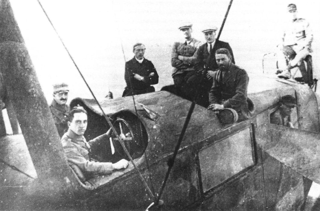
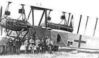
A Staaken R.XIVa in pristine condition with its crew. (Peter M. Grosz collection/STDB)
-

J.Herris - Zeppelin-Staaken Aircraft of WW1. Vol 2: R.VI R.30/16 - E.4/20 /Centennial Perspective/ (48)
Another view of a Staaken R.XIVa. The number of wheels were reduced to reduce weight. (Peter M. Grosz collection/STDB)
-

J.Herris - Zeppelin-Staaken Aircraft of WW1. Vol 2: R.VI R.30/16 - E.4/20 /Centennial Perspective/ (48)
Staaken R.XIVa on its tail skid. (Peter M. Grosz collection/STDB)
-
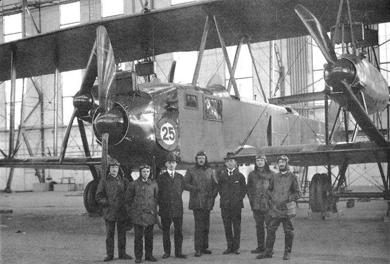
G.Haddow, P.Grosz - The German Giants /Putnam/
Staaken test pilots commemorating the completion of the 25th Staaken R-plane, an R.XIVa. Third from the right is Willy Mann who flew the first R-plane built by VGO.
-

M.Dusing - German Aviation Industry in WWI. Volume 2 /Centennial Perspective/ (85)
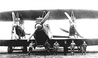
Long-range bomber R XIVa with 5 x 245 hp Maybach Mb.IVa at the Staaken plant. CEO Rasch is standing in the middle to the right of the propeller. The center propeller looks optically much larger than the side propellers due to the long nose which is almost 5 m long.
-
J.Herris - Zeppelin-Staaken Aircraft of WW1. Vol 2: R.VI R.30/16 - E.4/20 /Centennial Perspective/ (48)
Staaken R.XIVa with its ground crew. (Peter M. Grosz collection/STDB)
-
J.Herris - Zeppelin-Staaken Aircraft of WW1. Vol 2: R.VI R.30/16 - E.4/20 /Centennial Perspective/ (48)
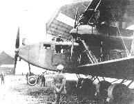
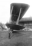
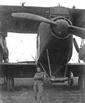
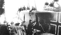
Staaken R.XIVa nose with large radiator for its nose engine. (Peter M. Grosz collection/STDB)
-
J.Herris - Zeppelin-Staaken Aircraft of WW1. Vol 2: R.VI R.30/16 - E.4/20 /Centennial Perspective/ (48)
Staaken R.XIVa serves as a background for a group photo. (Peter M. Grosz collection/STDB)
-
J.Herris - Zeppelin-Staaken Aircraft of WW1. Vol 2: R.VI R.30/16 - E.4/20 /Centennial Perspective/ (48)
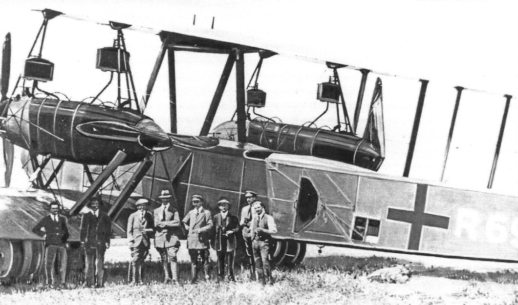
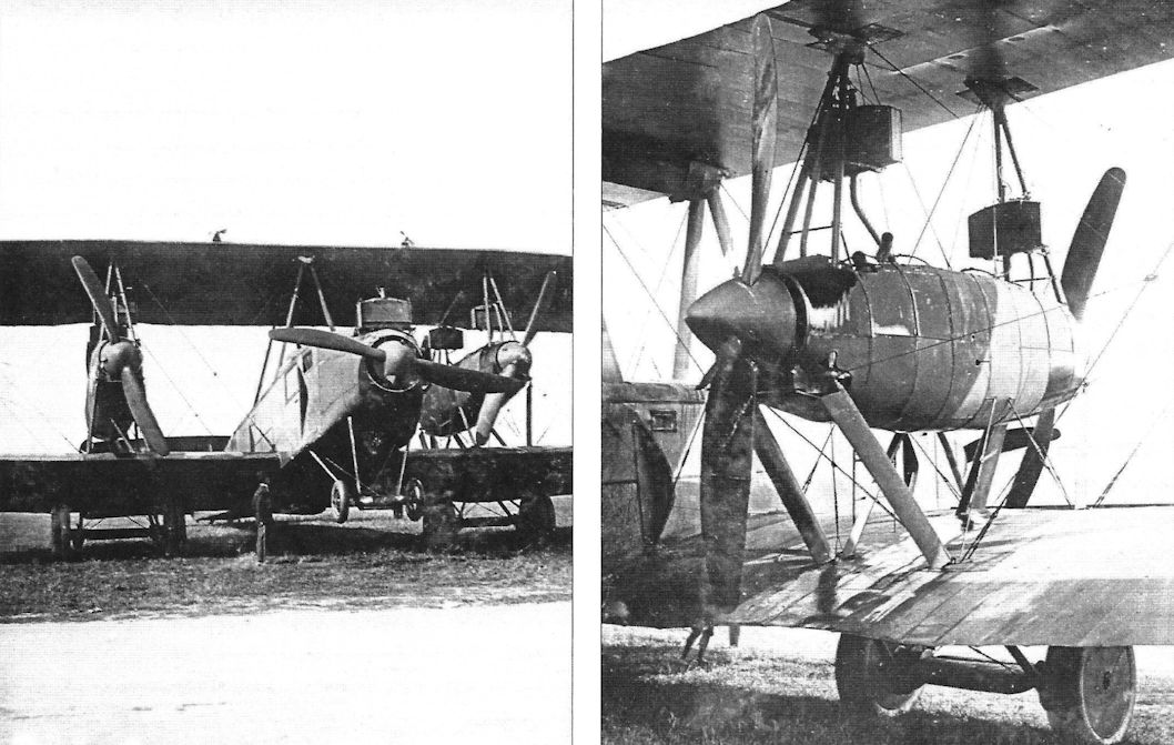
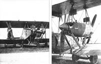
More detail views of a Staaken R.XIVa. Unlike the R.XIV, the R.XIVa omitted the upper wing gun positions over the nacelles. (Peter M. Grosz collection/STDB)
-
J.Herris - Zeppelin-Staaken Aircraft of WW1. Vol 2: R.VI R.30/16 - E.4/20 /Centennial Perspective/ (48)
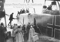
Staaken R.XIVa(Schul) being promoted as a passenger plane - still with German national insignia. These civilian flights were hardly mentioned in the daily and aeronautical press of the day, and it would appear that they brief and unimportant. The Allies were not enamored having these aircraft flying and Germany could not afford to subsidize them. A parachute shock cord runs from the rear exit to the parachute compartment - in a transport! (Peter M. Grosz collection/STDB)
-
G.Haddow, P.Grosz - The German Giants /Putnam/
Civilian passengers boarding a Staaken R.XIVa. Note the parachute shock cord running from the rear exit to the parachute compartment.
-

J.Herris - Zeppelin-Staaken Aircraft of WW1. Vol 1: VGO.1 - R.IV R.29/16 /Centennial Perspective/ (47)
The cockpit of a Staaken R.XIVa showing its night camouflage. (Piotr Mrozowski collection)
-

J.Herris - Zeppelin-Staaken Aircraft of WW1. Vol 2: R.VI R.30/16 - E.4/20 /Centennial Perspective/ (48)
Staaken R.XIVa with crew and onlookers. (Peter M. Grosz collection/STDB)
-
J.Herris - Zeppelin-Staaken Aircraft of WW1. Vol 2: R.VI R.30/16 - E.4/20 /Centennial Perspective/ (48)
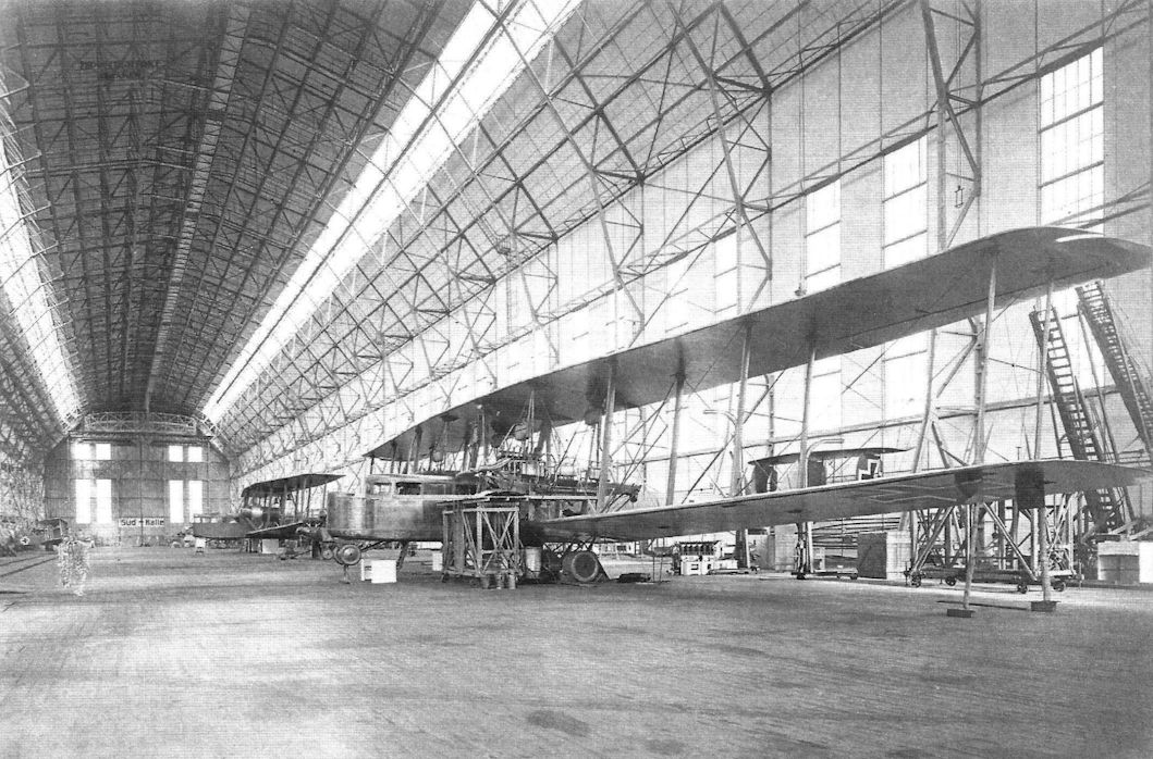
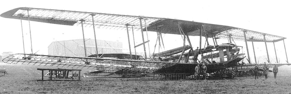
Unidentified Staaken bombers under construction. (National Archives)
-

-
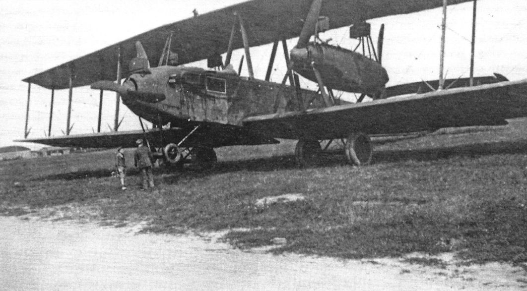
J.Herris - Zeppelin-Staaken Aircraft of WW1. Vol 2: R.VI R.30/16 - E.4/20 /Centennial Perspective/ (48)
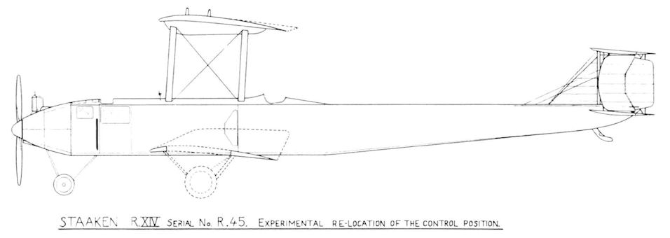
Staaken R.XIV 45/17. Photograph shows the condition of the machine after a night landing at Morville, Belgium. Notice the position of the cockpit behind the wings, unique to the R.45 among Staaken R-planes.
-

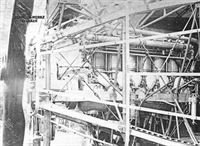
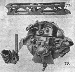
Журнал - Flight за 1918 г.
Some constructional details of the five-engined giant. - 67. Long gear box, complete with male clutch. 68. Long gear box seen from underside. 69. Broken gear box (long type), with bearers and oil radiator. 70. Driving pinion. 71. Windmill.
-

Журнал - Flight за 1918 г.
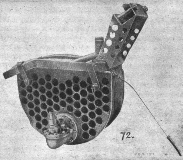
Fig. 72. - Oil radiator and gear pump of five-engined giant.
-

Журнал - Flight за 1918 г.
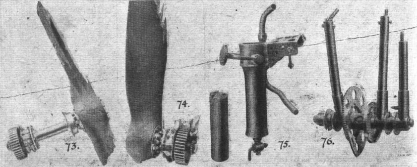
Some more details of five-engined giant. - 73. Pusher screw and driven pinion. 74. Tractor screw and pinion. 75. Oil filter of gear box. 76. Engine control levers.
-
Журнал - Flight за 1918 г.
Fig. 77. shows engine bearer transverse-girder. 78. "Douglas" type wireless and heating generator.
-
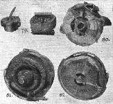
Журнал - Flight за 1918 г.
The five-engined giant. - 79. Pump and transformer, 80. Rear view of engine and flywheel. 81. Wireless generator. 82. Cowling and dynamo drive.
-
J.Herris - Zeppelin-Staaken Aircraft of WW1. Vol 2: R.VI R.30/16 - E.4/20 /Centennial Perspective/ (48)
Staaken R.XIVa, perhaps R.71, after crashing. The pilot had to work hard for such an outcome. (Peter M. Grosz collection/STDB)
-
G.Haddow, P.Grosz - The German Giants /Putnam/
Wreckage of the Staaken R.44 on the Cologne airfield. February 1919.
-

J.Herris - Zeppelin-Staaken Aircraft of WW1. Vol 2: R.VI R.30/16 - E.4/20 /Centennial Perspective/ (48)
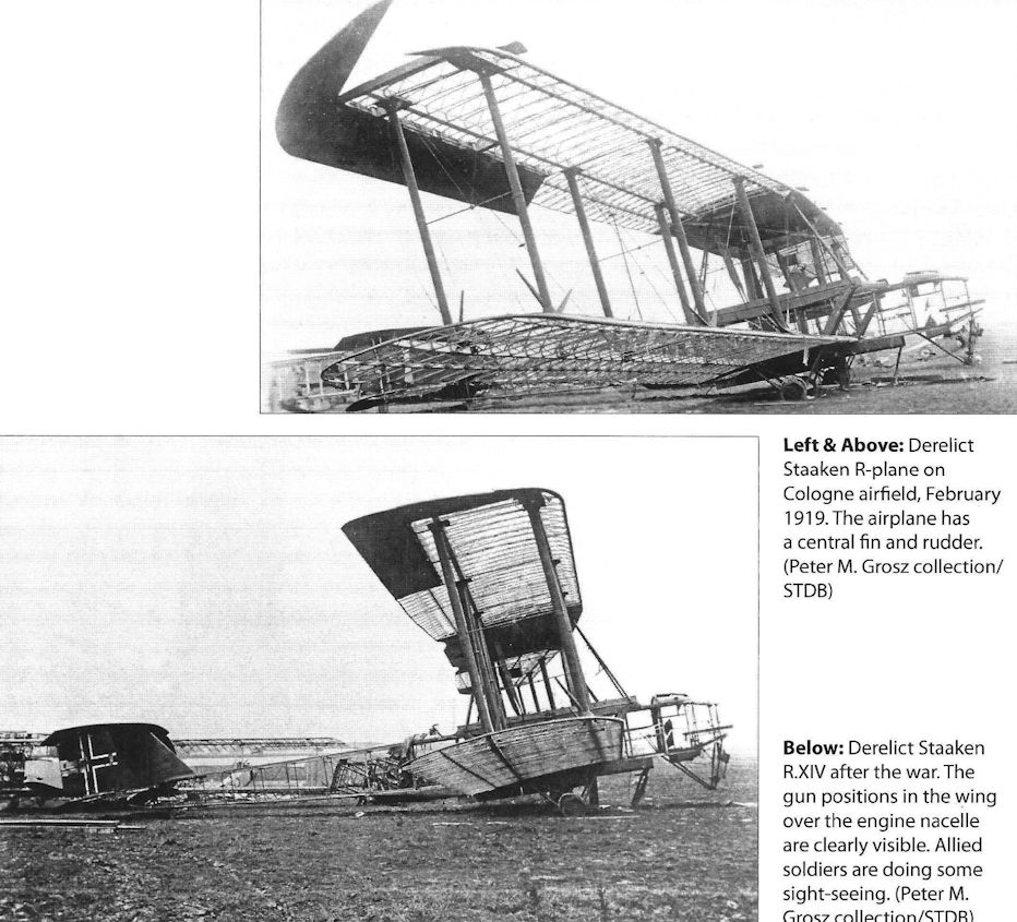
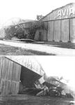
Derelict Staaken R-plane on Cologne airfield, February 1919. The airplane has a central fin and rudder. (Peter M. Grosz collection/ STDB)
-

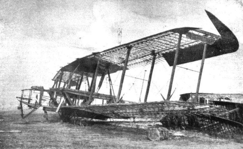
Журнал - Flight за 1919 г.
The skeleton remains on a 5-engined Gotha at Cologne.
-
G.Haddow, P.Grosz - The German Giants /Putnam/
Derelict Staaken R.XIV 44/17 left behind by the Germans at their abandoned airfield in Cologne, 11 February 1919.
-
J.Herris - Zeppelin-Staaken Aircraft of WW1. Vol 2: R.VI R.30/16 - E.4/20 /Centennial Perspective/ (48)
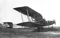
Derelict Staaken R.XIV after the war. The gun positions in the wing over the engine nacelle are clearly visible. Allied soldiers are doing some sight-seeing. (Peter M. Grosz collection/STDB)
-
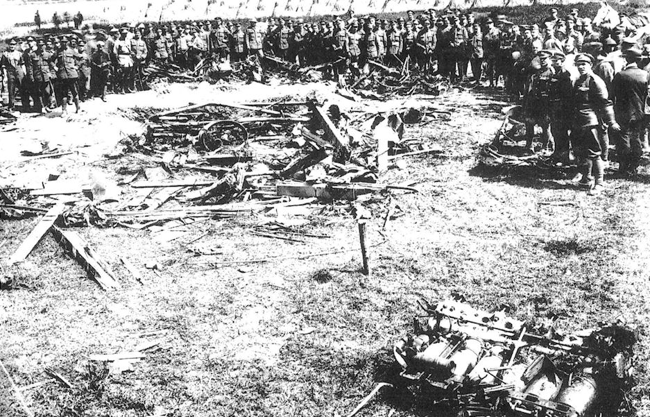
G.Haddow, P.Grosz - The German Giants /Putnam/
Remains of the Staaken R.XIV 43/17, shot down by Capt. Yuille R.F.C.
-

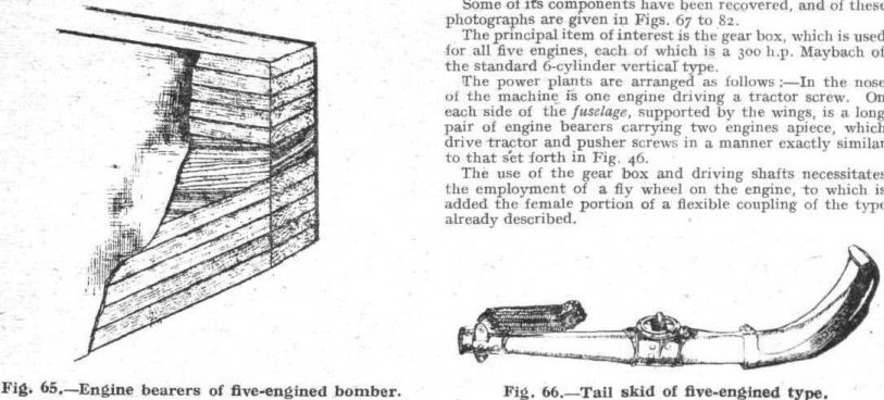
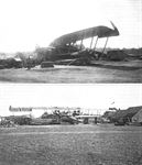
Журнал - Flight за 1918 г.
Fig. 65. - Engine bearers of five-engined bomber.
Fig. 66. - Tail skid of five-engined type. -
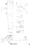
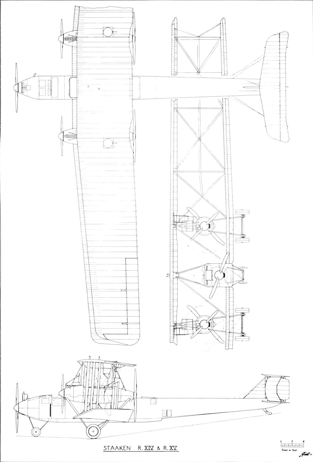
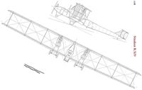
G.Haddow, P.Grosz - The German Giants /Putnam/
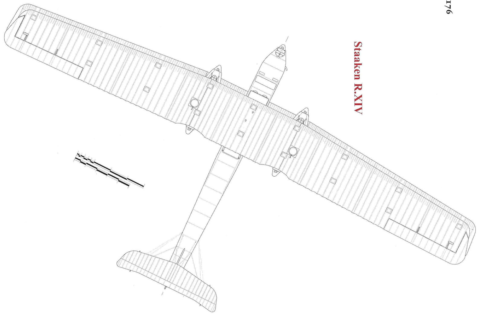
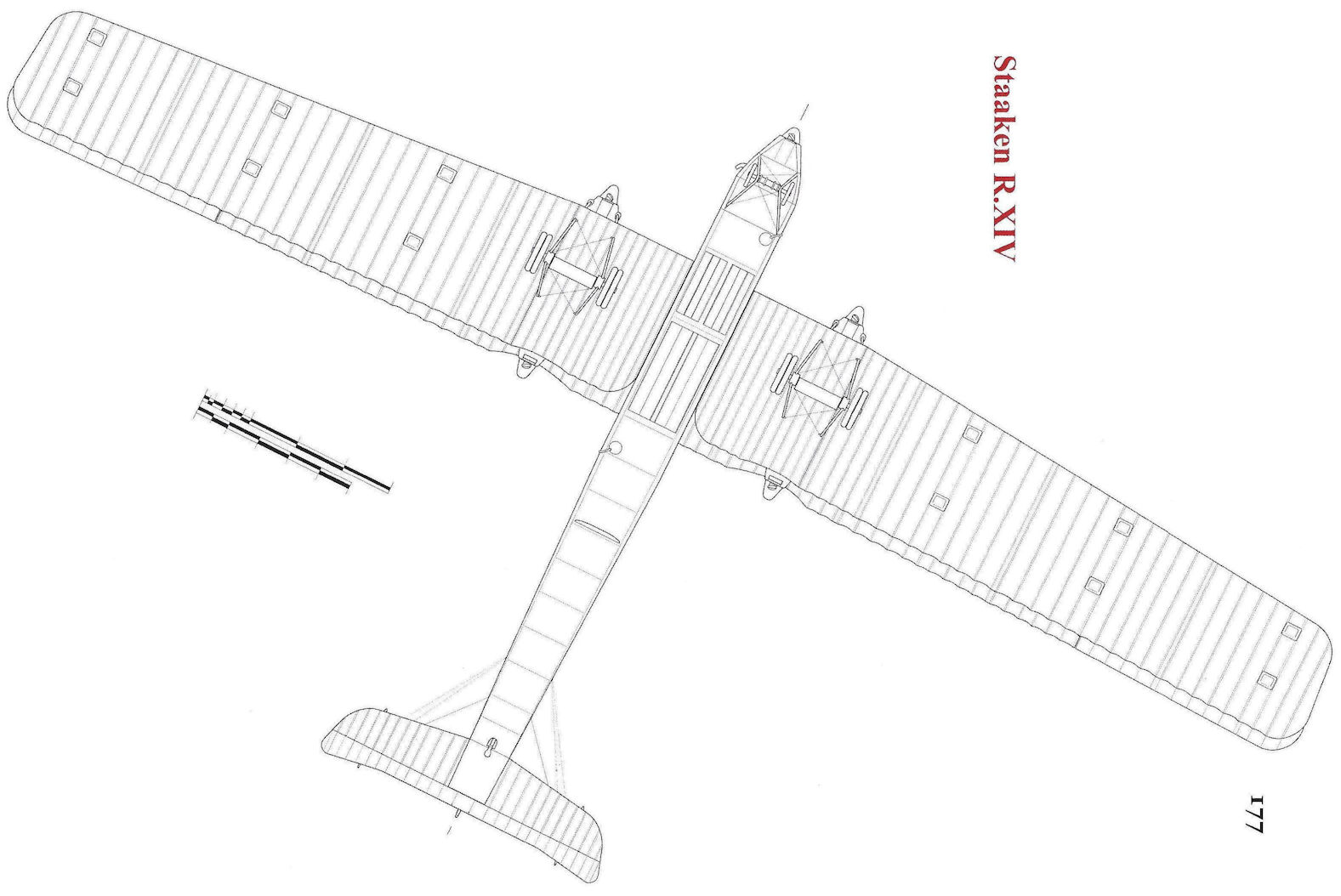
Staaken R.XIV & XV
-
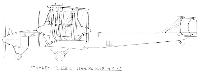
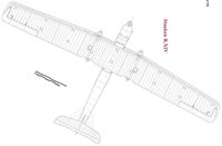
G.Haddow, P.Grosz - The German Giants /Putnam/
Staaken R.XIV serial No. R.45. Experimental relocation of the control position.
-
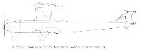
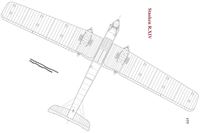
G.Haddow, P.Grosz - The German Giants /Putnam/
Staaken R.XIVa
-
-
-
В.Кондратьев Самолеты первой мировой войны
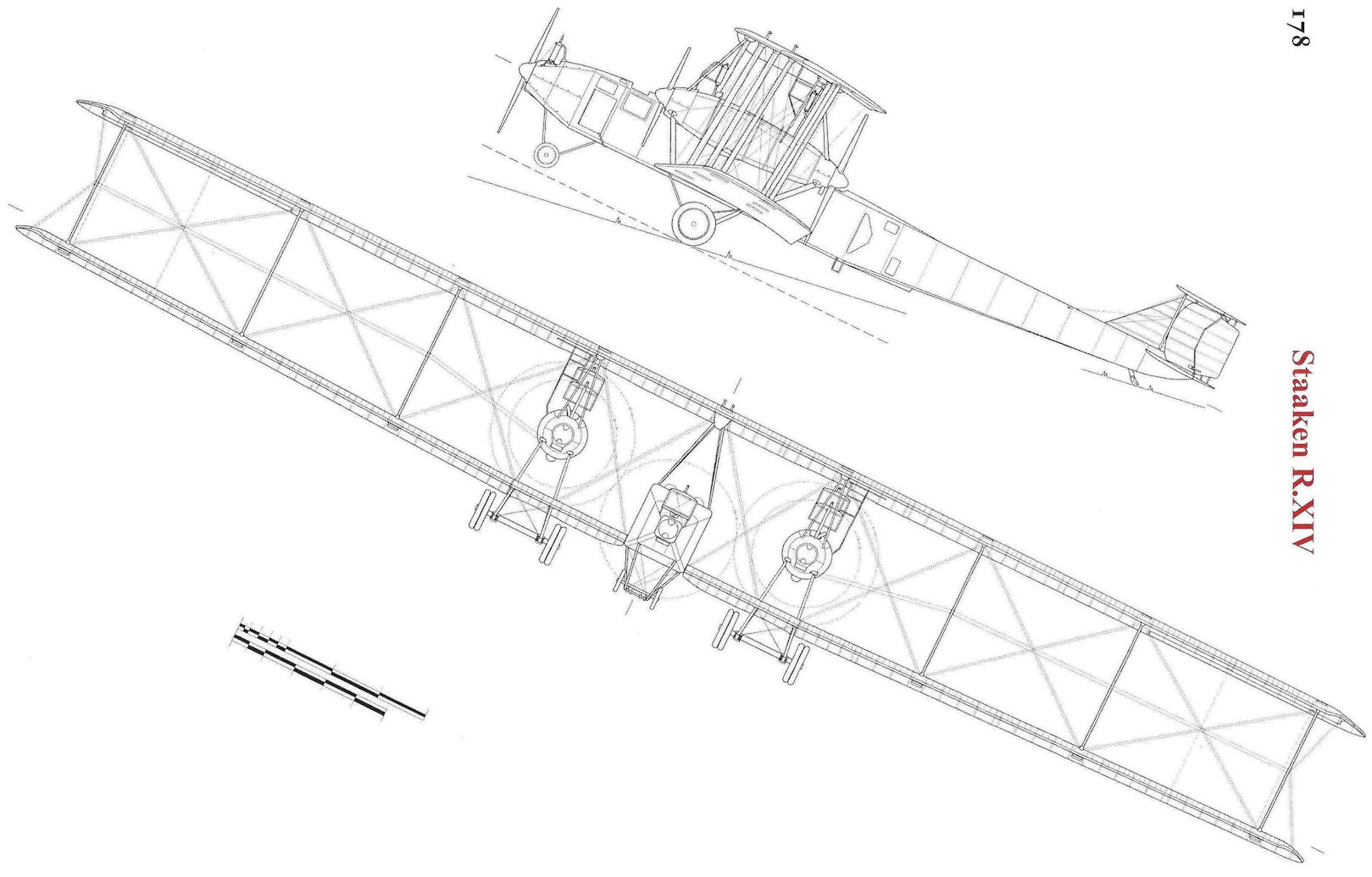
"Цеппелин-Штаакен" R-XIV и R-XV. Для дальнейшего повышения энерговооруженности своих машин фирма Штаакен в 1917 году вернулась к схеме пятимоторного самолета с носовой силовой установкой. Так появился R-XIV - самый крупный и тяжелый аэроплан эпохи Первой Мировой войны, настоящий шедевр тогдашнего авиастроения.
Объем бензобаков был значительно увеличен, в результате чего почти на треть повысилась дальность полета. Кроме того, на R-XIV нарастили площадь вертикального оперения и ввели роговую компенсацию элеронов.
До конца войны успели построить только 4 таких аппарата и 3 очень похожих на него R-XV. 5 из них принимали участие в боях на западном фронте. Экипаж, вооружение и оборудование R-XIV и R-XV такие же, как на R-VI.
ЛЕТНО-ТЕХНИЧЕСКИЕ ХАРАКТЕРИСТИКИ
("Цеппелин-Штаакен" R-XIV)
Размах, м 42,2
Длина, м 22,5
Площадь крыла, кв.м 334,0
Сухой вес, кг 10350
Взлетный вес, кг 14450
Скорость максимальная, км/ч 135
Дальность полета, км 1300
Время набора высоты, мин/м 45/3000
Потолок, м 4500
Описание: