В.Обухович, А.Никифоров Самолеты Первой Мировой войны
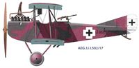
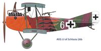
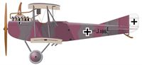
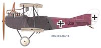
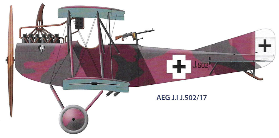
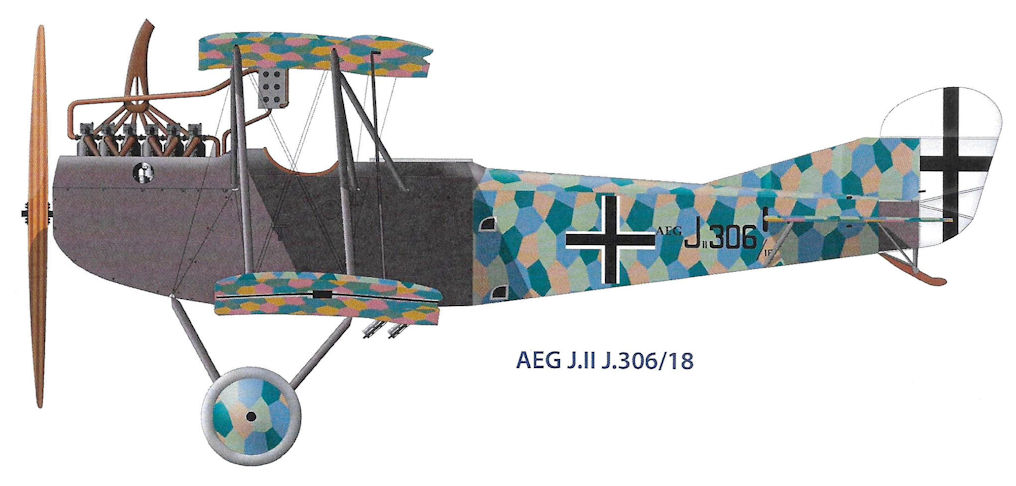
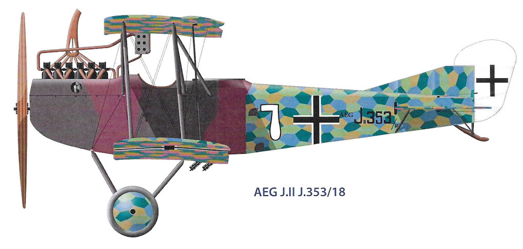
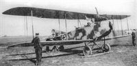
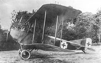
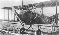
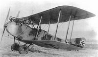
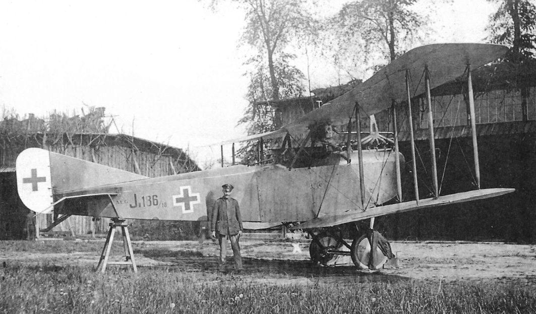
Битва под Верденом продемонстрировала высокую значимость самолетов непосредственной поддержки наземных войск В связи с этим в ускоренном режиме был разработан штурмовой самолет AEG J I. Он был создан на базе AEG С IV и отличался от него усиленным вооружением: имел два пулемета LMG 08/15, установленных для стрельбы вперед-вниз под углом в 45· и один оборонительный турельный пулемет "Парабеллум" в задней кабине. Была установлена бронезащита экипажа и двигателя Бенц Bz.IV (200 л. с). Модификация J II, выпущенная в 1918 г., была в целом аналогична варианту J I, но имела некоторые отличия в конструкции и оборудовании. Всего было произведено более 600 самолетов JI и JII.
Показать полностью
O.Thetford, P.Gray German Aircraft of the First World War (Putnam)
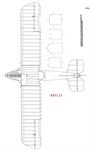
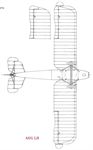
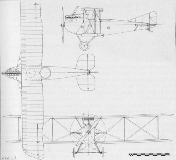
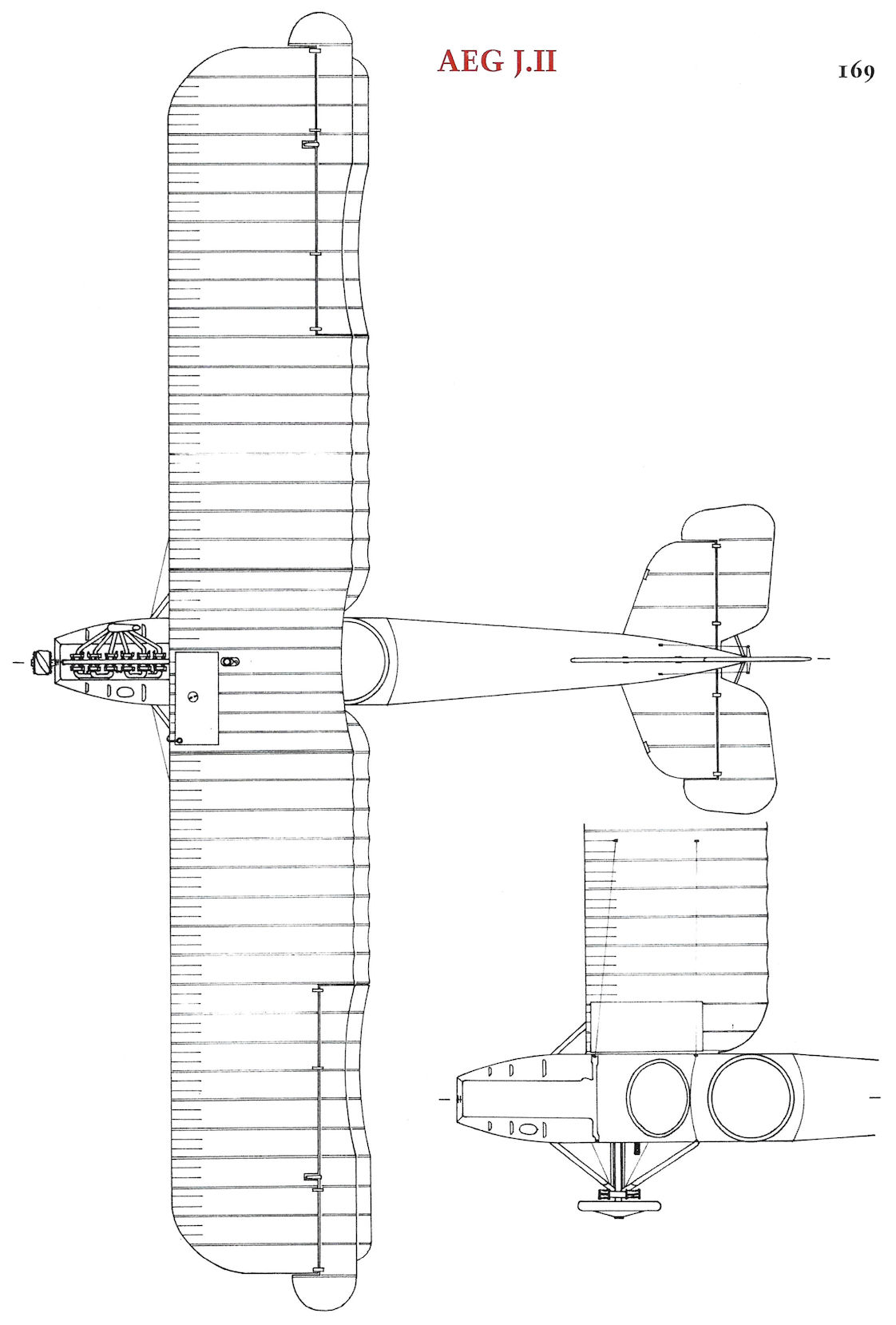
A.E.G. J I and J II
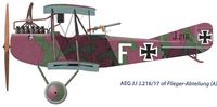
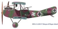
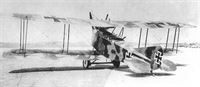
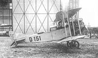
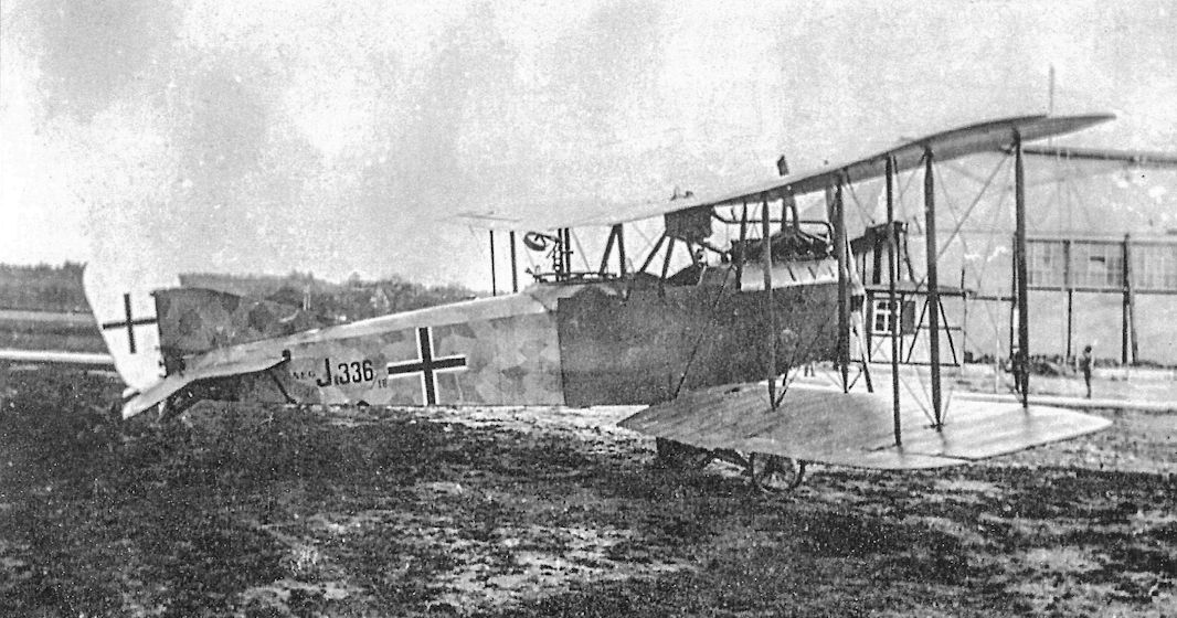
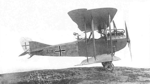
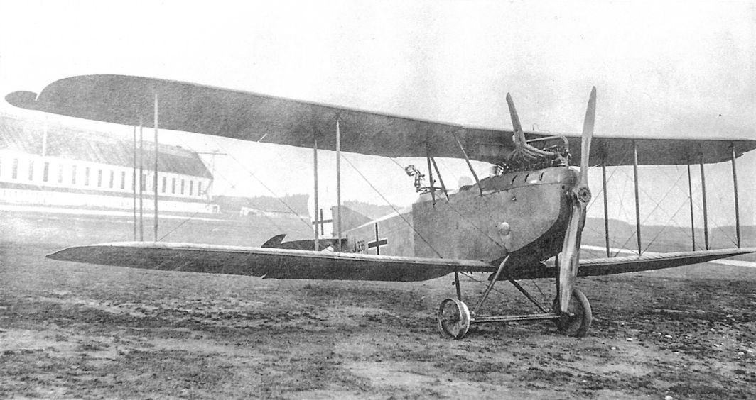
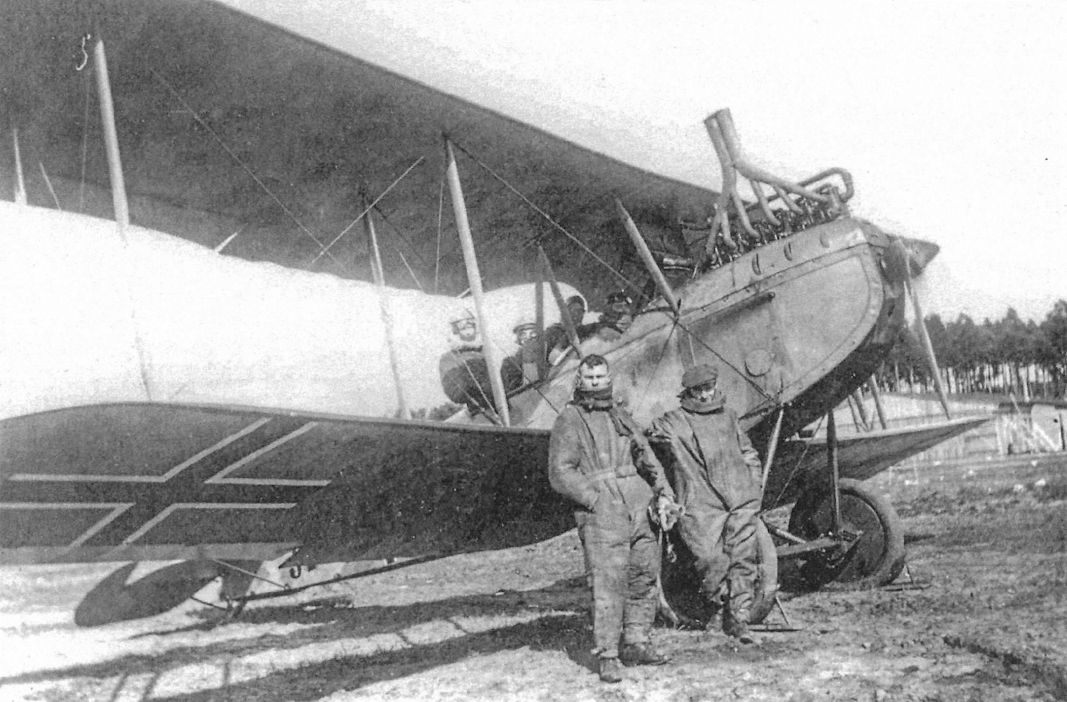
During 1917, formation and equipment of the Infanterie-Flieger units proceeded and, until specifically designed aircraft (e.g. Junkers J I, etc.) were available in sufficient quantity A.E.G. J Is and J IIs were allocated. Supply of these machines was a relatively simple matter, as the aircraft itself was virtually a C IV re-engined with a Benz and with a modified, armoured fuselage.
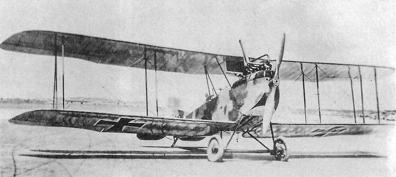
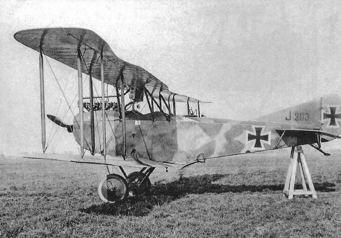
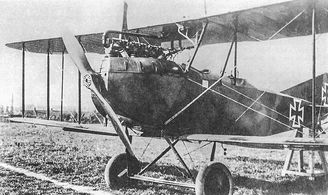
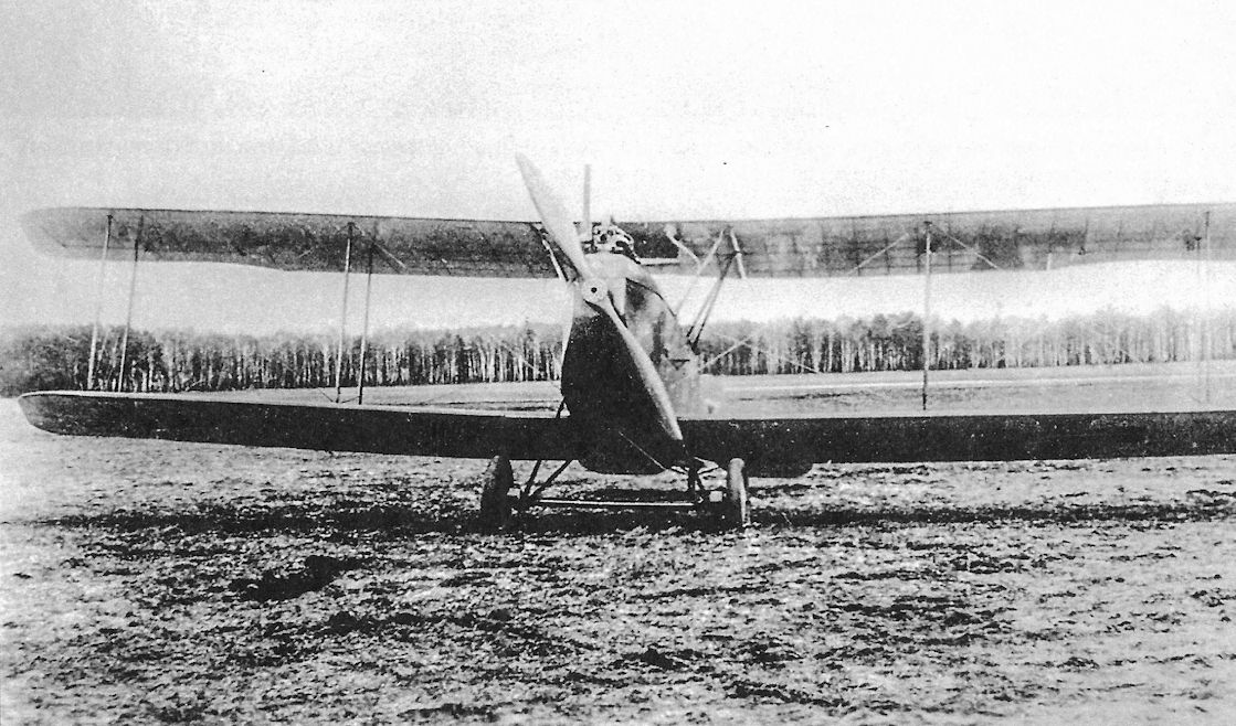
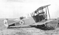
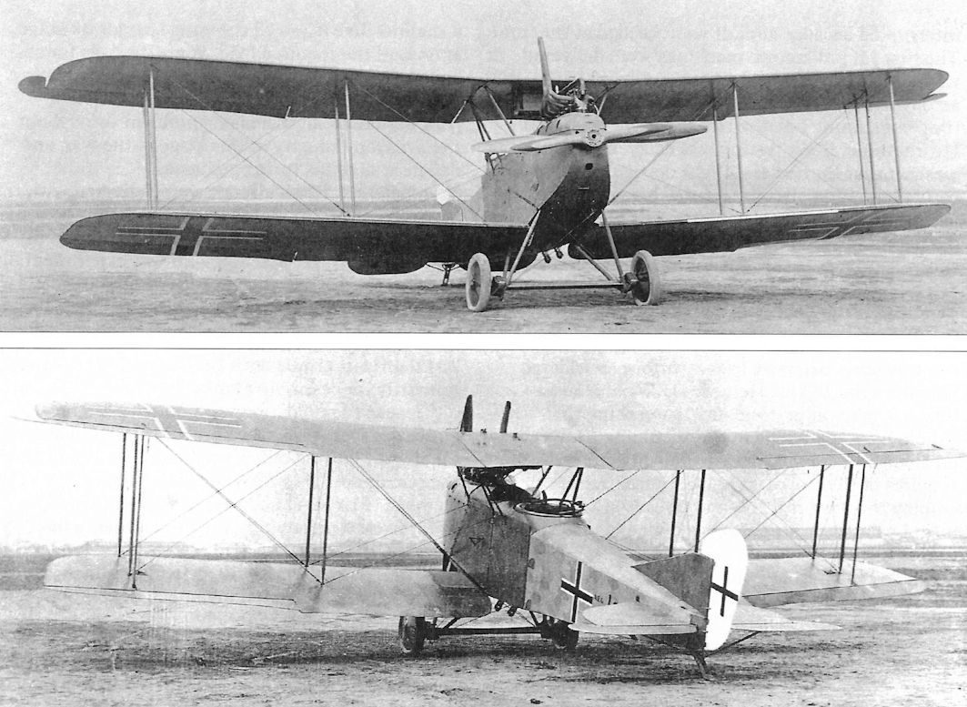
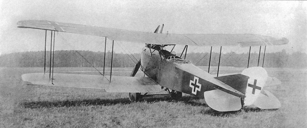
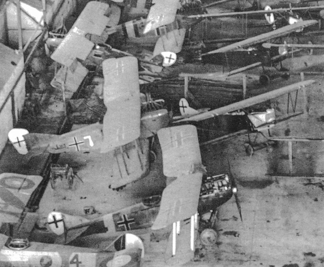
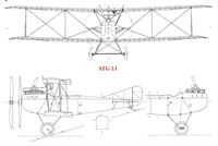
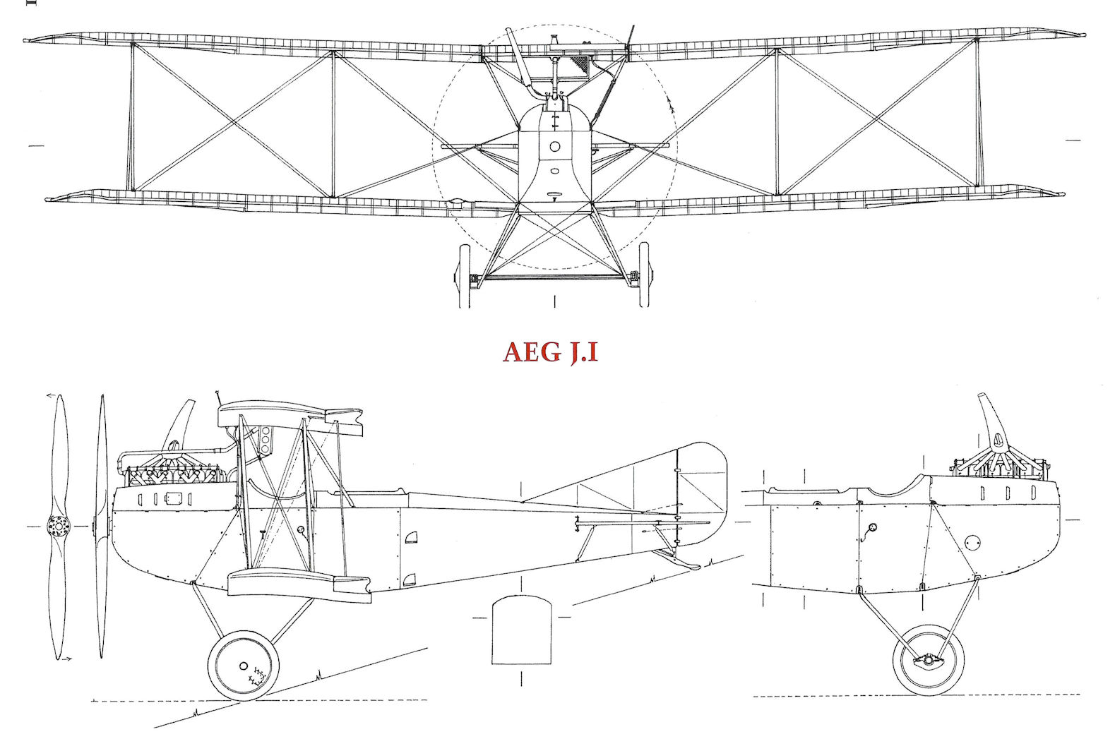
Powering the J I was the 200 h.p. Benz Bz IV, giving an increase of 40 h.p. over the Mercedes D III installed in the C IV. However, every ounce of this additional power was required to haul the extra 860 lb. of armour plate through the air. Armour plate extended from the nose to the aft extremity of the rear cockpit and was some 5.1 mm. thick. There were three panels either side of the fuselage, three underneath and a transverse bulkhead at the back of the rear cockpit to protect the observer from behind. The armour in no way formed part of the structure: it represented little more than sheets of steel fastened to the fuselage framework by set-screws entering clips clamped round structural members, with scant concession to shaping. In fact, the angular severity of the resultant nose contours was strongly reminiscent of a tank.
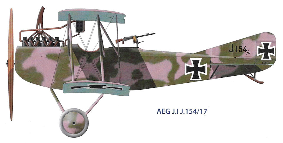
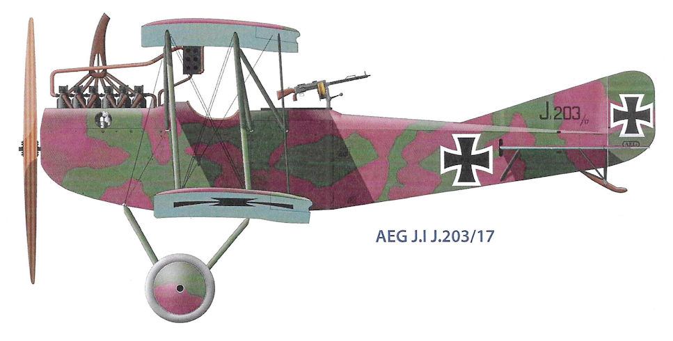
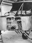
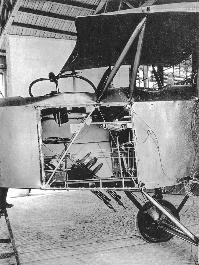
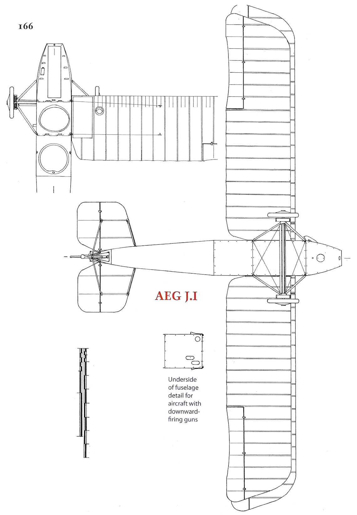
J Is were not fitted with any forward-firing armament, but two Spandau guns were bolted to tubular brackets on the rear cockpit floor. These fired forward and downwards at an angle of 45#' to facilitate Straffing of troops and harassing of ground targets, which were the prime duties of the A.E.G. J I. They were operated through Bowden wire controls from twin triggers mounted conveniently at the observer's right hand. Ammunition was belt-fed from a large supply drum mounted close to the guns. Rudimentary sighting was through a circular hole in the forward right-hand corner of the cockpit. For defensive purposes, the observer was equipped with the usual free-firing Parabellum gun on a ring mounting.
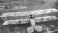
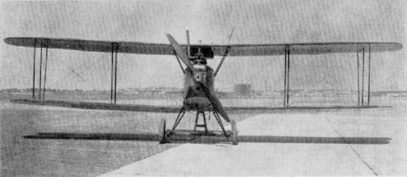
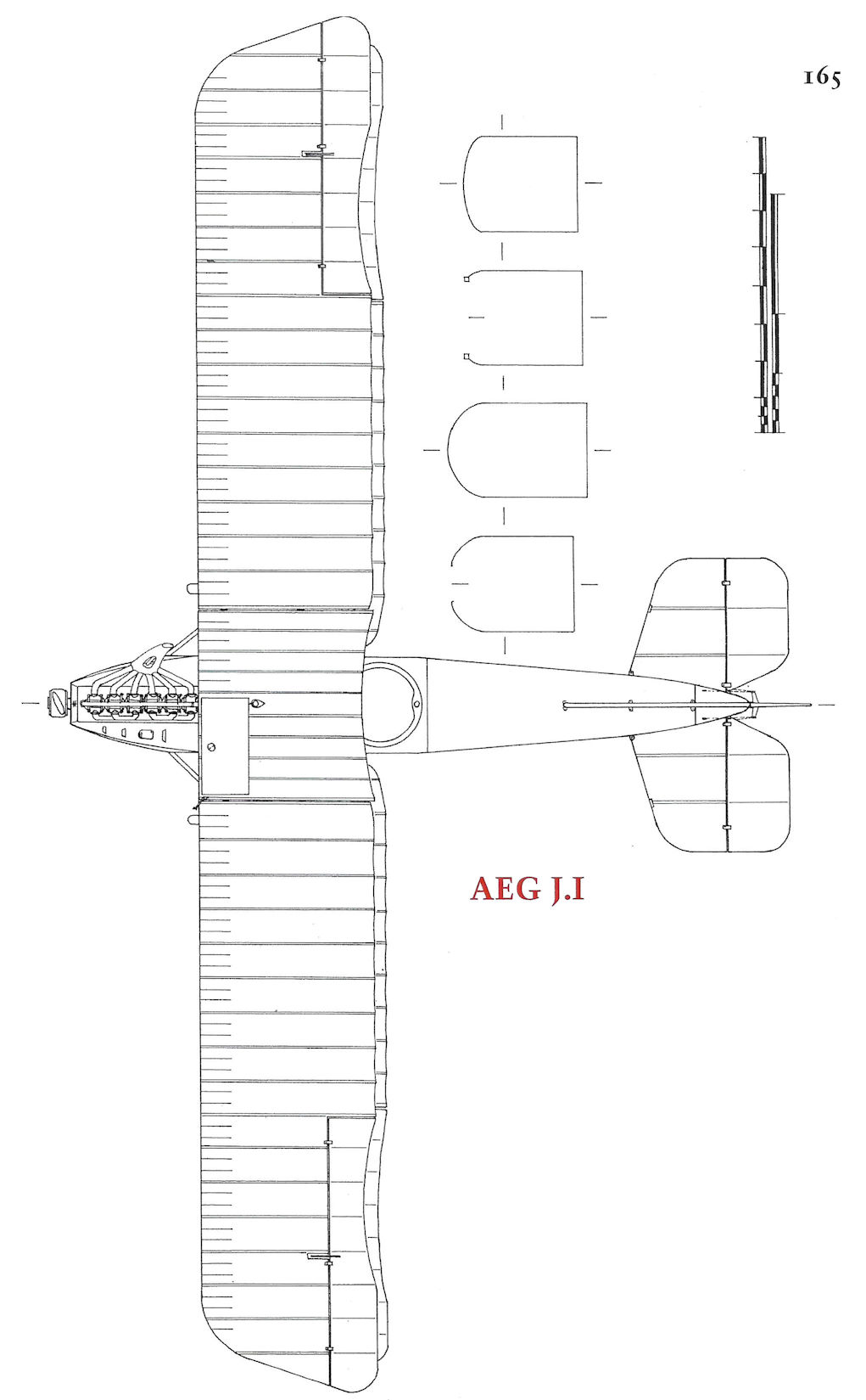
In the prototype machine the wing structure was identical with that of the C IV, but in operation, due to the added weight of the armour, the aeroplane was found to need a much greater degree of lateral control. To secure this without drastic revision of the flying surfaces, ailerons were added to the tips of the lower wings and simply connected to the upper ailerons with a rigid link strut, as the modus operandi was exactly the same as that of the earlier C type machine.
The remainder of the aircraft was almost pure C IV. Even the Daimler-Mercedes radiator was retained, though it now served a Benz engine. The number of spiral spring shock absorbers was reinforced to cater for the increased weight of the machine.
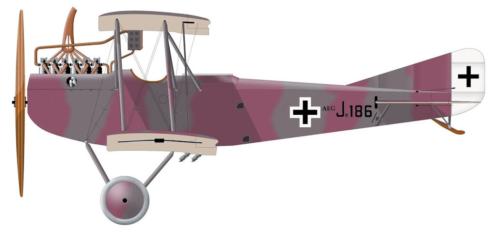
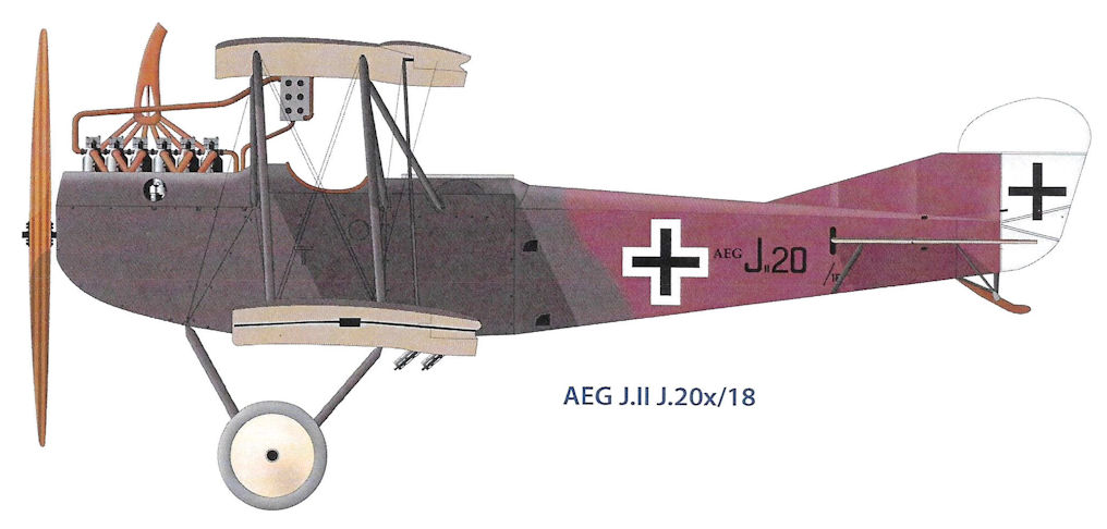
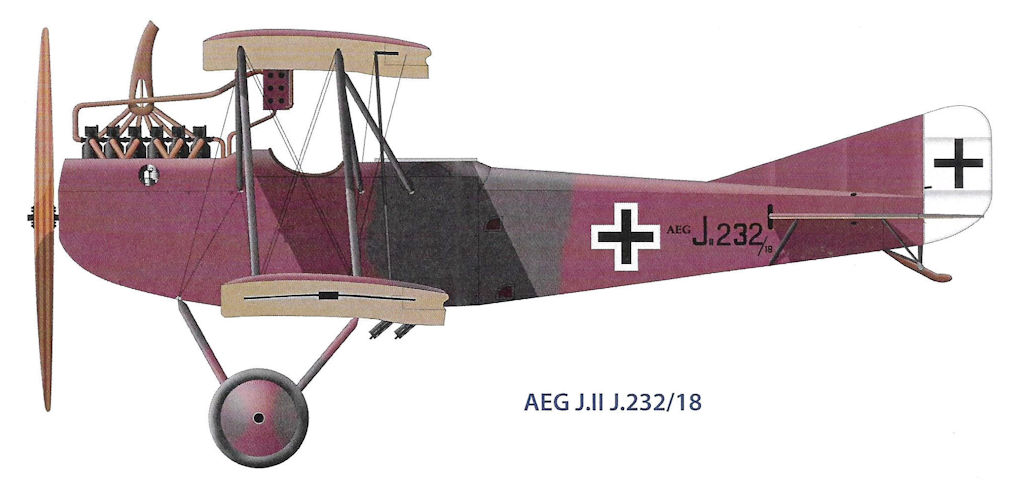
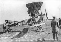
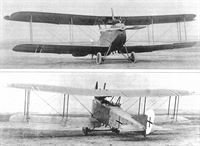
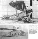
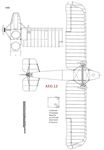
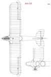
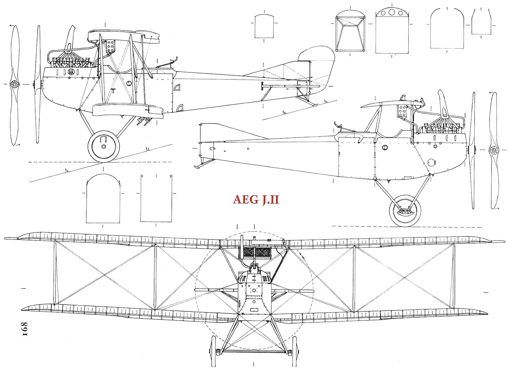
Later on, in 1918, a further development known as the J II was produced, but this differed little from the J I structurally. All control surfaces except for the lower ailerons, were now revised with large overhung horn balances which materially altered the appearance of the aircraft. To improve directional stability, the vertical fin was increased in area, raking up from the fuselage in a compound curve. The aileron link strut was located at the forward end of the operating crank instead of in the middle of the ailerons.
Altogether, according to the findings of the Inter Allied Commission immediately after the armistice, some 609 J type aircraft were produced by the A.E.G. concern.
TECHNICAL DATA
Purpose: Armoured Infantry Contact Patrol.
Manufacturers: Allgemeine Elektrizitiits Gesellschaft (A.E.G.).
Power Plant: 200 h.p. Benz Bz IV 6 cylinder in-line water cooled.
Dimensions: Span, 13.460 m. (44 ft. 2 in.). Length, 7.200 m. (7.900 m. J II) (23 ft. 7 1/2 in.) (25 ft. 11 in. J II). Height, 3.350 m. (10 ft. 11 7/8 in.). Wing area, 33.18 sq.m. (358.4 sq.ft.).
Weights: Empty, 1,455 kg. (1,480 kg. J II) (3,201 lb.) (3,256 lb. J II). Loaded, 1,740 kg. (1,765 kg. J II) (3,828 lb.) (3,883 lb. J II).
Показать полностью
J.Stroud European Transport Aircraft since 1910 (Putnam)
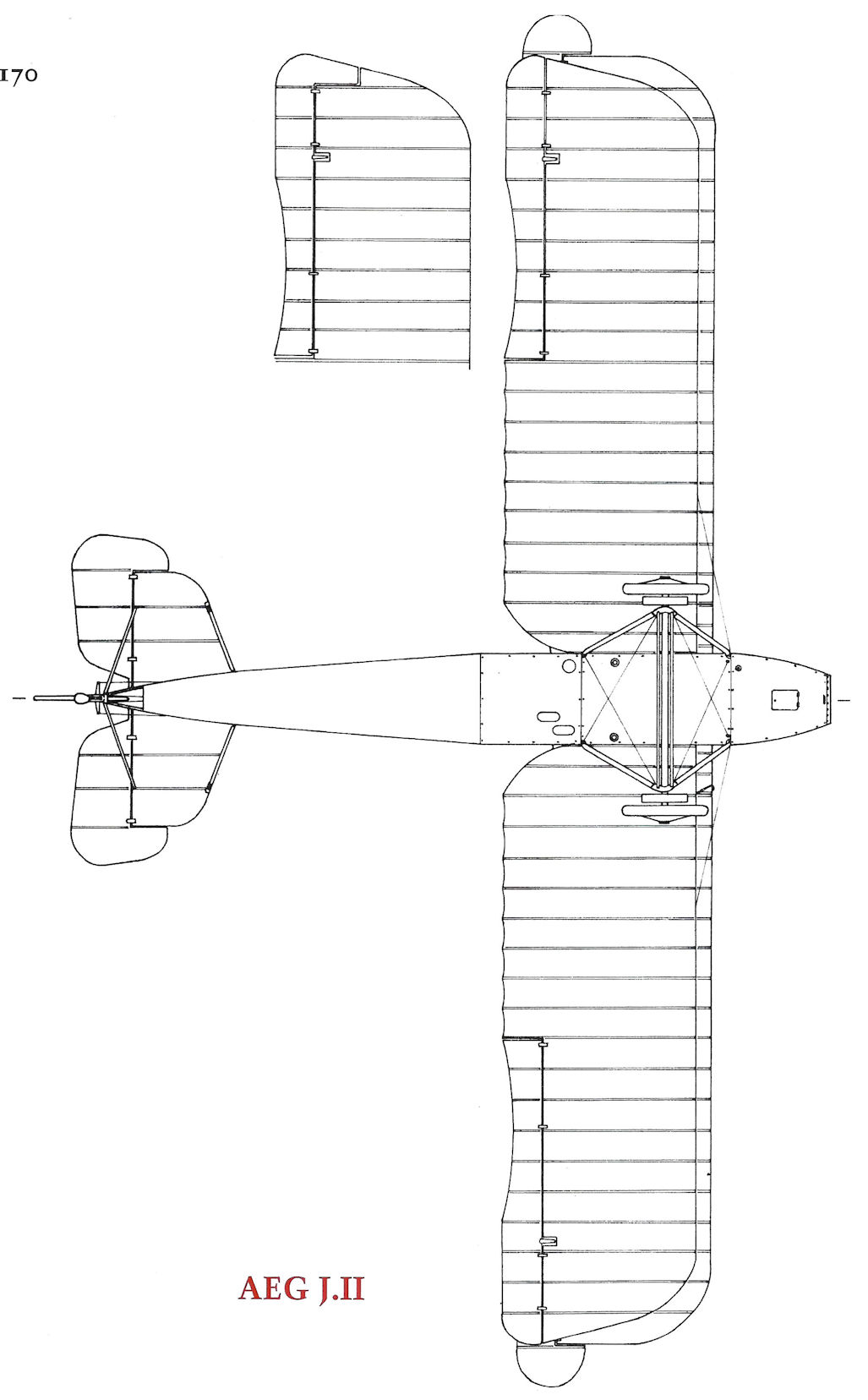
A.E.G. J II
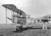
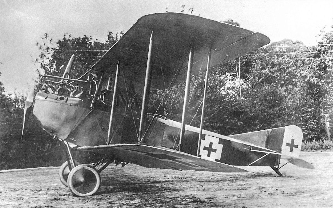
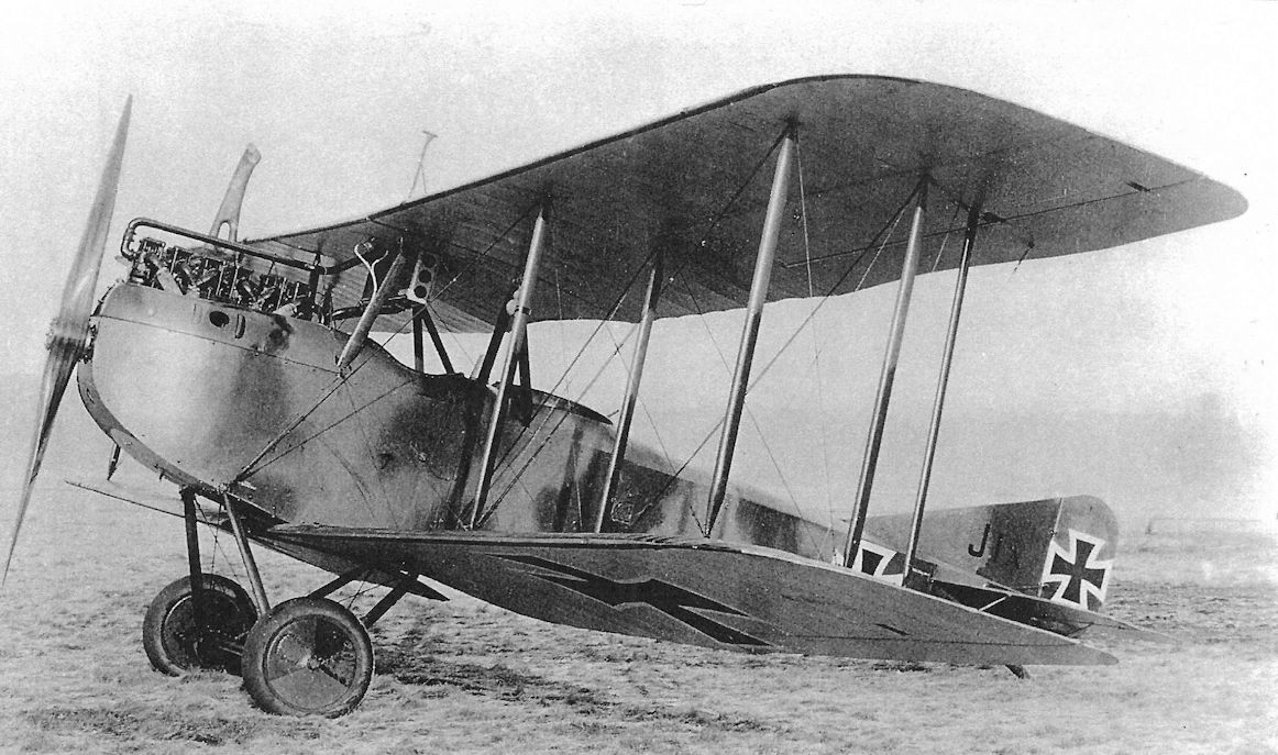
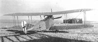
In 1917 the German Air Force began using the A.E.G. J I, which was an armoured version of the earlier A.E.G. CIV. The A.E.G. J I was a two-seat two-bay strut and wire-braced biplane with slightly greater span on the upper wing. The engine was a 200 hp Benz BzIV. Like the C IV, the J I was mainly of metal construction with steel-tube spars and welded steel-tube fuselage structure. The wing ribs were of wood, and the whole aircraft was fabric-covered. The radiator was beneath the upper centre section, and the exhaust was carried clear of the upper wing by the typical German horn-type stack.
In 1918 the J Il appeared. This was almost the same as the J I, but had horn-balanced ailerons on the upper wing, horn-balanced rudder and elevators, and a revised fin of greater area. Total production of J I, J Il and the intermediate J Ia is reported to have been 609.
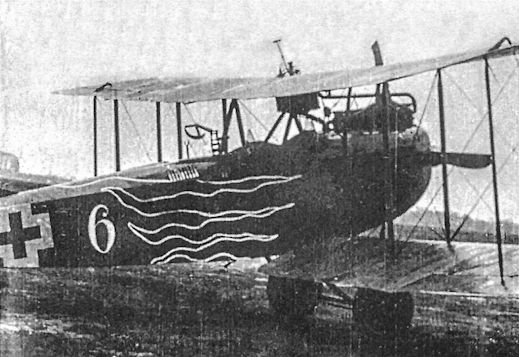
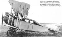
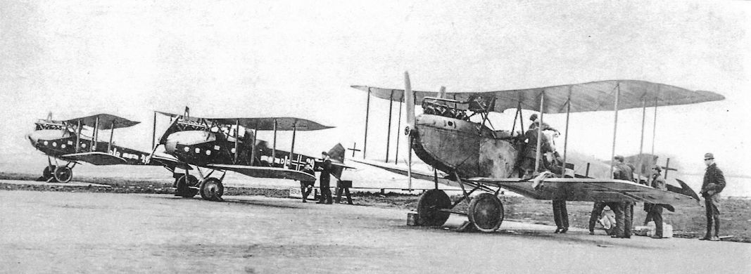
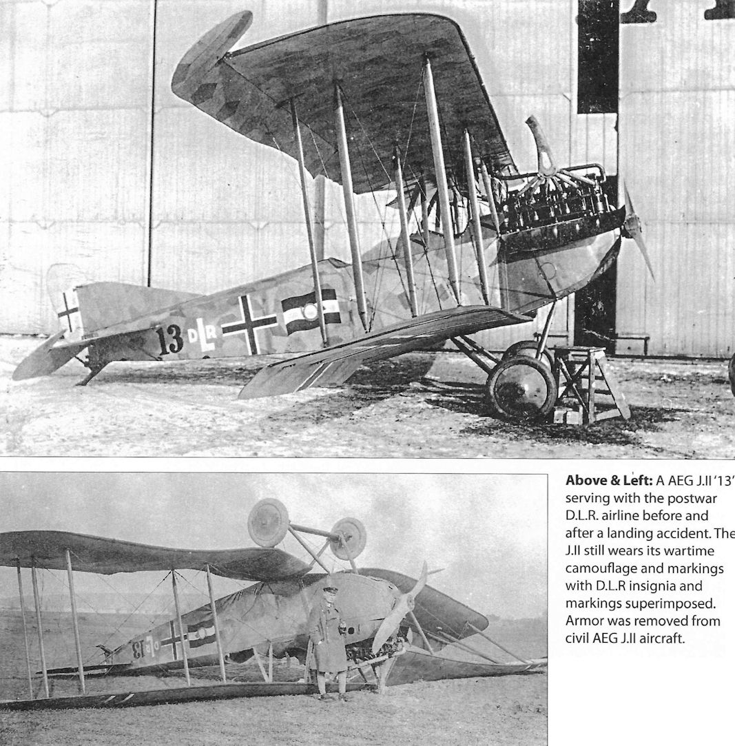
When Deutsche Luft-Reederei, which was in fact founded by A.E.G., began operating German domestic services in February 1919 a number of A.E.G. J IIs were used, and the type appears to have formed the major part of the fleet. Initially these aircraft were all operated simply with the military equipment removed and a two-seat open cockpit replacing the former gunner’s position. One of these J IIs bore the DLR number 13 and was used on the first Berlin-Weimar services; others were D-61, and DLR 97 (c/n 310) which later became D-479.
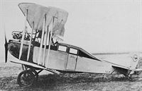
A number of A.E.G. J Ils were modified in DLR’s workshops to have enclosed cabins for two passengers. When so modified the aircraft were generally known by the designation A.E.G. K, and for long the appearance on the register of aircraft with this designation has been something of a mystery. It is now known that the K stood for Kabine and that the designation did not specifically refer to a modified A.E.G. J II, although most of the K aircraft were.
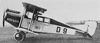
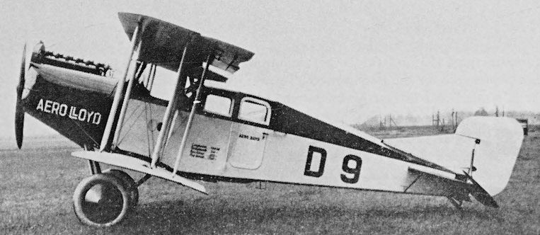
DLR 36 (c/n 419), D-9 and D-74 (c/n 439) were definitely cabin versions of the J II, and D-14, D-24, D-66 and D-68 (c/n 417) are almost certain to have been the same. D-9’s cabin was of different design to the others, and the aircraft was generally cleaned-up. Both versions are illustrated.
All these aircraft were operated by DLR, some passed to Deutscher Aero Lloyd and four went to Deutsche Lufthansa in 1926. These were D-14 (c/n 5053), D-24, D-68 Kreuzotter (Viper) and D-74. D-68 had been built in Berlin in 1918 and was still in Lufthansa’s fleet as a cargo aircraft in 1930.
Most of these civil A.E.G.s retained their 200 hp Benz Bz IV engines; but D-9 was fitted with a BMW IV, and at some stage D-68 and D-74 were re-engined with 240 hp Armstrong Siddeley Pumas.
<...>
A.E.G. J I. Span 13:46 m (44 ft 2 in); length 7:9 m (25 ft 11 in); wing area 33:18 sq m (357-14 sq ft). Empty weight 1,100 kg (2,425 Ib); loaded weight 1,620 kg (3,571 Ib). Maximum speed 150 km/h (93:2 mph); ceiling about 4,500 m (14,763 ft); endurance 4 hr.
These figures are for the Benz-powered version. With Puma engine the empty weight was 1,380 kg (3,042 lb), the loaded weight 1,870 kg (4,122 lb) and range 600 km (372 miles).
Показать полностью
J.Herris Development of German Warplanes in WWI (A Centennial Perspective on Great War Airplanes 1)
J-Class Armored Aircraft
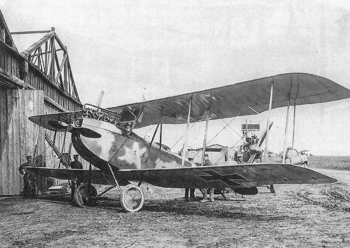
Because more J-types were need than Junkers could produce, the AEG company modified their standard C.IV reconnaissance plane, which featured a structure of welded steel tubes, into an armored J-type by attaching armor plate to the sides and under-surfaces of the engine and cockpit. Not integrating the armor into the primary structure was not as elegant a solution as the Junkers design, but resulted in an airplane, the AEG J.I, that was much easier and faster to build. Although not as impervious to ground fire as its Junkers sibling, the AEG was a good airplane for its role.
As the fighting continued the cooperation duties of the J-types evolved into more aggressive ground-attack, blurring the distinction between the role of the J-types and CL-types. Experience led to the addition of greater armament to the AEG J.I in the form of a downward-firing pair of machine guns mounted in the observer's cockpit and fired by him. The guns were normally angled to fire 45° below horizontal and aimed by the gunner observing the ground through a small hole in the floor in the front corner of his cockpit. The additional weight of this gun installation was too much for the heavy Junkers J.I, which never received additional armament and made do with only the observer's flexible gun.
Continued development by AEG resulted in the AEG J.II, which had revised controls for better maneuverability, doubled bracing wires and inner wing spars for reduced vulnerability to ground fire, and downward-firing machine guns fitted as standard.
To destroy Allied tanks, which were becoming a serious problem for the infantry, in September 1918 20 AEG J.IIs were delivered with a downward-firing 20mm Becker cannon on a flexible mount for the gunner.
The AEG J-types were the most valuable; they could be built in much greater quantity than the superior Junkers and were much less vulnerable to ground fire than the wooden Albatros J- types.
Показать полностью
J.Herris AEG Aircraft of WWI (A Centennial Perspective on Great War Airplanes 16)
AEG Armored Aircraft
AEG J.I
The successful AEG C.IV, with its steel-tube airframe, was well-suited as a starting point from which to develop an armored J-type. To develop the new type quickly, flat armored sheets, three on each side and three on the bottom, were bolted directly onto the metal airframe of the C.IV. The armor weighed a total of 400 kg. Integrating the armor plates as structural elements would have saved some airframe weight but cost a lot of time to develop and manufacture, and the AEG J.I was needed at the front as soon as practical. To improve maneuverability with the greater weight, ailerons were added to the lower wings. Finally, to haul the extra weight into the air, a 200 hp Benz Bz.IV engine replaced the 160 hp Mercedes D.III engine used in the C.IV. At first the wing area was unchanged from the C.IV, and the additional weight raised the stall speed and lengthened take-off runs.
Assembly of the AEG J.I prototype began in January 1917 and was completed in April. The first five production J.I aircraft were delivered in May. On 30 May 1917, AEG test pilot Theodor Schauenburg was killed when he attempted to loop a J.I and the wings came off. What possessed him to perform this terminally-foolish maneuver is unknown because aerobatics understandably were not a requirement for J-types.
The J.I airframe was identical to the AEG C.IV that had already passed its type-test, so Idflieg delayed the static-load test (on J.150/17) until August 1917 to expedite deliveries to the front. This was long after the J.I had entered combat, which was unusual for German aircraft. Starting in September 1917 the first running changes were introduced into J.I production to decrease vulnerability to ground fire. These changes were installation of double lift-bracing wires and double control cables. The AEG J.Ia engineering prototype was used to evaluate additional changes that were introduced as production progressed (see table).
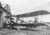
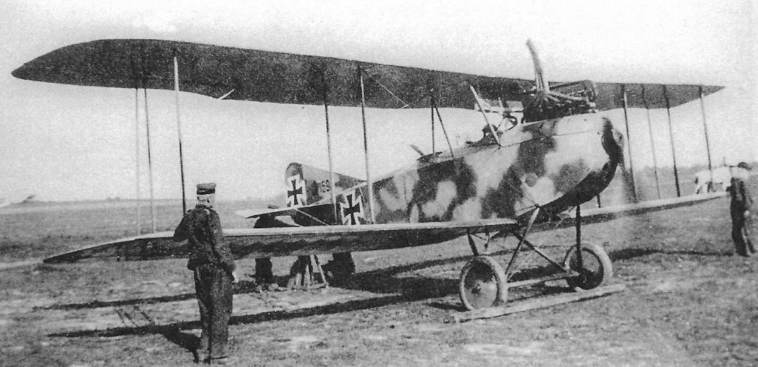
Because the AEG J-types were both relatively easy to built as well as resistant to ground fire, the AEG J.I and J.II became the most numerous J-types at the front. Like other J-types, the AEGs were assigned in ones or twos to divisional Flieger Abteilungen to fly contact patrol sorties, or 'Iffeln.' In the field, the AEG J.I was complimented for its high speed, estimated to be 150-200 km/h in level flight and as high as 250 km/h in a shallow dive. Unfortunately, this was optimistic; actual top speed in level flight was a mere 140 km/h. Due to its greater wing area and lighter weight, the Albatros J.I had a shorter take-off run, enabling it to operate from muddy airfields. In contrast, the heavy AEG J.I required a longer take-off run from drier surfaces. Though reasonably fast for an armored two-seater, it was not a fast airplane. Furthermore, the AEG J.I was cumbersome and difficult to land because the short fuselage and heavy nose made it easy to flip over on landing. On the other hand, crews felt more secure in the AEG J.I than the Albatros J.I because, unlike the Albatros, the engine was protected by armor. The armor's effectiveness was demonstrated by British firing tests on the armor plate of a captured J.I.
Installation of a 20mm Becker cannon in an AEG J.I fitted with an enlarged gun ring was undertaken in January 1918, followed by firing trials in February-March. The firing trials demonstrated the cannon was difficult to operate in the air as mounted, making this type of installation unsatisfactory for two-seaters.
Former observer Hanns-Gerd Rabe flew the AEG J.I in combat. "In order to make close observation possible and to take part in the land battles, armored airplanes were built with the engine, fuel tank, and pilot well-protected by armor plate. The observer was less protected because he had to move about freely to make his observations. Equally unprotected were the radiator above the engine and the control cables. At the end of July 1918 my unit, Flieger-Abteilung (A) 253, received an armored airplane of the AEG J.I type. We regarded it with suspicion for it was too heavy and seemed to be clumsy as the 200 hp engine was too weak. The pilots agonizingly circled the airfield with it, but it barely went over 500 meters. Risky maneuvers in aerial combat were out of the question... In our opinion it was a very primitive bird!" This was the opinion of many combat aircrewmen, who clearly did not agree with Idflieg's theories on required J-type performance.
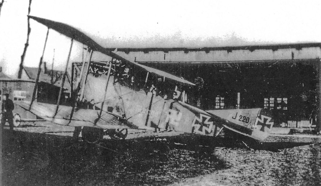
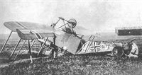
Continuing Rabe's comments, "The take-off was laborious; the crate lifted off very sluggishly and hung in the air... I heard the machine gun bullets hitting the armor plating and also saw holes being torn in the fabric... but I wasn't really concerned... When I had exposed all my photographic plates, I threw my hand grenades from the lowest altitude into the English posts and dropped gas bombs before the entrances of the dug-outs, and then fired my machine guns. I could work both machine guns in the floor with a foot pedal and I also fired the rotating machine gun at the machine gun emplacements in the trenches that were mainly firing at me from the rear... Suddenly, hot water hit me in the face. The vulnerable radiator had been hit. We could not last for more than a few minutes before the engine over-heated and froze up. Peter Johannes (the pilot) turned the AEG in a flat curve... to take us back to our own lines. But in the banked position, hits on the control cables to the rudder and ailerons tore them apart and caused the machine to dive towards a thick mass of barbed wire... Of course, the 'Emil' (nickname given to German two-seater pilots; the observer was 'Franz') succeeded in once again laboriously bringing the AEG back on an even keel, but the landing gear got caught in the barbed wire and the machine rolled over, leaving the landing gear pointed skyward..."
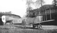
According to a French intelligence bulletin dated November-December 1918, the fuselage of an AEG J.I 468/17 (lang) was found near Strasbourg. The J.I was prone to landing accidents (flipping over) because of its short fuselage and heavy nose armor, and lengthening the fuselage for better pitch stability and control was an appropriate modification. The number of AEG J.I aircraft manufactured with longer fuselages is not known.
AEG J.Ia
AEG engineers began work in August 1917 to improve the J.I design. The wing loading was reduced by enlarging the wing area by 12 percent to reduce the stall speed and shorten the take-off run. The wing span remained constant; the wing area was enlarged by increasing the wing chord from 1.65 meters to 1.85 meters. To reduce the pilot's control forces, which improved maneuverability, the strut connecting the upper and lower ailerons was moved and attached to the aileron linkage. Installing double lift wires and control cables made the aircraft less vulnerable to ground fire. Some of these modifications, which were tested in August-October 1917 on the AEG J.Ia, were gradually introduced on the J.I production line, and later on all of the J.II machines. AEG J.Ia was not a military designation and appears to have been an internal AEG designation for a single development aircraft.
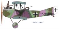
AEG J.II
As flight testing of the AEG J.Ia continued, the design of the AEG J.II, which incorporated many J.Ia features, was nearing completion. To further reduce vulnerability to ground fire the J.II's front spar was composed of two parallel steel tubes. By October 1917 the J.II prototype was undergoing flight evaluation. In January 1918 the flight-test results were still unsatisfactory, especially the poor rate of climb. A new control wheel for the pilot gave control forces that were much too heavy, hindering maneuverability.
The evolution of J.II control surfaces during its production run is evidence that flying qualities needed improvement, but production could not be interrupted because aircraft were needed at the front. The first J.II production machines were delivered with unbalanced control surfaces. Flight testing of aerodynamically-balanced controls was especially time-consuming because it was totally empirical. Furthermore, flight testing was delayed by winter weather that limited test-flight opportunities. A few early production aircraft featured balanced ailerons within the upper wing planform, but the standard configuration had projecting horn-balances for all control surfaces except the lower wing ailerons.
The AEG J.II was in quantity production by March 1918, and by April it was in combat at the front. Because of its similarity to the J.I, the static load test was apparently waived to expedite deliveries. According to combat reports, the AEG J-types performed very well during the Allied summer offensives. However, the long take-off run was still criticized. In fact, Idflieg considered installing the 260 hp Mercedes D.IVa engine to improve take-off performance, something that should have been done in the beginning. However, no changes were introduced, probably due to limited supplies of this popular engine. In fact, failure to employ the powerful 260 hp Mercedes D.IVa is inexplicable except as a consequence of inadequate supplies.
Several J.II crashes compelled Idflieg to perform a full static load test, which was done using J.II 294/18 during 8-20 August 1918. Testing revealed that in a shallow dive (Case C) the wing spar joints failed at 64% of the required load. Some fuselage frames and the aileron controls also needed strengthening. The problems were traced to a combination of poor materials, an increasing problem throughout the aviation industry at this stage of the war, and deficient manufacturing processes.
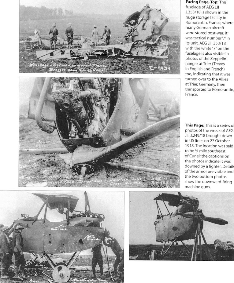
Apparently all J.II aircraft were delivered with the two-gun battery mounted in the observer's cockpit except for those with a 20mm Becker cannon. In June 1918, a single machine-gun was experimentally fitted in the nose so the pilot flying at 100 meters could fire at ground targets about 460 meters ahead. However, this was not placed in production. Also in June 1918, a flexible 20mm Becker cannon installed in the floor of the observer's cockpit was tested. Slotted armor grating protected the gun opening and aiming window. In September 1918, AEG delivered 20 J.II aircraft armed with the 20mm Becker cannon, primarily for destroying tanks.
Because of production with no recorded break between types, the exact number of AEG J.I and J.II aircraft built is unknown, but about 135 J.I and the remainder J.II is a reasonable estimate. Up to October 1918 some 508 J-types were delivered by AEG, more than any other manufacturer, which agrees with the Inter-Allied report that a total of 609 AEG J-types were built, a total that includes the machines completed in November and December 1918 and later adapted for civil use.
AEG J.III
The AEG J.III prototype, designed in September 1918, was finally fitted with the more powerful 260 hp Mercedes D.IVa engine needed from the beginning. Idflieg finally accepted what the aircrews knew from the beginning, that more power was needed not only to reduce take-off distance but also to increase speed and improve climb rate and agility. Greater power would improve operational flexibility, overall handling, and stall margin (for flight safety), and the ability to defend against fighter attack. In addition to the increased power, the J.III had redesigned armor plate that saved 100 kg of weight. As far as is known, the J.III did not reach series production before the Armistice and no photographs have been found.
AEG Armored Aircraft Specifications
AEG J.I AEG J.II AEG DJ.I Triplane AEG DJ.I Biplane AEG G.IVk
Engine 200 hp Benz Bz.IV 200 hp Benz Bz.IV 195 hp Benz Bz.IIIb V-8 195 hp Benz Bz.IIIb V-8 Two 260 hp Mercedes D.IVa
Span, Upper 13.00m 13.00m 11.20 m 10.00 m 18.00 m
Span, Lower 12.48m 12.48m 10.00 m 9.90 m 17.50 m
Chord, Upper 1.65m/1.85m 1.85m 1.475 m 1.80 m 2.40 m
Chord, Lower 1.65m/1.85m 1.85m 0.825 m 1.60 m 2.40 m
Gap 1.95m 1.95m 1.00 m 2.00 m 2.60 m
Wing Area 39.0 m2/43.6 m2 43.6 m2 31.3 m2 30.5 m2 65 m2
Length 7.20m 7.86m - 6.90 m 9.00 m
Height 3.3m 3.3m - - -
Track 2.19m 2.15m 1.90 m 1.90 m 4.80 m
Empty Weight 1,456 kg 1,480 kg 1,182 kg 1,185 kg 2,700 kg
Loaded Weight 1,876 kg 1,900 kg 1,412 kg 1,375 kg 3,150 kg
Maximum Speed 140 km/h 140 km/h 166 kmh 180 kmh 150 kmh
Climb to 1,000m 6.1 minutes 6 minutes 5.8 minutes 4 minutes 9 minutes
Climb to 2,000m 15.9 minutes 14 minutes - - -
Climb to 3,000m 31.6 minutes 30 minutes - - -
Climb to 4,000m - - 48 minutes - -
Armament 1 flexible machine gun, some had 2 fixed machine guns 1 flexible machine gun, 2 fixed machine guns 2 fixed machine guns, 4 small bombs 2 fixed machine guns, 4 small bombs 2 flexible machine guns, 2 flexible 20mm Becker cannon, small bombs
Notes:
1. AEG J.I specs are shown as early/late; later production AEG J.I aircraft had 1.85m chord and wing area of 43.6 m2. AEG J.I dihedral = 2°
2. At least 20 J.II aircraft fitted with a flexible 20mm Becker cannon in place of the 2 fixed machine guns.
3. The middle wing of the AEG DJ.I Triplane had a span of 10.60 m and a chord of 0.825 m.
AEG J-Type Orders & Production Notes
- About 135 AEG J.I aircraft were built; the rest were AEG J.II, making the AEG J.II the most numerous J-type.
- 508 AEG J-types were built through October 1918, and 609 were built through December 1918. About 373 and 474 respectively were J.IIs.
- The AEG J.III prototype was either J.375/18 or J.575/18.
- The AEG J.II series J.375-574/18 is conjectural. It is included because of the 609 AEG J-types built by the end of 1918; otherwise there are not enough serial numbers for these aircraft. Also, AEG J.II J.417/18 was used as a civil aircraft in 1919, proving that some aircraft in this serial number range were built.
AEG J-Type Modification Summary
AEG introduced running changes into production of their J-types; the key changes are summarized here.
Changes from AEG C.IV to Create AEG J.I
- Change engine from 160 hp Mercedes D.III to 200 hp Benz Bz.IV
- Ailerons added to lower wings for better maneuverability
- Armor added to protect engine and crew
- Pilot's fixed gun deleted
Running Changes Introduced During AEG J.I Production
- Double lift-bracing wires and double control cables installed to increase resistance to ground fire (tested on AEG J.Ia)
- Two fixed, downward-firing guns added for more offensive capability (also used in AEG J.II)
- Lengthened fuselage for improved stability, especially during landing
- Enlarged wing area for shorter takeoff run by increasing wing chord (tested on AEG J.Ia)
- Improved aileron control linkage for better maneuverability (tested on AEG J.Ia)
Changes Introduced to Create AEG J.II
- Front spar composed of two adjacent tubes to reduce susceptibility to ground fire
- Horn-balanced ailerons (upper wings) for improved controllability (various configurations used)
Changes Introduced During AEG J.II Production
- Wing spars, fuselage frames, and aileron control horns strengthened
- Horn balances added to elevators and rudder for improved maneuverability
- 20 J.II aircraft built with 20mm Becker in floor, Sept. 1918
- All J.II aircraft had two downward-firing guns except those with 20mm Becker in floor
Changes Introduced to Create AEG J.III
- 260 hp Mercedes D.IVa replaced 200 hp Benz Bz.IV for better performance
- Redesigned, lightened armor plate for better performance
Показать полностью
M.Dusing German Aviation Industry in WWI. Volume 1 (A Centennial Perspective on Great War Airplanes 84)
Allgemeine Elektrizitats-Gesellschaft, Flugzeugfabrik, Hennigsdorf (AEG)
Aircraft Development:
<...>
New requests from the front for an armored aircraft were met by converting the AEG C.IV, which was equipped with a 200 hp Benz engine and complete 400 kg armor plating of the fuselage (including engine), was delivered to the field in larger numbers from 1917 under the designation AEG J.I and had now been replaced by a J.II variant. Balanced control surfaces facilitated takeoff and landing, and this change also resulted in better maneuverability.
<...>
Показать полностью
Журнал Flight
Flight, August 29, 1918.
THE A.E.G, ARMOURED AEROPLANE.
Issued by the Technical Department (Aircraft Production) Ministry of Munitions.
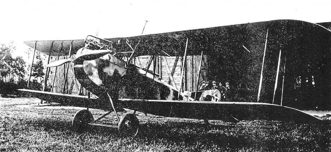
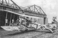
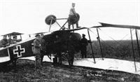
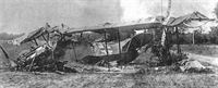
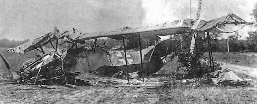
THIS machine was brought down by an R.E.8 of 21st Squadron, near Hinges, on May 16th, 1918. It bears the date February 3rd, 1918, stamped on the main planes, and also on portions of the fuselage, and is the first of its type to have been secured.
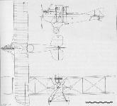
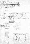
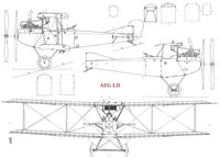
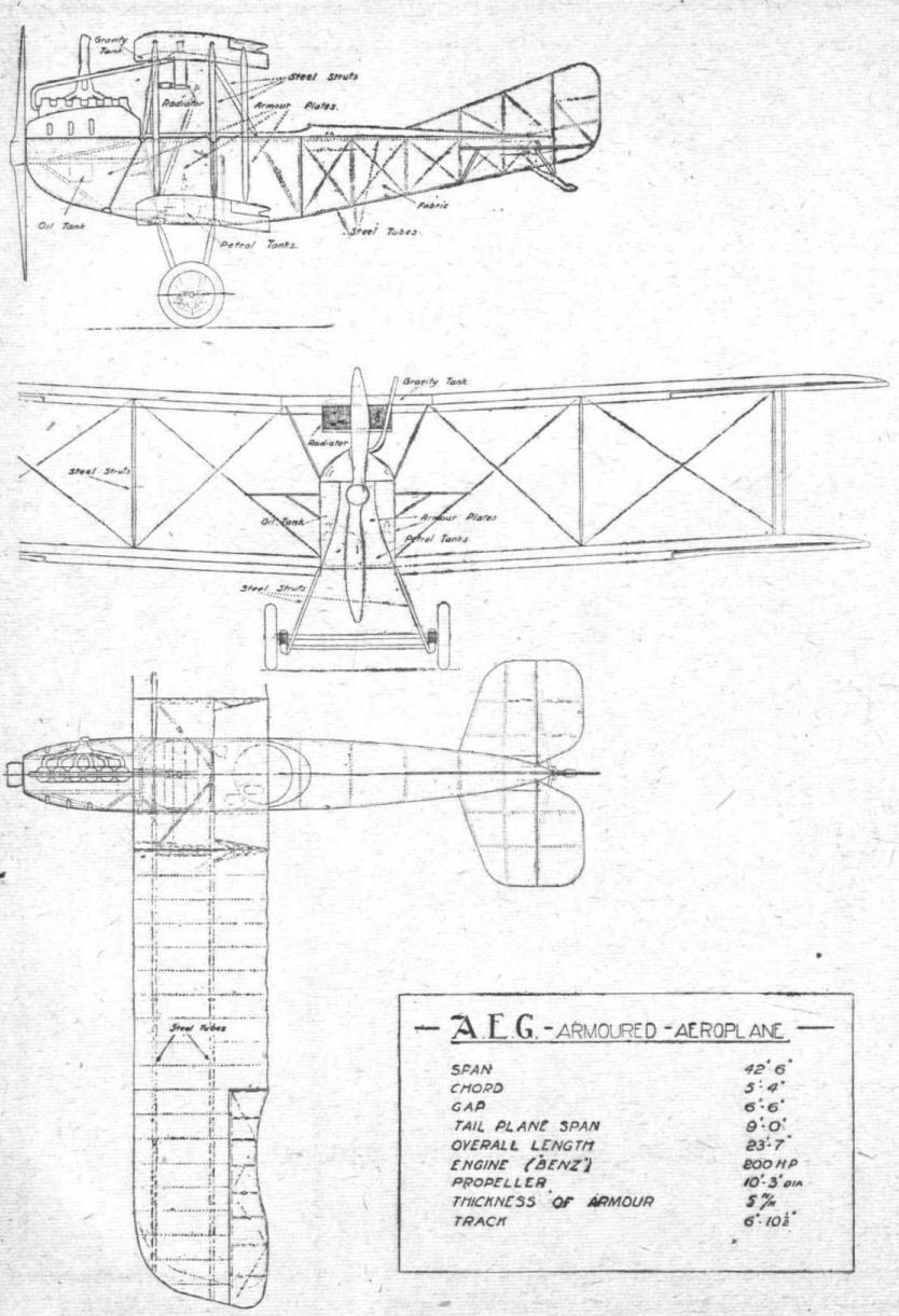
This aeroplane is designed for the purpose of carrying out offensive patrols against infantry, and is furnished with armour, which affords protection for its personnel. This armour appears, however, to be more or less experimental. In general construction it closely follows the lines of the A.E.G. twin-engined bomber G. 105, reported on in I.C. 607, though the arrangement of the power plant is, of course, entirely different. A steel tubular construction is used practically throughout. The machine was badly crashed, and some details are, therefore, not available ; but the general arrangement drawings at the end of this report may be regarded as substantially accurate.
The leading particulars of the machine are as follows :- Area of upper wings, 190.4 sq. ft.; area of lower wings, 168 sq. ft.; total area of wings, 358.4 sq. ft.; area of upper aileron, 11.2 sq. ft. ; area of lower aileron, 10 sq. ft.; area of tail plane, 9.4 sq. ft.; area of fin, 7.6 sq. ft.; area of rudder, 6 sq. ft.; horizontal area of body, 48. 6 sq. ft.; side area of body, 54.8 sq. ft.; cross sectional area of body, 14.4 sq. ft.; area of side armour, 33 sq. ft.; area of bottom armour, 29.4 sq. ft.; area of armour bulkhead, 10.4 sq. ft.
Engine, 200 h.p. "Benz." Crew - pilot and gunner, 360 lbs.; armament - three guns; petrol capacity, 38 galls.; oil capacity, 3 galls. The principal dimensions are shown on the general arrangements drawings.
Wings.
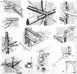
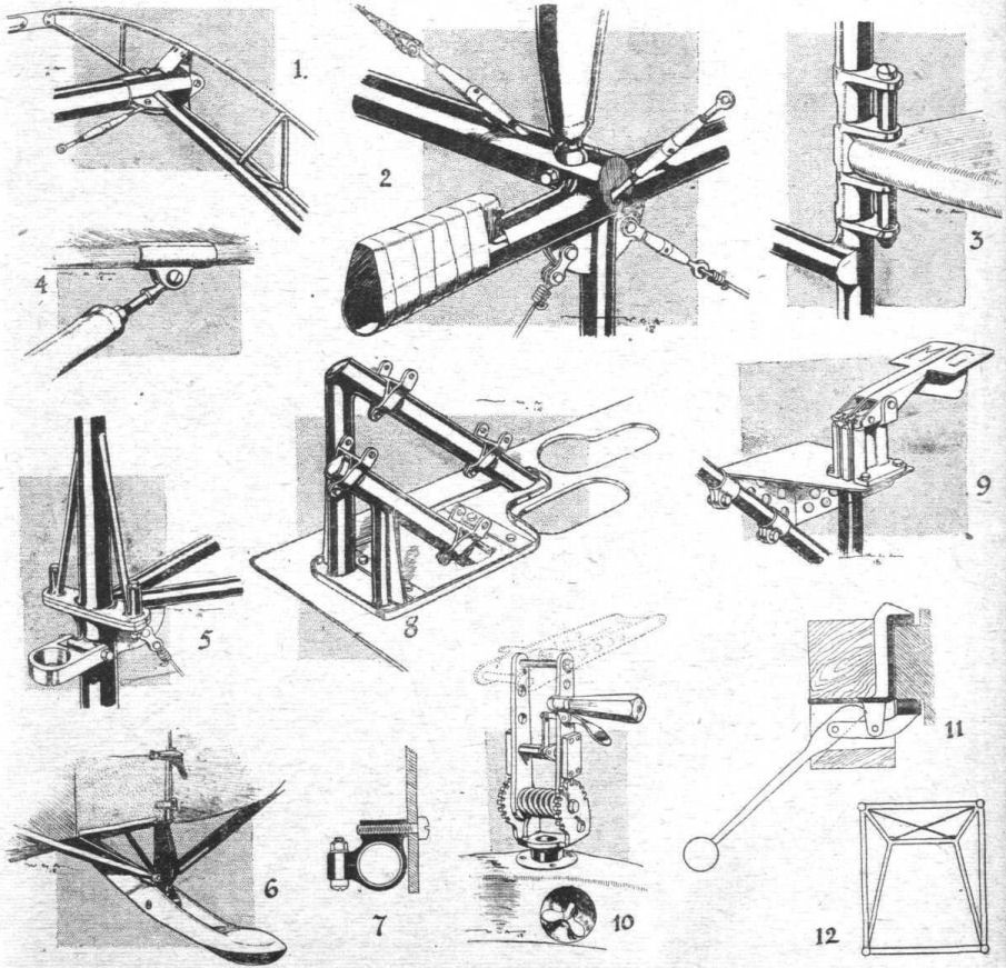
The manner in which the wings are constructed is exactly as shown in the report of the A.E.G. bomber - i.e., the spars consist of two steel tubes 40 mm. in diameter by .75 mm. thick. At their ends the upper and lower surfaces of the spars are chamfered away, and flat plates welded in position, so as to provide a taper within the washed-out portion of the wing tips. The wings were, unfortunately, so badly damaged that no accurate drawing of their section can be taken, but there is evidence that this very closely follows the section of the bomber, which has already been published. The ribs are of wood, and between each main rib is placed a half-rib joining the front spar to the semicircular section wooden strip which forms the leading edge. The wing construction is strengthened by two light steel tubes passing through the ribs close behind and parallel to the leading spar, which are used for housing the aileron control wires. The bracing against drag consists of wires and transverse steel tubes welded in position. At the inner end of the wings special reinforced ribs of light gauge steel tube are provided. The method of construction at this point is clearly shown in Fig. 1, which also indicates the manner in which the bracing tube is welded to a socket driven on the main spar. The spars are attached to the fuselage by plain pin joints.
Centre Section.
The centre section of the upper surface is constructed in a similar manner to that of the wings, except that it is considerably reinforced, and the spars are larger in diameter. The leading spar has a diameter of 51 mm. and the rear spar 45 mm. The centre section is secured to the fuselage by a system of stream-lined steel struts, the feet of which terminate in ball-ends dropped into sockets, and there bolted in position. One of these struts is shown in Fig. 2. The centre section contains an auxiliary gravity petrol tank, and also the radiator, and is, therefore, substantially braced with steel tube transverse members. The wings are set with a dihedral angle of approximately 6 deg.
Ailerons.
The aileron framework is of light steel tube throughout, the tube forming the trailing edge being flattened into an elliptical section. The ribs are fixed by welding. The framework of the ailerons on the upper wing is reinforced by diagonal bracing of light tube.
Struts.
These are of light steel tube stream-line in section, tapered at each end, and terminating in a socket which abuts against a ball-headed pedestal carried on the wing spars; through the socket and the ball is passed a small bolt. The manner in which this attachment is carried out is exactly similar to that described in I.C. 607.
Fuselage.
The whole of the fuselage is built up of steel tubes welded together, and having affixed at their junctions sheet steel lugs, which serve as the anchorage for the bracing wires. The diameter of the longerons and of the frame verticals is 20 mm., except the last three members adjacent to the tail, of which the diameter is 16 mm. The welding throughout the fuselage appears to be of very high quality. In Fig. 2 is illustrated a joint, which occurs in the fuselage immediately in front of the pilot's cockpit. The longeron is, from this point to the rear of the gunner's cockpit, fitted with a wooden strip taped in position. This joint shows the method in which the cross bracing wires are furnished with an anchorage. In one or two points in the frame construction the bracing wire lies in the same plane as the transverse tube, and to allow for this a diagonal hole is drilled through the tube and filled in with a small steel tube welded in place.
Engine Mounting.
This consists of a triangulated arrangement of steel tubes carrying hollow rectangular section steel bearers, on which the crank chamber is slung. The bearers are well trussed both in the vertical and horizontal planes, and are shown in dotted lines in the general arrangement drawings. The engine bearers themselves are 2 mm. in thickness, and have an approximate section of 2 1/16 ins. by 1 1/2 ins.
Tail.
The empennage possesses no particular points of interest, the planes having the usual steel tubular framework. The tail plane is not fitted with any trimming gear, but a method of adjustment is provided. This is shown in Fig. 3, which is self-explanatory. The diagonal struts which proceed from the base of the fuselage to the tail plane spar are fitted at each end with a method of adjustment shown in Fig. 4, allowing them to be extended as required according to the particular socket which is used to carry the leading edge of the tail plane. Neither the elevators nor the rudder are balanced. The rudder post is mounted on the end of the fuselage, as shown in Fig. 5, in which it will be seen that the vertical frame tube of the fin is very stoutly attached to the frame by a triangulated foot.
Landing Gear.
This is of the usual A.E.G. type, and is furnished with shock absorbers consisting of metal coil springs in direct tension, as is clearly shown in the general arrangement drawing.
The landing carriage axle has a diameter of 55 mm. The landing carriage struts, which are of similar section to those used between the planes, measure 70 mm. by 37 mm. At their upper ends they are furnished with ball and socket attachments similar to those of the interplane struts.
The wheels are fitted with 810 by 125 mm. tyres, and the track is 6 ft. 10 1/2 in.
The tail skid is unusually heavy, and it is a built-up construction of welded sheet steel. It is mounted on a stout tail post, which is reinforced by four stream-line steel diagonals. The forward end of the tail skid projects inside the fuselage and is there provided with four steel springs in direct tension. A sketch of the tail skid is given in Fig. 6.
Control.
This consists of the usual double-handled lever mounted on a transverse rocking shaft, which carries the elevator control cranks at each end. The upper ailerons are worked positively by wires which pass over pulleys on the wing spars at the outer struts, the outer and lower ailerons being connected by a stream-line steel tubular strut.
Engine.
The 200 h.p. Benz engine possesses no new features, and has already been made the subject of an exhaustive report.
Petrol System.
Underneath the pilot's seat are the two main petrol tanks, each of which contains 80 litres (equal to 16 gallons). These tanks are of brass, and are fitted with Maximall level indicators. The gravity tank, containing 27 litres (equals 5 1/2 gallons) is embedded in the centre section of the upper plane, where it forms the leading edge on the left-hand side. This tank is made of lead-covered steel. Cocks are provided, so that either the gravity tank or the pressure tanks, separately or together, can feed the carburettor.
It is of interest to note that the chamber which is used in connection with the Benz petrol supply system is not, as is usually the case, contained in the main tank, but is a separate fitting mounted on the side of the engine.
Radiator.
The radiator is of the Daimler-Mercedes type, measuring 32 1/2 ins. long by 11 1/2 ins. high and 6 ins. deep. This is fitted with imitation honeycomb tubes, of which there are 118 running vertically, each being fitted with 48 gills. The radiator is carried in a steel cradle, into which it is easily inserted from above, and this in turn is supported on specially built-up steel ribs. It is placed so that the tank which forms the upper part of the radiator lies about flush with the centre section of the top plane. The shutter or flap for controlling the water temperature is made of 3-ply wood stiffened with a light steel framework, and is mounted immediately behind the radiator, being worked by a handle within reach of the pilot. This handle is provided with a rack and pawl device. The shutter is 3 3/4 ins. deep, and is capable, therefore, of covering up about one-third of the total radiator surface. It will be noted that the position of the shutter behind the radiator is unusual.
Armour.
Protection for the pilot and gunner is afforded by armour, which, is shown in the general arrangement drawing in thick lines. There are three panels at each side, and three panels at the bottom of the fuselage, an armour bulkhead being placed at the rear of the gunner's cockpit to protect him from behind. The armour is 5.1 mm. thick, and its total area is 105.8 sq. ft. The weight of the armour is thus approximately 860 lbs. Careful tests have been made to ascertain the effectiveness of this armour, and the following table gives the ranges at which these plates are safe or unsafe against penetration by bullets of various types. These figures may be taken as correct within the limit of a practical firing test.
Angle to Normal Safe range Unsafe range
Ammunition. degrees. yards. yards.
German A.P. 0 - 600
15 500 400
30 400 300
Mark VII. 0 probably 700 600
Armour 15 400 300
piercing 30 300 200
German Spitze 0 150 100
15 100 50
30 50
Mark VII. 0 50
15 50
30 50
The armour is undoubtedly too light to afford protection against British armour-piercing bullets fired from the ground at a lower height than 500 ft., while a machine armoured with it would have to fly at, at least, 1,000 ft. to be safe from all but a very low percentage of hits.
The armour does not appear to have been employed, as it might well have been, in a structural capacity - i.e., it is simply an attachment to the framework, to which it adds no material strength. Its appearance seems to point to the fact that it had been added by way of experiment, and that it was of a more or less makeshift character. It had, for instance, evidently been necessary to open out existing holes and cut new holes in the course of erection. The armour is attached by set screws to clips clamped on the fuselage members, as shown in Fig. 7.
Armament.
In this machine the pilot is not provided with a gun, but the observer has to control three, of which two (Spandau) are fixed on the flooring of his cockpit, whilst the other (Parabellum) is carried on a rotatable mounting.
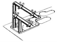
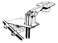
With regard to the fixed guns, these are secured to a couple of tubular steel brackets, mounted as shown in Fig. 8. The oval-section steel tubes, of which these brackets are composed, are welded to a light steel base, which forms a sort of tray, and is in turn bolted to the panel of armour which forms the floor of the cockpit.
Adjacent to these two guns, which fire forward at an angle of 45 deg., is a bracket carrying the belts of ammunition, which are fed from a large rotating drum.
In the right-hand front corner of the pilot's cockpit floor is a circular hole, which he would appear to use for sight purposes. The fixed guns are controlled by Bowden wires and triggers mounted on a diagonal frame member, convenient to the gunner's right hand, as shown in Fig. 9. The movable gun is of the Parabellum type, and the mounting is of the usual built-up wood variety. The gun cradle is, however, novel, the fixture for this purpose being illustrated in Fig. 10. It appears to be rather more handy than the usual German device, but is by no means lacking in weight. This fitting was in a very badly smashed condition. The vertical carrier is swivelled at its base, and is secured in position by sliding bolts engaging with teeth cut in the turned-up base plate. These sliding bolts are worked by a direct acting thumb lever. The turn-table is made of a single hoop of wood reinforced at the point where the gun is mounted by glued-on strips of ply-wood. A locking device of the type shown in Fig. 11 is fitted.
The transverse bracing in the immediate rear of the gunner's cockpit, at which point is mounted the armour bulkhead, suggests that it was the original intention for this aeroplane to carry a gun or guns firing downwards and backwards through a hole in the fuselage. The transverse arrangement of steel tubes and bracing wires is shown in Fig. 12.
Wireless and Heating.
The machine is fitted with the usual wireless leads and apparatus for heating, the dynamo being carried on a bracket attached to the fuselage immediately in front of the pilot's seat, where it is directly driven from the engine through a hand-controlled clutch. No wireless fittings, other than the dynamo and the leads, were found on the machine.
Instruments.
The instruments fitted to this machine are of standard type, and possess no new features of interest.
Fabric and Dope.
The fabric throughout is of good quality, but the dope appears to have been badly applied, as in many points it had completely peeled off the fabric.
Camouflage.
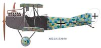
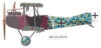
The colours used are dark purple and dark green, and in contradistinction to the usual method by which they are arranged in well-defined polygons, are applied so as to give a cloudy effect, and appear to have been sprayed on.
Steel Analysis.
A sample of the wing spar yields the following analysis :-
Carbon .098 per cent. Phosphor .014 per cent.
Silicon .011 per cent. Manganese .461 per cent.
Sulphur .017 per cent. Chromium .036 per cent.
Показать полностью