
Книги
Putnam
J.Stroud
European Transport Aircraft since 1910
60
J.Stroud - European Transport Aircraft since 1910 /Putnam/
A.E.G. J II
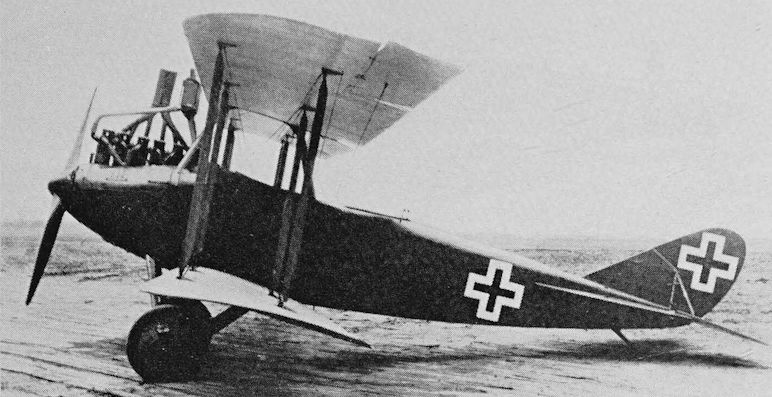
In 1917 the German Air Force began using the A.E.G. J I, which was an armoured version of the earlier A.E.G. CIV. The A.E.G. J I was a two-seat two-bay strut and wire-braced biplane with slightly greater span on the upper wing. The engine was a 200 hp Benz BzIV. Like the C IV, the J I was mainly of metal construction with steel-tube spars and welded steel-tube fuselage structure. The wing ribs were of wood, and the whole aircraft was fabric-covered. The radiator was beneath the upper centre section, and the exhaust was carried clear of the upper wing by the typical German horn-type stack.
In 1918 the J Il appeared. This was almost the same as the J I, but had horn-balanced ailerons on the upper wing, horn-balanced rudder and elevators, and a revised fin of greater area. Total production of J I, J Il and the intermediate J Ia is reported to have been 609.
When Deutsche Luft-Reederei, which was in fact founded by A.E.G., began operating German domestic services in February 1919 a number of A.E.G. J IIs were used, and the type appears to have formed the major part of the fleet. Initially these aircraft were all operated simply with the military equipment removed and a two-seat open cockpit replacing the former gunner’s position. One of these J IIs bore the DLR number 13 and was used on the first Berlin-Weimar services; others were D-61, and DLR 97 (c/n 310) which later became D-479.
A number of A.E.G. J Ils were modified in DLR’s workshops to have enclosed cabins for two passengers. When so modified the aircraft were generally known by the designation A.E.G. K, and for long the appearance on the register of aircraft with this designation has been something of a mystery. It is now known that the K stood for Kabine and that the designation did not specifically refer to a modified A.E.G. J II, although most of the K aircraft were.
DLR 36 (c/n 419), D-9 and D-74 (c/n 439) were definitely cabin versions of the J II, and D-14, D-24, D-66 and D-68 (c/n 417) are almost certain to have been the same. D-9’s cabin was of different design to the others, and the aircraft was generally cleaned-up. Both versions are illustrated.
All these aircraft were operated by DLR, some passed to Deutscher Aero Lloyd and four went to Deutsche Lufthansa in 1926. These were D-14 (c/n 5053), D-24, D-68 Kreuzotter (Viper) and D-74. D-68 had been built in Berlin in 1918 and was still in Lufthansa’s fleet as a cargo aircraft in 1930.
Most of these civil A.E.G.s retained their 200 hp Benz Bz IV engines; but D-9 was fitted with a BMW IV, and at some stage D-68 and D-74 were re-engined with 240 hp Armstrong Siddeley Pumas.
<...>
A.E.G. J I. Span 13:46 m (44 ft 2 in); length 7:9 m (25 ft 11 in); wing area 33:18 sq m (357-14 sq ft). Empty weight 1,100 kg (2,425 Ib); loaded weight 1,620 kg (3,571 Ib). Maximum speed 150 km/h (93:2 mph); ceiling about 4,500 m (14,763 ft); endurance 4 hr.
These figures are for the Benz-powered version. With Puma engine the empty weight was 1,380 kg (3,042 lb), the loaded weight 1,870 kg (4,122 lb) and range 600 km (372 miles).
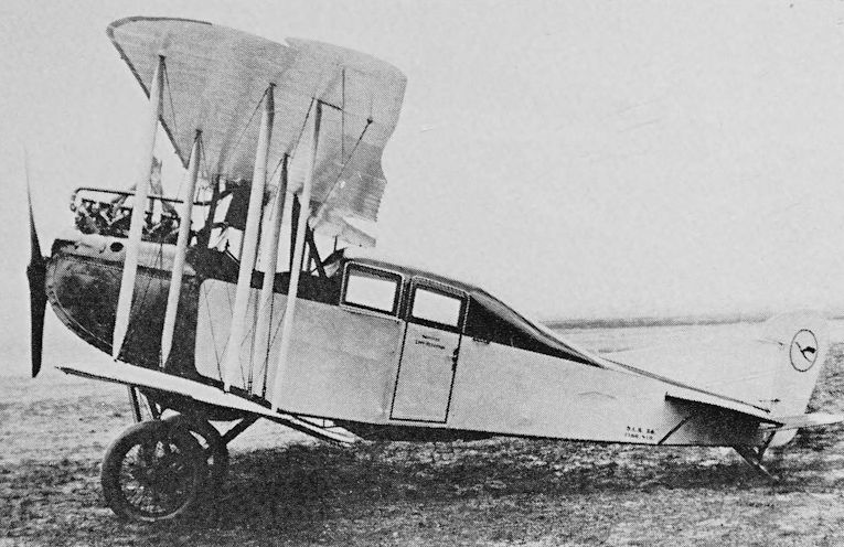
A cabin version of the A.E.G. J II. This example had a 200 hp Benz Bz IV engine and bore the DLR fleet number 36.
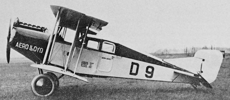
A much modified cabin version of the A.E.G. J II. Seen in Deutscher Aero Lloyd black and silver livery, D-9 had a BMW IV engine.
A.E.G. J II
<...>
One of the A.E.G. Ks was definitely not a modified J II. This was D-38 (DLR 74 and c/n 6748), which was used by DLR on Frankfurt-Berlin services in 1920 and passed to Lufthansa in 1926. This aircraft was a Benz-powered A.E.G. N I, of which only one is known.
A.E.G. N I. Span 15-3 m (50 ft 2 1/2 in); length 7:3 m (23 ft 11 1/3 in). Empty weight 880 kg (1,940 Ib); loaded weight 1,400 kg (3,086 Ib). Maximum speed 143 km/h (88-8 mph); service ceiling 3,500 m (11,482 ft)
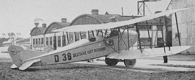
Deutsche Luft-Reederei’s A.E.G. N I which was used on Frankfurt-Berlin services in 1920
GERMANY
A.E.G. G.V
The G V was the last of a range of twin-engine bombers designed and built by the Allgemeinen Elektrizitats-Gesellschaft. It appeared in May 1918, too late to go into operational service, but some were used by Deutsche Luft-Reederei when it began operating regular services early in 1919.
The G V was a large three-bay biplane powered by two 260 hp Mercedes D.IVa six-cylinder inline water-cooled engines driving two-blade wooden airscrews. The wings were of equal span except for the overhanging ailerons on the upper wing. The tail unit comprised a main tailplane with horn-balanced elevators, twin fins and rudders, and an upper tailplane mounted on top of the fins and below the rudder horns. The main undercarriage consisted of two separate twin-wheel units. The main structure was of welded steel-tubing with fabric covering.
There was an open cockpit for two crew and a large open cockpit for six passengers.
This type entered service in standard camouflage and with military markings. The letters DLR were painted in white on the fuselage together with the German flag and post horn. No registrations are known, but the G Vs probably carried DLR fleet numbers.
A.E.G. produced a cabin version of the G V, and some of these entered service with Deutsche Luft-Reederei. The aircraft had six passenger seats on two levels, and aft of the cabin was a lavatory. There was a baggage hold in the extreme nose. The crew position was partially enclosed.
A DLR G V made a flight from Berlin to Eskjo in South Sweden early in 1919, with Paul Schwandt as pilot, and one of the same type was used for a Berlin-Vienna flight at about the same time. An open cockpit G V carried eight people to a height of 6,100 m (20,013 ft) on 30 July, 1919.
Span 27:3 m (89 ft 6 in); length 10-8 m (35 ft 5 in). Empty weight 2,800 kg (6,173 Ib); loaded weight 4,600 kg (10,141 Ib). Speed 145 km/h (90 mph); endurance 5-6 hr.
D.F.W. C.V
The D.F.W. C V was a reconnaissance and artillery co-operation two-seat biplane which entered service with the German Air Force late in 1916 and remained in service until the end of the war. It was a two-bay biplane of nearly equal span built of wood with fabric-covered wings and tail surfaces and ply-covered fuselage. The upper wing was mounted on a trestle-like structure which contained a small fuel tank. The tips of the upper wing were raked out towards the trailing edge, and the lower wing had rounded tips. The fuselage was of attractive appearance, and the braced tailplane and balanced elevators were heart-shaped. The pilot’s cockpit was beneath the centre section and the observer’s was aft of the wings.
The standard engine was the 220 hp Benz Bz IV six-cylinder inline watercooled unit which was neatly cowled and drove a two-blade wooden airscrew. The radiators were carried on each side of the fuselage.
A large number of D.F.W. C Vs were produced by Deutsche Flugzeug Werke GmbH (D.F.W.) of Leipzig, and the type was also built by Automobil und Aviatik AG, Halberstadter Flugzeug GmbH and Luft-Verkehrs GmbH (L.V.G.).
After the war some D.F.W. C Vs were used for mail and passenger carriage, and the type is known to have been used by Bayerische Luft-Lloyd on Munich - Constance (Konstanz) services in 1921. Two may have been D-87 and D-88, but this cannot be confirmed.
Span 13:27 m (43 ft 6 1/2 in); length 7:87 m (25 ft 10 in); wing area 42:5 sq m (457-46 sq ft). Empty weight 970 kg (2,138 lb); loaded weight 1,430 kg (3,152 Ib). Maximum speed 155 km/h (96:3 mph); ceiling 5,000 m (16,404 ft); endurance 3 1/2 hr.
Data for military aircraft.
A D.F.W. C V mail carrier still in military markings.
D.F.W. P 1
In 1919 Deutsche Flugzeug Werke produced the P 1 four-seat commercial biplane, which was referred to at the time as the Limousine and reported as a civil conversion of the C V two-seat military biplane.
In fact, the P 1 bore no resemblance to the C V, but was a development of the D.F.W. F 37 which was built in 1918 and may have been the C VII.
Only one P 1, D-187, is known, and there are reports that it was used on German domestic services.
In layout the P 1 was quite like the German wartime two-seat open biplanes, but it had a widened fuselage and an enclosed cabin, the design of which appeared to owe much to the horse-cab.
The aircraft was a two-bay strut and wire-braced biplane powered by a 200/220 hp Benz Bz IV six-cylinder inline water-cooled engine. Under the centre section was an open cockpit with two side-by-side seats, and immediately aft of the cockpit was the cabin with two slightly staggered side-by-side seats. This cabin had an unglazed roof and three windows on each side. The interior was padded, there was electric light and some rather frilly curtains. The large forward-opening carriage-type door was on the port side.
The P 1 was exhibited at ELTA in Amsterdam in August 1919.
Span 13-6 m (44 ft 7 1/4 in); length (tail up) 7-3 m (23 ft 11 1/2 in). Empty weight 970 kg (2,138 lb); fuel and oil 220 kg (485 Ib); loaded weight 1,470 kg (3,240 Ib). Speed 150 km/h (93-2 mph); absolute ceiling 5,500 m (18,044 ft); endurance 4 h
NETHERLANDS
Fokker F.II
During the 1914-18 war Anthony Fokker and his team designed and built a large number of military aircraft for the German forces, two of the best known being the D.VII fighter biplane and the Dr.I triplane. The last of the fighters was the D. VIII parasol monoplane.
When the war ended Fokker Flugzeug-Werke GmbH, at Schwerin, turned its attention to the design and production of commercial transport aircraft. Reinhold Platz was responsible for design, his first being the V.44 (F.I) six-passenger monoplane with open cockpits. The V.44 was rather like an enlarged D.VIII and was intended to have a 185 hp BMW IIIa engine. The wing was finished, but before the aircraft had been completed it was decided to abandon the design and produce instead a fully enclosed cabin aircraft. This was the V.45, which became the F.II and precursor of a long line of successful Fokker transports.
The V.45 flew for the first time in October 1919. After certification it was registered D-57 and, on 20 March, 1920, flown to the Netherlands by Bernard de Waal.
D-57 had the c/n 1500 and was acquired by KLM Royal Dutch Airlines as H-NABC. Two more F.IIs were then built by Fokker, they were c/n 1501, some time D-757, which went to Deutsche Luft-Reederei, and a second KLM aircraft, H-NABD (c/n 1502). These aircraft have also been reported as having c/ns 4057, 1571 and 4058 respectively.
The F.II was a high-wing monoplane with fabric-covered welded steel-tube fuselage and thick-section all-wood wing with ply covering, and this type of structure was used in all the pre-war Fokker transports. The wings were built in one piece and bolted to the top of the fuselages. On later types the ailerons were sawn out after the wing structure had been completed.
The wing of the F.II tapered slightly in chord and sharply in thickness. The tips were almost square, and the balanced ailerons projected aft of the trailing edge as well as overhanging the tips. Fuel was carried in the centre section.
The fuselage was of rectangular section, had hardly any taper in side elevation and ended in a vertical knife edge. The cabin for four passengers was beneath the wing, had three windows each side and a door in the port side. A fifth passenger could be carried beside the pilot in the open cockpit, which was immediately forward of the cabin.
The tailplane was strut-braced and the elevators balanced. There was no fin, and the rudder projected only slightly above the top line of the fuselage. A steel-tube strut on each side ran from the wing, close to the fuselage, to the lower longeron, and inverted V struts ran from the same wing attachment points to positions fore and aft of the cockpit. The undercarriage comprised four tubular struts on each side and a rubber-cord sprung cross-axle. Double-wheels with common hubs were used.
The original engine was a 185 hp BMW IIIa six-cylinder water-cooled inline unit, but D-757 had a BMW IV at one period, and one of the KLM aircraft is reported to have had a 240 hp Armstrong Siddeley Puma. With BMW engine the F.II sold for 26,000 fl, and with the Puma the cost was 30,000 fl.
The KLM F IIs entered service in September 1920. H-NABD flew to Croydon on 30 September that year and gave demonstrations there and, later, at Cricklewood. H-NABC and H-NABD were sold to Sabena in 1927 as O-BAIC and O-BAIB respectively, and were used between Brussels and Antwerp. Later they were re-registered OO-AIC and OO-AIB, and in 1933 the former returned to the Netherlands, where it served with the Rijksstudiedienst voor de Luchtvaart as PH-RSL and survived until the 1939-45 war. In KLM service H-NABC flew 962 hr and H-NABD 665 hr.
D-757 served DLR and Deutscher Aero Lloyd before passing to Deutsche Lufthansa in 1926. It was written off in September 1929. OO-AIB was sold by Sabena to a Belgian private owner in 1934, and its registration was cancelled in May 1936.
It is thought that a further small number of F.IIs were built at Schwerin or partly built there and completed by Deutsche Luft-Reederei, because the origins of three Danzig-registered aircraft, Dz 3, Dz 4 and Dz 5, are unknown. Dz3 (c/n 1503) later became DLR’s D-175 and passed to Lufthansa before being sold to Balair as CH 151. Dz 4 was chartered by DDL Danish Air Lines in 1924 and used on the Copenhagen - Hamburg route.
During 1925 and 1926 at least 19 F.IIs were built in Germany as Fokker-Grulich F.lls. These aircraft were of a considerably modified design, having improved cockpits, redesigned cabin windows, improved undercarriages and increased weights. They were originally powered by 250 hp BMW IV engines, but at least 14 were re-engined with 320 hb BMW Va engines and given the designation F.IIb. The wings of these F.IIs were built by Albatros, and fuselage construction and assembly was undertaken at Staaken by Deutscher Aero Lloyd. Dr Ing Karl Grulich was technical manager of the airline and responsible for the modifications.
Deutsche Lufthansa took over 19 F.IIs in 1926, named them after German rivers, and used them on numerous routes. In the summer of 1928 they were working passenger services over 13 routes, and in 1934 10 were in service over the Diisseldorf - Krefeld, Cologne - Aachen, Cologne - Essen/Milheim and Cologne - Krefeld routes. Four remained in Lufthansa’s fleet throughout 1935, but do not appear to have been in regular service. One was still on strength at 31 December, 1936. Lufthansa’s D-767 Ruhr is known to have been used at some time for crop dusting.
Another F.II, D-423 (c/n 1596), was used by DVS.
Span 16:1 m (52 ft 10 in); length 11-65 m (38 ft 2 3/4 in); wing area 42 sq m (452 sq ft). Empty weight 1,200 kg (2,645 lb); payload up to 400 kg (881 Ib); loaded weight 1,900 kg (4,188 lb). Maximum speed 150 km/h (93-2 mph); cruising speed at sea level 120 km/h (74:5 mph); landing speed 70 km/h (43-4 mph); range 1,200 km (745 miles).
Data for Fokker-built aircraft.
Most of the Fokker-Grulich F.lls were quoted as weighing 1,650 kg (3,637 Ib) empty and 2,300 kg (5,070 Ib) loaded, but a photograph of one shows the following figures painted on the fuselage: Empty weight 1,392 kg (3,068 Ib). Pilot and fuel 395 kg (870 Ib). Payload 400 kg (881 Ib). Loaded weight 2,187 kg (4,821 Ib).
Range of the BMW Va powered Fokker-Grulich F.IIb was stated to be 600 km (372 miles).
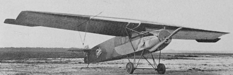
The Fokker V.45 with 185 hp BMW IIIa engine. This became the F.II.
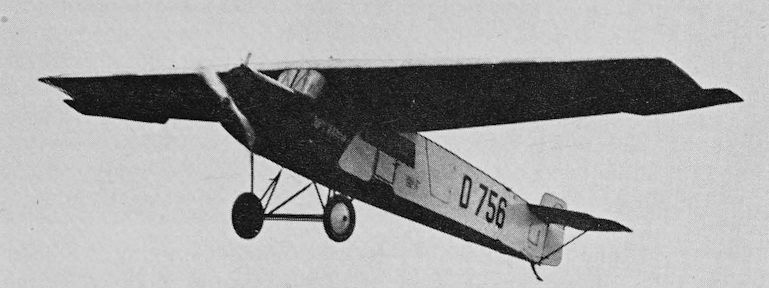
Deutsche Lufthansa’s Fokker-Grulich F.II D-756 Dievenow with BMW IV engine.
Friedrichshafen G IIIa
During 1917 Flugzeugbau Friedrichshafen GmbH produced its type FF 45 twin-engine bomber, which went into squadron service as the G III. This type and the Gotha G V formed the main equipment of German bomber squadrons until the end of the war.
The G III was a large biplane with straight centre section and sweptback outer wings. The two 260 hp Mercedes D.IVa six-cylinder inline water-cooled engines were mounted between the wings, had frontal radiators and drove two-blade pusher propellers. The tailplane, fin and balanced elevators and rudder were of generous proportions. The undercarriage comprised two twin-wheel main units with stone-guards to protect the propellers, a tailskid, and a front wheel to prevent nosing over. The pilot’s cockpit was under the leading edge and there were open cockpits in the nose and amidship.
The fuselage was a wooden structure with ply covering forward and fabric covering aft of the wing. The wings were of mixed construction, with ply covering on the inboard ends of the upper surface of the lower wing and fabric elsewhere.
In 1918 a modified version was produced. This was the G IIIa with modified wing tips and biplane tail with twin fins and rudders.
The total number of G IIIs and G IIIas is not known, but 93 aircraft were built by Hanseatische Flugzeug-Werke and 245 by Daimler Motoren-Gesellschaft.
After the war at least one G IIIa was converted for passenger carrying. This had a cabin over the trailing edge - in line with the propellers. The only known example was D-121 (c/n 1037), which was used by Deutsche Luft-Reederei and bore DLR number 503. This aircraft was also at some time used by Lloyd-Luftverkehr Sablatnig. No details are known, but it probably had accommodation for about six passengers.
Span 23-7 m (77 ft 9 in); length 12:8 m (42 ft); wing area 95 sq m (1,022:5 sq ft). Empty weight 2,695 kg (5,941 lb); loaded weight 3,930 kg (8,664 Ib). Maximum speed 135 km/h (83-8 mph); ceiling 4,500 m (14,763 ft); endurance 5 hr.
Data for military G III
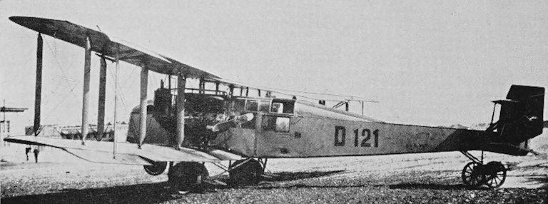
The Friedrichshafen G IIIa D-121 of Deutsche Luft-Reederei.
Friedrichshafen FF 49
In May 1917 Friedrichshafen brought out its FF 49c single-engine two-seat twin-float reconnaissance biplane. The FF 49c was a three-bay strut and wire-braced biplane of almost equal span and with marked sweepback and dihedral. The structure was of wood with fabric covering. The FF 49c was extremely successful in service with the German Navy, and on many occasions demonstrated its excellent seaworthiness. It has been reported that about 235 were built by Friedrichshafen, Luft-Fahrzeug GmbH (L.F.G.), and Sablatnig. There were also 25 examples of the FF 49b bomber version with aft-positioned pilot’s cockpit and modified rudder.
After the war a number of FF 49s were used for transport duties. These had the forward pilot’s cockpit of the FF 49c but the same rudder as the FF 49b.
DDL - Det Danske Luftfartselskab began its operations with an FF 49 when it opened a Copenhagen - Warnemunde service on 7 August, 1920. Powered by a 220 hp Benz Bz IV engine and registered T-DABA, this aircraft had accommodation for two crew and two passengers in four open cockpits.
In Germany Deutsche Luft-Reederei, Lloyd-Luftverkehr Sablatnig, Luftdienst GmbH and L.F.G. all used FF 49s.
There were two cabin versions of the FF 49 built by L.F.G. They were the V 1 with a short raised cabin for three passengers and the V 11 which had a longer superstructure containing two cabins for up to five passengers. Both types had an open cockpit for the pilot forward of the passenger accommodation. Known examples were the V 1s Max and Moritz and the V 11s D-134 (possibly named Nolte) and D-242 Fromme Helene. These aircraft were used on L.F.G.’s Stralsund - Rugen resort services in July and August 1919, and it is known that 236 passengers were carried in just over a month. Max and Moritz did not carry civil registrations, but all four had the German postal flag painted on their fuselages.
Deutsche Luft-Reederei is known to have had D-49 (c/n 1365) and D-146 (c/n 1364). D-49 was an open cockpit aircraft and, in the service of Luftdienst, was used for early experiments with the Schleppsegel (trailing curtain or flexible ramp) system of seaplane recovery by ships. The Norddeutscher Lloyd Lutzow was used for these trials, which paved the way for the South Atlantic Dornier Wal operations.
Sablatnig’s FF 49s included D-85 (c/n 1368), D-86 (c/n 223) and D-114. The last of these is known to have been a cabin version.
The standard engine in the FF 49s was the 220 hp Benz Bz IV, but the L.F.G. V 11 was reported as having the 260 hp Mercedes D.IVa; some aircraft were subsequently re-engined, D-49 having the Junkers-L 2 and D-85 the Junkers-L 5.
Span 17 m (55 ft 9 1/4 in); length 11-65 m (38 ft 2 1/2 in); wing area 71:16 sq m (765:9 sq ft). Empty weight 1,485 kg (3,273 lb); loaded weight about 2,140 kg (4,717 Ib). Cruising speed about 135 km/h (83:8 mph); endurance up to 6 hr.
There was considerable variation in weights and performance and the figures quoted must be regarded as only representative.
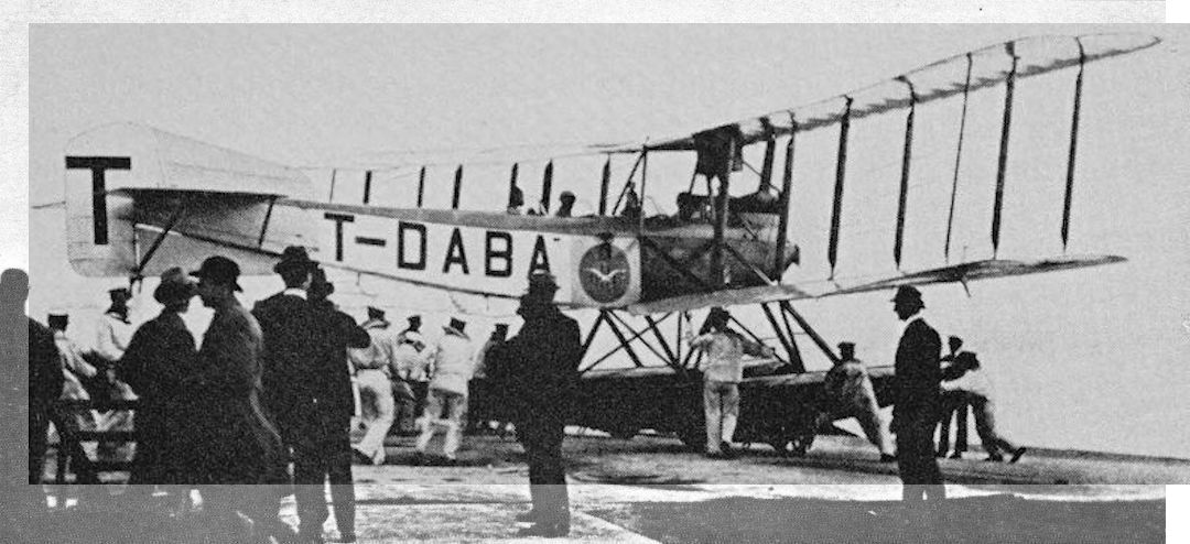
T-DABA was the Friedrichshafen FF 49C with which DDL began operation on 7 August, 1920, over the Copenhagen - Warnemunde route. This photograph is believed to be of the inaugural departure from Copenhagen.
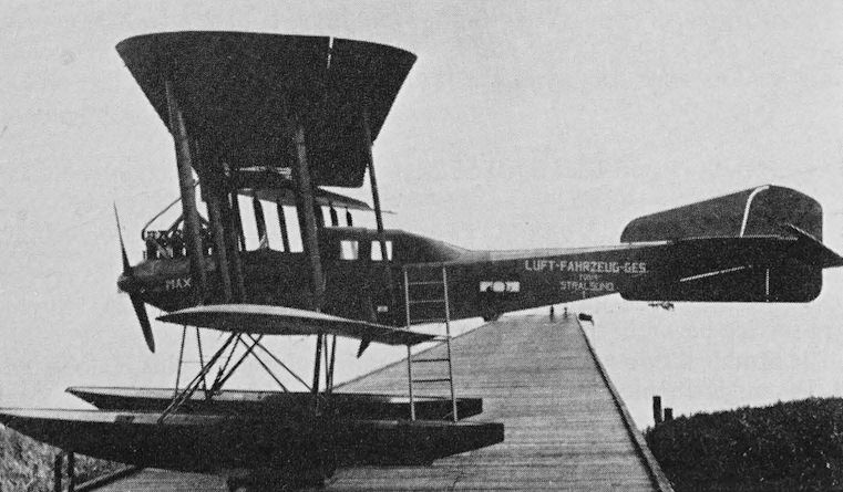
The L.F.G. V 1 cabin version of the Friedrichshafen FF 49. Max, illustrated, was one of those operated by Luft-Fahrzeug GmbH. The V 11 version had a longer cabin extending well back towards the fin.
Halberstadt CL IV
In December 1920 Paul Strahle, trading as Luftverkehr P. Strahle, began operating a regular service between Stuttgart and Constance. This service was suspended in the autumn of 1921, but a short-lived Stuttgart-Nuremberg service began in the spring of 1922.
The Strahle services were flown by a number of war-surplus Halberstadt CLIV single-engine biplanes, of which two are known to have been D-144 (c/n 4205) and D-71, while D-111 is also thought to have been a CLIV. D-71, modified to carry pilot and two passengers, is still in Strahle blue and silver-grey livery and preserved in the Daimler-Benz Automotive Museum at Unterturkheim near Stuttgart.
The CL IV was a two-seat ground attack and escort fighter designed by Halberstadter Flugzeug-Werke GmbH and introduced into German Air Force service in early 1918. The aircraft was a single-bay biplane of almost equal span. The upper wing had sweepback and was fitted with horn-balanced ailerons. The rear spar of the lower wing was bent and twisted to give the best possible wing and fuselage junction to achieve smooth airflow over the tail. The wing structure was of wood with fabric covering, and the radiator and fuel tank were in the centre section of the upper wing.
The fuselage was of wood with ply covering and, in the military type, housed the pilot and gunner in a large open single cockpit.
There was a one-piece horn-balanced elevator, and the fin and rudder were mounted above the tailplane. The tailskid was attached to a triangular ventral fin.
The 160 hp Mercedes D.III or D.IIIa six-cylinder water-cooled inline engine drove a two-blade wooden airscrew.
Span 10-74 m (35 ft 2 3/4 in); length 6:53 m (21 ft 5 1/4 in); wing area 27 sq m (290-6 sq ft). Empty weight 720 kg (1,587 Ib); payload 200 kg (440 Ib); loaded weight 1,150 kg (2,535 lb). Maximum speed 165 km/h (102:5 mph); cruising speed 132 km/h (82 mph); landing speed 86 km/h (53-4 mph); ceiling 5,000 m (16,404 ft); endurance 3 hr.
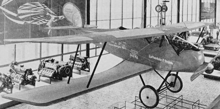
Luftverkehr P. Strahle’s blue and silver-grey Halberstadt CL IV D-71 on display in the Daimler-Benz Automotive Museum near Stuttgart.
AUSTRIA
Hansa-Brandenburg C I
The Hansa-Brandenburg C I two-seat observation aircraft was designed by Ernst Heinkel of Hansa und Brandenburgische Flugzeug-Werke GmbH and put into production for the Austro-Hungarian forces by Phonix of Vienna and Ungarische Flugzeugwerke AG (Ufag) of Budapest. Production began in 1916.
There were numerous versions, including the Phonix series 23 and 26 with 160 hp Austro-Daimler engine; series 27 with 185 hp Austro-Daimler; series 29 with 210 hp Austro-Daimler; series 29.5 and 229 with 200 hp Hiero; and series 429 with 230 hp Hiero. Ufag aircraft included the series 61, 64, 67 and 68 with 160 hp Austro-Daimler; series 63 with 160 hp Mercedes; series 269 with 200 hp Austro-Daimler; series 69 with 200 hp Hiero; series 169 with 220 hp Benz; and series 369 with 230 hp
Hiero.
These aircraft were two-bay strut and wire-braced biplanes of wooden construction with fabric-covered wings and ply-covered fuselage. The wings had slight dihedral and stagger, and ailerons were fitted only to the top wing, which had slightly greater span. All interplane struts sloped inward towards their upper ends.
There was a large triangular tailplane mounted on the top longerons, divided elevators, triangular fin and horn-balanced rudder. In the standard military aircraft, pilot and observer/gunner were in a large single open cockpit.
The upright inline water-cooled engine drove a two-blade wooden airscrew and the radiator was mounted above the leading edge of the upper wing.
On 20 March, 1918, C Is with 160 hp Austro-Daimler engines were used to open the Austro-Hungarian military air mail service between Vienna and Kiev via Krakow, Lemberg (Lwow) and Proskurov. This was the first regular scheduled international air mail service, it had a Proskuroy-Odessa branch, a Vienna-Budapest branch from July, and continued in operation until November 1918.
<...>
Старт первого почтового самолёта 1 апреля 1918 года с целью ввода в эксплуатацию авиапочтовой линии Вена - Киев.
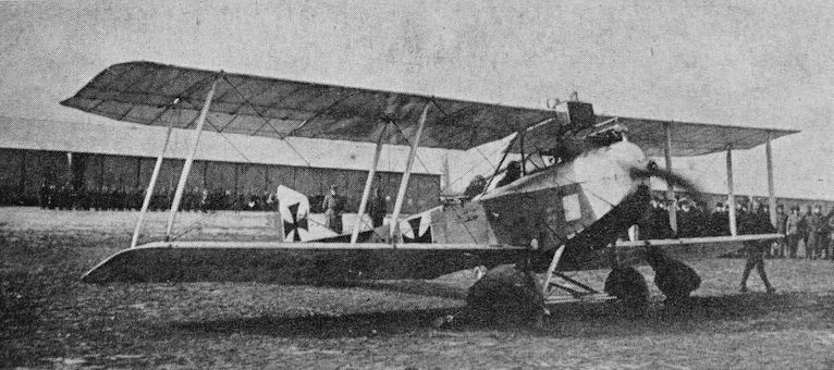
One of the Austro-Hungarian mail service Hansa-Brandenburg C Is used on the Vienna-Kiev route. This photograph is believed to have been taken at the inauguration of the service on 20 March, 1918.
One of the Austro-Hungarian mail service Hansa-Brandenburg C Is used on the Vienna-Kiev route. This photograph is believed to have been taken at the inauguration of the service on 20 March, 1918.
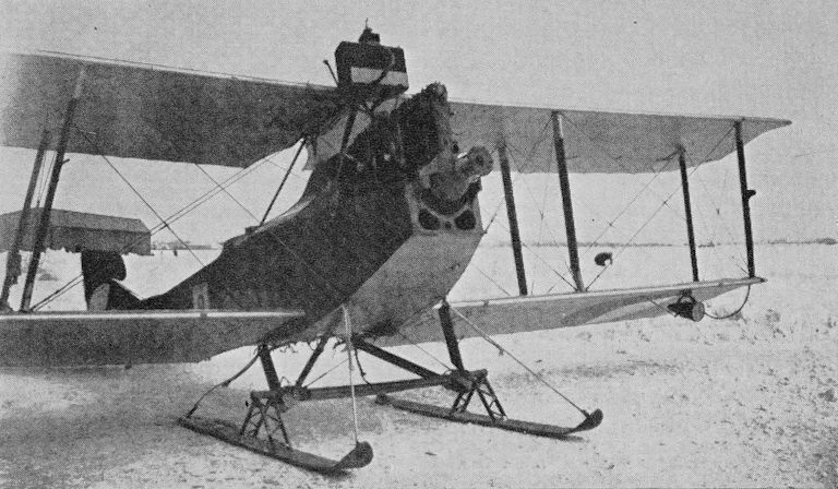
A Czechoslovak Army Air Service Aero A-14 on skis. A landing light can be seen beneath the port lower wing. The airscrew and part of the engine cowling has been removed.
Junkers-J 10
The J 10, given the German Air Force designation CLI, made its first flight on 4 May, 1918, and was put into production by Junkers-Fokker AG in the latter half of the year. It was a two-seat attack monoplane, and more than 40 were built.
The J 10 was a low-wing cantilever monoplane with a thick untapered wing and fairly deep fuselage. It had a one-piece elevator and a small balanced rudder but no fin. In some examples the ailerons projected aft of the trailing edge and also beyond the wing tips.
The wing was built up with a number of duralumin tubular spars which were braced to form a girder, and the fuselage was constructed from duralumin formers. The entire wing, fuselage and all control surfaces were covered by a corrugated metal skin which took some of the stresses.
The 160 hp Mercedes D.III six-cylinder upright inline water-cooled engine had a frontal radiator and drove a two-blade wooden airscrew.
It is almost certain that a J 10 was the first all-metal aeroplane to operate an air service. Junkers began operating a regular service between Dessau and Weimar in March 1919, and used a J 10 converted for commercial use by fitting a canopy over the rear cockpit. This canopy was hinged along its starboard side and, when closed, fitted between raised fairings which served to blend the lines of the structure. This J 10 retained its military markings but had painted on the fuselage the words Junkers Dessau - Weimar and was photographed in this form on 12 March, 1919. A Junkers publication of 1928 suggests that it was used to carry one passenger, and, on some occasions, cargo.
At least one J 10 appeared on the German civil register. It was D-78 used by Lloyd-Luftverkehr Sablatnig. It is not known whether this had an enclosed passenger cockpit, or indeed whether it had been the aircraft used by Junkers on the Dessau-Weimar service.
Span 12-25 m (40 ft 2 1/4 in); length 7-9 m (25 ft 11 in); wing area 23-4 sq m (251-8 sq ft). Empty weight 735 kg (1,620 Ib); loaded weight 1,155 kg (2,546 Ib). Maximum speed 190 km/h (118 mph); cruising speed about 155 km/h (96-3 mph); endurance 2 hr.

The Junkers-J 10 which was used by Junkers on the Dessau-Weimar services. This photograph, taken on 24 March, 1919, shows the cover closed over the rear cockpit.
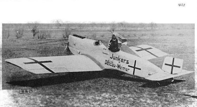
Demilitarized Junkers J.10 with cabin configuration for civil air transport, here flying between Dessau and Weimar, where the National Assembly of the Weimar Republic met in 1919.
The Dessau-Weimar Junkers-J 10 photographed on 12 March, 1919, with cockpit cover open.
The Dessau-Weimar Junkers-J 10 photographed on 12 March, 1919, with cockpit cover open.
Junkers-F 13
As early as 1909 Prof Hugo Junkers prepared drawings of a cantilever monoplane with thick wing, and in 1910 patents for this design were registered. In 1915 the first Junkers all-metal aeroplane to embody these features appeared, this was the J 1. The J 1 and its successor the J 2 had metal structures with smooth sheet covering, but the J 3, which was never completed, was designed to have a corrugated metal skin. The first completed aircraft to incorporate corrugated duralumin load-bearing skin was the J 4 biplane, and the J 7, J 9, J 10 and J 11 monoplanes all embodied this form of covering.
In November 1918, on Armistice Day it has been said, Prof Junkers called a meeting of senior staff, including his chief designer Dipl Ing Otto Reuter, and told them to stop work on military aircraft and instead design a transport aeroplane.
The first design, known as the J 12, was for a modified J 10. It employed the same wing and tail unit, but called for a widened and somewhat longer fuselage with semi-enclosed accommodation for four in two sets of side-by-side seats. The J 12, which was never built, was to have been powered by a 160 hp Mercedes engine and have a maximum weight of 1,220 kg (2,689 Ib).
Instead of the J 12 a much more advanced aeroplane was produced. Known at first as the J 13 and later as the F 13, this was one of the most important transport aircraft produced. The prototype made its first flight on 25 June, 1919.
It has been recorded that one of the first batch, c/n 531, received the registration D-1 when the type was awarded a certificate of airworthiness only a week after the first flight, and that on 18 July, 1919, the D-1 left Dessau for Berlin, Warnemunde and Stockholm on its first long flight, carrying two crew and four passengers. Nevertheless, there are grounds for doubt as to the accuracy of these statements. The first F 13 bore the name Annelise, but does not appear to have had a registration by September 1919. There is reason to believe that this aircraft was c/n 531, that it was registered D-183 and later re-registered D-1. In much modified form D-1 was still being used, in Berlin, for joyriding when the war started in 1939.
The F 13 was a very advanced design. It was a clean low-wing cantilever monoplane with an enclosed cabin for four passengers and an open cockpit for two crew and, unlike most transport aircraft of the 1920s and 1930s, the F 13 and subsequent Junkers transports had seat belts for the passengers.
The thick wing was built up of nine duralumin tubular spars which were braced to form an extremely strong all-metal girder. The centre section formed an integral part of the fuselage which was built up on a series of metal frames. The entire structure, including control surfaces, was covered by a corrugated duralumin skin. This form of construction proved to be very strong, have long life and be virtually impervious to weather and, with refinements, was used in all Junkers transports up to and including the famous Ju 52/3m.
The prototype F 13 had a 160/170 hp Mercedes D.IIIa engine, but the first production aircraft had 185 hp BMW IIIa engines and the designation F 13a. The F 13 was the subject of 31 type tests, supplementary type tests and validations, and there were some 60 or 70 variations on the basic design. A number of modifications, including strengthening and the fitting of the 200 hp Junkers-L 2 engine, were responsible for the designations F 13ba, F 13ca, F 13da and F 13fa. Then came an increase in all-up weight and the use of the 280/310 hp Junkers-L 5 in the F 13fe.
Modifications and the installation of L5 engines in F 13ba, F 13ca, F 13da and F 13fa aircraft made them the F 13be, F 13ce, F 13de and F 13fe respectively.
Later L5 powered aircraft included the F 13dle, F 13fle, F 13ge, F 13he and F 13ke. There were F 13bi, ci, di and fi versions with the 220/250 hp BMW IV, and F 13co, fo and ko with 360 hb BMW Va. Other known variants were the F 13fy and F 13fa. There were versions of the F 13 with a 230 hp Armstrong Siddeley Puma and at least one had a Jupiter nine-cylinder air-cooled radial in place of the usual six-cylinder water-cooled inline type, and there were reports of Armstrong Siddeley Jaguar and Pratt and Whitney Wasp powered examples.
Production aircraft had increased span and wing area, the prototype having a span of 14-47 m (47 ft 53 in) and an area of 39 sq m (419 sq ft) compared with the 17-75 m (58 ft 2 3/4 in) and 44 sq m (473-61 sq ft) of the production aircraft.
Although the F 13 was so much in advance of all other transports, it was not immediately successful because of the large numbers of surplus wartime aircraft which were available for transport work. Poland and Austria bought some F 13s in 1919, and at the end of the year six were ordered by the United States.
The F 13 programme was nearly wrecked by the intervention of the Inter-Allied Aeronautical Commission of Control, but early in 1920 this body decided that the F 13 was really a civil aeroplane, and production was allowed to continue, although for some years those licensed in Germany were restricted to 185 hp.
F 13 production continued until 1932 with a total of 322 aircraft being built. A small number, possibly about 12, were built in 1919, and about 80 produced in 1920-21. Only about a dozen were produced in 1922, but 1923 and 1924 production was at the rate of about one a week. As far as can be ascertained, 1925 production was about 20, while in the following year the rate was about one a month. Only four 1927 aircraft have been traced, but there were about 50 built in 1928-29. Very few were built in the period 1930-32.
In 1920 the United States Post Office bought eight F 13s for mail operation, and US rights for the aircraft were acquired by Mr John Larsen (J. L. Aircraft Corp.) - hence the US designation JL 6. These F 13s cost $20,000 each, with spares, and were used on the New York - Chicago - Omaha and New York - San Francisco routes.
SCADTA in Colombia ordered F 13s early in 1920, and other orders followed until the type saw worldwide service.
In 1921, mainly to encourage sales of F 13s, the Junkers concern set up its own transport company under the title of Junkers-Luftverkehr. By 1923 this concern had no less than 60 F 13s in service, and by 1926, when operations ceased, about 15 mn km (94 mn miles) had been flown and 281,748 passengers carried. Junkers encouraged the formation of other airlines by providing F 13s free, on loan, on lease or on favourable terms, and by 1923 two groups were working as Osteuropa-Union and TransEuropa-Union. These Unions comprised Junkers and eight other airlines. Nordeuropa-Union replaced Osteuropa-Union, and in May 1925 the two amalgamated to form Europa-Union made up of 16 airlines in Austria, Danzig, Denmark, Esthonia, Finland, Germany, Latvia, Sweden and Switzerland.
Junkers also operated Junkers-Luftverkehr Persien in Iran, using F 13s, and assisted in the formation of Junkers-equipped airlines in other parts of the world, particularly in South America.
Deutsche Lufthansa had a fleet totalling no less than 55 F 13s, and in the summer of 1928 the type was flying passenger services over 43 of the airline’s domestic routes and working on two cargo services. In the summer of 1937 DLH’s F 13s were still flying 12 services a week between Chemnitz and Halle/Leipzig, 21 a week between Breslau and Hirschberg, 14 over the Stettin-Swinemtinde-Sellin route and six a week between Konigsberg and Tilsit. Lufthansa’s last scheduled operation of F 13s was over the Breslau - Hirschberg route in 1938.
In addition, F 13s were employed by a wide range of aerial operators and private owners, and they worked on wheel, float and ski undercarriages.
Because of the strength of these aircraft, a considerable number of their occupants survived crashes and forced landings which did no more than bend the structure. Nevertheless, one aircraft, G-AAZK operated by Walcot Air Lines, broke up in the air over Meopham in Kent on 21 July, 1930, killing its six occupants. This led the Royal Aircraft Establishment at Farnborough to conduct the first full-scale investigation into the disintegration of a metal monoplane and the pattern of break-up, and the reassembly of the pieces by the RAE was to be very closely duplicated in the accident to the Comet 1 G-ALYP nearly 25 years later. The failure was found to be in the F 13’s tailplane. No other instances of inflight failure are known.
Although most F 13s were built by Junkers-Flugzeugwerk AG at Dessau, production was interrupted for several months in 1921 and 1922 by order of the Disarmament Commission, and to circumvent this restriction production was established at Danzig and Reval. There were also reports of F 13s being built at Fili, near Moscow.
The Danzig-registered F 13, Dz 4, built in 1920, had flown 4,600 hr by 1933, and by the same time the SCADTA F 13 floatplane A-8 Magdalena (c/n 602) built in 1921 had totalled 3,200 hr on South American operations.
Adequate coverage of the F 13 and its variants requires a separate book. It was the aeroplane that made air transport a practical proposition in many parts of the world, and it paved the way for all of today’s all-metal cantilever monoplanes. One example (c/n 715) registered S-AAAC and later SE-AAC has been preserved by the Stockholm Technical Museum, and one of the United States JL 6s is included in the French historical aviation collection in Paris. It is possible that Varig’s PP-VAG (c/n 2067) still exists in Brazil.
F 13 landplane with 185 hp BMW IIIa engine. Span 17-75 m (58 ft 2 3/4 in); length 9-6 m (31 ft 6 in); wing area 44 sq m (473-61 sq ft). Empty weight 1,150 kg (2,535 Ib); loaded weight 1,730 kg (3,814 Ib). Cruising speed 140 km/h (87 mph); landing speed 95 km/h (59 mph); ceiling about 4,000 m (13,123 ft); endurance 5 hr.
F 13 landplane with 200 hp Junkers-L 2 engine. Span 17-75 m (58 ft 2 3/4 in); length 10-5 m (34 ft 5 1/2 in); wing area 44 sq m (473-61 sq ft). Empty weight 1,150 kg (2,535 Ib); loaded weight 1,850 kg (4,078 lb). Cruising speed 140 km/h (87 mph); landing speed 95 km/h (59 mph); ceiling 4,000 m (13,123 ft).
F 13 landplane with 280/310 hp Junkers-L 5 engine. Dimensions as for L 2 powered aircraft. Empty weight 1,480 kg (3,262 Ib); loaded weight 2,500 kg (5,511 lb). Cruising speed 170 km/h (105-6 mph); ceiling 5,100 m (16,732 ft).
The floatplanes had a length of 10-3 m (33 ft 94 in) with BMW engines, and 11 m (36 ft) with Junkers engines. Cruising speed of the L 5 powered floatplane was 155 km/h (96-3 mph).
There was considerable variation in weights and performance of F 13s.
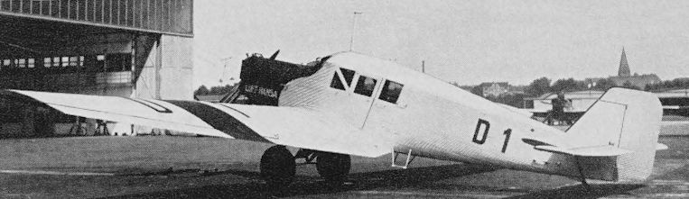
The Junkers-F 13 D-1 built in 1919. It is seen in much modified form at Tempelhof, Berlin, in the mid-1930s.

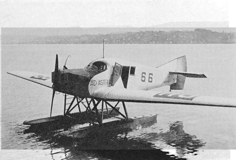
Ad Astra Aero’s Junkers-F 13 CH 92 was an early production aircraft with the original type of fin and rudder.
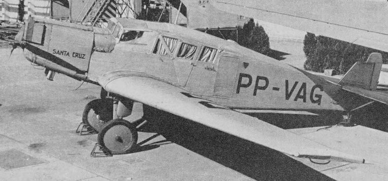
Varig’s Junkers-F 13 Santa Cruz after the addition of a cockpit enclosure. This photograph was taken since the 1939-45 war and the aircraft may have been preserved.
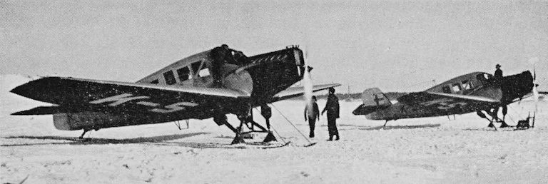
Two of Aero O/Ys ski-equipped Junkers-F 13s on the ice at Helsinki.
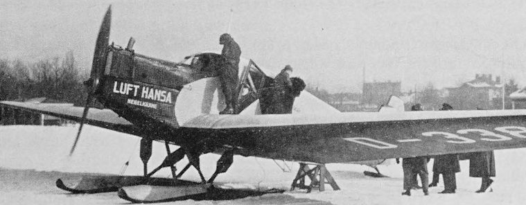
Deutsche Lufthansa’s Junkers-F 13 D-338 Nebelkrahe (Hooded Crow) on streamlined skis.
Ad Astra Aero’s Junkers-F 13 floatplane CH 66 was another early production aircraft.
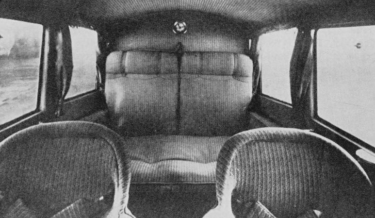
The cabin of an Ad Astra Aero Junkers-F 13. Seat-belts can be seen.
L.V.G. C IV, C V and C VII
Some of the best-known German two-seat reconnaissance aircraft of the 1914-18 war were the L.V.G. biplanes produced by Luft-Verkehrs GmbH. These were all single-engine two-bay strut and wire-braced biplanes. The C IV was built in 1916, the C V (also built by Deutsche FlugzeugWerke GmbH) entered service in 1917, and the C VI went into squadron service in 1918. About 1,000 C VIs had been built by the end of 1918 and, under the designation RK 8a, a three-seat version was put into licence production in 1920 by Raab-Katzenstein Flugzeugwerke GmbH. A cabin version was the RK 8 Marabu.
The C IV was powered by a 220 hp Mercedes D.IV and was mainly of wooden construction with fabric covering, except for ply-covered forward fuselage. It has been reported that a C IV made the first daylight aeroplane bombing raid on London on 28 November, 1916. The C V had a 200 hp Benz Bz IV engine. The C VI was normally powered by a Benz Bz IV, but Daimler D.IIIa and Junkers-L 2 engined examples are known.
It is believed that some C IVs were used on early German air services but none has been identified.
<...>
L.V.G. C IV. Span 13-6 m (44 ft 7 1/4 in); length 8-5 m (27 ft 10 3/4 in); wing area 38-2 sq m (411-18 sq ft). Empty weight 1,050 kg (2,314 Ib); loaded weight 1,600 kg (3,527 Ib). Performance not known.
L.V.G. C IV, C V and C VII
Some of the best-known German two-seat reconnaissance aircraft of the 1914-18 war were the L.V.G. biplanes produced by Luft-Verkehrs GmbH. These were all single-engine two-bay strut and wire-braced biplanes. The C IV was built in 1916, the C V (also built by Deutsche FlugzeugWerke GmbH) entered service in 1917, and the C VI went into squadron service in 1918. About 1,000 C VIs had been built by the end of 1918 and, under the designation RK 8a, a three-seat version was put into licence production in 1920 by Raab-Katzenstein Flugzeugwerke GmbH. A cabin version was the RK 8 Marabu.
The C IV was powered by a 220 hp Mercedes D.IV and was mainly of wooden construction with fabric covering, except for ply-covered forward fuselage. It has been reported that a C IV made the first daylight aeroplane bombing raid on London on 28 November, 1916. The C V had a 200 hp Benz Bz IV engine. The C VI was normally powered by a Benz Bz IV, but Daimler D.IIIa and Junkers-L 2 engined examples are known.
<...>
C Vs are also thought to have seen some service on German routes, and five, CH 2, CH 5, CH 7, CH 75 and CH 76, are known to have been operated by Ad Astra Aero AG.
<...>
Deutsche Lufthansa, in 1926 and 1927, had an L.V.G. Ch 2. This appears to have been a modified C V. It was registered D-1179 (c/n 695) and named Bisam (Musk).
<...>
L.V.G. C V. Span 13:62 m (44 ft 8 1/2 in); length 8-07 m (26 ft 5 3/4 in); wing area 42:7 sq m (459-6 sq ft). Empty weight 1,013 kg (2,233 Ib); loaded weight 1,533 kg (3,379 Ib). Speed at 2,000 m (6,561 ft) 164 km/h (101-9 mph); ceiling 5,000 m(16,404 ft); endurance about 3 1/2 hr.
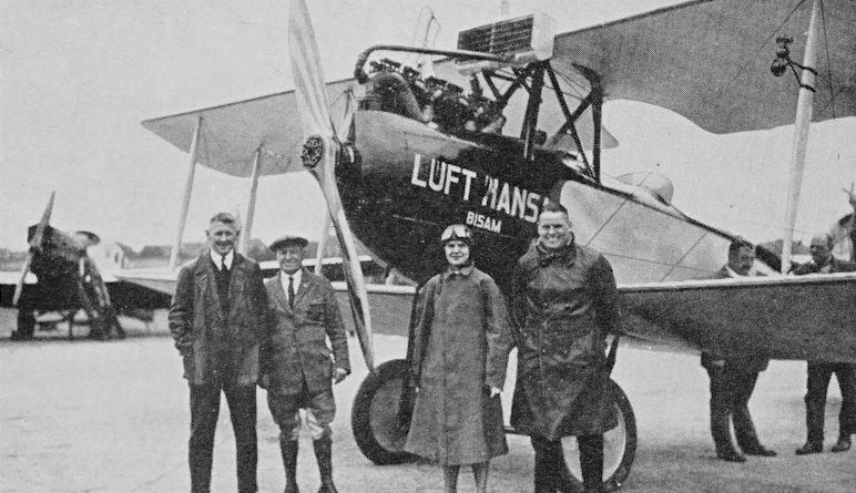
Deutsche Lufthansa’s L.V.G. Ch 2 D-1179 Bisam (Musk) appears to have been a modified L.V.G. C V.
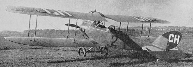
This L.V.G. C V was used by Ad Astra Aero and bore the second Swiss civil registration, CH 2.
L.V.G. C IV, C V and C VII
Some of the best-known German two-seat reconnaissance aircraft of the 1914-18 war were the L.V.G. biplanes produced by Luft-Verkehrs GmbH. These were all single-engine two-bay strut and wire-braced biplanes. The C IV was built in 1916, the C V (also built by Deutsche FlugzeugWerke GmbH) entered service in 1917, and the C VI went into squadron service in 1918. About 1,000 C VIs had been built by the end of 1918 and, under the designation RK 8a, a three-seat version was put into licence production in 1920 by Raab-Katzenstein Flugzeugwerke GmbH. A cabin version was the RK 8 Marabu.
The C IV was powered by a 220 hp Mercedes D.IV and was mainly of wooden construction with fabric covering, except for ply-covered forward fuselage. It has been reported that a C IV made the first daylight aeroplane bombing raid on London on 28 November, 1916. The C V had a 200 hp Benz Bz IV engine. The C VI was normally powered by a Benz Bz IV, but Daimler D.IIIa and Junkers-L 2 engined examples are known.
<...>
C VIs were used to a fairly large extent on early air services. Deutsche Luft-Reederei operated mail services with C VIs still camouflaged and bearing military markings. Known DLR fleet numbers for C VIs are DLR 6, 21, 34, 45 and 47; known registered DLR aircraft were D-13 (c/n 4590) DLR 6, D-15, D-17 (c/n 5083), D-35 (c/n 5071), D-60 (c/n 5060), D-62 and D-73 (c/n 699). Sudwestdeutsche Luftverkehrs had D-1106 (c/n RK 75) and D-1301 (c/n 5094); Deutsche Luft-Lloyd had D-112 (c/n 5072); Lloyd Ostflug D-141 (c/n 5138); Stiddeutsche Lufthansa D-184 (c/n 12090); Oberschlesische Luftverkehrs D-17 Mars from DLR: and Badisch-Pfalzische Luft Hansa D-1343 (c/n RK 77). Deutsche Lufthansa took over D-73 Maus (Mouse), D-141 and D-184.
In Belgium SNETA had O-BAHU (c/n 8995), O-BAIE (c/n 8990), O-BARD (c/n 8957) and O-BOMA (c/n 8922), and two passed to Sabena.
<...>
In 1919 limousine versions of the C VI were produced. These bore the designation P 1, and one bore the number 27/19 on the fuselage. One version had an enclosed cabin with hinged access panel in the top, and another had a full-depth door in the port side. These cabin versions had accommodation for two passengers, but there is no evidence of their entry into service. There was also a Kurier version known as the L.V.G. K 1.
There was also a three-seat twin-float version of the L.V.G. C VI, and this may have been used on some German coastal services.
L.V.G. C VI. Span 13 m (42 ft 7 3/4 in); length 7-5 m (24 ft 7 in); wing area 34-6 sq m (372-4 sq ft). Empty weight 965 kg (2,127 lb); loaded weight 1,400 kg (3,086 Ib). Speed at 2,000 m (6,561 ft) 160 km/h (99-4 mph); endurance 3 1/2 hr.
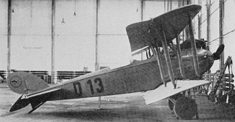
One of Deutsche Luft-Reederei’s L.V.G. C VIs.
Rumpler C I, Type 5A2 and C lV
Produced by Rumpler Flugzeug-Werke, the C I two-seat reconnaissance biplane first appeared in 1915. It was built of wood and mostly fabric-covered, and the standard engine was the 160 hp Mercedes D.III. Large numbers were built.
Some C Is were used on German passenger and mail services, with the largest number operated by Bayerische Rumpler-Werke and its airline offshoot Rumpler-Luftverkehr. The fleet is known to have included D-97 (c/n 451) built in 1915, D-98, D-100 (c/n 477), D-102, D-103, D-108 and D-290. Bayerische Luft-Lloyd used a three-passenger C I on its Munich - Constance services in 1921, it was D-126 (c/n 498).
Rumpler began operating Augsburg - Munich - Nuremberg - Leipzig - Berlin services in 1919, and the C Is were used on this route. To provide more comfort for passengers D-290 was modified to the Type 5A2 with enclosed two-seat cabin. The modification consisted of building a raised structure of bent-ply with Triplex windows. The passenger seats were side-by-side, and there was a speaking tube to provide communication between pilot and passengers. The conversion of D-290 is believed to have taken place in 1920.
Only one Rumpler 5A2 is known. It passed to Deutsche Luft-Reederei and was later put on exhibition in the Luftfahrt Museum in Berlin, where it was finally destroyed by Allied bombing. On 10 January, 1936, D-290 had been exhibited at Tempelhof in a parade of historic aircraft. On that occasion it had the wings of a Rumpler C IV which bore evidence of having belonged to D-920. The tailplane and elevators also appeared to have come from a C IV, but the fin and rudder were not identifiable.
In 1926 Deutsche Lufthansa acquired the C Is D-100, D-103 and D-108, the last two being withdrawn from use in 1929.
<...>
Rumpler Type 5A2. Span 12:15 m (39 ft 10 1/2 in); length 8 m (26 ft 3 in); wing area 35:7 sq m (384-2 sq ft). Empty weight 805 kg (1,774 lb); payload 250 kg (551 lb); loaded weight 1,350 kg (2,976 lb). Cruising speed 150 km/h (93-2 mph); ceiling 4,500 m (14,763 ft); endurance 5 hr; range 750 km (466 miles).
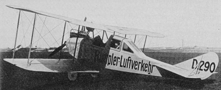
Rumpler-Luftverkehr’s Rumpler 5A2 D-290, which had been rebuilt from an open cockpit Rumpler C I.
Rumpler C I, Type 5A2 and C lV
<...>
In 1917 the Rumpler C IV was put into production as a successor to the C I. The C IV was powered by a 260 hp Mercedes D.IVa engine and was a generally cleaner and more advanced aeroplane. The two-bay wings, of nearly equal span, were staggered and had 24° sweepback. In 1919 Rumpler used the C IV D-72 on its Augsburg-Berlin services and on Berlin-Leipzig services in connection with the Leipzig Fair. This aircraft later passed to Deutsche Luft-Reederei.
In Belgium SNETA had at least ten Rumpler C IVs with 260 hp Maybach engines. They bore the designation Type 6A7 and were O-BABO, O-BAHI, O-BILL, O-BLEU, O-BOND, O-BORD, O-BREF, O-BRIS, O-BRUN and O-BUIS (c/ns 12208, 7779, 9984, 7959, 7983, 7974, 7960, 5741, 7957 and 7982). O-BAHI, O-BILL, O-BREF and O-BUIS passed to Sabena.
Rumpler C IV. Span 12:66 m (41 ft 5 in); length 8-4 m (27 ft 6 in); wing area 33-5 sq m (360-5 sq ft). Empty weight 1,017 kg (2,220 lb); loaded weight 1,630 kg (3,593 lb). Speed 175 km/h (108-7 mph); endurance 3 1/2 - 4 hr.
Figures for standard C IV with 260 hp Mercedes D.IVa.
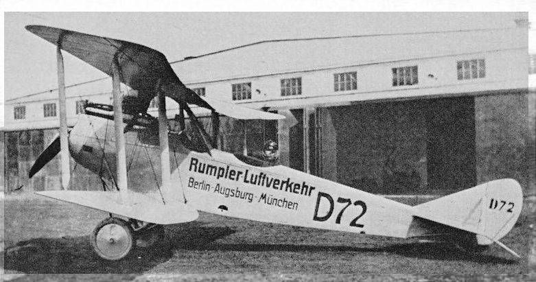
Rumpler-Luftverkehr’s Rumpler C IV D-72 photographed in 1919.
After the war Rumpler used both C.I and C.IV aircraft in a short-lived airline, Rumpler Luftverhehr (Rumpler Air Traffic). Here D72 shows its heritage of clean lines in March 1919. Its route of Berlin-Augsburg-Munich is painted on the fuselage.
After the war Rumpler used both C.I and C.IV aircraft in a short-lived airline, Rumpler Luftverhehr (Rumpler Air Traffic). Here D72 shows its heritage of clean lines in March 1919. Its route of Berlin-Augsburg-Munich is painted on the fuselage.
Sablatnig P I
During the period from November 1918 to January 1919 Sablatnig Flugzeugbau GmbH of Berlin produced the P I cabin version of its N I two-seat night bomber. The main modifications were the provision of a fully-enclosed, heated and lighted, four-seat passenger cabin immediately aft of the engine and the positioning of a long open cockpit for the pilot aft of the wings.
One of these aircraft made the first German long-distance international flight when, in April 1919, it flew from Berlin to Copenhagen and Stockholm.
The P I was a two-bay biplane of wooden construction, with ply-covered fuselage and fin, and fabric-covered wings. The undercarriage axle and spreader bar was faired in by a deep-section lifting surface. The engine was a 200/220 hp Benz Bz IV.
D-4 was a P I owned by Lloyd-Luftverkehr Sablatnig, and at least two, D-106 and D-127, were supplied to Dansk Luft Expres in 1919. A total of 12 has been reported. In 1921 or 1922 a P I operated a Tallinn - Riga service for the Esthonian airline Aeronaut A/S, which had been founded by DLE and Sablatnig. This P I was most likely D-156, which is known to have been supplied to Aeronaut. D-77 (c/n 128), registered as a Sablatnig N I, may well have been a P I and is known to have been part of Lloyd-Luftverkehr Sablatnig’s fleet in the autumn of 1921 before passing to Luftverkehrsgesellschaft Hamburg.
Span 10:95 m (35 ft 11 in); length 8-45 m (27 ft 8 1/2 in); wing area 54 sq m (581:25 sq ft). Empty weight 640 kg (1,410 Ib); loaded weight 1,170 kg (2,579 lb). Cruising speed 130 km/h (80:7 mph)
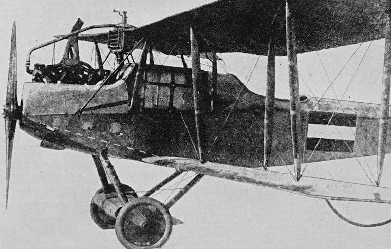
The Sablatnig P I showing engine installation and cabin. The designation Sab N3 appears on the port wheel.
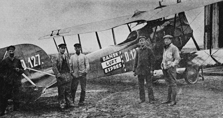
One of the Sablatnig P I cabin biplanes supplied to Dansk Luft Expres in 1919.
Sablatnig P III
After the end of the 1914-18 war Sablatnig Flugzeugbau turned its attention to commercial aviation. After producing the P I four-passenger conversion of its N I bomber, the company’s chief designer, Dr Hans Seehaase, designed a single-engine high-wing strut-braced monoplane with accommodation for six passengers. This was the P III, which first appeared in June 1919.
The P III was originally designed to take either a 200/220 hp Benz Bz IV or 260 hp Maybach Mb IVa engine, and to be easily assembled and repaired, to provide the maximum safety for its occupants, and to have short take-off and landing runs. It was of wooden construction with ply-covered fuselage and fabric-covered wings. The wings could be folded flat against the fuselage, the tailplane and elevators folded upward and the entire aircraft stowed in one standard German railway wagon. The inboard sections of the elevators could be locked at a pre-set angle for trim and also acted as air brakes. A crew of two could be carried in a large open cockpit aft of the wing.
In June 1919 Lloyd-Luftverkehr Sablatnig was founded by Sablatnig Flugzeugbau and Norddeutscher Lloyd and in the following month opened a Berlin - Stralsund service, the route being extended to Copenhagen in September. A Berlin - Bremen service was also operated. Luftverkehr Sablatnig also flew holiday services to Norderney and Wangerooge. When the first P III appeared it bore the words Luftverkehr-Sablatnig on its fuselage. At September 1921 the airline had a mixed fleet of 17 aircraft and at least three of these, D-50, D-143 and D-171, were Sablatnig P IIIs.
Six P IIIs, with balanced ailerons, were used from 1923 by Aeronaut A/S on Esthonian domestic services and on the Tallinn - Riga route. These aircraft are believed to have been registered E-6 to E-11 and have been reported as Esthonian-built. In 1924 Aeronaut exchanged its Sablatnigs for Junkers-F 13s at the rate of two Sablatnigs for one Junkers.
Deutsche Lufthansa acquired nine or ten P IIIs in 1926, and three of them were ex-Aeronaut aircraft. These Lufthansa aircraft were powered by a variety of engines, including the 240 hp Armstrong Siddeley Puma, the 220 hp BMW IV and 195/230 hp Junkers-L 2. During the summer of 1928 they were used on the Munich-Regensburg-Nuremberg and Cologne-Krefeld services, but do not appear to have been used after that September. Six are known to have been dismantled by early in 1932, although one was in existence in 1936.
One P III was fitted with a ski undercarriage in the winter 1920-21.
In Switzerland Alfred Comte’s flying school owned a Maybach-powered P III. It had clear-doped wings and was registered CH 54. This P III had been bought to operate a Zurich - Constance service, which never took place, and was sold in 1921, probably to Germany.
Span 16 m (52 ft 6 in); length 8:94 m (29 ft 4 in); wing area 44:9 sq m (483-29 sq ft).
With Benz engine. Empty weight 1,334 kg (2,941 lb); payload 450 kg (992 Ib); loaded weight 2,184 kg (4,815 lb); cruising speed 150 km/h (93-2 mph); endurance 3 1/2 hr.
With Maybach engine. Empty weight 1,400 kg (3,086 Ib); payload 450 kg (992 Ib); loaded weight 2,250 kg (4,960 Ib). Cruising speed 150 km/h (93:2 mph); take-off run 170 m (557 ft); landing run 110 m (360 ft); endurance 54 hr.
Lufthansa P IIIs
D-2 c/n 386 Hornisse (Hornet)
D-143 152 Biene (Bee)
D-171 262 Hummel (Humble-bee)
D-395 266 Wespe (Wasp)
D-451 268 Filiege (Fly)
D-581 E-10* Libelle (Dragonfly)
D-770 270 =Muicke (Gnat)
D-962 E-11* Moskito (Mosquito)
D-984 E-8*
*ex-Aeronaut aircraft. Registrations appear to have served as c/ns.
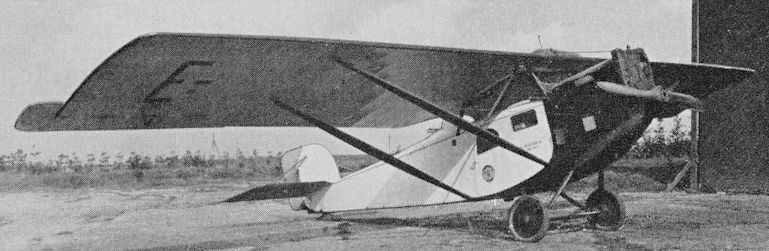
Aeronaut’s Benz-powered Sablatnig P III E-9 photographed at Tallinn in 1923 or 1924.
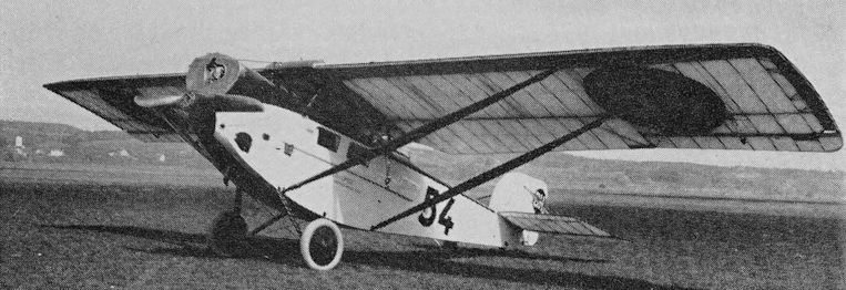
CH 54 was the Maybach-powered Sablatnig P III bought by the Alfred Comte Ortfliegerschule for a Zurich - Constance service. This example has unbalanced ailerons and clear-doped wing and tailplane.
Dornier Gs I
Dipl Ing Claudius Dornier joined the design staff of Luftschiffbau Zeppelin in 1910 and, after working on Zeppelins, was put in charge of design at Zeppelin-Werke Lindau GmbH, which was founded in 1914 for the construction of metal flying-boats.
Using the newly available duralumin together with steel, Dornier produced a range of very large flying-boats from 1915 until the end of the war, and in 1918 designed some very clean multi-engine monoplane flyingboats, only one of which was built. These large marine aircraft are fully described in ‘The German Giants’, by G. W. Haddow and Peter M. Grosz.
Many of the features which became common in Dornier designs were introduced in those wartime flying-boats, and these included the inherently stable broad-beam hull and sponsons or sea-wings.
Under construction when the war ended was the twin-engine Gs I. The design was modified to become a commercial flying-boat, and in January 1919 the components were moved from Lindau for completion at Seemoos. The Gs I made its first flight on 31 July, 1919, and service trials were undertaken for Ad Astra Aero in Switzerland in 1920, under the registration CH 8. The Gs I proved reliable and economic, and after these trials it left for a demonstration tour in the Netherlands and Sweden. The Amsterdam demonstration took place, but before the aircraft could reach Stockholm the Allies demanded its destruction, and it was sunk off Kiel on 25 April, 1920.
The Gs I was an all-metal strut-braced parasol monoplane with low-aspect-ratio untapered wing having square tips, the ailerons were balanced by small surfaces mounted above their leading edges, and the wing had slight anhedral.
The hull was shallow but quite broad, and in the bows was a humped superstructure with an open cockpit and an enclosed cabin for six passengers.
Two parallel outward-sloping wing bracing struts were attached to each sponson, and a multiplicity of struts supported the wing and tandem-mounted 260 hp Maybach Mb IVa water-cooled engines which each drove a two-blade wooden airscrew.
The tail unit comprised biplane strut-braced tailplanes and twin fins and rudders. The upper tailplane overhung the fins and carried a single-piece elevator. There was no lower elevator.
A nine-passenger development, the Gs I, was never completed, although two were under construction when their completion was banned.
Span 21 m (68 ft 10 3/4 in); length 15-3 m (50 ft 2 1/4 in); wing area 80 sq m (861-11 sq ft). Empty weight 3,115 kg (6,867 lb); loaded weight 4,315 kg (9,513 lb). Maximum speed 170 km/h (105-6 mph); cruising speed 140 km/h (86:9 mph); ceiling 4,250 m (13,943 ft); range 600 km (372 miles).
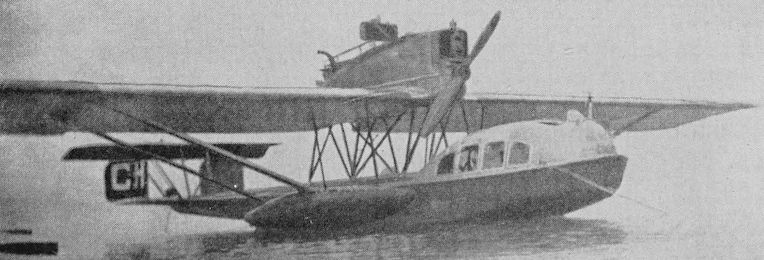
The Dornier Gs I, CH 8, while undergoing trials with Ad Astra Aero in 1920.
<...>
In May 1919 Zeppelin-Werke GmbH began construction, at Staaken near Berlin, of the E.4/20 four-engine civil transport aircraft which had been designed under the technical direction of Dr Ing Adolf Rohrbach. The E.4/20 was a strikingly advanced design with a 31 m (101 ft 8 1/2 in) span cantilever wing and four 245 hp Maybach engines. The loaded weight was 8,500 kg (18,739 lb), cruising speed 200 km/h (124.2 mph) and endurance between 5 and 6 hr. This aircraft was intended for operation of Friedrichshafen - Berlin services, but after its completion in September 1920 the Control Commission ordered the suspension of test flying, and the aircraft was finally broken up in November 1922.
<...>
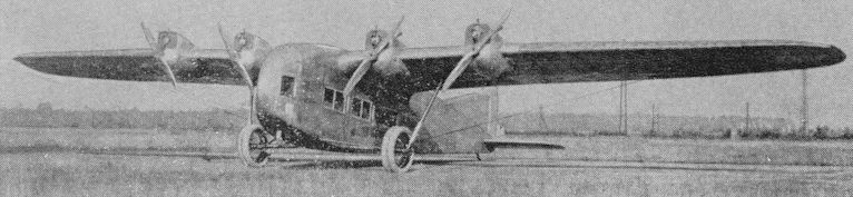
The E.4/20 designed by Adolf Rohrbach and built at Staaken by Zeppelin-Werke GmbH.
Ansaldo A.300/C and 300/T
The prototype Ansaldo A.300 single-engine two-seat military biplane first flew in 1919. Subsequent versions were the A.300/2 to A.300/6, and several hundred were built for military service. In 1921 two civil transport versions appeared, and these, together with some of the military aircraft, were built by Fiat.
The first of the civil aircraft was the A.300/C, a two-bay strut and wire-braced biplane with accommodation for two pilots and four passengers. It is thought that the structure was of wood, although provision was made in the design for the use of steel longerons. The wings were of equal span, fabric-covered, and lower and upper wings were fitted with unbalanced ailerons. Two sets of diagonal struts ran from the centreline of the cabin walls outward to the upper and lower wings.
The fuselage, which occupied the entire gap between the wings, was ply-covered in the cabin area and fabric-covered aft. Side-by-side pilots’ seats were in the front of the cabin, but the view was severely restricted by the engine cowling, which was unusually deep. There were two aft-facing and two forward-facing passenger seats.
The tailplane was wire-braced and the rudder and elevators balanced. The undercarriage consisted of two sets of V struts attached beneath the diagonal wing struts, an aerofoil-section covered cross-axle and two sets of V struts which, in front view, formed a W.
SNETA in Belgium acquired an A.300/C in 1921 which was registered O-BAHF (c/n C.6003). It passed to Sabena in 1923, but its registration was cancelled in November 1925. It is not known whether this was the prototype, although no other civil registered examples are known.
The second version was the A.300/T. This had an eight-seat cabin, and the pilot was in an open cockpit behind the cabin. The wing area was increased, a curved decking added to the fuselage top and a biplane tail unit fitted. The bottom tailplane was placed lower on the fuselage than in the A.300/C and the upper tailplane was attached halfway up the fin. The upper and lower elevators were strut-connected at their inner ends.
One A.300/T is known. It was registered I-ARNO, but there is no record of its entry into airline service.
Both the A.300/C and A.300/T were powered by 300 hp Fiat A.12bis six-cylinder water-cooled inline engines which drove two-blade wooden airscrews.
A.300/C. Span 13-65 m (44 ft 9 1/2 in); length 9:65 m (31 ft 8 in); wing area 48 sq m (516-66 sq ft). Empty weight 1,470 kg (3,240 Ib); loaded weight 2,180 kg (4,706 Ib). Maximum speed 190 km/h (118 mph); ceiling 4,500 m (14,763 ft); endurance 3 1/2 hr.
A.300/T. Dimensions believed as A.300/C, but wing area increased to 51 sq m (548-95 sq ft), probably by elimination of cut-outs in lower wing centre section. Empty weight 1,400 kg (3,086 Ib); loaded weight 2,065 kg (4,552 Ib). Maximum speed 160 km/h (99:4 mph); ceiling 4,500 m (14,763 ft); endurance 3 1/2 hr.
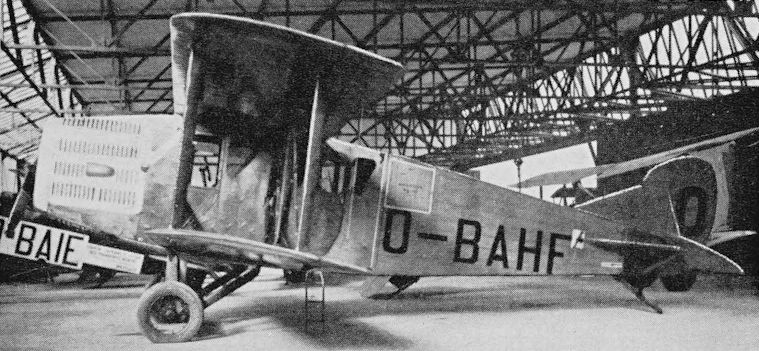
SNETA’s Ansaldo A.300/C. This version had an enclosed cabin for the pilots and an orthodox tail unit.
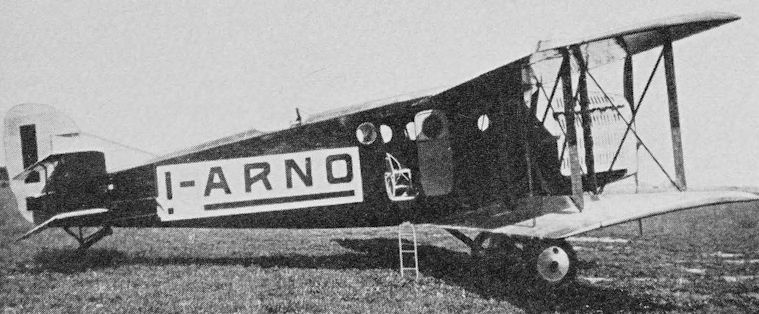
An Ansaldo A.300/T with open cockpit and biplane tail.
Macchi-Nieuport M.3
During the night of 27 May, 1915, the Austrian Lohner L.1 flying-boat L.40 was captured intact at Porto Corsini, Rimini. Societa Anonima Nieuport-Macchi produced a copy of this Austrian flying-boat and gave it the same type designation, L.1. A direct development was the L.2, and a further development, the L.3, was first flown in April 1916.
The L.3, later known as the M.3, was a single-engine flying-boat of wooden construction with ply-covered hull and fabric-covered wings and tail unit. Two hundred were built as reconnaissance aircraft, bombers and fighters, and some of these remained in service with military training schools in Italy until 1924.
After the war a few were converted for passenger carrying and two, CH 12 and CH 15, were employed on the Swiss lakes by Ad Astra Aero. CH 12 was burnt at Lugano in 1922, and CH 15 was withdrawn from use in the same year.
The M.3 was a biplane of unequal span and chord with sweepback on both upper and lower mainplanes. Ailerons were fitted only to the upper wing, and these had inverse taper giving the wing its greatest chord at the tips. The wings were braced by two sets of vertical interplane struts on each side, with another pair being splayed diagonally to support the overhang of the upper wing. The hull was a single-step structure with almost flat planing bottom. Flat-bottomed wing tip floats were fitted. In the military M.3s the tailplane and elevator was mounted above and aft of the hull on a number of struts, but in the passenger version the tailplane was attached to a tall single fin mounted on the hull and strut-braced to it.
The single 160 hp Isotta-Fraschini V.4B six-cylinder water-cooled inline engine was mounted below the top wing centre section. It had a frontal radiator and drove a two-blade wooden pusher propeller.
Military M.3s had a two-seat open cockpit in the bows, but the civil aircraft had a partially enclosed cabin for two passengers just forward of the wings and the open cockpit was in a raised decking beneath the engine.
Span 15-95 m (52 ft 4 in); length 10:25 m (33 ft 7 1/2 in); wing area 45 sq m (484-37 sq ft). Empty weight 895 kg (1,973 Ib); loaded weight about 1,350 kg (2,976 Ib). Maximum speed 145 km/h (90 mph); cruising speed 127 km/h (78-9 mph); absolute ceiling 6,000 m (19,685 ft); range 450 km (279 miles).
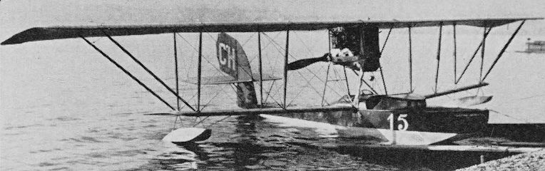
Ad Astra Aero’s red and white Macchi-Nieuport M.3, CH 15 (c/n 3022), at Zurichhorn.
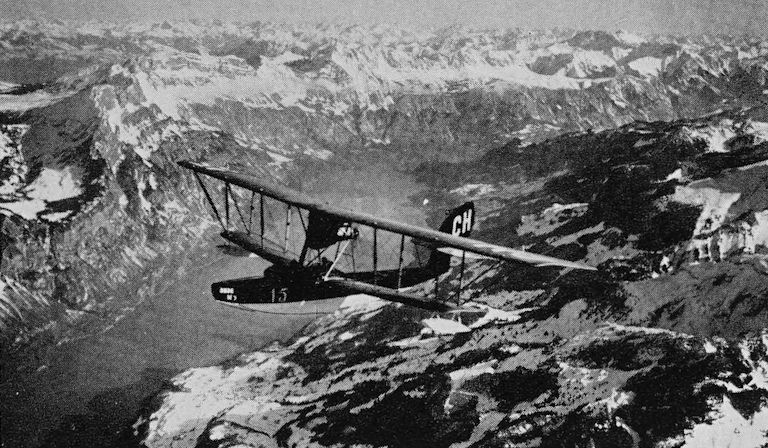
Flying-boats were widely used in the early years of European air transport. Ad Astra Aero’s red and white Macchi-Nieuport M.3 CH 15 over the Alps some time between 1919 and 1922.
Macchi-Nieuport M.9bis
In 1918 Macchi produced the M.9bis four-passenger cabin version of its wartime M.9 reconnaissance-bomber flying-boat. It was a direct descendent of the M.3, but incorporated a number of modifications, including a type of Warren truss wing bracing with three pairs of diagonal interplane struts on each side.
The entire structure was of wood with fabric covering on wings and tail.
The passengers were seated in a completely enclosed cabin forward of the wings, and large windows provided an extremely good view. The pilot sat in an open cockpit let into the raised fairing aft of the cabin.
The standard engine was a 250 hp Isotta-Fraschini V.6 six-cylinder inline water-cooled unit. It was mounted beneath the upper wing on two sets of N struts with two other sets of N struts bracing it to the upper wing. It had a frontal radiator and drove a two-blade wooden pusher propeller.
An Italian M.9bis was the privately owned I-BAEG. At least three M.9 type civil flying-boats were supplied to Switzerland, CH 19 and CH 20 being used by Ad Astra Aero and CH 96 by Aero Lausanne. It is reported that CH 20 and CH 96 were powered by 300 hp Fiat engines, which were presumably Italian licence-built Hispano Suiza engines, and the flyingboats so powered had the designation M.9ter.
Span 15:45 m (50 ft 8 1/4 in); length 9:5 m (31 ft 2 in); wing area 44:57 sq m (479-74 sq ft). Empty weight 1,100 kg (2,425 Ib); fuel 170 kg (374 |b); payload 225 kg (496 Ib); loaded weight 1,620 kg (3,571 Ib). Maximum speed 180 km/h (111-8 mph); cruising speed 160 km/h (99:4 mph); service ceiling 5,500 m (18,044 ft); endurance 3 hr
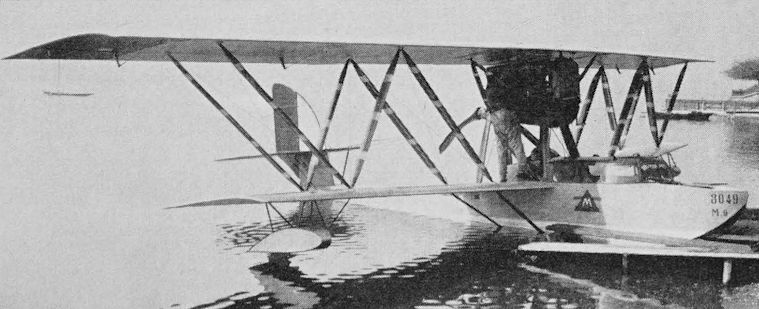
One of Ad Astra Aero’s Macchi-Nieuport M.9bis or M.9ter flying-boats at Zurichhorn. This aircraft bore c/n 3049 and was registered CH 19 or CH 20.
Savoia S.16
Societa Idrovolanti Alta Italia exhibited an attractive five-seat single-engine biplane flying-boat at the 1919 Paris Aero Show. This was the new Savoia S.16 commercial aircraft powered by a 280/300 hp Fiat A.12bis water-cooled engine and selling at 16,000 French francs. As far as can be ascertained, none of this type went into regular service with airlines, but a bomber version, known as the S.16bis, was adopted by the Regia Aeronautica.
In 1923 a modified version was produced with a 400 hp Isotta-Fraschini built Lorraine-Dietrich engine and the designation S.16ter.
A number of S.16bis and S.16ter came on to the Italian civil register, and some were used for airline work. Late in 1926 or early 1927 Aero Espresso acquired the S.16ter flying-boats I-BAUT and I-BAUV (c/ns 5148 and 5129); SISA used I-AABA, I-AABC, I-AAJU and I-AAJV as trainers from 1929; and Societa Incremento Turismo Aereo (SITA) used two S.16bis, three S.16ter and one S.16R (Fiat 300) on a San Remo - Genoa service. The SITA aircraft were I-AACD and I-AACI (S.16bis), I-AACH, I-AANW and I-AANZ (S.16ter) and I-AAOA (S.16R); the last three were c/n 5239, 5187 and 4004 respectively.
The S.16 was an equal-span two-bay strut and wire-braced biplane of wooden construction with single-step hull and single fin and rudder. The engine was mounted between the wings and drove a four-blade wooden pusher propeller. Passengers and crew were seated in two open cockpits forward of the wings.
Span 15-5 m (50 ft 10 1/4 in); length 9-9 m (32 ft 5 3/4 in); wing area 53 sq m (570-48 sq ft). Empty weight 1,850 kg (4,078 Ib); loaded weight 2,500-2,600 kg (5,511-5,732 Ib). Maximum speed at 2,000 m (6,561 ft) 194 km/h (120-5 mph); cruising speed 150 km/h (93-2 mph); alighting speed 100 km/h (62-1 mph); ceiling about 3,000 m (9,842 ft); endurance about 5 hr.
Figures for S.16ter.
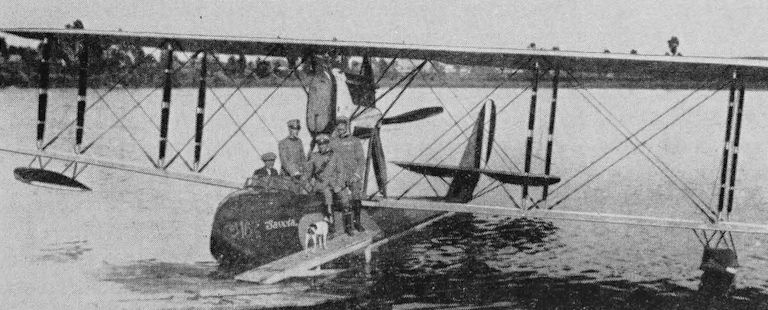
A Savoia S.16.
Blériot Spad 27
In 1919 Blériot-Aéronautique built the small Spad 27 cabin biplane as a development of the two-seat open cockpit Spad 18 Ca.1-2 also known as the Spad-Herbemont.
The Spad 27, which first flew in November 1919, was a very clean strut and wire-braced biplane with single-bay sweptback wings of unequal span. The upper wing was attached to the fuselage by splayed reverse-N struts and the upper and lower wings were connected by single I struts.
The fuselage was a monocoque structure of pleasing shape. The pilot’s open cockpit was beneath the cut-out in the trailing edge centre section of the upper wing, and immediately aft of the cockpit was a very small cabin for two passengers. The fin and rudder were of modest area, and the undercarriage was placed very far forward. The structure was of wood and the wings and tail unit fabric-covered.
The 300 hp Hispano Suiza 8Fa eight-cylinder vee water-cooled engine was closely cowled, had a frontal radiator and normally drove a two-blade wooden airscrew, although a four-blade airscrew was tried on one aircraft.
Only three Spad 27s are known. They were F-CMAV (c/n 1252), F-CMAW (c/n 1255) and F-CMAY (c/n 1254), which were used by Compagnie des Messageries Aériennes (CMA) from early 1920 on services between Paris and Hounslow and, later, Paris and Croydon. F-CMAW passed to Air Union when that company was founded on 1 January, 1923, and was sold abroad in the following year.
Span 9:72 m (31 ft 103 in); length 7-3 m (24 ft); wing area 30 sq m (322-91 sq ft). Empty weight 850 kg (1,873 Ib); loaded weight 1,260 kg (2,777 lb). Maximum speed 230 km/h (142:9 mph); landing speed 105 km/h (65-2 mph); endurance 3 hr.
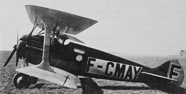
One of the Blériot Spad 27s used by Cie des Messageries Aériennes (CMA).
Breguet 14 and 18T
In June 1916 Société Anonyme des Ateliers d’Aviation Louis Breguet designed the Breguet 14 single-engine two-seat biplane. The prototype first flew at Villacoublay on 21 November, 1916, tests were completed in January 1917, orders were placed for Armée de l’Air in March, and the first aircraft was delivered on 12 April, 1917. Two main versions were laid down, the A.2 reconnaissance type and the B.2 day-bomber. The main difference was the lengthening of the lower wing of the B.2 to give almost equal span to upper and lower wings. The most commonly used engine was the 300 hp Renault 12Fe twelve-cylinder water-cooled unit, but a variety of engines was used including the 240 hp and 285 hp Fiats, the 300 hp Hispano Suiza, 375 hp Lorraine and 400 hp Liberty. The Belgian Air Force used Fiat-powered aircraft.
In all, 17 versions of the Breguet 14 were built, and during the last part of the war 5,500 Breguet 14 series were produced by Breguet, Bellanger, Darracq, Renault, Schmidt and SECM. Later, Breguet 14s were built in Spain. When production finally ceased in 1926 about 8,000 aircraft had been constructed. One example, c/n 2016, has been preserved in the French Musée de I’Air.
The Breguet 14 was of mixed construction with a mainly duralumin and steel frame covered with fabric. The wings had slight sweepback and negative stagger. Some aircraft had full-span automatic trailing edge flaps on the lower wing.
Early in 1919 a group of French aircraft industrialists, including Louis Breguet, Louis Blériot, René Caudron, Henry Farman, Robert Morane, Louis Renault and L. Saulnier, formed Cie des Messageries Aériennes (CMA). The original purpose of CMA was the operation of goods services between Paris and Lille, and this route was opened on 18 April, 1919, and two months later extended to Brussels. On 16 September, 1919, CMA began a Paris-London (Hounslow) service, and some time later this was worked through to Cricklewood in pool with Handley Page Transport. On these and other operations CMA is known to have used at least 24 Breguet 14s, of which several were provided with passenger cabins.
<...>
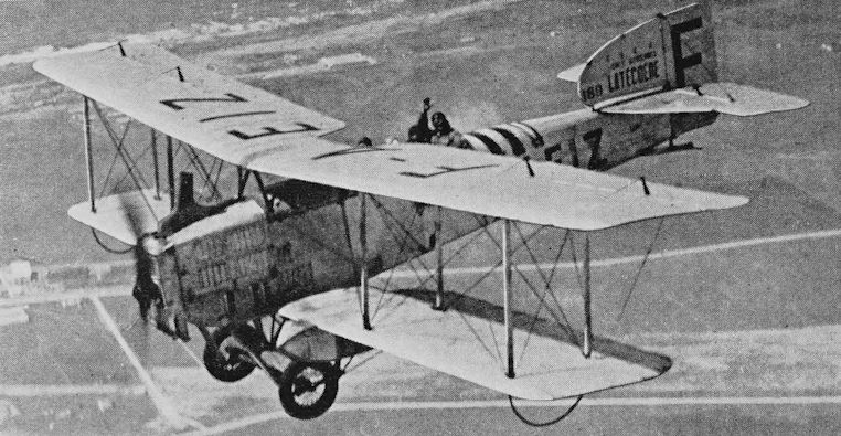
F-AEIZ, one of the very large fleet of open-cockpit Breguet 14s used by Lignes Aériennes Latécoére. This example has mail containers beneath the lower wings. The fleet number 189 appears on the fin.
Breguet 14 and 18T
<...>
A float version of the Breguet 14T was exhibited at the Paris Aero Show in 1919. Also on view was a larger version of the landplane 14T, this was the Breguet 18T Berline, which was a three-bay biplane with a 450 hp Renault 12Ja engine and a cabin for four passengers, the example shown being F-CMAX. This may have been used by CMA, but was considered generally too ambitious for its time, and was developed into the 300 hp Breguet 14T2 with a cabin for three passengers.
In 1921 a new version of the Breguet 14 was developed. This was the 14Tbis, which was a combination of the 14T and 18T. It had an improved cabin with four large windows on each side and four circular windows in each side of the upper decking in place of the older rectangular windows. The first 14Tbis, F-CMAL (c/n 1842), is reported as having made its first flight on 13 September, 1921. Judging from its registration, this would appear to have been a 14T2 rebuilt.
In the cabin Breguets the fuel tanks were removed from the fuselage and torpedo-shaped tanks were mounted underneath the upper wing between the fuselage and the inner set of interplane struts.
In French Guiana, Cie des Transports Aériens Guyanais used at least five Breguet 14Tbis cabin floatplanes. These had a large central float, stabilizing floats at mid-span and a small tail float. They worked services from St Laurent to Cayenne and Inini. Two other Breguet 14Tbis aircraft were used by the Swedish Red Cross - they could operate with wheel, float or ski undercarriage.
Immediately after the war Lignes Aériennes Latécoére (Cie Générale d’Entreprises Aéronautiques) founded by Pierre G. Latécoére began the practical development of regular service to South America. The first section, from Toulouse to Barcelona via Perpignan, was opened on 25 December, 1918. The extension to Rabat via Alicante, Malaga and Tangier opened on 1 September, 1919, and Casablanca was served regularly from April 1920. A Casablanca - Rabat-Fez - Oran service began in October 1922 and Toulouse-Alicante-Oran and Marseilles-Perpignan services early in 1924. In June 1925 the main route was opened through Agadir, Cap Juby, Villa Cisneros, Port Etienne and St Louis to Dakar. Most of these operations were undertaken by Breguet 14s, and the Latécoére company employed no less than 106 of these aircraft, with 97 on charge at the end of 1923.
Some of these Breguets were specially converted, by Latécoére, for mail carriage. They had a single cockpit, and beneath each lower wing a streamlined mail container. This type was known as the Breguet 14 Torpédo or Breguet Latécoére. It has been reported that Latécoére built Breguet 14s, and constructor’s numbers have been quoted for them; however, this does not appear to be true. It seems that, having begun operations with war-surplus aircraft still bearing camouflage and military markings, Latécoére embarked on a large-scale overhaul and rebuilding programme. These overhauled aircraft were aluminium doped on all surfaces and bore numbers in the 100, 200 and 300 series on their fins. These numbers were almost certainly fleet unit numbers and not constructor’s numbers. For example, the aircraft bearing the numbers 129, 131 and 157 are known to have had the c/ns 6389, 6365 and 3427, respectively.
The Royal Aeronautical Service of Thailand also used Breguet 14s on domestic mail services which began in 1922. Some had mail containers, but in others the bags were carried on racks on the fuselage side and held in place by nets. It was also reported that cabin Breguet 14s were used for passenger services.
SNETA in Belgium had three open-cockpit Breguet 14A.2s with 280 hp Fiat engines. These aircraft were heavier than the Renault-powered aircraft and had inferior performance.
Compania Rioplatense de Aviacion operated Breguet 14s on Buenos Aires-Montevideo services in 1921.
A number of other companies used Breguet 14s and the type set many records and made numerous outstanding flights in Europe, to the Middle East, and to North and West Africa.
Breguet 14T. Span 14-36 m (47 ft 1 1/4 in); length 9 m (29 ft 6 in); wing area 50 sq m (538-19 sq ft). Empty weight 1,238 kg (2,729 lb); useful load 300 kg (661 Ib); loaded weight 1,984 kg (4,374 lb). Cruising speed at 2,000 m (6,561 ft) 125 km/h (77:6 mph); landing speed 70 km/h (43:4 mph); ceiling 4,500 m (14,763 ft); range 460 km (285 miles).
Breguet 18T. Span 17-42 m (57 ft 1 3/4 in); length 10-1 m (33 ft 14 in); wing area 73:5 sq m (791-14 sq ft). Empty weight 1,600 kg (3,527 Ib); useful load 660 kg (1,455 Ib); loaded weight 2,700 kg (5,952 Ib). Maximum speed at 2,000 m (6,561 ft) 160 km/h (99-4 mph); ceiling 5,200 m (17,060 ft).
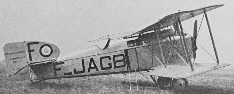
A Breguet 14T2 Salon used by CMA. This aircraft was clear-doped on all surfaces and carried the French red, white and blue roundel on its fin.
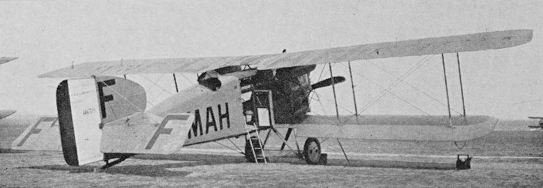
F-CMAH was a variant of the Breguet 14T2 with additional cabin windows. This CMA aircraft was clear-doped and had red, white and blue rudder stripes.
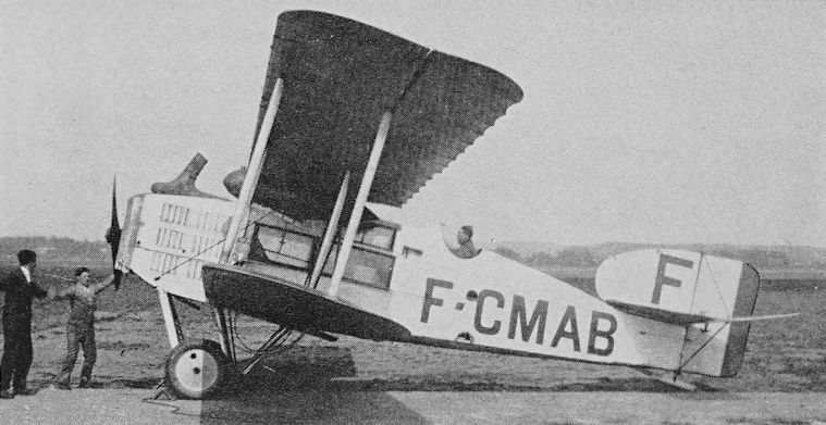
F-CMAB, seen at Croydon, was a Breguet 14A.2 converted to a Breguet 14T, It was operated by CMA.
Donnet HB 3
When l’Aéronavale (Société Maritime de Transports Aériens) began operating an Antibes - Ajaccio service at the end of November 1921 Donnet HB 3 flying-boats were used. These are believed to have been a modified version of the wartime Type D.D. three-bay biplanes built by Hydravions J. Donnet which had factories in both France and Tunis.
The Donnet HB 3 was a two-bay biplane of unequal span with the overhanging upper wing braced by a series of wires running outward from the base of the outer interplane struts. The single-step hull was ply-covered, divided into several watertight compartments, and the fin was built integrally with the hull. The wing tip floats were also of wood.
The single 275 hp Hispano Suiza 8Fd engine was mounted under the upper wing and drove a two-blade pusher propeller, a cut-out in the trailing edge of the upper wing providing propeller clearance. The car-type radiator was positioned below the leading edge. There were open cockpits for pilot and two passengers.
Two civil Donnet HB 3s are known, F-ADDX and F-ADDY (c/ns 3018 and 3019) built in 1919. Both were powered by the 275 hp Hispano Suiza 8Fd engines and operated by Aéronavale, although F-ADDY was registered to Lioré et Olivier. They are thought to have been withdrawn from service in 1927 when each had flown a little over 300 hr. It was reported that Aéronavale had three Donnet flying-boats in May 1922.
Span* 16-8 m (55 ft 1 1/2 in); length* 9-5 m (31 ft 2 in); wing area* 53 sq m (570-48 sq ft). Empty weight 1,050 kg (2,315 Ib); useful load 343 kg (756 Ib); loaded weight 1,750 kg (3,858 Ib). Cruising speed at 2,000 m (6,561 ft) 110 km/h (68-3 mph); range 240 km (149 miles).
* Dimensions for Donnet Type D.D. and weights and performance for HB 3. The span of the HB 3 is likely to have been about 14 m (46 ft).
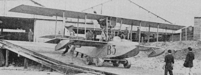
A Donnet HB 3. No photograph has been traced of a civil aircraft.
Dorand A.R.I and A.R.2
In 1916 Colonel Dorand of the Section Technique d’Aviation designed a two-seat reconnaissance biplane which bore the designation A.R.1 (A for reconnaissance and R for Renault), and this was put into production at the Government factory at Chalais-Meudon. It was also built in quantity by Farman and possibly by other companies.
The A.R.1 was a two-bay strut and wire-braced equal-span biplane of wooden construction with fabric covering. The wings had backward stagger and the fuselage was mounted at approximately mid-gap. The tailplane was strut-braced and there was no fin. The pilot’s cockpit was under the leading edge of the upper wing, the gunner/observer’s cockpit was level with the trailing edge of the top wing, and both wings had cut-outs to improve the view and field of fire.
The standard engine was the 190 hp Renault 8Bd or 8Gd eight-cylinder water-cooled unit with frontal radiator and driving a two-blade wooden airscrew. Some A.R.1s appear to have been powered by a 170 hp Renault.
After the war numbers of A.R.1s came on to the civil register and Cie Aérienne Francaise is reported to have had as many as 23. Most of these were used for training and joyriding, but some operated the company’s Nimes - Nice services which began in April 1920. Most of these aircraft had two passenger cockpits, but a few could carry three passengers over short distances.
A modified version of the A.R.1 was the A.R.2 with reduced span, and four were used by Réseau Aérien Transafricain in 1922 on services from Algiers to Ouagla via Biskra and Touggourt.
There is a report of a version of the Dorand known as the A.L.D. (A for reconnaissance and L.D. for Lorraine-Dietrich), but no civil examples are known.
Span 13:2 m (43 ft 34 in); length (tail up) 9:15 m (30 ft); wing area 50 sq m (538-19 sq ft). Empty weight 810 kg (1,785 Ib); fuel and oil 135 kg (297 lb); payload 200 kg (440 Ib); loaded weight 1,245 kg (2,745 Ib). Maximum speed at sea level 120 km/h (74:5 mph); cruising speed at 2,000 m (6,561 ft) 100 km/h (62:1 mph); stalling speed 60 km/h (37-2 mph); range with two passengers 180 km (111 miles).
Data for civil A.R.1
The A.R.2 had a span of 12 m (39 ft 44 in) and a wing area of 45 sq m (484-37 sq ft).
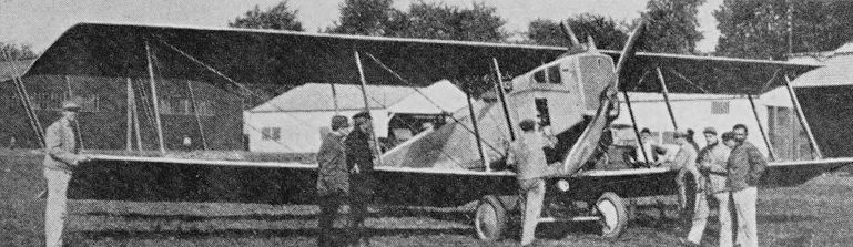
A Dorand A.R.1.
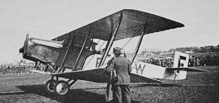
F-CAFW, one of the Dorand A.R.2s operated by Cie Aérienne Francaise.
Farman F.50
Towards the end of the 1914-18 war Avions H. & M. Farman of Billancourt, Seine, built a twin-engine night bomber known as the Type F.50-B.N.2, and it is believed to have entered service in small numbers with the French Air Force.
Farman, at the end of the war, produced a passenger-carrying version with the designation F.50P.
The F.50P was a strut and wire-braced biplane of wood and fabric construction powered by two 275 hp Lorraine-Dietrich 8Bd eight-cylinder vee water-cooled engines driving two-blade wooden airscrews.
The engines were mounted low on two sets of V struts with the radiators spanning the upper part of the front Vs. Outboard of the engines were two sets of vertical interplane struts on each side and near the wing tips another pair of struts splayed out at their upper ends. The upper wing had slightly greater span and carried balanced ailerons. The tailplane was wire-braced, and there was a single fin and rudder. Twin wheels were fitted to each main undercarriage unit.
The two-seat open cockpit was just forward of the leading edge, and between the wings was an enclosed cabin for four or five passengers.
Cie des Grands Express Aériens (CGEA) had the F.SOP F-GEAV (c/n B.N.2 6803), which made its first flight in July 1920 and was licensed to operate on the Paris-London and Paris-Amsterdam routes. It is known to have carried goods on a flight to Croydon on 31 July, 1920, but in 1922 was a reserve aircraft. F-GEAV passed to Air Union in 1923, and that company also had F-AECK, the earlier history of which is unknown.
Farman had F-HMFO (c/n 6851) which was built in 1919. This aircraft was licensed to carry only one passenger, and seems therefore to have been a modified B.N.2 and not a cabin F.50P. It was in storage at Toussus le Noble, near Paris, during the winter 1923-24.
Span 22:35 m (73 ft 4 in) upper, and 20-4 m (66 ft 114 in) lower; length (tail up) 12 m (39 ft 44 in); wing area 101-6 sq m (1,093-6 sq ft). Empty weight 1,800 kg (3,968 Ib); fuel 510 kg (1,124 lb); payload 650 kg (1,433 Ib); loaded weight 3,110 kg (6,856 Ib). Maximum speed 160 km/h (99:4 mph); cruising speed about 100 km/h (62:1 mph); ceiling 4,750 m (15,583 ft); endurance 3 1/4 hr.
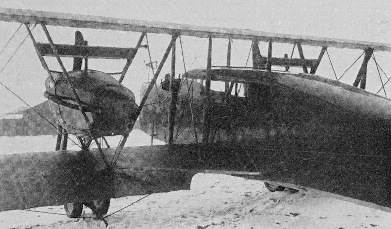
A Farman F.50P with four-five seat cabin.
Farman Goliath
The Goliath was one of the most important early transport aircraft, with somewhere around 60 examples being used in scheduled airline service. The Goliath had the type number F.60 and was intended as a bomber, and an old photograph of an uncompleted example with a forward machinegun position suggests that it was the Goliath prototype.
The first photographs of a completed Goliath, taken late in 1918, show it as a passenger aircraft with a lengthened nose housing a forward cabin. This Goliath had the military red, white and blue rudder stripes but no registration.
The Goliath was a large biplane of wooden construction with fabric covering. The untapered wings were cut off square at the tips and may have been responsible for the story that Farman wings were built by the mile and cut off by the yard.
The fuselage was quite deep and 1-328 m (4 ft 4in) wide. The rear cabin had eight seats and was separated from the four-seat front cabin by a raised open cockpit for the crew of two. The early examples had a rather hump-backed appearance, but this was eliminated in later aircraft by fairing the top decking right back to the kingpost. The first Goliath had diagonal structural members athwart the cabin, but these were omitted in production aircraft.
The original engines were two 230 hp Salmson Z.9 nine-cylinder watercooled radials. The exhaust was fed into a collector ring which formed a frame for the radiator. Most of the Z.9 engined aircraft were re-engined with the similar 260 hp Salmson CM.9.
The undercarriage consisted of twin wheel units beneath each engine, and a fairing extending from the wing to the axles gave the impression that it was trousered.
The early Goliaths had balanced ailerons which protruded beyond the wing tips, but this was later eliminated; this accounts for the discrepancies in published figures for the span. It was originally 28 m (91 ft 104 in) and after elimination of the aileron overhang 26:5 m (86 ft 10 in).
The Farman company made numerous flights with Goliaths, and one was from Toussus le Noble, near Paris, to Kenley on 8 February, 1919. The aircraft was flown by Lt Lucien Bossoutrot and carried 11 military passengers; this was the flight that has frequently been inaccurately claimed as the start of Paris-London services.
On 1 April, 1919, Bossoutrot took a Goliath, with four passengers, to 6,300 m (20,669 ft) in 1 hr 5 min; on 3 April 14 passengers were taken to 6,200 m (20,341 ft) in 1 hr 5 min; and on 5 May a height of 5,100 m (16,732 ft) was reached in 1 hr 15 min with 25 passengers. These were all world records. In August 1919 Bossoutrot and Coupet with six crew set a long-distance record by flying a Goliath nonstop for 2,050 km (1,273 miles), from Paris to Casablanca, in 18 hr 23 min.
On 29 March, 1920, Cie des Grands Express Aériens began a Paris (Le Bourget) - London (Croydon) service with Goliaths, although operation was irregular at first. The first service was flown by F-GEAB, which was one of the early aircraft. At about the same time Cie des Messageries Aériennes began using Goliaths on the Paris-London route.
Société Générale de Transports Aériens (Lignes Farman or Farman Line) opened a Paris-Brussels Goliath service on 1 July, 1920, extended it to Amsterdam on 17 May, 1921, and later extended it further to Berlin.
SNETA, the Belgian airline, began Goliath service between Brussels and London on 6 April, 1921, but ceased operation after one was lost in the Channel on 26 August and two were destroyed in a hangar fire at Haren on 28 September that year.
At least 10 of the early CMA, Grands Express and Farman Line Goliaths bore registrations which included the initials of Henry and Maurice Farman, and four of the Grands Express aircraft managed to incorporate the group GEA in their registrations.
It is difficult to assess the precise number of Goliaths built or operated, but CMA had at least 16, Grands Express had 12, and Farman Line about 18. When Air Union was formed in 1923 it took over at least 15 from CMA and Grands Express; Cie Aérienne Frangaise had F-ADCR and F-AEEE; SNETA had six, some or all of which came from Farman Line, and two of these passed to Sabena; in Czechoslovakia CSA is known to have had six, of which one was built by Avia and five by Letov; LARES in Rumania had Goliaths powered by Armstrong Siddeley Jaguar engines; and a few Goliaths were used in Latin America.
During their lives the Goliaths were fitted with a range of engines which in some cases altered their type designations. The F.60bis had the 300 hp Salmson 9Az, the F.61 the 300 hp Renault 12Fe and the F.63bis the 380 hp Gnome Rhone Jupiter 9A. Lorraine-Dietrichs were also used, some of the SNETA aircraft had 260 hp Maybachs, and the Czechoslovak aircraft had Skoda Lorraine-Dietrichs and Walter Jupiters. There was a special Goliath, F-ESAQ, fitted with four Salmsons, in tandem pairs, for record attempts. Yet another variation was a Goliath with three Salmsons. This was built for the 1921 Concours des Avions Civils, and it completed three 1,500 km (932 miles) circuits in 34 hr with a 2,250 kg (4,960 Ib) load.
A much cleaned-up Goliath, with two Jupiter engines and a two-wheel undercarriage, appeared in 1929. It was the F.169 with Jupiter 9Akx engines, and is believed to have entered service with Farman Line.
An illustration of how aircraft utilization has changed since the early days of air transport is given by the fact that in the first 10 years of operation the greatest time flown by a civil Goliath was 2,962 hr 25 min by F-GEAI. By 1933 F-GEAC had flown 3,843 hr. Many present-day transport aircraft regularly exceed this figure annually.
One of the Grands Express Goliaths, F-GEAD, made history by being involved in the first airborne collision between civil airliners when on 7 April, 1922, it collided with the Daimler Airway D.H.18 G-EAWO over Poix.
Two 10-passenger Jupiter-powered F.63ter aircraft built as late as 1929 were operated by Farman Line, and the last Goliaths in airline service appear to have been withdrawn in 1933. The fuselage, fin and rudder of the Air Union F-HMFU Ile-de-France have been preserved by the French Musée de l’Air.
A number of Goliath variants, including floatplanes, were used by the French forces.
At the end of 1919 the price of a Goliath was the equivalent of £4,250.
F.60 with Salmson CM.9 engines. Span 26:5 m (86 ft 10 in); length 14:33 m (47 ft); wing area 161 sq m (1,732-98 sq ft). Empty weight 2,500 kg (5,511 Ib); fuel 468 kg (1,031 lb); useful load 1,600 kg (3,527 Ib); loaded weight 4,770 kg (10,515 Ib). Cruising speed at 2,000 m (6,561 ft) 120 km/h (74:5 mph); ceiling 4,000 m (13,123 ft); range 400 km (248 miles).
F.63bis with Gnome Rhone Jupiter 9Aa engines. Span and wing area as F.60. Length 13-9 m (45 ft 7 in). Empty weight 3,030 kg (6,680 Ib); fuel 733 kg (1,616 Ib); loaded weight 5,395 kg (11,894 lb). Cruising speed at 2,000 m (6,561 ft) 152 km/h (94:4 mph); ceiling 3,900 m (12,795 ft); range 400 km (248 miles).
Weight and performance figures were subject to variation.
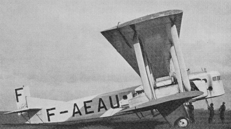
The Farman Line’s F.61 Goliath F-AEAU with Renault 12Fe engines, seen at Haren, Brussels. This aircraft is believed to have had a light blue fuselage and fin and clear-doped wings. The registration was in black on a white panel.
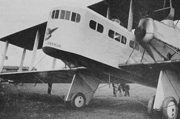
The SNETA Farman Goliath O-BLON with 260 hp Maybach engines.
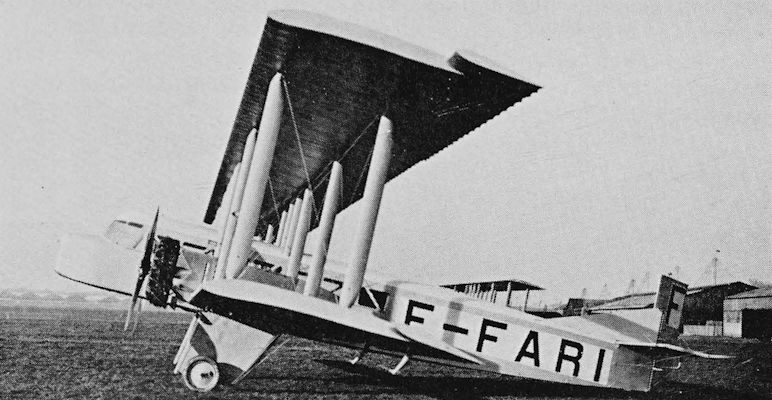
The Farman F.63bis F-FARI with Gnome Rhone Jupiter engines, forward crew cabin and horn-balanced ailerons, in 1927 after conversion from a standard Salmson-powered F.60.
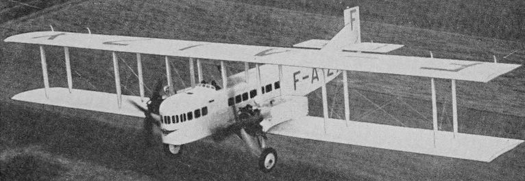
The 12-passenger prototype Farman F.169 Goliath F-AIZX of 1929 with Gnome Rhone Jupiter engines and two-wheel divided undercarriage.
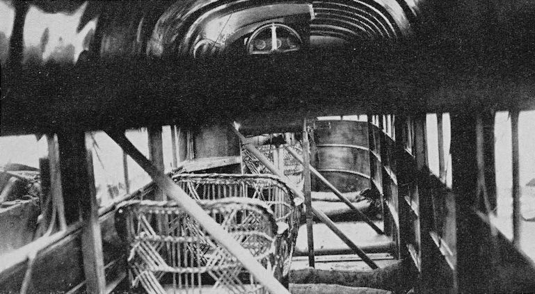
An early example of the completely enclosed transport aircraft. This is a Farman Goliath with very primitive accommodation. The dark bar running across the picture is a structural member. The raised pilot’s position is seen at the top of the picture.
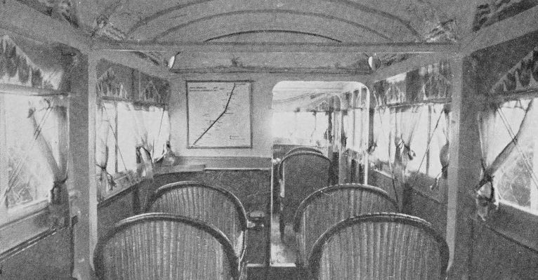
The cabins of a Farman Line Goliath, showing the Paris - Brussels - Amsterdam route map on the bulkhead and the décor of painted tulips, windmills and seagulls.
Latécoére 3 Postal
At the 1919-20 Paris Aero Show, Forges et Ateliers de Construction Latécoére showed a very clean two-bay biplane. On the side of the fuselage was inscribed, in capital letters, Lignes Aériennes G. Latécoére France Espagne Maroc, and on the rudder could be seen the words Avion Postal Type Toulouse Rabat. It was stated at that time that this type was in service between Toulouse and Rabat. The aircraft exhibited was the Latécoere 3, it bore no registration, and no other examples are known.
The Latécoere 3 had a fabric-covered duralumin structure, and the Paris Aero Show model had a high gloss finish. The wings were of equal span, and there were balanced ailerons on all four wings, the rudder was balanced and of large area but the triangular fin was very small. The pilot had an open cockpit under the centre section and there was a larger open cockpit aft of the wings - this had two seats in tandem. The 260 hp Salmson Z.9 nine-cylinder water-cooled radial engine was very neatly cowled and drove a two-blade airscrew.
Span 12-57 m (41 ft 3 in); length 7-56 m (24 ft 10 in). Empty weight 1,055 kg (2,325 Ib); loaded weight 1,675 kg (3,692 Ib). Maximum speed 200 km/h (124:2 mph); cruising speed 180 km/h (111-8 mph); range 600 km (372 miles).
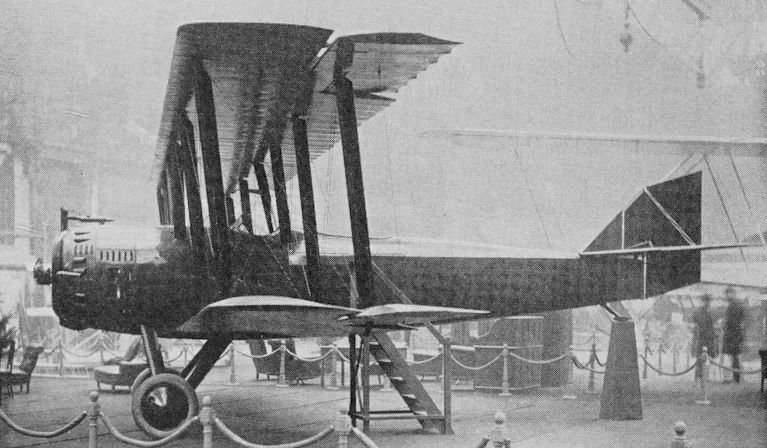
The Latécoére 3 Postal at the VIe Exposition Internationale de Locomotion Aérienne in the Grand Palais, Paris, December 1919 - January 1920.
Lévy-Lepen
This was a three-seat flying-boat built during the 1914-18 war for the French Marine by Hydravions Georges Lévy. It is believed to have been the Type R. Using this type, SNETA opened the first stage of the Ligne Aérienne Roi Albert from Kinshasha (now Léopoldville) to N’Gombé on 1 July, 1920. On 3 March, 1921, the N’Gombé-Lisala sector was opened and on 1 July, 1921, the entire Congo River route between Kinshasha and Stanleyville was inaugurated. These were the first air services in equatorial Africa. In spite of the problem of having to re-attach the fabric to the structure of the aircraft after each flight because of the effects of heat and humidity, the operations continued until 7 June, 1922. 125,000 km (77,671 miles) were flown and 95 passengers and about 2,000 kg (4,409 Ib) of mail carried.
Sté Franco-Bilbaine used the type on Bayonne - Bilbao - Santander services in 1920-21, and Cie des Transports Aériens Guyanais had five in French Guiana in 1922.
The Lévy-Lepen was a biplane of unequal span, with folding wings, and had an open cockpit with two side-by-side seats just forward of the wings with a single-seat cockpit further forward. The SNETA aircraft appear to have been unregistered.
The engine used was a 300 hp Renault which drove a pusher propeller.
Span 18-5 m (60 ft 7 3/4 in) upper, and 12 m (39 ft 4 1/2 in) lower; length 12-4 m (40 ft 8 in). Empty weight 1,450 kg (3,196 Ib); loaded weight 2,450 kg (5,401 Ib). Speed 145 km/h (90 mph). Other details unknown.
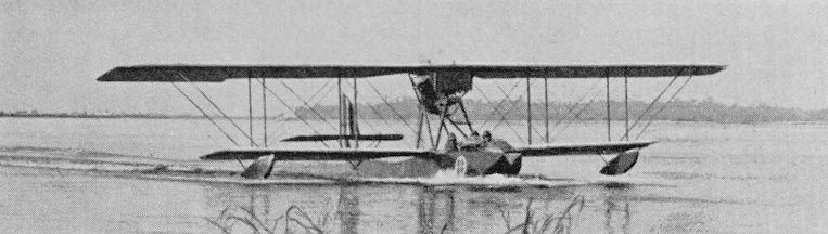
One of the SNETA Lévy-Lepen flying-boats on the Congo River.
Nieuport 30T
The Nieuport 30T was a single-engine two-bay biplane with backward stagger. It was built by Société Anonyme des Etablissements Nieuport and exhibited at the Paris Salon in the winter of 1919-20. At least seven were used on Paris-London services by Cie Gle Transaérienne in 1919 and 1920.
The Nieuport 30T was powered by a 450 hp Renault water-cooled engine which had three Lamblin radiators beneath the nose just forward of the undercarriage. The pilot’s open cockpit was beneath the centre section and there was a cabin for six to eight passengers. The structure was of wood and the wings were fabric-covered.
The Cie Gle Transaérienne Nieuport fleet comprised F-CGAT, F-CGTA, F-CGTE, F-CGTI, F-CGTO, F-CGTU and F-CGTY. The last of these was lost in the English Channel on 27 April, 1920. All had disappeared from the register by 1922, but in 1925 F-CGAT returned to the register and was shown as a Nieuport 30T.1 powered by a 350 hp Sunbeam engine and owned by Nieuport Astra.
A larger version of the Nieuport, with the designation 30T.2, was shown at the 1921 Paris Show. It was powered by a 420 hp Sunbeam Matabele engine and had accommodation for four to seven passengers. None are known to have gone into service.
30T.1. Span 13-5 m (44 ft 3 1/2 in) upper, and 14-5 m (47 ft 7 in) lower; length 10:7 m (35 ft 1 1/4 in); wing area 65 sq m (699-65 sq ft). Empty weight 1,500 kg (3,307 lb); fuel 250 kg (551 lb); useful load 650 kg (1,433 Ib); loaded weight 2,400 kg (5,291 lb). Performance unknown.
30T.2. Span 18 m (59 ft); length 10-8 m (35 ft 5 1/4 in); wing area 82 sq m (882-64 sq ft). Empty weight 2,100 kg (4,629 lb); fuel 436 kg (961 Ib); payload 500 kg (1,102 Ib); loaded weight 3,058 kg (6,741 Ib). Maximum speed 170 km/h (105-6 mph); cruising speed 140 km/h (86:9 mph); ceiling 4,000 m (13,123 ft); range 420 km (260 miles).
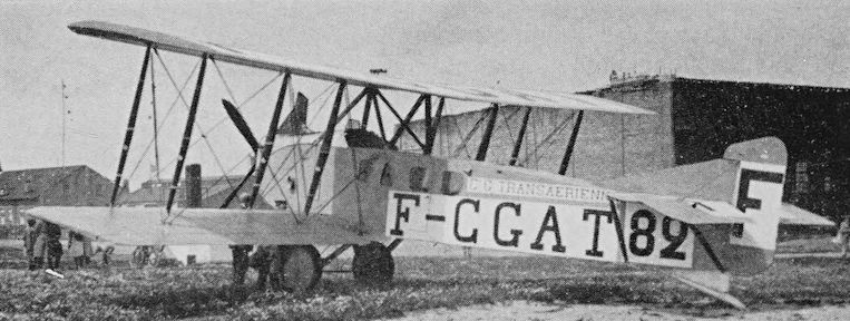
Cie Gle Transaérienne’s Nieuport 30T F-CGAT at Haren Airport, Brussels.
Potez S.E.A. VII
The civil Potez S.E.A. VII was one of the first products of Société des Aéroplanes Henry Potez which had previously been known as Société des Etablissements Angevins and Société d’Etudes Aéronautiques, from which came the initials S.E.A.
The civil S.E.A. VII was a development of the military reconnaissance S.E.A. VII of 1918, and the prototype was exhibited at the 1919-20 Paris Aeronautical Salon as the Potez S.E.A. VII Limousine. It made its first flight in December 1919.
The Potez S.E.A. VII was a two-bay tractor biplane powered by a 370 hp Lorraine-Dietrich 12Da water-cooled vee engine. The wings were of equal span and had slight backward stagger. The two-seat passenger cabin was a square cab-like structure positioned aft of the pilot’s open cockpit and reached by a fixed ladder on the port side of the fuselage.
Production aircraft appeared in 1920, and the prototype made a special flight to Croydon on 16 July that year. Twenty-five have been reported, with all going to Cie Franco-Roumaine de Navigation Aérienne. They were used on the trans-Europe route and are known to have operated as far as Warsaw and Constantinople. It is believed that the registrations of the Potez VIIs ran from F-FRAA to F-FRAY. Known aircraft were F-FRAA (c/n 106) the prototype, F-FRAE, F-FRAF, F-FRAG, F-FRAP (c/n 121), F-FRAR, F-FRAY (c/n 133) and F-FRAW (c/n 134). Of these F-FRAP and F-FRAW passed to CIDNA in 1925.
Span 14 m (45 ft 11 in); length 9-2 m (30 ft 2 in); wing area 44-5 sq m (478-9 sq ft). Empty weight 1,100 kg (2,425 lb); loaded weight 1,650 kg (3,637 Ib). Maximum speed 200 km/h (124-2 mph); cruising speed 180 km/h (111-8 mph); endurance up to 2 3/4 hr.

The Potez VII F-FRAE.
Salmson 2-A.2
The Salmson 2-A.2 two-seat reconnaissance biplane was built by Société des Moteurs Salmson, and the prototype completed its trials in April 1917 at Villacoublay. It entered service with the French Air Force early in 1918, and was adopted by the United States as the standard reconnaissance type. A total of 3,200 was built.
The 2-A.2 was an equal span two-bay biplane of mixed construction. The fuselage was circular in section for much of its length, and the 230 hp Salmson Z.9 or 260 hp Salmson CM.9 water-cooled radial engine was neatly cowled. The pilot’s cockpit was under the leading edge, and the second cockpit was very far aft. The aircraft had no fin.
A considerable number of Salmson 2-A.2s were used by civil operators, and some of them were rebuilt with a two-passenger cabin aft of the pilot’s cockpit. Some Salmsons were built, or rebuilt, by Latécoére and that company’s airline, Lignes Aériennes Latécoére, operated a large number. It had 17 in its fleet in May 1922, and the total number used by the airline was probably about 40. It was an open cockpit Salmson with military markings that was used on Latécoére’s first experimental mail flight from Toulouse to Rabat and Casablanca in July 1919.
Cie Franco-Roumaine had at least 14 Salmsons, and five of them passed to CIDNA in 1925; they were based at Le Bourget, Strasbourg and Prague. CMA had two Salmsons; Cie Gle Transaérienne is reported to have used Salmsons on its Paris-London services in 1919 and 1920; Cie Air Transport had at least one which passed to Air Union; Aero-Transports Ernoul had 14 Salmsons in 1922; and Japan Airways had at least 12, which were built by Kawasaki and the Nagoya Arsenal.
F-ALVI, of the Latécoére fleet, is known to have been a Limousine version, and F-ALAO, another Limousine, may also have belonged to the airline; CIDNA had Limousines, and it is likely that many of the airline Salmsons were of the enclosed type, but confirmation has not proved possible.
Span 11-75 m (38 ft 6 in); length 8-5 m (27 ft 10 1/2 in); wing area 37 sq m (398-26 sq ft). Empty weight 906 kg (1,997 Ib); fuel 273 kg (601 Ib); useful load 200 kg (440 Ib); loaded weight 1,488 kg (3,280 Ib). Cruising speed at 2,000 m (6,561 ft) 140 km/h (86:9 mph); ceiling 4,500 m (14,763 ft); range 500 km (310 miles).
Figures are for the Limousine.
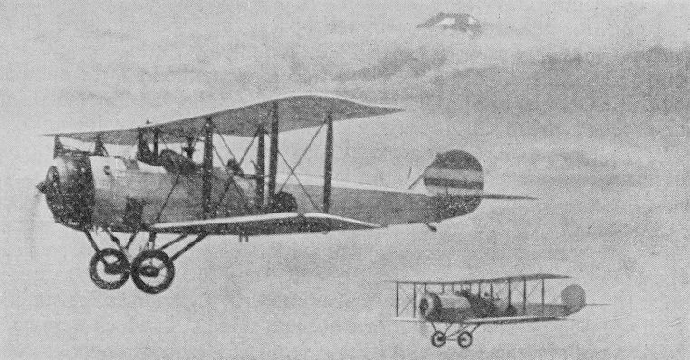
The Salmson 2-A.2 was used in numbers by French airlines and by Japan Airways. These, seen flying near Fujiyama, are Japanese military trainers.
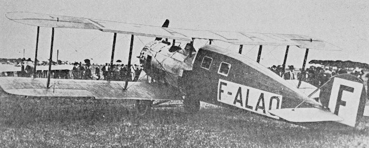
The Salmson Limousine F-ALAO may have been part of the Latécoere fleet.
Haefeli DH 3
The DH 3 was a two-seat reconnaissance bomber designed by A. Haefeli and ordered for the Swiss military service in 1916. A batch of 30 was laid down by the Federal Construction Works in Thun, and the first flight of a DH 3 took place on 25 June, 1917. Total production appears to have been 90 or 120.
The DH 3 was a two-bay biplane of unequal span, and was of wooden construction with fabric covering. The first 24 production aircraft had 120 hp Argus engines, but later aircraft had a 150 hp Hispano Suiza engine. A second batch of 30 was ordered in August 1917, and 25 of these had Hispano Suiza engines built under licence by Adolf Saurer. The other five had 200 hp engines, which were developed by the Swiss locomotive factory at Winterthur. It is reported that another batch of 30 DH 3s was built as late as 1926.
On 8 January, 1919, an experimental military mail service was opened between Zurich and Berne, using DH 3s. Bad weather interrupted the service, and only 14 return flights had been made by the end of the month. On 1 February the service was extended to Lausanne, but bad weather prevented the Berne - Lausanne sector being worked on 16 days out of the first 28. Public mail service was planned to begin on 1 May, but weather again interfered, and the first satisfactory flights took place on 5 May. From June passengers were carried, and when the service was closed at the end of October, 246 passengers and 20,348 despatches had been carried in six months.
The DH 3 was still in service as a trainer in 1936.
Span 12:5 m (41 ft); length 8-05 m (26 ft 5 in) with Argus, and 7:95 m (26 ft 1 in) with Hispano Suiza; wing area 38 sq m (409 sq ft).
With Argus engine. Empty weight 665 kg (1,466 Ib); loaded weight 1,040 kg (2,292 Ib). Maximum speed 135 km/h (83:8 mph).
With Hispano Suiza engine. Empty weight 690 kg (1,521 Ib); loaded weight 1,080 kg (2,380 Ib). Maximum speed 145 km/h (90 mph).
Other details unknown
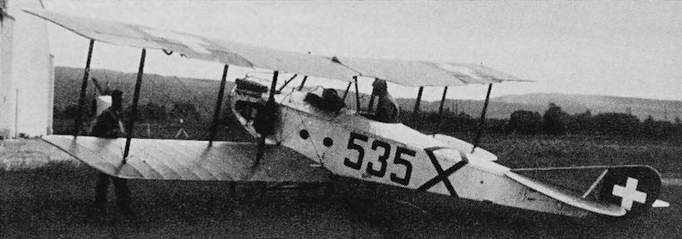
One of the Haefeli DH 3s used on the Swiss Army mail and passenger services in 1919.