Описание
Страна: Германия
Год: 1917
Twin-engined long-range bomber
Варианты
- Gotha - G.II/G.III - 1916 - Германия
- Gotha - G.IV - 1916 - Германия
- Gotha - G.V - 1917 - Германия
- В.Кондратьев Самолеты первой мировой войны
- O.Thetford, P.Gray German Aircraft of the First World War (Putnam)
- J.Herris Gotha Aircraft of WWI (A Centennial Perspective on Great War Airplanes 6)
- P.Grosz, G.Haddow, P.Shiemer Austro-Hungarian Army Aircraft of World War One (Flying Machines)
- Журнал Flight
-
J.Herris - Gotha Aircraft of WWI /Centennial Perspective/ (6)
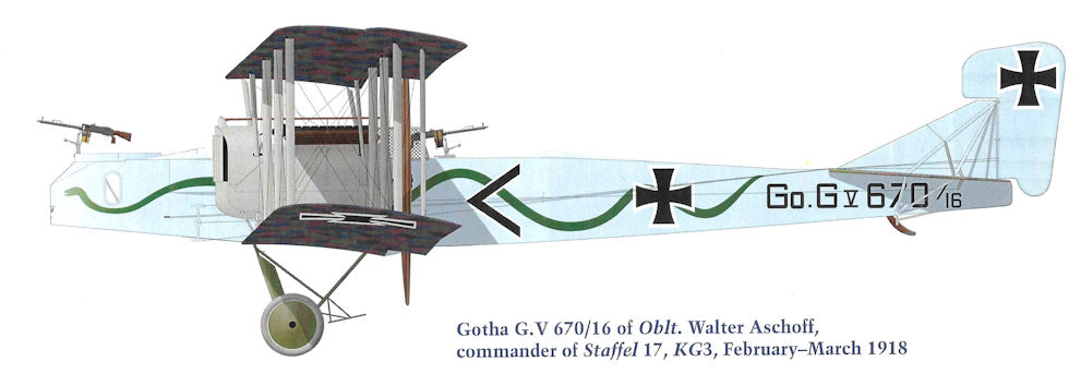
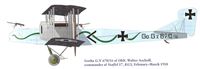
Gotha G.V 670/16 of Oblt. Walter Aschoff, commander of Staffel 17, KG3, February-March 1918
-
J.Herris - Gotha Aircraft of WWI /Centennial Perspective/ (6)
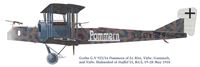
Gotha G.V 925/16 Pommern of Lt. Rist, Vzfw. Gummelt, and Vzfw. Huhnsdorf of Staffel 15, KG3, 19-20 May 1918
-

J.Herris - Development of German Warplanes in WWI /Centennial Perspective/ (1)
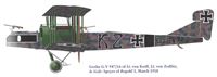
Gotha G.V(LVG) 947/16 of Bogohl 3, March 1918. The crew was Lt. von Korff Lt. von Zedlitz, and Gefr. Speyer.
-
J.Herris - Gotha Aircraft of WWI /Centennial Perspective/ (6)
Gotha G.V 947/16 of Lt. von Korff, Lt. von Zedlitz, & Gefr. Speyer of Bogohl 3, March 1918
-
J.Herris - Gotha Aircraft of WWI /Centennial Perspective/ (6)
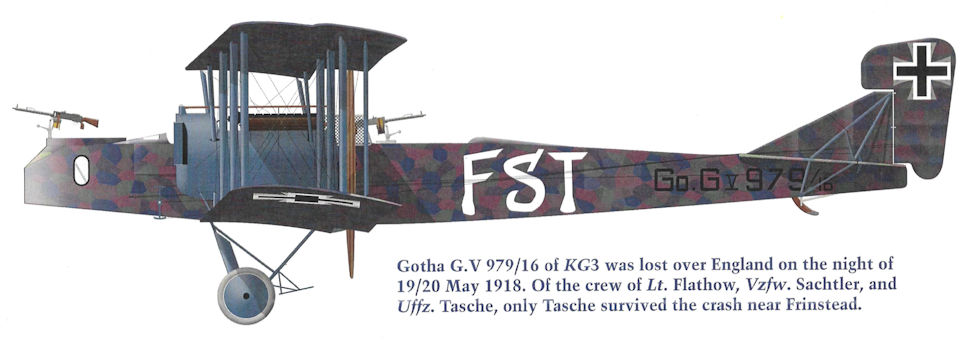
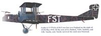
Gotha G.V 979/16 of KG3 was lost over England on the night of 19/20 May 1918. Of the crew of Lt. Flathow, Vzfw. Sachtler, and Uffz. Tasche, only Tasche survived the crash near Frinstead.
-
J.Herris - Gotha Aircraft of WWI /Centennial Perspective/ (6)
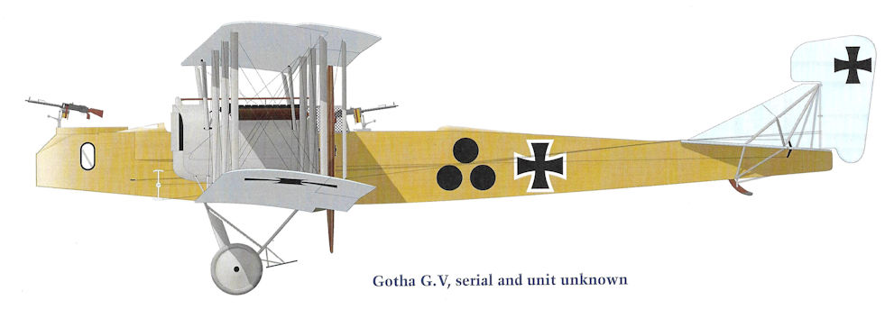
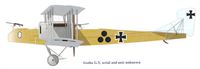
Gotha G.V, serial and unit unknown
-

-

E.Hauke, W.Schroeder, B.Totschinger - Die Flugzeuge der k.u.k. Luftfahrtruppe und Seeflieger 1914-1918
Gotha G V 08.11 Flik 101G Aviano Frühjahr 1918
-
J.Herris - Gotha Aircraft of WWI /Centennial Perspective/ (6)
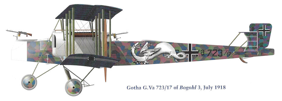
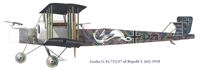
Gotha G.Va 723/17 of Bogohl 3, July 1918
-
J.Herris - Gotha Aircraft of WWI /Centennial Perspective/ (6)
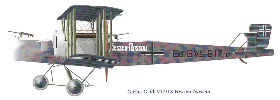
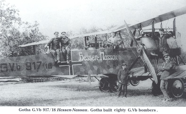
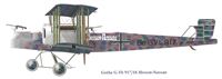
Gotha G.Vb 917/18 Hessen-Nassau
-

J.Herris - Gotha Aircraft of WWI /Centennial Perspective/ (6)
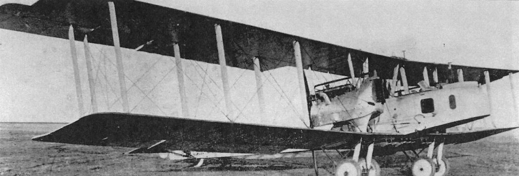
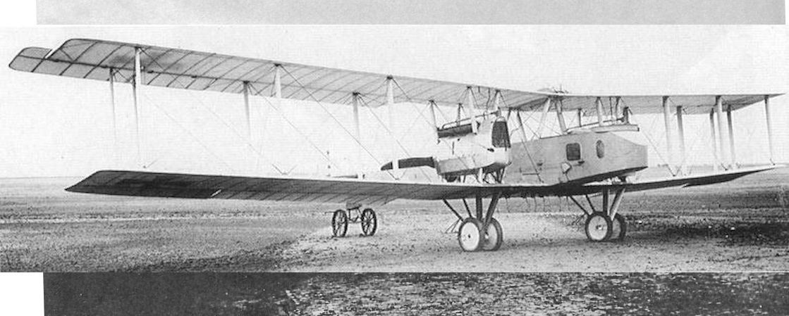
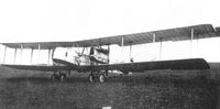
This Gotha G.V fitted with a simplified undercarriage is either the prototype or an early production model.
-
J.Herris - Gotha Aircraft of WWI /Centennial Perspective/ (6)
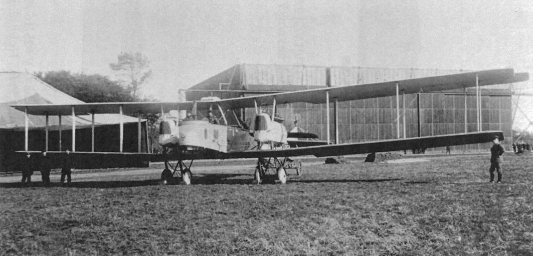
Front quarter view of an early Gotha G.V with faired struts supporting the engine nacelle.
-

-
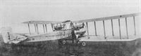
Журнал - Flight за 1918 г.
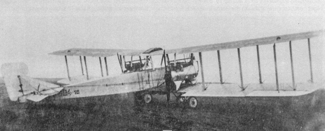
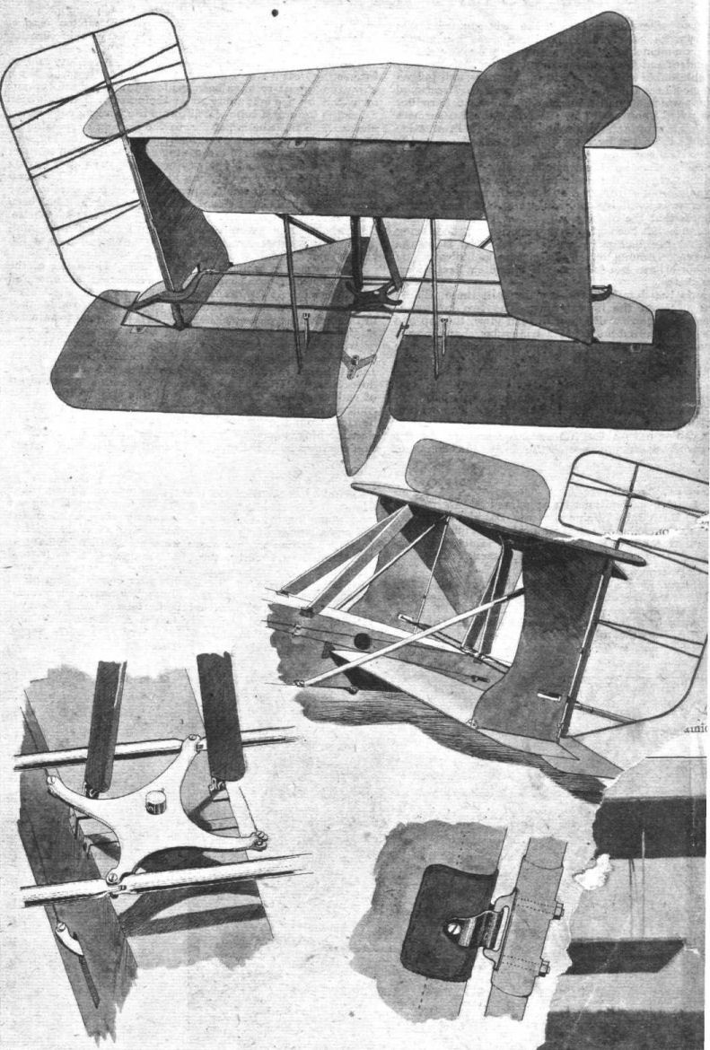
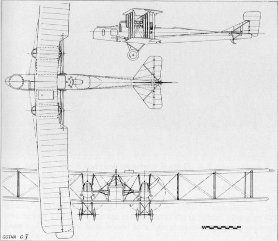
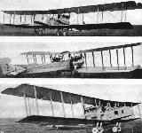
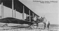
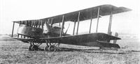
THREE VIEWS OF A GOTHA BOMBING BIPLANE. - It will be seen that it differs slightly from that described in "FLIGHT" for December 27th last, in that there is little or no sweep back, and that the engine housings are considerably modified.
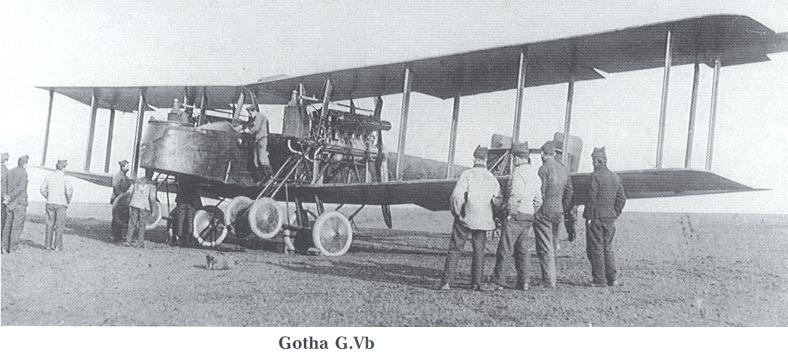
The Gotha G V used the same engines as the Gotha G IV, following it into operational service in 1918. Top level speed of the G V was 87mph, while cruising speed was 80.8mph. Range of the G V was quoted as 522 miles, but this figure clearly reflects operations with a reduced bomb load. 120 G Vs are reported to have been built, plus 25 G Va and 55 G Vb, the latter two variants being equipped with biplane tail units. -
J.Herris - Gotha Aircraft of WWI /Centennial Perspective/ (6)
Other than the change in location of the fuel tanks that affected the engine nacelles, the Gotha G.V was otherwise like the G.IV in all important respects. Not only did it offer no performance improvement, the deteriorating quality of the materials available for construction meant the G.V was a heavier airplane, reducing performance.
-

-

-

J.Herris - Development of German Warplanes in WWI /Centennial Perspective/ (1)
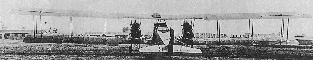
If one airplane epitomized German bombers, it was the Gotha. The Gotha G.II through G.V were of similar configuration; a G.V is shown. Gothas became instantly infamous for bombing London in broad daylight on 13 June, 1917, shocking the world. More daylight raids followed; in September 1917 the Gothas switched to night bombing when daylight defenses grew too strong.
-

Сайт - Pilots-and-planes /WWW/
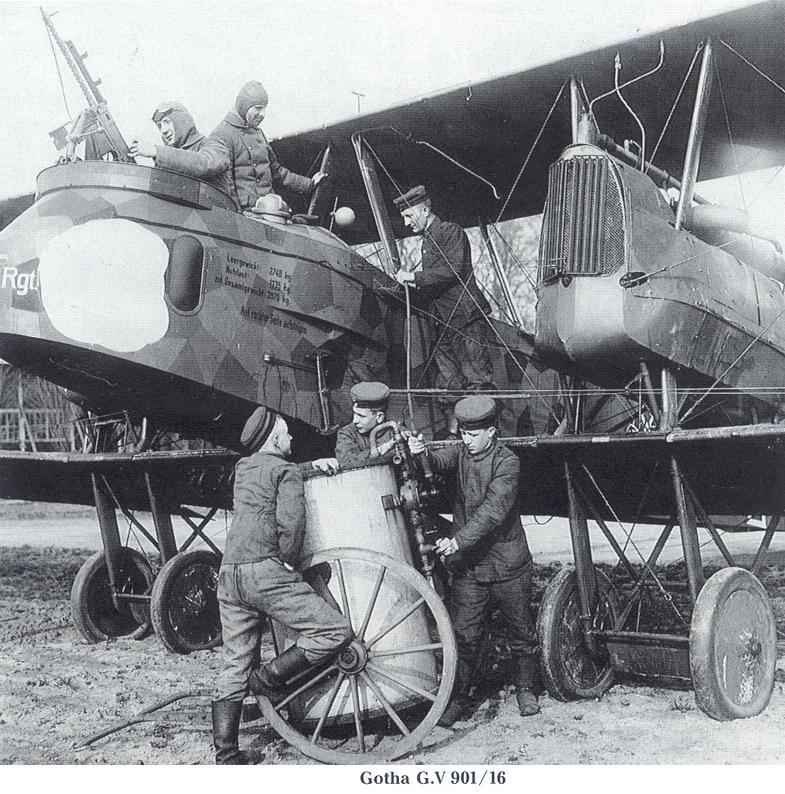
Gotha G.V 901/16
-
J.Herris - Gotha Aircraft of WWI /Centennial Perspective/ (6)
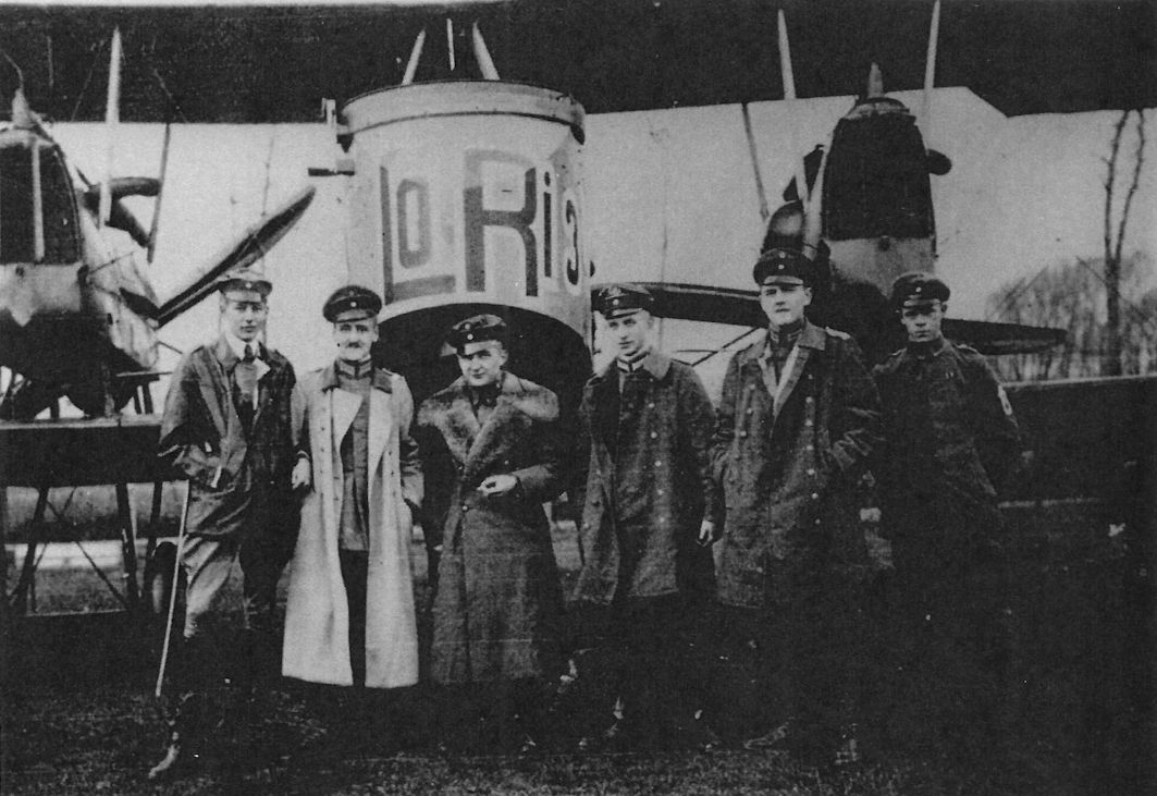
Gotha G.V LoRi 3 of Kasta 16, Bogohl 3, and crew.
-
J.Herris - Gotha Aircraft of WWI /Centennial Perspective/ (6)
A Gotha crewman inflates his life jacket before a mission over the English Channel.
-
J.Herris - Gotha Aircraft of WWI /Centennial Perspective/ (6)
The Gotha crewman gets a final adjustments of his flight gear from a ground crewman before take-off.
-
J.Herris - Gotha Aircraft of WWI /Centennial Perspective/ (6)
The distinguishing feature of the Gotha G.V was its new engine nacelles suspended between the wings. The fuel tanks were moved from the nacelles, their location in the G.IV, to the fuselage to reduce the danger of fire in a crash.
-
J.Herris - Gotha Aircraft of WWI /Centennial Perspective/ (6)
Gotha G.V in night camouflage.
-

M.Dusing - German & Austro-Hungarian Aero Engines of WWI. Vol.2 /Centennial Perspective/ (65)
Mercedes D IVa in Gotha G.V.
This view of a Gotha G.V flown by Kasta 17 of Bogohl 3 shows its new engine nacelles, the night camouflage, and the original iron cross insignia over-painted to the new, straight-sided insignia. The bomber has an interesting marking of a constellation of eight-pointed stars with a line connecting them. Plates behind the wheels deflect debris from going through the propeller arc. A large load of bombs is carried beneath the wing center section. -

J.Herris - Gotha Aircraft of WWI /Centennial Perspective/ (6)
Rear view of the Gotha G.V; this aircraft has only one over-wing gravity fuel tank.
-

J.Herris - Gotha Aircraft of WWI /Centennial Perspective/ (6)
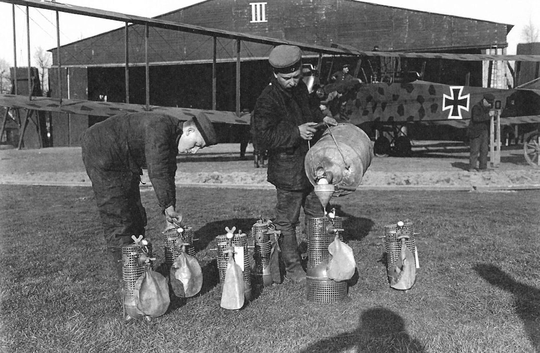
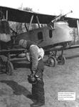
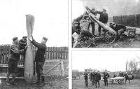
Mechanics of Kagohl III filling the containers of the Ahrendt and Heylandt breathing equipment with liquid oxygen. This was done shortly before take-off and the containers were sealed. Although the speed of vapourization varied, the pressure in the containers increased with the passage of time and a safety valve was necessary, but this had the effect of reducing the amount of oxygen available with increase of altitude. Later a barometric valve was fitted to similar equipment made by Fluessige Case (Liquid Gas) of Kiel and this automatically regulated the oxygen supply for altitude, and was more economical in use.
-

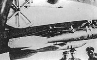
A.Imrie - German Bombers /Arms & Armour/
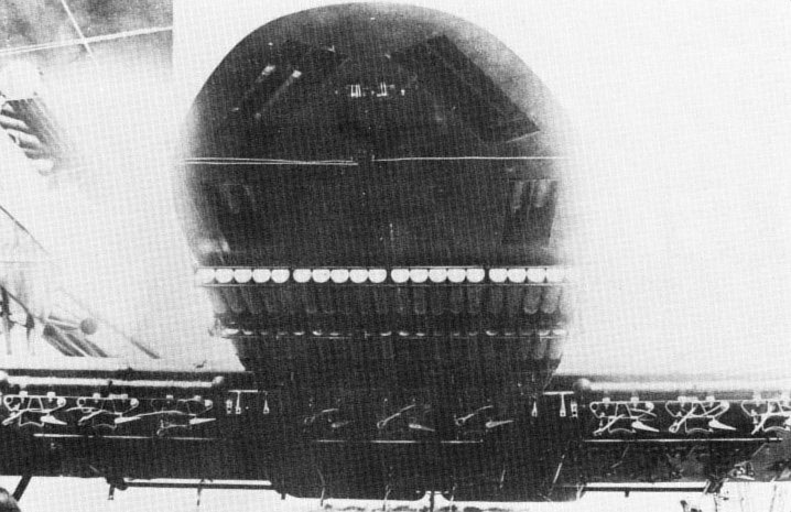
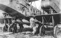
The small but highly effective Elektron incendiary bomb produced early in 1918 weighed only 1kg and could not be extinguished with water. It measured 14in long and was 2in in diameter, was filled with compressed thermite, and its three straight fins terminating in a circular tail ring made it almost identical to the weapon used by the Luftwaffe in World War Two. The intended use of the bomb against centres of population was prohibited on humanitarian grounds. However, in March 1918 large-scale incendiary attacks using these bombs were planned, to be carried out by Bogohl III against London, and Bogohl I, II, V and VII against Paris. Each aircraft could carry 500 bombs of this type, and in round-the-clock operation by both day and night it was considered that the number of fires started would swamp the fire protection services. (Fire-storm properties were understood at this time.) The German High Command (under whose auspices the Bogohl operated) must have issued the attack instructions, but they were countermanded (it is said by the Kaiser himself) only 30 minutes before the first aeroplane was due to take off. Forty Elektron bombs are shown here in special racks under the nose of a Gotha G V, while others are visible in the vertical magazine exits.
-
J.Herris - Gotha Aircraft of WWI /Centennial Perspective/ (6)
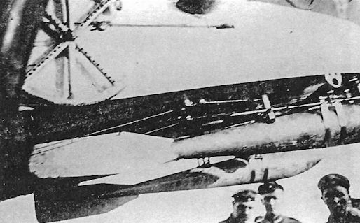
Closeup of bombs hung under the extreme nose of a Gotha to provide a proper center of gravity. The Gothas were stable until the bombs were dropped, but pitch stability deteriorated significantly after that!
-
J.Herris - Gotha Aircraft of WWI /Centennial Perspective/ (6)
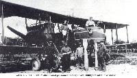
Gotha G.V 904/16 at the factory before night camouflage and the Stossfahrgestell were applied. The fairings on the engine nacelle struts were later removed. Seven 50-kg PuW bombs are under the center section.
-
-
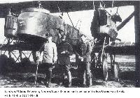
Сайт - Pilots-and-planes /WWW/
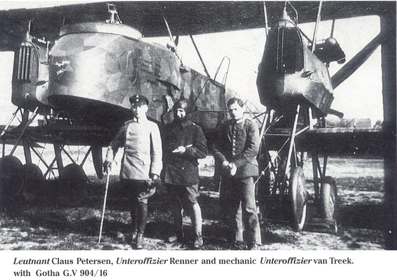
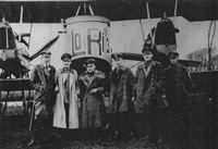
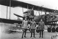
Leutnant Claus Petersen, Unteroffizier Renner and mechanic Unteroffizier van Treek with Gotha G.V 904/16
-
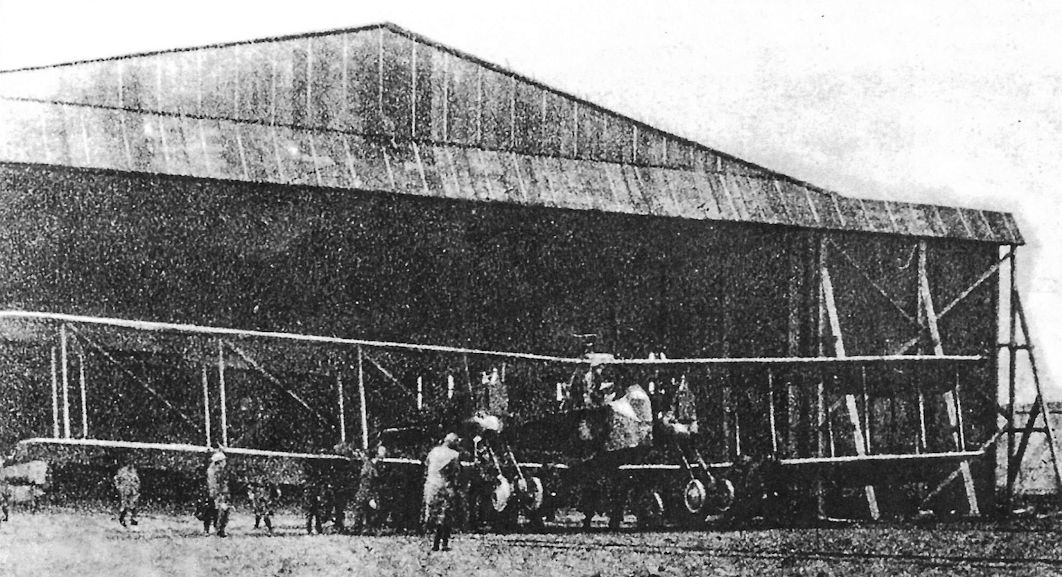
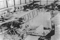
Сайт - Pilots-and-planes /WWW/
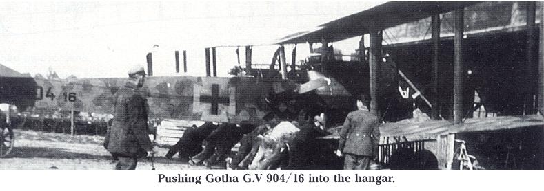
Pushing Gotha G.V 904/16 into the hangar.
-
Сайт - Pilots-and-planes /WWW/
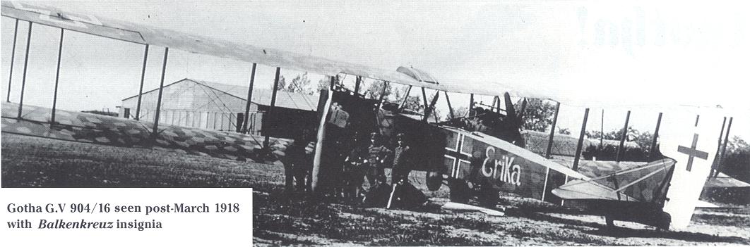
Gotha G.V 904/16 seen post-March 1918 with Balkenkreuz insignia.
-
Сайт - Pilots-and-planes /WWW/
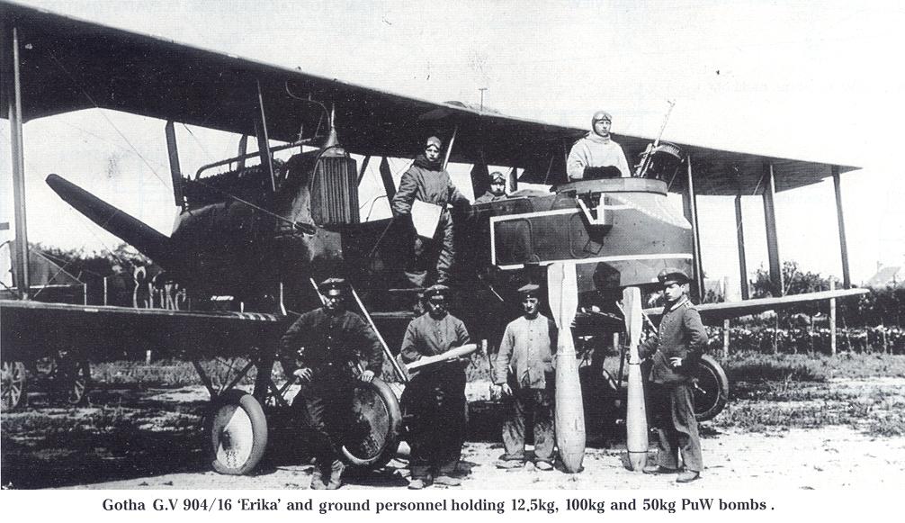
Gotha G.V 904/16 'Erika' and ground personnel holding 12,5kg, 100kg and 50kg PuW bombs.
-
J.Herris - Gotha Aircraft of WWI /Centennial Perspective/ (6)
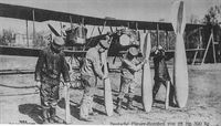
Mechanics of Kasta 14, Kagohl III, illustrate the range of bombs that Gotha bombers could carry with Gotha G.V 901/16 in the background. From left to right, the bombs are 12.5 kg, 50 kg, 100 kg, and 300 kg PuW bombs. The smaller sizes were in use from mid-1916, but the 100kg and 300kg P.u.W. bombs did not appear until over twelve months later, the first examples being dropped on St Omer by Kagohl I on 23 August 1917. Reproduced as a Sanke card, this was a popular propaganda photograph.
-
J.Herris - Gotha Aircraft of WWI /Centennial Perspective/ (6)
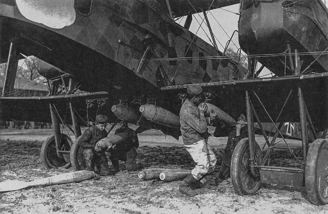
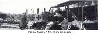
Groundcrew handling bombs to load on a Gotha. They are doing most of the work manually, with a primitive cart their only mechanical aid. These scenes could have been taken at any German base supporting twin-engine bombers in 1917 or 1918, regardless of the bomber's type.
-

J.Herris - Gotha Aircraft of WWI /Centennial Perspective/ (6)
Ground crewmen load bombs by hand onto Gotha G.V 901/16. The engine nacelles on the G.V were raised above the wing on struts, which distinguishes the G.V from the earlier G.IV.
-
-
J.Herris - Gotha Aircraft of WWI /Centennial Perspective/ (6)
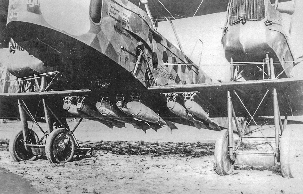
Gotha G.V 901/16 fully loaded with bombs; five 50-kg and two 100-kg PuW bombs are on the racks.
-

M.Dusing - German Aviation Industry in WWI. Volume 1 /Centennial Perspective/ (84)
Another view of a fully-loaded Gotha G.V. A number of 12.5 kg bombs were usually carried in the forward cockpit.
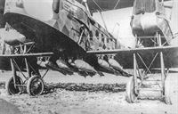
Using the standard racks for the P.u.W. bombs, the composition of bombload could easily be varied. Under the centre-section of this Gotha G V can be seen five 50kg and two 100kg bombs. Aircraft of this type seldom carried more than a maximum of 500kg bomb-load even on short-range operations. Care of the precious rubber tyres is shown by the use of small trestles under the undercarriage vees, with load-spreading boards to prevent the trestles sinking into the earthen floor of the hangar. -

J.Herris - Gotha Aircraft of WWI /Centennial Perspective/ (6)
An impressive view of Gotha G.V 901/16 loaded and ready to start engines for its mission. The dark night camouflage shows the aircraft was normally used for night bombing, so the actual mission will not be flown until after dark. The Gothas ran most of their control wires outside the airframe, creating additional drag.
-
J.Herris - Gotha Aircraft of WWI /Centennial Perspective/ (6)
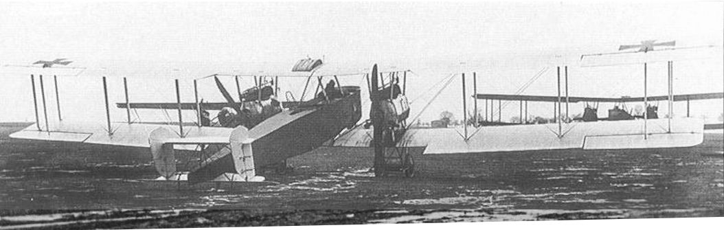
View of a night-camouflaged Gotha G.V in French hands with tri-color on the rudder undergoing evaluation. Until August 1918 when the Farman F.50 commenced operations the French had no twin-engine night bombers comparable to the Gotha in service; French night bombers were Voisin 8 and 10 single-engine pushers.
-

-

W.Pieters - The Belgian Air Service in the First World War /Aeronaut/
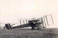
Captured Gotha G.V downed by Belgian AA-fire. One engine was hit and the pilot was able to bring his aircraft down safely. Here it is shown after being restored and marked with Belgian insignia.
-

W.Pieters - The Belgian Air Service in the First World War /Aeronaut/
A Gotha G.V downed by AA-fire was restored at Houthem and is seen here during the work in one of its Bessonneau hangars.
-
J.Herris - Gotha Aircraft of WWI /Centennial Perspective/ (6)
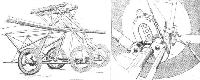
Some Gotha G.V bombers were fitted with an eight-wheel Stossfahrgestell undercarriage to prevent nose-overs.
-
Сайт - Pilots-and-planes /WWW/
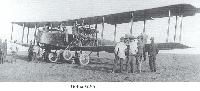
Gotha G.V of Staffel 18 in May 1918
-
-

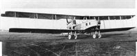
J.Herris - AEG Aircraft of WWI /Centennial Perspective/ (16)
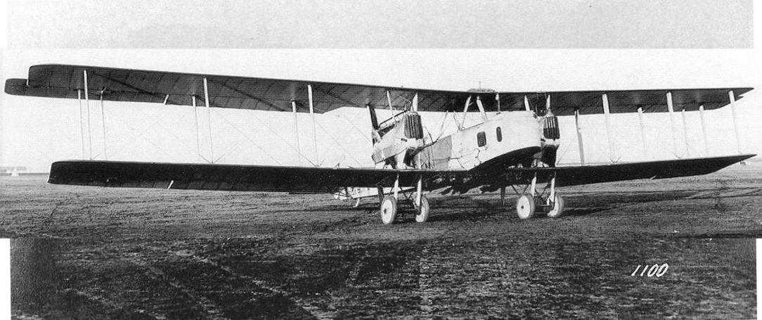
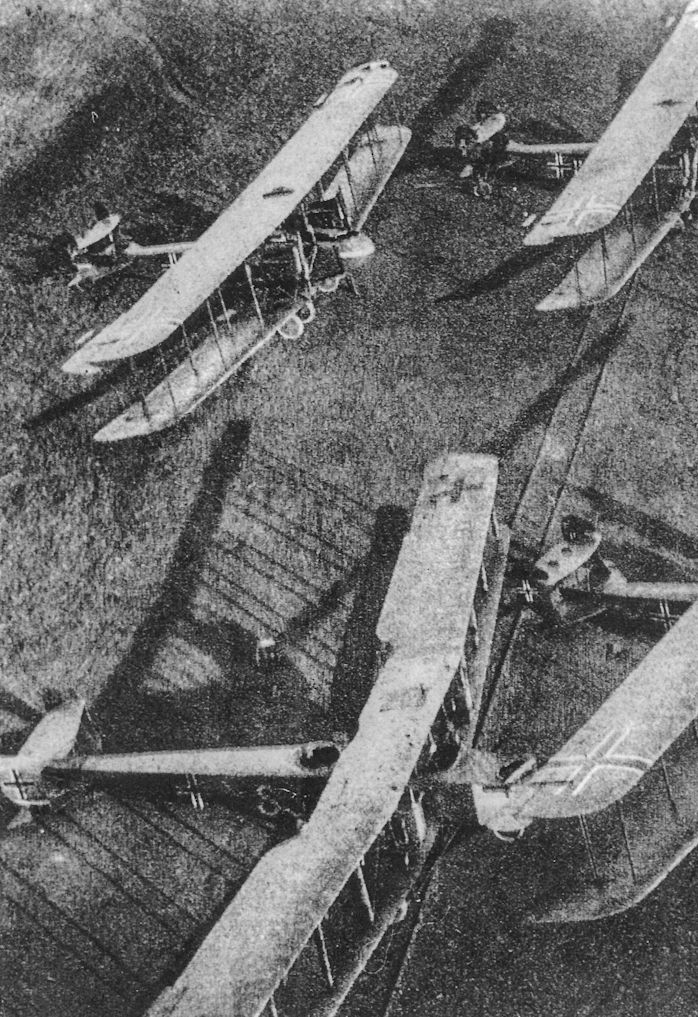
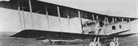
German bombers photographed postwar. The two aircraft at the top of the photo are AEG G.V bombers. A Gotha G.V is at bottom left and another AEG G.V is at bottom right.
Другие самолёты на фотографии: AEG G.V - Германия - 1918
-

J.Herris - Gotha Aircraft of WWI /Centennial Perspective/ (6)
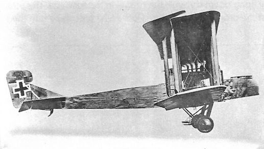
To improve controllability with one engine out, the Gotha G.Va with 'box' tail was developed. Above is the G.Va prototype fitted with an early version of the box tail.
-

M.Dusing - German Aviation Industry in WWI. Volume 1 /Centennial Perspective/ (84)
The Gotha G.Va prototype with the final configuration of the box tail used in production.
-
J.Herris - Gotha Aircraft of WWI /Centennial Perspective/ (6)
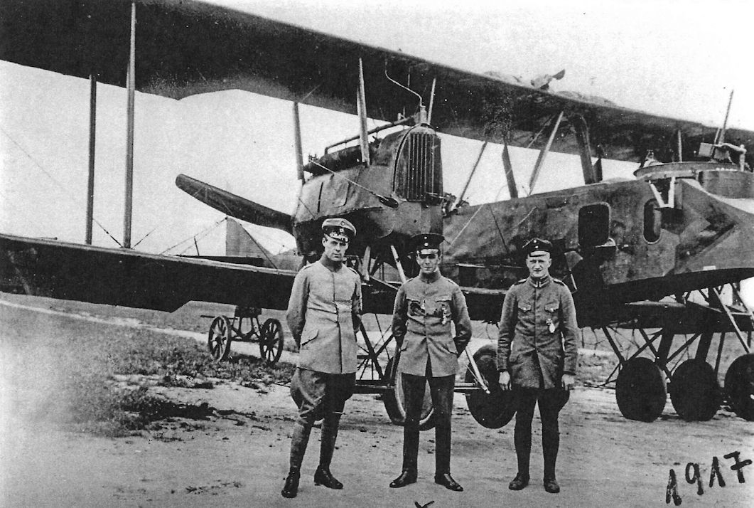
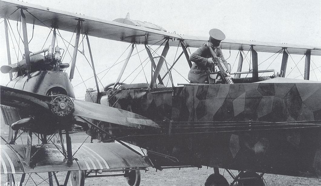
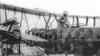
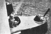
The nose undercarriage indicates this is likely a Gotha G.Va. These well-known photos show a gunner demonstrating the field of fire of the front and rear gunner's positions in a night-camouflaged bomber. A rare Gotha G.VI prototype is in the background.
Другие самолёты на фотографии: Gotha G.VI - Германия - 1917
-
J.Herris - Gotha Aircraft of WWI /Centennial Perspective/ (6)
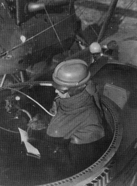
The gunner demonstrates how to protect against an attack from below by firing down through the tunnel in the fuselage. The screens on the sides of the rear gunner's cockpit keep his hands out of the propeller arcs.
-
Сайт - Pilots-and-planes /WWW/
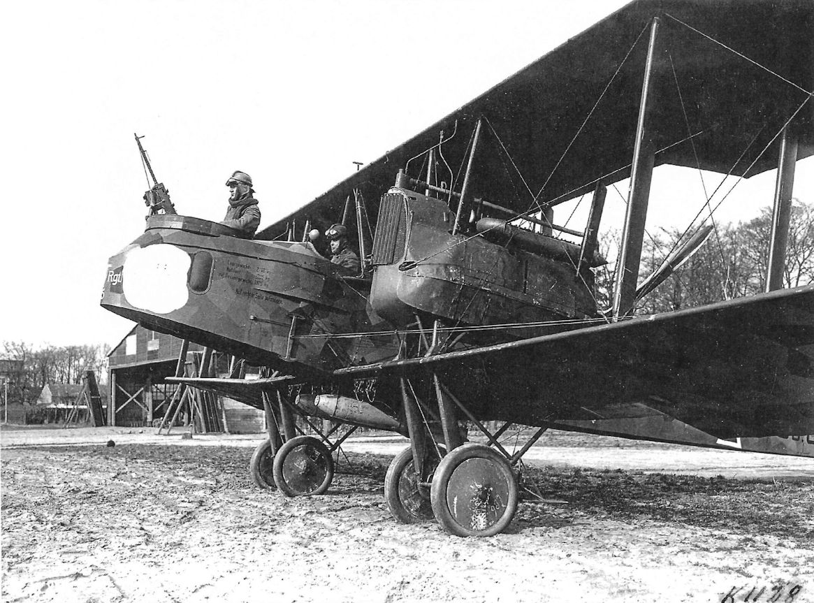
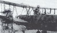
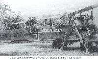
Gotha G V with twin-wheel nose undercarriage. This is probably the example that was evaluated in the field by Bogohl III. Based on the Friedrichshafen type nose undercarriage and using rubber-in-compression as a shock-absorber, it was not adopted; but Gotha fitted their own 'stossfahrgestell' to the G V's undercarriage assemblies with success and all late production Gotha G Va and G Vb machines had this refinement which greatly enhanced the safety of night operations. The gunner is demonstrating how he could fire via the tunnel aperture into the machine's 'blind spot'. The protective screens on either side of the cockpit are clearly shown, as are the external control cables to the tail and the over-wing fuel tank.
-

M.Dusing - German & Austro-Hungarian Aero Engines of WWI. Vol.2 /Centennial Perspective/ (65)
Two views of D IVa in a Gotha G.V.
-
J.Herris - Gotha Aircraft of WWI /Centennial Perspective/ (6)
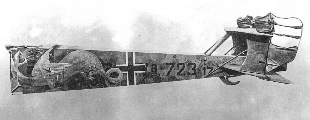
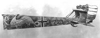
The tail of Gotha G.Va 723/17 brought down in France on 5 July 1918 wears a dramatic winged dragon personal marking. This aircraft is the one in the upper right of the photograph at the top of this page.
-

J.Herris - Gotha Aircraft of WWI /Centennial Perspective/ (6)
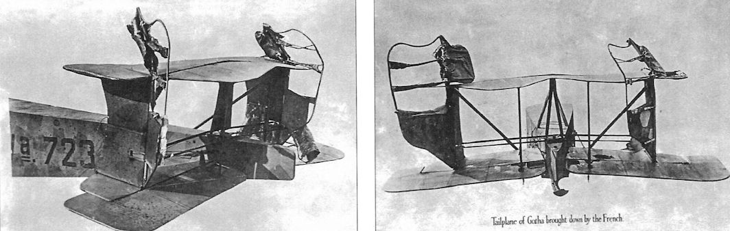
Two more views of the tail of Gotha G.Va 723/17 brought down in France on 5 July 1918.
-
Журнал - Flight за 1918 г.
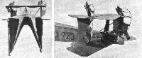
Figs. 38 and 39. - Two views of the biplane tail and fuselage of the twin-engine Gotha bomber. Illustrations and a brief description of this tail were published in our issue of October 3rd.
-
J.Herris - Gotha Aircraft of WWI /Centennial Perspective/ (6)
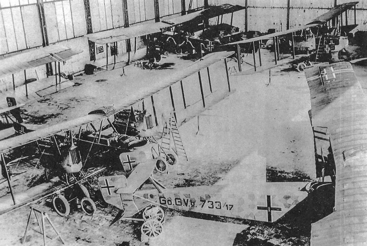
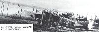
Gotha G.Va and G.Vb bombers stored in a hangar. The two G.Vb bombers in the foreground are not fitted with the Flettner servo-assist on the ailerons, normally a feature of the G.Vb.
-

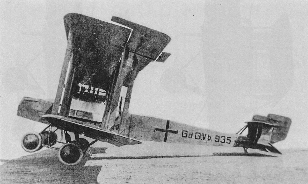
A.Imrie - German Bombers /Arms & Armour/
Gotha G Vb 935/18 showing the auxiliary landing gear angled well forward to prevent the machine touching the ground with the fuselage nose, especially during night take-offs and landings. This 'stossfahrgestell' revived the feature first used on the prototype Gotha G II and patented in 1916, whereby the powerplant, including a section of the bottom wing, could be completely disconnected from the airframe and wheeled away on the undercarriage assembly while the aircraft was trestled into flying position and supported at the appropriate wing tip. A replacement unit could than be moved into place and coupled up, thus greatly simplifying the procedure used in engine changes. The Flettner tabs can be seen hinged directly to the aileron trailing edges and not carried on outriggers as on Friedrichshafen and AEG designs.
-

M.Dusing - German Aviation Industry in WWI. Volume 1 /Centennial Perspective/ (84)
Gotha G.Vb (1917/18)
-

C.Owers - Fokker Aircraft of WWI. Vol.7: Postwar /Centennial Perspective/ (67)
View of Moeres airfield post-war. D.VII 6693/18 bears the Thistle emblem of the 9th Escadrille as does the Hanriot H.D.1 parked next to it. The serial 'F 2' is presented on the middle rudder stripe. The Escadrille was equipped with the Hanriot H.D.1 and the Fokkers were used as trainers - given that they had a stationary engine and were more powerful than the Hanriots, this seems a strange combination of types. A late-war Gotha bomber can be seen in the background. Belgium's air arm used some of these bombers along with other German types in the years following WWL (via D Brackx)
Другие самолёты на фотографии: Fokker D.VII / V11 / V18 / V22 / V24 - Германия - 1917Hanriot HD.1 - Франция - 1916
-

J.Herris - Gotha Aircraft of WWI /Centennial Perspective/ (6)
Gotha G Vb. Note servo tabs on ailerons.
-
-
Сайт - Pilots-and-planes /WWW/
Gotha G.Vb 917/18 Hessen-Nassau. Gotha build eighty G.Vb bombers.
-

J.Herris - Gotha Aircraft of WWI /Centennial Perspective/ (6)
Desperate to solve the landing accident dilemma that caused 76% of all Gotha bomber losses, the engineering team again modified the landing gear to create the Gotha G.Vb. The Gotha G.Vb reverted to an eight-wheel landing gear reminiscent of that fitted to the original G.II prototype. The additional forward-mounted wheels essentially eliminated the problem of nose-overs on landing, but at the expense of more weight and drag that reduced speed, range, and ceiling. This was a compromise the Gotha G.V could ill afford; it was already heavier than the G.IV due to inferior materials and more required equipment, and was now in an irreversible downward performance spiral.
-

-
Сайт - Pilots-and-planes /WWW/
Gotha G.Vb
-

M.Dusing - German & Austro-Hungarian Aero Engines of WWI. Vol.2 /Centennial Perspective/ (65)
View of D IVa engine module from a Gotha G.V.
-

M.Dusing - German & Austro-Hungarian Aero Engines of WWI. Vol.2 /Centennial Perspective/ (65)
View of D IVa engine module from a Gotha G.V.
-
Журнал - Flight за 1918 г.
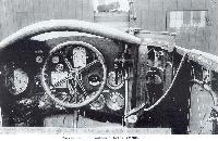
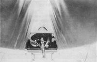
Fig. 41. - Twin-engine Gotha. Front of fuselage. Note Morell anemometer air-speed indicator.
-

A.Imrie - German Bombers /Arms & Armour/
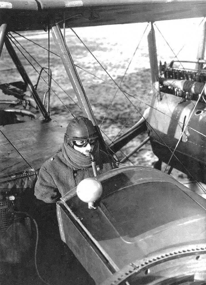
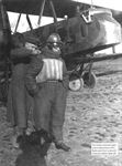
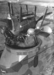
An observer in the front cockpit of a Gotha G V of Kagohl III demonstrates the use of oxygen supplied via the bladder to the breathing tube fitted with a mouthpiece. The oxygen produced by vapourization was extremely cold and uncomfortable to breathe and experiments were made to heat the supply tube by various means such as engine exhaust gases, radiator water and electrical elements. Despite the shortcomings of the basic Ahrendt and Heylandt equipment good results were reported.
-
J.Herris - Gotha Aircraft of WWI /Centennial Perspective/ (6)
A bombardier/gunner of a Gotha G.V bomber demonstrating the German oxygen system for aviators. The "pipe stem" mouthpiece was primitive and somewhat difficult to use.
-

J.Herris - Gotha Aircraft of WWI /Centennial Perspective/ (6)
A bombardier/gunner of a Gotha G.V bomber demonstrating the German oxygen system for aviators. The "pipe stem" mouthpiece was primitive and somewhat difficult to use.
-
Сайт - Pilots-and-planes /WWW/
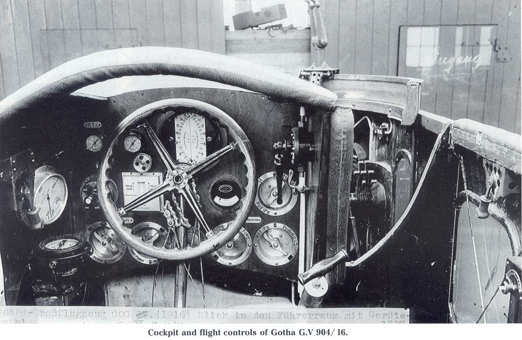
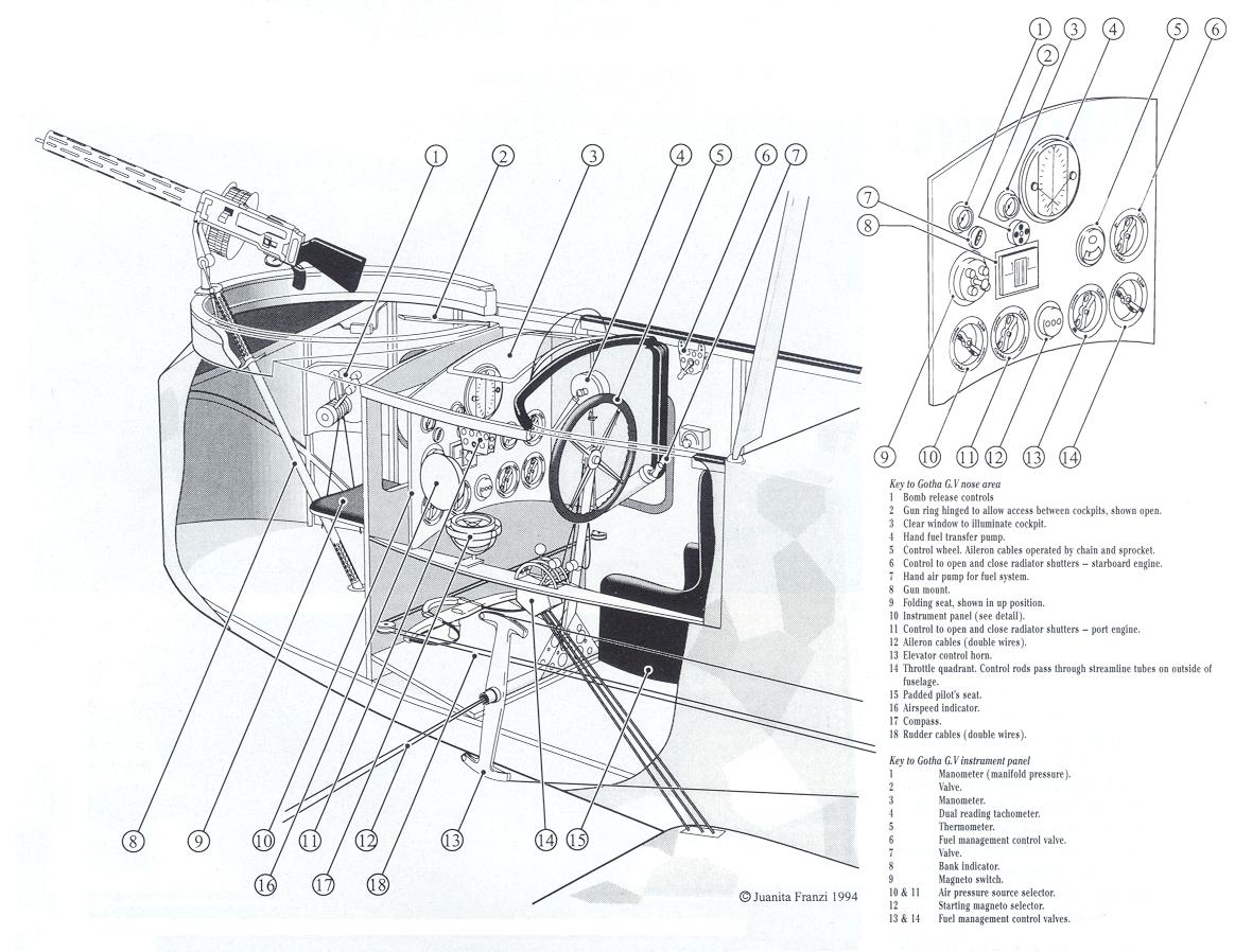
The cockpit and flight controls of Gotha G.V 904/16 are typical for Gotha G.IV bombers as well. The cellon window above the instruments provided illumination during the day.
-
-
J.Herris - Gotha Aircraft of WWI /Centennial Perspective/ (6)
The 'Gotha Tunnel' underneath the fuselage of a Gotha G.Va (notice the front undercarriage struts) as seen from the rear and being demonstrated by a gunner. The tunnel was introduced on the G.IV and carried forward into the G.V series; it enabled the rear gunner to protect the bomber against attacks from behind and below. A third machine gun could be mounted as shown, or the rear gunner's standard gun could fire downward through the slot in the rear fuselage.
-

W.Pieters - The Belgian Air Service in the First World War /Aeronaut/
Belgian AA-fire brought down a Gotha bomber on 7 June 1918.
-

Журнал - Flight за 1918 г.
A Gotha biplane tail.
-
Журнал - Flight за 1918 г.
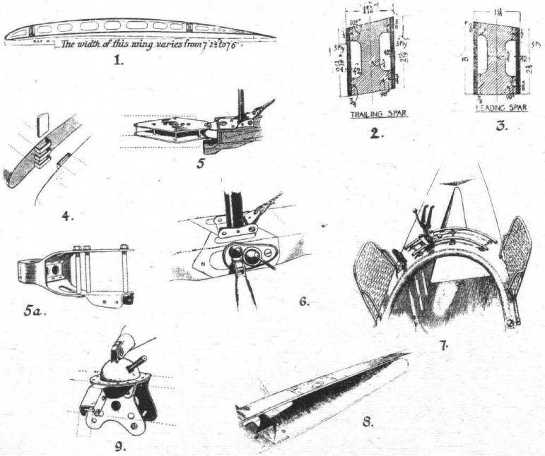
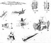
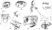
SOME CONSTRUCTIONAL DETAILS OF THE GOTHA BOMBER. - Figs. 1 to 9.
-
Журнал - Flight за 1918 г.
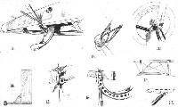
Some constructional details of the Gotha twin-engine bomber. Figs. 10 to 17.
-
Журнал - Flight за 1918 г.
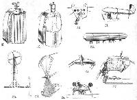
Some more constructional details of the Gotha twin-engine botnber. Figs. 18 to 27.
-
Журнал - Flight за 1918 г.
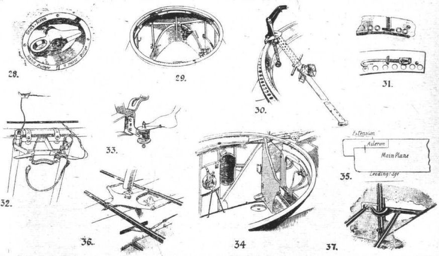
Constructional details of the Gotha twin-engine bomber. Figs. 28 to 37.
-
Журнал - Flight за 1918 г.
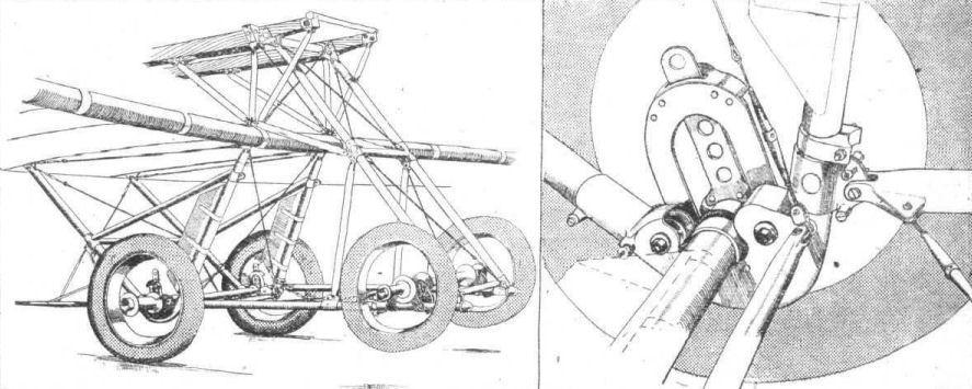
Three-quarter front view of one of the four-wheeled Gotha undercarriages. On the right a more detailed drawing of the shock-absorbing arrangement.
-

-

Журнал - Flight за 1918 г.
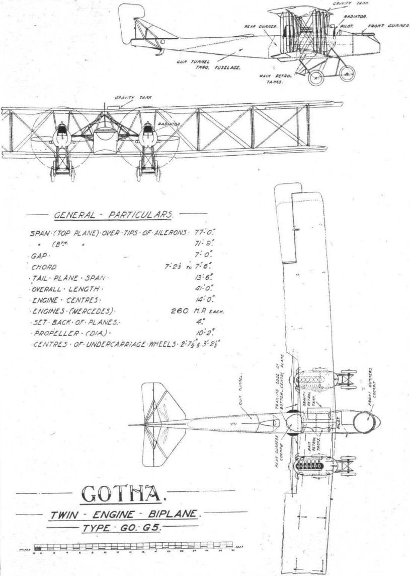
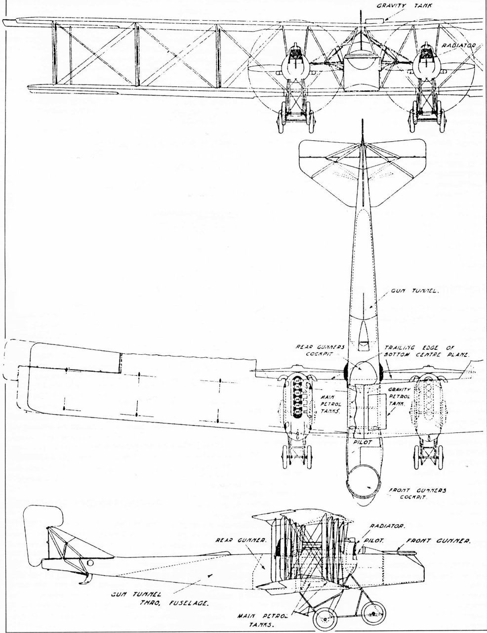
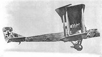
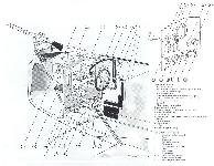
THE GOTHA BOMBER. - General arrangement drawings.
-

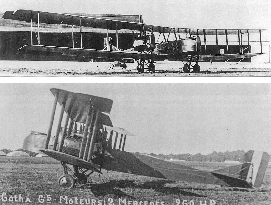
A.Imrie - German Bombers /Arms & Armour/
Gotha Type Go G5
-

В.Кондратьев - Самолеты первой мировой войны
"Гота" G-V
В.Кондратьев Самолеты первой мировой войны
ГОТА G-V / GOTHA G-V
В августе 1917-го была разработана очередная модификация "Готы", обозначенная G-V. Внешне самолет отличался более обтекаемыми мотогондолами овального сечения, укрепленными на стойках между крыльями.
Всего построено 120 "пятерок", из них несколько штук в варианте G-Va с укороченным носом и бипланным хвостовым оперением. Пик боевого применения "Гот" приходится на апрель 1918 года, когда на западном фронте одновременно находилось 36 машин этого типа. В дальнейшем их число постепенно сокращалось, но отдельные экземпляры провоевали до конца войны.
ДВИГАТЕЛИ
2 "Мерседеса" D.IVa по 260 л.с.
ВООРУЖЕНИЕ
Носовая и хвостовая турели с пулеметами "Парабеллум". Бомбовая нагрузка - 300-600 кг в зависимости от дальности полета.
ЛЕТНО-ТЕХНИЧЕСКИЕ ХАРАКТЕРИСТИКИ
Размах, м 23,7
Длина, м 12,4
Площадь крыла, кв.м 89,5
Сухой вес, кг 2400
Взлетный вес, кг 3635
Скорость максимальная, км/ч 140
Дальность полета, км 700
Время набора высоты, мин/м 21/3000
Потолок, м 5000
Описание: