
Книги
Centennial Perspective
J.Herris
Gotha Aircraft of WWI
306
J.Herris - Gotha Aircraft of WWI /Centennial Perspective/ (6)
The Gotha G.IX(LVG) in this postwar view has no visible markings other than the Belgian colors on the rudders, but its hexagonal camouflage fabric is well illustrated.The aileron aerodynamic balances have slots, but the aerodynamic balances on the rudders do not. A DH.9 is visible in the background.
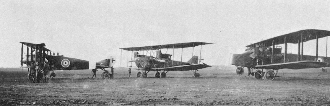
Postwar lineup of a Gotha GL.VII (at left), an AEG (center), and a Friedrichshafen (at right) at Bickendorf. The GL.VII has a fuselage band over the cross insignia, its location indicating it was built by Aviatik.
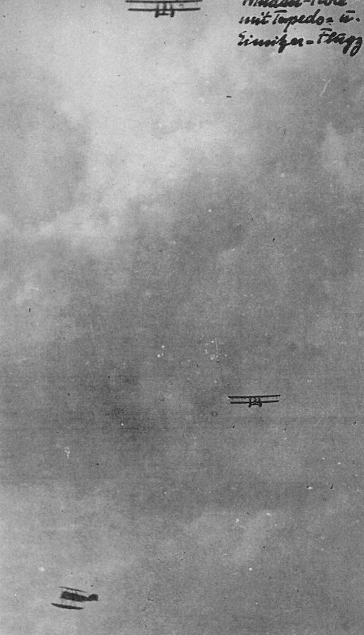
Two Gotha WD11 torpedo bombers being escorted by an Albatros W4 fighter.
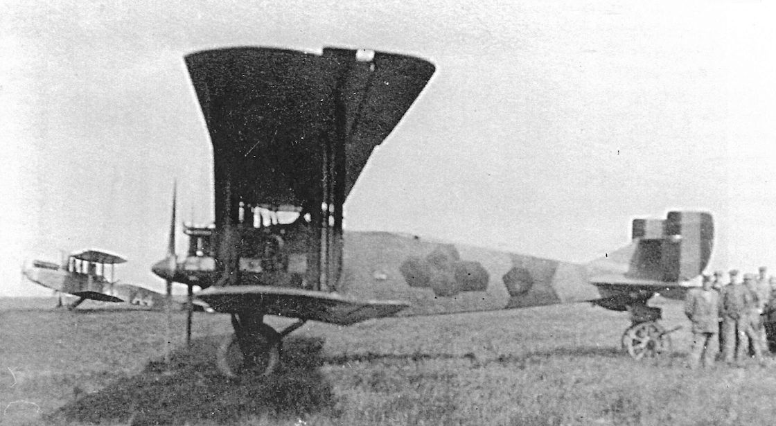
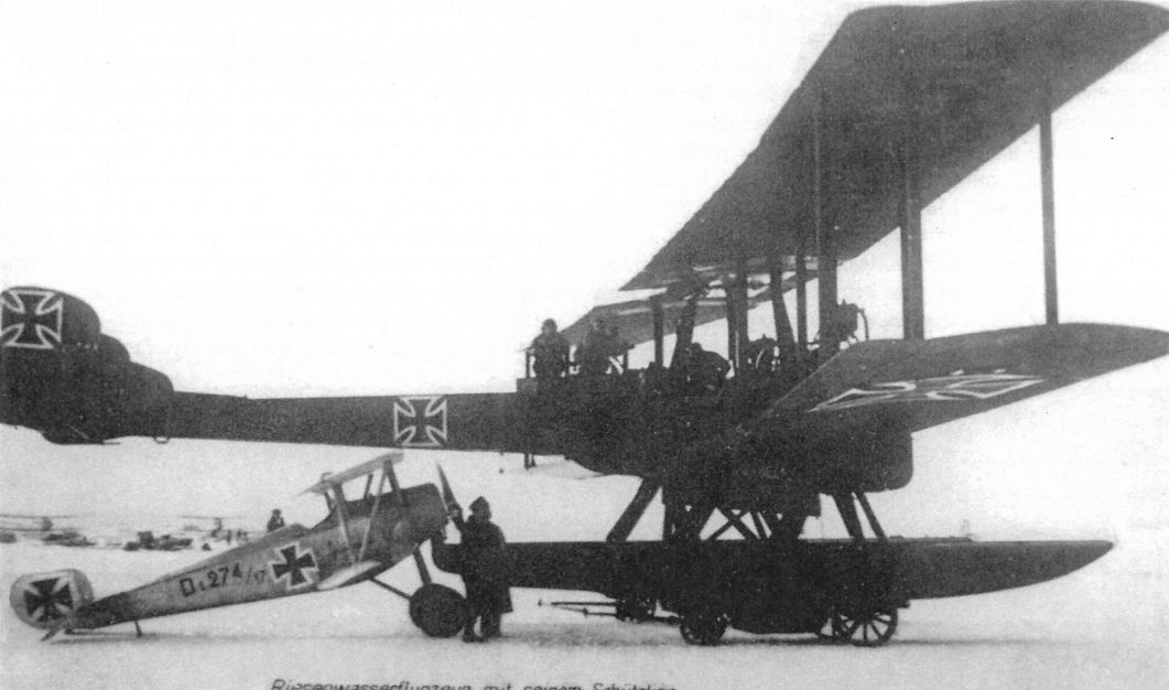
Delivered on 11 July 1917, WD14, Marine Number 1415 of the second series (Marine Numbers 1415-1430) had enlarged rudders and ailerons on all wings. Originally ordered as a torpedo bomber, it was modified for long-range maritime reconnaissance now that torpedo attacks had been basically abandoned. At Norderney, #1415 was used to test wireless equipment, navigation instruments, and droppable fuel tanks, here installed in the torpedo bay. Euler D.II 274/17, a single-seat trainer, provides an interesting size comparison.
On October 2, 1917, Gotha 1415 departed Norderney on a 10-hour flight along the German North Sea coast (departure 0745, landing 1745).
On October 2, 1917, Gotha 1415 departed Norderney on a 10-hour flight along the German North Sea coast (departure 0745, landing 1745).
The prototype WD14, Marine Number 801, upon delivery to the SVK on 16 January 1917. As a result of trials, ailerons were added to the lower wings and the rudder area was increased to improve control with one engine out.
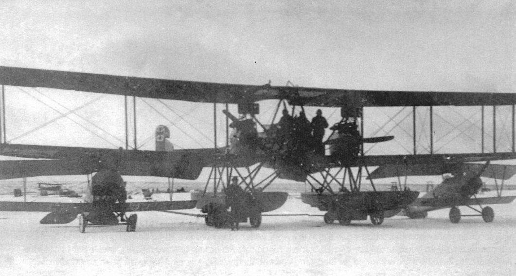
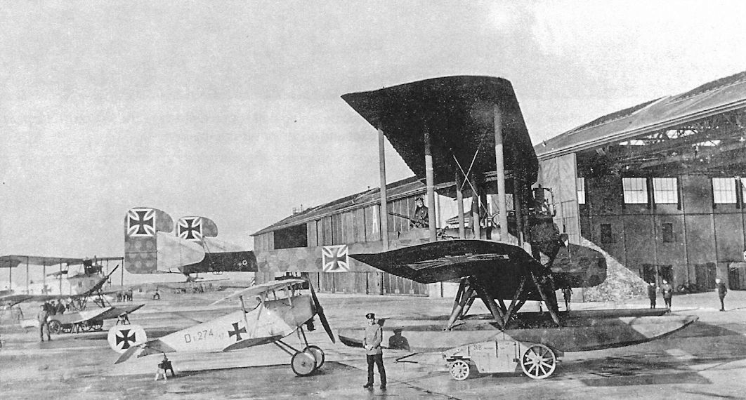
Delivered on 11 July 1917, WD14, Marine Number 1415 of the second series (Marine Numbers 1415-1430) had enlarged rudders and ailerons on all wings. Originally ordered as a torpedo bomber, it was modified for long-range maritime reconnaissance now that torpedo attacks had been basically abandoned. At Norderney, #1415 was used to test wireless equipment, navigation instruments, and droppable fuel tanks, here installed in the torpedo bay. Euler D.II singleseat trainers flank it on both sides.
Postwar lineup of a Gotha GL.VII (at left), an AEG (center), and a Friedrichshafen (at right) at Bickendorf. The GL.VII has a fuselage band over the cross insignia, its location indicating it was built by Aviatik.
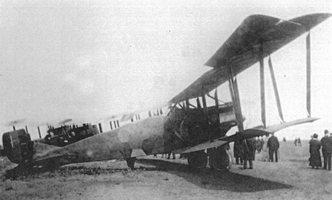
Gotha G.IX(LVG) serving in Belgium postwar illustrates the type's clean lines. It appears to be on public display. A Friedrichshafen bomber is in the background.
Gotha WD Types
Gotha achieved a modest degree of success in the seaplane business. The first Gotha seaplane design was a pusher floatplane designed by Bruno Buchner for the Bodensee Wettbewerb in June 1913.
<...>
Gotha Buchner See Specifications
Engine: 100 hp Mercedes D.I
Wing: Span Upper 20.00 m
General: Length 10.50 m
Height 3.90 m
Empty Weight 750 kg
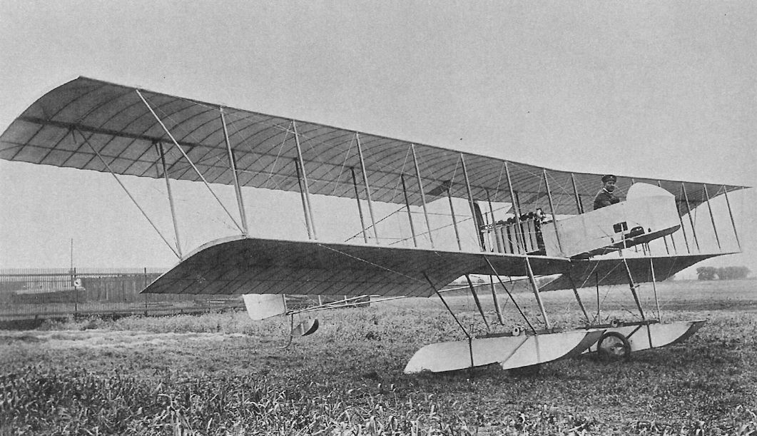
The Buchner See pusher floatplane was the first Gotha seaplane. Built in 1913, it was powered by a 100 hp Mercedes D.I. Only one was built, but it started Gotha in the seaplane business.
Gotha LE Types
Before WWI the Taube (Dove in German) configuration was very popular in Germany and Austria for its inherent stability, considered quite important at the time due to the limited flying experience of most airmen. Many German and Austrian manufacturers built aircraft to the Taube configuration and this is how Gotha got its start in aviation. The Gotha LE (Land Eindecker = land monoplane) series were all Taube designs.
Gotha's Tauben were rugged, well-built airplanes that saw reliable service on all war fronts. A total of 90 Gotha Tauben were purchased by the Fliegertruppe in 1913 and 1914, more than any other manufacturer except Jeannin.
Gotha LE1
Ordered on 4 February, 1913, eight Gotha LE1 Taube two-seat trainers were delivered to the Gotha flying school and two uncovered airframes were sent to Hamburg to serve as trainers at the Centrale fur Aviatik, an organization in which Gotha had a financial interest. In 1914 Centrale fur Aviatik was renamed Hansa Flugzeugwerke Hamburg Karl Caspar.
Designed by Gurlich and Bohnisch, the first Gotha LE1, powered by a 75 hp Mercedes engine flew its maiden flight on 22 April 1913. Two LE1 monoplanes participated in the Prinz Heinrich Flug of 1913; the one flown by Lt. Joly, with Oblt. Felmy as passenger, completed all the competition stages. A few LE1 trainers served into the early war months.
Gotha LE1 Specifications
Engine: 75 hp Mercedes
Wing: Span 14.40 m
Area 35.2 m2
General: Length 7.80 m
Height 3.20 m
Empty Weight 600 kg
Loaded Weight 972 kg
Maximum Speed 90 km/h
Climb: 800m 12 min
Gotha LE2
Designed by Bohnisch and Bartel, the next Gotha design was the LE2, another Taube clearly derived from the LE1. The LE2 had a more powerful, 100 hp Mercedes D.I engine and the landing gear was redesigned to better support the wing bracing cables. The LE2 was slightly faster than the LE1 but its rate of climb was lower, likely due to a combination of greater weight and reduced wing area.
In addition to the 100 hp Mercedes D.I, LE2s were fitted with a variety of Argus, Benz, and Rapp 100 hp engines, and a few were fitted with 80 hp Oberursel U.O engines to provide pilots with experience flying aircraft with rotary engines.
Gotha's reputation for good workmanship and solid construction led the Fliegertruppe to order 35 Gotha A (LE2) Tauben. These were used both for combat missions over the front and training.
Gotha LE2 Specifications
Engine: Wing: 100 hp Mercedes D.I
Span Area 14.40 m 28 m2
General: Length 10.22 m
Height 3.20 m
Empty Weight 690 kg
Loaded Weight 1,053 kg
Maximum Speed 102 km/h
Climb: 800m 20 min
Gotha LE3
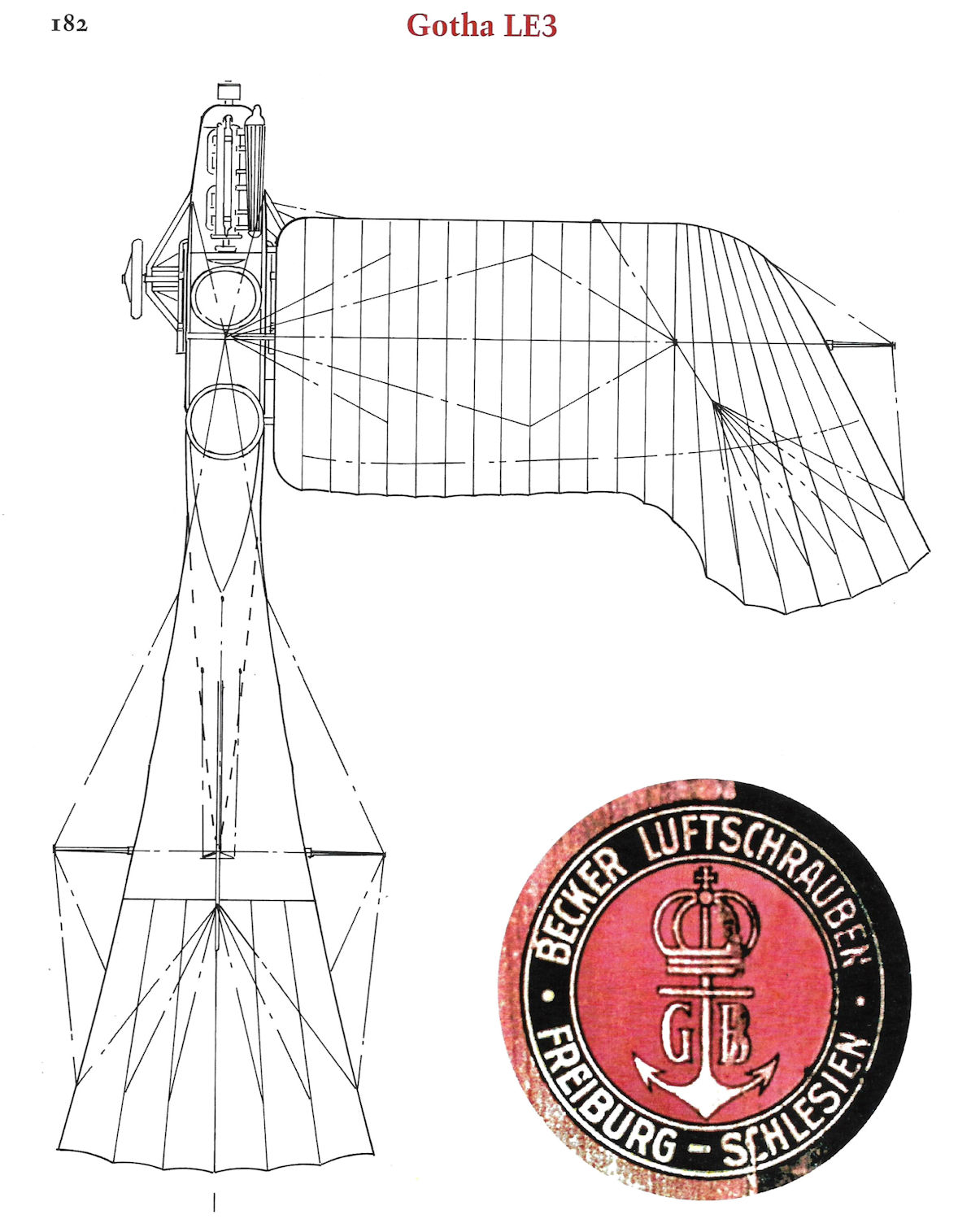
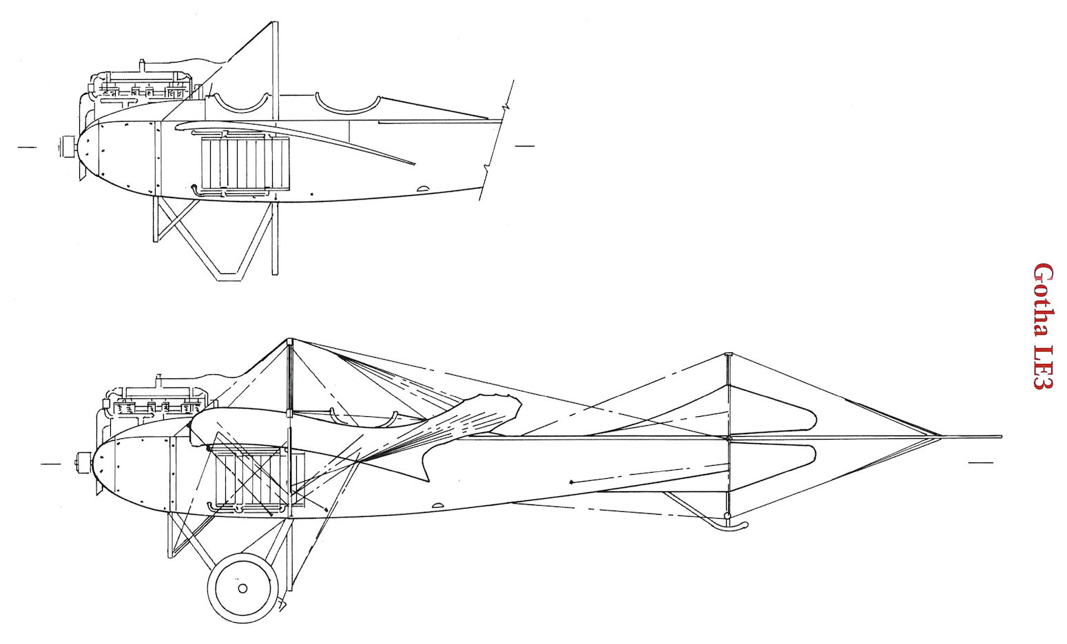
The LE1 and LE2 had fuselages of triangular cross section which tended to twist in flight, so Grulich and Bartl designed the LE3 with a much stiffer fuselage of rectangular cross section. The undercarriage was again redesigned and simplified, and a separate trestle supported the lift wires in order to separate them from the undercarriage.
On 10 January 1914 work began on the LE3. In June the Fliegertruppe ordered 16 LE3s with the first delivery on 31 August. Upon mobilization, eight LE3s built for the Gotha flying school were commandeered by the Fliegertruppe for combat. In September a further 20 were ordered, followed by 10 more in October, making a total of 54 accepted by the Fliegertruppe. The LE3 was a robust aircraft that saw combat on all fronts. The last LE3 was delivered to FEA 3 on 7 July 1915. LE3 A.90.14 was fitted with a 160 hp Benz engine.
Gotha LE3 Specifications
Engine: 100 hp Mercedes D.I
Wing: Span 14.50 m
Area 33.5 m2
General: Length 10.00 m
Height 3.15 m
Empty Weight 690 kg
Loaded Weight 1,062 kg
Maximum Speed 96 km/h
Climb: 800m 12 min
Range: 385 km
Gotha LE4
Designed by Karl Rosner, work on the Gotha LE4 began on 31 January 1914. Powered by a 100 hp Mercedes D.I engine, the LE4 was Gotha's last Taube, design. The nose radiator and tail surface with conventional, hinged elevators made the LE4 much more modern in appearance.
Initially the LE4 had the lift wires attached directly to the undercarriage struts, a configuration disliked by the Fliegertruppe. The LE4 was damaged on 15 May 1914 while participating in the Prinz Heinrich Flug. During repair the LE4 was modified to have the front and rear lift wires attached to separate pylons in front and behind the undercarriage. The repaired LE4 was entered in several more flying meetings before the war. After being rebuilt, the LE4 was assigned to the Herzog Carl Eduard Fliegerschule in Gotha. Only one LE4 was built.
Gotha LE4 Specifications
Engine: 100 hp Mercedes D.I
Wing: Span 14.00 m
Area 28 m2
General: Length 8.50 m
Height 2.80 m
Loaded Weight 980 kg
Maximum Speed 120 km/h
Range: 600 km
Before WWI the Taube (Dove in German) configuration was very popular in Germany and Austria for its inherent stability, considered quite important at the time due to the limited flying experience of most airmen. Many German and Austrian manufacturers built aircraft to the Taube configuration and this is how Gotha got its start in aviation. The Gotha LE (Land Eindecker = land monoplane) series were all Taube designs.
Gotha's Tauben were rugged, well-built airplanes that saw reliable service on all war fronts. A total of 90 Gotha Tauben were purchased by the Fliegertruppe in 1913 and 1914, more than any other manufacturer except Jeannin.
Gotha LE1
Ordered on 4 February, 1913, eight Gotha LE1 Taube two-seat trainers were delivered to the Gotha flying school and two uncovered airframes were sent to Hamburg to serve as trainers at the Centrale fur Aviatik, an organization in which Gotha had a financial interest. In 1914 Centrale fur Aviatik was renamed Hansa Flugzeugwerke Hamburg Karl Caspar.
Designed by Gurlich and Bohnisch, the first Gotha LE1, powered by a 75 hp Mercedes engine flew its maiden flight on 22 April 1913. Two LE1 monoplanes participated in the Prinz Heinrich Flug of 1913; the one flown by Lt. Joly, with Oblt. Felmy as passenger, completed all the competition stages. A few LE1 trainers served into the early war months.
Gotha LE1 Specifications
Engine: 75 hp Mercedes
Wing: Span 14.40 m
Area 35.2 m2
General: Length 7.80 m
Height 3.20 m
Empty Weight 600 kg
Loaded Weight 972 kg
Maximum Speed 90 km/h
Climb: 800m 12 min
Gotha LE2
Designed by Bohnisch and Bartel, the next Gotha design was the LE2, another Taube clearly derived from the LE1. The LE2 had a more powerful, 100 hp Mercedes D.I engine and the landing gear was redesigned to better support the wing bracing cables. The LE2 was slightly faster than the LE1 but its rate of climb was lower, likely due to a combination of greater weight and reduced wing area.
In addition to the 100 hp Mercedes D.I, LE2s were fitted with a variety of Argus, Benz, and Rapp 100 hp engines, and a few were fitted with 80 hp Oberursel U.O engines to provide pilots with experience flying aircraft with rotary engines.
Gotha's reputation for good workmanship and solid construction led the Fliegertruppe to order 35 Gotha A (LE2) Tauben. These were used both for combat missions over the front and training.
Gotha LE2 Specifications
Engine: Wing: 100 hp Mercedes D.I
Span Area 14.40 m 28 m2
General: Length 10.22 m
Height 3.20 m
Empty Weight 690 kg
Loaded Weight 1,053 kg
Maximum Speed 102 km/h
Climb: 800m 20 min
Gotha LE3
The LE1 and LE2 had fuselages of triangular cross section which tended to twist in flight, so Grulich and Bartl designed the LE3 with a much stiffer fuselage of rectangular cross section. The undercarriage was again redesigned and simplified, and a separate trestle supported the lift wires in order to separate them from the undercarriage.
On 10 January 1914 work began on the LE3. In June the Fliegertruppe ordered 16 LE3s with the first delivery on 31 August. Upon mobilization, eight LE3s built for the Gotha flying school were commandeered by the Fliegertruppe for combat. In September a further 20 were ordered, followed by 10 more in October, making a total of 54 accepted by the Fliegertruppe. The LE3 was a robust aircraft that saw combat on all fronts. The last LE3 was delivered to FEA 3 on 7 July 1915. LE3 A.90.14 was fitted with a 160 hp Benz engine.
Gotha LE3 Specifications
Engine: 100 hp Mercedes D.I
Wing: Span 14.50 m
Area 33.5 m2
General: Length 10.00 m
Height 3.15 m
Empty Weight 690 kg
Loaded Weight 1,062 kg
Maximum Speed 96 km/h
Climb: 800m 12 min
Range: 385 km
Gotha LE4
Designed by Karl Rosner, work on the Gotha LE4 began on 31 January 1914. Powered by a 100 hp Mercedes D.I engine, the LE4 was Gotha's last Taube, design. The nose radiator and tail surface with conventional, hinged elevators made the LE4 much more modern in appearance.
Initially the LE4 had the lift wires attached directly to the undercarriage struts, a configuration disliked by the Fliegertruppe. The LE4 was damaged on 15 May 1914 while participating in the Prinz Heinrich Flug. During repair the LE4 was modified to have the front and rear lift wires attached to separate pylons in front and behind the undercarriage. The repaired LE4 was entered in several more flying meetings before the war. After being rebuilt, the LE4 was assigned to the Herzog Carl Eduard Fliegerschule in Gotha. Only one LE4 was built.
Gotha LE4 Specifications
Engine: 100 hp Mercedes D.I
Wing: Span 14.00 m
Area 28 m2
General: Length 8.50 m
Height 2.80 m
Loaded Weight 980 kg
Maximum Speed 120 km/h
Range: 600 km
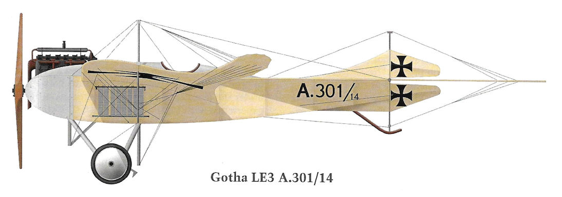
Gotha LE3 A.301/14
The Gotha LE1 was the first Gotha aircraft; it first flew on 22 April 1913. It was a typical Taube design for the period. Popular in Germany, the Taube configuration was basically obsolete in 1912, before the LE1 was designed. Ten LE1 aircraft were built.
Compared to the LE1, the Gotha LE2 had a redesigned landing gear and a more powerful engine. On 4 November 1914, Lt. Caspar and Oblt. Roos, flying a Gotha LE2, made history when they crossed the English Channel and dropped two bombs on Dover, returning safely after a flight of five and a half hours.
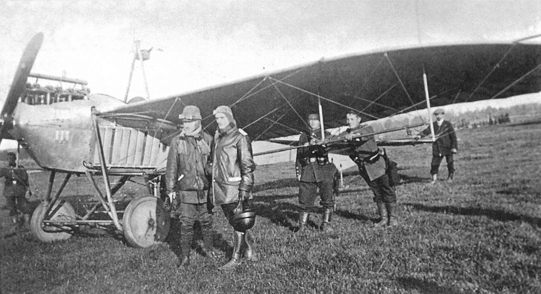
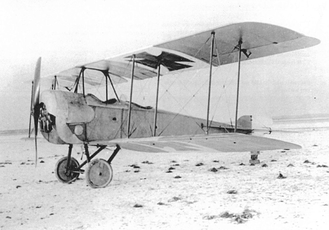
Gotha LE2 with crew Schlegel and Lt. Spang.
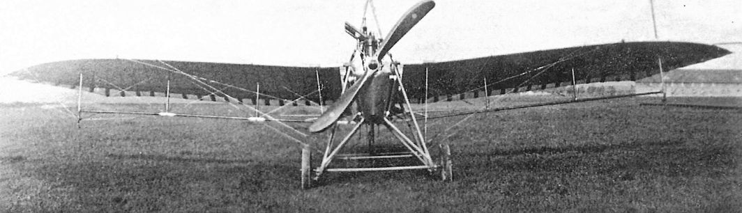
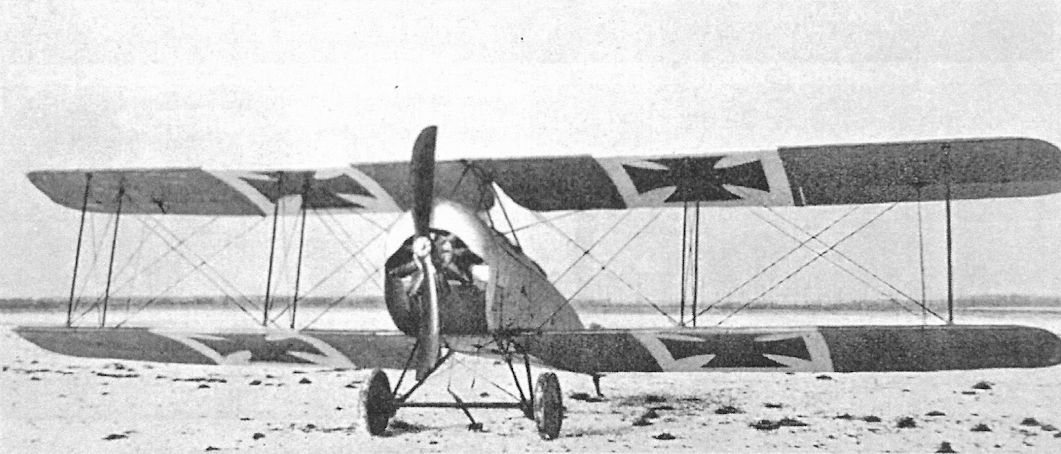
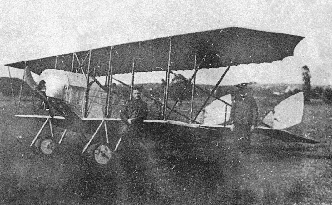
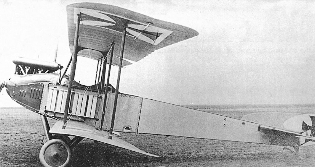
Front view of a Gotha LE2. A limitation of all Tauben was their sluggish wing- and tail-warping controls and automatic stability, which made them inadequate for effectively training pilots to fly comparatively maneuverable biplanes fitted with separate ailerons and elevators. Moreover, their complex rigging required painstaking adjustment and created excessive drag, limiting speed and climb. For these reasons Tauben were quickly superseded by biplanes with conventional controls after the war began.
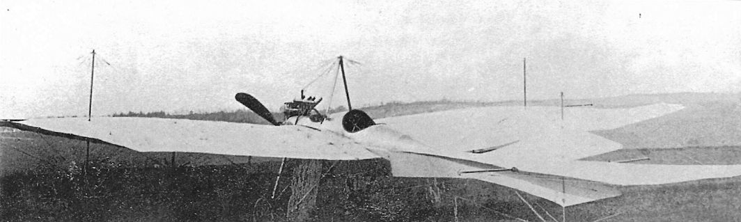
Rear quarter view of a Gotha LE2.
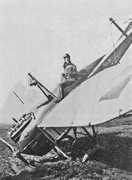
Gotha LE2 after a landing accident.
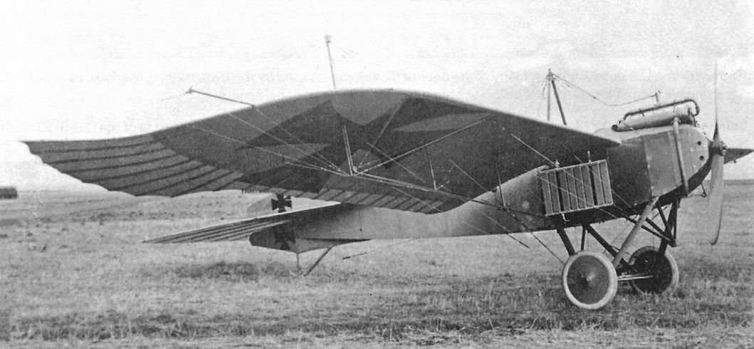
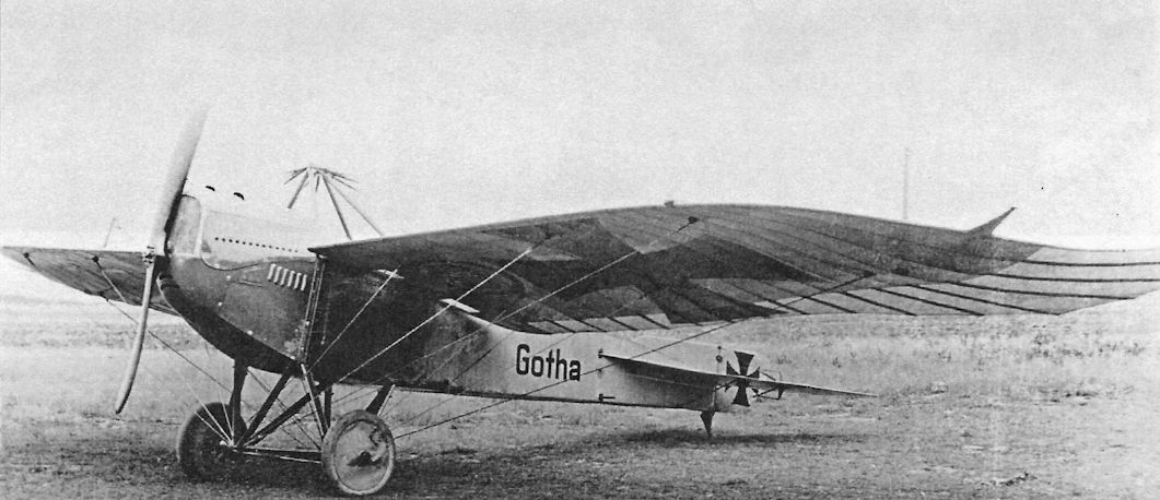
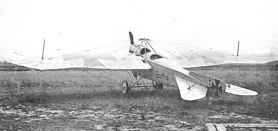
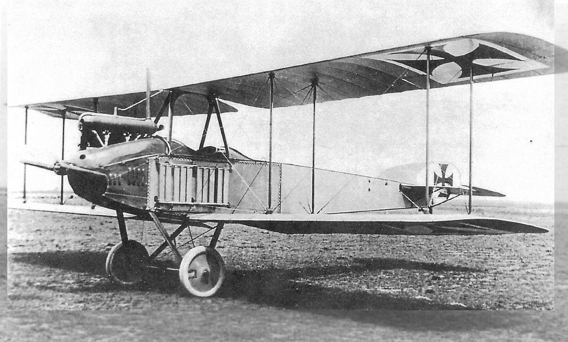
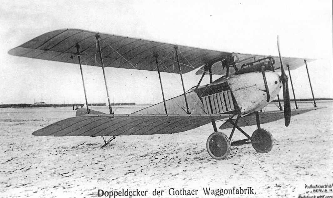
The LE3 featured a rectangular fuselage for greater stiffness to prevent twisting in flight. The iron crosses indicate combat service in the war.
The Gotha LE-3, military designation Gotha A I of 1914, was yet another minor variation on the Etrich Taube theme. Gotha built 20 of these two seaters with the army serials A79/14 to A91/14, A119/14 to A125 and A137/14 to A142/14. Employing the 100hp Mercedes D I, range for the machine was quoted as 239 miles.
The Gotha LE-3, military designation Gotha A I of 1914, was yet another minor variation on the Etrich Taube theme. Gotha built 20 of these two seaters with the army serials A79/14 to A91/14, A119/14 to A125 and A137/14 to A142/14. Employing the 100hp Mercedes D I, range for the machine was quoted as 239 miles.
The LE3 also introduced a simplified undercarriage to separate the wing lift wires from the undercarriage structure.
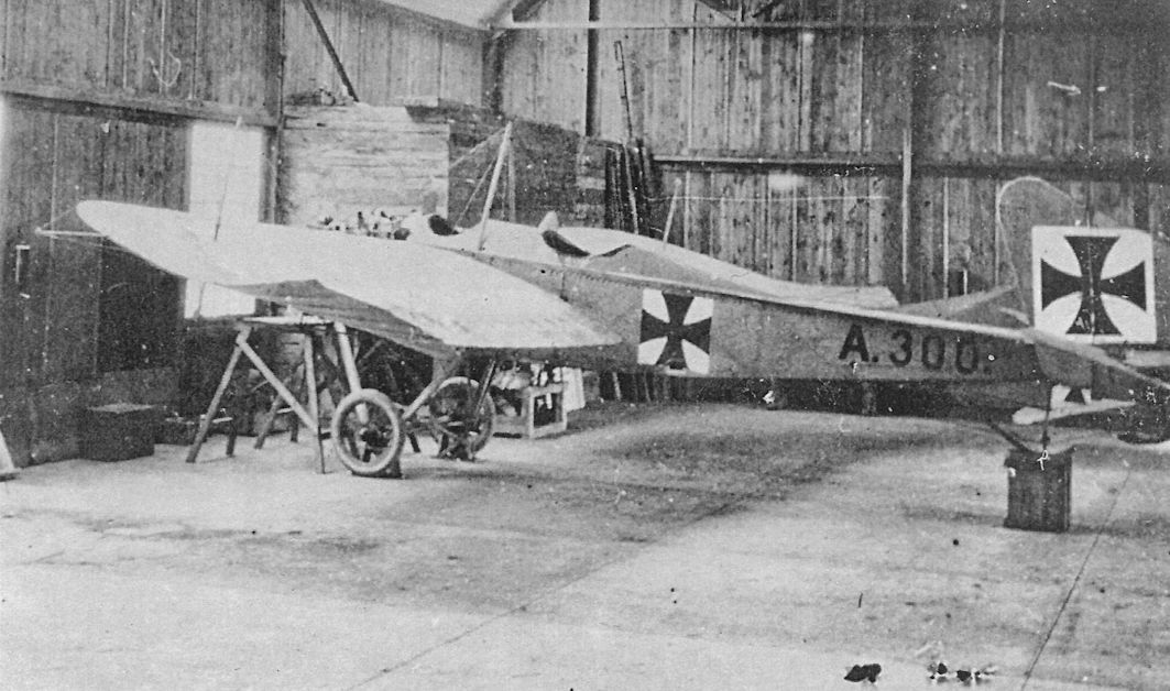
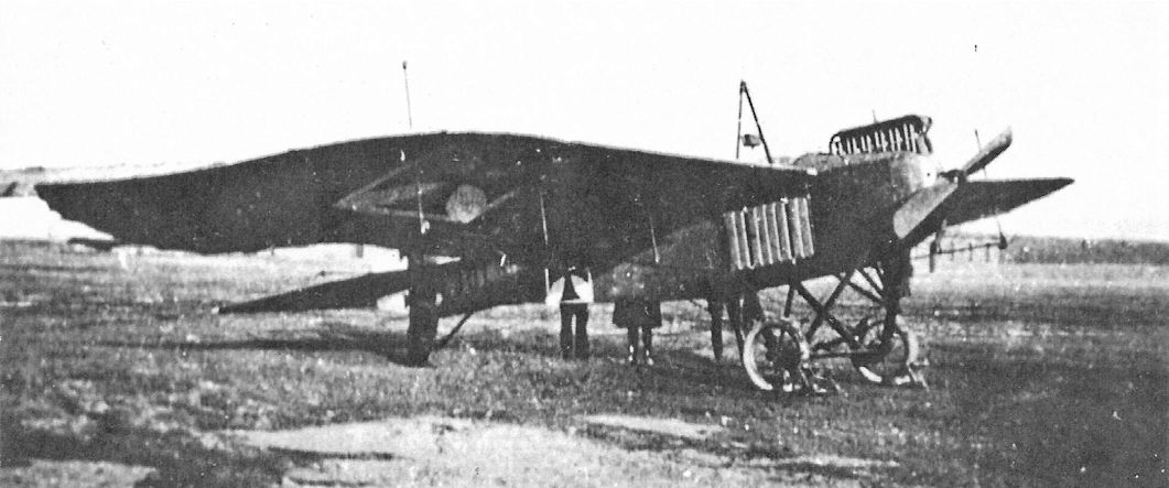
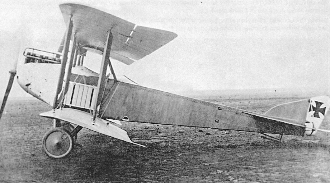
Gotha LE3 A.300/14 parked in a hangar. The rudder of an Albatros B-type obscures the tail of the LE3. In all, Gotha built 111 Taube monoplanes; 89 of those were delivered to the Fliegertruppe.
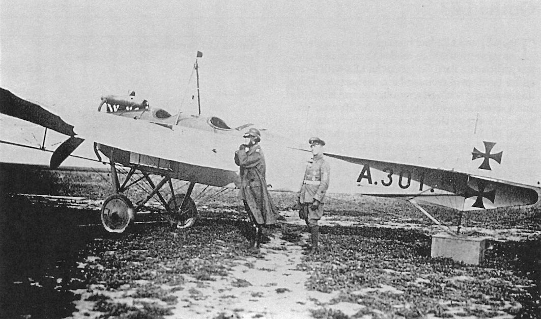
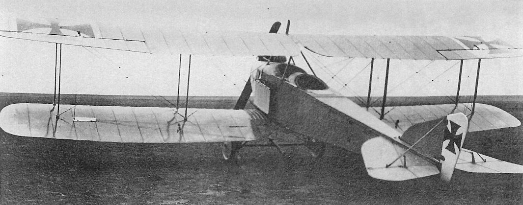
Gotha LE3 serial A.301/14. Many of the unarmed monoplanes used by the Fliegertruppe, nearly all two-seaters, were Tauben.The military serial and insignia confirm this LE3 is in operational service.

The Gotha LE3 Taube was the LE-type produced in greatest numbers. A robust, well-built machine, it was well suited for operational use and saw service on all fronts. The inherently stable Tauben were actually too stable for air combat and their great drag limited performance. Tauben soon disappeared from the front, replaced by higher-performance biplanes.
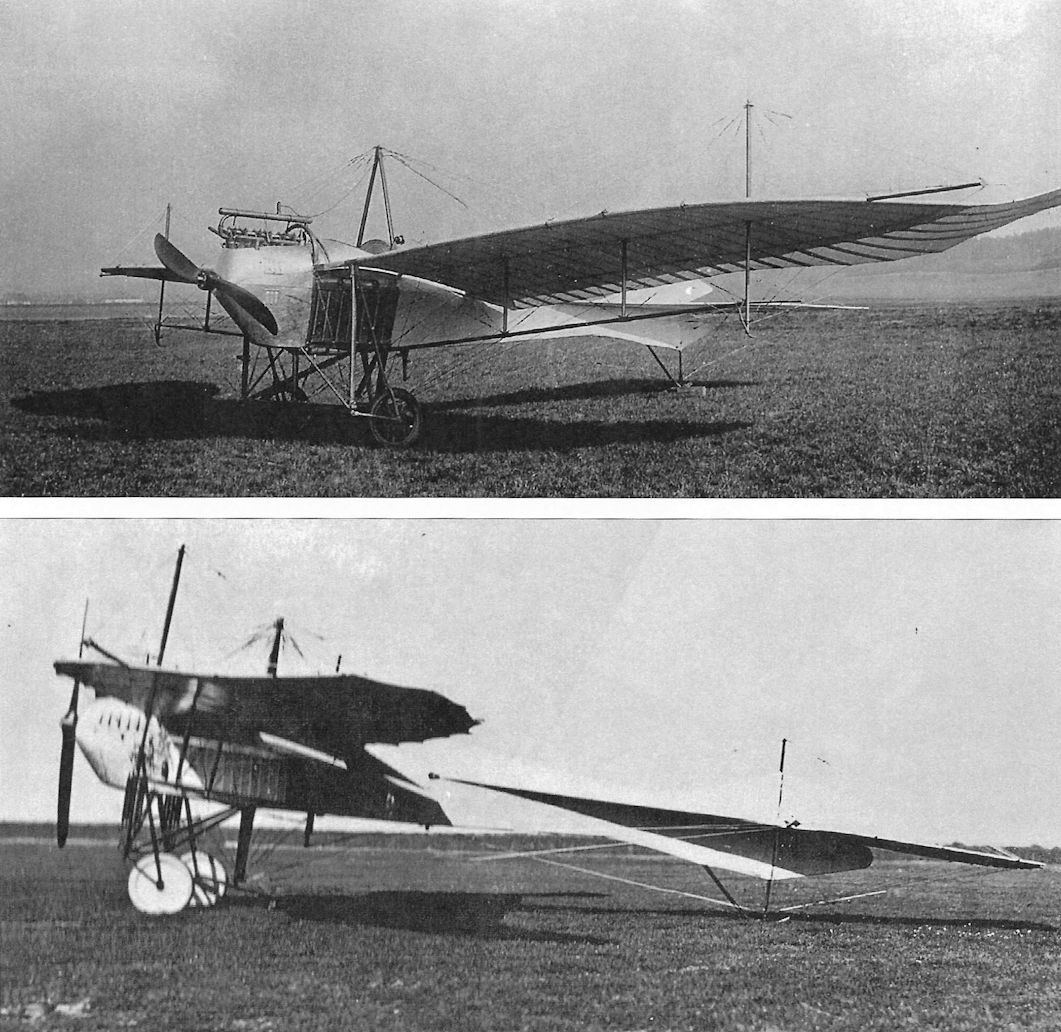
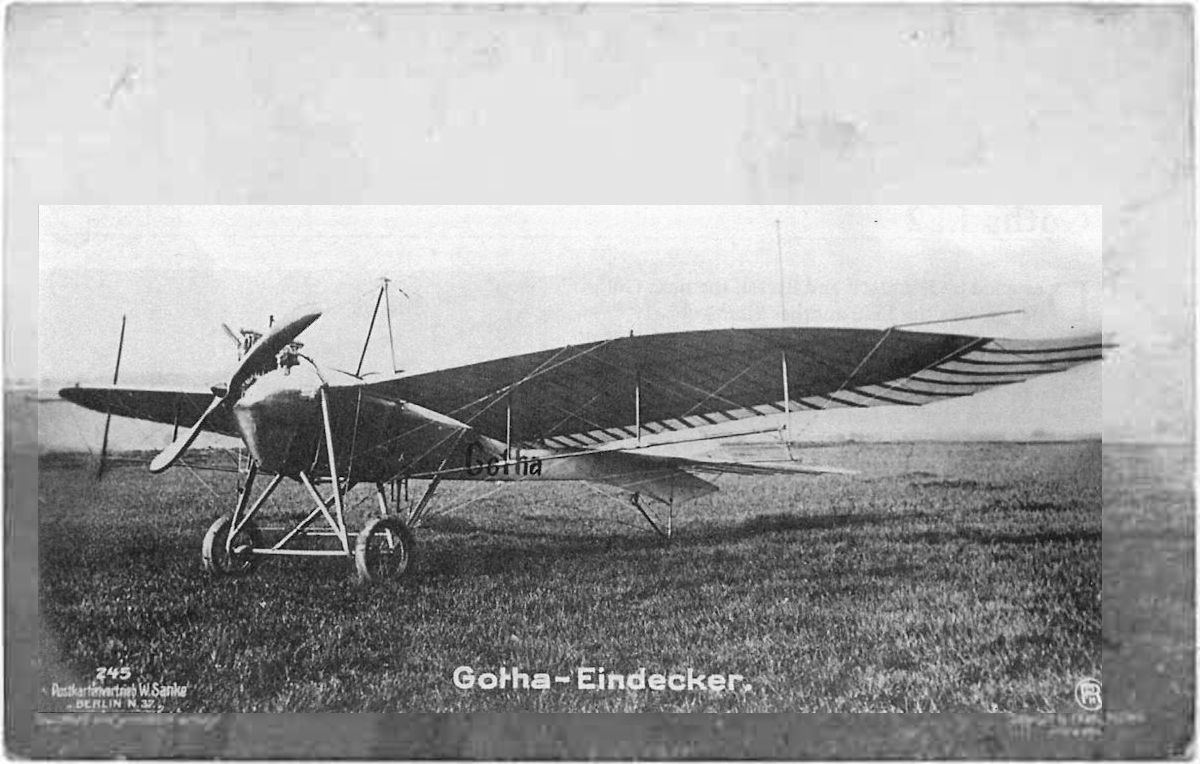
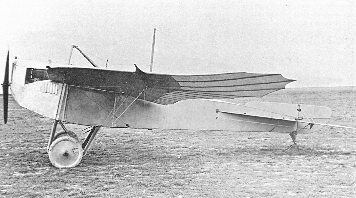
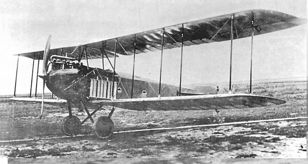
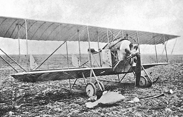
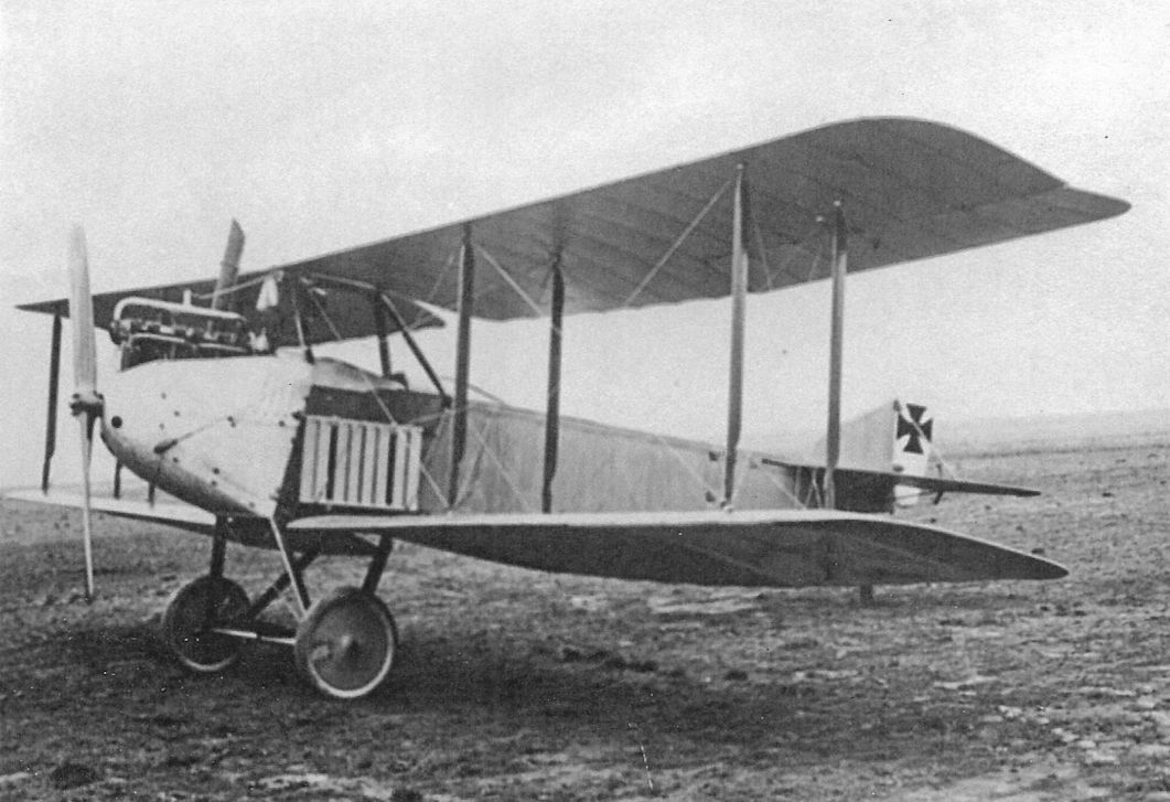
The Gotha LE4 after modification and assignment to the Herzog Carl Eduard Fliegerschule in Gotha.
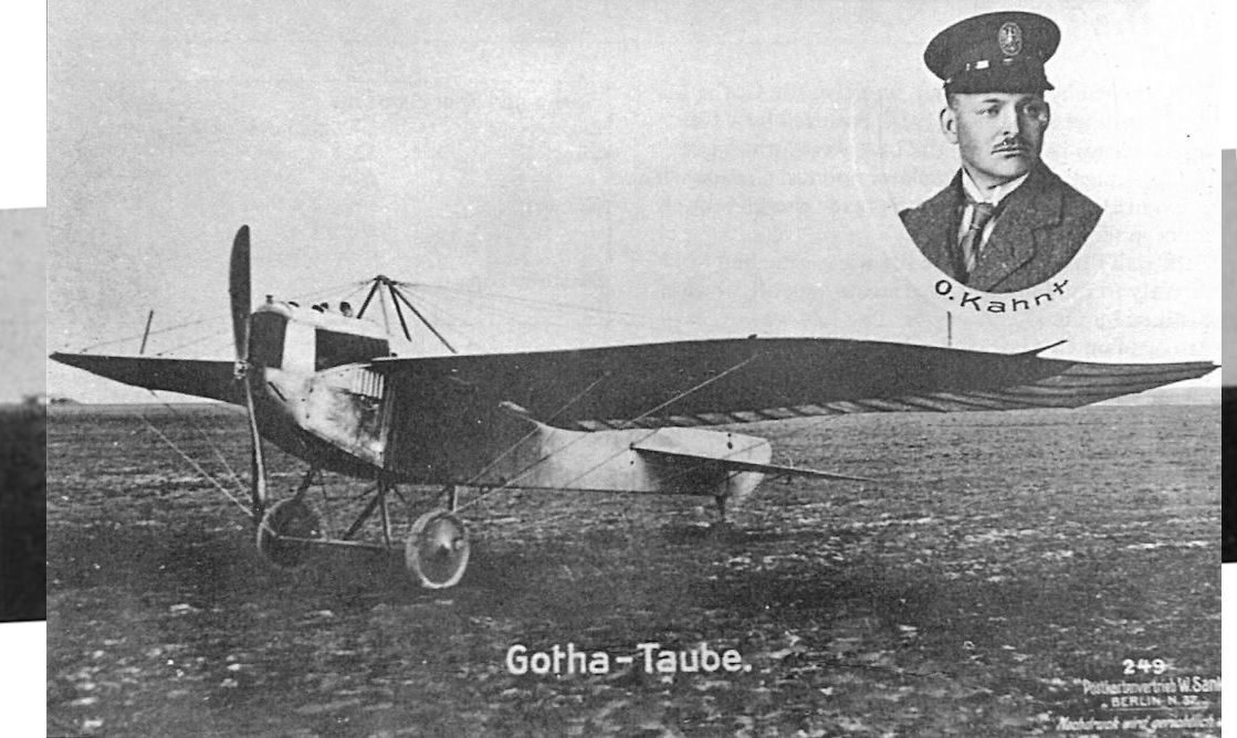
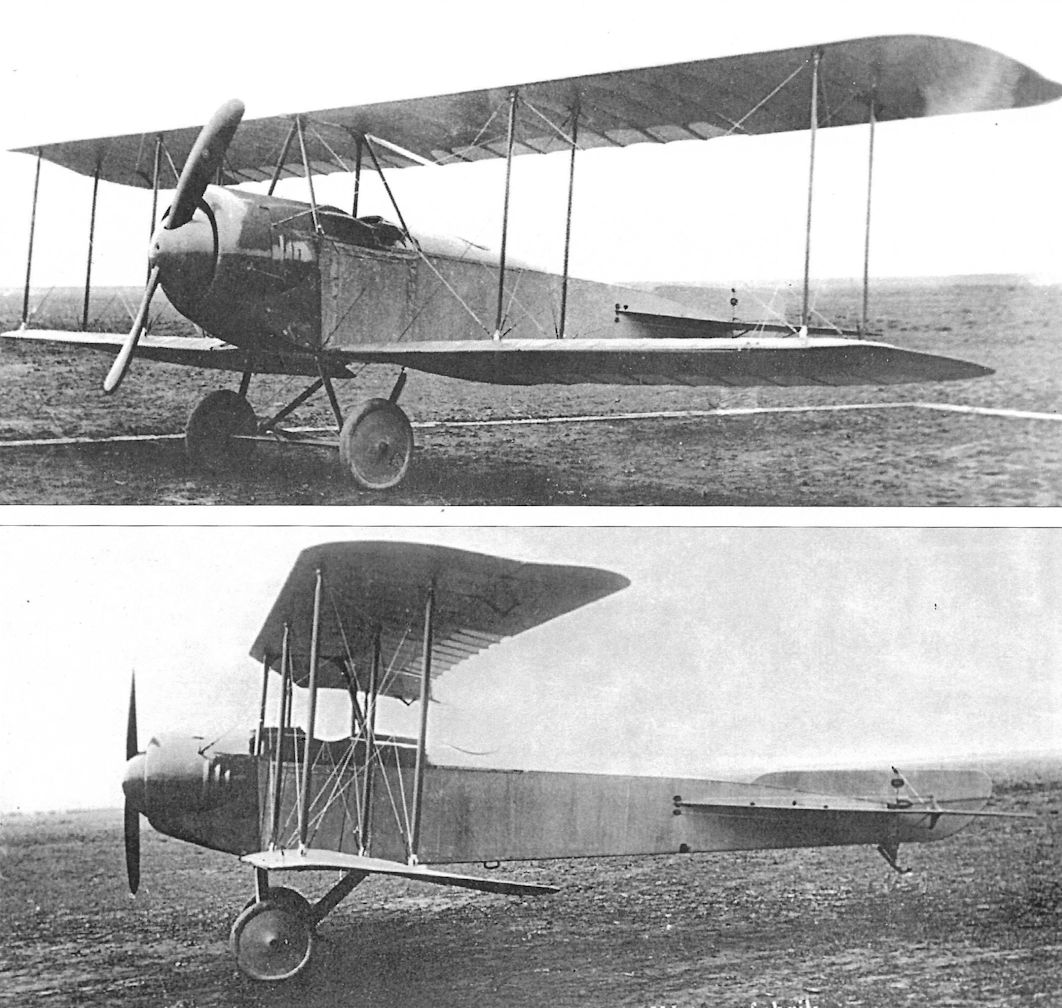
The original configuration of the Gotha LE4. Gotha test pilot Oswald Kahnt, commemorated on this card, was killed when the later LD6 crashed on its maiden flight.
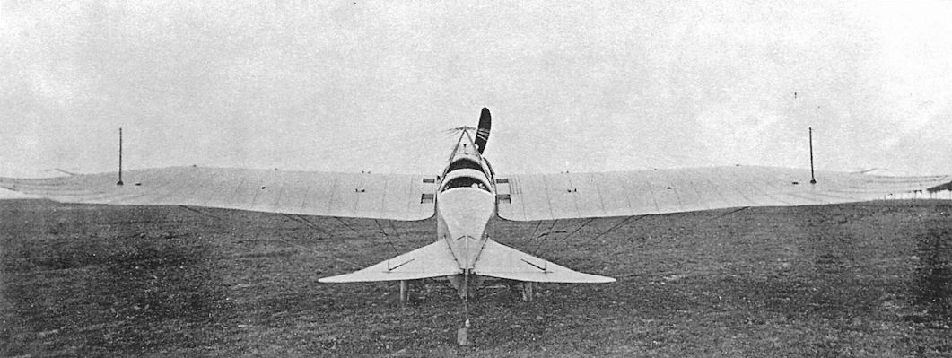
Rear view of the Gotha LE4; lack of national insignia indicates this is the original configuration before repair.
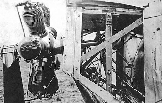
Side view of the Gotha LE4; lack of national insignia indicates this is the original configuration before repair. The engine was a 100 hp Mercedes D.I inline six-cylinder.
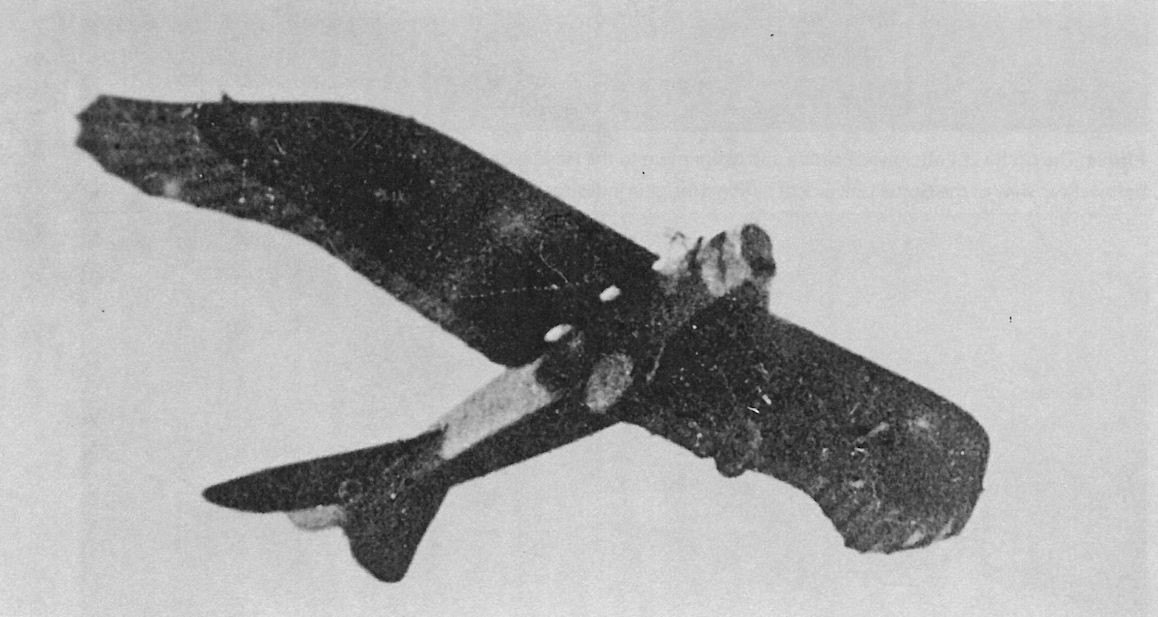
The Gotha LE4 in flight.
The Gotha LE4 photographed after repair and modification. During repair the LE4 was modified to have the front and rear lift wires attached to separate pylons in front and behind the undercarriage. After repair and modification, it was assigned to the Herzog Carl Eduard Fliegerschule in Gotha. The nose radiator and horizontal tail with conventional, hinged elevators made the LE4 much more modern in appearance than earlier Tauben. However, by the time the LE4 was built in 1914, the Taube configuration was obsolete and only a single LE4 was built.
The Gotha logo on a Gotha-built propeller included a Gotha Taube in its design.
Gotha LE3
Gotha LE3
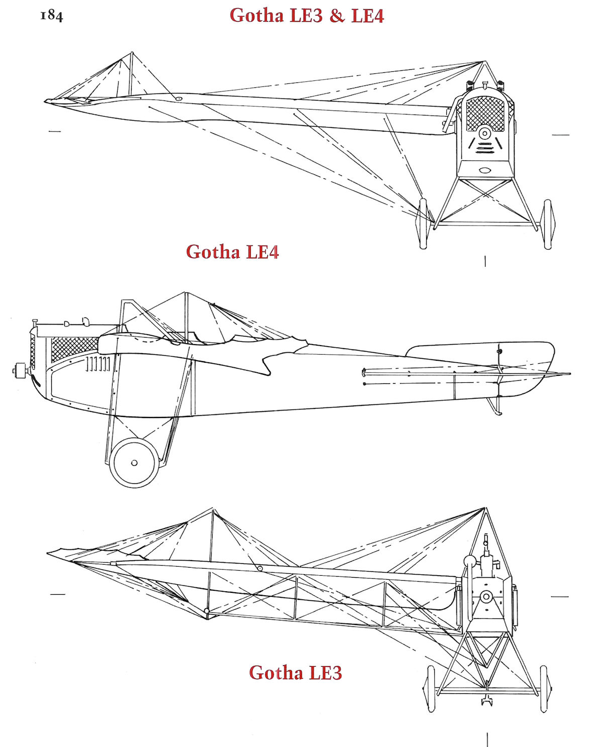
Gotha LE3 & LE4
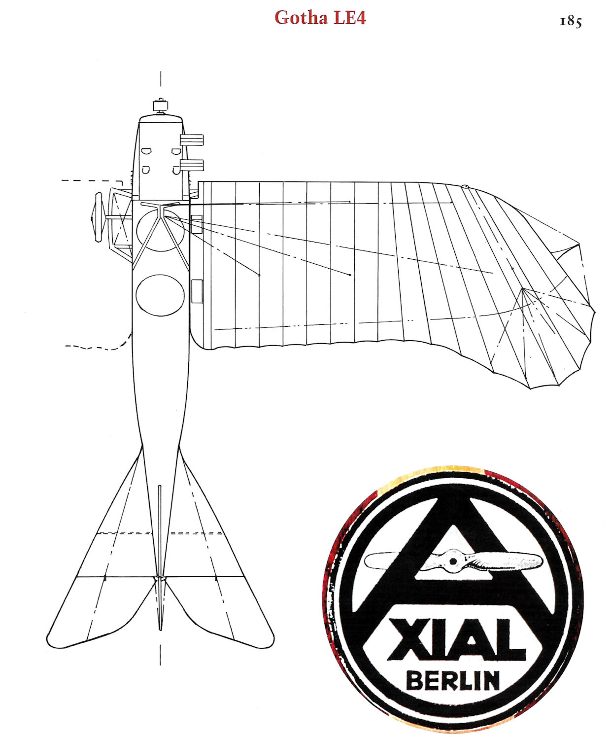
Gotha LE4
Gotha LD1
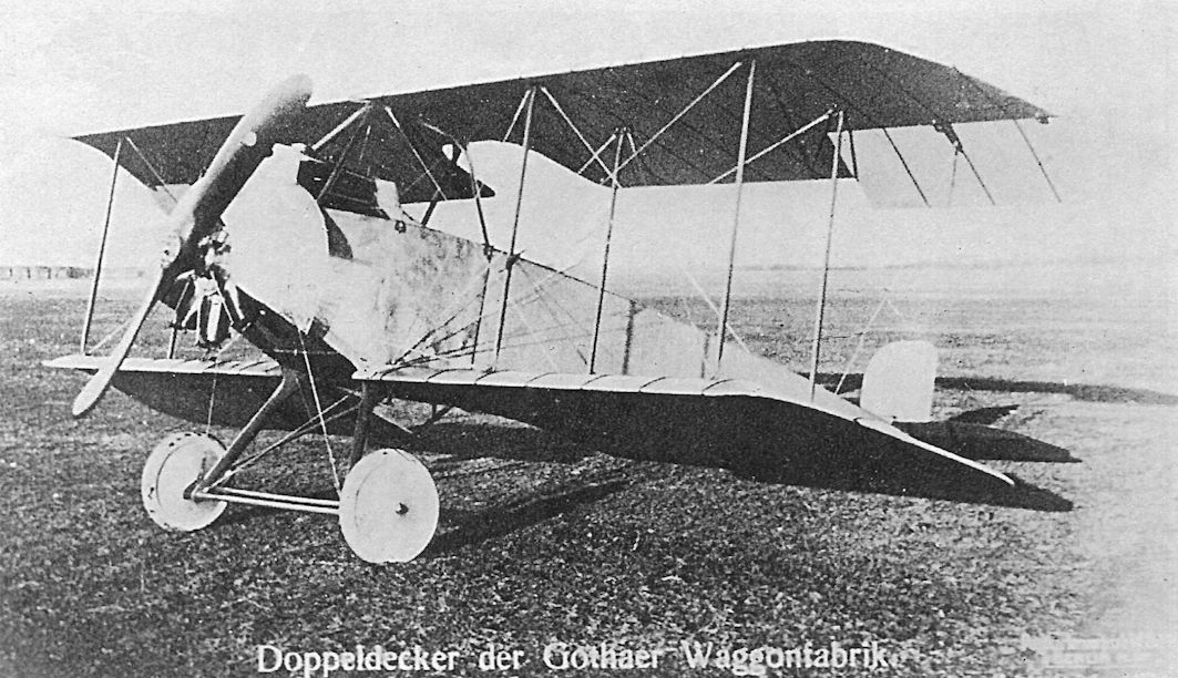
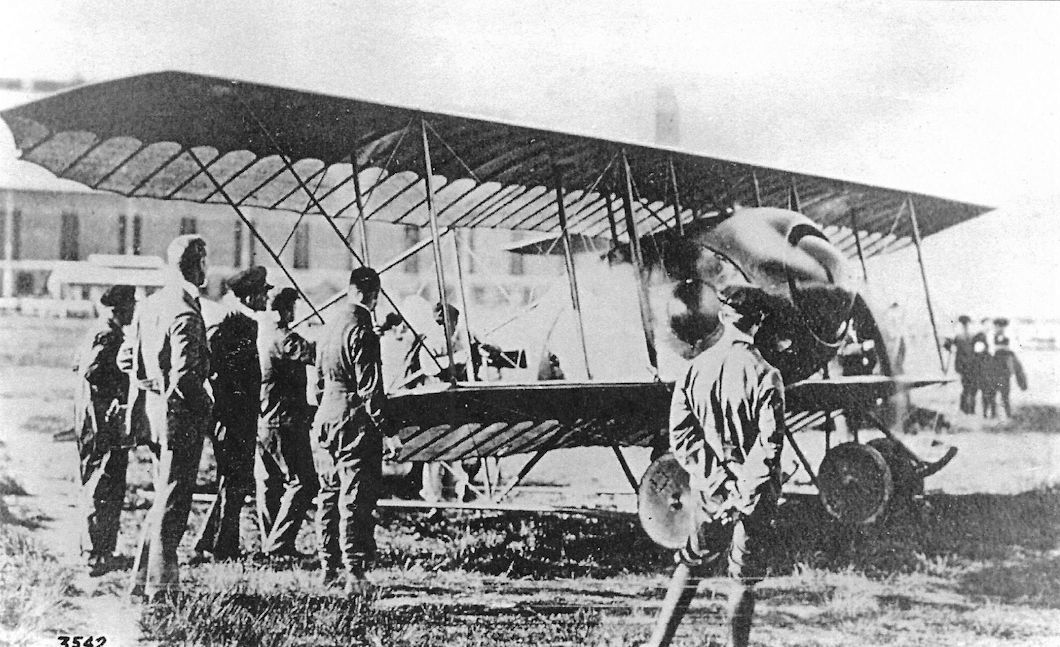
Designed by Rosner, the Gotha LD1 biplane (LD = Land Doppeldecker, or land biplane), powered by a 100 hp Mercedes engine, was ordered on 24 February 1914. It was a conventional, three- bay design with side-mounted radiators. It may have been intended as a competition machine but appears to have remained at Gotha for evaluation and training. During the course of flight trials, the LD 1 received a new rudder and other minor modifications.
On 31 August 1914 the LD1 was commandeered by officers of Feld-Flieger-Abteilung 4 and subsequently purchased by the Fliegertruppe, which assigned it the designation B.458/14. Only one LD1 was built.
Gotha LD1 Specifications
Engine: 100 hp Mercedes D.I
Wing: Span Upper 12.55 m
Span Lower 12.25 m
Area 36 m2
General: Length 8.00 m
Height 3.25 m
Empty Weight 525 kg
Loaded Weight 935 kg
Maximum Speed: 120 km/h
Climb: 800m 12 min
2000m 30 min
Range: 450 km
The Gotha LD1 was the start of Gotha's series of single-engine landplane biplanes. Powered by a 100 hp Mercedes D.I engine, it had a reasonable performance for its time but only one was built. Used at Gotha for training, it was commandeered by officers of Feld-Flieger-Abteilung 4 on 31 August 1914 and subsequently purchased by the Fliegertruppe, which assigned it the designation B.458/14. Only one LD1 was built.
Gotha LD2 (Gotha B.II)
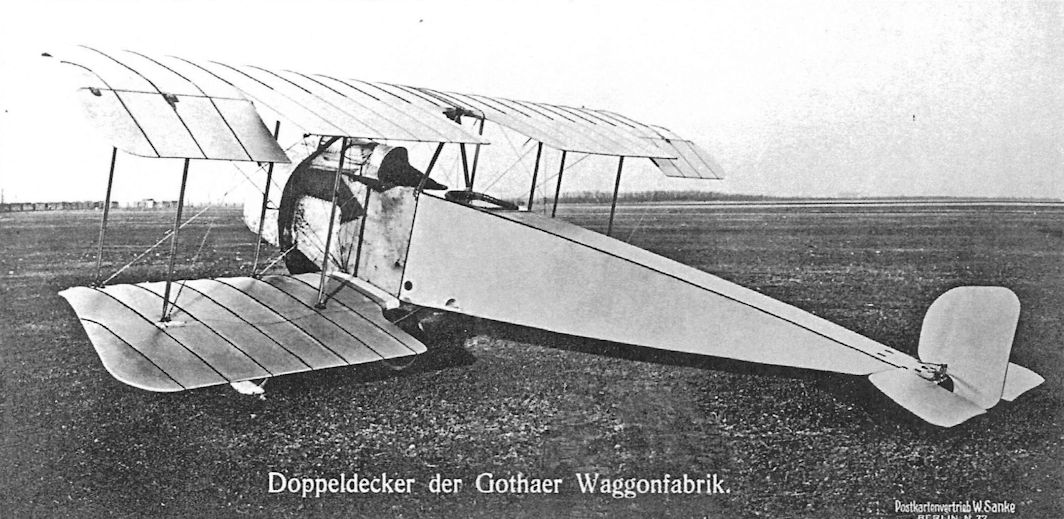
Designed by Rosner, the Gotha LD2 was powered by a 100 hp Oberursel rotary engine. Intended to achieve maximum speed, possibly to compete for the speed prize of 300,000 Marks posted by the National Flugspende, work on the LD2 prototype began on 31 March 1914.
On 24 August 1914, Idflieg ordered nine Gotha LD2 biplanes, numbered B.459-467/14. These were later assigned the designation Gotha B.II. The production prototype had a revised cowling for better engine cooling, and the cowling was again revised for the main production run, which also featured cut-down fuselage decking. Some time during the design's evolution the fixed vertical fin was eliminated, the revised aircraft having a button rudder. Starting 12 April 1915 all nine aircraft were delivered to FEA 3.
Gotha LD2 Specifications
Engine: 100 hp Oberursel U.I
Wing: Span Upper 14.50 m
Span Lower 13.50 m
Area 46 m2
General: Length 8.28 m
Height 3.45 m
Empty Weight 590 kg
Loaded Weight 982 kg
Maximum Speed: 115 km/h
Climb: 1000m 12 min
2000m 32 min
Range: 520 km
Gotha LD5
On 17 October 1914 Gotha began work on the LD5, which was designed by Ingenieur Hans Burkhard, a Swiss citizen who worked for Gotha throughout the war. Prior to joining Gotha in 1914, Burkhard had designed aircraft for Rumpler (1911), Bristol (1912), and Halberstadt (1913).
Powered by a 100 hp Oberursel rotary engine, the Gotha LD5 was a "cavalry biplane" intended as a light spotting aircraft to accompany an army on the move. The LD5, which first flew in December 1914, was a small, two-bay biplane with no fixed tail surfaces. Never assigned an official designation, the sole Gotha LD5 later served as a trainer at FEA 3.
Gotha LD5 Specifications
Engine: 100 hp Oberursel U.I
Two views of the prototype Gotha LD2 showing its streamlined engine cowling and spinner and very low profile fin and rudder.
The production prototype of the Gotha LD2 was far less appealing than the first prototype. The cowling was modified for better cooling and the fin and rudder were now enlarged for better stability and control.
Another view of the production prototype Gotha LD2 shows the unlovely cowling as redesigned for better cooling. National insignia were prominently painted on the wings.
The Gotha LD5, powered by a 100 hp Oberursel U.I, was designed as a 'cavalry biplane', a light observation plane designed to accompany an army on the move. The sole LD5 built served as a trainer at FEA 3.
The lesser-known Hun fighter, the Gotha short span two-seater.
Gotha LD3
Supervised by Ingenieur H. Schmieder, the Gotha LD3 was powered by a 50 hp Gnome rotary engine. The LD3 was a license-built Caudron. Work started on the LD3 on 7 October 1913; upon completion the aircraft was assigned to the Herzog Carl Eduard Fliegerschule. Only one LD3 was built.
Gotha LD3 Specifications
Engine: 50 hp Gnome
Wing: Span Upper 13.40 m
Span Lower 10.05 m
Area 26.4 m2
General: Length 6.40 m
Height 2.5 m
Empty Weight 340 kg
Loaded Weight 630 kg
Maximum Speed: 110 km/h
Gotha LD4
The Gotha LD4, powered by a 100 hp Gnome rotary engine, was another license-built Caudron but with side-by-side seating. It was ordered on 26 February 1914. Only one LD4 was built.
Gotha LD4 Specifications
Engine: 100 hp Gnome
Wing: Span Upper 13.40 m
Span Lower 10.05 m
Area 27 m2
General: Length 6.40 m
Height 2.5 m
Empty Weight 420 kg
Loaded Weight 710 kg
The Gotha LD3 was a license-built Caudron; only one was built.
The Gotha LD3 after an engine failure.
Close-up of the engine after failure in the LD3.
The Gotha LD4, a license-built Caudron, had a spinner and streamlined nose similar to that of the prototype LD2.
Gotha WD1
The first Gotha WD1 was a private venture completed in February 1914 and powered by a 14-cylinder, 100 hp Gnome rotary. The second WD1 powered by a 100 hp Mercedes D.I was built for the Ostseeflug Warnemunde 1914. This aircraft, competition number 20, was purchased by the Navy on 8 August 1914 and assigned Marine Number 59.
On 14 December 1914 the Navy purchased five Gotha WD1 seaplanes, Marine Numbers 285-289. Powered by a 100 hp Mercedes, these were delivered between 17 February and 24 March 1915. The WD1 suffered from poor aileron control and long take-off runs.
Despite being unarmed and low-powered, three WD1 seaplanes, Marine Numbers 286, 287, and 289, were sent to the German Wasserfliegerabteilung in Turkey, arriving in July 1915. These seaplanes were used for reconnaissance and light bombing of Allied forces on Imbros and the Gallipoli peninsula. These seaplanes also conducted anti-submarine patrols over the Sea of Marmara and attacked British submarines on several occasions. In October 1915 three armed Gotha WD2 seaplanes were added to the German unit. On 29 Nov. 1915 both #287 and #289 were lost in separate incidents due to mechanical failure.
Gotha WD1 Specifications
Engine: 100 hp Mercedes D.I
Wing: Span Upper 14.10 m
Span Lower 13.63 m
Area 50 m2
General: Length 10.32 m
Height 4.00 m
Empty Weight 800 kg
Loaded Weight 1220 kg
Maximum Speed: 90 km/h
Climb: 1000m 24.5 min
Service Ceiling 2500 m
Range: 540 km
Gotha WD2
Powered by a 150 hp Rapp engine, the Gotha WD2 was built for the Ostseeflug Warnemunde 1914. This aircraft, competition number 19a, was confiscated by the Navy at the beginning of the war and assigned Marine Number 61. Damaged several times during flight testing, it was repaired and finally accepted on 10 December 1914.
A second WD2, also entered in the Ostseeflug Warnemunde 1914, was competition number 19. Powered by a 150 hp Benz Bz.III, this WD2 was accepted by the Navy on 5 August 1914 and assigned Marine Number 60.
The first WD2 production series, five floatplanes with Marine Numbers 236-240 and powered by the 160 hp Mercedes D.III, was ordered in July 1914 and delivered between December 1914 and April 1915. The second WD2 production series, again of five aircraft, was given Marine Numbers 254-258. This series was ordered in March 1915, and the last aircraft was delivered that December. On 3 July 1915, accompanied by an Albatros floatplane, WD2 #257 from Zeebrugge bombed the Landguard Point signals station near Harwich without effect.
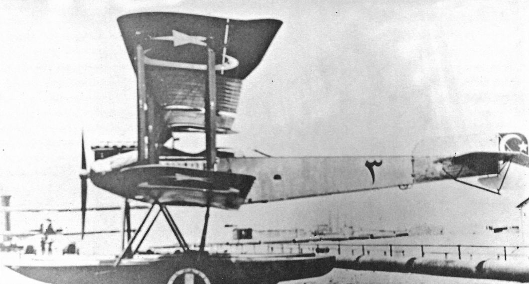
Two 160 hp Mercedes-powered WD2 aircraft were built as Marine Numbers 424-425; these were fitted with temporary wheels and a tailskid attached to each float for overland flights to Turkey because shipments through Romania were banned. These delivery flights took place in early 1916. These WD2s were fitted with a machine gun turret above the upper wing, giving the gunner a 360° field of fire.
Six WD2s were ordered for Turkey on 6 January 1916 and delivered in May-July 1916; these were powered by the 160 hp Mercedes D.III. Because these were ordered for Turkey no Marine Numbers were assigned. Five similar floatplanes were delivered to the German Navy in February-March 1916. Because the Navy criticized the WD2 floatplanes for poor seaworthiness, many WD2s were sent to the Dardanelles where the weather and sea conditions were less demanding.
The last two WD2s were ordered by Turkey on 29 April 1916 and delivered in August; no Marine Numbers were assigned. These were modified by having a conventional gun ring for the observer, split radiators mounted on the center-section struts, and a large gravity tank mounted away from the engine. Turkish sources label these machines as WD13s.
Gotha WD2 Specifications
Engine: 150 hp Benz Bz.III
150 hp Rapp Rp.III 160 hp Mercedes D.III
Wing: Span Upper 16.43 m
Span Lower 15.57 m
Area 58.5 m2
General: Length 10.50 m
Height 4.10 m
Empty Weight 1050 kg
Loaded Weight 1487 kg
Maximum Speed: 96 km/h
Climb: 1000m 12 min
2000m 32 min
Service Ceiling 3200 m
Range: 670 km
Gotha Seaplane Production Summary
Type Ordered Marine Numbers Remarks
WD1 6 59, 285-289 286, 287, and 289 served in Turkey
WD2 22 60-61, 236-240, 254-258, 424-425 424-425 went to Turkey. Turkey ordered 8 more without Marine Numbers
The first Gotha WD1 was a private venture completed in February 1914 and powered by a 14-cylinder, 100 hp Gnome rotary. The second WD1 powered by a 100 hp Mercedes D.I was built for the Ostseeflug Warnemunde 1914. This aircraft, competition number 20, was purchased by the Navy on 8 August 1914 and assigned Marine Number 59.
On 14 December 1914 the Navy purchased five Gotha WD1 seaplanes, Marine Numbers 285-289. Powered by a 100 hp Mercedes, these were delivered between 17 February and 24 March 1915. The WD1 suffered from poor aileron control and long take-off runs.
Despite being unarmed and low-powered, three WD1 seaplanes, Marine Numbers 286, 287, and 289, were sent to the German Wasserfliegerabteilung in Turkey, arriving in July 1915. These seaplanes were used for reconnaissance and light bombing of Allied forces on Imbros and the Gallipoli peninsula. These seaplanes also conducted anti-submarine patrols over the Sea of Marmara and attacked British submarines on several occasions. In October 1915 three armed Gotha WD2 seaplanes were added to the German unit. On 29 Nov. 1915 both #287 and #289 were lost in separate incidents due to mechanical failure.
Gotha WD1 Specifications
Engine: 100 hp Mercedes D.I
Wing: Span Upper 14.10 m
Span Lower 13.63 m
Area 50 m2
General: Length 10.32 m
Height 4.00 m
Empty Weight 800 kg
Loaded Weight 1220 kg
Maximum Speed: 90 km/h
Climb: 1000m 24.5 min
Service Ceiling 2500 m
Range: 540 km
Gotha WD2
Powered by a 150 hp Rapp engine, the Gotha WD2 was built for the Ostseeflug Warnemunde 1914. This aircraft, competition number 19a, was confiscated by the Navy at the beginning of the war and assigned Marine Number 61. Damaged several times during flight testing, it was repaired and finally accepted on 10 December 1914.
A second WD2, also entered in the Ostseeflug Warnemunde 1914, was competition number 19. Powered by a 150 hp Benz Bz.III, this WD2 was accepted by the Navy on 5 August 1914 and assigned Marine Number 60.
The first WD2 production series, five floatplanes with Marine Numbers 236-240 and powered by the 160 hp Mercedes D.III, was ordered in July 1914 and delivered between December 1914 and April 1915. The second WD2 production series, again of five aircraft, was given Marine Numbers 254-258. This series was ordered in March 1915, and the last aircraft was delivered that December. On 3 July 1915, accompanied by an Albatros floatplane, WD2 #257 from Zeebrugge bombed the Landguard Point signals station near Harwich without effect.
Two 160 hp Mercedes-powered WD2 aircraft were built as Marine Numbers 424-425; these were fitted with temporary wheels and a tailskid attached to each float for overland flights to Turkey because shipments through Romania were banned. These delivery flights took place in early 1916. These WD2s were fitted with a machine gun turret above the upper wing, giving the gunner a 360° field of fire.
Six WD2s were ordered for Turkey on 6 January 1916 and delivered in May-July 1916; these were powered by the 160 hp Mercedes D.III. Because these were ordered for Turkey no Marine Numbers were assigned. Five similar floatplanes were delivered to the German Navy in February-March 1916. Because the Navy criticized the WD2 floatplanes for poor seaworthiness, many WD2s were sent to the Dardanelles where the weather and sea conditions were less demanding.
The last two WD2s were ordered by Turkey on 29 April 1916 and delivered in August; no Marine Numbers were assigned. These were modified by having a conventional gun ring for the observer, split radiators mounted on the center-section struts, and a large gravity tank mounted away from the engine. Turkish sources label these machines as WD13s.
Gotha WD2 Specifications
Engine: 150 hp Benz Bz.III
150 hp Rapp Rp.III 160 hp Mercedes D.III
Wing: Span Upper 16.43 m
Span Lower 15.57 m
Area 58.5 m2
General: Length 10.50 m
Height 4.10 m
Empty Weight 1050 kg
Loaded Weight 1487 kg
Maximum Speed: 96 km/h
Climb: 1000m 12 min
2000m 32 min
Service Ceiling 3200 m
Range: 670 km
Gotha Seaplane Production Summary
Type Ordered Marine Numbers Remarks
WD1 6 59, 285-289 286, 287, and 289 served in Turkey
WD2 22 60-61, 236-240, 254-258, 424-425 424-425 went to Turkey. Turkey ordered 8 more without Marine Numbers
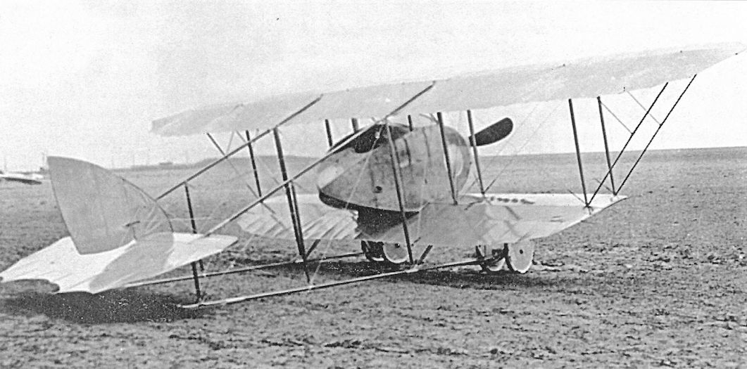
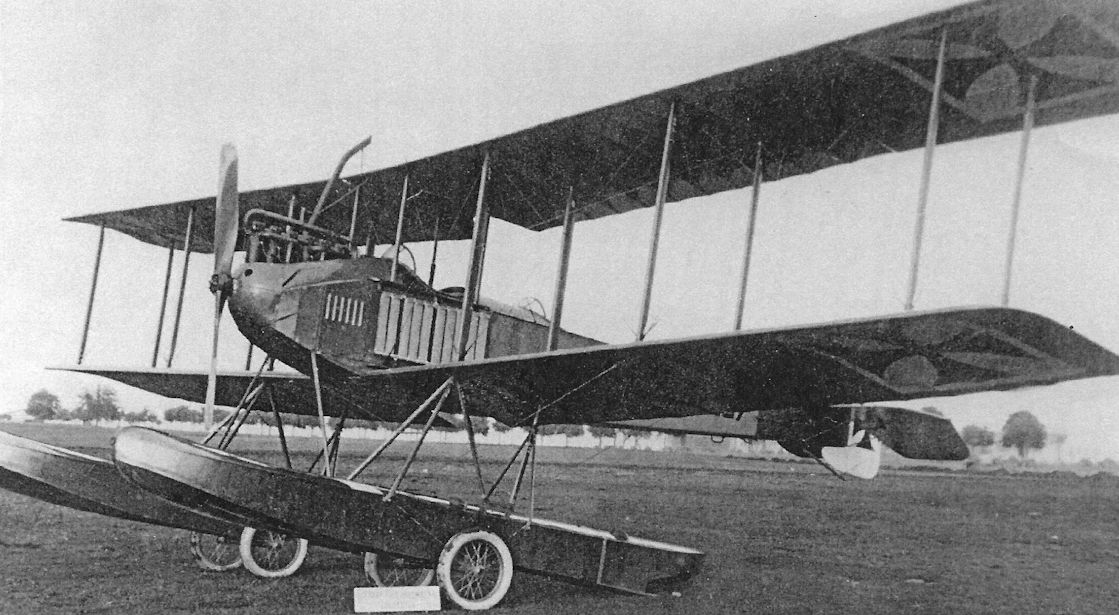
Gotha WD1 (1914), an Avro 503 copy.
The prototype WD1 was powered by a two-row, 100 hp Gnome rotary engine.The WD1 floatplane was a conventional 3-bay biplane; a small float was attached to the rudder.
The prototype WD1 was powered by a two-row, 100 hp Gnome rotary engine.The WD1 floatplane was a conventional 3-bay biplane; a small float was attached to the rudder.
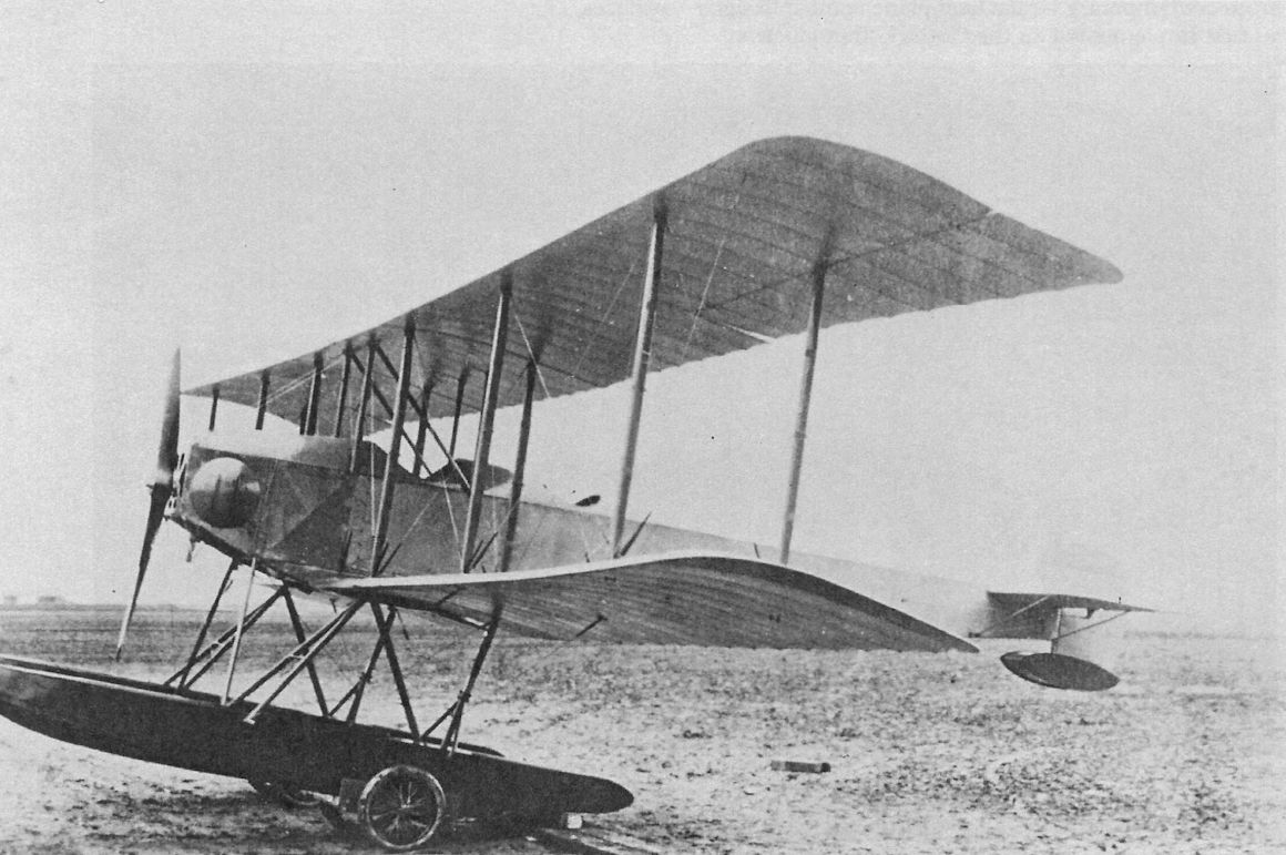
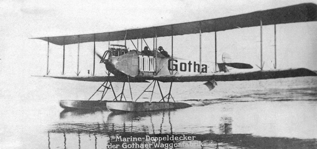
The six subsequent WD1 floatplanes were powered by a 100 hp Mercedes D.I engine. This WD1 is almost certainly the second WD1 built by Gotha for the Ostseeflug Warnemunde 1914 competition. It has the Gotha name painted on the fuselage and retains the small float attached to the rudder.This aircraft was later purchased by the Navy.
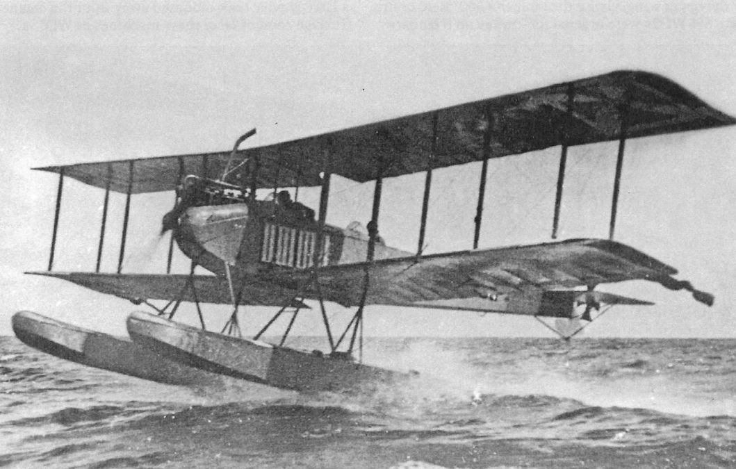
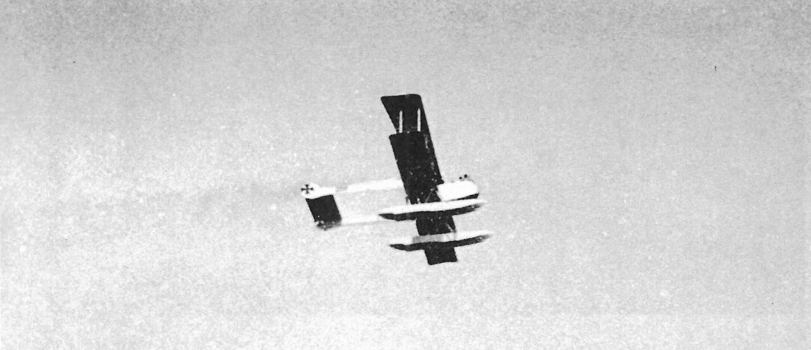
OFF! - A German (Gotha) seaplane starting on a reconnaissance flight. Note the long stepped floats which project backwards to a point considerably behind the pilot's seat.
This WD1 was in naval service as indicated by the national insignia and pennants attached to the outer struts. One of the series Marine Numbers 285-289, no float was attached to the rudder. Marine #285 was at Chanak seaplane station in Turkey by December 1915, while #286 was at Kawak.
This WD1 was in naval service as indicated by the national insignia and pennants attached to the outer struts. One of the series Marine Numbers 285-289, no float was attached to the rudder. Marine #285 was at Chanak seaplane station in Turkey by December 1915, while #286 was at Kawak.
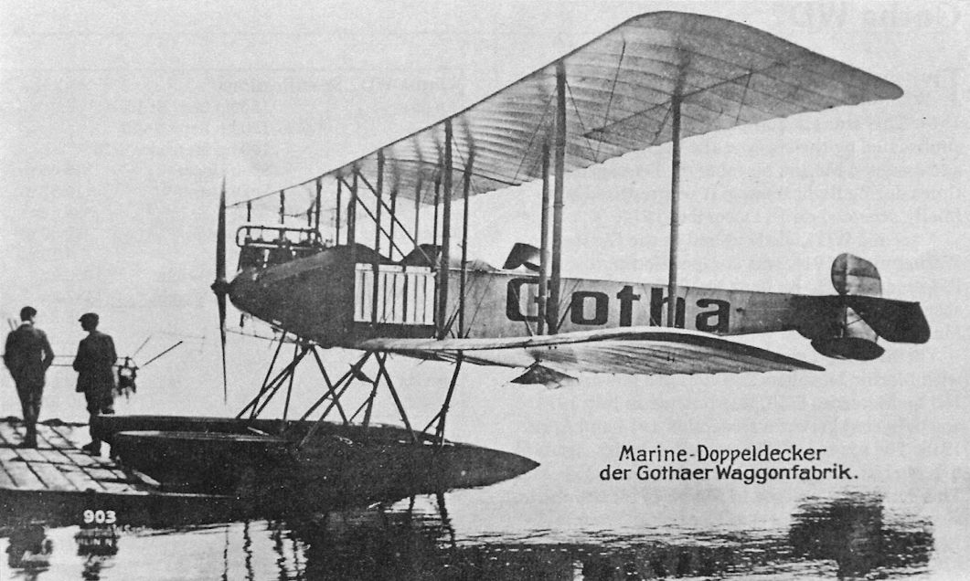
The first WD2 floatplane was powered by a 150 hp Rapp engine and was entered in the Ostseeflug Warnemunde 1914 competition, competition #19a. It has the Gotha name painted on the fuselage; this aircraft was later purchased by the Navy and assigned Marine Number 61.
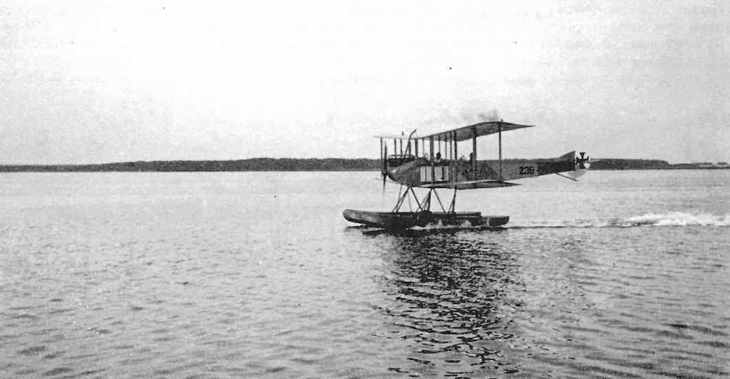
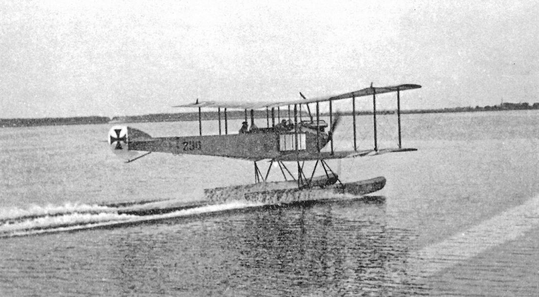
WD2 Marine Number 236 is seen taxiing for take-off. The float attached to the rudder of the early WD1 aircraft was no longer used on subsequent types. Its 160 hp Mercedes D.III gave it much more power than its WD1 predecessor. At least three WD2 floatplanes were sent to the German Wasserfliegerabteilung in Turkey in October 1915. In addition, at least ten WD2 floatplanes were delivered to Turkish forces.
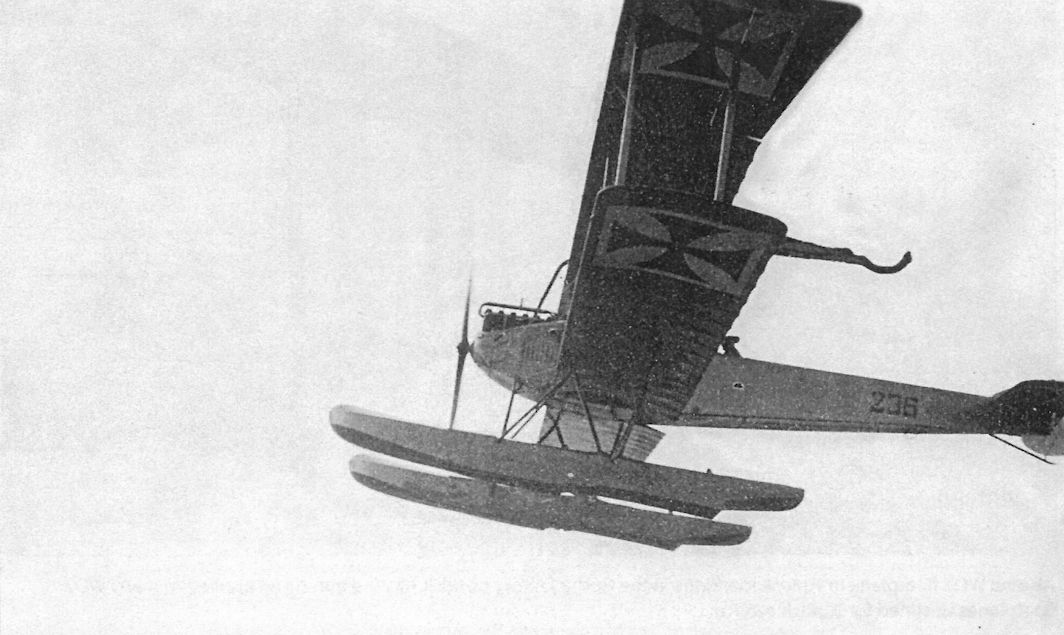
WD2 Marine Number 236 is seen in flight.
This WD2 floatplane on wheels appears different than Marine Number 424; it does not have the gun turret and the exhaust is different. It wears German markings.
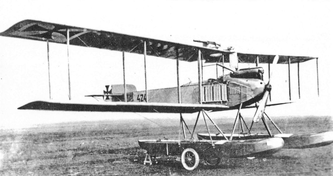
The serial 424 on the rear fuselage of this Gotha WD-2a identifies it as being one of the later production 'small wing' version, differentiated by the 'a' suffix. First flown in July 1914, the WD-2 and WD-2a, of which a total of 27 were built, used either a 100hp Benz Bz III, or a 150hp Rapp. Built for long range reconnaissance, the WD-2a's top level speed was 59.5mph at sea level, while its range was 415 miles, an 80 mile improvement on that of the earlier WD-1.
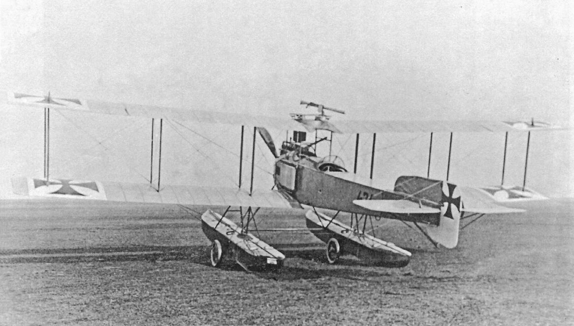
WD2 Marine Number 424 (shown here) and 425 were fitted with temporary wheels and tail skids attached to their floats to enable overland flights to Turkey because rail shipments through Romania were banned. These two aircraft were powered by the 160 hp Mercedes D.III engine and had a gun turret for the observer mounted above the upper wing, giving the gunner a 360° field of fire. WD2 #424 was at Chanak when credited with a victory in Jan. 1916 by Flgobmt Wilhelm Schubert (pilot)/Flgmt Werdier (observer), who shot down a Farman that crashed east of Tenedos. Later this aircraft was at Kawak.
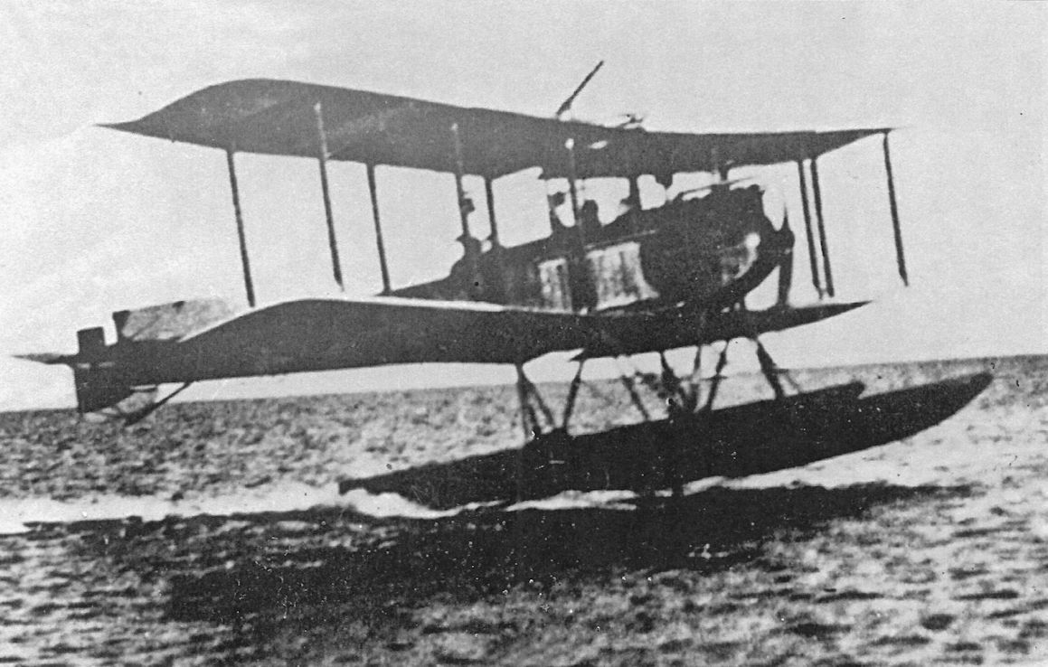
This WD2 floatplane on wheels wears Turkish markings. It lacks the gun turret applied to Marine Number 424 and many other WD2 floatplanes destined for Turkish service. The gun mount for the observer can just be seen.
Turkish WD2 floatplane.
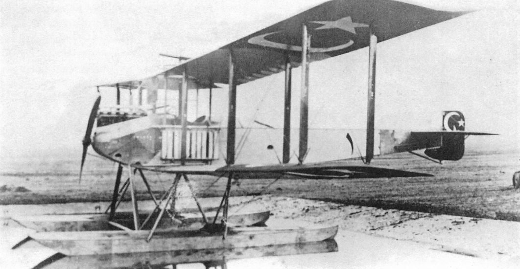
WD2 floatplane in Turkish markings in the Gotha factory pond about 1915. It has the gun turret applied to many WD2 floatplanes destined for Turkish service.
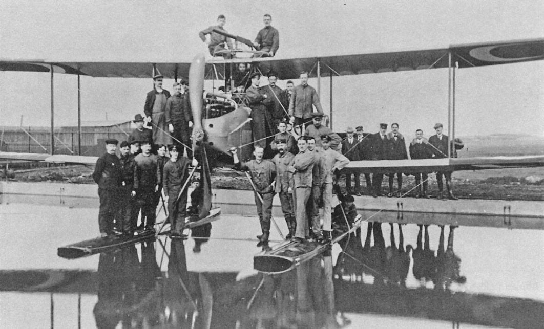
WD2 in the Gotha factory pond with 28 men on it for a test load.
WD2 floatplane in Turkish markings taking off. Like many WD2 floatplanes in Turkish service, it has the gun turret.
Turkish WD2 floatplane in flight. It has the gun turret applied to many WD2 floatplanes destined for Turkish service.
Gotha G.I
At the dawn of aviation, the military authorities of the major powers considered how aviation might be used in war. Reconnaissance and bombing immediately suggested themselves as potential roles for aviation, and in fact both were important in WWI and since. Of course, the next thought was, how to defend against the enemy using his aviation assets against your own forces? This concern lead to anti-aircraft guns and the idea of using airplanes for air-to-air combat.
But what kind of airplane would be best for defeating other aircraft? In retrospect the answer is clear, but it was far from obvious before the war. Synchronizers to enable machine guns to fire between the blades of a rotating propeller were being designed, but got little notice at the time. The concept that resonated with many designers and military authorities before the war, before there was any experience in air-to-air combat, was the idea of aerial cruisers. The aerial cruiser theory was derived from the warships of the day,- the pilot would fly the aerial cruiser within range of the enemy aircraft and gunners would fire flexibly-mounted machine guns and cannon to destroy the adversary. Thus was born the idea of the battleplane, and Britain, France, and Germany all built aircraft to this concept.
In early 1914 key German aviation authorities, including Idflieg, the VPK (Verkehrstechnische Prufungs Kommission = transport technical investigation commission) and aviation industry executives, discussed the role of military aircraft and reached a consensus. The VPK then issued a directive outlining the tactical role of aircraft and specified three categories: Typ I was a fast two-seater intended for extended flights for reconnaissance and light bombing; Typ II was a light, maneuverable two- seater for short flights over the lines and armed for self-defense; and Typ III was three-seater designed to carry a large payload and fly low within range of enemy fire. The Typ III was required to have a speed over 120 km/h, climb to 800m in 10 minutes, have a flight duration of 6 hours, and a useful load of 450 kg. In essence the Typ III was a battleplane (Kampfflugzeug in German).
The German army approved the VPK recommendations on 28 April 1914, and demanded that these airplanes be developed as soon as possible. The Typ I was essentially the B-type two-seat biplane, of which numerous designs were available, while the Typ II eventually converged with the developed B-type to become the C-type armed two-seater. In parallel, a number of companies responded with designs to the Typ III requirements.
However, the design that was to evolve into the Gotha G.l stemmed from an independent effort. Oskar Ursinus, founder and editor of Flugsport magazine and a civil engineer, received orders to report to FEA 3 (FEA for Flieger Ersatz Abteilung = aviation replacement unit) in Darmstadt on 1 August 1914. On 9 August Ursinus proposed building a twin-engine Kampfflugzeug to Major Friedel, FEA 3's new commander, using under-utilized military personnel from the unit. Friedel accepted and the new airplane would be known as the Friedel-Ursinus Kampfflugzeug, also known as the type FU. The aircraft was certainly built with the Typ III requirements in mind; for example the fuselage and engine nacelles were armored.
Design work started immediately, and on 1 September FEA 3 personnel began to build the aircraft, which was assigned the military designation B.1092/14. This indicates Idflieg approved the aircraft and may have provided funds. On 30 January 1915 pilot Herold performed the aircraft's first flight.
The aircraft was powered by two 100-hp Mercedes D.I engines. The high fuselage enabled the engines to be very close to the centerline, reducing asymmetric control forces in event of engine failure. It also gave a wide field of fire to the gunner in the nose. However, with no protective structure above the crew, a turnover on landing would be extremely dangerous to the crew.
According to Ursinus's biography, the type FU was eventually sent to Ujatz, near Lodz, for operational trials on the Russian Front, but there is no further information.
A production license for the type was offered to Fokker and Gotha; Gotha signed a license in March 1915. Likely in anticipation of that event, in February 1915 FEA 3 was transferred to Gotha. On 1 April 1915 Idflieg awarded a contract for six Gotha G.I aircraft to Gotha. The internal Gotha company designation was type UKL or type GUK; both were used. Of the first batch of six aircraft, five were to be powered by the 150 hp Benz Bz.III and the other was to be powered by two 160 hp Mercedes D.III engines. The contract required a crew of two with one machine gun, 200 kg of bombs, 150 kg of armor, and a maximum speed of 125 km/h.
Ursinus worked with Gotha engineer Hans Burkhardt to prepare manufacturing drawings. Starting on 27 July the aircraft were delivered as G.9/15 - G.14/15; the last was delivered on 8 September. The first three went to FEA 7 for defense of the Krupp works in Cologne, the next two went to FEA 3 at Gotha for training, and the last went to Armeeabteilung Falkenhausen. The production G.I differed in detail from the Type FU.
On 15 July 1915 a second series of six Gotha G.I aircraft were ordered, all to be powered by the 150 hp Benz Bz.III. These aircraft were accepted between 22 September and 5 November, and all remained at FEA 3 in Gotha.
The third and final series of six Gotha G. I aircraft was ordered on 17 October 1915. These were powered by the 160 hp Mercedes D.III engine. The Kampfflugzeug concept now having failed, bombing was emphasized and the required bomb load was raised to 350 kg. A third crewman with a second gun carried between the pilot and front gunner was now specified. Idflieg also asked that a machine cannon be installed in addition to a machine gun, leading to weapons trials with a 20mm Becker cannon and 37mm cannon. The final batch was delivered between 24 January 1916 and 20 March 1916. One machine went to FEA 1 at Doberitz; the other five went to the Prufanstalt und Werft (Idflieg’s test establishment and workshop) at Doberitz.
In service the slow G.l accomplished little as a battleplane, the basic concept being fundamentally flawed. Battleplanes of all designs soon demonstrated they were too slow to catch enemy aircraft. Furthermore, even when the enemy was within range, so were they; the enemy had as good a chance at victory as they did. Operational experience soon showed that large, twin-engine types were better suited for bombing than air superiority missions, leading to the last batch of G.Is being modified for a greater bomb load. More specifically to the unique design the G.I inherited from the Type FU, turnovers on landing were always a possibility and, if they occurred, were invariably fatal to the crew. Moreover, the G.I was structurally fragile.
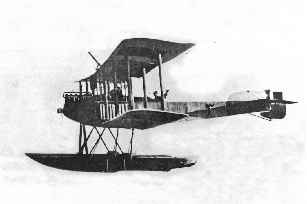
The German Navy purchased one float-equipped version of the G.I as the Gotha UWD, Marine Number 120.
Friedel-Ursinus B.1092/14 Specifications
Engines: 2 x 100 hp Mercedes D.I
Wing: Span Upper 22.00 m
Span Lower 19.00 m
Chord [Upper &. Lower) 2.2 m
Sweepback 4°
General: Length 17.60 m
Height 6.00 m
Empty Weight 4700 kg
Loaded Weight 6860 kg
Maximum Speed: 90-95 km/h
Gotha G.I Specifications
Engines: 2 x 150 hp Benz Bz.III
Wing: Span Upper 20.30 m
Span Lower 19.70 m
Chord [Upper &. Lower) 2.20 m
Gap 1.95 m
Sweepback 10°
Area 82 m2
General: Length 12 m
Height 3.9 m
Empty Weight 1800 kg
Loaded Weight 2966 kg
Maximum Speed: 130 km/h
Climb: 2000m 47 min
Gotha G.I Production Summary
Production Batch Serial Numbers Qty Engines Crew/Armament
#1 (ordered 1-4-15) G.9/15-G.14/15 6 2x150 hp Benz Bz.III (five) 2x160 hp Mercedes D.III (one) 2 crew, 1 gun, 250 kg bombs
#2 (ordered 15-7-15) G.40/15-G.45/15 6 2x150 hp Benz Bz.III 2 crew, 1 gun, 250 kg bombs
#3 (ordered 17-10-15) G.100/15-G.105/15 6 2x160 hp Mercedes D.III 3 crew, 2 guns, 350 kg bombs
The Friedel-Ursinus prototype was assigned designation B.1092/14. It had one gun.
Gotha G-Type Bomber Production Summary
Order Date Type Qty Serials Notes
April 1, 1915 G.I 6 9-14/15 Plus one Friedel-Ursinus prototype, B. 1092/14. Production G.Is delivered 27 July-8 Sep. 1915.
July 15, 1915 G.I 6 40-45/15 Delivered 22 Sep.-5 Nov. 1915.
Oct. 10, 1915 G.I 6 100-105/15 Delivered 24 Jan.-20 March 1916.
At the dawn of aviation, the military authorities of the major powers considered how aviation might be used in war. Reconnaissance and bombing immediately suggested themselves as potential roles for aviation, and in fact both were important in WWI and since. Of course, the next thought was, how to defend against the enemy using his aviation assets against your own forces? This concern lead to anti-aircraft guns and the idea of using airplanes for air-to-air combat.
But what kind of airplane would be best for defeating other aircraft? In retrospect the answer is clear, but it was far from obvious before the war. Synchronizers to enable machine guns to fire between the blades of a rotating propeller were being designed, but got little notice at the time. The concept that resonated with many designers and military authorities before the war, before there was any experience in air-to-air combat, was the idea of aerial cruisers. The aerial cruiser theory was derived from the warships of the day,- the pilot would fly the aerial cruiser within range of the enemy aircraft and gunners would fire flexibly-mounted machine guns and cannon to destroy the adversary. Thus was born the idea of the battleplane, and Britain, France, and Germany all built aircraft to this concept.
In early 1914 key German aviation authorities, including Idflieg, the VPK (Verkehrstechnische Prufungs Kommission = transport technical investigation commission) and aviation industry executives, discussed the role of military aircraft and reached a consensus. The VPK then issued a directive outlining the tactical role of aircraft and specified three categories: Typ I was a fast two-seater intended for extended flights for reconnaissance and light bombing; Typ II was a light, maneuverable two- seater for short flights over the lines and armed for self-defense; and Typ III was three-seater designed to carry a large payload and fly low within range of enemy fire. The Typ III was required to have a speed over 120 km/h, climb to 800m in 10 minutes, have a flight duration of 6 hours, and a useful load of 450 kg. In essence the Typ III was a battleplane (Kampfflugzeug in German).
The German army approved the VPK recommendations on 28 April 1914, and demanded that these airplanes be developed as soon as possible. The Typ I was essentially the B-type two-seat biplane, of which numerous designs were available, while the Typ II eventually converged with the developed B-type to become the C-type armed two-seater. In parallel, a number of companies responded with designs to the Typ III requirements.
However, the design that was to evolve into the Gotha G.l stemmed from an independent effort. Oskar Ursinus, founder and editor of Flugsport magazine and a civil engineer, received orders to report to FEA 3 (FEA for Flieger Ersatz Abteilung = aviation replacement unit) in Darmstadt on 1 August 1914. On 9 August Ursinus proposed building a twin-engine Kampfflugzeug to Major Friedel, FEA 3's new commander, using under-utilized military personnel from the unit. Friedel accepted and the new airplane would be known as the Friedel-Ursinus Kampfflugzeug, also known as the type FU. The aircraft was certainly built with the Typ III requirements in mind; for example the fuselage and engine nacelles were armored.
Design work started immediately, and on 1 September FEA 3 personnel began to build the aircraft, which was assigned the military designation B.1092/14. This indicates Idflieg approved the aircraft and may have provided funds. On 30 January 1915 pilot Herold performed the aircraft's first flight.
The aircraft was powered by two 100-hp Mercedes D.I engines. The high fuselage enabled the engines to be very close to the centerline, reducing asymmetric control forces in event of engine failure. It also gave a wide field of fire to the gunner in the nose. However, with no protective structure above the crew, a turnover on landing would be extremely dangerous to the crew.
According to Ursinus's biography, the type FU was eventually sent to Ujatz, near Lodz, for operational trials on the Russian Front, but there is no further information.
A production license for the type was offered to Fokker and Gotha; Gotha signed a license in March 1915. Likely in anticipation of that event, in February 1915 FEA 3 was transferred to Gotha. On 1 April 1915 Idflieg awarded a contract for six Gotha G.I aircraft to Gotha. The internal Gotha company designation was type UKL or type GUK; both were used. Of the first batch of six aircraft, five were to be powered by the 150 hp Benz Bz.III and the other was to be powered by two 160 hp Mercedes D.III engines. The contract required a crew of two with one machine gun, 200 kg of bombs, 150 kg of armor, and a maximum speed of 125 km/h.
Ursinus worked with Gotha engineer Hans Burkhardt to prepare manufacturing drawings. Starting on 27 July the aircraft were delivered as G.9/15 - G.14/15; the last was delivered on 8 September. The first three went to FEA 7 for defense of the Krupp works in Cologne, the next two went to FEA 3 at Gotha for training, and the last went to Armeeabteilung Falkenhausen. The production G.I differed in detail from the Type FU.
On 15 July 1915 a second series of six Gotha G.I aircraft were ordered, all to be powered by the 150 hp Benz Bz.III. These aircraft were accepted between 22 September and 5 November, and all remained at FEA 3 in Gotha.
The third and final series of six Gotha G. I aircraft was ordered on 17 October 1915. These were powered by the 160 hp Mercedes D.III engine. The Kampfflugzeug concept now having failed, bombing was emphasized and the required bomb load was raised to 350 kg. A third crewman with a second gun carried between the pilot and front gunner was now specified. Idflieg also asked that a machine cannon be installed in addition to a machine gun, leading to weapons trials with a 20mm Becker cannon and 37mm cannon. The final batch was delivered between 24 January 1916 and 20 March 1916. One machine went to FEA 1 at Doberitz; the other five went to the Prufanstalt und Werft (Idflieg’s test establishment and workshop) at Doberitz.
In service the slow G.l accomplished little as a battleplane, the basic concept being fundamentally flawed. Battleplanes of all designs soon demonstrated they were too slow to catch enemy aircraft. Furthermore, even when the enemy was within range, so were they; the enemy had as good a chance at victory as they did. Operational experience soon showed that large, twin-engine types were better suited for bombing than air superiority missions, leading to the last batch of G.Is being modified for a greater bomb load. More specifically to the unique design the G.I inherited from the Type FU, turnovers on landing were always a possibility and, if they occurred, were invariably fatal to the crew. Moreover, the G.I was structurally fragile.
The German Navy purchased one float-equipped version of the G.I as the Gotha UWD, Marine Number 120.
Friedel-Ursinus B.1092/14 Specifications
Engines: 2 x 100 hp Mercedes D.I
Wing: Span Upper 22.00 m
Span Lower 19.00 m
Chord [Upper &. Lower) 2.2 m
Sweepback 4°
General: Length 17.60 m
Height 6.00 m
Empty Weight 4700 kg
Loaded Weight 6860 kg
Maximum Speed: 90-95 km/h
Gotha G.I Specifications
Engines: 2 x 150 hp Benz Bz.III
Wing: Span Upper 20.30 m
Span Lower 19.70 m
Chord [Upper &. Lower) 2.20 m
Gap 1.95 m
Sweepback 10°
Area 82 m2
General: Length 12 m
Height 3.9 m
Empty Weight 1800 kg
Loaded Weight 2966 kg
Maximum Speed: 130 km/h
Climb: 2000m 47 min
Gotha G.I Production Summary
Production Batch Serial Numbers Qty Engines Crew/Armament
#1 (ordered 1-4-15) G.9/15-G.14/15 6 2x150 hp Benz Bz.III (five) 2x160 hp Mercedes D.III (one) 2 crew, 1 gun, 250 kg bombs
#2 (ordered 15-7-15) G.40/15-G.45/15 6 2x150 hp Benz Bz.III 2 crew, 1 gun, 250 kg bombs
#3 (ordered 17-10-15) G.100/15-G.105/15 6 2x160 hp Mercedes D.III 3 crew, 2 guns, 350 kg bombs
The Friedel-Ursinus prototype was assigned designation B.1092/14. It had one gun.
Gotha G-Type Bomber Production Summary
Order Date Type Qty Serials Notes
April 1, 1915 G.I 6 9-14/15 Plus one Friedel-Ursinus prototype, B. 1092/14. Production G.Is delivered 27 July-8 Sep. 1915.
July 15, 1915 G.I 6 40-45/15 Delivered 22 Sep.-5 Nov. 1915.
Oct. 10, 1915 G.I 6 100-105/15 Delivered 24 Jan.-20 March 1916.
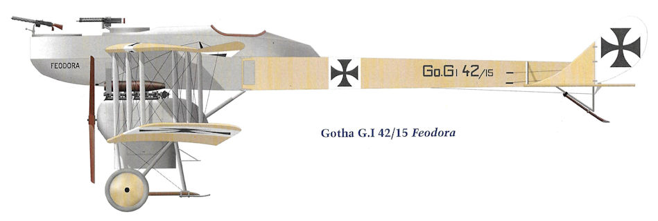
Gotha G.I 42/15 Feodora
Closeup of the first Gotha G.I in the lineup above. The national insignia were painted below the top wing in addition to the usual locations. Both photos were released as Sanke cards.
Designed by Ursinus and built by Gotha, this aircraft became the Gotha G.I and started Gotha in the bomber business. The unusual configuration accomplished two primary design goals; first was to give the gunners an unobstructed field of fire horizontally and above, second was to place the engines as close together as possible to minimize asymmetric thrust in event of engine failure. Giving the gunners a clear field of fire was essential for the aircraft's primary design role of Kampfflugzeug, basically an aerial cruiser. The battle plane concept turned out to be ineffective because they were too slow to intercept enemy airplanes, but they became successful as bombers. Engines were the 150 hp Benz Bz.III. Subsequent Gotha designs were completely different from the G.I.
Designed by Ursinus and built by Gotha, this aircraft became the Gotha G.I and started Gotha in the bomber business. The unusual configuration accomplished two primary design goals; first was to give the gunners an unobstructed field of fire horizontally and above, second was to place the engines as close together as possible to minimize asymmetric thrust in event of engine failure. Giving the gunners a clear field of fire was essential for the aircraft's primary design role of Kampfflugzeug, basically an aerial cruiser. The battle plane concept turned out to be ineffective because they were too slow to intercept enemy airplanes, but they became successful as bombers. Engines were the 150 hp Benz Bz.III. Subsequent Gotha designs were completely different from the G.I.
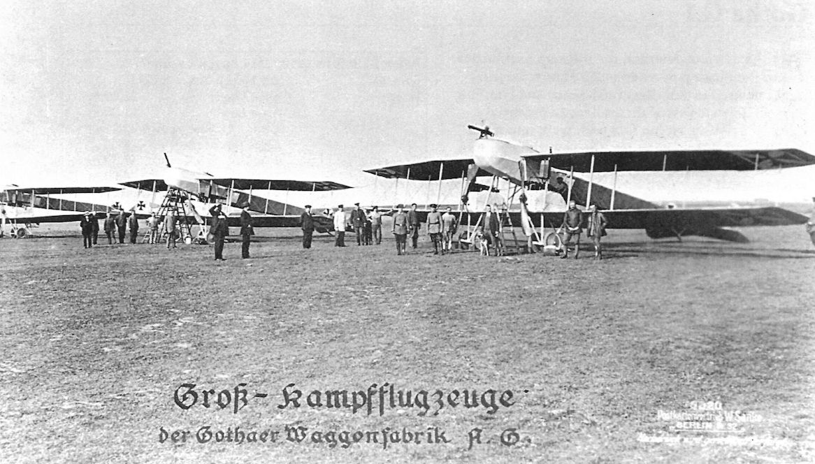
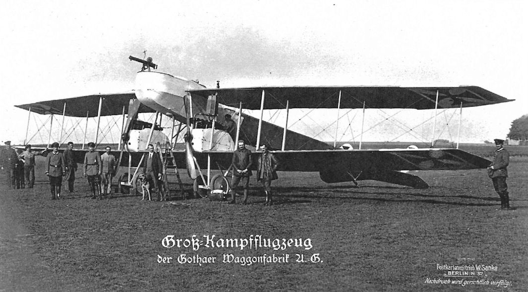
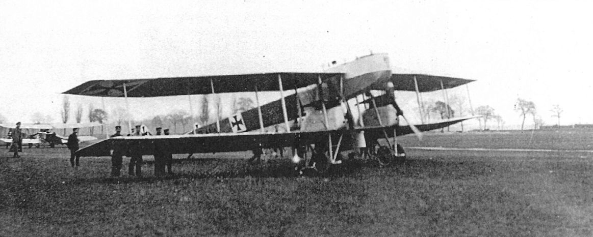
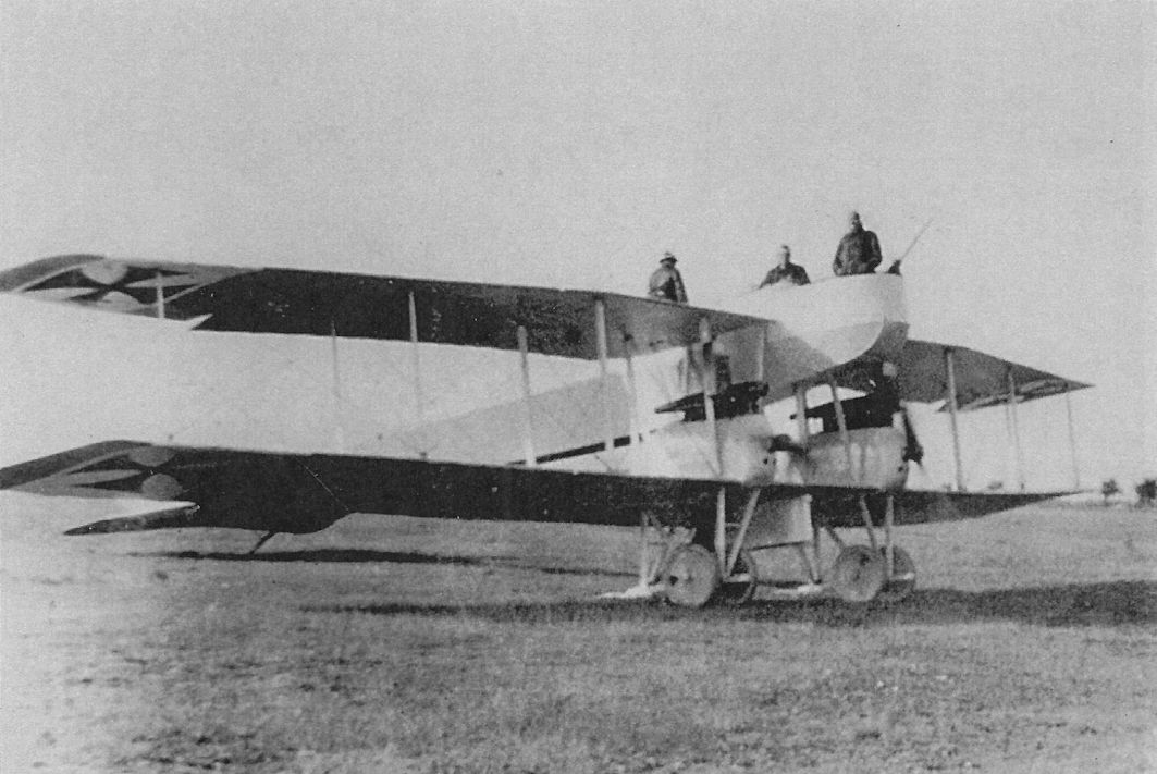
Three Gotha G.I aircraft stand on the Gotha airfield ready for flight testing. These may have been the first three built, G.9/15, G.10/15, and G.11/15, all of which were sent to FEA 1 to defend the Krupp steel works in Cologne.
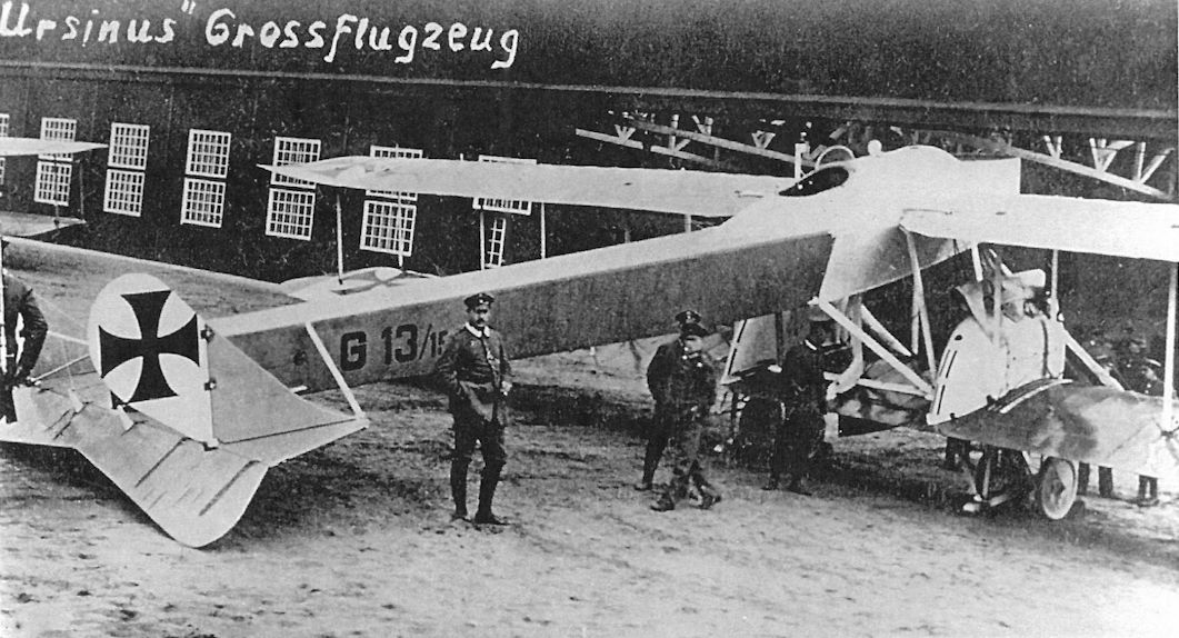
Gotha G.I 13/15 was delivered to FEA 3 on 2 September 1915, then flown to the Eastern Front. Enroute it landed at Schneidemuhl where this photograph was taken. A streamlined bomb container is just visible between the wheels
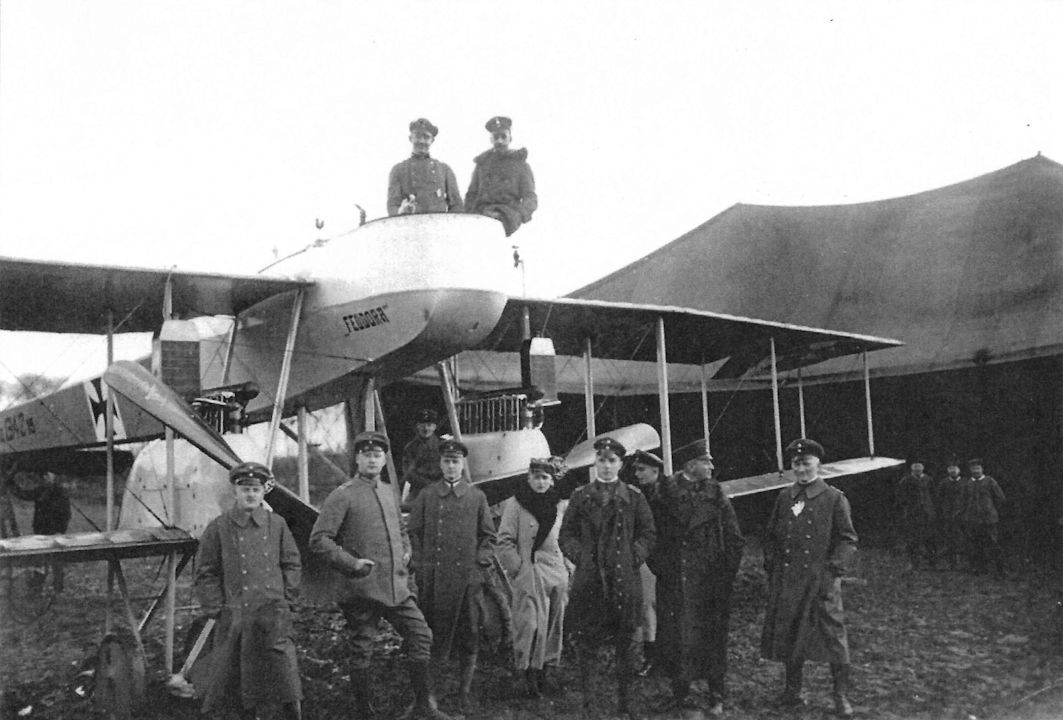
Gotha G.I 42/15, named Feodora, was delivered to FEA 3 in Autumn 1915 before being sent to the Eastern Front.
This may be Gotha G.I G.41/15 of the second production batch, but the serial number is partly obscured.
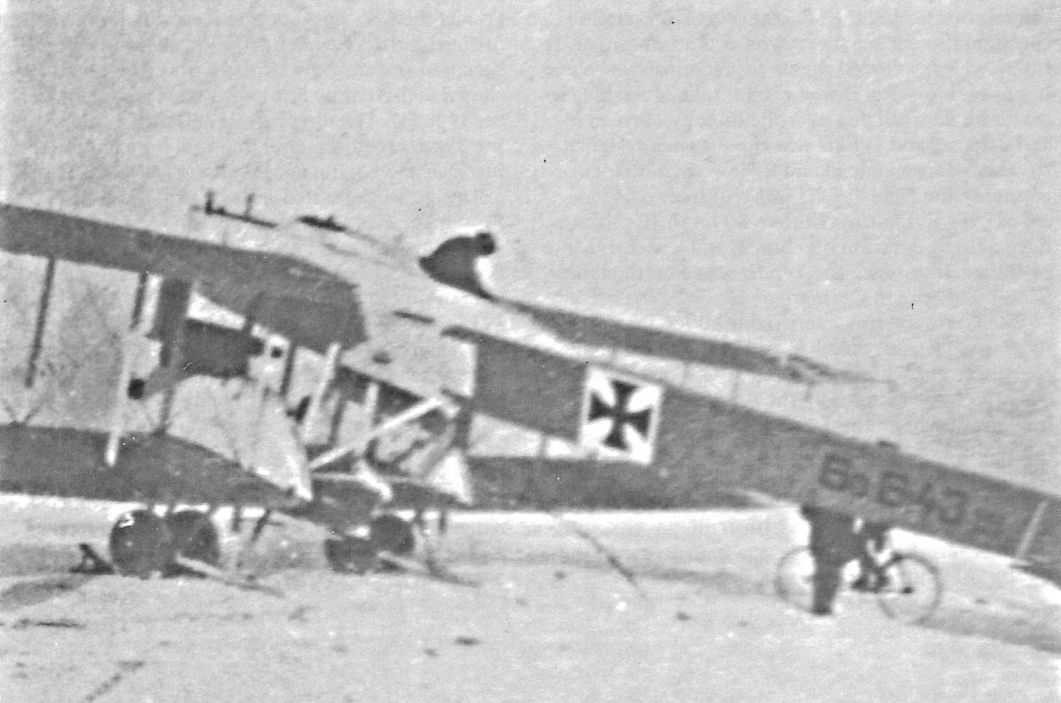
Gotha G.I 43/15 of the second production series.
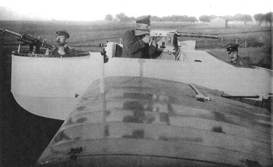
The battleplane heritage of the Gotha G.I is demonstrated here. Oskar Ursinus handles a 20mm Becker cannon in the nose turret while the second gunner demonstrates the Parabellum machine gun; the pilot is seated aft.
Oskar Ursinus demonstrates the use of the forward gun in a Gotha G.I. The streamlined bomb container between the wheels is clearly visible and the nose of a 20-kg Carbonit bomb just protrudes from the lower front. Together with the bomb-dropping chute beneath the gunner's cockpit the bomb container is a clear indication of the evolution of the battleplane into a bomber. The propellers rotate in opposite directions to minimize torque.
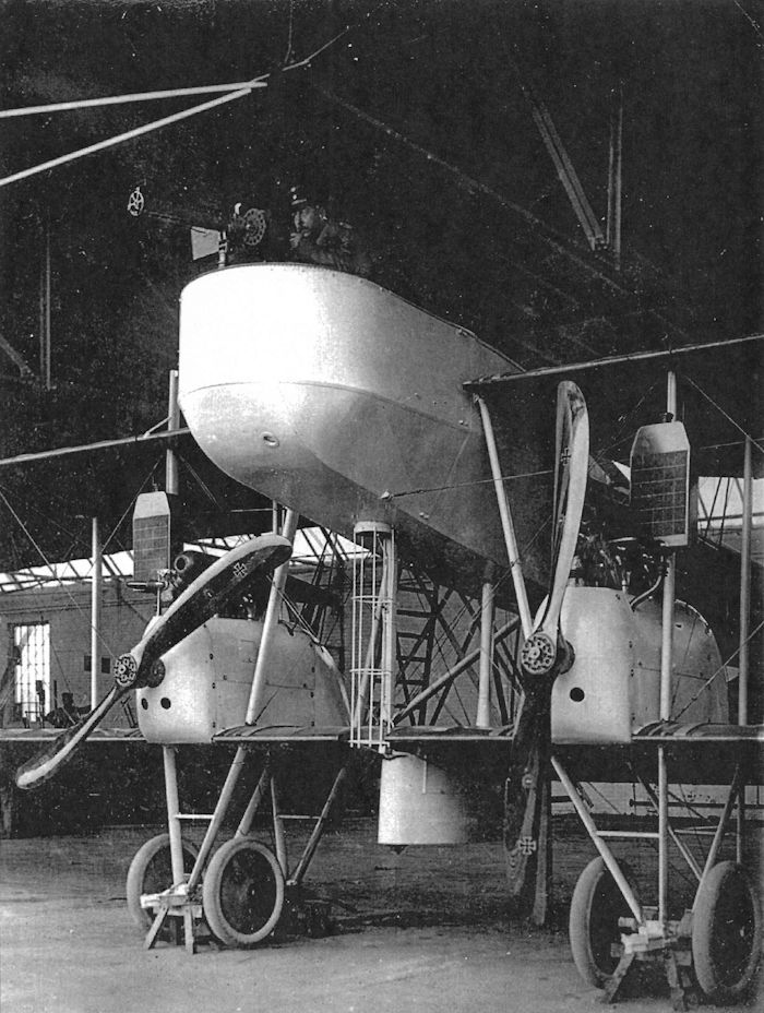
Engines running, a Gotha G.I is ready for take-off.
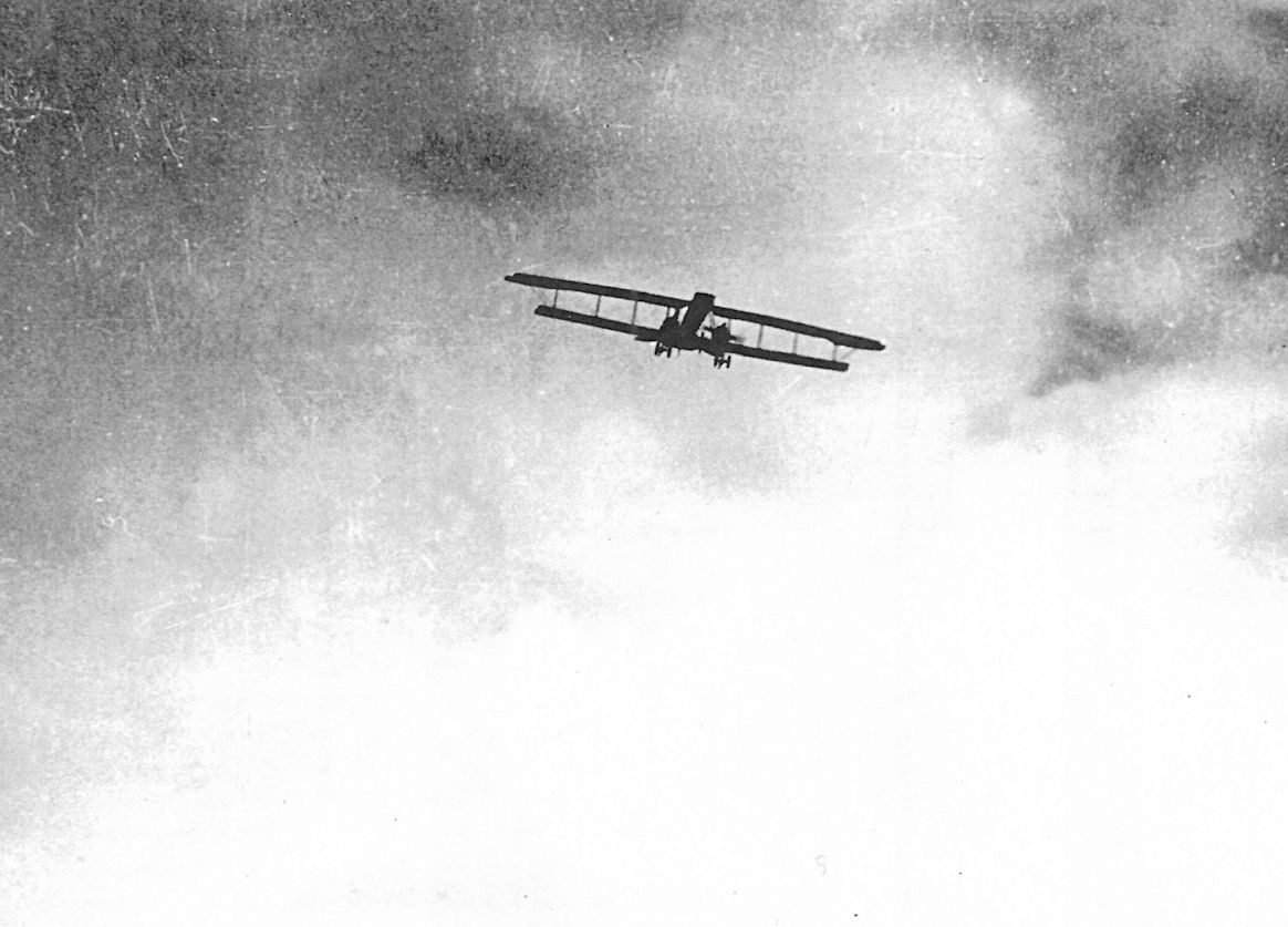
A Gotha G.I displays its distinctive silhouette in flight.
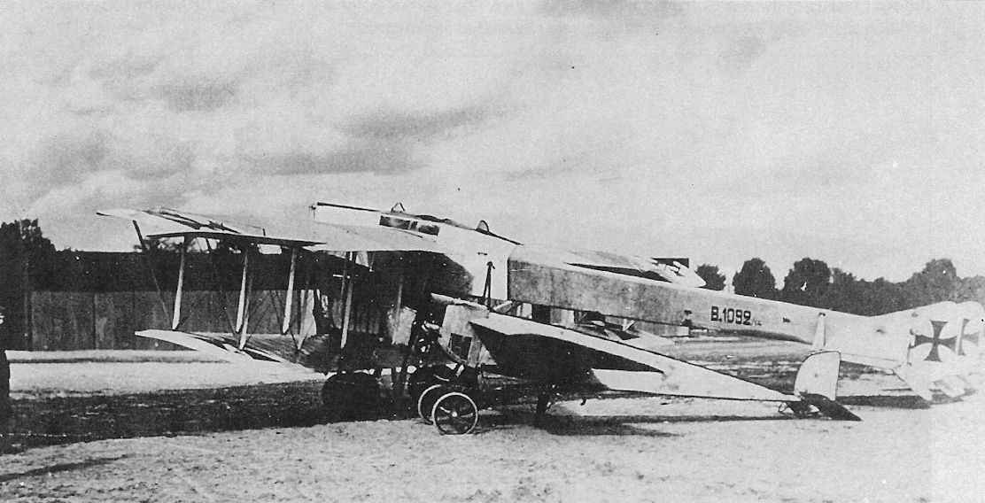
The modified Friedel-Ursinus B.1092/14 and a captured Morane monoplane at FEA 9 in Darmstadt for a size comparison. Aerodynamically-balanced ailerons have been fitted and the nose radiators have been replaced by larger, twin radiators on each engine. A long cellon window is in the fuselage side over the wing.
Gotha LD6
Construction of the Gotha LD6 began on 17 December 1914. Powered by a 150 hp Benz Bz.III engine, the LD6 was a larger, more powerful aircraft than its predecessors. Unfortunately, Gotha test pilot Oswald Kahnt was killed when the LD6 crashed on its maiden flight on 30 January 1915.
Undeterred by this setback, Idflieg ordered the modified Gotha LD6a with larger tail surfaces and other improvements in February 1915. Failing to meet the acceptance specifications, the LD6a was assigned to the Herzog Carl Eduard Fliegerschule, where it received school number 70.
Gotha LD6 Specifications
Engine: 150 hp Benz Bz.III
Gotha LD7 (Gotha B.I)
Designed by Ingenieur Hans Burkhard, Gotha began work on the LD7 on 10 December 1914. Powered by a 100 hp Mercedes, the LD7 was intended as a trainer for the Herzog Carl Eduard Fliegerschule. In May 1915 Idflieg ordered 18 LD7 trainers under the designation Gotha B.I. These were numbered B.960-974/14 and B.884-886/15. Early delivery was a priority, but modifications for observation missions and a switch from the 100 hp to the 120 hp Mercedes substantially delayed production, and the last B.I was not accepted until 11 November 1915.
Five machines, B.961-965/14, were dispatched to the German Air Service in Turkey via Chernowitz in August-September 1915. The remaining aircraft were used as trainers at FEA 3 in Gotha.
Gotha LD7 / B.I Specifications
Engine: 120 hp Mercedes D.II
Wing:
Span Upper 12.40 m
Span Lower 12.07 m
Area 39.5 m2
General: Length 8.40 m
Height 3.00 m
Empty Weight 725 kg
Loaded Weight 1125 kg
Maximum Speed: 125 km/h
Climb: 800m 8.5 min
2700m 45 min
Range: 530 km
The ill-fated original LD6 with small fin and rudder. It crashed on its maiden flight, killing test pilot Oswald Kahnt.
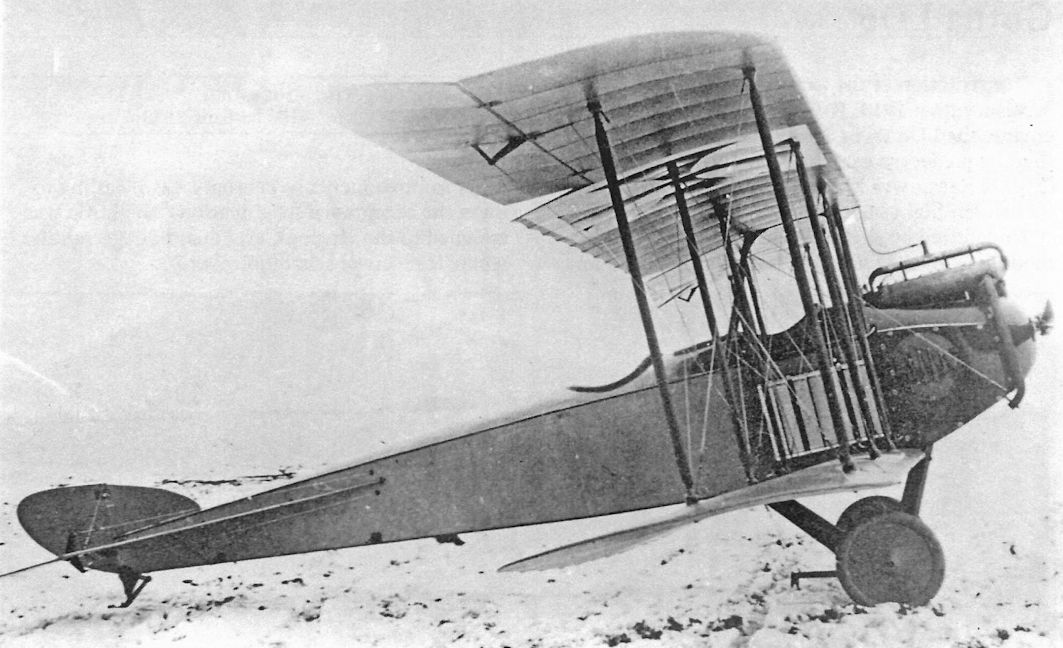
Another view of the original LD6 with small fin and rudder that crashed on its first flight.
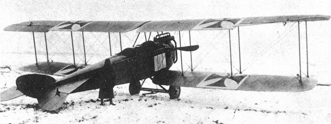
The Gotha LD6a with larger fin and rudder. Only one LD6a was built, and it was assigned to the Herzog Carl Eduard Fliegerschule, where it received school number 70. The engine was a 150 hp Benz Bz.III.
The Gotha LD 6a was a two-seat long-range reconnaissance type in service from March 1915. In common with most operational types of this period it was also employed as a light bomber with the observer dropping small bombs over the side of the aircraft.
The Gotha LD 6a was a two-seat long-range reconnaissance type in service from March 1915. In common with most operational types of this period it was also employed as a light bomber with the observer dropping small bombs over the side of the aircraft.
Side view of the revised LD6a with larger fin and rudder. It failed to meet the Idflieg acceptance requirements and was assigned to the Herzog Carl Eduard Fliegerschule, where it received school number 70.
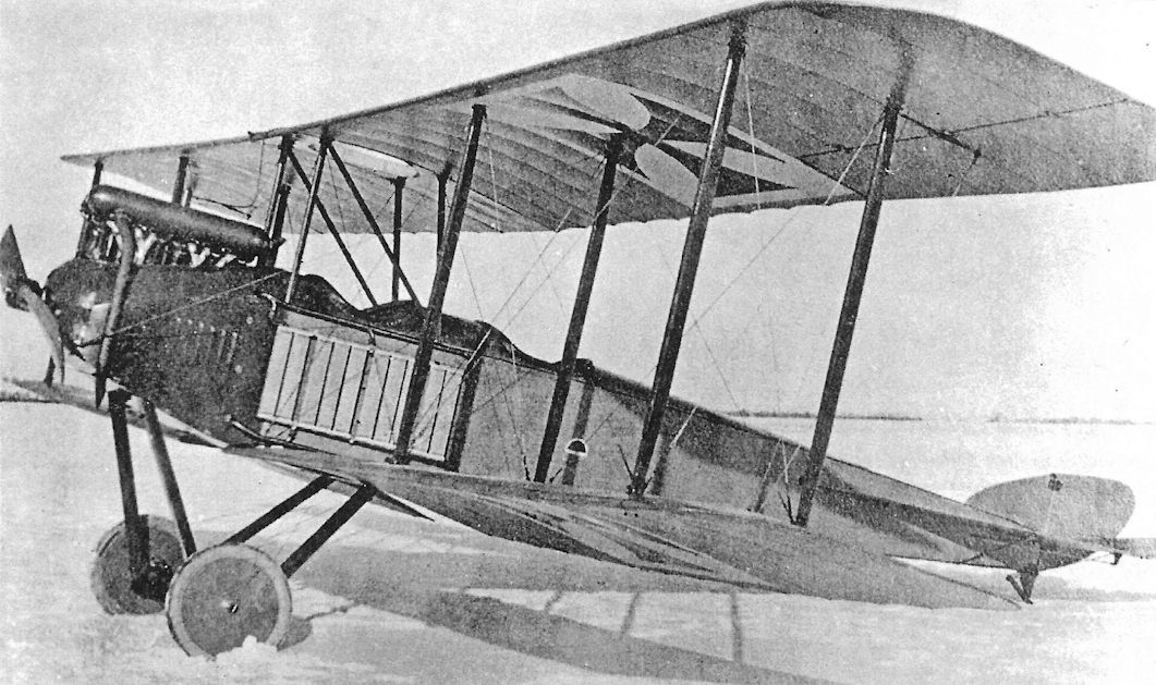
This side view of the Gotha B.I emphasizes the enlarged fin and rudder compared to earlier Gotha types.
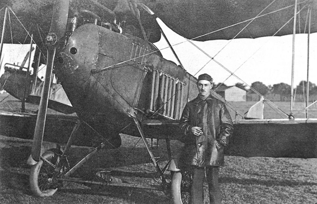
Gotha B.I with rhino-horn exhaust that discharged the hot, toxic gases over the wing for benefit of the crew.
Only ten of these 1915 two seat Gotha B Is were produced, just sufficent to equip a single Field Flight Section, although no evidence of their deployment, if ever, has survived. Using a 120hp Mercedes D Ia, the LD-7 to give its design bureau designation, had a top level speed of 77.5mph, with a range of 330 miles.
Only ten of these 1915 two seat Gotha B Is were produced, just sufficent to equip a single Field Flight Section, although no evidence of their deployment, if ever, has survived. Using a 120hp Mercedes D Ia, the LD-7 to give its design bureau designation, had a top level speed of 77.5mph, with a range of 330 miles.
The Gotha B.I was a conventional, two-bay biplane powered by a 120 hp Mercedes D.II engine.
This Gotha B.I is likely in training service at FEA 3 at Gotha. Of the 18 aircraft built, five went to the German Air Service in Turkey and the other 13 were assigned to FEA 3.
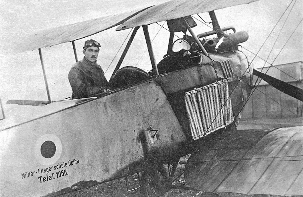
This Gotha B.I is in service at the Gotha Fliegerschule, as indicated by the circular insignia and the lettering below it. The phone number is given for the convenience of anyone finding one of these aircraft force-landed away from the aerodrome. The Gotha B.I in this photograph had a different design exhaust manifold than the one at the bottom of the next page.
This Gotha B.I and aviator appear to be the same as in the previous photograph.
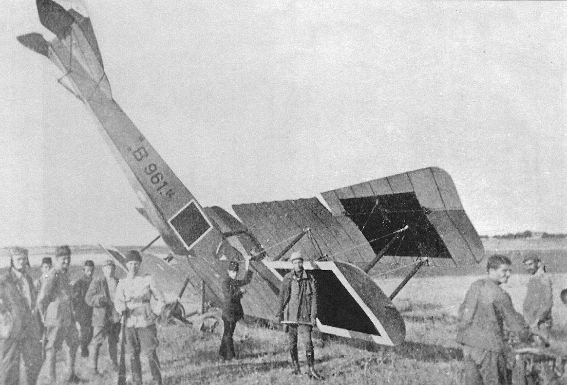
Gotha B.I B.961/14 is one of five sent to Turkey for use by the German Air Service. Despite being attached to the German Air Service, it carries Turkish markings.
Gotha WD3
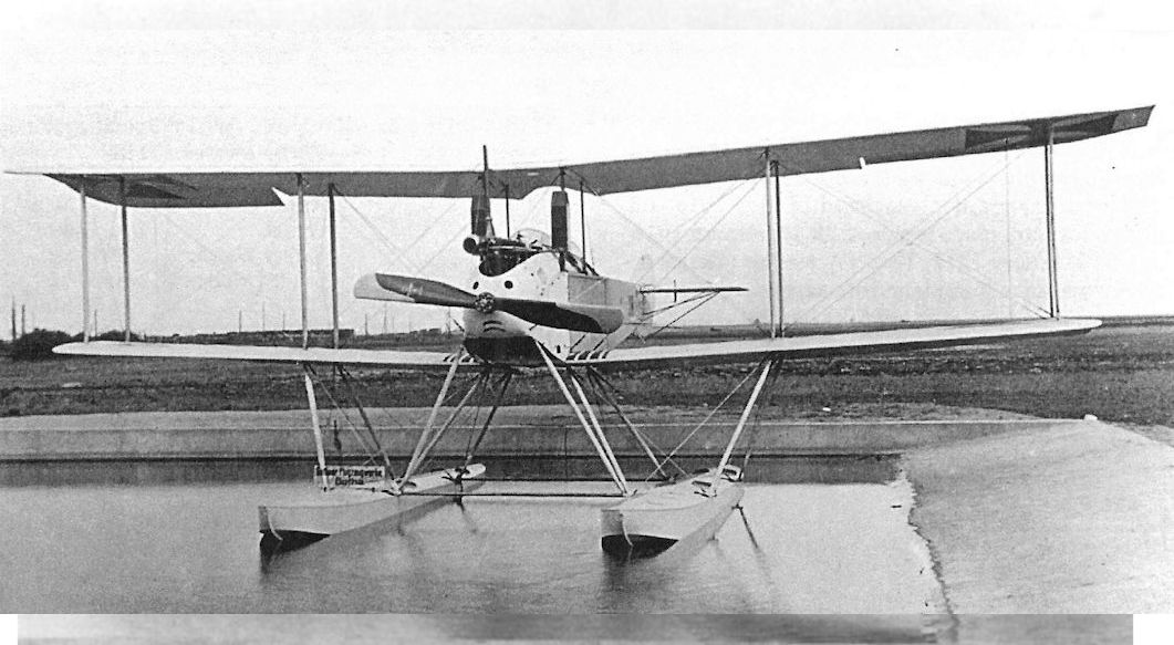
Powered by a 160 hp Mercedes D.III engine, the Gotha WD3 was one of the few pusher aircraft built in Germany. This aircraft, Marine Number 259, was a three-seat reconnaissance floatplane. Ordered in August 1914, it was not delivered until 14 September 1915, so was not a priority project.
The pusher configuration had advantages; the observer(s) had a clear view and field of fire forward, free of propeller turbulence and exhaust fumes. However, the additional weight and drag of the pusher design typically reduced its performance compared to tractor designs. The one WD3 built was flown at Warnemunde as a trainer.
Gotha WD3 Specifications
Engine: Wing: 160 hp Mercedes D.III
Span Upper Span Lower Area 15.65 m 14.35 m 54 m2
General: Empty Weight 1185 kg
Loaded Weight 1729 kg
Maximum Speed: 100 km/h
Climb: 1000m 24 min
Service Ceiling 2200 m
Range: 670 km
Gotha Seaplane Production Summary
Type Ordered Marine Numbers Remarks
WD3 1 259 Flown at Warnemunde as a trainer
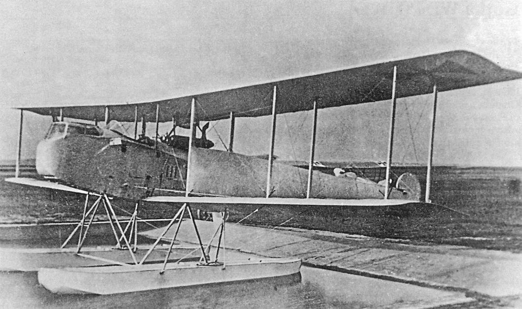
The WD3 floatplane in the Gotha factory pond before the Marine Number was applied.
The Gotha WD3 is seen in the Gotha factory pond before its Marine Number was applied.
The WD3 floatplane, Marine Number 259, taxiing on the water.There are three crew members, the pilot aft and two observers forward, an unusual arrangement; most similar aircraft had only one observer.
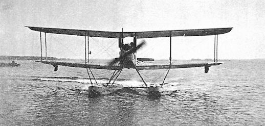
The sole Gotha WD3, Marine Number 259, is seen in flight. It later went to Stralsund/Wiek as a training aircraft, being flown there on 2 August 1916.
Gotha WD5
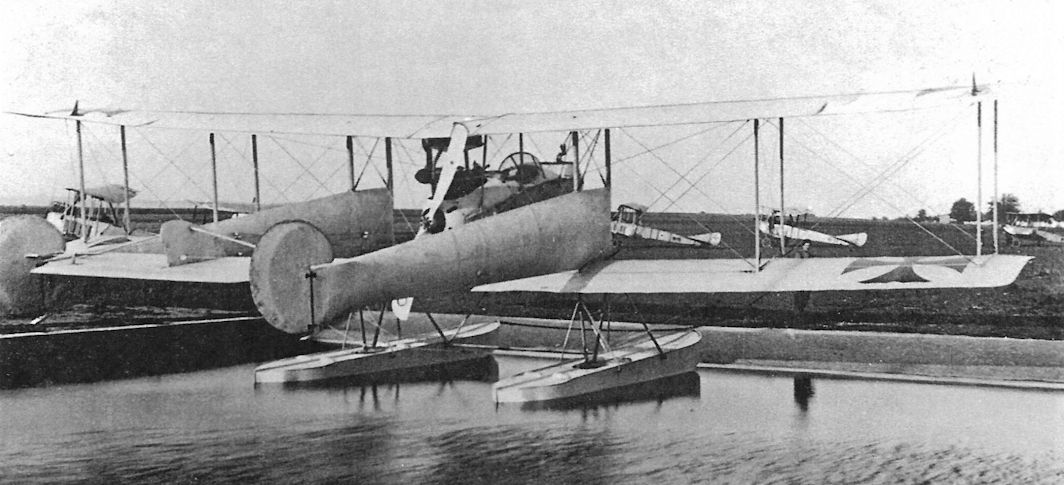
The Gotha WD5, Marine Number 118, was ordered on 26 April 1915 as a high-speed seaplane for bombing surface targets. Powered by a 160 hp Mercedes D.III engine, it was the first Gotha seaplane with a two-bay wing cellule.
The WD5 was considered fast for the time but with "overly sensitive rudder" making bomb aiming difficult. Further development was not recommended, and the sole WD5 was sent to Turkey on 13 July 1916.
Gotha WD5 Specifications
Engine: Wing: 160 hp Mercedes D.III
Span Upper Span Lower Area 12.00 m 10.00 m 42 m2
General: Length 10.35 m
Height 3.80 m
Empty Weight 980 kg
Loaded Weight 1465 kg
Maximum Speed: 126 km/h
Climb: 1000m 12 min
2000m 40 min
Service Ceiling: 2800 m
Range: 440 km
Gotha WD9
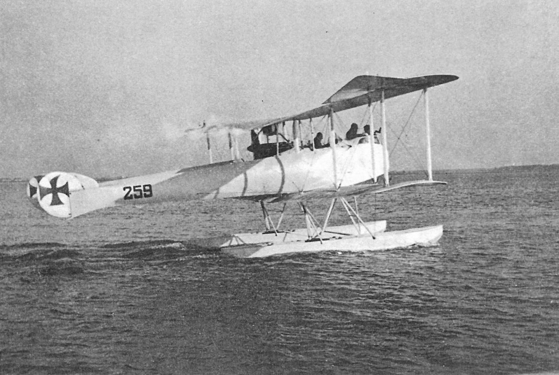
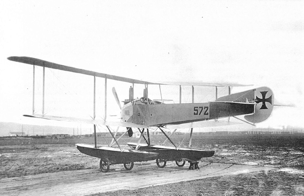
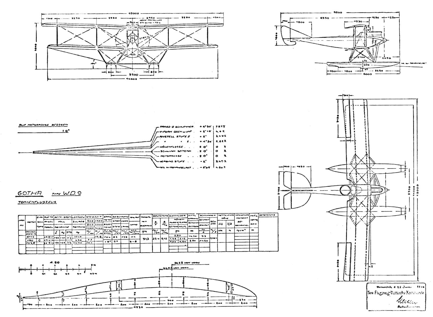
The Gotha WD9, Marine Number 572, was ordered on 26 October 1915. Designed by Karl Rosner and A. Klaube and powered by a 160 hp Mercedes D.III, it was derived from the WD5. The WD9 had a flexible gun for the observer; to increase the field of fire, the inner wing bay bracing was eliminated to enable the gunner to fire forward between the wings.
Delivered on 19 April 1916, the WD9 was assigned to Flandern I at Zeebrugge, where it arrived 10 May 1916. It remained until June 1916. It was ready to be sent to Turkey on 27 Sept 1916. It eventually was at Chanak, where it was flown by several aviators, including Vflgmr. Schubert.
Gotha WD9 Specifications
Engine: 160 hp Mercedes D.III
Wing:
Span Upper 12.50 m
Span Lower 11.30 m
Area 42.5 m2
General: Length 9.80 m
Height 3.80 m
Empty Weight 967 kg
Loaded Weight 1472 kg
Maximum Speed: 132 km/h
Climb: 1000m 12.5 min
2000m 36 min
Service Ceiling: 3000 m
Gotha Seaplane Production Summary
Type Ordered Marine Numbers Remarks
WD5 1 118 118 was sent to Turkey
WD9 1 572 Assigned to Zeebrugge, then sent to Turkey
The Gotha WD5, Marine Number 118, was ordered on 26 April 1915 as a high-speed seaplane for bombing surface targets. Powered by a 160 hp Mercedes D.III engine, it was the first Gotha seaplane with a two-bay wing cellule.
The WD5 was considered fast for the time but with "overly sensitive rudder" making bomb aiming difficult. Further development was not recommended, and the sole WD5 was sent to Turkey on 13 July 1916.
Gotha WD5 Specifications
Engine: Wing: 160 hp Mercedes D.III
Span Upper Span Lower Area 12.00 m 10.00 m 42 m2
General: Length 10.35 m
Height 3.80 m
Empty Weight 980 kg
Loaded Weight 1465 kg
Maximum Speed: 126 km/h
Climb: 1000m 12 min
2000m 40 min
Service Ceiling: 2800 m
Range: 440 km
Gotha WD9
The Gotha WD9, Marine Number 572, was ordered on 26 October 1915. Designed by Karl Rosner and A. Klaube and powered by a 160 hp Mercedes D.III, it was derived from the WD5. The WD9 had a flexible gun for the observer; to increase the field of fire, the inner wing bay bracing was eliminated to enable the gunner to fire forward between the wings.
Delivered on 19 April 1916, the WD9 was assigned to Flandern I at Zeebrugge, where it arrived 10 May 1916. It remained until June 1916. It was ready to be sent to Turkey on 27 Sept 1916. It eventually was at Chanak, where it was flown by several aviators, including Vflgmr. Schubert.
Gotha WD9 Specifications
Engine: 160 hp Mercedes D.III
Wing:
Span Upper 12.50 m
Span Lower 11.30 m
Area 42.5 m2
General: Length 9.80 m
Height 3.80 m
Empty Weight 967 kg
Loaded Weight 1472 kg
Maximum Speed: 132 km/h
Climb: 1000m 12.5 min
2000m 36 min
Service Ceiling: 3000 m
Gotha Seaplane Production Summary
Type Ordered Marine Numbers Remarks
WD5 1 118 118 was sent to Turkey
WD9 1 572 Assigned to Zeebrugge, then sent to Turkey
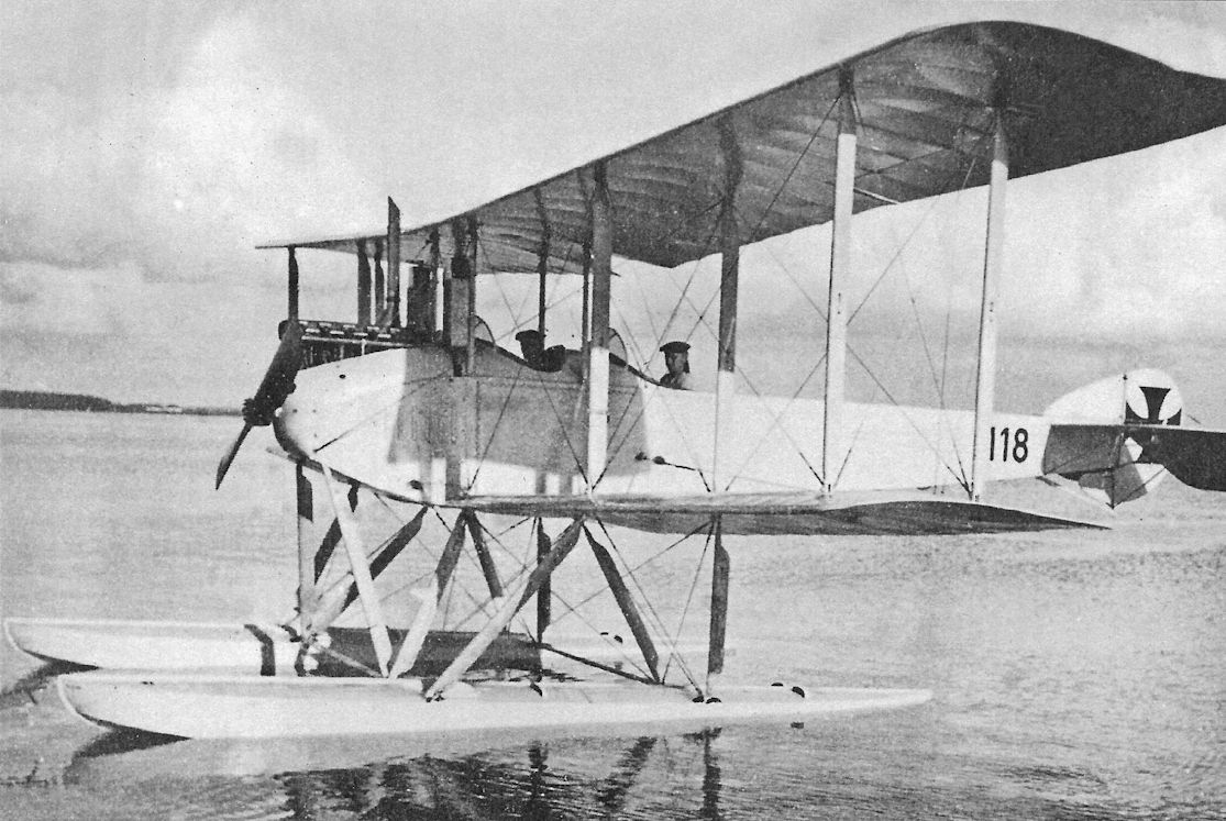
The Gotha WD5 on the water. Designed as a fast seaplane for bombing surface targets, the rudder was too sensitive for a steady bombing platform, and only one WD5 was built. On 13 July 1916 it was sent to Turkey.
Gotha See biplane WD 5 with Reschke propeller in artificially built water basin. The aircraft was equipped with a 160 hp Mercedes D.III engine.
The Gotha WD5 in the Gotha factory pond shows its comparatively compact, 2-bay design.
The one and only Gotha WD.5, used as a personal aircraft by Capt. Langfeld, commanding officer of the Haltenau naval air station.
The Gotha WD5 in the Gotha factory pond shows its comparatively compact, 2-bay design.
The one and only Gotha WD.5, used as a personal aircraft by Capt. Langfeld, commanding officer of the Haltenau naval air station.
The Gotha WD5 taxiing with identification pennants attached.
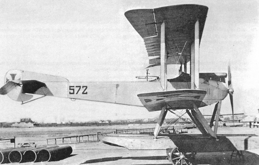
Gotha WD9 Marine Number 572 on beaching dollies. The WD9 was derived from the earlier WD5 and used the same 160 hp Mercedes D.III engine, but unlike the WD5 it was armed with a flexible gun for the observer. The WD9 had an enlarged fin and rudder to improve directional stability, and aerodynamic refinements made it slightly faster.
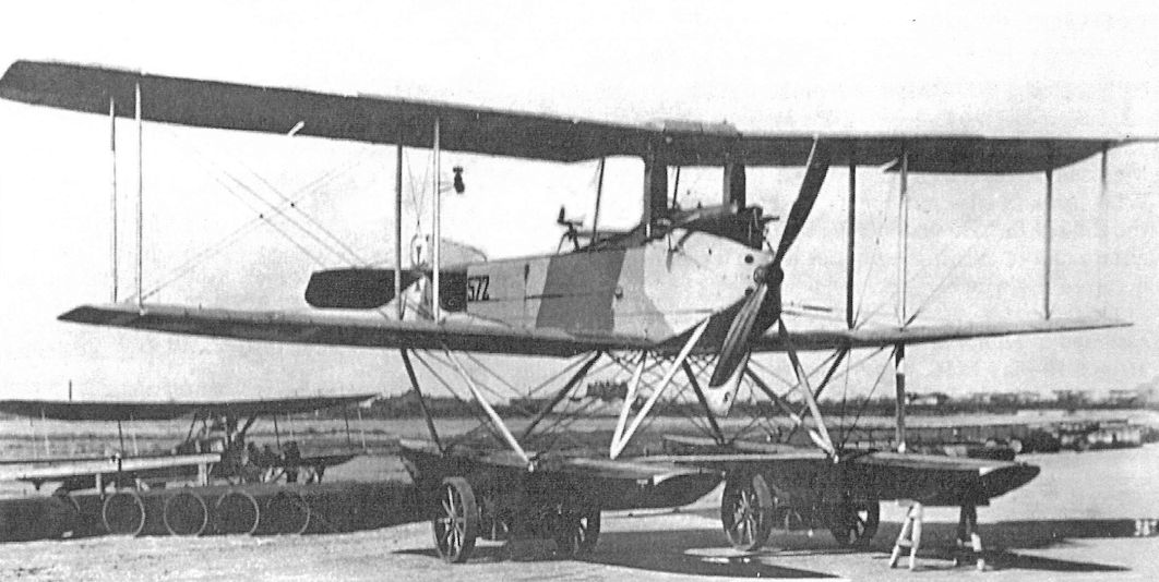
Gotha WD9 Marine Number 572 on beaching dollies. The inner wing bay wire bracing of the WD9 was eliminated to enable the gunner to safely fire forward between the wings. Only one WD9 was built. Initially assigned to Flandern I at Zeebrugge, it was later sent to Turkey.
Gotha WD9 Marine Number 572 on beaching dollies. The WD9 had an aerodynamic balance on the bottom of the rudder, a feature that by now was becoming a hallmark of Gotha floatplanes.
Gotha WD9
Gotha G.II
Construction of the Gotha G.I gave Gotha the experience needed to design and build a long-range bomber, something Major Wilhelm Siegert, the commander of Idflieg and a supporter of strategic bombing, had wanted since the beginning of the war. Gotha engineer Hans Burkhardt, who had worked with Oskar Ursinus to build the Gotha G.I, was the natural choice for designer of the new bomber.
Earlier Burkhardt had modified crashed Gotha G.I G.9/15 by placing the fuselage on the lower wing, which greatly reduced the likelihood of a nose-over on landing. Burkhardt stated he had three main priorities when he designed the Gotha G.II; speed, protection of the observer in the nose, and ease of transportation. The later sounds odd today, but at that time, when airplanes were transported long distances, they were normally dismantled and moved by train rather than flying them. This counter-intuitive procedure was driven by the limited reliability of contemporary aircraft.
Burkhardt's ideas were accepted by Idflieg, who placed a production order for ten bombers on 18 December 1915. To have a worthwhile range and payload the new bomber needed much more power than the Gotha G.I, and the engines were specified as 220 hp Mercedes D.IV straight-eights mounted as pushers. The Mercedes D.IV was an inline eight-cylinder motor developed from the reliable 160 hp Mercedes D.III six-cylinder by adding two more cylinders. The Mercedes D.IV was powerful and reliable in single-engine airplanes, but sometimes suffered crankshaft failures in twin-engine airplanes due to flexing of the block. A transitional design, the engine was soon replaced in production by the simpler six-cylinder D.IVa.
The resulting Gotha G.II was a completely new design that established the configuration for all subsequent operational Gotha bombers. The prototype G.II was a two-bay aircraft that entered flight trials in March 1916. The under-carriage had eight wheels, four underneath each nacelle, for safe landings. Both two-bladed and four-bladed propellers were tried with the slow-turning geared engine. Matching a fixed-pitch propeller with engine and airframe to maximize speed and climb was a painstaking task that could only be accomplished by time-consuming flight-testing.
The prototype G.II was fast for its time but had insufficient climb with a full bomb load. An enlarged, three-bay wing gave the production version the required performance.
The undercarriage was also revised for the production G.II. Although the original undercarriage prevented nose-overs, it lacked brakes as did all WWI aircraft. An extended landing run could result in a fatal accident by running off the edges of the field. To solve this potential problem Burkhardt simplified the undercarriage by removing the forward wheels and moved the center of gravity aft, allowing a conventional tail skid that provided the necessary braking action. Unfortunately, this aft shift in the center of gravity made the aircraft far less stable in pitch, a situation that was to plague all subsequent Gotha bombers in service. Landing accidents due to pitch instability were responsible for 76% of all Gotha bomber losses, more than three times as many losses as all other reasons combined.
Finally, the too-small rudder of the G.II prototype was replaced with a fixed fin and larger rudder in the production G.II, improving stability and controllability in flight.
The G.II had a crew of three,- a bombardier-gunner in the front cockpit, the pilot in the center cockpit, and a gunner in the aft cockpit. The wings and fuselage were of typical wood and fabric construction, although the nose was covered with plywood. The tail surfaces were of steel tubing covered with fabric. The engine nacelles and undercarriage formed a single sub-assembly; for easy handling these could be moved around when fitted with separate, auxiliary wheels, a feature that was pattented. Fuel and oil tanks were in the engine nacelles with a gravity fuel tank mounted above the upper wing. Two bomb racks in the fuselage held fourteen 10-kg bombs. The total useful load was 1,010 kg.
Production of the G.II began on 25 April 1916 and the type test was completed on 17 July 1916. Serial numbers assigned to the ten production aircraft were G.II 200/16 - 209/16. The G.II wing cellule finally passed the static load test during the week of 11 August 1916 after six failures that had to be rectified.
Of the 10 G.II bombers built only eight reached Staffel 20 of KG4 in August/September 1916, apparently the only unit to use the G.II operationally. One G.II remained at FEA 3 in Gotha and the other was badly damaged during flight evaluation. Unfortunately, there is no information available regarding the combat use of the G.II, which was limited by the small number of aircraft and the problematical reliability of the engines.
Gotha G.II Specifications
Engines: 2 x 220 hp Mercedes D.IV
Wing: Span Upper 23.70 m
Span Lower 21.90 m
Area 89.5 m2
Chord Upper 2.30 m
Chord Lower 2.30 m
Gap 2.22 m
Sweepback 1.5°
General: Length 12.40 m
Height 4.30 m
Empty Weight 2182 kg
Loaded Weight 3192 kg
Maximum Speed: 148 km/h
Climb: 3000m 28 min
4000m 41 min
Range: 500 km
Gotha G.III
The G.II was quickly superseded in production by the improved G.III. The main difference between the types was the engine; the G.III was powered by the 260 hp Mercedes D.IVa engine of six cylinders. The new engine did not suffer the occasional crankshaft failures of the straight-eight it replaced, was cheaper to produce, offered slightly more power, and was soon available in quantity. The additional power enabled the useful load to be increased from 1,010 kg to 1,235 kg.
The other important change for the G.III was an opening for a ventral, downward-firing machine gun. Idflieg ordered 25 G.III bombers on 3 May 1916; deliveries started on 16 October and were completed on 26 March 1917. Serial numbers are thought to be G.375/16 - G.399/16. One G.III, G.398/16, was sent to Halbgeschwader I as a trainer and G.392/16 was sent to the Daimler factory for flight-testing an experimental Mercedes D.IVa. The rest of the G.IIIs were delivered to KG2. KG2 was moved around and flew missions on the Western Front as well as daylight bombing missions on the Balkan Front, stationed at Hudova along with a few G.II bombers. The most significant result in the Balkans was destruction of the railway bridge over the Donau at Cernovoda in late September 1916; this deprived the Romanian army of essential supplies and reinforcements. Interestingly, one squadron commander complained that the G.III easily outdistanced its two-seat escorts. In August-September 1917 the G.III was retired from the front.
Gotha G.III Specifications
Engines: 2 x 260 hp Mercedes D.IVa
Wing: Span Upper 23.70 m
Span Lower 21.90 m
Area 89.5 m2
Chord Upper 2.30 m
Chord Lower 2.30 m
Gap 2.22 m
Sweepback 1.16°
General: Length 12.22 m
Height 3.90 m
Empty Weight 2383 kg
Loaded Weight 3618 kg
Maximum Speed: 140 km/h
Range: 700 km
Gotha G-Type Bomber Production Summary
Order Date Type Qty Serials Notes
Dec. 18, 1915 G.II 10 200-209/16 Delivered Aug.-Sep. 1916
May 3, 1916 G.III 25 376-399/16 Delivered 16 Oct. 1916-26 March 1917
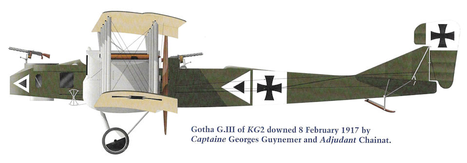
Gotha G.III of KG2 downed 8 February 1917 by Captaine Georges Guynemer and Adjutant Chainat.
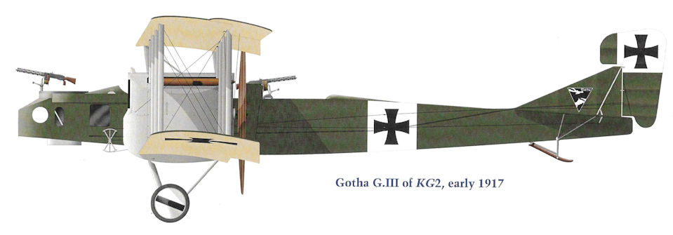
Gotha G.III of KG2, early 1917.
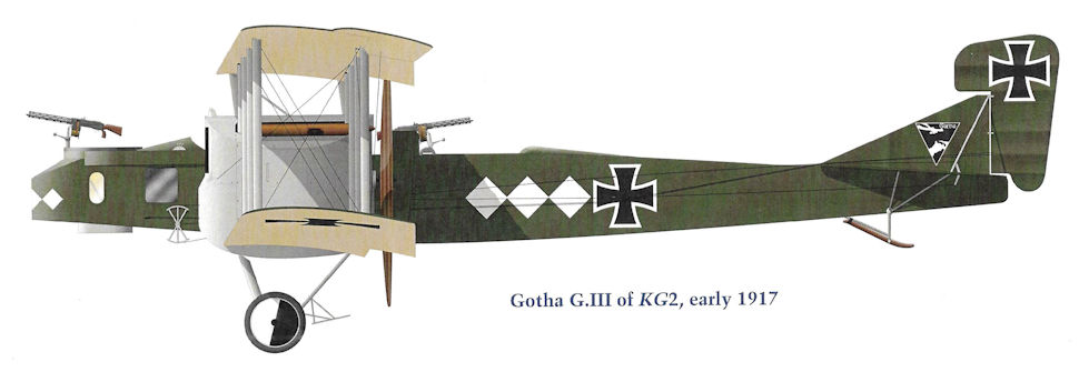
Gotha G.III of KG2, early 1917.
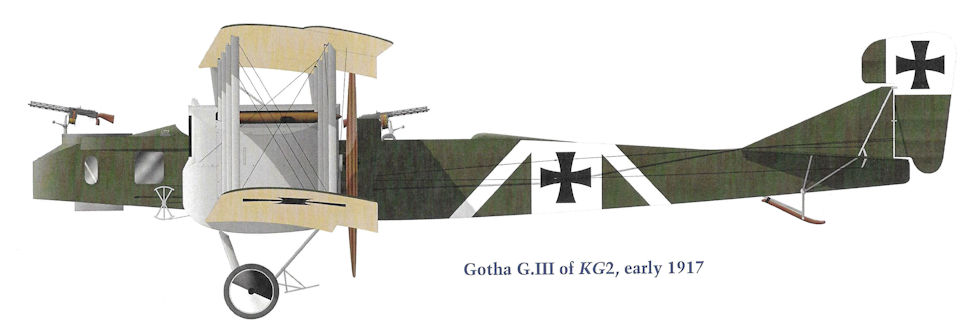
Gotha G.III of KG2, early 1917.
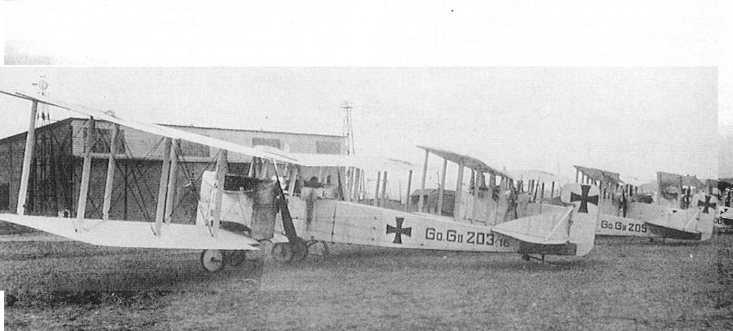
At least five production Gotha G.II bombers are parked in front of the flight test hangar in which the VGO Giant aircraft were built. Nearest the camera is G.203/16 with two-blade propeller, then G.205/16 with four-blade propeller, with G.200/16 behind it. The greatly enlarged vertical tail with fixed fin and enlarged, three-bay wings of the production aircraft is clearly shown.The engine was the straight-eight 220 hp Mercedes D.IV.
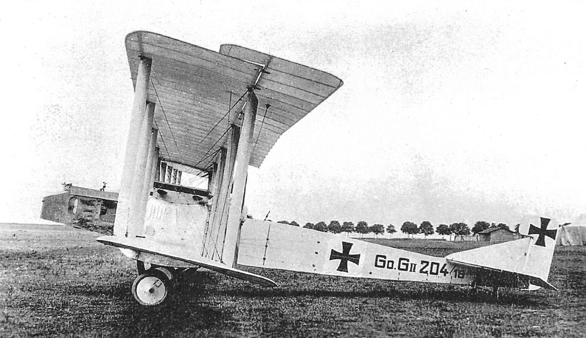
Gotha G.II 204/16 photographed at the Gotha factory. This was one of the aircraft delivered to Kagohl 4, Staffel 20 on 24 August 1916. The G.II airframe was the basis for the later G.III, G.IV, and G.V.
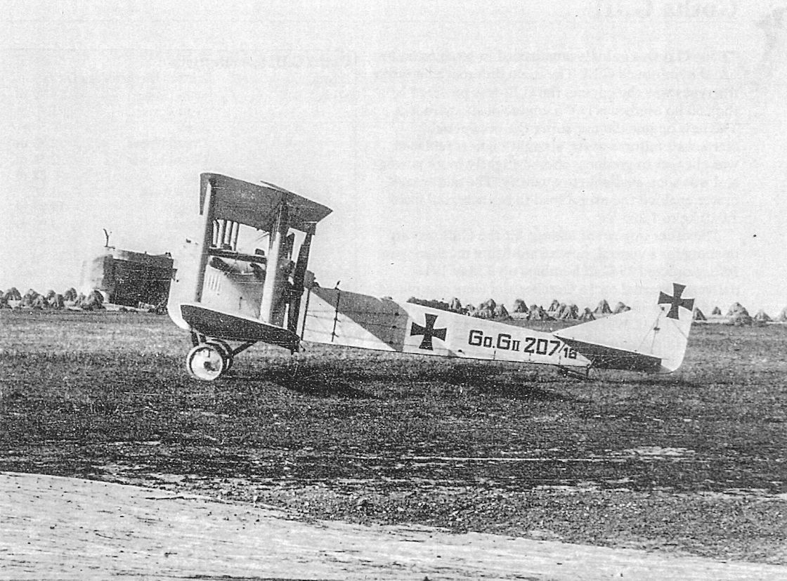
Gotha G.II 207/16; the dark nose is due to being covered in plywood; the rest of the airframe is covered in fabric.
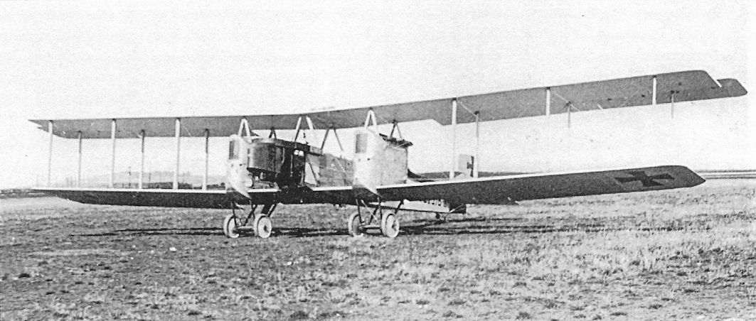
Gotha G.III 376/16 or 378/16; like the G.II, the dark nose is due to being covered in plywood; the rest of the airframe is covered in fabric.
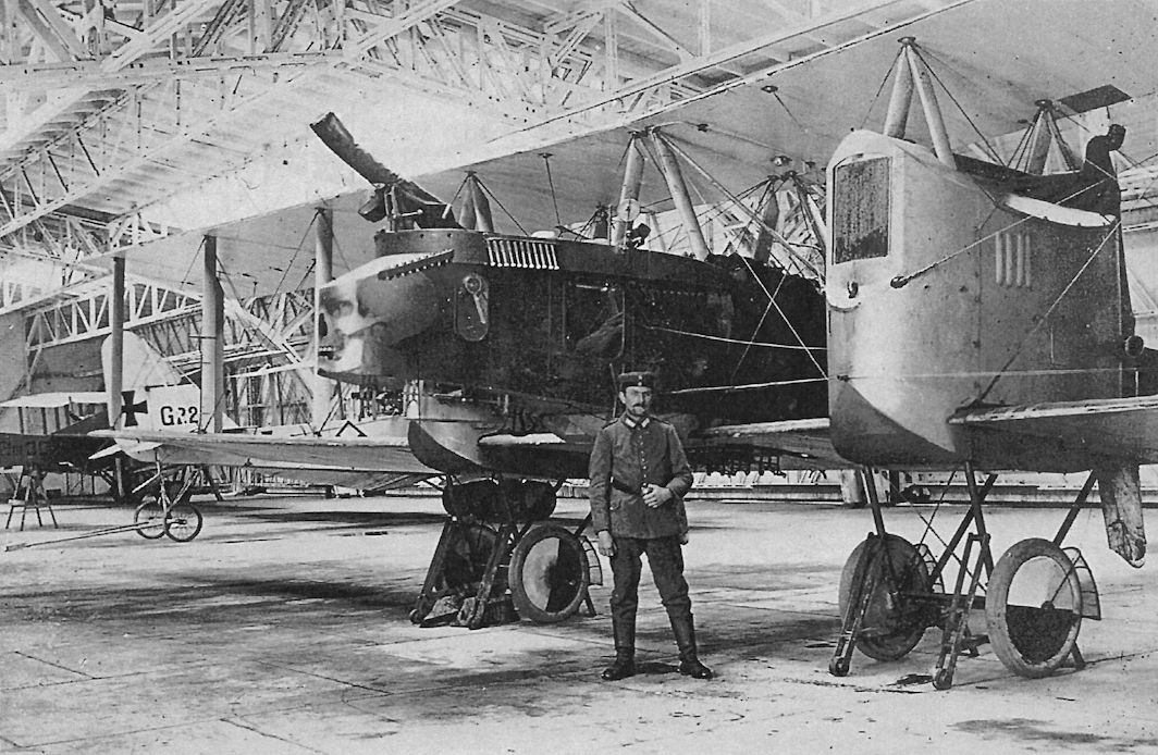
This Gotha G.III 389/16 (or possibly 385/16) of Kagohl 2, Staffel 19 wears a macabre 'death's head' marking on the nose. The upper surface and sides of the fuselage and upper surfaces of the wings were painted green. The outer wheel covers were painted in the black and white halves typical of Kagohl 2. A black triangle with white outline is painted on the rear fuselage. Belts of signal flares are attached to the side of the bombardier's cockpit, and the bomb racks are visible under the wing center section.
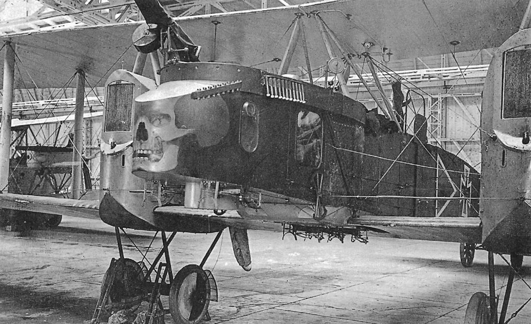
Gotha G.III of Kagohl 2, Staffel 19
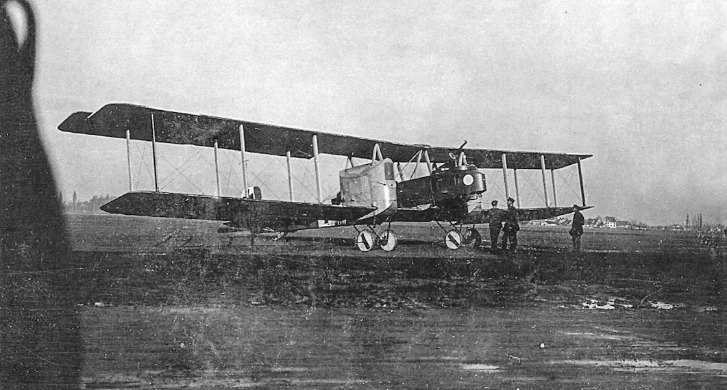
This Gotha G.III wears light wheel covers with a dark stripe; the exact colors are not known.
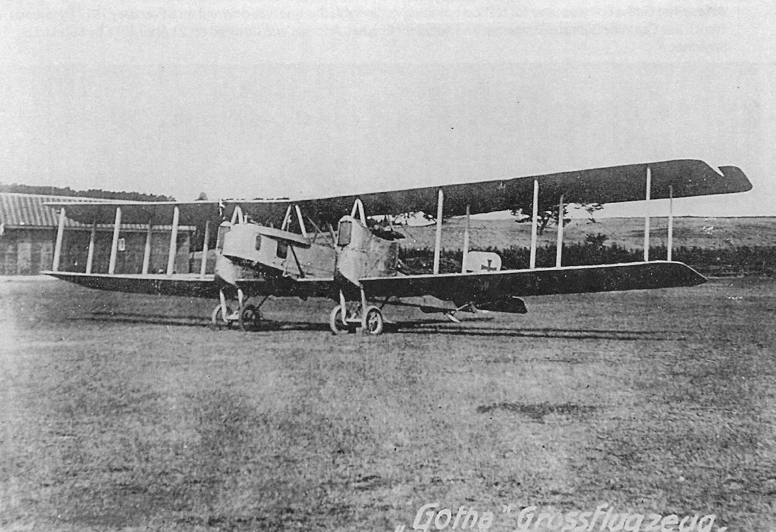
Gotha G.III; the bulge on the upper side of the cockpit provided room for the pilot's controls.
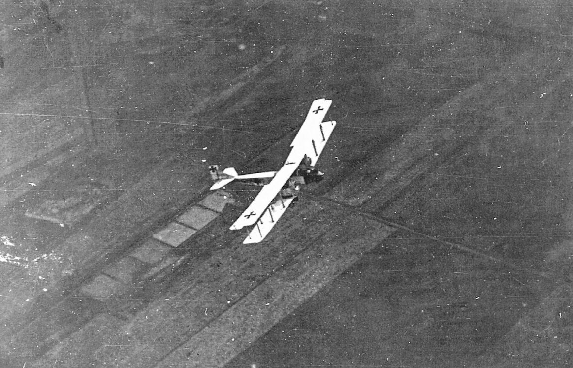
Gotha, probably a G.III but possibly a G.II, on a peaceful flight displays the characteristic Gotha shape.
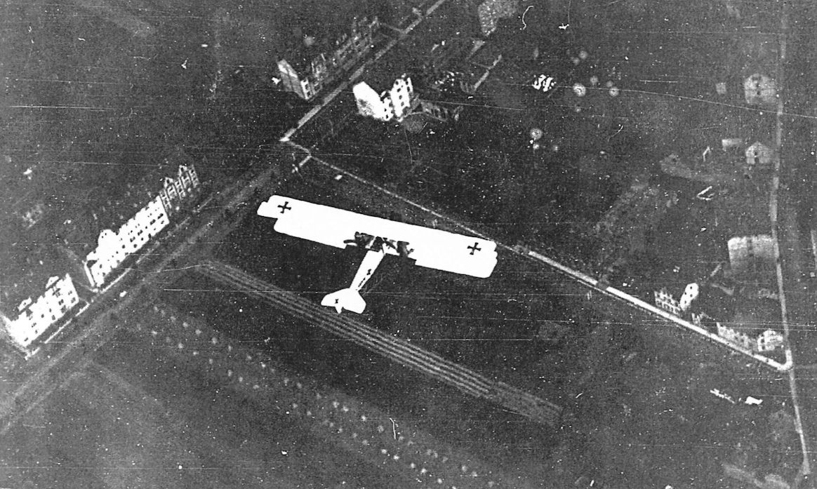
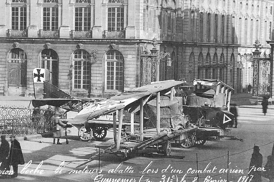
The Gotha G.III was used for tactical bombing in daylight; this one was downed on 8 February 1917 by famous French ace Captaine Georges Guynemer and Adjudant Chainat. Another was downed on 23 April 1917 by Sub-Lt. L.S. Breadner.
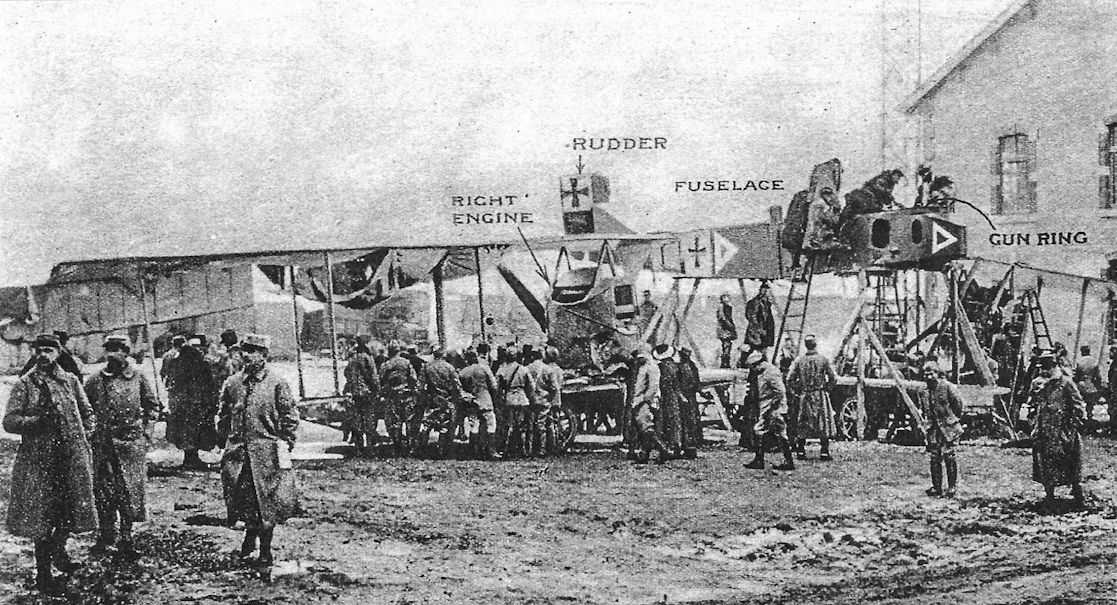
Two more views of the Gotha G.III downed on 8 February 1917 by French ace Captaine Georges Guynemer and Adjudant Chainat showing its markings as the wreckage was being re-assembled for display.
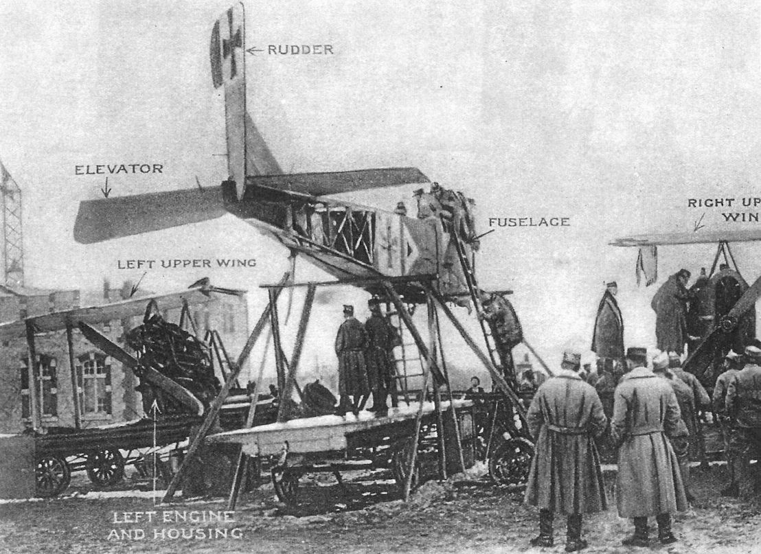
Gotha G.IV
By late 1916 it was apparent to the German Army that the strategic bombing campaign against Britain using Zeppelins was not a success, and furthermore the Zeppelins were too costly and vulnerable. The Army was planning to abandon airships in favor of cheaper, more effective heavy bombers. The operation to attack London and other strategic targets with bombers was called Turkenkreuz (Turk's Cross).
Of course, the plan required bombers with sufficient range and payload for the task, and the Gotha's performance made it the obvious choice. On 16 August 1916 Idflieg ordered 52 Gotha-built bombers of an improved type, the G.IV, making the G.IV the first Gotha design to be ordered in substantial numbers. So many of the new Gotha G.IV bombers were wanted that two other manufacturers, LVG and SSW, were given contracts to build the G.IV under license.
The G.IV was simply a refinement of the G.III. Powered by the same 260 hp Mercedes D.IVa engine used in the G.III, the G.IV featured ailerons on both upper and lower wings connected by an actuating strut for improved controllability. The G.IV also introduced the patented Gotha tunnel, a hollowed-out opening in the rear fuselage that enabled the gunner to depress his gun through the tunnel to fire at aircraft below, or to mount a ventral gun at floor level for a wider field of fire. To retain torsional rigidity despite the cut-out in the bottom of the fuselage, the fuselage was covered in plywood instead of fabric.
Gotha G.IV(LVG)
LVG received an order for 150 Gotha G.IV(LVG) bombers in December 1916. The type test for the initial 50 aircraft was completed on 25 June 1917, after the Gotha-built aircraft had already bombed London. One aircraft was fitted with two 245 hp Maybach Mb.IVa engines in an attempt to raise the bombers' operational altitude, but inability to find a suitable propeller thwarted the attempt. Another aircraft tested Flettner servo tabs starting in October 1917.
LVG built an additional 40 G.IV bombers to an Austro-Hungarian order. These were modified to take 230 hp Hiero engines built in Austria. The squadrons received these aircraft in March-April 1918. Weak engine bearers and unsuitable propellers led to excessive engine vibration that caused piping leaks and structural damage, limiting their usefulness, and by September 1918 the G.IV(LVG) bombers were essentially grounded.
Gotha G.IV(SSW)
Idflieg ordered 80 Gotha G.IV(SSW) bombers from SSW at the same time the LVG machines were ordered. The first batch of 40 were delivered between July 1917 and February 1918; about 30 went to operational units and the rest went to training and replacement units. The second production batch, ordered in May 1917, was delivered to training units between December 1917 and August 1918. The twin-wheel Stossfahrgestell (shock landing gear) designed by Siemens was fitted to all aircraft from G.217/17, and many machines were also fitted with the Flettner servo tabs. Instead of the normal 260 hp Mercedes D.IVa engines, some aircraft had 185 hp NAG C.III or 180 hp Argus As.III engines for training use.
Gotha G.IV Operations
The G.IV was the aircraft that made Gotha a household name. Built in much greater numbers than earlier models - 232 were built by Gotha, LVG, and SSW - it was intended by the German Army to replace the expensive, vulnerable Zeppelins as Germany's long-range bomber of choice. Although the first G.IVs were delivered in November 1916, a number of problems had to be resolved before the G.IVs were ready to bomb London, their intended target, delaying their first attack on England to 25 May 1917. This attack by Kagohl 3 did not reach London, nor did the second. But on 13 June the third attack did reach London, causing the most severe casualties of any bombing raid of the war. Together with the heavy casualties, the spectacle of Gothas leisurely bombing targets in London in broad daylight shocked the British public, with a significant ramification being the creation of the RAF from the RFC and RNAS on 1 April 1918 to provide a more coordinated and effective air defense capability. In the interim, the war cabinet agreed to double the size of both the RFC and RNAS as a direct result of these raids.
Initial Gotha G.IV losses during the daylight attacks were light, but rapidly improving defenses caused a shift to night bombing starting the night of 3/4 September after eight daylight raids.
The Gotha bombers were stable when fully loaded but only marginally stable when lightly loaded, as was normal during landing. Photos of loaded Gothas show bombs mounted under the front gunner's cockpit, far ahead of the center of gravity. Small, 12.5-kg bombs were also carried in bomb racks in the bombardier's cockpit. After release of these bombs the center of gravity moved aft significantly, making the Gothas much less stable in pitch. Accordingly, most operational losses were due to crashes during landing, when the lightly loaded bombers were least stable. And the night landings now required in its new role as night bomber emphasized the Gotha's handling problems during approach and landing; landing accidents causing 76% of all Gotha losses.
Gotha G.IV Specifications
Engines: 2 x 260 hp Mercedes D.IVa
Wing: Span Upper 23.70 m
Span Lower 21.90 m
Area 89.5 m2
Chord Upper 2.30 m
Chord Lower 2.30 m
Gap 2.22 m
Sweepback 1.16°
General: Length 12.40 m
Height 4.30 m
Empty Weight 2413 kg
Loaded Weight 3648 kg
Maximum Speed: 140 km/h
Climb: 1000m 3 min
2000m 9 min
3000m 16.5 min
4000m 25 min
Range: 700 km
Gotha G.IV Test Aircraft
G.210/17: Had Maybach Mb.IVa engines, tractor propellers, and a 24.94 m wing span. Later re-engined with NAG C.III engines and pusher propellers.
G.211/17: Had Mercedes D.IVa engines and four-bladed tractor propellers.
G.212/17: Had a span of 28.20 m.
G.213/17: Had Flettner servo-controls on all control surfaces.
G.220/17: Had Flettner servo-controls on all control surfaces.
G.227/17: Was powered by 260 hp Mercedes D.IVa engines supercharged with an SSW compressor.
Gotha G-Type Bomber Production Summary
Order Date Type Qty Serials Notes
Aug. 4, 1916 G.IV 12 401-412/16
Oct. 19, 1916 G.IV 25 600-624/16
Nov. 23, 1916 G.IV 15 649-663/16
Dec. 4, 1916 G.IV(LVG) 50 980-1029/16
Dec. 18, 1916 G.IV(SSW) 40 1055-1094/16 Delivered July 1917-February 1918
May 1917 G.IV(SSW) 40 200-239/17 Delivered Dec. 1917-Aug. 1918
Aug. 1917 G.IV(LVG) 50 100-149/17
In addition to these aircraft delivered to Idflieg orders, LVG built an additional 40 G.IV bombers that were delivered to an Austro-Hungarian order and used 230 Hiero engines built in Austria. The squadrons received these aircraft, Austro-Hungarian serials 08.01-08.40, in March-April 1918.
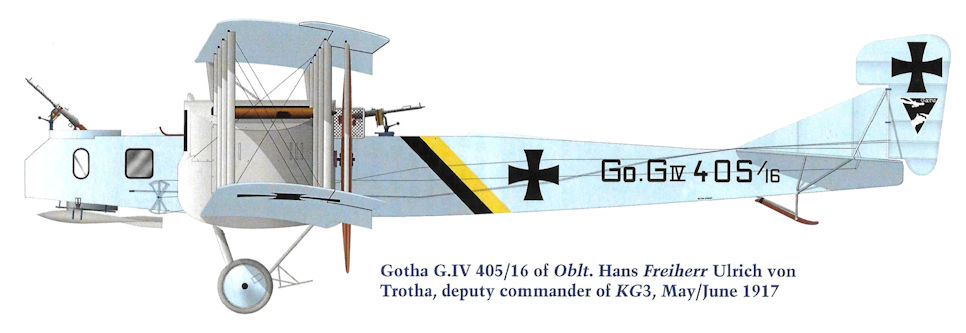
Gotha G.IV 405/16 of Oblt. Hans Freiherr Ulrich von Trotha, deputy commander of KG3, May/June 1917
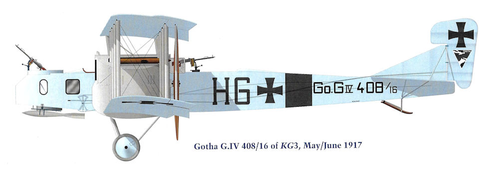
Gotha G.IV 408/16 of KG3, May/June 1917.

Gotha G.IV 604/16 of KG3, May/June 1917.
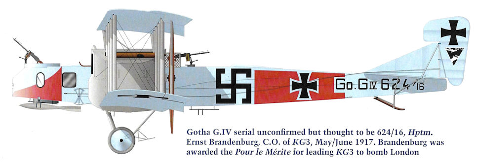
Gotha G.IV serial unconfirmed but thought to be 624/16, Hptm. Ernst Brandenburg, C.O. of KG3, May/June 1917. Brandenburg was awarded the Pour le Merite for leading KG3 to bomb London
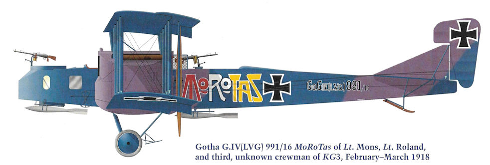
Gotha G.IV(LVG) 991/16 MoRoTas of Lt. Mons, Lt. Roland, and third, unknown crewman of KG3, February-March 1918
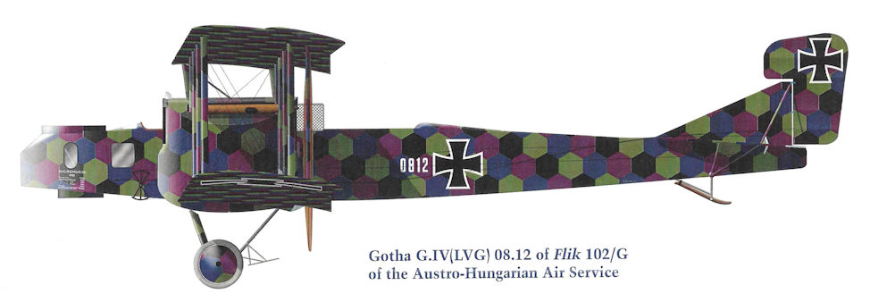
Gotha G.IV(LVG) 08.12 of Flik 102/G of the Austro-Hungarian Air Service
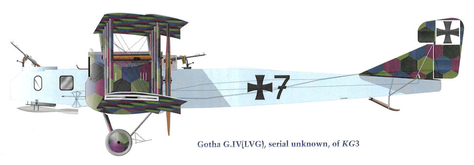
Gotha G.IV(LVG), serial unknown, of KG3
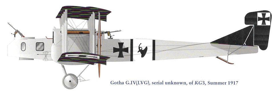
Gotha G.IV(LVG), serial unknown, of KG3, Summer 1917
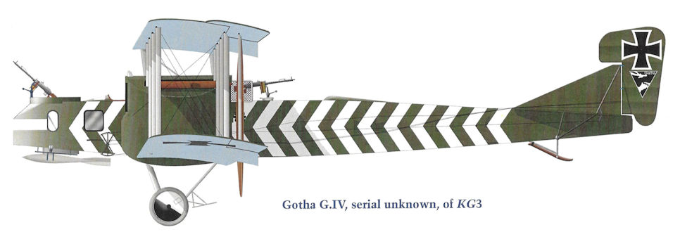
Gotha G.IV, serial unknown, of KG3
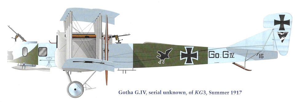
Gotha G.IV, serial unknown, of KG3, Summer 1917
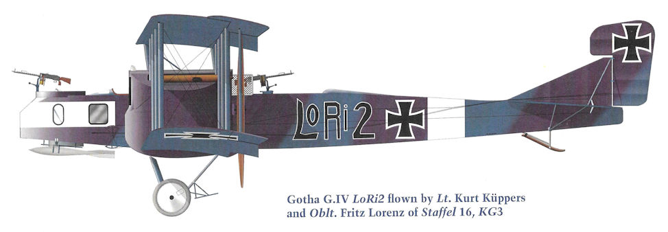
Gotha G.IV LoRi2 flown by Lt. Kurt Kuppers and Oblt. Fritz Lorenz of Staffel 16, KG3
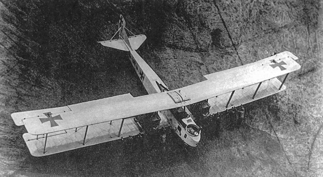
Gotha G.IV 408/16 was a bomber assigned to Kagohl 3, the England Geschwader, the unit assigned to bomb Britain. Two fuel tanks are mounted above the upper wing to give it enough range for these missions.
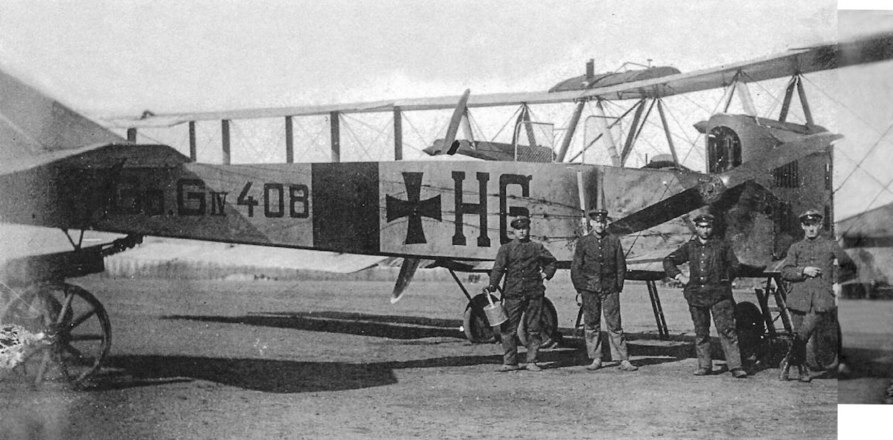
Gotha G.IV 408/16 of Kagohl 3 after full tactical markings were applied. The letters on the fuselage side are likely the initials of two of the crew members, a common marking practice in Kagohl 3.
The Gotha G.IV was one of the aircraft that bombed London in daylight. The engine nacelles of the G.IV were large and extended to the lower wing. The rear gunner's cockpit had protective screens on both sides to prevent him from leaning into the propellers. The additional fuel tank on top of the upper wing was needed for these long-range missions. The control cables were routed outside the fuselage, where they created additional drag and contributed to the type's stately maximum speed of 140 kmh (87 mph).
The Gotha G.IV was one of the aircraft that bombed London in daylight. The engine nacelles of the G.IV were large and extended to the lower wing. The rear gunner's cockpit had protective screens on both sides to prevent him from leaning into the propellers. The additional fuel tank on top of the upper wing was needed for these long-range missions. The control cables were routed outside the fuselage, where they created additional drag and contributed to the type's stately maximum speed of 140 kmh (87 mph).
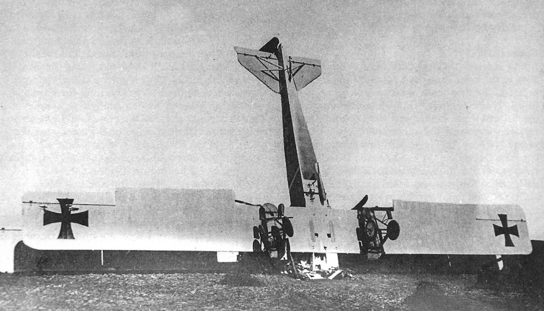
Gotha G.IV 410/16 of Kagohl 3 after a crash during take-off on April 23, 1917. The "Gotha Tunnel" that enabled the rear gunner to fire downward and to the rear is shown to advantage.
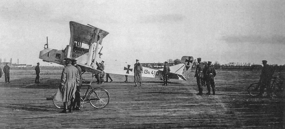
Gotha G.IV 410/16 of Kagohl 3.The early Gotha G.IV bombers were painted light blue overall with natural metal engine cowlings.
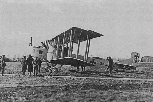
An early Gotha G.IV, possibly 610/16, wears an over-size Gotha company trademark below the iron cross insignia on the rudder.
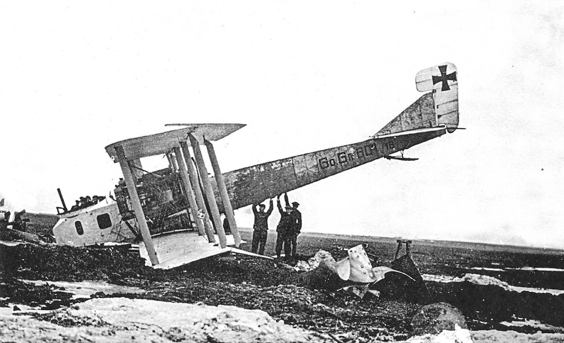
A factory photograph of Gotha G.IV 601/16 after a landing accident. All aircraft design decisions are compromises between competing concerns, but landing accidents claimed 76% of the Gotha G.IV and G.V bombers lost to all causes. If the CG is too far forward, the aircraft is excessively stable, too much download is required on the tail, raising the nose to abort a landing becomes difficult, and nose-overs become more likely. However, the extreme number of landing accidents is proof that Burkhardt moved the center of gravity too far aft during development of the G.II, a mistake that could have been easily rectified but was not.
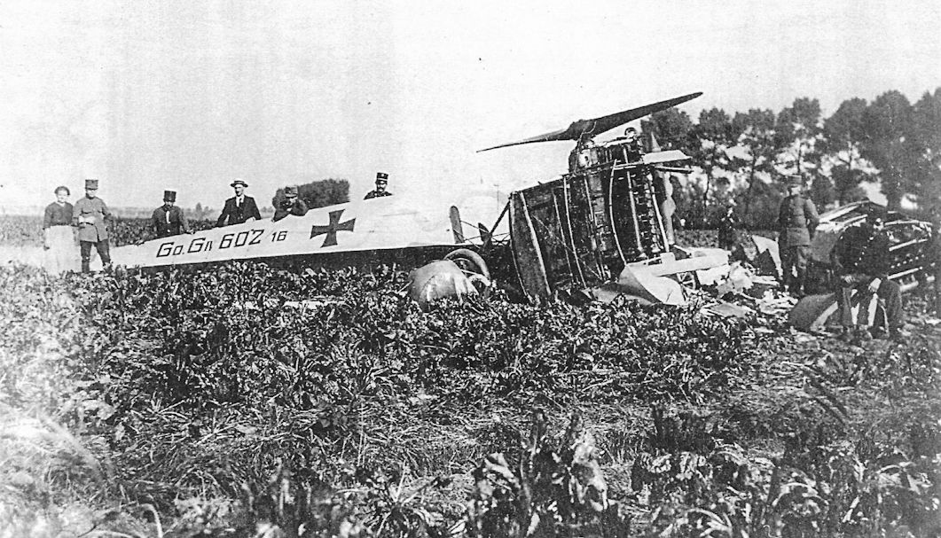
Gotha G.IV 602/16 crash-landed in neutral Holland at Sas van Gent on 28 September 1917 during a night raid on Britain. Another G.IV crashed and burned at Sneek the same day.
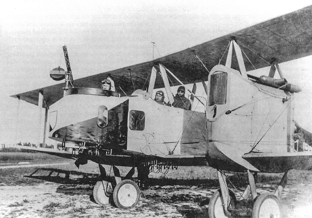
A Gotha G.IV 603/16 of Kagohl 3, the England Geschwader, with its crew. Gotha was a relatively obscure manufacturer until the dramatic daylight bombing raid on London by Gotha G.IV bombers of Kagohl 3 on 13 June 1917. This shocked the world and instantly made "Gotha" a household name. The Gotha G.IV is by far the most famous and significant Gotha type.
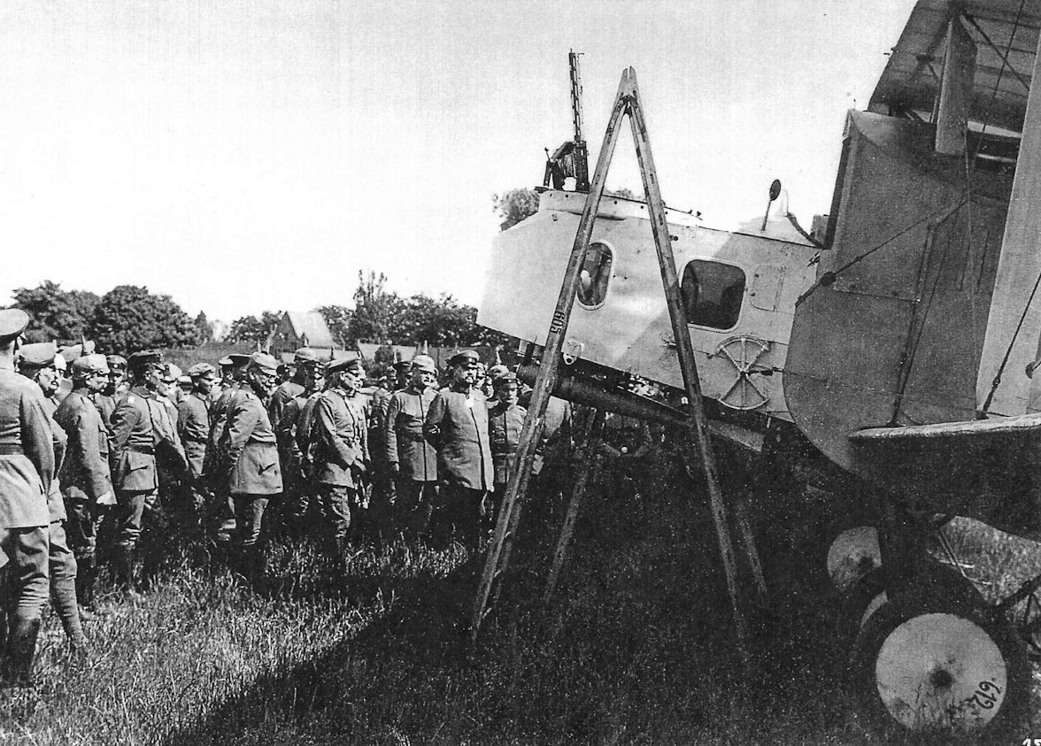
General Hindenburg and party inspect a Gotha G.IV, probably 612/16 if the lettering on the wheel cover is correct. The extreme forward mounting of the bombs below the nose clearly indicates the aircraft was tail-heavy after bombs were released.
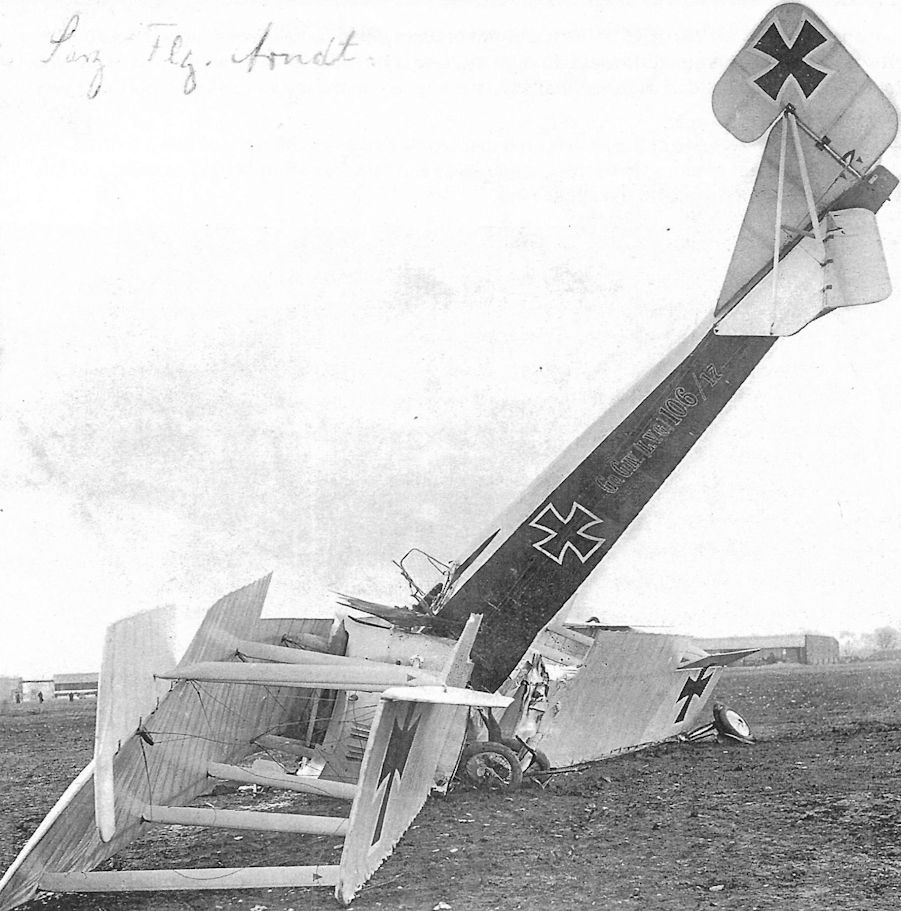
Gotha G.IV(LVG) 106/17 in a pose too often typical of a Gotha bomber.
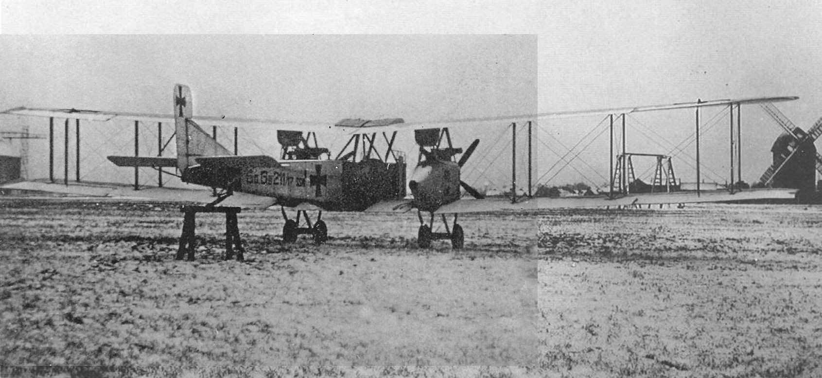
Gotha G.IV(SSW) G.211/17 delivered on March 14, 1918 to the Geschwaderschule Paderborn was one of the aircraft used to evaluate design modifications. Here it is fitted with 260 hp Mercedes D.IVa engines mounted in tractor configuration and fitted with four-bladed propellers. In this installation the radiators were suspended from the upper wing.
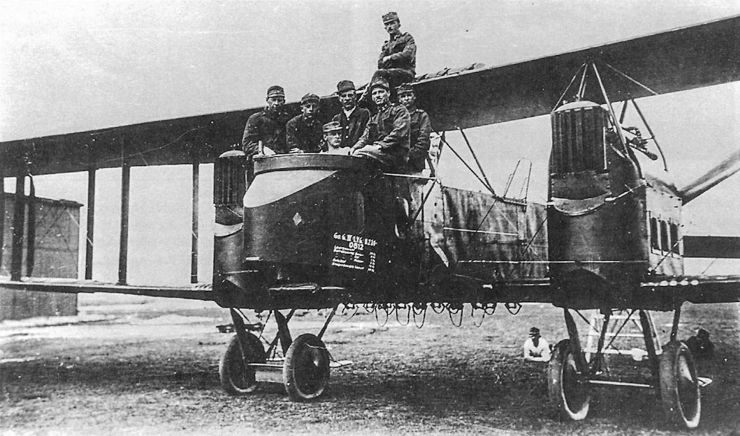
Austro-Hungarian Gotha G.IV(LVG) 08.12 has drawn a crowd. The bomb racks are visible under the wing center section. Because German engine production was inadequate for German needs due to Allied numerical superiority and the Royal Navy's distant blockade, the Austrians had to provide their own 230 hp Hiero engines for their Gothas. The revised engine installation was a disaster; weak engine bearers and unsuitable propellers caused excessive engine vibration that led to piping leaks and failures of the structure and instruments. Despite great efforts by the maintenance staff, by late September the Austrian Gothas were virtually grounded and the aircrews reverted to the reliable, single-engine Brandenburg C.I for most bombing missions.
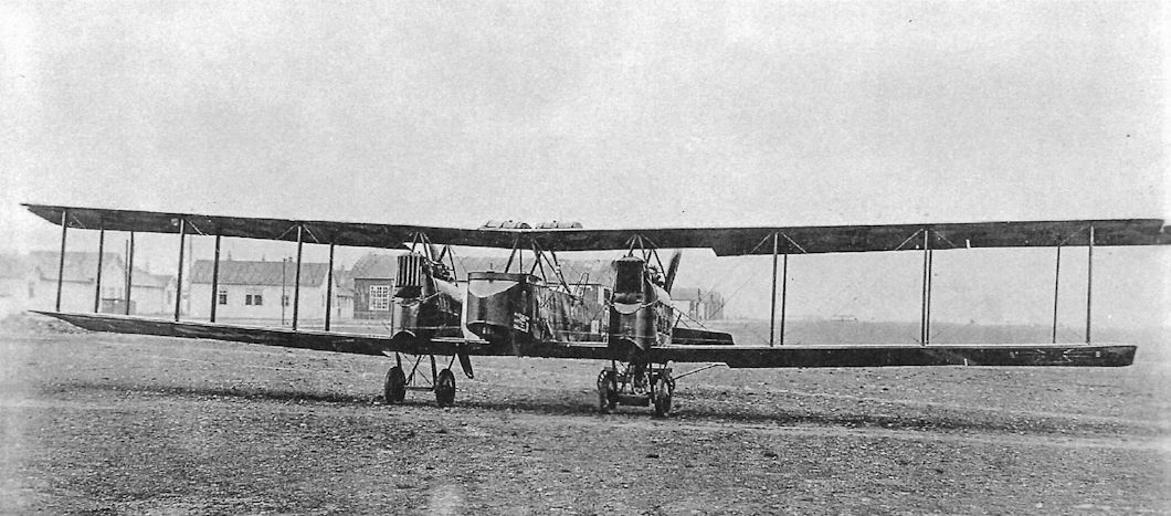
A Gotha G.IV(LVG) in Austro-Hungarian service.The 39 Austro-Hungarian G.IV(LVG) bombers delivered were assigned Austrian serials 08.01-08.40; one had crashed in a "typical landing accident" by an LVG pilot and was not replaced. These aircraft had twin fuel tanks above the wing center section and were camouflaged in dark German hexagonal fabric for night bombing.
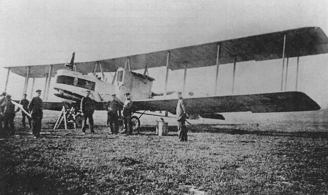
Gotha G.IV of Kagohl 3, the England Geschwader, the unit assigned to bomb Britain.There are bombs under the extreme nose of the airplane; this unusual placement was due to the tail-heaviness of the Gotha bombers. Once the bombs were released the Gothas became neutrally stable or unstable in pitch, resulting in numerous landing accidents that destroyed more Gotha bombers than all other causes combined. At this remove it is difficult to understand why Gotha did not fix the tail-heaviness problem before the bombers were produced in quantity. Regardless, these bombers were Gotha's major success as an aircraft manufacturer. Without them Gotha would have little reputation in aviation.
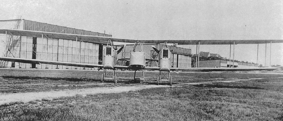
Front view of an unidentified Gotha G.IV. From this vantage point the actuating strut between upper and lower ailerons confirms this is a G.IV and not a G.III, which did not have ailerons on the lower wings.
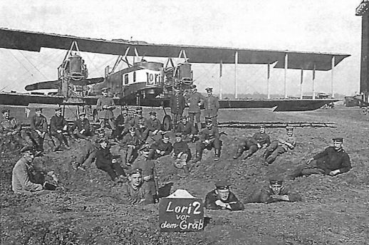
The crater was made by a British bombing attack on the airfield, but Lori2, flown by Lt. Kurt Kuppers and Oblt. Fritz Lorenz of Staffel 16 seems undamaged other than for its missing engine nacelle panels, which apparently were blown off by the bomb's blast. With typical gallows humor, the sign reads "Lori2 before the grave." The aircraft name is repeated on the rear fuselage. The aircraft is in dark camouflage for night bombing missions.
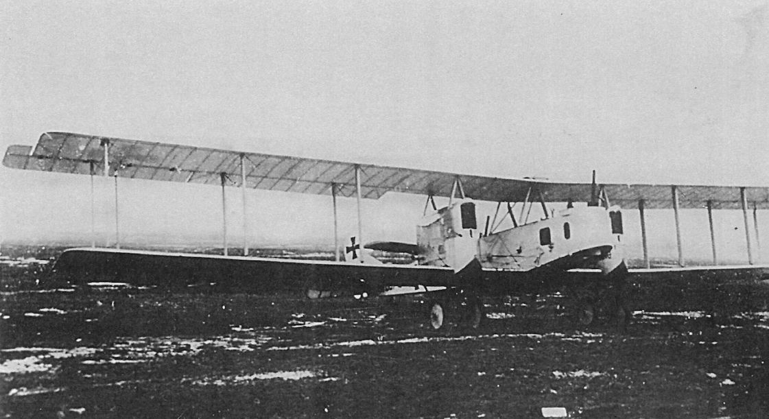
An early Gotha G.IV painted in light colors for daylight bombing.
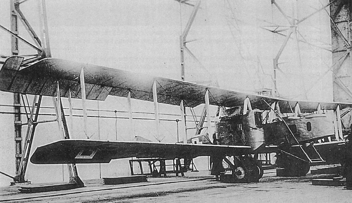
An unidentified Gotha G.IV at the factory. The twin-wheel Stossfahrgestell (shock landing gear) designed by Siemens was fitted to all SSW-built aircraft from G.217/17, and apparently this G.IV is one of those. Many SSW-built machines were also fitted with the Flettner servo tabs to reduce the control forces, making the aircraft more maneuverable and reducing the pilot's workload.
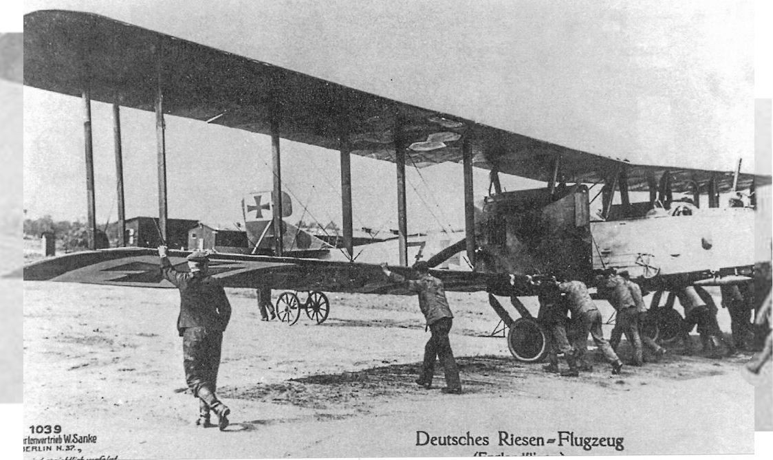
This photograph of an operational G.IV being positioned the old-fashioned way was made into a Sanke card. Although the fuselage is still a light color, the wings and tail have been camouflaged in dark lozenge colors for night bombing raids over Britain. It is an interesting safety note that the aircraft is carrying bombs while being moved.
The prototype Gotha G IV took to the air for the first time during December 1916. Larger than the preceding Gotha G III, the G IV was powered by two 260hp Mercedes D IVa engines that propelled it along at 87mph at 11,880 feet. With a full 1,100 Ib bomb load, the range of the 3-man G IV was 304 miles, extending further as bomb load was reduced and traded for additional fuel. Armed with three 7.92mm Parabellums, one of these was positioned in the aircraft's belly to catch the unwary attacker.
The prototype Gotha G IV took to the air for the first time during December 1916. Larger than the preceding Gotha G III, the G IV was powered by two 260hp Mercedes D IVa engines that propelled it along at 87mph at 11,880 feet. With a full 1,100 Ib bomb load, the range of the 3-man G IV was 304 miles, extending further as bomb load was reduced and traded for additional fuel. Armed with three 7.92mm Parabellums, one of these was positioned in the aircraft's belly to catch the unwary attacker.
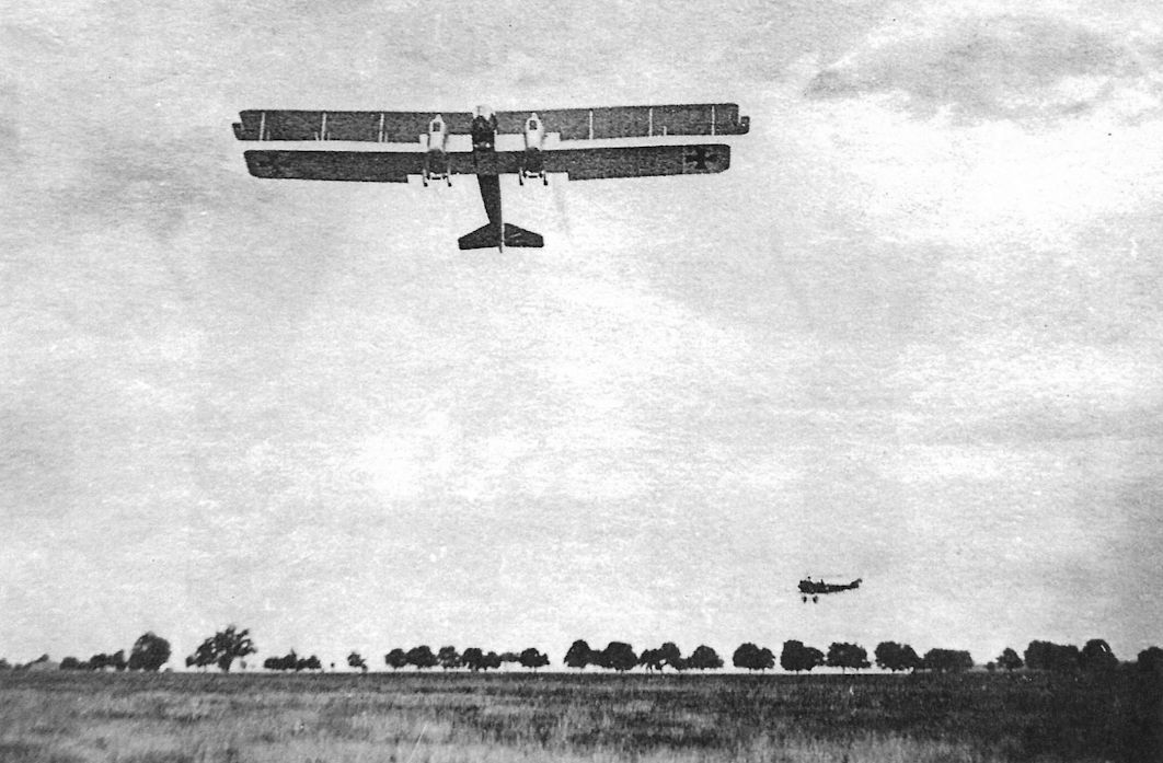
A Gotha G.IV, confirmed by the aileron actuating strut, takes off. It is painted in light colors for daylight bombing.
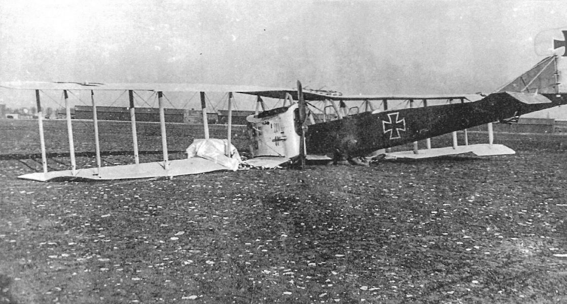
An unidentified Gotha G.IV after yet another landing accident.
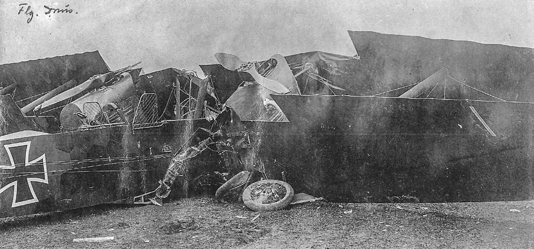
This late-production Gotha G.IV was covered in fabric printed with dark, hexagonal night camouflage for night bombing missions. Another detail of interest are the screens on both sides of the rear gunner's cockpit to prevent him from accidentally putting a hand or arm in the propeller arc.
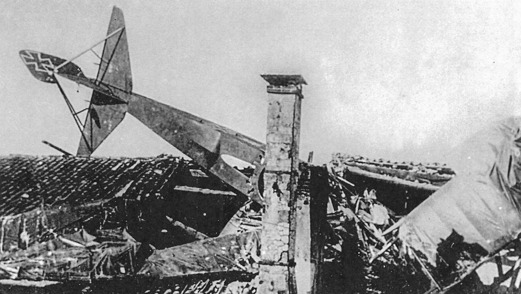
Austro-Hungarian Gotha G.IV(LVG) 08.16 of Flik 102/G was brought down by Italian anti-aircraft fire on 28 July 1918. The slot for the gunner to fire his gun downward through the "Gotha Tunnel" is clearly visible, as is the faired bulge behind it typical for the Gotha G.IV.The dark night camouflage, characterized in the resulting Allied report as "a very black, bluish gray", is evident.
Gotha WD10 (U-1)
Like the Gotha WD4/UWD, the Gotha WD10, Marine Number 782, was another design by Oskar Ursinus, a civil engineer who was founder and editor of Flugsport magazine.
The WD10, more commonly known as the U-1 or Ursinus Seaplane after its designer, was the most innovative single-seat floatplane fighter prototype built in Germany and a remarkable design for 1916. It featured retractable floats for higher speed through reduced drag. To improve maneuverability the 150 hp Benz Bz.III engine was located on the center of gravity and drove the propeller via an extension shaft. The floats were retracted by a manual crank. During trials there were problems with the propeller extension shaft and float retraction mechanism. Unfortunately, the prototype was destroyed before it could achieve its estimated top speed of 200 km/h.
Gotha WD10 (U-1) Specifications
Engine: 150 hp Benz Bz.III
Wing: Span Upper 9.00 m
Area 42.5 m2
General: Length 7.77 m
Height 2.90 m
Empty Weight 750 kg
Loaded Weight 1000 kg
Maximum Speed: 200 km/h
Gotha Seaplane Production Summary
Type Ordered Marine Numbers Remarks
WD10 1 782 Ursinus design, retractable float fighter
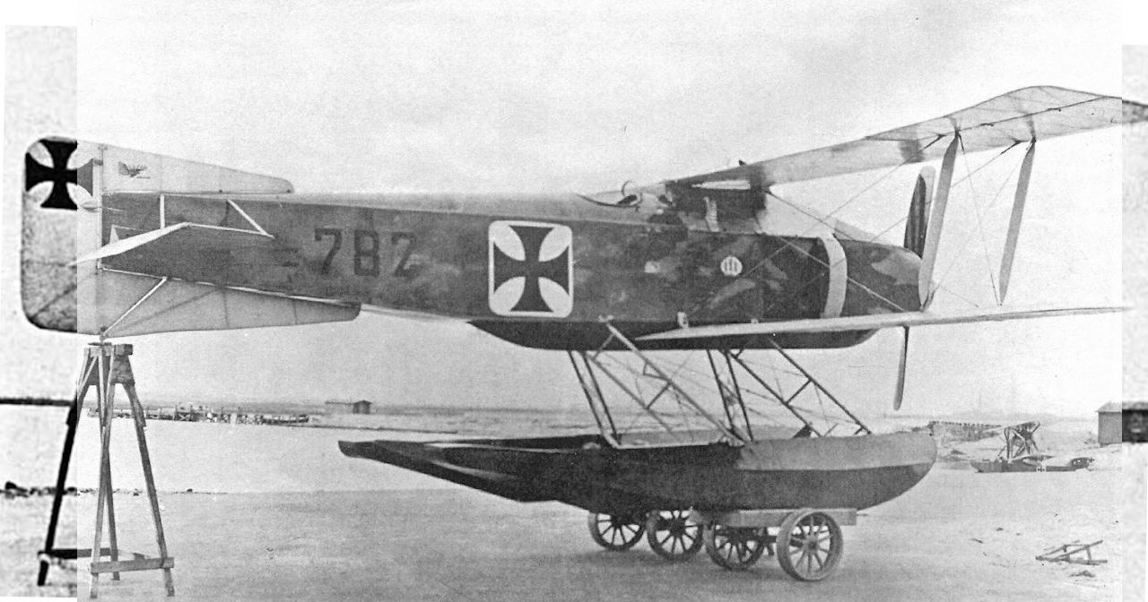
Oskar Ursinus (Editor of Flugsport magazine) designed a single-seater to embrace several features intended to obtain the very best performance from the 150hp Benz six-cylinder engine. Built by Flugmaschinen Rex GmbH and allocated naval number 782, the aircraft is shown at Warnemunde during evaluation in April 1917. The most revolutionary feature of the design was its retractable float undercarriage. The pilot manually operated a small differential winch which reduced the lengths of the bracing cables on one diagonal of the undercarriage struts and lengthened corresponding cables on the other diagonal, allowing the floats to be cranked to the 'up' position. They were retracted forward against the airflow; this kept the centre of gravity forward and also assisted with float extension. In the event, the aircraft was never flown, since during initial taxiing trials at 900rpm the machine nosed over. After further investigation the design was abandoned.
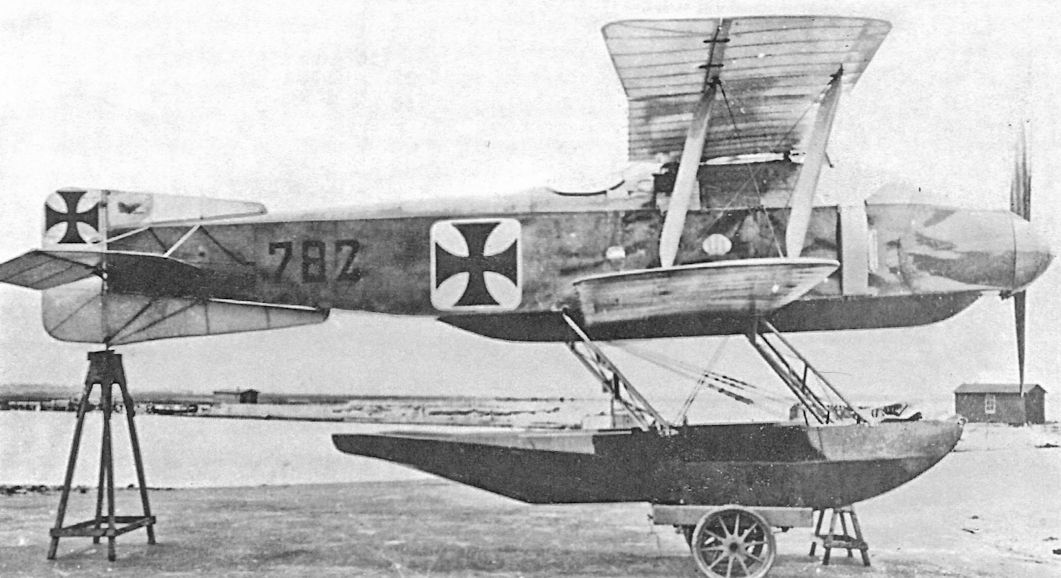
The Ursinus floatplane fighter, Marine Number 782, seen from the side with floats extended.The cockpit was well aft because the engine was set back to the center of gravity for improved maneuverability (due to reduced moment of inertia) and drove the propeller via an extension shaft.
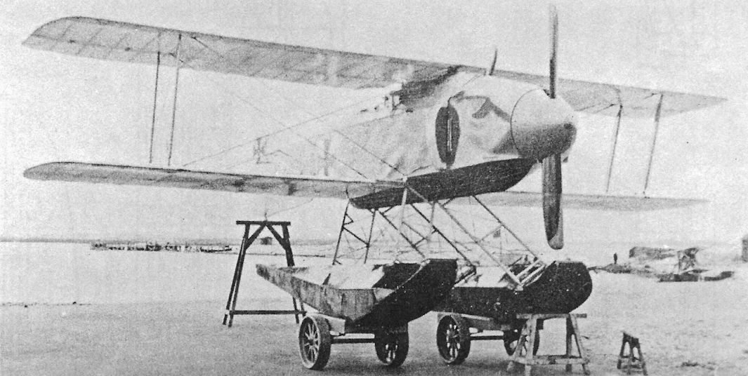
The Ursinus floatplane fighter was unique in having retractable floats, a significant innovation for its time. The inside upper edges of the floats were beveled to fit closely against the fuselage, which was shaped to accommodate them when retracted.
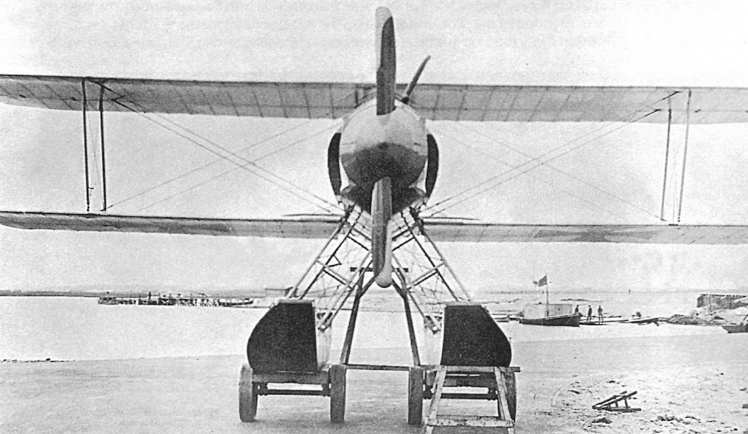
The Ursinus was an innovative design attempt to reduce the drag penalty of floats combined with an attempt to improve maneuverability through reducing the moment of inertia by locating the engine at the center of gravity.
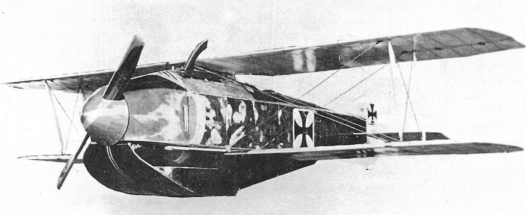
About the same time as the Junkers J.I was making its debut, the Gotha WD-10 was nearing completion, ready to enter flight trials early in 1916. While not representing such a fundamental advance as the J.I, this Oskar Ursinus creation merits more than passing interest for the novel and clever fashion in which the designer minimised the deleterious effects such things as floats would otherwise have on the fighter's overall performance. Thanks to its refined in-flight lines, brought about by the retractable floats, the WD-10, with its 150hp Benz Bz III had a top level speed of 124mph at sea level. At this speed, the German single seat naval fighter could outpace France's finest, in the shape of the Spad VII, first flown in April 1916. Perhaps it was fortunate for the Allies that the WD-10 was destroyed during flight test. The images not only show the aerodynamically cleansing affect of the retractable floats, but also the extremely neat housing of engine and fuselage flanking radiators devised by the Ursinus design team.
Gotha WD4 (UWD)
The Gotha WD4, more commonly known as the UWD (for Ursinus Wasser Doppeldecker = Ursinus Water Biplane), had an interesting history. It was a floatplane derivative of the Gotha G.I bomber, which was actually designed by Oskar Ursinus, a civil engineer who was founder and editor of Flugsport magazine and not employed by Gotha. After a prototype was built, Gotha built additional aircraft as the Gotha G.I (which see).
On 14 April 1915, only two weeks after the first order for the Gotha G.I Kampfflugzeug was received, the Navy ordered a floatplane version, the UWD, for combat evaluation. Powered by two 160 hp Mercedes D.III engines, the UWD was delivered to the SVK (Seeflugzeug Versuchs Kommando = Seaplane Testing Command) on 30 December 1915. Flight testing began on 5 January 1916 and the UWD was accepted on 6 February.
Assigned Marine Number 120, the UWD arrived at Zeebrugge on 18 February 1916. It was easy to fly and had an endurance of at least 4.5 hours, enabling it to undertake long-range scouting and bombing missions. Nose-overs were not a problem like they were with the G.I landplane version.
The UWD's configuration had advantages; the observer(s) had a clear view and field of fire forward, free of propeller turbulence and exhaust fumes, and the closely-spaced engines minimized asymmetric thrust in case of an engine failure. Starting 10 March 1916 the UWD made several bombing raids along the English coast until it was damaged on 10 July while taxiing for take-off. It was struck from inventory by the Navy on 2 October 1916.
Gotha WD4 / UWD Specifications
Engines: 2 x 160 hp Mercedes D.III
Wing: Span Upper 20.10 m
Span Lower 19.00 m
Chord (Upper &. Lower) 2.20 m
Gap 2.00 m
Sweepback 10 degrees
Area 82 m2
General: Length 14.20 m
Height 4.40 m
Empty Weight 1940 kg
Loaded Weight 2552 kg
Maximum Speed: 138 km/h
Climb: 1000m 8.5 min
2000m 20.5 min
3000m 45 min
Service Ceiling: 4000 m
Gotha Seaplane Production Summary
Type Ordered Marine Numbers Remarks
WD4 1 120 Ursinus design, also known as UWD
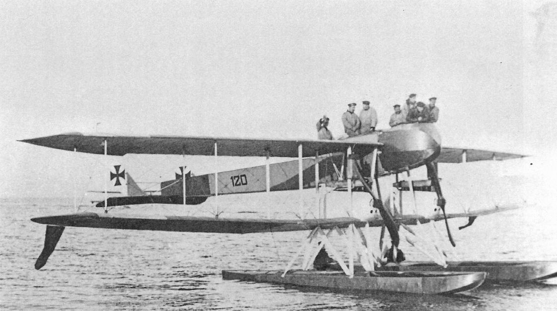
The Gotha UWD attracted a crowd during its sea trials in February 1916. So many people rode in it that it was nicknamed the "Trojan Horse".
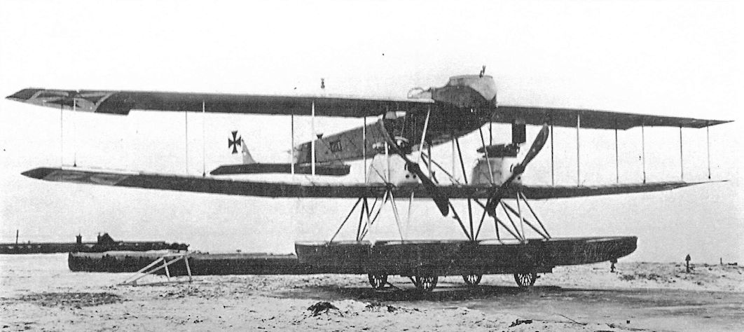
The Gotha UWD resting on a beaching dolly before the bomb-dropping fairing was added.
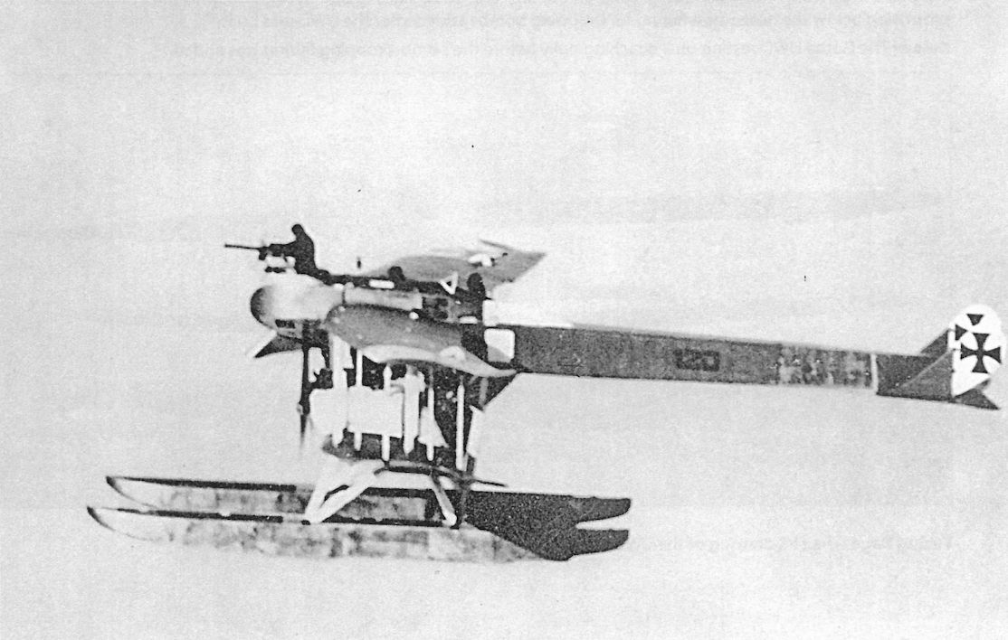
The Gotha UWD in flight displays its distinctive lines and the clear field of fire for its gunners, especially the nose gunner. The second gunner sat in the middle with the pilot aft as a result of its 'battle-plane' heritage from the Gotha G.I.
Only one Gotha Ursinus seaplane was used by the Navy, being allocated number 120. It is shown on 19 March 1916 on one of its operational flights, when in company with five other seaplanes from Zeebrugge it dropped bombs on Dover, Deal, Ramsgate and Margate, causing 14 fatalities among the civilian population.
Only one Gotha Ursinus seaplane was used by the Navy, being allocated number 120. It is shown on 19 March 1916 on one of its operational flights, when in company with five other seaplanes from Zeebrugge it dropped bombs on Dover, Deal, Ramsgate and Margate, causing 14 fatalities among the civilian population.
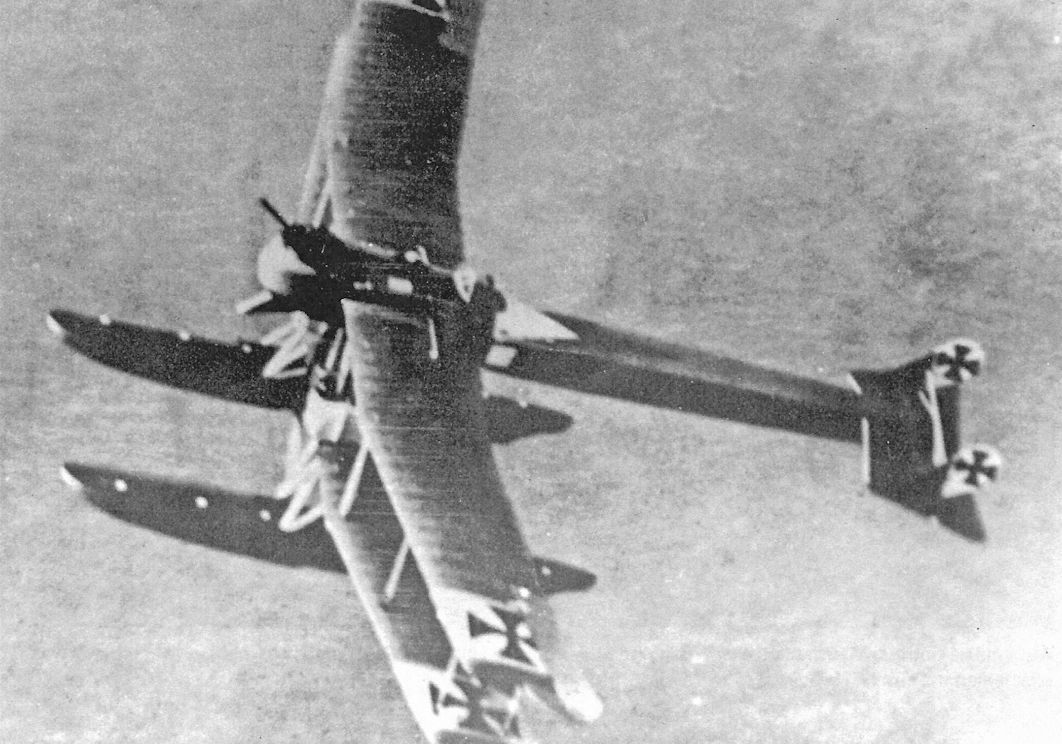
The Gotha UWD shows more of its distinctive profile in this dramatic image. Interestingly, the Iron Cross national insignia was painted on a white background on the tops and undersides of both wings and both sides of the rudders. The protrusion below the nose was a fairing for dropping bombs added after the UWD was built.
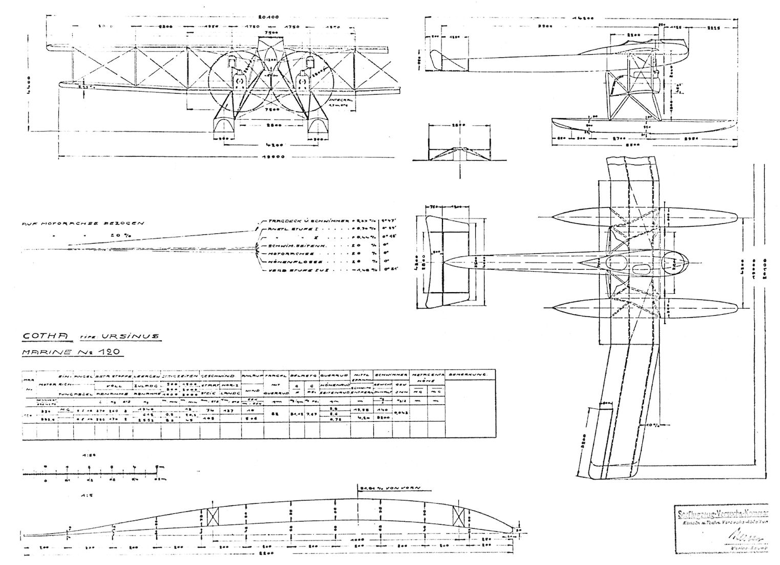
The SVK drawing of the UWD.
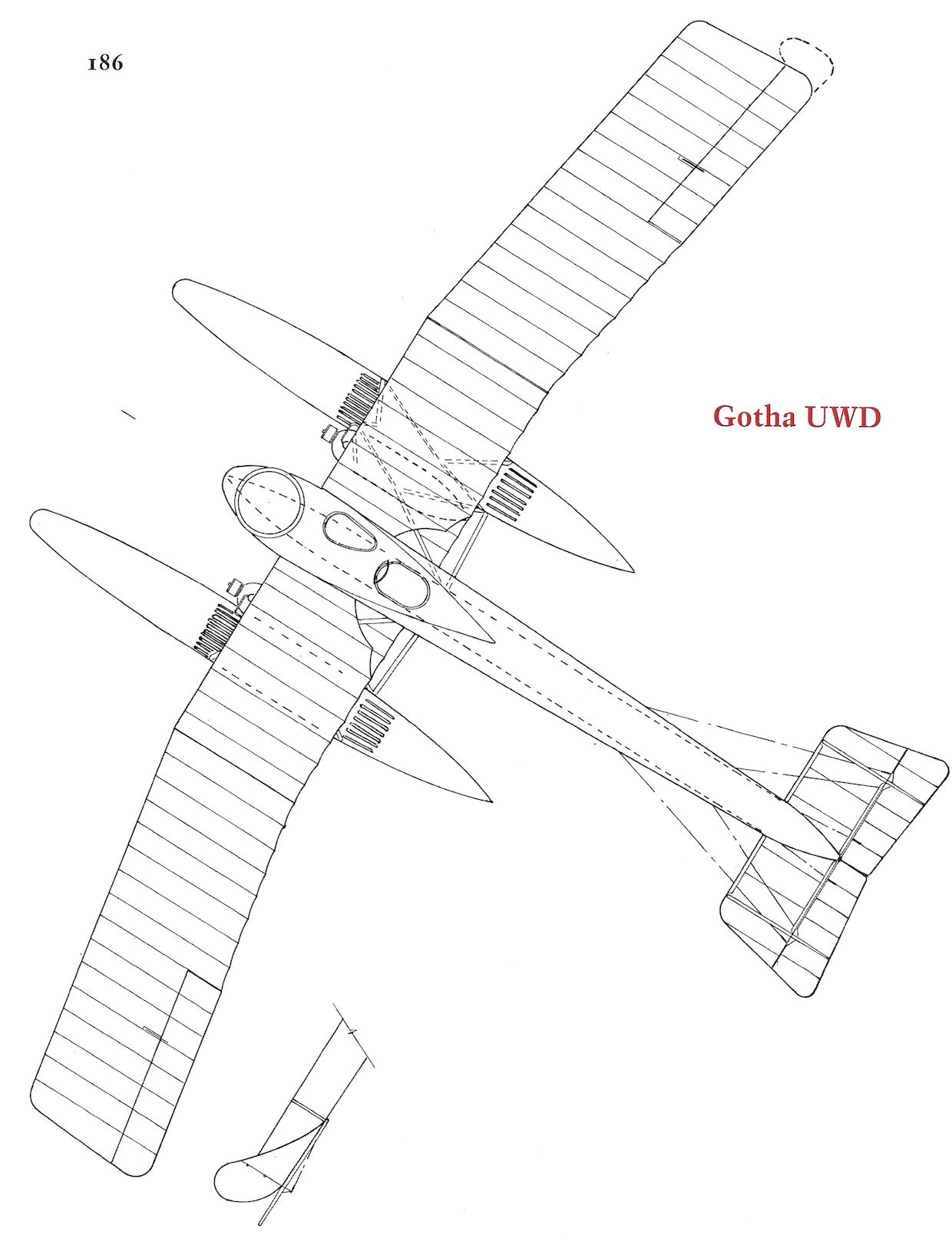
Gotha UWD
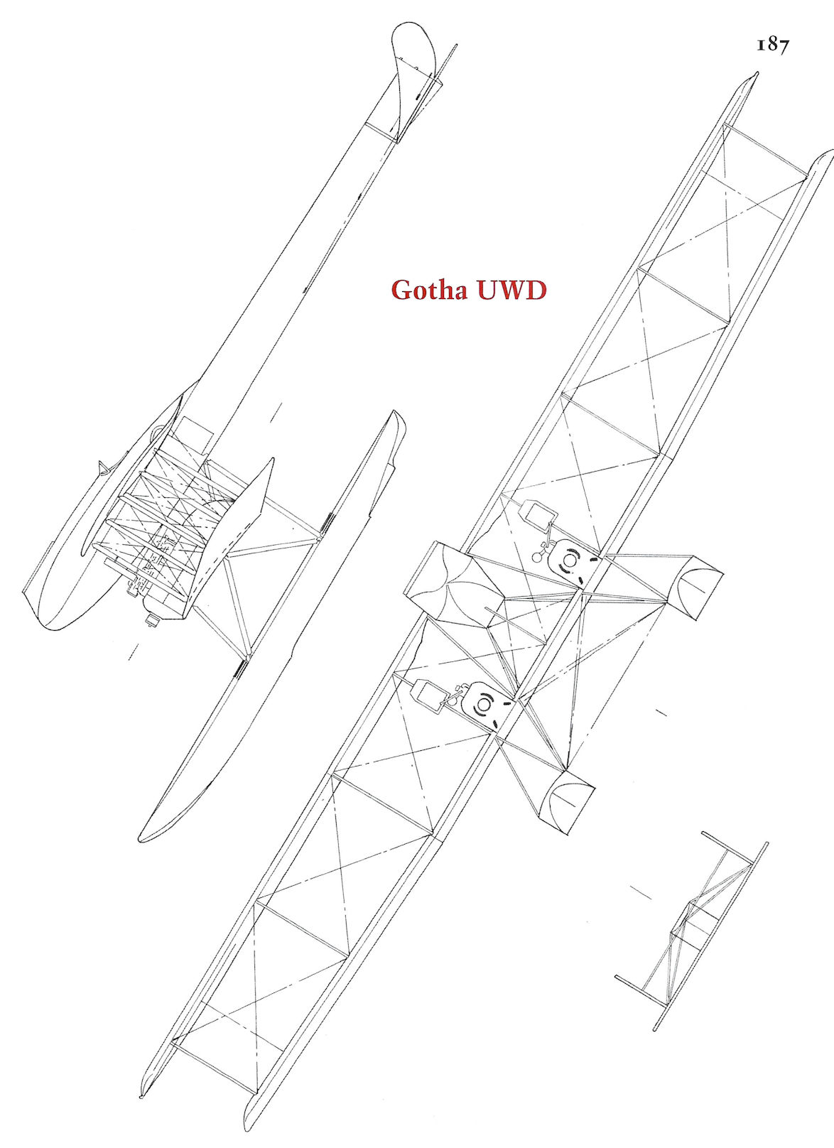
Gotha UWD
Gotha WD7
The Gotha WD7, Marine Number 119, was ordered on 10 May 1915. Designed by Karl Rosner and A. Klaube and originally intended as a three-seat Kampfflugzeug to attack enemy aircraft, it was powered by two 120 hp Mercedes D.II engines. Assigned to Flandern I at Zeebrugge, the WD7 prototype caught fire in flight on its first combat mission on 5 April 1916 and was forced to ditch. The crew and partly-burned airframe were captured by the French.
Seven additional WD7 floatplanes were ordered on 24 February 1916. Six, Marine Numbers 670-675, were powered by two 100 hp Mercedes D.I engines and one, Marine Number 676, was powered by two 120 hp Argus As.II engines. Armament was a single Parabellum LMG 14 machine gun in the front turret. These provided training at Apenrade for twin-engine torpedo airplanes. WD7 #671 was at Warnemunde, then went to Flensburg. WD7 #674 eventually was at Norderney, where among its pilots was Flgobmt. Hubrich, a future ace. Two WD7 seaplanes, #675 and #676, were used in weapons trials with 37mm DWN and 20mm Becker aircraft cannons mounted in a modified nose turret.
Gotha WD7 Specifications
Engines: 2 x 120 hp Mercedes D.II (119) 2 x 100 hp Mercedes D.I (670-675) 2 x 120 hp Argus As.II (676)
Wing: Span Upper 16.80 m
Span Lower 14.80 m
Area 55.5 m2
General: Length 11.30 m
Height 3.90 m
Empty Weight 1275 kg
Loaded Weight 1785 kg
Maximum Speed: 128 km/h
Climb: 1000m 9.5 min
2000m 40 min
Service Ceiling: 3500 m
Range: 475 km
Note: Performance specs for #119
Gotha Seaplane Production Summary
Type Ordered Marine Numbers Remarks
WD7 8 119, 670-676 Torpedo trainers
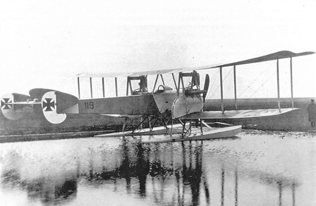
The prototype Gotha WD7, Marine #119, in the Gotha factory pond. The WD7 had distinctive tail surfaces with three fins and two rudders with aerodynamic balances at the bottom. The WD7 was designed as a 3-seat Kampfflugzeug meant to destroy enemy aircraft, but by the time the production batch was available that concept was out-moded.
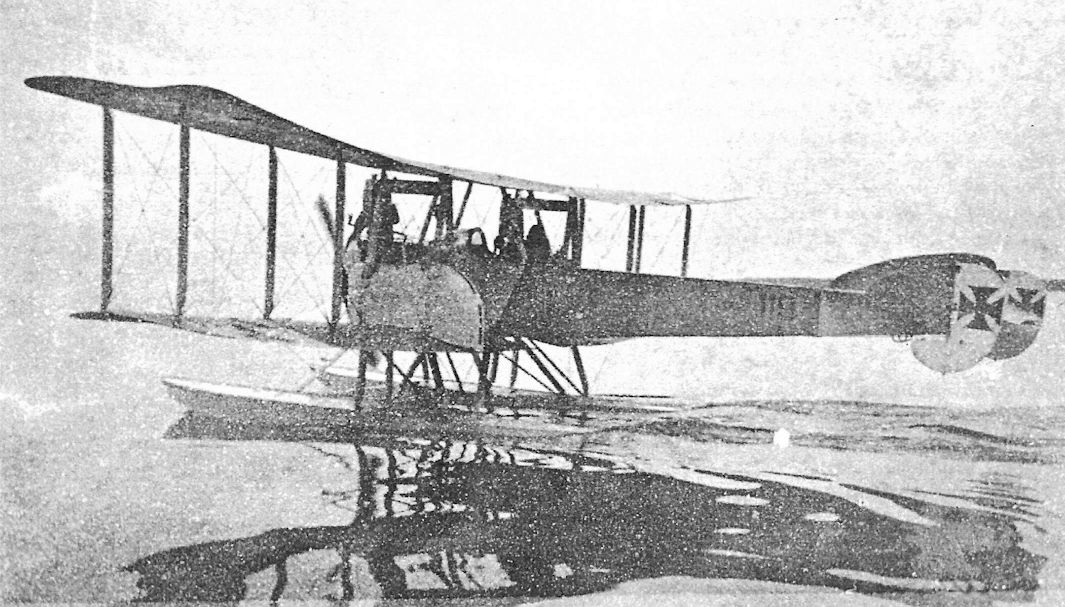
The Gotha WD7 prototype was MN 119; it was powered by 120 hp Mercedes D.II engines.
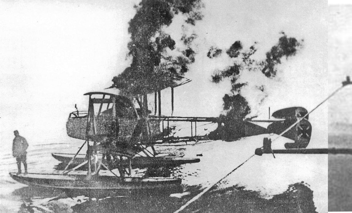
On its first combat mission on 5 April 1916, WD7 Marine Number 119 caught fire in flight and was forced to make an emergency landing. Here it is photographed from a French vessel that captured the crew and partly-burnt airframe.
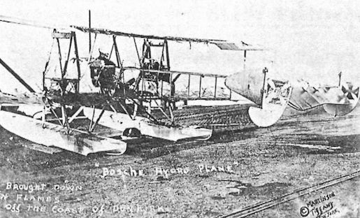
Gotha WD7 #119 after capture. The WD7 was indeed "brought down in flames off the coast of Dunkirk" as written on the photograph but that was due to mechanical failure, not Allied action. WD7 #119 was the subject of a French report in L'Aerophile from where we learn it was doped a very light blue.
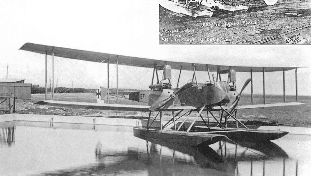
Gotha WD7 Marine Number 671 afloat in the Gotha factory pond.
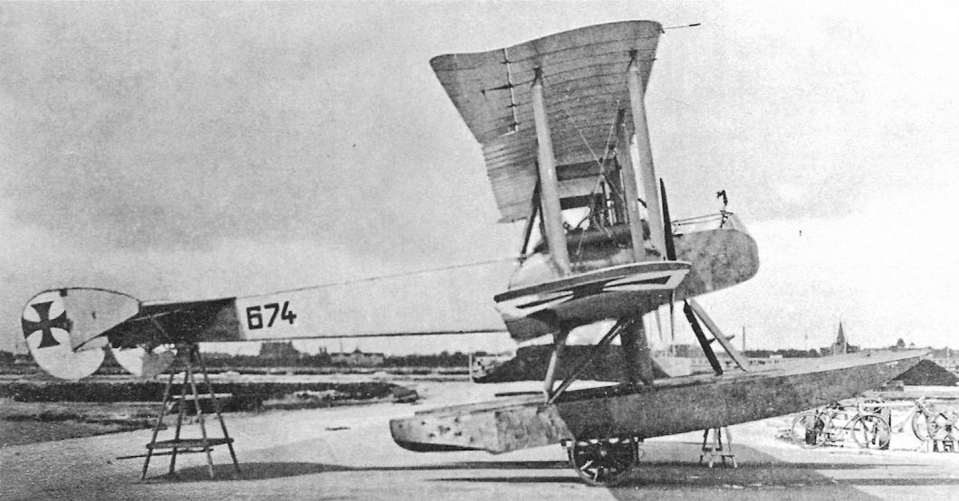
Side view of Gotha WD7 Marine Number 674 on a dolley. Power for MN 670-675 was two 100 hp Mercedes D.I engines; MN 676 was powered by 120 Argus As.II engines.
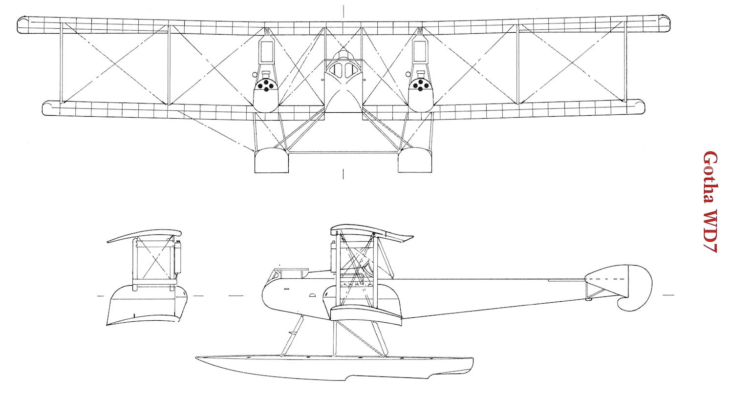
Gotha WD7
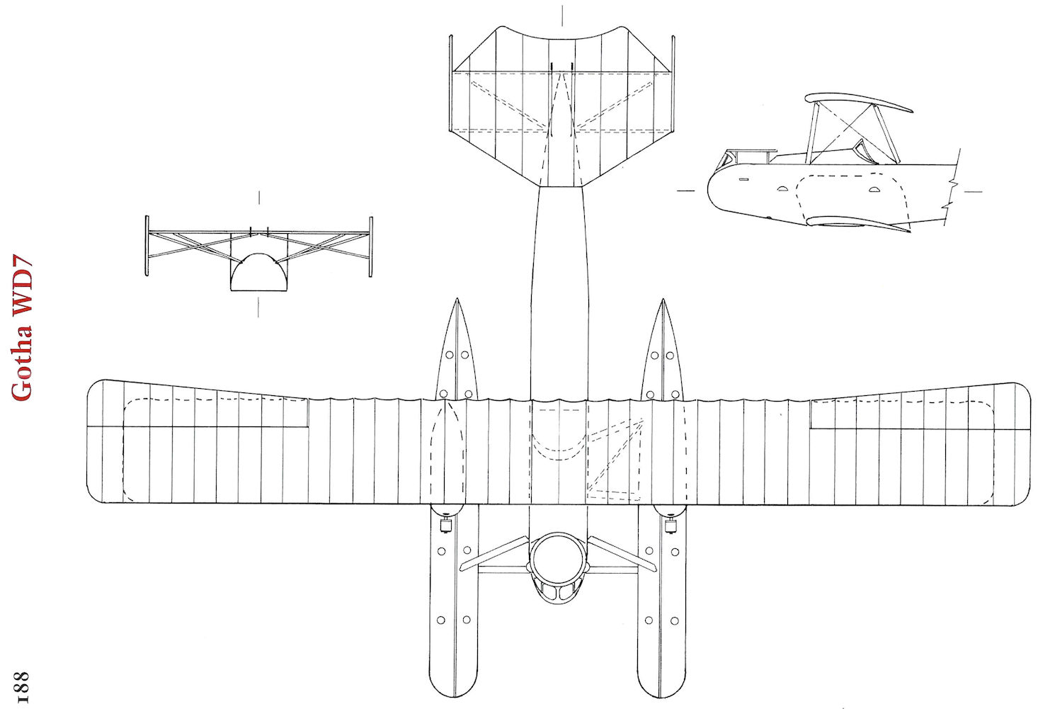
Gotha WD7
Gotha WD8
The Gotha WD8, Marine Number 476, was ordered on 22 July 1915. Designed by Karl Rosner and A. Klaube and powered by a single 240 hp Maybach Mb.IVa, it was ordered as a "comparison aircraft" for the twin-engined WD7 which had the same horsepower. The WD8 used the same wing cellule, tail assembly, and floats as the WD7, and was armed with both a fixed, forward-firing machine gun and a flexible rear machine gun for the observer.
Delivered on 9 February 1916, the WD8 was assigned to Flandern I at Zeebrugge, where it arrived on 23 April 1916. On operations the WD8 was reported as "totally unsuitable" owing to sluggish maneuverability, insufficient fuel capacity, and a poor field of fire due to the twin rudders. On July 28 the commander of the Seeflugstation Zeebrugge requested that the WD8 be withdrawn from front line service. The WD8 was shipped to Turkey by rail on 21 September 1916, and apparently arrived on 31 October. Only one WD8 was built.
Gotha WD8 Specifications
Engine: 240 hp Maybach Mb.IVa
Wing: Span Upper 16.00 m
Span Lower 14.80 m
Area 55.5 m2
General: Length 11.20 m
Height 4.10 m
Empty Weight 1254 kg
Loaded Weight 1778 kg
Maximum Speed: 138 km/h
Climb: 1000m 6.5 min
2500m 25 min
Service Ceiling: 4500 m
Range: 480 km
Gotha WD28
In July 1918 Gotha received a contract to build four WD28 seaplane prototypes, Marine Numbers 4001-4003 and 4034, based on the WD8 design. Powered by a 260 hp Mercedes D.IVa engine, the first two prototypes were configured as reconnaissance aircraft with wireless equipment and the last two were equipped to carry bombs. The first two prototypes were nearly complete when work was stopped in January 1919. No photographs appear to have survived.
Gotha Seaplane Production Summary
Type Ordered Marine Numbers Remarks
WD8 1 476 Assigned to Zeebrugge, then sent to Turkey
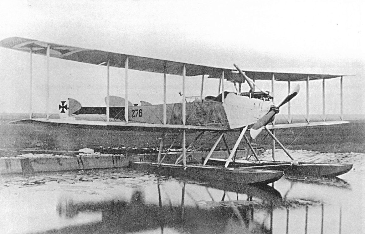
Gotha WD8 Marine Number 476 afloat in the Gotha factory pond. The WD8 used the same wing cellule, tail surfaces, and floats as the WD7 and was built as a comparison aircraft to the WD7 because both aircraft had the same power. Confusingly, the wrong Marine Number was painted on the floatplane when these photos were taken, a mistake later corrected.
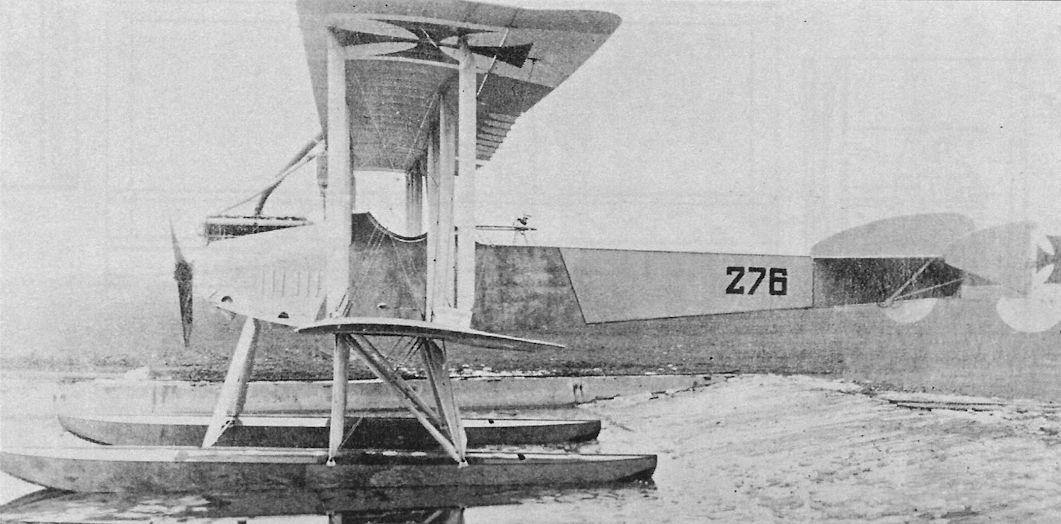
Side view of Gotha WD8 Marine Number 476 afloat in the Gotha factory pond. The wrong Marine Number was painted on the WD8 when these photos were taken. With the same total engine power as the WD7 had from two engines, the WD8 was 10 kmh faster due to lower drag.
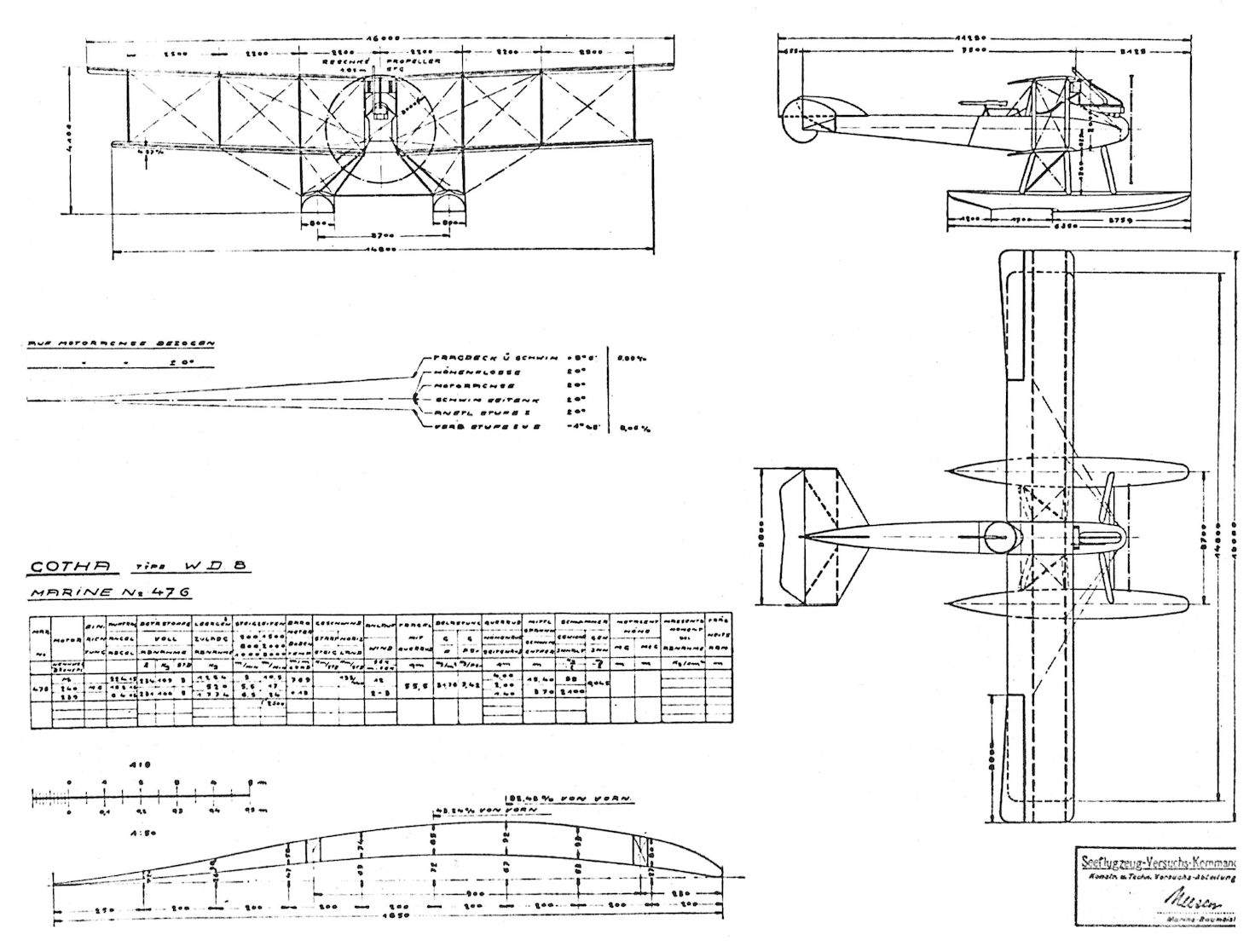
Gotha G.V
The Gotha G.V was a further refinement of the basic design. Experience had shown that housing the fuel tanks in the engine nacelles increased the chance of fire in the event of a crash. Therefore the fuel tanks of the G.V were moved to the fuselage away from the engines, which were enclosed in streamlined nacelles mounted between the wings. The engine remained the same 260 hp Mercedes D.IVa as used in the G.III and G.IV. Despite the nominal improvements incorporated into the G.V, the basic design had reached its peak. Furthermore, wartime shortages resulted in inferior materials being used to construct the G.V, making it heavier than the G.IV and reducing its performance. Additional equipment deemed necessary by operational experience aggravated the problem.
Regardless, Idflieg ordered 100 G.V bombers on 19 October 1916. The G.V passed its type test in July 1917 and the first aircraft reached Bogohl 3 in August 1917. The G.V arrived too late to participate in the daylight raids over the UK but were used for night bombing, performing both strategic raids over the UK and tactical bombing on the Western Front.
The Gotha G.Va was an attempt to improve flight safety. A re-designed 'box' tail with biplane horizontal stabilizers and elevators and twin fins and rudders improved engine-out controllability, even enabling turns into the running engine. A two-wheeled Stossfahrgestell mounted under the nose prevented nose-overs on landing to improve landing safety, the Gotha's Achilles Heel. The nose turret was also modified. Twenty-five of this transitional model were delivered.
The G.Vb was derived from the G.Va in a further attempt to improve flight safety. The 'box' tail was retained and, to reduce the pilot's workload and improve maneuverability, most G.Vb bombers were equipped with Flettner servo controls on the upper ailerons. To further improve landing safety a four-wheeled undercarriage underneath each engine, similar to the original G.II prototype, was fitted. Unfortunately, the new undercarriage reduced the already compromised flight performance due to its greater weight and drag, and the Gotha G.Vb was inferior to the contemporary AEG G.V and
Friedrichshafen G.IV based on comparative tests by Idflieg. Confirming this assessment, Idflieg placed an order with Gotha to build 50 Friedrichshafen G.IVa(Go) bombers under license, although the war ended before any were built. Although 80 Gotha G.Vb bombers were completed, the final few were delivered postwar directly to the Allies as part of the Armistice conditions.
Gotha G.V Specifications
Engines: 2 x 260 hp Mercedes D.IVa
Wing: Span Upper 23.70 m
Span Lower 21.90 m
Area 89.5 m2
Chord Upper 2.30 m
Chord Lower 2.30 m
Gap 2.22 m
Sweepback 1.16°
General: Length 12.40 m
Height 4.30 m
Empty Weight 2413 kg
Loaded Weight 3648 kg
Maximum Speed: 140 km/h
Climb: 1000m 2.5 min
2000m 8.5 min
3000m 17 min
4000m 29 min
Range: 840 km
Gotha G-Type Bomber Production Summary
Order Date Type Qty Serials Notes
Oct. 19, 1916 G.V 20 664-683/16 Delivered Aug. 1917-April 1918
Oct. 19, 1916 G.V 80 900-979/16 Delivered Aug. 1917-March 1918
Oct. 15, 1917 G.Va 25 700-724/17 Delivered 3 Apr-22 May 1918
Oct. 15, 1917 G.Vb 25 725-749/17 Delivered 4 June-15 Aug. 1918
May 18, 1918 G.Vb 25 913-927/18 Delivered 30 June-6 Sep. 1918
July 26, 1918 G.Vb 15 1450-1464/18 Delivered 9 Sep.-2 Oct. 1918
Aug. 4, 1918 G.Vb 15 1778-1792/18 Delivered 18 Oct.-14 Dec. 1918
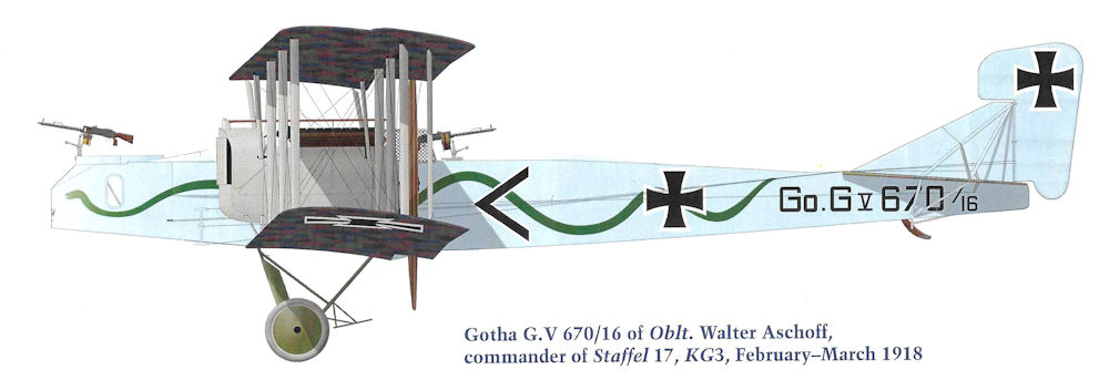
Gotha G.V 670/16 of Oblt. Walter Aschoff, commander of Staffel 17, KG3, February-March 1918
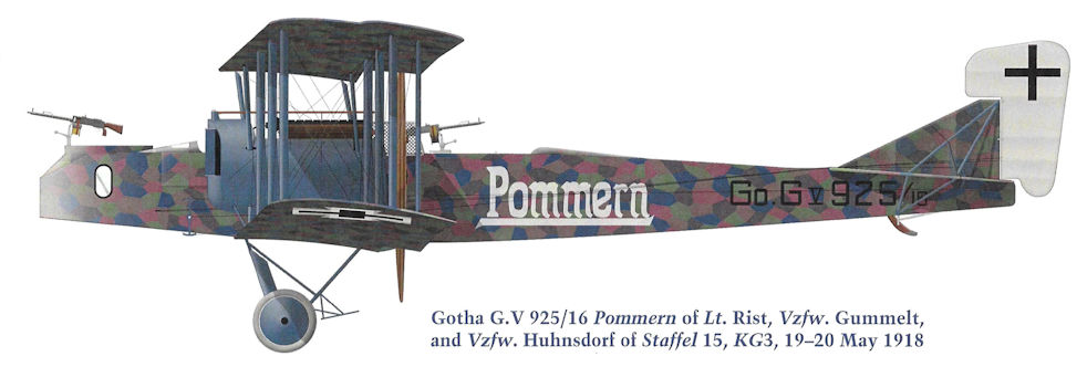
Gotha G.V 925/16 Pommern of Lt. Rist, Vzfw. Gummelt, and Vzfw. Huhnsdorf of Staffel 15, KG3, 19-20 May 1918
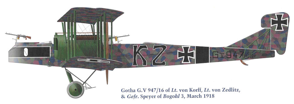
Gotha G.V 947/16 of Lt. von Korff, Lt. von Zedlitz, & Gefr. Speyer of Bogohl 3, March 1918
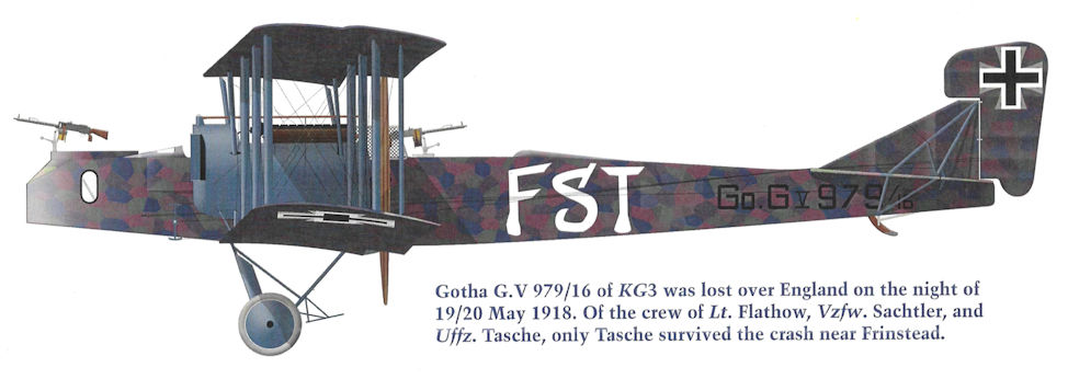
Gotha G.V 979/16 of KG3 was lost over England on the night of 19/20 May 1918. Of the crew of Lt. Flathow, Vzfw. Sachtler, and Uffz. Tasche, only Tasche survived the crash near Frinstead.
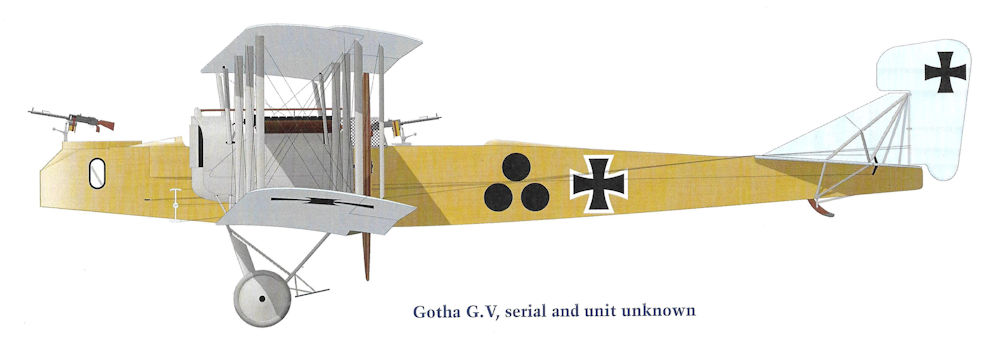
Gotha G.V, serial and unit unknown
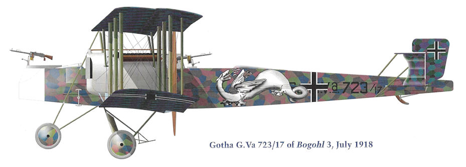
Gotha G.Va 723/17 of Bogohl 3, July 1918
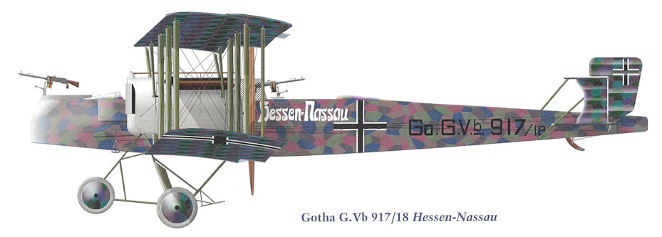
Gotha G.Vb 917/18 Hessen-Nassau
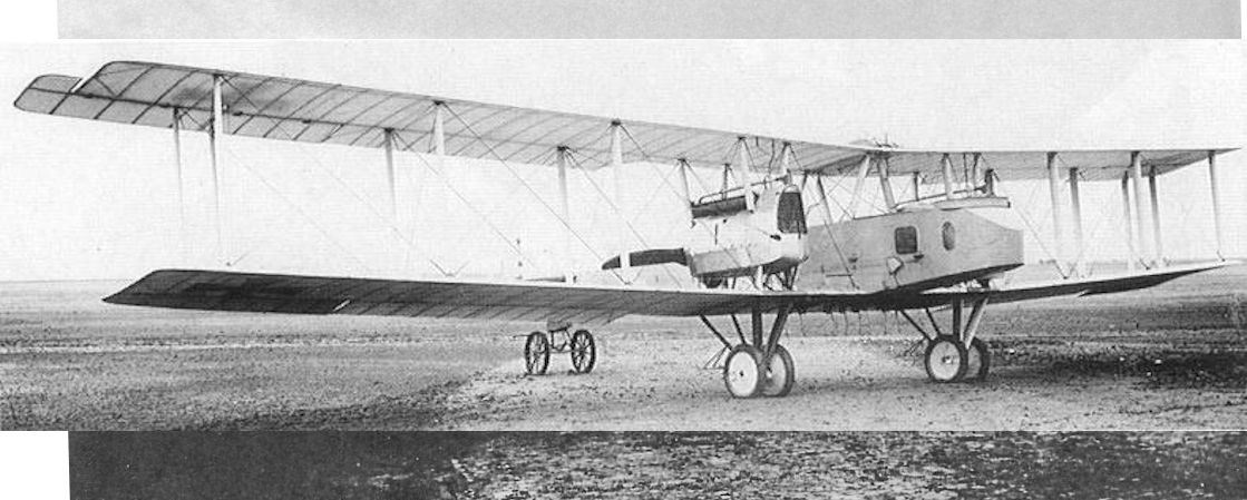
This Gotha G.V fitted with a simplified undercarriage is either the prototype or an early production model.
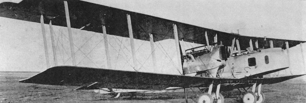
Front quarter view of an early Gotha G.V with faired struts supporting the engine nacelle.
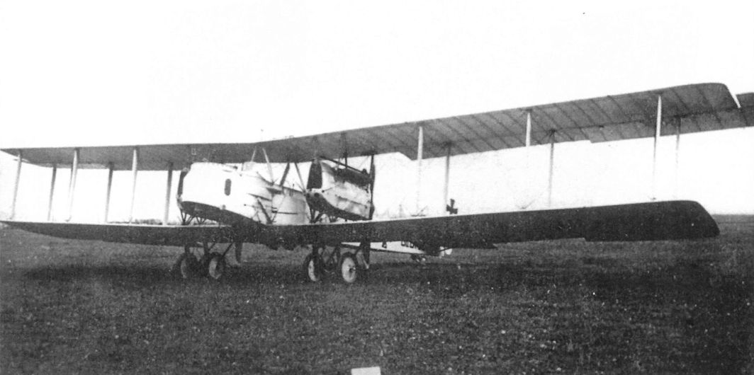
Other than the change in location of the fuel tanks that affected the engine nacelles, the Gotha G.V was otherwise like the G.IV in all important respects. Not only did it offer no performance improvement, the deteriorating quality of the materials available for construction meant the G.V was a heavier airplane, reducing performance.
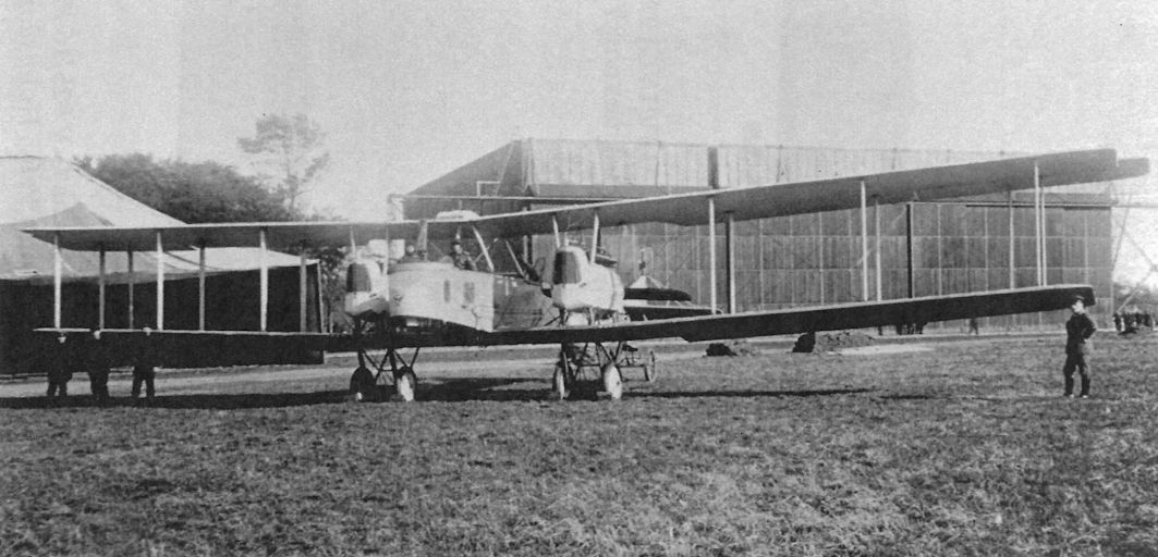
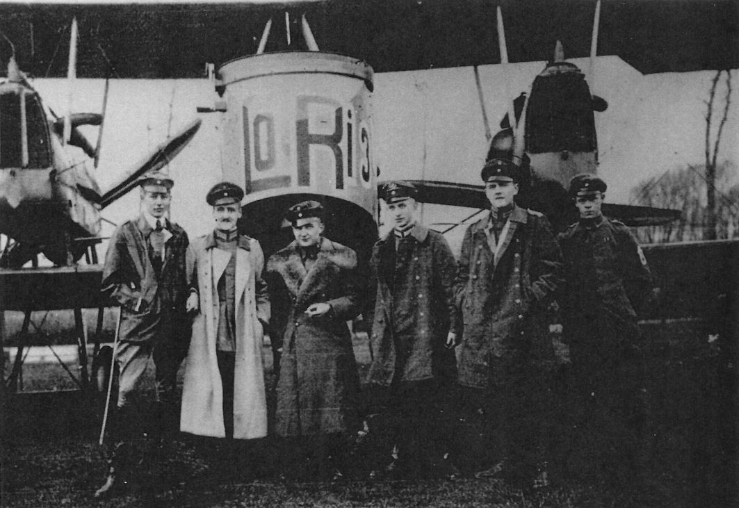
Gotha G.V LoRi 3 of Kasta 16, Bogohl 3, and crew.
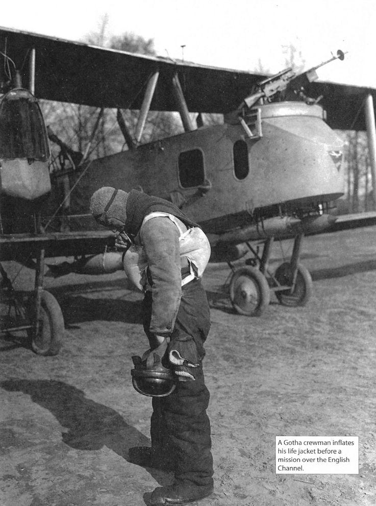
A Gotha crewman inflates his life jacket before a mission over the English Channel.
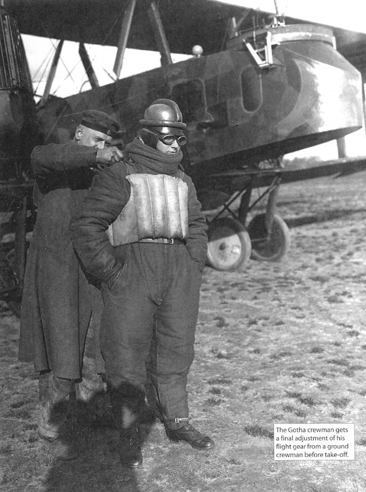
The Gotha crewman gets a final adjustments of his flight gear from a ground crewman before take-off.
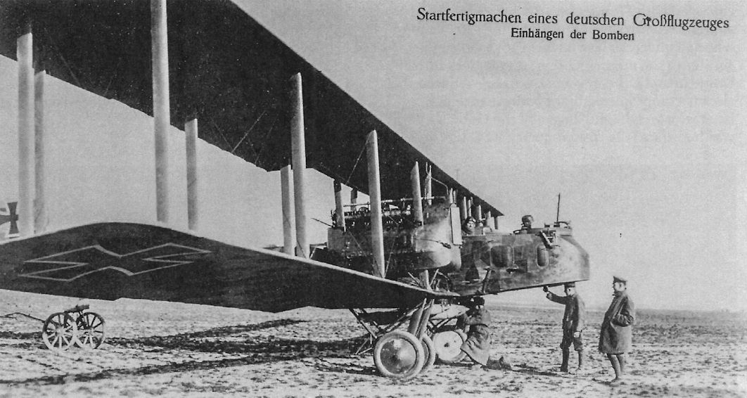
The distinguishing feature of the Gotha G.V was its new engine nacelles suspended between the wings. The fuel tanks were moved from the nacelles, their location in the G.IV, to the fuselage to reduce the danger of fire in a crash.
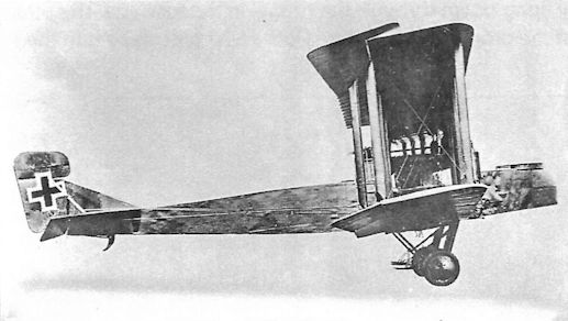
Gotha G.V in night camouflage.
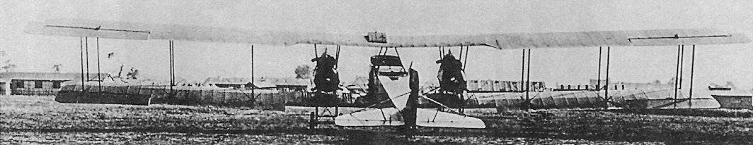
Rear view of the Gotha G.V; this aircraft has only one over-wing gravity fuel tank.
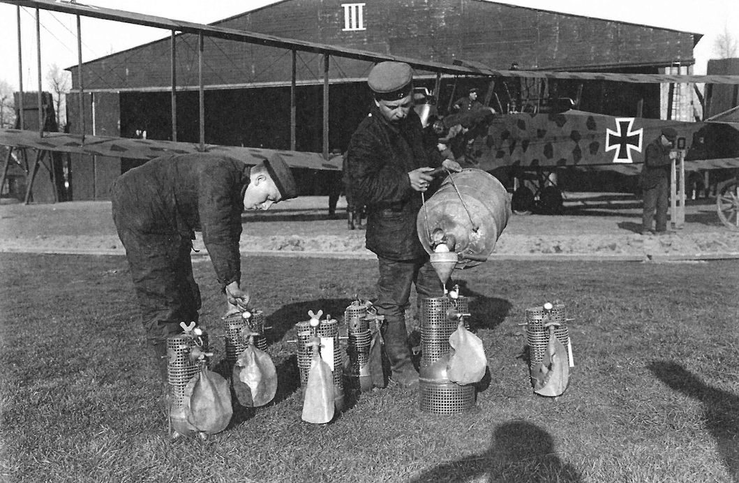
Mechanics of Kagohl III filling the containers of the Ahrendt and Heylandt breathing equipment with liquid oxygen. This was done shortly before take-off and the containers were sealed. Although the speed of vapourization varied, the pressure in the containers increased with the passage of time and a safety valve was necessary, but this had the effect of reducing the amount of oxygen available with increase of altitude. Later a barometric valve was fitted to similar equipment made by Fluessige Case (Liquid Gas) of Kiel and this automatically regulated the oxygen supply for altitude, and was more economical in use.
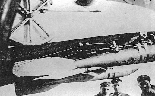
Closeup of bombs hung under the extreme nose of a Gotha to provide a proper center of gravity. The Gothas were stable until the bombs were dropped, but pitch stability deteriorated significantly after that!
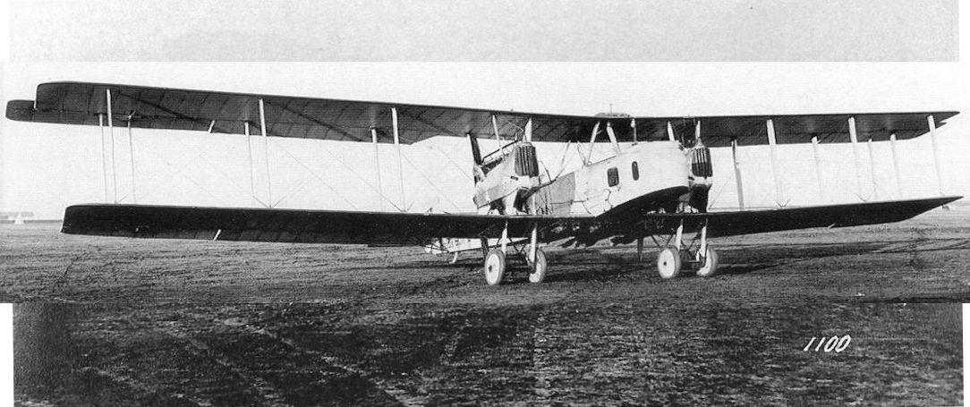
Gotha G.V 904/16 at the factory before night camouflage and the Stossfahrgestell were applied. The fairings on the engine nacelle struts were later removed. Seven 50-kg PuW bombs are under the center section.
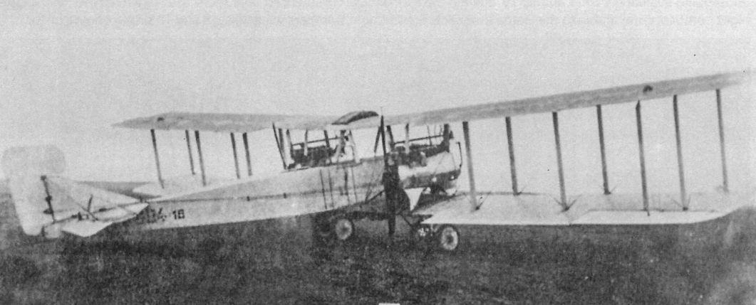
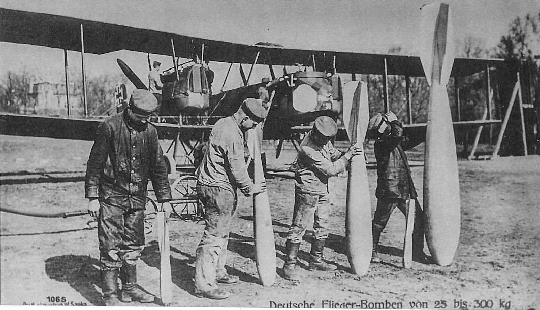
Mechanics of Kasta 14, Kagohl III, illustrate the range of bombs that Gotha bombers could carry with Gotha G.V 901/16 in the background. From left to right, the bombs are 12.5 kg, 50 kg, 100 kg, and 300 kg PuW bombs. The smaller sizes were in use from mid-1916, but the 100kg and 300kg P.u.W. bombs did not appear until over twelve months later, the first examples being dropped on St Omer by Kagohl I on 23 August 1917. Reproduced as a Sanke card, this was a popular propaganda photograph.
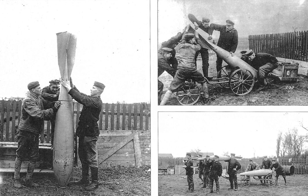
Groundcrew handling bombs to load on a Gotha. They are doing most of the work manually, with a primitive cart their only mechanical aid. These scenes could have been taken at any German base supporting twin-engine bombers in 1917 or 1918, regardless of the bomber's type.
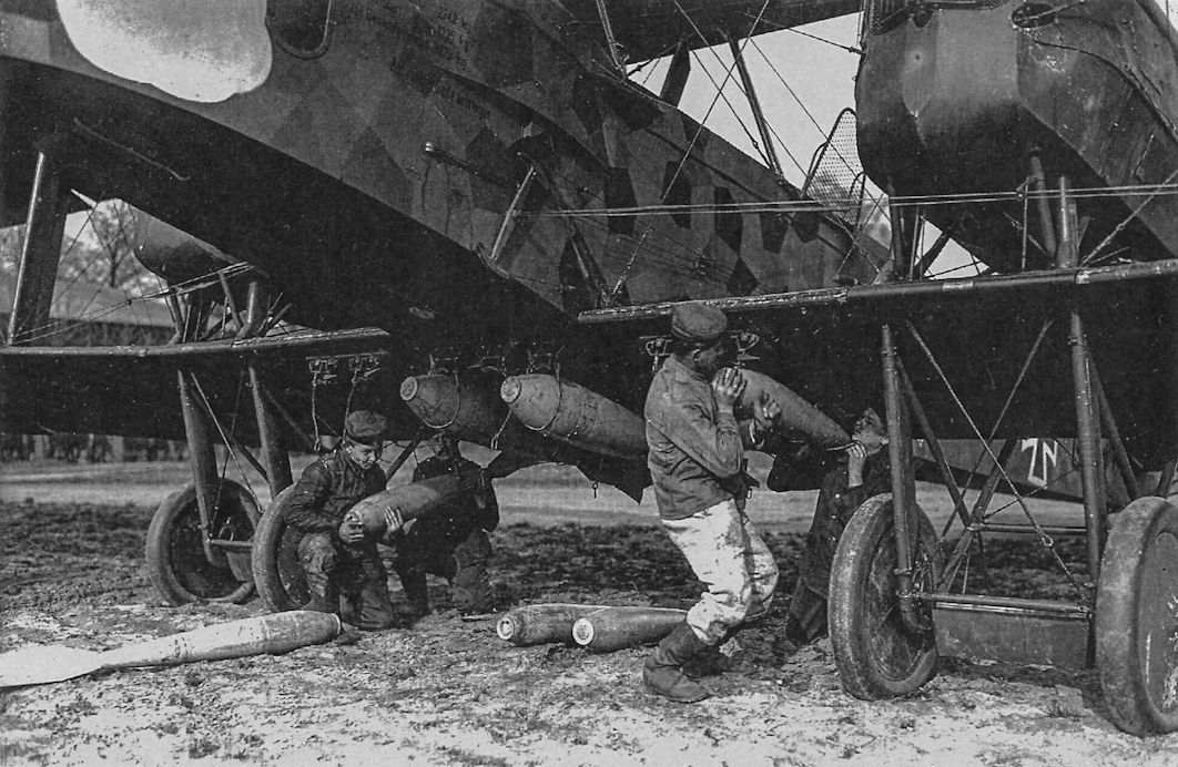
Ground crewmen load bombs by hand onto Gotha G.V 901/16. The engine nacelles on the G.V were raised above the wing on struts, which distinguishes the G.V from the earlier G.IV.
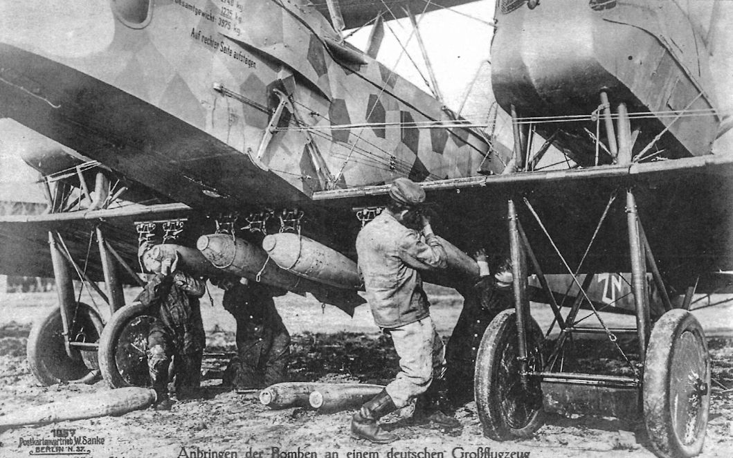
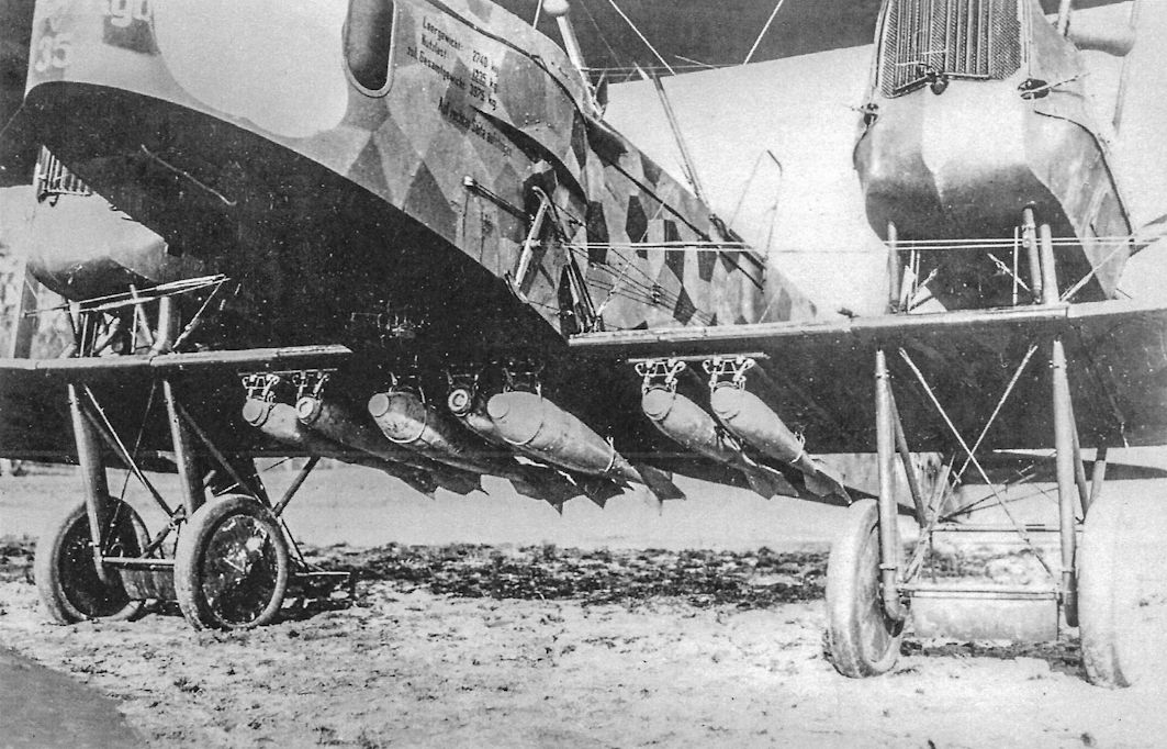
Gotha G.V 901/16 fully loaded with bombs; five 50-kg and two 100-kg PuW bombs are on the racks.
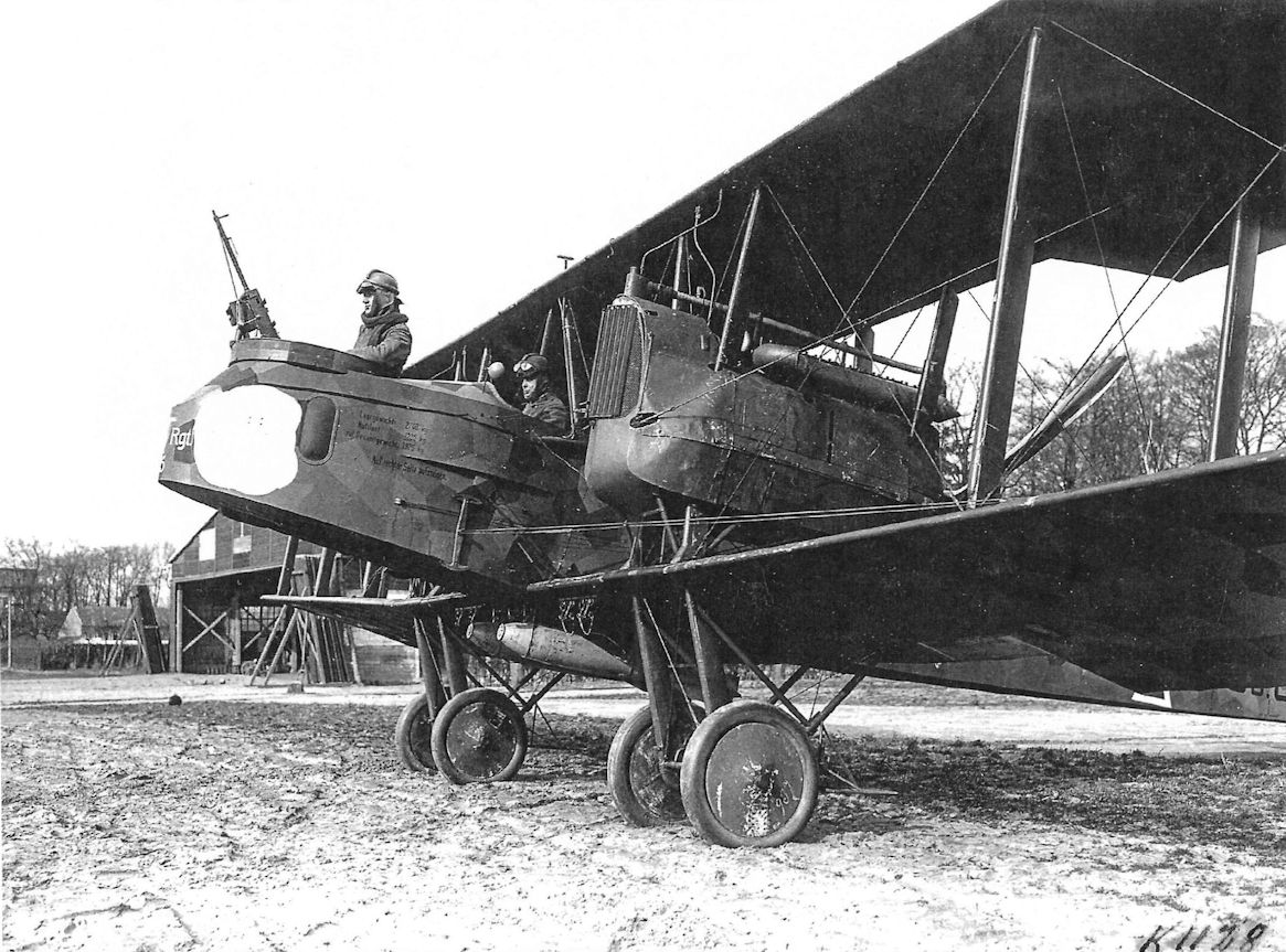
An impressive view of Gotha G.V 901/16 loaded and ready to start engines for its mission. The dark night camouflage shows the aircraft was normally used for night bombing, so the actual mission will not be flown until after dark. The Gothas ran most of their control wires outside the airframe, creating additional drag.
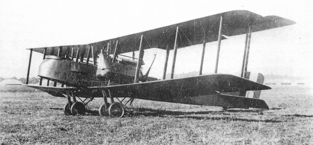
View of a night-camouflaged Gotha G.V in French hands with tri-color on the rudder undergoing evaluation. Until August 1918 when the Farman F.50 commenced operations the French had no twin-engine night bombers comparable to the Gotha in service; French night bombers were Voisin 8 and 10 single-engine pushers.
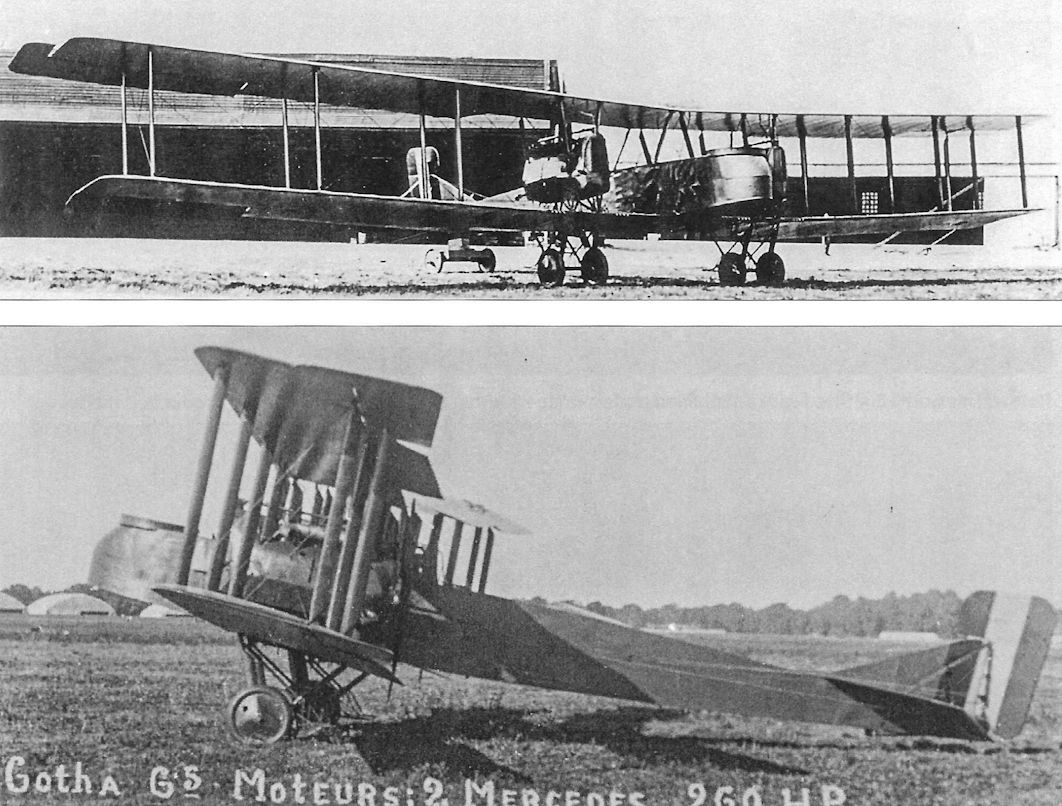
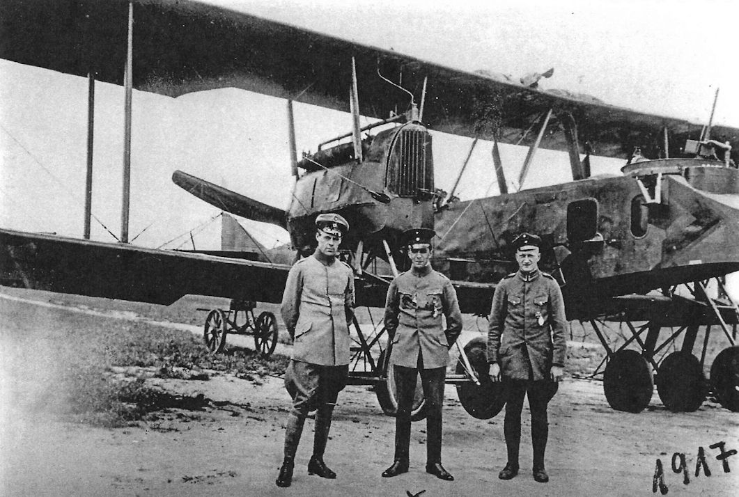
Some Gotha G.V bombers were fitted with an eight-wheel Stossfahrgestell undercarriage to prevent nose-overs.
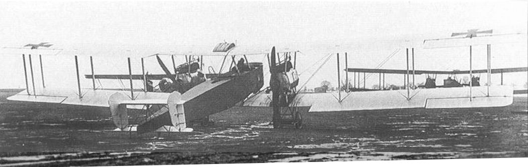
To improve controllability with one engine out, the Gotha G.Va with 'box' tail was developed. Above is the G.Va prototype fitted with an early version of the box tail.
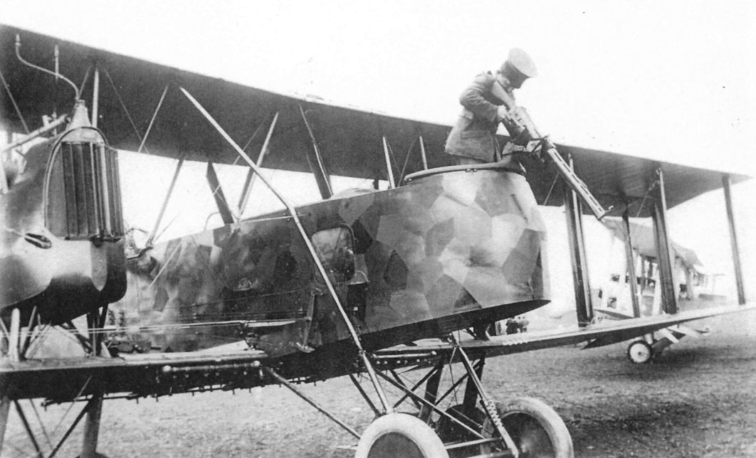
The nose undercarriage indicates this is likely a Gotha G.Va. These well-known photos show a gunner demonstrating the field of fire of the front and rear gunner's positions in a night-camouflaged bomber. A rare Gotha G.VI prototype is in the background.
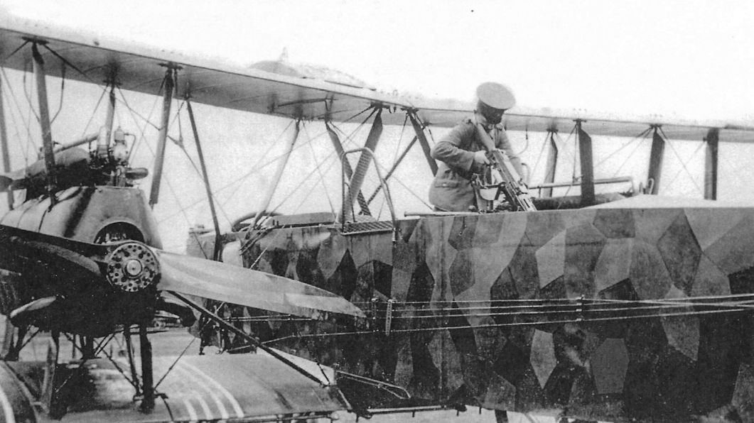
The gunner demonstrates how to protect against an attack from below by firing down through the tunnel in the fuselage. The screens on the sides of the rear gunner's cockpit keep his hands out of the propeller arcs.
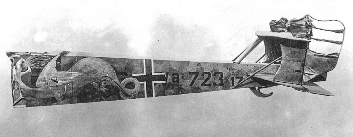
The tail of Gotha G.Va 723/17 brought down in France on 5 July 1918 wears a dramatic winged dragon personal marking. This aircraft is the one in the upper right of the photograph at the top of this page.
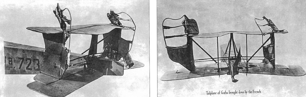
Two more views of the tail of Gotha G.Va 723/17 brought down in France on 5 July 1918.
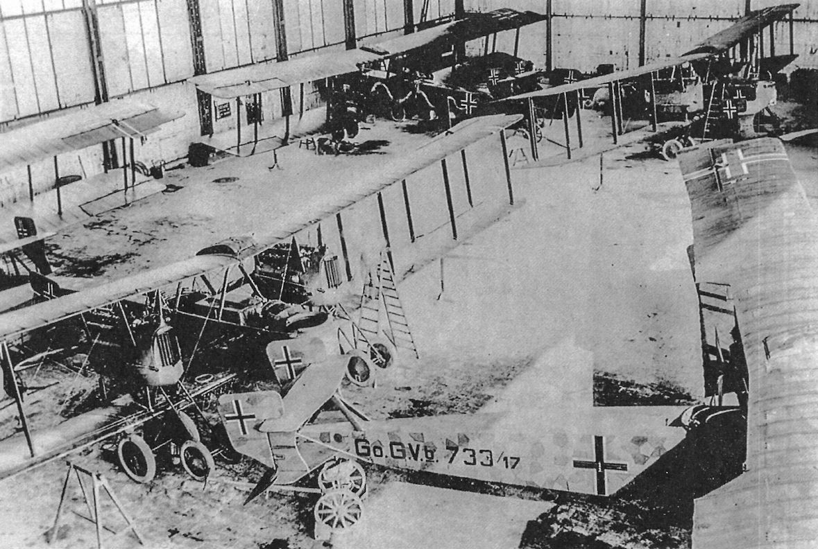
Gotha G.Va and G.Vb bombers stored in a hangar. The two G.Vb bombers in the foreground are not fitted with the Flettner servo-assist on the ailerons, normally a feature of the G.Vb.
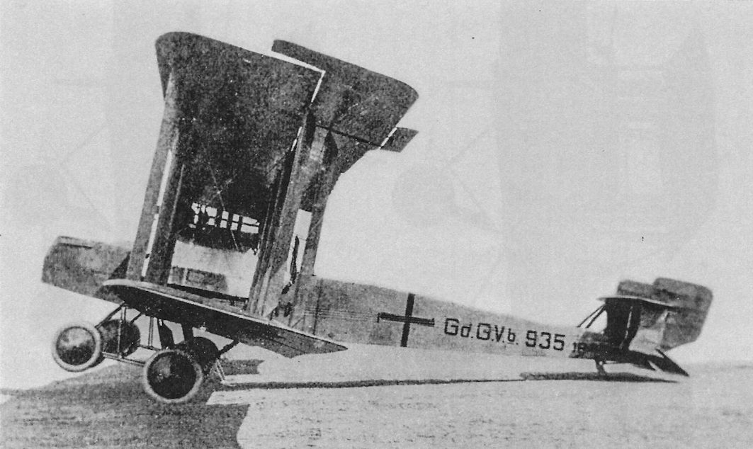
Gotha G Vb. Note servo tabs on ailerons.
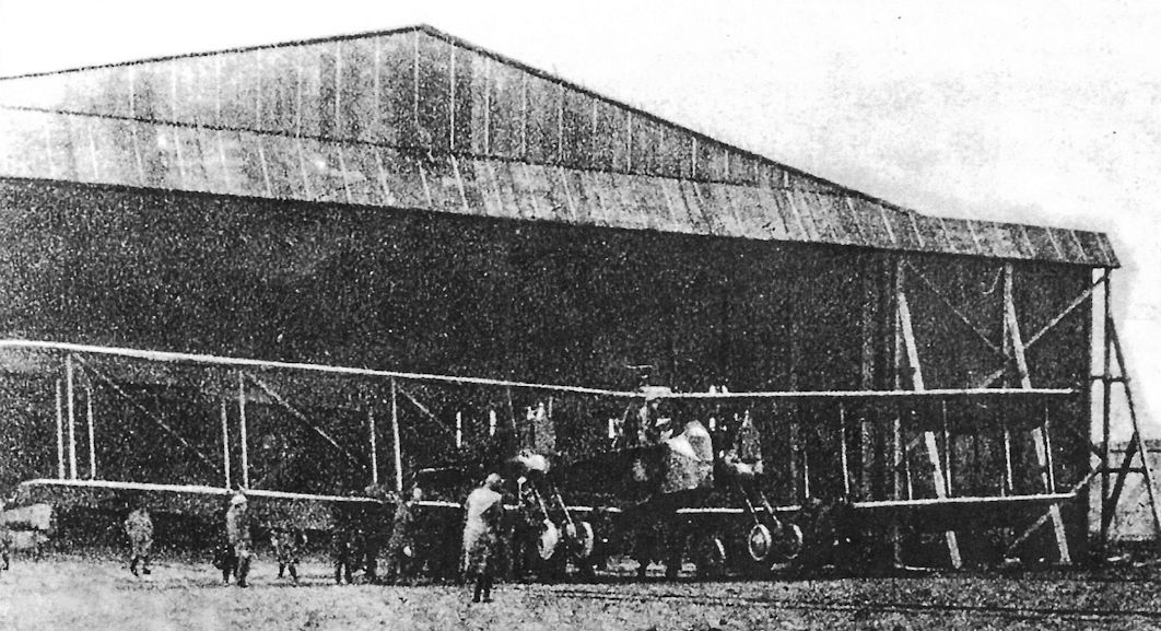
Desperate to solve the landing accident dilemma that caused 76% of all Gotha bomber losses, the engineering team again modified the landing gear to create the Gotha G.Vb. The Gotha G.Vb reverted to an eight-wheel landing gear reminiscent of that fitted to the original G.II prototype. The additional forward-mounted wheels essentially eliminated the problem of nose-overs on landing, but at the expense of more weight and drag that reduced speed, range, and ceiling. This was a compromise the Gotha G.V could ill afford; it was already heavier than the G.IV due to inferior materials and more required equipment, and was now in an irreversible downward performance spiral.
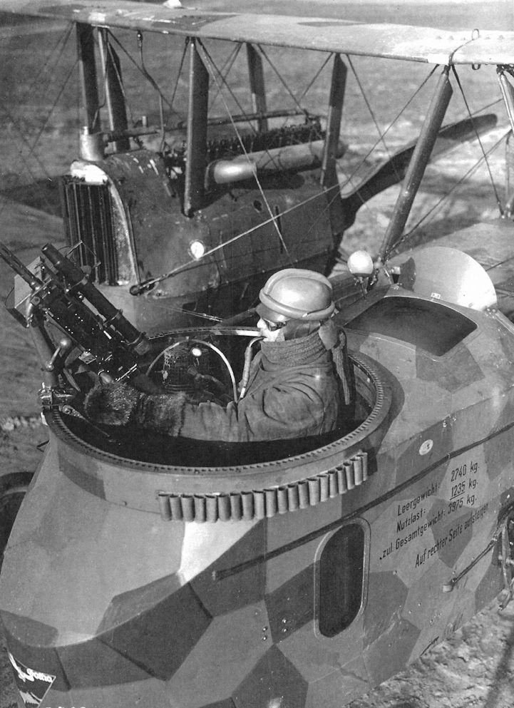
A bombardier/gunner of a Gotha G.V bomber demonstrating the German oxygen system for aviators. The "pipe stem" mouthpiece was primitive and somewhat difficult to use.
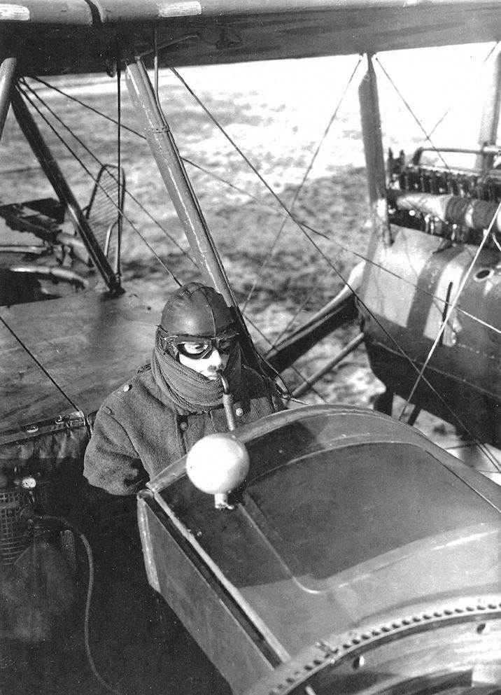
A bombardier/gunner of a Gotha G.V bomber demonstrating the German oxygen system for aviators. The "pipe stem" mouthpiece was primitive and somewhat difficult to use.
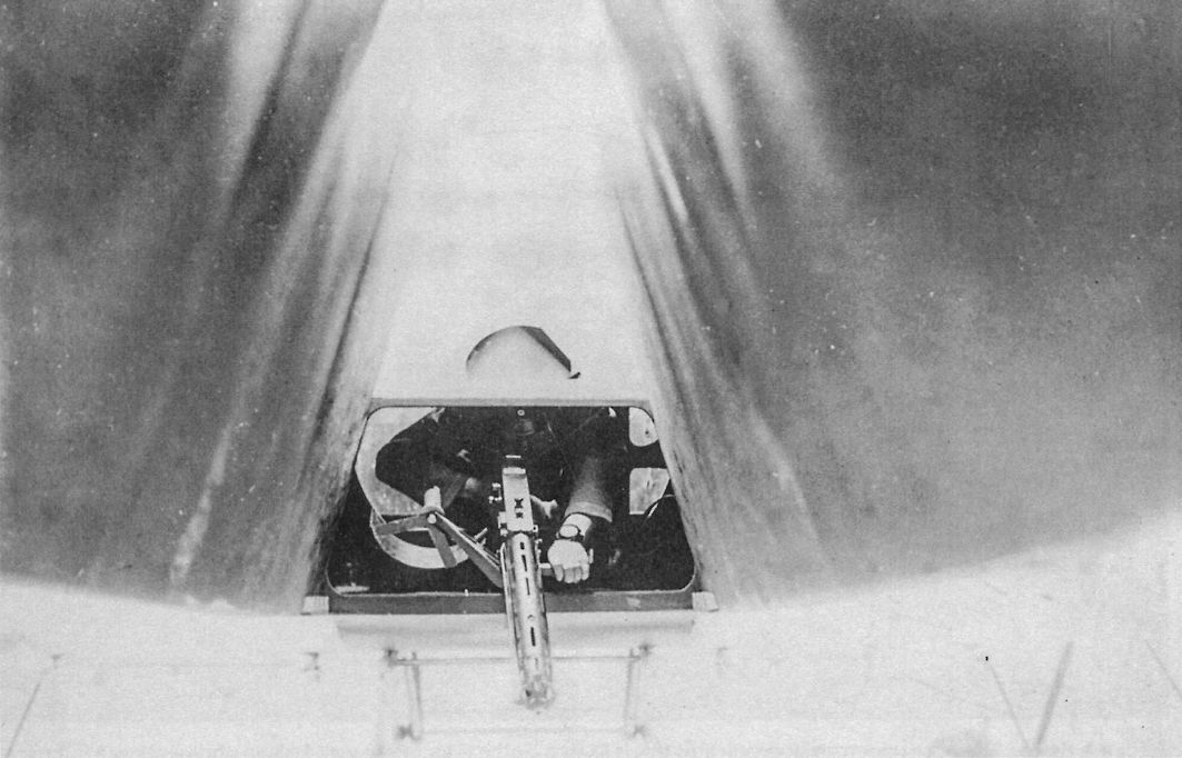
The 'Gotha Tunnel' underneath the fuselage of a Gotha G.Va (notice the front undercarriage struts) as seen from the rear and being demonstrated by a gunner. The tunnel was introduced on the G.IV and carried forward into the G.V series; it enabled the rear gunner to protect the bomber against attacks from behind and below. A third machine gun could be mounted as shown, or the rear gunner's standard gun could fire downward through the slot in the rear fuselage.
Gotha G.VI
Chief Engineer Burkhardt had been thinking about how to reduce drag to improve speed, and thought that eliminating one of the engine nacelles would accomplish that despite the resulting asymmetric configuration. Burkhardt decided the most efficient way to design the aircraft was a tractor engine in the fuselage and a pusher engine in a nacelle to starboard which also had an observer/ gunner's cockpit in the front that extended forward of the tractor propeller for greatest field of fire.
To compensate for asymmetric thrust and drag, the starboard nacelle was placed closer to the centerline of the wing than the fuselage. The thrust lines of the engines were close together, reducing asymmetric thrust in case of an engine failure. Burkhard obtained German Patent number 300 676 for his innovative design on September 22, 1915. Idflieg approved further study on 7 September 1915 but held off construction until design studies were completed. On 26 June 1916 Gotha management approved construction of the G.VI, which was underway the next month, but Idflieg did not sign a contract until 5 July 1917, when three G.VI bombers, serial numbers G.370-372/17, were ordered.
The first Gotha G.VI was flight-tested in the fall of 1917 and was badly damaged in a landing crash in November. The two-bay wing was similar to that used in the Gotha G.II and the fuselage was derived from the G.IV. The second Gotha G.VI had three-bay wings and large radiators. Flight tests of this aircraft began in January 1918 and continued through March. However, flight performance was mediocre and there were many radiator problems as well. In April work on the G.VI was abandoned to allow Gotha engineers to focus on the Gotha GL.VII and GL.VIII prototypes.
The Gotha G.VI is thought to be the first asymmetric aircraft design to fly, proving the asymmetric conception was practical. Although Burkhardt claimed that G.VI performance exceeded its conventional predecessors and that it flew very well, his description of its flying qualities may be optimistic given its crash-landing.
Gotha G.VI Specifications
Engines: 2 x 260 hp Mercedes D.IVa
Wing: Span Upper 23.70 m
Area 89.5 m2
General: Length 12.36 m
Gotha G-Type Bomber Production Summary
Order Date Type Qty Serials Notes
July 5, 1917 G.VI 3 370-372/17 Only first two built; third cancelled.
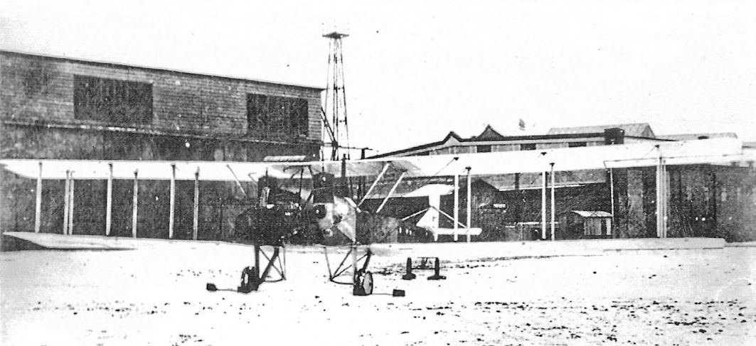
The second Gotha G.VI prototype had larger, three-bay wings. Flight tests began in January 1918 and continued through March. In April work on the G.VI was abandoned due to mediocre flight performance. Problems with the radiators were a contributing factor. Furthermore, terminating G.VI development enabled Gotha engineers to focus on development of the more promising GL.VII and GL.VIII bombers.
The nose undercarriage indicates this is likely a Gotha G.Va. These well-known photos show a gunner demonstrating the field of fire of the front and rear gunner's positions in a night-camouflaged bomber. A rare Gotha G.VI prototype is in the background.
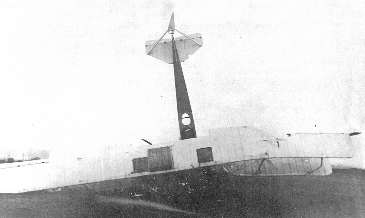
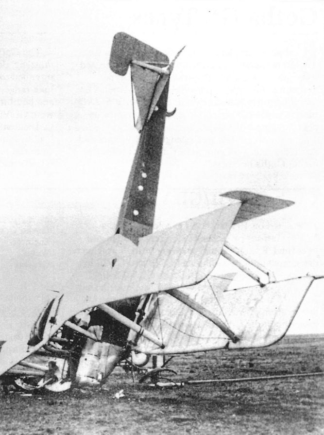
The first Gotha G.VI prototype had two-bay wings. It is shown here after a landing accident in November 1917. The fuselage and tail were derived from the Gotha G.IV and the wings were similar to those of the Gotha G.II.
Gotha WD11
Ordered on 9 March 1916 and designed by Rosner as a torpedo bomber, the WD11 resembled the earlier WD7 but was a much larger aircraft. The WD11 was powered by two 160 hp Mercedes D.III engines and was equipped to carry one Whitehead G/125 torpedo under the fuselage. All WD11 torpedo bombers were flown by a two-man crew, and the observer in the front cockpit had a flexible Parabellum LMG 14 machine gun.
After flight tests at the SVK, the prototype WD11, Marine Number 679, was used to train aircrews at the Sonderkommando Flensburg. Three more production batches followed the prototype; the first was a batch of five, Marine Numbers 991-995, followed by a batch of three, Marine Numbers 1211-1213, followed by a final batch of eight, Marine Numbers 1372-1379, for a total of 17 airplanes.
WD11 torpedo bombers were operational in the Baltic and North Sea, but they were reported to be underpowered - the Gotha G-types of similar size and weight had 260 hp Mercedes D.IVa engines - and too lightly built for the severe demands put on them.
Torpedo attacks proved very difficult and required ideal sea and weather conditions. A drag rod under the fuselage was lowered prior to the attack; it was a device to measure height over the water, and the pilot had to maintain an altitude of 5 meters for torpedo release. Optical height measuring devices were also tested. Because of the difficulty of torpedo attacks coupled with the vulnerability of the aircraft to ship-board anti-aircraft guns, torpedo attacks were soon abandoned and the WD11s were modified to carry ten 50-kg bombs or a single Teka anti-shipping mine.
Gotha WD11 Specifications
Engines: 2 x 160 hp Mercedes D.III
Wing: Span Upper 22.50 m
Span Lower 21.00 m
Area 104 m2
General: Length 13.45 m
Height 4.75 m
Empty Weight 2146 kg
Loaded Weight 3583 kg
Maximum Speed: 120 km/h
Climb: 1000m 12 min
1500m 20 min
Service Ceiling: 3200 m
Range: 500 km
Gotha Seaplane Production Summary
Type Ordered Marine Numbers Remarks
WD11 17 679, 991-995, 1211-1213, 1372-1379 Torpedo bomber, flew operational sorties
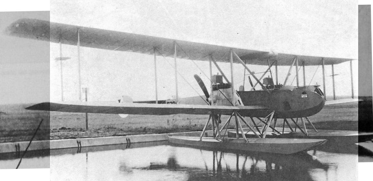
WD.11 в испытательном бассейне
The prototype WD11, Marine Number 679, afloat in the Gotha factory pond. Unlike the earlier WD7, the WD11 had its 160 hp Mercedes engines mounted as pushers. The box radiators were mounted directly above the engines.
The prototype WD11, Marine Number 679, afloat in the Gotha factory pond. Unlike the earlier WD7, the WD11 had its 160 hp Mercedes engines mounted as pushers. The box radiators were mounted directly above the engines.
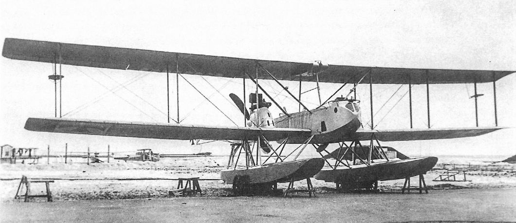
Front view of a WD11 emphasizing its distinctive Gotha appearance. A form of aileron servo is mounted on the outer rear interplane struts.
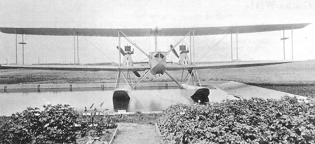
Front view of the prototype WD11, Marine Number 679, afloat in the Gotha factory pond.
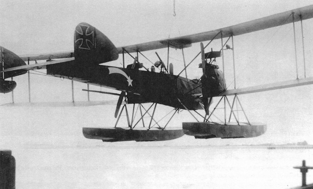
WD11 being maneuvered by crane. This WD11 has the hexagonal naval camouflage on upper and side surfaces; the standard naval camouflage pattern specified blue-gray sides without hexagons. Unfortunately, the photograph is too dark to read the Marine Number, but Marine #1376 (last digit unclear, could be #1375) with shooting-star marking is second from right in bottom photo, page 62. The variety of markings on these Lindau-based WD11 s indicates the shooting-star is a personal marking.
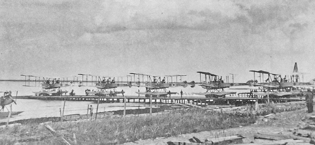
WD11s from the last production batch at Windau.
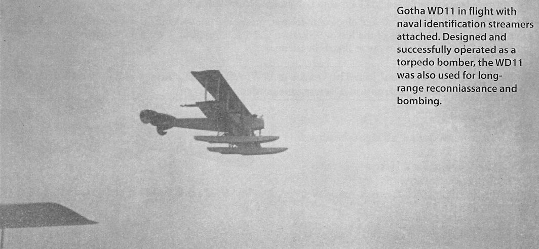
Gotha WD11 in flight with naval identification streamers attached. Designed and successfully operated as a torpedo bomber, the WD11 was also used for long-range reconniassance and bombing.

Gotha WD11 squadron flight at Flensburg, March 1917. (KMF)
Two Gotha WD11 torpedo bombers being escorted by an Albatros W4 fighter.
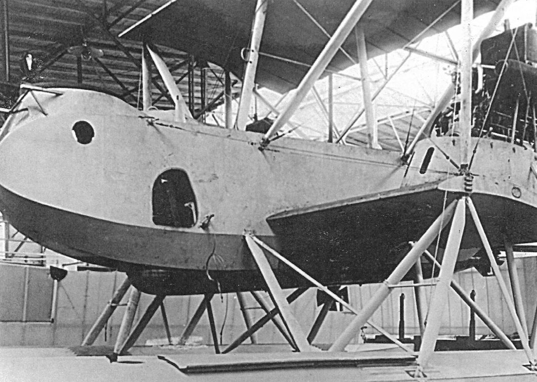
Gotha WD11 Marine Number 991 of the first production batch showing the Whitehead G/125 torpedo (45 cm diameter and 753 kg weight) hung in the semi-enclosed fuselage cavity. The wings and cowlings remain to be installed. On 15 June, 1917, this aircraft, crewed by Lt. Lowe &Thomsen, torpedoed and sank the S.S. Kankakee in the Thames Estuary.
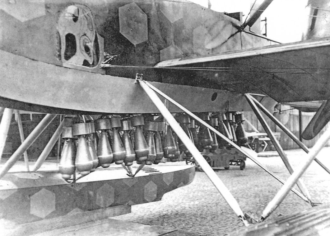
Previously identified as a WD14, this isa WD11 configured to carry bombs in place of a torpedo as shown by the pusher engine. The bombs were not carried internally but left to hang externally in this non-aerodynamic manner. The naval hexagonal camouflage was very distinctive on this WD11 and may indicate it had been recovered since being built.
Large calibre bombs were not used against ship targets; from the beginning the principle of dropping a stick of at least five bombs straddling a target was maintained. Experience with the bombsights then in use showed that this was the correct approach. Torpedo-carrying aircraft could carry eight 58kg bombs, and it was the fifth bomb of an eight-bomb stick that sunk the Russian destroyer Stroiny. A Gotha WD 14 bomb load of approximately 300kg is shown here, made up of 10kg bombs, a size commonly used on seaplanes. They are retained by a simple carrying strap across the tail of the bombs. no specially designed bomb cradles being required.
Large calibre bombs were not used against ship targets; from the beginning the principle of dropping a stick of at least five bombs straddling a target was maintained. Experience with the bombsights then in use showed that this was the correct approach. Torpedo-carrying aircraft could carry eight 58kg bombs, and it was the fifth bomb of an eight-bomb stick that sunk the Russian destroyer Stroiny. A Gotha WD 14 bomb load of approximately 300kg is shown here, made up of 10kg bombs, a size commonly used on seaplanes. They are retained by a simple carrying strap across the tail of the bombs. no specially designed bomb cradles being required.
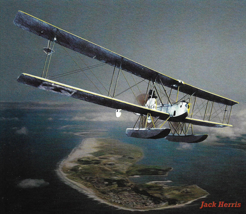
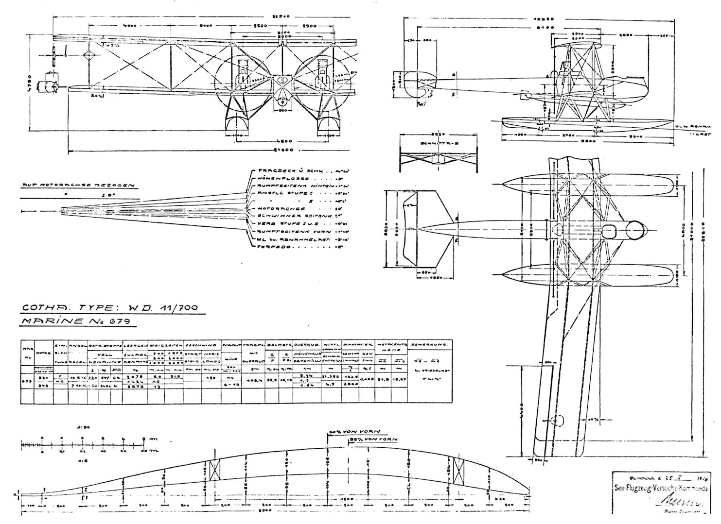
Gotha WD.11
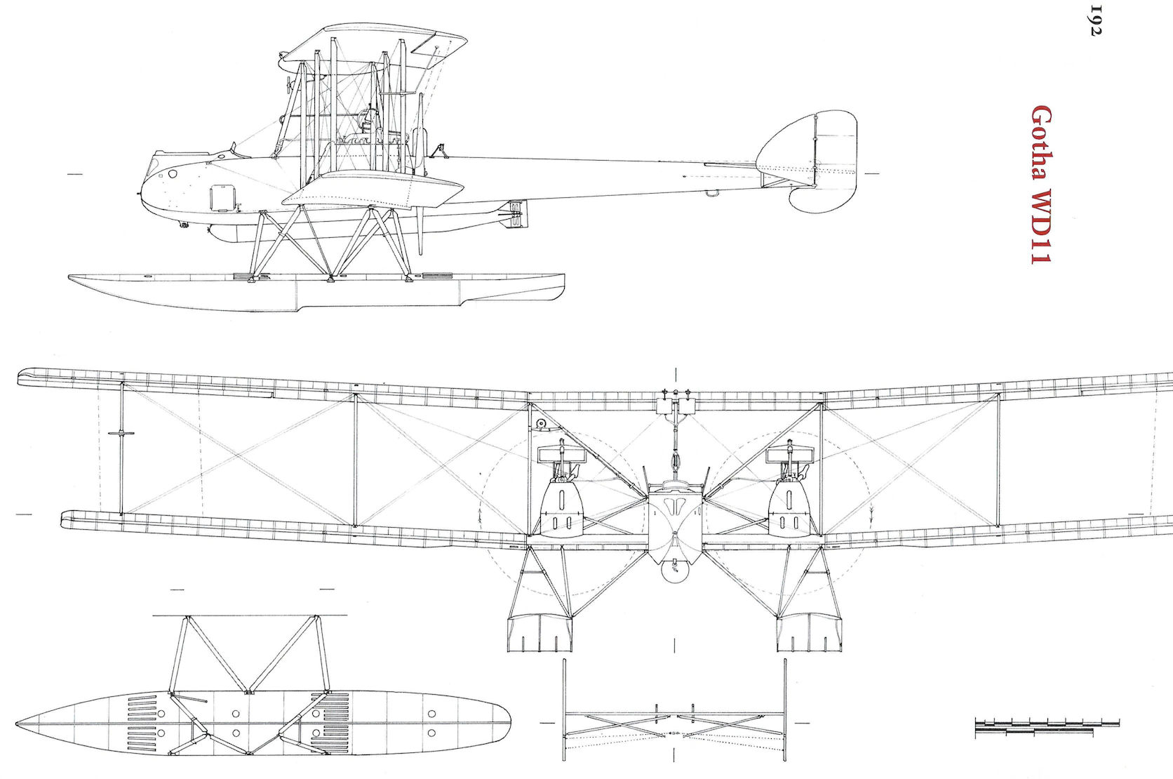
Gotha WD11
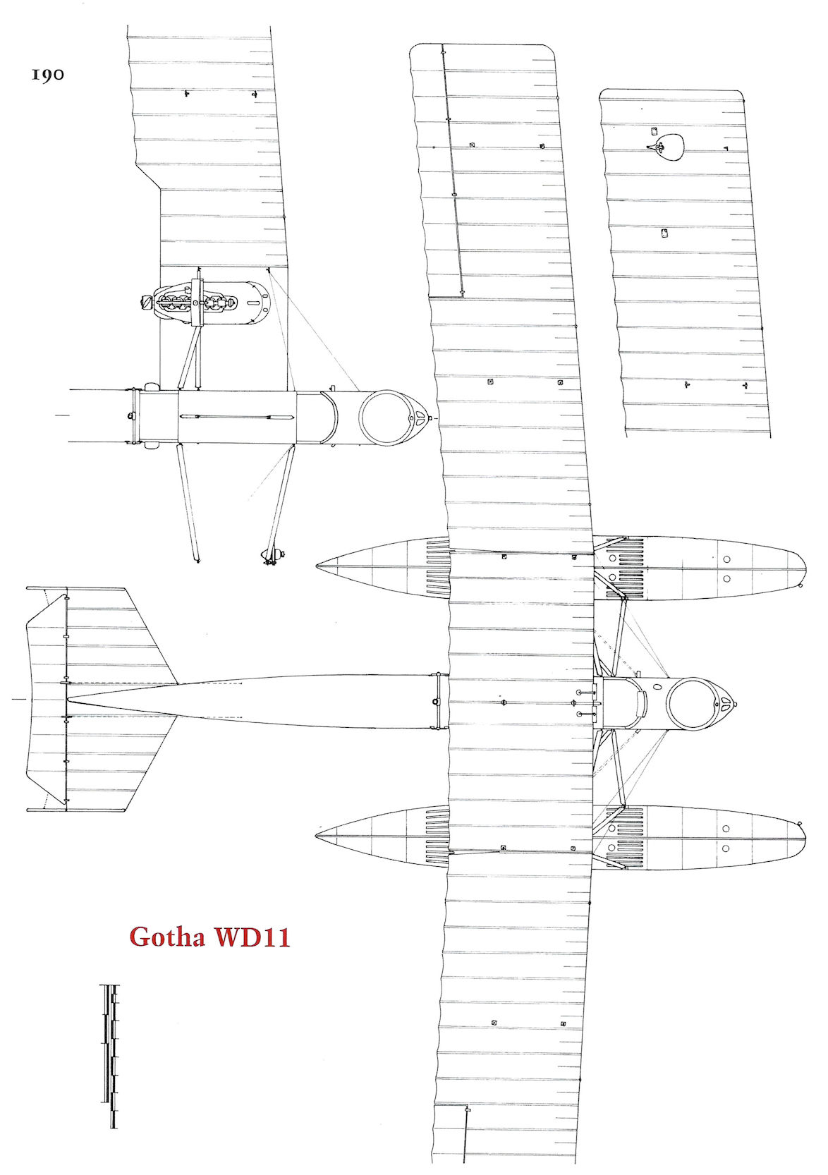
Gotha WD11
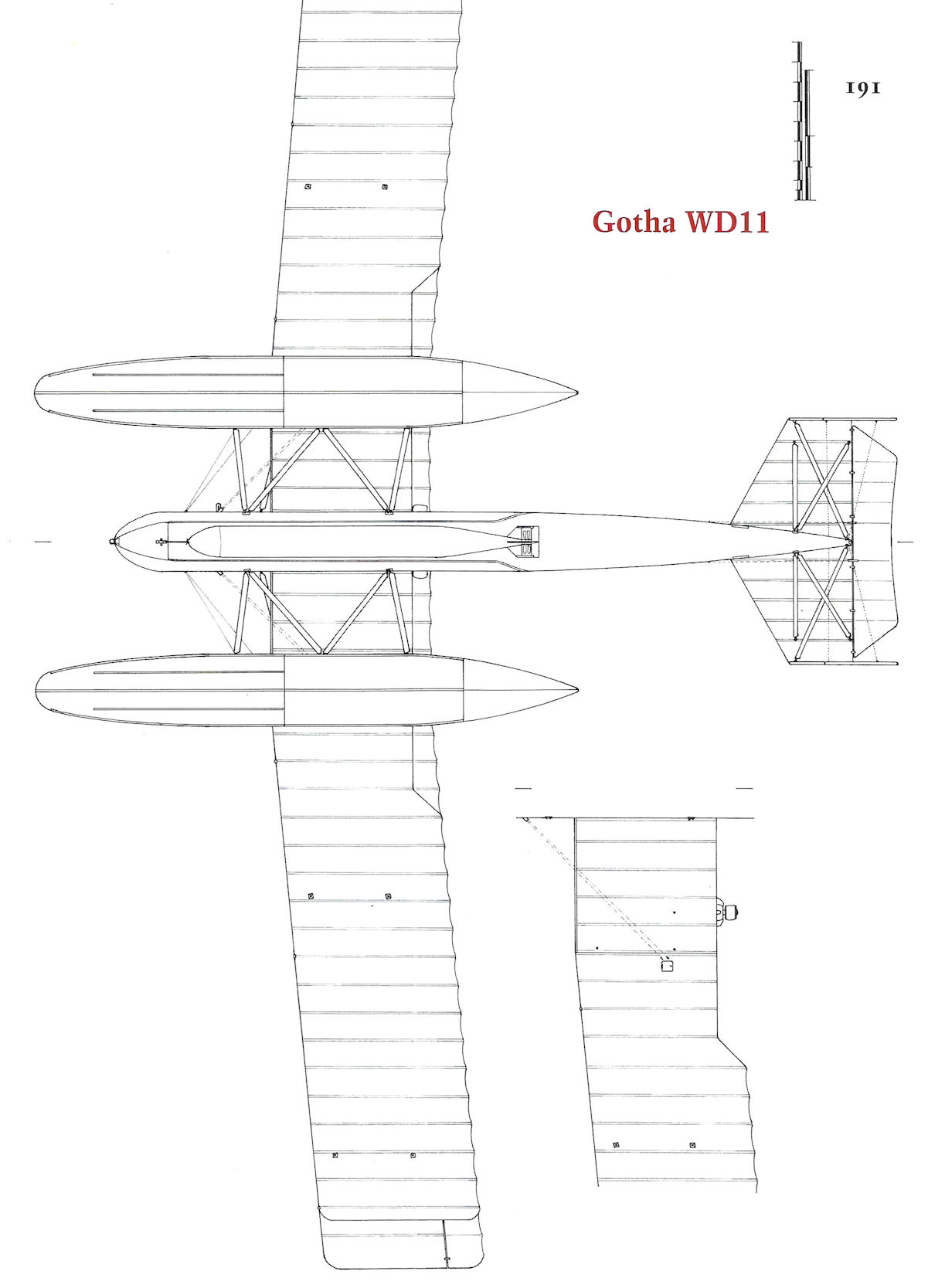
Gotha WD11
Gotha WD12
The Gotha WD12 was designed by Rosner for maximum speed. Powered by a 160 hp Mercedes D.III engine, the WD12 was proposed by Gotha on 14 April 1916, and the prototype, Marine Number 944, was delivered to the SVK on 24 February 1917. Designated WD12a after modifications made in May to gain acceptance, the seaplane was fitted with an electrical bomb release for bombing trials. The WD12 was recommended for production because of its good seakeeping qualities. The WD12a was assigned to the flight school at Holtenau in February 1918.
On 28 August 1917 nine WD12s were ordered by Turkey in the Gotha work number batch 2150-2166, even numbers. Six had the 160 hp Mercedes D.III engine like the prototype,- the other three had the 150 hp Benz Bz.III. The observer in the rear cockpit of these aircraft had a flexible Parabellum LMG 14 machine gun. These aircraft have been identified in some German Navy documents as WD9s, but the original Gotha factory photos are labeled WD12.
Gotha WD12 Specifications
Engine: 160 hp Mercedes D.III 150 hp Benz Bz.III
Wing: Span Upper 15.00 m
Span Lower 14.00 m
Area 54 m2
General: Length 10.00 m
Height 3.82 m
Empty Weight 1000 kg
Loaded Weight 1560 kg
Maximum Speed: 140 km/h
Climb: 1000m 7.5 min
3000m 41 min
Service Ceiling: 4200 m
Range: 775 km
Gotha WD13
The Gotha WD13 was designed by Rosner and Hartwig. Powered by a 150 hp Benz Bz.III engine, the WD13 was not used by the German Navy,- all six aircraft produced were to fill a Turkish order. These aircraft, Gotha works numbers 2186-2196, even numbers, were delivered between 21 December 1917 and 4 February 1918. The aircraft were accepted at the SVK and then shipped to Turkey. The observer in the rear cockpit of these aircraft had a flexible Parabellum LMG 14 machine gun.
Gotha WD13 Specifications
Engine: 150 hp Benz Bz.III
Wing: Span Upper 14.60 m
Area 49 m2
General: Length 10.07 m
Height 3.74 m
Empty Weight 1060 kg
Loaded Weight 1460 kg
Maximum Speed: 131.5 km/h
Climb: 1000m 9 min
Duration: 3 hours
Gotha WD15
Designed by Rosner and Klaube, two Gotha WD15s were ordered on 14 July 1916 as heavy, multi-purpose seaplanes powered by a 260 hp Mercedes D.IVa engine. Although it had an excellent speed and rate of climb, the WD15 had engine problems despite being powered by a well-proven production engine.
The WD15 prototype, Marine Number 842, was destroyed on 18 September 1917 when a float collapsed. The second WD15, Marine Number 843, was delivered the next day and incorporated improvements as a result of flight tests of the prototype, including having ailerons on all wings with a strut connecting the upper and lower ailerons. The second WD15 was accepted in January 1918 but the SVK disapproved series production.
Gotha WD15 Specifications
Engine: 260 hp Mercedes D.IVa
Wing: Span Upper 17.20 m
Span Lower 16.00 m
Area 64.5 m2
General: Length 11.15 m
Height 4.25 m
Empty Weight 1544 kg
Loaded Weight 2300 kg
Maximum Speed: 150 km/h
Climb: 1000m 8.5 min
3000m 42.5 min
Service Ceiling: 4200 m
Duration: 900 km
Gotha Seaplane Production Summary
Type Ordered Marine Numbers Remarks
WD12 10 944 9 went to Turkey, no Marine Numbers
WD13 6 na All 6 went to Turkey, no Marine Numbers
WD15 2 842-843 842 destroyed during testing
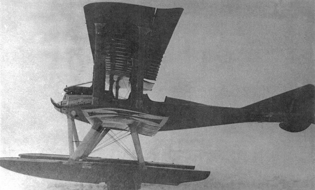
The prototype WD12 showing the observer's faired headrest, consistent with this aircraft being unarmed.
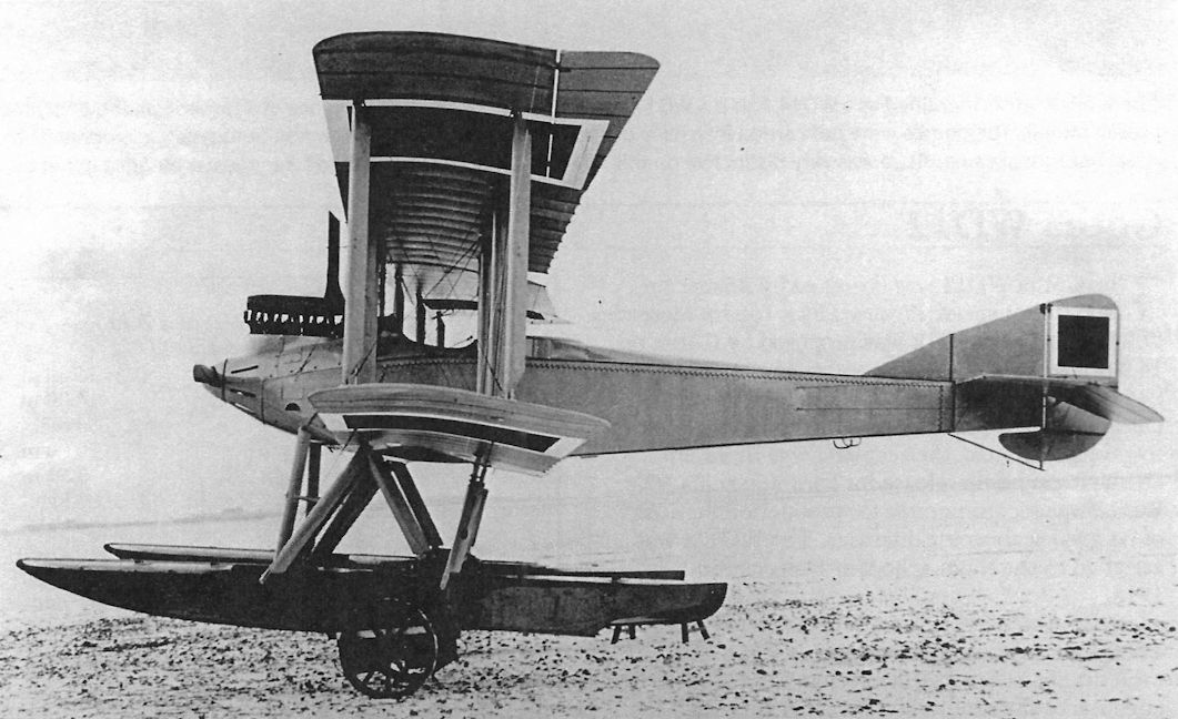
One of the Turkish WD12 seaplanes showing the aft gunner's cockpit with gun ring. This distinguishes the Turkish WD12s from the unarmed prototype used by the German Navy.
The Turkish Navy operated a number of Gotha WD12 seaplanes; its duration of over five hours made it useful for patrols over the Black Sea.
The Turkish Navy operated a number of Gotha WD12 seaplanes; its duration of over five hours made it useful for patrols over the Black Sea.
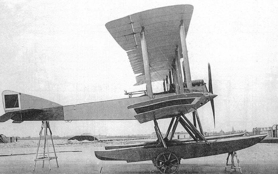
Side view of a WD13 in Turkish markings on a beaching dolly.The observer's gun ring is clearly visible. Unlike most preceding Gotha seaplanes, the rudder has no aerodynamic balance. The German Navy evaluated the WD13 but did not purchase any; all six WD13s built were purchased and operated by Turkey.
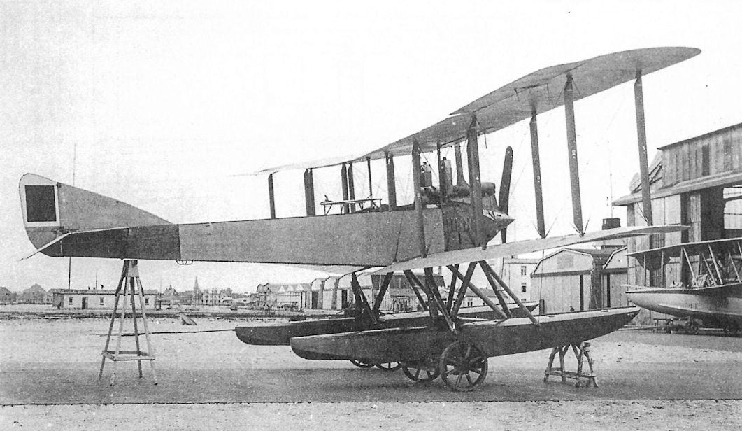
Little more than a cleaned up, 160hp Benz Bz IIIa-engined Gotha WD 9, their two seat WD 13 coastal patroller was bought by the navy in 1917 specifically for Turkish use. Built only in small numbers, the WD 13's top level speed was 87mph, the machine had a useful operational range of 466 miles. The observer's gun ring is clearly visible.
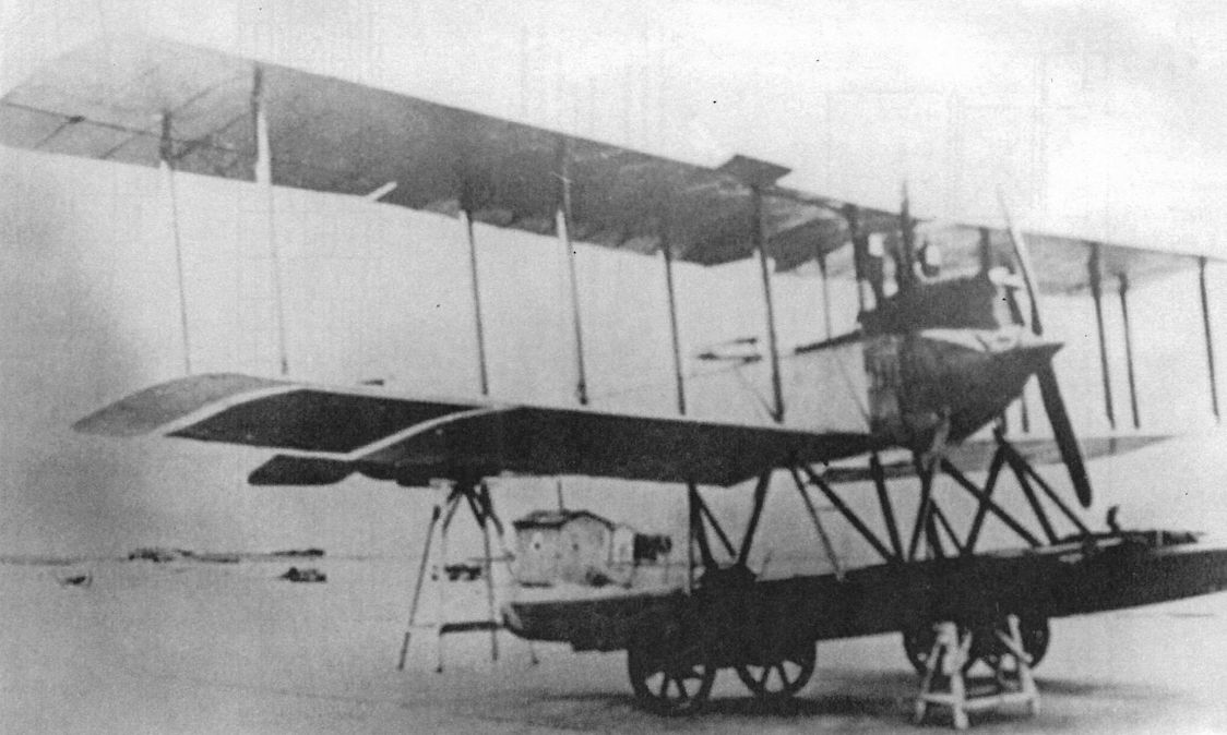
Gotha WD13 in Turkish markings. The German Navy evaluated the WD13 but did not purchase any; all WD13s were purchased and operated by Turkey.
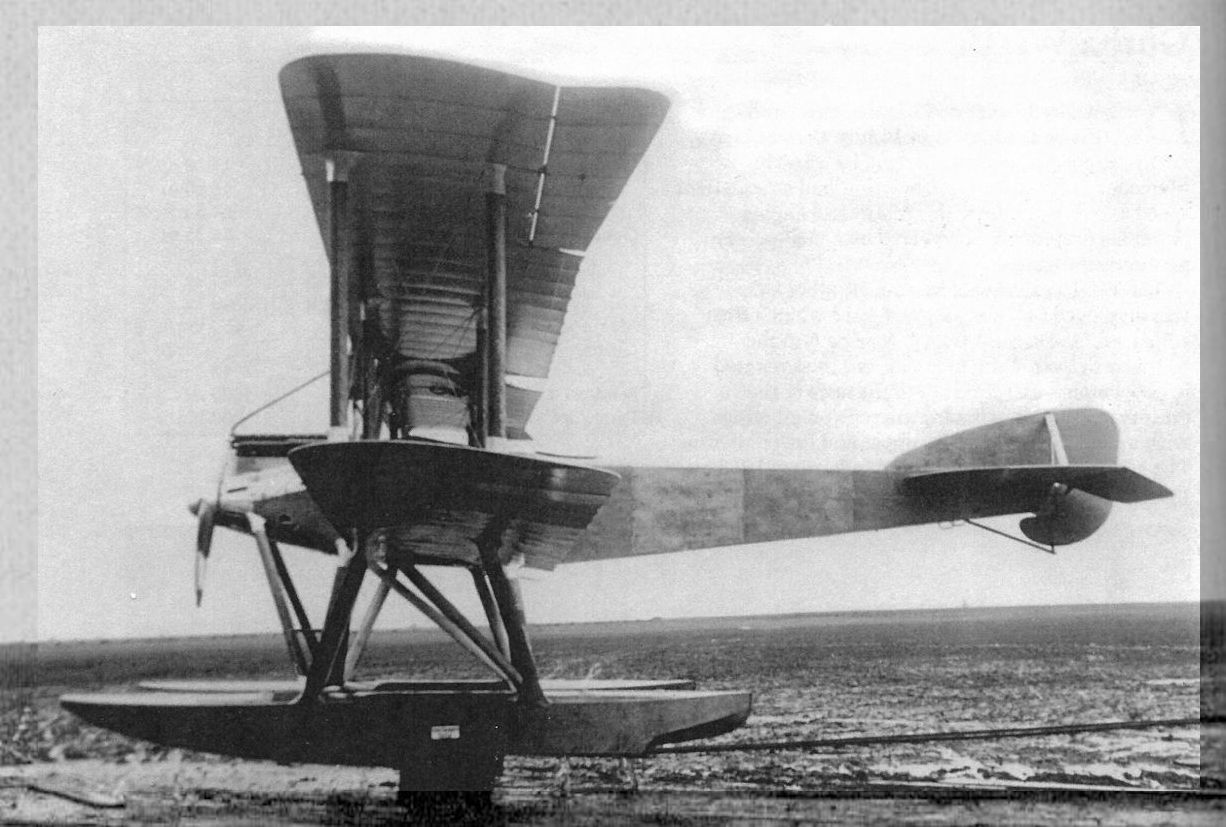
The first prototype WD15, Marine Number 842, before the Marine Number was added. The first prototype had ailerons on the upper wings only.
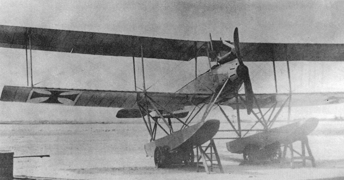
The first prototype WD15, Marine Number 842, on beaching dollies.
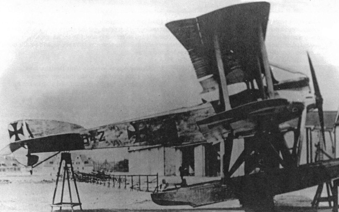
The first prototype WD 15, Marine Number 842, on beaching dollies. The typical Gotha rudder with horn balance underneath is evident.
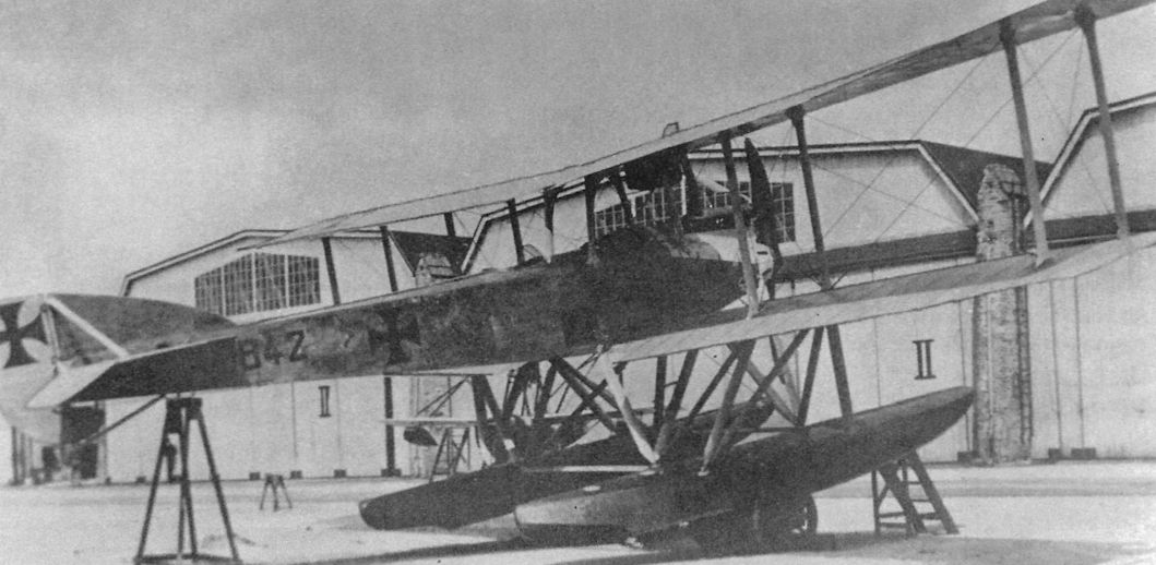
The first prototype WD15, Marine Number 842, on a beaching dolly upon delivery to the SVK.
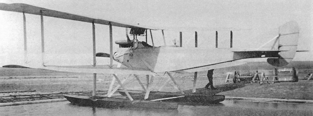
The first prototype WD15, Marine Number 842, in the Gotha factory pond before the Marine Number was added.
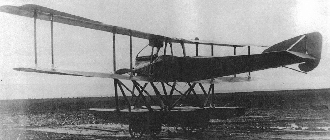
The first prototype WD 15, Marine Number 842, on dollies.The 260 hp Mercedes D.IVa engine gave the WD15 good performance but both prototypes suffered from engine problems despite the Mercedes D.IVa being a generally reliable engine in mass production and use. The Gotha bombers used the Mercedes D.IVa without significant problems, so the numerous problems with the D.IVa in the WD15 were unusual.
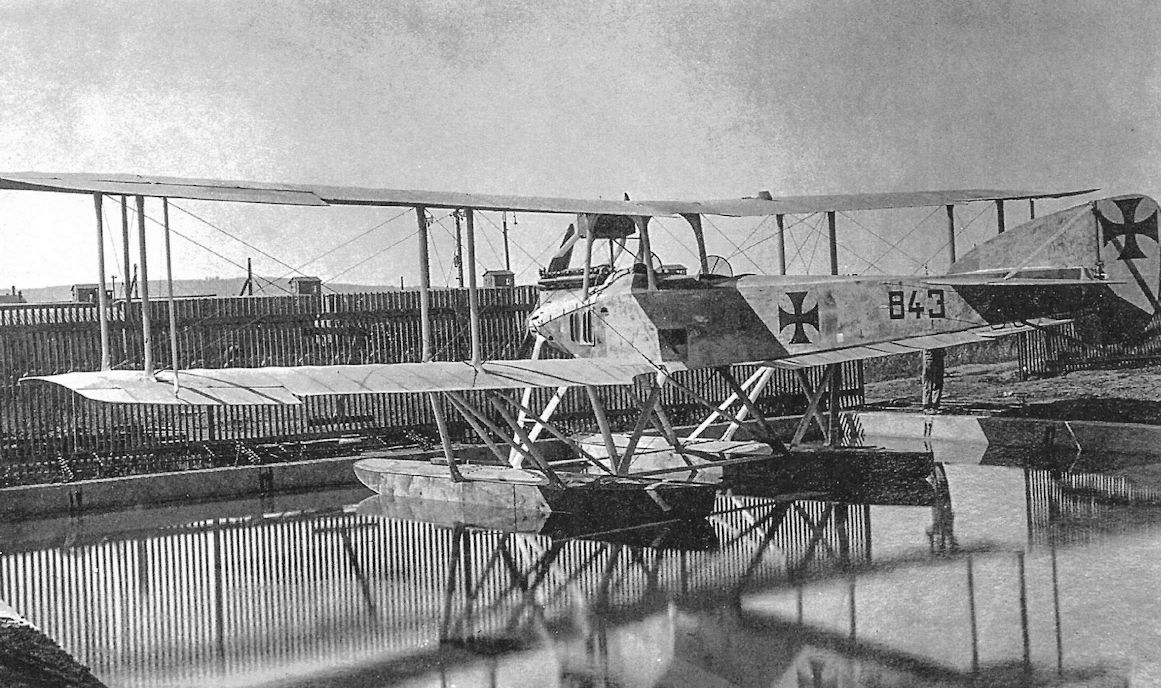
The second prototype WD15, Marine Number 843, afloat in the Gotha factory pond. The second prototype WD15 incorporated a number of improvements as a result of flight testing the first prototype; the most visible was the use of ailerons on all wings, with the upper and lower ailerons connected by an actuating strut. Like the first prototype, the second prototype also suffered a number of engine problems with its 260 hp Mercedes D.IVa engine, and despite being accepted in January 1918, the SVK did not approve series production.
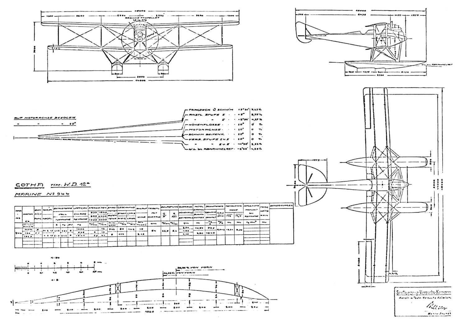
Gotha WD.12
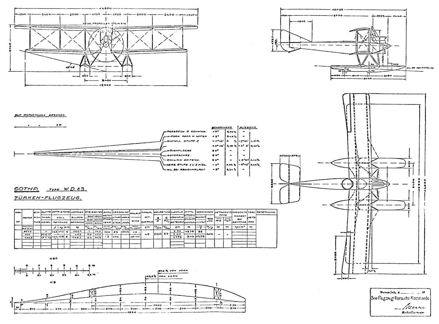
Gotha WD.13
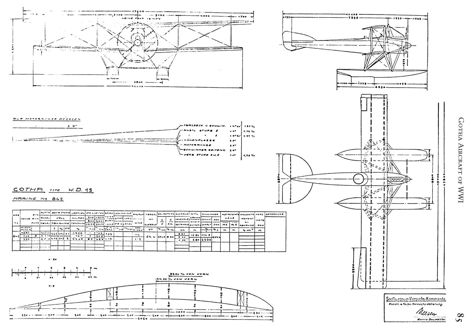
Gotha WD.15
Gotha WD14
Designed by Rosner and Klaube, the Gotha WD14 was essentially an enlarged WD11 powered by more powerful 200 hp Benz Bz.IV engines mounted as tractors. The SVK praised the side-by-side seating of the pilot and observer, which facilitated coordination between them during target acquisition and torpedo launch. A third crewman had a flexible Parabellum LMG 14 machine gun and an aft turret.
During trials of the prototype, Marine Number 801, ailerons were added to the lower wings and the rudder area was increased to improve control with one engine out.
The first production series, Marine Numbers 1415-1430, had ailerons on all wings and balanced rudders. By the time these aircraft were delivered torpedo attacks had been shown to incur heavy losses with limited results, so the aircraft were modified for long-range reconnaissance with droppable fuel tanks in the torpedo bay. The next production series, Marine Numbers 1617-1631, had a gun turret in the nose and provision for bombs for use as a maritime reconnaissance bomber. The final production series, Marine Numbers 1946-1970, were designed for long-range maritime reconnaissance with droppable fuel tanks replacing the torpedo. This series had an additional central rudder for increased controllability, but were still viewed as unsuitable for poor aileron and rudder response. Only nine of this series were accepted before the Armistice.
A total of 69 WD14s were ordered (801, 1415-1430, 1617-1631, 1651-1662, 1946-1970), of which 52 were delivered (1629-1631 were cancelled and the Armistice stopped deliveries of the last 14). Designed as a torpedo bomber, the WD14 was re-cast as a long-range reconnaissance bomber after it was determined that torpedo attacks were ineffective and too dangerous. Moreover, the WD14 was underpowered and its control response was not satisfactory.
Gotha WD14 Specifications
Engines: 2 x 220 hp Benz Bz.IV
Wing: Span Upper 25.00 m
Area 133 m2
General: Length 14.40 m
Height 5.00 m
Empty Weight 3090 kg
Loaded Weight 5000 kg
Maximum Speed: 126 km/h
Climb: 1000m 17.1 min
2000m 45 min
Service Ceiling: 3000 m
Duration: 1300 km
Gotha WD20
The Gotha WD16-19 designs were not built; the next Gotha seaplane design to appear was the WD20. Designed by Rosner and Klaube, three Gotha WD20s Marine Numbers 1515-1517, were ordered in April 1917. Powered by two 260 hp Mercedes D.IVa engines, the WD20s were designed to carry the larger 50cm torpedo. However, experience soon revealed the limitations of torpedo attacks and the WD20s were reconfigured for long-range maritime reconnaissance in the North Sea. Despite removing three fuel tanks, the wireless operator and equipment, and two machine guns, and incorporating the maximum sweepback allowable, the WD20 was considered unacceptable for operational service due to poor flying characteristics. This was similar to the problems plaguing the G.IV and G.V bombers, indicating a fundamental problem with Gotha designs of the period.
Gotha WD20 Specifications
Engines: 2 x 260 hp Mercedes D.IVa
Wing: Span Upper 25.50 m
Area 131.7 m2
General: Length 14.40 m
Height 5.00 m
Empty Weight 3030 kg
Loaded Weight 4540 kg
Maximum Speed: 126 km/h
Climb: 1000m 15 min
Service Ceiling: 2000 m
Duration: 700 km
Gotha Seaplane Production Summary
Type Ordered Marine Numbers Remarks
WD14 69 801, 1415-1430, 1617-1631, 1651-1662, 1946-1970 52 were produced; 1629-1631 were cancelled and 14 of the last batch were not delivered due to the end of the war
WD20 3 1515-1517 Not accepted for operational service
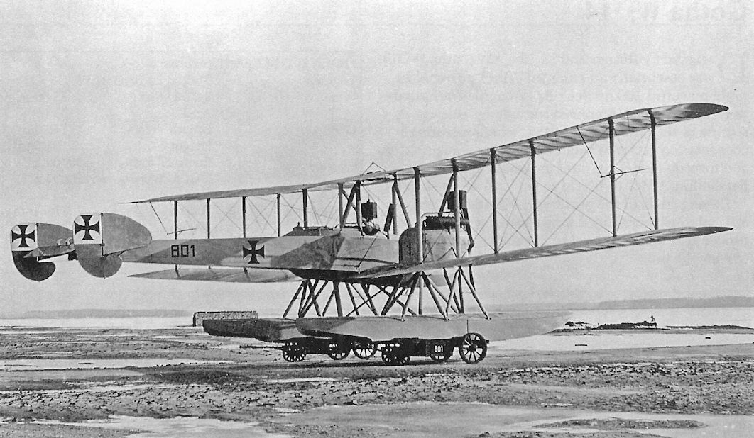
The prototype WD14, Marine Number 801, upon delivery to the SVK on 16 January 1917. As a result of trials, ailerons were added to the lower wings and the rudder area was increased to improve control with one engine out.
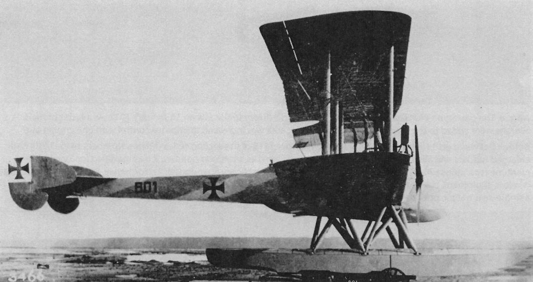
The prototype WD14, Marine Number 801, on a beaching dolly upon delivery to the SVK on 16 January 1917. This aircraft has a rear gunner but no nose turret; the pilot and observer sat side-by-side.
The prototype WD14, Marine Number 801, upon delivery to the SVK on 16 January 1917. As a result of trials, ailerons were added to the lower wings and the rudder area was increased to improve control with one engine out.
Delivered on 11 July 1917, WD14, Marine Number 1415 of the second series (Marine Numbers 1415-1430) had enlarged rudders and ailerons on all wings. Originally ordered as a torpedo bomber, it was modified for long-range maritime reconnaissance now that torpedo attacks had been basically abandoned. At Norderney, #1415 was used to test wireless equipment, navigation instruments, and droppable fuel tanks, here installed in the torpedo bay. Euler D.II 274/17, a single-seat trainer, provides an interesting size comparison.
On October 2, 1917, Gotha 1415 departed Norderney on a 10-hour flight along the German North Sea coast (departure 0745, landing 1745).
On October 2, 1917, Gotha 1415 departed Norderney on a 10-hour flight along the German North Sea coast (departure 0745, landing 1745).
Delivered on 11 July 1917, WD14, Marine Number 1415 of the second series (Marine Numbers 1415-1430) had enlarged rudders and ailerons on all wings. Originally ordered as a torpedo bomber, it was modified for long-range maritime reconnaissance now that torpedo attacks had been basically abandoned. At Norderney, #1415 was used to test wireless equipment, navigation instruments, and droppable fuel tanks, here installed in the torpedo bay. Euler D.II singleseat trainers flank it on both sides.
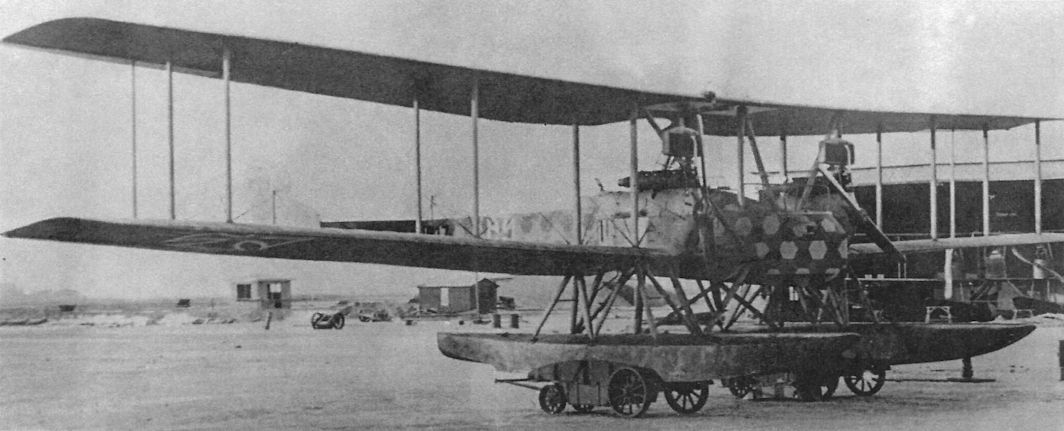
WD14 Marine Number 1617 of the third series was delivered in November 1917. To investigate its suitability as a reconnaissance bomber, it had a gun turret in a nose widened to hold five 10-kg bombs on each side. In place of a torpedo, ten 60-kg bombs could be carried in the torpedo bay. According to Navy records, twelve WD14s, Marine Numbers 1617-1628, were equipped for long-range reconnaissance flights of 8 1/2 hours duration and twelve WD14s, Marine Numbers 1651-1662, were equipped for torpedo attack missions of 4 hours duration.
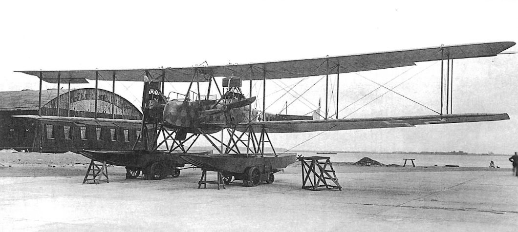
The Gotha WD.14 (MN 1946 shown here) was driven by two Fliegel propellers.
WD14 Marine Number 1946 of the last series was photographed after modification on 14 June 1918. Twenty-five WD14s, Marine Numbers 1946-1970, were ordered in October 1917 equipped for long-range reconnaissance with a droppable fuel tank replacing the torpedo. For improved controllability this series had an additional central rudder. Reported "totally unsuited for the front" due to poor aileron and rudder response, the modified Marine Number 1946 is shown with balanced ailerons of increased area. Only nine WD14s of this series were accepted before the Armistice. The German naval camouflage scheme standardized in April 1917 specified three-color hexagonal camouflage on all upper surfaces, with side surfaces blue-gray and undersurfaces light gray. Despite that, photos show that production models of the Gotha WD14 wore the naval lozenge fabric overall surfaces except the floats, giving them a much darker appearance than the standard camouflage.
WD14 Marine Number 1946 of the last series was photographed after modification on 14 June 1918. Twenty-five WD14s, Marine Numbers 1946-1970, were ordered in October 1917 equipped for long-range reconnaissance with a droppable fuel tank replacing the torpedo. For improved controllability this series had an additional central rudder. Reported "totally unsuited for the front" due to poor aileron and rudder response, the modified Marine Number 1946 is shown with balanced ailerons of increased area. Only nine WD14s of this series were accepted before the Armistice. The German naval camouflage scheme standardized in April 1917 specified three-color hexagonal camouflage on all upper surfaces, with side surfaces blue-gray and undersurfaces light gray. Despite that, photos show that production models of the Gotha WD14 wore the naval lozenge fabric overall surfaces except the floats, giving them a much darker appearance than the standard camouflage.
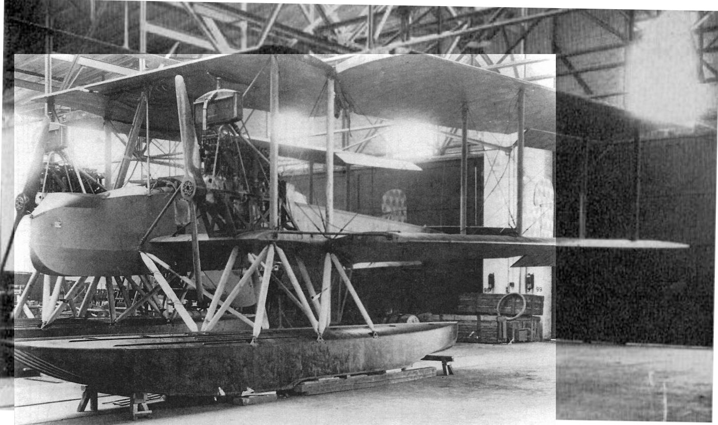
Gotha WD 20 Marine Number 1515 (of a 3-plane batch of 1515-1517) in the factory before delivery in May 1918. Derived from the WD14, the WD20s were designed to carry the larger 50cm torpedo, so power was from two 260 hp Mercedes D.IVa engines. Gotha WD 20 Marine Number 1517 had an additional, central rudder similar to that fitted to late-production WD 14s. Gotha WD 20 Marine Number 1517 had an additional, central rudder similar to that fitted to late-production WD14s. After disappointing results from torpedo attacks, the WD20s were reconfigured for long-range reconnaissance over the North Sea. The WD20 was not accepted for operational service due to poor flying characteristics; it was tail heavy, a problem plaguing the contemporary Gotha G.IV and G.V bombers.
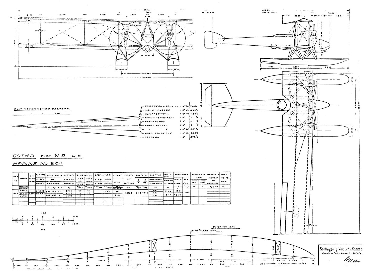
Gotha WD.14
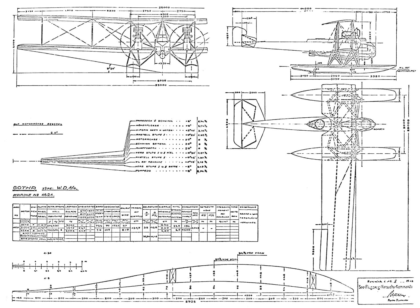
Gotha WD.14
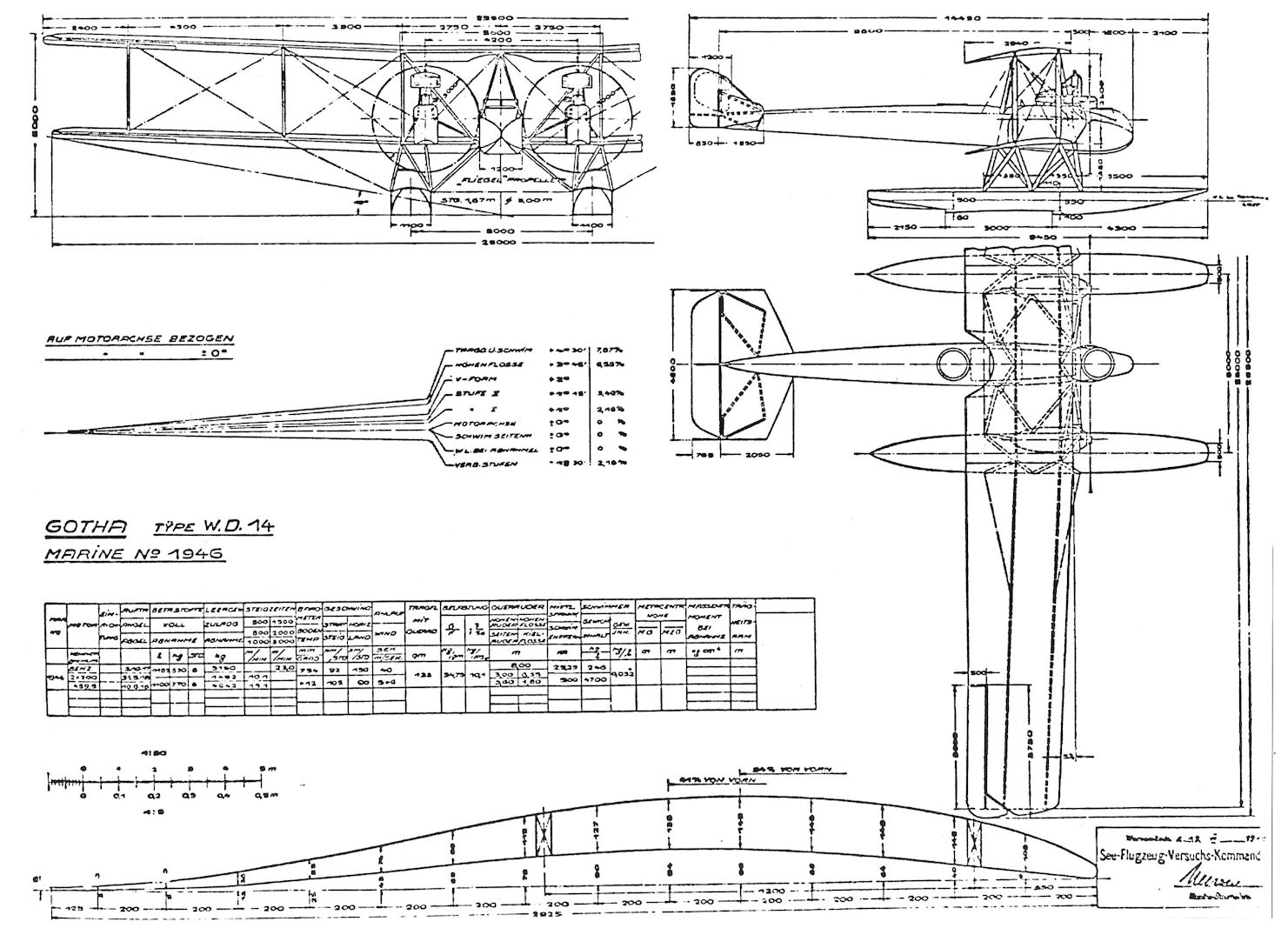
Gotha WD.14
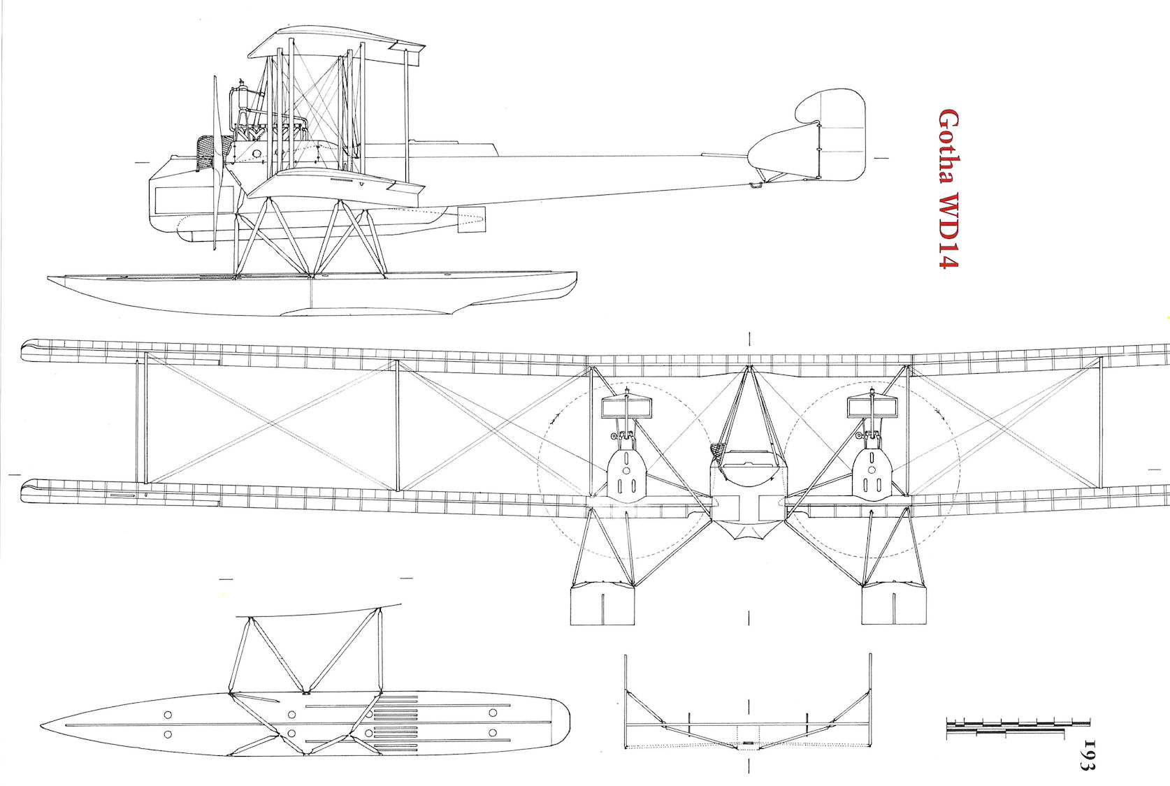
Gotha WD14
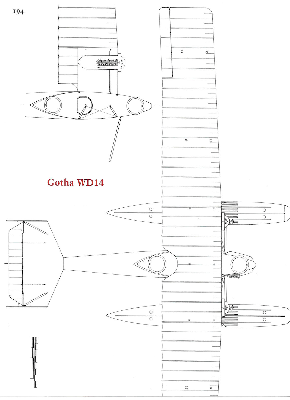
Gotha WD14
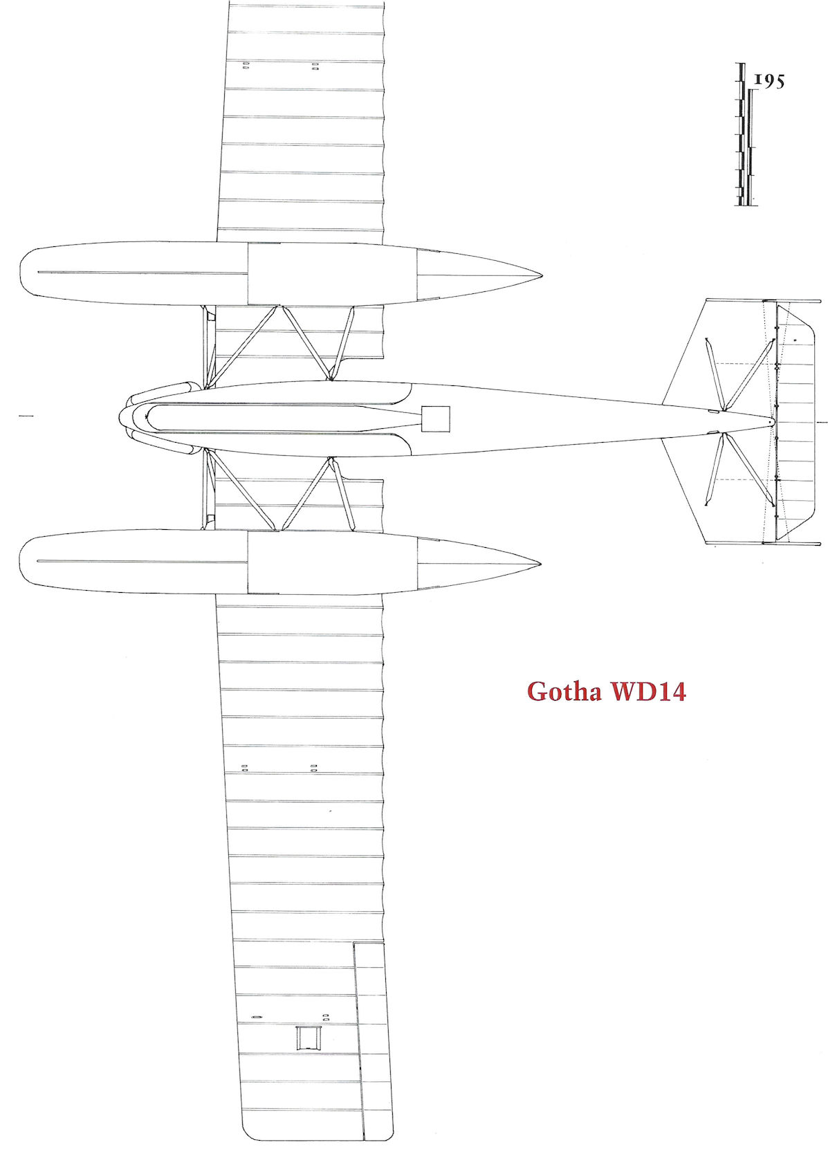
Gotha WD14
Gotha G.IX/GL.IX
In February 1918 LVG was given a production contract to build 30 Gotha GL.VII reconnaissance airplanes (G.200-229/18) and 70 Gotha G.IX bombers (G.230-299/18). The 260 hp Maybach Mb.IVa was the normal powerplant. Apparently all of the GL.VII(LVG) aircraft were built but no photographs of this version have been found. The G.IX day bomber, given an increased wing-span and length, was equipped to carry five 50 kg PuW bombs under the fuselage. According to a French inspection report, some 96 Gotha G.IX bombers were stored at the LVG factory on 15 December 1918. After the armistice a number of these bombers were given to the Allies. For example, Belgium received 23 G.IX bombers that were flown operationally by the Belgian air service. A Gotha G.IX(LVG) 289/18, delivered to Japan post-war as reparations, was powered by two 260 hp Mercedes D.IVa engines.
Gotha G.IX/GL.IX Specifications
Engines: 2 x 240 hp Maybach Mb.IVa
Gotha G.X/GL.X
On 16 August 1918, Idflieg ordered three Gotha GL.X prototypes (G.1725-1727/18), each powered by two 185 hp BMW.IIIa engines. Designed by Burkhardt, two GL.X versions were envisioned, one a fast, high-altitude reconnaissance machine and the second an armored ground-attack aircraft fitted with a single, forward-firing 20mm Becker cannon and five fixed machine guns. A gunner had a sixth, flexible machine gun for rear defense. The first two-bay GL.X, a more compact design than the G.IX bomber, was reported ready for flight testing on 1 January 1919, subject to clearance from Gotha management. It is difficult to understand how the same engine and airframe combination was expected to perform well at both extreme high and low altitudes.
Gotha G.X/GL.X Specifications
Engines: 2 x 185 hp BMW.IIIa
Gotha GL-Type Production Summary
Manufacturer Type Qty Serials Notes
LVG G.IX(LVG) 70 230/17-299/18 Bombers. Unknown number, perhaps all, completed.
Gotha G.X 3 1725/18- 1727/18 Prototypes. At least one completed.
Notes: According to a French inspection report 96 Gotha G.IX aircraft were stored at the LVG factory on 15 Dec. 1918. Many of these were transferred to the Allies postwar, especially Belgium.
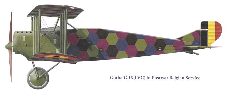
Gotha G.IX(LVG) in Postwar Belgian Service
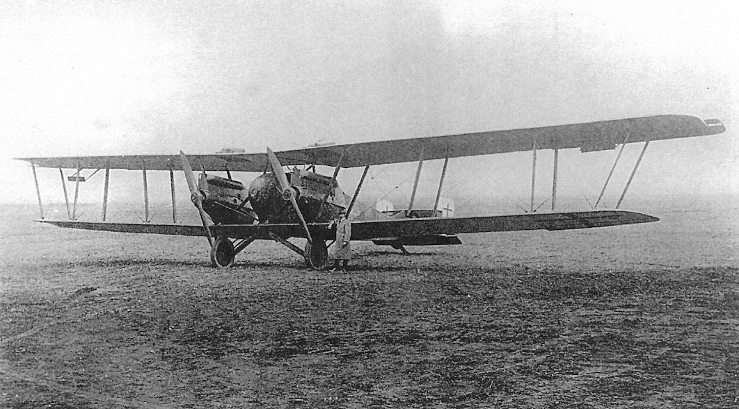
This Gotha G.IX(LVG) illustrates the extended wing-span of this version of the GL series. A British crew attempted to fly this aircraft back to Britain, but it crashed when leaving Bickendorf and the crew was killed.
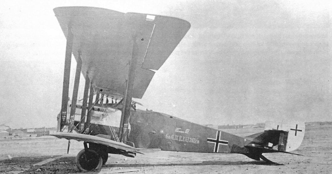
Gotha G.IX(LVG) G.263/18 displays the LVG-style markings and is armed with a PuW bomb under the fuselage.
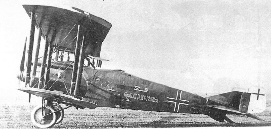
Gotha G.IX(LVG) G.257/18 is covered in dark, printed camouflaged fabric.
The Gotha G.IX(LVG) in this postwar view has no visible markings other than the Belgian colors on the rudders, but its hexagonal camouflage fabric is well illustrated.The aileron aerodynamic balances have slots, but the aerodynamic balances on the rudders do not. A DH.9 is visible in the background.
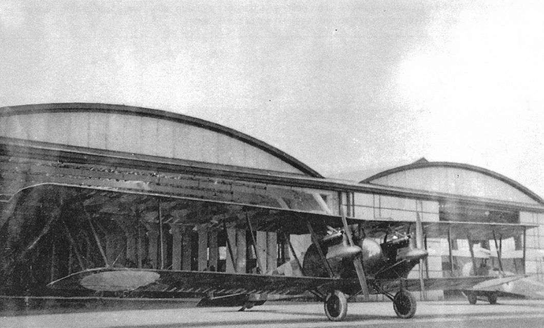
This Gotha G.IX(LVG) illustrates the type's clean lines. It is serving in Belgium postwar.The number '250' on the nose may indicate it is serial G.250/18, but there is no confirmation. Roundels are being painted under the wings but are not yet complete. The aircraft is covered in dark, printed camouflage fabric.
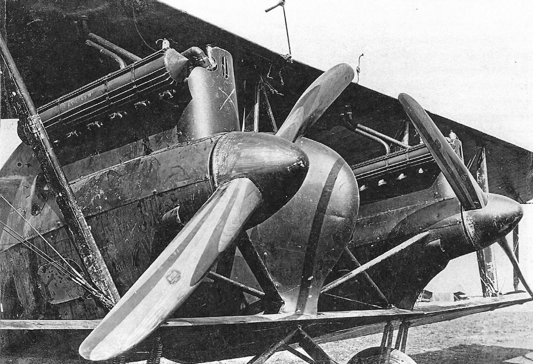
Gotha G.IX(LVG) in Belgian service postwar. These views illustrate details and emphasize the aerodynamic lines of the GL series. Problems of propeller selection for maximum ceiling and speed at altitude, always a challenge with fixed-pitch propellers, prolonged development of the GL-series.
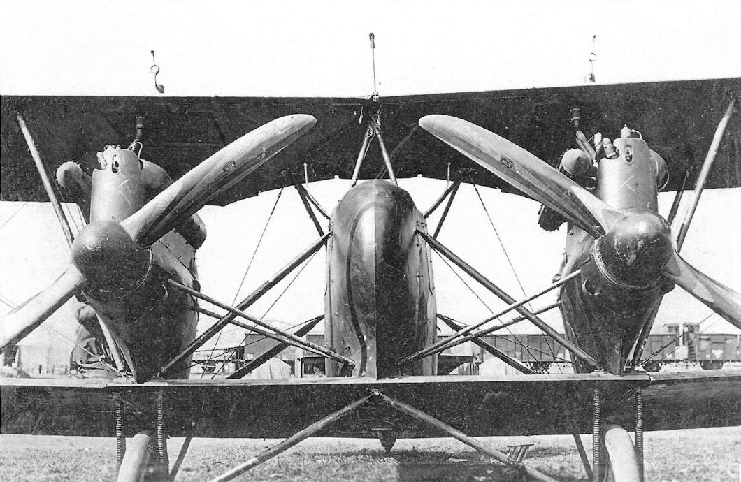
The front gunner position was eliminated in the Gotha GL designs to save weight and drag; the bomber depending on speed and its rear gunner for protection. Put into limited production, the GL.IX (shown) was too late to reach operational units before the armistice. Twenty were delivered to Belgium after the war as reparations, where this one was photographed.
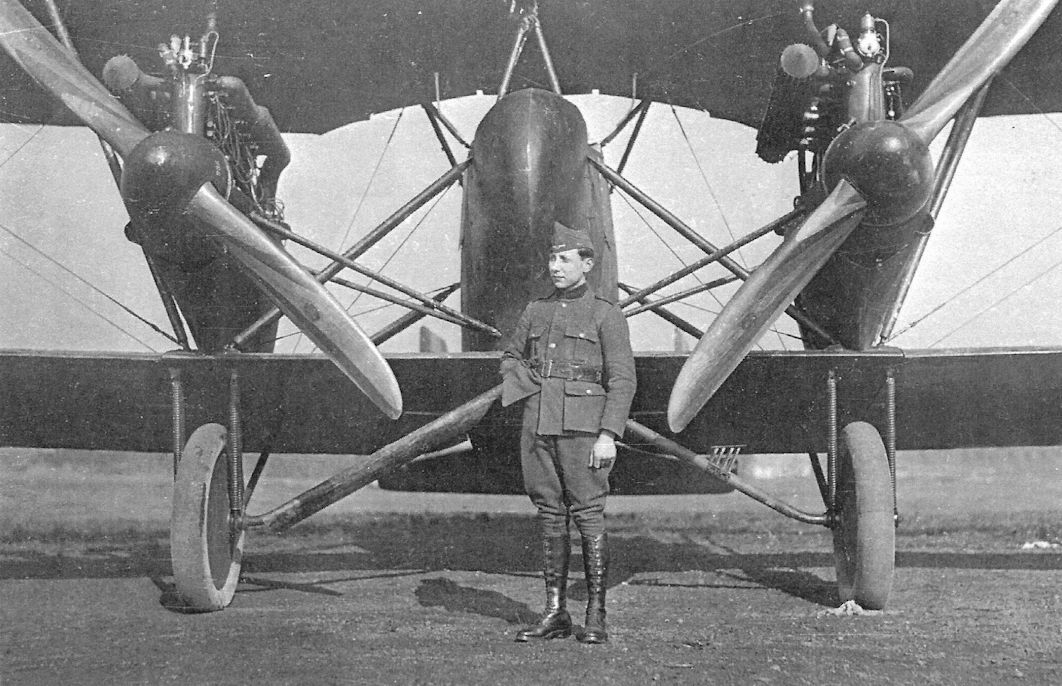
Gotha G.IX(LVG) in Belgian service postwar.
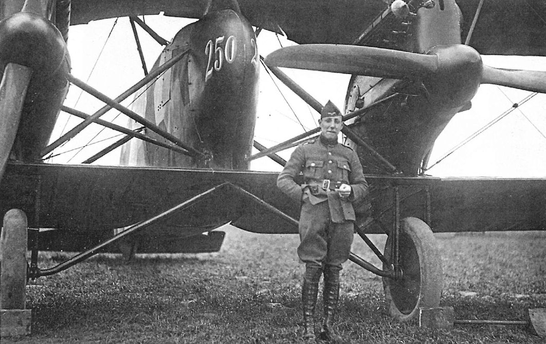
Gotha G.IX(LVG) in Belgian service postwar.
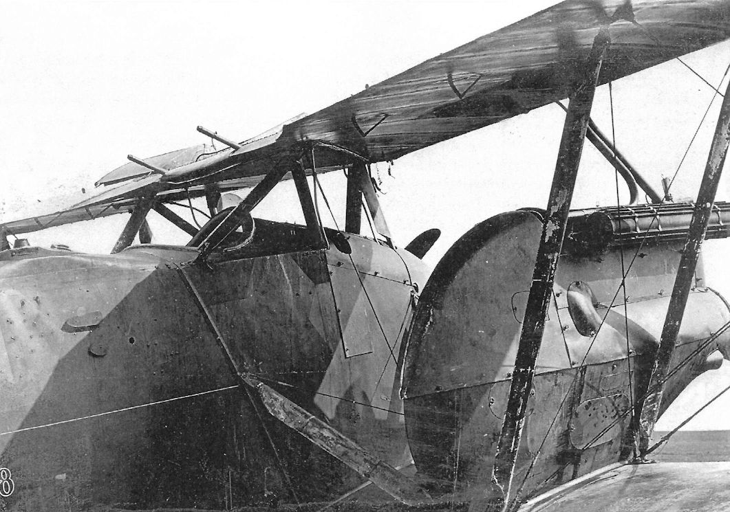
Gotha G.IX(LVG) in Belgian service postwar.
Gotha G.IX(LVG) serving in Belgium postwar illustrates the type's clean lines. It appears to be on public display. A Friedrichshafen bomber is in the background.
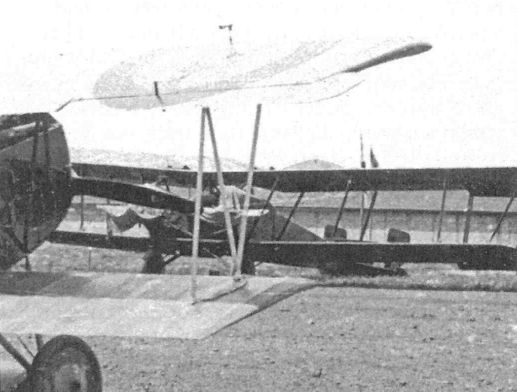
Gotha GL.IX in Belgium postwar.
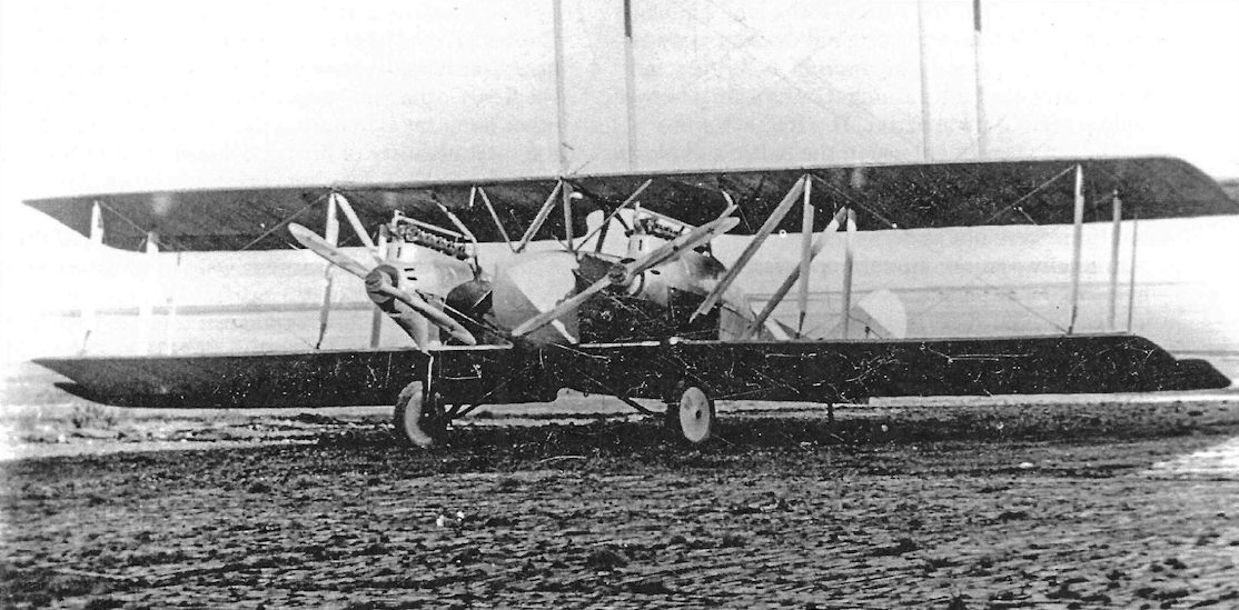
The Gotha G.X prototype had two-bay wings and was powered by two 185 hp BMW.IIIa engines. Somehow this airframe and engine combination was supposed to excel as both a high-altitude reconnaissance aircraft and a low-level ground-attack aircraft, seemingly contradictory requirements. The massive WD27 looms in the background.
Gotha G.VII/GL.VII
Ordered on 15 March 1917, before daylight operations by Gotha G.LV aircraft had begun over the UK, four prototypes were built. These were designated Gs.I by Gotha and G.VII and G.VIII by Idflieg. The first prototype, Gotha GL.VII 550/17, was completed in September 1917, the month that Kagohl 3 transitioned to night bombing of the UK due to strengthened British defenses and increasing losses of Gotha G.IV bombers on daylight missions.
The single-bay Gotha GL.VII 550/17, powered by two 260 hp Mercedes D.IVa engines, was one of four prototypes (G.550-553/17) ordered at the same time to explore different engine and wing configurations to determine the optimum layout to meet the demanding Idflieg requirements. A characteristic of the design was the close spacing of the engines to minimize asymmetric thrust with one engine out. This configuration was based on a patent by Ingenieur Michael Schlieffer, a Gotha pilot, and used the venturi effect between the nacelle and fuselage to minimize drag and help counter asymmetric thrust. The close engine spacing required a short nose that precluded a forward gunner.
The next prototype, Gotha G.VII 551/17, had a longer, two-bay wing cellule. The Gotha G.VII was faster than the Albatros D.III but, despite months of intensive testing to optimize engine, airframe, and propeller configurations to maximize speed, climb, and ceiling, the desired performance was not achieved. In late 1918 engines with experimental centrifugal superchargers were installed in this machine for testing.
The production standard GL.VII had a two-bay wing cellule with aerodynamically balanced ailerons on the upper wing and a box (biplane) tail. In 1918 eight aircraft were produced from an order for 55 aircraft (G.300-354/18). Gotha GL.VII 300/18 was the first of these and was powered by two Maybach Mb.IVa engines. It was sent to the front for evaluation in May 1918. GL.VII 302/18 went to the front on 27 June, followed by 301/18 on 1 August and 304/18 on 26 October. However, no further information is available on the evaluation of these aircraft and it is not known if they flew any operational sorties.
Owing to promising results obtained in early Gotha tests, both Aviatik and LVG were awarded contracts in February 1918 to build the Gotha G.VII under license. Aviatik built 30 G.VII aircraft (G.100-129/18), few of which were handed over to the Allies after the war. Aviatik-built Gotha G.VII(Av) 112/18 was experimentally fitted with nose radiators for flight trials.
Gotha G.VII/GL.VII Specifications
Engines: 2 x 260 hp Mercedes D.IVa
Wing: Span 19.27 m
General: Length 9.60 m
Empty Weight 2420 kg
Loaded Weight 3140 kg
Maximum Speed: 180 km/h
Service Ceiling: 6000 m
Gotha G.VIII/GL.VIII
Intended for high-speed day bombing, the Gotha GL.VII was fitted with an enlarged, three-bay wing to improve climb and ceiling. One fixed, forward-firing machine gun was fitted for the pilot, and the gunner had both dorsal and ventral flexible guns for defense.
The Gotha GL.VIII prototype, G.VIII 552/17, was powered by Mercedes D.IVa engines, but the production standard was the over-compressed 260 hp Maybach Mb.IVa for more power at high altitude. All control surfaces were aerodynamically balanced and the biplane tail was retained for improved control with one engine out. The PuW bombs were carried externally under the fuselage.
Gotha GL.VIII 307/18, powered by two 260 hp Maybach Mb.IVa engines, was sent to the Doberitz test center on 19 October 1918. The upper ailerons were fitted with Flettner servo controls for lighter control forces. According to an Idflieg appreciation, the performance of these aircraft "lagged far behind expectations." On the other hand, the war ended before sufficient experience was gathered to evaluate the aircraft adequately under combat conditions.
Gotha G.VIII/GL.VIII Specifications
Engines: 2 x 260 hp Maybach Mb.IVa
Wing: Span 21.73 m
Chord 2.05 m
Gap 2.00 m
General: Length 9.79 m
Useful Load 1030 kg
Loaded Weight 3706 kg
Maximum Speed: 180 km/h
Service Ceiling: 6000 m
Gotha GL-Type Production Summary
Manufacturer Type Qty Serials Notes
Gotha G.VII & G.VIII 4 550/17-553/17 Prototypes,- all 4 completed.
Gotha G.VII & G.VIII 55 300/18-354/18 Production aircraft; only 8 were completed.
Aviatik G.VII(Av) 100 100/18- 129/18* At least 30 completed.
LVG G.VII( LVG) 30 200/18-229/18 Reconnaissance aircraft. All 30 believed to have been completed.
Notes: *Rest of serials unknown.
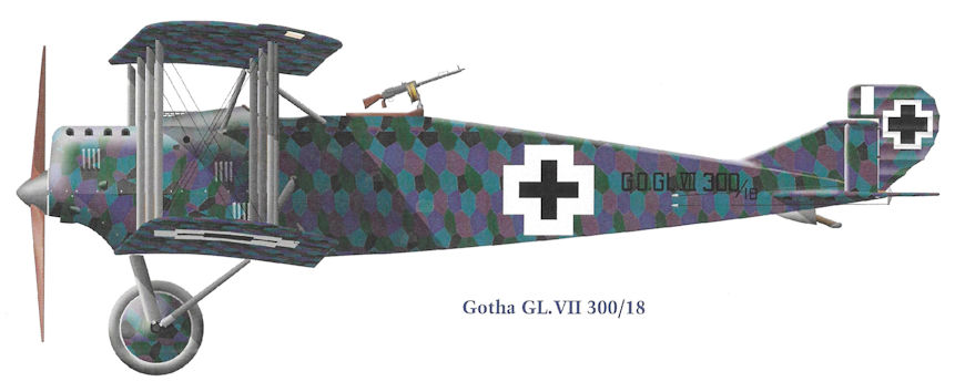
Gotha GL.VII 300/18
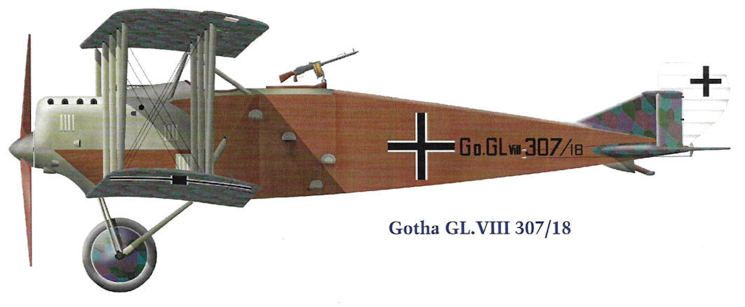
Gotha GL.VIII 307/18
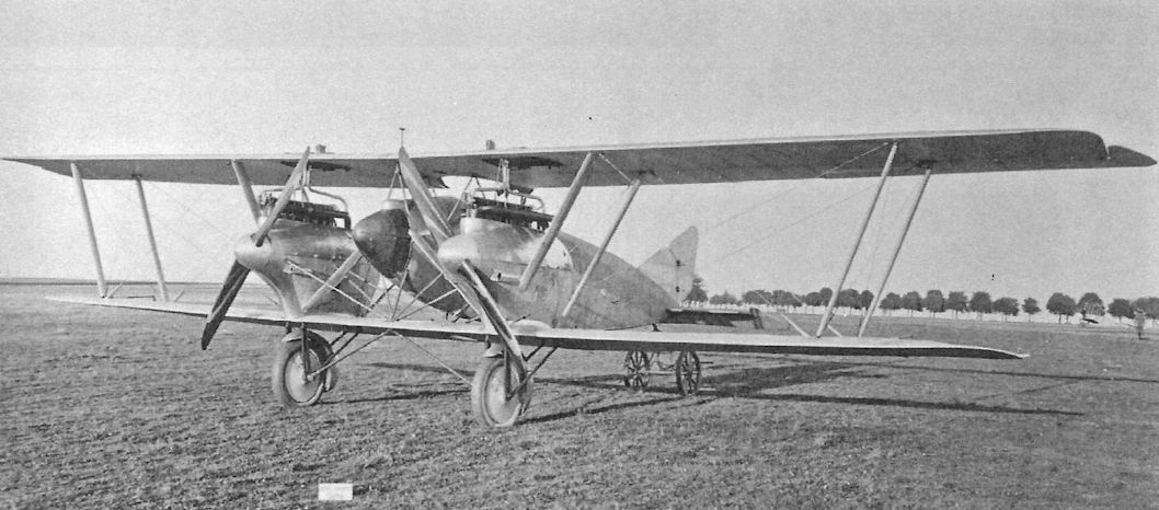
The prototype of a Gotha GL-type was the single-bay G.VII G.550/17, shown in September 1917. The engines rotated in opposite directions to minimize torque and the wheels are faired to reduce drag. However, the fuselage is suspended between the wings by a complex set of drag-producing struts.
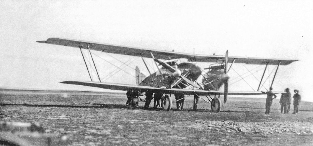
Gotha G.VII G.550/17 shown in September-October 1917 with wheel fairings removed for flight tests.
The Gotha GL.VII was an attempt to produce a fast day bomber and long-range reconnaissance plane. Prolonged development of the basic configuration was needed to achieve satisfactory speed and ceiling, with the result that none reached the front in time for combat.
The Gotha GL.VII was an attempt to produce a fast day bomber and long-range reconnaissance plane. Prolonged development of the basic configuration was needed to achieve satisfactory speed and ceiling, with the result that none reached the front in time for combat.
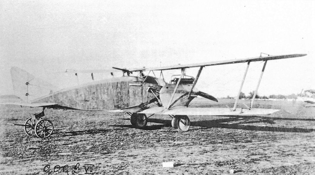
Gotha G.VII G.550/17 as built was very compact for a twin-engine aircraft.
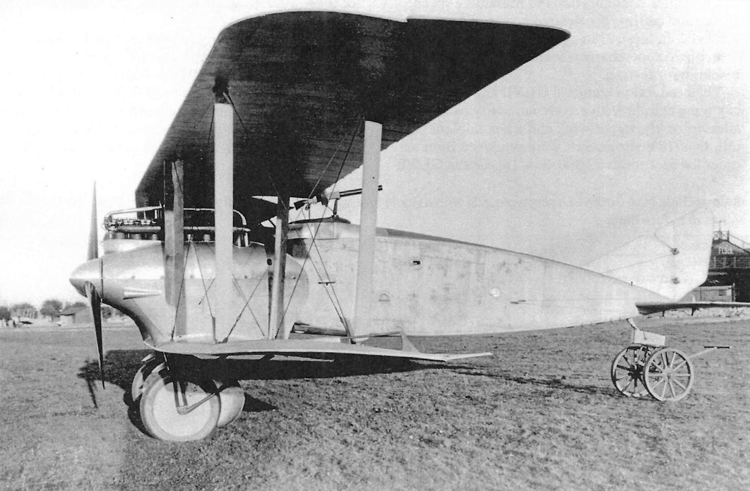
A Gotha GL-prototype, probably G.VII G.550/17 due to its wheel fairings, displays its very clean lines. Early GL-types had a single fin and rudder.
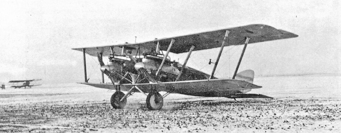
One of the Gotha GL-prototypes, still with a single fin and rudder, now has the fuselage faired into the lower wings to reduce drag.
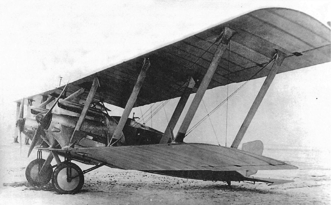
This Gotha GL-prototype may be the same aircraft as the one at the previous photo, but the propeller spinners have been removed.
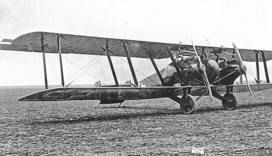
A Gotha GL.VII G.300/18 represents the production version of the aircraft. Now it has a 'box' tail for better directional control with one engine out, no wheel fairings, and no propeller spinners.The wings are now longer, with two-bays of struts, and the aileron aerodynamic balances have slots in them.
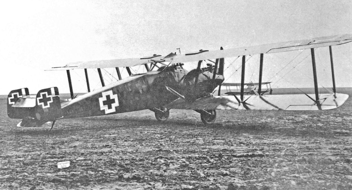
A rear quarter view of Gotha GL.VII G.300/18, the production version of the GL.VII. The 'box' tail is visible and the rudders, like the ailerons, have aerodynamic balances with slots in them.
Too late to take an active part in combat, the 3-man Gotha G VII bomber/long range reconnaissance type of mid-1918 had a top level speed of 112mph thanks to its twin 260hp Maybach Mb IVa engines. The G VII's operational ceiling was 19,685 feet, while the range, with bomb load, of 335 miles was clearly capable of significant extension for photo-reconnaissance work. Plans had been put underway to build this type in quantity, with contracts placed with Gotha for 55, plus a further 100 from Aviatik in Leipzig. As it was, only 11 had been completed at the time of the Armistice, three of which found their way into Soviet hands.
Too late to take an active part in combat, the 3-man Gotha G VII bomber/long range reconnaissance type of mid-1918 had a top level speed of 112mph thanks to its twin 260hp Maybach Mb IVa engines. The G VII's operational ceiling was 19,685 feet, while the range, with bomb load, of 335 miles was clearly capable of significant extension for photo-reconnaissance work. Plans had been put underway to build this type in quantity, with contracts placed with Gotha for 55, plus a further 100 from Aviatik in Leipzig. As it was, only 11 had been completed at the time of the Armistice, three of which found their way into Soviet hands.
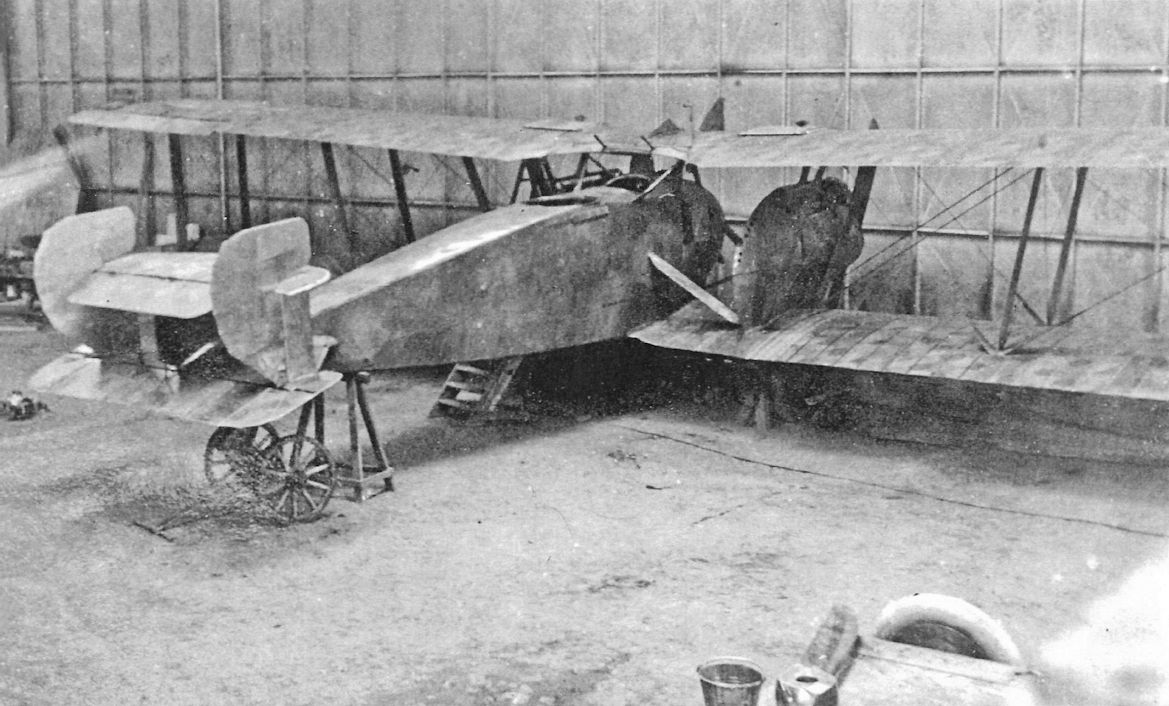
This Gotha GL.VII in the factory has no markings, but the wings are covered in regular camouflage fabric with hexagons. The fuselage has been spray-painted in hexagons with soft edges. This may be one of the GL-prototypes.The 'box' tail has the more common aerodynamic balances without slots in them.
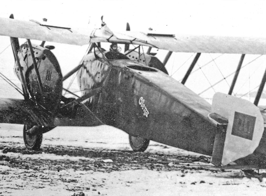
Post-war Ukrainian Gotha GL.VII Olena made an emergency landing at Vajnory airfield near Bratislava, Czechoslovakia, in early 1920. Despite the fact that Ukrainian aircraft had been over-flying Czechoslovakia with permission since 1919, Czechoslovakian authorities interned Olena. After repairs Olena was flown to Prague for evaluation in February or March.The German pilot flew the aircraft, but he had two Czech mechanics with him.
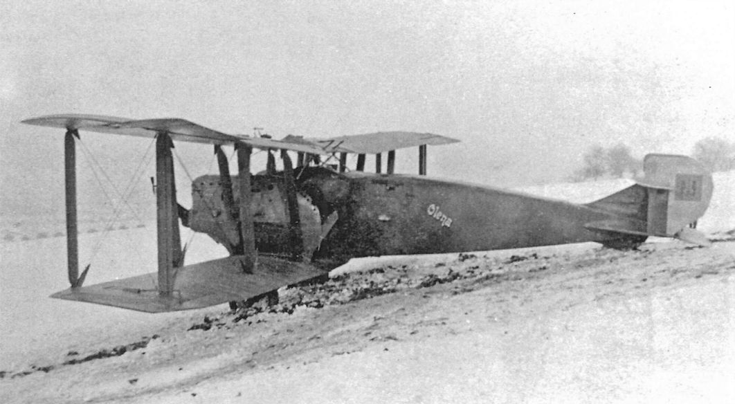
Postwar lineup of a Gotha GL.VII (at left), an AEG (center), and a Friedrichshafen (at right) at Bickendorf. The GL.VII has a fuselage band over the cross insignia, its location indicating it was built by Aviatik.
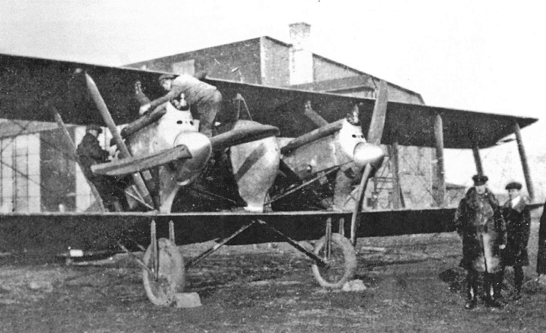
This Gotha GL.VII has an aluminum nose and propeller spinners. The radiators were mounted in the upper wing above the engines, the position used for production aircraft.
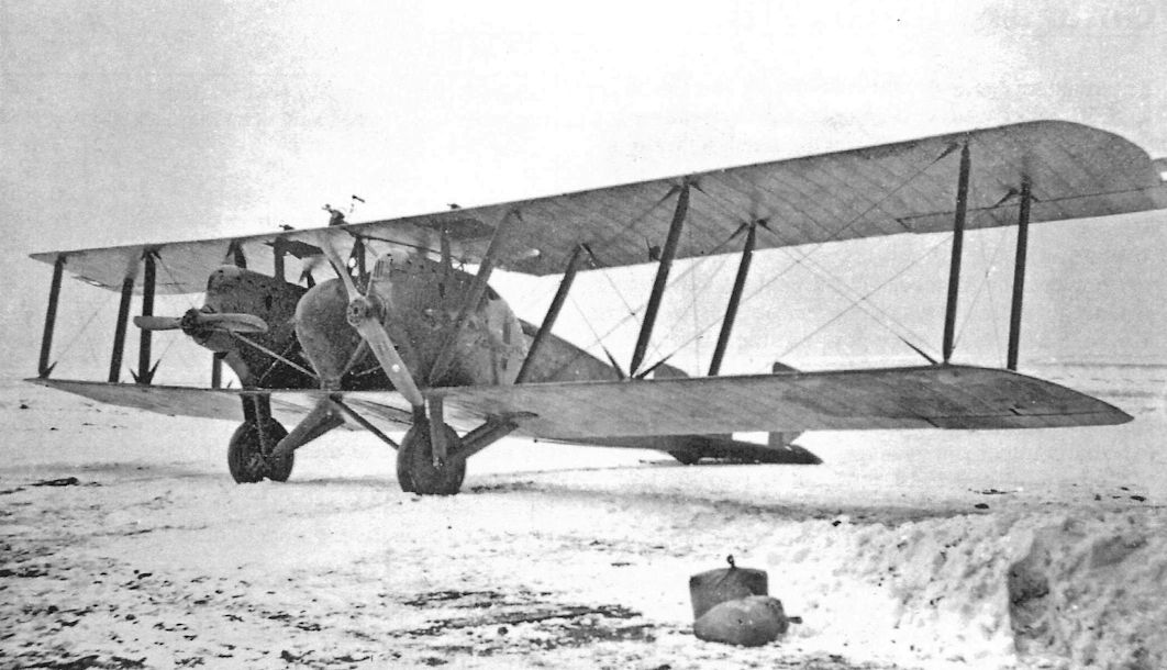
This Gotha GL.VII may have been photographed in Czechoslovakia, but details are unknown.
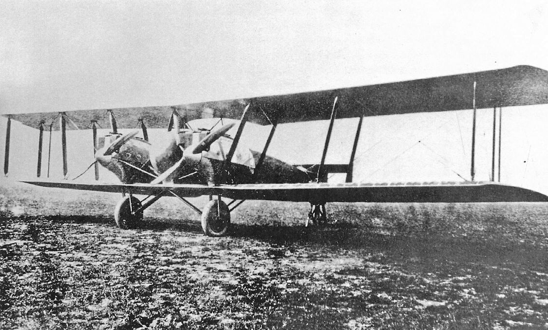
Aviatik-built Gotha GL.VII(Av) G.112/18 was fitted with nose radiators for evaluation. The aileron aerodynamic balances do not appear to have slots. Aviatik built 30 GL.VII bombers.
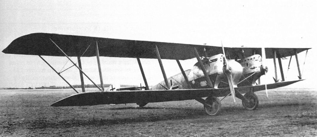
Gotha GL.VIII G.307/18, a production GL.VIII, was powered by two 260 hp over-compressed Maybach Mb.IVa engines optimized for power output at high-altitudes for maximum ceiling and speed at altitude. The slanting struts supporting the upper wingtips characterize the production GL.VIII and differentiate it from the GL.VII.
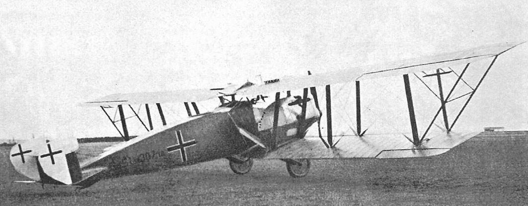
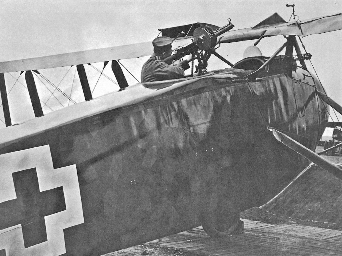
Although some Gotha GL prototypes appeared to carry a fixed gun for the pilot, the Gotha GL.VIII high-speed day bomber was the only type for which a fixed machine gun for the pilot was specified. Here the gunner demonstrates the field of fire of his dorsal gun; the fixed pilot's gun is also clearly visible. The gunner also had a flexible ventral gun to defend against attacks from below.The lozenge printed fabric and clean lines are evident.
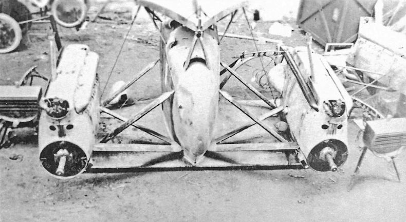
Gotha GL forward fuselage at the USAS center at Romorantin, France postwar.
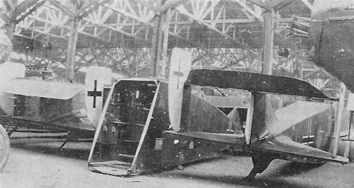
Gotha GL fuselages at the USAS center at Romorantin postwar show the fuselage cross section.
Gotha WD22
The Gotha WD21 was not built; the next Gotha seaplane design to appear was the WD22. Designed by Rosner and Klaube, two Gotha WD22 long-range maritime reconnaissance seaplanes, Marine Numbers 2133-2134, were ordered in October 1917 for comparison with the Navy's giant Staaken floatplanes. The first WD22, Marine Number 2133, had two tractor 160 hp Mercedes D.III engines and two 100 hp Mercedes D.I pusher engines mounted in tandem.
Delivered in May 1918, WD22 Marine Number 2133 was found to be seriously tail heavy, seemingly an endemic problem with Gotha twin-engine and multi-engine airplanes. It was returned to the factory for increased sweepback and was again delivered to the SVK in September 1918.
The second WD22, Marine Number 2134, was delivered on 21 August 1918. It featured reversed engine positions; the Mercedes D.III engines now serving as pushers and the D.I engines as tractors.
Both WD22s were found at the Hage storage depot in December 1918.
Gotha WD22 Specifications
Engines: 2 x 160 hp Mercedes D.III and
2 x 100 hp Mercedes D.I
Wing: Span Area 26.00 m 147 m2
General: Length 14.35 m
Height 5.20 m
Empty Weight 3830 kg
Loaded Weight 5200 kg
Maximum Speed: 131 km/h
Climb: 1000m 15.2 min
Service Ceiling: 3000 m
Duration: 780 km
Gotha Seaplane Production Summary
Type Ordered Marine Numbers Remarks
WD22 2 2133-2134 Too late for operational service
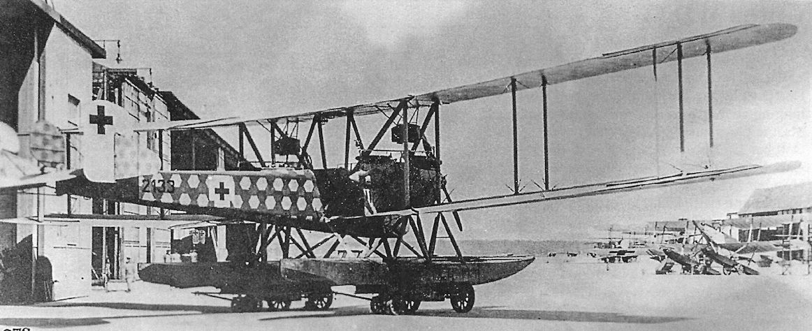
The first WD22, Marine Number 2133, photographed at the SVK on 3 July 1918 in its original form.The tractor engines were 160 hp Mercedes D.III engines and the pushers were 100 hp Mercedes D.I engines.
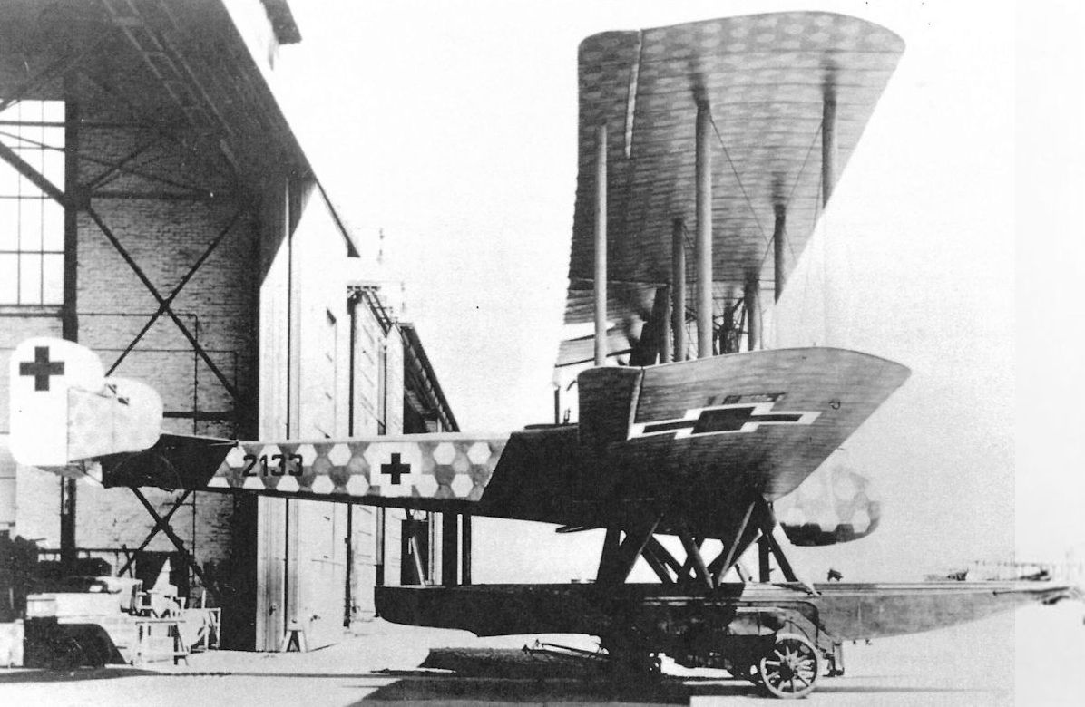
The first of two prototype WD22 seaplanes, Marine Number 2133, in its original form.
The Gotha WD 22 powered by a pair of 200 hp Benz Bz.IV engines, was one of the later, more powerful torpedo bomber designs. When actual torpedo operations gave disappointing results and the aircraft too vulnerable during their attacks, torpedo operations were abandoned and the aircraft were reassigned to long-range reconnaissance and bombing. To extend their reconnaissance range, jettisonable fuel tanks were carried in the torpedo slings.
The Gotha WD 22 powered by a pair of 200 hp Benz Bz.IV engines, was one of the later, more powerful torpedo bomber designs. When actual torpedo operations gave disappointing results and the aircraft too vulnerable during their attacks, torpedo operations were abandoned and the aircraft were reassigned to long-range reconnaissance and bombing. To extend their reconnaissance range, jettisonable fuel tanks were carried in the torpedo slings.
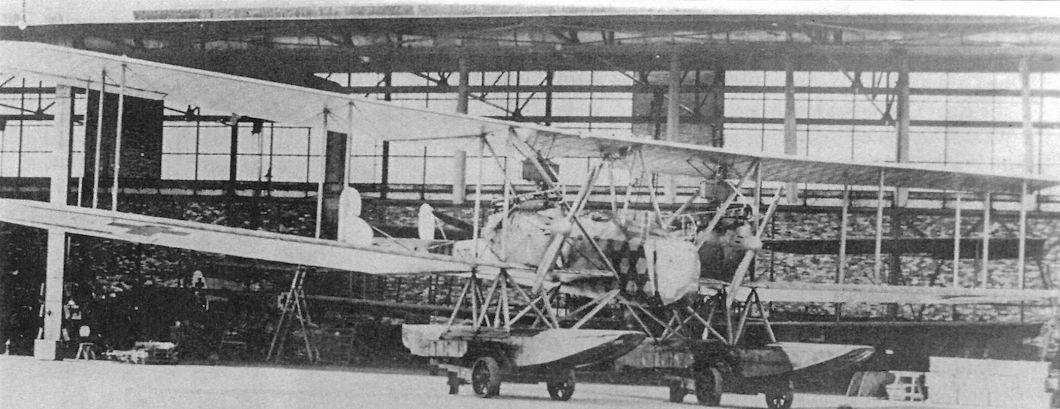
The first WD22, Marine Number 2133, photographed at the SVK. Like the Gotha G.IV and G.V bombers and the preceding WD20 long-range reconnaissance seaplane, the WD22 was very tail heavy, a fault that seriously reduced longitudinal stability and therefore greatly compromised flight safety. There was no rationale for this in a seaplane.
Gotha WD27
The Gotha WD23 through WD26 were not built; the final Gotha seaplane design to appear was the WD27. Designed by Rosner and Klaube, three Gotha WD22 long-range maritime reconnaissance seaplanes, Marine Numbers 4326-4328, were ordered for comparison with the Navy's giant Staaken floatplanes. The WD27s had four 175 hp Mercedes D.IIIa engines, two mounted as tractors and two in tandem mounted as pushers, enabling it to remain airborne with one engine out. This was difficult to achieve with the drag from a windmilling propeller; the fixed-pitch propellers of the time could not be feathered to reduce drag. The WD27 also featured folding wings to assist storage.
The WD27 was reported ready for factory engine trials in December 1918, unfortunately after the Armistice. Listed as complete in January 1919, the WD27 was later destroyed in accordance with Armistice requirements.
Gotha WD22 Specifications
Engines: 4 x 175 hp Mercedes D.IIIa
Wing: Span Upper 34.00 m
Span Lower 31.00 m
Area 197 m2
General: Length 17.60 m
Height 6.00 m
Empty Weight 4700 kg
Loaded Weight 6860 kg
Maximum Speed: 135 km/h
Climb: 1000m 15 min
Duration: 1100 km
Gotha Seaplane Production Summary
Type Ordered Marine Numbers Remarks
WD27 3 4326-4328 Too late for operational service. Only 1 built?
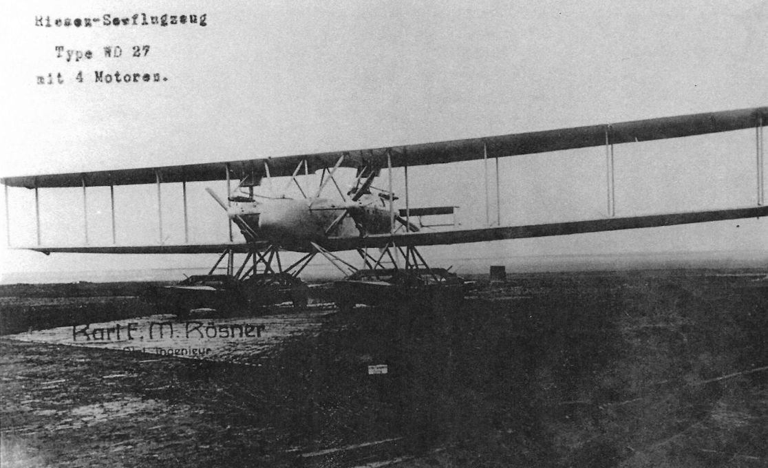
The first WD27, Marine Number 4326, in the Gotha factory pond.
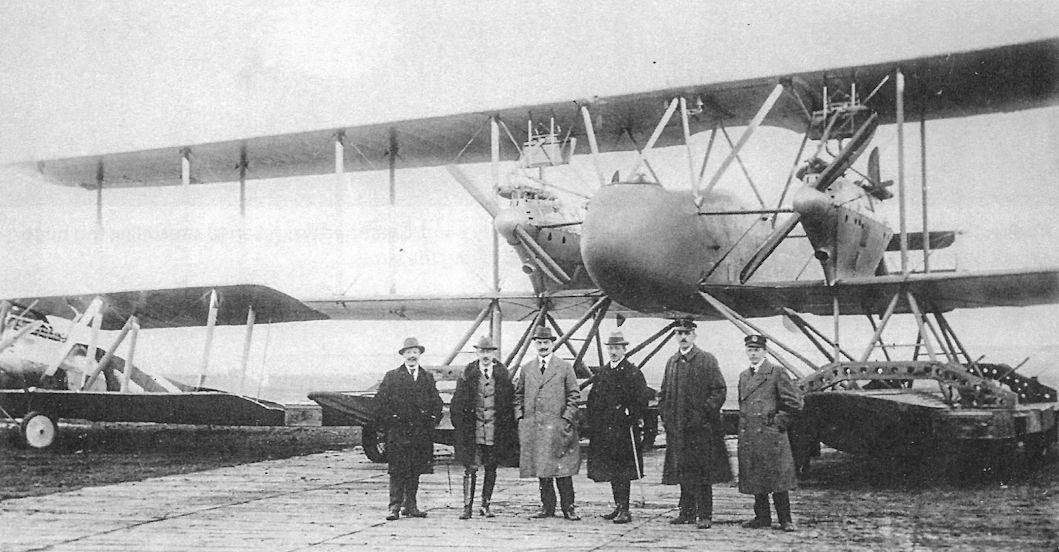
Front view of the first WD27 on a beaching trolley.
The Gotha G.X prototype had two-bay wings and was powered by two 185 hp BMW.IIIa engines. Somehow this airframe and engine combination was supposed to excel as both a high-altitude reconnaissance aircraft and a low-level ground-attack aircraft, seemingly contradictory requirements. The massive WD27 looms in the background.
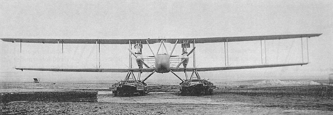
Front view of the first WD27 on a beaching trolley.
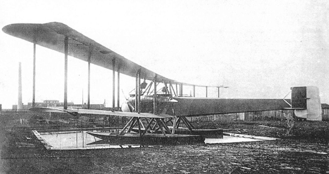
The first WD27, Marine Number 4326, in the Gotha factory pond.
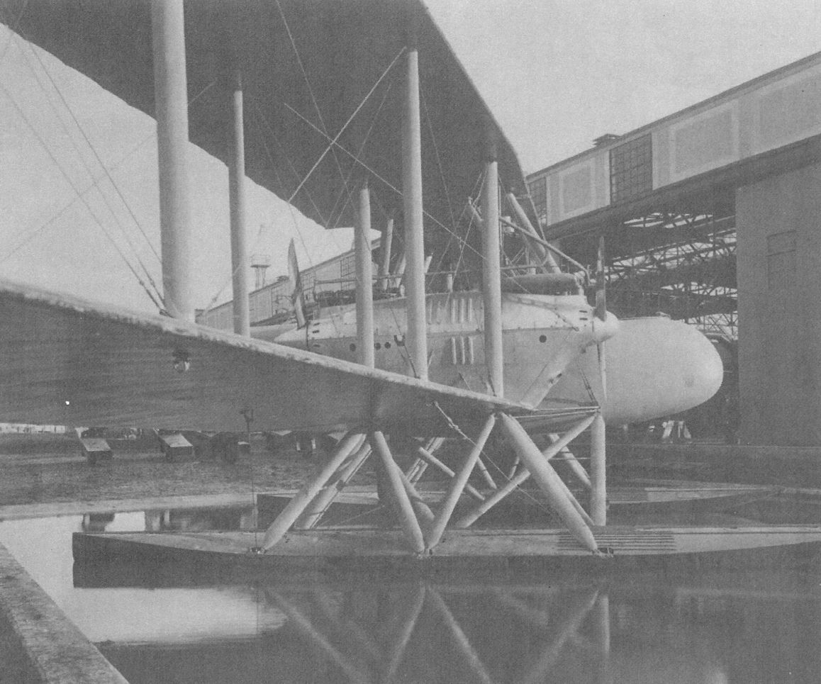
The first WD27, Marine Number 4326, in the Gotha factory pond. Great care was taken to streamline this huge aircraft by rounding the contours, smoothing the nacelles, and fairing the struts.
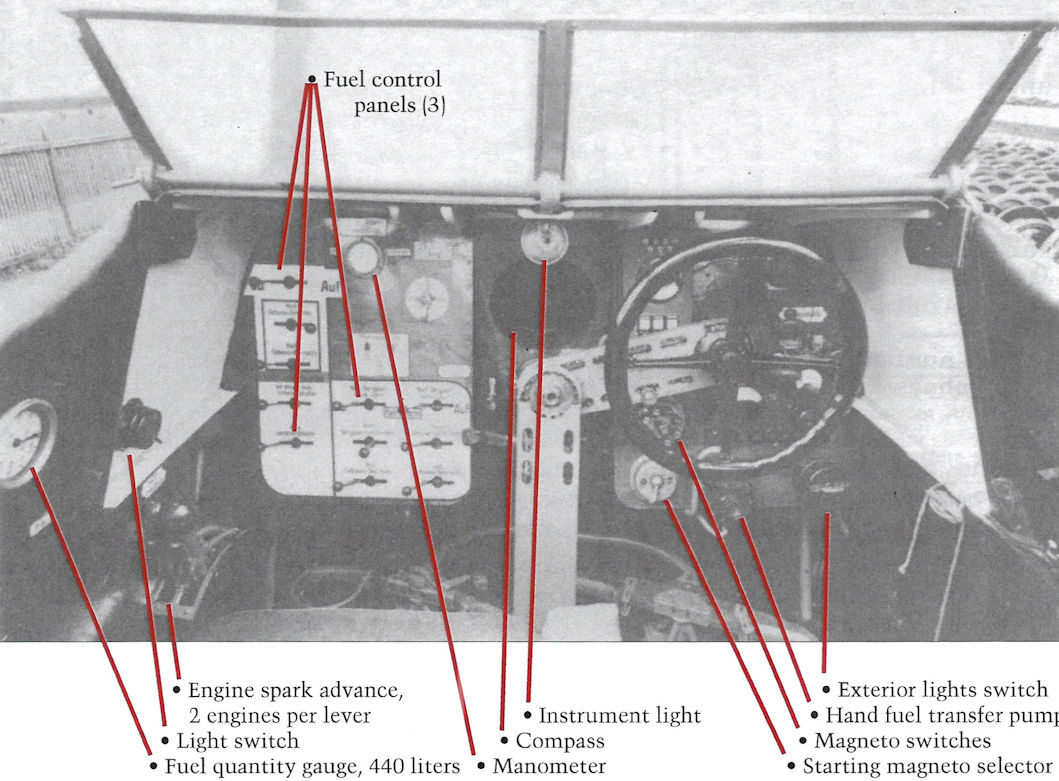
WD22 cockpit with some of the instruments and controls labeled; note the throw-over control wheel at right.
Gotha WD6
Gotha WD6 was the Gotha company designation for 30 Hansa-Brandenburg NW(Go) seaplanes, Marine Numbers 752-782, built under license. The production order was dated 14 May 1916 and deliveries took place between 29 September 1916 and 21 February 1917. The NW was an unarmed reconnaissance floatplane that carried a radio. Some were modified to carry ten 5-kg bombs.
Gotha WD6 / Brandenburg NW(Go) Specifications
Engine: 160 hp Mercedes D.III
Wing: Span Upper 16.50 m
Area 57.85 m2
General: Length 9.4 m
Empty Weight 1020 kg
Loaded Weight 1650 kg
Maximum Speed: 90 km/h
Duration: 4 hours
Gotha Seaplane Production Summary
Type Ordered Marine Numbers Remarks
WD6 30 752-782 Brandenburg NW built under license, designated Brandenburg NW(Go)
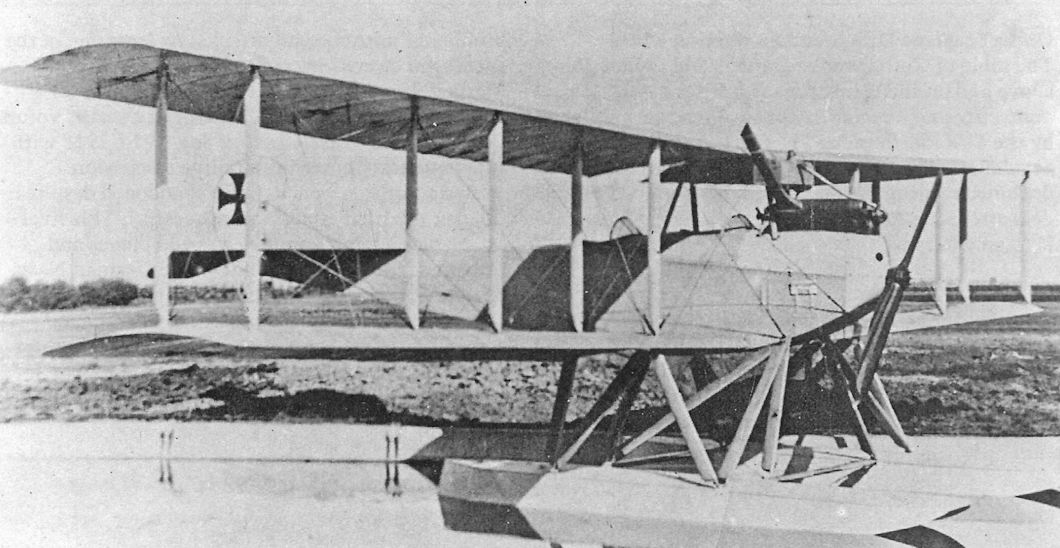
A Gotha-built NW in the Gotha testing pond. The streamlined undercarriage strut fairings are noteworthy.
The Brandenburg NW was built under license by Gotha as the Brandenburg NW(Go). Gotha built 30 of these floatplanes that were given the internal Gotha company designation WD6.
The Brandenburg NW was built under license by Gotha as the Brandenburg NW(Go). Gotha built 30 of these floatplanes that were given the internal Gotha company designation WD6.
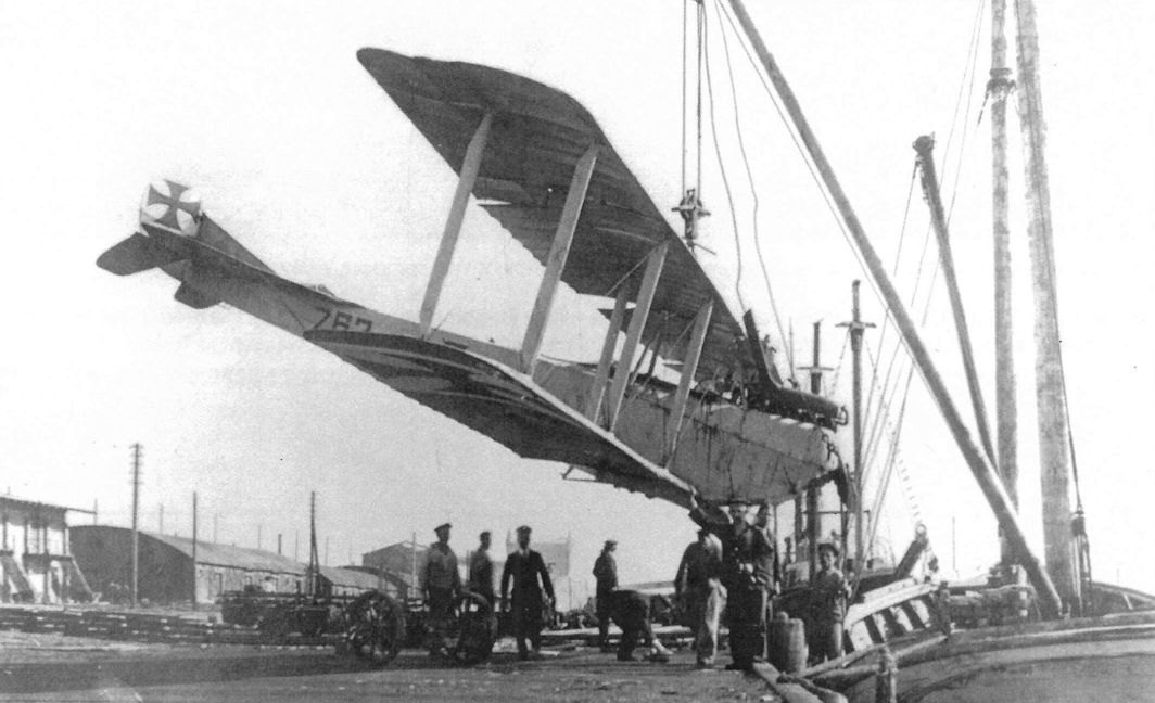
Brandenburg NW(Go) Marine #763 getting a lift. This seaplane was destroyed at Putzig on 12 August, 1918, when a student pilot was killed in a flying accident. Was this the event pictured?
The modified Friedel-Ursinus B.1092/14 and a captured Morane monoplane at FEA 9 in Darmstadt for a size comparison. Aerodynamically-balanced ailerons have been fitted and the nose radiators have been replaced by larger, twin radiators on each engine. A long cellon window is in the fuselage side over the wing.