Описание
Страна: Австро-Венгрия
Год: 1917
Истребитель
В.Кондратьев Самолеты первой мировой войны
"АВИАТИК" (Берг) D.I / AVIATIK (Berg) D.I
Первый серийный истребитель австро-венгерской конструкции был спроектирован конструкторским коллективом венской фирмы "Авиатик ГмбХ" (ранее "отпочковавшейся" от одноименной германской авиафирмы) под руководством инженера Юлиуса фон Берга. Первый полет прототипа состоялся 10 января 1917 г. Первый серийный экземпляр поднялся в воздух 3 мая того же года.
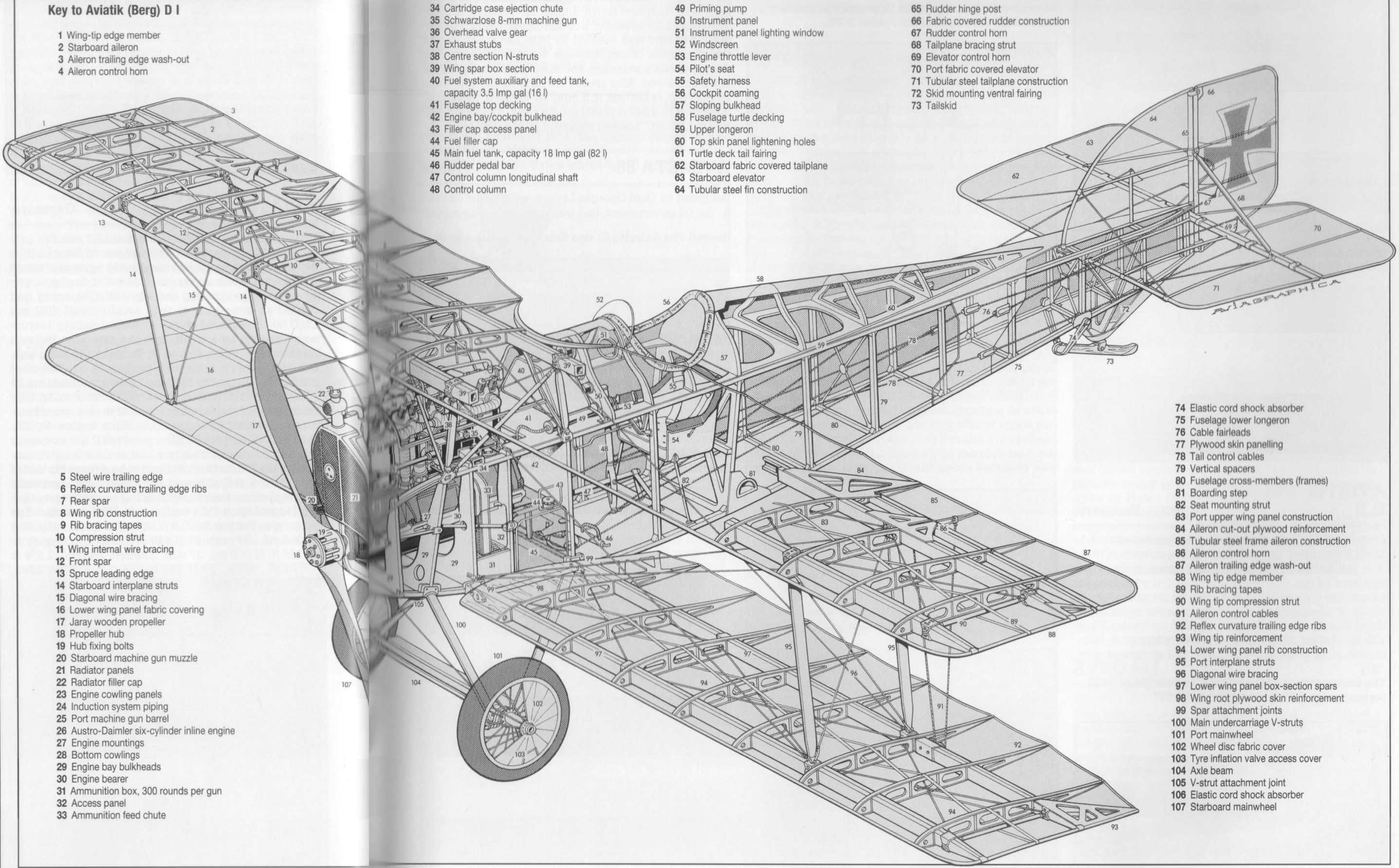
Самолет представлял собой цельнодеревянный одностоечный биплан. Фюзеляж обшит фанерой, крылья и оперение - полотном. Двигатель - "Австро-Даймлер" Dm-185 мощностью 185 л.с. Вооружение первоначально состояло из одного пулемета "Шварцлозе", установленного над верхним крылом под углом 15° к продольной оси самолета для стрельбы вперед-вверх вне диска ометания винта. В дальнейшем на серийные машины стали устанавливать по два курсовых пулемета с синхронизаторами, слева и справа от двигателя.
Первый серийный экземпляр вышел на испытания 3 мая, а с 15 мая аэропланы, получившие военное обозначение "Авиатик" D.I, начали поступать на фронт.
Самолет отличался хорошими летными данными в сочетании с простотой и технологичностью конструкции, позволявшей организовать производство на небольших и слабо оснащенных древообрабатывающих предприятиях. Помимо фирмы "Авиатик", его начали выпускать заводы WKF, MAG, "Зоннунд Фиала" и "Лёнер" и "Ллойд".
Истребители, построенные на "Авиатике", сначала имели индекс Ba.38 (построено 72 экземпляра), а затем, после установки более мощного 200-сильного мотора - Ba.138 (87 штук).
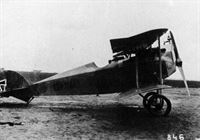
Однако новых 200-сильных "австро-даймлеров" для всех авиазаводов не хватало, а приоритет в их поставке был отдан фирме "Оэффаг". Из-за этого вскоре пришлось начать оснащать "авиатики" гораздо менее мощными моторами по 160 л .с. Внешне эти самолеты, получившие индекс Ba.238, отличались более округлой формой носовой части фюзеляжа без лобового радиатора. Радиаторы у них размещались по бортам.
Выпуск серии Ba.238 начался в январе 1918 г. Всего было построено 120 экземпляров. По сравнению с Ba.138, характеристики "238-го" заметно ухудшились, а фронтовые летчики отрицательно восприняли его появление. В результате уже к июлю "авиатики" со 160-сильными моторами были убраны из строевых частей и отправлены в летные школы.
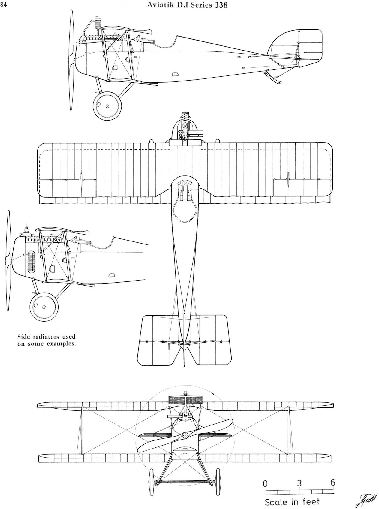
Последняя серийная модификация машины - Ba.338 с двигателем мощностью 225 л.с. Радиатор у нее размещался над передней кромкой верхнего крыла. Конструкция планера была усилена, в частности, уменьшен шаг нервюр на крыльях. Серийное производство этой версии развернулось в июле 1918 г., а на фронт она попала в сентябре.
До конца войны фирма "Авиатик" успела построить и сдать военной приемке 58 экземпляров Ba.338 и еще 33 самолета с теми же моторами сделаны на заводах "Лёнер", "Ллойд" и WKF.
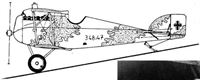
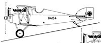
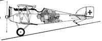
Общий итог поставок истребителя "Авиатик" D.I австро-венгерским ВВС составил 677 штук, из них 336 сдала фирма "Авиатик", 131 - MAG (индексы Ba.84 и Ba.92), 110 - "Лёнер" (Ba.115 и Ba.315), 31 - "Ллойд" (Ba.48, Ba.248 и Ba.348), 34 - "Зонн унд Фиала" (Ba.101 и Ba.201) и 35 - WKF (Ba.184, Ba.284 и Ba.384).
"Авиатик" D.I можно считать не только первым, но и лучшим истребителем Австро-Венгрии, принимавшим участие в мировой войне. Особенно это относится к самолетам 338-й серии.
После войны разоруженые "авиатики" использовались в Чехословакии, Венгрии, Румынии и Австрии в качестве спортивных машин, а также - для киносъемок и различных демонстрационных полетов.
МОДИФИКАЦИИ
Серия 38: двигатель "Австро-Даймлер", 185 л.с, вооружение - 1 несинхр. "Шварцлозе", установленный на капоте под углом 45 град, вверх.
Серия 138: двигатель 200 л.с, вооружение - 2 х 8-мм синхронных пулемета "Шварцлозе"
Серия 238: двигатель 160 л.с.
Серия 338: двигатель 225 л.с., усиленная конструкция крыла.
ЛЕТНО-ТЕХНИЧЕСКИЕ ХАРАКТЕРИСТИКИ
Ba.38 Ba.338
Размах, м 8,08 8,08
Длина, м 6,95 6,86
Высота, м 2,48
Площадь крыла, кв.м 21,8 20,3
Сухой вес, кг 606 638
Взлетный вес, кг 834 912
Скорость максимальная, км/ч 195 200
Время подъема на высоту
2000 м, мин 5,1 4,3
Потолок, м 6150 6500
Продолжительность полета, ч 2,5
Экипаж, чел 1 1
Описание:
- В.Кондратьев Самолеты первой мировой войны
- R.Keimel Osterreichs Luftfahrzeuge (Weishaupt Verlag)
- W.Green, G.Swanborough The Complete Book of Fighters
- P.Grosz, G.Haddow, P.Shiemer Austro-Hungarian Army Aircraft of World War One (Flying Machines)
- E.Hauke, W.Schroeder, B.Totschinger Die Flugzeuge der k.u.k. Luftfahrtruppe und Seeflieger 1914-1918
- Журнал Flight
Фотографии
-
В.Кондратьев - Самолеты первой мировой войны
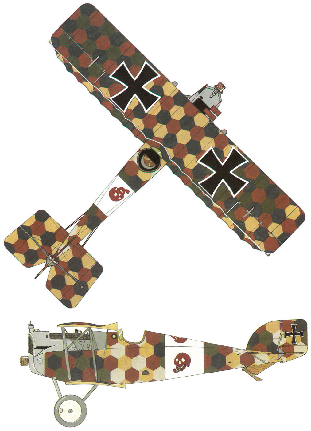
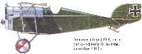
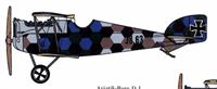
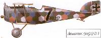
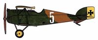
Авиатик (Берг) D-I, пилот - унтер-офицер Ф.Хефты, сентябрь 1917г.
-

E.Hauke, W.Schroeder, B.Totschinger - Die Flugzeuge der k.u.k. Luftfahrtruppe und Seeflieger 1914-1918
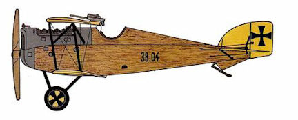
Aviatik-Berg D I 38.04 Frigyes Hefty Flik 42 J Prosecco Oktober 1917
-
В.Кондратьев - Самолеты первой мировой войны
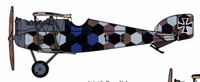
"Авиатик" D.I серии 38 из состава авиароты Flik 42J австро-венгерских ВВС, зима 1917-18гг.
-
P.Grosz, G.Haddow, P.Schiemer - Austro-Hungarian Army Aircraft of World War One /Flying Machines/
Aviatik D.I 38.37, Flik 63/J
-
E.Hauke, W.Schroeder, B.Totschinger - Die Flugzeuge der k.u.k. Luftfahrtruppe und Seeflieger 1914-1918
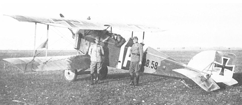
Aviatik-Berg D I 38.58 Robert Ellner Luftfahrzeugabwehrstaffel Wr. Neustadt Herbst 1918
-

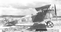
Z.Czirok - Austro-Hungarian Fighter Units of WWI. Volume 11 /Aeronaut/ (1)
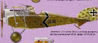
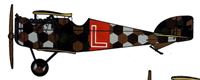
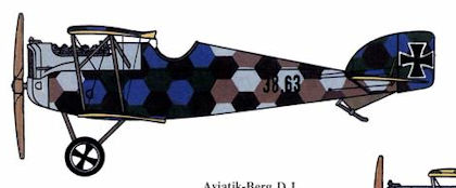
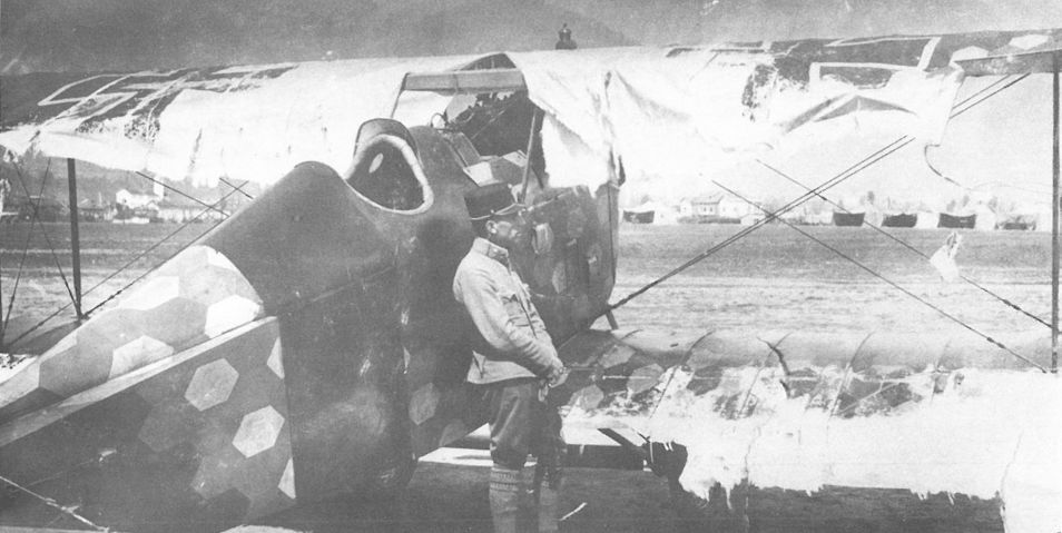
Aviatik D.I 38.63 of Flik 74/J with raised guns accessible, preferred by most pilots. The black Iron Cross on the white background painted on the wheel discs was a common decoration for the Austro-Hungarian aircraft. Kpl. Josef Marszalek crashed with this plane on 15th July 1918 due to structural wing failure.
-
E.Hauke, W.Schroeder, B.Totschinger - Die Flugzeuge der k.u.k. Luftfahrtruppe und Seeflieger 1914-1918
Aviatik-Berg D I 38.63 Josef Marszalek Flik 74 J Juli 1918
-

Z.Czirok - Austro-Hungarian Fighter Units of WWI. Volume 11 /Aeronaut/ (1)
Aviatik D.I (most likely) series 138 plane of Flik 74/J with a similar personal marking. If the marking is assumed to indicate the initial letter of a name, the fighters could belong to two people: Kpl. Karl Thomas (served at the squadron between 29th July 1918 and 22nd August 1918) or Lt. i.d.Res. Heinrich Tarangul v.Valea-Utsai (arrived at the unit on 22nd September 1918).
-

Z.Czirok - Austro-Hungarian Fighter Units of WWI. Volume 11 /Aeronaut/ (1)
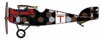
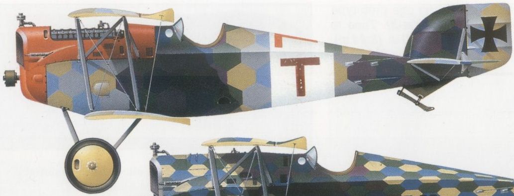
Aviatik D.I series 38 or 138 of Flik 74/J with a unique camouflage pattern and a personal marking (gothic "T").
-

Z.Czirok - Austro-Hungarian Fighter Units of WWI. Volume 11 /Aeronaut/ (1)
An Aviatik D.I with squadron markings of Flik 74/J known from a photo taken on S. Giacomo airfield awaiting an inspection, sometime in late summer or autumn 1918.
-
E.Hauke, W.Schroeder, B.Totschinger - Die Flugzeuge der k.u.k. Luftfahrtruppe und Seeflieger 1914-1918
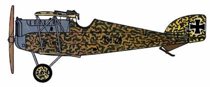
Aviatik-Berg D I 138.24 Robert Ellner Flik 56 J Seebach/Villach Dezember 1917
-
-

Z.Czirok - Austro-Hungarian Fighter Units of WWI. Volume 11 /Aeronaut/ (1)
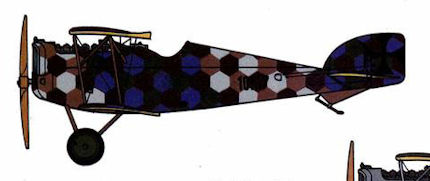
Aviatik D.I 138.43 flown by Kpl. August Staatz of Flik 74/J was forced to land near Treviso on 23rd June 1918. The personal marking (“T”) is believed to have belonged to Kpl. Karl Thomas, but he arrived at the unit on 26th July 1918.
-
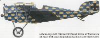
W.Green, G.Swanborough - The Complete Book of Fighters
A DI Series 138 forced down at Treviso on 23 June 1918
-
E.Hauke, W.Schroeder, B.Totschinger - Die Flugzeuge der k.u.k. Luftfahrtruppe und Seeflieger 1914-1918
Aviatik-Berg D I 138.43 Karl Thomas Flik 74 J San Fior Juni 1918
-
E.Hauke, W.Schroeder, B.Totschinger - Die Flugzeuge der k.u.k. Luftfahrtruppe und Seeflieger 1914-1918
Aviatik-Berg D I 138.48 Othmar Wolfan Flik 56 J Pianzano
-
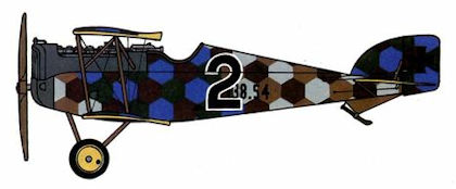
E.Hauke, W.Schroeder, B.Totschinger - Die Flugzeuge der k.u.k. Luftfahrtruppe und Seeflieger 1914-1918
Aviatik-Berg D I 138.54 Othmar Wolfan Flik 56 J Pianzano
-
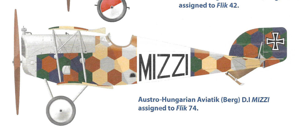
J.Herris - Aviatik Aircraft of WWI /Centennial Perspective/ (10)
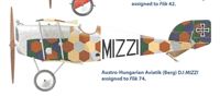
Austro-Hungarian Aviatik (Berg) D.I MIZZI assigned to Flik 74.
-

Z.Czirok - Austro-Hungarian Fighter Units of WWI. Volume 11 /Aeronaut/ (1)
Aviatik D.I 138.55 before and after having received new national markings in August 1918. On the latest version, the personal marking (“MIZZI”) was applied on the upper and maybe also on the under surfaces of the wide white band, while the earlier version beared it only on the sides. The aircraft was damaged by Kpl. Josef Kunz, crashing shortly after take-off on 28th August 1918.
-

Z.Czirok - Austro-Hungarian Fighter Units of WWI. Volume 11 /Aeronaut/ (1)
Aviatik D.I 138.62 shows the squadron markings of Flik 72/J, a black band on the fuselage with a white number and the black wheel discs. The aircraft crashed after a fight on 29th July 1918, killing its pilot Oblt. August Dehne.
-
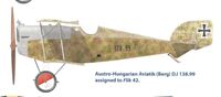
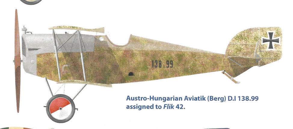
J.Herris - Aviatik Aircraft of WWI /Centennial Perspective/ (10)
Austro-Hungarian Aviatik (Berg) D.I 138.99 assigned to Flik 42.
-
E.Hauke, W.Schroeder, B.Totschinger - Die Flugzeuge der k.u.k. Luftfahrtruppe und Seeflieger 1914-1918
Aviatik-Berg D I 138.99 Frigyes Hefty Flik 42 J Motta di Livenza November 1917
-

Z.Czirok - Austro-Hungarian Fighter Units of WWI. Volume 11 /Aeronaut/ (1)
Aviatik D.I 138.119 was flown mostly by the squadron commander Oblt. Franz Cserich and Oblt. Arpad Pindter von Pindtershofen of Flik 74/J. Kpl. Adolf Wissinger safely force-landed with the plane on 19th September 1918 due to wing failure.
-
E.Hauke, W.Schroeder, B.Totschinger - Die Flugzeuge der k.u.k. Luftfahrtruppe und Seeflieger 1914-1918
Aviatik-Berg D I 138.120 Flik 63 J Motta di Livenza
-
P.Grosz, G.Haddow, P.Schiemer - Austro-Hungarian Army Aircraft of World War One /Flying Machines/
Aviatik D.I 138.XX, Flik 74/J
-

Z.Czirok - Austro-Hungarian Fighter Units of WWI. Volume 11 /Aeronaut/ (1)
A pipe-smoking skull in a white band as personal marking of Kpl. Milan Soviansky on an Aviatik D.I of Flik 74/J in August 1918, considered as a plane of series 138 (or it was maybe a series of 38, for example 38.30 flown many times by Soviansky).
-

Z.Czirok - Austro-Hungarian Fighter Units of WWI. Volume 11 /Aeronaut/ (1)
Aviatik D.I 238.39 of Flik 72/J was powered by 160 hp Austro-Daimler engine, which was more suitable for training than operational flying. Note the side radiators.
-

E.Hauke, W.Schroeder, B.Totschinger - Die Flugzeuge der k.u.k. Luftfahrtruppe und Seeflieger 1914-1918
Aviatik-Berg D I 238.39 Flik 72 J San Fior
-

J.Davilla - Italian Aviation in the First World War. Vol.1: Operations /Centennial Perspective/ (73)
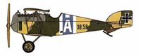
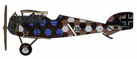
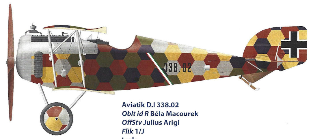
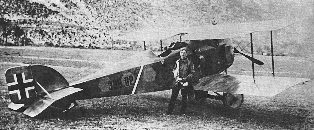
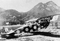
Aviatik D.I 338.02, Oblt id R Bela Macourek, OffStv Julius Arigi, Flik 1/J, Igalo, Summer 1918
-

В.Кондратьев - Самолеты первой мировой войны
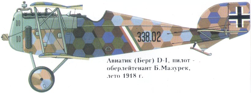
Авиатик (Берг) D-I, пилот - оберлейтенант Б.Мазурек, лето 1918г.
-
E.Hauke, W.Schroeder, B.Totschinger - Die Flugzeuge der k.u.k. Luftfahrtruppe und Seeflieger 1914-1918
Aviatik-Berg D I 338.02 Bola Macourek Flik 1 J Igalo Sommer 1918
-
-
E.Hauke, W.Schroeder, B.Totschinger - Die Flugzeuge der k.u.k. Luftfahrtruppe und Seeflieger 1914-1918
Aviatik-Berg D I 338.53 Aspern November 1918
-
В.Обухович, А.Никифоров - Самолеты Первой Мировой войны
Авиатик (Берг) D I
-
-
-
-
-
-
E.Hauke, W.Schroeder, B.Totschinger - Die Flugzeuge der k.u.k. Luftfahrtruppe und Seeflieger 1914-1918
Aviatik-Berg D I 92. Gustav Raab Flik 7 J Gardolo
-
-
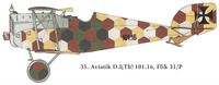
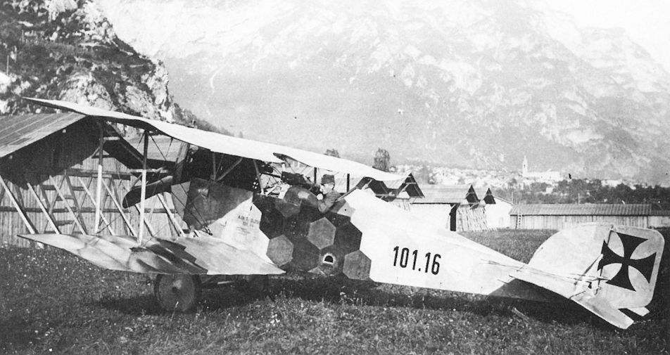
P.Grosz, G.Haddow, P.Schiemer - Austro-Hungarian Army Aircraft of World War One /Flying Machines/
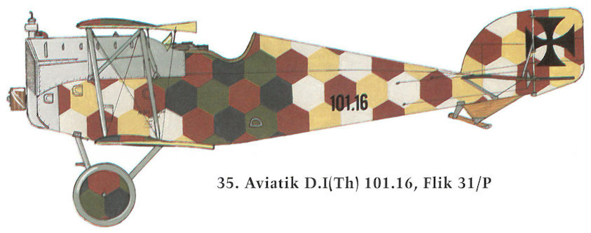
Aviatik D.I(Th) 101.16, Flik 31/P
-

E.Hauke, W.Schroeder, B.Totschinger - Die Flugzeuge der k.u.k. Luftfahrtruppe und Seeflieger 1914-1918
Aviatik-Berg D I 101.17 Photoaufklärer Flik 31 P Ospedaletto 1918
-
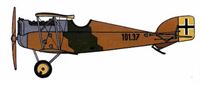
E.Hauke, W.Schroeder, B.Totschinger - Die Flugzeuge der k.u.k. Luftfahrtruppe und Seeflieger 1914-1918
Aviatik-Berg В I 101.37 ÜGr. I Aspern Oktober 1918
-
-

-
W.Green, G.Swanborough - The Complete Book of Fighters
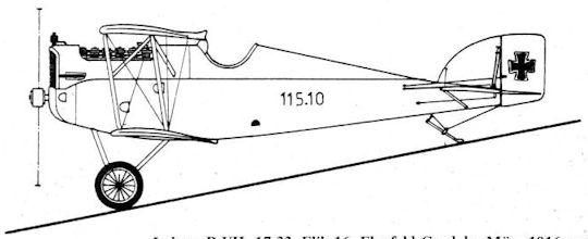
A D I Series 115 (Lohner-built) operated by Flik 60J in 1918.
-
E.Hauke, W.Schroeder, B.Totschinger - Die Flugzeuge der k.u.k. Luftfahrtruppe und Seeflieger 1914-1918
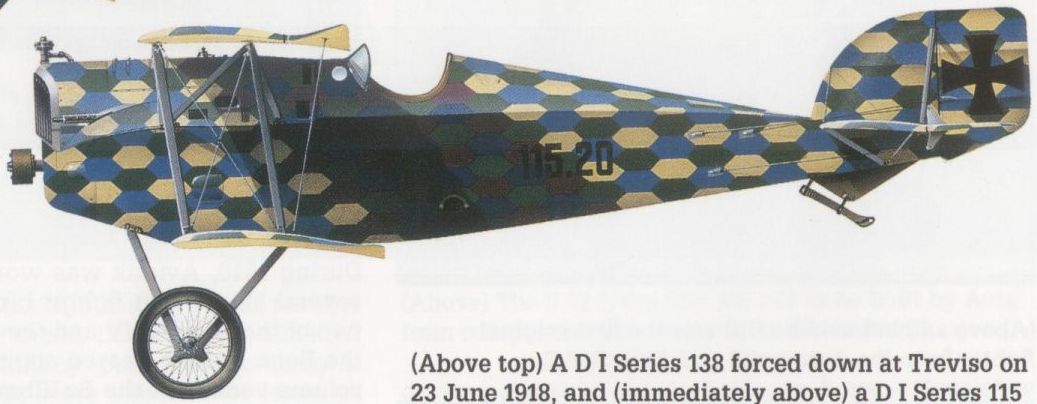
Aviatik-Berg D I 115.20 Flik 60 J Feltre Sommer 1918
-

Z.Czirok - Austro-Hungarian Fighter Units of WWI. Volume 11 /Aeronaut/ (1)
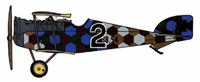
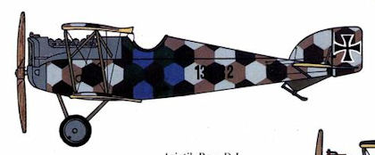
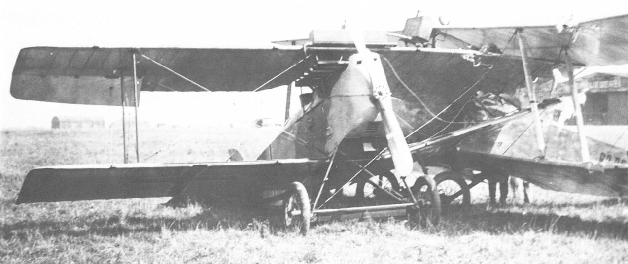
Aviatik D.I (Lo) 115.25 of Flik 72/J. Fwbl. Ernst Heinz crashed with the aircraft on 2nd June 1918. The series 115 fighter had a typical camouflage pattern of lozenge of flattened hexagons. Unlike the Aviatik-built aircraft, the “Bergs” produced by Lohner had camouflaged engine panels. The white number in a black band was a unit marking for identification, the exact number (“2”) is uncertain in this case (maybe “6”).
-
E.Hauke, W.Schroeder, B.Totschinger - Die Flugzeuge der k.u.k. Luftfahrtruppe und Seeflieger 1914-1918
Aviatik-Berg D I 115.32 Frank Linke-Crawford Flik 41 J Feltre Juli 1918


-
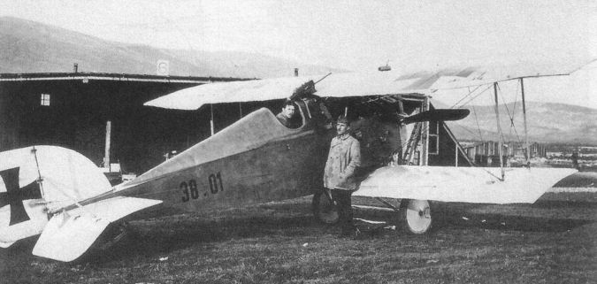
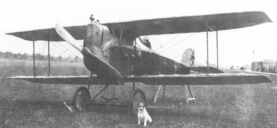
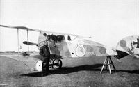
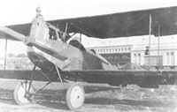
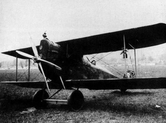
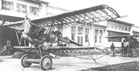
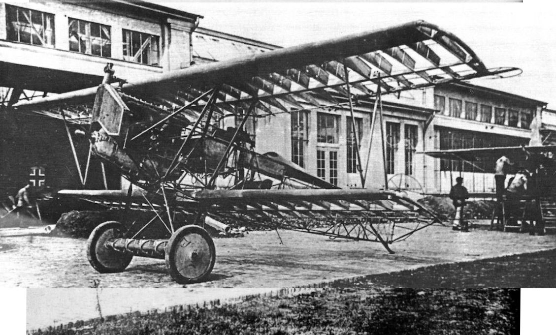
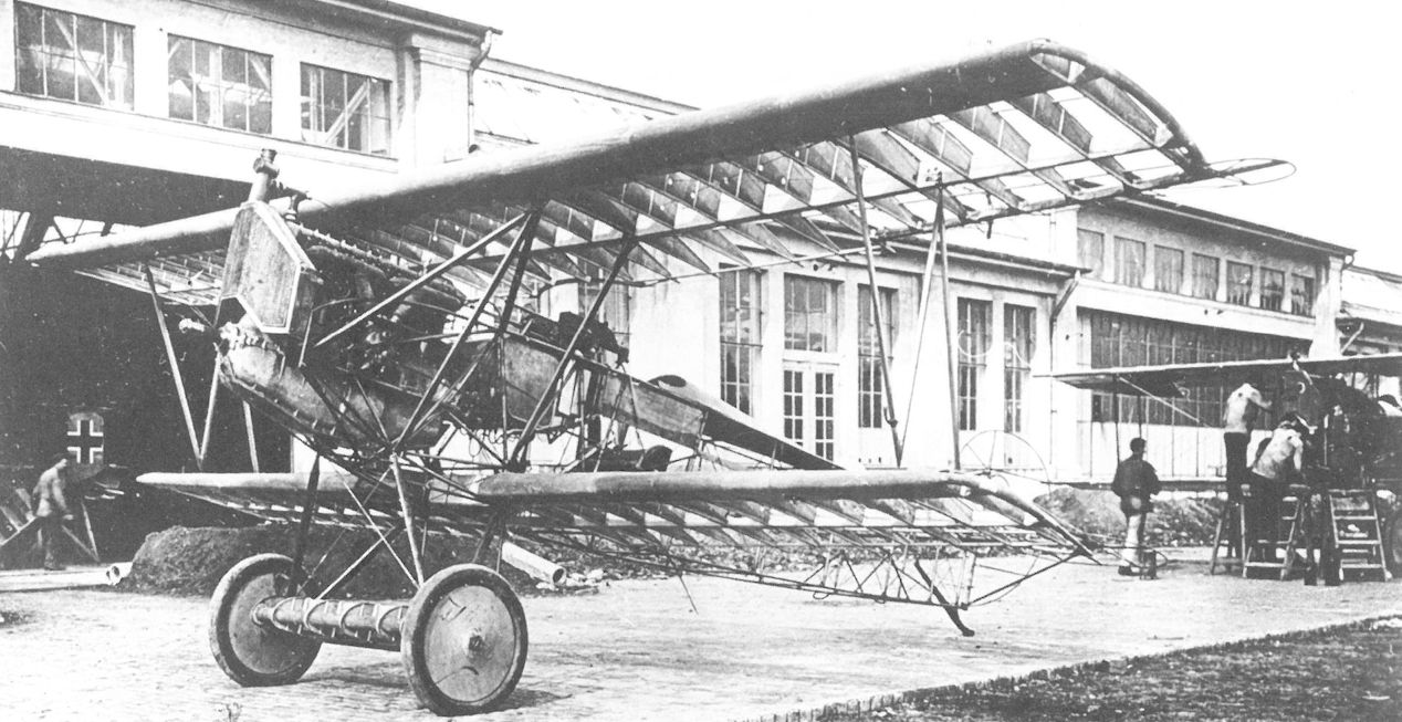
В.Кондратьев - Самолеты первой мировой войны
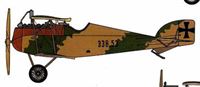
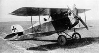
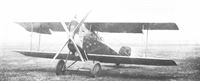
Первый серийный "Авиатик" D. I на аэродроме "Дивача" в Словении, май 1917 г. Самолет вооружен несинхронным пулеметом "Шварцлозе", установленным над верхним крылом.
-
P.Grosz, G.Haddow, P.Schiemer - Austro-Hungarian Army Aircraft of World War One /Flying Machines/
The Aviatik D.I 38.02 and 38.01 lead the line-up of Flik 101/G aircraft in September 1917. Accepted on 3 May 1917, D.I 38.01 was ordered dispatched to Fluggeschwader I on 15 May. D.I 38.02 was accepted in June 1917. Both fighters were armed with an over-the-wing machine gun.
-

Z.Czirok - Austro-Hungarian Fighter Units of WWI. Volume 11 /Aeronaut/ (1)
Aviatik D.I 38.03 at Aspern, assigned later to Flik 74/J for a short time. (Martin O'Connor via Aaron Weaver)
-
E.Hauke, W.Schroeder, B.Totschinger - Die Flugzeuge der k.u.k. Luftfahrtruppe und Seeflieger 1914-1918
Aviatik-Berg D.I 38.03 in Aspern, Einfliegerei 1917, Flugzeugführer Antal Feher erreichte am 12. Juni 1917 damit 193 km/h im Horizontalflug
Aviatik-Berg D.I 38.03 в Асперне, 1917 год. Пилот Антал Фехер достиг в горизонтальном полете 193 км/ч 12 июня 1917 года. -
E.Hauke, W.Schroeder, B.Totschinger - Die Flugzeuge der k.u.k. Luftfahrtruppe und Seeflieger 1914-1918
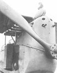
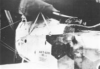
Aviatik-Berg D.I 38.05 in Aspern, Einfliegerei 1917, zu Versuchen mit starren Kameras verwendet, an der rechten Motorverkleidung ist eine Sottoskop-Halterung befestigt
Aviatik-Berg D.I 38.05 в Асперне, 1917 г., использовался для испытаний с фиксированными фотоаппаратами, кронштейн для "соттоскопа" прикреплен к правой крышке двигателя. -
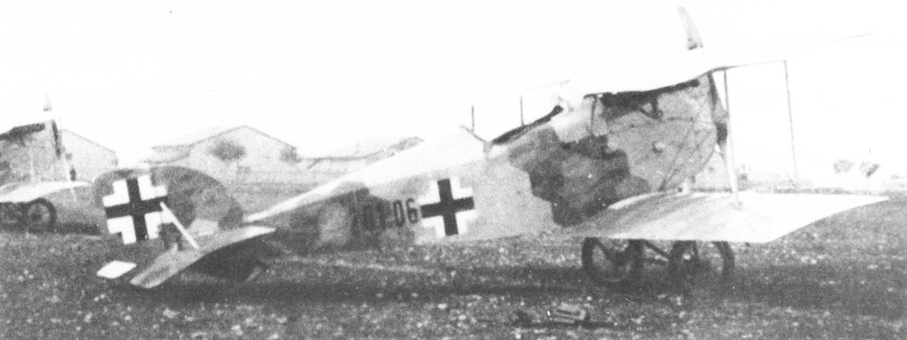
P.Grosz, G.Haddow, P.Schiemer - Austro-Hungarian Army Aircraft of World War One /Flying Machines/
The Sottoscope for ground viewing is mounted just above the exhaust stacks on Aviatik D.I 38.06. This aircraft remained attached to Flek 6 at Wiener-Neustadt for equipment trials.
-

P.Grosz, G.Haddow, P.Schiemer - Austro-Hungarian Army Aircraft of World War One /Flying Machines/
Aviatik D.I 38.15 served with Fliks 35/D and 4/D. At the end of the war, it was attached to the weapons school at Aspern. The angled Schwarzlose machine gun is hidden by the upper wing.
-
P.Grosz, G.Haddow, P.Schiemer - Austro-Hungarian Army Aircraft of World War One /Flying Machines/
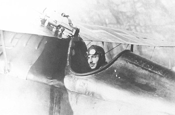
Aircraft type Aviatik "Berg" D.I Oblt. Marian Gawel from Flik 32 on the Italian Front in autumn 1917 during the timing of the machine gun.
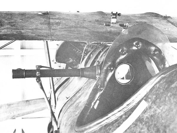
The Schwarzlose M 16 machine gun of Aviatik D.I 38.17 being aligned at Flik 32/D. The diving attitude required to fire straight ahead was disparaged as a serious combat liability by Austro-Hungarian fighter pilots. -

P.Grosz, G.Haddow, P.Schiemer - Austro-Hungarian Army Aircraft of World War One /Flying Machines/
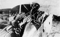
The deep cockpit of the Aviatik D.I 38.29 of Flik 17/D certainly protected the pilot from the elements but made aiming difficult. A ring gunsight is mounted on the front attachment of the Schwarzlose M 16 gun. The dark stain on the fuselage is from the gun chamber lubrication oil.
-
-
P.Grosz, G.Haddow, P.Schiemer - Austro-Hungarian Army Aircraft of World War One /Flying Machines/
The Aviatik D.I 38.58 fitted with side radiators and cowl-mounted guns. After serving with Flik 56/J, 38.58 flew with the Wiener-Neustadt defense flight in the fall of 1918. The rear strut carries an identification pennon.
-
P.Grosz, G.Haddow, P.Schiemer - Austro-Hungarian Army Aircraft of World War One /Flying Machines/
"Авиатик" D.I из состава авиароты 74J (Flik 74J), июль 1918 г. Пилот - Йозеф Маршалек
As of June-July 1918, Aviatik D.I fighters began leaving the factory with raised guns mounted within reach of the pilot. Aviatik D.I 38.63, attached to Flik 74/J, crashed on 15 July 1918 because of wing failure.
The Aviatik (Berg) DI fitted with a 200 hp Austro-Daimler engine, this being an aircraft of the first series, and one of the first D Is to be fitted with Schwarzlose guns immediately ahead of the cockpit (38.63)
Aviatik-Berg D.I 38.63 in Aspern, Einfliegerei 1918, nach der Übernahme der Flik 74J zugeteilt, Flugzeugführer Kpl Josef Marszalek stürzte nach Tragflächenbruch am 15. Juli 1918 damit ab, schwer verletzt
Aviatik-Berg D.I 38.63 в Асперне, летавший в 1918 году во Flik 74J, пилот Kpl Йозеф Маршалек разбился после разрушения крыла 15 июля 1918 года, тяжело ранен. -

E.Hauke, W.Schroeder, B.Totschinger - Die Flugzeuge der k.u.k. Luftfahrtruppe und Seeflieger 1914-1918
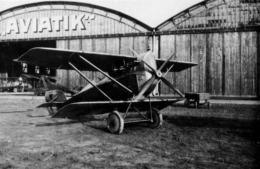
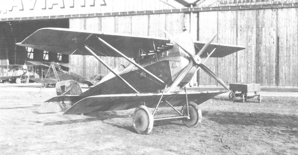
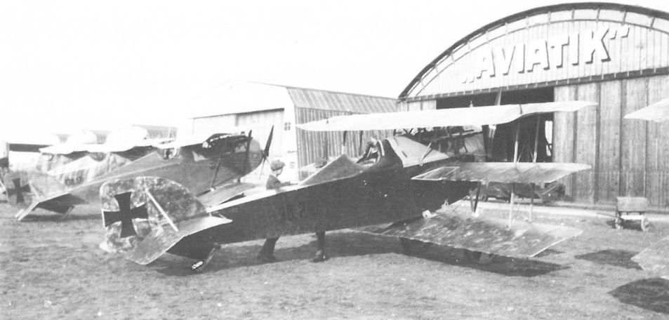
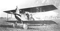
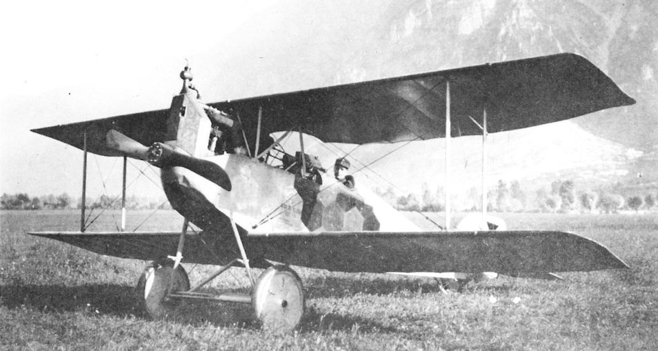
Aviatik-Berg D.II 39.01 in Aspern, Flugzeughalle von Aviatik. Erprobungsflugzeug, Herbst 1917, im Hintergrund Berg C.I 137.15 und Berg D.I Ba 38
Aviatik-Berg D.II 39.01 в Асперн, Ангар Aviatik. Экспериментальный самолет, осень 1917 г., на заднем плане Berg C.I 137.15 и Berg D.I Ba 38Другие самолёты на фотографии: Aviatik (Berg) C.I - Австро-Венгрия - 1917Aviatik (Berg) D.II - Австро-Венгрия - 1917
-

P.Grosz, G.Haddow, P.Schiemer - Austro-Hungarian Army Aircraft of World War One /Flying Machines/
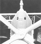
The unarmed Aviatik D.II 39.01 in front of the Aviatik hangars at Aspern in the fall of 1917. The four-bladed propeller was usually matched with a 200 hp Daimler engine. Behind the tail is Aviatik C.I 137.15.
Другие самолёты на фотографии: Aviatik (Berg) C.I - Австро-Венгрия - 1917Aviatik (Berg) D.II - Австро-Венгрия - 1917


-

P.Grosz, G.Haddow, P.Schiemer - Austro-Hungarian Army Aircraft of World War One /Flying Machines/
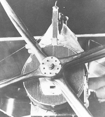
An, experimental circular radiator was flight tested on Aviatik D.I 138.11 in October 1917. The lower cowl fairing remains to be installed.
-

P.Grosz, G.Haddow, P.Schiemer - Austro-Hungarian Army Aircraft of World War One /Flying Machines/
The Aviatik 30.24 in front of the company hangar at Aspern. The aerodynamically-balanced ailerons on the top wing were unique for Berg-designed fighters. Cellon panels in the middle wing enhanced the pilot’s view downward. To the left are an Aviatik D.II 39.01 and a D.I 138.17.
Другие самолёты на фотографии: Aviatik (Berg) 30.24 - Австро-Венгрия - 1917Aviatik (Berg) D.II - Австро-Венгрия - 1917
-
E.Hauke, W.Schroeder, B.Totschinger - Die Flugzeuge der k.u.k. Luftfahrtruppe und Seeflieger 1914-1918
Aviatik-Berg D.I 138.43; ausgestellt in Treviso, am 23. Juni 1918 wurde Flugzeugführer Kpl August Staatz, Flik 74J, von Hanriot der italienischen 81. Squadron bei einem Begleitflug (sein dritter Feindflug) hinter den feindlichen Linien zur Landung gezwungen. Das persönliche Zeichen ,.T“ gehörte zu Flugzeugführer Kpl Karl Thomas
Aviatik-Berg D.I 138,43; вылетев из Тревизо 23 июня 1918 года для эскортирования (его третий боевой вылет) пилот Август Штаац, Flik 74J, был сбит самолетом Hanriot 81-й итальянской эскадрильи, и был вынужден приземлиться в тылу врага. Символ "Т" - персональный идентификатор летчика Kpl Карла Томаса. -

Z.Czirok - Austro-Hungarian Fighter Units of WWI. Volume 11 /Aeronaut/ (1)
Aviatik D.I 138.43 in Italian hands. (Colin Overs via Boris Ciglic)
-

Z.Czirok - Austro-Hungarian Fighter Units of WWI. Volume 11 /Aeronaut/ (1)
Kpl. Karl Thomas' Aviatik D.I 138.43 after landing on the Treviso racecourse with only minor damage on 23rd June 1918. (Rinaldo D'Ami via Paolo Varriale)
-

-

Z.Czirok - Austro-Hungarian Fighter Units of WWI. Volume 11 /Aeronaut/ (1)
The captured 138.43 was eventually displayed at Padua airfield on 20th September 1918 as a part of a great ceremony. (Paolo Varriale)
-

Z.Czirok - Austro-Hungarian Fighter Units of WWI. Volume 11 /Aeronaut/ (1)
Stfw. Karl Benko in his Aviatik D.I 138.44. Note the lack of personal marking on the plane and the rudder with streaked pattern originated maybe from another aircraft. (Reinhard Masajdek via Petr Aharon Tesar)
-

Z.Czirok - Austro-Hungarian Fighter Units of WWI. Volume 11 /Aeronaut/ (1)
Stfw. Karl Benko in his Aviatik D.I 138.44.
-
E.Hauke, W.Schroeder, B.Totschinger - Die Flugzeuge der k.u.k. Luftfahrtruppe und Seeflieger 1914-1918
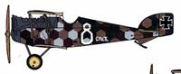
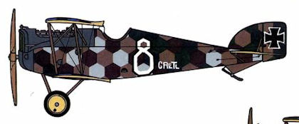
Aviatik-Berg D.I 138.48, Flik 56J, Pianzano, davor Feldpilot Oblt Othmar VVolfan, persönliche Kennzeichen „8“ und Name „Grell" am Rumpf
Aviatik-Berg D.I 138.48, Flik 56J, Pianzano, перед пилотом Oblt Отмаром Вольфаном, личный идентификатор «8» и имя «Грелль» на фюзеляже. -

P.Grosz, G.Haddow, P.Schiemer - Austro-Hungarian Army Aircraft of World War One /Flying Machines/
Leutnant Othmar Wolfan of Flik 56/J in Aviatik D.I 138.54 with raised guns accessible to the pilot. This placement was preferred by most pilots.
-

Z.Czirok - Austro-Hungarian Fighter Units of WWI. Volume 11 /Aeronaut/ (1)
The personal marking of MIZZI on all surfaces of the fuselage in the white band on Aviatik D.I 138.55. (Colin Overs via Boris Ciglic)
-

-

Z.Czirok - Austro-Hungarian Fighter Units of WWI. Volume 11 /Aeronaut/ (1)
Aviatik D.I 138.55 MIZZI of Flik 74/J with Eisernkreuz. Kpl. Josef Kunz crashed the fighter plane shortly after take-off on 28th August 1918. A signal flare pistol is mounted outside of the cockpit. The guns were mounted astride the engine out of the pilot’s reach.
-

Z.Czirok - Austro-Hungarian Fighter Units of WWI. Volume 11 /Aeronaut/ (1)
Aviatik D.I 138.55 MIZZI of Flik 74/J with Balkenkreuz.
-

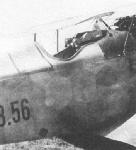
A.Olejko - War Wings Over Galicia 1918-1919 /Aeronaut/
Still in a foreign uniform... In November 1918, the commander of Polish pilots in Lwow was Oblt. Stefan Bastyr - photographed in the uniform of the K.u.K. Luftfahrtruppen against the background of his Aviatik "Berg" D.I no.138.56 fighter from Flik 37P. (internet via J. Butkiewicz)
-
E.Hauke, W.Schroeder, B.Totschinger - Die Flugzeuge der k.u.k. Luftfahrtruppe und Seeflieger 1914-1918
Aviatik-Berg D.I 138.60 in Aspern, Waffenversuchsflik, Sommer 1918 Sonderausführung mit hochliegendem MG-Einhau und neuem flachen Stirnkühler
Aviatik-Berg D.I 138.60 в Асперне, Waffenversuchsflik, лето 1918 г. Специальная версия с высокорасположенным пулеметом и новым плоским передним радиатором -
P.Grosz, G.Haddow, P.Schiemer - Austro-Hungarian Army Aircraft of World War One /Flying Machines/
Aviatik D.I 138.111 was given a production radiator with oblong machine gun cut-outs. The projecting extension is an air-cooled condenser for the radiator.
-
P.Grosz, G.Haddow, P.Schiemer - Austro-Hungarian Army Aircraft of World War One /Flying Machines/
Twin side radiators, mounted behind the front center-section struts, under test on the Aviatik D.I 138.111. The streamlined condenser tank was a unique feature.
-

E.Hauke, W.Schroeder, B.Totschinger - Die Flugzeuge der k.u.k. Luftfahrtruppe und Seeflieger 1914-1918
Aviatik-Berg D.I 138.112 in Aspern, Einfliegerei 1918, serienmäßiger rückversetzter MG-Einbau. Flugzeug wurde später der Flik 56J zugeteilt
Aviatik-Berg D.I 138.112 в Асперне, прилет в 1918 году, стандартная установка пулемета с синхронизатором. Позже самолет был переведен в Flik 56J. -
P.Grosz, G.Haddow, P.Schiemer - Austro-Hungarian Army Aircraft of World War One /Flying Machines/
The LFT sent two Aviatik D.I fighters to Germany for test. Here is 138.114 at the Adlershof test center in March-April 1918. The four-bladed propeller was often used in conjunction with the 200 hp Daimler engine.
-

Z.Czirok - Austro-Hungarian Fighter Units of WWI. Volume 11 /Aeronaut/ (1)
Aviatik D.I 138.116 was assigned to Flik 74/J and flown by squadron commander Oblt. Franz Cserich in the air combat of 23rd July 1918 when he force-landed with the aircraft. (Colin Overs via Boris Ciglic)
-
E.Hauke, W.Schroeder, B.Totschinger - Die Flugzeuge der k.u.k. Luftfahrtruppe und Seeflieger 1914-1918
Aviatik-Berg D.I 138.116 in Aspern, Frühjahr 1918, Waffeneinbau mit zwei Schwarzlose-MG M16, Sechsecktarnmuster
Aviatik-Berg D.I 138.116 в Асперне, весна 1918 г., с двумя пулеметами Шварцлозе M16, шестиугольный камуфляж -
P.Grosz, G.Haddow, P.Schiemer - Austro-Hungarian Army Aircraft of World War One /Flying Machines/
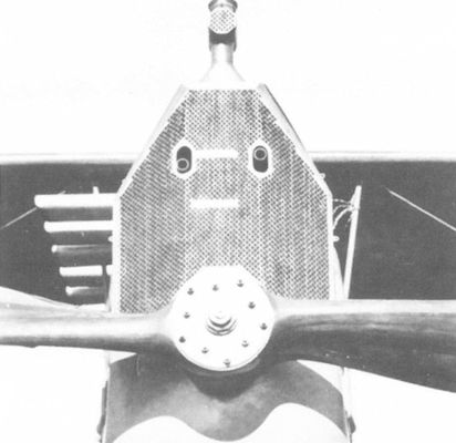
Aviatik D.I 138.116, showing a production radiator with twin rectangular cut-outs for the machine guns mounted at pilot’s eye level.
-

Z.Czirok - Austro-Hungarian Fighter Units of WWI. Volume 11 /Aeronaut/ (1)
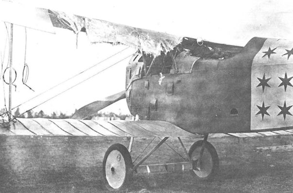
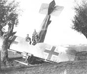
The broken rib section of Aviatik D.I 138.119 after force-landing by Kpl. Adolf Wissinger on 19th September 1918.
-

P.Grosz, G.Haddow, P.Schiemer - Austro-Hungarian Army Aircraft of World War One /Flying Machines/
The flexing stresses to which the thin rear rib section was exposed could cause failures. Korporal Alfred Wiesinger of Flik 74/J was fortunate to bring 138.119 down safely on 18 September 1918. The rear-view mirror on the center section helped prevent being surprised from behind.
-

Z.Czirok - Austro-Hungarian Fighter Units of WWI. Volume 11 /Aeronaut/ (1)
Leutnant Makowetz of Flik 72/J (74/J ???) with Aviatik D.I series 138 at San Fior, May 1918. The front gun sight is mounted above the forward exhaust stack.
Aviatik D.I series 38 or 138 of Flik 74/J with a personal marking of "gothic T".
Aviatik-Berg D.I Ba 138 bei der Flik 74J in San Fior (6.AK), am Pilotensitz Feldpilot Fw Karl Turek, persönliches Zeichen „T“ am Rumpf
Aviatik-Berg D.I Ba 138 на Flik 74J в Сан-Фиоре (6.AK), на месте пилота Feldpilot Fw Karl Turek, личный знак "T" на фюзеляже -

Z.Czirok - Austro-Hungarian Fighter Units of WWI. Volume 11 /Aeronaut/ (1)
Crash of another "Berg" fighter of Flik 74/J with a personal marking of "gothic T". The special camouflage pattern suggests a D.I produced by the W.K.F. factory. (Petr Aharon Tesar)
-

P.Grosz, G.Haddow, P.Schiemer - Austro-Hungarian Army Aircraft of World War One /Flying Machines/
The Aviatik hangar at Aspern provides a perfect backdrop for seven Aviatik aircraft undergoing flight and acceptance testing in the autumn of 1917. From the right are C.I 137.07, 30.24, 39.01, two D.I series 138, and a C.I.
Другие самолёты на фотографии: Aviatik (Berg) C.I - Австро-Венгрия - 1917
-

Z.Czirok - Austro-Hungarian Fighter Units of WWI. Volume 11 /Aeronaut/ (1)
Personnel of Flik 72/J on San Fior airfield, summer 1918. Sitting in the middle is the squadron commander, Oblt. i.d.Res. Josef Hoffmann, on his left, is Fwbl. Josef Peiger. The aircraft in the background is probably a series 138 "Berg". (Reinhard Masajdek via Petr Aharon Tesar)
-

P.Grosz, G.Haddow, P.Schiemer - Austro-Hungarian Army Aircraft of World War One /Flying Machines/
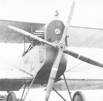
Standard production radiator with a single aperture for the starboard gun, mounted in Aviatik D.I Series 138. The bright red stripe signifies that the propeller is experimental; the white stripe signifies it is company property.


-

Z.Czirok - Austro-Hungarian Fighter Units of WWI. Volume 11 /Aeronaut/ (1)
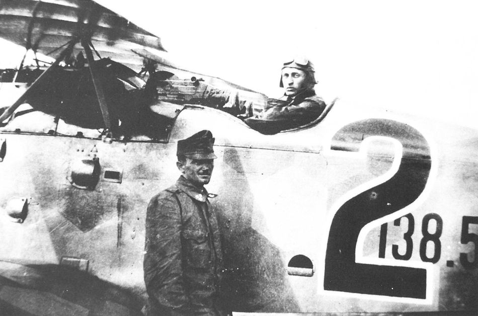
Aviatik D.I 238.39 fighter trainer of Flik 72/J. The unit and personal markings are clearly visible. (Colin Overs via Boris Ciglic)
Aviatik-Berg D.I 238.39 bei der Flik 72.J in San Fior (6.AK), Staffelmarkierung schwarzes Rumpfband, die weißen Ziffern wiesen auf die Rangordnung hin
Aviatik-Berg D.I 238.39 на Flik 72.J в Сан-Фиоре (6.AK), черная лента на фюзеляже - опознавательный знак подразделения, белые цифры обозначают порядковый номер -

Z.Czirok - Austro-Hungarian Fighter Units of WWI. Volume 11 /Aeronaut/ (1)
Line of aircraft on San Fior airfield, four fighters of Flik 72/J and one with unit markings of Flik 74/J on the right. The first on the left is Aviatik D.I 238.39 "4", and the second is a series 115 plane. (Reinhard Masajdek via Petr Aharon Tesar)
-
P.Grosz, G.Haddow, P.Schiemer - Austro-Hungarian Army Aircraft of World War One /Flying Machines/
Aviatik D.I 238.41 armed with raised machine guns and fitted with side radiators. It was dispatched to the Front on 20 July 1918.
-

E.Hauke, W.Schroeder, B.Totschinger - Die Flugzeuge der k.u.k. Luftfahrtruppe und Seeflieger 1914-1918
Aviatik-Berg D.I 238.41 in Aspern, Frühjahr 1918, Waffeneinhau mit zwei Schwarzlose-MG M 16, Seitenkühler, Sechsecktarnmuster
Aviatik-Berg D.I 238.41 в Асперне, весна 1918 г., с двумя Schwarzlose MG M 16, боковой радиатор, шестиугольный камуфляж -
P.Grosz, G.Haddow, P.Schiemer - Austro-Hungarian Army Aircraft of World War One /Flying Machines/
Production side radiators as mounted on Aviatik D.I 238.41. Stencilling the aircraft number on cowl and struts was mandatory.
-

P.Grosz, G.Haddow, P.Schiemer - Austro-Hungarian Army Aircraft of World War One /Flying Machines/
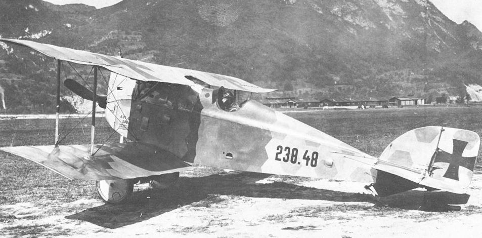
Photographed at the Jagdfliegerschule Pergine, D.I 238.48 has the nose radiator and buried guns. The deep cockpit protected the pilot, but his forward vision was restricted.
-
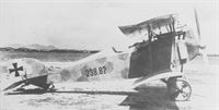
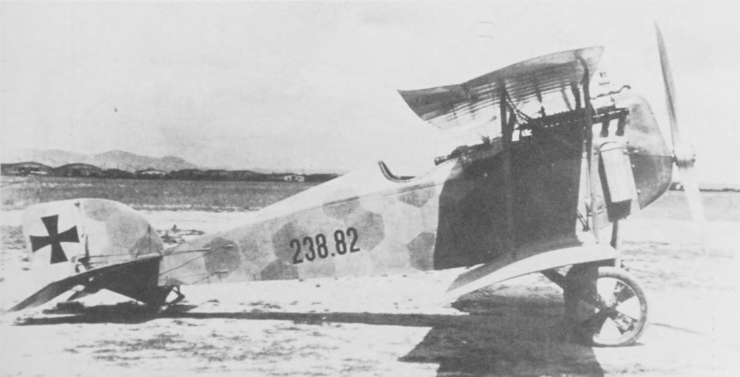
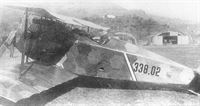
R.Keimel - Osterreichs Luftfahrzeuge /Weishaupt Verlag/
Aviatik-Berg D.I 238.82 in Aspern, Frühjahr 1918, MG bereits eingebaut, verändertes Schriftbild am Rumpf
Aviatik-Berg D.I 238.82 в Асперне, весна 1918 г., MG уже установлен, изменен шрифт на фюзеляже. -

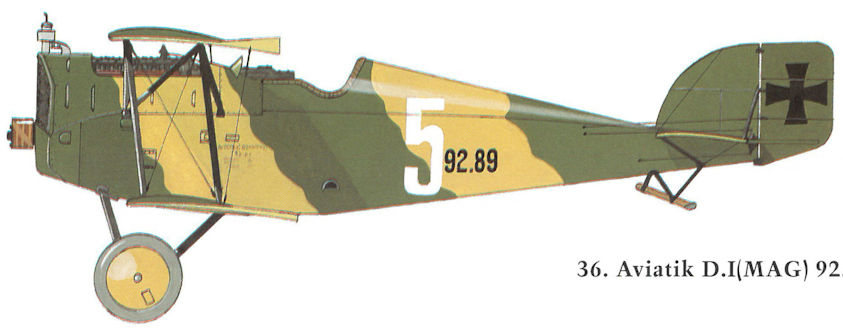
H.Cowin - Aviation Pioneers /Osprey/
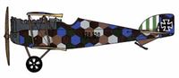
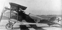
Авиатик (Берг) серии 238, пилот Линке Кроуфорд, 1918г / Design of the Austrian Aviatik, or Berg D I commenced very early in 1917, slightly ahead of Austria's other indigenous fighter, the Phonix D I. During the early stage of its flying career, the Berg D I suffered catastrophic structural wing failure, but once generally 'beefed-up', the machine proved to be both fast, agile and have a good climb, cited as reaching 13,000 feet in 11 minutes 15 seconds. Initially powered by a 185hp Austro-Daimler, these Bergs had top level speed of 113mph at sea level. The speed of later 200hp or 225hp powered aircraft rose to 115mph. Similarly, initial production Bergs carried a single 8mm Schwarzlose, while a second was added to later fighters. Delivered primarily to serve on the Italian Front from the late spring of 1917 onwards, the Berg D I was built in some quantities, involving 4 sub-contractors probably producing more than 300 machines. The fighter shown here was the mount of Austrian air ace, Oblt Frank Linke-Crawford, leader of Flik 60.


-
P.Grosz, G.Haddow, P.Schiemer - Austro-Hungarian Army Aircraft of World War One /Flying Machines/
Aviatik D.I 338.02 with Oberleutnant Bela Macourek, CO of Flik 1/J in Igalo (Bocche di Cattaro) in August 1918. The pilot’s seat has been raised to provide an improved forward view.
-

J.Davilla - Italian Aviation in the First World War. Vol.1: Operations /Centennial Perspective/ (73)
Flik 1/J's CO Oblt Bela Macourek at Igalo with Aviatik D.I 338.02. A five-victory ace, Macourek's victory tally included three British aircraft.
-
P.Grosz, G.Haddow, P.Schiemer - Austro-Hungarian Army Aircraft of World War One /Flying Machines/
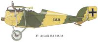
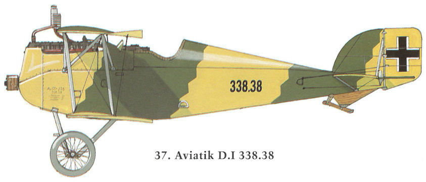
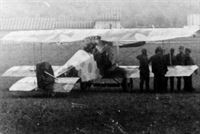
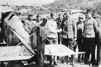
Aviatik D.I 338.38 being inspected by Italian troops near Egna, 10 November 1918.
-

P.Grosz, G.Haddow, P.Schiemer - Austro-Hungarian Army Aircraft of World War One /Flying Machines/
Aviatik D.I 338.42 with a block radiator mounted over the leading edge, an installation seen on some late production aircraft. The gun blast tubes are visible just above the engine cowling.
-
P.Grosz, G.Haddow, P.Schiemer - Austro-Hungarian Army Aircraft of World War One /Flying Machines/
Colonel Bares of the the Inter-Allied Aeronautical Control Commission talking with Hauptmann Karl Nikitsch before going aloft in the unarmed Aviatik D.I 338.53 at Fischamend in 1919.
-

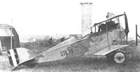
Z.Czirok - Austro-Hungarian Fighter Units of WWI. Volume 11 /Aeronaut/ (1)
Aviatik D.I 338.53 in a hangar at Aspern. Several planes of this series served at Flik 74/J in the last months of the war but very little is known about their operational use. (Martin O'Connor via Aaron Weaver)
Aviatik-Berg D.I 338.53 in Aspern, Hangar der Aviatik-Flugzeugwerke, letzte Ausführung der Tarnschemen, zweifarbig, großer Kastenkühler am Tragflügel
Aviatik-Berg D.I 338.53 в Асперн, ангар Aviatik-Flugzeugwerke, последний вариант камуфляжа, двухцветный, большой радиатор на крыле -
P.Grosz, G.Haddow, P.Schiemer - Austro-Hungarian Army Aircraft of World War One /Flying Machines/
An unarmed Aviatik D.I 338.59 with the early Austrian Volkswehr insignia on the rudder at Fischamend in 1919. All Aviatik D.I fighters had limited forward visibility because of the high engine placement.
-

Z.Czirok - Austro-Hungarian Fighter Units of WWI. Volume 11 /Aeronaut/ (1)
A poor quality but unique photo of Aviatik D.I 338.95 with a special personal emblem and late-war national markings. This aircraft is believed to possibly served at Flik 74/J. (Reinhard Masajdek via Petr Aharon Tesar)


-
P.Grosz, G.Haddow, P.Schiemer - Austro-Hungarian Army Aircraft of World War One /Flying Machines/
Aviatik D.I with an experimental radiator cut-back to provide improved sighting for the raised machine guns. The “5°” stencilled on the upper wing signifies the correct angle of incidence.

-

Z.Czirok - German Aircraft in Hungarian Service /Centennial Perspective/ (92)
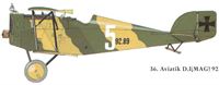
MAG 90.05 flys in to land; MAG 90.03 is at right. (Peter M. Grosz collection/STDB)
Im Fluge Fokker V 22, am Boden Dreidecker 90.03, Aviatik-Berg D.I 92.14, Aviatik-Berg C.I-Baureihe 91, Ufag C.I-Flugzeug 161.01Другие самолёты на фотографии: Aviatik (Berg) C.I - Австро-Венгрия - 1917Fokker D.VII / V11 / V18 / V22 / V24 - Германия - 1917Fokker Dr.I (Fokker Dreidecker) / V4 / V5 / V7 - Германия - 1917UFAG C.I - Австро-Венгрия - 1917
-

J.Herris, J.Leckscheid - Fokker Aircraft of WWI. Vol.5: 1918 Designs Part 1: Prototypes & D.VI /Centennial Perspective/ (55)
Tony Fokker wiping his hands after demonstrating the V 22 at Matyasfold in May 1918. A two-bladed propeller has been fitted and the standard Fokker streaked camouflage applied. In the background is the Fokker 90.03 (V7) and the Aviatik D.I(MAG) 92.14.
V22 was camouflaged before it was sent to MAG factory and designated 90.05. In this photo it has Fokker 2-bladed propeller. Fokker triplane prototype 90.03 is in the left background. (Peter M. Grosz collection/STDB)Другие самолёты на фотографии: Fokker D.VII / V11 / V18 / V22 / V24 - Германия - 1917Fokker Dr.I (Fokker Dreidecker) / V4 / V5 / V7 - Германия - 1917
-
P.Grosz, G.Haddow, P.Schiemer - Austro-Hungarian Army Aircraft of World War One /Flying Machines/
Aviatik D.I (MAG) 92.18 in front of the MAG factory in Matyasfold. This aircraft, fitted with strengthened wing ribs, was tested by Flik 72/J on 10 October 1918. The slot in the radiator is for one of the twin machine guns which remain to be installed.
Aviatik D.I, Flugzeugnummer 92.18. hochliegender MG-Einbau
Aviatik D.I, самолет № 92.18, высокорасположенный пулемет -

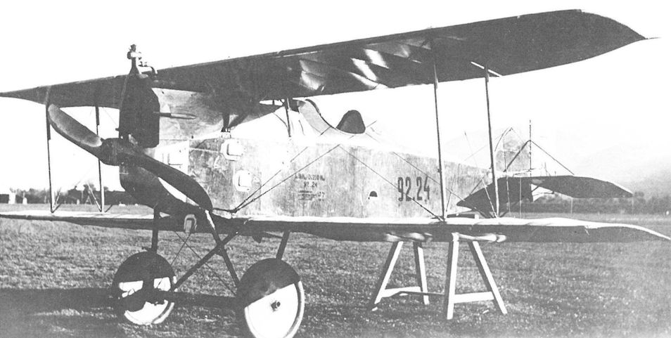
P.Grosz, G.Haddow, P.Schiemer - Austro-Hungarian Army Aircraft of World War One /Flying Machines/
The Aviatik D.I (MAG) 92.24 at the Front. It was shipped from the factory in July 1918. The blast tubes of the twin buried guns protrude from the cowling.
Aviatik-Berg D.I. Flugzeugnummer 92.24. tiefliegender MG-Einbau
Aviatik D.I, самолет № 92.24, низкорасположенный пулемет -
P.Grosz, G.Haddow, P.Schiemer - Austro-Hungarian Army Aircraft of World War One /Flying Machines/
Another view of 92.24 showing the highly-reflective finish characteristic of factory-fresh aircraft.
Aviatik-Berg D.I, Flugzeugnummer 92.24. Fliegerkompanie 7, Pergine -

D.Mechin - Foreign Fronts of the French Air Force 1914-1919 /Aeronaut/
The Magyar Altalanos Gepgyar (MAG) factory in Budapest also produced fighters, such as this Berg D.I of the Hungarian Communist Air Force with the red star and Austro-Hungarian registration 92.126. (Paolo Varriale)


-

P.Grosz, G.Haddow, P.Schiemer - Austro-Hungarian Army Aircraft of World War One /Flying Machines/
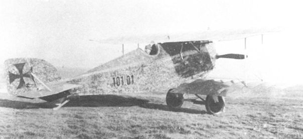
The first Aviatik D.I(Th) 101.01 built by Thone & Fiala was sent to Fischamend in November 1917 for armament installation and returned to the factory as a pattern aircraft in December.
-
E.Hauke, W.Schroeder, B.Totschinger - Die Flugzeuge der k.u.k. Luftfahrtruppe und Seeflieger 1914-1918
Aviatik-Berg D.l, Flugzeugnummer 101.01, Fischamend; diese Maschine diente als Musterflugzeug für die Produktion bei der Firma W.K.F.
Aviatik-Berg D.l, номер 101.01, Фишаменд; эта машина послужила образцом для производства в W.K.F. -

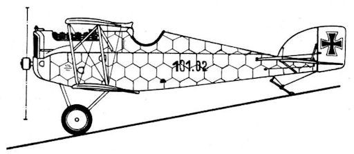
В.Кондратьев - Самолеты первой мировой войны
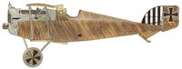
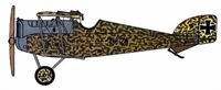
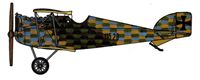
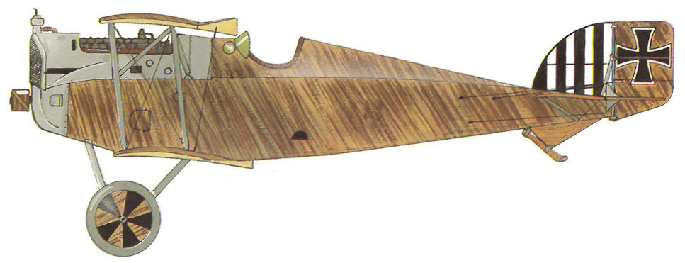
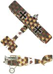
Редкая разновидность австрийского камуфляжа, состоящая из желто-бежевого фона, на который нанесены мелкие неровные колечки темно-зеленого и (или) темно-коричневого цвета (вероятно, "тычки" кольцевой кистью или губкой) в сочетании с редкими лиагональными полосами. Так окрашивались истребители "Авиатик" D.I, построенные на заводе "Зонн унд Фиала".
-
P.Grosz, G.Haddow, P.Schiemer - Austro-Hungarian Army Aircraft of World War One /Flying Machines/
Aviatik D.I(Th) 101.12 of Flik 9/J at Ospedaletto fitted with a four-bladed propeller, usually a sign that a 200 hp Daimler engine is installed. This aircraft has buried guns and a teddy bear mascot hung on the wing strut.
-

E.Hauke, W.Schroeder, B.Totschinger - Die Flugzeuge der k.u.k. Luftfahrtruppe und Seeflieger 1914-1918
Berg D.I, Flugzeugnummer 101.12, Flik 9, Ospedaletto
-
P.Grosz, G.Haddow, P.Schiemer - Austro-Hungarian Army Aircraft of World War One /Flying Machines/
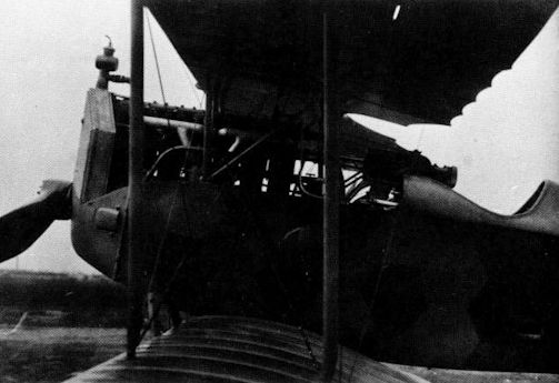
Aviatik D.I(Th) 101.14 with accessible twin Schwarzlose M 16 machine guns mounted at eye level. Because of the engine and radiator obstruction, the guns were aimed by leaning out of the cockpit and sighting through a rear and forward sight; the latter is seen mounted forward of the center-section struts.
-
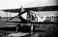
E.Hauke, W.Schroeder, B.Totschinger - Die Flugzeuge der k.u.k. Luftfahrtruppe und Seeflieger 1914-1918
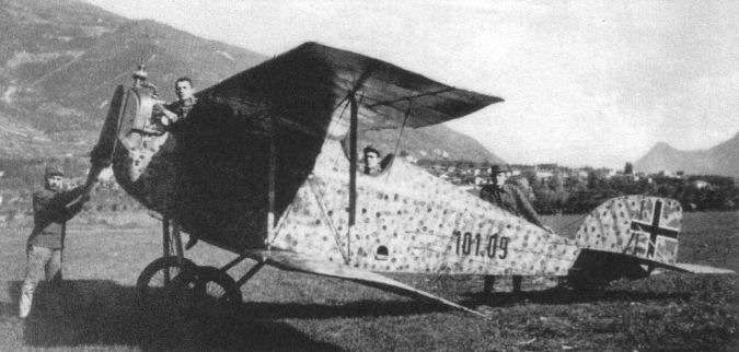
Aviatik-Berg D.I, Flugzeugnummer 101.15, im Juli 1918 an den Flip 7 ausgeliefert
-

P.Grosz, G.Haddow, P.Schiemer - Austro-Hungarian Army Aircraft of World War One /Flying Machines/
Aviatik D.I(Th) 101.16 of Flik 31/P at Levico in the summer of 1918. The cowling panels have been removed to provide improved cooling.
-
P.Grosz, G.Haddow, P.Schiemer - Austro-Hungarian Army Aircraft of World War One /Flying Machines/
Aviatik D.I(Th) 101.16 of Flik 31/P at Levico in the summer of 1918. The cowling panels have been removed to provide improved cooling.
-
E.Hauke, W.Schroeder, B.Totschinger - Die Flugzeuge der k.u.k. Luftfahrtruppe und Seeflieger 1914-1918
Aviatik-Berg D.l. Flugzeugnummer 101.17, an die Fliegerkompanie 31P ausgeliefert, Flugfeld Ospedaletto, Sommer 1918
-
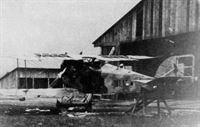
E.Hauke, W.Schroeder, B.Totschinger - Die Flugzeuge der k.u.k. Luftfahrtruppe und Seeflieger 1914-1918
Flugzeugnummer 101.17, am Flugfeld Ospedaletto im November 1918 von Italienern erbeutet
Самолет № 101.17, захваченный итальянцами на аэродроме Оспедалетто в ноябре 1918 года. -
E.Hauke, W.Schroeder, B.Totschinger - Die Flugzeuge der k.u.k. Luftfahrtruppe und Seeflieger 1914-1918
Aviatik-Berg D.I, Flugzeugnummer 101.18. im August 1918 an den Flip 7 ausgeliefert, Pergine


-

P.Grosz, G.Haddow, P.Schiemer - Austro-Hungarian Army Aircraft of World War One /Flying Machines/
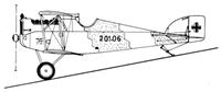
An unarmed Aviatik D.I(Th) 201.06, one of nine such aircraft accepted between June and September 1918.
-

Z.Czirok - Austro-Hungarian Fighter Units of WWI. Volume 11 /Aeronaut/ (1)
Close-up of the gun installation of Aviatik D.I (Lo) 115.13, which served at Flik 72/J (Martin O'Connor via Aaron Weaver)
-

E.Hauke, W.Schroeder, B.Totschinger - Die Flugzeuge der k.u.k. Luftfahrtruppe und Seeflieger 1914-1918
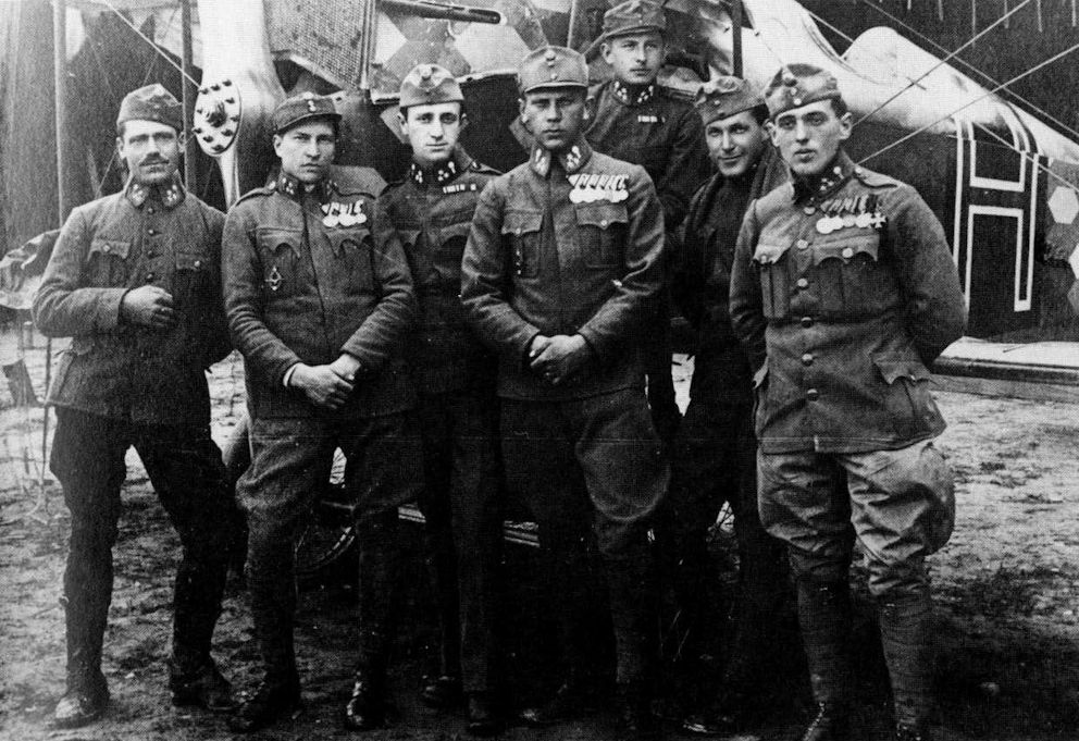
Aviatik-Berg D.I. Flugzeugnummer 115.30, Flik 60. Feltre, März 1918, 3. von links Offzstv Kurt Gruber. 4. Stfvv Albin Heidi
Aviatik-Berg D.I № 115.30, Flik 60. Фельтре, март 1918 года, 3-й слева Offzstv Kurt Gruber. 4. Stfvv Альбин Хайди -
E.Hauke, W.Schroeder, B.Totschinger - Die Flugzeuge der k.u.k. Luftfahrtruppe und Seeflieger 1914-1918
Aviatik-Berg D.I, Serie 115. Flik 24, Flugfeld Pergine, 6. Juni 1918, Selbstentzündung der Phosphormunition
Aviatik-Berg D.I, серия 115. Flik 24, аэродром Перджине, 6 июня 1918 г., самовоспламенение фосфорных боеприпасов. -
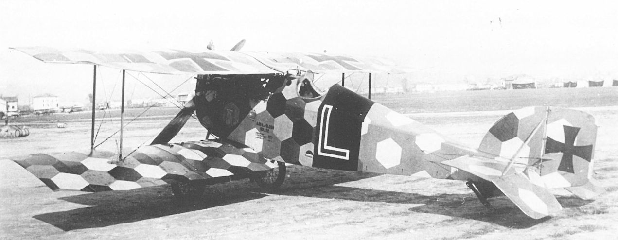
P.Grosz, G.Haddow, P.Schiemer - Austro-Hungarian Army Aircraft of World War One /Flying Machines/
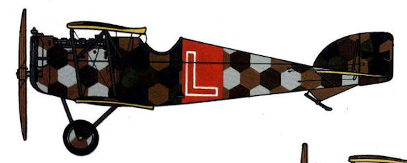
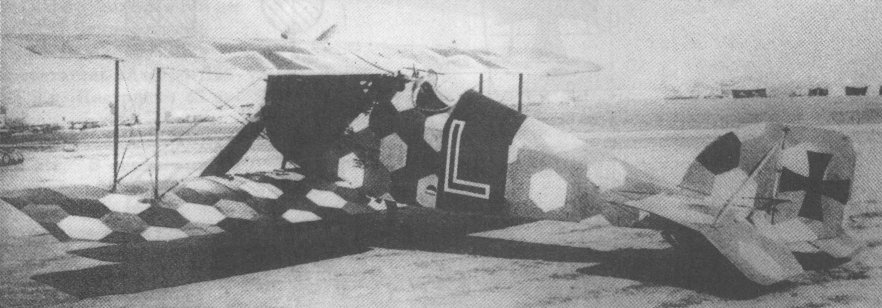
Linke-Crawford’s Aviatik D.I (Lo) 115.32 of Flik 60/J photographed on the Feltre airfield in late spring of 1918. Linke-Crawford was shot down in this machine on 31 July 1918; structural failure of the wing is thought to have contributed to his death.
Aviatik D.I 115.32 sports Frank Linke Crawford's last insignia, a capital L on a red band on the fuselage sides and on the center section of the top wing. Linke claimed seven victories flying this plane before he died in it. Its lozenge camouflage was hand painted. The Aviatik was lightly-built, contributing to its good maneuverability and performance, but it was fragile and susceptible to structural failure. (Carlo Lucchini) -
E.Hauke, W.Schroeder, B.Totschinger - Die Flugzeuge der k.u.k. Luftfahrtruppe und Seeflieger 1914-1918
Aviatik-Berg D.I, Serie 115, Flugfeld Pergine


-

P.Grosz, G.Haddow, P.Schiemer - Austro-Hungarian Army Aircraft of World War One /Flying Machines/
The unarmed Aviatik D.I(Ll) 348.01 at Aspern in September 1918.
-
E.Hauke, W.Schroeder, B.Totschinger - Die Flugzeuge der k.u.k. Luftfahrtruppe und Seeflieger 1914-1918
Aviatik-Berg D.I 348.01 in Aspern, Einfliegerei. September 1918; erster Berg mit dem 225 PS-Daimler, gebaut bei Lloyd; das Einiliegen erfolgte ohne Waffeneinbau
Aviatik-Berg D.I 348.01 в г. Асперн, облет. Сентябрь 1918 г.; первый Berg с 225-сильным Daimler, построенным Ллойдом; облет производился без установки оружия -
P.Grosz, G.Haddow, P.Schiemer - Austro-Hungarian Army Aircraft of World War One /Flying Machines/
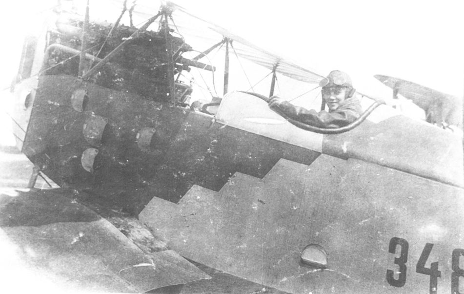
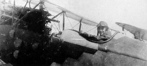
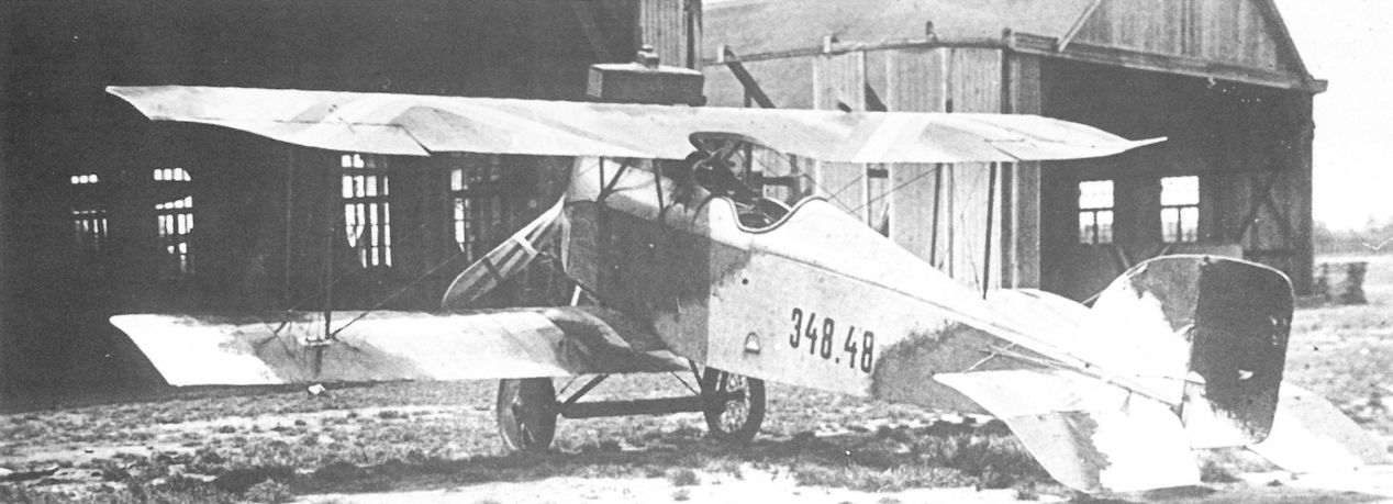
Prior to May 1919, when the red star became the national insignia, the Aviatik D.I(Ll) 348.48 was photographed in the colorful chevron markings of the post-war Hungarian Air Service.
Aviatik-Berg D.I 348.48 in Budapest 1919; verwendet in der Räterepublik, übermalte Balkenkreuze, statt dessen die ungarischen Nationalfarben in Pfeilform am Oberflügel, die Trennlinien des k.u.k. Tarnschemas sind neu übermalt worden
Aviatik-Berg D.I 348.48 в Будапеште 1919 г .; в Советской республике кресты были заменены на стрелки венгерских национальных цветов на верхнем крыле. Камуфляж перекрашен. -
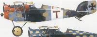
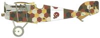
В.Кондратьев - Самолеты первой мировой войны
Еще один "Авиатик" D.I, на этот раз с завода "Ллойд". "Ступенчатый" камуфляж на его фюзеляже являлся сильно упрощенной разновидностью австрийского гексагонального "лозенга", в котором шестиугольники "холодных" и "теплых" тонов были объединены в одноцветные широкие полосы с зубчатыми границами. Цвета полос - бежевый и темно-зеленый или светло- и темно-серый.

-
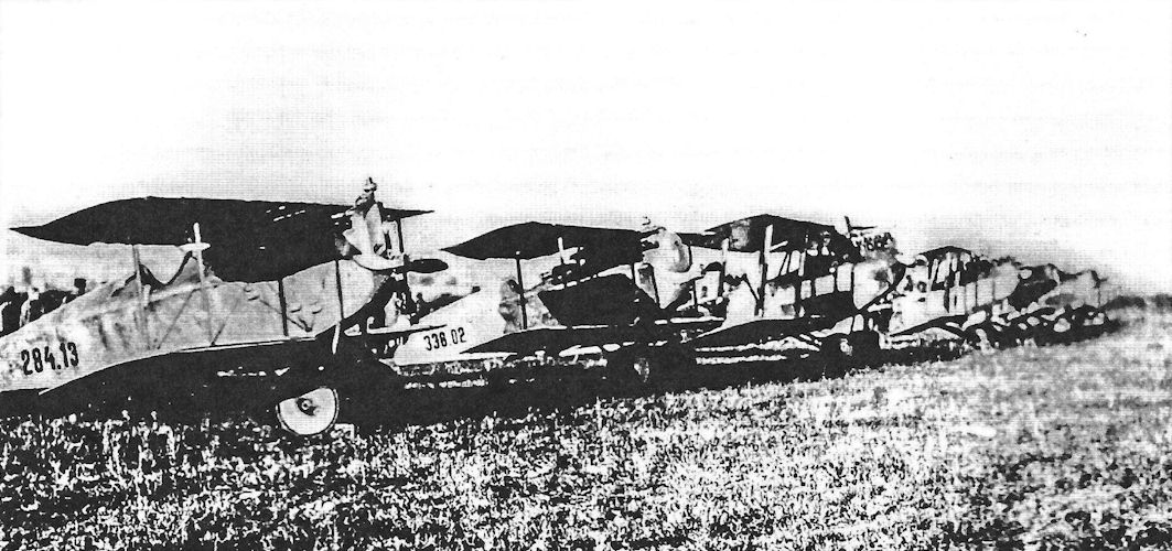
P.Grosz, G.Haddow, P.Schiemer - Austro-Hungarian Army Aircraft of World War One /Flying Machines/
Aviatik D.I(WKF) 284.13 possibly attached to Flik 1/J at Igalo. The next in line is Aviatik D.I 338.02 that served with Flik 1/J in August 1918.
-
J.Davilla - Italian Aviation in the First World War. Vol.1: Operations /Centennial Perspective/ (73)
Flik 6/F aircraft lined up in an unknown LFT airfield in 1918. In the photograph, OffStv Julius Arigi (right) and Hptm Josef Bendik (left) are talking behind Aviatik D.Is 284.13 and 338.02, the two aircraft nearest to the camera. The presence of Arigi (and of 338.02) may indicate that Flik 1/J fighters are present too. Petr Aharon Tesar
-
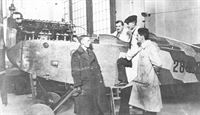
P.Grosz, G.Haddow, P.Schiemer - Austro-Hungarian Army Aircraft of World War One /Flying Machines/
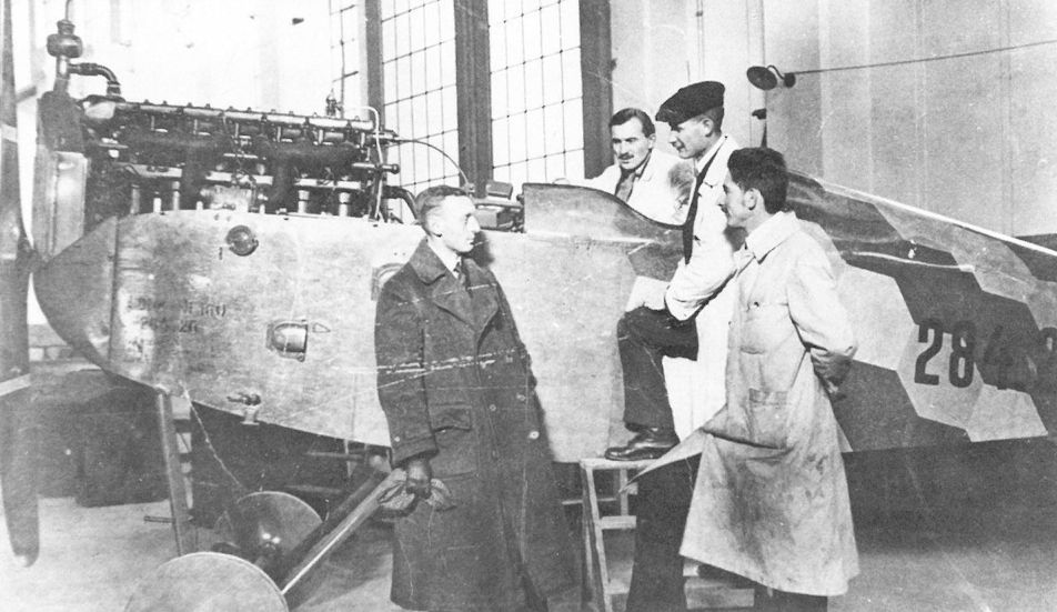
A group of WKF engineers posing with the uncompleted Aviatik D.I(WKF) 284.26 airframe. The engine is a 160 hp Daimler.

-
J.Herris - Aviatik Aircraft of WWI /Centennial Perspective/ (10)
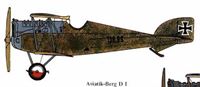
The Austro-Hungarian branch of Aviatik initially built German Aviatik B-type designs but after hiring talented designer Dr. Julius Berg developed its own series of successful designs, including fighters, reconnaissance aircraft, and even multi-engine bombers. The Aviatik (Berg) D.I, sometimes called the Berg D.I to distinguish it from the completely unrelated Aviatik D.I (a license-built Halberstadt D.II) is shown here. The Aviatik (Berg) D.I was built under license by five other companies and 677 were accepted.
-

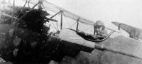
Z.Czirok - Austro-Hungarian Fighter Units of WWI. Volume 11 /Aeronaut/ (1)
Kpl. Milan Soviansky in front of a "Berg" of Flik 74/J with a personal marking of a pipe-smoking skull on San Fior airfield. (Martin O'Connor via Aaron Weaver)
-
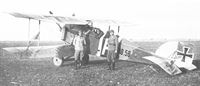
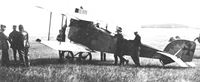
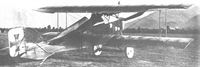
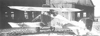
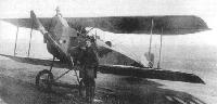
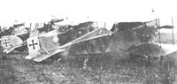
K.Delve - World War One in the Air /Crowood/
Isonzo Front with two Aviatik DIs and two KD fighters at Divacca.
Другие самолёты на фотографии: Hansa-Brandenburg D.I/KD - Германия - 1916
-

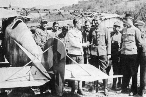
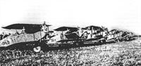
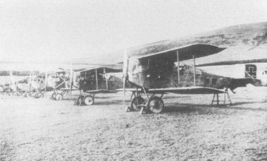
Z.Czirok - Austro-Hungarian Fighter Units of WWI. Volume 11 /Aeronaut/ (1)
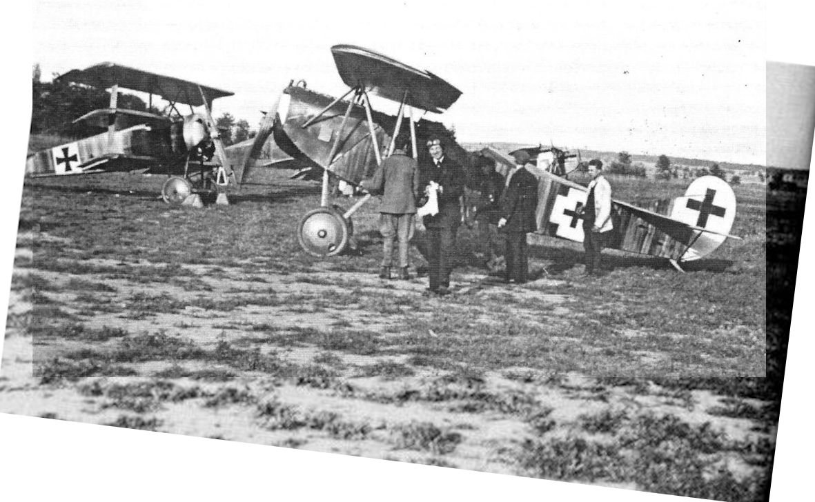
Two Aviatik D.I fighters, a Phonix C.I and a Hansa-Brandenburg C.I reconnaissance aircraft, waiting for the inspection of the commanding officer of Austro-Hungarian 6th Army, Generaloberst Alois von Schonburg-Hartenstein, on San Giacomo airfield. The second one-seater from the left wears the squadron markings of Flik 74/J. (Martin O'Connor via Aaron Weaver)
Другие самолёты на фотографии: Hansa-Brandenburg C.I - Германия - 1915Phonix C.I - Австро-Венгрия - 1917
-

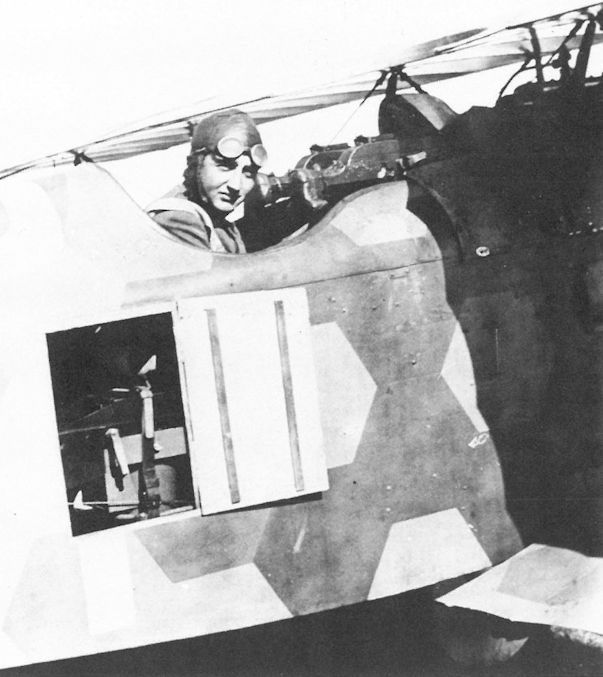
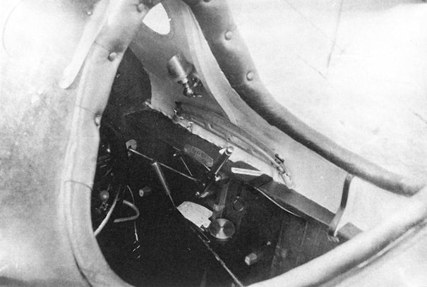
P.Grosz, G.Haddow, P.Schiemer - Austro-Hungarian Army Aircraft of World War One /Flying Machines/
The open door shows the remotely-controlled camera securely held by leather straps in an Aviatik D.I photo-reconnaissance fighter. The pilot, Oberleutnant Ludwig Stillmungus, commander of Flik 40/P, was killed in combat on 12 August 1918.
-
P.Grosz, G.Haddow, P.Schiemer - Austro-Hungarian Army Aircraft of World War One /Flying Machines/
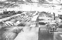
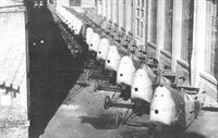
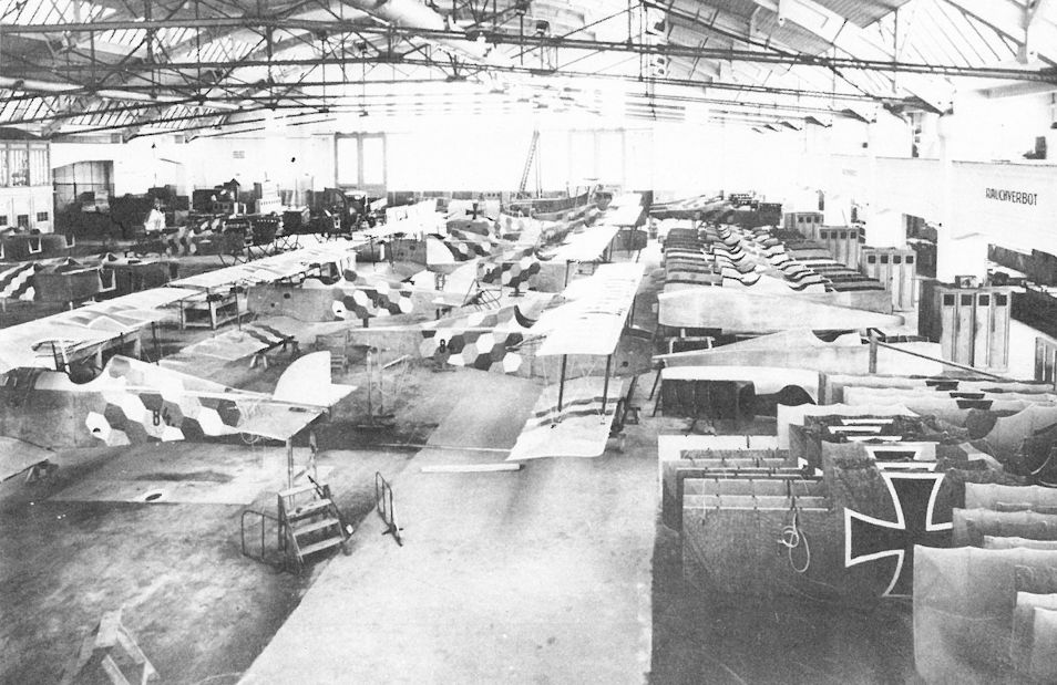
Mass production in the WKF factory. In the foreground are six Aviatik D.I(WKF) series 84 fighters under construction. Barely discernible in the background are two series 284 and one series 384 fighter.
WKF-Fabrikshalle, Wien 10. Laxenburgerstraße, im Bau Jagdeinsitzer Aviatik D.I-Serie 84.
Здание фабрики WKF, Вена 10. Laxenburger Strasse, сборка истребителей Aviatik D.I серии 84. -
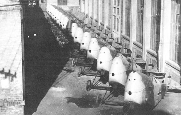
P.Grosz, G.Haddow, P.Schiemer - Austro-Hungarian Army Aircraft of World War One /Flying Machines/
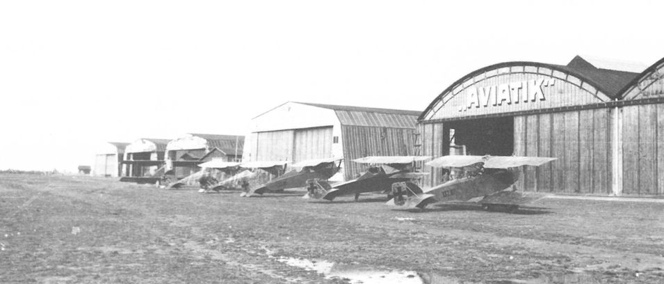
Eighteen completed Aviatik D.I(Lo) series 315 fighters awaiting assembly at the Lohner factory in late 1918. There is no record of these machines reaching the Front.
-
E.Hauke, W.Schroeder, B.Totschinger - Die Flugzeuge der k.u.k. Luftfahrtruppe und Seeflieger 1914-1918
Aviatik-Berg D.I, Flugzeugnummer 115.05 ,"P"; von links 115.26, 115.24, 115.30, 115.05, 138.24, 114.16, bei Lfa-Abvvehrstaffel in Wr. Neustadt
-

J.Herris - Fokker Aircraft of WWI. Vol.6: Foreign Service /Centennial Perspective/ (56)
Fully-assembled airframe of a MAG-built Fokker D.VII at the MAG factory rolled out for inspection just before the end of the war. In the background mechanics are working on an Aviatik D.I(MAG).
Fokker D.VII (MAG), Flugzeugnummer 93.01, Rohbau bei MAGДругие самолёты на фотографии: Fokker D.VII / V11 / V18 / V22 / V24 - Германия - 1917
-
P.Grosz, G.Haddow, P.Schiemer - Austro-Hungarian Army Aircraft of World War One /Flying Machines/
The fully-assembled airframe of a MAG-built Fokker D.VII rolled out for inspection shortly before the end of the war. Mechanics are working on an Aviatik D.I(MAG) in the background.
Другие самолёты на фотографии: Fokker D.VII / V11 / V18 / V22 / V24 - Германия - 1917
-

P.Grosz, G.Haddow, P.Schiemer - Austro-Hungarian Army Aircraft of World War One /Flying Machines/
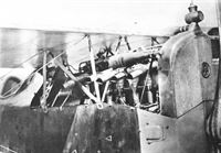
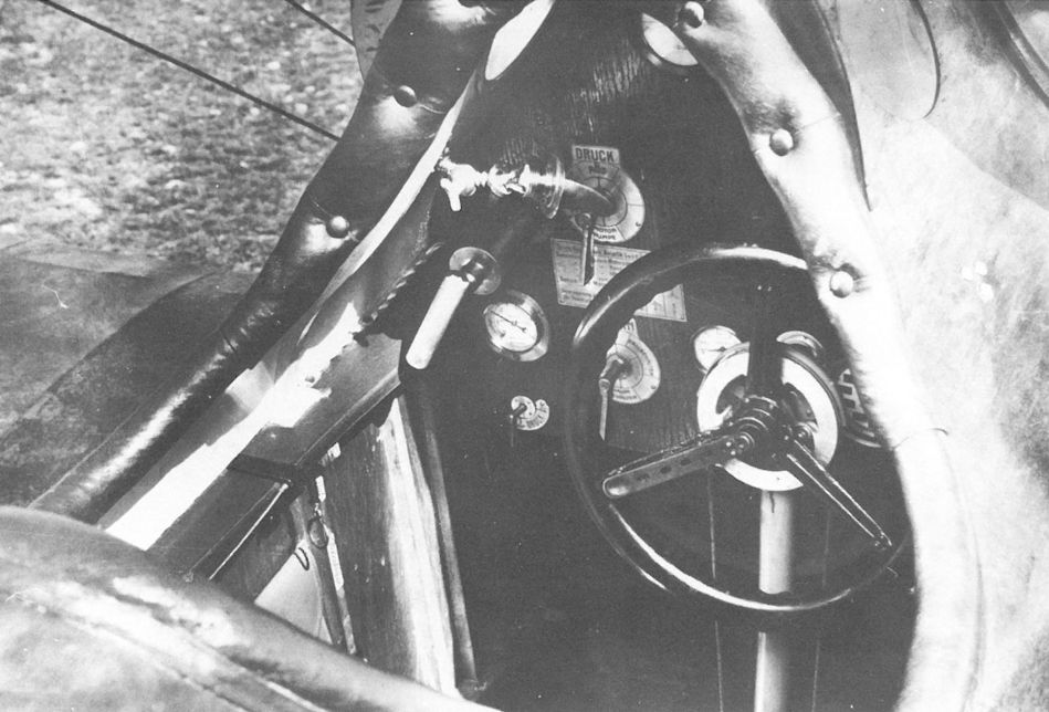
The cockpit of Aviatik D.I 38.06 showing the early control wheel that was replaced by a control stick on later production aircraft. The instrument panel was illuminated by two circular windows on each side of the cockpit and a small, swivelling light fixture. Valves for oil, gas and pressure for the fuel tank, etc are clearly marked on the panel with etched metal tags.
-

P.Grosz, G.Haddow, P.Schiemer - Austro-Hungarian Army Aircraft of World War One /Flying Machines/
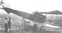
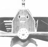
Beset by poor forward visibility, tests were performed with a forward-looking periscope on the Aviatik D.I series 38 fighter. The lugs for mounting the slanted machine gun can be seen on the upper wing.
-

P.Grosz, G.Haddow, P.Schiemer - Austro-Hungarian Army Aircraft of World War One /Flying Machines/
Aviatik D.I 38.06 cockpit with remote camera controls installed. Visible (from top to bottom) are the round window and small hooded light to illuminate the instruments, a level flight indicator, and the throttle, below which can be seen the camera plate-changing lever. The ring behind the throttle operates the fuselage aperture.


-

Z.Czirok - Austro-Hungarian Fighter Units of WWI. Volume 11 /Aeronaut/ (1)
Fwbl. Ernst Heinz's crash-landed Aviatik D.I (Lo) 115.25 on 2nd June 1918.
Aviatik-Berg D.I, Flugzeugnummer 115.25, Flik 72, San Fior. Feldpilot Fw Ernst Heinz bei C. Pezzole in Venetien abgestürzt, Pilot schwer verletzt
Aviatik-Berg D.I, № 115.25, Flik 72, Сан-Фиор. Пилот Эрнст Хайнц разбился возле К. Пеццоле в Венето, пилот тяжело ранен -

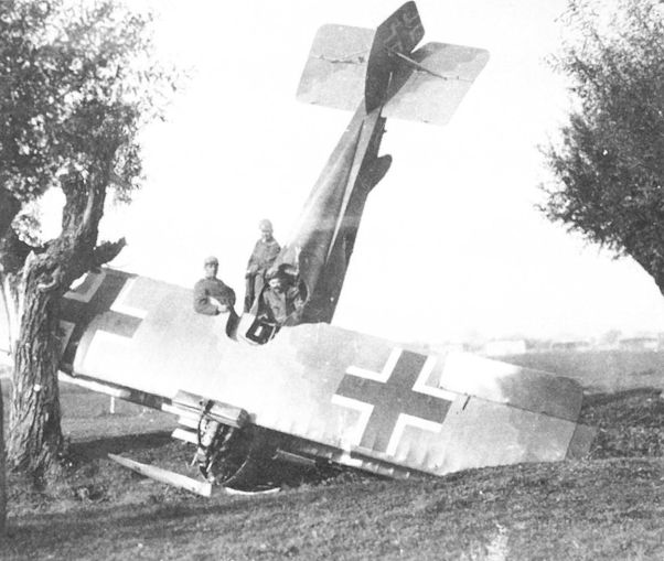
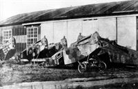
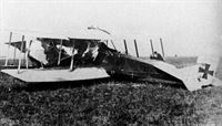
P.Grosz, G.Haddow, P.Schiemer - Austro-Hungarian Army Aircraft of World War One /Flying Machines/
Fortunate to survive, Oberleutnant Fritz Pisko of Flik 60/J contemplates the massive wing failure of his Aviatik D.I (Lo) 115.26 on 18 May 1918. An official investigation showed that Lohner had substituted a lighter rib design and attached the fabric contrary to Aviatik specifications.
-

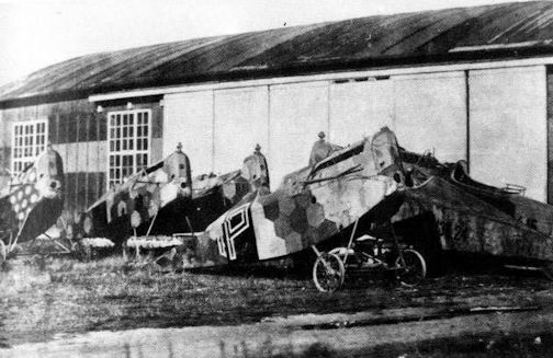
Z.Czirok - Austro-Hungarian Fighter Units of WWI. Volume 11 /Aeronaut/ (1)
Crash of Aviatik D.I (Lo) 115.51 at an unidentified unit and on an unknown date. The sixth from the left behind the aircraft is Zgsf. Ignaz Pillwein who served also at Flik 68/J. (Martin O'Connor via Aaron Weaver)
-

Z.Czirok - Austro-Hungarian Fighter Units of WWI. Volume 11 /Aeronaut/ (1)
The smashed fuselage of Oblt. August Dehne's Aviatik D.I 138.62 on a road near Vigonovo on 29th July 1918 after Italian Hanriots of 82a Squadriglia. (Reinhard Masajdek via Petr Aharon Tesar)
-
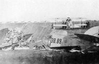
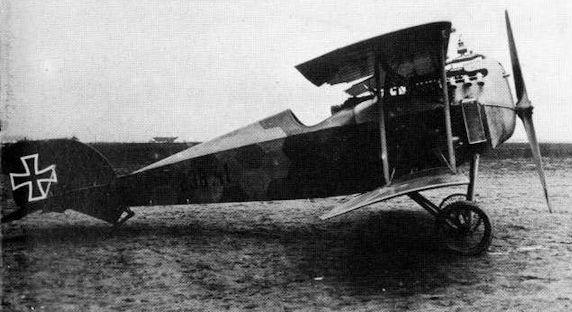
E.Hauke, W.Schroeder, B.Totschinger - Die Flugzeuge der k.u.k. Luftfahrtruppe und Seeflieger 1914-1918
Aviatik-Berg D.I 238.89 in Aspern. FliWaVersKp, Oktober 1918. Balkenkreuze in der letzten Ausführung, Feldpilot Fw Franz Trdik kam am 16. Oktober durch Absturz ums Leben, als sich die Maschine nach Bruch der linken Querruderbetätigung nicht mehr steuern ließ (Fw Trdik war Werkspilot bei Aviatik)
Aviatik-Berg D.I 238.89 в г. Асперн. FliWaVersKp, октябрь 1918 г. Поздний вариант Balkenkreuze, пилот Fw Franz Trdik погиб в авиакатастрофе 16 октября, после потери управления из-за поломки левого элерона (Fw Trdik был заводским пилотом в Aviatik) -
P.Grosz, G.Haddow, P.Schiemer - Austro-Hungarian Army Aircraft of World War One /Flying Machines/
Among the few of the series accepted was the Aviatik D.I (Lo) 315.08 in which Feldwebel Ernst Kerschischnig collided with Brandenburg C.I 63.25 on 27 September 1918 at Aspern. The leading edge radiator was standard for the series 315.
Другие самолёты на фотографии: Hansa-Brandenburg C.I - Германия - 1915
-
E.Hauke, W.Schroeder, B.Totschinger - Die Flugzeuge der k.u.k. Luftfahrtruppe und Seeflieger 1914-1918
Brandenburg C.I, Flugzeugnummer 63.25, abgestellt zu Fallschirmversuchen in Aspern, 1918. Zusammenstoß mit einem Aviatik-Berg D.I, Flugzeugnummer 315.08, am 27. September 1918
Brandenburg C.I, номер 63.25, полигон для испытаний парашютов в Асперне, 1918 год. Столкновение с самолетом «Aviatik-Berg D.I», номер 315.08, 27 сентября 1918 года.Другие самолёты на фотографии: Hansa-Brandenburg C.I - Германия - 1915


-
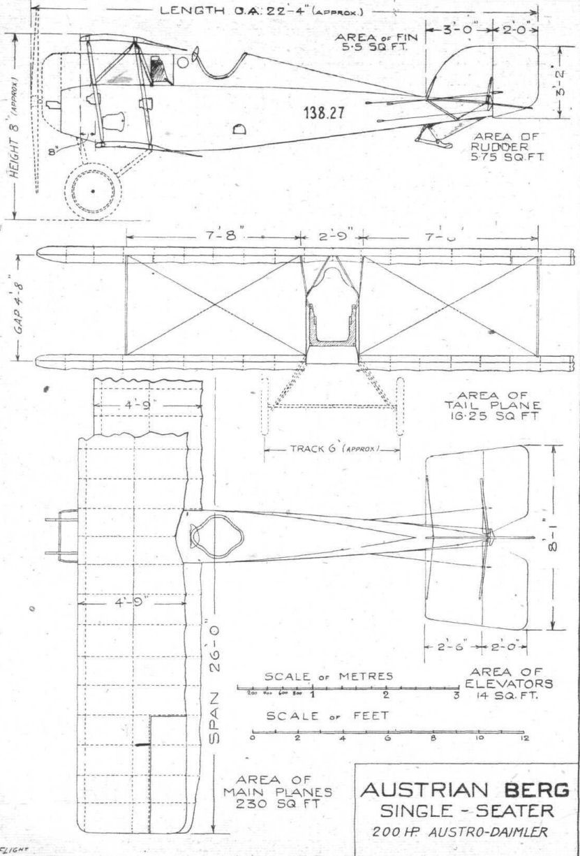
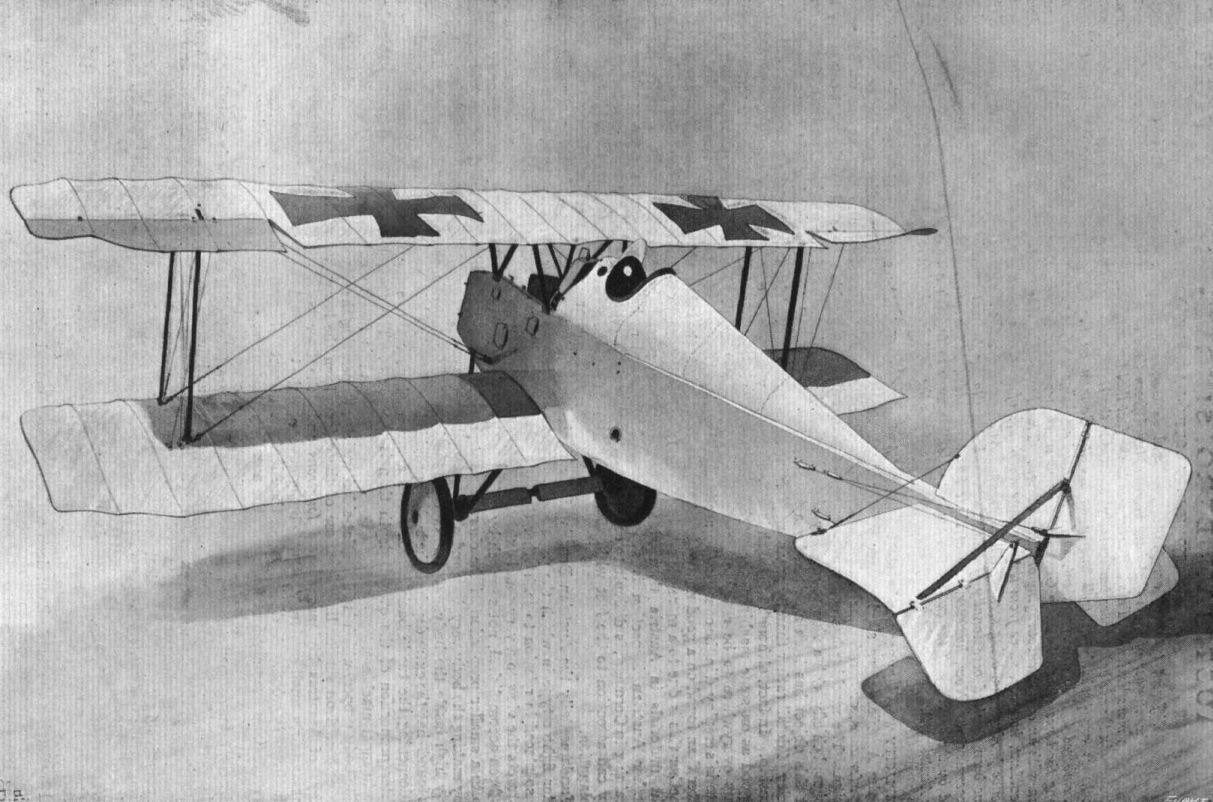
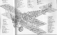
Журнал - Flight за 1918 г.
The Austrian-Berg single-seater fighter.
-
W.Green, G.Swanborough - The Complete Book of Fighters
Aviatik (Berg) D I
-
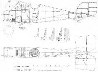
Журнал - Flight за 1918 г.
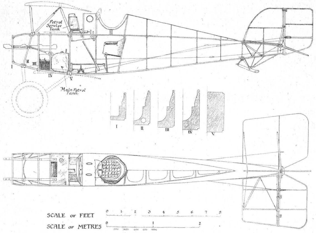
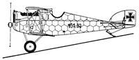
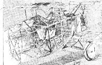
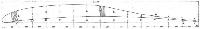
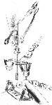
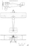
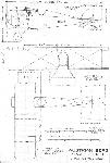
Fig. 1. - Side elevations and plan, to scale, of the body of the Berg single-seater.
-
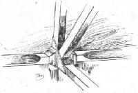
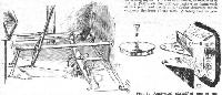
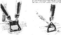
Журнал - Flight за 1918 г.
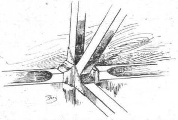
Fig. 2. - Sketch showing attachment of struts to longerons on the Berg single-seater.
-
Журнал - Flight за 1918 г.
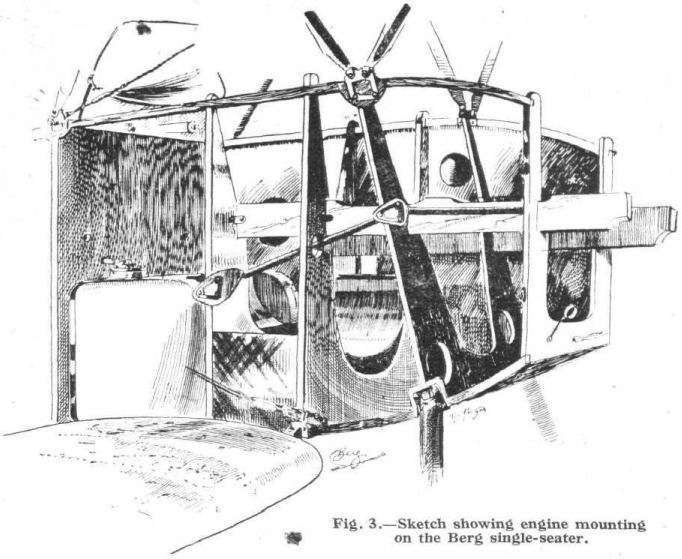
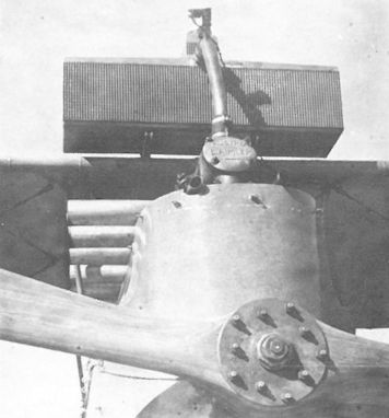
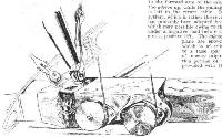
Fig. 3. - Sketch showing engine mounting on the Berg single-seater.
-
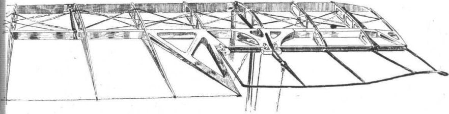
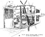
Журнал - Flight за 1918 г.
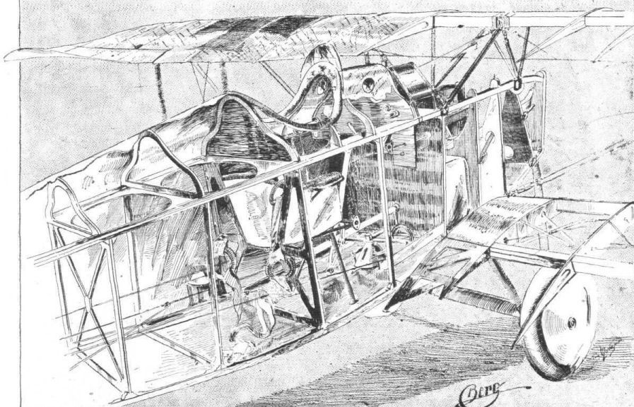
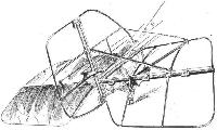
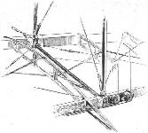
Fig. 4. - Three-quarter rear view of the front portion of the Berg. The covering has been removed to show the internal construction. In the top plane it would appear at first glance that only one spar is fitted. This is not, of course, the case, but is caused by the fact that the front spar is very close to the leading edge, and is therefore, in this particular view, covered by the rear spar.
-
Журнал - Flight за 1918 г.
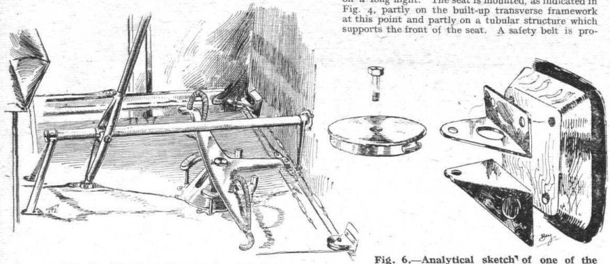
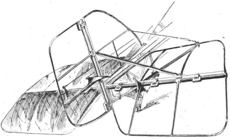
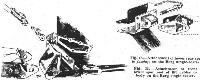
Fig. 5. - Sketch of the controls of the Berg.
Fig. 6. - Analytical sketch of one of the pulleys over which the rudder cables travel. -
Журнал - Flight за 1918 г.
Fig. 7. - The control cables on the Berg are carried, where passing through the sides of the body, in guides. The top sketch shows the metal guide on the outside of the body, while the lower drawing illustrates the wood guide employed on the inside of the three-ply body covering.
Fig. 8. - The tail skid of the Berg is mounted, as shown in this sketch, on a structure of wood strips, covered with three-ply. The shock absorbers are in the form of coil springs. -
Журнал - Flight за 1918 г.
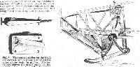
Fig. 9. - The tail planes of the Berg single-seater.
-
Журнал - Flight за 1918 г.
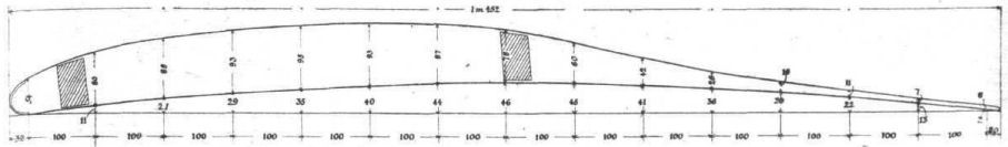
Fig. 10. - Wing section of the Berg single-seater. All the dimensions are in mm.
-
Журнал - Flight за 1918 г.
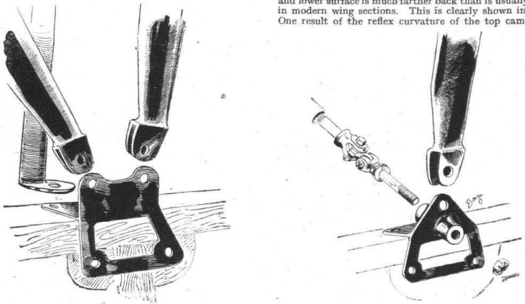
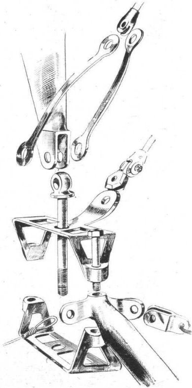
Fig. 11. - Attachment of front centre-section struts to fuselage of the Berg single-seater.
Fig. 12. - Attachment of rear centre-section struts to top longerons on the Berg single-seater. -
Журнал - Flight за 1918 г.
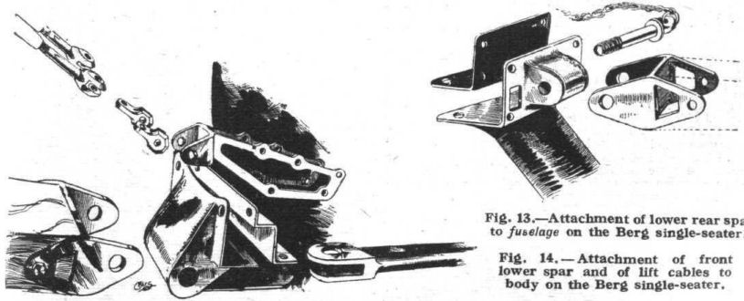
Fig. 13. - Attachment of lower rear spar to fuselage on the Berg single-seater.
Fig. 14. - Attachment of front lower spar and of lift cables to body on the Berg single-seater. -
Журнал - Flight за 1918 г.
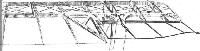
Fig. 15. - General sketch of internal bracing and of inter-plane strut attachment on lower plane of the Berg single-seater.
-
Журнал - Flight за 1918 г.
Fig. 16. - Analytical sketch of inter-plane strut attachment, lift cable attachment, internal drift bracing and compression tube in lower plane of the Berg single-seater.
-
Журнал - Flight за 1918 г.
Fig. 17. - View from outside of the strut fitting dissected in Fig. 16, also showing mounting of pulleys for aileron control cables.
-
Журнал - Flight за 1918 г.
Fig. 18. - Sketch showing part of top plane and one of the ailerons of the Berg single-seater.
-
P.Grosz, G.Haddow, P.Schiemer - Austro-Hungarian Army Aircraft of World War One /Flying Machines/
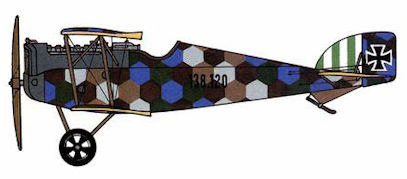
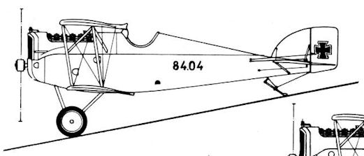
Aviatik D.I 38.37, Flik 63/J
-
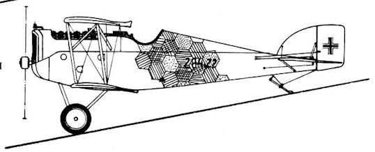
P.Grosz, G.Haddow, P.Schiemer - Austro-Hungarian Army Aircraft of World War One /Flying Machines/
Aviatik D.I 138.XX, Flik 74/J
-
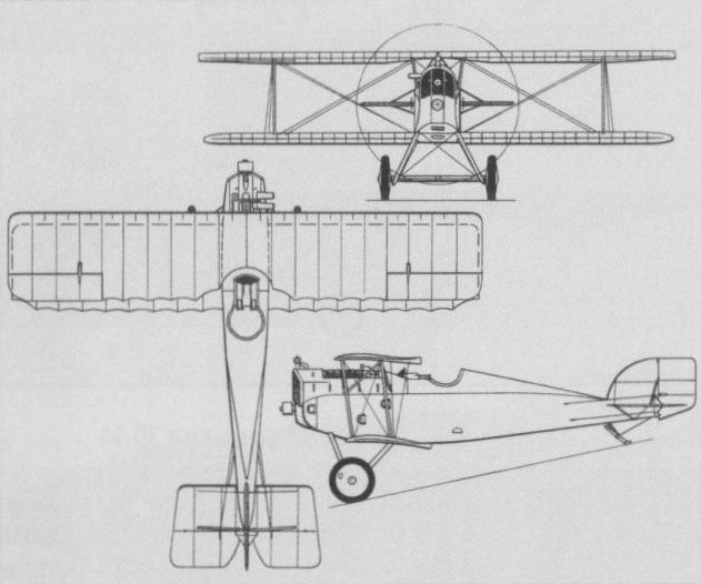
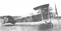
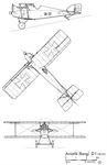
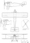
W.Green, G.Swanborough - The Complete Book of Fighters
A general arrangement drawing of the 200 hp Austro-Daimler-engined D I in standard form.
-
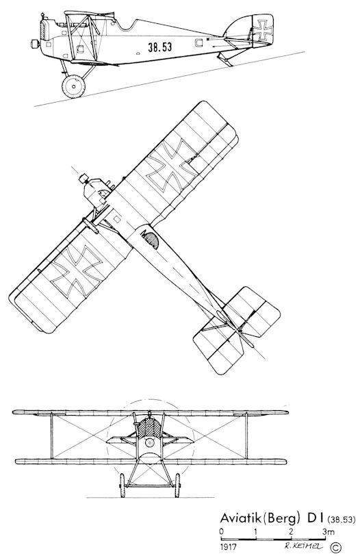
R.Keimel - Osterreichs Luftfahrzeuge /Weishaupt Verlag/
Aviatik (Berg) D.I (38.53)
-
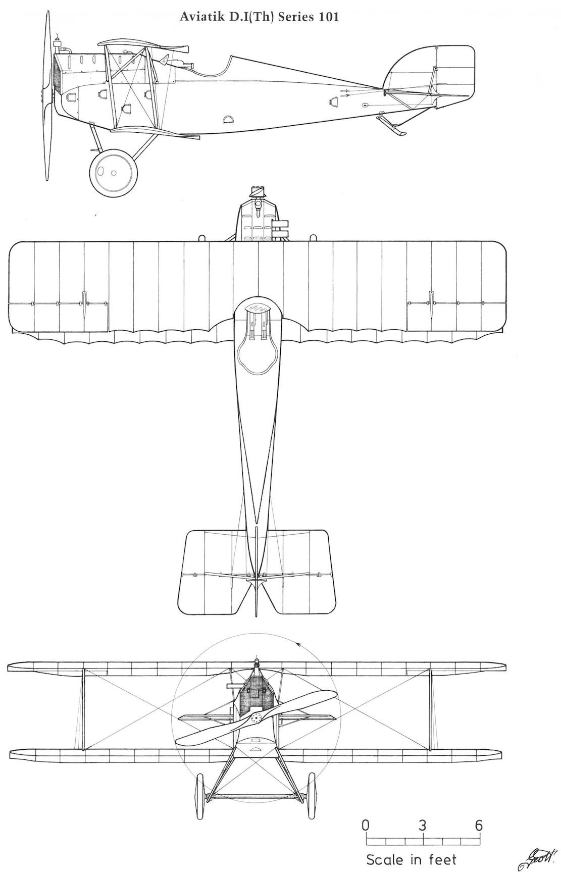
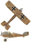
P.Grosz, G.Haddow, P.Schiemer - Austro-Hungarian Army Aircraft of World War One /Flying Machines/
Aviatik D.I(Th) Series 101
-
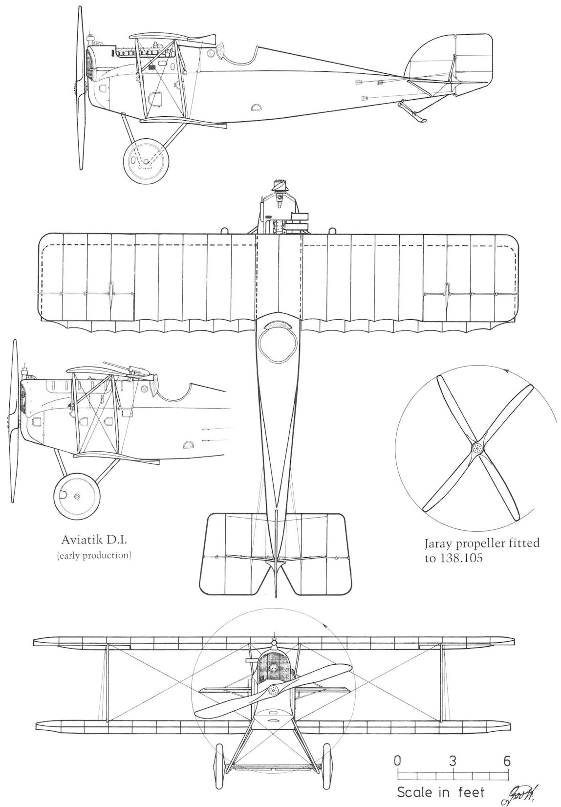
P.Grosz, G.Haddow, P.Schiemer - Austro-Hungarian Army Aircraft of World War One /Flying Machines/
Aviatik D.I Series 38 and 138 (early version)
-
-
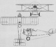
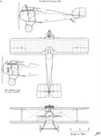
Журнал - Flight за 1918 г.
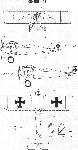
Plan, side and front elevations, to scale, of the Berg single-seater.
-
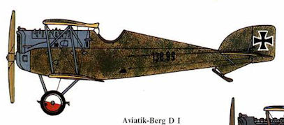
В.Кондратьев - Самолеты первой мировой войны
Aviatik (Berg) D-I