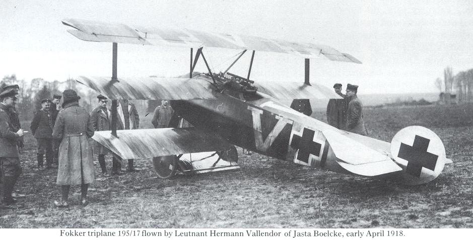
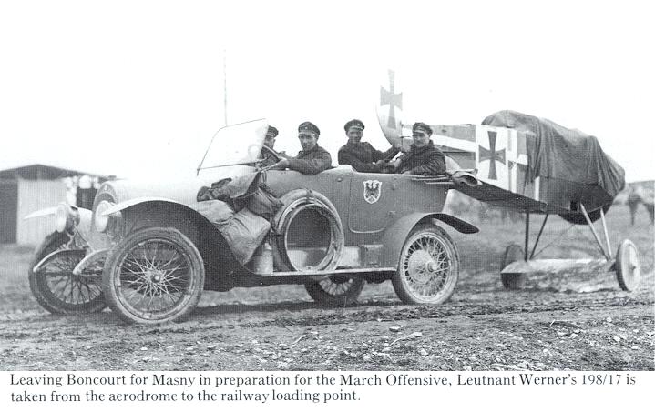
В.Кондратьев Самолеты первой мировой войны
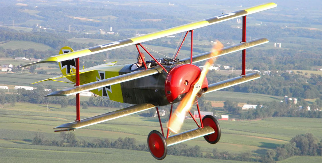
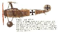
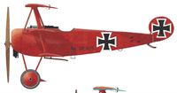
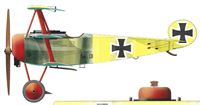
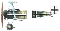
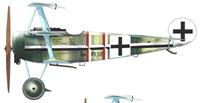
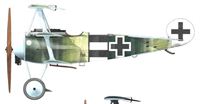
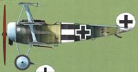
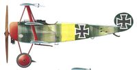
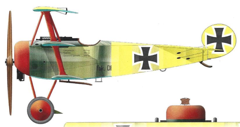
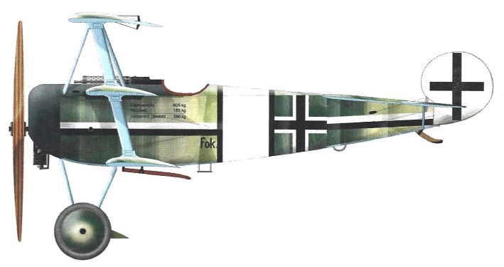
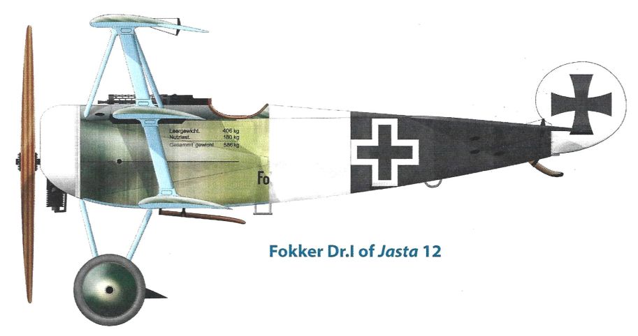
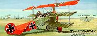
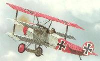
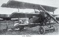
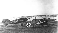
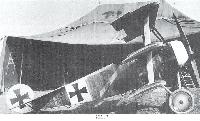
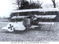
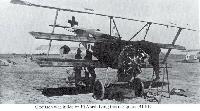
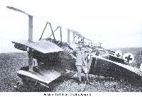
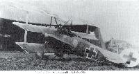
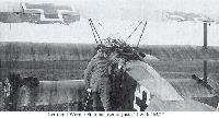
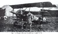
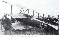
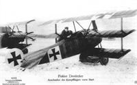
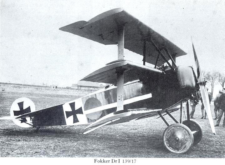
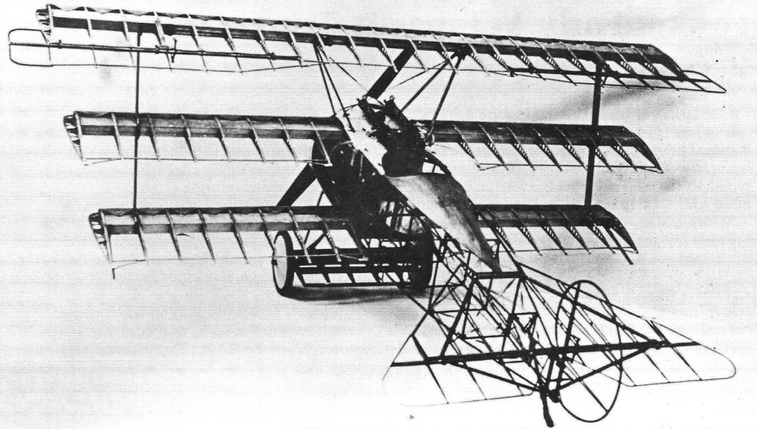
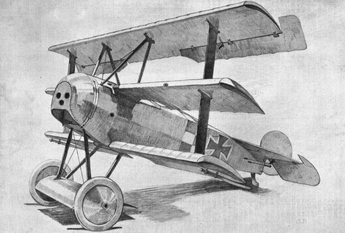
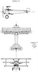
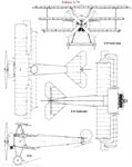
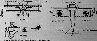
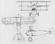
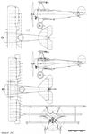
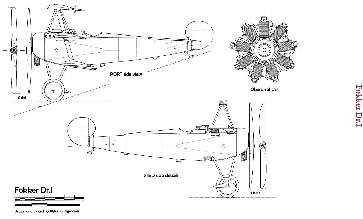
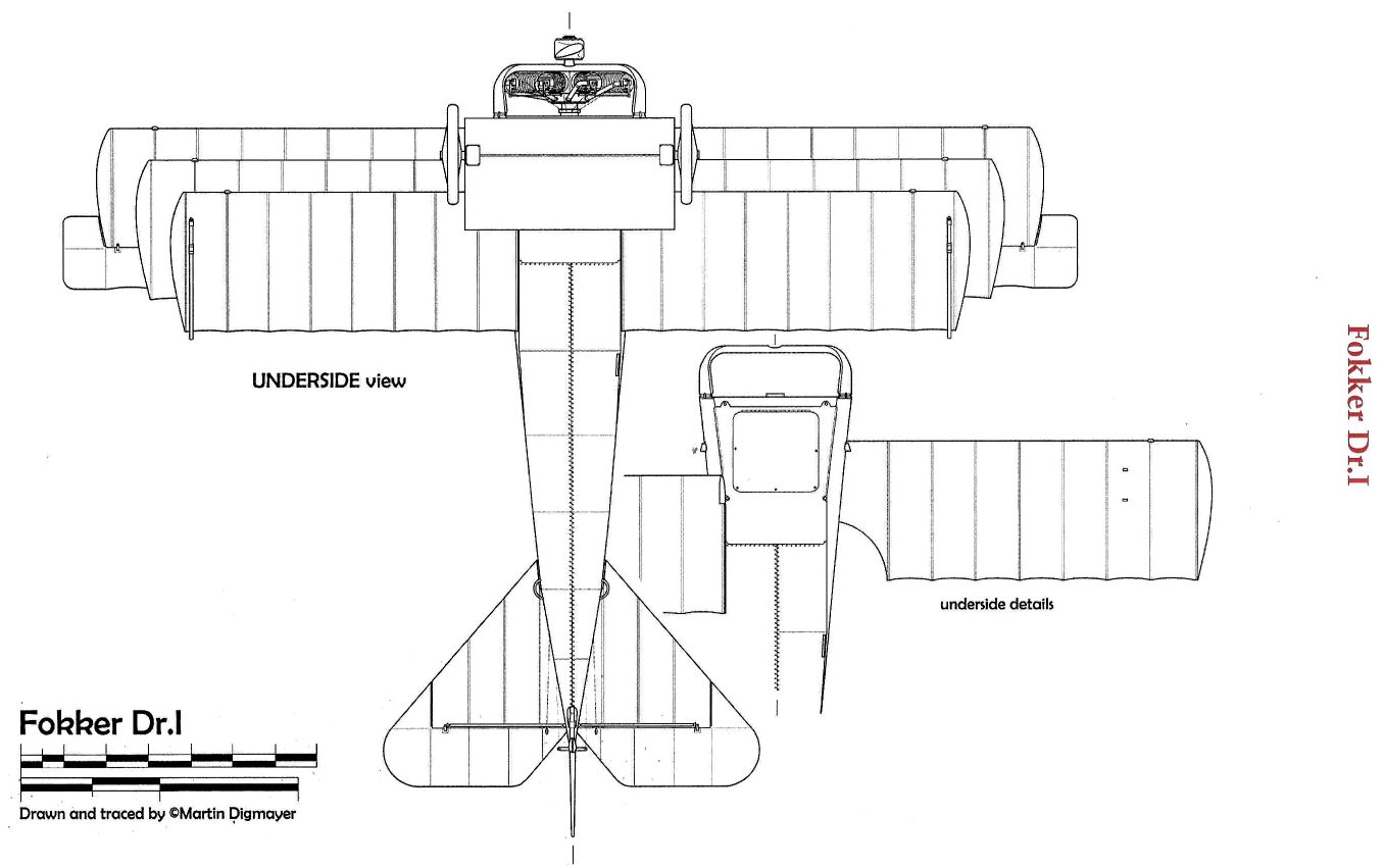
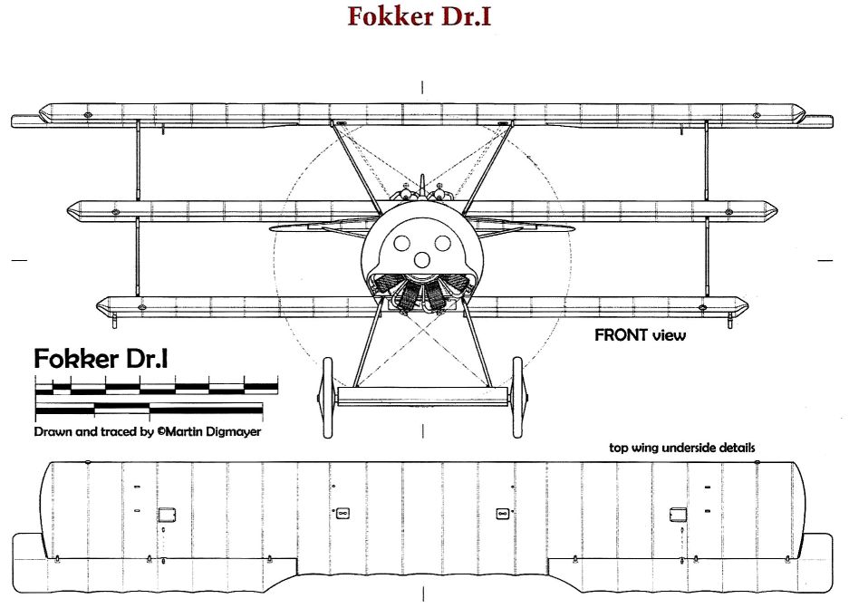
"ФОККЕР" Dr.I / FOKKER Dr.I
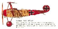
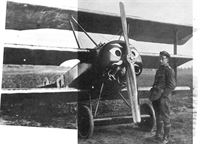
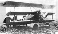
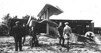
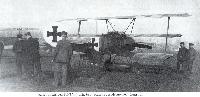
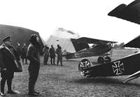
В июле 1917 года немцам достался трофейный английский истребитель "Сопвич триплан", совершивший вынужденную посадку на вражеской территории. Многие германские авиафирмы сразу начали работы по копированию этой удачной машины.
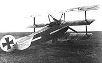
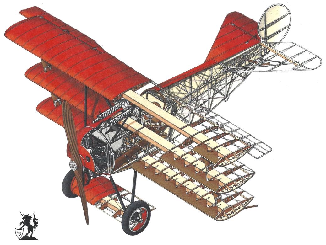
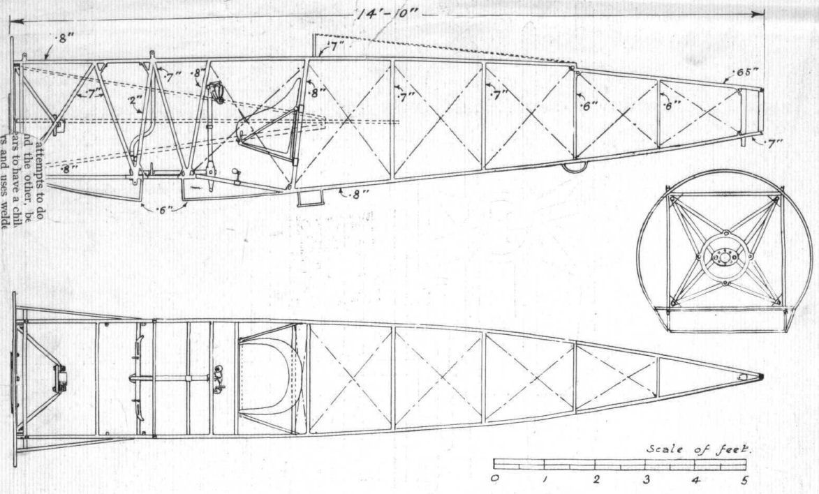
Наибольшего успеха добился авиаконструктор фирмы "Фоккер" Рейнольд Платц. Спроектированный им аэроплан во многом отличался от английского прототипа. Он имел типично "фоккеровский" фюзеляж и оперение с каркасом, сваренным из тонкостенных стальных труб и полотняной обшивкой. Важным нововведением были крылья относительно толстого профиля без наружных расчалок.
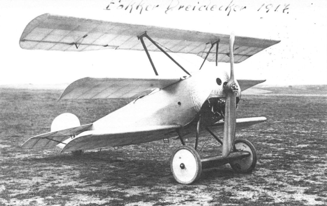
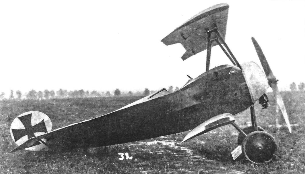
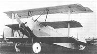
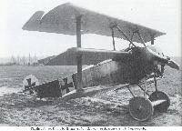
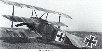
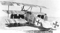
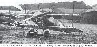
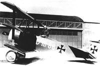
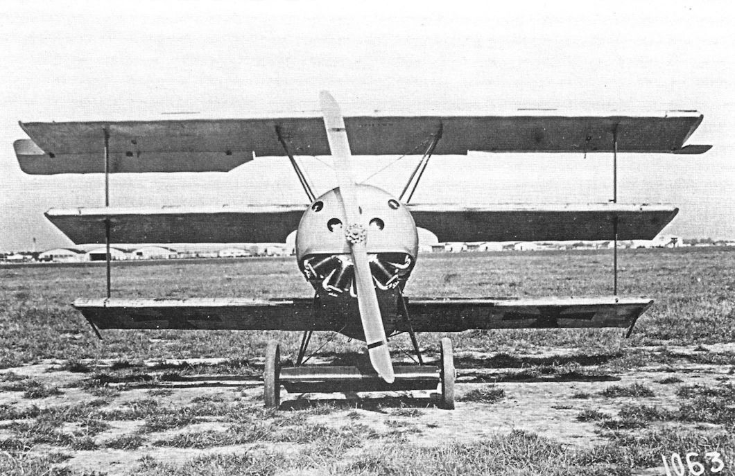
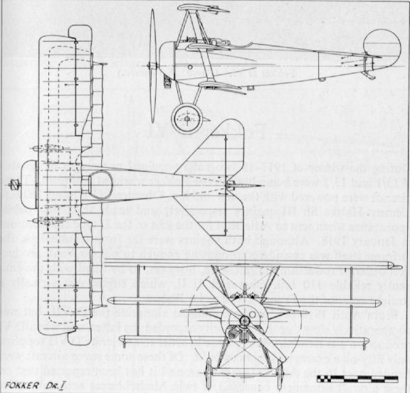
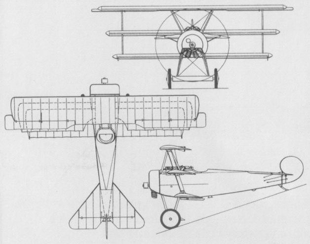
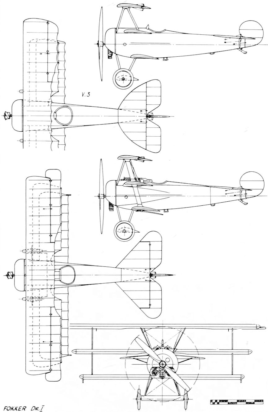
Прототипы V.3 и V.4 были быстро построены, успешно облетаны и рекомендованы к серийному производству под обозначением "Фоккер" Dr.I (Dr - сокращение от немецкого Dreidecker - "драйдеккер" - триплан).
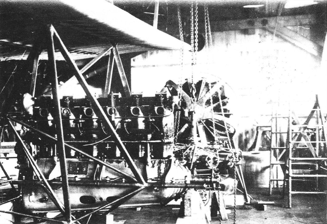
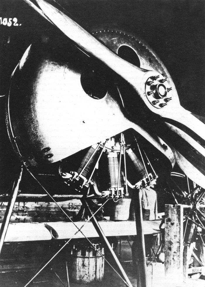
Поначалу самолеты комплектовались 100-сильными ротативными моторами "Оберурсель" Ur.I, затем - 110-сильными Ur.II или импортными шведскими моторами "Тулин" той же мощности (копия французского двигателя "Рон" 9J). Иногда ставили трофейные 130-сильные "Клерже", с которыми самолет демонстрировал выдающиеся летные характеристики.
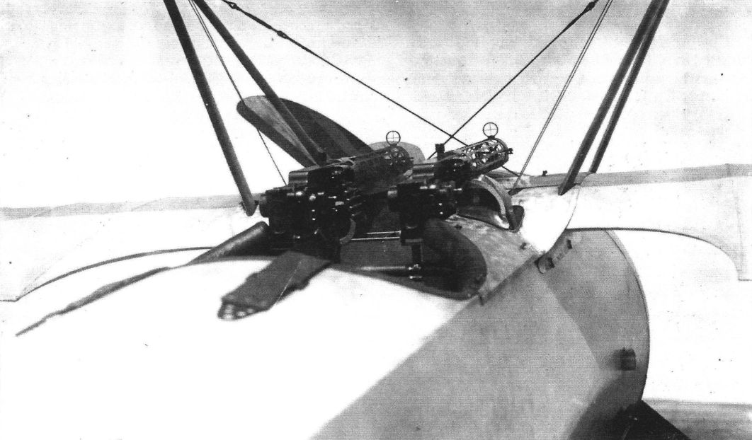
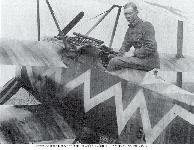
Вооружение - два синхронных пулемета LMG 08/15.
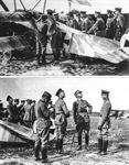
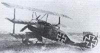
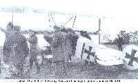
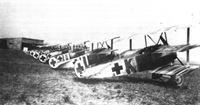
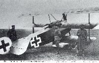
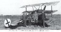
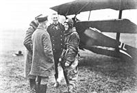
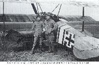
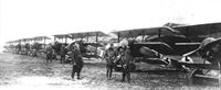
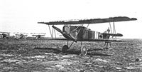
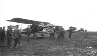
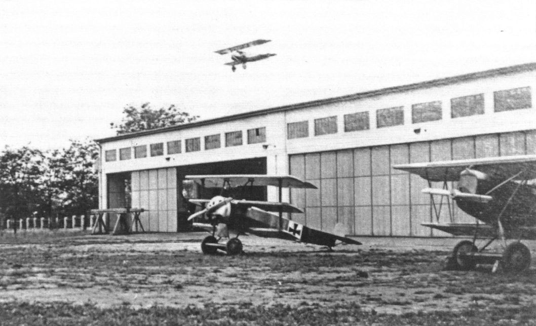
Первые два экземпляра машины в августе-сентябре 1917 г. успешно прошли войсковые испытания на западном фронте. В октябре новыми истребителями вооружили Первую истребительную эскадру Рихтхофена, а затем самолет начал поступать на вооружение других частей и подразделений.
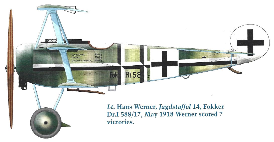
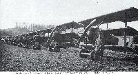
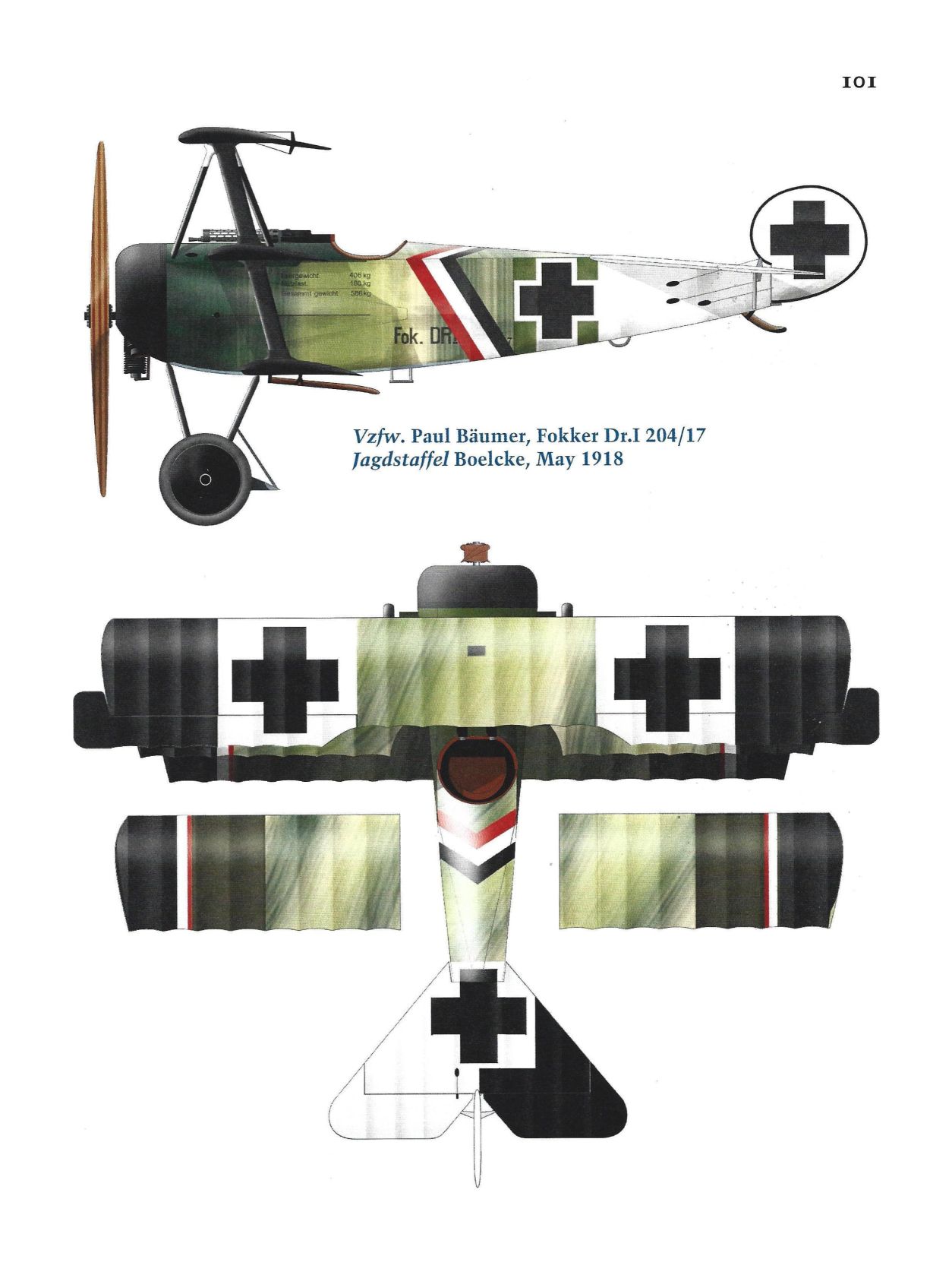
Всего было построено 318 "фоккеров" Dr.I. Пик их боевого применения приходится на май 1918 года. К началу этого месяца в немецких фронтовых эскадрильях числилось 170 машин данного типа. Но в том же месяце самолет был снят с производства.
К концу войны в строю оставалось еще около 70 "драйдеккеров". К тому времени они уже считались морально устаревшими и большинство из них входило в состав тыловых эскадрилий ПВО.
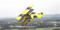
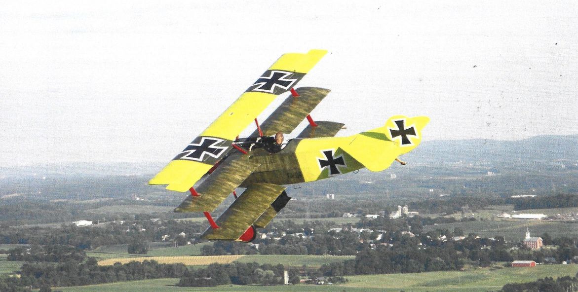
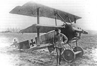
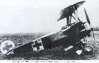
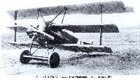
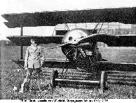
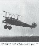
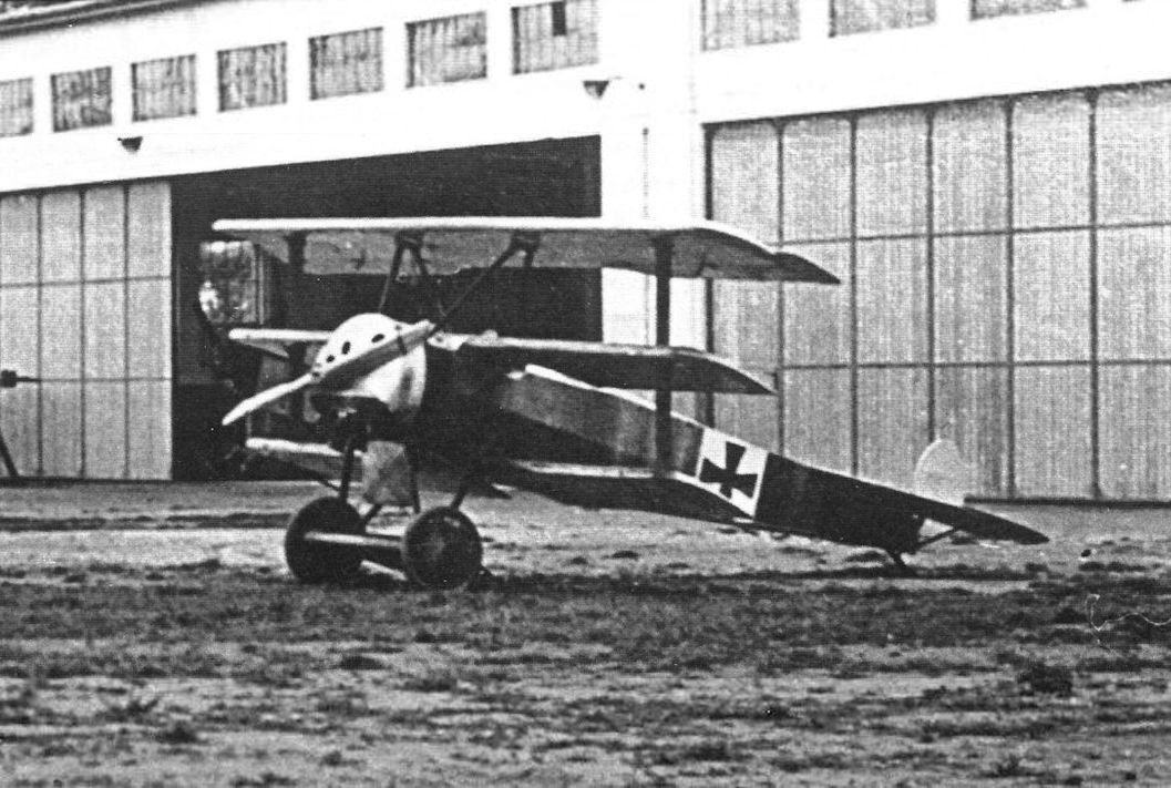
Надо отметить, что Dr.I, ставший сейчас на Западе своего рода символом авиации Первой мировой войны и образцом для постройки многочисленных летающих реплик, далеко не однозначно воспринимался немецкими боевыми летчиками. Обладая хорошей скороподъемностью и отличной горизонтальной маневренностью, он в то же время был весьма сложен в пилотировании и просто опасен для пилотов невысокой квалификации.
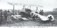
По скоростным данным он уступал современным ему истребителям стран Антанты (особенно - ранние машины со 100-сильным мотором). Кроме того, на фронте выявилась недостаточная прочность крыльев, из-за чего произошло несколько катастроф. В ноябре 1917-го полеты на "драйдеккерах" даже пришлось временно запретить до устранения этого недостатка. Лишь через месяц самолеты с усиленными крыльями вернулись на фронт.
Но при всех своих недостатках Dr.I был излюбленной машиной ведущих германских асов, так как он давал первоклассным пилотам наибольшие возможности в маневренном воздушном бою на близких дистанциях.
ДВИГАТЕЛЬ: "Оберурсель"Ur I, мощностью 100 л.с. (на первых серийных машинах), или "Оберурсель" Ur II, 110 л.с.
ВООРУЖЕНИЕ: 2 синхр. LMG 08/15 "Шпандау".
ЛЕТНО-ТЕХНИЧЕСКИЕ ХАРАКТЕРИСТИКИ
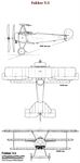
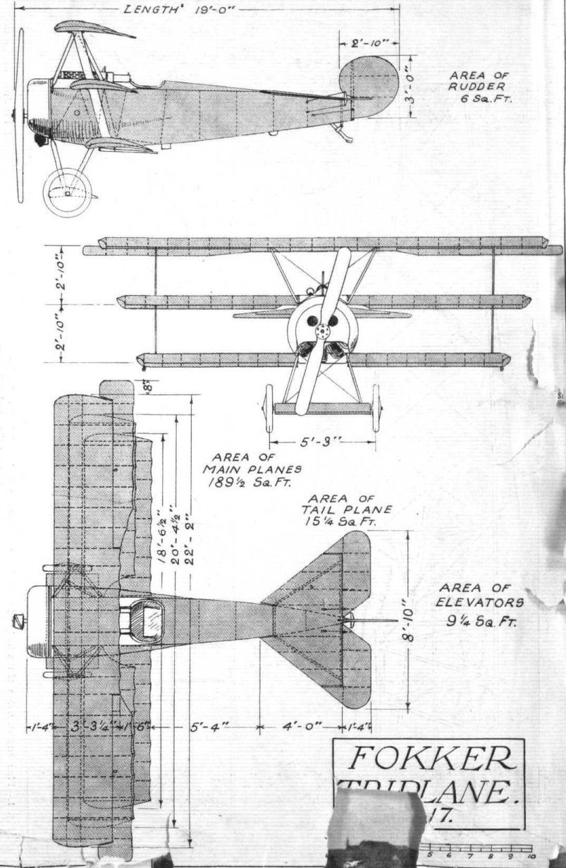
Размах, м 7,20
Длина, м, 5,76
Площадь крыла, кв.м 18,66
Сухой вес, кг 406
Взлетный вес, кг 586
Скорость максимальная, км/ч 165
Время подъема на высоту
2000 м, мин.сек 6,48
Потолок, м 6000
Показать полностью
R.Keimel Osterreichs Luftfahrzeuge (Weishaupt Verlag)
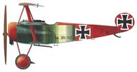
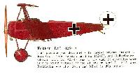
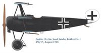
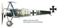
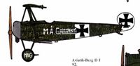
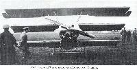
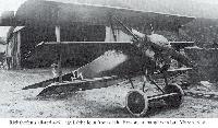
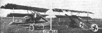
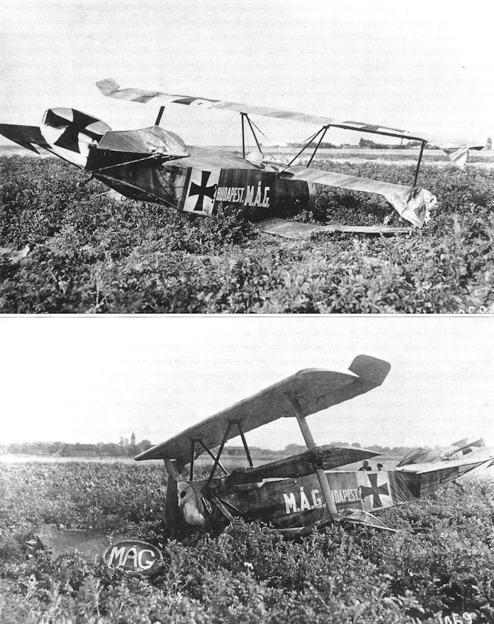
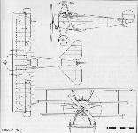
M.A.G. Fokker Dr. I 1917
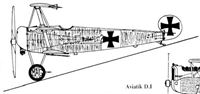
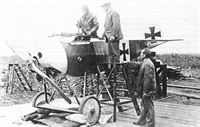
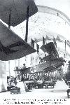
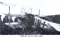
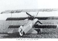
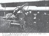
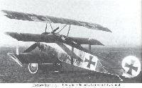
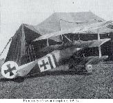
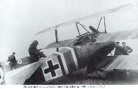
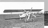
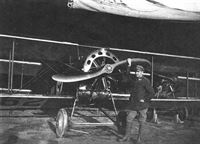
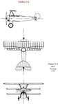
После прототипов 90.01 (Berg C I) и 90.02 (Berg D I) в 1917 году на Венгерской всеобщей машиностроительной фабрике был создан прототип 90.03 - копия истребителя-триплана Fokker Dr. I. До серийного выпуска дело не дошло.
Производитель: Лицензионная постройка, Ungarische Allgemeine Maschinenfabrik AG (MAG), Будапешт.
Назначение: Прототип истребителя.
Построен: 1917
Первый полёт: 1917
Количество: 1 экземпляр
Бортовой номер: Сер. № 90.03
Экипаж: 1
Двигатель: 1 × 118 кВт (160 л.с.) Le Rhône, ротативный, двухлопастный винт.
Размеры:
Размах крыла: 8,00 м
Длина: 6,80 м
Высота: 3,20 м
Веса:
Пустой: 620 кг
Макс. взлётный вес: 880 кг
Нагрузка на мощность: 7,5 кг/кВт
Макс. скорость: 170 км/ч
Потолок: 4500 м
Дальность: 500 км
Продолжительность полёта: 3 ч
Показать полностью
A.Weyl Fokker: The Creative Years (Putnam)
Fokker's travels to the Western Front
Early in 1917 Fokker again journeyed to the front. Although the German command was far-sighted enough to encourage such activities, in the interests of exchanging technical information between industry and operational units, Fokker was one of the few executives in the German aircraft industry who regularly paid visits to front-line formations. These visits were welcomed by pilots, who were able to air grievances about their equipment unhampered by Service regulations.
Fokker had two purposes for this particular visit: he wanted to find out what kind of fighter design, in continuation of the V.1/V.2 development, would be likely to be successful; and he wanted to discuss with his pilot friends ways and means of overcoming the growing resistance of the Adlershof technicians to his aircraft. He felt that something should be done to curb the slide-rule wielders and stress experts. So he assured one and all that he, Fokker, could give them the finest fighter aircraft on earth if only the thick-headed theorists of Adlershof would let him: his advanced designs were too practical for the chair-borne brigade at Adlershof.
These arguments struck a sympathetic chord; in fact, many of the leading fighter pilots had similar ideas. They had been provided with obsolete aircraft, some proving to be complete wash-outs; the pilots therefore ought to be consulted in the selection of new fighter types. The departmental chiefs of the IdFlieg and the Flz. readily agreed to this idea: it had always been a difficult and heavy responsibility for them to choose the best available type of aircraft; time and time again the chosen type, although good at the prototype stage, did not go into operational use until too late, when it was obsolescent. In other instances, new engines had proved disappointing under operational conditions.
For these failures the technical experts were blamed, consequently they were well content to leave the task of selection to operational pilots. It was decided that all new and airworthy prototypes should be sent to Adlershof to be flown in comparative trials by competent fighter pilots. In addition, it was suggested that promising new experimental aircraft should be sent to the front, even before being submitted to a type test. This, it was thought, should help to expedite production and re-equipment with the latest and best types.
These concessions to operational units were, of course, a quite startling innovation in the German Army. It was unheard of for soldiers to be allowed to choose their own equipment: no soldier had ever been invited (officially, that is) to express his opinion on the design or handling of his rifle. But the officers responsible for the innovation, notably Thomsen, Siegert and Wagenfuehr, did not hesitate to cut red tape in this way; they were confident that the arrangement with the fighter pilots would work well. Fokker hoped so too.
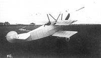
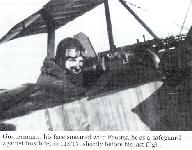
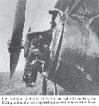
While Fokker was visiting Jagdstaffel 11, commanded by Manfred von Richthofen, he was told about the sensational new Sopwith triplane that had made its appearance at the front. Fokker was shown the first specimen brought down before it was passed on to Adlershof. He was also taken to an observation post, where he saw the triplane in flight. Von Richthofen and his technical officer Leutnant Krefft told Fokker that they needed just such an aircraft. But it had to come quickly and to be at least as good as the Sopwith.
Fokker hurried back to Schwerin. This was the chance he was waiting for. The time was late April 1917. Although he knew that other manufacturers would be invited to submit prototypes designed to counter the Sopwith triplane, he was confident that Platz would be able to get out a design more quickly than his competitors and that it would probably be better. Moreover, Fokker had a start over his rivals because he was the only manufacturer who had seen the Sopwith and knew its capabilities. He also recalled the large store of Bente Le Rhones at Adlershof: this engine would do as well as the Clerget that powered the Sopwith, and it was immediately available in quantity. There would therefore be no hold-up because of shortage of engines.
As soon as he got back to Schwerin Fokker told Platz of his discoveries and ideas. One might think that Fokker would have recorded fully all that he had learned about the Sopwith, with a technical description of the design and structural features that he might have been expected to note with care. Nothing of the kind! As Platz distinctly recalls - and he is quite emphatic about it - Fokker merely told him: “I have seen a good enemy triplane at the front. We must build one too”. And that was that. Platz gathered that the new prototype was to have a rotary engine that would be forthcoming from Adlershof almost at once.
Platz did not like the idea at all. He was all for Spartan simplicity: to him, it seemed an outrageous and retrograde complication to give an aeroplane three wings when one would be so much better: he could not understand it at all. But Fokker was the boss; to argue with such a stubborn fanatic was not easy, and Platz was very conscious of the fact that he was just beginning to find his feet as a designer. He could not help it: the triplane was an order: a triplane it had to be!
Platz is also quite certain that while he was designing the Fokker triplane he had no information whatever about the Sopwith triplane. No example of the Sopwith or any of its components came to Schwerin (contrary to the assertion made later by Dr. Sablatnig), and Platz’s only wartime visit to Adlershof did not occur until 1918. It is therefore certain that his triplane design, the Fokker V.3, was not influenced by that of the Sopwith; this is borne out by a comparison of the general arrangement and structural design of the two aircraft. How far any advice or suggestions of Fokker’s may have influenced the final development of the V.3 cannot now be ascertained, but any such advice seems to have been confined to points relating to the handling and armament of the new type.
Some small Sopwith influence might be attributed to the use, at a later stage, of a single interplane strut. Platz is emphatic that this strut was quite unnecessary when the prototype was first tested at Schwerin, but Fokker insisted on having it fitted after testing the aircraft. Platz cannot recall the reasons given by Fokker at the time. To the world Fokker let it be known that it was added because the Adlershof experts abhorred cantilever wings (which was quite untrue) and that the operational pilots did not want them either (which probably was true).
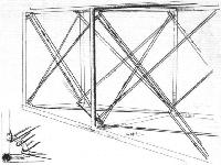
The Fokker V.3 was simpler and lighter than the V.1. With the elaborate streamlining abandoned, the slab-sided, fabric-covered fuselage saved weight and eased production and maintenance in the field. There were small plywood fairings on the fuselage sides to blend the circular cross-section of the engine cowling into the rectangular section of the fuselage structure; a rounded top decking was also fitted.
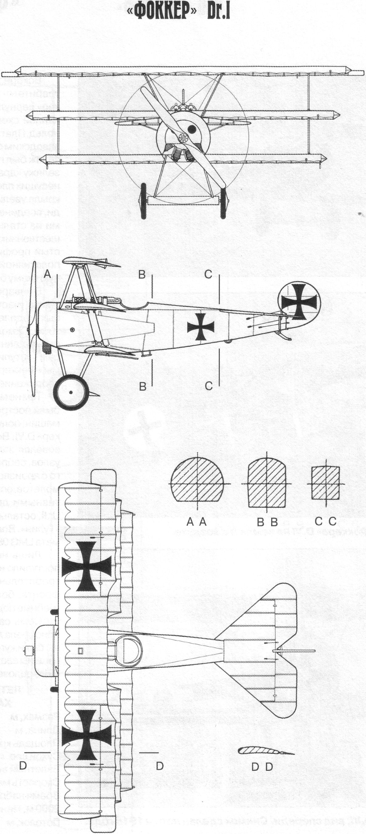
As on the Sopwith triplane, the three wings were staggered. This was neither coincidence nor imitation; it merely happened to be the best way of getting a decent view from the cockpit. All the wings had the same chord and section, but the top wing was of greater span than the other two; these were of equal span. Thus in each wing the cantilever portion was of the same length, consequently it was possible to make all the spars of the same cross-section. Platz neglected to take into account the actual lift grading over triplane systems. He assumed uniform loading everywhere. All wings were integral structures, the middle wing being attached directly to the upper longerons.
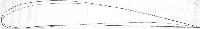
Much attention was given to the evolution of a suitable wing section. Platz thought that thick aerofoils might prove inefficient in a triplane system and that a section with no camber on the undersurface would give a high landing speed. He therefore reshaped, by eye, the V.1/V.2 section to the characteristic undercambered aerofoil of the Fok. Dr.I. This aerofoil was not tested aerodynamically in a wind-tunnel or in any other way when the V.3 and V.4 were designed. Later on, unknown to Platz, the Flz. subjected it to wind-tunnel tests at Goettingen as the Goettingen 298 aerofoil. The results of these tests were circulated by the Flz. to all German aircraft manufacturers. They were, of course, of limited value because of the low Reynolds numbers and the failure to take the turbulence of the wind-tunnel into account.
The results of British wind-tunnel tests of the Fokker aerofoil were largely ignored at the time: the leading aeronautical brains in this country were “positively certain” that thick aerofoil sections must be fundamentally bad. This being so, no-one would have been so unpatriotic as to admit that a German designer might be right with such an outlandish idea.
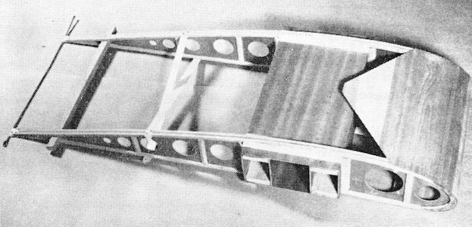
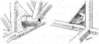
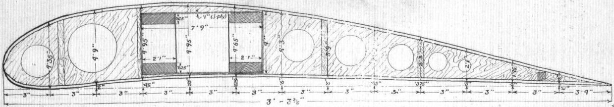
The two wing spars had to be placed as close together as possible so that the middle wing could be accommodated in front of the cockpit. But, as trials with the V.3 showed, this impaired the torsional stiffness of the wings. To put this right, the gap between the two spars was bridged, above and below, by span-wise plywood strips glued and bradded over the tops and bottoms of the spars. This produced a box structure with four vertical webs and four narrow flanges, covered by plywood flanges. This unique spar-box arrangement of the Fokker triplanes obviated the need for internal drag bracing, yet allowed the wings to be covered simply with fabric.
In such a wing the stiffness of the deep ribs with their plywood web could have been utilized to relieve the torsion strain (by compound action of the rib-spar system restraining the spars from warping). However, it was Fokker practice to make the spar gaps in the ribs large enough to allow the ribs to slide over the web splices during assembly; the ribs were subsequently attached to the spars by triangular corner pieces.
Each wing tip was formed by attaching a wing rib at right angles to the end rib. This was simple and yet gave a pleasing, rounded tip shape; it was also capable of resisting dope stresses and facilitated handling.
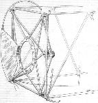
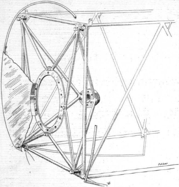
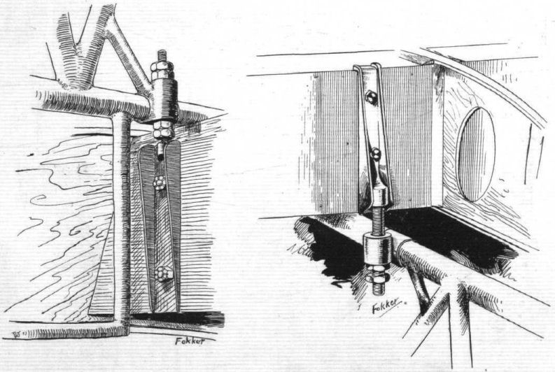
The cabane structure for the top wing was much simpler than that of the V.1, but was rather tall because the wing was above the level of the pilot’s head. The cabane of the V.3 (and of subsequent Fokker triplanes) consisted of two inverted-V struts with cable cross bracing in the plane of the front members. There was a wide bracket at the apex of each inverted-V strut; this attachment was fixed to both wing spars. The top wing attachment was consequently not so rigid as that of the V.1, but it was lighter, interfered less with the pilot’s view, and probably caused less interference drag than the ten-strut cabane structure of the V.1.
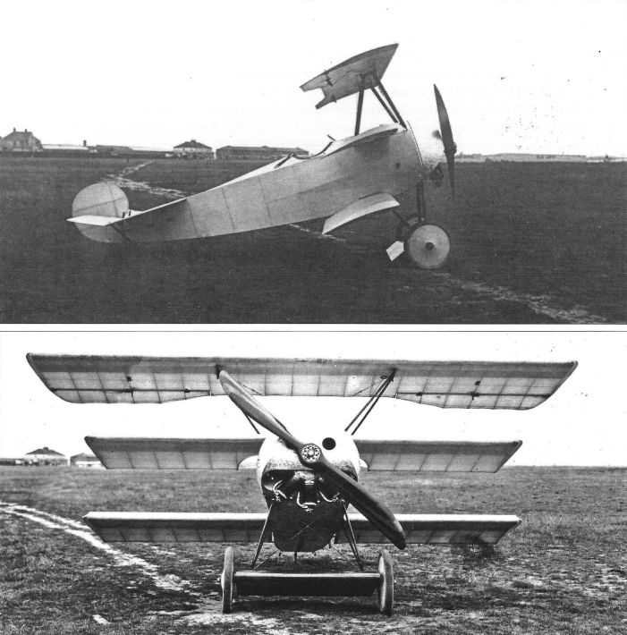
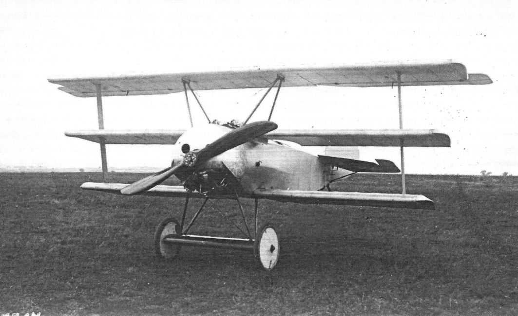
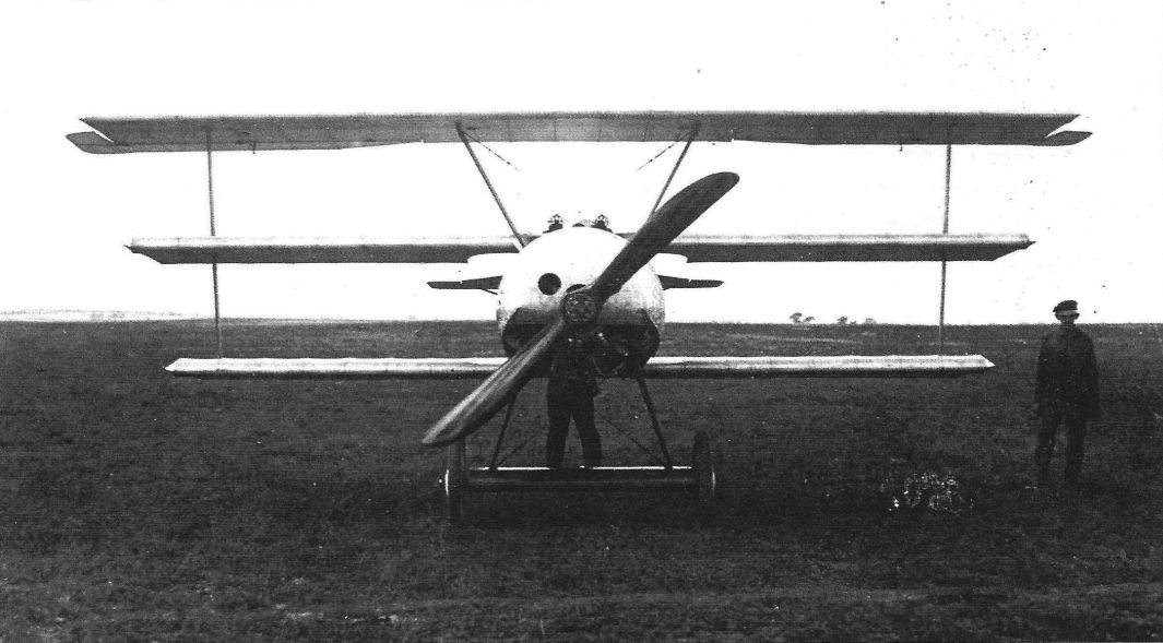
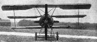
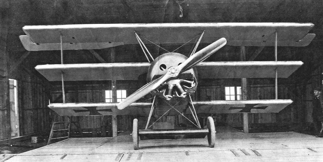
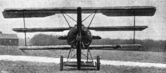
Seen from some angles, particularly from the front, the V.3 looked ungainly: neither Fokker nor Platz was much impressed by its lines.
In the V.3 Platz abandoned the peculiar control surfaces of the V.1 and V.2 and fitted conventional ailerons, elevators and rudder. In accordance with his views on simplicity the ailerons and elevators were not balanced surfaces. The standard comma-shaped rudder of the M types was retained. Although balanced, it was simple enough for Platz’s taste.
After flight-testing the V.3, Fokker demanded balanced ailerons and elevators. Platz disapproved of these luxuries, which he regarded as a mere fad of Fokker’s. But Fokker insisted on them, and was right to do so - every pilot who flew the Fokker triplane praised its effortless response to the controls. Platz returned to plain control surfaces in several subsequent designs. It is regrettable that he never troubled to learn to fly.
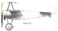
It was decided not to submit the V.3 to a type test or to an evaluation at the front. Instead, a re-design under the new designation V.4 was undertaken.
Platz realized that the appearance of the triplane could be improved by increasing the span of the middle wing so that the spans of the three wings decreased regularly from top to bottom. The increased span would mean a higher maximum bending moment at the fuselage, and Platz was not keen on fitting stronger spars to the centre wing on this account.
A new middle wing of the desired increased span was subjected to structural tests to determine whether stronger spars were needed. The results proved that the wing had an unusually high load factor for those days and needed no strengthening. Platz now realizes that the V.3 and V.4 spar flanges were generously dimensioned: when he designed the aircraft he failed to take into account the high strength of pine in tension. Had he done so he could have made the bottom flanges smaller.
Despite the favourable result of the structural tests, Platz was glad that the interplane strut was fitted, for it reduced the appreciable flexing of the wing. Although harmless enough in itself, this flexing would probably have alarmed pilots. In front elevation the interplane strut was perpendicular to the wings. Platz now recognizes that it would have been more logical to instal the strut obliquely, so as to form equal-span bays in the three wings. This might also have looked better.
The Fok. Dr.I was later flown experimentally without interplane struts by Adlershof test pilots: they wanted to find out what would happen if the interplane strut was hit in combat. The triplane remained manageable but the wings warped visibly and displayed an inclination to flutter during steep glides. This indicated that the interplane strut was subjected to bending fore and aft and was not a mere placebo, as Fokker had claimed. This was also proved by the official sand-loading tests; when the required ultimate load for case C (terminal nose dive) was reached, the fittings of the upper strut began to buckle, a sign of impending collapse from torsion.
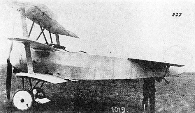
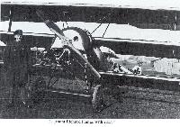
The Fokker V.4 emerged with a new set of wings in which the top and bottom surfaces were of greater span than those of the V.3; the middle wing was of intermediate span in order to provide progressively reducing spans. Horn-balanced ailerons were fitted to the upper wings, and the interplane strut made its initial appearance. The horn-balances of the elevators projected outside the tailplane contours, and twin fixed machineguns were fitted. Fuselage, rudder and installation appeared to be identical with those of the V.3.
The introduction of the Fok. F.I triplane
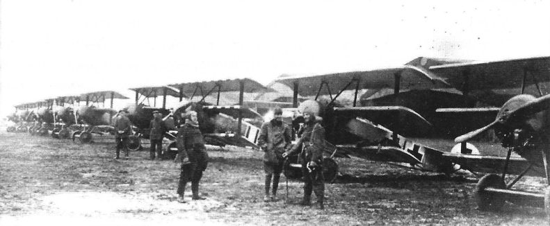
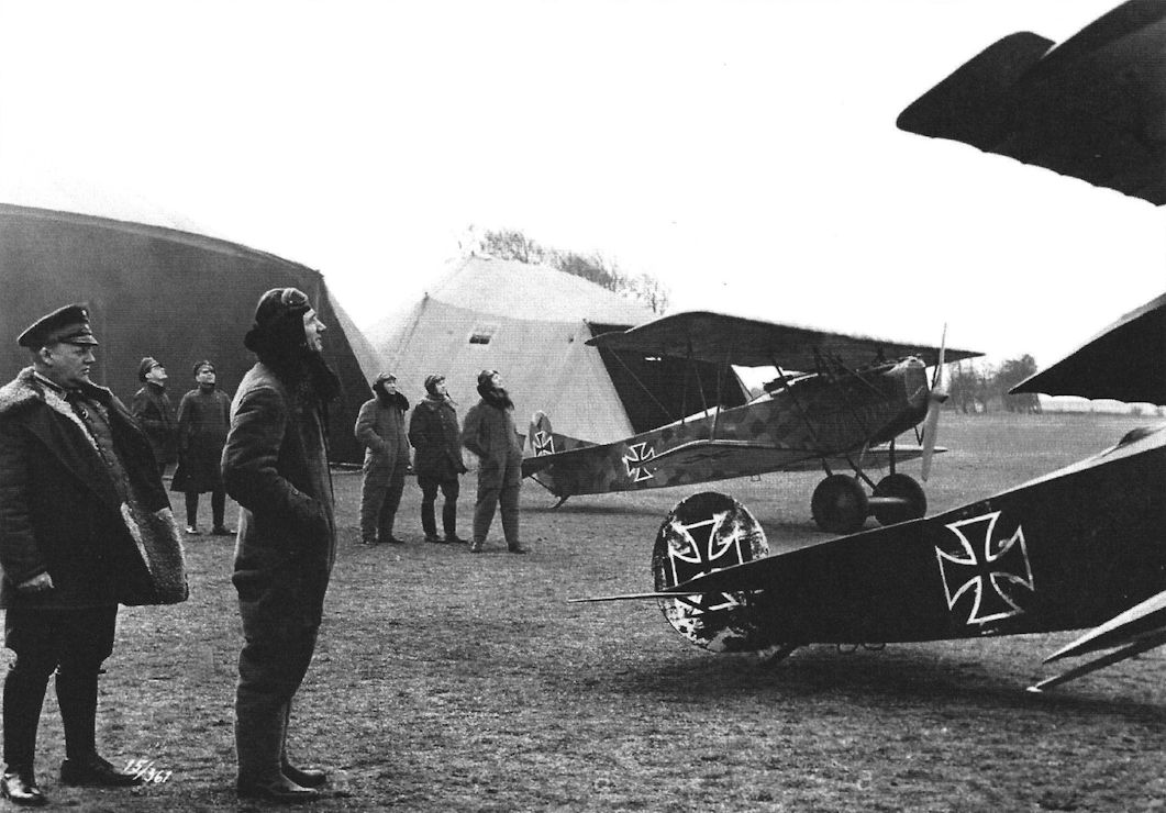
In June 1917, as a counter-measure to combat Allied air superiority in the Flanders sector, four of the best Jagdstaffeln (Nos. 4, 6, 10 and 11) were grouped together to form the first German Fighter Wing (Jagdgeschwader Nr. 1). The new unit was mobile, for it was intended that it should be moved to any sector threatened by Allied air activity. Its command was given to Manfred von Richthofen.
On July 6 von Richthofen was shot down wounded; he returned to the aerodrome at Marcke on July 25. On the following day he announced to his officers that the unit was to be re-equipped with Fokker triplanes. These he described as being “as manoeuvrable as the devil” and capable of “climbing like monkeys”. This re-equipment had been decided upon without waiting for a Type Test.
A possible reason for this hasty adoption of the new Fokker lay in the poor opinion of German fighter aircraft held by their pilots. They were then opposed by Sopwith Pups, Triplanes, Camels, S.E.5s, Spads, Nieuports and Bristol Fighters; the F.E.s and R.E.8s were easy meat for the German fighters. The new S.E.5a was greatly superior in climb and speed. Leutnant Adam, leader of Jasta 6, regarded the S.E.5 as about equal to the Albatros D.V; he regarded the Pup and Triplane as inferior, and thought the Camel might also prove to be inferior. There was no doubt about the superiority of the S.E.5a and the 200-h.p. Spad over the Albatros.
Voss, leader of Jasta 10, differed from Adam: he regarded all contemporary British single-seaters as better than the Albatros in climb, manoeuvrability and ability to dive. Leutnant Groos, the deputy leader of Jasta 11, agreed entirely with Voss. Manfred von Richthofen himself was convinced that re-equipment with better fighters was long overdue.
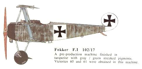
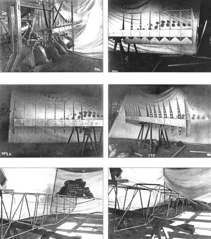
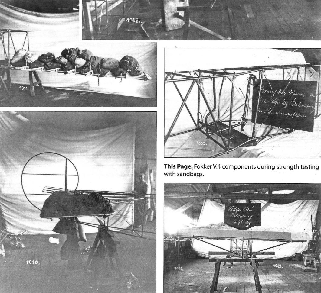
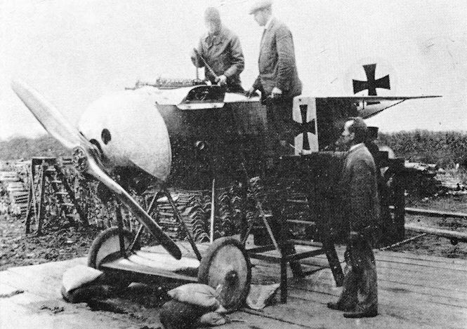
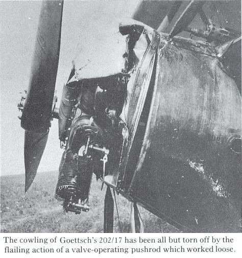
Fokker had been given an order for the supply of three experimental examples of his triplane design. The V.4 prototype (Military Order No. 101/17) was sent early in August to Adlershof for structural testing prior to operational evaluation at the front. The other two aircraft, No. 102/17 and No. 103/17, were nearing completion at Schwerin. The Flugzeugmeisterei conducted the strength tests with all speed between August 7 and 10, 1917, with Fokker present. The type was, at that early date, referred to as Fok. Dr.I.
For the first time a new Fokker aircraft passed its structural tests without major modifications. It was suggested that the rudder bar should be strengthened, and that the diameter of the steel-tube longerons in the rear fuselage should be increased to 20 mm. The tests appeared to indicate that the undercarriage strength was not up to the required standard but, as there were doubts about the testing rig (which was thought to be somewhat unrealistic), the aircraft was not grounded or retarded for this reason, and in fact no Fok. Dr.I ever gave cause for complaint about its undercarriage.
On August 11, the prototype V.4 was tested to destruction in Case A. The ultimate load factor proved to be 7-92, which was highly satisfactory. Fokker asked for the fabric to be removed from the lower wing so that structural deformation could be observed. The ribs began to buckle at a load factor of 7-75, final failure occurring with the buckling of the webs at the fuselage. Taking into account the lift from the aerofoil fairing of the undercarriage axle, the ultimate load factor could be as high as 8-38. It is doubtful whether any other operational aeroplane of the period possessed comparable strength.
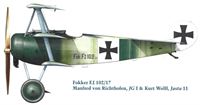
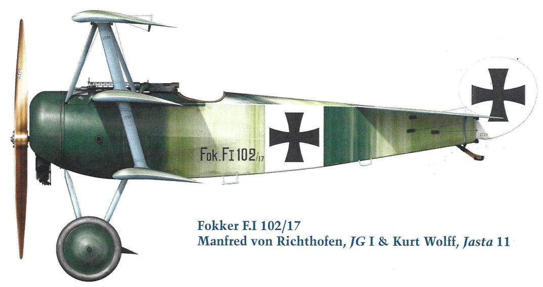
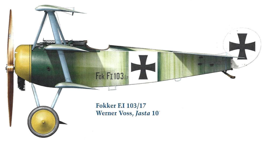
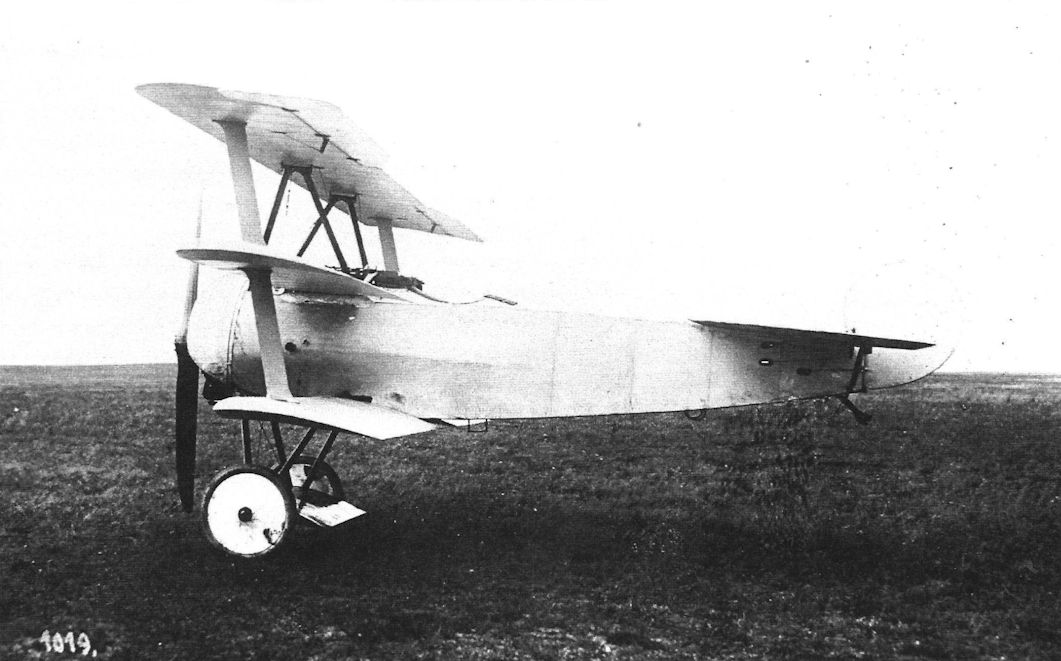
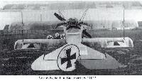
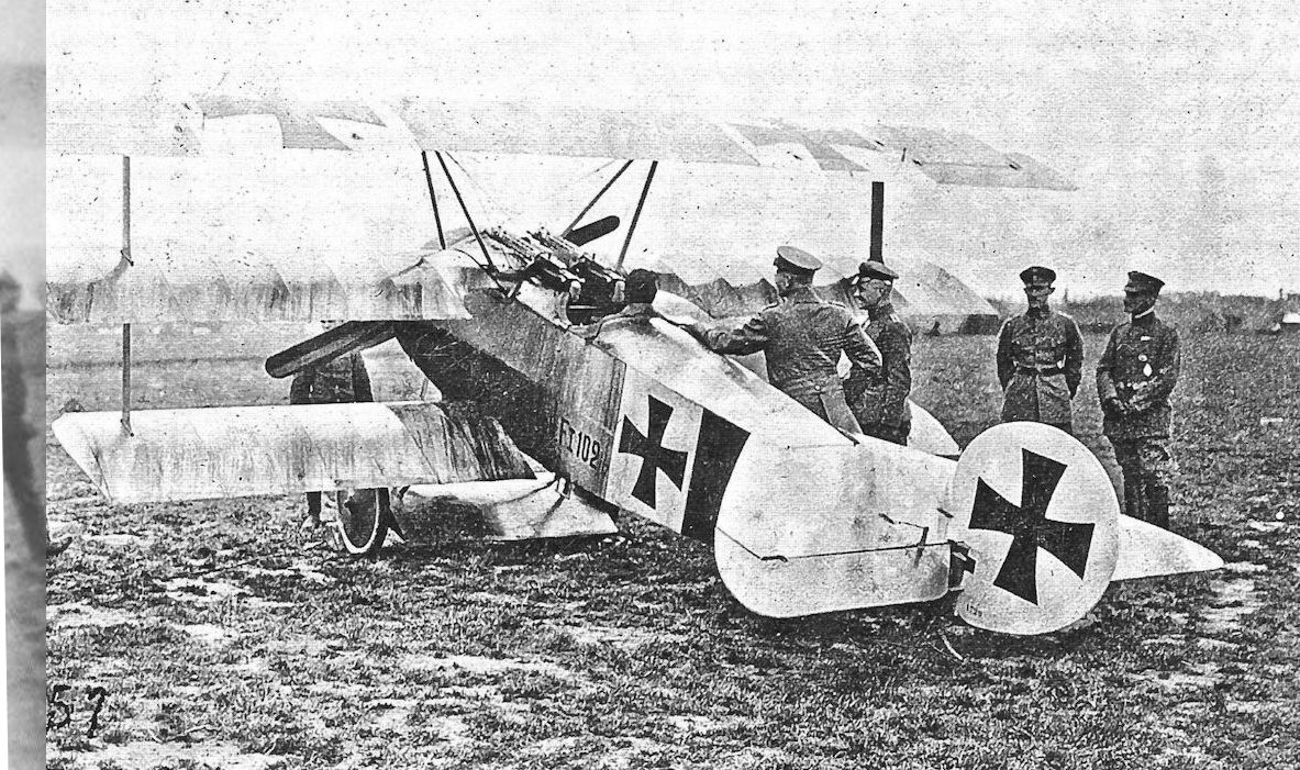
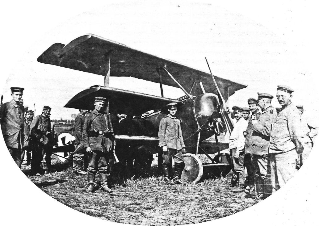
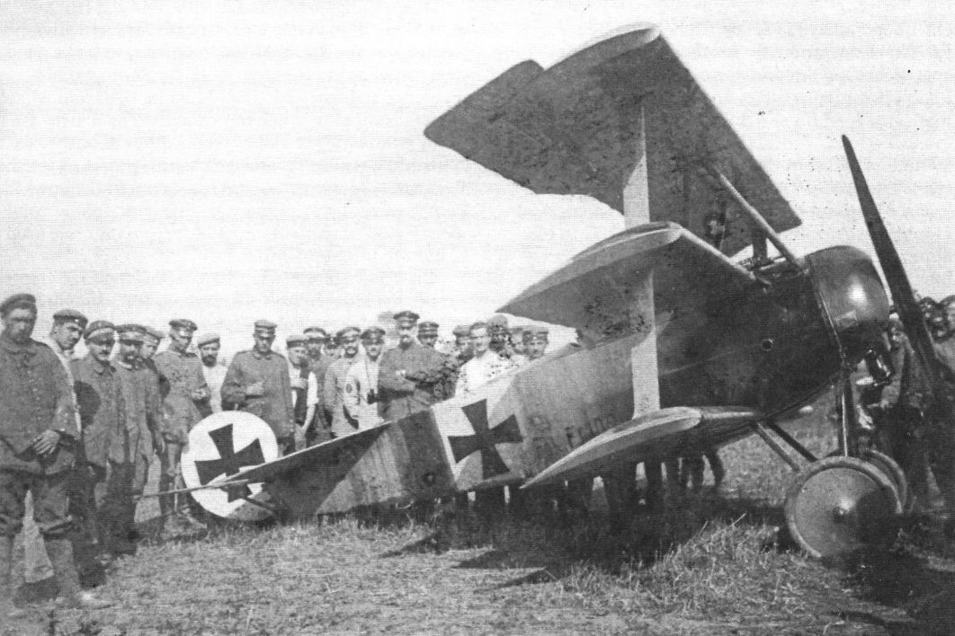
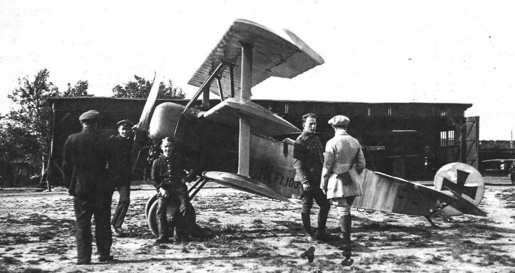
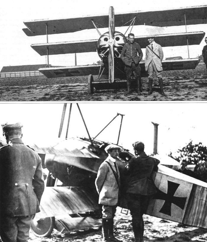
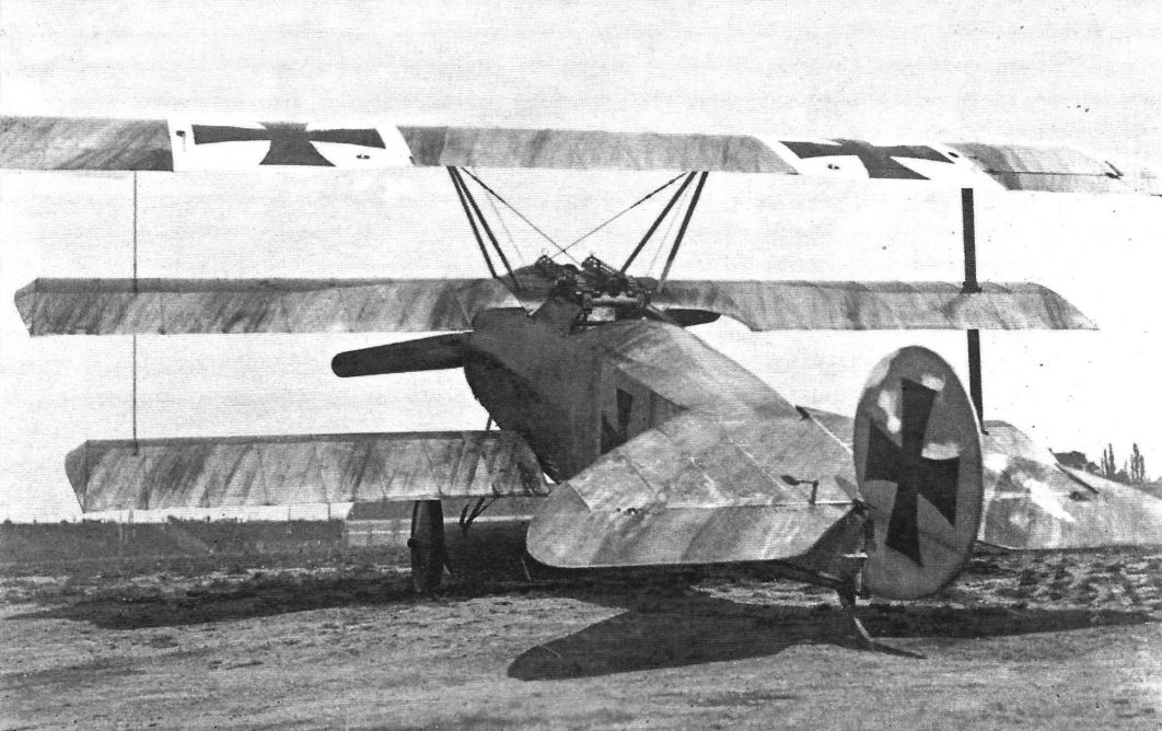
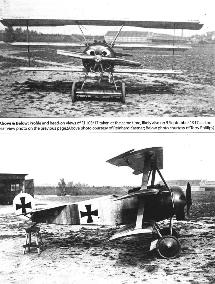
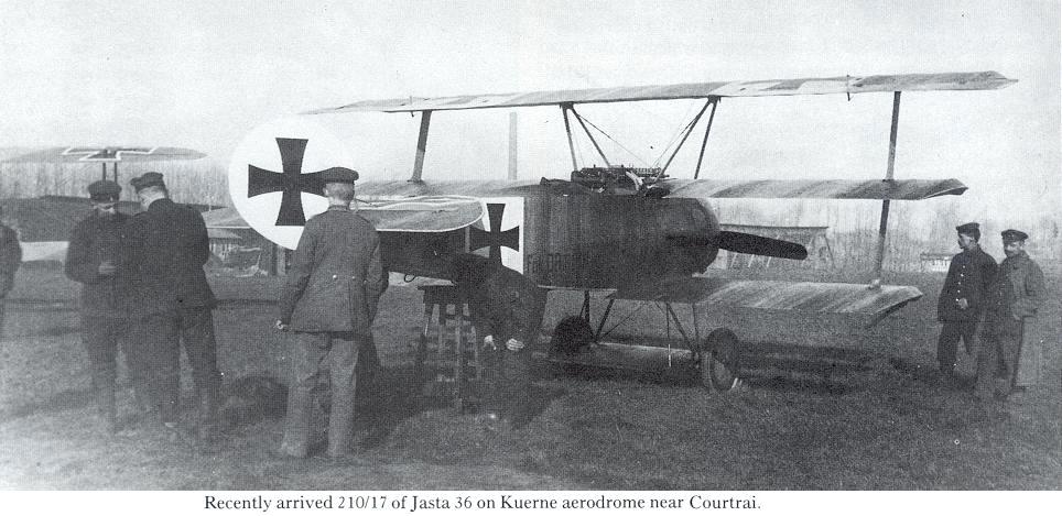
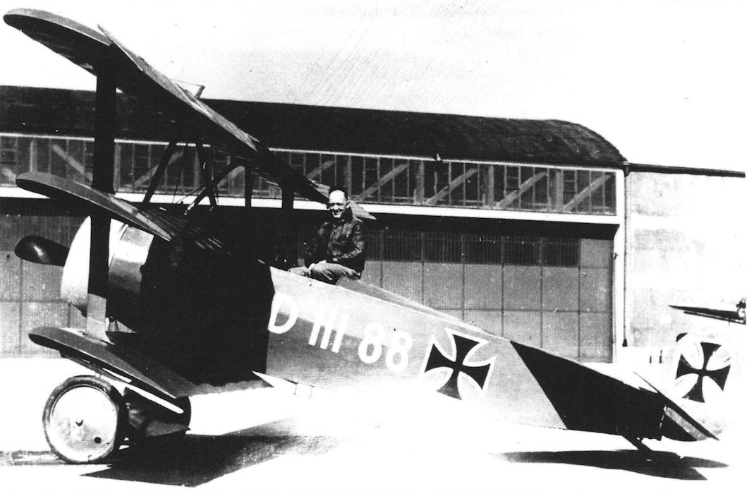
With the type designation Fok. F.I, No. 102/17 and No. 103/17 underwent acceptance flight tests at Schwerin on August 16, 1917. They were taken by Fokker to Manfred von Richthofen’s fighter wing at Courtrai on August 21. It is not known with certainty why the two aircraft were designated Fok. F.I. Perhaps the Kogenluft had decided on a new category that followed naturally on the official category letters A, B, C, D and E. But the IdFlieg had already settled on Fok. DR.I (or more correctly Fok. Dr.I) at a very early stage, as a Flz. drawing dated August 7, 1917, clearly proves. All doubt about the triplane’s official designation was removed by a Flz. order dated August 19, 1917, and signed by Muehlig-Hofmann. This order established the category Dr. for single-seat fighter triplanes; it also created the categories (CL (or Cl) and GL (or Gl) for light two-seaters and light twin-engined aircraft respectively. Thus 102/17 and 103/17 remained the only Fokker triplanes to bear the designation F.I. They differed visibly from the V.4 only in having the elevator horn balances lying within the contour of the horizontal tail surfaces.
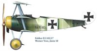
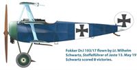
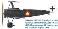
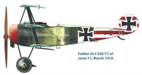
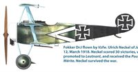
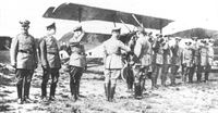
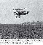
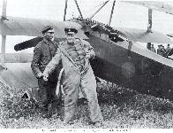
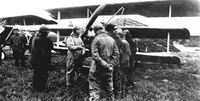
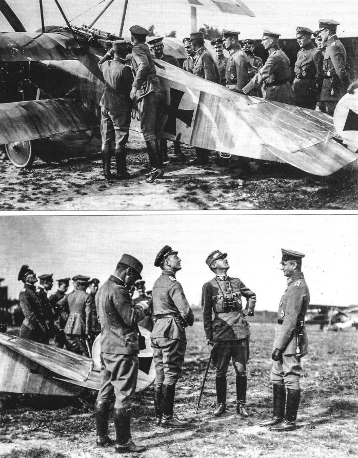
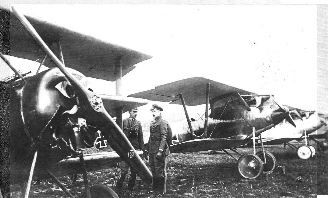
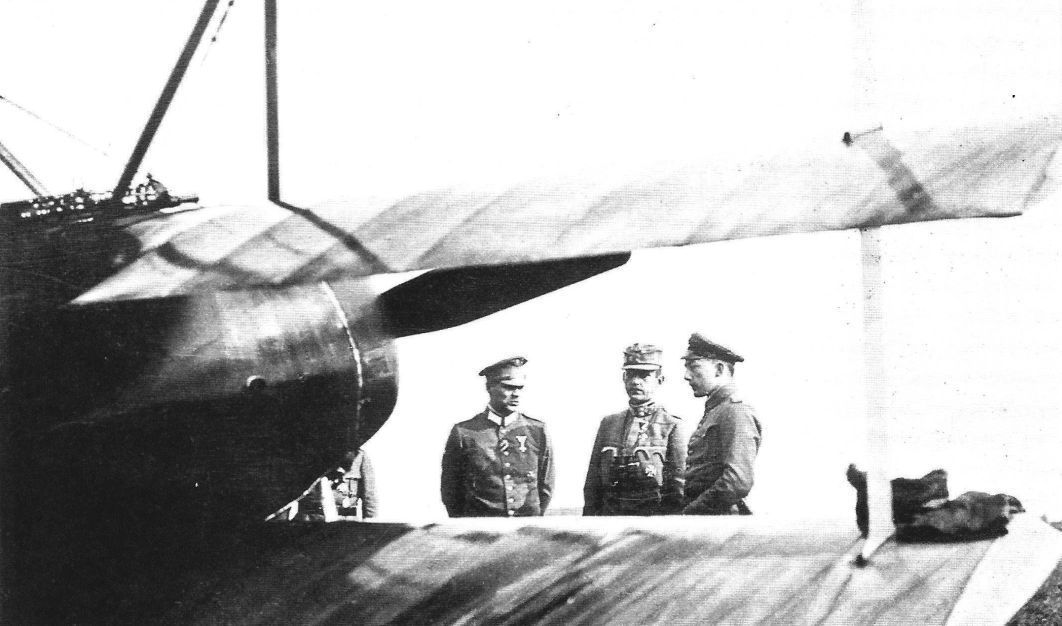
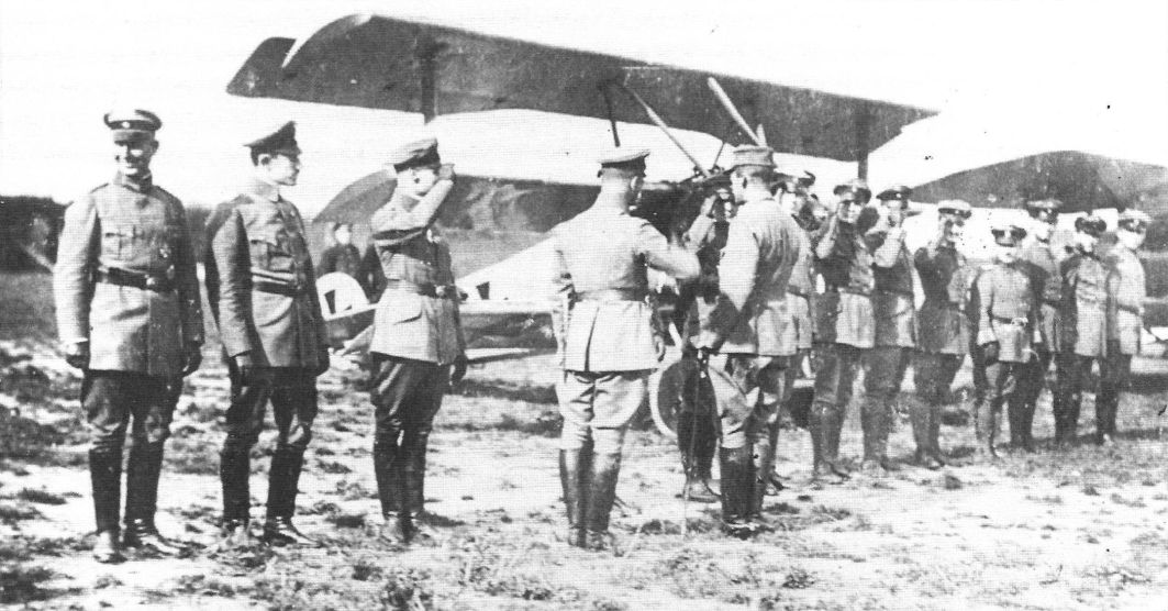
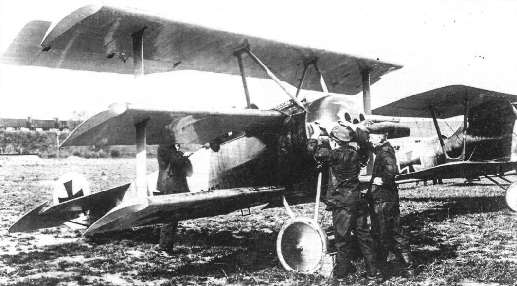
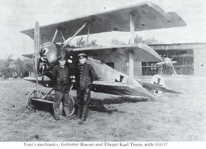
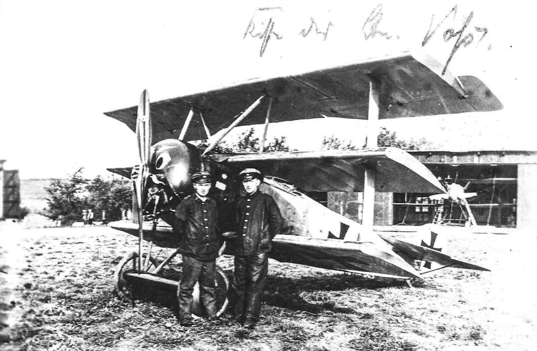
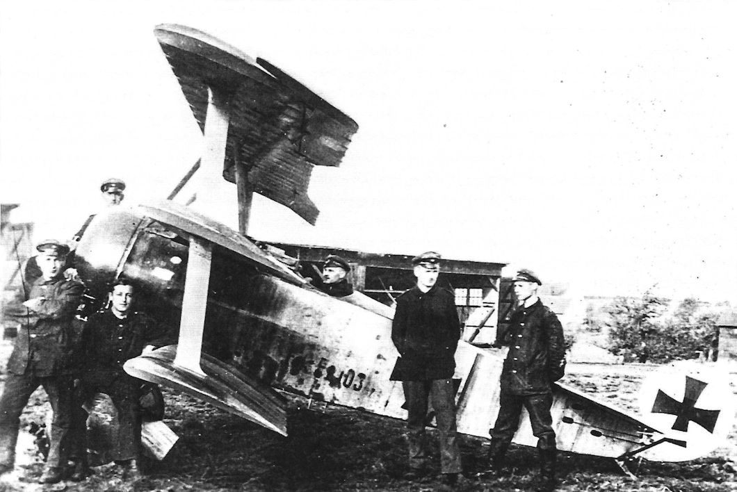
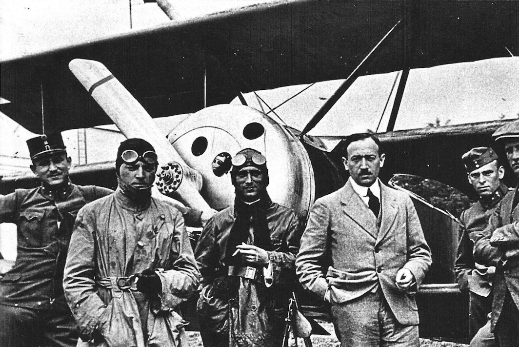
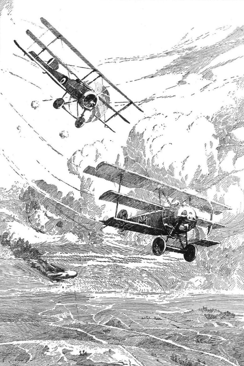
On August 26, 1917, no less a personage than Quartermaster-General von Ludendorff, commanding the German armies in the field, came to see the new Fokker fighter. Fokker demonstrated it with his usual skill. On the evening of August 29, Leutnant Werner Voss, leader of Jasta 10, tried it for the first time. He was delighted with the little triplane and its capabilities. He made the first operational flight on F.I No. 103/17 on the following day; during this flight he shot down a British aircraft. Voss’s fighting career with the triplane was brief, but with it he scored no fewer than twenty-one victories between August 30 and September 23.
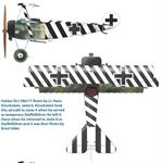
He was flying No. 103/17 when he met his death on September 23. He was flying alone on an evening patrol when he saw an S.E.5a, which he attacked. Other aircraft were attracted to the fight. These included the S.E.5a’s of “B” Flight of No. 56 Squadron, R.F.C., led by Captain J. T. B. McCudden and including Second Lieutenant A. P. F. Rhys Davids. After a long fight, in which Voss fought superbly, Rhys Davids at last placed a well-aimed burst of fire into the Fokker triplane. McCudden. who was the only witness of the triplane’s last plunge to earth, later praised Voss’s skill and courage; Rhys Davids bitterly regretted that he had been unable to take such a gallant foe alive.
Manfred von Richthofen flew a Fokker triplane for the first time on September 1, 1917: the aircraft was Fok. F.I No. 102/17. Although he was still suffering badly from his head wound and had little faith in rotary engines, he took instantly to the Fokker. Later that day, again flying the triplane, he shot down an R.E.8 near Zonnebeke. It was his sixtieth victory.
Although that particular victory was an easy one, so much did von Richthofen like the Fokker that on the following day he reported to the Kogenluft that it was distinctly superior to the Sopwith triplane and well suited to the requirements of his Jagdgeschwader. He requested complete re-equipment with triplanes with all possible speed.
Fok. F.I No. 102/17 had a shorter life than its sister machine. On September 15, Oberleutnant Kurt Wolff (Jasta 11), a frail-looking boy of great spirit who was very popular with Manfred von Richthofen and his brother officers, was shot down and killed while flying it in combat with Sopwith Camels of No. 10 Squadron, R.N.A.S.
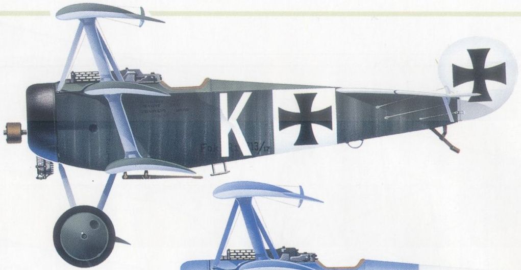
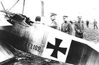
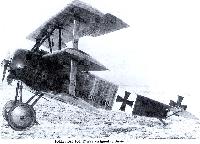
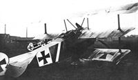
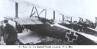
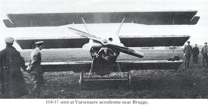
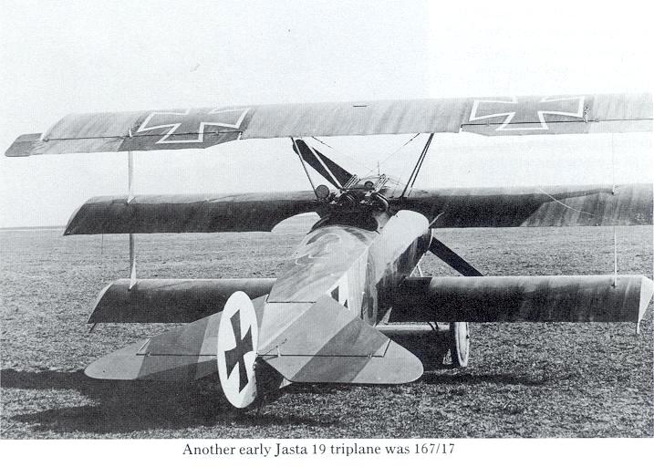
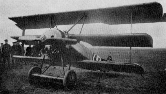
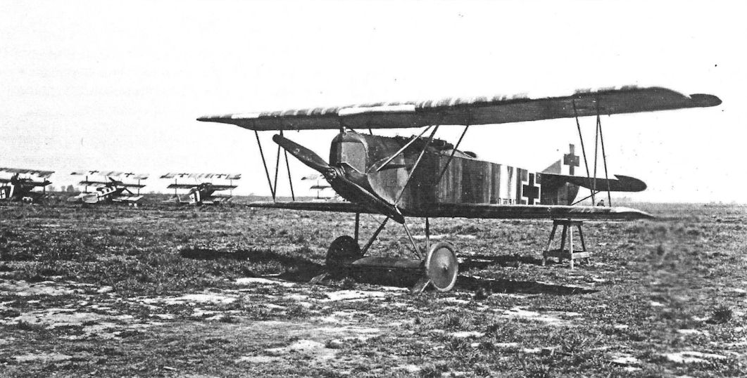
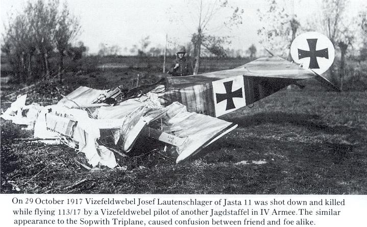
About the middle of October 1917, six new triplanes were delivered from Schwerin, all now bearing the designation Fok. Dr.I and differing from the F.Is in some details. The only external difference was the addition of wing-tip skids under the lower wings. The order numbers of these first six Fok. Dr.Is were 104/17, 106/17, 109/17, 110/17, II1/17 and 113/17.
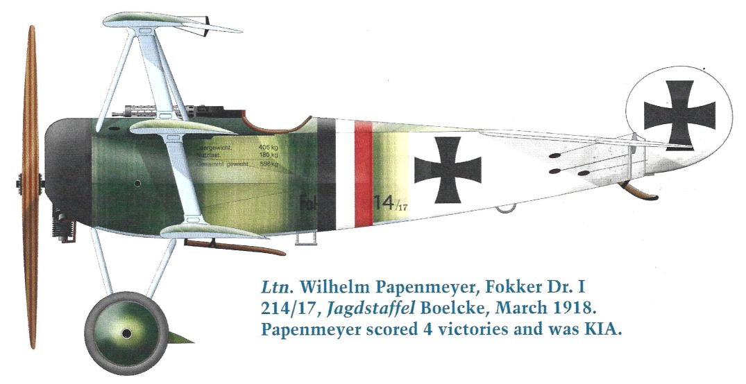
Eleven more arrived three days later, all with Beute Le Rhone engines. These were Nos. 107/17, 112/17, 114/17, 116/17, 118/17, 119/17, 121/17, 122/17, 123/17, 125/17 and 132/17. No. 108/17 did not go to the front: it was supplied to Adlershof for flying trials of the new 160-h.p. Goebel Goe.III engine.
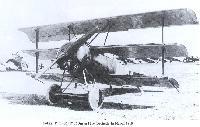
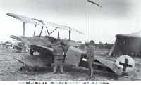
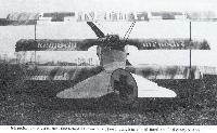
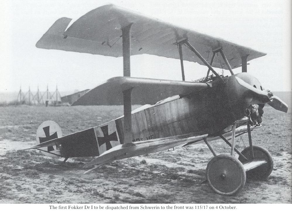
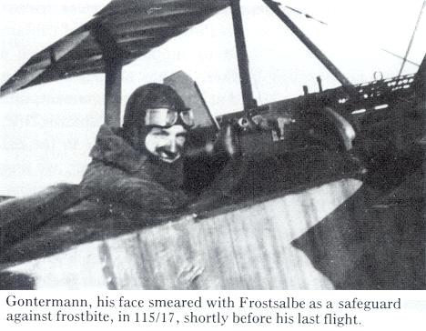
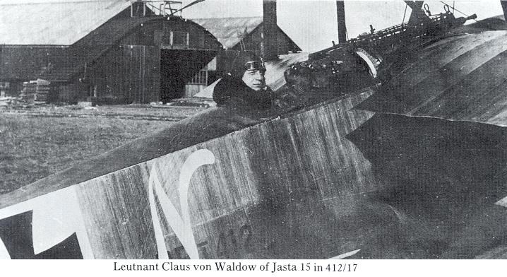
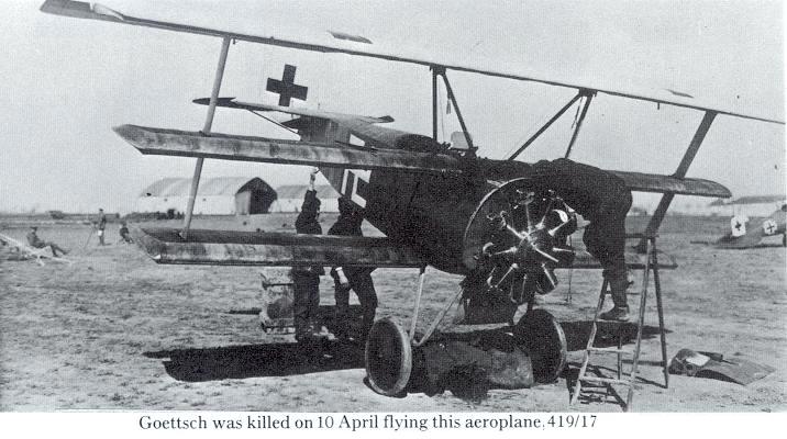
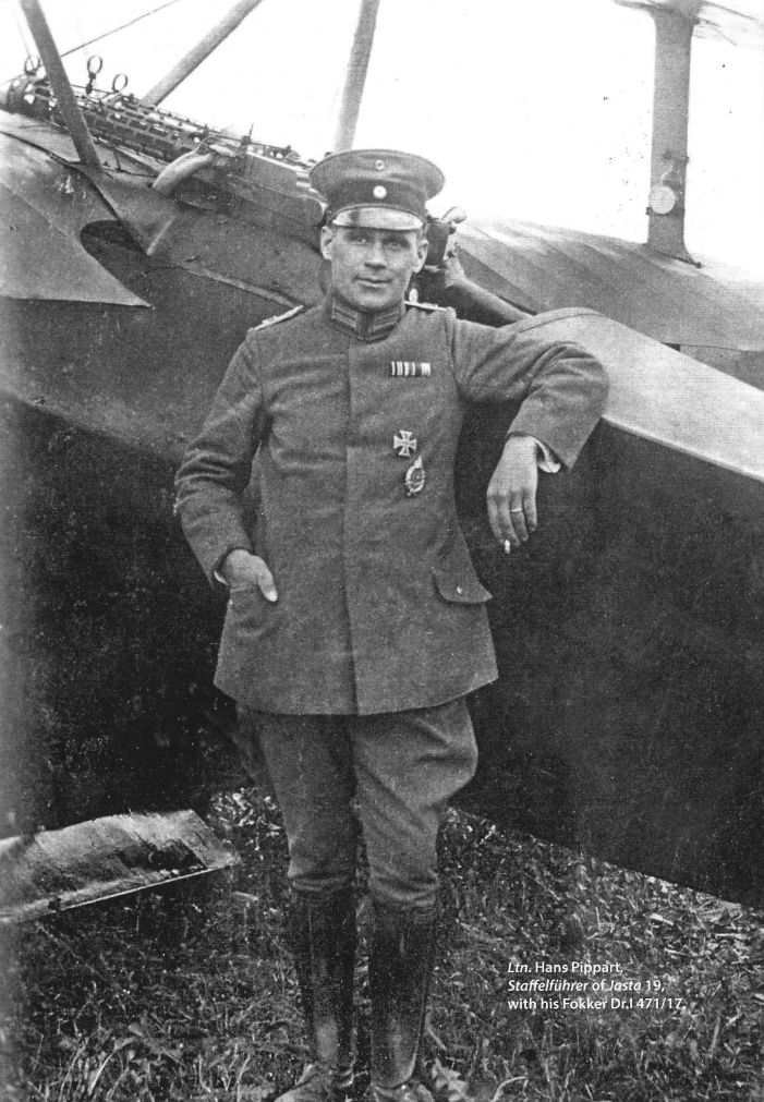
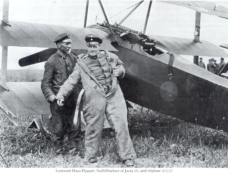
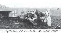
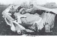
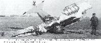
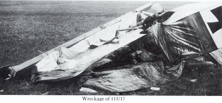
Included in the next batch of triplanes was the ill-fated No. 115/17. This Fok. Dr.I was delivered to Jasta 15, on October 22, 1917, where it was taken over by the Staffelfuhrer, Leutnant Heinrich Gontermann. Bad weather delayed his first flight in the aircraft until October 28, 1917. On the following day his second flight in the new triplane ended fatally: an eye-witness description indicates that Gontermann was performing aerobatics at 1,500 ft. over the aerodrome when it became apparent that his triplane was out of control. Several parts of the top wing were seen to break away, and the aircraft crashed. Gontermann was seriously injured and died next day, twenty-one years of age and with thirty-nine victories to his credit.
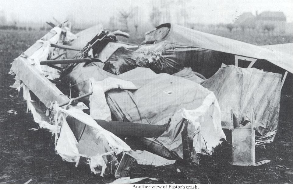
On October 31, two days after Gontermann’s fatal crash, Leutnant Pastor (Jasta 11) crashed in a similar manner while flying No. 121/17. In spite of the promise showed by the triplane all aircraft of the type were grounded immediately. A special commission of experts (Z.A.K. Sturz Kommission) was hastily formed and sent to the front to investigate. Its members were Oberleutnant Dr.-Ing. W. Hoff of the D.V.L., the Flugzeugmeisterei engineers Diebel and Fleckig, and - most important - Dipl.-Ing. Roland Betsch, technical officer of Bauaufsicht 13 at the Fokker works, Schwerin. A more searching structural examination of the aircraft was begun at Adlershof.
Meanwhile, the Richthofen Jagdgeschwader had to revert to Albatros D.Va and Pfalz D.IIIa, both with the 160-h.p. Mercedes and no longer competitive types in the more active sectors of the front.
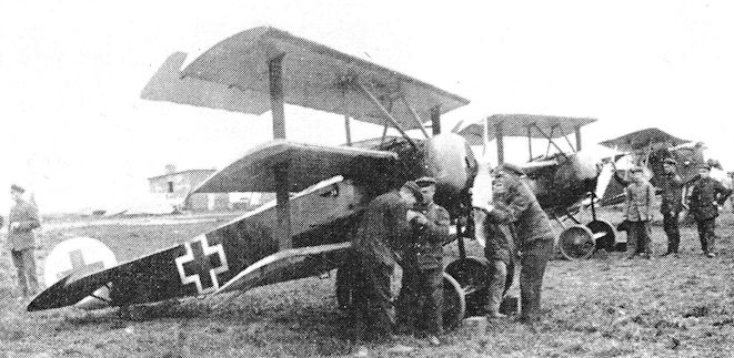
Manfred von Richthofen had been a witness of Pastor’s crash. Immediately after the accident, he and his Technical Officer, Leutnant Krefft, examined all the Fokker triplanes on the strength of Jagdgeschwader 1. The result was alarming: they found extensive evidence of bad workmanship. It was obvious that production of the wings had been rushed, and that such inspection as might have been made had been sketchy. When the crash-investigation commission arrived from Adlershof, accompanied by a much-subdued Fokker, von Richthofen showed them his findings. He also impressed upon the commission the urgent need for a speedy investigation and recommendation: the Fok. Dr.I was urgently needed and had shown great promise.
Examination of the remains of both the wrecked triplanes confirmed that the workmanship had been exceedingly poor. On the other hand, the wing spars had not failed in flight; but in each case the ailerons and ribs had come off in manoeuvres that could not be called violent, and this was puzzling. Several theories were advanced. It was suggested that sideslipping might have imposed some hitherto unknown loading on the ailerons, accentuated perhaps by the horn balances. Hoff did not like those balances: might not they, at some point, have produced an abrupt overbalancing force, thus producing sudden and unexpected peak loads? If so, the attachment of the ailerons did not look strong enough to cope with such loads, nor did the ribs that might have to transmit them look substantial enough. Some redesign seemed necessary: this ought to be investigated at Adlershof.
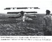
The accidents to Gontermann and Pastor were, by coincidence, investigated on the same day, November 2, 1917, the former at La Neuville, the latter at Kortryk. One eye-witness of Gontermann’s crash, a fighter pilot of Jasta 15, had noticed that during a side-slip to port the port aileron had broken away first; immediately afterwards the ribs came off the top wing. Examination of the wreckage showed that the top-wing spar had remained intact until the impact with the ground; the rest of the wing structure was missing. The Z.A.K Sturz Kommission found similar evidence in the remains of Pastor’s aircraft. The spar of the top wing and the port aileron were examined, and it was found that all the ribs had come away in the air. The inner portion of the aileron was missing, and the surface had fractured outboard of the horn balance. The hinges were intact; a part of the auxiliary spar to which they were attached was still in place. Manfred von Richthofen stated that Pastor was gliding down. As the triplane tended to drop its port wings Pastor would have applied starboard aileron, thus producing a load on the ailerons that might have caused the failure.
For examination, von Richthofen and Krefft had selected the Fok. Dr.I that had done most flying, and had stripped the fabric from its top wing. This immediately revealed an insecure connexion between the auxiliary spar and the wing-tip former. Moreover, the interior of the wing had been badly affected by moisture: all the plywood webs had warped, and some of the cap-strips of the ribs had come away from the webs.
Removal of the fabric from the bottom wing of another triplane revealed that many ribs had pulled out of the grooves of their cap-strips, and that the triangular-section gusset pieces attaching the ribs to the spar box had come adrift, probably because of moisture and careless gluing. In this instance, disintegration of the entire wing seemed imminent.
After the Kortryk investigation, Oblt. Hoff interviewed Fokker in the presence of Manfred von Richthofen and delivered a stern warning that he would have to improve his production and inspection methods. If he did not do so, drastic measures would have to be taken. Fokker’s lame excuse - that his factory had worked day and night to expedite the delivery of the first triplanes because von Richthofen wanted them so urgently - was brushed aside.
On November 6, 1917, the IdFlieg wrote to Fokker confirming in detail “the instructions imparted to Herr Fokker by Oblt. W. Hoff at Kortryk”. This letter was agreed with the Kogenluft and was signed by Muehlig-Hofmann. It stipulated that existing Fok. Dr.I aircraft were to be provided with new and properly constructed wings without delay: the new wings must be supplied by Fokker without extra charge. All wings of existing Fok. Dr.Is must be sent to the Central Aircraft Acceptance Commission (Z.A.K.) at Adlershof. Until new wings were fitted, all Fok. Dr.Is must remain grounded.
The letter from the IdFlieg further directed that all Fok. Dr.I wings already made must be uncovered, examined thoroughly, and modified as follows:
1. Reinforcement of the tip former by adding a second rib to form a box rib.
2. A third box rib to be incorporated in the wing to provide a more solid attachment for the auxiliary spar.
3. Improvement of the joint between the auxiliary spar and the wing-tip former.
4. Omission of the cut-out at the centre of the auxiliary spar.
5. Improvement of the joint between the auxiliary spar and the capstrips of the ribs that were attached to it.
6. Improvement of the joints between the rib webs and their capstrips.
7. Stiffening of the rib webs by the addition of vertical stays.
8. Omission of the lightening holes in the rib webs to reduce moisture absorption.
9. The fabric must be sewn to the ribs; it must no longer be nailed on.
10. Provision must be made of means for supporting the fabric, especially in the centre of the upper wing.
11. The wing interior must be protected against moisture by a coating of protective lacquer.
12. The Flz. would experiment on the size of the horn balances of the ailerons: these might have to be modified.
The IdFlieg requested that these modifications should be inspected and approved by the Flz. before any wings were accepted. They also emphasized that all wings supplied in the future had to be more carefully produced and must not require further structural modifications.
The crash-investigation commission submitted its report and recommendations on November 15, 1917. It and its associated documents were signed by Roland Betsch.
Critical though the IdFlieg letter of November 6 was, Platz never saw it (until the author showed him a copy recently), nor did he learn the findings of the crash-investigation commission. Apart from Fokker’s failure to pass this information to Platz, it seems extraordinary that Betsch, who was personally acquainted with Platz, did not consider it his duty to discuss with the designer the technical details of the report. One cannot escape the feeling that at Schwerin conceptions of duty were peculiar, war or no war.
Today, having learned all these technical facts belatedly, Platz is convinced that the Fok. Dr.I could have been made safe with fewer modifications, simply by more careful production and a modification of the rib construction that he had already introduced at that time. After a test flight with a production Fok. Dr.I, the pilot had shown him that the fabric on one of the bottom wings had become loose; there had been no accident of any kind. Platz found that the rib cap-strips had come off the webs. The grooved cap-strips, a relic of the early monoplane, had been insufficiently glued and had parted company with the rib webs. Platz obviated this danger by sandwiching the web between two separate rib-contour runners: this gave a secure joint. The ribs of all subsequent Fokker aeroplanes were made in this way, regardless of whether the wings were fabric-covered or plywood skinned.
Of the other modifications demanded by the IdFlieg, Platz agrees that Nos. 1, 3, 5 and 9 were good ideas. His own independent action had met requirement No. 6. Modifications Nos. 2, 4, 7 and 8 seemed to him quite unnecessary, and his arguments against them would probably have convinced the Flz. experts if they had realized that the designer of the triplane was Platz, not the great A. H. G. Fokker who was so curiously inarticulate when questioned about design details.
The effect of the crash-investigation commission’s report and the IdFlieg letter was to bring Fok. Dr.I production to a standstill. As a scapegoat, the Schwerin works manager was dismissed. The military authorities refused to accept any further aircraft until all wings had been modified and thoroughly inspected.
All this was a considerable set-back for Fokker and his company. The initial order had been for 320 triplanes (with the numbers 101/17 to 220/17, and 400/17 to 599/17), and Fokker had been told, before the wing-failure crashes, that much larger orders might be given: this depended only on engine supplies and, most of all, on the lubricating-oil situation. But now the triplane was in disrepute, and instead of accepting growing orders Fokker had to use up his profits in having all wings stripped, examined and modified.
The original delivery programme envisaged the supply of 173 Fok. Dr.Is by December 1, 1917, the balance of the first contract to be delivered thereafter. The grounding of the type changed this drastically, as the following table indicates:
Date of report Number of operational Fokker triplanes Number supplied by Fokker during period preceding date of report
1.9.17 2 (Fok. F.I) 3 (one as type aircraft to Adlershof)
1.11.17 17 None during September; 24 during October
1.1.18 35 6 during November; 47 during December
1.3.18 143
1.5.18 171
1.7.18 118 Up to 1.7.18, 150 Fok. Dr. I were withdrawn from front-line units in the major flying sectors
1.9.18 65
1.11.18 69 Almost all with home-defence fighter formations
The modified wing, when tested at Adlershof, proved capable of withstanding more than 200 % of the maximum load specified for the aileron attachment, in spite of an adverse load grading. Being over-strength it was, of course, heavier than it need have been. On November 28, 1917, Fokker was notified by telegram from Hoff that the wing had proved satisfactory on test. The ban on the Fok. Dr.I was then lifted.
Deliveries of the modified triplanes started again early in December. By that time, however, the type had lost its temporary superiority and, especially in those sectors where aerial fighting was most intense, something better than the Fok. Dr.I was wanted.
The official report on the strength tests of the modified Fok. Dr.I wing was dated November 28, 1917. It included a description of the way in which the Fokker works had complied with the detailed requests of the IdFlieg. The points in the IdFlieg letter of November 6 had been dealt with thus:
1, 2, 9 and 10: modifications effected as requested.
3 and 5: the auxiliary spar was joined to all ribs by a triangular gusset piece of plywood; this was glued and pinned in place. Finally, a strip of fabric was cemented over it as a moisture protection.
4: the cut-out had been retained, but local reinforcement had been provided by gluing an additional piece of wood aft of the spar.
6: the joint had been improved by cementing on fabric.
7: web stiffeners had been added; over each of these, a strip of fabric had been cemented reaching over the cap-strip.
8: had been disregarded; this was accepted.
11: all wooden and metal parts in the wing had been given a protective coating of lacquer.
The structural modifications increased the wing weight by 3-5 kg.; that is, 4-25% over the original wing-structure weight of 84-5 kg. (187 lb.).
In the loading tests of the strengthened wing, the lift contributed by the undercarriage aerofoil was neglected, as before. The modified airframe withstood the specified safe loads in Cases A and B without any permanent or excessive deformation. The upper wing deflected by 135 mm. at the tips under a load factor of 5 in Case A, whereas the deflection in the original airframe had been only 127 mm. This was not investigated, possibly because the deflection was wholly elastic.
The aileron strength was tested under a negative load of 150 kg./sq. m. (30-8 Ib./sq. ft.) with the control column fixed; simultaneously the wing in front of the loaded aileron was sand-loaded to 200 kg./sq. m. (41 lb./ sq. ft.). Again no excessive deformation was observed, but splintering began to occur at the strut ends under this exceptionally severe load.
The auxiliary spar was stressed from a chordwise load of 150 kg./sq. m. on the ailerons; but even at twice this load no failure or permanent deformation occurred.
Finally an overload was applied to the wing tips. In the Case A test the sand was first applied uniformly along the span. When this load (2,345 kg., or 5,160 lb.) proved safe, additional loading was applied, rising triangularly to the wing tips. At 65% of this unrealistic tip load, the spar of the bottom wing failed at a distance of 75 cm. (30 in.) from the port side of the fuselage.
The report concluded that failure of wings or ailerons was unlikely in service unless glued joints were badly affected by moisture. The Bauaufsicht was instructed to exercise greater care in supervising the production of these aircraft.
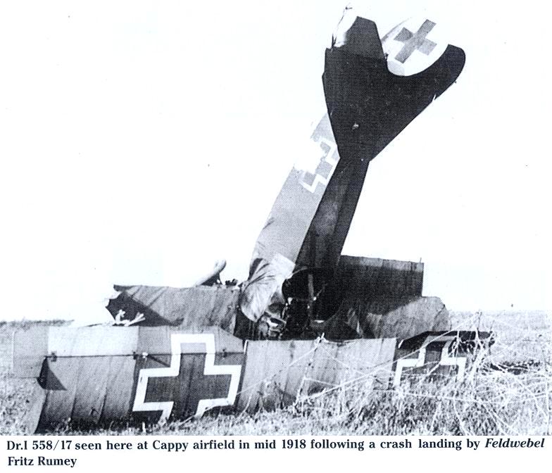
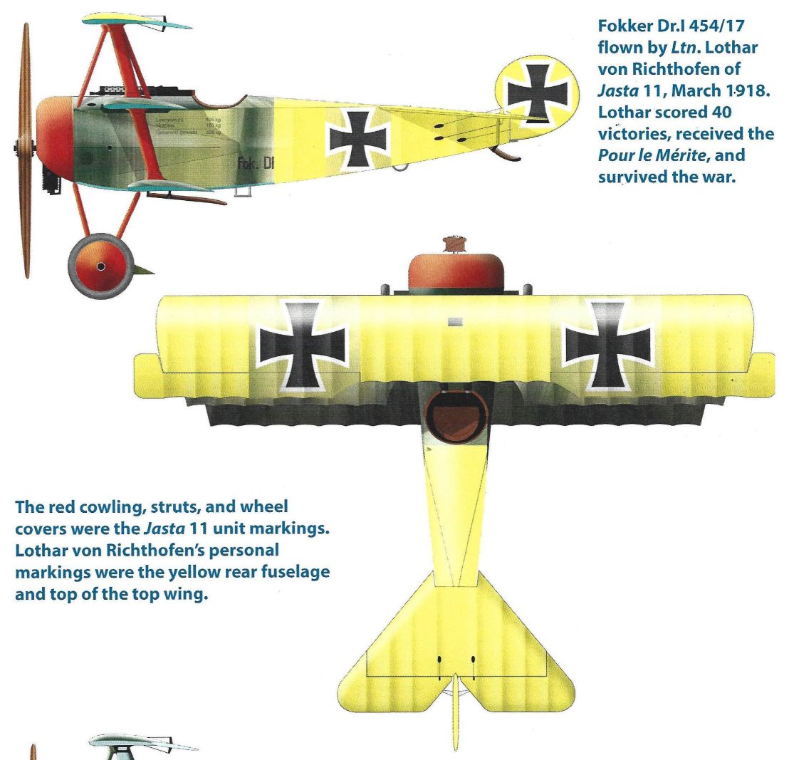
After this unhappy interlude the Fok. Dr.I was relatively trouble-free. Two wing failures that occurred early in 1918 might have been attributable to combat damage. On February 3, 1918, Leutnant Wolff (Jasta 11) had to crash-land No. 155/17 after failure of the top wing: the aft spanwise stringer and ribs of the wing had broken. On March 13, 1918, Leutnant Lothar von Richthofen lost his top wing while diving almost vertically from an unfavourable combat position; he managed to crashland and escaped with minor injuries.
Two days later, on March 15, 1918, following a crash report, the modified Fok. Dr.I ribs were again strength-tested at Adlershof. The rib was fixed at its spar gap and a concentrated lift load applied to it. Failure occurred by buckling of the web under a load of 55 kg. (121 lb.). Two plywood reinforcing pieces were bradded to the web on both sides of the lightening holes. The rib now supported a load of 75 kg. (165 lb.). The test arrangement was far from being realistic: when the report was shown to Platz he considered the reinforcing pieces to be quite unnecessary.
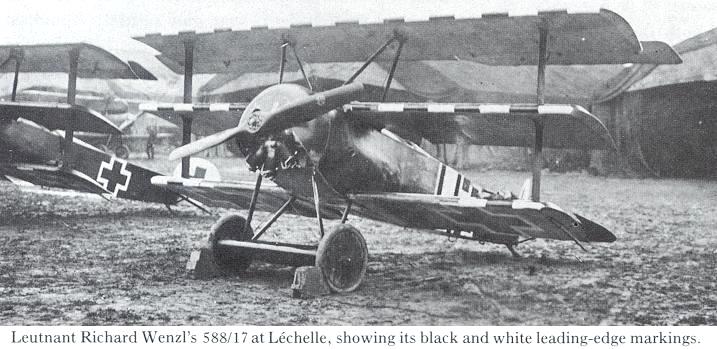
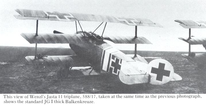
The bogey of wing failure was not completely exorcised: on May 9, 1918, Leutnant Wenzel (Jasta 11) had five ribs fail in the top wing of his Fok. Dr.I during violent combat manoeuvres. He managed to land unharmed, and the failure was found to have been caused by poor workmanship.
Concurrently with the structural testing, the Fok. Dr.I was subjected to flying tests at Adlershof. There, on November 10, 1917, Fok. Dr.I No. 141/17 was evaluated as a typical example of the type. During the final meeting of the test committee and the discussion of the results, the Fokker company was represented by Dr.-Ing. Koner. The standing practice was for the designer of the aircraft to represent his firm at such discussions. The unsuitability of Koner as the Fokker representative has already been commented on.
No attempt was made to measure performance during the November trials: the performance figures that had been obtained during the acceptance tests of No. 141/17 on October 15, 1917, were incorporated in the report. These figures had been established with a military load of 145 kg. (320 lb.), 55 litres of petrol (12-2 gals.), and 8 kg. (17-6 lb.) of oil. Climbing times were:
To 1-0 km. (3,300 ft.) 1-6 minutes
2-0 km. (6,600 ft.) 4-2 minutes
3-0 km. (9,900 ft.) 8-0 minutes
5-0 km. (16,400 ft.) 20-6 minutes
The take-off run was 45 m. (50 yd.); the landing run 50 m. (55 yd.). The top speed was stated to be no less than 190 km./hr. (118 m.p.h.), but this was in fact an over-optimistic figure. Careful speed measurements were made in April 1918 at Rechlin: these established a maximum speed of only 156 km./hr. (97 m.p.h.) at an altitude of 2-75 km. (9,200 ft.), decreasing to 138 km./hr. (86 m.p.h.) at 448 km. (13,800 ft.).
Thus, D.H.9 pilots were not exaggerating when they claimed that they had been able to run away from the Fokker triplane with ease. In fact, the Fok. Dr.I was appreciably slower than the Albatros D.V, which it was supposed to supersede. But it had a much superior rate of climb at medium altitudes, and it manoeuvred superbly, its instant response to its highly sensitive controls demanding no effort from the pilot.
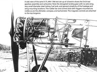
During the evaluation tests, various minor details were adversely criticized. These included better sealing of the entry of the aileron cables into the wing to minimize moisture absorption; poor attachment of the wing-tip skids (the need for them was not questioned!); the use of coloured anti-rust lacquer; defective cowling attachment; compass badly placed and not easily seen (it was unreliable anyhow); wheel track too narrow; front attachment nuts of the middle wing inaccessible; and so on.
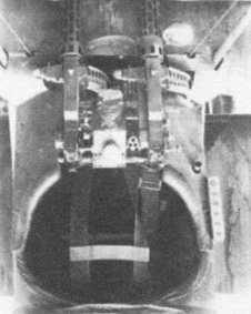
More serious criticism was levelled against the shoddy crash-protection padding in front of the pilot; this should have been of 10-cm. (4-in.) diameter. The aircraft was found to be 25 kg. (55 lb.) heavier than the weight inscribed on the fuselage side (but the Fok. Dr.I was not by any means unique in this respect). The aileron cables were considered to be poorly arranged, for they chafed in places. The rudder should have had three bearings instead of only two; and the ailerons were of such a length that they should have had one more hinge.
The petrol cock was criticized for being too small, and for allowing petrol to drip into the fuselage. It was thought that the fuel tank should be made of brass, and that its mounting should be more substantial. There was some doubt about the effectiveness of engine cooling and - a curious criticism - the accessibility of the engine installation was queried. This last point was somewhat startling in view of the fact that all other operational German fighters had their engines deep within plywood fuselages.
The triplane’s exceptional manoeuvrability was praised. But the type could be recommended for Service use only after the wing and aileron design had been passed as airworthy.
At the final meeting no fewer than twenty-seven officers and high-ranking engineering experts of the specialist departments of the Flz. were present. Among them was Roland Betsch of the Bauaufsicht. It could not be said that the final judgment had been lightly or hastily reached.
The detailed report of this test failed to reach Platz, despite the fact that one copy was sent to the Fokker firm and another to the Bauaufsicht for action. Thus he, the designer, remained in ignorance of all the criticisms, suggestions and new requirements; nor did he know that the report was accompanied by a reminder that the required stress analysis of the aircraft was still outstanding and should be submitted forthwith. Apparently Bauaufsicht 13 at the Fokker Works had their own ideas about liaison between a manufacturer and the IdFlieg!
The Fok. Dr.I at the front
When the new Fokker made its appearance on the Western Front, most of the German fighter pilots took to it instantly and were full of praise for its flying qualities: it was everything they wanted a fighter aircraft to be. Even after the set-back caused by the wing failures and the subsequent suspicion of structural weakness, the operational pilots demanded that the ban on its use should be raised as quickly as possible. When similar difficulties beset some other fighter types the pilots fervently hoped that the suspect aircraft would not be seen again.
Allied pilots soon had the measure of the Fok. Dr.I. They discovered that it was rather better than the obsolete Sopwith triplane but that it was too slow. The drag of the triplane wing system deprived it of the ability to make swift, surprise diving attacks. As the test results quoted on page 241 indicate, the Germans had overrated the Fokker triplane’s speed. Yet it was not lack of speed that was its major shortcoming, even though that allowed the D.H.4, D.H.9, Bristol Fighter and Spad to run away from the Fok. Dr.I if they chose to do so: it was the poor all-round performance at the steadily increasing combat altitudes that mattered most. All Allied aircraft could now fly and fight at substantially greater heights.
On January 14, 1918, the Kogenluft ordered a drastic reduction of the load to be carried by all operational single-seat fighters. The fuel load was cut to provide a maximum endurance of only If hours; during acceptance tests, fuel for only one hour needed to be carried. This load reduction for all fighters in the D and Dr categories was also to apply to all new designs. This was an admission of the serious consequences of the mismanagement of aero-engine development in the immediate past.
In spite of the relief provided by this order, the main combat weakness of the Fok. Dr.I continued to be the low power and low compression ratio of its 110-h.p. Le Rhone engine. The Allies had largely withdrawn the Le Rhone from operational use a year or so earlier. A programme with the aim of re-equipping the Fok. Dr.I with more powerful engines of better altitude performance was therefore initiated. None of these variants was put to the test of operational flying before the Fok. Dr.I was withdrawn from first-line units.
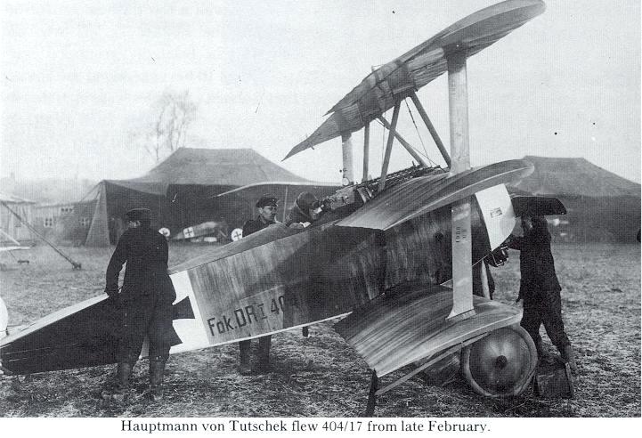
Typical of the opinions of the pilots who flew the triplane in its operational heyday are those of von Tutschek and Ernst Udet. Hauptmann von Tutschek claimed that the Fok. Dr.I was superior in dog-fighting to any contemporary Allied fighter, better even than the 200-h.p. Spad single- seater. He himself had dived the Fokker triplane until its terminal velocity was reached in a near-vertical dive: this he claimed to be in excess of 240 km./hr. (150 m.p.h.), which is just possible but not very probable.
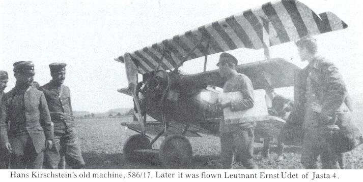
Ernst Udet stated, early in 1918, that to him the Fokker triplane seemed to be the ideal fighter aeroplane; he regarded it as superior to the Sopwith Camel in manoeuvrability and rate of climb. He was so fond of the triplane that shortly after the war he wanted a similar aircraft designed for him for exhibition flying.
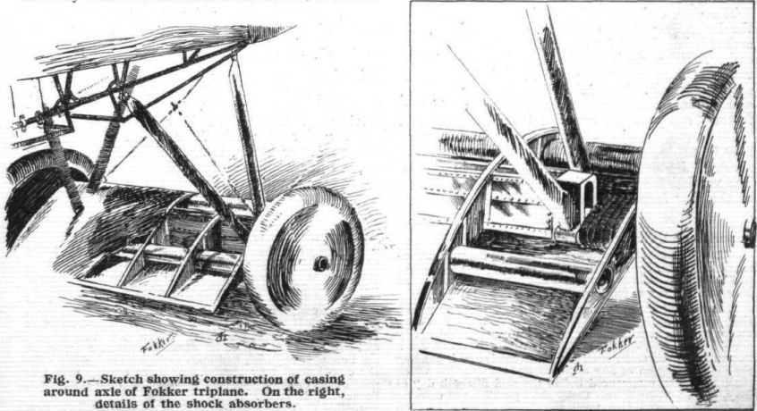
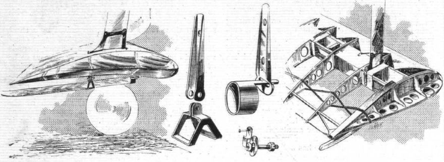
Less enthusiastic were those pilots who were built on more generous lines than the average mortal. The Fok. Dr.I was no aeroplane for long-legged pilots: E. A. Marquard has recounted the agonies he endured in the triplane’s cockpit; a contemporary cartoon depicted him with his legs protruding through the bottom of the triplane's fuselage, his feet resting on a rudder bar mounted on the undercarriage axle. Marquard also criticized the poor view from the cockpit during take-off and when touching down. This was certainly true, because the fuselage was short and the undercarriage tall.
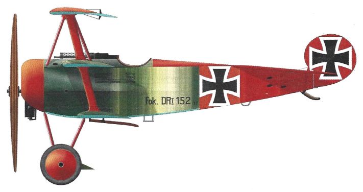
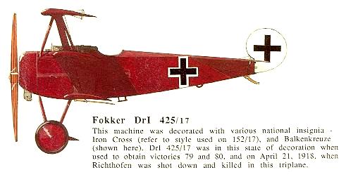
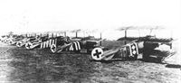
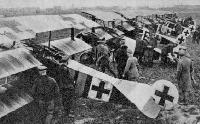
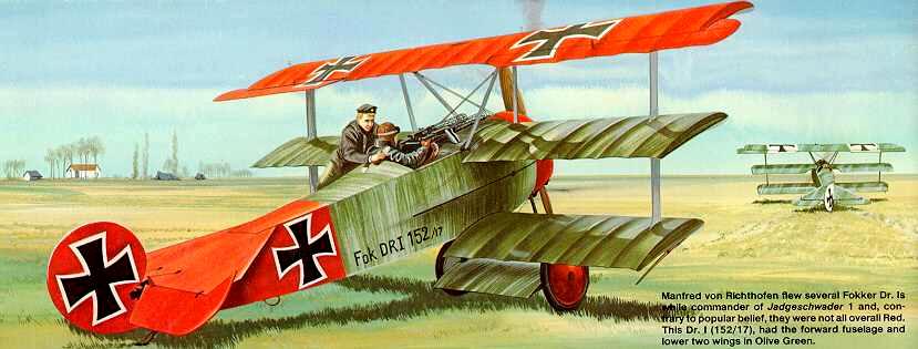
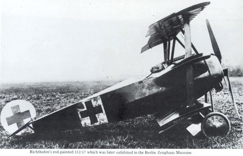
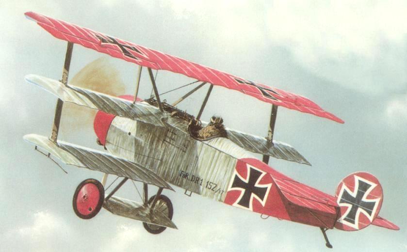
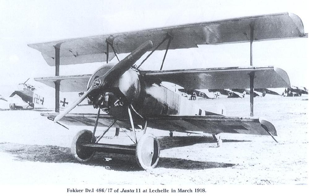
Most pilots of the Richthofen Jagdgeschwader flew the Fok. Dr.I until April 1918; from then onwards it was progressively replaced by the Fok. D.VII biplane. During the first big air battle over Le Cateau, on March 18, 1918, sixty German single-seat fighters took part: the majority were Fokker triplanes, one of which, No. 152/17, was flown by Manfred von Richthofen.
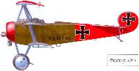
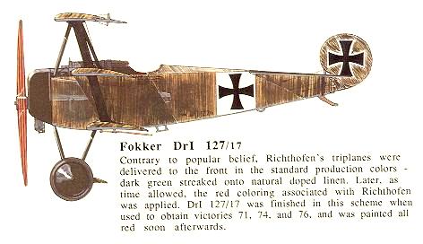
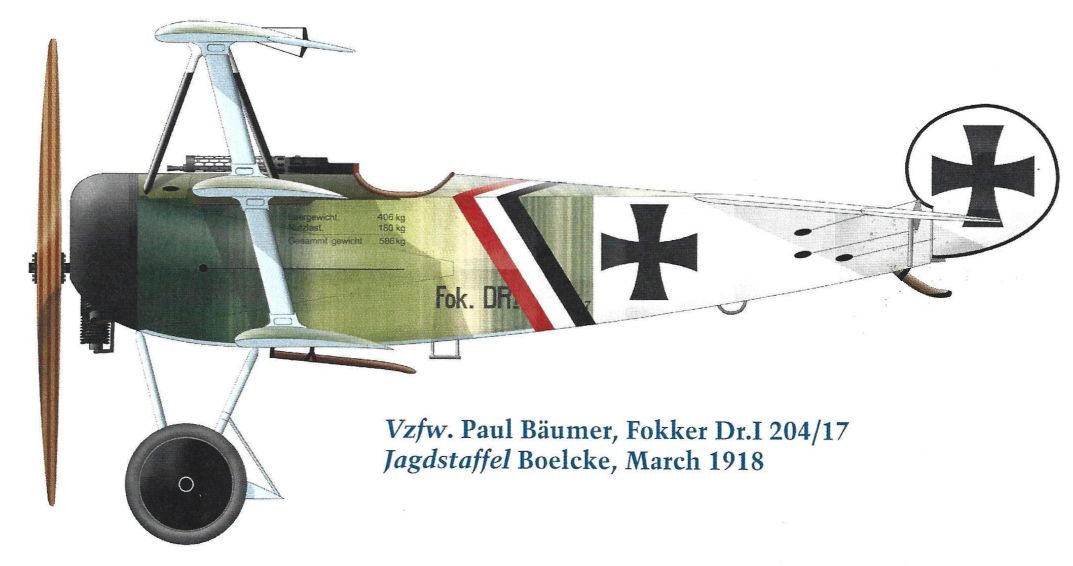
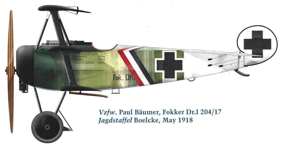
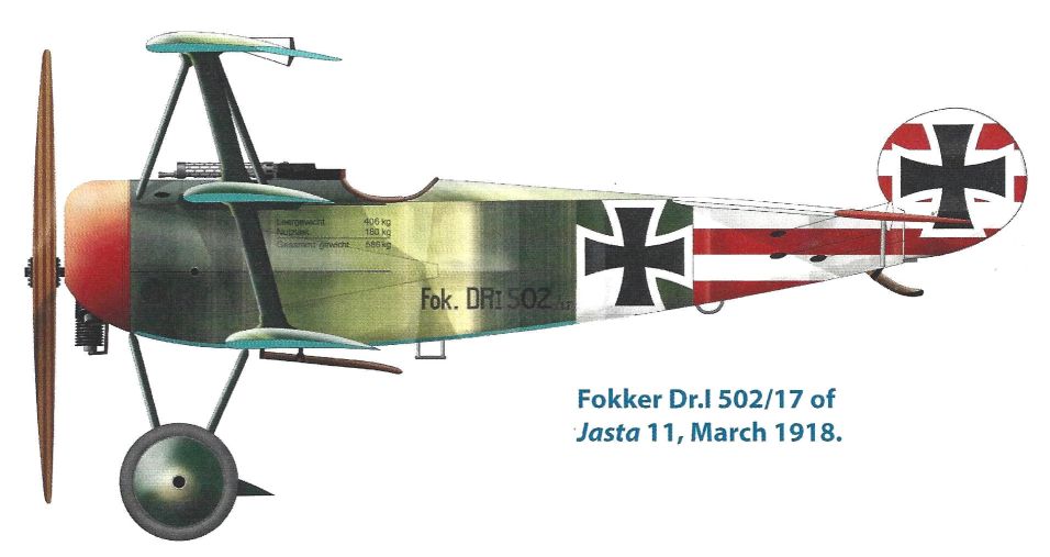
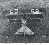
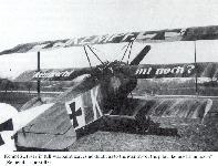
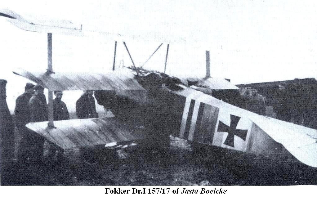
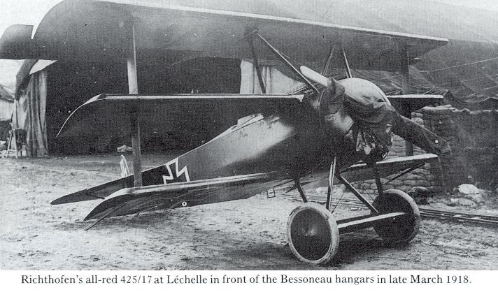
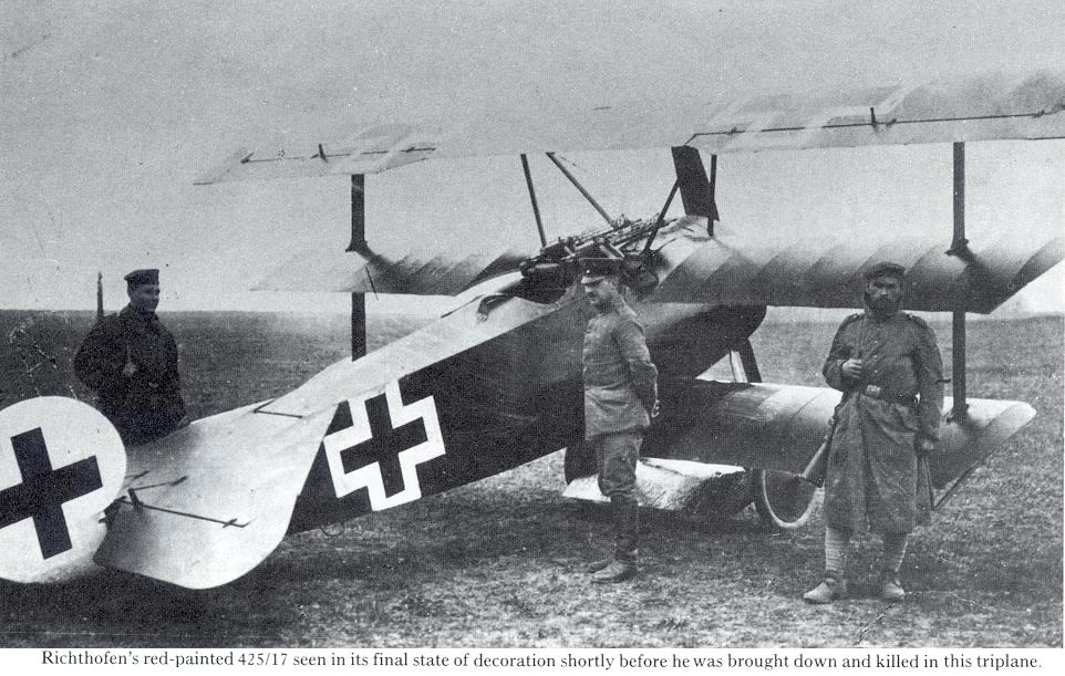
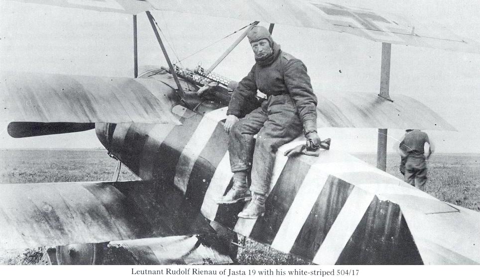
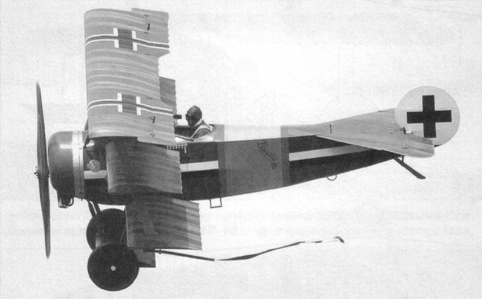
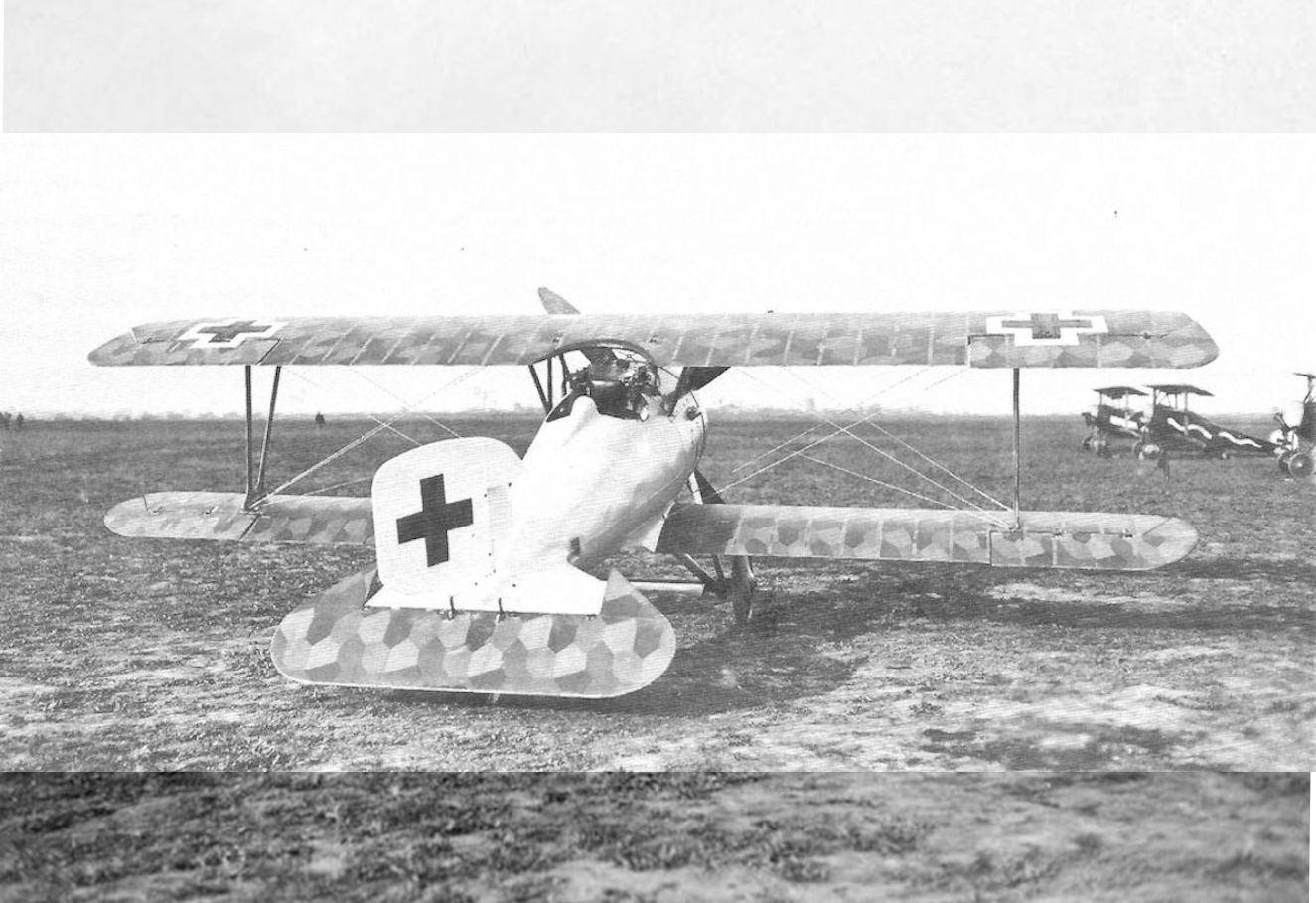
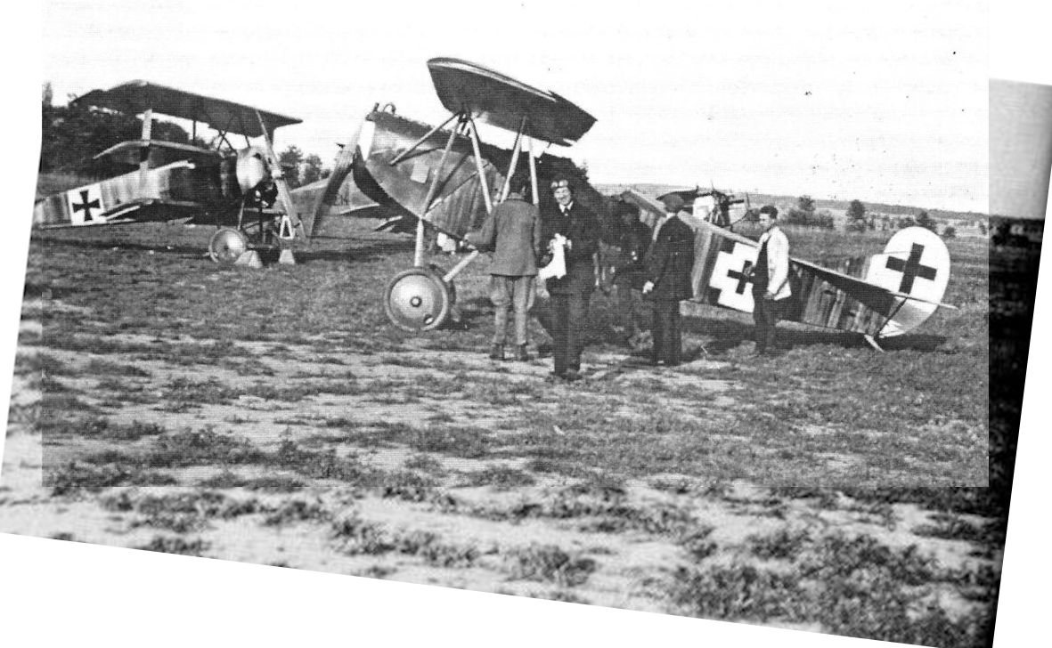
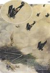
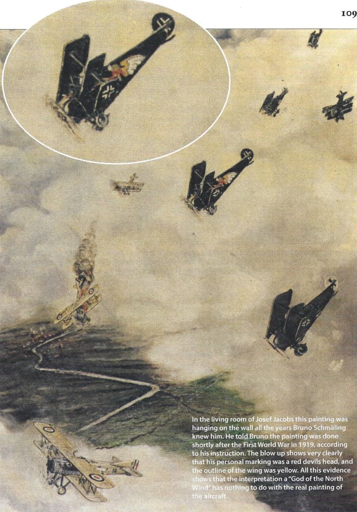
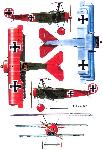
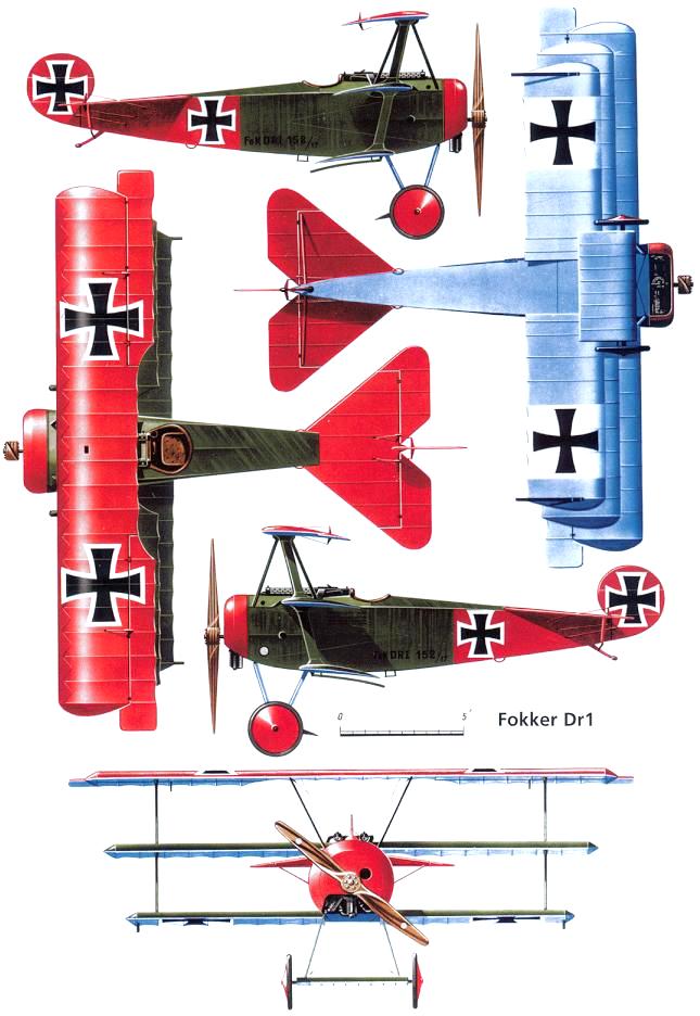
Contrary to all the sensational claims in Allied newspapers during the war and in certain American magazines published since then, Manfred von Richthofen’s triplanes were perfectly standard and carried no more than the two regulation machine-guns. He, however, had the privilege of having two or even three reserve aircraft. These were all alike and were always kept ready for immediate operational use in case his usual triplane was unserviceable for any reason.
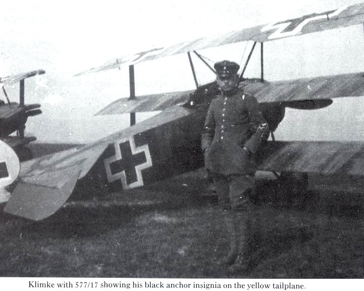
Occasionally the red wings of his Fok. Dr.I bore leader’s streamers similar to those used in British squadrons. He adopted these after a shotdown British pilot had said that during the fight he had looked in vain for the legendary Red Baron as the most desirable target. A Prussian officer could not let this pass.
Production of the Fok. Dr.I ceased during May 1918; after that, no more production triplanes were accepted.
The Fokker triplane seen through Allied eyes
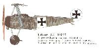
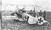
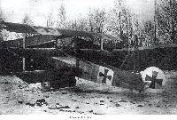
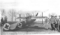
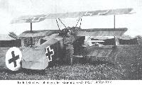
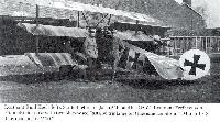
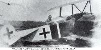
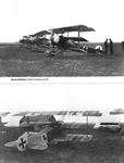
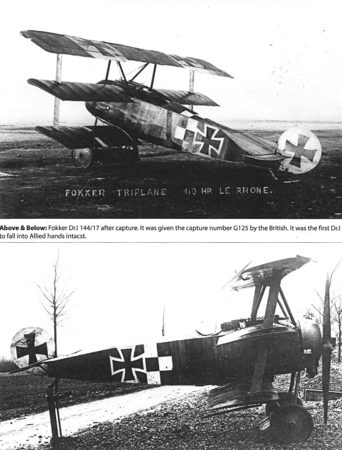
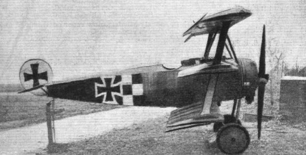
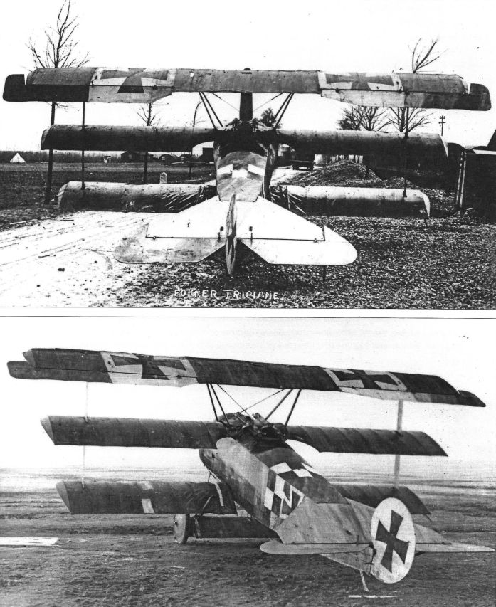
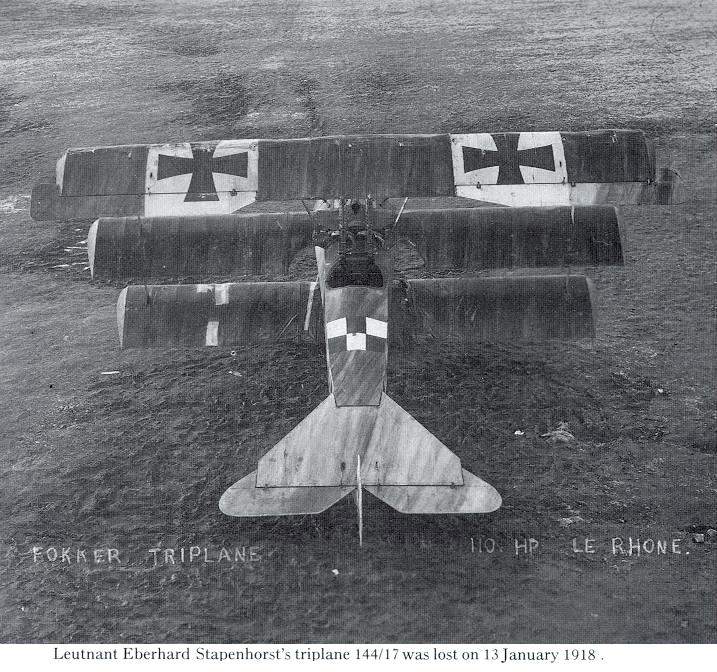
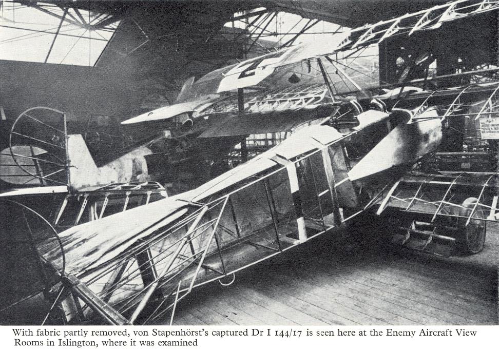
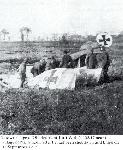
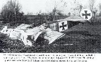
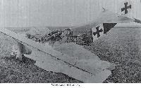
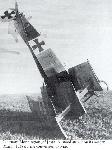
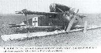
Examples of the Fokker triplane soon fell into Allied hands. One of the best specimens was No. 144/17, which came down in British-held territory in near-perfect condition, its pilot (Leutnant Stapenhorst of Jasta 11) having been wounded by anti-aircraft fire. This Fok. Dr.l had been despatched from Schwerin on December 12, 1917; its engine was apparently an Oberursel-built Le Rhone, or had been given an Oberursel nameplate.
The design features of the triplane were critically studied by Allied experts. At this remove it is difficult to know whether some were so strongly prejudiced that they thought that anything produced by the enemy was inevitably no good, or considerations of national security or propaganda required their reports to imply that that was the case. Others evaluated the Fokker intelligently, but took care not to hurt the tender feelings of the authorities and aircraft designers in this country.
In March 1918, Ministry of Munitions report No. I.C. 620 was published. It was brief, incomplete and inaccurate, its tone being set by the statement “It was felt the machine exhibits few instructive features”. The report asserted that the Fok. Dr.I was “one of the poorest of modern German designs”, emphasized “the grave structural weakness” of the airframe, and made it abundantly clear that the “expert” who wrote the report had been either insufficiently conscientious to make a rough paper check on the airframe strength or incapable of doing so: it would have cost less than an hour’s work. The report must have made remarkable reading for British pilots who had experienced the combat qualities of the Fokker triplane.
But British experts in less official positions thought somewhat differently. In particular, Flight took great pains to discuss the design objectively and in great detail: no doubt this description was written by C. M. Poulsen, who was the journal’s technical editor at that time. This excellent private effort allowed Allied aircraft designers to judge for themselves the merits of the Fokker triplane.
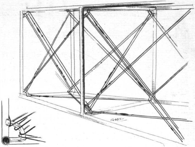
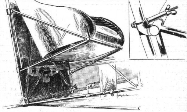
The Flight report criticized the fact that welded joints were stressed in tension. In comparison with other German fighters, the triplane's cockpit seemed cramped and spartan; the seat upholstery and padding were described as of inferior quality, like the rest of the furnishing. This criticism was justified: indeed, the poor finish and workmanship of the Fok. Dr.I may have been partly responsible for the poor impression it created among the British technicians.
The critic erred in objecting to the seemingly weak attachments of the undercarriage struts. This arrangement was intentional and in conformity with German official requirements.
On the whole, Flight's appraisement was not only intelligent and accurate; it was remarkably fair and far-sighted.
Immediately after the Armistice, the Allies discovered a number of serviceable Fok. Dr.Is in two fighter training establishments at Valenciennes and Nivelles. At Nivelles in particular, British and American officers had ample opportunity to make trial flights before these triplanes were scrapped. They were all astonished by the aircraft’s sensitivity, instant control responses, and the effortless ease with which it could be thrown about in the air. They now understood why their erstwhile German opponents had been so disconcertingly agile and elusive in combat. The Allied pilots were the more impressed because, during the war, the British authorities had not troubled to make proper flight tests of any of the captured triplanes. (Captured Fok. Dr.Is had been test-flown in France early in 1918, but the reports of these tests cannot now be traced.)
None of the officers who now had an opportunity of trying out the Fok. Dr.I found any real difficulty in mastering it. Although the specimens they flew were somewhat past their best and their engines were running on a low-grade castor-oil substitute, the triplanes still impressed with their spectacular climbing ability.
A few years after the war, one or two triplane single-seaters were built in Germany. These were more or less variations of the Fok. Dr.I and had Le Rhone-type rotary engines. Max Schueler, a veteran pilot and designer, flew one all over Germany advertising Sarotti chocolate. It had a Thulin-built engine, and its career ended in an unfortunate forced landing in 1926. It seems that no genuine Fok. Dr.I exists anywhere today.
Non-standard versions of the Fok. Dr.I
Towards the end of 1917 the Oberursel UR.II engine passed the official acceptance test; it was the Fokker-sponsored copy of the Le Rhone. Engines of this type were from then on installed in the Fok. Dr.I, but the pilots at the front preferred the Beute engines, and all kinds of subterfuges were employed to replace the UR.II. Both engines were practically identical, but the Thulin-built version embodied better materials and the workmanship was excellent.
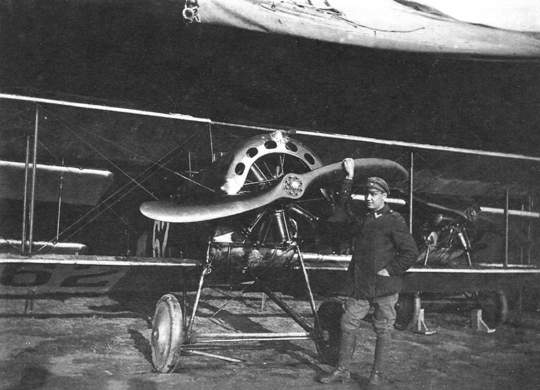
Siemens und Halske had now completed their new eleven-cylinder counter-rotating engine, the 160-h.p. Sh.3. As it had not then passed its type test it remained experimental. This engine was more powerful than the Le Rhone and, owing to its higher compression ratio, had a better altitude performance. The large, slow-running propeller had a high propulsive efficiency.
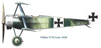
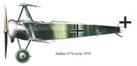
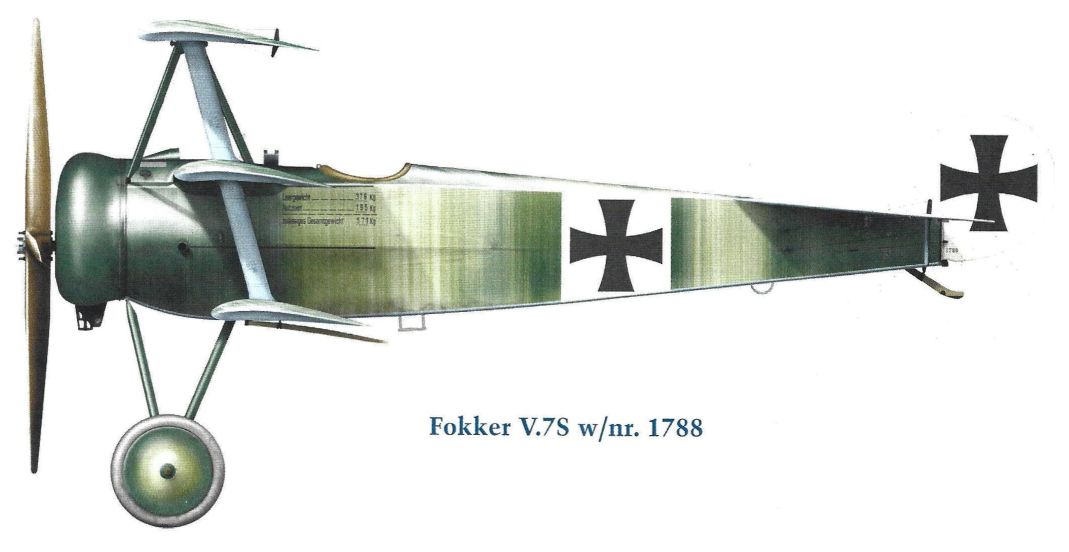
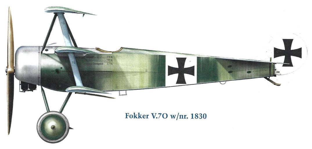
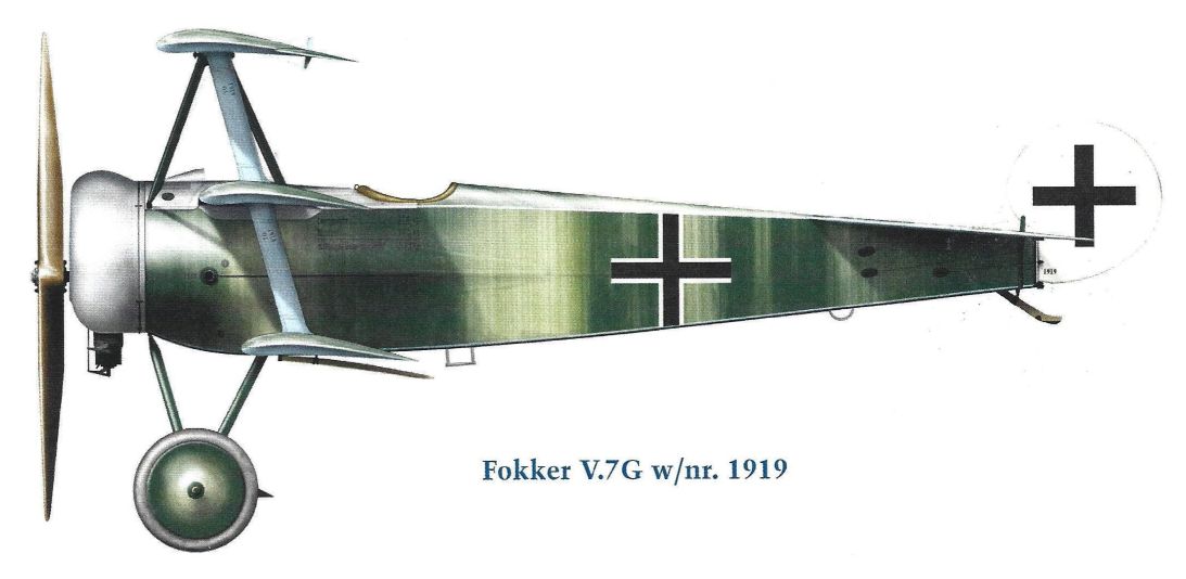
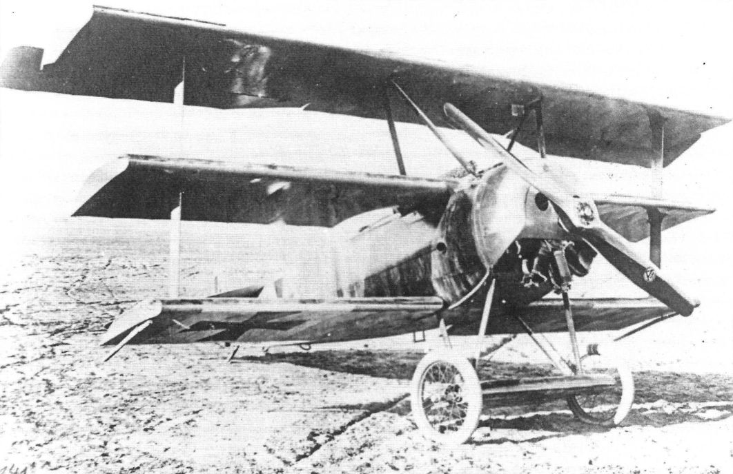
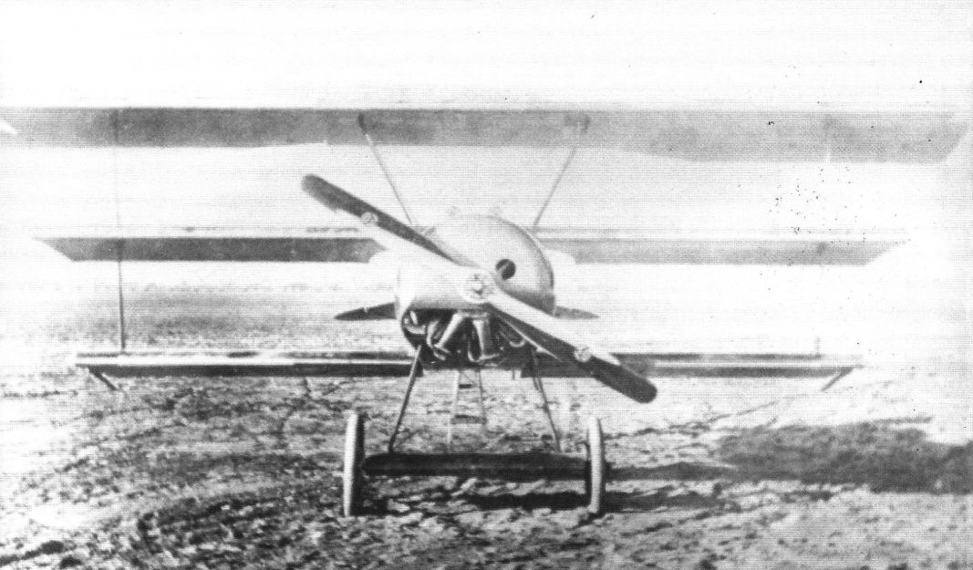
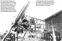
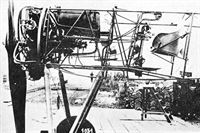
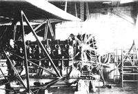
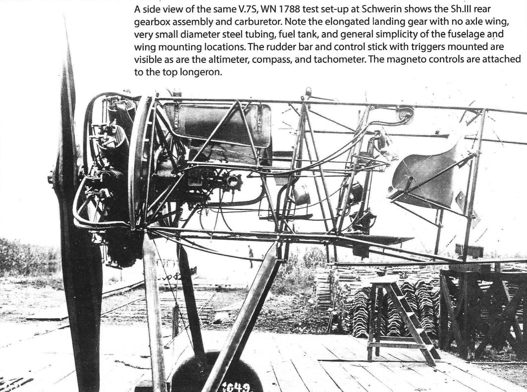
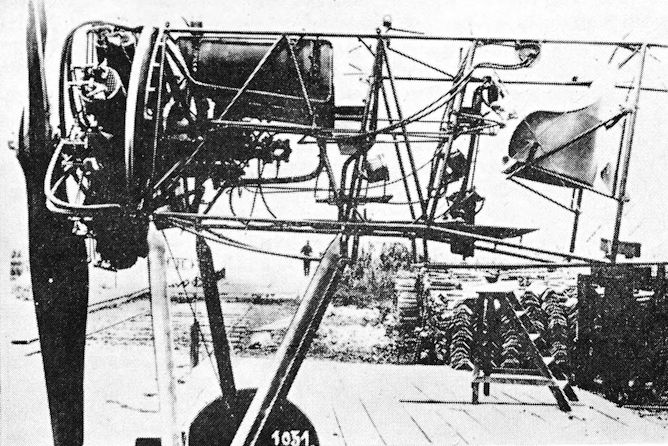
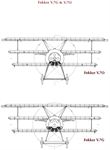
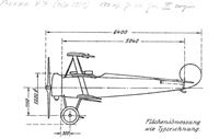
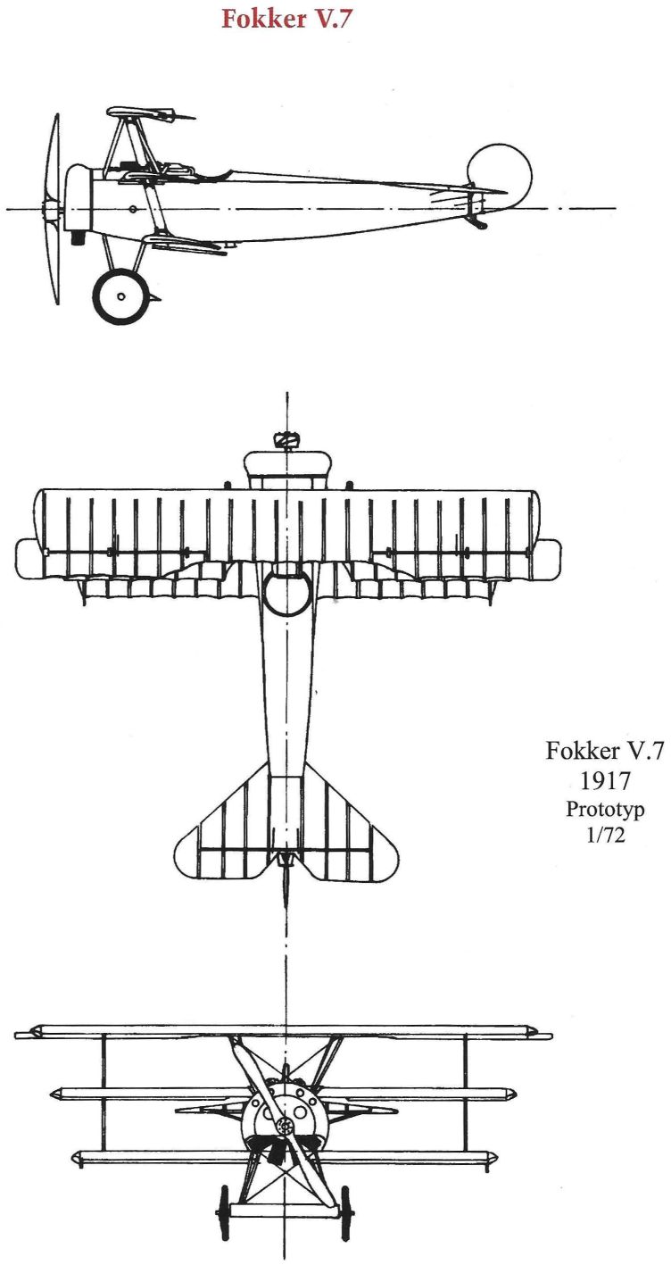
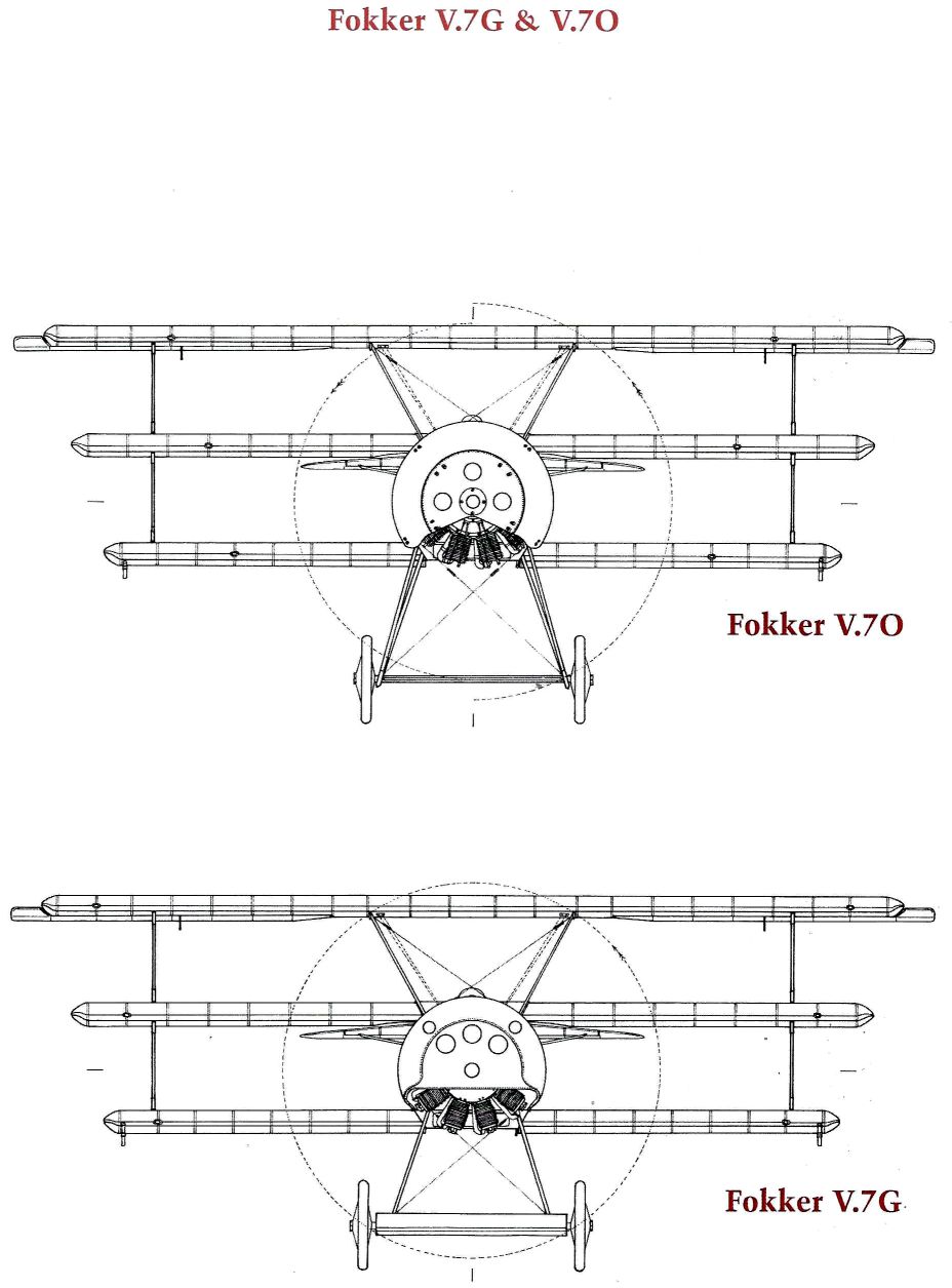
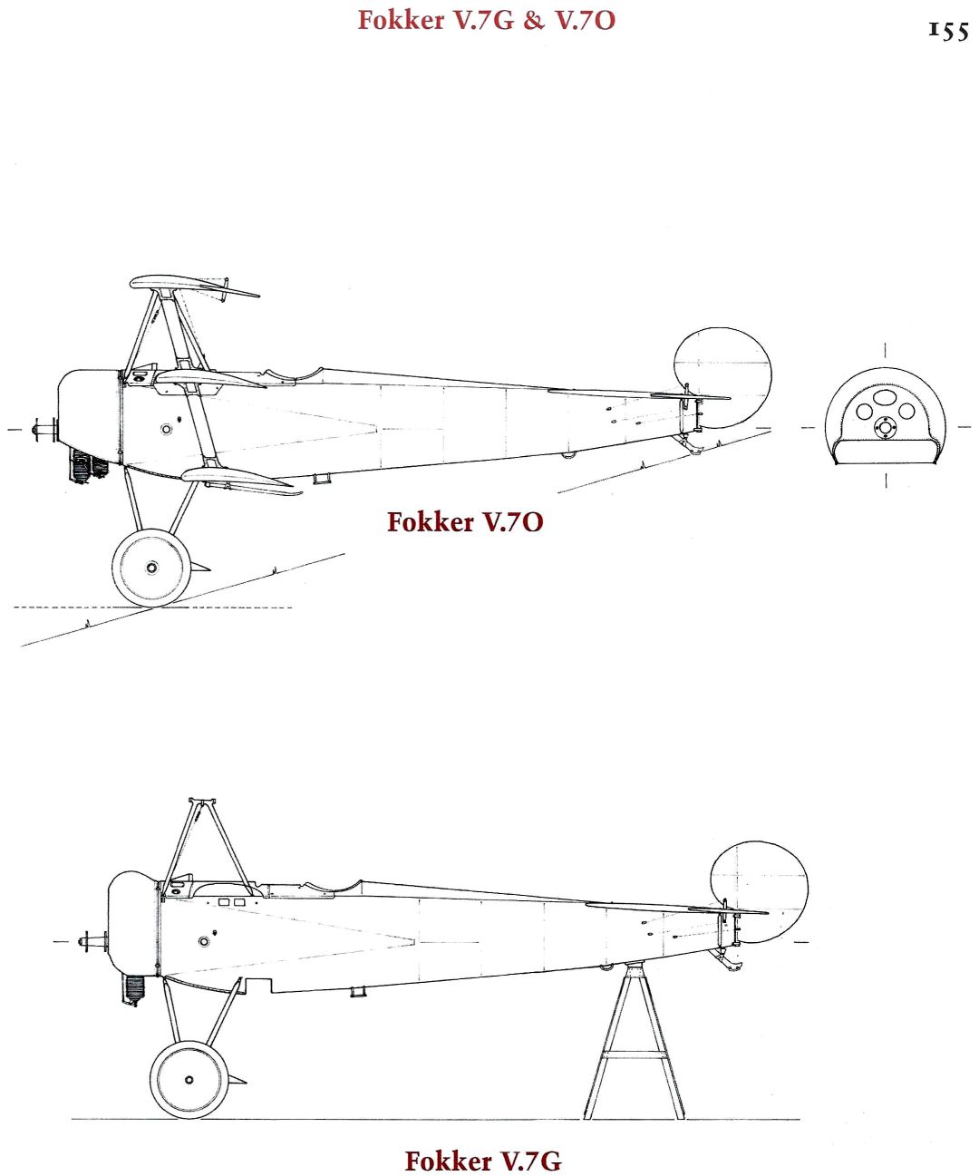
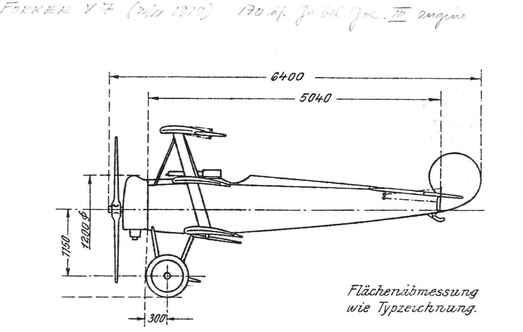
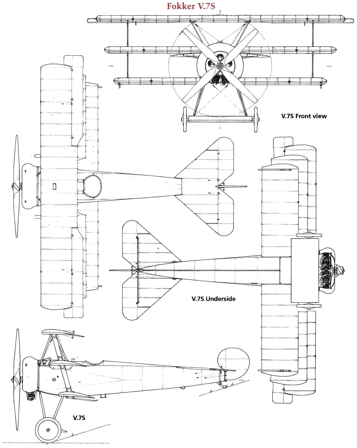
Fokker received an order for an experimental triplane to be powered by this engine. The Sh.3 needed a different engine mounting embodying a front bearing; the cowling also had to be modified. Even when a four- blade airscrew was fitted it was still of such a diameter that a taller undercarriage was necessary. This not only made the aircraft ungainly in appearance but impaired its handling characteristics on or near the ground. It was also heavier. Although otherwise virtually identical with the standard Fok. Dr.I, the triplane with the Sh.3 engine was given the new designation Fokker V.7. Later versions of this triplane had the fuselage lengthened by as much as 55 cm. (21 -7 in.).
A. Zeithammer, the Siemens engineer in charge of the field trials with the Sh.3 engine, complained bitterly of Fokker’s uncooperative attitude. Fokker persistently found fault with the engine during test flights, yet Zeithammer was unable to trace any trouble. Fokker, of course, was not anxious to see the Siemens-Halske engine achieve success and be adopted. He had instructed his Oberursel firm to develop with all speed an eleven-cylinder Le Rhone development for a more powerful variant of the Fok. Dr.I.
It seems that the IdFlieg finally decided to take the experiments with the Sh.3 out of Fokker’s hands. One or two further Fok. Dr.Is with the Sh.3 were sponsored by Adlershof, but these were modifications of existing Dr.I airframes made in the Flz. workshops and by the Siemens und Halske firm.
While these experiments were proceeding, experience with the Sh.3 elsewhere left no doubt that the engine was still a long way from being sufficiently serviceable for operational use. Piston trouble was experienced, and the only available oil was not suitable. Hence, in spite of its magnificent climbing performance and amazing ceiling, the Siemens-engined Fok. Dr.I never reached the front. Besides, as Kurt Student relates, this version was slightly unstable and too sensitive for the average fighter pilot of the time. The approach and landing needed care: the wing-like axle fairing had been omitted in order to reduce the tendency to float near the ground. The torque reaction from the large airscrew was felt powerfully because the wing span was so short; and the blip-switch had to be used with great care when flying close to the ground.
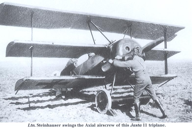
The IdFlieg had intended to prolong the operational life of the Fok. Dr.I by fitting more powerful engines. One of the earliest of these experimental installations was of the first Goebel Goe.III engines (Works No.1) of 170 nominal horse-power. This engine was fitted to one of the earliest production triplanes, No. 108/17, which was test-flown by Schuetzenmeister at Goerries on October 30, 1917. It was fitted with an Axial airscrew of 270-cm. (8 ft. 10| in.) diameter and 255-cm. (8 ft. 4-4 in.) pitch: this gave 1,260 r.p.m. on the stand and 1,300 r.p.m. in level flight near the ground. At 5-0 km. altitude (16,500 ft.) the engine speed dropped to 1,130 r.p.m.
Carrying ballast of 60 kg. (132 lb.), 55 litres (12 gals.) of petrol and 10 kg. (22 lb.) of oil, the Goebel-powered triplane climbed to 5-0 km. altitude in only 14-3 minutes. This was an excellent performance for that time and far better than that of the standard Fok. Dr.I. The Goe.III, which was then some way from developing all the power of which it was capable, had an hourly fuel consumption rate of 90 litres (20 gals.) of petrol and 9 kg. (20 lb.) of oil; the latter was ersatz castor oil. This was greater than the consumption of the Sh.3 engine for about the same power output.
The Goe.III was a promising development of the Gnome, with a half-controlled, half-automatic inlet valve, a high compression ratio, and (later) oversized cylinders. Final versions (Goe.IIIa) could produce over 200 h.p. for short periods. This engine was the first to have a separate gear for an auxiliary drive; this was supplied as part of the engine’s light alloy mounting.
Some of the Fok. Dr.Is delivered from January 1918 onwards were supplied with this Goebel engine, about thirty aircraft in all. It is improbable, but by no means impossible, that one or other of these triplanes may have been flown on the Western Front. Most of them went to home-defence fighter formations and training units, and experience of the Goe.III was favourable.
When the new 145-h.p. Oberursel UR.III Le Rhone development came out late in December 1917, one of the first examples to complete its bench test was quickly installed in Fok. Dr.I No. 469/17 and demonstrated by Fokker. This variant was not officially adopted, but the aircraft was flown extensively as an engine test-bed for the development of the UR.III.
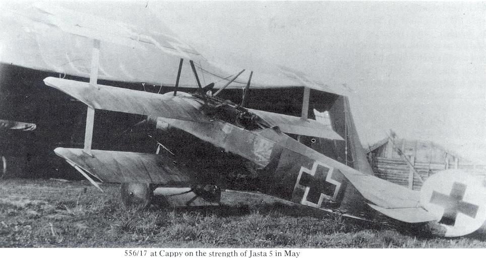
Three Fok. Dr.Is (Nos. 485/17, 527/17 and 562/17) were fitted with captured 130-h.p. Clerget engines: the engine numbers were 953, 1072 and 1503, the airframes Factory Nos. 2111, 2232 and 2195, respectively. The three aircraft made their acceptance flights on April 24, 1918, at Goerries, flown by Neisen, Grosse and Schuetzenmeister respectively. These Clerget-powered triplanes were not intended for operational purposes, but were used for an investigation into the Clerget engine’s behaviour.
This investigation almost certainly arose out of the serious difficulties experienced by Germany in trying to obtain lubricating oil for rotary engines. Castor oil had become so scarce on the German side that it could no longer be supplied even for the few rotary-powered German aircraft that were then operational. A German substitute (Voltol) had been developed; it was produced by a polymerization of ordinary mineral oil under electric discharges. This substitute was certainly less soluble in petrol than ordinary oil, but its lubricating qualities fell far short of those of castor oil. Worst fault of all, its quality was not consistent. Some at least of the troubles that afflicted German-built rotaries could be blamed on their oil, consequently there was good reason for subjecting captured engines with well-known performance to the torture of running on German ersatz lubricants.
During 1918, Fok. Dr.I aircraft were used in a special series of experiments instigated by the IdFlieg. The object of this work was the evolution of a supercharger for rotary engines in order to maintain constant power output up to altitudes of 6-5 km. (22,000 ft.) and higher; service ceilings of 9-0 km. (30,000 ft.) were envisaged for 1919, and were within reach when the Armistice supervened.
As a first step, a UR.II was installed in an otherwise standard Fok. Dr.I and fitted with a Schwade gear-driven compressor weighing 47-5 kg.(105 lb.). This was mounted behind the cylinders, alongside the crankshaft and carburettor. For the drive, Schwade had designed a suitable gear and a coupling embodying elastic clutches. When running at 10,500 r.p.m. the compressor absorbed about 20 b.h.p.
This was the first German direct-coupled aero-engine compressor to fly. Details of the flight tests have never become known, but the results were highly satisfactory. Had the war continued into 1919, Schwade would have received a large production order for a fully developed version to be used in a Fok. D.VIII variant: this would have given these single-seaters a marked superiority early in the year.
A compressor had also been developed by Siemens und Halske for the Sh.3 engine. This had already been flown in an obsolete Siemens-Schuckert D.I, in which it was mounted under the carburettor; the aircraft was turned over to the Flz. in October 1918 for further trials. The IdFlieg wanted comparative trials with a more modern aircraft and engine, however. The Siemens people would have preferred such trials to have been made in one of the later Siemens-Schuckert fighters, but none of the modern types could accommodate the compressor.
It was therefore decided to install the three-stage Siemens compressor in a Fok. Dr.I with Sh.3 engine. The compressor weighed 38 kg. (84 lb.) and ran at 8,600 r.p.m. The Fokker works obtained all installation details from Siemens in September 1918. Apparently in addition to the IdFlieg experiments with the supercharged Sh.3, the Fokker works intended to apply the Siemens compressor to an Oberursel UR.II in a Fok. Dr.I. This installation was never completed, however.
Показать полностью
J.Herris, T.Phillips Fokker Aircraft of WWI. Vol.4: V.1-V.8, F.I & Dr.I (A Centennial Perspective on Great War Airplanes 54)
Despite not achieving production status, the Fokker V.1, V.2, and V.3 were significant steps. With them Fokker introduced the new, cantilever wooden wing technology and combined the most advanced aeronautical concepts. However, these aircraft more closely resembled armed racing planes than production fighters.
Most significantly, future Fokker designs would use conventional flight controls, a more conventional configuration, and a new, lighter, second-generation wing design.
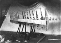
The original cantilever wooden wing was too thick and too heavy. It was replaced in subsequent designs by a new, second-generation cantilever wooden wing. This more advanced wing had a better airfoil section that was thinner for reduced drag and better flying characteristics. It was also more advanced structurally. Fabric replaced wood in areas that did not need the strength of wood, reducing the weight. The new wing design used a box spar for greater strength with less weight. Verneer covered the leading edge of the wing to maintain the more advanced airfoil section. The new structure was more efficient at the cost of greater complexity.
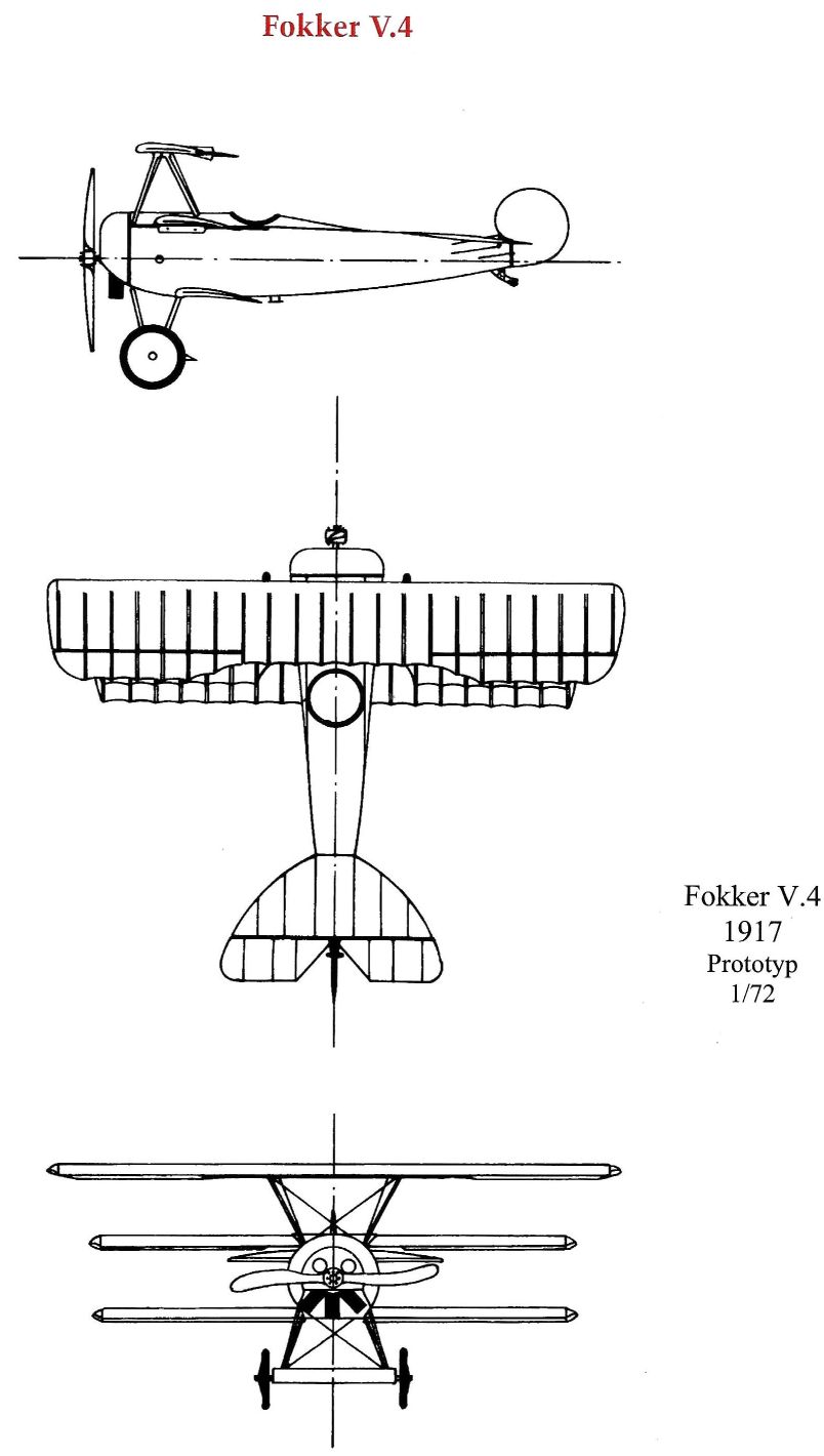
At this juncture fate, in the form of Idflieg, stepped in. In the spring of 1917 Idflieg was ait the beginning of its Triplane Craze and asked Fokker (and other manufacturers) to build a triplane fighter in the mistaken belief that the triplane configuration offered some unique advantages for a fighter. Just at the point Fokker was on the verge of excellent designs, he responded to Idflieg’s request with the V.4 triplane prototype, that lead to the V.5 and production Dr.I. The Dr.I possessed exceptional climb and maneuverability, qualities not possessed by frontline German fighters at the time.
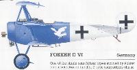
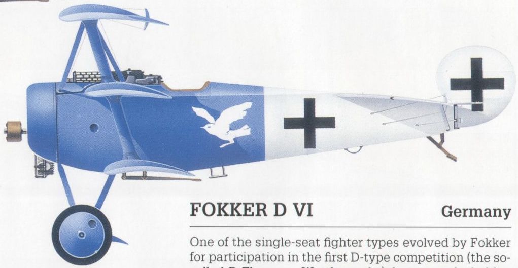
What the Dr.I did not have was good speed, and that was a result of the extra drag of its triplane configuration and low-powered engine. The later D.VI was essentially a biplane derivative of the Dr.I triplane. Powered by the same 110 hp Oberursel Ur.II rotary as the Dr.I, the lower drag D.VI offered notably better speed and slightly better climb than the Dr.I at the cost of a slight increase in its rolling moment of inertia that caused a small decrease in roll rate. The qualities and appearance of the Dr.I made it famous, while the later, better, and less distinctive D.VI biplane is nearly unknown.
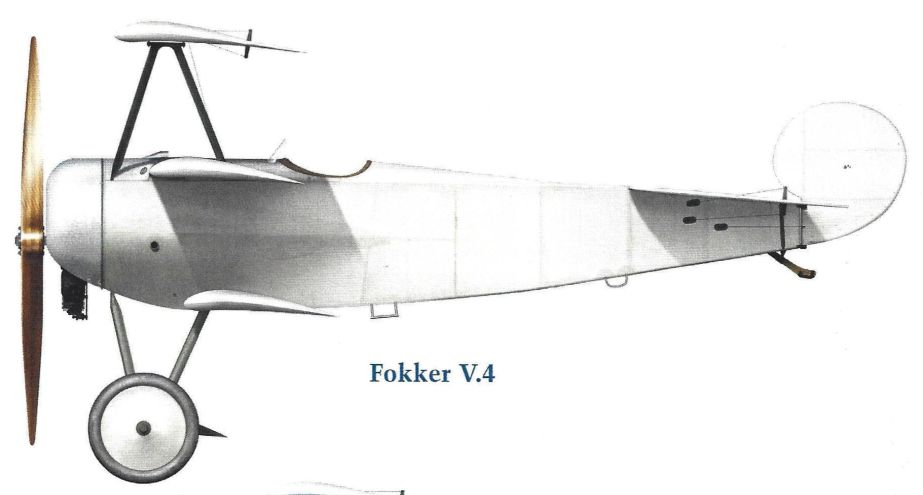
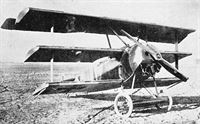
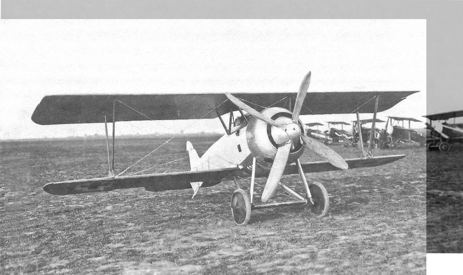
Fokker V.4
Although the V.1, V.2, and V.3 showed admirable turning and handling qualities and benign stall characteristics, overall performance was little better than the Albatros sesquiplane fighters currently equipping the Luftstreitkrafte. The problem was weight to power ratio (W/P), which was too high due to heavy, plywood covered wings and heavy, streamlined fuselages. For the V.1 W/P was 4.02 kg/hp (kilogram per horsepower), for the V.2 it was 4.14 and for the V.3 it was 4.25. Note that each horsepower was carrying more weight as the early V series aircraft evolved. Except for speed, the V.1 actually had superior performance, especially climb, to the later V.2 and V.3. The streamlined fuselages also compromised downward vision on all three types.
Since Fokker had a controlling interest in the Oberursel engine factory, it became obvious any fighter using the 110 hp Oberursel Ur.II copy of the Le Rhone 9J rotary would have to be both small and lightweight, with a weight to power ratio in the 3.0-3.5 kg/hp range. The Oberursel Ur.II was actually a copy of the Le Rhone 9Jb, which with its aluminum pistons, produced 120 hp vs the 110 hp of the steel piston 9J. The Ur.II also had aluminum pistons and British tests of a captured Ur.II showed a maximum horsepower of 127. This was excellent considering the low octane US gasoline being used by the Entente air forces, but was also achieved with good quality castor oil lubricant. The Royal Navy blockade of Germany prevented the Germans from obtaining castor oil relatively early in the war and an inferior substitute lubricant was developed. This T50 substitute lubricant (50% Voltol rapeseed and fish oil and 50% mineral oil) had a very negative effect on German rotary engine operations during the last two years of the war.
Fokker had a contract to provide the Austro-Hungarian Luftfahrtruppe a fighter aircraft through Fokker Magyar Atalanos Gepgyar (MAG) in Matyasfold, Hungary. A triplane fighter was ordered from the Fokker experimental shop on 13 June 1917 with internal designation D.VI, Werknummer 1661, Kommission Nummer 7623. Originally conceived as a biplane, the German triplane craze caused by the success of the Sopwith Triplane, resulted in the design being changed to a triplane.
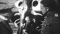
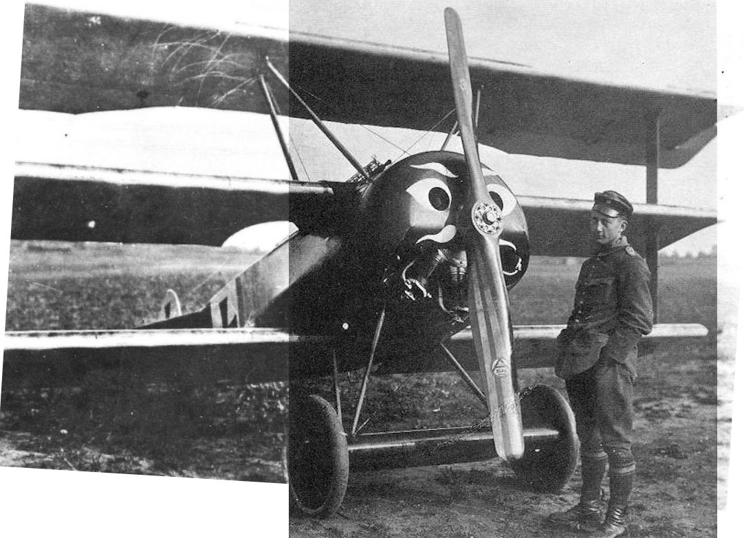
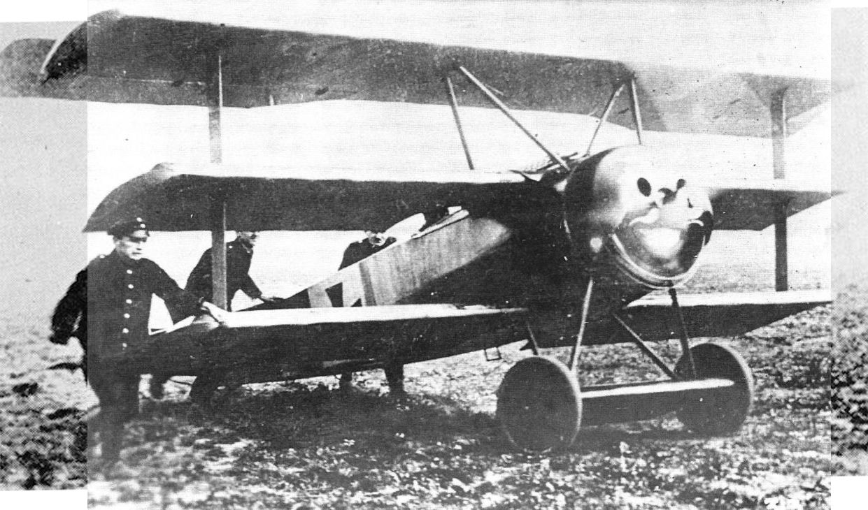
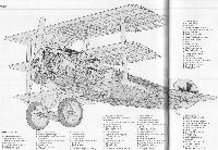
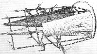
From the start, Fokker knew he had to keep the design as small and lightweight as possible for use with his Ur.II powerplant. Starting with the fuselage, a short, flat-sided design using very thin steel tubing trussed together with wire at the joints was developed. Thin plywood fillets were sparingly used, as were aluminum cover panels. The flat sides also aided lateral stability compared to the round fuselages of the V.1-V.3 designs and aided downward vision. The Le Rhone 9Jb engine, used until availability of the Ur.II, was covered by a simple aluminum cowl with two ventilation holes designed to force castor or T50 oil fumes out the slot in the bottom of the cowl. This cowl had a full front face, into which the two ventilation holes, propeller shaft hole, and a slot for cylinder rotation and oil vapor exit flow were cut. The Ur.II had passed its tests early in 1917 using castor oil, but modifications for the use of the T50 castor oil substitute meant final approval did not occur until August 1917. This meant most early triplanes were fitted with captured Le Rhone 9Jb engines.
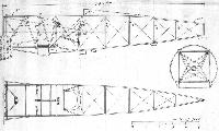
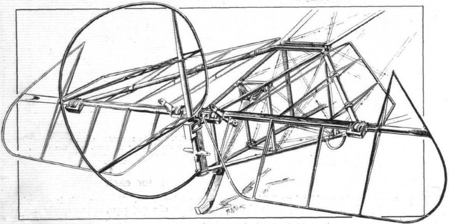
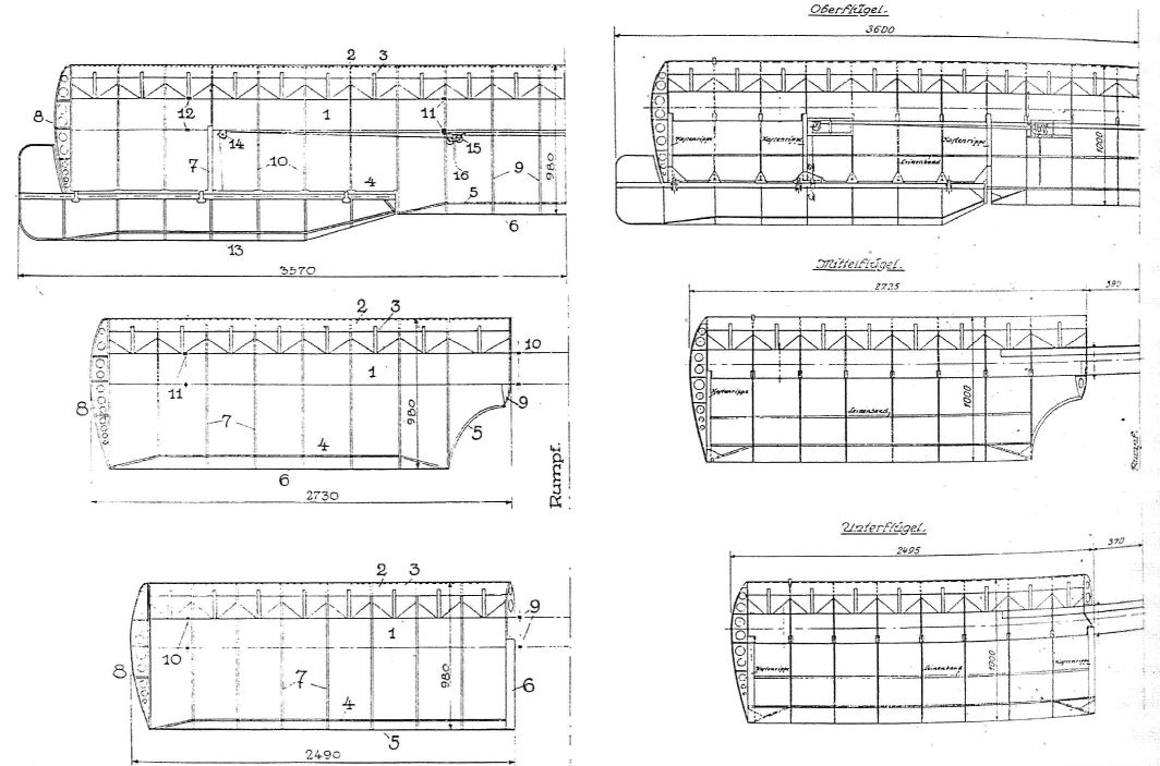
Instead of using plywood covered wings for stiffness like the V.1-V.3, lightweight, fabric-covered wings were developed with a single, very stiff and strong double box spar to maintain the cantilever configuration. This box spar carried through the fuselage for the bottom two wings, which were all in one piece. A thin plywood, almost a veneer, was used on the leading edge of the wings and there was a wire trailing edge. Fabric shrinkage on covering caused the wire to form the familiar scalloped trailing edge. The bottom and middle wings had the same span, while the top wing had a much greater span. Ailerons were only fitted to the top wing, unlike the Sopwith Triplane with its 3 sets of ailerons. For ease of construction, a common rib design and box spar cross section were used for all three wings. The bottom, middle, and center of the top wing had a common chord of 980 mm (millimeters). The wings featured the thick cross section Fokker had come to believe in since his semi-forced partnership with Junkers. Unbalanced ailerons and elevator were matched with a comma shaped rudder with no vertical fin. The only external wires on the aircraft were in an X configuration between the upper wing and fuselage and another X between the landing gear struts. No interplane struts between the wings were used and a small airfoil wing was incorporated around the landing gear axle for extra lift. This actually resulted in some early Idflieg documents referring to Fokker triplanes as vierdeckern (quadraplanes) instead of dreideckern (triplanes).
Construction and testing of the V.4 took place at a very rapid pace, with the V.4 likely flying by 25 June 1917, only 12 days after Fokker ordered the biplane fighter under construction to be completed as a triplane. By 2 July, the English already had an intelligence report that a new triplane fighter was flying. The V4 data table shows the dimensions and other characteristics of the V.4.
From the start, the performance and handling qualities of the V4 were excellent in the hands of an expert pilot. Stall characteristics of the V.4 were relatively benign, like the V.1-V.3. Pitch, roll, and yaw were all relatively unstable, making for a very maneuverable aircraft, with aileron and roll control being one of the primary criticisms of the design. This was likely caused by flexing of the upper wing, due to lack of interplane struts, limiting effectiveness of the ailerons. Top speed was exceptional at 200 km/hr kilometers per hour (124 mph), especially considering the relatively low power of the rotary engine. Climb rate was better than the Albatros V-strutters, but not as good as Fokker had hoped. Werner Voss flew the V.4 and fell in love. The maneuverability of the triplane was phenomenal, with unprecedented rudder authority, and good climb rate. With no dihedral and no vertical fin, the V.4 could happily fly along at ridiculous yaw angles. Flat yaw turns were possible with complete control and the large propeller allowed the triplane to hang on its propeller while pointing the nose in any direction the pilot desired. All of this performance was helped by the much improved weight to power ratio of 3.15 kg/hp, especially when compared to the V.1-V.3, all of which exceeded 4 kg/hp. Details are in the V.4 performance table. Testing was done without the twin machine gun armament, hence the 165 kg payload.
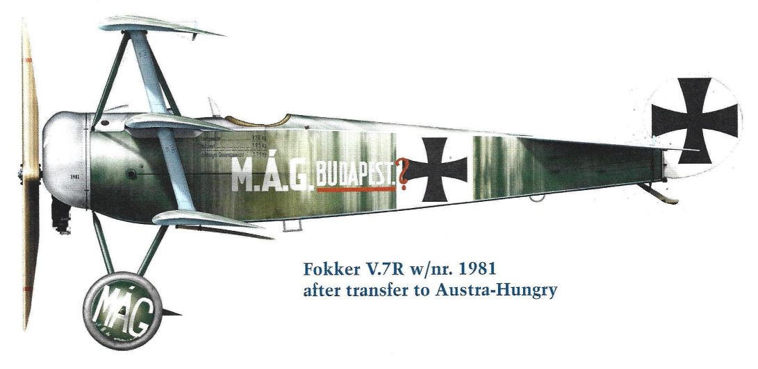
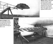
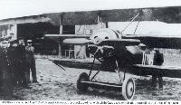
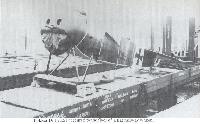
According to Fokker records, Fokker V.4, WN 1661, was painted and shipped to the Ungarische Machinenfabrik, Budapest without an engine or machine guns in August 1917 and received on 3 September 1917 with its cowling missing. It was assigned Austro-Hungarian designation 90.02 and was tested extensively with A-H license built engines. Austro-Hungary received a further triplane for testing, V.7R, WN 1781, at a later date, but decided to go with a version of the simpler V.12/Fokker D.VI biplane fitted with an A-H license built version of the 145 hp, 11 cylinder, Le Rhone rotary.
Fokker V.4 Specifications
Engine: 120 hp Le Rhone 9Jb
Wing: Span Upper 6.21.m
Chord Bottom, Middle, Center top 0.980 m
Wing Area 14.0 m2
General: Length 5.75 m
Height 2.95 m
Empty Weight 346 kg
Loaded Weight 528 kg
Fuel capacity 751
Oil capacity 121
Power to Wt. Ratio Empty 3.15 kg/hp
Maximum Speed: 200 km/h
Climb: 1000m 2.5 min
2000m 5.5 min
3000m 10 min
4000m 17 min
5000m 28 min
Performance with 165 kg load
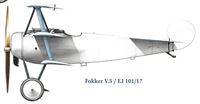
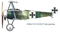
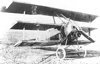
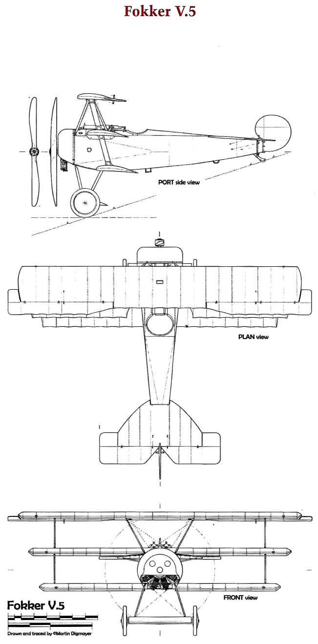
Fokker V.5 / Idflieg El 101/17
Although V.4, WN 1661, performance and handling characteristics already exceeded that of his Albatros rival's fighters, Fokker could immediately see that changes needed to be made to make aircraft handling more suitable for the average pilot, to increase roll rate, to improve climb rate, and to damp the fluttering of the top wing attached only by the fuselage struts. This would result in a modified design ordered on 5 July 1917, variously identified as a V.4 (Alex Imrie's modified V.4) and V.5 for the same airframe in Fokker sources. The same dichotomy would be found in the two later F.I triplanes, F.I 102/17, WN 1729, and F.I 103/17, WN 1730, also identified as both V.4 and V.5 triplanes, when they were all three V.5 types.
Fokker knew there was a trade-off to be made between climb rate and maximum speed. His observations at the front with Jasta 11 made him think climb rate was more important in summer 1917. This would change in 1918, when maximum speed would become considered most important. Unlike many units, Jagdgeschwader I did not usually fly standing patrols, but used forward airfields to quickly climb after enemy formations were spotted. Warnings came from forward anti-aircraft artillery batteries and other frontline observers, as well as JG I's own observations using binoculars and other optic devices. To increase climb rate Fokker knew the easiest way was to increase wing area and thus decrease wing loading. The spans of the middle and top wings were increased to give an overall wing area of 16 m2 (square meters) compared to the 14 m2 of V.4, WN 1661. This also gave a pleasing symmetry to the wings with their graduated span increase.
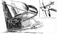
To increase roll rate and decrease roll sensitivity, balanced ailerons were fitted with long chord horn balances. To prevent the wing from vibrating and flexing and thus decreasing roll rate, thin wood interplane struts were fitted. The horizontal stabilizer leading edge was less rounded than on V.4, WN 1661, and a balanced elevator with rounded, rectangular horn balances was fitted. This also made the V.5, WN 1697, less sensitive in pitch response and easier to fly.
V.5, WN 1697, was fitted with a Le Rhone 9Jb (120 hp), even though noted in some Fokker sources as an Oberursel Ur.II of 110 hp, others show a 120 hp Le Rhone. The cowling was identical to that on V.4, WN 1661. This design, with a slot in the bottom plate for cylinder rotation, tended to pool castor oil/T50 synthetic substitute oil in the bottom of the cowl and would eventually be changed on the production Dr.I aircraft. Unlike V.4, WN 1661, which was never fitted with machine guns in Germany, V.5, WN 1697, was fitted with two standard, air-cooled, Maxim LMG 08/15 machine guns manufactured by the Spandau Arsenal. Each of these LMG 08/15s carried 500 rounds of ammunition.
Performance of V.5, WN 1697 was spectacular, especially in climb, with climb time to 5000 meters using Fokker figures being nearly halved compared to V.4, WN 1661, 14.5 minutes vs 28. Roll rate increased significantly while being easier to control. Pitch was still very sensitive and the large horn balances on the elevator would be decreased in area on later triplanes. Yaw authority was unchanged, although there would be slight changes to rudder shape as the triplane design progressed, likely more for manufacturing reasons than aerodynamic ones. Fokker still noted a maximum speed of 200 km/ hr (kilometers per hour), although other sources note a decrease to 190 km/hr, to be expected with the increase in weight, payload, and drag from the increased wing span and area. Similarly, other sources noted a 5000 meter climb time of 18 minutes instead of the 14.5 minutes Fokker claimed. This was still a spectacular climb rate for mid-1917.
V.5, WN 1697, was assigned the designation of F.I 101/17 by Idflieg, with the 'F' designation being a new one for the previously non-existent triplane type. This would quickly be changed to 'Dr' for dreidecker. Two further triplane pre-production prototypes, F.I 102/17 and F.I 103/17, for front-line evaluation were ordered on 11 July 1917. These three F.I prototypes were incorporated into an Idflieg order for 20 F.I triplanes from F.I 100/17 through F.I 119/17 made on 14 July 1917. Fokker would eventually figure out how to be paid for F.I 100/17 by assigning the Dr.I 100/17 designator to an experimental triplane built later, V.7O, WN 1830.
In its unpainted, clear-doped linen form and in its later streaked olive and light blue camouflage form, V.5/F.I 101/17 was demonstrated by Fokker and flown by front-line pilots and Idflieg test pilots, including most likely Manfred von Richthofen. Von Richthofen gave a very favorable report on the triplane to his JG I pilots and anxiously awaited its arrival. He had complained about the performance of the Albatros V-strutters equipping JG I that seemed to him little improved over the Albatros D.II of 1916, plus being more fragile.
On 7 August 1917, F.I 101/17, WN 1697, was shipped to Adlershof for testing and its structure was destructively tested, passing with only minor problems. On 11 August 1917, V.5, WN 1697, F.I 101/17, which can be considered the prototype of the Fokker Dr.I series, passed its Bruchprobe (breaking test). V.5/F.I 101/17, WN 1697 details and performance are shown in the accompanying table. This performance would never be matched by a production Fokker Dr.I, especially with the rotary engine problems T50 Voltol induced. The next two V.5/F.I pre-production triplanes, F.I 102/17 and F.I 103/17, though, likely did closely match F.I 101/17's spectacular performance.
Fokker V.5 Specifications
Engine: 120 hp Le Rhone 9Jb
Wing: Span Upper 6.725 m
Wing Area 16.0 m2
General: Length 5.75 m
Height 2.725 m
Empty Weight 375 kg
Loaded Weight 571 kg
Fuel capacity 75 l
Oil capacity 12 l
Maximum Speed: 200 km/h
Climb: 1000m 1.75 min
2000m 3.75 min
3000m 6.5 min
4000m 10 min
5000m 14.5 min
Armament: 2 mgs
V.5 Frontline Prototypes; F.I 102/17 & 103/17
Based on the performance of the V.4, WN 1661 triplane and the praise heaped upon it by frontline pilots, especially Werner Voss, Idflieg ordered a second modified triplane on 5 July 1917. Although this V5, WN 1697 was unlikely to have already flown, Idflieg wanted to get prototypes into the hands of front-line pilots as soon as possible and ordered two more triplanes for operational testing on 11 July 1917. These two triplanes, designated F.I 102/17 (WN 1729) and F.I 103/17 (WN 1730), were destined for Jagdgeschwader I. Pilots would be JG I commander Rittmeister (cavalry captain) Manfred von Richthofen and Jagdstaffel 10 commander Oberleutnant Werner Voss.
Fokker made only minor changes from V.5, WN 1697/F.I 101/17 for these two triplanes. The most obvious were to the horizontal stabilizer and elevator. The large, rectangular horn balances on V5, WN 1697's elevator were reduced in size to match the slightly curved leading edge of the horizontal stabilizer. This slightly curved horizontal stabilizer leading edge was characteristic only of these two prototypes and would be straightened on the production triplanes. The horn balance area decrease alleviated some of the pitch sensitivity noted in the V4 WN 1661, and V5, WN 1697. Both triplanes were fitted with long chord balances on their ailerons that would be shortened on later triplanes. The 980 mm chord on the V.4 and V.5 prototypes' wings would be changed to 1000 mm (1 meter) on the production triplanes.
Since the Oberursel Ur.II was still undergoing qualifications tests with T50 Voltol, both aircraft were fitted with Le Rhone 9Jb engines of 120 hp. F.I 103/17, to be assigned to Oblt Voss, for example, was fitted with an engine, Le Rhone Number 6247, captured from a Nieuport 17 in April 1917. Both engines were fitted with Axial propellers, the one on Voss' triplane having Axial decals covering propeller balance weights, while the one on von Richthofen's triplane had no decals. These decals (or lack of decals) make a handy guide to which F.I is in early photographs. Cowlings identical to that on the V.4, WN 1661 and V5, WN 1697/F.I 101/17 were fitted, with a full front plate with holes and a slot for the cylinders on the bottom. Like Fokker's earlier M series monoplane and biplane fighters, two data plates were riveted to the cowl, one above the other. Production triplanes would only have one data plate.
F.I 102/17 and F.I 103/17 were painted in streaks of olive over clear doped linen on the wing tops, fuselage tops and sides, and horizontal stabilizer tops, with the olive becoming almost solid in the forward part of the fuselage to match the original olive cowls. Cross fields on the upper wing tops and fuselage sides were painted white, as were the rudders. The bottoms of the wings (except for the Eisernkreuz fields, which were left bare clear doped linen), fuselages, and horizontal stabilizers were painted light blue, as were the struts. The wheel covers and top of the landing gear airfoils were also olive, with airfoil bottoms and landing gear struts in light blue. On production triplanes, the light blue paint was returned over the fuselage sides and horizontal stabilizer tops to form a light blue border. This feature was not present on either of the two front line prototype triplanes.
Wingtip skids later fitted to production triplanes were not fitted. Another difference from the production triplanes was that both these F.Is only had the Werk Nummer on the interplane struts without the 'U' for unten (below), 'O' for oben (above), 'L' for links (left), or 'R' for recht (right). As a consequence, Voss' F.I 103/17 eventually had its interplane struts installed with the WN on the struts' insides instead of the correct outsides. Since they were symmetrical, this had no effect on performance or strength.
Both of these F.I triplanes were built by the. Fokker experimental shop with careful attention to materials, construction and workmanship. Neither exhibited any of the poor quality control of wing construction that was to plague early production triplanes. Likely, these two triplanes used some of the scarce remaining castor oil stocks in Germany in August/September 1917, improving reliability of the Le Rhone rotaries.
On 16 August 1917, both F.I triplanes were accepted by ZAK (Zentral-Abnahme-Kommission) at the Fokker factory. On 21 August they were shipped directly from Fokker Schwerin to JG I at Marckebeeke, near Courtrai in Belgium. Arriving with much fanfare at Marckebeeke, both were likely test flown on 28 August 1917, even though the weather was poor. These two triplanes are likely the most photographed aircraft of WWI, with multiple images and extensive movie footage showing Fokker, von Richthofen, Voss, and visiting dignitaries. These visits culminated in the 9 September visit to Jasta 10 by the Austrian Crown Prince with F.I 103/17 displayed in a line-up of shiny new, yellow-nosed Pfalz D.IIIs.
F.I 102/17, WN 1729 Operational History
On 1 September 1917, von Richthofen flew F.I 102/17 operationally for the first time. He approached a 6 Squadron, Royal Flying Corps (RFC) RE8 performing artillery spotting, which apparently misidentified him as a Sopwith Triplane and took no evasive action. Von Richthofen approached within 50 meters and shot the RE8 down using only 20 rounds for his 60th victory.
On 3 September 1917, von Richthofen engaged Lieutenant A. F. Bird of 46 Squadron, RFC in his Sopwith Pup and forced him to land after a fairly long engagement for his 61st victory. Bird later seemed pleased to have survived an engagement with von Richthofen and smiled for photos after his capture. Von Richthofen noted that his triplane was clearly superior to the Pup during the engagement. With a power, speed, maneuverability, firepower, and climb advantage over the 80 hp Pup, this is hardly surprising. After this victory, von Richthofen went on extended leave forced on him by his superiors to recover from his still unhealed 6 July 1917 head wound. He would not score again until 23 November 1917.
F.I 102/17 was turned over to the Jagdstaffel 11 commander, Oberleutnant Kurt Wolff, who had been badly wounded in the hand on 11 July 1917. Wolff returned to flying status on 11 September 1917 and made a visit to the front and Pionierkompanie 89 to familiarize observers on the front with the new triplane aircraft. Several photos were taken of Wolff's visit to Pionierpark Nachtigall.
On 15 September 1917, Wolff was leading Jasta 11's Albatros scouts on a patrol near Moorslede when they encountered a formation of Sopwith Camels. During the subsequent engagement, Sub-Lieutenant N. M. MacGregor of 10 Naval Squadron took a snap shot at F.I 102/17 that unfortunately hit Wolff in the head, instantly killing him. F.I 102/17 dived into the ground very close to where he had visited Pionierkompanie 89, near Klein-Bahnhof Nachtigall (rail substation nightingale). Naval 10's pilots had reported 4 triplanes in the engagement, even though there was only one. MacGregor only claimed an out of control.
F.I 103/17, WN 1730 Operational History
Werner Voss liked to embellish his aircraft personally and soon decorated his triplane like one of the kites he flew as a child in Krefeld. Jasta 10 was equipped with the brand new Pfalz D.III biplane, which Voss did not like because it was too stable. He was still using an Albatros V-strutter while his pilots flew the new Pfalz aircraft, so he was especially happy to receive F.I 103/17. Voss could do amazing things with an Albatros, and the triplane suited his flying style even better. Voss had already wrung out the V4, WN 1661 triplane, so had a good feel for what his triplane could do. Photographic evidence indicates F.I 103/17 had its cowl and wheel covers painted in what was described by a Jasta 10 pilot as an orangey yellow, sometimes described as mustard colored. To this dark yellow, Voss added the famous eyes, eyebrows and mustache to the cowl in white paint. Later in the war, this dark yellow color became difficult to obtain and Jasta 10 aircraft used a lighter, brighter yellow.
On 3 September 1917, Voss scored his first victory in the triplane over a 45 Squadron, RFC Sopwith Camel. This was Voss' 39th victory and his 2nd over a Camel.
Sometime on the 3rd or 4th of September, Voss' Triplane was hit by machine gun fire that put the famous 9 holes in the rudder and other holes in the right horizontal stabilizer and top wing. This damage was previously thought to have been done on 11 September during an engagement with Sopwith Camels of 45 Squadron. Newly discovered photos from 5 September 1917 at 1600 hours with Fokker and Voss together with F.I 103/17 already show the repaired bullet holes in the rudder. In addition to the photos of Voss and Fokker with the Triplane, a series of 3 photos, front, side, and rear, were likely taken on 5 September that highlight the damage to F.I 103/17. Clearly visible in the rear photo are the 9 repaired bullet holes in the rudder later noted by Lieutenant Rhys Davids, who received F.I 103/17's white rudder as a souvenir. Also visible in the photos are holes in the top wing and horizontal stabilizer. Voss was lucky he was not hit. No details of how the damage was done in early September have been discovered.
On 5 September a Sopwith Pup of 46 Squadron, RFC became Voss' 40th credited victory, although 2nd Lt C.W. Odell managed a forced landing just inside English lines. This Pup was eventually recovered and repaired. Odell survived the war with 7 victories. Voss' second victory of the day was credited as his 41st over a French Caudron, although no matching French loss can be found. The Caudron may have made a forced landing inside French lines and was not counted as a loss by the French.
On 6 September, an F.E.2d of 20 Squadron RFC fell in flames to Voss above Boesdinghe. This was number 42 for Voss.
On 10 September Voss scored a triple. In the same engagement, he shot down two Sopwith Camels of 70 Squadron, RFC, killing both pilots. 25 minutes later, Voss then shot down a French SPAD 7 from Escadrille Spa 7. These were his 43rd, 44th, and 45th victories.� On 11 September Voss scored another double, first likely forcing down a Bristol F.2B from 22 Squadron, RFC (also reported as a Sopwith Camel of 45 Squadron) in the morning for number 46. On a later sortie in the afternoon, Voss downed a Sopwith Camel of 45 Squadron, RFC for number 47. While shooting down Lieutenant O. L. McMaking, an ace with 6 victories, Captain Norman MacMillan tried to save McMaking and fired at F.I 103/17. In his book Into the Blue, MacMillan noted Voss looked over his shoulder at him, dismissed the threat, and then continued to shoot down McMaking in flames. Voss was getting increasingly confident as time went on, almost as if he and the Triplane were invulnerable. In this case, Voss was correct, as MacMillan scored no hits on F.I 103/17.
Voss had scored nine victories in only 8 days and was rapidly closing in on von Richthofen's 61 victories. This was especially true since von Richthofen was on extended leave and not expected back until November. After this engagement, Voss went on what was probably a much needed leave. He visited the Fokker factory during this time and a photo exists of him sitting in an early production Triplane with a makeshift headrest never used on production Triplanes.
On 23 September 1917, Voss was back from leave and flying F.I 103/17 again. That morning Voss engaged and quickly shot down a D.H.4 of 57 Squadron, RFC that had been engaged in a bombing mission against Hooglede. A photo was taken of the Voss brothers Werner, Otto, and Max, likely taken after lunch and before his late afternoon sortie.
In the late afternoon of 23 September, Voss and F.I 103/17 were involved in what must be considered one of the greatest aerial engagements and fight against odds in aviation history. Voss engaged S.E.5a aircraft of 60 Squadron and 56 Squadron, RFC, forcing four S.E.5a aircraft out of the fight with serious damage, and putting bullet holes through all 11 aircraft he engaged. As some context, contrasting the performances of the S.E.5a and F.I triplane may help understand the bravery of Voss during this engagement. The S.E.5a top speed at sea level was approximately 135 mph (217 kph), at least 10 mph (16 kph) faster (and probably more) than the triplane's 124 mph (200 kph). At low altitude in climb, though, the F.I had a clear advantage, taking only 6.6 minutes to reach 10,000' (3048 m), while the S.E.5a required 11 minutes to reach the same altitude. This matches with 56 Squadron pilot after action reports and later comments that Voss had a much better climb, was often the highest aircraft in the engagement, and could have climbed east out of danger at any time. This altitude advantage could also be used by Voss to dive and gain airspeed. The triplane also offered a clear advantage in maneuverability over the S.E.5a, which was a fast, tough, and stable gun platform but not particularly maneuverable by rotary engine fighter standards and with a tendency to lose altitude in turns. The F.I triplane's lack of dihedral and thick airfoil section allowed quick, flat rudder turns, which the high dihedral S.E.5a could not match. Several pilots mention Voss making flat rudder turns and throwing the tail behind him without affecting controllability at all. Lastly, the triplane enjoyed firepower superiority to the S.E.5a with its two LMG 8/15 machine guns with 500 rounds each compared to the S.E.5a and its single Vickers with 400 rounds and over the wing Lewis with four 97 round removable drums. Several of the S.E.5a pilots mention departing the fight to change out their Lewis drums, and this cut down on their engagement time.
The outcome of this engagement is well known and extensively documented, with Lieutenant Rhys Davids eventually killing Voss after a nearly 10 minute engagement. F.I 103/17 crashed on the English side of the lines near Plum Farm. This ended the operational history of the two F.I frontline prototypes. Several pieces of F.I 103/17 were recovered, including the rudder mentioned previously, and all eventually ended up at the Imperial War Museum, where they have been lost to history except for photographs.
The first production Fokker Dr.I triplanes, little changed from F.I 102/17 and F.I 103/17, were accepted by ZAK on 9 September and six had been accepted before Voss' final flight on 23 September. The first production triplane, Dr.I 115/17, WN 1783, to reach the front was shipped from Fokker Schwerin on 4 October 1917 for the ill-fated Leutnant Heinrich Gontermann, commander of Jasta 15.
Fokker V.7 & Experimental Dr.I Triplanes
Anthony Fokker's prototype shop built four documented V.7 (Versuchs for experimental) aircraft based on his Fokker Dr.I Triplane. Factory documents show all four V.7 Triplanes having 160 h.p. engines installed, each from a different manufacturer. These four aircraft were easily identified as different from a standard Dr.I by their lengthened fuselages and modified cowlings. The stretched fuselages balanced the extra weight of the heavier, higher horsepower engines fitted to boost performance. The modified cowlings were needed to fit what were considerably larger engines than the Dr.I's standard and interchangeable Oberursel Ur.II and Le Rhone 9J engines.
The V.7 Triplanes were initially built with the intention of gaining more orders for an improved performance Dr.I. Start dates on building the V.7 aircraft fit into the relatively short time period of 13 August - 24 October 1917. Since the V.11 prototype for the eventual Fokker D.VII was started on 20 September 1917, the V.7 Triplanes were most likely not Fokker's highest priority. He was in the process of building numerous new designs for the Adlershof fighter competition scheduled for January 1918.
This lack of priority could also have been exacerbated by the problems rotary engines were having with rotary engine lubricating oil because the English naval blockade had cut off all supplies of castor oil. This did not stop Fokker, however, from producing new rotary engine designs that ultimately became the Fokker D.VI and E.V/D.VIII. With the help of factory documents and photos from the Fokker Heritage Trust, a fairly complete description of these experimental triplanes can be made.
Fokker V.7S WN 1788
The first V.7 was Werknummer (WN) 1788, which was identified by the factory as the V.7S for its 160 h.p. Siemens-Halske III eleven-cylinder rotary engine. V.7S was ordered on 13 August 1917, well before the two prototype Fokker F.I Triplanes were sent to Jagdgeschwader I for operational evaluation. The Sh.III high compression engine was to have severe teething troubles until fully developed. The Sh.III ultimately provided phenomenal performance, especially in climb and at high altitude, in the later Pfalz D.VIII and Siemens-Schuckert SSW D.III and D.IV fighters. In the Sh.III engine, the cylinders rotated in one direction and the crankshaft rotated in the opposite direction. This cleverly overcame the normal rotary engine speed limitation of approximately 1500 revolutions per minute (rpm), above which rotation speed the cylinders tended to come off. By using the counter-rotating design, the cylinders and propeller could rotate at 1800 rpm and the crankshaft in the opposite direction at 900 rpm for an actual rotation speed of propeller and cylinders of 900 rpm. In general, the higher the rpm, the higher the horsepower an internal combustion engine can develop, so the Sh.III had an advantage over typical rotary engines with limited rotation speed.
The only drawback was that the cooling provided by the spinning cylinders was also decreased by the lower rotation speed. The Sh.III's low cylinder rotation speed and high compression, combined with lubricant problems, caused initial overheating, cylinder bluing, piston failure and other heat related issues until Sh.III development matured. Surprisingly, the license built Sh.III (Rh) built by the Rhemag-Rhenania Motorenfabrik in Mannheim did not seem to have as many problems. These cooling problems were not actually solved until summer 1918 when the Sh.IIIa became available from Siemens and Rhemag.
The V.7S, WN 1788 is probably the most familiar of the V.7 Triplanes to WWI aviation enthusiasts. Relatively well documented in photographs while under construction and test at the Fokker factory in Schwerin and while at Adlershof, V.7S was also the most heavily modified of the V.7 aircraft. In addition to the longer fuselage and large, distinctive cowl, made even larger by the Sh.III requirement to provide structure to carry front and rear motor mount bearings and a rear gearbox assembly, the landing gear was also lengthened. This lengthening of the landing gear was necessary to clear the large propeller necessary for the Sh.III to provide maximum performance at low propeller rpm, especially with the initial two bladed propeller.
These extensive modifications made the V.7S the heaviest of all rotary-powered Triplanes, and V.7S was a full 115 kilograms heavier than a standard Dr.I. Photographs of V.7S show it fitted with both two- and four-bladed propellers. Like the Pfalz D.VIII and the SSW D.III/D.IV, the ultimate choice was the four-bladed propeller, which could absorb all the Sh.III's power while turning relatively slowly.
V.7S was initially fitted with a huge axle wing, nearly the size of one lower wing, but this caused the aircraft to float on landing and the axle wing was eliminated, as shown on most V.7S photographs.
V.7S was at Adlershof, but did not compete in the first fighter competition held there. It is known that two modified Dr.I aircraft did participate at Adlershof, and these Dr.I Triplanes will be discussed later. V.7S is one of two V.7 Triplanes Fokker may not ultimately have claimed to convert to a Dr.I, the other being WN 1981, which was sold to the Austro-Hungarian government. Fokker converted (on paper at least) V.7 aircraft back to the Dr.I standard so he could be paid for them as part of the 320 or so Dr.I Triplanes Idflieg ordered. At least one source, however, states V.7S, WN 1788 was refitted as Dr.I 120/17 after having a standard Ur.II installed. There is no record of Dr.I 120/17 ever being accepted, so the conversion is questionable. V.7S could also have been originally ordered as an experimental aircraft by Idflieg. Rumors of Fokker resisting fitting the Sh.III to the Dr.I have been published in the past, but are most likely just that, rumors, his ownership of Oberursel notwithstanding.
Fokker V.7S with Axle Wing
Shown on a photo of V.7S taken at Fokker Schwerin on 29 December 1917 with a very large axle wing. Because of the lengthened landing gear struts, needed to provide clearance for the two-blade and eventual four-blade Axial propellers, the axle wing appears to be nearly twice the size of a standard Dr.I axle wing. It is little wonder it caused the aircraft to float, it is nearly a bottom wing half in size.
Looking at the photo closely, the elevator has been removed. The markings on the top wing show the "DRI XXXX FL N XX" are not centered around the middle rib as on later Dr.I aircraft, but offset to port. Whether this was true of some or all early Dr.I wings is not known because most photos of pre-grounding aircraft are not high enough resolution to see this level of detail. The wings still retain the Fokker F.I style ailerons with the long chord balance horns and two aileron rib taper to merge with the rear of the wing.
The wing rib tapes are very unusual for a Triplane since they appear to have been applied after the wings were painted. On later Dr.I aircraft, it is nearly impossible to see the wing rib tapes except in a very high resolution photograph because they were painted the same colors as the wings. Here they are very visible. Since V.7S was fitted with a set of wings identical to the early Dr.I, the wings would have had to be modified to meet the Idflieg directive on Fokker Dr.I wings. Based on this photo, it now appears Fokker repaired the original early Triplane wings and even reused the same fabric after the repairs. This is the most logical explanation for the light colored rib tapes over the painted fabric.
The cowling is unpainted in this early photograph, but would be painted olive before shipping to Adlershof. The wheels are clear doped over what appears to be very light, bleached linen, and they would also be painted before shipping. The Fokker Dr.I aircraft in the background also have unpainted cowls most likely painted before delivery. The massive Siemens-Halske Sh.III engine is clearly visible. Although its compression ratio was only 5.0-5.1:1, the Sh.III was considered a Hohenmotor or high altitude engine and uberkompromierte or overcompressed.
Fokker V.7O WN 1830
V.7O, WN 1830, was named by the factory for its Gnome-based, twin-row, fourteen-cylinder, 160 h.p Oberursel U.III rotary engine. One other factory document shows it as the V.7m for Gnome. Oberursel engine designations were U.0 - U.III (skipping, apparently, U.II) for Gnome-based engines and Ur.II - Ur.III for Le Rhone based engines. Idflieg and factory documents used Gnome and the Oberursel U-series engines' names interchangeably as they did for the Le Rhone and Oberursel Ur series engines. As an example, an original Dr.I propeller inspected by Fred Murrin was stamped with engine type Le Rhone, not Oberursel.
The U.III, a license-built version of the Gnome double-lambda engine, was essentially two Oberursel U.0, seven-cylinder, 80 h.p. engines mounted on a common crankshaft. The U.III, like the Sh.III, required both front and rear bearings to support the engine. Most rotary engines required only a rear bearing. The front and rear bearing configuration necessitated fitting a large diameter, lengthy cowl to cover the engine and support structure. The Oberursel U.III is the same engine fitted to the thin-winged M-series Fokker E.IV Eindecker and Fokker D.III biplane.
Large and heavy, the U.III provided small performance improvements in the E.IV over the Fokker E.III fitted with the Gnome Delta based, 100 h.p. Oberursel U.I, and only small improvements in the Fokker D.III over the Fokker D.II also fitted with the U.I. Since the U.III used the same early Gnome automatic intake valves as the U.0 and U.I, the U.III also suffered from the same lack of reliability, but with more chances for failure. The U.III did provide a slight increase in top speed and more weight-carrying capability, and the E.IV and D.III could thus carry twin gun armament. Climb, however, was only marginally improved and maneuverability suffered compared to the E.IV's and D.III's lighter engine predecessors. Why Fokker elected to try what was essentially a dead-end engine in a Triplane is unknown, but his ownership of the Oberursel factory undoubtedly had an influence.
Fokker V.7O WN 1830, which was begun on 23 August 1917, is very poorly documented by photographs. The only known photo is Fokker factory photograph #1055 of the Fokker V.11 under construction. In the background of this photo can be seen, head-on, the uncovered fuselage of V.7O with a twin-row Oberursel U.III and sheet metal support structure fitted. Even though published sources on this Triplane have speculated on what engine it carried, careful study of the photograph shows the twin row configuration of the U.III engine. The landing gear appears to be standard Dr.I. On the factory floor next to V.7O can be seen a massive cowl which undoubtedly went with the airframe. As would be expected, V.7O must not have impressed with its performance and was converted to a standard Dr.I. Assigned serial number 100/17 (sometimes seen as 100/18), Dr.I 100/17, WN 1830 was accepted on 26 April 1918. Idflieg's initial order for 20 F.I Triplanes included 100/17 through 119/17, and Fokker made sure he was paid for every one of them.
Fokker V.7G WN 1919
V.7G, WN 1919 was one of several Triplanes fitted with the nine-cylinder, 160-200 h.p. Goebel Goe.Ill rotary engine. The Goe.III's conventional, large diameter (1140 mm vs 960 mm for a Ur.II), single-row, rear-bearing-only layout made it relatively easy to adapt to the Dr.I airframe. The Goe.III weighed 183 kg vs. the approximate 148 kg of the Ur.II or Le Rhone 9J, so it did not have a large impact on aircraft center of gravity.
According to Fokker factory documents, an uberkompromierte (over-compressed or high compression) 160-175 h.p. version of the Goe.III was fitted to V.7G. An NACA (National Advisory Committee for Aeronautics, which was the 1915-1958 NASA predecessor) report on Goebel engines published in March 1921, stated that the Goe.II and Goe.III used a single pushrod-actuated exhaust valve and an automatic inlet valve, much like the 100 h.p. Gnome Delta-based Oberursel U.I engine fitted to the Fokker E.III. The automatic intake valves on the early Gnomes and derivative Oberursel U-series engines were a maintenance nightmare and caused no end of in-flight and ground aborts when the intake valves stuck open. The main difference between the Goebel engine and the early Greek letter Gnome engines is that the Goe.III connecting rods provided positive closing of the intake valves.
Only 229 Goe.IIIs were produced during the war and none were used as the production engine in a series-produced aircraft. It is interesting to note Idflieg's original order for the Fokker E.V specified the 160 h.p. Goe.III or the 145 h.p., eleven-cylinder, Oberursel Ur.III. Neither the Ur.III nor the Goe. Ill engine could be produced in sufficient quantity for production use, however, and the original order E.V monoplanes were fitted with 110 h.p. Oberursel Ur.IIs.
V.7G WN 1919 was an especially mysterious V.7 for which no known photographs existed until recently. Peter Grosz' files had a profile drawing of the aircraft from the Baubeschreibung fur D.R. Flugzeuge Fok Dr.I Blatt 2 (Construction Specification for Triplane Aircraft Fokker Dr.I Sheet/Page 2) and the note that it was powered by a 170 h.p. Goe.III.
Fokker began building V.7G on 12 October 1917. Intermediate in weight between a standard Dr.I and the extensively modified V.7S, the high compression engine gave excellent climb performance, especially at altitudes above 4000 meters. This Triplane had standard Dr.I landing gear, the V.7 lengthened fuselage and a bulged cowling to fit over the large diameter engine.
Factory photo #1674 was taken at the Fokker factory in Schwerin and most likely shortly postwar. Sitting in the background of this factory floor shot, with numerous Fokker E.Vs/D.VIIIs and D.VIIs in the foreground, was a V.7 fuselage which could only be V.7G. The fuselage in the photograph perfectly matched Peter Grosz' profile drawing from the Baubeschreibung. Painted with streaked camouflage and the latest Balkenkreuz markings, V.7G must have been updated several times during its life. Fokker records indicate V.7G, WN 1919 was converted to a standard Dr.I, serial number 599/17, the last Dr.I in serial order. This obviously never happened, although a new DR.I fuselage could have been matched with V.7G's standard Triplane wings as DR.I 599/17 WN 1919.
Fokker V.7R WN 1981
V.7R, WN 1981 was named for its Austrian-built, Steyr Le Rhone, 150 h.p. rotary engine. The Steyr Le Rhone was an eleven-cylinder, large-diameter, single-row rotary engine supported by a rear bearing only. The Steyr Le Rhone was virtually a direct copy of its French Le Rhone counterpart and displayed no Oberursel characteristics. This engine is described in various sources as having 145 h.p., 150 h.p., and 160 h.p. ratings, even for the same installation, but there was only one engine type.
The Steyr Le Rhone was very similar to the 145 h.p. Oberursel Ur.III, but was much more successful and actually went into series production. The engine ran well using the castor oil replacement, T50 synthetic lubricant, though shortages of even the synthetic castor oil plagued Austro-Hungarian operations until the end of the war. Production Fokker aircraft were shipped from Schwerin to the Austro-Hungarians with no guns, engines or propellers. These indigenous components were then fitted by Fokker MAG (Magyar Atalanos Gepgyar) in Matyasfold, Hungary.
To give some idea of the high regard in which the Germans held the Steyr Le Rhone, efforts were underway when the war ended to do an exchange for this outstanding rotary engine with the very successful 185 h.p. BMW IIIa inline six. Fokker V.7R, WN 1981 and a sister ship, the Fokker D.VI prototype, V.12, WN 1980, were sent to MAG on 3 January 1918 and may or may not have already had the Austro-Hungarian components fitted as the first prototypes for a possible production buy. In any event, it was the V.12-based Fokker D.VI which was eventually chosen for purchase by the Austro-Hungarian government over the Dr.I-based V.7. Cost may also have been a factor in this decision since factory invoices show that the V.7R, WN 1981 cost DM 26,000 vs. DM 23,500 for both the engineless production Fokker D.VI and for later purchases of engineless Fokker D.VIIs.
A relative bounty of photographs documents V.7R, WN 1981. Begun on 24 October 1917, V.7R had the V.7 lengthened fuselage, standard Dr.I landing gear and a bulged cowl with three additional cooling holes above the normal pair of Dr.I cooling holes. In one photo of V.7R, "DRI 1981" can be seen on the bottom leading edge of the top wing. Given the serial number 90.03 more or less unofficially, V.7R eventually had "M.A.G. BUDAPEST?" painted on its side, the "?" referring to the fact the 90.03 serial number had not yet been allocated officially.
This Triplane took part in the July 1918 Austro-Hungarian equivalent of the Adlershof fighter competitions, which were held at Aspern. Following the Fighter Evaluation competition, V.7R was badly damaged in a crash landing while being flown by MAG factory test pilot Feldwebel Josef Nemeth. During a test flight, the rudder cable broke and the resultant crash landing severely damaged the Triplane. By this time, Fokker was using double rudder cables in Germany to prevent such mishaps. Clearly visible in post-crash photos, the landing gear was destroyed, the starboard side wings and both ailerons were heavily damaged, the horizontal stabilizer and elevator and rudder were nearly destroyed, and the front of the fuselage and cowl were crushed. In all probability, V.7R, WN 1981 was written off after this accident, especially since the decision had already been made to go with the Steyr Le Rhone powered Fokker V.12/D.VI biplane instead.
Fokker V.7 Myths Disproved
It begins to appear that there were several myths about the V.7 Triplanes which have been perpetrated over the years. The first of these myths is that the 145 h.p. Oberursel Ur.III engine was fitted to a V.7. We now know an Oberursel Ur.III was fitted to a relatively standard Dr.I, but never to a V.7. The second myth is that a V.7 was fitted with a captured nine-cylinder, 160 h.p. Gnome 9N monosoupape which normally powered the Nieuport N.28.
This latter myth came about because of confusion in factory documents about a V.7 being fitted with a 160 h.p. Gnome. The engine fitted to V.7m/V.7O was, of course, the license-built Gnome fourteen-cylinder, twin-row rotary, the Oberursel U.III. The Americans did not begin flying the Nieuport 28 until the spring of 1918, by which time the D.VII was Fokker's future, not the Triplane. There is no evidence of an operational Dr.I ever flying with a captured 160 h.p. Gnome 9N either.
The third myth is that the Fokker V.7S, WN 1788 with the Sh.III engine, competed at the first Fighter Competition in January 1918. Written sources now show that two relatively standard Dr.I Triplanes fitted with Oberursel Ur.III and Goebel Goe.III engines flew during the competition, but not as formal competitors. Adlershof was the German WWI equivalent of Edwards AFB today, with many experimental aircraft and production aircraft flying. Just because V.7S spent most of its life at Adlershof does not mean it participated in the competition. Highlighting the V.7S and other Triplanes at Adlershof would have distracted from production orders Fokker hoped to obtain for the eventual Fokker D.VI and D.VII.
Other Experimental Dr.I-based Triplanes
Some sources have stated that as many as 30 Dr.I Triplanes were fitted with Goebel Goe.III engines and delivered for Jasta service. In actual fact, there is no photographic record of any Goe.III-engined Dr.I ever having been delivered for combat use. Only V.7G, WN 1919, and a handful of experimental Dr.I Triplanes were fitted with the Goe.III, and there is virtually no photographic record of the Dr.I fitted with the Goe.III. One confusion factor was the fact that several late production Dr.I Triplanes were delivered with the seven-cylinder, 100 h.p. Goe.II for use at the Jastaschulen, and these Goe.IIs may have been confused with Goe.IIIs. An example of this is Dr.I 416/17, WN 2000, which was stated in some sources as having a lengthened fuselage and Goe.III engine. In fact, there is a widely published photograph, taken at a Jastaschule, of the quite standard, unarmed Dr.I with a seven-cylinder Goe.II and a plainly visible "DRI 2000" stencil on the bottom of the top wing.
The first Dr.I to be fitted with the Goe.III was Dr.I 108/17, which went to Adlershof for evaluation. Converted back to Le Rhone/Ur.II power, Dr.I 108/17, WN 1776, was accepted by Idflieg as a standard Triplane on 12 December 1917. The results of this evaluation were apparently good enough to encourage Fokker to install a Goe.III on Dr.I 200/17, WN 1918, which flew during the January 1918 Adlershof Fighter Competition. This was reported by the factory as a 200 h.p. Goe.III.
The next Triplane in sequence, Dr.I 201/17, WN 1920, was reported to have a 178 h.p. Goe.III and to have been delivered on 13 November 1917. The difference in horsepower ratings between Dr.I 200/17 and 201/17 may have been due to the different power levels the engine developed at different altitudes and may also have been due to experimentation with different compression ratio pistons. If the pistons gave a high enough compression ratio, the engine was called uberkomprimiert. Engines which were uberkompromiert normally could not use full throttle at sea level without risking pre-ignition detonation damage. These engines actually produced more power at altitude where full throttle could be used. The most well-known example is the BMW IIIa inline six, which developed 185 h.p. at sea level, but 260 h.p. at altitude.
It is doubtful 201/17 was still fitted with a Goe.Ill when delivered, and in fact Dr.I 201/17, WN 1920, went to Adlershof on 13 November as the first aircraft fitted with the new, improved wings. It most likely had a Ur.II when shipped. Such an unusual configuration as a Goe.III fitted Dr.I would undoubtedly have generated photographic evidence at the front and Triplanes thus equipped would have gravitated towards one of the top aces. No photographs of 108/17, 200/17, or 201/17, and their Goe.III installations have surfaced. It is interesting to note that three Triplanes in WN sequence received Goebel engines, WNs 1918 (Dr.I 200/17), 1919 (V.7G), and 1920 (Dr.I 201/17).
Hauptman Adolf von Tutschek's Dr.I 404/17, WN 1988, is also mentioned in some sources as being fitted with a Goe.III. All photographs of this machine in Jasta 12 service, however, show an engine that looks exactly like a standard Le Rhone 9J installation. Further research by Peter Grosz, however, discovered that Dr.I 404/17 had actually been fitted with a Ur.II (Rh), serial number 82. Ur.II (Rh) engines are indistinguishable visually in photos from Le Rhone 9J or Jb engines, unlike Ur.IIs with their separate front propeller shaft cover. There was initially confusion over the low serial numbers of the Ur.II (Rh) engines that resulted in postulation they were Goe.III engines.
One modified Dr.I for which photographic evidence exists is Dr.I 469/17, WN 2095, which was fitted with the 145 h.p., eleven-cylinder, Oberursel Ur.III. This aircraft was a more or less standard Dr.I with a bulged cowling to accommodate the large-diameter Ur.III. Some confusion also existed in the past that Dr.I 469/17 was a V.7, but photographic evidence proved otherwise This Triplane flew in the January 1918 Fighter Competition, but not as a formal competitor. Fokker performed a valuable service by painting "Fok DRI 469" in large letters and numbers on this Triplane's wheels.
A later photo of this same Triplane clearly shows the Ur.III installation and that the aircraft by then had no wing tip skids fitted. This photograph was mistakenly identified as F.1101/17, WN 1697, based on its lack of wing tip skids, unpainted aluminum cowl, and clear-doped linen wheel covers. Closer examination of the photo, however, shows the last version Dr.I ailerons, a larger cowl of different shape without the F.I engine slot, a straight leading edge on the horizontal stabilizer, stacking pads which were never fitted to the F.I, too many exposed cylinders, and a standard Dr.I rudder.
Two photographs taken at Adlershof, one of which is shown, are of a Dr.I with an extended cowl much like V.7O, WN 1830. This Dr.I was powered by a Siemens developed Schwade supercharged rotary. Originally thought to be a Ur.II, then an Sh.I, neither matched the layout of the rotary in the photos. Best guess is a captured 80 hp Le Rhone 9C, an Oberursel version of which is not documented. Fitted to an Sh.I in a Nieuport inspired SSW D.I, the supercharger halved climb times to 5000 meters.
Summary
Experimental versions of the Fokker Dr.I, including the V.7 Triplanes, were fitted with a variety of engines to try and improve performance.
The Sopwith Camel, an aircraft with similar performance, was upgraded during its service life with improved performance 140 hp Clergets, the 150 hp BR-1, and the 160 h.p. Gnome 9N to keep it up to date, even though some Camel units soldiered on until the end of the war with 120 h.p. Le Rhone engines.
In the Fokker Dr.I Triplane's case, though, the original order was for a few hundred, not several thousand, aircraft. Despite the phenomenal climb performance of the up-engined V.7s and Dr.Is, line pilots wanted speed more than climb or maneuverability. A triplane's extra drag ensured it would never be as fast as an equivalent biplane or monoplane. By the time the Fokker Dr.I Triplane's grounding was lifted and aircraft were flowing again to a select few units in the winter of 1917/18, Fokker had better designs, both on the drawing board and flying, from which to choose. The miserable service record of aircraft fitted with rotary engines running the synthetic T50 oil was probably also a factor in the lack of interest in an up-engined Triplane.
V.7 and Other Modified Fokker Dr.I Triplanes
Type WN SN Engine Comments Disposition
V.7S 1788 N/A * 11 Cylinder, F&R Bearing Siemens-Halske Sh.III Tested at Adlershof Unknown? 120/1’7 ?
V.7O 1830 N/A * 14 Cylinder, F&.R Bearing, Twin Row Oberursel U.III Little Known of
Test History Delivered as Dr.I 100/17
V.7G 1919 N/A *9 Cylinder, Rear Bearing Goebel Goe.III Markings Latest Balkenkreuz Schwerin 1918/1919
V.7R 1981 N/A * 11 Cylinder, Rear Bearing Steyr Le Rhone Extensively Tested in A-H Heavily Crashed
Dr.I 1776 108/17 160 h.p. Goebel Goe.III Tested at Adlershof Unknown
Dr.I 1918 200/17 200 h.p. Goebel Goe.III Flew Jan 1918
Adlershof Unknown
Dr.I 1920 201/17 178 h.p. Goebel Goe.III Tested Adlershof Unknown
Dr.I 1988 404/17 110 h.p. Ur.II (Rh) Serial
Number 82 Von Tutschek Jasta
12 Destroyed in Combat
Dr.I 2000 416/17 7 Cylinder, 100 h.p. Goebel Goe.II No V.7
Characteristics Delivered Jastaschule
Dr.I 2095 469/17 11 Cylinder, Rear Bearing
145 h.p. Oberursel Ur.III Flew Jan 1918
Adlershof Unknown
Dr.I Unk Unk 9 Cylinder, Schwade Supercharged Rotary Tested at Adlershof Unknown
* All V.7s reported by factory as having 160 h.p. engines.
�
Time to Climb Performance from the Dr.I Baubeschreibung and A-H Documents
Time to Climb (Mins) Dr.I 141/17
WN 1853 V.7G WN 1919 V.7R
WN 1981* V.7R WN 1981** Dr.I 469/17
WN 2095
0-1000 m 2.9 2.0 1.5 1.9 2.0
0-2000 m 5.5 4.0 4.0 4.3 4.3
0-3000 m 9.3 7.0 7.3 7.9 7.1
0-4000 m 13.9 10.0 11.5 12.5 10.8
0-5000 m 21.9 14.0 N/A N/A 15.5
0-6000 m N/A 20.0 N/A N/A 23.5
* Fokker figures
*‘Official A-H K.u.K. figures from 12 March 1918 test
Weights from the Dr.I Baubeschreibung
Weights Dr.I 141/17 WN 1853 V.7S WN 1788 V.7G WN 1919 Dr.I 469/17
WN 2095
Empty 376 Kg* 491 Kg 440 Kg 430 Kg
Payload 195 Kg 195 Kg 195 Kg 195 Kg
Gross 571 Kg 686 Kg 635 Kg 625 Kg
* Seen as 391 Kg, 195 Kg, and 586 Kg in some sources
�
Fokker Triplane Serial Numbers & Work Numbers
Type Military Serial Number Fokker Works
Number
See note 100/17 1830
V.5 / F.I 101/17 1697
F.I 102/17-103/17 1729-1730
Dr.I 104/17-119/17 1772-1787
V.7S 1788
V.7O 1830
Dr.I 121/17-140/17 1832-1851
141/17-170/17 1853-1882
171/17-200/17 1889-1918
V.7G 1919
Dr.I 201/17-220/17 1920-1939
V.7R 1981
Dr.I 400/17-429/17 1984-2013
430/17-459/17 2055-2084
460/17-489/17 2086-2115
490/17-519/17 2117-2146
520/17-549/17 2188-2217
550/17-597/17 2220-2267
598/17 2269 (?)
599/17 1919
Fokker Dr.I Production Fighters
The operational debut of the Fokker Triplane had been brief and spectacular. RFC pilots reported there were many more at the front than just the two F.I triplanes. Von Richthofen was notified while on leave that his two good friends, Wolff and Voss, had been killed in combat flying the two prototype Triplanes. One was killed by a more or less lucky shot on 15 September 1917 and the other by a concentrated effort of the aces of 56 Squadron, RFC, and their S.E.5a aircraft on 23 September 1917.
As mentioned earlier, six production Fokker Dr.Is had been accepted by ZAK before 23 September 1917, when Voss was killed. These Triplanes differed only slightly from the two F.I Triplanes flown by Wolff and Voss. For simplicity, the basic wing chord was changed from 980 mm to 1000 mm. The leading edge of the horizontal stabilizer was straightened to simplify production. The early V.4/V.5 cowl shape was changed by eliminating the lower section of the front plate that had been slotted for engine cylinder rotation. This left the lower part of the cowl open so castor/T50 oil was no longer trapped and made the cowl easier to remove. The large central opening for the prop boss was changed to a smaller opening to make it easier to remove. Flight tests of the V.4 and V.5 had shown a tendency to drag a wing tip on rough surfaces, sometimes resulting in a ground loop but always in wing tip damage. So wooden skids were fitted on the bottom of the wings to alleviate this problem. Factory markings were added to identify most assemblies, and the interplane struts were marked with upper and lower, right and left markings in addition to the WN. Instead of being built at the Fokker factory, the wings were now built at Fokker's Perzina Werk piano factory. This latter fact would have grave consequences for early Dr.I Triplanes.
The first production Fokker Triplane to be sent to the front was Dr.I 115/17 on 4 October 1917, fitted with a Le Rhone 9Jb, as were most early Dr.I aircraft. This aircraft was sent to Ltn. Heinrich Gontermann, Staffelfuhrer of Jasta 15 and noted balloon buster. Due to illness Gontermann did not fly the airplane until 26 October. Gontermann considered the Triplane to be "fabulous" but "in any case, with mine I will take my time and feel my way with caution." He had learned the lesson from Wolff's and Voss's deaths.
This first production aircraft was soon followed by 17 more that arrived in late October, then a subsequent batch of five before the end of the month for delivery to Jasta 11, the unit that Richthofen flew with while commanding Jagdgeschwader I, his famous "Flying Circus".
The introduction of the production Triplane into service was traumatic. Vzfw. Lautenschlager was shot down by mistake while flying Dr.I 113/17 by another German fighter aircraft operating in the area of the IVth German Army. The pilot responsible for Lautenschlager's death was to be courtmartialed as a consequence. Upon hearing about this, Manfred von Richthofen intervened and proved that neighboring German units had not been properly informed about the introduction of the new Triplane. The charges were dropped, and the unnamed pilot was later transferred to JG I. Richthofen wrote off 114/17 after an emergency landing due to a cylinder separating from his rotary engine and destroying the cowl. Much worse, on 30 October Ltn. Gontermann was tragically killed when he crashed due to top wing failure, and the next day Ltn. Pastor was killed when the top wing of 121/17 failed in the air. The Triplane was grounded and an investigation was started.
In retrospect a number of technical faults, combined with mediocre quality control during construction, caused the failures of the upper wing and ailerons. The wings of the existing airplanes had to be replaced with new wings. Assembly procedures of the new wings were made more rigorous, the ailerons and aileron hinges were modified for additional strength, and strengthened wing ribs were used. Although not spelled out in the Idflieg requirements, Fokker worried the ailerons were applying too much torque to the wing structure and the aileron balance horn chord was reduced. The Triplane was generally a robust aircraft, but despite the new, strengthened wings, at least three more episodes of wing failure occurred, usually due to combat damage, and fortunately without any further fatalities.
Meanwhile, another triplane, the Pfalz Dr.I, was type-tested at Adlershof in October 1917. The Pfalz was not quite as maneuverable as the Fokker, but powered by the 160 hp Siemens-Halske Sh.III rotary, its advantage was an exceptional climb rate. It was planned to build 100 of this new fighter and introduce them en masse to the front in January 1918. However, this was impossible due to the early stage of development of the Sh.III counter rotary, which also delayed deployment of the SSW D.III and D.IV, and only ten Pfalz Triplanes were built. Nine were recorded at the front at the end of April, and one was photographed at Jasta 73, but nothing more is known about the combat career of the Pfalz Dr.I.
Rotary engine shortages, coupled with the need to replace all the top wings in the initial production aircraft, delayed getting the Fokker Triplane into service at the front. After the botched start, Triplane production never caught up with front-line demands and the twelve Staffels of JGI, JGII, and JGIII were never fully equipped with the Triplane as intended. It was planned that these three elite units would spearhead the German air effort during the massive spring offensive, Operation Michael, scheduled for 21 March 1918. Completely equipping them with the best fighter available, the Fokker Triplane, was part of the plan.
From a strategic standpoint, the German spring offensive, better known as the Kaiserschlacht (the Kaiser's battle), was Germany's last chance to win the war on the Western Front before the arrival of masses of American troops. This emphasized how critical its success was, and how important it was that the German fighter units have the best airplanes possible. Unfortunately for the Germans, the fighter they really needed, the Fokker D.VII biplane with high compression Mercedes or BMW engines, arrived at the front too late. By the time the D.VII arrived in quantity, the German offensive had failed and the momentum had shifted irrevocably to the Allies.
After the rocky start to its service at the front, Fokker Triplane numbers started to increase and peaked during the period February through May 1918, coinciding with the Kaiserschlacht and its aftermath. By then the Triplane's shortcomings were clear. At low altitude the Triplane could still use its superior maneuverability and climb, but it was not fast enough at high altitude and its useful ceiling was inadequate, exacerbated by poor reliability of the Oberursel Ur.II partially caused by lack of genuine castor oil. The increasing performance of Allied airplanes had now put a premium on ceiling and speed at high altitude. However, pilots generally preferred the Triplane to the outdated Albatros sesquiplanes and relatively new Pfalz D.III/IIIa fighters that were the alternatives. By 1918 the Albatros and Pfalz were inferior to most of the Allied fighters in all respects, whereas the Triplane was at least superior in maneuverability and climb at low altitude, and pilots preferred having some advantages to no advantages.
The Fokker Triplane was always out-numbered at the front by the old standbys, the Albatros D.V and Pfalz D.III. Only 320 Triplanes were ordered because newer, more effective fighters were in the offing. Once the Fokker D.VII started to arrive in quantity in May, the Triplane's days were numbered. The D.VII was not as maneuverable as the Triplane but was faster, had a higher useful ceiling, was easier to fly, and had more reliable powerplants. The D.VII started replacing the Triplane, the Albatros, and the Pfalz once it arrived at the front. Albatros was even forced to build D.VIIs under license. On 24 June the Kofi of the XVIII Armee ordered the Triplanes of JGII removed from service. Similarly, by mid-June most of the Triplanes in use by JGIII has been sent back to Armee Flugpark VII. However, a few Triplanes lasted in Jasta 36 of JGIII into late July and Jasta 5 also received ex-JGI Triplanes. When D.VII fighters with high-compression engines started arriving in June, their climb, ceiling, speed, and maneuverability at altitude established superiority over all other fighters at the front.
Once the JGs started to release their Fokker Triplanes, they became available for use by other Jagdstaffeln. Some Triplanes were put to good use for a time, but most were replaced by the D.VII as soon as production of the Fokker biplane permitted. A few Triplanes lingered on at the front, often used by aces like Josef Jacobs for low-altitude combat, until the war's end. Some were refitted at the front with uprated engines like the 130/140 hp Clerget.
Late Dr.Is were often delivered directly to the Jagdstaffelschulen fitted with 7 cylinder Goebel Goe.II engines. These Triplanes were usually unarmed. Triplanes removed from service were also sent to a subcontractor where they were rebuilt and fitted with the Goe.II engines for school use.
Fokker Dr.I Specifications
Engine: 110 hp Oberursel Ur.II
Wing: Span Upper 7.190 m
Span Middle 6.225 m
Span Lower 5.725 m
Wing Area 18.66 m2
General: Length 5.77 m
Height 2.95 m
Empty Weight 406 kg
Loaded Weight 586 kg
Maximum Speed: 185 km/h
Climb: 1000m 2.9 min
2000m 5.5 min
3000m 9.3 min
4000m 13.9 min
5000m 21.9 min
Ceiling: 6000m
Duration: 1.5 hrs
Armament: 2 mgs
Показать полностью
J.Herris Fokker Aircraft of WWI. Vol.6: Foreign Service (A Centennial Perspective on Great War Airplanes 56)
Fokker-MAG 90.02 & 90.03 Triplanes
Fokker triplane V.7R, WN 1981, was designated for its Austrian-built, Steyr Le Rhone, 150 hp rotary engine. The Steyr Le Rhone was an eleven-cylinder, large-diameter, single-row rotary engine supported by a rear bearing only. The Steyr Le Rhone was virtually a direct copy of its French Le Rhone counterpart and displayed no Oberursel characteristics. This engine is described in various sources as having 145 hp, 150 hp, and 160 hp ratings, even for the same installation, but there was only one engine type.
The Steyr Le Rhone was very similar to the 145 hp Oberursel Ur.III, but was much more successful and actually went into series production. The engine ran well using the castor oil replacement, T 50 synthetic lubricant, though shortages of even the synthetic castor oil plagued Austro-Hungarian operations until the end of the war. Production Fokker aircraft were shipped from Schwerin to the Austro-Hungarians with no guns, engines, or propellers. These indigenous components were then fitted by Fokker MAG (Magyar Atalanos Gepgyar) in Matyasfold, Hungary.
To give some idea of the high regard in which the Germans held the Steyr Le Rhone, efforts were underway when the war ended to do an exchange for this outstanding rotary engine with the very successful 185 hp BMW IIIa inline six. Fokker V.7R, WN 1981 and a sister ship, the Fokker D.VI prototype, V.12, WN 1980, were sent to MAG on 3 January 1918 and may or may not have already had the Austro-Hungarian components fitted as the first prototypes for a possible production buy. In any event, it was the V. 12-based Fokker D.VI which was eventually chosen for purchase by the Austro- Hungarian government over the Dr.I-based V.7. Cost may also have been a factor in this decision since factory invoices show that the V.7R, WN 1981 cost DM 26,000 vs. DM 23,500 for both the engineless production Fokker D.VI and for later purchases of engineless Fokker D.VIIs.
A relative bounty of photographs documents V.7R, WN 1981. Begun on 24 October 1917, V.7R had the V7 lengthened fuselage, standard Dr.I landing gear and a bulged cowl with three additional cooling holes above the normal pair of Dr.I cooling holes. In one photo of V.7R, "DRI 1981" can be seen on the bottom leading edge of the top wing. Given the serial number 90.03 more or less unofficially, V.7R eventually had "M.A.G. BUDAPEST?" painted on its side, the "?" referring to the fact the 90.03 serial number had not yet been allocated officially.
This Triplane took part in the July 1918 Austro-Hungarian equivalent of the Adlershof fighter competitions, which were held at Aspern. Following the Fighter Evaluation competition, V.7R was badly damaged in a crash landing while being flown by MAG factory test pilot Feldwebel Josef Nemeth. During a test flight, the rudder cable broke and the resultant crash landing severely damaged the Triplane. By this time, Fokker was using double rudder cables in Germany to prevent such mishaps. Clearly visible in post-crash photos, the landing gear was destroyed, the starboard side wings and both ailerons were heavily damaged, the horizontal stabilizer and elevator and rudder were nearly destroyed, and the front of the fuselage and cowl were crushed. In all probability, V.7R, WN 1981 was written off after this accident, especially since the decision had already been made to go with the Steyr Le Rhone powered Fokker V.12/D.VI biplane instead.
Показать полностью
C.Owers Fokker Aircraft of WWI. Vol.7: Postwar (A Centennial Perspective on Great War Airplanes 67)
<...>
On 4 May 1920, Fokker Dr.I, registration D-600, was taken over by the Dutch company Internationale Lucht Vervoer Onderneming (ILVO). Due to the lack of civil aircraft, the IAACC wrote to the German Foreign Office that DLR could keep 32 LVG C.V and C.VI, 13 AEG J.II, three Fokker D.VII biplanes, and three Friedrichshafen FF 45 and eleven FF49 floatplanes. The IAACC took over DLR’s Fokker Dr.I, D-39, in 1921 and destroyed it.
<...>
In April 1934, all German civil registrations were changed from four numbers to four letters, but no list of the change-over appears to have survived.
The Berlin Zeughaus was opened in 1706 by Friedrich I of Prussia as a repository for all types of German arms. It later became a military museum and Oswald Boelcke’s Fokker D.III, 352/16, was placed on display shortly after his death. Similarly, one of Richthofen’s Dr.I triplanes (152/17) was also selected for preservation. They did not survive the war. It was said that Russian troops made cooking fires from material from the Zeughaus and this included the two badly damaged aircraft.
Dr.I 528/17 also survived. This was in the final batch of ten triplanes and was fitted with 100-hp Goebel Goe II seven-cylinder rotary for training purposed. It was at the Deutsche Versuchsanstalt fur Luftfahrt (DVL - German Aviation Test Institute) where it was apparently undergoing experimentation. This machine was given to the Deutsche Luftfahrt Museum (German Aviation Museum) at Stuttgart in 1931. Georg Krupp had long been trying ot get an aviation museum established in Berlin and he organized a small museum at Tempelhof aerodrome in 1925. Obtaining the use of two old hangars at Johannisthal and by 1932 had some 40 aircraft to display. In 1932 he asked Fokker for a triplane and Fokker provided on loan, at his own expense, a Dr.I fitted with Oberursel No. 3223 and a model of the Fokker interrupter gear. The serial of this Dr.I is unknown. Alex Imrie concluded that it was an assembly of a number of Dr.I components.
The establishment of the Deutsch Luftfahrt Sammlung (German Aviation Collection) in Berlin, saw the Stuttgart machines transferred to Berlin and when the Museum was opened by the Nazis in June 1936. A number of WWI types that had survived the Allies hunt and destroy missions post-Armistice, were displayed with the immense Dornier Do.X taking pride of place. Three Fokkers, a Dr.I, D.VII, and a D. VIII were displayed along with a Fokker Spinne. To these were added captured aircraft from the German victories early in WWII. The Fokker Dr.I was not the original from Stuttgart, but the Fokker-Ioan machine.
The rise of the Nazi party and the reconstruction of the Luftwaffe saw WWI ace Willi Gabriel called up and trained on the Heinkel He 51. When Ernst Udet could not carry out his ‘The Flying Professor’ aerial act due to his Luftwaffe commitments, Gabriel was given the opportunity to replace him. He flew these displays regularly up to the beginning of WWII. In early 1938, the film Pour le Merite was being developed.
The loan-Fokker Dr.I from the Luftfahrt Museum in Berlin, and 528/17 were overhauled to airworthiness by a small aircraft maintenance firm at Strausberg near Berlin. This firm was run by Alfred Friedrich, a well-known pre-War pilot. 528/17 was registered as D-EFOK while the loan aircraft must also have been registered. The aircraft were to be flown from Rechlin aerodrome where the film was to be shot.
However, the machine’s Clerget rotary engine had not been run for 20 odd years and had not been inhibited, and so gave a lot of trouble. After overhaul, Gabriel did the initial test flights and one hour endurance flight for the machine to be accepted. He then flew to Rechlin passing over Berlin in the triplane. When over the Olympic Stadium a cylinder blew off taking the cowling with it. Although he had a parachute, Gabriel decided to land the machine and disrupted the traffic pattern at Staaken aerodrome by landing straight in against the landing pattern. After repairs he flew the triplane in all scenes for Pour le Merite. The Fokker D.VII (D-EIRA) that Udet obtained from Switzerland took pride of place in this film, appearing in two colour schemes to give the appearance of more than one aircraft. The D.VII was flown exclusively by Alfred Niemz, while Gabriel flew the Dr.I 528/17. The pilot of the other Dr.I is not known. Apparently this most original Dr.I was badly damaged when flown by a Rechlin test pilot and scrapped. After this only Gabriel was allowed to fly the Dr.I.
In 1938, Gabriel was given temporary leave in order to fly the triplane for the film DIII 88. The French adversaries were played by Bucker Bii 131 Jungmann trainers with the front cockpit faired over, and painted in bizarre colour schemes. This time he had to fly the remaining triplane over the Baltic Sea and almost had to ditch when the ignition cut out. He made it to the beach. Gabriel considered that flying for films was more dangerous than flying in WWI. The film people complained that they flew too high - he flew three feet above the water but it was too high for the camera people.
The Fokkers and many other aircraft in the Luftfahrt Museum are believed to have been destroyed in WWII. Some aircraft did survive and were sent to Poland where they were recovered after the war and are now on display in the Muzeum Lotnictwa Polskiego at Cracow.
The Sarotti chocolate company is reputed to have hired Max Schuler to fly a Dr.I around Germany advertising their wares. It was crashed and written off in 1926 but parts were apparently used to build the Vagel-Grip SP-5.This had modified wings, a revised fin, rudder and tail. The 80-hp Thulin rotary that had to be positioned ahead of the original engines location to restore the centre of gravity. It was flying in 1925. Registered D-664 it was destroyed in November 1931.
Fokker Aircraft in Service in April 1920
Fokker Type Air Force Air Police
Dr.I 22
Source: Andersson, L & Sanger, R. Retribution & Recovery - German Aircraft and Aviation 1919 to 1922, Air Britain, UK, 2014. P.135.
Fokker Aircraft on the First German Civil Register
Registration Type Air Police
D-600 Dr.I DLR. To Netherlands 5 May 1920, for exhibition.
Source: Andersson, L & Sanger, R. Retribution & Recovery - German Aircraft and Aviation 1919 to 1922, Air Britain, UK, 2014.
Fokker Aircraft on the Second German Civil Register
Registration Type Air Police
D-39 Dr.I DLR, June 1920. Destroyed 1921.
United States of America
The Fokker Dr.I
Six Fokker Dr.l triplanes were obtained by the US at Koblenz in January 1919, including 141/17 (shipped to USA on 12 March 1919); and two recorded as 1778/17 and 1877/17. Dr.l No. 165/17 was also shipped to the USA on 12 March 1919.
Показать полностью
O.Thetford, P.Gray German Aircraft of the First World War (Putnam)
Fokker V 3
This neat little cantilever triplane was built at the request of the German authorities during February 1917. In construction it was identical to the Dr I, which was its eventual production form. It differed from the Dr I in having unbalanced ailerons and elevators, and the centre and lower wing were both of the same span. In flight the wings were found to vibrate considerably, and lateral and fore-and-aft controls were found to be insufliciently sensitive. Engine was 110 h.p. Oberursel U II.
Fokker V 4
This machine was a development of the V 3 with light, hollow interplane struts fitted to damp out the wing vibration. Balanced ailerons were fitted, likewise balanced elevators, and these were squared off at the ends, this beting practically the only visible feature that distinguished the V 4 prototype from the production Dr I. Engine, 110 h.p. Oberursel U II. Span, 7.19 m. (23 ft. 7 1/8 in.). Length, 5.77 m. (18 ft. 11 1/4 in.). Height, 2.95 m. (9 ft. 8 1/8 in.). Weights: Empty, 406 kg. (893 lb.). Loaded, 586 kg. (1,289 lb.). Speed, 165 km.hr. (103.12 m.p.h.). Climb, 1,000 m. (3,280 ft.) in 2.9 min. Duration, 1.5 hr. Armament, two fixed Spandau machine-guns firing forward.
Fokker Dr I
Following the success of the Sopwith Triplane used by the R.N.A.S. squadrons on the Western Front from the spring of 1917, adoption of the triplane layout was immediately given serious consideration by the major manufacturing concerns of the Central Powers, and in a comparatively short time the majority produced prototypes. Some, as in the Albatros Dr I, were simply an adaptation of an existing fighting scout, while others devoted much original thought to the project. One such designer was Reinhold Platz, who, since the death of Martin Kreutzer, had initiated most new projects in the Fokker drawing office.
His original triplane prototype showed a completely revolutionary line of thought in an endeavour to extract the utmost advantage in manoeuvrability, offered by the reduction in wingspan without loss of wing area. This was the V 3 (there is still doubt as to whether the V prefix, now adopted, was intended to indicate "Versuchsmaschine" - experimental plane, or "Verspannungsloser" - wing without bracing), a diminutive triplane with cantilever wings based on deep-section hollow box-spars of great strength and considerable lightness. Although these wings were strong enough to dispense with orthodox interplane struts, a disconcerting vibration occurred in flight. The next machine to appear, the V 4, was fitted with light, hollow struts to obviate this vibration and at the same time modifications to improve manoeuvrability and control were put in hand, mainly in the addition of overhung balance portions on the ailerons, balancing of the elevators and the simplification of the tailplane shape from near semicircular to a triangular profile. In this guise the aircraft went into production in the summer of 1917; the first examples were designated F I, but after three machines had been completed the newly instituted military designation Dr I was applied.
The fuselage and complete empennage followed the earlier successful Fokker formula, utilising welded steel-tube construction with transverse cable bracing to make a rigid box-girder structure. Power unit was mainly the 110 h.p. Le Rhone rotary. This may at first seem strange, but these engines had been built under licence in Sweden by the Thulin firm, and at one time some 700 were stored at Adlershof. Some 110 h.p. Oberursel engines (a straight copy of the Le Rhone) were fitted but preference was for the Thulin-built motor, the materials used therein being reputedly superior to the home product. A near-circular cowling housed the engine, the flat front plate being fretted with round cooling holes, although some machines had open front cowls similar to those fitted to French Nieuport scouts. The circular-section cowl was faired into the basic slab-sided fuselage by the clipping to the sides of triangular plywood panels which tapered aft as far as the cockpit. A similar plywood panel was attached to the curved decking aft of the cockpit, the whole then being fabric covered.
Of deep section, the cantilever wings were identical in chord and construction and only differed slightly in span. These were built on a single spar which was actually two box-spars, joined together top and bottom with ply, to form a single compound unit of constant cross-section throughout its length. Circular lightening holes were extensively fretted in the plywood ribs and the leading edge was covered with thin plywood sheet extending as far aft as the spar, to which the sheet was tacked. The trailing edge was simply a wire which formed a scalloped profile when the fabric covering was doped. Ailerons were of welded steel tube with overhung balance portions; wingtips were fashioned from rejected ribs and ash tip skids were fitted to the under sides of the lower wings. Quadrant-shaped cut-outs were made at the inboard ends of the middle wing to improve downward vision from the cockpit.
Centre-section and undercarriage struts were of streamlined steel tube, and an additional aerofoil lifting surface was built over the axles and spreader bars, the wheels being sprung with elastic shock cord. A stout steel-shod ash tailskid was fixed to the rear post, and light steel struts braced the tailplane to the underside of the fuselage.
The Fokker Dr I entered service in August 1917 and was flown with success by many well-known pilots. Without doubt the most celebrated was the legendary "Red Baron", Manfred von Richthofen, whose "red triplane" has probably been the subject of more models than any other. However, doubt now seems to exist as to whether von Richthofen ever did fly a completely scarlet Dr T. Richthofen first flew a Dr I in September 1917 (102/17) and he subsequently used 114/17 (crashed 30th October 1917), 127/17, 141/17, 152/17, 477/17 and 425/17. Although not as fast as contemporary scouts, it was the agility of the Fokker that appealed to the leader of Geschwader 1 (as indeed it did to many other pilots), and once having flown the type, he used it almost exclusively until he was killed in Dr I 425/17 on 21st April 1918.
A possibly more spectacular exponent of the Fokker Triplane was Werner Voss, a young pilot of Jasta 10, whose skill and dash resulted in a final score of forty-eight Allied aircraft. Voss received Dr I (103/17) on 28th August 1917. He was a born instinctive fighter, in contrast with Richthofen's calculated approach. The saga of his death is an epic in First World War literature. On 23rd September 1917, flying alone, he ran across a patrol of S.E. 5s from No. 56 Squadron led by the famous Capt. J. B. (Jimmy) McCudden, V.C., and managed to shoot holes into all of them before eventually being shot down by Lieut. A. Rhys-Davids, a young Welshman still in his teens. Another famous pilot, Heinrich Gontermann, renowned for his balloon-busting activities, was flying Dr I 115/17 on 30th October 1917 when a fault developed in the wing structure; but for the serious facial injuries received from contact with the gun butts when he crash-landed, he would probably have got away with it.
As several other Dr Is had crashed in similar circumstances about this period, the type was temporarily grounded for the wing structure to be strengthened, and it did not resume operations again until the last weeks of 1917. It remained in service until the summer of 1918, but was not widely used outside the Richthofen Geschwader after the beginning of the year. Total production of the type amounted to 320, the last example being completed in May 1918.
TECHNICAL DATA
Description: Single-seat fighting scout.
Manufacturer: Fokker Flugzeug-Werke G.m.b.H. (Fok.).
Power Plant: One 110 h.p. Oberursel UR II or Thulin-built Le Rhone 9 cylinder rotary.
Dimensions: Span, 7.19m. (23 ft. 7 3/8 in.). Length, 5.77 m. (18 ft. 11 1/8 in.). Height 2.95 m. (9 ft. 8 1/8 in.). Wing area, 18.66 sq.m. (201.5 sq.ft.) including axle.
Weights: Empty, 406 kg. (893.2 lb,). Loaded. 586 kg. (1,289.2 lb.).
Performance: Maximum speed, 165 km.hr. (103.12 m.p.h.) at 4,000 m (13 120 ft ) Initial climb, 1,000 m. (3,280 ft.) in 2.9 min. Ceiling 20,000 ft. Duration ca. 1 1/2 hr.
Armament: Twin fixed Spandau guns synchronised to fire forward through the airscrew. (Guns could be fired independently.)
Fokker V 5
The V 5 was little more than a standard Dr I airframe fitted with the 160 h.p. Goebel III engine, solely for participation in the first D types Competition. It was slightly longer than the Dr 1 - 6.4 m. (21 ft. 0 in.) and somewhat heavier - empty 440 kg. (968 lb.), loaded 635 kg. (1,397 lb.). During competition, on 2nd February 1918, it climbed to 6,000 m. (19,680 ft.) in 20 min. No photograph available.
Fokker V 7
A standard Dr I airframe fitted with 160 h.p. Siemens-Halske Sh III geared rotary carrying four-blade airscrew. Weight showed increase: empty, 491 kg. (1,080 lb.); loaded, 686 kg. (1,509 lb.). It may be noted this machine did not have the lifting surface fairing over the axle.
Fokker V 10
Purely a 145 h.p. Oberursel U III engined Dr I. The machine weighed 430 kg. (946 lb.) empty and 625 kg. (1,375 lb.) loaded. It climbed to 6,000 m. (19,680 ft.) in 23-5 min. and attained a ceiling of 9,500 m. (31,160 ft.). No photograph available.
Показать полностью
W.Green, G.Swanborough The Complete Book of Fighters
FOKKER V 4 Germany
The V 4, also referred to contemporaneously as the D VI - although possessing no relationship other than a common design origin to the fighter subsequently to be officially assigned that designation - was originally designed as a single-seat fighter biplane ordered on 13 May 1917 for the Austro-Hungarian Luftfahrttruppe. As a result of the service debut of the Sopwith Triplane, however, this aircraft was completed by Reinhold Platz - at the behest of Anthony Fokker - as a triplane. The V 4 (a prototype frequently to be erroneously referred to as the V 3) was an extremely compact aircraft powered by a 120 hp Le Rhone nine-cylinder rotary engine, having a slab-sided, rectangular-section, fabric-covered fuselage and three staggered cantilever wings. All three wings were of the same chord and section, but the top wing was of greater span than the equi-span middle and bottom wings. The V 4 was flown at Schwerin for the first time in May 1917, and, unlike preceding Platz fighter designs, had orthodox unbalanced ailerons on the top wing and unbalanced elevators. Aerodynamically balanced ailerons and elevators were introduced after initial flight testing, together with I-type interplane struts to reduce wing flexing. Two synchronised LMG 08/15 machine guns were fitted, and, in late August 1917, the V 4 was shipped to Austria-Hungary. Prior to this, on 5 July, a second and similar V 4 (alias D VI) had been ordered, and, six days later, a contract had been placed for two more as V 5s to be powered by the 110 hp Le Rhone, a copy of which, the Oberursel Ur II, was to power the series Dr I fighter. Performance, weights and dimensions of the V 5s were generally similar to those of the Dr I (which see).
FOKKER V 6 Germany
Developed in parallel with the V 5 (the true prototype of the series Dr I) the V 6, ordered on 7 July 1917, represented an attempt by Platz to mate the 160 hp Mercedes D III six-cylinder water-cooled engine with a triplane airframe. In order to achieve a wing loading similar to that of the rotary-engined V 5 despite the substantially heavier D III engine, the wing span and area were increased, overall span being extended by 35.4 in (90 cm) and mainplane chord being increased, this last change dictating increased interplane gap. The lower position of the bottom wing led to deepening of the forward fuselage and cg considerations necessitated positioning of the cockpit well aft. The V 6, also referred to as the D VII, lacked the manoeuvrability demonstrated by the parallel V 5 (see Dr I) and development was discontinued. No data are available for this prototype.
FOKKER DR I (V 5) Germany
The series version of the V 5, which, with a 110 hp Le Rhone, differed from the V 4 (which see) primarily in having an intermediate-span centre wing, the Dr I single-seat fighter triplane began to reach the Front in October 1917. In fact the second and third series aircraft had been evaluated from the latter part of August from Courtrai by Manfred von Richthofen's Jasta. Armed with two synchronised 7,92-mm LMG 08/15 machine guns, the Dr I was powered by the 110 hp Oberursel Ur II copy of the nine-cylinder Le Rhone rotary. The Dr I enjoyed some success in combat, being extraordinarily manoeuvrable, but deliveries to the Fliegertruppen were inhibited by engine shortages and the need to replace the wings of all early production aircraft, manufacturing standards of which were considered unacceptable by the Idflieg. The original V 5 was brought up to production standards and delivered as a Dr I, and 320 series Dr Is were delivered to the Fliegertruppen. One was supplied to the Austro-Hungarian MAG concern. Four prototypes with more powerful engines were completed as V 7s. One of these, with an 11-cylinder Oberursel Ur III rotary of 145 hp, participated in the first D-type contest at Adlershof, attaining an altitude of 16,405 ft (5 000 m) in 15.5 min. Two V 7s were delivered to Austria-Hungary, one with a 160 hp Siemens-Halske Sh III rotary and the other with a 145 hp Steyr-built Le Rhone, and the fourth was fitted with a 170 hp Goebel Goe III rotary.
Max speed, 115 mph (185 km/h) at sea level, 102 mph (165 km/h) at 13,125 ft (4 000 m).
Time to 3,280 ft (1000 m), 2.9 min.
Range, 186 mis (300 km).
Empty weight, 895 lb (406 kg).
Loaded weight, 1,292 lb (586 kg).
Span, 23 ft 7 in (7,19 m).
Length, 18 ft 11 in (5,77 m).
Height, 9 ft 8 in (2,95 m).
Wing area, 200.9 sq ft (18,66 m2).
Показать полностью
P.Grosz, G.Haddow, P.Shiemer Austro-Hungarian Army Aircraft of World War One (Flying Machines)
MAG-Fokker Triplane (90.01)
In the monthly MAG progress report of July 1917, Flars was told that a single-seat triplane with "a continuous wing strut and powered by a 185 hp Daimler(MAG) engine" was under construction and was expected to appear for flight tests in August. Another reference which may to relate to the above aircraft was a Flars technical order dated 24 August 1917, dispatching a 185 hp Daimler engine to "Fokker for installation in a triplane." A Flars engineer who visited Matyasfold on 25 October 1917 submitted this report:
MAG-Fokker triplane with 185 hp Daimler(MAG) engine: a MAG company aircraft. At present only taxi trials, since ostensibly the lower wings vibrate excessively. Wing spars have been strengthened and the triplane is being reassembled.
Unfortunately, the photograph attached to the report was missing. There is no Fokker company record of an in-line engined triplane being shipped to MAG in 1917, but it is probable that Fokker engineers at Matyasfold had a hand in its design, possibly based on the Fokker V 6 triplane. The provisional prototype designation, 90.01, assigned by the authors, is consistent with the list of MAG prototypes, but confirmation is lacking.
MAG-Fokker Triplane (90.02)
On 13 June 1917, Fokker instructed his prototype shop to build one biplane fighter prototype (company designation D VI, w/n 1661) powered by a 110 hp Oberursel Ur.II rotary engine. In mid-stream, the design was changed to a triplane later known as the V 4. After being demonstrated to military authorities in Schwerin, the V 4 was shipped to Matyasfold, arriving there on 3 September 1917. The cowling and several parts were lost in transit, and during assembly it was discovered that the French Le Rhone engine supplied by the LFT did not fit the mounting. On 25 October 1917, a Flars engineer, after inspecting the triplane and its new flexible-shaft interrupter gear, proposed the type for production, powered by the Steyr-built 150 hp Le Rhone rotary engine. Further details are lacking. The provisional prototype designation, 90.02, assigned by the authors, is consistent with the list of MAG prototypes, but confirmation is lacking.�
MAG-Fokker 90.03
In December 1917, aircraft manufacturers received a Flars specification for a "very-light, rapidly-climbing interceptor" powered by a 150 hp Le Rhone (St) engine of which the first production examples were available for flight testing. Having been kept abreast of LFT intentions via MAG, Fokker had ordered two fighters from the prototype shop. The first of these was the V 7 triplane (w/n 1981), authorized on 24 October 1917 and shipped to MAG on 3 January 1918 for engine installation. The airframe was identical to the production Dr.I triplane, except that the fuselage was lengthened by 55cm (21.6 in) to compensate for the additional weight of the eleven-cylinder Le Rhone (St) rotary engine.
The V 7 was demonstrated to Flars engineers at Matyasfold on 12 March 1918 by Fokker test pilot Neisen. The LFT purchased the V 7 less engine, machine guns, and propeller on 7 June 1918. Under the designation MAG-Fokker 90.03, it was entered in the Fighter Evaluation of 9-13 July 1918. During the first demonstration flight the rudder control broke, forcing MAG company pilot Feldwebel Josef Nemeth to land in rough terrain, which severely damaged the aircraft.
MAG-Fokker 90.03 Specifications
Engine: 150 hp Le Rhone (St)
Wing: Span Upper 7.20 m (23.62 ft)
Span Middle 6.22 m (20.41 ft)
Span Lower 5.73 m (18.80 ft)
Chord Upper 1.00 m (3.28 ft)
Chord Middle 1.00 m (3.28 ft)
Chord Lower 1.00 m (3.28 ft)
Dihedral Upper 0 deg
Dihedral Lower 0 deg
Sweepback Upper 0 deg
Sweepback Lower 0 deg
Gap Upper 0.88 m (2.89 ft)
Gap Lower 0.86 m (2.82 ft)
Stagger Upper 0.23 m (0.75 ft)
Stagger Lower 0.26 m (0.85 ft)
Total Wing Area 17.5 sq m (188 sq ft)
General: Length 6.40 m (21.00 ft)
Height 2.95 m (9.68 ft)
Track 1.67 m (5.48 ft)
Empty Weight 376 kg (829 lb)
Loaded Weight 571 kg (1259 lb)
Climb: 1000m (3,281 ft) in 1 min 30 sec
2000m (6,562 ft) in 4 min
3000m (9,843 ft) in 7 min 20 sec
4000m (13,124 ft) in 11 min 30 sec
Показать полностью
E.Hauke, W.Schroeder, B.Totschinger Die Flugzeuge der k.u.k. Luftfahrtruppe und Seeflieger 1914-1918
90. Flugzeuge der Ungarischen Allgemeinen Maschinenfabrik, M.A.G.
90.01 Fokker Prototyp
90.02 Fokker Prototyp
90.03 Fokker Dr — Umbau des Dr I-Prototyps V 7 St 160
Показать полностью
Журнал Flight
Flight, March 14, 1918.
THE FOKKER TRIPLANE.
[The collection of captured enemy aeroplanes at the Enemy Aircraft View Rooms is constantly increasing, and every week brings something interesting of which we should like to inform our readers. It is not, however, possible to do justice to each new arrival before the next one follows, so rapidly do the numbers increase. As we have only available in our columns a limited amount of space which can be devoted to this particular subject, we are faced with the problem of either curtailing the matter of the articles or else perforce defer much that is of interest until space permits publication. A case in point is the Fokker triplane which has just arrived at the View Rooms. We are naturally anxious to place particulars of this interesting machine before our readers as quickly as possible, but at the same time, having far from finished our detailed description of the Albatros Fighter, we should like to complete this before turning our attention to other machines, however interesting. We, therefore, decided this week to somewhat, curtail the description of the Albatros, in order to be able to give just a brief outline of the features of the Fokker triplane. In so doing we regret having had to reduce the instalment dealing with the Albatros to less than it would otherwise have been, but trust that we have made up for this by being the first journal in the world, we believe, to publish illustrations of the Fokker triplane. To the authorities who have courteously given us every facility for dealing with this interesting machine, our readers no less than we ourselves are indebted for the following information.-ED.]
IT has been one of the features of the development of German aeroplanes during the war that, up till comparatively recently their performance has been obtained by a constant increase in engine power rather than by highly efficient aerodynamical design. Such refinements as stream-lined cables, and "spinners" over the propeller boss were not in the past a characteristic feature of German aeroplanes. As, however, the demands for better and still better performance grew, the Germans were obliged to pay more attention to such details, and such machines as the Albatros chaser, with its stream-line semi-monocoque body, was one of the manifestations of this attempt at increased efficiency. The Fokker triplane marks a further step in the battle against that enemy of efficiency, Kx, once expressed by Mr. A. E. Berriman, we believe, as the price paid for the lift. In the Fokker triplane this price has been reduced to what would appear to be an irreducible minimum. So far has the designer gone in his reduction of head resistance as to eliminate all trace of external lift bracing. The Fokker triplane can, therefore, be said to be of the "wireless" type; more truly so than is the case with, for instance, the Curtiss "wireless" in which, although no wires are employed, the struts sloping out from the landing wheels to the lower plane perform the function of lift wires.
No such struts are fitted on the Fokker triplane, the internal construction of the wings being designed to provide all the strength without any external aid of any kind. The interplane struts, which are really ties rather than struts, might conceivably have been omitted altogether, and so far as one is able to judge, their only function is to help to distribute the load more evenly between the three wings. It is well known that in a biplane the upper wing carries about four-sevenths of the total load (when the wings are of equal section, span, and chord) and the lower wing about three-sevenths. In a triplane much the same distribution is found, with the exception that the middle and lower wing each take a share (not equal) of the three-sevenths of the total load.
In the Fokker triplane the upper wing is of larger span than the middle wing, which in turn is of slightly greater span than the lower wing. In consequence, as the three wings appear to be all of the same section, the upper wing must carry more than four-sevenths of the total load. In order to provide a better load distribution, the middle and lower wings are made to carry their share of the load on the top plane by connecting them to this via thin high fineness ratio struts, which are in reality ties as they are working in tension. This explains why the struts are so extremely thin (about 1/2 in.) and the moment of inertia of the strut section would be so small that the struts would buckle under a very small load if subject to compression.
The fact that no lift bracing is employed naturally necessitates wing spars of considerable depth if the spar weight is to be kept reasonable low, and in the Fokker triplane this has been attained by making the wing section very thick in proportion to the chord. As a matter of fact the section is a far greater percentage of the chord than any we have ever seen on a modern aeroplane. For the time being we cannot go into details, this must be postponed until we do a full description of the Fokker, but roughly we should say that the maximum camber is in the neighbourhood of one-eighth of the chord.
The two wing spars are placed very close together, and are enclosed in a box of three-ply wood. The function of this box is two-fold, it increases the strength of the spars for taking bending and at the same time acts as internal drift bracing. At the moment of writing we are not able to say whether or not any other drift bracing is employed, but we are inclined to think that this function is performed solely by the ply-wood box.
The upper wing, which is in one piece, runs right across, and is supported on struts sloping outwards as in the Sopwiths. The other two wings each have a centre section rigidly attached to the body, the middle one resting on the top longerons and the bottom one running underneath the lower longerons, an aluminium shield streamlining the normal surface presented by the deep flat sides of this spar.
From the illustrations it will be seen that the gap is unusually small, being very considerably less than the chord. The inefficiency thus caused is partly made up for by staggering the wings but even so one would imagine the machine to be somewhat inefficient. The interference owing to too close spacing of the wings chiefly affects the lift co-efficient, and as the machine is probably very lightly loaded compared with the majority of German machines - it is possible that the landing speed is not excessive.
Strictly speaking the Fokker is not a triplane. It would be more correct to term it a three-and-a-half plane, as the wheel axle is enclosed in a casing of ply-wood which has a section somewhat similar to that of the wings. Experiments have shown that floats of such a section as to have a deeply cambered top surface may be made to support their own weight during flight. In the case of the Fokker triplane it appears probable that this ply-wood casing around the wheel axle carries a not inconsiderable load during flight. Its section appears capable of supporting a fair load per sq. ft. of area, and its inefficiency due to low aspect ratio is probably less than one would expect in a plane of an aspect ratio of about two, on account of the proximity of the covered-in wheels to the tips, the effect of which must be to stop end losses to a considerable extent.
As regards the body of the Fokker triplane this is constructionally very similar to that of the Fokker monoplanes. Longerons as well as struts and cross members are in the form of steel tubes, and are joined together by welding. The internal bracing of the body is peculiar in that the bracing wires are in appearance in duplicate, although they are not so in effect.
The arrangement, to which we shall revert again when dealing with the Fokker in detail, does not appear to possess any other advantage than that in each bay only half the number of loops have to be made in the wires.
The tail plane, as well as the elevators and rudder, is made of steel, and is of a symmetrical section, much thinner than that of the Albatros, but otherwise similar to it in that no external bracing is employed. While this is quite satisfactory in the Albatros on account of the thick tail plane spars employed, it appears wholly inadequate in the Fokker, as the plane is very thin, and since, moreover, the trailing edge of the tail plane is a steel tube, which section, as is well known, is not a good one for a laterally loaded beam, owing to the fact that much of the material is massed around close to the neutral axis where it is not taking very much of the load.
As exhibited at the Enemy Aircraft View Rooms the Fokker is not complete inasmuch as the engine has been removed. The cowling shows without a doubt that the engine must have been a rotary, and the mounting is of the type usually employed for rotary engines, i.e., a main engine plate bolted to the nose of the body, and a pyramid of steel tubes, supporting at its apex the rear end of the crank-shaft. A sheet of aluminium is placed immediately in front of the engine plate. The manner of cowling in the engine will be apparent from our illustrations, and does not present anything of particular interest, following as it does conventional practice.
Although they are not in place in the machine as exhibited, it is evident from the aluminium casings for the cartridge belts that two synchronised machine guns have been fitted, one on each side above the fuselage. The usual triggers, operating the guns through Bowden cables, are mounted on the control lever, which latter is of the usual type.
Painted on the side of the fuselage are the following data relating to the weight of the machine: Weight empty, 376 kg., useful load, 195 kg., total weight, 571 kg. (about 1,250 lb.)
With these brief particulars we must leave the Fokker triplane for the time being, but later on we hope to return to it again, and to be able to give illustrations of some of its more important constructional details.
Flight, May 2, 1918.
THE FOKKER TRIPLANE.
[Just as we have completed the preparation of our data for an illustrated description of the Fokker triplane which is now exhibited at the Enemy Aircraft View Rooms, we receive from the Technical Department of the Aircraft Production Department of the Ministry of Munitions an official report on this machine. The report is somewhat brief, possibly owing to the fact that the design is now said to have been discontinued. That the German "Ace" Freiherr von Richthofen should have chosen for his favourite mount a Fokker triplane after this machine had been turned down by the authorities need not cause any surprise, and only goes to prove that this is not the only country in which opinions may differ as to what is or is not a safe and suitable design. We do not mean to infer that the machine on which the famous German pilot met his death was necessarily identical with the one here under review, which was built during the latter part of last year, and of which we have already published a brief description in our issue of March 14th. As a matter of fact the probabilities are that there were considerable differences. But thereby hangs a tale, which is recorded elsewhere in this issue.
To return to the official report on the Fokker triplane. It is apparent, from a paragraph on the cover, that the authorities feel called upon to apologise for the brevity of the report, and it is stated that the report is issued for information, "though it is felt that the machine exhibits few instructive features." This is a policy with which we cannot in any way agree. It may happen - and, we think, very frequently does happen - that a thing which has proved a failure is very often far more instructive than one which was a success. After all there is always a tendency for anything successful to engender imitation, whereas failure tends to stimulate original thought which may in time lead to the production of something really good. Moreover, to come down to a specific case, although this particular design may have proved itself bad, who will venture to say that it may not contain the germ of an idea which someone may be clever enough to grasp and to turn to good account? We therefore propose to deal with this machine in our own particular manner and as fully as seems necessary, hoping that it will prove as interesting and instructive as our numerous correspondents have been good enough to tell us our previous articles of this nature have been. - ED.]
THE Fokker triplane is chiefly remarkable on account of its total absence of external lift bracing, but offers, on closer examination, a number of constructional details, some good, some indifferent, and some frankly bad, but always interesting, which are well worth a careful study. It appears that, generally speaking, German designers either try to do without metal altogether, or else go to the other extreme and use it exclusively. In the latter ease it will often be found that welding is very extensively employed, even on jobs for which it is least suitable, as, for instance, fittings working in tension. This gives one the impression that German designers are divided into two schools. One, which does not trust welded joints and therefore attempts to do without metal as far as possible; and the other, being "all out for metal," which appears to have a childlike faith in the skill of their welders and uses welded joints in and out of place.
The Fokker triplane indicates that its designer does not belong exclusively to either school, but is influenced by both. That is to say, he seems to have incorporated in his design the extremes of both schools. Where he uses metal he uses it exclusively and throws in a profundity of welded joints, and where wood takes his fancy he goes to considerable trouble to circumvent the difficulties attending wood construction, simply to be able to use wood where in many cases metal would have offered a much simpler solution. The explanation may be that den Heer Fokker commenced his aeronautical career as a disciple of the all-metal school - his old monoplane was, it may be remembered, built almost exclusively of steel - but is beginning to lean towards the all-wood school, whether by inclination or because of the conditions prevailing at present one cannot say. It is in the wing structure that the wood construction predominates, while the body is built entirely of steel.
In conformity with his past preferences, Fokker has employed steel tubing throughout in the construction of the fuselage of his triplane. The longerons, struts and cross members are all made of this material, the diameter of the tubing employed varying somewhat locally according to the different stresses. Probably the gauge of the tubes varies also, but this we have not been able to verify, as none of the tubular members are cut through on the machine exhibited.
The general arrangement of the body of the Fokker triplane is shown in Fig. 1 in plan and side elevation. It will be noticed that the lower longerons <...> a rather abrupt upward bend just behind <...>where the spar of the lower wing is attac<...> that secondary longerons are employed for <...> the continuity of the curve from this po<...> engine plate. At the rear the top lon<...> dropped a matter of a couple of inches to acci<...> the tail plane, much after the manner of the <...> Deperdussin monoplanes.
In section the main body is rectangular, while the front portion carries in addition superstructures on top and sides, which carry the circular section near the engine gradually into the flat sides and top of the rear part. As regards the detail construction, struts and cross members are butt-welded to the tubular longerons. This does not impress one as a particularly good arrangement, since the effect of vibration on the welded joints may easily become serious.
If the method of joining the members of the fuselage structure is open to criticism, the arrange<...> the bracing system is even more so. As briefly <...> out in our previous notes on the Fokker <...> the bracing wires of the body have the <...> of being in duplicate, but are in effect <...> they are merely looped around the tubular <...> forming the standard terminal at the <...> of struts and longerons. The details of this arrangement will be more easily understood from reference to Fig. 2. It will be seen that the only advantage gained by having the bracing wires so arranged is a saving of two loops and two ferrules in each wire. From the point of view of rapid production the gain thus effected cannot be considerable, while the saving in weight could only amount to a very few pounds in the whole body. Against this we have the weakness due to the fact that if one part of the wire breaks - whether the part with the wire strainer or the plain part matters little - the whole strength is gone, since the wire would, as soon as subjected to a tension of a few pounds, pull around the tubular anchorage. Another point suggests itself when examining the body bracing. When tuned up the tension in the wire is probably uneven, the plain part of each wire being tensioned to a less extent than the length incorporating the strainer, owing to friction between the loop of the wire and the terminal tubular quadrant. In certain instances this wire attachment has been varied to suit local requirements, but everywhere where other considerations do not have to be taken into account the anchorage and wiring is as shown in Fig. 2.
(To be continued.)
Flight, May 9, 1918.
THE FOKKER TRIPLANE.
(Continued from page 476.)
FROM Fig. 1 (see page 474 in last week's issue) it will be seen that in the front portion of the body the strutting is so arranged that the usual diagonal wire bracing becomes superfluous, the tubular struts being arranged in a series of triangles which by themselves render the structure rigid. As a consequence the anchorage tubes differ somewhat from those employed in the rear part of the body. Generally speaking they take the form of straight tubes welded over the angle formed by adjacent struts, and instead of lying in a transverse plane, as do the rear ones, they are in the same plane as the sides of the body. As for the attachment of the struts themselves to the longerons, this is practically the same as that employed in the rear part of the body, i.e., by butt-welded joints. Here and there one finds additional fittings for receiving chassis struts or wing attachment, but these are supplementary rather than departures from the universally adopted scheme.
As we have already mentioned, the rectangular section of the main body of the Fokker triplane is partly streamlined in front by superstructures secured to the sides and top of the body. These fairings take the form of triangular sheets of thin three-ply wood, attached to the upright struts of the body by means of short distance pieces of spruce and by aluminium clips, as shown in Fig. 3. The middle spruce rail of these fairings, it will be seen, runs back slightly farther than the top and bottom ones, and its rear end is not attached to the body except in so far as it rests against one of the body struts. Apparently the tension of the fabric body covering is relied upon to keep it in place. Reference will be made to the armament of the Fokker triplane later, but while dealing with Fig. 3, we would call attention to the mountings for the two machine guns, which this sketch shows. Each gun, it will be seen, is supported on two fork end brackets, the front ones of which are rigidly attached to one of the top cross struts of the body, while the rear ones are so designed as to allow of aligning the guns. Each of these supports is in the form of a fork end mounted on the end of a tubular pillar, which is in turn held in position at its lower end by a split collar on the transverse body strut. This collar may be shifted laterally along the horizontal strut and locked in position at any desired point, thus providing for the lateral alignment of the rear gun support. The vertical adjustment is effected by the vertical displacement of the pillar carrying the fork end, which is locked in position by the vertical part of the split collar or clip.
Having dealt with the general construction of the body, we next come to consider its internal fitting up. The pilot's cockpit, which appears to be of somewhat less generous proportions than those usually found on German machines, gives a somewhat ascetic impression contrasted with the somehow cosy and comfortable cockpits of other machines of German origin. This may be partly accounted for by the fact that the body structure is steel tubing, but no doubt the chief reason is to be found in the inadequate upholstering of the seat, which is of the aluminium "bucket" type. The covering is some sort of pegamoid stuff, and looks on the whole "cheap and nasty." This appearance, by the way, is not confined to the seat only, but is noticeable throughout the machine. To finish, as we understand it, there is no pretence, and the workmanship, which is not, of course, by any means the same thing, although the two are frequently confused, even by those who ought to know better, is not by any means beyond reproach. On the whole we are inclined to think that the unfavourable impression left by an inspection of the Fokker triplane is due to bad finish and workmanship quite as much as if not more than to poor design. The pilot's seat is so mounted as to be capable of being easily adjusted in height. It is supported on a framework of steel tubes, as shown in Fig. 4. This framework is attached to the upright body struts by tour sliding collars, the upper two of which are split and fitted with a locking bolt, as shown in the inset, Fig. 4. This locking bolt is rather long, so as to make more accessible the wing nut which tightens up the split collar. The necessary adjustment is easily made from inside the body, both wing nuts being easily reached from the seat.
The controls, which are shown in the central sketch of Fig. 5, consist of a vertical tubular control lever mounted on a longitudinal rocking shaft, and of a tubular foot bar for the rudder. The details of the control gear will be readily followed in the sketch. A large collar, to the top and bottom of which are welded the anchorages of the elevator cables, is pivoted to the rocking shaft by a horizontal bolt and is free to be moved through a considerable angle in a longitudinal plane owing to being so much larger in diameter than the shaft. The latter, which is carried in bearings formed by clips gripping the lower cross struts, is free to oscillate laterally, and carries near its forward end two cranks placed at an angle and staggered in relation to one another. From these cranks cables pass over pulleys on the top spar to the ailerons.
At its upper end the control column carries a double-handled grip and the triggers for the machine guns, as well as the cut-out switch for the engine. The handle on the left is not, however, fixed in the usual manner, but serves, by being pivotted, for operating the engine throttle, via Bowden cables. Two triggers are provided by means of which either of the two machine guns can be brought into gear. On the front of the lever will be seen a bent steel rod which, on being pulled back, puts both machine guns into gear, thus firing them simultaneously. The connection is as usual by Bowden cables, and the interrupter gear is driven by a pinion engaging with the gear wheel that meshes with the magneto and oil pump drives. The gun triggers and other details of the control handle are shown in the inset in the bottom right-hand corner of Fig. 5.
The foot bar for the rudder is in the form of a steel tube pivotted around a vertical tube resting at its lower end on a bracket under the floor boards and secured at its upper, after being bent back slightly, to the deck of the body. The pilot's feet rest in loops of thin tubing welded to the main foot bar, while the rudder cables are attached to the bar by two stirrups, the bolts for which have their bearing in a short length of tubing welded to the front of the foot bar.
Throughout the body of the Fokker triplane extensive use is made of split collars similar to that shown in the upper right-hand corner of Fig. 5. Extra stiffness of the flange is provided by stamping this out to the shape of a shallow cup in which are the holes for the bolt locking the collar in position. Where, as frequently happens owing to the tubular construction, two of these collars have to be placed at right angles to one another, they are joined together by welding. This is the case, for instance, with the guides for the control cables running to the tail. These guides are shown in the bottom left-hand corner of Fig. 5, while yet another form of the clip, slightly different in detail but similar in principle, is shown on the left. This sketch represents the clip and guide tube for the aileron cable on its way from the cranks in the body to the pulleys on the spar of the top plane.
As shown at the Enemy Aircraft View Rooms, the Fokker triplane did not show any signs of having been fitted with an instrument board, and of such instruments as revs, counter, altimeter, air speed indicators and fuel indicators there was no trace. On the right-hand side of the pilot the cardan support for the compass was still in place, and the bracket supporting it is of the form shown in the sketch, Fig. 5. On the left was a quadrant and shaft, evidently for controlling the fuel and oil. One large tank just behind the engine support is divided by a longitudinal bulkhead, the right-hand compartment containing the oil and that on the left the petrol. According to the official report on the Fokker triplane, the capacities of the two tanks are 4 gallons and 16 gallons respectively, or sufficient for a flight of 2 1/2 hours' duration.
(To be continued.)
Flight, May 16, 1918.
THE FOKKER TRIPLANE.
(Continued from page 512.)
THE engine mounting on the Fokker triplane has already been briefly indicated in our side elevation and plan of the fuselage (see page 474 of our May 2nd issue). Fig. 6 is a perspective sketch further illustrating the general arrangement of the engine support. The main engine plate, which is in the form of a ring, is supported on a structure of steel tubes arranged in the shape of a four-pointed star. The rear engine support, on the other hand, is mounted on a pyramid of steel tubes, running to the same four points, i.e. the corners of the fuselage, as the four points of the star. The attachment to the body is shown in detail in Fig. 7. The apex of the three-legged pyramid formed by the two front bearer tubes and single rear bearer tube is welded to a longitudinal horizontal lug. This lug is in turn supported by a long bolt passing through a hole in a triangular corner plate welded to the vertical and transverse body struts. Thus by undoing the four bolts the whole engine mounting may be removed bodily. This is, of course, an advantage, but structurally the arrangement can only be considered very weak. Ultimately, it will be seen, a welded joint - that of the triangular corner plate to body struts - or, more correctly speaking, four of them, is relied upon to support the engine. This can scarcely be considered anything except very bad practice. In conformity with usual practice there is an aluminium capping plate covering the front engine bearer. This plate is held in place by the four bolts carrying the engine mounting, the bolts passing through and being locked on the front face of the aluminium plate, where they are easily accessible.
The under-carriage of the Fokker triplane is of the now usually employed Vee type, but it differs in several respects from standard practice. Thus the fairing round the axle is of much larger dimensions than those usually obtaining, so much so that it constitutes in reality a supporting surface of an area that can by no means be considered negligible. In the official report on the Fokker triplane, this fairing is represented as being of symmetrical cross section. We confess that we are not quite decided as to whether or not this is correct. In the specimen shown at the Enemy Aircraft View Rooms, the fairing is very much damaged, and it is almost impossible to ascertain definitely what was the exact cross section, but from the fragments left intact we are inclined to think that the three-ply casing was not a symmetrical stream-line section, but rather a section approaching somewhat to that of the main planes, with the exception, possibly, that, it had a flat under-surface and a cambered top. However, this is somewhat in the nature of a conjecture, and we merely express it as our personal opinion. That the extra lift obtainable by making this member a lifting surface would be worth considering appears probable, since the inefficiency due to low aspect ratio would be to some extent compensated for by the proximity of the flat inner sides of the wheels to the tips of the surface, which would thus act as baffle plates and tend to reduce end losses.
Constructionally, the casing around the axle consists of a covering of three-ply wood, supported on a rectangular section aluminium casing around the axle, and on two circular section aluminium tubes acting as auxiliary spars. The end of the axle casing is a steel box to which are welded the lower ends of the under-carriage struts. From this steel box also project the two tubular stubs to which are anchored the shock absorbers. This arrangement is shown on the right in Fig. 9, while the sketch on the left gives an idea of the general construction of the whole axle casing. The under-carriage is braced laterally by stranded cables in the front bay only.
The struts of the under-carriage are secured to the body by a form of ball and socket joint, the socket being slotted for some distance from its open end. A short pin is passed through an opening in the ball-shaped end of the strut, and is locked by a small split pin. The joint looks extremely weak, and cannot, one imagines, have nearly as high a factor of safety as the strut which it is meant to secure.
While on the subject of the under-carriage reference may be made to the tail skid. This is of wood and pivoted, the attachment being as shown in Fig. 8. The vertical tube supporting the tail skid is welded to the four longerons which at this point converge to within a very short distance of one another. At its upper end the tube secures the rear spar of the tail plane.
Fig. 10 shows the tail plane and rudder. The former, as already pointed out, is brought down to the level of the top longerons, by dropping these for the last few feet slightly below those in the front part of the body. The main framework of the tail plane is in the shape of a trapezoid, three sides of which are formed by steel tubes of large diameter, while the fourth side is a wood beam. Over this framework the ribs are built, the flanges being in the form of small diameter steel tubes. These tubes are welded to thin collars surrounding the converging tubes, thus avoiding the possibility of weakening the larger tubes by heat. The construction of the elevator ribs is similar to that of the tail plane, while the rudder ribs are slightly different, being reinforced by short lengths of tube running zig-zag fashion from one flange to the other. The hinges for the elevator tube are of a very simple form, being in appearance short lengths of channel section metal bent around the tube and fastened by a single bolt to the tail plane spar. These hinges are extensively employed on the Fokker triplane, being used also for the rudder and aileron hinges. The elevator and rudder crank levers are welded direct to their tubes without the intermediary of a collar. Their general shape will be clear from Fig. 10.
(To be continued.)
Flight, May 23, 1918.
THE FOKKER TRIPLANE.
(Continued from page 536.)
WE now come to deal with the most interesting part of the Fokker triplane, the wing structure. It has already been pointed out that the machine is of the "wireless" type, inasmuch as there are no lift wires or landing wires, the only wires employed in the wing structure being the diagonal cross bracing between the centre struts sloping upwards and outwards from the body to the top wing. Aerodynamically this is advantageous from the point of view of low resistance, but structurally it is open to criticism on the score that it is difficult to provide adequate strength in such a structure, and that the only possibility of doing so is to employ a very deep wing section which will allow of using spars of such a section and depth that its moment of inertia is large without its area being excessive. This is precisely what the designer of the Fokker triplane has done. The wing section is one of far greater depth than one is accustomed to find on a modern fast machine, and inside this deep section he has built up a composite spar of somewhat unusual construction. Hitherto the vast majority of aeroplanes of any nationality have had wing spars which were either of the I or of the box section. In the Fokker spar we have neither strictly speaking, since it is certainly not an I section and only a box spar after making certain allowances. Briefly speaking, the principle of the Fokker triplane spar is the following: There are two spars as in the majority of other wings, but placed absurdly close together. Each spar is of the box type inasmuch as it consists of spruce flanges top and bottom, with a web of three-ply on each side. The top and bottom faces of these two spars are then united by a sheet of three-ply covering, them up so as to form in effect two boxes within a box. In this manner there is no need # or at any rate the designer appears to be of that opinion # for any internal wing bracing, this being provided by the top and bottom three-ply covering.
In Fig. 11 are shown some of the constructional details of the Fokker wings. The sketch at the top of the illustration shows the upper starboard wing in general arrangement. The construction is similar in all wings as regards fundamental principles, and only differs in minor details where this is necessitated by local requirements. The outward appearance of the wing spar is shown in the top sketch, and also the manner of attaching the ribs, which are prevented from sliding along the spar by little triangular section blocks of wood tacked to the spars. The sketch in the centre shows the construction of the spar, and one of the longitudinal partition, which occur at certain intervals along the spar. These partitions are made up of four strips of spruce, halved together and glued. The ribs have spruce flanges and very thin webs of three-ply wood, approximately 1 mm. thick.
The leading edge is formed by a long strip of three-ply, wrapped around the nose of the ribs, and cut out in triangular shapes, the apices of which are secured to the top of the spar.
As shown in the scale drawings of the Fokker triplane (published in our issue of May 2nd), the upper wing is supported from the body on two inverted Vees of steel tubing, sloping outward at a considerable angle. Details of the attachment of the apex of the Vee to the top spar are shown in the two sketches at the bottom of Fig. 11. Two channel section plates are secured to front and rear faces respectively of the spar, by two horizontal bolts passing through the spar. To the bottom end of each plate is welded a small lug, internally threaded, into which is screwed a vertical bolt, the other end of which passes through a lug on the strut structure and is secured in position by locknuts. It will be seen that by suitably adjusting the bolts securing the spar, the angle of incidence may be slightly varied. To the left of the strut attachment will be seen the pulleys for the wing flap cables, which run from this point to the cranks of the rocking-shaft in the body.
Mention has already been made of the fact that the interplane struts are extremely thin, and are in effect ties rather than struts. They are made of wood, and the attachment to the spars is shown in the remaining sketches of Fig. 11. That on the left shows the attachment to the lower spar, and the sketch on the right indicates how the same method, with slight modifications, is employed for securing the inter-plane struts to the middle spar. A shoe of thin sheet steel is wrapped around the end of the strut, and through it a long tubular bolt is passed, which also runs through the holes in the channel section plates on the sides of the spar. The principle is really the same as that for attaching the body struts to the spar. In the latter, however, the channel plate has its upper end bent over the edge of the spar, presumably to assist in relieving the bolts passing through the spar of the shearing stress.
In Fig. 12 are shown some of the details of the lower wing near the tip. On the right will be seen a sketch illustrating the peculiar construction of the extreme wing tip. This is formed by placing an ordinary rib horizontally, attaching it to the last main rib by triangular brackets of wood. The remaining sketches of Fig. 12 show the details of the wing tip skid. From the sketch on the left it will be seen that the skid is so close up against the lower surface of the wing that the machine would have to cant over at an alarming angle before the skid would come into play, and it is difficult to see how the skid could be of any great practical use. Its attachments are shown in the detail sketches, that on the left indicating how the skid is pivoted, while that on the right shows how the free end of the skid is secured. Small bolts pass through these fittings and are locked on the inside of the spar in the manner indicated in the small sketch.
The attachment to the body of the lower and middle wing is shown in the sketches of Fig. 13. That on the left, illustrates the bottom plane attachment. It may be remembered that the main lower body rails were passed over the bottom spar, auxiliary rails being provided for maintaining the continuity of the curve underneath the spar. This is indicated in the sketch on the left. The attachment itself is exactly similar in principle to that of the top spar to the body struts. Again provision has been made for adjusting the angle of incidence. The middle spar attachment, shown on the right, is to all intents and purposes the same reversed. In this connection it should be remembered that the spars run right across from side to side in one piece. This has an important bearing on the wing spar stresses, with which we hope to deal next week.
(To be continued.)
Flight, May 30, 1918.
THE FOKKER TRIPLANE.
(Continued from page 569.)
Among the interesting features of the Fokker mention must be made of the wing section, which alone has made the "wireless" arrangement possible. Although wing sections are nowadays probably thicker, on an average, than they were some years ago, due to the more insistent demands for strength and light weight, there are few machines if any, that can compare in this respect with the Fokker triplane. The maximum depth, which occurs in the neighbourhood of the front part of the composite spar, is no less than 4.95 ins, or practically 5 ins, and this for a chord of only 1 metre (about 3 ft. 3 1/4 ins.). A scale drawing of the wing section is given in Fig. 14, from which the depth at various points along the chord can be found. The web of the rib, which is made of thin three-ply, is unusual in that it is not cut where it abuts against the spar faces, as is general practice, but is continuous from leading to trailing edge. This has been made possible by the fact that the composite spar is of a rectangular section of a maximum depth determined by the rib depth at the rear edge of the spar, which leaves a small space between the top and bottom faces of the spar and the rib flanges. Whether or not this provides any very great increase in the strength of the rib is perhaps doubtful, but keeping the spar of rectangular section would certainly appear to have advantages from the point of view of construction, as all the four strips of the spar may thus be kept of rectangular section instead of, as they would otherwise have to be, being shaped to fit the slopes of upper and lower faces of the spar. As regards the spar itself, reference has already been made in a previous instalment to its general construction. Fig. 14 gives the dimensions of the various component parts of the spar. These dimensions apply to the inner portion of the spar, near the root, and to this point only, as the dimensions vary throughout the length of the spar, an attempt having apparently been made to proportion, to a certain extent, the strength of the spar to the load at any point. As regards the four spruce strips of the spar, these are tapered in plan view, their width from front to back changing from about 2 ins. at the root to about 3/8 in. at the tip. The depth of the flanges, on the other hand, remains constant. The ply-wood covering or box spar has also been varied, the outer half being covered with one layer of three-ply, while the inner portion has an extra thickness of three-ply, making in reality a flange of six-ply wood.
As the wings are to be regarded as cantilevers, the object of this construction is evidently to reduce weight to a minimum by reducing the size of the spar where the loading permits of doing so, that is to say more or less gradually from the root towards the tip.
The opinion has been advanced that the Fokker triplane construction is extremely weak. So, on the face of it, would it appear to be, but as the machines have repeatedly been mentioned as doing good work, (although this may possibly refer to a later type) and since the arrangement is very unusual, we have thought it might be of interest to examine whether or not the Fokker system is as weak as one is apt to imagine at first sight. A reference to the front elevation of the machine (published in our issue of May 2nd) shows that the span of the upper wing is greater than that of the middle wing, which is in turn of greater span than the bottom one. From tests carried out by Mr. J. C. Hunsaker at the Massachusetts Institute of Technology (the results of which were published in "FLIGHT" for November 23rd, 1916), on triplane combinations of wing sections of the R.A.F. 6 type, it appears that for a triplane combination in which the three wings are of equal span and chord and not staggered, the triplane ky is .0004, while the value of upper, middle and lower wing ky is respectively .0006, .0002, and .0004. In other words, the ky of the lower wing is practically the same as that of the triplane combination, while that of the upper wing is very much greater and that of the middle wing considerably smaller. In the case of the Fokker allowance should be made for stagger and for the fact that the three wings are of unequal span, but as we have no data to go on, and since, moreover, any difference in interference caused by the unequal spans will probably not be sufficiently great to seriously affect our purpose of making an approximate estimate of the spar stresses, we shall disregard the difference due to unequal spans and take the figures as they stand. The weight of the Fokker triplane is given as about 1,260 lbs. The area of the top wing is about 83 sq. ft., that of the middle wing 54.5 sq. ft., and that of the bottom wing 51.9 sq. ft. Assuming the lift distribution to be the same as that found by Hunsaker, we obtain a lift of 9.21 lbs./sq. ft. of the upper wing, 3.09 lbs./sq. ft. of the middle wing, and 6.14 lbs./sq. ft. of the lower wing - the average loading being that of the bottom wing, or 6.14 lbs. per sq. ft.
Fundamentally the Fokker wing bracing is such that each wing may be considered a cantilever beam, and they would be truly so except for the struts, or rather ties, connecting them. These ties, however, only serve to force the middle and lower wings, which are more lightly loaded on account of the load distribution and also by reason of their shorter span, and which have the same spar section as the upper wing, to share some of the load on the top wing. If, therefore, we disregard the assistance given the top wing by the other two, and if we further assume a uniform distribution along the span of the wing instead of taking into account that the portion of a wing near the tip is always more lightly loaded than the inner part, we can hardly be accused of being unduly optimistic with regard to the Fokker wing system.
The load carried by the upper wing in the Fokker triplane is 9.21 x 83 = 764.43 lbs., say 770 lbs. The central span in about 5 ft. 2 ins., leaving on each side a cantilever of about 8 ft. 4 ins. or 100 ins. Assuming a uniform loading along the span, and remembering that the bending moment on the centre section wl^2/8 while that on the cantilever portions is wl^2/2, it will be seen that compared with the bending moment on the cantilever, the bending moment on the centre span is negligible. As a matter of fact it is only about 1,400 lb. in. The loading per inch run is 2.9 lbs., and the bending moment on the cantilever is wl^2/2 = 2.9 x 100^2 / 2 = 14,500 lb. in.
From Fig. 14 it will be seen that the dimensions of the four spruce flanges of the spar are 2 1/8 ins. by 5/8 in., so that the area of the four spruce sections is 5.36 sq. ins. The depth of the spar is 4 ins., and the section modulus Z may be taken with sufficient accuracy as being equal to area of flanges multiplied by half the depth of the spar, or 5.36 x 2 = 10.72. Assuming the strength of spruce as being 8,500 lbs. sq. in. the moment of resistance of the spar flanges will be: 8,500 x 10.72 = 91,120 lb. in.
Treating the box spar formed by the ply-wood separately, the section modulus Z = (1 / (6 x 4) ) x (7.88 x 64 - 7.38 x 52) =5.02, and the moment of resistance of the ply-wood box, assuming the strength of the ply-wood to be the same as that of spruce, will be: 8,500 x 5.02 = 42,670 lb. in.
The total moment of resistance of the spar will then be 91,120 + 42,670 = 133,790 lb. in. Without knowing the travel of the centre of pressure on the Fokker wing section it may reasonably be assumed to be such that it may coincide with one flange of the composite spar, and to be on the safe side we shall take it that when the c.p. is in this position the strength of the composite spar is reduced to half. The moment of resistance is then 66,895 lb. in., and as the maximum bending moment was found to be 14,500 lb. in., the factor of safety is apparently about 4.5. This is without regard to the fact that this load is greatly reduced by the interplane struts, by how much is rather outside the scope of a descriptive article like the present to determine, but to which we may refer on a future occasion. One can, therefore, only arrive at the conclusion that the Fokker wing bracing system need not be inherently weak, although detailed calculations based upon more exhaustive data than we have available would possibly indicate that the spar weight compares somewhat unfavourably with, that of spars of more usual type and arrangement.
As regards the aerodynamical qualities of the Fokker wing section, it is difficult to express an opinion. Generally speaking machines of the Fokker class have been found most efficient for their purpose when fitted with wings of a section giving a rather low ky, but a good L/D ratio, whereas the deeply cambered section, having a very high value of the lift coefficient, has generally a smaller L/D value. The opinion has been expressed that the Fokker wing section resembled that tested by Dr. Schukowsky. In order to ascertain if this were the case we have plotted the two sections shown in Fig. 15. Some difficulty was experienced owing to the fact that the dimensions of the Schukowsky aerofoil given in A. W. Judge's book "Properties of Aerofoils," did not, when plotted out, give a fair curve. However, by comparison with the small illustration in above book, we were able to plot out an approximately correct section of the Schukowsky aerofoil. In Fig. 15 the Schukowsky section is shown in dotted lines. It will be seen that except for the trailing portion of the upper surface there is little or no resemblance between the two sections. It would therefore be futile to attempt to predict, from a knowledge of the Schukowsky coefficients, the performance of the Fokker wing section. One can only point out that it appears probable that the section has been chosen primarily with a view to accommodate the very deep spars, and that it has been found in practice to give reasonably good results - probably especially at a considerable altitude. It would appear that the section is suited for good climb rather than for great speed, and according to German claims, the climb of the Fokker is what they like to boast of rather than the speed. Whether or not the latter is made up for by an ability on the part of the Fokker triplane to climb rapidly and to a great altitude, hence to dive on to its victim from above, we cannot say. It is possible that it may be. Taking it all around, it is doubtful if the gain in reduction of head resistance due to absence of external lift wiring is sufficient to make up for the necessarily heavier wing construction. Of strength, it would appear from the foregoing that one can only conclude that this can be provided to an adequate degree.
The following dimensions and data are taken from the official report on the Fokker triplane :-
Identification marks. - R.F.C. No. G. 125; Maker No. 1856; Military No. FOK. D.R.I. 144/17; date of construction, 20.10.17.
Weights (as stencilled on machine). - Weight, empty, 376 kg. (829 lbs.); permissible load (including fuel), 195 kg. (430 lbs.); total weight, 571 kg. (1,259 lbs.).
Weight of engine. - 334 lbs., including hub, magneto, oil pump and carburettor. (NOTE.-Weight of 110 h.p. Le Rhone is 330 lbs.)
Tank capacity. - Petrol, 16 gallons (approximate) ; oil, 4 gallons (approximate) ; approximate duration, 2 1/2 hours at 10,000 ft.
From the above it is possible to construct the following approximate weight analysis : Fuel, oil and tank, 170 lbs. (allowing tank, 18 lbs.); crew, 180 lbs.; military load, 98 lbs.; engine and propeller, 358 lbs. (allowing propeller, 24 lbs.); structure, 453 lbs. (including engine bearers and instruments); structure percentage, 36; surface of main planes, 205 sq. ft. (approximately); estimated B.H.P. (by analogy with 110 h.p. Le Rhone), 113; lbs. per square foot, 6.14; lbs. per B.H.P., 11.15.
Показать полностью