
Книги
Putnam
P.Hare
Royal Aircraft Factory
193
P.Hare - Royal Aircraft Factory /Putnam/
The Balloon Factory's work continued as best it could during the upheaval of moving and, in June 1904, extensive tests were conducted to evaluate the effectiveness of a new system of man-lifting kites which had been developed by an expatriate American showman named Samuel Franklin Cody. This system used a number of biplane box kites, flown on a common cable with a smaller pilot kite to steady the line, and a huge carrier kite, equipped with a balloon basket or bosun's chair, which could ascend the cable under the control of its occupant.
Cody's kite system proved far superior to anything previously tried, and observers were lifted to altitudes greater than 1,000ft on several occasions during the trials, without the dangerous instability in gusty conditions which had marred previous systems. Because the kites became effective at similar wind velocities to those at which balloons became unstable, the system was recommended for adoption by the British Army. Cody, who was a Texan by birth, and who had variously been a cowboy, a prospector, a horse-dealer, a showman, an actor and a playwright, was engaged to instruct Balloon School personnel in their operation. He was initially engaged for three months only, but his contract was repeatedly renewed until, finally, in April 1906, he was appointed 'Chief Kite Instructor' at a salary and status approximately equivalent to that of a British Army colonel.
In the autumn of 1904 Col Capper, accompanied by his wife, Edith, visited the St Louis World's Fair, which was held to celebrate the centenary of the 'Louisiana Purchase' which had brought the region within the United States of America. He went as the representative of the War Office, intending to study the many aeronautical exhibits on display, but found these to be something of a disappointment, as did the organisers. His long journey was far from wasted, however, as he made calls upon a number of individuals who had made significant contributions to aviation. These included Octave Chanute, the author of Progress in Flying Machines; Professor Samuel Pierpont Langley of the Smithsonian Institution; and the Wright brothers, who had already made the first powered aeroplane flights. As a result of the last of these visits, which was made entirely upon his own initiative, Capper included in his report to the War Office a recommendation that Britain should seek to purchase an aeroplane from the Wrights. This recommendation was accepted, and negotiations were duly opened by a sporadic exchange of correspondence, but initially the Wrights did not regard their aeroplane as being sufficiently developed to be sold. Later negotiations were to become bogged down in bureaucracy and hampered by misunderstanding and un-seized opportunities on both sides. Finally, Capper, for reasons which will become apparent, came to believe that British interests would be better served by the development of an indigenous aeroplane, specifically designed to fulfil the requirements of military scouting.
During the summer of 1905, while Col Templer's attention was still largely focussed upon the move to Farnborough and the construction of the airship hangar, S F Cody, whose restless mind was always seeking a new challenge and who was already working towards manned flight, designed a biplane 'glider-kite' which had a wingspan of over fifty feet and an empty weight of only 116lb. This was built at the new Farnborough factory and was tested, with the assistance of personnel from the Balloon Sections, by flying it up to the desired altitude - usually around 100ft - in the normal kite manner, and then releasing it to return to earth as a glider, its pilot occupying a prone position on the lower wing. This craft, which had numerous triangular fin surfaces above the upper wing and below the lower wing, was equipped with small winglet ailerons for lateral control, one of the earliest recorded uses of this form of control. The inclusion of these ailerons, together with the adoption of the prone pilot position introduced by the Wrights, demonstrated Cody's awareness of general aeronautical development and his willingness to learn from others.
Numerous glides were made across the clear expanse of Farnborough Common, including several in which the craft travelled in excess of 700ft. The trials ended when a sudden gust of wind caused a sideslip and the pilot, Cody's younger son, Vivian, was badly injured in the resulting crash, although he eventually made a complete recovery and continued to work at Farnborough until his retirement in the 1950s. The glider was not repaired, most probably because it was felt that the experiment had by then served its purpose. Cody was already planning another experiment.

S F Cody, assisted by his sons (also wearing sombreros), launches a string of man-lifting kites some time before their adoption by the Army.
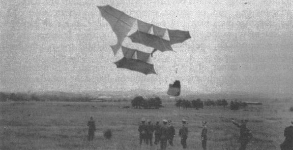
S F Cody (in sombrero) and men of the Royal Engineers launch a man-lifting kite.
S F Cody, meanwhile, following his period of involvement with the airship Nulli Secundus, had been away demonstrating his man-lifting kites to the Royal Navy, in the unfulfilled hope that they, too, would decide to purchase his system. He returned to Farnborough on 6 September 1908 to supervise completion of the machine which had been officially titled British Army Aeroplane No 1, but which showed the unmistakable hand of Cody in its design. The construction of this aeroplane had been proceeding sporadically since the previous November, in whatever time Cody had been able to spare from his numerous other duties. Now, perhaps spurred on by the purchase of a replacement 50hp Antoinette engine, and by a desire to beat Dunne, work on the aeroplane progressed rapidly, and by the 19 September it was sufficiently complete to be taken out for engine tests. Taxying trials, made two days later in a clearing near the Factory, revealed that the machine was nose heavy, but ended suddenly when a wingtip struck a post and was slightly damaged. This was soon repaired, and ground trials recommenced on the 24th, this time on Laffan's Plain where there was far more space, although the surface was poorer.
At one point, during further taxying trials on 30 September, Cody became aware of a brief pause in the vibration, and a subsequent examination of the machine's wheel tracks revealed that it had left the ground for a short distance. Although Cody dismissed this as 'only a jump', it was a genuine take-off and a positive step towards powered flight. Unfortunately further tests had to be postponed, as Cody was required to return to Portsmouth to conclude his kiting demonstrations for the Royal Navy. He returned to Farnborough in time to resume trials with the aeroplane on 14 October, some modifications intended to reduce drag and improve the pilots' view having been carried out during his absence. On this occasion two more short hops were made, each of about fifty yards, at a height of eight to ten feet.
On 16 October British Army Aeroplane No 1 was taken out again, and, while taxying at speed in order to climb a slope, Cody made yet another 'jump' of some seventy-five yards. Then, starting near to the south-eastern corner of Farnborough Common, close to the Swan Inn plateau, Cody set off towards the north-west and, after a ground run of some sixty yards, took off and flew at a height of approximately thirty feet until he was forced to turn to avoid a clump of trees. During this manoeuvre the tip of the port wing made contact with the ground and the flight ended in a crash, with considerable damage to the port wings. Fortunately, Cody was completely unhurt.
This flight, now officially recognised as the first sustained and controlled powered aeroplane flight in Great Britain, covered more than a quarter of a mile and lasted twenty-seven seconds (an airspeed of 35mph).
The next day's edition of The Times carried a full account of the flight under the headline 'The Army Aeroplane - Accident at Farnborough', and totally ignored the real significance of the event. Thus were Cody and the Balloon Factory deprived of the public recognition their joint achievement deserved.
Capper's report to Whitehall, written on the day of the flight, was equally unenthusiastic, concentrating upon the accident and the resultant damage rather than upon the significance of the flight itself. It ended with the words, 'I do not propose to abandon trials of this machine'. Perhaps Capper was a little disappointed that his protege, Lt Dunne, had not been the first to fly. Whatever his reasons for this unnecessarily negative attitude, Capper's report, coupled with his suggestion that more space was required for aeroplane experiments than existed at Farnborough, was the first step towards a conclusion which must have been the last thing he wanted.
British Army Aeroplane No 1 was repaired, a number of small modifications being incorporated at the same time, and flight trials resumed in January 1909, this time on the slightly less restricted ground of nearby Laffan's Plain. These trials included the attachment of numerous streamers to various points on the machine's surfaces to show the airflow.
Cody, an accomplished horseman, quickly developed his piloting skills, making numerous flights, often close to the ground, to explore the machine's control responses. Dunne, meanwhile, continued his experiments, still confident that his was the superior design and that he, too, would achieve true powered flight and eventually overtake his rival.
Then came a setback.
<...>
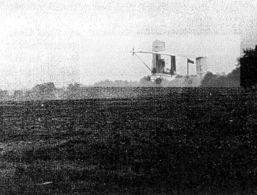
Samuel Cody makes the first powered, sustained and controlled flight in Great Britain, in British Army Aeroplane No I, on October 1908.

British Army Aeroplane No 1 emerges from the Airship Shed on 20 January 1909, after rebuilding. The streamers are to show the path of the airflow over the machine. Note the folding tailbooms, designed to facilitate storage.
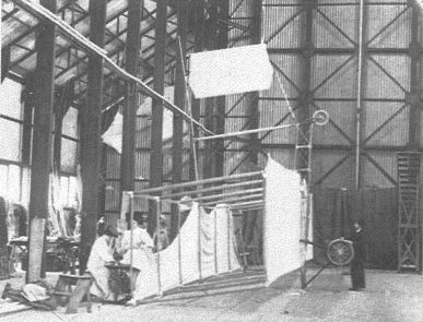
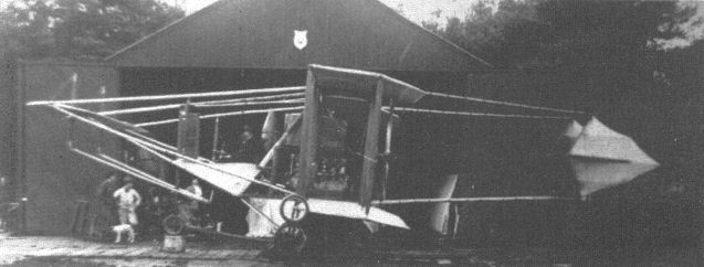
Sewing the fabric covering on to the mainplanes of British Army Aeroplane No 1 inside the original airship shed, with S F Cody keeping a watchful eye on the workmanship.
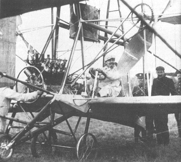
S F Cody at the controls of British Army Aeroplane No 1. The photograph was taken in September or early October 1908, and was almost certainly posed for the benefit of the press, as one wheel is still without a tyre. Note the crossed chain drive to the propeller on the port side.
S F Cody's victorious Military Trials machine outside his shed on Laffan's Plain. The greater modernity of contemporary Farnborough designs such as the B.E.2 is all too obvious.
F.E.1
With ?1,000 financial backing obtained from his grandfather in anticipation of a legacy, Geoffrey de Havilland gave up regular employment and built two successive aeroplanes of his own design. The first broke up on take-off, fortunately without injury to its creator, but the second was a success, and first flew on 10 September 1910, piloted by de Havilland. This was also his first flight.
A conventional Farman-type pusher biplane with a forward elevator, it was powered by a 45hp horizontally-opposed four-cylinder engine which had also been designed by de Havilland and was built for him by the Iris Motor Company of Willesden, north-west London.
De Havilland used the machine to teach himself to fly and then, having almost exhausted the ?1,000, he was appointed designer/test pilot at the Balloon Factory. At the same time he sold his aeroplane to the War Office for ?400, subject to its passing acceptance trials which principally consisted of demonstrating its ability to fly for one hour without adjustment or repair. This de Havilland achieved on 14 January 1911, although, owing to the freezing weather, he was allowed to land twice during the test to thaw out.
As Government property the aeroplane became known as the Farman Experimental or F.E.I. It was the first aeroplane to be classified in accordance with the Factory's system, and was the subject of continual development. First it was cleaned up aerodynamically, which included being fitted with new struts of improved streamline form. By the end of March its tailplane and rear elevator had been replaced by units of increased area, and by 11 April wing extensions had been fitted, enabling de Havilland to take up a number of passengers over the next few days. The extensions were removed early the following month because they were found to have an adverse effect on lateral control, but they were refitted by the end of the month, together with larger rudders, the Factory having realised that the existing rudders were not sufficiently powerful to overcome the drag of the ailerons when the extensions were fitted. By June 12 the tailplane incidence had been increased so that it would produce additional lift, thereby taking all load off the forward elevator. The subsequent tests obviously proved satisfactory, as the F.E.I was flown on 3 July with the front elevator removed. As usual the pilot was Geoffrey de Havilland, who reported that the fore-and-aft trim was not satisfactory. This problem was remedied overnight by re-rigging the wings to alter the position of the centre of pressure relative to the centre of gravity, and the machine was flown on numerous occasions throughout the month without further modifications. On 27 July de Havilland reached an altitude of 920ft, and the following day he gave short passenger flights to eighteen officers and men of the London Balloon Company Territorials, covering about eighty miles in the process.
Lt Theodore Ridge, the Factory's Assistant Superintendent, began to learn to fly on this machine in late July and early August, but on Tuesday 15 August he crashed while landing, damaging the engine, its mountings, the undercarriage and one lower wing.
There is no record of the aeroplane flying again, and officially it was 'reconstructed' as the F.E.2. However, as the latter was actually a totally new aeroplane and was already completed at the time of Ridge's crash, it is most probable that the F.E.I was broken up for spares.
Powerplant: 45hp four-cylinder Iris-built de Havilland engine
Dimensions:
span 33ft 0in
wing area 340sq ft;
length 40ft 0in;
Weight: 1,100lb (loaded).
Performance:
max speed 37mph at sea level;
endurance 1hr 20min.
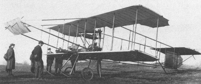
De Havilland No.2 was flown in 1910 and was purchased by the War Office and used for development work at Farnborough identified as FE 1.

Another project carried out early in 1907, in parallel with Cody's work, was the construction of a full-sized aeroplane in accordance with the ideas developed by Lt Dunne as a result of his extensive experiments. This craft, designated simply D l , was initially to be tested as a glider before fitting the propulsion system which had been designed for it by Capt Carden.
By arrangement with the Marquis of Tullibardine, eldest son of the Duke of Atholl, the flight tests took place, in secret, at a remote location near Blair Atholl, on his family estate in the Grampian highlands, during the summer of 1907. This desire for secrecy, especially when compared with the Factory's normal habit of operating from a public common, clearly illustrates the significance attached to Dunne's 'discovery'. Since Cody's work was an extension of his already well-known kite experiments, any attempt at secrecy would have been futile, and none was made. It was also entirely possible that Capper hoped to focus all attention on Cody, thereby allowing Dunne to work without distraction.
A number of successful glides were made, the craft being piloted by various officers from the Balloon School, as Dunne's frail health was not considered up to the task. A minor crash occurred while Capper was at the controls, during a brief visit to judge what progress was being made. The glider made contact with a wall, and flight trials were stopped pending repairs. During the course of this work the glider was converted into a powered aeroplane, the D1-B (the glider thus becoming, retrospectively, the D1-A). The propulsion system comprised twin propellers mounted on outriggers and driven, via belts or chains, by two 12hp Buchet engines, one of which had previously powered Cody's power kite. The two engines were coupled to a single shaft, and some initial difficulties were resolved when it was discovered that they had been installed so as to run in opposite directions.
It was intended that the powered aeroplane would be launched from a wheeled trolley running along a raised pathway of planks, laid to provide a reasonably level surface. Unfortunately the trolley ran off the planks during the first take-off attempt, and the machine was damaged to an extent which almost certainly would have required its return to Farnborough. It was felt that this would make it impossible to resume flight trials before the onset of winter, so the experiments were abandoned until the following year. The team's enthusiasm does not appear to have been diminished by this setback, and Capper seems to have had little trouble in convincing the War Office that they should be allowed to continue with the project.
<...>
By early September Lt Dunne had returned to Blair Atholl. He was accompanied by a team of helpers which included Lt Westlake, who had been a member of the previous year's party, and a young militia lieutenant, Lancelot Gibbs, who was to act as pilot. They took with them a new glider, the D3, trials of which were intended to provide information required to complete the powered machine, D4, which was under construction at Farnborough.
The glider proved quite promising at first, with a good number of short flights being made by Lt Gibbs on the very first day of the trials. However, later efforts were less successful, being hampered by the roughness of the terrain and the turbulence of the wind. As a consequence, the party appears to have spent a considerable amount of time roaming over a wide area, seeking a location which offered more favourable operating conditions, but without success.
At the end of the month Dunne left Gibbs in charge of the group testing the glider in the hills while he, together with a few assistants, returned to Blair Atholl itself to begin erecting the powered D4, which had by then arrived from Farnborough. This operation appears to have been extremely difficult, especially at a distance of some 500 miles from the Balloon Factory's workshops. Problems with warped timber and inadequate tools delayed completion of the aeroplane until the middle of November 1908, by which time Capt Carden had come up to supervise the installation of the engine and to take charge of the testing.
Flight trials started on 15 November, with Gibbs at the controls, but difficulties with the undercarriage caused an immediate halt. Ground runs, interspersed with engine malfunctions, occupied the remainder of the month, and the first take-off, covering a distance of about thirty feet, did not occur until 4 December. Two days later Carden had to return to Farnborough, and the tests continued in his absence, more short hops being achieved despite the lack of his skills with the engine. On 10 December Gibbs managed a flight of 120 feet, and on this note of minor triumph the trials were ended.
In common with many of its contemporaries, the Dunne D4 appears to have been rather underpowered, especially in view of its very heavy undercarriage, and the final acceptance of this shortcoming may well have been the reason for the seemingly premature ending of the tests. Alternatively, it is equally possible that the Dunne party was defeated by the weather, for winters in the Scottish highlands can be very severe. In any event, the test flights of the D3 and D4 seemed to uphold Dunne's theories regarding stability, even if his designs of aeroplanes and their control systems needed further development.
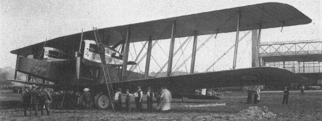
The colossal Handley Page V/1500 bomber. Royal Aircraft Factory research established that the rear propellers in such tandem engine arrangements could never achieve more than ninety per cent of their usual efficiency owing to interference from the slipstream of the tractor propellers.
B.E.1
The third machine in the Factory's initial research series, each of which was of a distinct and separate type, was a tractor biplane. It was named the Bleriot Experimental Number 1, or B.E.1. As with other contemporary Farnborough designs, it was ostensibly a reconstruction of another aeroplane, in this case a Voisin which had originally been presented to the War Office by the Duke of Westminster and which, following a crash, had been delivered to the Factory for repair in June 1911. The War Office granted permission for the alterations and additions which O'Gorman had suggested on 12 August 1911, but it is probable that design work, most of which was carried out by Geoffrey de Havilland, was already well advanced by that date.
Only the Voisin's engine, a water-cooled Wolseley V-8 developing a nominal 60hp, its radiator, and possibly a few metal fittings were actually used in the construction of the new machine, which was a two-bay biplane. Its upper wing was of slightly greater span than the lower, the wings originally being rigged with neither stagger nor dihedral. The large, low-aspect-ratio tailplane was of true aerofoil section, contributing to the overall lift, but was set at a smaller angle of incidence than the mainplanes to provide longitudinal stability. It was fastened directly to the upper longerons. The ear-shaped rudder hung from an unbraced sternpost, and there was no fin. Lateral control was by wing warping, the control column being of generous height to give the pilot good leverage and thereby reduce control forces to a level designed to eliminate fatigue.
The fuselage had decking behind the rear seat only, none being provided behind the engine or between the tandem cockpits. The passenger was placed in the forward seat, very close to the centre of gravity, so that no trim changes would occur when the machine was flown with two aboard. The radiator was mounted on the forward centre-section struts, where it benefited from the full force of the slipstream to achieve the necessary cooling with the minimum possible weight of water. The comparative quietness of the water-cooled engine, which was enhanced by the inclusion of silencers in its long exhaust pipes, led to the B.E.1 being dubbed the 'Silent Army Aeroplane'. The undercarriage incorporated long ash skids, intended to prevent the propeller tips touching the ground when the tail was raised, and the tailskid was fully swivelling, allowing a remarkably small turning circle on the ground.
Although photographs taken inside the workshop (known today as the Q27 building) in October 1911 show the aeroplane apparently complete, it did not make its first flight until 3.30pm on 4 December, when de Havilland took it up for a brief circuit, for which he was rewarded with two shillings and sixpence (12 1/2p) in flying pay. He reported that he was satisfied with the aeroplane, but less than happy with throttle control provided by the Wolseley's carburettor, and recommended the substitution of a Claudel unit. This may have been a more complex modification than de Havilland had imagined, because the machine did not fly again until 27 December, when, with the new carburettor installed, he made six short flights, several of them with a passenger. The maximum speed was found to be 55mph, although the engine was not achieving the 1,200rpm stated to be its maximum output (it never did so, despite continual attention).
De Havilland considered that the elevator operating mechanism was too coarsely geared for ease of control, tending to over-correct, and asked for it to be geared down, but otherwise he thought the aeroplane's stability to be good. He also expressed the opinion that too much weight was carried by the tailskid, lengthening the take-off run and, as a consequence, the wheels were repositioned twelve inches to the rear before the aircraft made its next flights, on the first day of the new year, when Mervyn O'Gorman occupied the front seat for two short flights.
By 7 January 1912 the top wing had been re-rigged with three inches of backstagger, presumably to move the centre of pressure slightly to the rear, and a scoop had been fitted in the front of the carburettor's air intake, a measure which increased engine speed by approximately 100rpm to about 1,100rpm.
On 10 January one degree of dihedral was given to each wing panel (an included angle of 178°), and two days later the aeroplane was tested with a Zenith carburettor, which was found to be much less flexible than its predecessor. De Havilland ran out of petrol during the tests, but accomplished the forced landing without mishap. Next day the Claudel was refitted and the B.E.1 was timed at 59mph over a measured three-quartermile course, with both seats occupied.
On 20 January, in a final attempt to improve engine performance, the propeller tips were cut down, producing an engine speed of 1,150rpm. This was the best ever achieved, although it was still just short of the maker's stated figure.
Throughout the remainder of January de Havilland flew the B.E.1 on numerous occasions, carrying many passengers, and he appears to have been completely satisfied with it. He did not suggest any further changes, and flew it in winds of up to 25mph before turning his attention to its twin sister, the B.E.2, which was completed by 1 February 1912.
On 11 March the B.E.1 was formally handed over to Capt C J Burke of the Air Battalion, Royal Engineers. Burke flew it for the first time three days later - the day on which the document which has come to be regarded as the first Certificate of Airworthiness was issued, certifying that the B.E.1 had been fully tested by the Factory.
The machine was given the serial B7, and the following month it became the property of No 2 (Aeroplane) Squadron of the newly formed Royal Flying Corps. In August its serial was changed to 201, an identity it retained throughout the remainder of its long career.
A heavy landing on 31 March 1912 resulted in the B.E.1 being returned to the Factory to be fitted with a new undercarriage. It was also fitted with a compass and an aneroid altimeter. On Thursday 11 April it suffered engine failure while being test flown by Mr Perry, and a wingtip was damaged in the ensuing forced landing. This was soon repaired, and the aeroplane was test flown by de Havilland at 6.00pm the following day. Following some alterations to the elevator cables, it was again test flown on 15 April before being returned to the RFC.
A further engine failure, on 28 May, led to its again being returned to the Factory. As its Wolseley engine was considered to be beyond economic repair, it was replaced by a Renault similar to that in the B.E.2. This engine, being air-cooled, allowed the removal of the radiator from the centre-section struts, with consequent improvements in performance and in the crew's forward view.
Following a test flight by de Havilland on 22 June, 201 was handed back to the Flying Corps, seeing service with No 4 and, later, No 5 Squadron. By the end of 1913 it had amassed a total of 172 flying hours. It had made several visits to the Factory for minor repairs, and had acquired fuselage decking ahead of, and between, the cockpits, making it virtually identical to contemporary B.E.2s. This similarity was further enhanced when its tailplane was replaced by one of slightly reduced area which had become the standard B.E.2 fitting at that time.
At the outbreak of war the B.E.1 was not sent to France, as were most of the RFC's effective aircraft, but remained with a training unit in England. Following a crash in January 1915 it was returned to Farnborough once more for repair, and was reported as still being there the following May. It is recorded as having been at the Central Flying School as late as July 1916, although by that date it had again been rebuilt and had acquired a B.E.2b-type fuselage.
The eventual fate of the B.E.1 is unknown. It merely fades from official records into an obscurity wholly undeserved by the 'revered grandfather of a whole brood of Factory aeroplanes'.
Powerplant: 60hp Wolseley V-8 (later 60hp Renault)
Dimensions:
span 38ft 7 1/2in (upper); 34ft 11 1/2in (lower);
chord 5ft 6in;
gap 6ft 0in
wing area: 374 sq ft
length 29ft 6 1/2in
height 10ft 2in
Performance: (Wolseley)
max speed 59mph (at sea level)
min speed 42mph
climb 155ft/min (to 600ft).
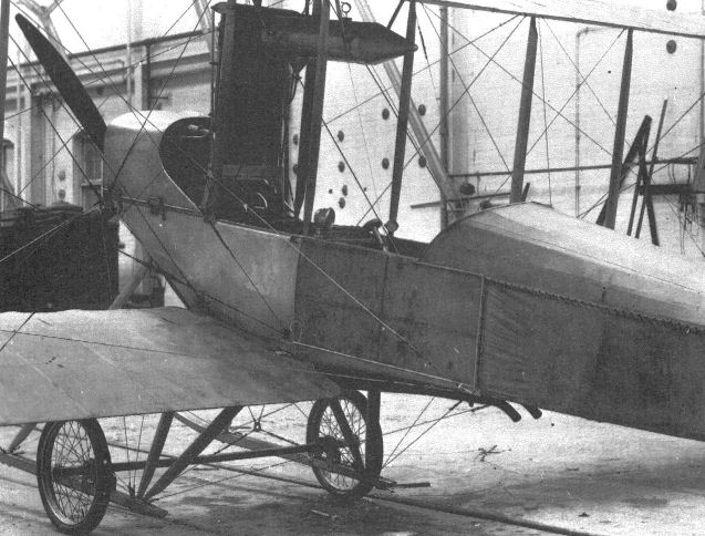
The B.E.I, apparently complete, inside the Factory workshops on 1 October 1911. Its first flight was not made until 4 December.
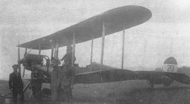
The B.E.1 after the installation of a Renault engine in place of its original Wolseley.
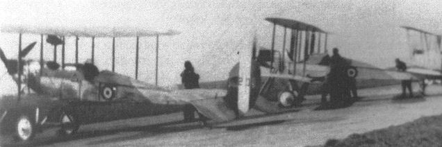
The aeroplane nearest to the camera is almost certainly 201, the B.E.I , seen here late in its life, by which time it had acquired a B.E.2b-type fuselage.

S.E.1
The first aeroplane built at Farnborough after the hiatus which followed the dismissal of Cody and Dunne came about as a result of a subterfuge, for the War Office denied the Factory the right to design and build aeroplanes. In the late summer of 1910 a Bleriot XII of uncertain history was being operated on Salisbury Plain by a group of Army officers led by Lt Cammell (to whom ownership of the machine has sometimes been attributed), and towards the end of the year suffered considerable damage in a crash, eventually finding its way to Farnborough for repair. One of Bleriot's less-successful designs, the machine was reputed to be very tricky to fly, and although officially known as B1 it was popularly known as the Man-Killer. Mervyn O'Gorman therefore sought War Office permission to redesign the Bleriot and to include controls of the Farman type, so that it might be flown by anyone familiar with the Farman. Such permission was granted, and the Farnborough design team, led by de Havilland and F M Green, set to work on the 'S' class machine which previous study had led O'Gorman to believe would prove most successful.
The result of their endeavours, the S.E.1, bore little resemblance to the tractor monoplane from which it was allegedly 'reconstructed', being a canard pusher biplane and, although the shape of its wings was at least reminiscent of those of the Bleriot, the only actual link between the two machines was the 60hp ENV 'F' engine.
The new machine made its first outing at dawn on 7 June 1911, when de Havilland made some taxying trials and broke two wheel spokes in the process. Therefore the wheels were moved forward to improve the balance. At the same time the twin rudder outriggers were shortened by three feet, bringing the rudders closer to the fuselage, because they were found to be vibrating and causing the mainplanes to flex. At 5.30am the following morning de Havilland made the first flight, even though the undercarriage problem was not yet entirely resolved. The machine flew about a mile, but its propeller shaft was found to have twisted. Following another outing on the 10th, de Havilland decided to restore the wheels to their original positions and to fit a skid under the forward elevators.
The fore and aft stability was reported as good, but de Havilland thought the elevators to be too powerful. After the S.E.1's next flight, made on 28 June, their area was reduced by cutting four inches from their trailing edges. However, on 3 July de Havilland recorded that they were still too powerful, and arranged construction of a new canard surface. He also recorded that he was experiencing difficulty in turning, and had the body stripped of fabric to reduce forward keel area, but this made little improvement and the fabric was therefore reinstated. The earlier shortening of the rudder outriggers had clearly been a contributory factor to this problem, and by the 14th an additional rudder had been installed on the nose of the machine, operating in conjunction with those at the rear. At the same time the new elevators were fitted and the dihedral reduced. While turning was now improved, the S.E.1's designer/test pilot was still not satisfied, recording his opinion that the rear rudders appeared to be too sensitive. In addition, the radiators, which were on the fuselage sides, were found to boil over whenever the machine was at rest.
In the next two weeks the front skids were moved back, the wheels were again repositioned, and stronger rubber cords were fitted to the undercarriage. Several half-turns were made on 1 August, and on the 16th de Havilland successfully flew it to Laffan's Plain and back twice. The day's flying was brought to a premature end by a choked carburettor.
Two days later Lt Theodore Ridge, the Factory's Assistant Superintendent, took the S.E.1 up for the first time, despite de Havilland's advice that he should not do so because it was still a tricky machine. Ridge, who is reputed to have been something of a martinet, ignored him, sideslipped while attempting a sharp turn and crashed, receiving injuries from which he died later the same day. Thus the Factory's first design had resulted in tragedy, and the Man-Killer had finally lived up to its name.
The type was presumably acknowledged to have been a failure, and the canard concept was not continued with, subsequent 'S.E.' types being of the 'scouting' rather than 'Santos' class.
Powerplant: 60hp ENV type 'F' water-cooled V-8
Dimensions:
span 38ft 0in;
dihedral 2 1/2;
wing area 382 sq ft;
length 29ft 0in;
height 11ft 6in.
Weights:
1,200lb (empty);
1,640lb (loaded).
B.E.2
The B.E.2 was virtually a copy of the B.E.1, except that it was powered, from the start, by a 60hp Renault V-8 air-cooled engine. Its designation was not intended to identify it as a separate design, but merely to denote that it was the second machine built in the general-purpose tractor, or Bleriot Experimental, class. Construction of the B.E.2 was well advanced before the B.E.1 flew, the 'reconstruction' subterfuge again being used to explain its origins. Both the ill-fated S.E.1 and a damaged Breguet were named, on different occasions, as the parent aeroplane, although the latter seems more likely as it did, at least, have a Renault engine.
Among the few differences between the two B.E.s was the routeing of the newer machine's exhaust pipes down through the fuselage rather than outside it, achieving a minor reduction in drag, albeit at the expense of a consequent increase in fire risk. The B.E.2's undercarriage incorporated radius rods to locate the axle positively, particularly against longitudinal movement, and the wheel spokes were fabric covered, an innovation which not only reduced their resistance but was considered by de Havilland to 'damp out lateral oscillations'. The undercarriage skids were shorter than those of the B.E.1, lacking the long projection ahead of the propeller.
The B.E.2 made its maiden flight on 1 February 1912, with de Havilland at the controls. He appears to have judged it entirely satisfactory as built, for no modifications are recorded to have been required. This is not altogether surprising when it is remembered that all the necessary development work had effectively been carried out during the testing of the B.E.1.
De Havilland lost little time in taking up passengers, among whom were F M Green and S Hiscocks. He found its performance to be superior to that of the Wolseley-powered B.E.1 in speed and in climb.
On 21 February, after it had been fitted with a Claudel carburettor, it was flown by de Havilland to a height of 2,600ft. Two days later it made a return flight to Brooklands, covering about fifty miles.
Towards the end of March a wireless set which had been constructed at the Factory was installed in the B.E.2. Experimental transmissions were started on the 26th, but were curtailed when the equipment broke down. The result of further tests on 28 March and 1 and 2 April were described as good, and for the next week or so numerous passengers were taken up so that they could sample the novelty of airborne wireless for themselves. By 1 May a new amphibian undercarriage having both floats and wheels had been fitted, but it was found to be unsuitable for 'rolling' (taxying) and was removed. Two days later power had been increased by the fitting of a 70hp Renault, and the B.E.2's speed was measured at 68mph.
On 11 May the machine was flown to Fleet Pond, where the floats were refitted, but the trials were inconclusive because their draught proved too great for the pond and the tail float was found to be set at too small an angle. Modifications were completed by the evening, and a short flight from the water was made, but the floats were damaged on landing. It seems probable that they were not repaired, as no record has been found of any further trials with this undercarriage.
On Friday 17 May de Havilland flew the B.E.2 before the King and Queen in company with some other machines, as part of His Majesty's official review of the armed forces, and on the 31st he climbed it to 6,050ft in fifteen minutes.
By early the following month the B.E.2 had flown more than 500 miles since being fitted with the larger engine, and it continued to be used almost every day for tests of one kind or another.
During the second week of August de Havilland flew the aeroplane to Larkhill, on Salisbury Plain, where the Military Aeroplane Trials were taking place. Because Mervyn O'Gorman, in his capacity as Factory Superintendent, was one of the competition judges, the B.E.2 was clearly ineligible for the competition, but it still undertook many of the tests hors concours and achieved overall results at least equal to those of the eventual winner, the massive Cody 'Cathedral' (itself a development of the Balloon Factory's British Army Aeroplane No 1, built at Farnborough four years previously). Its use as a general 'hack', taking officials and pressmen to and fro throughout the trials, did a great deal to convince observers that aviation had reached a level of practicality which had been previously unappreciated.
On 12 August de Havilland, accompanied by Maj F H Sykes, took off at about 5.00am and, in the still, cool air of early morning, decided to test the B.E.2's climbing powers to the full. They eventually reached an altitude of 10,560ft, capturing the British record not only for flights with a passenger, but for solo flights as well.
Although the purpose of the Military Trials was to decide with which machine the RFC should be equipped, the B.E.2 was clearly more suitable than the actual winner, and the War Office decided to adopt the Factory's creation. Although a few further examples were built at Farnborough, much to the chagrin of C G Grey, orders were placed with private constructors such as the British and Colonial Aeroplane Company and Vickers. All such production machines appear to have been designated B.E.2a.
Powerplant: 60hp Renault V-8; 70hp Renault V-8
Dimensions:
span 38ft 7 1/8in (upper); 34ft 11 5/8in (lower);
chord 5ft 6in;
gap 6ft 0in;
wing area 374 sq ft;
length 28ft 4in;
height 10ft 2in;
propeller diameter 8ft 10in;
wheel track 6ft 2in;
tailplane span 11ft 0in;
tailplane area 52 sq ft;
elevator area 25 sq ft;
rudder area 12 sq ft.
Weight: 1,700lb (loaded).
Performance: (70hp)
max speed 70mph at sea level;
min speed 40mph;
climb 244ft/min to 1,000ft (60hp);
305ft/min to 1,000ft (70hp);
glide angle 1 in 6 1/4.
B.E.2a
It now seems certain that the designation B.E.2a was applied to all production B.E.2s, or to those built by contractors, rather than to any specific variant, for the earliest examples were almost identical to the prototype, certain modifications being made later without any change in designation. The 'a' suffix was not consistently applied in service use, but this did not cause any confusion at the time because virtually all the B.E.2s were 2as. Drawings bearing the title B.E.2a are dated as early as February 1912, the type is described in R & M 66, dated 12 June 1912, and the first production order was placed in August 1912, apparently before the final result of the Military Trials was known.
These early machines had unequal-span wings of NPL3a section and large lifting tailplanes exactly similar to that of the original B.E.2, the only discernible difference being the addition of a fuselage decking between the seats. Later examples, which formed the majority, had equal-span wings of a new aerofoil section which allowed a deeper rear spar and required an angle of incidence of only 3 1/2, compared with the 4 1/2 of the earlier wing, resulting in a reduction in drag without any loss of lift. Their tailplane area was reduced, the spar remaining the same to allow the original elevators to be used, and the chord being reduced to give a surface which was roughly semicircular in planform. The upper fuselage decking remained at its original length, resulting in a small flat area immediately in front of the tailplane. The new tailplane was designated T.P.2, the original surface retrospectively becoming T.P.1
Total production of the B.E.2a cannot now be quantified exactly, but appears to have been just short of 100 machines. Nevertheless, it was still the most numerous single type on the strength of the diminutive prewar RFC. Several B.E.2as served with the Royal Naval Air Service and, in addition, the type saw service in India and with the Australian Air Service. It also provided the Royal Aircraft Factory with a reliable test vehicle of reasonable performance and predictable handling with which to conduct its wide-ranging aeronautical research.
As part of E T Busk's investigations into aeroplane stability one B.E.2a, No 601, was fitted with two small fins on its upper wing, immediately over the centre-section struts. A high-aspect-ratio tailplane of rectangular planform was also fitted, braced to an inverted vee-shaped kingpost on the fuselage centreline. Known as T.P.3, it had a similar area to its semicircular predecessor, T.P.2, but was of a symmetrical aerofoil section and provided no lift in the normal flying position.
In another experiment, possibly connected with that above, No 206 (which had started its life as the B.E.6) was fitted with interplane struts which had greatly increased chord at their upper end, and were known as 'fin struts'. This aircraft was also fitted with an experimental oleo undercarriage, but appears to have reverted to its original unit.
The type also continued the wireless development tests started with the original B.E.2, aircraft 240 and 336 being among the machines chosen to carry the primitive equipment aloft.
A number of spectacular flights were made by B.E.2as piloted by regular service personnel. Number 218, a Bristol-built example, was fitted with an additional petrol tank in its faired-over front cockpit, increasing its total capacity to about fifty-four gallons. On 22 November 1913 it was flown by Capt Longcroft of No 2 Squadron from their base at Montrose directly to Portsmouth, and then, without stopping, back to Farnborough, covering a total of 560 miles in 7hr 20min. This prodigious achievement won Longcroft the 1913 Britannia Trophy for the longest flight of that year. On 13 December 1913 Capt J M Salmond, flying a B.E.2a from Upavon on Salisbury Plain, reached an altitude of 13,140ft, thereby setting a new solo British record.
A number of B.E.2as went to France with the RFC at the outbreak of the war. One of them, a No 4 Squadron machine piloted by Lt G W Mapplebeck, shared with Joubert de la Ferte's Bleriot the distinction of carrying out Britain's first active-service reconnaissance.
Despite this, and many other invaluable contributions to the conduct of the war, the B.E.2as were rapidly replaced by more recent designs and returned to England, where they gave equally useful service with training establishments.
Powerplant: 70hp Renault V-8
Dimensions:
span 36ft 11 1/8in;
chord 5ft 6in;
gap 6ft 0in;
wing area 376sqft;
stagger minus 2in;
dihedral 2°;
length; 28ft 4in;
height 10ft 2in;
tailplane area 34 sqft;
Weights: 1,100lb (empty);
1,600lb (loaded).
Performance:
max speed 74mph at sea level;
endurance 3hrs;
climb 9min to 3,000ft;
30min to 6,000ft.
B.E.2b
The B.E.2b was developed early in 1914 to afford its crew better protection from the elements, and had a modified fuselage top-decking with shallower cockpit cutouts. The rudder and elevator control runs were also revised, but in all other respects the B.E.2b was similar to the earlier model. It was built by a number of contractors. After the outbreak of war comparatively large orders were placed, several with companies not then experienced in large-scale production and, although some machines were eventually completed as B.E.2cs, the last B.E.2bs were finally delivered to the RFC in February 1917. By that time they had long been superseded by later variants which were themselves already approaching obsolescence.
Although it was usually unarmed, except perhaps for a revolver or service rifle carried by the observer, the B.E.2b was occasionally equipped to carry a few small bombs. The first Victoria Cross to be awarded to an airman was won by the pilot of B.E.2b 687, Lt W B Rhodes Moorhouse of No 2 Squadron, who, on 26 April 1915, carried out a bombing attack on the railway station at Courtrai. Although he received numerous wounds from retaliatory ground fire, he managed to bring his machine back. His injuries later proved fatal.
The B.E.2b remained in use with training squadrons, albeit in ever-diminishing numbers, right up to the Armistice. Several machines were fitted with components such as fins, sump cowlings and even undercarriages from later variants, either as 'improvements' or because the correct spares were no longer available.
Dimensions as B.E.2a.
B.E.5
The fifth of the Royal Aircraft Factory's series of two-seat general-purpose tractor biplanes returned to the B.E. 1/2 layout, but used a 60hp ENV 'F' engine recovered from the damaged Howard Wright biplane of which it was ostensibly a 'reconstruction'. Being a water-cooled engine, the ENV obviously needed a radiator, and this was mounted on the forward centre-section struts in a manner similar to that on the B.E.1.
The B.E.5's first flight was made on 27 June 1912, only three days after that of the B.E.4, and it was handed over to the RFC on 18 July. It served with No 2 (Aeroplane) Squadron for a few weeks before returning to the Factory to be re-engined with a V-8 Renault. It thus became, in effect, a standard B.E.2, and was thereafter regarded as such in service. After being returned to the RFC it served briefly with No 3 Squadron before returning to No 2, and was allotted the serial 205.
On 27 May 1913 the starboard upper wing collapsed while the aircraft was making a gliding turn at a height of about 2,500ft, and the pilot, Lt Desmond Arthur, was thrown out and killed. An investigation conducted by the Royal Aero Club's Accident Investigation Committee concluded that the cause of the disaster was a badly spliced repair near the tip of the rear spar, although there was no record of the repair being made either by the Royal Aircraft Factory or while the machine was in service. In addition to prompting the suggestion that all such repairs should be properly inspected and the name of those carrying out the work recorded, the incident triggered another attack on the Royal Aircraft Factory by C G Grey in the pages of The Aeroplane. The machine was officially struck off charge on 25 September 1915.
Data as B . E . 2.
B.E.6
Officially a 'reconstruction' of the ill-fated S.E.1, and powered by its 60hp ENV engine, the B.E.6 was identical to the B.E.5 and was built at the same time, its designation being intended not to distinguish it as a separate type, but merely to identify it as the sixth in the B.E. series of tractor machines.
The ENV engine may have sustained more damage in the crash of the S.E.1 than had been realised, for the B.E.6 did not make its first flight until 5 September 1912, some months after its sister. While it is not recorded how it was powered on that occasion, it was fitted with a 60hp Renault when it was handed over to the RFC a few days later, and it is probable that the ENV was never actually used.
The B.E.6 was given the serial 206, and seems never to have been regarded as anything other than a standard B.E.2, which, with its Renault engine, is effectively what it was. By September 1914 it had flown a total of 111 hours and, following a period with No 2 Squadron, it had been transferred first to No 4 Squadron and then to No 6, with whom it saw active service in France before being relegated to training duties back in England.
Some time during 1914 it underwent an engine change, the replacement being the 70hp Renault that was, at that time, the standard power unit for the B.E.2. Its further career and eventual fate have not been discovered.
Data as B.E.2.
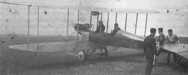
The original B.E.2 as it first appeared. Note how the exhaust pipes pass within the fuselage, giving a small reduction in head resistance.
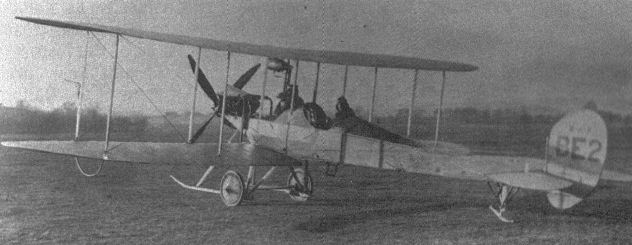
The original B.E.2 modified to include decking between the cockpits. The exhaust pipes are now fully external, whereas they had initially passed through the fuselage. The pilot is Geoffrey de Havilland. Note that the undercarriage skids are shorter than those of the B.E.I.
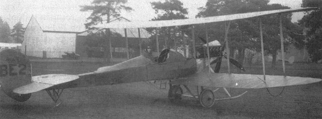
Geoffrey de Havilland in a B.E.2 outside the RFC hangars which later became famous as the 'Black Sheds'.
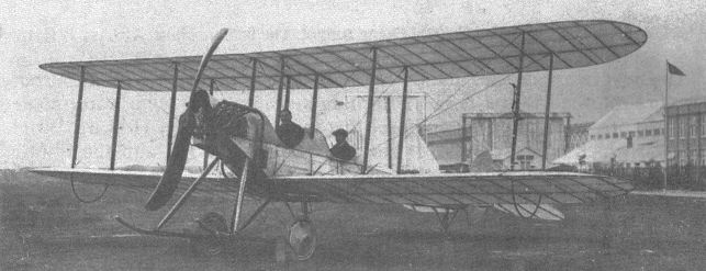
A B.E.2a with an experimental two-bladed propeller. Its wing structure is clearly visible through the translucent clear-doped fabric. The office block, Balloon Shed and new airship sheds are in the background.
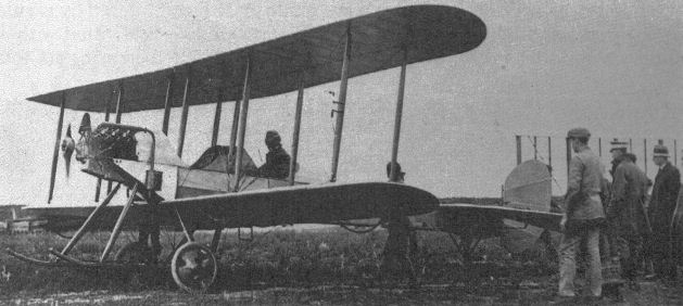
A B.E.2a at Point Cook, Australia, in 1914. The pilot is Lt Williams (later Air Vice Marshal Sir Richard Williams).

A B.E.2a fitted with experimental interplane struts designed to provide additional fin area.
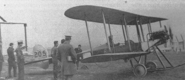
B.E.5 number 205 at Montrose, after the engine change which brought it to B.E.2 configuration.
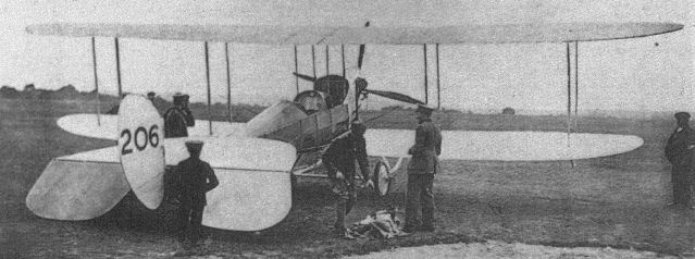
B.E.6 number 206 soon came to be regarded as a B.E.2 which, in effect, is what it always was.

An assortment of Royal Aircraft Factory designs in front of the RFC sheds on Farnborough Common. Aircraft 206 was built as B.E.6, 239 and 329 are B.E.2as, and behind them is the R.E.I.

A Farnborough-built B.E.2a, showing the decking behind the engine introduced on this model.
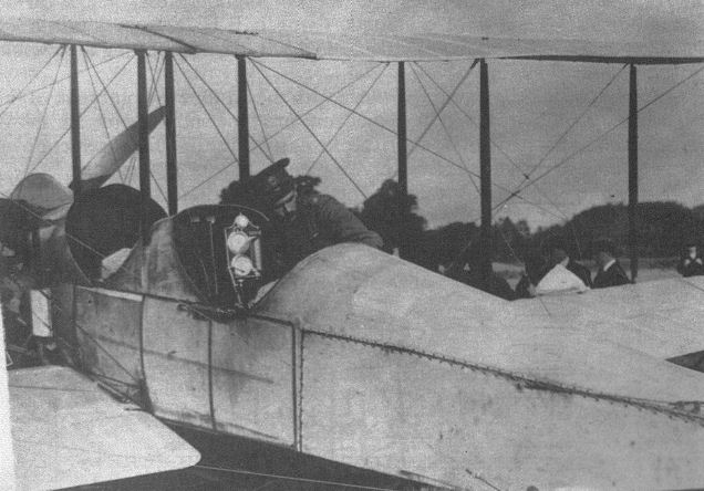
B.E.2a 225 photographed after crossing from Ireland on 26 September 1913. The simple instrument panel, which contained a revolution counter, an airspeed indicator, an altimeter, and a watch, was combined into a single unit manufactured by Elliot Brothers.
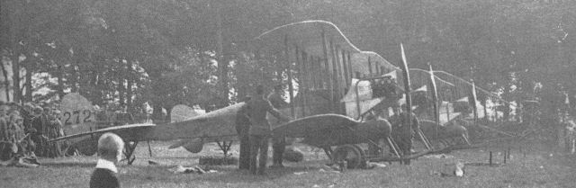
B.E.2as of 2 Squadron RFC fitted with flotation bags in case of a need to ditch during their flight across the Irish Sea.
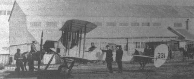
B.E.2a 331 at the edge of Farnborough Common, with the Balloon Shed in the background, 10 February 1914. This machine crashed en route to Netheravon on 15 May 1914.
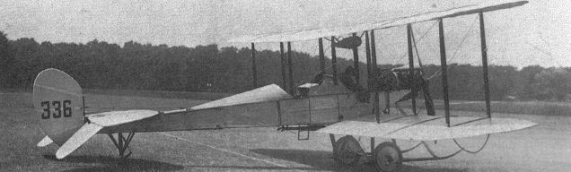
An immaculate Vickers-built B.E.2a. The purpose of the box-like structure in the pilot's cockpit is not known.
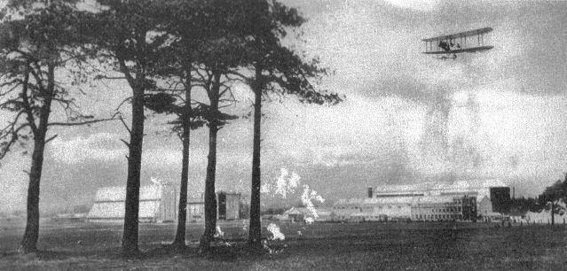
This view across Farnborough Common towards the Factory site was taken during 1913-14. The B.E.2 flying overhead was added in the photographer's studio.

A B.E.2a fitted with an experimental oleo undercarriage. It also has the 'fin struts' whose increased area can be seen at their upper ends.
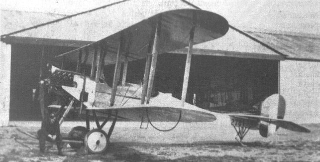
This B.E.2b, 2781, was one of a batch built by Jonques, some of which may have been completed as B.E.2cs.

The occasion which prompted this impressive line-up of Factory designs is unfortunately not recorded, nor is the purpose of the marquee behind them, but the types present suggest a date of mid-1916. Left to right, the aircraft are: B.E.2c, B.E.2c, B.E.2b. B.E.12, Hispano-Suiza-powered B.E.2c, F.E.8, S.E.4a, F.E.2c, F.E.2b, R.E.8, R.E.8, and R.E.7.
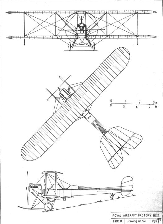
BE2
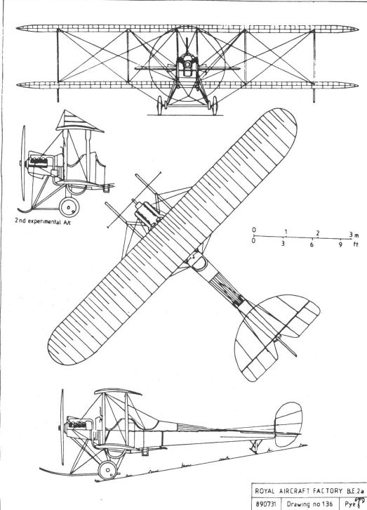
BE2a
B.E.3
The third in the Factory's series of tractor designs, the B.E.3 was originally conceived as being essentially similar to the B.E. 1/2 but powered by a rotary engine, to enable its performance to be compared with that of the stationary-engined aircraft. However, the final design, for which John Kenworthy was responsible, differed quite considerably in detail. Its two-bay wings inherited their construction and planform from the previous design, and retained warping for lateral control, but were heavily staggered. The tailplane was similar to that of earlier B.E.s but the rudder, while very similar in shape, was mounted with its shorter axis vertical and with a small area forward of its steel-tube pivot to provide an aerodynamic balance. This enabled an undivided elevator to be fitted. The fuselage was broader than in previous models, the increase being necessitated by the diameter of the rotary engine, and was mounted clear of the lower wing in the mid-gap position. As in the predecessors, the undercarriage incorporated lengthy skids, but was simplified by the elimination of a strut on each side.
A Paulhan Biplane, serial F2, of unusual and not entirely successful design, had been sent to the Army Aircraft Factory by the Air Battalion in February 1912, presumably for repair. Yet again O'Gorman sought permission to reconstruct the machine along more conventional lines. Such permission was readily granted but, as before, only its engine, a 50hp Gnome, was actually used in the new aeroplane. An alternative and unconventional control system, in which the warping mechanism for lateral control was operated by the pilot's feet, was fitted for a brief period but removed again before its effectiveness could be fully evaluated because, for some reason which is not now apparent, the machine was urgently needed by the RFC.
The B.E.3 made its first flight on Friday 3 May 1912, with Geoffrey de Havilland, at that time the Factory's only test pilot, at the controls. Later the same day, as was then common practice, he took up several passengers, including Factory personnel and members of the recently formed Royal Flying Corps.
On the following Monday de Havilland took the B.E.3 up again, the rudder having been adjusted to increase the available movement and the wings re-rigged to increase the amount of wash-out. Although he reported that it was now 'flying better', he broke two undercarriage struts and the propeller in a heavy landing. By 10th May the damage had been repaired, the skids being replaced and the front undercarriage struts moved slightly to the rear in an effort to strengthen the assembly and prevent a recurrence of the damage.
These modifications were clearly considered satisfactory, as on the following Monday, 13 May 1912, the B.E.3 was handed over to the RFC. That only ten days had elapsed since its first flight might be taken as confirmation that it was wanted in a hurry. It was given the serial 203, together with the nickname Goldfish, and served with No 3 Squadron until early in 1914, occasionally returning to the Factory for minor repairs.
The B.E.3 took part in a wide range of signalling experiments, not only with wireless, but with electric lamps and flags. At some stage it was fitted with an experimental four-bladed propeller with alternate acute and obtuse angles between the blades.
Following the crash of its sister aircraft, the B.E.4, in March 1914, which was believed to have been caused by the rudder post breaking, the B.E.3 was fitted with new vertical tail surfaces. These comprised a B.E.l/2-type rudder mounted above the fuselage, so as to be clear of the undivided elevator, and hinged behind a new triangular fin, the whole design being clearly inspired by the tail of the H.R.E.2.
The B.E.3's flying career ended soon after it received its new fin and rudder, and it became a ground instructional airframe. It was last recorded at Farnborough at the end of 1914 but, like many other early aeroplanes, its eventual fate is not known.
Powerplant: 50 hp Gnome rotary
Dimensions:
Span 39ft 6in;
Chord 5ft 6in;
Length 27ft 3in.
B.E.4
Structurally identical to the B.E.3, the fourth aeroplane in the Factory's tractor series was alleged to be a 'reconstruction' of Bristol Boxkite number F9, which at least provided the new machine with its 50hp Gnome rotary. The B.E.4 was test-flown by Geoffrey de Havilland on 24 June 1912 and, following the usual brief period of trials and adjustments, was handed over to the Royal Flying Corps on 8 August. After a short period with the designation 'B.E.4' on its rudder, it was given the serial 204.
An engine failure brought about a forced landing which caused some damage, and 204 was returned to the Factory at the beginning of September for repairs. While there, its previously hardworked engine was replaced by a new Gnome, this time of 70hp.
Two other examples, serials 416 and 417, are known to have been built by private contractor, at least one being fitted with dual controls for use at the Central Flying School (CFS). It is possible that a further example was also built and was given the serial 303.
On 11 March 1914 204 crashed on Salisbury Plain with the tragic death of its crew. The subsequent enquiry offered the opinion that the rudder shaft had become crystallized and had snapped, one of the first suggestions of metal fatigue. While this could not be conclusively proved, it raised sufficient doubt regarding the safety of the B.E.3/4 rudder for a new unit to be developed and fitted to the remaining machines with commendable rapidity. The new unit comprised a B.E.2-type rudder mounted above the undivided elevator and behind a triangular fin, its obvious origins in the H.R.E.2 clearly accounting for the speed with which it was designed. Thus equipped, 416 and 417 continued to serve at the CFS, and are believed to have ended their respective careers in the almost inevitable training crashes.
Powerplant:
50hp Gnome rotary
70hp Gnome rotary
Dimensions:
span 39ft 6in;
chord 5ft 6in;
length 27ft 3in.
B.E.7
Designed by John Kenworthy about July 1912, the B.E.7 was, essentially, a high-powered version of the B.E.3/4. It used the same wings and tail surfaces as the earlier types, but had its forward fuselage shortened by one bay to compensate for the increased weight of the 140hp two-row Gnome rotary selected as its powerplant. The undercarriage was also similar to that of the B.E.3/4, but with the skids suitably shortened to match the new fuselage.
Construction was completed early in 1913, the first flight taking place on 28 February with Geoffrey de Havilland at the controls. It was apparently judged to be faultless as built, for it was handed over to the Royal Flying Corps later the same day.
The B.E.7 was given the serial 438, although there is some evidence to suggest that it bore the number 408 for a brief initial period. This may have been due to a simple error, as that identity had been given to a Bristol Boxkite. Alternatively, it is possible that it was done deliberately to create the impression that the B.E.7 was a reconstruction of the Bristol, which had been grounded late the previous year.
On 2 May the B.E.7 achieved an altitude of 8,400ft piloted by Maj Gerrard, who was accompanied by two air mechanics who shared the forward cockpit, thus establishing a new British record.
The B.E.7 continued to serve at the Central Flying School, where it was regarded as 'very satisfactory', until November 1913, with a brief visit to the Factory in June, presumably for repairs. It was struck off charge when it was discovered that flames from the engine exhaust ports had burnt, and seriously weakened, the engine bearers.
Powerplant: 140hp two-row Gnome rotary.
Dimensions:
span 39ft 6in;
chord 5ft 6in;
length 27ft 3in

The B.E.3 with Geoffrey de Havilland in the cockpit.
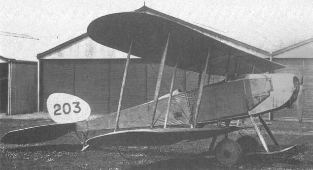
The B.E.3 after hand-over to the RFC, most probably at Hendon in September 1913.
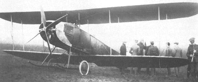
B.E.3 number 203 with four-bladed propeller, date and location unknown.
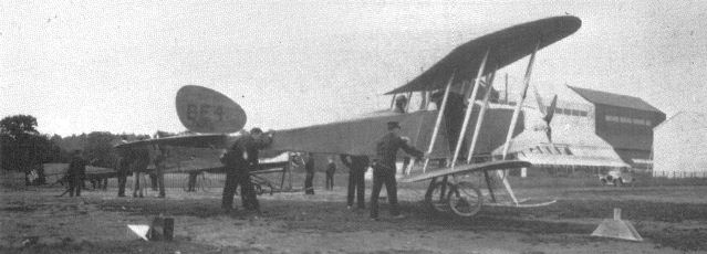
A B.E.4 on Farnborough Common with the Factory buildings, including the newly extended airship shed, in the background.
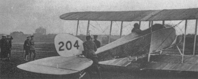
A B.E.4 prepares to take off, observed by a group of senior officers, one of whom appears to be HM King George V.
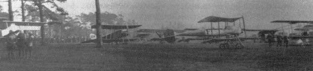
Ill-fated B.E.4 204, which crashed, killing its crew, on Farnborough Common, together with other RFC machines including a Breguet and several Farmans.
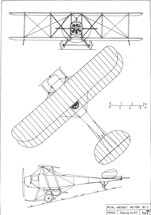
BE3
F.E.2
Two broadly similar but entirely separate aeroplanes each received the designation F.E.2 (without a suffix), although it is believed that the second machine was, officially at least, a rebuild of the first. In the same way it was, and occasionally still is, alleged that the first of the F.E.2s was a reconstruction of its predecessor, the de Havilland-built F.E.1. However, at the time of the F.E.1's last recorded flight, which was made on 15 August 1911 and ended in a crash, the F.E.2 was already complete and ready for flight, awaiting Geoffrey de Havilland's return from his holidays.
The wings, tail and undercarriage of the F.E.2 closely resembled those of the earlier machine, but there were numerous detail changes. These included a reduced cut-out in the upper wing centre-section, ailerons of increased span on upper and lower wings, and a simple nacelle to afford the crew some protection from the elements. Power was provided by a 50hp Gnome rotary which unfortunately proved to be a constant source of irritation. The first take-off, on 16 August, had to be aborted after a run of only fifty yards when a piston broke. This was replaced, and another attempt was made two days later when, despite constant misfiring, four circuits of Laffan's Plain were made. De Havilland, who was responsible for the machine's testing as well as for its design, reported that its lateral control was good but that it was tail heavy, and that, as a consequence, gliding was particularly difficult. Two further circuits were made on the evening of the same day with fifty pounds of lead in the nose, but the centre of gravity was still too far back. This problem was resolved by the end of the month, most probably by re-rigging, and de Havilland reported that the machine was 'flying well' and was very stable, although he felt that more rudder movement was required.
A test flight on 1 September, after the rudders had been modified, was cut short when an inlet valve broke, and the next flight, a few days later, was similarly abbreviated, the problem on this occasion being with the petrol feed. Engine troubles plagued almost every flight until 22 September, when de Havilland records that the engine was running better because the valves had been cleaned. On the same date the lower part of the machine's biplane tail was removed, and subsequently the wings were treated with the new dope Emaillite and a new propeller was fitted.
Finally the F.E.2 appears to have been satisfactory, and it made many flights, frequently carrying a passenger, throughout the remainder of 1911. In November it was fitted with dual controls, initially to the elevator and rudder only, but these were later provided for the ailerons as well.
On 6 December de Havilland flew the F.E.2 to Larkhill on Salisbury Plain, and then on to Shrewton, before returning to Farnborough, covering 100 miles in a flight time of 2 3/4 hrs, this flight being one of the tests for his Superior Aviator's Certificate. A climb to 1,900ft on 23 December appears to have been a further part of the qualifying tests.
Some time in the new year (1912) a set of floats was designed to enable the F.E.2 to operate from water, and on 3 April the machine was flown to Fleet Pond, its wheels removed, and the floats fitted in their place. Problems were experienced in launching owing to the low level of the water, but once afloat the 'Hydro-Aeroplane' F.E.2 was found to ride well. The engine was started in the usual way, a mechanic wading into the shallow water to provide the necessary muscle power to swing the propeller. Steering was found to be as easy as on land, and then, after a run of about 100 yards, the machine took off, piloted by Mr Perry, and landed successfully after a short flight. Six flights were made in all, each of about a quarter of a mile and at a height of about twenty feet.
Later that month the troublesome engine was replaced by a new one, this time of 70hp, and on the 27th it was again flown to Fleet Pond, this time by de Havilland, for the floats to be fitted. Two days later it made a number of flights from the pond, again piloted by de Havilland, its increased power enabling a passenger to be carried. Curiously the experiment seems to have stopped at this point, and the results of the trials were reported to the War Office. It is possible that the floats were transferred to the B.E.2 for similar trials.
Following its success as a seaplane, the F.E.2 was again modified, the intention on this occasion being to enable it to carry a machine gun. The undercarriage was strengthened and the tailplane re-set to balance the additional weight, and a belt-fed Maxim gun was fitted to the nose, where it could be aimed and operated by the passenger. Tests revealed that a gunner in such a machine was blessed with a wide arc of fire, but could only take advantage of much of the potential range of elevation by kneeling or standing up as appropriate. It was concluded that a special mounting giving a variable-height pivot point would be required to enable such a gun to be used effectively.
The second and separate F.E.2 was built during 1913, possibly using components from the earlier machine. It had a capacious but well streamlined nacelle, a 70hp Renault V-8 engine, and outer wing panels copied from those of the B.E.2. The monoplane tailplane was mounted on to the upper tailbooms and braced by struts to the lower booms. The rudder was fairly large and had no balance area. There was no fin, an omission which very probably brought about its end, for on 23 February 1914, after a period of satisfactory testing, it spun to the ground from a height of 500ft and was wrecked. The pilot, Ronald Kemp, who had by that time replaced Geoffrey de Havilland as the Factory's chief test pilot, suffered a broken leg, and his passenger, Mr E T Haynes, was killed.
1911 version
Powerplant: 50hp Gnome rotary
Dimensions:
span 33ft 0in
wing area 340 sq ft;
length 28ft 0in;
Weight: 1,200lb (loaded).
Performance:
max speed 48mph at sea level;
initial climb 140ft/min (with passenger).
1913 version
Powerplant: 70hp Renault V-8
Dimensions:
span 42ft 0in
wing area 425 sq ft;
length 30ft 0in;
Weight: 1,865lb (loaded).
Performance:
max speed 67mph at sea level;
initial climb 330ft/min;
ceiling 5,500ft.
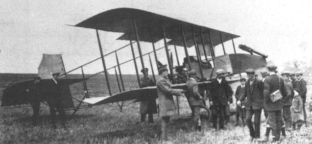
The 1911 version of the F.E.2, fitted with a Maxim-type machine gun.
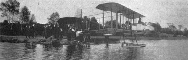
The 1911 F.E.2 on floats was tested on Fleet Pond with a 70hp Gnome engine. The age of the spectators suggests that they are not Factory employees.
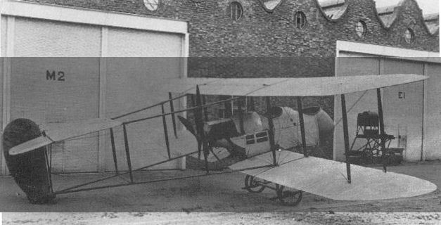
RAF FE.2 the 1913 version had a 70 h.p. Renault engine and new wings among other changes.

The nacelle of the 1913 F.E.2 under construction, with the 70hp Renault engine already installed.
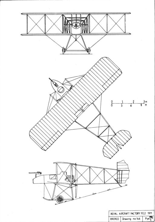
FE2 1911
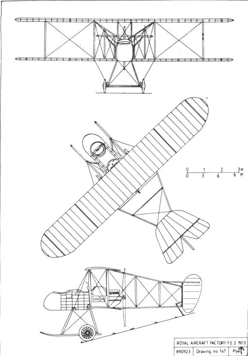
FE2 1913
B.E.8
The rotary-engined B.E.8 was designed by John Kenworthy. It broadly followed the layout of his previous designs, the B.E.3 and B.E.4, but its lower wings were attached directly to the fuselage, without the gap of the earlier designs, and the tail surfaces were modelled upon those of the original B.E.2. In common with most of its contemporary stablemates, the B.E.8 had wing-warping for lateral control and undercarriage skids to protect the propeller tips during landing.
The prototype, which was powered by a 70hp Gnome and had no division between the cockpits, made its first flight on 20 August 1913. It was followed by a second example which had obviously been built concurrently, as it flew less than three weeks later, on 8 September.
The type was apparently thought to present a viable alternative to the B.E.2, and was adopted for limited production by Vickers, which built eleven, the Coventry Ordnance Works (seven), and the Bristol based British and Colonial Aeroplane Company (six), the initial order being placed with the last-named company a few days before the prototype first flew. Production examples differed from the prototypes in having a decking between the cockpits and a triangular fin identical to that later adopted for the B.E.2c. They were powered by 80hp Gnome rotary engines driving four-bladed propellers. The two prototypes were later converted to production standard and transferred to the RFC, in whose service they bore the serials 423 and 424.
The first production machine, 365, was delivered for inspection on 10 March 1914 and was retained at the Royal Aircraft Factory. Records indicate that it was eventually tested to destruction.
Nicknamed The Bloater, the B.E.8 served in small numbers with Nos 1, 3, 5, 6 and 7 squadrons of the RFC and at the Central Flying School, and two examples found their way to India. The type saw service on the Western Front in the early days of the war, but was regarded as being somewhat underpowered. Unfortunately it proved to be rather prone to spinning, and as that manoeuvre and the recovery from it were far from universally understood, several machines were lost in crashes. On 18 August 1914 391 crashed at Peronne, killing its observer and badly injuring the pilot, Lt R Smith-Barry. He eventually recovered, although he needed to walk with a stick for the rest of his life, and in 1917 founded and commanded the School of Special Flying at Gosport, in Hampshire.
The B.E.8 s fuel system appears to have been a source of annoyance and the subject of criticism since, if the need arose to repressurise the tank manually, the hand pump was in the observer's cockpit and the pressure gauge was in the pilot's. Difficulty in communication could result in fuel overflowing, with the obvious fire risk. Although there is no evidence of such a fire actually occurring, the problem clearly reduced the crews' confidence in their mounts.
In January 1915 an attempt was made to improve the B.E.8's performance by the substitution of a 100hp Monosoupape for the 80hp engine. The conversion was made to 658 but, while it had the desired effect, the 'Mono' was relatively scarce, those available being needed for more potent aeroplanes, so no service B.E.8s were ever thus powered. So, underpowered, yet denied the proven remedy, the remaining B.E.8s had all been withdrawn from front-line service by mid 1915, and finished their careers with training units.
Powerplant: 80hp Gnome rotary
Dimensions:
span 37ft 8in;
chord 5ft 6in;
gap 6ft 0in;
wing area 368 sq ft;
length 27ft 4 1/2in;
height 9ft 4in.
Performance:
max speed 70mph at sea level;
climb 10 1/2min to 3,000ft;
endurance 1 1/2hrs.
B.E.8a
Making its debut early in 1915, the B.E.8a used the wings and horizontal tail surfaces of the B.E.2c, thereby having ailerons instead of the warping of the earlier model.
No prototype was produced. Instead, as soon as the drawings were completed, production orders for twenty-one machines each were placed with Vickers and the Coventry Ordnance Works. The 80hp Gnome, as used in the B.E.8, remained the standard engine, although a few machines were fitted with the Clerget 7Z of similar power.
One example was used to test the experimental 120hp R.A.F.2 radial engine, and another had its undercarriage modified to incorporate skis affixed to the axle inboard of the wheels, but neither installation was adopted for production machines.
With a perception that was all too rare at that stage in the war, the RFC never regarded the B.E.8a as an operational machine, and the majority served with reserve squadrons and other training units in the UK. It seems to have shared the earlier version's reputation for being easy to spin, and as result a number were fitted in service with the larger fin, with its distinctive curved leading edge, which was the standard fitment for the B.E.2e.
Powerplant:
80hp Gnome rotary
80hp Clerget 7Z
Dimensions:
span 37ft 8 1/2in;
chord 5ft 6in;
gap 6ft 3in;
wing area 368sqft;
length 27ft 4 1/2in;
height 10ft 3 1/2in.
Performance:
max speed 75mph at sea level;
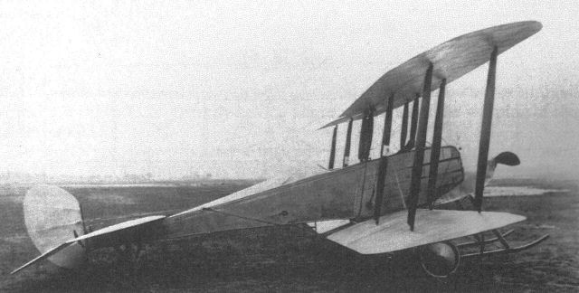
Another view of the prototype B.E.8. The family resemblance to the B.E.2 is obvious.

BE8
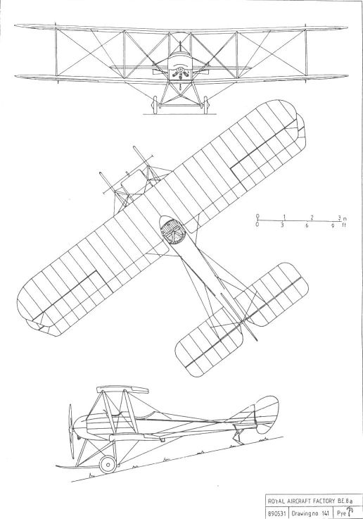
BE8a
B.S.1
The design of this, the world's first single-seater scout, was undertaken by Geoffrey de Havilland, with assistance from Henry Folland and S J Waters. Its basic layout was scaled down from the B.E.3, though it had single-bay wings, an early use of such a bracing system. Lateral control was by warping. The streamlined fuselage was of circular cross-section, and the front section was built around four longerons which extended only from the engine mounting plate to a point some three feet aft of the cockpit. The rear fuselage was of true monocoque construction. Although the engine cowling allowed sufficient space for the 140hp two-row Gnome rotary which de Havilland considered might prove necessary to attain the desired speed, a smaller Gnome, rated at 100hp, was fitted initially.
Immediately behind the engine mounting plate was a divided tank holding twenty-two gallons of petrol and eleven gallons of oil, thus placing the disposable load on the centre of gravity. There was no instrument panel as such, the few instruments fitted - revolution counter, altimeter, airspeed indicator, watch and compass - being attached directly to the rear face of the fuel tank. The sturdy twin-skid undercarriage, which was typical of the period, was less aesthetically pleasing than the rest of the otherwise advanced design, although the wheel spokes were fabric covered to reduce drag.
The 'Bleriot Scout' was completed early in 1913 and was test-flown by de Havilland on 13 March. Its maximum speed was in excess of 90mph, and its initial rate of climb was around 800ft/min. Control was light, but de Havilland thought that the rudder was too small, as a result of the scaling down from the B.E.3, especially as the covered wheels added keel area forward of the centre of gravity. By 25 March he had designed a larger rudder, but continued to fly the aeroplane with the original unit while waiting for the replacement.
Unfortunately, at about 5.00pm on 27 March, de Havilland went into a spin in the B.S.1 while turning at a height of about 100ft, proving his diagnosis regarding the rudder to have been correct, and crashed to the ground. His injuries, according to O'Gorman's report, were confined to 'two badly strained ankles and the loss of some teeth', but in fact he had also fractured his jaw. The report, which was intended for submission to the War Office, was probably composed to make as light as possible of the affair, and refers to the machine ' . . . smashing first the skids and then the bodywork', but as O'Gorman estimated the cost of repairs at ?900 the damage was clearly much more serious than the description suggests.
Authority for the repair was eventually granted, and upon completion the aeroplane became known as the S.E.2 ('S' now standing for 'Scouting'). There is some evidence to suggest that it had already been thus redesignated at the time of its crash, and its continued career is described under that designation.
Powerplant: 100hp Gnome rotary
Dimensions:
span 27ft 6in
length 20ft 6in;
height 8ft 10in.
Weight: 1,232lb (loaded).
Performance:
max speed 92mph at sea level;
min speed 51mph;
initial climb 800ft/min (approx).
B.S.2
Few details are known of this machine, except that it was to have been rather larger than its predecessor, with a welded-steel-tube fuselage. It has been suggested that it may have formed the basis for the design of the R.E.1.
No dimensions known.

The very advanced B.S.I ouside the Factory compound, with the new airship sheds, a spherical balloon, and the airship Gamma II in the background.
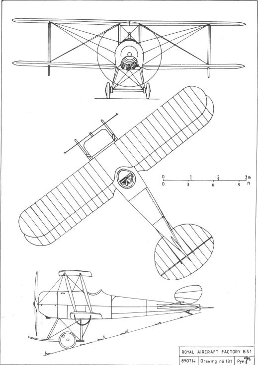
F.E.3 (A.E.1)
This quite remarkable two-seater, which included several novel and ingenious design features, was built in 1913 and was also known as the A.E.1, or Armed Experimental. It was conceived expressly to carry a Coventry Ordnance Works (COW) gun, which fired a one-pound shell, in an effort to provide the flying services with a weapon for which it was confidently expected there would be an eventual demand, although there was no immediate need. S J Waters appears to have had overall responsibility for the design, assisted by messrs Beadle, Folland, Reynolds and Swan.
As was almost inevitable for a gun-carrier, the machine was a pusher, power being provided by a water-cooled, six-cylinder in-line Chenu engine of 100hp. This was mounted well forward in the nacelle so that, in the event of a crash, there was no risk of it breaking free and crushing the pilot, a common failing of most pushers. A shaft extended rearwards from the engine along the bottom of the nacelle, driving the propeller via a chain running in an oil-tight case behind the pilot's seat. In an attempt to eliminate the drag of the braced tailbooms normally associated with pusher designs, the tailplane was carried on the end of a single tailboom which was supported on bearings at the end of the propeller shaft and by bracing wires running to the upper wing and to the undercarriage.
Surviving drawings suggests that there was some indecision as to how the fully enclosed engine was to be cooled. At least one drawing shows extensive surface radiators along the top of the nacelle, following its contour from nose to cockpit rim. However, as finally built, the forward portion of the nacelle was clad in aluminium sheet, over a framework of steel tube, and the remainder was clad in plywood. The radiators were mounted inside the nacelle, cooling air being admitted through a circular hole in the nose. The wing and tail surfaces were of entirely conventional construction, being of fabric covered spruce, and their design clearly owed a great deal to the contemporary F.E.2, as did the undercarriage.
Test flying, undertaken by Geoffrey de Havilland, assisted by Ronald Kemp, revealed that the tail was not sufficiently rigid for satisfactory service, and the tests were discontinued without the gun being fired in flight. It was, however, tested with the machine suspended from the roof of one of the Farnborough airship sheds to establish that the gun's recoil would not pose a problem in flight.
The F.E.3's eventual fate is not recorded, but it is possible that rather more than the lessons learned from its trials was incorporated in its successor, the F.E.6.
Powerplant: 100hp eight-cylinder Chenu
Dimensions:
span 40ft 0in;
chord 5ft 9in;
gap 6ft 4in;
wing area 436 1/2sqft;
incidence 3°
dihedral 1 1/2°;
length 29ft 3in;
height 11ft 3in.
Weights: 1,400lb (empty); 2,080lb (loaded).
Performance:
max speed 75mph at sea level;
ceiling 5,000ft;
climb 350ft/min to 1,000ft.
F.E.6
Designed early in 1914, the F.E.6 continued to explore the ideas previously incorporated in the F.E.3 and, like its predecessor, carried a one-pounder quick-firing Coventry Ordnance Works gun. It closely followed the layout of the earlier machine and was again a pusher, but, being a slightly heavier design, it was powered by the more powerful 120hp six-cylinder Austro-Daimler. The wings were standard R.E.5 components, and the tall oleo undercarriage incorporated a small nose wheel, making it very similar in appearance to that of the F.E.2b. The tail surfaces, like those of the F.E.3, were carried at the end of a single tubular tailboom attached to a bearing on the end of the propeller shaft. Unlike the boom of the earlier machine, this one was a cantilever structure, with no bracing wires to support it. The control wires operating the rudder and elevators were run inside the tailboom tube, thus eliminating another potential source of drag.
The F.E.6's fin and rudder, in common with those of many of its contemporaries, appear to have been of insufficient area to balance the keel area forward of the centre of gravity. This may have been one of the reasons why its flying career, at the hands of Frank Goodden, was very brief. Following a test flight on 14 November 1914, a heavy landing resulted in some damage to the undercarriage, but the aircraft was not repaired. Instead the machine was broken up, the wings being returned to store as R.E.5 spares. As with the F.E.3, it is extremely doubtful if the gun was ever fired, at least not while the machine was in flight.
Powerplant: 120hp eight-cylinder Austro-Daimler
Dimensions:
span 49ft 4in;
chord 6ft 0in;
wing area 542 sq ft;
length 29ft 6in;
height 15ft 0in.
Weights:
2,000lb (empty);
2,630lb (loaded).
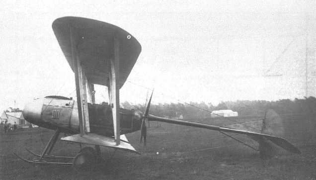
As with many aeroplanes of its time, the F.E.3's streamlined appearance was rather marred by the heavy undercarriage considered necessary to cope with unprepared aerodromes. RAF FE.3 originally AE.l (Armed Experimental) built in 1913 was soon abandoned.
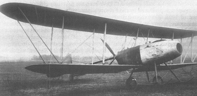
The innovative F.E.3, showing its single tailboom and the nose aperture which admitted air to the internally mounted radiator.
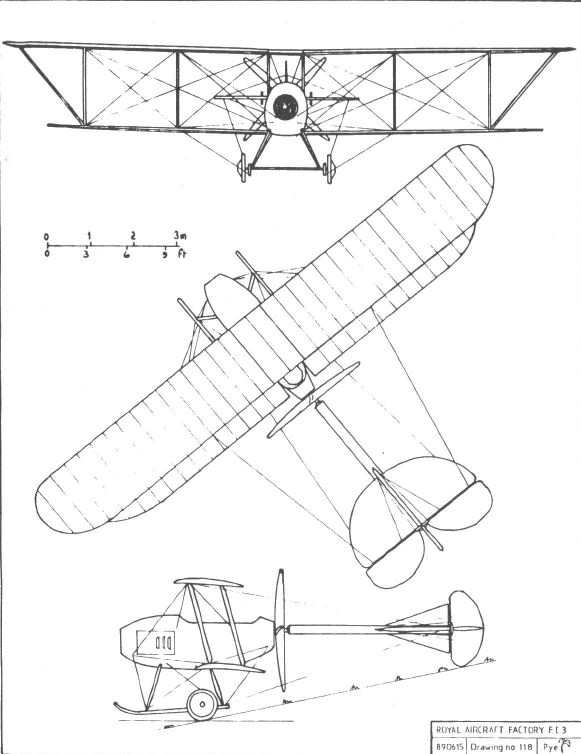
FE3
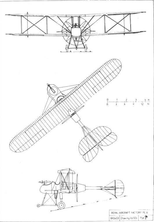
RAF FE.6 with the same one-pounder COW gun as FE.3 was built in 1914 but was also fundamentally unsound.
R.E.1
The design of this neat and attractive two-seat tractor biplane appears to have been something of a joint effort, with Geoffrey de Havilland, Henry Folland and Edward Busk each having some involvement. It might have been begun under the designation B.S.2, although this was soon changed to Reconnaissance Experimental No 2, clearly indicating its intended purpose. Although its derivation from the B.E.2 was obvious, it was a smaller and more refined machine, its role requiring it to carry no more load than its crew and sufficient fuel for its mission.
The staggered single-bay wings had warping for lateral control, and used a recently developed aerofoil section which allowed a greater depth of rear spar, eliminating a weakness discovered in tests upon the B.E.2. The fuselage structure made some use of steel tube, was fabric covered, and had deep coamings giving well-protected cockpits. A triangular fin was fitted, together with a rudder of similar shape to that of the B.E.2, and the undercarriage employed only four struts, two fewer than in the earlier aeroplane. Neat aluminium cowlings enclosed the 70hp Renault engine, which drove a four-bladed propeller. To facilitate transport by road, the wings could easily be removed and strapped to the fuselage sides.
A large wheel on the control column operated the wing-warping mechanism, one of the machine's less successful innovations being the incorporation of the engine controls within the centre of this wheel.
Two R.E.1s were built, the first, which became 607, being completed during May 1913. Following its initial flight tests it was used by Busk for a lengthy programme of development and test flying in connection with his investigations into inherent stability. Over a period of some months the dihedral angle was progressively increased from one degree to something in excess of three degrees. The fin area was reduced, that of the rudder increased, and a new tailplane of rectangular planform substituted for the original. These modifications gave longitudinal stability, but lateral stability proved impossible to achieve with warping wings, as their tendency to self-warp in gusts was too great. New wings incorporating ailerons were therefore fitted, and were rigged with their stagger reduced by four inches.
On 25 November 1913 Busk was able to fly the machine for seven miles without touching the aileron control, relying on the dihedral to right the aeroplane in a gust. Turns were made on rudder alone, the machine automatically taking up the appropriate angle of bank.
The second R.E.1 was completed by September 1913, and was allotted the serial 608. It differed from its predecessor in several ways; the fuselage was longer, the rudder included a curved balance area forward of the rudder post, and there was no fin. Later, four small rounded fins were fitted on the upper wing, one above each pair of interplane and centre-section struts. These were removed when new wings of increased span and incorporating ailerons were fitted early in 1914. In this form 608 was handed over to the RFC, which gave it the serial 362 on 6 March 1914, only to revert to 608 ten days later without the new number appearing on the machine.
The aircraft was used by 6 Squadron up to the outbreak of the war, when it was reallocated to 2 Squadron to help bring the unit up to strength before it flew to France with the Expeditionary Force. On 1 September 608 suffered engine failure and was wrecked in the resulting forced landing.
The first R.E.1 remained at Farnborough throughout its life, its stability making it ideal for testing various devices whose operation occupied much of the pilot's attention, most of them being connected with aerial photography or wireless transmission. It is not clear how many of the numerous modifications made to 607 throughout its life were designed to assist in achieving stability, and how many may have been intended to assess their effect upon what was already an inherently stable aeroplane.
In the original design provision had been made for the installation of 1mm-thick armour plate on the forward fuselage, to afford the engine, fuel tank, and crew at least some protection against small-arms fire from the ground. This armour, which was to be made detachable, appears to have been fabricated during June/July 1913. Surviving records do not indicate to which machine it was actually fitted, how effective it might have been, or if and when the aeroplane was flown with it in place. However, its additional weight does suggest a logical explanation for the later increase in wingspan.
The eventual fate of 607 is unknown, the last confirmed report of its existence being in February 1915, when it was still flying at Farnborough.
Powerplant: 70hp Renault V-8
Dimensions:
span 34ft 0in (later 36ft 0in);
chord 5ft 6in;
wing area 316sqft.
Weights:
1,000lb (empty)
1,580lb (loaded).
Performance:
max speed 78mph at sea level;
stalling speed 48mph;
initial climb 600ft/min.
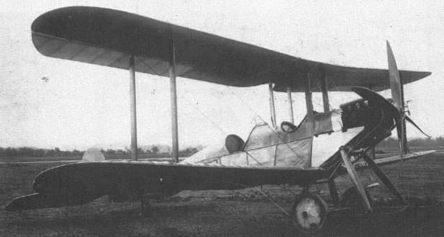
The first R.E. 1 following its modification to include ailerons.

R.E.I 608 with new wings, incorporating ailerons, photographed on Jersey Brow in company with a Sopwith three-seater and a Farman.
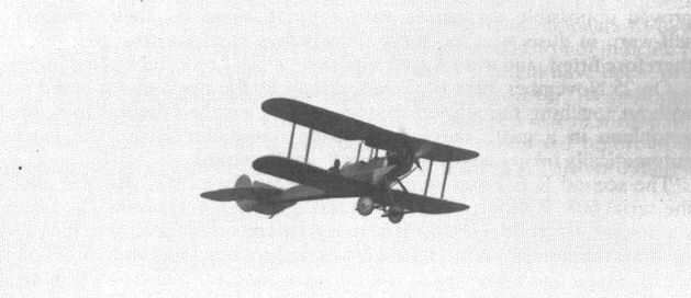
The R.E. 1 in flight, with short-span warping wings.

E T Busk seated in his first stable aeroplane, the R.E.I, seen here with experimental fin surfaces above the upper wing.
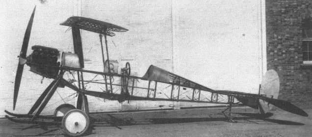
The R.E.I fuselage before covering.
An assortment of Royal Aircraft Factory designs in front of the RFC sheds on Farnborough Common. Aircraft 206 was built as B.E.6, 239 and 329 are B.E.2as, and behind them is the R.E.I.
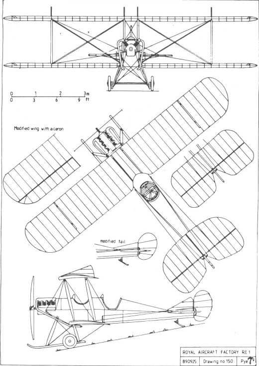
R.E.2
A two-seat reconnaissance aeroplane, the R.E.2 clearly had roots in the R.E.1 and the B.E. series. It had two-bay wings with moderate forward stagger, lateral control being achieved by warping. The low-aspect-ratio rudder was aerodynamically balanced, and bore a marked resemblance to that of the B.E.3. There was no fin and, since there was no need to make allowance for the high-mounted rudder, the elevator was in one piece. Power was provided by a 70hp Renault engine, and the original undercarriage was similar to that of the R.E.1.
The R.E.2 made its initial flight on 1 July 1913 and, following satisfactory trials, it was converted into a seaplane - or 'hydro-aeroplane' in contemporary parlance - by replacing the wheels with floats and fitting an additional small float, incorporating a water rudder, under the tail. These floats differed from those hitherto fitted to Factory aeroplanes in having stepped undersides designed to help break the adhesion of the water, and represented one of the earliest uses of this type of float. In this form the machine was known as the H.R.E.2 (Hydro-Reconnaissance Experimental). To offset the additional forward keel area created by the floats, a triangular fin was added, together with an unbalanced B.E.2-type rudder, this being mounted unusually high to keep it clear of the water and to avoid the need to modify the existing elevator.
The H.R.E.2 appears to have been underpowered, as no take-off is recorded. Its engine was replaced by a 100hp Renault before tests were resumed on Fleet Pond at the western end of Laffan's Plain. Unfortunately it again failed to rise, ran into the bank, and turned over on to its back with consequent damage to the floats and rudder. No further attempts to fly it from water appear to have been made, and during repair it was converted back to its wheeled undercarriage, the modified vertical tail and the 100hp engine being retained. In this form it reverted to the designation R.E.2, and was handed over to the Admiralty to replace an Avro biplane which had previously been equipped with floats by Commander Oliver Schwann RN, and which, following an accident, had ended up at Farnborough for repair. The fate of the Avro is not recorded, and so tenuous is its connection with its replacement that even O'Gorman seems to have become confused as to which machine was meant to fill that role. On at least one occasion he refers, in his private diary, to the R.E.3 as being in lieu of 'Schwann's Avro'.
The R.E.2 served with the RFC's naval wing (later the RNAS), and was given the serial 17.
At some time about November 1914 it was returned to the Factory and fitted with new wings incorporating ailerons, as designed for the R.E.5. It crashed on 10 February 1915 and was not repaired.
Powerplant:
70hp Renault V-8;
100hp Renault V-12
Dimensions:
span 45ft 3 1/2in;
chord 6ft 0in;
gap 6ft 3 1/2in;
length 32ft 3in;
height 12ft 2in;
stagger 1ft 7in;
dihedral 2°;
incidence 4 1/2°;
wing area 498 sqft.
Performance:
max speed
(70hp) 60mph at sea level;
(100hp) 75mph at sea level;
climb 5min to 3,000ft;
endurance: 4 1/2hrs.
R.E.3
Completed in November 1913, the R.E.3 was very similar to the penultimate version of the R.E.2, having warping wings, a wheeled undercarriage, a one-piece elevator, and vertical tail surfaces identical to those of its predecessor. The major difference was in the forward fuselage, which was deepened to accommodate the extra height of the 120hp six-cylinder Austro-Daimler engine.
Although O'Gorman, in his private diary, once identified it as the replacement for Schwann's Avro seaplane, this was almost certainly a confused reference, to the R.E.2, for the R.E.3 was clearly intended as a two-seat reconnaissance aeroplane for Army use, paving the way to the R.E.5.
Its career was cut short when, on 27 September 1914, it suffered engine failure and crashed while flying over Farnborough Common, fortunately without injury to its pilot, E T Busk. Already superseded by the R.E.5, it was deemed to have served its purpose and was not repaired.
Powerplant: 120hp six-cylinder Austro-Daimler
Dimensions:
span 45ft 3 1/2in;
chord 6ft 0in;
gap 6ft 3 1/2in;
length 32ft 3in;
height 12ft 2in;
wing area 498 sq ft.
R.E.4
The R.E.4 was designed to descend steeply so that it could land in fields surrounded by trees, for reconnaissance on active service. It is referred to in O'Gorman's diary as his 'out of field machine'.
It would presumably have been a continuation of the R.E.2/R.E.3 series, being a two-seater with unequal-span wings, powered by a 120hp Austro-Daimler.
No drawings survive, and there is no evidence that it was built.
R.E.6
This 1914 design was for a three-seat biplane powered by a 250hp engine and fitted with a float undercarriage, possibly similar to that of the H.R.E.2. The project was abandoned before the design had been completed, and only a handful of component drawings survive.
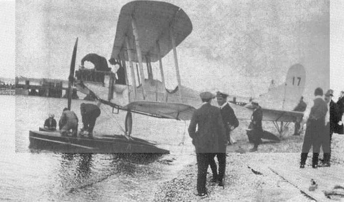
The H.R.E.2 with a 100hp Renault engine undergoes flotation trials on Fleet Pond. It was unable to take off and reverted to a modified form of the land version for the RNAS.
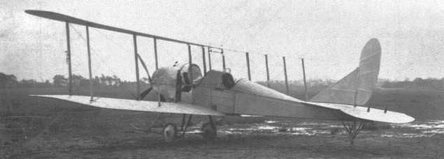
The R.E.3 at Farnborough. This was the same as the RE.2 in its final form but had an Austro-Daimler engine.
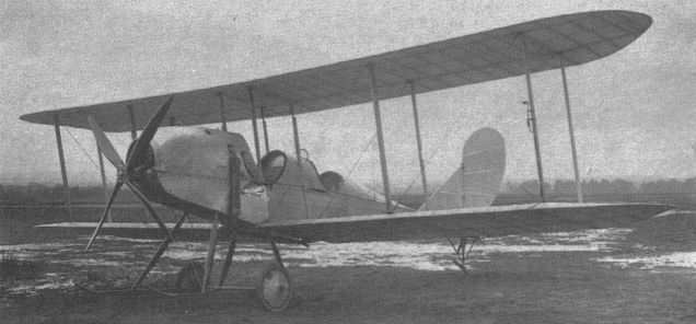
The R.E.3, showing the deep cowling needed to enclose its 120hp Austro-Daimler engine.

HRE2

RE2
S.E.2
Following its crash in March 1913, the B.S.1 (which see) was rebuilt at a cost of around ?900. Various minor improvements were incorporated, and at the same time it was redesignated S.E.2, S.E. standing for 'Scouting Experimental'.
The only apparent changes from its predecessor were a new tail unit and a revised engine cowling enclosing the 80hp single-row Gnome which replaced the 100hp two-row unit previously fitted. The new tail had symmetrical ventral and dorsal fins, inversely tapered elevators hinged from a semi-circular tailplane, and a high-aspect-ratio rudder, considerably larger than the previous one, which had its bottom edge steel-shod to serve as a tailskid. The undercarriage and wing structure were unchanged, as was the divided tank holding both petrol and oil.
The rebuild was completed by October, several months later than O'Gorman had hoped. Again Geoffrey de Havilland acted as test pilot, although at least one RFC officer had flown the machine by 5 November, when O'Gorman reported on its performance to the Assistant Director of Military Aeronautics at the War Office. His report stated that the lower power of the smaller engine was compensated for by its reduced weight, and that the S.E.2's climb and maximum speed were nearly as good as those of the B.S.1. Its stalling speed was lower. O'Gorman also commented that the monocoque fuselage had proved expensive and slow to build, and suggested that he could make a conventional wire-braced structure at least as strong for the same weight.
A request to be allowed to retain the machine for continued trials was refused, and on 23 December the Factory was instructed to hand it over to the RFC. On 1 January 1914 O'Gorman replied, explaining that the machine was awaiting the replacement of a broken skid, and emphasizing that the S.E.2 was an experimental design and not suited for service use. He also drew attention to a number of defects, which included cracked engine cowls, and suggested that it should remain in the Farnborough vicinity so that it could be attended to whenever necessary.
Despite his protests the S.E.2 was handed to 5 Squadron on 17 January, and was allotted the serial 609. Service pilots found it easy to fly and not difficult to land, although its shallow gliding angle made it hard to get into any field surrounded by trees unless it was very large. The view of the ground from the cockpit was described as good, but the forward view was considered impossible when the nose was raised in taxying or climbing.
Early in April the S.E.2 was returned to the Factory for modification and repair. The monocoque fuselage was replaced by a conventional structure of four longerons, wire-braced and faired to circular section by formers and stringers, as previously suggested by O'Gorman. The engine cowling was again modified, and a new tail, similar to that designed for the S.E.4, was fitted. The wing structure was unchanged, but the bracing wires were replaced by Farnborough's new streamlined 'Raf wires'. Although the designation S.E.2a has often been applied to this version, no official or contemporary use of this suffix can be traced, the surviving Factory drawings referring to this version as the 'S.E.2 rebuilt'.
The modifications were completed by 3 October and, owing to the needs of war, after very brief tests at the hands of Frank Goodden the aircraft was returned to the RFC, joining 3 Squadron in France on 27 October. Never armed with more than service rifles, the S.E.2 remained a high-speed reconnaissance aeroplane, a true 'Scout'. Its eventual fate is unknown.
S.E.2
Powerplant: 80hp Gnome rotary
Dimensions:
span 27ft 6in;
chord 3ft 9 1/2in;
gap 4ft 7in;
wing area 188 sq ft;
length 20ft 5in;
height 9ft 3 1/2in.
Weights:
720lb (empty);
1,132lb (loaded)
Performance:
max speed 85mph at sea level.
S.E.2 rebuilt
Powerplant: 80hp Gnome rotary
Dimensions:
length 20ft 10in.
Weight: 1,200lb (loaded).
S.E.3
Conceived by Mervyn O'Gorman as a continuation of the B.S.1/S.E.2 formula, but powered by a nine-cylinder Gnome rotary of 100hp, the S.E.3 was shelved, after some preliminary design work by H P Eolland, in favour of the more advanced S.E.4.
It was to have been an unstaggered biplane with single interplane T struts. Its ailerons could also act together as landing flaps, or could be reflexed to reduce resistance in high-speed flight.
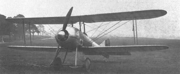
The rebuilt S.E.2, again seen on Farnborough Common, on 20 October 1914.
In its reconstructed form, the sole S.E.2 was used briefly in France with make shift armament.
In its reconstructed form, the sole S.E.2 was used briefly in France with make shift armament.

The rebuilt S.E.2 in service with the Royal Flying Corps.
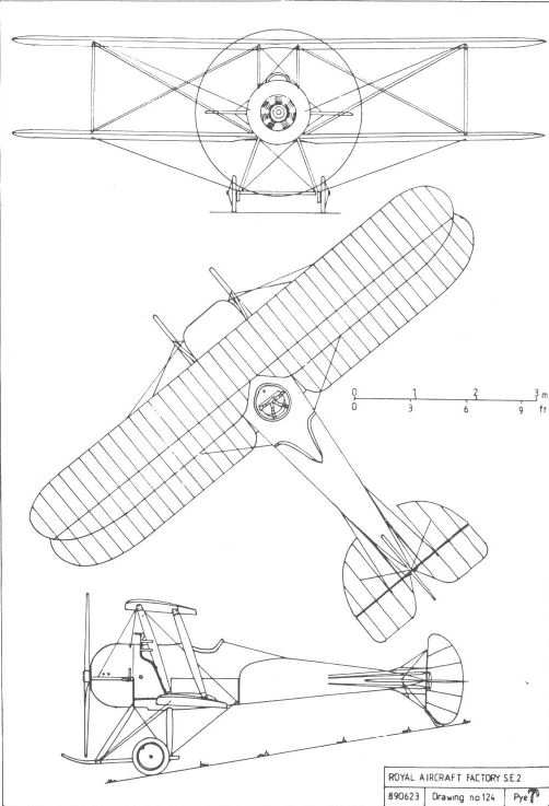
SE2
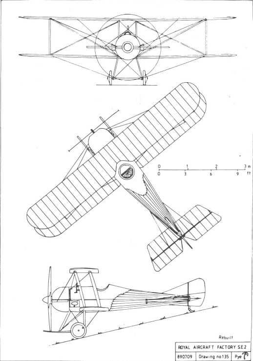
SE2a
B.E.2c
Representing the culmination of E T Busk's investigation into aeroplane stability, the B.E.2c was so different from earlier B.E.2 variants as to be almost a totally new design, yet it retained an obvious family resemblance to its forebears.
Before and immediately after the outbreak of the First World War inherent stability was almost universally considered to be the most desirable attribute of an aeroplane employed in reconnaissance, the primary function of most military machines at that time. A mount which possessed true inherent stability freed its pilot from the need to make constant control inputs, and allowed him to concentrate his attention upon his military duties.
To achieve this desirable quality in the Royal Aircraft Factory's most popular design, Busk took production B.E.2b 602, added a triangular fin, substituted a new non-lifting tailplane of almost rectangular planform, and introduced twenty-four inches of positive stagger. This was done by moving the lower wing back to return the centre of pressure to its correct position, following the loss of the lift previously contributed by the tailplane. The wing structure was almost totally new, being of R.A.F.6 aerofoil section, with ailerons replacing the wing-warping used in previous models. The dihedral angle was increased to 3 1/2, and cutouts were made in the trailing edge of the lower wing roots to restore the pilot's view of the ground.
Busk took the converted 602 for its first flight on 30 May 1914, and thereafter made numerous short flights to enable its stability to be tested and demonstrated. On 9 June it was flown to Netheravon on Salisbury Plain to visit the RFC's 'Concentration Camp'. Its pilot on this occasion was Maj W S Brancker, who, although he was not an experienced pilot, recorded that, after climbing to 2,000ft and setting course, he was able to make the forty-mile journey without placing his hands on the controls until he was preparing to land. He spent his time writing a report on the countryside passing below, although he did admit to the inclusion of a number of extraneous dots and dashes caused by the more violent bumps or gusts.
This demonstration of the benefits of inherent stability was sufficient to ensure that the B.E.2c was put into production by private constructors to supersede the earlier variants in service with the RFC.
Meanwhile, 602 again visited the Concentration Camp on 19 June and stayed there for a week, affording a number of pilots an opportunity to experience its stability at first hand, before returning to Farnborough on the 26th. It was handed over to No 4 Squadron in July, and at the outbreak of war returned to the Aircraft Park, where it was dismantled and crated for shipment to France. When finally reassembled it was erroneously numbered 807, a serial which, it was later realised, duplicated one already issued by the Navy, and it was renumbered 1807. As such it saw service with No 2 Squadron until December, when it returned to England to finish its days in a training unit, being finally struck off charge on 14 December 1915.
Another early variant, 601, was also converted into a B.E.2c. It was fitted with a prototype R.A.F.1a engine, which was dimensionally similar to the Renault but which provided an additional twenty horsepower. On 5 November it caught fire in the air and was completely destroyed, with the tragic loss of its pilot, the aeroplane's designer, Edward Busk.
Although early production B.E.2cs retained the 70hp Renault engine which powered the earlier variants, the Factory's own R.A.F.1a became the standard powerplant as soon as it was available in sufficient numbers. New vertical-discharge exhaust pipes, terminating just above the upper wing centre-section, together with a neat cowling for the engine sump, distinguished the R.A.F.1a-powered examples. A plain vee undercarriage was introduced at the same time, replacing the twin-skid pattern of the earlier machines.
The first production machine, built by Vickers and given the serial 1748, was delivered to the Aeronautical Inspection Department at Farnborough by 19 December 1914. It was followed by the first Bristol-built example, 1652, on 4 January 1915, this aircraft becoming the first production example to go to France, which it did on 25 January. By the end of March there were twelve in service, and by the end of the year there were more than ten times that number.
The B.E.2c's stability was initially well received by service pilots, and remained so in the less demanding theatres of war, earning the machine such affectionate nicknames as Stability Jane or the Quirk. One pilot (Maj WG Moore, Early Bird (Putnam, London, 1963)) wrote of it:
"But the beauty of these machines was that, once you were up to your cruising height, you could adjust a spring which would hold your elevator roughly in the position you wanted for level flying, and you could afford to ignore totally the violent bumps that threw up one wing-tip and then the other. With your rudder central and held in that position by a spring, you could fly hands-off, because the machine was automatically stable and would right itself whatever position it got into provided there was enough space between you and the ground. We used to try, when well up, to see if there was any position we could put them in from which they would not right themselves if left alone. If you pulled them up vertically (so that they hung momentarily on the propellers) and then let go everything, they would tail slide very gently and then down would go the nose until the machine gained flying speed and everything would be normal again."
As originally conceived, the B.E.2 was unarmed. When the fitting of armament became desirable, the location of the observer in the front cockpit, which had been done for sound reasons, made the installation of any kind of defensive weaponry almost impossible. Similarly, the Allies' lack of any synchronisation gear, to allow a gun to fire forwards through the propeller disc, rendered the provision of offensive armament equally difficult. However, almost immediately the type entered service attempts were made to arm it, initially with rifles or pistols and later with machine guns, usually the comparatively light, drum-fed Lewis. The rifles and pistols were usually hand held, but the machine guns required a fixed mounting to enable them to be operated with any effect.
At first the necessary mountings were fabricated, ad hoc, in squadron workshops, but they gradually became standardised into a number of officially adopted types. The earliest of these appears to have been the 'candlestick' mounting, fixed to the cockpit rim, into which a spike or pivot pin attached to the gun could be inserted. This allowed the gun to be swivelled as necessary to engage the enemy, but relied entirely on the observer's skill in avoiding hitting parts of his own machine. This was superseded by the No 2 Mk 1 mounting designed by Lt Medlicott, and frequently known by his name, in which the gun's pivot pin was placed in a socket which was supported from a tube attached to the front centre-section struts, and arranged to slide up and down. A wire guard was frequently fitted which limited the muzzle movement and prevented the observer from shooting his own propeller.
A 'goalpost' mounting between the cockpits, officially designated the No 10 Mk 1, allowed the observer to fire to the rear, over the pilot's head. This gave some measure of protection against attack, but required courage and co-operation in use because the gun's barrel was barely inches above the pilot's head. It was unusual for a machine to be burdened with the weight of more than one gun, and the observer had to transfer it from mounting to mounting as the need demanded. Wooden racks were often fitted to the fuselage sides, outside the rim of the observer's cockpit, to hold spare ammunition drums.
Another type of mounting, more common to single-seaters, had a Lewis gun fixed to the fuselage side, firing forward at an angle to miss the propeller and with its muzzle held in place by cross-wires. A number of such installations were made on B.E.2cs to satisfy the whim of the more aggressive pilots.
None of these arrangements was entirely satisfactory, and they were far from being universally fitted, so for all practical purposes the B.E.2c remained virtually defenceless. Consequently the advent of true fighter aeroplanes, such as the Fokker monoplanes of 1915 and the Albatros biplanes which followed them, meant that the B.E.2c became easy prey, along with its equally unarmed contemporaries. Thus Noel Pemberton Billing was able to shock Parliament, and the nation, with his accusations of incompetence and murder, and so indirectly bring to an end the family of Royal Aircraft Factory aeroplanes.
A few machines were also fitted with bomb racks, either under the wings to carry four 20lb bombs, or under the fuselage, at the centre of gravity, where one 112lb bomb was the normal load.
Losses to ground fire, as the B.E.s monotonously patrolled over the trenches on reconnaissance or artillery observation duties, were also a problem and, in an attempt to provide a solution, a small number of machines were fitted with armour plate which covered the forward fuselage. While this effectively protected the engine, fuel tank and crew against small-arms fire, the reduction in streamlining, together with the addition of over 400lb in weight, so reduced performance that the idea was shortlived.
In common with its predecessors the B.E.2c was used by the Factory as a test bed for a wide range of aeronautical experiments and investigations, a purpose for which its stability and entirely predictable performance made it ideal. The machines used in such experiments were not built at Farnborough, but were standard production machines, built by private contractors and modified as required after inspection.
An oleo undercarriage incorporating a small buffer-type nosewheel was fitted to a few B.E.2cs, but any improvement in landing, and in handling on the ground, could not compensate for the reduction in performance caused by the increased weight and considerable drag, and it was not adopted for general use.
Another undercarriage experiment, which was conducted at the School of Aerial Gunnery, Loch Doon, in November 1916, comprised the removal of the wheels of 4721, an early Vickers-built machine, and the substitution of a central float manufactured by S E Saunders. This was simply attached to the undercarriage skids, and a small tail float was also fitted. Neither the intention nor result of this experiment are now recorded, but it is doubtful whether it served any useful purpose.
Like most other aeroplanes which had a lengthy service career, the B.E.2c was constantly modified and improved with a view either to simplified production or improved performance. It was with the latter object in mind that the wing section was changed early in 1916 from R.A.F.6 to R.A.F. 14, with a consequent slight improvement in rate of climb.
As its performance became the subject of growing criticism, several attempts were made to re-engine the B.E.2c with the 150hp Hispano-Suiza, this having been the first projected use for this impressive new engine. The first attempt managed to produce one of the ugliest installations of this neat and attractive powerplant that it is possible to imagine. The engine was partially enclosed within a crude cowling which left the sides of the cylinder blocks exposed, and cooling was provided by honeycomb radiators of unusual construction attached to the fuselage sides. A later installation was made in the Bristol-built machine 2599. This was neater without being neat, for the radiators, which this time were fitted above the cylinder heads, still looked like the afterthought which, in reality, they were. Although the sixty per cent increase in power obviously improved the aeroplane's performance, it was then decided to develop new machines to realise the Hispano-Suiza's full potential, and the plan to fit it in the B.E.2c was discontinued.
For some obscure reason the R.A.F.1a engine was never popular with the RNAS, so some of the few B.E.2cs operated by that service were equipped either with the six-cylinder 75hp Rolls-Royce Hawk or the 90hp Curtiss OX-5, a car-type radiator being used in each case. It seems strange that this simple solution to engine cooling appears not to have been considered by those responsible for the experimental Hispano-Suiza installations.
When nocturnal bombing raids on London and the eastern counties by the huge German rigid airships brought the war to civilians for the first time, it immediately became apparent that some defensive action was urgently needed, as much to preserve the nation's morale as to prevent the relatively small amount of damage that was being suffered. Here the stable B.E.2c came into its own, for, being easy to fly and to land, it made an admirable night-fighter. However, like most contemporary aeroplanes, it lacked the performance to attack the enemy airships under any but the most favourable circumstances. Whilst they were slower, the airships could better any aeroplane's ceiling, and could ascend at an incredible rate simply by releasing large quantities of ballast. In a commendable attempt to overcome the poor climb and endurance of the B.E.2c compared with that of its intended victim, an experiment was made in 1915 in which the aeroplane was suspended from the envelope of a type SS non-rigid airship. It was intended that the 'airship-plane' would patrol at height until the raiders approached, when the aeroplane would detach itself from the envelope and go into the attack. The experiment was discontinued after 21 February 1916, when a fatal accident occurred after the aeroplane failed to release properly.
This was not the only connection between the B.E.2c and the Submarine Scout airship, for the S.S.I class consisted of a Willows-type envelope from which was suspended an aeroplane fuselage, the early B.E.2c being one of three types used, complete with engine, propeller and undercarriage skids. No wheels were needed, because ascents and landings were made without forward motion.
On the night of 2 September 1916 the Schutte-Lanz airship SL11 was spectacularly brought down over Cuffley in Hertfordshire by Lt William Leefe Robinson of No 39 Squadron RFC, flying B.E.2c No 2092, an act for which he was awarded the Victoria Cross. This was not the first time that an enemy airship had been brought down, for Flt Sub-Lt Rex Warneford had brought down the Zeppelin L37 with a bomb more than a year previously, but it was certainly the most public instance. Warneford's action had taken place over the Belgian coast, whereas Leefe Robinson's victim fell in flames where most of the population of London could see it. Before the end of the year four more raiders, the Zeppelins L21, L31, L32, and L34, had fallen to the guns of night-flying B.E.2cs.
The B.E.2c remained in service, in declining numbers, until the end of the war, gradually being superseded by later variants and by newer designs. It saw service with more than a dozen squadrons of the RFC in France, in Home Defence units and training establishments, with the RNAS, and in every theatre of war, including Africa and the Middle East. At one time it was certainly the most efficient and the most numerous aeroplane in use by the British armed forces. That it was allowed to outlive its usefulness was a tragedy that should be blamed upon those who were responsible for its procurement, not upon the machine or its designers.
The B.E.2c did not survive in service use for very long after the Armistice. At least one was retained as a test vehicle at Farnborough until the mid 1920s, and a small number found their way on to the civil register via the numerous disposal sales held after the war's end. Three examples survive in museums.
Powerplant: 70hp Renault V-8; 90hp R.A.F.1a V-8
Dimensions:
span 37ft 0in;
chord 5ft 6in;
gap 6ft 3in;
stagger 2ft 0in;
dihedral 31/2°;
incidence 3 1/2° (R.A.F.6); 4° 9" (R.A.F.14);
wing area 354 sq ft;
length 27ft 3in;
height 11ft 1 1/2in;
wheel track 5ft 9 3/4in.
Weights: (R.A.F.1a) :
1,370lb (empty);
2,142lb (loaded).
Performance: (R.A.F.1a) :
max speed
86mph at sea level;
72mph at 6,500ft;
ceiling: 10,000ft;
endurance 3 1/4hrs;
climb
6min to 3,000ft;
20min to 6,500ft.
B.E.2d
Although it was structurally similar to the B.E.2c, this new variant included dual controls, presumably to give the observer a chance of survival if the pilot was hit. The provision of controls in the front cockpit necessitated the elimination of the fuel tank which was previously installed under the observer's seat, to allow the rudder cables and the torque tube linking the two control columns to pass through this space. A large gravity tank was substituted, positioned beneath the upper port wing near its root, and was connected to an additional gravity tank within the fuselage top-decking, between the cockpits. At the same time the capacity of the pressure tank, located immediately behind the engine, was increased from fourteen to nineteen gallons. Thus the B.E.2d had a total fuel capacity of forty-one gallons, compared with the thirty-two gallons of the B.E.2c, giving it a useful increase in endurance, albeit at the expense of a reduction in the type's already leisurely rate of climb.
Production orders for the B.E.2d were placed in October 1915, and it was built in relatively small numbers by the British and Colonial Aeroplane Company, Ruston Proctor, and Vulcan. Such great things were expected of the later 'e' variant that all unfulfilled orders for earlier models were changed to the latter type, and consequently many machines which began as B.E.2ds were actually delivered as B.E.2es.
Use of the B.E.2d was largely confined to training establishments, where its dual controls were a boon, its endurance allowed the best use to be made of favourable weather, and its outdated performance was no real handicap.
Powerplant: 90hp R.A.F.1a V-8
Dimensions:
span 36ft 10in;
chord 5ft 6in;
gap 6ft 3in;
wing area 354 sq ft;
stagger 2ft 0in;
dihedral 3 1/2°;
incidence 4° 9";
length 27ft 3in;
height 11ft 0in.
Performance:
max speed
88mph at sea level;
75mph at 6,500ft;
ceiling 7,000ft;
climb
12min to 3,000ft;
36min to 6,500ft.
B.E.10
Designed in May 1914, the B.E.10 was developed from the B.E.2c but had a steel-tube fuselage frame, fabric covered and with a deeper coaming than on previous B.E. types, making it somewhat similar to that of the R.E.5. Its oleo undercarriage incorporated a small 'buffer' nosewheel. The wing span - was slightly reduced from that of the B.E.2c, and the ribs were pressed from alloy sheet. The aerofoil section had a reflex trailing edge, and the full-span ailerons could be operated together as flaps. The rudder was of modified shape, and the small high-aspect-ratio triangular fin anticipated that later adopted for the R.E.8.
Surprisingly, power was to be provided by the rather outdated 70hp Renault, although it may well have been intended that the dimensionally similar 90hp R.A.F.1a would be substituted for full-scale production.
No prototype B.E. 10 was built at Farnborough, but four examples were ordered from the British and Colonial Aeroplane Company. The order was cancelled soon after, when it was decided that the B.E.2c would remain the RFC's standard mount, and none were completed, although enough work was done for the Bristol employees to dub it the 'Gas Pipe Aeroplane'.
Powerplant: 70hp Renault V-8
Dimensions:
span 35ft 8in;
chord 5ft 4in;
wing area 355sqft;
length 27ft 1in;
height 10ft 9in.
B.E.11
No drawing or description of this project has survived, and it therefore seems unlikely that it ever progressed beyond the concept stage. It is almost certain that it was yet another variant upon the B.E.2 theme.
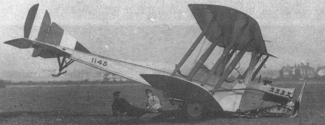
Early B.E.2c 1145 (70hp Renault) after a mishap at RNAS Redcar in October 1916. Note the bomb rack under the sump and the unusual fin marking.
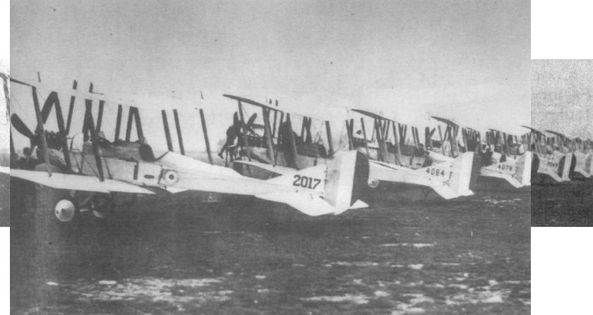
B.E.2cs of 13 Squadron at Gosport on 12 October 1915, en route for France. Aircraft 2017 was built by Armstrong Whitworth, 4084 and 4079 by the British and Colonial Aeroplane Company, and 2045 by Daimler. The difference in serial styles is noteworthy.
The BE2c Squadrons proved invaluable in the early months of the war, providing timely reconnaissance to the commanders on the ground. Furthermore, it was not long before they were showing their value in co-operating with the artillery on spotting fall of shot: this particular role, in which the RFC squadrons became particularly adept, grew in importance as the land battle became more static.
The BE2c Squadrons proved invaluable in the early months of the war, providing timely reconnaissance to the commanders on the ground. Furthermore, it was not long before they were showing their value in co-operating with the artillery on spotting fall of shot: this particular role, in which the RFC squadrons became particularly adept, grew in importance as the land battle became more static.
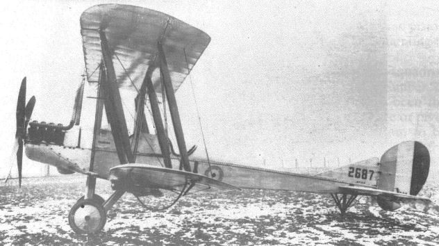
A later B.E.2c, with an R.A.F.Ia engine and the vee undercarriage. This particular machine, 2687, was built by Ruston, Proctor, and is fitted with underwing bomb racks.
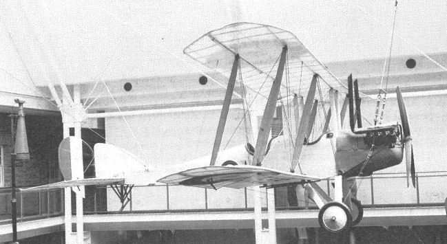
The beautifully restored B.E.2c 2699 on display at the Imperial War Museum, London.
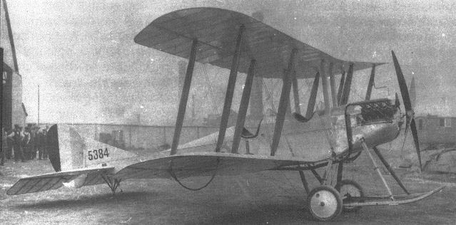
A beautifully finished Renault-powered B.E.2c, the first of a batch built by Wolseley Motors.
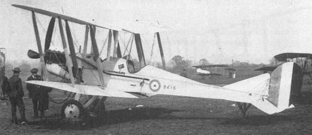
A production B.E.2c built by Hewlett and Blondeau, one of twenty or so contractors who undertook its manufacture.
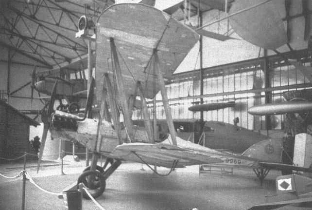
Blackburn-built B.E.2c 9969 on display at the Musee de L'Air, Paris, France, in 1980. The sump cowling and wheel covers are missing, and the fin is of the later B.E.2e pattern, a modification frequently carried out in service.
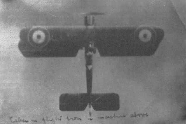
An unidentified B.E.2c photographed from a machine flying above it. Note the squadron marking on the rear decking behind the pilot's cockpit.
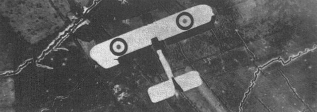
An unidentified B.E.2c, one of many on reconnaissance duties over the trenches of the Western Front.
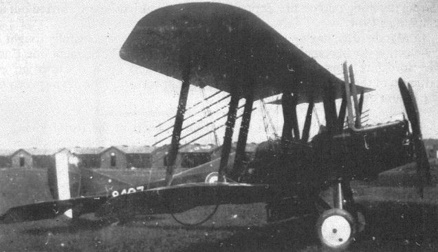
'A gun is stuck on here and a bomb hung on there ...'; a B.E.2c loaded with a 112lb bomb (below fuselage) and eight Le Prieur rockets, with obvious detriment to its already poor performance.
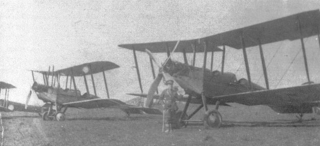
B.E.2cs at South Carlton in 1917. The aircraft nearest to the camera has had its exhausts modified to discharge to the side instead of over the upper wing, as was usual for machines powered by the R.A.F.la.

B.E.2d 4451. Note the gravity tank under the upper port wing. As was common with later examples of the type, this machine has been fitted with the larger, B.E.2e-type fin.

A B.E.2c fitted with a 150hp Hispano-Suiza engine. The identity of the gentleman standing in front of it is now known, but, judging by his worried look, he may have been responsible for this remarkably ugly installation.
The occasion which prompted this impressive line-up of Factory designs is unfortunately not recorded, nor is the purpose of the marquee behind them, but the types present suggest a date of mid-1916. Left to right, the aircraft are: B.E.2c, B.E.2c, B.E.2b. B.E.12, Hispano-Suiza-powered B.E.2c, F.E.8, S.E.4a, F.E.2c, F.E.2b, R.E.8, R.E.8, and R.E.7.
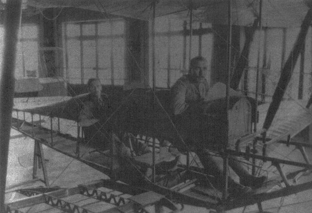
An early B.E.2c in use as an instructional airframe. The wing construction is typical of the early R.A.F.6 aerofoil section wings.

A Renault-powered B.E.2c fuselage in use as a car for an SS-class airship. Note the flotation bags attached to the undercarriage skids, the additional fuel tank beneath the fuselage, and the air duct to the ballonet.
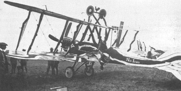
The 'B.E.2xyz' was a heavily modified B.E.2c which took part in a post-war Hendon pageant. In addition to the extra undercarriage for 'inverted landings', it appears to have been rigged with negative stagger, and was almost certainly not capable of safe flight in this form.
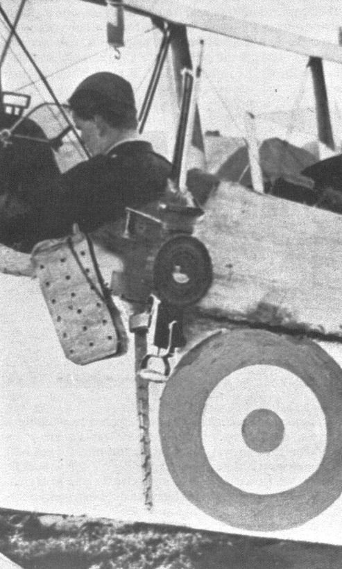
A B.E.2c, showing the seatbelt (there were no shoulder straps) and defensive armament, a Lewis gun on a swivel mounting.
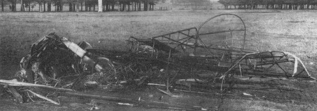
The burnt-out remains of the B.E.2c in which Edward Busk perished.
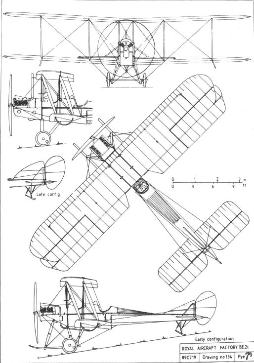
BE2c
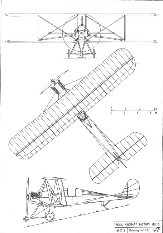
BE10
F.E.2a
In mid-1914 work was begun on a new version of the pusher format, incorporating lessons learned from the previous F.E. designs and intended, from the start, to carry a Lewis gun. Larger and heavier than the 1913 F.E.2 from which it was derived, the F.E.2a was designed to be powered by the six-cylinder, 100hp water-cooled Green engine which had won the Patrick Alexander Engine Competition, recently hosted by the Royal Aircraft Factory. The outer wing panels were again identical to those of the B.E.2, but this time were taken from the newest variant, the B.E.2c, and therefore incorporated ailerons. These wings were fixed to a centre-section which extended outboard to pairs of interplane struts at the tailboom attachment points, thus giving a three-bay wing structure. The tailplane was mounted on the upper tailbooms and wire-braced from a triangular kingpost which was fabric covered to provide fin area. Further fin area was provided by increasing the chord of the rearmost vertical struts between the tailbooms, and the rudder was aerodynamically balanced. The trailing edge of the wide centre-section was hinged for use as an airbrake, and the undercarriage had oleo legs and a small buffer nosewheel.
In the atmosphere of urgency which followed the outbreak of war a batch of twelve F.E.2as was ordered off the drawing board. The first of these, 2864, made its first flight on 26 January 1915, piloted by Frank Goodden. Unfortunately the Green engine proved to be far too heavy for its power output, and it was therefore decided to substitute the 120hp Austro-Daimler which William Beardmore was by then building under licence in the company's own name. The first F.E.2a thus powered was flown, again by Goodden, on 16 March, and was found to be so much improved that the Beardmore engine was adopted for all the uncompleted F.E.2as. However, delays in engine production resulted in consequent delays in the completion of the aeroplanes, and deliveries dragged on all through the summer of 1915.
The last of the twelve, 5648, was delivered on 5 October. This machine differed from the rest in having a conventional vee-strut undercarriage and wings of R.A.F.14 aerofoil section instead of the R.A.F.6 of earlier machines, reflecting a similar change made to the B.E.2c. The flap-type airbrake was omitted from this machine as it was seldom, if ever, used by service pilots. An experimental braking parachute system which was tested during the spring of 1915 similarly found no favour, particularly as the landing run was not excessive anyway, and was not adopted for general use. This was, however, the first recorded use of such a device.
All twelve F.E.2as saw service with the RFC in France, and were among the few adequately armed aeroplanes that the force possessed. Had the type been available sooner and in greater numbers the struggle for command of the air might have been very different.
Powerplant:
100hp eight-cylinder Green
120hp six-cylinder Austro-Daimler (Beardmore)
Dimensions:
span 47ft 9in
chord 5ft 6in;
gap 6ft 3 1/2in;
wing area 494 sq ft;
incidence (R.A.F.6) 3 1/2°;
length 32ft 3in;
height 12ft 7 1/2in.
Weights:
1,993lb (empty);
2,680lb (loaded)
Performance:
max speed
(100hp) 75mph at sea level;
(120hp) 80mph at sea level;
ceiling 6,000ft;
climb: 8 1/4min to 3,000ft.
F.E.2b
Clearly impressed with the warlike potential of the first F.E.2a, the War Office ordered its mass production by a number of contractors. These mass-produced machines differed from the F.E.2a in a number of ways intended either to improve performance or to simplify production, and were therefore designated F.E.2b to distinguish them from the earlier model. The upper centre-section was revised to eliminate the airbrake, which was not actually used in service, and the fully streamlined underwing gravity tank was replaced by a simpler unit which was easier to produce yet did not cause any significant loss of performance.
The drawings were quickly amended for issue to contractors, enabling the first F.E.2b, 5201 built by Boulton & Paul, to be delivered in October 1915, concurrently with the last of the F.E.2as.
Early examples were powered by the 120hp Beardmore engine and had wings of R.A.F.6 aerofoil section rigged at an incidence of 3 1/2°. Wings of R.A.F. 14 section were substituted early in 1916, following their introduction for the B.E.2c, and resulted in generally improved performance, although the rate of climb at altitudes above 5,000ft suffered slightly owing to the increased angle of incidence required by the new wings.
A need for increased endurance, combined with the adoption of the uprated and therefore thirstier Beardmore engine (which had an increased cylinder bore and gave 160hp), led, in March 1916, to the provision of an additional eighteen-gallon tank under the pilot's seat.
A variety of mountings were tried for the observer's Lewis gun, each giving an excellent field of fire forwards and to the sides, but defence against attack from behind depended upon the observer/gunner being sufficiently brave to stand up in the full force of the slipstream and fire backwards over the upper wing. Flights of the big pushers, known officially as 'Battleplanes' and affectionately as 'Fees', roamed the skies over the lines on 'offensive patrol', thus offering some protection to the unarmed reconnaissance machines and taking the war to the enemy in accordance with the beliefs of Brig-Gen Trenchard, Commander of the RFC in France. Their presence did much to combat the 'Fokker scourge' for, although they lacked sufficient speed to chase and catch the enemy fighters, they were formidable opponents once battle had been joined.
An effort was made to improve the F.E.2b's performance by replacing the efficient but fairly massive oleo undercarriage by a simple vee-strut structure similar to that common to other aeroplanes, such an installation having previously been made to the last of the F.E.2as. Although this modification obviously reduced drag and thereby effected a small but useful increase in speed and climb, the improvement was achieved at the expense of the machine's previous ease of landing, and the change was not universally popular within the RFC, being particularly unwelcome among the less experienced pilots. However, Lt Trafford Jones of 20 Squadron later devised a modification to the oleo undercarriage which greatly reduced its drag by eliminating the 'buffer' nosewheel, together with the struts needed to support it, while retaining its strength and efficiency. This simple modification was therefore adopted for all future F.E.2bs, and at the same time the lower longerons were changed from spruce to ash, presumably to increase their strength, because the landing shocks were less dispersed than with the original undercarriage.
By the middle of 1916 the role of the F.E.2b began to change as it became outdated as a fighter. The generous lift of its broad wings prompted its adoption as a bomber, a duty in which it continued throughout the war, switching to nocturnal operations as it became too far outclassed for daytime use. In this role its vee-strut undercarriage was found to be a definite advantage, as it allowed sufficient clearance for a 230lb bomb to be carried beneath the nacelle, which the oleo version did not.
Constant problems with the Beardmore engine, which often needed a complete overhaul after only a few hours' flying, led to the experimental installation of the only available alternative, the 150hp R.A.F.5, F.E.2b - 6360 being so equipped in March 1916. However, the reduction in power cannot have enhanced the machine's already outdated performance, and no service machines were thus powered.
Experiments with the F.E.2b's armament continued throughout the war. A number had their nacelles modified to accommodate a quick-firing Vickers one-pounder together with a belt of forty shells, and a handful of such machines saw active service, being used in particular for attacks upon road and rail transport.
In October 1916 one example, 4928, was fitted with a small searchlight mounted on the undercarriage near to the nosewheel, the power being supplied by a propeller-driven generator mounted on the nose of the nacelle. An installation of a larger light was made on A781 in March 1917. This light had two Lewis guns attached to it, and was mounted on the machine's nose, where it could be aimed by the observer. In this case the necessary generator was suspended below the front of the nacelle. Although they were designed with the intention of equipping the F.E.2b as a night fighter, these installations can only have been regarded as experimental, and neither was adopted for wider use.
Another experimental installation which was not adopted for service use was a device intended to deflect the cables of barrage balloons. This comprised a 'bowsprit' projecting from the nacelle, from which a stout cable extended to each wingtip. The aircraft thus equipped was deliberately flown into suspended wires by Roderic Hill, but a number of mishaps caused the tests to be discontinued before a fatality occurred.
A proposal, made in April 1918, that the F.E.2b should be used for anti-submarine patrols (the role for which the C.E.1 had previously been designed), led to the development of emergency flotation bags, fastened below the nacelle, for use if an engine failure forced such a machine to ditch into the sea. Trials, which included at least two ditchings, were successfully conducted at the Isle of Grain but, perhaps fortunately, there is no record of any pilot having to deploy the bags 'in anger'.
Use of the F.E.2b ceased almost immediately upon the signing of the Armistice, although one was retained at the RAE as a test vehicle until some time in 1924.
Only one example, D3822, found its way on to the civil register, spending a few years as G-EAHC with the Bournemouth Aviation Company, giving joy rides.
Powerplant: 120hp six-cylinder (Beardmore) (later 160hp)
Dimensions: As F.E.2a.
Weights:
120hp 1,993lb (empty); 2,967lb (loaded).
160hp 2,061lb (empty); 3,037lb (loaded).
Performance:
120 hp
max speed 80mph at sea level;
ceiling 9,000ft;
climb: 9min 50 sec to 3,000ft.
160hp
max speed 88mph at sea level;
92mph with vee undercarriage;
ceiling: 11,000ft;
climb 7min 24 sec to 3,000ft;
endurance 3hrs.
F.E.2c
The first machine to bear the designation F.E.2c was built as an F.E.2a (possibly either 5644 or 5646), and had the crew positions reversed to place the pilot in front but was otherwise of normal configuration. This modification was apparently made to improve the pilot's view, particularly for night landings, but the change so restricted the observer's field of fire that the idea met with little favour from its intended users, a situation which the provision of a forward-firing Lewis gun for the pilot did little to improve.
At the same time, October 1915, the Factory was adapting a number of production F.E.2bs to the new configuration and, in view of the pilot's disapproval, work was stopped when only two, 6370 and 6371, had been converted. The former machine was retained at Farnborough for continued trials, but 6371 was sent to France in April 1917, possibly in the erroneous belief that it was a standard F.E.2b, and served briefly with 22 Squadron before being written off in a crash in July.
The final appearance of the type was made late in 1917, when six F.E.2bs were converted to the 'c' configuration, with the pilot's cockpits in front, and served with 100 Squadron. They were probably equipped with Vickers quick-firing guns.
Dimensions: As F.E.2b.
F.E.2d
In what now seems to have been an almost desperate attempt to improve the performance of the sturdy but somewhat sluggish F.E.2b, a new variant, designated F.E.2d, was designed early in 1916, powered by the 250hp Rolls-Royce Eagle V-12 engine. The airframe remained unaltered except for those detail changes necessary to accommodate the new engine, but the fuel system was modified to allow the storage of an additional twelve gallons of petrol.
The prototype, 7995, was completed, ready for inspection, by 4 April 1916, and flew for the first time three days later with Frank Goodden at the controls. Although the massive increase in power brought about only a small increase in top speed, and manoeuvrability and landing speed were adversely affected, the rate of climb and service ceiling were sufficiently improved to justify its adoption, especially as the Beardmore engine normally used in the F.E.2b was far from reliable. Production was therefore undertaken at the Royal Aircraft Factory and by Boulton & Paul of Norwich.
The Factory seems to have worked with commendable dispatch, and A 1, the first of a batch of forty machines, was completed by the end of May. The last machine was delivered by the end of August.
To facilitate the removal of the massive engine from its mounting, surrounded by tailbooms and bracing wires, the Factory designed a portable hoist with which the engine could be lifted clear and lowered to the ground or on to a bench.
The radiator designed for use with the Rolls-Royce engine was found, in practice, to be too large, resulting in excessive cooling. Although shutters, operated by the pilot, went some way towards alleviating the problem, they relied principally on his intuition for correct operation, and provided a distraction which was wholly unwelcome in a combat aircraft. The final solution turned out to be remarkably simple; the radiator previously used for the Beardmore engine was substituted, but installed without the cowlings fitted to the earlier variants so that it received the full effect of the airflow. Shutters were still fitted to allow a faster warm-up, especially during colder weather.
The modification to the oleo undercarriage which eliminated the nosewheel, and which was already in use on the lower-powered F.E.2b, was tested on the '2d' towards the end of August 1916, and was adopted for all new machines with effect from 15 October.
Unfortunately the German air force became familiar with the new machine almost as quickly as did the RFC, for A5, one of the first F.E.2ds to go to France, was ferried across the Channel by an inexperienced crew and inadvertently landed, without serious damage, on the wrong side of the lines, near Lille, effectively making a present of it to the enemy.
The F.E.2d had originally been conceived as a stopgap until the problems with the 160hp Beardmore engine could be resolved, and some machines, ordered as Rolls-Royce-powered '2ds' were actually completed with the smaller engine. The type continued in service, alongside its forebear, the far more numerous F.E.2b, and many other, newer designs until the end of the war.
In April 1917 work was started on the design of a seaplane version of the F.E.2d, but before much work had been done the scheme was dropped in favour of the C.E.1 project.
Powerplant: 250hp Rolls-Royce Eagle V-12
Dimensions:
span 47ft 9in;
chord 5ft 6in;
gap 6ft 3 1/2in;
wing area 494 sq ft;
length 32ft 3in;
height 12ft 7 1/2in.
Weights: 2,509lb (empty); 3,469lb (loaded).
Performance:
max speed 97mph at sea level;
ceiling 17,000ft;
climb 6min to 3,000ft; 14 1/2min to 6,000ft;
endurance 3 1/2hrs.
F.E.2e,f,g&h
Although relatively few details survive of the variants to which these designations were applied, it is recorded that the F.E.2h was a standard F.E.2b or d modified to accept the 230hp Siddley Puma in an effort to conserve stocks of the Rolls-Royce Eagle, which was in great demand for other designs, while producing an aeroplane of equivalent performance.
The prototype was produced late in 1917 by the conversion of an existing F.E.2d, A6545, the actual work being undertaken by Ransomes, Sims & Jefferies. Testing at Martlesham Heath, with both vee and oleo undercarriages, was undertaken early in 1918, and proved that the new variant's performance was little better than that of the F.E.2b and much lower than that of the Eagle powered F.E.2d. Nevertheless, three more Boulton & Paul-built machines, A6501-6503, were converted to the Puma engine, the work again being undertaken by Ransomes, Sims & Jefferies. These were renumbered E3151-3153, and were tested at the Isle of Grain armed with the recoilless six-pounder Davis gun.
Various other engine installations were tested, including the R.A.F.5, and all failed to find approval. It is believed that the remaining designations were to have been applied to these machines if they were placed into production, thereby forestalling the confusion which had arisen with the early B.E.2es.
Powerplant: 230hp six-cylinder Siddeley Puma
Dimensions: As F.E.2d.
Weights: 2,280lb (empty); 3,355lb (loaded).
Performance:
max speed 93mph at sea level;
ceiling 14,000ft;
climb 11 1/2min to 6,000ft;

An early production F.E.2B, No 4962, probably built at the parent Factory with 120hp Beardmore engine and the cumbersome oleo undercarriage with nose wheel.

Presentation F.E.2b A5481, Gold Coast No 13, fitted with a vee undercarriage. A pillar mounting for the Lewis gun can be seen to the rear of the observer's cockpit.
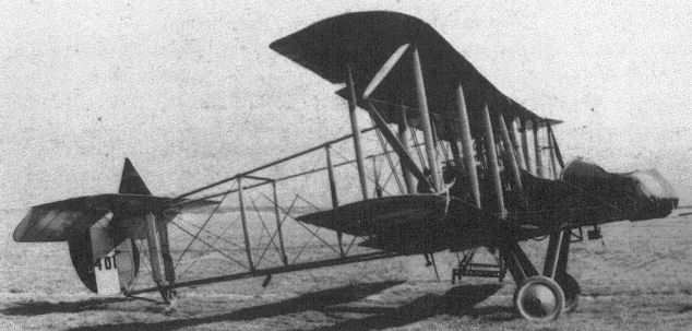
F.E.2b B401 equipped for experiments in flying into balloon cables. Note the outriggers from the outermost interplane struts, carrying the fender wire to the bowsprit in the nose.
The occasion which prompted this impressive line-up of Factory designs is unfortunately not recorded, nor is the purpose of the marquee behind them, but the types present suggest a date of mid-1916. Left to right, the aircraft are: B.E.2c, B.E.2c, B.E.2b. B.E.12, Hispano-Suiza-powered B.E.2c, F.E.8, S.E.4a, F.E.2c, F.E.2b, R.E.8, R.E.8, and R.E.7.
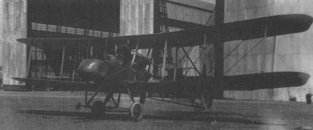
An F.E.2d, showing the unshuttered radiator. The airship sheds in the background were, at that time, the home of the Southern Aeroplane Repair Depot.
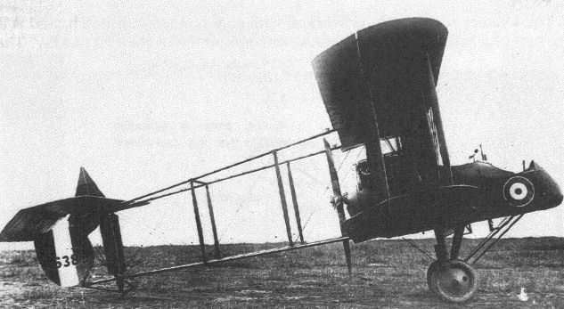
An F.E.2d with the Trafford Jones modification to its oleo undercarriage.
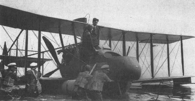
Flotation trials of F.E.2b 6536 at the Isle of Grain.
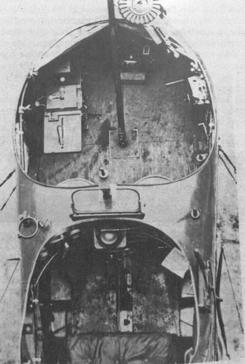
The cockpits of an F.E.2b. The observer's Lewis gun is attached to the front pillar mounting, and alternative mountings are provided immediately in front of the pilot's windscreen and to each side of the nacelle, that on the port side having a fixing clamp already attached.
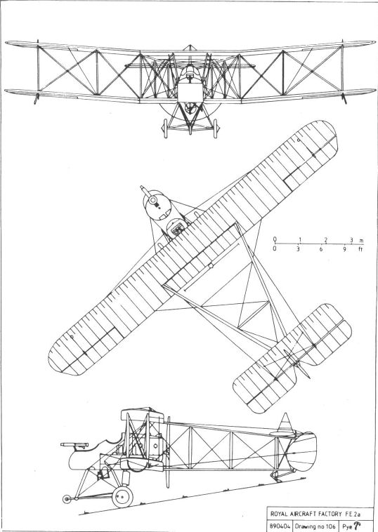
FE2a
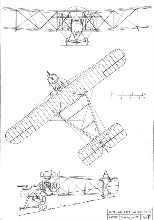
FE2b

FE2c
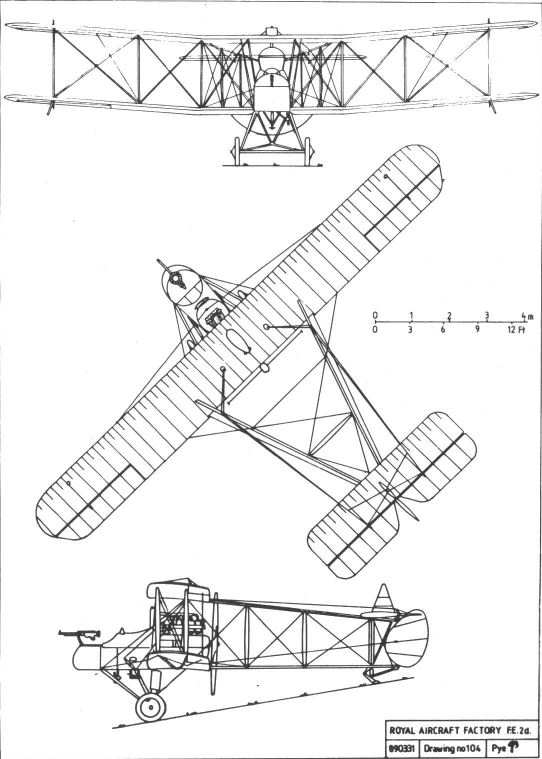
FE2d
R.E.5
Developed from the R.E.2 and R.E.3, this sturdy two-seater was designed towards the end of 1913 and shared many details with the earlier machines. The two-bay wings had ailerons on upper and lower mainplanes and, as in earlier R.E. types, the fuselage frame made some use of steel-tube construction. Power was again provided by the 120hp water-cooled Austro-Daimler engine. The triangular fin was a legacy from the earlier designs, but the unbalanced rudder was of a new shape, and was attached to the sternpost at a lower level than on its predecessors, the elevators being divided to accommodate it.
Because the R.E.5 was not a wholly new design, but a step in a steady development, and appeared to fill an operational requirement exactly, the War Office obviously felt justified in ordering it into production 'off the drawing board'. Construction of a batch of twenty-four was therefore put in hand at the Factory, their cost nominally being taken from the ?25,000 provided by the Admiralty in exchange for the Army's airships, which were to be transferred to the Navy on 1 January 1914.
The first R.E.5 was completed, ready for inspection, by 26 January, and three more were completed the following month. The fifth and sixth examples, delivered in March, had long extensions to the upper wing, supported by additional interplane struts inclined steeply outwards, and appear to have been built as single-seaters. A Factory test pilot, Norman Spratt, took aircraft 380 to an altitude of 18,900ft on 14 May, a feat which, following the machine's handover, service pilots spent much of the summer trying to emulate. Capt J H W Becke, the CO of 6 Squadron, reached over 17,000ft in June.
At least two more examples, the twelfth and thirteenth produced, had the extended upper wing, together with increased fuel tank capacity to extend their range.
Problems with the Austro-Daimler engines delayed production, and later examples were fitted with Beardmore-built engines which incorporated a number of modifications to the Austro-Daimler design, including modified crankshafts. Although at least fifteen machines had been completed by the outbreak of war, the last of the twenty-four were not completed until early in 1915.
Active service revealed that the R.E.5's landing run was rather too long for many of the makeshift aerodromes adopted by the RFC in France, and experiments were made with a 'plough brake', which was fitted to the undercarriage and lowered on landing to reduce the run. This may also have been the reason that experiments were carried out with airbrakes. These comprised flat plates which normally lay against the fuselage sides near to the louvres which allowed airflow through the internal radiator, and were hinged so as to project at right angles to the airflow when required. These airbrakes were also fitted to many R.E.7s.
No further R.E.5s were built once the original production run of twenty-four had been completed. The majority of these served with the RFC either in France or with training squadrons, but one found its way to the RNAS. Another was retained at Farnborough for experimental purposes, eventually being written off while engaged in experiments in the lifting and release of heavy weights, as part of an investigation designed to ascertain what bomb loads might safely be carried in the future.
During 1915 the Factory fitted an R.E.5 with an oleo undercarriage of the type later adopted for the R.E.7. The same machine was also given a pre-production R.A.F.4 V-12 engine with an exhaust manifold similar to that later adopted for the B.E.12. An enlarged fin, with a curved leading edge, was also fitted to this machine.
On 31 July 1915 Capt J A Liddell of 7 Squadron was flying an R.E.5 on a bombing mission, and was badly hurt when it was hit by anti-aircraft fire, which also smashed the top of his control column. Despite his injuries he succeeded in returning the damaged machine to the British side of the lines, thereby saving the life of his observer. He was awarded the Victoria Cross for his courage, but died of his wounds some weeks later.
One R.E.5 which was brought down behind the enemy lines was recovered intact and exhibited in Germany, together with other captured Allied weaponry.
Towards the end of 1915 the R.E.5s were gradually withdrawn from active service, the last machine returning from France early the following year, but they continued to serve with training establishments until they were written off.
Powerplant: 120hp Austro-Daimler or Beardmore
Dimensions:
span 45ft 3 1/2in (57ft 2 1/2in with extensions);
chord 6ft 0in;
wing area 498 sq ft (569 sq ft with extensions);
Performance:
max speed 78mph at sea level;
initial climb 400ft/min.
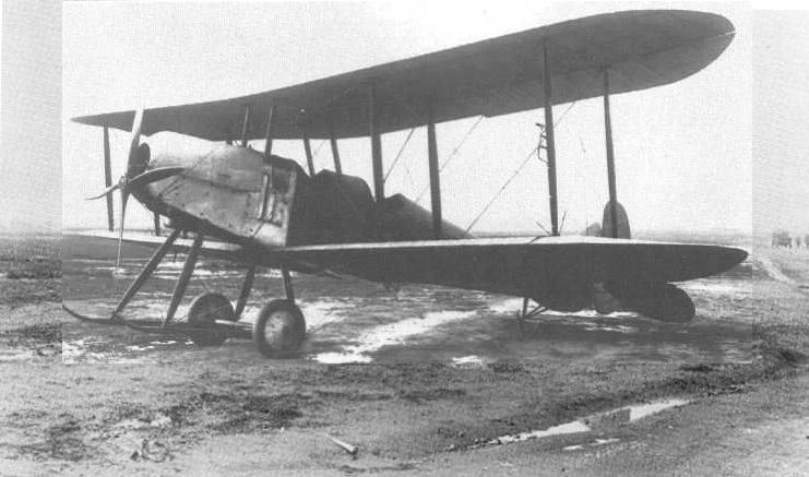
A standard R.E.5, powered by a 120hp Austro-Daimler engine driving a four-blade propeller, and with wings of equal span. Twenty-four of them were built in 1914-1915 with short or long span wings.
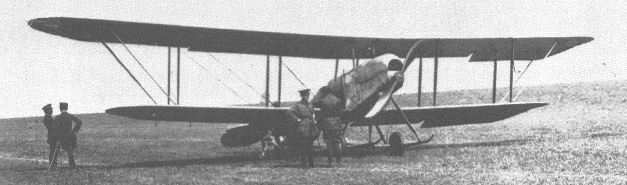
An R.E.5 with the long-span upper wing. One of the officers by the wingtip appears, from his uniform, to be French.
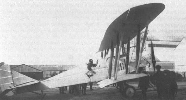
Norman Spratt about to take off in an R.E.5 to break the altitude record, 16 January 1914.
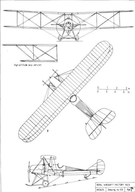
S.E.4
Yet another product of the fertile mind of Henry Folland, the S.E.4 was designed to be very fast, and may well have been the fastest aeroplane of its day. It was powered by a fully cowled fourteen-cylinder two-row Gnome rotary of 160hp, and the hub of its four-blade propeller was covered by a large, dish-like spinner. A fairly conventional fuselage structure based on four cross-braced longerons was faired to a circular cross-section by formers and stringers. The attention to streamlining included a moulded celluloid cockpit cover but, although this was made, it was never used because no pilot could be persuaded to fly the aircraft with it fitted.
The biplane wings were separated by single T struts, their extremities extended to allow attachment to both the front and rear spars. The centre-section struts were of similar configuration, but were hollow, providing a route for the aileron cables. Full-span ailerons were fitted to all four wings, and incorporated a system, originally designed for the S.E.3, whereby they could be lowered together to act as landing flaps or reflexed to reduce drag for high-speed flight. The tailplane, like that of the S.E.2, incorporated the dorsal and ventral fin surfaces favoured by its designer. To reduce drag, the gaps between fixed and moveable surfaces were faired over with elastic netting. The undercarriage comprised a transverse leaf spring carrying the wheels at its ends and attached to an inverted tripod of streamlined struts.
Construction was completed by 17 June, and test flying was begun by Norman Spratt. The sprung undercarriage was found to cause excessive rolling while taxying, landing or taking off, and by 23 July, when Spratt made taxying trials, it had been replaced by a conventional structure comprising an axle bound by rubber bungee within the apexes of two vee struts. He flew it again four days later.
The 160hp engine proved troublesome, not only because of inadequate cooling, which was overcome by modifying the spinner, but because of its continued unreliability. It was eventually replaced by a single-row Gnome monosoupape rated at 100hp. This dramatically reduced the machine's previously impressive performance, the maximum speed dropping from 135mph to 92mph.
On 4 August the S.E.4 was flown by Maj J M Salmond, who found its performance and handling favourable, although its 52mph landing speed was considered too high for squadron pilots. Nevertheless it was taken over by the RFC, given the serial 628, and had a primitive camouflage scheme applied. It never saw active service because it was wrecked at 11.45am on 12 August when a wheel appeared to collapse on landing, its pilot fortunately escaping without injury. The aircraft was not rebuilt.
Powerplant:
160hp two-row Gnome rotary
100hp Gnome Monosoupape rotary
Dimensions:
span 27ft 6in;
chord 3ft 9 1/2in;
gap 5ft 1in;
wing area 188 sqft;
length 21ft 4in;
height
9ft 0in (tripod undercarriage);
9ft 10in (vee undercarriage).
Performance:
max speed
135mph (160hp);
92mph(100hp);
stalling speed 52mph;
initial climb l,600ft/min(160hp);
endurance 1hr.
S.E.4a
This trim little scout owed little to the S.E.4, and the choice of designation is therefore hard to explain. Designed by Henry Folland late in 1914, it was intended to further the Factory's research into the relationship between stability and manoeuvrability, its wings incorporating 3 1/2 of dihedral and having multi-function, full-span ailerons as used on the S.E.4. The only other link with its supposed parent was its horizontal tail surfaces.
The S.E.4a's fuselage was a conventionally cross-braced four-longeron structure, although the forward portion of each longeron was of steel tube, being joined by fishplates to the spruce rear fuselage members just aft of the single cockpit. The tailskid was hinged from the bottom of the sternpost, and enclosed within a fairing which continued the line of the ventral fin. There was no centre section, the wing panels being joined above the fuselage centreline and the centre section cabane struts forming inverted vees.
The powerplant was an 80hp Gnome rotary enclosed within a streamlined cowling which blended neatly into the fuselage, which was faired to a circular cross-section by formers and stringers. A large dish-shaped spinner covered the propeller boss.
The first prototype was completed on 23 June 1915, and flew for the first time two days later, with Frank Goodden at the controls. Tests using the ailerons as flaps showed that they could reduce the landing speed by 5mph, but it is debatable whether this relatively minor reduction justified the complexity of the system required to achieve it.
Three further examples were completed in the Farnborough workshops during the following six weeks, but they lacked the streamlining of the first machine. Their fuselages were flat-sided apart from a small fairing behind the cowling, and no spinners were fitted. They were handed over to the RFC as scouts, and were among the first British machines equipped with forward-firing machine guns. These were Lewis guns, mounted above the upper wing to fire clear of the propeller disc.
One S.E.4a crashed at Hounslow in September 1915, killing its pilot, Capt Binden Blood. The fates of the other aircraft are not known, although one, 5611, returned to Farnborough in June 1916 to have the 80hp le Rhone with which it had been built changed for a Gnome, as fitted to the others. In October this engine was replaced by a Clerget, but the reason for the change is not recorded.
Despite the S.E.4a's reputation as a good aerobatic aircraft, the role of single-seat fighter, to which it seemed perfectly suited, scarcely existed at the time of its emergence. Newer designs were already under way by the time the need for such a machine had arisen, and the S.E.4a did not go into production.
Powerplant: 80hp Gnome rotary
Dimensions:
span 27ft 6in;
chord 4ft 2in;
gap 4ft 9in;
length 20ft 10 1/2in;
height 9ft 5in.
A replica of the S.E.4's original cockpit canopy, which was never actually used in flight.
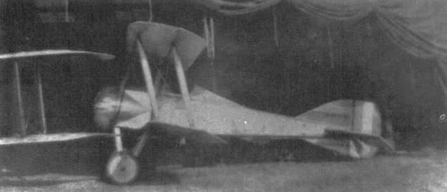
A poor but unique photograph of S.E.4a 5610.
The occasion which prompted this impressive line-up of Factory designs is unfortunately not recorded, nor is the purpose of the marquee behind them, but the types present suggest a date of mid-1916. Left to right, the aircraft are: B.E.2c, B.E.2c, B.E.2b. B.E.12, Hispano-Suiza-powered B.E.2c, F.E.8, S.E.4a, F.E.2c, F.E.2b, R.E.8, R.E.8, and R.E.7.

This sketch in H P Folland's notebook, dated 28 December 1914, depicts an armoured scout based on the S.E.4a.
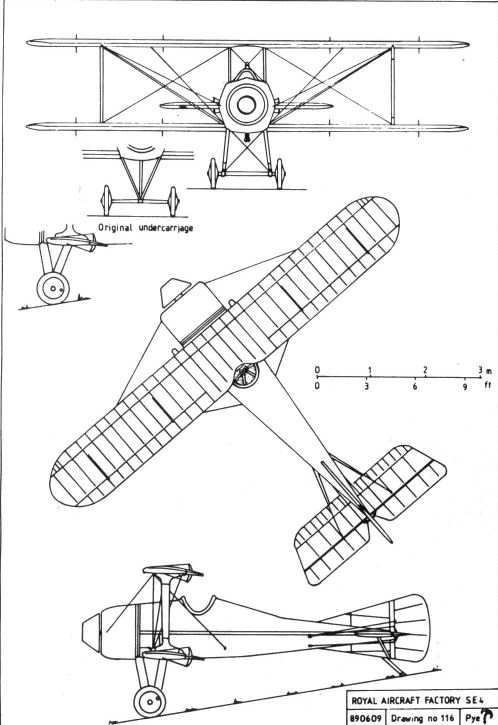
SE4
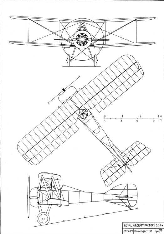
SE4a
B.E.9
As it became ever more apparent that the British flying services urgently needed an aeroplane suitably armed for an offensive role, and as no synchronisation mechanism was yet available to the Allies to enable a machine gun to be fired through the propeller disc, the most obvious solution appeared to be the pusher layout. However, although it offered an unrivalled forward field of fire, the pusher suffered from the additional drag of its tailbooms, and could never match the performance of a well-designed tractor of similar power. In a bold attempt to combine the pusher's field of fire and the tractor's performance in one aeroplane, the B.E.9 was conceived.
It was built, in mid-1915, by the conversion of the Bristol-built B.E.2c 1700, thereby continuing the tradition of 'reconstruction'. The observer's cockpit was eliminated, and the engine was moved back to occupy the space thus gained, the propeller being located about twelve inches in front of the leading edge of the upper wing. The wingspan was increased by the provision of a new, wider centre section, the cabane struts being raked outwards to clear the cylinders of the relocated engine. A gap was left at the root of the lower wing to improve the pilot's downward view. A plywood nacelle was mounted, via a ball-race, on the forward end of the propeller shaft, and braced to the undercarriage by a system of struts. Additional bracing was provided by wires running out to the wings. A greatly enlarged fin was fitted to offset the additional side area forward of the centre of gravity, but the standard rudder was retained.
The Pulpit, as it almost inevitably became known, was presented for final inspection on 14 August and taken up for a brief first flight later the same day, with Frank Goodden at the controls. It was passed to the Central Flying School for service trials, their official report finding the design 'excellent', the stability 'very good', and the speed only slightly reduced from that of the B.E.2c. Communication between the crew was regarded as 'difficult' (which was something of an understatement considering that they were separated by the engine and propeller), and the report recommended that dual controls should be provided. Although finding a route for the necessary cables must have taxed the designers' ingenuity to the full, these were installed before the B.E.9 was flown to St Omer on 11 September so that it could be tested by crews from operational squadrons, Nos 6, 8 and 16 being among those selected.
Front-line pilots seem to have been almost unanimous in their condemnation of the machine. Lord Douglas of Kirtleside (then Lt Sholto Douglas) took it on a reconnaissance patrol over the lines on 26 October. He considered it 'ugly' and 'sluggish but very stable', and commented that his observer was, at best, 'lonely' in his little plywood box. Trenchard, then commanding the RFC in France, was equally unimpressed, and reported: 'this type of aeroplane cannot be recommended'.
The B.E.9 was therefore returned to the depot at St Omer and then, early in the new year, flown quietly back to Farnborough, where it was never heard of again.
A French machine, the SPAD A-2, which was of similar design, was likewise not widely adopted and, although the concept was adjudged to have been a failure, it is perhaps unfair to condemn a brave, if misguided, solution to a pressing problem.
Powerplant: 90hp R.A.F.1a V-8
Dimensions:
span 40ft 10 1/2in;
chord 5ft 6in;
gap 6ft 3in;
stagger 2ft 0in;
length 29ft 0in;
height 11ft 5in .
Performance:
max speed 82mph at sea level;
climb 4 1/2min to 1,000ft.
B.E.9a
A plan to build a variant of the B.E. 9 powered by the 140hp R.A.F.4a was, considering the unsuitability of its forebear, not proceeded with.
F.E.10
This projected single-seat scout was abandoned while still in the design stage. It was to have been a rather improbable and ill-conceived machine, with the cockpit in a 'pulpit' mounted in front of the propeller, in the manner of the unsuccessful B.E.9, presumably in an attempt to produce a fighter with a forward-firing gun without incurring the pusher's drag penalty. The fact that it was given a designation in the F.E. series demonstrates not only the degree to which the B.E. class had been discredited, but of the difficulty in placing each and every design concept into a 'pigeon hole'.
The F.E. 10 was to have been powered by the 150hp Hispano-Suiza V-8 engine, as was the S.E.5, the design of which was taking place concurrently. As the availability of gun synchronisation gears had rendered the pusher and 'pulpit' concepts out of date, and as demand for the Hispano continued to exceed supply, commonsense prevailed and the F.E. 10 project was dropped in favour of the more promising tractor design. It was, however, decided that the F.E.10's vertical tail surfaces were more pleasing than those originally designed for the S.E.5, and the latter's drawings were amended accordingly.
Dimensions
Span: 35ft 0in.
F.E.11
No record of this project has been discovered.
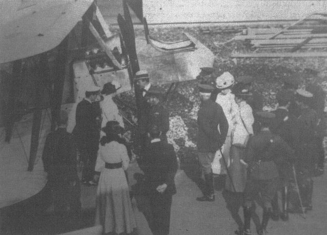
The B.E.9 is shown to HM King George V during his visit to Farnborough on 18 August 1915.
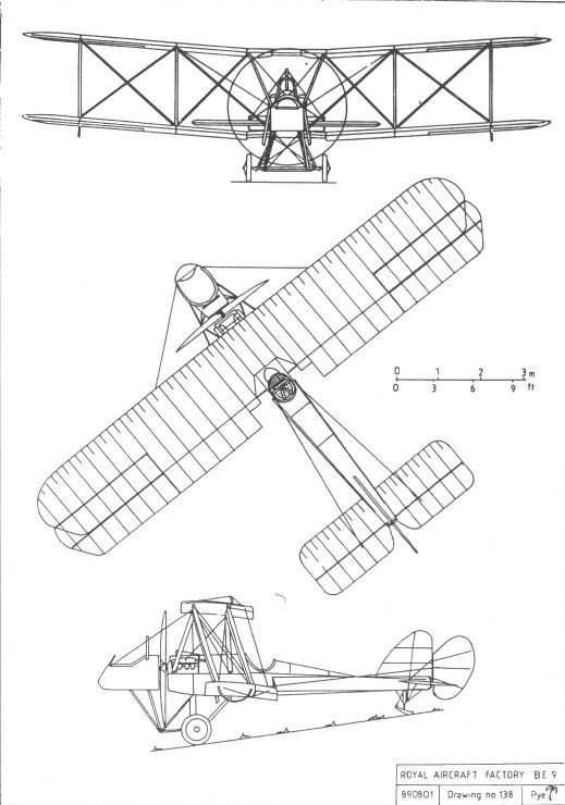
BE9
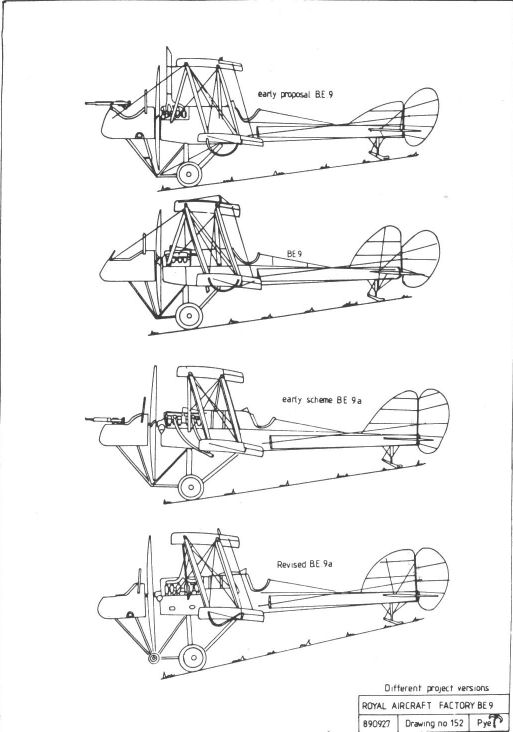
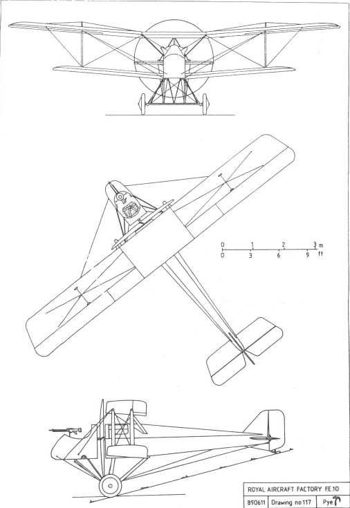
FE10
F.E.8
By mid-1915 it had become evident that the Royal Flying Corps was in fairly urgent need of a single-seater fighter (or 'Scout', in contemporary parlance), both to afford some protection to its vulnerable two-seaters and to take the war to the enemy by attacking German aircraft.
Such a machine obviously needed to be equipped with a forward-firing gun, placed within easy reach of the pilot so that it could be loaded and any jams could be cleared. As the Allies still lacked a workable gun synchronisation system, the only practicable solution was to make the new machine a pusher, despite the drag penalty and consequent reduction in performance.
The aeroplane which the Farnborough team, headed by John Kenworthy, designed to fill this role was broadly similar in concept to its closest 'rival', the D.H.2, produced contemporaneously by the Aircraft Manufacturing Company, where Geoffrey de Havilland was then chief designer, but it differed almost totally in detail.
The single tubular tailboom previously employed in the F.E.3 and F.E.6 was abandoned, despite its reduced drag, because its structural integrity was still far from proven. Instead, conventional steel-tube tailbooms were employed, but these were arranged to meet, unconventionally, at the tailplane spar, rather than at the sternpost. They thus formed a vee in elevation and not, as was common, in plan. The tailplane incidence was adjustable, although only on the ground and, to reduce overall weight and control forces, the rudder and elevator ribs were of duralumin. The nacelle, which was of conventional appearance, was built upon a triangulated framework of welded steel tubing which eliminated any need for internal bracing wires, the shape of its duralumin covering being maintained by wooden formers. The high-aspect-ratio, two-bay wings were rigged with five degrees of dihedral outboard of the wide centre section. Ailerons spanned all four outer wing panels, and on the early F.E.8s no spanwise balance cables were fitted, the ailerons being returned to their normal position by rubber bungees.
Power was provided by a 100hp Gnome monosoupape rotary driving a four-blade propeller which, for some inexplicable reason, was fitted with a conical spinner.
Instrumentation was typically spartan, comprising only a tachometer, altimeter, airspeed indicator, transverse clinometer, watch holder, compass, and fuel pressure gauge (this being vital as no gravity tank was fitted, and the engine would cut out if the pressure within the tank fell too low. A hand pump was provided for emergency use).
The first prototype, 7456, made a brief initial flight on 15 October 1915, before any armament was fitted. Its pilot on that occasion was Frank Goodden, who was entirely satisfied with the new scout. Four days later he took it up for an hour and a half, exploring its handling characteristics to the full.
By early November 7456 had been equipped with a Lewis machine gun pointing through an opening in the extreme nose, and capable of being swivelled through an arc of up to 30° in any direction via a linkage connected to the pilot's sighting device. On 8 November it was flown to the Central Flying School at Upavon for service trials. The school's report was most favourable, describing it as manoeuvrable, easy to land, and possessing excellent stability. The gun installation found less favour because it was inaccessible and unnecessarily complex. It was thought simpler merely to fix the gun and aim the whole aeroplane at the enemy. A week later the F.E.8 was returned to the Factory by the famous prewar display pilot B C Hucks, who had the great misfortune to crash-land and damage it beyond economical repair. The engine, which was undamaged, was removed for use in the second prototype, 7457, which was already under construction and which first flew on 19 December, piloted by Frank Goodden.
Trenchard considered its 2 1/4hr endurance to be insufficient, and it was therefore decided to increase the fuel tankage from 24 to 29 gallons. The gun mounting, which had been widely criticised, was changed to a fixed position on the cockpit rim, similar to that of the D.H.2. Wooden racks were provided on the cockpit sides for spare ammunition drums. These modifications were incorporated in production machines, the first order for which had been placed with the Darracq Motor Engineering Company on 11 October, four days before the type's first flight.
To forestall any possible problems, should supplies of the Gnome Monosoupape prove troublesome, experimental installations were made of a 110hp Le Rhone and of a Clerget of similar power so that any difficulties in substituting these engines should be solved in advance. In practice, however, it was airframes which proved to be a problem. Deliveries were delayed for a variety of reasons, not the least of which was the fact that this was Darracq's first venture into aircraft manufacture. Therefore it was October 1916 before a complete squadron, No 40, was in service on the Western Front, although the first six machines had been pressed into use at the beginning of August.
Allegations that the F.E.8 was prone to spin caused considerable concern, especially among the many recently qualified pilots whose training was, at best, somewhat basic. Therefore, during August 1916, Frank Goodden carried out a series of trials in which he deliberately spun an F.E.8 in both directions, recovering easily on each occasion by employing the standard method (centralise the controls, push the stick forwards to gain airspeed, then apply opposite rudder if required). His report stated that the aeroplane was perfectly stable, and that he had only been able to initiate each spin by 'misuse' of the controls. The report, together with the story of the trials, which passed quickly down the 'grapevine' throughout the RFC, did much to stop the rumours and to restore pilots' confidence in their mounts.
A rather more justified criticism of the aeroplane was made in respect of the rubber bungees connected to the ailerons, which broke much too frequently. On 30 August it was decided to replace the bungees with a balance cable, not only on all future machines, but retrospectively on those already in service. The fuel system was also criticised by squadron pilots, as it often proved difficult to maintain the necessary pressure, particularly when the tank was nearly full. To resolve this, a small gravity tank was fitted internally within the centre section, fed from the main tank under pressure and itself feeding directly to the engine. The D.H.2 tank was also tried, mounted externally below the upper wing centre section, but although it was streamlined it caused an unacceptable reduction in speed and the internal tank was standardised.
Later, when it was discovered that the duralumin ribs in the elevators were reacting with the dope and causing the fabric to rot, new control surfaces with steel ribs were designed. As a temporary measure while the new elevators were being manufactured, some machines were fitted with D.H.2 elevators, their hinge type and position being modified as required to make them fit.
Almost 300 F.E.8s were eventually built, and the type remained in service at least until July 1917. By that time it was long obsolete, but it enjoyed the dubious distinction of being the last pusher scout to see active service on the Western Front.
Powerplant: 100hp Gnome Monosoupape rotary
Dimensions:
span 31ft 6in;
chord 4ft 0in;
gap 4ft 6in;
wing area 214 sq ft;
dihedral 5°;
length 23ft 0in;
height 9ft 2in.
Weights:
895lb (empty);
1,346lb (loaded)
Performance:
max speed 94mph at sea level;
ceiling 14,500ft;
climb 9 1/2min to 6,000ft;
endurance 2 1/2hrs.
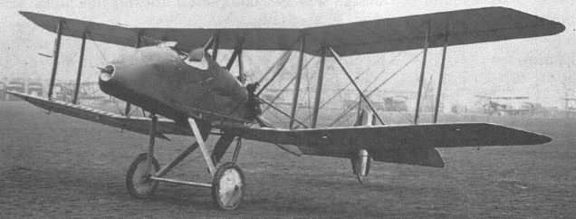
The first prototype F.E.8, showing the original gun installation. The location is not known, but the aeroplanes faintly discernible in the background are B.E.2cs.
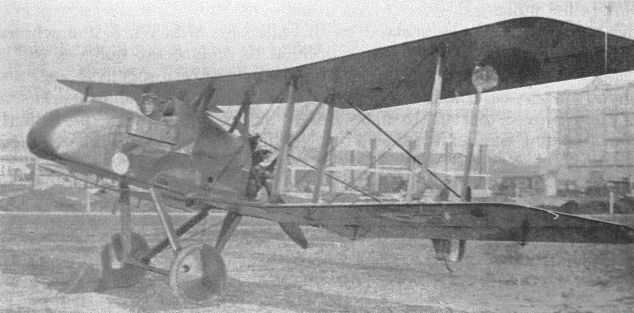
An unidentified production F.E.8 on Farnborough Common, with the Factory buildings in the background.
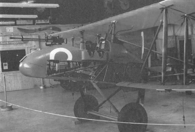
A replica F.E.8 on display at the Owl's Head Museum of Transportation, Maine, USA.
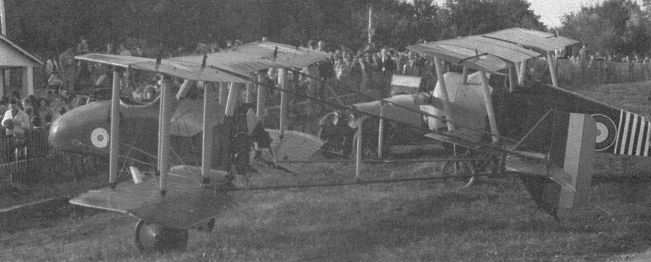
The replica F.E.8 built and flown by Cole Palen at Old Rhinebeck Aerodrome, New York, USA.
The occasion which prompted this impressive line-up of Factory designs is unfortunately not recorded, nor is the purpose of the marquee behind them, but the types present suggest a date of mid-1916. Left to right, the aircraft are: B.E.2c, B.E.2c, B.E.2b. B.E.12, Hispano-Suiza-powered B.E.2c, F.E.8, S.E.4a, F.E.2c, F.E.2b, R.E.8, R.E.8, and R.E.7.

R.E.7
Strictly speaking there was no prototype for the R.E.7, although the modified form of the R.E.5, with extensions to the upper wing, can possibly be regarded as having fulfilled that role. In fact, the design was briefly known as the R.E.5a before being redesignated R.E.7. The broad span of its wings endowed it with weight-lifting abilities which caused it to be regarded as worthy of volume production, and 233 were eventually ordered from various subcontractors.
As in the R.E.5, the forward fuselage was of steel tube, becoming a more conventional wire-braced wooden structure aft of the rear cockpit. The oleo undercarriage, which had a small buffer nosewheel, was similar to that of the early F.E.2b, and the airbrakes which had been tested on the R.E.5 were included, with the aim of reducing the landing run. The 120hp Beardmore engine, a licence-built Austro-Daimler, was again adopted, together with the concealed radiator previously designed for use in the R.E.5.
The production R.E.7 differed from the modified R.E.5 in several ways, being fitted with a new tailplane of higher aspect ratio and having a revised wing structure which eliminated the centre-section, the upper wing panels meeting above the fuselage centreline, where they were supported by inverted-vee cabane struts.1 The wingtip shape was modified to a semicircular planform, rather than the elliptical shape of the earlier design. The interplane struts were of a broad streamlined shape, their ends tapered in accordance with a formula established by W H Barling and H A Webb which eventually became standardised for strut design.
A mounting was provided beneath the cockpits to carry the 336lb bomb, which had itself been designed at the Factory, but, as was common at the time, no provision was made for any other armament.
Delivery of completed machines began in July 1915 and, following flight testing, the first example reached a front-line squadron in France by late the following September.
The R.E.7's service career was destined to be brief and undistinguished. Not only was the observer in the front cockpit, surrounded by struts and wires, unable to operate any effective armament, but the type was very seriously underpowered. Engineers at the Royal Aircraft Factory announced on 21 January 1916 that an increase in power of approximately five per cent could be obtained by the removal of the silencers and the substitution of stub exhausts. While this was useful when considered as pure research, it did little to improve the performance of the R.E.7, and the War Office was, quite understandably, unimpressed.
By March, Trenchard considered the R.E.7 to be so outclassed as to be 'useless', and he requested its immediate replacement. At that time, however, there was simply nothing better available, although the following month saw the first delivery of machines powered by the 140hp R.A.F.4a engine, copying an experimental installation made in the R.E.5 the previous summer. This engine, being both slightly more powerful and lighter than the Beardmore, gave a marked improvement in climb, although the top speed was little better. Difficulties with lubrication in the early production engines limited their reliability, and the aeroplanes thus powered soon met with Trenchard's disapproval, for they were still woefully underpowered. However, as was often the case at that stage in the war, the RFC simply had to accept whatever was available, and await the arrival of new types which had been designed in full knowledge of the needs of war.
Nevertheless, the Farnborough staff laboured on, making experimental installations of a number of alternative power units including the R. A.F.3a and the Rolls-Royce Falcon and Eagle. As with the F.E.2 series, only a massive increase in power could bring about any real improvement in performance, and the few engines capable of providing such power were needed for newer designs.
The R.E.7's lack of effective defensive armament, which was as great a handicap as its poor performance, was rather more easily resolved. A number of them had a third cockpit, complete with a Nieuport gun ring, installed behind the pilot. The first of these three-seaters, 2348, was completed and ready for trials by 26 September 1916, and had a 160hp Beardmore engine in lieu of the 120hp unit previously installed. Another benefited from the provision of a Rolls-Royce Eagle, and proved quite useful before it was written off in a crash on 31 January 1917.
Despite these various improvements the R.E.7 was still not really suitable for front-line service, and its withdrawal began in mid-1916, although it served with training establishments virtually until the end of the war.
A role in which the type finally found a niche was that of target tug, it being one of the first machines employed for this purpose, towing a cloth sleeve against which trainee aircrew could practise aerial gunnery.
Powerplant:
120hp Beardmore; 140hp R.A.F.4a V-12;
250hp Rolls-Royce Eagle V-12
Dimensions:
span
57ft 2in (upper);
42ft 0in (lower);
chord 6ft 0in;
gap 6ft 6in;
wing area 548 sq ft;
stagger 3in (11in with Rolls-Royce Eagle);
length 31ft 10 ? in;
height 12ft 7in.
Weights
(Beardmore): 2,170lb (empty); 3,290lb (loaded)
(R.A.F.4a): 2,140lb (empty); 3,349lb (loaded)
(R.R. Eagle): 2,702lb (empty); 4,109lb (loaded)
Performance (Beardmore):
max speed 82mph at sea level;
ceiling 6,500ft;
climb 30 1/2min to 5,000ft.
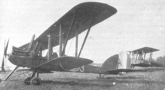
R.E.7 2423 at South Carlton. The aircraft behind the rudder is a D.H.6.
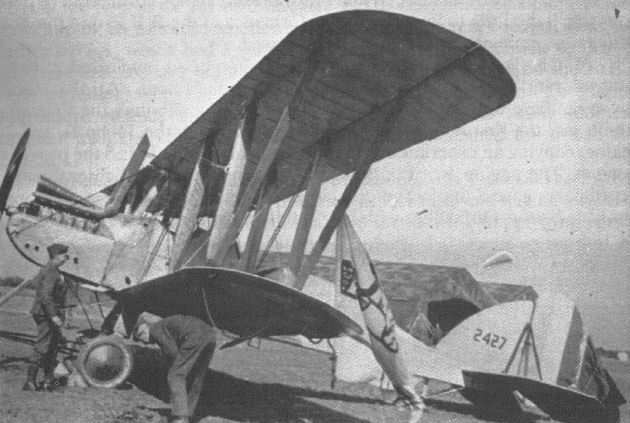
R.E.7 2427 in service as a target tug. The actual target, a crude drawing of an aeroplane fuselage, can be seen behind the port outer interplane struts.
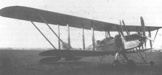
An unidentified R.E.7, showing the installation of its R.A.F.4a engine. Note the hinged airbrakes beside the forward cockpit.
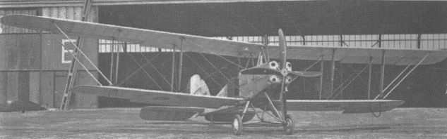
An R.E.7 fitted with a 225hp Sunbeam Maori engine in an elaborate cowling.
The occasion which prompted this impressive line-up of Factory designs is unfortunately not recorded, nor is the purpose of the marquee behind them, but the types present suggest a date of mid-1916. Left to right, the aircraft are: B.E.2c, B.E.2c, B.E.2b. B.E.12, Hispano-Suiza-powered B.E.2c, F.E.8, S.E.4a, F.E.2c, F.E.2b, R.E.8, R.E.8, and R.E.7.

B.E.12
Conceived about May 1915, when the B.E.2c continued to be the most effective aeroplane operated by the RFC and serious aerial combat was still a thing of the future, the design which became known as the B.E.12 was intended to give improved performance for roles such as bombing or photography, for which an observer was not usually carried. That it was not, initially, intended as a fighter is perhaps most clearly illustrated by the fact that the type had been in production for several months before any attempt was made to fit a gun to it.
The prototype was created by the conversion of standard production Bristol-built B.E.2c 1697. The front cockpit was eliminated, and the engine bearers were modified to accept the 140hp R.A.F.4 V-12 engine. This had separate exhaust pipes from each cylinder, and they were led to a single vertical exhaust stack in the form of an inverted 'Y' on the aeroplane's centreline, where it can have done nothing to improve the pilot's forward view. Twin air scoops were mounted in tandem in the cylinder-head vee to assist engine cooling. A large pressurised fuel tank, shaped to follow the line of the fuselage top decking, was mounted between the centre-section struts. The skid-equipped undercarriage with which 1697 had originally been fitted was replaced by the more modern vee-strut type.
This work was completed by 28 July, when the machine was presented for its preflight inspection, and testing and development proceeded at a fairly unhurried pace thereafter. By the end of August a large, single air scoop had been fitted, necessitating the division of the exhaust into separate stacks for each cylinder bank.
The B.E.12 remained at Farnborough for most of the next month, supposedly for bomb-dropping experiments, although no evidence has been found of a bomb rack being fitted. On 22 September a larger, curved fin, as was to become standard for later B.E.2s, was fitted, and 1697 then went to France for service trials.
Production orders were placed with the Coventry Ordnance Works, the Standard Motor Company and Daimler, the last also undertaking production of the R.A.F.4a engine. Perhaps coincidentally, all three companies were based in Coventry.
Delays in engine manufacture held up completion of the first production B.E.12 until late March 1916, when Daimler-built 6478 arrived at Farnborough. Production aircraft differed from the prototype in having their upper fuselage longerons set down to a lower level forward of the cockpit, the engine mounting being similarly lowered. This improved the forward view over the engine air scoop, and allowed a larger petrol tank to be fitted. A streamlined gravity tank was also provided, under the port wing. Early examples had the original triangular fin, a larger fin of a type already fitted to 1697 being introduced later. All production machines were equipped with a camera mounting on the starboard side of the fuselage, outside the cockpit.
The prototype remained at the Factory and, from March 1916, was fitted with a number of experimental gun installations. Since there was still no British synchronisation gear, the initial installation, using a Lewis gun, featured blocks fitted to the propeller to deflect bullets. A later installation had the six-pounder Davis gun firing upwards at an angle of forty-five degrees, the muzzle being level with the top wing to place the breech within easy reach of the pilot. This was presumably intended for use against high-flying Zeppelins, but it was not adopted for service use.
Finally, the newly developed Vickers-Challenger interrupter gear was adopted, operated a belt-fed Vickers machine gun mounted on the port side of the fuselage. The engine's air scoop prevented its installation in the favoured position on top of the decking, immediately in front of the cockpit. This fuselage-side mounting made jam clearing difficult, as the pilot had to reach far outside the cockpit. Unfortunately the sights also needed to be positioned on the aircraft's side for the same reason, forcing the pilot to lean out into the slipstream to take aim.
In mid-1916, in the wake of the 'Fokker scourge', the B.E.12 was pressed into service as a fighter, but its use in this role was soon curtailed following reports that it lacked even the limited manoeuvrability of the B.E.2c. In July the smaller tailplane designed for the B.E.2e was adopted for the B.E.12, and brought some improvement in handling, but the type quickly returned to the bomber role for which it had been designed, and in which it continued until February 1917.
Like the B.E.2c from which it was derived, its stability made it eminently suitable for use as a night fighter. It replaced the B.E.2c in this duty, and its greatest success occurred on 17 June 1917, when Lt L P Watkins of No 37 Squadron, flying 6610, brought down the Zeppelin L48.
Experiments in rendering aeroplanes less visible led, in February 1917, to the rear fuselage of 6148 being covered in transparent celluloid instead of fabric, but a lack of success is suggested by the early termination of the experiment.
Like many machines designed in the early part of the war, the B.E.12 continued in service for longer than its suitability dictated, new and less demanding roles being found as obsolescence approached. Thus the B.E.12 served almost to the end of the war as a trainer and on anti-submarine patrols, for which duty it was usually armed with two 112lb bombs.
The uprated R.A.F.4d, developing 200hp, was fitted to B.E.12 C3188 at the Orfordness experimental establishment, but no details of improvements in performance are available.
Powerplant: 140hp R.A.F.4a V-12
Dimensions:
span 37ft 0in;
chord 5ft 6in;
gap 6ft 3 1/4in;
wing area 354sqft;
dihedral 3 1/2;
stagger 2ft 0in;
incidence: 4° 9''.
length 27ft 3in;
height 11f t 1 1/2in.
Weights:
1,635lb (empty)
2,353lb (loaded)
Performance:
max speed 102mph at sea level;
97mph at 6,000ft;
endurance 3hrs;
ceiling 12,500ft;
climb
6min to 3,000ft;
14 min to 6,000ft.
B.E.12a
Since the B.E.2e was viewed, at the time of its inception, as being almost infinitely superior to previous variants, it was inevitable that the B.E.12 should also be modified to have the new unequal-span wings. In this form the machine was initially designated the B.E.12Ae, but this was quickly simplified to the more conventional B.E.12a. Production orders, each for fifty aircraft, were placed with Daimler and the Coventry Ordnance Works.
The B.E.12a was initially judged to be easier to land and manoeuvre than its two-bay predecessor but, in reality, it showed little improvement over the earlier type and its use was largely confined to Home Defence units and the less-demanding theatre of operations in the Middle East. Some also served with the Royal Australian Air Force.
In November 1916 a new set of wings was constructed which had increased tip rake and included ailerons, incorporating large balance areas, on the top wing only. These wings were fitted to 6511, which had originally been built as a B.E.12, and on the 13th of that month Frank Goodden began flight tests. These showed no significant improvement in performance, and were reported to render the handling characteristics 'unpleasant', so the design was dropped, although a similar wingtip plan was reintroduced with the F.E.9.
Powerplant: 140hp R.A.F.4a V-12
Dimensions:
span
40ft 6in (upper);
30ft 6in (lower);
chord 5ft 6in;
stagger 2ft 0in;
gap 6ft 3in;
wing area 360sq ft;
length 27ft 3in;
height 12ft 0in.
Weights:
1,610lb (empty)
2,327lb (loaded)
Performance:
max speed 105mph at sea level;
93mph at 6,000ft;
climb
5min to 3,000ft;
11 1/2min to 6,000ft.
B.E.12b
Despite occasional successes by Home Defence squadrons, Zeppelin raids continued to cause widespread concern, and the raiders usually escaped simply because the defending aeroplanes lacked sufficient performance to reach the airships' normal operating altitudes in time to catch them. Therefore, in September 1917, a 200hp Hispano-Suiza engine was fitted to a B.E.12, this machine being preferred by service pilots to its single-bay successor. A car-type radiator gave the new machine a nose profile similar to that of the S.E.5, and long exhaust pipes, terminating aft of the cockpit, were fitted. It is possible that the installation was made by the Southern Aircraft Repair Depot, which shared the Farnborough site, but, whatever the case, the designers of the Royal Aircraft Factory were closely involved.
The new machine, designated B.E. 12b, was found to possess a rate of climb so much improved that, despite the (ever-pressing) shortage of Hispano-Suiza engines or the licence-built variants, 100 examples were ordered to be built by Daimler.
The B.E.12b was normally armed with a single Lewis gun on an overwing mounting, firing over the propeller disc, the wing shielding the pilot's eyes from the muzzle flash. Some examples sported twin guns, similarly positioned. A ring-and-bead sight was provided, fixed to the starboard centre-section struts. In view of their intended role as night fighters, B.E.12bs were provided with navigation lights and Holt flare brackets under their lower wingtips to facilitate landing. Some machines had exhaust pipes with their ends flared out to act as flame dampers. The normal B.E.12 fuel tank was retained but, as this was shaped to continue the slope of the air scoop needed with the R.A.F.4a engine, it was turned around so that it sloped upwards to the rear, thus reducing its resistance.
As the Zeppelin attacks had virtually stopped before many B.E.12bs could be built, few ever saw service. It is possible that many airframes never actually received Hispano-Suiza-type engines and may have been completed as standard B.E. 12s powered by R.A.F.4as.
Powerplant: 200hp Hispano-Suiza V-8
Dimensions: As B.E.12a.
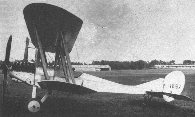
The prototype B.E.12. Note the tandem air scoops to cool its R.A.F.4a engine, and the complex exhaust system.

A B.E.12b with its ground crew. Note the bomb racks under the wings and fuselage.
The occasion which prompted this impressive line-up of Factory designs is unfortunately not recorded, nor is the purpose of the marquee behind them, but the types present suggest a date of mid-1916. Left to right, the aircraft are: B.E.2c, B.E.2c, B.E.2b. B.E.12, Hispano-Suiza-powered B.E.2c, F.E.8, S.E.4a, F.E.2c, F.E.2b, R.E.8, R.E.8, and R.E.7.
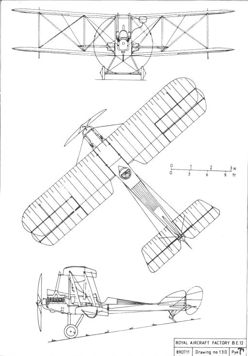
BE12
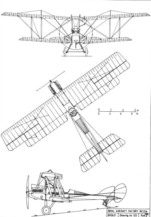
BE12a
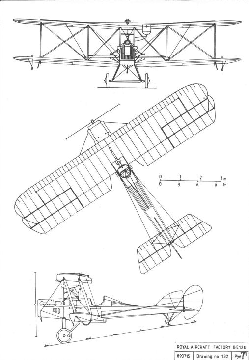
BE12b
B.E.2e, f & g
Designed with the admirable intention of bringing about an improvement in the B.E.2's somewhat outdated performance, the 'e' variant had single-bay wings of unequal span and with outwardly-raked tips, the long upper-wing extensions being braced from inverted-vee kingposts above the interplane struts. The wings were rigged at a constant incidence, without wash-out. The tailplane was also new, being of reduced area and also having outwardly-raked tips. A larger fin with a curved leading edge was adopted for the new machine. There seems to have been no attempt to reverse the crew positions, although the arrangement of the fuel tanks was again revised.
The prototype, which was created by fitting the new wings and tail surfaces to Bristol-built production B.E.2c number 4111, made its first flight on 18 February 1916. As had been expected, its performance was somewhat better than that of earlier variants, and on 1 March Mervyn O'Gorman informed the War Office that its maximum speed was 97mph at ground level and about 90mph at 6,000ft. There is some reason to believe that these results may have been obtained using the R.A.F.1b engine, which was rated at 105hp, but this engine did not enter production, and the 90hp R.A.F.1a remained the standard powerplant. Thus powered, the B.E.2e's speed was recorded as 82mph at 6,000ft, which, although not fast, was at least ten per cent faster than the B.E.2c at the same altitude.
Lateral control was reported as being 'very much better', landing was 'more easy', and climb increased by between seven and ten per cent. These improvements were considered sufficient to justify putting the B.E.2e into large-scale production, and also having all unfulfilled orders for earlier variants completed as B.E.2es. While these machines were all taken on charge by the Royal Flying Corps as B.E.2es, however, it was found that, in practice, they were of three distinct and different types: the B.E.2e as designed, the B.E.2c fuselage fitted with the new tail and single-bay wings, and the B.E.2d fuselage similarly equipped. Each type had a different arrangement of fuel tanks and a slightly different performance. In addition, those with the B.E.2d fuselage retained the dual controls of that variant. This made maintenance and the requisitioning of spares unnecessarily difficult, and clearly required some easy means by which the three types could be distinguished. The RFC therefore decided that aeroplanes with single-bay wings and the B.E.2c fuselage would be designated the B.E.2f, and those with the B.E.2d fuselage would be B.E.2gs.
Although the B.E.2e's performance was an improvement on that of its predecessors, it was less than adequate for service on the Western Front and, since the machine was as poorly armed as previous variants, losses were high. Nonetheless, the B.E.2e carried on to the end of the war, gradually being replaced by the R.E.8 and various other, more modern, types.
The B.E.2e also served in every other theatre of war and, by the time of the Armistice, when all outstanding orders were cancelled, it had been produced in greater numbers than any other B.E.2 variant. In addition, a very great number served in training establishments in England, and it was rare indeed for any pilot to gain his wings without having flown one.
Allegations that the long extensions on the upper wing were structurally unsound, and that they would collapse if too much stress was put on them by violent manoeuvres, were investigated by the Royal Aircraft Factory and proved to be unfounded. Despite this the rumours persisted, and prompted a number of pilots to treat their mounts with undue caution.
As with the B.E.2c, at least one attempt was made to fit the 150hp Hispano-Suiza, utilising a car-type frontal radiator of the type by that time used on the S.E.5. Although the installation was technically a great success, it was not adopted for production, simply because a number of other aircraft - most notably the S.E.5 - had a better claim to the limited supply of engines then available.
At least one experimental version was built with wings of increased chord and of R.A.F.18 section, although neither its intended purpose nor relative success can now be ascertained.
After the war use of the B.E.2e was quickly discontinued. Only a handful found their way on to the civil register, perhaps reinforcing the generally held opinion that the type was staid and uninteresting, but the type was used by a number of foreign air services, notably that of Norway, until the mid-1920s.
Powerplant:
90hp R.A.F.1a V-8
105hp R.A.F.1b V-8
Dimensions:
span
40ft 6in (upper);
30ft 6in (lower);
chord 5ft 6in;
gap 6ft 3in;
wing area 360sqft;
stagger 2ft 0in;
dihedral 3 1/2°;
incidence 4° 9";
length 27ft 3in;
height 11ft 9in.
Weights:
1,431lb (empty);
2,100lb (loaded)
Performance (R.A.F.1a) :
max speed
90mph at sea level;
82mph at 6,500ft;
ceiling 9,000ft;
climb 20min to 6,000ft;
endurance 4hrs.
(R.A.F.1b)
max. speed 97mph at sea level;
ceiling 12,000ft.
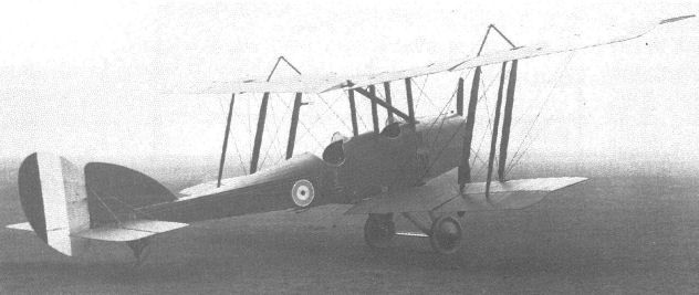
RNAS B.E.2e 6326 with a neatly-cowled Curtiss OX-5 engine and a car-type frontal radiator.
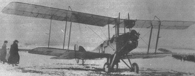
This unidentified B.E.2e (or g), forced down by a blizzard near Wragby in Lincolnshire, clearly shows the long upper-wing extensions which distinguished the type and which gave rise to initial concern regarding their strength.
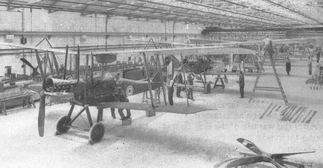
B.E.2gs under construction at Wolseley Motors. The nearest aircraft is A3113, a presentation machine bearing the legend Orissa States No3.
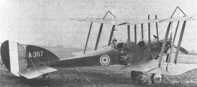
B.E.2e A3117 with a camera fitted beside the pilot's cockpit. The type's inherent stability must have been an asset when plates had to be changed while trying to hold the machine in straight and level flight.

F.E.4
In mid-1915 a team led by S J Waters and Henry Folland undertook the design of a twin-engined pusher biplane designated F.E.4, the basic layout of which was based upon the results of windtunnel tests intended to establish the most effective configuration. The machine was somehow intended to meet three rather diverse requirements:
a Ground-attack fighter, armed with a one-pounder Coventry Ordnance Works gun and with an endurance of four hours,
b Short-range bomber, with a 1,200lb bomb load and a three-hour endurance.
c Long-range bomber with eight hours endurance, albeit with an appropriately reduced bomb load.
The last specification was the specific request of Brig-Gen Trenchard, Commander of the RFC in France and thus the aeroplane's ultimate 'end-user'.
The F.E.4 was a big aeroplane, particularly by the standards of 1915, with a wing span greater than 75ft. The overhanging extensions to the upper wing were arranged to fold downwards, a feature which was intended to facilitate storage but which, in reality, merely added unnecessary complexity to the machine's structure.
The pilot was placed in the extreme nose, with an observer/gunner immediately behind him. Dual controls were provided, a facility which most crews would consider obligatory in a machine for which an endurance of up to eight hours was planned. Since the observer would clearly be unable to defend the machine's tail against attack, a third crew position was provided behind the wings to house a rear gunner. A revised drawing was later prepared in which this gunner is repositioned in a streamlined nacelle above the top wing centre-section, giving him an enormous field of fire, but this modification does not appear to have been incorporated in an actual aeroplane. In the same drawing the auxiliary nosewheels are replaced by small semi-circular skids.
Although it was originally intended that the F.E.4 should be powered by two R.A.F.3a engines, none was available for installation in the prototype and two lower-powered R.A.F.5s were substituted. These, the pusher version of the air-cooled R.A.F.4, had small tractor propellers to ensure that there was an adequate movement of cooling air over the engines at all times.
The prototype, which was given the serial 7993, was completed ready for AID inspection on 8 March 1916, and made its first flight a few days later, with Frank Goodden at the controls. It proved to be woefully sluggish, as might have been expected with engines developing only three-quarters of the power for which it had been designed, and could barely exceed 80mph, compared with the 100mph anticipated by its designers.
Despite its shortcomings, which were not apparent to a casual observer, it was demonstrated to King George V during his visit to Farnborough on 26 April. On 11 May it went to the Central Flying School for evaluation, and was found to be stable but pitifully underpowered.
As there were still no R.A.F.3as available, a second prototype, 7994, was converted to accept 250hp Rolls-Royce Eagle engines, complete with radiators similar to those used on the F.E.2d. At the same time the total fuel capacity was increased from 193 gallons to 250. There was no rear gunner's cockpit. This machine, to which the designation F.E.4a has often, but erroneously, been applied, did not fly until 5 June 1916, again with Goodden in the pilot's seat. Despite the increased power the performance was still wholly unremarkable and, since there were many obviously superior designs available, the trials were discontinued and the Rolls-Royce engines, for which there was an insatiable demand, were removed for use in other aircraft. A production order for 100 machines, which had been placed with Daimler, was cancelled before any could be completed.
Both prototypes were still extant in July 1917, but a suggestion that they should be pressed into service as night bombers, a duty for which their lack of speed was no real handicap, was not taken up owing to a continued shortage of suitable engines. They were eventually broken up.
Powerplant:
2 x 140hp R.A.F.5a
2 x 250hp Rolls-Royce Eagle
Dimensions:
span
75ft 2in (upper);
62ft 6in (lower);
chord
9ft 0in (upper);
7ft 6in (lower);
wing area 1,032 sqft;
length 38ft 8 1/2in;
height 16ft 9in
Weights
(R.A.F.5a): 3,754lb (empty); 5,988lb (loaded)
(Eagle): 7,825lb (loaded).
Performance:
(R.A.F.5a)
max speed 84mph at sea level;
ceiling 6,000ft
(Eagle)
max speed 92mph at sea level;
ceiling 12,000ft.
F.E.5
Although it was never completed, this ambitious project showed great potential. It was to have been a twin-fuselage, three-engined development of the F.E.4, powered by two tractor 140hp R.A.F.4as mounted in the nose of each fuselage, and a pusher R.A.F.5 mounted centrally on the lower wing. Intended as a heavy bomber, and designed with a wing span in excess of 100ft, the F.E.5 would almost certainly have been as painfully underpowered as the original F.E.4, and may well have been abandoned for that reason.
In common with many other Royal Aircraft Factory projects, the F.E.5 was the subject of windtunnel testing during its design, the tests being described at length in the Advisory Committee's report for 1916-17.
Dimensions Span 103ft 0in.
F.E.7
Another uncompleted design project developed from the F.E.4 concept, this big biplane was to have been powered by two 250hp Rolls-Royce engines mounted within the fuselage, driving twin pusher propellers via gears and shafts.
It was clearly intended for an offensive role, as proposals for its armament appear to have included the one-pounder COW gun, with which its designers seemed to be obsessed, as its main weapon. Several Lewis guns were provided for defence. It was also planned for use as a long-range or heavy bomber, but the design was not completed and no machines were built.
Dimensions
Span 67ft 9in
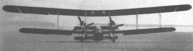
The first F.E.4, with R.A.F.5 engines. Note the small tractor propellers and huge air scoops essential to assist engine cooling.
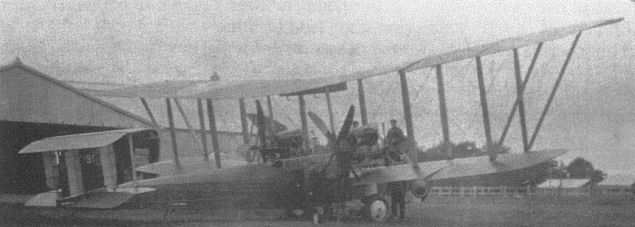
The first prototype F.E.4, 7993, in P.C.10 finish at the Central Flying School for service trials.
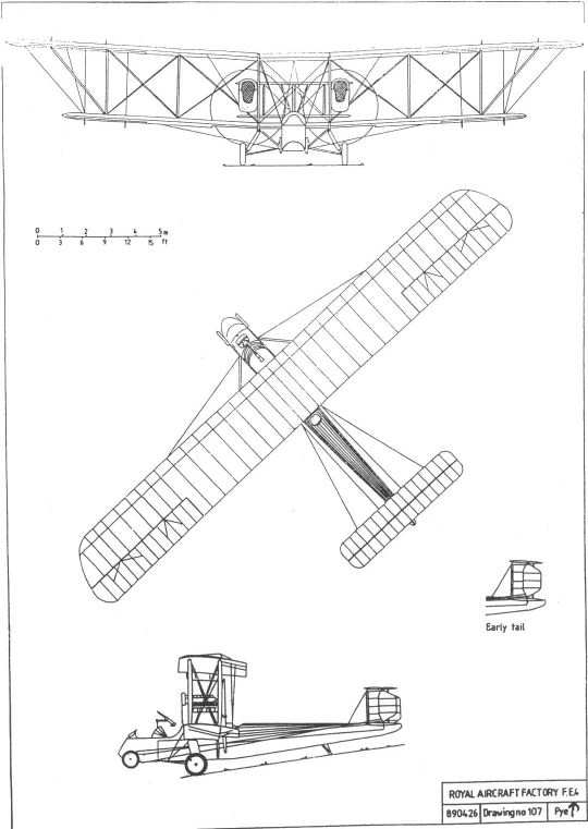
R.E.8
Design work on this general-purpose two-seater, which was conceived as a replacement for the obsolescent B.E.2c, started late in 1915, the drawings being finalised early the following year. It owed little or nothing to any previous R.E. type, except perhaps that the powerplant was the R.A.F.4a, the lubrication problems of which were now believed to be solved. As the wings and tailplane of the new design were virtually identical with those of the B.E.2e, it is not unreasonable to suggest that the designation R.E.8 was deliberately chosen to avoid any prejudice which may have been caused by placing it within the now discredited B.E. series where it really belonged.
The fuselage was a conventional wire-braced wooden structure, the cross-sectional area of the aft end being kept as small as possible to reduce the vulnerable 'blind spot' and to increase the observer's field of fire. The engine was mounted to give downthrust which, together with the mainplanes' generous angle of incidence, would reduce the landing run, obviating the need for the airbrake which had been a feature of earlier designs. This inclination, visually exaggerated by the scoop which admitted cooling air to the engine, gave the machine a somewhat 'broken-backed' appearance which was not immediately attractive.
Rudimentary dual control was provided in the rear cockpit, but was arranged so as not to interfere with the observer's normal duties. His control column, which operated the elevators only, was on the starboard side, convenient to his right hand, and was normally clipped to the fuselage framework when not in use. On the port side of the cockpit there was a conventional throttle, below which was a hand grip attached to the rudder cables.
The pilot's instrument panel included only a compass, an oil pressure gauge, a revolution counter, an airspeed indicator, an altimeter, a clinometer and a watch. The tailplane incidence could be adjusted by a wheel in the pilot's cockpit to trim the aeroplane, which could be made to fly 'hands-off', the inherent stability beloved by Farnborough's designers being provided by generous lateral and longitudinal dihedral. To offset the machine's normal tendency to turn slowly to the right as a torque reaction to the rotation of the propeller, a rubber cord was attached to the rudder bar, its tension being adjustable via a Bowden-type lever. This relieved the pilot of the need to apply constant foot pressure to keep the machine on a straight course.
The rudder was of high aspect ratio and adequate area, but the fin, although of generous proportions in the preliminary layout drawings, was reduced in size in the final design and appears, in hindsight, to have been dangerously small.
The initial design work was completed before any gun synchronization system became available, and preliminary drawings included provision for a fixed forward-firing Lewis gun, deflector blocks being attached to the propeller blades to prevent damage. The R.E.8 was equipped with a mounting for a Thornton Pickard camera.
Two prototypes, 7996 and 7997, were built, the former taking to the air for the first time on 17 June 1916, piloted by Frank Goodden. The second machine made its first flight on 5 July, and on the 16th Goodden flew it to France for the all-important service trials. It was tested by an unusually wide range of personnel, ranging from Gen Brooke-Popham to pilots from front-line squadrons, and although a number of small details were criticised, all reported favourably. Brooke-Popham was particularly impressed by its speed range, but insisted that its offensive armament should be a belt-fed Vickers gun, not the Lewis as originally planned.
The necessary modifications were speedily incorporated into the drawings, and into the batch of approximately fifty machines already under construction in the Farnborough workshops. Within a matter of weeks production orders for over a thousand more had been placed with numerous contractors.
The engine's air scoop made it nearly impossible to mount the Vickers gun in the usual position, on the cockpit coaming immediately in front of the pilot, and several alternative, locations were tried before an external mounting low on the port side of the fuselage was adopted as standard. The Vickers-Challenger interrupter gear used in early installations was later replaced by the hydraulically operated Constantinesco gear, and the far more effective Scarff ring eventually replaced the simple pillar mounting which originally carried the observer's Lewis gun.
The first, Royal Aircraft Factory-built, production R.E.8 was completed by 13 September 1916, and by November 52 Squadron had been fully equipped with the type. However, it appeared not to live up to its initial promise, and the squadron's pilots encountered difficulties both with the engine, which was still not totally free of its earlier problems, and with involuntary spins. Totally disillusioned with the new machines, they were allowed in January 1917 to exchange their R.E.8s for the B.E.2es then being operated by 34 Squadron, whose much more experienced pilots were considered better able to cope with the R.E.8's alleged 'trickiness'. Maj J A Chamier, who was on the staff of the Third (Corps) Wing, to which both squadrons belonged, prepared the following notes for the guidance of pilots, describing the characteristics and handling of the R.E.8:
". . . the chief thing to remember is that the machine gives very little indication of losing its speed until it suddenly shows an uncontrollable tendency to dive which cannot be corrected in time if you are near the ground . . .
"You will find that the rudder control in every case of spinning or swinging tail will become very stiff, and you may not be able to get it very central but you should aim (without putting on sufficient pressure to break anything) to do this.
"With the engine off the only thing is to avoid gliding too slowly . . . at 65mph or below, when gliding, the machine suddenly loses speed. This is particularly the case when making a turn to enter the aerodrome as the extra resistance caused by the rudder is sufficient to bring down the pace . . .
"One more point as regards losing speed. Observers must be cautioned that when an aeroplane is gliding down from work over the lines they must not stand up in order to look over the pilot's shoulder for the fun of the thing, as the extra head resistance caused may lead to the aeroplane falling below its critical gliding speed, and so bring about an accident."
At the request of Lord Cowdray, Chairman of the Air Board, the Factory conducted a series of spinning trials in February 1917 to determine the cause of the difficulty. Three machines were tested; a standard production example, another with an enlarged fin, and a third in which the engine thrust line was less inclined. The report of these trials, dated 5 March, concluded that the standard R.E.8 could only be spun either by a determined effort or by serious misuse of the controls. The report also criticised standards of training, for many new pilots reached the Front after only a few hours' instruction, and with no knowledge of spin recovery.
As with the F.E.8 the previous summer, the publication of this report appeared sufficient to restore confidence in the machine. Its production and introduction into front-line service continued, a total of fifteen Corps Squadrons eventually being equipped with the type, as well as units in Palestine and Mesopotamia.
However, the Farnborough staff did not rest upon their laurels, but continued to investigate the R.E.8's spinning characteristics, experimenting with various forms of fin and rudder, some of which were balanced. They finally settled for a small increase in the area of both the dorsal and ventral fins, the original rudder being retained. These changes were incorporated into production machines as soon as possible. If the report was correct in asserting that the R.E.8 could only be spun deliberately, it is tempting to speculate that the change was made only to appease popular opinion. A similar lack of explanation surrounds the fin of greatly increased area fitted to some machines in use at training establishments. If such a modification was considered advantageous for training, why was it not thought necessary for active service?
Regardless of these uncertainties, RFC crews generally thought well of the R.E.8. One man who flew it, Phillip Townsend, said, 'It was a fine aircraft; easy, comfortable, lovely to fly. It would do anything asked of it up to its limited ability. It was very good on side slips, I never had any difficulty, the engine never let me down.'
A number were equipped, in service, with underwing bomb racks, and could carry either two 112lb bombs or up to eight 20lb bombs.
Affectionately known as the 'Harry Tate', after the contemporary music hall performer of that name, the R.E.8 remained in service and in production up to the end of the war, a total of 4,077 being built. Apart from modifications to the fin, very few detail changes were made to its design during its career, but those which were made included the substitution of all-wooden undercarriage legs for the faired-steel-tube units originally fitted, a deeper sump cowling and, in July 1917, a change of carburetor which marginally improved engine performance.
One batch of seventy-five was ordered with the Rolls-Royce Eagle engine, but the Eagle was never available in sufficient quantities to meet the need of those aeroplanes which were unable to accept any other power unit, so no R.E.8 was ever thus powered.
One example was retained by the Factory, and was used to test an experimental R.A.F.4d engine which had its output boosted to 200hp by supercharging via an exhaust-driven Rateau turbine. Initial overheating problems were solved by fitting a hugely enlarged air scoop over the cylinder heads. Testing was cut short when the turbine burst on 4 May 1918 and the experiments were discontinued. A four-bladed variable-pitch propeller was also tested with this engine, but was removed after two flights because its adjustment mechanism was unsatisfactory.
A small number of R.E.8s was supplied to Belgium, and these were converted upon arrival to the water-cooled Hispano-Suiza V-8 engine, enclosed within a neat, extensively louvred cowling.
Like many of its contemporaries which were designed for a specific role in war, the R.E.8 found virtually no use after the Armistice, either with the RAF or on the civil register.
Powerplant: 140hp R.A.F.4a V-12
Dimensions:
span
42ft 7in (upper);
32ft 7 1/2in (lower);
chord 5ft 6in;
stagger 2ft 0in;
wing area 377 1/2sqft;
gap 6ft 3 1/2in;
dihedral 31/2;
length 27ft 10 1/2in;
height 11ft 4 1/2in.
Weights
1,803lb (empty);
2,869lb (loaded plus 2 x 112lb bombs).
Performance
max speed 103mph at sea level;
stalling speed 47mph
ceiling 13,500ft;
climb 21min to 6,500ft (with 2 x 112lb bombs);
endurance 4 1/4hrs.
R.E.8a
In December 1916 a 200hp Hispano-Suiza V-8 engine was experimentally installed in R.E.8 A95, one of the original Farnborough-built batch. In this form the machine was referred to as the R.E.8a. It had a neat radiator and engine cowling reminiscent of that of the S.E.5.
Although no performance figures survive for this variant, the almost fifty per cent increase in power can only have brought about a significant improvement. However, production difficulties with the Hispano-Suiza were already delaying the completion of S.E.5as, for which there was no effective alternative powerplant, and there were never any engines to spare to enable the R.E.8a to be put into production.
Dimensions
As R.E.8
Weights and performance unknown

An early R.E.8 with a pillar mounting for the observer's Lewis gun. Later machines were fitted with the Scarff-ring mounting.
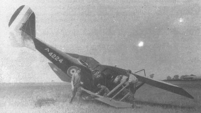
This view of Daimler-built R.E.8 A4224 following a landing accident shows the roominess of the pilot's cockpit.
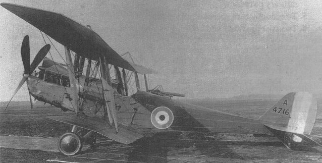
A production R.E.8, built by the Coventry Ordnance Works, with the deeper sump cowling introduced for later machines.
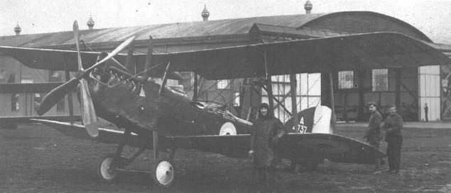
A tyro pilot leans proudly against R.E.8 A4737 at Scampton in 1918. This machine has the later sump cowling and the enlarged fin common at training establishments but never used in active service.
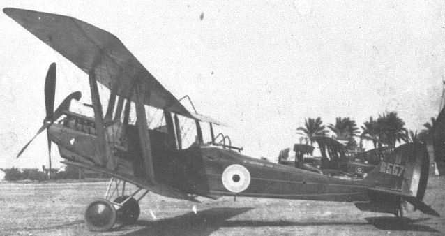
R.E.8 6557 of 142 Squadron with the slightly enlarged fin adopted for most production aircraft. Note the unfaired steel-tube undercarriage legs.
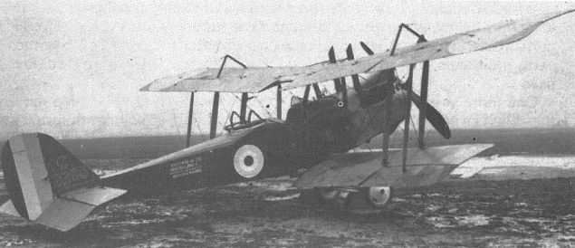
Immaculate Daimler-built R.E.8 C2298. Note the wheel chocks and the screw pickets beneath the wings.
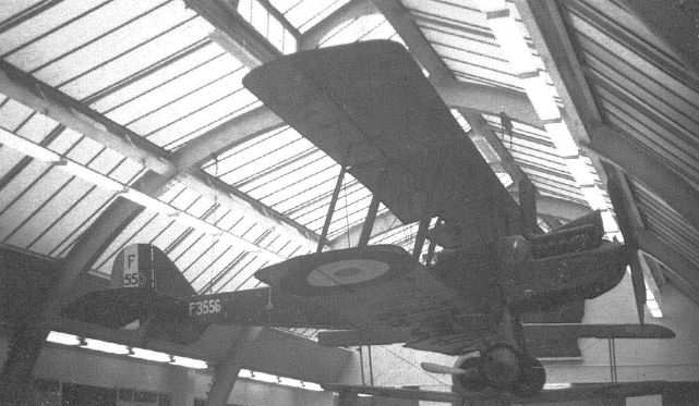
R.E.8 F3556 at the Imperial War Museum in London before its transfer to Duxford for restoration and display.
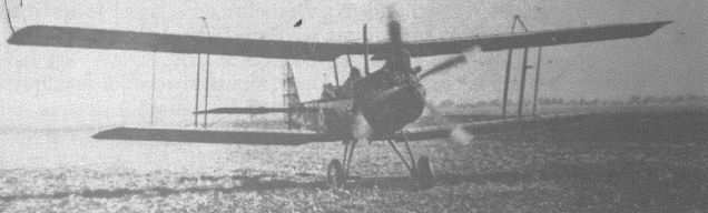
An unidentified R.E.8 taking off from a large, level and luxuriantly grassed field.

The R.E.8, like its predecessor, the B.E.2, served in every theatre of war. This example is over the desert somewhere in the Middle East.
The occasion which prompted this impressive line-up of Factory designs is unfortunately not recorded, nor is the purpose of the marquee behind them, but the types present suggest a date of mid-1916. Left to right, the aircraft are: B.E.2c, B.E.2c, B.E.2b. B.E.12, Hispano-Suiza-powered B.E.2c, F.E.8, S.E.4a, F.E.2c, F.E.2b, R.E.8, R.E.8, and R.E.7.
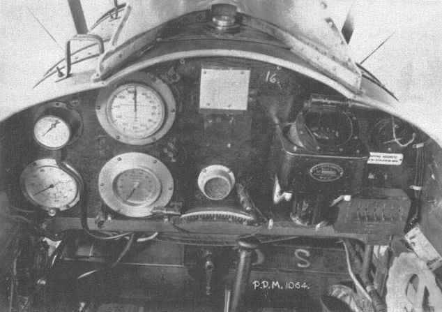
An R.E.8 pilot's 'office', including a Royal Aircraft Factory-pattern compass. Layouts varied slightly between manufacturers, but all machines were similarly equipped.
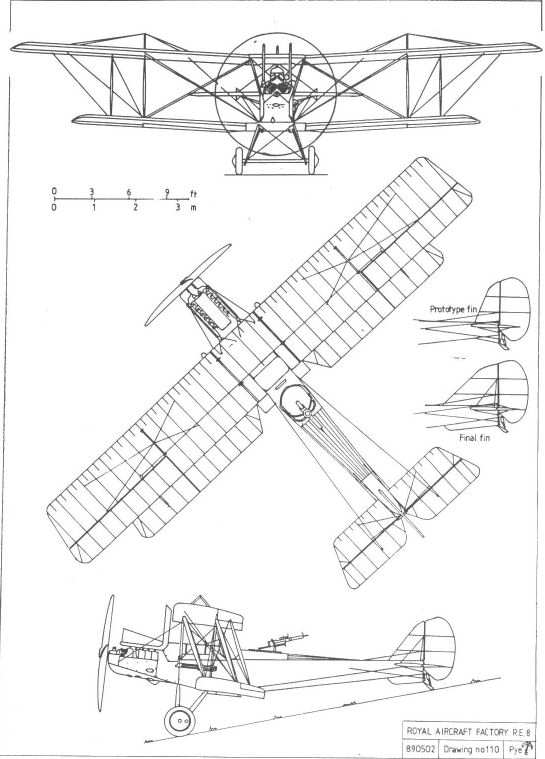
R.E.9
In mid-1917 a production R.E.8, A4600, had its wings replaced by those from a B.E.2d. Flight trials proved satisfactory and, since this wing structure was stronger than the standard R.E.8 assembly, drawings were prepared for a production version, to be designated the R.E.9.
It may have been the intention of H P Folland, the machine's designer, to settle all the criticism levelled at the R.E.8, for, in addition to its new equal-span, two-bay wings with blunt tips and narrow-chord ailerons hinged from a false rear spar, the new machine was to have an enlarged fin and an aerodynamically balanced rudder. A second machine, A3561, was similarly modified, but had ailerons of slightly shorter span. However, test results showed no advantage in performance over that of the standard R.E.8, the rate of climb being somewhat poorer, and the new design was consequently not adopted for production.
The eventual fate of the two machines is not known, although A3561 was retained at Farnborough as a test bed for some time, and was fitted with various modified control surfaces and also, during 1918, with a 265hp Sunbeam Maori engine.
A broadly similar design, designated the R.T.1, was produced by the Siddeley Deasy Motor Car Company, where both F M Green and J Lloyd had taken up employment after leaving Farnborough. It appears to have been based upon preliminary work previously undertaken at the Royal Aircraft Factory concurrently with the R.E.9 project. The R.T.1 had a modified R.E.8 fuselage, for which type the company was.a contractor, to which were fitted two-bay wings of new design, the upper wing being of greater chord than the lower. Three prototypes were built and tested, but the type was not adopted by the RFC.
Powerplant: 140hp R.A.F.4a V-12
Dimensions:
span 38ft 6in;
chord 6ft 0in;
wing area 382 sq ft;
gap 6ft 3 1/2in;
length 27ft 7in;
height 10ft 5in.
Weight: 2,803lb (loaded).
Performance
ceiling 13,000ft.

S.E.5
Although it has occasionally been suggested that the design of this neat and attractive single-seater scout was carried out, at least in part, by Frank Goodden, it is doubtful whether his role extended beyond suggesting features he felt would be desirable, for H P Folland's style is clearly evident in every detail.
The S.E.5 was designed around the Hispano-Suiza V-8 engine, which, when it was first unveiled in mid-1915, was universally heralded as a significant advance in engine design. The use of this largely untried 200hp engine, with its reduction-geared propeller, was clearly intended from the start, because the sole armament originally envisaged for the S.E.5 was a Lewis gun mounted between the cylinder heads and firing through a hollow propeller shaft, an arrangement which obviated the need for synchronization gear, which the Allies had yet to perfect.
The original drawings show a compact and very conventional tractor biplane, its pilot seated unusually high to give him the best possible view past the upper wing. The vertical tail included both dorsal and ventral fin surfaces and a rudder which, save for its rounded corners, was a narrow parallelogram. The control wires to the rudder and elevators were routed wholly within the fuselage to reduce drag. To make the aircraft safe to be flown by inexperienced or inadequately trained pilots, the wings were given generous dihedral angle to afford a reasonable degree of stability, equally generous control surfaces being provided to allow good manoeuvrability. The tailplane incidence could be adjusted, via a control wheel in the cockpit, to trim the machine to fly 'hands off#.
One departure from convention, made in the interests of simplified construction, was the omission of compression ribs in the wing structure. Instead, some of the normal aerofoil ribs were formed from solid ply to carry the compression forces.
Three prototype S.E.5s were built, the first, A4561, being completed by November 1916. It differed from the original drawings in having the fin and rudder originally designed for the F.E. 10, an unbuilt project also designed around the Hispano engine. As no 200hp engine was available, a direct-drive unit of 150hp was installed in A4561, which was not fitted with any armament.
Frank Goodden took it up for its initial flight at about 10.00am on 22 November and, on landing after about ten minutes, exuberantly announced to the waiting spectators, 'She's a pixie!'. Capt Albert Ball, who was allowed to make a short flight the following day while on a visit to Farnborough, was less enthusiastic, comparing the new machine unfavourably with the lightness of the rotary-powered Nieuport which was then his usual mount. However, he was later to revise his opinion.
The second prototype, A4562, which appears to have been identical to the first, was test flown, again by Goodden, on 4 December. A heavy landing during subsequent testing necessitated a replacement undercarriage, and while it was in the workshop the machine was fitted with what would become the type's service armament. A belt-fed Vickers gun was mounted in the forward fuselage decking, offset to port and inclined at five degrees above the line of flight to lessen the effects of bullet drop and extend the effective range. The gun was synchronised to fire through the propeller disc by the recently developed Constantinesco gear. Since this gear could operate only a single gun at that time, a drum-fed Lewis gun was also fitted, on an overwing Foster mounting, firing above the propeller disc. Both an Aldis optical sight and a simple ring and bead were provided, the former directly in the pilot's line of sight and the latter fixed above the barrel of the Vickers gun.
The third prototype, A4563, had the 200hp geared engine for which the type had originally been designed, but otherwise differed little from the two previous examples. It made its first flight on 12 January, with Goodden in the cockpit, and, after suitable modification, eventually became the prototype S.E.5a.
On 28 January 1917 the port wing cellule of A4562 folded up in flight and its pilot, Frank Goodden, was killed in the resulting crash. A committee of investigation headed by Dr A P Thurston concluded that the wings had failed owing to the inadequate strength of the compression ribs, allied with unsatisfactory attachment of the interplane struts to the spars, which had allowed the former to become detached. The Factory staff quickly redesigned these components and the modifications were incorporated in all production machines, the first batch of which was already well advanced in the newly extended Farnborough workshops.
The first production S.E.5, A4845, was tested at Martlesham Heath in March 1917. It was criticised both for its poor lateral control at low speeds, and for its huge 'greenhouse' windscreen which, although it was designed to protect the pilot in his rather elevated position, tended to distort his view. Research carried out at the Factory established that the cause of the former deficiency was the sharp outward rake of the wingtips, and plans were made to modify this, thereby reducing the overall wingspan by about fifteen inches.
The first unit to be equipped with the S.E.5 was the newly formed 56 Squadron, whose pilots included Albert Ball. Before the CO, Maj Blomfield, would allow the pilots to begin operations, the greenhouse windscreens were removed by squadron personnel and replaced by small flat screens intended for Avros. This modification was eventually made to all S.E.5s, and in addition the pilot's seat was lowered and a faired headrest was fitted.
Later aircraft were fitted with long, straight exhaust pipes discharging aft of the cockpit, in place of the original 'T' shaped manifolds and stub exhausts. Radiator shutters, operated by the pilot, were added to assist in controlling engine temperature.
Only fifty or so machines had been completed when the decision was taken to fit all future machines with the 200hp engine, which was finally expected to become available in quantity. The shorter-span wings were also to be adopted at the same time, machines thus equipped being designated S.E.5a.
Powerplant: 150hp Hispano-Suiza V-8
Dimensions:
span 27ft 11in;
chord 5ft 0in;
gap 4ft 7in;
wing area 249 sq ft;
dihedral 5·;
length 20ft 11in;
height 9ft 5in.
Weights:
1,390lb (empty);
1,935lb (loaded)
Performance:
max speed 122mph at sea level;
ceiling 19,000ft;
endurance 2 1/2hrs.
S.E.5a
The third prototype S.E.5, A4563, which had been fitted with a 200hp geared Hispano-Suiza at the time of its first flight in January 1917, was subsequently modified in an effort to overcome the defects noted in the Martlesham Heath report on the type. It therefore had the shorter-span wings, an internal gravity petrol tank and water header tank within the centre-section, a lowered pilot's seat and a faired headrest. Although no criticism appears to have been made of the original two-bladed propeller, a four-bladed unit of slightly reduced diameter was substituted, in accordance with common Factory practice.
On 29 May Roderic Hill flew the modified aircraft to Martlesham Heath, where it received lightly favourable and enthusiastic reports. All production orders placed were therefore for the new type, now given the designation S.E.5a.
The aircraft industry was already swamped with work, and although Martin and Handasyde and the Air Navigation Company accepted orders, the majority went to companies previously engaged in other fields of engineering, including Wolseley Motors and Austin. Production was also undertaken by the Royal Aircraft Factory, and by the end of 1917 almost a thousand airframes had been produced.
Unfortunately, owing to problems with the geared engine, and consequent delays in manufacture, more than 400 machines were stockpiled awaiting engines. In an effort to forestall this eventuality an order had been placed with Wolseley for a number of direct-drive engines. However, because of a misunderstanding, instead of producing licence-built examples of the well-proven 150hp version which powered the S.E.5, the company set about developing an uprated version, intended to give the same output as the unreliable geared variant. By increasing the compression ratio from 4.5:1 to 5.6:1 it became possible to obtain 220hp at 2,000rpm, although this speed was rather high by the standards of the day. An example of this new engine, named the Viper, was tested in a production S.E.5a, after which its compression ratio was slightly reduced to 5.3:1. Although this lowered the nominal power output to 200hp, it gave a slightly enhanced performance at altitude and was adopted for production. A geared version, with the same rating but a lower propeller speed, was also produced, although in much smaller quantities.
To facilitate the installation of whichever of these engines was available, a new radiator, split into two separate banks each with its own shutters, was developed. This left a central vertical slot which could accommodate the different thrust lines of the various engines. The new radiator, which gave the machine a more purposeful, aggressive appearance, was fitted to all Wolseley-powered aircraft, stocks of the original one-piece radiator being used up on the Hispano-powered machines for which it had been designed. Hispano-powered S.E.5as also had small fairings over the ends of the projecting cylinder heads, while those with the Wolseley, which projected slightly less, did not. Machines with geared engines, of whatever make, were fitted with four-bladed propellers, and had a modified Foster mounting for their overwing Lewis guns to allow for the higher thrust line.
While the engine shortage was at its most acute a small number of S.E-.5as were fitted experimentally with the 200hp Sunbeam Arab, but this unit proved less reliable than the Hispano it was intended to replace, and was not adopted for mass production.
Complaints that the original steel-tube undercarriage lacked sufficient resilience for unprepared fields led to the development of a new type, with twin front legs in a narrow inverted vee, all encased in wooden fairings. Another, all-wood version was found to be equally successful and, being far simpler to produce, was adopted thereafter.
Overall, the S.E.5a was a great success, being strong, easy to fly, a stable gun platform, and possessing a performance at least equal to that of any adversary. Its success as a fighter, measured in terms of combat victories, was second only to that of its 'rival', the Sopwith Camel, but the Camel was a much trickier machine to fly and had an unenviable reputation for killing inexperienced pilots. Marshal of the Royal Air Force Lord Douglas of Kirtleside, who flew the type in 1917/18, said in his autobiography, 'Many of us felt that it was the best fighter in Britain in the First World War'. He described it as 'a very strong aeroplane', and 'the most beautiful aeroplane that has ever been built'.
Despite the S.E.5a's acknowledged success, the Factory continued to explore ways of enhancing its performance. In one experiment the S.E.5 A4862, which had remained at Farnborough and been converted to S.E.Sa configuration, had its nose covered by a blunt fairing, the car-type radiator being replaced by an underslung radiator beneath the fuselage. This appears to have been formed by mounting two Viper-type radiator blocks together, one above the other. As no significant improvement in performance resulted, the modification was not adopted, especially as the car-type installation was slightly easier to produce.
Various alternative tail surfaces were designed, including one with twin fins and rudders and another with a rounded vertical tail which gave the machine a vaguely Teutonic appearance. None of these was adopted, and, as no particular criticism appears to have been levelled at the aeroplane's existing tail surfaces or its control or stability, it can only be assumed that the installations were part of a programme of 'pure' research, in keeping with the Royal Aircraft Factory's redefined role. However, one tailplane modification which was adopted, although for relatively few machines, was the use of elevators of reduced chord. These were designed to increase manoeuvrability, but appear to have had little effect.
To facilitate pilot training a number of S.E.5as were converted to dual-control two-seaters. The main petrol tank was drastically reduced in size to make room for the second cockpit, which was positioned under the centre section, and no armament was carried.
Tests were carried out with a variable-pitch propeller, at least one machine being so equipped, but no real success was achieved during the existence of the Royal Aircraft Factory.
By the time of the Armistice 5,205 S.E.5as had been completed, the total reaching 5,269 before production finally ceased. After the war the type continued to serve with the United States Air Service and South African Air Force. Those belonging to the Royal Air Force were quickly disposed of, and a number found their way on to the civil register, at least one being powered, in the interests of economy, by an 80hp air-cooled Renault, with which the top speed fell to about 65mph.
Apart from pleasure and sporting use, the S.E.5a pioneered the art of 'skywriting' both in England and in the USA, a use which served to ensure that three examples would be preserved for posterity in England. Two more survive in the museums of the Australian and South African air services, and two American Eberhart-assembled examples are also extant.
Powerplant:
200hp Hispano-Suiza V-8
200hp Wolseley Viper V-8
200hp Wolseley Adder V
Dimensions:
span 26ft 7 1/2in;
chord 5ft 0in;
gap 4ft 7in;
wing area 245 sq ft;
dihedral 5·;
length 20ft 11in;
height 9ft 5in.
Weights:
1,531lb (empty);
2,0481b (loaded).
Performance: (Wolseley Viper)
max speed
136mph at sea level;
117mph at 15,000 ft;
ceiling 23,000ft.
S.E.5b
Early in 1918 A8947, the last of a batch of Farnborough-built machines, which had been ordered as an S.E.5 but completed as an S.E.5a, was modified to become the S.E.5b. New wings of unequal span and chord were fitted, the upper-wing ailerons being of narrow chord and hinged from an auxiliary spar. The interplane struts were raked outwards. The nose was streamlined, a large shallow spinner covered the propeller boss, and a retractable underslung radiator was provided to cool the 200hp geared Hispano-type engine.
Testing revealed that the induced drag of the large upper wing offset any advantage gained by the streamlining of the nose, and the anticipated improvements in performance were not realised.
Some time after the Armistice it was fitted with standard S.E.5a wings of equal span and chord, and was tested against a production S.E.5a with a nose radiator. The production machine was found superior in powered flight, the modified machine only bettering its performance when gliding with its radiator retracted.
Powerplant: 200hp Wolseley Viper V-8
Dimensions:
span
30ft 7in (upper);
26ft 6in (lower);
chord
6ft 0in (upper);
4ft 3in (lower);
wing area 278sqft;
length 20ft 10in;
height 9ft 6in.
S.E.5E
After the war the Eberhart Company in the USA assembled about sixty S.E.5as, largely from spare parts, for use by the US Air Service. These had plywood-covered fuselages and were powered by direct-drive 180hp Hispano-Suizas built under licence by the Wright Company.
The designation S.E.5E has frequently been applied to these machines.
Powerplant: 180hp Wright-built Hispano-Suiza V-8
Dimensions: As S.E.5a.
S.E.6
This was to have been a single-seater scout for which both the Rolls-Royce Falcon and the supercharged R.A.F.4d have been suggested as possible powerplants. It was to have had equal-span wings separated by 'N' struts. It is doubtful whether anything other than preliminary sketches were made, and no drawing connected with it has survived.
S.E.7
The S.E.7 appears to have been a radial-powered variant of the S.E.6, with which it is known to have shared its wings and tail surfaces. The projected engine was the R.A.F.8, for which a long-chord cowling was developed by windtunnel tests upon scale models.
The design was not completed, but it may have formed the basis for the S.R.2, designed by the Siddeley Deasy Company, of which Fred Green was then chief engineer and where the R.A.F.8 engine was developed into the Jaguar.
T.E.1
The T.E. classification was originally an abbreviation of 'Tatin Experimental', and was therefore reserved for aeroplanes with propellers behind their tails, but no machines of that type were built. In the case of the T.E.1 there is no record of what the 'T' stood for, the aircraft being a two-seat 'fighter' based upon a scaled-up S.E.5.
The drawings, completed early in 1917, show the machine with the now-universal variable-incidence tailplane and a steerable tailskid. Its intended armament was to have been a forward-firing Vickers gun fitted with the Constantinesco synchronisation gear, and a Scarff-ring-mounted Lewis for the observer. Power was to be provided by a 200hp Hispano-Suiza, or a variant thereof.
Three prototypes were ordered on 23 February, to be completed within three months, and three more examples were planned for later completion. The serials A8951-8956 were allotted to the six aircraft.
The first T.E.1 was approaching completion, slightly later than specified, when, on 11 June, work was suspended and was never resumed. The reason has not been discovered, but the emergence of the superb Bristol F.2B Fighter, coupled with the difficulties with production of the Hispano engine, must have influenced the War Office's decision.
Dimensions:
span 31ft 3in;
chord 5ft 8in;
wing area 327 sqft;
length 25ft 0in;
height 9ft 6in.
Weight:
(estimated) 2,300lb (loaded).
Performance: (estimated)
max speed 120mph;
endurance 4hrs.
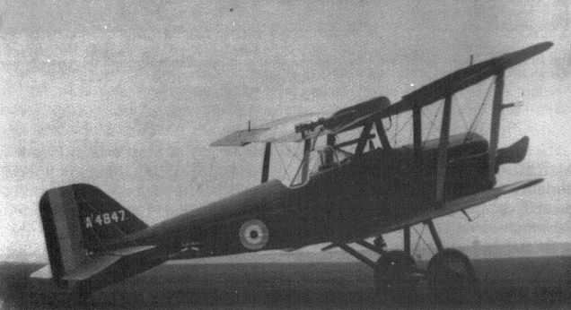
An early S.E.5 with the 'greenhouse' windscreen and overwing gravity tank.

A Farnborough-built, early-production S.E.5 for service with No 56 Sqn in 1917.
S.E.5 A4853 displays its 'Avro' pattern windscreen and the unusually long taper to its head fairing.
S.E.5 A4853 displays its 'Avro' pattern windscreen and the unusually long taper to its head fairing.
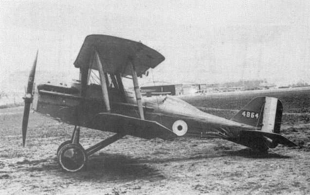
This machine is most probably A4864, and was originally built as an S.E.5. It has the low thrust line of the ungeared engine, but the long exhaust pipes and all-wood undercarriage of later examples. The curved headrest is unusual.
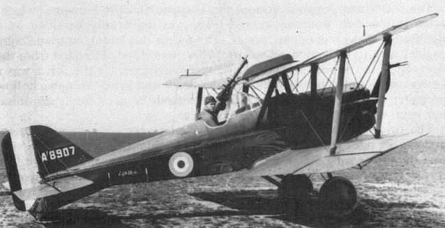
Albert Ball shows the high seating position of the early S.E.5s in A8907, which also has the 'greenhouse' windscreen and over-wing gravity tank.
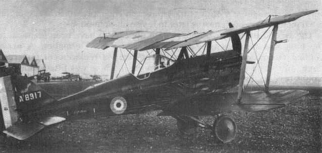
Unarmed S.E.5 A8917 fitted with an internal gravity tank and the early 'greenhouse' windscreen.

Designed around the Hispano-Suiza V-8 engine; the Factory's pugnacious S.E.5.
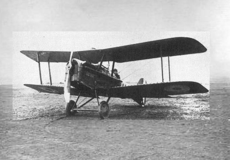
An unidentified S.E.5a with the early form of undercarriage. Note the higher thrust line of the geared engine, which necessitated a modified Foster mounting to prevent the bullets from its over-wing Lewis gun striking the propeller.
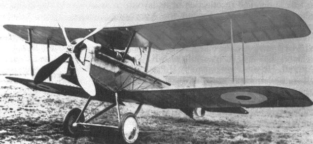
A standard production S.E.5a with a geared 200hp Hispano-Suiza engine.
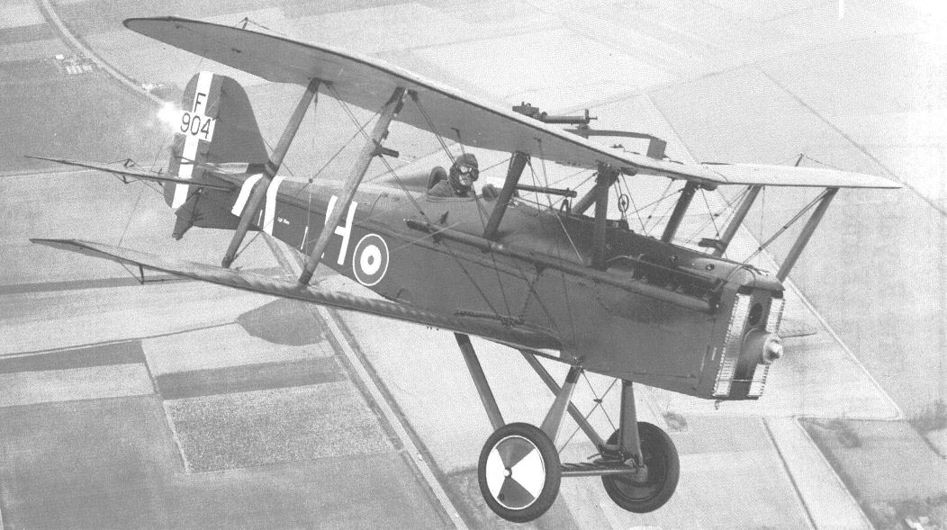
A fine air-to-air study of the Shuttleworth Collection's S.E.5a, G-EBIA/F904, taken on April 11, 1977, shortly after its first flight following the replacement of the geared 200hp Hispano-Suiza engine by a direct-drive 200hp Wolseley Viper.
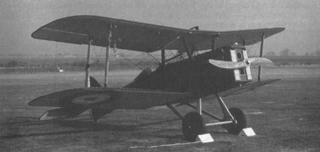
This original S.E.5a is now part of the Shuttleworth Collection at Old Warden Aerodrome, Bedfordshire, England, where it performs regularly in flying displays.
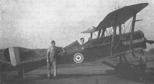
An unidentified S.E.5a fitted with an experimental low-aspect-ratio fin and rudder of remarkably Teutonic appearance. The handle of the starting magneto is visible just below the exhaust pipe, where it could be operated either by the pilot or by a mechanic standing alongside.
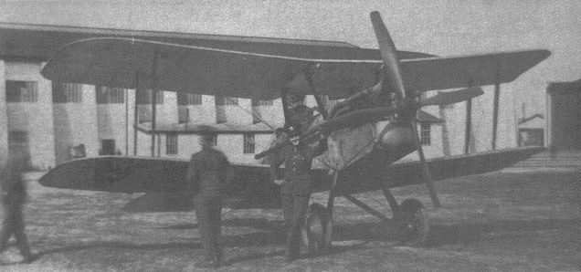
S.E.5a G-EBCA (ex-E5956) fitted with an 80hp air-cooled Renault engine in private ownership. Its maximum speed thus powered is believed to have been about 65mph.

Eberhart-assembled S.E.5a (or S.E.5E) 22-325, photographed in the USA in 1926.
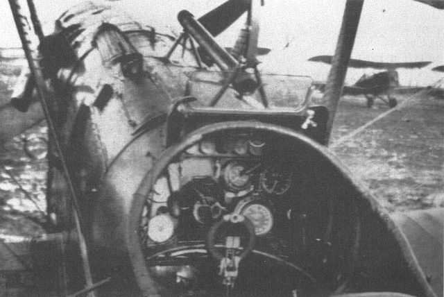
An S.E.5a cockpit, showing the Aldis optical gunsight directly in front of the pilot, and the Vickers gun offset to port. The exhaust pipes have been shortened, leaving a redundant support bracket on the fuselage side below the Vickers gun.
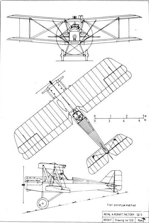
SE5
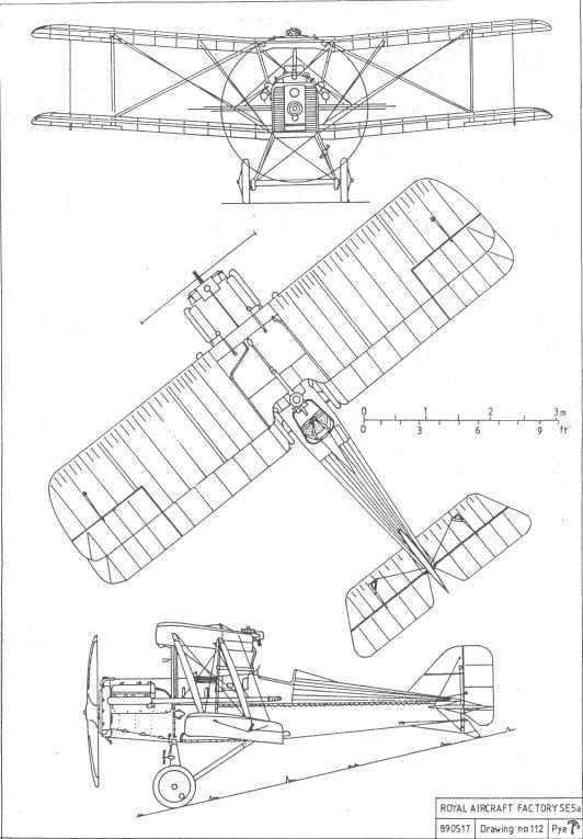
SE5a
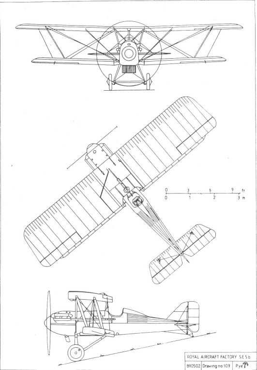
SE5b
Aerial Target
Conceived late in 1916, this was a radio-controlled, pilotless aeroplane intended both for defence against Zeppelins and as a flying bomb. In the former role it was planned that it would be controlled from the ground, but in the latter role control from an accompanying manned aeroplane was also considered. To disguise its intended purpose it was always referred to as the Aerial Target.
Its wireless apparatus was designed by Capt Archibald M Low of the RFC's wireless unit at Feltham, whose idea it was. His attempt to build the aeroplane himself, largely from spare parts, had met with no success, and the assistance of the Royal Aircraft Factory had therefore been requested. The project was undertaken by Henry Folland, although much of the detail work was drawn by his assistant, H E Preston. The Farnborough design was a small shoulder-wing monoplane powered by a two-cylinder ABC Gnat of 35hp, with numerous radio aerials running vertically down the fuselage sides and chordwise across the wings. In the interests of simplicity, lateral control was by wing warping, and generous dihedral ensured lateral stability.
Six examples, A8957-A8962, were constructed, the first being delivered to RFC Northolt, where the trials were to take place, on 5 June 1917. The intention was that the machine should be trimmed to take off and climb away to a reasonable height before radio control was attempted. Extensive windtunnel tests on models had indicated what the necessary tailplane incidence should be, but the first flight, on 6 July, consisted of an almost vertical climb away from the launching rail, followed by the inevitable stall and consequent crash, before the radio control system could take effect. It was clear that the still imperfectly understood aerodynamic differences between scale models and full-sized aeroplanes had resulted in insufficient tailplane incidence.
A second example was tested on 25 July but failed to take off, merely running along the ground until its undercarriage finally collapsed, the tailplane adjustment having been somewhat overcorrected. A third attempt, with the tailplane finally set at the correct angle, was made three days later, but unfortunately resulted in yet another crash when the engine failed just after take-off. Although damage was confined to a broken propeller and some easily repaired undercarriage components, official interest in the project appears to have diminished and no further trials are recorded as having taken place, although the project was resurrected briefly in the early 1920s.
One example was later converted to a manned aeroplane by No 3 (Western) Aircraft Depot at Bristol, and was fitted with a wheeled undercarriage and ailerons. As a rebuilt aircraft it was allotted a serial number from a batch allocated for that purpose. It received the number B8962, with numerals similar to those of its original, uncertain identity, and this has caused much ill-founded conjecture among latter-day historians.
By 1934 it had been disposed of, and was owned by Mr Ron Shelley of Billericay, but it was broken up without appearing on the civil register.
Dimensions:
span 22ft 0in; length 20ft 4in; height 5ft 10 1/2in;
chord 5ft 2in; incidence 6°; dihedral 5°.
Weight 500lb.
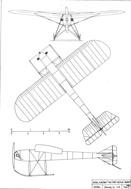
F.E.9
Bearing in mind that the F.E.9 was designed about September 1916, as a replacement for the F.E.2 series, it is rather surprising that it was yet another pusher. By that time the availability of gun synchronisation systems had rendered the pusher concept obsolescent, although every possible effort was made to reduce the layout's inherent disadvantages to a minimum.
The F.E.9 was designed around the 200hp geared-drive Hispano-Suiza, and its nacelle was positioned well above the mid-gap position, to afford the observer a reasonable rearward field of fire over the upper wing without the need to resort to the acrobatics required in the F.E.2. Two Lewis guns were provided, each on a pillar mounting, one firing forwards and one to the rear. It was planned that the machine should carry a third gun for the pilot's use, mounted on the starboard side of the nacelle, but no evidence has been found that this weapon was installed. The neat undercarriage had short but effective oleos attached to the lower centre-section, and the tailskid arrangement echoed that of the S.E.5 and R.E.8.
Dual controls were provided, those in the observer's cockpit comprising two control columns, one operating the elevators and the other controlling the rudder, as it was felt that a conventional rudder bar would obstruct the observer's freedom of movement as he performed his normal duties. Since these controls were intended only for use in an emergency, it was not considered necessary to provide any aileron controls, turns being made on rudder alone.
Steel-tube N-struts secured the nacelle to the single-bay wings, which were of unequal span, the upper-wing extensions being supported by bracing wires and inverted triangular kingposts, as was common Factory practice. Ailerons were fitted to the upper wing only, and had large horn balances, being similar to those originally fitted to the B.E.12a. As in the F.E.8, the tailbooms met at the tailplane spar. The fin was almost semi-circular, and the rudder was unbalanced.
With what, unfortunately, turned out to be misplaced confidence, a batch of twenty-four aircraft was put into production 'off the drawing board', using the Factory's own facilities.
The first of these, A4818, was completed by the beginning of April 1917, and test flying was undertaken by Roderic Hill, who found the rate of climb disappointing and the handling unpleasant, particularly during left-hand turns, a characteristic he attributed to the ailerons being over-balanced and the rudder being of insufficient power.
On 6 June Hill flew the aircraft to the Aircraft Depot at St Omer for service trials, apparently without any modification to its control surfaces. Lt Clark of 13 Squadron, an experienced observer who was taken up in it, reported that, from the observer's point of view, the field of fire was very good and that it was easy to fly with its odd controls. Pilots were less enthusiastic, and on 9 June Maj-Gen Trenchard reported that, although the view was excellent, the machine itself was already a year out of date and of no use to the RFC. He recommended that experiments with the F.E.9 should be stopped, and suggested that putting the 200hp Hispano-Suiza into it was a waste of a really good engine. At this stage it appears that the nacelles had been completed for all twenty-four machines, and at least two more airframes were well advanced and were eventually completed.
The Factory's design staff appear to have regarded the type's poor handling as a challenge to be overcome at all cost (perhaps the correct attitude to take in an aeronautical research centre), and when A4818 returned to Farnborough it underwent a lengthy series of modifications to its control surfaces. A new, high-aspect-ratio rudder of reduced area, incorporating a small horn balance, was fitted, and then the fabric was removed from the fin. Later a large balanced rudder of lower aspect ratio was substituted, without a fin. At the same time the aileron balance areas were progressively reduced.
By mid-October A4818 had been joined by the second machine, A4819, which had the high-aspect-ratio rudder and redesigned wings with two-bay interplane bracing, the outer pairs of struts being raked outwards to support the upper wing extensions and thus eliminating the need for kingposts. The ailerons had smaller horn balances than those of A4818. The second machine eventually saw service with No 78 (Home Defence) Squadron, and was written off in a landing accident at Biggin Hill the following winter.
The third and final example, A4820, which was completed ready for inspection on 1 November, also had two-bay wings. By this time a third type of aileron, with the balance area still further reduced, had been fitted to A4818 and, since this type was considered to give a marked improvement in handling, it is probable that it was also fitted to A4820.
The fates of the first and third F.E.9s are unknown, but A4820 is last recorded as undergoing engine tests in January 1918, and A4818 continued to serve as a research vehicle for investigations into aircraft control at least until March of that year. Thereafter the F.E.9 faded into oblivion, the information obtained from its protracted development and testing being used in the design of its successors, most notably the N.E.1.
Powerplant: 200hp Hispano-Suiza V-8
Dimensions:
span 40ft 1in (upper);
37ft 9 1/2in (modified ailerons);
29ft 5 1/4in (lower);
wing area 365 sq ft;
length 28ft 3in;
height 9ft 9in.
Weight: 2,480lb (loaded).
Performance:
max speed 105mph at sea level;
ceiling 15,500ft;
climb 5min to 3,000ft.
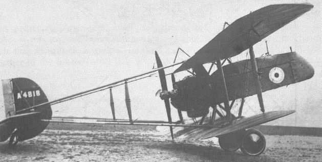
The anachronistic Royal Aircraft Factory FE 9 two-seat reconnaissance fighter was powered by a pusher-mounted 200hp Hispano-Suiza and first flew in the early spring of 1917. As the Bristol F2B was already more than adequately meeting this requirement, it was not surprising that this design with its top level speed of 105mph at sea level, plus faltering climb that took 8 minutes 25 seconds to reach 5.000 feet was abandoned. The only machines to fly were the three development aircraft, the first of which, Serial no A 4818, is seen here.

F.E.12
Yet another uncompleted project, this big two-seater night-fighter was designed during 1917. Many of its major components, including the undercarriage, tailbooms and centre-section, were F.E.9 components, possibly derived from the cancelled production of that machine. The nacelle was basically an F.E.9 unit with the crew positions reversed, presumably with the intention of providing the pilot with the best possible view of his intended target and also to facilitate landing at night. Like the F.E.9, it was to have been powered by the 200hp Hispano-Suiza.
Armament was to have been a Vickers rocket gun, and two searchlights were to have been fitted, one in the extreme nose and the other fixed to the gun. Power for these lights was to be provided by a wind-driven generator.
Before completion the design was modified to become the N.E.1, and is further described under that designation.
Powerplant: 200hp Hispano-Suiza V-8
Dimensions:
span 50ft 0in;
chord 6ft 0in;
gap 5ft 6in;
wing area 550 sq ft;
dihedral 4 1/2°;
length 28ft 1 1/2in;
height 9ft 9in.
Weight: 2,700lb (estimate).
N.E.1
Developed from the F.E.12, the N.E.1, or Night-flying Experimental, employed a number of standard F.E.9/F.E.12 components, including the tailbooms, undercarriage legs, rudder and tailskid. The three-bay wings were of equal span, and had generous dihedral outboard of the centre section. Ailerons were fitted to upper and lower mainplanes. Heeding the lessons learned from the development of the F.E.9, the ailerons were plain and unbalanced. The tailbooms were parallel in plan, and followed what had become normal Factory practice by meeting at the tailplane spar, the tailplane itself being positioned on the thrust line. The elevators incorporated large horn balances, and the semi-circular fin was symmetrical about the tailplane. The undercarriage had a very wide track, the wheels being outboard of the innermost pairs of interplane struts, to facilitate landing at night. Therefore, unusually for the period, the two undercarriage legs were entirely separate, with no transverse axle. Power was provided by a 200hp Hispano-Suiza driving a four-bladed pusher propeller. The intended armament was the Vickers rocket gun or the one-pounder Coventry Ordnance Works gun, with which an element within the Factory seems to have been obsessed. As in the F.E.12, a searchlight was included in the nose of the nacelle, powered by a wind-driven generator.
Six prototypes, B3971-3976, were ordered, the first of which was inspected on 3 September 1917 and made its initial flight five days later. On 14 September it was damaged, most probably in a landing accident, and the nacelle was rebuilt with the crew positions reversed, moving the pilot to the rear cockpit, where a Lewis gun was mounted on the starboard cockpit coaming for his use, in the manner suggested for the F.E.9. The searchlight was not refitted. Test flying resumed on 4 October.
Service trials started on 6 November at Martlesham Heath, and the resulting report cast doubts upon the adequacy of the N.E.1's performance compared with that of its contemporary 'rivals'. While it was considered to be a slight improvement on the F.E.2b, which it was thought most likely to replace, and while the view from either cockpit was described as excellent, it was found to be heavy and awkward, although generally easy to fly. As the N.E.1 was neither smaller nor much better streamlined than the F.E.2b, it was hardly surprising that its performance, with similar power, was so little better.
The general lack of enthusiasm on the part of its intended users was sufficient to ensure that the N.E.1 did not enter volume production. Nevertheless, all six prototypes were completed, most probably because they were already well advanced. In fact the second, B3972, was completed by 14 November and, after acceptance trials, was handed over to the RFC, serving with No 78 (Home Defence) Squadron at Sutton's Farm. It is probable that this machine was built without the searchlight or rocket gun, and it may have had the modified nacelle then fitted to B3971.
A redesigned fin, with increased ventral area, was fitted to B3973, which was completed on 23 November. Early in the new year this aircraft was fitted with bomb racks under the lower centre-section, and throughout February and March it took part in bomb-dropping trials at the experimental station at Orfordness.
The fourth prototype was not flown, being used exclusively for static experiments, and may eventually have been tested to destruction. The fifth example, B3975, was completed late in December 1917 and flown by the experimental station at Orfordness and at the Isle of Grain, but for what purpose is not known. Although the final machine, B3976, was completed, it was never fitted with its engine and obviously was not flown.
Powerplant: 200hp Hispano-Suiza V-8
Dimensions:
span 47ft 10 1/2in;
chord 6ft 0in;
gap 5ft 5 1/2in;
wing area 555 sq ft;
dihedral 4 1/2°;
length 28ft 6in (30ft 2in with searchlight);
height 10ft 0in.
Weights:
2,071lb (empty)
2,946lb (loaded).
Performance:
max speed 95mph at sea level;
ceiling 17,500ft.
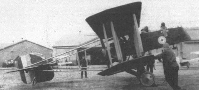
N.E. 1 B3970 with increased area to its ventral fin.
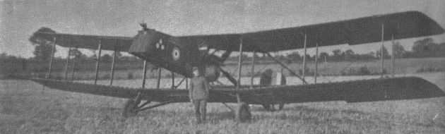
The N.E.I B3975 during bomb-dropping trials at Orfordness. Note the bombsight fitted to the rim of the forward cockpit.
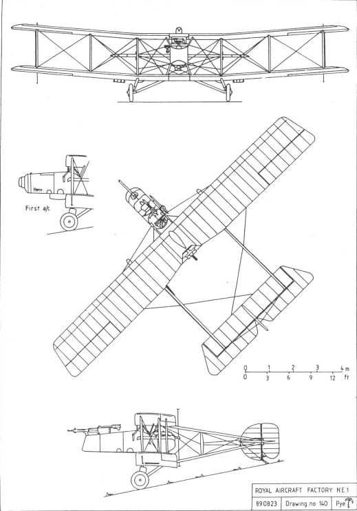
A.E.2
Designed during 1917 and probably intended for ground attack, the Armoured Experimental No 2 was to have been a tractor biplane with an armour plated forward fuselage intended to afford the crew, engine and fuel tanks a measure of protection against retaliatory small-arms fire. It is believed it had been based upon the B.E. series of machines, but it is almost certain that the project never progressed beyond the initial stages of design, for no records exist of it having been built, and no drawings of it survive.
Wingspan: 42ft 7in
A.E.3
This armoured two-seater, which was almost certainly the last aeroplane to be designed at Farnborough, has the obscure distinction of being the only Royal Aircraft Factory type to bear an official name. Under the system of nomenclature which was adopted by the Royal Air Force towards the end of the war it became the Farnborough Ram.
Intended primarily for ground attack, the A.E.3 was a pusher biplane developed from the N.E.I, with which it shared its undercarriage, outer wing panels and horizontal tail surfaces. Its nacelle, containing the crew and engine, was protected by steel armour plate, the floor having two skins, the inner being 5 gauge and the outer 10 gauge. The armament comprised three Lewis guns, two firing forward and a third on a telescopic mounting for defence against attack from behind. The forward-firing pair were coupled together and aimed with the aid of an Aldis optical sight mounted between them. Provision was made for no fewer than thirty-two double Lewis drums, each holding ninety-seven rounds, giving the crew what was, at that time, an immense store of ammunition.
It was originally intended that the A.E.3 should be powered by the geared 200hp Hispano-Suiza, but, owing to the almost unending delivery problems with that engine, the first prototype, B8781, which was completed on 28 March 1918, was equipped with a Sunbeam Arab of similar power. The radiator was initially installed between the rear centre-section struts, but was soon repositioned above the centre-section, alongside the overwing gravity tank.
A second example, B8783, had its nacelle modified to accommodate a 230hp Bentley B.R.2 rotary engine. Designated Ram II, it was completed by the end of May. The third machine, B8782, another Arab powered Ram I, was completed a few days later.
The flight trials of B8783, which began on 4 June, revealed that the control response was barely adequate, and by the 30th, when the machine went to France for service trials, the rudder and ailerons had been replaced by surfaces of increased area. The aircraft was tested by crews from both 201 and 209 squadrons before returning to Farnborough on 20 July. At the same time B8781 underwent armament trials at the testing station at Orfordness.
In common with many of the Factory's less-inspired designs, the A.E.3 found little favour with its intended users, service reports being best described as 'unenthusiastic'. No production orders were placed, especially as its intended role would clearly be better filled by more conventional designs such as the Sopwith Salamander.
The design of a further version, the Ram III with wings of increased chord, for which the more plentiful 150hp B.R.I had been suggested as a powerplant, was not completed.
Dimensions
span 47ft 10in; length 27ft 9in; height 10ft 0in; chord 6ft 0in; gap 5ft 6in; wing area 560sq ft; dihedral 5°.
Performance:
maximum speed 95mph (estimated).
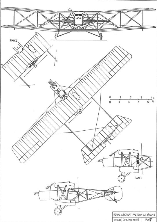
C.E.1
The Royal Aircraft Factory's only flying-boat design, the Coastal Experimental No 1 was first conceived in February 1917, to assist in combatting the growing threat to shipping posed by enemy submarines. W S Farren had overall responsibility for the design.
The C.E.1 was a two-seat pusher with a wooden hull which had a single step. The underside of the after portion was concave. Its empennage was carried on booms which met at the tailplane spar in a manner reminiscent of the F.E.8, and the fin and horn-balanced rudder were symmetrical above and below the tailplane. The wings were arranged to fold, the hinges being immediately outboard of the point at which the tailbooms joined the rear spar, a small section of the trailing edge having to be hinged upwards to make folding possible. Provision was made for up to three Lewis guns carried on pillar mountings, and for bombs carried beneath the lower wing.
Two prototypes were built, the first, N97, being powered by a 230hp R.A.F.3a and the second, N98, by a 260hp Sunbeam Maori, each engine driving a four-bladed propeller. After construction at Farnborough they were taken, in turn, to Hamble for assembly and testing, where N97 made its first flight on 17 January 1918, with its designer at the controls. Lateral control clearly gave some cause for concern because, following these trials, the ailerons were shortened and their horn balances removed.
Although the type completed service trials at the Isle of Grain, no production orders were placed because the Felixstowe F.2 was considered superior. The two prototypes were then used extensively in experiments to verify data obtained from tests on model hulls conducted in the tank at the National Physical Laboratory, particularly with regard to 'porpoising' when in motion on the water. Their eventual fate is unknown.
Powerplant:
230hp R.A.F.3a (N97)
260hp Sunbeam Maori (N98)
Dimensions:
span 46ft 0in
chord 7ft 0in;
gap 7ft 0in;
wing area 609 sq ft;
dihedral 3 1/2°;
length 36ft 3in;
height 13ft 4in.
Weights:
N97 3,241lb (empty) 4,910lb (loaded)
N98 3,342lb (empty) 5,000lb (loaded)
Performance:
N97
max speed 88mph at sea level;
ceiling 6,800ft
endurance 4 1/2hrs.
N98
max speed 92mph at sea level;
ceiling 7,500ft;
endurance 3 3/4hrs.

The C.E.I N97 on its beaching trolley at the Isle of Grain.

A front view of C.E.I N97, showing the bomb racks under its lower wings and the small sections of the upper wing trailing edge which hinged upwards to allow the wings to fold.
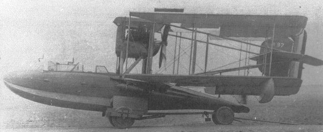
The C.E.I N97 with its wings folded for storage.
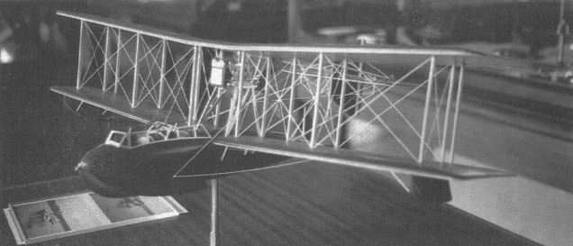
This superb model of the C.E.I, which is housed in the RAE's private museum, clearly shows the forest of booms, struts, and wires which handicapped the performance of such pusher designs.
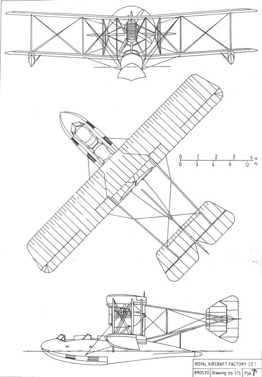
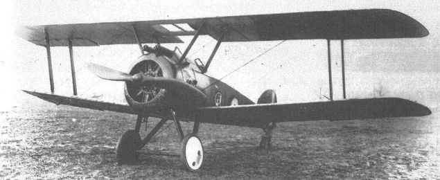
Rival British fighters, the Sopwith Camel (foto) and the Factory's S.E.5a. Together they finally wrested aerial supremacy from the Germans.
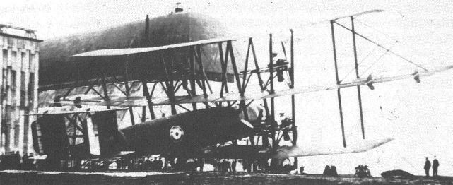
A view of the western end of what had by then become the RAE, taken from Jersey Brow during 1919. The aeroplane is the unsuccessful Tarrant Tabor, the testing of which was to have been supervised by the RAE staff. Unfortunately the huge machine crashed on its initial take-off attempt, and the project was abandoned.
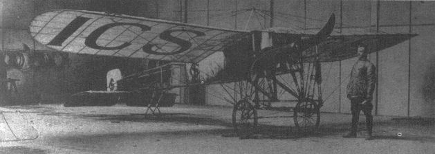
O'Gorman designated all tractor machines 'B' Class after Bleriot's famous cross-channel machines, which remained in production until about 1915.
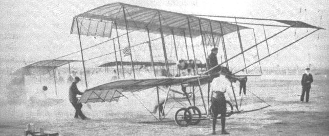
The famous pioneer pilot Claude Grahame-White in a Farman pusher of the type which gave O'Gorman the designation 'F' Class for pusher designs.
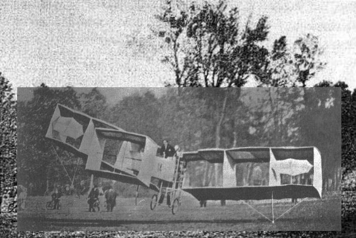
Santos-Dumont made the first powered flights in Europe in his 14bis canard boxkite biplane in October 1906, but it was dead-end design and its 'flights' were nothing more than brief hop-flights that paled into insignificance when compared with the extended, fully controlled flights already achieved by the Wrights.