
Книги
Журнал
Flight за 1910 г.
764
Журнал - Flight за 1910 г.
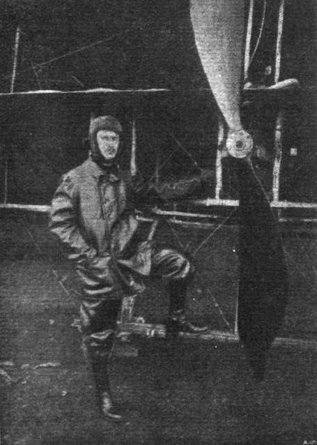
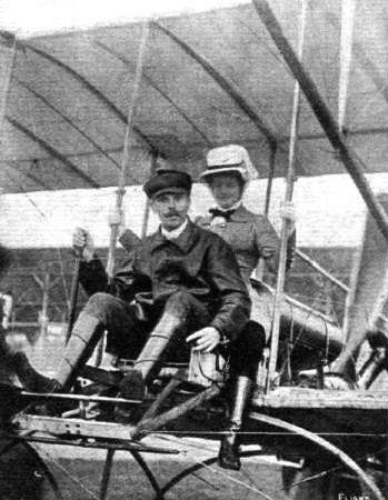
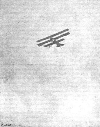
Herr Etrich, the successful Austrian aviator, whose machine we illustrated last week in full flight.
Flight, May 21, 1910
Etrich Carries Two Passengers and Breaks Records.
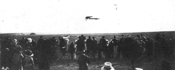
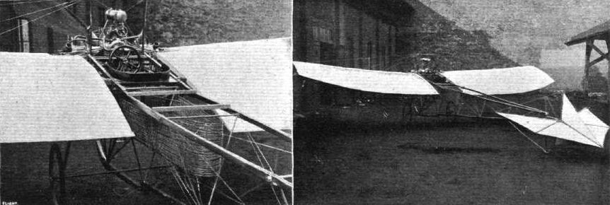
ON Thursday of last week Herr Etrich, the Austrian aviator, whose machine was illustrated in these pages last week, made a flight of 5 mins., during which he carried two passengers. We give this week a photograph of the machine in flight with the two on board. On Saturday he beat the Austrian altitude and duration records, reaching a height of 300 metres during a trial which was continued for 1 hr. 11 mins. The Etrich monoplane is of 14 metres span, has a lifting surface of 32 sq. metres, with a tail surface of 10 square metres. It is fitted with a 50-h.p. 4-cylinder Clerget motor, which drives the 2.2 metre Chauviere propeller at 1,500 revs, per min.
Etrich Carries Two Passengers and Breaks Records.
ON Thursday of last week Herr Etrich, the Austrian aviator, whose machine was illustrated in these pages last week, made a flight of 5 mins., during which he carried two passengers. We give this week a photograph of the machine in flight with the two on board. On Saturday he beat the Austrian altitude and duration records, reaching a height of 300 metres during a trial which was continued for 1 hr. 11 mins. The Etrich monoplane is of 14 metres span, has a lifting surface of 32 sq. metres, with a tail surface of 10 square metres. It is fitted with a 50-h.p. 4-cylinder Clerget motor, which drives the 2.2 metre Chauviere propeller at 1,500 revs, per min.
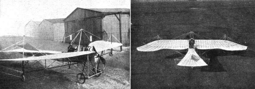
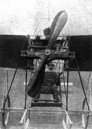
Igo Etrich's monoplane, "Taube," with which he has been flying at the Steinfeld, Wiener-Neustadt. View from the front and from above.
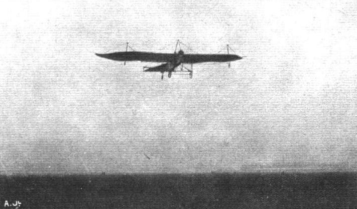
Etrich and Illner flying on the "Taube" monoplane over the Steinfeld, near Wiener-Neustadt. On this machine Illner flew from Wiener-Neustadt, starting at 6.20 a.m. on Tuesday, to Vienna, a distance of 31 miles, arriving at the Semmeringer Helde at 7.30 . After a short stop, he flew back to his starting point.
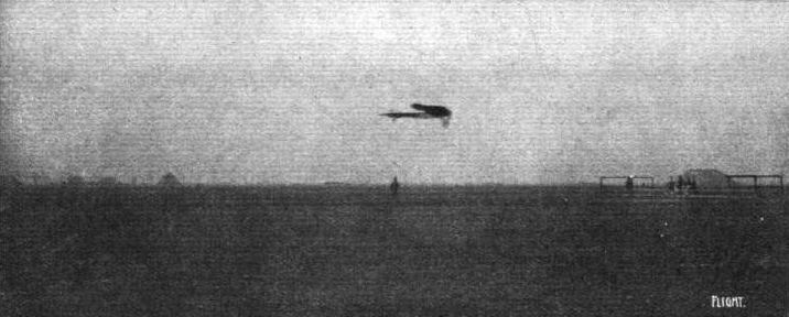
Herr Igo Etrich, on his special monoplane, in flight over the Steinfeld, near Wiener-Neustadt, about an hour's train journey from Vienna.
The Etrich monoplane, with Austrian-Daimler engine, in flight at Wiener Neustadt. This is the aeroplane of which the German Government have ordered twenty replicas.
Flight, September 3, 1910
An Austrian Biplane over Vienna.
EARLY in the morning of the 18th ult., before the festivities in connection with the Emperor's birthday had begun, Adolf Warchalowski, on a machine which he has designed as the result of his experience with the Henry Farman biplane, succeeded in flying from Wiener-Neustadt to the Austrian capital and back to his starting place. At twenty minutes past five, he rose from the aerodrome, and rapidly attained a height of 200 metres. Still rising, he headed for Vienna, and was soon over the Imperial castle at Laxenburg. Crossing the Danube, he made for the Cathedral of St. Stephen, and at 6.20 made a wide circle round it at a height of 700 metres, and then started off on the journey home, reaching Wiener-Neustadt safely at ten minutes to seven. During the hour and a half he had covered about 110 kiloms., this being the best cross-country flight so far made in Austria, completely eclipsing that made by Illner. The latter, although over a similar course, except that Illner did not fly over the city, was made in two stages. The Warchalowski machine was made at the Autoplan works, which, we understand, also builds the Pischoff monoplane.
Flight, September 24, 1910
Flying at Wiener Neustadt.
GOOD progress was made on the opening day of the flying meeting at Wiener Neustadt, which was attended by the Emperor Francis Joseph, the Archduke Leopold-Salvator, Don Jaime de Bourbon, and many other prominent personages. The height prize was won by Warchalowsky with 460 metres, while Illner took the duration prize with 31 mins. 28 secs. Four competed in the cross-country trip from Wiener to Neukeicher and back, a distance of 32 kiloms. The winner was Illner, with 23 mins. 3 secs., Warchalowsky being second, 23 mins. 37 sees.; Stohaugh, on a Voisin, third in 28 mins. 36 secs.; and Flesc, also on a Voisin, fourth in 31 mins. 10 secs.

Both the Grand Duke and the Grand Duchess Augusta of Austria at Budapest Meeting were taken for flights by Adolf Warchalowski on his biplane. In our picture a general view of the Royal passenger is seen prior to the start.
Warchalowski and the Grand Duchess Augusta after the flight at Budapest.
Flight, April 16, 1910
An Hungarian Monoplane.
IN the two accompanying photographs is seen a monoplane which has just been constructed at Budapest by an engineer, Aladar Zselyi. The frame is constructed of spruce and steel-tubing, braced in the ordinary way by steel wires. The two main-planes fit into sockets in the main frame at a small dihedral angle. They have a span of 20 ft. and a chord of 6 ft., while the total lifting surface of the machine is 130 sq. ft., and the elevator has an area of 21.5 sq. ft. A two-bladed Chauviere tractor-screw, 6 ft. in diameter, is driven direct by a 30-h.p. Darracq water-cooled motor; and the novel arrangement of the radiator will be noticed in the photographs. The total length of the machine is 23 ft., and it weighs 340 lbs., or 475 lbs. with the pilot on board.
A new monoplane built in Hungary, built by a member of the newly-formed Aero Club of Hungary at Budapest.
Flight, July 2, 1910
An Ambitious Experimenter.
IT is reported from Brussels that in view of the successful experiments made with his new monoplane, fitted with flexible wings, the aviator Goffaux is now making arrangements to fly from Ostend to London and back during next month.
An Ambitious Experimenter.
IT is reported from Brussels that in view of the successful experiments made with his new monoplane, fitted with flexible wings, the aviator Goffaux is now making arrangements to fly from Ostend to London and back during next month.
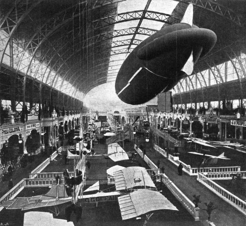
BRUSSELS AUTO AND FLIGHT EXHIBITION. - General view of the main hall taken from the aviation section of the building, the cars being seen at the further half of the hall. The dirigible suspended from the roof is the "Belgica." This is equipped with wireless telegraphy, and the staircase seen in the centre of the building leads up to a platform from which visitors can examine this and the aeronaut's car and the motor. The monoplane seen immediately in the foreground is the "Goffaux" machine.
Flight, March 12, 1910
A NEW ALL-BRITISH AEROPLANE.
THE "A.S.L." MONOPLANE.
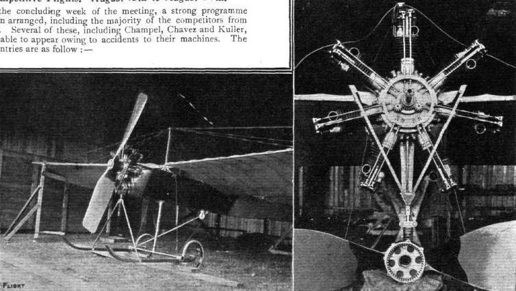
VERY quietly, but with much determination to succeed, the "Aeronautical Syndicate " have, during the past year, been carrying out experiments in Wiltshire with a monoplane of their own design, and finally, after many trials, they recently achieved their first flight of several hundred yards.
Their machine, as the accompanying illustrations show, is peculiar in flying "tail first," in which respect it may be said to resemble the famous Santos-Dumont aeroplane that won the first flight prize in history. The A.S.L. machine, however, is a monoplane, whereas that used by Santos-Dumont was a biplane. Unlike the majority of modern monoplanes this machine has a propeller behind the main planes, which arrangement possesses the advantage of leaving the pilot with an unobstructed view, and free from the annoyance of the exhaust. The pilot's seat is approximately in line with the leading edge of the wings.
The wings have a span of 42 ft. and form a slight dihedral angle, the upward slope being 1 in 25. From the accompanying photograph it might be supposed that they were very similar to those employed on the Antoinette monoplane, but, as a matter of fact, they have quite a different camber, the maximum versine in the wings of the A.S.L. machine being much closer to the leading edge than in the Antoinette flyer. In plan, the wings taper towards the extremities, the chord being 10 ft. at the shoulder and 6 ft. at the tips. The fabric, which is Pegamoid aerocloth, is stretched on to a series of shaped ribs that are fastened to a pair of main spars. The spars are trussed by centre posts and diagonal wires. The rear spar is pivoted to the frame in order to facilitate the warping of the wings.
The overall length of the machine is 31 ft., and in front is fixed a small aeroplane having an area of 18 sq. ft. (6 ft. by 3 ft.). On either side of this fixed plane is a pivoted elevating plane measuring 9 sq. ft. in area (3 ft. by 3 ft.). Immediately above the fixed central plane is a vertical rudder. The horizontal planes are, it will be noticed, mounted below the framework of the machine, the rudder being above.
The machine as a whole is supported on a chassis of "A" formation, the lower members of which consist of a pair of skis provided with wheels attached thereto by an elastic suspension, on the Farman principle. The fore part of the machine is also independently supported by a light wheeled chassis.
The machine is driven by a two-bladed propeller that is direct coupled to the crank-shaft of a 60-h.p. Green engine. The propeller has a diameter of 8 ft. 2 in., and an actual pitch of 2 ft. Including the engine, the machine weighs 802 lbs., or less than 2 1/2 lbs. per sq. ft. of supporting surface, the wings being 310 sq. ft. in area.
On the ground the angle of incidence made by the chord of the wings to the horizontal is 90. The angle of incidence of the leading plane is greater than this by an amount that is determined by practical experiment. The designers look forward to extended trials of this type of machine to demonstrate that it possesses a very considerable amount of longitudinal stability, there being much evidence already to show that the principle of the leading plane is associated with this quality.
A NEW ALL-BRITISH AEROPLANE.
THE "A.S.L." MONOPLANE.
VERY quietly, but with much determination to succeed, the "Aeronautical Syndicate " have, during the past year, been carrying out experiments in Wiltshire with a monoplane of their own design, and finally, after many trials, they recently achieved their first flight of several hundred yards.
Their machine, as the accompanying illustrations show, is peculiar in flying "tail first," in which respect it may be said to resemble the famous Santos-Dumont aeroplane that won the first flight prize in history. The A.S.L. machine, however, is a monoplane, whereas that used by Santos-Dumont was a biplane. Unlike the majority of modern monoplanes this machine has a propeller behind the main planes, which arrangement possesses the advantage of leaving the pilot with an unobstructed view, and free from the annoyance of the exhaust. The pilot's seat is approximately in line with the leading edge of the wings.
The wings have a span of 42 ft. and form a slight dihedral angle, the upward slope being 1 in 25. From the accompanying photograph it might be supposed that they were very similar to those employed on the Antoinette monoplane, but, as a matter of fact, they have quite a different camber, the maximum versine in the wings of the A.S.L. machine being much closer to the leading edge than in the Antoinette flyer. In plan, the wings taper towards the extremities, the chord being 10 ft. at the shoulder and 6 ft. at the tips. The fabric, which is Pegamoid aerocloth, is stretched on to a series of shaped ribs that are fastened to a pair of main spars. The spars are trussed by centre posts and diagonal wires. The rear spar is pivoted to the frame in order to facilitate the warping of the wings.
The overall length of the machine is 31 ft., and in front is fixed a small aeroplane having an area of 18 sq. ft. (6 ft. by 3 ft.). On either side of this fixed plane is a pivoted elevating plane measuring 9 sq. ft. in area (3 ft. by 3 ft.). Immediately above the fixed central plane is a vertical rudder. The horizontal planes are, it will be noticed, mounted below the framework of the machine, the rudder being above.
The machine as a whole is supported on a chassis of "A" formation, the lower members of which consist of a pair of skis provided with wheels attached thereto by an elastic suspension, on the Farman principle. The fore part of the machine is also independently supported by a light wheeled chassis.
The machine is driven by a two-bladed propeller that is direct coupled to the crank-shaft of a 60-h.p. Green engine. The propeller has a diameter of 8 ft. 2 in., and an actual pitch of 2 ft. Including the engine, the machine weighs 802 lbs., or less than 2 1/2 lbs. per sq. ft. of supporting surface, the wings being 310 sq. ft. in area.
On the ground the angle of incidence made by the chord of the wings to the horizontal is 90. The angle of incidence of the leading plane is greater than this by an amount that is determined by practical experiment. The designers look forward to extended trials of this type of machine to demonstrate that it possesses a very considerable amount of longitudinal stability, there being much evidence already to show that the principle of the leading plane is associated with this quality.

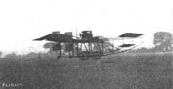
The new A.S.L. all-British Monoplane undergoing its trials in Wiltshire.
A.S.L. Monoplane No.2.
A.S.L. Monoplane No.2.

A close view of the A.S.L. Monoplane, showing the chassis and part of the main frame. The wings have a maximum thickness of 8 ins. at the root.
Flight, October 1, 1910
THE VALKYRIE AEROPLANE.
IT is always instructive to watch the progress of a machine, no matter in what field of operations, that differs from the accepted practice in certain easily recognised characteristics of design. Thus, for example, "Valkyrie I" - the product of the Aeronautical Syndicate - has as its particular characteristic the peculiarity of flying tail first. As an expressive phrase this defines exactly what the machine would appear to be doing in the eyes of the average observer whose acquaintance with aviation was limited to his attendance at a few flight meetings where machines of orthodox type were alone to be seen in the air. On the other hand, it is undesirable to use the expression seriously as a technical description for the very obvious reason that the tail of anything must be behind. Moreover we are, in a sense, on the horns of a dilemma in respect to the Valkyrie, in deciding whether the main planes themselves should be considered as a tail or of stating quite plainly that the machine possesses no tail at all.
In the ordinary use of the term, "Valkyrie I" is a tailless monoplane fitted with a leading plane in front of the main planes, but there are scientific reasons for regarding the main planes themselves as performing the function of a tail in respect to the leading plane. The same principle has been much discussed, for instance, in connection with the well-known Clarke model flyers, which also have as a characteristic feature the presence of a leading plane and the absence of a tail. Their longitudinal stability, and also, presumably, that of the Valkyrie, is due to the dihedral angle formed by the leading plane in respect to the main planes. The main planes are set at a lesser angle of incidence to the axis of the propeller than the leading plane; which principle is observed in respect to the after surfaces of all machines. Of the theory of the dihedral angle itself there has been so much discussion in FLIGHT that we scarcely feel called upon to do more in the present instance than refer our readers to such pages as, Vol. I, p. 662 ; Vol. II, pp. 56, 82, 98, 222, 244, 261.
It is important to bear in mind in order to avoid any possible confusion when looking at the accompanying illustrations of the machine, that the large leading plane in front is a fixed plane; that is to say, it is not in any way under the control of the pilot when in flight. On the other hand, it is, for convenience, so mounted that its angle of incidence can be varied for experimental purposes, and in particular for compensating any considerable difference in the load supported. Beneath the leading planes, but a little to the rear, is the elevator proper, which is a much smaller plane of scarcely more than half the span of the leading plane. The operation of this elevator is effected by wires from a universally-pivoted lever mounted in the same fashion as the corresponding member of control on the modern Farman biplane. This same lever, when moved sideways, controls the machine laterally by deflecting the balancers that are hinged to the trailing edges of the main planes, at the extremities. A pivoted foot-rest in front of the pilot controls a pair of interconnected rudders that are also located on the trailing edge of the main planes.
The presence of these rudders close up to the main planes is somewhat reminiscent of the original Short biplane, and is in some respects the most important feature of the machine, for coupled as it is with the absence of a tail, the principle involved results in a most important reduction in the overall length. "Valkyrie I," which is shown in the accompanying illustration, measures only 22 ft. from stem to stern, although it has a span of 34 ft. Experiments were originally carried out with the independent operation of the rudder-planes, but the interconnection of these members has been found preferable, and the steering effect is the same, in principle, as that of a rudder carried on the extremity of an outrigger. The absence of leverage, which would ordinarily be provided by the distance of the outrigger from the main planes, is in this case seemingly made up by the increased influence of the slip of the propeller on the particular rudder-plane that happens to be turned into the wash. It will be observed that the rudders are situated one on either side of the slip-stream from the propeller. These rudders are not especially large; indeed, they have actually less area than those on the Wright biplane, with which machine the Valkyrie, although a monoplane, is almost unconsciously compared.
In this comparison, moreover, it is interesting to note that although the leading plane of the Valkyrie seems to be an unusually long way in front of the main planes it is actually scarcely more than a foot further off than the elevator on the Wright biplane, and the dimension is identical with the corresponding measurement on the Curtiss biplane of last year. Regarding dimensions, an outstanding feature of the Valkyrie is that it provides over 140 sq. ft. of supporting surface for a total weight of 520 lbs. This weight is approximately that of the Bleriot monoplane, but the Valkyrie is a machine of much wider span, and much greater area. Such lightness is due entirely to detail design, for the machine carries a standard Green engine of 30-h.p., and a glance at the accompanying illustrations, particularly the drawings, is sufficient to show that, with the exception of the tail outrigger, it has the usual number of principal members. Perhaps the most important constructional feature of the machine from the point of view of detail is the use of a single-surfaced main plane, which is considerably lighter than a double-surfaced member, firstly owing to the smaller quantity of fabric, and secondly owing to the lighter character of the cambered ribs.
In connection with the attachment of these latter to the transverse main spar forming the leading edge of the plane, there is an interesting detail that is illustrated in one of the accompanying sketches. It will be observed that in order to avoid weakening the main spar by making mortice joints, the ribs are held in aluminium sockets fastened to the back edge of the spar by screws. These sockets are also flanged, and the flange is grooved so that it overlaps the edge of the spar and thereby obtains great rigidity of support without cutting the wood. The ribs themselves have a slightly triangular section, this shape having been found to give the greatest ratio of lateral stiffness to weight of any simple form of construction.
The main plane of the Valkyrie is built in three sections, and special aluminium sockets have been designed to facilitate an adjustment of the angle of incidence of the main plane by raising or lowering the rear transverse main spar during erection. The central portion of the main plane has a shorter chord than the extremities, and is also adjusted to a smaller angle of incidence owing to its presence in the slip stream of the propeller.
Special aluminium sockets are employed in many places on the Valkyrie, and especially should their use be noted as abutment pieces in connection with the method of anchoring the tie wires on this machine. Not one of the important wires used in bracing the Valkyrie is either fitted with a sirainer or bent over at the ends. The method of attachment adopted avoids the necessity of doing either, and thus simultaneously saves the weight of a wire strainer, and likewise overcomes any objection that there may be to bending.
The wires used are of larger gauge than ordinary, and it has been found preferable to employ wire that does not exceed n o tons tersile strength owing to the liability to brittleness of the higher grade steel. All the wires are cut approximately to the desired length, and then have a screw thread chased upon their extremities so as to take an ordinary nut. The wires are threaded through the lugs at the points of attachment to the frame, and the nuts are fastened down against the special aluminium brackets provided for their abutment. One such bracket is shown in an accompanying sketch, and another is illustrated in a detail photograph, which shows how the tie wires are fastened to the main spars of the main plane. As a practical flying machine, the designers of the Valkyrie lay emphasis on the advantages associated with the position in which they place the pilot. He is situated in front of the engine away from the exhaust and the draught of the propeller, and he has an unobstructed view of the ground below and of the country all round. From the beginner's point of view, there is a feature of the Valkyrie to which we would particularly call attention, and that is the use of those very long skids, which form such a prominent feature in the general appearance of the machine. Since the various accidents to skilful pilots that have been due solely to the necessity of landing on bad ground, we have strongly advocated the employment of adequate skids on modern machines, and the Valkyrie appears to us to be an excellent example of such a type, although it does not happen to possess the disappearing wheel combination that we should so much like to see in general use. Incidentally, it may be remarked that the skids of the Valkyrie play a very important part in the construction of the machine, for they facilitate the forward bracing of the main planes, and thus serve to guard against the danger of bending spars that was pointed out by R. J. Macfie in a recent issue of FLIGHT.
A special feature in connection with the power plant of the Valkyrie is the provision of a small plunger pump on the Green engine for delivering petrol from the main-tank beneath the motor to a small gravity tank overhead. This system avoids pressure-feed, and maintains a constant head, for if the delivery of the pump exceeds the consumption of fuel the surplus overflows the reservoir into the main tank. The pump is driven by an eccentric on the transverse magneto-shaft, and has a 3/4 in. bore by 1/4 in. stroke.
In conclusion, it may perhaps be of interest to summarise a few of the detail weights and dimensions :-
Weights. - Main planes, 50 lbs.; front planes, 23 lbs.; chassis frame, 105 lbs.; wheels, 50 lbs.; engine, 155 lbs.; magneto, 10 lbs.; dual ignition, 15 lbs.; propeller, 22 lbs.
Dimensions. - Propeller, diameter, 7 ft. 3 in.; pitch, 4 ft. 1 1/2 in.; angle of incidence of the main planes with the propeller-shall, 9'; maximum camber, 5 in., situated one-third of chord from leading edge; main fore and aft booms of chassis frame, 1 1/4 in. square section. Skid-members are of the same size, but strengthened by extra pieces, which double the depth in the vicinity of the axle; main plane spars, 2 in. by 1 in. (front), 1 5/8 in. by 1 in. (rear).
Materials. - Honduras mahogany is used almost exclusively throughout the machine. The surfacing of the planes is made with unproofed Egyptian cotton fabric. The back edge of the plane is stretched by a cord.
Flight, October 29, 1910
FROM THE BRITISH FLYING GROUNDS.
Hendon Aerodrome.
DURING the past week the Aeronautical Syndicate's "Valkyrie" has been much in evidence at Hendon. The school machine has been out every day, excellent progress being made by Messrs. Benson and Hirst. On Saturday afternoon there was quite a crowd present, and the Syndicate's pilot made some excellent flights, circulating the aerodrome with remarkable precision and steadiness, and scoring particularly with his vol plain's. We understand that more than one aviator has registered his application with the Aero Club to compete with a "Valkyrie" for the De Forest Cross Channel Prize, which looks distinctly promising for this distinctive All-British" machine. "Blinkers" have now been fitted forward and under the front plane, and the rudders have been carried further aft. So satisfied are the Syndicate with the success already obtained that the standardisation of this model is now complete, and any changes that may take place in the future will be in minor details only.
We shall shortly give full particulars of the new three-seater "Valkyrie," which is now undergoing its trials. The following brief notes concerning it are in the meantime of interest :-
Bare weight, fitted with 60-65-h.p. Green engine, 740 lbs., or only 12 lbs. to the horsepower. Surface, 320 sq. ft., or 2.31 lbs. to the square foot, which is certainly remarkable for a monoplane. Safety skids, 26 ft. long, set 9 ft. apart, which would appear to be a landing arrangement of extraordinary efficiency. The amount of rudder surface would appear to be excessive, but the designer of the "Valkyrie" sets great store on having a large margin of control.
Several short flights were also made by Prier on the Anzani engine Bleriot on Saturday afternoon, most of them very low, but once or twice he ventured to a good height and planed down. On Monday Benson had some good practice on the "Valkyrie."
Flight, November 26, 1910
The London Aerodrome.
DURING the morning of Tuesday last week the Bleriot school had two pupils, Mr. Bouwens and Capt. Board, out for some 20 mins. each, when rolling practice was indulged in. The way the pupil with each lesson attains iurther proficiency is most marked. "Valkyrie III" (small type) was out, and made a number of successful flights, in one of which the pilot flew rather more than three complete circles of the aerodrome. In the afternoon it was both windy and wet, and no one was out.
Next day the weather proved altogether too rough for flying.
On Thursday, in the afternoon, "Valkyrie III" was again out, and made three good flights, each of about two and a-half circles of the aerodrome. At dusk "Valkyrie II" (the three-seater passenger carrier) was taken out for the first time. At the first attempt it lifted easily and flew about half a mile; it then made a full circuit of the aerodrome, when descent had to be made owing to the darkness. The machine behaved very well, rose quickly, and flew with very little power. M. Prier took out the Bleriot-cum-Gnome, and made a fine flight over the aerodrome and surrounding country, attaining a height of 1,200 ft., from which he came to earth by means of a singularly daring vol plane, in which he turned several times with great dexterity. The pupils, Mr. Bouwens and Capt. Board, were both out in the morning, the former being only out for a short time, while the latter was out rather longer. The termination was rather sudden, as when flying he came rather too neat the sheds and had to alight too sharply, with the result he broke his propeller.
Friday and Saturday were blank days again, owing to the unpropitious weather.
The weather on Sunday was not quite perfect, a slight wind disturbing an otherwise ideal afternoon. The "Valkyrie" three-sealer made several fine flights, totalling to nine circuits, including one of about four complete circuits of the aerodrome, in addition to several straight flights for the benefit of a photographer.
The pilot had intended to put up a longer flight, but was not sufficiently clothed to stand the intense cold.
On Monday a good deal of work was done. After a somewhat breezy morning the afternoon proved bright and calm, although it was always very cold. Capt. Board came out first, and showed marked improvement on his last lesson; in fact, he left the ground and flew for a short distance at a height of about 15 ft. In the course of the lesson he got very close to the sheds, and it was only by means of a dexterous turn that he got down safely. Mr. Bouwens then went out for a short time and made four creditable flights, in which he showed marked ability in turning. The monoplane belonging to Mr. Everett was also out, with Mr. E. Clutterbuck as pilot for a time, and later with Mr. Everett. The machine indulged in rolling practice.
The event of the afternoon, however, was the flying of the Aeronautical Syndicate's "Valkyrie II" (the large three-seater passenger-carrying type). After a short trial trip, the pilot took up three passengers - Mr. Clutton, secretary of the London Aerodrome, Mr. Laborde, assistant secretary of the Aeronautical Syndicate, Ltd., and Capt. Board - one after the other.
Each passenger was carried about a circuit of the ground, and a few short runs, at an average height of 50 ft. from the ground. The machine was wonderfully steady, and the unanimous opinion of the passengers was that she was exceedingly comfortable, and well adapted for observation purposes.
Altogether a creditable record of work for the week. The Aeronautical Syndicate are to be warmly congratulated on the great success attained by their three-seater. This large Valkyrie has proved not only that she can fly but that she has all the stability of the small machines.
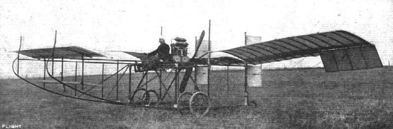
"VALKYRIE I." - General view of the Aeronautical Syndicate's monoplane, photographs of which machine in flight appeared in our last issue.
VALKYRIE (1910). This was one of the first "tail first" machines to be designed. The experimental machine (also known as the A.S.L.), was completed in Feb., 1910.
VALKYRIE (1910). This was one of the first "tail first" machines to be designed. The experimental machine (also known as the A.S.L.), was completed in Feb., 1910.
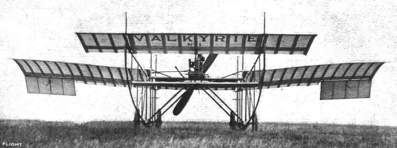
"VALKYRIE I" SEEN FROM IN FRONT. - The plane on which the name is written is a fixed leading plane; beneath it is a small elevator.
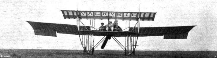
The new 3-seater "Valkyrie" at Hendon flying grounds, from the front.
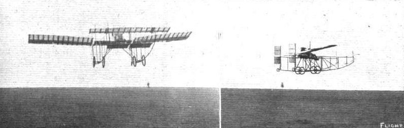
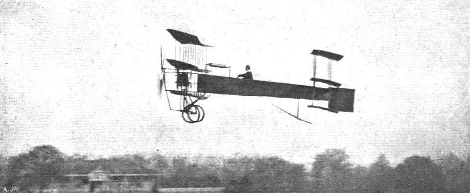
A NEW BRITISH FLYER. - The above photographs show "Valkyrie I" in flight on Tuesday, September 13th, prior to dismantlement for removal to the new works and schosl that the Aeronautical Syndicate, Ltd., have established at Wendon. This machine is the fifth of a series of experimental models with which trials have been carried out on Salisbury Plain during the past 17 months. It is a monoplane, and is characterised by several interesting features both in design and construction. There is no tail, and the pilot sits in front of the engine, which is in front of the main planes; he thus has a clear outlook in every direction. In front of the pilot is a leading plane, baneath which is the elevator.
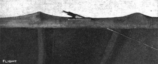
The "Valkyrie" takes a trip at the Hendon flying grounds last Saturday.
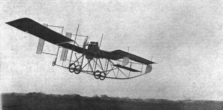
"Valkyrie II," the three-seater machine, during one of its long flights at the London Aerodrome on Sunday week, referred to in last week's FLIGHT.
Detail view showing the method of attaching the tie wires for bracing the spars of the main planes.
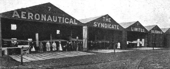
Where the "Valkyrie" Aeroplanes of the Aeronautical Syndicate, Ltd., live at the London Aerodrome, near Hendon. These machines, our readers will remember, are doing daily, when the elements permit, some very fine flying work.
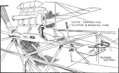
"VALKYRIE I." - Sketch illustrating the position of the pilot's seat and the arrangement of the control.
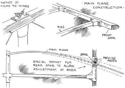
"VALKYRIE I." - Sketches illustrating various special features of construction.
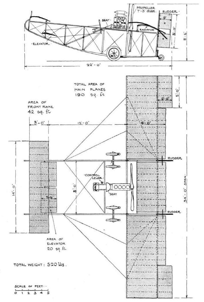
"VALKYRIE I." - The Aeronautical Syndicate's monoplane, 1910.
Flight, January 1, 1910
Mishap to Mr. A. V. Roe.
AFTER making several good flights at Wembley Park Mr. A. V. Roe had a slight mishap on Christmas Eve, of which we are able to give a snapshot. Mr. Roe endeavoured to turn sharply, but as a result of some recent modifications in the steering arrangements, found it impossible to rectify the tilting movement quickly enough, and this caused the machine to fall, damaging one of the planes. Just previous to this Mr. Roe had made several very successful flights of 400 to 500 yards in length. The damage Mr. Roe hopes to have repaired shortly, when he will make further attempts.
Flight, March 12, 1910
THE SECOND OLYMPIA AERO SHOW.
AEROPLANES.
Roe.
BRITISH-BUILT triplane, having a span of 20 ft.; the height of the machine is 9 ft. and the overall length 23 ft. The total supporting surface, including that of the triplane tail, is 320 sq. ft. The machine is driven by a two-bladed tractor screw of adjustable pitch, and the steering is effected by a vertical rudder at the rear operated by the feet. The main planes are operated by hand to serve as elevators.
Flight, April 16, 1910
FLYER SILHOUETTES FROM OLYMPIA.
THE AVROPLANE.
Leading Particulars of the Avroplane.
General Dimensions.-Areas-Main planes, 246 sq. ft.; elevator, 74 1/4 sq. ft. ; rudder, 7 sq. ft.
Lengths.-Span, 26 ft.; chord, 3 ft. 6 ins.; camber, 1 1/2 ins.; leverage of rudder, 14 ft.; skid track, 6 ft.; overall length, 24 ft. 6 ins.
Angles.-Incidence, variable from 11 to 4 degrees; dihedral, 1 in 22.
Materials.-Timber, silver spruce struts and spars, ash frame; fabric, Pegamoid.
Engine.-35-h.p. Green.
Propeller.-Roe; diameter, 8 ft.; pitch, 3 ft.; material, birch.
Weight.-Total flying weight, 550 lbs.; loading, 17 lbs. per sq. ft.
Speed of Flight.-40 m.p.h.
System of Control.-Warping of planes, elevator and rudder.
Price.-L6oo.
THIS was the only triplane exhibited, and represented the outcome of much careful work on the part of its designer, A. V. Roe, who has pioneered this type of machine in England. The special feature of its construction is the provision that is made for altering the angle of incidence during flight, the main planes and also the tail, which is a triplane, and carries part of the load, being pivoted and interconnected with an operating mechanism. In a future design we understand that this feature will be extended by making the camber variable as well as the angle of incidence. A strong but light type of "A" chassis frame is employed, and the machine is supported upon a combination of wheels and skis.

Mr. A. V. Roe, on his triplane, flying at Wembley on Friday of last week. - Our photograph was taken during the first flight.
Mr. Roe, at Wembley on Friday of last week, in full flight immediately before the mishap.
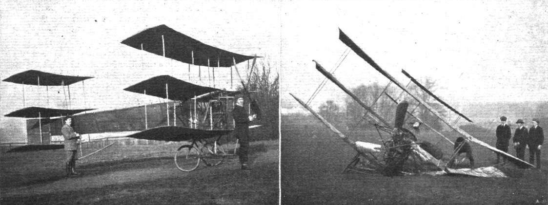
Mr. A. V. Roe and his successful triplane flyer at Wembley. - On the left Mr. Roe is standing by the four-bladed propeller of his machine, and the picture on the right shows the machine immediately after the accident on Friday of last week.
FLYING MACHINES AT BROOKLANDS ON EASTER MONDAY. - Mr. A. V. Roe starting away on his triplane.
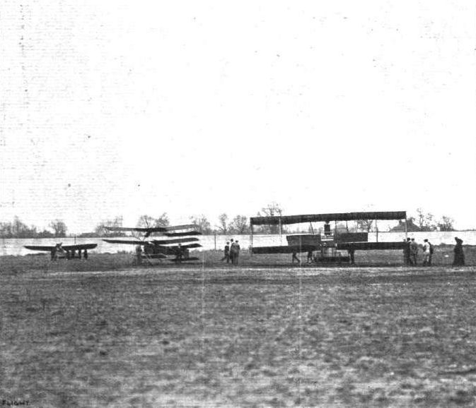
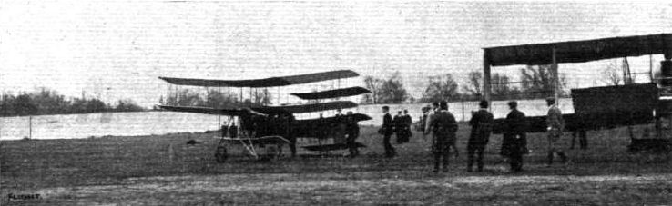
FLYING MACHINES AT BROOKLANDS ON EASTER MONDAY. - A trio of aeroplanes. From left to right: Mr. Astley's Lane monoplane, Mr. A. V. Roe's triplane, and Mr. Moreing's Voisin biplane.
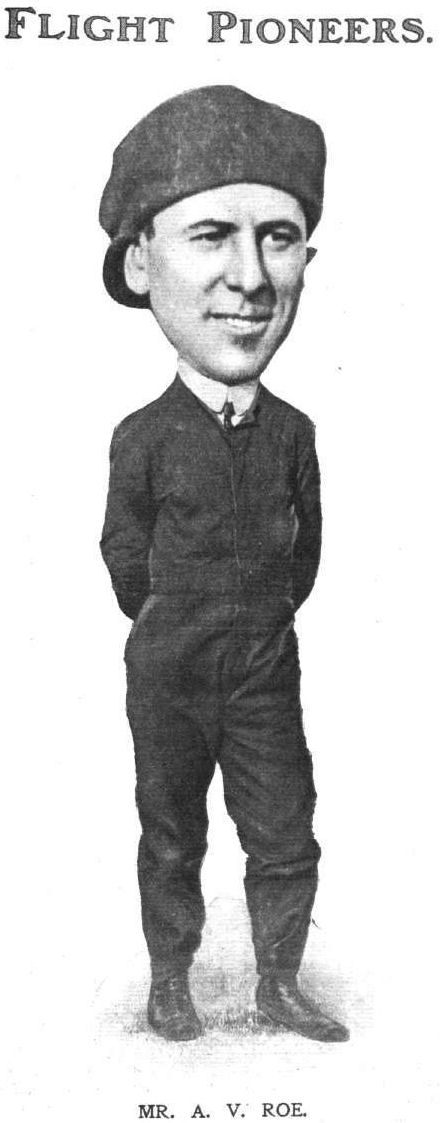
MR. A. V. ROE.
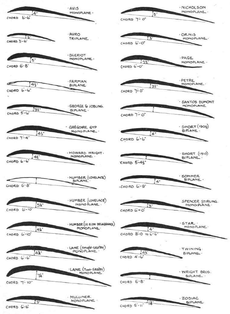
WING SECTIONS. - The above diagrams afford an interesting comparison of the wing sections of aeroplanes exhibited at Olympia. They are all drawn to a common scale, but have been set at an arbitrary angle of incidence, which does not necessarily represent that of the aeroplane In actual flight.

A. V . Roe starting, on his triplane, for a flight at Blackpool Aerodrome. Inset he is seen In full flight round the course.

ONE, TWO AND THREE PLANES. - Grahame-White, in his Henry Farman biplane, flying over Drexel's Bleriot monoplane and Roe's triplane.
Flight, December 3, 1910
FROM THE BRITISH FLYING GROUNDS.
Brooklands Aerodrome.
BROOKLANDS has again distinguished itself. When Mr. Cody, flying his Cody biplane on Laffan's Plain, recently captured the all-British record for distance and duration - 94 miles in 2 hrs. 24 mins. - the British airmen here determined to go one better. There were several aspirants to the honour, Mr. Sopwith, on the Howard Wright biplane, and Mr. Pixton, on the Avroplane, being warm favourites. The odds, however, were slightly against Mr. Pixton, as the magnetism of the sewage farm had to be discounted.
To Mr. Sopwith, the aviator, and to Messrs. Howard Wright, the builders, we have to extend our hearty congratulations on having put up on Saturday last a new all-British distance record of 107 miles, and at the same time established a British duration record of 3 hrs. 12 mins. for any type of machine, British or foreign, flown in this country.
Mr. Sopwith has also by the same flight achieved the best performance to date for the British Empire Michelin Cup. The Howard Wright machine on which these records were made is a biplane fitted with a 60-h.p. E.N.V. engine and Spiral tube radiator. It has a Farman type wheel-base, monoplane tail and elevator, with a central rudder above and below the tail plane. Mr. Sopwith first flew a Howard Wright monoplane - this was only some few weeks ago - and we drew attention in a previous issue to the rapid progress he made. He has only had delivery of the biplane a few days, which speaks well for the ease of control of this make of machine. This flight and triple record breaking naturally by comparison overshadows the smaller events of the week, although much good work has been put in by the other tenants.
Mr. Graham-Gilmour on Thursday last week piloted the Martin-Handasyde for straight flights at about 20 feet high. Mr. Collier rolled the Otazell, as did Mr. Oxley the Avroplane and Mr. Macfie his biplane.
The Bristol-Gnome, piloted by a pupil, made short flights, and Mr. Sopwith was out carrying passengeis.
On Friday Mr. Low took up a passenger on the Bristol-Gnome, and Mr. Snowden-Smith made several circuits, at a good height, on M. Blondeau's Farman.
Mr. Sopwith, on the Howard-Wright, remained in the air for half an hour, and Mr. Pixton was flying the Avroplane. The Macfie and Otazell were seen rolling.
On Saturday all minor essays were eclipsed by Mr. Sopwith's performance, but Mr. Morisson, on his single-seated Gnome-Bleriot, did remarkably well, rising quickly and at an acute angle. The Avro team, Messrs. Pixton, Oxley, Beattie and Jenkins, all did their utmost, and returned the machine home without a scratch. The Bristol-Gnome was also flying.
Sunday, mud, rain and wind kept shutters up, and people away.
On Monday the Spencer-Stirling biplane, fitted with R.H. engine, made short flights. Mr. Sopwith, on his Howard Wright biplane, and Mr. Low, on the Bristol-Gnome, made several circuits, the latter with passengers, otherwise there was little done. Mr. Oxley was the first out on Tuesday, the 29th ult., followed later by Mr. Pixton on the same machine. The latter was flying off and on for the whole afternoon. He is a very daring and pretty flyer, but the sudden movements he makes must put a severe strain on the bodywork. In particular, one dive and sudden righting appeared to actually bend the body, and it speaks well for the work Mr. Roe has put into his fuselage that nothing serious happened. We do not wish to appear pessimistic, but if Mr. Pixton continues his progress on his present lines we doubt whether he will get through life unmaimed, and the science may lose the fine work which so promising an airman can put in.
The outstanding event of the day was Lieut. Snowden Smith's flight to Aldershot and back on the Farman biplane belonging to Mrs. Maurice Hewlett and M. Blondeau. This is referred to on P. 995.
Mr. Low contributed his quota by vol plank from about 200 ft., and carrying passengers on the Bristol-Gnome. Mr. Sopwith, resting on his laurels, gave pleasure or otherwise by carrying passengers of both sexes.
Mr. Fisher and Mr. Raynham, on "Neale VI," made hops and short straight flights, as did also the Spencer-Stirling biplane.
M. Blondeau was passenger carrying, and at one time attained a good altitude.
Mr. Pixton, on an Avro triplane, making a fine high flight at Brooklands this week.
Flight, November 19, 1910
AEROPLANES AT THE STANLEY SHOW.
<...>
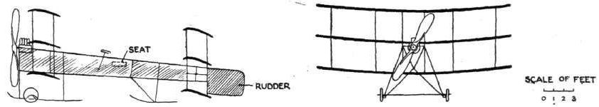
Major Baden-Powell's machine is of monoplane form, with a forward elevator and a fixed non-lifting stabilising tail. With the exception of the main frame of American elm, holding the engine and giving rigidity generally, the framework is constructed entirely of bamboo. The lower members of the fusellage act as skids, each being divided into two at the point of contact with the ground. In these two divisions are placed wheels working on spiral springs. The main planes, with an area of 90 sq. ft., are similar in shape to the wings of a bird, and are of Pegamoid stretched over a bamboo framework. The forward elevator, which is similarly constructed, is hinged to the forward point of the fuselage by a single steel clip, and is operated by a single control lever in front of the pilot. The rudder is of triangular shape, and is placed over the tail. No steering control is shown, but it no doubt would be by means of a foot lever. The pilot sits in a hammock-like seat in front of the main planes, whilst behind him and underneath the planes is the engine and propeller. The motor is a 12-h.p. 3-cyl. Buchet, and the propeller, which is mounted on the crank-shaft, is of original design, 5 1/2 ft. in diameter. A general note of lightness is to be observed. The total stated weight of the machine complete with the aviator aboard is only 350 lbs. The price is low, L120. Major Baden-Powell tells us certain slight alterations will be made before testing the aeroplane.
<...>
AEROPLANES AT THE STANLEY SHOW.
<...>
Major Baden-Powell's machine is of monoplane form, with a forward elevator and a fixed non-lifting stabilising tail. With the exception of the main frame of American elm, holding the engine and giving rigidity generally, the framework is constructed entirely of bamboo. The lower members of the fusellage act as skids, each being divided into two at the point of contact with the ground. In these two divisions are placed wheels working on spiral springs. The main planes, with an area of 90 sq. ft., are similar in shape to the wings of a bird, and are of Pegamoid stretched over a bamboo framework. The forward elevator, which is similarly constructed, is hinged to the forward point of the fuselage by a single steel clip, and is operated by a single control lever in front of the pilot. The rudder is of triangular shape, and is placed over the tail. No steering control is shown, but it no doubt would be by means of a foot lever. The pilot sits in a hammock-like seat in front of the main planes, whilst behind him and underneath the planes is the engine and propeller. The motor is a 12-h.p. 3-cyl. Buchet, and the propeller, which is mounted on the crank-shaft, is of original design, 5 1/2 ft. in diameter. A general note of lightness is to be observed. The total stated weight of the machine complete with the aviator aboard is only 350 lbs. The price is low, L120. Major Baden-Powell tells us certain slight alterations will be made before testing the aeroplane.
<...>

Major Baden-Powell's monoplane at the Stanley Show, as seen from the side.

Plan View of Major Baden-Powell's Monoplane at the Stanley Show. - Above the exhibit, it will be noticed, is placed a model of a bird.
Flight, July 2, 1910
A BRITISH-BUILT MONOPLANE.
I enclose you photos of my monoplane which I have built all myself (excepting the Alvaston engine and the Cochrane propeller) in my spare time. It is all English; the covering is by Dunlop. I commenced it last September, and have had it finished the last three weeks, but am waiting for the Royal Aero Club, of which I am a member, to allow me to try it at Eastchurch. The width over all is 28 ft., with a total length of 26 ft.; the total weight is 480 lbs., with petrol and water complete. I shall be pleased to show it to anyone interested or anyone thinking of building. I find it is a task not to be lightly undertaken.
Rochester. ALBERT BATCHELOR.

Mr. A. Batchelor's Monoplane.
Front View of Mr. Batchelor's Monoplane.
Flight, August 13, 1910
THE BLACKBURN HEAVY TYPE MONOPLANE.
THE accompanying photographs illustrate a monoplane that has been constructed by Messrs. Blackburn Aeroplanes at their Leeds works. It is what they call their "heavy type," as every effort has been made to secure substantial construction rather than light weight. It will be observed that the pilot's seat consists of a wicker chair placed on the platform of a car that is suspended at some considerable distance below the planes. The car is supported upon a three-wheeled chassis, of which the suspension forms one of the special features of the construction. The front wheels are mounted on cantilevers, the tail ends of which form skids. Elastic springs are used, and if the shock of landing is very severe the skids come into direct contact with the ground. In front of the pilot is an inclined steering wheel very much on the lines of that on a motor car. This wheel effects all controls, for the steering column is pivoted so that a movement to the right or left warps the planes for lateral stability, while a to and fro motion operates the elevator. The steering is effected by turning the wheel which moves the rudder.
The wires, C, in the sketch, are connected round the pulleys, G, through the hollow tube, F, to the pin, H, so that a movement to right or left of hand-wheel, A, and column, B, pulls the wire, C, which is connected to the rudder, for steering. The column, B, being pivoted at I, this movement slightly acts on the control wire, E, which warps the main planes, therefore simultaneously with turning, the planes are slightly warped. To warp the planes more or independently of other movements, the wheel, A, is turned, whereby the wire, E, is wound round the pulley, J.
Depressing or elevating the wheel, A, and column, B, turns the hollow tube, F, which is supported in bearings, K, and which also has a fixed two-armed lever, L, attached to it. From the two-armed lever, L, to the elevator are connected the elevator wires, D.
The control of the three movements can act simultaneously or independently.
The engine is placed on the car in front of the steering column, which still further carries out the motor car idea, and the propeller, which is mounted overhead, is driven by a long chain.
A cruciform tail of the Santos Dumont type is fitted at the rear end of the main girder, while just in front of this member there is another horizontal plane.
The following are the principal dimensions :- Span of main plane, 30 ft.; length overall, 26 ft.; supporting surface, 170 sq. ft.
Weight. - 800 lbs.
Motor. - 35-40-h.p., water-cooled.
Propeller. - Two-bladed wooden, 8 ft. 6 in. diameter; reduction of 2 to 1.
Speed. - 60 miles per hour.
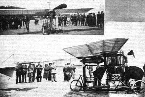
Front and side views of the Blackburn heavy type monoplane.
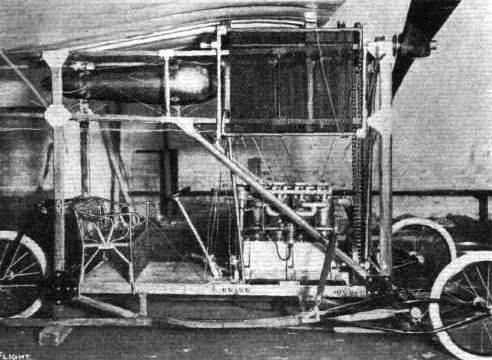
View of the car beneath the planes on the Blackburn heavy type monoplane.
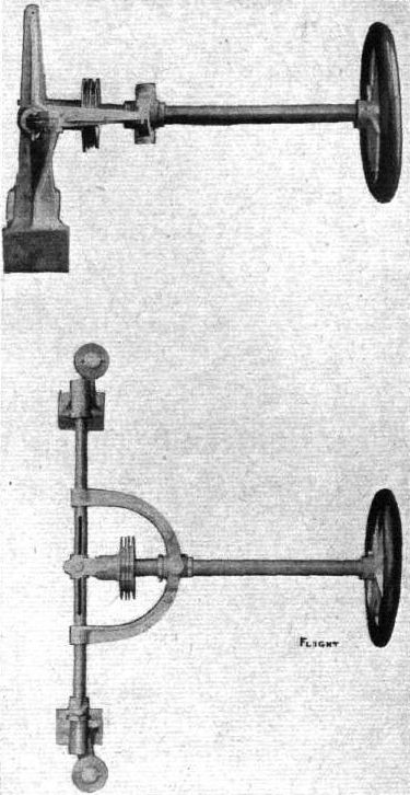
Two views of the Blackburn aeroplane control mechanism.
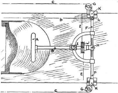
Diagrammatic sketch of the Blackburn aeroplane control.
THE BLACKBURN LIGHT MONOPLANE WHICH ARRIVED AT BLACKPOOL LAST WEEK. - On the left the machine, showing details of the landing chassis and propeller, is seen in its shed; and on the right is the 35-40-h.p. Isaacson engine with which it is fitted, showing reduction gear (2 to 1) and internally cut gear-wheel attached to propeller.
Flight, February 19, 1910
MISS LILIAN E. BLAND'S BIPLANE "MAYFLY."
I enclose two photos of my biplane, the "Mayfly." I made her entirely myself, with the exception of the metal clips, and, of course, the sockets, strainers, &c, were bought from English firms. I think she is the first biplane made in Ireland.
I had her out again to-day, wind of 18 m.p.h. My only difficulty is at present to prevent her flying when I do not want her to. To-day I had three men to assist me, two of them knew nothing about it, and she ran the rope through their hands and soared up 20 ft. before anyone was prepared. Fortunately the third man and myself had hold of a long rope, which saved the situation; in fact, we got the machine soaring beautifully for some time until a downward gust caught the elevators, which I had fastened, when she dived down and broke both skids, but did no other damage. It is quite a new sensation being charged by an aeroplane.
We then had quite a lively time sailing her down hill to the shed; a 4-ft. bank was cleared in fine style, and indeed the only drawback was the pace, for she wants to go about 30 m.p.h. I have now altered the steering arrangement so that the elevators can be controlled from the ground, which I naturally ought to have done from the first. I am also fitting two side panels, as I cannot very well work the balancing wings from the ground.
I have not yet had a chance of ascertaining the gliding angle exactly, but she soars with vertical ropes, and I imagine her angle is about 7 degrees. As I told you, she rises straight off the ground when faced to the wind. If we bring her gliding down in a steady wind she lands as softly as a feather. A. few hours work has made the skids stronger than they were before; they both broke where the wood was cross-grained, but I have the greatest difficulty here to get good wood. The skids are American elm, which is very springy, and I must say they were severely tried.
LILIAN E. BLAND.
[Other aviators in embryo will not fail to have read with pleasure Miss Bland's breezy letter of her preliminary experiments, nor to wish her success in all future trials, particularly when she becomes the pilot of her machine.
[Soaring tests were carried out by the Brothers Wright with one of their gliders; the gliding angle is given by the slope of the hill if the glider soars on absolutely vertical ropes and the wind is blowing truly over the surface of the ground.-ED.]
Flight, May 21, 1910
THE SKIDS AND OTHER FEATURES OF THE "MAYFLY."
I am interested to see that Short Bros, are placing their motors in the centre of the planes, because a long time ago I suggested that the balance would be much better if the weight was placed between the planes, and not all on the lower plane, and rather above than below the centre. I had found this out on my model biplane, and so far the Curtiss machine was the only one to have the motor in that position.
I am experimenting with various skids. I find the wooden skids of the Wright type will stand the shock of landing, but something else generally breaks, so I am now trying steel and wood, of which I enclose a drawing. The "Mayfly" came down very hard on these last week, when the wind dropped, and she bounded like a tennis-ball, and nothing gave way, but the steel bent a little; they are, so far, the most satisfactory, but I am going to make another pair like No. 1 drawing with wheels, as I could then start her down the hill without men on the ropes; my difficulty is that I have to take the skids off each time to get her into the shed.
At present I am flying her with a Santos-Dumont type tail, but I am making another - a horizontal plane, pivoted so that I can alter the angle, with a single rudder above, and the rudder is connected with a wheel for steering on the ground. I am also putting a rudder in front, and the two will be connected. At present my two elevators work in the usual way, and also in opposite directions in connection with the balancing-planes, i.e., for turning to the right, the right-hand balancer is depressed to right the falling tendency, and the left-hand elevator is depressed; the balancing-planes are hinged to outside rear stanchions, and are on the same principle as the Farman flaps, so that rocking the lever depresses one and the opposite elevator at the same time, and this has apparently a much quicker tendency to right the machine than using a balancer by itself. I find my method of waterproofing is excellent, even in a driving rain and wind no rain gets through.
LILIAN E. BLAND.
Flight, July 16, 1910
THE "MAYFLY" GETS ITS ENGINE.
I have at last got my engine. To hasten matters, I went over to England and brought it back not quite under my arm, but on two spars; it fitted very neatly into a railway carriage and also on to an outside car. I got it on the aeroplane and tried it late last night; but as I have not got my tank yet I tried to feed it out of a whisky bottle, and the only tubing I could find was my aunt's eartrumpet. Under the circumstances the engine behaved better than I expected, it was like a cat-fight on a very enlarged scale. The natives, I hear, thought one of the mills had blown up, but as the noise continued they put it down to a thunderstorm; in the meantime I found the mechanic while deeply interested in the engine was liberally pouring the petrol over the main plane instead of down the ear-trumpet, and the engine subsided with a sigh. As it was pouring with rain and too dark to see, the proceedings were terminated and I think I will wait for the tank, and as the engine is English its sense of humour is not devoloped sufficiently for these proceedings.
LILIAN E. BLAND.
I enclose two photos of my engine in case you care to publish them. The one on the right is a side view, showing carpet seat, pedals, lever, & c, while the other is a back view of engine and myself. I find mechanic's overalls are the best things to wear; skirts are out of the question with all the wires, &c., not to speak of oil. The boxwood wheels on end of skids are only for running the machine along the road. The motor is a 20-h.p. Avro, and the propeller an Avro, adjustable pitch, 6 ft. 6 in. diameter; the engine is beautifully balanced, but all the same the vibration is enormous, and I find that all the nuts dance themselves loose; however, I can doublenut most of the bolts. I had the engine running nicely on Saturday, and as soon as I have got everything so that it will not shift, I shall take the machine up to the flying ground I have been lent. It is a fine place, 800 acres, but it also contains a loose bull, and if it gets annoyed and charges I shall have every inducement to fly!
LILIAN E. BLAND.
Flight, December 17, 1910
THE "MAYFLY" - THE FIRST IRISH BIPLANE.
AND HOW SHE WAS BUILT.
By LILIAN E. BLAND.
IN view of the considerable interest which has been taken in my biplane, which has gradually been evolved from a glider, I have at the request of the Editor, written the following description of it :-
As the principal dimensions of the machine are given in the scale drawings, it will be unnecessary to repeat them here. The wood used for the main spars is ash, the curve of the wing tips being steam bent. The ribs and stanchions are of spruce, the outriggers of bamboo, the skids of ash, and the engine bed of American elm. This engine bed is really a separate chassis set across the main spars to which it is clipped; stays run from the rear spar to the chassis, which is also wired out to the upper and lower spars, so that it would be impossible for the engine to shift unless the whole machine were wrecked. Additional strength is also given to the wings by the wiring. The chassis carries the tank and the pilot's seat, the latter being slung by four straps. In front of the seat, which is enclosed on all sides so, that it is impossible to fall out of it, is the bar for the elevator control. The whole chassis can be removed in one piece either with or without the engine, which is held in place by four bolts.
The controls consist of a bicycle handle bar which rocks and turns. Turning the handle to the right raises the right hand elevator and depresses the left, the connecting wires being crossed. The elevators are connected to the horizontal tail planes, which work in the opposite direction to the elevators; all controls are double, wire and strong waterproofed whipcord. The balancing planes, which are hinged to the rear stanchions, are controlled by the back of the seat, leaning to the right pulls down the right hand balancer and vice versa. The vertical rudder is worked by pedals. The engine controls consist of a butterfly valve which regulates the petrol supply, an air throttle, and a lever to the magneto, while when starting one cylinder is cut out. All these controls may sound complicated, but in practice they are quite simple to work, and I think it is a great advantage to have the engine and aeroplane under complete control, as it is not always necessary to run the engine all out.
When the engine starts the draught from the propeller lifts the tail and the tip of the skids off the ground, and the machine balances on the two wheels; the third wheel in front only comes into action over rough ground, and is to prevent the machine from going on to her nose; it answers the purpose admirably, as my practice ground is rough grass with ridge and furrow, which on hunting principles I take at a slant. I have wasted much time in trying to run the machine on ball-bearing wheels and spindles, fitted with various springs, rubber bands, &c, none of which were satisfactory. The spindles were always bending or breaking, and the wheels are now rebuilt on to 7 in. hubs, which run on the axle. The axle is clipped to the skids, and the only spring is that afforded by the Palmer tyres.
The construction of the machine is more or less of the usual type, but the trailing edge and wing tips are more flexible. Originally steamed ribs were used, but were later discarded, as they did not keep their proper curve; the present ribs are cut out solid to the correct curve for the lower surface of the rib, and are given a flatter curve on the top, while they are bored out for the sake of lightness.
The double surface of fabric is laced on, a method which allows one to make any alterations without spoiling the fabric, and also it can be tightened up when it stretches. The machine was out for four months in the open, including the wettest August we have had for years, and the fabric is still waterproof, and except that it looks very dirty, is as good as when it was put on. The machine was tethered with three ropes fore and aft, from the main spars, and with her back to the south, and the west wind blowing along the span, she rode out several gales in safety.
I should not advise any amateurs to commence building aeroplanes unless they have plenty of spare time and money, but there are nevertheless many people who like myself have the time, but lack the necessary ? s. d.
As the result of my experience I am certain that the only way to build an aeroplane cheaply is to put the best or everything into it. Eyebolts, I think, should be hand turned with good solid heads, and, needless to add, wire-strainer eyes should be strong, and the threads properly cut. Castle nuts or patent locking washers of some kind should be used to prevent the nuts working loose with the vibration. I may say that I got all my wire, bolts, & c , from Messrs. A. V. Roe and Co., and was very well satisfied. The actual cost of a biplane is not very serious, as sufficient good wood (in the rough) costs about ?3 or ?4. With regard to the fabric, I now use unbleached calico, which is 6 ft. wide and costs 9d. a yard. The running gear will cost anything from ?6 upwards. The engine, as everyone knows, is the most serious item. My own machine has a 20-h.p. engine, and the expenses have not yet amounted to L200, although the machine has been practically rebuilt, has had two propellers, several pairs of skids, three different tails, &c. It should be borne in mind, however, that this means doing all the work oneself, which is not altogether a disadvantage.
My first propeller was broken by some wires snapping from the vibration of the engine, and when the second propeller had had some narrow shaves from the same cause I tied all the wires back, so that when it snapped it could do no further harm; the break was always at the bend on the loop. Unless the wire is silver plated it has to be continually cleaned to keep it free from rust, and as many wires are difficult to get at to clean it is a good plan to paint them. I use a good black enamel for all the clips. All the woodwork is copal varnished to protect it.
Bamboos should be carefully selected, the section of the cane being thick and round, and one generally has to sort through 20 or more canes to find one good one. The bamboos also get a coat of varnish, the ends have an air hole drilled, before the plug is driven in. A piece of cycle lube with one end flattened to make the necessary clip, is slipped over the bamboo, and riveted on. The other clips, &c., are made of different gauges of hoop iron or steel.
The tank and carburetter float are placed across the span of the machine, so that the fore and aft tilt does not interfere with the petrol supply when the tank is getting empty; tanks are made now with two cocks leading to the tube, which gets over this difficulty where the fuel is fed by gravity.
As to the actual flying of a machine, I am not a good enough pilot yet to give much advice, and my own machine is the only one I have been on. She rolls considerably until she gets up speed, and I imagine all machines do the same. As this is the natural action of the beast when one sits still, it is not necessary to try and balance the roll. If the balancing planes fail to right the machine quick enough, the vertical rudder can always be relied on to do so. One can learn a great deal by watching good pilots. Unfortunately there are none in Ireland at present, but I have been fortunate in seeing Farman, Paulhan, and Latham, all masters of the art.
Certainly it is the finest sport in the world, and well worth all the hard work, but there is still plenty of room for improvement both in the aeroplanes, engines, and propellers. I imagine one of the best types of aeroplane would be a tandem monoplane, in which the wings would be used for balancing and elevation.
To sum up the various points one has to settle before starting the construction of a machine :-
Firstly.- A place to fly it in. Bad ground is waste of time and takes much longer to learn on.
Secondly.- The engine, if of low h.p., the aeroplane must be light and have large area to weight.
Thirdly.- The placing of engine and pilot, and whether main planes will carry all the weight, &c.
Fourthly.- To draw out every detail to scale, and if trying an original design, to make a good-sized model, and see if any new point in controls or design is going to work as it is intended.
Fifthly.- Design the machine so that it can be easily taken to pieces for transport, &c. (by turning the skids round, my machine will wheel along any road when the outriggers are taken off).
In conclusion, I should be glad to get orders either for gliders or full-sized machines, and provided I can use my own designs, I will guarantee that the machines will glide or fly, that the work and quality will be of the best, but the engine and propeller must be reasonably efficient, otherwise it is only waste of time.
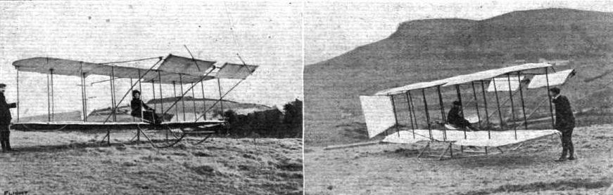
Miss Lilian E. Bland's biplane, "Mayfly," the owner up in the left-hand photograph. On the right S. Girvany, Ballymore, who has made the metal fittings and helped throughout its construction, is in the pilot's seat. The biplane has a span of 27 ft. 7 ins., area 260 sq. ft., weight with skids 200 lbs., aspect ratio 5.5, angle on skids 6 degs.
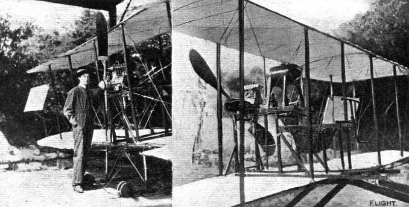
The "Mayfly," with its 20-h.p. Avro engine in place. Miss Lilian Bland, Its designer and owner, is seen in her businesslike working overalls in the left-hand photograph.

Bland Mayfly powered version of 1910. - This side view shows the machine as she now is, but in the new tail Miss Bland contemplates fitting, the fin in front of the rudder will not be used.
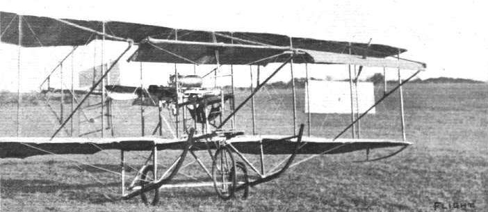
THE "MAYFLY" - View of the front of the biplane, showing how one elevator rises and the other lowers. In this photograph also the wiring of the wings to the skids is noticeable. The angle of the machine on the skids is 6 degrees.
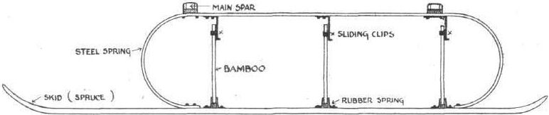

THE "MAYFLY." - Sketch showing the general arrangements of the detachable framework containing the power plant, &c.
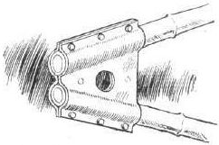
The "Mayfly." - Detailed sketch of the outrigger pivot.
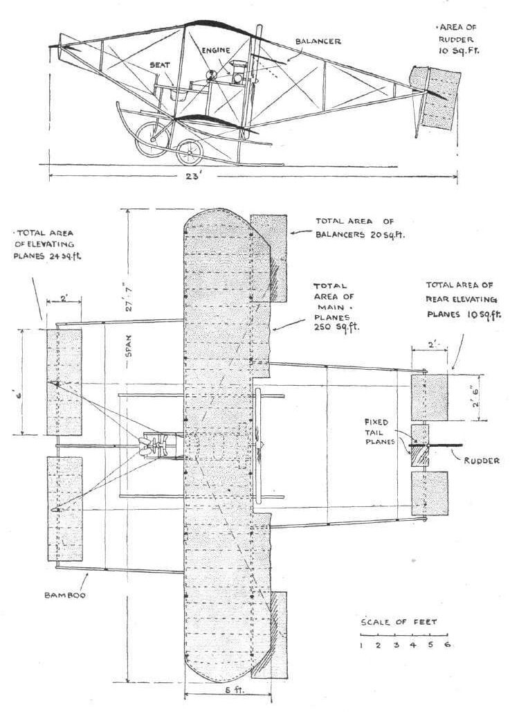
THE "MAYFLY." - Plan view and side elevation to scale.
Flight, May 14, 1910
ANOTHER GLIDER.
I enclose a photo of my glider, which I think you might care to put in your valuable paper. It is a biplane, built to my own designs, and of somewhat original shape. Note the boat-like shape of the lower plane; this gives it perfect automatic lateral stability even in a strong wind. I finished it a day before I sailed to South Africa, so was unable to give it a fair trial, but it made a very successful short glide in Wimbledon Park, with a fairly strong side wind. The machine kept a perfectly steady keel throughout, and my model does not object to even a strong wind. The photo, I'm afraid, is a bad one, taken in a rapidly failing light, with a four minutes' exposure. My mechanic is seen silting in it.
I give a few dimensions : -
Span of main planes ... 22 1/2 ft.
Width of same : 6 1/2 ft.
Length of elevating planes : 13 ft.
Total lifting surface about : 285 sq. ft.
Weight : 150 lbs.
The whole frame is constructed of ash, except the elevating planes, which are of bamboo. It is mounted on strong bike wheels.
Patents are being taken out for this invention.
The Karroo, Cape Colony. CEDRIC BOUSTEAD.
Flight, September 17, 1910
The "Bristol" Aeroplane at the Manoeuvres.
ON Tuesday last at the flying school of the British and Colonial Aeroplane Co., Ltd., at Lark Hill, Salisbury Plain, some trial tests were carried out by Captain Dickson, the well-known aviator, with the "Bristol" biplane he will use in the forthcoming Army manoeuvres. This aeroplane was specially built for the purpose at the Filton works of the British and Colonial Aeroplane Co., and is fitted with a 50-h.p. Gnome engine. It was only commenced on August 17th, and yet it was delivered on Saturday last. Early on Tuesday Captain Dickson took it out for its first trial, when it did a fine flight and showed great stability in the air. A few minor adjustments were then made, and the trials were resumed in the evening, when the wind had moderated to about 12 miles an hour. On this occasion Captain Dickson made some magnificent flights for a long distance over the surrounding country at a height of about 200 ft., finishing several of them with very fine vol planes, landing on each occasion with great skill and smoothness. In view of the coming manoeuvres these flights were watched with the greatest interest by a large number of officers from the neighbouring camps, and a considerable number of the public were also interested spectators of this fine exhibition of the new "Bristol" biplane.
In the final week of the manoeuvres, Captain Dickson expects to give a number of exhibitions of the use of aeroplanes in warfare, showing their possibilities for despatch carrying, reconnaissance and observation duties. It will no doubt give the liveliest satisfaction in military circles that the machine to be used in the British Army manoeuvres will be of British manufacture.
Flight, October 1, 1910
BRITISH NOTES OF THE WEEK.
Bristol Biplanes at the Manoeuvres.
CONSIDERABLE gratification has been felt at Bristol with the splendid results obtained in the Army manoeuvres with the two biplanes of the Farman type, built by the British and Colonial Aeroplane Co., at Bristol, and piloted by Capt. Dickson and Mr. Robert Loraine respectively. Both these aviators made several flights of varying duration, and after Capt. Dickson, through a misunderstanding, had landed in the enemy's camp, it was decided that the aeroplanes should be regarded as "neutral." Lieut. Gibbs also made some flights on a Bristol biplane, but most of his work was done on his racing Henry Farman machine.
Flight, November 19, 1910
Flying at Bristol.
STARTING on Friday afternoon of last week a fine series of flights were carried out at Bristol by the machines built by the British and Colonial Aeroplane Co. On Friday evening, although a heavy rain was falling, Mr. Macdonald brought out one of the machines from the shed which has been erected on the Sea-walls Plateau at Durdham Downs and made three short flights in a straight line, the last one accompanied by a passenger. M. Jullerot then took charge of the machine and flew round the ground for a few minutes, after which the machine, having proved itself satisfactory, was returned to its shed for the night. Operations were commenced early on Saturday morning, when M. Jullerot set the ball rolling by taking Mr. Stanley White for a ten minute trip. The wind then freshened considerably, and it was decided to postpone further attempts until the afternoon. During the morning a large crowd of people wended their way out to the grounds to see the flying, and those who remained were not disappointed. At 3 o'clock Tetard took his seat on the machine, and as soon as the police had cleared a course for him started off. He steered for the sea walls and then took a wide sweep round the grounds in the direction of the reservoir. He afterwards started on another wide circle, after which he came to earth quite successfully. During the latter part of this flight it was evident that the wind was very trying, and he found it difficult to pass over the Avon Gorge. After this flight the weather conditions became worse, and it was eventually decided to abandon any further attempts for the day. Monday was a blank day on account of the wind; several distinguished visitors, however, inspected the machines in their sheds, including Mr. Birrell, the Secretary for Ireland. It had been hoped, too, that Mr. Haldane would have been able to see the machine flying, but he was detained by his other engagements.

Getting the Bristol biplane of the British and Colonial Aeroplane Co. ready for M. Edmonds, who is in charge of this machine, at the Lanark Flight Meeting.
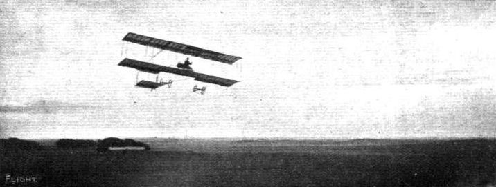
A British-built "Bristol" biplane in flight on Salisbury Plain, piloted by Edmond. This machine was built entirely at their Filton works, near Bristol, by the British and Colonial Aeroplane Co., of which Sir George White, Bart., is a director. Needless to say, it has aroused considerable interest at the Company's flying school on Salisbury Plain, where Edmond has, we understand, been very successful in carrying passengers with it. This type of machine is now being turned out as rapidly as possible, and the Company's proficiency may be judged from the fact that the machine is seen in flight above the very first day it was erected.
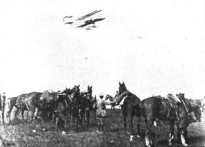
DURING THE BRITISH ARMY MANOEUVRES. - Captain Dickson, on his biplane, reconnoitring over the Somerset Yeomanry.
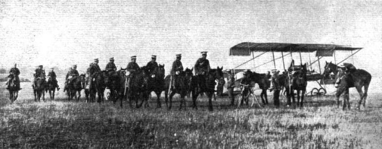
DURING THE BRITISH ARMY MANOEUVRES. - Captain Dickson's aeroplane retaken by the "Reds."

ON WYLYE DOWN IN THE EARLY MORNING MISTS DURING THE BRITISH ARMY MANOEUVRES. - Guarding Captain Dickson's biplane in Camp.
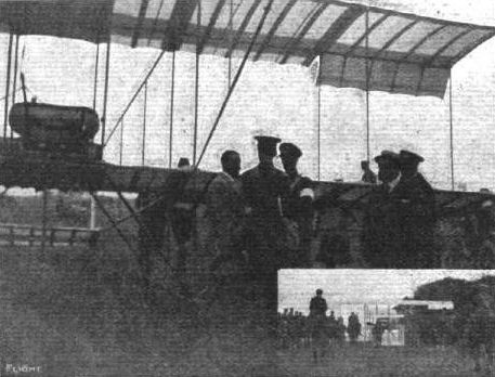
Capt. Dickson, at the British Army manoeuvres, with his British-built "Bristol" biplane, in consultation with some of the officers. Inset below is a general view of the "Bristol" machine in charge of the cavalry.
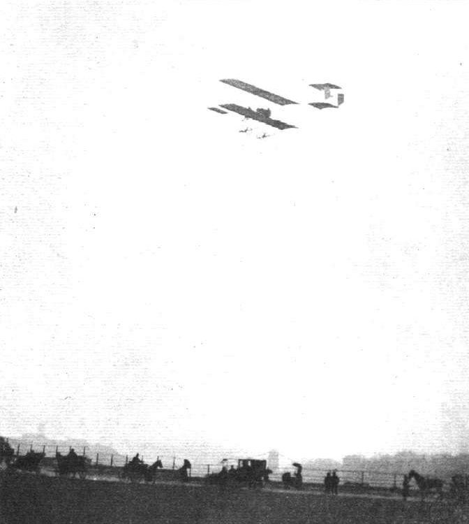
FLYING OVER THE AVON GORGE. - Monsieur Tetard flying a "Bristol" biplane over the Avon Gorge recently, as reported in these pages.

AVIATION ON SALISBURY PLAIN. - The school buildings of the British and Colonial Aeroplane Co., Ltd., the builders of the "Bristol" aeroplane, with which Capt. Bertram Dickson, during the recent Army manoeuvres, carried out some fine flights.
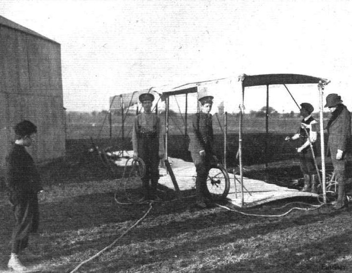
AFTER THE STORMS LAST WEEK. - Sorting out Mr. Greswell's aeroplane after the wreck of his hangar. Mr. Greswellt who had hoped to have started for the De Forest L4,000 Prize, is standing on the extreme right of the machine.
Flight, December 31, 1910
PROGRESS OF FLIGHT ABOUT THE COUNTRY.
Bristol and West of England Ae.C. (STAR LIFE BLDGS., BRISTOL)
ON Saturday, the 17th inst., a fair muster of the members of the club motored out to Keyusham to commence gliding operations. This was the first opportunity the members had of testing the new glider which has been presented to the club by the British and Colonial Aeroplane Co., of Bristol.
Unfortunately the weather was not all that could be desired, and the conditions were unfavourable for carrying out experiments on an extended scale, the surface of the ground being so wet and soft that it handicapped the members during the starting operations.
The glider was brought out of the hangar and much admired, it being beautifully constructed and fitted with all the latest improvements. The machine is of the biplane type and so constructed that it can be fitted with engine, propeller and chassis. The main planes have a span of 32 ft. 4 ins., and the overall length from elevator to tail is 33 ft. 10 in. The height to the top of the planes is 6 ft. 8 in. The control of the elevator and tail is by means of forward and backward movement of the hand lever, and the control of the ailerons by moving the same lever to the right or left, whilst the rudder is worked by a foot lever. A detachable chassis has been supplied on which the glider can be mounted for pulling it up the hill.
The ground, which is situated near Keynsham, is almost ideal for gliding purposes. The aspect is north-west, and on the top of the hill there is a slight decline for 20 yards of about I in 12, then the hill suddenly dips for a distance of 100 yards at a decline of about 1 in 4. At the bottom there is a flat piece of land extending for about another 150 yards, which makes a good landing place, the width of the ground being 120 yards.
The glider is kept in the hangar which has been erected by the club at the foot of the hill.
After the glider had been photographed it was taken a short distance up the hill, and an endeavour was made to fly the machine as a kite. Ropes were attached to the two outside corners of the main planes, and two members towed the machine down the hill, but owing to the lack of wind the machine only lifted a couple of feet off the ground. The next attempt, however, was far more successful, and the glider was taken up to the top of the hill, and on being towed quickly down it rose to a height of about 12 ft., and would undoubtedly have flown higher had the tow ropes been longer. It was then decided to take the glider to the top of the hill, and see if it would fly with a passenger. Mr. G. H. Challenger took his seat in the machine, and two of the members towed the machine down the hill. The wind, however, had dropped considerably, and was insufficient to lift the machine more than two or three feet from the ground. However, the glider descended safely, and there is no doubt whatever that with sufficient wind the machine will be capable of gliding with a passenger.
By this time the rain had commenced to fall and the light was failing, so it was decided to give up operations for the day. The glider was taken back to the hangar, and the members were quite satisfied with their first attempt, and expressed the hope that they would soon be able to have another opportunity of using the machine.
Wednesdays and Saturdays will be general club days for gliding, but no further trials will be made until Saturday, December 31st.
It is hoped that next year the membership of the club will be considerably increased, and the honorary secretary (Mr. A. Alan Jenkins), Star Life Buildings, Bristol, would be glad to receive the names of any gentlemen who would like to join.

A view from In front of the Glider of the Bristol and West of England Aero Club.
Flight, August 20, 1910
BIPLANE GLIDER.
We have just completed a biplane glider, and enclose photographs which we hope will interest the readers of your invaluable paper. The main planes have a spread of 30 ft., and the machine an overall length of 24 ft.; the total area is 260 sq. ft. The biplane is built entirely of ash, and the interesting part of the machine is the control (see photo.). The rudder is worked by the feet, the elevator by a forward movement of the steering wheel, and the ailerons by means of rotating the wheel. The tail elevator is also adjustable by a special lever; all the struts, &c, are cut to the correct stream line form, and the whole machine can be taken in half from the middle for purposes of transit, &c. A few preliminary experiments showed that the machine is not only strong, but showed particularly great longitudinal and lateral stability. There are two or three very good hills in the neighbourhood of Keynsham, which is four miles from Bristol, and as we understand that the Bristol Aero Club have a glider but no ground, it is possible that one of these hills might meet their requirements.
Keynsham. ELDON AND GILBERT BUSH.
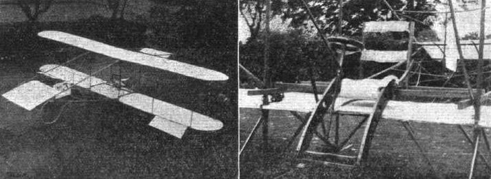
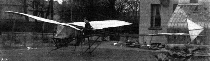
A Monoplane, built by Master Dhoual Cameron, aged 16, of Castlewood College, Rathmines, Dublin. - He was born deaf, and has been educated on the pure oral system under Mr. Newburn, having been successful in passing several competitive examinations. He enters for Trinity College next year, and is building two models for the exhibition at Ballsbridge in June.
Flight, February 26, 1910
MR. CANDLER'S "MONOFOIL."
I enclose a photograph taken a few weeks ago of a monofoil type of flying machine, which is in most respects similar to Bleriot's cross-Channel flyer.
I do not think the weight exceeds 250 lbs. without motor, &c., whilst the supporting surface will be about the same number of square feet. It is to be named "The Stella." The foils which can be seen suspended from the joists above on both sides of the carriage each measure 18 ft. span by 6 ft. fore-aft, thus together allowing for rounded tips, say 210 sq. ft. They are built up with about 1,000 separate lengths of wood; the fabric used is a green oiled calico, which is perhaps a novelty as regards colour; each foil required over 2,000 short sprigs for fixing this, the adjuster plus the steering tails at each end of same is similarly covered. Its fore-aft dimension is 3 ft. and span 12 ft., giving an additional supporting area of 36 sq. ft.
The main spars of the carriage frame are hollow, all struts arc pared to a cutting edge, thereby considerably reducing head resistance; every pains has been taken to gain efficiency in this way and all details have been carefully considered by the constructors - the Farnborough Aviation Works, Kent.
The body and foils suspended from the roof has nothing to do with the above, being a flying machine model now being constructed for Mr. C. H. M. A. Alderson. It is interesting to note that an old broken gliding machine, built entirely of cycle tubing brazed together, may be seen on the roof of the building. This was invented by Mr. Geo. Nichol, an enthusiastic experimenter, about 1900, and experimented with during the early years of this century. Each aerofoil had an elongated trail appendage; these were elevated or depressed alternately or together at the will of the operator, by means of levers worked from his cycle-saddle seat. Unfortunately, photographs of this machine in action were unobtainable, as the trial flights took place in the evenings after 7 p.m. I understand, however, a few photographs are in existence of its being put together on the field.
Mr. Thomas Moy, one of the best-known experimenters of the last century, constructed a small railway here, on which he conducted many scientific experiments bearing on wing machines. Records of these are, I believe, in the care of the proprietors of the Farnborough Aviation Works.
I hope to send you further photographs of the monofoil later.
H. A. W. CANDLER.

Mr. H. A. W. Candler's "Monofoil."

The "C.R." biplane, designed and built by the J. P. CHITTENDEN and L. H. ROBINSON.
Flight, October 29, 1910
THE C.R. MONOPLANE AND BIPLANE.
In your paper of January 22nd and 29th you published a paper and photograph of a C.R. biplane, for which I was jointly responsible. I now enclose some photographs which I trust you will consider worthy of publication in FLIGHT.
One photograph shows the workshop where Mr. Chittenden and I made our machine, and which has since been used by us for the construction of the monoplane, a photograph of which is enclosed, the work being carried out in the name of A. W. Seymour, Motor and Aeronautical Engineers, Rugby. The other two photographs are of the C.R. biplane No. 2. This machine is very satisfactory, and although we have not actually made a flight with it, it has lifted about 18 ins. from the ground, and runs well. Unfortunately we are greatly handicapped by the limited space at our disposal. It is fitted with an Alvaston engine (water cooled) of 30 h. p. at 1,200 r.p.m., and a Weiss propeller, 7 ft. diameter, made by Messrs. Lascelles and Co., of London. The main planes are about 30 ft. across and 4 ft. deep.
The monoplane is fitted with a 40-h.p. Lascelles 4-cyl. air-cooled engine, and a 7 ft. diameter Weiss propeller made by the same company. It will be a favour if you will note that the biplane was built and is owned by Mr. Chittenden and myself, whereas the monoplane was built by us in the name of A. W. Seymour, in which name we hope to continue the business.
Chiswick. LESLIE H. ROBINSON.
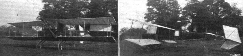
Chittenden-Robinson biplane No.2 of 1910.
Flight, October 29, 1910
THE C.R. MONOPLANE AND BIPLANE.
In your paper of January 22nd and 29th you published a paper and photograph of a C.R. biplane, for which I was jointly responsible. I now enclose some photographs which I trust you will consider worthy of publication in FLIGHT.
One photograph shows the workshop where Mr. Chittenden and I made our machine, and which has since been used by us for the construction of the monoplane, a photograph of which is enclosed, the work being carried out in the name of A. W. Seymour, Motor and Aeronautical Engineers, Rugby. The other two photographs are of the C.R. biplane No. 2. This machine is very satisfactory, and although we have not actually made a flight with it, it has lifted about 18 ins. from the ground, and runs well. Unfortunately we are greatly handicapped by the limited space at our disposal. It is fitted with an Alvaston engine (water cooled) of 30 h. p. at 1,200 r.p.m., and a Weiss propeller, 7 ft. diameter, made by Messrs. Lascelles and Co., of London. The main planes are about 30 ft. across and 4 ft. deep.
The monoplane is fitted with a 40-h.p. Lascelles 4-cyl. air-cooled engine, and a 7 ft. diameter Weiss propeller made by the same company. It will be a favour if you will note that the biplane was built and is owned by Mr. Chittenden and myself, whereas the monoplane was built by us in the name of A. W. Seymour, in which name we hope to continue the business.
Chiswick. LESLIE H. ROBINSON.
THE C.R. MONOPLANE AND BIPLANE.
In your paper of January 22nd and 29th you published a paper and photograph of a C.R. biplane, for which I was jointly responsible. I now enclose some photographs which I trust you will consider worthy of publication in FLIGHT.
One photograph shows the workshop where Mr. Chittenden and I made our machine, and which has since been used by us for the construction of the monoplane, a photograph of which is enclosed, the work being carried out in the name of A. W. Seymour, Motor and Aeronautical Engineers, Rugby. The other two photographs are of the C.R. biplane No. 2. This machine is very satisfactory, and although we have not actually made a flight with it, it has lifted about 18 ins. from the ground, and runs well. Unfortunately we are greatly handicapped by the limited space at our disposal. It is fitted with an Alvaston engine (water cooled) of 30 h. p. at 1,200 r.p.m., and a Weiss propeller, 7 ft. diameter, made by Messrs. Lascelles and Co., of London. The main planes are about 30 ft. across and 4 ft. deep.
The monoplane is fitted with a 40-h.p. Lascelles 4-cyl. air-cooled engine, and a 7 ft. diameter Weiss propeller made by the same company. It will be a favour if you will note that the biplane was built and is owned by Mr. Chittenden and myself, whereas the monoplane was built by us in the name of A. W. Seymour, in which name we hope to continue the business.
Chiswick. LESLIE H. ROBINSON.
Flight, July 2, 1910
THE ACCIDENT TO MR. CODY.
THE sympathy of all interested in British aviation has been extended to Mr. S. F. Cody, in consequence of the untimely accident which befel him on Thursday of last week while testing his new biplane. The machine had been completed on the previous evening, and was noteworthy for the fact that Mr. Cody had abandoned the system of twin propellers previously employed, while he had fitted duplicate engines, so that in the event of one giving trouble its place could be taken by the other. Early on Thursday morning Mr. Cody started up, and as the machine attained a greater speed than anticipated, when running over the ground, he determined on a flight. The machine gracefully rose to a height of 100 ft., and easily circled round the Plain twice. It then traversed the length of Laffan's Plain, but just when gliding down an unexpected gust of wind caught the machine and caused it to fall about 40 ft. to the ground.
Mr. Cody was pinned beneath the wreckage, and was unconscious when released. He was immediately taken to his home, where he was found to be suffering from concussion of the brain and severe bruises. He made rapid progress, and on Monday was able to leave his bed, when he expressed a hope that he would be fit again in time for the Bournemouth meeting. Except that it is smaller, the new Cody machine has a very similar appearance to the biplane with which Mr. Cody was so successful last year. The engines are two of the 5o-h.p. 4-cyl. Green type.
Flight, July 16, 1910
Mr. Cody Flying Again.
RAIDED no doubt by his robust constitution and plucky nature Mr. S. F. Cody made a very rapid recovery from his recent severe accident, so much so that on Friday of last week he was able to once more mount his machine and make a satisfactory trial trip, about three miles in length; before packing up the machine for transport to Bournemouth, where he was flying on Wednesday.
Flight, September 10, 1910
Mr. S. F. Cody in the Air Again.
AT the latter end of last week, Mr. S. F. Cody made a successful flight at Aldershot with his new biplane.
Flight, September 17, 1910
Mr. Cody Again Flying.
SEVERAL times during last week Mr. S. F. Cody was practicing on his new biplane. On Tuesday he made a fine flight at Aldershot, passing over South Camp, the Long Valley, Bourley Woods, Pyestock, Laffan's Plain and Farnborough, being in the air about 25 mins. in all. On Friday again he was up for about half an hour, flying round the district, and altogether his very substantial machine is shaping well.
Flight, October 1, 1910
A Good Flight by Cody.
IN the course of a forty minute flight on Tuesday evening, at Farnborough, Mr. S. F. Cody was mostly flying across country. In the afternoon he made a shorter trip with Mr. Mervyn O'Gorman, Superintendent of the Balloon Factory, as a passenger.
Flight, November 12, 1910
THE CODY BIPLANE.
AMONG pioneers in aviation S. F. Cody deserves much credit. He has fought an up-hill fight against great odds, and he has forced success to come to him as a reward not only for perseverance but for real original work. Alone among the designers of aeroplanes has he succeeded in building a really large machine, and if there are some who have been wont, facetiously, to call it the "flying cathedral," nevertheless, their humour is born of admiration, for the machine does fly, and in the hands of its designer oftentimes performs remarkably well. This particular department of design - the large-sized aeroplane - S. F. Cody has made particularly his own, and he intends to devote the greater part of his private time to its further development, although now that he has decided to place his machine on the market commercially, the standard models will be built on smaller lines. Two sizes have so far been decided upon, the smaller of which, fitted with a 30-35-h.p. engine, will be sold for L1,000, and the larger, fitted with a 50-60-h.p. engine, for L1,200. In both cases flights will be guaranteed, and the purchasers will be trained as pilots free of charge, or they can have a professional pilot trained for them if they do not wish to control the machine themselves. So far, however, we have yet to meet the sportsman aviator and his paid chauffeur - he is a type unborn - but he will put in an appearance later on, sure enough.
From a practical point of view, the Cody biplane is remarkable mainly for its strength. It is subjected to very severe strains on Laffan's Plain, over which Mr. Cody has secured flying rights, and the starting ground itself is uneven enough to give a great machine like this a very severe jolting. It is, therefore, to the undercarriage that the eyes of the engineer are almost inevitably directed after he has taken in at a glance the general proportions of the structure that it has got to carry. The chassis in question is an interesting and ingenious piece of work; it supports the machine on the ground by the aid of two pneumatic-shod wheels and a trailing skid arranged "kangaroo-tail" fashion. Between the wheels and joining the trailing-skid is a single central skid that normally remains about 8 ins. clear of the ground. The trailing-skid is reinforced by a top batten, so that it is to all intents and purposes a laminated structure, for all the time that the machine is running over the ground it is constantly pressing on the surface, and acts as a very useful brake after a descent. The main central skid only comes into action if the landing has been so forced as to result in a severe shock, in which case the wheels rise against the pressure of their long helical springs, and allow the full weight of the machine to be directly borne upon the skid. On one occasion quite recently a forced descent was made, and the machine charged a fallen tree trunk. The upturned end of the skid, which is provided with a pair of small wheels, cleared the trunk, and the entire machine glissaded bodily over the obstacle without doing any damage to the chassis, and not very much to the tree itself. Supported above the under chassis are two horizontal bearers to which the spars of the lower main planes are attached, and immediately above these again come two other bearers of less span, which carry the engine. The engine thus rests centrally upon the lower main plane, and it drives the large single propeller by means of a chain.
Directly in front of the engine, and about on a level with the cylinders, is the passenger's seat, for the Cody biplane is essentially a passenger-carrying machine, while in front and a little below the passenger's seat is the pilot's seat. Both are of the pressed-steel kind commonly employed on agricultural machines, and it has often been rather a surprise to us that Mr. Cody has not provided something a little more luxurious for his own comfort; the passenger can, at any rate, hold on to the framework until the machine is safely in the air.
(To be continued.)
Flight, November 19, 1910
THE CODY BIPLANE.
(Concluded from page 925.)
CENTRALLY in front of the pilot's seat is a steering-wheel on an inclined column, arranged in exactly the same way as a steering-wheel on a motor car. As far as turning the wheel for steering is concerned, the operations are likewise analogous. The wheel is connected with the rudder, which is carried on an outrigger at the rear of the machine.
In addition to the rotary motion of the steering-wheel, the steering-column itself is mounted on a universal trunnion about one-third of its length from the bottom, and it is thus capable of acting as a powerful lever for the manipulation of the elevator and balancing planes. The elevator on the Cody biplane differs constructionally from that on any other machine in being divided into two parts, which are placed side by side; each half is connected to the control-lever by means of a bamboo rod, and the connections are such that the two planes can be made to operate in unison or in opposite directions. When they operate in unison the device is an elevator pure and simple, but when one half is tilted and the other dipped the action is supplementary to that of the balancing planes mounted in the gap of the main planes under the trailing edge. This double elevator, and its use as a balancer, is quite a special feature of the Cody machine, and is one of the several original ideas of its designer. The balancing action is obtained by a sideways motion of the steering-column, which so thrusts on the bamboo connections of the elevators as to move these two members in opposite directions. Simultaneously a supplementary mechanism, consisting of a rock-shaft and a lever, pulls down the trailing edge of one of the balancers against the action of a spring. The arrangement of the balancing-planes on the Cody biplane is such that they are normally held in a horizontal position by springs, and only one of them can therefore be pulled into a position of positive lift by the control; the other balancer, although it may be dipped by the action of the spring, cannot exert a downward thrust, by virtue of this attitude, of a greater magnitude than the springs themselves can support. Interconnected with the balancer mechanism is the rudder - which, as already explained, is capable of independent operation by turning the steering-wheel - and this member is likewise put over in synchronism with the balancing movements. It will be observed, as an outstanding feature of the Cody control, that the balancing forces are brought to bear upon the machine at several points, and it can be readily appreciated that in large aeroplanes of this kind such a feature may be very desirable in order to guard against failure through undue local stress. With the exception of the rather small horizontal tail plane, which is quite flat - and can really almost be regarded more as a member for trussing the rudder, to which it is permanently fixed, than as a factor of great importance in the stability of the machine - all the planes on the Cody biplane are cambered to carry load. And, in connection with the camber of the main planes, there is another original feature which it is only fait to designate as the "Cody curve."
The section of the main planes is very peculiar, and it is rather curious that the peculiarity in question would scarcely ever be observed even by the expert eye, for it is scarcely visible on the finished machine, although very pronounced in an individual rib. One of the accompanying sectional sketches shows a main plane rib, and it will be noticed that the underside is cambered more abruptly than the top side, so that the two laths of which the rib is built up touch one another at a point about one-third of the chord from the leading edge. The attitude of the main planes in respect to the normal axis of flight is such that the upper surface is practically tangential to the line of flight in the vicinity of the leading edge, consequently the lower surface has a dipping front edge and the upper surface has not. Mr. Cody claims for this particular system of construction that it produces the most efficient plane that he has ever tried.
The main planes are built up in sections of 8 ft. span each, and they are divisible into these sections when the machine is dismantled or transport. The joint between sections is completed by a rectangular steel sleeve, and the spigoting ends of the spars are fitted with steel ferrules.
Steel traps are also employed to brace the spars to the main ribs, which occur at these joints. The upright struts separating the upper and lower main planes coincide with the main ribs, and a very ingenious fastening has been employed for their attachment. The struts themselves are of stream line section, and their tapered extremities are spliced into hollow steel ferrules. The ferrule rests upon the cylindrical collar of a specially shaped bolt that passes through the steel strap binding the main spar to the main rib, and has, above the collar, a spherical head that is enclosed by the ferrule. A bolt fastens the ferrule to the spherical head of the bolt, but the joint is essentially a loose connection, and in principle belongs to the ball-socket type. The remainder of the bracing is, of course, effected by steel wires arranged diagonally, and it is also important to remark that the end thrust on the main spars is taken by diagonal wires that tie the spars to the axle of the undercarriage.
When the machine rises off the ground the pressure of the springs used for the suspension of the wheels thrusts down upon these diagonal tie wires, and puts 2 cwt. of tension on to them.
Silver spruce is mainly used in the construction, but the outriggers carrying the elevator and tail are of bamboo. The tail outrigger is hinged, so that the tail can be folded against the main planes in order to save room in accommodation. The undercarriage is made entirely of hickory.
The power plant on the Cody biplane, as illustrated, consists of a 65-h.p. E.N.V. engine, which drives by a single chain a propeller of 10 ft. 2 ins. diameter and to ft. 8 ins. pitch. The speed of the propeller is 600 r.p.m. when the engine is running at 1,200 r.p.m. One very interesting point in connection with the machinery on the Cody biplane is the presence of a radiator immediately in front of the pilot, and Mr. Cody asserts that he has found great benefit from this in cold weather through the air being slightly warmed before it strikes his body. The degree to which aeroplane pilots suffer from the cold while flying is sufficiently well-known to make an idea of this sort well worthy of consideration.
The following summary of some of the principal dimensions and minor details of construction will supplement the data given on the full-page drawing. The span of the main plains is 46 ft., and the main spars have an inverted dihedral of 9 ins. The chord is 6 ft. 6 ins., and the camber 4 ins. in height one third from the leading edge. The gap is 8 ft. 6 ins. The whole of the centre portion of the machine is designed to be accommodated in a railway truck without dismantling. The centre of gravity is located approximately on the front spar. With the exception of a few fittings in the centre of the machine, aluminium is not used in the construction. In every case where bamboo is employed the cane is bound with cord in the middle of each section. The upper bamboo strut carrying the elevator is 3 ins. in diameter, and those beneath are 2 ins. in diameter each. The bamboo poles used for operating the elevator are about 1 1/2 ins. in diameter. The vertical struts in the gap of the main planes have a 4 3/4 by 1 1/8 in. section. They weigh 5 1/2 lbs. each, including the nuts and bolts at their extremities. Between the upper and lower surfaces of the main planes the ribs are trussed by diagonal wires. The planes are surfaced with Pegamoid.
Flight, December 31, 1910
THE BRITISH MICHELIN CUP.
Mr. S. F. Cody Scores 115 Miles.
A VERY fine effort was made by Mr. Cody on the 22nd inst. at Aldershot to win the British Michelin Cup for this year. For 2 hrs. and 50 mins. he steered his large biplane round a marked course over Laffan's Plain, being officially observed on behalf of the Royal Aero Club by Lieut. Fox, R.E. Although Mr. Cody did not beat Mr. Sopwith's duration record of 3 hrs. 12 mins., it is claimed that he covered a greater distance, about 115 miles. A 20-mile wind was blowing, and at the end of the Plain, opposite to that on which the hangar is erected, the wind was particularly gusty and uncertain, with a result that the turn there had to be made very carefully. On one side lay a clump of trees and on the other a flag-post, whilst between these were some iron railings. Time after time the machine escaped the trees by about eight feet, and frequently it was hurled to within six feet from the ground from a height of 30 to 35 ft. This really splendid flight was brought to an equally sensational climax. After being 2 hrs. 50 mins. In the air, the machine was hurled down to the ground with a crash, from a height of well over 35 ft. In spite of this the machine was found to be quite undamaged, and Mr. Cody none the worse for what was probably the finest bit of airmanship he has ever displayed. The biplane was fitted with a Green engine, which ran perfectly throughout the trip.

Mr. S. F. Cody, as we have recorded, is once more doing practical work with his new biplane, our photograph shows Mr. Cody in flight passing over the Basingstoke Canal.
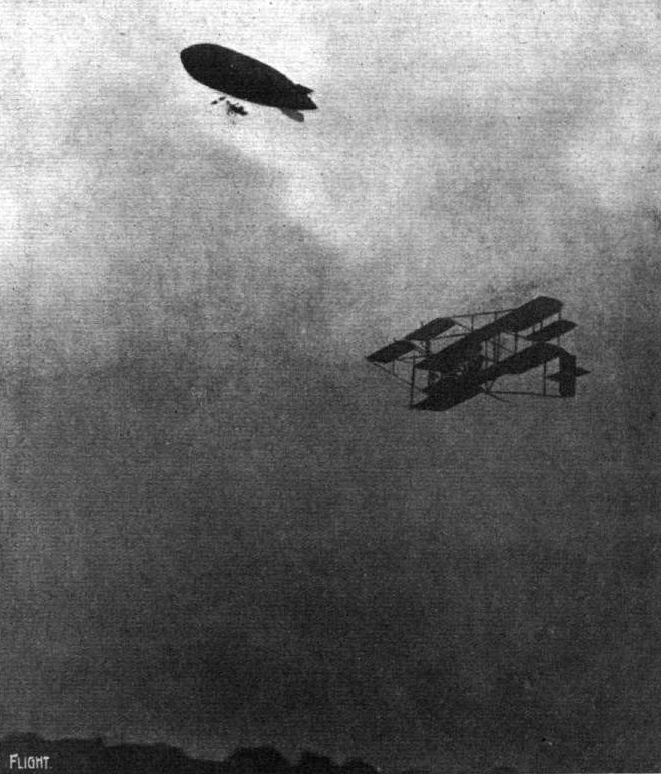
BRITISH ARMY AND AERONAUTICS. - Unique photograph of the Army airship "Beta" and Mr. S. F. Cody's new biplane in flight at Aldershot at 7 p.m. on Thursday the week before last. It is gratifying to know that both these craft are equipped with British-built Green engines.
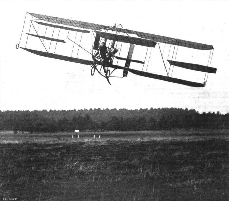
Mr. S. F. Cody, on his biplane, competing for the British Michelin Cup at Farnborough Friday of last week. Mr. Cody made a magnificent flight, remaining up for 2 hrs. 24 mins. Mr. Cody also intends to put in a journey for the Baron de Forest Cross-Channel Distance Prize in good time before the worst of the winter weather sets in.
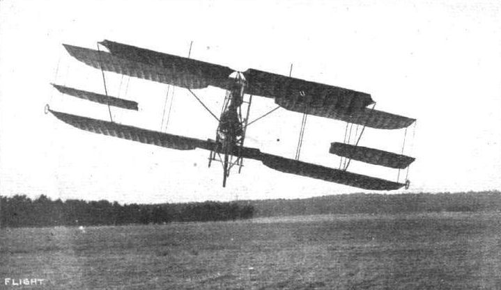
MR. S. F. CODY'S FINE FLIGHT FOR THE BRITISH MICHELIN CUP. - Taking a corner of the course at a fine angle.
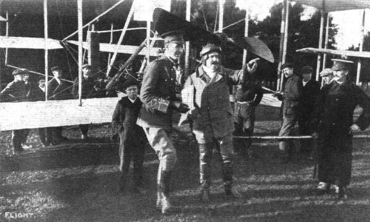
Mr. S. F. Cody and Lieut. A . E. Fox, R.E., the official observer on behalf of the Royal Aero Club of Mr. Cody's fine flight for the British Michelin Cup last week. Mr. Cody's biplane is in the background.
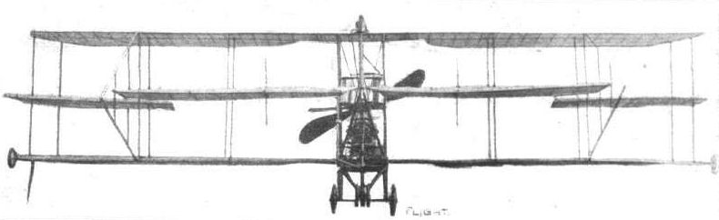
Front view of the Cody biplane, showing the inverted dihedral of the main planes, the extremities of which drop nine inches below the centre.
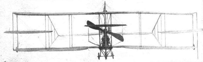
Rear view of the Cody biplane.
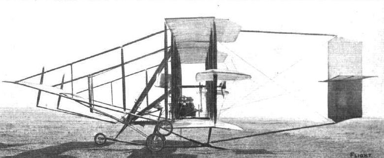
Side view of the Cody biplane, showing the arrangement of the under-carriage. Guard wheels are fitted to the extremities of the main plane.
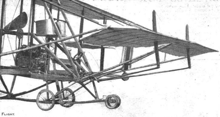
General view of the elevator on the Cody biplane.

On the left one of the balancing planes on the Cody biplane, and on the right the tail of the Cody biplane. The horizontal tail plane is rigidly fixed to the rudder, and moves with it.
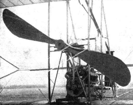
View of the engine and propeller on the Cody biplane.

Mr. Cody and his propeller.
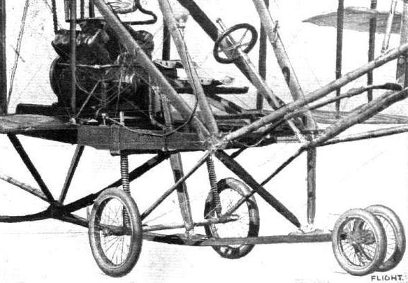
Detail view of the under-carriage on the Cody biplane.

View of the steering-wheel on the Cody biplane.
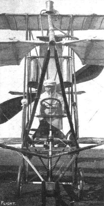
Front view of the pilot's seat on the Cody biplane, showing Mr. Cody at the wheel. This photograph is taken through the radiator, which protects the pilot to a certain extent in cold weather. That the radiator is no obstruction to the view in this position maybe judged from the above picture.

Diagrammatic sketch illustrating the use of the elevators as balancers on the Cody biplane, and also the simultaneous action of one of the main balancing planes.
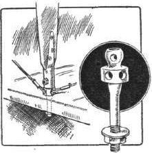
Sketch illustrating how the vertical struts are fastened by a ball-socket joint to the main spars in the Cody biplane. Inset is an illustration of the bolt.

Sketch illustrating how the steering column simultaneously operates the balancing-planes and the rudder when moved sideways.
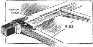
Sketch illustrating how the main ribs are fastened to the main spars by a steel strap on the Cody biplane.
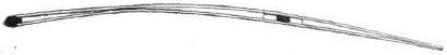
The Cody rib. Sketch illustrating the peculiar camber of the ribs employed on the Cody biplane. The top surface has its entering edge tangential to the line of flight so that the under surface has a dipping front edge.
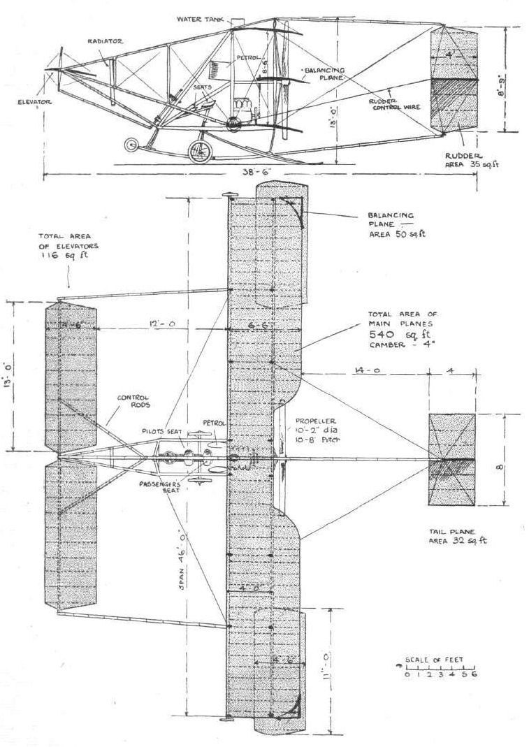
The Cody biplane.
Flight, May 7, 1910
A BRITISH-BUILT MONOPLANE.
I am sending you some particulars of my monoplane.
I have been studying aviation since August, 1908, and have been through the various stages, with models, making experiments with wing-flapping machines; also building monoplanes with bamboo framing, but do not consider that bamboo makes a nice-looking job, as it is difficult to make clips to look very neat.
My latest machine has a spread of 35 ft. and chord 6 ft. I in., length 22 ft. over all. Tail elevators of a special shape; 30 sq. ft. area; rudder 6 sq. ft.
Lateral stability is secured by ailerons 18 sq. ft. each, and controlled by hand lever, right hand, or can be worked by moving one's knees. A left hand lever works elevator, and foot levers work the rudder.
The shock absorption is taken by pneumatic sprung wheels, tested to 10 cwt. pressure, and then the skids take the weight.
The framework is of special grained pitch-pine, very light and very strong, every spar you can follow the grain from one end to the other. Our firm being in the timber trade and also wireworkers, building aeroplanes comes quite naturally. No wire tighteners are used on the machine at all, and every wire is drum tight. A special way of tightening them has been devised, and, naturally, a considerable saving in expense. The covering material of the planes is Spencer's aeroplane fabric, which I may say works very well, as we were able to fix it on without a crease, and very tight. First the fabric was all sewn together, and then drawn over the planes and fastened off at the trailing edge. Split canes were used for tacking fabric to ribs, and makes a very neat job. Also in case of damage to planes it will be easy to remove for repairs. The War Office have granted to us the use of a large flat field, over a mile square, and I have built a hangar there to house the machine.
The total weight of monoplane as now, without motor, is 320 lbs.
Also I have got some very good results from a 6 ft. laminated steel tractor screw which I have made. It was tried on shafting at 500 r.p.m. at 14-h.p., and gave a thrust of 135 lbs., and weighs 16 lbs. I seem to fancy a steel propeller instead of a wooden one, as it ought to have a good fly-wheel effect, and make the engine run steady.
The machine is made shorter than usual, because every bird has a greater spread than length, and when going backward and forwards to Gosport to the hangar I have been very carefully watching seagulls.
You can judge of the amount of work in the planes, for there are 620 pieces in the two.
The monoplane has a good lifting surface, as when it was out in the open, having its photo taken, in a slight wind head on, it took three of us to hold it down steady, and once when we let it go it rose by itself about one foot off the ground. Every spar in the machine can be replaced in case of breakage, special means being taken in building to enable it.
If any of your readers would care to take a financial interest to help purchase the engine, I shall be pleased to hear from them.
Portsmouth. F. DAY.
Flight, April 9, 1910
ANOTHER ALL-BRITISH BIPLANE.
DETAILS OF THE DE HAVILLAND MACHINE.
UNFORTUNATELY, the actual machine with which we are concerned in the present article was one that proved to have a very short life, although it is none the less interesting on that account, for two distinct reasons. On the one hand, it is now being replaced by a second machine designed and constructed in the light of the knowledge gained from it; and in the second place, there is much to be learned from the mere fact that this initial attempt at aeroplane building resulted somewhat disastrously. Fortunately for the British industry, Mr. G. de Havilland, its designer and builder, is a man of the type whose enthusiasm and determination is apt to increase rather than diminish after any preliminary setback; while equally fortunate is it for readers of FLIGHT that he should be willing to place much of the experience that he has just gained at the disposal of fellow British workers in the interests of the aeronautic movement.
The machine of which we are, by his courtesy, now enabled to give a fully illustrated description, was built entirely by himself and by his assistant, Mr. F. T. Hearle. And they it is who are now alone busily engaged with an exceedingly promising "Havilland No. II," although possibly, for the sake of accelerating matters, Mr. de Havilland would feel disposed to consider the advisability of arranging for some other would-be pioneer to join him if the right man were to come forward to help him bear the burden of the undertaking. Needless to say, the expense of building preliminary machines like these is considerable if the task is shouldered, as it has been in Mr. de Havilland's case up till now, by one man only.
Briefly stated the machine in question was a 36-ft. span biplane, having a front mono-elevator, an adjustable mono-tail, a rear vertical rudder, and hinged wing-tips mounted near the extremities of the upper main planes. It was supported on three wheels - one beneath the tail - and was provided with an additional front wheel beneath the elevator, as well as with skids below the ends of the lower main planes. Also it should be mentioned in advance that it was propelled by a pair of bevel-driven screws situated behind and between the main planes on either side of the central girder.
And then it should be added that the past tense has advisably been used in the foregoing paragraph, inasmuch as the first free flight of the machine terminated in almost complete wreckage. The first time that it left the ground it did so after travelling some 40 yards on a downward slope under its own power; it then rose at rather a steep angle, which was corrected by the pilot; and almost immediately afterwards - about 35 yards from the take-off - the left main plane doubled up, causing the machine to fall heavily forward and to the left. Luckily, Mr. de Havilland himself was not hurt, but it will be observed from some of the photographs which we reproduce that the machine as such, apart from the propelling mechanism, the rudder, and the tail, was, for all practical purposes, virtually annihilated by the fall.
As will be observed from what now follows, some important and original features are embodied in this machine, although in general principles there is no radical departure from systems that have proved successful in other cases hitherto. Also, the student of details would do well to bear in mind that this particular machine showed itself to be insufficiently strong for its purpose, thereby, by the way, indicating not only the inadequacy of the cross sections employed, but also the great difficulty that there is in selecting suitable woods for aeroplane construction. To a large extent a form of American whitewood was chosen by Mr. de Havilland, chiefly in order to obtain a good straight grain, but the subsequent fractures indicate an internal softness which was not apparent previously, and we understand that the very much stronger machine now in hand will have silver spruce, ash and hickory in place of the whitewood.
Referring to the special features of Mr. de Havilland's design, it should briefly be mentioned here that these include a neat form of bevel drive for the two propellers in conjunction with the 4-cylinder horizontal opposed engine that also owes its origin to this same designer; while even the propellers themselves are unlike those on other flyers, inasmuch as the aluminium blades are adjustable as to pitch, and as to twist.
Our Illustrations.
Concerning the photographs that we reproduce herewith, it will be observed that one of these only shows the "Havilland No. I" complete and prior to the accident, while two others were taken from the wreck. The first of these is sufficiently clear to be self-explanatory in very large measure, while the other two repay inspection for the light that they throw upon the whole matter. The remaining photograph includes two views of the propeller, and demonstrates the manner and extent to which the blades are adjustable; while among the line drawings will be found detailed sketches showing the construction of the main girder, of the principal planes, and of the propeller, in addition to the full page that contains scale drawings of the kind that we have made peculiarly our own. Wherever possible, dimensions have been added to these line drawings, and hence it is unnecessary to repeat this extremely valuable information in the text.
(To be concluded)
Flight, April 16, 1910
ANOTHER ALL-BRITISH BIPLANE.
DETAILS OF THE DE HAVILLAND MACHINE.
(Concluded from page 268.)
The Central Girder.
RUNNING from end to end, and causing the entire propelling mechanism to form a single unit with the elevator in front and with the tail and rudder behind, the large girder is built up of wood with metal clips and steel wires as indicated in our illustrations. The longitudinal members have a cross-section of 1 1/2 in. by 1 1/2 in. at the thickest part, and each is made in two parts, lap jointed at the centre, while beneath these members in the immediate neighbourhood of the engine are fitted angle-steel stiffening members, each of which is about 3 ft. 6 ins. long. At the widest place this girder is 2 ft. 4 in. wide by 2 ft. deep, while the lattice members at the rear (which are added subsequently to original intentions) are 1 1/4 in. wide by 1/4 in. in depth. For carrying the propellers with their bevel gear, tubular members are employed branching out on either side of the main girder, and here it may be observed that the engine lies snugly with its comparatively short crank-shaft at right angles to the direction of travel, while continuation shafts are carried from both its ends to the bevel gear-boxes into which the longitudinal propeller-shafts also pass. A very compact substitute is thus obtained for the more usual chain drive, and an engine of the de Havilland type is thus caused to stow very snugly away.
The Main Planes.
These are built up in four parts, each pair of which is bolted together by means of flitch-plates and is then secured by bolts to the engine frame. Wooden spars are employed of the dimensions given in our separate sketch, and it will be observed that distance pieces are fitted between the ribs and the spars in order to give the latter a greater depth where the ribs are attached, and thus to prevent the fabric from sagging down between the ribs and assuming an ugly shape by resting on the spars. The arrangement of the thin webs between the two surfaces will also be noted, and, of course, it will be understood that a double fabric surface is obtained. Incidentally, we are told that a good deal of trouble was experienced with this particular fabric, owing to its tendency to contract in damp weather, even to the extent of distorting the planes, and to hang in festoons when the atmosphere was dry.
Eight pairs of vertical struts are arranged between the upper and the lower main planes, the distance between these planes being 6 feet, as may be observed from the drawing.
Also it may be added that the leading edge of the lower plane stands about 4 feet from the ground under normal conditions. As regards the wing tips on the upper planes, the plane which we give shows precisely the manner in which these are hinged, so as to be operated from the pedals that are situated in front of the pilot's seat.
Elevator, Rudder, and Tail.
Each of these three members - the elevator, the rudder, and the tail - is formed with spars of steel tubing. The area and shape of each is clearly marked on the drawings, and it will be observed, moreover, that provision is made whereby the angle of the tail can be altered if necessary. For controlling the machine the elevator is coupled up to a hand lever on the left, while the rudder can be actuated from a lever on the right.
The Chassis.
Normally when the machine is resting upon the ground or is running along, it rests upon the three spring-suspended wheels that are anchored to the main frame by guide-rods and by forwardly mounted radius-rods. The two front wheels are, of course, arranged together in a kind of tubular frame of their own, and it is they that take the bulk of the weight initially. The details of this chassis are likely to be altered very considerably indeed in Mr. de Havilland's next machine, for he found the present scheme of arranging clumsy and otherwise unsatisfactory. We have already mentioned the additional front wheel and the supplementary side skids that are used.
The Propelling Mechanism.
Details of the engine will be found in a separate article, for which we hope to find room in FLIGHT very shortly; but it must suffice here to say that it weighs about 250 lbs., and that its four 4 1/2 in. bore by 4 3/4 in. stroke cylinders develop about 45-h.p. at 1,500 revs, per min. We are told that it ran with an entirely satisfactory absence of vibration on t he "Havilland No. I" and in fact that it, with the whole propeller drive, fully came up to all expectations. In the machine a radiator built up of 3/4 in. tubes was fixed at an angle of 1 in 6 between and beneath the two parts of the upper main plane, and natural circulation took place through large aluminium pipes coupling it up with the jackets.
Concerning the propellers, our illustrations show very clearly how four clips are used for securing each of the sheet aluminium blades to the single steel tube which passes unbroken right through the T - shaped hub, and it will readily be understood how these clips permit the angle of the blade with the tube to be adjusted at each of those four points, and thus permits the twist as well as the pitch to be varied. Centrifugal force is guarded against by the thrust washers, and the whole of the back of the blade is neatly covered in with a stiff millboard casing in order to provide a smooth rear surface.
One advantage of this form of propeller construction is that a considerable amount of strength is ensured at the root of each blade where it passes into the hub. This is so not only because the steel tube is continuous from end to end, but also because its central portion is wood filled. On "Havilland No.I" the two-bladed propellers have a diameter of 7 ft. 4 in., and each propeller weighs about 14 lbs.
ANOTHER ALL-BRITISH BIPLANE.
DETAILS OF THE DE HAVILLAND MACHINE.
UNFORTUNATELY, the actual machine with which we are concerned in the present article was one that proved to have a very short life, although it is none the less interesting on that account, for two distinct reasons. On the one hand, it is now being replaced by a second machine designed and constructed in the light of the knowledge gained from it; and in the second place, there is much to be learned from the mere fact that this initial attempt at aeroplane building resulted somewhat disastrously. Fortunately for the British industry, Mr. G. de Havilland, its designer and builder, is a man of the type whose enthusiasm and determination is apt to increase rather than diminish after any preliminary setback; while equally fortunate is it for readers of FLIGHT that he should be willing to place much of the experience that he has just gained at the disposal of fellow British workers in the interests of the aeronautic movement.
The machine of which we are, by his courtesy, now enabled to give a fully illustrated description, was built entirely by himself and by his assistant, Mr. F. T. Hearle. And they it is who are now alone busily engaged with an exceedingly promising "Havilland No. II," although possibly, for the sake of accelerating matters, Mr. de Havilland would feel disposed to consider the advisability of arranging for some other would-be pioneer to join him if the right man were to come forward to help him bear the burden of the undertaking. Needless to say, the expense of building preliminary machines like these is considerable if the task is shouldered, as it has been in Mr. de Havilland's case up till now, by one man only.
Briefly stated the machine in question was a 36-ft. span biplane, having a front mono-elevator, an adjustable mono-tail, a rear vertical rudder, and hinged wing-tips mounted near the extremities of the upper main planes. It was supported on three wheels - one beneath the tail - and was provided with an additional front wheel beneath the elevator, as well as with skids below the ends of the lower main planes. Also it should be mentioned in advance that it was propelled by a pair of bevel-driven screws situated behind and between the main planes on either side of the central girder.
And then it should be added that the past tense has advisably been used in the foregoing paragraph, inasmuch as the first free flight of the machine terminated in almost complete wreckage. The first time that it left the ground it did so after travelling some 40 yards on a downward slope under its own power; it then rose at rather a steep angle, which was corrected by the pilot; and almost immediately afterwards - about 35 yards from the take-off - the left main plane doubled up, causing the machine to fall heavily forward and to the left. Luckily, Mr. de Havilland himself was not hurt, but it will be observed from some of the photographs which we reproduce that the machine as such, apart from the propelling mechanism, the rudder, and the tail, was, for all practical purposes, virtually annihilated by the fall.
As will be observed from what now follows, some important and original features are embodied in this machine, although in general principles there is no radical departure from systems that have proved successful in other cases hitherto. Also, the student of details would do well to bear in mind that this particular machine showed itself to be insufficiently strong for its purpose, thereby, by the way, indicating not only the inadequacy of the cross sections employed, but also the great difficulty that there is in selecting suitable woods for aeroplane construction. To a large extent a form of American whitewood was chosen by Mr. de Havilland, chiefly in order to obtain a good straight grain, but the subsequent fractures indicate an internal softness which was not apparent previously, and we understand that the very much stronger machine now in hand will have silver spruce, ash and hickory in place of the whitewood.
Referring to the special features of Mr. de Havilland's design, it should briefly be mentioned here that these include a neat form of bevel drive for the two propellers in conjunction with the 4-cylinder horizontal opposed engine that also owes its origin to this same designer; while even the propellers themselves are unlike those on other flyers, inasmuch as the aluminium blades are adjustable as to pitch, and as to twist.
Our Illustrations.
Concerning the photographs that we reproduce herewith, it will be observed that one of these only shows the "Havilland No. I" complete and prior to the accident, while two others were taken from the wreck. The first of these is sufficiently clear to be self-explanatory in very large measure, while the other two repay inspection for the light that they throw upon the whole matter. The remaining photograph includes two views of the propeller, and demonstrates the manner and extent to which the blades are adjustable; while among the line drawings will be found detailed sketches showing the construction of the main girder, of the principal planes, and of the propeller, in addition to the full page that contains scale drawings of the kind that we have made peculiarly our own. Wherever possible, dimensions have been added to these line drawings, and hence it is unnecessary to repeat this extremely valuable information in the text.
(To be concluded)
Flight, April 16, 1910
ANOTHER ALL-BRITISH BIPLANE.
DETAILS OF THE DE HAVILLAND MACHINE.
(Concluded from page 268.)
The Central Girder.
RUNNING from end to end, and causing the entire propelling mechanism to form a single unit with the elevator in front and with the tail and rudder behind, the large girder is built up of wood with metal clips and steel wires as indicated in our illustrations. The longitudinal members have a cross-section of 1 1/2 in. by 1 1/2 in. at the thickest part, and each is made in two parts, lap jointed at the centre, while beneath these members in the immediate neighbourhood of the engine are fitted angle-steel stiffening members, each of which is about 3 ft. 6 ins. long. At the widest place this girder is 2 ft. 4 in. wide by 2 ft. deep, while the lattice members at the rear (which are added subsequently to original intentions) are 1 1/4 in. wide by 1/4 in. in depth. For carrying the propellers with their bevel gear, tubular members are employed branching out on either side of the main girder, and here it may be observed that the engine lies snugly with its comparatively short crank-shaft at right angles to the direction of travel, while continuation shafts are carried from both its ends to the bevel gear-boxes into which the longitudinal propeller-shafts also pass. A very compact substitute is thus obtained for the more usual chain drive, and an engine of the de Havilland type is thus caused to stow very snugly away.
The Main Planes.
These are built up in four parts, each pair of which is bolted together by means of flitch-plates and is then secured by bolts to the engine frame. Wooden spars are employed of the dimensions given in our separate sketch, and it will be observed that distance pieces are fitted between the ribs and the spars in order to give the latter a greater depth where the ribs are attached, and thus to prevent the fabric from sagging down between the ribs and assuming an ugly shape by resting on the spars. The arrangement of the thin webs between the two surfaces will also be noted, and, of course, it will be understood that a double fabric surface is obtained. Incidentally, we are told that a good deal of trouble was experienced with this particular fabric, owing to its tendency to contract in damp weather, even to the extent of distorting the planes, and to hang in festoons when the atmosphere was dry.
Eight pairs of vertical struts are arranged between the upper and the lower main planes, the distance between these planes being 6 feet, as may be observed from the drawing.
Also it may be added that the leading edge of the lower plane stands about 4 feet from the ground under normal conditions. As regards the wing tips on the upper planes, the plane which we give shows precisely the manner in which these are hinged, so as to be operated from the pedals that are situated in front of the pilot's seat.
Elevator, Rudder, and Tail.
Each of these three members - the elevator, the rudder, and the tail - is formed with spars of steel tubing. The area and shape of each is clearly marked on the drawings, and it will be observed, moreover, that provision is made whereby the angle of the tail can be altered if necessary. For controlling the machine the elevator is coupled up to a hand lever on the left, while the rudder can be actuated from a lever on the right.
The Chassis.
Normally when the machine is resting upon the ground or is running along, it rests upon the three spring-suspended wheels that are anchored to the main frame by guide-rods and by forwardly mounted radius-rods. The two front wheels are, of course, arranged together in a kind of tubular frame of their own, and it is they that take the bulk of the weight initially. The details of this chassis are likely to be altered very considerably indeed in Mr. de Havilland's next machine, for he found the present scheme of arranging clumsy and otherwise unsatisfactory. We have already mentioned the additional front wheel and the supplementary side skids that are used.
The Propelling Mechanism.
Details of the engine will be found in a separate article, for which we hope to find room in FLIGHT very shortly; but it must suffice here to say that it weighs about 250 lbs., and that its four 4 1/2 in. bore by 4 3/4 in. stroke cylinders develop about 45-h.p. at 1,500 revs, per min. We are told that it ran with an entirely satisfactory absence of vibration on t he "Havilland No. I" and in fact that it, with the whole propeller drive, fully came up to all expectations. In the machine a radiator built up of 3/4 in. tubes was fixed at an angle of 1 in 6 between and beneath the two parts of the upper main plane, and natural circulation took place through large aluminium pipes coupling it up with the jackets.
Concerning the propellers, our illustrations show very clearly how four clips are used for securing each of the sheet aluminium blades to the single steel tube which passes unbroken right through the T - shaped hub, and it will readily be understood how these clips permit the angle of the blade with the tube to be adjusted at each of those four points, and thus permits the twist as well as the pitch to be varied. Centrifugal force is guarded against by the thrust washers, and the whole of the back of the blade is neatly covered in with a stiff millboard casing in order to provide a smooth rear surface.
One advantage of this form of propeller construction is that a considerable amount of strength is ensured at the root of each blade where it passes into the hub. This is so not only because the steel tube is continuous from end to end, but also because its central portion is wood filled. On "Havilland No.I" the two-bladed propellers have a diameter of 7 ft. 4 in., and each propeller weighs about 14 lbs.
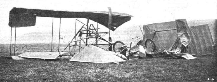
The wreck of "Havilland I," denoting the inadequacy, as regards strength, of this 850-lb. machine.

View looking down on the Havilland engine, as it appeared within the main girder after the smash.
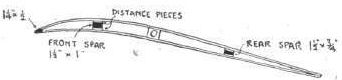
Section through one of the main planes, indicating the dimensions of the wooden spars.
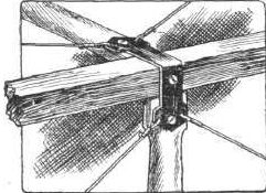
Sketch showing the neat strut joint for the main girder.
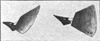
Two views of the Havilland adjustable propeller, indicating the extent to which the pitch and the twist of the blades can be changed to suit requirements.
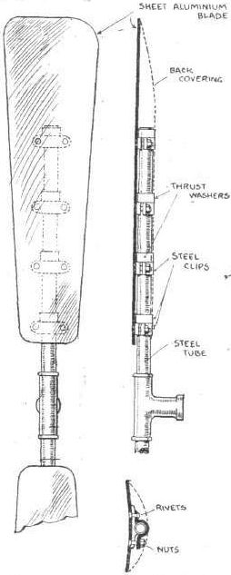
Sketches showing details of the Havilland propeller.
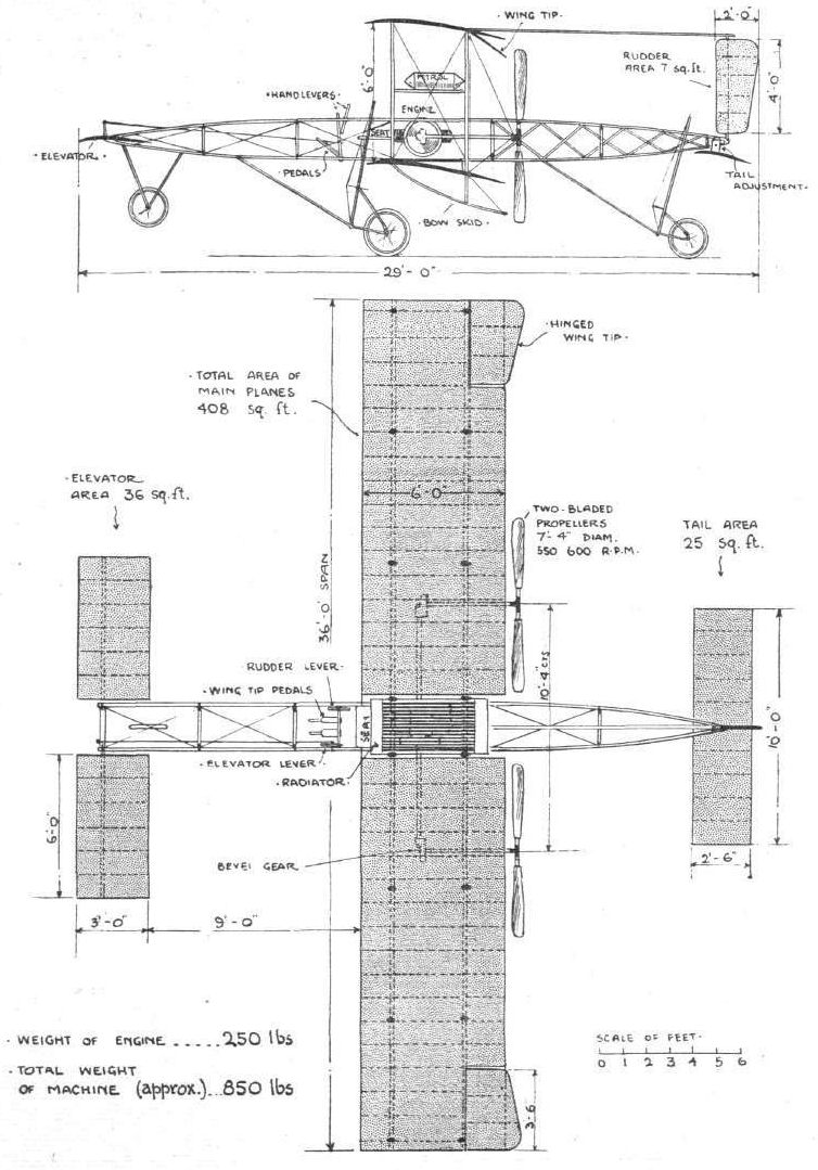
Front elevation and plan of Mr. G. de Haviliarid's first biplane.
Flight, September 24, 1910
BRITISH NOTES OF THE WEEK.
Success of the Havilland Aeroplane.
FOLLOWING upon the wrecked machine described by us in April 9th and 16th last, Mr. G. de Havilland has lost no time in building a fresh biplane fitted with his own engine (see FLIGHT, May 21st), and has this time met with success almost from the start. As the accompanying illustration shows, the new design follows close upon Sommer-Farman lines, while, in order to save time, a single propeller is this time used instead of the specially arranged pair with their bevel-wheel drive. Following upon a few preliminary hops prior to that day, a flight of about a quarter of a mile was accomplished a fortnight ago, the machine leaving the ground after running about 40 yards. Three times since then steadily improved trips have been made, and on Friday last ten or twelve flights of half a mile each - the full extent permitted, without turning, by the ground - were accomplished at heights varying from 20 to 50 ft. Apparently a lift is obtained in less than 40 yards, even when there is no wind, and although the run has to be made on a slight upgrade. Mr. Havilland is particularly pleased with the running of the engine, which seems to be able to do its work even with the throttle partly closed.
Flight, October 22, 1910
BRITISH NOTES OF THE WEEK.
Progress by Mr. de Havilland.
A NOTE to hand from Mr. de Havilland, at Newbury, states that he has been making very satisfactory progress with his biplane. In all, the machine has flown between 30 and 40 miles, and the designer is now feeling quite at home in the air. During last week the machine was idle through the breaking of a connecting-rod, which occurred when the machine was about 50 ft. off the ground. Mr. de Havilland had, fortunately, just previously been practising gliding flight, and so had no difficulty in bringing his machine down safely.
Flight, November 19, 1910
BRITISH NOTES OF THE WEEK.
The Havilland Aeroplane.
SOME very successful flights of long duration have, we learn, been made by Mr. G. de Havilland down at Newbury, and the engine with its new nickel steel connecting-rods is apparently running with perfect consistency and regularity. On one occasion a continuous run of 40 mins. was made, and weather permitting Mr. de Havilland hopes to qualify for the Royal Aero Club certificate during next week. Considering the restricted nature of the trial ground, his progress has been remarkably good, rabbit warrens and railway lines not being by any means conducive to facilitate the acquirement of the art by any novice.
BRITISH NOTES OF THE WEEK.
Success of the Havilland Aeroplane.
FOLLOWING upon the wrecked machine described by us in April 9th and 16th last, Mr. G. de Havilland has lost no time in building a fresh biplane fitted with his own engine (see FLIGHT, May 21st), and has this time met with success almost from the start. As the accompanying illustration shows, the new design follows close upon Sommer-Farman lines, while, in order to save time, a single propeller is this time used instead of the specially arranged pair with their bevel-wheel drive. Following upon a few preliminary hops prior to that day, a flight of about a quarter of a mile was accomplished a fortnight ago, the machine leaving the ground after running about 40 yards. Three times since then steadily improved trips have been made, and on Friday last ten or twelve flights of half a mile each - the full extent permitted, without turning, by the ground - were accomplished at heights varying from 20 to 50 ft. Apparently a lift is obtained in less than 40 yards, even when there is no wind, and although the run has to be made on a slight upgrade. Mr. Havilland is particularly pleased with the running of the engine, which seems to be able to do its work even with the throttle partly closed.
Flight, October 22, 1910
BRITISH NOTES OF THE WEEK.
Progress by Mr. de Havilland.
A NOTE to hand from Mr. de Havilland, at Newbury, states that he has been making very satisfactory progress with his biplane. In all, the machine has flown between 30 and 40 miles, and the designer is now feeling quite at home in the air. During last week the machine was idle through the breaking of a connecting-rod, which occurred when the machine was about 50 ft. off the ground. Mr. de Havilland had, fortunately, just previously been practising gliding flight, and so had no difficulty in bringing his machine down safely.
Flight, November 19, 1910
BRITISH NOTES OF THE WEEK.
The Havilland Aeroplane.
SOME very successful flights of long duration have, we learn, been made by Mr. G. de Havilland down at Newbury, and the engine with its new nickel steel connecting-rods is apparently running with perfect consistency and regularity. On one occasion a continuous run of 40 mins. was made, and weather permitting Mr. de Havilland hopes to qualify for the Royal Aero Club certificate during next week. Considering the restricted nature of the trial ground, his progress has been remarkably good, rabbit warrens and railway lines not being by any means conducive to facilitate the acquirement of the art by any novice.
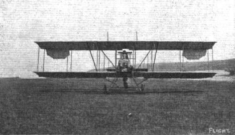
The De Havilland biplane.
Flight, September 3, 1910
THE BLAIR ATHOLL EXPERIMENTS.
THE accompanying photographs of early Dunne aeroplanes have a particular interest on account of their association with the secret War Office experiments that were carried out during 1906, 1907, and 1908 on the Duke of Atholl's estate at Glen Tilt. Our readers doubtless recollect the mysterious accounts of these experiments that appeared in the daily Press. It is safe to say that no reporter ever saw the machine - the Scotch gillies who acted as outposts saw to that; indeed we believe that it is rumoured thereabouts to this day that a broken walking-stick is all that remains in existence of a concealed telescope camera and of the foreign spy who carried it. Be that as it may - and we have no doubt that the individual in question will enjoy the story as much as another - the fact remains that very important experiments were, at that time, conducted under Government supervision, and that the machines employed were the direct forerunners of the Dunne aeroplane that is now attracting so much attention at Eastchurch.
The accompanying photographs were, as we have mentioned, actually taken on the spot. Fig. 1 shows the machine being brought out of its shed, and incidentally it gives a very good idea of the bleakness of the surrounding country, which is quite characteristic of the Highlands in this respect. We can quite easily imagine that an interested, but unauthorised, spectator would be seen from afar long before he could see anything worth noting, and it is not difficult to suppose that he might have a wry arduous time of it before he could make himself scarce on such a desolate waste. Like the ostrich, he would doubtless be willing to bury his head in a hole if he could persuade himself that this would by any means protect his body from an onslaught of the aforesaid Scotch gillies.
Fig. 2 shows the machine being lifted on to its trolley. The initial experiments were carried out with the aeroplane as a glider. It will be observed that the machine is mounted on a skid for landing; circular springs, which look like wheels, can be seen between the skids and the lower plane. In Fig. 3 the glider is undergoing inspection by the authorities, among whom were General Hadden, General Ruck and the Duke of Atholl.
Fig. 4 shows the start of a glide with Colonel Capper as pilot. In this attempt he attained a height of about 15 ft. above the ground, and finally charged the wall that is visible in the foreground of the picture. Subsequent to these experiments another machine was commenced in 1907, and was tried in the lower park at Blair Castle during 1908. The fifth photograph shows this machine, which is a power-driven aeroplane, ready for flight. Lieutenant Lancelot D. Gibbs, whose name is now well known as an aviator, was at the helm. Mr. Gibbs made most of the glides on the Dunne aeroplane at the hill camp earlier in 1908, when he used a small scale replica of this machine.
A peculiarity in the appearance of "D4," which might perhaps escape notice, is that it has been disguised by painting so as to obliterate as far as possible evidence of its essential characteristics, so far as they might be ascertained by an observer at a distance. The special curvature of the planes and other peculiarities which were fully described in our article on the Dunne aeroplane that appeared in FLIGHT of June 18th and June 25th, 1910, were thus rendered so far as possible invisible to the ubiquitous gentleman of the camera and the telescope.
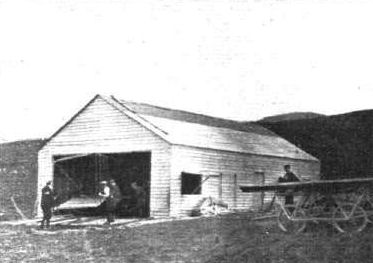
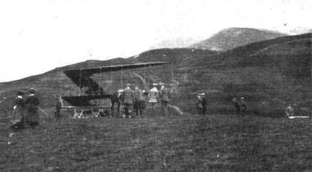
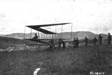
Flight, June 4, 1910
LIEUTENANT DUNNE'S "AUTOMATIC STABILITY" MACHINE.
ON Friday of last week Lieut. J. W. Dunne made a highly successful trip on his cleverly designed biplane. Starting from Eastchurch, and rising to a height of 20 ft., Lieut. Dunne flew for two miles in a bee-line for Leysdown, and during this part of the flight the machine was left to take care of itself. This it did in masterly style, the aviator not requiring to make any adjustment of the elevating levers until Capel Hill was reached. It was then decided to pass over this, but Lieut. Dunne misjudged the distance and could not rise high enough in time. He therefore flew in a circular direction for about a third of a mile, and landed on the top of the hill. The skids were slightly damaged in landing.
Photos of the machine in flight appeared in our issues of April 9th and 30th, and our readers will remember that the planes are in the form of an arrow, sloping backwards slightly. They have an area of 560 sq. ft., and during the above flight a load of 1,700 lbs. was carried. The speed over the ground was 29 miles an hour, and as this was against a ten-mile wind, the speed of the machine was estimated at 39 miles an hour. The engine is a 50-h.p. Green.
Flight, June 18, 1910
THE DUNNE AEROPLANE.
ONE of the most important items recently chronicled in FLIGHT was that recording the achievement of Lieut. J. W. Dunne, who, at Eastchurch in the Isle of Sheppey, flew a distance of 2 1/4 miles on a machine of his own design, which displayed so much natural stability as to render the use of the control levers totally unnecessary except so far as they were required for the purpose of directing the course. There is no doubt that this flight marks an important period in the development of the aeroplane, and although the outcome of it can only be vaguely surmised, this in no way detracts from its present importance, and should increase, rather than otherwise, the amount of interest in the machine itself.
When a man pursues a line of thought for nine years and proceeds to evolve a system of construction from data collected in ceaseless experiment; when, having built not the first, nor the second, nor third, not even the fourth, but the fifth machine, the inventor thereof flies at the first attempt under conditions that vindicated, at least so far as was possible on that occasion, the accuracy of his deductions, it is something for him to be proud of, and something for his country to be proud of, too. Lieutenant Dunne pursued his investigations of the problem of natural stability in the true spirit of science. He did not start with an idea and try to prove it; in fact, he has had very little time in which to evolve abstract theories that will fit in with the why and wherefore of every part of his machine. His is the sort of practice on which theory is founded. He set himself to observe. He made models and he watched them fly. He studied the works of others and he compared notes. As a result, he would tentatively adopt some general idea, such as, for instance, that in any stable flying machine, of which the main supporting surfaces are cambered aerofoils, the correct overall fore and aft length is very largely dependent upon that of the span. It is for this reason, among others, that the wings of the Dunne aeroplane slope backwards from the body to the extremities. The machine has no tail, as ordinarily understood, but it has a very considerable fore and aft length beyond that represented by the mere chord of the supporting surfaces.
Another general principle that he was forced to adopt, as a result of his own experiments and those of others, was that the tail plane and the main planes of a naturally stable aeroplane should make a dihedral angle with one another. Now, there is no tail plane on the Dunne machine, but the wings themselves are twisted so that the angle of incidence at the tips is less than at the centre, wherefore the principle of the dihedral angle is, as will be seen, adhered to, although the form of it is so extraordinary as to suggest, at first sight, that there is no such comparison. As for the why and wherefore of innumerable other points of interest it would be almost impossible for anyone, even the inventor himself, to say; they have just been arrived at by a long painstaking series of trials, such as are within the means of anyone to carry out, but conducted always in an atmosphere of strictly scientific observation. There is a reason for everything on this machine, but the reasons themselves have been evolved step by step with the design; they are not mere ideas, but careful deductions based on past experience. It was perhaps a little unfair to offer such a simple explanation of the reason for two of the outstanding features of the Dunne aeroplane, for it rather suggests that those features were tried in their present form from the first, whereas, on the contrary, the general lines as well as details are the result of gradual development.
It has been necessary thus to introduce the subject at some length in order to emphasise the point of view from which the Dunne aeroplane is most properly regarded, for in a mere description of the machine itself it is impossible to adequately imply the sort of appreciation that ought to be given to a design that is evolved in this fashion.
The Dunne aeroplane is a biplane, and was constructed by Short Brothers at Shellbeach to the designs of Lieut. J. W. Dunne, who is responsible for all the calculations concerned therewith, while Short Bros, themselves were given a free hand in the choice of material and fittings. As far as the actual construction itself is concerned, therefore, it is not necessary to say much in detail, for the machine is a typical example of the substantial and high-class workmanship with which that firm have already made a name, and with which our readers are already familiar. At first glance the observer is impressed with the solidity of the machine, and although there is no doubt that the weight could be considerably reduced in the commercial manufacture of duplicates, such robustness is by no means to be despised in an experimental apparatus even if the desired characteristic of the machine itself does happen to be complete natural stability.
The outstanding feature of the Dunne biplane is the arrangement of the main planes, V fashion, as viewed from above. In plan the machine is like an arrow head, the main planes sloping sharply backwards from the centre where they join the body. Their extremities lie a little behind the rear end of the body, and thus the wings themselves constitute the greatest fore and aft dimension as well as the greatest span. The leading edge of each wing is straight, but the gap narrows a little along the leading edge towards the extremities, so as to give an expanding passage to the air. This is another of those details that have been evolved from experiment, and for which the precise reason, from an aerodynamic standpoint, is not at present clear.
The main planes are cambered in a very peculiar way, for the camber varies at every point from the centre to the tips. In order to understand what this camber is like, the only accurate procedure is to construct a simple paper model, which may be done in the following manner. In the first place, cut a strip of paper to represent one of the wings, then roll another sheet of paper into a cone after the fashion of a foolscap. The piece of paper that is cut to represent one of the wings must be a rhomboid instead of a rectangle in order to allow for the slope back when one of the short edges is joined to the side of the body of the machine. Taking this strip of paper, it is laid on the cone so that its longest diameter is in contact with the surface of the cone from the apex to the base. The corner of the paper should coincide with the apex of the cone. The short edge of the sheet of the paper representing the wing, which is adjacent to the base, is then bent down to touch the surface of the cone, while the short edge adjoining the apex is allowed to stick out tangentially behind. Thus arranged, the sheet of paper represents one of the wings of the Dunne aeroplane, only the camber will, of course, be much exaggerated owing to the scale on which such a paper model would probably be constructed. It will be observed that the initial contact line with the cone runs diagonally from the leading edge where the wing joins the body to the trailing edge at the outer extremity. Near the body, therefore, the wings of the Dunne aeroplane are not much curved, whereas near the extremities they are curved for the greater part of the chord. At first sight this will suggest that the extremities are much more cambered than any other part of the wings, but it must be remembered that the radius of the curvature also increases towards the wing tip, for the centre from which it is struck lies on the axis of a cone, and not on that of a cylinder. If, therefore, less of the rib is actually curved in the vicinity of the body, that part which is curved has a more abrupt and consequently relatively greater deflection.
(To be concluded.)
Flight, June 25, 1910
THE, DUNNE AEROPLANE.
(Concluded from page 462.)
IT has been said above that the wing is flat where it joins the body, but actually this is not the case, for although the wings are undoubtedly made up on the above-mentioned principle, which would give a flat section in the place indicated, a secondary consideration introduces the necessity for a certain form of curvature in this particular part of the wing, which, as a matter of fact, is extremely cambered at that point and for about two feet from the body. Here again, however, the camber is not uniform, and it is obtained entirely by deflecting the trailing edge. Its purpose, which has nothing whatever to do with the general action of the machine, nor with the general principle on which the wings as a whole are designed, will be referred to later.
By the aid of the little paper model it is easy to appreciate that most important salient feature of the wings on the Dunne aeroplane, viz., that the angle of incidence becomes less towards the outer extremity of the wing. With a certain normal attitude it will even change its algebraic sign, being positive in the vicinity of the body, zero somewhere in the middle of the wing, and negative at the tip. If the angle of incidence at the tip is positive, then the angle of the whole wing will be positive, and conversely if the angle at the root is negative then the angle of the entire wing will also be negative. Insufficient experience has been obtained to show what is exactly the normal flying attitude of the Dunne aeroplane. Lieut. Dunne himself imagined that it would be such as to reverse the algebraic sign of the angle of incidence somewhere in the vicinity of the outer extremity of the wing, but some of those who were eye-witnesses of the flight declare that the datum line to which the trailing portion of the wing is parallel, was horizontal in flight, which would mean that the entire wing was flying with a negative angle of incidence.
It may be mentioned that the entire machine is constructed to a datum line, which is carefully laid off in the body. The upper part of the body framework lies parallel to this line, and thus affords an easy mark of observation in flight. That portion of each wing which does not follow the surface of the cone, but juts out tangentially from the diagonal, is constructed so as to lie in the plane of the datum line, and consequently whatever may be the observed angle of the datum line in flight, that also is the angle of the tangential trailing portion of each wing. The angle of incidence represented by the chord between the leading edge and the trailing edge will of course be less than this, so that if the datum line is observed to have zero angle (i.e., be horizontal) in flight, it necessarily follows that the angle of incidence is everywhere negative. On this subject of the negative angle of incidence we have already had some discussion in FLIGHT, and we expect to have still more ere the mathematics of the cambered aeroplane is properly understood.
Reference has been made above to the extreme depression of the trailing edge of the wings adjacent to the body. This feature was introduced as the result of some early model experiments that showed it to be necessary to stability for the extreme case in which a model was let fall vertically bow first. It is to be hoped that no experience of this sort may befall the full-sized machine in flight, but Lieut. Dunne decided to retain the feature for what it was worth.
Coupled with the above description, the accompanying photograph ought to render the general arrangement and leading details of construction of the wings of the Dunne aeroplane sufficiently comprehensive. Incidentally it may be remarked that this machine is one of the most difficult to illustrate by photographs of any that we have seen. Any one view, taken by itself, almost invariably leads to a wrong impression with anyone who is not familiar with its actual features. The view from in front is apt to suggest that the machine is nothing but an arched biplane, whereas, in fact, the amount of arching that actually exists, for constructional convenience rather than as a principle of design, only amounts to a few inches. In order to overcome the difficulty we have taken photographs of the machine from almost every point of the compass, so that by comparing one with another our readers may elucidate for themselves any feature on which they are in doubt. These photographs, too, are extremely well worth studying in detail, for every one of them shows some characteristic feature of this most interesting machine.
The wings are double surfaced, and built up on two main spars that are reinforced with numerous shaped ribs; the upper surface was regarded as the more important curve. The upper deck is supported above the lower deck by struts and diagonal wire bracing, the attachment of the struts and spars being effected by means of the steel ferrule joint adopted by Short Brothers. Vertical panels are fitted to the extremities of the wings, principally because it is thought that their presence tends to increase the lifting efficiency of the planes by preventing too much leakage at the extremities. In the trailing edge of the upper deck a hinged flap is inserted at the extremities in order to afford a means of steering the machine. These flaps are coupled up by wires to a pair of levers, one of which is situated on either side of the pilot. The flaps are thus independently controlled, and can be used either as rudders or as an elevator. When steering to the right the right-hand lever is drawn backwards, and the left-hand lever simultaneously pushed forwards. These actions result in the flap on the pilot's right having its trailing edge elevated, while the flap on the pilot's left has its trailing edge depressed. For ascending both levers are simultaneously pulled backwards, which raises the trailing edges of both flaps.*
* For an explanation of the aerodynamic reactions accompanying these actions, see Lieut. J. W. Dunne's letter in Correspondence.
The pilot's seat is situated in the bows of the machine, the seat being formed inside the principal longitudinal girder, which is a lattice-work construction of timber and strip steel, shaped somewhat on the lines of a flat-bottomed boat. The bows and the stern come to a sharp edge, but in the centre there is sufficient beam to accommodate the 50-h.p. Green engine that drives the twin screws. The pilot sits a little in front of the engine, and there is just room for a passenger behind the pilot. The sides as well as the bottom of the girder are covered in, so that the pilot's head is alone exposed, lieut. Dunne is of opinion that this surfacing of the girder and the almost complete enclosing of such principal masses as the engine and pilot is of very great importance, not so much on account of the advantage of stream line form in respect to minimizing head resistance, as because of the locality of those masses in respect to the supporting surfaces. A large mass situated above the supporting surface gives rise to disturbances in the air currents similar to those that would be created by a vertical plane set at right angles to the supporting surface, which in turn might be represented by an equivalent cambered aerofoil of inverted position, for the air current would, in effect, disregard the right angle by conforming to an upwardly curved path. Arguing on these lines, it seems that the relative position of the principal masses has considerable importance from an aerodynamic point of view, and might possibly affect the resultant centre of pressure in a way that would be serious on a machine like the Dunne aeroplane, which is designed for a high degree of natural stability. It is in order to avoid any tendency to reverse the direction of the air stream that the girder of the Dunne machine is so carefully surfaced.
The twin propellers that drive the machine are carried on the extremity of a light transverse lattice-work beam, and are driven by chains from the crank-shaft. The propellers are 7 ft. in diameter, and have a pitch of 7 ft 6 in. Both revolve in the same direction; the torque is balanced by a lead weight attached to one of the skids that protect the extremities of the wings. The propellers were constructed by Short Brothers to the designs of Capt. Carden. Their bosses are fitted with twenty-tooth sprockets, and the sprocket on the crankshaft has twelve teeth. The engine runs at about 1,100 r.p.m.
The petrol tank is carried immediately above the engine on a light frame, and the radiators are mounted in the gap between the main planes, where they are supported upon bearers attached to the vertical struts.
The chassis upon which the machine is mounted is also an interesting piece of construction, although naturally its present form is not essential to the machine; it was, however, designed at a time when the wheeled chassis was the only device in practical use, and it should be judged accordingly. Compared with the original Voisin chassis, it possesses some interesting modifications that it is only proper to recognise as improvements. The hubs of the two wheels are universally-jointed to an axle that holds them at the required distance apart. They are carried in a double fork that is attached by a couple of radius-rods to the girder member of the machine. The arrangement of these radius-rods is such that they are always in tension, which is a far more suitable stress for tubular work of this description than a compressed strain. The accompanying illustrations show how the helical springs are arranged to give the requisite suspension. The rear end of the girder is supported by an independent single-wheel chassis that combines a skid, and the nose of the machine is also fitted with a single wheel, which, however, is not shown in our photographs. This latter member is so placed that when it makes contact with the ground the aeroplane is in its running position. This facilitates starting, because it prevents the machine from being tilted too far over, and yet it avoids the necessity of trying to get under way with too great an angle of incidence.
THE DUNNE AEROPLANE CONTROL.
In considering the control of our machine, it is essential to remember that the wing tips are not normally inclined at a positive angle to the trajectory, as is the case in every other machine. Actually they are at a negative angle.
When we want to steer to the right we pull back the right-hand lever, thereby elevating the trailing edge of the right-hand flap. In an ordinary system, regarding the tip as normally positively inclined, you would say, "The angle of incidence of the right-hand extremity is thereby reduced." This is incorrect. The angle of incidence, which is negative is thereby increased, and the drift, one might almost call it the negative drift, is increased. This wing, therefore, tends to hang back, at the same time, owing to the increased negative inclination, this side is depressed. One could steer by this movement alone, were it not that the flap, situated behind the centre of gravity, is an elevator, and when it depresses the right wing tip it depresses the rear of the machine as a whole. In order to counteract this elevator effect, we simultaneously push forward the left-hand lever, thereby lowering the trailing edge of the left-hand flap. This does not "increase" the angle of incidence on that side, but decreases the previous negative angle of incidence of that side. This left side then has more lift than it had before, and balances the elevator effect of the right-hand flap. At the same time, owing to the decrement in the negative angle, this left tip has less resistance than formerly, and so travels faster than before, thus aiding the turning movement slightly. Since the right tip is depressed and the left tip raised, the machine is banked with the right side lower than the left.
Possibly some may imagine that this banking is the reverse of that usually done in rounding a corner with an aeroplane, as there appears to be some confusion in aeronautical literature on this point. Most people seem to argue that when a machine is circling to the right, the left side, which travels faster than the other, rises, tending to capsize the machine, and that ailerons or warping have to be used to keep the right side up. The problem is really a purely quantitative one. The effect of any rudder action is primarily to point the machine's head in the new direction. Then you have the centrifugal tendency of a machine of, in our case, 1.700 lbs. to contend with. Is the banking which occurs owing to the outer wing moving faster than the inner sufficient to overcome centrifugal movement (which is of course a sort of side-slip) or not? The answer obviously depends on the mass, the speed, the radius of the circle, and the design of the machine. In a machine with a big dihedral surface forward, like the Antoinette, or big vertical surfaces well forward and above the centre of gravity like the Voisin, the centrifugal motion, which occurs as soon as the bow is diverted from its previous course, produces reactions on the underside of the dihedral wing, or on the vertical panels, tending to cant up the outer side considerably, quite apart from the lift it might get owing to its relatively faster movement. In our own machine the immediate effect of this centrifugal side-slip would be to depress the outer wing. You will see this if you look at the machine from the side in one of your photographs. Thus, the machine is turning to the right, and the centrifugal movement, which we are assuming for the moment to be unbalanced, causes it to skid to the left. The rough sketch above shows the position, the machine skidding towards the spectator. Notice that the left-hand surfaces appear as a comparatively thin edge, while a very broad expanse of the under surfaces of the right-hand side is exposed. The right-hand side is thus lifted and the left depressed. This is more than sufficient to counteract the tendency of the left to rise owing to its relatively faster motion. Therefore our controls are arranged so as to cause the outer side to rise and the inner side to fall. As a matter of fact this machine can bank up on a sharp turn to over 45 without any centripetal movement being apparent.
J. W. DUNNE.
[The above very lucid explanation of the steering of the Dunne aeroplane was sent in reply to an editorial letter on the subject, and as we feel that our readers would prefer to have Lieut. Dunne's description in his own words, we are publishing the letter itself simultaneously with our article on the machine.-ED.]
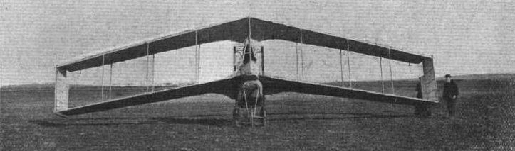
Lieut. Dunn's Blair Athol Aeroplane, "No.5," at Eastchurch, the Royal Aero Club's Flying Grounds. - View from the front. At first glance the above photograph conveys the impression that the machine has the planes set at an inverted dihedral angle, but this elfect is only due to the fact that the planes on either side of the body slope backwards. The Dunn biplane is the most remarkable and interesting machine yet constructed, for it is tailless and without an elevator, being designed to have natural stability. Steering is effected by hinged flaps behind the extremities of the main planes.
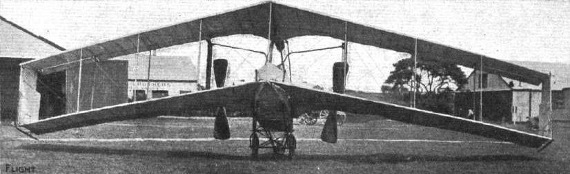
The Dunne Biplane. View from in front, showing the machine in its natural position on the ground. The perspective caused by the slope back of the wings gives an erroneous impression in this view that the planes are greatly arched.
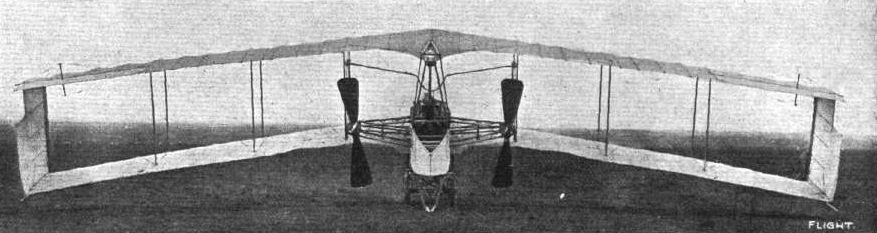
Another view ot the Dunne aeroplane taken from behind. In this photograph the rear wheel is resting on the ground. The supplementary camber that is given to the central portion of the trailing edge is very noticeable in this view.
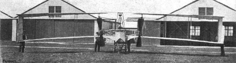
View of the Dunne biplane taken from behind. In this view the trailing wheel has been raised to bring the machine into its flying position. The twist of the decks and the diverging gap are quite noticeable in this view.
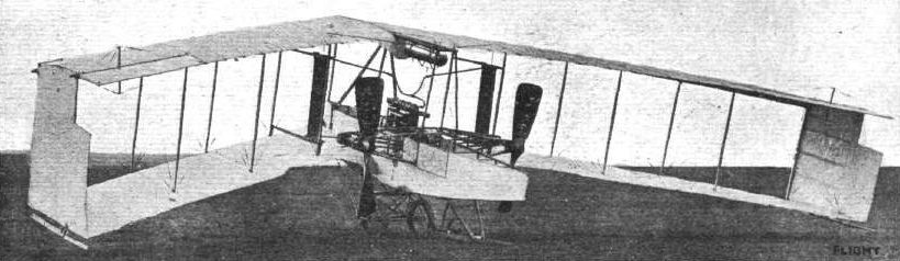
General view of the Dunne aeroplane taken from behind. This illustration also shows the twist on the main decks in a very marked manner.
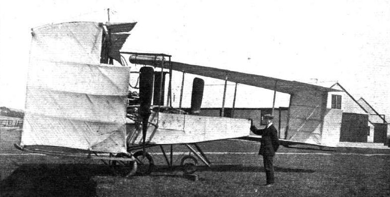
Another side view of the Dunne biplane looking down one of the leading edges from the wing extremity. Careful study of the shape of the vertical panel in the foreground reveals the negative angle of incidence at the extremity of the upper deck, and also the diverging gap.
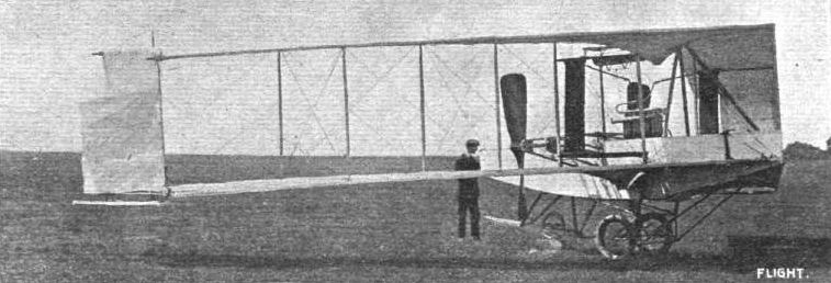
Side view of the Dunne biplane taken from in front and looking down one of the leading edges, The supplementary camber in the central portion of the trailing edge is illustrated in the above photograph.
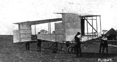
Side view of the Dunne aeroplane. Careful inspection of this photograph will convey an accurate conception of the varying camber of the planes. It is comparatively easy to grasp the position of the imaginary cone on which the camber is laid off by studying the upper deck in the above photograph.
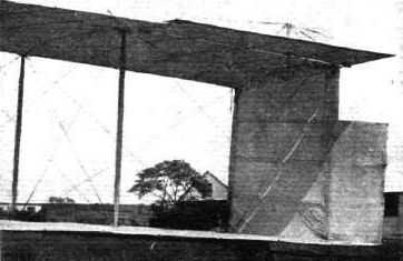
View of one of the wing extremities on the Dunne biplane showing the arrangement of the steering flaps.
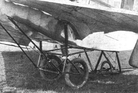
View of the chassis on the Dunne aeroplane. It should be observed that the principal members, A., are in tension. Each wheel can rise independently of the other.
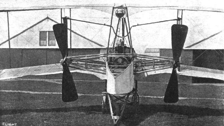
General view of the beam that supports the propellers on the Dunne biplane.
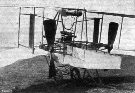
Another view of the propellers on the Dunne aeroplane.

Detail view of the mounting of one of the propellers on the Dunne biplane.

View of one of the propellers on the Dunne biplane showing its general shape.
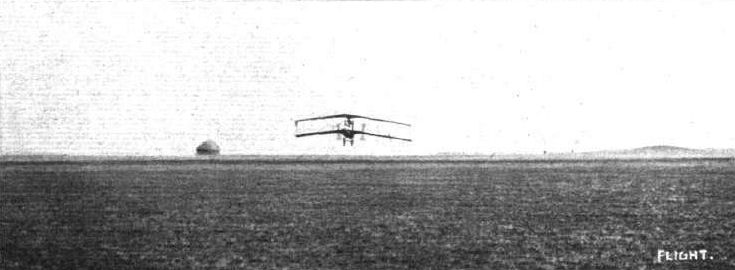
BRITISH FLYERS AT SHEPPEY. - Mr. Dunne in full flight on his Dunne biplane. The machine is travelling towards the spectators.
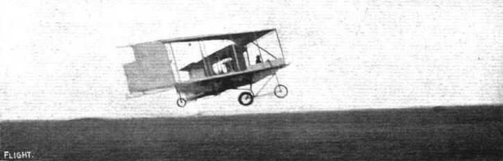
BRITISH FLYERS AT SHEPPEY. - A side view of Mr. Dunne in flight.
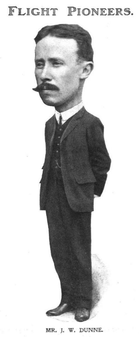
MR. J. W. DUNNE.
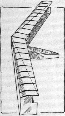
Diagrammatic sketch illustrating the varying curvature of the ribs in the wings of the Dunne biplane. The dotted line represents the line of contact with the imaginary cone upon which the wings are drawn out. Aft of this line the wing surfaces are flat.

Sketch illustrating the use of a paper model in order to explain the shape of the wings on the Dunne aeroplane.
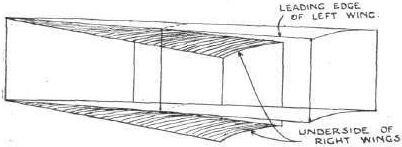
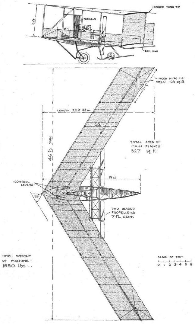
The 1910 Dunne biplane, "D5." Plan and side elevation.
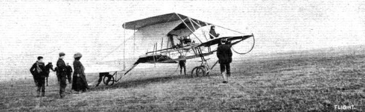
Dunne-Huntington triplane still with Wolseley engine but with modified chassis and side curtains.
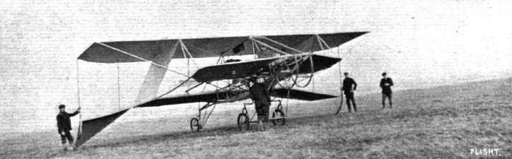
BRITISH FLYERS AT SHEPPEY. - Professor A. K. Huntington's biplane seen from the front.

BRITISH FLYERS AT SHEPPEY. - Professor A. K. Huntington' s biplane in flight.
Flight, February 5, 1910
AN ORIGINAL ALL-BRITISH AEROPLANE.
PARTICULAR interest attaches to the machine concerning which we are now enabled to give comparatively full general particulars, inasmuch as it is not only novel to a very unusual extent as aeroplanes have heretofore gone, but is of British conception, British design, and British manufacture in its entirety. It is, in fact, one of the numerous machines upon which a great amount of work and thought have been bestowed during the past year or so in this country in a quiet and unobtrusive manner, which cannot fail before long to assure for this country the position that it ought to take in aeronautic matters in the eyes of the civilised world. At the moment we are debarred from giving it a name, inasmuch as those associated with its development prefer to remain in the background until actual success has been achieved, or at any rate until the machine has been brought out to undergo its trials in the full light of day. At the present time it is receiving its finishing touches in readiness for an early test, and consequently the time is ripe when details of a broad character may be made public.
Apart from that we may only add that, as far as the preliminary arrangements of a commercial character are concerned, the enterprise has been backed by a large and very well known firm which is closely connected with the automobile industry. Our illustrations are amply sufficient for the immediate purpose that we have in view. The first of them gives a diagrammatic idea of the principle of construction as applied to a biplane, and is virtually a view of a small paper gliding model that can easily be made by anyone desirous of observing the upshot of that particular form of construction for an aeroplane. Similarly, briefly referring to the other illustrations, the third is reproduced from a photograph of a monoplane model with which numerous experiments were carried out during the initial stages, and with which some very remarkable results - which we ourselves had the pleasure of witnessing - were obtained. And then our large full-page scale drawings include a side elevation and a plan of the big biplane that is now nearing completion, while the two remaining sketches show the details of construction of the two principal members of this big machine.
Essentially the shape of the planes is rhomboidal, with a similarly rhomboidal opening that causes the two front surfaces to be considerably narrower than the two rear surfaces, as may be seen in several of the illustrations. The fore and aft axis lies diagonally across between the two more acute angles of the rhombus, and from either side of this axis the surfaces slope upwards slightly to give the familiar dihedral angle form of construction, the advantages of which most of our readers already know. All that need be added on general principles is that the leading edges of the narrower front, and of the wider back planes are rendered rigid, while all trailing edges are not only made flexible but are given a normal downward trend; for these are the features upon which reliance is placed for giving unusual stability for the machine, and carrying the load centrally in such a way that its weight is equally distributed without any undue concentration of strain at any one place. We do not propose at the moment to go into the question of the why and wherefore for the automatic stability which is apparently obtained, but it will of course be observed that the large central aperture essentially tends that way, and that a compactness is obtained which differentiates the design from any other machines that are at all well known.
Passing direct to the large biplane that is now nearing completion, we may say at once that there are two very marked reasons why considerable interest is demanded by it. Firstly, there is, of course, this new principle on trial, affecting the form of the planes, but also, even apart from that, many of the constructional details that have been introduced are valuable contributions to the constructional development that is now going on all round. The inventor and designer has in this way displayed a degree of constructional skill which is far above the average in a first machine of this kind; and certainly haste to put his ideas to the practical test on a large scale has not been allowed to interfere with the thorough soundness of the job. The new biplane is ambitious in proportions, for it is intended to carry a very considerable weight, representing at least two or three persons, in addition to the comparatively heavy engine that is being installed. An extraordinary degree of strength has been secured with a remarkably low total weight, by the use of wood and of steel wire in a very special way. Thus has a net result been obtained of a total spread of about 1,200 square ft of surface with a total weight of about 1,600 lbs., including 500 lbs. for the 50-h.p. engine.
As a backbone, two main girders are employed, one above the other, 8 ft. 4 ins. apart and some 45 ft. long. Each of them is triangular in shape, built as shown in our separate detailed sketch, some 1 ft. deep and built up of 1 1/4 in. diameter spars with short 1 in. struts and with diagonal wires that run spirally around them and are soldered where they pass over the screw heads that hold the struts to the spars. These long girders are, moreover, made in three separate lengths and are readily jointed together for erection; and the girders when in place are coupled up by five pairs of vertical tie-bars, disposed as shown in our drawing, and of a square cross-section chamfered off fore and aft to reduce their wind resistance.
Universally-jointed on either side of each of these girders is a transverse spar that slopes upwardly outwards and serves to carry the main planes by means of steel cables passing between its extremities and those of the girder to which it is attached. Each pair of transverse spars lies approximately on the level of each of the planes, and these spars are tied together by diagonals that render them comparatively rigid in spite of their ball-and-socket joints. Each spar is built up in the manner shown in our final sketch with six wooden members having a cross-section of 1 3/8 in. by 1/2 in., with intermediate steel wire diagonals soldered to steel straps. Special wire strainers are used during the process of construction of this central portion, and an immensely strong member results. Finally, the completed spar, as illustrated in our sketch, is covered with fabric, and then its cross-section,, which is oval in shape, is approximately 1 ft. in width by 2 3/4 in. maximum depth. As will be observed from the plan, moreover, these spars are about 16 ft. in length.
The planes themselves are of fabric and are carried by steel cables stretched between the ends of the girders and the ends of the spars as already mentioned. The fabric forms a single surface upon bent wood ribs that lie longitudinally through it and are pocketed against it, these ribs tapering off rearwardly and thus giving the desired flexibility to the trailing edge that projects behind the stretched cable. For the front planes, the ribs lie about 1 ft. apart, while at the rear they are situated about 18 ins. apart. The camber of the planes is in the neighbourhood of 4 ins.
Our scale drawings show the position of the engine and of the two 8 ft. wood propellers that lie about 9 ft. 6 ins. apart and almost centrally between the planes. As will be observed, the engine lies just forward of the spars, where it rests on a channel steel frame, and is therefore right in front of the pilot's seat and of the seats which may be provided for passengers. A framing of steel tube is employed for carrying the propellers, which are driven by a pair of chains, one of which is crossed, and are geared in the ratio of about 3 to 1, giving a normal speed of some 600 revs, per min.
Concerning the control, the exact position of the rudder or rudders is not fully determined, provision having been made whereby it can either be fixed at the back as seen in our drawings, or in front immediately behind the fore pair of uprights. It and the elevator form the sole means of control, and both are to be operated by a single universally jointed lever. The idea is to move this lever in one direction for elevating and in the other direction for lateral steering. Finally it will be observed that the machine is provided with five supporting wheels, all of which are spring suspended; and with this we may leave the subject of an unusually interesting machine for the moment, until the next stage in development has been completed. Needless to say, everybody in this country, at any rate, will wish its inventor the success which he deserves, if only because of his originality and obvious inventive ability.
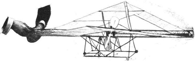
View of the experimental monoplane with which numerous practical experiments were carried out before the large machine now building was commenced. This model, with its elastic motor, used to rise under its own power off its starting-rail, and travel a considerable distance in the air.
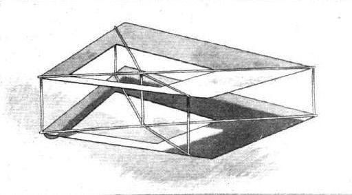
Diagrammatic sketch indicating the principle of the hollow rhomboidal construction as applied to a biplane.
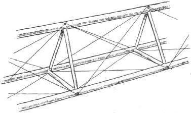
Details showing the wood and steel wire construction of the main girders.
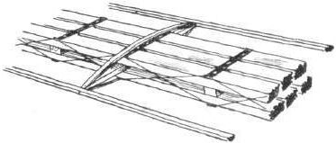
Internal wood and steel wire construction of the transverse spars.
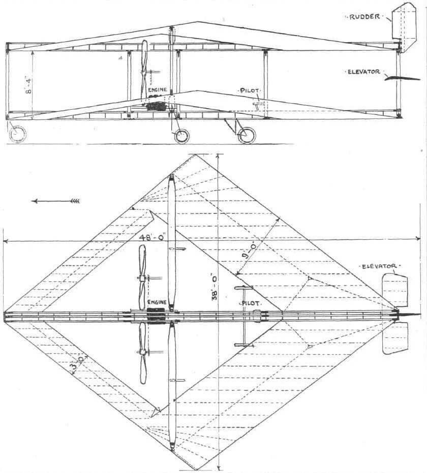
Side elevation and plan of the large all-British rhomboidal aeroplane now nearing completion.
Flight, January 8, 1910
FIRST FLIGHT IN IRELAND.
THE Emerald Isle is not by any means very far behind the times in matters of practical value, and among the several flying machines which have been built and experimented with, that of Mr. H. G. Ferguson, of Belfast, appears to give very good promise of success. So far the work of trying it has been hampered by the lack of a suitable ground, but it is hoped that this will shortly be remedied. It has been located at Lord Downshire's park at Hillsborough, but this, having proved to be too hilly, a move has been decided upon. During the three weeks the monoplane has been at Hillsborough, the weather has been all against practice, but on the last day of the old year Mr. Ferguson, after fitting a new Cochrane propeller, was successful in getting his machine to rise and fly for 130 yards, and this in spite of a gusty wind blowing at an average rate of 25 miles an hour. During this trial Mr. Ferguson had the machine under perfect control and landed again without difficulty. The machine is a monoplane somewhat suggestive of the Bleriot cross-Channel flyer, having a supporting surface of 192 sq. ft., the main planes being 34 ft. span. They are mounted with a dihedral angle of 4°, while the angle of incidence when flying is 7°. The length of the machine is 30 ft., and it weighs 620 lbs. It is fitted with a 7 ft. tractor, driven at a speed of 1,200 revs, per min. by a 35-h.p. 8-cyl. air-cooled J.A.P. engine, and a speed of 32 miles has to be obtained before lifting is accomplished. The monoplane was constructed entirely in the works of Messrs. J. B. Ferguson, Ltd., of Belfast, and was designed by Mr. H. G. Ferguson after studying the various aeroplanes which took part in the Rheims and Blackpool meetings. The owner hopes to be the first to fly across the Irish Channel, and moreover to accomplish it before long.
Flight, October 8, 1910
MR. HARRY G. FERGUSON STEADILY ADVANCES.
ALTHOUGH Mr. Ferguson does not claim to have made World's record performances in Ireland, his steady application and work are bringing their natural rewards, and many good flights are resulting. His chief flying ground has been at Magilligan Point (co. Derry), where he has been out practically every day. Recently he indulged in many graceful manoeuvres in the air on his monoplane, his daily aggregate distance getting up to about 10 miles; some individual trips coming out at 2 miles. He is becoming very adept at controlling his machine, once or twice having encountered very gusty weather - and gained good experience accordingly. Passenger carrying he also indulges in, and as he took up a lady passenger with him prior to the Leopardstown meeting, he is justly entitled to the record of having achieved the first passenger flight in Ireland. Some interesting snapshots of Mr. Ferguson in flight, &c, appear this week. His methods are to always get right up to about 40 ft., and until his engine, which is not nearly powerful enough, gets "tired," he keeps the air, and then comes down. We wish Mr. Ferguson further successes in his helpful work in Ireland.
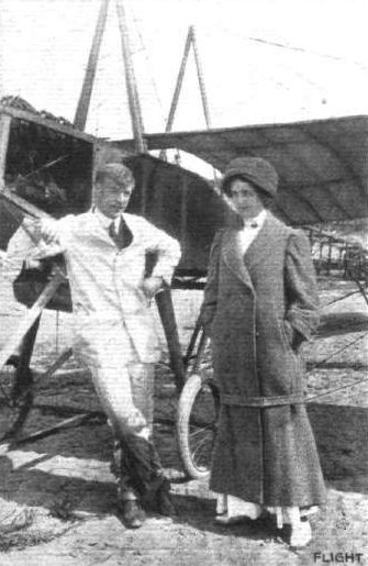
Mr. H. G. Ferguson and his monoplane, with a lady passenger, the first to be carried in Ireland.
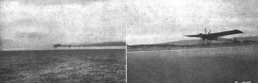
FLYING IN IRELAND. - Mr. H. G. Ferguson at Lough Foyle. On the left just away for a flight over the water, and on the right a good start.
Flight, March 12, 1910
THE SECOND OLYMPIA AERO SHOW.
AEROPLANES.
G. and J.
BRITISH-BUILT biplane of 30 ft. span, the supporting surface of the main planes being 325 sq. ft., while the total surface, including tail, elevator and ailerons, is 438 sq. ft. A feature of this machine is the triplicate control, whereby both rudder, elevator and ailerons can be operated by one hand without any one motion interfering with any other. The rear tips of the top plane are extended and flexible, and coupled to the ailerons, so that lateral stability is governed both by the entering edge of the aileron and the trailing edge of the flexible tips.
Flight, April 2, 1910
FLYER SILHOUETTES FROM OLYMPIA.
GEORGE AND JOBLING BIPLANE.
Leading Particulars of the George and Jobling Biplane.
General Dimensions,-Areas-Main planes, 426 sq. ft.; fixed tail, 50 sq. ft.; elevator, 38 sq. ft.; rudder, 25 sq. ft.
Lengths.-Span, 30 ft.; chord, 5 ft. 6 ins. (15 ins. additional chord for flexing tips); camber, 3 1/2 ins., situated about 24 ins. from leading edge; leverage of rudder, about 12 ft.; gap, 5 ft.; overall length, 30 ft.
Angle.-Incidence, 9 1/2 degs.
Materials.-Timber-Principal struts American elm, others spruce; hollow spars and struts, main ribs between struts I section; Dunlop fabric.
Engine.-60-h.p. Green.
Propeller.-George and Jobling, 28 lbs. weight; diameter, 9 ft.; pitch, 10 ft.; material, timber, single piece.
Weight.-Machine with engine, 662 lbs.; driver, oil, petrol, water, 200 lbs.; total flying weight, 862 lbs.; loading (all weight supported on main planes), 2.6 lbs. per sq. ft.
Speed of Flight. -48 m. p. h.
System of Control.-Balancing flexing tips, elevator, rudder.
BIPLANE designed by A. E. George and principally remarkable for the fact that all the struts and spars are hollow. The outriggers that carry the elevator and tail are made of bamboo. A curious form of combination wheel and ski chassis has been adopted, the skis being wholly in front of the wheels and normally inclined upwards; their object is mainly to assist the machine over holes and small ditches. A very interesting feature of the machine is the method of mounting the single chain-driven propeller upon a stationary axle, which is held by adjustable tubular steel struts upon the engine bearers. This stationary axle lies immediately above the engine, and the mounting of the propeller is thus entirely independent of the framework of the machine.
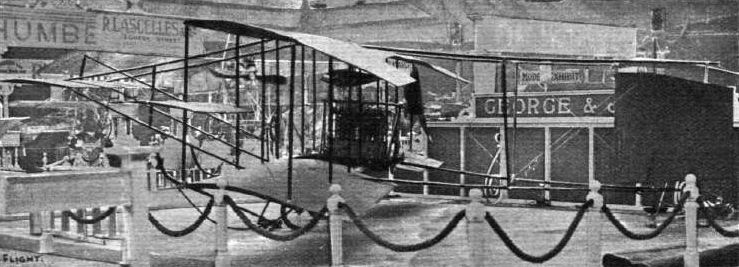
OLYMPIA, 1910. - George and Jobling's biplane. This machine has a monoplane tail and a monoplane elevator. The spars and struts are hollow.

Sketch illustrating how the end skids are mounted on the planes of the George and Jobling biplane.
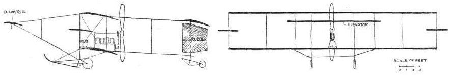
WING SECTIONS. - The above diagrams afford an interesting comparison of the wing sections of aeroplanes exhibited at Olympia. They are all drawn to a common scale, but have been set at an arbitrary angle of incidence, which does not necessarily represent that of the aeroplane In actual flight.
Flight, February 19, 1910
PROGRESS IN SCOTLAND.
Herewith I send you two photos of biplane of our own model and construction.
This is our third made and sold. We are now making a fourth, 29 ft. span; and a fifth is ordered, which must be ready for the London Show. It is intended by the purchaser to show also at Berlin.
I thought you would like to know what we up North are doing for aviation.
Caledonian Motor and Cycle Works and Garage, Leith. JOHN GIBSON.

A SCOTTISH-BUILT BIPLANE. - This is the work of "Gibson's Aeroplanes" of Lelth. Mr. John Gibson, its designer, in sending us the photographs, writes: "The machine which we are at present practising with promises well, rising readily, but none of us are capable of handling her efficiently as yet. Of course, we have had our engine troubles and a few smashes, but all the fault is either with the engine or with our own inexperienced handling, which time will remedy. The machine itself is all right, and I believe the first Scottish-built aeroplane to leave the ground. My son, age 19, can handle her best; he appears in photos.
Flight, October 15, 1910
THE CRUCIFER AEROPLANE.
THE accompanying illustrations show a type of aeroplane - not yet actually constructed except in model form - that has as its principal characteristic a floating connection for the attachment of the wings to the body. The body itself is fish-shaped, and is encircled by a huge ball-bearing, to the outer race of which the main planes of the machine are rigidly connected. The object of this method of construction is to allow the planes freedom of canting movement, so that when they are displaced from their proper position of transverse equilibrium their canting shall not have any effect on the position of the body itself. The inventor of this system, which forms the subject of patent No. 8,687 of 1909, is Mr. L. B. Goldman, and the fundamental idea underlying his design is that the principle involved confers an enhanced facility of quick control on the machine to which it is applied.
On the pros and cons of the fundamental principle involved in this system we have some remarks to make in our leader this week. There are several other interesting features of the Crucifer aeroplane deserving of brief reference, although space does not permit of a very detailed description of such a machine as this prior to its practical development.
The control of the planes about the body is intended to be effected by the automatic operation of balancers, A, which are adjusted by a chain mechanism, C, that is moved by a running weight, B. The body of the Crucifer aeroplane is an example of the fish-shaped, or stream line form, construction that in one or other of its various styles must almost necessarily come into vogue in later stages of aviation if the high speeds that are anticipated become common practice. At the moment little effort is made to convert normal pressure into skin friction by enclosing the principal masses on most aeroplanes with a suitable body, although the natural facilities that are afforded by the modern monoplane show something of an advance over the biplane in this particular respect. In this machine, the Crucifer, the body has a hemispherical head, short cylindrical trunk, and a long gradually-tapering tail. Another peculiarity of the Crucifer aeroplane that is worthy of notice is the backward slant of the main planes, in which respect it resembles the Dunne machine.
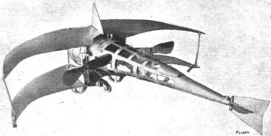
Back view of a model of the Crucifer aeroplane, showing the tapering conical tail and the twin propellers.
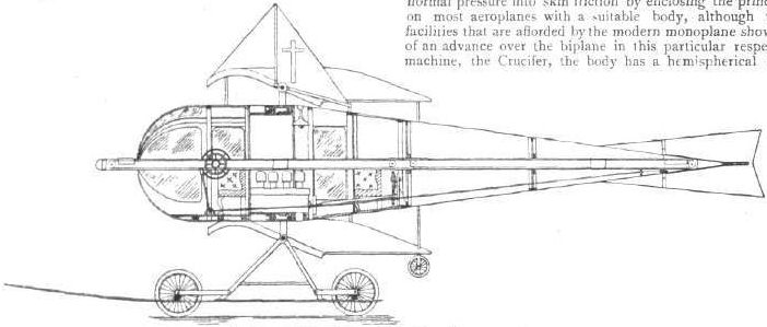
Sectional elevation of the Crucifer aeroplane.
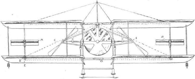
Front elevation of the Crucifer aeroplane.
Flight, June 11, 1910
Mr. C. Grahame-White's New Biplane.
DURING the past week the British-built biplane with which Mr. Claude Grahame-White hopes to make an early attempt to fly from London to Paris has been on view at Messrs. Gamage's. In general appearance the machine resembles that designed by M. Sommer, but it differs in several minor details. Approximately the two main planes have a span of 33 ft., and they are placed about 5 ft. 9 ins. apart. The lifting surface is about 450 sq. ft., and the machine weighs approximately 800 lbs. The ribs are made of poplar and ash, a nd are so constructed that they can be easily replaced by slotting on to the main supports of the planes. These, together with the stanchions, are made of ash.
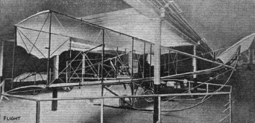
Mr. Claude Grahame-White's new British-built Biplane on which he hopes to fly from London to Paris. - This photograph was secured in Messrs. Gamage's show-rooms, where the machine has been on exhibition recently.
This Sommer-type biplane was built for Grahame-White in 1910 by Windham's motor body company.
This Sommer-type biplane was built for Grahame-White in 1910 by Windham's motor body company.
Flight, May 28, 1910
New Gratze Monoplane.
FOLLOWING somewhat the lines of his old machine, Mr. Eugene V. Gratze has now completed his new monoplane, and is ready for trial at Cahewdon, near Southend-on-Sea, it being formerly christened "Daisy" last week by breaking a bottle of wine over the propeller. The steering is performed by means of the propeller, while the elevating is regulated by an overhead plane placed slightly forward of the main plane. Lateral stability is effected by means of two flaps at the ends of the main planes. Mr. Gratze has secured a good flying ground at Canewdon, which runs along the Crouch for two miles, and has a superficial area of about 200 acres, all perfectly flat. He will be pleased to arrange for anyone wishing to share the ground.
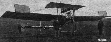
Front view of the aeroplane with which Mr. Eugene Gratze is expert menting at Canewdon, near Southend, to which reference has been made rn these columns recently. This shows the general arrangement of the machine. The balancing flaps on the main planes are shown in their raised position.

THE BRITISH-BUILT "GROSE" MONOPLANE. - View from in front and behind. The general dimensions are :- Span, 26 ft.; length, 25 ft.; surface, main planes, 160 sq. ft.; engine, 20-25 h.p. In the photographs sent us by Mr. A. M. Grose, of Oakington, Cambs., the wings are set temporarily at a greater angle than is correct for flying, as at the time of photographing the engine and propeller were being tested by running freely over the ground. Mr. Grose is desirous of arranging for a suitable engine to complete his equipment.
Flight, March 12, 1910
THE SECOND OLYMPIA AERO SHOW.
AEROPLANES.
Handley-Page.
MONOPLANE of 30 ft. span, the wings having a cord of 6 ft. It is controlled by a rudder at the rear, activated by a lever at the side of the pilot. Total lifting surface of the machine 150 sq. ft., and weight without the pilot 300 lbs. It is fitted with a 20-25-h.p. air-cooled 4-cyl. engine, directly coupled to a 6 ft. 6 diam. special H.P. propeller.
Flight, April 2, 1910
FLYER SILHOUETTES FROM OLYMPIA.
THE. HANDLEY-PAGE MONOPLANE.
Leading Particulars of the Handley-Page Monoplane.
General Dimensions.-Areas-Main planes, 150 sq. ft.; elevator, 6 sq. ft.; rudder, 6 sq. ft.
Lengths.-Span, 32 ft. 6 ins.; chord, 6 ft.; camber, 2 1/2 ins. skid track, 6 ft.; overall length, 20 ft.
Angles.-Angle of incidence, 6°; dihedral, nil.
Engine.-20 to 25-h.p. Advance.
Propeller.-Diameter, 6 ft. 6 ins.; pitch, 3 ft. 6 ins.
Weight.-Total flying weight, 450 lbs.; loading (all weight supported on main planes), 3 lbs. per sq. ft.
Speed of Flight.-35 m.p.h.
System of Control. - Elevator and rudder (warping optional).
Price.-L375.
MONOPLANE of the bird's wing type, designed somewhat on the lines of the Weiss model but fitted with a cross-tail serving the purpose of an elevator and rudder. This tail is one of the special features of the design, being mounted on a single pivot so arranged that it cants when steering; the object being to create a torque to assist in maintaining stability.
The most interesting minor detail of this machine is the ash axle that carries the wheels upon which the machine is mounted. This axle is a specially selected piece of wood, and its natural flexibility is used as a substitute for springs. The wheels are splayed, and the wheel hubs have been made 12 ins. long in order to give great strength.
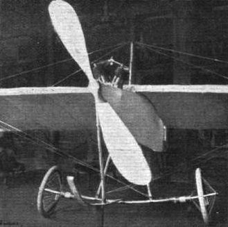
View of the very simple chassis employed on the Handley Page monoplane. The natural flexibility of the ash axle constitutes the suspension.
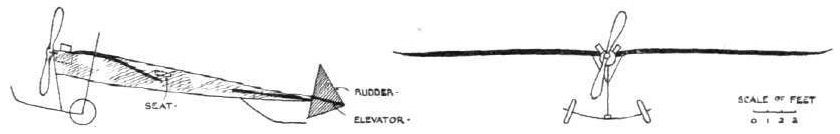
WING SECTIONS. - The above diagrams afford an interesting comparison of the wing sections of aeroplanes exhibited at Olympia. They are all drawn to a common scale, but have been set at an arbitrary angle of incidence, which does not necessarily represent that of the aeroplane In actual flight.
Flight, December 3, 1910
PENDULUM STABILITY.
I have seen numerous letters in your paper on pendulum stability, and your reply especially to Mr. Thos. Kelham, and I think you may be interested in hearing that we have ourselves tested this pendulum theory to the uttermost, and I enclose you the photograph of a machine which is being daily flown, often for long distances, has been tried for weeks in every conceivable manner, such as for height, for going out in a strong wind, for turning in a short radius, and for going long distances, and has proved remarkably successful, and has been entered for the De Forest prize to France. On one occasion it started with a monoplane and a biplane at Freshfield to go a given distance, turn round a given point, and come back again. For about half a mile of this distance our aviator informs us that he hardly once put his hand to the steering and elevating lever, and all the bystanders agreed that its flight was wonderfully steady as compared both with the monoplane and the other biplane which accompanied it. It alone of the three machines was able to go round the goal point owing to the strong current the other two having had to come to earth, and our aviator, Mr Fenwick informs us that, in his opinion, it is a much easier and safer machine to manage than one with the weight nearer the centre of gravity. This machine has been patented under various patents ranging from 1906 on.
6, Lord Street, Liverpool. PLANES LTD CHAS. LESLIE, Secretary.
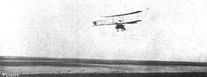
Last week in the correspondence columns a photograph of the biplane of Planes, Ltd., was published. Above is a photograph of the same machine in flight on Formby Sands. This was secured before a serious smash last week, entirely wrecking the machine, due, we are informed, to the passing over it, when about 70 feet from the ground, of another biplane.
Flight, April 2, 1910
THE HORNSTEIN BIPLANE.
THE characteristic feature of Mr. Homstein's machine, on which he had a mishap on Sunday, is extreme lightness of construction, his argument being that, for experimental purposes at any rate, the greater number of advantages lie with such a system. An interesting detail is the use of cork pads as distance-pieces in the construction of the skids. Each skid consists of two thin strips of wood, set edge on to the ground and braced together by thin bolts passing through the cork pads, as shown in the accompanying sketch. This system of construction, although extremely light, is not very rigid laterally and the skids do not keep their shape very well, but it has been Mr. Hornstein's contention that anything capable of bending would be less liable to break, and therefore safer in the early days of experiments when it is generally a case of either bending or breaking something.
Mr. Hornstein's biplane has a span of 10 metres, and a chord of 2 metres, the supporting area of the main planes being thus 40 square metres. In front is a biplane elevator, having a span of 2.35 metres, and a chord of 85 cms. Two machines of approximately similar dimensions have been constructed, one being fitted with a Green engine and the other with a J.A. P. Chauviere propellers of 2.1 metres diameter and 1.6 metres pitch are employed. The estimated total weight of the machine in flight is 403 kilogs., including 193 lbs. for the pilot.
The ribs that stiffen the fabric of the main planes are also of unusual construction. They have a modified T section, as shown in the accompanying sketch, and are steam bent to the required curvature.
Mr. Hornsteinfs Accident.
AMONG the many British flyers who have been quietly experimenting in England is Mr. Hornstein, who on Easter Sunday met with a mishap while flying on a private ground at Halliford, near Shepperton-on-Thames. On the previous Friday Mr. Hornstein had flown a mile and a quarter at a height of about 40 ft., and it was from about the same height that the machine came down suddenly on Sunday, apparently due to a mistake in steering. Mr. Hornstein was pinned beneath the machine, and sustained injuries to the head. He has for some time been designing machines that have been constructed by the Thames Bank Wharf Co., and has recently been experimenting with the biplane with which the accident occurred. Elsewhere we give a few details of the machine.
Flight, April 9, 1910
Mr. Hornstein's Good Friday Flight.
SOME further particulars have been given to us by an independent eye-witness concerning the flight which was made by Mr. Hornstein with his machine on Good Friday, and about which - as also his unfortunate accident on the following Sunday - we reported in brief last week. It seems that there were at the time plenty of spectators about, to all of whom the outstanding feature of the performance was the remarkably high rate of speed that was maintained. Apparently a run of about 25 metres was taken before actually leaving the ground, and then the distance travelled was 21 kiloms., at a height varying between 12 and 18 metres from the ground. Amateur clocking credited the time taken as being but 48 secs., though needless to say this is entirely unofficial as a record - such as it would seem to constitute.
Ground was regained in a ploughed field, on to which the machine alighted without sustaining injury of any kind, and this particular machine, which is one of those that Mr. Hornstein has built in England, is equipped with an 8-cyl. Jap engine of 35-h.p. On a new machine which he has in course of construction, a trial is to be given to an 80-h.p. engine of Italian origin that has a special system of air-cooling embodied in it.
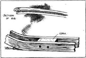
Sketches illustrating two interesting details on the Hornstein biplane. The rib is solid, and steam bent to the required curvature. Each skid is made of two strips of wood, trussed by cork pads.
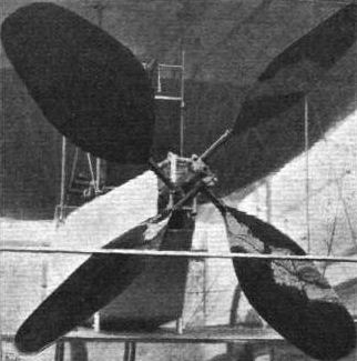
Although apparently a single four-bladed propeller, the mechanism illustrated above, which is a photograph of the Howard Wright machine, consists of a pair of two-bladed propellers which revolve in opposite directions. The blades nearest the engine are larger than the others, and do two-thirds of the work.
Flight, March 12, 1910
THE SECOND OLYMPIA AERO SHOW.
AEROPLANES.
Ornis.
A MONOPLANE of 25 ft. span and 28 ft. overall length, with a surface of 170 sq. ft., the weight complete being 450 lbs. It is fitted with a four-cylinder air-cooled Lascelles engine, driving a Weiss propeller.
Flight, April 16, 1910
FLYER SILHOUETTES FROM OLYMPIA.
THE ORNIS MONOPLANE.
Leading Particulars of the Ornis.
General Dimensions.-Areas-Main planes, 160 sq. ft.; fixed tail, 10 sq. ft.; elevator, 10 sq. ft.; rudder, 5 sq. ft.
Lengths.-Span, 28 ft.; chord, 6 ft.; camber, 3 ins.; leverage of rudder, 25 ft.; skid track, 4 ft. 6 ins.; overall length, 30 ft.
Angle.-Dihedral, 1 in 90.
Materials.-Timber, ash throughout; steel chassis.
Engine.-35-h.p. Lascelles.
Propeller.-Weiss; diameter, 8 ft.; pitch, 3 ft.; material, Kauri pine.
Weight,-Machine, 250 lbs.; engine, 150 lbs.; driver, oil, petrol and water, 200 lbs.; total flying weight, 600 lbs.; loading (all weight supported on main planes), 3.8 lbs. per sq. ft.
Speed of Flight.-30 m.p.h.
System of Control.-Warping of planes, rudder and elevator.
Price.-L450.
MONOPLANE of modified Bleriot design, being slightly larger in dimensions and rather lighter in details of construction. Control is effected by an inclined steering wheel, and includes wing warping, elevator, and rudder. The main frame is made of timber braced with diagonal wires, and the chassis is entirely constructed of steel tubes.
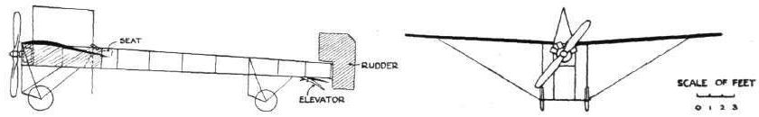
Ornis monoplane.
WING SECTIONS. - The above diagrams afford an interesting comparison of the wing sections of aeroplanes exhibited at Olympia. They are all drawn to a common scale, but have been set at an arbitrary angle of incidence, which does not necessarily represent that of the aeroplane In actual flight.
Flight, March 12, 1910
THE AVIS MONOPLANE.
AMONG the new British-built monoplanes at the Aero Show is one exhibited by the Scottish Aeroplane Syndicate. For some time past the first machine of this type has been undergoing practical tests at Brooklands. The machine has a neat, light, and strong appearance. The main wings have a span of 27 ft. and a chord of 6 ft. 6 ins.; they are set at a slight dihedral angle. Lateral stability is obtained by warping, and longitudinal stability by the manipulation of a crossplane tail similar in design to that used on Santos Dumont's "Demoiselle."
An uncommon feature of the control is that the warping is accomplished by pedals, the pilot depressing the pedal on that side of the machine that is at the lower level, in order to restore equilibrium. Those who have studied modern systems of control will observe that this is, in one sense, the reverse of that commonly adopted inasmuch as those machines that have hand-controlled warping of the wings are so arranged that the lever is pressed over to the right when the right wing is too high and vice versa. The machine is driven by a tractor - screw, mounted direct upon the crank - shaft of a 25-30 - h.p. Anzani engine.
The machine is mounted upon a pair of long skis, carried upon three groups of struts. A pair of wheels is placed on either side of each ski, the axles being attached by stout rubber in order to absorb the shock of landing. Attention has been paid to the detachability of the former members, and as far as possible provision has been made for easily renewing any that get broken.
The total weight of the machine is stated to be only 430 lbs., of which 150 lbs. represents the weight of the engine.
Flight, April 16, 1910
FLYER SILHOUETTES FROM OLYMPIA.
THE AVIS MONOPLANE.
Leading Particulars of the Avis.
General Dimensions.-Areas-Main planes, 160 sq. ft.; fixed tail, horizontal, 30 sq. ft., vertical, 25 sq. ft.; elevator, 15 sq. ft.; rudder, 9 sq. ft.
Lengths.-Span, 28 ft.; chord, 6 ft. 6 ins.; camber, 4 ins.; leverage of rudder, 20 ft.; skid track, 4 ft.; overall length, 27 ft.
Angles.-Incidence, 9 degrees; dihedral, 1 in 26.
Materials.-Timber, ash throughout; fabric, Pegamoid.
Engine.-25-h.p. Anzani.
Propeller.-Howard Wright; diameter, 6 ft.; pitch, 2 ft.; material, Kauri pine.
Weight.-Machine, 280 lbs.; engine, 150 lbs.; driver, oil, petrol and water, 200 lbs.; total flying weight, 630 lbs.; loading (all weight supported sq. ft. on main planes), 3.9 lbs. per sq. ft.
Speed of Flight.-35 m.p.h.
System of Control.- Warping of planes, rudder and elevator.
Price.- L490.
MONOPLANE constucted by Howard Wright for the Scottish Aeroplane Syndicate, and exhibited by their agents, the Aeroplane Supply Co. The machine is of modified Bleriot design, and is characterised by the use of a Santos-Dumont type tail. It has an "A" chassis frame and a combination of wheels and skis for the support of the machine.
The engine is carried on a tubular steel framework forming an extension of the main frame, which is made of timber.
THE AVIS MONOPLANE.
AMONG the new British-built monoplanes at the Aero Show is one exhibited by the Scottish Aeroplane Syndicate. For some time past the first machine of this type has been undergoing practical tests at Brooklands. The machine has a neat, light, and strong appearance. The main wings have a span of 27 ft. and a chord of 6 ft. 6 ins.; they are set at a slight dihedral angle. Lateral stability is obtained by warping, and longitudinal stability by the manipulation of a crossplane tail similar in design to that used on Santos Dumont's "Demoiselle."
An uncommon feature of the control is that the warping is accomplished by pedals, the pilot depressing the pedal on that side of the machine that is at the lower level, in order to restore equilibrium. Those who have studied modern systems of control will observe that this is, in one sense, the reverse of that commonly adopted inasmuch as those machines that have hand-controlled warping of the wings are so arranged that the lever is pressed over to the right when the right wing is too high and vice versa. The machine is driven by a tractor - screw, mounted direct upon the crank - shaft of a 25-30 - h.p. Anzani engine.
The machine is mounted upon a pair of long skis, carried upon three groups of struts. A pair of wheels is placed on either side of each ski, the axles being attached by stout rubber in order to absorb the shock of landing. Attention has been paid to the detachability of the former members, and as far as possible provision has been made for easily renewing any that get broken.
The total weight of the machine is stated to be only 430 lbs., of which 150 lbs. represents the weight of the engine.
Flight, April 16, 1910
FLYER SILHOUETTES FROM OLYMPIA.
THE AVIS MONOPLANE.
Leading Particulars of the Avis.
General Dimensions.-Areas-Main planes, 160 sq. ft.; fixed tail, horizontal, 30 sq. ft., vertical, 25 sq. ft.; elevator, 15 sq. ft.; rudder, 9 sq. ft.
Lengths.-Span, 28 ft.; chord, 6 ft. 6 ins.; camber, 4 ins.; leverage of rudder, 20 ft.; skid track, 4 ft.; overall length, 27 ft.
Angles.-Incidence, 9 degrees; dihedral, 1 in 26.
Materials.-Timber, ash throughout; fabric, Pegamoid.
Engine.-25-h.p. Anzani.
Propeller.-Howard Wright; diameter, 6 ft.; pitch, 2 ft.; material, Kauri pine.
Weight.-Machine, 280 lbs.; engine, 150 lbs.; driver, oil, petrol and water, 200 lbs.; total flying weight, 630 lbs.; loading (all weight supported sq. ft. on main planes), 3.9 lbs. per sq. ft.
Speed of Flight.-35 m.p.h.
System of Control.- Warping of planes, rudder and elevator.
Price.- L490.
MONOPLANE constucted by Howard Wright for the Scottish Aeroplane Syndicate, and exhibited by their agents, the Aeroplane Supply Co. The machine is of modified Bleriot design, and is characterised by the use of a Santos-Dumont type tail. It has an "A" chassis frame and a combination of wheels and skis for the support of the machine.
The engine is carried on a tubular steel framework forming an extension of the main frame, which is made of timber.
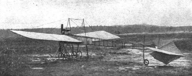
AVIS MONOPLANE. - View from behind.
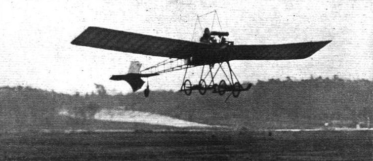
The Hon. Alan Boyle flying at Brooklands on his Bleriot monoplane. On Wednesday Mr. Boyle was out for sport, and made an excellent flight at a height of about 70 feet.

The Hon. Alan Boyle was last week seen in a photograph, published on page 306, flying on the "Avis" monoplane - obviously not a Bleriot, as appeared by a slip in the inscription. Above we are now able to give two much clearer pictures of this successful British-built machine in full flight at Brooklands under the direction of Mr. Boyle, The builders of the "Avis" are the Scottish Aeroplane Syndicate, of 166, Piccadilly.

Flying at Brookiands on Wednesday of last week when at one time there were no less than six machines in the air together. - Our photograph shows in full flight the Hon. Alan Boyle on his Avis monoplane (on the left) and Mr. Claude Grahame-White, with a passenger, on his Henry Farman biplane.
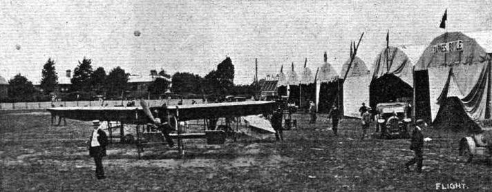
IN FRONT OF THE BOURNEMOUTH AEROPLANE SHEDS. - The Humber and Avis monoplanes are standing in the foreground,
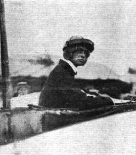
THE FLYING MEN AT BOURNEMOUTH AND THEIR "MOUNTS." - Hon. Alan Boyle (Avis).

Mr. Wickham, who is flying the Channel in connection with the De Forest L4,000 prize, at the wheel of his Avis monoplane.
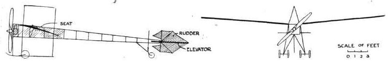
WING SECTIONS. - The above diagrams afford an interesting comparison of the wing sections of aeroplanes exhibited at Olympia. They are all drawn to a common scale, but have been set at an arbitrary angle of incidence, which does not necessarily represent that of the aeroplane In actual flight.
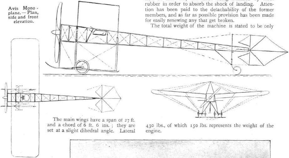
Avis Monoplane. - Plan, side and front elevation.
Flight, March 12, 1910
THE SECOND OLYMPIA AERO SHOW.
AEROPLANES.
Warwick Wright.
BRITISH-BUILT monoplane having a spread of 27 ft. and an overall length of 29 ft., the lifting surface being 160 sq. ft. It is fitted with a 40-h.p. E.N.V. engine weighing 155 lbs. The machine is mounted on runners which in turn are fitted with wheels and rubber springs. By these means the machine is able to rise from the ground without the aid of a starting apparatus, and at the same time the advantage of skids for alighting is obtained.
Flight, April 2, 1910
FLYER SILHOUETTES FROM OLYMPIA.
THE E.N.V. MONOPLANE.
Leading Particulars of the "E. N. V." Monoplane.
General Dimensions.-Areas-Main planes, 160 sq. ft.; fixed tail, 18 sq. ft.; elevator, 17 sq. ft.; rudder, 6 sq. ft.
Lengths.-Span, 27 ft.; chord, 6 ft. 6 ins.; camber, 4 1/2 ins.; leverage of rudder, 21 ft.; overall length, 29 ft.; skid track, 4 ft.
Angles.-Angle of incidence 6°; dihedral, 1 in 24.
Materials.-Timber.-Ash frame, spruce spars.
Engine.-40-h.p. "E.N.V."
Propeller.-Howard Wright; diameter, 6 ft.: pitch, 2 ft. 3 ins.
Weight.-Machine, 250 lbs.; engine, 155 lbs.; driver, oil, petrol and water, 200 lbs.; total flying weight, 605 lbs.; loading (all weight supported on main plane), 3.8 lbs. per sq. ft.
Speed of Flight.-35 m.p.h.
System of Control.-Elevator, rudder, warping of main planes.
Price.- L630.
MONOPLANE constructed for Warwick Wright by Howard Wright. It is a machine of modified Bleriot design, but having an original system of combined steel and wood frame construction. The chassis is an example of the "A" type, and is made of timber; it is surmounted by a steel frame for the support of the engine. The machine is carried upon wheels and skis. The radiator is placed under the main wings, as on the Santos-Dumont monoplane.
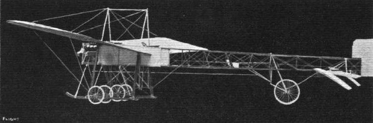
OLYMPIA, 1910. - The E.N.V. monoplane constructed by Howard Wright for Warwick Wright combines timber and steel in the construction of the chassis and frame. The chassis is an interesting example of the "A" type.

The E.N.V. monoplane.
WING SECTIONS. - The above diagrams afford an interesting comparison of the wing sections of aeroplanes exhibited at Olympia. They are all drawn to a common scale, but have been set at an arbitrary angle of incidence, which does not necessarily represent that of the aeroplane In actual flight.
Flight, December 3, 1910
FROM THE BRITISH FLYING GROUNDS.
Brooklands Aerodrome.
BROOKLANDS has again distinguished itself. When Mr. Cody, flying his Cody biplane on Laffan's Plain, recently captured the all-British record for distance and duration - 94 miles in 2 hrs. 24 mins. - the British airmen here determined to go one better. There were several aspirants to the honour, Mr. Sopwith, on the Howard Wright biplane, and Mr. Pixton, on the Avroplane, being warm favourites. The odds, however, were slightly against Mr. Pixton, as the magnetism of the sewage farm had to be discounted.
To Mr. Sopwith, the aviator, and to Messrs. Howard Wright, the builders, we have to extend our hearty congratulations on having put up on Saturday last a new all-British distance record of 107 miles, and at the same time established a British duration record of 3 hrs. 12 mins. for any type of machine, British or foreign, flown in this country.
Mr. Sopwith has also by the same flight achieved the best performance to date for the British Empire Michelin Cup. The Howard Wright machine on which these records were made is a biplane fitted with a 60-h.p. E.N.V. engine and Spiral tube radiator. It has a Farman type wheel-base, monoplane tail and elevator, with a central rudder above and below the tail plane. Mr. Sopwith first flew a Howard Wright monoplane - this was only some few weeks ago - and we drew attention in a previous issue to the rapid progress he made. He has only had delivery of the biplane a few days, which speaks well for the ease of control of this make of machine. This flight and triple record breaking naturally by comparison overshadows the smaller events of the week, although much good work has been put in by the other tenants.
Mr. Graham-Gilmour on Thursday last week piloted the Martin-Handasyde for straight flights at about 20 feet high. Mr. Collier rolled the Otazell, as did Mr. Oxley the Avroplane and Mr. Macfie his biplane.
The Bristol-Gnome, piloted by a pupil, made short flights, and Mr. Sopwith was out carrying passengeis.
On Friday Mr. Low took up a passenger on the Bristol-Gnome, and Mr. Snowden-Smith made several circuits, at a good height, on M. Blondeau's Farman.
Mr. Sopwith, on the Howard-Wright, remained in the air for half an hour, and Mr. Pixton was flying the Avroplane. The Macfie and Otazell were seen rolling.
On Saturday all minor essays were eclipsed by Mr. Sopwith's performance, but Mr. Morisson, on his single-seated Gnome-Bleriot, did remarkably well, rising quickly and at an acute angle. The Avro team, Messrs. Pixton, Oxley, Beattie and Jenkins, all did their utmost, and returned the machine home without a scratch. The Bristol-Gnome was also flying.
Sunday, mud, rain and wind kept shutters up, and people away.
On Monday the Spencer-Stirling biplane, fitted with R.H. engine, made short flights. Mr. Sopwith, on his Howard Wright biplane, and Mr. Low, on the Bristol-Gnome, made several circuits, the latter with passengers, otherwise there was little done. Mr. Oxley was the first out on Tuesday, the 29th ult., followed later by Mr. Pixton on the same machine. The latter was flying off and on for the whole afternoon. He is a very daring and pretty flyer, but the sudden movements he makes must put a severe strain on the bodywork. In particular, one dive and sudden righting appeared to actually bend the body, and it speaks well for the work Mr. Roe has put into his fuselage that nothing serious happened. We do not wish to appear pessimistic, but if Mr. Pixton continues his progress on his present lines we doubt whether he will get through life unmaimed, and the science may lose the fine work which so promising an airman can put in.
The outstanding event of the day was Lieut. Snowden Smith's flight to Aldershot and back on the Farman biplane belonging to Mrs. Maurice Hewlett and M. Blondeau. This is referred to on P. 995.
Mr. Low contributed his quota by vol plank from about 200 ft., and carrying passengers on the Bristol-Gnome. Mr. Sopwith, resting on his laurels, gave pleasure or otherwise by carrying passengers of both sexes.
Mr. Fisher and Mr. Raynham, on "Neale VI," made hops and short straight flights, as did also the Spencer-Stirling biplane.
M. Blondeau was passenger carrying, and at one time attained a good altitude.
Flight, December 24, 1910
THE HOWARD WRIGHT BIPLANE.
ALTHOUGH at the first Flight Show held at Olympia in 1909 Mr. Howard Wright showed a biplane which was noteworthy for some very interesting points, both in design and construction, most of the successes attained up till quite recently with machines made by Mr. Wright were accomplished on monoplanes. It will be remembered, however, that after quiet but persistent work the Howard Wright biplane came into prominence again at the end of last month, when Mr. Thomas Sopwith succeeded in setting up new British duration and distance records at Brooklands. He then covered 107 3/4 miles in 3h. 12m. 55s., but this performance, splendid as it was, Mr. Sopwith completely eclipsed on Sunday last, in his magnificent attempt to win the Baron de Forest prize, details of which are given elsewhere in this issue. In view of the extraordinary success attained with the machine, which by the way is entirely British built, we have no doubt that the description of it which we give below, as well as the photographs and scale drawing which clearly show the construction, will be appreciated by our readers. From a glance at the series of photographs of the complete machine, it will be noticed that superficially parts of it bear some resemblance to other well-known and successful machines, but when one comes to examine the details of construction, it is seen that considerable originality has been incorporated in the design. Although the span is fairly large, being 36 ft., the machine has the appearance of lightness and yet the construction is very strong. The main planes are single surfaced, and both are fitted with hinged flaps for maintaining lateral stability. The planes are placed 6 ft. 6 ins. apart by means of eight pairs of struts fitting into lugs on the main spars. One of these spars forms the leading edge of each main plane, while the other is placed approximately 5 ft. further back. These spars are rectangular in section, and are strengthened by a system of wire bracing similar to that which is a feature of the Sommer machine. As can be seen from the photograph taken from the front of the machine, the ribs of the main planes are placed equidistant, and enclosed in pockets made on the upper side of the fabric. A single elevator is mounted on a triangular outrigger in front, and it is inter-connected with the elevating flap at the rear end of the fixed tail. The elevator is regulated by the single control lever, which has a dual function, for besides controlling the elevator it also regulates the balancing flaps at each end of the main plane, a backward and forward movement being required for the former and a sideways adjustment for the latter. The tail consists of a horizontal rectangular fixed plane having an area of 60 sq. ft., and, as we have said, to the rear edge of it is hinged an elevating flap. Above and below this tail plane are arranged vertical rudders, each of them being of a similar size, and controlled by a bar worked by the pilot's feet. Each side of the elevator outrigger framework, which runs from the main spars of each plane, is braced by a single strut.
The framework carrying the tail, which runs out from the rear spars, is braced by four pairs of struts, and at the after end is a cross-bar carrying a pillar, on which the two vertical rudders are hinged. For protecting the after part of the machine from damage when landing, or when running over rough ground, a single-plane skid is hinged at the bottom of this central pillar, to which it is flexibly anchored by means of elastic. Should the shock be more than this simple device will absorb, the end of the framework is bent round to form a skid, and this should prove equal to the task. The chassis consists of two pairs of wheels mounted on short skids attached to the end, while additional struts from the central pairs of struts make the construction amply strong. Throughout the machine lugs are used for connecting up the various parts of the framework, and wire bracing is utilised freely to give added strength. In the scale drawing we have not included all these wire stays, as this would tend to confusion, but we have simply given the leads of the main bracing and connecting wires. Those who wish, however, for details of the various parts will be able to follow them by aid of the photographs. The engine and seating accommodation form one unit, being mounted on a couple of stout beams which are clipped to the main spars of the lower frame. It will be noticed, however, that the two radiators, which are by the Spiral Tube Co. and specially light, are separate, being clipped to the two central pairs of struts, while the petrol tank is slung from the top spars, the lubricating oil tank being mounted above the engine. As it is necessary for machines competing for the Baron de Forest prize to be entirely British-built, the engine is one of the latest E.N.V. type, of 60-h.p., which have been specially built in this country. It has eight cylinders arranged V-fashion, and Mr. Sopwith states that it went through its arduous trial without a falter, and in fact that he could have gone on for a much longer time had he so wished. This engine was described in our issue of October 15th last, and our readers will remember that the bore and stroke is 105 mm. by no mm., and that a special feature of the construction is the use of electrolytically deposited copper water-jackets. In connection with the engine, it is interesting to know that the complete power plant, including the accessories such as radiator, water, &c., weighs just over 400 lbs., and as Mr. Sopwith was carrying sufficient petrol and Vacuum oil for six hours, his trip was practically equivalent to one made with a passenger on a machine fitted with the lighter air-cooled rotary motor. Mr. Sopwith's machine has, as our readers will remember, shown itself very capable as a passenger carrier, Mr. Sopwith having made quite a feature of this side of his work at Brooklands. The machine is fitted with a Howard Wright propeller of 8 ft. 4 in. diameter, having a pitch of 4 ft. 8 in. The pilot's seat is placed above the lower front spar, while behind it, and arranged a little higher, is the second seat, for the passenger. The cross-beams are carried out in front to form a foot-rest, and on the board between his feet Mr. Sopwith fitted a compass to aid him in his cross-country journey. It is instructive to note, in regard to the compass, that during the cross-Channel flight the needle persisted in sticking at one point, so that the aviator was forced to rely upon the sun for guiding him on his way until that, in turn, hid itself.
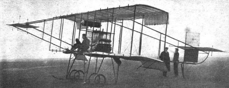
Mr. Sopwith, on his E.N.V. engined Howard Wright biplane, after his record flight.
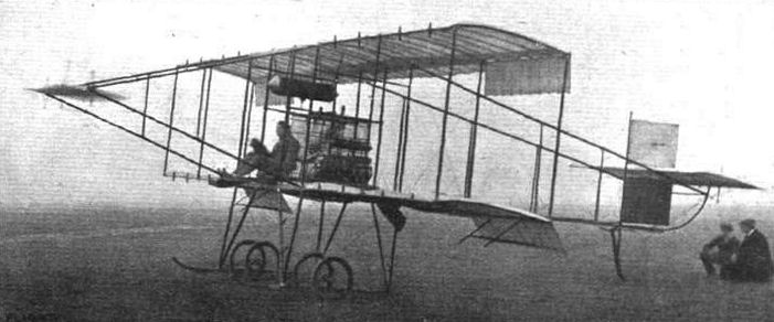
Half-side view of the Howard Wright biplane.

THE HOWARD WRIGHT BIPLANE. - Side view of Mr. Sopwith's E.N.V. engined machine, on which he flew from the Royal Aero Club's Eastchurch grounds to Belgium on Sunday.
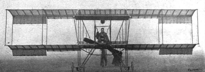
Front view of the Howard Wright biplane, with Mr. Sopwith in the pilot's seat.
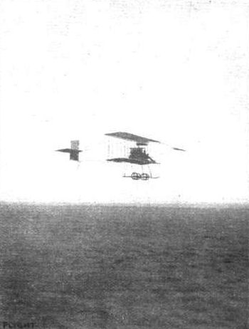
Mr. Sopwith in flight in the mist on his Howard Wright biplane.
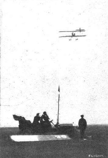
BRITISH RECORD FLIGHT. - Mr. Thomas Sopwith, on his Howard Wright biplane, completing his 90th mile at Brooklands. Note the score board which conveyed to the flyer, mile by mile, his distance traversed.
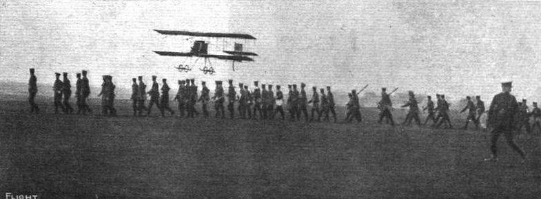
Lieut. Watkins, on his Howard Wright biplane, flying over the troops at Shorncliffe during his trips preparatory to trying for the Baron de Forest L4,000 Cross-Channel Prize.

View from behind of the central portion of the Howard Wright biplane, showing the propeller, E.N.V. engine, Spiral Tube.Co.'s radiators, &c.
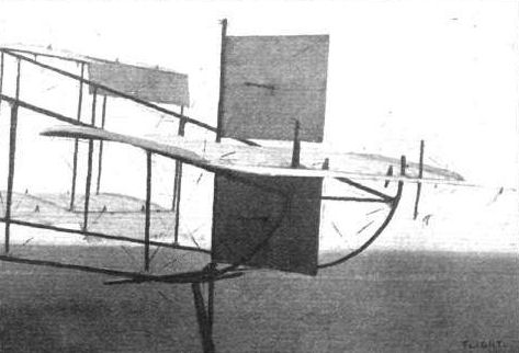
Tail details of the Howard Wright biplane.
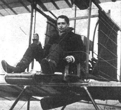
Mr. Thomas Sopwith in the pilot's seat of his Howard Wright biplane, fitted with E.N.V. engine, after creating a new British record for distance and duration by his flight at Brooklands Aerodrome on Saturday of 107 3/4 miles in 3h. 12m. 55s.

Mr. Sopwith takes up his sister, Miss May Sopwith, for a flight at Brooklands on his Howard Wright machine.
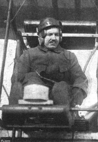
Lieut. Hugh E. Watkins, who is flying his E.N.V.-engined Howard Wright biplane in the Baron de Forest L4,000 Cross-Channel Prize contest.
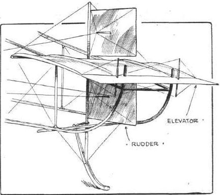
Sketch of the tail of the Howard Wright biplane showing elevator and rudder.
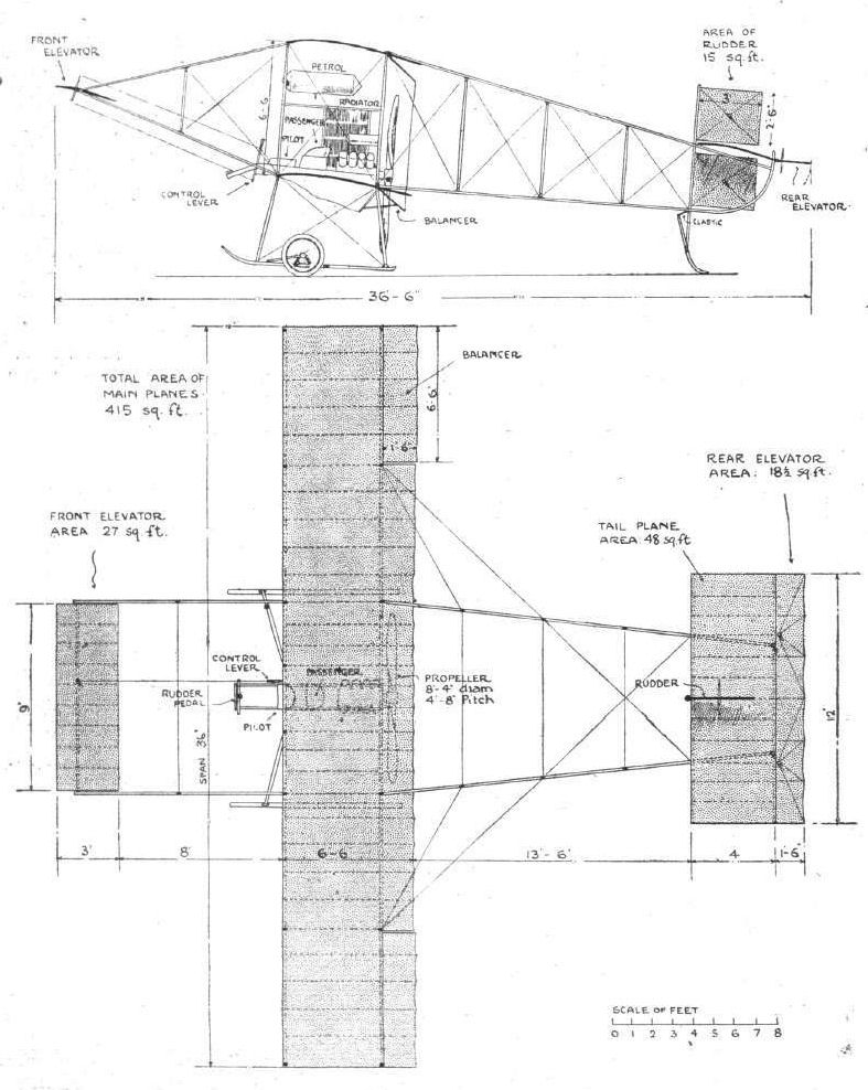
THE HOWARD WRIGHT BIPLANE. - Elevation and plan to scale.
Flight, March 12, 1910
THE SECOND OLYMPIA AERO SHOW.
AEROPLANES.
Humber.
Two British-built monoplanes of the Bleriot type are on view on Messrs. Humber's stand, as well as a monoplane and a biplane designed by Capt. Lovelace. The main planes of the last-mentioned are of 41 '6 span, and the total lifting surface is 526 sq. ft. The Lovelace type monoplane is of 29 ft. span with a total lifting surface of 232 sq. ft. In each the engine fitted is a 50-h.p. 4-cyl. water-cooled Humber.
Flight, March 26, 1910
FLYER SILHOUETTES FROM OLYMPIA.
HUMBER BIPLANE.
Leading Particulars of the Humber Biplane.
General Dimensions.-Areas-Main planes, 482 sq. ft.; elevator, 16 sq. ft. ; rudder, 12 sq. ft.
Lengths.-Span, 40 ft.; chord, 6 ft. 8 in.; camber, 3 1/2 in.; gap, 5 ft. ; skid track, 6 ft. ; overall length, 33 ft.
Angle.-Incidence, 6 1/2°.
Materials.-Steel struts and spars, hickory chassis; Mackintosh fabric.
Engine.-50-h.p. Humber.
Propeller.-Humber; diameter, 6 ft. 11 in.; pitch, 3 ft. 6 in.; material, laminated mahogany, spruce and walnut.
Weight. - Unknown at present.
Speed of Flight.-50 m.p.h.
System of control.-Rudder, elevator, warping of wings.
Price.-L1,000.
THIS machine is specially constructed solely for tuition purposes. It has three seats, the pilot's seat in the middle and a pupil's seat on either side. The control is in triplicate, but a pedal solely under the pilot's command enables the effect of the pupils' movements to be suspended. All main spars and struts are of tubular steel with the exception of the outrigger spars that carry the tail.
The main spars of the main frame are jointed so that the machine can be dismantled in three sections. The control is the same as on the Humber monoplane designed by Capt. Lovelace.
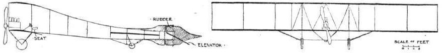
WING SECTIONS. - The above diagrams afford an interesting comparison of the wing sections of aeroplanes exhibited at Olympia. They are all drawn to a common scale, but have been set at an arbitrary angle of incidence, which does not necessarily represent that of the aeroplane In actual flight.
Flight, December 24, 1910
Aviation in India.
THE first flight in connection with the Allahabad Exhibition was made by Pecquet on the 17th inst., using his Humber biplane. Starting from the Exhibition Grounds he flew across the Ganges and Jumna, round the fort, and so back to the flying ground, the trip being made at a height of about 600 ft. On Monday last some flying was witnessed at Calcutta, when Tyck, who has gone to India with Baron de Caters, started from the Tolbygunge Club Grounds on his Bleriot monoplane and made a short flight, attaining a height of 1,200 ft. Among the small group ot spectators who witnessed the ascent was General Sir O'M. Creagh, the Commander-in-Chief.
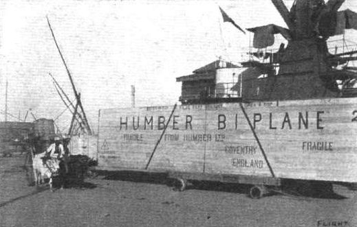
HUMBER BIPLANES IN INDIA AT THE ALLAHABAD EXHIBITION. - Unshipping the cases, of which there were sixteen, measuring end on 170 feet. These machines have been taken out by Mr. Windham, who is in charge of the flying exhibitions under arrangement with the Exhibition authorities. Note the yoked oxen to the native land vehicle.
Flight, January 15, 1910
Humber-Bleriots at Cannes.
CAPT. DAWES and Mr. Neale have been practising at Cannes since the 5th inst. on the two Humber-built Bleriot monoplanes which Mr. Ballin Hinde has entered for the Cairo meeting. So far, however, no striking success has attended their efforts although many short trial flights have been made. On the 5th inst. Mr. Neale's machine was caught in the boggy ground and thrown forward, being slightly damaged, while on the 7th inst. Capt. Dawes had a slight accident, apparently through the machine being caught unawares in a sudden gust of wind. Some further details regarding the doings of these British flyers are embodied in a letter from a correspondent , who writes under date of Jan. 11th , from Cannes, as follows :-
"The ground here is no better than Brooklands, plenty of ditches and soft boggy ground. The track, a racecourse, is rough, and on the whole not suitable for beginners.
"Mr. Neale last Wednesday made his first attempt here, and after a short flight, in trying to turn rallied too sharply. The machine went at a dangerous angle, he righted it, and brought it to ground seemingly on the track, but it proved to be soft ground. The wheels dug in up to the hub, and the machine went forward, breaking supports, but not propeller. This is the serious accident reported generally as "fell from a height of 16 ft." After three days spent in repairs, spares not having arrived, he flew about a quarter of a mile quite successfully.
"Captain Dawes was not in any way injured, and has only had so far one accident. The reason for coming here was to complete his training on a good ground, but the only advantages are the quiet days, with no wind."
Flight, February 19, 1910
HUMBER AEROPLANES.
As readers of FLIGHT are already aware, considerable progress has been made by the Humber Company in the development of the new aeronautic department of their huge factory at Coventry. Their intention is to build biplanes as well as monoplanes, and indeed their present catalogue includes full particulars concerning both these first standard models; but chiefly the shops are now busily engaged in the output of the latter, and of special engines for aeroplane propulsion, as may be gathered from the accompanying photograph taken by us last week in one of the erecting shops.
A good idea can be obtained from this illustration of the very thorough manner in which the work of manufacture is being conducted by the Company, particularly when it is realised that this is but one of the numerous shops engaged in aeroplane construction, and that every part is built upon the premises. Therein may be observed a monoplane complete except for its finishing touches, while the various men are busy with, main planes, elevators and propellers for similar machines.
Other shops at the time of our visit were in full swing building large numbers of the wooden propellers, while we found quite a considerable amount of interest centering around the triple-cylinder Humber engines that have been specially designed for the work of propulsion. These 3-cylinder engines are of the radial type, with a bore and stroke of 180 mm. and 135 mm. respectively, their normal output being 30-h.p., with a total weight of 155 lbs., including magneto. The Company also build a 4-cylinder model of 50-h.p., the total weight of which is 190 lbs.; and this engine, the bore and stroke of which are 110 mm. and 120 mm., has copper water-jackets to each individual cylinder.
Apart from these flyers and engines, a special Humber radiator has been produced; but this is only one of the many other details to which we hope to refer at considerably greater length within the next few weeks. For the moment it must suffice to draw attention to the remarkable progress that has been made within a comparatively short time.
IN FRONT OF THE BOURNEMOUTH AEROPLANE SHEDS. - The Humber and Avis monoplanes are standing in the foreground,
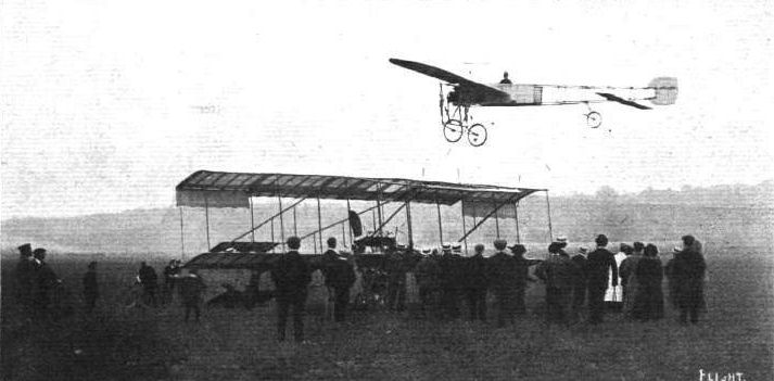
Mr. George Barnes, on a Humber monoplane, flying last week at Brooklands close over Mr. Claude Grahame-White's Henry Farman machine.
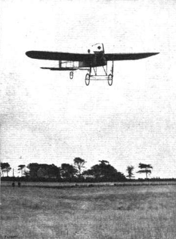
Mr. A. G. Barnes in flight at Folkestone Meeting ten seconds before his accident last week.
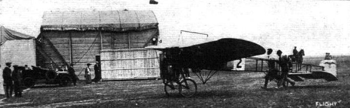
STOPPING A MONOPLANE AFTER FLIGHT. - G. A. Barnes bringing his Humber to rest after being in the air.
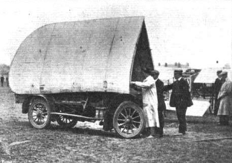
How Mr. Barnes packs up the wings of his Humber monoplane on a Humber car for transporting from place to place - a reminiscence of Bournemouth.
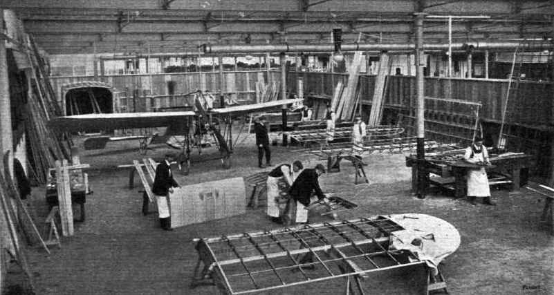
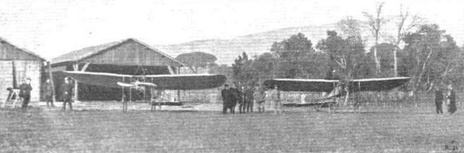
The two first British-built Humber-Bleriot monoplanes at Cannes, where Mr. Ballin Hinde took them with the intention of proceeding on to the Heliopolis Aviation Meeting opening next week.
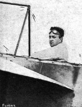
THE FLYING MEN AT BOURNEMOUTH AND THEIR "MOUNTS." - G. A. Barnes (Humber).

AFTER THE TUMBLE. - Mr. Barnes' monoplane upon its back at Folkestone after his bad fall last week.
Flight, March 12, 1910
THE SECOND OLYMPIA AERO SHOW.
AEROPLANES.
Humber.
Two British-built monoplanes of the Bleriot type are on view on Messrs. Humber's stand, as well as a monoplane and a biplane designed by Capt. Lovelace. The main planes of the last-mentioned are of 41 '6 span, and the total lifting surface is 526 sq. ft. The Lovelace type monoplane is of 29 ft. span with a total lifting surface of 232 sq. ft. In each the engine fitted is a 50-h.p. 4-cyl. water-cooled Humber.
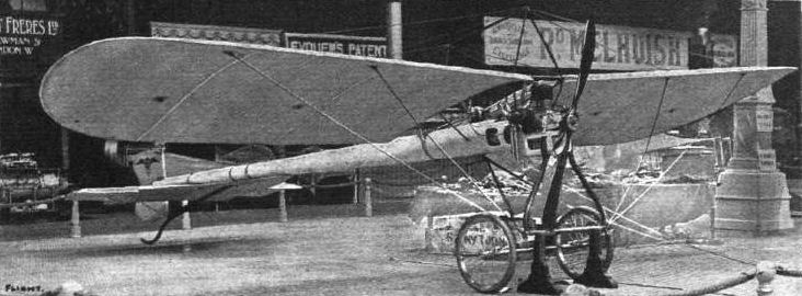
OLYMPIA, 1910. - The Humber monoplane designed by Le Blon is characterised by its dragon-fly body, which consists of a hollow wood boom of tapering circular section. The exterior of the boom is bound with tape.
WING SECTIONS. - The above diagrams afford an interesting comparison of the wing sections of aeroplanes exhibited at Olympia. They are all drawn to a common scale, but have been set at an arbitrary angle of incidence, which does not necessarily represent that of the aeroplane In actual flight.
Flight, March 12, 1910
THE SECOND OLYMPIA AERO SHOW.
AEROPLANES.
Humber.
Two British-built monoplanes of the Bleriot type are on view on Messrs. Humber's stand, as well as a monoplane and a biplane designed by Capt. Lovelace. The main planes of the last-mentioned are of 41 '6 span, and the total lifting surface is 526 sq. ft. The Lovelace type monoplane is of 29 ft. span with a total lifting surface of 232 sq. ft. In each the engine fitted is a 50-h.p. 4-cyl. water-cooled Humber.
Flight, March 26, 1910
FLYER SILHOUETTES FROM OLYMPIA.
HUMBER MONOPLANE (LOVELACE TYPE)
Leading Particulars of the Humber Monoplane (Lovelace type).
General Dimensions.-Areas-Main planes, 210 sq. ft.; fixed tail, 16 sq. ft.; elevator, 16 sq. ft.; rudder, 10 sq. ft.
Lengths.-Span, 33 ft.; chord, 6 ft. 10 ins.; camber, 5 1/4 ins., situated about 26 ins. from leading edge; leverage of rudder, 20 ft.; skid track, 4 ft. 9 ins.; overall length, 26 ft. 6 ins.
Angles.-Incidence 6 1/2°; dihedral, 1 in 11.
Materials.-Oval steel tube struts, hickory chassis, American elm spars in frame from front end to the splice behind pilot's seat, behind which ash spars are used; fabric, Mackintosh.
Engine.-50-h.p. Humber, 4 cylinders.
Propeller.-Humber; diameter, 6 ft. 11 ins.; pitch, 3 ft. 6 ins.; material, laminated mahogany, spruce, and walnut.
Weight.-Weights not known.
Speed of Flight.-50 m.p.h. for loading lift.
System of Control.-Warping of wings, elevator, and rudder.
Price.- L750.
MONOPLANE of modified Bleriot design. The peculiarity in the construction of the frame consists in the use of tubular steel struts of oval section. The timber used is hickory, American elm and ash. The machine is mounted on two wheels in front and also has a single rigid skid supported upon three triangular tubular steel struts. The control, which consists of wing warping, elevator and rudder, is effected by a steering wheel, mounted upon a jointed shaft so that the steering column can be moved sideways and to and fro, as well as being turned upon its axis.
Flight, October 1, 1910
Folkestone Meeting.
ALTHOUGH, as we recorded in our last issue, the first two days of the meeting at Folkestone produced some good flying, the proceedings on Wednesday of last week were marred by the serious accident to Barnes. A strong northerly wind had been blowing all the morning, and it was not till half-past four that there was any possibility of demonstrations. Then Barnes, having got the engine of his Humber monoplane to run properly, determined to take his chance. He rose to a height of about 80 ft., and flew against the wind for half a mile, then turning. It was then apparent that the engine was not running well, as the flying was unsteady, but Barnes managed to clear some trees and a hedge, and after coming very close to the earth, the machine suddenly rose for some distance. Then something happened, and the spectators were amazed to see Barnes leave his seat and leap to the ground from a height of some 30 ft. Relieved of the weight of the pilot the machine shot upward for a few feet, then turning over and crashing to the ground. The doctors and ambulance men who hurried to the spot where Barnes had fallen found that he had fractured his skull and broken his wrist. These injuries were attended to on the ground, and then the aviator was conveyed to the Royal Victoria Hospital, where, according to the latest reports, he is making good progress towards recovery.
<...>

WING SECTIONS. - The above diagrams afford an interesting comparison of the wing sections of aeroplanes exhibited at Olympia. They are all drawn to a common scale, but have been set at an arbitrary angle of incidence, which does not necessarily represent that of the aeroplane In actual flight.
Flight, April 16, 1910
An English Entrant for Lyons.
AMONG the entrants for the International meeting to be held at Lyons from May 7th to 15th, is Mr. Harding, who has recently been flying at Huntingdon racecourse. He has entered a monoplane fitted with a J. A. P. engine. The other entrants so far are Metrot (Voisin), Van den Born (Henry Farman), Latham (Antoinette), Molon (Bleriot), Legagneux (Sommer), Dubonnet (Tellier), Paulhan (Henry Farman), and it is also almost certain that Rougier will enter his new racing Voisin.
Flight, June 25, 1910
Harding at Amberieu.
MR. HARDING has been making good progress with his J. A. P. monoplane at Amberieu recently, and on Saturday he twice described a figure eight over the flying ground.
Flight, July 9, 1910
Harding at Amberieu.
MR. HARDING has been making good progress with his J. A. P. monoplane at Amberieu lately, and on the 1st executed two flights, one of 5 and the other of 15 kiloms. length, the altitude being about 10 metres.
Flight, July 30, 1910
Mr. Harding a "Pilote-Aviateur."
ON the 19th inst. Mr. Harding, who has been making some good flights at Amberieu, on his J. A. P. monoplane, successfully made two of the flights necessary to obtain his pilot's certificate, and later in the week he completed the tests. Moulthier, who has been practising at the same place with a Bleriot monoplane, has also passed the Ae.C. F. examination.
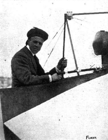
Harding in the pilot's seat of his J.A.P. monoplane at Blackpool.
Flight, October 1, 1910.
FROM THE BRITISH FLYING GROUNDS
Royal Aero Club Ground, Eastchurch.
Early on Friday morning we had the first glimpse of the latest arrival here. This is a machine of somewhat peculiar appearance, built to the design of Mr. Jobling. It consists of one huge plane, at each end of which is a rear extension tapering off to a point. These extensions are pliable, and the direction of flight is controlled by wires connected to the extreme points and operated from the pilot's seat, located centrally beneath the plane. The total absence of elevators, tail or rudder give to this machine an unusual appearance, and its behaviour will be watched with interest. On the present occasion the machine was only run over the ground a short distance, so it is impossible yet to give any idea of her behaviour when in flight. The impression left by such a brief inspection was that it would be exceedingly unstable, owing, no doubt, to the flimsy appearance of the wing extensions before mentioned. The accompanying rough birdseye outline view will give some idea of the form this machine takes, but we hope to give a more detailed description after it has passed through the preliminary stages.
Flight, November 5, 1910.
FROM THE BRITISH FLYING GROUNDS
Royal Aero Club Eastchurch Grounds.
ON October 19th Mr. Charles Jobling took out his monoplane for a trial flight at Eastchurch. After a short ran the machine rose easily to a height of over 30 ft. Owing, however, to an inside wire strainer having been broken before the start, the wing gave way after a flight of about 130 yards, and the plane dived to the ground, Mr. Jobling fortunately sustaining no injury. The monoplane, a diagram of which appeared in our issue of October 1st, is controlled entirely by ailerons of unusual length; it has no tail, and the propeller is behind. It has been built throughout of English materials to Mr. Jobling's design, and was driven by a 35-h.p. British de Havilland engine.
FROM THE BRITISH FLYING GROUNDS
Royal Aero Club Ground, Eastchurch.
Early on Friday morning we had the first glimpse of the latest arrival here. This is a machine of somewhat peculiar appearance, built to the design of Mr. Jobling. It consists of one huge plane, at each end of which is a rear extension tapering off to a point. These extensions are pliable, and the direction of flight is controlled by wires connected to the extreme points and operated from the pilot's seat, located centrally beneath the plane. The total absence of elevators, tail or rudder give to this machine an unusual appearance, and its behaviour will be watched with interest. On the present occasion the machine was only run over the ground a short distance, so it is impossible yet to give any idea of her behaviour when in flight. The impression left by such a brief inspection was that it would be exceedingly unstable, owing, no doubt, to the flimsy appearance of the wing extensions before mentioned. The accompanying rough birdseye outline view will give some idea of the form this machine takes, but we hope to give a more detailed description after it has passed through the preliminary stages.
Flight, November 5, 1910.
FROM THE BRITISH FLYING GROUNDS
Royal Aero Club Eastchurch Grounds.
ON October 19th Mr. Charles Jobling took out his monoplane for a trial flight at Eastchurch. After a short ran the machine rose easily to a height of over 30 ft. Owing, however, to an inside wire strainer having been broken before the start, the wing gave way after a flight of about 130 yards, and the plane dived to the ground, Mr. Jobling fortunately sustaining no injury. The monoplane, a diagram of which appeared in our issue of October 1st, is controlled entirely by ailerons of unusual length; it has no tail, and the propeller is behind. It has been built throughout of English materials to Mr. Jobling's design, and was driven by a 35-h.p. British de Havilland engine.
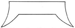
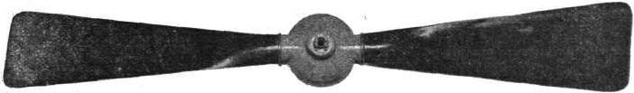
In the Lamplough propeller the blades are each made from a single piece of wood, and are hollowed out from the root towards the tip. They are mounted in a hollow copper stamping which forms the boss.
Flight, March 12, 1910
THE SECOND OLYMPIA AERO SHOW.
AEROPLANES.
Lane.
Two monoplanes, one of 30-ft. spread, and the other of 36-ft. span, the former fitted with a 30-h.p. engine, and the latter a 60-h.p. engine, both of the N.E.C. type.
Flight, April 9, 1910
FLYER SILHOUETTES FROM OLYMPIA
THE LANE SINGLE-SEATER MONOPLANE.
Leading Particulars of the Lane Monoplane (Single-Seater).
General Dimensions.-Areas-Main planes, 195 sq. ft.; fixed tail, 21 sq. ft.; elevator, 18 sq. ft.; rudder, about 5 1/2 sq. ft.
Lengths.-Span, 30 ft.; chord, 6 ft. 6 ins.; camber, 4 3/4 ins., situated about 24 ins. from leading edge; leverage of rudder, 20 ft.; skid track, 6 ft.; overall length, 24 ft.
Angles.-Dihedral, 1 in 40.
Materials.-Chassis of wood; front carriage of wood and steel tubes.
Engine.-25-h.p. "N.E.C"
Propeller.-Diameter, 7 ft.; pitch, 3 ft. 6 ins.
Weight.-Machine, 285 lbs.; engine, 165 lbs.; driver, oil, petrol and water, 200 lbs.; total flying weight, 650 lbs.; loading (all weight supported on main planes), 3.3 lbs. per sq. ft.
Speed of Flight.-30 m.p.h.
System of Control.-Warping of wings, rudder and elevator.
Price.-L500.
A MONOPLANE of modified Bleriot design, having the elevator situated above the fixed tail plane instead of forming the extremities of the tail plane, as is the case in the original Bleriot design. The framework is constructed of timber and forms an open lattice box-girder. An original method of anchoring the diagonal wire ties has been devised, which enables the anchor bolts themselves to be used for the purpose of straining the wires. The suspension of the chassis is also original, elastic springs being anchored to the frame a considerable distance behind the pilot's seat. The machine is mounted upon a pair of wheels, each of which is carried in a special design of triple fork mounted on swiveling bracket.
THE LANE DOUBLE-SEATER MONOPLANE.
Leading Particulars of the Lane Monoplane (Double- Seater).
General Dimensions.-Areas-Main planes, 250 sq. ft.; elevator, 25 sq. ft.; rudder, 7 sq. ft.
Lengths.-Span, 36 ft. 6 ins.; chord, 7 ft. 10 ins.; camber, 7 1/4 ins., situated about 30 ins. from leading edge; skid track, 6 ft.; overall length, 24 ft.
Angle.-Dihedral, 1 in 38.
Materials.-Chassis of wood, front carriage of wood and steel tubes.
Engine.-60-h.p. N.E.C.
Propeller.-Diameter, 8 ft. 8 ins.; pitch, 4 ft. 6 ins.
Weight.-Machine, 550 lbs.; engine, 220 lbs.; driver, oil, petrol and water, 200 lbs.; total flying weight, 970 lbs.; loading (all weight supported on main planes), 3.9 lbs. per sq. ft.
Speed of Flight.-30 m.p.h.
System of control.-Warping of wings, rudder and elevator.
Price.-L800.
THE Lane two-seater was the only example of a monoplane constructed to carry two passengers that was exhibited at Olympia. Its design follows more or less closely on the lines of the single-seated model, the frame being constructed of timber and having the same system of wire straining. The basis of the design is the original Bleriot two-seated monoplane. The engine is situated low down immediately in front of the pilot's seat, and drives a large two-bladed tractor screw by means of a vertical chain. The propeller-shaft is carried on brackets attached to the main frame but is also stayed to the engine crank-shaft by an adjustable strut.
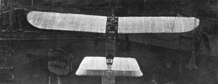
View from above and behind of the Lane monoplane. This is the single-seater; on the left will be noticed part of the skeleton framework of the two-seater.
FLYING MACHINES AT BROOKLANDS ON EASTER MONDAY. - A trio of aeroplanes. From left to right: Mr. Astley's Lane monoplane, Mr. A. V. Roe's triplane, and Mr. Moreing's Voisin biplane.
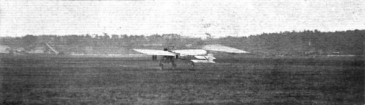
FLYING MACHINES AT BROOKLANDS ON EASTER MONDAY. - Mr. Astley's monoplane taking a run across the aerodrome.

FLYING AT BROOKLANDS. - Mr. Lane on his monoplane giving an exhibition flight on Saturday last. In the distance Mr. Morison on his machine can also be seen well up in the air.
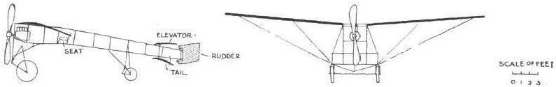
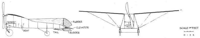
WING SECTIONS. - The above diagrams afford an interesting comparison of the wing sections of aeroplanes exhibited at Olympia. They are all drawn to a common scale, but have been set at an arbitrary angle of incidence, which does not necessarily represent that of the aeroplane In actual flight.
Flight, August 20, 1910
THE LOCKE GLIDER.
I promised some time ago, in a letter you published, to tell you about my experiments with a glider then in course of construction on lines which, unhappily for me, had been to some extent anticipated by Lieut. Dunne.
The glider is now more or less completed, after an annoying delay, and on Tuesday, July 26th, I attempted flight at Barking. The wind was not strong enough, however, and as the construction of the machine and the nature of the ground made a launch impracticable without the help of the wind, I have, unluckily, no success to report. But with time and patience great things may happen yet, and when they do you shall know of them.
The accompanying photo was taken at the time of the trial. It gives some idea of thу glider's chief characteristic - that is, its broad-arrow shape. The planes meet at an angle of 90 o, and are 37 ft. across from tip to tip. I don't think I'll give you any further details now.
The tousled-looking person standing in the angle at the back of the glider is myself. Of the three people on the other side of the planes, those bareheaded are friends who underwent a vast deal of violent exertion and acute discomfort (Barking has many thistles) in order to help me fly. My associate in building the glider unfortunately does not appear. He was working the camera.
I hope to have something really interesting to tell you before very long.
Chingford. J. C. LOCKE.
Flight, March 5, 1910
THE MACFIE BRITISH AEROPLANE.
SOME little time ago, as our readers may remember, flight experiments were carried out on the Maplin Sands by Mr. Macfie, who succeeded in making a few long jumps before the military authorities in charge of the gunnery range at Shoeburyness caused these promising trials to be temporarily abandoned. Mr. Macfie transferred his machine to France in the hope of finding a satisfactory trial ground, but meeting with considerable difficulty in arranging for what he considered to be reasonable conditions under which he could continue his experiments, he has once more returned to England, and is now about to conduct further trials over home soil.
The Macfie aeroplane is interesting as an almost entirely home-made machine, and also because it embodies several ingenious features in the details of its construction. As a type it resembles at first sight the Bleriot monoplane, but the wings have a dihedral angle like the Antoinette. They are fastened to a frame that is built of wood and wire and forms a V-section lattice girder of tapering section. In front, the frame is mounted on a wheeled chassis, and behind it rests upon a skid. The rear part of the frame carries a pivoted tail and a rudder. In front, immediately above the chassis, is the engine, which drives a two-bladed tractor-screw. The pilot's seat is between the wings, and the control, which includes wing-warping, is effected by a single vertical lever and a pedal.
The Frame.
The frame of the machine is a light V-section ash girder measuring about 3 ft. deep at the forward end and 12 ins. deep at the tail. The bottom member lies horizontal when the machine is on the ground, and the two top members, therefore, have a gradual slope from the tail to the forward end of the machine. The front extremity of the frame is formed by a kind of prow that is specially constructed as a support for the engine, pains having been taken to try and reduce the effect of vibration as much as possible.
The two upper members of the frame are spaced about 2 ft. 6 ins. apart at the widest point, which is immediately between the wings, and they likewise taper together towards the tail, where they terminate 12 ins. apart. At intervals the longitudinal members are stayed by cross-pieces, and the fastening of these is one of those peculiarities, it might almost be said curiosities, in the constructional detail of the Macfie aeroplane. An accompanying sketch shows exactly how the joints are made.
The girder struts abut flat and true against the bearer spars, but they do not make any sort of a mortice joint. Their fastening is effected by the use of steel angle-plates that are lashed to the different members by strips of fine Irish linen tape. The tape is previously soaked in a solution of glue and water and is bound in place while wet so that the binding contracts tight and hardens while drying. This very original method of bracing a frame Mr. Macfie claims to have found extremely satisfactory, especially for an experimental machine. He also found it to be a very expeditious method of building up a frame, and ascertained as the result of much hard usage that the joints would withstand strains very well indeed. Moreover, if one should loosen it is a simple matter to remake it, for the component parts, with the exception of the binding, are intact. When screws or bolts are used in any joint of this description they are apt to spoil the wood so much if they work loose that it is difficult to remake the joint in exactly the same place. This is, of course, one of the principal claims that Mr. Macfie makes for his system of construction.
An incidental feature associated with this method of jointing is the anchorage that it provides for the diagonal tie-wires used to complete the trussing of the frame. Close inspection of the accompanying sketch already referred to will show that the steel angle-plate is indented at the corner, so as to receive a steel pin. The angle-plate is also drilled so that the centre of the pin, which is cranked, can project through to the front, where it forms an eye for the anchorage of the tie-wire.
The same system of binding, it may be remarked, is also employed for joining together the two lengths that compose each of the longitudinal spars of the main frame. In front the frame is supported on a wheeled chassis constructed of steel tubing. The details of this chassis are sufficiently clearly shown by one of the accompanying photographs to need no special description.
It will be observed that, in the main, it consists of a rectangular frame, to the upright members of which the two wheels are attached by swivel brackets. There are two forked brackets to each wheel, and one of them abuts against a helical compression spring situated near the top of the vertical member in the chassis frame. These springs form the suspension members of the machine, and enable the wheels to rise and fall vertically without interfering in any way with the swivelling movement. She hubs of the wheels are connected by a light axle that is hinged at each end. At the rear the frame is supported on a light shoe or skid shown in the sketch above.
(To be concluded.)
Flight, March 12, 1910
THE MACFIE BRITISH AEROPLANE.
(Concluded from page 154.)
THE skid was specially designed for use on the sand over which the first experimental trials were carried out. It is very light and is provided with a combination of elastic and steel springs, as shown in one of the accompanying sketches. The shoe itself is pivoted to a vertical wood column that is free to rotate in its supporting brackets.
The Wings, Elevator and Rudder.
The wings of the Macfie monoplane have a span of 28 ft. 6 ins., and a chord of 6 ft. 6 ins., which gives an aspect ratio of 4.4. They are set at a dihedral angle and are double surfaced. A feature in connection with their plan form is the removal of their trailing corners for a distance of about 3 ft. from the extremities along the trailing edge.
The surface material, for which Continental fabric No. 100 B has been used, is laid on a skeleton framework consisting of two main spars and a set of shaped ribs in each wing. The main spars are of I-section, those in front being rigidly bolted to the frame of the machine, while those behind are each so fastened by a single bolt that they possess a certain amount of hinge action, which is employed for purposes of warping. The details of the attachment of the rear spars to the main frame of the machine is shown in one of the accompanying sketches.
The ribs are spaced along the spars at intervals of about twelve inches, and each rib consists of a built-up member representing the camber of the wing section. The details of this construction are also shown in an accompanying sketch, where the principal dimensions of the rib are given and also the method by which it has been made as light as possible. Further light is also thrown on these details of construction by an accompanying photograph, which shows a portion of the skeleton framework of the elevator tail. There are some differences between the actual details of this member and of the main frame, but the same system is followed in both cases. The ribs, it will be noticed, project beyond the front spar, and their extremities mortice into a kind of U-section member that forms a rigid leading edge along the front of each wing. The ribs also overlap the rear spar, and in this case form a flexible trailing edge. In the construction of the tail there is no rear spar, properly speaking, but it will be observed from the photograph aforementioned that the ribs are tied together near their extremities by a light lath. Attention should also, perhaps, be drawn to the shape of the main spar in the photograph of the tail framework, as this member has a different section to that employed for the main wings. For its span, a much more massive spar is employed in the tail, owing to the fact that it is so mounted as to be capable of rocking in its supporting brackets, the tail being used as an elevator as is the case on most monoplanes.
In applying the surface fabric, a system is adopted of stretching the material on a kind of former in advance. The former is so constructed that it is possible to transfer the stretched fabric direct to the machine without releasing the tension. This method was, we understand, found to be not only very satisfactory in its result, but also a great time-saver, the surfacing of an aeroplane being commonly one of the longest jobs in its construction compared with the apparent amount of work that it involves.
After the surface material has been applied, the wings are braced by the attachment of tie-wires and bars. Flat strip steel is used for bracing the forward main spars to the chassis-frame, but elsewhere steel wire is employed, mainly on account of the movement necessitated by warping. In connection with the attachment of the tie-bars from the forward spars to the chassis frame, it should be pointed out that these slope backwards as well as upwards from their anchorage, in order, according to the designer, to give the spars additional rigidity in overcoming head resistance.
In addition to the tie-wires beneath the wings, there are others above, which pass, between corresponding points in the main spars, over a central triangular framework that projects as a strut above the centre of the machine. In the case of the tie-wire between the rear main spars a pulley wheel is provided for its support on the strut, owing to the movement that takes place when the wings are warped. Details of this attachment are illustrated in one of the accompanying photographs, which shows the position of the pilot's seat.
The rudder is an interesting example of the use of Venesta wood. It consists of two panels, fastened to a light skeleton frame, and each panel consists of three layers of wood, of which the individual thickness is only one twenty-fifth of an inch. This form of construction produces a smooth rigid surface that is not easily damaged and is reasonably light. It seems particularly suited to a rudder that is as much over-hung in its support as that on the Macfie machine.
The Engine.
The engine installed on the Macfie aeroplane is a 35-h.p. 8-cyl. Jap. The cylinders are arranged V-fashion and are air-cooled. The engine is situated right up in the bows of the frame and is carried on two timber bearers that are rigidly attached to an extension of the main-frame of the machine. The tractor-screw, which is a two-bladed design constructed in solid teak, is mounted direct on the end of the crank-shaft. It has a diameter of 6 ft. 6 ins. and a pitch that is calculated to produce a flight speed of 40 miles an hour at 1,200 r.p.m., after allowing for a 30 per cent. slip. Close inspection of some of the accompanying photographs illustrates an obvious cutting-away of the trailing edge of the propeller, a modification from its original form that was found to result in a considerable improvement in the tractive effort.
The Control.
The control of the Macfie aeroplane is accomplished by means of a universally pivoted lever, and also by the aid of a pivoted foot-rest that serves the purpose of a pedal. The pedal controls the action of the rudder; and is independent of all other connections. The lever Is mounted vertically and directly in front of the pilot; its position and method of attachment is very clearly illustrated by the accompanying sketch and also by the various photographs. It can be moved in any direction and with either or both hands as the operator may find most convenient. Its lower extremity carries the wires that operate the elevator-tail and near the lower end of the lever are attached the wires that produce the wing warping. The connections of these latter wires and the manner in which they are "reversed" by the aid of pulleys attached to the main frame, forms the subject of a separate diagrammatic sketch.
This use of a single universally pivoted lever for the double purpose of warping the wings and working the elevator - in a manner that corresponds to the Bleriot control - must not be confused with the Wright system, wherein a similar lever is employed for the dual purpose of warping and steering. The arrangement on the Macfie machine is not associated with any particular system of control, it is merely a device for reducing the number of levers that would otherwise be necessary.
On the Macfie machine warping and the manipulation of the elevator can be carried out by the use of a single lever, but this does not imply that there is necessarily any purpose in the interconnection other than that associated with the pilot's convenience.
Moving the lever to and fro operates the elevator, moving it from side to side warps the wings. Warping or the manipulation of the elevator can be accomplished independently with the lever in any position; that is to say, supposing the pilot happens to be holding the lever forward of the neutral position for the purpose of setting the elevator, he can instantly warp the wings by a sideways movement without in any way upsetting the elevator adjustment, and vice versa. The manipulation of the rudder, which is commonly necessary in connection with any wing warping operation, is independently accomplished by the use of a pivoted foot-rest to which the rudder is directly connected.
THE MACFIE BRITISH AEROPLANE.
SOME little time ago, as our readers may remember, flight experiments were carried out on the Maplin Sands by Mr. Macfie, who succeeded in making a few long jumps before the military authorities in charge of the gunnery range at Shoeburyness caused these promising trials to be temporarily abandoned. Mr. Macfie transferred his machine to France in the hope of finding a satisfactory trial ground, but meeting with considerable difficulty in arranging for what he considered to be reasonable conditions under which he could continue his experiments, he has once more returned to England, and is now about to conduct further trials over home soil.
The Macfie aeroplane is interesting as an almost entirely home-made machine, and also because it embodies several ingenious features in the details of its construction. As a type it resembles at first sight the Bleriot monoplane, but the wings have a dihedral angle like the Antoinette. They are fastened to a frame that is built of wood and wire and forms a V-section lattice girder of tapering section. In front, the frame is mounted on a wheeled chassis, and behind it rests upon a skid. The rear part of the frame carries a pivoted tail and a rudder. In front, immediately above the chassis, is the engine, which drives a two-bladed tractor-screw. The pilot's seat is between the wings, and the control, which includes wing-warping, is effected by a single vertical lever and a pedal.
The Frame.
The frame of the machine is a light V-section ash girder measuring about 3 ft. deep at the forward end and 12 ins. deep at the tail. The bottom member lies horizontal when the machine is on the ground, and the two top members, therefore, have a gradual slope from the tail to the forward end of the machine. The front extremity of the frame is formed by a kind of prow that is specially constructed as a support for the engine, pains having been taken to try and reduce the effect of vibration as much as possible.
The two upper members of the frame are spaced about 2 ft. 6 ins. apart at the widest point, which is immediately between the wings, and they likewise taper together towards the tail, where they terminate 12 ins. apart. At intervals the longitudinal members are stayed by cross-pieces, and the fastening of these is one of those peculiarities, it might almost be said curiosities, in the constructional detail of the Macfie aeroplane. An accompanying sketch shows exactly how the joints are made.
The girder struts abut flat and true against the bearer spars, but they do not make any sort of a mortice joint. Their fastening is effected by the use of steel angle-plates that are lashed to the different members by strips of fine Irish linen tape. The tape is previously soaked in a solution of glue and water and is bound in place while wet so that the binding contracts tight and hardens while drying. This very original method of bracing a frame Mr. Macfie claims to have found extremely satisfactory, especially for an experimental machine. He also found it to be a very expeditious method of building up a frame, and ascertained as the result of much hard usage that the joints would withstand strains very well indeed. Moreover, if one should loosen it is a simple matter to remake it, for the component parts, with the exception of the binding, are intact. When screws or bolts are used in any joint of this description they are apt to spoil the wood so much if they work loose that it is difficult to remake the joint in exactly the same place. This is, of course, one of the principal claims that Mr. Macfie makes for his system of construction.
An incidental feature associated with this method of jointing is the anchorage that it provides for the diagonal tie-wires used to complete the trussing of the frame. Close inspection of the accompanying sketch already referred to will show that the steel angle-plate is indented at the corner, so as to receive a steel pin. The angle-plate is also drilled so that the centre of the pin, which is cranked, can project through to the front, where it forms an eye for the anchorage of the tie-wire.
The same system of binding, it may be remarked, is also employed for joining together the two lengths that compose each of the longitudinal spars of the main frame. In front the frame is supported on a wheeled chassis constructed of steel tubing. The details of this chassis are sufficiently clearly shown by one of the accompanying photographs to need no special description.
It will be observed that, in the main, it consists of a rectangular frame, to the upright members of which the two wheels are attached by swivel brackets. There are two forked brackets to each wheel, and one of them abuts against a helical compression spring situated near the top of the vertical member in the chassis frame. These springs form the suspension members of the machine, and enable the wheels to rise and fall vertically without interfering in any way with the swivelling movement. She hubs of the wheels are connected by a light axle that is hinged at each end. At the rear the frame is supported on a light shoe or skid shown in the sketch above.
(To be concluded.)
Flight, March 12, 1910
THE MACFIE BRITISH AEROPLANE.
(Concluded from page 154.)
THE skid was specially designed for use on the sand over which the first experimental trials were carried out. It is very light and is provided with a combination of elastic and steel springs, as shown in one of the accompanying sketches. The shoe itself is pivoted to a vertical wood column that is free to rotate in its supporting brackets.
The Wings, Elevator and Rudder.
The wings of the Macfie monoplane have a span of 28 ft. 6 ins., and a chord of 6 ft. 6 ins., which gives an aspect ratio of 4.4. They are set at a dihedral angle and are double surfaced. A feature in connection with their plan form is the removal of their trailing corners for a distance of about 3 ft. from the extremities along the trailing edge.
The surface material, for which Continental fabric No. 100 B has been used, is laid on a skeleton framework consisting of two main spars and a set of shaped ribs in each wing. The main spars are of I-section, those in front being rigidly bolted to the frame of the machine, while those behind are each so fastened by a single bolt that they possess a certain amount of hinge action, which is employed for purposes of warping. The details of the attachment of the rear spars to the main frame of the machine is shown in one of the accompanying sketches.
The ribs are spaced along the spars at intervals of about twelve inches, and each rib consists of a built-up member representing the camber of the wing section. The details of this construction are also shown in an accompanying sketch, where the principal dimensions of the rib are given and also the method by which it has been made as light as possible. Further light is also thrown on these details of construction by an accompanying photograph, which shows a portion of the skeleton framework of the elevator tail. There are some differences between the actual details of this member and of the main frame, but the same system is followed in both cases. The ribs, it will be noticed, project beyond the front spar, and their extremities mortice into a kind of U-section member that forms a rigid leading edge along the front of each wing. The ribs also overlap the rear spar, and in this case form a flexible trailing edge. In the construction of the tail there is no rear spar, properly speaking, but it will be observed from the photograph aforementioned that the ribs are tied together near their extremities by a light lath. Attention should also, perhaps, be drawn to the shape of the main spar in the photograph of the tail framework, as this member has a different section to that employed for the main wings. For its span, a much more massive spar is employed in the tail, owing to the fact that it is so mounted as to be capable of rocking in its supporting brackets, the tail being used as an elevator as is the case on most monoplanes.
In applying the surface fabric, a system is adopted of stretching the material on a kind of former in advance. The former is so constructed that it is possible to transfer the stretched fabric direct to the machine without releasing the tension. This method was, we understand, found to be not only very satisfactory in its result, but also a great time-saver, the surfacing of an aeroplane being commonly one of the longest jobs in its construction compared with the apparent amount of work that it involves.
After the surface material has been applied, the wings are braced by the attachment of tie-wires and bars. Flat strip steel is used for bracing the forward main spars to the chassis-frame, but elsewhere steel wire is employed, mainly on account of the movement necessitated by warping. In connection with the attachment of the tie-bars from the forward spars to the chassis frame, it should be pointed out that these slope backwards as well as upwards from their anchorage, in order, according to the designer, to give the spars additional rigidity in overcoming head resistance.
In addition to the tie-wires beneath the wings, there are others above, which pass, between corresponding points in the main spars, over a central triangular framework that projects as a strut above the centre of the machine. In the case of the tie-wire between the rear main spars a pulley wheel is provided for its support on the strut, owing to the movement that takes place when the wings are warped. Details of this attachment are illustrated in one of the accompanying photographs, which shows the position of the pilot's seat.
The rudder is an interesting example of the use of Venesta wood. It consists of two panels, fastened to a light skeleton frame, and each panel consists of three layers of wood, of which the individual thickness is only one twenty-fifth of an inch. This form of construction produces a smooth rigid surface that is not easily damaged and is reasonably light. It seems particularly suited to a rudder that is as much over-hung in its support as that on the Macfie machine.
The Engine.
The engine installed on the Macfie aeroplane is a 35-h.p. 8-cyl. Jap. The cylinders are arranged V-fashion and are air-cooled. The engine is situated right up in the bows of the frame and is carried on two timber bearers that are rigidly attached to an extension of the main-frame of the machine. The tractor-screw, which is a two-bladed design constructed in solid teak, is mounted direct on the end of the crank-shaft. It has a diameter of 6 ft. 6 ins. and a pitch that is calculated to produce a flight speed of 40 miles an hour at 1,200 r.p.m., after allowing for a 30 per cent. slip. Close inspection of some of the accompanying photographs illustrates an obvious cutting-away of the trailing edge of the propeller, a modification from its original form that was found to result in a considerable improvement in the tractive effort.
The Control.
The control of the Macfie aeroplane is accomplished by means of a universally pivoted lever, and also by the aid of a pivoted foot-rest that serves the purpose of a pedal. The pedal controls the action of the rudder; and is independent of all other connections. The lever Is mounted vertically and directly in front of the pilot; its position and method of attachment is very clearly illustrated by the accompanying sketch and also by the various photographs. It can be moved in any direction and with either or both hands as the operator may find most convenient. Its lower extremity carries the wires that operate the elevator-tail and near the lower end of the lever are attached the wires that produce the wing warping. The connections of these latter wires and the manner in which they are "reversed" by the aid of pulleys attached to the main frame, forms the subject of a separate diagrammatic sketch.
This use of a single universally pivoted lever for the double purpose of warping the wings and working the elevator - in a manner that corresponds to the Bleriot control - must not be confused with the Wright system, wherein a similar lever is employed for the dual purpose of warping and steering. The arrangement on the Macfie machine is not associated with any particular system of control, it is merely a device for reducing the number of levers that would otherwise be necessary.
On the Macfie machine warping and the manipulation of the elevator can be carried out by the use of a single lever, but this does not imply that there is necessarily any purpose in the interconnection other than that associated with the pilot's convenience.
Moving the lever to and fro operates the elevator, moving it from side to side warps the wings. Warping or the manipulation of the elevator can be accomplished independently with the lever in any position; that is to say, supposing the pilot happens to be holding the lever forward of the neutral position for the purpose of setting the elevator, he can instantly warp the wings by a sideways movement without in any way upsetting the elevator adjustment, and vice versa. The manipulation of the rudder, which is commonly necessary in connection with any wing warping operation, is independently accomplished by the use of a pivoted foot-rest to which the rudder is directly connected.
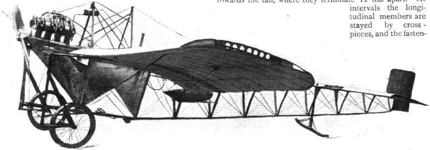
View of the Macfie monoplane from in front.
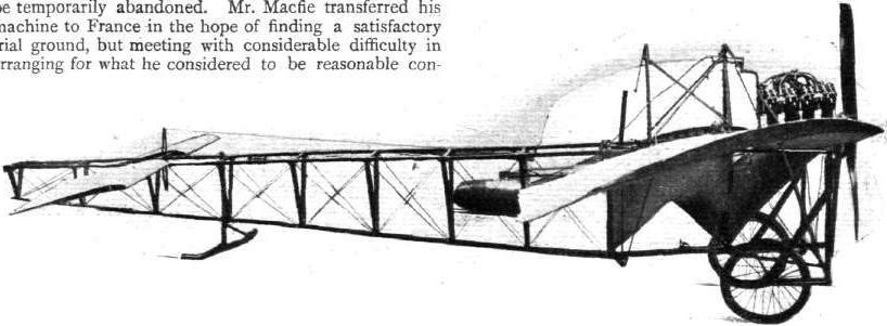
Side view of the Macfie monoplane.

Two views of the tail on the Macfie monoplane. The tail consists of an elevating plane and a rudder.
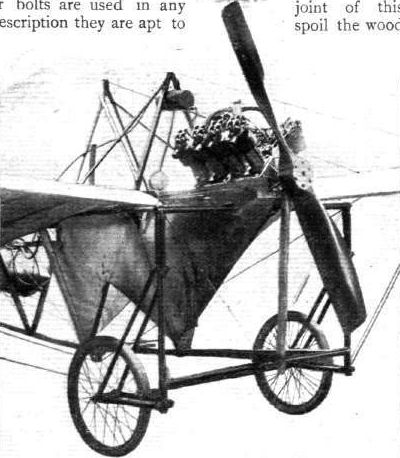
View of the two-wheeled chassis that supports the fore part of the Macfie monoplane.
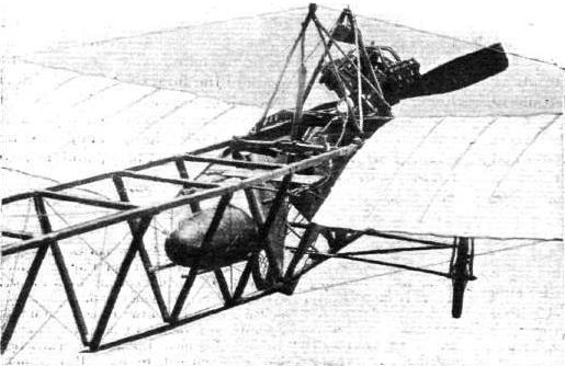
View of the Macfie monoplane, showing the position of the pilot's seat and the overhead frame used in the trussing of the main wings.
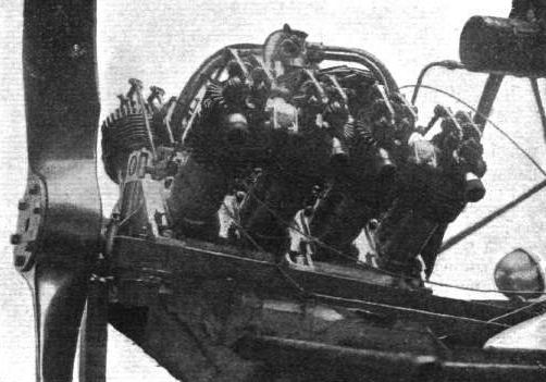
View of the 35-h.p. 8-cyl. air-cooled Jap engine on the Macfie monoplane.
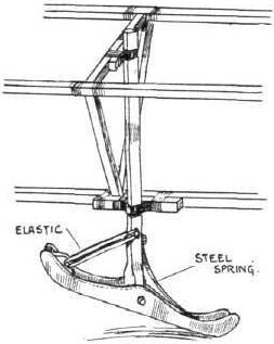
Sketch showing the mounting of the skid that supports the tail end of the Macfie monoplane.
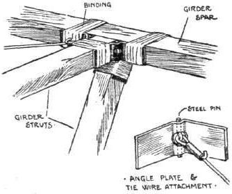
Sketch showing how the joints are made on the Macfie monoplane.

Sketch showing the mounting of the elevator on the Macfie monoplane.
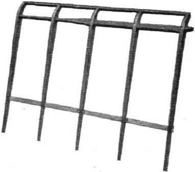
View showing a portion of the skeleton framework of the elevator on the Macfie monoplane.

Sketch showing the construction and dimensions of the ribs employed in the main wings of the Macfie monoplane.
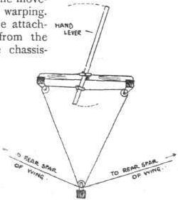
Diagrammatic sketch showing the crossing ol the wires employed for warping the wings of the Macfie monoplane.
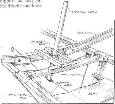
Sketch showing the pilot's seat and control lever; also illustrating the hinged attachment of the rear spars of the Macfie monoplane.
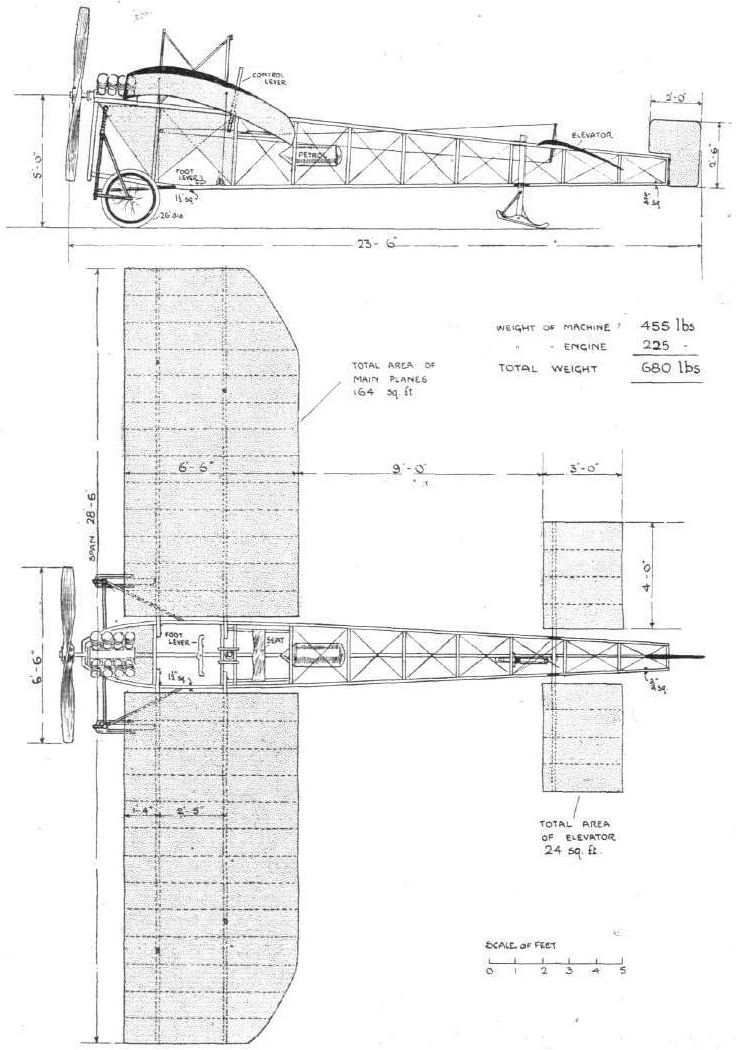
The Macfie Aeroplane.
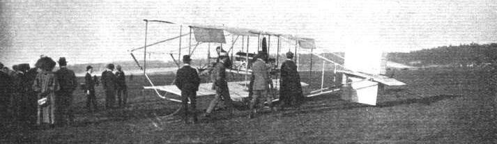
FLYING AT BROOKLANDS. - Mr. Macfie preparing his biplane for a flight.

Mr. Macfie in flight on his biplane at Brooklands.
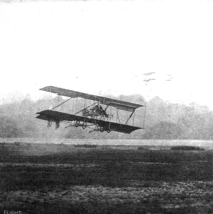
AT BROOKLANDS AERODROME. - Mr. R. F. Macfie on a Macfie biplane flying low recently at Brooklands grounds, with M. Blondeau above on a Farman biplane.
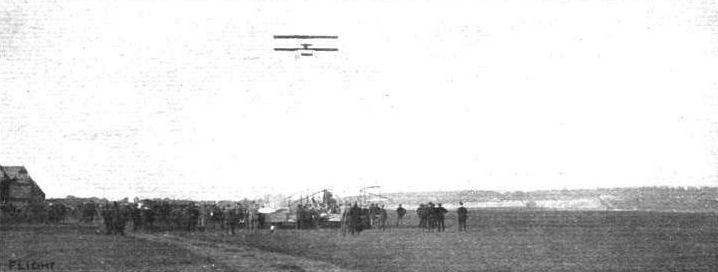
FLYING AT BROOKLANDS. - M. Blondeau flying over Mr. Macfie's biplane at rest below.
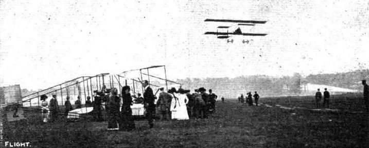
THE AGGREGATE TIME FLIGHT COMPETITION AT BROOKLANDS FOR THE NEILL CUP. - M. Blondeau making a flight. On the ground is Mr. Macfie's biplane, Mr. Macfle, without a hat, standing in the foreground.
Flight, March 12, 1910
THE SECOND OLYMPIA AERO SHOW.
AEROPLANES.
Mann and Overtons.
A MONOPLANE, very much on the lines of Santos Dumont's "Demoiselle," fitted with a twin-cylinder V-type air-cooled Anzani engine of 20-h. p.
Flight, April 9, 1910
FLYER SILHOUETTES FROM OLYMPIA
MANN AND OVERTONS' MONOPLANE.
Leading Particulars of the Mann and Overtons (Santos Dumont Type).
General Dimensiotis.-Areas-Main planes, 128 sq. ft. elevator, 16 sq. ft.; rudder, 6 1/2 sq. ft.
Lengths.-Span, 18 ft. 4 ins.; chord, 7 ft.; camber, 3 1/4 ins.; skid track, 3 ft. 8 ins.; overall length, 20 ft.
Materials.-Wooden frame, tubular steel axle.
Engine.-30-h.p. Anzani.
Propeller.-Diameter, 6 ft. 6 ins.
Weight.-Machine, with engine, 326 lbs.; driver, oil, petrol and water, 200 lbs.; total flying weight, 536 lbs.; loading (all weight supported on main planes), 42 lbs. per sq. ft.
Speed of Flight.-45 m.p.h.
System of Control.-Warping of wings, rudder and elevator.
Price.-L300.
MONOPLANE of Santos Dumont type but having main frame constructed of hollow wood spars, instead of being made of tubular steel. The struts in the main frame, like those in the chassis, are made of tubular steel, as in the original Santos Dumont design. The disposition of the engine and of the pilot's seat is relatively the same, but the details of control are different. The Santos Dumont type of tail, however, is retained. The lever on the pilot's left operates a rudder by a to-and-fro motion, and the warping of the wings by a sideways movement; on the pilot's right is a lever controlling the elevator.
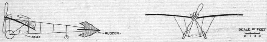
Flight, January 8, 1910
THE NEW MAXIM AEROPLANE.
By SIR HIRAM S. MAXIM.
Six years ago I commenced making drawings with a view to building a flying machine with a petrol motor, but I did not finish it at that time, as I had a lot of other work on hand.
All the flying machines which have been built in recent years do not differ much from my original Baldwyn's Park machine, except as regards size and the kind of motive power employed.
About eighteen months ago, in making a careful study of the whole subject, it appeared to me that the Baldwyn's Park type of machine, with slight modifications, was still the best that could be devised. I therefore decided to make another machine, on practically the same lines, but very much smaller, and to drive it with a petrol engine.
I made the drawings, and about twelve months ago started to make a new light engine and a reliable carburettor, in fact, everything relating to my present flying machine.
The engine which I designed has four cylinders, each 5 ins. in diameter, with a common stroke of 5 5/8 ins. The cylinders, pistons, connecting-rods, and the crank-shaft, are made of a special brand of "Vickers" steel, which perhaps is the strongest and toughest steel that has ever been produced, in fact, I have never seen anything to compare with it. It has a tensile strength of 57 tons, with an elongation of 14 per cent. This is remarkable, and it enabled me to make all the parts of extreme lightness and still have a reasonable factor of safety, moreover, the great lightness of the moving parts enables the engine to run faster if required than it would if the parts were heavy.
I n order to get a high speed if required, I made all the passage ways and valves of the engine very large and free. I had noticed at the various places on the Continent where I had seen flying machine engines in action that they worked very badly and unsteadily, the exhaust being very irregular. A study of this question demonstrated only too clearly that the great trouble was with the carburettor; the explosive charge was not thoroughly mixed, or perhaps not mixed at all, and never of a uniform density.
I therefore experimented on a carburettor and made one that would produce gas of a uniform density, and it was found that when the air and the gas were thoroughly mixed before they entered the cylinder at all, the petrol engine behaved exactly as a gas engine does. The exhaust was perfectly regular, and, as a well-known steam engineer said on witnessing the running of my engine, "It runs as steady as any steam engine I have ever seen, and altogether different from any other petrol engine."
This engine has a forced water circulation, and everything about the engine, including the spindles of the exhaust valves, is cooled, so there is never any overheating.
A new system of oiling is also used. A small pump, having a bore of 1 1/4 in., and a stroke of 1 1/2 in., is so arranged and driven by a train of gears and "clockwork," that the piston is raised against the resistance of a spring, and liberated four times in a minute, and the spring is of sufficient strength to produce a pressure of 120 lbs. per sq. in. on the oil, the result being that every part of the engine, including the gudgeon-pins, is thoroughly lubricated four times a minute, and it has been found that no excess of oil gets past the piston into the explosion-chamber.
The screw propellers are three in number. One is placed directly on the screw shaft, and runs, of course, the same speed as the engine, and takes the place of a fly-wheel; the others are very much larger, and revolve at a much slower rate.
Two of the screws, the small one, and one of the large ones, rotate in a right-hand direction, and the other one in a left-hand direction, but the left-hand screw has a finer pitch than its mate, and revolves at a higher velocity, just high enough so that its gyroscopic action is equal to the gyroscopic action of the other two screws, and the rotating parts of the engine; therefore there is no gyroscopic action at all when the screws are considered "ensemble" as the left-hand screw exactly neutralises the gyroscopic action of all the other rotating parts.
The framework of the machine has been made of American yellow pine of a very fine quality. Although it is not quite so strong as spruce per square inch, it is really stronger than spruce when considered in terms of its own weight. Moreover, spruce was difficult to obtain.
The machine has fore and aft rudders (balanced) and one horizontal rudder also balanced.
The main part of the machine is made up of six aeroplanes; the central section carries the machinery and the driver, and the two side sections are simply superposed wings, but they are not level. The outside ends are raised very much above the central section, and their surfaces are curved in such a manner that when the machine is in the air whichever side is the lower will lift the most. This ensures lateral stability, without the necessity of any machinery.
I know that some mathematicians might dispute this, as they believe, or think they believe, that the pressure on the aeroplane is always perpendicular to its surface, but if they would give the matter one moment's careful consideration they would know that such is not the case.
It would be a case, I will admit, if the whole machine was mounted on a shaft, and could rotate in the air after the manner of a windmill, but the machine is not mounted on a shaft, it is suspended in the air and resting on the air, and falling through the air at the rate of 6 or 7 miles an hour. True, it is going ahead at the same time, but nevertheless it is falling as relates to the air, therefore its downward motion through the air, while travelling, has the same effect as it would if the machine was not travelling at all, but simply falling through the air. Therefore, the side that is lowest and presents the best angle to the wind, and also presents a lifting effect farthest from the centre of gravity, must lift the most, and have a strong tendency to keep the machine on an even keel. The centre of gravity, however, is very low, and very much below the centre of lifting effect. This, of course, also tends to keep the machine right side up.
I have also applied a device which I invented and patented many years ago, which enables the pilot to vary the pitch of the wings while the machine is still in flight; but instead of doing it after the manner of the Wright Brothers, I strictly adhere to my original patent, the wings being moved in one direction by hand, and in the reverse direction by a spring. But this device I do not think will be absolutely necessary on account of the shape of the wings and the arrangement of the weights.
In making this machine I have sought to group all the parts together, as near as I can, in line (tandem) in order to reduce the atmospheric resistance as much as possible, and to have what there is of it in the path of the screw, that is, the motor, the driver, the densest part of the framework, the magneto, steering-gear, and the petrol tank are all placed in line very low down, and all in the path of the small screw, so that if it should take, we will say, 10-h.p. to overcome the resistance of these parts, the 10-h.p., having been expended on the air itself, would draw the air forward in the direction of flight, so that the screw would be running in air which was already advancing, and fully 80 per cent, of the energy would be recovered by the screw.
It is the same also with the two large screws. All the parts that offer considerable resistance are forward of the screw, so that as much as possible of the energy lost in atmospheric resistance will be recovered.
The width of the aeroplanes fore and aft is 6 ft. 6 ins., and they are 6 ft. 6 ins. apart.
I have not given so much curvature to the aeroplanes as one would find on most of the machines of the present day, because in my early experiments I found that, when we consider the lifting effect of an aeroplane in terms of the drift, the thin aeroplanes, which are only slightly curved, do the best. Quite true, they do not lift so much per square foot, but they lift more per h.p., and I have preserved the shape which was found best at Baldwyn's Park.
Both the top and the bottom sides of the aeroplanes are covered with very thin and extremely strong waterproof silk. It is altogether the strongest and lightest I have ever seen, weighing only about 2 ozs. to the square yard.
This silk is laced on to the aeroplanes with a great deal of care, and the whole of it as tight as a drumhead.
The aeroplanes are thin and sharp. The stays are of two kinds - oval steel and fiat steel, and the struts partly of oval steel tubing and partly of American pine.
The total width of the machine is 44 ft.
One of the novel features of the machine which makes it look so much neater and simpler than other forms is the manner of constructing the frame and mounting the screws. Instead of having a lattice-work frame running round the screws to support the aft rudders, the screws are not mounted on a rotating shaft, but rotate themselves on a part of the framework of the machine.
In fact the real foundation of the machine consists of two steel tubes, to which everything else is suspended or attached, and it is these steel tubes on which the screw-propellers rotate.
This enables the principal member of the framework of the machine to pass directly through the centre of the screws, as an extension of these steel tubes carries all the rudders - fore, aft and vertical.
The screws being of very large size - over 11 ft. in diameter - of necessity have to be made very thin, in order to be light, and also in order to cut the air with little resistance. They are of pine, of the Baldwyn's Park type, which is common to nearly all machines at present, but a new feature has been introduced.
As the screws are not strong enough by themselves to stand the thrust without being distorted and broken, they are held back by strong steel strips 1/32 in. thick, and about 1 1/4 in. wide.
These strips, having the same pitch as the blades themselves, also act as a screw propeller, cutting the air keenly, and being very efficient. The screws are therefore held in position, their blades can neither be twisted nor deformed, and there is nothing to prevent their cutting through the air with the least possible resistance. By this means a very large amount of air can be engaged - a great deal more than has ever been engaged before per h.p. - therefore there would be less slip than with any other system so far invented.
Moreover, the resistance required for driving the machine through the air would be less, because everything is much sharper and smoother than in any other machine I have ever seen, but unfortunately a large and level field is not obtainable near the Crayford Gun Works at the present moment. True, land can be obtained, but it costs a lot to get it and to level it off and protect it, so I have devised a new system of testing - one that I think is quite different from anything suggested before.
I have constructed a tarred sand circular track, having a circumference of 2,200 ft. This track is 25 ft. wide, and in the centre I have erected a steel mast, to which I propose to attach a steel wire rope about 35 ft. from the ground, and to hold this rope up by very fine wires from another support over 100 ft. high. The steel wire will have attached to it three branches, which will take hold of the machine in three places, and in this way the machine will be held on an even keel, as far as relates to "port" and "starboard," but will be free to move forward, to ascend and descend ; and will also be free to depress or elevate the forward end, that is, every movement which is necessary to make when testing a machine is obtained, while the machine is prevented from flying off at a tangent.
It will therefore be possible not only to try the working of the engine, the cooling effect of the air, the propulsion of the screws, the lifting effect of the aeroplanes, the balancing of the weights, and, in fact, everything connected with' the working of the machine, without any danger whatsoever of injury to the pilot or breakage, while it affords a unique opportunity for the pilot to learn to manipulate all the necessary steering-gear, and so forth, and it is very evident that after this has been done for a certain length of time, the machine may be connected with a single wire, so as to find out if all the other movements are completely under control, and after this free flight ought to be quite simple and safe.
At any rate, a circular track will always afford a very simple manner of teaching men to fly, because they can do it without danger to themselves or to the machine.
Flight, April 30, 1910
THE MAXIM BIPLANE.
IT is given to few pioneers as early in the field as Sir Hiram Maxim was with his original experiments in Baldwyns Park to have an opportunity of again devoting themselves to practical work of the same description at a time when success is already a foregone conclusion along recognised lines. Yet Sir Hiram Maxim, who built his first machine at a time when it was impossible to achieve success owing to the absence of the modern petrol engine, has lived to see the conquest of the air by others and to again take an active part in the development of flight by the construction of another large machine. An account of the leading features of this machine, written by Sir Hiram Maxim himself, has already appeared in this volume of FLIGHT, p. 136, and we are now able to supplement that description with a very complete set of photographs and sketches, which give a very clear idea of the leading features of this interesting machine.
Some Leading Features.
The machine is a large biplane and is characterised by the unusual form of dihedral angle exhibited in the disposition of the main planes, and also by the use of a fore and aft control, which is obtained by the interconnection of a biplane tail with a biplane elevator. The main planes are constructed in three sections. The central section has a straight edge, but the outer sections are arched and form dihedral angles with the central section. This disposition of the planes is made for the purpose of introducing a factor of natural stability. The central section carries the engine and the pilot's seat, both being located on the lower deck, so that the centre of gravity is considerably below the centre of lifting effect.
The elevator and the tail are both pivoted to the extremities of two tubular spars that run fore and aft the whole length of the machine. These spars constitute the main members of the framework and are a very important feature of the design. They also carry the propellers and thus save the weight of independent brackets for this purpose. They are built up in three lengths, the central portion being steel and the two outer members being aluminium. The latter are stayed by diagonal struts to the lower deck of the main planes, and are not, therefore, subjected to any appreciably direct bending strain.
Materials of Construction.
The greater part of the framework of the machine has been made of a fine quality American yellow pine, but there is a limited amount of tubular metal work, and a little hard wood is also used in places. A pair of tubular steel struts are situated in the centre of the main-planes on either side of the engine, and these members have been employed as water pipes to communicate with the radiator, which lies below the upper deck. The machine is mounted upon a pair of pneumatic-shod wheels, which are independently attached to the frame, and together afford a very wide track. Each wheel is mounted on a short axle held by a massive wooden fork, which is hinged to the frame, and attached to a pneumatic spring. Jutting out from the fork is a bow-shaped member of ash forming a fender, which is intended as a protection to the more important parts of the machine in the event of accident. The tail is supported upon a pair of light wheels mounted on castors that are interconnected with the rudder mechanism, so that the machine can be steered upon terra firma at low speeds, when the rudder itself would have but a feeble effect. Immediately beneath the lower deck of the main-planes is an inclined board serving as the support to the petrol-tank, and a protection to the central propeller. It has been so arranged as to afford some lifting effort.
Strip Steel Ties.
An important and interesting feature of the framework is the bracing of the various lattice-girder members by diagonal ties of strip steel instead of wire. These ties are set edge on to the direction of flight. The main planes have been surfaced with a rubber - proofed Japanese silk, which Sir Hiram Maxim had specially woven for the purpose. It is exceedingly light and very strong for its weight. It is stretched very tightly over the framework of the main planes, and in order to maintain uniform curvature of surface under varying conditions of pressure, the lower surface of each deck is provided with a vent hole so located as to maintain equilibrium of the static pressures inside and outside the deck. The exact position of this air vent has an important bearing on its utility; for the particular camber employed on this machine the vents are situated about a quarter of the chord from the trailing edge. The vent holes are about 2 ins. in diameter, and have been covered with fine gauze in order to prevent flies being blown into the cavity.
(To be concluded,.)
Flight, May 7, 1910
THE MAXIM BIPLANE,
(Concluded from page 325.)
Three Propellers.
ONE of the most important features of the machine is the system of using three propellers. Two of the propellers are mounted on the main spars of the frame, while the third, which is much smaller in diameter, is direct driven by the engine. The larger screws revolve in opposite directions, and are driven by ropes. The right-hand screw, viewed from behind, rotates in the same direction as the central screw; the other propeller, which has a reverse direction of rotation, has therefore, a finer pitch and a higher velocity than its mate in order to compensate for the gyroscopic effect of the central screw. The propellers are two-bladed, and exceedingly thin and light for their size; in fact, the blades are so thin that they would bend if unsupported, and they have, therefore, been trussed by strip steel ties, which anchor their extremities to a tubular extension of the boss. These strips of steel are so arranged that their surfaces have approximately the same pitch as the screw itself, it being intended thereby to minimize as far as possible the loss caused by their rotation through the air. It will be observed, on reference to one of our photographs, which shows a propeller separately, that the tubular extension at the boss affords a remarkably long bearing surface for the support of the propeller upon its shaft.
The pulley for driving the propeller is fastened direct to the blades by steel brackets and also similarly to a pair of wooden stumps that project from the boss at right angles to the blades. It is thus supported at four points. The groove in which the rope runs is cogged to give an effective grip.
The Rope Drive.
The rope drive of the propellers is an interesting and original feature of the Maxim system, and much care has been taken in the construction of the ropes, which are woven on a special machine designed and erected at the Crayford works. The ropes are endless and are made of a very fine tough thread, such as is used by bootmakers for certain purposes in connection with their trade. The adjustment of the rope is effected by jockey pulleys, and the surface of the rope is prepared with the best quality beeswax.
A very important consideration to be borne in mind regarding the arrangement of the three propellers on the Maxim biplane is their disposition in respect to the principal masses represented by the various members of the machine itself. It will be observed, for instance, that the pilot, the engine, and the central screw are arranged in tandem; in fact, the central screw has been provided solely in order to recover some of the energy from the wake of this mass. This is a particularly interesting point, because the value of the wake is by no means accepted as an appreciable quantity by the majority of flight engineers, and this very definite verdict on the part of Sir Hiram Maxim should at least bring the matter into prominence.
No marine engineer would ever think of putting a screw in front of a ship; indeed it can be theoretically proved that with any wake whatsoever a boat can be propelled for less power than it can be towed. Deductions from water experiments do not apply to air in the same degree, but they undoubtedly afford useful information that should not be neglected. At the present time constructional considerations have more to do with locating the position of a propeller on a flying machine than anything else, but engineering fails to accomplish its purpose if constructional difficulties are allowed to limit design in such matters of fundamental importance.
Whether others will think it worth while to follow Sir Hiram Maxim's example of providing an additional propeller to work in the wake of the principal mass, naturally very much depends on the success of this particular machine.
The Engine.
The engine on the Maxim biplane, like the machine itself, has been designed by Sir Hiram Maxim. It has four separate steel cylinders with detachable heads and water-jackets; the former being made of steel, and the latter of German silver. Long steel bolts passing into the crank-chamber hold the cylinder-heads in place. The valves are all overhead, and are operated by an overhead cam-shaft, which is skew-gear driven from the crank-shaft.
A belt from the rear end of the cam-shaft drives a clockwork mechanism employed for operating the lubricating system. The oil reservoir contains a spring-loaded plunger-pump, which is raised and liberated four times a minute. The force of the pump exerts a pressure of about 120 lbs. per sq. in. on the oil, and delivers a momentary stream under this high pressure to all the principal bearings.
A transverse skew-gear driven shaft in front of the engine drives the magneto and the water-pump. The cylinder-heads are water cooled as well as the walls, and the cooling water passes through a radiator mounted on the upper deck of the main-planes. One of the hollow steel struts that support the upper deck is employed to convey the water to the radiator.
The carburettor on the Maxim engine is very noticeable on account of its large size, and it is also of somewhat peculiar construction, being mainly remarkable for the very large capacity of the mixing-chamber that contains the throttle-valve. The object of this chamber is to thoroughly mix the gas in large quantities before it is admitted to the cylinders. Part of the mixing-chamber is warmed by an arrangement of water pipes.
The Control.
The control of the Maxim biplane involves the manipulation of the elevator, tail, and rudder, and also the warping of the wings. These operations are effected by a steering wheel riding upon a pivoted lever, and by a pivoted cross-bar under foot control. The interconnections are shown diagrammatically in an accompanying sketch. The elevator and the tail are interconnected by cross wires so that they work in unison, and the elevator is directly connected to the pivoted lever by a system of links, so as to be operated by a to-and-fro movement of the lever. The rudder, which is carried by the tail, is operated by a rotary motion of the steering wheel upon the pivoted lever as an axis. The warping of the planes is accomplished by means of the pedal. A feature of the warping system is that the planes are warped in one direction by the wires, and in the other direction by springs.
A minor detail in the control mechanism to which it is necessary to draw attention is the method of mounting the steering wheel upon the pivoted lever. The steering wheel is mounted on a sleeve fitted with a jaw-clutch that engages with a corresponding member on the rod. The rudder is thus locked in any desired position by this device, and it is necessary to force the steering wheel downwards against the action of a spring in order to rotate it. There is also a split collar on the steering wheel sleeve into which a handle bar can be screwed if the pilot prefers such a device to a steering wheel. Some of our photographs show the machine with the handle bar in place. It is made in halves and the split collar is automatically clipped in place by screwing the halves of the handle bar together.
It is Sir Hiram Maxim's intention, when the preliminary experiments have been brought to a satisfactory conclusion, to fit gyroscopic control. The gyroscopic mechanism has already been constructed for this purpose. The gyroscope, which consists of a spinning fly-wheel, is contained in a cylindrical casing, and it is designed to operate, through a relay mechanism, a cylinder containing a piston to which an operating rod is attached. Some very ingenious mechanical details have been introduced in the construction of this piece of apparatus.
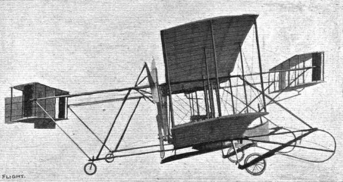
Side view of the Maxim biplane, showing very clearly the arrangement of the two principal fore and aft spars that carry the elevator, tail and propellers.
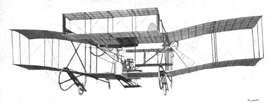
Front view of the Maxim biplane, showing the dihedral angle formed between the central section and - the arched outer sections.
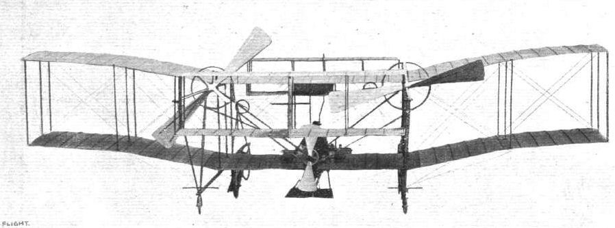
Rear view of the Maxim biplane, showing the disposition of the three propellers. The small propeller runs in the wake of the principal masses.

Photograph illustrating the arrangement of seats on the Maxim biplane. On the left is T. Jackson, who assisted Sir Hiram Maxim in the construction of his original machine, and was a passenger thereon during its accidental free flight in Baldwyn's Park.
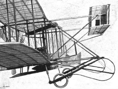
View of the chassis of the Maxim biplane, showing the landing wheels and fenders. The shock is resisted by pneumatic springs.
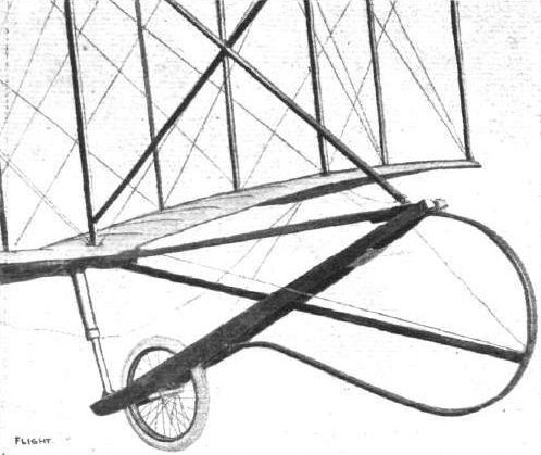
Detail view of the chassis suspension on the Maxim biplane.

View illustrating the rope drive to the propellers on the Maxim biplane.

Photograph of one of the propellers for the Maxim biplane, with Sir Hiram Maxim standing alongside, which gives some idea of the size of these screws. The trussing of the very thin blades to the tubular sleeve is a special feature of the design.
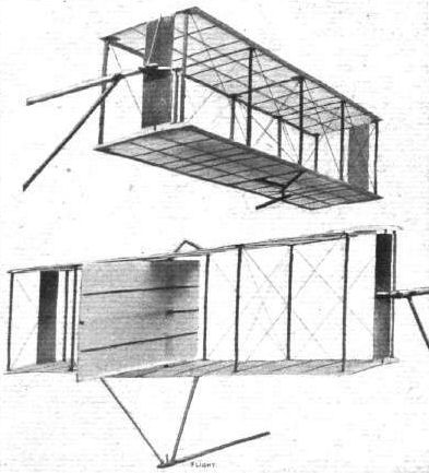
Views of the elevator and tall on the Maxim biplane. The tail, which carries the rudder, acts in unison with the elevator.
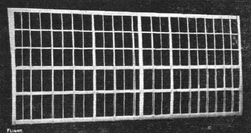
View showing the construction of the framework of the main planes of the Maxim biplane.
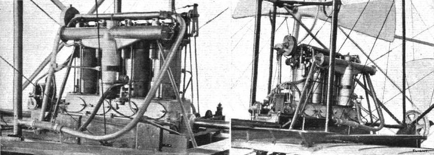
Views of the Maxim engine on the Maxim biplane. The cylinders are made of steel, and have detachable heads and detachable German silver water-jackets. The vertical water-pipe on the extreme left forms a main strut in the framework of the machine.
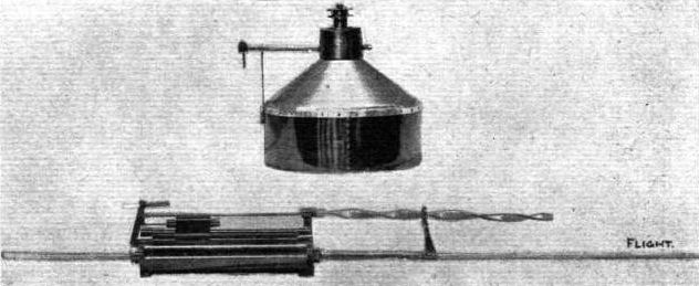
View of the gyroscopic control mechanism constructed for attachment to the Maxim biplane after the preliminary tests.
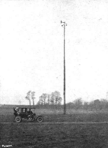
General view of the aerodrome at Crayford where the Maxim biplane is to be tested on a circular track by running it on a lead attached to the wind tower in the centre.

SIR HIRAM S. MAXIM.

Sketch illustrating the arrangement of the jockey-pulleys, which are used to tighten the rope drive of the propellers on the Maxim biplane.
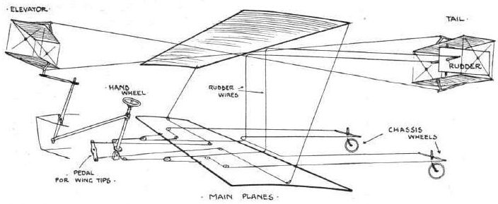
Diagrammatic sketch illustrating the connections in the control of the Maxim biplane. The elevator and tail work in unison, being interconnected by cross wires. The chassis wheels and the rudder also work in unison. The main planes are warped by a pedal.
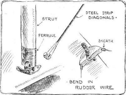
Sketches showing details of the strut-joints, tie-strips, and wire guides on the Maxim biplane.

Sectional sketch of a rib in the main decks of the Maxim biplane.

Sketch illustrating the steering-wheel and elevator-lever on the Maxim biplane.
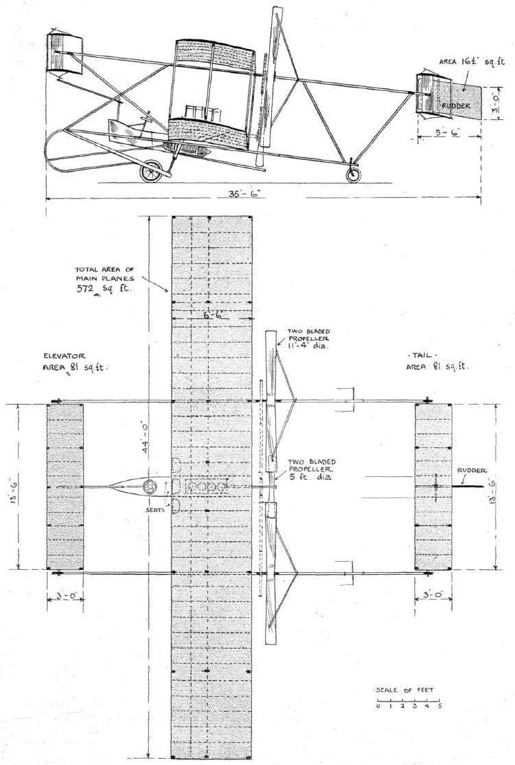
THE MAXIM BIPLANE. - Plan and elevation to scale.
Flight, June 11, 1910
THE "MOONBEAM."
Thinking it a matter of some interest, I enclose you photos of my aeroplane ("Moonbeam"). It is a monoplane, built rather on the lines of the "Santos," though of light steel tubing, planes having a tapering chord and a span of 24 ft. A 4-cyl. 20-h.p. J.A.P. engine is fitted, and a 6-ft. wooden propeller.
The machine is manipulated from a single wheel, which is mounted on a spherical trunnion, thus taking all control.
The machine weighs about 260 lbs., of which 160 lbs. is engine and propeller.
I regret not having a photo of plane during flight, although several satisfactory flights have been made.
The machine has been under trial for some weeks. It was made in my own shops at Southampton.
ROWLAND MOON.
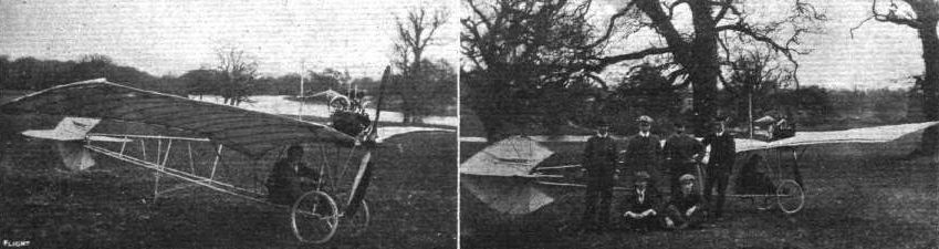
Mr. Rowland Moon's "Moonbeam," after Santos Dumont.
Flight, March 12, 1910
THE SECOND OLYMPIA AERO SHOW.
AEROPLANES.
Mulliner.
NEW British monoplane, built by the well-known coachbuilders of Long Acre and Northampton. The main planes have a span of 33 ft. and a chord of 6 ft. 6 ins., while the overall length of the machine, which has a total lifting surface of 220 sq. ft., is 27 ft. It is fitted with a 35-40-h.p. 8-cyl. J.A.P. engine, which drives a 6 ft. 3 ins. tractor screw of 4 ft. 6 ins. pitch. Stability and directional control are effected by a system of warping the trailing edge of the main planes, combined with the action of the elevator and rudder at the rear.
Flight, March 26, 1910
FLYER SILHOUETTES FROM OLYMPIA.
MULLINER MONOPLANE.
Leading Particulars of the Mulliner Monoplane.
General Dimensions.-Areas-Main planes, 210 sq. ft.; fixed tail, 13 sq. ft. ; elevator, 14 sq. ft. ; rudder, 4 sq. ft.
Lengths.-Span, 33 ft.; chord, 6 ft. 6 in.; camber, 3 in.; skid track, 4 ft. 2 in.; overall length, 27 ft.
Angles.-Incidence, 10° ; dihedral, nil.
Materials.-Timber: ash throughout, few parts poplar; Dunlop fabric, single surface.
Engine.-35-h.p. J.A.P., 8 cylinders.
Propeller.-Spencer; diameter, 6 ft. 3 in. ; pitch, 4 ft. 6 in. material, white wood.
Weight.-Machine, 190 lbs. (approx.); engine, 215 lbs.; driver, oil, petrol, water, 200 lbs.; total flying weight, 605 lbs. (approx.); loading (all weight supported on main planes), 28 lbs. per sq. ft.
Speed of Flight.-40 m.p.h.
System of Control.-Warping of wings, elevator and rudder.
Price.-L500.
NEW British-built monoplane of very light construction, designed by Gordon Stewart, and built at the Northampton factory of Messrs. Mulliner, the well-known coachbuilders. The design is mainly remarkable for the skeleton-like frame that has been adopted, and the high finish of the workmanship. There are some parts, however, that we shall expect to see strengthened within a short while of this machine commencing its practical trials. The main planes have a comparatively flat camber, and there is even a tendency to reverse the curvature at the trailing edge. The wings are built up upon two main spars, the rear pair of which are hinged together to facilitate warping, which operation is performed by an inclined steering-wheel. The engine is carried right forward in front of the leading edge, and the pilot's seat is situated about two feet behind the trailing edge of the main planes. The machine is supported upon a pair of wheels mounted in a hinged rhomboid or diamond-shaped frame, across the centre of which is stretched an elastic spring that serves for the suspension. The main wings are braced to the "A" extension of the chassis frame, which is constructed of tubular steel.
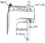
Sketch illustrating an ingenious method of fastening the rudder-hinge to the rudder-post on the Mulliner monoplane.
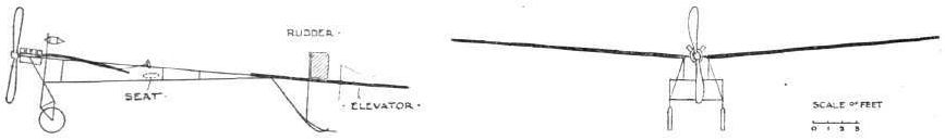
Flight, May 14, 1910
The "Neale VI" Monoplane.
WITH reference to the photograph of the new monoplane with which Mr. J. V. Neale is experimenting at Brooklands, which appeared in our issue of last week, we have since received some particulars and dimensions which we now publish. The span of the main planes is 30 ft., and the method of control is by ailerons set in the rigid wings. The weight supported on the front wings amounts to 3.2 lbs. per sq. ft., while on the back surfaces the weight carried is 1.9 lbs. per sq. ft. The propeller, of 7 ft. 8 ins. diameter and 6 ft. 2 ins. pitch, is driven at a speed of 620 revs, through a reduction gear, which is self-contained with the engine. Including aviator, petrol, &c, the machine in running order weighs 530 lbs., and its lifting speed is 32 miles per hour.
Flight, October 8, 1910
THE NEALE BIPLANE.
A NEW PRINCIPLE OF CONTROL DESIGNED TO AVOID THE WRIGHTS' PATENTS.
THOSE who have paid the merest superficial attention to the principles of modern aeroplane control are aware that lateral stability is maintained either by twisting the wings or by using independent horizontal planes (ailerons) as balancers. Those who have interested themselves still more deeply in the subject are probably also aware that the principle of wing warping constitutes one of the great claims in the Wright patent, and that, moreover, the Wright brothers regard machines fitted with any form of horizontal balancers to be infringements of their claim. It should not therefore be difficult for anyone to appreciate the significant importance of a system of control that is fundamentally different to this standard practice of the day.
The Neale biplane, with which, as our readers know, experiments have for a long time been conducted on the Brooklands flying ground, is a machine that certainly does embody a method of control that is, so far as we are aware, quite original, and there is little doubt it constitutes one of the most interesting developments in aeroplane construction that is at present on trial. This machine is steered and balanced by movable vertical planes that are hinged to the outermost forward struts of the main planes, and these vertical planes, in conjunction with the fore and aft elevators, constitute the sole controlling organs. Balancing planes were originally fitted to the trailing edges of the upper main plane as a precaution during the initial stages of experiment; but the vertical planes having been found to be entirely satisfactory in their operation, the horizontal balancers were duly abandoned, and the machine now flies with the mechanism for operating them disconnected.
The Neale biplane never possessed a rear rudder, and this peculiarity is the starting point from which the development of the machine in question should be studied; for it may be quite frankly admitted that the principle of control as it now stands, although something of a basic idea, was actually a discovery resulting from practical experiment with the machine. The inventor's fundamental intention was to design an aeroplane that should be an easier machine to fly across the wind than are the majority of modern aeroplanes, which tend to head up into the breeze by the automatic leverage of the rudder in its capacity as a vertical tail. Early gliders employed fixed vertical tail planes for this very purpose, in order to keep them automatically head-on to the wind without any "attention on the part of the pilot; but in a power-driven flyer this particular quality is no longer required, and if evidenced to any marked degree becomes a distinct interference with the control. The original idea out of which the Neale biplane in its present form was evolved may, therefore, be summed up by saying that it was to be a machine without a rear rudder or any sort of vertical tail surface.
The next step was, obviously, to introduce some form of steering apparatus capable of taking the place of a rear rudder, and it was solely for this purpose that the hinged vertical planes were originally placed in the gap between the main planes.
There are two alternative methods of steering an aeroplane in flight, one being to exercise a lateral pressure by means of a rudder, on the end of a long lever such as an outrigger, while the other is to "put the brake on" at one of the extremities of the main planes. It is the latter system that is employed on the Neale biplane. Any plane set at an angle to the line of flight offers resistance, and will, therefore, serve as a brake; the hinged vertical planes in the gap of the Neale biplane are, therefore, primarily brakes. Normally, they are quite free to adjust themselves edge on to the wind, but if either of them is forced into an oblique position the machine slows up on that side and the other extremity wheels round until the pilot once more allows the deflected plane to hang free. Up to the time of writing, these planes, or screen rudders as we have called them for reasons that will be presently obvious, have had a chord of 1 ft. 8 ins., and it has been found in practice that a deflection of 5° has been sufficient to make the machine turn in its own length.
At first these planes were used only as rudders, but it was found by experience that various other effects could be produced by them, and that, in short, they constituted a complete system of lateral control. If one of the planes was smartly deflected to an angle of about 45#, and then as suddenly released, it was found that the machine would heel over without altering its course, and the action was so sure that it was finally adopted as the sole means of balancing, although up to that time horizontal balancers had been inter-connected with the control lever in case of emergency.
The theory associated with this balancing action is extremely interesting, and is illustrated diagrammatically in one of the accompanying sketches. It is supposed that the sudden deflection of the vertical plane temporarily screens off a very appreciable area of the main plane from the lifting effect of the wind, thus concausing the machine to drop on that side. The success of this manoeuvre depends essentially on the rudder being released immediately after it has been deflected, for if it is held in that position air would be drawn in on the other side and the desired effect neutralised, if not reversed. Should a single operation of the screen be insufficient to entirely restore lateral equilibrium, the operation is repeated in quick succession as often as may be necessary, but inasmuch as it appears to be possible to make the machine heel over to about 45# by a single operation of the screen if properly executed, it is not often that any situation should call for a repetition of the action.
There is yet one other interesting feature associated with the use of these screen rudders. If the action of putting the rudder hard over is performed very quickly indeed, which necessitates quite a strong pull on the control lever, the machine has been found to shift bodily sideways through the air without either canting or swerving. It would appear, therefore, as if this very simple device has quite a number of important possibilities in connection with aeroplane control, and there is no doubt that the further development of the Neale biplane will be watched with the greatest interest in all quarters.
Not unnaturally the features already mentioned overshadow others of a less sensational if nevertheless important character. The Neale biplane itself in its broader characteristics has the appearance of a Farman, and it is mounted on a Farman type wheel and skid chassis. The horizontal tail is a monoplane, and is cambered to carry weight; its trailing portion is hinged and constitutes the rear elevator. This member is interconnected with the front elevator, and is so arranged that its effect is always the superior force. To a certain extent, therefore, these elevators operate automatically, inasmuch as the wind pressure on the rear member serves to adjust the attitude of that in front. The control of the elevators and of the screen rudders is also effected on the Farman principle by a universally-pivoted lever, which in this machine happens to be provided with a wheel, because, in the initial experiment, the rudders were operated by a rotary movement and the horizontal balancers by the sideways action.
The machine is fitted with a 35-h.p. Green engine, and many tests have been made with different propellers of Mr. Neale's own design, until at last one has been constructed of adequate efficiency to give satisfaction with this comparatively low-powered plant. The propeller in question has a diameter of 7 ft. 9 ins., and an apparent pitch represented by the chord angle of 3 ft. 6 ins. The difficulty has been, as it is in all wooden propellers, to obtain an efficient section through the blade with sufficient strength to prevent warping under pressure. Of the other details of construction we have space only to mention one that forms the subject of the sketch below, showing the method of bracing the fore and aft main transverse spars by straight struts that give the requisite rigidity to the framework to allow very light ribs to be used for cambering the planes. The construction of the planes is also an ingenious method of using a single surface, for each rib consists of two semi-circular sections screwed together with the fabric sandwiched between their flat faces.

Side view of the Neale biplane.

Front view of the Neale biplane.

AT BROOKLANDS. - Mr. Rippen, one of the Neale pupils, making a good flight on "Neale VII" after its new propeller had been fixed, and before the little mishap.
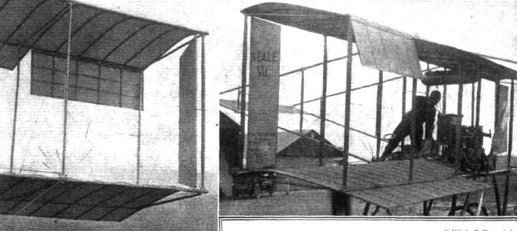
Two views of the screen rudders on the Neale biplane. These members are used for steering and lateral control, the horizontal balancers having been entirely discarded.
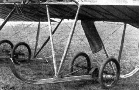
Detail view of the wheel and skid chassis un the Neale biplane.
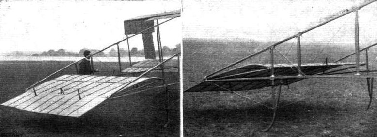
Two views of the tail on the Neale biplane. The trailing portion of the tail forms the rear elevator.

View of the pilot's seat and control mechanism on the Neale biplane. One of the pedals lifts the exhaust-valve of the engine.

View of the Green engine, propeller, and Lamplough radiator on the Neale biplane.
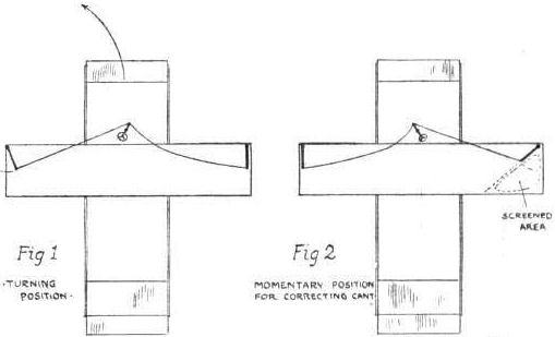
Diagrams illustrating the principle of control on the Neale biplane. Fig. 1 shows a slight deflection of one of the screen rudders for steering. Fig, 2 illustrates the screen put hard over for balancing.
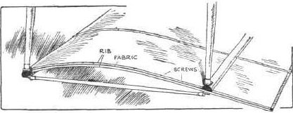
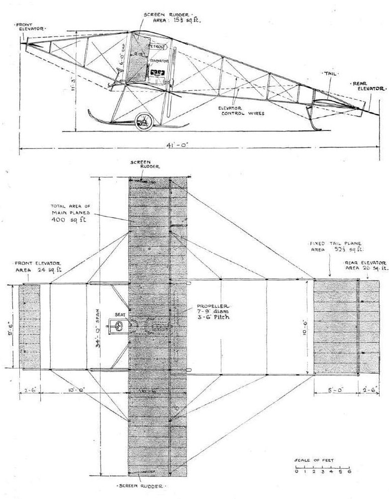
"Neale VII."
Flight, March 12, 1910
THE SECOND OLYMPIA AERO SHOW.
AEROPLANES.
Nicholson.
MONOPLANE built by Holland and Holland and exhibited on the stand of the Royal Aero Club.
THE SECOND OLYMPIA AERO SHOW.
AEROPLANES.
Nicholson.
MONOPLANE built by Holland and Holland and exhibited on the stand of the Royal Aero Club.
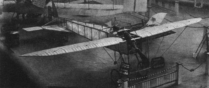
The Nicholson monoplane, which has been constructed by the well-known coachbuilders, Messrs. Holland and Holland, and follows the lines of the Bleriot machine.
WING SECTIONS. - The above diagrams afford an interesting comparison of the wing sections of aeroplanes exhibited at Olympia. They are all drawn to a common scale, but have been set at an arbitrary angle of incidence, which does not necessarily represent that of the aeroplane In actual flight.
Flight, April 30, 1910
ANOTHER BRITISH MACHINE.
Enclosed is photo of my latest machine, which I tried for first time last week.
I have not yet attempted to rise her, but results so far are very promising. Particulars of machine are :-Equipped with wheels and skids, weight complete under 500 lbs., front elevator and ailerons, controlled by one lever, rudder actuated by feet, 20-h.p. motor air-cooled, auxiliary exhausts, adjustable pitch propellers 2 ft. 8 1/2 ins. at 1,500 revs, per min. Total surface 200 sq. it., all planes double surface.
In photo I am seated. My brother, by propellers, is constructing a biplane, a few particulars of which he hopes to favour you with when completed.
The whole machine, bar engine, has been entirely constructed in Monmouth at Mr. T. Preece's Carriage Works.
Monmouth. CHAS. H. PARKES.
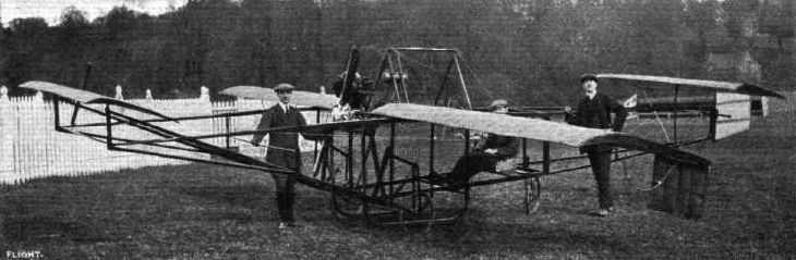
Mr. Charles H. Parkes' monoplane of 1910 was built by coachbuilders at Monmouth.
Flight, November 12, 1910
MR. PASSAT'S ORNITHOPTER.
I am pleased to forward you the photos and the particulars of my ornithopter, which I promised you.
This I claim to be the first flapping-wing machine which has risen successfully off the ground for 20 yds. with an ordinary motor cycle engine of 4-h.p. It is now being fitted with a light 8-h.p. George engine, and is expected to go to Brooklands shortly. This is the result of five years' study. I claim to have mastered the secrets of birds' flight, not only theoretically but practically, and I just lately had to strengthen some parts of the machine on account of the wings giving a far greater propulsion than I thought possible.
The machine spans 24 ft. across and is 20 ft. in length.
The front wings are used as an elevator, also for lateral balancing; they are worked individually, while the back wings are flapping by means of a very simple mechanism. The tail is used as a rudder.
The wings of this mechanical bird can be folded in ten minutes, and the machine is then ready to go along the road exactly the same as a motor car.
In the pilot's seat, in the photograph, is Mr. A. Shury, and on the right myself and Mademoiselle Passat.
Hoping this will prove interesting to your readers, and wishing your journal every success.
Wimbledon, Oct. 23rd. J. B. PASSAT.
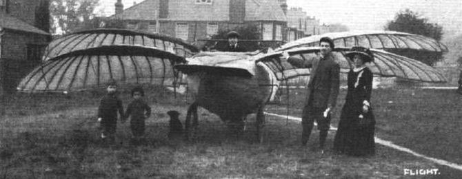
Mr. J. B. Passat's ornithopter, fitted with a small motor-bicycle motor, with which he has raised himself off the ground.
Flight, May 21, 1910
A Biplane at Liverpool.
IN a biplane of his own construction, which somewhat resembles the Curtiss machine, Mr. C. Compton Paterson, of Liverpool, succeeded in making a flight of half-a-mile along the Freshfield shore, near Liverpool, on Saturday morning. The machine, the result of lengthy study of the subject in France, weighs about 500 lbs., and is fitted with a 30-h.p. engine.
Flight, May 28, 1910
MR. C. C. PATERSON'S BIPLANE.
IN our last issue we referred to the successful trial of a biplane built at Liverpool for Mr. C. Compton Paterson, and now by the courtesy of the owner, we are enabled to give a few photos of the machine together with some further particulars. As a result of his observations at Rheims and other flying meetings on the Continent, Mr. Paterson determined to have a machine built on the lines of the Curtiss biplane.
The work of construction was undertaken by the Liverpool Motor House, of which Mr. Paterson is a director, and was completed on the 13th inst. Very early the following morning the machine was towed, as shown in one of our photographs, by road to the seashore at Freshfield, near Southport. Soon after 5 a.m. the biplane was ready, and Mr. Paterson, who had never been on a flying machine before, took his seat at the wheel. As the machine had not been tested in any way, Mr. Paterson first made a trial run along the beach at a speed of between 30 and 40 miles an hour, which was easily accomplished in spite of a strong easterly breeze blowing from the land, which caused the machine to roll a good deal. During the next run the machine rose to a height of about 10 ft., and was off the ground for 100 yards. In consequence of the cross wind, Mr. Paterson then decided to fly up the shore from the edge of the sea landwards, and in this way he covered half a mile at an elevation of 20 ft. In a third flight with the wind behind, the machine rose for a distance of 200 yards, and then came down rather heavily, buckling one of the wheels. In consequence of this and the incoming tide, it was decided to suspend operations and to take the machine back to Liverpool in order to embody one or two minor improvements suggested by the experiments.
From the photographs it will be seen that the machine follows on general lines the design of the Curtiss biplane, with its biplane elevator, the crossed tail, and the ailerons between the extremities of the main planes. At present the machine is fitted with a 25-30-h.p. 3-cyl. Anzani, but it is proposed to substitute for this very shortly a more powerful British engine, thus making the biplane entirely British.
The main framework is of bamboo, while the hollow stays are made of silver spruce and ash. A feature of the machine is its lightness, and with the tank full, the weight is only a little over 600 lbs. The tank holds six gallons of petrol, sufficient to last for a journey of 90 miles. The main planes are made in three sections, so that they may be taken apart, thus facilitating the work of transporting the machine. So successful has the machine proved that arrangements are being made for turning out replicas in large quantities, and at a comparatively low price.
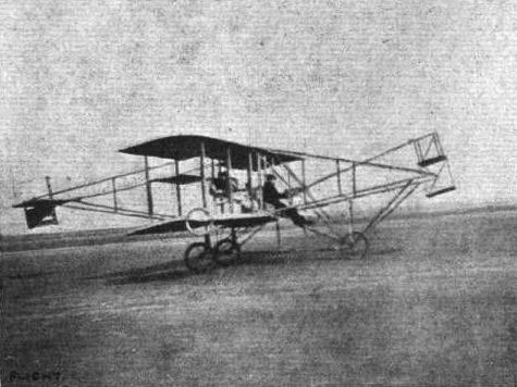
General side view of Mr. C. C. Paterson's biplane just about to rise off the Freshfield sands near Liverpool.
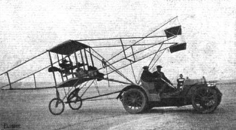
Method of conveying the Paterson biplane from place to place. - It will be noted that the extensions on both sides of the main planes are detached for this purpose.
Flight, March 12, 1910
THE SECOND OLYMPIA AERO SHOW.
AEROPLANES.
Petre.
MONOPLANE exhibited by Messrs. Leo Ripault and Co., and fitted with an N.E.C. engine.
Flight, April 16, 1910
FLYER SILHOUETTES FROM OLYMPIA.
THE PETRE MONOPLANE.
Leading Particulars of the Petre Monoplane.
General Dimensions.-Areas-Main planes, 195 sq. ft.; elevator, 35 sq. ft.; rudder, 6 sq. ft.
Lengths.-Span, 30 ft.; chord, 7 ft.; camber, 3 1/2 ins. situated about 28 ins. from leading edge; skid track, 5 ft.; overall length, 29 ft.
Angles.-Incidence, 10 degrees; dihedral, nil.
Materials.-Timber, ash; fabric, Dunlop.
Engine.-35-h.p. N.E.C.
Propeller.-Handley Page; diameter, 7 ft.; pitch, 3 ft. 4 ins.; material, pine.
Weight.-Machine, 385 lbs.; engine, 155 lbs.; driver, oil, petrol and water, 200 lbs.; total flying weight, 720 lbs.; loading (all weight supported on main planes), 3.7 lbs. per sq. ft.
Speed of Flight.-30 m.p.h.
System of control.-Hinged balancing flaps; rear elevator and rudder.
Price.-L8oo.
THE Petre monoplane is unique in having the propeller situated at the rear, behind the tail, where it is driven by a long hollow shaft from the engine. The engine is situated just behind the trailing edges of the main wings. The pilot's seat is in front of the leading edges of the main wings, being placed right up in the bows of the frame. The frame construction is also uncommon, being entirely of timber, even to the diagonal ties. The longitudinal spars are of L section and the struts of T section, both members being built up of strip wood. Another important characteristic of this machine is the pivoting of the main wings so that the angle of incidence can be altered in flight. Control is effected by a pair of hinged balancing flaps mounted diagonally on the trailing corners of the main wings by an elevating plane pivoted to a V frame at the rear of the machine and by a rudder mounted under the elevator. Experiments with a machine having the propeller at the rear ought to be extremely instructive. Although at first sight the position is one that looks impracticable, owing to the well-known difficulty of pushing any long object from behind, yet it does not necessarily follow that this arrangement of the propeller is out of the question on aeroplanes any more than it is on ships. It must be remembered that the propeller, being fixed relatively to the frame, is always thrusting through the centre of gravity. If, however, the thrust is applied from without - as, for instance, by a man pushing at the tail of the machine - such a force, although it would be of constant direction, would be variable in respect to the centre of gravity of the machine if the machine swerved from its original path.
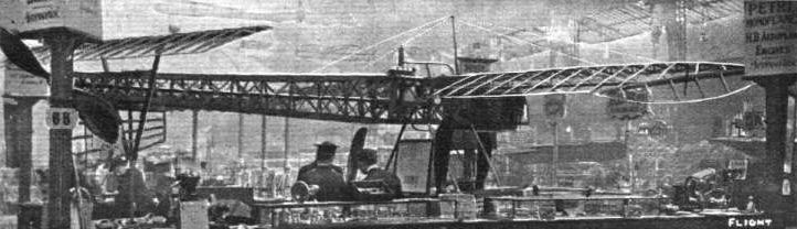
General view of the framework of the Petre monoplane, exhibited by Leo Ripault and Co. A characteristic feature of this machine is the position of the propeller behind the tail.
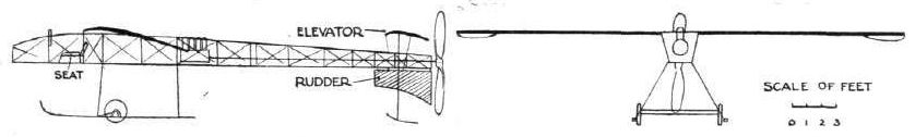
WING SECTIONS. - The above diagrams afford an interesting comparison of the wing sections of aeroplanes exhibited at Olympia. They are all drawn to a common scale, but have been set at an arbitrary angle of incidence, which does not necessarily represent that of the aeroplane In actual flight.
Flight, September 10, 1910
Mr. H. Piffard at Shoreham.
As a result of solid perseverance and experiments Mr. Piffard is now starting practical work in earnest, and last week was making some satisfactory essays over a half-mile stretch with his biplane.
Mr. H. Piffard at Shoreham.
As a result of solid perseverance and experiments Mr. Piffard is now starting practical work in earnest, and last week was making some satisfactory essays over a half-mile stretch with his biplane.

MR. H. H. PIFFARD'S ALL-BRITISH BIPLANE ON THE SHOREHAM FLYING GROUND. - Driven by an 8-cyl. 40-h.p. E.N.V. engine and 7-ft. propeller, the span is 31 ft. The Shoreham grounds are controlled by Aviators' Finance, Ltd.
Flight, May 21, 1910
THE PIGGOTT BROS. BIPLANE.
A NEW British-built biplane, the trials of which are about to take place and should be watched with extreme interest, has been constructed by the well-known constructors, Messrs. Piggott Bros, and Co., Ltd., of Bishopsgate Street, to the designs of their engineer, Mr. S. C. Parr. The machine is in every way uncommon, but to the lay mind its outstanding feature of interest is its great size, for it has a span of no less than 60 ft. and is essentially designed for carrying one or more passengers in addition to the pilot. From the point of view of design, the machine is also exceptionally interesting, because Mr. Parr has embodied a very great deal of what may be described as Lanchester's theory. Those who have studied F. W. Lanchester's works on Aerial Flight will recognise certain characteristics in the general form of the aeroplane surfaces; and in other details, too, it is possible to discuss the design from Lanchester's standpoint. This fact is in itself one that we regard as being very important, and the designer is to be congratulated in having taken the trouble at the commencement to master another man's line of thought and to build up his own experience on that as a basis. We do not wish to imply that the design itself is in any way due to Lanchester, who possibly would disagree with much that is represented.
From a constructional point of view the machine is full of interesting details, and possibly the outstanding feature is the extensive use of aluminium. As a system the leading features that are likely to attract most attention are the use of two propellers in tandem and the somewhat peculiar method of suspension.
The accompanying illustrations are somewhat incomplete, having been taken under difficulties while the machine was being dismantled at the factory, but they serve to indicate the more important points. The uncommon character of the design more than justifies the publication of these particulars in advance of any practical performance on the part of the machine itself.
The machine is, as we have mentioned, a biplane, the decks having a 60 ft. span and a maximum chord of 6 ft. measured on the minor axis of their elliptical plan form. The aspect ratio is thus nominally 10, but the equivalent value of this ratio for an ellipse as compared with a rectangle is unknown. The decks are double surfaced with a special cotton fabric that has been waterproofed and fireproofed by Piggott Bros. The fabric is stretched over built-up ribs shaped to the desired camber, which on the under surface has a maximum value of 3 1/2 ins. situated 2 ft. 3 in. from the leading edge.
About 6 ft. in front of the main decks is a monoplane elevator, and about 15 ft. behind the decks is a fixed monoplane tail. Both members have an approximate elliptic plan form, their leading and trailing edges being elliptical curves, being drawn to different minor axes. Between the tail and the planes is a monoplane rudder, also similarly shaped. At the extremities of the main planes, between the last pair of vertical struts and midway in the gap, are situated balancing planes for controlling lateral equilibrium.
The main planes and supplementary surfaces are all supported upon a central framework that is for the most part constructed of aluminium. This framework carries the engine and the pilot's seat. It is supported upon the ground by a pair of pneumatic-shod triple-spoked wire wheels that are carried by a peculiar pivoted arrangement of cantilevers. The resiliency of the suspension is obtained from a set of helical springs introduced between the inner ends of the cantilevers and the frame.
One of the most uncommon features of the whole design is the propelling mechanism. There are as our illustrations show, two pro pellers in tandem; both are very large but differ in diameter and in pitch. The larger of the two has a diameter of 13 ft 6 ins.; the smaller has a diameter of 8 ft. 4 ins.
The propellers are driven by chain transmission from the engine through a differential-gear that ensures each propeller taking up its full load. The arrangement of this differential-gear is illustrated by a sectional drawing. The chain wheel, which is driven by the engine, is rigidly bolted to the casing of the mechanism, which carries a toothed annulus. This latter member engages with a set of planet pinions carried by a three-armed spider that is coupled up to the tubular shaft on which the larger of the two propellers is mounted.
The planet pinions also engage with a central sun wheel mounted direct upon the solid shaft that drives the smaller of the two propellers. It will be observed that neither propeller is directly driven by the chain wheel, and it will further be observed that the tendency of the planet pinions is to rotate the small propeller-shaft in the reverse direction to that in which the three-armed spider would "walk" round the sun if that member were held stationary. That is to say, that the propellers revolve in opposite directions.
In order that the large propeller may rotate at all, it is necessary that the three-armed spider should "walk" round the sun, which in turn implies that the sun wheel itself is experiencing resistance to movement. Very two propellers. If there is less load on the smaller propeller than on the larger, the smaller propeller will revolve faster than the other, because the three-armed spider will tend to stand still and thereby cause the mechanism to become analogous to a simple reverse gear. If, on the other hand, it is the smaller propeller that experiences the greater resistance, then the sun wheel will tend to stand still so that the three-armed spider will thereupon walk round it at a relatively greater rate. Whatever happens, therefore, the two propellers must essentially balance one another, and consequently a simple observation of their relative speeds in practice, is sufficient to indicate whether they are operating in accordance with the conditions for which they were designed.
The blades of the propellers have pointed extremities, and are constructed of sheet aluminium; they have a hollow section. Each blade is attached to the boss by a flange, and provision has been made for resetting this flange in order to give a slight variation to the pitch of the blade. The boss proper is enclosed in an ovoid casing so as to improve the stream line form.
In order to compensate for any springing of the frame a flexible coupling is introduced into the solid propellershaft. This coupling, a sectional sketch of which is shown herewith, consists of a leather annulus riveted to the flanges on adjacent ends of the shaft. The thrust is communicated from one shaft to another through a steel ball abutment. It is also important to observe in connection with the very large propellers that are employed on this machine, that a clutch is necessary for setting them in motion and for this purpose a leather friction clutch similar to that used on motor cars has been introduced between the crank-shaft and chain sprockets.
In addition to the figures incorporated on the outline drawing, the following data are of interest: power of engine, 70-h.p. at 1,400 r.p.m., 80-h.p. at 1,600 r.p.m.; weight of clutch, 56 lbs.; diameter of clutch over the driving face, 18 ins.; weight of differential gear, 55 lbs.
The fabric weighs about 2 3/4 oz. per sq. yd. in its natural state and about 3 1/4 oz. per sq. yd. when dressed. The tail plane weighs 16 lbs. and the elevator weighs 12 lbs. The larger propeller is designed to give a flight speed of 48 miles an hour when the slip is 33 per cent, of the pitch velocity. The smaller propeller is designed to receive the slip stream from the large propeller under these conditions, that is to say it is advancing through air at 104 ft. per second when the larger propeller is working under the conditions above mentioned. The coefficient of longitudinal stability of the machine, calculated in accordance with Lanchester's equation, is 2.85.
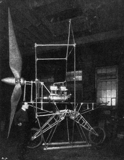
View of the framework of the Piggott biplane, showing the general arrangement of the suspension and the larger of the two propellers in situ.
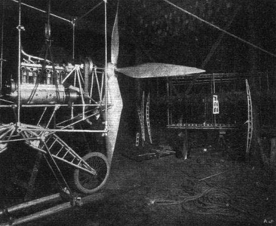
Another view of the chassis of the Piggott biplane, taken while the engine was being dismantled.
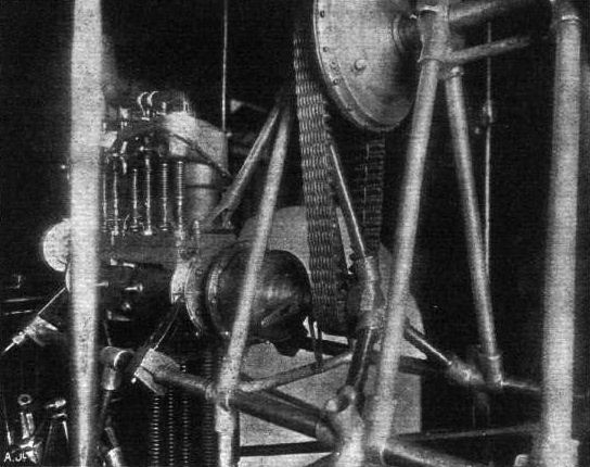
Detail view of the chain drive on the Piggott biplane, showing the multiple-disc clutch between the crank-shaft and the chain-sprocket, and the differential gear between the chain wheel and the propeller-shafts.
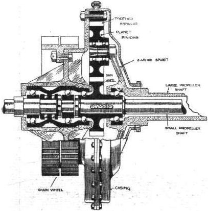
Sectional drawing of the differential gear oh the Piggott biplane.
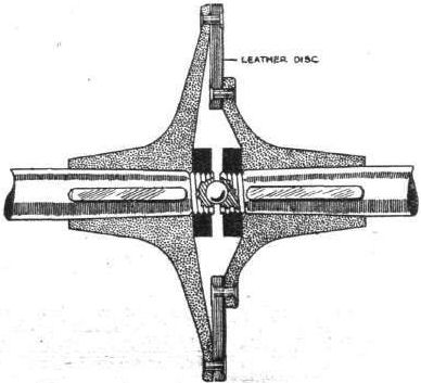
Sectional sketch of the flexible coupling of the propeller shaft of the Piggott biplane.
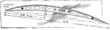
Sketch of one of the ribs in the main plane of the Piggott biplane.
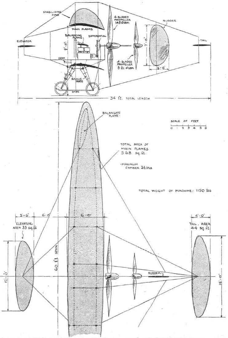
THE PIGGOTT BIPLANE. - Plan and side elevation to scale.
Flight, January 1, 1910
THE LILIENTHAL AND PILCHER GLIDERS COMPARED.
<...>
The Pilot's "Seat" and its Consequences.
Although Pilcher was doubtless inspired to his work by Lilienthal's example, it is apparent that he brought an original mind to bear in the constructive details of his task, whatever bias he may have been under to follow his leader's methods in their general lines. Constructionally the two gliders are as different as they can well be for machines of such similarity in size and purpose. But Pilcher and Lilienthal had this much in common, that they both employed the same method of riding their machines, by hanging upon them, and from such experience as has since been collected by the Brothers Wright, there is little doubt that the custom was at the bottom of many of their difficulties, if not actually the cause of Lilienthal's death. One consequence of deciding to use a glider as Lilienthal and Pilcher used theirs is the necessity of designing a machine of small weight, for the pilot has to be prepared to carry the load both when launching and landing. Pilcher, it is true, fitted a small chassis to his glider consisting of two spring-suspended wheels, but this addition was no more than a compromise, as its purpose was mainly to enable him to bring the machine more easily into position, and to take some of the initial shocks of landing. In flight Pilcher's body hung suspended beneath the wings, only his head and shoulders projecting above, his weight was borne upon two bolsters fitting under the armpits. Lilienthal was perhaps even more beneath his machine than Pilcher, for his arms rested in sockets beneath the wings, and the bolsters which supported his shoulders were about on a level with the upper surface.
Stability and Control.
The greater part of their weight being thus suspended beneath the supporting surfaces caused the centre of pressure to be considerably above the centre of gravity, and although this is often thought to be conducive to automatic stability by constituting a kind of natural pendulum, as a matter of fact, the inertia of such a system very naturally complicates the control, which in both cases was carried out by the shifting of the pilot's body in whatever direction might be required to restore balance. Pilcher had quite satisfied himself upon this point before he came to the end of his experiments, and another matter upon which he became convinced was that the upward slanting of the wings # or the principle of the dihedral angle # resulted in diminished stability in sidewings.
Leading Dimensions.
Of the two machines there is little to choose in weight, as they were both supposed to be in the order of 45 to 50 lbs. when actually in use. Lilienthal's glider has the smaller amount of supporting surface, and even that machine must have been one of the largest he constructed, for he was inclined at first to build gliders having barely 110 sq. feet of deck. The span of 22 feet for the Lilienthal machine is 2 ft. 8 ins. less than the Pilcher, and the overall length is 2 ft. shorter. The height is proportionally much less than that in the Pilcher glider, owing to a different system of staying the surfaces and to the absence of a chassis.
The Tail.
Both gliders were fitted with tails of similar type although different in shape, the tail in each case consisting of one vertical plane and one horizontal plane, the latter being set at a negative angle, and being also free to rise unrestricted if subjected to any pressure from beneath. It will be distinctly noticed from the accompanying drawings that the stay wires for the horizontal planes are only arranged so as to resist pressure from above. The vertical tail plane is nominally rigid, although, in the Pilcher glider, it happens to be mounted upon the horizontal member, and thus moves with it. In the Lilienthal machine the horizontal plane is hinged separately to the vertical plane, which is attached rigidly to the main frame. It was Pilcher's object in designing the tail of his machine as shown, to make it as compact as possible for storage, and with this end in view the tail was arranged to fold over on to the main planes.
(To be concluded.)
Flight, January 8, 1910
THE LILIENTHAL AND PILCHER GLIDERS COMPARED.
Willow and Bamboo.
THERE is a subtle difference in the construction of these two gliders, otherwise so much alike, which is directly attributable to the difference in the materials employed, for where Lilienthal used willow sticks, Pilcher adopted bamboo. Both had, it will be seen, sufficiently awkward materials to deal with, but Pilcher, it must be confessed, made a far more engineering-looking job of his work than Lilienthal, whose constructive methods are somehow reminiscent of bent-wood furniture. Both designers embodied the principle of folding-wings in their machines, and thus both were under the same necessity of adapting their construction to suit the special requirements imposed by this important condition. At the same time, however, both had to provide their wings when finished with an artificial camber, and it is particularly interesting to compare the two methods by which these details were accomplished.
The Folding of the Wings.
Pilcher, who was working with bamboo, fitted the inner extremities of the ribs of his wings with wooden plugs, to which he lashed a loop of iron wire so as to form a ring. These rings he subsequently strung over the central standard, around which each wing spread out like an open umbrella. In order to close the wings, it was only necessary to unlash the attachment between the front edge and the main frame, when the ribs would then all swing round one above the other into any convenient position.
Lilienthal obtained much the same effect, but in his case the ribs folded up side by side, being hinged to a central bracket into which their wedge extremities normally fitted like the spokes of a wheel.
In this machine the hinge centres are 6 ft. apart, and in the Pilcher machine the same points are separated by a distance of 7 ft. 6 ins. In both cases the hinges are joined by a wooden beam, but whereas in the Pilcher glider this member consists of a simple rectangular piece of wood, in the Lilienthal machine it is a built-up structure in the form of the letter X; which system was adopted in order to enable the staying of the wings to be conveniently accomplished. It would doubtless have been better had Pilcher attached more importance to the strains on the main beam of his machine, because it was that which gave way during his last glide.
Pilcher and His Wire.
Pilcher adopted a very different method of bracing his wings to that employed by Lilienthal, in fact, it is in this respect that the two machines are most unlike. He relied entirely upon the use of piano-wire for cambering the surfaces of his wings to the desired shape, and in order to get the effect sought he braced each to a central hinge pin consisting of a bamboo pole some 6 ft. in height, which stood up 3 ft. above the deck and projected 3 ft. beneath it. Radiating from the top and bottom ends of this pole are a number of wires, for the most part there are three wires attached above and beneath each rib, only the two front ribs in each wing having less than this number. There are nine ribs in each wing, and altogether 50 wires were required to stay them.
How Pilcher managed to retain all these wires properly taut is a matter for conjecture, but he must have been a man of great patience if he really gave proper attention to each of the 100 wires on which the camber of his surfaces depended. It is no easy matter to adjust wires used for such a purpose, as no sooner is a slack wire tightened up a little too much, than it relieves the strain upon two or three other wires, which become slack in turn. And Pilcher, it must be remembered, worked before the days of those very pretty little wire strainers which commonly form a feature in the bracing of modern flyers, and his method of adjustment must have been as tedious as it was effective. Each of his wires he fitted with a curtain-ring - Pilcher was very fond of curtain-rings - and on the rib he fastened a wire eye. The wires were cut to a fixed length in advance, and calculated to allow about an inch between the ring and the eye when in place. This gap was filled up by a piece of string, passed several times through each member to give the required strength, and by pulling on one end of the string a very minute adjustment could be made in the tension. More curtain-rings were employed for fastening the other ends of the wires to the vertical bamboo poles, so that the wings could be folded without twisting the wires.
Another little device for which Pilcher's construction is peculiar is his method of plugging his bamboo rods with wood. The wood plugs were glued into the hollow ends of the bamboo, which were then carefully lashed with string. Pilcher was very careful about lashing the ends of his bamboo poles as he evidently fully appreciated their liability to split. His use of wire eyes as lugs is another neat detail well worthy of attention, and these little fittings he would also lash in place.
Lilienthal's Stiffening Ribs.
Lilienthal, who very possibly had a natural objection to the use of a lot of wires, hit upon a very ingenious method of doing away with some of them, for he maintained the camber of his wings by the use of detachable supplementary ribs, of which there were four placed fore and aft above the deck. These ribs were strips of wood having an inverted T section, and they were cut to shape so as to serve as templates. As their permanence would have interfered with the folding of the wings, they were fitted in such a manner as to be detachable, and the method of doing this was to fasten small steel clamps on to the primary ribs of the wings, through which the flange of the template could slide. As the wings were naturally flexible there was no difficulty in sliding the curved templates in place from one end, and once in position these members were fastened by little clips. Their purpose was primarily to give the wings the desired camber, although they would of course tend to increase the rigidity of the structure; by their use, the necessity for employing a large number of wires was obviated, in fact, there were only two tie-wires radiating from each of the vertical posts mounted above the hinge plates. Beneath the wings, however, there was a wire to every rib, but even in this respect Lilienthal contrived to do without some 78 wires which Pilcher found necessary.
Relative Cambering.
It may be remarked that the number of ribs in each of the two machines is identical, viz., 18, but the camber and arching of the wings themselves is distinctly different in the two cases. Pilcher employed an umbrella-like form, in which the camber may be described as being of a uniform character. Lilienthal, on the other hand, flattened the extremities of his wings to such an extent that the curvature of some of the ribs was virtually reversed. The maximum camber on the Lilienthal glider, as on the Pilcher machines, occurs at the hinge of the wing, which on the former is situated 18 ins., and on the latter 2 ft. 6 ins. behind the leading edge. At this point the camber is deeper on the Lilienthal than on the Pilcher glider, but on the Lilienthal machine the camber is almost confined to this point alone, and is far more concentrated, if the term may be used, than in Pilcher's construction.
It is known that Lilienthal experimented with cambers of considerable height in proportion to the chord, and he has stated that the maximum versine (camber) of the wing curvature should be less than 1/12 of the chord, and preferably only 1/18 to 1/15 for considerations of stability.
Both machines had the surface material attached above the ribs.
The Framework.
Having compared the wings and supplementary surfaces, it is of interest to consider the main frames of the two machines, by which we imply that central structure to which the whole is braced, and on which the pilot supports his weight. In the Lilienthal glider this member is of somewhat peculiar form, and is best observed by reference to the accompanying plan; it bears in a marked degree that bent-wood furniture appearance to which we have already drawn attention. One of the principal members is an approximately circular hoop of willow, across which pass in a fore and aft direction two willow rods that ultimately converge at a point where the bamboo tail rod emerges from the wing surface. Transversely across the hoop passes the main beam to which reference has already been made, and immediately behind this an orifice is provided in the surface to accommodate the upper part of the pilot's body. Two small bolsters attached to the frame rest under the pilot's shoulders, and the pilot's arms pass through rests provided for them in the corners of the X-shaped main beam. Just in front of this beam is another transverse rod which the pilot can grip with his hands, and in front of the main hoop member is another bent-wood construction lashed in place with wicker, the object of this device being to act as a fender in the event of collision.
On Pilcher's glider the main frame consists of two bamboo rods spaced 18 inches apart above the main transverse beam, to which they were lashed in a cradle. Fore and aft these members converge, and are joined together in metal sockets, that at the rear carrying a bamboo extension to the tail. The entire space occupied by the two frame members was left open in the Pilcher machine, in which respect it differs from Lilienthal's glider, where every possible square inch is covered in. The pilot on Pilcher's glider was supported by two small bolsters fitting under the armpits, which bolsters were attached to the ends of short rods projecting obliquely from the sides of the main frame. Thus supported, the pilot's forearms would rest along the frame-members, and flat pieces of wood are lashed in place at these points to give greater comfort. At the ends of these armrests two handles project for the pilot to grip.
Both machines are more or less similarly braced as regards the wings to the frame and the tail to the frame; but in the Pilcher glider a transverse wooden strut is provided between the bamboo uprights in addition to the diagonal tie-wires which alone sufficed in the Lilienthal machine. Underneath the frame on Pilcher's glider two bamboo rods project obliquely outwards and carry wooden extensions on which the chassis wheels were mounted. The hollow bamboo is here made use of to contain a spring, and the wooden extension, once more fitted in the form of a plug, in this case became a plunger.
THE LILIENTHAL AND PILCHER GLIDERS COMPARED.
<...>
The Pilot's "Seat" and its Consequences.
Although Pilcher was doubtless inspired to his work by Lilienthal's example, it is apparent that he brought an original mind to bear in the constructive details of his task, whatever bias he may have been under to follow his leader's methods in their general lines. Constructionally the two gliders are as different as they can well be for machines of such similarity in size and purpose. But Pilcher and Lilienthal had this much in common, that they both employed the same method of riding their machines, by hanging upon them, and from such experience as has since been collected by the Brothers Wright, there is little doubt that the custom was at the bottom of many of their difficulties, if not actually the cause of Lilienthal's death. One consequence of deciding to use a glider as Lilienthal and Pilcher used theirs is the necessity of designing a machine of small weight, for the pilot has to be prepared to carry the load both when launching and landing. Pilcher, it is true, fitted a small chassis to his glider consisting of two spring-suspended wheels, but this addition was no more than a compromise, as its purpose was mainly to enable him to bring the machine more easily into position, and to take some of the initial shocks of landing. In flight Pilcher's body hung suspended beneath the wings, only his head and shoulders projecting above, his weight was borne upon two bolsters fitting under the armpits. Lilienthal was perhaps even more beneath his machine than Pilcher, for his arms rested in sockets beneath the wings, and the bolsters which supported his shoulders were about on a level with the upper surface.
Stability and Control.
The greater part of their weight being thus suspended beneath the supporting surfaces caused the centre of pressure to be considerably above the centre of gravity, and although this is often thought to be conducive to automatic stability by constituting a kind of natural pendulum, as a matter of fact, the inertia of such a system very naturally complicates the control, which in both cases was carried out by the shifting of the pilot's body in whatever direction might be required to restore balance. Pilcher had quite satisfied himself upon this point before he came to the end of his experiments, and another matter upon which he became convinced was that the upward slanting of the wings # or the principle of the dihedral angle # resulted in diminished stability in sidewings.
Leading Dimensions.
Of the two machines there is little to choose in weight, as they were both supposed to be in the order of 45 to 50 lbs. when actually in use. Lilienthal's glider has the smaller amount of supporting surface, and even that machine must have been one of the largest he constructed, for he was inclined at first to build gliders having barely 110 sq. feet of deck. The span of 22 feet for the Lilienthal machine is 2 ft. 8 ins. less than the Pilcher, and the overall length is 2 ft. shorter. The height is proportionally much less than that in the Pilcher glider, owing to a different system of staying the surfaces and to the absence of a chassis.
The Tail.
Both gliders were fitted with tails of similar type although different in shape, the tail in each case consisting of one vertical plane and one horizontal plane, the latter being set at a negative angle, and being also free to rise unrestricted if subjected to any pressure from beneath. It will be distinctly noticed from the accompanying drawings that the stay wires for the horizontal planes are only arranged so as to resist pressure from above. The vertical tail plane is nominally rigid, although, in the Pilcher glider, it happens to be mounted upon the horizontal member, and thus moves with it. In the Lilienthal machine the horizontal plane is hinged separately to the vertical plane, which is attached rigidly to the main frame. It was Pilcher's object in designing the tail of his machine as shown, to make it as compact as possible for storage, and with this end in view the tail was arranged to fold over on to the main planes.
(To be concluded.)
Flight, January 8, 1910
THE LILIENTHAL AND PILCHER GLIDERS COMPARED.
Willow and Bamboo.
THERE is a subtle difference in the construction of these two gliders, otherwise so much alike, which is directly attributable to the difference in the materials employed, for where Lilienthal used willow sticks, Pilcher adopted bamboo. Both had, it will be seen, sufficiently awkward materials to deal with, but Pilcher, it must be confessed, made a far more engineering-looking job of his work than Lilienthal, whose constructive methods are somehow reminiscent of bent-wood furniture. Both designers embodied the principle of folding-wings in their machines, and thus both were under the same necessity of adapting their construction to suit the special requirements imposed by this important condition. At the same time, however, both had to provide their wings when finished with an artificial camber, and it is particularly interesting to compare the two methods by which these details were accomplished.
The Folding of the Wings.
Pilcher, who was working with bamboo, fitted the inner extremities of the ribs of his wings with wooden plugs, to which he lashed a loop of iron wire so as to form a ring. These rings he subsequently strung over the central standard, around which each wing spread out like an open umbrella. In order to close the wings, it was only necessary to unlash the attachment between the front edge and the main frame, when the ribs would then all swing round one above the other into any convenient position.
Lilienthal obtained much the same effect, but in his case the ribs folded up side by side, being hinged to a central bracket into which their wedge extremities normally fitted like the spokes of a wheel.
In this machine the hinge centres are 6 ft. apart, and in the Pilcher machine the same points are separated by a distance of 7 ft. 6 ins. In both cases the hinges are joined by a wooden beam, but whereas in the Pilcher glider this member consists of a simple rectangular piece of wood, in the Lilienthal machine it is a built-up structure in the form of the letter X; which system was adopted in order to enable the staying of the wings to be conveniently accomplished. It would doubtless have been better had Pilcher attached more importance to the strains on the main beam of his machine, because it was that which gave way during his last glide.
Pilcher and His Wire.
Pilcher adopted a very different method of bracing his wings to that employed by Lilienthal, in fact, it is in this respect that the two machines are most unlike. He relied entirely upon the use of piano-wire for cambering the surfaces of his wings to the desired shape, and in order to get the effect sought he braced each to a central hinge pin consisting of a bamboo pole some 6 ft. in height, which stood up 3 ft. above the deck and projected 3 ft. beneath it. Radiating from the top and bottom ends of this pole are a number of wires, for the most part there are three wires attached above and beneath each rib, only the two front ribs in each wing having less than this number. There are nine ribs in each wing, and altogether 50 wires were required to stay them.
How Pilcher managed to retain all these wires properly taut is a matter for conjecture, but he must have been a man of great patience if he really gave proper attention to each of the 100 wires on which the camber of his surfaces depended. It is no easy matter to adjust wires used for such a purpose, as no sooner is a slack wire tightened up a little too much, than it relieves the strain upon two or three other wires, which become slack in turn. And Pilcher, it must be remembered, worked before the days of those very pretty little wire strainers which commonly form a feature in the bracing of modern flyers, and his method of adjustment must have been as tedious as it was effective. Each of his wires he fitted with a curtain-ring - Pilcher was very fond of curtain-rings - and on the rib he fastened a wire eye. The wires were cut to a fixed length in advance, and calculated to allow about an inch between the ring and the eye when in place. This gap was filled up by a piece of string, passed several times through each member to give the required strength, and by pulling on one end of the string a very minute adjustment could be made in the tension. More curtain-rings were employed for fastening the other ends of the wires to the vertical bamboo poles, so that the wings could be folded without twisting the wires.
Another little device for which Pilcher's construction is peculiar is his method of plugging his bamboo rods with wood. The wood plugs were glued into the hollow ends of the bamboo, which were then carefully lashed with string. Pilcher was very careful about lashing the ends of his bamboo poles as he evidently fully appreciated their liability to split. His use of wire eyes as lugs is another neat detail well worthy of attention, and these little fittings he would also lash in place.
Lilienthal's Stiffening Ribs.
Lilienthal, who very possibly had a natural objection to the use of a lot of wires, hit upon a very ingenious method of doing away with some of them, for he maintained the camber of his wings by the use of detachable supplementary ribs, of which there were four placed fore and aft above the deck. These ribs were strips of wood having an inverted T section, and they were cut to shape so as to serve as templates. As their permanence would have interfered with the folding of the wings, they were fitted in such a manner as to be detachable, and the method of doing this was to fasten small steel clamps on to the primary ribs of the wings, through which the flange of the template could slide. As the wings were naturally flexible there was no difficulty in sliding the curved templates in place from one end, and once in position these members were fastened by little clips. Their purpose was primarily to give the wings the desired camber, although they would of course tend to increase the rigidity of the structure; by their use, the necessity for employing a large number of wires was obviated, in fact, there were only two tie-wires radiating from each of the vertical posts mounted above the hinge plates. Beneath the wings, however, there was a wire to every rib, but even in this respect Lilienthal contrived to do without some 78 wires which Pilcher found necessary.
Relative Cambering.
It may be remarked that the number of ribs in each of the two machines is identical, viz., 18, but the camber and arching of the wings themselves is distinctly different in the two cases. Pilcher employed an umbrella-like form, in which the camber may be described as being of a uniform character. Lilienthal, on the other hand, flattened the extremities of his wings to such an extent that the curvature of some of the ribs was virtually reversed. The maximum camber on the Lilienthal glider, as on the Pilcher machines, occurs at the hinge of the wing, which on the former is situated 18 ins., and on the latter 2 ft. 6 ins. behind the leading edge. At this point the camber is deeper on the Lilienthal than on the Pilcher glider, but on the Lilienthal machine the camber is almost confined to this point alone, and is far more concentrated, if the term may be used, than in Pilcher's construction.
It is known that Lilienthal experimented with cambers of considerable height in proportion to the chord, and he has stated that the maximum versine (camber) of the wing curvature should be less than 1/12 of the chord, and preferably only 1/18 to 1/15 for considerations of stability.
Both machines had the surface material attached above the ribs.
The Framework.
Having compared the wings and supplementary surfaces, it is of interest to consider the main frames of the two machines, by which we imply that central structure to which the whole is braced, and on which the pilot supports his weight. In the Lilienthal glider this member is of somewhat peculiar form, and is best observed by reference to the accompanying plan; it bears in a marked degree that bent-wood furniture appearance to which we have already drawn attention. One of the principal members is an approximately circular hoop of willow, across which pass in a fore and aft direction two willow rods that ultimately converge at a point where the bamboo tail rod emerges from the wing surface. Transversely across the hoop passes the main beam to which reference has already been made, and immediately behind this an orifice is provided in the surface to accommodate the upper part of the pilot's body. Two small bolsters attached to the frame rest under the pilot's shoulders, and the pilot's arms pass through rests provided for them in the corners of the X-shaped main beam. Just in front of this beam is another transverse rod which the pilot can grip with his hands, and in front of the main hoop member is another bent-wood construction lashed in place with wicker, the object of this device being to act as a fender in the event of collision.
On Pilcher's glider the main frame consists of two bamboo rods spaced 18 inches apart above the main transverse beam, to which they were lashed in a cradle. Fore and aft these members converge, and are joined together in metal sockets, that at the rear carrying a bamboo extension to the tail. The entire space occupied by the two frame members was left open in the Pilcher machine, in which respect it differs from Lilienthal's glider, where every possible square inch is covered in. The pilot on Pilcher's glider was supported by two small bolsters fitting under the armpits, which bolsters were attached to the ends of short rods projecting obliquely from the sides of the main frame. Thus supported, the pilot's forearms would rest along the frame-members, and flat pieces of wood are lashed in place at these points to give greater comfort. At the ends of these armrests two handles project for the pilot to grip.
Both machines are more or less similarly braced as regards the wings to the frame and the tail to the frame; but in the Pilcher glider a transverse wooden strut is provided between the bamboo uprights in addition to the diagonal tie-wires which alone sufficed in the Lilienthal machine. Underneath the frame on Pilcher's glider two bamboo rods project obliquely outwards and carry wooden extensions on which the chassis wheels were mounted. The hollow bamboo is here made use of to contain a spring, and the wooden extension, once more fitted in the form of a plug, in this case became a plunger.
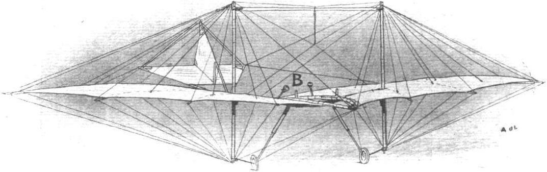
View of the Pilcher glider from in front, showing the method of staying the wings. One hundred wires were employed for this purpose. In the centre of the machine will be noticed two short posts capped with small bolsters marked B. In use they came beneath the arm-pits of the pilot and supported his weight, whilst his fore-arms rested along the frame, and his hands grasped a pair of small handles which are also visible in the sketch.
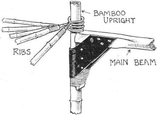
Method of attaching the ribs to the wing standards on the Pilcher glider.
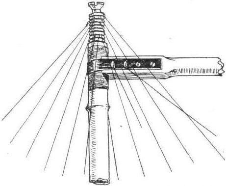
Head of a wing standard on the Pilcher glider, showing radiating tie-wires.

One of the ribs of the Pilcher glider.
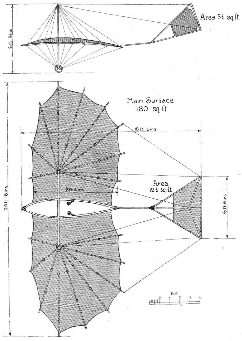
The Pilcher glider.
Flight, July 16, 1910
THE PORTWAY AEROPLANE.
THE accompanying illustrations show a home-made aeroplane of the Santos Dumont type, that has been constructed during the last three months, at Bromley, in Kent, by Mr. A. P. Portway and his brother. The machine is described as follows by its designer :-
The machine is a monoplane of a modified Santos Dumont type, but larger, the spread of the wings being 25 ft., and length of chord 6 ft. 6 ins. The wings start at a slight dihedral angle, and then become horizontal at about a third of their length from the centre; they are double surfaced and covered in proofed silk.
The body is almost entirely of bamboo joined up with special cast sockets of aluminium, which makes a job remarkable for its strength, lightness and neatness. The tail-elevator is of the usual Santos Dumont, cruciform, non-lifting type. As will be seen in the second photo, we have replaced the original wheels by a pair having broad tyres, and the wheel-skid combination suspension has beenadopted.
The control is by an inclined steering wheel, universally jointed at its base. Rotating the wheel moves the elevator, while a lateral horizontal movement works the rudder. Warping is effected by a vertical lever behind the pilot, which is operated by his shoulders.
The engine is a 4-cylinder 35-h.p. Lascelles, driving a 7 ft. propeller at 1,200 revolutions. The petrol is pressure-fed from a torpedo tank behind the pilot. The total weight of the machine complete is 350 lbs., and the surface 150 sq. ft. The angle of incidence is 8°.
The first trials were most successful, the machine showing a high, speed and getting off the ground; but trouble with the tyres, and finally with buckled wheels, necessitated delay in repairs.
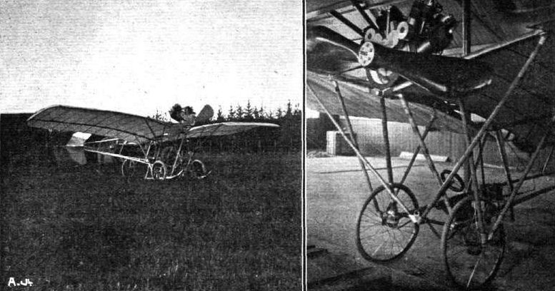
Messrs. Portway's monoplane.
Flight, February 19, 1910
Sanders Biplane has a Mishap.
A MISHAP befell the biplane which has been built by the Brothers Sanders at Kessingland, near Lowestoft. On Saturday, Mr. Kempton Sanders was trying the machine and had got it to rise to a height of about 20 ft. when it came into collision with some telegraph wires. This caused the machine to pitch forward and fall to the ground, smashing it, but fortunately Mr. Sanders was able to jump clear.
Flight, February 26, 1910
THE SANDERS AEROPLANE.
LAST week we recorded the mishap to the Sanders aeroplane, and we are now able to give some photographs of the "incident."
Captain Sanders, of the London Aeroplane and Aerial Navigation Co., has been working very quietly in conjunction with Messrs. J. W. Brooke and Co., Ltd., of Lowestoft, on this biplane on the Benacre Denes, about 5 miles from Lowestoft, and has gradually built up this machine to a successful issue, a number of flights having been carried out from time to time.
The accident, which took place at 8 o'clock in the morning, was not the outcome of any fault of the machine or the motor. As we stated last week, it was owing to the close proximity of some coastguard telephone poles, the tip end of one of the wings catching the top of one of these poles, and so bringing the machine right round and completely upsetting the balance.
The motor used in this biplane is a 30-h.p. Brooke, and weighs as much as 240 lbs., as after building several engines for flight purposes, Messrs. J. W. Brooke and Co. came to the conclusion that it was better to sacrifice lightness to obtain reliability. Captain Sanders has looked after the engine himself for several months without any trouble, and intends using the same engine in his new aeroplane. The Sanders machine weighs in flying order 1,100 lbs.

THE SANDERS AEROPLANE MISHAP. - Two views of the biplane taken immediately after the fall.

THE SANDERS AEROPLANE MISHAP. - A few moments after the crash, Capt. Sanders standing by the machine. Note the splintered spar which passed through Capt. Sanders' clothing, fortunately without injuring him.
Flight, November 19, 1910
FROM THE BRITISH FLYING GROUNDS.
<...>
On Monday, the 7th, Mr. Seddon brought out his huge tandem biplane for the first time for a run along the ground. The weight of the machine, however (which is somewhere between 20 and 30 cwts.), proved too much for the axle of the right wheel, which gave way under the load. This machine, which, it will be remembered, is fitted with two N.E.C. engines of 50-60 h.p. each and Beedle propellers, showed good acceleration powers in the short run before the collapse, but a speed sufficient to lift the machine was not attained. The stationary pull of the two propellers is something over 600 lbs. These are not in any way connected together, and both engines have to be run up to a certain speed and kept in unison. The machine in its short run turned considerably from, the straight path, presumably from this reason. It is, however, we believe, Mr. Seddon's intention to connect both engines by a chain.
<...>
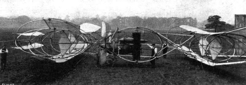
Side view of the Seddon aeroplane.
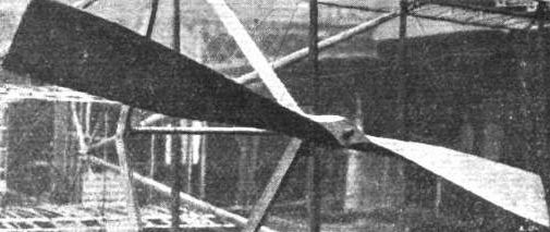
The Short propeller is constructed entirely of wood, and consists of six separate layers which are joined together to form a solid piece.
Flight, March 12, 1910
THE SECOND OLYMPIA AERO SHOW.
AEROPLANES.
Short.
A BRITISH-BUILT biplane of special light design, and fitted with a 30-35-h.p. 4-cyl. Green engine. A feature of the design is the patent front elevating rudder, while another special detail is the arrangement of spring tension balancing planes. The lifting surface of the machine is 270 sq. ft., while the weight complete is 700 lbs. A similar machine is also exhibited by Mr. J. T. C. Moore-Brabazon on the Royal Aero Club's stand.
Flight, March 19, 1910
THE NEW "SHORT" BIPLANE.
Leading Particulars of the Short Biplane, 1910 Model.
General Dimensions.-Areas-Main planes, 282 sq. ft.; fixed tail (hor.), 21 1/2 sq. ft.; (vert.), 10 sq. ft.; elevator, 55 sq. ft.; rudder, 10 sq. ft.
Lengths.-Span, 31 ft. 8 in., chord, 5 ft. 4 ins. (aspect ratio, 6) ; camber, 3 1/4 ins., situated about 24 ins. from leading edge; leverage of rudder, about 8 ft. 6 ins. from leading edge of main planes; gap, 4 ft. 4 ins. ; overall length, 31 ft.
Materials.-Timber, spruce; fabric, North British Rubber Co.
Engine.-35-h.p. Green.
Propeller.- Make, Short ; diameter, 7 ft. 6 in.; material, spruce.
Weight.-Machine, 390 lbs.; engine, 225 lbs. ; driver, oil, petrol, 200 lbs.; radiator, tanks, piping, 42 lbs. ; total flying weight, 857 lbs. ; loading (all weight supported on main planes) 3 lbs. per sq. ft.
Speed of Flight.-45-50 m.p.h.
System of Control.-Balancing planes, elevator, rudder.
Price.-L650.
THAT fact which above all others makes the new Short biplane interesting, is that its design is the outcome of actual experience in flight. During the last twelve months, Short Brothers have been collecting information from the practical aviation that has been actively in progress at Eastchurch and Shellbeach, which has proved invaluable to them, and it may be said that all their experience to date is embodied in the design and construction of this latest machine that they have developed. What makes it even more interesting, is that this machine is by no means radically different from the larger biplane with which Mr. Moore-Brabazon won the Daily Mail prize. That flyer was the first of the Short models to be actually flown, and the similarity between the two seems to us to be good cause to compliment the firm on the success that attended the scientific thoroughness with which they went to work in the first instance.
Leading Characteristics.
The latest Short biplane is characterised by its apparently massive construction, yet on examining it more closely it will be seen how scientifically the bulk of the material has been disposed. That this is the case is proved by the low actual weight of this machine, the framework and fabric weighing only 390 lbs. One fact that has stood out among all others as the result of practical experience is the absolute necessity for making the chassis portion of the machine and the engine bearers as strong as possible. These are, pre-eminently, the massive parts of the new Short biplane.
The chassis itself is a particularly interesting and very simple piece of work, consisting of a pair of lattice girders forming landing skis. These members owe their rigidity mainly to the fact that they are not very deep, and it is in fact a characteristic of the machine, distinguishing it from the majority, that the lower deck is very close to the ground when the machine is on the earth. Short Brothers regard this as a most important feature of their design, their experience having taught them how difficult it is to construct a high chassis that is sufficiently rigid to stand the terrific severity of the shocks to which it is likely to be subjected by beginners, who are sometimes apt to suddenly "drop" their machines from a height of possibly ten feet straight on to the ground.
Centre of Gravity.
Another outstanding characteristic of the Short design in this particular model, is the position of the engine midway up the gap, instead of being supported on the lower deck as is the more common practice. This position has resulted from the desire to have a low chassis and a single direct driven propeller of large diameter, but it seems to us that there is even a theoretical advantage in placing the engine in this position resulting from its tendency to raise the centre of gravity.
In any biplane there must be two main centres of pressure and resistance as the result of using two planes a considerable distance apart. Commonly the disposition of the principal masses locates the centre of gravity nearer to the lower centre of pressure than to the upper, with the result that it probably increases the inertia factor that militates against lateral stability, and also gives rise to the phenomenon of "kick up" that may occur when the engine is stopped in flight. Both the effects are probably caused by inequality in the leverages forming the couple represented by the two principal centres of pressure about the centre of gravity. The phenomenon of "kick up," which consists of an upward tilting of the front part of the machine automatically resulting from an interruption of the drive in flight, is a manifestation of the superior leverage of the centre of resistance of the upper plane, or it may be regarded as the more direct action upon the lower plane of the momentum of the principal mass - which comes to the same thing.
In respect to the matter of lateral stability mentioned above, it seems as if any position of the centre of gravity that is not coincident with the resultant of the two principal centres of pressure - which position is, presumably, midway in the gap - must be regarded as ascentric and, therefore, as possessed in some degree of the inertia factor that is generally recognised as detrimental to the stability of any such system.
This latter point has not yet been thoroughly discussed, and it would be helpful if some such attention as our readers recently gave to the principle of the dihedral angle, which we broached in our description of the Antoinette monoplane, were devoted to a discussion of the centres of pressure and centre of gravity in biplanes. Diagrams are given herewith to facilitate reference, and the point to which special attention is drawn is that the inertia to recovery on the part of a system in which the centre of gravity is located on the lower plane is greater than when the centre of gravity is located midway in the gap, owing to the fact that the inertia of a mass is proportionate to the square of its radius from the centre of rotation.
(To be concluded.)
Flight, March 26, 1910
THE NEW "SHORT" BIPLANE.
(Continued from page 213.)
Short-Wright Comparisons.
ALTHOUGH there are some points in common between the Short machine and the Wright machines that are manufactured in England by Short Brothers, the design in general is entirely different. The rudder, for instance, in the Wright biplane is placed behind; in the Short biplane it is placed in front where it is situated immediately behind the elevator. The Short biplane, too, has a horizontal and a vertical tail, whereas the Wright flyer has nothing but its double rudder at the rear of the planes. These differences are, of course, of a fundamental character, and entirely outweigh such small features of similarity as may be noticed in the appearance of the decks. The system of control, too, is fundamentally dissimilar, inasmuch as the planes of the Short machine are rigid, whereas those of the Wright are capable of being warped. Lateral equilibrium in the Short biplane is maintained by the manipulation of a pair of independent balancing planes that are pivoted to the vertical struts at the extremities of the machine.
In detail, as in generalities, the Short biplane is most interesting, and it gives evidence everywhere of most careful and original thought in its construction, as will be shown by a glance at the accompanying illustrations and a perusal of the following brief description of the more characteristic features of the machine.
Main Planes.
The main planes are so erected that they can be dismantled in three sections and packed fore and aft into a width of 10 ft., the principal transverse spars are jointed on either side of the central portion that forms a permanent part of the chassis. The joint is a simple socket and the fastening is accomplished by a single bolt, the strain being, of course, taken off the joints by the diagonal wire bracing that converts the construction of the decks as a whole into a lattice box-girder. Between the main spars are placed the cambered ribs upon which the surfacing material is stretched. The planes are double surfaced, that is to say the fabric is applied to the upper and lower faces of the ribs.
The Leading Edge.
The front spar of each deck forms the leading edge and is quite blunt; in fact, it is only rounded off at the corners, no attempt whatever having been made to provide a sharp entry, Short Brothers having been led to the conclusion, as the result of their experience, that there is no practical advantage in such a refinement. This is, of course, a very interesting and important point, because not only is it common opinion that the entering edge should at least be well rounded, but many constructors have gone to the trouble of continuing the ribs beyond the front spar in order to provide a really sharp entering edge without reducing the section of that member. It has always seemed to us that while a sharp entering edge may be advantageous in theory, the difficulty is to ensure that the machine shall fly with that edge tangential to the relative wind, in other words we are of the opinion that while the sharp cutting edge is probably best in one particular position it is quite likely to be less efficient than a blunt edge in other positions than that for which it was designed. Information on the subject of the actual behaviour of the air in the vicinity of the leading edge is very limited, and it would be interesting to know whether there may not be some sort of piling-up action taking place in the air itself of such a character as to give a blunt leading edge an artificial sharpness that automatically adjusts itself to the attitude of the machine in flight. Whether or no there is any justification for any such view, or whether the actual differences in efficiency between the theoretical streamline section and the blunt edge are far less than have been supposed we do not know, but it is, at any rate, very interesting to find how little attention is bestowed to the sharpening of the edges of struts and spars in the Short biplane.
Struts and Ties.
The struts themselves, like the main spars, are made of spruce, and are rectangular in section. They taper from the centre towards each extremity in order to combine strength with lightness, and they are mounted in manganese-steel sockets. These sockets are attached to the spars and not to the struts; in fact, there is no metal fitting on the struts at all, and if a strut should be broken another can immediately replace it. Being in compression as the result of the tension of the diagonal tie-wires, the struts are automatically prevented from coming out of their sockets; moreover, with this system of construction something of the flexibility that characterises the Wright joint has been retained, without the complication of the hook and eye. The tie-wires on the Short machine are stronger than was formerly considered necessary, 10 and 12 S.W.G. being the gauge that is now employed, whereas 16 used to be considered heavy enough.
It is interesting to note that Short Brothers have come to the conclusion that wires offer less resistance than is popularly supposed to be the case. Some of our readers may remember that Esnault-Pelterie publicly stated how, after having tried a Wright type of glider of his own construction, he abandoned the biplane principle in favour of the monoplane system solely because of excessive head resistance caused by the wires necessary in biplane construction. He attributed this resistance to the vibration of the wire and seemed to be distinctly of opinion that a single wire had resistance equivalent to a rigid strut an inch or more in diameter.
Chassis and Suspension.
The chassis forms another example of the lattice box-girder type of construction, four spruce beams being trussed together by vertical struts and diagonal ties. The tie-members between the upper and lower beams on each side are formed by strip manganese-steel, while the crossties between the side-members are formed by piano wire. The lower beams form the skis on which the machine lands, but in conjunction therewith a set of wire wheels are also provided in order to enable the machine to run about on the ground for starting. Two of these wheels, which carry the greater part of the load, are so mounted that they can be raised out of action by a small lever near the pilot's seat, as soon as the machine is in flight, thereby relieving them of all shock when landing. This releases a set of supplementary springs, which raise the wheels out of action above the level of the skis. The forward wheels, which merely serve to support the weight of the elevator and rudder, are suspended by elastic, and thus offer very little resistance to shock.
(To be concluded.)
Flight, April 2, 1910
THE, NEW "SHORT" BIPLANE.
(Concluded from page 229)
Supplementary Surfaces.
THE supplementary surfaces on the Short biplane consist of a biplane elevator, mounted on the front end of the chassis, a single vertical rudder situated immediately behind the elevator, and a fixed horizontal and vertical tail carried by a triangular outrigger behind the main planes. The horizontal member of the tail is cambered and is so mounted that its angle of incidence can be adjusted, but not while in flight. Even under normal conditions it is intended that this angle shall have a slight positive value, but the tail is not regarded as a load carrying member of the machine. The elevator has flexible surfaces so arranged that the pilot can camber them to give a positive or negative lift as may be required for the purpose of maintaining equilibrium or altering the attitude of flight. In its fundamental idea, this flexing of the elevator follows a principle introduced by Wright, but there are important differences in construction between the elevators of the two machines, notably in the fact that the planes of the Short elevator flex from the leading edge, which forms the fixed member of the structure.
Two other supplementary surfaces are provided at the extremities of the main planes. These consist of pivoted balancing planes for maintaining lateral equilibrium. Their construction embodies a recent patent and is particularly ingenious, inasmuch as the plane consists merely of a horizontal sheet of fabric stretched between two spars by the action of springs joining the trailing edge of the fabric to the rear spar.
A fore and aft spar joins the two transverse spars and serves as a means of attachment to one of the vertical struts between the main planes. Provision is made for tilting these balancing planes either to a positive or negative angle, and owing to the method of mounting the fabric the planes automatically assume a camber as the result of the air pressure.
Control.
Control of the Short biplane is effected by means of two levers and a pair of pedals. The lever held in the pilot's left hand operates the elevator by a simple to and fro movement. The lever held in the pilot's right hand controls the lateral equilibrium of the machine by movements of the balancing planes. The pedals operate the rudder, which is normally held in a straight-ahead position by the action of elastic springs.
The coupling up of the right hand lever to the balancing planes is such that the pilot pushes the lever away from him when the right hand extremity of the machine is tilted above its proper level. It will be observed that the head resistances of the two balancing planes are equal to one another for any angle, consequently the machine does not tend to swerve from a straight path as the result of their use, and there is no need to employ the rudder in order to keep the course, as is the case with wing warping.
The Engine and Propeller.
The engine on this machine is a four-cylinder 35-h.p. Green motor having a bore and stroke of 105 by 120 mm. and is mounted on two wooden girders that pass fore and aft between a couple of massive transverse girders bolted to four of the vertical struts between the main planes. The engine, as we have already pointed out, is raised above the lower deck so that the axis of the crank-shaft lies about midway in the gap. The two-bladed wooden propeller is direct-coupled to the crank-shaft. The petrol-tank lies just above the lower deck between vertical radiators on either side. Owing to the position of the engine it has been possible to fit a starting-handle on a swiveiling-bracket so that the engine can be started without handling the propeller, a refinement that is commendable, for the use of the propeller as a starting-handle unquestionably involves an element of danger that should be unnecessary.
Flight, April 9, 1910
THE SHORT CONTROL.
Referring to your recent description of the new Short biplane, could you give me further particulars relating to the exact arrangement and method of operating the vertical rudder, which I notice you state is controlled by foot ?
Liverpool. JAMES K. CHAPMAN.
[The accompanying sketch clearly illustrates the method of mounting and controlling the rudder on the Short biplane. The rudder is situated immediately behind the elevator, and is attached to a vertical post that passes through the rudder plane a short distance behind the leading edge, and, therefore, approximately through the centre of pressure for small angles. The lower end of the rudder-post carries a cross-bar to which two rods are pivoted. These rods are hinged at their other extremities to a pair of hinged pedals. The cross-bar on the lower end of the rudder-post is tied by elastic springs to the side-members of the chassis frame; consequently, the rudder has a normal straight-ahead position, to which it automatically returns of its own accord. Although the elastic springs are sufficiently strong for this purpose, they do not interfere with the delicacy of the control.-ED.]
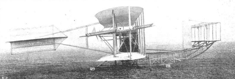
Short S.2 the final version with extended tail.
Mr. Moore-Brabazon's "No. 5," being his all-British "Short" biplane, in which the most noticeable alteration since we published a photograph of this machine, on October 9th last, is the tail.
SHORT (1910). The first machine to Short's own design. (The tail here shown is a specially large one fitted by Moore-Brabazon).
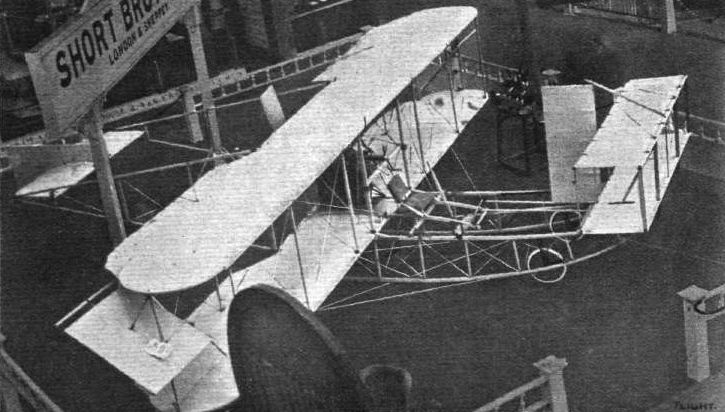
General view from above of the new Short biplane, with fixed tail, front rudder, and balancing-planes among the special features.
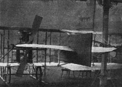
View of the tail on the Short biplane.

View of the pilot's seat on the Short biplane. The lever on the pilot's right controls the balancing-planes, that on his left the elevator; the pedals control the rudder.
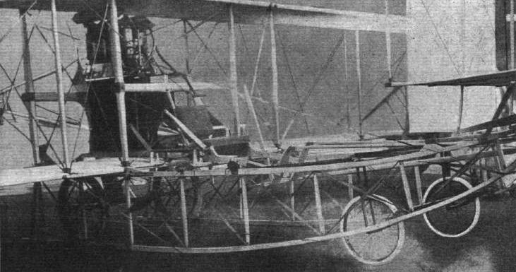
View of the chassis on the Short biplane; the wheels are suspended on helical springs that are wound up by a ratchet-pawl device. The pilot releases a catch when he has ascended in the air and the wheels are drawn up above the level of the skis, upon which the machine therefore lands direct.
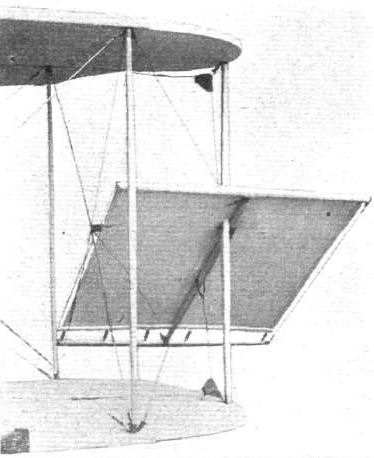
View of one of the balancing planes on the Short biplane. The fabric is stretched between the leading and trailing edges by a series of springs, which allow it to take its own camber from the wind pressure.
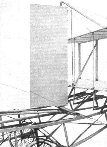
View of the rudder, which is situated in front, on the Short biplane.
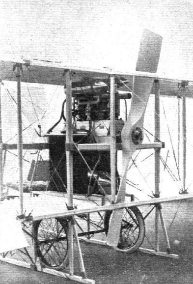
View of the engine and propeller on the Short biplane. The engine is mounted high up in the gap
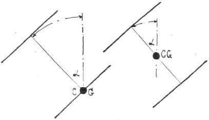
Diagram illustrating the comparative movement caused by a cant at equal angular displacement when the centre of gravity is on the lower deck and midway in the gap.
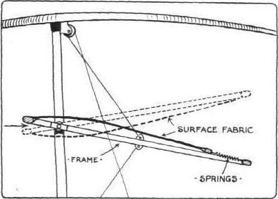
Sketch illustrating the action of the balancing planes on the Short biplane. The method of mounting the fabric so that it automatically cambers under the air pressure is one of the most important of the patented devices on this new machine.
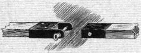
Sketch illustrating the jointing of the main spars on the Short biplane.
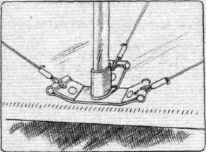
Sketch illustrating the method of attaching the struts to the spars in the Short biplane. The manganese-steel socket-brackets are fixed to the spars and not to the struts.
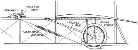
Diagrammatic sketch illustrating the suspension of the Short biplane, and the method of mounting the "disappearing" wheels so that the machine will land on the skis if the driver releases the ratchet pawl device by which the spring tension is maintained.

Diagrammatic sketch illustrating the control of the elevator and the rudder on the Short biplane. The elevator planes flex from the front edge by the manipulation of a lever. The rudder pivots on a vertical column by the action of pedals. Both are normally held in their neutral position by elastic springs.
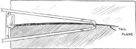
Sketch illustrating the mounting of the horizontal tail plane on the Short biplane. The tail is fixed in flight, but its angle of incidence is adjustable within a small range by means of the slotted bracket illustrated above.
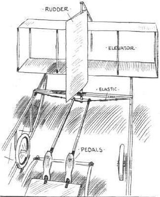
WING SECTIONS. - The above diagrams afford an interesting comparison of the wing sections of aeroplanes exhibited at Olympia. They are all drawn to a common scale, but have been set at an arbitrary angle of incidence, which does not necessarily represent that of the aeroplane In actual flight.
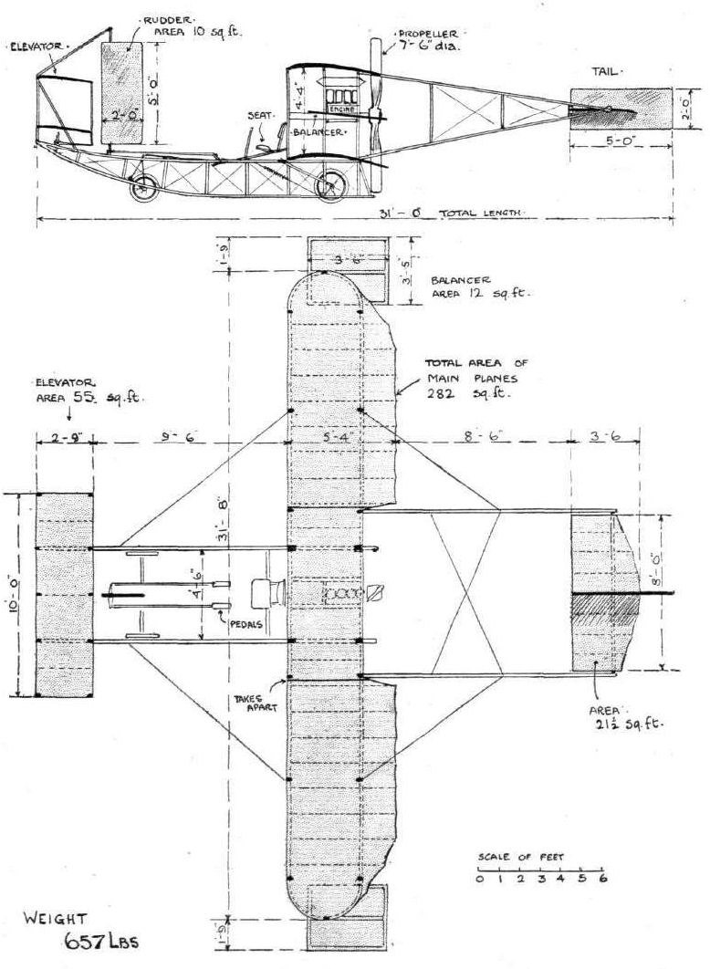
THE NEW "SHORT" BIPLANE. - Elevation and plan.
Flight, March 12, 1910
THE SECOND OLYMPIA AERO SHOW.
AEROPLANES.
Short-Wright Machine.
BRITISH-BUILT biplanes, after the design which has been evolved by the Wright Brothers. The machine on view is that with which the Hon. C. S. Rolls has been flying at Eastchurch.
Flight, June 4, 1910
HON.C.S. ROLLS AT DOVER.
As we mentioned in our last issue, the Hon. C. S. Rolls, although forestalled in the winning of the Ruinart Prize, decided to stay on at Dover with the object of flying across to France at the first opportunity.
Unfortunately, up to the time of going to press on Wednesday, the weather was against flying, and Mr. Rolls therefore deemed it prudent to postpone the attempt.
On the 26th ult., everything was in readiness, and a trial trip was decided on.
The machine .rose from the rail in a meadow on the East Cliff with perfect ease, and rising to a height of about 200 ft., flew out towards the Channel. Turning at the edge of the cliff, Mr. Rolls continued flying in a series of circles for about 20 minutes.
On the following afternoon, Friday, the conditions were again right, and Mr. Rolls decided to make another trial, and if everything was working perfectly, to start on the cross-Channel trip. Unfortunately, motor trouble supervened, and in a sudden descent from a height of 120 ft., the runners were damaged, and so caused another postponement.
Flight, June 11, 1910
THE HON. C. S. ROLLS' HISTORICAL FLIGHT.
AN important page in the history of the development of flight has once more been turned down by the splendid achievement of the Hon. C. S. Rolls on his Short-Wright type biplane with horizontal tail, in flying over the Channel and returning to his starting point without alighting on French soil. Abroad most of the noteworthy feats have been accomplished by professional aviators. In Britain it is otherwise, as in all sports and science. The man who outstands in progress is almost without exception the amateur. In this respect the art of flying is proving no exception. We doubt if any foreigner, without the smallest monetary inducement, would, like Mr. Rolls, have started on this flight across the Channel. And in that lies the difference in sport as understood in Great Britain and as understood abroad.
In making this flight Mr. Rolls has placed to his credit several records of which he may well be proud. It.is the first time the Channel has been flown by a Britisher, the first time the double journey has been accomplished, the first time it has been done on a biplane, and, moreover, it is the first time the landing after the event has been made at the exact pre-arranged spot and without damage. Incidentally another record also attaches to the flight, viz., the occasion of the most elaborated journalistic account, "a la Munchausen," as supplied by an enterprising reporter to the general Press. Practically all the "details" which have appeared in morning papers have been pure fabrications. Mr. Rolls never disclosed the contents of the congratulatory telegram received from the King, this being of a purely private character. Yet what purports to be the exact text has duly appeared. All the wonderful tales of the doings at Dover, of Mr. Rolls' parents. Lord and Lady Llangattock, and his sister after the event, although quite picturesque, are hardly accurate, inasmuch as none of them were there! It is true they had visited the scene of preparation some days previously, but this hardly justifies romancing upon such a very elaborate scale. However, as present-day journalistic methods in certain quarters demand this sort of sensationalism, we presume there will always be those who will be ready to supply it.
Now, as to facts, first and foremost the exact times of the flight as recorded by Capt. Moore, R.E., are perhaps the most important. Mr. Rolls on his Wright machine left the starting rail by his shed at Broadlees, Dover, at 6.30 1/2 p.m. by the clock; he crossed the British coast line at 6.34 1/2 p.m., the French coast line about 1 1/2 miles east of Sangatte upon his return journey at 7.15 p.m. (English time) re-crossed the British coast line at 8.2 p.m., and, after circling Dover Castle, finally landed at his starting place by the rail at his shed at Broadlees at 8.6 p.m. Before turning for his homeward journey flew for a third of a mile inland over French soil, and "posted," by dropping a letter of greeting to the Aero Club of France.
Probably no man's name was more prominent in the Press of the World, especially the British, following this record flight than Mr. Rolls'. Yet the man himself had little to say in praise of his own remarkable achievement. It was the machine, not the man. Credit should go to the designers, the Wright Brothers. He was merely the user of their work. All he had to do was to sit quietly and let the machine take him across and back again, or words to that effect.
Whilst acknowledging the justice of this apportioning of credit up to a point, it is only with such men as Mr. Rolls to back up their creations that continued progress can be hoped for by the originators of the machines themselves.
Asked what his feelings and sensations were, Mr. Rolls, as ever modest, could not say there was anything unusual to talk about. He had just flown over the water and back, and that was all. There was no trouble, no worry or sensations to speak about. That had ceased from the moment the machine left the starting rail. Any anxiety that there might be was rather in the preliminaries - waiting for suitable weather, tuning up the engine, seeing to wires and spars, and all such other matters. These constituted the only worries of the undertaking. The public, however, know how to value such services in a great cause as those performed by Mr. Rolls, and in spite of his belittlement of his own work, we think the receptions which are likely to be accorded to this pioneer upon every occasion when he shall appear in public, whether as aviator or otherwise, will give very audible voice to the appreciation in which he is held. It might be a fitting and graceful act if a memorial stone were to be erected upon the spot of departure and return, in like manner to that marking the point of alighting by M. Bleriot. That there is a strong feeling abroad in this connection there may be instanced a donation towards this object received by the Mayor of Dover from a working man, who takes for granted that such a movement will be the natural corollary to Mr. Rolls' flight.
It will be seen from the official notices that the Gold Medal of the Royal Aero Club has been conferred upon Mr. Rolls for his Channel flight.
Flight, June 25, 1910
Teaching British Army Officers to Fly.
AT last an official start has been made with the instruction of British Army officers in the art of flying. On Monday evening the Hon. C. S. Rolls visited the balloon factory at Farnborough, and explained to a number of officers of the balloon companies of the Royal Engineers the working of his Short-Wright machine, which has been at the balloon factory for some time. The instruction was continued early on Tuesday morning, and although no attempt at flight was made the motors were started up and the method of handling the machine was demonstrated. A starting-rail has been laid down on Jersey Brow, and it was anticipated that practical flying would be commenced at the end of this week.

BRITISH FLYERS AT SHEPPEY. - Mr. Cecil S. Grace during one of his numerous flights on his Short-Wright machine at Eastchurch.
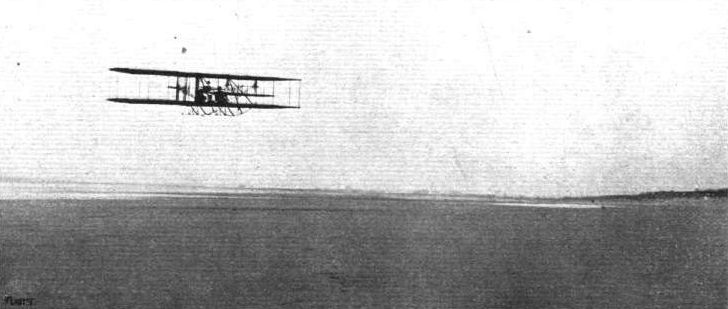
Mr. Stuart Ogilvie flying on his Short-Wright biplane over Camber Sands.

Mr. Claude Grahame-White, on his Henry Farman at Wolverhampton, flying over Mr. Ogilvie's Wright machine, which is being towed back to the starting place.
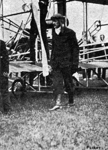
The late Hon. C. S. Rolls after his first official flight on Monday last at the Bournemouth Meeting.
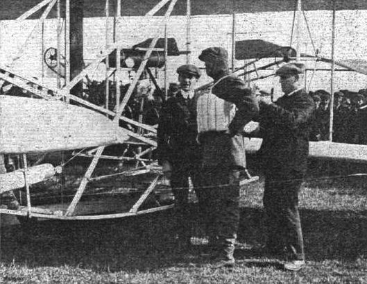
The Hon. C. S. Rolls has his lifebelt adjusted prior to his attempt to fly the Channel on his Wright machine.
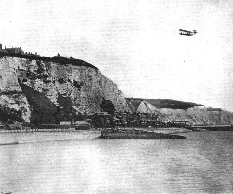
The Hon. C. S. Rolls' Epoch-making Flight, on his Short-Wright type Biplane, across the Channel and back last week. - A "composite" photograph, giving a vivid impression of the flight as seen from the water.
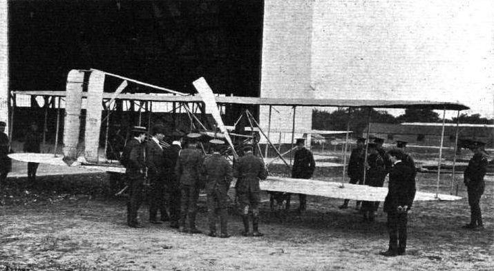
As announced last week, the Hon. C. S. Rolls has been giving helpful instruction to the officers at Aldershot in connection with the Wright biplane which has now its home there with the Army. Our picture shows Mr. Rolls (with the cap and muffler) explaining the working of the machine. Mr. Mervyn O'Gorman is standing to his left.
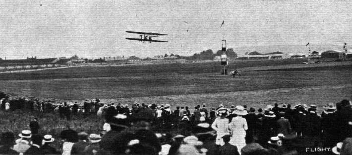
The late Hon. C. S. Rolls, on his Wright flyer, starting for his trial in the Slow Competition at Bournemouth.

M. Christiaens on his Henry Farman during a long-distance flight, and above, the late Hon. C. S. Rolls going for the height prize on his Wright machine.
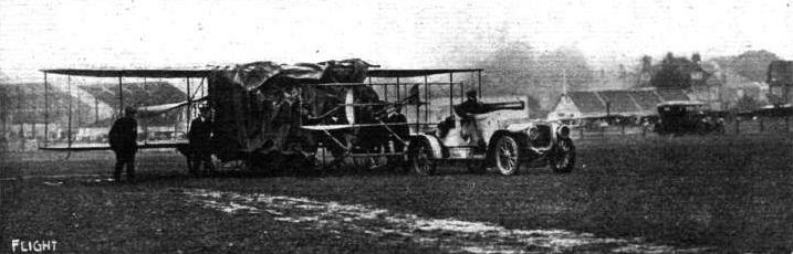
Towing back Ogilvie's machine after he was driven down to earth by a sudden storm. Note engine, &c, protected with tarpaulin.

How the Hon. C. S. Rolls, with his 6-cyl. Rolls-Royce car, towed his Short-Wright flyer from Eastchurch to Olympia. The car and "trailer" on the road. When travelling during the night, lanterns were hung round the aeroplane, with some rather amusing results amongst the sleepy waggoners and other traffic met en route.
Flight, June 4, 1910
A NEW SHORT BIPLANE, "No. 27."
A NEW biplane has just been constructed by Messrs. Short Bros., and flown by Mr. C. S. Grace, who bids fair to become one of our leading, if not actually the most expert aviator in Great Britain. The biplane is, as a mere glance at our accompanying photograph is sufficient to show, an entire departure in design so far as Short Bros.' previous practice is concerned. It embodies features, however, that are at any rate superficially suggestive of the Sommer and Henry Farman machines, and when we speak of these designs it is, perhaps, only fair to give credit to the pioneer house of Voisin, on whose original plans they were grafted.
It should be quite unnecessary to say concerning any work executed by Short Bros., however, that the design and construction are in every detail as original as if they bore no likeness to anything that anyone else had done. The machine, as the illustration shows, is a biplane that has a monoplane tail. Above and below the tail plane are the rudder planes, and in front of the main planes is a monoplane elevator. The trailing edges of both main planes, from the extremity to the next strut, are hinged so as to serve as balancing flaps. The machine is driven by an 8-cyl. E.N.V., mounted on a special framework. To the design of this framework the greatest possible care and attention is devoted, for the pilot sits in front of the engine, and in the event of a catastrophe it is most important that he should be rendered as little liable as possible to have it break away and fall on top of him. After a series of very successful flights, a mishap occurred that would have resulted in this very calamity, had not the structure behaved in the manner that was intended.
It will be observed from the photograph that the position of the machine at rest is such as to give a very considerable angle of incidence to the main planes. The tail plane is so adjusted, however, that it lifts when the slip stream of the propeller is coupled with a very low velocity over the ground, and consequently when the machine has advanced only a few yards it assumes its flying position automatically, and is very quickly in the air. The attitude of the main planes in flight is such as to give an extraordinarily small angle of incidence - this, together with the remarkable speediness of the machine (about 45 miles an hour) being the outstanding feature of this latest important Short development.
Flight, June 25, 1910
NEW BRITISH ALTITUDE RECORDS.
MOUNTED on his Bleriot machine, Mr. Armstrong Drexel on Saturday evening, at the New Forest Aviation School ground, succeeded in beating the British height record and taking it to 1,070 feet; but on Monday evening this was bettered by Mr. Cecil Grace at Eastchurch, on his new Short machine, which was fitted with an aneroid barometer. Mr. Grace steadily rose to a height of 1,180 feet, and then, switching off the ignition, glided down to earth. The gliding angle of his machine is about 15°. There was a strong wind blowing, and at times the machine was quite stationary in the air.
Flight, November 19, 1910
FROM THE BRITISH FLYING GROUNDS.
Royal Aero Club Ground, Eastchurch.
THE weather here during the past week has been very squally, but the short spells experienced in which it was at all possible to venture out have been taken full advantage of by Mr. McClean on his Gnome-engined "Short" biplane.
On Wednesday, the 9th inst., he brought out this machine, and despite a stiffish breeze immediately rose to about 100 ft. He was content, on this occasion, to remain within the immediate vicinity of the grounds, flying in circles and figure eights and executing several successful vols plane, at which, by the way, he is becoming quite an adept. One of these exhibitions was particularly clean, the machine approaching to within 15-20 ft. of the ground before the engine was re-started. Later in the day Mr. McClean was again seen to advantage, on this occasion making several short trips carrying a lady passenger.
On Thursday, the 10th, Mr. McClean again brought out his machine and made a splendid flight of over an hour's duration. He frequently passed over Harty and the surrounding country, returning each time along the coast line, and ultimately effecting a good landing from a steady vol plane of some 150 ft.
Friday was an impossible day, but on Saturday Mr. McClean beat all his previous performances by remaining aloft for well over an hour and a quarter. His journeyings on this occasion extended over Harty and Shellbeach on the one side, and Queenborough and Sheerness on the other.
Mr. McClean's performances this season have been consistently good, and his total mileage since July now stands well over 600. His machine has behaved splendidly, and has not given the slightest trouble since leaving the works.
Mr. Jezzi was out for some time on Saturday on his biplane testing the efficiency of the power plant in its new position, this having recently been altered to the front of the machine. Mr. Grace is trying a similar experiment on one of his "Short" biplanes, and we shall hope to give some particulars of the trials of both these machines, which will be held during the next week if weather conditions are favourable, in our next issue.
Sunday and Monday were blank days, the weather being wretched.
On Tuesday, the 15th inst., Mrv McClean brought out his latest "Short" biplane. This is on the lines of the Farman, but embodies all the original features of Short Bros', productions. The machine was only completed on Monday, but after devoting about half-an-hour to the tuning up of its Gnome engine, Mr. McClean essayed a short trial. She rose at the first attempt in about 100 yards or so, and flying at about 50 ft. Mr. McClean completed several circuits before bringing her down. After lunch Mr. McClean was quickly off the mark, rising sharply to a height of some 150 ft. Keeping at this altitude he completed eight or nine circuits of the ground in good time, when he landed for a few further adjustments to the engine. Shortly afterwards he made a further flight, and this time gave a good exhibition of "planing." These three flights represented a total of some three minutes short of the hour - not bad for the first spin. The machine rides the wind beautifully, answers to the helm readily, and from all appearances will develop a good turn of speed when the engine is thoroughly tuned up.
Flight, December 31, 1910
THE DE FOREST CROSS-CHANNEL PRIZE.
The Disappearance of Mr. Grace.
THE one absorbing topic among those interested in aviation and flying matters during the past week has been the mysterious disappearance of Mr. Cecil Grace, and although we are still hoping against hope that he may yet be found, the worst fears have to be entertained, as it is patent to all who have experience of such matters that so long without news of any sort is terribly ominous of the worst. It is now a matter of history of how in his attempt to beat Mr. Sopwith's record for the Baron de Forest's prize Mr. Cecil Grace left Dover about 9 o'clock on the morning of December 22nd and flew over to France, where after making a wide circle over the country he landed at Las Baraques, near Calais. Mr. Grace decided to come down, as the conditions and the wind militated against any chance of doing better than Mr. Sopwith. By half-past two, taking advantage of a lift in the haze, Mr. Grace determined to fly back to Dover in order to be ready for a fresh attempt on the prize. He had previously arranged with the captain of the mail boat "Pas de Calais" to start from France some time after the boat left and follow its course by the smoke. The mail boat, however, was some ten minutes late in leaving Calais and Mr. Grace passed out to sea before she left, there to encounter a bad sea fog by which he appears to have been entirely engulfed. Since then nothing has been heard of Mr. Grace except that it was reported from the North Goodwins Lightship that an aeroplane had passed over the vessel, while a coastguard at Ramsgate declared that he heard the noise of an aeroplane's engine at a point which he estimated to be six miles off the shore. The skipper of a Ramsgate fishing smack also reported having seen a biplane when fishing to the south-west of the East Goodwins Lightship.
On Friday, the 23rd, on the urgent representations of the Royal Aero Club, the Admiralty officials at Sheerness and Chatham readily did everything that they could to assist in a most strenuous search for Mr. Grace. On Sunday morning the Aero Club officials were startled to receive a cable message from Lima, Ohio, to the following effect:- "Grace landed with machine in crevice under high cliff, exact location unknown." To this a reply was sent asking for further details, when the following message was received:- "Dropped on shore, not water. Could not rise above cliff. Request British east coastline people to search water's edge minutely." Under the distressing circumstances, even so curious a chance as this was not passed by. In fact, after an emergency meeting with the brothers of Mr. Grace, steps were taken by the Royal Aero Club to communicate with the coastguard and naval officers, and a thorough examination of the entire coastline was made, but without any trace of the missing aviator or his aeroplane being found. The Aero Club officials have, indeed, not spared themselves throughout the whole holidays in organising search parties, and in doing everything humanly possible to assist in the unfortunately fruitless search for Mr. Grace. There still remains the last glimmer of a hope that he may have been picked up by some slow sailing vessel or a fishing boat, to be heard of possibly in a day or two, and it is to this faint comfort only that the lost aviator's friends and coworkers must cling for a while longer.

Short Biplane, "No. 27."
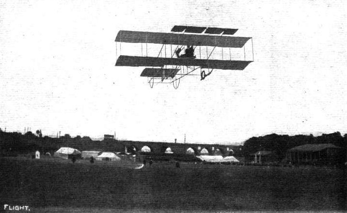
WOLVERHAMPTON FLIGHT MEETING. - General view of the aerodrome looking towards the hangars. Mr. Cecil Grace in flight on his Short biplane.
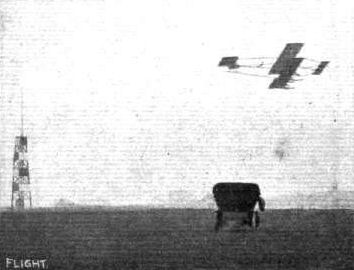
Cecil Grace, on his "Short" biplane, gets up for the Altitude Contest.

FLYING IN THE FACE OF THE SETTING SUN. - A "November setting," by Dr. William J. S. Lockyer, to Mr. Frank K. McClean and his Short biplane at the Royal Aero Club's ground, Eastchurch. This picture is a fine example of a Genuine photograph, and was secured by Dr. Lockyer on the evening of November 6th just before sunset. It was on this machine that Mr. McClean has recently been making his long cross-country flights.
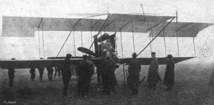
Mr. Cecil Grace ready in the pilot's seat prior to his start for the De Forest Cross-Channel Prize,
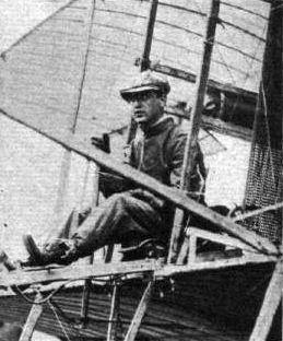
THE FLYING MEN AT BOURNEMOUTH AND THEIR "MOUNTS." - Cecil Grace (Short).
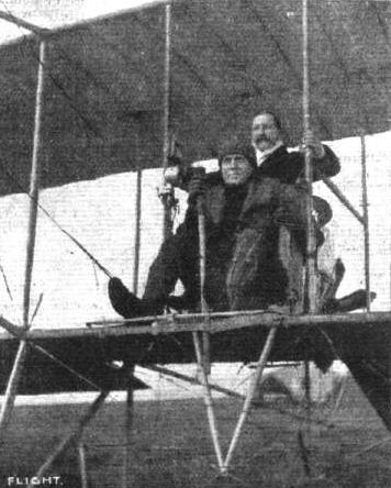
Mr. Frank K. McClean and his first passenger, Dr. William J. S. Lockyer, with whom, on his Short biplane, he flew on October 22nd at the Royal Aero Club grounds at East' church, Sheppay. Mr. McClean has been, as we record, making some splendid cross-country flights, one lasting for 1 hr. 6 mins.
Flight, January 8, 1910
MODEL FLYER.
I receive your paper as a member of the Aero Club, and have read with great interest Mr. Horace W. Vaughan's article. During the last few months my brother-in-law and I have been experimenting with a glider of almost identical design, and with very similar results. The frame of our glider was of bamboo throughout, with piano wire stays. It has had plenty of falls, and many struts and stays have been broken from time to time, but these can be easily and quickly replaced. Since September it has been left in the open under an old oak tree, and still is apparently none the worse. We have had several successful flights with a passenger, but the pressure of the wind, acting against the men towing on the ropes, had to be sufficiently strong to enable the glider to support the passenger at the same angle that it assumed when flown without the passenger. Otherwise it would not rise. We attributed this at first to the excessive weight of the tail. To rectify this we added a front elevator, consisting of a single adjustable plane. Greatly to our disappointment this made matters no better. The glider still would not lift except at the same large angle. Further, the increased surface made it impossible to make good progress against the wind unless we had several men on the ropes. Without the elevator two men were sufficient. To try and discover how much pressure was required to maintain longitudinal balance we removed both tail and elevator, and flew the main planes by themselves. To steady and prevent them tipping over, we attached a cord to the middle of the lower back strut. With two men towing the front ropes, and a third regulating the cord from the rear, the main planes flew very steadily. We were greatly surprised at the very small pressure that was required on the cord behind to maintain the planes at the correct angle. This convinced us in the idea that our tail was by far too heavy. We are now building a light tail, with a single plane and a vertical panel on the Santos Dumont principle.
Sundridge Park. A. SlM.
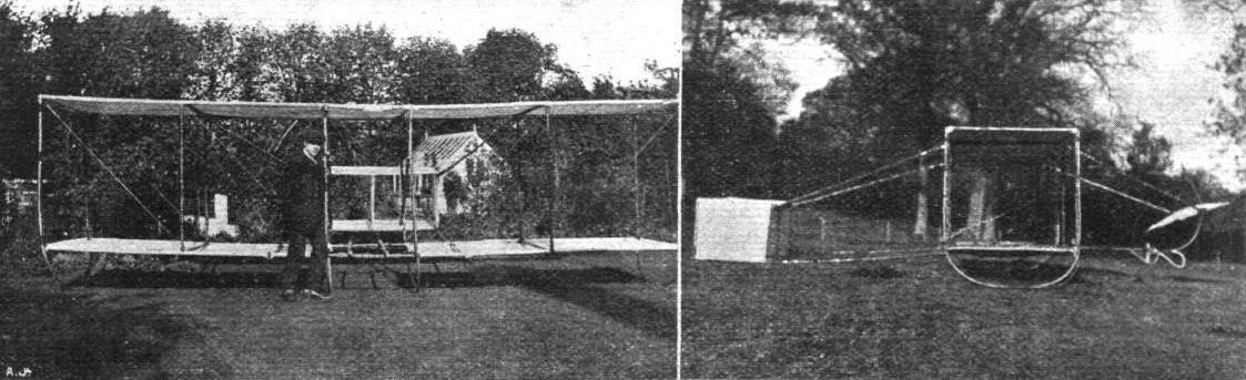
MR. A. SIM'S BIPLANE GLIDER.
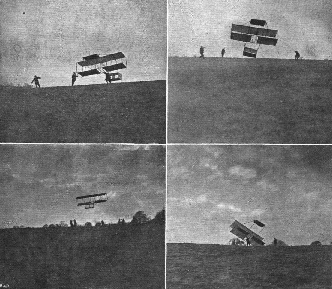
GLIDING EXPERIMENTS. - Mr. A. Sim, who has been making some successful gliding flights, has sent us some valuable hints, in a letter which appears in our correspondence columns, as a result of his experience, accompanied by some interesting photographs, reproduced above. The upper pictures show the glider rising off the ground. On the left, below, a good flight is in progress without the elevator, and, on the right, one of the troubles from which lessons are learnt.
Flight, November 12, 1910
ANOTHER BRITISH MACHINE.
I enclose two photos of a monoplane, which I hope you will consider worthy of illustration in your journal.
This machine was built by my brother and a friend (both engineers) and possesses several novel features. The frame is made of steel tubing, welded by oxy-acetylene process; the backbone is of bamboo, and the main plane is in one piece, and can easily be detached from the frame.
The pilot's seat is below the main plane, giving a low centre of gravity.
All the controls are by the steering-wheel, which is raised and lowered for elevating and descending, and moved right or left for warping wings.
Although this machine was designed long before the particulars were published in your journal, it is very similar to the successful German monoplane built by Herr Grade.
The constructors have been unable to give this machine a fair trial owing to lack of funds and a suitable practice ground, and I thought you might be able to put them in touch with someone interested who would assist them, for a share in the machine.
Beckenham. ARTHUR H. SIPPE.
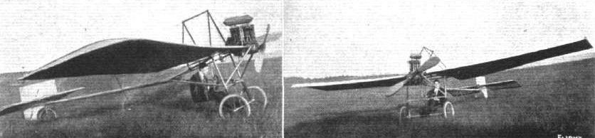
Sippe monoplane was constructed by the brothers and a friend at Beckenham in 1910 and was tested at Addington.
Flight, March 12, 1910
THE SECOND OLYMPIA AERO SHOW.
AEROPLANES.
Spencer-Stirling.
MONOPLANE having a span of 34 sq. ft. and a lifting surface of 200 sq. ft. It is fitted with an R.H. 4-cyl. engine.
Flight, April 2, 1910
FLYER SILHOUETTES FROM OLYMPIA.
THE SPENCER-STIRLING MONOPLANE.
Leading Particulars of the Spencer-Stirling Monoplane.
General Dimensions.-Areas-Main planes, 200 sq. ft.; fixed tail, about 19 sq. ft.; elevator, about 19 sq. ft.; rudder, 6 sq. ft.
Lengths.-Span, 34 ft.; chord, 6 ft.; camber, 3 in., situated about 2 ft. from leading edge; leverage of rudder, 21 ft. 6 in.; skid track, 5 ft.; overall length, 27 ft.
Angles.-Incidence, 10° ; dihedral, 1 in 17.
Materials.-Timber: English ash throughout; fabric, Dunlop.
Engine.-40-h.p. "R . H ."
Propellers.-Two Spencer-Stirling; diameter, 6 ft. 6 in.; pitch, 10 ft.
Weight.-Machine, 382 lbs.; engine, 268 lbs.; driver, oil, petrol and water, 200 lbs.; total flying weight, 850 lbs.; loading (all weight supported on main planes), 4.3 lbs. per sq. ft.
Speed of Flight.-40 m.p.h.
System of Control.-Warping, elevator and rudder.
Price.-L650.
THE characteristic feature of this machine is the use of two tractor screws, which are mounted on outriggers in front of the main wings, and are driven by chains direct from the engine. Although neither of the chains is crossed, the propellers do not both revolve in the same direction, as a reverse gear is included in the bracket that supports one of the propellers. The chassis is an example of the "A" frame, and the sloping members are carried to an apex. Two radiators lie between the upper portions of the frame, but although this is a neat and compact position for them, it seems to us that they are likely to interfere somewhat with the pilot's view.
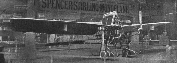
General view of the Spencer-Stirling monoplane, exhibited on the Berliet stand. This is the only monoplane fitted with twin screws.
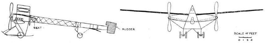
WING SECTIONS. - The above diagrams afford an interesting comparison of the wing sections of aeroplanes exhibited at Olympia. They are all drawn to a common scale, but have been set at an arbitrary angle of incidence, which does not necessarily represent that of the aeroplane In actual flight.
Flight, February 19, 1910
THE STAR MONOPLANE.
YET another British aeroplane is illustrated by the accompanying photograph, the machine in question being a monoplane built by the Star Engineering Co. at their Wolverhampton Works.
This monoplane has a span of 38 ft. and an overall length of 30 ft. The framework is built of ash braced with steel wires, while the body is divisible into two parts for convenience in transport, the division point of the frame occurring just behind the pilot's seat. The wings are double surfaced and are set at a dihedral angle; they are braced to a central mast by radiating wires. The tail consists of a horizontal plane and a vertical plane; and both these members are extended by hinged planes, thus forming a rudder and elevator, of which the exact details of control are the subject of patents taken out by the manufacturers. All movements of the machine are controlled by the steering wheel, which operates both sets of steering planes.
Beneath the machine in front is a light wood chassis, having a pair of skids that also carry a pair of aluminium wheels for use when running along the ground. These wheels are suspended by light leaf springs that allow them to rise sufficiently far for the runners to take the entire weight of the machine in the event of sudden shocks, and the tail end of the machine is protected by a light skid. After preliminary trials in Dunstall Park it was found advisable to replace the aluminium wheels with larger pneumatic-shod wheels, the metal wheels being too liable to sink into the ground in its present heavy state in consequence of the recent bad weather.
As will be seen from the photograph, the engine is situated right in front and drives a two-bladed tractor-screw that exerts a pull of 180 lbs. at 1,200 r.p.m. The blades of the screw are made of aluminium, stiffened by a strip of steel riveted along the back, while the entire surface is highly polished. Arranged alongside the body somewhat on the lines of the "Antoinette," the radiator consists of a large number of thin brass tubes, and the circulation of the cooling water is effected by a pump.
Without the pilot, the total weight of the machine is 876 lbs., and it is expected that a speed of 30 miles per hour will be necessary for ascent. It is fitted with an exact replica of the 15-h.p. Star engine that made such good running on the Brooklands Track recently, and from which as much as 30-h.p. has been obtained.
This engine is only fitted temporarily pending the completion of a special 50-h.p. motor that is being constructed at the Star works, and is expected to weigh about 100 lbs. less than the motor now being used.
Up to the present no attempts at actual flight have been made, the pilot merely running the machine round the track, minus the wings, so that he might become thoroughly familiar with the working of the controlling gear.
Flight, March 12, 1910
THE SECOND OLYMPIA AERO SHOW.
AEROPLANES.
Star.
BRITISH-BUILT monoplane of the "Antoinette" type, the span being 42 ft., while the wings have a cord bearing from 8 ft. 6 ins. at the junction with the body to 6 ft. at the tips. It is driven by a 6-ft. tractor screw connected to a 40-h.p. engine. The tail is formed of 4 planes which steer and elevate in the usual way, but also can be warped for maintaining lateral stability, and the whole of these movements are carried out from the one steering-wheel.
Flight, April 23, 1910
FLYER SILHOUETTES FROM OLYMPIA.
THE STAR MONOPLANE
Leading Particulars of the Star Monoplane.
General Dimensions.-Areas-Main planes, 290 sq. ft.; fixed tail, 28 sq. ft.; elevator, 20 sq. ft.; rudder, 20 sq. ft.
Lengths.-Span, 42 ft.; chord, 8 ft. to 6 ft. 6 ins; camber, 4 ins., situated about 24 ins. from leading edge; skid track, 5 ft.; overall length, 32 ft.
Angles.-Incidence, 6 degrees; dihedral, 1 in 13.
Materials.-Timber, ash throughout; fabric, Dunlop.
Engine.-40-h.p. Star.
Propeller.-Star; diameter, 6 ft. 6 ins.; pitch, 4 ft.; material, aluminium.
Weight.-Machine, 395 lbs.; engine, 155 lbs.; driver, oil, petrol and water, 200 lbs.; total flying weight, 750 lbs.; loading (all weight supported on main planes), 2.5 lbs. per sq. ft.
Speed of Flight.-36 m.p.h.
System of Control.-Entirely by helicoidal movement of rudder and elevator.
Price.- L450.
THE most important and interesting feature of this machine is the method by which it is controlled by movements of the tail planes. There are four movable tail planes, all of them identical in shape and area, two of them normally horizontal and two vertical. The vertical pair when moved together act as a rudder, and the horizontal pair similarly perform the purpose of an elevator when moved together. Provision is, however, made for moving the tail planes in different directions, the pilot being able to move all four simultaneously and equally so that they are arranged in the form of a helix. That is to say, suppose the upper rudder plane has its trailing edge moved over to the right, then the trailing edge of the lower rudder plane will be moved over to the left; the right hand elevating plane will have its trailing edge depressed, and the left hand elevating plane will have its trailing edge raised. The air pressure acting upon each plane separately has the resultant that forms a torque or twisting action upon the body of the machine, the direction of which will be anti-clockwise, or left-handed, for the case stated above, when looking at the machine from behind. That is to say, the effect of arranging the planes as above will tend to lower the wing situated on the pilot's left.
The relatively low price of this machine is also a feature. It has been designed by Granville E. Bradshaw. Another interesting detail of the Star monoplane is the chassis, which represents a very simple form of "A" frame, the sloping members being carried to an apex to which the main wings are trussed. The machine is mounted upon a pair of wheels, but there is a central skid that takes the load in the event of a severe shock. The method of suspending the wheels somewhat resembles the Bleriot system, but has been carried out on an altogether different scale. With the exception of the struts between the wheel hubs and the spring buffers, almost the entire chassis is made of timber. The main frame of the machine forms a triangular box-girder, as on the Antoinette monoplane, and the arrangement of the tubular radiator at the side of the body is also similar. Altogether this machine gave evidence of being one of the most carefully thought out designs in the Show.
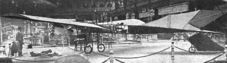
OLYMPIA, 1910. - On the Star monoplane the trailing edges of the wings are flexible, and the four similar pivoted planes forming the rudder and elevator - which comprise the moving members of the tail - can be so manipulated in flight as to produce a torque on the frame for the purposes of maintaining lateral equilibrium.
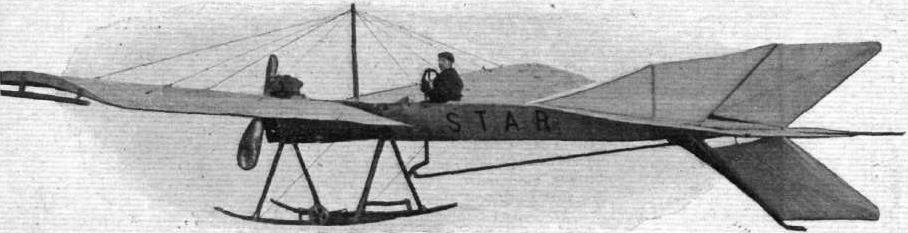
The "Star" Monoplane.
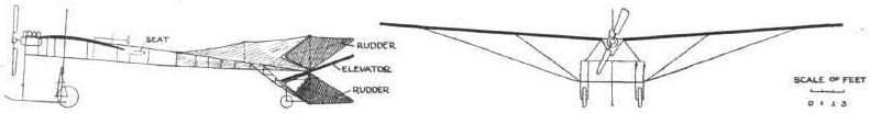
WING SECTIONS. - The above diagrams afford an interesting comparison of the wing sections of aeroplanes exhibited at Olympia. They are all drawn to a common scale, but have been set at an arbitrary angle of incidence, which does not necessarily represent that of the aeroplane In actual flight.
Flight, November 19, 1910
AEROPLANES AT THE STANLEY SHOW.
<...>
The Steward monoplane shown by the Scout Aero Club is superficially of conventional design but of very small size. The width is only 16 ft., and the length overall 15 ft. The wooden fuselage resembles the type made popular by M. Bleriot. The two wings have a bearing-surface of 75 sq. ft., and are placed at a pronounced angle of inclination. Behind a fixed non-lifting tail plane is a cruciform tail of Demoiselle type pivoted to the fuselage. Lateral stability is maintained by small ailerons fitted to the trailing edge of the main planes. A wheel control is employed, the backward and forward movement of which operates the elevator and a sideways movement the ailerons. The rudder is moved by a foot-lever. An Alvaston 20-h.p. 2-cyl. water-cooled engine is fitted, driving a small wooden propeller.
<...>
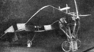
AT THE STANLEY SHOW. - The Steward monoplane, which, it will be noticed, has hinged ailerons fitted to the trailing edges of the main plane.
Flight, April 23, 1910
Mr. Thiersch at Erith.
AFTER making several short flights with his new aeroplane over the Belvedere marshes, Erith, Mr. Thiersch made arrangements to make a long trial, but unfortunately one of the main wooden struts was smashed. This will necessitate the suspension of the experiments for several days.
Flight, April 23, 1910
Mr. Handley Page at Barking.
SEVERAL short but successful flights were made by Mr. Handley Page on his monoplane at his flying grounds at Barking on the 26th ult., and Mr. Thiersch, who made a flight of three-quarters of a mile at Belvedere on the same day, used a machine which was built by Mr. Handley Page at Barking.
Flight, March 12, 1910
THE SECOND OLYMPIA AERO SHOW.
AEROPLANES.
Twining.
BIPLANE of the tail-less type, with a monoplane elevator in front. The main planes have a span of 28 ft., whilst the cord is 4 ft. 6 in. The gap at the centre is 5 ft. 6 in., diminishing to 4 ft. 6 in. at the tips, the lower plane being curved upwards at the ends. Lateral stability is maintained by means of ailerons pivoted on the end stanchions, at an angle of 450 to the horizontal. The ailerons are inter-connected, having a constant angle of 900 between them, so that the movement of one in a certain direction is followed by a corresponding movement of the other in the opposite direction.
WING SECTIONS. - The above diagrams afford an interesting comparison of the wing sections of aeroplanes exhibited at Olympia. They are all drawn to a common scale, but have been set at an arbitrary angle of incidence, which does not necessarily represent that of the aeroplane In actual flight.
Flight, December 10, 1910.
IS THE HELICOPTER POSSIBLE?
[940] Although from time to time, both in FLIGHT and the public Press, the question of the helicopter or self-raising machine is discussed or referred to, it is significant that there is no actual example of this type of machine that has ever flown or even risen from the ground by its own power, although we read of "propellers" or "lifters" having been constructed showing a high duty in thrust in lbs. per sq. ft.
From consideration of the matter it seems to me that the true explanation of the failure of the helicopter to materialise is that it is a mechanical impossibility to construct one owing to the mechanical and structural difficulties which arise from the inevitable concentration of weights in a helicopter machine, for the following reasons. As the helicopter propeller or lifter has to lift the total weight of the whole machine from the ground from a state of rest, it is evident that the "lifter" or "propeller" must be of a sufficient size and strength to move a volume, and therefore weight of air at a sufficient velocity to not only balance the total weight to be lifted, but also provide an excess of power, and therefore weight to cause the translation of the machine after being lifted. And it will be seen that this necessitates the whole load, due to the total weight of the machine, and that excess required for the translation of the machine through the air, being borne at a point over the end of the axle of the propeller or lifter ; and the strength of the framework of the machine to take this concentrated load requires a structural weight which at once precludes any chance of its being lifted, as there is no known material which could be used and would give the required strength and necessary lightness, even if no factor of safety were provided for.
Admitting that probably anyone attempting to construct a helicopter would use two or more propellers instead of one, that will not make the case any better but rather worse, for although the total weight to be borne would be divided between the propellers, still the share of the weight of each propeller is still concentrated above it, and it will be found that the combined weights of the structures and each propeller will be actually heavier than if one propeller only were used. Further, in a helicopter, it is necessary that the propellers or lifters are unobstructed both above and below to allow of free entry and egress of air to and from the propeller. This necessitates a cantilever type of construction by which the strains set up in the structure are, of course, enormously increased.
Take the case of a propeller of 25 ft. diameter, and suppose it to be revolved at a sufficient rate to lift 3 tons (that is to say, it would just balance 3 tons, and no extra power is available for progress), one half of its diameter would be 12 ft. 6 ins., and allowing 1 ft. for clearance, the length of the cantilever from its junction with the body of the machine to the centre of the propeller-shaft would be 13 ft. 6 ins., and assuming that the depth of the supporting-arm at its junction with the body of the machine is 2 ft. 6 ins., the strain in the top and bottom members of the arm at this junction will be 16 tons 4 cwt. to tear it away at the bottom and the same to crush the members at the top, from which it will be seen that nothing but an iron plate girder could carry the weight, and this is allowing for no factor of safety. In such a construction a factor of safety of 2 at the lowest would be required; this would at once double the strains the structure is to be capable of bearing, which would then be 32 tons 8 cwt. at bottom and top respectively, and there is still to be added the extra thrust of the propellers required to propel the machine. No wonder the helicopter has never materialised, for it is an impossible machine, in my opinion.
Maidenhead. CHARLES JAMES REYNOLDS.
Flight, December 24, 1910.
IS THE HELICOPTER POSSIBLE?
[978] With regard to your correspondent's remarks re helicopter flying machines, these are, at any rate at present, not a practicable type of machine as helicopters pure and simple, but given a suitable plane surface as a weight-carrying medium, it appears to me that helical screws could be used to very great advantage in assisting when rising or descending, and for other manoeuvres, as providing a more positive and quicker means of handling an aeroplane.
If it were not possible to actually elevate and sustain the necessary load by means of the screws alone, it should be possible by their aid to get up with a much shorter run than at present, and also to sustain oneself in the air at a very much lower flight speed than is now required with the thrust of large diameter screws, of small pitch ratio, helping to maintain and equilibrate the machine if suitably arranged.
This would greatly facilitate the handling of a flying machine, especially for scouting and other observation purposes, and would probably enable the machine to practically hover in the air, or at any rate to descend very slowly, under the sustaining influence of its screws.
I cannot agree with Mr. Reynolds' figuring of the probable necessary weight of such a machine, in fact if, say, two large diameter screws were arranged to pull the machine up from the ground, which would probably be found more convenient for constructional purposes, the weight could hang suspended from the axis of each screw, on a light framework similar to the method used on dirigibles.
A smaller propelling screw could be used to acquire velocity to raise the machine from the ground, if assisted by plane surfaces, and powerful vertical screws, and should result in a very quickly rising machine. As a purely direct lift machine, I am of opinion that the ornithopter is the probable type, although I seem to recollect a French helicopter, by one M. Cornu, I believe it was, getting off the ground, but very few particulars were published, and as the experiments were carried out some four years ago nothing very striking can have resulted, or more would have been heard of the machine.
From experiments with my ornithoplanes I have found that a very positive lifting effect can be obtained by flapping wings properly arranged, and I have no doubt that a successful machine of this type will be evolved which will rise straight from the ground. He will be a bold man who can say that anything is impossible in these days of scientific advancement, and every new development in light yet strong metals, improved motive powers, &c., only places more material to the hand of the worker wherewith to attain his end, and render possible the conquest of that elusive element the air.
My ornithoplane No. 2, equipped with a new type of 40-50-h.p. aerial engine, and embodying several of my ideas in this direction, will be out again shortly, and in the meantime I shall be pleased to give particulars of my experiments and the results obtained to anyone who is interested in the above types of flying machines, as I believe that the exchange of ideas on such a subject may often save time and money which would otherwise be wasted in following out useless experiments, and which could be used in advancing along the paths pointed out by the many failures of the past, which have at least resulted in a partial solution of the problem of mechanical flight.
Coventry. WILLIAM A. WEAVER.
IS THE HELICOPTER POSSIBLE?
[940] Although from time to time, both in FLIGHT and the public Press, the question of the helicopter or self-raising machine is discussed or referred to, it is significant that there is no actual example of this type of machine that has ever flown or even risen from the ground by its own power, although we read of "propellers" or "lifters" having been constructed showing a high duty in thrust in lbs. per sq. ft.
From consideration of the matter it seems to me that the true explanation of the failure of the helicopter to materialise is that it is a mechanical impossibility to construct one owing to the mechanical and structural difficulties which arise from the inevitable concentration of weights in a helicopter machine, for the following reasons. As the helicopter propeller or lifter has to lift the total weight of the whole machine from the ground from a state of rest, it is evident that the "lifter" or "propeller" must be of a sufficient size and strength to move a volume, and therefore weight of air at a sufficient velocity to not only balance the total weight to be lifted, but also provide an excess of power, and therefore weight to cause the translation of the machine after being lifted. And it will be seen that this necessitates the whole load, due to the total weight of the machine, and that excess required for the translation of the machine through the air, being borne at a point over the end of the axle of the propeller or lifter ; and the strength of the framework of the machine to take this concentrated load requires a structural weight which at once precludes any chance of its being lifted, as there is no known material which could be used and would give the required strength and necessary lightness, even if no factor of safety were provided for.
Admitting that probably anyone attempting to construct a helicopter would use two or more propellers instead of one, that will not make the case any better but rather worse, for although the total weight to be borne would be divided between the propellers, still the share of the weight of each propeller is still concentrated above it, and it will be found that the combined weights of the structures and each propeller will be actually heavier than if one propeller only were used. Further, in a helicopter, it is necessary that the propellers or lifters are unobstructed both above and below to allow of free entry and egress of air to and from the propeller. This necessitates a cantilever type of construction by which the strains set up in the structure are, of course, enormously increased.
Take the case of a propeller of 25 ft. diameter, and suppose it to be revolved at a sufficient rate to lift 3 tons (that is to say, it would just balance 3 tons, and no extra power is available for progress), one half of its diameter would be 12 ft. 6 ins., and allowing 1 ft. for clearance, the length of the cantilever from its junction with the body of the machine to the centre of the propeller-shaft would be 13 ft. 6 ins., and assuming that the depth of the supporting-arm at its junction with the body of the machine is 2 ft. 6 ins., the strain in the top and bottom members of the arm at this junction will be 16 tons 4 cwt. to tear it away at the bottom and the same to crush the members at the top, from which it will be seen that nothing but an iron plate girder could carry the weight, and this is allowing for no factor of safety. In such a construction a factor of safety of 2 at the lowest would be required; this would at once double the strains the structure is to be capable of bearing, which would then be 32 tons 8 cwt. at bottom and top respectively, and there is still to be added the extra thrust of the propellers required to propel the machine. No wonder the helicopter has never materialised, for it is an impossible machine, in my opinion.
Maidenhead. CHARLES JAMES REYNOLDS.
Flight, December 24, 1910.
IS THE HELICOPTER POSSIBLE?
[978] With regard to your correspondent's remarks re helicopter flying machines, these are, at any rate at present, not a practicable type of machine as helicopters pure and simple, but given a suitable plane surface as a weight-carrying medium, it appears to me that helical screws could be used to very great advantage in assisting when rising or descending, and for other manoeuvres, as providing a more positive and quicker means of handling an aeroplane.
If it were not possible to actually elevate and sustain the necessary load by means of the screws alone, it should be possible by their aid to get up with a much shorter run than at present, and also to sustain oneself in the air at a very much lower flight speed than is now required with the thrust of large diameter screws, of small pitch ratio, helping to maintain and equilibrate the machine if suitably arranged.
This would greatly facilitate the handling of a flying machine, especially for scouting and other observation purposes, and would probably enable the machine to practically hover in the air, or at any rate to descend very slowly, under the sustaining influence of its screws.
I cannot agree with Mr. Reynolds' figuring of the probable necessary weight of such a machine, in fact if, say, two large diameter screws were arranged to pull the machine up from the ground, which would probably be found more convenient for constructional purposes, the weight could hang suspended from the axis of each screw, on a light framework similar to the method used on dirigibles.
A smaller propelling screw could be used to acquire velocity to raise the machine from the ground, if assisted by plane surfaces, and powerful vertical screws, and should result in a very quickly rising machine. As a purely direct lift machine, I am of opinion that the ornithopter is the probable type, although I seem to recollect a French helicopter, by one M. Cornu, I believe it was, getting off the ground, but very few particulars were published, and as the experiments were carried out some four years ago nothing very striking can have resulted, or more would have been heard of the machine.
From experiments with my ornithoplanes I have found that a very positive lifting effect can be obtained by flapping wings properly arranged, and I have no doubt that a successful machine of this type will be evolved which will rise straight from the ground. He will be a bold man who can say that anything is impossible in these days of scientific advancement, and every new development in light yet strong metals, improved motive powers, &c., only places more material to the hand of the worker wherewith to attain his end, and render possible the conquest of that elusive element the air.
My ornithoplane No. 2, equipped with a new type of 40-50-h.p. aerial engine, and embodying several of my ideas in this direction, will be out again shortly, and in the meantime I shall be pleased to give particulars of my experiments and the results obtained to anyone who is interested in the above types of flying machines, as I believe that the exchange of ideas on such a subject may often save time and money which would otherwise be wasted in following out useless experiments, and which could be used in advancing along the paths pointed out by the many failures of the past, which have at least resulted in a partial solution of the problem of mechanical flight.
Coventry. WILLIAM A. WEAVER.
Flight, December 10, 1910
Passenger Carrying by Brunnhuber.
SIMON BRUNNHUBER, who has just been appointed instructor at the Military Aviation Ground at Doeberitz by the Prussian War Minister, accomplished a notable performance on the 24th ult. Using his German-built Sommer machine, he took up three passengers beside himself, and carried them for 2 1/2 kiloms., landing after a three minutes flight in splendid style.
Flight, December 17, 1910
Doings at Johannisthal.
ORVILLE WRIGHT was at the Johannisthal flying ground on the 6th inst, and made a flight of several circuits of the aerodrome at a height of 150 metres. On the following day Brunnhuber repeated his exploit of taking four passengers with him on his Farman machine for two circuits of the ground, while Capt. Engelhardt, on a new Wright biplane, made a cross-country flight at a height of 300 metres, passing over Glienicke, Schoenefeld, Eichwalde, Gruenau, to Aldershof and back.
It is a rather curious coincidence that two of the aviators at Johannisthal should have met with trouble through losing their propellers last week-end. On Saturday afternoon Brunnhuber was flying on his German-built Farman at a height of 50 metres when the propeller dropped off, but the aviator was able to land safely and without damage. Two days later Thelen was giving a passenger a trip on his Wright biplane when the starboard propeller fell off. The machine dropped suddenly from a height ot six metres to the ground and although Thelen himself was unhurt, the passenger was rather severely shaken up, while the machine was smashed.
Last week a deputation of Russian military officers paid a visit to the Johannisthal Flying Ground, where they were especially interested in the Albatross Works, which builds Farman biplanes in Germany. It is rumoured that the Russian Government intend to order a number of aeroplanes from this firm.
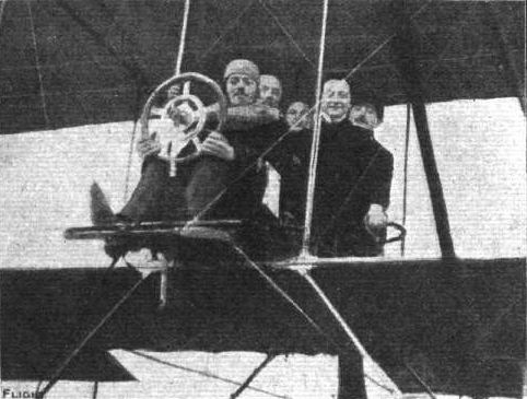
Brunnhuber, the German aviator, on his "Albatross" biplane, with his four passengers, whom, on December 7th, he carried twice round the Johannisthal flying grounds.
Flight, November 26, 1910
FOREIGN AVIATION NEWS.
Prince Henry Qualifies as a Pilot.
DURING last week Prince Henry was continuing his practice on the Euler biplane, and on the 16th flew 4 kiloms. at a height of 15 metres. On Saturday last, on the military parade ground at Darmstadt, he successfully qualified for the pilot's certificate of the German Aeronautic Association, the official observers being Herr von Hiddessen, Herr von Hammacher, and Herr Auguste Euler.
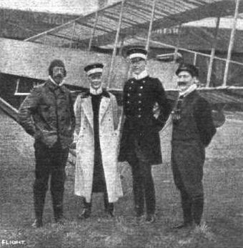
Prince Henry of Prussia in his aviator's dress, after qualifying for his pilot's certificate at Frankfurt on the Euler biplane. Reading from left to right are: Prince Henry, von Hammacher, von Hiddessen, and August Euler, the Prlnce's instructor.

GERMAN FLYERS - the Hanuschke biplane;
Flight, January 1, 1910
THE LILIENTHAL AND PILCHER GLIDERS COMPARED.
<...>
The Pilot's "Seat" and its Consequences.
Although Pilcher was doubtless inspired to his work by Lilienthal's example, it is apparent that he brought an original mind to bear in the constructive details of his task, whatever bias he may have been under to follow his leader's methods in their general lines. Constructionally the two gliders are as different as they can well be for machines of such similarity in size and purpose. But Pilcher and Lilienthal had this much in common, that they both employed the same method of riding their machines, by hanging upon them, and from such experience as has since been collected by the Brothers Wright, there is little doubt that the custom was at the bottom of many of their difficulties, if not actually the cause of Lilienthal's death. One consequence of deciding to use a glider as Lilienthal and Pilcher used theirs is the necessity of designing a machine of small weight, for the pilot has to be prepared to carry the load both when launching and landing. Pilcher, it is true, fitted a small chassis to his glider consisting of two spring-suspended wheels, but this addition was no more than a compromise, as its purpose was mainly to enable him to bring the machine more easily into position, and to take some of the initial shocks of landing. In flight Pilcher's body hung suspended beneath the wings, only his head and shoulders projecting above, his weight was borne upon two bolsters fitting under the armpits. Lilienthal was perhaps even more beneath his machine than Pilcher, for his arms rested in sockets beneath the wings, and the bolsters which supported his shoulders were about on a level with the upper surface.
Stability and Control.
The greater part of their weight being thus suspended beneath the supporting surfaces caused the centre of pressure to be considerably above the centre of gravity, and although this is often thought to be conducive to automatic stability by constituting a kind of natural pendulum, as a matter of fact, the inertia of such a system very naturally complicates the control, which in both cases was carried out by the shifting of the pilot's body in whatever direction might be required to restore balance. Pilcher had quite satisfied himself upon this point before he came to the end of his experiments, and another matter upon which he became convinced was that the upward slanting of the wings # or the principle of the dihedral angle # resulted in diminished stability in sidewings.
Leading Dimensions.
Of the two machines there is little to choose in weight, as they were both supposed to be in the order of 45 to 50 lbs. when actually in use. Lilienthal's glider has the smaller amount of supporting surface, and even that machine must have been one of the largest he constructed, for he was inclined at first to build gliders having barely 110 sq. feet of deck. The span of 22 feet for the Lilienthal machine is 2 ft. 8 ins. less than the Pilcher, and the overall length is 2 ft. shorter. The height is proportionally much less than that in the Pilcher glider, owing to a different system of staying the surfaces and to the absence of a chassis.
The Tail.
Both gliders were fitted with tails of similar type although different in shape, the tail in each case consisting of one vertical plane and one horizontal plane, the latter being set at a negative angle, and being also free to rise unrestricted if subjected to any pressure from beneath. It will be distinctly noticed from the accompanying drawings that the stay wires for the horizontal planes are only arranged so as to resist pressure from above. The vertical tail plane is nominally rigid, although, in the Pilcher glider, it happens to be mounted upon the horizontal member, and thus moves with it. In the Lilienthal machine the horizontal plane is hinged separately to the vertical plane, which is attached rigidly to the main frame. It was Pilcher's object in designing the tail of his machine as shown, to make it as compact as possible for storage, and with this end in view the tail was arranged to fold over on to the main planes.
(To be concluded.)
Flight, January 8, 1910
THE LILIENTHAL AND PILCHER GLIDERS COMPARED.
Willow and Bamboo.
THERE is a subtle difference in the construction of these two gliders, otherwise so much alike, which is directly attributable to the difference in the materials employed, for where Lilienthal used willow sticks, Pilcher adopted bamboo. Both had, it will be seen, sufficiently awkward materials to deal with, but Pilcher, it must be confessed, made a far more engineering-looking job of his work than Lilienthal, whose constructive methods are somehow reminiscent of bent-wood furniture. Both designers embodied the principle of folding-wings in their machines, and thus both were under the same necessity of adapting their construction to suit the special requirements imposed by this important condition. At the same time, however, both had to provide their wings when finished with an artificial camber, and it is particularly interesting to compare the two methods by which these details were accomplished.
The Folding of the Wings.
Pilcher, who was working with bamboo, fitted the inner extremities of the ribs of his wings with wooden plugs, to which he lashed a loop of iron wire so as to form a ring. These rings he subsequently strung over the central standard, around which each wing spread out like an open umbrella. In order to close the wings, it was only necessary to unlash the attachment between the front edge and the main frame, when the ribs would then all swing round one above the other into any convenient position.
Lilienthal obtained much the same effect, but in his case the ribs folded up side by side, being hinged to a central bracket into which their wedge extremities normally fitted like the spokes of a wheel.
In this machine the hinge centres are 6 ft. apart, and in the Pilcher machine the same points are separated by a distance of 7 ft. 6 ins. In both cases the hinges are joined by a wooden beam, but whereas in the Pilcher glider this member consists of a simple rectangular piece of wood, in the Lilienthal machine it is a built-up structure in the form of the letter X; which system was adopted in order to enable the staying of the wings to be conveniently accomplished. It would doubtless have been better had Pilcher attached more importance to the strains on the main beam of his machine, because it was that which gave way during his last glide.
Pilcher and His Wire.
Pilcher adopted a very different method of bracing his wings to that employed by Lilienthal, in fact, it is in this respect that the two machines are most unlike. He relied entirely upon the use of piano-wire for cambering the surfaces of his wings to the desired shape, and in order to get the effect sought he braced each to a central hinge pin consisting of a bamboo pole some 6 ft. in height, which stood up 3 ft. above the deck and projected 3 ft. beneath it. Radiating from the top and bottom ends of this pole are a number of wires, for the most part there are three wires attached above and beneath each rib, only the two front ribs in each wing having less than this number. There are nine ribs in each wing, and altogether 50 wires were required to stay them.
How Pilcher managed to retain all these wires properly taut is a matter for conjecture, but he must have been a man of great patience if he really gave proper attention to each of the 100 wires on which the camber of his surfaces depended. It is no easy matter to adjust wires used for such a purpose, as no sooner is a slack wire tightened up a little too much, than it relieves the strain upon two or three other wires, which become slack in turn. And Pilcher, it must be remembered, worked before the days of those very pretty little wire strainers which commonly form a feature in the bracing of modern flyers, and his method of adjustment must have been as tedious as it was effective. Each of his wires he fitted with a curtain-ring - Pilcher was very fond of curtain-rings - and on the rib he fastened a wire eye. The wires were cut to a fixed length in advance, and calculated to allow about an inch between the ring and the eye when in place. This gap was filled up by a piece of string, passed several times through each member to give the required strength, and by pulling on one end of the string a very minute adjustment could be made in the tension. More curtain-rings were employed for fastening the other ends of the wires to the vertical bamboo poles, so that the wings could be folded without twisting the wires.
Another little device for which Pilcher's construction is peculiar is his method of plugging his bamboo rods with wood. The wood plugs were glued into the hollow ends of the bamboo, which were then carefully lashed with string. Pilcher was very careful about lashing the ends of his bamboo poles as he evidently fully appreciated their liability to split. His use of wire eyes as lugs is another neat detail well worthy of attention, and these little fittings he would also lash in place.
Lilienthal's Stiffening Ribs.
Lilienthal, who very possibly had a natural objection to the use of a lot of wires, hit upon a very ingenious method of doing away with some of them, for he maintained the camber of his wings by the use of detachable supplementary ribs, of which there were four placed fore and aft above the deck. These ribs were strips of wood having an inverted T section, and they were cut to shape so as to serve as templates. As their permanence would have interfered with the folding of the wings, they were fitted in such a manner as to be detachable, and the method of doing this was to fasten small steel clamps on to the primary ribs of the wings, through which the flange of the template could slide. As the wings were naturally flexible there was no difficulty in sliding the curved templates in place from one end, and once in position these members were fastened by little clips. Their purpose was primarily to give the wings the desired camber, although they would of course tend to increase the rigidity of the structure; by their use, the necessity for employing a large number of wires was obviated, in fact, there were only two tie-wires radiating from each of the vertical posts mounted above the hinge plates. Beneath the wings, however, there was a wire to every rib, but even in this respect Lilienthal contrived to do without some 78 wires which Pilcher found necessary.
Relative Cambering.
It may be remarked that the number of ribs in each of the two machines is identical, viz., 18, but the camber and arching of the wings themselves is distinctly different in the two cases. Pilcher employed an umbrella-like form, in which the camber may be described as being of a uniform character. Lilienthal, on the other hand, flattened the extremities of his wings to such an extent that the curvature of some of the ribs was virtually reversed. The maximum camber on the Lilienthal glider, as on the Pilcher machines, occurs at the hinge of the wing, which on the former is situated 18 ins., and on the latter 2 ft. 6 ins. behind the leading edge. At this point the camber is deeper on the Lilienthal than on the Pilcher glider, but on the Lilienthal machine the camber is almost confined to this point alone, and is far more concentrated, if the term may be used, than in Pilcher's construction.
It is known that Lilienthal experimented with cambers of considerable height in proportion to the chord, and he has stated that the maximum versine (camber) of the wing curvature should be less than 1/12 of the chord, and preferably only 1/18 to 1/15 for considerations of stability.
Both machines had the surface material attached above the ribs.
The Framework.
Having compared the wings and supplementary surfaces, it is of interest to consider the main frames of the two machines, by which we imply that central structure to which the whole is braced, and on which the pilot supports his weight. In the Lilienthal glider this member is of somewhat peculiar form, and is best observed by reference to the accompanying plan; it bears in a marked degree that bent-wood furniture appearance to which we have already drawn attention. One of the principal members is an approximately circular hoop of willow, across which pass in a fore and aft direction two willow rods that ultimately converge at a point where the bamboo tail rod emerges from the wing surface. Transversely across the hoop passes the main beam to which reference has already been made, and immediately behind this an orifice is provided in the surface to accommodate the upper part of the pilot's body. Two small bolsters attached to the frame rest under the pilot's shoulders, and the pilot's arms pass through rests provided for them in the corners of the X-shaped main beam. Just in front of this beam is another transverse rod which the pilot can grip with his hands, and in front of the main hoop member is another bent-wood construction lashed in place with wicker, the object of this device being to act as a fender in the event of collision.
On Pilcher's glider the main frame consists of two bamboo rods spaced 18 inches apart above the main transverse beam, to which they were lashed in a cradle. Fore and aft these members converge, and are joined together in metal sockets, that at the rear carrying a bamboo extension to the tail. The entire space occupied by the two frame members was left open in the Pilcher machine, in which respect it differs from Lilienthal's glider, where every possible square inch is covered in. The pilot on Pilcher's glider was supported by two small bolsters fitting under the armpits, which bolsters were attached to the ends of short rods projecting obliquely from the sides of the main frame. Thus supported, the pilot's forearms would rest along the frame-members, and flat pieces of wood are lashed in place at these points to give greater comfort. At the ends of these armrests two handles project for the pilot to grip.
Both machines are more or less similarly braced as regards the wings to the frame and the tail to the frame; but in the Pilcher glider a transverse wooden strut is provided between the bamboo uprights in addition to the diagonal tie-wires which alone sufficed in the Lilienthal machine. Underneath the frame on Pilcher's glider two bamboo rods project obliquely outwards and carry wooden extensions on which the chassis wheels were mounted. The hollow bamboo is here made use of to contain a spring, and the wooden extension, once more fitted in the form of a plug, in this case became a plunger.
THE LILIENTHAL AND PILCHER GLIDERS COMPARED.
<...>
The Pilot's "Seat" and its Consequences.
Although Pilcher was doubtless inspired to his work by Lilienthal's example, it is apparent that he brought an original mind to bear in the constructive details of his task, whatever bias he may have been under to follow his leader's methods in their general lines. Constructionally the two gliders are as different as they can well be for machines of such similarity in size and purpose. But Pilcher and Lilienthal had this much in common, that they both employed the same method of riding their machines, by hanging upon them, and from such experience as has since been collected by the Brothers Wright, there is little doubt that the custom was at the bottom of many of their difficulties, if not actually the cause of Lilienthal's death. One consequence of deciding to use a glider as Lilienthal and Pilcher used theirs is the necessity of designing a machine of small weight, for the pilot has to be prepared to carry the load both when launching and landing. Pilcher, it is true, fitted a small chassis to his glider consisting of two spring-suspended wheels, but this addition was no more than a compromise, as its purpose was mainly to enable him to bring the machine more easily into position, and to take some of the initial shocks of landing. In flight Pilcher's body hung suspended beneath the wings, only his head and shoulders projecting above, his weight was borne upon two bolsters fitting under the armpits. Lilienthal was perhaps even more beneath his machine than Pilcher, for his arms rested in sockets beneath the wings, and the bolsters which supported his shoulders were about on a level with the upper surface.
Stability and Control.
The greater part of their weight being thus suspended beneath the supporting surfaces caused the centre of pressure to be considerably above the centre of gravity, and although this is often thought to be conducive to automatic stability by constituting a kind of natural pendulum, as a matter of fact, the inertia of such a system very naturally complicates the control, which in both cases was carried out by the shifting of the pilot's body in whatever direction might be required to restore balance. Pilcher had quite satisfied himself upon this point before he came to the end of his experiments, and another matter upon which he became convinced was that the upward slanting of the wings # or the principle of the dihedral angle # resulted in diminished stability in sidewings.
Leading Dimensions.
Of the two machines there is little to choose in weight, as they were both supposed to be in the order of 45 to 50 lbs. when actually in use. Lilienthal's glider has the smaller amount of supporting surface, and even that machine must have been one of the largest he constructed, for he was inclined at first to build gliders having barely 110 sq. feet of deck. The span of 22 feet for the Lilienthal machine is 2 ft. 8 ins. less than the Pilcher, and the overall length is 2 ft. shorter. The height is proportionally much less than that in the Pilcher glider, owing to a different system of staying the surfaces and to the absence of a chassis.
The Tail.
Both gliders were fitted with tails of similar type although different in shape, the tail in each case consisting of one vertical plane and one horizontal plane, the latter being set at a negative angle, and being also free to rise unrestricted if subjected to any pressure from beneath. It will be distinctly noticed from the accompanying drawings that the stay wires for the horizontal planes are only arranged so as to resist pressure from above. The vertical tail plane is nominally rigid, although, in the Pilcher glider, it happens to be mounted upon the horizontal member, and thus moves with it. In the Lilienthal machine the horizontal plane is hinged separately to the vertical plane, which is attached rigidly to the main frame. It was Pilcher's object in designing the tail of his machine as shown, to make it as compact as possible for storage, and with this end in view the tail was arranged to fold over on to the main planes.
(To be concluded.)
Flight, January 8, 1910
THE LILIENTHAL AND PILCHER GLIDERS COMPARED.
Willow and Bamboo.
THERE is a subtle difference in the construction of these two gliders, otherwise so much alike, which is directly attributable to the difference in the materials employed, for where Lilienthal used willow sticks, Pilcher adopted bamboo. Both had, it will be seen, sufficiently awkward materials to deal with, but Pilcher, it must be confessed, made a far more engineering-looking job of his work than Lilienthal, whose constructive methods are somehow reminiscent of bent-wood furniture. Both designers embodied the principle of folding-wings in their machines, and thus both were under the same necessity of adapting their construction to suit the special requirements imposed by this important condition. At the same time, however, both had to provide their wings when finished with an artificial camber, and it is particularly interesting to compare the two methods by which these details were accomplished.
The Folding of the Wings.
Pilcher, who was working with bamboo, fitted the inner extremities of the ribs of his wings with wooden plugs, to which he lashed a loop of iron wire so as to form a ring. These rings he subsequently strung over the central standard, around which each wing spread out like an open umbrella. In order to close the wings, it was only necessary to unlash the attachment between the front edge and the main frame, when the ribs would then all swing round one above the other into any convenient position.
Lilienthal obtained much the same effect, but in his case the ribs folded up side by side, being hinged to a central bracket into which their wedge extremities normally fitted like the spokes of a wheel.
In this machine the hinge centres are 6 ft. apart, and in the Pilcher machine the same points are separated by a distance of 7 ft. 6 ins. In both cases the hinges are joined by a wooden beam, but whereas in the Pilcher glider this member consists of a simple rectangular piece of wood, in the Lilienthal machine it is a built-up structure in the form of the letter X; which system was adopted in order to enable the staying of the wings to be conveniently accomplished. It would doubtless have been better had Pilcher attached more importance to the strains on the main beam of his machine, because it was that which gave way during his last glide.
Pilcher and His Wire.
Pilcher adopted a very different method of bracing his wings to that employed by Lilienthal, in fact, it is in this respect that the two machines are most unlike. He relied entirely upon the use of piano-wire for cambering the surfaces of his wings to the desired shape, and in order to get the effect sought he braced each to a central hinge pin consisting of a bamboo pole some 6 ft. in height, which stood up 3 ft. above the deck and projected 3 ft. beneath it. Radiating from the top and bottom ends of this pole are a number of wires, for the most part there are three wires attached above and beneath each rib, only the two front ribs in each wing having less than this number. There are nine ribs in each wing, and altogether 50 wires were required to stay them.
How Pilcher managed to retain all these wires properly taut is a matter for conjecture, but he must have been a man of great patience if he really gave proper attention to each of the 100 wires on which the camber of his surfaces depended. It is no easy matter to adjust wires used for such a purpose, as no sooner is a slack wire tightened up a little too much, than it relieves the strain upon two or three other wires, which become slack in turn. And Pilcher, it must be remembered, worked before the days of those very pretty little wire strainers which commonly form a feature in the bracing of modern flyers, and his method of adjustment must have been as tedious as it was effective. Each of his wires he fitted with a curtain-ring - Pilcher was very fond of curtain-rings - and on the rib he fastened a wire eye. The wires were cut to a fixed length in advance, and calculated to allow about an inch between the ring and the eye when in place. This gap was filled up by a piece of string, passed several times through each member to give the required strength, and by pulling on one end of the string a very minute adjustment could be made in the tension. More curtain-rings were employed for fastening the other ends of the wires to the vertical bamboo poles, so that the wings could be folded without twisting the wires.
Another little device for which Pilcher's construction is peculiar is his method of plugging his bamboo rods with wood. The wood plugs were glued into the hollow ends of the bamboo, which were then carefully lashed with string. Pilcher was very careful about lashing the ends of his bamboo poles as he evidently fully appreciated their liability to split. His use of wire eyes as lugs is another neat detail well worthy of attention, and these little fittings he would also lash in place.
Lilienthal's Stiffening Ribs.
Lilienthal, who very possibly had a natural objection to the use of a lot of wires, hit upon a very ingenious method of doing away with some of them, for he maintained the camber of his wings by the use of detachable supplementary ribs, of which there were four placed fore and aft above the deck. These ribs were strips of wood having an inverted T section, and they were cut to shape so as to serve as templates. As their permanence would have interfered with the folding of the wings, they were fitted in such a manner as to be detachable, and the method of doing this was to fasten small steel clamps on to the primary ribs of the wings, through which the flange of the template could slide. As the wings were naturally flexible there was no difficulty in sliding the curved templates in place from one end, and once in position these members were fastened by little clips. Their purpose was primarily to give the wings the desired camber, although they would of course tend to increase the rigidity of the structure; by their use, the necessity for employing a large number of wires was obviated, in fact, there were only two tie-wires radiating from each of the vertical posts mounted above the hinge plates. Beneath the wings, however, there was a wire to every rib, but even in this respect Lilienthal contrived to do without some 78 wires which Pilcher found necessary.
Relative Cambering.
It may be remarked that the number of ribs in each of the two machines is identical, viz., 18, but the camber and arching of the wings themselves is distinctly different in the two cases. Pilcher employed an umbrella-like form, in which the camber may be described as being of a uniform character. Lilienthal, on the other hand, flattened the extremities of his wings to such an extent that the curvature of some of the ribs was virtually reversed. The maximum camber on the Lilienthal glider, as on the Pilcher machines, occurs at the hinge of the wing, which on the former is situated 18 ins., and on the latter 2 ft. 6 ins. behind the leading edge. At this point the camber is deeper on the Lilienthal than on the Pilcher glider, but on the Lilienthal machine the camber is almost confined to this point alone, and is far more concentrated, if the term may be used, than in Pilcher's construction.
It is known that Lilienthal experimented with cambers of considerable height in proportion to the chord, and he has stated that the maximum versine (camber) of the wing curvature should be less than 1/12 of the chord, and preferably only 1/18 to 1/15 for considerations of stability.
Both machines had the surface material attached above the ribs.
The Framework.
Having compared the wings and supplementary surfaces, it is of interest to consider the main frames of the two machines, by which we imply that central structure to which the whole is braced, and on which the pilot supports his weight. In the Lilienthal glider this member is of somewhat peculiar form, and is best observed by reference to the accompanying plan; it bears in a marked degree that bent-wood furniture appearance to which we have already drawn attention. One of the principal members is an approximately circular hoop of willow, across which pass in a fore and aft direction two willow rods that ultimately converge at a point where the bamboo tail rod emerges from the wing surface. Transversely across the hoop passes the main beam to which reference has already been made, and immediately behind this an orifice is provided in the surface to accommodate the upper part of the pilot's body. Two small bolsters attached to the frame rest under the pilot's shoulders, and the pilot's arms pass through rests provided for them in the corners of the X-shaped main beam. Just in front of this beam is another transverse rod which the pilot can grip with his hands, and in front of the main hoop member is another bent-wood construction lashed in place with wicker, the object of this device being to act as a fender in the event of collision.
On Pilcher's glider the main frame consists of two bamboo rods spaced 18 inches apart above the main transverse beam, to which they were lashed in a cradle. Fore and aft these members converge, and are joined together in metal sockets, that at the rear carrying a bamboo extension to the tail. The entire space occupied by the two frame members was left open in the Pilcher machine, in which respect it differs from Lilienthal's glider, where every possible square inch is covered in. The pilot on Pilcher's glider was supported by two small bolsters fitting under the armpits, which bolsters were attached to the ends of short rods projecting obliquely from the sides of the main frame. Thus supported, the pilot's forearms would rest along the frame-members, and flat pieces of wood are lashed in place at these points to give greater comfort. At the ends of these armrests two handles project for the pilot to grip.
Both machines are more or less similarly braced as regards the wings to the frame and the tail to the frame; but in the Pilcher glider a transverse wooden strut is provided between the bamboo uprights in addition to the diagonal tie-wires which alone sufficed in the Lilienthal machine. Underneath the frame on Pilcher's glider two bamboo rods project obliquely outwards and carry wooden extensions on which the chassis wheels were mounted. The hollow bamboo is here made use of to contain a spring, and the wooden extension, once more fitted in the form of a plug, in this case became a plunger.
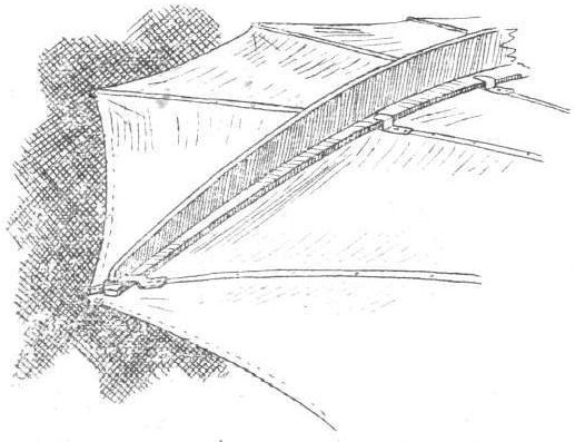
Method of attaching the supplementary stiffening ribs on the Lilienthal glider.
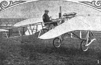
GERMAN FLYERS - The Gebr: Timm monoplane;
Flight, March 26, 1910
AN INDIAN BIPLANE.
We have yours giving us names of motor engines, for which we are much obliged, and in return we are posting you photograph of what we believe is the first aeroplane in India, which has been constructed by one of our customers, a Mr. C. D'Angelis, of Madras. The machine has been built by our friend entirely from his own designs, and we understand that although up to the present he has been experimenting with a small horse-power engine, the results given by this are so satisfactory that with a higher horsepower he anticipates being able to make long and consecutive flights.
E. AND A. LEVETUS AND Co.
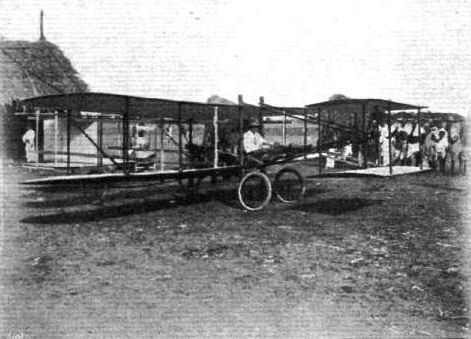
Mr. C. D'Angelis' Indian biplane.
Flight, January 8, 1910
Flying in Canada.
MR. MCCURDY has again commenced active practice on the "Baddeck No. 2" at Baddeck, and a few days ago flew for about eight miles at an altitude varying between 30 and 250 feet. The weather was extremely cold, and it was this which eventually caused the termination of the flight. Further experiments are to be made over the frozen lakes. Prof. Graham Bell has stated that the machine is now fitted with a motor which should enable it to be run for a whole day, and Messrs. McCurdy and Baldwin are now endeavouring to bring their flying machine to a stage at which it would be of commercial use.
Flight, March 19, 1910
Flying in Canada.
MR. D. C. FRASER, Governor of Nova Scotia, and Major Maunsell, of the Canadian Militia, witnessed flights with the Baldwin-McCurdy biplane at Baddeck, on the 13th inst. In all, eight flights were made, the total distance covered being about 20 miles, while the average altitude was between 50 and 100 ft.
Flight, April 9, 1910
BADDECK NO.2 BIPLANE.
FROM two photographs which we reproduce herewith a very good idea can be obtained of the "Baddeck No. 2" biplane, with which Messrs. Baldwin and McCurdy have been experimenting (or some time at Dr. Graham Bell's laboratory at Baddeck, Nova Scotia. It will be seen that wing tips are still used for correcting lateral stability and steering, although they are somewhat different in shape to those used on the "Silver Dart" machine, which, it will be remembered, was the forerunner of " Baddeck No. 2." They are about 5 ft. by 5 ft. in size, and hinged near their front edges, and are controlled by means of a fork fitting around the aviator's shoulders. The main planes are of 40 ft. span, and have a chord of 7 ft. at the centre, gradually diminishing to 5 ft. at the tips. Fifteen feet in advance of the leading edge is fitted the biplane elevator, the surfaces of which are 12 ft. by 28 ins., placed 30 ins. apart, and the tail, mounted 11 ft. behind the main plane, is of exactly similar size. Steering is effected on a somewhat similar system to the Curtiss machine, a fore and aft movement of the steering-wheel adjusting the elevator, while twisting the wheel operates the vertical rudder.
A single propeller of 7 ft. 8 ins. diam. and 6 ft. pitch is fitted, and is chain-driven in the ratio of 3 to 5 from a 6-cyl. Water-cooled Kirkham motor of 40-h.p. The radiator consists of thirty flattened tubes 7 1/2 ft. long by 3 ins. wide and 3/32 in. thick, and they are curved and arranged in a similar way to the main planes, so that they are practically self-supporting when travelling through the air. The photos were taken while the machine was flying over the Bras d'Or Lake, and are reproduced from our contemporary, the Scientific American.
Flying in Canada.
MR. MCCURDY has again commenced active practice on the "Baddeck No. 2" at Baddeck, and a few days ago flew for about eight miles at an altitude varying between 30 and 250 feet. The weather was extremely cold, and it was this which eventually caused the termination of the flight. Further experiments are to be made over the frozen lakes. Prof. Graham Bell has stated that the machine is now fitted with a motor which should enable it to be run for a whole day, and Messrs. McCurdy and Baldwin are now endeavouring to bring their flying machine to a stage at which it would be of commercial use.
Flight, March 19, 1910
Flying in Canada.
MR. D. C. FRASER, Governor of Nova Scotia, and Major Maunsell, of the Canadian Militia, witnessed flights with the Baldwin-McCurdy biplane at Baddeck, on the 13th inst. In all, eight flights were made, the total distance covered being about 20 miles, while the average altitude was between 50 and 100 ft.
Flight, April 9, 1910
BADDECK NO.2 BIPLANE.
FROM two photographs which we reproduce herewith a very good idea can be obtained of the "Baddeck No. 2" biplane, with which Messrs. Baldwin and McCurdy have been experimenting (or some time at Dr. Graham Bell's laboratory at Baddeck, Nova Scotia. It will be seen that wing tips are still used for correcting lateral stability and steering, although they are somewhat different in shape to those used on the "Silver Dart" machine, which, it will be remembered, was the forerunner of " Baddeck No. 2." They are about 5 ft. by 5 ft. in size, and hinged near their front edges, and are controlled by means of a fork fitting around the aviator's shoulders. The main planes are of 40 ft. span, and have a chord of 7 ft. at the centre, gradually diminishing to 5 ft. at the tips. Fifteen feet in advance of the leading edge is fitted the biplane elevator, the surfaces of which are 12 ft. by 28 ins., placed 30 ins. apart, and the tail, mounted 11 ft. behind the main plane, is of exactly similar size. Steering is effected on a somewhat similar system to the Curtiss machine, a fore and aft movement of the steering-wheel adjusting the elevator, while twisting the wheel operates the vertical rudder.
A single propeller of 7 ft. 8 ins. diam. and 6 ft. pitch is fitted, and is chain-driven in the ratio of 3 to 5 from a 6-cyl. Water-cooled Kirkham motor of 40-h.p. The radiator consists of thirty flattened tubes 7 1/2 ft. long by 3 ins. wide and 3/32 in. thick, and they are curved and arranged in a similar way to the main planes, so that they are practically self-supporting when travelling through the air. The photos were taken while the machine was flying over the Bras d'Or Lake, and are reproduced from our contemporary, the Scientific American.
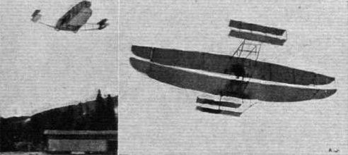
Two views of "Baddeck No. 2" the biplane with which Messrs. McCurdy and Baldwin have been experimenting at Baddeck, Nova Scotia.
Flight, September 10, 1910
THE BALDWIN BIPLANE.
ANOTHER machine that is attracting considerable attention in America is that employed by Capt. T. S. Baldwin at Mineola. The span of the main planes is 36 ft. 3 ins., which length is divided into five sections of 7 ft. 3 ins., each representing the distance between a pair of main struts. The chord is 3 ft. 8 ins., and the gap 4 ft. 6 ins. Midway in the gap, and at the lateral extremities of the machine, are two balancing planes arranged on the Curtiss system. They are controlled by a lever forming the back of the pilot's seat. The rudder and the elevator are likewise controlled on the Curtiss principle by a vertical steering wheel mounted on a pivoted column. In this machine the elevator is a cambered monoplane, having a o ft. span and a chord of 2 ft. 8 ins. The tail, on the other hand, is a biplane, and is so constructed that the normal angle of incidence can be adjusted by the tension of the tie wires used in the bracing. The spars of the main planes have a section of 1 3/4 in. by 1 1/4 in., and are nearly elliptical in section. The struts measure 2 1/2 in. by 1 in., and have a section as shown in the accompanying sketch. Spruce is employed for the spars and struts, except in the case of the two rear centre struts which are made of steel tubing and assist in the support of the engine bearers. The front centre struts, although made of timber, are of much stronger section for the same reason.
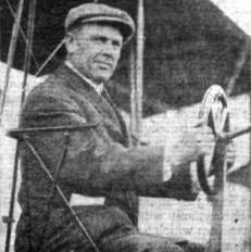
AMERICAN FLYING MEN AT BELMONT PARK MEETING. - Capt. T . S. Baldwin.
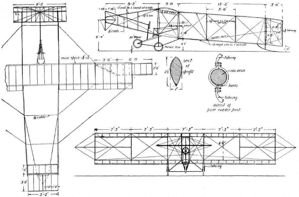
Capt. Baldwin's biplane. - American Aeronautics.
Flight, April 23, 1910
THE HERRING-BURGESS BIPLANE.
HERRING, who was formerly associated with Curtiss in the construction of a biplane, has recently been working in conjunction with Messrs. Starling and Burgess in the production of a new type of machine that is mainly interesting for the manner in which it has been sought therein to obtain lateral stability without infringing the Wright system of control. An injunction was obtained by the Wrights against the Herring-Curtiss Co., it will be remembered.
In the Herring-Burgess biplane the principle adopted by Voisin, of using side-panels, has been introduced in modified form. Instead of turning the main-planes into a large box-kite by putting side panels between the struts, the panels are set like fins above the top deck. There are six such fins, each of triangular form, which stand up about three feet above the surface of the plane. The object of these fins is to resist the capsizing tendency by virtue of the air pressure acting on their surfaces when the machine slips sideways.
The Stability Fins.
The principal object of placing the fins above the upper deck has been to secure an ascentric disposition of the centre of pressure and the centre of gravity whereby the restoring couple is in the nature of a pendulum, the fins affording the necessary abutment on the air to enable the centre of gravity to swing back into place. The practical value of these fins remains to be proved, and especially will the effect of their position in respect to the centre of gravity be watched with interest. The necessity of forming a couple of some sort as a means of restoring lateral equilibrium is obvious, but this Herring-Burgess device is certainly rather a singular combination of dynamic and static forces.
On the part of the fins we have a potential force of the dynamic kind, that is to say, the value of the fins as an abutment strictly depends on their lateral motion through the air. Either the machine must slip sideways or the wind must blow upon the fins from the side, and only when this condition obtains can the fins offer the desired abutment that will enable the centre of gravity to swing back into its proper position relatively to the centre of supporting effect. The value of the weight of the machine as a factor in restoring equilibrium is, however, a fixed quantity for regarding the apparatus as a pendulum; in principle, the time of the oscillation is proportional to the square root of the length between the centre of gravity and the point of support. In practice, the point of support represented by the vertical fins has a lateral movement of its own in the same direction as the swing of the pendulum, and it would appear as if the actual time of recovery is likely to be a variable quantity owing to the difference in the actual lateral speed of the fins through the air under the changing conditions of wind and other fundamental factors. The question of oscillation past the normal position would seem to be another serious consideration in this system.
It is claimed that the fins will not offer much resistance to straight flight, and possibly the amount would be of no material importance if the machine always flew strictly in the eye of the relative wind. We cannot believe, however, that any fixed surface on a flying machine can have an actual neutrality to the relative wind for more than a small fraction of the whole duration of flight, and when a surface presents an angle of incidence the question of aerodynamic resistance must be considered, and may quite well become a factor of material importance, not only as a resistance but as a disturbing influence on normal stability.
It would appear, from the arrangement of the fins, that they could be constructed so as to fold up, but nothing of this sort has, so far as we are aware, been attempted, nor do we imagine that there would be much advantage to be gained by the complication.
Shielding Effect.
Another point to which we should like to draw attention in connection with these fins, is the difference in their spacing apart. For constructional reasons they have been situated coincident with the main-spars, but we are rather inclined to think that the two central fins might have been omitted without a very serious loss in the effective value of the surface area. One of the most important series of experiments that has so far been conducted by Dr. T. E. Stanton at the National Physical Laboratory related to the shielding effect of one surface placed in front of another (see "Flight Manual," Note 15). It is, of course, true that the relative wind on the fins of the Herring-Burgess machine will always blow obliquely, owing to the forward velocity of flight on the part of the machine as a whole being compounded on the lateral slip, but for all that the question of interference should not be overlooked.
The Skids.
The general appearance of the machine is shown in the accompanying photograph, and the leading dimensions in the full-page drawing opposite. We have endeavoured to give reliable dimensions on the drawing, but the information is unfortunately not altogether corroborative from different sources. In the photograph, the machine is illustrated on the ice, and the arrangement of skids shown in the drawing is especially designed for work under these conditions.
It will be observed that there are some features of similarity between the Herring-Burgess machine and the Curtiss biplane illustrated in FLIGHT, Vol. I, p. 389, but the similarity hardly extends further than mere appearances. The Herring-Burgess biplane is rather a short span machine, and the aspect ratio of the planes is under 5. The decks are mounted on the frame with a much greater angle of incidence than they had in the Curtiss machine. It may also be observed that the engine is situated further back so as to avoid cutting a notch in the trailing edges to clear the propeller.
The control is effected by two levers and two pedals. The right and left-hand levers operate the steering rudder and the right-hand pedal controls the elevator. The left-hand pedal controls the engine throttle.
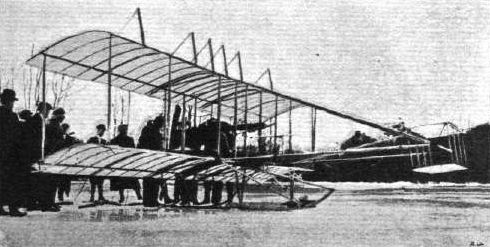
The new Herring biplane, a special feature of which is the series of six triangular fins on the top plane for maintaining lateral stability.
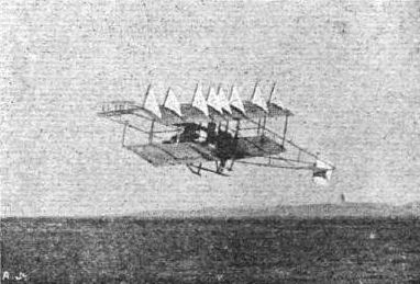
The Herring-Burgess biplane in its latest form. It will be noticed that two additional fins have been fitted since the machine was described in this journal on April 23rd last.

THE HERRING-BURGESS BIPLANE. - Diagrammatic sketch, showing the fins from in front.
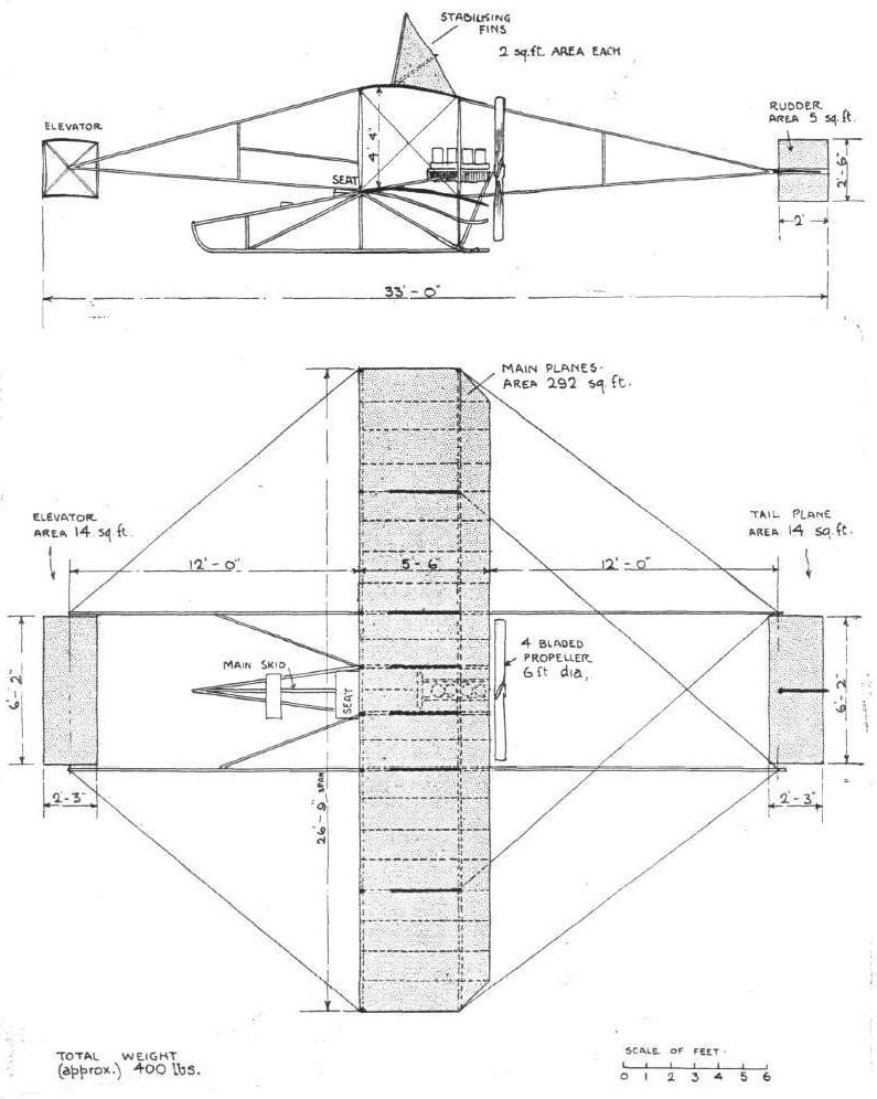
THE HERRING-BURGESS BIPLANE. - Side elevation and plan.
Flight, May 28, 1910
Aeroplane versus Car.
DURING the three days' motor race meeting on the Atlanta (Ga., U.S.A.) Speedway held on May 5th, 6th and 7th, some diversion to the ordinary car racing was provided in the form of some exhibition flights by Mr. Charles K. Hamilton with his biplane. What purports to be the first flyer versus automobile race took place on one of the days when Hamilton raced Kjelson, on an S.P.O. car, for 4 miles, or twice around the track. The airman kept close to the ground and not more than a few feet separated car and flyer any part of the distance. The aeroplane won in the final stretch by a few feet, the time for the 4 miles being 5 mins. 6 secs. Previously Hamilton had made one circuit (2 miles) in 2 mins. 38 1/2 secs.
Flight, June 18, 1910
CROSS-COUNTRY FLYING IN AMERICA.
FOLLOWING up the recent successful journey of his master, Glenn Curtiss, from Albany to New Vork, Charles Hamilton on a similar machine to that used by Mr. Curtiss at Rheims, flew from New York to Philadelphia and part of the way back on Monday. Rising from Governor's Island at 7.35 a.m., he made straight for Philadelphia, covering the 86 miles in 1 hr. 52 mins., his average speed being about 47 miles an hour. At half-past eleven he started on the return journey, and all went well until after passing Trenton, where the aviator got mixed in his directions, and followed the wrong railway. Realising he had lost his way, and having trouble with his engine, he came down on some mud flats at Perthamboy, unfortunately damaging the propeller. He had covered 56 miles of the return journey in an hour and a half. Late in the afternoon he started again, and flew the remaining 30 miles in as many minutes. Previous to this flight, Hamilton had been giving demonstrations on Governor's Island, New York, where on Sunday he made a spectacular flight which lasted 66 mins.
Flight, September 10, 1910
THE NEW CURTISS BIPLANE.
THE accompanying interesting drawings, reproduced from our American contemporary, Aeronautics, show the general arrangement and many of the more important constructional details of the new Curtiss biplane. This machine does not differ in its general lines from the original Curtiss aeroplane described in FLIGHT on July 3rd, 1909 (Vol. I, p. 389), but the span now measures 32 ft., and the chord of the planes is 5 ft., the gap between the planes being the same amount. All these dimensions are greater than on the earlier Curtiss model. In order to facilitate transport the main planes are built in five sections, which are detachable. The joint of the main spars is formed by a steel sleeve made of 18-gauge metal. This sleeve is split longitudinally along the back, and the edges turned out to form flanges, which are drilled to take bolts; by this simple device the sleeve is clamped upon the spars. A couple of bolts also pass diagonally through the body of the sleeve, in order to centre the spars in position. When trussed by the wire bracing there is, of course, no bending strain on the joints.
Details of the camber of the plane are given in the accompanying sketches, and the surfacing material is Baldwin's rubberised linen. This is placed on the tops of the ribs only, and is applied in sections of 6 ft. span, the sections being laced to the large ribs which lie adjacent to the main struts. The fabric is tacked down to the small ribs through a protecting strip of tape.
Laminated ash and spruce are the two woods chiefly employed in the construction.
Fourteen feet in front of the main planes is the elevator, which has a span of 7 ft. with a chord and a gap each measuring 2 ft. 3 in. The planes of this member are doubled surfaced. In the rear is a fixed horizontal tail plane having a span of 7 ft. and a chord of 2 ft. 6 in. Intersecting this plane at right angles is the rudder, which also has a chord of 2 ft. 6 in. and measures 3 ft. in height. The elevator and the tail planes have both cambered sections, so that they are normally lifting planes; the camber is represented by a versine height of 3/4 in., measured one-third of the chord from the leading edge.
At the extremities of the main planes, situated midway in the gap, are balancing planes, having a span of 9 ft. 11 in. and a chord of 2 ft. 9 in. Four feet of the span of each balancer projects beyond the extremities of the main planes. The control of these members is effected by wires attached to a lever that forms the back of the pilot's seat, and the pilot controls their movements by leaning his body to one side or the other. In order to rebalance the machine if it has heeled over, he leans towards the rising side; in other words, keeping the body upright automatically tends to check canting. This action, it will be observed, is to all intents and purposes that advocated by Sir Richard Paget in a recent issue of FLIGHT. The essential point of Sir Richard Paget's contention is that the system of control should be such that the pilot should automatically perform the correct operation for balancing the machine so long as he succeeds in keeping his own body in a normal position. This, it will be observed, is what the pilot of the Curtiss biplane does so far as concerns lateral stability. If, when flying the Curtiss biplane, the pilot found himself unable to lean far enough over to one side without assistance, he would have to pull himself across by catching hold of one of the struts of the machine. It is precisely this action that Sir Richard Paget advocates in principle, and it is, as our readers know, contrary to the usual system of control, where the hand is employed to push a lever towards the rising side of the machine.
Although this reaction system applies to balancing the Curtiss biplane, the ordinary method of control is employed in tilting and steering. Situated in front of the pilot is a wheel mounted in a vertical plane on the top of a pivoted column. Pushing the entire column forward dips the nose of the machine down, and pulling the column backwards tilts it up. The connection to the elevator is effected by a bamboo rod. Turning the wheel to the left steers the machine to the left, on the same principle as an automobile; the steering-cables pass round grooves in the steering-wheel itself, and they are carried through the hollow steering column.
The engine on the new Curtiss biplane is an 8-cylinder model of Curtiss' own design. It is a V-type water-cooled motor, and is direct coupled to a 7 ft. Curtiss propeller. The engine control is effected by an accelerator pedal on the left of the steering column, and there is also a throttle-lever close to the pilot's seat. Another pedal, under the action of the pilot's right foot, is employed to cut off the ignition, and to apply a brake to the front wheel of the chassis that carries the machine on the ground. This chassis is a three-wheeled construction, as in the earlier Curtiss aeroplane.
It is estimated that the weight of the machine is 650 lbs., and the first flight therewith was accomplished by C. F. Willard, on August 11th , over the Hempstead Plains. On August 14th the same pilot carried three extra passengers for a distance of a quarter of a mile. On this trip the total weight supported was probably about 1,200 lbs.; the effective area is 320 sq. ft.
Flight, September 3, 1910
Mars has a Lucky Escape.
WHILE flying across New York Bay from Coney Island to Staten Island on Saturday, the aviator Mars had a lucky escape. He was at a height of about 2,000 ft. when his motor stopped, and his Curtiss machine began to fall rapidly. He, however, righted the machine and planed down to the water, although he was unable to prevent the machine from striking the water at a high speed. The shock broke up the machine, but Mars himself was unhurt.
Flight, November 19, 1910
Flying from a Cruiser.
FOR some time Mr. McCurdy has been trying to make arrangements to fly on his Curtiss machine from an outgoing steamer back to New York, but so far has not been able to carry out the project. A fellow pilot, however, Mr. Eugene Ely, on Monday made a short experiment in Chesapeake Bay by flying from the deck of the U.S. cruiser "Birmingham," and landing on Willoughby Spit. Mr. Ely was forced to land somewhat sooner than he intended, as his propeller was damaged soon after starting owing to its striking the water.
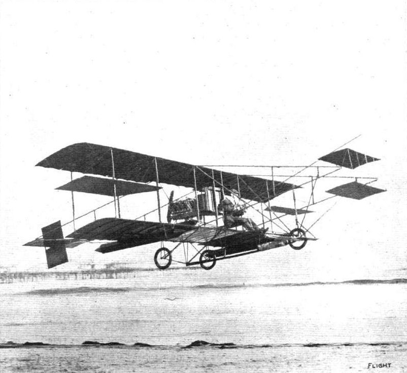
Glenn Curtiss, on his biplane, during an exhibition flight over the sea at Atlantic City.
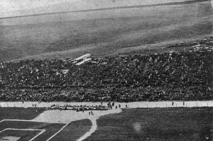
LOS ANGELES FLIGHT MEETING. - Remarkable photograph of Curtiss in flight, on his biplane, over the Grand Stands, taken from a captive balloon.
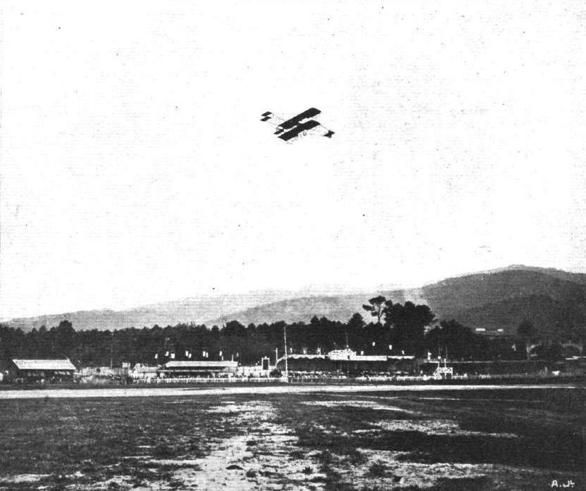
A fine flight by Reimsdyck on his Curtiss biplane during the successful Cannes Flight Meeting.
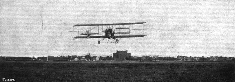
AEROPLANES FOR MILITARY SCOUTING. - Glenn Curtiss on his biplane with Lieut. Fickle, of Governor's Island, U.S.A., target practising with a rifle from the machine while in flight.
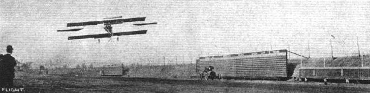
C. K. Hamilton on his biplane, racing Kjelson on an S.P.O. car at Atlanta Speedway (U.S.A.).
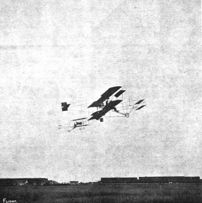
Mars and Glenn Curtiss on Curtlss machines circling round each other over Sheepshead Track, U.S.A.
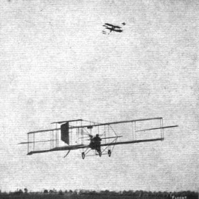
Mr. Charles K. Hamilton at Hempstead (U.S.A.) executing one of his sensational "trick" flights. The lower machine is Captain Baldwin's biplane.

LAUNCHING AN AEROPLANE FROM THE DECK OF A LINER. - McCurdy's biplane on the special launching stage prepared on the Hamburg-American liner "Pennsylvania" for the proposed test which had to be postponed, as referred to in FLIGHT.

Chas. F. Willard, in his Curtiss machine on which he carried in America, at Albany Park meeting, three passengers. Both he and his sister, Miss Emily T. Willard, are given as competitors at the Harvard aviation meeting.
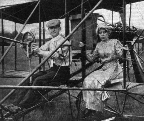
Mars, who on his Curtiss machine has been making good flights in America, amongst other trips, flying from Coney Island to Staten Island, and his wife.

AMERICAN FLYING MEN AT BELMONT PARK MEETING. - Charles K. Hamilton.
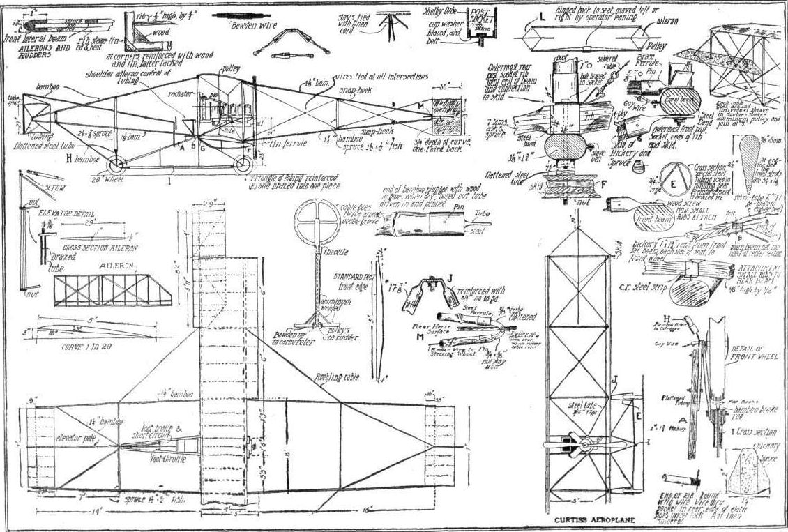
NEW CURTISS BIPLANE. - General arrangement and constructional details.
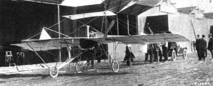
Glenn Curtiss' new racing biplane at the Belmont Park (U.S.A.) Meeting.
Flight, February 26, 1910
A NOVEL MONOPLANE.
ALTHOUGH most of the machines which have been experimented with in America have been of the biplane type, there is one monoplane with which a certain measure of success has been attained. This is the invention of Mr. A. L. Pfitzner, who has been for some time associated with Mr. Glenn Curtiss, and from the two photographs, which we reproduce from the Scientific American, it will be seen that the design is in some ways reminiscent of the Curtiss biplane. The novel feature of the machine lies in the means for maintaining lateral stability. At each end of the main plane there is a sliding tip, which normally lies 15 inches beyond the main plane. These tips are interconnected, and controlled by the steering-wheel, so that when one is slid out to its full extent of 30 inches the other is completely withdrawn, any movement of one being accompanied by a corresponding adjustment of the other.
The main plane itself measures 31 ft. by 6 ft., giving an area of 186 sq. ft., while the sliding wing tips are 2 1/2 ft. by 5 ft. Fourteen feet in front of the main plane is the elevator, a single plane 6 ft. by 3 ft., while above it is the triangular rudder 2 ft. high by 3 ft. in length, and both these are connected-up to the single steering wheel. At the rear, 10 ft. from the main plane, is the horizontal tail 6 ft. by 2 ft.
It will be seen that a single propeller is fitted, driven by a 25-h.p. 4-cyl. Curtiss motor. With 6 gals, of petrol in the tanks, 1 gal. of oil, and 1 1/2 gals. of water the machine weighs 430 lbs. The propeller is 6 ft. in diameter, and is said to give 235 lbs. thrust at 1,200 r.p.m.
A large number of short flights have been made, and the machine rises from the ground very quickly, the average distance run to get up being about 100 ft., when the machine was tried over snow.
Flight, March 12, 1910
THE PFITZNER MONOPLANE.
IN our issue of Feb. 26th we published a couple of photographs, together with a few particulars of a monoplane which embodied many unique features, and which had been constructed in the Curtiss factory at Hammondsport, New York, by Mr. A. L. Pfitzner. We are now able to give scale drawings of this machine, and in view of its unique design, and the fact that it has already flown, although only very short distances, we think these further particulars will be welcomed.
Each of the wings of the main plane is made in three sections, each 5 ft. long, which are attached and connected by steel sockets and steel cable, the latter forming a symmetrical double king truss with the beams, the king posts being at the junction of the detachable sections. The two wings are set at a dihedral angle of 5 deg. The surface is single, with the framework exposed on the under side, and consists of vulcanized Japanese silk material which is stretched over the ribs by lacing at the junction of each of the seven sections. The curvature of the surface is of the high-speed type, with the centre of pressure 18 in. from the leading edge. The ribs have a camber of 3 3/4 in. in a 6 ft. length, the highest part of the surface being 1 1/2 in. above the leading edge, while the angle of incidence is 8 deg.
The unique feature of the monoplane is the system of equalisers at the tips of the main planes. The main surface, as will be seen from the plan, stops short 30 ins. from the end of each wing, and in this space slides a panel 30 ins. wide by 50 ins. deep, of the same curvature as the main surface. These two balancing tips are inter-connected to the hand wheel, and normally they project 15 ins. at each end.
The system of control, which is shown clearly in our diagram, is a combined one in which all the necessary movements are connected to the one wheel and column. The elevating plane, which is in front of the machine, is operated by giving the steering column a movement to or from the body of the operator; while steering to right and left, by means of the vertical rudder placed above the elevator, is effected by twisting the steering column wheel; and lateral stability is maintained by turning the wheel. This being connected by cables to the balancing tips causes one of them to project further out and the opposite one to be withdrawn a corresponding amount. By the side of the controlling column is a lever connected to the throttle of the motor, while a switch button on the steering-wheel enables the Bosch high-tension magneto-ignition to be switched off for the purpose of stopping the motor. The motor is a 25-h.p. 4-cyl. Curtiss, and drives a 6 ft. spruce propeller of 4 1/2 ft. pitch, giving 235 lbs. thrust at 1,200 r.p.m. It is said to weigh only 6 3/4 lbs.
A noticeable departure from usual monoplane design is the placing of the propeller and engine behind the operator. The design of the chassis, too, is also unusual. It will be noticed that four wheels are employed, and the machine so balanced as to enable it to start in any direction. The chassis is built up of four vertical posts, each forked at the bottom, and holding a 20 in. diameter wheel fitted with a pneumatic tyre. These four posts are spaced by seamless steel tubing, while at the bottom there is a wooden skid which takes the strain after the first shock has been absorbed by the wheels.
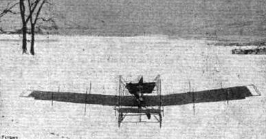
THE PFITZNER FLYER. - The first American monoplane to fly. Note the sliding wing "tips."
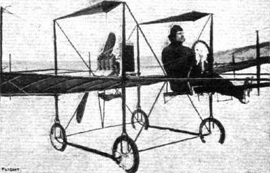
THE PFITZNER MONOPLANE. - Mr. Pfitzner at the wheel. In this view the general arrangement of the centre of the machine is clearly shown.

Front view, showing the trussing of the wings, of the Pfitzner monoplane.
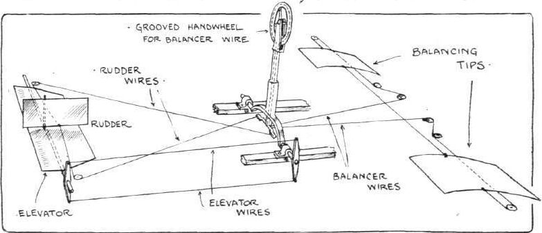
Diagram of the controlling arrangements on the Pfitzner monoplane.
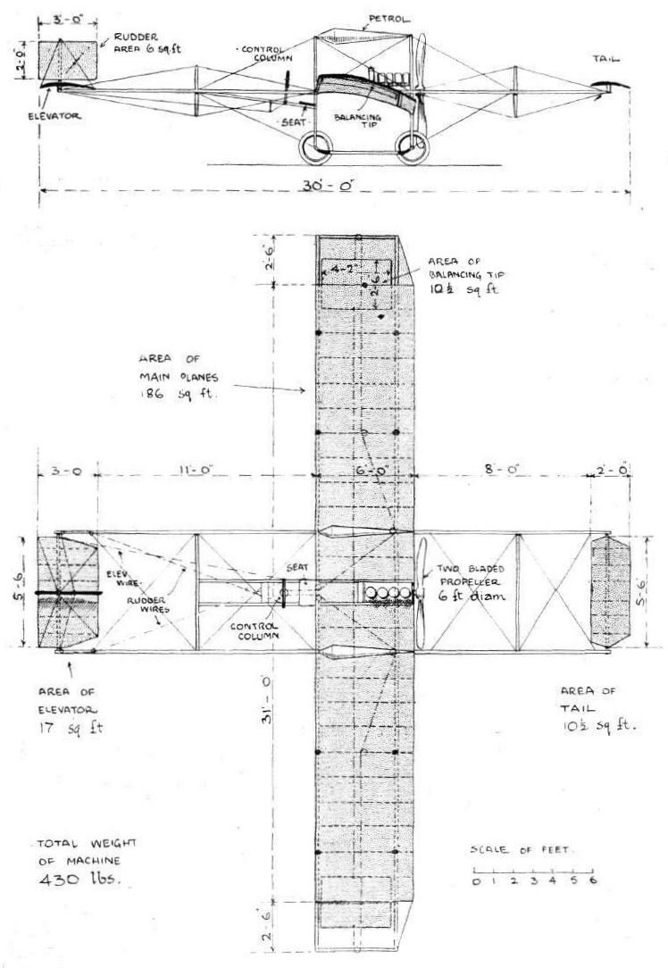
Flight, October 29, 1910
IMPRESSIONS OF THE PARIS SHOW - (continued).
By OISEAU.
<...>
The Sloan "bicurve," as it is called, is a biplane employing two converging main planes. It is claimed that this convergence supplies some manner of lateral stability, and greatly increases the possible strength of construction. Stabilising ailerons are only used attached to the trailing edges of the lower main planes. The elevator is part of the tail, and as usual on this type of machine the propeller is placed in front of the main planes. The Farman type of under carriage is employed.
<...>
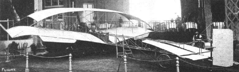
The biplane exhibited at the Paris Salon on the stand of Messrs. Sloan and Co.
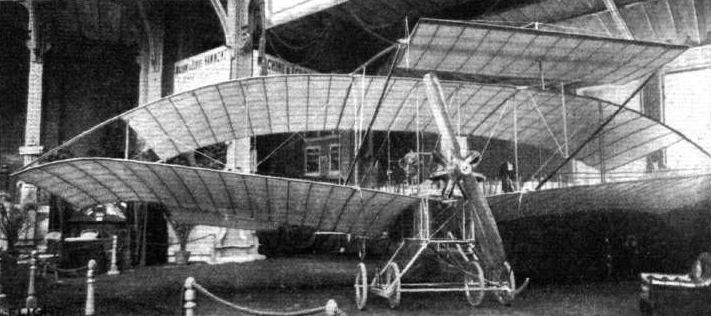
Last week we published a view, from behind, of the Sloan biplane, and above we now give a view, as seen from the front, at the Paris Flight Salon.
Flight, January 8, 1910
WRIGHT GLIDER LAUNCHING APPARATUS.
IN connection with the description, with scale drawings, of the full-size Wright glider in our issues of September 18th and 25 th last, we have been repeatedly asked for details regarding the starting arrangements suitable for such a glider, and now through the courtesy of Messrs. T. W. K. Clarke and Co., we are able to give them. From the side elevation it will be seen that the starting rail itself is about 90 ft. long, while the derrick is 15 ft. high. The actual arrangement shown was that constructed for Mr. Ogilvie's glider at Camber, and there the derrick was made from such timber as was available on the spot, and the starting weight originally consisted of a bag containing the earth excavated from below the derrick. Later this was changed to a number of metal discs up to a total weight of 250 lbs.
The rail itself, consisting of "T" iron in 15 ft. lengths mounted on long wooden blocks, was laid on a slope of about 1 in 10, and to compensate for the irregularity of the hillside a clearance of 1/4 in. was allowed at the joints. Owing to the long grass present in this particular case, it was found necessary to put additional wood blocks 6 ins. deep under the sleepers. The actual details of construction are clearly shown in the three small sketches, while the precise arrangement of the starting rope can be followed from the side elevation.
In launching, the glider is placed in position close up to the derrick (as shown in the drawing), with its two small grooved trolley wheels resting on the "T" iron rail; the 250 lbs. weight is then raised by hauling on the free end of the rope, which terminates in an iron ring; this is then slipped over a downwards-pointing iron hook, carried on the end of a wooden bar fixed in front between the skids of the machine. At first a Manila rope, about 11 ins. circumference, was employed, but a wire cable has since been substituted.
The glider is balanced laterally on the mono-rail by hand on each side (when in motion this is effected by the action of the wing-warping lever), and is held back by hand against the pull of the rope. As soon as the pilot is ready the machine is released, the weight falls, and the glider is shot forward along the starting rail.
When there is a good wind, the machine usually rises into the air after traversing only about 30 ft. of the rail.
Flight, January 29, 1910
FIRST FLIGHT IN AUSTRALIA.
ON December 9th, at the Victoria Park Racecourse, Sydney, N.S.W., Mr. Colin Defries, as we recorded at the time, accomplished the first flight ever made on an aeroplane in Australia, although a heavy S.W. gale was blowing at the time.
Further particulars and photographs are now to hand from Mr. D. C. Defries, the young aviator's - he is twenty-five years of age - father. The aeroplane - a Wilbur Wright - which was mounted on a superstructure carried on three pneumatic wheels (instead of going off from the starting platform usual with these machines), rose to a height of about 35 ft., and covered about a mile in 1 1/4 mins., when the aviator had to come to earth as the motor was performing badly, due, it was found, to faulty sparking plugs.
The event created a lot of excitement, and there was a large crowd on the ground.
On the following day another short flight was accomplished, when Mr. Defries took up a passenger - Mr. C. S. Magennis, a well-known Australian mining engineer - and although a long flight was again impossible on account of the engine not running perfectly, enough was done to prove his complete mastery of the aeroplane.
Mr. Colin Defries was educated at St. Paul's College, at Darmstadt, and University College, London, and received his practical engineering training at the works of Messrs. Bruce, Peebles, and Co., Edinburgh. Previous to going to Australia, where he is sole agent for several well-known motor cars, he had made a considerable reputation in the motor world, and amongst other races drove in the Grand Prix and Kaiserpreis in 1907, and on each occasion was the only Englishman who finished.
Flight, March 12, 1910
THE WRIGHT BIPLANE.
EVERYONE who has followed the history of the development of the Wright biplane is familiar with the fact that it was evolved from a glider of almost identical design although different in actual dimensions. In having very fully described the construction and operation of a Wright glider in FLIGHT, Vol. I, page 568, therefore, we have already covered a great deal of the ground that would otherwise afford subject matter for the present article; in fact, the accompanying remarks and illustrations must largely be regarded as supplementary to the previous description. We publish on the opposite page a plan and elevation of the machine, and there appear herewith three sketches of details that we have not hitherto fully illustrated. One shows the bracing of the rudder, another shows the attachment of the vertical struts to the main spars, and the third illustrates how the radius-rods between the chain-brackets are coupled up to cases containing ball-bearings that ride upon the crank-shaft.
The general construction of the machine is much the same as the glider that we have already described. Each main deck is built up of two transverse spars placed four feet apart and joined at intervals of about twelve inches by specially shaped rib members that project behind the rear spar and form the flexible trailing edge that is such an important feature of these machines. Two points of especial interest about the arrangement of the ribs are that those near the extremities of the spar are curtailed and are also less in camber than those in the centre, and that the two main spars themselves lie at the same level above the ground, so that it is entirely due to the trailing portion of the decks that the chord has any angle of incidence at all.
The flattening and curtailing of the ribs in the vicinity of the extremities of the decks reduces the intensity of the aerodynamic disturbances, and tends thereby to avoid loss of efficiency by reducing the lateral spewing of the air from beneath the decks.
The horizontal position of a chord drawn between the two main spars is of particular interest because it emphasises the practical application of the principle of the dipping front edge. The machine in horizontal flight proceeds through the air with the chord between the two main spars in a horizontal position, consequently the leading edge dips down instead of being tangential to the line of flight.
Lanchester's theory of the dipping front edge - the discovery of which, by the way, is due to Phillips, who describes this peculiarity of a bird's wing in his patent No. 13,768 of 1884 - is that an aeroplane in horizontal flight is virtually always falling through the air and is, therefore, always meeting an up-current. This up-current, when compounded with the horizontal motion of the machine, gives to the relative wind an actual obliquely upward trend, and it is to this slope that the leading edge of the aeroplane should be tangential in order that it may receive the air without shock. Having received the air in this way the cambered surface of the aeroplane proceeds to change the upward motion of the air into downward motion, and this is done gradually by the gentle camber of the decks. By the time that the molecules of air have reached the rear spar their direction of motion has been entirely reversed, and this has taken place, it will be seen, without reference to the trailing portions of the decks or to the question of the amount of the angle of incidence represented by the chord between the leading and trailing edges of the complete deck.
By its action of continuously changing the direction of flow of a stream of air, the aeroplane experiences the upward lift that supports it in flight, and according as the engine power is more or less than the exact amount required for horizontal flight so does the machine ascend or glide obliquely to the earth. The thrust of the two propellers (which are driven in opposite directions by chains, one of the chains being crossed), forces the machine through the air, and causes the aerodynamic condition that has been described above.
In order to maintain the machine in equilibrium, the pilot is provided with three controls that are operated by two levers, one of which he holds in his right hand while the other he holds in his left hand. The lever held by the pilot's right hand controls a miniature biplane that is mounted on a horizontal transverse axis situated about twelve feet in front of the main decks. This elevator, as it is termed, is carried on a light outrigger framework that also extends beneath the body of the machine and forms the ski or runners wherewith the machine alights upon the ground.
The purpose of the elevator is to assist in maintaining longitudinal equilibrium, and its two decks are so constructed that they can be flexed into a camber that is either concave or convex to the earth as required. When the pilot moves the lever so as to make the camber of the elevator concave to the earth, its aeroplane action, which is the same as that of the main planes already described, is such as to tilt up the front end of the machine. Conversely, if the machine is already tilted up too far, a reversal of the camber serves to restore the horizontal position.
The term elevator that has been applied to this device must not be supposed to suggest that it is capable of lifting the machine as a whole. Its elevating power is sufficient only to tilt the machine either for the purpose of .restoring equilibrium or for the purpose of inclining the attitude of flight. Actual ascent can only be effected as the result of developing an excess of power over and above that required for horizontal flight, hence the engine must be considerably larger than considerations of horizontal flight alone demand. Owing to the fact that an aeroplane does not develop the reaction necessary for its support unless it is travelling at a certain speed, it is, unfortunately, impossible to compensate for ascent by travelling more slowly through the air in order to economise power. Ascent automatically results from an increase of velocity through the air, and descent similarly results from a decrease in the velocity through the air, unless provision is made for altering the angle of incidence (i.e., the angle made by the chord to the relative wind), so as in the first place to reduce the lift for a given velocity, or, in the second place, to increase the lift for a given velocity. It would seem that the limits within which any such alteration is possible in machines with rigid planes is very limited in amount.
So far, we have considered only the longitudinal stability of the machine as it is determined by the operation of the elevator; an equally important matter is the transverse equilibrium and steering that are under control through the agency of the lever in the pilot's left hand. This lever is mounted on a universal pivot so that it can move sideways, or to and fro. When moved to and fro it operates the rudder at the rear of the machine and steers in the same way as a boat. If moved sideways it causes the extremities of the decks to warp in such a manner that the trailing edge at one end is depressed while that at the other end is raised.
This at once affects the camber of the decks and consequently the angle of incidence, so that, for a given velocity, one side of the machine exerts a greater lifting effect than the other. Should the machine be accidentally canted by a wind gust, warping thus affords a means of restoring balance. It is important, however, to bear in mind in connection with this system that any alteration in the angle of incidence likewise involves an alteration in the resistance of such a character as to make the machine swerve from its path. This tendency can be neutralised by a suitable use of the rudder, which, as we have explained, is controlled by the same lever, and it is, in fact, the great feature of the Wright control that the warping of the wings and the moving of the rudder can be simultaneously accomplished in this manner.
When steering, the warping and rudder movements are both brought into play. Flying over a curved path causes the outer extremity of the aeroplane to have a higher relative velocity than the inner extremity, and this in turn causes the outer extremity to exert a relatively greater lift so that the machine cants over. A certain amount of canting is obviously advantageous, in the same way that a banked road is advantageous when going round a curve on a motor car, but if the canting becomes excessive the machine might capsize, and in order to check this, the warping of the wings may be brought into action. If thought desirable the warping of the wings may, of course, be employed to give an initial cant to the machine; in fact any combination of rudder and warping movements may be employed as may seem to be best suited to particular requirements.
The Wright biplane is, as has been described, supported upon a pair of skis. It is not provided with any wheels for running along the ground, and, in order to be launched in flight, it has to be mounted on a light detachable trolley that is constructed to run upon a single rail previously laid down for that purpose. The initial acceleration is obtained by the use of a falling weight dropped from a tower and coupled up to the machine by a rope, but if the conditions are suited to the use of a longer rail, the machine may be started by the thrust of its own propellers alone. The trolley is, of course, left behind when the launching has been accomplished. If it is necessary to push the machine about over the ground another pair of light single wheeled trolleys are employed.
It is sometimes urged by those who take a pessimistic view of the future of aviation that this characteristic of the Wright flyer constitutes a permanent disability in machines of this type, and it should therefore be pointed out that there is no reason why the skis should not be fitted with wheels like the machines of Farman and others. The problem of making a re-ascent from any spot upon which the machine might happen to land as the result of a breakdown during an attempted cross-country flight is obviously one that is only capable of limited solution at the present time. The main desideratum has been to accomplish flight first and to work out details associated with such questions as re-ascent afterwards. It would trouble even a helicopter (i.e., direct lifting machine) to rise gracefully after a forced descent in the forest, and just as it is commonly difficult to re-float a stranded boat so is it only reasonable to suppose that flying machines may occasionally find themselves in difficulties, if for any reason they are unintentionally displaced from their element. The proper solution lies rather along the lines of reliability than special invention, for this factor, which has most contributed to the practical utility of the motor car, is also most likely, so it seems to us, to contribute to the practical utility of the flying machine.
From a constructional point of view the Wright biplane is of extreme interest, and it may be remarked that its many details have been the subject of most stringent criticism. For our own part we are inclined to appreciate the design as the embodiment of a remarkable amount of common-sense. One of the leading details of the machine is the method of attachment of the vertical struts, which support the upper deck, to the transverse spars that form the principal members of the decks. This detail forms the subject of an accompanying illustration.
The strut, which, like the rest of the framework, is made of wood, is fitted with a steel eye-piece that is let into a groove and lashed in place as shown in the sketch. The eye-piece fits over a steel hook that is fastened to the spar by a steel plate, and the hook and eye joint thus formed is locked by threading a piece of wire through two holes as shown in the sketch. It is a simple and effective coupling, as it enables the machine to be strained without doing permanent damage, and it also facilitates dismantling the parts.
Flight, March 19, 1910
Capt. Engelhardt at St. Moritz.
ON Tuesday morning Capt. Engelhardt, on his Wright biplane, flew for 32 mins. above St. Moritz, and thus won the Kurverein aviation prize. The altitude of the St. Moritz lake is 6,000 ft.
Flying from Satory to Issy.
CAPT. ETEVE, who, by the way, is the only French officer to possess all three of the Ae.C.F. pilot certificates, for balloons, dirigibles, and aeroplanes, flew on the 15th inst. from Satory to Issy. His machine is a Wright biplane which has been modified by himself, a tail being now fitted as well as wheels to render the starting rail unnecessary. Leaving Satory at 20 minutes past 5 he reached Issy at a quarter to six, having traversed the 19 kiloms. In 25 minutes.
Capt. Eteve has a Tumble.
WHILE practising on his Wright machine at Issy on Friday, Capt. Eteve fell from a height of 20 metres. He had previously had a slight mishap, but the result was not serious, only a wheel being buckled. He flew for 12 minutes on the following day.
Flight, September 3, 1910
WITH THE WRIGHTS IN AMERICA.
By GRIFFITH BREWER.
Apologia.
WHEN I accepted the hospitality of the Wright Bros., I had no idea of publishing the observations of a private visit, nor did I give any hint to them of such a possibility. It was only after waving farewell at Dayton Railway Station that the thought developed of giving to my fellow members of the Royal Aero Club some small idea of what is being done at Dayton, so that when the pioneers of flight have an opportunity to return to England, we in the Royal Aero Club may not have followed the general lead like a flock of sheep, and have shown by our actions and our talk in their absence, that out of sight from England means also out of mind. I therefore crave indulgence if the writing of this account is indiscreet, and I fear it must be so, because it was the only work that could be found for my hands to do on the voyage back on the "Baltic."
We are apt to forget in our desire to see flying general, that we owe everything to these two American scientists. If it had not been for their discarding the then accepted scientific data and starting at the beginning and building up their own tables and diagrams, they might still have been floundering in endless experiments together with others who have since been successful. It is no use deceiving ourselves into the belief that it was the introduction of the petrol engine that gave the Wrights the opportunity that was denied to others, because when they flew they carried sufficient margin of power to have flown with the power available twenty years earlier. In 1892 Maxim built a machine with sufficient power to fly, but all the modern petrol engines in the world would not be able to coax that machine to go up in the air to-day. I am as confident that we should not be flying to-day were it not for the Wrights as I am that the pneumatic tyre would still be unknown to the world were it not for Dunlop. I am also confident that if we can get these pioneers of aviation to spare us some of their attention, that the cause of flight in England will be considerably enhanced. It is therefore with a feeling of pleasant anticipation that we may look forward to a visit from our American friends towards the end of the present year.
The First Mechanical Flights.
I never thoroughly realised the absurdity of the so-called mystery of the early flights made by the brothers Wilbur and Orville Wright, until this August, when I visited the first flying field. I knew before that the field was surrounded by a fence, and this fence, with its suggestion of secrecy, naturally implied a high palisade such as we call fences in England. Instead, however, of the 6 ft. split-oak palisading to obstruct the view, I found nothing but a row of low posts, supporting four rows of wires, to keep the farmer and other wayfarers from looking their fill as they travelled down the main road between Springfield and Dayton, both towns of over 100,000 inhabitants. Moreover, if one main road bounding one side of the ground were not sufficient, then a cross-road bounding another side of the land afforded equal facilities; whilst three electric railway cars per hour also passed along the track adjoining the main road, and allowed their fifty occupants to view the whole ground, and if sufficiently interested to alight at "Simms" station, which abuts directly on one corner of the land rented by the brothers for their early experiments in 1904, and now used by them to-day as a school for their pupils.
Newspapers have always been accustomed to receive voluminous copy from those experimenting with so-called flying machines, the necessity of giving a full report seeming to most experimenters to be of greater importance than the accomplishment of something to report on; so when the two quiet young men squabbled amongst themselves over the theories of flight during their leisure at home, and put their differences of opinion to the test outdoors in their vacation, it was natural for the newspapers to regard these holiday pranks of no serious importance. As it was in 1903 to 1906, so it is to-day. The work of building machines and testing alterations is proceeding in the same methodical manner as the development of a motor launch, and those genial brothers are getting as much fun out of it as Tom Thornycroft gets in making himself hot and dirty down on the "Enchantress."
Manufacturing Facilities.
I had expected to find the Wright Co. installed in an up-to-date factory adjoining the flying ground, and Wilbur and Orville Wright sleeping on beds up amongst the rafters of the shed, and cooking tasty meals between whiles. Instead I found them living with their father and sister in the wooden house they had grown up in from the time when they were all children. The workshop where they make their engines is within a quarter of a mile, and is the same where six years ago they were turning out the Wright bicycles which hold their own to-day. Even closer to the house is the little printing works, where before making bicycles, they expended their unlimited energy and ingenuity not only in printing a newspaper, but in making the printing machine, which they constructed out of pieces of wood and bits of string. This Robinson Crusoe printing press was only designed for home use, for it invariably refused to go unless one of the brothers were looking on.
The factory where the flying machines are built is three miles away on the other side of the city, and there in a large airy ground floor building some six machines were in various stages of construction. One machine just on completion attracted my attention, as it enabled me to compare the tail used by the Wright Brothers in America with the tail fitted by Mr. Rolls to his French-built Wright machine just before his fatal accident. The differences in construction were very considerable, the American pattern being considerably stronger than the French pattern, whilst a clearance of 11 ins. between the propellers and the tail frame showed a considerable increase in the margin of safety compared, with a 3 in. clearance on the French designed tail. The maximum working strain that can be brought on to the tail is less than 70 lbs., and this tail took the strain of Wilbur Wright's weight and my own, or over 250 lbs. dead weight on its outer end without bending more than an inch out of line. The breaking of the tail-frame under wind pressure would, therefore, be impossible in the American-built machine, and although the French construction was weaker, it is extremely improbable that the tail on Mr, Rolls' machine collapsed under wind pressure.
Mr. Rolls' Accident.
The propellers probably fouled the frame of the tail and cut through the lower members, but how the frame approached sufficiently to take up the three inches clearance, whether by bending or disconnecting, will never be known. Although it is certain that the tail frame broke in the air, it is by no means certain that this was the cause of the main accident. The wind was blowing towards the grand stand, and would be rising in a wave over it, and in commencing the dive towards the target the machine would be running down at an angle in a rising current. Most of the weight of the machine is between the main planes, and when the machine entered the lower strata of air this would be travelling horizontally, and would catch the elevating front planes on their upper side, thus tending to still further increase the downward angle of travel, irrespective of the angle at which they might then be set. The inertia of the weight would, however, maintain the forward direction of the heaviest part, and assist the completion of the vertical movement. Rolls attempted a daring manoeuvre, just as a hundred times previously he had dared some feat in motoring or ballooning, but on this occasion the risk he took prevailed. The fact that the Wright Brothers neither designed nor authorised the tail fitted to Mr. Rolls' machine does not therefore appear to be of much importance, because, no matter what machine had been flown and brought into that diving position in the wind wave before that grand stand, the result must have been the same.
Pupils Learning to Fly.
The flying ground used by the Wright Brothers is situated about eight miles west of the city of Dayton, at a small station called "Simms" on an electric car line between Dayton and Springfield. The cars, which are as large as Pullmans, leave the main street in Dayton on the ordinary city tram rails every half-hour, and in twenty minutes drop their crowd of aviators and spectators on the main road which runs alongside the rough weed-grown field. Every morning at breakfast the telephone used to ring, and the same answer suited all enquirers, "Well, you are as likely to see a flight to-day as any other day. The Wright Brothers don't know themselves whether there will be any flying," and this explanation was literally true. They never knew, any more than other inventors, what stage of the designing, testing, or experimenting they would reach that day. After the first day's visits to the factory and the workshop I generally remained at home, until Wilbur or Orville came running in to say they were going out to Simms on the next car. If the weather was fine, then we had to fight our way on to the car, Orville generally riding on the step because of the crowd going out to see the "airship proposition." Why will the man in the street muddle the airship with the aeroplane? He does not muddle a life-belt which enables him to float in the water with a pair of skates for gliding on the surface; but perhaps he did make this mistake when skates were first invented.
On arriving at Simms we cross a plank bridge over a ditch, pass through a little wicket gate and enter the back of the shed where two machines are standing. One is on skids and the other has auxiliary pairs of wheels attached to the skids. Mr. Coffyn is in charge of the school, and two other pupils, Messrs. Brookins and Johnstone, are tinkering with the machines preparatory to making trial flights. Both machines have adjustable tail planes attached, and one has had the two front planes removed and the "blinkers" have been nailed temporarily to the front framing. This frontless machine is the first to be taken out, and we pull it out on to the smoothest part of that rough ground, where weeds as stiff and high as young willows cover most of the land. Then the engine is started up, and before I know what is about to happen there is Orville riding up in the air on the machine without its bridle. "They'll be going up soon on the engine alone with half a propeller," remarks the man who hands back my cap across the fence where it has been blown by the wind from the propellers. After a short three minutes' flight Orville is down again to make some adjustments, and then in another seven minutes is up for a second trial. They have a simple homemade range-finder at Simms composed of a wooden yard stick and a little metal slide on it having two pairs of prongs projecting from it at 1 in. and 1/2 in. apart respectively. You point the stick and sight it at the machine as it flies overhead, and run the slide out until the prongs enclose the wings exactly. Knowing the wings to be about 40 ft. wide, and assuming the 1 in. prongs fit at 10 ins. distance down the stick, the height of the machine is approximately 400 ft. One of the first flights that I saw measured by Wilbur in this way gave Orville a height of 1,200 ft.
More Flights and "Stunts."
My second visit to Simms was a pupils' day, commencing with Brookins going up and doing "stunts" for my benefit. He turned many circles in less than ten seconds each, and the banking angle to which the machine was brought in these quick turns was 45 at the least. On expressing surprise at these quick evolutions, I am told that he has turned a complete circle in less than seven seconds, but has been instructed not to do so quick a turn again before the strains brought on to the machine, and which exceed twice the ordinary flying strain, have been accurately figured out. This Brookins is a promising kind of pupil, and holds the world's record for height, having flown under official observation 6,175 ft.* *(Drexel at Lanark has since then bettered this.) This was done early in July at Atlantic City when he won the L1,000 prize for beating all officially certified high flights. Brookins seemed too daring, and I told him that I for one would nor care to experience the exhilaration of a flying trip with him. A new pupil is to be taken up for the first time, and Orville decides to take him instead of leaving him to Brookins. "I guess he was afraid I'd scare him too much for a first trip," says Brookins as they fly overhead, the novice squeezing the sap out of the upright, to use the parlance of the expert flyers of two months standing. It is well to notice here that Brookins, who had never seen a flying machine three or four months ago, has found no difficulty in mastering the "complicated Wright flyer" and capturing a world's record on it. Before I left ten days later, the novice, Parmalee, was using both levers, and told his instructor that he thought he had nearly got the hang of that "double-jointed lever." After this lesson Johnstone was sent up for a practice flight of an hour, sufficient petrol being put into the tank to cover the hour, but insufficient to tempt him to make a record for endurance. At the end of an hour and thirty-four minutes he came down with the petrol finished. The day terminated by Coffyn making two 20 minute flights, the second being terminated by signal, so that we might all catch the next tram home. This time I stood on the step and Wilbur and Orville got jammed somewhere in the vestibule. Brookins and Johnstone hung on to the buffer and cowcatcher outside, whilst the spectators sat it out comfortably on the seats.
And so the days flew by. Crammed full of interest from the time of eating the cantaloupes in the morning, to the sitting out on the verandah after dinner at night, when the brothers talked horse-power and wind surfaces, while I watched the fire-flies and got in the way of the arguments as little as I could. And I don't think the pleasure was all on my side. All the Wright family seemed out for fun, and each member worked hard to get it. Even Bishop Wright at the age of 82 wants his share, and when Orville took his venerable father for a ride aloft, he had to mount to many hundred feet in compliance with his passenger's requests to go up higher. This enthusiasm also struck others, for the lighthouse keeper at Kitty Hawk said he had never seen men work so hard for fun before.
A Ride on the Wright Flyer.
Those who have been favoured with a ride with Wilbur or Orville have never had previous warning. The simple question, "Are you ready for a ride?" has now been put to several, and I have never yet heard of its being refused. At Le Mans, when Wilbur rewarded the "English bunch" for their enthusiastic patience, he took all four of us up one after the other, these Aero Club members all having instantly answered "Yes" to this welcome invitation. So when Orville put the same gratifying question to me at Simms I stifled my determination to keep out of the way so as to let them get on with their work, and took my place on the central seat next to the engine. This time we were to fly with one elevator plane detached, and with the right-hand blinker only. We also tried the experiment of running through the long weeds before the wind; but, although we succeeded in decorating the machine with green, and taking on board a cargo of grasshoppers, we made the first and only false start. My weight has gone up since my last trip, but it is still below that of one of my rival butterflies at Le Mans. A second attempt in the opposite direction was more successful, and we began to climb up stepless stairs as we went round the field. Out of consideration for my novice feelings Orville refrained from anything in the way of "stunts," although he took the machine round some beautiful curves, and up to about 400 ft., where the air was delightfully warm as distinct from the damper air near the ground. Then we slowed the engine down to walking pace, and slid down an elastic slope to the level of the tree-tops, when we quickened up and ran through the weeds, collecting their tops on the skid-stays without the wheels or skids touching the ground. Perhaps they'll add a scissors attachment below the machine, and use it as a reaper later on.
A "Hole in the Air."
Up into the air again, waving a greeting in return from those at the shed, and later at the other end of the field we ran into the "hole in the air" that has been referred to by many aviators. M. Paulhan told me that in his flight to Manchester he encountered such a hole, and the machine fell some 30 ft. before recovering its airy support. My experience was mild compared to this. We were running quite smoothly when the seat seemed to give way, and it was quite an appreciable moment before I felt I could sit on anything solid. Looking to Orville on my left, I met his reassuring smile, and we went smoothly on to inspect neighbouring cornfields and cut a few eights as a fitting termination to a 23 minute flight. They say the particular spot where we had the "little drop" is in a corner of the field where it is quite usual to encounter similar whirls or disturbances. The machine did not pitch or oscillate, but simply went down bodily about 2 ft.
More Pupils and Workshop Observations.
After my own flight, other flights seemed to me of less consequence, but they went on just the same. Each pupil did his "stunt," and each instructor reflected how green he must have been a month before when then only a pupil. The days when we did not go out to Simms brought in a report from Coffyn giving a list of flights by the various pupils, and the brothers went on in their leisurely, get-there way, designing, thinking, making and testing - not testing to find out, but testing to prove conclusions, already arrived at. At the works one morning I noticed an engine running by itself and turning an arm giving similar resistance to a pair of propellers. This engine, which seemed to have been forgotten, was still running later in the afternoon when I went there again, so I enquired, and found that it had been started at 8 a.m., and with the exception of the lunch hour, it had been running all day without attention and would run like that till 5.30. Why do we have such engine troubles in Europe, and why can't we get our engines to run like they invariably do in America? Is it because the Americans have to work so much harder across the Atlantic, and that their engines out of sheer force of example do the same?
And so they go on day after day, gaining the love and respect of their pupils and all with whom they come in contact. Just as it was at Le Mans and Pau, where their influence was more far-reaching than in the cause of flight alone.
The Wright Patent Litigation.
Before closing, let me say a few words to explain the present situation of the Wright Patents. Both in America and England the Courts have power to issue an interim injunction restraining infringement of a patent, in which it is shown to the satisfaction of the Court that infringement is taking place and that damage will be incurred if the continued infringement is not restrained. It is, however, extremely rare that such a power is exercised before the hearing of the trial, when the witnesses are examined. The validity of the patent was not disputed, and the judge, after consideration of the documents in the case, decided that the infringement was so obvious that he granted the interim injunction. The defendant appealed, and filed additional documents, and the Wright Co. considering the new documents to be unimportant, did not apply to refer the new documents to the first Court, but, in order to save time, went direct to the Court of Appeal. The latter held that they could only consider the judgment of the Court below, and they could not go into the merits of the case as affected by new documents. In view, therefore, of the fact that the new documents were now on the record, but had not been before the first Court, the Appeal Court could not support the injunction on the unconsidered documents, and, therefore, the interim injunction must be quashed. There can be no doubt that the Wright Co. will win their action, seeing that their case was strong enough to enable them to obtain an injunction in the same Court before. The parties are now in the same position as if the injunction had never been obtained, and the trial in the first Court will come on for hearing at the end of the year in the ordinary way.
Flight, September 10, 1910
Capt. Engelhardt at Johannisthal.
FLYING on a Wright biplane Capt. Engelhardt on Monday last made a cross country journey, passing over Rudow, Lichtenrade and Glienicke at a height of 400 metres. The trip lasted 20 mins., the distance being about 18 kiloms.
Flight, October 29, 1910
BOYS' MODELS.
Enclosed you will find two photos of a model biplane of my own design and construction. The main planes are 2 ft. 11 ins. in span, and the elevator and rudder are worked by two levers on the Wright principle. This is my third model, the two previous ones being monoplanes.
Hounslow. R. E. M. FERRY.
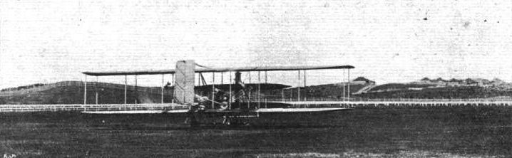
Mr. Colin Defries just starting for the first aeroplane flight in Australia, on his Wright flyer, from the Victoria Park racecourse, Sydney, N.S.W., on December 9th last.
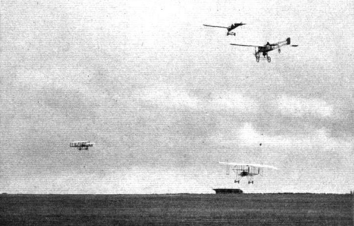
A GROUP OF FOUR FLYERS IN THE AIR AT ONCE AT RHEIMS. - Above, an Antoinette and a Bleriot; below, a Henry Farman; and, to the left, a Wright machine.
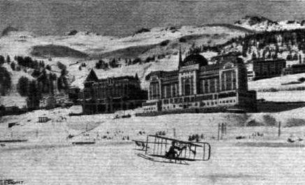
Captain Engelhardt flying over the snows on his Wright machine at Saint Moritz.
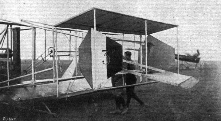
Detail view of the new automatically-controlled tail-planes evolved by Capt. Eteve for his Wright biplane, with which he has been making such successful flights.
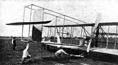
WRIGHT FLYER IN AMERICA. - Our photograph above, taken at the Wright school at Montgomery, Ala., shows the form of tail which the Wright Brothers are fitting to their own machines. It will be noticed this consists of a horizontal plane and one vertical rudder only.
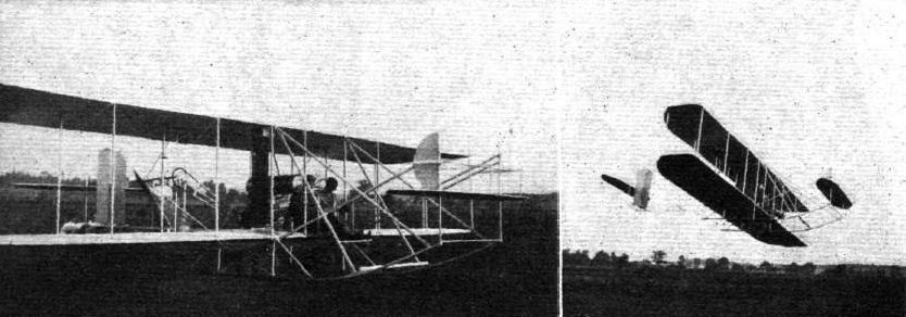
WITH THE WRIGHT BROS. - Ready for a flight. On the right the Wright machine in the air is an instance of this biplane flying with one elevator and one "blinker."
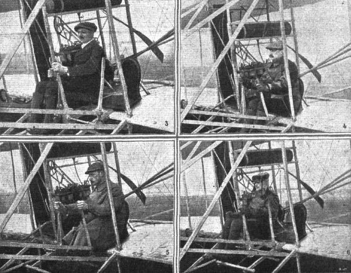
GERMAN FLYERS - (3) Thaddaus Robl; (4) Paul Lange; (5) Engineer Thelen in his Wright machine; (6) Fridolin Keidel, the instructor at the German Wright Company.
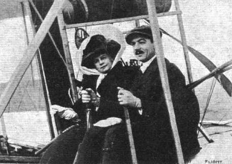
A VICTIM OF MOB CLAMOUR. - Herr Thaddeus Robl and his wife. Herr Robl met his death on Saturday last at Stettin, when, to appease the unreasoning clamour of the public who had assembled to witness some flying exhibitions, he ascended In very treacherous winds. This incident should be a warning to the British public at the coming exhibitions and meetings, that at the present stage of aviation it is hardly up to the standard of their sporting instincts to insist upon the flying men risking death merely to gratify their pleasure at the moment.

Mr. Colin Defries in the pilot's seat of his Wright machine. This shows the way in which Mr. Defries covered one of the supporting wires to prevent himself getting damaged in the event of an accident.

Hoxsey, in the pilot's seat of his Wright biplane, in America, accompanied by Governor Fort.
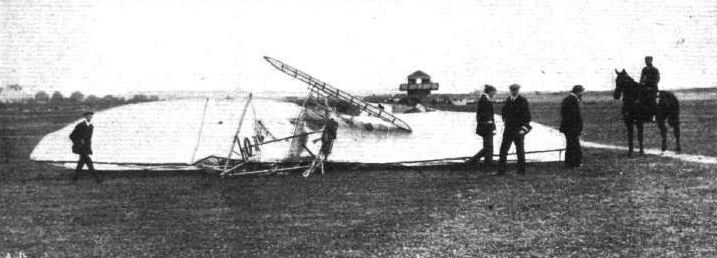
The late Hon. C. S. Rolls' machine at Bournemouth after the fatal accident last week.

The human "fence" instantly formed round the wreckage, at Bournemouth, of the machine of the late Hon. C. S. Rolls, to keep back the public from interfering with the doctors and others who were dealing with the accident
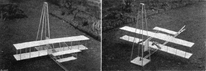
R. E. M. Ferry's Wright model.
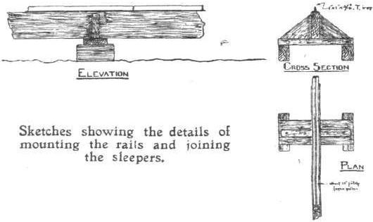
Sketches showing the details of mounting the rails and joining the sleepers.
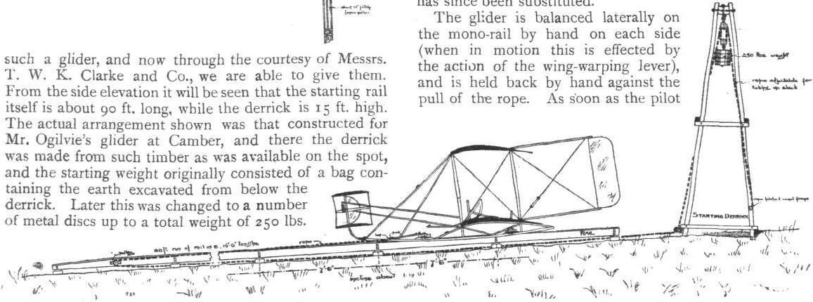
Side elevation of starting derrick and rail for full-size Wright glider.

Sketch showing the bracing of the rudder on the Wright biplane.
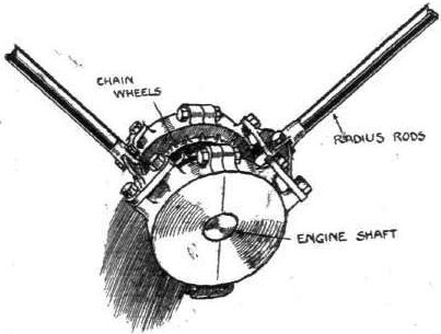
Sketch showing how the radius-rods that form struts between the chain-brackets on the Wright biplane are supported by ball-bearings on the crank-shaft of the engine.
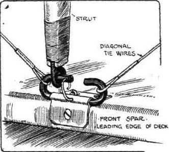
Sketch showing how the vertical struts between the main decks of the Wright biplane are attached to the main spars.
WING SECTIONS. - The above diagrams afford an interesting comparison of the wing sections of aeroplanes exhibited at Olympia. They are all drawn to a common scale, but have been set at an arbitrary angle of incidence, which does not necessarily represent that of the aeroplane In actual flight.
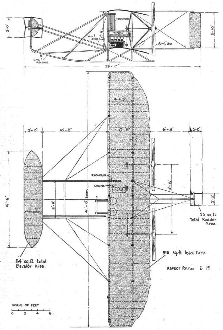
THE WRIGHT BIPLANE. - Side elevation and plan.
Flight, October 15, 1910
AMERICAN NOTES.
Long Cross-Country Flight in U.S.A,
USING a Wright biplane, A. Hoxsey, on Saturday last, made a successful trip from Springfield to St. Louis. On arrival at his destination he failed to recognise his landing place and flew five miles further on, where he came down successfully. As the crow flies the distance from Springfield to St. Louis is 86 miles, but it is claimed that as Hoxsey followed a circuitous route the total distance traversed by him was 104 miles.
Mr. Roosevelt Ventures Aloft.
DURING a visit to the flying ground at St. Louis on Tuesday, Mr. Roosevelt accepted the invitation of Mr. Hoxsey to accompany him for a short trip in the "central blue." Three laps of the aerodrome were covered, the Wright biplane being in the air for just under 3 1/2 mins. It is a good testimonial for flying that the ex-President was so greatly pleased with the trip, which he said was the finest experience he had ever had, that he would have liked to have stayed up for an hour.
Flight, October 29, 1910
Thelen Flies over Berlin.
USING his German-built Wright biplane, Thelen on the 19th inst., in the course of a demonstration before the military authorities, started off from Johannisthal flying ground, and made a successful trip to the military parade ground at Teglitz. The distance between the two points is about 40 kiloms., and this was covered in one minute over the hour.
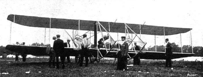
In 1910 the Wrights began to experiment with doing away with the forward biplane elevator. This aircraft is being flown without it, though the booms which carried the surfaces are still evident. The skids have bungee-sprung twin wheels attached; the large simply positioned beneath the wings to facilitate ground-handling.
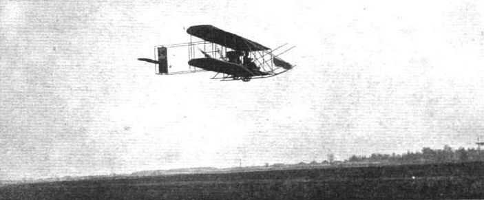
Hoxsey, in his new type Wright biplane, travelling well in his start for the high altitude contest at Belmont Park (N.Y.).
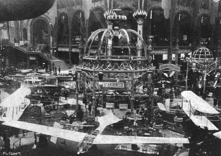
PARIS FLIGHT SALON. - General view of the centre of the Grand Palais. On the right is seen the Wright biplane, on the left the Maurice Farman biplane, just beyond being the Henry Farman machine, whilst in the foreground, in the centre, is the two-seater Antoinette monoplane.
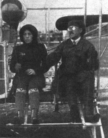
Engineer Thelen, with Frau Direktor Worner as passenger, on his Wright biplane during the Berlin Aviation week this month.
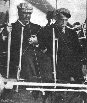
Ex-President Colonel Roosevelt in the passenger seat with Hoxsey on the Wright biplane on which Mr. Roosevelt had his flight at St. Louis on October 11th last.
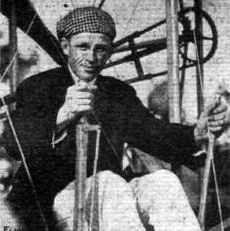
AMERICAN FLYING MEN AT BELMONT PARK MEETING. - Archie Hoxsey.
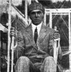
AMERICAN FLYING MEN AT BELMONT PARK MEETING. - Walter Brookins.

AMERICAN FLYING MEN AT BELMONT PARK MEETING. - Ralph Johnstone.
Flight, October 29, 1910
AMERICAN NOTES.
The Wright Racing Biplane.
FROM New York it is cabled that the new racing biplane evolved by the Wright Bros., and which it is hoped will keep the Gordon-Bennett Trophy in America, is extraordinarily small in comparison with its predecessors. The main planes are said to be only 21 ft. 6 ins. span, and only 3 ft. chord, while in the standard type of Wright biplane the dimensions are 39 ft. 6 ins. by 7 ft. The motor is an 8-cylinder V type of 65-h.p. The Brothers Wright have also a second racing machine, in which the planes are a little larger, being 26 ft. long and 3 ft. 4 ins. wide.
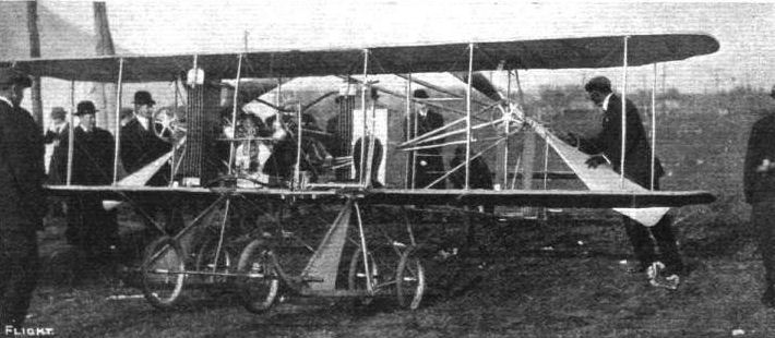
The new "Baby Wright" which made its first appearance at the Belmont Park (U.S.A.) International Meeting - and, it will be remembered, came to grief.

Hubert Latham at the wheel of his Antoinette before his start for his record high flying and trip over Rheims Cathedral during the Aviation Meeting last week.
Flight, January 22, 1910
ANOTHER SCALE MODEL FROM "FLIGHT."
Is this of any interest to you or your readers? Photo of model Antoinette I made from the scale drawings in Nos. 43 and 44 of FLIGHT. It is not an actual flyer at present. I have it for show purposes in the shop window, working (the propeller) by electric motor. The scale is 20/23rds inch to the foot.
Church Street, Preston. A. C. BECKETT.
Flight, August 20, 1910
ANTOINETTE MODEL.
I am sending a photo of an Antoinette type monoplane I have built. It is driven by an elastic motor, and as I have not seen one like it described in your correspondence columns, I have sent a sketch of it.
In the photo, the elastic and frame can be seen faintly through the fabric.
I worked from the scale drawings which you gave in Vol. I of FLIGHT. The machine is 46 ins. wide by 40 ins. long, and weighs 10 1/2 ozs.
Budleigh Salterton. H. BEASLEY.
Flight, October 8, 1910
FOREIGHN AVIATION NEWS.
Trials with "G.B." Antoinettes.
DURING the end of last week Mr. Latham was very busy at Mourmelon putting the Antoinette machines, which have been built for the Gordon-Bennett competition, through their paces. These monoplanes are fitted with 16-cyl. Antoinette motors rated at 100-h.p., and in the course of a 35 min. flight on Monday Latham was said to have attained a speed of 112 kiloms. an hour. Mr. Latham in previous trials has got up to a speed of 110 k.p.h., and in order to test the machines thoroughly he intended to make a flight from Paris to Brussels, but this idea fell through owing to lack of opportunity.
CONTINENTAL FLIGHT MEETINGS.
Milan Flying Meeting.
THE Milan meeting was unfortunate in that not only was the opening clouded by the lamentable death of Chavez, but after a very successful week the closing day was marred by a collision between Thomas, on an Antoinette machine, and Capt. Dickson, on his Henry Farman biplane. Capt. Dickson during the week had been very popular because of his splendid gliding flights from high altitudes, and on Sunday afternoon, after a glide downwards, he was once more rising when Thomas, who had been flying very high and very fast, commenced to plane down at a fast speed. He was unable to see Capt. Dickson, and also the noise of his own motor drowned that of the British airman, and to the horror of the spectators the Antoinette monoplane crashed on to the biplane, both machines falling to earth a mass of broken planes and tangled wires. Thomas escaped serious injury, but Capt. Dickson was not so fortunate. He sustained grave internal injuries, and it was at first feared that he would not recover. Later reports from Milan, however, indicate that there is now hope that he will pull round, and we know that all our readers will join with us in expressing sympathy for this daring and distinguished British aviator, and hope that it will not be long before he completely recovers from the effects of his accident and is once more amongst us.
<...>
Flight, October 22, 1910
IMPRESSIONS OF THE PARIS SHOW.
By OISEAU.
<...>
There is no alteration worth noticing on the Antoinette monoplane. In fact, since the disappearanoe of ailerons from this type well over a year ago, no change of any importance has been made. Since the death of Wachter the wire stay cables below the wings have been strengthened sufficiently to render a recurrence of that fatality even under similarly adverse circumstances extremely unlikely. A wooden propeller, the Normale, has now taken the place of the old adjustable one of metal, which was never really satfsfactory. A few changes have been made in the structure of the engine, to the improvement of which is due the recent excellent performances of the Antoinette.
<...>
Flight, October 29, 1910
A New Aviatress.
AFTER a very long period of instruction at Mourmelon Mdlle. Marvingt, on her Antoinette monoplane, on Saturday last succeeded in passing the necessary tests in order to obtain her pilot's certificate. She is the third woman to obtain a pilot's certificate from the Aero Club of France, the others being Madame de la Roche (Voisin) and Madame Niel (Koechlin).
Flight, December 24, 1910
AN ANTOINETTE.
I enclose photo of a model Antoinette, scale 1 ft. 6 ins. to foot, which I have made. I have to thank your paper for supplying me with most of the detail dimensions, &c.
Chorlton-cum-Hardy. R. M. H. CLEMSON.

HELIOPOLIS AVIATION MEETING. - An incident during the competitions. Latham, on his Antoinette, with Rougier, on his biplane, behind.

AT LE CRAU AERODROME. - An Antoinette machine ready for flight. In front are Mdlle. Linda Venderbar, a lady flyer, and MM. des Jardins and Barthes, engineers.
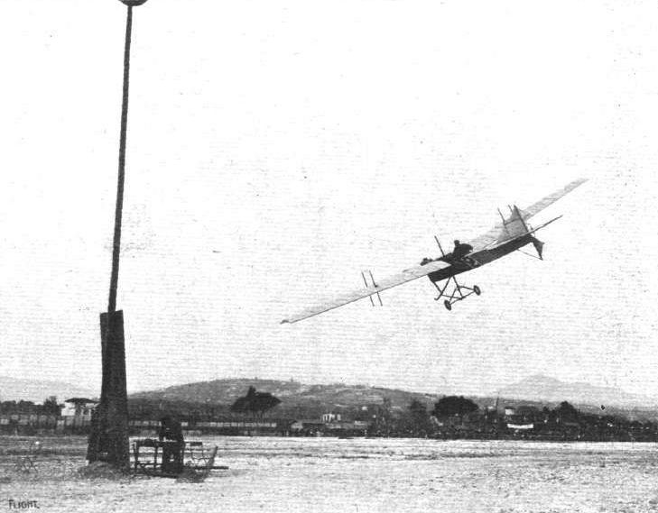
Latham, on his Antoinette, rounding one of the mark posts during his winning flight for the Grand Prize for the best circuit at the Nice Aviation Meeting.
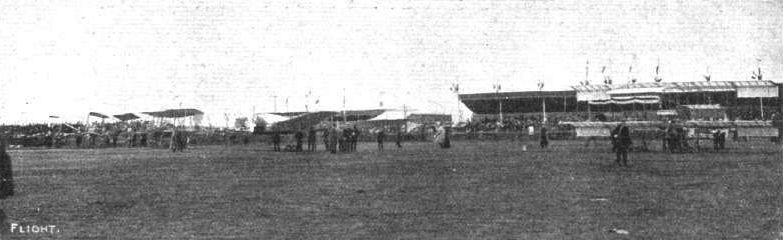
IN LINE FOR THE FIRST AERIAL "RACE." - MM. Martinet (H. Farman), Mumm (Antoinette), Legagneux (Sommer), and Capt. Dickson (H, Farman), ready for the start from the Anjou Aerodrome for the cross-country race to Saumur on June 6th.
A GROUP OF FOUR FLYERS IN THE AIR AT ONCE AT RHEIMS. - Above, an Antoinette and a Bleriot; below, a Henry Farman; and, to the left, a Wright machine.
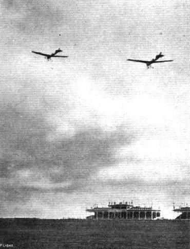
REAL RACING IN THE AIR. - A "neck and neck" race at Rheims Meeting on Sunday last, the opening day, between 'Wachter, who unfortunately was killed later, and Thomas.
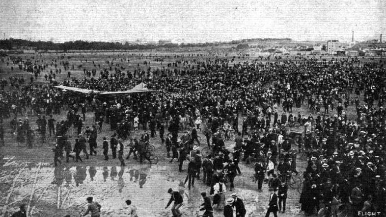
THE "CIRCUIT DE L'EST." - Starting for the first stage on Sunday last from Issy for Troyes, 135 kiloms. M. Latham, has just arrived at Issy ground on his Antoinette machine, having flown over from Chalons, a distance of 169 kiioms., passing over Paris en route.
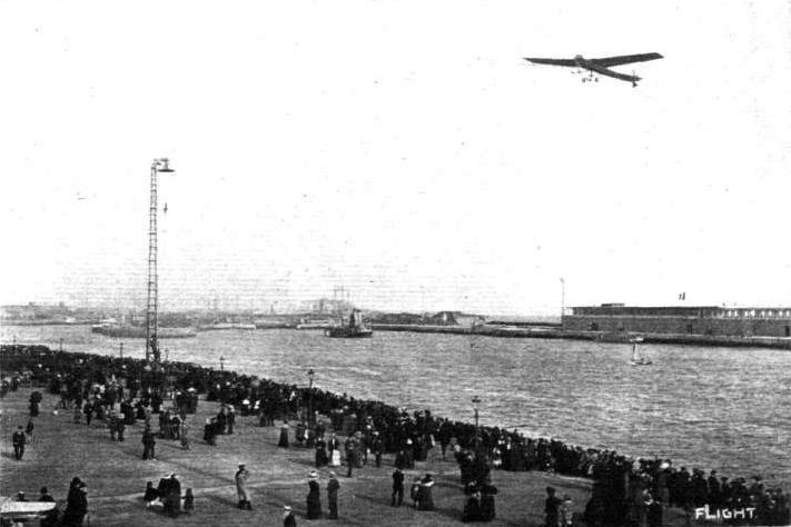
THE GREAT HAVRE-TROUVILLE-DEAUVILLE MEETING. - Latham on his Antoinette arriving at Trouville upon one of his many oversea journeys at this aviation meeting.

AN INCIDENT DURING THE FRENCH ARMY MANOEUVRES. - M. Latham, just about to start on his Antoinette lor a scouting expedition with a French officer, taking instructions as to the work to be carried out. Note the military assistants holding down the impatient flyer.

M. Latham flying at Chalons on the monoplane fitted with a 16-cyl. 100-h.p. Antoinette motor, and specially built for the Gordon-Bennett Aviation Cup Race. With this M. Latham is credited with having attained a speed of 110 k.p.h.
PARIS FLIGHT SALON. - General view of the centre of the Grand Palais. On the right is seen the Wright biplane, on the left the Maurice Farman biplane, just beyond being the Henry Farman machine, whilst in the foreground, in the centre, is the two-seater Antoinette monoplane.
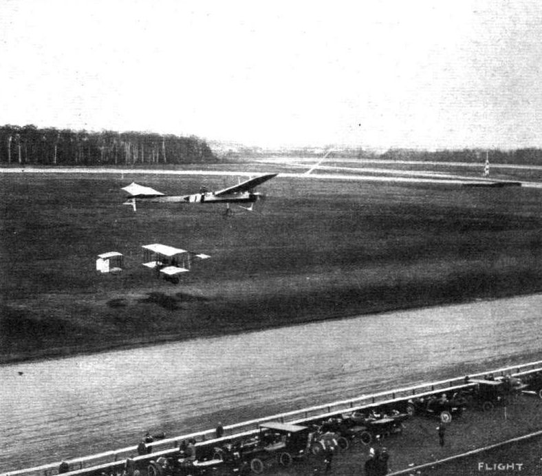
AT BELMONT PARK (N.Y.) INTERNATIONAL MEETING. - Hubert Latham, on his Antoinette, passing directly over Grahame-White on his Henry Farman during one of the competitions.
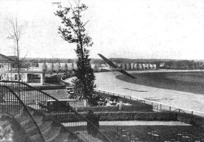
A CLOSE THING. - Hubert Latham blown out of his course at Belmont Park (N.Y.) Meeting during the contest for the Gordon-Bennett Cup.
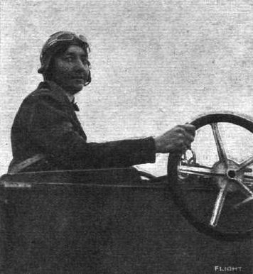
Mdlle. Marvingt at the wheel of the Antoinette monoplane upon which she made a new record for a woman at Mourmelon, by flying 30 miles in 53 minutes, incidentally qualifying for her pilot's certificate.

FIRST COLLISION IN THE AIR. - As the mishap to Capt. Bertram Dickson, on his Henry Farman, when M. Thomas, on his Antoinette, dashed Into him from above, at Milan, appeared to A. Beltrame, an Italian artist. This picture appeared in La Domenica del Corriere.
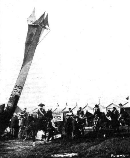
The scene at Milan immediately following the crash to earth of the Antoinette monoplane of M. Thomas and Capt. Dickson's Farman machine. The tail portion of the Farman biplane, showing No. 18, can be seen between the military, the main planes being mixed up completely with the planes of the Antoinette, the tail and body of which is seen standing straight up on end.
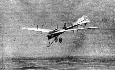
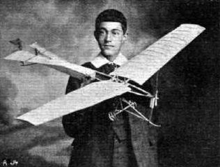
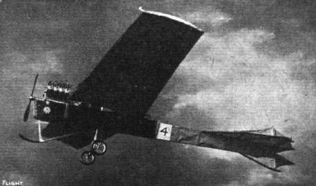
Mr. R. M. H. Clemson's Antoinette.
Flight, January 22, 1910
Flying into London.
WHILE at Pau recently Mr. Grahame-White made a wager that he would fly from a point down the River Thames to within a mile of the heart of London, Mr. Grahame-White has one of his Bleriot monoplanes at Brooklands, and on Thursday of last week made several short flights for the purpose of tuning up the engine of his flyer, but the wind was against making any attempt at cross-country flying at the beginning of this week. The actual starting and landing places will not be made known until just before the start, as it would obviously be undesirable to have a large crowd at either place. In order that Mr. White may fly as little as possible over houses, the route chosen will be directly over the river.
Flight, February 12, 1910
M. Bleriot at Pau.
M. BLERIOT returned to Pau on the 4th inst, and the next day was making several experiments in landing by stopping the motor and gliding down. He also stopped the motor several times during a flight, and skimming down to a short distance of the ground, started again and rose to a height of twenty metres. Lieut. Aquaviva, the military pupil, is making splendid progress, and will shortly make the necessary flights to qualify for the Ae.C.F. pilote-aviateur certificate.
Flight, February 26, 1910
Mamet at Barcelona.
A GRAND aviation fete was announced to take place at Barcelona on the 17th inst., but the wind prevented any flying until late in the afternoon, when Mamet made two short trials of six and eleven minutes' duration respectively on a Bleriot monoplane belonging to Sen. Garcia Cames. At the conclusion of the second flight Mamet stopped the engine and glided down from a height of 100 metres, landing perfectly. On the 19th the aviator made a good flight, but his landing was spoilt by a photographer who got in the way. In endeavouring to avoid him Mamet brought his machine down too suddenly, and as a result smashed the propeller.
Flight, March 5, 1910
FURTHER DETAILS OF THE BLERIOT CROSS-CHANNEL FLYER.
WE have prepared the accompanying sketches primarily in order to answer certain points raised by a correspondent, F. W. Bramley, whose letter appears this week. There has been so much correspondence about this machine, however, that the following remarks relating to the details in question will doubtless have a wider interest. We have consequently thought proper to deal with them in this form.
One of the two sketches shown herewith represents the wheel at the rear of the chassis. The diameter of this wheel has not previously been given; it measures 20 ins. An interesting minor detail to which attention may be drawn in connection with the arrangement of this wheel is the use of a piece of elastic anchoring the wheel bracket to the chassis frame. The fork that carries the wheel is pivoted to a vertical post that is trussed substantially to the chassis frame. In addition to this pivotal motion the forks are also hinged and mounted in such a way that they afford a spring suspension. The spring is situated at the top of the vertical post in the position illustrated by the sketch. The object of the elastic is, of course, to keep the wheel in line ready for landing, but at the same time it does not interfere with the free swivelling of the wheel when the machine is running along the ground.
The other sketch shows in very complete detail the construction and arrangement of the tail on the Bleriot cross-Channel flyer. It affords answers to all the questions raised by our correspondent. The tail is supported on a steel tube. A, by aluminium brackets, C, clamped to the main spars of the frame. The steel tube forming the main transverse member of the tail is trussed by a flat strip steel tie-bar, B, that extends from the top of the main frame to the junction of the tail with the elevating tips.
Further support for the tail is afforded by the diagonal struts, E, made of light steel tubes that pass from the trailing edge of the tail plane to vertical uprights in the main frame of the chassis. This latter attachment is so arranged as to afford an adjustment whereby the angle of incidence of the tail can be varied. The small perforated bracket, F, is similarly made adjustable for the same purpose.
The operation of the elevating tips, which are movable at either extremity of the central tail plane, is effected by means of the main transverse tubular spar, A. The elevating tips are fixed to this spar, as also is the central lever, B, that is connected by wires to the operating lever under the pilot's control. The main spar, A, can, of course, rock in its bracket. The central portion of the tail plane is not movable in flight, but can be adjusted as already described.
Flight, March 12, 1910
THE SECOND OLYMPIA AERO SHOW.
AEROPLANES.
Bleriot.
REPLICAS of the monoplane on which Mons. Bleriot flew across the Channel, exhibited by Messrs. Bleriot, Limited, Messrs. Humber, Limited, and the Aeroplane Supply Company. A full description of this machine, together with scale drawings, appeared in FLIGHT for July 31st last, just after the historic trip. The main planes measure about 25 ft. 6 ins. across, and the overall length is about 26 ft. The engine is a three-cylinder Anzani, weighing 65 kilogs., of which the bore and stroke are 105 mm. x 130 mm.
Flight, April 2, 1910
Mr. Hornstein's Accident.
AMONG the many British flyers who have been quietly experimenting in England is Mr. Hornstein, who on Easter Sunday met with a mishap while flying on a private ground at Halliford, near Shepperton-on-Thames. On the previous Friday Mr. Hornstein had flown a mile and a quarter at a height of about 40 ft., and it was from about the same height that the machine came down suddenly on Sunday, apparently due to a mistake in steering. Mr. Hornstein was pinned beneath the machine, and sustained injuries to the head. He has for some time been designing machines that have been constructed by the Thames Bank Wharf Co., and has recently been experimenting with the biplane with which the accident occurred. Elsewhere we give a few details of the machine.
Flight, April 9, 1910
THE FATAL ACCIDENT TO M. LE BLON
YET another aviator has been added to the list of those who have lost their lives in pursuit of the new sport, this being M. Le Blon, who by his flying on his Bleriot at Doncaster and in Egypt, as well as at various places in France, had shown himself to be a very clever flyer. The accident occurred at San Sebastian, while M. Le Blon was using a similar machine to that on which Delagrange met his death, and it would seem that the accident was partly due to the same cause - that the machine was overpowered. Although his contract had come to an end on the previous day, Le Blon, in spite of the strong winds, determined to give an exhibition flight over the sea. He rose to a height of about 150 ft., and after flying for some distance turned to come back. It was then seen that the machine stopped, and a moment later it fell into the sea.
Unfortunately, as no flying was anticipated, no boats were at hand, and it was some time before he could be rescued. According to the medical evidence, death was due to drowning. As the motor was found to be intact, it can only be surmised that the abnormal strain proved too much for the construction, and so caused the planes to collapse.
Flight, April 23, 1910
FLYER SILHOUETTES FROM OLYMPIA.
THE BLERIOT "CROSS-CHANNEL" MONOPLANE.
Leading Particulars of the Bleriot, "Cross-Channel" type.
General Dimensions.-Areas-Main planes, 193 sq. ft.; fixed tail, 18 sq. ft.; elevator, 18 sq. ft.; rudder, 5 1/2 sq. ft.
Lengths.-Span, 28 ft. 8 ins.; chord, 6 ft. 8 ins.; camber, 5 ins., situated about 20 ins. from leading edge; leverage of rudder, 17 ft. 6 ins.; skid track, 5 ft.; overall length, 24 ft. 9 ins.
Angles.-Incidence, 9 degrees; dihedral, 1 in 33.
Materials.-Timber, ash; fabric, Continental.
Engine.-25-h.p. Anzani.
Propeller.-Chauviere; diameter, 6 ft. 7 ins; material, walnut.
Weight.-Machine, 318 lbs. (approx.); engine and propeller, 142 lbs.; driver, oil, petrol and water, 200 lbs.; total flying weight, 660 lbs. (approx.); loading (all weight supported on main planes), 3.4 lbs. per sq. ft.
Speed of Flight.-40 m.p.h.
System of Control.-Warping of main planes, rudder and elevator.
Price.-L480.
GENUINE Bleriot machines were exhibited on three stands, those of Bleriot, Ltd., of Long Acre; L. Bleriot, of London and Paris; and the Aeroplane Supply Co. The essential difference between the 1910 model and the cross-Channel type, of which it is otherwise an exact copy, lies in the method of attaching the main spars of the wings to the body. The front spar now terminates in a circular section spigot that is held in a tubular steel socket. The rear spar is still held by a bolt, but the bracket to which it is attached is more simple in design. For further particulars of this machine we would refer our readers to a full description that appeared in FLIGHT of July 31st, 1909. A minor detail of the 1910 model that differs from the cross-Channel design is the use of elastic springs in the cross ties behind the hubs of the wheels and on the vertical columns of the chassis frame.
Flight, May 28, 1910
THE CHANNEL AGAIN CROSSED.
BY an oversight when M. Bleriot entered for the Daily Man prize and flew across the Channel on July 25th last year, he failed to make formal entry for the Ruinart prize of L500, and so left the way open for his feat to be repeated. This was successfully done, as our readers already know, on Saturday last, when M. Jacques de Lesseps, the youngest son of the famous engineer of the Suez Canal, flew from Les Baraques to a large meadow some distance inland from the South Foreland Lighthouse, and thus secured the prize, as well as the L100 cup offered by the Daily Mail for the second aviator to cross the Channel. The time taken was 37 minutes, only a little better than M. Bleriot's time. His machine, "Le Scarabee," was similar to the one used by M. Bleriot, except that it was fitted with a Gnome motor and a "Progressive" propeller made by Passerat and Radiguet. The wings were surfaced with Continental fabric. Arrangements had been made for the French destroyer "Escopette," the same which accompanied Bleriot, to follow the aviator, but owing to the thick fog, each sighted the other but once for a brief moment in mid-Channel. The start at Les Baraques was made in the presence of Vicomte Andre de Bremont, the proprietor of Messrs. Ruinart; Mr. F. E. Croft, and Mr. J. Dunlop Watson, their English representatives; M. Fournier, representing the Aero Club de France; and Mr. H. E. Perrin, the Royal Aero Club. Before leaving the coast of France M. de Lesseps attained a height of about 800 ft., while on arriving at the English coast his altitude was considerably over 1,000 ft. The watchers on the cliffs at Dover had almost given up all hope of seeing the flight, in view of the weather, when the coastguard officer, who first saw Bleriot when he made his successful crossing, announced that he could hear the motor. A few minutes after the machine, flying at a great height, emerged from the fog, heading for the Langdon Battery, further along the cliffs than Northfall Meadow, where Bleriot landed. The crowd followed as quickly as they could, and it eventually transpired that the descent was accomplished after a long gliding descent of over two miles in a meadow belonging to Wanstone Court Farm, about three miles east of Dover and about a mile inland. There M. de Lesseps was welcomed by Mr. R. Clayson, of St. Margarets, who happened to be in the field, while the ladies of the farm provided the aviator with refreshment. Among the first to congratulate the young aviator was the Hon. C. S. Rolls, who is waiting for a favourable opportunity to fly from Dover to Calais, and had himself entered for the Ruinart prize. In addition there were several officials of the British and French Aero Clubs, and Mr. Norbet Chereau, M. Bleriot's manager for the United Kingdom. The official observers for the Royal Aero Club at Dover were the Hon. C. S. Rolls and Mr. Chereau. M. de Lesseps wanted to fly back again almost at once, but was dissuaded by Mr. Chereau, as the weather conditions were rapidly getting worse. Prospects of improvement being small, the aviator eventually decided to abandon his intention of returning by way of the air to France. He ultimately boarded the French destroyer which crossed with him for his flight and returned to France, his machine following in due course.
AN AVIATION SCHOOL AT BOURNEMOUTH.
THE two photographs which we reproduce herewith give some idea of the work which is being done by Mr. W. E. McArdle at the flying school he has established in conjunction with Mr. A. Drexel just by Brockenhurst Station in the New Forest. At the present time the equipment includes seven Bleriot machines, three of which have been built at Bournemouth, while two biplanes are also under construction. During Whit week both Mr. McArdle and Mr. Drexel were flying at Wallisdown, near Bournemouth. One of the snapshots shows the latter on a locally built machine passing over the flying grounds. Arrangements can be made for any aviator to rent a shed at a charge of L50 per annum with free use of ground about 500 acres in extent, with excellent surface for landing and practice. The other facilities include a large workshop with competent men to do repairs.
Flight, June 4, 1910
BLERIOT CONSTRUCTION.
Could you insert in your valuable paper a sketch of the Bleriot pattern wire clamps application. I do not quite gather from Capt. Windham's explanation on p. 548 of FLIGHT for Sept. 4th, 1909, how it works.
I am indebted greatly to you for many constructive details of great value.
Delhi, India. JAC.
[The accompanying sketch illustrates very clearly the particulars asked for by our correspondent. The U bolts are of steel, and vary in size from a diameter of 1/8 in. to 3/16 in., the larger size being used for the front end of the girder. The vertical struts are placed slightly in advance of the horizontal struts to enable the U bolts to clear each other.-ED.]
Flight, June 11, 1910
FLYING IN SCOTLAND.
DURING the three closing days of last week, Mr. J. Radley gave a series of exhibition flights on his Bleriot monoplane at Pollok, in some grounds lent by Sir John Stirling Maxwell. The flying was arranged in connection with a fete organised with the object of aiding the funds of a local chapel. On the 2nd inst., Mr. Radley made a series of long jumps, and in view of the cramped nature of the flying grounds and the surrounding trees, did not attempt any long flight. He however, showed the capabilities of his machine, and the trials were watched by a large and interested crowd, who, however, hampered the aviator's movements by crowding round the machine. On one occasion, in negotiating an eddy of wind, Mr. Radley was carried over the heads of the spectators, who fled in all directions, and the aviator in endeavouring to avoid them only just missed smashing his machine. On the following day the wind was too strong for any flying to be done, and although the conditions were little better on Saturday Mr. Radley made a series of short flights against the wind. During the afternoon the proceedings were enlivened by a series of experiments with a man-carrying glider belonging to the Glasgow Model Aero Club. Late in the afternoon while making a trip, Mr. Radley met with a mishap. He was making a flight, when a sudden gust of wind drove him out of his course, over the crowd. In order to avoid the crowd Mr. Radley had to make a sudden turn, and in his hurried landing his monoplane suffered considerably, the chassis being twisted and one of the planes buckled. Fortunately Mr. Radley escaped unhurt.
Flight, June 25, 1910
A BLERIOT IN NORTH WALES.
I enclose some photographs of my Bleriot monoplane, and as I claim to be the first one to fly on an aeroplane in North Wales I thought they would be interesting to your valuable paper. I have been practising for some time on my machine, and had rather a nasty smash about two months ago, landing in the railway hedge from a height of about 30 feet. However, on the 26th of May I towed my machine to a large field, and succeeded in making a flight of half a mile, during which I attained a height of about 70 feet. The centre photograph shows the method of towing the Bleriot behind my car. In the left-hand picture I am starting up prior to my flight, and that on the right was taken by my mechanic immediately after landing. The Bleriot behaved very well during the flight, at the end of which I switched off and glided down, and, although it bumped a little on landing, nothing was damaged. Since then I have made numerous small flights, and hope to do better when I become more accustomed to the machine.
Bodfari, North Wales. VIVIAN V. D. HEWITT.
Flight, October 8, 1910
The San Sebastian Meeting.
AT the three days flying meeting which opened at San Sebastian on Sept. 27th, Morane was the star performer. On the opening day before the King of Spain, he made several flights of a total duration of 25 mins., and afterwards had the honour of explaining his Bleriot monoplane to King Alfonso. On the following day he made four flights of a little over half an hour's duration when the proceedings were enlivened by the arrival of Tabuteau from Biarritz. After landing and adjusting his machine he made two other flights of a total duration of 17 mins. On the 29th, Morane made three flights as also did Tabuteau, while Loygorry, a Spanish aviator, made two trips, each of these aviators being in the air for about 25 mins. Competing for the height prize, which he easily won, Morane reached an altitude of 800 metres. Subsequently King Alfonso conferred on both Morane and Tabuteau the cross of the Order of Carlos III.
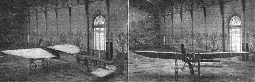
BLERIOT'S CROSS-CHANNEL FLYER. - As a souvenir of M. Bleriot's historic feat in flying across the Channel, Messrs. Bleriot, Ltd., the London manufacturers of the famous lamps designed by M. Bleriot, have issued postcards, reproduced above, showing the flyer as it appeared when on exhibition in London afterwards. These can be obtained at the Company's stand at Olympia during the present Show.
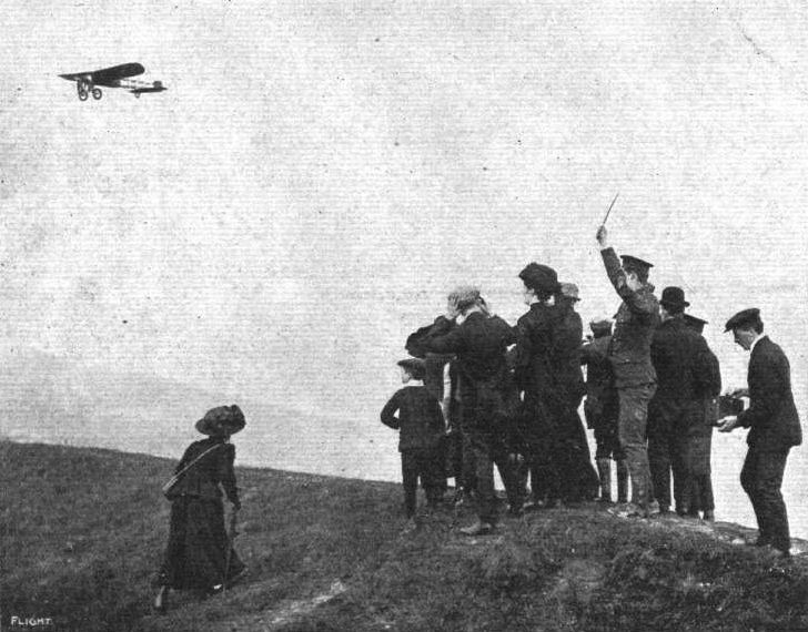
THE SECOND CROSS-CHANNEL FLIGHT. - M. Jacques de Lesseps, on his Bleriot, passing over the cliffs at Dover on Saturday last. A good specimen of a "composite" photograph.
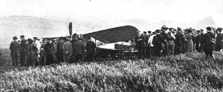
M. JACQUES DE LESSEPS' CHANNEL FLIGHT. - His Bleriot machine immediately after landing near Dover.
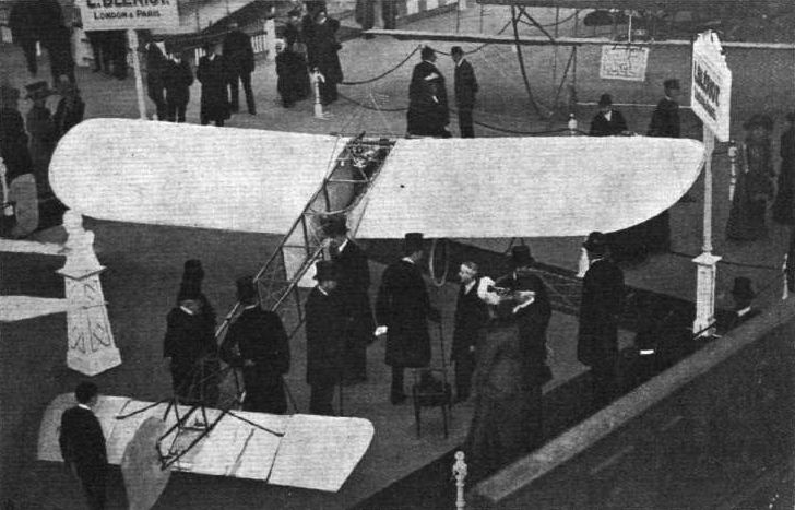
THE PRINCE AND PRINCESS OF WALES AT OLYMPIA. - Our photograph was secured during the inspection of the famous Louis Bleriot monoplane. On the stand are also Prince Francis of Teck, Mr. Roger W. Wallace, K.C., Chairman of the Royal Aero Club; the Hon. C. S. Rolls, who drove the Prince and Princess on his car from Marlborough House and back, and explained many points of interest in the exhibits during the Royal party's tour of Olympia; Mr. Edward Manville, President of the S.M.M.T.; and Mr. Norbet Chereau, manager for M. Bleriot.
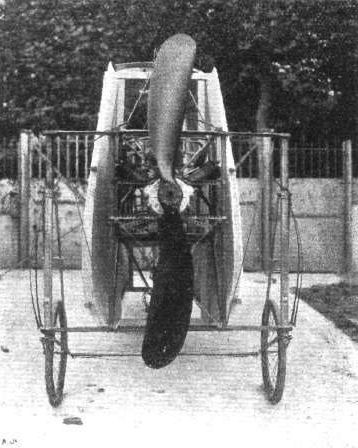
The Bleriot monoplane, with its main planes folded up ready for housing or travelling.
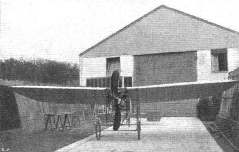
Under the method of construction of his monoplanes M. Bleriot does away with the necessity of huge places for housing them. The main planes can be quite readily folded down to the sides, the whole being brought well within the compass of the main framework. In the above photograph a Bleriot is seen with its planes fully set after coming out of its dock, seen behind. In our other photo the same machine is seen folded up.
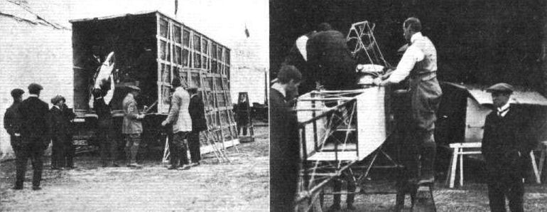
HOW AN AEROPLANE ARRIVES AT AN AERODROME. - Mr. Grahame-White superintending the unpacking of his monoplane; and, on the right, assisting in its erection.
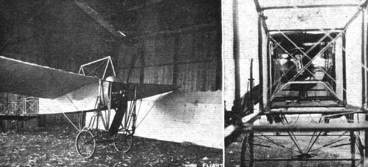
GRAHAME-WHITE'S BLERIOT, SHOWING THE CENTRAL ARRANGEMENTS. - On the right, a view taken from the tail end shows the pilot's seat, control pillar and wheel warping arrangement and metal splash-board to protect the aviator from oil.

A Bleriot type machine just completed by Messrs. Hill and Co., of Bury, Lancashire.
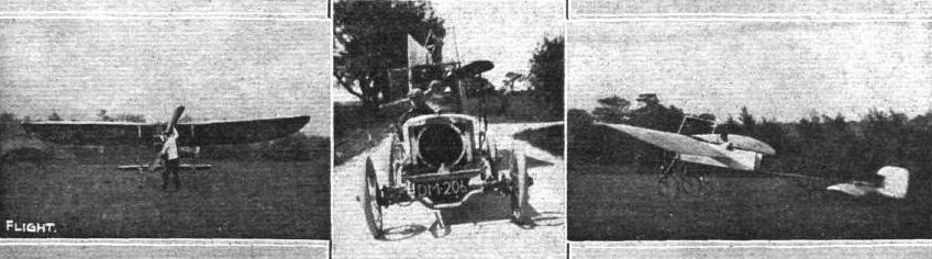
Mr. Vivian V. D. Hewitt's Bleriot.
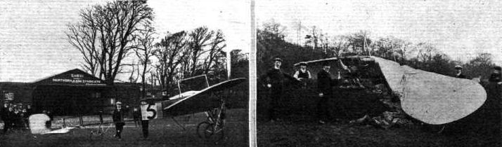
Last week the Bleriot monoplane which is being exploited by Mr. Albert House, Managing Director of the Northern Aero Syndicate at Bradford, was out for practice at the Company's Apperley Bridge flying ground, and some interesting short flights were obtained. Unfortunately, at the finish, when taking a turn to avoid a wall, the machine came to grief. Our photographs above show the machine before and after the mishap. In the left-hand photo is Mr. J. W. House, at the wheel, and standing behind the figure 5 is Mr. Albert House, junr. In the right-hand photograph, from left to right, are Mr. J. W. House, Mr. Albert House, junr., and Mr. Albert House.
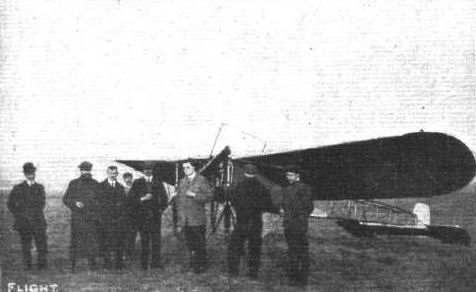
AT THE BLERIOT SCHOOL, HENDON (LONDON AERODROME). - From left to right: Mr. P. Prier (instructor), Mr. E. A. Paul, Capt. Board, Mr. Bouwens, Mr. Petitpierre, Mr. Grabette.

KING EDWARD AT BIARRITZ AVIATION MEETING. - His Majesty questioning M. Bleriot upon details of his monoplane.
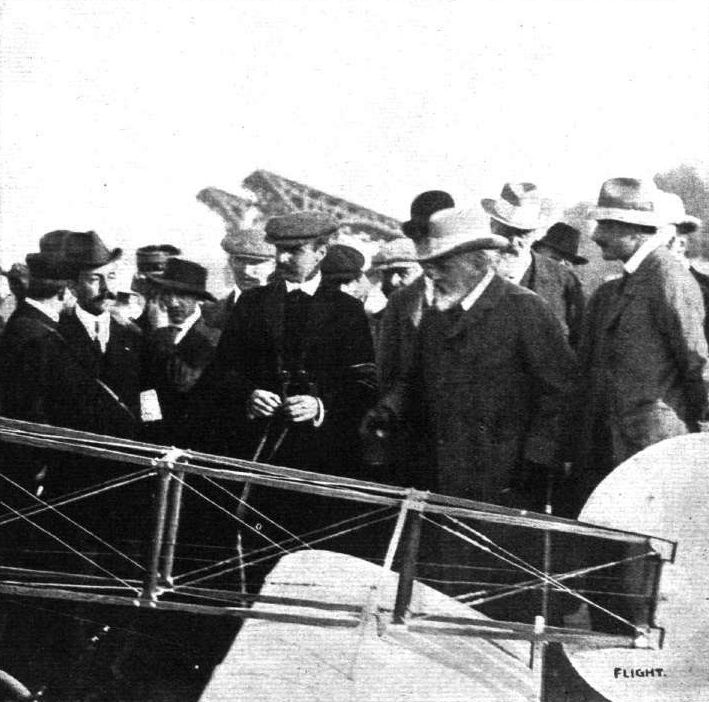
A Typical Incident in the Career of the Monarch, Counsellor, Sage, and Sportsman, whose Death has cast a gloom over Five Continents.
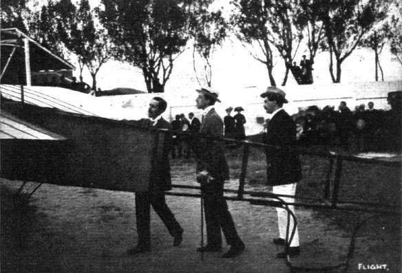
King Alfonso of Spain (in centre) takes intense Interest in the Bleriot of M. Morane at San Sebastian.
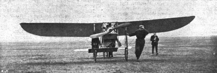
Mr. Claude Grahame-White bringing back his Bleriot to its dock at Brooklands after some short flights last Saturday. Mr. Grahame-Whlte is seen in front helping to pull by the chassis.
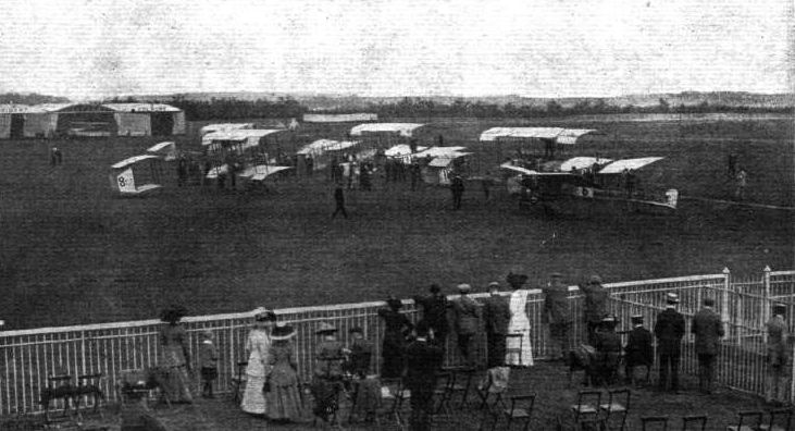
Competitors at the Starting Line at Lanark Meeting, as seen from the Members' Enclosure. - The machines, reading from the front, are: No. 6, Cattaneo's Bleriot; No. 12, Gilmour's Bleriot; 18, Grace's Henry Farman; 131, Ridley's Bierlot; 11, Capt. Dickson's Farman; 21, McArdle's Bleriot; 8, Blondeau's Henry Farman; 5, Champel's Voisin.
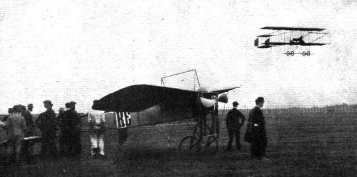
GRAHAME-WHITE IN FLIGHT ON HIS HENRY FARMAN AT BLACKPOOL AERODROME. - The machine at rest on the ground is Cecil Grace s Bleriot.
ONE, TWO AND THREE PLANES. - Grahame-White, in his Henry Farman biplane, flying over Drexel's Bleriot monoplane and Roe's triplane.
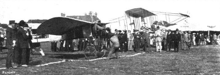
DREXEL OFF ON HIS BLERIOT FOR HIS SPLENDID SEA FLIGHT. - Beyond is Grahame-Whlte's Henry Farman also about to take the air.
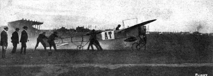
RESTRAINING AN IMPATIENT MOUNT. - Cattaneo, at Blackpool, starting for the speed contest, in which he made three laps in 3m. 36s. = 50 m.p.h. Note the exhaust from engine and position of extra petrol tank. A general view of the aerodrome, with the Tower in the distance, is obtained in this picture.
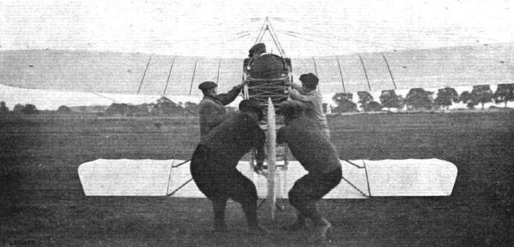
M. Paul de Lesseps' Bleriot impatient to take the air at Doncaster Flight Meeting. - How the mechanics restrain her.

Mr. Radley in flight on his Bleriot monoplane over the Huntingdon Racecourse, now used as an aviation ground.
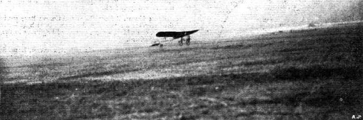
Mr. Claude Grahame-White, who has been flying at Pau, last week, during his visit to London, made some short flights at Brooklands preparatory to any attempt at his proposed long flight from the Valley of the Thames to some central point within two miles or so of Charing Cross. Our photograph shows Mr. Grahame-White in the air on his Bleriot monoplane.

The late M. Le Blon flying over the rocks and sea at San Sebastian last week. It was upon a later day that the disaster which ended fatally, occurred.
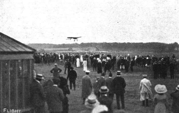
FLYING AT BROOKLANDS. - Mr. Astley is seen flying on his monoplane.
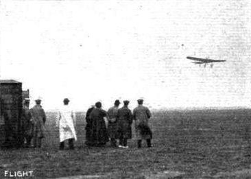
Louis Bleriot, who was a visitor at the Bournemouth Aerodrome, takes a turn in the air on one of his monoplanes.
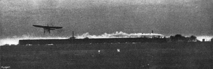
Mr. James Radley flying at Brooklands Aviation Grounds at dusk on Wednesday of last week over one of the London and South-Western trains
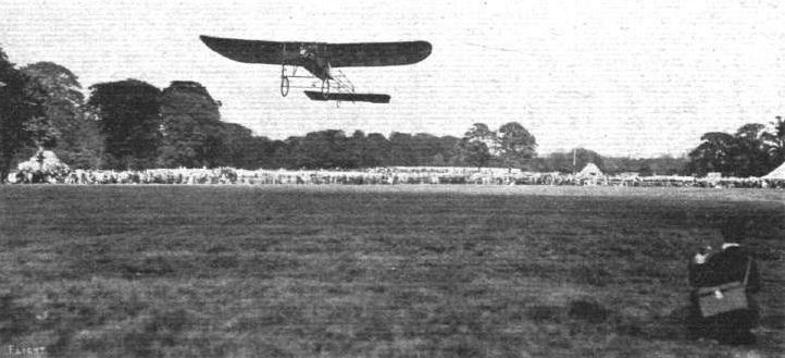
FLYING IN SCOTLAND - FIRST PUBLIC FLIGHTS, - Mr. Radley giving exhibitions on his Bleriot monoplane at Pollok last week.
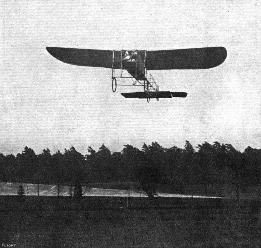
Mr. D. Graham Gilmour during one of his splendid flights on his Bleriot monoplane recently at Brooklands.

M. Pierre Prier, the Bleriot instructor, makes his first flight on the Bleriot School opening day at Hendon Aerodrome last Saturday. - His start, and, inset, well up in the air.
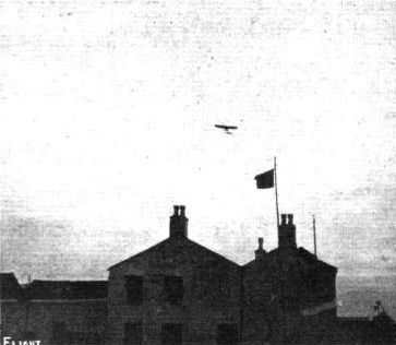
Drexel on Cecil Grace's Bleriot flying over the Club-house on Saturday last at the Blackpool meeting. For this achievement he was awarded the Daily Merit Prize of L100.
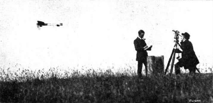
Major Kennedy and Mr. Hogarth taking Drexel's altitude at Lanark Meeting.
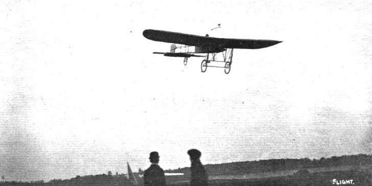
Mr. James Radley flying at Brooklands at the Spring Meeting on Wednesday last week on his Bleriot machine.

A vol plane by Radley on his Bleriot monoplane at Bournemouth Aviation Meeting.
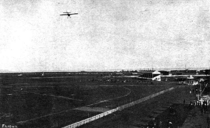
HAVRE FLIGHT MEETING. - General view of the aerodrome and grand stands, looking towards the sea. Aubrun, on his Bleriot, is flying.
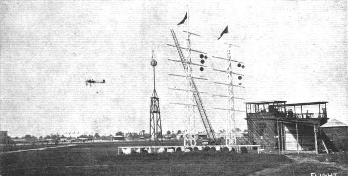
MILAN MEETING. - General view of the aviation grounds, showing the timekeeper's box, signalling arrangements hangars, &c. A Bleriot is in flight round the course.
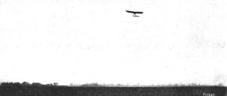
Mr. A. Drexel flying high on a Bleriot over the McArdle and Drexel New Forest Aviation School grounds.
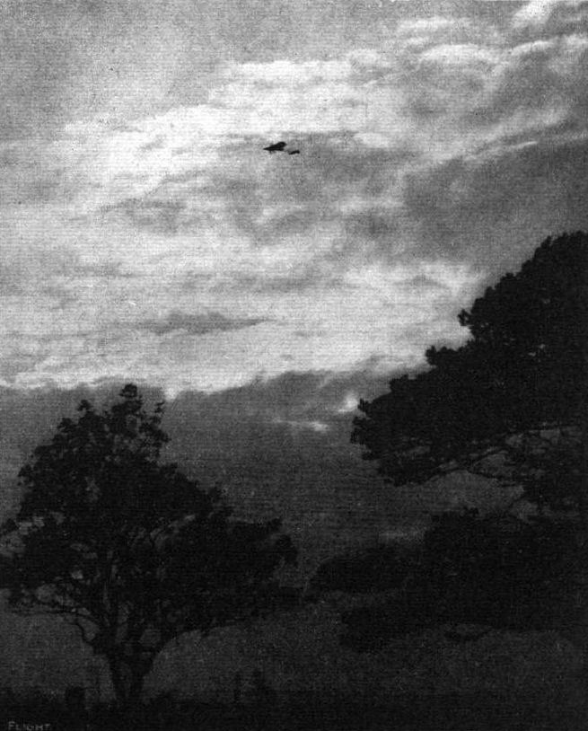
FLYING AT DUSK. - Mr. Cecil Grace, on his Bleriot recently making one of his high flights during the close of the day.
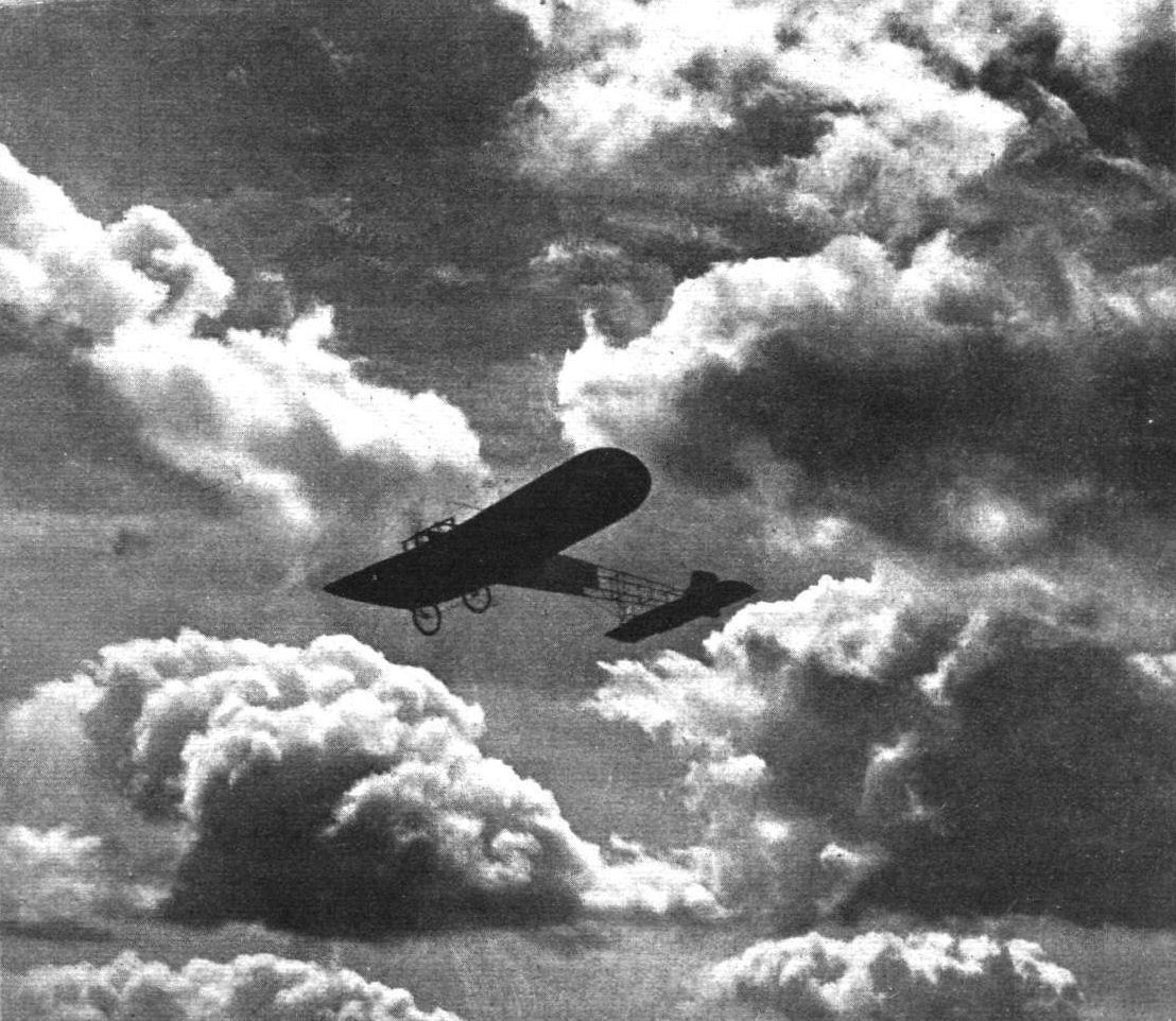
FLIGHT PHOTOGRAPHS - An impression of the future-flying in the clouds. A clever "faked" photograph, of which so many have been given currency. It is interesting to contrast this with the genuine pictures which have formed the last two frontispieces in FLIGHT.
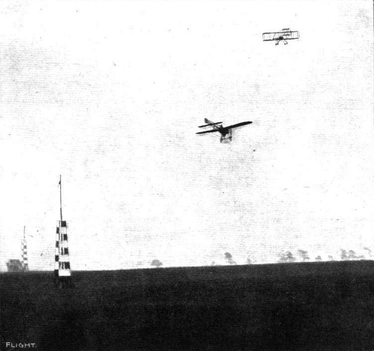
Captain Dickson, on his Henry Farman, and Cattaneo, on his Bleriot, in the air at the same time at the Lanark Flight Meeting.
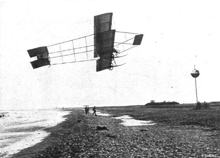
Mr. A. Rawlinson during one of his daring flights on his Henry Farman on the opening day of the Nice Meeting. - In the distance, exactly over the heads of the three men on the beach, Olieslagers, on his Bieriot monoplane, can be seen flying.
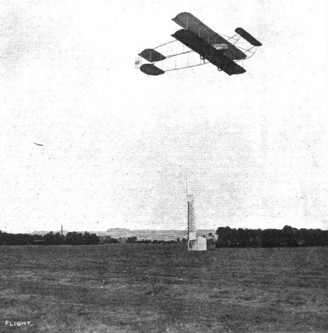
AT THE HAVRE FLIGHT MEETING. - Barra, on his Maurice Farman, circling the aerodrome. In the distance, on the left, is seen a Bleriot in flight.
A GROUP OF FOUR FLYERS IN THE AIR AT ONCE AT RHEIMS. - Above, an Antoinette and a Bleriot; below, a Henry Farman; and, to the left, a Wright machine.
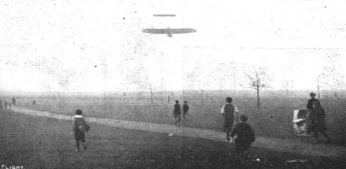
M. Prier, chief instructor at the Bleriot Aviation School at Hendon, landing with a fine vol plane at the "Scrubbs" last week in connection with his flight on a Bleriot monoplane from the Hendon flying grounds to Wormwood Scrubbs and back, in order to give Mr. Willows greeting prior to his start on his airship for France and Paris.
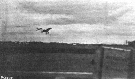
COMING OR GOING? - J. Armstrong Drexel landing with his Bleriot in the Gordon-Bennett Contest at Belmont Park. As a New York reader writes, in sending us this photograph : "You can only tell whether the machine is coming or going by the size of the higher wing."
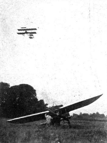
Another "passing" incident during the Midland National Meeting. - Mr. Grahame-White flying over one of the Bleriot monoplanes.
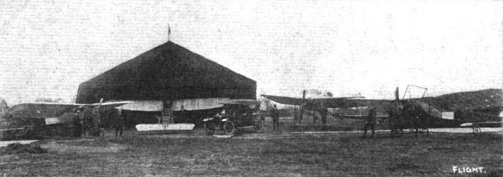
MESSRS. McARDLE AND DREXEL'S NEW FOREST AVIATION SCHOOL. - The flying grounds extend to 500 acres, and already there are seven Bleriots installed at the School.
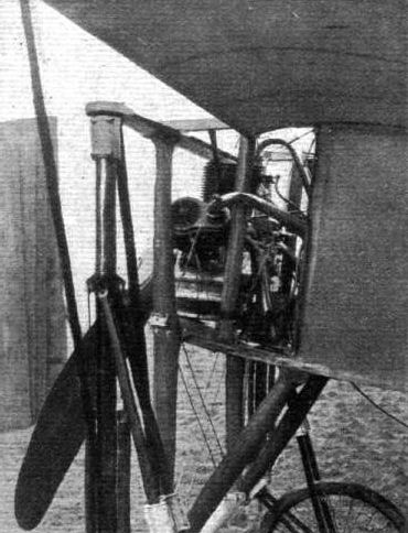
The above illustration shows an Interesting portion of the Bleriot monoplane at close quarters. It is one of Mr. Claude Graham-White's machines that is now being experimented with by Mr. R. W. A. Brewer.
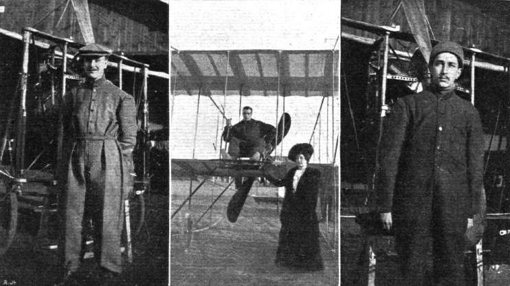
Mr. C. Grahame-White, after his 65 mins. flight on March 28th, and a couple of his pupils, Mr. Armstrong Drexel (left) and Mr. Charles Hubert (right). In the centre picture Mr. Grahame-White's mother, who has flown with her son, is standing in front of the Henry Farman machine.
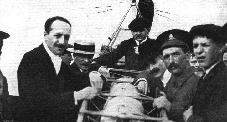
M. Jacques de Lesseps (without hat) standing by his Bleriot monoplane, just after landing near Dover, at the finish of his cross-Channel flight.
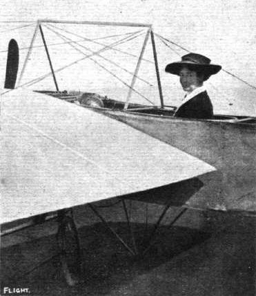
Countess Fitzwilliam in the pilot's seat of her husband's Bleriot monoplane in the grounds of Wentworth Woodhouse, Earl Fitzwilliam's seat near Rotherham. Lady Fitzwilliam, who is a younger daughter of Lord and Lady Zetland, is Lady Mayoress of Sheffield for this year.
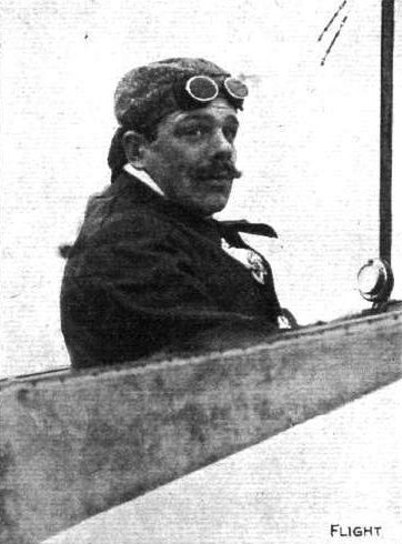
Olieslaegers, on his Bleriot, the Long Distance and Time World's Record Holder. - At Rheims Meeting last week he broke record by flying 255.25 kiloms. in 2h. 3 9 m . 28s., and on Sunday, the last day, he far surpassed this by remaining up for 5h. 3m. 5 2/5s., covering in that time 392.75 kiloms. (245 miles).
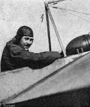
J. Armstrong Drexel (Bleriot).
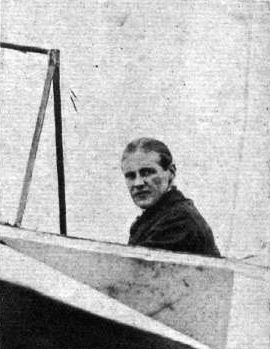
THE FLYING MEN AT BOURNEMOUTH AND THEIR "MOUNTS." - J. Radley (Bleriot).
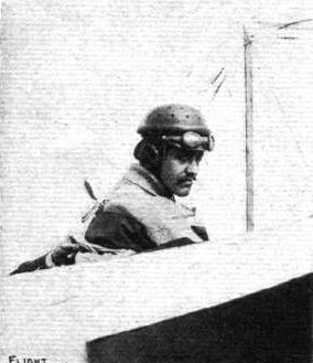
THE FLYING MEN AT BOURNEMOUTH AND THEIR "MOUNTS." - Leon F. Morane (Bleriot).

McArdle, on Grahame-White's Bleriot, just before starting on Saturday for the Altitude Prize at Blackpool Aerodrome.
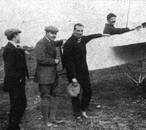
Four of the great flyers at Blackpool. From left to right - Cecil Grace, Armstrong Drexel, Claude Grahame-White, and, in the Bleriot pilot's seat, McArdle.
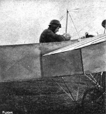
Chavez reading the barograph after making his high flight of 5,887 1/2 ft. on his Bleriot at Blackpool.

Chavez handing over the barograph to Mr. Harry Delacombe after his British record high flight at Blackpool.
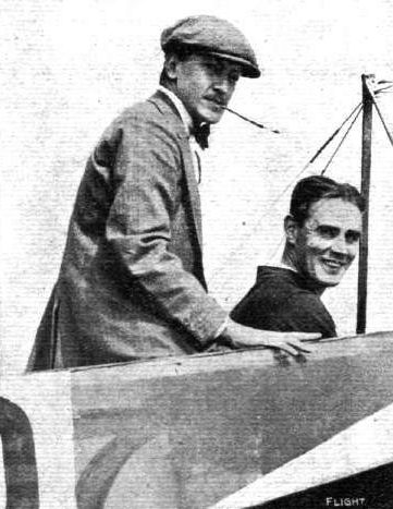
Graham Gilmour on his Bleriot with one of his passengers, Mr. Moorhouse.

Bartolomeo Cattaneo at Blackpool in the Blerlot which holds the British long-distance record.
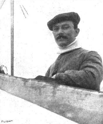
M. Leblanc to the pilot's seat of his Bleriot on which he won the first place in the Circuit de l'Est last week.
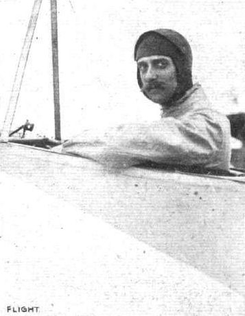
M. Aubrun, who, on a Bleriot, obtained second prize in the Circuit de l'Est, he being the only aviator, besides the winner, Leblanc, to complete the entire circuit.

M. Mamet, who has been making such good flights at Doncaster and Burton.

AT THE BLERIOT SCHOOL, HENDON (LONDON AERODROME). - Mr. B. G. Bouwens, one of the pupils on the Blerlot school machine.
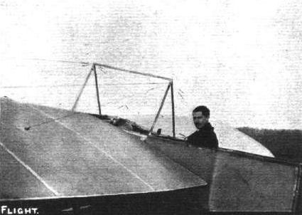
Capt. A. G. Board at the Bleriot School at Hendon, where he has just obtained his Royal Aero Club pilot's certificate.
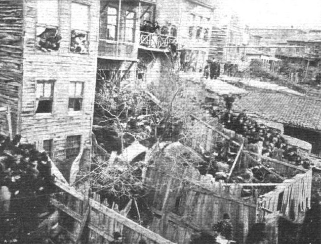
BLERIOT'S ACCIDENT IN CONSTANTINOPLE. - The crazy houses in the Tetavia quarter against which M. Bleriot's monoplane was driven by the boisterous wind when he, to please the crowd, undertook his hazardous flight on December 12th on the Tuscum military field at Pera. Our photograph shows the machine as it fell across the centre palings of the two back yards.
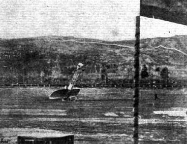
Unique instantaneous photograph of an accident to Mamet on his monoplane during his exhibition flights in Spain.
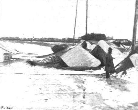
What is it? A wreck thrown up by the sea? A collapsed house, or what? Just the aeroplane "hangar" provided at the Baltimore (U.S.A.) aviation grounds after a night's "weather." Mr. R. J. H. Hooper, in sending us this unique photograph, writes: "The wreck of Radley's Bleriot at the Baltimore Aviation Meeting. I took this on November 4-th, the morning after a gale and snowstorm had brought down the large tent. Underneath the same tent were Drexel's Bleriot, De Lesseps' Bleriot, and Latham's Antoinette. We were first on the field, and cut away the tent before taking this photo. The other machines were still uncovered. The engine end of Latham's Antoinette is just visible beyond Radley's machine. Little wonder there is a reported loss of L8,000 on the meeting."
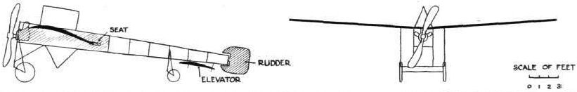
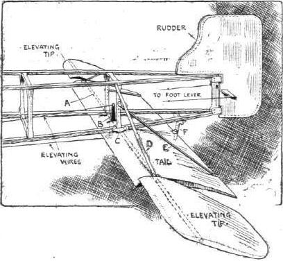


WING SECTIONS. - The above diagrams afford an interesting comparison of the wing sections of aeroplanes exhibited at Olympia. They are all drawn to a common scale, but have been set at an arbitrary angle of incidence, which does not necessarily represent that of the aeroplane In actual flight.
Flight, July 30, 1910
FROM BOURNEMOUTH TO THE NEW FOREST BY AEROPLANE.
THAT within about two years from the first public flight in the world, men should be flying home after fulfilling an engagement at an aviation meeting, instead of elaborately packing up their machines and carting by road or despatching by train, is the most eloquent demonstration it is possible to adduce of the phenomenal progress achieved in the conquest of the air in so short a period. That such a feat should also pass almost unnoticed in the Press is a still further proof of the advances made, rendering such a journey as accepted quite in the ordinary course of daily events. Yet such is the position to-day, whilst it is but three or four months back that there was a big wave of lamentations and sneers that Great Britain was all behind again, and had not a real flyer to her name! After the Bournemouth aviation week had been closed, all haste was made by most of the men who had taken part to forward their machines to the next point of demonstration. Mr. Armstrong Drexel and Mr. W. E. McArdle, who have founded such a fine school of flying at Beaulieu, in Hampshire, however, determined to return home by way of the air, in like manner to the arrival at the Southbourne aerodrome by McArdle a week previously. Then only one Bleriot was available. For the return the two-seated Bleriot of Morane had also been added to their fleet by the firm, so that Drexel was this time able to take a mount as well as his partner. And so it came about that, without fuss or blowing of trumpets, they both set out on Tuesday evening of last week and accomplished what three years ago would have secured for them pages of laudatory notice in practically every newspaper in the world. It is still a feat to be supremely proud of, more particularly from the fact that Drexel took with him Mr. Harry Delacombe, the well-known newspaper correspondent, who is so keenly interested in bringing home to the naval and military authorities the practical and national purposes to which the aeroplane can be put. He has clearly demonstrated the ease with which notes and sketches can be made in writing by a passenger that would in the hands of a General prove of immeasurable value. To this end we reproduce his original notes made during the flight with Drexel. Each of these slips of an ordinary note-book were signed in advance by Mr. Spottiswood and others as blank pages, and from these the announcement of the journey was made in the Morning Post the next morning. Supplementing on the following day the bare facts of the flight, the following details of his experience appeared on Thursday, which are of such historical interest that we reproduce them in full, as well as a special account from the pen of Mr. McArdle of his little trip, in which he was so encircled in clouds and mist that he lost his way, and descended at last at Fordingbridge by reason of petrol shortage. It is thus that Mr. Delacombe describes his trip :-
"When we reached the aerodrome at 4.30 there was a nasty gusty wind blowing, and Mr. McArdle (Mr. Drexel's partner in the Beaulieu Aviation School), considering the conditions quite unsuitable for our attempt to fly over the sea and forest to Beaulieu, suggested postponing the start, hoping the wind might drop. Mr. Drexel thought, on the contrary, that it might become more blustery, and was most anxious to be off. It had been arranged that he and I in the double-seated Bleriot monoplane should start first, followed after a few minutes by Mr. McArdle on the single-seater, as the latter, with only one person to carry, was sure to travel the faster, and probably overtake us en route. There was also the possibility that either machine might drop into the sea (where there was no cordon of motor boats and steam yachts as arranged for the over-sea flights to the Needles last week), be perceived by the other, and perhaps be reached sooner from the definite information it could carry to land. As no change in the weather appeared likely at 6 p.m., we decided to set out. Mr. Drexel thought our safety lay in rising about 1,000 ft. before making the journey, and said it would probably be necessary to encircle the aerodrome two or three times to attain this altitude. A single circuit only enabled us to climb to 350 ft. So round we went again, rising rapidly as we faced the wind, but having great difficulty in keeping our height with the wind astern, the "lift" being enormously decreased and the position of our machine becoming somewhat like that of a kangaroo sitting on its tail. Mr. Drexel's idea in flying high was: first, the hope of escaping gusts and finding a steadier wind than prevailed below; and, secondly, if the motor should perchance stop, the better chance of gliding down either into one of the few small open spaces among the almost endless trees, or else turning about and planning down for the sea, where we had a far better chance than if descending involuntarily among trees, houses, or marshy land.
A Bird's-Eye View.
"Satisfied at last as to our height, he steered direct from Hengistbury Head towards the Needles, which seemed almost below us, though really some two miles distant. We could see Mr. Loraine's aeroplane with people surrounding it very distinctly on the high land over Alum Bay, and as we turned to the left over the promontory of Hurst Castle the view up the Solent as far as Southampton on the left and Cowes on the right was clearly mapped out underneath. At this time the wind had been dead astern, and Mr. Drexel had a hard tussle to preserve our altitude to his liking. Once, when he asked me if I could see anything of 'Mac' following, I turned round, distinguished the aerodrome, but saw no machine aloft. I did, however, see that our tail, instead of being horizontal, was horribly out of the level, and momentary thoughts of head resistance and a backward fall flashed through my mind. The placid smile and cool behaviour of my companion would, however, have reassured the most timid, and I was happy in the sensation of unlimited power conveyed by the regular throbbing of the motor and the mighty beats of our propeller-blades as we soared steadily ahead. Suddenly I heard 'Look! there's old Beaulieu!' Following the direction in which he was gazing, I could distinguish nothing but apparently black forest. A winding road and a peculiar shaped patch of water, however, I guessed were his landing marks, and it was with a feeling rather of regret that I saw we were turning sharply to the left, and leaving the friendly sea behind, to fly over country which, from a height of 1,500 ft., looked everywhere literally unapproachable for our frail craft. With a nudge and a grin Drexel put forward the cloche, and we headed downwards till he was almost standing on his foot tiller, and my feet were pressed against the front part of our little cockpit. Then at last I realized how much we had been leaning backwards during the flight, for we were rushing through the air at about 80 miles an hour at a bigger angle probably than we had previously assumed in the other direction.
"At once I could make out the road and hangars of the Aviation School to our right, and could see a small crowd of black dots running out on what I had just before mistaken for another patch of murky forest. In three minutes we had glided more than 1,500 ft. downwards, and then came the end of my novel experience, for we landed, and were surrounded by friends, to one of whom I gave the notes I had scribbled on leaves of my pocket-book, signed as blank pages by other friends just before we left the ground at Southbourne.
Possibilities of Aeroplane Reconnoitring.
"Throughout the run I was entrusted with a rubber ball, by squeezing which a constant pressure is maintained in the feed, and I also constantly learnt forward and peeped over our bows to keep Drexel informed of our whereabouts. These minor duties, however, did not prevent me from carrying out my cherished hope of proving the practicability of writing legibly during a flight, and my scribbled log of the trip is sufficiently legible to prove beyond any question that trained officers or men could easily do surveying work of the utmost importance and utility at far greater heights than we reached, for with binoculars and a clearer atmosphere I could have distinguished every necessary detail, and transmitted my impressions to paper with explanatory notes in perfect comfort by stooping below the backwash of our propeller and the ordinary rush of air as we raced along. We saw Mr. McArdk flying about 800 ft. over the Beaulieu Aviation School five minutes after our descent, but he passed out of sight in the direction of Lyndhurst. As he did not reappear after an hour's interval, and we knew his petrol supply at the start could only suffice for a flight of one hour and a half, we started off in motor cars to try and glean some news, fearing he might have been obliged to descend in the New Forest, a most risky undertaking. Although we made circles of gradually increasing radii, knocked up every house or cottage showing a light, and questioned everyone we met, we got no definite news until reaching Fordingbridge (from Downton, near Salisbury) at 3 a.m., when, with a sigh of relief, we learnt that he had landed safely in a cornfield at Stuckton, a mile away, at about 7.30 p.m., and that his machine, not much damaged, had been housed for the night in a neighbouring iron-foundry. Fagged out, hungry, and sleepy, Mr. Cecil Grace, who had been driving us ceaselessly since 8.30 p.m., turned his car for Beaulieu, 24 miles distant, and we all enjoyed a good sleep at last, after a somewhat arduous day and very anxious night. Mr. Drexel expressed his opinion yesterday that it would probably be hard to find a more unfavourable part of England for a cross-country flight than that from Southbourne to Beaulieu, especially burdened with a passenger. 'Where ignorance is bliss!' I need not further explain my enjoyment of the trip."
NOTES BY MR. DREXEL.
Mr. Drexel is a man of few words. He believes in action more. We managed nevertheless to obtain a few points from him of his impressions and his methods in connection with a trip of this character. The following are a few of his helpful hints :-
"The first most important discovery I made was that in crossing over water one appears to be much lower than really is the case. It is extraordinary the difference one estimates one has risen to and the exact height registered by the ' altitude finder.' The downward currents which are often encountered over the sea I fortunately only experienced once, and found it necessary in order to increase my altitude to at once turn into the teeth of the wind. My general impressions of the velocity of the wind was that it maintained, as near as I could judge, about 15 miles an hour. And the wind going in the same direction as I was, I had great difficulty in getting to what I consider a safe height, about 800 ft. in flying over water or across country, and, in order to arrive at that height, had twice to turn back near the Aerodrome and face the wind. Over Lymington I had some difficulty in finding Beaulieu owing to some clouds beneath us, but as soon as we had passed them by I immediately recognised our destination by a long white road and a lake near by. All the way over the sea for a good 15 miles I found it very difficult indeed to rise, but as soon as we were over Lymington we got a wind from the opposite direction, and rose without any trouble to 1,500 ft. As soon as we got to 1,000 ft. I felt much easier in my mind, as, personally, I never like to fly across country in England under 800 ft. At that height it seems to me one always has a fair chance it one's engine stops or starts miss-firing, if looking about and planing down on to clear ground, but anything under, unless the country is singularly free from trees and houses. I consider most dangerous, and does not give one a fair chance. There is no doubt in my mind at all that aeroplanes will become the accepted agents for the purpose of scouting in warfare. I was particularly struck with the view we got of the Solent and the land on each side, and although it was a very misty day, we could see a very long way. But coming back to the point before mentioned, my own thought after the flight was that the higher you are the safer it is in cross-country flying."
MR. McARDLE'S EXPERIENCES.
Mr. McArdle's account of his extraordinary experiences during his homeward flight from Bournemouth is as follows: -
"Tuesday, July 19th, three days after the close of the first International aviation week held at Bournemouth, I decided to fly our Bleriot monoplane - the same machine which I flew to Bournemouth the day previous to the opening of the meeting - back to Beaulieu to the school ground. The distance as the crow flies is about 20 miles, but to avoid rather bad forest ground we prefer the sea route, which is about 6 or 8 mins longer. Glancing at the watch strapped in front of me, I noticed it was 6.15 p.m., and setting my motor (Gnome) to run 1,200 revs, per minute, I rose steadily from the aerodrome. Drexel had left just 8 minutes before, accompanied by Harry Delacombe. Before leaving the ground I could easily see them in the distance making for the same place as I intended. I at once went up to 500 feet. Unlike our big machine I had no occasion to circle the aerodrome, as I reached this altitude before passing Hengistbury Head, although the machine did not rise as quick as usual owing to a following wind of about 15 miles an hour. Banks of mist at once loomed ominously ahead, and looking towards the land I noticed the mist was much worse than over the sea. I determined therefore to head direct for Hurst Lighthouse. Flying over the sea the whole way, and rising up to 1,000 ft. on my way, I passed through several banks of mist. I thought it rather strange that these banks of mist should linger idly about, especially considering that it had been blowing fairly hard all day, but the air has a lot of secrets yet to be discovered.
"By way of this, my flight a few days before on the Saturday came back to my recollection, when, flying over part of the town and bay, I found when I turned my machine around in the direction of the aerodrome I appeared to be practically stationary, so strong was the wind against me. Below, more than 1,000 ft., I could see Bournemouth Pier. I gazed at it in almost the same manner as one would from a stationary tower. Easing my motor to come to a lower level, I was almost spun round. Instantly I increased my power sufficient to keep my head to wind until I fell to about 500 ft., when I discovered I was again going ahead, there being less wind at this height, and when I reached the aerodrome fifteen minutes later the flags hung absolutely still! Therefore meditate ye scientists who wish to help to the complete conquest of the air, upon the problem of aviators having to meet violent winds 1,000 ft. up on what below is considered to be a calm day. The secret of success would appear to be plenty of reserve power, considering that on this day in question the 50-h.p. Gnome could not make any appreciable headway with a tiny object like the Type XI Bleriot at an altitude of 1,000 ft.
"To resume my homeward journey, when opposite the Isle of Wight I endeavoured to catch a glimpse of friend 'Jones' or his biplane, but failed. Passing over Hurst Castle I saw it was 6.25. By that it is evident I was travelling more than a mile a minute, the wind being directly behind. At the moment though I did not think much about pace, except that I appeared to be travelling rather slowly than the reverse. Looking below at Hurst I thought how easy it would be to take a 'snap' of the place, and for a foreigner to disclose some of our naval secrets, should any be visible from above.
"Leaving Hurst behind about three miles, I turned over the mainland direct for our Beaulieu school-ground, on which I calculated I ought to have landed in a few minutes. To the right I saw Southampton, and such a thing as losing my way never occurred to me for a moment, as the whole of the forest and the surrounding country is so entirely familiar to me from having motored over it for the past ten years. Again glancing at my clock I saw it was sixteen minutes to seven. I at once realised that I must have passed my destination. It seemed incredible that I could do this, as the flying grounds are nearly 5,000 acres, I believe, in extent. What height could I be up to have done this? Referring to my recorder I found it registered 1,200 feet, from which height I should have seen it easily. However, facts are facts, so I decided to drop down a little and circle round to pick up a bearing. The third circle brought me into a white cloud or mist which enveloped me for a minute or so, thus completing my mystification. After this nothing appeared familiar that might have helped me out of my quandary, although even then I felt I would find my way. So I dropped low enough to follow a road, which I felt sure would give me a clue. But in this I was disappointed. Road after road I picked out and followed with the same result. Small villages that I must have motored through dozens of times were all alike, unrecognisable. Not until 7.30 did I give up hope of getting to Beaulieu. As a last resource, why not try to find the sea, I thought? I had found it very easy to distinguish water from land at almost any height within sight. So I determined I would mount up, spy out the sea, and return to Bournemouth. After steadily rising to over 2,000 ft. or so, I had, however, to give up this idea, as glancing at my petrol and oil, I found it was nearly all gone. Then and not before did I really realise the distance I must have travelled to have used 10 gals, of petrol and 4 1/2 gals, of oil. I quickly made up my mind to find a landing spot. Descending at once to a low level I found I was over the heart of the forest, whereas before my final effort to discover the sea I had noticed plenty of possible decent landing places, had I wished to regain terra firma. Now, flying straight on, in as direct a line as possible, in a very few minutes I was over fields and a small town. The fields, although very small, at least offered fairly safe landing, and selecting what appeared to be the largest, I was forced to switch off my motor and do a vol plane. Levelling my machine up just before reaching the earth, I let her fall flat, the tail slightly low. Unfortunately my propeller had stopped in an upright position and stuck in the earth, causing the machine to heel up. Alighting from the front instead of the usual back way, I caught hold of the tail and pulled her down straight, when I found the two front cross-pieces, top and bottom, were damaged. The propeller had a split from the boss down to about a foot from the end. Previous to landing I saw a lot of people, who now rushed up. One of the locals demanded 'Who be 'e?' To which I replied, 'I hardly know myself. Where am I?' 'Thee be about a mile from Fordingbridge,' came the prompt reply. And it was then about ten minutes to eight, one hour and thirty-five minutes since I left Bournemouth. I must, therefore, have travelled, circles and straight, something over 70 miles. Dismantling my machine, I proceeded at best speed by motor, hired in the village, to Beaulieu to relieve the anxiety of my wife and friends who were following me by cars. I arrived at 10 p.m., but so difficult a course to follow had I flown that poor Drexel, Grace, Delacombe and Spottiswood hunted the Forest till five o'clock next morning before locating the place of my descent. Hearing at last that I was safe, they at once turned for Beaulieu and rest after nearly nine hours' search. They told me afterwards that I passed right oyer the ground and sheds - in fact, clean over the machine which Drexel and Delacombe came in. I was then about eight or ten hundred feet high. Believing I was making for Southampton they did not worry about me until it began to get dark. My wife, who was present, assured them I knew the Forest too well to lose myself; I must, therefore, have come down somewhere, owing to motor or other troubles. That I had lost my way never entered anybody's mind.
"Now the real cause of my losing my way was due to my motor not being sufficiently guarded to restrain the oil from flying in my face. Almost impossible as it may be to believe, this formed a film right over my eyes without my being aware of the fact! The consequence of this was that I thought I was in a dense mist until I bathed my face in hot water. After which the mist disappeared, as if by magic, thus accounting for my passing over the school ground and sheds without seeing them. Upon reflection my route must have been as follows :- Bournemouth direct to 3 or 4 miles beyond Hurst, up the Solent, across Beaulieu Heath and village, Hythe, Sowley, across the railway at Lyndhurst Road direct for Lyndhurst, circled over part of the Forest in the direction of Cadnam, back over the Lyndhurst Road Station, turned again near Totton direct for Salisbury, finally circling over Fordingbridge, and landing in an oatfield one mile out."
Flight, August 20, 1910
PARIS TO LONDON
Moissant Flies the Channel with a Passenger.
JUST as we go to Press news comes to hand that for the fourth time the English Channel has been crossed, and this time by a monoplane carrying two persons. On Tuesday afternoon at five o'clock M. Moissant left Issy, near Paris, announcing his intention of flying to London. He was accompanied by his mechanic, and without more ado, heading for Amiens, landed there at half-past seven. He decided to stay there for the night, but early the next morning he was astir, and at a quarter-past five was in the air and making for Calais; there he descended at 7.15 a.m. A rest of two hours and a half was then made, and meanwhile the faithful mechanic replenished the tanks, and made all preparations for the cross-Channel trip. At a quarter to eleven all was ready, and the Bleriot two-seater once more took the air. A fairly stiff breeze was blowing, driving the aviator a little off his course, so that, instead of striking the English coast at Dover, as he hoped, he passed over Walmer. Owing to a strong wind then encountered it was decided to land, and a safe descent was made at Willows Wood, near Tilmanstone, about 7 miles from Dover, the time then being 11.25 a.m.
Flight, August 27, 1910
"PARIS TO LONDON" BY AEROPLANE
WE were just able to give details in our last issue regarding Mr. John B. Moisant's flight from Paris to his landing on British soil at Tilmanstone, near Walmer. It is a little curious that during the first three stages, up to his landing, everything went off without a hitch, but as soon as the aviator landed in Great Britain, his troubles began in the shape of wind and rain. All day on Wednesday he remained at Tilmanstone waiting for the weather to moderate, and eventually he decided to postpone his departure till the following morning. The sun was shining brilliantly on Thursday morning, when shortly before 5 o'clock the machine was wheeled out, and in a few minutes, with its pilot and his trustful mechanic Fileux on board, it was in the air, and heading for London. Canterbury was soon passed, and good progress made until Sittingbourne was sighted, when a broken valve-rod necessitated a stop after a flight of 1 hour 5 mins. A local mechanic effected a repair, and at half past nine the machine once more rose to continue its journey to the Metropolis. Only a short distance had been covered, however, when the engine stopped again, and Mr. Moisant was forced to make a sudden descent at Upchurch, near Rainham, 7 mins. after leaving Sittingbourne. About the best spot he could reach, under the circumstances, was an allotment garden, and in landing there the machine sank into the soft soil, with the result that the propeller was done for and the chassis damaged. Mr. Moisant sought the assistance of Messrs. Short Bros., whilst Capt. Hordern, R.E., of Chatham, rendered valuable aid, repairs being effected very quickly, and soon all was in readiness with the exception of the propeller. A new one was wired for, but this did not arrive from Paris until Friday morning. It was soon fitted, but then the strong wind rendered it advisable to postpone the start. On Saturday morning Moisant made another trial, but could only advance by between two and three miles, when the wind over the hills proved too much for him, and he landed at Gillingham. There he was forced to remain during Sunday. He was early astir on Monday, and was in the air at 4.29, with the intention of going to the Crystal Palace. He, however, found the tussle with the wind a very fierce one, and at the end of 58 mins. he had been driven considerably off his course. As his petrol supply was then getting rather low he determined to descend, and landed at Wrotham, a distance of about 19 miles from Rainham. The petrol tank was replenished, and another start made after a stop of half an hour. No less than 27 minutes were expended in covering four miles, the aviator finding it impossible to get his machine to rise sufficiently to clear the Otford Hills. He therefore deemed it prudent once more to descend, this time at Kemsing, a little place not far from Sevenoaks. A sudden landing damaged the machine, but Moisant, in his characteristic optimistic manner, set to work at once to put matters right, and announced his determination of completing the journey to London, and that only by aeroplane.
The determination of the man is exemplified by the undertaking of this journey, although it is the first time Mr. Moisant has been in England, and in fact he declares that until he flew to Amiens he was entirely ignorant of the country north of Paris. He is an American architect of Spanish descent, who came to Europe some months ago to study aviation. He went to Issy, and there experimented with a couple of machines of his own construction, and eventually decided that it would expedite his own experiments if he learnt to fly a well-known machine first. He therefore obtained a Bleriot, and soon proved remarkably proficient, obtaining his certificate quite easily. His first noteworthy flight was that from Etampes to Issy on the first day of the Circuit de l'Est. During this trip, as throughout his flight from Paris to England, Mr. Moisant has always been accompanied by his mechanic, and during the last stages from Rainham he has carried an extra passenger in the shape of a little kitten. Mr. Moisant has steered throughout his trip by the aid of a compass floating in glycerine, and he asserts that he has found it perfectly satisfactory.
In referring to the two machines which he has himself designed and had constructed, Mr. Moisant gives some interesting details regarding them. The first had a bird-shaped body, and on its first trial at Issy last year shot up about 90 ft. in the air, but came down again as suddenly. This machine was followed by one which was a cross between a biplane and a monoplane, and its chief peculiarity was that there was not a wire in it. The planes were constructed on the suspension bridge principle, and Mr. Moisant declares they were so strong that a weight of 500 lbs. could be hung at one end without them bending. As soon as Mr. Moisant feels proficient with his Bleriot he proposes to recommence experimenting with this machine, which he says can attain a speed of 120 kiloms. an hour.
Flight, October 8, 1910
FOREIGHN AVIATION NEWS.
Morane Tries for the Michelin Grand Prix.
FRESH from his triumphs in Spain, Morane, after spending a few days at Etampes testing a new two-seated Bleriot fitted with a 100-h.p. Gnome engine, flew over to Issy to try for the Michelin Grand Prix of L4,000. This calls, as our readers will remember, for a flight from Paris to Clermont-Ferrand over the Puy-de-Dome, the machine carrying two passengers throughout. He made his attempt on Wednesday, and it ended in disaster. He left Issy all right, but at Boissy St. Legere the machine fell. Morane had both his legs broken, and his brother, who was accompanying him, sustained a fractured skull.
Flight, October 15, 1910
FOREIGHN AVIATION NEWS.
The Mishap to the Morane Bros.
IN our last issue we were just able to mention the abortive attempt by Leon Morane, accompanied by his brother, to fly from Issy to the Puy-de-Dome. Although both the brothers were seriously injured, they were not so bad as at first reported, and the latest advices from the hospital state that they are now out of danger and progressing satisfactorily. Leon Morane had his right leg broken in two places, while his brother sustained a fracture of the left leg and dislocation of the hip. Up to the present the cause of the accident has not been definitely discovered, but Leon Morane gives it as his opinion that one of the steering wires broke, while Mons. Bleriot himself, after examining the machine, stated that he thought the accident had been caused by a spare tin of petrol shifting its position and jamming one of the wires.
Flight, October 22, 1910
IMPRESSIONS OF THE PARIS SHOW.
By OISEAU.
<...>
The military value of aeroplanes as illustrated during the recent manoeuvres has induced many makers to design specially for the Army. Clerget, for instance, has produced a tandem monoplane with three seats and driven by a 200-h.p. motor. Voisin is the first to fit a mitrailleuse to his two-seater biplane. The effects produced after firing this gun from some height ought to be interesting. The Breguet biplane and the Hanriot and Bleriot monoplanes are also mounted as aeroplanes of war.
<...>
M. Bleriot exhibits machines similar to those which have done so much to increase his reputation during the past few months. He, too, has a military type of monoplane - a two-seater made rather heavier and stronger than usual. Except in so far as the fuselage has been altered to take the Gnome engine, the Bleriot remains the same in appearance now as it was a year ago. The angle of inclination and the wing curvature is much less, and to the passenger machine is fitted a fan-shaped tail. Beyond that no change.
<...>
Flight, December 31, 1910
THE BLERIOT TWO-SEATER MONOPLANE, TYPE XI, 2 BIS.
THERE are some names in aviation as in other spheres of life that carry with them, apart from the fame of recent successes, a certain glamour inseparable from intimate association with the making of history. Bleriot is a name like that, for ever since one sunlit morning of July, 1908, when he made the first flight across the English Channel on a heavier-than-air machine his name has entered into the records of all time. His flight was the first to strike the public imagination. Others previously had made longer flights and perhaps more meritorious flights, and he himself had put up performances to his credit of a much more daring kind, but that one romantic crossing of a twenty mile strip of the sea outbalanced all other attainments in the eyes of the world. From that date he and the pilots trained by him, who fly the materialised products of his brain, have stepped from one success to another until now he stands amongst the half dozen who are now supreme in the realm of flight.
Four or five years have elapsed since M. Bleriot first interested himself in a practical manner in the problem of human flight. Nor was his progress to ultimate success at first attended with unvaried good fortune. Accidents happened to his -machine with unerring regularity up to within a month or two of his great flight. Often he changed his designs, but always did he remain a firm supporter of the monoplane principle, and now that he has evolved a successful passenger-carrying machine it is still of this type.
It was at the historic Rheims meeting of 1909 that M. Bleriot flew his first two-seater, but in this machine the seats were placed directly below the main planes, and behind the engine - an 8-cyl. E.N.V. The propeller was chain-driven, and geared down. This type was but a qualified success. It will be remembered that the first machine purchased by Mr. Grahame-White was one of this model, and was named by him the "White Eagle."
In time for the Rheims meeting of this year, M. Bleriot produced his latest two-seater, which was first seen in England at the Bournemouth meeting. In this model the passenger and pilot sit side by side on a seat similarly arranged to that on the single-seater; in fact, the only essential differences from the smaller model are the wider body and the pigeon-shaped tail.
The Oregon pine body is of the same box-girder construction used on all Bleriot machines. Four slender wooden booms run the entire length of the machine, being strutted apart at intervals of 18 ins. or so, and tied by diagonal wire bracing anchored to small wire V-pieces, which also help to secure the strut-sockets. This method of construction and the use of these V-anchor-pieces is patented by M. Bleriot. At the tail, the wooden booms come together to join a sternpost to which the single rudder is hinged. In front they open out, to admit of the seats and the engine-bearers.
The landing chassis differs but little in fundamental principles from that of the cross-Channel Bleriot, except that it is, of course, much stronger. Two stout ash struts run from the engine to the lower cross bar of the carriage, while a similar pair are carried from a point further back on the body, thus ensuring great rigidity between the carriage and the frame that it supports. As is usual on Bleriot machines there are no skids, but the two wheels are pivoted on castors so that they may turn in any direction. One great advantage of this system is that a sideways landing, so frequently made even by expert pilots, can happen with very little risk of damage, the wheels turning in the direction required, and running quite freely. On the other hand the absence of skids makes it less easy to withstand the shock of a clumsy descent, and even after a good landing the very freedom of the running of the wheels makes it difficult to stop in a reasonable distance.
The wings are double-surfaced with Continental aeroplane fabric spread over slender ribs of pine, which are themselves secured by brass screws to the two main spars of ash running the entire length of the wings. The front spar is situated about a foot from the entering edge of the wing and is secured to the body by a socket formed by a steel tube placed across the frame in front of the pilot. The rear main spar is attached by means of screws to the side members of the body. The planes are of slight curvature, and are suspended from a kind of trestle set above the body by several wire cables running to different parts of the wings, which cables on Messrs. Gibbs' machine are duplicated in every case. Below, the wings are attached to the carriage by steel tapes an inch broad. The wires effecting the flexing of the wings for the recovery of lateral stability are duplicated.
The tail of the two-seater is different to that of any other Bleriot in that it is of the non-lifting type, and has the elevator (which is made in two sections to allow space for the rudder) hinged to its trailing edge. The shape can best be realised by reference to the general plan of the machine annexed to this article. The framework of the tail is of steel tubes, over which the fabric is stretched. The broadest part is at the rearmost edge, where it is 12 ft. span. Along this edge runs a steel tube, to which the elevator is hinged. This tube is stayed at the upper edge of the body by two steel tubes. Under the tail plane is a single landing wheel, sprung in the same manner as those on the carriage.
The two seats are placed side by side, that on the right being for the pilot, before whom is the control cloche. This consists of a column surmounted by a fixed wheel, serving the purpose of a handle.
At the base of the column is a large bell-shaped member in aluminium surrounding the pivot on which the column is universally mounted. To this bell the control wires are attached. At the front and back are wires leading to the elevator; on the right is a bar leading to an arm below the body, which controls the warping of the wings. The two elevator wires are attached below the bell to a cross-shaped steel piece, from which run two wires direct to the elevators. Similarly from the flexing arm run wires to the rear spar of either wing. Reference to the accompanying sketch will explain such details as must ever remain complicated in any written description. The movements of the column for the purpose of control are all natural in action. To elevate the aeroplane the column must be pulled backwards, and a movement in the contrary direction brings the machine down again. Falling to the right is corrected by moving the column to the left, and vice versa. Directly below the hand wheel are placed the control levers of the Gnome motor.
The 50-h.p. 7-cyl. air-cooled Gnome motor is mounted in a special pressed-steel frame fastened to the front of the fuselage. This frame is covered above and at the sides by a sheet aluminium casing. Behind the frame, inside and across the body, are placed the petrol and oil tanks.
The make of propeller naturally varies according to the ideas of the purchaser, but as a rule the Chauviere Integrale is fitted.
The price of the Bleriot two-seater complete with Gnome motor is 28,000 frs.
In concluding we would acknowledge the courtesy of Messrs. L. D. Gibbs, Ltd., for the permission to photograph their Bleriot two-seater for the purpose of illustrating this article. The machine in question is at Brooklands, where, piloted by Mr. Gilmour, it has made some of the finest flights yet performed above British soil.
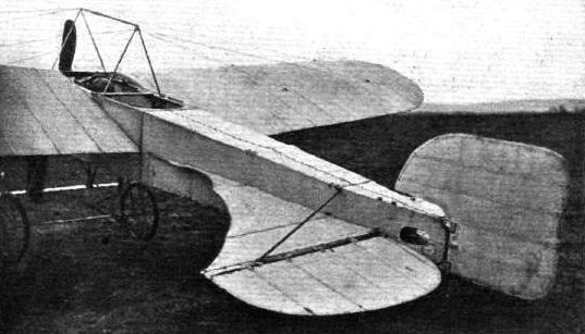
THE NEW BLERIOT MONOPLANE. - This is modified in several respects. The main body is 1 metre shorter, viz. 6.6m., whilst the elevators, as will be seen from the above side view from behind, have been considerably altered.

THE NEW BLERIOT MONOPLANE. - View from behind.
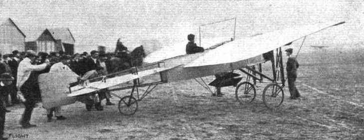
M. BLERIOT'S LATEST MONOPLANE. - M. Bleriot has now evolved a new model monoplane which bears the designation "No. 13." It differs from the Cross-Channel type in having a long and wide tail shaped like that of a bird, and ending in two hinged flaps.

BLERIOT TWO-SEATER MONOPLANE. - View from the side.

BLERIOT TWO-SEATER MONOPLANE. - View showing the outrigger and tail portion of the machine.
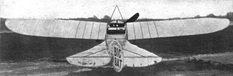
BLERIOT TWO-SEATER MONOPLANE. - View from behind.
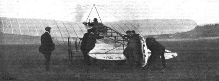
Mr. D. Graham Gilmour just before his start, on his Gnome-engined Bleriot, for his second flight last week for the Neill Cup.
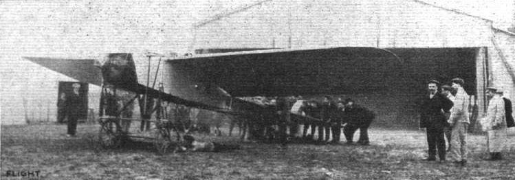
Start of M. Leon Morane and his brother from Issy last week on the 100-h.p. Gnome-englned Bleriot for the Michelin Prize, which ended in the serious accident soon after the start. Note the four assistants on the ground helping to hold back this very powerful flyer.

Morane, on his passenger-carrying Bleriot, leaving terra firma for one of his passenger trials.
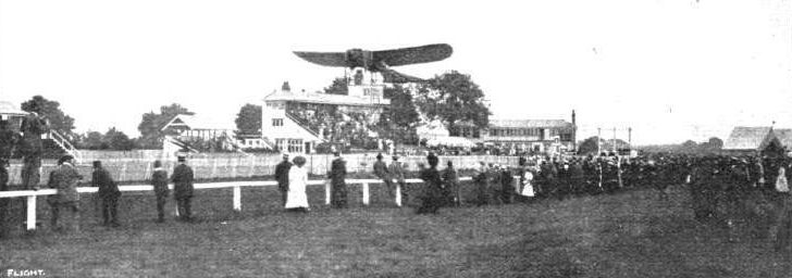
Mr. Moisant circling round the Folkestone Racecourse on his Bleriot.
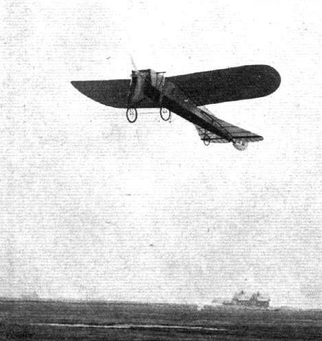
Drexel flying at Blackpool on the two-seater Bleriot, with Cecil Grace as passenger.

Mr. Graham Gilmour, on his "Big Bat" flying at Brooklands with a passenger at dusk.
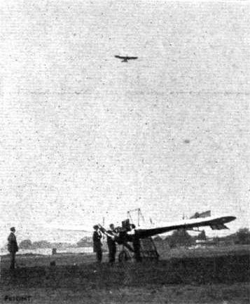
Mr. Graham Gilmour's Bleriot flying over the Hanriot monoplane at Brooklands.
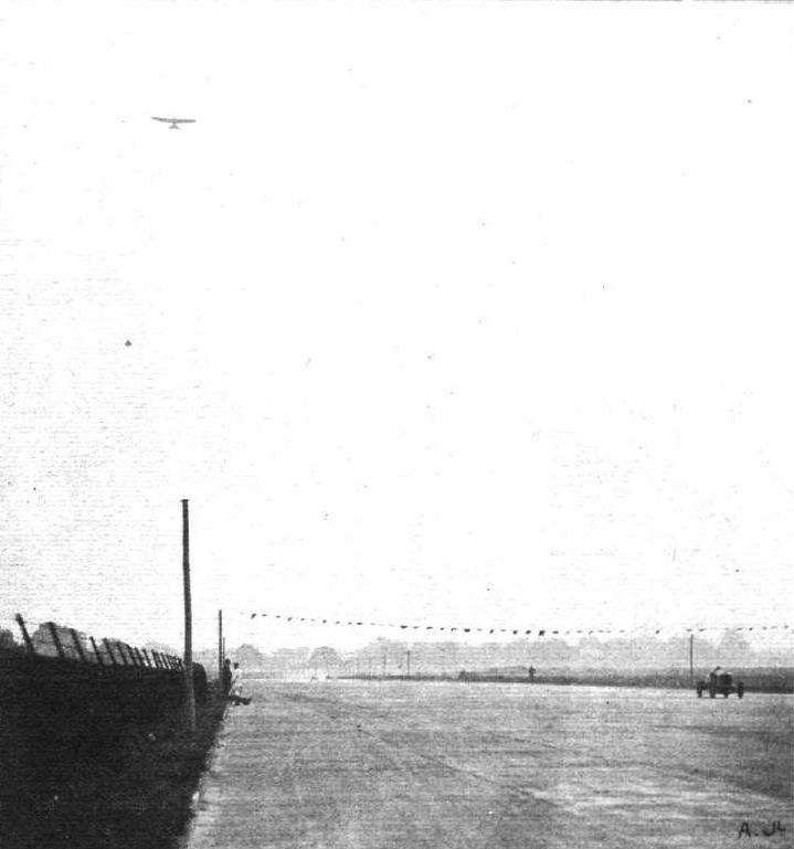
"NECK AND NECK" DOWN BROOKLANDS STRAIGHT. - An incident at the Season-End Meeting during the finish of the 76-m.p.h. Handicap. Overhead is Mr. Graham-Gilmour racing on his Gnome-engined Bleriot.

HOME BY AEROPLANE. - Mr. J. Armstrong Drexel and his 2-seated Bleriot just before his start last week for home at Beaulleu after the Bournemouth Aviation Week. On the right Mr. Delacombe, his companion on this cross-sea flight, is standing waiting to take his seat on the machine.
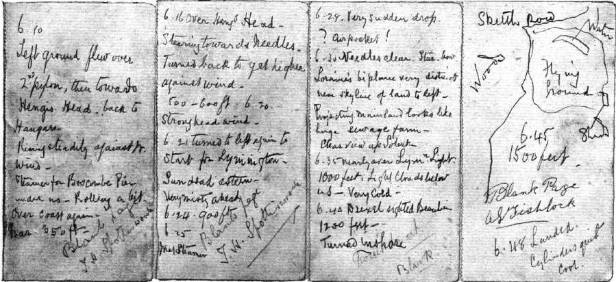
Photographs of the original leaves from Mr. Delacombe's note-book.
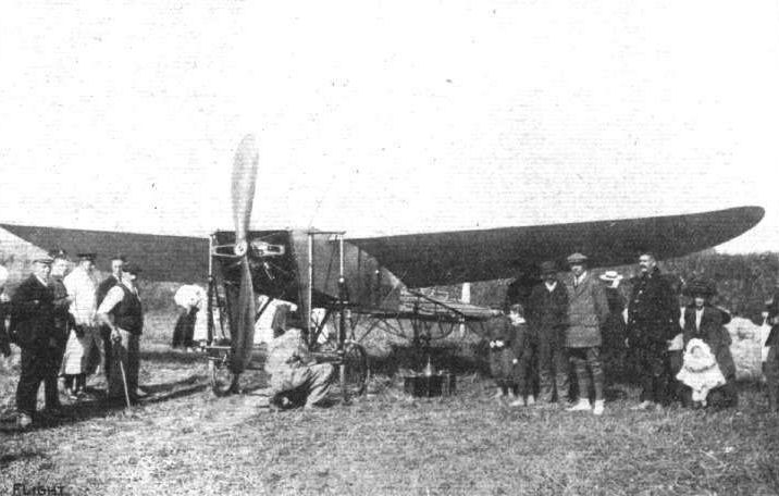
PARIS TO LONDON. -Mr. John B. Moisant's Bleriot at Tilmanstone, where he alighted after crossing the Channel with his mechanician Fileux.
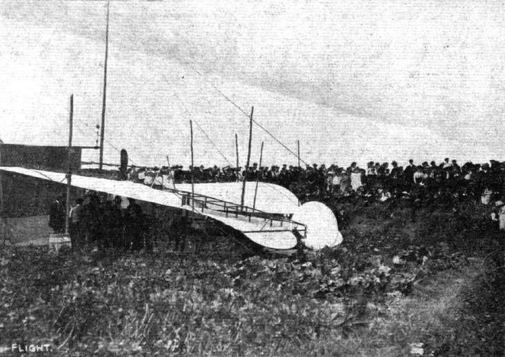
PARIS TO LONDON. - Moisant's Bleriot in the brickfield at Upchurch, near Rainham, ready for the finishing stage to London.

Military two-seated type of Bleriot monoplane at the Paris Salon, showing details of the landing chassis and body construction.
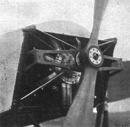
BLERIOT TWO-SEATER MONOPLANE. - Detail view of the Gnome engine and propeller, and the method of mounting.
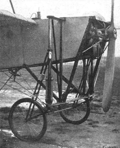
BLERIOT TWO-SEATER MONOPLANE. - The front portion of the chassis.
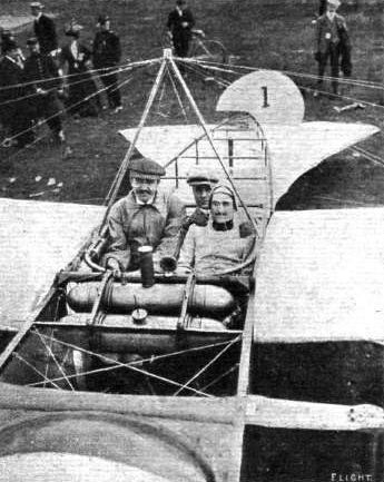
M. Morane at Rouen Meeting with his two passengers (not "Three Men in a Boat"), whom he took up in his new Bleriot monoplane, "No.1." Both man and machine will be seen at Bournemouth Aviation Meeting this month.
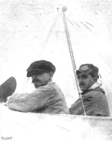
M. Leon Morane (on right) and his brother, who accompanied him as passenger in connection with the unsuccessful attempt last week to win the Michelin Prize for the flight from Paris to the Puy-de-Dome.
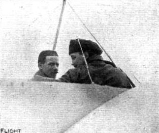
Mr. Armstrong Drexel and his passenger, Mr. Delacombe (who travelled without hat or coat), just before leaving terra firma for the homeward journey from Bournemouth to Beaulieu flying school.
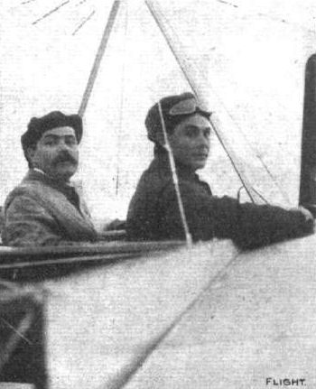
PARIS TO LONDON. - Mr. John B. Moisant and his mechanician, Fileux, on the Bleriot two-seater with which he made his remarkable flight from Paris across the Channel last week.
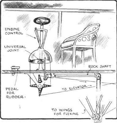
Section through floor showing the special "cloche" control system in the Bleriot two-seater monoplane.
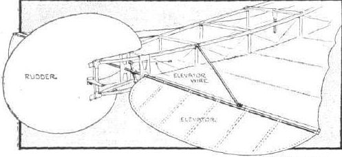
Sketch showing mounting and control of the elevator of the Bleriot two-seater monoplane.

BLERlOT TWO-SEATER MONOPLANE. - Elevation and plan to scale.
Flight, April 23, 1910
BREGUET FLIES ACROSS COUNTRY.
USING his No. 3 biplane, Breguet on the 11th inst. succeeded in making a splendid cross-country flight. Rising from the Brayelle aerodrome he twice flew round the ground and then steered a course for Arras, about 20 kiloms. away, over which he turned for the homeward journey. The complete journey of 40 kiloms. occupied 28 mins., and, although it was not officially certified, the speed attained was in the neighbourhood of 80 kiloms. an hour. On Tuesday Breguet met with a nasty accident. He was flying at a height of about 20 metres when the machine suddenly capsized # owing, it is said, to a propeller-blade breaking # and fell to the ground. The aviator was rendered unconscious by the fall, but according to the latest reports is not seriously injured.
Flight, October 22, 1910
THREE-BLADED PROPELLERS.
Concerning Mr. Bowles' letter about three-bladed propellers, the earlier Breguet biplane was fitted with one, coupled to a 50-h.p. Renault. The propeller appears, from the post-card which I enclose, to have been built of metal blades riveted to three arms of tubular steel. As to whether any flights were made with this or not, I can't say, but M. Breguet appears to have given it up in his newer machines for the ordinary two-bladed.
Chelsea. J. R. BLUNT.
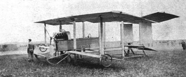
The Louis Breguet biplane, upon which he last week made his sensational flight, leaving the aerodrome at Douai and flying over the streets and buildings of the town, then returning to his starting point, after covering about 12 1/2 miles in about 13 mins.
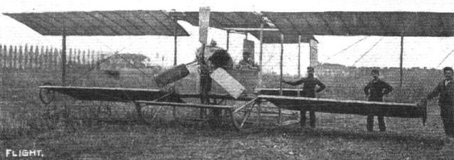
The early Breguet machine, referred to in Mr. J. R, Blum's letter.
Flight, December 17, 1910
AEROPLANE SILHOUETTES FROM THE PARIS SHOW.
THE BREGUET BIPLANE.
CONSTRUCTED by Louis Breguet at Douai. Fuselage and framework of steel and wood. Planes double-surfaced throughout. The main planes are connected by four stanchions placed a short distance back from the leading edge. Well known for its weight-lifting powers. On one occasion M. Breguet carried five passengers beside himself, the total weight of the six persons being 420 kilogs. Beside the one described, a racing model with only 26 sq. metres bearing surface, and fitted with a higher-powered engine, is also made.
General Dimensions. - Bearing surface, 38 square metres. Length, overall, 9.20 metres. Span of upper main plane, 13-20 metres; of lower main plane, 9 90 metres. Wings of normal type are 170 metres broad.
Seating capacity. - Two seats, placed one behind the other.
Engine. - 50-60-h.p. 5-cyl. semi-radial R.E.P. motor. Normal revs., 1,000. Any motor fitted.
Propeller. - Breguet, of two blades. Diameter, 2.90 metres. Geared down, variable pitch. Normal revs., 600.
Chassis. - Three wheels, one centrally in front of other two (which are each double); short skids in front of each wheel; front wheel is steerable by means of ordinary control wheel. The entire aeroplane is suspended on these three wheels, there being neither skid nor wheel under the tail.
Tail. - Cruciform monoplane tail, mounted on universal joint.
Lateral stability. - By the flexing of the trailing edges of the main planes.
Weight. - About 475 kilogs. complete with motor.
Speed. - 85 kiloms. an hour.
System of control. - By a wheel placed on a lever. Rotation of the wheel steers the machine. Backward and forward movements of the entire column elevate and depress the aeroplane, and a sideways movement to the right or left depresses the opposite wing in either case.
Price. - With 50-60-h.p. R.E.P. motor, 30,000 francs.
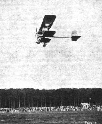
Bathiat flying on the new Breguet biplane at Rouen Meeting.
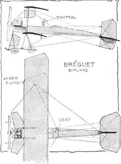
Flight, September 24, 1910
ROUND-ABOUT FRENCH NOTES.
By OISEAU.
I HAD hoped to be able to give a detailed description this week of the S.A.F.A. biplane designed and piloted by M. Rene Caudron, but the intervention of Fate, in the form of a gusty wind, has, by upsetting and smashing the machine during a practice flight, made my desire impossible for the moment. But as M. Caudron was only very slightly hurt, it is probable that a new machine will be finished and in the air in the course of the next few days. A general impression of the appearance of the machine can be obtained from the photograph published in last week's FLIGHT. It will be observed that the skids themselves form the lower main members of the fuselage, two small wheels under the main plane raising them sufficiently from the ground to add to the ease of starting. The control is the almost universal Farman type of a hand-lever operating both the gauchissement ailerons and the elevator, and a foot-bar for steering. An Anzani five-cylinder motor is fitted.
The few flights I saw M. Caudron make on the S.A.F.A. were all quite excellent, and were very much faster than any other biplane that I have yet seen. The impression one gained from watching fairly closely was of the extreme sensitiveness of the control, the slightest movement of the elevator or ailerons being responded to immediately. I must say, however, that one rather expected disaster after watching M. Caudron's very pronounced banking as he took the corners, with the added danger of flying too low at the curves. But with more experience his performances will no doubt greatly improve. It is certainly pleasing to see a machine of such promise and to realise that in no way is it a copy of any other specific type.
<...>
Flight, December 31, 1910
AEROPLANE SILHOUETTES FROM THE PARIS SHOW.
THE S.A.F.A. BIPLANE.
FRENCH-BUILT biplane, designed by MM. Caudron Freres, and built at Paris-Plage, close to Boulogne.
General dimensions. - Span, 8 metres; length overall, 8 metres; carrying surface, 22 square metres.
Seating capacity. - One; a two-seater machine is also built, but this has a carrying surface of 32 square metres.
Engine. - Five-cylinder 40-li.p. Anzani. Gnome motors can also be fitted, and if water-cooled engines are preferred the Eole motors are supplied.
Propeller. - Two-bladed Normale propeller of 2.1 metres diameter, which is driven at 1,200 revs, per min.
Chassis. - The lower members of the main frame are continued forward and brought close to the ground so as to take the place of skids. Two wheels are also fitted to facilitate starting.
Tail. - A horizontal plane is mounted at the rear of the machine, the forward part of this plane is fixed but the latter edge is free so that it can be flexed to form an elevator. Above this plane are mounted twin rudders.
Lateral stability. - Maintained by two ailerons placed between the main planes as in the Curtiss machine. In another type of machine warping of the main planes is utilised as on the Wright biplane.
Weight. - In running order 220 kilogs.
Speed. - 75 kiloms. an hour.
System of control. - The warping of the rear elevator and the adjustment of the ailerons (or warping of the main planes, whichever is used) is controlled by a single lever worked by the pilot's left hand. The twin rear rudders are operated by a pedal while all the engine controls are so placed that they can be operated by the driver with his right hand.
Price. - With 5-cyl. 40-h.p. Anzani, 14,500 francs; with 50-h.p. Gnome, 22,000 francs; with 25-h.p. Eole motor, 12,500 francs. The two-seater machine with 40-h.p. Anzani engine costs 16,500 francs.

Biplane of the Soc. Anom. Francais d'Aviation constructed by MM. Caudron Freres, which last week was flying at a high rate of speed at Issy. M. Rene Caudron is in the pilot's seat.
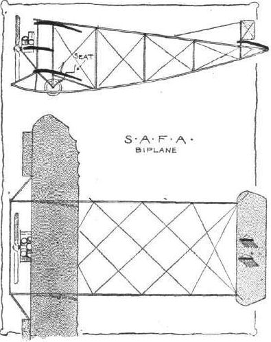
Flight, June 11, 1910
Maurice Clement at Issy.
WITH his biplane, Maurice Clement has been meeting with a good deal of success, and on the 2nd he made the last two flights for his pilot's certificate. Later in the day he made four flights with passengers and then changed over to the "Demoiselle" on which he flew for some minutes. He was also flying well on Saturday last on his biplane.
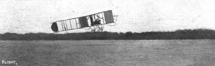
Maurice Clement flying at Lamotte-Breuil on his Clement-Bayard biplane.
Flight, October 29, 1910
IMPRESSIONS OF THE PARIS SHOW - (continued).
By OISEAU.
<...>
On the next stand is displayed a monoplane which is certainly original in conception, a tandem monoplane built by Clerget and Co. for the special purpose of exploiting a 200-h.p. 8-cyl. V-shaped motor designed by the Clerget Co. Following the usual custom of all those exhibiting two or three-seaters at this Salon, they name it a "military type". An ordinary Bleriot type fusellage of 14 metres in length has two sets of wings, the first of 10 metres from tip to tip in the usual forward position, whilst the latter pair, of 7 metres width, are placed 6 metres from the others. Following immediately behind is a tail plane with rudder and elevator. This rear plane seems almost unnecessarily large in view of the great lifting power of the back planes. Between the two series of main planes three seats, placed equidistantly, are arranged. The front one is that of the mecanicien controlling the motor, the observer takes the middle seat, whilst furthest back of all sits the pilot. I am afraid one is not greatly impressed by the prospective ease of management, and great modifications can be expected before any really satisfactory flights can be made.
<...>
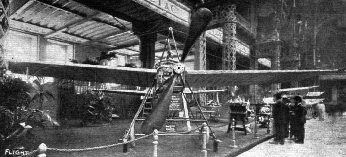
The Clerget tandem three-seated monoplane, military type, fitted with 200-h.p. Clerget motor, at the Paris Flight Salon. The distance from tip to tip of front wings is 10 metres and the back wings 7 metres, the intervening distance between these being 6 metres. Total surface 37 square metres, total length 14 metres, and weight 650 kilogs. The propeller is 3 metres in diameter.
Flight, October 29, 1910
IMPRESSIONS OF THE PARIS SHOW - (continued).
By OISEAU.
<...>
In the gallery, in solitary state, are shown the Fabre marine aeroplane and the Coanda monoplane. The first is well known from photographs and descriptions. It is mounted on three hollow floats, and is a sort of tandem monoplane. The wing construction and lattice-work beams are M. Fabre's patented design, and are similarly employed in the Paulhan biplane, described last week. The Coanda, a large monoplane constructed entirely of wood, has in place of the customary propeller a turbine, of remarkably small proportions in relation to the size of the machine. A much greater tractive power is claimed, with at the same time less vibration.
<...>

Side view of the Coanda aeroplane, upon the turbine-propulsion system and without propellers, at the Paris Flight Salon. This machine has been purchased by Mr. Weymann.
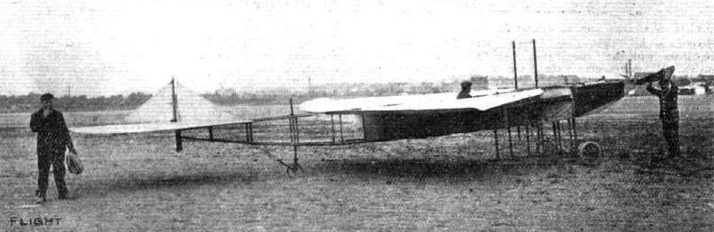
Delabrosse and Christolet's variable monoplane with its wing extensions closed, giving 7 metres span.
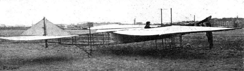
DELABROSSE AND CHRISTOLET'S VARIABLE SURFACE MONOPLANE. - The machine with its "wings" fully extended, giving 9 metres span.
Flight, December 24, 1910
AEROPLANE SILHOUETTES FROM THE PARIS SHOW.
THE DEPERDUSSIN MONOPLANE.
A FRENCH-BUILT monoplane. Framework of wood. M. Busson, formerly a Bleriot pilot of some distinction, has made many successful flights on this machine at Issy-les-Moulineaux, and he has announced his intention of using it in an attempt to fly from Paris to Brussels and back for the A.C.F. Grand Prix d'Aviation.
General dimensions. - Length overall, 9 metres; width, 9 metres; mean width of wings, 1.80 metres; bearing surface, 15 square metres.
Seating capacity. - One.
Engine. - 50-h.p. water-cooled vertical 4-cyl. Clerget, or a 70-h.p. water-cooled vertical 4-cyl. Austrian-Daimler. Any motor fitted if desired.
Propeller. - Six-bladed Deperdussin propeller (Licence Rapid), driven at a speed of 1,400 revs, per minute. An ordinary two-bladed Deperdussin propeller is fitted on Busson's machine at Issy-les-Moulineaux.
Wheels and skids. - Two wheels and two skids, the latter members being somewhat similar to those employed on the Antoinette monoplane.
Tail. - Non-lifting tail plane (horizontal empennage). Single vertical fin placed centrally. Elevator divided in centre, is hinged to trailing edge of tail plane. The single rudder is placed centrally behind elevator.
Lateral stability. - Maintained by flexing the trailing edges of the wings.
Weight. - Complete with engine, about 280 kilogs.
Speed. - About 90 kiloms. an hour.
System of control. - The rotation to the right or left of a single wheel, mounted on a column in front of the pilot, flexes the wings for the maintenance of lateral stability. A backward movement of the entire column elevates the machine and vice versa. A foot lever controls the vertical rudder.
Price. - Not stated.
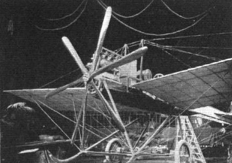
View from In front of the Deperdussin monoplane, fitted with Its six-bladed propeller, and showing the chassis and skid arrangement, at the Paris Flight Salon.
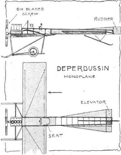
Flight, June 4, 1910
Fabre Hydro-Aeroplane.
ON the 19th ult., M. Fabre conducted some experiments with his hydro-aeroplane over Mede Bay, close to Martigues, and they were watched by M. Louis Paulhan. After attaining a speed of 55 kiloms. an hour, the machine rose from the water to a height of 2 metres, and continued flying for about 500 metres. It then suddenly dived at a sharp angle, and the sudden shock of landing on the top of the water damaged one of the wings and one of the floats.
Flight, August 13, 1910
Fabre Hydro-aeroplane Out.
THREE trials were made with the Fabre hydro-aeroplane, illustrated in these pages a few weeks ago, on Tuesday week. Two of them were successful, but the third was brought to a premature conclusion through one of the floats breaking. This brought the propeller in contact with the water and the shock caused the aviator to be thrown from his seat to the water, and several parts of the machine gave way. However, the damage was not very extensive and will be quickly repaired.
Flight, September 24, 1910
Fabre Hydro-Aeroplane Flies.
LAST Saturday the Fabre hydro-aeroplane was given another trial at Martignie, and, piloted by Marius Burdin, it rose in the air to a height of between 5 and 6 metres and traversed a distance of a little more than 3 kiloms.
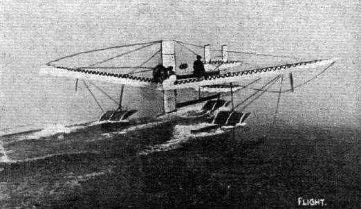
M. Henri Fabre's marine-aeroplane skimming over the sea.
Flight, January 15, 1910
"FAKED" FLIGHT PHOTOGRAPHS.
I noticed in your issue of Jan. 1st a "faked " photograph ("flying in the clouds") as the frontispiece. I beg to enclose two genuine photographs, taken by myself at Brooklands, of Paulhan flying. I thought, possibly, these might be of some use to you.
Maida Vale. F. A. HALFORD.
[These interesting photographs sent by our correspondent are a striking object-lesson of the size of a flyer as really seen by the camera at fair heights.-ED.]
Flight, March 12, 1910
THE SECOND OLYMPIA AERO SHOW.
AEROPLANES.
Henry Farman.
An amateur French-built biplane embodying many of the latest improvements introduced by Mr. Henry Farman, and fitted with a Darracq motor. Shown by Capt. A. Rawlinson.
Flight, March 26, 1910
MR. A. RAWLINSON TRIES HIS HENRY FARMAN.
ON Wednesday of last week, a number of people journeyed down to the Handley Page flying ground at Barking to see Mr. A. Rawlinson carry out some trial flights on the Henry Farman biplane on which he recently made some lengthy flights at Chalons Camp. Unfortunately, however, as the machine was travelling across the ground, a wire stay broke, and fouling the propeller, smashed it, necessitating the postponement of the trial until a new propeller could be obtained. The 50-h.p. Darracq motor fitted to the aeroplane has four horizontal opposed cylinders, and during the preliminary tests it gave every satisfaction, so that but for the mishap with the wire stay, trifling in itself, there was every prospect of successful flights being made.
An interesting match is being arranged between Mr. A. Rawlinson and his Henry Farman machine and Mr. J. T. C. Moore-Brabazon on his Short machine, with which he recently won the Daily Mail L1,000 prize. It is suggested that they should have a race starting from a given point together and flying across country for twenty miles, the first man to be the winner.
Flight, April 2, 1910
Mr. Grahame-White Flies for an Hour.
DURING the past week Mr. Claude Grahame-White has been experimenting at Chalons Camp with the Henry Farman machine on which he intends to fly into London. His first flight was on Saturday, when he covered about 50 kiloms., and later made a second trip of 20 kiloms. with a passenger, while on Sunday he flew for 65 minutes, his average altitude being about 150 ft. Later in the day he carried Kulher as a passenger, and in a subsequent flight took his mother for an aerial jaunt lasting some 15 minutes.
Flight, April 23, 1910
FLYER SILHOUETTES FROM OLYMPIA.
THE HENRY FARMAN BIPLANE.
Leading Particulars of the Henry Farman.
General Dimensions.-Areas-Main planes, 450 sq. ft.; elevator, 27 1/2 sq. ft.; rudder, 17 sq. ft.
Lengths.-Span, 34 ft. 8 ins.; chord, 6 ft. 6 ins.; camber, 4 1/2 ins., situated about 19 ins. from leading edge; gap, 6 ft.; skid track, 8 ft. 8 ins.; overall length, 43 ft.
Engine.-50-h.p. Darracq.
Propeller.-Chauviere; diameter, 8 ft.; pitch, 4 ft. 9 ins.
Weight.-Machine, 616 lbs.; engine, 234 lbs.; driver, oil, petrol and water, 200 lbs.; total flying weight, 1,050 lbs.; loading (all weight supported on main planes), 2.3 lbs. per sq. ft.
Speed of Flight.-55 m.p.h.
System of control.-Balancing flaps, rudder and elevator.
Price.-L1,050.
SINCE our description of this machine in FLIGHT of October 16th, 1909, the only important alteration has been the addition of a hinged flap at the rear of the upper tail plane. This flap is interconnected with the elevator, and is so arranged that its trailing edge is raised simultaneously with the leading edge of the elevator. When the elevator is tilted to raise the front of the machine the flap on the tail forces the tail downwards, and thus assists in overcoming the relatively great inertia to vertical movement on the part of the tail. In any machine of this type the elevator itself is materially hampered in its action owing to the adverse leverage through which it has to operate upon the tail. The Farman biplane is introduced in this country by A. Rawlinson on behalf of Messrs. Darracq. The engines fitted are all 50-h.p. Darracq motors of special design. Farman himself used, as our readers will remember, a Gnome engine on this machine.
Flight, April 30, 1910
THE LONDON-MANCHESTER L10,000 FLIGHT PRIZE.
PROBABLY the most talked of man at the moment, not only in Great Britain, but in every part of the civilised world, is Mr. Claude Grahame-White, for although it is true that his attempt to fly from London to Manchester on Saturday last was not successful, it was nevertheless a splendid achievement. We have dealt with the importance of the flight from the national standpoint in our leader this week, so it is unnecessary to elaborate this side of the performance. In the same way it is unnecessary to go into any lengthy details regarding the incidents of the actual journey, as of course our readers are already in possession of these from many points of view. But it is essential that as a matter of history we should place on record the chief facts with regard to this "splendid failure."
It was a cold, cheerless, misty morning on Saturday last, when some 200 people gathered at Park Royal, about five o'clock, to see Mr. Claude Grahame-White start off for Cottonopolis. There was, however, practically no wind, and hopes were raised that a successful trip was to be made. When the aeroplane was wheeled out of its shed everything was ready, the aviator took his seat, and after a short run along the ground steadily rose in the air without a hitch. The gasometer at Wormwood Scrubbs had been decided upon as the official starting point, that being just inside the five-mile radius from the Daily Mail office, and thither Grahame-White steered his Henry Farman biplane. Mr. Harold Perrin, the secretary of the Royal Aero Club, was on the top of the gas-holder, and as the aviator swung round the mark a big flag was waved to signify that the starting-line had been crossed. The actual time of the official start was 5h. 15m. 30s. About 5,000 people had by this time assembled on Wormwood Scrubbs, and they gave the intrepid flyer a rousing send-off. Everything that was available was spread to wave him a parting greeting as he sped along. Crossing Kensal Green Cemetery, he made his way to the L. & N.W. Ry. at Willesden, and thence followed the line to Rugby. As soon as the machine was officially started, Mr. Pexrin boarded one of the two White cars which had been placed at the disposal of the Royal Aero Club by Mr. Frederic Coleman, and accompanied by two special mechanics of the Gnome Motor Co., the party made straight for Rugby, Mr. Coleman personally driving the White steamer. Mr. Grahame-White was sighted at Fenny Stratford and was kept in view for a distance of fourteen miles. Eventually the R.Ae.C. official car reached Rugby about 10 minutes in front of the aeroplane, and it is interesting to note that the White steamer was the only car present at the start which reached Rugby in time to see Mr. Grahame-White during his halt there of over an hour. The news that he had left London soon spread to Rugby, and so by the time Mr. Grahame-White arrived at 7.20 an expectant crowd, including Mr. Roger Wallace, Chairman of the Royal Aero Club, was awaiting him in the field a few miles out of the town. His arrival invoked splendid enthusiasm, but when he climbed down from his seat the aviator was almost frozen. He had found the cold very trying, but wrapped up in a fur cape lent by Lady Denbigh, and a big muff lent by another lady, he was hurried to a house, and there in a short time, by the aid of a fire and some hot coffee, he was once more in his usual high spirits, and back again in the meadow to superintend the replenishing of the tanks, &c. During this time some Boy Scouts rendered valuable assistance in keeping the crowd back. At twenty-five minutes past eight everything was ready, and Grahame-White once more took his seat. A run of 80 yards was all that was necessary before the machine was again in the air, and skirting the town of Rugby he headed for Crewe.
Unfortunately there were signs that the wind was increasing, and fears were expressed as to how far it might be possible to continue. The report from Tamworth was that he was flying very low, and at Lichfield the cars which were following the flight were stopped, and the officials informed that a descent had been made at Hademore Crossing, between Whittington and Tamworth, not far from Lichfield. The wind had become very trying, and the motor was not quite up to form, two of the inlet-valve springs having become weak, and Mr. Grahame-White therefore deemed it prudent to make his second stop before Crewe. Selecting the best looking field within sight he glided down, and after making sure that the motor trouble was not serious he walked over to the railway signal box and telegraphed to Lichfield to stop the following cars.
Unfortunately the spot selected would appear to be a regular "Windy Gap," and all hope of an immediate restart had to be abandoned. As there appeared to be practically no chance of getting under way before sundown, Mr. Grahame-White was induced to have a few hours sleep. In the meantime the wind refused to drop, rather it increased in force, and so everyone went off to bed early with the possibility before them of a call for a night flight. At 2 a.m. on Sunday, however, it was still impossible, and all hope of completing the flight before 5.15 a.m. had to be abandoned. Mr. Grahame-White immediately, however, set about arranging to fly the remaining distance to Manchester, and then make a fresh attempt from there.
This project, however, was knocked on the head by the unfortunate accident to the machine on Sunday. It had been left out in a field, and Mr. Grahame-White had ordered that it was to be securely pegged down. This precaution was unfortunately neglected, and on Sunday afternoon a sudden gust of wind blew the machine over, doing considerable damage. It became therefore necessary to return with the machine to London, where repairs were put in hand at once, and on Wednesday afternoon it was once more ready for a second attempt.
In the meantime Paulhan, who had arrived at Hendon with his Henry Farman machine, had progressed so well with getting the aeroplane together that he also was at any moment ready to take the air, and if possible snatch the prize from the hands of the British representative, and at the same time forestall M. Dubonnet, who had also hurried back to London with his Tellier monoplane, after having made formal entry on Monday last for flying for the prize. M. Dubonnet's turn to try was down for Monday next.
THE PRIZE WON.
Wednesday Evening.
Although M. Paulhan's machine only arrived at Hendon about six o'clock this morning, by dint of unremitting toil he had it assembled at five o'clock in the afternoon, and was then ready for the flight to Manchester. Earlier in the afternoon he had notified the Royal Aero Club to have their observers in readiness, and at 5.21 p.m. he took his "jump-off" from Hendon, and made his way towards Hampstead Cemetery, which had been decided upon as his official starting line. Turning there at 5.31 p.m. he steered straight for Harrow, and then kept to the L. and N.W. main line as his guide. Paulhan had arranged for his flight to be followed by' a special train, which left Willesden as soon as Mdme. Paulhan, Mr. H. Farman, and the other members of the party reached there by motor. This train caught up to the aviator just past Weedon, and kept the machine in sight until Rugby was reached, where of course some little delay ensued in getting the special clear of the junction. At Rugby the news was learnt that Grahame-White had started, but it was impossible to communicate this to Paulhan, who passed over Rugby at 7.20 p.m. It was then rapidly fetting dark, but Paulhan, still at a good height, flew on until achfield was reached when he decided to come down in a field by the Trent Valley Station, at ten minutes past eight, being then 117 miles on his way to Manchester. After seeing the machine safely pegged down, Paulhan went with his party to the George Hotel for the night, intending to make a fresh start at 3 a.m.
At the time Paulhan started, Mr. Grahame-White was getting a much-needed sleep, having decided to postpone his start until early morning, but as soon as the news came through he was awakened, and with characteristic promptness, he decided to set out in pursuit. He had had no opportunity of testing the repairs to his machine, but feeling confident that they were all right, he had the machine started up. It was ten minutes past six when the first report of Paulhan's start was received, and within 10 minutes Grahame-White was in the air, and at 6.29 was officially started on his second attempt to win the big prize. Watford was passed by him at 6.50, Boxmoor a quarter of an hour later, Leighton Buzzard at 7.28, and Wolverton at 7.41. There the gathering darkness made it difficult to see the way, and at five minutes to eight Mr. Grahame-White decided to descend in a field by the railway line at Roade, 60 miles from London. There Dr. Ryan offered the hospitality of his house to the aviator, who, like Paulhan, decided to restart at 3 a.m.
THE LAST STAGE.
Thursday Morning.
Grahame-White was the first to start this morning, having determined to make a "night attack," with the object of trying to secure the lead, and was accordingly away before it was quite light, the brilliant beams from the searchlights of the attendant motor cars also aiding the work of getting ready for the start. At 2.50 the flyer was once more in the air, and forty minutes later had passed Rugby, thereby materially reducing the lead which the Frenchman had gained overnight. Everything appeared to be going well when Nuneaton was passed at 3.50 a.m., but a few minutes after engine trouble began to assert itself, and rendered a descent necessary at Polesworth, 107 miles from London. A few minutes later Paulhan had made his restart from Lichfield, 10 miles further ahead, and while the matters with regard to the engine on Grahame-White's machine were being put right, the news came through that his rival had reached the goal. Then all hope of securing the prize having gone, he decided to take his time about completing the remaining stage, and so went to bed for a few hours' sleep.
Delayed slightly beyond his intended time of starting, Paulhan did not get into the air again until 4 a.m., but his machine ran without a falter. Rugby was passed at 4.25, Stafford at 4.45, Crewe at 5.20, and at 5.32 his machine glided to rest amid a roar of applause from the waiting crowd in the field at Didsbury, two miles from Manchester, and so within the five mile radius of the Manchester offices of the Daily Mail, which had been chosen as the official finishing place. And thus, in spite of the splendid work and efforts of Great Britain's representative, Mr. Grahame-White, the great prize passes to a Frenchman, admiration for whose pluck and success is only tempered by a patriotic regret that fortune had not shed its favour more on the Britisher.
Flight, May 7, 1910
Mr. Grahame-White's Last Attempt.
ALTHOUGH Mr. Grahame-White had been beaten in his flight, he determined to try and complete the distance on Thursday of last week, and when the rain ceased and the wind dropped a little he prepared to re-start from Polesworth. Everything was ready at 5 p.m., and he rose splendidly. He had not gone far, however, before a piece of the lower tail plane became detached, and as this was impeding his flight he determined to come down close to Hademore crossing, where his flight ended on the previous Saturday.
As the spot was 3 1/2 miles from the Trent Valley station at Lichfield, he later flew over there to obviate the necessity of fetching a railway truck from the station.
Flight, May 28, 1910
A MODEL FARMAN BY A BOY OF 15.
Miss Height, of the Clarendon Newsagency, has asked me to write and send you a photo of myself and the model Farman biplane, which she has had in her window as an advertisement for your valuable paper, FLIGHT.
I have never seen a full-sized aeroplane, and the whole of my model was built from the instructions given by you.
Miss Height asked me to tell you that her exhibition has been the means of putting on a great many more customers for FLIGHT.
I shall be pleased to help other readers of FLIGHT who are making a Farman biplane of about the same size as mine (1/12).
I shall be fifteen in September.
Grange House, 64, Clarendon Avenue, Leamington Spa. J. F. MILLER.
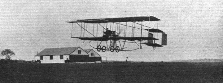
Mr. A. Rawlinson flying at Eastchurch this last week-end on his Henry Farman machine.

MR. CLAUDE GRAHAME-WHITE'S BIG CROSS-COUNTRY FLIGHT. - Below, trying the Henry Farman machine at Park Royal prior to the start on Saturday last; and above, Mr. Grahame-White re-starts from Rugby for Crewe.
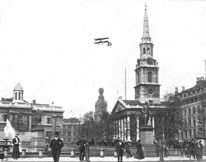
In the year, when Paulhan arrives on a Henry Farman aeroplane in London, and calls at the offices of FLIGHT and the AUTO, at 44, St. Martin's Lane, near by St. Martin's Church, Trafalgar Square, the National Gallery, and Coliseum. Another FLIGHT "fake."
Two Genuine, not "faked" photos of Paulhan flying high at Brooklands (see Mrs. Halford's letter).
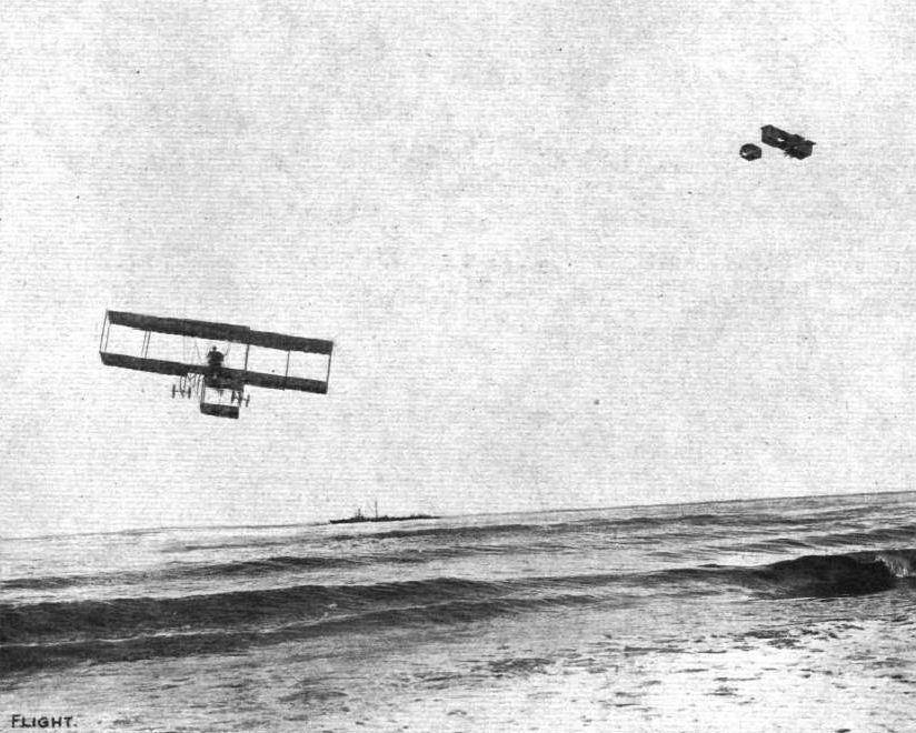
NICE FLIGHT MEETING. - Mr. A. Rawlinson, on the left, on his Henry Farman, and M. Rougier on his Voisin biplane, flying over the sea at Nice.
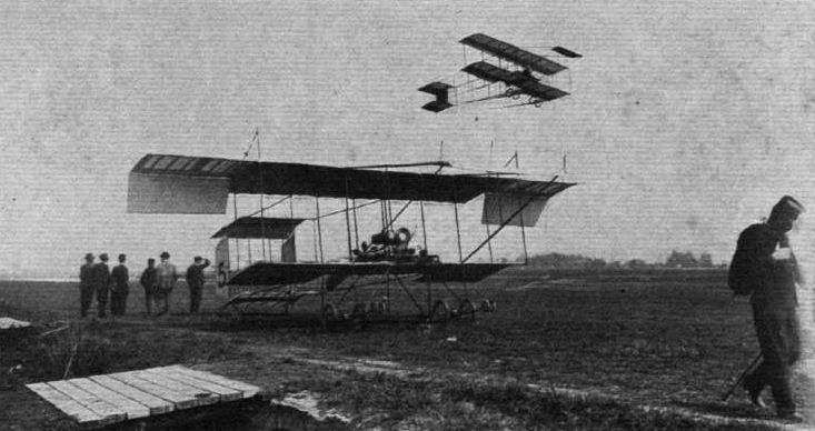
AT CANNES AVIATION MEETING. - Crochon flying on a Henry Farman biplane, and passing over Christiaens' machine at rest. The latter, on March 31st, on his Henry Farman, covered 2.2 kiloms., one tour of the aerodrome, in 1m. 34 3/5s., a speed of 84.25 k.p.h., which it is sought to have established as an official speed record.
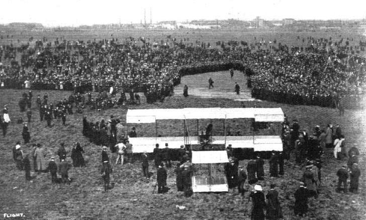
THE GREAT LONDON-MANCHESTER FLIGHT. - General view of the scene on Wormwood Scrubbs prior to Mr. Grahame-White's start for his second attempt on April 27th. Bringing the Henry Farman machine out for the flight.
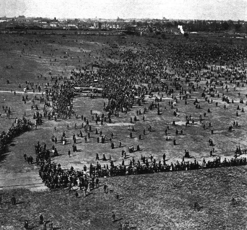
THE GREAT LONDON-MANCHESTER FLIGHT. - Remarkable photograph of the scene on Wormwood Scrubbs on Wednesday, April 27th, when Mr. Grahame-White's Henry Farman machine was brought out for a few trial tests after the repairs had been completed.
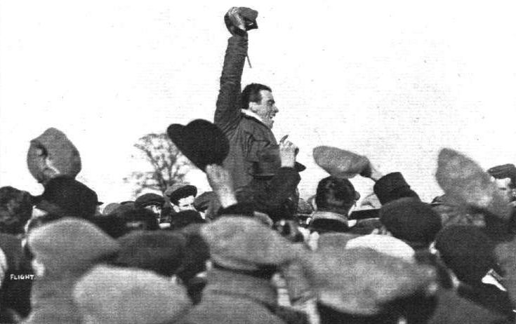
THE GREAT LONDON-MANCHESTER FLIGHT. - Mr. Claude Grahame-White at Polesworth, where he came down after his night flight on Thursday morning, April 28tb, calling for three cheers for Mons. Paulhan upon the receipt of the news of his having won the L10,000 prize.
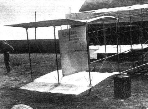
The tail of the Henry Farman machine used by Mr. Claude Grahame-White for his London to Manchester flight, which it will be seen differs from the Farman machine which was last year dealt with in detail by us. On the very latest Farman a monoplane type tail has been adopted.
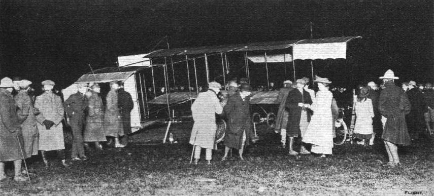
THE GREAT LONDON-MANCHESTER FLIGHT. - Flashlight photograph at Lichfield of Paulhan's Henry Farman machine before his start for finishing the race on Wednesday morning, April 27th.
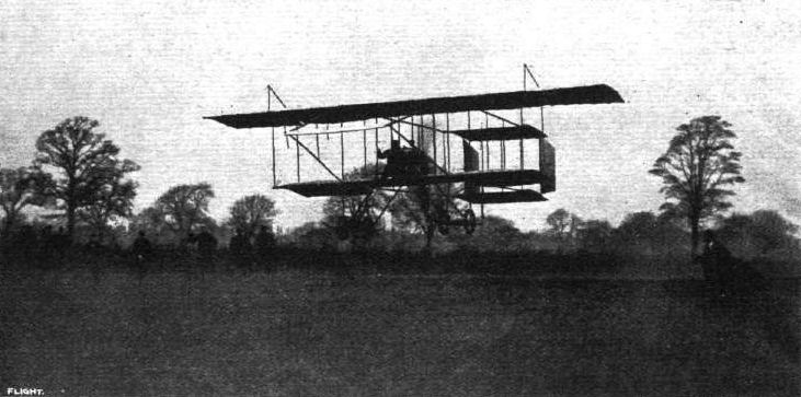
THE GREAT LONDON-MANCHESTER FLIGHT. - M. Paulhan winning the L10,000 prize by landing in the pre-arranged field at Didsbury, near Manchester, on his Henry Farman machine.
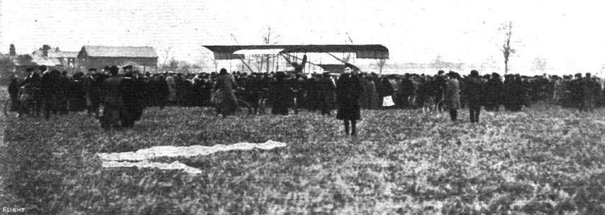
THE GREAT LONDON-MANCHESTER FLIGHT. - Immediately after the prize was won. The crowd gathering round the Henry Farman machine immediately after Paulhan had landed at Didsbury. The white sheet in the foreground was used for marking the spot for the descent.
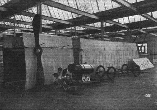
Paulhan's biplane dismantled at the Manchester works of Hans Renold, Ltd., and ready for its return to France, after the completion of the London to Manchester flight. This shows clearly the unit system of construction utilised by Mr. Henry Farman in his machines.
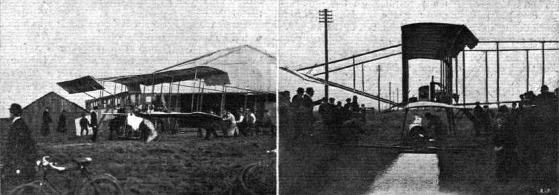
Mr. A. Rawlinson and his Henry Farman Biplane at Messrs. Handley-Page's Grounds at Barking. - Bringing out the machine, and, on the right, getting tha aeroplane over a dyke to the flying grounds.
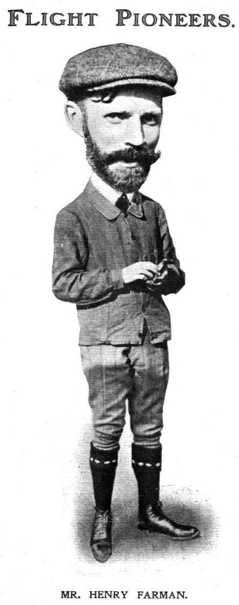
MR. HENRY FARMAN.
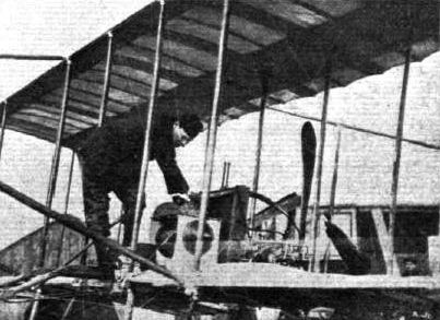
Mr. A. Rawlinson tuning up his Darracq engine on his Henry Farman machine.
Mr. C. Grahame-White, after his 65 mins. flight on March 28th, and a couple of his pupils, Mr. Armstrong Drexel (left) and Mr. Charles Hubert (right). In the centre picture Mr. Grahame-White's mother, who has flown with her son, is standing in front of the Henry Farman machine.
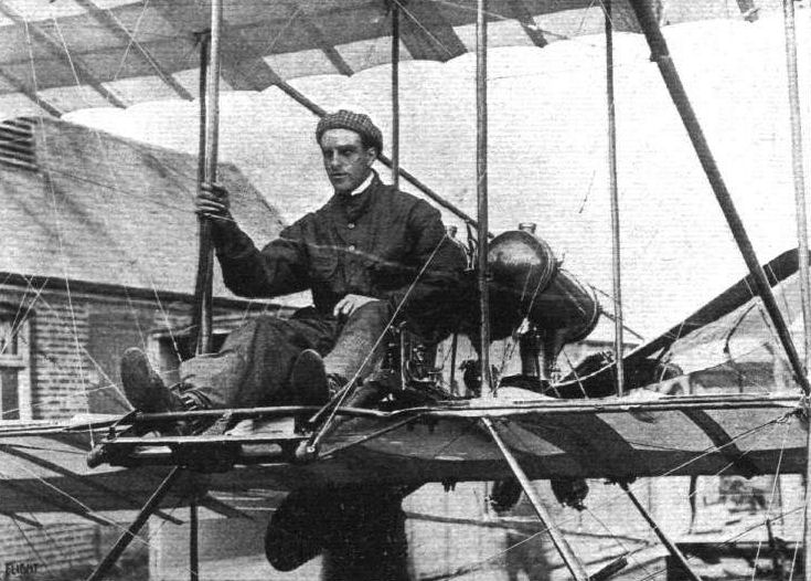
Mr. Claude Grahame-White in his place on the Henry Farman biplane ready for starting his big flight on Saturday last.
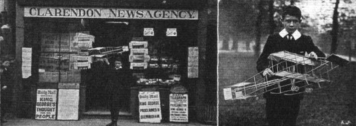
Master J. F. Miller with his model Farman outside Miss Height's shop, and on the right the model is seen upon a larger scale in the bands of its constructor.
H ALLEY'S COMET. - Oh, lord that's the third one that's passed me! (But it was only Paulhan.)
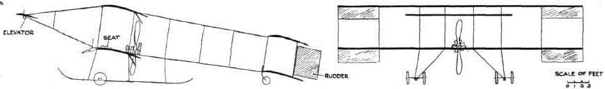
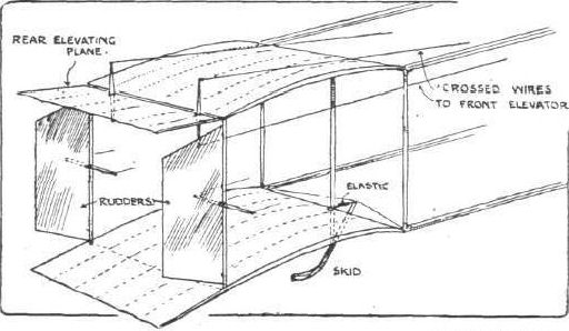
TAIL OF PAULHAN'S HENRY FARMAN BIPLANE. - The main differences between Paulhan's and Grahame-White's biplanes are that in the former the lower main plane is shorter than the upper one, while twin rudders are fitted instead of a single one as in the Grahame-White machine. These twin rudders are smaller, and placed a little further back, as shown in the above sketch.
WING SECTIONS. - The above diagrams afford an interesting comparison of the wing sections of aeroplanes exhibited at Olympia. They are all drawn to a common scale, but have been set at an arbitrary angle of incidence, which does not necessarily represent that of the aeroplane In actual flight.
Flight, December 3, 1910
Henry Farman at Etampes.
By the aid of a couple of motor cars, Mr. Henry Farman transferred from his works at Mourmelon to Etampes, on Sunday afternoon, the new machine on which he proposes to try to beat the world's duration record and retain the Coupe Michelin. On one car was the central portion of the biplane, including the chassis, with the motor and propeller and tail planes, while on the second car was the extension of the main planes and other parts.
Flight, December 10, 1910
FOREIGN AVIATION NEWS.
Mr. Henry Farman Flies In the Dark.
HAVING completed the erection of the new machine on which he intends to compete for the Coupe Michelin, and which we illustrate this week, Mr. Henry Farman on Monday, at Etampes, made his first flight with it. By the time everything was ready the aerodrome was enveloped in darkness, but Mr. Farman had lamps placed at the pylones and so he was enabled to cover several rounds of the course.
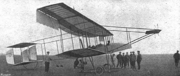
Mr. Henry Farman at the wheel of his special machine referred to by us last week, upon which he will try to beat the record flight for the Michelln Cup before December 31st. It will be noticed that the machine has three rudders.
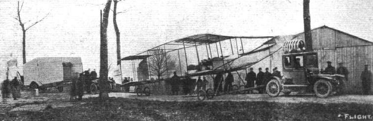
Mr. Henry Farman starting from his works at Chalons Camp for Etampes with his new biplane, with which he proposes to compete for the Michelin Cup. This little road journey was referred to last week.
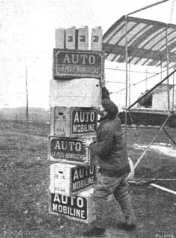
Mr, Henry Farman and the stock of fuel for which he has made provision to carry in his long-distance attempt for the Micheltn Cup.
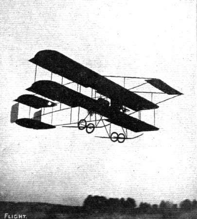
THE LATEST FARMAN MACHINE IN FULL FLIGHT. - The "Henry-Maurice Farman." The curious rounding of the ends of the planes will be noticed, whilst the combination of the best features in the Henry and in the Maurice models is apparent in the ailerons and the tail. Numerous pictures of the Henry Farman machines have been published in FLIGHT, and on March 19th, p. 219, the more recent model of the Maurice Farman machine.
Flight, May 28, 1910
Cross-Country Passenger Record Beaten.
ON the 19th inst. Cheuret on his Henry Farman biplane succeeded in beating the cross-country record for a flight with a passenger. Accompanied by Mme. Branger he started from Mourmelon and flew round the church at Chalons and then back to the camp, afterwards continuing the trip over the surrounding country until 1 hr. 12 mins. had elapsed. He was timed by officers of the military school to cover the 44 kiloms. from Mourmelon to Chalons and back in 34 mins. at a speed of 75 kiloms. an hour. This Farman machine is fitted with an E.N.V. motor.
Flight, June 4, 1910
MR. C. GRAHAME-WHITE FLIES TO RANELAGH.
HAVING arranged to make a series of exhibition flights at Ranelagh, Mr. Claude Grahame-White determined to fly over there from Brooklands on Thursday of last week, and successfully made the journey during the evening. Before leaving the Brooklands track he flew round the flying ground three times at a height of about 200 ft., and came down to repair a couple of stays which had given way. Fixing a board to accommodate a passenger behind his seat, Mr. Grahame-White then took Lord Wodehouse for a trip twice round the track. On his descent he had the machine put in order and started off for Ranelagh. There was practically no wind, and he rose steadily to a height of 1,000 ft., and then headed for town. Still rising until he got up to 1,500 ft., he bore to the left towards Thames Ditton, and then over Kingston and Richmond Park, landing at Ranelagh at ten minutes to eight, having covered the fifteen miles in twenty minutes. As a final effort Mr. Grahame-White went up again, and made a wide circle over the neighbourhood of Ranelagh.
Unfortunately on Saturday afternoon the wind was against flying, and although many prospective passengers made tempting offers to Mr. Grahame-White to take them for an aerial excursion, he had to ask them to wait awhile. Arrangements had been made for flying to take place between 3 and 6 p.m., but it was not till after 6 p.m. that Mr. Grahame-White deemed it prudent to start. Then the flying was cut short by a sharp shower, which sent the crowd of spectators hurrying home. Shortly after 8, however, Mr. Grahame-White started again, and flew for about a quarter of an hour, flying at a height of about 600 ft. over Putney and Barnes Common. Arrangements were made to take a number of people for five minute trips at L10 10s. each.
Mr. Grahame-White has arranged to give a series of exhibition flights at the Crystal Palace on Tuesday, June 7th, from 5.30 to 8 p.m.
Flight, June 11, 1910
And at the Crystal Palace.
ON Tuesday Mr. Grahame-White shifted his venue to the Crystal Palace, where he made a couple of trips from the flying enclosure in connection with the "Rendezvous" arranged in the Palace grounds by the Aerial League. Both flights were short, each only being of about five minutes' duration. In the first he flew towards Penge, and after making a couple of wide circles returned to the Palace grounds and planed down to his shed from a height of 60 ft. The second trip was confined to the grounds, and the thousands of people assembled on the terrace had the experience of seeing the machine pass over them. Later in the clay the machine was dismantled and packed for its journey to Halifax, where Mr. Grahame-White had arranged to make some flights this week-end.
Flight, June 18, 1910
Mr. Grahame-White at Halifax.
MR. CLAUDE GRAHAME-WHITE having arranged to give demonstrations of flying on his Henry Farman machine at Halifax during last week-end, about 5,000 assembled on Friday afternoon on the racecourse to see the sport. Unfortunately it would appear that the place is not particularly suitable for the purpose, as the treacherous winds are rather the rule than the exception. After waiting till eight o'clock, in the vain hope that the wind would be more accommodating, Mr. Grahame-White pluckily determined to chance it, so as not to disappoint the crowd. He rose to a height of about 50 ft., but descended after a trip of only four minutes. On Saturday, Mr. Grahame-White made five trips. The longest was the first, of 13 minutes' duration, during which he flew from the flying ground to the Zoo and back again. The other trials were all under 10 minutes in duration, and in the last, one of Mr. White's assistants, Mr. Cresswell, was taken up as a passenger.
Flight, June 25, 1910
Saturday Last at Brooklands.
A FEATURE of the race meeting held at Brooklands last Saturday was the auction sale held in the paddock, at which the rights to fly with Mr. Grahame-White as passengers were offered. Bidding was general up to 50 guineas, when a spirited contest ensued between Lady Abdy and Miss Pauline Chase. Eventually the hammer fell on Lady Abdy's offer of 120 guineas for the first trip. Several tickets for subsequent trips were disposed of at various prices. At twenty minutes to five Lady Abdy took her seat, and Mr. Claude Grahame-White started the engine. Difficulty was experienced in getting the machine to rise, owing apparently to motor trouble, and after 500 yards the aeroplane, which was only a few yards off the ground, fouled some bushes on the farther side of the River Wey, and came down with a crash, damaging the lower plane. Fortunately the aviator and his passenger suffered nothing worse than a few bruises. During the afternoon Mr. Graham Gilmour and Mr. Morison on Bleriots, and Mr. Astley and Mr. Lane on Lane monoplanes made some very good flights, whilst two Roe triplanes were also out, although they did not get off the ground for any appreciable distance.
Herr Robl Killed.
IT is comparatively speaking only a few days ago since Thaddeus Robl, after winning success upon success in cycle races, decided to turn his attention to flying, and learnt to fly a Farman biplane. He rapidly attained proficiency, and arranged to fly at a meeting arranged to take place at Stettin. On Saturday evening a squally wind was blowing, and none of the aviators deemed it advisable to go up. At this the crowd showed signs of anger, and, in response to calls for him, Robl decided to attempt a flight. He reached a height of about 200 ft., and was then descending, when the machine was apparently caught by a squall and capsized. It fell to the ground and Robl was buried beneath the wreckage. On being extricated it was found that his neck was broken, and he expired in a few minutes without regaining consciousness.
Flight, July 9, 1910
British-Built Farman-type Biplanes.
A WEEK or so ago we mentioned that Messrs. A. V. Roe and Co., Manchester, had received orders for a couple of Farmans. We hear that these are now almost complete. A Farman in a fortnight is a pretty good record, as all the work is excellent, with no signs of being rushed. One is being fitted with a 40-h.p. "Avro" motor, the other a 60-h.p. E.N.V.
THE Aerial Manufacturing Co. of Great Britain and Ireland, Ltd., 26, Shaftesbury Avenue, W., ask Mr. Gerald N. J. Carr to send his address so that they may send on a copy of their Catalogue, for which he has sent a P.O. for U., but omitted his address.
MESSRS. NORMAN AND M'KNIGHT, of 145, Argyle Street, Glasgow, inform us that they have been appointed official aeronautical and repairing engineers to the Scottish International Aviation Meeting at Lanark. The firm are erecting an up-to-date workshop on the course, equipped with plant and machinery, whilst a staff of trained builders and mechanics will be always in attendance, ready to execute renewals and repairs to all types of machines. They will also have on hand a large selection of spare parts for all types, together with special timber, wheels, and all conceivable accessories.
Flight, August 6, 1910
Doings at Brooklands.
ALTHOUGH a series of good prizes were offered by the Brooklands Club for competition among the flyers there during the racemeeting on Monday, the high wind which prevailed until 6 o'clock rendered it advisable for all machines to remain under cover. At 6 o'clock, however, the improved conditions brought out Blondeau on Mrs. Grace Bird's Farman biplane, and he successfully completed fifteen rounds of the course in 36 mins. 47 secs., the distance covered being about 25 miles. Cordonnier made a start on the Hanriot monoplane, but he had only covered a short distance when he came down again, and before he could stop the machine it ran down the bank of the Wey to the water. It was, however, soon rescued with the aid of some Boy Scouts. Mr. L. D. Gibbs. was also trying his Sommer biplane, but did not make any lengthy flight.
Doings at Mourmelon.
The Farman School. - During the past week Mr. Henry Farman has been busy every day testing new machines and new ideas. On Saturday he made a trial trip lasting a quarter of an hour, for the purpose of trying a new elevator, while on Monday he flew for ten minutes with a passenger weighing 16 stone, and later he took three passengers at one time for a 20 minute jaunt. Dufour, Beaud and Efimoff have also been daily either testing new machines or giving lessons to some of the pupils; while Weymann, at the end of last week, was practising with his new machine. On Friday Louis Dufour was trying two new machines built for the Russian Government. On one he flew for 32 mins. over the country, and on the other for 12 mins.
Flight, August 20, 1910
ROUND-ABOUT FRENCH NOTES.
By OISEAU.
<...>
I enclose a sketch of the tail fitted on the Farman used by Legagneux in the Circuit de l'Est. It is interesting to observe the tendency of even the most confirmed exponents of the biplane amongst aeroplane constructors towards the monoplane idea in their new designs. The latest Farman with its cut-away lower plane and monoplane tail working in unison with the front elevator, as far as elevating is concerned, has almost more of the monoplane than the biplane in its construction. In the new experimental Voisin, the Breguet, and the Goupy, even the front elevator has been suppressed, the tail; performing all the necessary functions in a quite satisfactory manner. The absence of the front elevator certainly removes thatcurious buffeting sensation experienced in flight on the ordinary biplane, and at the same time has given an increase of speed.
<...>
Flight, August 27, 1910
Training for the Manoeuvres.
MANY of the French officers have been very busy training for the forthcoming manoeuvres. On Saturday morning Lieut. Remy arrived back at Chalons, after being absent eight days. During that time he had covered, on his Henry Farman machine, 500 kiloms., his flights including stops, among other places, at Vendeuil, Douai, Arras, Longpre, Amiens, and Soissons.
On Sunday Capt. Marie, during a flight which lasted I hour 20 mins., twice made a circuit over Buoy, Cuperly, St. Hilaire, Suippes, and Mourmelon, while Lieut. Fequant flew over to Verdun with an officer on board, with a view to taking observations en route.
Flight, September 17, 1910
WEYMANN'S SPLENDID CROSS-COUNTRY PASSENGER FLIGHT.
DAY by day as more extended, more daring, and more astonishing flights carried out in a masterly way without a hitch or hesitation of any sort become facts of the past, it is getting beyond even "dreamers" to think where the ultimate end is going to be. What with the extraordinary heights attained, one surpassing the other, the long-distance flights, with and without passengers, and the cross-sea trips by the score, which only three months back would have been regarded as epoch-making, culminating in Mr. Loraine's Irish Channel flight, it is difficult to know when to let enthusiasm have its fling over any fresh achievement, or take up the attitude of merely chronicling facts as they occur. First comes Mr. Drexel's high flight at Lanark, hugely surpassed almost immediately by Morane, he again bettering his own performance within a day; and now again, even before they have had time to be formally recorded officially as records, these stupendous performances are once more lowered by the extraordinary altitude flight of Chavez at Issy on Thursday of last week, when he is credited with having reached the astounding height of 8,790 ft. Then, again, the London-Manchester flight of Paulhan was hardly past before a series of other cross-country flights of long distances were accomplished, topped by Mr. Moisant's remarkable achievement between Paris and London, to be equalled in nearly all degrees and in some surpassed by Bielovucie's splendid three-stage flight between Paris and Bordeaux recorded by us last week. Before the printing ink was hardly dry on last week's issue of FLIGHT, Weymann - who, by the bye, hails from America - once more adds to the steady advance by his great and almost successful effort to annex the Michelin Cup, which was generously offered by Mons. Michelin about a couple of years ago, and which in those days even Mr. Henry Farman himself thought would not be likely to be won until many years had passed. It was hardly conceivable by the greatest optimist that within two years anything approaching a flight with a passenger from Paris to Clermont-Ferrand, a distance by railway of over 250 miles, should be accomplished by a pilot in an aeroplane, carrying with him a passenger, in a maximum time of six hours. Not only had the competitor for this prize to fly the actual distance, but at the end of the journey it was necessary for him to alight at the top of the famous Puy de Dome mountain, which is within five miles of the west of Clermont-Ferrand, after having circled round the Cathedral of that town. The sum offered of L4,000 is, of course, a great inducement, and it is quite evident from the work of Weymann that it will be now but a very few weeks before this grand prize will be annexed. The one feature in the rules which renders the task slightly less onerous is the fact that descents may be made to any extent en route, but against this the time limit is to be taken into consideration, as every minute lost in descending and taking on replenishments necessarily means precious moments whittled off the maximum of six hours allowed in which to cover the distance between the two points specified in the conditions regulating the prize. Had it not been for a storm encountered, and for fog and mist at the latter end of the journey, there is little doubt that Weymann would have succeeded in reaching his destination within the time allowed, in spite of a contrary wind. As it was, he managed to cover 420 kiloms. before having to give up for the time his attempt.
Starting on Wednesday of last week from Buc on his Henry Farman, having on board with him Mons. Faye as passenger, he passed over the flying park of the Aero Club of France at Saint Cloud at 11 h . 58m. 59s. by the clock, thus necessitating him actually alightjng at the top of the Puy de Dome - 5,860 ft. above sea level - at 5h. 58m. 59s. also by the clock, in order to secure the prize. Taking a line at a height of 350 metres direct across Issy, he made at a big speed direct for Melun. Passing over the Loire at Gien at 1.40 p.m., his first stop was at 3 p.m. at Neronde, where he made a fine descent, and within five minutes he had replenished his stock of petrol and was up again, passing over Nevers at 3.15, and descending again at Chantenay St. Imbert, about 32 kiloms. the other side of Nevers, having at this point covered 290 kiloms. Unfortunately from here he encountered a storm which delayed him best part of an hour. Taking the air again at the earliest moment, at 4.30 he had reached Montlucon, which he passed over at a fairly low elevation, bearing away then in the direction of Gannat, and passing the latter place at 5.40. Immediately afterwards he entered the Department of Puy de Dome, although he still had a considerable distance to travel; but the mist by this time was troublesome, and he found it impossible to continue beyond Volvic, just beyond Riom, especially as by the time he reached the latter place - close upon 7 p.m. - the maximum time had been exceeded in which it was necessary for him to finish at the Puy de Dome and, moreover, he had learnt that the mountain itself was wrapped in fog. The total distance which he had actually flown to this point was 420 kilometres.
Although he was thus some few miles from the final point, his achievement is one equalling anything that has hitherto been accomplished even in the rapid progress of aviation, and at least he has the gratification of knowing that by his carrying a passenger with him, he has thereby secured for himself a world's record in this respect for distance.
Flight, September 17, 1910
Dirigibles and Aeroplanes at the French Manoeuvres.
To the envy of the whole of the rest of Europe are the French elaborate preparations and experiments with aeroplanes and dirigibles in connection with their Picardy manoeuvres now in progress. No less than 30 aeroplanes are already possessed by the French army, and orders for another 30 have been given, of which 17 are two-seated Bleriots, and three single-seated machines. Many of the Farmans are also for two passengers. Three main aeronautical stations have been established in connection with the manoeuvres, the first at Briot in close proximity to Grandvilliers, the second at Formerie about ten miles distant, and the third on the Poix Plateau. In many cases the aviators who are taking part in the manoeuvres have flown under orders to the particular station to which they have been appointed, and the whole scheme is being carried out in the most elaborate manner for proving the real value and practicability of utilising these swift air machines for obtaining vital information of the movements of the enemy, and keeping up rapid connection between the different divisions of each army.
The Clement-Bayard airship has made a good start by sailing to its headquarters at Briot. Starting from Lamotte-Breuil at 9.15 she arrived at her destination at 11.30. En route she was utilizing for the first time wireless telegraphy, and by this means was able to keep in touch, within a range of about 60 miles, with the wireless station, and thus communicate her progress through the air. On board her were Mons. Clement, the constructor, Engineer Sabatier, Lieut. Tixier, who was in charge as pilot, Adjutant Baudry, assistant pilot, and two mechanicians, Delacere and Vieillard.
Flight, October 1, 1910
Flying at Brooklands.
IN connection with the annual race meeting of the Auto-Cycle Union, held at Brooklands last Saturday, a novel event was arranged in the shape of a race between a motor cycle and an aeroplane. The motor cyclist was F. A. McNab, mounted on his Trump motor cycle, and he had to cover four laps of the full course, while Blondeau, on Mrs. Grace Bird's Farman biplane, was making five circuits of the aerodrome course - about an equivalent distance. Fine weather favoured the proceedings, which were watched by a large number of spectators. The aeroplane had a flying start, and completed one lap before the motor cyclist was given the word to go. After an exciting tussle, McNab won by 36 secs. Subsequently some fine flying was seen by Blondeau, but he was surpassed by Graham Gilmour, who, taking Miss Bacon as a passenger on his Bleriot machine, ascended to a height of about 1,000 ft., and detoured over the surrounding country. Blondeau, at a height of 300 ft., also ventured out beyond the bounds of the aerodrome. While these flights were going on the spectators on the ground were much interested in short flights by Macfie, on his biplane, and experiments by several other flyers.
Flight, September 24, 1910
The Trans-Alpine Contest.
Of the ten aviators who had entered their names to take part in the race over the Alps from Brigue to Milan, two of the elect - Chavez with a Bleriot, and Weymann with a Farman - were at the starting place on Monday morning with every intention of setting out on their journey. Unfortunately the weather was not propitious, and at the time of going to press the aviators are still waiting for more favourable conditions. By way of compensation, however, several interesting flights have been seen by the many sportsmen who are gathered to witness the commencement of this historic trip. In the early hours of Monday morning, Chavez, in the course of a 12-min. trip, rose to a height of 2,000 metres, and tried to start on his journey through the Simplon Pass, but he found the wind eddies so disconcerting that he returned to the starting place. Later in the day he made another attempt, but with no better result, and Weymann also made an essay, but quickly returned to earth.
Heavy rains on Tuesday morning precluded any attempt at flight, but later in the day the conditions improved, and an exhibition flight was given by Taddeoli in his biplane. He reported very gusty winds above the valley, and said he had found the conditions exceedingly trying. In the twilight Weymann went for a couple of very short trips just to test the repairs he had made to his machine. Another competitor arrived in the person of Wiencziers, who ordered his Antoinette to be got ready as quickly as possible, and spent Tuesday in inspecting the course in a motor car.
Flight, October 1, 1910
THE TRANS-ALPINE FLIGHT AND ITS TRAGIC SEQUEL.
WHAT a triumph for the pioneers of flight that at this early stage of the art it should have been found possible to cross over the Simplon Pass by way of the air. That the epoch-making achievement should have ended in taking toll of the life of Chavez is a calamity to be profoundly regretted. But it is by such magnificent feats that history is made, and Chavez has indeed inscribed his name thereby indelibly upon the tablets of Fame. And there is, moreover, a measure of consolation in the fact that after conquering all the trying conditions of the Simplon Pass, Chavez should have been overtaken by misfortune, resulting in ultimate death, at the moment of landing at Domo d'Ossola. After several days of patient waiting for favourable conditions, Chavez determined to start on Friday afternoon last. After a run on his car to the top of the Pass, he started from Brigue at half past one, and eighteen minutes later had successfully passed the highest point of the Simplon Pass, while after he had been in the air about ten minutes under the hour he was at Domo d'Ossola, thirty-five miles from his starting point. He then decided to come down, and made a splendid and awe-inspiring gliding flight to within a short distance of the ground. Then the machine appears to have capsized and crashed to the ground, burying the aviator beneath it. He sustained very severe injuries, including fractures of both legs, but it was confidently hoped that he would pull through. Good progress was made at first, but on Tuesday it was seen that the nervous shock had been too much, and the aviator gradually sank, passing away during the afternoon. Although he only obtained his pilot's certificate last February, Chavez had had a distinguished career, and at several of the French meetings he had made notable performances on a Henry Farman machine. On the last day of the Rheims meeting he suddenly appeared on a Bleriot monoplane, and three weeks ago he successfully attacked the height record at Issy, carrying it to 2,680 metres. He used a Bleriot machine during his Trans-Alpine flight.
Just previous to the start of Chavez's flight Weymann made a trial, but after reaching a height of 1,000 metres he descended again, and expressed the opinion that any attempt should be postponed till next year. On the preceding days various trial flights had been carried out from Brigue by Chavez, Weymann and Taddeoli.
Flight, October 8, 1910
CONTINENTAL FLIGHT MEETINGS.
Milan Flying Meeting.
THE Milan meeting was unfortunate in that not only was the opening clouded by the lamentable death of Chavez, but after a very successful week the closing day was marred by a collision between Thomas, on an Antoinette machine, and Capt. Dickson, on his Henry Farman biplane. Capt. Dickson during the week had been very popular because of his splendid gliding flights from high altitudes, and on Sunday afternoon, after a glide downwards, he was once more rising when Thomas, who had been flying very high and very fast, commenced to plane down at a fast speed. He was unable to see Capt. Dickson, and also the noise of his own motor drowned that of the British airman, and to the horror of the spectators the Antoinette monoplane crashed on to the biplane, both machines falling to earth a mass of broken planes and tangled wires. Thomas escaped serious injury, but Capt. Dickson was not so fortunate. He sustained grave internal injuries, and it was at first feared that he would not recover. Later reports from Milan, however, indicate that there is now hope that he will pull round, and we know that all our readers will join with us in expressing sympathy for this daring and distinguished British aviator, and hope that it will not be long before he completely recovers from the effects of his accident and is once more amongst us.
<...>
Flight, October 22, 1910
PARIS TO BRUSSELS AND BACK.
TRULY it will be hard luck if after all Wynmalen is not awarded the L4,000 prize offered by the Automobile Club of France for a flight from Paris to Brussels and back. In that eventuality, however, he will only have himself to blame, for the rules very distinctly reiterate in several places that the onus rests with the competitor to see that an official representative of the club is present to vouch for the start for Brussels and the landing there, and the start and finish of the return journey. This formality Wynmalen neglected to see carried out, and so the A.C.F. are now debating the point as to whether they can give him the prise. Whatever the result, Wynmalen on Sunday morning made his start from Issy for Brussels on his Henry Farman, accompanied by his friend, Louis Dufour, while later in the morning Legagneux, at the wheel of a similar machine, with Martinet as a passenger, followed in his tracks. Wynmalen got away at 7.30, and he arrived at Brussels at 1.30, having in two stops on the way, one of half an hour at St. Quentin, and the other of ten minutes at Pontacelles. Legagneux did not leave Issy until just on 9.30 and he arrived at Brussels just as Wynmalen was starting on his return journey at 2.20. The latter, during the afternoon, got as far on the way back as St. Quentin, and there decided to spend the night. Early next morning he was astir and at 7 o'clock was well on his way towards the French capital. Heavy mists, however, made the journey anything but an easy one, and at Tracy Le Val a landing was necessary in order to fill up the petrol-tank. After a stop of half an hour the aeroplane was once more in the air and got as far as Meux, where another 40 minutes stop was made. Then half an hour was spent in completing a further stage to Orry la Ville. The next stopping place was at Bagatelle, and from there Issy was reached at a few minutes before a quarter past twelve, thus the double journey had been made well inside the limit of 36 hours. The annexed table shows the times of landing and restarting at the various stopping places, from which it will be seen that the total time occupied was 27h. 50m. 28s., while deducting the duration of the stops, the actual time spent in flight was 11h. 25m. 28s. The total distance between the Belgian and French capitals is 190 miles, so that the double journey is 380 miles.
Legagneux started back on the following morning, but only got as far as St. Quentin, where he damaged his machine, and in view of the delay necessary to obtain the spare parts Legagneux found it necessary to abandon his attempt.
Time-Table of Wynmalen's Flight.
Outward Journey.
Arrive. Leave.
Paris (Issy) - 7.33.30a.m.
St. Quentin 10.15a.m. 10.45 "
Pontacelles 12.55p.m. 1.5 p.m.
Brussels 1.30 " -
Homeward Journey.
Arrive. Leave.
Brussels - 2.19p.m.
St. Quentin 5.5p.m. 6.40a.m.
Tracy-le-Val 7.32a.m. 8.5 "
Meux 8.45 " 9.25 "
Orry-la-Ville 9.55a.m. 10.25a.m.
Bagatelle 11.35 " 12.2 "
Paris (Issy) 12.13.43p.m. -
Flight, November 5, 1910
HOW I LEARNT TO FLY.
By MAURICE DUCROCQ.
As an aviator I occupy a unique position. Accident of birth has made me a Frenchman, accident of business has kept me in England; the result of these two accidents and an intense desire to conquer the air has been that I am the only Frenchman who has taken his pilot's certificate in this country. From start to finish I have accomplished my desire in twenty lessons, and I greatly doubt whether France, far in advance as it is of England, could have served me better. I ought to add here that, before my first lesson, I had never been in an aeroplane and had had no previous experience on gliders or oscillators, and, perhaps also, that I came into the practical part of the business with an open mind and a good deal of determination.
I began operations by a close survey of all schools and so called schools of aviation in England. I mention no names, but there is no harm in saying that last August there were no schools actually in being within easy reach of London. One there was which had neither aeroplane nor pilot; another had an aeroplane but no engine; another had an engine but no pilot; another, even others, had insufficient engines, or planes which declined (very properly) to take the air. All this was most unsatisfactory to my mind. I was prepared to pay and pay well for instruction, but not for nothing. Then by accident on the telephone I heard that a man had produced a Farman at Brooklands, had started the Gnome, that capricious spinning monster, at the first turn of the propeller, and made a fine flight. This I heard was his debut in England. Having made enquiries I went to M. Blondeau at Brooklands with my desires and proposals.
I found that he was in partnership with Mrs. Hewlett, whom he is also teaching to fly, and that they were prepared to teach me from that moment. My lessons began immediately, with the result that I passed the Royal Aero Club tests for my pilot's certificate on October 21st in a wind varying from 12 to 20 m.p.h.
The method is simple, and the manner of tuition is quiet and sympathetic.
M. Blondeau is a Frenchman, but speaks English, and has lived several years on this side of the Channel. He has had eight years in the construction of motors, and drove one of his own make in the Paris to Madrid race. He went over to the Farman School last January with Mrs. Hewlett, and while learning there he spent his time in the workshops, actually working himself. He also studied the Gnome near Paris. He is a very quiet man, hardly ever making a remark unless it is asked for; he neither loses his head or his temper. He can't be made to hurry. It was quite a joke at the Lanark meeting; the officials found out that it was no good "fussing round," so they let him alone to come out when he was ready. When he first came to Brooklands there were not many who flew out daily as they do now, and the older dwellers of the place were inclined to be patronising; they told him the Gnome didn't like the air of Brooklands, that the eddies were very bad and dangerous, and that a Frenchman had been there three months, and then left because as a flying ground it was a death-trap. M. Blondeau, like Brer Rabbit, "kept on saying nuffin." He is not a showy pilot; he never does things to amuse the public, but he loves flying on his own machine, as he is certain that the motor and the plane are as safe and true as they can be made, in every detail. He leaves this to no mechanic; he has none. He does all tuning up himself, and verifies every wire.
His method of teaching is as follows: Every morning or evening, as the wind may allow, the pupil is taken up. He has all he can do to sit tight and keep his raptures to himself for the first two or three days. The engine purrs like an enormous cat, but with the regularity of a clock; there is a rush along the ground, then a steady lift, when one becomes insensible to speed, conscious only of a strange exhilaration and an ampler air. For my first lesson I was deliberately taken to a considerable height and across country, for, as was explained to me afterwards, it is good that the pupil should lose any sense of fear he may have and learn the possibilities of his new and wonderful faculty. After two or three days' experience of the sort, when my ecstacies were sobered down and my pulse steadier, I was taken day by day round the course at a lower altitude, for by now I was prepared to give my attention to the machine and its working rather than to my own sensations. After three or four lessons, I was allowed to touch the lever and let the machine "feel my hands," and then it was that, with that lucidity and absence of fuss which marks Blondeau out as a born teacher, he taught me all I now know. After eleven lessons I began to fly in straight lines up and down the aviation ground, at first skimming the ground, then leaving it for short bouts, lastly in the air. In twenty-one lessons I was passed by the Aero Club. I do not hesitate to say that I could not have been taught better or more economically in England or anywhere else. I should be more than ungrateful if I did not testify to M. Blondeau's efficiency and patience, and I think I may add that I am the first pupil of any aviation school in this country to qualify by examinations, and that certainly I am the first at Brooklands.
PARIS TO BRUSSELS AND BACK.
UNDETERRED by his unsuccessful attempt some days ago for the Grand Prix of the Automobile Club of France, Michel Mahieu flew over from Etampes to Issy on the 27th ult. On the following day the Farman machine was got ready once more, and with De Manthe occupying the passenger's seat, Mahieu set off at half-past twelve on his second attempt to fly to Brussels and back. After making satisfactory progress the aviators landed at 3 o'clock at Dravecy, on the Belgian frontier, in order to replenish the fuel tanks. A quarter of an hour later they were on their way again, and succeeded in getting as far as Braine-le-Comte, about 18 miles from Brussels, where they landed at a quarter past five. During the last stage of the journey the flyers were much bothered by the strong side wind, and they, therefore, decided to stay the night at Brarne. At 7 o'clock the next morning a fresh start was made, and Brussels reached within 25 minutes, the landing being safely made on the Etterbeeck Plain. After resting for two hours and a half the aviators determined to start again for Paris, but the wind proved to be too much, and Mahieu did not succeed in getting his machine properly launched in flight. After a delay of an hour and twenty minutes Mahieu tried to make another start, but after circling the ground four times, came down at a third attempt. Mahieu started off alone, but as he could not get the machine to rise above 30 metres, he decided to give up his attempt to get back to Paris.
Flight, December 24, 1910
Enclosed I send photographs of model of C. Grahame-White's Henry Farman, which was the first aeroplane to fly over the Midlands. This is a half-size model, and was made by myself and sent round in a procession at Lichfield, and afterwards placed in the Museum grounds on view, where the photo was taken, and close to the George Hotel, where Mr. Grahame-White and M. Paulhan slept on the night of their stop at Lichfield in the London to Manchester flight.
Whittington. FRANK FOSTER.

General view of the Farman biplane from behind, showing the hinged trailing edge of the upper tail-plane, which constitutes the principal new feature in the 1910 model.
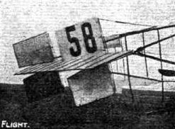
The new tail on Legagneux's Henry Farman machine.
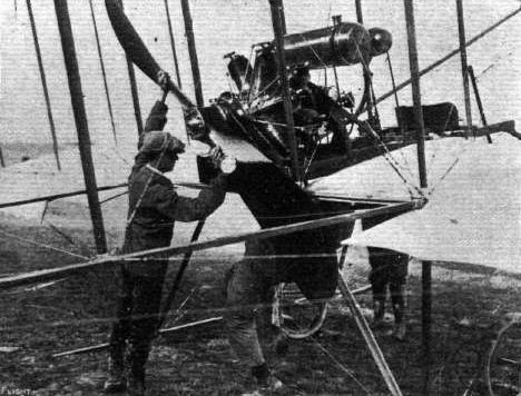
Mr. Henry Farman's biplane, as fitted with a 100-h.p. Gnome engine, at Rheims Meeting last week.
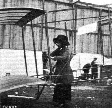
Mrs. Arthur adjusting the wire strainers on Gibbs' racing Henry Farman at Blackpool.
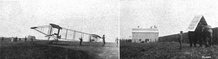
FLYING AT HALIFAX. - Mr. Claude Grahame-White's Henry Farman machine on the racecourse prior to his daring flight on Friday evening last week. The elevator of the machine is just visible outside the shed in the right-hand picture.
Competitors at the Starting Line at Lanark Meeting, as seen from the Members' Enclosure. - The machines, reading from the front, are: No. 6, Cattaneo's Bleriot; No. 12, Gilmour's Bleriot; 18, Grace's Henry Farman; 131, Ridley's Bierlot; 11, Capt. Dickson's Farman; 21, McArdle's Bleriot; 8, Blondeau's Henry Farman; 5, Champel's Voisin.
DREXEL OFF ON HIS BLERIOT FOR HIS SPLENDID SEA FLIGHT. - Beyond is Grahame-Whlte's Henry Farman also about to take the air.
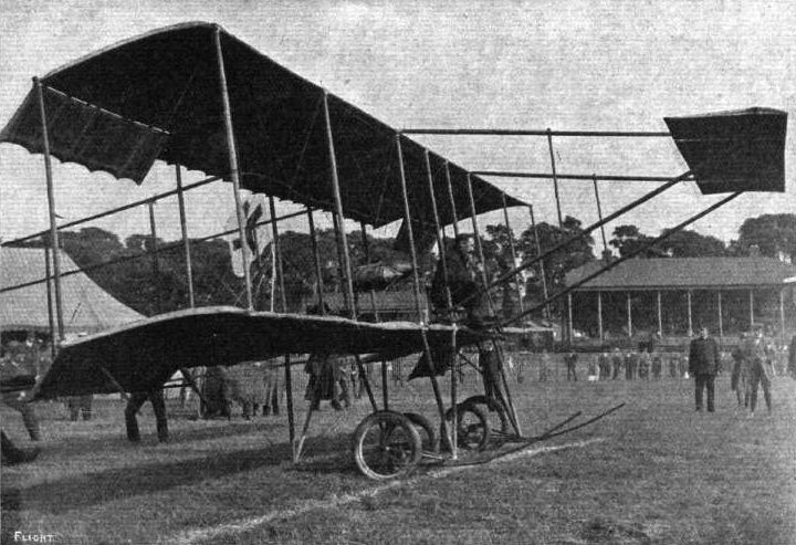
One of the most interesting items on the programme of the Midland Meeting at Wolverhampton was the "Quick-rising" Competition. In our photograph Mr. Cockburn, the winner of this contest, is seen on his Henry Farman "toeing" the starting line for one of these trials.
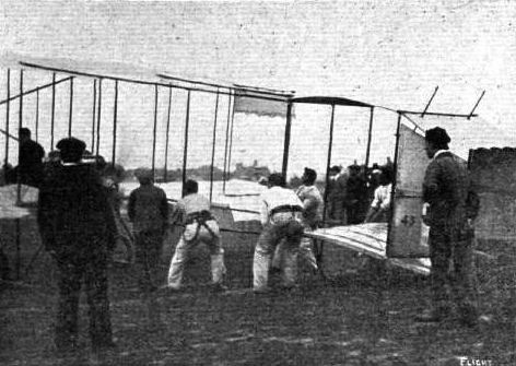
Holding back Captain Dickson's Henry Farman machine for a start at Bournemouth Meeting.
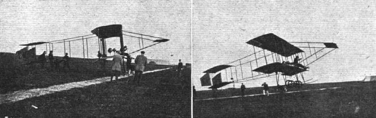
"GETTING-OFF" CONTEST AT BLACKPOOL. - Grahame-White, on his Henry Farman, takes his turn. On the left the machine is ready, Mr. V. Ker Seymer marking the position of the axles; and on the right the Farman is in the air, the officials, Col. Grantham, Mr. Ker Seymer and Mr. Rutter being seen rushing to mark the exact spot of leaving the ground, Grahame-White's best of 20 ft. 9 ins only just missed the world's record.
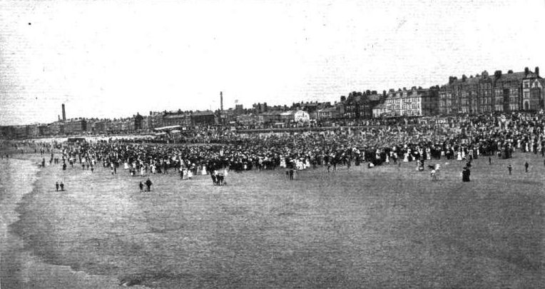
Grahame-White, on his Henry Farman, just rising from the sands on the South Shore, Blackpool, on Sunday afternoon last, to which point he flew from the Aerodrome in order to visit the Lancashire Aero Club.
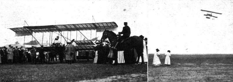
Robert Loraine ("Tones") on his Henry Farman, ready, with lifebelt on, for his sea flight to Alum Bay - and "en route." Note the lady "snappers."
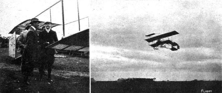
THE FIRST MAN UP AT BLACKPOOL FLYING CARNIVAL. - Robert Loiaine circles the aerodrome on his Henry Farman Saturday afternoon last. On the left, McArdle and Loraine are discussing the prospects of being able to give some exhibitions on the day before, Friday.
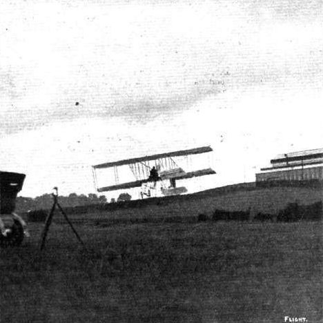
Mr. Rawlinson during one of his flights at Wolverhampton last week on his Henry Farman machine.
Mr. A. Rawlinson during one of his daring flights on his Henry Farman on the opening day of the Nice Meeting. - In the distance, exactly over the heads of the three men on the beach, Olieslagers, on his Bieriot monoplane, can be seen flying.
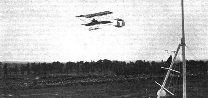
Capt. Dickson beating the passenger-carrying record on his Henry Farman machine at the Anjou Aviation Meeting.

Captain Dickson, on his Henry Farman, making the opening flight at the Lanark International Flight Meeting on Saturday last. Rounding one of the mark towers.
Captain Dickson, who was badly injured by M. Thomas colliding with him in the air at Milan Meeting last week, flying over a camp on Salisbury Plain on his biplane.
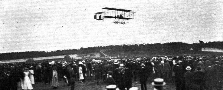
Blondeau, on Mrs. Grace Bird's Farman biplane, in flight over the aviation grounds at Brooklands on Bank Holiday.
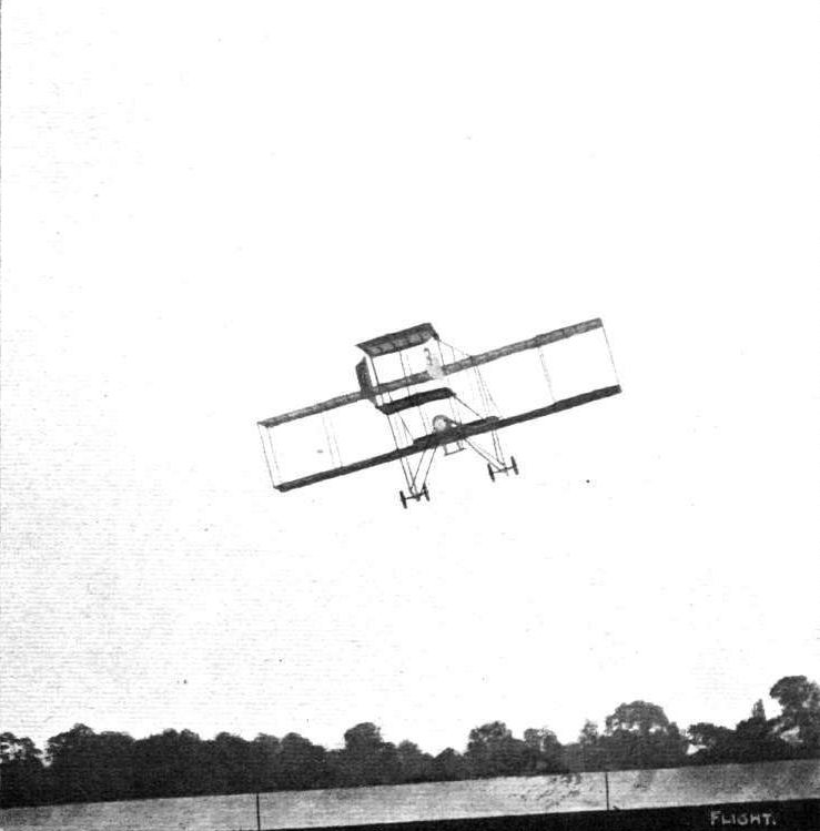
FLYING AT BROOKLANDS FOR THE NEILL CUP. - M. Blondeau making a good turn on Mrs. Grace Bird's Farman biplane.
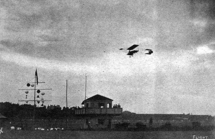
Claude Grahame-Whlte, on Monday evening during his long evening flight on his Henry Farman, passing the Judges' box and signalling apparatus at Bournemouth Aerodrome,
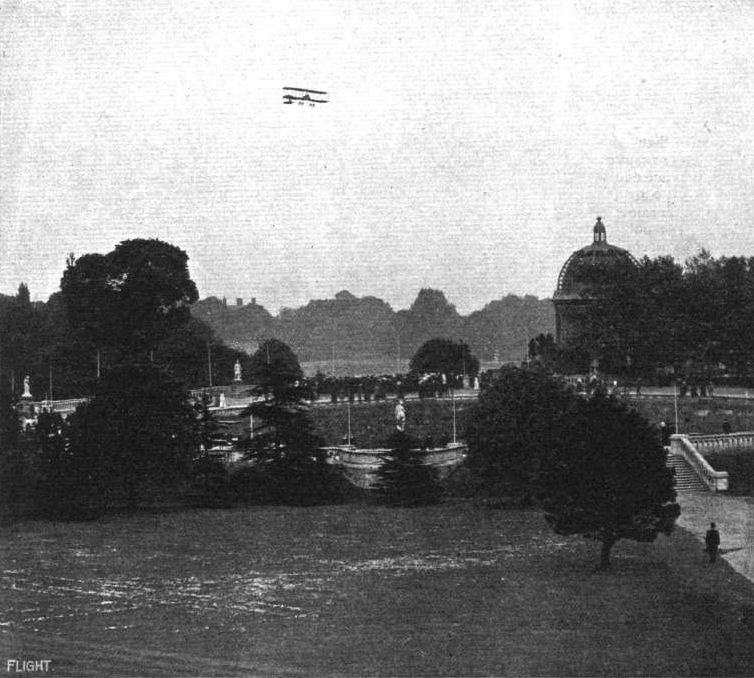
Mr. Claude Grahame-White, on his Henry Farman biplane, giving exhibition flights over the Crystal Palace grounds last week.
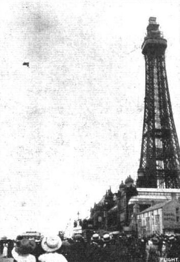
Grahame-White rounding the Blackpool Tower on his Henry Farman during one of his recent remarkable cross-country flights.
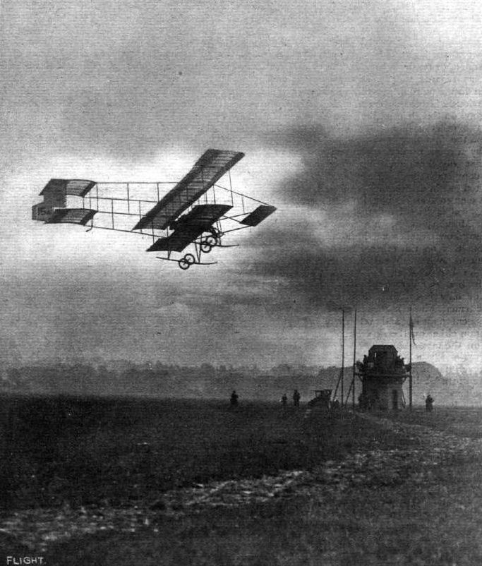
MIDLAND NATIONAL MEETING. - Mr. Lancelot Gibbs making a fine flight on his Henry Farman during the gusty weather on Saturday evening last, the closing day of the meeting.
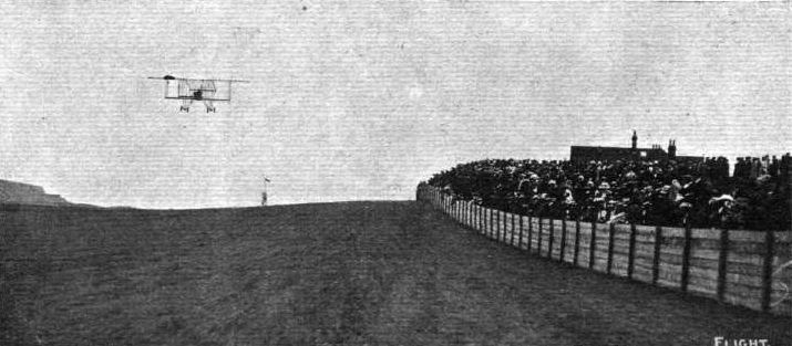
Christiaens travelling down the aerodrome on his Henry Farman biplane past the two-shilling enclosure at the Bournemouth Aerodrome. Note the mark-post in the distance for which Christiaens Is making.
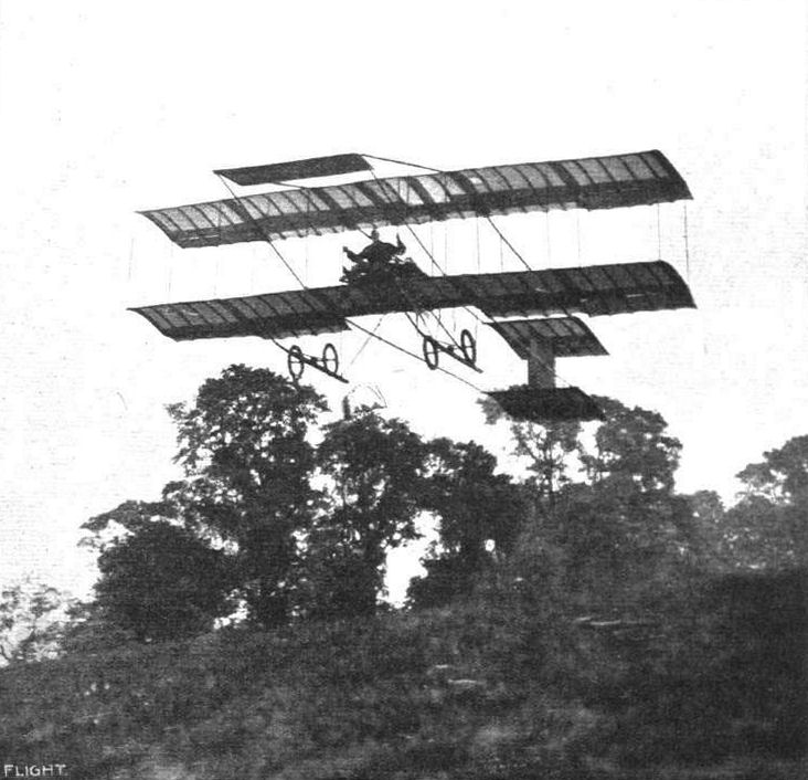
A REMINISCENCE. - Mr. Claude Grahame-White, on his Henry Farman machine, flying from Ranelagh for a tour over Barnes Common and Putney.
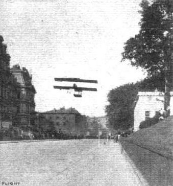
Mr. Grahame-White paying a visit on his Henry Farman to the White House and the War and Navy Departments, Washington, during his recent trip to America. - This is probably the most daring and successful practical flight so far accomplished.
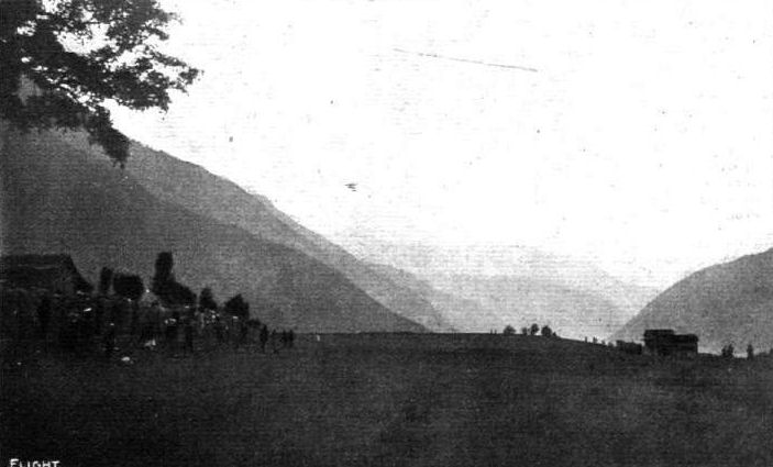
ACROSS THE SIMPLON PASS. - Weyman making a trial flight from Brigue plateau.
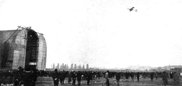
PARIS-BRUSSELS FLIGHT. - Legagneux leaves Issy for his journey to Brussels on his Henry Farman.
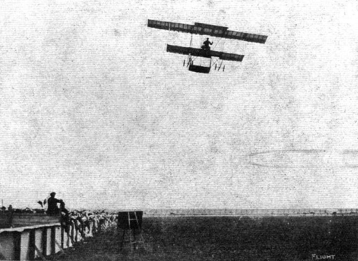
Robert Loraine coming down the aerodrome on his Henry Farman at Blackpool upon the occasion of his recent fine flight.
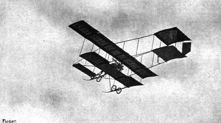
Robert Loraine's start from Blackpool grounds for his splendid and unrehearsed trip to Liverpool and back on Monday.
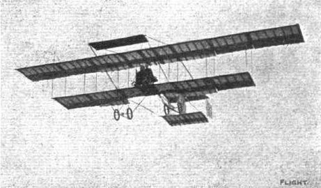
Henry Farman during his recent flight on his biplane with three passengers besides himself.
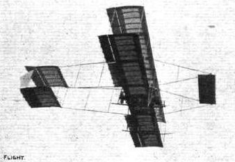
M. Blondeau flying at Brooklands with his French pupil, M. Ducrocq, on his Henry Farman.

The exciting incident at the Lyons Aviation Meeting when Paulhan, on his Henry Farman machine, overtook Legagneux on his Sommer biplane.
Flying at Brookiands on Wednesday of last week when at one time there were no less than six machines in the air together. - Our photograph shows in full flight the Hon. Alan Boyle on his Avis monoplane (on the left) and Mr. Claude Grahame-White, with a passenger, on his Henry Farman biplane.
M. Christiaens on his Henry Farman during a long-distance flight, and above, the late Hon. C. S. Rolls going for the height prize on his Wright machine.
Captain Dickson, on his Henry Farman, and Cattaneo, on his Bleriot, in the air at the same time at the Lanark Flight Meeting.
AT BELMONT PARK (N.Y.) INTERNATIONAL MEETING. - Hubert Latham, on his Antoinette, passing directly over Grahame-White on his Henry Farman during one of the competitions.
AT BROOKLANDS AERODROME. - Mr. R. F. Macfie on a Macfie biplane flying low recently at Brooklands grounds, with M. Blondeau above on a Farman biplane.
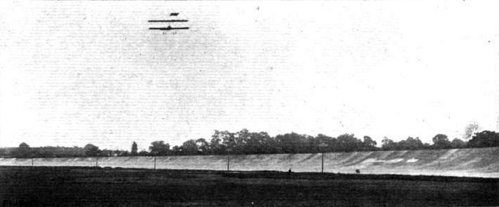
AEROPLANE VERSUS MOTOR CYCLE AT THE A.C.U. BROOKLANDS MEETING. - M. Blondeau racing F. A. McNab, on a 3 1/2-h.p. Trump, round the Brooklands Track.
Mr. Claude Grahame-White, on his Henry Farman at Wolverhampton, flying over Mr. Ogilvie's Wright machine, which is being towed back to the starting place.
GRAHAME-WHITE IN FLIGHT ON HIS HENRY FARMAN AT BLACKPOOL AERODROME. - The machine at rest on the ground is Cecil Grace s Bleriot.
ONE, TWO AND THREE PLANES. - Grahame-White, in his Henry Farman biplane, flying over Drexel's Bleriot monoplane and Roe's triplane.
Another "passing" incident during the Midland National Meeting. - Mr. Grahame-White flying over one of the Bleriot monoplanes.
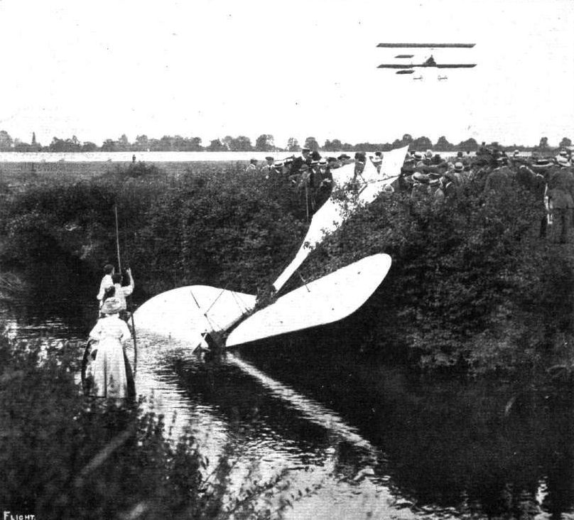
CORDONNIER'S MISHAP AT BROOKLANDS ON BANK HOLIDAY. - His Hanriot monoplane on the bank of the River Wey after his sudden descent. Overhead Blondeau is in full flight on his Henry Farman. Note the punting party ready to assist if necessary.
FLYING AT BROOKLANDS. - M. Blondeau flying over Mr. Macfie's biplane at rest below.
THE AGGREGATE TIME FLIGHT COMPETITION AT BROOKLANDS FOR THE NEILL CUP. - M. Blondeau making a flight. On the ground is Mr. Macfie's biplane, Mr. Macfle, without a hat, standing in the foreground.
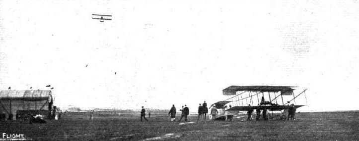
GRAHAME-WHITE ON A DISTANCE FLIGHT. - At rest is Capt. Dickson's Farman.
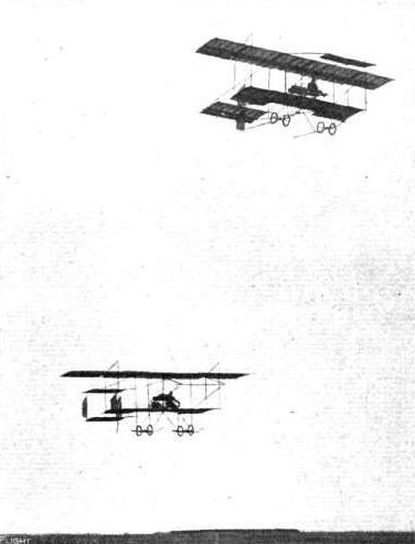
A brace of Henry Farmans racing at Rheims Aviation Meeting on Sunday last.
A GROUP OF FOUR FLYERS IN THE AIR AT ONCE AT RHEIMS. - Above, an Antoinette and a Bleriot; below, a Henry Farman; and, to the left, a Wright machine.
Mr. George Barnes, on a Humber monoplane, flying last week at Brooklands close over Mr. Claude Grahame-White's Henry Farman machine.
View of Burton-on-Trent, as seen from M. Beaud's Henry Farman biplane when he flew over that town at the recent aviation meeting.
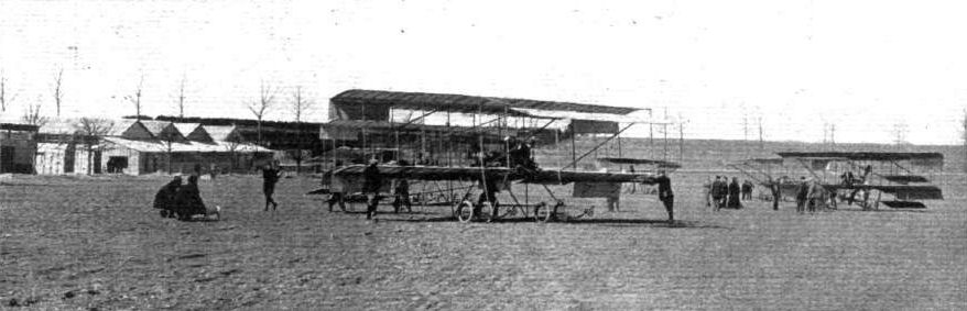
In England it is hardly realised yet the rate of aviation progress on the Continent. Already good flyers are abundant, and it is difficult to keep track of the new pupils who are daily completing their initiation into practical aviation. As a typical example of a French aviation school, the above photograph at Mourmelon grounds is very convincing.
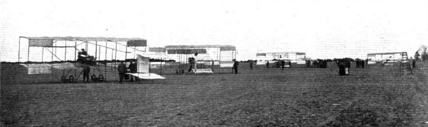
Another view of the Mourmelon Aviation School, showing the ordinary business-like methods which pervade the routine of teaching the young idea how to fly.
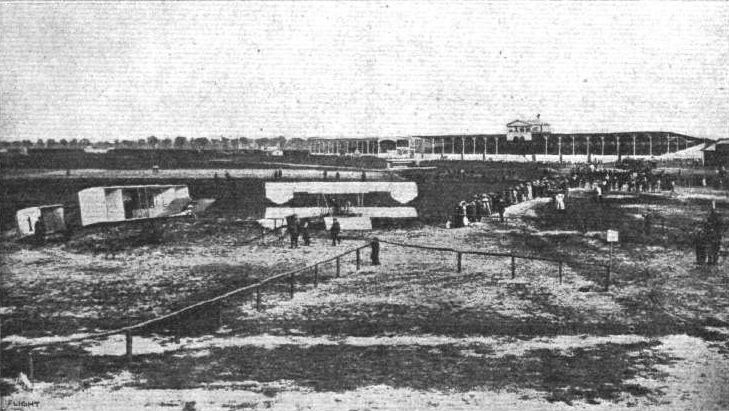
General view of the Stands and Starting Place on the Johannisthal Aerodrome near Berlin. - The machines in the foreground are Baron de Caters' Voisin (No. 1) and Herr Jeannin's Henry Farman.
IN LINE FOR THE FIRST AERIAL "RACE." - MM. Martinet (H. Farman), Mumm (Antoinette), Legagneux (Sommer), and Capt. Dickson (H. Farman), ready for the start from the Anjou Aerodrome for the cross-country race to Saumur on June 6th.

A GROWING "STREET" AT BROOKLANDS AVIATION GROUNDS. - The machine in the shed is Mr. Claude Grahame-White's Henry Farman which he used on the Manchester flight. The next shed is the home of the first machine built by Sir George White's company - the British and Colonial Aeroplane Co., Ltd., of Bristol.
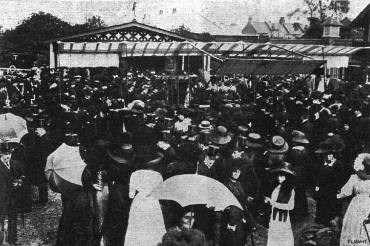
MR. CLAUDE GRAHAME-WHITE AT RANELAGH. - The habitues examining the Henry Farman biplane during the afternoon.

FLYING AT BROOKLANDS. - The scene at Brooklands on Saturday last was the occasion of the auction for the first passenger to ascend on that day with Mr. Grahame-White in his Henry Farman biplane, when Lady Abdy secured the right against Miss Pauline Chase by a bid of 120 guineas.
PARIS FLIGHT SALON. - General view of the centre of the Grand Palais. On the right is seen the Wright biplane, on the left the Maurice Farman biplane, just beyond being the Henry Farman machine, whilst in the foreground, in the centre, is the two-seater Antoinette monoplane.
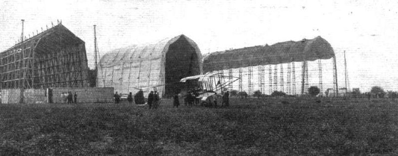
FRENCH PICARDY ARMY MANOEUVRES AND AERONAUTICS. - General view of the dirigible sheds at Briot-Aviation. One of the Army biplanes will be noted in the centre of the picture.
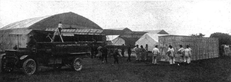
AEROPLANES AT THE FRENCH PICARDY MANOEUVRES. - General view of the aeroplane sheds at Briot-Avlation during the getting ready of the aeroplanes.
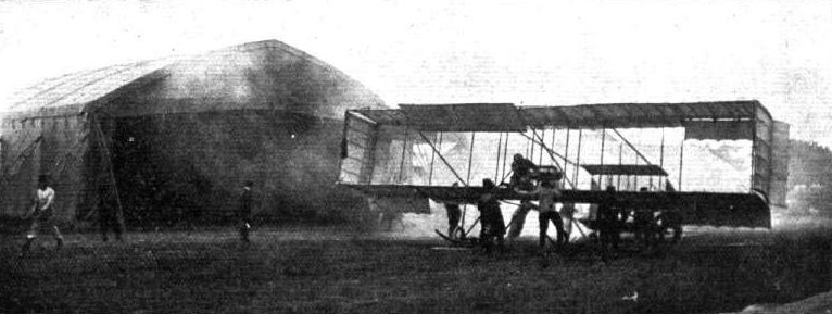
AEROPLANES AT THE FRENCH PICARDY MANOEUVRES. - Adjutant Menard just about to start on his biplane from Briot-Aviation to rejoin his post at Formerie.
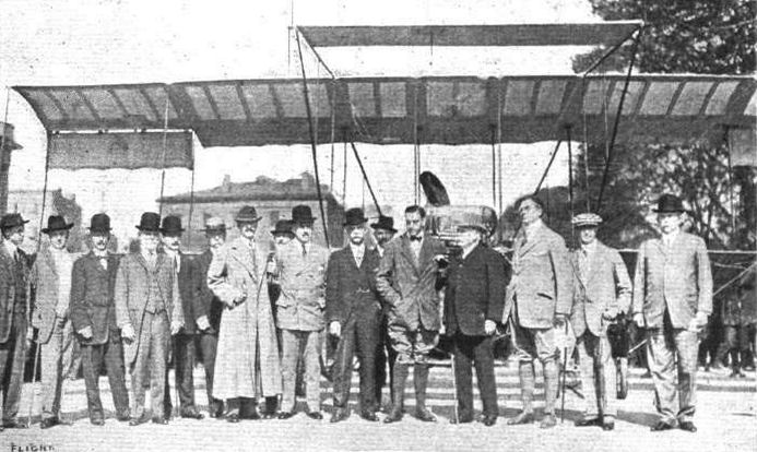
Mr. Claude Grahame-White and the Military Chiefs of the Government when he called at the White House, and the War and Navy Departments in an aeroplane. - Reading from left to right: Richard R. Sinclair, Capt. Barr, Major George O. Squiler, U.S.A., Brig.-Gen. James O. Murray, U.S.A., Capt. H. B. Wilson, U.S.N., Commisioner Johnston, Commodore Johm Barry Ryan, Brig.-Gen. A. W. Greeley, ret., Maj.-Gen. Leonard Wood, Gen. Oliver, Gen. James Ailen, C. Grahame-White, Admiral Dewey, Clifford B. Harmon, Sidney McDonald, Maj.-Gen. James A. Bell.
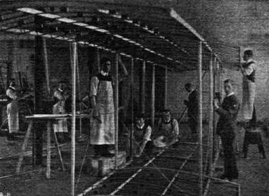
One of the Farman type of machines in course of construction by Messrs. A. V. Roe and Co., to be fitted with an Avro motor, for a Bolton gentleman.
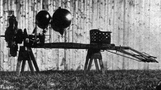
A Gnome motor "set" for Henry Farman biplane, showing engine, propeller, oil and petrol tanks, pilot's seat, and foot control of vertical rudders.

Rear view of Gnome motor on Henry Farman machine, showing carburettor with air inlet and throttle control, position of magneto, petrol tank, and oil feed tube.

Henry Farman and his three passengers with whom he recently flew.
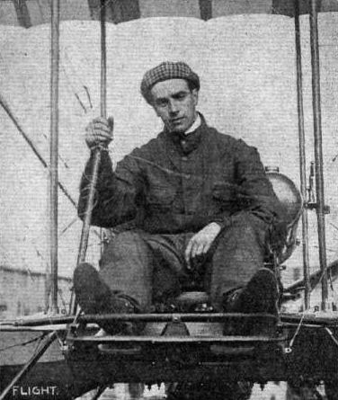
Claude Grahame-White (Henry Farman).
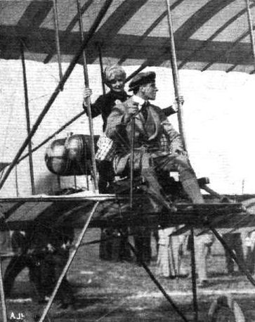
Grahame-White, ready with one of his lady passengers, before the word to let go. - Note the assistants behind holding the machine back from rising.
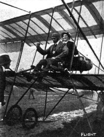
Claude Grahame-White, at Blackpool aerodrome, just about to start for a flight on his Henry Farman, with Miss Florence Parbury, the authoress, as passenger.
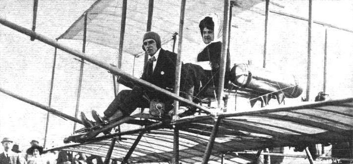
FLYING AT BROOKLANDS. - Mr. Claude Grahame-White, with Lady Abdy in the passenger's seat, just ready to start for his flight at Brooklands last Saturday, which unfortunately ended somewhat disastrously, but happily without any serious injury to either driver or passenger.
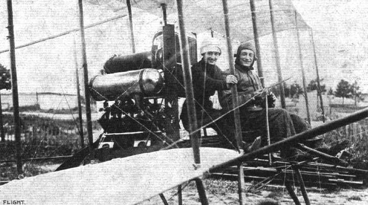
Cheuret, with Mdme. Branger as passenger, on a Henry Farman biplane, Thursday. May 19th, when a new cross-country passenger record was put up between Mourmelon and Chalons Cathedral and back.
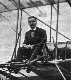
THE FLYING MEN AT BOURNEMOUTH AND THEIR "MOUNTS." - Capt. Bertram Dickson (Henry Farman).

THE FLYING MEN AT BOURNEMOUTH AND THEIR "MOUNTS." - Robert Loraine ("Jones") (Henry Farman).
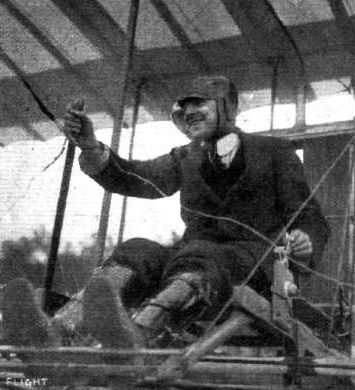
De Baeder, who is now recovering from his recent severe accident.
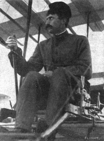
Lieut. Remy, seated in his Henry Farman machine on which he recently spent a week "touring" over the North of France. As we recorded in our last issue, he covered about 500 kiloms. in eight days.

Mr. Weymann, the record flyer, who last week, on his Henry Farman, flew from Paris to Volvlc, 420 kiloms., in his great attempt to win the big Michelln prize for flying with a passenger from Paris to the Puy de Dome mountain in 6 hours. With him is M. Faye, who accompanied him as passenger.
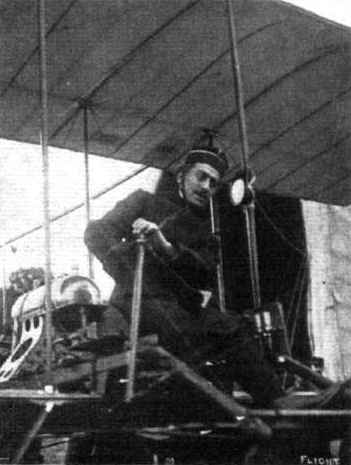
Sub-Lieut. Paulhan on "Le Gypaete," his Henry Farman machine, during the French Army Manoeuvres. - Owing to the accident to his right arm, it will be noted M. Paulhan has to use his left hand for working his levers.
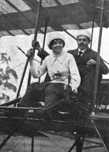
AVIATORS AT DONCASTER MEETING. - Mdlle. Dutrieu, with M. Beau as passenger, ready for a flight on one of the Henry Farmans.

PARIS-BRUSSELS FLIGHT. - M. Legagneux and his passenger, M. Martinet, readv to start for Brussels from Issy on their Henry Farman.
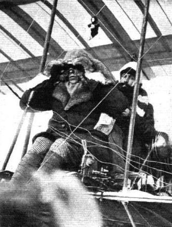
PARIS-BRUSSELS AND BACK BY AEROPLANE. - M. L. Wynmalen and his passenger, M. Dufour, on the Henry Farman immediately before the start for Brussels from Issy.
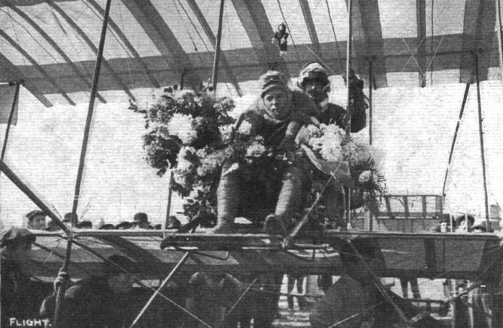
Wynmalen and his passenger Dufour at Issy immediately after their return from the successful Brussels flight last week. Note the bouquets with which they have been presented, and the "mascot," immediately above their heads.
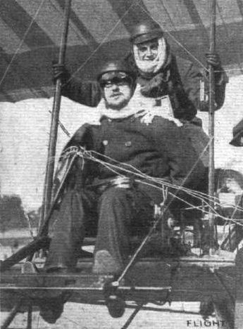
M. Michel Mahieu, with M. Gaston de Manthe as passenger, just before their start last week from Issy for Brussels in the Paris-Brussels 36-hour competition of the A.C.F.
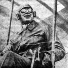
AMERICAN FLYING MEN AT BELMONT PARK MEETING. - Clifford D. Harmon.
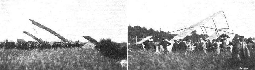
FLYING A T BROOKLANDS. - Mr. Grahame-White's machine, after the mishap at Brooklands, at the edge of the River Wey.
FIRST COLLISION IN THE AIR. - As the mishap to Capt. Bertram Dickson, on his Henry Farman, when M. Thomas, on his Antoinette, dashed Into him from above, at Milan, appeared to A. Beltrame, an Italian artist. This picture appeared in La Domenica del Corriere.
The scene at Milan immediately following the crash to earth of the Antoinette monoplane of M. Thomas and Capt. Dickson's Farman machine. The tail portion of the Farman biplane, showing No. 18, can be seen between the military, the main planes being mixed up completely with the planes of the Antoinette, the tail and body of which is seen standing straight up on end.
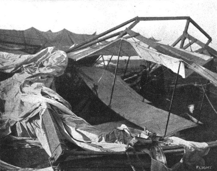
LAST WEEK'S STORMS AND THE CROSS-CHANNEL FLYERS. - The wreck of Mr. Loralne's hangar and aeroplane on Saturday last at Dover. "Inspecting" the debris.
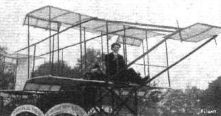

GRAHAME WHITE'S HENRY FARMAN BIPLANE. - The above sketch shows the way in which the auxiliary tail plane on Mr. Claude Grahame-White's Henry Farman machine is inter-connected by means of crossed wires with the front elevator, while the elevator is directly connected to the control lever. In this machine a skid with an elastic buffer is fitted, instead of wheels, to the tail. During a practice flight one of the long front skids was damaged, and Mr. Grahame-White had them both shortened, the part dotted in the above sketch being sawn away.
Flight, June 11, 1910
The Henry Farman Monoplane.
ON the 2nd inst. Mr. Henry Farman was out testing his new monoplane at Mourmelon when his best flight was for two circuits of the flying ground. Although the machine was only two metres above the ground it manoeuvred quite easily and is said to have carried a load equal to 22 kilogs. per sq. metre of surface. Further trials were also made last Saturday with equal success.
Flight, June 18, 1910
THE FARMAN MONOPLANE.
LAST week we published details of the successful trial flights made by Mr. Henry Farman on his new monoplane, and now we are able to give a couple of photographs of the machine with Mr. Farman at the wheel. It will be seen that the main plane resembles the upper plane of the Farman biplane, with the usual ailerons at the ends. The span is 8 metres, the overall length is a little less, while the weight is given as 300 kilogs. The general arrangement of the framework is clearly shown in the photograph, but an important point in connection with the design is that the main planes are some distance above the framework, so that the aviator has a clear view of the ground beneath him. A Chauviere tractor is fitted, driven by a 50-h.p. Gnome motor. The rudder is mounted above the rear plane, with a triangular fin in front of it, while the rear plane itself is divided, the rear half serving as an elevator.
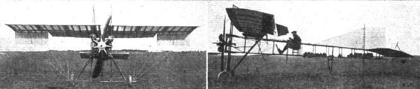
THE HENRY FARMAN MONOPLANE. - Views, from in front and of the side, of this new machine, the advent of which we announced a few weeks ago.
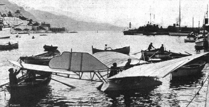
A STRANGE CRAFT IN THE HARBOUR AT MONACO LAST WEEK. - This novel aero-hydroplane is fitted with a 50-h,p. 3-cyl. Anzani motor.
The Gabardini flying boat of early 1910, with its catamaran hull, variable-incidence wing, rear elevator and tractor propeller.
The Gabardini flying boat of early 1910, with its catamaran hull, variable-incidence wing, rear elevator and tractor propeller.
Flight, July 16, 1910
NOVEL MACHINES AT RHEIMS.
BY HANDLEY PAGE.
<...>
Of the biplanes, the Savary, Goupy and Breguet have several new features.
The Goupy biplane has already been illustrated and described, its chief feature being that the top plane is not vertically above the lower one, but in advance of it. The tail is constructed on the same lines. The ends of the main planes are hinged like those of a Bleriot elevator tail, and these are used instead of warping the planes themselves.
<...>
Flight, December 3, 1910
AEROPLANE SILHOUETTES FROM THE PARIS SHOW.
THE GOUPY BIPLANE.
FRENCH-BUILT biplane, with elevators on main planes and tail planes. Planes double-surfaced throughout. The upper planes are placed slightly further forward than the lower.
General dimensions. - Bearing surface, 22 square metres; length overall, 7 metres; width, 6 metres.
Seating capacity. - If two-seater, one behind the other.
Engine. - Gnome air-cooled rotary: 7 cylinders, of 50-h.p. Propeller and motor, to which it is bolted, are placed in front of the main planes. Any engine is fitted, according to personal desire.
Propeller. - To choice. Chauviere frequently used. 2.50 metres; diameter, 1.'25 metres pitch; normal revolutions, 800.
Wheels and skids. - Two wheels mounted in somewhat similar fashion to the well-known Bleriot type. Two short skids, curving upwards towards the front, are placed before the wheels.
Tail. - Biplane tail with single rudder placed centrally behind the two planes. Elevators are attached to the outside edges of both planes, and work in conjunction with those on the main planes. On some machines a fixed empennage is fitted in front of the tail.
Lateral stability. - By tips fitted to the outside edges of both upper and lower main planes. Both sets work simultaneously. If the machine is falling to the right, the right tips are raised and the left tips depressed to regain balance, and vice versa. Similarly the tail planes have tips, which, however, only act as elevators, but in unison with those on the main planes.
Weight. - With Gnome motor, 250 kilogs.
Speed. - 70 to 85 kiloms. an hour.
System of control. - By means of a wheel mounted on a column in front of the pilot. Rotation of the wheel to the right or left steers the machine in those directions. A movement of the entire column to the right raises the left wing-tips, and a movement to the left the right tips. A backward movement of the column raises the tips on the main planes, and depresses those on the tail, thus effecting elevation. A forward movement has the reverse effect.
Price. - Without motor or propeller, 12,000 frs. With 50-h.p. Gnome motor and propeller of any known make, 25,000 frs.
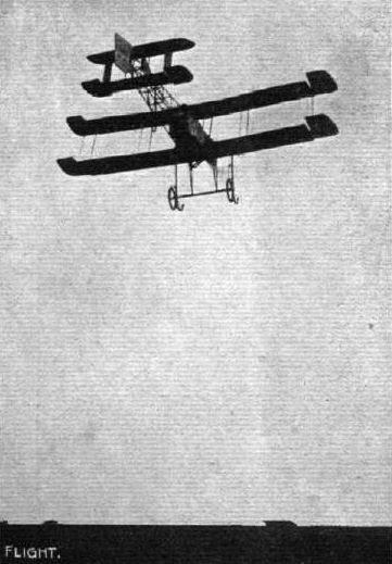
The Goupy biplane, piloted by Ladougne, at the Rheims Meeting.
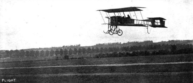
HAVRE FLIGHT MEETING. - Ladougne, on his Goupy biplane, in flight with a passenger.

M. Ladougne flying on a stormy day on his Goupy biplane at Doncaster Flight Meeting.

DOWN THE STRAIGHT AT DONCASTER MEETING. - Ladougne giving an exhibition flight on his Goupy.
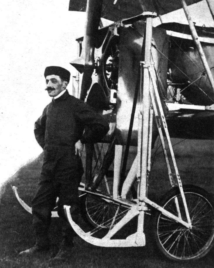
M. EMILE LADOUGNE.

Flight, March 12, 1910
THE SECOND OLYMPIA AERO SHOW.
AEROPLANES.
Gregoire-Gyp.
FRENCH-BUILT monoplane of a type intermediate between the Antoinette and Bleriot. The main wings are of 34-ft. span, and are warped for steering and securing; lateral stability. Control is by two hand-wheels, one on each side of the driver, that on the right warping the wings, while the one on the left operates the horizontal rudder, the vertical rudder being worked by a foot-bar. The machine is carried on a combined skate-and-wheel frame, the wheels being used to run on the ground for starting purposes, and the skids coming into operation on landing.
Flight, April 23, 1910
FLYER SILHOUETTES FROM OLYMPIA.
THE GREGOIRE-GYP MONOPLANE.
Leading Particulars of the Gregoire-Gyp Monoplane.
General Dimensions.-Areas-Main planes, 244 sq. ft.; elevator, 20 sq. ft.; rudder, 8 1/4 sq. ft.
Lengths.-Span, 34 ft.; chord, 7 ft. 4 ins.; camber, 41/2 ins, situated about 27 ins. from leading edge; skid track, 5 ft. 6 ins.; overall length, 34 ft.
Angle.-Incidence, 6° 40'.
Materials.-Timber, ash and hickory; fabric, Gregoire.
Engine.-40-h.p. Gregoire-Gyp.
Propeller.-Diameter, 7 ft.
Weight.-Machine, with engine, 620 lbs.; driver, oil, petrol and water, 200 lbs.; total flying weight, 820 lbs.; loading (all weight supported on main planes), 3.4 lbs. per sq. ft.
Speed of Flight. -45 m .p. h.
System of Control.- Warping of planes, rudder and elevator.
Price.-L850.
MONOPLANE of modified Antoinette type, mounted on a massive but strong and light "A" chassis with ski and wheel attachment. The feature of the power plant is the fitting of a 40-h.p. Gregoire engine upside down. Lubrication is effected by means of a pump forcing castor oil direct to the crank-shaft bearings. It is claimed that with proper fitting pistons there is no greater liability to soot the plugs through an excess of oil passing the pistons than occurs with the engine in an upright position. Wing warping, with tail and elevator control, is accomplished by side wheels and pedals, as on an Antoinette monoplane.
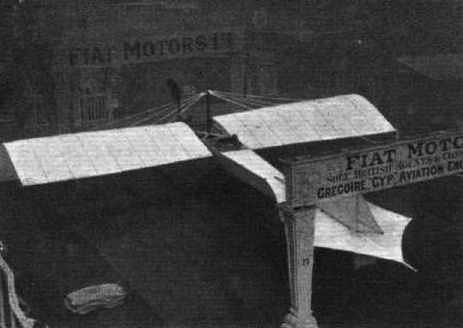
View from behind of the Gregoire-Gyp monoplane, exhibited by Fiat Motors, Ltd. The system of steering is very similar to that on the Antoinette machine.
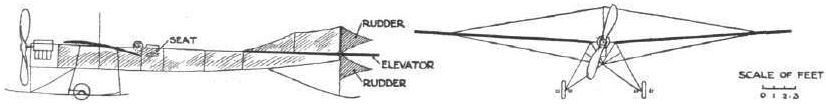
WING SECTIONS. - The above diagrams afford an interesting comparison of the wing sections of aeroplanes exhibited at Olympia. They are all drawn to a common scale, but have been set at an arbitrary angle of incidence, which does not necessarily represent that of the aeroplane In actual flight.
Flight, August 6, 1910
Doings at Brooklands.
ALTHOUGH a series of good prizes were offered by the Brooklands Club for competition among the flyers there during the racemeeting on Monday, the high wind which prevailed until 6 o'clock rendered it advisable for all machines to remain under cover. At 6 o'clock, however, the improved conditions brought out Blondeau on Mrs. Grace Bird's Farman biplane, and he successfully completed fifteen rounds of the course in 36 mins. 47 secs., the distance covered being about 25 miles. Cordonnier made a start on the Hanriot monoplane, but he had only covered a short distance when he came down again, and before he could stop the machine it ran down the bank of the Wey to the water. It was, however, soon rescued with the aid of some Boy Scouts. Mr. L. D. Gibbs. was also trying his Sommer biplane, but did not make any lengthy flight.
Flight, December 3, 1910
THE HANRIOT MONOPLANE.
WHEREVER it has been seen, the Hanriot monoplane has invariably attracted attention, and more often than not received favourable criticism of its shipshape appearance. And, now that it is about to be brought to the fore in this country under the regis of a powerful syndicate, the interest that it has awakened in the capacity of a mere "visitor" at some of our flight meetings is likely to mature in a more practical form among those who have an ambition to fly. There are many points of distinct originality in the Hanriot design and construction, but it is not always that these features in question are appreciated individually as such by those on whom their tout-ensemble makes a good impression. First and foremost there is, of course, the wooden boat-shaped hull, that naturally strikes everyone at first sight as the outstanding departure from orthodox practice, but there is also the "A" type frame that supports this body upon the wheel and skid chassis, and those who attended the previous Paris Aero Show will doubtless remember that a similar feature of construction characterised the Hanriot monoplane of last year. Those who were not actually present at that Exhibition, but who care to turn up their first volume of FLIGHT, will find our own illustration and description of the machine on page 740 of our November 20th issue, 1909. It was, in our opinion, one of the most interesting constructional details that the Paris Aero Show brought to light. Simple in design and construction, strong in principle, it formed a clever solution to a problem that it has not been easy to turn into a really neat job; that the method has been generally appreciated may be judged from the fact that several other makers of monoplanes subsequently adopted the essential features of this design.
There is also a good deal to be said in favour of the boat body on the Hanriot monoplane, and quite apart from any intrinsic merit that this system of construction may possess on its own account, there is a distinct advantage in the system in that it dispenses with the use of a tremendous amount of wire that would otherwise be necessary for bracing some equivalent girder member. We have no objection to wire in principle, and unquestionably it is a wonderfully strong and light method of building up a frame; but on the modern aeroplane there is so much wire that any method of reducing the amount is welcome on this score alone. Wire bracing needs some little attention, for it should at least be periodically inspected, and if more wire is used than is absolutely necessary it seems to us that there is just the likelihood that it may provoke carelessness with regard to its proper maintenance. By the use of a boat body, the Hanriot monoplane is clear of all wire for which a suitable substitute can be provided, and those wires that do remain take on, in consequence, an added importance that should ensure their proper attention. It may, perhaps, seem a little outside the zone of present day conditions to bring forward a criticism of this description, but it must after all be remembered that manufacturers essentially hope to obtain a fairly wide sale for their machines, and many aeroplanes are quite likely to pass into the hands of users who will not always realise the necessity of persistent attention to small mechanical points while their chief object is to get up into the air. The wider and the more rapid the development of aviation, the more is this likely to be the case - as it has been, for instance, in connection with motor cars - so that in considering the construction of machines, it is necessary, even now, to take note of features such as these, because of the influence that they may have on future design.
The boat body of the Hanriot monoplane is constructed on the lines of a racing skiff, and it is well known that this form of construction produces a very strong and very light girder. The top of the body is entirely decked in, except for a little cockpit containing the pilot's seat. Immediately behind the pilot's seat the deck is thickened so that it is safe for the pilot to stand thereon when mounting and dismounting. No wires of any description interfere with free access to this part of the machine. Three steel strips form a kind of cradle for the support of the body on the "A" type chassis frame, the strips being bolted to the inclined struts of the frame and passing under the body as shown in one of the accompanying sketches. Steel strips are also employed for lashing the main spars of the wings to the body, and it will be observed in the same sketch how these spars are mounted on blocks and lashed in place as described. The spars are not horizontal, but are set at an angle to one another, the "dihedral" being 7 ins., that is to say, the extremities of the wings rise 7 ins. above the shoulders. The spars in question are 3 ins. deep and 1 1/2 ins. wide, and they are constructed on the three-ply principle instead of being cut from one piece of wood. This is a departure from common practice that we have not noticed elsewhere, and in view of the criticism that has been levelled against the supposed tendency of monoplane-wing spars to buckle, this method of construction will doubtless arouse interest. The laminae of the spars are arranged vertically, but again bearing in mind the matter just referred to, it is conceivable that some use might be made of this principle with horizontal laminae to strengthen the spars against the forward pressure; it is the end thrust on a machine that is the difficult force to meet. The vertical forces can be more readily provided for because the presence of the propeller in no way interferes with any system of bracing that may be preferred. In the Hanriot monoplane it is worthy of note that the rear spars of the main wings are individually trussed by a diamond bracing, each spar being fitted with a vertical cross strut in the centre and the four extremities being tied by diagonal wires. The rear spars are hinged to the frame so that they can rock for wing warping, and the hinge pins are tied together by a steel tube so as to relieve the body of undue strain.
The control of the Hanriot monoplane is mainly interesting on account of the use of two levers, one under the control of the pilot's left hand and the other under the control of his right hand. That on the left moves sideways and operates the wing warping, that on the right moves to and fro and controls the elevator that forms a hinged extension of the tail plane. In front of the pilot's seat is a pivoted cross-bar that can be rocked by the pressure of his feet. This controls the rudder, which is mounted between the halves of the elevator. The fixed tail-plane on the Hanriot monoplane is quite flat, and consists of a sheet of fabric tightly stretched by the aid of a couple of transverse spars. The rear portion of the tail plane is deflected a little below the line of the leading portion, to which it has a relative, although small, angle of incidence.
Well forward of the main planes is the engine, which on this machine is an 8-cyl. 40-h.p. E.N.V. This is mounted in the bows of the boat body, and is also partly supported by the struts of the "A" frame, a pair of which are situated immediately beneath the motor. The tractor-screw, which is direct-driven by the engine, is 2.1 metres is diameter, and 1.2 metres in pitch. When at rest on the ground, the machine is carried by a pair of pneumatic-tyred wheels in front and by a light trailing-skid behind. The wheels are mounted on a steel axle that is reinforced by a wood batten and mounted in vertical guides, so that it has a considerable upward travel. Suspension is effected by elastic springs anchored to the main skids and attached to the upper end of a column that rests upon the axle itself.
The construction of the axle is shown very clearly in one of our photographs, in which it will be observed that the system represents a very strong but rather rigid form of construction ; rigid, that is to say, so far as lateral stiffness is concerned, for the vertical play permitted by the guides is considerably in excess of that usually obtained with the ordinary rubber attachment of the axle to the skids. The clearance is enough, in fact, to enable the wheels to rise up so high as to enable the weight to be taken directly on the skids in the event of a very severe bump. Like everything else in the Hanriot design, solidity seems to be the keynote of its construction.
It is with a machine of this type that some very satisfactory flights have been made at Brooklands recently.
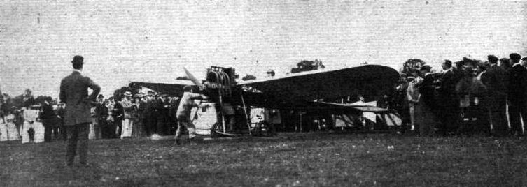
FLYING AT BROOKLANDS ON BANK HOLIDAY. - Starting Cordonnier's Hanriot monoplane for the flight in which he landed his machine in the river Wey.

Wagner just getting away for a trial on his Hanriot monoplane.
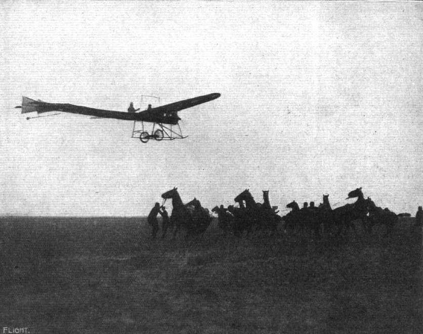
A breezy "snap" at dusk of Wagner on the large Hanriot monoplane, "No. 4," during one of his long flights on the Champagne Aerodrome. The effect of the fleet aeroplane, as seen, upon the military horses, was somewhat disconcerting to the riders.
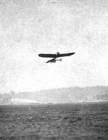
Mr. Davies, one of the new flyers at Brooklands, on the Hanriot monoplane,
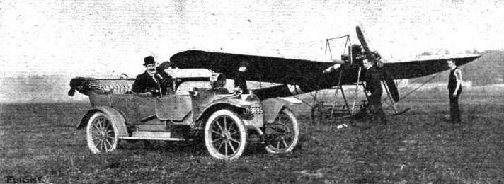
MR. A. C. THOMAS IN HIS MOTOBLOC CAR AT BROOKLANDS AVIATION GROUND. Behind is Mr. Thomas' Hanriot monoplane fitted with E.N.V. engine.
Mr. Graham Gilmour's Bleriot flying over the Hanriot monoplane at Brooklands.
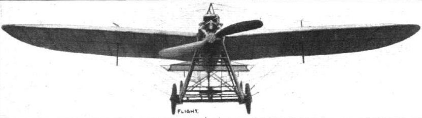
Front view of the Hanriot monoplane, showing the "A" type chassis frame that was introduced by this firm last year.

Rear view of the Hanriot monoplane, showing the bird-like tail and the dihedral angle of the wings.
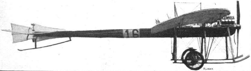
Side view of the Hanriot monoplane. The disposition of the parts is such that the machine is practically in equilibrium when balanced on its supporting wheels. There is very little weight on the trailing skid with the aeroplane in the above position.
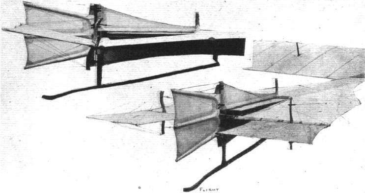
Two views of the Hanriot tail. In the side view the deflected trailing portion can be distinctly observed.
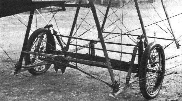
View showing the method of mounting the axle on the Hanriot monoplane. The axle is carried between vertical guides, and the machine is suspended on the rubber springs that are anchored to the skids.

View of the 8-cyl. E.N.V. engine in place on the Hanriot monoplane.
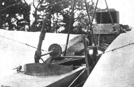
View of the pilot's seat on the Hanriot monoplane. The lever on the left warps the wings, that on the right operates the tail-elevator. There is a pivoted foot-rest in front controlling the rudder. The switch is mounted on the warping-lever, and a rubber bulb for maintaining pressure in the petrol tank is attached to the elevator-lever. The hinging of the rear spars to the body can just be distinguished in the above illustration.
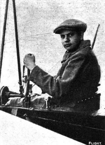
Marcel Hanriot, the "Boy Aviator," at Rheims Aviation Meeting on his Hanriot monoplane.
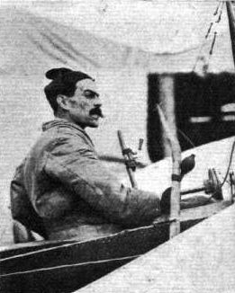
THE FLYING MEN AT BOURNEMOUTH AND THEIR "MOUNTS." - L. Wagner (Hanriot).
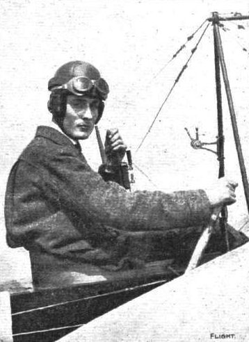
Vidart in the pilot's seat of his Hanriot monoplane at Lanark Meeting.
CORDONNIER'S MISHAP AT BROOKLANDS ON BANK HOLIDAY. - His Hanriot monoplane on the bank of the River Wey after his sudden descent. Overhead Blondeau is in full flight on his Henry Farman. Note the punting party ready to assist if necessary.

Diagrammatic sketch illustrating the system of hand control on the Hanriot monoplane. A pivoted foot-bar, not shown, operates the rudder.

Sketch illustrating the attachment of the front spars to the body of the Hanriot monoplane and the method of carrying the body itself in a cradle of steel straps.
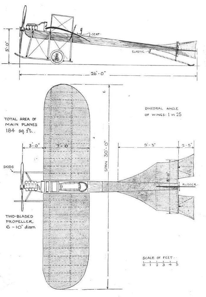
The Hanriot monoplane, 1910.
Flight, December 31, 1910
AEROPLANE SILHOUETTES FROM THE PARIS SHOW.
THE KOECHLIN MONOPLANE.
A FRENCH-BUILT monoplane, constructed at Billancourt. Framework of poplar wood with ash spars. It is on a machine of this make that Madame Niel, the first lady to obtain a pilot's certificate on a monoplane, has made many good flights.
General Dimensions. - Span, 10 metres; carrying surface, 26 square metres; overall length, 9.5 metres.
Seating capacity. - Two, one behind the other.
Chassis. - Two wheels arranged with a single skid in the centre; the wheels are so arranged that they adapt themselves to any unevenness in the ground over which they are travelling, while the skid is designed to protect the propeller when landing.
Engine. - 70-h.p. 4-cyl. Labor, but a 50-h.p. Gnome or 50-h.p. Chenu motor can be fitted at slightly increased price.
Propeller. - Two-bladed Koechlin, made of wood, 2.5 metres diameter, 1.8 metres pitch.
Tail. - This consists of a fiat plane, the rear end of which is flexible, to form an elevating flap. A vertical rudder is fitted above this tail plane, while in front is a triangular fin. A fin is also fitted below the tail.
Lateral stability. - Maintained by movable tips at the ends of the main plane.
Weight. - 320 kilogs.
Speed. - Not stated.
System of control. - By a single wheel of the motor car type mounted in front of the pilot. A backward or forward motion flexes the elevator, while the rotation of the wheel to the left or right operates the vertical rudders. For controlling lateral stability the wing tips are operated by the movement of the back of the pilot's seat, and it is claimed that this is done instinctively. The feet play no part in the steering.
Price. - Without motor, 13,000 francs; with Labor motor, 21,000 francs; and with 50-h.p. Gnome motor, 26,000 francs. The price of the single-seated machine is 11,000 francs without motor.

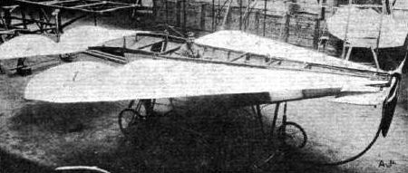
THE FLECHE MONOPLANE. - This novel machine has been constructed at Levallois to the designs of MM. Lanzi and Billard. It has two propellers, one in front and one behind, driven by a 25-h.p. motor. It is 8 metres long, 6 metres span, and weighs 290 kilogs. in running order. The chassis has 4 wheels and skids. The wings have stabilising flaps.
Flight, October 22, 1910
IMPRESSIONS OF THE PARIS SHOW.
By OISEAU.
<...>
M. Maurice Farman has discarded the vertical planes once fitted by him, and the skids on his machine are now continued until they join the elevator, as on the Sommer.
<...>
Flight, November 5, 1910
FOREIGN AVIATION NEWS.
Flying for a Quarter of a Day.
WITH the approach of the end of the year and the closing of the annual competition for the Michelin Cup, the competition for the world's duration record suddenly becomes active. We mentioned last week that Tabuteau had flown over to Etampes from Buc in order to spy out the land with a view to attacking the world's records. Everything was ready on Friday, and at 9 o'clock in the morning he started off on his Maurice Farman biplane. Around and round his course he flew for 6h. 1m. 35s., when he landed after having covered 465 kiloms. (290 miles), about as far as from London to Carlisle. In the course of this trip his 8-cyl. Renault consumed 190 litres of petrol, and 20 litres of lubricating oil. The old world's record was that of Olieslaegers, who at Rheims flew 244.309 miles in 5h. 3m. 5 1/5s.
Flight, November 19, 1910
AEROPLANE SILHOUETTES FROM THE PARIS SHOW.
THE MAURICE FARMAN BIPLANE.
FRENCH-BUILT biplane with forward elevator working in unison with elevator on tail. Planes double-surfaced throughout. All control wires duplicated. Similar in type to the Henry Farman biplane. Holds at the present time world's record for duration of flight. Maurice Tabuteau on an M. Farman biplane with Renault motor flew at Etamps for 6h. 1m. 35s., covering 465 kiloms.
General dimensions. - Bearing surface, 50 square metres; length overall, 12745 metres; width, 11 metres.
Seating capacity. - Two, one behind the other.
Engine. - Renault, 8 cylinders, V type, air-cooled of 60-h.p.; weight, 170 kilogs. Propeller is mounted on the cam-shaft. Any motor fitted.
Propeller. - One Chauviere Integrate of two branches, 2.75 metres to 3 metres in diameter; pitch, 1.60 metres; normal revolutions, 900. Situated behind main planes.
Chassis and skids. - The two skids are continued forward and upward until they join the front elevating plane. Two wheels are fitted, with spring suspension, to the skids, and are joined by a light axle.
Tail. - Biplane tail having two rudders hinged to the rear struts of the cellule. Elevators are attached to the trailing edges of both tail planes, and are connected with and operate simultaneously with the front elevator.
Lateral stability. - By ailerons fitted to the trailing edges of both the upper and lower planes.
Weight. - Without motor, 250 kilogs.
Speed. - About 80 kiloms. an hour.
System of control. - By a wheel at the end of a horizontal shaft, moving in a sleeve, and mounted on ball-bearings. Pulling the wheel elevates the machine; pushing depresses the elevator. Rotation to the left depresses the right ailerons, and similarly rotation to the right affects the left ailerons. Foot pedals control the rudders.
Price. - Without motor, 14,000 francs; with 60-h.p. Renault, 28,000 francs.

From the above side view of the latest biplane built by Mr. Maurice Farman it will be seen that the design has been considerably simplified. A noticeable feature is the boat arrangement which shields the aviator from the wind.
AT THE HAVRE FLIGHT MEETING. - Barra, on his Maurice Farman, circling the aerodrome. In the distance, on the left, is seen a Bleriot in flight.
PARIS FLIGHT SALON. - General view of the centre of the Grand Palais. On the right is seen the Wright biplane, on the left the Maurice Farman biplane, just beyond being the Henry Farman machine, whilst in the foreground, in the centre, is the two-seater Antoinette monoplane.

Maurice Farman control at the Paris Flight Salon. - The pedals are used to actuate the ailerons, the wheel is turned for steering and moved backwards and forwards for elevating and depressing.
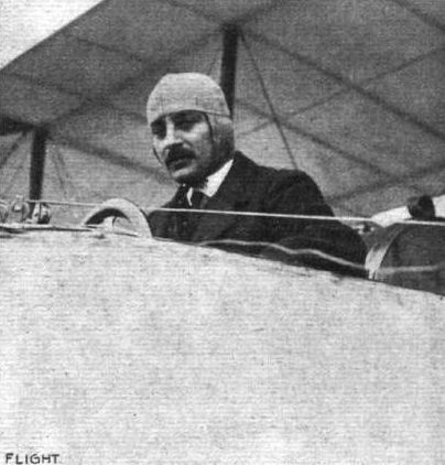
M. Tabuteau, who last week at Etampes, on a Maurice Farman machine, made the magnificent new world's record distance and duration flight in his flight for the Michelin 1910 Prize.
M. Tabuteau, the winner of the French Michelin Aviation Cup for 1910. - He covered approximately 365 miles in 7 hrs. 4.8 mins. on his Maurice Farman biplane, Renault motor.
M. Tabuteau, the winner of the French Michelin Aviation Cup for 1910. - He covered approximately 365 miles in 7 hrs. 4.8 mins. on his Maurice Farman biplane, Renault motor.
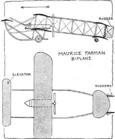
Flight, May 21, 1910
Practice at Issy.
M. BLERIOT has once more commenced flying at Issy, and was out as well as Leblanc on Saturday last, trying some new machines. On the 12th inst. Lieut. Bier made some satisfactory trials with the new Montgolfier monoplane.
Flight, May 28, 1910
Flying at Issy.
ONCE more the flying ground is resuming an animated appearance. On the 19th, Leblanc had the new Bleriot out, and covered three circuits of the ground at a height of 20 metres. The same day, Duclos, Thorms and Molleuf were practising on Bleriots, Maurice Clement and Audemar were trying their Demoiselles, Anzani was testing his biplane, Lieut. Bier was testing the Montgolfier monoplane preparatory to sending it to Budapest, and Andre Frey was flying on his Sommer biplane. These same flyers were out on the next day, and were added to by Temain who was flying at Wembley Park some time ago on a Bleriot, and Bunau-Varilla on a racing Voisin. On Saturday, Anzani was trying a Saulnier monoplane, which is fitted with a 50-h.p. Anzani engine; Vitzig was testing a monoplane with two propellers, Contenet was out on the Vendome monoplane, while Sasles was instructing two pupils in the use of the Zenith aeroplane.
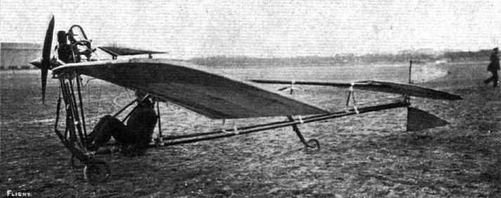
The new French monoplane, "Montgolfier," with Lieut. Bier in the pilot's seat, who has recently been making some successful flights with this 25-30-h.p. Anzani-englned machine.
Flight, July 16, 1910
NOVEL MACHINES AT RHEIMS.
BY HANDLEY PAGE.
<...>
Of the other monoplanes, the Werner, driven by Pischoff, and the Nieuport are distinct types of their own.
The Nieuport monoplane, with its rectangular-shaped, covered-in body, has the engine very neatly mounted in the "bows." The front of the body, about 2 ft. square, is finished quite flat and end-on to the wind, but the main spars are carried through and bent, so that the top and bottom ones on either side meet. The horizontal opposed two-cylinder motor used has a pressed steel ring fitting on each cylinder, and these rings fix on to the projecting ends of the main spars. The latter are bound round with tape to strengthen them. As in some of the Bleriots, there is a small inspection-door at the side of the body.
The "spring axle" arrangement has been adopted for the chassis. The body is carried in three steel tube V's with parallel tops, the parallel parts at the side of the body, the points of the V's being fixed to a long tubular skid below the body. The axle, made up of three "leaves," is about 5 ft. long, and carries at each end two wheels about 15 ins. in diameter. It is fixed in a small fitting at the bottom of one of the upright V tubes.
<...>
Flight, December 17, 1910
AEROPLANE SILHOUETTES FROM THE PARIS SHOW.
THE NIEUPORT MONOPLANE.
FRENCH-BUILT monoplane. Made its first appearance at the Rheims Meeting, 1910. Planes double - surfaced throughout. Entire fuselage is covered in with fabric. One of the lightest and most efficient aeroplanes on the market.
General dimensions. - Bearing surface, 14.9 metres; length overall, 7.50 metres; span, 8.40 metres.
Seating capacity. - One or two seats.
Engine. - 20-25-h.p. 2-cyl. horizontal opposed air-cooled Darracq motor. Normal revolutions, 1,200. The 5-cyl. 40-h.p. Anzani or the 50-h.p. Gnome can be fitted at an increased cost, as shown below.
Propeller. - Chauviere Integrate. Diameter, 2 metres. Pitch, 1.20 metres. Effective revs., 1,200.
Wheels and skids. - Two wheels connected by a flexible leaf spring. A single skid is placed centrally curving forwards and upwards.
Tail. - Non-lifting fin extending to elevator, which is in two parts to allow single rudder placed centrally to work freely.
Weight. - Complete with engine, 250 kilogs.
Lateral stability. - Maintained by flexing the trailing edges of the wings. The wings are connected by a patented arrangement by which one wing automatically alters the curvature of the other wing when under undue pressure, thereby maintaining stability to some degree.
Speed. - 75 kiloms. an hour.
System of control. - The flexing of the wings for the maintenance of lateral stability is performed by two independent pedals, each controlling owe wing. A wheel control actuates the rudder, and the backward and forward movement of a lever works the elevator.
Price. - Two-seater, with Darracq 20-h.p. motor, 18,000 francs. Two-seater, 40-h.p. 5-cyl. Anzani, 22,000 francs. One-seater, 50-h.p. Gnome, 24,000 francs. Two-seater, 50-h.p. Gnome, 26,000 francs. Any engine can be fitted if required.

The Nieuport monoplane, which was successfully flown by its constructor at Rheims Meeting. - It is fitted with a 20-h.p. 2-cyl. Darracq engine. Inset the Nieuport monoplane in flight.
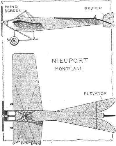
Flight, October 29, 1910
IMPRESSIONS OF THE PARIS SHOW - (continued).
By OISEAU.
<...>
Messrs. Turcat-Mery and Rougier have designed a biplane of the later type developed by Breguet and Goupy amongst others. The tendency towards reducing the area of the main planes is here clearly demonstrated. The four-branched propeller, also of Turcat-Mery design, is placed in front of the machine, and is driven by a 60-80-h.p. E.N.V. motor. The tail plane, with which is combined the elevator, has underneath it two rudders. The control is by a wheel mounted on a pivoted pillar actuating the elevating and wing-flexing wires, and a foot-bar for steering. To the excellent two-wheeled chassis of this machine is fitted a brake which acts on the ground itself, and is worked by a lever at the pilot's right hand. A pathetic interest is attached to the Turcat-Mery, as not only was it designed by a pilot, Rougier, whose accident at Nice has incapacitated him from further flying, but it was to have been flown by the unfortunate Chavez had he lived. There is, however, to all appearances, a successful future before it.
<...>
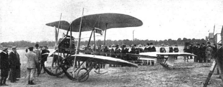
The latest Odier-Vendome monoplane which is to be used by Rougier. It is fitted with a 60-h.p. 8-cyl. E.N.V. engine.
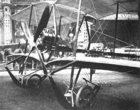
The Turcat-Mery-Rougier biplane, showing the chassis and landing skids and the four-bladed propeller, at the Paris Flight Salon.
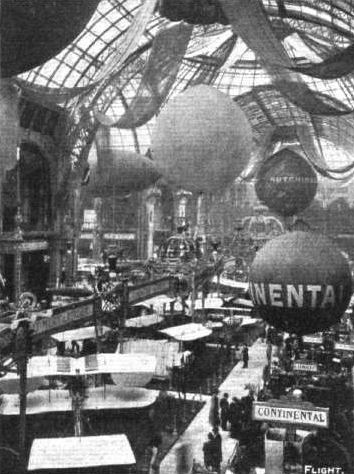
General view, down the centre, of the Paris Flight Salon. - In the foreground is seen the Turcat Mery-Rougier machine and the Compagnie-Aerienne stand also, prominent aloft being the small spherical balloon over the "Continental" exhibit, the Hutchinson "Astra" balloon, and on the left the nose of "Zodiac III."
Flight, October 22, 1910
THE PAULHAN BIPLANE.
CONSIDERABLE interest attaches to Paulhan's machine a voler, as he prefers to call it, both because of its constructor's great reputation as an aviator of the highest class and because of the originality of the design. One is anxious to find out from it the secrets taught by experience to an expert and observant aviator, and to see if possible how such teaching differs, if at all, from that of abstract theory.
Superficially, the most striking feature is the method employed шn the construction of the framework, a method which at once shows the connection of Henri Fabre with the design. The fuselage and the leading edges of the planes are of a built-up lattice-work of great strength, thus doing away with the majority of the customary wire stays.
The machine is a biplane fitted with a forward elevator and single-plane stabilising tail, in front of which appears the rudder. The main planes lie midway between the elevator and tail, and are divided into three sections, the centre one of which is stationary, the two outer ones being connected in such a way that the angle of one or other of the sections can be altered for the purpose of maintaining lateral stability.
The construction of the wings is very interesting. The entering edge consists of a beam made by the insertion of a kind of lattice work between two strips of ash of about 6 ins. in width, the ends of which approach each other. In the centre of the plane the two strips are 6 ins. apart. From this beam spring the ribs, each fastened by an ingenious clip, which can be released readily when the replacement of broken spars is necessary, or if it is desired to alter the curvature of the wing. Over these is spread the canvas, each rib sliding through a pocket. The canvas is attached to the trailing edge end of the ribs by tiny hinged spring-clips. It is thus possible to remove the entire canvas covering, if a hangar is not available during rain, or when making long journeys far from houses and spending the night in the open, or if it be necessary to alter the wing area. Four wooden stanchions are fitted between the beams of the main planes, and to the centre pair are clipped the beams which run fore and aft to carry the elevator in front and the horizontal tail behind. To these central stanchions are also attached the pillars at the rear of the landing skids. For nearly all these flexible joints and for the hinges of the elevator and tail M. Paulhan has introduced a neat arrangement in which a strip of chrome leather bears all the movement.
One very interesting part of the design is that the nacelle, which carries the motor and propeller, the petrol tank, and the seats tor pilot and passenger (side by side), and on the forward end of which is mounted the controlling wheel and levers, is rigidly suspended between the main planes by steel cables from top and bottom of the central stanchions. It is claimed that this method of attachment is exceptionally light, and facilitates the mounting and adjustment of the motor. The vertical rudder, which, as we have said, is placed just in front of the horizontal tail, is also attached to the rear end of the outriggers in the same way. At the foot of the vertical beam carrying the rudder is a wooden skid, which can be operated by a cable from the pilot's seat to act as a brake.
The control is by wheel, mounted on a shaft, the backward or forward movement of which works the elevator. For steering, the wheel is rotated and a right or left movement of the entire control alters the angle of the wing sections.
The angle of the tail, which is hinged to the frame, can be readily adjusted on the ground by the movement of levers up and down a slotted bar, mounted on the rear end of the outrigger, as in one of the accompanying photographs.
M. Paulhan fits the Gnome motor and Normale propeller as standards.
The landing chassis resembles that used on the Farman machine in many ways, but it has some useful original points. The skids are connected in front to the elevator outriggers by the chrome leather hinge-clips and wooden rods.
The strength of the construction is incontestable, and the expenditure of thought is obvious, but as yet one knows nothing of the flying capabilities of the appareil.
The rights for Great Britain and the Colonies are vested in Mr. Holt Thomas, and the appearance of the novel aeroplane on this side of the Channel will be awaited with great interest.
Flight, November 12, 1910
Trial of the Paulhan Machine.
PILOTED by Caille, the new Paulhan biplane was out on Saturday for trial at St. Cyr, and was in the air altogether for about an hour and a half.
Flight, December 3, 1910
BRITISH NOTES OF THE WEEK.
Tests with the British Army Paulhan Machine.
SEVERAL very good trial flights have been made recently by the Paulhan biplane purchased by the British Government. On Saturday last Caille twice made cross-country trips from St. Cyr to Buc and back, while later in the day he carried out a series of altitude tests.
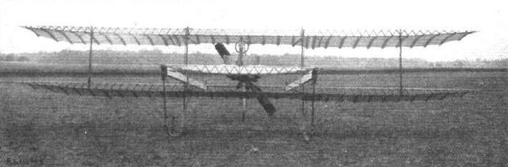
PAULHAN'S NEW BIPLANE. - View from in front.
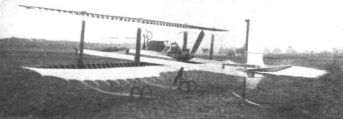
PAULHAN'S NEW BIPLANE. - General view from behind. The surface area of the planes can be altered in a few minutes.
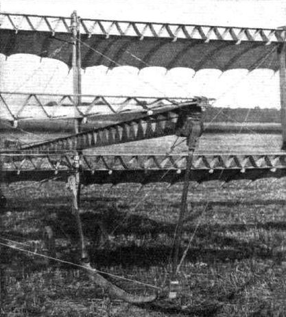
In this view ot the Paulhan biplane the girder construction details ol the front of the planes and the leather attachments employed for all joints can be seen.
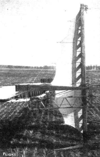
Detail view of the wooden rudder on the new Paulhan biplane.
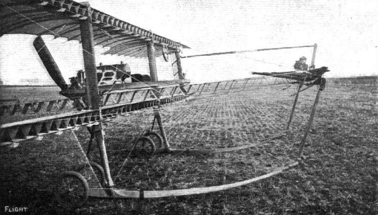
The skids, elevator, pilot's seat and steering-gear of the new Paulhan biplane are seen in this photograph.
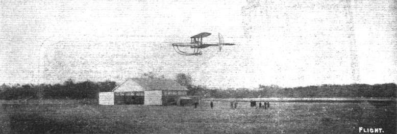
The new Paulhan biplane making a flight at St. Cyr last week.

Paulhan biplane flying well at St. Cyr.
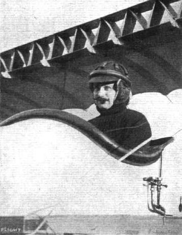
M. Caille, the first pilot to fly the new Paulhan biplane.
Flight, July 16, 1910
NOVEL MACHINES AT RHEIMS.
BY HANDLEY PAGE.
<...>
Of the other monoplanes, the Werner, driven by Pischoff, and the Nieuport are distinct types of their own.
The main planes of the Werner machine are carried on the top of an open fuselage, which tapers to the tail plane in the rear. The engine is carried low down in the front, and drives through a long shaft, sprocket wheels and chain, a large propeller fixed at the rear of the plane. Below the plane also, and at the back of the engine, are the two seats for pilot and passenger. The whole machine is brightly finished with a glossy aluminium paint that would make one feel chary of sitting in it with new clothes on. The aeroplane flies well, and seemed to turn the corners fairly easily, in spite of its very low centre of gravity, which should make this somewhat difficult. The "tip-up" of the wing-ends is very noticeable when in flight.
<...>
Flight, November 19, 1910
AEROPLANE SILHOUETTES FROM THE PARIS SHOW.
DE PISCHOFF MONOPLANE
FRENCH-BUILT monoplane with seats, engine, and landing-chassis placed beneath the main plane. This machine was designed and experimented with in Austria, but has since been developed in France.
General dimensions. - Total bearing surface, 27 square metres; length, 9 metres; width, 11 metres.
Seating capacity. - Two, seats placed side by side.
Engine. - Daimler (Austrian) 4-cyl. vertical, 60-70 h.p., watercooled. Engine and radiator placed in front as on motor car, a driving-shaft and clutch intervening between the engine and sprocket-wheel driving the propeller. E.N.V. and Gnome motors also fitted.
Propeller. - Designed by M. de Pischoff; of two branches. It is placed behind the main planes, and is driven by chain from a sprocket-wheel on the propeller-shaft.
Chassis and skids. - The chassis is very similar to that of a motor car, with the radiator mounted in front of the engine. The long skids are practically prolongations of the lower members of the main frame, and are fitted at their forward ends with auxiliary skids to take sudden shocks. Two wheels are fitted below the tail. Lateral stability is maintained by the flexing of the trailing edge of the wings.
Tail. - Elevation is regulated by the movement of sections of the tail. Double rudders are fitted, and above them is a small triangular fixed tail plane with vertical fins both on the upper and under sides. The tail is of the lifting type.
Weight. - Complete with engine, 360 kilogs.
Speed. - 85 kiloms. an hour.
System of control. - By a single lever placed in front of the pilot. A backward movement raises the aeroplane, a forward depresses the machine, a right-hand action flexes the left wing, and a left-hand does the opposite. A foot-pedal controls the double vertical rudders.
Price of two-seater, with 60-70-h.p. Daimler (Austrian) motor, 27,000 francs.
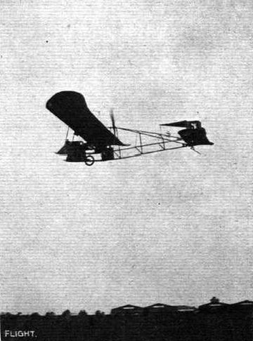
De Pischoff in flight on the Werner monoplane during the Rheims Meeting.

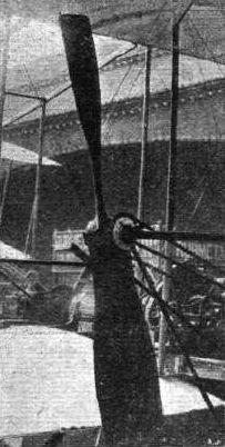
A curious feature of the propeller on the Pischoff biplane is the lip formed on the periphery of the blade, which thereby somewhat resembles a big wooden spoon.

On the R.E.P. monoplane the propeller forms a four-bladed tractor-screw in front.
Flight, October 29, 1910
IMPRESSIONS OF THE PARIS SHOW - (continued).
By OISEAU.
<...>
Another aeroplane, though not of recent initial design, is so altered as to make it almost a new type - the R.E.P. M. Esnault-Pelterie, one of the pioneers of aviation, has, until the last few months, stolidly refused to depart from his early individualistic ideas of how to design a flying machine, with the inevitable consequence that success rarely came his way. Profiting by his own failure to fly really well, and by the experience of others, he has at last allowed sufficient of conventional design to enter into his machine that it has now become of the first rank. A chassis has been added, perhaps a little too closely resembling the Antoinette in superficial appearance to entirely please my fancy, and yet greatly in advance of the one-wheel carriage. The tail, too, has the usual elevator and rudder in place of one confusedly arranged that warped in various curious directions. The wings are stayed by wire cables, as on other monoplanes, and lateral stability is maintained by gauchissement and not by the altering of the entire wing angle. One of the new type R.E.P. 5-cyl. 55-h.p. engines is fitted, driving a two-branch wooden propeller in place of the four-bladed metal propeller used until recently. The entire aeroplane is covered in scarlet "Continental" canvas, therefore appealing greatly to the aesthetic taste of those to whom appearance counts before all things.
<...>
Flight, December 3, 1910
A Record by the R.E.P.
A NOTABLE performance was accomplished at Buc on Sunday by Laurens when he took out the new R.E.P. two-seater for its first trial. Accompanied by his young wife, Laurens flew for two minutes over the hour, during which time he set up new passenger speed records for distances up to 80 kiloms., and covering 79 kiloms. in the hour. For the sake of comparison we reproduce below the old figures and the new, from which it will be seen that the improvement is a very decided one. Both Laurens and his wife are to be congratulated on this result, especially as the cold and mist made their experience a very trying one.
Flight, December 10, 1910
AEROPLANE SILHOUETTES FROM THE PARIS SHOW.
THE R.E.P. MONOPLANE.
A FRENCH-BUILT monoplane. Framework of steel tubes covered with Continental aeroplane fabric, coloured red. Planes double-surfaced throughout. M. Robert Esnault-Pelterie, the designer and constructor of both the aeroplane and the engine bearing his initials, though yet but a little over thirty, was one of the earliest successful pioneers of mechanical flight.
General dimensions. - Length overall, 9.500 metres; width, 12.800 metres; height, 3 metres; length of each wing, 6.300 metres; breadth of each wing at widest point, 2.500 metres; total bearing surface, 25 square metres.
Seating capacity. - One or two seats.
Engine. - 50-60-h.p. 5-cyl. semi-radial R.E.P. Normal revoluions, 1,000.
Propeller. - Normale. Two-bladed in wood, 2.60 metres diameter.
Wheels and skids. - Two wheels with single central hollow wooden skid. Whole chassis carefully sprung.
Tail. - Non-lifting tail plane with elevator hinged to trailing, edge, divided to admit of the rudder working in the centre. The rudder is similarly divided to allow for the working of the elevator.
Lateral stability. By flexing the trailing edges of the mainplanes.
Weight. - With 50-60-h.p. R.E.P. motor, 480 kilogs.
Speed. - 90 kiloms. an hour.
System of control. - By means of two levers situated on opposite sides of the pilot. The left-hand lever when moved backwards elevates the machine, and vice versa. A sideways movement to the left depresses the right wing, and to the right the left wing. The right-hand lever, if moved to the right, steers the machine in that direction, and the opposite movement steers to the left.
Price. - With 50-60-h.p. R.E.P. engine, 29,000 francs. No other engine is fitted, and the aeroplane is not supplied without a motor.
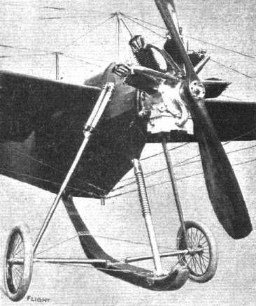
Details of the landing-skid and chassis, engine and propeller of the R.E.P. monoplane at the Paris Flight Salon.
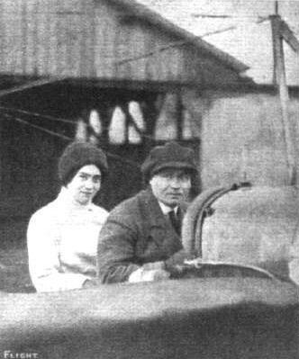
M. Laurens and his wife, who, as recorded in FLIGHT last week, put up a new record on his R.E.P. monoplane by flying with his passenger a distance just under 80 kiloms. in the hour.
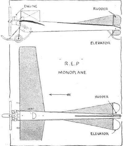
Flight, March 19, 1910
Doings at Issy.
VERY little has been doing at Issy during the past week or so. MM. Busson and Noel have been trying their Bleriots, and M. Jacques de Lesseps has been making further experiments with the "Fregate," illustrated in our issue of the 26th ult. Mdlle. Dutrieu is continuing her lessons on the "Demoiselle," while the brothers Regy have been experimenting with a monoplane built to their design by Messrs. Peugeot.
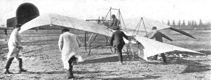
"La Fregate" monoplane, fitted with 30-h.p. 3-cyl. Anzani motor, and piloted by M. Robert De Lesseps.
Flight, March 12, 1910
THE SECOND OLYMPIA AERO SHOW.
AEROPLANES.
Santos-Dumont.
REPLICAS of the little "Demoiselle" monoplane built in France by Mons. A. Clement. A fully-illustrated description, with scale drawings, appeared in our issues of October 2nd and 9th last. It is fitted with a two-cylinder water-cooled motor, and the weight complete is about 110 kilogs. The overall measurements are 6.2 metres long and 5.'5 metres wide.
Flight, April 9, 1910
FLYER SILHOUETTES FROM OLYMPIA
SANTOS-DUMONT "DEMOISELLE."
Leading Particulars of the Santos Dumont "Demoiselle"
General Dimensions.-Areas-Main planes, 108 sq. ft.; elevator, 12 sq. ft.; rudder, 7 sq. ft.
Lengths.-Span, 18 ft.; chord, 6 ft. 6 ins.; camber, 3 ins.; skid track, 3 ft. ; overall length, 21 ft.
Angle.-Incidence, 7 degs.; dihedral, 1 in 11.
Propeller.-Diameter, 6 ft. 6 ins.; pitch, 2 ft. 6 ins.
Engine.-32-h.p. Clement.
Weight.-Total flying weight, 530 lbs.; loading (all weight supported on main planes), 4.9 lbs. per sq. ft.
Speed of Flight.-40 m.p.h.
System of Control.-Warping of main planes, combined rudder and elevator.
Price.-L300.
A COPY of the original Santos Dumont model, built with a steel triangular frame and other details of construction as described in FLIGHT, Vol. I, p. 604. One of the special features is the fitting of tubular radiators underneath the wings. The engine on this machine is a horizontal twin-cylinder Clement. The pilot sits underneath the wings. Wing warping is effected by a lever temporarily attached to the pilot's back by a strap. The pilot leans over towards the wing that has been raised by the wind gust in order to restore equilibrium.
In leaning in this direction he reduces the camber of the raised wing, and increases the camber at the extremity of the wing that is depressed, consequently the lift of the depressed wing becomes greater than that of the other wing.
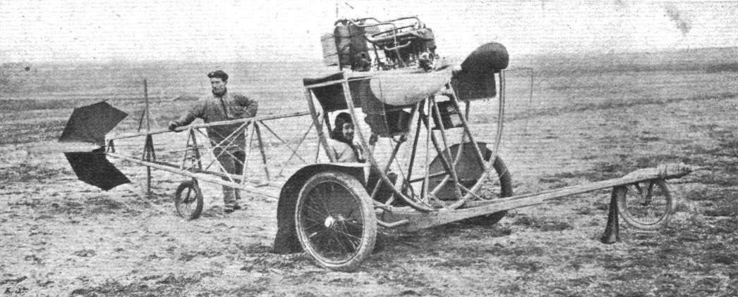
Messrs. Clement-Bayard, who are constructing the Santos Dumont "Demoiselle" machines, have devised the above ingenious apparatus for the better teaching of novices in the handling of these small flyers. Several ladies are already learning the art of flight in connection with these machines, and an extensive output is likely to result very shortly.
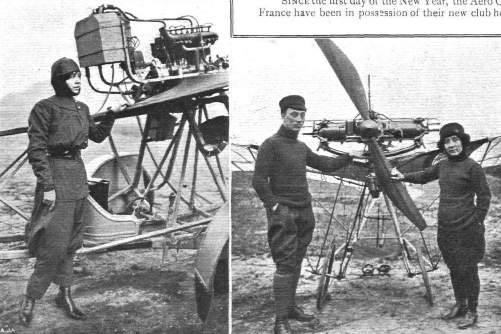
Two of the lady novices who are learning to fly on the Santos Dumont "Demoiselles.'' On the left is Mdlle. Dutrieux, in her special aviation costume, standing by the side of the Clement-Bayard novices' apparatus, and on the right are Mdlle. Aboukaia and Mr. Tod Lane in front of a complete "Demoiselle" flyer. Mdlle. Aboukaia is well known professionally in Paris and other cities for her daring feats In the past in connection with "looping" on a bicycle (1904) and taking a plunging leap "en automobile" (1906).
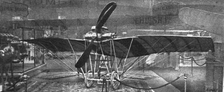
A genuine Santos-Dumont "Demoiselle" exhibited on the Clement-Bayard stand.
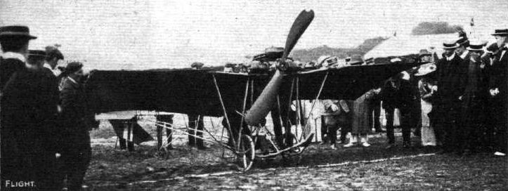
Audemars starting for one of his trips on the "Demoiselle," alias "Angry Wasp."
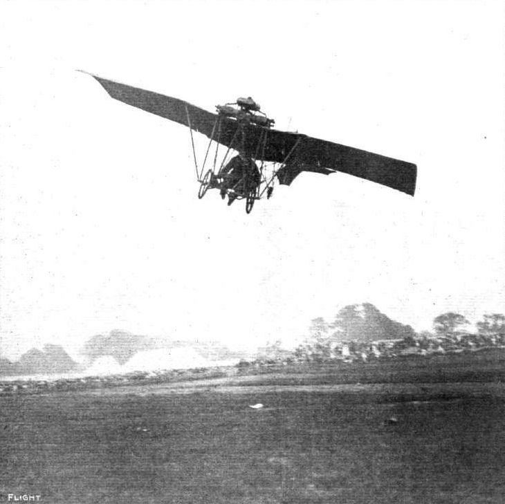
A characteristic turning swoop of Audemars on his "Demoiselle," alias the "Angry Wasp," during the Bournemouth Aviation week.
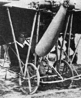
THE FLYING MEN AT BOURNEMOUTH AND THEIR "MOUNTS." - E. Audemars (Demoiselle).
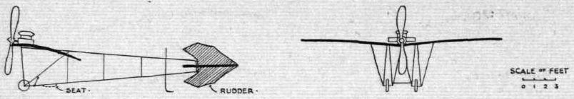
WING SECTIONS. - The above diagrams afford an interesting comparison of the wing sections of aeroplanes exhibited at Olympia. They are all drawn to a common scale, but have been set at an arbitrary angle of incidence, which does not necessarily represent that of the aeroplane In actual flight.
Flight, July 16, 1910
NOVEL MACHINES AT RHEIMS.
BY HANDLEY PAGE.
<...>
Of the biplanes, the Savary, Goupy and Breguet have several new features.
The Savary has a triangular-shaped open body, something like the skeleton of a boat, fitted underneath the planes, and extending about 6 to 8 ft. in front of them. This acts as a skid in landing, and to it the wheel and spring arrangement is fixed. The engine is on top of it, at the front edge of the lower plane, and drives through chains a propeller on either side, in front of the planes. The reduction in speed did not appear to be # judging by the size of the chain wheels # as large as might have been to give the best results with the propellers.
The tail at the end of framework projecting at the rear has a horizontal plane only. The machine is steered by vertical planes at either end of the main plane. Two of these are hinged at each end at the same point, and open out at an angle with one another when they are used.
<...>
Flight, October 1, 1910
M. POILLOT.
ANOTHER fatal accident has occurred in France, this time with a type of biplane against which no serious accident had been recorded hitherto. This is the Savary, a characteristic feature of which is the system of two propellers. The victim was Edmond Poillot, who forsook journalism a few months ago to take up aviation, and had made many successful flights with the Savary machine. On Sunday morning, at Chartres, he had carried out four trips with pupils, and then started off on a fifth trial with another pupil, Partiot. He rose to a height of 80 metres, and was circling the grounds, when the machine was seen to tilt suddenly and fall to earth. Both the occupants were thrown out, Poillot with such force that his back was broken, so that he was killed almost instantly. Partiot, luckily, was only slightly injured. No explanation is forthcoming as to the cause of the accident, but it is surmised that it came about by a treacherous gust of wind.
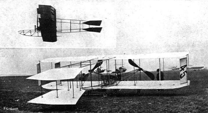
SAVARY BIPLANE PILOTED BY FREY AT RHEIMS MEETING. - Two tractor screws are employed, and a chain-driven 8-cyl. E.N.V. engine. Inset Frey is seen in the air on the Savary biplane.
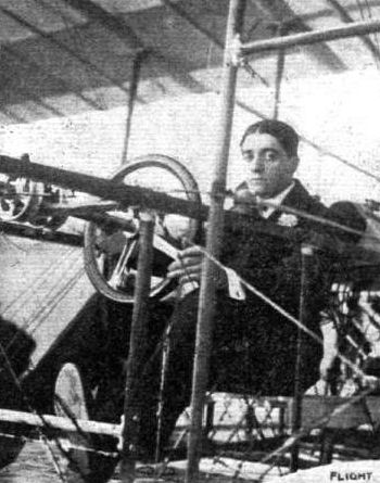
M. Poillot, who was last week killed at Chartres.
Flight, October 29, 1910
IMPRESSIONS OF THE PARIS SHOW - (continued).
By OISEAU.
<...>
M. SOMMER again shows a biplane which in no way differs from his previous models, but there also appears on his stand a monoplane which has during the past few months made some successful cross-country flights. It follows in appearance the conventional lines of the average monoplane, but differs in one or two matters of detail. The fusellage is of the Bleriot type now so commonly employed, and the tail is weight carrying, though with the elevator hinge on to the trailing edge. The angle of inclination of the tail plane can be altered at will by the pilot by means of a wheel fixed by his left hand. This fitting has been copied direct from the Sommer biplane. The control-lever and the chassis also closely resemble those of the biplane. As one might expect, the Gnome motor is fitted.
<...>
Flight, December 24, 1910
AEROPLANE SILHOUETTES FROM THE PARIS SHOW.
THE SOMMER MONOPLANE.
CONSTRUCTED at Mouzon, in the Ardennes, by Roger Sommer, whose biplane is already well known. Double-surfaced planes. Framework of wood. Has passed its trials satisfactorily.
General dimensions. - Length overall, 9 metres; width, 10.50 metres; bearing surface, 17 square metres.
Seating capacity. - One.
Engine. - 50-hp. 7-cyl. air-cooled rotary Gnome.
Propeller. - Rapid, of two blades.
Chassis. - Similar to that employed on the Sommer biplane. Two wheels, connected by a steel axle and fastened by rubber springs to a simple wooden chassis, the lower members of which form two skids curving forwards and upwards. Under the tail is a curved wooden skid.
Tail. - Weight-lifting tail plane, the angle of which may be altered during flight by means of a series of rods and cranks leading to a small hand-wheel placed on the right side of the pilot. The elevator, which is hinged to the trailing edge of the tail plane, is divided into two sections, to admit of the single centrally-placed rudder working freely.
Lateral stability. - Maintained by the flexing of the trailing edges of the main planes.
Weight. - Complete with motor, 265 kilogs.
Speed. - 90 kiloms. an hour.
System of control. - The sideway movement to the right or left of a single vertical lever controls the flexing of the wings, whilst the backward and forward movement of the same lever elevates and depresses the machine. Steering is controlled by a foot-lever. All control wires are duplicated.
Price. - Complete with 50-h.p. Gnome, 20,000 frs.
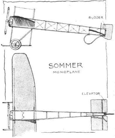
Flight, March 12, 1910
THE SECOND OLYMPIA AERO SHOW.
AEROPLANES.
Sommer.
BIPLANE, designed and built by M. Sommer as a result of his successful experience with a biplane of the Henry Farman type. It is exhibited by the Hon. C. S. Rolls.
Flight, April 23, 1910
FLYER SILHOUETTES FROM OLYMPIA.
THE SOMMER BIPLANE.
Leading Particulars of the Sommer Biplane.
General, Dimensions.-Areas-Main planes, 456 sq. ft.; tail, 67.5 sq. ft.; elevator, 45 sq. ft.; rudder, 9 sq. ft.
Lengths.-Span, 34 ft.; chord, 6 ft. 8 ins.; gap, 6 ft.; skid track, 9 ft.; camber, 4 ins.
A BIPLANE of the Farman type characterised by a monoplane tail and a very small biplane rudder situated immediately beneath the tail plane. The machine is mounted upon wheels and skis, the latter members being carried right forward to join the outrigger upon which the elevator is mounted. As on the Farman biplane, lateral equilibrium is maintained by the manipulation of flaps inset in the trailing edges of the main planes. These flaps, however, are of different shape to those used on the Farman machine, and they are only introduced into the upper deck.
An important characteristic of the Sommer biplane is the mounting of the tail plane so that its angle of incidence can be altered during flight. For this purpose a wheel is provided adjacent to the pilot's left hand. The control of the elevator and the balancing flaps is accomplished by a single vertical lever situated immediately in front of the pilot's seat. The control of the rudder is effected by a pivoted foot-rest. These latter features are similar to the original Farman design.
Some of the minor details of construction on the Sommer biplane are very interesting. The machine is mounted on a wheel and ski chassis, and only one pair of wheels is used, these being mounted on a tubular steel axle that passes between the skis to which it is lashed by elastic springs. The wheels are mounted inside the skis, and have a certain amount of lateral freedom upon the axle. Their normal position is defined by buffer-springs situated on either side of each hub. The axle is trussed by wires passing through holes drilled near the periphery of a disc mounted on the centre of the axle. The principal struts used for attaching the skis to the main spars of the machine have rubber pads inserted under their lower extremities in order to deaden the shock.
Flight, April 30, 1910
Four on an Aeroplane.
GRADUALLY but surely the capabilities of the aeroplane as regards weight-lifting are being evidenced in an extraordinary way. When Henry Farman at the Rheims Meeting last year carried two passengers besides himself on his machine it was deemed a splendid achievement, but Sommer at Mouzon on Wednesday of last week completely put this in the shade by flying with three passengers, one of them a lady. True, the flight was only a short one of five minutes duration, but during that time he passed over the village of Remilly. The weight carried during the five-mile trip was
M. Sommer = 138 lbs.
Mdlle. Dutrieux = 102 ,,
M. Colombo = 138 "
M. Frey = 132 "
Machine complete with motor and petrol = 550 lbs
Total 1,060 ,,
Mdlle. Dutrieux Carries a Passenger.
HAVING mastered the details of her Sommer biplane, and made several short quarter-hour flights by herself, Mdlle. Dutrieux, on the 20th inst., flew with a passenger for about six minutes over the Douzy fields near Mouzon. This "aviatress" hopes to take her machine to Russia soon and give exhibition flights there.
Flight, July 2, 1910
French Army has a Sommer Biplane.
AFTER a trial trip lasting 2 hrs. 10 mins., and a passenger flight of half an hour, Sommer has delivered his first military machine to the French Army. Three other Sommer biplanes, also destined for the Army, are nearly ready for delivery.
Flight, August 20, 1910
THE LATE C. S. ROLLS AND THE SOMMER.
I enclose a photo of the late Hon. C. S. Rolls on, his Sommer machine, taken at Eastchurch at the end of last April. This may be of interest, as I have not seen a photo of this machine published in any paper yet. I do not think he actually did any flying on it, as the day this was taken it was only his second day on it, and he left for Nice a few days later.
Aldershot. F. R. HARFORD.
Flight, October 22, 1910
FOREIGN AVIATION NEWS.
Military Aviation in Germany.
ON Monday afternoon three aeroplanes succeeded in flying from Johannisthal to Doeberitz Camp, situated between Berlin and Potsdam, the distance being 32 kiloms. Illner was the first to get away, and he completed the course in 35 minutes. He was followed by Jeannin and Brunnhuber, the former on a German-built Farman and the latter on a French Farman, and both of them completed the course in 31 minutes. Each aviator was accompanied by a military officer, and the tests were carried out under the observation of the military authorities. On Tuesday Mente and Thelen, on Wright machines, and Lindpaintner, on a Sommer, had to carry out similar tests, while on Wednesday all the flyers were inspected by a Military Commission which has been appointed to choose the aeroplanes for use in the German Army.
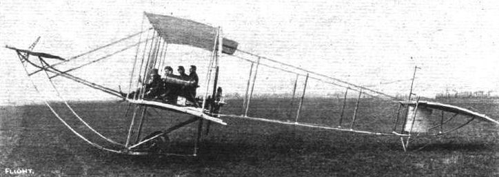
FOUR IN AN AEROPLANE. - Mons. Sommer on his Sommer biplane upon the occasion when he carried three passengers, including Mdlle. Dutrieux, in addition to himself, for a flight. It will be t remembered we gave the particulars of this Flight in last week's issue, the weight of the machine complete with its passengers totalling to no less than 1,060 lbs.
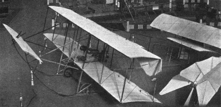
One of the most successful flyers of the day is the new Roger Sommer machine seen above, which was purchased and shown by the Hon. C. S. Rolls as one of the exhibits in the Royal Aero Club's section.
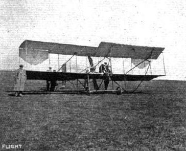
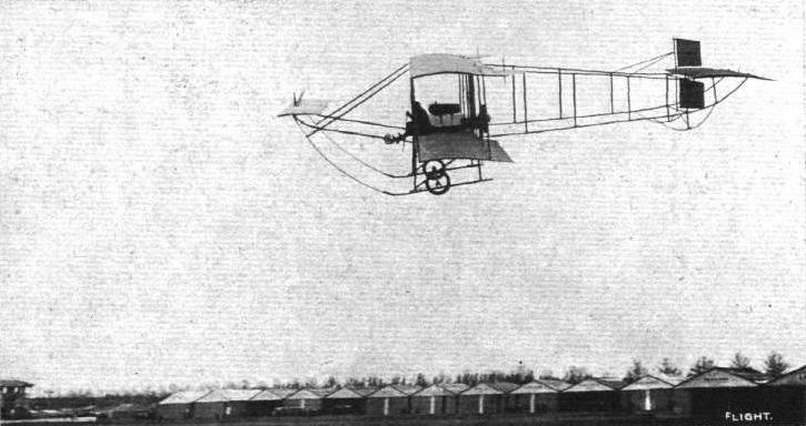
Legagneux in full flight on his Sommer biplane at the Lyons Aviation Meeting.
The exciting incident at the Lyons Aviation Meeting when Paulhan, on his Henry Farman machine, overtook Legagneux on his Sommer biplane.
IN LINE FOR THE FIRST AERIAL "RACE." - MM. Martinet (H. Farman), Mumm (Antoinette), Legagneux (Sommer), and Capt. Dickson (H, Farman), ready for the start from the Anjou Aerodrome for the cross-country race to Saumur on June 6th.

Mr. Roger Sommer's own biplane with which he made a successful flight at the Rheims Flying Grounds on June 13th. This remarkable machine, as will be noticed, is fitted with one of the Humber Co's 4-cyl. 45-h.p. motors.
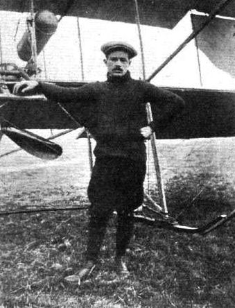
Tetard, one of the flyers who did well at the Blackpool Aviation Meeting last week.
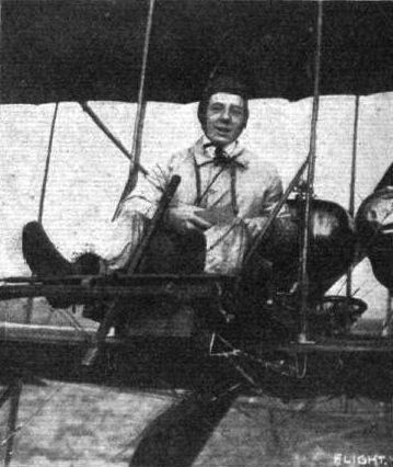
Lindpaintner, the winner of the German Minister of War's prize at the Berlin Aviation Week this month.

WING SECTIONS. - The above diagrams afford an interesting comparison of the wing sections of aeroplanes exhibited at Olympia. They are all drawn to a common scale, but have been set at an arbitrary angle of incidence, which does not necessarily represent that of the aeroplane In actual flight.
Flight, March 26, 1910
Boat Builders and Aeroplanes.
IN view of the recent tendency in motor boat design towards the hydroplane it is hardly surprising that some builders are turning their thoughts to flying machines. The Tellier works in France, which have turned out some of the speediest motor boats, are responsible for the monoplane seen in the accompanying photographs, and it is being tested by M. Dubonnet, who is famous as a helmsman of racing motor boats. The Tellier monoplane has a span of 11 metres, and the length is the same dimension, while the lifting surface is 24 sq. metres. The Panhard motor drives a Tellier two-bladed propeller and gives the machine a speed of 70 kiloms. an hour.
Dubonnet a Pilote-Aviateur.
AT its first trial the Tellier monoplane has proved itself an entire success. On the 16th inst. Dubonnet flew for 40 minutes at Draveil and on the following day for a quarter of an hour, while on Saturday last he succeeded in making the necessary qualifying flights for his Ae.C.F. certificate as pilote-aviateur.
Flight, April 9, 1910
Sixty-eight Miles Across Country.
IT is not often that a new machine has so propitious a start to its career as that secured by the Tellier monoplane. It is less than a month ago since M. Dubonnet commenced experimenting with the machine, and yet on Sunday last he succeeded in carrying off the prize of 10,000 francs (L400) offered by La Nature for the first cross-country flight of 100 kiloms. in a straight line. M. Dubonnet started from a field at Draveil, near Juvisy, where he has been trying the machine, and rising to a height of between 300 and 400 ft. he headed for Orleans, following the railway line. Passing over Arpajon he kept to the left of Etampes and Toury, went over Artenay, and passed Orleans to the right, eventually landing at La Ferte-St. Aubin, 110 kiloms. away from the starting point, after a flight lasting 1 hr. 50 mins. About 200 people, including the officials of the French Aero Club, assembled at the landing place to welcome the aviator, who, although only a tyro, had won a prize which many prominent aviators have unsuccessfully tried for. It will be remembered that two photographs of this machine, which is fitted with a Panhard motor, appeared in our issue of the 26th ult.
Flight, April 23, 1910
Flyers at Brooklands.
IT was reported some days ago that M. Dubonnet, on his Tellier monoplane, would be flying at the Brooklands meeting on the 27th inst., but although he hopes to be at Brooklands before long, M. Dubonnet will not be there next Wednesday. Several of the British aviators who are training there have, however, made good progress lately, and it is anticipated that there will be some good flying.
Flight, June 4, 1910
Dubonnet Has a Fall.
WHILE practising on his Tellier monoplane, on the 28th ult., at Draveil, M. Dubonnet met with a nasty mishap, through the sudden stopping of his engine. He was flying at a height of ten metres at the time, and as a result of the sudden drop the machine was seriously damaged, but the aviator escaped unhurt.
Flight, June 11, 1910
Tellier Monoplanes in the U.K.
THE exclusive rights for the Tellier monoplane have been secured by Mr. D. Lawrence Santoni, and anyone who is thinking of purchasing one of these machines can obtain from him at 10, Coburg Place, Hyde Park, W., a little brochure giving particulars of the machine and its performances, as well as the terms of sale, &c
Flight, July 23, 1910
Chateau now Using a Tellier.
HAVING mastered both the Voisin and Zodiac types of biplane, Chateau has now turned his attention to the Tellier monoplane. At his first attempt he made one circuit of the Draveil Aerodrome; the next day he covered two circuits, while on Saturday last he was flying several times at a good height.
Flight, July 30, 1910
Chateau on the Tellier.
AT the Tellier flying ground at Draveil, Chateau has been making several good flights on his Tellier monoplane and has obtained his pilote-aviateur's certificate. He was up for half-an-hour on the 19th inst.
Flight, October 29, 1910
IMPRESSIONS OF THE PARIS SHOW - (continued).
By OISEAU.
<...>
The Tellier Co. show a two-seater monoplane fitted with a 6-cyl. Panhard engine. It does not differ as to design from the smaller better known model. The fusellage, owing to its being of box-girder type uncovered by canvas, a method of construction not very usual in such large machines, gives the entire appareil an abnormally long, and, I think, unbalanced appearance. In truth, however, the length and width are the same, 11I metres. One expects from a boat builder of the celebrity of Tellier a perfect finish, and one certainly finds it here, combined with great strength. The control, while of the Bleriot cloche type, has a further rotary movement actuating the vertical rudders.
<...>
Flight, December 3, 1910
AEROPLANE SILHOUETTES FROM THE PARIS SHOW.
THE TELLIER MONOPLANE.
BUILT by the famous French boat-building firm. Planes double-surfaced throughout. Of excellent finish. M. Emile Dubonnet, whose name will always be associated with the early successes of the Tellier, won on his first cross-country flight a prize offered by Nature for a 100-kilom. flight from town to town. The day following he flew from the aerodrome of Juvisy across Paris to Bagatelle.
General dimensions. - Bearing surface, 24 square metres; length overall, 11.85 metres; width, 11.85 metres.
Seating capacity. - One or two-seater. The machine described is a single-seater.
Engine. - 35-h.p. Panhard, water-cooled, 4-cyl. vertical. Steel cylinders, copper water-jackets. Bore, 110 mm.; stroke, 140 mm. Weight, 100 kilogs. Revolutions, 1,000. Petrol consumption at normal revolutions, 14 litres an hour. Silencer is fitted if required.
Propeller. - Tellier, 1,000 revs.
Landing chassis. - Two wheels, mounted with springs in front, with a small wheel placed in front of the tail. The two front wheels are so arranged that they adapt themselves to any unevenness in the ground on which the machine lands.
Tail. - Fixed non-lifting tail-plane with fixed vertical fin over it. Elevating-plane fixed to the trailing edge of tail-plane. Single rudder fixed centrally above.
Lateral stability. - By flexing the trailing edges of the main planes.
Weight. - Complete with motor, 400 kilogs.
Speed. - About 85 kiloms. an hour.
System of control. - By steering-wheel mounted on a column in front of the pilot. A rotary movement of the wheel controls the rudder. A sideway movement of the entire column to the right or left flexes the left or right wing. A forward movement depresses the machine, and a backward movement elevates.
Price. - With 35-h.p. 4-cyl. Panhard engine, 25,000 francs. A large two-seated model, known as the "Type Militaire," and fitted with a 50-h.p. 6-cyl. vertical Panhard engine is also built.
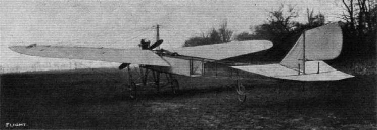
View from the rear of a monoplane which has been built by the Tellier Co., the famous builders of French racing boats. The arrangement of the tail and rudder presents some novel features. It is being tested by M. Dubonnet, another well-known name in motor boating circles.

LATEST TELLIER MONOPLANE, SEEN FROM IN FRONT AND FROM BEHIND. - Mr. D. L. Santoni is in the pilot's seat.
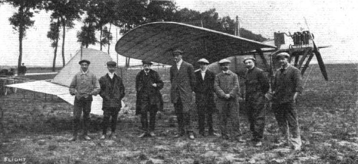
AT THE TELLIER SCHOOL AT ETAMPES - SOME OF THE PUPILS. - (1) Prince de Nissole; (2) Le Maire; (3) Hammersley; (4) Becue; (5) D. L. Santoni.
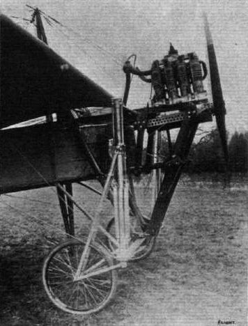
The Panhard motor fitted to the Tellier monoplane. It will be noticed that the engine is carried on a wooden framework, which has all its edges carefully rounded off.

The front chassis section of the Tellier monoplane, showing the very strong construction of the fusellage and simple fitting of the 6-cyl. Panhard aviation motor.
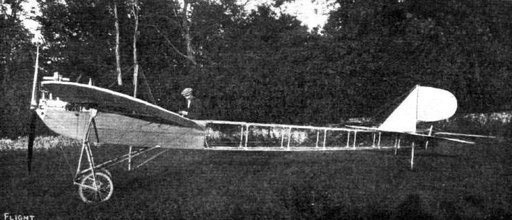
The latest Tellier racing monoplane, fitted with a 45-h.p. Panhard engine, which will be used at the big International-meeting at Lanark by Audemars. The weight is 350 kilogs., span, 9 metres; length, 9 metres and surface, 20.2 square metres.
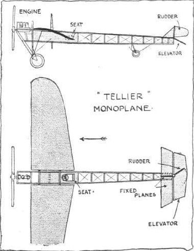
Flight, September 17, 1910
ROUND-ABOUT FRENCH NOTES.
By OISEAU.
<...>
I send you a photograph of a monoplane recently designed and built by M. Raoul Vendome. The general construction is extremely strong, the fuselage, which resembles slightly the Le Blon Humber, having successfully borne the weight of six men without any signs of breakage. Lateral stability is controlled by ailerons, worked by the hand-wheel seen in the photograph. This wheel is mounted on a lever, of which the forward or backward movement operates the elevator. Steering is by a foot-lever, as on a Bleriot. M. Henry Jacques, who has already purchased three of these machines, has made some excellent flights during the last few days. He has very kindly placed one at my disposal for practice purposes, so that shortly I shall be in a position to give personal details of its behaviour in the air.
<...>
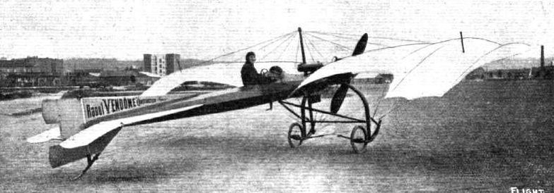
M. HENRY JACQUES AT THE WHEEL OF THE NEW RAOUL VENDOME MONOPLANE. - The wing span is 9.5 metres, length 7 metres, motor 3-cyl. 25-h.p. Anzani, and Vendome propeller.
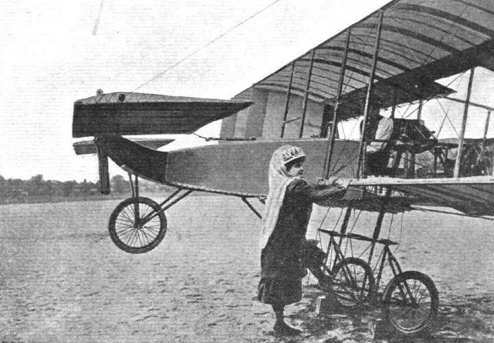
Madame Paulhan, in her aviation costume, about to mount on to her husband's Voisin biplane, with which he was flying at Issy last year. This is a very good sample of one of the many "faked" aviation photographs so prevalent in France.
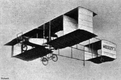
"WOLSELEY No. I." - The above photograph of M. de Baeder flying at Chalons on the Voisin aeroplane, "Wolseley No. 1," fitted with a 50-60 h.p. Wolseley flight motor, is the subject of a charming postcard which is being issued by the Woiseley Co. The occasion of the picture was when de Baeder won his four prizes in one day for flying on this machine.

De Baeder, who secured several prizes at Mourmelon last week in a single day, on his Voisin machine, which is fitted with a 50-60-h.p. British-built Wolseley engine.
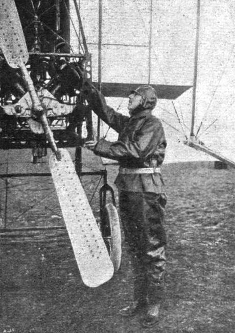
De Baeder, one of the latest successful flyers at Mourmelon, and his Wolseley-engined Voisin biplane.
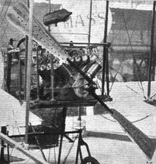
A neat method of fixing a two-bladed propeller to the crankshaft is to use the shanks of the blades as bolts, and to fasten them by nuts to the boss, as is shown in the above illustration of the Voisin flyer.
HELIOPOLIS AVIATION MEETING. - An incident during the competitions. Latham, on his Antoinette, with Rougier, on his biplane, behind.
NICE FLIGHT MEETING. - Mr. A. Rawlinson, on the left, on his Henry Farman, and M. Rougier on his Voisin biplane, flying over the sea at Nice.
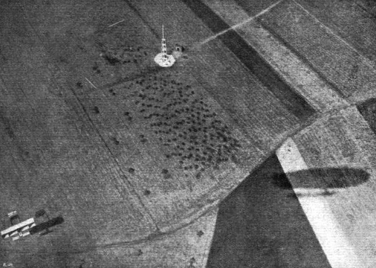
SEEN FROM ABOVE. - Striking photograph taken from an airship during the Rheims Aviation Meeting last year. On the left is a biplane in full flight, whilst the shadow of the dirigible itself from which the picture was snapped is seen on the right. Note also the pylone and the white guide marks on the ground, which were used for indicating the "course" for the flying men.
FLYING MACHINES AT BROOKLANDS ON EASTER MONDAY. - A trio of aeroplanes. From left to right: Mr. Astley's Lane monoplane, Mr. A. V. Roe's triplane, and Mr. Moreing's Voisin biplane.
General view of the Stands and Starting Place on the Johannisthal Aerodrome near Berlin. - The machines in the foreground are Baron de Caters' Voisin (No. 1) and Herr Jeannin's Henry Farman.
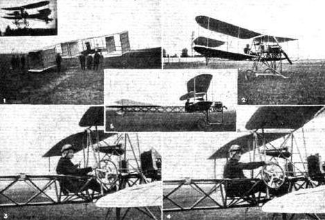
Some interesting views of the Swiss-built Dufaux biplane which has been constructed by the Dufaux Brothers of Geneva. In No. 3 M. Henry Dufaux is in the pilot's seat, in No. 4 M. Armand Dufaux is in charge, and in Fig. 6 the machine is in flight. No. 1 is a Voisin machine, with M. Nigg at the wheel. The photographs, which are from the Suisse Sportive, were taken at the Viry Aerodrome, near Geneva.
Flight, April 16, 1910
NEW RACING VOISIN BIPLANE.
ON this page we reproduce a couple of photographs which convey a very good idea of the new Voisin machine which has just been built for Rougier, and on which he hopes to win some of the chief prizes at the various big meetings during the year. It will be noticed that one striking departure from the characteristic of the Voisin is in the tail, which is now similar to that adopted by Sommer and Farman. Side curtains between the main planes have also been dispensed with, and transverse stability is controlled by long biplane ailerons between the main planes. The arrangement of the prow and elevating plane has also undergone slight modification. The span of the main planes is 9 metres, and the total lifting surface of the machine 33 square metres, while the overall length is 9 metres. The weight, with fuel, &c, on board, is 350 kilogs. A single two-bladed Voisin propeller, of 2 metres diameter, is fitted, and driven at a speed of 1,200 revs, per min. by an 8-cylinder 50-h.p. water-cooled E.N.V. motor.
Flight, July 16, 1910
Flying from Denmark to Sweden.
ALTHOUGH there was a strong wind blowing, four aviators, endeavoured to fly across the Sound from Copenhagen to Malmoe, Sweden, on Wednesday of last week. Two of them turned back, as the wind proved to be too strong. Baron Cederstrom, on a Bleriot, and M. Svendson, on a Voisin, descended on the Isle of Saltholm, nearly half way across, as both were experiencing trouble with their engines. Later M. Svendson flew back to the Danish shore.
Flight, September 10, 1910
PARIS-BORDEAUX.
TRULY rapid fame, almost unequalled in the annals of the world, is being attained by means of aviation. Day by day some new flyer whose name has hardly appeared in print, becomes one of the leading lights of the universe by reason of some extraordinary feat, either novel in itself or surpassing previous exploits of a similar character. In this category must almost be included Bielovucie, for although he has been known in certain circles in the flying world, until the last few weeks his name was practically unknown to the general public. And yet, with little preliminary fuss last week, and mainly in order to avoid the very heavy expense entailed in transporting his Voisin machine to Bordeaux from Paris, where he proposes to fly at the big aviation meeting, he determined to take the air for the entire journey, merely descending for necessary replenishment stops and rest. Without a suspicion of Serious delay he has succeeded magnificently, and once more the tablets of history must receive an addition by the inscription of his name for this fine work. The total distance between the two points is 540 kiloms., and this Bielovucie covered in three successive days with three landings, in the total flying time of 6 hrs. 15 mins. The longest stage was between Orleans and Chatellerault, this totalling to 170 kiloms., the shortest being the first stage, starting from Issy, between Paris and Orleans, with 110 kiloms. The various stages, with times, are as follows :-
kiloms. Start. Arrival. Time, h. m.
Paris-Orleans 110 6.5 7.15 1 10
Orleans-Chatellerault 170 9.35 11.20 1 45
Chatellerault-Angouleme 135 3.30 5.15 1 45
Angouleme-Bordeaux 125 10.48 12.25 1 37
Total for the 540 kiloms. 6 15
In the first stage he travelled over Montrouge, D'Arpajon and Etampes, before alighting at Orleans. Rising from the military field of manoeuvres at Grouves before actually making a start for the second stage, Bielovucie made a trip round the plain four times in spite of a very bad fog prevailing at the time. Later, when the sun had dissipated the thick mist at 9.35, he rose from the ground for his second stage. During this journey the route took him over Blois and Tours, he passing over the latter town at three minutes past eleven, and at 11.20 he descended at Chatellerault for dejeuner. Restarting at 3.30, he was speeding over Poitiers at 3.45, Couhe-Verac at 4.10, and descended at Angouleme for the night at 5.15. The next morning the completion of the journey to Bordeaux was successfully accomplished with a start at 10.48, he was sighted over Libourne at 12 noon, where he had to rise to about 1,000 metres in consequence of some violent wind eddies met with. Bordeaux was reached at 12.25, although Bielovucie did not actually finish his journey at the Beau Desert Aerodrome until 10 minutes later, during which interval he passed over the Cathedral at a height of 1,600 ft., and the Grand Theatre, where the streets were positively black with the populace who had sallied forth en masse to welcome the popular aviator. And so, what will presently become hardly a matter for unusual comment, this further remarkable step in the history of aviation ended, with the material reward to the hero of a gold medal which is to be presented to him by the Bordeaux Departmental Assembly in recognition of the first man to fly from Paris to Bordeaux. As a preliminary to the Bordeaux aviation meeting, the promoters have assuredly reaped a magnificent advertisement for their project, which starts on Sunday next.
Flight, October 22, 1910
IMPRESSIONS OF THE PARIS SHOW.
By OISEAU.
<...>
The military value of aeroplanes as illustrated during the recent manoeuvres has induced many makers to design specially for the Army. Clerget, for instance, has produced a tandem monoplane with three seats and driven by a 200-h.p. motor. Voisin is the first to fit a mitrailleuse to his two-seater biplane. The effects produced after firing this gun from some height ought to be interesting. The Breguet biplane and the Hanriot and Bleriot monoplanes are also mounted as aeroplanes of war.
<...>
After many months of faithful adherence to the cumbersome but simple box-kite type of biplane, Messrs. Voisin have recently come into line with other makers, and with astonishingly successful results. The machine displayed by them on the stand of the Compagnie Aerienne is a two-seater copy of the Paris-Bordeaux type. The front elevator has gone, though the fusellage is still built out in the canoe-shaped manner of the earlier models, but without the former canvas covering. Gone, too, are the vertical planes and the box tail. Large ailerons are fitted to the trailing edge of the upper plane, and the present tail is one of the simplest on the market. The trailing edge of the tail plane (which is curved and weight carrying) is hinged and acts as an elevator, and the square rudder is immediately beneath. The two seats are placed side by side, the passenger sitting to the left. In front of him is placed, on this model, a mitrailleuse of similar calibre to those used in the French Army, but considerably lighter. Steel tubes have replaced the wooden portions of the framework.
<...>
Flight, December 10, 1910
AEROPLANE SILHOUETTES FROM THE PARIS SHOW.
THE VOISIN BIPLANE.
CONSTRUCTED in France by Voisin Freres (Charles and Gabriel Voisin). The first European biplane of real success. Elevator incorporated in tail. No forward elevator. Framework of steel tube. Fabric is Continental aeroplane material. A type with conventional wooden framework is still constructed. Holder of the world's biplane speed record made by Bunau-Varilla at Rheims (1910).
General Dimensions. - Length overall (steel type), 10.50 metres; (wooden type) 10.40 metres; width (steel type), 11 metres; (wooden type) 10 metres. Width of main planes (both types), 2 metres.
Seating capacity. - (Steel type) two seats placed side by side and with dual control; (wooden type) single seater, seats placed in front of main planes in both types.
Engine. - 60-h.p. 8-cyl. V-type water-cooled E.N.V., or 50-h.p. 7-cyl. rotary air-cooled Gnome, or according to choice.
Propeller. - Voisin two-bladed, of steel; variable pitch. Situated behind main planes.
Chassis. - Two wheels; no skids; small wheel placed forward about three feet from the ground to take initial shock of bad landing.
Tail. - Monoplane tail with elevator hinged to trailing edge. Single rudder placed centrally below tail plane.
Lateral stability. - By large ailerons fitted to the trailing edge of the upper main plane.
Weight. - Complete with motor (60-h.p. E.N.V.), 370 kilogs.
Speed. - 80 to 90 kiloms. an hour.
System of control. - By a wheel at the end of a horizontal shaft and moving in a sleeve; pulling the wheel elevates the machine, pushing depresses the elevator; rotating the wheel in either direction steers the aeroplane as an automobile. Two pedals in front of the pilot actuate the ailerons for the maintenance of lateral stability, the right pedal depressing the left aileron and vice versa.
Price. - (Steel type) with 60-h.p. E.N.V., 25,500 francs; with 50-h.p. Gnome, 28,000 francs.; without engine or propeller, 14,000 francs. (Wooden type) with 60-h.p. E.N.V., 23,500 francs; with 50-h.p. Gnome, 26,000; and with 55-h.p. Antoinette, 25,000 francs.
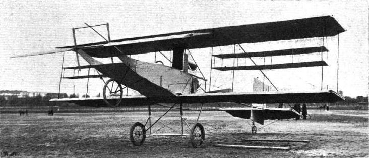
NEW VOISIN RACING BIPLANE. - View from in front.

Side view of the new Voisin biplane, racing type.
Competitors at the Starting Line at Lanark Meeting, as seen from the Members' Enclosure. - The machines, reading from the front, are: No. 6, Cattaneo's Bleriot; No. 12, Gilmour's Bleriot; 18, Grace's Henry Farman; 131, Ridley's Bierlot; 11, Capt. Dickson's Farman; 21, McArdle's Bleriot; 8, Blondeau's Henry Farman; 5, Champel's Voisin.
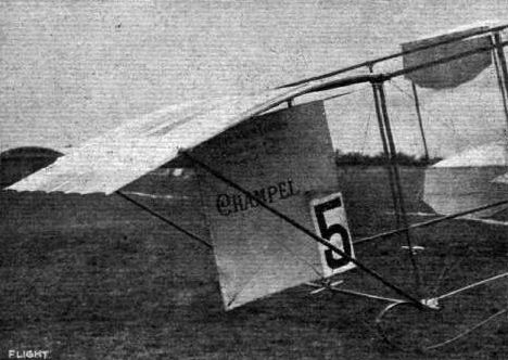
The tail of Champel's Volsin biplane at Lanark Meeting.
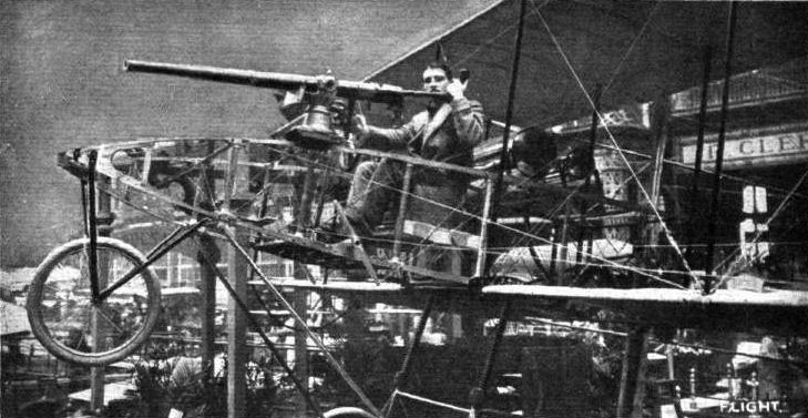
Voisin new type two-seater biplane, without elevator, fitted with 50-h.p. Gnome motor and French service mitrailleuse in front of passenger's seat.
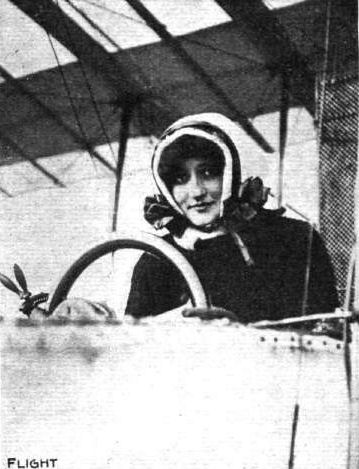
The Baronne de Laroche, whose unfortunate accident on her Voisin somewhat marred last Friday's doings at the Rheims Meeting. - Latest accounts report the Baroness as out of danger.
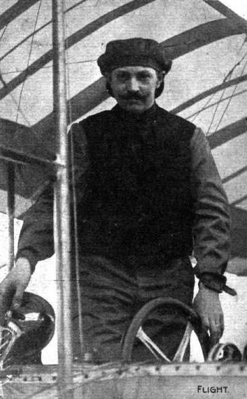
Svendson, the Swedish aviator, who, on his Voisin, flew across the Sound recently, starting from Copenhagen (Denmark) at 4.3 p.m., reached Sweden (Melmo) at 4.34 p.m., a distance of 28 kiloms. as the crow files.
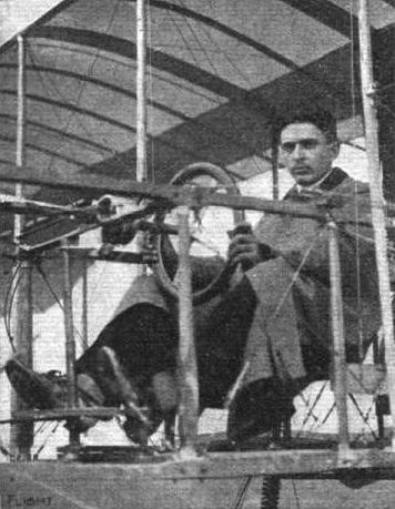
Bielovucie, who has just flown from Paris to Bordeaux, at the wheel of his Voisin biplane.
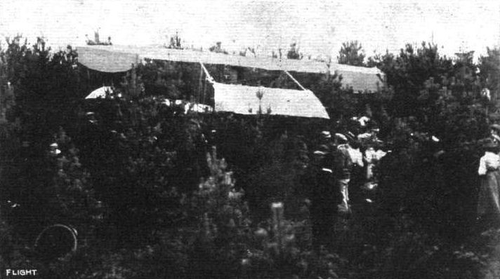
Champel's Voisin biplane after its fall into the fir plantation at Lanark Aviation Meeting.
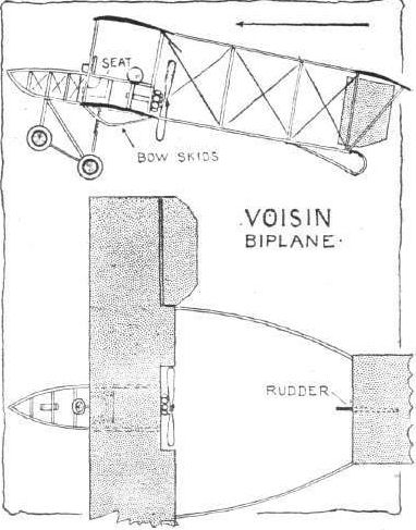
Flight, March 12, 1910
THE SECOND OLYMPIA AERO SHOW.
AEROPLANES.
Zodiac.
A BIPLANE and a monoplane, exhibited by the British and Colonial Aeroplane Co., being the type which it is proposed to build at that firm's works at Bristol, of which Sir Geo. White is at the head.
Flight, March 26, 1910
FLYER SILHOUETTES FROM OLYMPIA.
ZODIAC BIPLANE
(BRITISH AND COLONIAL AEROPLANE SYNDICATE).
Leading Particulars of the Zodiac Biplane.
General Dimensions.-Areas-Main planes, 475 sq. ft.; fixed tail, 50 sq. ft.; elevator, 32 sq. ft.; rudder, 10 3/4 sq. ft.
Lengths.-Span, 33 ft. 3 ins., chord, 5 ft. 11 ins.; camber, 1.88 ins., situated about 18 ins. from leading edge; leverage of rudder, 20 ft. 10 ins.; gap, 5 ft. 9 ins.; skid track, 6 ft. 6 ins.; length over all, 39 ft. 3 ins.
Materials.-Timber, spruce, with certain short struts of ash; fusellage, ash ; Zodiac fabric.
Engine.-50-h.p. Darracq.
Propeller.-Chauviere ; diameter, 8 ft. 3 ins.
Weight.-Machine and engine, 900 lbs.; driver, oil, petrol, water, 200 lbs.; total flying weight, 1,100 lbs.; loading (all weight supported on main planes), 2.3 lbs. per sq. ft
Speed of Flight.-35 m.p.h. at 1,200 r.p.m.
System of Control.-Flaps, elevator, and rudder.
Price.-L1,000.
BIPLANE of the Farman type, characterised by an extremely flat camber to the main planes and by side panels between the extreme struts. There are no panels in the tail. Another interesting detail in design is the chassis. It represents a combination of wheels and skis, but the skis only touch the ground in the event of a very severe shock, and then only the front part of the skids come in contact with the soil. The skids really form pivoted levers, on one end of which the wheel is mounted and to the other end of which the rubber springs are anchored.

Sketch illustrating the cantilever method of mounting the wheels on the Zodiac biplane.
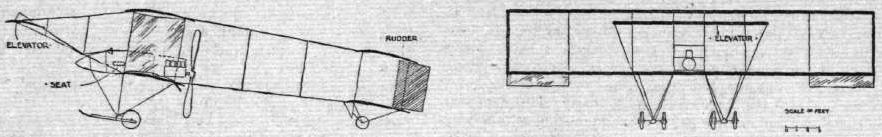
WING SECTIONS. - The above diagrams afford an interesting comparison of the wing sections of aeroplanes exhibited at Olympia. They are all drawn to a common scale, but have been set at an arbitrary angle of incidence, which does not necessarily represent that of the aeroplane In actual flight.
Flight, January 1, 1910
A Swiss Aerodrome.
THE Count de Viry has decided to construct an aerodrome in his grounds at Viry, near Geneva, with a view to encouraging flight in Switzerland. At present there are four aeroplanes there, and two more are expected almost at once. One of these is the Dufaux biplane which, as we announced last week, has made one or two short flights, and promises well.
Flight, January 8, 1910
Flying in Switzerland.
OWING to the accident which befell M. Dufaux's machine a day or two ago, it has been decided to postpone the public demonstrations at the Viry aerodrome to the 9th, 10th, and n t h inst. It is hoped that several other Swiss sportsmen who have recently acquired aeroplanes will be ready to take part then. With a view to encouraging local talent, the journal A.B.C has offered a prize of 1,000 francs for the first Swiss aviator to fly 100 metres, and 2,000 francs for the first flight of 2 kilometres. All the local authorities are displaying great keenness to promote the success of the meeting.
Flight, July 23, 1910
Good Flight by Dufaux.
HAVING once more got his machine in going order, Armaud Dufaux, on the 12th inst., succeeded in making a flight of 36 kiloms. in 31 mins. 30 secs, at the Viry flying grounds. He is now practising with a view to making an early attempt to cross the Lake of Geneva.
Flight, August 20, 1910
Swiss Aviators in Competition.
AT the flying meeting which opened at Geneva on Sunday two Dufaux machines were seen in competition for the first time and the longest flight of the day was made on one of them. This was of 1h. 1m. 27 2/5s. duration. The speed prize was won by Audemars on his Demoiselle. Amerigo, on a Bleriot, took the height prize, although he only reached 30 metres, and Dufaux secured the starting prize, getting, off the ground in 60 metres. Noflying was possible on Monday because of the wind.
Some interesting views of the Swiss-built Dufaux biplane which has been constructed by the Dufaux Brothers of Geneva. In No. 3 M. Henry Dufaux is in the pilot's seat, in No. 4 M. Armand Dufaux is in charge, and in Fig. 6 the machine is in flight. No. 1 is a Voisin machine, with M. Nigg at the wheel. The photographs, which are from the Suisse Sportive, were taken at the Viry Aerodrome, near Geneva.
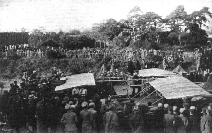
AEROPLANES IN JAPAN. - Captain Narohara and the aeroplane of his own construction in Japan, which is being tested with a view to its adoption for the Japanese forces. His brother officers, it will be noted, are interested members of the crowd.