
Книги
Журнал
Flight за 1911 г.
751
Журнал - Flight за 1911 г.
Flight, June 10, 1911.
AN AUSTRALIAN PIONEER AND CONSTRUCTOR.
WRITING from Spring Plains, Mia Mia, Victoria, Mr. J. K. Duigan sends us some very interesting particulars and photographs of his pioneer work in Australia which has ended in his construction of a successful biplane. Mr. Duigan tells his story thus:-
"I am sending a couple of photos of two recent flights I made here with a machine built entirely by myself with the exception of the engine. I have been working on it for about two years now, having to do all my own experimenting, make all fittings, wheel gears, propeller-shaft, as well as design it all. The wheel gear was originally sprung but not trailing, and this caused the only two breakages I have had. Since altering it to trailing I have had 25 flights, most over 100 yards, many over 200, and three of about a quarter of a mile, the only damage being two slightly bent plunger rods on one landing due to the piston sticking. The springs are compressed air. My engine was built here, originally being a 4-cyl. vertical air-cooled 86 by 108 mm., and weighing about 135 lbs. Since then I fitted water-cooled heads, which was an improvement, but the power was not great enough, so I fitted larger cylinders, 94 mm., with same heads, and this has given the flights shown. I have had endless difficulties, but have managed to overcome them all, and have made a machine that will lift in about 50 yards, and is under perfect control and can be trusted to always land safely. The machine is 25 ft. wide and about 28 ft. long, and weighs with 10-stone operator about 620 lbs. Engine is 138 lbs., 1 gal. water 10 lbs., radiator, centrifugal (all designed and made by myself), 7 lbs., piping 2 lbs.; total of engine and water-cooling 165 lbs. Propeller, shaft, stays to take pull of chain, and thrust-stays, about 40 lbs. This leaves 275 lbs. for the machine, minus engine and operator, which is light as it is all ash with the exception of the ribs, and is all double-surfaced with Dunlop material, made here.
"Both photos were taken when the machine was about 110 yards from starting-point. All the calculations were based on Sir H. Maxim's figures given in his excellent book on artificial and natural flight, and that book has been all I have had to work on.
"I have been a subscriber to your paper for over a year now, but have not previously sent any photos. The machine is very different now in appearance to when first completed. My first successful controlled flight was on October 7th, 1910, when I flew 196 yards at a height of about 12 feet. I had had hops long before that but the machine was not quite under control. That 196 yards flight was the first successful flight by an Australian built machine. The engine also was made in Melbourne by J. E. Tilly, a motor engineer. The ground I use for flying limits me to a bit over a quarter of a mile and there is no other in the district, so I have done about all I can do now. At present I am considering my next move, which may possibly be in your direction."
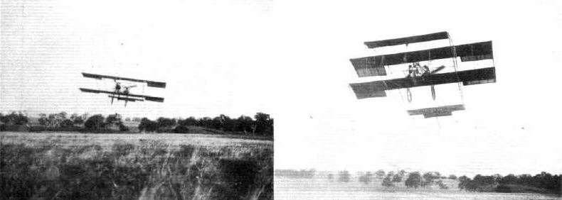
AN AUSTRALIAN BIPLANE. - Mr. J. R. Duigan in flight upon his Australian-built biplane at Mia Mia in Victoria. The machine is about 100 yards from starting point in left-hand photo and 110 yards in right-hand one. The small plane at rear is connected to elevator. The propeller is 8 ft. 6 ins. diameter and 10 ft. pitch, is driven by 3/4-in. Brampton chain, gear 19 teeth and 42. Ordinary Bosch cycle magneto, two brakes, 4-cyl. motor, Schebler carburettor, with inlet-pipe bored out.
Flight, April 8, 1911.
Austrian Passenger Record Beaten.
ON Monday, Herr Illner on his Etrich monoplane succeeded in beating the Austrian passenger record. Taking Herr Amau as a passenger he travelled round and round a circular course for 2 hrs. 33 mins., covering in that time about 150 kiloms.
Flight, April 29, 1911.
Tests With the Etrich Monoplane.
SOME interesting tests were made recently with an Etrich monoplane, built for the Austrian Army. The machine was first of all flown with a passenger on board for 2 hrs. 33 mins. while the wind was blowing at a rate of 4 to 5 metres a second. Afterwards the machine was dismantled, an operation which occupied 8 mins., while in 25 mins. the machine was once more ready for flight, and, in fact, was taken for a trial. The specification under which the machine was built stipulated that it could be dismantled in one hour and be again ready for flying within two hours. Herr Illner has also demonstrated the controllability of the Etrich monoplane by flying in small circles, during some of which the planes were at an angle of 30 to 35 degrees to the horizontal, while as a conclusion the aviator took his hands from the steering wheel and let the machine proceed on its way some distance of its own accord. The machine in question is seen in our photograph on this page.
High Flying in Austria.
UP to the present no great amount of attention has been paid to altitude flying in Austria, but on the 21st inst. Lieut. Bier improved on Miller's old record of 600 metres by rising to a height of 1,110 metres on his Etrich monoplane. The record was made at the Etrich testing ground near Vienna.
Flight, September 16, 1911.
Germany's First Lady Pilot.
THE number of lady aviators is gradually mounting up, and we learn that Germany now has a certificated aviatress, Fraulein Nelly Beese having made the tests to qualify for her certificate on the 8th inst., at Johannisthal.
Flight, November 11, 1911.
THE ETRICH MONOPLANE.
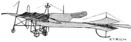
To Igo Etrich must be given a foremost place amongst those pioneers who, not content merely with constructing a machine that would fly, probed more deeply into the problem of flight in order to evolve an aeroplane naturally stable in a disturbed medium. Working on entirely independent lines, the researches of the three pioneers - Dunne and Weiss in England, and Etrich in Austria - have all resulted in the discovery of the improvement of longitudinal stability by the incorporation of the negatively-incident thrown-back wing tip.
It must be admitted, however, that Etrich has moved a step in advance of his contemporaries on this side of the Channel for, whereas all three have demonstrated the effectiveness of their inferences as applied to practical man-lifting machines, the Austrian inventor has succeeded in establishing the manufacture of his monoplanes on a sound commercial basis. Like the famous Wright Bros., Etrich commenced his experiments by the study of gliding flight in the year 1898 when he acquired a Lilienthal glider. Pursuing the investigations commenced by the latter, he delved into every subject that would be likely to throw light on the problem he had set himself out to solve. He studied the propulsive organs of every kind of flying animal - birds, insects, bats, flying-fish, and even went to the extent of investigating the different species of flying seeds, those of the sycamore and pine, for instance, which are so abundant in the vegetable kingdom.
This preparatory work led him to try a glider of his own design, very ingeniously constructed, and of such an original plan form, that at that time it was considered bordering on the fantastical. Experiments with the glider commenced in 1904 at Trantenau, and during the year glides of up to three-quarters of a mile in length were made.
It was not until 1909 that a power-driven aeroplane was evolved, which, piloted by Illner, soon captured all existing Austrian records. Since then it has undergone improvement after improvement, and to-day is universally ranked among the most successful and most scientifically designed of air-craft.
Its appearance in England, on the occasion of the Circuit of Britain, was a revelation to our English constructors, and its influence will doubtless have an effect on current design.
The body of the Etrich monoplane is a fish-shaped structure of steel tubing cross-braced by wire. From the elliptical radiator, which is mounted at its forward end, the body deepens and widens in the vicinity of the pilot's seat, and from that point, still preserving its elliptical cross-section, gradually tapers away to the tail, where it terminates in a vertical line. To avoid internal disturbance in the air discharge, the body is covered in front with metal sheeting and aft of the pilot's cockpit with fabric.
In the matter of under-carriage, the Etrich monoplane has undergone repeated modification in the past, but it seems as though the constructor has definitely decided that one modelled upon Henry Farman lines is most suitable - at least, for the present.
As the main planes form the most distinct feature of the machine, they merit careful study. Reference to the accompanying diagram (Fig. 1) will facilitate description. The front part of each wing, shaded in the sketch, is rigidly constructed of webbed ribs, built over three longitudinal spars, of which the forward one forms the leading edge. This section is surfaced on both sides with fabric. Behind the rear boom extend bamboo continuations of the ribs, which, covered with a single surface of fabric, form a flexible trailing edge. The camber is very slight, even at the point where the wings are attached to the fuselage, and it decreases, together with the angle of incidence, towards the tip, which is flat and presents no incidence to the direction of flight.
The flexible wing-tips, however, are turned up at the rear, and so give the end of the wing an effective negative angle of incidence. It is to this feature that the machine owes its pronounced degree of natural stability. Lateral balance is maintained by raising either wing-tip by means of a cable, which, passing over a pulley situated at the top of the king-post, divides up into eight wires connected to the flexible extremities of the wing. A cable passing over the lower end of the king-post lowers the opposite tip a corresponding amount.
Enormous strength is imparted to the wing by a bridge-like structure of steel tubing, which embraces the three wing-spars, and is attached below the under surface - strength which renders them capable of withstanding strains many times in excess of those that they are likely to be called upon to bear in flight. The wire-bracing throughout is carried out in a most thorough and conscientious manner; for what part of an aeroplane, especially on such a heavy example, deserves more careful attention than the bracing of those surfaces which support and control it?
A small wheel mounted at the lower extremity of the king-post protects the wing-tip from contact with the ground, and small transparent panes are provided in the wings to enable the pilot to see what is directly beneath him.
The tail surface is fan-shaped and balanced, and pivots in one unit about a horizontal axis. Forward of the axis the movement of the surface is "damped" by the introduction of a spring device, which prevents a purely rocking motion, as in the case of the Bristol elevator, and allows the rear edge of the elevator to flex to a certain extent.
Two small triangular vertical rudders, one above and the other below the horizontal tail plane, are hinged to the rear edges of two triangular stabilizing fins, and possess the function of directing the machine to the right or left at the will of the pilot, who operates them by means of pedals.
Elevation and lateral balance are controlled by a rotatable hand-wheel, mounted at the top of a vertical column.
The manufacture of the Etrich monoplane has been standardized into four types, a two-seater touring machine of 65-h.p., a single-seater racer of similar power, a 120-h.p. three-seater touring machine, and a similarly engined racer to carry two.
It was to the latter type that the Etrich monoplane representing Austria in the Circuit of Britain belonged. Behind the 6-cylinder Austro-Daimler motor was a small cockpit, for the accommodation of the mechanic whose duty it was to attend to the engine. Communication was carried on with the pilot by means of a speaking tube connected to specially-designed helmets.
As for the machine's future, what but success can be expected to attend the efforts of one who has already safely piloted into commercial waters such a clever synthesis of convictions resulting from serious personal study?
AEROPLANES AT TRIPOLI.
MR. QUINTO POGGIOLI, who will be remembered by our readers as having taken his pilot's certificate in England under the Royal Aero Club's regulations, sends us some interesting details of the practical work being carried out in Tripoli in connection with the Italian-Turkish War. Mr. Poggioli writes :-
"On the 25th Oct. Capt. Piazza with his Bleriot, and Capt. Moizo on his Nieuport, observed three advancing columns of Turks and Arabs of about 6,000 men. The Italians, after receiving this information, could successfully calculate distances and arrange for their defence.
"On the day following, the 26th Oct., the battle of Sciara-Sciat took place, resulting in the loss to the Turkish Army of 3,000 men. During the battle two aeroplanes, Lieut. Gavotti with his Etrich and Capt. Piazza, were circling the air. The flights took place above the line of fire, so as to be able to direct the firing of the big guns from the battleship 'Carlo Alberto,' and also of the mountain artillery. The aeroplanes were often shot at by the guns of the enemy, but with no result. The only difficulty they had was caused by the currents of air caused by the firing of the big guns.
"Previously, on the 22nd Oct., Capt. Moizo when reconnoitering passed over an oasis, and, in order to observe better the movements of the enemy, descended to an altitude of about 200 metres, and in consequence the wings of his machine were pierced by bullets in six or seven places, and also a rib was broken.
"On November 1st Lieut. Gavotti (Etrich) flew over the enemy, carrying four bombs, carried in a leather bag; the detonator he had in his pocket.
"When above the Turkish camp, he took a bomb on his knees, prepared it and let it drop. He could observe the disastrous results. He returned and circled over the camp, until he had thrown the remaining three bombs. The length of his flight was altogether about 100 kiloms.
"The bombs used contained picrato of potassa, type Cipelli."
THE first official communication by one of the belligerents, in regard to the use of aeroplanes in actual warfare, has been issued by the Italian authorities, dated November 5th, from Tripoli. As a matter of historical record we reproduce the text in extenso as follows :-
"Yesterday Captains Moizo, Piazza, and De Rada carried out an aeroplane reconnaissance, De Rada successfully trying a new Farman military biplane. Moizo, after having located the position of the enemy's battery, flew over Ain Zara, and dropped two bombs into the Arab encampment. He found that the enemy were much diminished in numbers since he saw them last time. Piazza dropped two bombs on the enemy with effect. The object of the reconnaissance was to discover the headquarters of the Arabs and Turkish troops, which is at Sok-el-Djama."
Austrian Passenger Record Beaten.
ON Monday, Herr Illner on his Etrich monoplane succeeded in beating the Austrian passenger record. Taking Herr Amau as a passenger he travelled round and round a circular course for 2 hrs. 33 mins., covering in that time about 150 kiloms.
Flight, April 29, 1911.
Tests With the Etrich Monoplane.
SOME interesting tests were made recently with an Etrich monoplane, built for the Austrian Army. The machine was first of all flown with a passenger on board for 2 hrs. 33 mins. while the wind was blowing at a rate of 4 to 5 metres a second. Afterwards the machine was dismantled, an operation which occupied 8 mins., while in 25 mins. the machine was once more ready for flight, and, in fact, was taken for a trial. The specification under which the machine was built stipulated that it could be dismantled in one hour and be again ready for flying within two hours. Herr Illner has also demonstrated the controllability of the Etrich monoplane by flying in small circles, during some of which the planes were at an angle of 30 to 35 degrees to the horizontal, while as a conclusion the aviator took his hands from the steering wheel and let the machine proceed on its way some distance of its own accord. The machine in question is seen in our photograph on this page.
High Flying in Austria.
UP to the present no great amount of attention has been paid to altitude flying in Austria, but on the 21st inst. Lieut. Bier improved on Miller's old record of 600 metres by rising to a height of 1,110 metres on his Etrich monoplane. The record was made at the Etrich testing ground near Vienna.
Flight, September 16, 1911.
Germany's First Lady Pilot.
THE number of lady aviators is gradually mounting up, and we learn that Germany now has a certificated aviatress, Fraulein Nelly Beese having made the tests to qualify for her certificate on the 8th inst., at Johannisthal.
Flight, November 11, 1911.
THE ETRICH MONOPLANE.
To Igo Etrich must be given a foremost place amongst those pioneers who, not content merely with constructing a machine that would fly, probed more deeply into the problem of flight in order to evolve an aeroplane naturally stable in a disturbed medium. Working on entirely independent lines, the researches of the three pioneers - Dunne and Weiss in England, and Etrich in Austria - have all resulted in the discovery of the improvement of longitudinal stability by the incorporation of the negatively-incident thrown-back wing tip.
It must be admitted, however, that Etrich has moved a step in advance of his contemporaries on this side of the Channel for, whereas all three have demonstrated the effectiveness of their inferences as applied to practical man-lifting machines, the Austrian inventor has succeeded in establishing the manufacture of his monoplanes on a sound commercial basis. Like the famous Wright Bros., Etrich commenced his experiments by the study of gliding flight in the year 1898 when he acquired a Lilienthal glider. Pursuing the investigations commenced by the latter, he delved into every subject that would be likely to throw light on the problem he had set himself out to solve. He studied the propulsive organs of every kind of flying animal - birds, insects, bats, flying-fish, and even went to the extent of investigating the different species of flying seeds, those of the sycamore and pine, for instance, which are so abundant in the vegetable kingdom.
This preparatory work led him to try a glider of his own design, very ingeniously constructed, and of such an original plan form, that at that time it was considered bordering on the fantastical. Experiments with the glider commenced in 1904 at Trantenau, and during the year glides of up to three-quarters of a mile in length were made.
It was not until 1909 that a power-driven aeroplane was evolved, which, piloted by Illner, soon captured all existing Austrian records. Since then it has undergone improvement after improvement, and to-day is universally ranked among the most successful and most scientifically designed of air-craft.
Its appearance in England, on the occasion of the Circuit of Britain, was a revelation to our English constructors, and its influence will doubtless have an effect on current design.
The body of the Etrich monoplane is a fish-shaped structure of steel tubing cross-braced by wire. From the elliptical radiator, which is mounted at its forward end, the body deepens and widens in the vicinity of the pilot's seat, and from that point, still preserving its elliptical cross-section, gradually tapers away to the tail, where it terminates in a vertical line. To avoid internal disturbance in the air discharge, the body is covered in front with metal sheeting and aft of the pilot's cockpit with fabric.
In the matter of under-carriage, the Etrich monoplane has undergone repeated modification in the past, but it seems as though the constructor has definitely decided that one modelled upon Henry Farman lines is most suitable - at least, for the present.
As the main planes form the most distinct feature of the machine, they merit careful study. Reference to the accompanying diagram (Fig. 1) will facilitate description. The front part of each wing, shaded in the sketch, is rigidly constructed of webbed ribs, built over three longitudinal spars, of which the forward one forms the leading edge. This section is surfaced on both sides with fabric. Behind the rear boom extend bamboo continuations of the ribs, which, covered with a single surface of fabric, form a flexible trailing edge. The camber is very slight, even at the point where the wings are attached to the fuselage, and it decreases, together with the angle of incidence, towards the tip, which is flat and presents no incidence to the direction of flight.
The flexible wing-tips, however, are turned up at the rear, and so give the end of the wing an effective negative angle of incidence. It is to this feature that the machine owes its pronounced degree of natural stability. Lateral balance is maintained by raising either wing-tip by means of a cable, which, passing over a pulley situated at the top of the king-post, divides up into eight wires connected to the flexible extremities of the wing. A cable passing over the lower end of the king-post lowers the opposite tip a corresponding amount.
Enormous strength is imparted to the wing by a bridge-like structure of steel tubing, which embraces the three wing-spars, and is attached below the under surface - strength which renders them capable of withstanding strains many times in excess of those that they are likely to be called upon to bear in flight. The wire-bracing throughout is carried out in a most thorough and conscientious manner; for what part of an aeroplane, especially on such a heavy example, deserves more careful attention than the bracing of those surfaces which support and control it?
A small wheel mounted at the lower extremity of the king-post protects the wing-tip from contact with the ground, and small transparent panes are provided in the wings to enable the pilot to see what is directly beneath him.
The tail surface is fan-shaped and balanced, and pivots in one unit about a horizontal axis. Forward of the axis the movement of the surface is "damped" by the introduction of a spring device, which prevents a purely rocking motion, as in the case of the Bristol elevator, and allows the rear edge of the elevator to flex to a certain extent.
Two small triangular vertical rudders, one above and the other below the horizontal tail plane, are hinged to the rear edges of two triangular stabilizing fins, and possess the function of directing the machine to the right or left at the will of the pilot, who operates them by means of pedals.
Elevation and lateral balance are controlled by a rotatable hand-wheel, mounted at the top of a vertical column.
The manufacture of the Etrich monoplane has been standardized into four types, a two-seater touring machine of 65-h.p., a single-seater racer of similar power, a 120-h.p. three-seater touring machine, and a similarly engined racer to carry two.
It was to the latter type that the Etrich monoplane representing Austria in the Circuit of Britain belonged. Behind the 6-cylinder Austro-Daimler motor was a small cockpit, for the accommodation of the mechanic whose duty it was to attend to the engine. Communication was carried on with the pilot by means of a speaking tube connected to specially-designed helmets.
As for the machine's future, what but success can be expected to attend the efforts of one who has already safely piloted into commercial waters such a clever synthesis of convictions resulting from serious personal study?
AEROPLANES AT TRIPOLI.
MR. QUINTO POGGIOLI, who will be remembered by our readers as having taken his pilot's certificate in England under the Royal Aero Club's regulations, sends us some interesting details of the practical work being carried out in Tripoli in connection with the Italian-Turkish War. Mr. Poggioli writes :-
"On the 25th Oct. Capt. Piazza with his Bleriot, and Capt. Moizo on his Nieuport, observed three advancing columns of Turks and Arabs of about 6,000 men. The Italians, after receiving this information, could successfully calculate distances and arrange for their defence.
"On the day following, the 26th Oct., the battle of Sciara-Sciat took place, resulting in the loss to the Turkish Army of 3,000 men. During the battle two aeroplanes, Lieut. Gavotti with his Etrich and Capt. Piazza, were circling the air. The flights took place above the line of fire, so as to be able to direct the firing of the big guns from the battleship 'Carlo Alberto,' and also of the mountain artillery. The aeroplanes were often shot at by the guns of the enemy, but with no result. The only difficulty they had was caused by the currents of air caused by the firing of the big guns.
"Previously, on the 22nd Oct., Capt. Moizo when reconnoitering passed over an oasis, and, in order to observe better the movements of the enemy, descended to an altitude of about 200 metres, and in consequence the wings of his machine were pierced by bullets in six or seven places, and also a rib was broken.
"On November 1st Lieut. Gavotti (Etrich) flew over the enemy, carrying four bombs, carried in a leather bag; the detonator he had in his pocket.
"When above the Turkish camp, he took a bomb on his knees, prepared it and let it drop. He could observe the disastrous results. He returned and circled over the camp, until he had thrown the remaining three bombs. The length of his flight was altogether about 100 kiloms.
"The bombs used contained picrato of potassa, type Cipelli."
THE first official communication by one of the belligerents, in regard to the use of aeroplanes in actual warfare, has been issued by the Italian authorities, dated November 5th, from Tripoli. As a matter of historical record we reproduce the text in extenso as follows :-
"Yesterday Captains Moizo, Piazza, and De Rada carried out an aeroplane reconnaissance, De Rada successfully trying a new Farman military biplane. Moizo, after having located the position of the enemy's battery, flew over Ain Zara, and dropped two bombs into the Arab encampment. He found that the enemy were much diminished in numbers since he saw them last time. Piazza dropped two bombs on the enemy with effect. The object of the reconnaissance was to discover the headquarters of the Arabs and Turkish troops, which is at Sok-el-Djama."
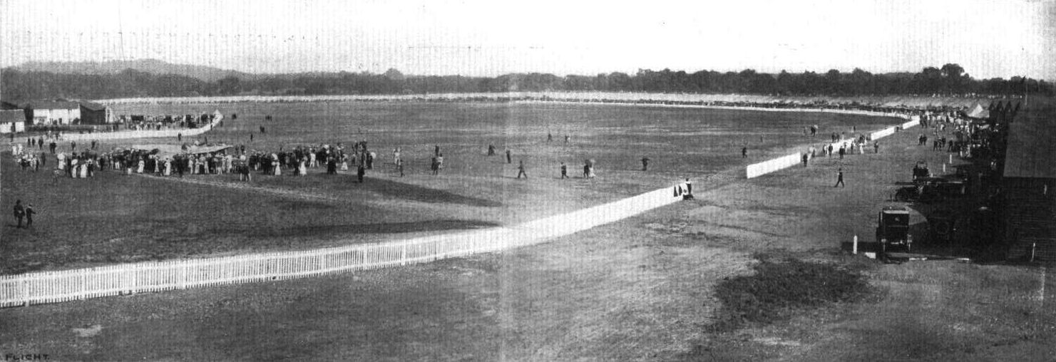
THE DAILY MAIL CIRCUIT OF BRITAIN. - General panoramic view of the scene at the Brooklands aerodrome for the start on Saturday last, taken from the new bridge over the track to the flying ground. Note the extraordinary concourse of motor cars parked round the entire track and the thouthands of the public who have secured positions on the top of the banking. The machine to the left surrounded by the crowd is Lieut. Bier's Etrich monoplane.
Lieut. Bier, with his passenger, starts away on the Etrich.

AN INCIDENT DURING THE RECENT JOHANNISTHAL FLYING WEEK. - Photograph taken from Pietschker's aeroplane, before he met with his death, of the Johanntsthal aerodrome and of Miss Melli Beese flying on her aeroplane.

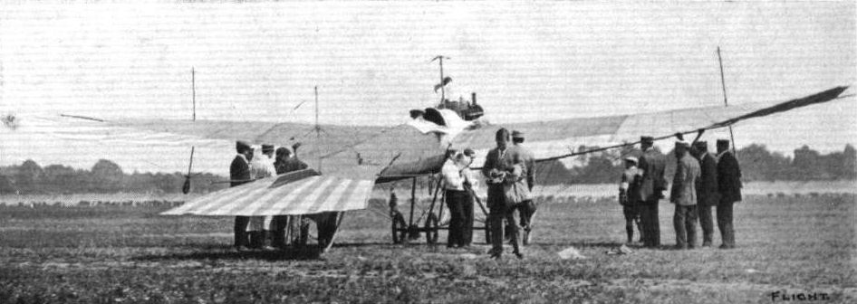
Latest model of the Etrich Monoplane, which has just been acquired by the Austrian Army. - These machines are constructed by the Motor-Luftfahrzeug-Gesellschaft of Hutteldorferstrasse, Vienna. In our photograph Oberlieutenant Miller, who has charge of the machine, is in the pilot's seat; in front the Army delegates, Rittmeister Schmidl, Captain von Petroczy, First Lieutenant Blaschke, First Lieutenant Stohanzl, the Managing Directors of the Motor-Luftfahrzeug-Gesellschaft, Kommerzialrat Castiglioni, Director of the Austro-American India-Rubber Manufacturing Co., Ltd., of Vienna, and Director Fischer of the Oesterreichische Daimler Motoren A . G .; and next to the propeller Mr. Illner, the Etrich pilot.

The 130-h.p. Etrich monoplane photographed from the front.
Rear view of the Etrich monoplane.
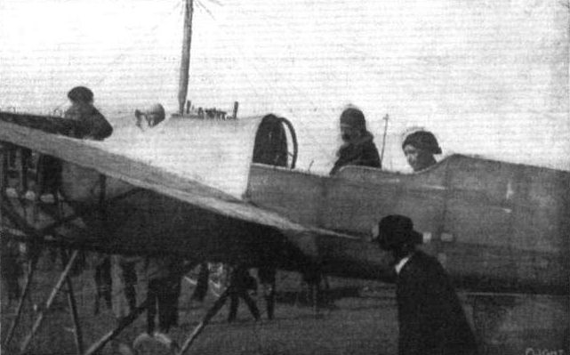
The cockpit of the Etrich monoplane, showing accommodation for mechanic, pilot and passenger.
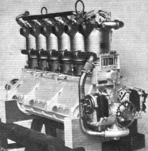
The motor employed on the 3-seater Etrich monoplane - a 6-cyl. Austro-Daimler of 130-h.p.
MONOPLANES AND BIPLANES IN THE DAILY MAIL CIRCUIT ROUND GREAT BRITAIN. - From these every machine can be readily identified either in flight or on the ground.
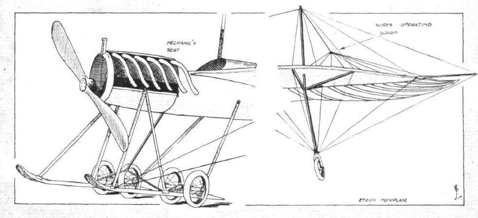
DETAILS OF THE ETRICH MONOPLANE. - On the left the landing carriage, somewhat reminiscent of Henry Farman practice; on the right the details of the wing tip, showing a portion of the steel bridge-like structure which strengthens the wings, and the fitting of the small wheel which prevents damage occurring to the tip of the wing.
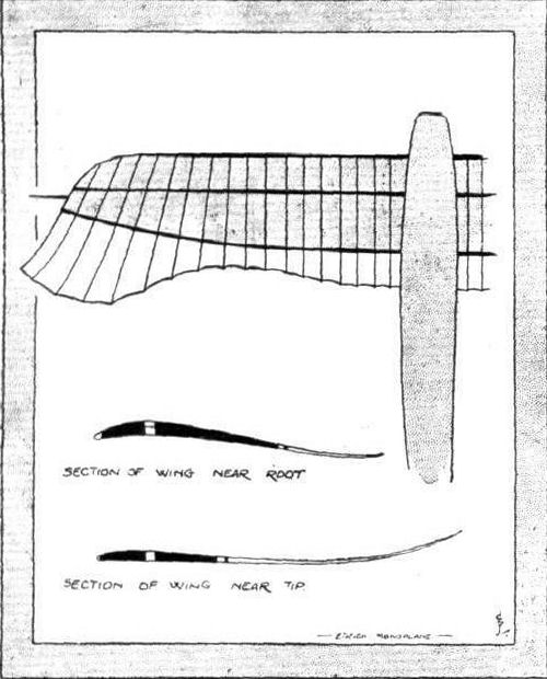
Diagram illustrating the arrangement of spars and ribs in the wing construction. The shaded portion indicates the rigid portion of the wings; the trailing edge, unshaded, is flexible.

THE ETRICH MONOPLANE. - Plan and elevation to scale.
Etrich-Taube with 120 hp Austro-Daimler engine installed. [1911]
Etrich-Taube with 120 hp Austro-Daimler engine installed. [1911]
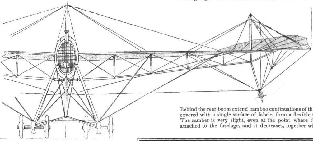
Front elevation of the Etrich monoplane.

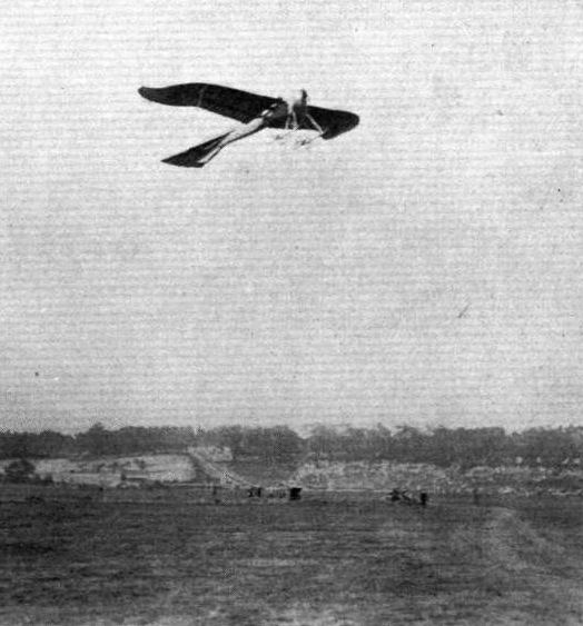
The glider which has been built at Aberdeen by Messrs. Anderson and Singer has been making some excellent glides. The photographs were taken after certain alterations had been carried out as a result of experience gained, and with the machine seen in our pictures the most successful glide obtained was about 25 to 30 yards.
Flight, March 18, 1911
FROM THE BRITISH FROM THE BRITISH
Valkyrie School. - "Valkyrie IV" school machine, in the hands of the School instructor, was out on Wednesday last week, and made altogether five circuits. There was a good deal of wind at the time, but the machine behaved with great steadiness.
Despite a gusty breeze on Saturday, the Valkyrie School instructor took out "No.IV" about mid-day and executed several circuite of the aerodrome very gracefully. The wind then dropping, several pupils claimed his attention for the rest of the afternoon. Both Mr. Benson and Mr. Chambers put in good practice making straight flights, and Mr. Cedric Lee, of Manchester, took his first lesson. Unfortunately the day ended with a mishap owing to a Bleriot pupil charging one of the Valkyrie School machines, and demolishing its left main plane. For the first time for months the big passenger carrier was not in evidence, as it is having it planes re-covered. It will be on the wing again in a few days, and some interesting doings should then be chronicled, as several cross-country flights have been booked. The new "Baby" Valkyrie will be finished on Monday, and its appearance is being looked forward to with considerable interest. Many improvements are noticeable in this dainty little machine, which is cleaner in design and obviously lighter than the old Type A. The new method of attaching the main stay wires of the planes to the frame is particularly neat, and greatly simplifies the detaching or erection of the planes.
Flight, March 25, 1911
AEROPLANES.
Valkyrie (THE AERONAUTICAL SYND., LTD.) - The latest Valkyrie monoplanes differ somewhat in appearance from their prototype in being lower in overall height. The general design and construction, however, remain much the same and they are still of the tail first type and of distinctly British design and construction. Among the interesting minor constructional features is the method of bracing by wire without bending the wire at the extremities.
Flight, April 1, 1911.
THE VALKYRIE RACER.
IT was about this time last year that we first drew our readers' attention in any marked degree to the Valkyrie monoplane, then known as the "A.S.L.," from the initial letters of the Aeronautical Syndicate, Limited, who now, as then, represent the commercial side of the business. It is, therefore, appropriate that we should again refer about Show time to the latest of these machines, and in doing so it is only proper that we should say a few words of congratulation on the steady progress of the firm during the past twelve months. When the Valkyrie monoplane was first introduced to readers of FLIGHT it had already flown, but that was about all, and no doubt a good many of those who were interested in its peculiar design wondered whether this tail first idea was going to be any good at all. The Aeronautical Syndicate were the first to establish themselves at Hendon, and in the inconvenient conditions that then existed it took some little while to get settled; but from that time onwards they have done their best to prove the merits of their machine on every decent flying day, and those who are interested have, therefore, no excuse for not satisfying themselves as to the appearance and general behaviour of the tail first monoplane in the air.
It is, of course, all the more interesting to be able to record Valkyrie progress, because the machine is, after all, essentially British, both in design and construction, and it is only right that all who are following aviation should watch with a kindly eye the evolution of anything that goes particularly to the credit of British brains. Commercially it is often wiser policy to copy a standard article, and initiative in design is therefore all the more worthy of appreciation and encouragement, and there is, at least, this to be said for the Valkyrie that it is no copy of anything else.
The latest machine, of which the accompanying photographs and sketches are illustrations, is known as the type "B" racer, and in appearance is characteristically different from its prototypes, although, as a matter of fact, the difference in question is merely a marked optical effect produced by a relatively small structural alteration. The present machine has its main planes closer to the ground than formerly, the height from the skids to the main fore and aft girders of the carriage being 4 ft. The result of this shortening of a very important dimension, so far as the perspective of the machine is concerned, has made a marked difference in its general appearance, especially when it is standing on the ground. Also, of course, being a racer it is generally smaller and lighter-looking in all its principal parts. The span is 31 ft.; the overall length 26 ft., which includes the increased distance at which the rudder planes are now carried behind the main plane; and the total weight is only 550 lbs. The general design of the main plane, which is, as before, built in three sections, has been somewhat modified by the introduction of a marked dihedral angle and a slight arching of the wings. The central portion of the main plane, which has a span of 8 ft. 4 ins., has its leading edge set back in order to clear the propeller. The trailing edge is in line with the trailing edges of the wings, and consequently the chord is less than the full chord of 6 ft., which characterises the wing members. About 12 ft. in front of the main planes is the fixed leading plane, which can be set to any required attitude, according to the load carried and general balance of the machine. Beneath this leading plane and a little to the rear thereof is the movable elevator, which on this machine is characterised by a slightly upturned trailing edge. Balancing planes are let into the trailing extremities of the wings, and rudder planes are mounted on two outriggers that form extensions to the under-carriage, but are raised to the level of the main plane.
A characteristic feature in the construction of the Valkyrie monoplane is the use of guy wires of large section, which are screwed at their extremities and fastened and adjusted by nuts so as to avoid bending the wires for this purpose. On the present machine a Gnome rotary engine is fitted, which contributes considerably to the neatness of the design, because constructional considerations make it necessary to have the engine in the centre, and on a one man machine the pilot has to sit in front of the engine. Any saving of length is, therefore, an advantage, inasmuch as it facilitates the concentration of the principal masses about the actual centre of gravity. The control of the machine may be described as arranged on the Farman principle, for the elevator and balancers are operated by the universal motion of a pivoted upright lever conveniently situated for the pilot's right hand, and the rudder, planes are controlled by a pivoted foot-rest. A minor feature that affects the external appearance of the machine is a very neat saddle tank surrounding the engine. This tank is of horseshoe shape, and contains compartments for petrol and oil. It is mounted rigidly on the engine frame.
Flight, May 13, 1911.
FROM THE BRITISH FLYING GROUNDS.
London Aerodrome, Collindale Avenue, Hendon.
Valkyrie School. - The Valkyrie pupils, who are nothing if not enthusiastic, started work at 4 a.m. on Thursday last week. Miss Meeze had her second lesson and made good progress. Mr. Turner and also Mr. Perry each had their second lesson, and both made straight flights, Mr. Perry making his essay after only 35 minutes rolling practice. The school instructor was out on "Valkyrie II" and put in some useful flying, carrying several passengers. The wind rising at 7.30 put an end to air work.
The weather moderating later, the school machine was out again at half past five, where Miss Meeze, Mr. Chambers, and Mr. Turner were all hard at it again, the last two specially improving in their flying. Mr. Turner, unfortunately, had a slight mishap, doing some damage to the school machine. It was, however, unimportant, and the machine should be in commission again in a day or two. The school pilot took out the new Type A VII machine, and put up some remarkable demonstrations, during which he made turns with his hands above his head. One flight lasted for half an hour, during which the machine flew over the surrounding country. Dr. Lightstone and Mr. Davis had passenger flights.
On Friday the Valkyrie designer had No. VII out at 5 a.m., and made a very fine cross-country flight of 20 minutes' duration, passing near Harrow. Returning to the aerodrome, he ascended to a considerable height, and put up a steady flight of some 40 minutes, although during part of the time there was quite a breeze blowing.
The next day proved too windy for pupils, but the Valkyrie designer took out the new Type B racer, fitted with a Gnome engine, and made a series of pretty flights. The machine showed high speed and great lifting capacity.
Early in the morning of Sunday the Type B racmg machine was out again, and made a tine flight of about twelve miles, during which the pilot indulged in numerous vol plane descents from a height of several hundred feet, and executed some sharp turns. This machine has shaped very well in practice, exceeding all expectations regarding speed and lifting capacity.
Flight, May 20, 1911.
FROM THE BRITISH FLYING GROUNDS.
London Aerodrome, Collindale Avenue, Hendon.
Valkyrie School. - Great disappointment was experienced at the Valkyrie School on Friday, 12th inst., owing to the controllers of the aerodrome not permitting even one of the five Valkyrie machines to take part in the military tests.
On Saturday, May 13th, school work started at 5 a.m., and the following pupils each had lessons :- Miss Meeze, Messrs. Perry, Chambers, Uenson, llawker, Clutterbuck, and Turner. Messrs. Turner, Perry, and Hawker are making rapid progress and executed very steady flights at a moderate height. In the afternoon, about 2,000 people being present, the Valkyrie designer made numerous flights, each of from half an-hour to an hour in duration, during which all the evolutions known to airmen were made with precision and steadiness. Moreover, certain of these evolutions were of quite a startling character, notably quickly ascending in a corkscrew spiral, the diameter of which was only 100 to 120 yards, and descending in the same way with engine slopped. The pilot then gave an impressive demonstration of the inherent stability of the Valkyrie. For over a mile, steering a circular course, he flew the machine steadily with both hands off the controls and held high above his head.
At the expiration of this demonstration Lieut. Wells, of the Indian Army, joined the Valkyrie School, while Messrs. R. H. Klein and A. Wendell Jackson and Miss A. A. Morten were given passenger flights.
The morning of Monday last was taken up with numerous passenger flights, among those ascending being Messrs. Perry, Chambers, Sadlet, Turner, Miss Meeze, and Lieuts. W. D. and N. E. Barber. The school machine was very busy, being kept in the air almost continuously by different pupils, among whom Messrs. Perry, Hawker, Benson and Miss Meeze are coming on remarkably quickly. Mr. Benson was circling the aerodrome in fine style and should secure his certificate speedily. In the evening more passenger flights were given, several passengers being taken to a height of 300 ft. There was a considerable crowd present, including several members of the Royal Aero Club, and at the request of Prince Bolotoff a demonstration was given of the new Type 15 military monoplane. It was a magnificent flight, the pilot taking it up to a height of 2,000 ft., and from that level descending by means of a spiral vol plane with engine stopped. The pilot then made a "stability" flight of three times round the aerodrome with both hands off the controls and above his head. An ascent was afterwards made in the form of a corkscrew spiral to a height of over 500 ft., the diameter of the spiral not being more than 120 yards.
On Tuesday morning the pupils were very busy taking full advantage of the weather, while in the evening another excellent flight was made with the Type B military Valkyrie; and although the wind was blowing at a velocity of from 20 to 25 miles an hour, the pilot had no difficulty in climbing to a height of at least 2,000 ft., from which he descended by means of an impressive spiral vol plane.
Flight, May 27, 1911.
FROM THE BRITISH FLYING GROUNDS.
London Aerodrome, Collindale Avenue, Hendon.
Valkyrie School. - "Valkyrie II," the big passenger-carrier, was very busy indeed carrying numerous passengers at heights ranging from 50 to 400 ft. on Wednesday last week. Among those carried were Miss Meeze, Major Wells, Mr. Halse, and W. H. Barnes. "Valkyrie VI," the new Type B military monoplane, was also out in a considerable wind, and made numerous circuits of the aerodrome in fine style.
Next day the passenger-carrier was again busy, commencing its flights at 5 a.m., and carrying a host of passengers. The wind rising about breakfast time, further flying had to be discontinued for the rest of the day.
On Monday last a very fine flight up to 2,000 ft. high was made in the military type, ending with a long spiral vol plane. The school machine was also very busy the whole of the day.
Flight, July 8, 1911.
"VALKYRIES" AND THE GOVERNMENT.
WITH remarkable generosity Mr. H. Barber, in his presentation to the British nation of four of his military monoplanes, has, in a practical way, come to the rescue of the British nation in making it possible for practical work now to proceed in the Navy in addition to the very circumscribed work which is at present being carried on by the Army. Nothing but contempt can be felt by Britishers in general at the state of things which at present exists in connection with the grant of funds by the Government for the purpose of placing our Army and Navy upon equal footing with aerial weapons of offence with other nations; a state of things which throws the executive upon the "charity" of such patriotic men as Mr. Barber and a host of officers who have expended time and their own cash in large amounts. By this means they have provided what in any other country would unhesitatingly have been voted to ensure the position which a first-class nation like Great Britain should maintain without possibility of challenge. Mr. Barber is a scientific enthusiast, who for the past two and a half years has been to great expense in designing and experimenting with aeroplanes, with the result that his Valkyrie military machine has been evolved. Not the slightest official recognition has been given to him during all his labours, and although the admirable work which he has carried through and the complete success with which he has established the efficiency of his monoplane, especially for military purposes, has been common knowledge, an opportunity has not even been given him to demonstrate the capabilities of his machines to the higher military officials. It is to men like Mr. Barber, who help forward the British industry by designing and constructing entirely British machines, that special credit and recognition should be given. When one sees the titles and honours which are showered upon absolute nonentities, and in many cases worse, for the purpose of serving very questionable political ends, it gives one to think very strongly as to whether it is not time that a revision should be brought about in the methods of deciding as to who should be honoured (?) in the distribution of such empty honours which many of the best men think it better to be without.
It is to be hoped that in the gift of these four Valkyries such practical work will be immediately forthcoming that even our closefisted Government may be induced to see the error of their ways and be a little more generous in acquiring machines, especially of British construction, which will help towards obtaining for Great Britain the supremacy of the air even as she now holds the command of the sea.
The machines presented by Mr. Barber are as follows :-
1. One Valkyrie military monoplane fitted with 30-h.p. Green engine. Carries one person. Speed 45 miles per hour. Built especially strong, and particularly adapted for the use of beginners. In flying order.
2. One Valkyrie military monoplane, to carry pilot and passenger (or two light passengers). Fitted with 60-80-h.p. Green engine. Speed 40-50 miles per hour. Especially suitable for pupil passenger work. In flying order.
3. One Valkyrie military monoplane, to carry one person. Latest design of this type. Fitted with 40-50-h.p. Green engine. Speed 45 miles per hour. In flying order.
4. One Valkyrie military monoplane. Latest passenger-carrying type. Built to carry a 50-h.p. Gnome engine. Speed 50-55 miles per hour. Just finished.
On Sunday evening, before handing over to the Government, the new 30-h.p. Green-engined model was taken straight off the stocks, and so standardised has the Valkyrie type become, that she straight away rose with ease in the air, Mr. Barber executing right and left-hand turns without a falter, being up for fifty minutes, and finishing with a fine vol plane.
In respect to the Gnome-engined machine trials have been made with this since its issue from the workshop, and on Monday not only did she give a good account of herself under Mr. Barber's solo guidance, but she also carried several passengers at heights varying from 1,000 to 2,000 ft., in one instance transporting a useful load of no less than 28 stone. These are facts which speak for themselves, and we must congratulate the services, especially the Navy, upon the acquisition of such fine specimens of British work.
Not only has Mr. Barber presented these machines to the British nation, but he has also offered his services as a designer, constructor and pilot to the Government as far as his time permits. Although no conditions were attached to the gift, he suggested that two machines might be allotted to the Navy, as they are particularly adapted to being fitted with combination floats and wheels to allow them to rise from or descend upon either land or water. This suggestion was, we understand, accepted, and two accordingly will be allotted to the Navy.
Mr. Barber, who is thirty-six years of age and of independent means, became imbued nearly three years ago with the idea that aviation was bound to become an indispensable factor in warfare, and since then he has devoted his entire time to inventing and constructing aeroplanes designed for naval and military purposes. For two years he built numerous machines, and carried out many costly experiments on Salisbury Plain, but lately his work has been transferred to Hendon. He has built twelve machines, and taught numerous men to fly, including several Army Officers. His work has cost him up to the present nearly ? 10,000. His latest Valkyrie type of military monoplane has the engine and propeller behind the pilot, thus securing an unobstructed view, whilst the under-carriage permits the machine to descend safely upon extremely rough ground. The machine is light, though strong, and can be folded up in a few minutes for transportation by road.
Mr. Barber intends to continue devoting his time to aeronautical research and experiments, and he is now commencing another and improved type of military monoplane in which his object is to secure automatic lateral stability equal to the longitudinal stability he has been so successful in finding. During the past six months Mr. Barber has made some attempt to augment his resources for carrying on such expensive work by entering the commercial field, but he intends to abandon this now as it encroaches too much upon his time; which he wishes to devote exclusively to research work and practical experiments connected with improved types of aerial craft. His company, the Aeronautical Syndicate, will, however, continue as before except that Mr. W. R. Prentice, who is a certificated pilot of the Royal Aero Club, will now take over the entire management.
MR. BARBER MAKES A CROSS-COUNTRY FLIGHT.
AFTER having carried out his arrangement at the Shoreham Aerodrome for giving exhibition flights during last week, Mr. Barber on Wednesday morning last, starting about 5 a.m. from the Shoreham Aerodrome, accompanied by Miss Edith Meeze, a pupil of the Valkyrie School, as passenger, made a two hours' cross-country flight to Hendon. In this trip he was using the small Gnome-engined racing Valkyrie, which was designed to carry one person only. Therefore, taking a second person on the machine and making the trip without a hitch from Shoreham to Hendon is a remarkably praiseworthy achievement to have accomplished. Incidentally, thereby Miss Meeze can probably lay claim to be the first lady who has been favoured with so long a cross-country flight. Moreover, she did not prove a mere dead weight, as, being quite at home upon an aeroplane, she manipulated the map by which Mr. Barber sought his way, and finally was able to espy Brooklands Aerodrome some seven miles ahead even before the pilot had realised he was anywhere near it. Unfortunately the compass which was being used got out of order, and Mr. Barber therefore got right away from his reckoning, passing Brooklands fully 20 miles to the left. He then came down and started off again, but his compass still serving him ill he once more got astray and landed at King's Langley, the other side of St. Albans, where he was most courteously received by Mr. Bradford, on whose grounds he came to earth. After a welcome meal hospitably provided by Mr. Bradford the voyagers were again off, and this time managed to reach Hendon without further incident.
On Tuesday night, the evening before his cross-country trip, Mr. Barber indulged in a novel form of trip. At the suggestion of the General Electric Co., he made a flight with commercial goods from Shoreham to Hove, delivering a large case for the Company of Osram electric lamps. Having accomplished his errand, he at once returned to the Shoreham Aerodrome. For this little episode Mr. Barber received a sum of ?100, and with generosity only exceeded by that of his recent gift to the Government, he proposes that this sum, together with any other sums of a similar character which he may receive in payment for trips and exhibitions of this nature, he will devote entirely to the giving of prizes in connection with aviation. Those who, therefore, make any arrangements with Mr. Barber on these lines, may have the satisfaction of knowing that they are thereby incidentally helping forward the great cause of aviation.
Flight, July 15, 1911.
FROM THE BRITISH FLYING GROUNDS.
London Aerodrome, Collindale Avenue, Hendon.
Valkyrie School. - On Tuesday last week, Mr. Barber, at Shoreham, at 6 a.m., made the first attempt to carry passengers on the Type B racing machine. He was successful in taking Miss Meeze up to a height of 1,000 ft., afterwards also carrying Mr. Barrons to 500 ft. In the latter case the useful weight lifted amounted to 28 stone. In the evening Mr. Barber fulfilled the contract with the General Electric Co., by flying from Shoreham to Hove Marine Park with a case of Osram lamps as reported in our last issue. He accomplished the journey at a height of 1,500 ft., and everything passed off satisfactorily. The landing place was not more than six acres in extent and surrounded by trees, whilst a wind from 15-20 miles an hour was blowing.
Type B racing machine was out on Wednesday, and passenger flights were given to Messrs. Clutterbuck, Wells, Perry, and Miss Prentice, all of whom did well in managing the elevator. Miss Prentice, who is only sixteen years of age, "piloted" the machine round almost a complete circuit.
A lot of flying was got through in the evening of Thursday on the Type B military Valkyrie. Two solo flights, each about 20 mins. duration, at heights ranging well over 1,000 ft., were put up, although a tricky wind registering 17 miles an hour was blowing. During the evening the following passengers were given flights :- Messrs. Wells, Perry, Prentice, Chas. C. Turner, Lan Davies, and Miss Meeze. This machine is now fitted with auxiliary levers for pupil passenger work, which have proved to be of the greatest service in assisting tuition.
The No. 5 Type B monoplane, which is now fitted with dual controls for pupils, was in work next day, when lessons were given to Messrs. Wells, Perry, and Miss Meeze, in addition to several passenger flights, including one to Mr. Greswell, the well-known aviator. By way of a finish, Mr. Barber indulged in two solo flights, attaining in each case heights over 1,000 ft.
Saturday the school machine was out, and Mr. Barber, after accomplishing a figure of eight at a height of 500 ft., the machine was taken in hand by Mr. Perry, who put in a lot of good practice, accomplishing circular flights in good style. In the evening the No. 5 Type B machine carried numerous passengers, among them being Miss Meeze and Mr. Bellingham, the former being taken to well over the height of 1,000 ft., and the latter to a height of 500 ft. or 600 ft.
Flight, September 2, 1911.
I have pleasure in enclosing photo of my one-eighth scale model Valkyrie Type "A," on which I should be pleased to receive the criticism of your readers.
Shoeburyness. W. BACON.
Flight, October 14, 1911.
THE NEW VALKYRIE RACER.
THIS latest emanation from the workshops of the Aeronautical Syndicate, while it presents little or no difference in its broad outline to its Gnome-engined predecessor, is chiefly remarkable for the care that has been bestowed upon the detail design in general and the excellence of the workmanship throughout. Indeed it would be impossible to cite a machine in which these features, especially that of finish, have been the subject of such careful consideration.
The use of aluminium, except for those small lugs which serve as bases for the nuts that tighten the bracing wires, has been altogether discarded and mild steel has been substituted in its place.
Each welded steel socket is doubly plated, first with a deposit of copper and then with a coating of nickel. This absolutely eliminates rusting and is claimed to be far more effective than if only one deposit were applied. The pressed steel engine bearers, the eye-bolts and even the cylindrical coils of steel wire that are used in place of copper ferrules for attaching wires, are all nickel-plated in a similar fashion.
Mr. Barber has introduced a refinement in the design of the attachment of the heavy gauge wires that brace the wings from the underneath. Each of these wires is threaded and screwed into a conical steel adapter, machined from the solid. To its upper end is bolted a length of stout strip steel which is bent at an obtuse angle, according to the angularity of the particular wire to which it is attached. This angle-piece is applied to the wing spar by a single bolt, from which also depend the wires that cross-brace the wings, that take their weight when stationary, and that take their drift in flight.
At the point where the bolt is passed through, the spar is armoured by a shoe of mild steel embracing its near side. Unfortunately the sketches that we have in preparation of this and other fittings are not ready for insertion. They will appear in next week's issue.
The unit comprising the engine bed and pilot's and passenger's seats is so arranged as to be readily detachable for transportation purposes.
Varnish has been applied t o the supporting surface immediately in the wake of the propeller draught in order to protect the fabric from the rotting effect of the oil thrown out by the engine - a 50-h.p. Gnome.
Flight, November 11, 1911.
FROM THE BRITISH FLYING GROUNDS.
London Aerodrome, Collindale Avenue, Hendon.
Valkyrie School. - Early in the morning of Tuesday last week Capt. Loraine was out making several fine flights on the Gnome-Valkyrie racer. At the same time Chambers was practising on the school machine. Later Mr. Barber was up on the Valkyrie No. 10, making several pretty flights.
Conditions were ideal next day early in the morning. At 7 a.m. Capt. Loraine ascended on the Gnome-Valkyrie, and rose to 300 ft., and then earned out several figure eights. On descending he decided to fly for his certificate. He then rose several hundred feet, and made the first distance flight of five figure eights for his brevet, attaining quite twice the necessary altitude. His vol plane descent was very fine. Messrs. Driver and Silmet officially observed this flight. Consistent gales took charge of the air, and prevented him making his second test flight, lust before dark, Mr. Barber gave an extended passenger flight to Miss Franklin. At the same time, Ridley-Prentice was out on the school machine, and made two circuits of the aerodrome at an altitude of 100 ft., descending en vol plane, with a very light landing. Chambers took over the machine and made an excellent circuit.
Heavy fog prevented a start on Friday before 9 a.m., when Mr. Barber ascended on No. 11. He had only accomplished a few circuits before a strong wind rose, gradually increasing to the gale which prevented any flying during the week-end.
At 7.40 on Tuesday last, Captain Loraine ascended on the 50-h.p. Gnome-Valkyrie, and made his second series of figure eights for his certificate. During this flight an altitude of at least 300 ft. was attained. On descending, the machine ran outside the limit of 50 metres from the observers, and to clear up any doubt, Capt. Loraine re-ascended and made two more circuits, landing perfectly within 20 metres of the observers. Messrs. Driver and Salmet acted as official observers. We believe he is the first pupil to secure his brevet on a 50-h.p. Gnome-engined monoplane.
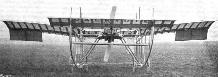
Front view of the Valkyrie racing-type monoplane.
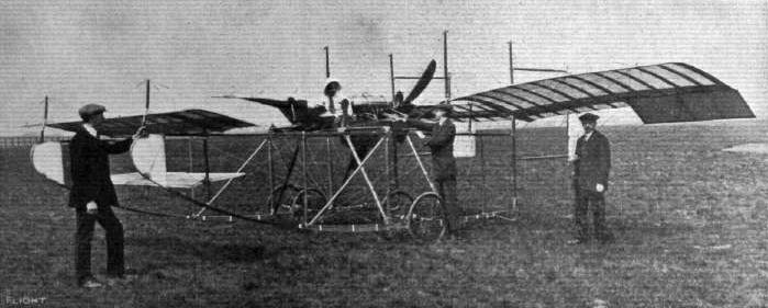
AT THE VALKYRIE SCHOOL AT HENDON. - Miss Edith Meeze, a pupil, just about to start. Reading from left to right: Barnes, the engineer-in-charge at the Valkyrie School, Miss Meeze, the School Instructor, and Mr. Harris, Works Manager.

The latest Valkyrie monoplane, with Green engine, at Olympia.
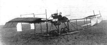
"Valkyrie," with a pupil in charge, at the London Aerodrome.
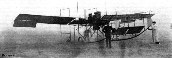
The Hon. Mrs. Assheton-Harbord, who secured the Royal Aero Club Challenge Cup for ballooning in 1910, about to take her first trip at the London Aerodrome on an aeroplane - the "Valkyrie."
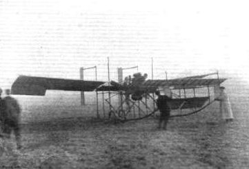
FLYING WORK AT THE LONDON AERODROME. - The "Valkyrie" three-seater ready to start with a full freight.
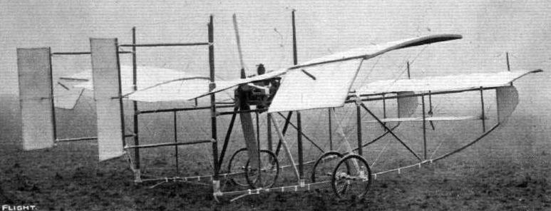
View of the Valkyrie B monoplane racer, showing the hinged balancing-planes and the outrigged rudders.
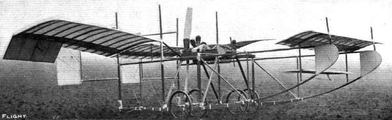
View from the side of the Valkyrie monoplane racer.
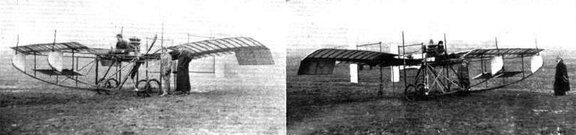
THE VALKYRIE SCHOOL MACHINE AND SOME PUPILS. - On the left is seen Mr. Clutterbuck at the helm, and just about to start. Standing by the side of the machine is the school instructor and Mr. Cedric Lee, the latest pupil. The right-hand photo shows Mr. Chambers in the pilot's seat just about to start, with two other "Valkyrie" pupils waiting to see his ascent.
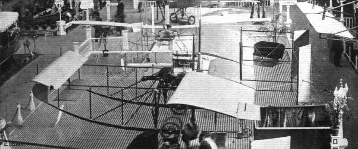
The 3-seater Valkyrie, by the Aeronautical Syndicate, at Olympia.
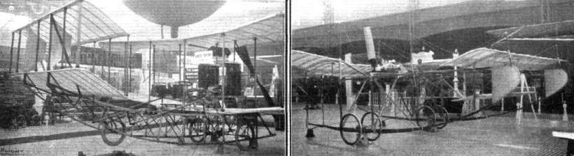
UNDERCARRIAGES AT OLYMPIA. - The Sanders and Valkyrie varieties of the girder skid.
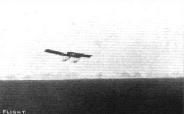
FLYING WORK AT THE LONDON AERODROME. - The "Valkyrie" three-seater in flight.
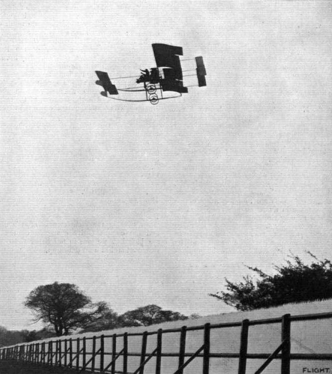
FLYING AT HENDON. - A snap of the pilot of the Valkyrie School flying at the London Aerodrome with one of the Valkyrie Type A monoplanes recently, during some demonstrations before some thousand or more spectators. The pilot was flying for considerable distances with both hands above his head, during one of which our photograph was secured. The photograph was taken from slightly below the machine, so that the most effective view of the picture is by holding it slightly forward and above one's eyes.

A fine vol plane by Mr. H. Barber on his Valkyrie monoplane last week upon the occasion of his flight from Shoreham to Hendonf accompanied by Miss Edith Meeze as passenger.
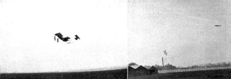
PROGRESS AT HENDON. - The first trials of the new Type B "Valkyrie" cross country racing machine fitted with Gnome engine. This machine was tried for the first time on Saturday, May 6th, and has exceeded all expectations of its designer. The speed is estimated to be at least 60-70 miles an hour. The machine has a remarkable rising capacity, which leads one to believe that it would be very easy to sacrifice a little of that quality In order to make the machine even still speedier. During the second trial of the machine it made six rounds of the Hendon Aerodrome, during which time, in order to keep the machine from rising above 200 ft. high, the pilot had to make over twenty vol plane descents. This machine carries a passenger easily, and is specially designed for fast crosscountry work and military service.
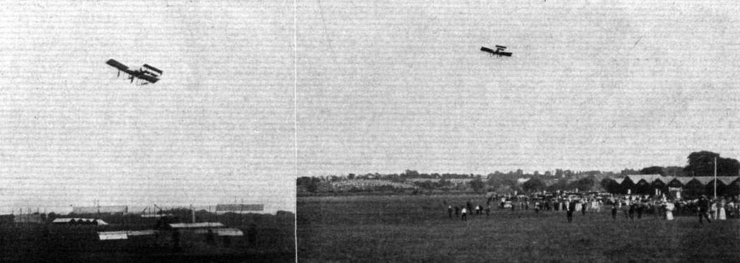
During the wait for the start from Hendon for the Daily Mail Circuit of Britain Mr. H. Barber made some very fine exhibition flights on his Valkyries, attaining a height of 2,000 ft., a flight also being made with a passenger. Our photographs show Mr. Barber in flight, and the right-hand picture gives a good idea of the crowds in the distance.
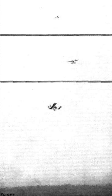
The Valkyrie Military Monoplane, high-flying and in gliding flight at Hendon. In the top photograph she is at a height of 2,000 ft., in the middle picture she is descending, and below, the pilot is completing a spiral vol plane.
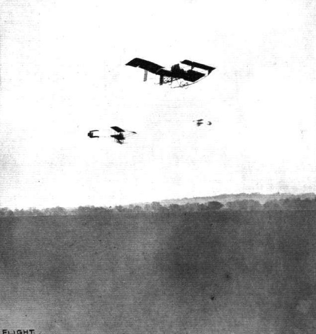
A trio in flight at the London Aerodrome, Hendon. Two Henry Famans and, in the foreground, a Type A Valkyrie.
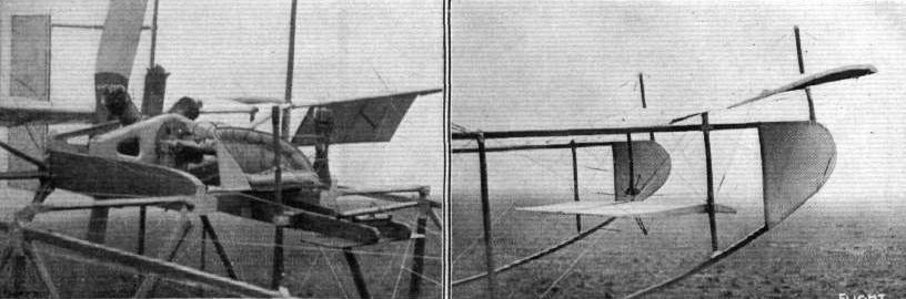
Detail views of the Valkyrie monoplane racer, showing (on the left) the pilot's seat and mounting of the Gnome engine. The right-hand view shows the two small "prows" under the fixed front plane.
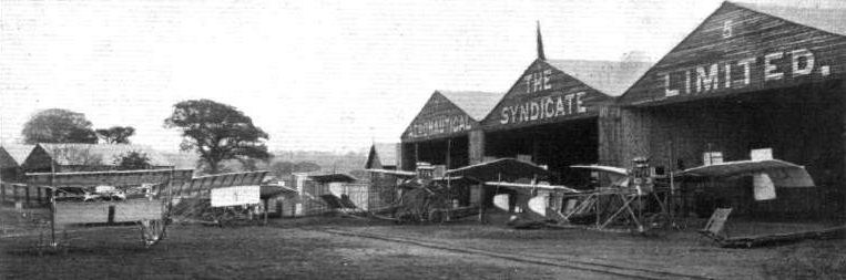
Part of the Valkyrie fleet of military aeroplanes on view at Hendon during the recent Parliamentary demonstration.

AN OBJECT LESSON IN MOBILITY. - An all-British "Valkyrie" military monoplane on its own wheels passing the Marble Arch en route from Hendon flying grounds to Brighton last week, where arrangements for exhibition flights have been made. In this manner the Valkyrie military design can travel anywhere with freedom, and the planes, which are attached to the sides, can be fitted in a few minutes, the machine then being in complete flying order.
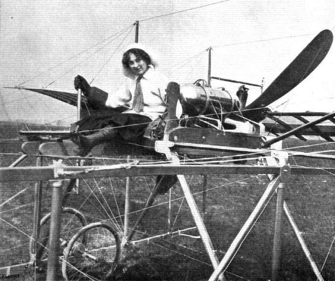
Miss Edith Meeze, a promising pupil at the Valkyrie Aviation Schcol at Hendon, in the pilot's seat ot the school machine.
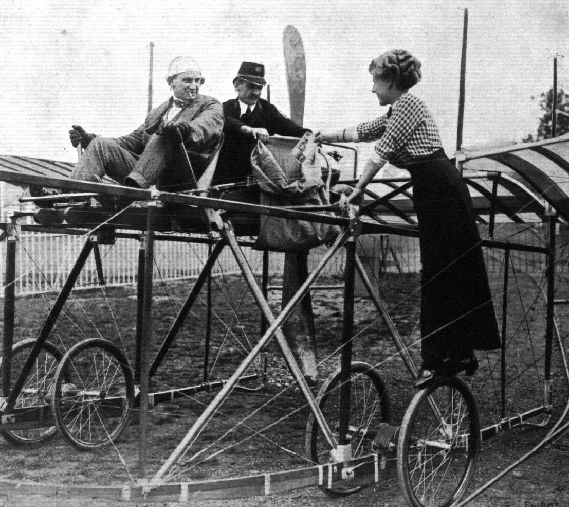
AERIAL LETTER POST. - An undress "rehearsal" at Hendon under Post Office conditions. Handing in a "late fee" letter. The aerial post, which will be carried out under the auspices of the Grahame White Co., starts, as referred to elsewhere, en September 9th.
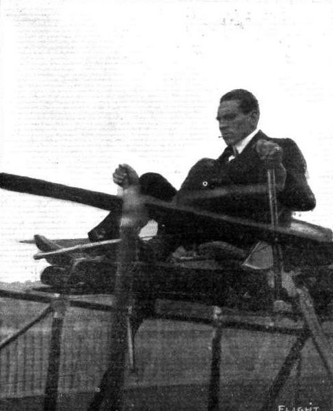
Mr. W. Ridley-Prentice, who is now taking active control in connection with the Aeronautical Syndicate at the Hendon London Aerodrome. Mr. Ridley Prentice is seen in the pilot's seat of the new Valkyrie racer.
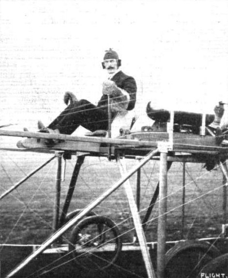
Capt. E. B. Loraine, of the Grenadier Guards, who last week secured his Royal Aero Club certificate on a 50-h.p. Gnome-engined Valkyrie at the Valkyrie School at Hendon.

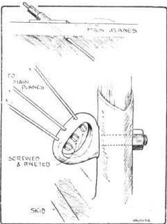
An interesting constructional detail on the latest Valkyrie, showing how the main wing guy-wires are anchored to a solid steel forging that can be detached as one piece from the principal strut. It is a feature of the Valkyrie design that none of the guy-wires are bent at the point of fastening.
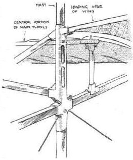
Sketch of the aluminium sockets as used for the attachment of the wings.
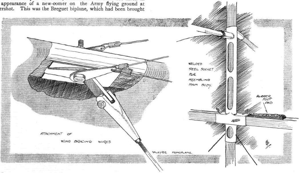
Constructional details of the new Valkyrie racer equipped with a Gnome motor of 50-h,p., to which we referred last week. One important innovation is the fact that the use of aluminium has been discarded, steel being used in its place.
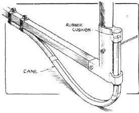
Sketch illustrating the cane fender under the rear end of the skid of the Valkyrie racer.
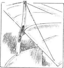
Sketch illustrating the manner of adjusting the attitude of the leading plane on the Valkyrie racer.
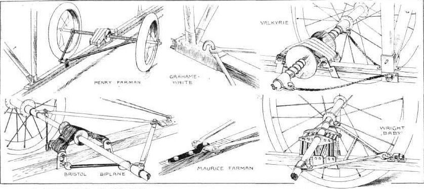
UNDERCARRIAGES AT OLYMPIA. - Comparative details in the construction of the Farman type wheel and skid combination.
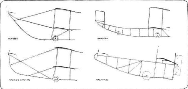
UNDERCARRIAGES AT OLYMPIA. - A comparison of some girder skids.
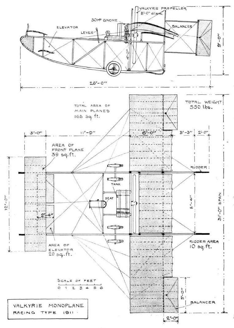
VALKYRIE RACER. - Plan and elevation to scale.
Flight, April 1, 1911.
THE ROE TRIPLANE.
GOING back into the early days before flying was popular and practical encouragement mostly conspicuous by its absence in England, the figure of A. V. Roe stands out in a kind of forlorn loneliness that is peculiarly British. Inspired by the conviction of the great future of flight, energised by the enthusiasm of the true pioneer, but handicapped always by lack of the wherewithal to do the thing properly, Roe struggled laboriously to achieve what, nowadays, is an almost ordinary accomplishment. Even to-dav, however, he is still original in his ideas, and his firm build the only triplane on the world's market. Regarded purely from a commercial standpoint it is possibly a pity that the Avroplane, as Roe called his machine long before it would fly, did not belong to one of the more popular types, for popularity is the greatest of all commercial assets these days, whether as a matter of business or pleasure.
On the other hand there is nothing so fickle as this aspect of fortune, and in the present struggle between the inherently fast monoplane and the evolved light biplane racer, it may yet be that the triplane shall come to its own. Fundamentally the problem of flight is to obtain the greatest supporting area for the least weight and the principle of superposed planes, so strongly advocated by such early pioneers as Wenham and Phillips, is by no means necessarily limited to the biplane formation, originated by Chanute, that is so popular to-day. The three-decker built with the monoplane type body is, as may be seen by the accompanying illustrations, by no means an ungainly machine, and it is at least interesting that its outstanding feature, which is the combination of the monoplane body with multiplane wings, has already found its way into general biplane construction, and characterises one or two of the prominent machines at Olympia this year.
Not unnaturally the Roe triplane has undergone many modifications in design, but its present form is unquestionably the most shipshape, as it is likewise the best flyer. Originally a machine that was practically a tandem triplane was constructed, but the multiplane tail member gave place to a simple monoplane directive organ that carries none of the essential load. The system of control, too, is now more or less conventional, the tail member carrying a single plane vertical rudder between the two parts of the divided monoplane elevator that form hinged extensions on a rigid triangular tail. The elevator is operated by a to-and-fro motion of the steering column, while the rudder is controlled by a pivoted cross-bar forming a foot-rest. A steering wheel mounted at right angles to the axis of the pivoted column is the means of maintaining lateral balance by warping the wings, but it will be observed that in the latest machine the lowest of the three planes has less span than the others, and it is only the latter that are influenced by the warping movement.
The body of the machine is an open triangular section girder made of ash and trussed with wires. It is situated just beneath the level of the middle plane, and its fore part is cased in from the engine to the pilot's seat. The engine itself, as may be observed from the illustrations, is mounted high up in the bows, and the direct driven propeller is some little distance in front of the leading edge of the planes. A simple undercarriage, supported on the Farman principle by four wheels mounted independently in pairs on the two skids, serves to support the entire weight of the front part of the machine, while the tail is kept clear of the ground by a rocking skid anchored to the frame by a piece of elastic.
A minor detail of construction indicative of thoughtfulness in design can be seen in the sketch of the mounting of this tail skid, which shows how it has been provided with a special rocker-shaped surface where it takes abutment against the base of the rudder post. Some other interesting constructional details are also illustrated in the sketches, which show the method of fitting the end struts of the main planes loosely into their sockets, and taking the tension by auxiliary tie-wires in order to facilitate the warping of the wings. Another detail illustrated by a sketch is the method of anchoring the diagonal tie-wires to thin steel plates that are clipped against the spars of the body by the principal aluminium brackets.
A characteristic feature of the Roe machine, considered as a triplane, is, of course, the relatively high aspect ratio of its planes. Owing to the fact that it has three planes, the same equivalent surface is available from a given span with a considerably reduced chord, and consequently the ratio of span to chord in each plane, which is termed the aspect ratio, has a higher value than is ordinarily to be found in biplane construction. In the machine illustrated a span of 32 ft. is accompanied by a chord of 3 ft. 6 ins., which corresponds to an aspect ratio of over nine. In most biplanes the same factor seldom exceeds six, and in monoplanes it is still less likely to be as high. The advantage of a high aspect ratio is fundamental in character, and has been substantiated in such laboratory experiments as have been conducted. It is concerned with the leakage of air over the extremities, which leakage bears a smaller percentage of the total volume of air dealt with as the aspect ratio increases for a given area of plane. Fundamentally, therefore, the triplane is potentially a more efficient combination than the biplane - provided always that other practical considerations do not interfere with the realisation of this feature - and it is at least to Mr. Roe's credit that he has flown with less power than anyone.

General view of the Roe triplane from behind.
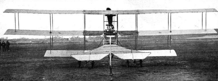
Rear view of the Roe triplane.
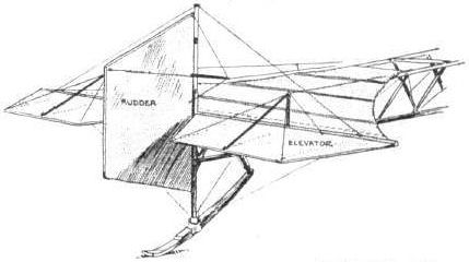
Sketch of the tail on the Roe triplane.
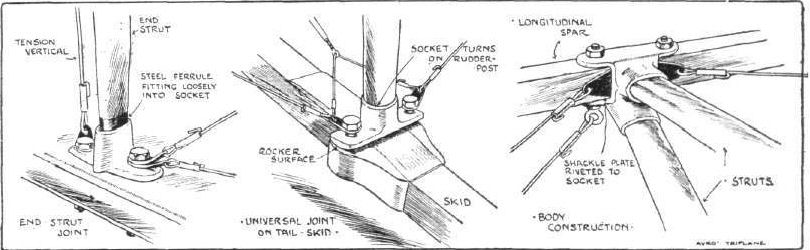
Sketches illustrating some constructional details on the Roe triplane.
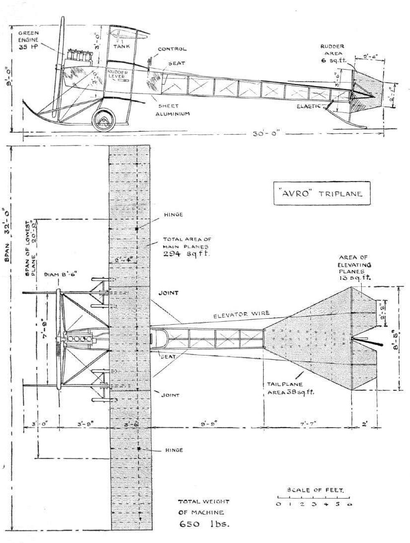
THE ROE TRIPLANE, 1911. - Plan and Elevation.
Flight, April 22, 1911.
FROM THE BRITISH FLYING GROUNDS.
Brooklands Aerodrome.
THE flying at Brooklands on Easter Monday was limited during the afternoon to a couple of lengthy flights by Mr. Pixton on the Avro biplane, built by Messrs. A. V. Roe and Co. The breeze was fairly strong and treacherous during the time the motor racing was on, and Mr. Pixton was the only one to venture aloft, he making one flight of about an hour's duration, and the second of about half an hour, and he consequently took the L30 prize for aggregate flight. During these trips Mr. Pixton occasionally attained a very good height, at one time being in the neighbourhood of 1,000 ft. above the ground. The second prize was won by Mr. Gustav Hamel, who went up at ten minutes to six on his Bleriot monoplane, with the intention of beating the world's record for height. Although the wind was still pretty strong, he climbed steadily until an altitude of 6,300 ft. had been reached, when he was obliged to give up the attempt, and came down in a long spiral glide, having been in the air for 19 minutes. Mr. Sopwith brought out the Martin-Handasyde monoplane, but in landing tipped the machine over on one side and damaged a wing. The Macfie biplane was out, and carried a passenger during a straight flight, while Mr. Eric G. England on a Bristol and M. Ducrocq on his Henry Farman biplane made several short demonstration flights in the evening.
Avro School. - On the first Thursday of this month Pixton brought out the new Avro biplane, fitted with 30-h.p. Green, for the first time, intending to try for a three-hour flight. No sooner had he started than the wind sprang up to 25 m.p.h., backed by a snowstorm, and so he returned to the more congenial atmosphere of his hangar after a few minutes.
On the following Saturday, in spite of a stiff wind, there was quite a large attendance, so to minimise their disappointment as much as possible Pixton determined to try a show with the Avro biplane. Starting at the Byfleet end, he rose in a wind that was blowing up to 35 m.p.h. This lifted him up and down bodily, and he landed at the Paddock end, as he was unable to turn owing to the wind being too strong, so the machine was wheeled back.
On the Sunday morning the wind was 15 m.p.h. Lieut. Beatty, Conway, Jenkins, and Pixion had the Avro biplane out giving each other flights, and the two former made straight flights alone. Tuesday afternoon, the n t h inst., the Avro was first out after the rough spell, as usual. Pixton did a few circles, and then handed the machine over to a new pupil, Lieut. Parke, R.N., he having had instructions to only roll for a start. To everyone's astonishment, he opened the engine full out, making a series of flights, and, landing by the Paddock, turned round and flew back, this being his first time on an aeroplane.
Wednesday, the 12th, Lieut. Parke, at his third attempt, kept up for half a circle on the Avro biplane in rather a stiff wind, greatly to his instructor's surprise. While over the sewage farm, his sleeve caught the switch, the machine divine; down before he was able to bring her nose up again, the skids sticking into the ground. Fortunately, only the tip of a skid was broken and a propeller. On Friday and Saturday Pixton was carrying passengers on the Avro biplane. Sunday he took up the Avro biplane 1,500 ft., vol planing down from that height.
On Monday, 17th, Bank Holiday, the wind was very tricky, almost a calm at times, and blowing 23 m.p.h. at others. Pixton was first out on the Avro biplane, and others followed, but they found the wind too uncomfortable. Pixton, therefore, had the field to himself. His first flight was nearly half-an-hour, and his second nearly an hour. Considering he had only a 30-h.p. Green, the performance was certainly a very meritorious one, and says a great deal for English piloting, design, and workmanship. The sooner manufacturers turn their attention to light, cheap machines that will fly with little power the sooner will aeroplaning become increasingly popular.
Flight, April 29, 1911.
FROM THE BRITISH FLYING GROUNDS.
Brooklands Aerodrome.
Avro School. - Messrs. A. V. Roe and Co. have added a genuine Farman driven by a Gnome to their school, for pupils who prefer this type of machine, which is to be used for carrying passengers as well.
Sunday morning Lieut. Beatty and Conway Jenkins had the Avro biplane out, and each flew several straight flights, and were carrying each other as passengers, in spite of a nasty wind.
Quite a number of people turned up on Sunday afternoon, although there was a tricky wind blowing. Pixton, as usual, with his disregard of the elements, and in order to lessen their disappointment, gave a clever display, flying several circuits.
Monday morning Conway Jenkins proved himself a very promising flyer, for at his second attempt on the Avro biplane he covered several circuits and made figure eights, landing quite well. There are now several pupils of the Avro School who are competent to go for their certificates if they can manage to get to Brooklands during a decently fine spell.
Lieut. Parke, who last week gave such an able display on the Avro biplane during his first three lessons, owing to a previous arrangement went through the formal tests for his brevet on a Bristol biplane.
In the evening Mr. Jenkins put in some pretty work on the Avro biplane, finishing with vol planes., while Pixton was flying around the track and district for an hour and ten minutes, preparing himself for the Brighton flight.
Flight, August 12, 1911.
BRITISH NOTES OF THE WEEK.
A Hydro-Aeroplane at Barrow.
BARROW is not so completely taken up with the naval airship as to ignore the heavier-than-air type of craft, and on Thursday of last week some interesting experiments were made with the Roe biplane which was recently purchased by Commander Schwann and fitted with a couple of floats. No attempt was made to get the machine in the air, but both Commander Schwann and Lieut. Boothby made trials with it, the former contenting himself with a straight run, while Lieut. Boothby made a circular trip on the surface of the Cavendish Dock. On Wednesday during some tests with the floats reversed the machine capsized but the pilot escaped with a ducking.
Flight, November 4, 1911.
THE AVRO BIPLANE.
THREE things at least stand to the credit of A. V. Roe, the development of the first successful triplane, the application of the monoplane type body on multiplane machines, and the construction of commercial aeroplanes for men of moderate means. Aeroplaning is considered the sport of the few, but all along it has apparently been A. V. Roe's object to make it the pastime of the many, for it has been his ambition to build machines that are inexpensive in initial cost and reasonable in upkeep.
Regarded purely from the technical standpoint, the design of the Avro biplane is characterised by its slender gracefulness, which is perhaps less appreciated by those inartistic souls who regard extreme robustness as the first principle in construction. Nevertheless, the designer seeks to acquire more than mere pleasing lines, for efficiency has ever been one of the principal objects that this pioneer constructor has sought to obtain with his machine. In his present model not only has the attribute of efficiency been combined with symmetry of outline and the safety of the pilot obtained by the monoplane type body construction, but a real attempt has been made at remedying the unwieldiness and awkwardness of transport that has so long characterised machines of cellular construction. To effect this, the main supporting surfaces are constructed in sections that are readily attachable and detachable by means of the simple clip illustrated.
A subsidiary advantage that this method of construction possesses is the ease with which the wing can be repaired by merely replacing a damaged section. This feature alone should place the Avro design in favour with those who have experienced the tedious stripping, boom-grafting, rib-refitting and recovering process associated with the general run of such machines. The planes are covered on both sides with cotton fabric, which is sized and varnished after being stretched in position over the wooden wing skeleton. Warping is utilised to preserve lateral balance, the end sections of the planes being flexed much after the manner adopted by the Wright Brothers. To accommodate the warping movement the rear boom of each end section is hinged to its rigidly-braced continuation in the inner wing sections by the simple hinge shown in the accompanying sketch, so that in the process of wing flexing that portion of the rear boom moves helically. The compression struts that brace the main planes are held in position by welded steel sockets and ears, to which the bracing wires are attached, and are formed integrally with the base of each socket - a really neat method.
The main body, of equilateral triangular section, is roughly boat-shaped, and assumes its maximum beam and draught just forward of the pilot's seat. At its front end, mounted on stout bearers which are in reality continuations of the top pair of body longitudinals, is the engine, a 35-h.p. Green, coupled direct to an 8 ft. 6 in. Avro propeller.
A very convenient point about the Roe body, from a constructor's point of view, is that its upper surface is flat from end to end and forms a "level line" from which all adjustments can be made. Thus the engine is merely placed in position on its bearers and no vertical adjustment whatever is required to ensure the propeller revolving in a plane normal to the line of flight. Similarly the flat, non-lifting tail needs no further adjustment after it has been fixed in position on the upper surface of the body.
Apart from this consideration, the main body of the Avro biplane possesses further interest in that it is cross-braced in a very neat manner. This is illustrated in Fig 3. An aluminium socket, in which the transverse struts are assembled, is applied to the longitudinal member by a single bolt, which also keeps in position a mild steel wiring lug. In this way the whole of the longitudinal spar can be removed or replaced by simply withdrawing the several bolts that keep it in position, without disturbing the remainder of the body. Each wire is tightened by a wire strainer.
The front end of the body is armoured with a "nose" of pressed steel, while, for a length of 2 ft. aft of this, aluminium panelling is applied to serve as a drip tray for oil leaking from the engine and to preserve the approximate stream line form of the body. From this point to its rear end the fuselage is covered with fabric.
Opinions vary as to the advisability of carrying this covering further than a point just to the rear of the pilot's cockpit on the grounds that an adverse affect is experienced in side winds. Such discussion can hardly be applied in this case, for the Avro biplane has proved, both in the hands of Pixton and Raynham, a most stable craft in wind. In any case it cannot be more harmful than those vertical stabilising fins that are still used to advantage by such constructors as the Antoinette Co., Robert Esnault-Pelterie, and Blackburn, while its correcting effects in case of a side dive are undoubted and easily apparent.
The landing carriage needs little description, as it has much in common with Henry Farman's conception, but being lower in build it is possibly stronger. Two fairly thick struts connect the front of the main body with the forward parts of the skids to protect the former from strain in the event of a rough landing.
The tail group is unique as regards the shape and area of the flat fixed plane, to the rear edge of which are hinged the two elevators. The former organ is rectangular and of a fairly high aspect ratio. Its area seems rather on the small side and, as has been discovered by experience, the elevator is thus rendered more sensitive. The reason for the employment of such a small directional surface is, it appears, an effort to eliminate the depressing effect on the tail produced when a large flat surface is working in the down draught of the wake from the main planes.
Both the rudder and the pair of elevating flaps swing on sets of hinges, having one pin to each series. A wooden skid, anchored by a stout elastic band to the bottom member of the body and loosely attached to the mast, which forms the rudder post, and to which the horizontal tail surface is braced, protects the tail unit.
The controlling surfaces are operated by a central lever, at the upper extremity of which is mounted a rotatable wheel, which governs the wing warping. A backward and forward motion of this lever controls elevation and depression. For the reason that the hand-wheel lever is conveniently placed and that the movements are to a great degree natural, this form of control is steadily gaining favour, and has been adopted by many of the leading constructors, among them Messrs. Short Bros, on their latest machine, and the Maison-Deperdussin, A pivoted foot bar operates the rudder.
FROM THE BRITISH FLYING GROUNDS.
Brooklands Aerodrome.
THE flying at Brooklands on Easter Monday was limited during the afternoon to a couple of lengthy flights by Mr. Pixton on the Avro biplane, built by Messrs. A. V. Roe and Co. The breeze was fairly strong and treacherous during the time the motor racing was on, and Mr. Pixton was the only one to venture aloft, he making one flight of about an hour's duration, and the second of about half an hour, and he consequently took the L30 prize for aggregate flight. During these trips Mr. Pixton occasionally attained a very good height, at one time being in the neighbourhood of 1,000 ft. above the ground. The second prize was won by Mr. Gustav Hamel, who went up at ten minutes to six on his Bleriot monoplane, with the intention of beating the world's record for height. Although the wind was still pretty strong, he climbed steadily until an altitude of 6,300 ft. had been reached, when he was obliged to give up the attempt, and came down in a long spiral glide, having been in the air for 19 minutes. Mr. Sopwith brought out the Martin-Handasyde monoplane, but in landing tipped the machine over on one side and damaged a wing. The Macfie biplane was out, and carried a passenger during a straight flight, while Mr. Eric G. England on a Bristol and M. Ducrocq on his Henry Farman biplane made several short demonstration flights in the evening.
Avro School. - On the first Thursday of this month Pixton brought out the new Avro biplane, fitted with 30-h.p. Green, for the first time, intending to try for a three-hour flight. No sooner had he started than the wind sprang up to 25 m.p.h., backed by a snowstorm, and so he returned to the more congenial atmosphere of his hangar after a few minutes.
On the following Saturday, in spite of a stiff wind, there was quite a large attendance, so to minimise their disappointment as much as possible Pixton determined to try a show with the Avro biplane. Starting at the Byfleet end, he rose in a wind that was blowing up to 35 m.p.h. This lifted him up and down bodily, and he landed at the Paddock end, as he was unable to turn owing to the wind being too strong, so the machine was wheeled back.
On the Sunday morning the wind was 15 m.p.h. Lieut. Beatty, Conway, Jenkins, and Pixion had the Avro biplane out giving each other flights, and the two former made straight flights alone. Tuesday afternoon, the n t h inst., the Avro was first out after the rough spell, as usual. Pixton did a few circles, and then handed the machine over to a new pupil, Lieut. Parke, R.N., he having had instructions to only roll for a start. To everyone's astonishment, he opened the engine full out, making a series of flights, and, landing by the Paddock, turned round and flew back, this being his first time on an aeroplane.
Wednesday, the 12th, Lieut. Parke, at his third attempt, kept up for half a circle on the Avro biplane in rather a stiff wind, greatly to his instructor's surprise. While over the sewage farm, his sleeve caught the switch, the machine divine; down before he was able to bring her nose up again, the skids sticking into the ground. Fortunately, only the tip of a skid was broken and a propeller. On Friday and Saturday Pixton was carrying passengers on the Avro biplane. Sunday he took up the Avro biplane 1,500 ft., vol planing down from that height.
On Monday, 17th, Bank Holiday, the wind was very tricky, almost a calm at times, and blowing 23 m.p.h. at others. Pixton was first out on the Avro biplane, and others followed, but they found the wind too uncomfortable. Pixton, therefore, had the field to himself. His first flight was nearly half-an-hour, and his second nearly an hour. Considering he had only a 30-h.p. Green, the performance was certainly a very meritorious one, and says a great deal for English piloting, design, and workmanship. The sooner manufacturers turn their attention to light, cheap machines that will fly with little power the sooner will aeroplaning become increasingly popular.
Flight, April 29, 1911.
FROM THE BRITISH FLYING GROUNDS.
Brooklands Aerodrome.
Avro School. - Messrs. A. V. Roe and Co. have added a genuine Farman driven by a Gnome to their school, for pupils who prefer this type of machine, which is to be used for carrying passengers as well.
Sunday morning Lieut. Beatty and Conway Jenkins had the Avro biplane out, and each flew several straight flights, and were carrying each other as passengers, in spite of a nasty wind.
Quite a number of people turned up on Sunday afternoon, although there was a tricky wind blowing. Pixton, as usual, with his disregard of the elements, and in order to lessen their disappointment, gave a clever display, flying several circuits.
Monday morning Conway Jenkins proved himself a very promising flyer, for at his second attempt on the Avro biplane he covered several circuits and made figure eights, landing quite well. There are now several pupils of the Avro School who are competent to go for their certificates if they can manage to get to Brooklands during a decently fine spell.
Lieut. Parke, who last week gave such an able display on the Avro biplane during his first three lessons, owing to a previous arrangement went through the formal tests for his brevet on a Bristol biplane.
In the evening Mr. Jenkins put in some pretty work on the Avro biplane, finishing with vol planes., while Pixton was flying around the track and district for an hour and ten minutes, preparing himself for the Brighton flight.
Flight, August 12, 1911.
BRITISH NOTES OF THE WEEK.
A Hydro-Aeroplane at Barrow.
BARROW is not so completely taken up with the naval airship as to ignore the heavier-than-air type of craft, and on Thursday of last week some interesting experiments were made with the Roe biplane which was recently purchased by Commander Schwann and fitted with a couple of floats. No attempt was made to get the machine in the air, but both Commander Schwann and Lieut. Boothby made trials with it, the former contenting himself with a straight run, while Lieut. Boothby made a circular trip on the surface of the Cavendish Dock. On Wednesday during some tests with the floats reversed the machine capsized but the pilot escaped with a ducking.
Flight, November 4, 1911.
THE AVRO BIPLANE.
THREE things at least stand to the credit of A. V. Roe, the development of the first successful triplane, the application of the monoplane type body on multiplane machines, and the construction of commercial aeroplanes for men of moderate means. Aeroplaning is considered the sport of the few, but all along it has apparently been A. V. Roe's object to make it the pastime of the many, for it has been his ambition to build machines that are inexpensive in initial cost and reasonable in upkeep.
Regarded purely from the technical standpoint, the design of the Avro biplane is characterised by its slender gracefulness, which is perhaps less appreciated by those inartistic souls who regard extreme robustness as the first principle in construction. Nevertheless, the designer seeks to acquire more than mere pleasing lines, for efficiency has ever been one of the principal objects that this pioneer constructor has sought to obtain with his machine. In his present model not only has the attribute of efficiency been combined with symmetry of outline and the safety of the pilot obtained by the monoplane type body construction, but a real attempt has been made at remedying the unwieldiness and awkwardness of transport that has so long characterised machines of cellular construction. To effect this, the main supporting surfaces are constructed in sections that are readily attachable and detachable by means of the simple clip illustrated.
A subsidiary advantage that this method of construction possesses is the ease with which the wing can be repaired by merely replacing a damaged section. This feature alone should place the Avro design in favour with those who have experienced the tedious stripping, boom-grafting, rib-refitting and recovering process associated with the general run of such machines. The planes are covered on both sides with cotton fabric, which is sized and varnished after being stretched in position over the wooden wing skeleton. Warping is utilised to preserve lateral balance, the end sections of the planes being flexed much after the manner adopted by the Wright Brothers. To accommodate the warping movement the rear boom of each end section is hinged to its rigidly-braced continuation in the inner wing sections by the simple hinge shown in the accompanying sketch, so that in the process of wing flexing that portion of the rear boom moves helically. The compression struts that brace the main planes are held in position by welded steel sockets and ears, to which the bracing wires are attached, and are formed integrally with the base of each socket - a really neat method.
The main body, of equilateral triangular section, is roughly boat-shaped, and assumes its maximum beam and draught just forward of the pilot's seat. At its front end, mounted on stout bearers which are in reality continuations of the top pair of body longitudinals, is the engine, a 35-h.p. Green, coupled direct to an 8 ft. 6 in. Avro propeller.
A very convenient point about the Roe body, from a constructor's point of view, is that its upper surface is flat from end to end and forms a "level line" from which all adjustments can be made. Thus the engine is merely placed in position on its bearers and no vertical adjustment whatever is required to ensure the propeller revolving in a plane normal to the line of flight. Similarly the flat, non-lifting tail needs no further adjustment after it has been fixed in position on the upper surface of the body.
Apart from this consideration, the main body of the Avro biplane possesses further interest in that it is cross-braced in a very neat manner. This is illustrated in Fig 3. An aluminium socket, in which the transverse struts are assembled, is applied to the longitudinal member by a single bolt, which also keeps in position a mild steel wiring lug. In this way the whole of the longitudinal spar can be removed or replaced by simply withdrawing the several bolts that keep it in position, without disturbing the remainder of the body. Each wire is tightened by a wire strainer.
The front end of the body is armoured with a "nose" of pressed steel, while, for a length of 2 ft. aft of this, aluminium panelling is applied to serve as a drip tray for oil leaking from the engine and to preserve the approximate stream line form of the body. From this point to its rear end the fuselage is covered with fabric.
Opinions vary as to the advisability of carrying this covering further than a point just to the rear of the pilot's cockpit on the grounds that an adverse affect is experienced in side winds. Such discussion can hardly be applied in this case, for the Avro biplane has proved, both in the hands of Pixton and Raynham, a most stable craft in wind. In any case it cannot be more harmful than those vertical stabilising fins that are still used to advantage by such constructors as the Antoinette Co., Robert Esnault-Pelterie, and Blackburn, while its correcting effects in case of a side dive are undoubted and easily apparent.
The landing carriage needs little description, as it has much in common with Henry Farman's conception, but being lower in build it is possibly stronger. Two fairly thick struts connect the front of the main body with the forward parts of the skids to protect the former from strain in the event of a rough landing.
The tail group is unique as regards the shape and area of the flat fixed plane, to the rear edge of which are hinged the two elevators. The former organ is rectangular and of a fairly high aspect ratio. Its area seems rather on the small side and, as has been discovered by experience, the elevator is thus rendered more sensitive. The reason for the employment of such a small directional surface is, it appears, an effort to eliminate the depressing effect on the tail produced when a large flat surface is working in the down draught of the wake from the main planes.
Both the rudder and the pair of elevating flaps swing on sets of hinges, having one pin to each series. A wooden skid, anchored by a stout elastic band to the bottom member of the body and loosely attached to the mast, which forms the rudder post, and to which the horizontal tail surface is braced, protects the tail unit.
The controlling surfaces are operated by a central lever, at the upper extremity of which is mounted a rotatable wheel, which governs the wing warping. A backward and forward motion of this lever controls elevation and depression. For the reason that the hand-wheel lever is conveniently placed and that the movements are to a great degree natural, this form of control is steadily gaining favour, and has been adopted by many of the leading constructors, among them Messrs. Short Bros, on their latest machine, and the Maison-Deperdussin, A pivoted foot bar operates the rudder.

STARTING FOR THE BRIGHTON RACE. - Mr. H. Pixton getting away for Brighton from Brooklands on the Roe biplane.
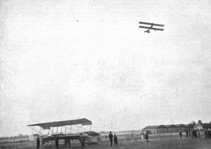
FLYING AT BROOKLANDS ON EASTER MONDAY. - In spite of the high wind whteh prevailed at Brooklands, Mr. Pixton, on the Roe biplane, put up a good flight for the Endurance Prize, securing it with 1h. 27m. 32s. In our photograph Mr. Pixton is seen during this flight, the machine on terra firma being one of the famous Bristol biplanes.
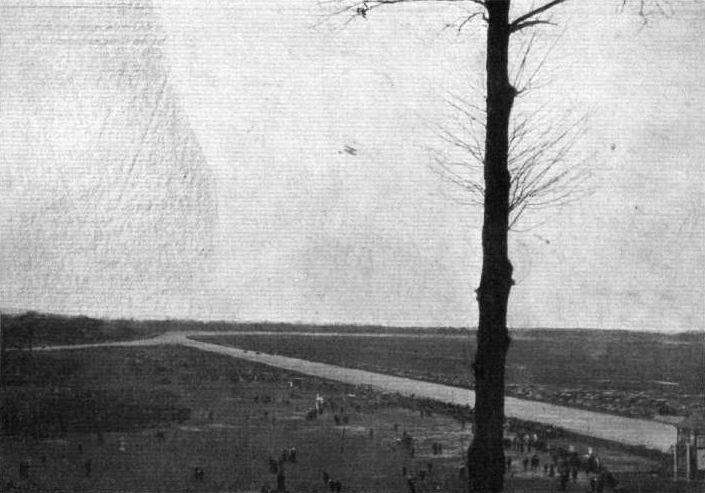
CARS AND AEROPLANES AT BROOKLANDS. - Pixton on the Roe biplane during the duration flight at Brooklands on Easter Monday. Below will be noted a race finishing up the straight, with the crowds in the enclosures, and the long wide string of motor cars stretching away beyond the paddock.
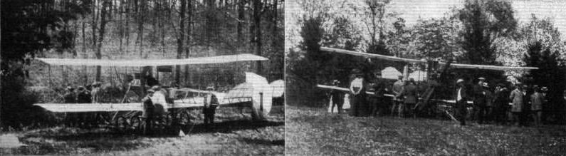
Mr. Pixton and the Avro biplane at rest for the night in Mr. England's grounds at Oakwood, Hayward's Heath, May 7th and 8th, en route for Brooklands upon his return flight from Brighton after the recent Brooklans-Brighton Race. On the left the Avro anchored for the night, and on the right ready for the start next morning.

A NAVAL AERO-HYDROPLANE BEING TESTED AT CAVENDISH DOCK, BARROW-IN-FURNESS. - Commander Schwann, of H.M.S. "Hermione," carrying out early morning trials on the Roe biplane, which has been fitted with float attachments of his own invention. The uninitiated should note that the smoking chimney stack has no connection with the biplane.
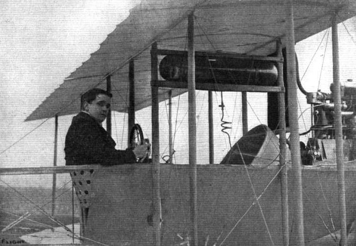
Mr. F . Conway Jenkins, one of the latest aviators to qualify for the Royal Aero Club pilot's certificate, on the 30-h.p. Green-engined Avro biplane, upon which he passed the tests on the 30th ult. in a 12-15 m.p.h. wind. This was only Mr. Jenkins' fourth time on the Avro machine, and previous to the official tests he was in the air at Brooklands for forty minutes at about 1,000 ft. height, rising to about 1,800 and finishing with a neat vol plane.
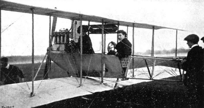
Mr. Pixton, just about to carry a lady passenger for a short trip, on the new Roe biplane, with which he so successfully flew at Brooklands on Easter Monday.
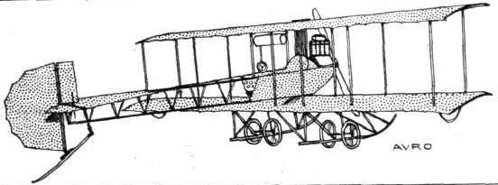
MONOPLANES AND BIPLANES IN THE DAILY MAIL CIRCUIT ROUND GREAT BRITAIN. - From these every machine can be readily identified either in flight or on the ground.
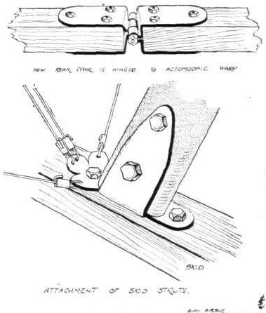
Constructional details of the Avro biplane.

The method employed on the Avro biplane of assembling the wing sections.
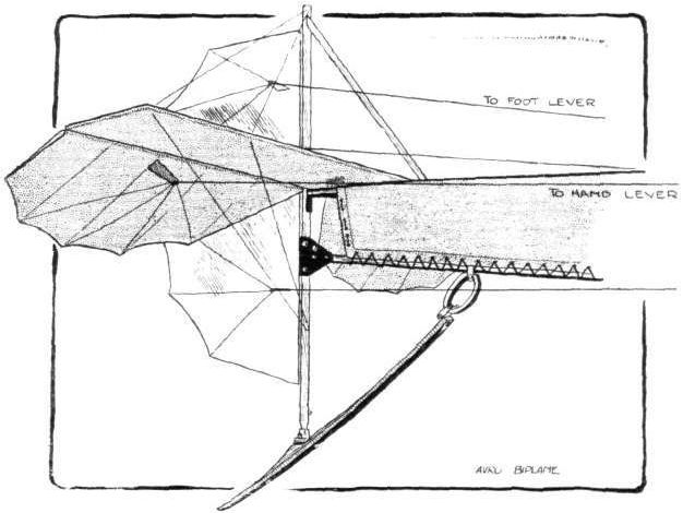
Arrangement of the tail unit of the Avro biplane.

The Avro method of cross-bracing the main body.
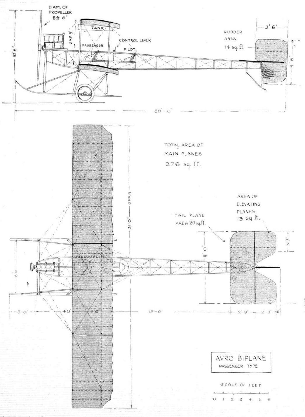
THE AVRO BIPLANE. - Plan and elevation to scale.
Flight, February 18, 1911
THE BARNWELL MONOPLANE,
THE accompanying photographs which have been sent to us by Mr. R. H. Barnwell, show something, although much less than might be desired, of the all-Scottish monoplane with which he is upholding Scottish prestige in the flight world and has just succeeded in winning the J. R. K. Law prize of L50 open to members of the Scottish Aeronautical Society. As our readers are aware, for a long time past Mr. Barnwell and the Grampian Motor Works, with which he is associated, have been experimenting in aeroplane work and the success that has attended his efforts at last is the result of a great deal of personal experience necessarily obtained very largely by trial and error, inasmuch as the work is being carried on in a place that is not exactly qualified to rank as yet as a centre of aviation in England.
The Barnwell monoplane is primarily interesting on account of the arrangement of the horizontal twin-cylinder Grampian engine with which it is fitted. This is very neatly placed in front of the body, within which the greater part of the engine is enclosed, only the cylinder-heads projecting on either side. The engine is said to develop 40 to 50-h.p., and is direct-coupled to a two-bladed wooden propeller. The rotation is anti-clockwise viewed from in front. Another interesting feature is the inclined position of the radiator, which is arranged as a kind of dashboard over the control mechanism and forms a sort of cab for the pilot. The whole machine is mounted on a central skid carriage supported by a light reinforced axle, which is braced to the front of the skid and t the body by wires. The body itself is entirely covered in, and is quite one of the characteristic features of the design. It terminates in the tail formed by fixed horizontal and vertical planes that carry hinged extensions, constituting the elevator and the rudder. The wings are given a considerable dihedral angle and a glance at the photograph showing the machine from behind also illustrates how the wings are stayed from above by a single wire attached to the side of the body. Presumably the designer is quite satisfied that the overhead mast and the usual multiplicity of wires to the top surface are unnecessary. The comparative absence of external trussing in this machine is at any rate very striking.
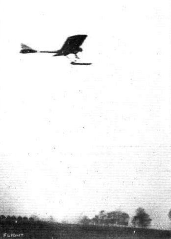
The Barnwell aeroplane, which has just won the J. R. K. Law L50 prize open to members of the Scottish Aeronautical Society, in flight.
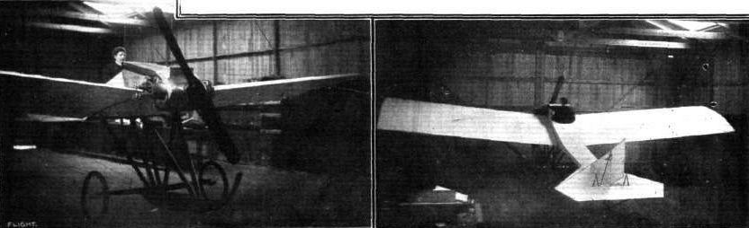
TWO VIEWS OF THE BARNWELL AEROPLANE. - On the left will be seen the very neat arrangement of the horizontal twin-cylinder engine; on the right the tail will be observed, and also the bracing of the main planes to the body.
Flight, March 25, 1911
AEROPLANES.
F. T. Bartelt. - An entirely original type of machine invented by Mr. F. T. Bartelt, Chairman of the Polysulphin Co., Ltd., of Bristol. At first glance this new invention reminds one in outline of an ordinary biplane, but, scrutinized in detail, it is at once found to be very different. It is true that there is a wooden propeller, and bicycle wheels are provided for the runs along the ground when starting or alighting, but the surfaces, which for the moment one may mistake for planes, are, as a matter of fact, movable wings, and in these lies the essence of the invention. There are four wings, two - one above the other - on each side. The engine - a 40-h.p. aviation engine with four fixed cylinders - works the wings by means of a chain-drive, which actuates a series of cranks. The result is that the wings beat with great force; when the upper wings have made their stroke, the stroke of the lower wings immediately follows, thus ensuring a smooth continuity in the propulsion. The wings consist of aerocloth laced to frames made of steel tubing. Each frame is 13 ft. long, 12 ft. broad at the base, and 7 ft. at the end, giving the wing a graceful taper. Instead of the aerocloth being strained over the frames as in aeroplanes, a considerable amount of slack is allowed, with the result that at each flap the wing gives the fabric well swell out into a kind of pocket. It's expected that this will give enormous lifting power, and, of course, the sustaining surface will be much bigger than if the wings were flat, or only slightly curved
Flight, April 1, 1911.
Third International Aero Exgibition at Olympia - 1911.
THE EXHIBITS ANALYSED.
<...>
The Bartelt machine is something apart from all accepted types. It consists of a steel structure of biplane appearance with loose saggy wing surfaces. The wings are mounted at their shoulders on cranks, whereby they rise and fall, while always remaining parallel to the ground. The motion of the cranks being circular, the wings, simultaneously with their rise and fall, move forwards and backwards - in other words, they perform a modified form of paddle action, the object being to derive support by beating the air. The wing motion is obtained from chain transmission, and in addition to the supporting reaction, there is said to be a propelling force sufficient to keep the machine going without the small propeller that is such a comparatively insignificant constructional feature of the machine as a whole. We are informed that the small scale prototype of the machine exhibited actually flew with a pilot weighing 8 stone 4 lbs.
<...>
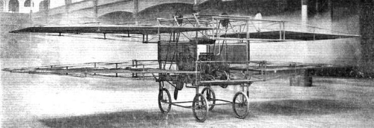
Bartelt ornithopter at Olympia Aero Show in 1911.
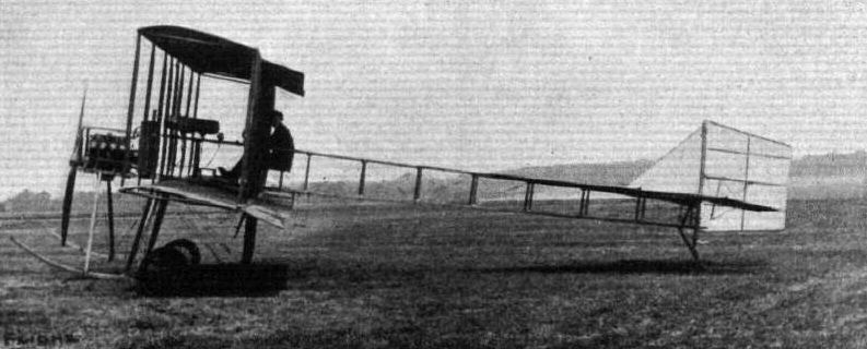
Mr. Percival in the pilot's seat of the Billing biplane at Brooklands, on which he has just obtained his pilot's certificate.
Flight, March 11, 1911
BRITISH NOTES OF THE WEEK.
The Blackburn Monoplane at Filey.
ALTHOUGH the machine was somewhat damaged in the end, very fair success was attained on Tuesday during some trials over Filey Sands with the Blackburn monoplane. With Mr. Hucks in the pilot's seat, the machine was run for a distance of three miles along the sand, just to see that everything was in order. Then, on the elevator-lever being moved, the monoplane took the air, and rising to a height of about 30 ft. headed for Filey Brigg, the speed being about 30 m.p.h. Unfortunately, in making a turn, the machine swooped, and one wing caught the ground, bringing the machine down, damaging the chassis.
Flight, March 25, 1911
AEROPLANES.
Blackburn Aeroplane Co. - Blackburn monoplane "Mercury," passenger type. In general design, the machine is composed of a body, to which are attached the two sustaining planes and where also is the pilot's seat. At the front is the motor and tractor screw and at the rear the tail for stability, at the extremity of which are hinged the controlling planes for direction and altitude.
The whole is supported by a landing chassis.
The following are the characteristics of the "Mercury" :-
Body. - The body is triangular in section and tapers backwards from that point where is fixed the pilot's seat, which occupies a position behind the passenger's seat, to the rear.
The construction, which is throughout of specially selected English ash, is in the form of a lattice girder, the members of which are butted up to the three main beams in such a manner as to ensure, as much as possible, their working in compression. This method of construction gives great strength and elasticity.
The front portion of the fuselage is covered with highly polished veneered wood, and the latter part with fabric, in order to reduce head resistance.
Planes. - The main planes are trapezoidal in form.
The two main spars on which the sections are built are of solid ash, grooved out along the neutral axis to form a channel section. In addition to these, lattice girder work, which is very strong, and, at the same time, light, runs the whole length of the planes, giving increased strength to counteract the upward and backward thrusts imparted to the planes whilst travelling through the air.
The sections are cut out to their true form and built up with wooden cords, forming the ribs to which is attached the fabric. The inner ends of the main spars form the attachment to the fuselage, the rear attachment being pivoted in a manner which will permit of the warping of the planes without causing the slightest strain.
Landing Chassis. - The fuselage is supported on a very strong chassis which is composed of two long skids connected to the body by ash struts and strongly braced up with high-tension steel wire.
Each skid is borne by a pair of wheels, the axle of which is held down by strong elastic shock-absorbers.
On the axle of the wheels are fitted steel springs which take any side thrust caused by the rough nature of the ground or a sideward landing. The whole arrangement allows for a deviation from the straight course.
Tail. - The rear portion of the body carries the tail, formed of a horizontal and vertical plane.
These are supported by vertical and horizontal ash beams, to which are also hinged the elevator and rudders. The whole is supported on a skid attached to the bottom of the vertical beam and carried up to the under portion of the fuselage.
Control. - The "Blackburn" patented triple control has been designed with the object of effecting all the necessary movements with one control. The three movements can be operated independently or simultaneously by the hand-wheel, leaving the feet free for the control of the engine.
The engine speed is controlled by a throttle lever, placed at the side of the pilot's seat, and also by a foot accelerator pedal operating in conjunction with but independent of the hand lever. By this means the throttle-lever can be set for a minimum or any desired engine speed, and thus, by depressing the foot-pedal the engine is instantly accelerated. When it is required to retard the speed of the engine, the accelerator pedal is released, but without any fear of stopping the engine, as it cannot retard below the setting of the throttle-lever.
Motor. - This machine is fitted with a 50-h.p. 7-cyl., radial, "Isaacson" engine. Bore 90 mm. Stroke, 115 mm. Number of revolutions, 1,600 per min.
Propeller. - The "Blackburn" propeller.
Weight. - 800 lbs. approx.
Flight, May 27, 1911.
FROM THE BRITISH FLYING GROUNDS.
Filey School (Blackburn Aeroplane Co.)
ON Thursday last week, Mr. Hucks, after completing his flight to Scarborough, spent over two hours in the air, repeating over and over again the necessary tests required for the Royal Aero Club's certificate. In one of his flights he executed a pretty vol plane from a height of 1,300 ft., and landed perfectly without the slightest jar.
On this day arrangements had been made with the Aero Club officials to witness the official flights for the pilot's certificate. He accomplished the distance flights with the greatest ease, as he had repeatedly done the required tests day by day previously.
He rose at 12.22 1/2 p.m. and completed the first figure of eight at 12.24, the second at 12.25 1/2, the third at 12.27, the fourth at 12.28 1/2, the fifth and last to count at 12.29 1/2, the sixth being finished at 12.30 1/2. He did one or two extra turns, but the official figures given show how he decreased his time each round. During this time the machine, which answered perfectly to his every demand, attained a height of over 300 ft., from which he came gracefully down to the exact starting point.
It was then thought that Mr. Hucks had completed everything for his certificate, when a doubt arose as to whether two distinct flights were necessary, and therefore to make assurance doubly sure on this point, Mr. Hucks decided to go up again. He set off and completed the first circuit, and was in the act of turning in the second circuit when the propeller flew clean off the engine and continued spinning round till it touched the ground. Had the machine been making a straight course there is no doubt but that Mr. Hucks would have been able to plane down with safety, but owing to the severe angle he was turning at the moment, the machine came to the ground and was badly damaged. Fortunately, Mr. Hucks escaped without any severe injury. The cause of this accident was due to the breaking of the sleeve of the propeller, which was due to it seizing and getting overheated. It is expected that Mr. Hucks will soon be ready to fly again.
Throughout the week Mr. Weiss has been practising by making trial straight runs to enable him to steer the machine in a straight course. He has now practically mastered this, and will shortly make attempts at short flights.
Flight, August 5, 1911.
THE BLACKBURN MONOPLANE.
AMONG the British firms early in the aeroplane industry, the Blackburn Co., of Leeds, is now achieving a success that is the reward of steady perseverance. Their machines have been flying particularly well lately over the Filey sands, and it is interesting, therefore, to publish at this moment the accompanying illustrations showing their general lines and constructive detail.
Broadly speaking, the Blackburn monoplane must be classified as belonging to the Antoinette type, its dihedral double-surfaced wings, boat-like covered body, and general arrangements of the tail members being superficially similar to this prototype. In detail, however, the apparent similarity disappears to give place to marked originality of constructive work. A mere glance at the accompanying full page drawing is sufficient to indicate at least one decided departure from Antoinette practice in the use of an under-carriage of altogether different design. The Blackburn monoplane is supported on a Farman type wheel and skid combination, but the skids have a narrow track of only five feet and the body is supported above them by a very substantial multiple "A" frame, which gives great rigidity and strength to the fore part of the machine.
The skids, it will be observed, are carried sufficiently far forward to protect the propeller, which is of unusually large diameter owing to the use of an Isaacson stationary radial engine, one of the features of which is, as our readers are aware, the combination of the engine with a half-speed reduction-gear for the propeller-drive. From the point of view of protecting the propeller, the utility of the strong "A" frame becomes still more apparent, for it will be noticed how little overhang there is to the toe of each skid.
The body of the machine is triangular in section and tapers towards the tail aft of the pilot's seat. It is built throughout of ash in the form of an openwork lattice girder, the vertical and diagonal struts being carefully butted against the longitudinal booms so as to make a thoroughly sound job without the use of wire. When finished, the body is surfaced with fabric on the after part and with veneered wood in front.
Ash spars are also used in the wings, and these are grooved to an I section so as to combine lightness with strength. The ribs are very carefully built about the spars, and a certain amount of lattice girder work is also introduced into the construction of the wing so as to increase its rigidity. The front main spars are rigidly fixed to the body, but those behind are hinged in order to facilitate wing warping.
The control of the Blackburn monoplane is one of the special features of its design, a universal mechanism being employed which differs, however, from the usual types. Immediately in front of the pilot, who occupies a seat in line with the trailing edges of the wings, is a steering-wheel placed in a vertical plane on a longitudinal shaft. This shaft terminates in a universal-joint, the forward portion of which is itself mounted in bearings on a bracket that is attached to a hollow transverse-shaft carried in supports projecting above the body of the machine. This transverse-shaft is divided at the centre in order to accommodate the aforementioned bracket, which is itself cut away so as to give room for a small winding-drum that is attached to the forward extremities of the universally-jointed shaft.
When the hand wheel is rotated, this winding drum operates a cord passing through the hollow transverse-shaft over pulleys to a lever that controls a longitudinal rock-shaft situated immediately under the body of the machine. From the forward end of this underneath rock-shaft other cords pass to the rear spars of the wings, for the purpose of warping. Turning the wheel is, therefore, employed for the purpose of balancing the machine by wing-warping.
Between the hand-wheel and the universal-joint, the first-mentioned shaft carries a fixed collar from which radiate four wires. Two pass over pulleys mounted on the tops of the brackets that support the transverse rock-shaft. The other two are connected in such a way that an up and down movement of the wheel causes the transverse-shaft already mentioned to rock. On the transverse-shaft is a lever from the extremities of which wires pass to the elevator. Raising and lowering the hand-wheel is thus employed for controlling the attitude of the machine in flight by means of the elevator, which consists of a hinged extension to the fixed horizontal tail plane.
When the hand-wheel is moved bodily sideways, the other wires, already described, operate the rudder, which consists of two triangular planes situated above and below the elevator. The special shape of these rudder planes is, of course, to enable the elevator to move up and down to the required extent.
The tail portion of the machine is supported above the ground by a simple skid that is trussed by the rudder post. Similar skids may also be observed on the extremities of the main wings, where they act as fenders should the machine accidentally heel over while running along the ground.
By no means the least interesting point in connection with the development of the Blackburn aeroplane is the fact that this Company have from the first been firm supporters of the Isaacson radial stationary engine. As our readers are already familiar with the features of this motor, it is, however, unnecessary to do more than merely refer to its three outstanding peculiarities, the first of which is that although radial the engine does not revolve; the second being that while stationary the engine is, nevertheless, air cooled, while the third feature is that, while the propeller is mounted concentrically about the crank-shaft it is, nevertheless, driven at half engine speed.
Flight, October 14, 1911.
THE BLACKBURN WARPING DEVICE.
A CLEVER method of effecting wing warping is employed on the Blackburn monoplane, and is illustrated herewith. Whereas it is customary to carry merely one wire to the wing-tip for the purpose of flexion, while the middle portion of the rear-boom is left more or less to look after itself, Mr. Blackburn designs his warping mechanism so that the whole of the rear boom swings positively about its pivoted attachment to the main body. Three clips are arranged approximately equidistant along the rear wing spar, and from these clips stranded cables are led over pulleys fixed on the back of the landing skids and attached by means of steel plates and split-pins to different radii set off on a small pressed-steel rocker, illustrated in Fig. 1.
The cable from the wing-tip, where there is naturally the greatest amount of flexion, is attached to the end of the rocker at a, and the cables from the two other clips are connected to points b and c on the rocker in such a way that the requisite amount of pull is given to each.
The method of dealing with those wires that support the rear wing boom when the machine is stationary is also a departure from usual practice. It will be recalled that these wires are generally passed over pulleys or through tubes at the apex of the cabane. This, of course, introduces friction, and to eliminate this Mr. Blackburn utilises the device illustrated in Fig. 2. The wires from the rear spar are passed through and securely brazed to a ribbon steel pendulum, which swings about a bolt at the top of the stout ash mast. They are connected so that the wire that undergoes the most movement passes through that part of the pendulum where the amplitude of swing is greatest, i.e., the end, and vice versa.
BRITISH NOTES OF THE WEEK.
Mr. B. C. Hucks Demonstrates at Cheltenham
AFTER his exhibition flights at Cardiff, Mr. Hucks' next point was Cheltenham, where he terminated his recent aviation tour in the west. Some excellent flights were made on the 5 th and 7 th inst., a special exhibition being given on the Gnome-engined Blackburn monoplane for the benefit of the Cheltenham collegians, who showed the greatest enthusiasm for the treat afforded them. On Saturday, whilst flying at a height of somewhere near 1,000 ft., Mr. Hucks' petrol gave out, but this in no way disconcerted him, as he made a graceful vol plane landing without damage in a neighbouring field to the Whaddon Farm, where his hangar was erected.
BRITISH NOTES OF THE WEEK.
The Blackburn Monoplane at Filey.
ALTHOUGH the machine was somewhat damaged in the end, very fair success was attained on Tuesday during some trials over Filey Sands with the Blackburn monoplane. With Mr. Hucks in the pilot's seat, the machine was run for a distance of three miles along the sand, just to see that everything was in order. Then, on the elevator-lever being moved, the monoplane took the air, and rising to a height of about 30 ft. headed for Filey Brigg, the speed being about 30 m.p.h. Unfortunately, in making a turn, the machine swooped, and one wing caught the ground, bringing the machine down, damaging the chassis.
Flight, March 25, 1911
AEROPLANES.
Blackburn Aeroplane Co. - Blackburn monoplane "Mercury," passenger type. In general design, the machine is composed of a body, to which are attached the two sustaining planes and where also is the pilot's seat. At the front is the motor and tractor screw and at the rear the tail for stability, at the extremity of which are hinged the controlling planes for direction and altitude.
The whole is supported by a landing chassis.
The following are the characteristics of the "Mercury" :-
Body. - The body is triangular in section and tapers backwards from that point where is fixed the pilot's seat, which occupies a position behind the passenger's seat, to the rear.
The construction, which is throughout of specially selected English ash, is in the form of a lattice girder, the members of which are butted up to the three main beams in such a manner as to ensure, as much as possible, their working in compression. This method of construction gives great strength and elasticity.
The front portion of the fuselage is covered with highly polished veneered wood, and the latter part with fabric, in order to reduce head resistance.
Planes. - The main planes are trapezoidal in form.
The two main spars on which the sections are built are of solid ash, grooved out along the neutral axis to form a channel section. In addition to these, lattice girder work, which is very strong, and, at the same time, light, runs the whole length of the planes, giving increased strength to counteract the upward and backward thrusts imparted to the planes whilst travelling through the air.
The sections are cut out to their true form and built up with wooden cords, forming the ribs to which is attached the fabric. The inner ends of the main spars form the attachment to the fuselage, the rear attachment being pivoted in a manner which will permit of the warping of the planes without causing the slightest strain.
Landing Chassis. - The fuselage is supported on a very strong chassis which is composed of two long skids connected to the body by ash struts and strongly braced up with high-tension steel wire.
Each skid is borne by a pair of wheels, the axle of which is held down by strong elastic shock-absorbers.
On the axle of the wheels are fitted steel springs which take any side thrust caused by the rough nature of the ground or a sideward landing. The whole arrangement allows for a deviation from the straight course.
Tail. - The rear portion of the body carries the tail, formed of a horizontal and vertical plane.
These are supported by vertical and horizontal ash beams, to which are also hinged the elevator and rudders. The whole is supported on a skid attached to the bottom of the vertical beam and carried up to the under portion of the fuselage.
Control. - The "Blackburn" patented triple control has been designed with the object of effecting all the necessary movements with one control. The three movements can be operated independently or simultaneously by the hand-wheel, leaving the feet free for the control of the engine.
The engine speed is controlled by a throttle lever, placed at the side of the pilot's seat, and also by a foot accelerator pedal operating in conjunction with but independent of the hand lever. By this means the throttle-lever can be set for a minimum or any desired engine speed, and thus, by depressing the foot-pedal the engine is instantly accelerated. When it is required to retard the speed of the engine, the accelerator pedal is released, but without any fear of stopping the engine, as it cannot retard below the setting of the throttle-lever.
Motor. - This machine is fitted with a 50-h.p. 7-cyl., radial, "Isaacson" engine. Bore 90 mm. Stroke, 115 mm. Number of revolutions, 1,600 per min.
Propeller. - The "Blackburn" propeller.
Weight. - 800 lbs. approx.
Flight, May 27, 1911.
FROM THE BRITISH FLYING GROUNDS.
Filey School (Blackburn Aeroplane Co.)
ON Thursday last week, Mr. Hucks, after completing his flight to Scarborough, spent over two hours in the air, repeating over and over again the necessary tests required for the Royal Aero Club's certificate. In one of his flights he executed a pretty vol plane from a height of 1,300 ft., and landed perfectly without the slightest jar.
On this day arrangements had been made with the Aero Club officials to witness the official flights for the pilot's certificate. He accomplished the distance flights with the greatest ease, as he had repeatedly done the required tests day by day previously.
He rose at 12.22 1/2 p.m. and completed the first figure of eight at 12.24, the second at 12.25 1/2, the third at 12.27, the fourth at 12.28 1/2, the fifth and last to count at 12.29 1/2, the sixth being finished at 12.30 1/2. He did one or two extra turns, but the official figures given show how he decreased his time each round. During this time the machine, which answered perfectly to his every demand, attained a height of over 300 ft., from which he came gracefully down to the exact starting point.
It was then thought that Mr. Hucks had completed everything for his certificate, when a doubt arose as to whether two distinct flights were necessary, and therefore to make assurance doubly sure on this point, Mr. Hucks decided to go up again. He set off and completed the first circuit, and was in the act of turning in the second circuit when the propeller flew clean off the engine and continued spinning round till it touched the ground. Had the machine been making a straight course there is no doubt but that Mr. Hucks would have been able to plane down with safety, but owing to the severe angle he was turning at the moment, the machine came to the ground and was badly damaged. Fortunately, Mr. Hucks escaped without any severe injury. The cause of this accident was due to the breaking of the sleeve of the propeller, which was due to it seizing and getting overheated. It is expected that Mr. Hucks will soon be ready to fly again.
Throughout the week Mr. Weiss has been practising by making trial straight runs to enable him to steer the machine in a straight course. He has now practically mastered this, and will shortly make attempts at short flights.
Flight, August 5, 1911.
THE BLACKBURN MONOPLANE.
AMONG the British firms early in the aeroplane industry, the Blackburn Co., of Leeds, is now achieving a success that is the reward of steady perseverance. Their machines have been flying particularly well lately over the Filey sands, and it is interesting, therefore, to publish at this moment the accompanying illustrations showing their general lines and constructive detail.
Broadly speaking, the Blackburn monoplane must be classified as belonging to the Antoinette type, its dihedral double-surfaced wings, boat-like covered body, and general arrangements of the tail members being superficially similar to this prototype. In detail, however, the apparent similarity disappears to give place to marked originality of constructive work. A mere glance at the accompanying full page drawing is sufficient to indicate at least one decided departure from Antoinette practice in the use of an under-carriage of altogether different design. The Blackburn monoplane is supported on a Farman type wheel and skid combination, but the skids have a narrow track of only five feet and the body is supported above them by a very substantial multiple "A" frame, which gives great rigidity and strength to the fore part of the machine.
The skids, it will be observed, are carried sufficiently far forward to protect the propeller, which is of unusually large diameter owing to the use of an Isaacson stationary radial engine, one of the features of which is, as our readers are aware, the combination of the engine with a half-speed reduction-gear for the propeller-drive. From the point of view of protecting the propeller, the utility of the strong "A" frame becomes still more apparent, for it will be noticed how little overhang there is to the toe of each skid.
The body of the machine is triangular in section and tapers towards the tail aft of the pilot's seat. It is built throughout of ash in the form of an openwork lattice girder, the vertical and diagonal struts being carefully butted against the longitudinal booms so as to make a thoroughly sound job without the use of wire. When finished, the body is surfaced with fabric on the after part and with veneered wood in front.
Ash spars are also used in the wings, and these are grooved to an I section so as to combine lightness with strength. The ribs are very carefully built about the spars, and a certain amount of lattice girder work is also introduced into the construction of the wing so as to increase its rigidity. The front main spars are rigidly fixed to the body, but those behind are hinged in order to facilitate wing warping.
The control of the Blackburn monoplane is one of the special features of its design, a universal mechanism being employed which differs, however, from the usual types. Immediately in front of the pilot, who occupies a seat in line with the trailing edges of the wings, is a steering-wheel placed in a vertical plane on a longitudinal shaft. This shaft terminates in a universal-joint, the forward portion of which is itself mounted in bearings on a bracket that is attached to a hollow transverse-shaft carried in supports projecting above the body of the machine. This transverse-shaft is divided at the centre in order to accommodate the aforementioned bracket, which is itself cut away so as to give room for a small winding-drum that is attached to the forward extremities of the universally-jointed shaft.
When the hand wheel is rotated, this winding drum operates a cord passing through the hollow transverse-shaft over pulleys to a lever that controls a longitudinal rock-shaft situated immediately under the body of the machine. From the forward end of this underneath rock-shaft other cords pass to the rear spars of the wings, for the purpose of warping. Turning the wheel is, therefore, employed for the purpose of balancing the machine by wing-warping.
Between the hand-wheel and the universal-joint, the first-mentioned shaft carries a fixed collar from which radiate four wires. Two pass over pulleys mounted on the tops of the brackets that support the transverse rock-shaft. The other two are connected in such a way that an up and down movement of the wheel causes the transverse-shaft already mentioned to rock. On the transverse-shaft is a lever from the extremities of which wires pass to the elevator. Raising and lowering the hand-wheel is thus employed for controlling the attitude of the machine in flight by means of the elevator, which consists of a hinged extension to the fixed horizontal tail plane.
When the hand-wheel is moved bodily sideways, the other wires, already described, operate the rudder, which consists of two triangular planes situated above and below the elevator. The special shape of these rudder planes is, of course, to enable the elevator to move up and down to the required extent.
The tail portion of the machine is supported above the ground by a simple skid that is trussed by the rudder post. Similar skids may also be observed on the extremities of the main wings, where they act as fenders should the machine accidentally heel over while running along the ground.
By no means the least interesting point in connection with the development of the Blackburn aeroplane is the fact that this Company have from the first been firm supporters of the Isaacson radial stationary engine. As our readers are already familiar with the features of this motor, it is, however, unnecessary to do more than merely refer to its three outstanding peculiarities, the first of which is that although radial the engine does not revolve; the second being that while stationary the engine is, nevertheless, air cooled, while the third feature is that, while the propeller is mounted concentrically about the crank-shaft it is, nevertheless, driven at half engine speed.
Flight, October 14, 1911.
THE BLACKBURN WARPING DEVICE.
A CLEVER method of effecting wing warping is employed on the Blackburn monoplane, and is illustrated herewith. Whereas it is customary to carry merely one wire to the wing-tip for the purpose of flexion, while the middle portion of the rear-boom is left more or less to look after itself, Mr. Blackburn designs his warping mechanism so that the whole of the rear boom swings positively about its pivoted attachment to the main body. Three clips are arranged approximately equidistant along the rear wing spar, and from these clips stranded cables are led over pulleys fixed on the back of the landing skids and attached by means of steel plates and split-pins to different radii set off on a small pressed-steel rocker, illustrated in Fig. 1.
The cable from the wing-tip, where there is naturally the greatest amount of flexion, is attached to the end of the rocker at a, and the cables from the two other clips are connected to points b and c on the rocker in such a way that the requisite amount of pull is given to each.
The method of dealing with those wires that support the rear wing boom when the machine is stationary is also a departure from usual practice. It will be recalled that these wires are generally passed over pulleys or through tubes at the apex of the cabane. This, of course, introduces friction, and to eliminate this Mr. Blackburn utilises the device illustrated in Fig. 2. The wires from the rear spar are passed through and securely brazed to a ribbon steel pendulum, which swings about a bolt at the top of the stout ash mast. They are connected so that the wire that undergoes the most movement passes through that part of the pendulum where the amplitude of swing is greatest, i.e., the end, and vice versa.
BRITISH NOTES OF THE WEEK.
Mr. B. C. Hucks Demonstrates at Cheltenham
AFTER his exhibition flights at Cardiff, Mr. Hucks' next point was Cheltenham, where he terminated his recent aviation tour in the west. Some excellent flights were made on the 5 th and 7 th inst., a special exhibition being given on the Gnome-engined Blackburn monoplane for the benefit of the Cheltenham collegians, who showed the greatest enthusiasm for the treat afforded them. On Saturday, whilst flying at a height of somewhere near 1,000 ft., Mr. Hucks' petrol gave out, but this in no way disconcerted him, as he made a graceful vol plane landing without damage in a neighbouring field to the Whaddon Farm, where his hangar was erected.
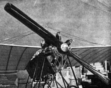
The Isaacson stationary radial engine on the Blackburn monoplane.
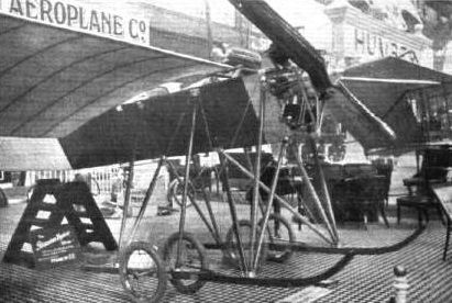
UNDER-CARRIAGES AT OLYMPIA. - The multiple "A" frame of the Blackburn monoplane.

The Mercury I monoplane (50 hp Isaacson) flying at Filey in 1911. The slipway below the machine led to Robert Blackburn's hangar on the right.
Mr. Hucks flying the Blackburn monoplane over the marked course on Filey Sands last week for his certificate. - In the background is seen the aeroplane shed on the cliffs and the road from the beach.
Mr. Hucks flying the Blackburn monoplane over the marked course on Filey Sands last week for his certificate. - In the background is seen the aeroplane shed on the cliffs and the road from the beach.

The Blackburn "Mercury" monoplanes entered for the Daily Mail Circuit of Great Britain, to be piloted respectively by Mr. B. C. Hucks and Mr. Conway Tenkins.

Mr. B. C. Hucks' Blackburn monoplane being brought back to the shed at Cheltenham last week followed by an admiring crowd of Cheltenham collegians, for whom Mr. Hucks has just made an exhibition flight.
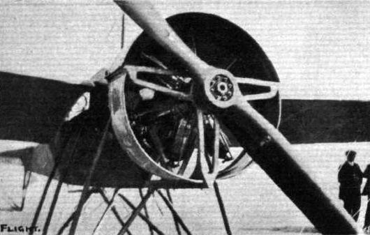
THE BLACKBURN MONOPLANE. - View showing the method of mounting and encasing a Gnome rotary engine, when this type of motor is employed.
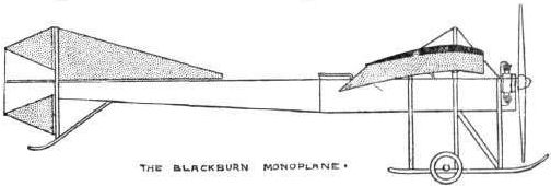
THE BLACKBURN MONOPLANE.

MONOPLANES AND BIPLANES IN THE DAILY MAIL CIRCUIT ROUND GREAT BRITAIN. - From these every machine can be readily identified either in flight or on the ground.
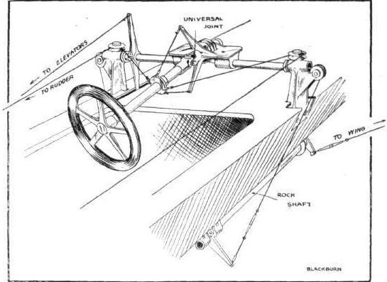
Sketch illustrating the control on the Blackburn monoplane.
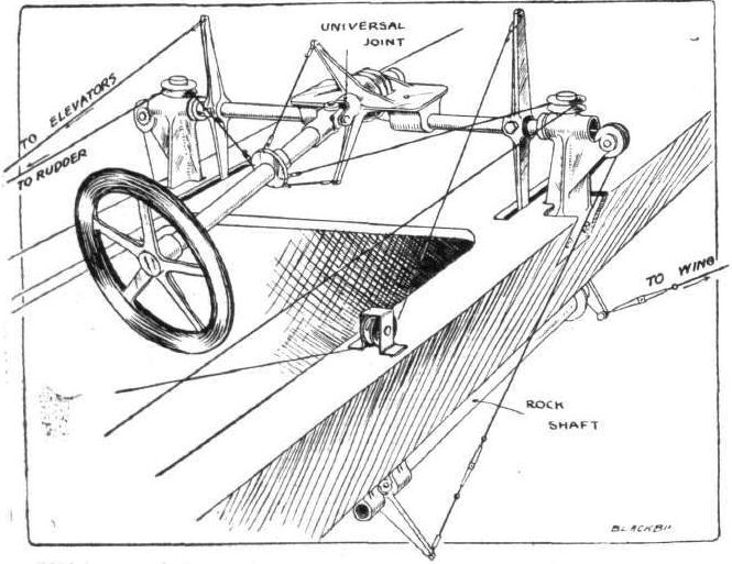
Sketch showing the control system of the Blackburn monoplane.
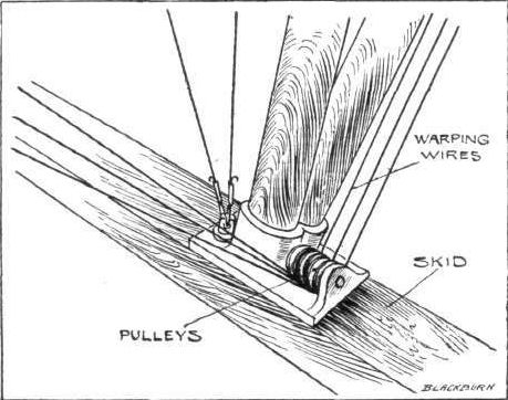
Sketch illustrating the very neat pulley arrangement combined with a strut socket on one of the skids of the Blackburn monoplane.
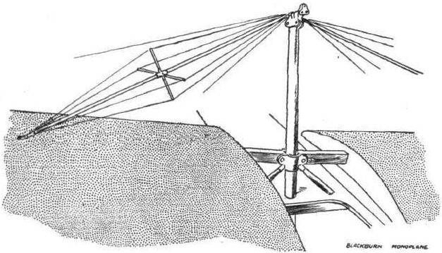
Sketch illustrating the mast and special arrangement of guy wires for the support of the main wings on the Blackburn monoplane.
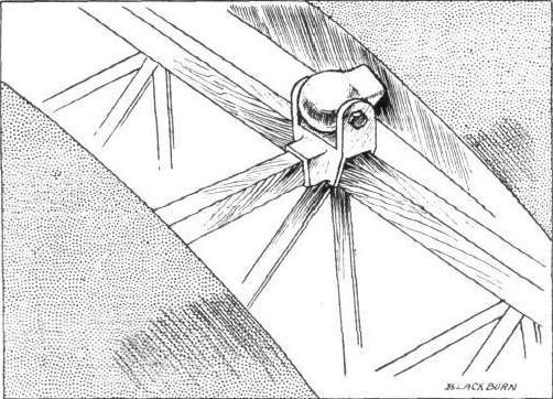
Sketch illustrating the hinged attachment of the rear spar in the main wings to the body of the Blackburn monoplane.
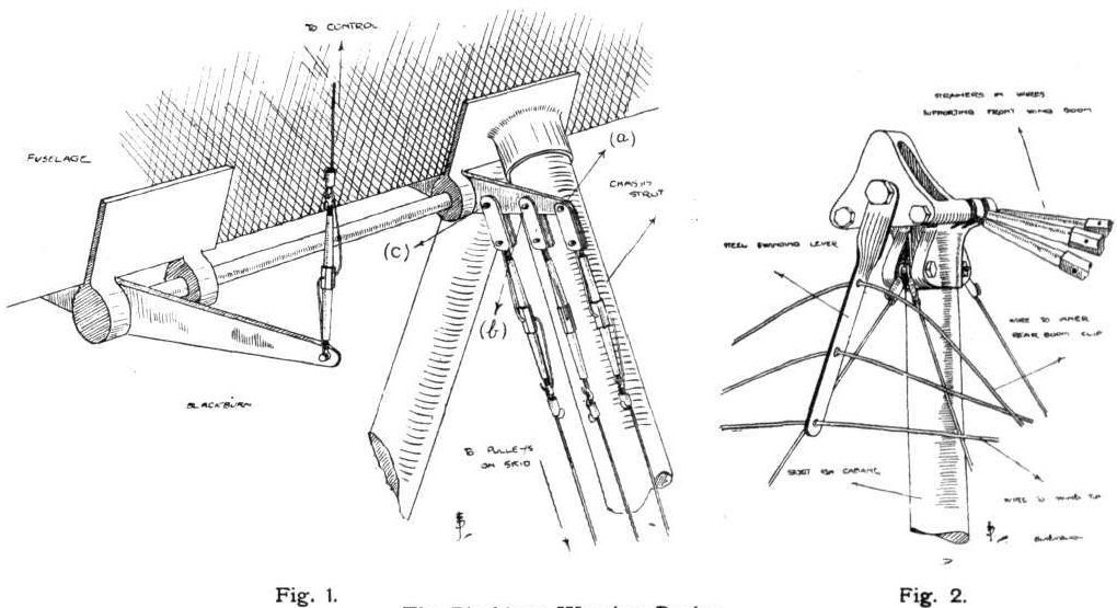
The Blackburn Warping Device.
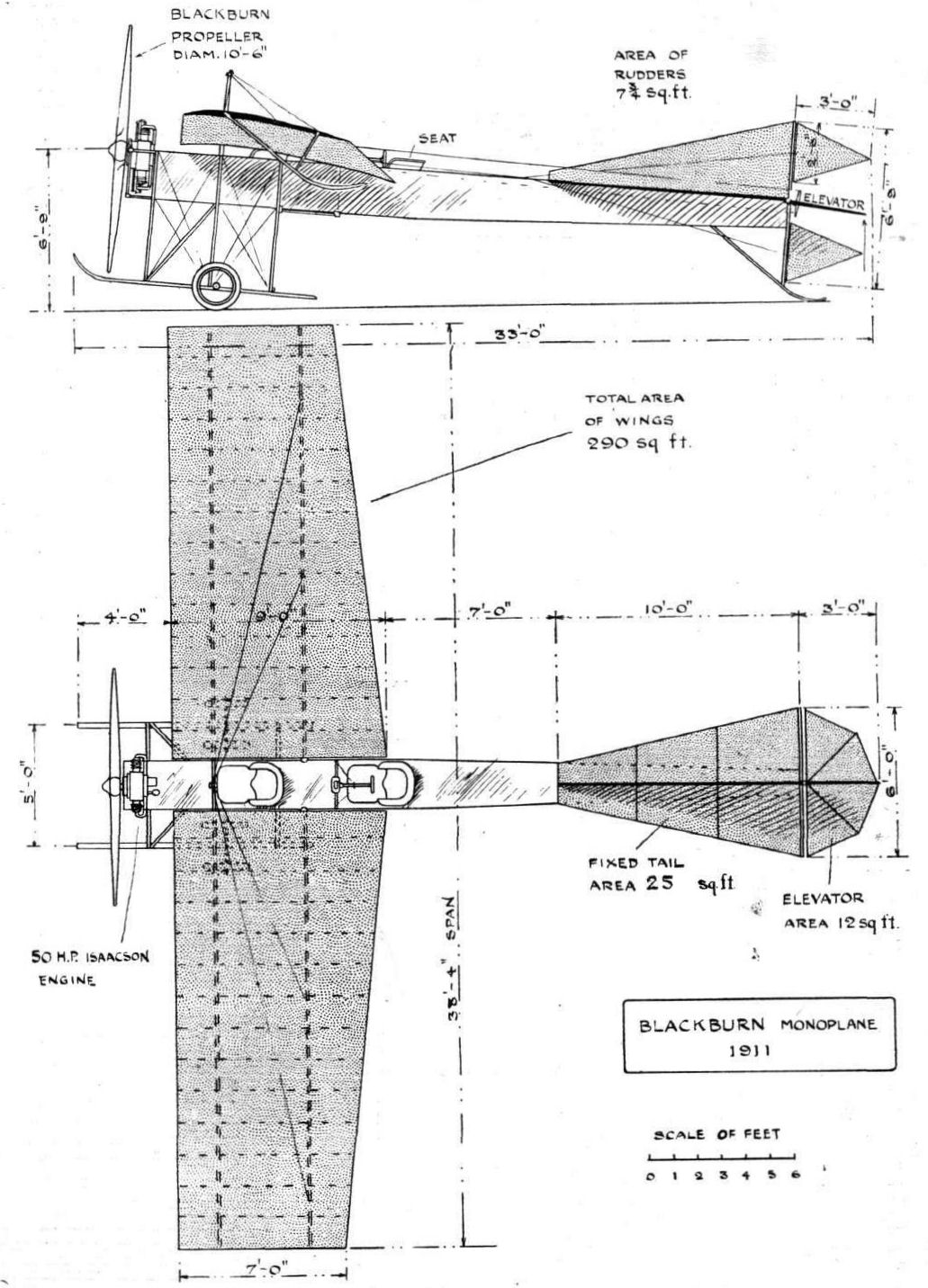
THE BLACKBURN MONOPLANE, 1911. - Plan and elevation to scale.
Flight, March 18, 1911
Model Mayfly.
I enclose a photo of a scale model of my improved type 30-ft. span machine.
The model is 7 ft. 7 ins. span, and has an area of 13.8 sq. ft. and weighs 5 1/2 lbs. It behaves like a full-size machine, and I hope to carry out several tests for weight-lifting and stability. Under varying conditions, in a wind of 24 m.p.h., the model, was easily carrying 12.8 ozs. per square foot. I could not then get on any more weight without removing the chassis of the model. The controls are the same as the full-size machine, and when the control lever is left free to move on the model the machine is automatically stable, by which I mean she corrects her own movements. In the photograph there was a very light wind and she is soaring tail down. I test all my models the same way, soaring, towed flight and gliding. I do not think the usual light elastic-driven models are of any use for experiments. I expect this model will lift over 1 lb. to the square foot if she will take all the extra weight without breaking.
Carnmoney, Belfast. LILIAN E. BLAND.
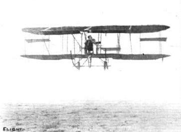
FLYING IN IRELAND. - The "Mayfly," the Bland biplane, with Miss Lilian E. Bland, its designer and constructor, in the pilot's seat, in full flight at Carnamoney, near Belfast, where this very enterprising lady is carrying on her work of building machines. Our photograph was
secured during a foggy and hard frosty day.
secured during a foggy and hard frosty day.
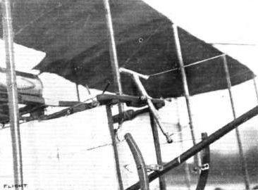
MISS L. E. BLAND'S "MAYFLY." - View showing the general arrangement of the controls. The main lever of the Farman action type is made of steel tubing, and it will be seen that bicycle pedals have been fitted to the footlevers as longer pull was required with new type of rudder. Wire connections have been found better than rods for the petrol and throttle-levers seen at the side of the seat which is enclosed in fabric.
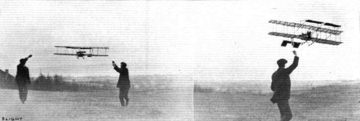
MISS BLAND'S MODEL MAYFLY, TYPE NO. 2. - Towed flight (on left), and soaring (on right).
Flight, April 15, 1911.
MODEL PRIZE WINNERS AT OLYMPIA.
1st Prize, Workmanship.
G. P. BRAGG SMITH (NO. 50)
A 1 1/2 in. scale model of a full-sized machine in course of construction. The principal feature of this machine Consists in the lower planes being so curved that the extremities join those of the upper horizontal plane, the theory being that as the machine tilts laterally a greater projected surface is presented on the side that needs it most, i.e., the lower. Other features are as follows :- Main planes can be bodily removed from the fuselage, and the under-carriage is also easily dismantled. The pilot's seat is situated high up behind the engine between the main planes. The propeller is at the rear, and there is a fixed monoplane right in front; this latter, which has a dihedral angle, can be adjusted. Just behind the leading plane is the elevator, which is in line with the middle of the gap. The fuselage is purposely kept narrow so that the head resistance is concentrated as near the centre as possible. Situated at the front of the fuselage is a very neat skid carrying a running wheel, which would prevent any damage occurring should the machine come down head first.
Flight, April 1, 1911.
Christiaens at Singapore.
A SERIES of flights were made in the neighbourhood of Singapore on Saturday week by M. Christiaens, using one of his Bristol biplanes. Some difficulty was experienced in getting the machine to rise to any considerable height, this being due, it was stated, to the rarity of the atmosphere.
Flight, May 20, 1911.
BRITISH NOTES OF THE WEEK.
Flying Through a Thunderstorm.
WHILE delivering a Bristol biplane by way of the air to Mr. Morison at Brighton, Mr. Collyns Pizey, of the British and Colonial Aeroplane Co., had a thrilling experience. He rose from Salisbury Plain on a new Bristol military biplane late on Thursday afternoon, and had not gone far when a thunderstorm which had been threatening for some time broke in all its fury. Afterwards Mr. Pizey said that he then had what was probably the most awe-inspiring quarter of an hour ever experienced by an airman. Lightning played about the machine almost like flames, and the noise of the thunder was deafening. Owing to the dense rain, the pilot was unable to see the earth for some time, but he eventually effected a landing to the east of Portsmouth, where he anchored for the night. Early the next morning he was able to resume his journey, and duly delivered the new Bristol to Mr. Morison. It was the aviator's first long cross-country flight, and the experience will undoubtedly live long in his memory.
Flight, August 26, 1911.
BRITISH NOTES OF THE WEEK.
A British General Gets His Brevet.
THE British Army, as well as the French, can now boast a General as a certificated pilot, as on Wednesday, the 16th inst., Brigadier-General David Henderson - Chief Staff Officer to Sir John French - who had been learning under the name of Henry Davidson at the Bristol Company's School at Brooklands, made the necessary flights to get his certificate. He had only had one week's training, and the diary of the seven days' work will no doubt prove interesting to some of our readers. It is as follows :-
Wed., 9th inst. - 2 1/2 circuits passenger flight.
Thur., 10th. - Long passenger flight.
Fri., 11th. - Nil.
Sat., 12th. - Long passenger flights.
Sun., 13th. - 1 1/4 hrs. passenger flights. 1/4 hr. rolling alone.
Mon., 14th. - 20 mins. passenger flight. 1/4 hr. rolling alone. Another short passenger flight.
Tues., 15th. - 2 circuits passenger flight, then alone for three flights, lasting a total of 35 mins., at an average height of 60 ft., rising to 150 ft. No straight flights, but went off at once and made circuits.
Wed., 16th. - Passed tests for his certificate.
It should help considerably at the War Office to have an officer of such high rank fully qualified as a pilot aviator.
Flight, September 16, 1911.
FROM THE BRITISH FLYING GROUNDS.
Salisbury Plain.
The Air Battalion. - The officers have hardly settled down to normal work yet, but they are returning in ones and twos, as also are the machines, several of which are decidedly the worse for wear. Tuesday evening of last week was splendid for flying, and Capt. Fulton made several good trips. As Lieut. Barrington Kennett was expected fires were lighted to guide him, but he came not. On Wednesday Capt. Fulton and Lieut. Conner put in a good deal of scouting practice, mostly at a height of about 800 ft. Several more officers and twenty-seven men returned to camp from manoeuvres during the day. Two more sheds to accommodate the Army machines are now being erected by Messrs. Harbrow, of Bermondsey. On Thursday Capt. Fulton and Lieut. Conner were again busy, and a few minutes after seven in the evening Lieut. Barrington Kennett arrived from Farnborough, at a good height, and landed by a spiral vol plane. On Friday two more machines arrived from Oxford and a good deal of work was put in by Capt. Fulton and Lieut. Barrington Kennett, in the evening these same officers with Lieut. Conner and Lieut. Reynolds again flying. A great amount of work was put in on Saturday morning repairing the various machines in the hangars, while outdoor work consisted of flying by Capt. Fulton, Lieut. Barrington Kennett and Lieut. Conner, all three again flying on Sunday morning, Lieut. Conner carrying a passenger. On Monday they were practising in view of some despatch-carrying and bomb-dropping experiments which will shortly be carried out.
Flight, October 28, 1911.
BRITISH NOTES OF THE WEEK.
Mr. Pixton Flies from Amesbury to Hayling Island.
ON Saturday week last Mr. Pixton made a trip on a Bristol biplane to Hayling Island, mainly with the object of making some flights over the sea. Starting from Amesbury at 2 p.m, with Lieut. Burney, R.N., as passenger, they arrived at Hayling Island at 5 o'clock, having stopped at Durley, near Eastleigh, for lunch. In addition to the stop for lunch, the aviators were handicapped so far as speed was concerned by a very strong head wind, which they had to battle with. When nearing the sea, the gustiness of the wind contiderably moderated, and the change to a steady current was particularly helpful. After Mr. Pixton's arrival the weather remained so persistently gusty that he was only able to fly on three occasions, the wind going steadily from bad to worse. During all this time the machine was simply tied down on the shore, surrounded by a few bathing machines, as seen in our photograph, a fact which speaks volumes for the high-class workmanship put into the Bristol machines by the constructors.
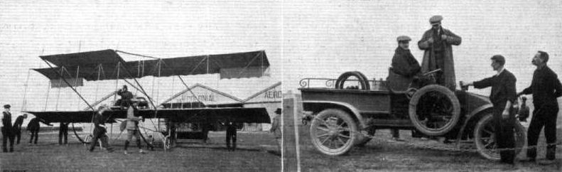
Mr Collyns Pizey just about to start off from Salisbury Plain for Brighton with the Bristol biplane for Mr. O. C. Morlson, as described in our last issue. Mr. Fleming is in the foreground, and on the extreme right M. Vusepey. In the right-hand photograph are Mr. Hotchkiss, sitting at wheel of car, and Mr. Fleming, standing, who followed Mr. Pizey to Brighton by road.
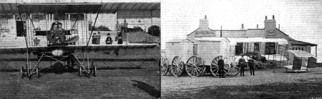
Mr. E. Howard Pixton and his "Bristol" biplane, which he recently flew from Amesbury to Hayling Island, where he subsequently made some flights under the somewhat trying conditions of the gales which have been blowing in that district. The left-hand view shows the machine just starting for a flight in front of the Royal Hotel, with Lieut. Burney, R.N., and Mr. Farnall Thurston, of the Bristol firm, as passengers. The float under the seat should be noted, which is provided in case the machine should descend into the sea. The right-hand view shows the machine "camped" out for the night between a house and some bathing machines.

Mr. Low just "off" on his Bristol biplane at Brooklands Aerodrome.
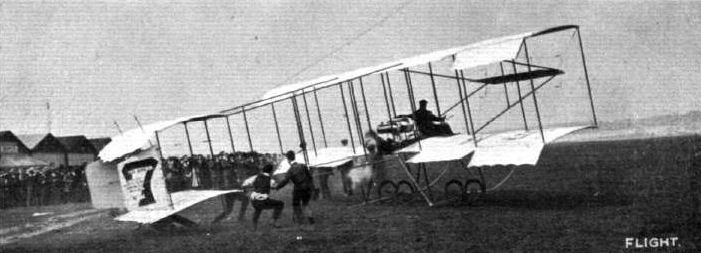
STARTING FOR THE BRIGHTON RACE. - D. Graham Gilmour taking-off at Brooklands in the Bristol Boxkite No. 31 on 6 May, 1911, in the race to Brighton in which he came second.
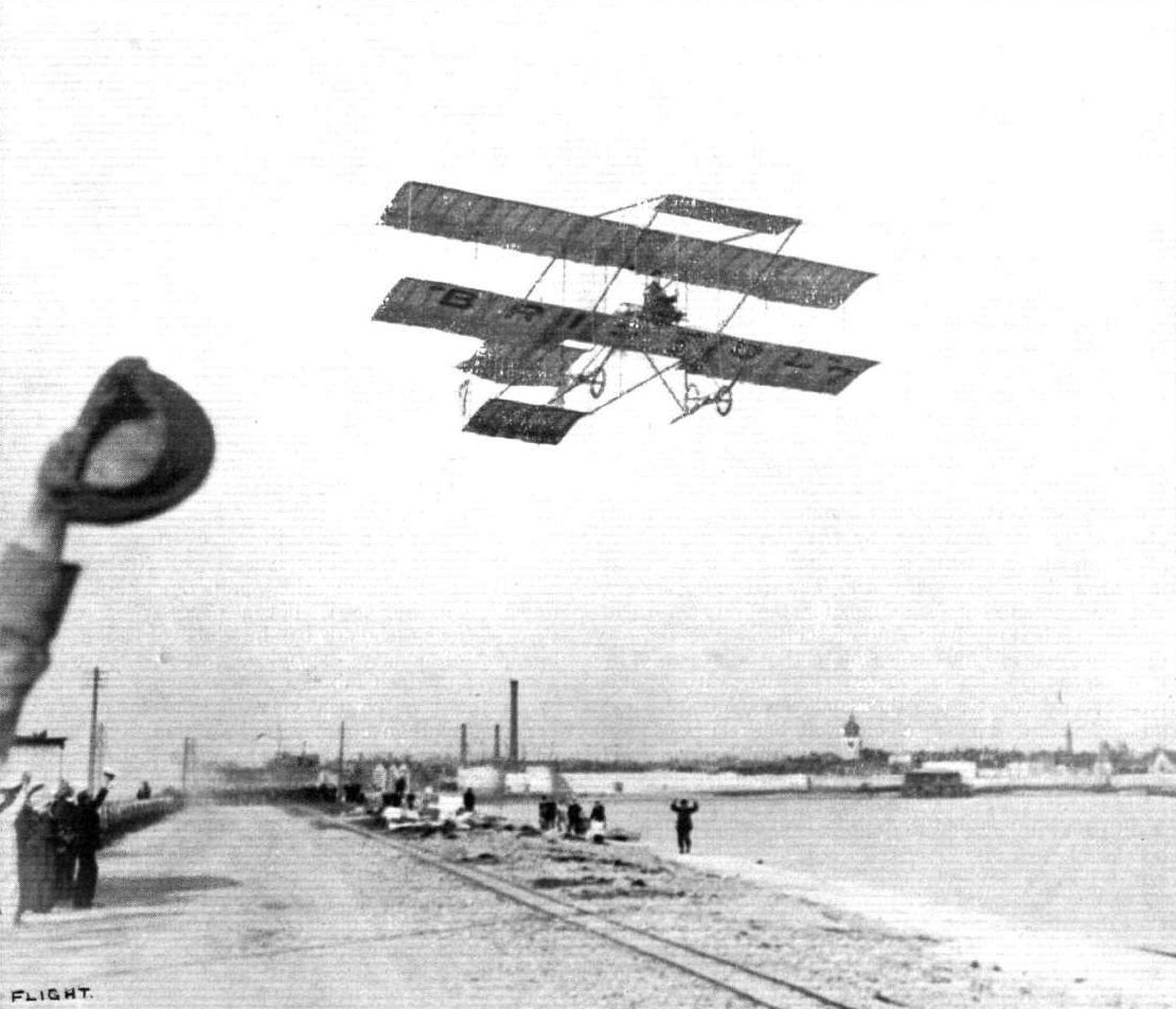
OVER PORTSMOUTH BY AEROPLANE. - The somewhat suggestive photograph of a trip taken some little time ago by Mr. Graham Gilmour on a Bristol biplane, after having "shelled" Fort Blockhouse, when flying to Portsmouth a few days before. In our picture Mr. Gilmour is seen flying from the Haslar sea wall - a difficult rising ground by reason of the telegraph wires and other obstructions on the ground - out to sea on his way to Brighton.
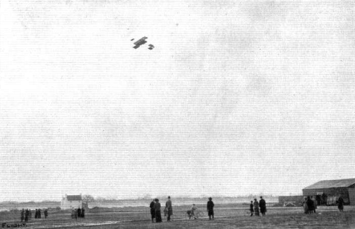
Mr. Graham Gilmour giving an exhibition flight at Brooklands on the Bristol biplane last Saturday by way of gratifying the disappointed visitors who had foregathered to witness the start for the Brighton flight. At the time a very high wind, amounting almost to a gale, was blowing.

BROOKLANDS TO BRIGHTON RACE. - Graham Gilmour well up over Brooklands for the Brighton Race.

FLIGHT IN AUSTRALIA. - From New South Wales, Mr. A. H. Wakeford sends us the above interesting photographs of Mr. J. Hammond flying on his Bristol biplane at Ascot, Sydney, on May 5th last. On the left Hammond is crossing the main road during a trial spin, and on the right he is finishing the day with a high flight as the sun is setting.
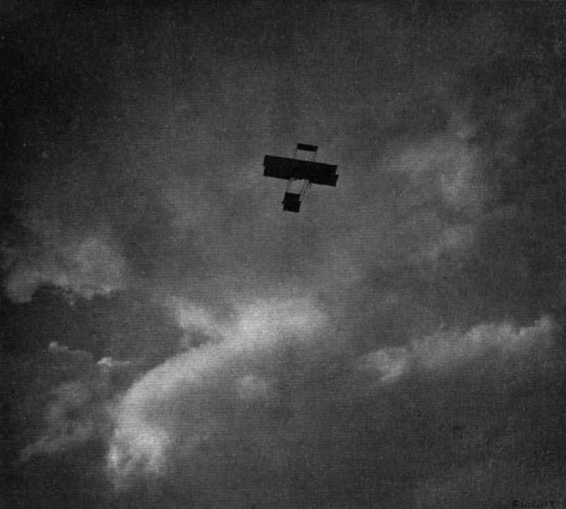
IN THE CLOUDS. - A snapshot of Mr. H. M. Maitland flying over Salisbury Plain recently, the day before he had the accident which has temporarily taken him out of the aviators on the active list.
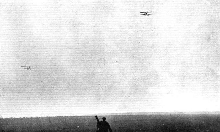
FLYING OVER SALISBURY PLAIN. - M. Maurice Tetard and Mr. A. R. Low flying their Bristol biplanes over Salisbury Plain. The photograph was taken while M. Tetard (on the right) was ascending for an altitude flight. On the left is the Bristol military type machine with the extended upper plane. The illustration affords an excellent comparison of the two types of machine in flight.
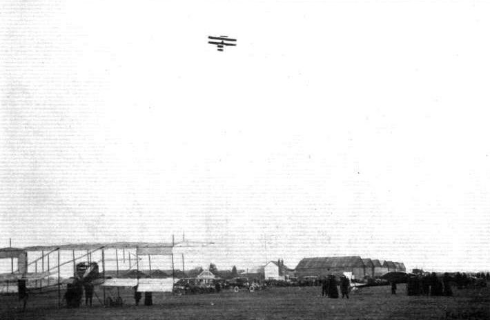
Mr. Low, on his Bristol biplane, getting well into the air at Brooklands. At rest are Mr. Sopwlth's Howard Wright biplane, and in the distance the Hanriot monoplane.
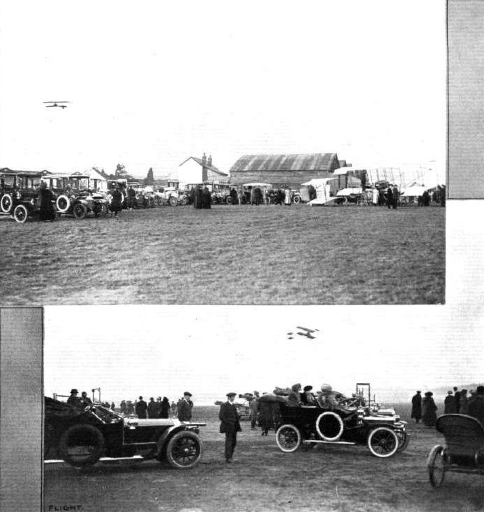
CARS AND FLYING AT BROOKLANDS. - Brooklands has now become quite a centre of activity by reason of the flying attractions daily in operation there. Two pictures, taken on Saturday last, above give some idea of the gatherings which assemble day by day around the actual flying village. In the upper photograph Mr. Tom Sopwith is flying his E.N.V.-engined Howard Wright biplane, one of the very successful Bristol machines being seen to the right. In the bottom picture Mr. Low, one of the expert pilots of the Bristol Co., is making one of his fine flights round the aerodrome.
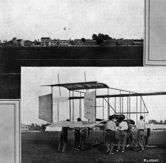
AVIATION IN SINGAPORE. - Scene during the aviation meeting organised there in March. The photographs show Mr. Joseph Christiaens in full flight on a "Bristol" biplane, and below, his machine being wheeled out ready for "taking off."
FLYING AT BROOKLANDS ON EASTER MONDAY. - In spite of the high wind whteh prevailed at Brooklands, Mr. Pixton, on the Roe biplane, put up a good flight for the Endurance Prize, securing it with 1h. 27m. 32s. In our photograph Mr. Pixton is seen during this flight, the machine on terra firma being one of the famous Bristol biplanes.
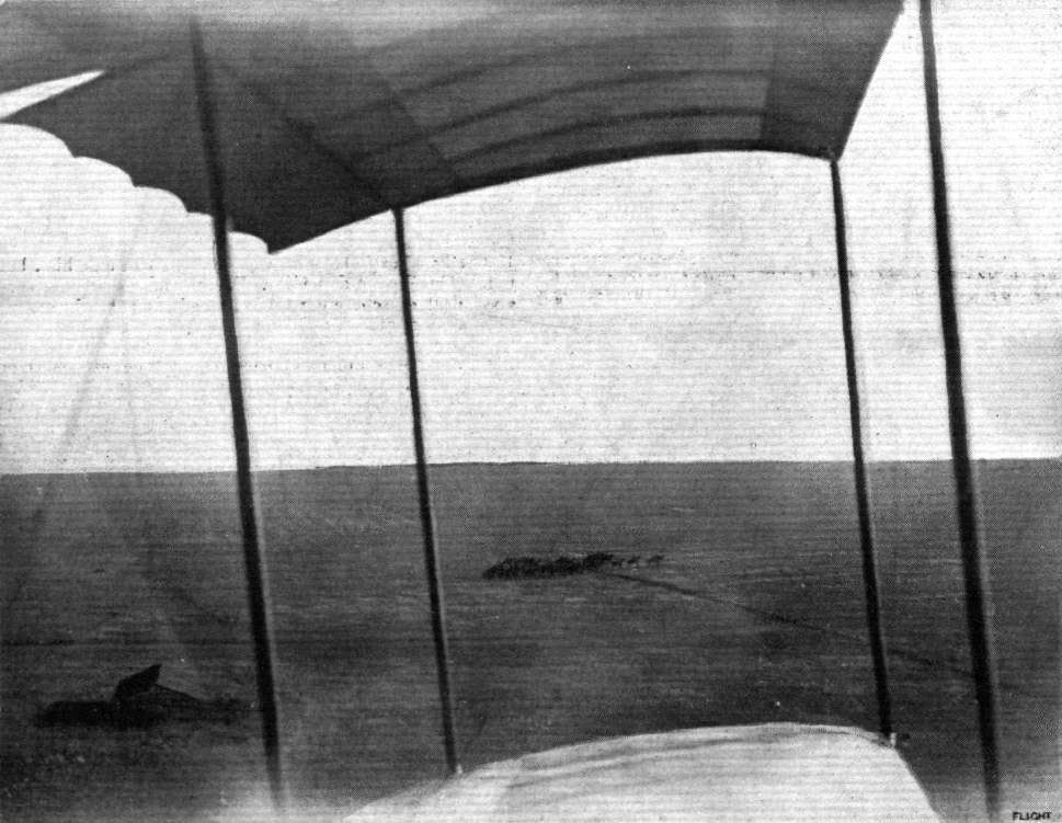
AEROPLANES AND THE BRITISH ARMY. - Another photograph secured from Lieut. Barrington Kennett's biplane last week at Salisbury Plain in the early morning. In this some of the cavalry will be seen in the centre of the picture, and, away beyond on the horizon, the regiment is seen in full strength stretching across the plain.
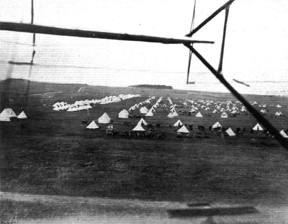
AEROPLANES AND THE BRITISH ARMY. - A general view of Hamilton Camp, Salisbury Plain, where the 4th Cavalry Brigade are encamped in readiness for the divisional training. This picture was secured on Thursday morning of last week, at reveille, from the biplane of Lieut. Barrington Kennett, who has been putting up such splendid flying work recently. Note the shadow of the biplane in the extreme foreground.

STONEHENGE AS SEEN FROM A BRISTOL AEROPLANE. - This is, we believe, the first photograph of this ancient landmark as seen from above. It was secured at 5 a.m. by a member of FLIGHT staff when flying with Mr. C. P. Pizey on a Bristol biplane last week.
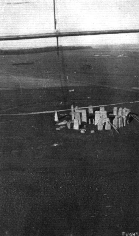
A new view of Stonehenge, taken from Mr. H. Busteed's "Bristol" biplane, by Mr. Dacre, a pupil, when flying as passenger.
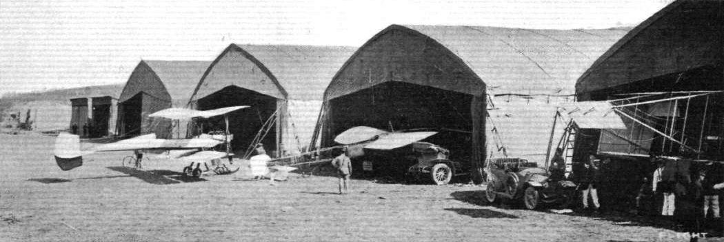
AVIATION AT THE FRENCH ARMY MANOEUVRES. - Some of the Bessonneau hangars at Vesoul, and the military aeroplanes which are giving such a splendid account of themselves.
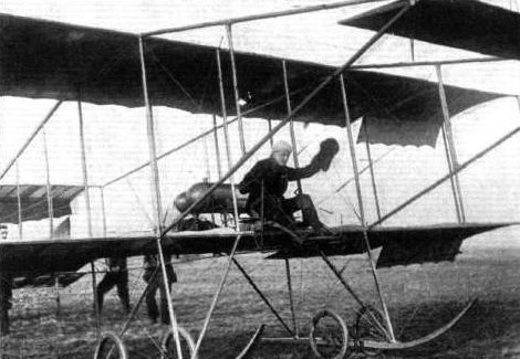
Mr. H J. Thomas, nephew of Sir George White, the head of the enterprising British and Colonial Aeroplane Company of Bristol, about to commence a flight on one of the Bristol machines. Mr. Thomas has the proud distinction of being the youngest certificated aviation pilot in Great Britain.
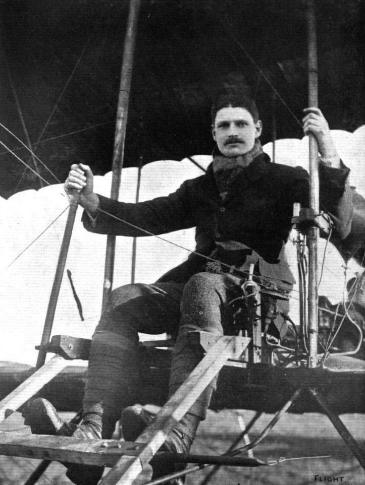
LIEUT. D. G. CONNER, R.F.A.
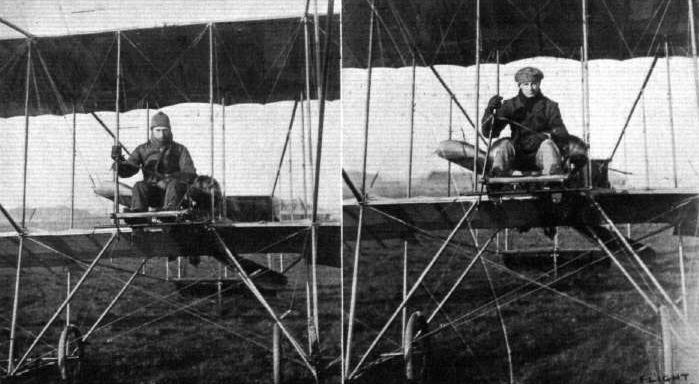
TWO OF THE FLYERS ON BRISTOL BIPLANES AT SALISBURY PLAIN. - On the left Mr. R. W. Philpott, and on the right Mr. E. Hotchkiss, who took his brevet on Tuesday, he being the ninth Bristol pupil to secure his certificate during the last three weeks.
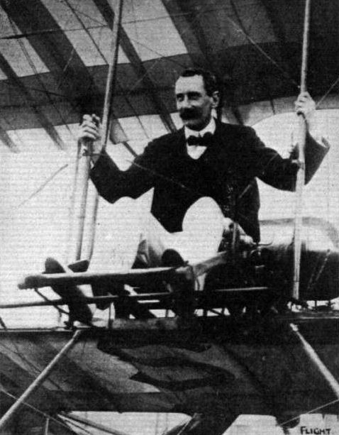
Brigadier-General David Henderson, pupil of the British and Colonial School at Brooklands, who took his flying brevet last week.

LIEUT. B. H. BARRINGTON KENNETT. One of the most prominent aviators in the British Army.
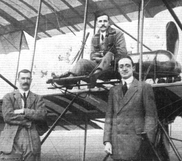
AT THE BROOKLANDS "BRISTOL" SCHOOL. - In the pilot's seat Lieut. Harford, on the left Capt. Harrison, and on the right Mr. Fleming of the Bristol Co.
Flight, March 18, 1911
THE BRISTOL BIPLANE MILITARY TYPE.
BRISTOL is a city that has been associated with most of the stirring events in English history, and yet many are apt to forget what manner of men this secluded town in the west has sent out into the world on the nation's behalf. From Bristol sailed the ships of old that brought to light America, and, pioneer in two elements, it is Bristol to-day that is doing so much towards the creation of the aerial fleet of the future. Sir George White is a Bristol man and well worthy to follow in the steps of Cabot. Humphry Davy and Stringfellow - to mention only three Bristol men whose deeds need no recalling to our readers - for having succeeded so well in his work of pioneering the tramways, he has turned his enterprise and ability into the work of pioneering these new vehicles of the air. And, above all else, it needs at the present time, as it will need in the future, a master mind, capable of appreciating as one clear picture the commercial aspects of the situation, to realise in full the possibilities of the new locomotion. Not every day is there to be found a man of this stamp keen enough to take up this side of aviation seriously, yet with all the enthusiasm of youth. Not every industry has at its inception the immeasurable advantage of numbering in its ranks such an important unit as the British and Colonial Aeroplane Company is to-day, and must in the natural order of things continue to remain. Stability is not only desirable in aeroplanes; it is needed, perhaps, even more in the industry that makes them, for it is out of the confidence born of such evidence of steady progress that there comes the financial support without which no new movement can hope to permanently establish itself in the interests of social economy. It is, therefore, as much towards the firm as towards the machines they are making that readers' thoughts will naturally turn on any reference to the Bristol biplane.
Of the machine itself there is not much to be said that cannot be explained in a very few words, for the situation may be summed up in saying that the Company adopted the eminently commercial policy of following a proved type that was already not only successful but popular, so that they could devote their energies to the perfection of constructive detail and general excellence of workmanship. The particular model we have selected for the purpose of illustration is their military type machine, which we thought might be the more interesting to our readers as a slight variety on the standard pattern Farman, which is the type to which the Bristol biplane at present belongs. This military model is characterised by the extended span of the upper plane, which affords an appreciable increase in the supporting area, and enables either two passengers to be carried in addition to the pilot, or which is, perhaps, still more serviceable from a military point of view - it permits of an extra large reserve of fuel when only one passenger is carried. Another distinctive feature of this machine is to be found in the three rudders that are supported on the tail. These rudders are controlled as usual by a pivoted foot-rest, while the universally pivoted vertical lever, under the pilot's right hand, controls the balance by manipulating the balancing flaps on the extremities of the main planes and the elevators fore and aft on the machine. A sideways movement of the lever to the right draws down the balancer on the pilot's left, thus increasing the effective angle of the plane on that side of the centre, and thereby increasing the lift for the same velocity of flight. As a result that side of the machine heels up in order to restore balance by correcting a list, or in order to artificially bank the machine preparatory to a turn. When balancing, therefore, the pilot moves the lever sideways towards the side of the machine that tends to rise above its normal position, and simultaneously checks any tendency to swerve by the rudder. Elevator movements are accomplished by a to and fro motion of the same lever, the elevator in front being interconnected with the rear elevator, which forms an extension of the tail. One of the accompanying sketches shows an interesting constructional detail in connection with the front elevator, which is rocked on its trunnions by a light steel lever, coupled up at each extremity to the control lever by wires in duplicate.
The other sketches also show several interesting constructional features of this machine, notably the method of supporting the extensions to the upper main plane, which form the characteristic feature of the military model. These extension planes are braced by diagonal tubular steel struts which are anchored to the lower main planes by attachment to the sockets of the vertical struts. The steel tube is capable of taking tension and compression stresses, but a safety tension wire has also been introduced, on the principle of duplicating such members, which is characteristic of the design of this machine. It will be noticed that all the control wires, for instance, are in duplicate. Another little detail about the wires on this machine which is worth observing is that those in the vicinity of the propeller are bound with whipcord, so that should they break they will be less likely to fly about and get caught in the propeller. Two other interesting constructional details are shown in the illustration that includes a sketch of the whipcord winding round the wire. One is the extra strong end rib employed in the construction of the framework of the main planes, the other is the very neat hinge by which the rudder is mounted on the tail strut. As may be seen from the photograph, four such hinges are employed for the support of each of the three rudder planes. Before leaving the consideration of this machine reference should be made to the fact that, as set out below, the British Government have ordered four to be delivered next month.
Flight, April 22, 1911.
The Vogue of Flying.
DAILY the vogue of flying is becoming more pronounced, and such custom bodes still more rapid progress for the great movement. At Brooklands, Hendon, and elsewhere a roll of the passengers, if published, would be a little astonishing to the general public; and a little idea of the spread of the cult may be formed from the visit on Easter Monday of M. Tabuteau and Mr. Herbert J. Thomas to Badminton House, Wilts, whither they had flown on a Bristol biplane from Filton, Bristol, at the invitation of the Duke and Duchess of Beaufort. Alighting in a field close to Badminton House they were received by Lord Lonsdale and cordially welcomed by the Duke and Duchess and their house party. An exhibition flight having been made by M. Tabuteau, a series of trips was made with a number of the guests present, in addition to the host and hostess and their children, the Marquis of Worcester, and the Ladies Blanche and Diana Somerset. Amongst others who thus obtained their "air baptism" were Countess Nora Lutzow, the Hon. Cyril and Mrs. Ward, the Hon. Henry Lygon, General and Mrs. Brocklehurst, and Mr. M. H. Chaplin.
Unalloyed pleasure was the verdict of one and all at their novel experience, and it was with regret that the time came in the evening for Mr. Tabuteau and his companion, Mr. Thomas, to return by the way they had come to Bristol, where they landed without incident to the delight of a big holiday crowd.
Flight, May 6, 1911.
BRITISH NOTES OF THE WEEK.
British Work at the Russian Exhibition.
THE first International Aeronautical Exhibition to be held in Russia had a very successful opening on the 26th ult., when among a large number of distinguished visitors were the Grand Dukes Alexander and Cyril and the Russian Minister of War, besides many officers of the Russian Navy and Army. The exhibit of British-built Bristol biplanes attracted a good deal of attention, especially in view of the fact that the Russian Army has purchased several of them, and the distinguished visitors complimented Mr. H. White Smith, Secretary of the Company, on the success which has been obtained with Bristol machines. On Saturday the Czar paid a visit to the Exhibition and spent over two hours examining the machines. The Czar also remained a considerable time m conversation with Mr. Kennedy, an English engineer resident in St. Petersburg, who has given prolonged study to the problems of aerial navigation. As we go to press we learn that a Silver Medal has been awarded to the Bristol exhibit.
Flight, May 13, 1911.
A Bristol Over a Bristol.
THE bluejackets aboard H.M.S. "Bristol," lying at anchor at Avonmouth, were rather surprised on Friday afternoon of last week to observe a biplane flying directly over them. It proved to be a Bristol machine which had started from the Bristol works at Filton. It was piloted by M. Tetard, who, in the course of his twenty-three minute flight to Avonmouth and back, kept his machine mostly at a height of 2,000 ft.
Flight, July 15, 1911.
Flight in the Isle of Wight.
No little excitement was caused in the Isle of Wight on Tuesday when it became known that Messrs. Pizey and Fleming intended to fly from Shoreham to Ventnor on the following day, and long before 6 p.m., when it was anticipated they would arrive, a large crowd made their way to the "Station," and about ten minutes past eight the first Bristol arrived with Mr. Fleming in charge, and Mr. Collyns Pizey in the passenger seat. The aeroplane was at once cleared off the ground in order to allow as much room as possible for Mr. Gordon-England, who arrived half an hour later with the luggage on the second Bristol. In flying across the Solent, Messrs. Fleming and Pizey were at a height of 2,700 ft. On Thursday a number of exhibition flights were made, some of them with passengers, and one of the machines was slightly damaged through coming down on rough ground. Messrs. Fleming and Pizey made an early start for home soon after five on Friday morning, and flying by way of Shanklin, Sandown, Ryde, and Southampton, reached Salisbury after an hour and a half s trip,
Flight, October 14, 1911.
THE MANVILLE PRIZE.
ON Wednesday of last week, the final day of the competition for the Manville prize for the best aggregate flight on an all British machine with a passenger, attempts were made by Mr. Cody at Aldershot and Mr. Pixton at Brooklands to improve their records. The result was a win for Mr. Pixton, who was already leading, on the Bristol biplane. During the eight specified days on which flying for this prize had been permissible, Pixton had placed an aggregate of 187 mins. to his credit, while Mr. Cody was second with 156 mins. The latter intended to start early on the morning of the 4th inst. to try and improve his position, but a northerly gale put flying out of the question. It was not until ten minutes to five in the afternoon that Mr. Cody was able to get under way, and then he was flying until 5-30 at which hour the competition finally closed. Mr. Cody's record was thus 196 mins. At Brooklands, however, Mr. Pixton was in-the air for 129 mins., and so he was an easy winner of the L500 Manville prize with a lead of 120 mins. It will be remembered that Mr. Pixton learnt to fly on the Avro biplane, and it was on this machine that the first portion of his aggregate flights for the Manville and Brooklands competition was carried out. The latter and major part, however, of his flying has been accomplished on a Bristol biplane, on which he has not hesitated to go up when the wind has made the conditions distinctly unpleasant.
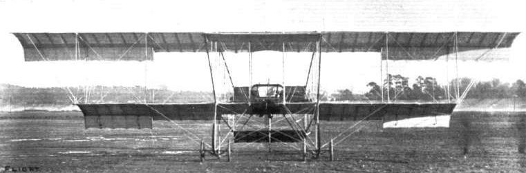
Front view of the Bristol military type biplane.

Side view of the Bristol military type biplane. The balancing planes and method of supporting the extensions of the top plane are very prominent in this illustration.

View from behind of the Bristol military type biplane.
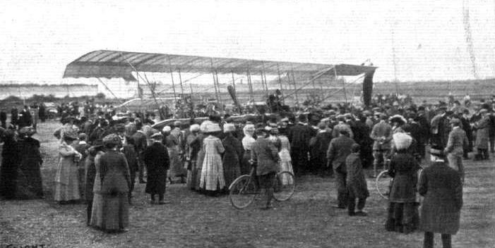
Mr. Graham-Gilmour preparing his Bristol biplane on Saturday for the proposed flight to Brighton, with a few of the 5,000 visitors to Brooklands looking on.
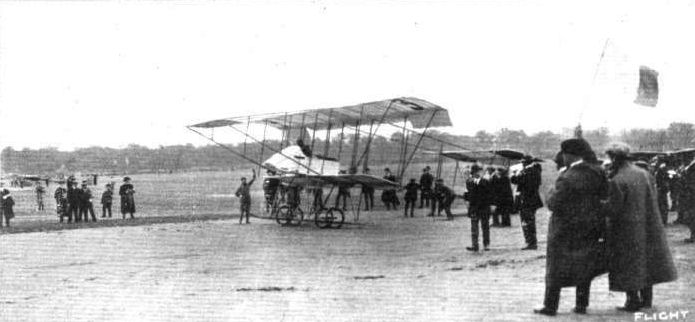
EUROPEAN CIRCUIT. - Tetard in one of the British Bristols at the moment of starting from Vincennes on Sunday. Note the huge crowd in the distance.

THE VOL PLANE. - Photograph of a superb example of the vol plane executed by Mr. A. R. Low on a Bristol military-type biplane when finishing a flight with a passenger over Salisbury Plain on the occasion of the recent Press visit. It will be observed that the propeller is stationary.
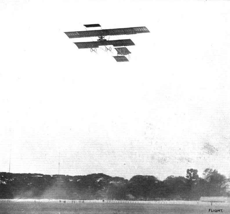
FLYING IN INDIA. - Mr. Henry W. Jullerot giving an exhibition flight over the Calcutta Maidan Racecourse on one of the Bristol biplanes, which are doing such good ''missionary" work in the Indian Empire. The racecourse was specially lent to the British aod Colonial Aeroplane Co's Commission for flying demonstrations, and this is the only occasion upon which flying exhibitions have been given upon it. The Viceregal Party, the Commander-in-Chief, Sir Norman Baker, the Lieut.-Governor of Bengal, and a crowd of about half a million people were present to witness the display.
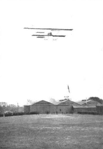
Mr. Maurice Tetard flying a "Bristol" military biplane at Filton upon the occasion of the recent visit to the British and Colonial Aeroplane Co.'s works of the officers and crew of H.M.S. "Bristol."
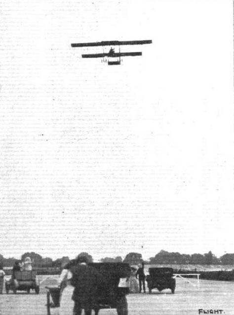
Mr. Graham Gilmour on the Bristol biplane, flying over the Brooklands course during the race meeting last Saturday after his return from Windsor.

Graham Gllmour, on a Bristol biplane, gives a few exhibition flights at Eastchurch whilst waiting for the Gordon-Bennett Race to commence.
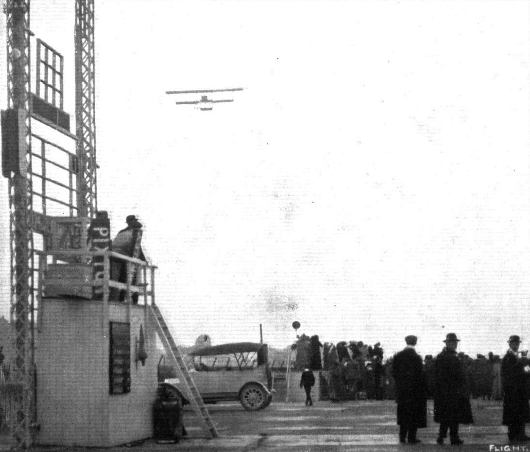
WINNING THE MANVILLE PRIZE. - Mr. Pixton on the Bristol biplane at Brooklands on Wednesday of last week, when he was competing finally for the Manville Aviation Prize. Mr. Pixton is seen on the Bristol passing over the paddock at Brooklands.
FLYING OVER SALISBURY PLAIN. - M. Maurice Tetard and Mr. A. R. Low flying their Bristol biplanes over Salisbury Plain. The photograph was taken while M. Tetard (on the right) was ascending for an altitude flight. On the left is the Bristol military type machine with the extended upper plane. The illustration affords an excellent comparison of the two types of machine in flight.
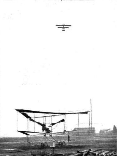
The new Edwards rhomboidal biplane at Brooklands out for an airing on Saturday last. - This machine, it will be remembered, was described in FLIGHT on February 5th, 1910. Flying in perfect form above is Capt. F. H. Wood on a Bristol machine.
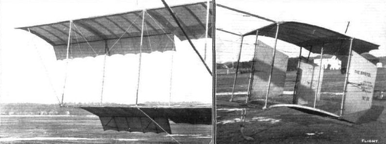
Detail views of the Bristol military type biplane, showing the balancing planes and the tail. The three rudders in the tail constitute a characteristic feature of this machine.
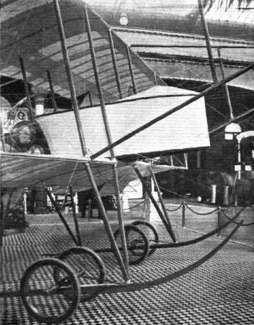
An example of enclosed pilot's seat on the Bristol military type biplane.
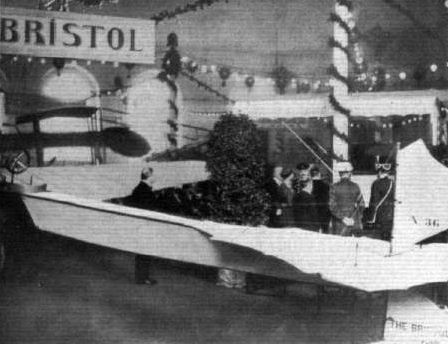
The Czar of Russia inspecting the Bristol military biplane of the British and Colonial Aeroplane Co. at the St. Petersburg Aero Exhibition. Mr. H. White Smith, the special representative of the Company, is seen explaining the machine to His Imperial Majesty. This biplane, it will be remembered, net only secured the gold medal for excellence of workmanship, but was purchased by the Russian War Office for the Engineer Corps of the Russian Army.
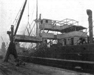
Shipping a "Bristol" biplane to Straits Settlements in the Far East per steamship "Glenstree," Glen Line (McGregor, Gow and Co.). Ltd. - We announced recently that amongst other shipments this machine had been despatched.
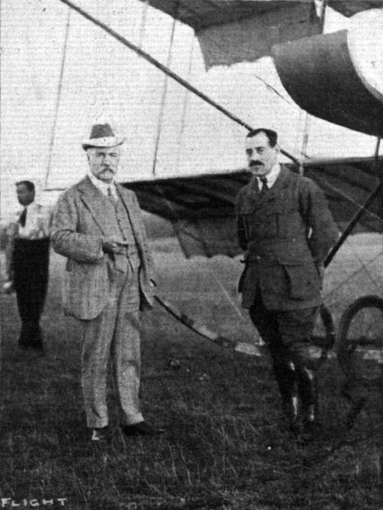
Sir George White, (on the left), the founder of the British and Colonial Aeroplane Co., Ltd., and M. Jullerot, one of the many eminent pilots now associated with the Company.
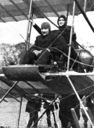
The Countess Nora Lutzow as passenger with M. Maurice Tabuteau on the Bristol military biplane at Badminton House, April 17th, referred to in last week's Issue.

Mr. H. Busteed, of the Tarrant Motor Co., Melbourne, on a Bristol biplane at Salisbury Plain, where he has been making many fine flights.
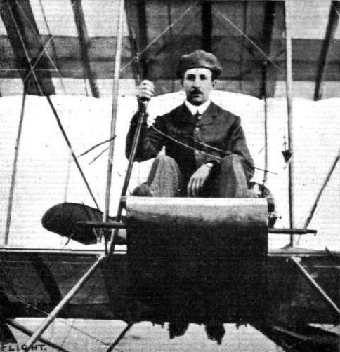
Lieut. Pepper, R.G.A., one of the Bristol pupils at Salisbury Plain, who passed for his Royal Aero Club certificate last week.
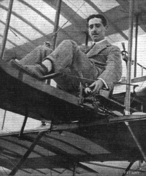
Mr. Walter Lawrence, another Bristol pupil who last week obtained his pilot's certificate at Salisbury Plain.
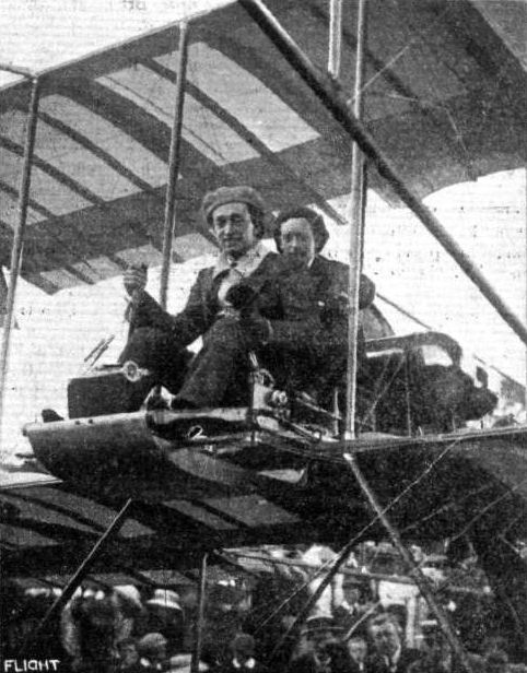
Mr. H. R. Fleming, pilot, and Mr. C. P. Pizey, passenger, on the Bristol biplane with which they flew from Ventnor to Amesbury, Salisbury Plain, after having visited by way of the air the scene of the Gordon-Bennett Race; then after flying to Dover and Shoreham to greet their brother flyers in the European Circuit, they continued on to the Isle of Wight, and thence back to Salisbury Plain.
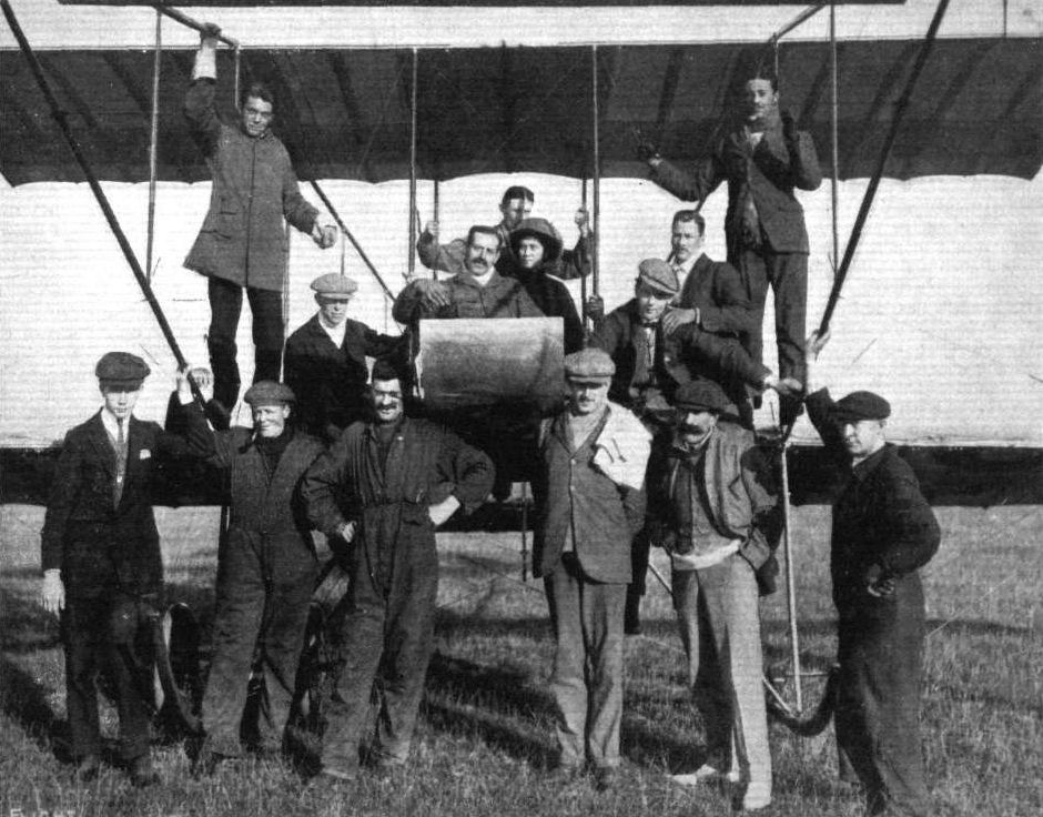
A group of Bristol pilots, pupils, and assistants at the Bristol schools on Salisbury Plain. Reading from left to right (front row): Mr. O. L. Mellersh, Mr. E. Harrison, Mechanic, Mr. S. P. Cockerell, Mr. Fitzmaurice (British Embassy, Constantinople, visitor), Mechanic; top row (left to right): Naval Cadet N. F. Wheeler, Mr. W. E Gibson, Mr. H. M. Jullerot (Chief Instructor), behind him Lieut. Wyness Stuart, Mrs. Stuart, Mr. R. Smith Barry, Lieut R. J. Watts, Lieut. C. L. N. Newall

Sketches illustrating some minor constructional details on the Bristol military type biplane. That on the left shows the attachment of one of the diagonal struts used for supporting the extensions to the upper plane.
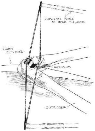
Sketch illustrating the lever attached to the elevator on the Bristol military type biplane.

THE BRISTOL MILITARY TYPE BIPLANE. - Plan and Elevation.

The latest Idea in suspension. How the Bristol monoplane is supported on crutches.
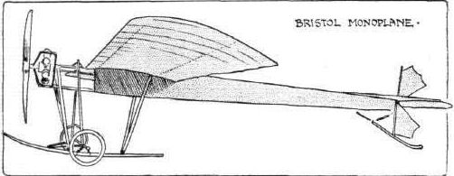
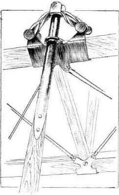
Sketch Illustrating the crutch suspension of the Bristol monoplane.

UNDER-CARRIAGES AT OLYMPIA. - A comparison in tail skid construction.
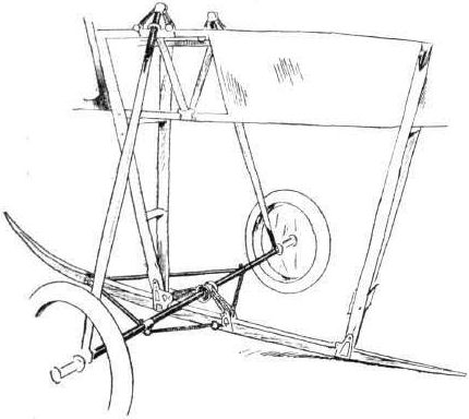
UNDER-CARRIAGES AT OLYMPIA. - The Bristol monoplane showing the crutches.
Flight, September 30, 1911.
THE BRISTOL MONOPLANE.
As more rumour than fact has generally formed the basis of current aerodrome discussion of the merits of the new Bristol monoplane, the accompanying illustrations and description of its construction may prove of exceptional interest. The machine, itself, is undoubtedly the centre of many thoughts, but its comparative inaccessibility on Salisbury Plain does not contribute much to the general fixing of ideas as to its leading characteristics.
To those who follow the trend of aeroplane design and are sufficiently au fait with events to know that Pierre Prier - one time Bleriot pupil, now one of the best of modern pilots - is now associated with the British and Colonial Company, it will come as no surprise to learn that a good deal of the credit for this model is due to him. Indeed, the machine itself is in some respects not unlike his old Bleriot mount, although needless to say it shows marked originality at many points, more particularly in respect to the tail planes and under-carriage. In the former, a fan-shaped surface is pivoted about a horizontal axis to perform the double duty of stabiliser and elevator, thereby departing from the common practice of using a hinged extension to a fixed plane.
The main body is constructed on the usual box girder principle, with the important differences that strainers are altogether dispensed with, and that the longitudinal members are not pierced except by small wooden screws that serve to keep in position the steel plates to which the cross-bracing wires are attached.
At the forward end of the body is mounted the 50-h.p. Gnome engine, with its direct driven 8 ft. 6 in. Normale propeller. There is no support between the engine and propeller, a feature that renders the motor extremely accessible for tuning or cleaning purposes.
While the front engine bearer follows customary design, the rear support is quite original, for, in place of the usual pressed steel mounting, the Gnome crank-shaft is anchored in position by four adjustable steel rods, arranged diagonally, in tension. An aluminium dome above the engine prevents any oil reaching the pilot.
The landing carriage is of the skid and wheel variety, the common axle between the two wheels being flexibly attached to the skids by rubber shock-absorbers. Very little wire bracing is resorted to in the under-carriage as rigidity is given to the structure by diagonal struts.
Projecting in front are two short upturned skids, which pivot about horizontal bolts against the action of strong steel compression springs. The idea is sound besides being original, for should a landing be made at too steep an angle these skids will give upwards and ease the descent. Rigid skids of this type are unsatisfactory in that they have the habit of digging into the ground and snapping off short under such conditions. The wings, which have a slight dihedral angle, are of notably strong construction.
The front and rear spars are fashioned from steel tubing of circular section cored with wood.
Three trusses of substantial stranded steel cable attached to the front spar of each wing take the weight of the machine in flight. Tne two outer "haubans" are connected to a fitting on the undercarriage skids, and the inner one is attached to a clip round the bottom main body "longeron." Both the camber and the angle of incidence of the wings are exceptionally slight, and to these features must be attributed the fine turn of speed that the Bristol monoplane exhibits. A pyramid of oval-section steel tubing supports the weight of the wings, the warp-compensating wire from the rear spar passing through tubes brazed in a fining provided at its apex.
The fan-shaped elevating-surface is balanced, in order that its operation should call for little exertion on the part of the pilot. Steering laterally is effected by a balanced vertical rudder mounted at the rear extremity of the main body. The tail unit is protected from contact with the ground by a double skid of rattan cane.
Control, in the three dimensions of elevation, lateral balance, and direction, is maintained by the usual universally-jointed vertical lever and pivoted foot bar, which is employed by almost every monoplane descended from the paternal Bleriot. All wires leading to the controlling organs are fitted in duplicate, thereby reducing to a minimum the risk of mechanical failure in the air. The pilot is kept well acquainted with the condition of his fuel supply by a petrol gauge fitted to a small dashboard before him, and a revolution indicator by its side tells him his engine speed.
As soon as the Bristol single-seater emerges from its trial stage, and its construction upon standardised lines is embarked upon, the British and Colonial Aeroplane Co. propose to carry out experiments with a passenger-carrying monoplane of similar design. Such a machine should be most valuable for military reconnaissance work, both on-account of the wide range of view that is obtained from the pilot's seat, and also because of the exceptional speed that it is hoped, and with good reason, such a machine would attain.
Flight, December 23, 1911.
A British Aeroplane Over Paris.
To Mr. James Valentine belongs the proud distinction of having been the first Britisher to look down on Paris from an aeroplane. On Thursday of last week he started up from Issy on the Bristol two-seater monoplane, and circling the Eiffel Tower, crossed the Seine and the Place de la Concorde to Notre Dame. After circling the dome, he continued on to Vincennes, and afterwards flew back to Issy.
The Bristol Monoplane in Paris.
THE only British machine on exhibition at the Grand Palais is the Bristol monoplane, and naturally President Fallieres, on the opening day, paid a visit to the British and Colonial Aeroplane Co.'s stand, where, after admiring the machine, he accepted from Mr. Stanley White a magnificent album bound in vellum, and suitably decorated, containing views of the works and flying school of the Company. In view of Mr. Valentine's flight over the French capital on the British monoplane, the stand on which it is exhibited has proved a centre of attraction, while the design and construction of the machine have evoked favourable comments on all sides.
Flight, December 30, 1911.
PARIS AERO SHOW.
British and Colonial Aeroplane Co.
OCCUPYING one of the central stands in the Salon was the Bristol two-seater monoplane, a thoroughly worthy example of British enterprise, design and workmanship. As far as excellence of finish was concerned, although there were many machines in the show which were perfection in this respect, none could be said to be superior to the Bristol. In its main features the machine presents little difference from the monoplane described in these pages some few weeks since, although naturally being a passenger-carrying machine, it is somewhat larger all round. Passenger and pilot are seated in tandem, the passenger being seated approximately over the centre of pressure. The landing carriage is a greatly improved A-type wheel and skid construction, possessing natural advantages of strength, simplicity, and neatness. A great improvement that the Bristol Company have effected in this type of landing-gear is the extension in a backward direction of the skids. These extensions are in length some 3 ft., and are composed of several super-imposed strips of wood, forming in effect a laminated spring. They take the place of a tail-skid, and serve to rapidly bring the machine to rest after a landing has been made. One interesting little detail that the writer noticed, one that is typical of Bristol thoroughness, was the self-locking screw-on hub caps of the landing-wheels, which have replaced the much less mechanical method of attaching such organs by means of washers and split-pins. Mounted at the front of the fuselage is the power unit, a Gnome engine of 50 h.p. driving a Bristol propeller, the former being fed by Zenith carburettor, a practice which is steadily coming into favour in France. Surrounding the passenger are quite a number of useful accessories to help him in his observation work. There is a map roller, compass, thermos flask, field glasses, and a small writing tablet. The seats themselves are attached in a very interesting manner, they being supported from the main framework by steel wires in tension, a feature which allows them to be adjusted for the personal convenience of the occupants, and ensures safety against bodily damage that might be caused by broken splinters in case of a smash. At the Salon considerable interest was manifested in the machine, which had become widely known because of its flight over Paris, with Valentine at the lever, on the Thursday preceding the opening.
Principal dimensions, &c.
Length 23 ft.
Span 34 ft.
Area 200 sq. ft.
Weight 650 lbs.
Speed 65 m.p.h.
Motor 50-h.p. Gnome.
Price L950

One of the "Bristol" monoplanes, as seen from the front and behind, entered by the British and Colonial Aeroplane Co. for the Daily Mail Circuit of Great Britain. Note the small tail of this machine. The length overall is about 8 metres, and the span 10 metres. The area of the main plane is approximately 14 sq. metres.
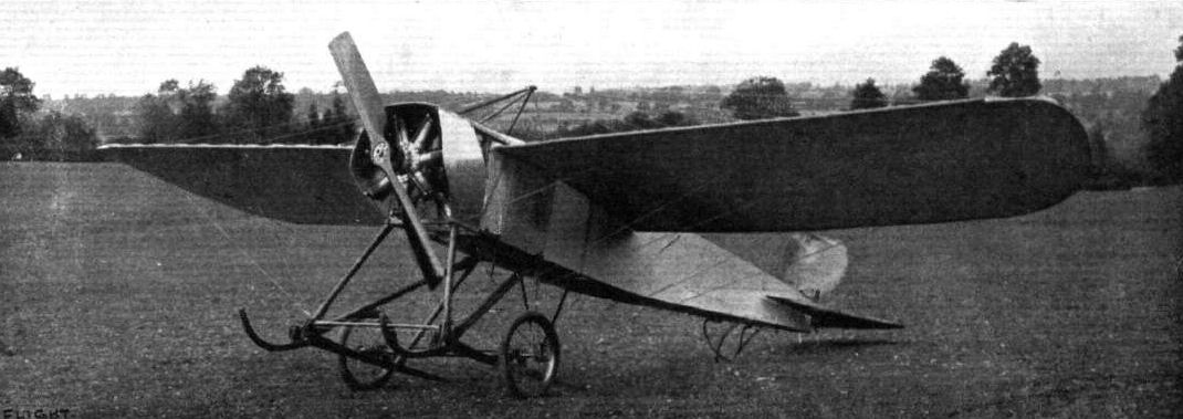
Front view of the Bristol monoplane, showing the engine and landing carriage.
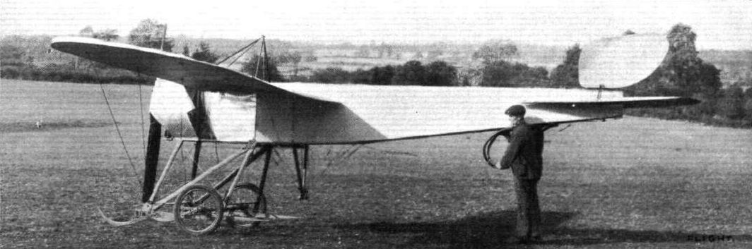
Side view of the Bristol monoplane, showing it on a horizontal keel.
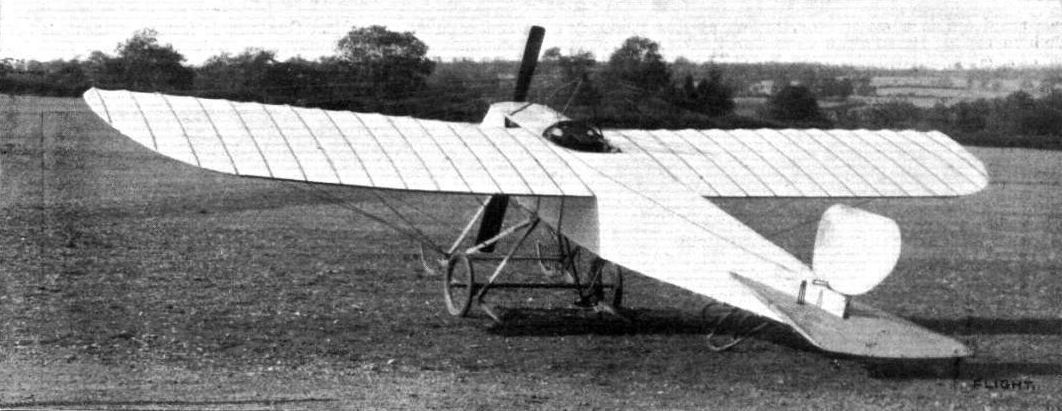
Rear view of the Bristol-Prier school monoplane, showing the tail elevator and the rudder. A low-powered single-seater.
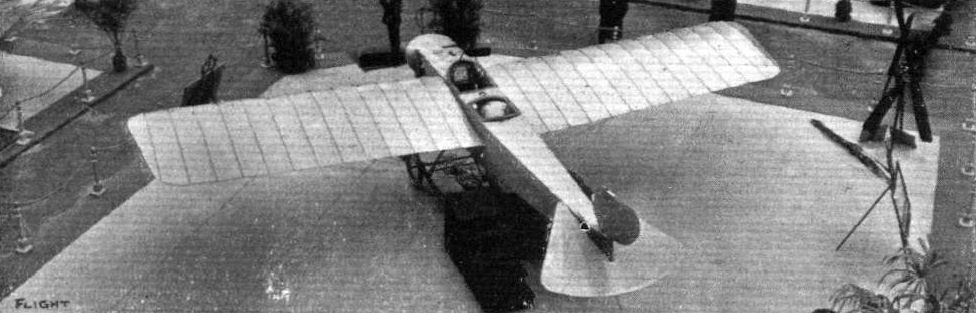
The sole representative of Great Britain at the Paris Salon - the "Bristol" 50-h.p. military two-seater, constructed by the enterprising British and Colonial Aeroplane Co., Ltd.
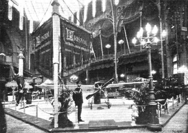
The Bristol stand - the sole representative of Great Britain - at the Paris Show. It was on a machine of this type that Valentine carried out his daring flight over Paris two days before the opening of the Show.
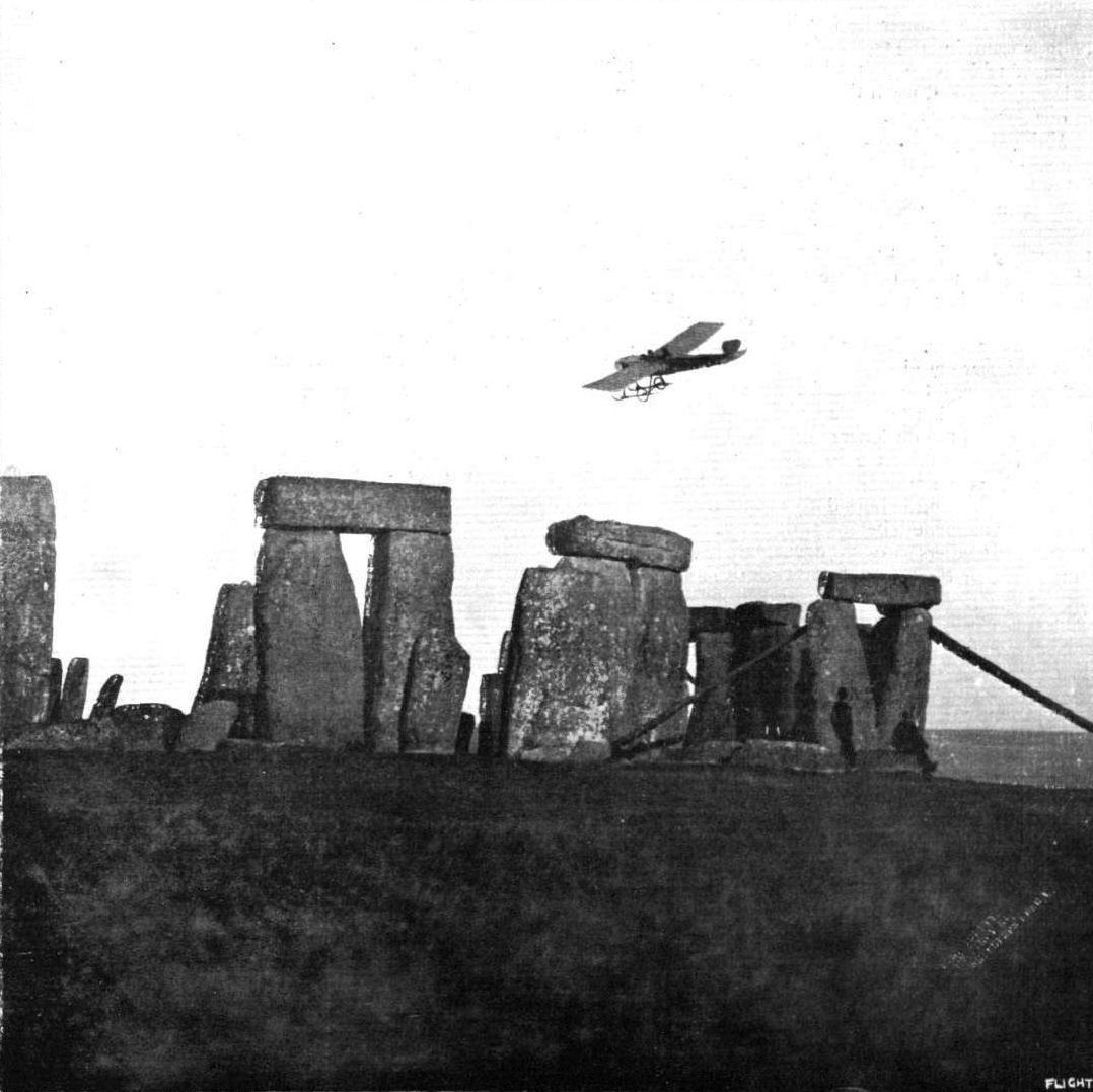
ANCIENT AND MODERN. - Unique photograph of a Bristol monoplane in flight at Salisbury Plain over Stonehenge.
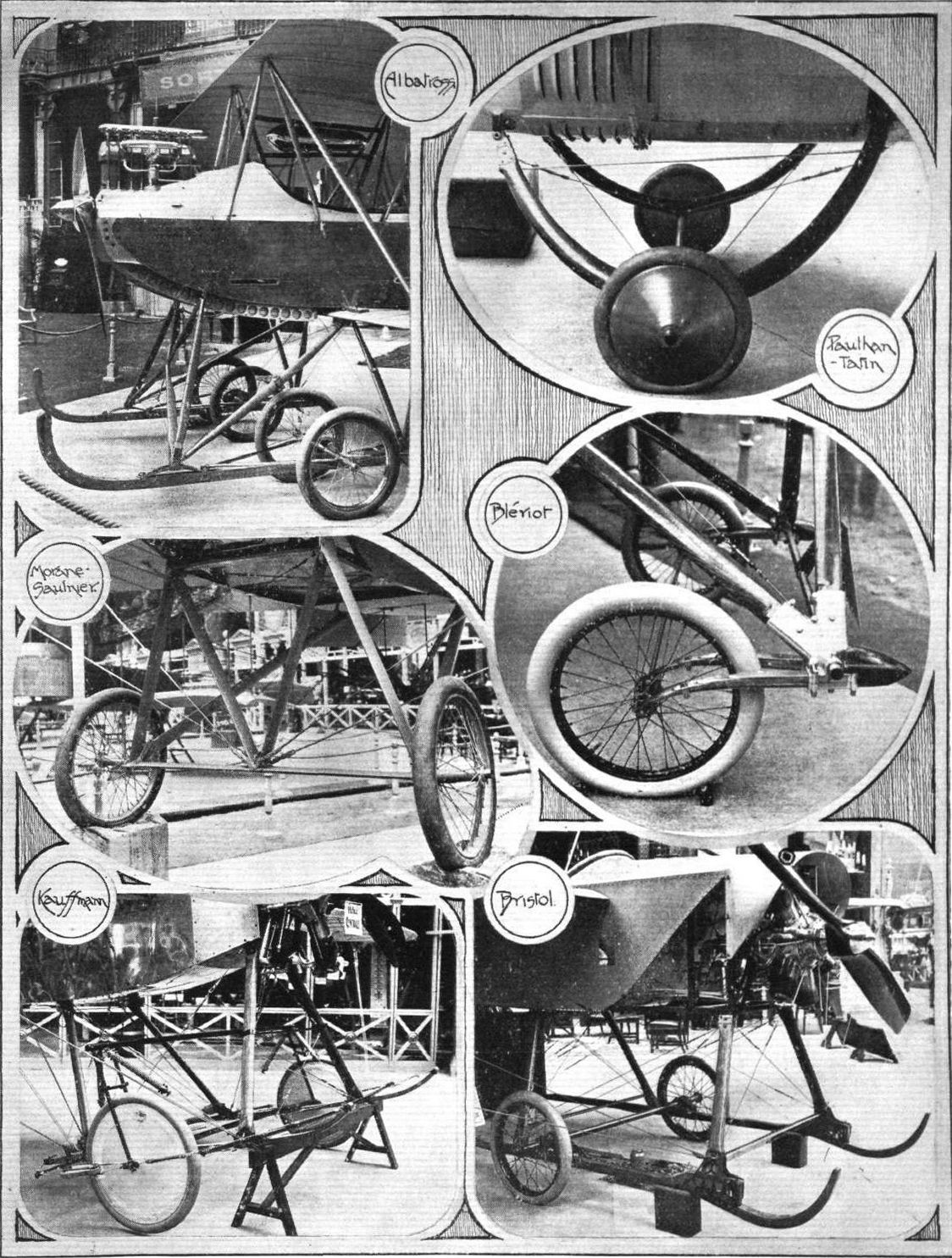
Six types of landing gear at the Paris Aero Salon.

MONOPLANES AND BIPLANES IN THE DAILY MAIL CIRCUIT ROUND GREAT BRITAIN. - From these every machine can be readily identified either in flight or on the ground.
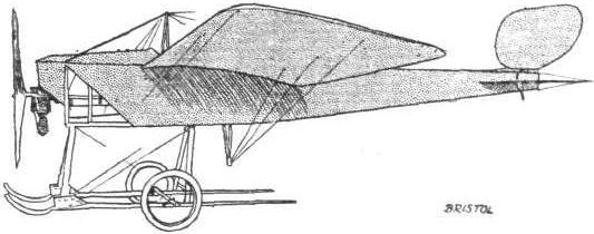
Side view of the Bristol two-seater monoplane.
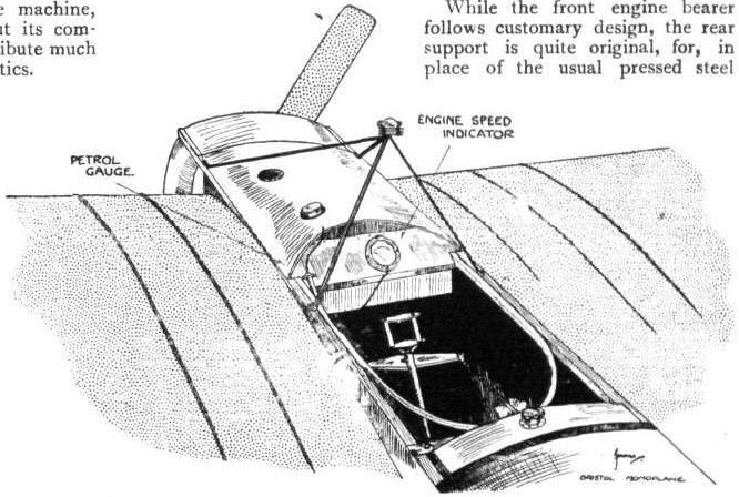
Sketch of the Bristol monoplane illustrating the accommodation in the pilot's cockpit and the arrangement of the auxiliary petrol tank. The wires from the cabane are omitted for the sake of clearness.

Sketch illustrating the flexible front skids of the Bristol monoplane and the method of springing the single axle. To avoid complication in the sketch the wheel is omitted, but its hub indicates its position.
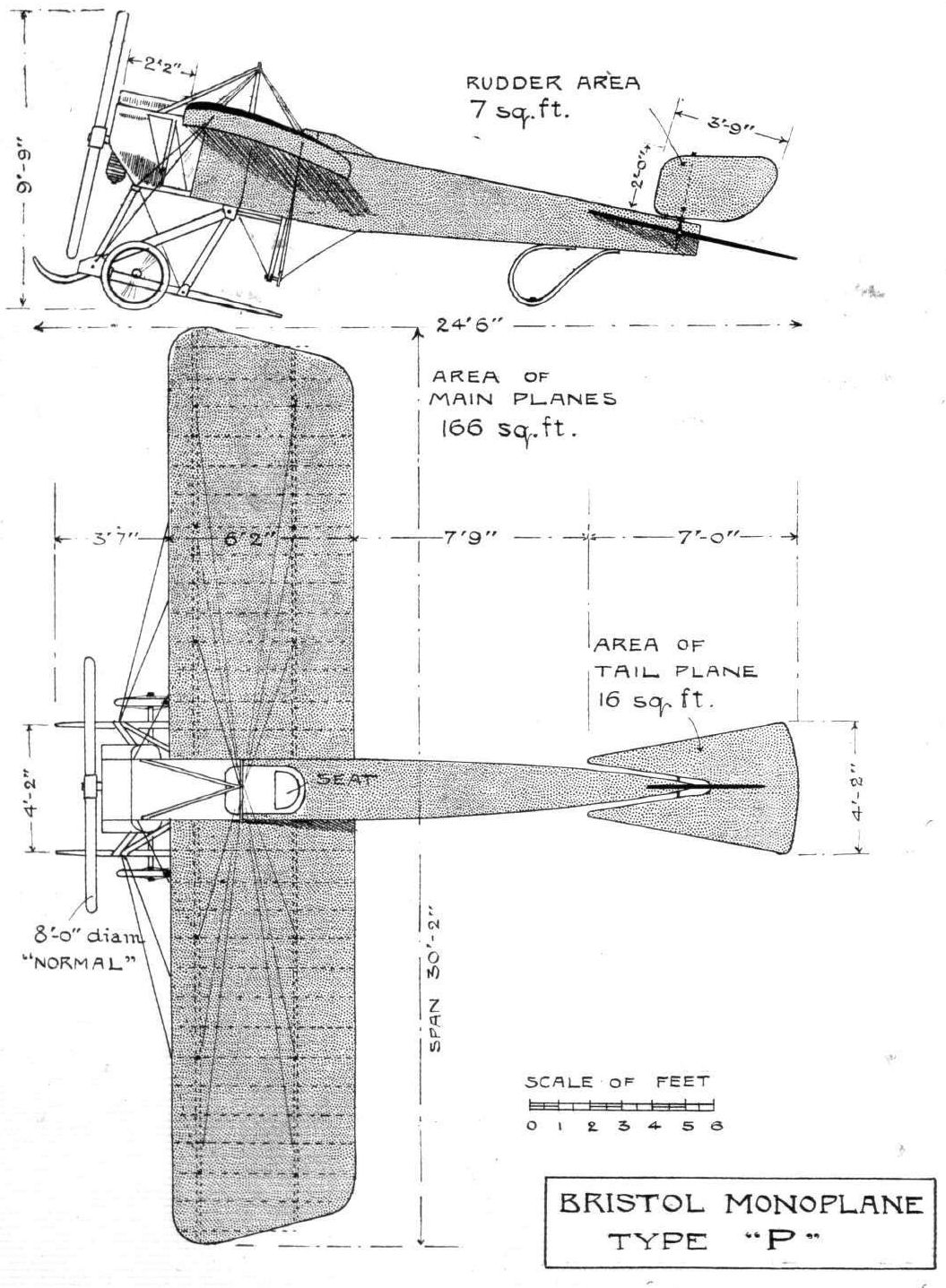
THE BRISTOL MONOPLANE. - Plan and side elevation to scale.
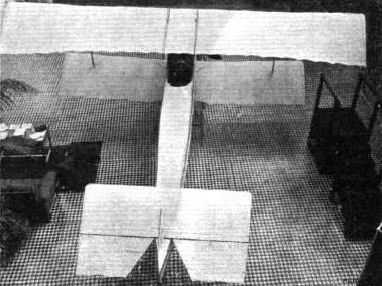
The Bristol biplane of the Breguet type, showing the characteristic enclosed boat body and the single struts separating the upper and lower planes.
UNDERCARRIAGES AT OLYMPIA. - Comparative details in the construction of the Farman type wheel and skid combination.
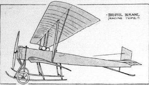
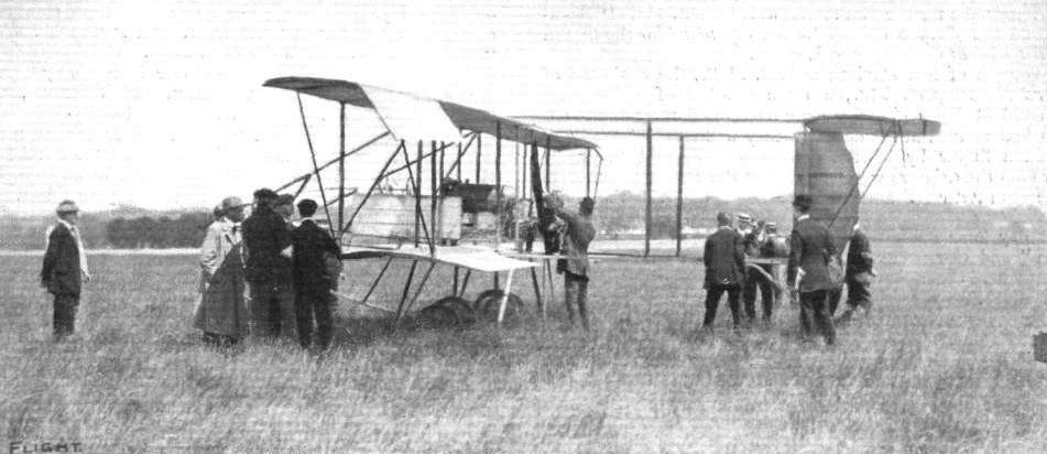
EUROPEAN AVIATION CIRCUIT. - Bristol Type T No.45 raced by Maurice Tabuteau in 1911. - M. Tabuteau immediately after his descent at Hendon on the British-built Bristol biplane.
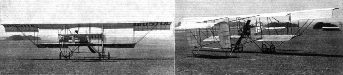
Views of one of the "Bristol" biplanes entered by the British and Colonial Aeroplane Co. for the Daily Mail Circuit of Great Britain. The top plane has a span of 15 metres, while the lower plane is of approximately 8 metres span, the chord in each case being 15 metres. Steel has been substituted for aluminium in the fittings of all machines, and 50-h.p. Gnome engines are fitted to both biplanes and monoplanes.
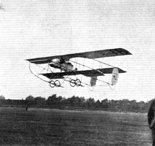
Pixton making a good start on the Bristol.
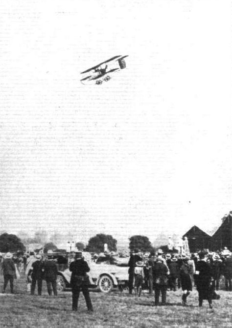
Howard Pixton makes a fine vol plane on the Bristol upon his arrival at Hendon.
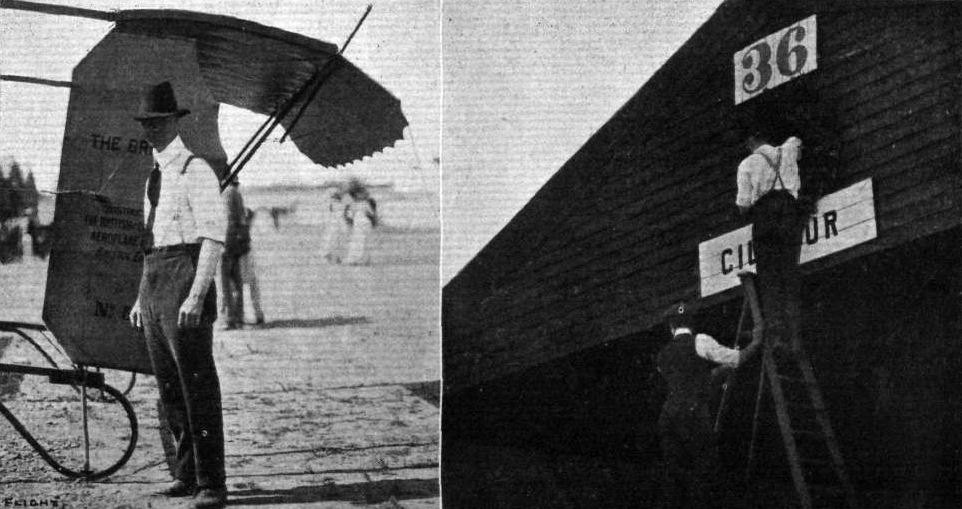
Graham Gilmour, who was refused - by the Royal Aero Club - permission to take part in the Circuit of Britain, standing by his special Bristol biplane. On the right a creped laurel wreath is being placed on his hangar as a token of mourning for non-participation.
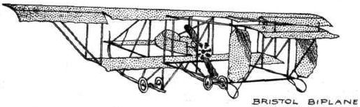
MONOPLANES AND BIPLANES IN THE DAILY MAIL CIRCUIT ROUND GREAT BRITAIN. - From these every machine can be readily identified either in flight or on the ground.
Flight, January 14, 1911
FROM THE BRITISH FLYING GROUNDS.
Salisbury Plain.
<...>
Mr. Carter was out on the new machine which arrived about a fortnight ago, and with the engine running fairly well, the machine made a few hops. From the accompanying photographs it will be noticed that the machine is of the biplane type of very short span, with the upper planes of slightly greater span than the lower ones. There is no elevator in front, but that position is occupied by the engine and propeller. The engine is an 8-cyl. one, made by the Nonpareil Motor Fitting Co. at Birmingham. At present it gives about 60-h.p., but when properly tuned up it is expected to reach about 80-h.p. On the following day Mr.Carter was out again, and succeded in getting the biplane off the ground for short distances.
<...>
Mr. Carter was also out with his biplane after having made a few alterations to the tail. The machine rises very rapidly, in one case getting off the ground in 15 ft. but no extended flights were made owing to the fact that the engine was not running up to form.
<...>
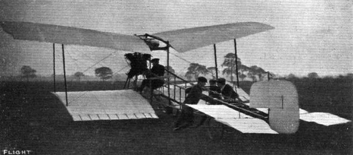
View from the rear of Mr. Carter's novel biplane.
Flight, January 28, 1911
FROM THE BRITISH FLYING GROUNDS.
Laffan's Plain.
ON Thursday of last week Mr. de Havilland had his biplane out, and was flying for two hours around Laffan's Plain. Although a stiffish northerly breeze was blowing, it was noticeable that the machine was flying much more steadily than on his previous trip. On Monday Mr. Cody was out, and made several trips with passengers, including Major Sir Alexander Bannerman and Lieut. Cammell. In one of these trips he chased after the "Beta," and succeeded in getting past her.
Flight, March 4, 1911
MODELS.
Model Cody Biplane.
I have pleasure in enclosing a photo of a model of Mr. S. F. Cody's aeroplane. It is built to scale 1/2 in. to 1 ft., from drawings published in your journal November 12th, 1910. The framework is made of white pine, and braced with strong thread.
Wandsworth. F. FISHER.
Flight, April 1, 1911.
Third International Aero Exgibition at Olympia - 1911.
THE EXHIBITS ANALYSED.
<...>
The Cody biplane is similarly a balanced machine, but it differs from the present Wright type in having an elevator. The elevator on the Cody machine is a cambered plane, and normally carries some of the load for convenience in control, although it is not essential from constructional considerations that it should do so. The engine on the Cody biplane is carried on the lower plane, and, within reason, both it and the pilot can have their positions altered in order to effect any degree of balance that may be required. In practice, as has been mentioned, Mr. Cody prefers that the elevator should be loaded a little, as he considers that it facilitates control.
<...>
Flight, April 8, 1911.
Model Cody.
I have pleasure in sending you a photo of a model of Mr. Cody's biplane which I have made and flown. I have to thank your paper for some of the chief dimensions. The machine is built of split cane joined with thread and braced with wire. I am experiencing some trouble with the motor. I cannot get the elastic to hold for any length of time. Perhaps one of your readers would be good enough to give some advice.
Westcliff-on-Sea. RIVERS SHERMAN.
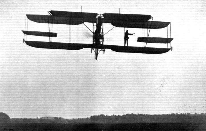
Mr. S. F. Cody on Saturday last carried a passenger on his biplane over Laffan's Plain, standing on the lower main plane, 10 ft. 6 ins. away from himself in the pilot's seat, as seen above in our photograph. Mr. Cody, by this means, wishes to emphasise his claim for the great lateral stability of his machine.
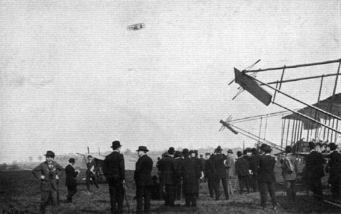
Mr. S. F. Cody arrives From Brooklands on his biplane for the Hendon Demonstration. - His fine vol plane to the demonstration grounds.
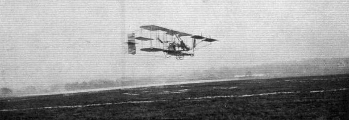
Mr. S. F. Cody finishing his flight from Brooklands to Hendon.
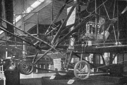
UNDERCARRIAGES AT OLYMPIA. - The Cody.
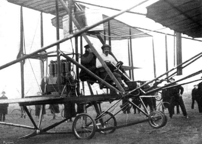
Mr. S. F. Cody, with Major Sir Alexander Bannerman, Commandant of the Army Ballon School at Farnborough, as passenger on his biplane, ready for their flight last week,
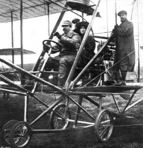
Mr. S. F. Cody last week carried three passengers - Mdlle. Armand de Lavette and Messrs. Moreton and Bloomfield - for a flight on his biplane. Our photograph shows the disposition of the party ready for their voyage.
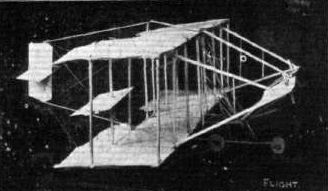
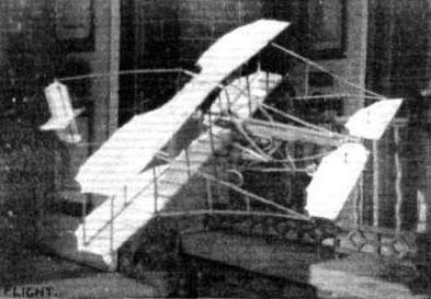
Flight, November 4, 1911.
BRITISH NOTES OF THE WEEK.
Mr. Cody's Fine Flight for the British Michelin.
A SPLENDID flight was made by Mr. Cody on Sunday last at Aldershot, with the object of placing the British Michelin Cup once again to his credit. A course of about 7 miles round had been laid down, and starting off from Laffan's Plain at 8 o'clock in the morning he continued on until he had been in the air for just over 5 hours, and by the time he decided to come down he had covered 261 1/2 miles. On Mr. Cody descending from his machine, he was carried shoulder high to his hangar by the crowd which had gathered. On the previous Friday he covered a distance of 160 miles in just on 3 hours. When he started from Laffan's Plain there was a fog over the ground, and it seemed to make little difference to Mr. Cody, who kept flying steadily at a height of 800 feet until a broken wire rendered a descent advisable.

The new Cody biplane, constructed to take part in the Daily Mail Circuit of Great Britain.
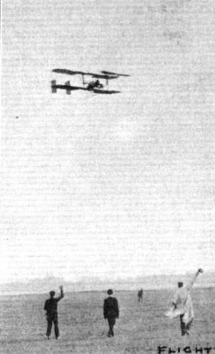
Cody well away for the first section to Hendon.
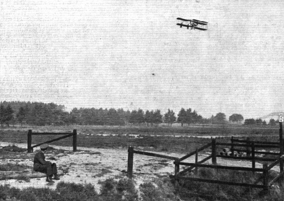
Mr. S. F. Cody making his fine flight at Aldershot on Sunday last for the British Michelin prize, when he remained up for over five hours, covering 261 1/2 miles in the time.
Flight, March 25, 1911
OLYMPIA-1911
Aeroplanes.
Wm. Cole and Sons, Ltd. - A new type of biplane with a new engine, the whole constructed entirely by themselves. This machine is exhibited in an unfinished state.
Flight, April 1, 1911.
Third International Aero Exgibition at Olympia - 1911.
THE EXHIBITS ANALYSED.
<...>
The necessity for overall length on a machine as a factor in its stability, and the necessity for providing an adequate body in order to carry the tail, certainly suggest the possibility of developing a useful type in the tandem monoplane since it plausibly offers an opportunity to provide twice the lifting surface for the extra weight of a pair of wings. Whether or no the Cole machine will succeed as the modern prototype of this class we should not like to say. In its present form it certainly seems to us to be following an undesirable principle in attempting to combine such unknown quantities as a tandem monoplane, wooden folding wings, twin propellers, and a new type of rotary engine on the same machine.
<...>
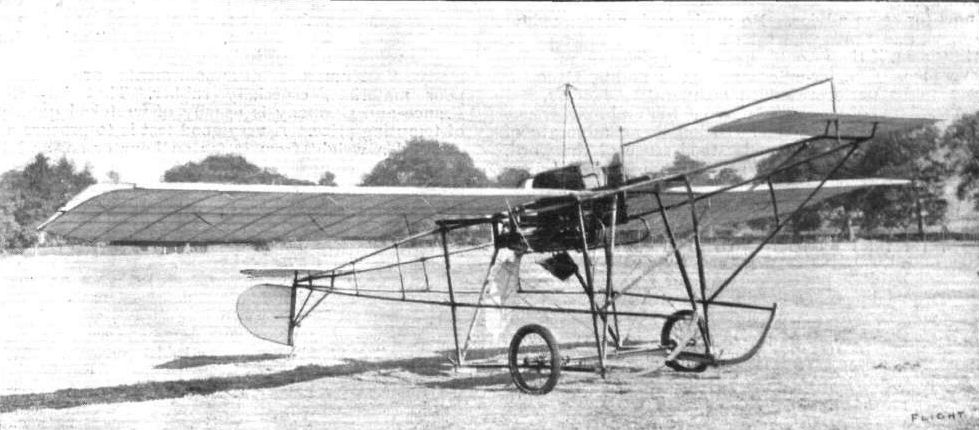
A man-carrying monoplane designed and constructed in its entirety, including the propeller, by Mr. H. D. Crompton, of Walton-on-the-Hill. The engine, which is a 30-h.p. Alvaston, is slung underneath the main bearers, the pilot's seat being on the top. The span is 30 ft., the length 28 ft., main plane surface 160 sq. ft., and the weight 600 lbs. in flying order, including allowance for pilot. No aluminium is employed, all joints being made from sheet steel.
Flight, August 12, 1911.
My First Glider.
I enclose a photo of a biplane-glider that I have made entirely myself with the exception of the wire strainers and aluminium sockets, which were supplied by Messrs. Handley Page, Ltd.
This biplane being the first and only one made in Dudley I had her out a week or so ago in a wind of about 15 m.p.h., my great difficulty being to hold her down. I had four men to assist me, and when running the slightest distance the glider shot up into the air like a kite and travelled over our heads. At first this quite startled me as I never dreamt she would rise so quickly. After running some distance we stopped, when I expected to see her come down crash, but no, to my great astonishment she landed like a feather.
The wind getting considerably stronger and requiring all our strength to hold her down, I thought it advisable to get into the pilot's seat and see what she would do by towed flights.
A run as usual taking place, the glider once more soared beautifully into the air, quite 10 to 12 ft. from the ground with myself at the controls, requiring very little skill in balancing and elevating as the speed was slow, requiring quite 30 m.p.h. before the ailerons would be of any service.
No free flights were attempted as the field is quite flat and surrounded by trees, this being my only drawback to find a suitable slope. I am at present waiting for the grass to be cut when I hope to get some better results.
I would like to mention that FLIGHT has been of great service to me, and that apart from models this glider is my first attempt. Dimensions :- Span, top plane 30 ft., bottom plane 20 ft., chord 5 ft., tail 7 ft. 6 in. by 3 ft., elevator 7 ft. 6 ins. by 18 ins., area 283.75 sq. ft.
Dudley. WALTER DAVIES.
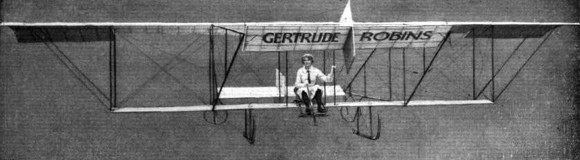
Dawson glider built by Mulliners Coachworks Ltd. for actress Gertrude Robins (Mrs. Dawson).
Mr. Chas. E. Dawson's full-sized glider with which he and his wife, "Miss Gertrude Robins," practise. This machine was built by Messrs. Mulliners, the well-known carriage body builders, and Mrs. Dawson is seen above in charge ready for a glide.
Mr. Chas. E. Dawson's full-sized glider with which he and his wife, "Miss Gertrude Robins," practise. This machine was built by Messrs. Mulliners, the well-known carriage body builders, and Mrs. Dawson is seen above in charge ready for a glide.
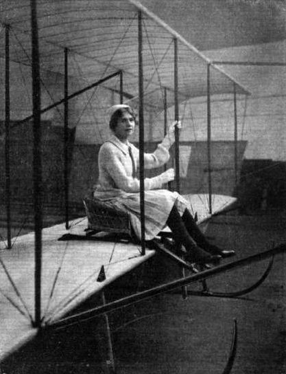
"Miss Gertrude Robins," the authoress of "Pot Luck," who is playing in "Don't Ask Any Questions" at the Palace Theatre, and who in private life is Mrs. Chas. E. Dawson of Naphill, is a great supporter of the art of flying. Miss Robins practises gliding on the machines designed by her husband, and is seen above in the pilot's seat of the biplane.
Flight, January 14, 1911
FROM THE BRITISH FLYING GROUNDS.
Laffan's Plain.
<...>
On Tuesday Mr. De Havilland was out on the biplane designed by himself, and made several good flights. In one of them 10 miles was traversed in a quarter of an hour, his height being about 100 ft.
<...>
FROM THE BRITISH FLYING GROUNDS.
Laffan's Plain.
<...>
On Tuesday Mr. De Havilland was out on the biplane designed by himself, and made several good flights. In one of them 10 miles was traversed in a quarter of an hour, his height being about 100 ft.
<...>
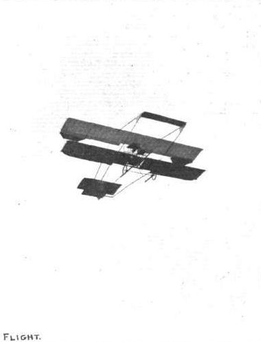
The De Havilland Army biplane, which emerged from the Army Balloon Factory at Farnborough on Tuesday last, and made a successful initial 10-mile flight, remaining up at about 100 ft. for 15 min.
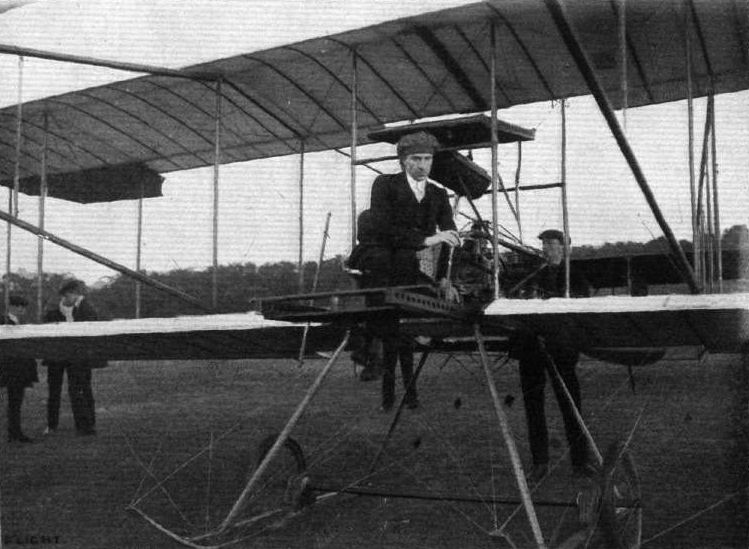
THE DE HAVILLAND ARMY BIPLANE. - View showing Mr. G. de Havilland - now a member of the War Office mechanical staff - in the pilot's seat on the occasion of the machine's successful flight at Farnborough on Tuesday last. Readers of FLIGHT are well acquainted with the pioneer work carried out by this designer, whose first machine was illustrated In these pages on April 9th, 1910.
Flight, April 15, 1911.
MODEL PRIZE WINNERS AT OLYMPIA.
1st Prize, Flying Model. W. H. SAYERS (NO. 46).
A very small Ding-Sayers biplane, fitted with running wheels to enable it to rise from the ground. The lower and upper planes are both of an elongated diamond shape in plan form but have a proper and inverted dihedral respectively, so that their extremities meet together and form a diamond-shaped gap in elevation. Between the main planes are two triangular-shaped vertical fins, and right in front is an elevator of diamond plan form, having a dihedral angle. At the rear of the main planes are two built-up propellers of 4 1/2 ins. diameter. The planes, framework and propellers are all mounted on a central tubular girder, which is very efficiently trussed with wire and struts. This model rises from the ground after a run of a few yards and flies very steadily, covering a considerable distance for its size. It also flies very well when launched from the hand, and can be so adjusted as to fly in small circles. It will be noticed that a bent wire skid is arranged in front of the model, and this also acts as a shock absorber should the model land suddenly. Waterproof silk is used for covering the wings of this model, which weighs only 1 1/2 ozs. complete.

Scale drawings of the Ding Sayers biplane; 1st prize flyer.
Flight, September 2, 1911.
THE DIXON MONOPLANE.
READERS of FLIGHT will doubtless remember reading of experiments that were carried out by Mr. H. S. Dixon at the Acton Aerodrome some time ago. They resulted in rather an unfavourable manner owing to the premature disablement of the machine as the result of one of those severe contacts with terra firm a that are so frequent during the early stages of learning to fly. The machine itself was of a distinctly uncommon design, and the accompanying illustration of it will probably be of interest to a large number of readers who make a study of these different systems of aeroplane construction.
The Nipper, as Mr. Dixon calls his first attempt, is a monoplane of the tail-first type, and is also characterised by its boat-shaped body. The leading plane consists of a tiny biplane, each member being about 2 ft. 6 ins. span and the same in chord, and, as the photographs show, the planes of this member have a considerable angle of incidence. Extending out from the gap of this leading plane are the two halves of a monoplane elevator, which is controlled by a universally pivoted lever in front of the pilot's seat. The sideways movement of this same lever is used to operate the rudder planes that will be noticed mounted vertically above the extremities of the main wing. These rudders were intended to be used as brakes, and lateral equilibrium was maintained by steering thereby into the eye of the wind. Most of the framework is made of bamboo and the wings have aluminium leading and trailing edges. The pilot's seat, as will be observed from the illustrations, is situated practically in line with the leading edge, while the propeller, which is of 6 ft. 8 ins. diameter, works in a recess in the trailing edge. The engine, a 25-h.p. V type air-cooled Advance, is mounted just in front of the rear main-spar. A simple A type under-carriage, fitted with wheels and skids, is mounted under the main wings to support the bulk of the weight when the machine is on the ground, but a lighter carriage, also fitted with wheels and skid, is placed further forward to take the weight of the leading portion.
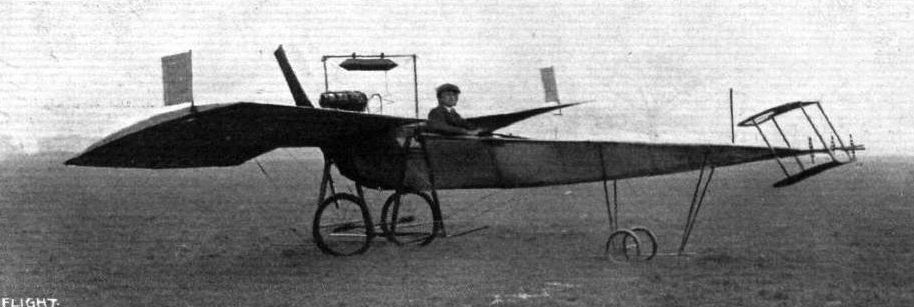
Side view of the Dixon monoplane.
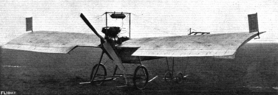
Dixon Nipper No.l monoplane was wrecked on test at Acton in 1911.

View illustrating the undercarriage of the Dixon monoplane.
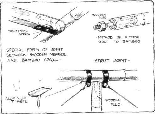
Sketch showing some details of construction in the Dixon monoplane.
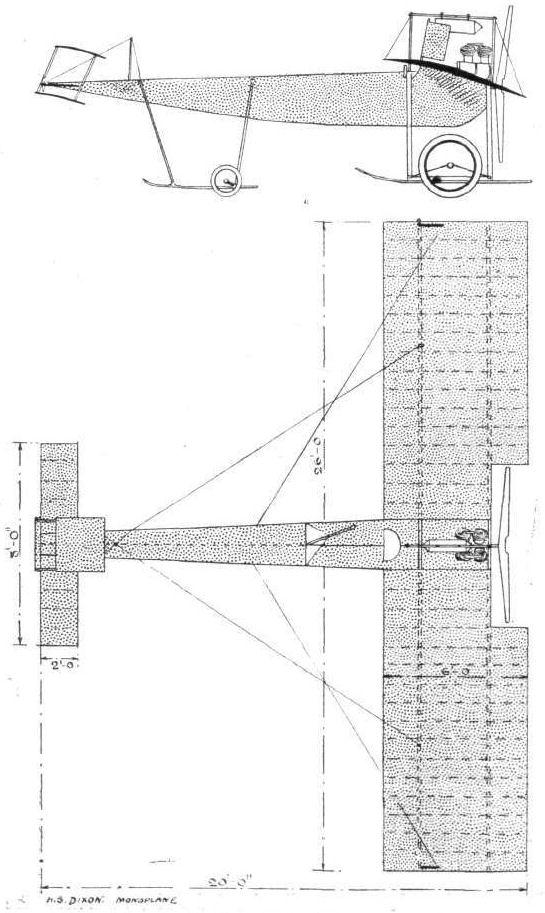
Elevation and plan of the Dixon monoplane.
Flight, April 1, 1911.
Third International Aero Exgibition at Olympia - 1911.
THE EXHIBITS ANALYSED.
<...>
A monoplane that is altogether in a class by itself is the Dunne, which is, so far as practical flying machines are concerned, an evolution of the Dunne biplane. The biplane was in itself, however, originally evolved from still earlier monoplane models. A characteristic feature of this machine is the absence of a tail and the V-plan form of the wings, which also have a varying angle of incidence from root to tip. The object of the design is the acquisition of natural stability, and the purpose of sloping back the wings is to acquire an overall length for the machine as distinct from the chord dimension. This increment in length virtually introduces the principle of a tail, and the change in the angle of incidence throughout the succeeding sections of the wings confers the principle of the dihedral angle on the relative attitude of the virtual tail portion in respect to the central leading portion of the machine.
<...>
Flight, April 8, 1911.
MORE AEROPLANES AT OLYMPIA.
WITH SPECIAL REFERENCE TO THE DUNNE MONOPLANE.
<...>
Among the monoplanes, that which will probably attract the greatest interest among our readers is the Dunne, for all will recollect what a number of interesting features the Dunne biplane, which we described some time ago, possessed. The Dunne monoplane, like its prototype biplane, is designed to possess natural stability, and is tailless in the ordinary sense of the term. In principle, however, the V-plan form of its wings gives it two tails instead of one, and the hinged flaps in the trailing extremities of the wings provide it with two elevators instead of one. These flaps are under independent control, and serve the purpose of steering the machine horizontally and vertically. The principle of stability associated with the Dunne monoplane is somewhat complicated, and has to do entirely with the special formation of the wings, which are generated on the surface of a cone. This is not the place in which to go into precise details of this method, which is fully described in our article on the Dunne biplane; but it will be interesting to those familiar with that description to be told that the apex of the cone is altogether in a different place, being situated, on the monoplane, a little way behind the trailing extremity of the wing and more or less directly in line with the outside edge. This formation of the wing gives a variable angle of incidence from shoulder to tip, which, in conjunction with the V-plan form, confers on the machine the principle of the fore-and-aft dihedral angle, which is one of the accepted methods of obtaining natural stability and is a characteristic feature in the design of all successful aeroplanes. Owing to the wing extremities being situated in an exposed region and not sheltered behind the middle portion of the plane, as is more or less the case with the tail of an ordinary aeroplane, Mr. Dunne claims that their tail effect is enhanced. Also the same argument applies to the efficacy of the dihedral angle, because, owing to the formation and continuity of the wings, it is impossible to define what part constitutes main plane and what part tail. That in fact the relative functions of these members are performed by different parts of the wings in accordance with the requirements of the moment. Lateral stability in the Dunne monoplane is somewhat more difficult to explain, but that which is the most significant feature in the design is unquestionably the fact that the wing formation provides down-turned wing tips as distinct from the upturned wing tips on such monoplanes as the Handley Page and Weiss, which are also designed more or less with a view to natural stability. It will be noticed, of course, that it is the leading edge of the Dunne monoplane that is turned down, whereas in the Handley Page and Weiss monoplanes it is the trailing edge that is turned up, so that the relative positions of the leading and trailing edges in all three machines are identical. On the other hand, it will be observed that there is a very material and fundamental difference in principle between the two methods, for whereas in principle the upturned trailing edge represents the lateral dihedral angle, the down-turned leading edge represents the gull's wing, which is an accepted method of obtaining lateral stability in side gusts. The general action is as follows: A side gust ordinarily lifts that side of the machine against which it first strikes, because of the aeroplane action of the planes considered in their attitude towards the gust and the consequent travel of the centre of pressure towards the virtual leading edge facing the gust, which involves an actual travel of the centre of pressure laterally from the real centre of gravity of the machine. Thus the machine cants over and the upset is emphasised with the dihedral angle, because the upturned wing offers an increasing surface for the more effective surface to the gust and tends to counteract the lift due to the travel of the centre of pressure on the remainder of the plane. It is, in principle, little more or less than this idea which was tried by the Wright Brothers in some of their early gliding experiments. Like most things of this kind, however, there is all the difference between the broad principle and the detail of carrying it into effect on a practical machine. It is the detail that makes the Dunne monoplane such an original design.
<...>
Flight, June 24, 1911.
THE DUNNE MONOPLANE, 1911.
As our readers are already thoroughly familiar with the general features of the Dunne system from our description of the biplane in FLIGHT, June 18th, 1910, it is unnecessary to make any elaborate reference to the monoplane that is now undergoing its trials at Sheppey. This machine, as a glance at the accompanying illustrations shows, has the same general type of wings, but a point that will escape casual observation is that the camber of each is generated on the surface of a cone having its apex in the vicinity of the trailing extremity, whereas it may be remembered that the generating cone used in connection with the wings of the biplane had its apex in the vicinity of the prow of the machine. The meaning of this reference to the generating cone will be understood by those who read our description of the Dunne biplane, but for the sake of those who are unfamiliar with the principle, we may briefly explain that the characteristic feature of the Dunne wing formation is that the camber changes from point to point between shoulder and tip. This change takes place both in camber and attitude (angle of incidence) and is gradual in character; it is represented by the change of curvature on the surface of a cone arranged in a special way with respect to the setting of the wings. For a complete explanation of this particular point, however, we must refer our readers to our above mentioned article.
Since the tips are set back behind the shoulder, owing to the V plan form of the wings, the change in angle between shoulder and tip introduces the principle of the longitudinal dihedral. In order to render this clear it is convenient to imagine that the middle section of each wing is removed. In this case the extremities form two tails at a negative angle in respect to the leading main plane. In practice the extremities act as tails, and being out of the influence of the draught of the propeller they do not tend to disturb the balance of the machine if the propeller stops in flight. As to where the tail portion begins and the main plane ends, it seems impossible to say, for it seems only reasonable to suppose that the dividing line varies with circumstances. Provided that it moves in the right direction, this differential action is, of course, all to the advantage of the natural stability of the machine.
Natural stability is the great aim, we might almost say the raison d'etre, of the Dunne aeroplane, and, so far as the longitudinal stability is concerned, the simple principle of the fore and aft dihedral is apparently a sufficient explanation of the system. In many modern machines the principle of the dihedral is also used for lateral stability, but in the Dunne machine this equilibrium is arranged in a different way. As a glance at the accompanying illustrations shows, the wings are arched rather than upturned, and it is therefore to the principle of the gull's wing, and not to the dihedral angle, that the lateral stability of the machine is due.
Unfortunately, this principle does not lend itself to any very precise explanation, but as a general description it may be pointed out that the down-turned extremities are so arranged that if the relative wind veers from an initial position, which may be assumed to be in the line of flight, the near wing will be partially shielded and may even have a downward pressure on its extremity. Simultaneously, the downturned extremity of the far wing will be more exposed and will thus exert a greater lifting force at its full leverage.
The first tendency of the veering wind is to lift the near wing, owing to the improved aspect ratio of that wing and to the diminished aspect ratio of the far wing, which is also possibly shielded somewhat by the body of the machine; it is this disturbing force that is counteracted in the manner just explained. As the equilibrium of the machine depends on the nicety with which one force just balances another it can be understood that the exact design of the wings is rather a difficult matter.
It will be observed, from what we have said, that the disturbance and correction thereof are simultaneous and are both brought about by the relative wind itself, without change in the position of the machine. In the theory of the dihedral angle, the machine is assumed to heel over in order to obtain a righting force. This difference in the actions of the two types of machine seems to draw a line between two types of stability, which may be described as "stiff" and "rolling." The Dunne principle belongs to the former, inasmuch as the machine is not supposed to be actually moved at all by the disturbing influence.
From a constructural point of view, the Dunne monoplane is mainly interesting on account of its dissimilarity in general appearance to any other well-known type. The wings form a canopy over the pilot, who is seated in the bows of a shallow body that carries the engine at its after end. The propeller revolves immediately behind the V of the wings, and its axis is, of course, in line with the centre of gravity of the machine. Above the wings is the radiator, which is placed there principally to raise the centre of gravity as high as possible. The entire machine is carried on a simple wheel-skid under-carriage.
The control of the machine is effected by two levers, which are quite independent, and control the hinged wing-tips in the trailing edges of the planes separately. These flaps serve the dual purpose of elevator and rudder, for when they are both moved simultaneously in the same direction they alter the attitude of the machine, and thereby cause it to climb or descend; but when moved in opposite directions, or when one of them is moved alone, it is equivalent to rudder action, because it alters the resistance to motion and thus tends to accelerate or retard that extremity of the plane, so that the machine alters its course.
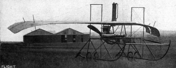
Three-quarter view of the Dunne monoplane from in front.
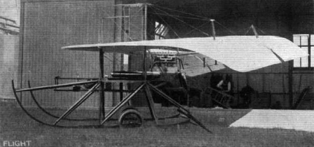
Side view of the Dunne monoplane.

Three-quarter view of the Dunne monoplane from behind.

Rear view of the Dunne monoplane.

Front view of the Dunne monoplane.
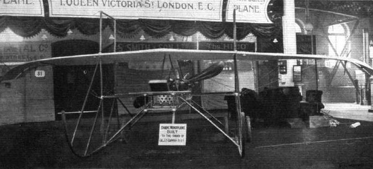
The Dunne "Auto-Safety" monoplane.
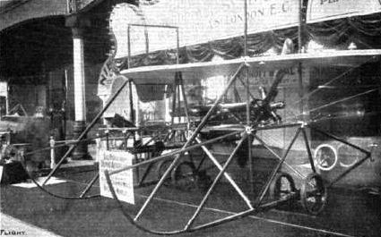
UNDERCARRIAGES AT OLYMPIA. - The Dunne.
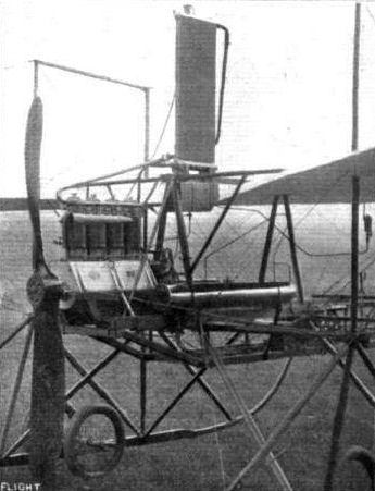
Engine and propeller on the Dunne monoplane.

The control levers, pilot's seat, and map case on the Dunne monoplane.
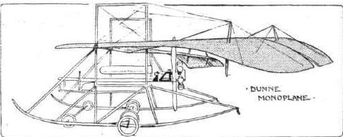
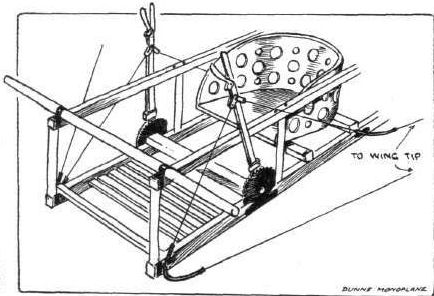
Sketch illustrating the pilot's seat and two control-levers on the Dunne monoplane.
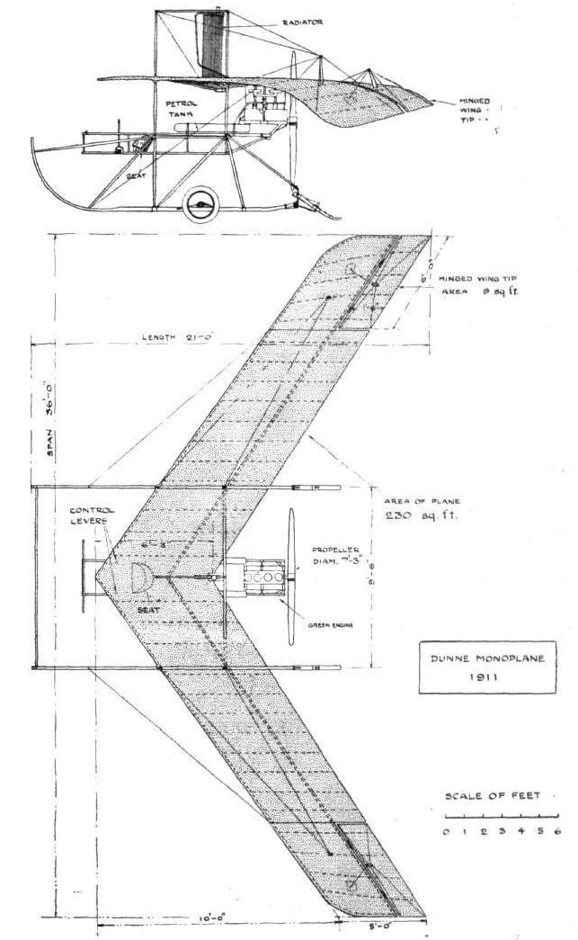
THE DUNNE MONOPLANE, 1911. - Plan and side elevation to scale.
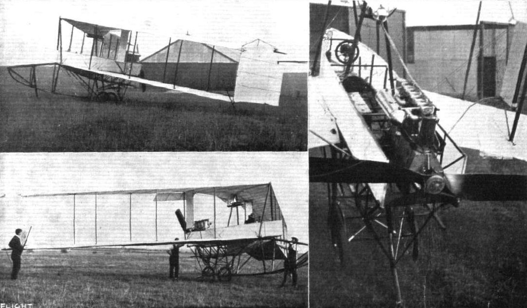
Three views of Lieut. Dunne's latest aeroplane at the Royal Aero Club's Eastchurch flying ground. - The top photograph shows the machine after its first flight with Lieut. Dunne in the pilot's seat, the lower view giving the machine from the opposite side. On the right the photograph of the pilot's "boat" gives a good idea of the ample room available. To the right of the steering wheel is seen the torque-flap lever; the torque-flap itself is just visible on the right. On the left is the Bosh coil and Elliott counter. The petrol tanks are placed on either side of the boat immediately in front of the engine.
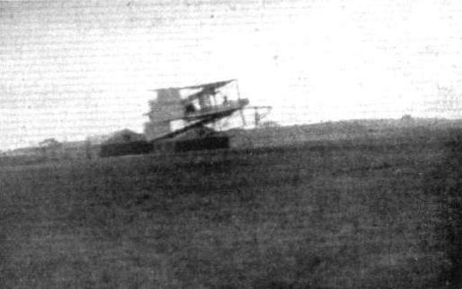
Lieut. Dunne is seen in the left-hand view making a low flight at Eastchurch on his biplane.
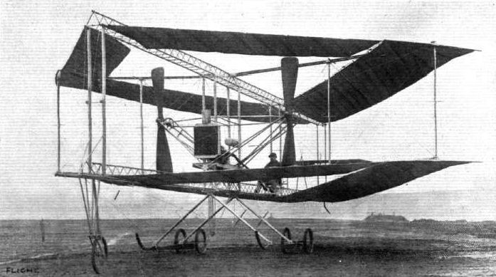
Quite one of the most interesting experimental machines down at Brooklands is that which was described in very full detail by us as long ago as February 5th last year. Not only does it unusually large size (a total surface of some 1,200 sq. ft.) render it notable, but the entire form of construction is quite unlike that of any of the other aeroplanes now in existence, and is based upon the results of a remarkable series of experiments that were conducted before this particular full-sized biplane was put in hand - results which seem to indicate the possession of an astonishing degree of automatic stability. A good general idea of the hollow rhomboidal (or diamond) shape is conveyed by the above illustration, as also of the special girder construction of the framework, and the disposition of the propelling mechanism.
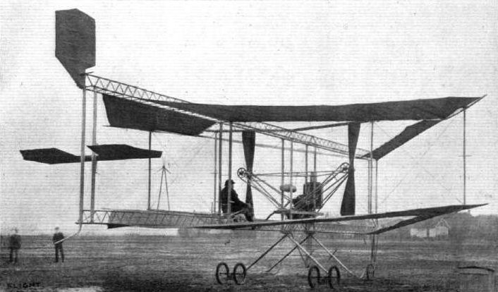
Another three-quarter view - in this case from the rear - of the unique diamond-shaped biplane now being tested at Brooklands. This photograph shows the elevator and the rudder, both of which are attached at the extreme rear, and also perhaps serves to convey a useful supplementary impression concerning the tout ensemble. In front the converging planes are narrow, being only about 3 ft. deep, whereas those that join the front planes at the point of greatest width of the framework, and meet at the extreme rear, have a depth of some 9 ft. A Humber engine of about 50-h.p. is fitted.
The new Edwards rhomboidal biplane at Brooklands out for an airing on Saturday last. - This machine, it will be remembered, was described in FLIGHT on February 5th, 1910. Flying in perfect form above is Capt. F. H. wood on a Bristol machine.
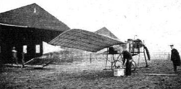
AT THE LONDON AERODROME. - Mr. Clutterbuck by Mr. Everett's monoplane, where this machine has been under test.
Flight, September 23, 1911.
AIR EDDIES.
In my opinion, it would be well nigh impossible to find a constructor possessing a more complete grasp of his subject than does Howard Flanders of Brooklands. Indeed the way in which his monoplane carries passengers with the 60-h. p. Green seemingly at half-throttle is sufficient evidence of his worth as a designer. I should have thought that he would have made an attack on the Michelin prize ere now, but apparently he is not yet quite satisfied with its running, as he intends to spend another week or two in adjustments.
Awfully particular chap, Flanders!
Flight, October 21, 1911.
AIR EDDIES.
The Flanders monoplane, which has earned for itself a very enviable reputation down Brooklands way, has retired to its hangar pending preparations for an early attempt on the Michelin prize for duration. For three days preceding the closing of the cross-country Michelin competition, Ronald Kemp had been patiently awaiting an opportunity of putting up a good performance in this connection, but the weather conditions put cross-country work out of the question. The Flanders should make its reappearance in a few days' time.
AIR EDDIES.
In my opinion, it would be well nigh impossible to find a constructor possessing a more complete grasp of his subject than does Howard Flanders of Brooklands. Indeed the way in which his monoplane carries passengers with the 60-h. p. Green seemingly at half-throttle is sufficient evidence of his worth as a designer. I should have thought that he would have made an attack on the Michelin prize ere now, but apparently he is not yet quite satisfied with its running, as he intends to spend another week or two in adjustments.
Awfully particular chap, Flanders!
Flight, October 21, 1911.
AIR EDDIES.
The Flanders monoplane, which has earned for itself a very enviable reputation down Brooklands way, has retired to its hangar pending preparations for an early attempt on the Michelin prize for duration. For three days preceding the closing of the cross-country Michelin competition, Ronald Kemp had been patiently awaiting an opportunity of putting up a good performance in this connection, but the weather conditions put cross-country work out of the question. The Flanders should make its reappearance in a few days' time.
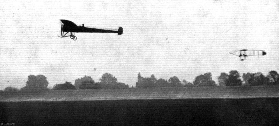
FLYING AT BROOKLANDS ON WEDNESDAY OF LAST WEEK. - The Flanders monoplane, and, over the track, the Avro biplane making circuits.
Flight, November 11, 1911.
Naturally-Stable Machine.
Having read with considerable interest the letters of Harold Kelk and Will H. Booth, and having ourselves, for a long time, been experimenting on the lines adopted by these gentlemen, we send you photographs (reproduced herewith) of our full-size machine, which we have built as a result of our successful experiments with models.
We patented it in 1909. The patent No. is 20846, and we append particulars of size which, with the photograph now sent, will enable you to see the principles upon which we have built:-Length, 24 ft.; width, 16 ft.; height, 10 ft.; surface, 350 ft.; weight with pilot, 450 lbs.
The principal objects we studied to accomplish in creating our machine were - 1st, safety; 2nd, natural stability; 3rd, simplicity in steering, elevating, &c.; 4th, small motive power; finally, low cost of building. The lifting surface is so arranged that, in the event of the engine stopping, the machine will descend in a series of glides, and settle on a level base.
It is seeing that our ideas are apparently coming into vogue that it seems advisable to explain our position.
Leigh-on-Sea. VICTOR F. FORBES, ARTHUR J. ARNOLD.

A view from the front of Messrs. Forbes and Arnold's novel machine.
Flight, August 12, 1911.
THE FRITZ MONOPLANE.
AN all-British machine that has recently been constructed by Messrs. Oylers, Ltd., of 35, New Cavendish Street, London, W., to the designs of Mr. Fritz Goetze, is illustrated by the accompanying photographs and drawings. It calls to mind in some respects the Demoiselle of Santos Dumont fame, for it is of the light spidery variety albeit of much more substantial construction with regard to the under-carriage. It has, too, somewhat the same system of control, which includes pedals for wing warping and rotating hand wheels on either side of the pilot's seat for operating the elevator and the rudder. The main frame of the machine consists of three bamboo spars trussed by light steel triangular frames forming struts, and the usual system of diagonal wires. In the wings, there are also three spars, which are likewise of bamboo. The two principal spars therein have a diameter 2 ins. while that near the trailing edge has a diameter of 1 in. The largest spar in the body has a diameter of 2 1/2 ins. and is in one piece 24 ft. long. The ribs of the wings are of bamboo and pegamoid is employed for covering the planes, which are double surfaced. An aluminium leading edge is introduced to give stiffness to the front of the wing and a steel wire is carried round the trailing extremities of the wing over which the surfacing fabric is laced.
The under-carriage resembles in its outline the Bleriot system, and consists of a pair of neatly designed hinged diamond frames carrying the two landing wheels, which are braced together by a light steel axle that is itself reinforced by a disc in the centre, over which a series of steel wires are stretched between the extremities of the axle tube. The power plant includes a 40-h.p. E.N.V. engine direct coupled to a 7 ft. 10 in. propeller. The engine is located wholly in front of the wings and the propeller-shaft is practically in line with the chord at this point. The pilot's seat is under the wings.
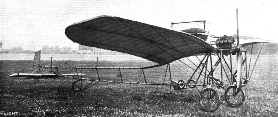
Side view of the Fritz monoplane of 1911 was built by Oylers Ltd.
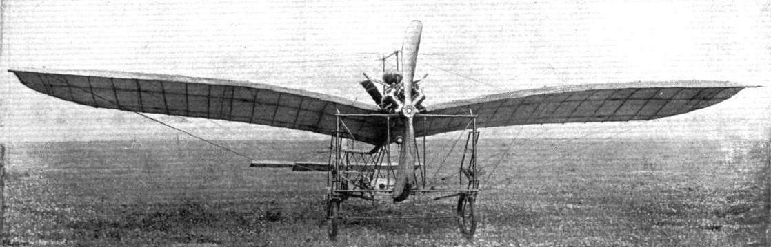
Front view of the Fritz monoplane, built by Messrs. Oylers, Ltd.

Sketches illustrating some constructional details of the Fritz monoplane. Above, on the left, is seen the method of lacing the Pegamoid fabric to the trailing edge of the wings. Beneath is a little releasing catch intended to enable the pilot to dispense with assistance when starting. On the right is shown the method of mounting the rudder to the tail end of the bamboo frame.
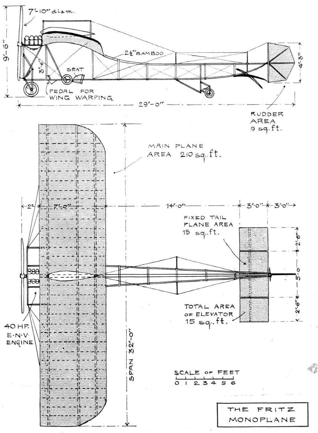
THE FRITZ MONOPLANE. - Plan and elevation to scale.
Flight, March 11, 1911.
See-Saw Type Aeroplane.
[1103] I enclose a sketch of the see-saw type of aeroplane that I have invented and for which I claim that it is easier to learn to fly than any other type. The pilot has the whole of the machine in front of him with direct control and "feel" of both elevating and steering handle, which is of gun-metal and similar to the cycle handlebar in use for steering, but with up and down movement for balancing.
Primarily, the invention is to secure a better sense of direction in beam winds. The present loading of aeroplanes is a central disposition of carried weights, which in a beam wind acts as a pivot for the aeroplane to veer round.
Features not to be lost sight of are :- the compass is a long way from the engine, so is the pilot, and the provision of a hoe shoe or grapnel will be useful to hold back aeroplane whilst starting engine and as an emergency drag in finishing a flight.
The idea is the outcome of another original machine I have designed, built and flown with an Alvaston engine.
JOHN GAUNT.
Flight, April 1, 1911.
BRITISH NOTES OF THE WEEK.
Mishap with the Gaunt Monoplane.
ON Tuesday week the Hon. W. S. Leveson-Gower R.N., visited Southport with the object of trying the Gaunt monoplane, of which he is part owner. After two runs of about a mile each along the North Foreshore the machine on its third trial rose to a height of between 10 and 15 ft. It swerved to the left, and on recovering pitched forward and turned turtle. Fortunately the pilot was thrown clear and escaped with only a bruise or two. The left wing of the monoplane was buckled and the chassis damaged, while the propeller was broken to splinters.
Flight, June 17, 1911.
FROM THE BRITISH FLYING GROUNDS.
South port Aerodrome.
MR. GAUNT is now making good progress each day in learning to manage the Baby biplane racer he has made at Southport, and hopes soon to be numbered with the constructor-aviators. The machine has but 200 sq. ft. area, and shows a good turn of speed. So far, Mr. Gaunt has been doing straight flights up to half a mile each, and is now making safer landings, being more accustomed to the drag caused by the wheel-contact with the sands, which have been rather of a loose nature lately, sometimes bringing the machine to a sudden stop instead of rolling on.
Flight, July 1, 1911.
FROM THE BRITISH FLYING GROUNDS.
Southport Aerodrome.
ON the 12th and 13th ult. Mr. Gaunt out the "baby" racing biplane which he has designed and built, and is now learning to fly, and made several straight flights up to half a mile each. On Thursday morning he did a mile, and in the evening a mile and a half, descending with the engine stopped from a height of 60 ft., landing perfectly. Friday was a blank, the weather not clearing until sunset on the 17th ult., when Mr. Gaunt ventured out and flew two miles again, gliding down and landing perfectly after taking a half turn. For speed and steadiness the machine leaves nothing to be desired, and all the flights have been made with the engine (30-h.p. Alvaston) throttled down.
On the 23rd. ult. Mr. Gaunt made a very good flight from his hangar at the north end of the Promenade to the Pier. In the evening he again made this trip and was able to fly back to his hangar. A third trip was made subsequently, making the total distance flown during the day about seven miles.
Flight, July 8, 1911.
FROM THE BRITISH FLYING GROUNDS.
Southport Aerodrome.
ON the 3rd inst., after a week's enforced idleness due to squally weather, the Dines anemometer fell to 19 m.p.h., and Mr. Gaunt took out the "Baby" biplane he has made for a straight 2-mile trip, which subsequently he repeated, descending with a neat vol plane. Owing to some mischievous tampering by the crowd, half the elevator got bent 6 ins. out of normal, and Mr. Gaunt had a narrow escape on his next attempt, the machine quickly turning over, landing on the wing tip; but this fortunately held together, and so saved a smash.
On the 4th, Mr. Gaunt made several trial flights in the evening, after altering the adjustable incidence of planes to do slow flights, and covered over 10 miles with remarkable steadiness in the 12 m.p.h. wind.
Flight, July 15, 1911.
FROM THE BRITISH FLYING GROUNDS.
Southport Aerodrome.
MR. GAUNT last week put in some very fine trips upon the "Baby" biplane he has made, at times flying 100 feet high and descending neatly with the engine stopped. On Friday evening he was flying quite half an hour, but on Saturday was in difficulties trying to rise in a side wind and damaged the propeller, wheels, and the lower planes, although the chassis stood up to the shock.
Repairs took until the evening of the 11th, and then on taking out the machine again Mr. Gaunt made several trips to the Pier and finished up with a flight to Crossens.
Flight, July 29, 1911.
FROM THE BRITISH FLYING GROUNDS.
Southport Aerodrome.
ON the 18th, Mr. Gaunt made several trips over the oreshore, keeping about 100 ft. up, flying very steadily. Mr. Hubert, flying Mr. Graham-White's Farman, at one time crossed over Mr. Gaunt, much to the delight of the crowd of holiday makers. Owing to high winds nothing further was done until Monday, when Mr. Gaunt made his most successful flight to date. Keeping 300 ft. high, he flew from the Pier to Crossens at a good speed, so steadily that the machine appeared to be travelling on a wire.
Flight, August 12, 1911.
FROM THE BRITISH FLYING GROUNDS.
South port Aerodrome.
OWING to high tides leaving the foreshore muddy, flying had been impossible for twelve days up to the 4thinst. Then, however, conditions were more favourable, and Mr. Gaunt made several pretty flights at a good height, and attempted a left-hand turn for the first time with his Alvaston engine.
On the 8th further flights were made, but a broken petrol pipe terminated experiments, Mr. Gaunt making a perfect landing after switching off on the first indication of this trouble.
Flight, August 26, 1911.
FROM THE BRITISH FLYING GROUNDS.
South port Aerodrome.
SINCE the 12th Mr. Gaunt has been able to put in daily practice, flying over the foreshore, and though nothing great has been achieved, everything points to the fact that he has evolved a low-powered machine of great stability with a good turn of speed, and he continues to make splendid landings.
Flight, September 2, 1911.
FROM THE BRITISH FLYING GROUNDS.
Southport Aerodrome.
ON the 23rd ult. Mr. Gaunt made several flights over the foreshore on his baby biplane, and although the condition of the shore was bad he made very successful landings. Little flying was attempted again until the 28th. In the morning some fine flights were made, and later at 4 p.m., when Mr. Gaunt had an exciting moment or two during a squall. When a mile out and 40 ft. up, he was tossed up over 60 ft. one second, only to drop the next, and when near terra firma a cross gust shot him up again almost capsizing the machine. Mr. Gaunt, however, by skilful warping for level again managed to land without damage.
The anemometer reading recorded a fairly steady 15 m.p.h. with a sudden squall 32 m.p.h. at this period, whilst the anemoscope reading shows the first squall gust W. by N. and the second gust S. by E.
A local enthusiast, Mr. Pochin, is building a monoplane and hopes to have it ready for trying here in about six weeks time.
Flight, September 9, 1911.
FROM THE BRITISH FLYING GROUNDS.
Southport Aerodrome.
ON the 30th and 31st ult. and 1st inst. Mr. Gaunt made flights over the foreshore in the direction of the pier, but was not able to attempt turns owing to the tricky wind. He made a trial flight on the "Baby" biplane on the 5th prior to the Hon. W. S. Leveson-Gower, R.N., taking charge. Mr. Leveson-Gower, after a few preliminary runs, made three short flights, landing perfectly each time, before darkness suspended operations.
Flight, September 16, 1911.
FROM THE BRITISH FLYING GROUNDS.
South port Aerodrome.
IN the few days last week that the Hon. W. S. Leveson-Gower, R.N., was over, he made rapid progress in handling the small biplane built by Mr. Gaunt, in all making twelve flights, several being of over half a mile each. The wind prevailing was N.W., consequently the course was restricted by the tide, or longer flights would have resulted, as Mr. Gower showed plenty of confidence and made good landings. He is a good five stone heavier than Mr. Gaunt, but the extra weight appeared to make no difference to the 30-h.p. Alvaston.
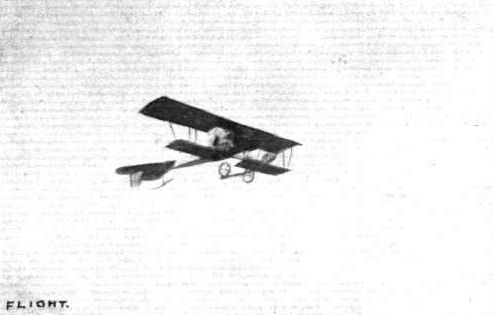
Mr. J. Gaunt flying his small biplane over the Southport sands.
Flight, February 25, 1911
FROM THE BRITISH FLYING GROUNDS.
The Grahame-White School. - Monday morning of last week was not all that one could wish as far as temperature was concerned, but happily there was a dead calm. The three Grahame-White instructors gave an impressive demonstration of flying, all three being in the air together at times.
Hubert opened proceedings at 10 o'clock by bringing out the Wolseley-Farman, which he had intentions of flying for one hour. After 20 minutes circling the aerodrome at a height of about 100 feet he was forced to come down owing to an air-lock forming in the petrol pipe. As soon as he had descended Martin brought out the "New Baby," the new racer built to Grahame-White's designs, and made a most excellent little trip of 20 minutes duration. During his first half-dozen circuits he maintained a good altitude, finishing his flight by three circuits not 6 feet from the ground, showing off effectively the little machine's speed. He was not content to rest over long, soon getting away again practising right-handed turns. On landing he expressed the opinion that the right-handed turn was decidedly more awkward than turning to the left, but it was in all probability simply due to the fact that the left-hand turn had become a habit and that it only required a little practice to render the righthand turn equally simple.
Hubert was soon at work again on his Farman with the Wolseley motor, and getting off the ground quickly covered two laps of the aerodrome at an altitude of about 200 ft. Clement Greswell, with hopes of making a cross-country trip to Brooklands on the Gnome-Bleriot, ascended after lunch to ascertain if the weather conditions were suitable for the trip. Finding that a slight mist rather obscured landmarks he decided to postpone the attempt. Soon after he was up again, climbing steadily until an altitude of 200 ft. was reached, passing the boundaries over the country in the vicinity of the aerodrome.
Passing over Edgware, he doubled back, following the main Edgware Road until he came to West Hendon. Here he steered at a sharp turn, and cutting off his engine made a superb vol plane right back on to the aerodrome, a distance of approximately a mile and a half. J. V. Martin in the meantime was making some very good flights on the "New Baby" racer. On one occasion he took the head mechanic as passenger for a single circuit, thus demonstrating the weight-carrying capabilities of this small-surfaced machine.
<...>
Flight, March 25, 1911
THE GRAHAME-WHITE BIPLANE.
THE "NEW BABY" TYPE.
ALTHOUGH belonging to a very conventional type - the Farman - the latest Grahame-White biplane is full of interesting constructional details that well repay a close study on the part of those who are concerned in the aeroplane development of the day. So soon as any one particular type becomes popular because of its extended success, progress is necessarily confined more or less to minor features, and in this way detail design and workmanship steadily improves, and a fund of useful experience is gradually built up to enhance the chances of success with any new model that may be ultimately evolved. Most of the high-class machinery of the present day is useful only because it is well made, and the excellence of engineering workmanship nowadays is not only a matter of relative superiority as between one machine and another, but is absolutely a fundamental necessity to the success of the type as such. The internal combustion engine, for example, would be a complete failure but for the fact that it is well made, and thus it is that there is a distinct interest attaching to an investigation of a number of aeroplanes of the same type. At the present time the Farman biplane represents a type of machine that is most popular. Many manufacturers very wisely adopted it as a basis of their own design, because for one thing it is a line along which they are assured of success; and secondly, which is equally important, the popularity of the type itself is more or less a guarantee of some measure of commercial prosperity as a reward for such labours. Notwithstanding the fact that there are so many machines on the market of the Farman type, however, each one of those that we have illustrated in FLIGHT has had some detail or other that has been worthy of the attention of our readers, and the present machine is no exception. Its broad feature of interest is its small size, for the span is only 27 ft., and the overall length only 32 ft. 3 ins. It is intended for a light, fast flyer, and it has been beautifully built throughout. Most of the timber is silver spruce, with the exception of the central struts and the under-carriage, which are made of ash. It will be noticed, too, that the under-carriage does not extend very far below the main planes, consequently the machine as a whole is not very high; indeed, when standing on the ground it is only 8 ft 6 ins. to the edge of the upper main plane.
In order to allow the propeller to clear the ground, too, it has been necessary to raise the engine, which now occupies a position midway in the gap. A very neat sloping frame supports the engine and the pilot's seat.
Among constructional details, the most interesting feature of this Grahame-White biplane is the use of steel fittings throughout, instead of the aluminium sockets and lugs that are commonly employed in aeroplane construction. Some examples of these steel fittings are illustrated in the accompanying sketches; and one that is of particular interest, inasmuch as it is called upon to withstand very severe shocks, is that forming the sockets that carry the struts supporting the machine upon the skids. The sketch itself gives a very good idea of the neatness and lightness which is so characteristic of the actual appearance of these details on the machine itself. Another place in which a steel bracket is used is for the attachment of the leading spar of the tail plane to the outrigger, and this also is shown in one of the illustrations. The method of hinging the rudder plane to the tail strut is likewise shown in detail in a similar manner, as also is the safety wiring by means of which the guy-wires in the vicinity of the propeller are prevented from fouling the propeller blades should one of them accidentally break. Experience has taught that some precaution of this sort is eminently desirable, not because breakages are frequent but because the consequences of one are so very unpleasant if the wire gets tangled up in the propeller. Moreover, the propeller is not the least expensive part of the machine, and there is also the engine to be considered. On one occasion on which we witnessed a rather indifferent landing with a standard type Farman biplane we recollect noticing that one of the guy-wires had in some extraordinary way been jerked under the rock-lever operating the exhaust valve on one of the cylinders of the Gnome engine, and it is to guard against consequences of this sort that these simple precautions are taken by experienced constructors, and are therefore, of general interest, although apparently of such a minor character. The system of control on the Grahame-White model is the standard system, but the arrangement of the control-lever is uncommon and interesting. The lever is duplicated so that one lever is fitted on the left and another on the right of the pilot's seat. These levers are coupled together by a cross-bar, which can be hinged out of the way whilst the pilot is mounting to his seat. In flight the pilot has the cross-bar immediately in front of him, and can thus use either or both hands in the control; the movements themselves, however, are of course of the usual kind, and the cross-bar, being pivoted at both ends, interferes no more with the sideways balancing movement than it does with the to-and-fro operation of the elevator. In connection with this detail, again, the use of steel sockets constitutes a prominent feature, and although the design has incorporated an additional member, nevertheless the characteristic lightness and neatness in appearance has been retained.
Flight, November 11, 1911.
AIR EDDIES.
Claude Grahame-White has arrived back in England for a short period in order to take a slight respite from his strenuous work on the other side of the Atlantic, and to direct his rapidly-growing undertakings at Hendon. His firm's factory at Hendon is now in full working swing, and is replete with all the labour - saving machinery necessary for the economical production of all types of air-craft. He intends to return to the States on the 18th of this month, sailing by the "Lusitania." Both his 70-h.p. Nieuport and his 50-h.p. Indian-engined "Baby" biplane have been dispatched to California, which he will make the scene of his operations on his return.
* * *
The Indian aero motor, which was mentioned in last week's notes, has been undergoing rigorous tests at the hands of Mr. Grahame-White in America, and I have it as his opinion that as soon as one or two minor modifications have been made the engine bids fair to attain a reputation as the best of its type.

View of the casing which protects the pilot on Grahame-White's "New Baby" biplane. This photo also shows the arrangement of the skids.
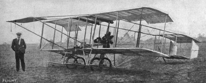
Mr. Grahame-White and his "New Baby" biplane.
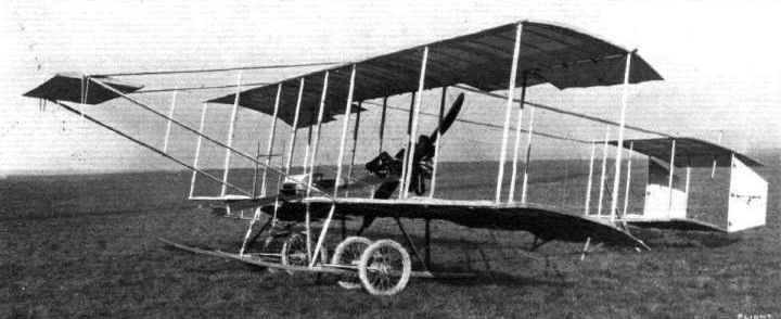
ONE OF THE LATEST GRAHAME-WHITE BIPLANES. - This is built up in three parts, rendering it very easy of transport, the centre part forming a single unit which can be dismembered by merely undoing four bolts. It is claimed to be faster by about 15 m.p.h. than the Farman and Curtiss, of which types it embodies the leading features.
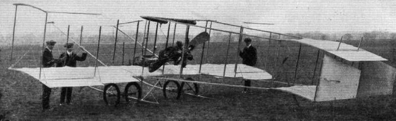
Rear view of the Grahame-White "New Baby" biplane.
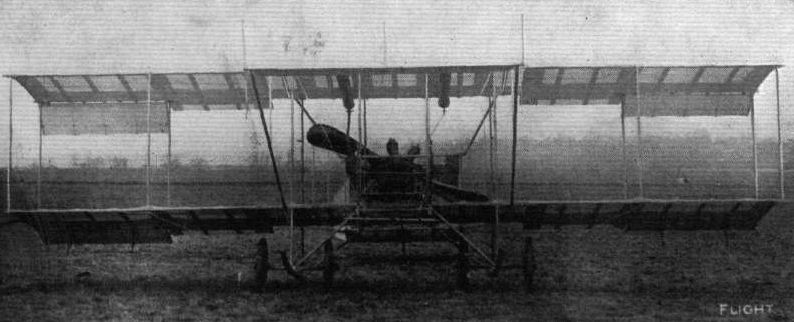
Front view of ths Grahame-White "New Baby" biplane.

View of Mr. Grahame-White's "New Baby" biplane from behind, showing the balancing planes and the hinged extension of the upper tail plane.

MR. GRAHAME-WHITE'S "NEW BABY" BIPLANE RECENTLY COMPLETED. - (1) The machine seen from in front just before its first trial run. (2) A view from behind immediately after landing; and (3) "New Baby," piloted by Mr. Grahame-White, getting well up on its first circuit at the London Aerodrome, Hendon.
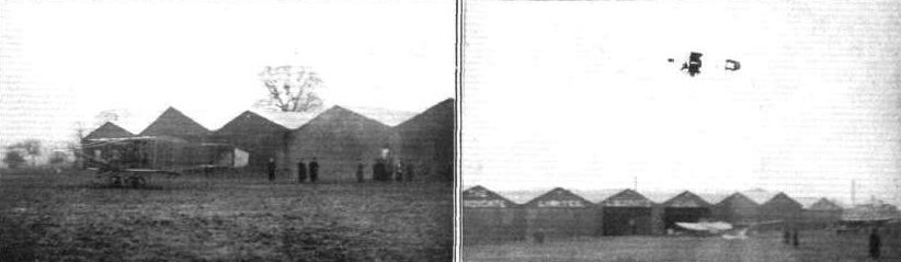
HENDON-BROOKLANDS-HENDON. - Mr. Martin, on the Grahame-White "New Baby" racer, was one of those who, on Saturday, made fine flights for this competition. In the left-hand photo Martin is just starting away from Hendon Aerodrome. An idea of the rapidity of the "get-off" can be gathered by the fact that although he only started from the spectators in the background, the tail is well up, and the ailerons are flying right out. Only 34 secs, elapsed before the right-hand photo was secured, and in this time Martin had to make a complete turn and double back on his original direction.
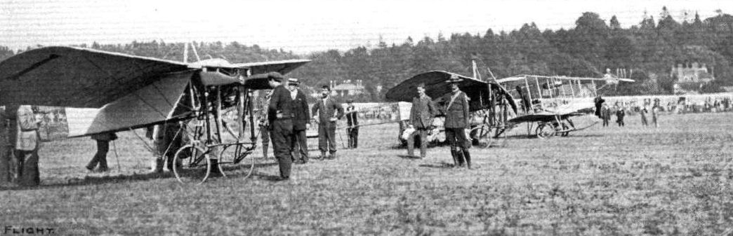
DAILY MAIL CIRCUIT OF BRITAIN. - The imaginary starting line from which the whole of the machines were sent off from Brooklands on Saturday. Ready for being started are Nos. 1 and 2, and Compton Paterson's Grahame-White "Baby" biplane.
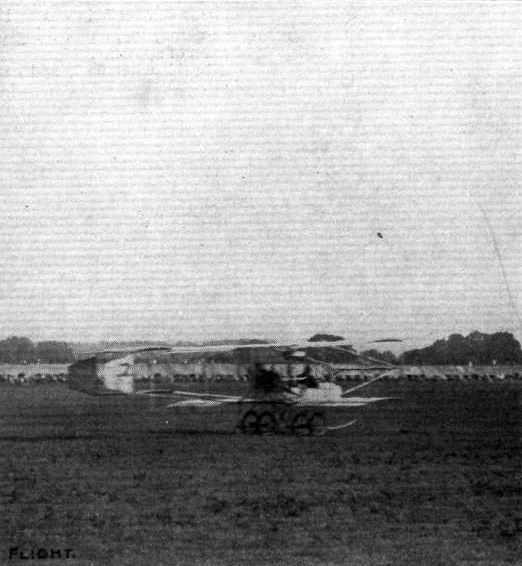
Compton Paterson taking his run off on the "Baby" Grahame-White.
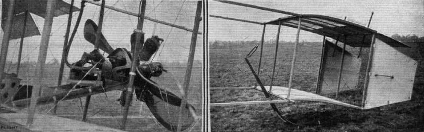
Views of the engine and the tail on the Grahame-White "New Baby" biplane.
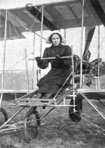
Miss Irvine, who last week became Mrs. Martin, on the "New Baby" Grahame-White biplane. Miss Irvine, in the intervals of learning to fly, has made many long flights with her husband at the London Aerodrome.
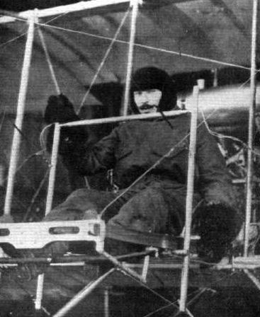
Mr. Turner, one of the pupils at the Grahame-White School, and the first Englishman to obtain his pilot's certificate under the new regulations, having passed the necessary tests on Saturday last.
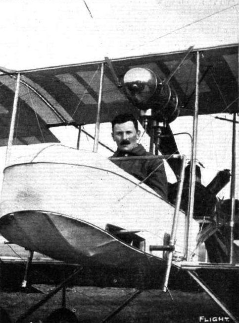
Mr. Compton Paterson, one of the most promising pilots in the Daily Mail Circuit, in the pilot's seat of the Grahame-White "Baby" biplane, upon which he flew from Hendon to Brooklands and back last week.
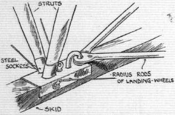
Sketch illustrating one of the steel sockets which are such a characteristic feature of the Grahame-White "New Baby" biplane.
UNDERCARRIAGES AT OLYMPIA. - Comparative details in the construction of the Farman type wheel and skid combination.
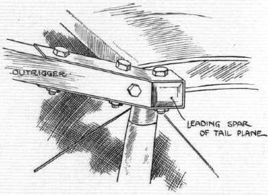
Sketch illustrating the attachment of the tall to the outrigger by means of steel sockets on the Grahame-White "New Baby" biplane.
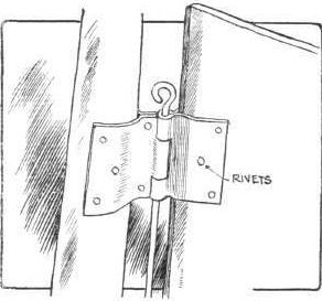
Sketch illustrating the Steel rudder hinge on the Grahame-White "New Baby" biplane.
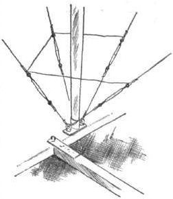
Sketch illustrating how some of the guy-wires in the vicinity of the propeller are anchored to one another for safety, in case either breaks, on the Grahame-White "New Baby" biplane.
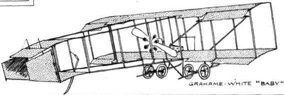
MONOPLANES AND BIPLANES IN THE DAILY MAIL CIRCUIT ROUND GREAT BRITAIN. - From these every machine can be readily identified either in flight or on the ground.

GRAHAME-WHITE "NEW BABY" BIPLANE. - Plan and elevation.
Flight, January 7, 1911
FROM THE BRITISH FLYING GROUNDS.
Brooklands Aerodrome.
<...>
Mr. Hammond's "mono-bi-triplane" has at length also reached the engine-testing stage. This machine is certainly a marvel of light construction, so light indeed that it looks at first sight quite inadequate to support the weight of engine and aviator, to say nothing of landing in the ever popular sewage farm. We hope he will surprise the tenants, who appear in the meantime to be somewhat sceptical.
<...>
Flight, March 25, 1911
OLYMPIA-1911
Aeroplanes.
Handley Page, Ltd. - Handley Page monoplane with automatic stability, due to the shape of plan, form and cross section of the wings.
The main dimensions of the machine exhibited are :-
Span, 32 ft. Chord, 6 ft. Area, 150 sq. ft. Overall length, 22 ft. Wheel base, 7 ft. Engine, 35-40-h.p. Green, H.P. propeller, direct-coupled to engine. Weight without pilot, 420 lbs.
Control. - Upright steering wheel on top of lever. Movement left and right warps wings. Movement backwards and forwards elevates or depresses. Rotation of wheel steers.
Remarks. - Shock-absorbing device consists of spring axle with central skid. For transport purposes the wings fit on side of body, tail fits inside the body. Price, L450. Tuition free to purchasers.
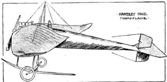
MONOPLANES AND BIPLANES IN THE DAILY MAIL CIRCUIT ROUND GREAT BRITAIN. - From these every machine can be readily identified either in flight or on the ground.
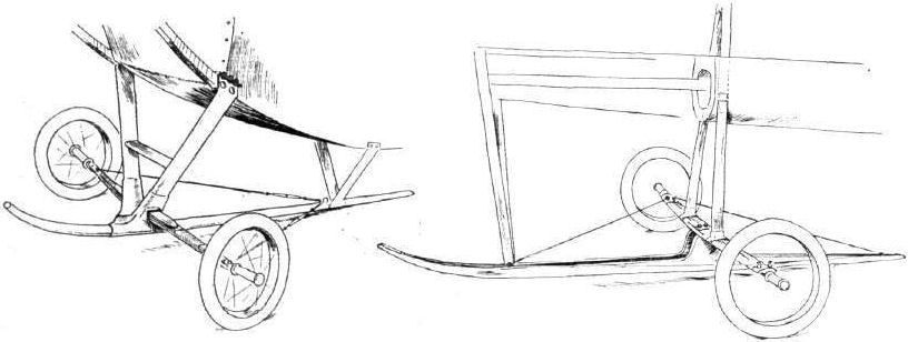
UNDER-CARRIAGES AT OLYMPIA. - A comparison of the Nieuport laminated steel spring axle and the Handley Page flexible wooden axle.
Flight, January 21, 1911
F. J. STRINGFELLOW.
THE death of Mr. F. J. Stringfellow, son of the famous J. Stringfellow, which occurred at Bristol on New Year's Day, is the breaking of yet another direct link with the very foundation of the science of flight in this country, for it was his father who made the first successful power-driven model, which demonstrated the phenomenon of dynamic flight for the first time, in 1848.
Previously, J. Stringfellow was associated with W. S. Henson, and together they produced a model, which was not successful on trial, but is perhaps the best known of all early ideas in flying machines. It is the subject of many curious old prints, and it is rather a coincidence that we should have just received from the Rev. Sidney Swann an excellent photograph of an old printed handkerchief belonging to Mrs. Mackintosh, of Edinburgh, showing a cartoon illustration in which the Henson and Stringfellow model is the central figure. A reproduction of this photograph appears on this page, and one of the most remarkable features of the machine is the trussing of the main planes in a manner identical with that of the Antoinette monoplane of the present day. Indeed, the machine as a whole might have been a copy, rather than the prototype, of the modern monoplane.
J. Stringfellow's successful model was designed on similar lines, but was even more closely in accord with modern principles. F. J. Stringfellow, son of J. Stringfellow, carried on his father's work and built a biplane model, but he was unable to properly complete his experiments. Quite apart from the interest associated with the construction of the models as flying machines, it is equally important to remember that the Stringfellows showed remarkable ability in the making of small engines, which is quite a problem in itself and has exercised the minds of many other flight pioneers. We also reproduce on this page a portrait of the late J. Stringfellow, kindly sent us by Mrs. F. J. Stringfellow, with whom, in her present trouble, our readers will, we feel sure, join us in an expression of sympathy. All the machinery of his father's models Mr. F. J. Stringfellow has bequeathed to his youngest son, Mr. E. Stringfellow.
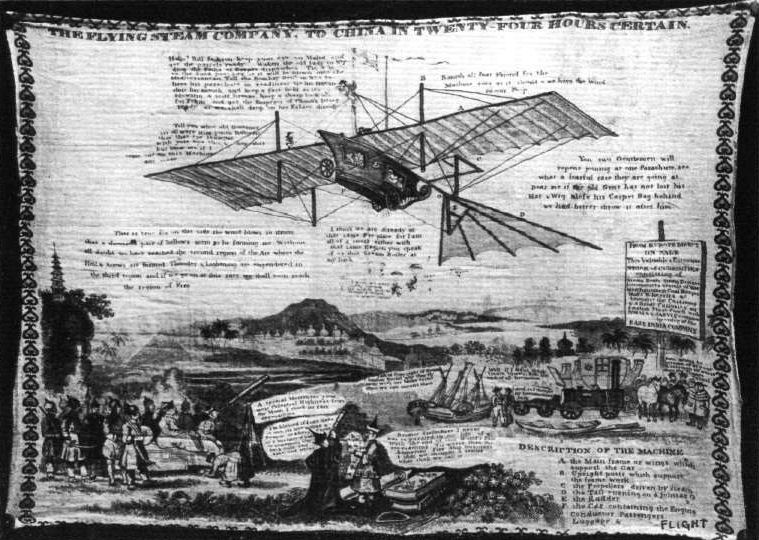
The curious old handkerchief which chronicles the popular jokes of the period under the heading of "The Flying Steam Company. To China in twenty-four hours certain," which were directed at the machine so very much like the Antoinette of to-day, designed about 1848 by Stringfellow and Henson. This picture has been placed at our disposal by the Rev. Sidney Swann.
Flight, January 7, 1911
THE BRITISH MICHELIN CUP.
IN our last issue we were able to give brief particulars of Mr. Alec Ogilvie's splendid try for the British Michelin Cup, and it seemed then not improbable that his fine record would not be beaten. Both Mr. Sopwith and Mr. Cody were not to be so easily deterred, however, and on Saturday, the closing day of the competition, Mr. Cody secured the leading position, giving him the right to hold the trophy for 1911, as well as the cash prize of L500. Just as in France, the competition on the last day proved an exciting one, for the three British flyers we have mentioned were making simultaneous attempts to seem e the coveted trophy.
Mr. Sopwith's Final Try.
HAVING been displaced from the leading position by Mr. Alec Ogilvie, Mr. T. Sopwith determined not to let the prize slip from his grasp too easily. On the 29th, at Brook lands, he started off at 9 o'clock in the morning, but after going for a matter of two hours found a gusty wind made the conditions too trying, and so came down after covering just on 70 miles. The following day he was up at 8 a.m., but, curiously enough, again was beaten by the wind when nearly 70 miles had been traversed. On the Saturday he started oft about twenty minutes to nine, but a necessary adjustment to the ignition brought him down after 17 miles. At twenty minutes to ten Mr. Sopwith was off again, and put up a splendid flight of over four hours, during which time he covered about one furlong over the 150 miles. This distance, although surpassing that of Mr. Ogilvie, was not sufficient to secure the cup, Mr. Cody having exceeded it by 30 miles or so. The course was a little over 1 mile 5 furlongs round, and 92 laps were made, the machine going on until the petrol was exhausted. The timing was done by Mr. G. F. Joseph, the Assistant Secretary of the Royal Aero Club. The Howard Wright machine used by Mr. Sopwith was the same which carried him across the Channel to Belgium in his try for the Baron de Forest prize, and was also used by him for his magnificent first attempt for the Michelin Cup. This machine was fully described in our issue of December 24th, while the E.N.V. engine, which ran so splendidly, was also described in these pages on October 15th last.
Flight, February 11, 1911
KING GEORGE AND AVIATION.
THE little trip from Brooklands to Windsor made by Mr. T. Sopwith on the 1st inst., demonstrated yet once again the utility of the aeroplane in getting quickly from point to point across country, and incidentally it showed that His Majesty the King takes the liveliest interest in matters relating to flying. Having received an invitation - not actually a command - from the King that he should fly to Windsor, Mr. Sopwith started up his machine at about 1 p.m. and was away for his visit forthwith. Although a thick fog obscured the ground at Brooklands, Mr. Sopwith had ascertained that it was clear at Windsor, In order to keep his landmarks in sight Mr. Sopwith remained at a height of about 150 ft. when leaving the aerodrome, but at Staines he found it beautifully clear, and so rose to a height of 1,000 feet. He could then see the Castle in the distance, but one of the radiators of the machine developed trouble through "frostbite," and Mr. Sopwith decided to make a halt on the Datchet Golf Links, descending there about 1.20 p.m. After having lunch he left Datchet at 2.55 p.m., and flying across the Home Park circled Windsor Castle, passed over the Round Tower, and alighted on the Royal Golf Links below the Eastern Terrace, where the King was waiting with Princes Henry, George and John to receive him. The aviator was presented to His Majesty, who at once descended from the Terrace, by Sir Charles Cust, and afterwards the King and the young Princes closely examined the Howard Wright machine and had the various details of it explained. His Majesty also congratulated Mr. Sopwith on his splendid win in the Baron de Forest competition and also upon his gallant attempts to secure the British Michelin prize. After taking tea at the Castle Mr. Sopwith remounted his machine and flew back to Datchet, where, on hearing that the fog was thicker at Brooklands than when he left in the morning, he decided to leave his aeroplane until the following day, when he duly returned without incident, although, even then, the fog was very thick.

Rear view of the Howard Wright biplane.

The Howard Wright biplane, which will be steered by Lieut. Reynolds in the Daily Mail Circuit of Great Britain.

Mr. T. Sopwith, the winner of the Baron de Forest L4,000 Prize, on his E.N.V.-engined Howard Wright biplane during his second attempt at Brooklands for the British Michelin Prize. Note the old method of locomotion, the automobile stuck in the mud being assisted by the original "h.p.'s."
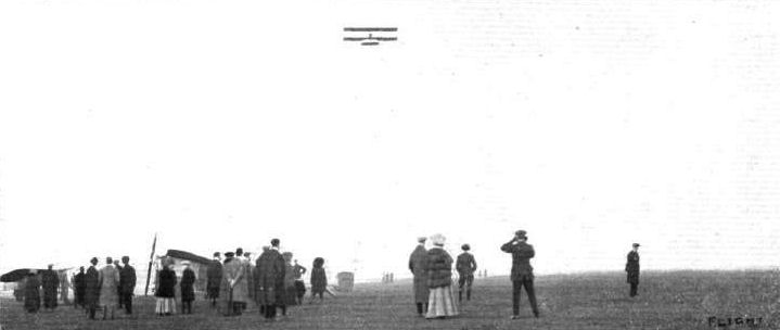
Lieut. Watkins flying well at Brooklands on Saturday last on Capt. Maltland's "No.2" Howard Wright.
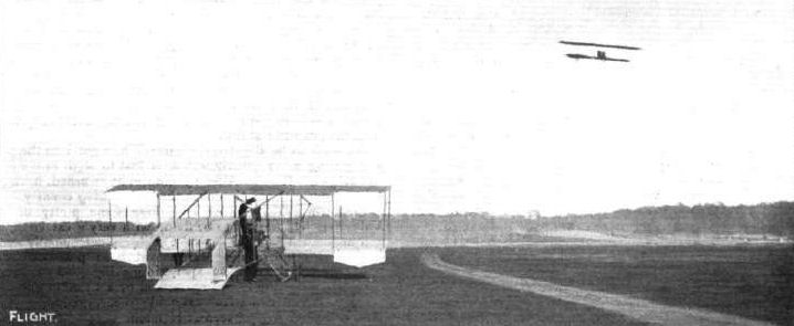
AT BROOKLANDS ON SATURDAY. - Tom Sopwith in flight on his Howard Wright, and the Spencer-Stirling machine on the ground.
CARS AND FLYING AT BROOKLANDS. - Brooklands has now become quite a centre of activity by reason of the flying attractions daily in operation there. Two pictures, taken on Saturday last, above give some idea of the gatherings which assemble day by day around the actual flying village. In the upper photograph Mr. Tom Sopwith is flying his E.N.V.-engined Howard Wright biplane, one of the very successful Bristol machines being seen to the right. In the bottom picture Mr. Low, one of the expert pilots of the Bristol Co., is making one of his fine flights round the aerodrome.
Mr. Low, on his Bristol biplane, getting well into the air at Brooklands. At rest are Mr. Sopwlth's Howard Wright biplane, and in the distance the Hanriot monoplane.

A PASSENGER FLIGHT AT BROOKLANDS. - Lieut. Watkins, with a passenger, on Mr. Maitland's Howard Wright biplane, making one of his graceful flights past the hangars. At temporary rest is the Weiss monoplane.
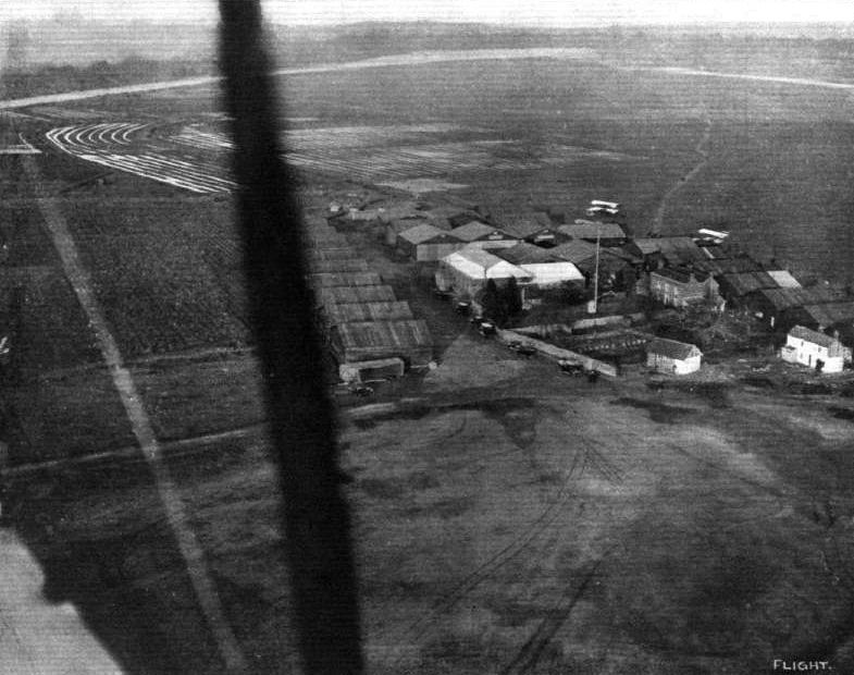
BROOKLANDS AS SEEN FROM ABOVE. - A view when passing over the flight colony at Brooklands Aerodrome on Mr. Tom Sopwith's Howard Wright. Note the "magnetic" sewage farm on the left, and in the far distance the motor test hill, finishing straight, &c.
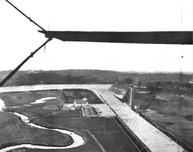
BROOKLANDS AS SEEN FROM ABOVE FROM MR. TOM SOPWITH'S HOWARD WRIGHT BIPLANE. - Passing over the winding Wey and the Brooklands Club House. Note the bridge across the Wey leading to the aviation grounds.
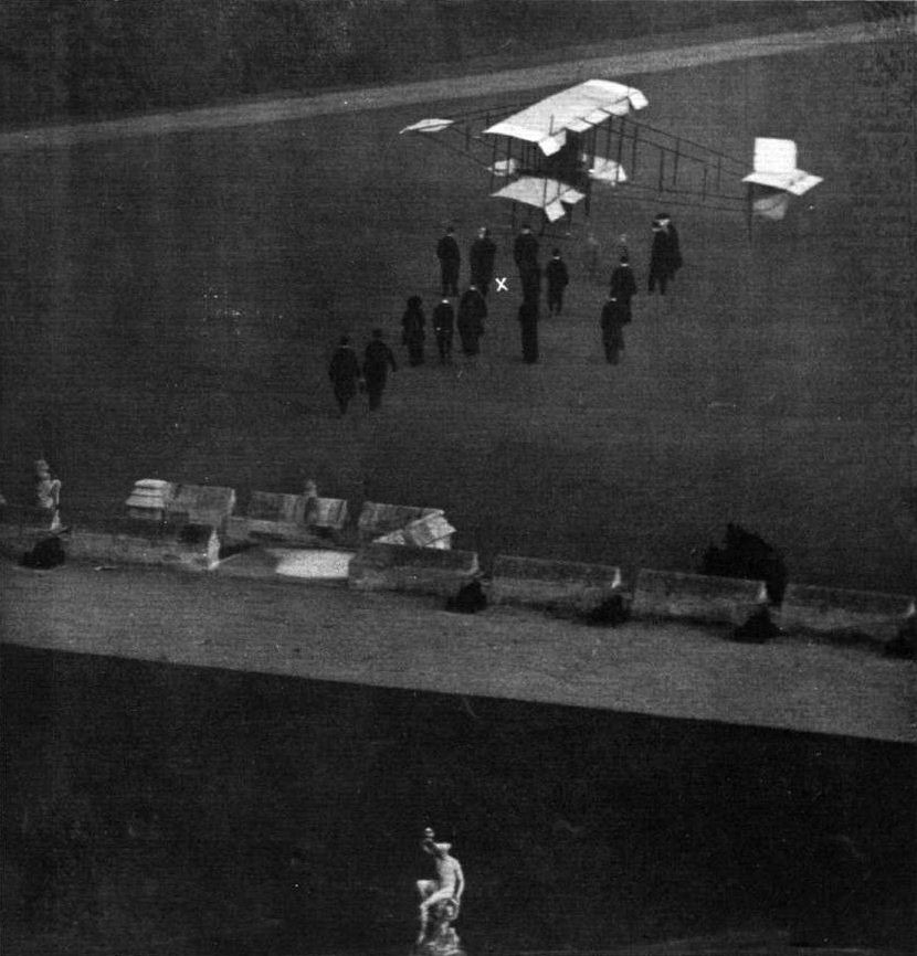
BY THE KING'S COMMAND. - Mr. Tom Sopwith's visit to Windsor Castle on his E.N.V.-engined Howard Wright biplane on Wednesday of last week, in response to an invitation from King George to fly over from Brooklands. King is seen (X) shaking hands with Mr. Sopwith immediately after landing in front of the terrace.

UNDER-CARRIAGES AT OLYMPIA. - The typical Farman-Wright type as built by Howard Wright.

Lieut. Watkins, with Mr. Cecil Pashley as passenger, just prior to a flight at Brooklands last Saturday on Capt. Maitland's "No.2" Howard Wright.
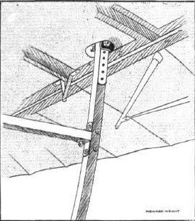
Sketch showing the arrangement of the framework at the tail of the Howard Wright machine.
UNDER-CARRIAGES AT OLYMPIA. - A comparison in tail skid construction.

MONOPLANES AND BIPLANES IN THE DAILY MAIL CIRCUIT ROUND GREAT BRITAIN. - From these every machine can be readily identified either in flight or on the ground.
Flight, March 25, 1911
OLYMPIA-1911
Aeroplanes.
Humber, Ltd. - One Humber biplane. This machine is not yet complete, but it has a special interest in that it is exactly similar to the Humber biplane that has been used for the first aerial post at Allahabad, India.
OLYMPIA-1911
Aeroplanes.
Humber, Ltd. - One Humber biplane. This machine is not yet complete, but it has a special interest in that it is exactly similar to the Humber biplane that has been used for the first aerial post at Allahabad, India.
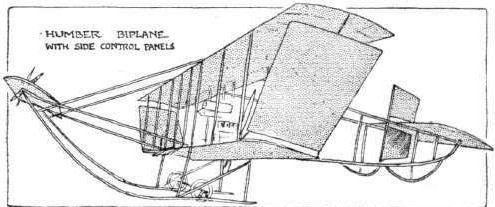
UNDERCARRIAGES AT OLYMPIA. - A comparison of some girder skids.
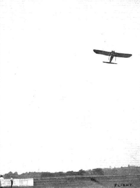
M. Pequet in practice flight at Brooklands on the Humber monoplane.

AVIATION IN INDIA. - Mr. Keith Davies with his Humber monoplane under "inspection" by the elephants. Above, Mr. Davies is standing in front of his 3-cyl. Humber-engined monoplane.

M. Pequet and the Humber monoplane he flies at Brooklands.

Mr. J. B. D. Long's monoplane with which he has been making experiments at the Acton Aviation Grounds. - Beautifully constructed by Mr. Long from the high-grade materials supplied by Handley Page, Ltd., this well-designed machine should do well in the near future when the engine troubles, which have up to now bothered the constructor, have been overcome.

Mr. Valentine on the Macfie biplane passing over Mr. Ducrocq's Henry Farman at Brooklands last Saturday.
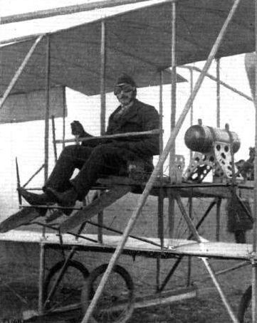
Mr. Valentine, who is now flying the Macfie biplane at Brooklands.
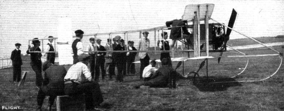
Mr. Macfie's V-shaped biplane, which made its first appearance at Brooklands on Tuesday, but had to retire from the Circuit of Britain owing to the chassis being damaged.
Flight, March 25, 1911
THE MARTIN.HANDASYDE MONOPLANE.
ANYONE first glancing at the Martin-Handasyde monoplane No. 3, or at the accompanying illustrations thereof, might be pardoned for supposing it to be an Antoinette; no intelligent observer familiar with the details of the Antoinette machine, however, could possibly fail to regard the Martin-Handasyde as anything but an original design after a few moments' thought. Where, to take only the popular aspect of the case, are those hand-wheels outside the body that pilots of the Antoinette monoplane manipulate so dexterously in windy weather? Then again, this is a much smaller machine and it is supported on an under-carriage quite like the Antoinette at a distance, but totally dissimilar in detail when examined at close quarters. Moreover, not only is the machine supported on this under-carriage, but it balances about the axle when the pilot is not on board. The engine is situated rather far forward and the propeller is, as a matter of fact, 3 ft. 8 ins. from the front edge of the planes. The weight of the engine has therefore sufficient leverage to balance the weight of the tail. Taken on its broad lines, however, it is presumably correct to say of the Martin-Handasyde monoplane that it belongs to the Antoinette type.
It has a boat-like body covered with wood, and in the bows thereof is mounted the 40-h.p. Jap engine with which the machine is at present equipped. Direct-coupled to the crank-shaft is a 7 ft. two-bladed propeller, which is protected against damage in rough landing by a skid jutting out from beneath the body and provided with a spoon-like foot. This skid, although strong, is flexible and bends noticeably when it comes in contact with the ground. Its spoon-shaped foot is formed by a sheet of steel hammered into shape and fastened to the end of the skid as shown in an accompanying sketch. The under-carriage itself, which this skid adjoins where it springs from the body, is of particular interest on account of the use of a divided tubular steel axle, reinforced and suspended by a laminated leaf-spring of lancewood. The constructional details of this interesting feature are well illustrated by an accompanying sketch, where it will be observed that each wheel is mounted on a half-axle hinged at its inner end to the lower extremity of the central mast that forms the principal upright of the machine. Bridging this joint is the laminated construction of lancewood that forms the principal member of the suspension. At the centre it rests in a channel bracket and its extremities engage with shackles that are hinged to the axle. Thus mounted, each wheel is free to rise and fall independently, for it will be observed that the diagonal strut, which forms a subsidiary member in the bracing, is telescopic; incidentally it is fitted with a rubber cushion inside the tube, which comes into action in emergency. Equally ingenious is the bracing of the axle fore and aft by wires that are linked together with a tension spring so arranged as to automatically keep them taut. This detail is likewise illustrated in the same sketch.
Above the body of the machine at this point, the mast carries the guy wires to the front and rear spars of the wings, and as the rear spars are hinged to the frame to facilitate warping, their guy wires are supported on a pulley so as to automatically adjust themselves to the warping movement. The operation of wing warping is effected by turning a steering-wheel mounted on an axis at right angles to that of an inclined column situated immediately in front of the pilot's seat. On the wheel-spindle is a small drum, round which is the warping wire leading to a pivoted cross-beam mounted on the central mast below the body. In order to increase the leverage, a block and tackle gear has been ingeniously introduced into the cable, as shown in an accompanying sketch. Fixed to the pivoted cross-bar is a chain-wheel engaging with which is a chain that has its extremities fastened to the wires leading to the rear spars of the wings. There is, of course, a very considerable tension on these wing-warping wires arid consequently no tendency for the chain to fall off the wheel, but a light guard, not shown in the sketch, is fitted in practice.
Moving the steering-wheel and the column on which it is mounted bodily to and fro operates the elevator, which is formed by two triangular flap extensions of the fixed horizontal tail-plane. The triangular shape of these planes gives room for the free movement of a rudder-plane mounted vertically between them, and, like the elevator, forming an extension of a fixed tail-plane. The rudder is operated by foot through the agency of a pivoted bar.
Of the wings themselves, it is interesting to remark that they each weigh 70 lbs. complete and are very strongly constructed, in spite of the fact that the spars by which they are attached to the body have the appearance of being very light. Inside the wings themselves, however, these spars are of T-section, 2 1/2 ins. in width and 7 ins. in depth. In addition to their top and bottom guy wires, the wings are also stayed by wires leading forwards to the projecting skid. The camber of the wings varies from the shoulder to the tip, the chord having a positive angle of incidence of about 5° adjacent to the body and being horizontal at the outer extremities. The thickness of the plane at the shoulder is 8 ins., but diminishes 2 1/2 ins. at the extremities and the chord itself also diminishes from 6 ft. to 5 ft., although this latter change is brought about more or less abruptly by obliquely cutting away the trailing edge from a point about 5 ft. from the extremities.
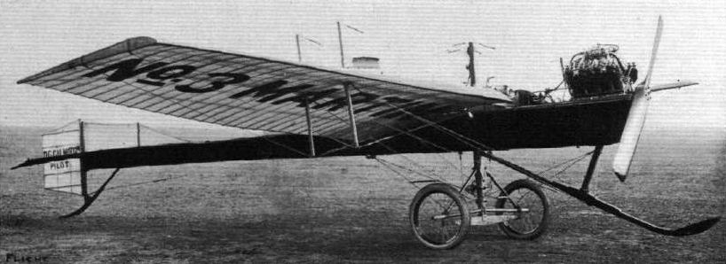
Side view of the Martin-Handasyde monoplane. No. 3.
Martin-Handasyde monoplane No.3 was the previous machine converted to a control stick with wheel for warping and was finally powered by an OHV JAP engine.
Martin-Handasyde monoplane No.3 was the previous machine converted to a control stick with wheel for warping and was finally powered by an OHV JAP engine.

General view from in front of the Martin-Handasyde monoplane, No. 3, showing the forward bracing of the wings to the skid.

General view of the Martin-Handasyde monoplane from behind, showing the bracing of the wings. The plate in front of the control-wheel is a shield to protect the pilot from the oil that is thrown out by the engine.
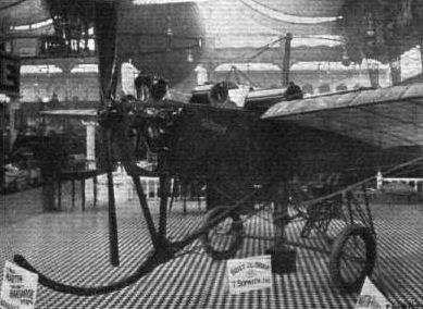
UNDER-CARRIAGES AT OLYMPIA. - The Martin-Handasyde axle and forward skid.
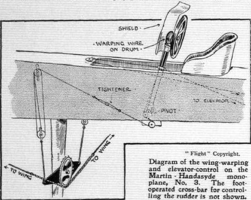
Diagram of the wing-warping and elevator-control on the Martin-Handasyde monoplane, No. 3. The foot-operated cross-bar for controlling the rudder is not shown.
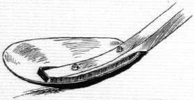
Sketch of the spoon foot on the skid of the Martin-Handasyde monoplane, No. 3.
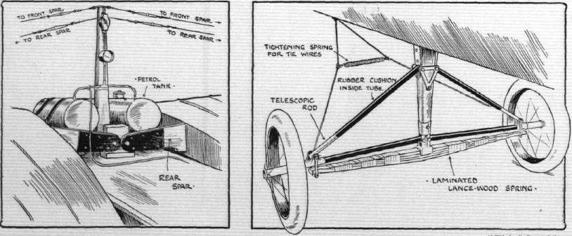
Sketches illustrating the attachment of the wings to the body, and the details of the undercarriage supporting the body of the Martin-Handasyde monoplane, No. 3.
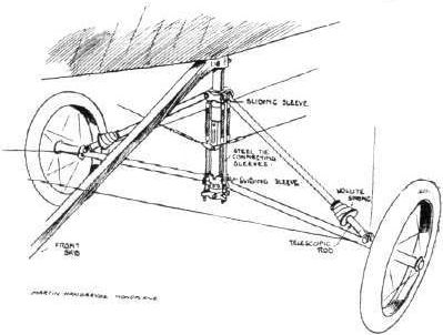
Under-carriage of the Martin-Handasyde monoplane.
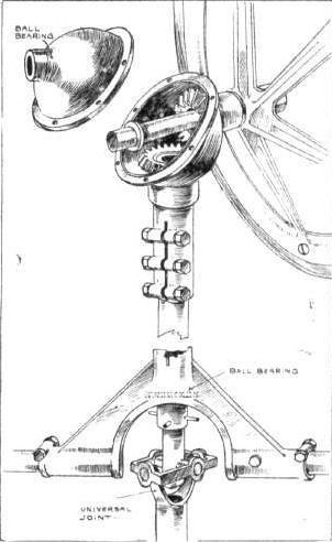
The Martin-Handasyde Control Gear.
UNDER-CARRIAGES AT OLYMPIA. - A comparison in tail skid construction.

MARTIN-HANDASYDE MONOPLANE, No. 3. - Plan and elevation to scale.
Flight, November 18, 1911.
AIR EDDIES.
At Brooklands, the new Martin-Handasyde monoplane is now off the stocks, and is undergoing its trials. As our readers are aware, this machine is built on exceptionally pretty lines, and for excellence of workmanship and detail design it would be impossible to find a better example in this or any other country. Its flying capabilities are equally as good, and under the pilotage of such an experienced aviator as Tom Sopwith it bids fair to attain considerable success.

Grahame Gilmour in the New Martin-Handasyde monoplane. In the background is the Walton-Edwards biplane, in its latest form at the Brooklands aerodrome. This very substantial machine is now carrying out flights on the grounds.
Flight, March 25, 1911
OLYMPIA-1911
Aeroplanes.
Mulliner Monoplan. - It will be remembered that Messrs. Mulliner, of London and Northampton, exhibited a monoplane at the last Olympia Aero Show that attracted considerable attention from visitors by reason of its light appearance and the good workmanship bestowed upon it. This year they are also exhibiting, and again it is a monoplane, but this machine differs greatly from that of last year, although we have no doubt that this difference will not be found in the workmanship.
The machine, which is known as the "Kny-plane," is a monoplane having a span of 39 ft. and an overall length of 36 ft. The weight of the machine complete with aviator and in flying order is 1,250 lbs., with an actual lifting surface of 300 sq. ft. The wings are controllable, and by means of a simple steering device, similar to that used in motor car construction, it becomes possible to increase or decrease the angle of incidence and the camber synchronously or independently. The body is torpedo shaped. The powerplant, which is entirely enclosed, consists of a 60-80-h.p. E.N.V. engine with dual ignition, and drives, through a flywheel and a specially-designed clutch, a Normale tractor-screw. The chassis embodies some unique features, one of which, it is claimed, enables the machine to start on any railway if the ground is in any way unsuitable. This should be worthy of consideration for military requirements. It is also claimed that the body of the machine always remains horizontal in flight.
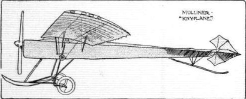
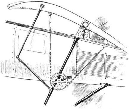
Sketch showing how the wings on the Mulliner "Kny" aeroplane are mounted on a central bearing so that the angle of incidence can be altered during flight. Simultaneous with this movement an alteration in the camber is brought about by means of pivoted rods, as shown above, acting on a special flexible leading edge.
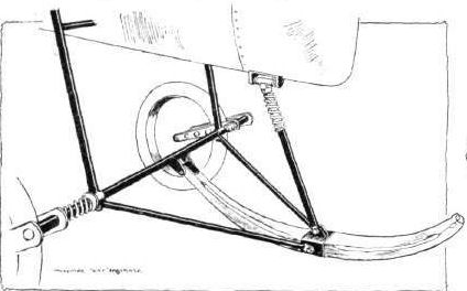
Under-carriage of the Kny aeroplane, built by Mulliner's, of Long Acre and Northampton.
Flight, November 25, 1911.
Aviation in Nottingham.
Having been a reader of your paper ever since the first issue, I have noticed enthusiasts in Nottingham have written to you regarding model and full-sized Aero Club for this city and district. For instance, about two and a-half years ago a very well-known Nottingham resident published in your paper that he would like all those interested in this district to communicate with him with the intention of forming such a club in Nottingham. I wrote this gentleman four times and never received an answer, nor have I heard any more about the formation of the club. I might also say that we have built our own machine, which cost just under L600, which is fitted with a 30-horse-power Alvaston motor (photo enclosed), and have spent shillings in advertising that we are prepared to assist in forming an Aero Club for this district, to try and create interest, and it could not have escaped the eye or the ear of those interested, and as our machine has been on exhibition twice in this town, once for a month and once for a week, now we think we have done our share toward the organising of an Aero Club in Nottingham, but still not downhearted we have managed to yet 15 names for such an organisation, and shall be pleased to hear from the Nottingham reader that wrote to your paper last week or anyone else interested.
We intend putting our machine in the hands of the members as soon as they prove proficient on the glider which we are about to construct.
Hartley Road, Nottingham. SEARBY, ALLEN AND SEARBY.
Flight, January 28, 1911
Paterson and King Biplane.
I enclose a photo taken at about 4 o'clock on December 31st afternoon, showing the wrecked biplane of Messrs. Paterson and King on the sands at Freshfield. They had flown to Southport (Paterson as pilot and King as passenger) and were within about 300 yds. of their hangar on the return journey and close to the sands about to land, when a sudden gust caught the left plane and drove the right plane into the sand. Fortunately neither were hurt, but the machine was badly smashed as you can see from the photo.
I t might be of interest to readers of FLIGHT, which I may say I look forward to each week.
Waterloo Park. T. E. C. WILSON.
Flight, February 18, 1911.
BRITISH NOTES OF THE WEEK.
A New British Biplane.
WRITING with reference to the new biplane of the Curtiss type, which has been built for him by the Liverpool Motor House, Mr. G. Higginbotham, of Macclesfield, says it has quite exceeded the expectations of the designers. It has proved very fast and exceptionally steady in flight. Fitted with a 50-h.p. Gnome motor, but without fuel, it weighs only 700 lbs. On the recent trip to Southport and back, with Mr. Paterson in charge, Mr. Higginbotham says he was able to take control of the machine with ease during part of the return journey
Flight, May 13, 1911.
BRITISH NOTES OF THE WEEK.
Ante-Breakfast Trial Trips.
BEFORE breakfast on Saturday last Mr. Higginbotham twice carried his mechanic on his biplane from Freshfield to Southport and back, the approximate distance covered being fifty miles.
Flight, May 20, 1911.
BRITISH NOTES OF THE WEEK.
Ante-Breakfast Trial Trips.
FURTHER details are now to hand regarding the cross-country flights made by Mr. G. Higginbotham, of Macclesfield, at Freshfield on Saturday week. At 7.30 a.m. Mr. Higginbotham, on his British-built biplane, set out from Freshfield and flew to Southport and back. After a few minutes rest he was in the air again and was away again over to Waterloo in order to pay a visit to Mr. Melly at his school there. Mr. Melly was out, however, so after leaving a card Mr. Higginbotham returned to Freshfield and then once more made the round trip to Southport and bick. Each of the three trips was of about 16 miles round, and so the total distance flown was roughly 48 miles. In the afternoon Mr. Higginbotham again went over to Southport and back, and then made several short flights of about six or seven minutes with figures of eight. He finished up by taking Mr. Fenwick for a trip of about 10 miles, going out over the sea for about a mile.
Flight, June 3, 1911.
FROM THE BRITISH FLYING GROUNDS.
Freshfield Aerodrome, near Liverpool,
ON Saturday, 20th, Mr. Higginbotham took out his biplane and, accompanied by his mechanic, flew along the coast towards Liverpool and back. Although the wind and weather conditions were not very favourable, he persevered and accomplished many short flights, taking up friends as passengers. The machine is behaving remarkably well since certain alterations have been made. Mr. King was down, but did not take his machine out. Mr. Melly with his pupil (Mr. Jones) came over, intending to take back his 50-h. p. Bleriot, which he had left at Freshfield some days previous. He, however, did not like the weather, and left it till the following (Sunday) morning, when he flew it back to Waterloo.
On Saturday, 27th, Mr. Higginbotham motored over from Macclesfield and got to work at once. Taking his mechanic with him he flew to Southport and back, and then gave many friends a few miles flight each, which was greatly appieciated.
On Sunday morning, about 7 o'clock, Mr. Higginbotham was out again, and carrying his mechanic, he made a trip to Altcar, circled the rifle range, then steered across country over part of the town of Ainsdale, thence to Southport, and after circling the pier and marine lake, landed on the shore. At about 8.30 a.m., Mr. Melly passed the hangars at Freshfield, flying along the coast toward Southport. The two airmen met at Southport and breakfasted at the Victoria Hotel, both returning later to their respective flying grounds, flying at an altitude of about 1,000 ft. At about 7.30 p.m. Mr. King took out his Henry Farman and made a few short flights towards Ainsdale and back.
Flight, July 8, 1911.
FROM THE BRITISH FLYING GROUNDS.
Freshfield Aerodrome, near Liverpool.
MR. GERALD HIGGINBOTHAM, of Macclesfield, received his pilot's certificate from the Royal Aero Club on Saturday last, having gone through the test on his 50-h.p. Gnome-engined biplane. He showed consummate skill, especially when taking the right hand turns. Mr. Higginbotham has this week departed on a tour through Switzerland and France, and he will therefore not be doing any flying again for about a month.
Flight, August 12, 1911.
FROM THE BRITISH FLYING GROUNDS.
Freshfield Aerodrome, near Liverpool.
ON Friday last week Mr. Higginbotham, who is now back again, accompanied by his mechanic, flew from the aerodrome to Ainsdale and around by Formby, returning by way of the aerodrome. He then made a figure-of-eight turn, and again flew towards Ainsdale. Later he attempted another figure-eight turn over the sea, where he found less buoyancy in the air. He was flying low at the time, when suddenly the air seemed to lose its sustaining power or he struck an air-pocket, for she dropped quickly and touched the water. Although the pilot used the elevator for all he was worth, the propeller caught the water and was smashed. Fortunately no great harm resulted beyond a wire striking Mr. Higginbotham's ear and cutting it, also bruising the mechanic's arm. Both swam ashore without difficulty, and the machine was presently hauled on shore with its broken propeller and damaged elevator. Mr. Higginbotham did not appear to be upset in the least by the episode and seemed as fearless in aviation as he used to be in the motor races, just smiling and remarking "One must be prepared for accidents in new ventures of this kind." He was at the hangar on Saturday and made arrangements for repairing the elevator and hopes to be soon in the air again.
Flight, October 21, 1911.
FROM THE BRITISH FLYING GROUNDS.
Freshfield Aerodrome, near Liverpool.
MR. G. HIGGINBOTHAM, who has made himself such a name by his flying at the Freshfield Aerodrome, recently duplicated in a small way the scheme carried out in connection with the aerial post at Hendon. In similar fashion he arranged to inaugurate an aerial post from Freshfield to Southport by aeroplane. Directly it was known he contemplated this, a big bag of cards and letters was made up in the district by his friends and others, and these were duly endorsed with the aerial post stamp, ready for conveyance to the post office. Mr. Higginbotham made a start from Freshfield with his freight at about four o'clock on Friday afternoon last week, carrying with him his mechanic, and was quickly at Southport, where he landed on the shore. After disposing of his burden at the post office, he returned to Freshfield in seven minutes, the distance being about 8 miles. On the journey, fog was rather bothering, rendering it difficult to find the way near Southport. The occasion was noteworthy by reason of its being Mr. Higginbotham's first flight of any distance since he had his little accident a little time back through finding an air pocket over the sea, when he had to swim for it, as recorded in FLIGHT at the time. Incidentally it may be mentioned that Mr. Higginbotham parted with a portion of his ear upon the occasion. We give on page 918 a photograph of Mr. Higginbotham's machine, taken from one of the aerial postcards carried by himself.
On Saturday last Mr. Higginbotham was in the air again at Freshfield, carrying Mr. A. Pochin, a new aviator at the aerodrome. Later he also took up Mr. Pochin's mechanic for a trip.
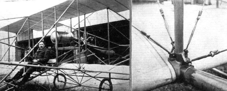
THE PATERSON BIPLANE. - The view on the left shows how the engine is mounted in the Paterson biplane, while the other view clearly illustrates the extremely neat and handy method of attaching wires and strainers at the point marked X in the left photograph. A new wire can be fitted in ten minutes, all that is necessary being to remove two split pins and replace them after changing the wire.
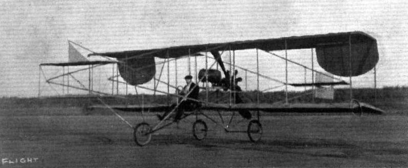
Another "Aerial Post" is being run unofficially from Freshfield to Southport. Through this channel we have received the picture postcard above of Mr. Hlgginbotham's biplane.

Mr. G. Higginbotham immediately before the start for his aerial post trip from Freshfield to Southport, as recorded in last week's issue. Accompanying Mr. Hlgginbotham is Mr. A. Pochtn's mechanic. Note the stirrup for helping to mount the machine, and the mascot on one of the stays.
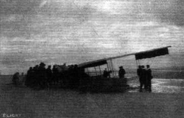
Flight, December 2, 1911.
THE PATERSON BIPLANE.
Looking back over the general run of biplanes, particularly those of the cellular type, constructed during the past three years, one cannot help being struck with the lack of finesse in design that most of them display, probably on account of the ease of construction that characterises that class of machine.
Mr. Compton-Paterson cannot be accused of erring in this respect, for, as a pilot who prefers the biplane as a mount, he has attacked the problem of construction with a view to eliminating as far as possible the shortcomings of that type. Undoubtedly the most evident bugbear of the cellular biplane is its unwieldiness in transport, and to remedy this failing the cellule of the Paterson biplane is constructed in three sections, each of the two outer units being easily detachable from the central one by the simple process of disconnecting twelve stay wires and the cable operating the ailerons. So easy is the whole operation that either end section can be removed by three men within 2 1/2 minutes, and within double that time the biplane, of 32 feet span, can be got ready to pass through a 10-foot gateway by the removal of both end portions. The advantages of this feature will be easily apparent to those who have had any dealings with the transport of machines of this type, and although it may seem to some an innovation, it must be said to Paterson's credit that he adopted the same system in the autumn of 1909 in the construction of the Anzani-engined Curtiss-type on which he carried out his initial experiments.
The internal construction of the planes is of considerable interest, as they are double-surfaced, the fabric being supported by a well-conceived wooden skeleton, after the manner adopted in monoplane practice.
Both front and rear spars are cut from best English ash and are hollowed out to H section for the sake of lightness, excepting in those portions to which struts are applied and through which eye-bolts are passed. To the front spar is applied a hollow wooden strip, forming a nose piece, which not only strengthens the boom to a considerable extent but forms an efficient entering edge. Running parallel with the booms are three silver spruce stringers of rectangular section, that pass through corresponding mortises cut in the main ribs. In this manner the stringers may be considered as being interlaced through the wing structure, a more satisfactory method than that of merely keeping the ribs in position by the use of a few tin tacks or perhaps wood screws. Five main ribs, shaped from ash and drilled to reduce weight, serve to give the proper curvature to each wing section and midway between these ribs are fitted pairs of silver spruce lath ribs which support both top and bottom surfaces. The intervals between these ribs are further divided by the application of single lath ribs which support the lower surface only. A good idea of the construction of the plane skeleton can be gathered from the accompanying sketch, and the neat workmanlike manner of accommodating the ends of the compression struts is also shown.
The method by which the end sections are rendered detachable is closely analogous to that employed in the fitting of Bleriot monoplane wings. Both front and rear spars of the central section project on each side for a distance of 6 inches beyond the end of the plane. Each projection is cylindrical in form in order that it may be accurately accommodated in the large-diameter steel tube which forms the termination of the corresponding spar of the outer section. A notable feature as regards the wing construction is the fact that no tacks are used, every fastening being entrusted to either bolts or wood screws.
The outriggers, which proceed from the front and rear booms to support the elevator and tail surfaces respectively, are identical in every respect, and they are applied to the planes by means of magnalium-bronze sockets. These latter embrace three sides of the wing spar and also accommodate the vertical cellule struts and those struts supporting the landing carriage.
Contrary to customary practice, Paterson has not adopted a front elevator working in conjunction with a flap hinged to the rear edge of the tail, but has entrusted the function of steering in a vertical sense to a single slightly cambered surface mounted about 13 feet in advance of the main planes.
In horizontal flight this surface presents an angle of incidence slightly in excess of that of the main planes, this feature doubtless contributing to a certain extent towards the longitudinal stability of the machine. The fixed tail plane is identical with the forward elevator, both as regards size and camber, and its attitude is positively incident to the line of flight. Hinged to the tubular mast of steel, which forms the keystone in the construction of the tail unit, is the directional rudder. This organ, rectangular in shape, is constructed of sheet aluminium of light gauge supported by a thin wooden frame-work. A neat ash skid, pivoting about the base of the tubular mast before mentioned, guards the tail against damage by contact with the ground.
With the object in view of utilising the main supporting surfaces as an air brake in order to quickly bring the machine to rest after landing, the tail unit is high-built and arranged as compactly as possible. By so raising the situation of the tail with regard to the remainder of the machine, the main planes present a large angle incident to forward advance when the rear skid is touching the ground, and so perform this secondary function of air brake. It was during his early experiments over the smooth sands at Freshfield that Paterson was first impressed by the need of quickly retarding the forward motion of the machine on landing, and although he tried all manner of frictional brakes applied to earth either directly, by means of rubbing skids, or indirectly, by braking the running wheels, the conclusion was arrived at that the system at present adopted was the most efficacious and by far the simplest from the constructional point of view.
The unit which accommodates the pilot, passenger, fuel tanks and motor has been the object of refinement in design. The front section which supports the pilot's and passenger's seats, and to which all the control wires are carried, is detachable from the rear section, to which are attached the tanks and motor, by the simple expedient of withdrawing four bolts. U-bolts have been dispensed with for assembling this unit in the cellule. The bearers rest on brackets shaped integrally with the four very strongly constructed central struts and are attached thereto by four bolts, one through each strut - a method which makes for ease of dismantling and facility and accuracy of re-erecting.
Almost identical with that originated by Henry Farman is the running gear with which the Paterson biplane is furnished - the only difference being that the radius rods are much shorter and consequently subject to each other a more obtuse angle at their point of attachment to the skid. They are so arranged that the wheels will have a greater "lock" for swivelling.
Control of the elevating and balancing surfaces is operated from a "gate" lever of the type first employed on the Macfie biplane and later adopted on the Grahame-White "Baby."
The customary foot-bar controls the steering laterally.
As our readers are no doubt aware the machine has been built with the object of using it for a tour of exhibition flying in South Africa. For this purpose it is exceptionally well suited as it is capable of lifting two passengers in addition to the pilot and of maintaining a speed somewhere in the neighbourhood of 50 miles an hour. For facility of transport it is quite exceptional, as the whole machine, motor included, can pack away in a case, the dimensions of which are no more than 14 ft. by 6 ft. by 8 ft. Its weight without fuel or human complement is 750 lbs.
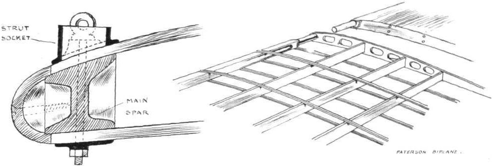
Details of the wing construction of the Paterson Biplane. - The sketch on the left illustrates the application of the strut sockets to the built-up front spar.
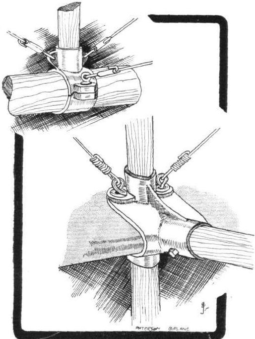
Two sketches of magnalium-bronze sockets used in the assembling of the Paterson biplane.

Paterson Biplane. - Diagrammatic sketch of engine mounting.

THE PATERSON BIPLANE. - Elevation and plan to scale.
Flight, September 2, 1911.
A Valkyrie Type Glider.
The enclosed photograph represents the unaided work of my son and his friend, aged 16 and 15 respectively. They take more than a keen interest in aviation, and have during their holidays the last year or so built successful models of most of the various types of biplanes and monoplanes. They have now tried something on a larger scale, viz., a glider, obtaining their idea from your scale drawing of a Valkyrie monoplane, on page 273 of your issue of April 1st, 1911. The dimensions of the glider are - span of plane 26 ft., length 20 ft., breadth of body 6 ft. The planes are covered with strong proofed and sized cloth. The machine is substantially built, easily assembled, convenient to transport, and only cost, for the raw material, about 25s. The builders, Charles Leigh Pickering and Norman Dean Willoughby, are now waiting for a suitable breeze and at least a "flight." The machine took about a fortnight to build.
Knutsford. ROBERT L. PICKERING.
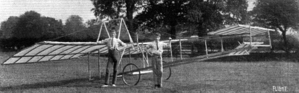
Man-carrying glider constructed by Masters Pickering and Willoughby at Knutsford in 1911.
Flight, April 1, 1911.
Third International Aero Exgibition at Olympia - 1911.
THE EXHIBITS ANALYSED.
<...>
At Olympia this year, then, stream-line bodies are the predominating feature in design. In the degrees of completeness they range all the way from the new Piggott monoplane which has every part of the body, the engine, pilot and passenger completely enclosed in a large torpedo-shaped casing with a hemispherical head. This represents the extreme development of the stream-line idea and it will be interesting to watch how far this whole-hearted adoption of a good principle works out in practice. Generally speaking such things are best evolved by degrees, and we do not doubt that it will be necessary to cut a few more holes in the Piggott shell before it satisfies the requirements of the average pilot. It will, at any rate, take, we should imagine, some little time to get used to being completely boxed in, for even as it is, with orthodox machines, aviators often complain of impeded vision. On the Piggott machine the outlook is entirely through windows made of insoluble gelatine, and the passenger and the engine are both situated in front of the pilot. The propeller boss, which is conical, forms a revolving pointed nose on the otherwise hemispherical head of the body.
<...>

UNDER-CARRIAGES AT OLYMPIA. - The Piggott.
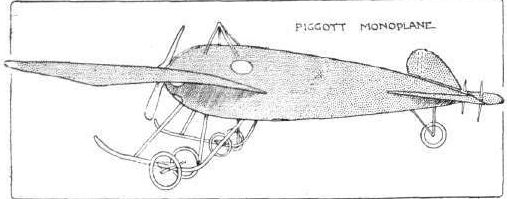
Flight, July 15, 1911.
THE NEW ARMY BIPLANE.
FOLLOWING up the details which we have already published regarding the experimental biplane, built in the Army aircraft factory at Farnborough, we are now able to give some photographs of it, as well as scale drawings, which give a very good idea of the machine in its present state. It is of course inevitable that, being an experimental machine, this latest production of the Farnborough factory should undergo a good deal of modification as the result of the tests which are being carried out with it, but we think our readers will appreciate these further details which we have been able to obtain. Although in several parts it is reminiscent of various successful types, the machine embodies many original features, and the actual performance of it will be watched with close attention by all engaged in the study of aviation.
It is unnecessary to give the dimensions in detail here as they are all clearly shown on the drawings, but it may be pointed out that the lower plane is 2 ft. less span than the upper one, while it also has a slight dihedral angle, as can be seen from the view from in front of the machine. Another point to which attention might be drawn is the substantial nature of the main struts. They are all of stream line section, and at the thickest part the dimensions are 5 ins. by 1 1/2 ins. All the sockets on the machine are of welded steel.
The details of the control mechanism are given in a separate sketch. By a backwards and forwards motion the control lever operates the elevator, while a sideways movement warps the ailerons, the connecting wires to which, on their way from the rocking lever, pass through the radiator. The ailerons have both the inside edges fixed to the main plane as on the Paulhan machine. It will be noticed that springs are fitted at the connection of the elevator rod with the control lever in order to damp out any sudden shocks on the elevator. The rudders are operated by means of a pedal. As we mentioned in our last issue, the rudders have been carried in nearer the main planes, in fact, their original position was nearly twice their present distance from the trailing edge. The propeller shaft is carried in bearings mounted on the upper framework of the fuselage and is geared down so that it normally runs at about 800 revolutions.
Since the initial appearance of the machine the undercarriage has been considerably altered, and in addition to placing the flexible skid at the forward end of the fuselage, four additional struts arranged "V" fashion have been fitted at the rear end of the main skids.
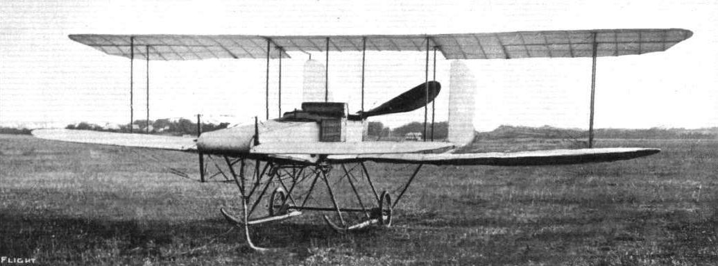
THE NEW ARMY BIPLANE. - View from in front.
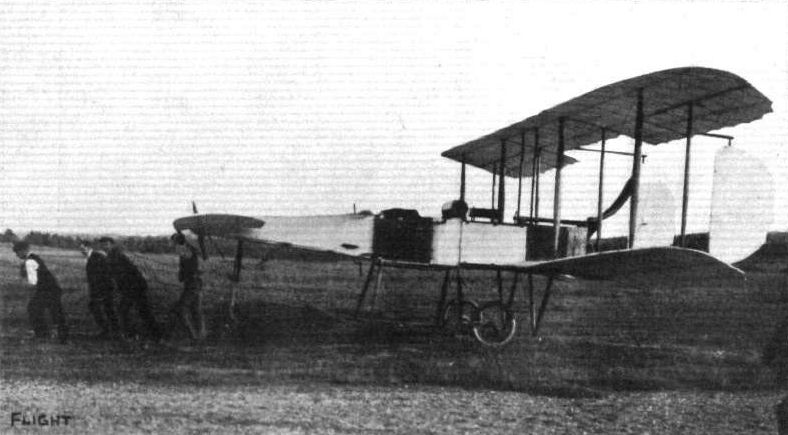
THE NEW ARMY BIPLANE. - Side view.
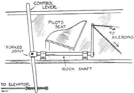
THE NEW ARMY BIPLANE. - Section through body of machine, showing arrangement of control.
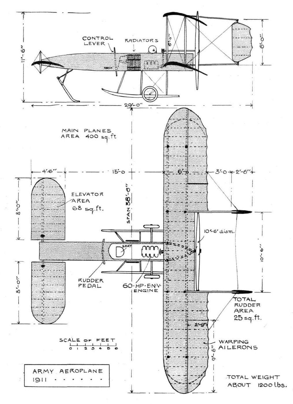
THE NEW ARMY BIPLANE. - Plan and elevation to scale.
Flight, March 4, 1911
THE SANDERS BIPLANE.
FROM A CORRESPONDENT.
THOSE who have followed the progress of aviation and the development of the aeroplane know that the thirty odd different types of British machines now in existence all have some speciality in their design or construction of which their inventors expect great things. There are, however, few machines with so many novel features as the Sanders biplane now flying at Beccles. It was in June, 1909, that Captain Sanders first flew, and from that date until February, 1910, when his experiments came to a temporary but abrupt conclusion through an unfortunate collision with the telephone wires, he steadily gained mastery over his machine. Nothing daunted by his mishap, reconstruction was at once commenced and the works were at this time also removed to Beccles, where very shortly a flourishing firm was established. Now there is a large shed that houses the biplane and adjacent to it a workshop equipped with every facility for building duplicates. Every portion of the machine is manufactured in these shops, except, of course, the wheels, engine and certain small fittings that are made outside to the firm's own designs.
In the present Sanders biplane, known as Type 1, because the first of its kind on the market, strength and attention to detail have been aimed at rather than lightness of construction. It should not be inferred, however, that the machine is cumbersome, but rather that the safety of the pilot has been made the first consideration of design. As a type it is of considerable interest, inasmuch as it is a biplane, with a forward elevator and no tail. It has, however, a triplane rudder carried on an outrigger 12 ft. behind the trailing edges of the main planes and a very peculiar feature of the main planes themselves is that in the centre their own trailing edges are extended by hinged flaps that form a kind of atrophied tail. At the extremities of the planes, midway in the gap between the trailing edges, are supplementary balancing planes. There are also two other supplementary planes in the form of a prow, which is mounted vertically between the planes of the elevator. One of the most important and interesting details of the construction of the Sanders biplane is the under carriage, a massive girder construction, extending from the main planes to the elevator. It is supported on three wheels, two immediately under the main planes and one well forward. The single wheel is so sprung that it easily adjusts itself to the attitude of the machine when running over the ground and it is the wheels at the rear that carry the greater part of the weight. They revolve on an axle suspended on rubber springs and these springs are so arranged that they can be released by a lever after ascent, and the wheels are thereby drawn up above the level of the skids. Landing is thus accomplished on the skids direct, which not only saves the wheels and axle from damage, but generally is the means of alighting with greater safety.
The control of the machine is effected by a steering-wheel mounted, motor car fashion, on an inclined column, which has a universal motion on its pivoted support in addition to the rotary motion imparted by the wheel. Moving the steering column sideways controls the balancing planes, while the rudder answers to the circular motion of the wheel. The elevator is controlled by duplicate levers, one on either side of the pilot's seat.
At present the machine is fitted with a 50-h.p. Alvaston motor, which is water-cooled through spiral tube radiators mounted alongside the pilot's seat. The radiators are slightly offset to the direction of flight in order to get a n equal draught over all the tubes. Twin propellers of 8 ft. 6 ins. diameter are carried by brackets midway in the gap immediately behind the main planes and are driven by chains at 400 r.p.m. The entering edge of the propeller-blade is peculiar and similar in principle to the entering edges of the main planes, which are concave instead of convex, the idea, according to the designer, being that the air is compressed on contact and afterwards expands against the lower surface.
The main planes have a dihedral angle and the upper plane, which overlaps the lower plane, has down-turned extremities. Both planes are built in three sections and can be easily dismantled. Silver spruce is used throughout for the construction of the spars and framework generally, except for the engine-bed, which is made of ash, and the diagonal bracing of the under-carriage, for which strip manganese steel is used. Pegamoid cloth is used as a surfacing material.
A new type of biplane is at the present moment being constructed and will be exhibited at Olympia. It will differ, among other respects, from the type illustrated in having a single propeller instead of two.
Flight, April 1, 1911.
Third International Aero Exgibition at Olympia - 1911.
THE EXHIBITS ANALYSED.
<...>
The Sanders aeroplane is fundamentally a modification of the original Wright biplane, as its only tail member is the rudder, and there is an elevator in front. This elevator, however, probably carries proportionately more load than on the original Wright, because the very strong Short type girder under-carriage is probably heavier than the corresponding outrigger on the original Wright machine. These girder skids and the elevator itself are, to all intents and purposes, the same as those on the Short biplane last year. The main planes themselves are characterised by sharply downturned extremities on the upper plane that act as side curtains to prevent leakage and sideslip. The engine and propeller on the Sanders biplane are arranged more or less on the same lines as the Cody - that is to say, the propeller is mounted midway in the gap and is driven at hall engine speed by a single vertical chain. The rudder is a triplane, in which respect it differs from the biplane rudder on the Wright.
<...>

Front view of the Sanders biplane, Type I.
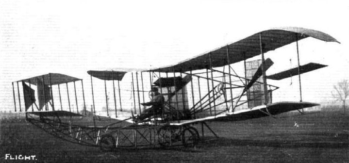
Side view of the Sanders biplane, Type I.
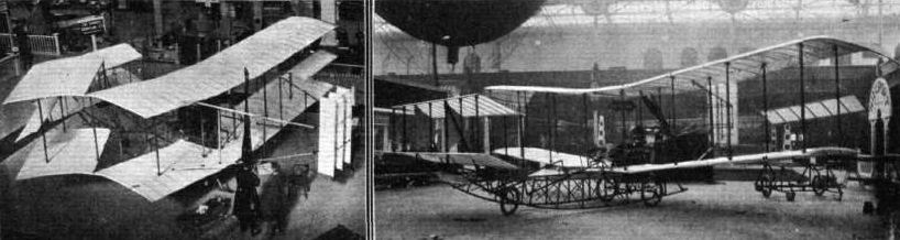
The Sanders biplane, showing the downturned extremities of the upper planes, and a view showing how the main planes on the Sanders biplanelare hinged in order to temporarily reduce the span.
UNDERCARRIAGES AT OLYMPIA. - The Sanders and Valkyrie varieties of the girder skid.

Captain Sanders at the helm of his biplane.

Sketch illustrating the mechanism of the disappearing axle on the Sanders biplane. By releasing a catch the axle and wheels are drawn above the level of the skids, on which latter members the machine can therefore land direct.
UNDERCARRIAGES AT OLYMPIA. - A comparison of some girder skids.
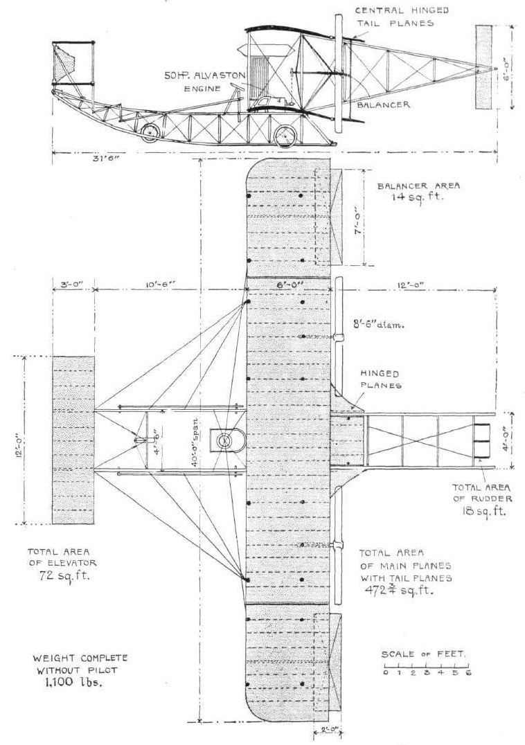
THE SANDERS BIPLANE. - Plan and elevation to scale.
Flight, June 17, 1911.
BRITISH NOTES OF THE WEEK.
New Scottish Flying Ground.
AT the opening of the new flying ground of the Scottish Aviation Co. at Barrhead on the 3rd inst., the strong wind unfortunately prevented any actual flying. The visitors, however, were much interested in the Caledonia monoplane and also in the Bleriot school machine, the details of which were explained by Mr. F. Norman, the general manager. Arrangements have been completed for building both monoplanes and biplanes, the latter being suitable for carrying one or two persons.
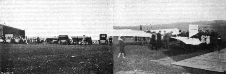
OPENING OF THE SCOTTISH AVIATION CO.'S FLYING GROUND AT BARRHEAD, GLASGOW. - This is situated about 5 1/2 miles from the city, and is conveniently served by both rail and tram. Our photographs show the general company assembled on the opening day, and on the right is the Caledonia monoplane built by the Scottish Aviation Co. from designs by Mr. F. Norman, the General Manager of the Company. Mr. Norman is standing by the machine in overalls and talking across to Mr. Wilson, of the W. W. Proofing Co., a firm which is making a speciality of balloon fabrics in Glasgow.
Flight, January 7, 1911
THE BRITISH MICHELIN CUP.
IN our last issue we were able to give brief particulars of Mr. Alec Ogilvie's splendid try for the British Michelin Cup, and it seemed then not improbable that his fine record would not be beaten. Both Mr. Sopwith and Mr. Cody were not to be so easily deterred, however, and on Saturday, the closing day of the competition, Mr. Cody secured the leading position, giving him the right to hold the trophy for 1911, as well as the cash prize of L500. Just as in France, the competition on the last day proved an exciting one, for the three British flyers we have mentioned were making simultaneous attempts to seem e the coveted trophy.
Mr. Alec Ogilvie's Second Try.
MR. OGILVIE was the victim of very hard luck, because although his flight of 140 miles on the previous Wednesday gave him the leading position for the time being, he could have continued for very much longer but for the fact that a serious leak developed in the water system, while on Saturday last at Camber Sands he was compelled to come down owing to faulty ignition after covering 55 miles in about an hour and a half. Mr. Ogilvie's two flights are particularly interesting for those watching the all-British side, for the British built Short-Wright biplane used was fitted with the first of the new type two-stroke N. E.C. engines described in our issue of the 24th ult.
Flight, January 28, 1911
MR. OGILVIE'S WRIGHT BIPLANE.
THROUGH the courtesy of Mr. G. F. Mort, of the New Engine Co. (N.E.C.), we are able to publish this week a few very interesting photographs of Mr. Alec Ogilvie's Wright biplane, taken on the Camber sands near Rye, after his recent experiments with the new two-stroke engine that Mr. Mort designed. These trials, as our readers know, very nearly resulted in his winning the British Michelin Cup, for at one time he headed the list of competitors. The photographs in question were taken after the removal of the engine and happen to be the more interesting on that account, because they show, more clearlv than would otherwise be possible, the new features that have been introduced into the machine since Mr. Ogilvie's return from America, where he took part in the Gordon-Bennett Race on behalf of Great Britain.
It will be observed, first and foremost, that the machine has been essentialy changed in type by the substitution of a tail for the front elevator. There still remain in front, however, a pair of "blinkers," which take the place of the half-moon panels formerly fitted between the panels of the elevator. These blinkers are situated at the front ends of the skids and fill the corners made between the skids and the oblique struts that truss them to the upper front spar. Their purpose is, of course, to make the machine sensitive to the rudder.
The tail plane that substitutes the front elevator is a monoplane and is rigid for the forward portion of its chord. Through the action of the elevator lever its effective angle can be varied in order to control the machine in a vertical plane.
One very interesting circumstance associated with this tail plane occurred when the new two-stroke engine was fitted. It is not generally recognised that the Wright motors run in the reverse sense to most engines, and the N.E.C. motor, following orthodox practice, consequently reversed the direction of rotation of the propellers on the Wright biplane. This caused a reversal in the trend of the spiral slip stream and upset the adjustment of the attitude of the tail plane to such an extent as to eventually necessitate a very material alteration before the effect was compensated. The new tail is far less sensitive in its action than was the old front elevator and Mr. Ogilvie tells how, when receiving instruction in the new control during his visit to America, the elevator lever was put hard over in each direction in order that he might be assured on this point. The machine stood on its head and then on its tail, as he described the effect of this manoeuvre, but remained under control; which certainly would not have happened with the old system. The elevator is still operated by a lever at the pilot's left hand, which lever is moved to and fro and is held in any desired position automatically by the action of a friction-brake embracing a drum on the shaft to which it is attached. The purpose of this constructive detail is to enable the elevator to be adjusted to a certain angle, say, for instance, for steady climbing, and to leave it there for any desired duration without attention.
Another most important innovation on the machine is the Orville Wright type of control-lever for the rudder and warping movements. The operation of this lever is essentially different from that used in the Wilbur Wright system and we have even heard it said that Wilbur Wright himself can no longer fly since all the Wright machines are now being fitted with his brother's device. But we have heard stranger things than this of Wilbur Wright, and whilst telling a story of this sort it is perhaps even more appropriate to tell another that is touching on the same point, although it gees back to the beginning of time when Wilbur Wright was learning to fly at Le Mans. Most people never knew that he was learning to fly there, but it is the truth nevertheless, and the reason why is precisely the reason for which he is said to be unable to fly now. He was unacquainted with the control of his own machine. When the Wrights were developing their aeroplane they developed the details of control by degrees, and the two brothers, having different tastes in this matter, suited their own convenience in design. Wilbur Wright was not altogether satisfied with his own apparatus and just before going to France evolved the universal lever with its diagonal and elliptic motions as a scheme that seemed to him best suited to his requirements. He never had a proper opportunity of practising with this control before he started flying at Le Mans, and a great deal of the one step at a time procedure, which characterized his method at that date, was doubtless due to this circumstance.
The Orville Wright system is simpler than the Wilbur Wright control, but necessarily confusing at first to those who have learned to use Wilbur's lever. On the other hand, Mr. Ogilvie very quickly accustomed himself to its peculiarities under ordinary flight conditions and now feels quite confident of doing the right thing unconsciously in an emergency.
The lever in question is characterised by a hinged handle that is moved sideways by twisting the wrist when it is desired to operate the rudder independently of the wing warping. Normally the stem of the lever is moved to and fro with the handle vertical. This action balances the machine without causing it to swerve from its straight path, for the rudder and warping mechanism are connected so as to operate simultaneously and in the correct relative degree.
For special manoeuvres that require a greater or less degree of rudder action for a given amount of warp, the handle s merely moved over to one side or the other, which may be done without disturbing the position of the lever itself. A glance at our illustrations shows how these interconnections are carried out.
The handle carries a small bell-crank-lever that is connected to a free disc on the operating rock-shaft, by a rod. When the handle is moved independently of the lever, this disc is rotated independently of another similar disc alongside it and the rudder to which it is connected moves independently of the wing tips that are connected to the other disc.
The other disc itself is attached rigidly to the stem of the lever and when the lever is moved to and fro both discs rotate in unison, for the connecting-rod already mentioned then locks the rudder disc to the warping disc, as may be understood by a glance at the accompanying sketch, which shows why it is obviously impossible for the warping disc to move without the rudder disc unless the handle is thrown over simultaneously and to an extent sufficient to exactly neutralise the lock.
Speaking of warping, one of the most interesting photographs ever published of the Wright biplane is that among those herewith, which shows the maximum extent of warp possible. The position illustrated corresponds to the lever being pushed right forward with the handle vertical and it will be noticed that the rudder has been turned to an extent sufficient to show the number 20 on the face of one of its planes.
Whilst on the subject of control, it is interesting to point out that the arrangement of the levers on the Wright biplane is such that the pilot may be either right or left-handed. Suppose, for the sake of example, that he sits in such a position as to use the warp and rudder lever with his right hand, then his pupil will be trained to use the same lever with his left hand, because there is only one such lever on any Wright machine, although the elevator levers are in duplicate. The reason for this is that the duplication of the warp and rudder lever would involve serious complication in the various connections, whereas the elevator connections are not altered in the least by the presence of another lever at the opposite end of the operating rock-shaft.
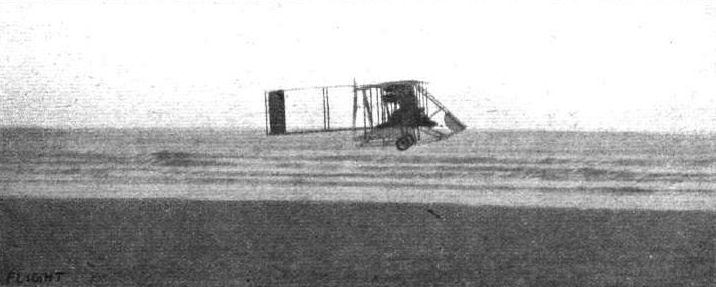
Mr. Alec Ogilvie making his flight of 140 miles in 3 hrs. 55 mins., for the British Michelin Cup on his British-built N.E.C.-engined Wright flyer, on Camber Sands last week.
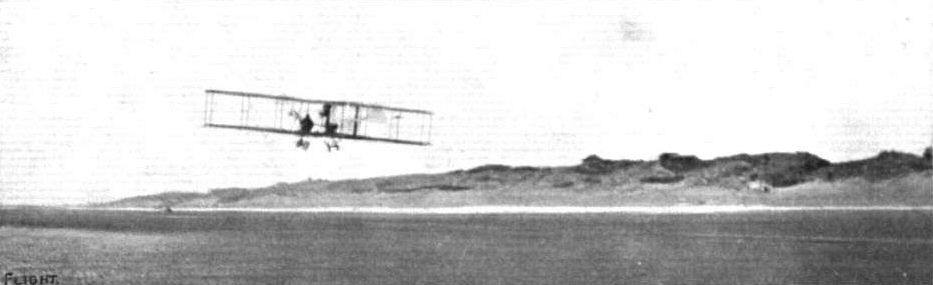
Mr. Alec Ogilvie, on his N.E.C. engined Short-Wright machine, flying well over the Camber sands during his recent fine flight for the Michelin Cup.

Another view of Mr. Alec Ogilvie rounding one of the mark rowers during his flight for the Michelin Cup on his N.E.C.-engined Short-Wright biplane.
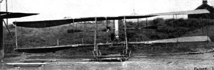
Full warp on Mr. Ogilvie's Wright biplane. Note the position of the rudder. The combined movements are the result of a permanent interconnection between the two mechanisms, and are effected by simply pushing the control lever forward.
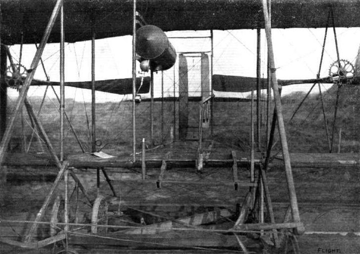
View showing the position of the rudder on Mr. Ogilvie's Wright biplane when the handle of the control lever is turned over as illustrated.
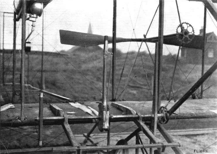
View of the warp and rudder-control lever on Mr. Ogilvie's Wright biplane. On the right is the elevator-lever controlling the tail, and by its side is the friction-brake that holds it in position.
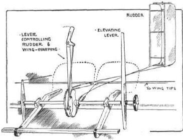
Sketch illustrating the control of Mr. Ogilvie's Wright biplane,
Flight, August 26, 1911.
FROM THE BRITISH FLYING GROUNDS.
Royal Aero Club Flying Ground, Eastchurch.
<...>
On Saturday morning Lieuts. Samson, Gerrard, Longmore and Gregory were out early putting in their usual practice flights. At 4.50 a.m. Lieut. Samson, carrying one passenger, on the Short No. 38, made a long tour of the island, returning at 6 a.m., having been up one hour and ten minutes. He was so pleased with the way the machine was flying that he expressed his intention of trying, without a passenger, for the British duration record, and he started away again immediately, getting into the air at 6.7 a.m. For the next hour the weather conditions were fairly good, but at 7.30 a change for the worse set in, the sky becoming overcast with stormy clouds, and a strong ground wind springing up. The indefatigable Samson had no intention, however, of coming down, and continued to fly with almost monotonous regularity to and fro above the aerodrome. By 10 a.m. the air conditions had become still worse, and the sun breaking through the clouds in patches appeared to cause upward and downward trends in which the aeroplane rose and fell vertically, but, by the skill of the aviator, was kept constantly on an even keel. Shortly after 10 o'clock the observers on the ground heard a voice coming from the aeroplane each time it passed overhead, but owing to the roar of the engine they could not make out what the aviator was shouting. Someone suggested that he was merely singing as he worked away at the elevator, but at last, by the aid of an ear trumpet, the words were caught. It appears that the aviator's watch had stopped, and he wanted to know the time. A blackboard was at once secured from the lecture room, and on this the time was chalked every five minutes, so that the aviator was kept well informed of his progress. Shortly after 11.15 a.m. Lieut. Samson descended, having been in the air 4 hrs. 58 1/2 mins., thus creating a new British duration record with a fine flight under difficult conditions. Lieut. Samson was not at all tired, although he had been flying almost continuously for over six hours. He had also plenty of petrol and oil left, but the treacherous air currents made a continuance of the flight inadvisable.
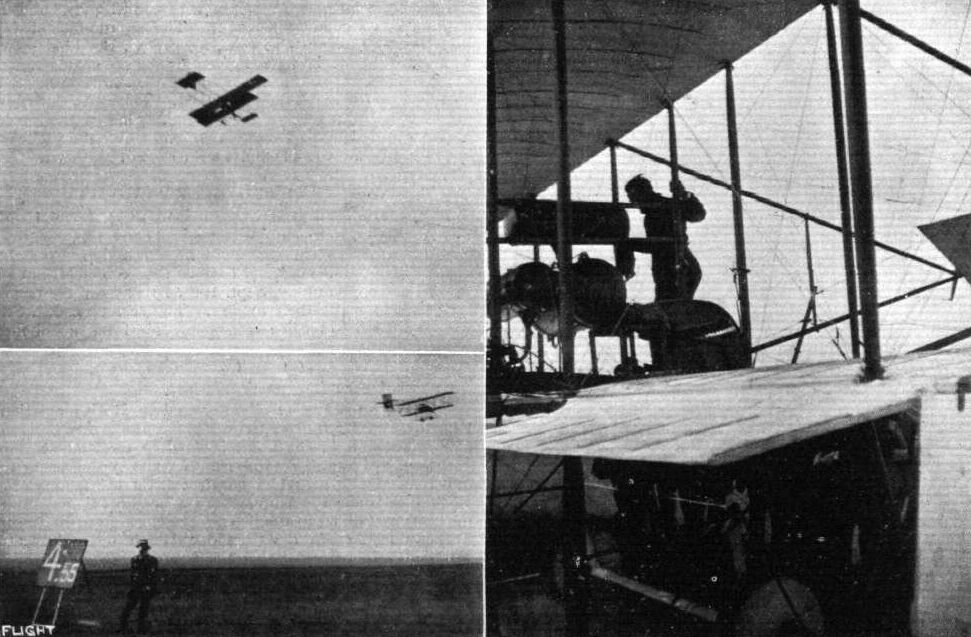
Lieut. Samson, R.N., making his British duration record of nearly five hours on a Short biplane at Eastchurch Aerodrome last Saturday. At the top he is seen making a good turn; below, Mr. Travers is seen chalking on a board the time Lieut. Samson had been in the air, this being rendered necessary by reason of the aviator's watch having stopped, a fact which he communicated to the observers by shouting from his aeroplane. On the right Lieut. Samson is seen in the act of dismounting after his splendid flight.
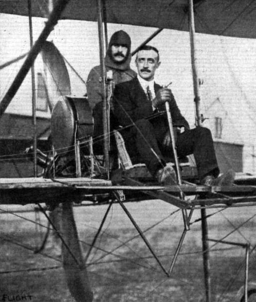
Lieut. Gerrard, R.M.L.L, in the pilot's seat of the Short biplane upon which he made his world's record cross-country duration flight of 4 hrs. 13 mins. with a passenger, Lieut. Wildman Lushington, R.M.A., at Eastchurch flying grounds on August 16th. Lieut. Gerrard was competing for the Mortimer Singer prize, which is open only to British officers.
Flight, June 10, 1911.
THE SHORT BIPLANE, 1911 TYPE.
CONSIDERING their position as pioneers of aeroplane construction in England, and the reputation that they have established for thoroughly reliable if particularly British workmanship, it is a matter of course that any production of Short Brothers should be regarded with special interest. The machine at present under review, which is the latest output of the Sheppey factory, reflects modern prejudice in favour of the Farman type biplane, a prejudice that is well founded, for шt is after all not surprising that pilots should prefer to fly those machines which have proved most successful. Moreover, it is often by taking a successful type as a basis in design that there is most scope for originality in detail development, and it is in this respect that Short Brothers' work has always been notable, in their earlier machines no less than in this. As a matter of fact, too, the general design of this machine differs considerably from the real Farman so soon as its construction is looked into with more than superficial interest. Even the casual observer, for instance, will notice some difference in the appearance of the tail, which includes a monoplane lifting member fitted with a trailing elevator attachment and a large divided rudder half of which is above and half below the horizontal plane.
Particular attention may also be directed to the trussing of the tail outrigger, which is especially well stayed laterally by diagonal ties leading to the rear transverse boom of the main planes. The same system of trussing is applied to the elevator outrigger, which member is of the accepted triangular frame type. The elevator itself is a cambered monoplane, and is operated on the Farman system from a universally pivoted lever that is mounted vertically and centrally in front of the pilot. From this lever wires also pass laterally to the hinged balancing planes that trail behind the extremities of the upper main planes. A glance at the front view of the machine shows how these balancers are of exceptionally long span, and consequently have a relatively high aspect ratio.
It will also be observed from this front view of the machine that it belongs to the extended upper plane or "military" type, the upper plane having a span 14 ft. in excess of the lower plane, and the overhanging extremities being supported by slanting stays attached to the extremities of the lower main spars. Altogether the machine is a neat and well thought out example of rather a large type of flyer, and by no means the least interesting or important of its features is the elaborate system of bracing that characterises the design. Two points of special importance in this connection are the struts in the gap of the panels on either side of the main central panel, and the fore and aft struts in the chord of both upper and lower main planes. The former struts join the points of intersection of the diagonal tie wires with the rear spar of the lower main plane, and their purpose is to add stiffness by resisting the bending that is apt to take place at this point when the machine lands. The nature of the stress induced is illustrated by one of the accompanying sketches, which shows how the principal mass represented by the engine and pilot tends to make the spar sag in the centre, while the same result tends to take place at the extremities, due to the mere weight of the planes. As a result a sinuous deflection is set up in the spar, which tends to bend up in those panels immediately adjacent the main central panel. The presence of vertical struts in this position thus tends to stiffen the entire spar by resisting deflection at the point where the tendency to bend is most pronounced. Similarly a V-frame trussed diagonally is introduced immediately beneath the centre of both main spars. The purpose of the fore and aft struts in the chord of the main planes is to provide a framework that is independent of the ribs or fabric of which the planes proper are constructed. In the Short biplane the ribs and fabric might be stripped off the machine, and the box-girder construction would still remain as a skeleton to which the planes might be refitted. This system of construction enables lighter rib sections to be used throughout, and in some respects gives greater latitude for the design of the planes as independent supporting members than can be considered apart from any subsidiary purpose they may play in the construction of the machine.
Another interesting constructional detail of the same order is the axle of the under-carriage of this machine. It will be observed that the axle it stiffened by vertical struts adjacent to the wheels, which struts are tied together by a horizontal wire and are trussed down to the axle extremities by diagonal wires. The undercarriage itself belongs to the Farman type, inasmuch as it is a wheel and skid combination joined by rubber springs, the use of radius-wires and the arrangement of the radius-rods, as shown in one of the accompanying sketches, however, really puts the Short under-carriage quite in a class by itself.
Some minor constructional details are shown in another accompanying sketch, which illustrates several of the special joints employed. Short Brothers have always had a marked preference for the use of manganese steel fittings, and the illustration in question shows a variety of ways in which this material is employed. Especially interesting are the U bolts and slotted ferrules, by means of which the struts are attached to the booms with a minimum reduction in the material of either. A detail that is sure to attract attention in our photograph is the use of straight ribs at the extremities of the main planes. Elsewhere the planes are cambered as usual.

Short S.35 built for the Hon. Maurice Egerton at Eastchurch in 1911. Side view, showing the enclosed car for the pilot and passenger. The horizontal rib in the extremities of the main planes, which are cambered elsewhere, is a curious feature of interest.
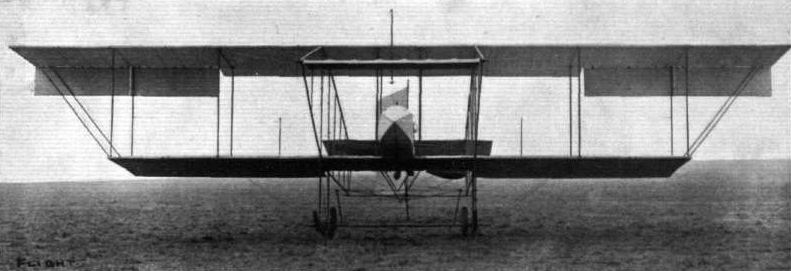
Front view of the Short biplane 1911 type.
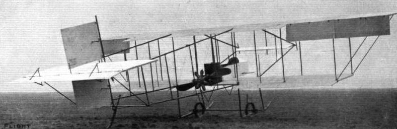
View from behind of the Short biplane, showing the Gnome engine in position.
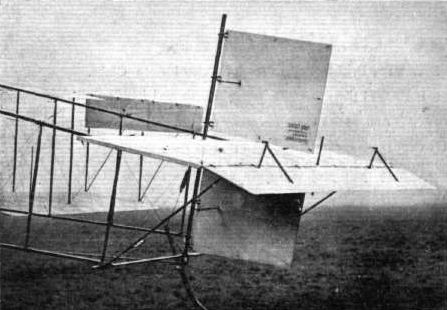
View of the tail on the latest Short biplane. In the view one of the balancers on the extremities of the upper main planes appears rather like a vertical keel in front of the rudder, due to an absence of proper perspective in the photograph.

Hanging on to the tail of a Short biplane before a trial at the Royal Aero Club's flying grounds at Eastchurch.

View of the pilot's car on the latest Short biplane.
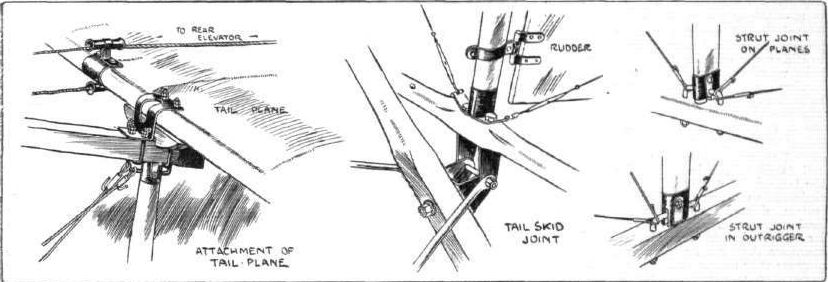
Sketches illustrating some of the joints on the latest Short biplane.
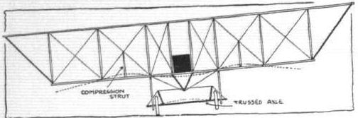
Diagrammatic sketch illustrating the special trussing of the lower main plane to resist the stresses imposed by a rough landing due to the concentration of the load In the centre of the plane and of the weight of the extremities of the planes acting through the leverage of a wide span.
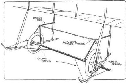
Sketch illustrating the construction of the Short under-carriage and axle.
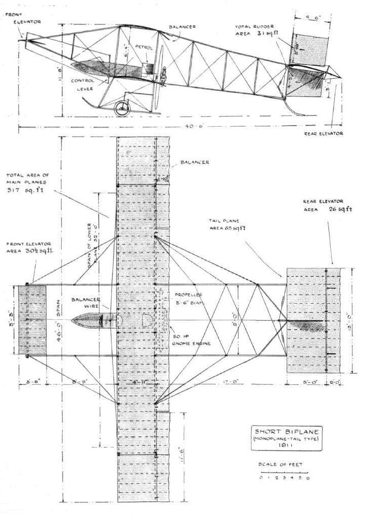
THE SHORT BIPLANE, 1911 TYPE. - Plan and elevation to scale.
Flight, September 9, 1911.
THE NEW SHORT BIPLANE.
To design and construct a new biplane fitted with a 100-h.p. plant consisting of two engines and three propellers, is sufficient proof, if any were needed, that Messrs. Short Brothers do not lack enterprise. Moreover, it is evidence that they have the courage of their convictions, for the machine is a full scale experiment intended to test some of their more recent patents. So far as the framework and planes are concerned, the machine adheres more or less closely to the standard practice of the firm, and thus they are following the very proper course of trying out new things on a basic design that they already know something about.
The new feature is the power plant, which consists of two engines placed fore and aft. The forward engine drives two tractor-screws by means of chains, the after engine is direct coupled to a propeller. The combined power of the equipment is 100-h.p., and both engines are intended to be in operation simultaneously. However, the machine is so designed that either one of its engines will be sufficient to keep the machine flying at a speed of about 36 miles an hour, while with both in operation the speed is expected to be somewhere in the neighbourhood of 55 miles an hour. By so equipping the machine with two entirely independent power plants, the risk attending engine failure is almost entirely obviated, for should one peter out, the pilot will be able to proceed unconcernedly by the aid of the other, and leisurely choose a suitable landing place, where he may descend to make any adjustments to his temporarily disabled engine. This is one advantage that the makers claim for the system. Another is, naturally, the enhanced efficiency of the slow-speed tractor-screws driven by the forward motor, but the third claim is the most interesting of all. Messrs. Short Bros, consider that the draught from these tractor screws will be sufficient to establish a permanent uniform "wind" through the gap of sufficient magnitude to blow out any ordinary gust, and that to this extent they will render the machine far more stable in windy weather than would otherwise be the case. Also, it is anticipated that the efficiency of the planes will be enhanced by working in the propeller draught, which will at all times augment the effective flight speed, and an even more important consideration is that the balancers, which are directly in its wake, will be rendered far more sensitive at slow velocities. It has always been argued in connection with the control of aeroplanes by organs like balancers, which themselves derive their force by flying through the air, that their effectiveness varies with the speed of the machine, and is a minimum when the disturbance is likely to be most dangerous. On the new Short biplane, however, these balancers, by operating in the draught of the tractor screws, will have a minimum useful value that is independent of the speed of flight.
Although these are not all the points that Messrs. Short Bros, are seeking to investigate in their new biplane, they must suffice for the moment, and they are, in any case, sufficient to give weight to our statement that the machine in question is one of exceptional interest and does the makers credit. If we turn from the principles to the machine itself, there is one point on which we feel compelled to make an early remark, which is that the structural work has been finished with all the care that one expects on an aeroplane built to order, and but too seldom finds on one that is built for trial purpose, only. It is, however, characteristic of the firm that their experimental work should be of this description, so we need say no more about its
Most of what it is necessary to know about the design and construction of the machine can be seen at a glance by the aid of the accompanying photographs and drawings, and much of the detail that is invisible can be taken for granted by assuming that it is the same as that already described by us in connection with the standard Short models. Two differences that may be noted, however, are the triple rudder and the small span of the elevator outrigger booms, compared with the span of the elevator itself.
Both engines are seven-cylinder rotary Gnomes, and that in front forms as it were the nose of a car, fashioned somewhat, as it appears at first glance, like the outline of a racing automobile. The pilot sits in this car, and there is room for a passenger alongside him, but although the extra seat is not there yet, we have visions of accommodation being provided for two other passengers behind the pilot if the machine proves anything like as successful as is hoped. The aft motor is situated well behind the back of the car, as one of the photographs shows.
The tractor screws are driven by very long chains, running in tubular guides, and rotate in opposite directions, one of these chains being crossed in order to give the necessary reversal of motion. Wright practice is recalled in the use of these steel guide tubes, and in the shape of the tractors themselves; it affords, in fact, a particularly interesting comparison to note the difference in form between the slow-speed propellers in front and the high-speed propeller behind.
In front of the pilot is a wheel mounted on the top of a pivoted column. Turning the wheel operates the balancers, and a to-and-fro motion of the column controls the elevator. Steering is effected by a pivoted cross-bar under the feet, and this mechanism is fitted in duplicate so that the passenger may work in unison with the pilot.
A point that is worth noting is that the fuel tanks are situated as far away from the engines as is practicable, in order to remove as far as possible the liability of serious accident in the event of an atterrissage brusque. They are also fitted with feed pipes of such design as to ensure a constant supply to the carburettor for any attitude that the machine may assume in flight.
So much is, for the moment, all we need say of the new Short biplane, but the fact that it is an experimental machine affords us the opportunity for remarking that it is by no means indicative in itself of the extent of Short Bros.' experimental work, and we should like to congratulate them on this occasion for the thoroughness with which they investigate stresses and strains, and by every means do their utmost to protect the pilot against mechanical failure in flight, for which they very properly say "there is no excuse."
Flight, September 23, 1911.
FROM THE BRITISH FLYING GROUNDS.
THERE is not a great deal to report, but a first trial has been made, as mentioned below, with the new Short double-engined biplane, fully described in the issue of FLIGHT of the 9th inst.
<...>
On Monday Mr. F. C. McClean made the first trial flights in his new Short twin engine biplane, the flights proving very successful, and the machine answering fully the expectations of its constructors. The first trial was made by Mr. McClean alone, who made a short straight flight, in which the machine showed great buoyancy, rising rapidly into the air in spite of the preliminary run being uphill.
Afterwards, with Lieut. Samson on board, Mr. McClean made eight laps of the ground in which he frequently flew with either engine throttled down. A strong feature of the tactics was the large margin of power exhibited by the machine in flight, it being possible to vary the speed considerably, by throttling down either or both engines without causing a descent.
Mr. McClean stated afterwards that he found the warping control very effective and the biplane very steady in flight; it also showed a very flat gliding angle, when the engines were cut off, in this respect, strongly reminding one of the Nieuport monoplanes at the last Gordon-Bennett Race. The speed was estimated at 52 to 54 m.p.h.
<...>
Flight, November 4, 1911.
FROM THE BRITISH FLYING GROUNDS.
Royal Aero Club Flying Ground, Eastchurch.
INTEREST centred on Sunday around the trail of another new twin-engine machine which has just been completed in the shops of Messrs. Short Bros., the design of which is included amongst their patents for twin-engine system machines.
No doubt the method of employing the two propellers will be largely criticised, as it has always been an accepted theory that one propeller working directly in the wake of another is not an ideal and efficient arrangement; but, so confident has Mr. H. L. Short been that this system could be made quite efficient and simple, that the present machine was built, and on its first trials fully justified the confidence which the designer had placed in it.
The machine is fitted with two 50-h.p Gnomes, one behind the main planes in the centre line of the machine, with a single propeller, and the other engine directly at the back of the planes on the same axial line as the front engine, also fitted with a single propeller. The nacelle is situated between the two engines and is arranged with thwartship seats and dashboard, and dual control throughout. The engines turn in opposite directions, so that there is no gyroscopic action and no engine torque, as one engine balances the other when both are running at the same speed and give off the same horse-power. The machine flies easily with either engine.
So great has been the success of twin-engine drives, both with three screws, and the latest with two screws, that Messrs. Short Bros, are now commencing to build a machine of 250-h.p., which will have four propellers.
Upon the dashboard of the machine now under review are conveniently arranged a complete set of instruments such as an aviator requires, which include a speed indicator for each engine and an aneroid barometer, the latter specially made for aviation work by Short Bros. Another new feature introduced by the makers is in regard to the petrol supply, which is controlled by a special cock, which in turn is connected to an indicator finger working against a graduated dial, thus enabling the tap to be set to the most suitable opening and the exact position noted - a detail of considerable importance in relation to Gnome engines. As before mentioned, the machine is fitted with dual control, so that it can be operated from either seat, and by a neat arrangement the switches and throttles of the two engines can be worked either separately or both at once by a single movement of the hand, as occasion requires.
Mr. Frank McClean, who piloted the machine on its first run, did not attempt any preliminary ground rolling, but took the machine straight into the air and made a lap of the aerodrome at a height of about 100 feet. On descending he expressed great satisfaction at the behaviour of the machine, which flew extremely well and at a great speed. During the afternoon he made several extended flights, taking in turn Lieut. Samson, R.N., Lieut. H. V. Gerrard (brother of Capt. Gerrard, the aviator) and Mr. J. L. Travers, of Messrs. Short Bros., as passengers. For a final flight, taking with him Lieut. Gregory, R.N., as passenger, Mr. McClean made a long tour of the island, passing over Queenborough and Sheerness, keeping at an altitude of about 600 feet the whole way. The machine exhibited splendid climbing powers, rising with unusual rapidity.
<...>
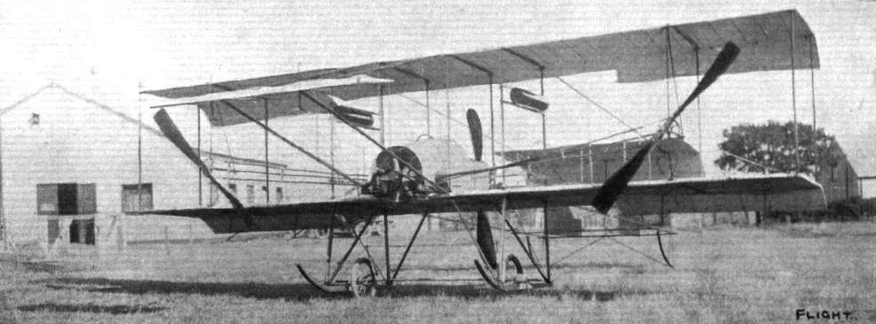
Short S.39 Triple-Twin a development to improve control by providing greater coverage of the control surfaces by the slipstream. - General view from the front, showing the two tractor-screws at the ends of the main planes, and the single propeller in the centre behind.
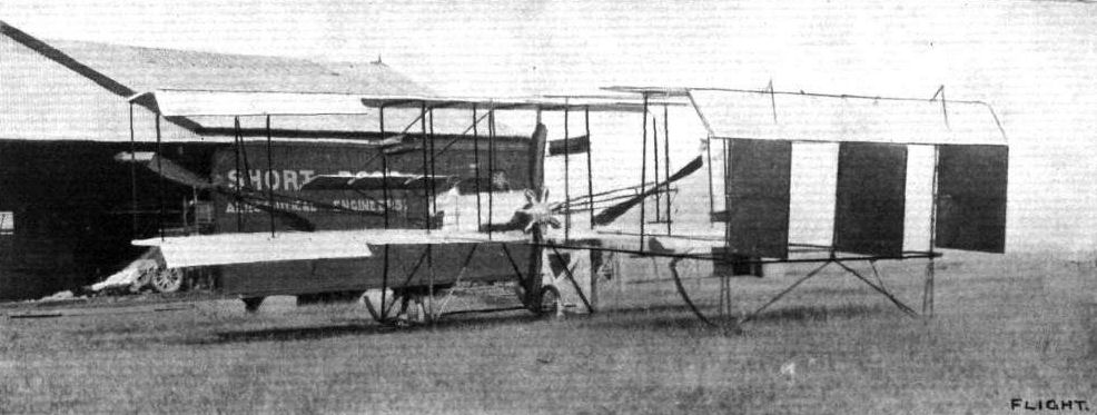
General view from behind of the new Short double-engined biplane, showing the triple rudder. In this the position of the rear propeller and Gnome engine are seen.
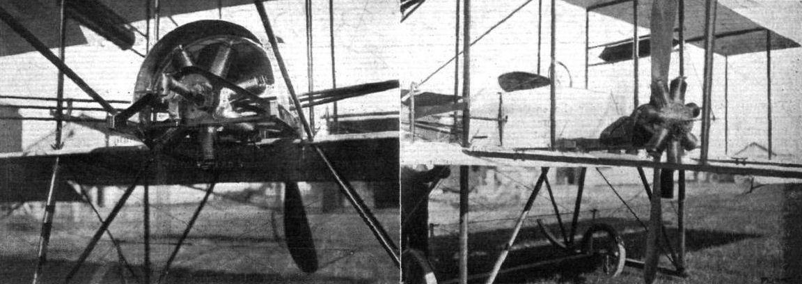
THE NEW SHORT DOUBLE-ENGINED BIPLANE. - On the left the front engine, and on the right the rear engine, propeller, pilot's seat, &c.

The New Two-Engined Short Biplane, which has during the past week made such successful flights under the pilotage of Mr. Frank McClean at the Royal Aero Club's Eastchurch flying grounds. On the left Mr. Frank McClean is in the pilot's seat just ready to start, and on the right is a view from behind, showing Mr. McClean up with Lieut. Samson as passenger.

The Short 100-h.p. twin-engined biplane with which Mr. Frank McClean is carrying out such excellent work at the Royal Aero Club's Eastchurch flying grounds. In the left-hand photograph, Mr. McClean is seen in the air on Saturday last, and on the right, Mr. McClean has just finished a passenger flight with the Hon. Maurice Egerton. Reading from left to right are Mr. Frank McClean, Capt, Gerrard, Mr. Horace Short, and the Hen. Maurice Egerton.
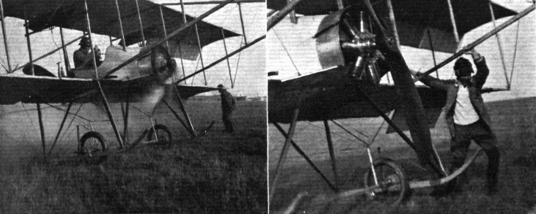
MR. FRANK McCLEAN AND HIS SHORT TANDEM TWIN-ENGINED MACHINE. - On the left just starting away from the Eastchurch grounds, with Lieut. Samson as passenger, and on the right Mr. McClean helping to store his machine after his first flight on it.
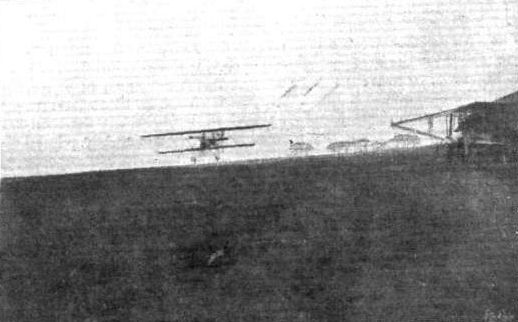
Mr. McClean just alighting after a flight on the Short twin-engined machine.
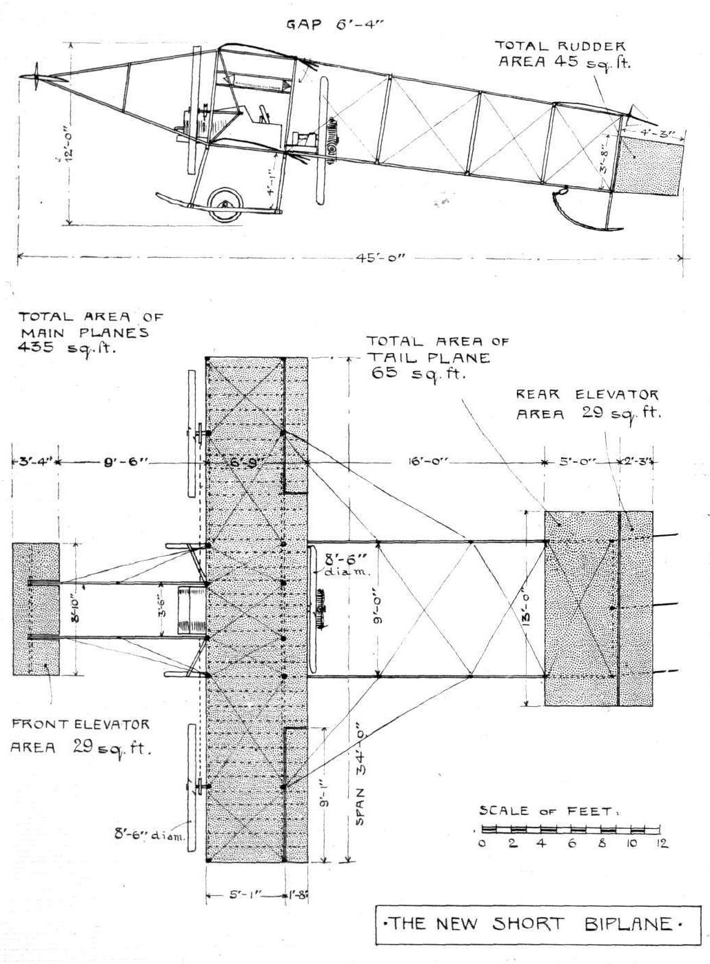
THE NEW SHORT DOUBLE-ENGINED BIPLANE. - Plan and elevation to scale.
Flight, May 20, 1911.
The Sirie Monoplane.
[1175] Aeroplanes are usually classed according to their distinctive features, as the Bleriot, Farman and the Tellier, and the present one is no exception to the rule, except in this particular, that it takes its name not from its inventor but from the name of a tropical tree, which it resembles. The leaves of this tree are, in fact, miniature monoplanes, and soar through the air for long distances before they reach the ground.
The machine consists essentially of two large concave wings, somewhat similar in clinure to the wings of a crow when soaring. These wings are fixed to the main carriage, as indicated, and have a span of 18 ft. from tip to tip. In CROSSING one another they form a triangle, where the engine is fixed. The vertical plane between the wings is a control plane to prevent zig-zag flight. This takes the place of the usual tail in other monoplanes.
Two elevating planes are fixed at the front of the machine, and are operated from the carriage by means of rods. They can move in four different ways, so that by simply turning the right hand plane the machine swerves to the right. Planing up and down is accomplished in the same simple manner. The engine and petrol supply is conveniently placed to the operator. Numerous experiments have been carried out by the inventor on a model of this machine, and the results have been so highly satisfactory that he is led to believe that this type of monoplane will surpass in speed and stability many of the popular types of the present day.
2, Hamilton Terrace, East Partick. M. LESLIE-MILLER.
AT BROOKLANDS ON SATURDAY. - Tom Sopwith in flight on his Howard Wright, and the Spencer-Stirling machine on the ground.
A snap from the Spencer biplane when flying at Brooklands, a L. & S.W.R. express being seen in the distance beyond the banking.
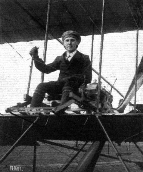
Mr. Herbert Spencer, who has just qualified for his pilot's certificate at Brooklands, on a biplane constructed by himself.
Flight, July 1, 1911.
THE STAR MONOPLANE.
AMONG the many interesting features in the way of aeroplane design brought to light at the Olympia Show of last year, one of the most striking, it will be remembered, was the Star monoplane, and although as yet this machine has no very extended flights to its credit this can be partly accounted for by the fact that the designers, instead of adopting at once accepted methods with regard to tail construction and control, were desirous of evolving a tail that, besides performing the usual functions of elevator and rudder, would also be capable of maintaining lateral stability.
To this end experiments were carried out with a cross tail having four movable members of diamond shape, two being pivoted vertically on the stern post and two on a horizontal spar at right angles to it. When either pair of planes were deflected in unison, the effect was of course precisely that of a rudder or elevator respectively. But the control system was such that one plane of each pair could be operated in the opposite direction to its fellow, and it was hoped by this means to create a twisting action along the longitudinal axis of the machine and thereby to correct those lateral deviations, for which recourse is ordinarily made, in monoplanes, to wing warping. Actual experiment, however, has led to the substitution for this system of the simple rudder and elevator control. Two of the diamond-shaped planes are retained but they now work permanently together and constitute the elevator, as shown in the illustrations.
Though the Star monoplane in its present form may not show any marked difference in general appearance from many successful machines at the present day, it nevertheless displays, on closer inspection, so much originality of construction as well as of sound workmanship that a short description will doubtless be of interest.
For the body of the machine a triangular girder form of construction has been adopted. This has also been made in two sections, so that the machine can be taken to pieces for transport; the joints occur some 3 ft. behind the main planes. An accompanying sketch shows the construction of this joint in detail; it consists of channelled fish-plates fixed permanently to the fore part of the girder, which constitutes the body proper of the machine. These fish-plates thus provide a kind of socket for the reception of the small spars of the aft portion of the frame. The diagonal bracing of the main section of the body is particularly neat and worthy of notice, for the wires, which are of substantial gauge, are cut in the centre of each panel and their threaded ends engage with a small steel ring. The nipples on the ends of the wires thus serve as a means by which tensional adjustment can easily be made.
The main spars of the wings, which are set at a slight dihedral angle, are rather unusual in that they are not solid, but are built up of two lengths of American white wood placed one over the other and separated by a few inches. On the inner end of the leading spar an aluminium socket is fitted, which receives and is bolted to a rectangular lug of the same metal attached to the main girder. The rear spar is hinged to a strong steel channel, which being fixed at both ends to the body, incidentally contributes to its rigidity.
The main planes are double-surfaced and in plane form resemble those of the Bleriot. Their span is 37 ft. and their maximum camber approximately 5 ins. The span of the tail is 7 ft. 4 ins. across the maximum dimension, and is of the flat non-lifting type. It will be noticed, on reference to the plan of the machine, that the tail plane is recessed to admit the triangular fore parts of the diamond-shaped elevating planes. The arrangement of these planes in this way is presumably intended to place the members in question more or less in equilibrium about their axes of support. It would be interesting, however, to know something more of the effect of an entering edge of this form and also of the effect of the orifice in the tail plane through which the air deflected by the fore part of the elevator necessarily has to flow.
The control system of the machine is, as may be observed from one of our sketches, commendably free from complication; a lever is pivoted on the lower member of the body immediately in front of the pilot's seat. At its upper end this lever carries a hand-wheel, by rotating which the wings may be warped through the agency of a small sprocket-wheel, chain, and suitably arranged wires. Moving the control-lever as a whole forwards or backwards operates the elevator. There is no sideways movement to this lever, the operation of the rudder being obtained by the control of a pivoted cross bar supporting the pilot's seat.
A 4-cyl. 40-h.p. Star engine, weighing 182 lbs., and driving a 6 ft. 8 in. Clarke propeller, constitutes the power plant. Pressed steel bearers of a special channel section support the engine and are bolted to the forward struts of the body. The consequent strain on these members, however, is considerably reduced by an ingeniously arranged series of small clips embracing the upper spars at the strut joints. Reference to an accompanying sketch will show how these clips really constitute a sling-mounting of considerable strength, but very small weight. The ash under-carriage is built up on the A principle and is a very rigid construction. It carries, a light axle, by means of which the machine is supported on two pneumatic-shod wheels. The ends of the skids of the under-carriage are laminated to give greater flexibility in the event of an awkward landing. The axle itself is attached. to the skids by rubber springs and light steel tubular radius-rods. At the base of the rudder-post a short length of flat steel spring is fitted to form a simple tail skid. It is pivoted so as to facilitate the tail movement when manoeuvring the machine on the ground.
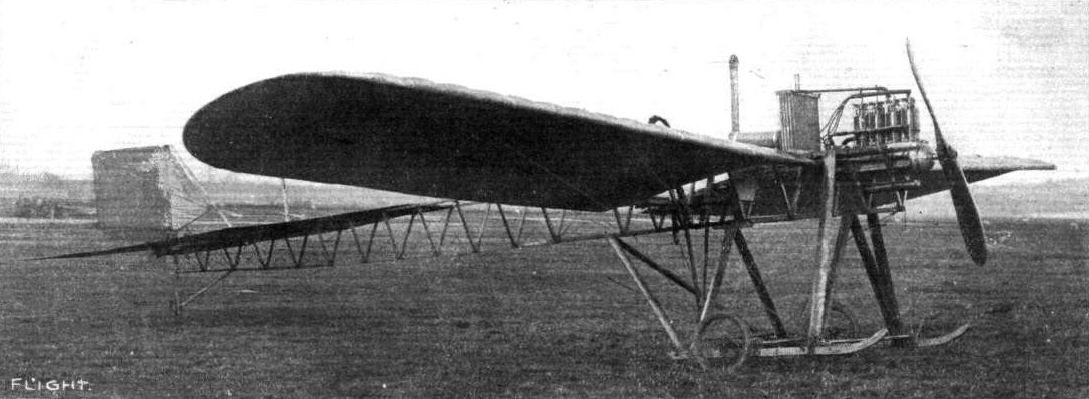
Star monoplane. The second version was tested at Dunstall Park and moved to Brooklands in early 1911.
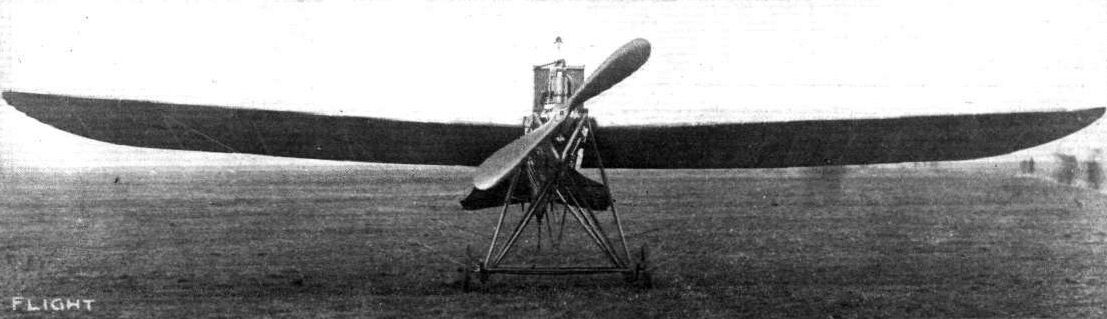
View of the Star monoplane from in front.
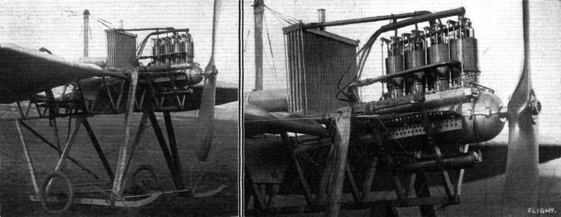
Views illustrating the engine and carriage of the Star monoplane.
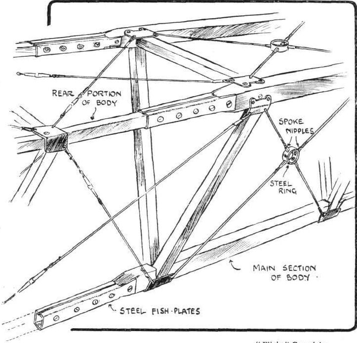
Sketch illustrating the joint in the main frame on the Star monoplane, and also the system of wire bracing.
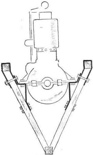
Sketch illustrating the steel engine bearers on the Star monoplane.

Sketch illustrating the control on the Star monoplane.
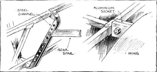
Sketches illustrating the wing attachment on the Star monoplane.
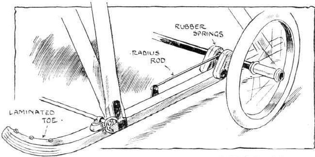
Sketch Illustrating one of the skids on the carriage of the Star monoplane.
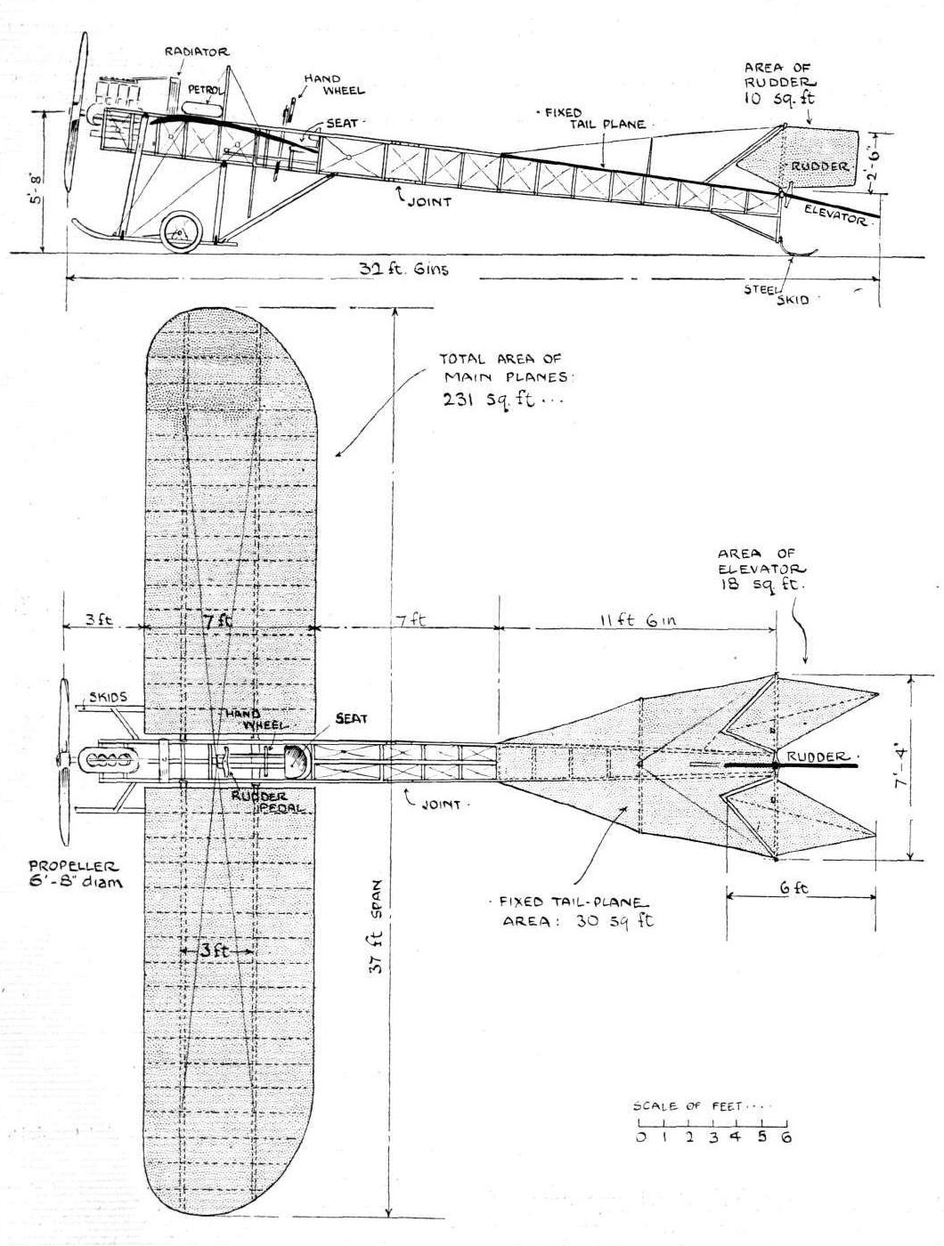
THE STAR MONOPLANE. - Plan and elevation to scale.
Flight, July 29, 1911.
BRITISH NOTES OF THE WEEK.
The South Pole Monoplane.
THE monoplane of the R.E.P. type built by Messrs. Vickers, Ltd., at Crayford, for Dr. Mawson's South Pole Expedition, having been completed, the initial tests were successfully carried out the other day on the firm's flying ground at Long Reach, Dartford, Brooklands being the scene of further trials.
Flight, August 26, 1911.
THE VICKERS MONOPLANE.
IT is only typical of the unerring foresight that Messrs. Vickers exhibit in all their new undertakings that they should have turned some of their vast energy to aeroplane construction, and further that, in doing so, should commence work on such a successful and well developed machine as the R. E. P. monoplane.
The experience of such a pioneer as Robert Esnault-Pelterie counts for a good deal under any circumstances, but coupled with the unique facilities for the commercial manufacture of aircraft that Messrs. Vickers possess, it means that the firm has but to get its organisation established for this department to be a success forthwith.
In this also, however, they are happily situated in having such able services as those of Captain Wood and Mr. Archibald Low, M.A., to assist them in their new departure.
Timber is very little used in the construction of the Vickers monoplane, in fact it only appears in three places, the rear skid, the two main skids, and the wings. The wings are going to have metal booms, and there is little doubt that, in these times of rapid advancement, all these parts will be fashioned from steel, much in the same way as in motor car construction the wooden chassis frame, even though armoured with metal, had soon to give way to the neat and homogeneous steel stamping.
The body framework is built up of steel tubing, cross-braced with piano wire, and, covered with fabric, possesses excellent streamline form.
The 60-h.p. R.E.P. motor protrudes from the front of the fuselage, and from its mounting bracket the body rapidly deepens, and assumes its maximum cross-section in the neighbourhood of the pilot's seat.
This deep body is an excellent point, as not only does it form a good directive keel but it enables the wing trusses and warp-operating cables to be carried to its lower longidudinal member and not as in most other machines to a portion of the chassis, a part that is always liable to serious derangement.
The Vickers landing carriage, at first sight, is strongly reminiscent of Henry Farman practice, but on closer inspection it will be observed that the shorter chassis struts are pivoted to the bottom boom of the body and that the longer struts are connected to collars that slide up and down the steel fuselage columns against the tension of strong cotton covered rubber cord.
By this means the undercarriage is endowed with a double amount of flexibility - that of the Farman and R.E.P. combined - while it has the advantage of being very little heavier than the former and certainly much lighter than the latter. It is flexible enough to enable the pilot to negotiate ploughed land with comparative comfort, and also, which is very important, it has a good wide track to prevent the machine canting over on to its wing tips.
The wings are of wood and steel construction and taper from the body to the tips. They are particularly efficient, being of a modified Phillips cross-section, as they have not the slightest difficulty in lifting this machine, in which the cutting down of weight has been ignored in favour of solid strength.
The way in which the wing trusses are fastened to the main booms and also to the fuselage is interesting, and it is refreshing to find another constructor who is not content to trust the life of the aviator to a 4 mm. bolt. The wing truss, which is formed of two strips of high tension steel wrapped together by tape, is butted into a conical ferrule, which is attached to the steel lugs of the boom clip in the manner illustrated. The tail surface is purely directional and supports no weight, thus the longitudinal stability of the machine is rendered more automatic and the pilot, by being placed further forward, has a better view of his surroundings than he otherwise would have.
Two approximately semi-circular planes rock on ball-bearings at the rear edge of the horizontal tail, and serve as elevators. The rudder, too, is swung on ball-bearings, and the whole of the tail is protected from contact with the ground by a small wooden skid.
Elevation and depression is effected by a backward and forward motion of a lever situated between the pilot's knees, and balance is maintained by rocking it laterally.
The lateral motion of the lever is transmitted to the warping-crank under the body framework by means of a crank and tubular steel connecting-rod. The rudder control is by the customary pivoted foot-lever.
The motor is a 5-cyl. 60-h.p. R.E.P. of the latest type, and a direct coupled Regy Freres tractor-screw transforms the rotary motion of the crank-shaft into effective thrust. Petrol is carried in a large tank under the passenger's seat, whence it is fed by pressure to a smaller tank placed above and behind the engine; the final feed to the carburettor is thus by gravity.
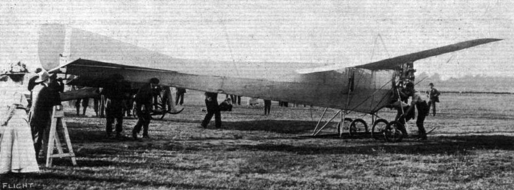
DR. MAWSON'S POLAR AEROPLANE. - The above monoplane is doubly interesting: as being one of the first machines built by Messrs. Vickers, Ltd., to the designs of Robert Esnault Pelterie (R.E.P.), and also because it has been ordered for use in connection with Dr. Mawson's expedition to the South Pole. The machine has the characteristic R.E.P. body, built of steel and surfaced with fabric. In front is the R.E.P. semi-radial engine direct coupled to the propeller.
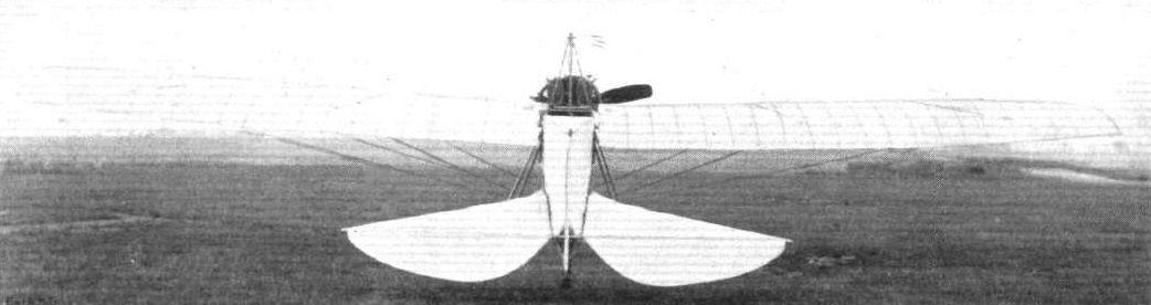
The Vickers monoplane, as seen from behind.
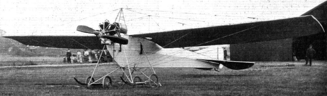
No. 1 monoplane showing fan-type REP engine and typical REP fuselage of steel-tube construction.
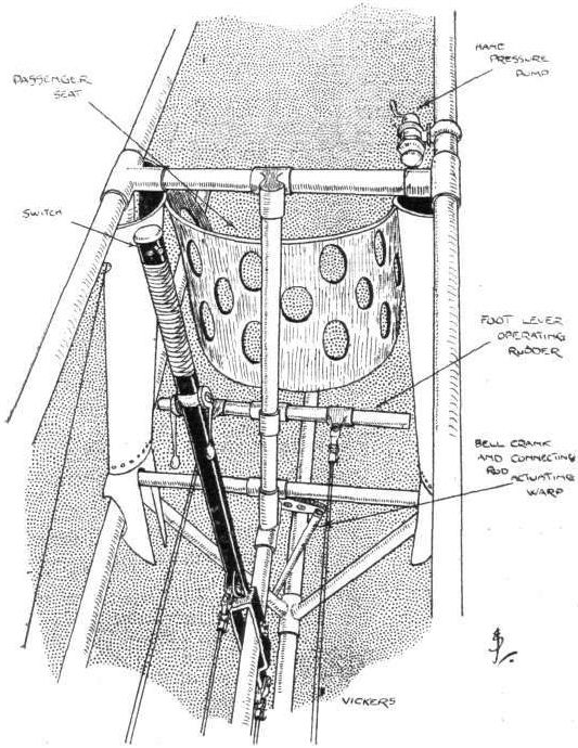
Details of control, sketched from the pilot's seat of the Vickers monoplane.
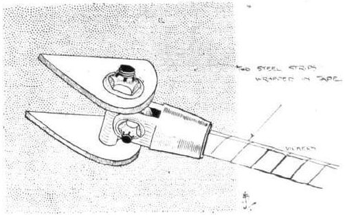
Details of the wing-truss attachment on the Vickers monoplane.

The Vickers Monoplane. - Sketch of tail, showing how the control wires are carried from the short levers on elevator and rudder through the body.
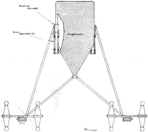
Diagrammatic sketch of the Vickers landing carriage.
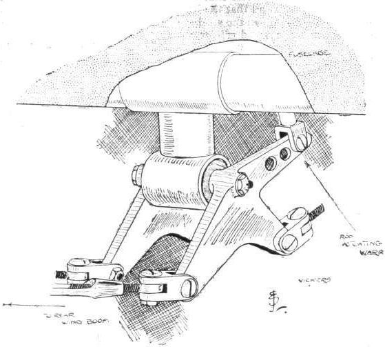
The Vickers Monoplane. - Double-bell crank operating warping.
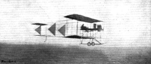
Messrs. Walton' and Edwards' biplane in flight at Brooklands.
Grahame Gilmour in the New Martin-Handasyde monoplane. In the background is the Walton-Edwards biplane, in its latest form at the Brooklands aerodrome. This very substantial machine is now carrying out flights on the grounds.
Flight, January 7, 1911.
IS THE HELICOPTER POSSIBLE?
[1005] In Mr. Reynolds' letter, No. 940, appearing in your issue of the 10th ult., he states "that there is no actual example" of a helicopter type of machine having flown or even risen from the ground by its own power.
It is evident that he is not conversant with the very careful experiments carried out by M. Cornu in France. M. Cornu in 1907 constructed a helicopter consisting of two 20 ft. diameter screws, one behind the other, the blades of which were adjustable to any angle; provision was made for the horizontal progress of the machine by means of two inclined planes, so placed that a small portion of the downward current of air produced by the screws was changed in direction so as to obtain a horizontal thrust. The power of the Antoinette engine at the speed at which it ran (about 900 revolutions per minute) was estimated by the maker at not more than 14-b.h.p.
The machine rose from the ground carrying two men and travelled forward at a speed of 10 ft. per second, the weight lifted being about 704 lbs. The flight was of very short duration, under a minute, somewhat less than the first aeroplane flight of the Wright Brothers.
There is no doubt that M. Cornu's machine was very unstable. The most interesting point in the experiment from a scientific point of view is, if we calculate the possible lift from the screws with the power applied (assuming the machine to be stationary), we could not expect a greater lift than about 450 lbs. This goes to prove that the forward motion tended to augment the lifting power; after all, that is what we should expect, because by the forward motion each screw is enabled to act upon and set in motion air over a greater area in a second of time. If we substitute this value for the area acted upon in place of the disc area of the two screws, we at once see there is no reason why the screws should not lift the above weight.
Experiments at the Koutchino Institute have since proved that the lifting power of a screw was increased nearly three times when subject to a considerable horizontal blast. The reason is obvious in either of the above cases. With the forward motion of the machine, or the horizontal blast of air, the screws are unable to force the air downwards with the same velocity as when stationary; this causes a greater resistance, resulting in a greater lift.
We are therefore forced to the conclusion that to obtain great lifting power from a helicopter the forward speed must be considerable.
M. Cornu, I believe, experimented further with this object, but his results seem to prove that the question of stability altogether outweighs the question of lift, principally for the reason that with a forward motion the reaction from one blade is not counterbalanced by the reaction from the blade opposite (one blade is acting against a horizontal air current and the other is travelling with the current during a period of each revolution).
From the above I am forced to agree with Mr. Reynolds that the helicopter is not a practical machine, although my reasons for doing so, it will be noticed, are very different to his.
Gray's Inn Square. J. R. PORTER, A.M.Inst.C.E.
[1006] In reference to the remarks of your correspondent, Mr. William A. Weaver (letter 978, in your issue of December 24th), concerning my letter under the above title (940, in your issue of December 10th), your correspondent does not seem to realise that, whether for a flying machine, a bridge, or any other mechanical structure, the same mechanical laws and limitations govern all, and that any structure or machine in which the load is concentrated will and must be heavier to sustain the load than one in which the load is more distributed or less concentrated, and that the larger the machine or structure is, and therefore the greater the total weight or load borne, the lighter per unit of weight will be the machine to bear the load; and therefore it follows that if, as stated in my letter, supposing the machine to be of such a size that the weight to be lifted amounts to 3 tons for each propeller, it is impossible to obtain a structure strong enough to bear the load and at the same time be light enough to fly or be air-borne; it will be still more impossible to do it with a smaller machine as then the unit weight in respect to unit strength will be increased, and the smaller machine will be found relatively heavier than the larger, and Mr. Weaver's suggested combination of supporting planes and propelling screws with lifting screws as well, will be heavier than either, for the more the total power required is divided up the heavier will the machinery and necessary supporting structure be to transmit that power. The same remarks apply to flapping wings or reciprocating paddles; these must be very strong, as they bear the whole weight of the structure at the hinge to which they are articulated, and the weight of the machinery per horsepower (that is the useful horse-power exerted by the wings or paddles) is very heavy indeed, as owing to their reciprocating action the inertia stresses, due to their reversals in direction are very heavy, and absorb so large a proportion of the engine-power that so large an engine has to be provided that its weight becomes prohibitive. Mr. Weaver talks about suspending the structure from the screws in a helicopter, instead of resting it on the top of the axles. This will be an actually heavier form of construction than the one I mentioned; the friction will be greatly enhanced, and therefore the necessary horse-power (and weight) of the engine will also be greatly increased, while the concentrated weights on the structure still remain as I have said in my former letter. If Mr. Weaver cares to write to me, I shall be pleased to hear how far he has got. But, all said and done, a certain weight has to be lifted in a certain way. This requires a certain horsepower (and, therefore, weight) to be exerted at a certain place or places; this requires a certain structural strength, which can easily be calculated and its weight known, when the question, to fly or not to fly, can at once be answered, without any waste of time or money in experiment. No structural conception that does not agree with the laws of mechanics can ever be brought to a successful issue.
Maidenhead. CHARLES J. REYNOLDS.
Flight, April 15, 1911.
Is the Helicopter Possible.
[1140] After reading the letter which appeared in your issue of January 7th (letter 1006, from Mr. Reynolds), I have taken the trouble to go more fully into the question of designing a helicopter on the lines I suggested in my letter of December 24th, and I am now in a position to state, positively, that a machine of the type I proposed would be a mechanical possibility at a weight not exceeding 15 cwts.
Mr. Reynolds cannot have much practical knowledge of flying machines, or he would not compare their structural laws with those governing the design of bridges and other mechanical structures.
If Mr. Reynolds takes as his guide the data available to the ordinary engineer-designer and applies it to the construction of a flying machine, he will be very much astonished at the weight of the resulting machine. It will be found in all machines which can fly, that the question of the safe load margin, so beloved by English designers of machinery, has to be almost entirely disregarded, and a machine produced which will stand up to its work with the lightest possible margin of strength, and (as is borne out only too sadly by most of the fatal accidents to aviators) with practically no margin for extraordinary strains which may arise in the course of flight.
In the machine I have sketched out planes are provided of sufficient size to assist the helical screws in supporting the machine in flight, and to counterbalance any fluctuations of horse-power which might momentarily reduce the efficiency of the supporting screws, and cause the machine to drop and to parachute the machine, or enable it to execute a vol plane in case of total stoppage of the screws. A helicopter without planes would be a death-trap, if it ever got any height up, to my mind.
In the machine I propose a 100-h.p. engine would drive a 10-ft. pair of helical screws, revolving in opposite directions (the gyroscopic effect of these screws would greatly enhance the stability of the machine), and a 50-h.p. engine would drive a 7-ft. tractor and propeller.
As nearly as I can estimate from what little data there is on the subject the planes would be 25 ft. by 8 ft., and steering would be effected by ailerons on the extremities of the planes.
Although it would possibly not attain high flight speeds, a machine on these lines would have great controllability, and would hover and descend in an almost vertical path, consequently less area would be required for stopping and starting places, and it would be much handier for general observation purposes.
Now that the question of human flight is having the attention of all thinking men in engineering circles, no doubt great strides will be made, but not on present aeroplane lines I feel sure.
The possibilities of aeroplanes are, after all, very limited, and I am convinced that before long the practical bird machine will make its appearance, and it will then give an impetus to a growing industry, and concentrate the lines of thought in a direction which will lead to the evolution of machines thoroughly practical and commercial in their uses, and more in accordance with natural principles.
There is a great deal more in the action of a bird's wings than most people, I venture to say, think; and when it is copied mechanically it will be simple but very different to the preconceived notions of bird flight, and very much less power will be required ; in fact, I believe that man has sufficient power to fly if he can learn to apply it properly.
Coventry, WILLIAM A. WEAVER.
Flight, May 6, 1911.
"Is the Helicopter Possible?"
[1163] In answer to Mr. Weaver's letter (1140 in your issue of April 15th), I would ask Mr. Weaver to re-read my letter (1006 in your issue of January 7th) and also the extremely interesting one (1005 in the same issue) from Mr. J. JR. Porter, when I think he will be led to modify his views.
Mr. Weaver takes me to task for supposing that any factor or safety at all should be considered in the construction of a flying machine; but the necessity of some factor of safety is evident unless the machines are to be death-traps, and this is admitted by Mr. Weaver in his letter in spite of himself. For he there states that in a flying machine the factor of safety "has to be almost entirely disregarded," and then goes on to say that the fact that flying machines are thus constructed "is borne out, only too sadly, by most of the fatal accidents to aviators."
As a matter of fact, the importance of a factor of safety in the construction of flying machines is now being recognised, and the advances that have lately been made in these machines are solely due to truer mechanical construction and the allowance of a more or less reasonable factor of safety.
Mr. Weaver now proposes a helicopter type of machine of a total weight of 15 cwt., or 1,680 lbs. To be fitted with a 100-h.p. engine to drive a pair of helical (or lifting) screws 10 ft. in diameter, and also with a 50-h.p. engine to drive two screws 7 ft. in diameter (one as a tractor and the other as a propeller). The machine, in addition, to be provided with supporting planes (after the manner of an aeroplane) to have, as I take it, a total area of 25 ft. by 8 ft. = 200 sq. ft., and be provided with ailerons for steering purposes.
If we take out the various weights of the above we shall find that it is impossible to construct the machine within the limits of the total of 15 cwt. The 100-h.p. engine, at the low weight of 4 lbs. per horse-power, will weigh, without the radiator and connections, 400 lbs., and the 50-h.p. engine, on the same basis, 200 lbs., a total of 600 lbs. for the two engines alone. The radiators with their connections and necessary water, at a modest estimate, will weigh 50 lbs. Then there is the fuel and oil, if enough is carried for only one hour's consumption we shall require, at the rate of 1/2 lb. per horse power per hour, 75 lbs. of petrol, which with its container will weigh say 85 lbs., and allowing 5 lbs. for the lubricating oil and its container, makes a total for engines, radiators, fuel, water, oil and tanks of 740 lbs. The two helical screws, 10 ft. diameter, which have to transmit 50 horse power each and support the whole weight of the machine, will weigh, at a moderate estimate, with their shafts and spindles, thrust-blocks and bearings, 200 lbs. each, or 400 lbs. for the two, and the transmission gear from the engine to these screws, with attachments, would weigh at least another 50 lbs., making a total for the helical screws and all attachments and gears of 450 lbs. ; each of the 7 ft. screws, with their shafting, gearing, bearings and attachments, would weigh at least 40 lbs., or a total of 80 lbs. for the two.
The planes, at the low estimate of 1 lb. per square foot, will weigh 200 lbs., making a grand total up to now of 1,470 lbs., which deducted from 1,680 lbs. leaves a balance of 210 lbs. only out of which we have to construct the body of the machine capable of carrying all this and the weight of the driver as well, besides being strong enough to transmit the strains due to the exertion of 150-h.p. within it on a medium outside it; which, to my mind, is impossible.
If Mr. Weaver can do this, both myself and others, I am sure, will be deeply interested to learn how it can be done, and to see the actual machine when it is made.
Maidenhead. CHARLES J. REYNOLDS.
Flight, May 20, 1911.
Is the Helicopter Possible.
[1178]. With reference to the above, and letter 1163 in your issue of May 6th, I do not wish to turn what has been, to me, an instructive correspondence into an argument, especially as I am able to prove what I said in my letter, having actually constructed a machine, on the lines I mentioned, some years ago.
If Mr. Reynolds will call at my works here, I shall be happy to show him most of the parts which were used in this machine, and which, together with others which I have since used in the construction of my present machine, ornithoplane No. 2, weighed under 15 cwt. when complete.
The reason I did not proceed further with the machine was owing to steering and other difficulties, which I could not see my way to surmount at that time.
I had not embodied plane surfaces in the design, and this, as I pointed out in my other letter, appears to be necessary even with a helicopter machine.
Coventry. W. A. WEAVER.
[The accompanying sketch shows the arrangement of Mr. Weaver's proposed machine. This diagram and explanation should be read with his letter 1,140 on p. 344. A is the hull of aluminium and wood; B, 100-h.p. water-cooled engine ; C, 50-h.p. rotary engine ; D, pilot's seat and controls; C, C1, helical-screws, geardriven; F, F1, tractor and propeller; G, plane surfaces ; H, petrol, oil, and water tanks; I, shaft connecting tractor and propeller. All screws to be driven in opposite directions to each other, thus giving the machine gyroscopic stability.-ED.]
Flight, January 14, 1911
THE WEISS MONOPLANE.
In a recent number of FLIGHT you state that I found the "Weiss" monoplane rather hard to turn. This was not so. In fact I found that it commenced very well, canting over to its own angle and maintaining its balance. The cause of my finding a roost in the softest part of the sewage farm was due to two compression struts not being up to their work.
The machine was otherwise most remarkable as a flyer, being as light as snow on the controls, and very steady. As you doubtless know, the Weiss has no warping or ailerons.
Shed 19, Brooklands. ERIC C. GORDON ENGLAND.
[We are extremely glad to have Mr. England's assurance, as we have great admiration for the perseverance of those associated with the Weiss machine. Possibly the distance somewhat deceived our correspondent in regard to his impressions.-ED.].
Flight, June 17, 1911.
THE WEISS MONOPLANE.
WHETHER from the point of view of construction or design, there is no more interesting machine at Brooklands to-day than the Weiss monoplane, which is British built, not to say home made, and is the outcome of many years' painstaking experimental work on the part of Mr. Jose Weiss, who was one of the earliest and likewise one of the most persistent investigators of that branch of aerodynamics concerned with the principle of automatic stability. It is to this side of the problem of flight that Mr. Weiss has devoted most of his energy and model after model was made an flown on the hillside near Arundel long before the habitu?s of Brooklands received him and Mr. Cordon-England, who piloted a man-lifting model of that period, as newcomers amongst them.
The Weiss monoplane is, therefore, primarily interesting in that it embodies the results of Mr. Weiss's search after this elusive quality of natural stability. This attribute of the Weiss monoplane lies in the shape of the wings and in the balance of the machine as a whole. Equilibrium is the coincidence of the centre of pressure with the vertical axis through the centre of gravity; natural stability is the quality of maintaining equilibrium under disturbing influences, and it is the function of the peculiar shape of the wings on the Weiss monoplane to confer natural stability in flight. These wings and the balance of the machine are the result of the innumerable aforementioned experiments. The wings themselves are characterised by a marked change of angle and attitude from shoulder to tip. Near the body they have a very steep camber and an attitude represented by a positive angle of incidence of about 5°. At the extremities they are flexible and flat and their tips are upturned in such a way that the attitude hereabouts presents a distinct negative angle of incidence. In addition, the entering edge of each wing slopes back from the shoulder to the tip, where it joins the trailing edge. Only 4 ft. behind the trailing edge is the commencement of the tail, which is a squat arrangement of two triangular planes, horizontal and vertical, with hinged extensions forming an elevator and rudder. These latter members are operated by a lever and pedal-bar respectively; they are intended to be organs of direction and not organs of control in the sense of balance, and it is, of course, a feature of the Weiss monoplane that there is no provision for mechanically correcting lateral disturbance by the use of wing-warping or balancing planes.
Constructionally, the Weiss monoplane is as interesting as it is in design, for almost the entire machine is built of bamboo and the joints are for the most part only lashed with twine, although the bamboo diagonals, which are used as struts, have a steel angle-plate joint introduced into the lashing in a manner that is illustrated by one of the accompanying sketches. It will be observed in this detail illustration of the frame-joint that the diagonals are lashed and pegged to the angle-plate, which thus forms the actual connection between the two members. A modification of this system of construction may be observed in the sketch illustrating how the bamboo diagonals that truss the wing-spars to the under-carriage are attached by ferrule-plates, lashed and pegged in place and provided with a hinged adjustment bolt. The mounting of the rudder also affords an interesting example of lashing, and an ingenious detail that will be observed in this case is the introduction of a smooth distance-piece of wood between the two bamboo members. This distance-piece holds the two pieces of bamboo sufficiently far apart so that the knots in the bamboo are clear of one another, As the rudder turns on this hinge it rolls over on the distance-piece and the lashing remains taut in all positions, because during the movement it merely unwinds off one member on the other.
Not only the body, but also the spars of the wings are made of bamboo on this machine and the manner in which the bamboo ribs are attached to the spars is illustrated in detail in one of the accompanying sketches. It will be observed that the wings have three spars in each and that the ribs are so deep in the centre that the lower rib member has to be specially strutted at this point in order to enable the central main spar to afford it any support. The main spar themselves are attached to the body by ash spigots that are fastened into the bamboo and engage with the tubular steel transverse members that form the front of the body, and also serve as a support for the 8-cyl. E.N.V. engine with which this machine is equipped. The engine, as may also be observed from one of the accompanying sketches, is carried in a steel cradle slung from the same transverse steel tubes that support the wings. The body itself is mounted on an A type carriage, of which the principal members are constructed of ash; its diagonals, however, are made of bamboo. The skids of the under-carriage are suspended to a steel axle, supported on two wire wheels by elastic springs. Between the under-carriage and the engine, fastened to the bottom of the body, is the radiator, which may be seen in the photograph showing the front of the machine.
THE WEISS MONOPLANE.
In a recent number of FLIGHT you state that I found the "Weiss" monoplane rather hard to turn. This was not so. In fact I found that it commenced very well, canting over to its own angle and maintaining its balance. The cause of my finding a roost in the softest part of the sewage farm was due to two compression struts not being up to their work.
The machine was otherwise most remarkable as a flyer, being as light as snow on the controls, and very steady. As you doubtless know, the Weiss has no warping or ailerons.
Shed 19, Brooklands. ERIC C. GORDON ENGLAND.
[We are extremely glad to have Mr. England's assurance, as we have great admiration for the perseverance of those associated with the Weiss machine. Possibly the distance somewhat deceived our correspondent in regard to his impressions.-ED.].
Flight, June 17, 1911.
THE WEISS MONOPLANE.
WHETHER from the point of view of construction or design, there is no more interesting machine at Brooklands to-day than the Weiss monoplane, which is British built, not to say home made, and is the outcome of many years' painstaking experimental work on the part of Mr. Jose Weiss, who was one of the earliest and likewise one of the most persistent investigators of that branch of aerodynamics concerned with the principle of automatic stability. It is to this side of the problem of flight that Mr. Weiss has devoted most of his energy and model after model was made an flown on the hillside near Arundel long before the habitu?s of Brooklands received him and Mr. Cordon-England, who piloted a man-lifting model of that period, as newcomers amongst them.
The Weiss monoplane is, therefore, primarily interesting in that it embodies the results of Mr. Weiss's search after this elusive quality of natural stability. This attribute of the Weiss monoplane lies in the shape of the wings and in the balance of the machine as a whole. Equilibrium is the coincidence of the centre of pressure with the vertical axis through the centre of gravity; natural stability is the quality of maintaining equilibrium under disturbing influences, and it is the function of the peculiar shape of the wings on the Weiss monoplane to confer natural stability in flight. These wings and the balance of the machine are the result of the innumerable aforementioned experiments. The wings themselves are characterised by a marked change of angle and attitude from shoulder to tip. Near the body they have a very steep camber and an attitude represented by a positive angle of incidence of about 5°. At the extremities they are flexible and flat and their tips are upturned in such a way that the attitude hereabouts presents a distinct negative angle of incidence. In addition, the entering edge of each wing slopes back from the shoulder to the tip, where it joins the trailing edge. Only 4 ft. behind the trailing edge is the commencement of the tail, which is a squat arrangement of two triangular planes, horizontal and vertical, with hinged extensions forming an elevator and rudder. These latter members are operated by a lever and pedal-bar respectively; they are intended to be organs of direction and not organs of control in the sense of balance, and it is, of course, a feature of the Weiss monoplane that there is no provision for mechanically correcting lateral disturbance by the use of wing-warping or balancing planes.
Constructionally, the Weiss monoplane is as interesting as it is in design, for almost the entire machine is built of bamboo and the joints are for the most part only lashed with twine, although the bamboo diagonals, which are used as struts, have a steel angle-plate joint introduced into the lashing in a manner that is illustrated by one of the accompanying sketches. It will be observed in this detail illustration of the frame-joint that the diagonals are lashed and pegged to the angle-plate, which thus forms the actual connection between the two members. A modification of this system of construction may be observed in the sketch illustrating how the bamboo diagonals that truss the wing-spars to the under-carriage are attached by ferrule-plates, lashed and pegged in place and provided with a hinged adjustment bolt. The mounting of the rudder also affords an interesting example of lashing, and an ingenious detail that will be observed in this case is the introduction of a smooth distance-piece of wood between the two bamboo members. This distance-piece holds the two pieces of bamboo sufficiently far apart so that the knots in the bamboo are clear of one another, As the rudder turns on this hinge it rolls over on the distance-piece and the lashing remains taut in all positions, because during the movement it merely unwinds off one member on the other.
Not only the body, but also the spars of the wings are made of bamboo on this machine and the manner in which the bamboo ribs are attached to the spars is illustrated in detail in one of the accompanying sketches. It will be observed that the wings have three spars in each and that the ribs are so deep in the centre that the lower rib member has to be specially strutted at this point in order to enable the central main spar to afford it any support. The main spar themselves are attached to the body by ash spigots that are fastened into the bamboo and engage with the tubular steel transverse members that form the front of the body, and also serve as a support for the 8-cyl. E.N.V. engine with which this machine is equipped. The engine, as may also be observed from one of the accompanying sketches, is carried in a steel cradle slung from the same transverse steel tubes that support the wings. The body itself is mounted on an A type carriage, of which the principal members are constructed of ash; its diagonals, however, are made of bamboo. The skids of the under-carriage are suspended to a steel axle, supported on two wire wheels by elastic springs. Between the under-carriage and the engine, fastened to the bottom of the body, is the radiator, which may be seen in the photograph showing the front of the machine.

Mr. Eric England in the pilot's seat of the latest Weiss monoplane which he has been flying at Brooklands.
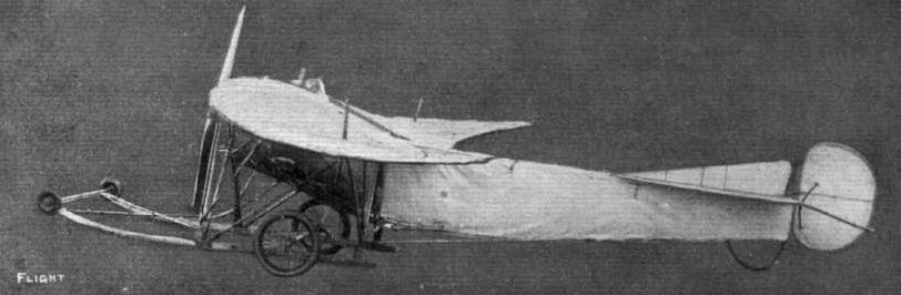
Side view of the Weiss monoplane, showing the upturned wing-tips.
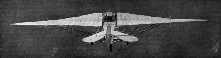
Rear view of the Weiss monoplane.
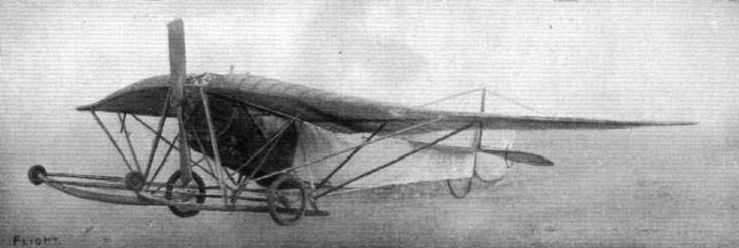
Front view ot the Weiss monoplane.
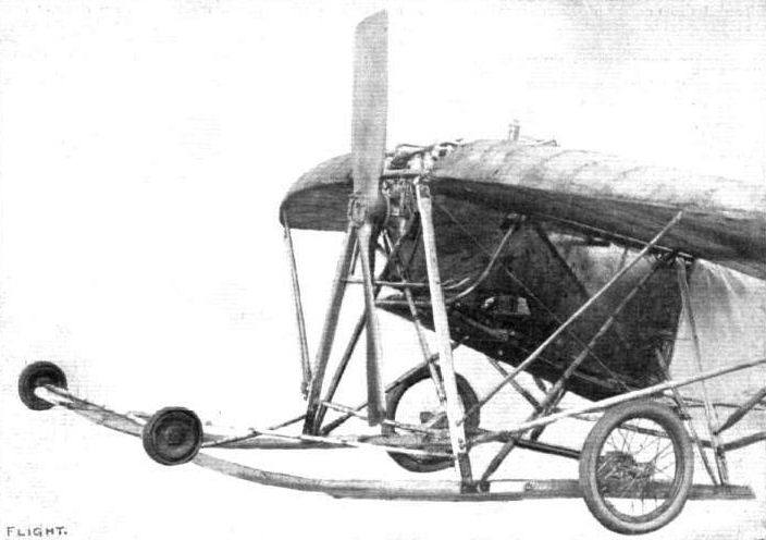
View of the front portion of the Weiss monoplane, showing the carriage.
A PASSENGER FLIGHT AT BROOKLANDS. - Lieut. Watkins, with a passenger, on Mr. Maitland's Howard Wright biplane, making one of his graceful flights past the hangars. At temporary rest is the Weiss monoplane.
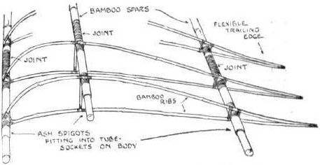
Sketch illustrating the wing framework on the Weiss monoplane.
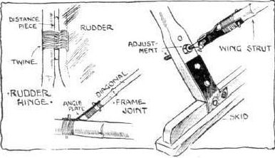
Sketch illustrating some lashed joints used In the construction of the Weiss monoplane. The lashing is coated with tyre cement.

Sketch illustrating some lashed joints used In the construction of the Weiss monoplane. The lashing is coated with tyre cement.
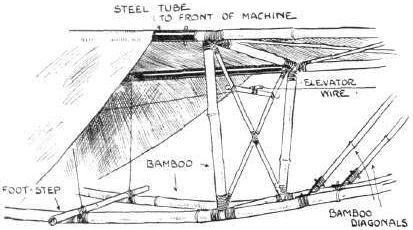
Sketch illustrating the body construction of the Weiss monoplane. Spars and diagonals are made of bamboo.
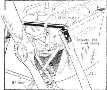
Sketch illustrating how the engine is carried in the Weiss monoplane.
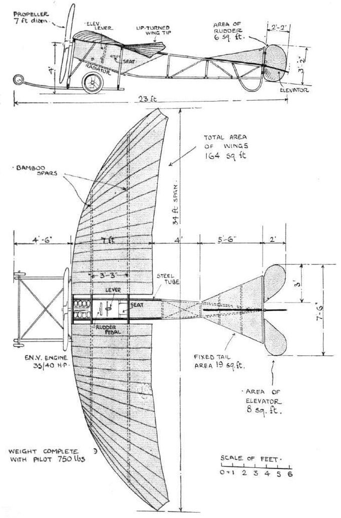
THE WEISS MONOPLANE. - Plan and elevation to scale.
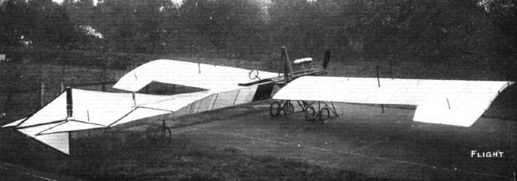
A monoplane recently constructed by Messrs. Wilson Bros, and Gibson, of Twickenham, to their own design, and sold to Messrs. Allan Knight and Co. for practice on the London Aviatron Ground, Ealing. The span is 46 ft.
Flight, November 18, 1911.
FOREIGN AVIATION NEWS.
Flying Round Berlin.
ON Monday Pietschker, accompanied by Lieut. Schwarz on an Albatross biplane, started from Johannisthal and making his way round the north of Berlin, flew to Potsdam. Proceeding on his way to the south of the German capital, he landed at Schulzendorf in order to visit a friend, and then steered his way back to Johannisthal via Telton and Templehof, having taken 1 hr. 40 mins. for the round trip.
AN INCIDENT DURING THE RECENT JOHANNISTHAL FLYING WEEK. - Photograph taken from Pietschker's aeroplane, before he met with his death, of the Johanntsthal aerodrome and of Miss Melli Beese flying on her aeroplane.
Six types of landing gear at the Paris Aero Salon.

One of the two German aeroplanes at the Salon - the Albatros biplane.
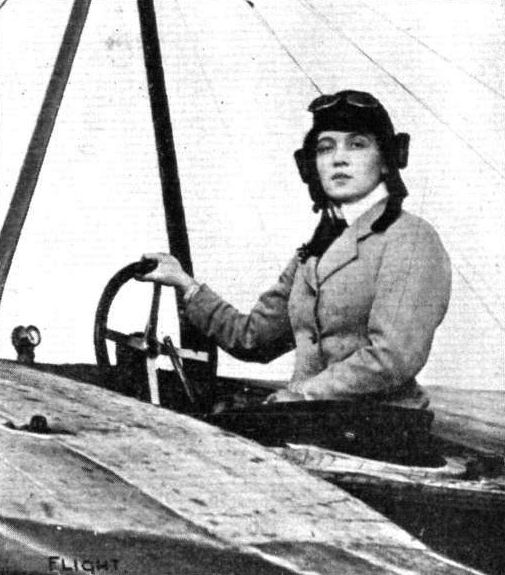
Miss Nellie Beese, the first German lady flyer who has secured her pilot's certificate. This she recently gained on a Rumpler Taube monoplane at the Johannisthal aerodrome, near Berlin.

The Harlan monoplane at the Johannisthal Aerodrome with Grulich in the pilot's seat, who, on this machine on January 8th, flew for 2h. 11m. 15s.
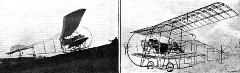
A "ONE AND A HALF DECKER" CONSTRUCTED A T THE GERMAN MOTOR SCHOOL AT MAINZ. - The top plane measures 10 metres and the lower one 7 metres.
Flight, January 28, 1911
ELY'S FLIGHT TO WARSHIP'S DECK.
THE recent demonstration by Mr. Eugene B. Ely of the possibility of aeroplanes working in conjunction with the Naval arm of the service has brought home to the authorities more rapidly the importance of flying machines as an auxiliary for scouting purposes than the most sanguine enthusiasts could have hoped for. It will be recollected that last year in FLIGHT. Mr. Griffith Brewer put forward his views and suggestions in regard to the attempting of this feat, when, as he pointed out, there was little doubt that sooner or later it would be accomplished and ultimately become an everyday event. It is only recently that we reported a more or less successful attempt from America in this connection, and by Mr. Ely's work on Thursday, the 19th inst., in San Francisco on a Curtiss biplane, it has now been finally proved that there are no insurmountable difficulties in utilizing aeroplanes for the Navy in practical work which may very greatly assist Naval commanders in settling their line of action when engaged in some important movement. Rising from Selfridge Field, near San Francisco, Mr. Ely, after flying over the city and the warships in the Bay, finally came to rest on the deck of the cruiser "Pennsylvania," where a special landing superstructure had been previously erected, similar to the one which was illustrated in FLIGHT on November 26th last.
He started at 10.45 and was flying over the Bay within a few minutes, and although it was misty he continued his flight at a fairly low altitude, ultimately sighting the "Pennsylvania," with which vessel he was kept in touch by the hooting of the siren. Before actually coming to rest on the deck of the vessel he flew past her for some hundreds of yards, then, circling back, he rose comparatively slowly, keeping up to the wind towards the stern of the vessel and finally settling down with skilful judgment on the special platform. The successful issue of the attempt was announced by the blasts of the "Pennsylvania's" siren, this being taken up by the whole of the vessels in the harbour. The wooden superstructure measured 130 ft. by 50 ft. wide, and when the Curtiss machine first touched the deck she was travelling probably at 40 miles an hour. A series of rope brakes weighted with sand bags were so arranged that they were caught in special hooks attached to the biplane and gradually brought the machine to rest within about 60 ft. from first contact. The entire flight occupied about 16 mins. In exactly 1 hour after a lunch in his honour, provided by Captain Pond, Ely once more took his seat on the Curtiss and was immediately away again at high speed, with a gentle drop towards the water before rising high over the ships in the harbour, back on his return journey to Selfridge Field, passing en route at an altitude of about 2,000 ft. over San Francisco. On alighting he was vociferously cheered by the officers of the 13th U.S. Infantry Regiment, who were in camp on the field.
Flight, February 18, 1911.
AEROPLANE SCOUTING IN ACTUAL WARFARE,
WHAT no doubt must be regarded as the first time of using an aeroplane in actual warfare, is reported in connection with the Mexican rebellion now in progress. Mr. Harry Harkness, on his Antoinette, under an arrangement with a patrol of American cavalry, which is watching the Mexican boundary to prevent any of the insurgents crossing into the United States, flew from San Diego, California, to Juana, a distance of about 40 miles, carrying with him a message to the patrol. In connection with this work the American War Department have granted L5,000 in order that Lieut. Foulois, U. S. Army, may carry out some practical tests with the Government aeroplanes of scouting in the neighbourhood. Mr. Glenn Curtiss, who is at San Diego, where he has established an aviation school, has once more offered his services, with three of his machines, to the War Department for scouting experiments.
Mr. Charles Hamilton on his aeroplane is, however, the first man to have actually flown over a town whilst under siege, he having on Friday of last week passed twice round Ciudad Juarez in Mexico, which is under siege by the Mexican insurgents, and then returned across the American frontier with a graphic account of the conditions of the city which he had observed. Although it was arranged with the attacking Mexican force that the aeroplane was not to be fired upon, there was nothing known as to what would be the behavior of the besieged Mexicans. Probably had they not been so unexpectedly scared by the sight of Hamilton's biplane, "Black Demon," suddenly appearing over their heads, giving visions of bomb-dropping, he might possibly have had a different tale to tell than the successful return across the border, as with extraordinary but almost foolhardy enthusiasm, he descended quite low over the besieged town, certainly to within 400 ft. of the troops.
Flight, July 8, 1911.
FOREIGN AVIATION NEWS.
Flying over Niagara.
OF course it was inevitable that some daring and foolhardy aviator should flirt with death on an aeroplane above the rapids of Niagara, and no one can but deplore the pity of it. Starting from a field about a mile below the falls, Lincoln Beachy on his biplane first flew over the falls, and then turning, dipped down and swooped under the upper steel bridge spanning the gorge, which at this point is about 100 ft. wide and 70 ft. high. Rising rapidly, he cleared the trees at the top of the gorge and landed on the Canadian side. It is hardly to be wondered at that the machine tipped and swayed in a perilous manner during the trip, and the spectators were greatly relieved when the exploit was over.
Flight, September 2, 1911.
Flying in Canada.
I am sending you herewith photographs of the first aeroplane flights in Saskatchewan. These were made this week by "Bob" St. Henry on a Curtiss biplane at the Dominion Exhibition, which is being held in Regina this year. He gave exhibition flights on five evenings; these mostly consisted of circular flights in front of the grand stand. On one of his flights he went from the Exhibition grounds to the Parliament Buildings, where he circled the dome at a height of 250 ft., and then returned to the grounds again - the whole trip being about four miles.
He was most successful throughout, and was, without doubt, the star attraction of the Exhibition.
Regina, Saskatchewan, Canada. CARL P. RICHARDS.
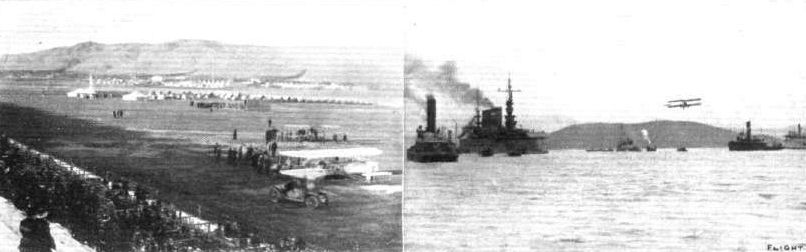
The Selfridge Military Camp, San Francisco, from and back to which Eugene Ely flew on his Curtiss biplane when making his flight on to the U.S. warship "Pennsylvania." Note the Curtiss machine in readiness for its trip. On the right Eugene Ely is seen in flight across the sea at San Francisco, en route for the deck of the "Pennsylvania."

Mr. Eugene Ely just alighting with his Curtiss biplane on the special landing stage erected on the U.S. warship '"Pennsylvania" at San Francisco. Note the bags of sand connected up to act as brakes in stopping the aeroplane when running up the stage.
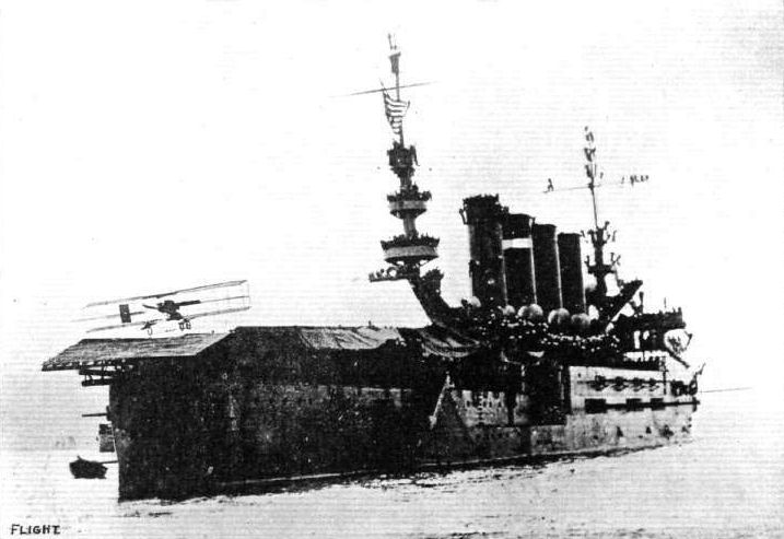
General view of the U.S. warship "Pennsylvania" at the moment when Eugene Ely was alighting on the special landing superstructure. Note the human masses of seamen manning every available inch of the vessel giving a sight of the feat.
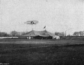
"INTERNATIONAL AVIATORS" IN AMERICA. - On the left, Hamilton starting away for his scouting trip on the Mexican frontier. The "hangar" is where the machines rest. This holds comfortably twelve machines, which are roped off for exhibition purposes.
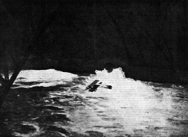
FLYING OVER NIAGARA FALLS. - It will be remembered we recently recorded the fact that Lincoln Beachey, on June 27th, flew over the Niagara cataract on a Curtiss biplane. Whatever view one may take of a feat of this character, at least the above picture records a remarkable achievement which will go down to history. The photograph shows Beachey passing under the upper steel bridge at Niagara Falls. After having circled over the cataract he then swooped down beneath the arches of the bridge and continued on down the gorge almost to the whirlpool, finally regaining terra firma on the Canadian side.
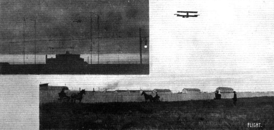
Mr. St. Henry flying on a Curtiss biplane at the Dominion Exhibition in Regina, Canada.

Eugene B. Ely. who made the remarkable flight on a Curtiss biplane on January 18th, starting from San Francisco and alighting on the deck of the warship "Pennsylvania" standing 13 miles out at sea, and then returning to his starting place. Beside him is Mrs. Ely.
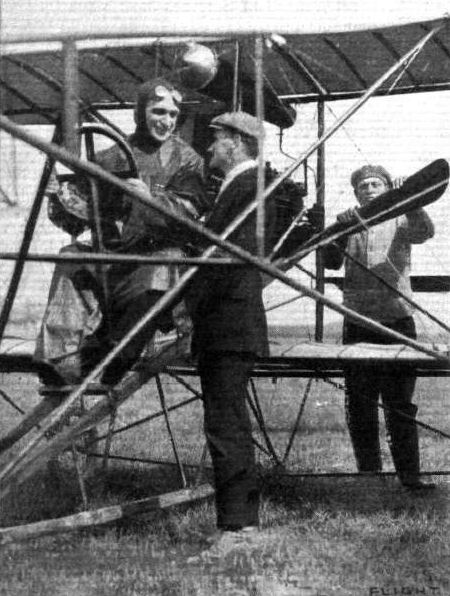
John Wilmer sends us greeting from Plattsburg, N.Y., in the above photograph, as '"From the man who fell from the balloon last October 2nd, I fly at Ottawa County State Fair, week September 11th."
Flight, February 25, 1911
RISING FROM THE WATER BY AEROPLANE.
ALTHOUGH according to "authority" no advance has been made in aviation since the Wright Brothers first flew, there are some who consider the feat of Mr. Glenn H. Curtiss, on January 26th last, in rising from the surface of the bay at San Diego, California, on his experimental hydro-aeroplane, as some slight encouragement to others to try and help towards advancing aviation beyond the early Wright stages. At the time we made a brief note of the cabled information and further details are now to hand in regard to this very practical work in helping forward the art. The machine, fitted with special pontoons, was pushed into the water from the shed erected upon the beach near to the Army and Navy Aviation School recently established by Glenn Curtiss. The engine having been started, the aeroplane at once moved away steadily towards deep water. Gaining speed, the pontoons began to rise in the water until it was seen that the main support by this means on the water was practically gone. The head resistance and skin friction being thus reduced, speed rapidly increased, and Curtiss, tilting the lifting plane well up, the machine rose from the water almost as easily as leaving the ground. After rising to a good altitude, Curtiss veered round on his aeroplane towards deep water, and after a few seconds aloft, again came down quite gracefully on the water. For a first effort this was a great achievement. For the second flight, after a short run on the surface, he again ascended, circling over the channel, and re-alighted after being in the air for 1 min. 21 secs. During the day two more experimental flights followed, and on the next day he went up off the water, remaining aloft 3 1/2 mins., and he was satisfied upon this occasion that he could have remained in the air carrying his pontoons just as long as his fuel lasted. On the 21st inst. he was again up and flew for 5 miles over the sea. The balance appeared to be quite as perfect with the addition of the pontoons as when on wheels, and the 8-cyl. 50-h.p. Curtiss engine maintained its reputation for reliability without a hitch.
The following particulars of the pontoons and scheme of the machine are given by the Scientific American :-
The pontoons or hollow hydroplanes developed by Curtiss are of peculiar construction, altogether different from many newspaper illustrations of his remarkable flights at San Diego. In reality, after a speed of 30 miles an hour is reached, the main pontoon sustains the machine. This apparatus is constructed of steel sheets laid over a wooden framework. A horizontal cross-section, midway between top and bottom, would show a perfect parallelogram 6 ft. from side to side and 7 ft. from front to rear. At the rear is a "tail," 8 ins. deep, extending the full width of the pontoon. The greatest depth of the pontoon (at the centre) is 16 ins. between surfaces. As attached to the frame of the aeroplane, it is inclined slightly upward, so that when full speed is attained just before leaving the water, practically the only part submerged is the extreme rear of the pontoon and the "tail."
This pontoon takes the place of the two rear wheels on the Curtiss type of aeroplane, and it acts with a hydroplane effect, rising to the surface of the water as the speed increases.
In front of the main pontoon, at the point where the single wheel is attached on the ordinary land machine, is fixed a small pontoon or "shoe" of approximately the same shape, 18 ins. wide, 40 ins. long, and 6 ins. deep. This pontoon answers the same purpose on water that the forward wheel does on land. Above the front pontoon and a little forward is a canvas-covered water shield 6 ft. wide and 2 ft. high, tilted at an angle of 45°. This apparatus is to protect the aviator and machinery from the upward swish of the water; also to add to the buoyancy of the machine in case of a sudden tendency to dive.
At the extreme forward end of the framework, and at about 1 ft. lower level than the front of the small pontoon, is attached a wooden hydroplane, 6 ft. long, 8 ins. high and 11/2 ins. thick. This is tilted at an angle of about 250 and is intended to aid in lifting the forward part of the machine when it is under way. The forward elevating plane, ailerons, main planes and rear control are the same as the ordinary type of Curtiss racing biplane, the main planes having a spread of 26 ft. and a width of 4 ft. 9 ins. The speed in the air is from 50 to 55 miles an hour.
On Friday of last week Mr. Curtiss publicly proved again the value of his hydroplane when used for practical flight in connection with war vessels, demonstrating inter alia that a specially constructed platform on a ship's deck is not in any way necessary for rendering the aeroplane of practical use to the Navy. Using his special hydro-aeroplane, he made a flight towards the cruiser "Pennsylvania" and alighted on the water close alongside the vessel. His machine was then hauled on board and presently dropped back again into the water, Curtiss once more rising' into the air with the greatest ease and returning by the air back to his shed.
All this must indeed gladden the heart of Admiral Sir E. H. Seymour, who, at the Royal Aero Club dinner recently, stated that he was greatly impressed by the fact that Mr. McCurdy, in his Havana flight, was able, when his engine stopped, to alight on the water with his machine without any fear of the whole arrangement sinking, including himself. This further evidence of the practical work obtainable from aeroplanes should still more bring home its lesson.
Flight, August 19, 1911.
The U.S.A. Hydro-Aeroplane.
WITH Lieut. T. G. Ellyson and Capt. Paul W. Bick on board, some interesting trials were carried out over Lake Keuka on the 24th ult. with the Curtiss hydro-aeroplane, built for the United States Government. Both on the water and in the air the officers handed the control from one to the other without any difficulty.
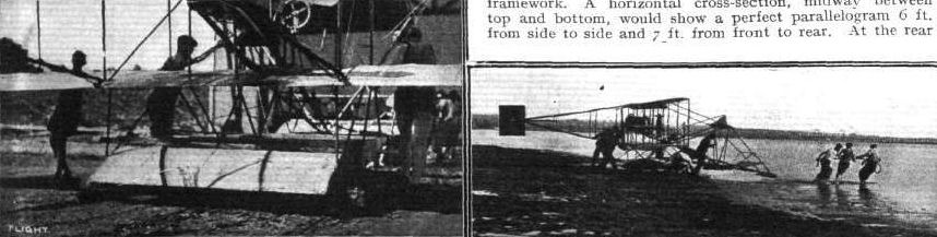
GLENN CURTISS' START OFF WATER. - On the left the main pontoon is seen, and on the right the biplane is being towed on to the water for the first trial.

A good idea of the general arrangement of the two-seated hydroaeroplane built for the U.S. Navy by Glenn H. Curtiss. It is fitted with duplicate controls, the ailerons being operated by shoulder-braces, while the steering-wheel is hinged so that it may be passed from one to the other by the two occupants of the machine.
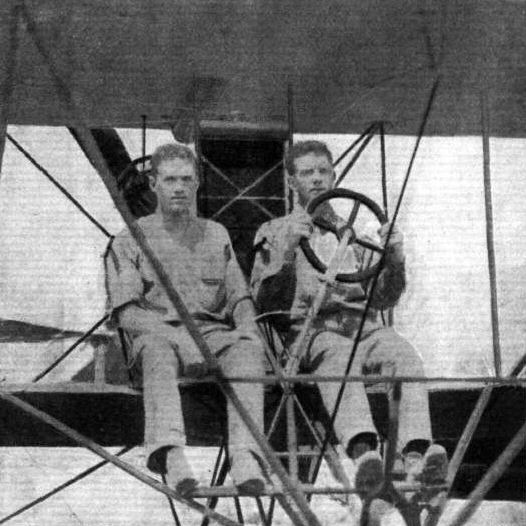
Lieuts. Ellyson and Towers on the new Curtiss hydroaeroplane of the U.S. Navy. The braces operating the ailerons can be seen on the shoulders of both officers, while the arrangement of the swinging steering-wheel is also clearly seen.
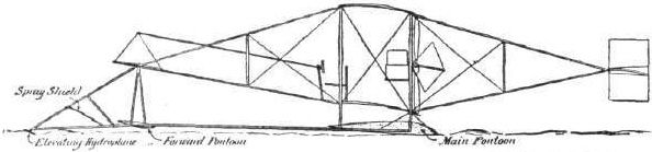
GLENN CURTISS' START OFF WATER - Sketch showing the position of pontoons at the instant of rising from the water.
Flight, October 21, 1911.
AIR EDDIES.
It is stated in America that Grahame-White is going to fly the Martin biplane, equipped with a Gnome motor of 100-h.p., which is illustrated in another part of this issue, and that he intends, on this machine, to make an attempt on the world's speed record.
James V. Martin, a former pupil of Mr. Grahame-White, who is responsible for the design and construction of this biplane, makes no attempt to hide the fact that most of the ideas embodied in his machine were secured from that exceptionally efficient biplane - the Avro.
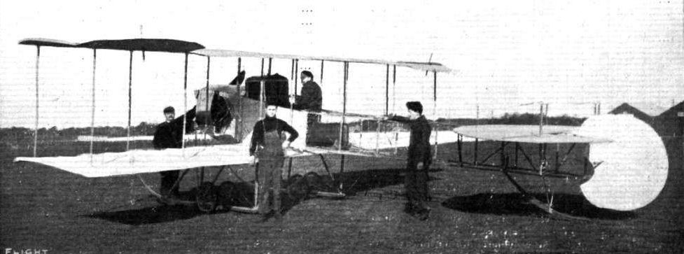
J. V. Martin, who graduated in aviation at the Grahame-White School at Hendon, at the helm of the new 100-h.p. Gnome-engined Martin biplane, which the Queen Aeroplane Co., of New York, have constructed to his designs. On this machine Martin himself has put up a speed of 72 miles per hour flying across country.
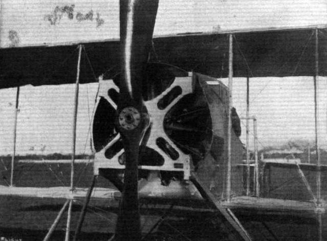
The mounting of the 100-h.p. Gnome motor on the new Martin biplane.
Flight, November 11, 1911.
Death of J. T. Montgomery.
WE regret having to record the death of Prof. John f. Montgomery, of California, which took place while he was experimenting with his gliders at Santa Clara. One of the earliest practical workers, and also one of the closest students of the science, Mr. Montgomery was, perhaps, best known to the public through the experiments made with his Langley type gliders by Maloney, who launched himself into the air on these machines after ascending with them attached to a balloon.
Flight, November 25, 1911.
AIR EDDIES.
In connection with the death of Professor John J. Montgomery, of Santa Clara College, who succumbed on October 31st to injuries received while conducting further experiments with his gliders, it is interesting to recall that his double monoplane glider was, according to his claim, the first in the country to employ wing warping on cambered surfaces. With this glider he met with a tremendous amount of success, and during the year 1905 glides of long duration from various heights up to 4,000 feet were made. Despite the fact that so much success was attained with this machine, all attempts to equip it with propeller and power plant during the past few years have failed. It is extremely sad to think that the work of such a clever pioneer should have been cut short by a fall from a height of only 20 feet.

The late Prof. John J. Montgomery on his glider, upon which he met his death at San Jose, California, on October 31st, as recently recorded in FLIGHT.
The only pure derivative that did fly, and looked remarkably like the original Walker, was John J. Montgomery’s glider, which the professional parachute-jumper D. Maloney launched from a hot-air balloon in California in 1905. Maloney made two hazardous landings, but on the third launch he crashed and was killed.
The only pure derivative that did fly, and looked remarkably like the original Walker, was John J. Montgomery’s glider, which the professional parachute-jumper D. Maloney launched from a hot-air balloon in California in 1905. Maloney made two hazardous landings, but on the third launch he crashed and was killed.
Flight, May 20, 1911.
Low-Powered Flight.
Under the heading of "The Dipping Front Edge," in his letter in your issue of April 22nd, 1911, "Sky Pilot" makes the statement that Mr. A. V. Roe holds the record for flying with low horse-power, viz., 9-h.p.
It may interest him to know that Mr. Sellers, of Kentucky, flies with 4-h.p., and that Mr. Gordon, of California, flies with 5-h.p. Both the above actually fly.
Your magazine improves with every issue.
New York. JOHN GUY GILPATRIC.
Flight, August 12, 1911.
Low-Powered Flight.
Since sending my last letter re low-powered flight I have written Mr. Sellers, and through his courtesy I am enabled to give you details of his machine. I enclose his letter and one of the photos which he has kindly furnished.
Port Washington, July 6th. J. G. GILPATRIC.
[Enclosure from Mr. Sellers.]
Your letter of the 20th was received on my return from New York. I am not anxious at present to make public the details of my aeroplane, but shall give you the information asked for in your letter, and, if you wish, you are welcome to send this letter to FLIGHT and that paper can publish it and the enclosed photos if desired. I did not read the article you mention so do not know what is claimed in it. The machine shown in flight in the two photographs enclosed was built in 1908. The rudder shown is only a temporary makeshift. My object in building this machine was to try out some results obtained in laboratory experiments, and incidentally to produce a light, small, slow and small horse-power machine. The first engine used was 2-cyiinder, 4-cycle, opposed, air-cooled, weight 23 lbs., bore and stroke 3 1/8 ins. giving 4-b.h.p. at 1,400; later increased to near 5-b.h.p. by auxiliary exhaust ports. Propeller 54 ins. by 24 ins. Weight of machine ready to fly, with this engine, 78 lbs. My weight 130 lbs. The present engine is of the same type but 3 5/8 in. bore and stroke, about 8-h.p.
Weight of machine with this engine = 110 lbs., propeller 66 ins. diameter by 30 ins. maximum pitch. The first engine would fly the machine but would not give enough power to climb or turn. The present engine gives plenty of power while not overheated. Both engines quickly overheat in warm weather (air cooled).
Area of this aeroplane 200 sq. ft.; planes 3 ft. by 18 ft. We timed a number of flights in still air; speed 21 miles per hour. The machine is light but has been found strong enough to stand intermittent use for two years.
Baltimore, June 29th. M. B. SELLERS.
Flight, October 14, 1911.
Low Powered Flight.
A correspondent, R.G.P., has asked for particulars of the Gordon and Sellers machines, which are notable on account of their ability to fly with small power. The Gordon machine is a familiar 2-2-P-1 Curtiss, apparently very lightly constructed.
The Sellers machine I consider distinctly novel and fairly safe. Its formula is 0-P-4-1. The main planes have a pronounced "stagger," as in the Goupy. The motor and tractor are mounted on the second plane from the bottom. I regret I am unable to furnish any dimensions, but enclose a sketch.
The machine illustrated is by no means standard; it is only one of this type used for experimental purposes by Mr. Sellers.
Port Washington, L.I., U.S.A. J. G. GILPATRICK.
Low-Powered Flight.
Under the heading of "The Dipping Front Edge," in his letter in your issue of April 22nd, 1911, "Sky Pilot" makes the statement that Mr. A. V. Roe holds the record for flying with low horse-power, viz., 9-h.p.
It may interest him to know that Mr. Sellers, of Kentucky, flies with 4-h.p., and that Mr. Gordon, of California, flies with 5-h.p. Both the above actually fly.
Your magazine improves with every issue.
New York. JOHN GUY GILPATRIC.
Flight, August 12, 1911.
Low-Powered Flight.
Since sending my last letter re low-powered flight I have written Mr. Sellers, and through his courtesy I am enabled to give you details of his machine. I enclose his letter and one of the photos which he has kindly furnished.
Port Washington, July 6th. J. G. GILPATRIC.
[Enclosure from Mr. Sellers.]
Your letter of the 20th was received on my return from New York. I am not anxious at present to make public the details of my aeroplane, but shall give you the information asked for in your letter, and, if you wish, you are welcome to send this letter to FLIGHT and that paper can publish it and the enclosed photos if desired. I did not read the article you mention so do not know what is claimed in it. The machine shown in flight in the two photographs enclosed was built in 1908. The rudder shown is only a temporary makeshift. My object in building this machine was to try out some results obtained in laboratory experiments, and incidentally to produce a light, small, slow and small horse-power machine. The first engine used was 2-cyiinder, 4-cycle, opposed, air-cooled, weight 23 lbs., bore and stroke 3 1/8 ins. giving 4-b.h.p. at 1,400; later increased to near 5-b.h.p. by auxiliary exhaust ports. Propeller 54 ins. by 24 ins. Weight of machine ready to fly, with this engine, 78 lbs. My weight 130 lbs. The present engine is of the same type but 3 5/8 in. bore and stroke, about 8-h.p.
Weight of machine with this engine = 110 lbs., propeller 66 ins. diameter by 30 ins. maximum pitch. The first engine would fly the machine but would not give enough power to climb or turn. The present engine gives plenty of power while not overheated. Both engines quickly overheat in warm weather (air cooled).
Area of this aeroplane 200 sq. ft.; planes 3 ft. by 18 ft. We timed a number of flights in still air; speed 21 miles per hour. The machine is light but has been found strong enough to stand intermittent use for two years.
Baltimore, June 29th. M. B. SELLERS.
Flight, October 14, 1911.
Low Powered Flight.
A correspondent, R.G.P., has asked for particulars of the Gordon and Sellers machines, which are notable on account of their ability to fly with small power. The Gordon machine is a familiar 2-2-P-1 Curtiss, apparently very lightly constructed.
The Sellers machine I consider distinctly novel and fairly safe. Its formula is 0-P-4-1. The main planes have a pronounced "stagger," as in the Goupy. The motor and tractor are mounted on the second plane from the bottom. I regret I am unable to furnish any dimensions, but enclose a sketch.
The machine illustrated is by no means standard; it is only one of this type used for experimental purposes by Mr. Sellers.
Port Washington, L.I., U.S.A. J. G. GILPATRICK.
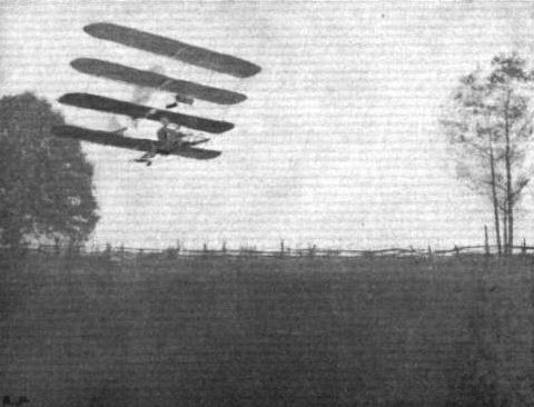
Mr. Sellers' low-powered quadruplane in flight.
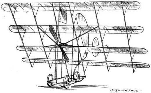
Flight, January 7, 1911
FOREIGN AVIATION NEWS.
Activity at Juvisy.
AVIATOR Weiss has now turned his attention to the Sloan aeroplane, with which he has been making some successful flights at the Juvisy aerodrome. On the 31st ult. he was in the air for an hour and a half, and on the previous day for half an hour.
<...>
FOREIGN AVIATION NEWS.
Activity at Juvisy.
AVIATOR Weiss has now turned his attention to the Sloan aeroplane, with which he has been making some successful flights at the Juvisy aerodrome. On the 31st ult. he was in the air for an hour and a half, and on the previous day for half an hour.
<...>
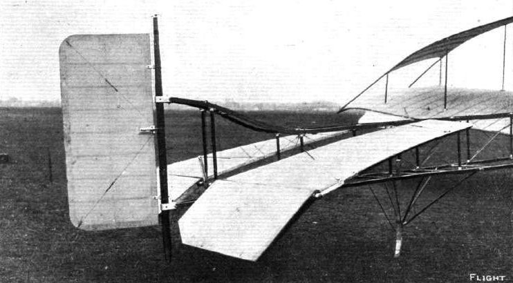
Tail of the Sloan biplane.
Flight, March 11, 1911
A COAL CITY BIPLANE.
AN interesting set of photographs reaches us from Coal City, Illinois, showing the good aviation work in progress in that district. Mr. William E. Sommerville, who is Mayor of the town and is the builder and pilot of his own machine, sends us at the same time the following interesting description and details:-
"The total area is 510 sq. ft. Total weight, 1,020 lbs. The upper main plane is 45 ft. by 5 ft. The lower 35 ft. by 5 ft. The tail, 8 ft. by 5 ft., is placed 18 ft. back of the trailing edge. The elevator, 3 ft. by 10 ft., is 10 ft. ahead of the leading edge. The engine has 4 cyls., 4-cycle, 5 ins. by 5 ins., developing 40-h.p. at 1,000 revs, per min., propeller 7 ft. by 6 ft. pitch, flying angle 50. It will be seen from the photos that the top main plane has upturned ends, also a fin placed on top. I have found that the upturned ends and the central fin are sufficient to maintain lateral stability. In calm weather I had no use for the Venetian blind arrangement situated near the extremities of the top plane, but with a breeze the machine rocked a little, so I opened the blind on the high side, and the machine immediately regained an even keel. I am positive, as soon as I get accustomed to being in the air, the blinds will not be required, as the upturned ends and the central fin will maintain lateral stability automatically. During September a few short flights were made, and on October 1st a flight of two miles was made, and the machine flew as if on rails. The flight terminated when the engine went all to pieces. The great difficulty in this country experimenters meet with is in the securing of a reliable engine. I am building an engine myself, and expect to be flying next month. I have also built a monoplane, with upturned ends and central fin, and expect to test it soon. My biplane was built in 1909, but owing to the difficulty of getting an engine same was not tested until late this summer.
"I am sure that a flying machine can be designed that will be automatically stable, and a few improvements on the design shown will accomplish it."
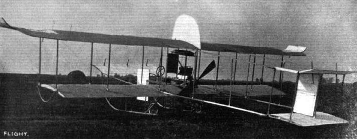

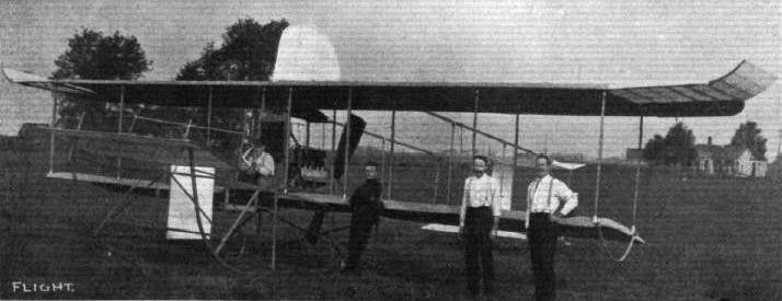
Mr. W. E. Sommerville and his biplane.

THE WRIGHT GLIDER IN OPERATION BY ORVILLE WRIGHT AT KILL DEVIL HILL, NORTH CALIFORNIA. - The photograph was taken from beneath, during the time when the glider was stationary in the air.
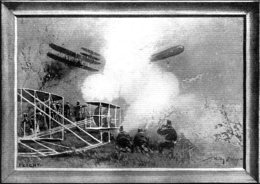
A PEEP INTO THE POSSIBLE FUTURE. - An up-to-date method in Germany of advertising the German-built Wright flyers under the legend of "Wrights to the Front."
Flight, January 7, 1911
Death of Moisant and Hoxsey.
THE closing day of the Old Year saw the names of two of America's foremost aviators added to the list of victims of dynamic flight, one of the two men being well known here by reason of his exploit in flying from Paris to London last year. At Harahan, on the banks of the Mississippi, not far from New Orleans, Mr. J. B. Moisant set out on a Bleriot monoplane in an attempt for the Michelin Cup, the flight being witnessed by an official representative of the Aero Club of America. The accident occurred during a preliminary trial to test the machine, when, after circling the ground twice, the monoplane was seen to dip its head and drop down from a height of 100 ft. The aviator was pitched out of the machine, and, when picked up, was still alive. He was hurried on a special train to New Orleans, but, unfortunately, died before reaching there. As to the cause of the accident nothing is known definitely; but it is pointed out that the position of the course is an extremely dangerous one, owing to the tricky air currents and the gusty winds.
Mr. A. Hoxsey, who carried Mr. Roosevelt for a short aerial trip last autumn, was the victim of the second accident, which occurred at Los Angeles while the aviator was attempting to better his height record of the previous Monday. He had gone up to a great height and was descending in a series of spiral glides for which he was famous, when at a height of about 300 feet the machine was caught by a sudden gust of wind and overturned. In its rush to the earth the machine again turned over twice, but the aviator retained his seat and was apparently killed by the motor falling upon him. Here again the accident was probably caused by the tricky nature of the course, both Latham and Willard having given over flying for the day owing to the prevalence of dangerous air pockets.
Flight, April 1, 1911.
Third International Aero Exgibition at Olympia - 1911.
THE EXHIBITS ANALYSED.
<...>
The Wright biplane in its present form is characterised by the absence of any front elevator and by the use of a nonlifting tail. Practically, the machine is in balance about the centre of pressure with the pilot on board, and, indeed, the spiral draught from the propellers is enough to upset this balance through its influence on the tail plane.
<...>
Flight, October 7, 1911.
Captain Englehart Fatally Injured.
ON Friday, owing to a disaster which accounted or the death of Captain Englehart, flying at the Johannisthal Meeting was stopped for the day. Piloting one of the German Wright machines, and carrying with him Herr Scdlemayr, another aviator, Englehart took the air at 3.21, in spite of a very treacherous and gusty wind. Flying low and finding the pockets very disconcerting, he rose to a height of 30 metres. At 4.26 it was noticed that something was wrong, and apparently one of the propellers had broken in somewhat similar manner to the accident which overtook Henn in the spring of last year. The machine turned over and crashed down to the earth with its two occupants. Captain Englehart was apparently killed almost instantaneously, but Sedlemayr, his companion, was more fortunate, and was at once taken to hospital, where ultimately his injuries were found to be not of an extremely serious nature, and it is hoped he will at least survive. Captain Englehart was one of the finest, although very daring, pilots in Germany. He was the third certificated aviator, dating from March of last year, and was the chief pilot of the German Wright school, having given up his position as Aide-de-Camp to the Prince Imperial for the purpose of devoting his efforts to aviation.

TWO REMARKABLE SNAPSHOTS OF WRIGHT MACHINES IN FLIGHT. - That on the left shows Walter Brookins in the course of making a complete circle in 6 2/5 secs., while the photograph on the right was taken of Hoxsey's machine during the fearful plunge, following a "trick" descent, which caused the aviator's death.
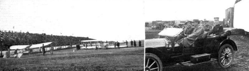
SAN FRANCISCO AVIATION MEETING. - On the left general view of the flying grounds in front of the Grand Stand, with T. Radley's Bleriot and Brookins' Wright biplane ready for flying. On the right Radley at the wheel of his car, with Hubert Latham by his side and U.S. Army officers in the tonneau.

The late Capt. Englehard, who was recently killed at Johannisthal, looking over his German-Wright machine before making a flight at the German aerodrome.
Flight, March 18, 1911
THE "BABY" WRIGHT.
THE accompanying sketch shows a "model R" Wright biplane which is a much smaller and lighter type than the standard model and is designed especially for speed and altitude work.
The design was, in fact, the result of the investigations and calculations made by the Wright Bros, when considering the question of building a defender for the Gordon-Bennett Aviation Cup last year. It carries no passenger except the pilot but is equipped with the usual Wright engine and control. It was this machine that was used by Johnstone when he ascended to 9,714 ft. at Belmont Park on October 31st, 1910. The span is 20 ft. 6 ins. and the chord 3 ft. 7 ins. The overall length is 24 ft. and the overall height 6 ft. 6 ins. The weight is 585 lbs. and the engine is of the four-cylinder vertical type having a bore and stroke of 4 3/5 ins. by 4 ins., rated at 30-35-h.p. and weighing 180 lbs.
One of these machines, that which was used by Mr. Alec. Ogilvie in the Gordon-Bennett race, will be on view at the Olympia Show, where it will be staged on one of the Royal Aero Club's stands. In America this machine sells for the same price as the standard model, which is $5,000.
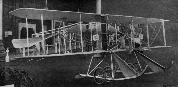
Mr. Alec Ogilvie's Baby Wright, the smallest machine in the Show. The propellers are the same as those used on the standard model, and together spread across the full span of the machine. An N.E.C. two-stroke engine is htted In this model, which is otherwise the same as that with which Mr. Ogilvie competed on behalf of England in the Gordon-Bennett Race.
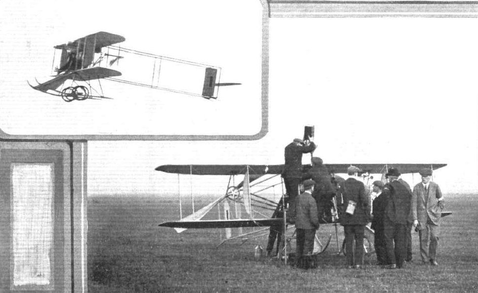
GORDON-BENNETT RACE AT EASTCHURCH. - Mr. Alec Ogilvie's N.E.C.-engined "Baby" Wright fills up with petrol. Above, Mr. Ogilvie is seen in his steady flight round the course.
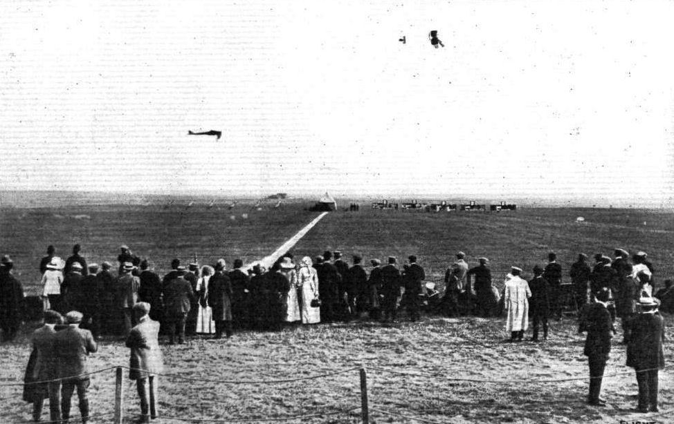
GORDON-BENNETT RACE AT EASTCHURCH. - The starting line which the competitors had to cross in flight, as seen from the Press enclosure. At the other end of the line is the Judges' box, and right and left the scoring boards and public announcements. In the air above Mr. Alec Ogilvie is seen on his N.E.C.-engined "Baby" Wright, and below, Weymann, the winner, on his Nieuport monoplane.
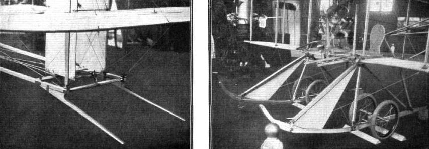
UNDER-CARRIAGES AT OLYMPIA. - The tail skids and the wheels and front skids of the Wright Baby.
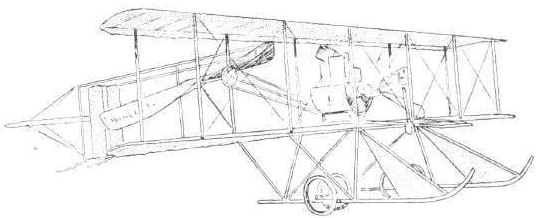
UNDERCARRIAGES AT OLYMPIA. - Comparative details in the construction of the Farman type wheel and skid combination.
Flight, January 7, 1911
The Fatal Accident to Laffont.
UNFORTUNATELY, the competition for the A.C.F. Grand Prix has been marred by a fatal accident by which both the pilot and the passenger were killed. The pilot was Laffont, who had been remarkable for his careful and steady flying of the Antoinette monoplane. He had succeeded Labouchere as the chief instructor at the Antoinette School at Mourmelon, and had been persuaded by one of his pupils - Mario Pola, a young Spanish sportsman - to make an attempt for the Paris to Brussels flight The machine, which belonged to the latter, was taken to Issy, and on the 28th ult. a start was decided upon. Upon testing the engine this did not give satisfaction, but after adjusting everything was pronounced to be ready. Laffont took the machine up for a short trial flight, and as everything seemed to be right the passenger took his place, and the two aviators set off for a preliminary turn round the aerodrome. Three circuits had been covered, and the fourth was just being commenced when the machine swerved towards the centre of the ground, and although the aviator was obviously struggling to regain control of the aeroplane, one of the planes became detached, and the machine fell rapidly to the ground from a height of 500 ft. Both the occupants were killed instantly, while the machine was simply a mass of twisted iron and splintered woodwork. The cause of the disaster is unknown, but some of the aviators who witnessed the mishap give it as their opinion that it occurred through the steering wires becoming jammed.
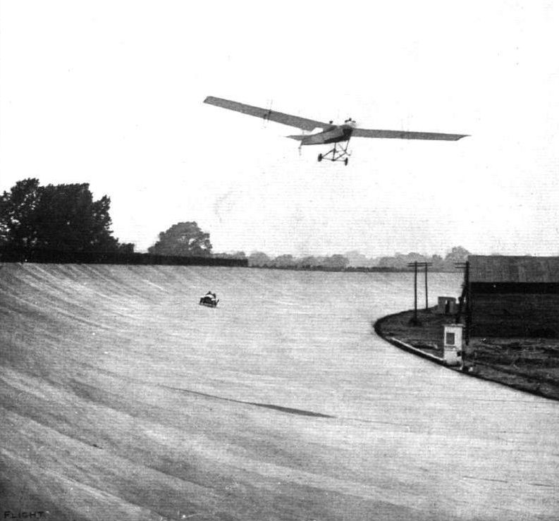
MONOPLANE VERSUS 60-H.P. CAR. - Last week at Brooklands a test of speed was tried between Mr, Hubert Latham on an Antoinette monoplane and Mr. Gordon Watney on a 60-h.p. Mercedes car. In our photograph, which is a specimen of an "unfaked" negative, the race in progress is seen.
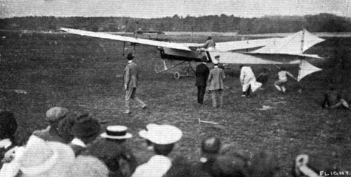
Rene Labouchere at Brooklands just released for a flight on his Antoinette monoplane.
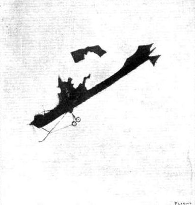
Remarkable "snap" of the Antoinette monoplane in midair during the recent disastrous and fatal accident to MM. Laffont and Mario Pola, showing a portion of the planes torn completely away. The tractor-screw, it will be seen, is still in revolution.
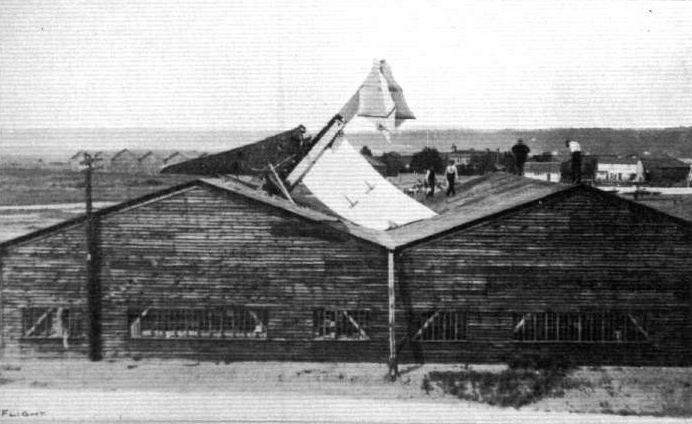
Mr. Hubert Latham's Antoinette after its unconventional "call" at the Martin-Handasyde hangar on Whit-Monday at Brooklands. Mr. Latham was quite unhurt.
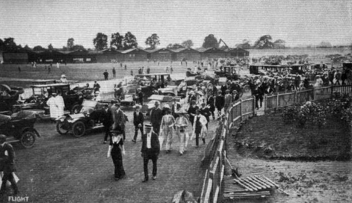
ON THE BROOKLANDS AVIATION GROUNDS ON WHIT-MONDAY. - Note Latham's smashed machine still "in place" on the root of the right end shed.
Flight, September 30, 1911.
FOREIGN AVIATION NEWS.
The New Antoinette Tested.
ON Sunday afternoon the new Antoinette machine illustrated in these pages the other day, and built for the French Army Competition, was put through some tests at Mourmelon, and, as far as can be gathered, gave every satisfaction.
FOREIGN AVIATION NEWS.
The New Antoinette Tested.
ON Sunday afternoon the new Antoinette machine illustrated in these pages the other day, and built for the French Army Competition, was put through some tests at Mourmelon, and, as far as can be gathered, gave every satisfaction.

LATHAM'S ANTOINETTE FOR THE MILITARY COMPETITION. - General view from the rear of this new machine which embodies a good many departures from previous Antoinette practice. The body is entirely enclosed, as also is the 100-h.p. Antoinette engine. The body has been so designed that the pilot has a complete range of vision, windows in the floor enabling him to see beneath him. The span of the machine is given as 15.9 metres, and the surface 56 sq. metres. The overall length is about 11 1/2 metres. The chord of the main planes is 4 metres at the junction with the fuselage, and decreases to 3 metres at the tip. The machine in flying order weighs 1,250 kilogs.

DETAlLS OF THE NEW ANTOINETTE. - On the left is seen the fore part of the new machine, showing the way in which the landing chassis is fitted under the wings and is enclosed. This also indicates the location of the 100-h.p. Antoinette engine inside the boat-shaped body and also the shape of the main planes, the trussing of which is all arranged Internally. The landing skids are 3.25 metres long, and each one is fitted with four wheels, two at each end. The view on the right shows the arrangement of the tail and the way in which the fixed plane can be adjusted, while the two landing wheels are also observable.
Flight, September 9, 1911.
FOREIGN AVIATION NEWS.
The Astra Triplane at Issy.
BOTH the new biplane and the triplane produced by the Astra Works have been tested nearly every day during the past week at Issy. Only straight flights have been made with the triplane, but the double-decker was taken round the ground several times on Monday by Goffin, who is conducting the tests.
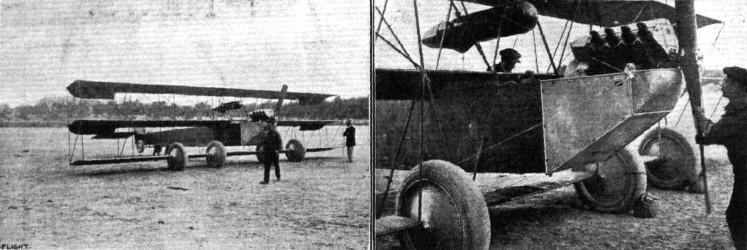
A TRIPLANE, ONE OF THE LATEST PRODUCTIONS OF THE ASTRA COMPANY. - This is another of the machines designed in view of the French military aeroplane competition. The canoe type of body is similar to that of the latest biplane, but other special features are the design and arrangement of the wheels. The span is 12 metres, and the lifting surface 45 sq. metres, while the propeller is driven by a 60-h.p. 8-cyl. Renault motor.
Flight, September 9, 1911.
FOREIGN AVIATION NEWS.
The Astra Triplane at Issy.
BOTH the new biplane and the triplane produced by the Astra Works have been tested nearly every day during the past week at Issy. Only straight flights have been made with the triplane, but the double-decker was taken round the ground several times on Monday by Goffin, who is conducting the tests.
Flight, December 30, 1911.
PARIS AERO SHOW.
Astra.
THIS interesting three-seater tractor biplane, which made its appearance in the French aviation arena just prior to the Military Trials at Rheims, gives me an impression of immense strength, solidity, and power when compared with those light speed craft which form such a great percentage of the exhibits at the Salon. Its fuselage, which is divided and made detachable for convenience of transport at a point to the rear of the pilot's seat, is triangular in section, and built throughout in ash, with the exception of the forward portion, which is cross-strutted with drilled-out steel struts of C section, so provided to strengthen the body to withstand the extra strains imposed upon it by the motor - a 100-h.p. six-cylinder Chenu. This latter drives an 8-ft. Astra tractor screw through reduction gearing. Radiators for the cooling of the motor are disposed on each side of the body in the neighbourhood of the middle seat.
The main planes, double surfaced, are built up cellular fashion and are so constructed that they may be detached, leaving a centre section about 7 ft. in width in order that the machine may be easily transported along the road.
Warping is employed for the correction of lateral balance, this being carried out on the Wrights' system, under whose licence the Astra machines are made.
The landing gear is somewhat reminiscent of Antoinette practice, and has the triple advantage of being simple, strong and presenting little head resistance. Landing shocks are taken by a large diameter Oleo pneumatic spring that forms the centre unit of the chassis. In common with many other types of landing gear at the Salon, no provision has been made to relieve any strains resulting from a sideways movement of the machine on landing, and the fact that so many designers are apparently ignoring this detail, which has hitherto been deemed a most important one, seems to demonstrate that the constructional difficulties of obtaining this accommodation for sideways strains altogether outbalances any advantages that might accrue from its adoption.
Command is maintained over the controlling surfaces from duplicated controls arranged for the use of the occupants of the two rear seats. The duty of the occupant of the forward seat is to act as observer and for this purpose he is most conveniently placed.
There was also exhibited on the Astra stand a dirigible nacelle equipped with two Chenu motors, each of 100-h. p.
Principal dimensions, &c. :-
Length 36 ft.; Weight 1,540 lbs.
Span 40 ft.; Speed 56 m.p.h.
Area 528 sq. ft.; Motor 100-h.p. Chenu.
Price L1,120
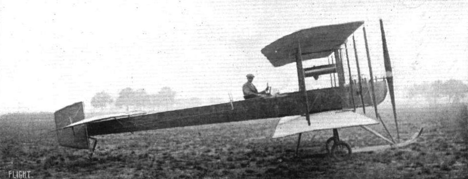
The Astra Company have just produced a biplane in which the monoplane type of body is the principal characteristic. The above side view, taken at Villacoublay, gives a very good idea of the arrangement of the new machine.
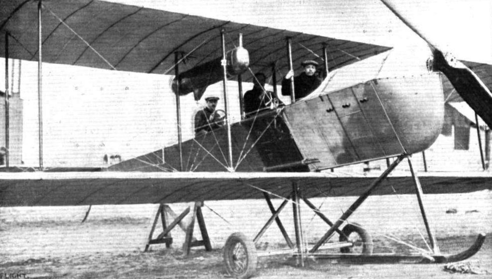
The latest Model Astra Biplane, which is representing the Societe Astra at the French Military Tests. - This machine, with the exception of the landing chassis, which is reminiscent of Antoinette practice, has a striking resemblance to the Avro biplane. It is furnished with double control, and the propulsive effort is obtained from a 75-h.p. Renault motor driving at half speed a "Normale" propeller. It will be noticed that the Horatio Phillips wing cross-section, brought into prominence by the late Edouard Nieuport, has been made use of.

This photograph of the new Astra biplane, which is upholding the credit of that firm in the French Military Tests, gives a good idea of the general disposition of this interesting machine. Seating accommodation is provided for three, one of whom has a seat right in front for observation purposes, while the two seated in tandem behind him are each provided with controls. The motor is an 80-h.p. 6-cyl. Chenu, and drives a large diameter tractor-screw through reduction gearing.
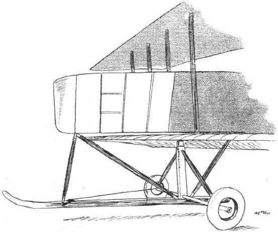
Front of the Astra biplane, showing the general disposition of the under-carriage.
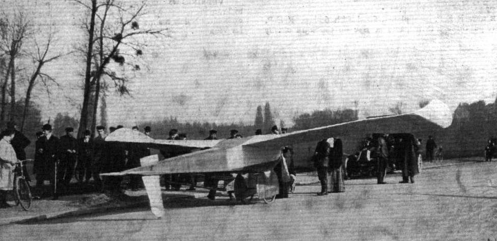
The above photograph illustrates the original monoplane tried by M. Bleriot at Bagatelle and Issy during 1907. In it the use of struts and wire ties was reduced to a minimum, and one of the characteristic features was the upturned wingtips. M. Bleriot has just built a new machine on somewhat similar lines which is to be tried shortly.
Flight, January 7, 1911
Coupe Femina.
THE competition for the Coupe Femina closed on the last day of 1910, and although Mme. Niel, Mdlle. Marvingt and Mdlle. Herveu had announced their intention of trying for the cup none of them ventured aloft, and so Mdlle. Dutrieu's record of 167.2 kiloms. in 2 hrs. 35 mins. was sufficient to easily secure for her the cup. It will be remembered that the first try for the prize was by Mdlle. Marvingt, who at Mourmelon flew for 53 mins. on her Antoinette, covering 43 kiloms. This was bettered by Mdlle. Dutrieu, who on her Henry Farman biplane flew 60 kiloms. in I hr. 9 mins., and later again bettered this with the record mentioned above. Mdlle. Herveu, on her Bleriot, at Pau, flew for 1 hr. 15 mins. and also 2 hrs. 2 mins., while Mdlle. Marvingt, on a second trial, only kept going for 45 mins.
On the 29th ult. Mdlle. Dutrieu tried at Etampes to better her own record, but after flying for 40 mins. the mist became so thick that she had to give up.
Flight, January 14, 1911
MODEL BLERIOT.
I have pleasure in enclosing photos of a 1/8th-scale model Bleriot I have just completed. I fitted it with a model Gnome motor and petrol tanks, itc. The propeller is a 9-in. Aerospeed, which I bought from A. Melcombe, Bedford. The frame is made from 1/4-in. square poplar wood.
Swansea. A. P. BROWN.
Flight, January 21, 1911
MODEL BLERIOT.
Enclosed please find photos of a model Bleriot we have built. The principal dimensions are as follows :- Main plane, span. 34 ins., chord 5 1/2 ins.; elevator, span 12 ins., chord 3 1/2 ins.; length overall 48 ins. The tractor is 10 ins., cut from a solid block. The machine will raise itself from the ground under favourable conditions.
Heme Hill. L. WILLIAMS and M. PALMER.
Flight, February 18, 1911
A Large Bleriot Model.
I am sending you two photos o f a large Bleriot model I have just completed in the hope that they may prove of interest to some of your readers.
It is built to the scale of 3 in. to 1 ft. and measures 7 ft. across the wings.
The fuselage is composed entirely of ash and the wings are built up in a similar manner to the full-sized machine, and double surfaced with Pegamoid model fabric. The model weight including complete engine is just over 14 lbs.
The engine at present fitted is a rather heavy 1/2-b.h.p. petrol engine which weighs complete with coil, carburettor and small accumulator, 8 lbs.
As this is not quite powerful enough I intend fitting a 1-h.p. engine of lighter build, which will weigh less than the smaller engine.
The whole of the work including building up of engine from castings and the carving of propeller has been carried out by me with the assistance of two engineering friends.
Carlisle. E. TEMPLE ROBINS.
Flight, April 22, 1911.
Fast Trip from Brooklands to Hendon.
ON Friday of last week Mr. Gustav Hamel set out to fly from Brooklands to Hendon, and succeeded in doing the trip in 17 mins as against 20 mins. 29 secs., which was the best time made in the recent competition.
Hendon to Brighton and Half-way Back.
ABOUT the same time that M. Prier left Hendon, on his way to Paris, Mr. Gustav Hamel prepared his machine for a trip to Brighton and back. He succeeded in covering the 56 miles to London -by-the-Sea in 2 minutes under the hour, and after a short rest he started to return to London. When at West Grinstead, however, his supply of lubricating oil gave out, and darkness coming on before a further supply could be obtained, he was compelled to stop there for the night.
Flight, September 16, 1911.
INAUGURATION OF THE FIRST AERIAL POST OF THE UNITED KINGDOM.
LAST Saturday was one of those occasions on which the London Aerodrome awakens out of its customary work-a-day existence and appearance and assumes a gala-day aspect. Thousands must have directed their steps to Hendon, for not only were the enclosures comfortably filled but the slopes overlooking the aerodrome served as natural grand stands to those who were content to witness the inauguration of the First Aerial Mail from a distance. For such a crowd to assemble when the chances of seeing flying were remote was a sure indication of the interest that has been aroused in the public mind by the aeroplane post conceived by Capt. W, G. Windham, and engineered, with the assistance of the Postmaster-General, by him and Mr. D, Lewis Poole. At the aerodrome on Friday evening there was an enormous demand for the special post-cards and envelopes and many people sallied out from town in taxicabs to post their missives at the special box provided on the ground in the hope that their communications would be amongst the first batch delivered to Windsor by aeroplane.
The weather conditions were far from being suitable for the occasion and many of those who had extensive aerodrome experience volunteered the opinion that the mails would not be delivered to Windsor that day. M. Salmet, however, proved the possibility of flying, at least on a fast monoplane, by bringing out his Gnome-Bleriot and performing many figures of eight in the gusty wind. His struggle with the wind was thoroughly appreciated by the crowd and did much to sustain interest, a task with which the military band had previously been entrusted.
At half-past four Greswell's machine, "Aerial Mail No. 1," was wheeled from its hangar to the front of the Committee enclosure where Gustav Hamel, who had volunteered to pilot it, took delivery of the first mail bag and stowed it away on the machine, after having been presented, together with the other aviator-postmen, with medals by Mrs. Grahame-White to commemorate the occasion.
Hamel made his departure at 4.55 amidst a scene of great enthusiasm, and rising to 500 ft. was soon out of sight, travelling at a tremendous speed in the following wind. Considering its gusty nature Hamel kept his Bleriot extraordinarily steady and seemed quite at home in the disturbed element. Soon after his departure Silmet made another flight on his Gnome-Bleriot. Meanwhile Hamel had made a swift journey to Windsor where he landed at 5.8 p.m. in a meadow on the Royal farm close to the predetermined spot, after having maintained a speed over the 19 miles of something in the neighborhood of 105 miles an hour. The mail bag, which contained messages for His Majesty the King and many of his regal kinsmen abroad, was taken from him and delivered by Mr. A. T. Avard, the Windsor Postmaster, to a postman mounted on a bicycle - now a rather more prosaic form of locomotion - for conveyance to the local post office.
On the ground Mr. Hamel was received by the Mayor, of Windsor, Sir Frederick Dyson.
Of the two biplanes that were to have made the trip to Windsor only one appeared. It was Hubert, who, as game as usual, was determined to fly his Farman round the aerodrome even if he fought shy of a cross-country flight under such exacting conditions. He was blown about a good deal and one could see that he was having a busier time than would be relished by most pilots.
Hamel's return to Hendon was spectacular in the extreme. He appeared above the aerodrome at a height of 2,000 ft., and, cutting off his engine, made a magnificent spiral glide to earth. Naturally everyone was anxious to congratulate him on his splendid achievement, and a wild rush was made to his machine. Congratulations, Hamel evidently thinks, are necessary evils that one has to put up with on such occasions; but when he noticed an ominous determination, on the part of his admirers to "chair" him, he lost little time in making for the refuge his hangar would have afforded him. He was, however, "collared" on the way, and forcibly chaired by his enthusiastic friends, who kept him shoulder high until a photographer had taken an indelible record of the episode.
A painful incident marred the resumption of the Aerial Post service on Monday last. The three pilots of the Grahame-White Co., Greswell, Hubert, and Driver, had made preparations to fly over to Windsor with a further delivery of mails. Greswell on his Bleriot and Driver on one of Grahame-White's Farman machines got away with their supplies of mails soon after 6.30 a.m. Hubert, who was to have followed them, was not so successful, for as he was making a circuit, preliminary to striking out for Windsor, a gust struck him and he came heavily to earth in an effort to restore his balance.
The military machine that he was flying has been a bete noir amongst Grahame-White's pilots, and although Hubert possessed a deep-rooted hatred for it, on the score that it was extraordinarily sluggish in answering to the controls, he was always more or less "dared" into flying it. Hubert had had two previous accidents on the same machine, and while the writer was helping to nurse him out of the slight brain concussion caused by his last accident, he swore that he would never fly the machine again unless the weather conditions were as near perfect as possible.
Poor Hubert would have hated to have seen his fellow pilots get away to Windsor without making some attempt to follow, although he knew full well by experience that his machine was much less suitable for wind-flying than theirs were. His accident was the result, for by the time he was ready to start, the wind had risen, and, in making his first circuit, the machine was caught in a nasty gust, and failing to respond to Hubert's lever movements, was dashed to the ground. He was considerably bruised, and suffered serious injury to both his legs. We are sure our readers will join with us in wishing him a rapid recovery.
Greswell and Driver made good passages to Windsor, where they delivered between them six bags of correspondence.
Through a defect in his engine Greswell was unable to return to Hendon, and Driver mistaking his return course, landed on Nazeing Common, a point some twenty miles north of London. Gustav Hamel made another trip to Windsor on Monday evening delivering two mail bags and yet another on Tuesday evening, Greswell making a trip in the morning and Driver two trips. The following are the times of the various outward journeys with the number of mail bags conveyed :-
Aviator. Left Hendon. Arrived Windsor. No. of bags.
Saturday-
Hamel 4.58 p.m. 5. 8 p.m. 1
Monday-
Driver 6.30 a.m. 7. 5 a.m. 4
Greswell 6.35 a.m. 7. 0 a.m. 2
Hamel 6.15 p.m. 6.45 p.m. 2
Tuesday-
Greswell 6.10 a.m. 7.40 a.m. 2
Driver 6 22 a.m. 6.52 a.m. 4
" 8.43 a.m. 9.13 a.m. 3
Hamel 5.58 p.m. 6.31 p.m. 2
Greswell's time of arrival at Windsor on Tuesday is accounted for by his having lost his bearings through a haze which he had to fly through, and having to descend at Slough to ask his way.
So much general interest has been aroused by this novel method of delivering mails, that doubtless a great deal of the public's appreciation of the aeroplane is dependent on the regularity with which the service is maintained. On the other hand, although great strides have been made in wind flying, on account of improvement in design of the machine and greater confidence and skill on the part of the pilot, it must be confessed that the day of the weather-indifferent aeroplane is not yet at hand. Under these circumstances it is to be hoped that those pilots to whom the service has been entrusted will not be tempted to take any undue risks, for it is certain that a serious accident connected with a scheme that is at present so much in the public eye would have a greater adverse effect on the lay mind's estimation of the aeroplane than would be caused by any slight disorder in the methodical running of the service.
On Wednesday the severe weather made it impossible for the service to be carried out.
Flight, October 21, 1911.
Model Construction.
I enclose photos of a 1/12 scale model Bleriot, built from the drawings in FLIGHT. Pine and birch have been used as the timber, and the planes are covered with silk. The propeller is 9 ins. in diameter, and the weight of the model 7 1/2 ozs.
Swanley. H. PLUME.
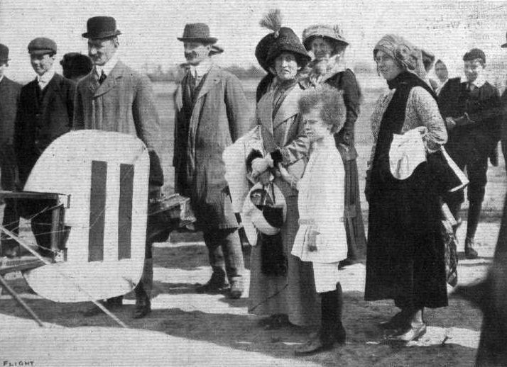
Mrs. Asquith, Miss Asquith, and Master Asquith watching Mr. Gustav Hamel preparing his Bleriot monoplane on Saturday at Brooklands, in readiness for the flight to Brighton.
SAN FRANCISCO AVIATION MEETING. - On the left general view of the flying grounds in front of the Grand Stand, with T. Radley's Bleriot and Brookins' Wright biplane ready for flying. On the right Radley at the wheel of his car, with Hubert Latham by his side and U.S. Army officers in the tonneau.
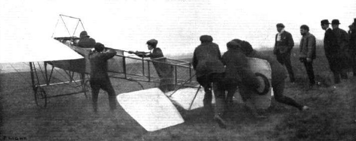
Holding back Mr. Hamel on a Grahame-White Bleriot at the London Aerodrome upon the occasion when Mr. Hamel flew across country, as reported last week, losing himself in the fog, and having to descend in a field at the top of Mill Hill to ascertain his whereabouts.
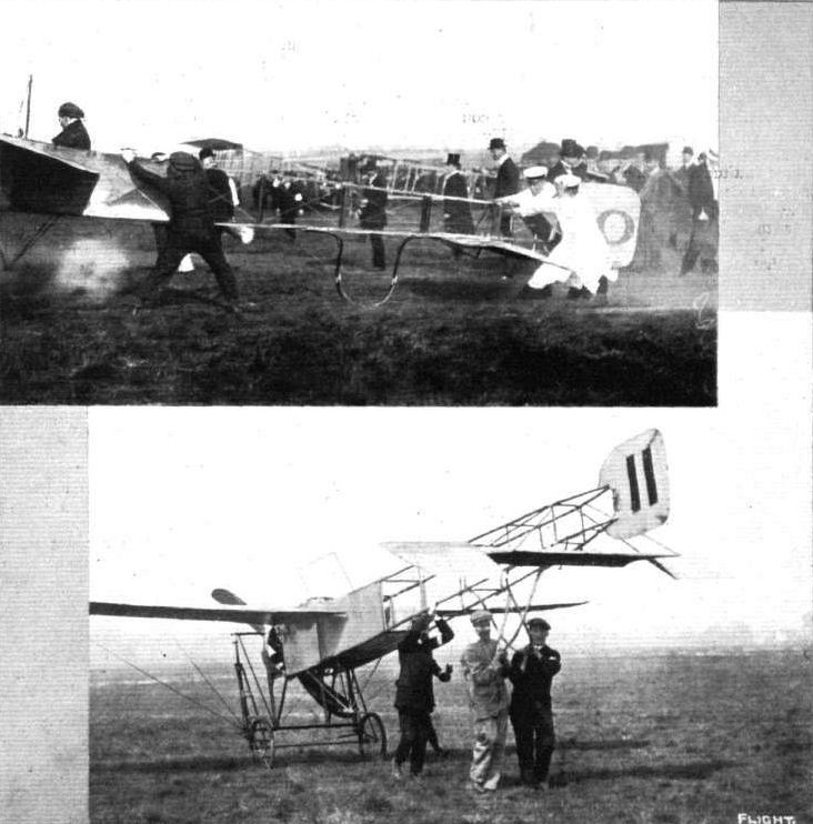
INCIDENTS AT HENDON. - The impatient Bleriot monoplane before flight, and returning to its hangar after work.

STARTING FOR THE BRIGHTON RACE. - Hamel just off on his Bleriot.
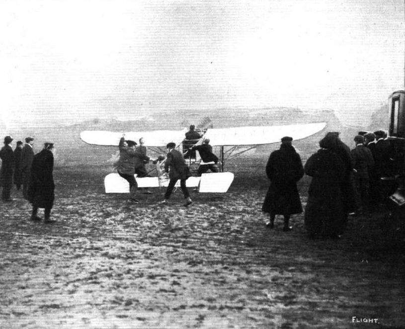
Mr. Morison and his Bleriot at the moment before starting from Brooklands Aerodrome last Saturday for his flight to Hurst Park and back.
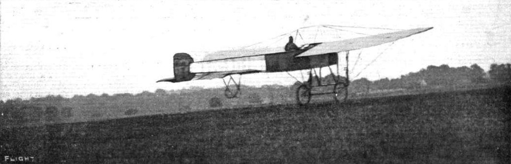
THE FIRST AERIAL POST OF THE U.K. - Hamel leaving the Hendon Aerodrome on his Bleriot for his 108-m.p.h. journey to Windsor on Saturday last.
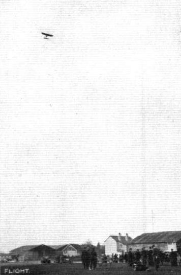
BROOKLANDS TO BRIGHTON RACE. - Hamel, the winner, after one circuit of the aerodrome, passing away for his trip to Brighton.
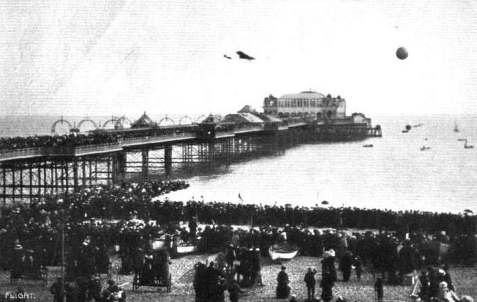
BROOKLANDS-BRIGHTON RACE. - Gustav Hamel, the winner, crossing the pier at Brighton and winning the race on Saturday last.
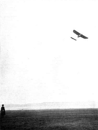
Mr. O. C. Morison making a graceful turn at Brooklands on a Bleriot monoplane prior to his 6,000-ft. altitude flight.
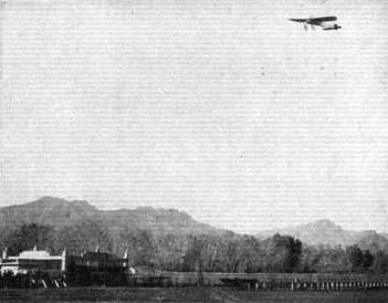
"INTERNATIONAL AVIATORS" IN AMERICA. - Rene Simon is seen at El Paso returning from his trip over the Mexican insurgents' camp.
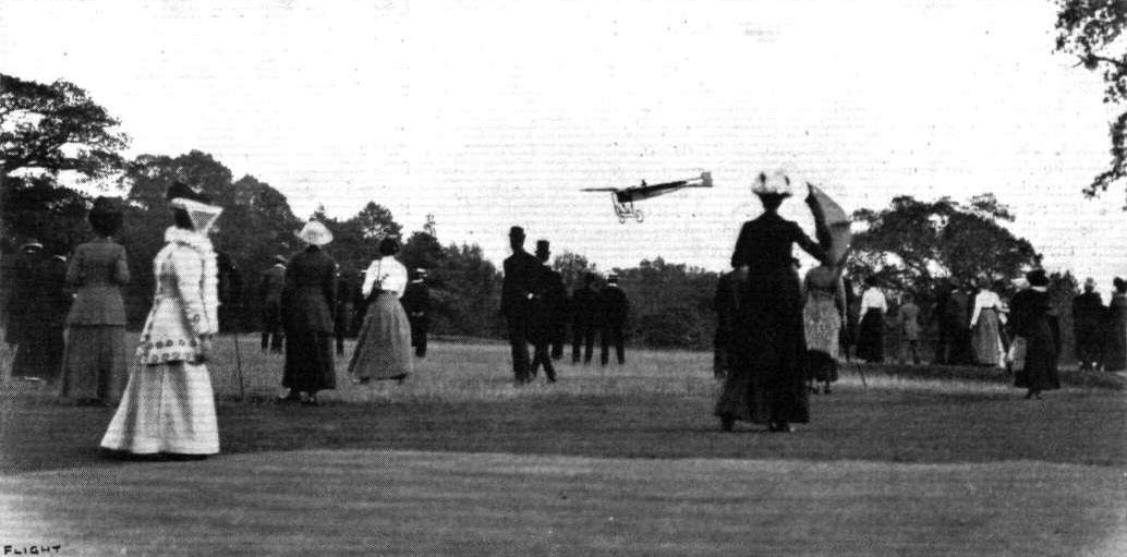
Mr. Gustav Hamel arriving last week at Bushey Hall Golf Club on his Bleriot monoplane. He is seen just descending on the fifth green after having flown the seven miles from Hendon intabout 5 1/2 mins.
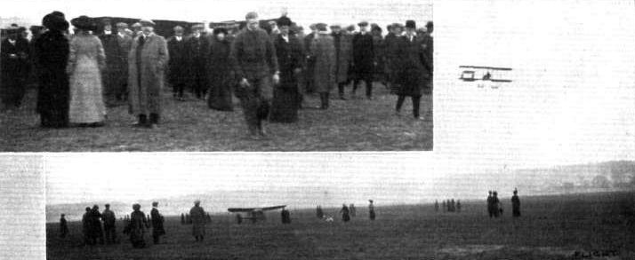
HENDON-BROOKLANDS-HENDON. - Mr. Hamel, who made best times, arrives at Brooklands from Hendon on Saturday. His Bleriot is seen on the ground, and inset he is seen in the centre immediately after landing.

The two hangars erected by the Liverpool Aviation School at Sandheys Avenue, Waterloo, showing the School machine and the two-seater Bleriot on which Mr. Henry G. Melly, the Principal of the School, recently accomplished the circuit of Liverpool and Birkenhead, as recorded in FLIGHT.
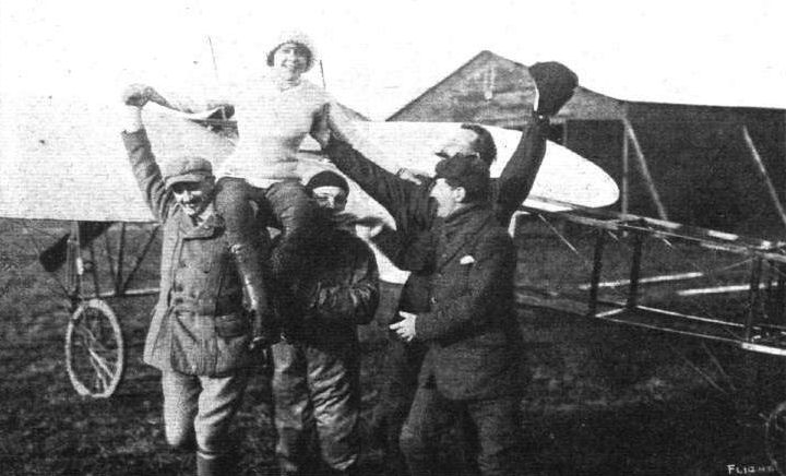
Mdlle. Herveu being "chaired" by her admirers at Pau after her fine flights on a Bleriot for the Coupe Femina, when she was flying for 1 hr. 15 mins. and 2 hrs. 2 mins., having in the end, however, to cede first place to Mdlle. Dutrieu with her 167.2 kiloms. in 2 hrs. 35 mins.
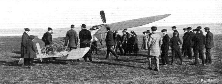
Mr. Morison's machine after a sudden descent at Brooklands recently prior to a contemplated surprise visit by aeroplane to Brighton.
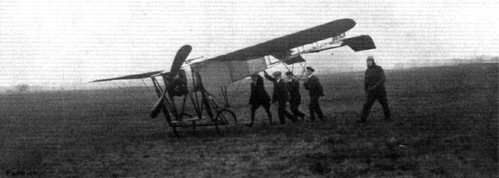
Hamel (to the right) bringing In a Grahame-White School Bieriot after a cross-country flight from the London Aerodrome at Hendon.
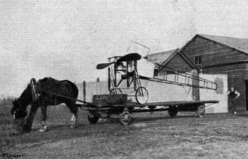
A 100 TO 1 REDUCTION IN HORSE POWER. - Grahame-White's Gordon-Bennett racer leaving the London Aerodrome en route for the Royal Aero Club's stand at Olympia.
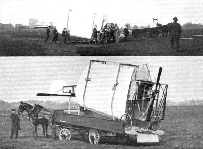
ERECTING AND DISMANTLING TEST. - The Bleriot military monoplane with which this item of the programme was carried out at the Hendon Demonstration. Below, the Bleriot on its transport wagon; and above, immediately after the order for erection had been issued.
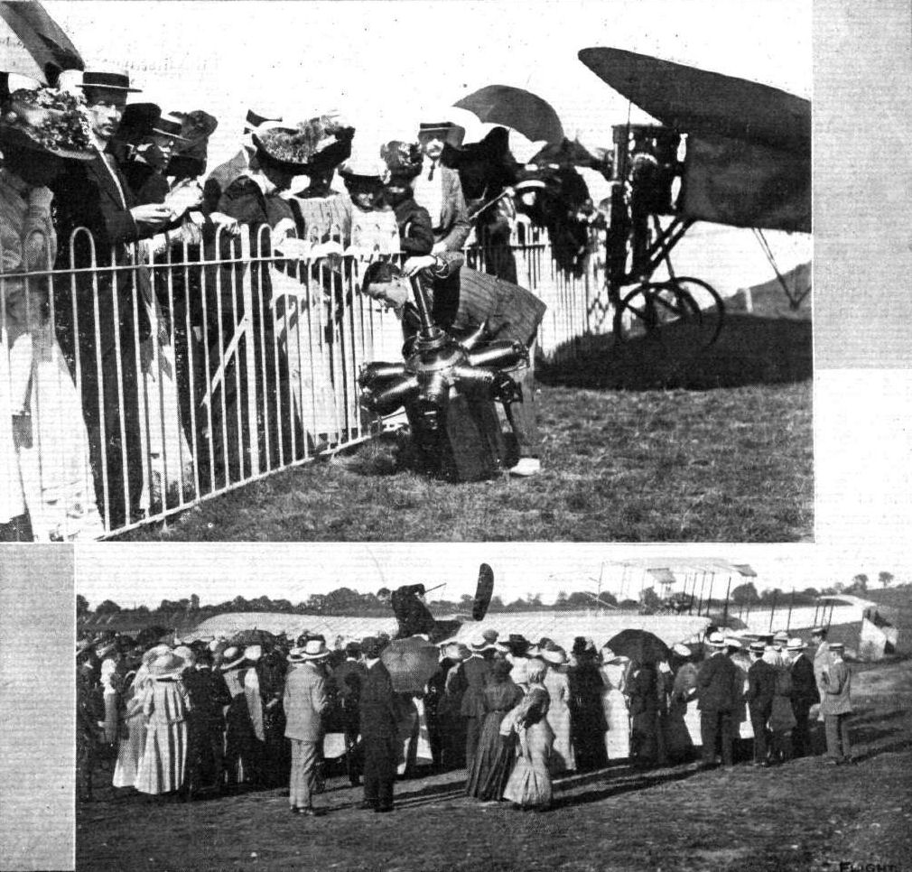
THE WOMEN'S AERIAL LEAGUE AT HENDON. - The recent visit of the members of the Women's Aerial League to the London Aerodrome at Hendon. Though great disappointment was experienced in it not being possible to give any flights owing to the strong wind, the visitors were kept thoroughly interested in studying different points of the machines. Mr. Grahame-White is seen in the lower picture giving a practical lecture upon the Bleriot monoplane, whilst above, Mr. Compton Paterson is explaining the working of the Gnome engine.
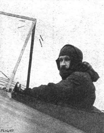
Mr. Morrison, who, on his Bleriot last Saturday, made such fine flights from Brooklands over Weybridge, reaching an altitude of about 1,000 ft.
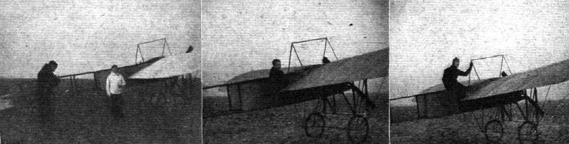
Mr. B. G. Bouwens. Lt. G. B. Hynes, R.G.A. Mr. St. Croix Johnstone.
Above we give three pupils of the Bleriot School, who, at the London Aerodrome, near Hendon, on the same day - December 28th - successfully qualified for their Royal Aero Club's pilot certificates. Easily a record for Great Britain.
Above we give three pupils of the Bleriot School, who, at the London Aerodrome, near Hendon, on the same day - December 28th - successfully qualified for their Royal Aero Club's pilot certificates. Easily a record for Great Britain.
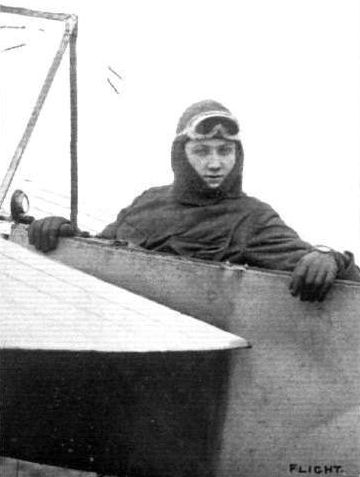
Mr. Hamel on one of the Grahame-White Bleriot machines at the London Aerodrome.

Signor Quinto Poggioli, who has iust obtained his pilot's certificate from the Royal Aero Club, having qualified at the New Forest Aviation School at Beaulieu on a Blerlot monoplane.
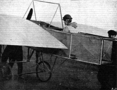
AT THE GLASGOW BARRHEAD FLYING GROUNDS. - Mr. James Clinkskill about to start for a spin on his Bleriot.
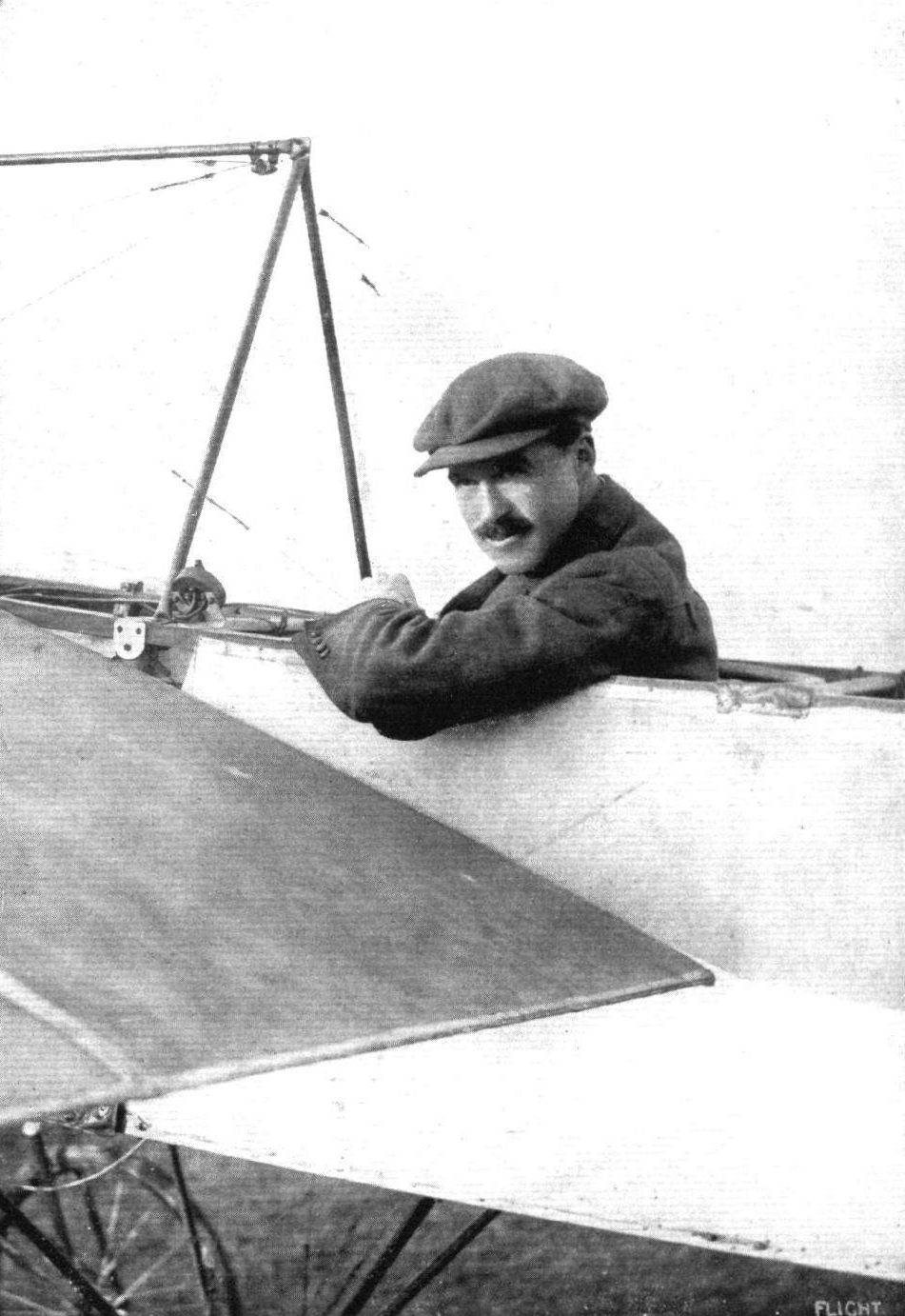
CAPTAIN J. D. B. FULTON, R.F.A., The first and, up to the present, the only British officer to secure the Special Flying Certificate of the Royal Aero Club, for which the tests consist of a 100-mile cross-country flight, a 1,000-ft. altitude flight, and a vol plane, with engine completely stopped, from 500 ft.

IN THE WAR OFFICE AND PARLIAMENTARY ENCLOSURE AT THE HENDON DEMONSTRATION LAST WEEK, SHOWING ALL THE MACHINES IN LINE IN FRONT OF THE HANGARS. - In the distance, on the left of the photograph, is Mr. Armstrong Drexel's monoplane just had come to grief owing to a mechanic having wrongly crossed the wires of the elevating plane.
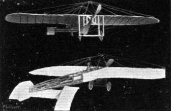
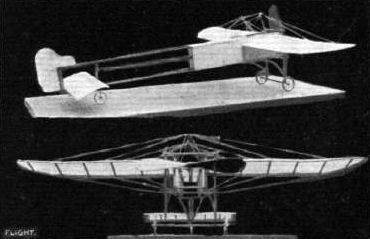
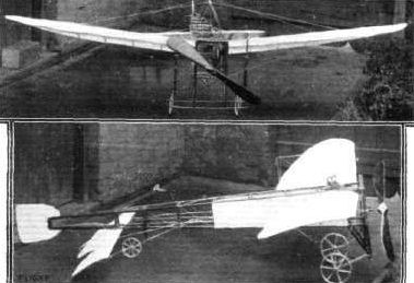
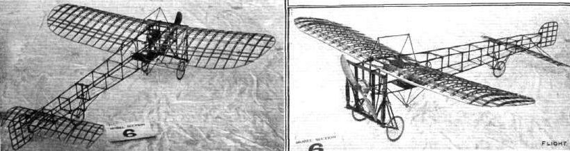
Two views of a scale model Bleriot built by Willyboldt Birkinger, which gained second place for construction.
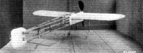
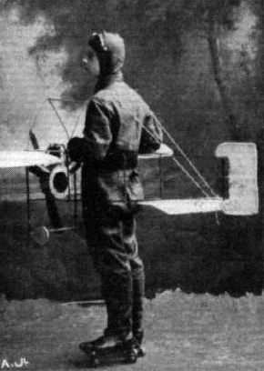
Mr. Archie Allan in his flight costume with which he secured first prize at Tynemouth Palace Skating Carnival. It represents a Bleriot C.C. monoplane (one-sixth full size).
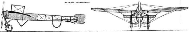
PARIS-MADRID RACE. - Diagrammatic sketches of some of the machines entered in the race.
Flight, March 25, 1911
OLYMPIA-1911
Aeroplanes.
L. Bleriot (STAND 43). - Bleriot type XXI. Monoplanes, single-seaters, fitted with 50 h.p. Gnome engines. Also a Type XXI-"two-seater" military type monoplane, fitted with 70-h.p. Gnome engine.
Single-seater. - Dimensions: length, 23 ft. Span, 29 ft, Weight, 550 lbs.
Remarks. - This type follows closely in general design the well-known Cross-Channel type, but several improvements have been effected, viz. :-
The motor and the tanks are now covered by a metallic bonnet, which has proved a great improvement, to facilitate the power of penetration of the machine through the air at high speed, and it protects very greatly the aviator against the rush of wind caused by the propeller and the speed; this bonnet is fitted with sliding openings to obtain access to the tanks.
The top pylon holding the cables that support the wings has been altered; it is now a single one, which offers less resistance to the air, and the construction of which gives the maximum of strength to that important part.
The back wheel has been replaced by a new skid made of very elastic wood, which greatly absorbs shock in landing and brings the machine more quickly to a standstill.
The elevator or horizontal rudder consists of two ailerons fixed behind the tail, after the principle which has been so successfully used during last year on the double seater.
All the transmission cables, acting on the rudder and elevator, are doubled; all materials are submitted to the most rigorous tests with special machines, and the wings, tested with sand, on the machine turned upside down, can support without deformation or extra strain a pressure of 610 kilogs. on each wing, or a total of 1,220 kilogs. (a security coefficient of 4 according to the rules adopted bv the Ae.C.F.).
This trial was made officially on March 3rd, before the delegates of the French War Ministry and other officials.
Two-seater. - Dimensions: Length, 26 ft. Span, 36 ft. Weight, 700 lbs.
Remarks. - Similar in general design to the single-seater, but has been speciallv designed for military work. The two seats are placed side by side and protected by a bonnet covering the motor, and with the control-levers so arranged that either of the aviators can take command in turn.
The instruments necessary to the proper use of an aeroplane in cross-country flights, such as compass, map-holder, altimeter, block-note holder, &c, are fixed on a sliding rest, which can be shifted in front of one or the other instantly.
The back part of the body is entirely covered and the sides taper down to the end of the tail to reduce the effect of the side wind on the tail and balance it with the front planes when they receive a strong gust of wind.
The general shape of the machine is very graceful and the elevator is placed behind the tail, the rudder coming slightly in front of it over the fuselage.
A special very short landing skid is fitted so as to bring the tail very low down when at rest, so that the wings offer a great resistance in landing and bring the machine at rest in a very short space.
The French and Russian Governments have already ordered a great number of this type of Bleriot monoplane.
Flight, June 3, 1911.
FROM THE BRITISH FLYING GROUNDS.
Liverpool Aviation School, Sandheys Avenue, Waterloo.
ON the 23rd, 24th and 25th ult. no flying was attempted owing to excess of wind. On the 26th Mr. A. Dukinfield-Tones made several straight line flights of half a mile each, and on the 27th in the evening he repeated the performance in a 12-mile wind, showing considerable aptitude in balancing and steering against a nasty cross drift.
On the 28th Mr. Melly had out the two-seater and flew to Southport with Mr. Jones as passenger, total distance 34 miles. On the outward journey he followed the coast line, but on the return journey he took a direct course across country.
On the 30th Mr. Jones made a few short flights before breakfast, but owing to the missing of the engine brought the machine in for examination. Meanwhile Mr. Melly took out the two-seater with Mr Swaby as passenger, and starting in a northerly direction made a complete circle of Liverpool, via Crosby, Amtree, Wavertree, Aigburth, then crossing the Mersey to Port Sunlight. He then followed the left bank of the Mersey passing over Birkenhead Park and west of Liscard, circled the New Brighton Tower, re-crossed the Mersey and landed opposite the school hangars. The total distance was 35 miles, which was accomplished in the extraordinarily short time of 41 minutes. The average height maintained was 1,000 feet.
Flight, June 17, 1911.
BRITISH NOTES OF THE WEEK.
Flying at Liverpool Gymkhana.
A NOVELTY was introduced in the programme of the gymkhana held at Childwall on Saturday by the Liverpool A.C. in conjunction with the Liverpool Polo Club in the shape of a couple of exhibition flights by Mr. Melly. Accompanied by Mr. Dukinfield Jones Mr. Melly flew over from his flying grounds at Waterloo early in the morning. Unfortunately the wind freshened after his arrival, and it was not until about six o'clock in the afternoon that Mr. Melly got into the air again. He then carried Mr. Lyle Rathbonc, of the Liverpool A.C., for a flight of 6 minutes, during which a figure of eight was made. About half an hour later a second trip was made, this time with Mr. J. Grahame Reece. Subsequently, although the weather was not very good, Mr. Melly succeeded in flying back to his hangar at Waterloo, being accompanied again by Mr. Dukinfield Jones.
Flight, August 26, 1911.
FOREIGN AVIATION NEWS.
An American Lady Aviator.
THE number of certificated aviators among the gentler sex is being gradually added to. The first to obtain her certificate under the new rules was Madame Driancourt, at the French Caudron School, but soon after her was Miss Harriet Quimby, of California, who qualified on a Moisant monoplane at Mineola, N.Y., on August 1st. Miss Matilda Moisant, sister of the late J. B. Moisant, has also qualified for a pilot's licence on a Moisant monoplane, and Miss Blanche Scott should qualify shortly.
Flight, October 14, 1911.
NASSAU BOULEVARD MEETING.
<...>
In the event for greatest altitude for women aviators. Miss Mathilde Moisant was the only one entered, and she made a bid under these circumstances for the Rodman-Wanamaker trophy by climbing in her 50-h.p. Gnome-Moisant-Bleriot to a height of about 1,200 ft., descending with a spiral vol plane.
<...>
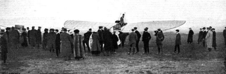
Mr. Gilmour has a look round before settling down in his seat in "Big Bat" Bleriot for a spin round Brookiands Aerodrome.
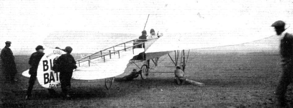
Mr. Astley, on " Big Bat" Bleriot at Brooklands recently, just getting away with a passenger. - Note the mechanics on the ground helping to hold back the machine by the skid wheels.

AT THE LIVERPOOL A.C. GYMKHANA. - Mr. H. Melly, the Principal of the Liverpool Aviation School, ilying over the gymkhana grounds on Saturday on his 50-h.p. Gnome-Bleriot.
Mr. H. G. Melly on his two-seater Bleriot, as seen from the s.s. "Victorian" lying in the Mersey. This photograph, by Mr. Alex Reid, gives an excellent idea of the height and position of the machine over the Mersey.
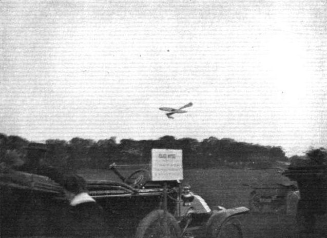
AT THE LIVERPOOL POLO GROUND. - A vol plane by Mr. H. G. Melly on his Bleriot.
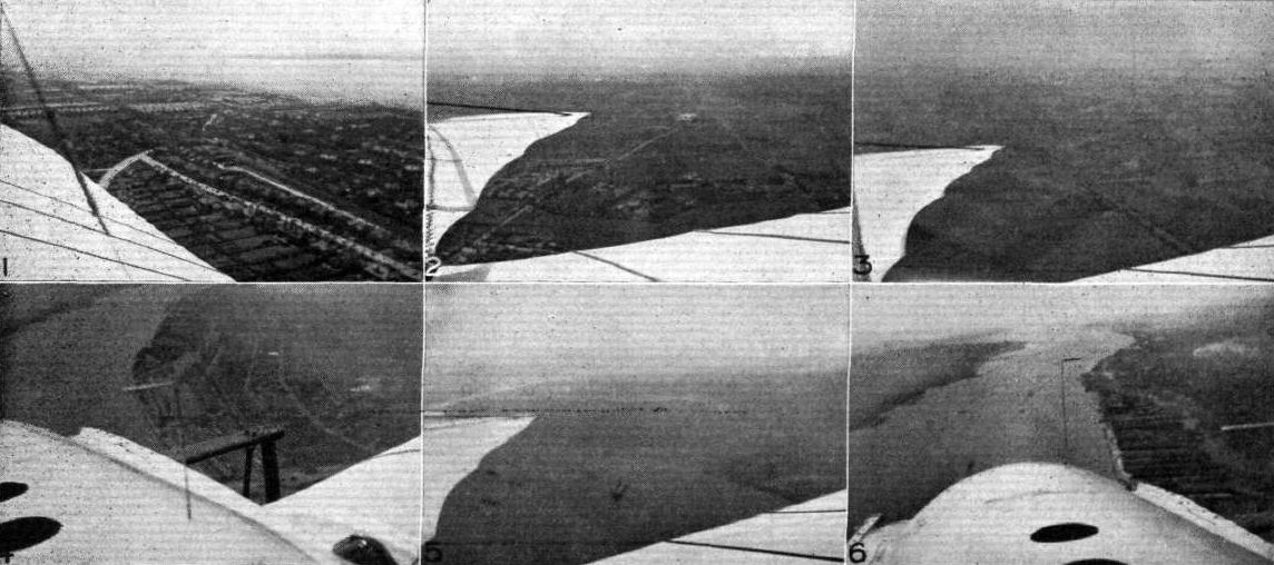
Liverpool, Manchester and the Mersey, seen fiom Mr. H. G. Melly's two-seater Bleriot, as snapped by his passenger. 1. Leaving Waterloo, looking back over Blundell Sands to the Mersey. 2. Over Rainhill, looking back at Prescot. 3. Leaving Manchester, looking back. 4. Over the Mersey, taken from over the Herculaneum Dock. 5. Looking back over the Sloyne and "Lusitania." 6. Looking down the Mersey to the estuary.

TESTING THE WINGS OF A BLERIOT MONOPLANE WITH SAND LOAD. - Standing on the left are Mr. Grahame-White, M. Bleriot, Col. Bouttieaux, General Roques, &c.
The two hangars erected by the Liverpool Aviation School at Sandheys Avenue, Waterloo, showing the School machine and the two-seater Bleriot on which Mr. Henry G. Melly, the Principal of the School, recently accomplished the circuit of Liverpool and Birkenhead, as recorded in FLIGHT.
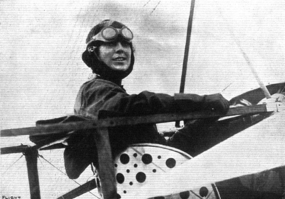
Miss Harriett Quimby, a native of California, who has just been awarded the pilot's certificate of the Aero Club of America, this being the first woman's certificate Issued by the Club. Miss Quimby passed her tests at Mineola, Long Island, on a Moisant monoplane.
Miss Harriet Quimby, who on Tuesday last, on a Bleriot monoplane, flew the Channel from Dover to Equihen - the first time the feat has ever been accomplished by a lady pilot unaccompanied.
Miss Harriet Quimby, who on Tuesday last, on a Bleriot monoplane, flew the Channel from Dover to Equihen - the first time the feat has ever been accomplished by a lady pilot unaccompanied.

Miss Mathilde Moisant in the pilot's sieat of her machine just before the start for the Rodman Wanamaker Trophy for height for women at the Nassau Boulevard Meeting on September 24th.
UNDER-CARRIAGES AT OLYMPIA. - A comparison in tail skid construction.
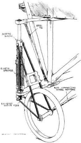
The well-known Bleriot undercarriage.
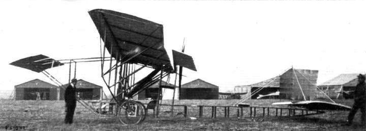
The new 4-seated Bleriot monoplane as seen from the side, showing the biplane elevator, the first to be fitted to a Bleriot.

View from behind of the new 4-seated Bleriot monoplane.
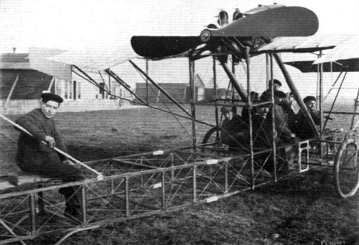
The new 4-seated Bleriot monoplane, with the 8 passengers in their places as carried in the air at Pau by M. Lemartin for about eight minutes. Note the eighth passenger, who is sitting behind on the fuselage. The general construction from behind is well seen in this view.

THE NEW 4-SEATED BLERIOT MONOPLANE. - M. Lemartin, who carried the 8 passengers, in the pilot's seat. The skids and forward construction are clearly seen in this picture.
Flight, April 22, 1911.
LONDON TO PARIS NON-STOP BY AEROPLANE.
TRULY can it be said that aviation history is being made at a marvellous rate, and it would seem that record cross-Channel flights are to mark the periods of that history. The year 1909 saw the famous flight of M. Bleriot from Calais to Dover. In 1910 the late Hon. C. S. Rolls made the double journey from Dover to Sangatte and back without a stop, while 1911 is likely to be remembered as the year in which Pierre Prier improved on the records by flying from London to Paris without breaking his journey. It is true the late Mr. J. B. Moisant succeeded in covering the space between the French and English capitals last year by way of the air, but it will be remembered that he made numberless stops - albeit they were unwilling ones - on the way, while his journey occupied a good many days owing to difficulties encountered on this side of the Channel. Not only is M. Prier's trip a record for cross-Channel work but it is also a world's record for a cross-country flight from point to point. That it should be possible for an aviator to set off at practically a moment's notice on a journey of 250 miles without making any very elaborate preparations is an extraordinary commentary upon the progress in aviation which has been accomplished during the past year. It is, in fact, what happened, for although the aviator had been thinking over the possibility of making such a trip for six weeks, the recent spell of bad weather had necessitated the temporary abandonment of the project. On Wednesday of last week, however, M. Prier was giving M. Norbert Chereau a trial run on one of the new Bleriot monoplanes at Hendon, when it was suggested that the conditions were favourable for a flight to Paris. The suggestion was acted on forthwith. M. Prier had his cross-Channel flyer brought out, got into readiness, and by a quarter-past twelve was in the air. When he had travelled only a little way, however, he found it was practically impossible to keep up the pressure in his petrol tank, and so returned to the aerodrome for this to be remedied, after having been in the air for about half an hour. At 1.30 p.m. the adjustments were completed, and at 1.37, to be exact, M. Chereau timed the aviator away for his journey to Paris.
Following a route which had been carefully prepared beforehand on a roller map, which was arranged in front of the pilot, the aeroplane winged its way round the suburbs on the north side of London, and then working eastward of the Metropolis, followed the Thames to Chatham, turning southward when past Canterbury, to Dover. From here, M. Prier steered across the Channel to Cape Grisnez, on reaching which point he turned and followed the coast to Boulogne, arriving there at 3.15, as he was more familiar with the landmarks on the route between there and Paris. Continuing his journey onwards to Abbeville and Beauvais without incident, he crossed the French capital, which was so enshrouded in mist that even the Eiffel Tower was not distinguishable, and sighting Issy, came down in front of the Bleriot sheds there at 5.33 p.m., being warmly welcomed by M. Louis Bleriot himself. Throughout the journey the Gnome-engined Bleriot behaved splendidly, and M. Prier had no difficulty in finding his way by the aid of the special map and a compass. When Hendon was left the wind was blowing slightly from the north-east, but at Dover it had veered to north-west. The only difficulties experienced were due to the mists passed through in England and a bank of fog encountered near Beauvais. The actual time taken for the trip of 250 miles was 3 hrs. 56 mins., so that the average speed maintained was in the neighbourhood of 64 miles an hour. During most of the journey M. Prier was at a height of about between 2,000 and 3,000 feet.
Flight, June 10, 1911.
PARIS-ROME-TURIN.
IN our last issue were just able to briefly announce that "Beaumont" was the first to actually arrive at Rome on Wednesday of last week. He made a magnificent flight from Nice, after having had a new motor fitted to his machine, A quarter of an hour's trial flight was indulged in as soon as the mechanics had finished their work, and then he set off at 3.57 a.m. He landed at Genoa at 6.47, and an hour later started off once more for Pisa, where he arrived at 9.40, landing on the horse racecourse in error. Realising his mistake, he afterwards restarted the machine and flew over to the proper aerodrome, where he landed an hour later. At ten minutes past twelve he left for Rome, and landed in the precincts of the Eternal City at eight minutes past three, his passage over the city being witnessed by His Holiness the Pope and Cardinal Merry del Val from a balcony of the Vatican.
Garros made a move from Pisa at 4.35 a.m., but had only progressed 60 kiloms. on his journey when he was forced to make a landing at Castagneto-Carducci. In coming down very suddenly from a height of 200 metres the machine was very badly smashed. Frey continued his journey from Genoa to Pisa, but in alighting at the latter place smashed his propeller and also damaged the chassis of his machine. Of the other competitors, Vidart advanced from Avignon to Nice, while Bathiat was brought down by motor troubles at Macon, after covering the 110 kiloms. from Dijon in 54 mins. Lieut. Lucca succeeded m getting from Lyon to Avignon
Flight, September 2, 1911.
AIR EDDIES.
Hendon habitues will be glad to hear that Frank L. Champion, who will be remembered by Hendonites as that delightfully droll "Candy Kid" who came across from Southern California to graduate at the Bleriot School, is doing really well out West at Los Angeles. He is now flying a Gnome-Bleriot, the machine purchased from Radley by Earle V. Remington at the Los Angeles aerodrome. In order to demonstrate to a Long Beach committee his ability to give exhibitions at the forthcoming midsummer carnival, Champion flew there from Los Angeles, a distance of roughly 20 miles, and circled over the town at a height of 1,500 feet. It is hardly surprising to hear that as a result of his flight, which, by the way, was his first since his return to the States, he has been engaged to fly at the Long Beach Carnival festivities. Since then he has succeeded in falling into the sea - accidentally, or for advertisement's sake, we wonder! That aviators are drawn from all sources is pretty well known. Champion formerly carried on a photographer's business at Long Beach.
Flight, September 9, 1911.
NEW WORLD'S RECORDS.
Garros Creates New Altitude Record - 13,943 ft.!
STILL the competition for the altitude record goes merrily on Lincoln Beachy's height of 11,578 ft. made at Chicago has now been put in the shade by the extraordinary performance of Garros, who on Monday, in the neighbourhood of St. Malo, went up on a Bleriot monoplane to a height recorded by his barograph as 4,250 metres, or 13,943 ft., subject to official recognition. The previous French record, and a world's record previous to Beachy's flight, was the 2,350 metres reached on August 5th by Capt. Felix.
Flight, October 7, 1911.
FROM THE BRITISH FLYING GROUNDS.
Portholme Aerodrome, Huntingdon.
ON Friday of last week some flying was seen at these grounds, when Mr. W. B. R. Moorhouse took the pilot's seat of his Gnome-Bleriot for the first time. He got off in 20 yards, and flew four times round the drome at an average altitude of 200 feet, his aneroid in one instance registering 300 feet. He finished up with a very neat landing, not bumping in the least. His success speaks well for Mr. Moorhouse's future, as it was his first attempt with a Gnome-Bleriot, and he had had but a very little previous practice with an old Anzani-Bleriot, which was available last year. On Saturday it was raining and blowing a couple of gales lashed together, and flying was out of the question,
Flight, October 14, 1911.
FROM THE BRITISH FLYING GROUNDS.
Portholme Aerodrome, Huntingdon.
MR. W. B. R. MOORHOUSE, after his essays the previous week, was last week making a series of remarkably successful flying trips. On the Monday, he, on his Gnome-Bleriot with Chauviere propeller, made four good flights in the morning, travelling well outside the aerodrome, in the afternoon putting up a further five flights, again outside the aerodrome, keeping well up at above 2,000 ft. or so. The next day he flew from Huntingdon to Northampton, accomplishing the distance (45 miles) in the half-hour, most of the time being at an altitude of fully 3,000 ft. Mr. Moorhouse is a fearless flyer, and merely took in Northampton, having steered there via Bedford, Turney and Yardley Hastings on route, during a visit to his parents' house, Spratton Grange, a few miles northward of Northampton. This was Mr. Moorhouse's first cross-country flight, and the machine he was using was the identical Bleriot on which Mr. Morison not so very long ago took a dip into the Channel near Folkestone. On his return journey to Huntingdon Mr. Moorhouse again passed over Huntingdon, and continued on by Wellingborough and Kettering, reaching Portholme at 3.5 p.m., having started a little after 2 p.m. from Spratton. On Wednesday and Thursday work was in progress on the new Radley-Moorhouse monoplane, but on Friday Mr. Moorhouse resumed his cross-country work by flying from Huntingdon to Northampton, where, after partaking of lunch, he struck out again for Brooklands, encountering en route some extremely gusty winds and fogs, although he rose to a height of 4,000 ft. to get away from this trouble. Saturday afternoon, testing was again the chief work on the R. and M. monoplane, which appears to be working very successfully, as he, during the day, was up on the machine and actually passed for his certificate on it. Mr. Morison subsequently had a flight round in the new machine and appeared to be well satisfied with its behaviour.
On Tuesday evening last Mr. Moorhouse left Brooklands in his Bleriot for Huntingdon, but running short of petrol near Cambridge, he came down at Parkers Piece, having made a magnificent gliding descent commencing at about Trumpington, two miles south of Cambridge. He flew on to Huntingdon on Wednesday morning at 6.30 a.m.
Flight, November 11, 1911.
AEROPLANES AT TRIPOLI.
MR. QUINTO POGGIOLI, who will be remembered by our readers as having taken his pilot's certificate in England under the Royal Aero Club's regulations, sends us some interesting details of the practical work being carried out in Tripoli in connection with the Italian-Turkish War. Mr. Poggioli writes :-
"On the 25th Oct. Capt. Piazza with his Bleriot, and Capt. Moizo on his Nieuport, observed three advancing columns of Turks and Arabs of about 6,000 men. The Italians, after receiving this information, could successfully calculate distances and arrange for their defence.
"On the day following, the 26th Oct., the battle of Sciara-Sciat took place, resulting in the loss to the Turkish Army of 3,000 men. During the battle two aeroplanes, Lieut. Gavotti with his Etrich and Capt. Piazza, were circling the air. The flights took place above the line of fire, so as to be able to direct the firing of the big guns from the battleship 'Carlo Alberto,' and also of the mountain artillery. The aeroplanes were often shot at by the guns of the enemy, but with no result. The only difficulty they had was caused by the currents of air caused by the firing of the big guns.
"Previously, on the 22nd Oct., Capt. Moizo when reconnoitering passed over an oasis, and, in order to observe better the movements of the enemy, descended to an altitude of about 200 metres, and in consequence the wings of his machine were pierced by bullets in six or seven places, and also a rib was broken.
"On November 1st Lieut. Gavotti (Etrich) flew over the enemy, carrying four bombs, carried in a leather bag; the detonator he had in his pocket.
"When above the Turkish camp, he took a bomb on his knees, prepared it and let it drop. He could observe the disastrous results. He returned and circled over the camp, until he had thrown the remaining three bombs. The length of his flight was altogether about 100 kiloms.
"The bombs used contained picrato of potassa, type Cipelli."
THE first official communication by one of the belligerents, in regard to the use of aeroplanes in actual warfare, has been issued by the Italian authorities, dated November 5th, from Tripoli. As a matter of historical record we reproduce the text in extenso as follows :-
"Yesterday Captains Moizo, Piazza, and De Rada carried out an aeroplane reconnaissance, De Rada successfully trying a new Farman military biplane. Moizo, after having located the position of the enemy's battery, flew over Ain Zara, and dropped two bombs into the Arab encampment. He found that the enemy were much diminished in numbers since he saw them last time. Piazza dropped two bombs on the enemy with effect. The object of the reconnaissance was to discover the headquarters of the Arabs and Turkish troops, which is at Sok-el-Djama."
Flight, November 18, 1911.
Aeroplanes in War.
THE Italian Army in Tripoli are now using three Bleriot monoplanes which have been in use in Italy for some time, one of them being flown by Captain Piazza, who is the Commander of the Aviation Section, and who will be recaused, membered as being the winner of the Italian Circuit during last summer (Bologne-Venise-Rimini and Bologne). The Italian Government has placed a further order for three more Bleriot monoplanes, and Captain Anostini is now at Etampes to see the trials of the machines, which are to be delivered this week.
Flight, December 30, 1911.
PARIS AERO SHOW.
L. Bleriot.
FOUR monoplanes are on view on this stand, the 70-h.p. two-seater, which Hamel has popularised in England, the familiar 50-h.p. cross-country model, a new 50-h.p. racing monoplane, and a new low horse-power monoplane, type XXVIII, designated the "Popular" type. Of these machines we are already familiar with the former two, and no description of them is necessary.
<...>
Principal dimensions, &c. :-
Cross-country type-
Length 25 ft.
Span 29 "
Area 165 sq. ft.
Weight 528 lbs.
Speed 60 m.p.h.
Motor 50-h.p. Gnome.
Price L860.
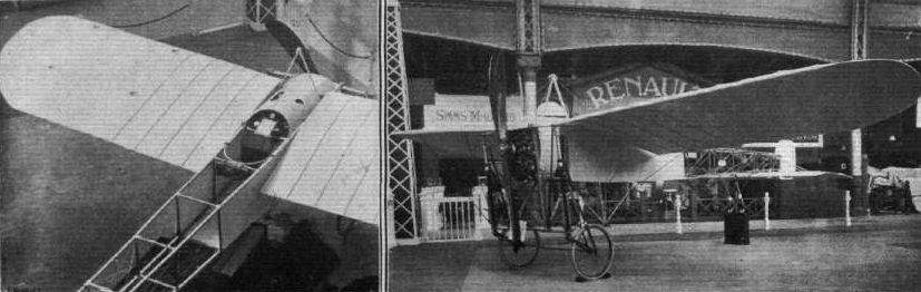
Two views of the latest genuine Bleriot monoplane, showing the protective roof over the engine and tank and the partially covered framework.

LIEUT. SAMSON, R.N., AND HIS BLERIOT AT THE R.Ae.C.'S EASTCHURCH GROUNDS. - On the right Lieut. Samson is making circuits on the machine.
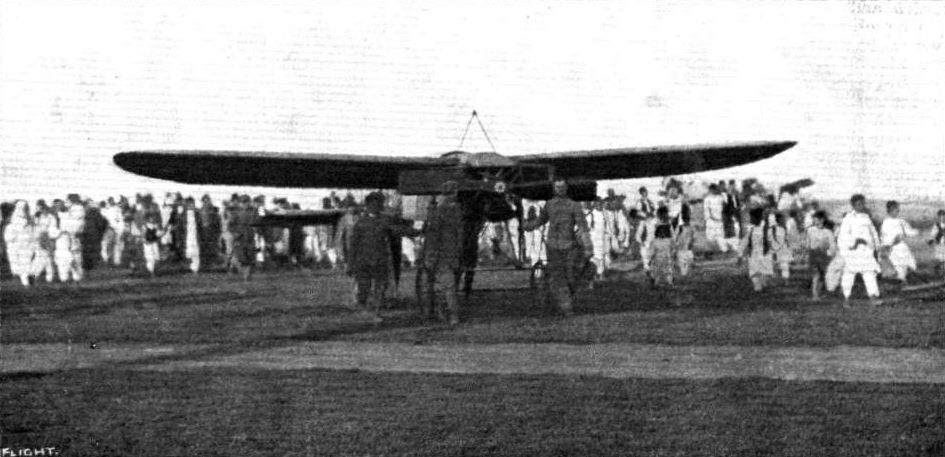
THE AEROPLANE IN ACTUAL WARFARE. - Capt. Piazza, of the Italian Army, bringing out his Bleriot monoplane at Tripoli for the purpose of reconnoitring the Turkish entrenchments outside the Tripoli fortifications. Note the crowd of Arabs who are following in the wake of the aeroplane.
DAILY MAIL CIRCUIT OF BRITAIN. - The imaginary starting line from which the whole of the machines were sent off from Brooklands on Saturday. Ready for being started are Nos. 1 and 2, and Compton Paterson's Grahame-White "Baby" biplane.
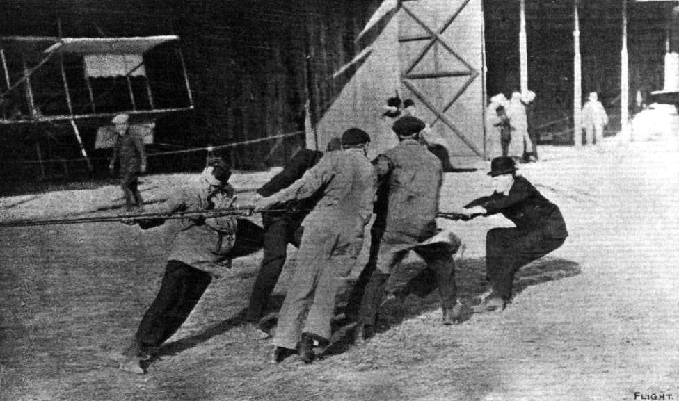
HOLDING BACK A 100-H.P. BLERIOT MONOPLANE. - An "incident" in the successful attempt by Mr. Claude Grahame-White at Belmont Park Meeting, U.S.A., last year, to secure for Great Britain the Gordon-Bennett International Trophy.

DAILY MAIL CIRCUIT OF BRITAIN. - The two first off from Brooklands. At the top,"Beaumont" (Lieut. Conneau) on his Bleriot, and below, Mr. H. J. D. Astley on his Birdling monoplane.
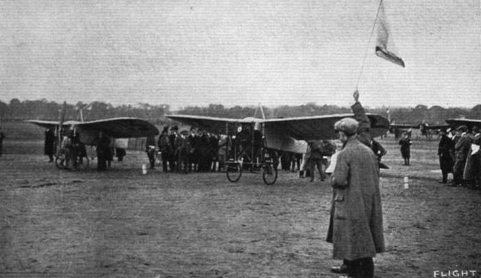
EUROPEAN CIRCUIT. - Two great heroes on the starting line at Vincennes - Garros and Beaumont. The latter (No. 12) is just receiving the signal to get away, his companion following him at the next starting interval.
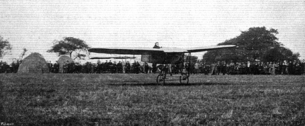
CIRCUIT OF BRITAIN. - Hamel leaving Chryston on his Bleriot.
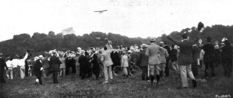
PARIS-ROME. - "Beaumont" (Lieut. Conneau) arriving at the Rome Aerodrome.
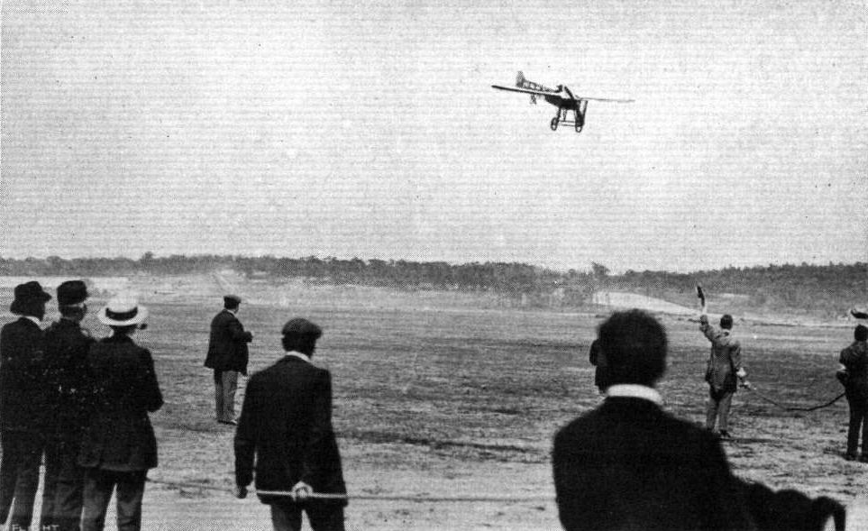
CIRCUIT OF BRITAIN. - Lieut. Conneau ("Beaumont") finishing on his Bleriot and winning the L10,000 at Brooklands on Wednesday, July 26th.
AVIATION AT THE FRENCH ARMY MANOEUVRES. - Some of the Bessonneau hangars at Vesoul, and the military aeroplanes which are giving such a splendid account of themselves.
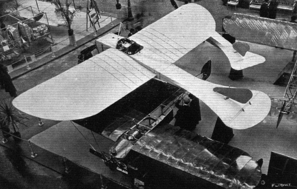
THE BLERIOT STAND. - At the bottom of the picture, with the warnished wings, is the new "Popular" type Bleriot, fitted with a Y-type Anzani motor of 35-h.p. as listed at L380. The larger monoplane is the 70-h.p. military two-seater, while the tail-half of a machine emerging from under the right wing of the two-seater belongs to the new 50-h.p. Racer.
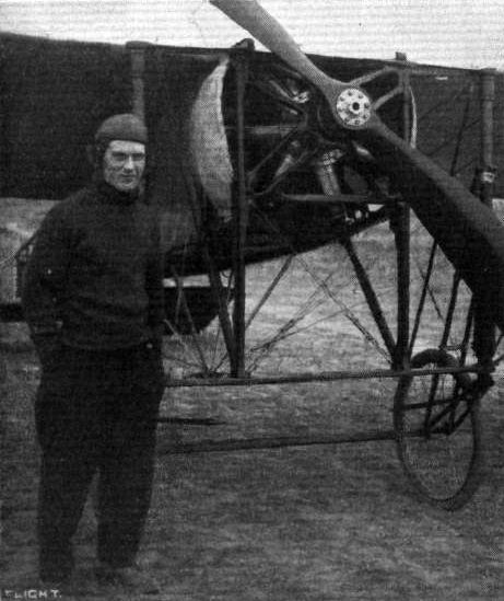
Mr. Frank L. Champion with Radley's old Gnome-Bleriot monoplane, on which he is now flying at Los Angeles, South California. Champion, it will be remembered, was a pupil of the Bleriot School at Hendon.
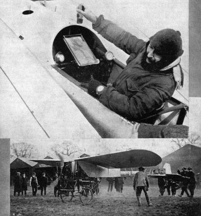
LONDON TO PARIS FLIGHT. - Above is M. Prier in his seat, with route map in front of him, just before his start from Hendon; and below is M. Prier's Gnome-engined Bleriot having its final testing immediately before the start for this record journey last week.
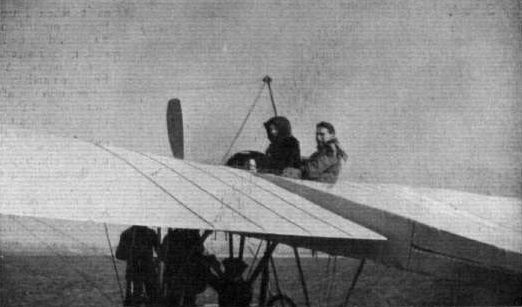
M. Prier, with Mrs. Gordon Jones, a pupil at the Bleriot School of Aviation at Hendon, in the passenger seat, just about to get away for a flight.
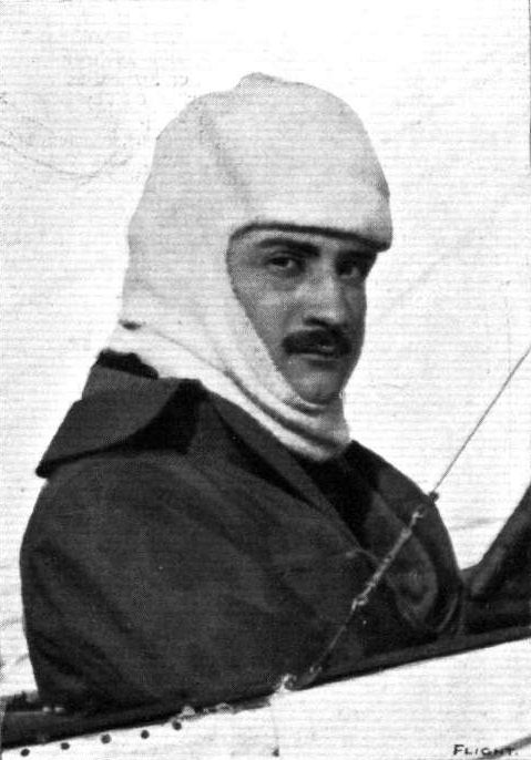
M. Roland Garros, who last week put up a new altitude record on a Bleriot monoplane of 13,943 feet at Parame, near St. Malo.
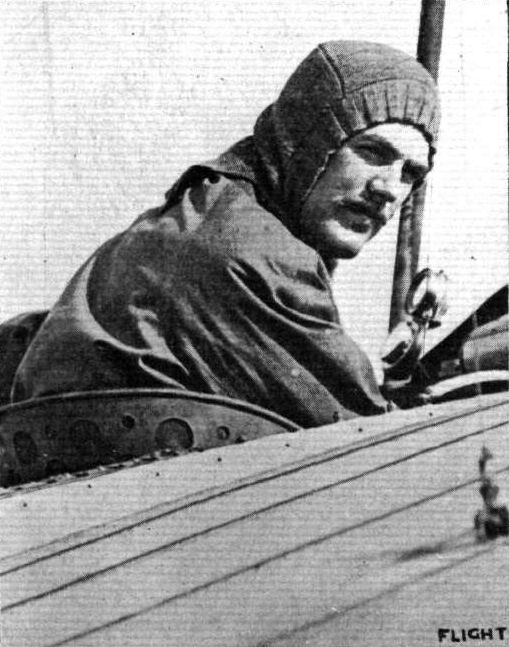
Lieut. R. A. Cammell, the distinguished Array aviator who was killed at Hendon on Sunday last.

MR. W. B. R. MOORHOUSE. Who has recently been making such excellent cross-country flights on his Gnome-Blerlot from Portholme Aerodiome, Huntingdon, to Northampton and the district, and on Friday from Huntingdon to Brooklands.
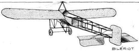
MONOPLANES AND BIPLANES IN THE DAILY MAIL CIRCUIT ROUND GREAT BRITAIN. - From these every machine can be readily identified either in flight or on the ground.

Amongst those machines taking part in the tests promoted by the French military authorities at Rheims the new Blerlot 3-seater possesses considerable interest. It will be seen from the above photograph that Bleriot has reverted to the lifting tail and balanced elevator planes which formed a feature of his early cross-Channel model. Its span is 11.36 metres, and length 8.5 metres. Triple wheels have been fitted to the strengthened landing chassis, and, like the Breguet, is equipped with a Gnome engine of 130-h,p.
Flight, December 30, 1911.
PARIS AERO SHOW.
L. Bleriot.
FOUR monoplanes are on view on this stand, the 70-h.p. two-seater, which Hamel has popularised in England, the familiar 50-h.p. cross-country model, a new 50-h.p. racing monoplane, and a new low horse-power monoplane, type XXVIII, designated the "Popular" type. Of these machines we are already familiar with the former two, and no description of them is necessary.
<...>
Principal dimensions, &c. :-
Military type-
Length 27 ft.
Span 36 "
Area 275 sq. ft.
Weight 726 lbs.
Speed 60 m.p.h.
Motor 70-h.p. Gnome.
Price L1,200.
THE BLERIOT STAND. - At the bottom of the picture, with the warnished wings, is the new "Popular" type Bleriot, fitted with a Y-type Anzani motor of 35-h.p. as listed at L380. The larger monoplane is the 70-h.p. military two-seater, while the tail-half of a machine emerging from under the right wing of the two-seater belongs to the new 50-h.p. Racer.
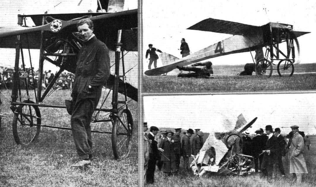
GORDON-BENNETT RACE AT EASTCHURCH. - Mr. Gustav Hamel and his 100-h.p. Bleriot just before his start in the race. On the right he is just away, to be brought down, however, after three-quarters of a minute, after rounding the first mark tower, as seen in the wreckage below. Note the rolling method of the assistants in clearing the machine at the moment of starting.
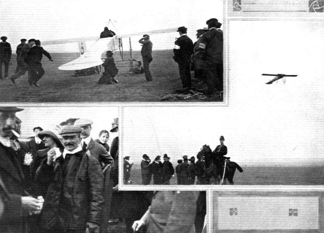
GORDON-BENNETT RACE AT EASTCHURCH. - M. Leblanc and his Bleriot machine, with which he secured second place in the race. Below, M. Leblanc is seen immediately after finishing; above, he is just off for the race; and on the right he is in flight over the course.
Flight, November 25, 1911.
THE FIRST "AEROCAR."
THE Bleriot workshops have just turned out a machine which marks a distinct point in construction and to which previous reference has been made in these pages. Built to the order of M. Henri Deutsch de la Meurthe, it is the first passenger-carrying aeroplane to be constructed in which the comfort of the human complement has been taken into serious consideration.
In this respect it signifies the commencement of a new era in aeroplane construction.
The passengers are comfortably accommodated in a side-entrance body, built by Rothchild, which is provided with mica windows in front and on either side, in order to afford to its occupants a good view of the country over which the machine is passing. Its interior is padded with pneumatic cushions for the purpose of protecting the passengers should a rough landing be made. The pilot maintains control of the monoplane by means by a regulation Bleriot cloche and foot bar from his seat on the platform extending in front of the body, and to his left is a space which can be utilized either for the purpose of accommodating a mechanic or personal attendant, or for packing luggage. To facilitate communication between passengers and pilot, a speaking tube, similar to those in use on taxis, is fitted. The landing chassis is of the customary Bleriot type, and it is further interesting to notice that the control of the machine's elevation has been entrusted to a front elevator, which is not connected with a plane working in inverse conjunction at the tail, as is usually the case when an organ of this description is employed.
It will be remembered that the experimental 100 h.p. monoplane built a few months ago by Bleriot with the object of providing data for the construction of the machine at present under consideration, made use of a method of wing bracing very much analogous to that of the Etrich. This has been abandoned and triangulation of the wings by stout steel cable resorted to.
As can be seen in the accompanying photograph, both the motor, a Gnome of 100-h.p., and the fuel tanks are arranged above and to the rear of the body, a disposition which, we must admit, savours a little too much of the Sword of Damocles to be to our liking.
The wings span 43 ft. from tip to tip, and the overall length of the machine is 46 ft. Ready for flight, but without its human load, the monoplane weighs 1,540 lbs.
Although allowances must be made for the fact that the Bleriot aerocar is still more or less in the experimental stage, it is curious that so little attention has been paid to the reduction of head resistance, for the odd 20 sq. ft. of plane surface, represented by the front of the body, presented normally to a relative wind velocity of approximately 50 miles per hour, must surely result in an enormous and unnecessary waste of power. The machine is at present at Etampes, and its preliminary trials are expected to take place shortly.
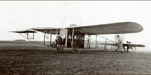
At the end of 1911, the famous Louis Bleriot had also built a cabin aircraft for four passengers and a pilot outside. This Bleriot XXIV 'Limousin' was a special order for a certain Henri Deutsch de la Meurthe.
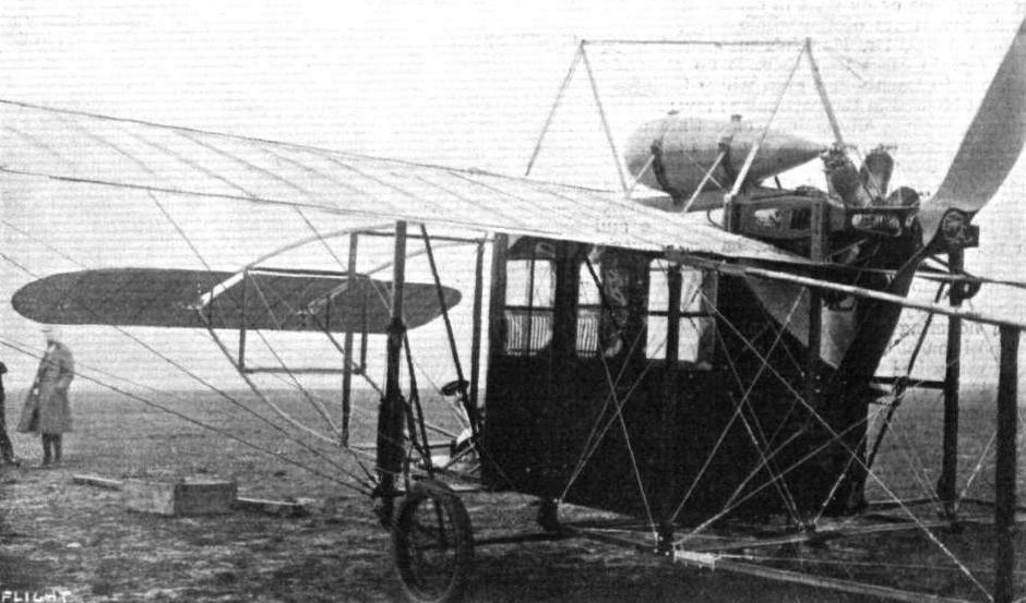
M. Deutsch de la Meurthe's Bleriot "Berline" aeroplane, showing the suspension of the car body part of the machine and the disposition of the Gnome motor, petrol tank, &c. The pilot sits in front of the enclosed body, the cloche being seen in our photograph just projecting forward. Note the special stabiliser fitted to this machine.
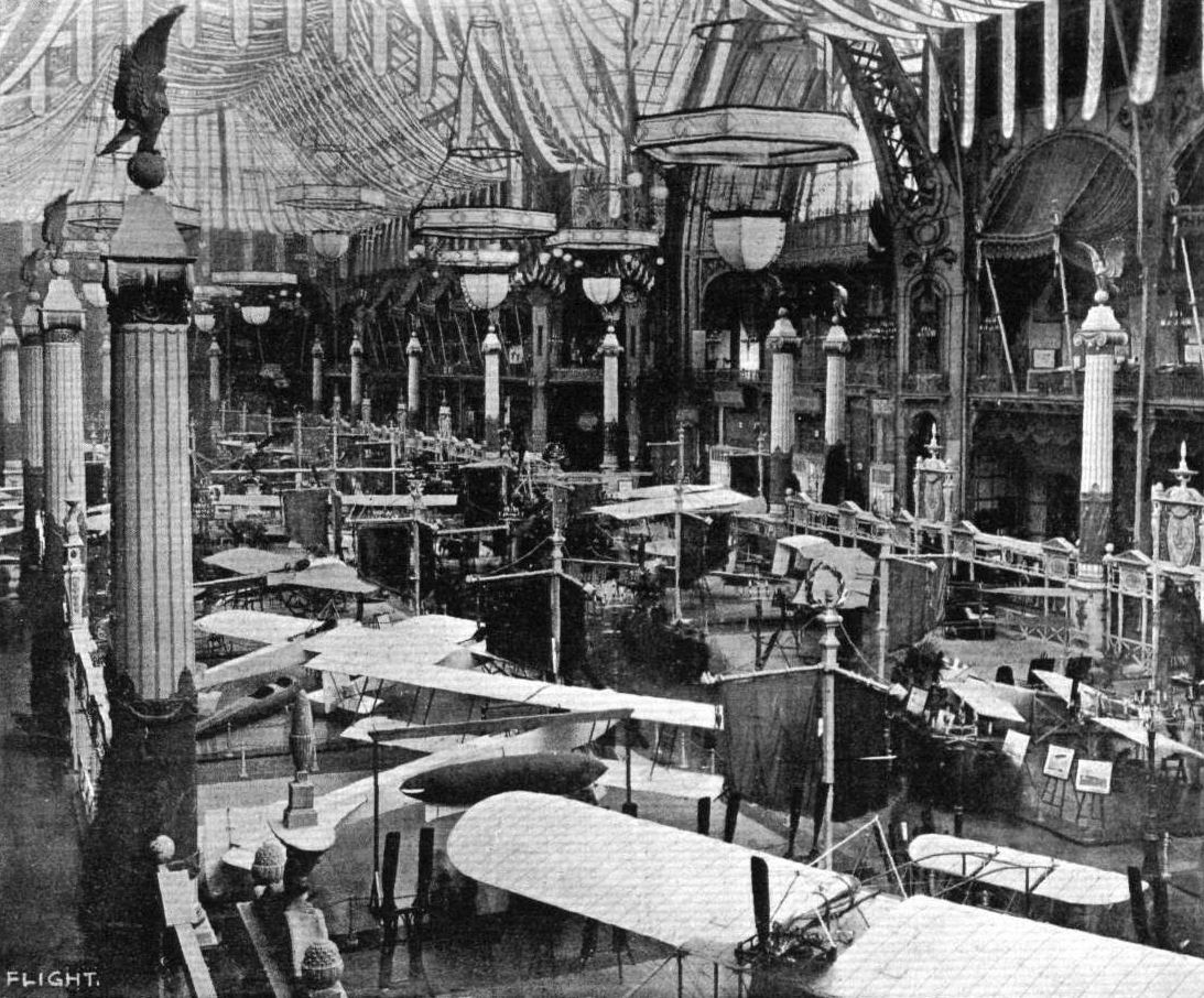
GENERAL VIEW OF THE THIRD PARIS AERO SALON. - The machine at the bottom of the photograph is the Bleriot 100-h.p. "Aeronef," built to the order of M. Henri Deutsch de la Meurthe. On the same side, but towards the centre of the Exhibition, may be seen the Zodiac biplane and the Borel and Deperdussin monoplanes, while opposite are the Train and H. Farman monoplanes and Savary and M. Farman biplanes.
Flight, September 30, 1911.
NEW BLERIOT "CANARD."
As we mentioned in a recent issue, the report that Bleriot has again been turning his attention to the production of a monoplane of a tail-first type is no canard, and we reproduce herewith photographs taken of this interesting machine at Hardelot, near Boulogne, where the machine is now undergoing tests. The landing carriage is an absolute departure from orthodox Bleriot design, and, together with the peculiar steel construction which comprises the tail skid and serves as a bridge to which the wings are braced, seems to indicate the effect of the Nieuport on current practice. Steering to the right and left is effected by miniature rudders, mounted vertically at the ends of the wings, and lateral balance is maintained by ailerons which present a slightly convex surface on the underside. One notable feature of the design is its shortness of overall length, being only 5.50 metres from tip of elevator to propeller. The wings span 8.90 metres, and have a carrying surface of 12 sq. metres. A 50-h.p. Gnome engine, direct coupled to an Integrale propeller, supplies the propulsive effort. Its weight is 400 kilogs.
In one of the views the rear disposition of the Bleriot "Canard" is clearly seen, as also the manner in which the engine is mounted. The oil system inspection glasses seem to have been mounted in rather a unique position, one calling for acrobatic contortion on the part of the pilot, should he wish to acquaint himself with the way his oil pump is working.
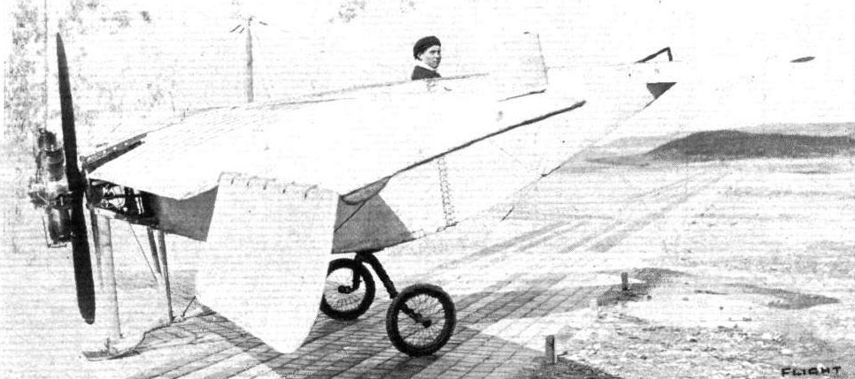
NEW BLERIOT "CANARD." - Three-quarter view, as seen from behind.
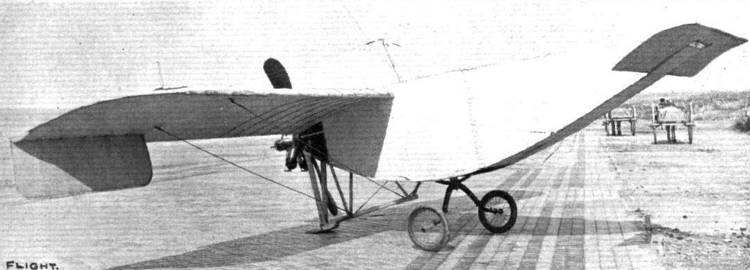
NEW BLERIOT "CANARD." - Three-quarter view, as seen from in front.
Flight, September 30, 1911.
Leblanc Trying the New Bleriot.
ON Saturday last at Hardelot, Leblanc was trying a new Bleriot racer, No. 27, and unofficially was timed to attain a speed of 130 k.p.h. (81 m.p.h.). which promises well for this machine when it appears in public competitions. We give elsewhere photographs of this new machine.
Flight, December 30, 1911.
PARIS AERO SHOW.
L. Bleriot.
FOUR monoplanes are on view on this stand, the 70-h.p. two-seater, which Hamel has popularised in England, the familiar 50-h.p. cross-country model, a new 50-h.p. racing monoplane, and a new low horse-power monoplane, type XXVIII, designated the "Popular" type. Of these machines we are already familiar with the former two, and no description of them is necessary.
As far as neatness and soundness of design, and excellence of workmanship are concerned, the new 50-h.p. racing model could give points to any other machine in the Salon. The fuselage, which is tapered off towards the front to reduce head-resistance, is splayed out at its rear end, after the manner of the 70-h.p. two-seater, to form a flat stabilising tail. The elevator is semielliptical in shape and is hinge d to the rear of the tail surface. Contrary to customary Bleriot practice, the engine is not supported on both sides of its crank case, but protrudes from the front of the fuselage, a system which allows of great neatness of mounting and greater accessibility to the engine. Bleriot, too, has altogether gone away from the design of landing chassis to which he has so faithfully adhered since long before his cross-Channel flight. In the new type the two wheels are each supported by a pair of laminated steel springs, and only four struts are employed to attach the system to the fuselage. Its simplicity and neatness must appeal strongly to those who have given any thought to the subject of chassis design. One failing it has, however, and one which could be very easily overcome is that no side-play of the landing wheels is provided for. In this machine the controlling lever is no longer provided with the aluminium dome from which it originally derived the name of cloche, but is made to operate the wing-warping and the elevator through an extremely neat system of chains and chain-wheels. The bottom pylone, from which the wing-warping is actuated, is constructed of two steel tubes of oval section, through which pass the wires connecting the mechanism at its base to the controlling-lever. A notable point about the design of the machine is that as much head resistance as possible is eliminated, and to this end not only has the design of the fuselage and landing chassis received special study, but several parts which would normally present a flat surface to the relative wind have been enclosed by stream-line shapes of wood. Tested over the sands at Hardelot, with Leblanc at the lever, this machine has developed a speed of 80 miles an hour, and on this account we are expecting to see it figuring largely in next season's meetings.
<...>
Principal dimensions, &c. :-
Racer type-
Length 21 ft.
Span 23 "
Area 132 sq. ft.
Weight 500 lbs.
Speed 80 m.p.h.
Motor 50-h.p. Gnome.
Price L960.
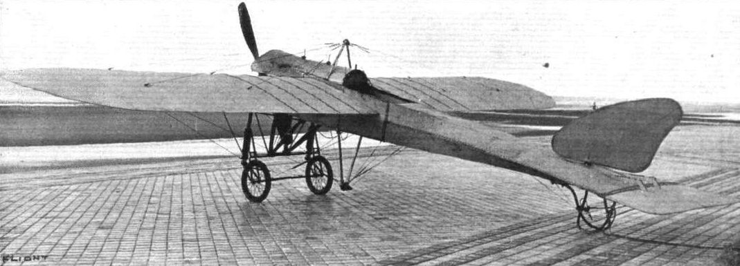
NEW RACING TYPE BLERIOT MONOPLANE (No. XXVII). - Many details in the design of Bleriot's two-seater model are incorporated in the new single-seater racer with which Bleriot is now experimenting over the sands at Hardelot. The main body is constructed in the form of a double-ended wedge, at the front of which protrudes the 50-h.p. Gnome engine, mounted in position without the employment of a bearing between the propeller and the engine. The stabiliser, as in the two-seater model, is constructed integrally with the fuselage and at the rear edge is hinged the elevator. The overall length of the machine is 7 metres, and the wings, which have a supporting surface of 12 sq. metres, span 8.90 metres from tip to tip. This new model, which weighs 430 kilogs., has been timed to attain a speed of 130 kiloms. an hour.
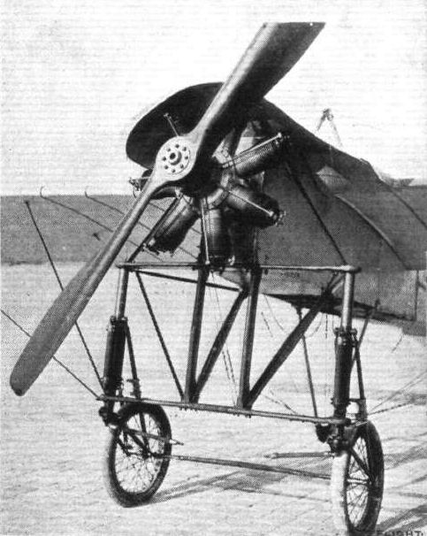
Front view of the new Bleriot racer (No. XXVII), showing the reduced landing carriage, the overhung mounting of the engine and propeller, and the peculiarly shaped cowl which prevents the lubricating oil from reaching the pilot. Bleriot, such a strong believer in mounting the engine by bearings on both sides, has, it will be noted, at last abandoned that method in favour of one which renders the motor considerably more accessible. It will be observed that a very slight dihedral angle is employed on this new model, and that the main body has a decided taper towards the front to minimise head resistance.
THE BLERIOT STAND. - At the bottom of the picture, with the warnished wings, is the new "Popular" type Bleriot, fitted with a Y-type Anzani motor of 35-h.p. as listed at L380. The larger monoplane is the 70-h.p. military two-seater, while the tail-half of a machine emerging from under the right wing of the two-seater belongs to the new 50-h.p. Racer.
Six types of landing gear at the Paris Aero Salon.
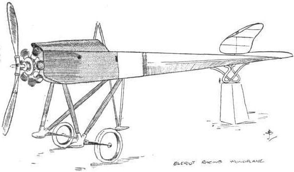
Sketch of the new 50-h.p. Bleriot racing monoplane.
Flight, December 30, 1911.
PARIS AERO SHOW.
L. Bleriot.
FOUR monoplanes are on view on this stand, the 70-h.p. two-seater, which Hamel has popularised in England, the familiar 50-h.p. cross-country model, a new 50-h.p. racing monoplane, and a new low horse-power monoplane, type XXVIII, designated the "Popular" type. Of these machines we are already familiar with the former two, and no description of them is necessary.
<...>
The new single-seater "Popular" type of machine, as its name infers, should also become widely known during the forthcoming year for, while it is capable of fairly extended cross-country flying, it is inexpensive in initial cost and upkeep. The landing-carriage is applied to the bottom of the fuselage, a feature which not only diminishes its weight and head resistance, but reduces the overall height of the machine to something under 7 ft. From the pilot's point of view, the machine possesses the advantage over the ordinary school type, that the fuselage in front of him is totally enclosed, thus preventing any oil from being thrown back over him by the engine. A section of the floor of his cockpit is left uncovered, so that he is capable of seeing the ground immediately beneath him.
Principal dimensions, &c. :-
Popular type -
Length 25 ft.;
Span 29 "
Speed 50 m.p.h.
Motor 35-h.p. Anzani.
Price L472.
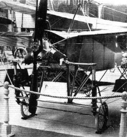
The new "Popular"-type Bleriot equipped with a Y-type 35-h.p. Anzani motor.
THE BLERIOT STAND. - At the bottom of the picture, with the warnished wings, is the new "Popular" type Bleriot, fitted with a Y-type Anzani motor of 35-h.p. as listed at L380. The larger monoplane is the 70-h.p. military two-seater, while the tail-half of a machine emerging from under the right wing of the two-seater belongs to the new 50-h.p. Racer.
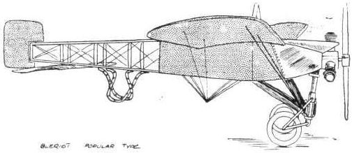
The new "Popular"'type Bleriot, fitted with 35-h.p. Y-type Anzani motor.
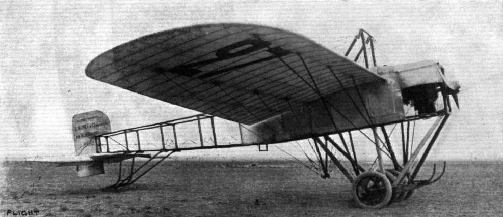
A side view of the new passenger-carrying Borel monoplane, furnished with a Gnome motor of 140-h.p. The machine follows broadly the general disposition of the single-seater monoplane of the same maker. The chassis, it will be noticed, is equipped with four wheels, in place of the two on the lighter model, while the skids are more strongly connected with the fuselage. The wings, too, are slightly different, in that their entering and trailing edges taper towards the tips.
Flight, January 28, 1911
Advancing the Passenger Carrying Record.
PROGRESS continues in practical work accomplished by aeroplanes. On the 19th inst., at Douai, Breguet on a military type Breguet aeroplane (R.E.P. motor), which has been acquired by the Russian Government, beat the world's record for passenger carrying by covering 50 kiloms. in 34 mins. 54 1/5 secs, and 100 kiloms. in 1h. 9m. 28 4/5s., giving an average of 86.368 k.p.h.
Flight, April 1, 1911.
Third International Aero Exgibition at Olympia - 1911.
THE EXHIBITS ANALYSED.
<...>
On the Breguet biplane, where the relative positions of the engine and pilot are reversed, the tail becomes, practically speaking, a non-lifting member, although in actual practice the tail of the Breguet is a slightly cambered plane. Incidentally, of course, the Breguet system facilitates the use of a monoplane type body, because the propeller, being in front, does not interfere with the continuity of the longitudinal spars in the construction of such a member. The enclosing of the body so as to be more or less of stream-line form, which feature has already been discussed, is, of course, only a natural evolution as the outcome of taking a further step in detail design. While on the subject of the Breguet machine it should also be mentioned that quite apart from the question of type this model belongs to a class apart in any case, because it is constructed entirely of steel - timber being now, as formerly, the standard material for aeroplane framework. The Breguet-type aeroplane made by the British and Colonial Aeroplane Co. is constructed of wood.
<...>
Flight, April 29, 1911.
A Breguet Biplane for the Russian Army.
ON the 20th inst. Capt. Alexandroff paid a visit to M. Breguet's headquarters near Douai, to witness a Breguet biplane built for the Russian Army put through its paces. With M. Breguet himself at the wheel the machine had no difficulty in passing the tests laid down, and Capt. Alexandroff expressed himself thoroughly satisfied with the result.
Flight, June 24, 1911.
Breguet Machines for French Army.
AT the Douai Aerodrome on the 15th inst., Lieut. Ludmann and Lieut. Fequant, on behalf of the French military authorities, accepted delivery of five Breguet biplanes. Each one was put through a test flight by either M. Breguet or Debussy, and attained an altitude of 600 metres, a speed of 95 k.p.h., with a useful load of 305 kilogs. on board. Breguet, flying with the wind, attained a speed of 120 k.p.h.
Flight, July 22, 1911.
THE BREGUET AEROPLANE.
AT a time when everything in aeronautics is virtually new it seems inappropriate to refer to any particular machine as out of the ordinary, but the stereotyping influence of the popularity of one or two leading makes has already had a marked tendency in fixing ideas in aeroplane construction so that it is, after all, a matter of necessity to say of the Breguet aeroplane that it is a machine of uncommon design and exceptional interest.
In the first place it is built of steel throughout, whereas most aeroplanes are built of timber with minor metal fittings. The body of the Breguet aeroplane has, in fact, a frame built up with pressed-steel channel-section side members just like the frame of the chassis of a motor car, which point is worthy of immediate reference as it serves to emphasise the completeness of the steel structure and also happens to be invisible in the accompanying illustrations. Another important feature of the Breguet design, which is now becoming more common, is the monoplane type body in conjunction with biplane wings. This firm was one of the first to introduce the combination, and, indeed, M. Breguet was in the habit of describing his aeroplane as a double monoplane, but this definition is not in accord with our own terminology, and it seems to us impossible to regard the Breguet aeroplane as other than a biplane pure and simple, for the planes are unquestionably superposed and their only difference is one of span. The span of the upper plane is, as a matter of fact, very much greater than that of the lower plane.
In the construction and mounting of the main planes the outstanding feature that is apparent from a glance at the accompanying illustrations is the use of a single row of struts, whereas most biplanes have their wings separated by a double row of struts. The presence of only a single row of struts is an indication of the presence of but one main spar and, indeed, the real feature of the Breguet planes is related to this fact. The surfacing material is stretched on ribs that are in themselves flexible and have in addition a flexible attachment to the tubular steel main-spar. (The constructive detail is mentioned in Patent No. 7209 of 1909.) The result is an automatically variable angle of incidence, which the makers also claim acts in the nature of a spring suspension, or, shall we say, "shock damper" in the air.
(To be concluded.)
Flight, July 29, 1911.
THE BREGUET AEROPLANE.
(Continued from page 625.)
WHEN at rest the planes have an angle of incidence of about 11°, the strength of the construction is such that under test a load of 20 lbs. per sq. ft. reduces the angle of incidence to about 2° without permanently distorting any of the constructive details. Tests made by loading the wings with sand have been conducted officially at the Douai works. Of the importance of a variable angle of incidence in connection with the problem of variable speed our readers are already acquainted through our discussion of the subject in a series of articles entitled ''Can we fly faster for less Power," which appeared in FLIGHT recently.
An important outcome of the use of but one row of struts between the main planes is that provision can be made for folding the wings against the body of the machine as a means of reducing the bulk for transport. The manner in which this is done on the Breguet aeroplane is very clearly illustrated by the accompanying illustrations, one of which is a photograph of the machine with its wings thus folded. When we speak of a single row of struts it is necessary to observe that even this single row comprises only four struts in all, and of these four two are immediately adjacent to the body of the machine; thus there is but one strut that is in any way in a position to interfere with the folding of the wings, and this, as will be evident from the photograph, constitutes no sort of inconvenience in practice. The wings are attached to the body by a knuckle-joint that is itself anchored by an adjustment bolt as shown in one of the sketches. This adjustment affords a means of varying the normal angle of incidence, but it is a shop adjustment and users of the machine are not supposed to tamper with it. When disconnected the entire wing can be turned into a vertical position, that is to say, with an angle of incidence of 900, and in this position the knuckle-joint enables the wing to be folded back against the body of the machine. Both wings are rotated in this manner but the initial movement takes place in opposite directions, that is to say, the lower plane has its trailing edge raised, while the upper plane has its trailing-edge lowered. In this way the wings overlap and occupy a minimum of space.
Whilst dealing with the constructive details associated with methods of attachment, it is interesting to observe the manner in which the tail is mounted on the frame by a universal-joint. The details of this joint are also shown in one of the sketches. The tail itself is somewhat uncommon, too, inasmuch as it is of the cruciform type and moves en bloc. The vertical plane is the rudder and the horizontal plane the elevator, but neither can move without the other. The whole structure is carried on the universal-joint already mentioned and is braced to the body by wires that contain fairly stiff compression springs in order that they may accommodate themselves to the movements of the control.
The system of control on the Breguet aeroplane includes wing-warping for balancing and the use of the elevator and rudder already described. These operations are carried out by means of a universally pivoted lever fitted with a steering-wheel at its upper extremity. Rotation of the wheel moves the rudder and the to and fro movement of the lever which forms the steering-column operates the elevator. A sideways movement of the steering-column warps the wings. Either operation can thus be carried out separately or all can be carried out simultaneously. A minor point well worthy of notice is that the wing-warping wires are attached to the steering-column by springs so that the action of wing-warping is necessarily performed gradually.
In addition to the tail already described there is a fixed tail plane situated beneath the body and in advance of the elevator. The object of this fixed tail plane is, of course, to stabilise the machine, and it is designed to carry the light load represented by the after part of the body and the movable tail members. Practically speaking the machine is in balance about the spars of the main wings, for the engine and propeller are situated well forward to balance the pilot, who sits rather to the rear of the trailing-edges of the main planes. In front of the pilot is the passenger, and as our readers know, the Breguet aeroplane has been successful in flying with exceptionally heavy loads.
The undercarriage, like every other part of the machine, is of distinctly original design. It is a three-wheeled structure so arranged that the forward wheel of the three can be used for steering the machine over the ground. For this purpose it is inter-connected with the rudder. The struts by which the undercarriage is attached to the body of the, machine are telescopic and are fitted with compression springs, two of them also have oil shock-dampers. Short skids are provided as a protection against very rough landing, such as might damage the wheels, but lit will be noticed that the wheels themselves are unusually small in diameter and therefore unusually strong.
Flight, September 16, 1911.
Flying in Morocco.
BREGI with a Breguet biplane has arrived at Casablanca where he is to be at the disposal of General Bonnier. He is shortly to carry out a flight with two passengers from Casablanca to Tangier via Rabat, Mequinez, and Fez.
Flight, September 23, 1911.
FLYING IN MOROCCO.
LAST week Bregi on his Breguet machine succeeded in flying with a passenger from Casablanca to Fez, a distance of about 300 kiloms. The idea was started by the Petit Journal, which offered to pay the expenses of the expedition, while the Breguet firm co-operated by lending one of their three-seated machines. Bregi happened at the moment to be doing his military service, so he was sent with the machine to General Moinier in order that he might assist him in the operations which were taking place. After making several flights in the neighbourhood of Casablanca, Bregi, on the 14th inst., set out with M. Lebaud, of the Petit Journal, to fly to Fez. They carried on board their arms and provisions as well as camping equipment, the latter including a cover for the machine in case it should be necessary to land during a storm. The pilot, passenger and baggage represented a load of about 350 kilogs. Bregi on starting from Casablanca made for Rabat, stopping on the way at Feldha in order to deliver a message to his uncle who is in command of a regiment of Zouaves. On the following day he continued on his way and reached Fez safely.
Flight, September 30, 1911.
The Casablanca-Fez Flight.
BREGI did not actually complete his flight to Fez quite so quickly as was reported in our last issue, the mistake being due to a telegraphic error. He was detained at Rabat for five days mainly owing to the sand storms, and it was not till Tuesday morning last week that he was able to get on from Rabat to Mequinez, covering the 81 miles in 1 hr. 35 mins. Delay was experienced there owing to the scarcity of petrol, but on Thursday morning the journey was resumed and Fez reached safely, the aviator and his companion being given a hearty welcome by the European colony at the Moorish capital.
Flight, October 7, 1911.
AIR EDDIES.
HENRI BREGI has undoubtedly had a much better time touring on his Breguet biplane in Morocco, where the natives have been prostrating themselves to the ground before his mechanical bird, than he would have had as a simple sapper in the French military manoeuvres. It is not generally known that the machine on which he has carried out these splendid flights is the same one as that used by de Montalant in breaking the world's record for altitude with a passenger at Brooklands some six weeks ago.
Flight, December 16, 1911.
A Medal for Bregi.
FOR his services in Morocco, and especially for his flight from Casablanca to Fez, Bregi, the Breguet pilot, who is also a sapeur aerostier in the Third Regiment, has been awarded the military medal by the French Minister of War.

AT DOUAI. - A Breguet biplane in the air.

THE LATEST BREGUET. - View showing the bows of one of these machines fitted with a Breguet flexible propeller gear-driven at slow speed from a Gnome rotary engine.

The Breguet military biplane packed for conveyance by road by car. - On the right the machine is seen with wings closed for easy transport for short distances.
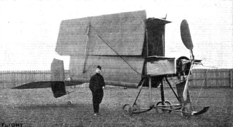
The Breguet biplane with its wings folded for transport.
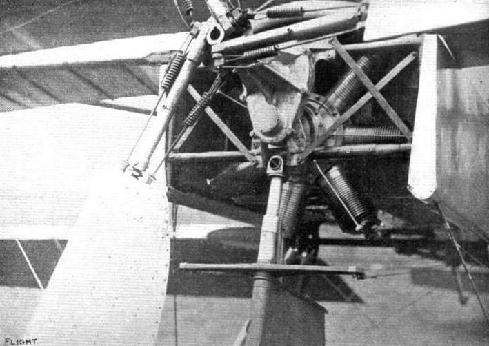
GEAR DRIVING A PROPELLER FROM A GNOME ROTARY ENGINE. - Detail view of the latest Breguet, showing how a Gnome rotary engine is used to drive a Breguet flexible propeller at reduced speed. The blades of the Breguet flexible propeller are hinged to the boss, and are anchored by springs so arranged as to allow the blades to fold back a little towards the engine under exessive pressure. The purpose of this mechanism is to diminish the stress due to gyroscopic and centrifugal force resulting from sudden changes of the attitude of the machine in flight.
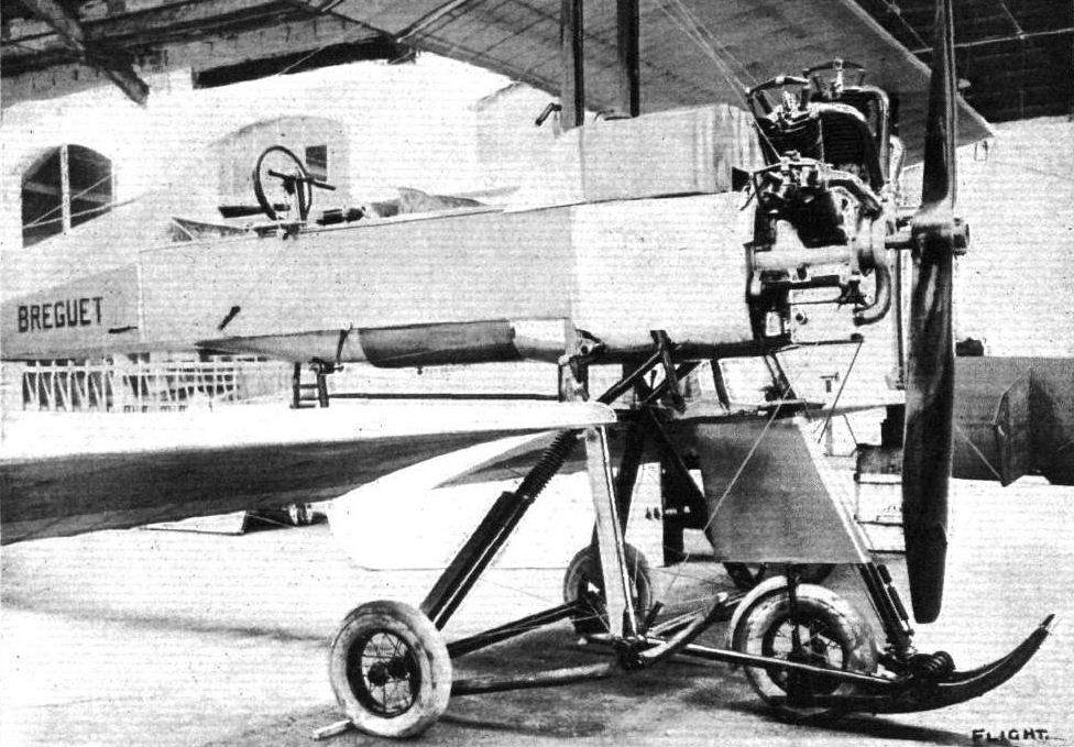
Undercarriage of the Breguet biplane.
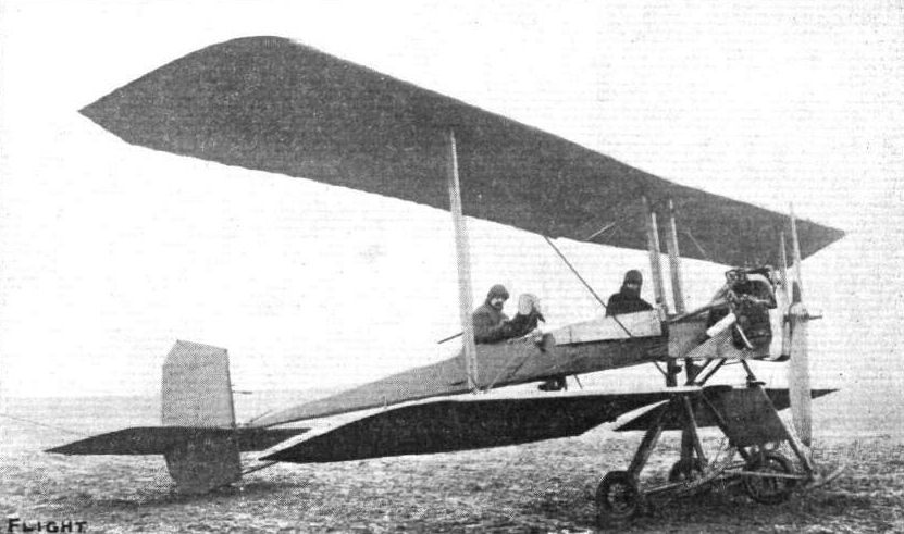
General view of the Breguet biplane from in front.
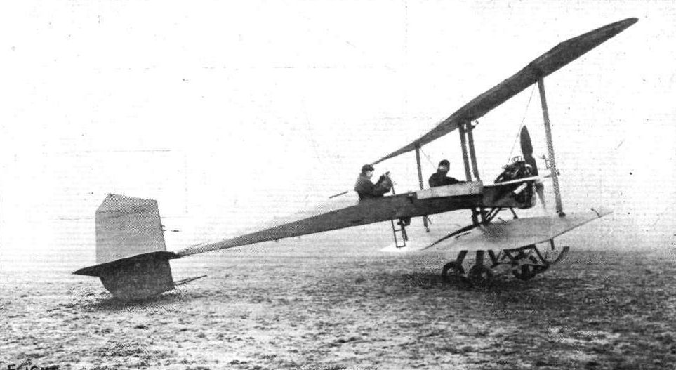
The military-type Breguet biplane upon which M. Louis Breguet, accompanied by M. Pierre Chaussier, recently put up a fine record for 50 kiloms. in 34m. 54 4/5s. and 100 kiloms. in 1h. 9 m. 28 4/5s. This machine is now being introduced into Great Britain by Mr. Arthur Turner of 173, Piccadilly.
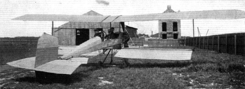
View from behind of one of the new Military Breguet Biplanes which have been employed during the French Manoeuvres. - The three officers on board are able to dispose themselves quite comfortably in the body of this machine.
AVIATION AT THE FRENCH ARMY MANOEUVRES. - Some of the Bessonneau hangars at Vesoul, and the military aeroplanes which are giving such a splendid account of themselves.

A souvenir from Henri Bregi, dated from Rabat, Morocco, where be arrived with his Breguet triplane recently, and remained for about five days owing to the violent sand-storms.

The Breguet biplane, an example of the monoplane-type body applied to biplane construction. The engine is in front, and the entire body is enclosed from head to tail. The passenger sits in front of the pilot, and being approximately on the centre of pressure, his presence does not seriously affect the balance of the machine.
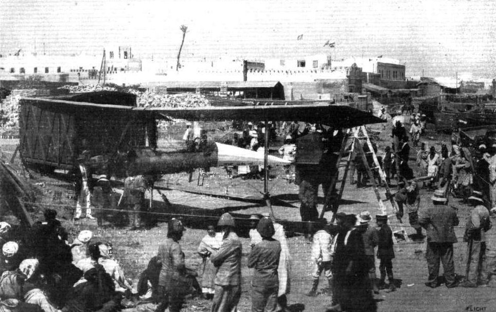
Henri Bregi's Breguet machine in Morocco.

The Colossal "Double Monoplane" which has emanated from the Breguet Workshop for the purpose of upholding the firm's honour in the Military Tests. - This machine, whose appearance was foretold in "Air Eddies" columns, is furnished with a Gnome engine of 130-h.p. Its weight, with pilot, passengers, and fuel aboard is 2,420 lbs. Although this machine has been designed to lift three passengers, Breguet is confident of its ability to carry eight.
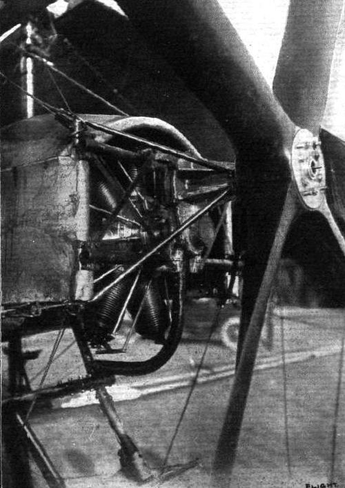
One of the results of the French aviation tests has been the increase ia popularity of the four-bladed propeller. The above photograph illustrates a four-bladed propeller fitted to a Breguet biplane, and driven by a 100-h.p. Gnome engine through reduction gearing. Use is also made of a similar propeller on a 100-h.p. Nieuport monoplane.
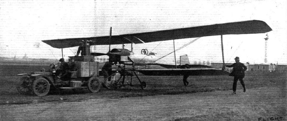
A 140-h.p. Gnome-engined double Breguet monoplane in tow for the weighing operations at the French military tests at Rheims.
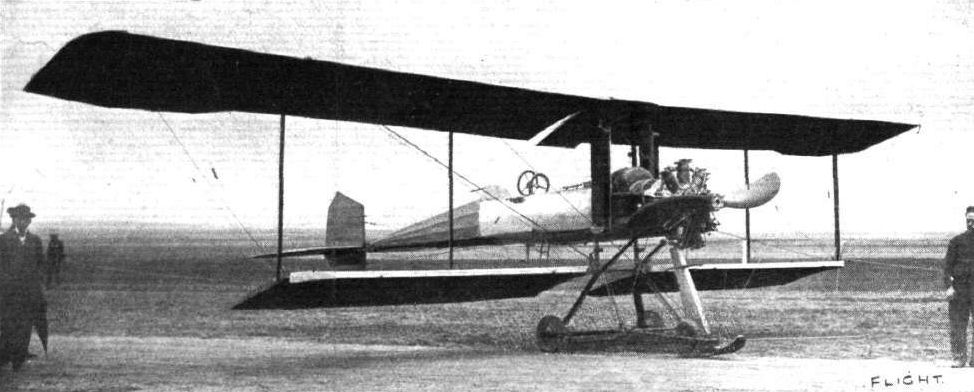
Double Breguet monoplane, fitted with 110-h.p. Salmson motor (Canton-Unne system) at the French military tests at Rheims.
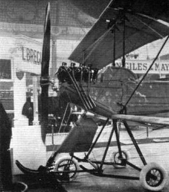
UNDERCARRIAGES AT OLYMPIA. - The Breguet mechanism.

AT THE PARIS AERO SALON. - The current trend of design towards the torpedo type of body is well illustrated by these photographs: the Aero Torpedo on the left is the two-seater Breguet, with Chenu motor, and on the right is the unfinished Morane-Saulnier war monoplane; it is constructed entirely of steel, including the wing skeletons.

Close view of the prow of the Breguet biplane, showing the very characteristic armour-plated appearance of the body. The entire framework of this machine is made of steel.
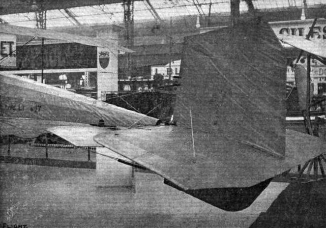
Tail of the Breguet biplane.

The pilot's seat and the passenger accommodation on the Breguiet biplane.
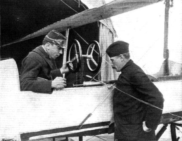
M. Henri Bregi, one of the chief pilots of Breguet machines, taking instructions as a sapper from Lieut. Ludmann, aviation officer in command at Douai, in connection with a military aerial reconnaissance.

Sapper Henri Bregi, who has recently flown with a passenger and spares and tools from Cassablanca to Fez on a Breguet machine.
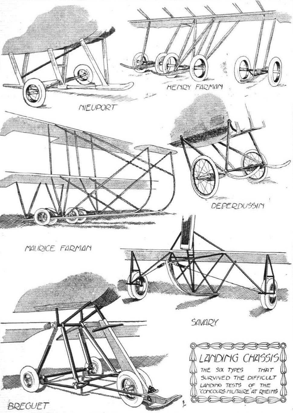

MONOPLANES AND BIPLANES IN THE DAILY MAIL CIRCUIT ROUND GREAT BRITAIN. - From these every machine can be readily identified either in flight or on the ground.
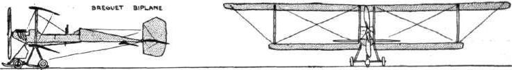
PARIS-MADRID RACE. - Diagrammatic sketches of some of the machines entered in the race.
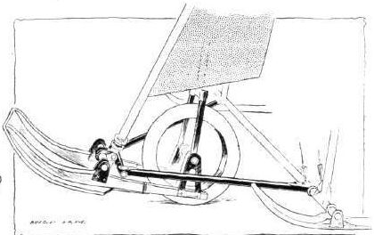
Swivelling fore part of the under-carriage on the Breguet biplane.
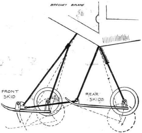
Diagram illustrating the suspension of the undercarriage on the Breguet biplane.
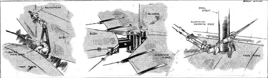
On the left is a view of the knuckle-joint attachment of the wings to the body; in the centre is the universal-joint supporting the tail, and on the right is shown the method of anchoring the tie-wires to the base of a strut on the main plane.
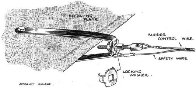
Sketch illustrating the attachment of the rudder control wire to the elevating-plane of the tail on the Breguet biplane.
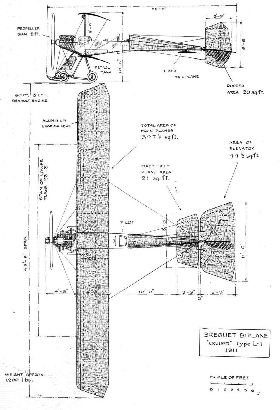
THE BREGUET BIPLANE. - Plan and Elevation to Scale.
Flight, December 30, 1911.
PARIS AERO SHOW.
Bronislawski.
ON this stand was exhibited a Henry Farman biplane fitted with the new Bronislawski method of balancing. This system consists of a pair of cambered planes set at a positive angle of incidence and rigidly mounted to a vertical mast, which is supported from the main planes by a skeleton of steel tubing. One of these units is situated at each end of the cellule. In normal flight these supplementary planes are arranged in end-on aspect to the relative wind, but as soon as the machine is tilted out of the horizontal in a lateral sense these planes are rotated about their vertical axes by means of wires passing from the pilot's controlling lever to a drum attached to the bases of their respective masts. By their rotation, the planes become incident to the relative wind and thus lift or depress according to whether their incidence is positive or negative. Both systems of planes at either end of the main supporting surfaces work in conjunction, thus forming a righting couple. As one of the most important features of this system, the inventors claim that in the action of restoring balance the position of the centre of resistance of the machine as a whole is not altered, so that there is no necessity to bring the vertical rudder into action, and on this score they claim that the Wright patents are not infringed.
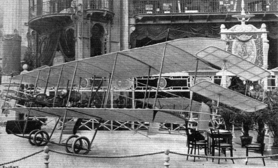
The 50-h.p. Henry Farman biplane, equipped with the new Bronilawsky stabilising system of rotatable planes, shown on the Bronislawsky stand.
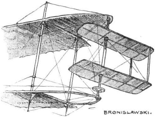
The Bronislawski system for lateral stability as applied to a Henry Farman biplane.
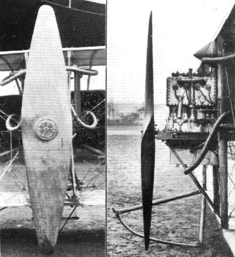
THE CYRNOS PROPELLER. - The above illustrations show a new propeller in use on the Caudron biplane. The design is due to M. Fillipi, and appears to be based on the assumption that the two blades may together be considered as analogous to one aeroplane. The generally accepted view, however, is that each blade separately should be considered in this light.
Flight, December 30, 1911.
PARIS AERO SHOW.
Caudron Biplane.
MUCH interest attaches to the little Caudron biplane by reason of its diminutive size and the simplicity of its construction. The machine in question is fitted with one of the new "V" type Anzani engines and is capable of a speed somewhere in the neighbourhood of 55 miles per hour. A certain degree of automatic stability in a lateral sense is obtained by the method of construction of the planes. The rear-boom of the plane is situated only two feet behind the entering edge, and the remainder of the plane that extends for a distance of 2 ft. 6 ins. behind the rear boom is formed by the application of a single surfaced covering over flexible continuations of the ribs. Landing carriage and tail outriggers are combined in this little machine, and in this way much multiplicity of parts is done away with. A little body is provided for the accommodation of the pilot midway between the main plane, and at its forward extremity is mounted its power plant. A single monoplane surface performs duty as both stabiliser and elevator, elevation being effected by flexing the rear half of this surface which is constructed after the same manner as the main planes. Two vertical rudders, working in parallel, provide means whereby steering is done. This handy little machine is listed at L320 and at this price should find many customers.
Principal dimensions, &c.:-
Length 22 ft. Weight 500 lbs.
Span 24 ft. Speed 55 m.p.h.
Area 220 sq. ft. Motor 35-h.p. Anzani.
Price L320
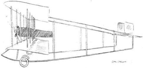
The diminutive Caudron monoplane, fitted with 35-h.p. Y-type Anzani motor.
Flight, April 22, 1911.
A Clement Monoplane.
A NEW monoplane, built entirely of metal by the Clement-Bayard firm, is expected to shortly commence its trials at Issy.
Flight, April 29, 1911.
Practice at Issy,
DURING the past week Colliex has been practicing with the Voisin-Canard and also with a two-seated biplane of the military type, while Anzani and Darioli have been testing their Anzani-engined Bleriot, the former having a 5-cyl. motor and the latter a 3-cyl. one. Another monoplane which has been out is the Roux, while Deletang has made several short flights on the new Clement-Bayard aeroplane illustrated below.
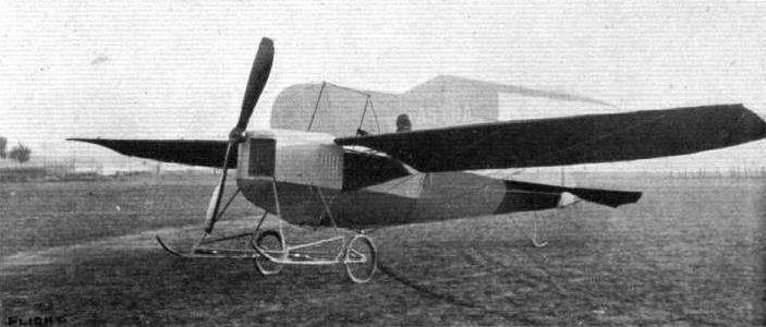
THE NEW CLEMENT-BAYARD MONOPLANE AT ISSY. - Weight 400 kilogs., 20 m. surface, R.F. propeller. She is fitted with a 4-cyl, 45-h.p. Clement Bayard motor.
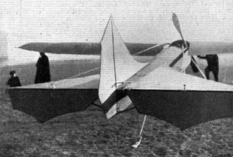
The tail of the new Clement-Bayard monoplane.
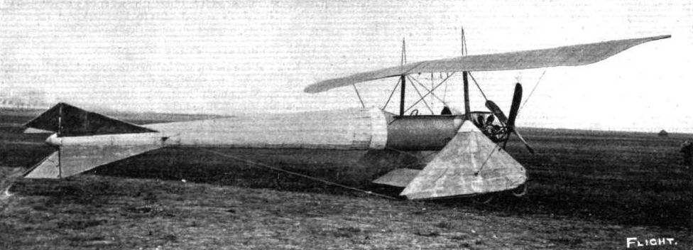
The latest Coanda aeroplane, as seen at the French military aeroplane competition at Rheims. The main plane is of 16 metres span, and the supporting surface is about 33 sq. metres. The fin-shaped lower planes fitted at an inverted dihedral angle, and the diagonal arrangement of the tail planes and rudders, is most unusual, while the machine is also unique in having two 70-h.p. Gnome engines, one being placed on each side of the fore part of the fuselage, and driving the four-bladed propeller by gearing.
Flight, August 12, 1911.
The De Dion Biplane.
THE latest De Dion biplane has just made its appearance in the open and created a good deal of interest in French aeronautical circles, chiefly by reason of its large size and massive construction. In general appearance, as will be gathered from our photograph, the machine resembles the Henry Farman type of machine, while the main beams running fore and aft are reminiscent of the Paulhan design. Two four-bladed propellers are driven by chains from a 100-h.p. 8-cylinder V-type De Dion engine, and a tubular radiator is fitted in front of the driver's seat. The span of the main planes is 20 metres and the surface 100 sq. metres, while the weight is given as 1,200 kilogs. The trials are to be conducted by Champel, who, it will be remembered, was at the Lanark meeting with a Voisin machine last year.
Flight, March 18, 1911.
RECORDS WITH AND WITHOUT PASSENGERS.
Two and Four Passenger Records.
FOLLOWING upon the remarkable series of speed records made by Nieuport on his monoplane at Chalons the same aviator on the 10th inst. succeeded in beating the speed record with two passengers, and setting up a new distance record under such conditions of 110 kiloms. in 1h. 4m. 58 1/5 s. The times for the intermediate distances will be found elsewhere in this issue in the list of new official records. Afterwards M. Nieuport brought out another machine fitted with a 30-h.p. Nieuport engine, on which he succeeded in flying by himself 80 kiloms. in 44 mins. 52 2/5 secs., getting very near the time of 44 mins. 29.5 secs., being the world's record of Leblanc.
Another remarkable performance was made on the following day when Busson on the Deperdussin monoplane accompanied by four companions covered 50 kiloms, in 31 mins. 23 1/5 secs. The total weight of the five persons was 352 kilogs., and the intermediate times were: 10 kiloms., 6 mins. 16 3/5 secs.; 20 kiloms., 12 mins. 33 1/5 secs.; 30 kiloms., 18 mins. 48 secs.; 40 kiloms., 25 mins. 5 2/5 secs. The monoplane was fitted with a 100 h.p. Gnome engine and the attempt was made over a course of 2.5 kiloms. at the Courcy-Betheny Aerodrome. The four companions of Busson were MM. Borie, Valentin, Soulier and Scheiber.
Flight, September 9, 1911.
FIRST ACROSS THE FIRTH OF FORTH.
ALTHOUGH some time ago a prize was offered for a flight across the Firth of Forth, it was subsequently withdrawn, owing to lack of competition. On the 30th ult., however, the double journey across the Forth was made in splendid style by Mr. W. H. Ewen on his Deperdussin monoplane, one of the latest "popular" type. Starting from the Marine Gardens of Portobelio, Mr. Ewen rose until he was about 1,000 ft. high, and passing Inch Keith went on until within a mile of Kinghorn. He then turned and proceeded up the Firth in the direction of Leith. Two miles from the port he once more turned, and this time headed for his starting point at Portobello. He was planing down there, but coming to the conclusion that the Sports Ground was rather too restricted for landing, he flew outside the ground, and descended in a field in the neighbourhood. As soon as the mechanics arrived the wings were taken off and the machine wheeled back to the aerodrome. Mr. Ewen was in the air for about ten minutes, and covered roughly twelve miles.
On his return to the Marine Gardens, Mr. Ewen was welcomed on behalf of the Executive by Councillor Rawson. Speaking of his flight, which he described as successful in every way, he said that he had a bad five minutes when at about the middle of the Firth on the return journey, when the machine rocked and swayed a good deal, but the Anzani-engined Deperdussin stood up to her work in fine style. He never had any difficulty in observing his location, and when over the water was easily able to make out the steamers beneath.
Flight, November 4, 1911.
FROM THE BRITISH FLYING GROUNDS.
Lanark Aerodrome (Lanark, N.B.).
ON Saturday afternoon last Mr. Ewen made a fine flight to Edinburgh on his Deperdussin monoplane. Leaving the Lanark aerodrome at 12 mins to 4 and rising rapidly to a height of well over 1,000 feet, he disappeared in the direction of Carstairs. Here he picked up the Caledonian Railway, which he followed to Edinburgh, landing safely at Gorgie Farm, which is on the outskirts of the city, at 4.23. The distance is roughly about 30 miles. The Deperdussin behaved splendidly and Mr. Ewen landed in the farm grounds without a mishap, and was hospitably received by the Rev. Father Forsyth. This performance is of considerable merit, considering the hilly country which had to be flown over and that the Anzani engine was only 28-32-h.p.
His flight was witnessed by thousands of people along the route, and he was easily identified by the word "Ewen," which was painted in large letters under the wings.
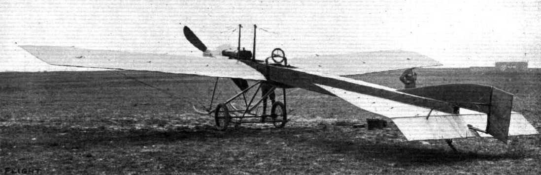
One of the new Deperdussin Monoplanes which were built to take part in the European Circuit. - It will be noticed that the square fuselage is entirely cased in, while another special feature is the long skids which project out in front to protect the propeller.
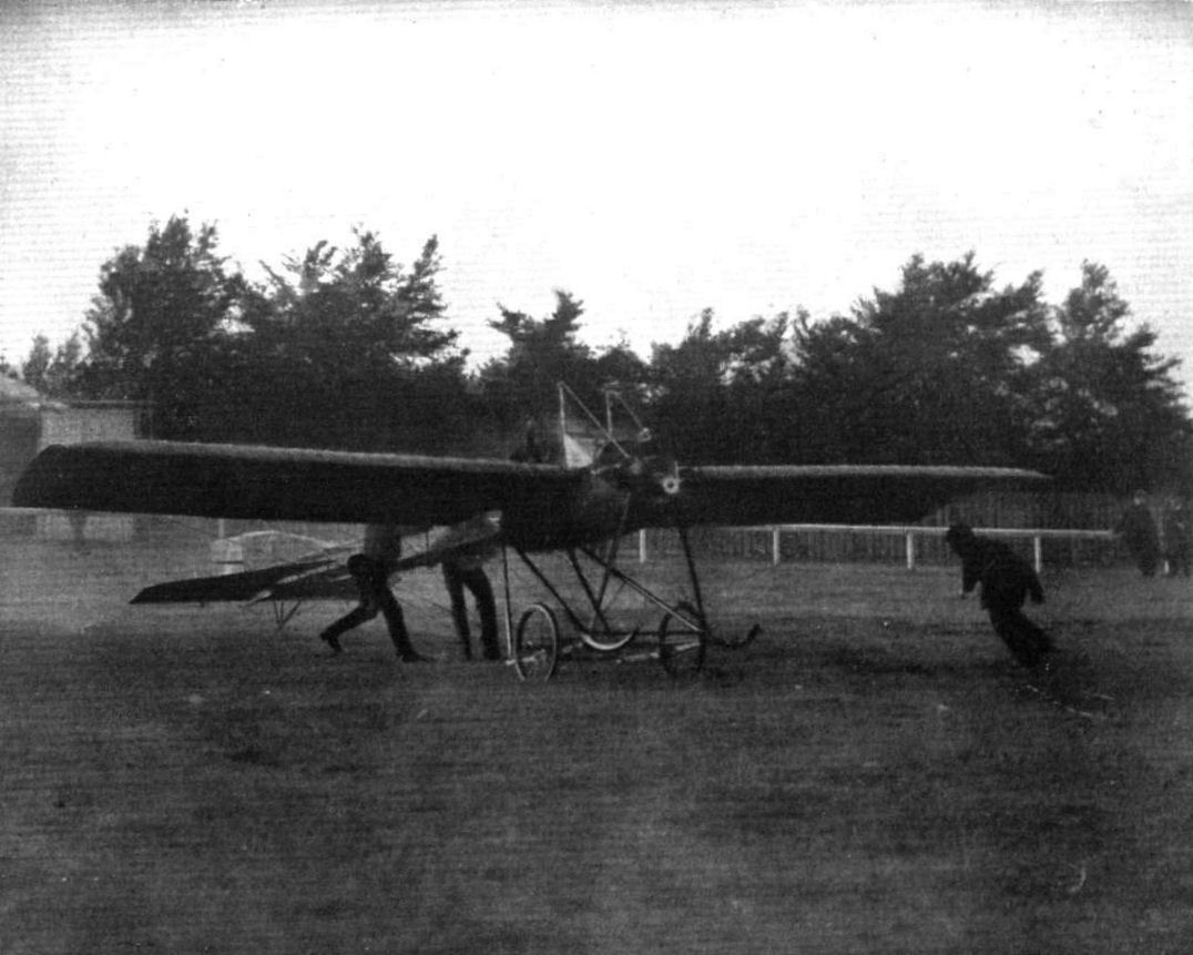
Mr. W. H. Ewen's start for his recent Lanark-Edinburgh flight on his 28-h.p. Anzani-engined Deperdussin monoplane.
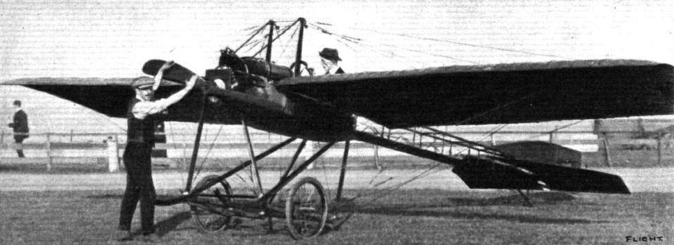
Mr. W. H. Ewen, who on Thursday last week flew across the Firth of Forth, from Portobello to Kinghorn and back again, on his Deperdussin monoplane, fitted with 3-cyl. Anzani engine. In our photograph, Mr. Ewen is seen in the pilot's seat ready for the starting of the propeller.
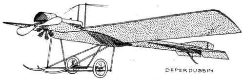
MONOPLANES AND BIPLANES IN THE DAILY MAIL CIRCUIT ROUND GREAT BRITAIN. - From these every machine can be readily identified either in flight or on the ground.
Flight, August 19, 1911.
THE DEPERDUSSIN MONOPLANE.
SINCE the first appearance of their product, which gave all those who were fortunate enough to be present at the last Salon Aeronautique in Paris an impression of neatness in design and workmanlike construction, the Maison Deperdussin has characterised its existence in the aviation industry by a commercial vigour that few have equalled and none exceeded.
They first of all designed a good machine, and then employed good pilots to fly them. They established flying schools on the best aerodromes of France, Belgium and England, and lately have done their best to popularise their models by entering them in all the big competitions, and by putting them on the market at a very alluring price.
From the performances achieved by the Deperdussins in the Circuits of Europe and Britain, and from the fact that it was a "first reserve" in the Gordon-Bennett Race, may be judged their cross-country and speed qualities.
The fuselage under its fabric covering is of the ordinary box-girder type, but is peculiar in that the top and bottom longitudinals are parallel from engine to rudder, while to afford more accommodation for engine mounting, tanks, and pilot, a semi-cylindrical well is provided under the front section, consisting of a light wooden framework covered inside and outside with veneer.
The fuselage is pretty to the eye, but is so shallow that the pilot sits on it rather than in it.
Another unique feature is the method of attaching the cross-bracing wires to the small aluminium sockets accommodating the struts.
The landing carriage is a neat and light wheel and skid combination, the axle being sprung by the conventional radius-rods and elastic shock-absorbers. The cross-members of the chassis are of steel tubing, and it is noticeable that the four main struts are covered with canvas. Very little wire bracing is used, but rigidity is given to the structure by two wooden diagonal struts in compression.
These struts extend in front of the chassis proper, and are curved up in hockey-stick fashion to form a protection for the propeller.
Shocks occasioned by rough landings are distributed over as much fuselage area as possible by means of stranded cables, which pass under the well of the body and over grooves at the top of the chassis-struts, thus forming a kind of cradle.
The method of mounting the motor is, without doubt, neat in the extreme. A sheet-steel cap fits over the front end of the fuselage, and to this is screwed in the usual manner that flat plate keyed to the Gnome crank-shaft which would form the fly-wheel if the cylinders were kept stationary. Aluminium inspection doors are provided for access to the magneto, & c, and an aluminium dome is arranged over the top of the motor, to prevent the spray of oil from the exhaust reaching the pilot.
The weight of the wings when the machine is at rest is supported by two struts erected vertically from the front of the main body in order, at the same time, to strengthen the wings against end stresses when in flight. They are of ample proportions near the base, as they also serve to accommodate the front wing spar.
The construction of the wings follows conventional lines, with the exception that the trailing edge is laced to the ribs and is allowed a small degree of flexibility. Aluminium plates are fastened on the under surface of the wings against the main body, to protect the fabric from becoming saturated with oil. Their brownish tint is due to the treatment of the fabric with "Emaillite," a preparation that renders it weather and oil proof, and endows it with exceptional tautness. This same varnish is also employed to proof the main frame covering and the tail planes.
The control is extremely neat, and the movements are more or less natural. A wheel, mounted in the centre of an inverted U-shaped sweep of wood, is rotated for the correction of lateral balance, while a to-and-fro motion controls the elevation. Steering is effected by the usual form of pivoted foot-lever.
The wires from the warping-wheel are carried to a rock-lever on the rear cross-member of the chassis, and after passing over pulleys on the skids, each wire branches into three. These are connected to clips on the rear wing spar. By rotating the wheel to the left, therefore, the whole of the rear spar of the right wing is pulled down, while the similar spar on the left wing rises a corresponding amount, and vice versa.
The combined oil and petrol tank is mounted in the front of the pilot between the two wooden masts, and gauges are fitted so that he is constantly acquainted with the state of his fuel supply. A small reserve petrol tank is arranged under the seat, and the fuel is fed under pressure to the main tank by a pump on the right of the pilot.
The passenger-carrying and school Deperdussin models have purely flat tail planes triangular in shape, but the racer, probably to render the machine more "lively" to the controls or to introduce greater internal strength, possesses a tail in which the upper surface is considerably cambered. This constitutes a lifting plane and contributes to a certain extent to the efficiency of the machine by actually doing work instead of being a solely directive organ.
Hinged to the rear of the tail plane is the rectangular elevator, while forward of the rudder extends a small vertical stabilising fin.
A neat skid, hinged in the centre and flexibly anchored at the top, protects the rear of the machine from ground contact.
Flight, August 26, 1911.
The Ventnor Flying Week.
FROM a flying point of view the Ventnor week was somewhat of a fiasco, as from one cause or another most of the machines which it had hoped would have taken part were put out of commission. Mr. Valentine, on the Deperdussin machine which he had flown from Brooklands, saved the situation by making a fine series of flights on the 17th inst. Rising from the Dean Farm on the Whitwell Road, he made quite a long trip over the Downs, and also circled round the town.
Flying from Ventnor to Brighton.
ON Monday last Mr. Valentine left Ventnor on his Deperdussin monoplane, and steered for Brighton. Arrived at "London-by-the-Sea," he first circled the Palace Pier and then landed safely at the Shoreham aerodrome.
A telegram handed in at Ventnor as Mr. Valentine left was not delivered at Brighton until some time after the aviator arrived.
Flight, December 16, 1911.
Flying at Night by Searchlight.
A CORRESPONDENT sends us the following interesting account of a night in America by Mr. George M. Dyott, a member and pilot of the Royal Aero Club :-
"The sensation of the week ending October 28 that the Nassau Aerodrome in New York was the ascent by night of two Englishmen, Mr. George Dyott, with Captain Hamilton as passenger, in a Deperdussin monoplane. With the aid of a powerful searchlight attached to the running gear of his aeroplane and connected by electric wires, Mr. Dyott flew all about the vicinity of the Nassau Aerodrome and landed without even straining a wire.
"The other machines had been in their hangars for some time, and all was a thick inky darkness when Mr. Dyott ended his remarkable flight. Captain Hamilton manipulated the searchlight and picked out a landing for Mr. Dyott near his hangar.
"Ths aeroplane presented a most remarkable appearance in the dark sky with the searchlight sending its rays in all directions. At times the light would be shut off, and except for the throbbing of the motor the location of the aeroplane could not be determined. As the monoplane came down from a height of 300 feet the searchlight was turned towards the ground, and the spectacle resembled a monster shooting star rushing earthward.
"Captain Hamilton, who has had much experience in aeronautics in England and France, declared the experiment to be a marked success, and that it would be but a short time before aeroplanes would be flying at night whenever occasion required.
"Mr. Dyott took his brevet at the Bleriot School of Aviation at Hendon last summer, and afterwards spent several weeks in France at the Deperdussin School of Aviation, from there he went to the magnificent works of the Deperdussin Company, and watched the building of the two fine machines which he and Captain Hamilton took with them to America.
"Mr. Dyott and Captain Hamilton left New York on November 1st for Mexico City, where they have arranged to fly for a month."
Flight, December 30, 1911.
PARIS AERO SHOW.
Deperdussin Monoplane.
IN order lo exhibit their four types of monoplanes most effectively, the Deperdussin firm went to the extent of engaging two stands for that purpose. On one stand, situated under the centre dome of the Grand Palais, were exhibited the 100-h.p. Gnome-engined three-seater monoplane and the 50-h.p. single-seater cross-country machine. At the further end of the Show was the other stand, on which the 35-h.p. Anzani-engined popular- and the 70-h.p. two-seater military-types were exhibited. Very little need bу said of these excellent machines, as, in the main, they do not differ from the Deperdussin monoplane, as has already been described in FLIGHT, and demonstrated practically in England by such pilots as W. H. Ewen, Lieut. Porte and Gordon Bell, and on the Continent by Such men as Prevost and Vedrines. The latter model - the 70-h.p. military monoplane, however, is a new one, but its only difference lies in the fact that passenger and pilot are arranged tandem fashion in the fuselage in such a way that the former is so far forward that he can obtain an excellent view of what is directly beneath the aeroplane by glancing over the front of the wings. The importance of this feature for military requirements is readily apparent. Both in design and workmanship the machines are of the highest order, and reflect great credit on the Deperdussin firm, and more particularly on the firm's designer and works manager, M. Bechereau.
Principal dimensions, &c.:-
School type-
Length 25 ft.; Weight 500 lbs.
Span 29 ,,; Speed 55 m.p.h.
Area 165 sq. ft.; Motor 35-h.p. Anzani.
Price L460.
Single-seater military-
Length 25 ft.
Span 29 ,,
Area 264 sq. ft.
Weight 550 lbs.
Speed 65 m.p.h.
Motor 50-h.p. Gnome.
Price L920.
Two-seater military-
Length 26 ft.
Span 36 ,,
Area 310 sq. ft.
Weight 924 lbs.
Speed 65 m.p.h.
Motor 70-h.p. Gnome.
Price L1,080.
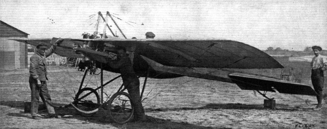
General view of the Deperdussin monoplane.
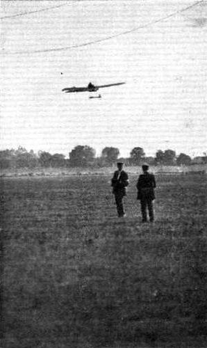
Valentine making his rapid rise and turn on the Deperdussin.
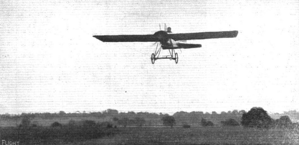
EUROPEAN AVIATION CIRCUIT. - Valentine, the only British aviator, arriving at Hendon on his Deperdussin machine.
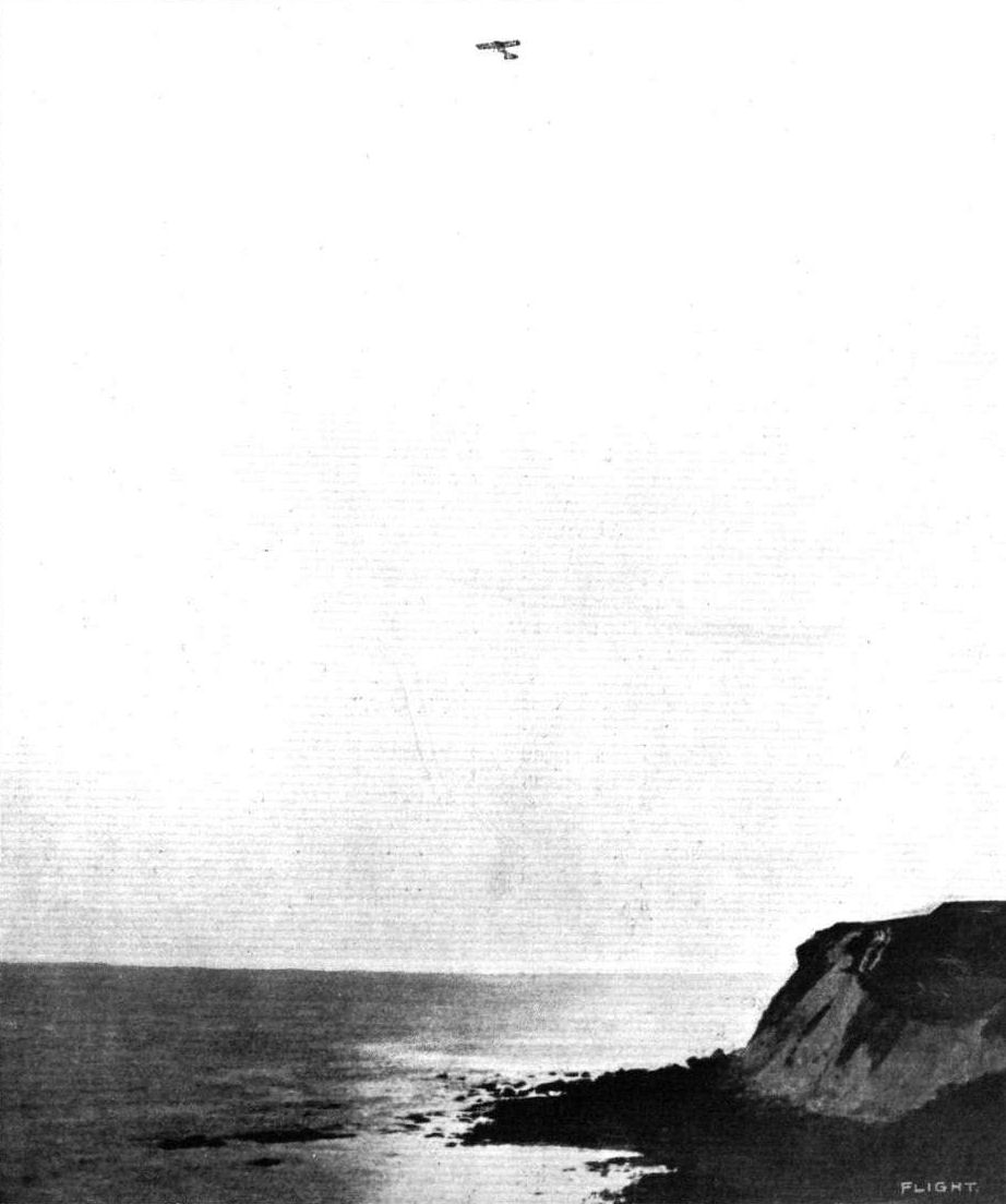
THE FLYING WEEK IN THE ISLE OF WIGHT. - Mr. Valentine making a high flight over the sea on his Deperdussin monoplane at Ventnor.
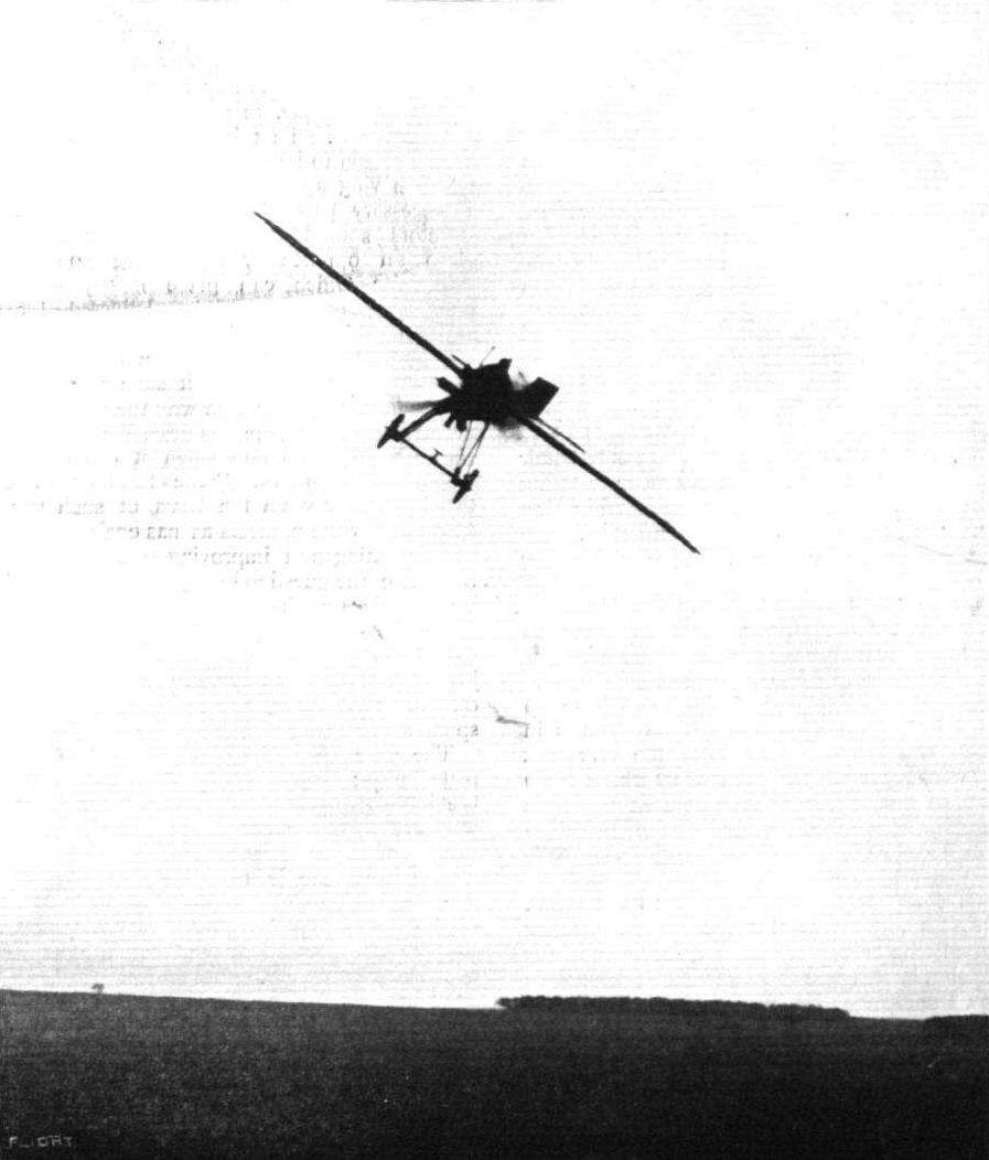
A fine bit of banking by Aubrun on a single-seater 80-h.p. Anzani-engined Deperdussin racer during the Rheims Military Aeroplane Competition.
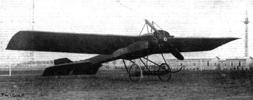
THE LATEST TYPE OF MILITARY DEPERDUSSIN MONOPLANE. - This is one of the machines which has been participating in the Military Competition at Rheims, and is engined with a 100-h.p. Gnome.
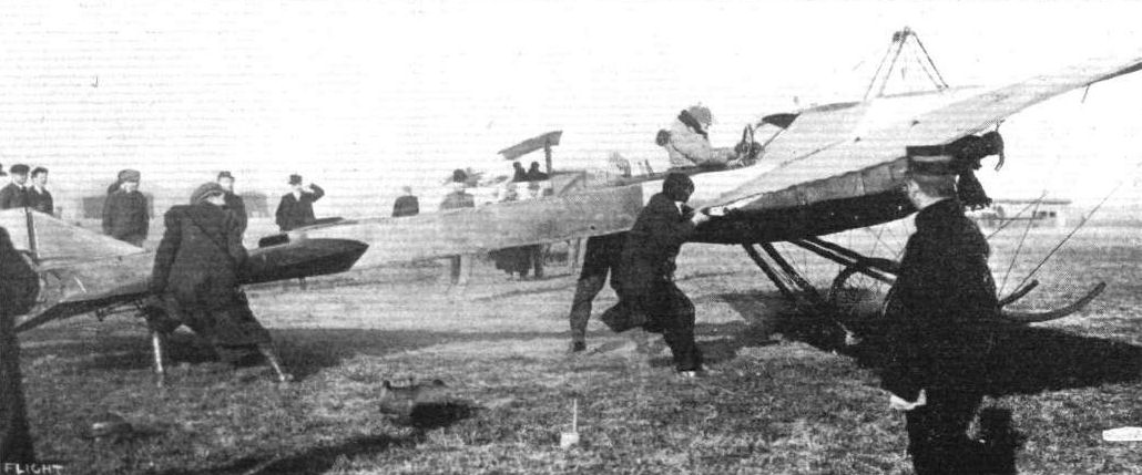
Vedrines, on a Deperdussin monoplane, just receiving the signal to depart for the long flight test in connection with the military competition at Rheims.

Mr. Valentine, on his Deperdussin machine, tuning up his Gnome engine for a flight at Ventnor in the Isle of Wight. On the right Mr. Valentine is just landing after an exhibition trip in the air.
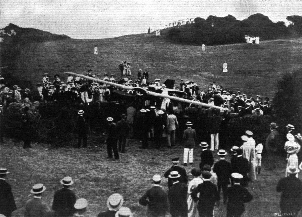
FLYING IN THE ISLE OF WIGHT. - Mr. Valentine and his Deperdussin when landing at Ventnor came down on some very rough ground, and he is seen in our photograph having the machine lifted over a wall into a more suitable field for recommencing flying.
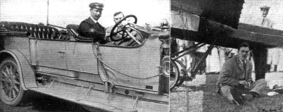
AVIATION IN THE ISLE OF WIGHT. - Mr. Valentine, who has been flying his Deperdussin monoplane, is seen arriving by car on the left at the Ventnor grounds; and on the right, waiting in the shade of his machine for a pair of mislaid goggles before starting his flight.
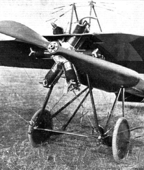
Disc wheels, which were originated by the Short Bros., have made their appearance on many of the machines entered for the French Military Tests. They have been fitted to the Paulhan and Astra triplanes and to the Deperdussin monoplane. The above photograph shows the fitting of a new 80-h.p. Anzanl to a machine of the latter type. It is evident that the front upturned extensions of the skids have proved of little use beyond contributing to the machine's gracefulness of outline, for in this machine they have been done away with.
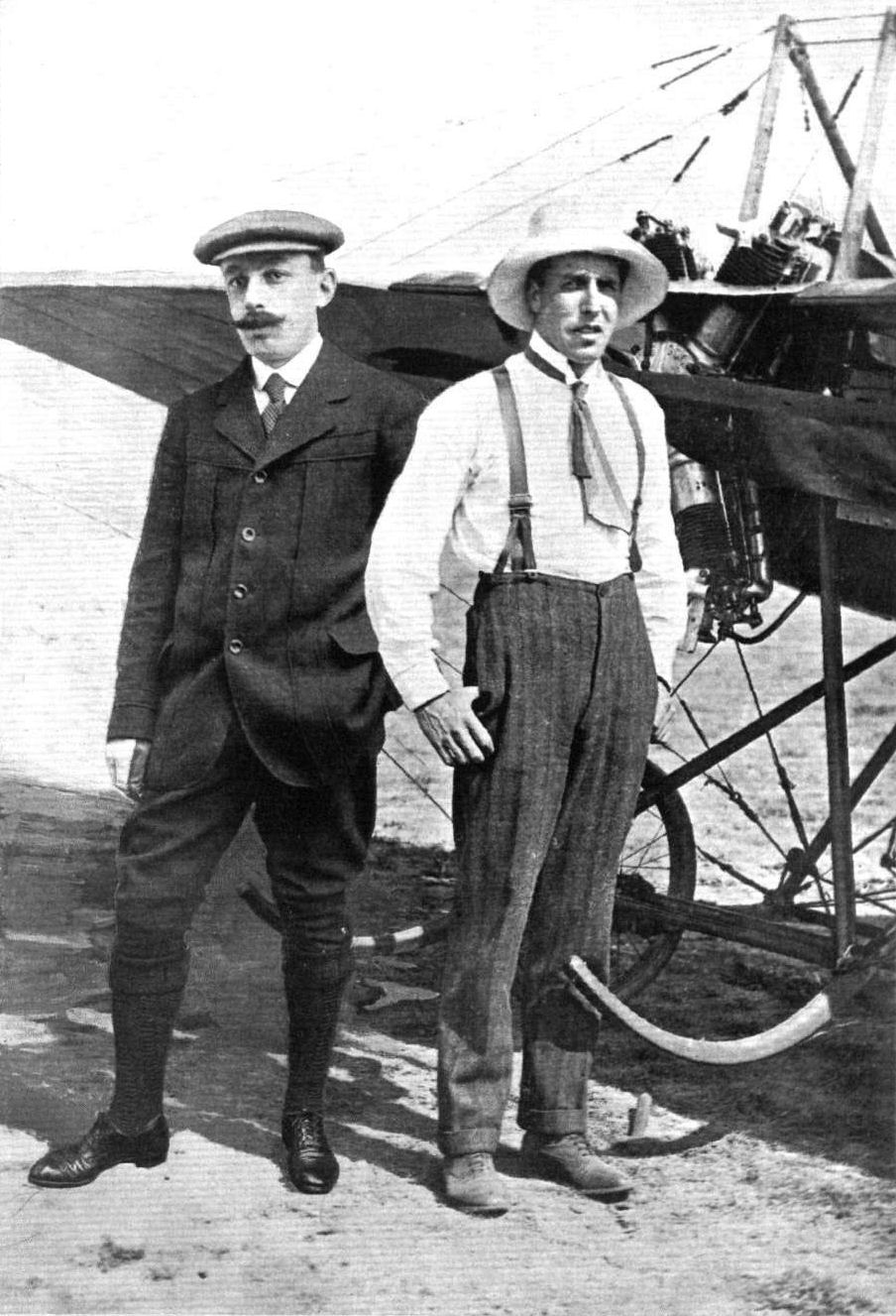
MESSRS. D. LAWRENCE SANTONI and LIEUT. J. CYRIL PORTE, R.N., Two pilots who are the first to establish and operate a British factory for a foreign aeroplane, viz., the Deperdussin.
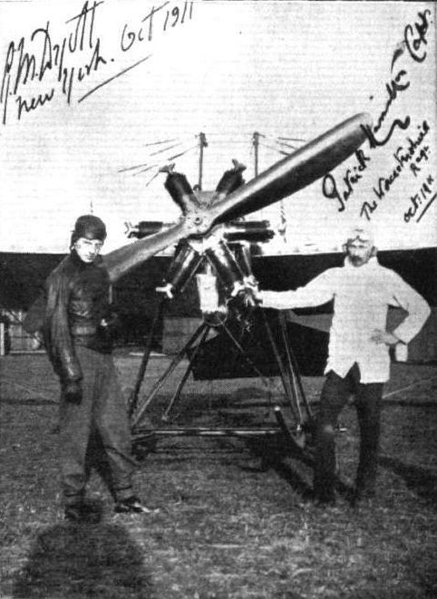
Mr. G. M. Dyott and Capt. Patrick Hamilton of the Worcestershire Regiment, who have been flying so well in America after learning to fly in England.
A memento of the late Capt. Hamilton, who was killed whilst flying near Hitchin with Lieut. Wyness-Stuart. This card was sent us by Capt. Hamilton and Mr. G. M. Dyott from America last year, where the two were flying at the time. Capt. Hamilton was one of the old pupils of the late M. Petitpierre at the Hendon Bleriot School, and both he and Mr. Dyott, who was also a pupil of Petitpierre, had the greatest admiration for their helpful instructor, to whom they jointly presented a mark of their appreciation last August twelvemonth. By Capt. Hamilton's death the Army has indeed lost a valuable officer.
A memento of the late Capt. Hamilton, who was killed whilst flying near Hitchin with Lieut. Wyness-Stuart. This card was sent us by Capt. Hamilton and Mr. G. M. Dyott from America last year, where the two were flying at the time. Capt. Hamilton was one of the old pupils of the late M. Petitpierre at the Hendon Bleriot School, and both he and Mr. Dyott, who was also a pupil of Petitpierre, had the greatest admiration for their helpful instructor, to whom they jointly presented a mark of their appreciation last August twelvemonth. By Capt. Hamilton's death the Army has indeed lost a valuable officer.
GENERAL VIEW OF THE THIRD PARIS AERO SALON. - The machine at the bottom of the photograph is the Bleriot 100-h.p. "Aeronef," built to the order of M. Henri Deutsch de la Meurthe. On the same side, but towards the centre of the Exhibition, may be seen the Zodiac biplane and the Borel and Deperdussin monoplanes, while opposite are the Train and H. Farman monoplanes and Savary and M. Farman biplanes.
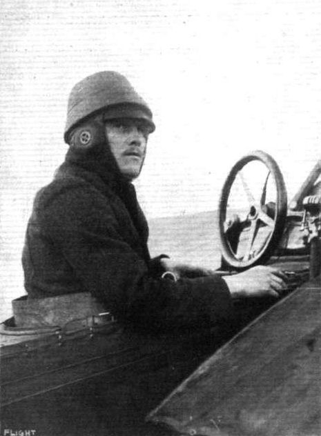
Prevost, who, on a Deperdussin monoplane, made second best time in the final cross-country test for the French Military Competition.
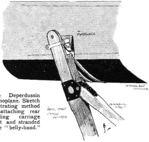
The Deperdussin Monoplane. Sketch illustrating method of attaching rear landing carriage strut and stranded wire "belly-band."
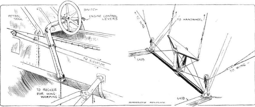
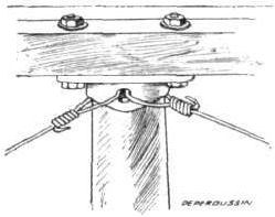
Method of cross-bracing the main body adopted in the Deperdussin monoplane.
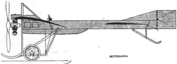
The 50-h.p. Deperdussin racer.
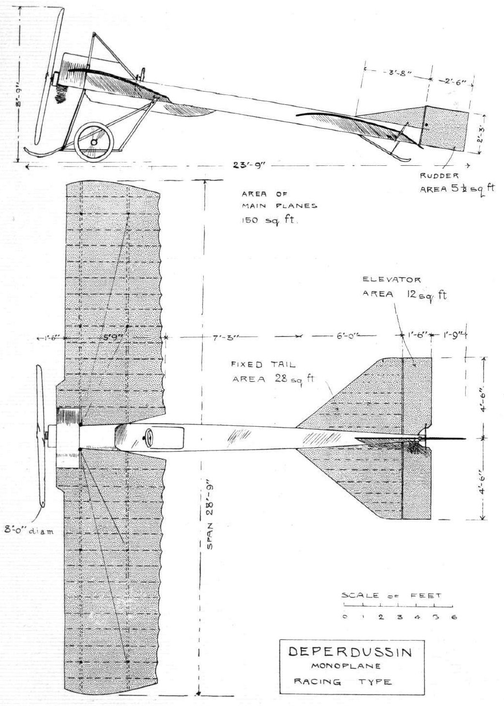
THE DEPERDUSSIN MONOPLANE. - Plan and elevation to scale.
Flight, November 18, 1911.
FOREIGN AVIATION NEWS.
Rheims to Issy on a Deperdussln.
HAVING to go back to Paris at the end of last week, Vedrines, on the 9th inst., mounted his Deperdussin monoplane at Rheims and left the ground there at a quarter past seven. Two hours later he landed at Issy and reported having had an excellent trip, although the cold and rain had forced him to land at Meaux, where at the dirigible shed, however, he was able to find some comfort for the inner man. His actual flying time was 1 hr. 20 mins.
Five Deperdussins Flying in Company.
ON the 10th inst. five Deperdussin monoplanes flying in close order over the country round about Rheims, made a very fine spectacle. Three of the machines were part of an order from the French Military Authorities, and were being tested by Vidart, Prevost and Vedrines, while the other two had Lieuts. Tretarre and Briey at their helms. Starting from the Deperdussin Aerodrome at Courcy Betheny, the flyers made a wide circuit over Rheims, Mourmelon, Chalons, Vervins, Epernay, and Laon.
Flight, December 30, 1911.
PARIS AERO SHOW.
Deperdussin Monoplane.
IN order lo exhibit their four types of monoplanes most effectively, the Deperdussin firm went to the extent of engaging two stands for that purpose. On one stand, situated under the centre dome of the Grand Palais, were exhibited the 100-h.p. Gnome-engined three-seater monoplane and the 50-h.p. single-seater cross-country machine. At the further end of the Show was the other stand, on which the 35-h.p. Anzani-engined popular- and the 70-h.p. two-seater military-types were exhibited. Very little need bу said of these excellent machines, as, in the main, they do not differ from the Deperdussin monoplane, as has already been described in FLIGHT, and demonstrated practically in England by such pilots as W. H. Ewen, Lieut. Porte and Gordon Bell, and on the Continent by Such men as Prevost and Vedrines. The latter model - the 70-h.p. military monoplane, however, is a new one, but its only difference lies in the fact that passenger and pilot are arranged tandem fashion in the fuselage in such a way that the former is so far forward that he can obtain an excellent view of what is directly beneath the aeroplane by glancing over the front of the wings. The importance of this feature for military requirements is readily apparent. Both in design and workmanship the machines are of the highest order, and reflect great credit on the Deperdussin firm, and more particularly on the firm's designer and works manager, M. Bechereau.
Principal dimensions, &c.:-
Three-seater military-
Length 26 ft.
Span 43 "
Area 350 sq. ft.
Weight 1,000 lbs.
Speed 65 m.p.h.
Motor 100-h.p. Gnome
Price L1,820.
Flight, July 1, 1911.
A Model Farman.
I send you two photographs of a model Farman, which may be of interest to your readers. The engine and propeller are now in course of construction.
Burton-on-Trent. C. O. HAYWARD.
Flight, September 2, 1911.
Model Construction.
The photograph that I send you of a model Farman is interesting on account of the dummy Gnome engine with which the model is equipped. The loading of this model is 5 ozs. to the square foot, but I have had success with other models loaded as heavily as this before.
Salisbury. S. J. ROBINSON.
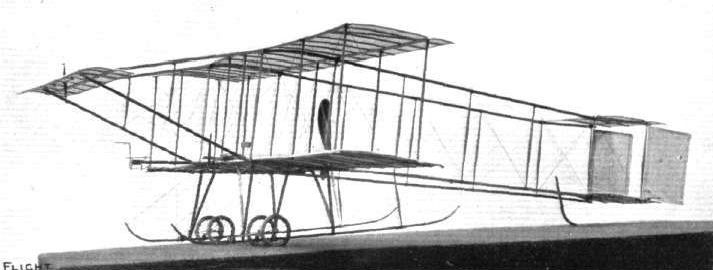
A "SPECIMEN" MODEL. - Model Farman biplane to scale, 1 in. to 1 ft., built by Mr. G. P. Smith, of Fulham, from the Twining Aeroplane Company's No. 10 parcel of materials and working drawings. The model is driven by a Chauviere pattern propeller geared in a ratio of 3 to 1 with the elastic rubber motor. The whole "power plant" is placed on the centre of gravity of the machine. The landing gear is exactly the same as in the prototype, with rubber ring suspension and radial arms. The rudders are moved by foot cross-bar, the elevator by lever on the right-hand side of the aviator's seat. Mr. Smith has put some very neat and careful work into the model, and the Twining Aeroplane Company inform us that they have had other fine examples sent them of Bleriot, Wright, and Antoinette machines made from their well-known sets of materials. These sets are in all cases accompanied by full drawings and instructions, and some twelve different parcels are in all supplied at prices ranging from 1s. to 3s. 9d.
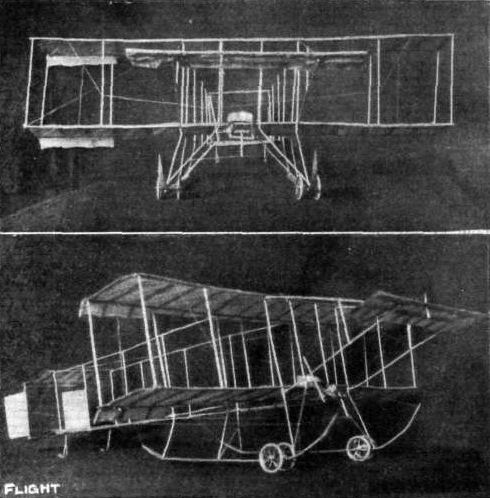
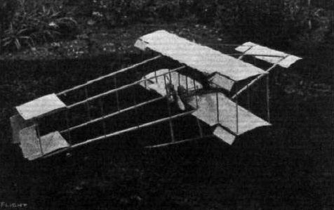
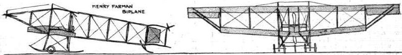
PARIS-MADRID RACE. - Diagrammatic sketches of some of the machines entered in the race.
Flight, January 7, 1911
The Lazare Weiller Prize.
ANOTHER competition which closed with the end of the year was that for the Lazare Weiller Prize of L1,000 for cross-country flying by French officers in uniform and carrying a passenger. The winner was Lieut. Cammerman, who, accompanied by Capt. Hugoni, on December 21st last, as already recorded in FLIGHT, flew from Bouy to Montigny-sur-Aube and back, a distance of 232 kiloms., in 4h. 2m. 30s.
A last attempt to win the prize was made by Lieut. Delage on the 29th ult. when, leaving Etampes, he flew accompanied by Lieut. Maillons to Orchaise, a distance of 106 kiloms., in 3 hrs. 31 mins. The journey was a most trying one and it speaks well for the endurance powers of the two officers that they kept going as long as they did. During the journey they passed through a snowstorm and their slow progress was in some measure due to the load of snow and ice which they "picked up" on the way, while the flight was finally brought to a conclusion through the carburetor freezing up. It will be remembered that the first flight in the competition for the Cup was made by Lieut. Delage some time ago when he flew from Etampes to Blois and back, a distance of 204 kiloms., in 3 hrs. 16 mins., his passenger then being Lieut. Maillons.
Coupe Femina,
THE competition for the Coupe Femina closed on the last day of 1910, and although Mme. Niel, Mdlle. Marvingt and Mdlle. Herveu had announced their intention of trying for the cup none of them ventured aloft, and so Mdlle. Dutrieu's record of 167.2 kiloms. in 2 hrs. 35 mins. was sufficient to easily secure for her the cup. It will be remembered that the first try for the prize was by Mdlle. Marvingt, who at Mourmelon flew for 53 mins. on her Antoinette, covering 43 kiloms. This was bettered by Mdlle. Dutrieu, who on her Henry Farman biplane flew 60 kiloms. in I hr. 9 mins., and later again bettered this with the record mentioned above. Mdlle. Herveu, on her Bleriot, at Pau, flew for 1 hr. 15 mins. and also 2 hrs. 2 mins., while Mdlle. Marvingt, on a second trial, only kept going for 45 mins.
On the 29th ult. Mdlle. Dutrieu tried at Etampes to better her own record, but after flying for 40 mins. the mist became so thick that she had to give up.
Flight, January 14, 1911
FROM THE BRITISH FLYING GROUNDS.
Laffan's Plain.
THE Farman machine which was purchased by the War Office was delivered at the balloon factory, South Farnborough, last week. Capt. Burke, who gained his certificate in France, also arrived to pilot the machine,
On Saturday morning Capt. Burke, R.E., made his first flight, but with unfortunate results. He made a very fine flight of about two miles over Laffan's Plain at a height varying from 50 to 80 ft., after which he descended near the balloon factory. A few minutes later he attempted a second flight, but before he had flown 50 yards the machine came down sideways on its right wing. As soon as it touched the ground it swung completely round and smashed to pieces. The machine was a total wreck, and Capt. Burke was nastily injured, one of his feet being crushed.
<...>
Flight, January 28, 1911
Farman Model.
The enclosed photo is an exact scale model H. Farman 1 in. to the foot. It is complete with propeller, dummy engine petrol tank, &c, and is covered with aero fabric. It is only a show model, and was strung up for the purpose of photographing.
Manchester. C. H. ASHLEY.
Flight, February 25, 1911
FLYING TO THE DOG DERBY.
IT was a decidedly original scheme of Mr. C. C. Paterson, of Freshneld, Liverpool, to attend the Waterloo Cup meeting at Altcar last week by means of his Farman aeroplane. Although quite an ordinary little trip so far as Mr. Paterson was concerned, it was a source of intense delight and astonishment to the habitues of the great Dog Derby. Accompanied by Mr. King, in quite ideal weather, Mr. Paterson, rising easily from the Freshneld flying grounds, arrived upon the Altcar course just before 1 o'clock. No sooner was the approach of the machine noticed than all interest momentarily ceased in connection with the coursing. Every eye was strained watching the approach of the flyers. When right over the course at a height of about 50 yards, Mr. Paterson completely encircled the coursing field and then made a detour beyond Hill House Wood, disappearing from the public view. After about three-quarters of an hour Mr. Paterson and Mr. King arrived together at the grounds by motor car and subsequently, having re-started on their aeroplane, returned to the coursing field, arriving there at about 2.30, this time coming to earth at the back of the Club enclosure, their very graceful landing being much applauded by the spectators. Quite a reception for half-an-hour or more followed and after the finish of the sport of the day they again took wing, passing away over the heads of the crowd at a height of about 20 ft., steering straight back for Freshfield. The vociferous cheering must have delighted the ears of the two aviators for a very considerable distance on their journey home.
Flight, March 4, 1911
MODELS.
Model Farman
Seeing, that you encourage model-makers by publishing their results in your valuable paper. I venture to send herewith a photo of a model Henry Farman biplane I have just finished. It is 1 in. to 1 ft. scale, the drawings appeared in your paper, No. 42, October 16th, 1909.
A model of this description is not expensive to construct considering that the one in the enclosed photo cost under 4s. 6d. for materials. It is jointed together, no nails, screws or bolts being used. This makes it just as strong and does not require so much patience.
I herewith send a list of materials used, where I got them and the price :-
Birch wood, Hobbies, Ltd., 42 ft., is. 2d.; floral wire, R. Dyas, 3 reels, 3d.; varnish, R. Dyas, 2d.; wheels, Gamages, 2 pairs, is. 10d.; fabric, nainsook, 1 yd., 5d.; gelatine, R. Dyas, 4d.; gum, R. Dyas, 3 tubes, 3d. Total, 4s. 5d.
Hoping this may be of use to fellow readers.
Clapham. A NOVICE.
Flight, March 11, 1911
Cagno Flies Over Venice.
USING the Farman biplane belonging to the Pordenone School, Cagno, on the afternoon of the 2nd inst., flew over Venice, passing close by St. Mark's Cathedral, and after making a wide circle over the city at a height of 300 metres returned to his starting point. Disturbed from their accustomed calm by the unusual visit, the pigeons of St. Mark's were vastly agitated and swooped round the Cathedral towers by way of protest.
Flight, April 8, 1911.
SEEING THE BOAT-RACE BY AEROPLANE.
THOSE who are inclined to indulge in prophesying will have a care in the future with regard to flying. When last year several venturesome spirits dared, in more or less jesting mood, to suggest that it might be possible to view the Boat-race from an aeroplane, they had little idea that twelve months from then no less than seven people would view the historic contest between the Light and Dark Blues from the region of the clouds. On Saturday last the great crowds which lined the river banks between Putney and Mortlake had plenty to interest them during the period of waiting. Some time before the rival crews were due to pass there was that movement in the crowd which tells that something is happening, and the experienced ear caught the sound of the open exhaust of a Gnome motor which heralded the rapid approach of a flying machine. Out of the mist they suddenly appeared, not one but six of them, three monoplanes and three biplanes. Five of the flyers - Mr. C. Grahame-White, accompanied by Mr. C. C. Paterson on a Farman, M. Hubert also on a Farman and Mr. G. Hamel, Mr. C. H. Greswell and M. Prier on Bleriot monoplanes - had all started from Hendon and struck the river at Kew. From thence they followed its course to Ranelagh, there descending. Mr. Graham-Gilmour a Bristol type biplane made his start from Brooklands, and he reached the river a few minutes before the crews got way from Putney. Several times he circled above Hammersmith Bridge, and when the crews were on their way to Mortlake he flew above them. In the meantime Mr. Gilmour more than once executed a short vol plante, and this manoeuvre was each time watched with breathless excitement by the crowds. After flying over the finishing point Mr. Gilmour ran out of petrol and landed in a field. A friendly motorist supplied him with four gallons, and after a little instruction from the pilot a man from the crowd started the engine, while a few more hung on in approved fashion and enabled the re-start to be made. At the conclusion of the race Mr. Grahame-White, Mr. Greswell and M. Prier took the air again back to Hendon, while Mr. Hamel and Mr. Hubert first went on to Brooklands before returning to Hendon, which they reached soon after six p.m.
Flight, May 6, 1911.
A First Flight Experience.
I enclose herewith three photos which may be of interest to yourself and to readers of FLIGHT. Some months ago you published a letter from myself re the possibility of passenger flights for say one guinea. While still believing that these will come to pass in the near future, I find that applications are treated with indifference at anything about that figure. At the present time and state of aviation I cannot, however, blame aviators in this matter. It is easy to take one's seat behind a skilful pilot on a well-tuned aeroplane and to smoothly fly and return to earth, and then wonder why the charges are seemingly high. But the enterprise, daring and patience to make this possible, can only, I take it, be really appreciated by those strenuously engaged in "the game." This by the way, however. I should like, with your permission, to give a brief account of how I took these photos. Through the courtesy of C. Compton Paterson, Esq., the Liverpool aviator, I got my long-tried-for flight, and it exceeded my expectations in many ways. I arrived at the Freshfield Aerodrome just after 2 p.m. on Saturday, 8th ult., and met the racing Farman just returning from a spin. The wind was rising and blowing strongly, but Mr. Paterson decided to take me up, and I was in the seat, the engine throbbed, and away we went along the broad smooth sands towards Southport, and took the air without knowing it. Now began the experiences of which I had no conception. The sands below and sandhills on our right, the sea away directly on our left, all sank below and we stood still seemingly, although the exhilarating rush of air said 50 m. p. h. For some miles we kept this course at about 300 feet up, then we turned to the left and swept out over the sea, hecling over as gracefully as a yacht. Here I took No. 1 photo, right over the pilot's head and beyond the elevator. You will notice the ribbed and coursed sands and the incoming tide. A long undulating course back beyond our starting point towards Liverpool found us at a height of 400 ft. We swept round again and passed directly over the line of the five large hangars. Here I took photo No. 2. This is a good gauge of our height. The blur, at the junction of the road and the beach, is a small crowd of spectators. We circled out to sea and dropped to about 200 ft. over the hangars again, to get photo No. 3 at closer range. Then up to 300 ft. and - silence and a steep dive, with the beach rushing up to us, as with the Gnome stopped we vol planed to earth, landing, as we started, imperceptibly. Although there is nothing striking about these photos at first sight, yet when it is borne in mind that it was a misty, windy day, that I had never been aloft before, and yet was able to work the camera with both hands and yet feel quite secure, and that, travelling at this great speed over an exposed coast line, the well-defined image of the frame and elevator, and even the wires, makes the photos a striking testimony to the wonderful balance of the machine and the absolute control and skill of the aviator. I admired the ease and confidence with which Mr. Paterson fought the gusts and wind waves, and kept the aeroplane running smoothly. To my surprise, he was able to call out a running comment upon his moves for my benefit. The flight convinced me of the vast strides which aviation has made in little more than a year, and even if I cannot get aloft again the experience has added greatly to my already keen interest in aviation.
Flixton, near Manchester. PERCY A. AMOS.
Flight, June 3, 1911.
Model Farman.
Enclosed herewith are photos of my model Farman biplane. The main planes are 36 ins. span and 6 ins. chord, the gap between the planes 7 ins., and overall length 39 ins. The model is now fitted with another propeller. I may add that it was shown in an exhibition at which it gained a prize.
Cambridge. E. G. NORFIELD.
Flight, June 17, 1911.
FROM THE BRITISH FLYING GROUNDS.
Freshfield Aerodrome, near Liverpool.
A VERY fine cross-country flight was made on the 7th inst. by Mr. R. A. King on his Farman biplane. Leaving the aerodrome at 12.20, and crossing over the Mersey, he passed over Hoy lake on the River Dee, finally coming down between Rhos and Colwyn Bay. In the afternoon Mr. King returned to his headquarters, leaving Colwyn Bay at 3.35. For the first part of the journey he was at a height of about 700 ft., but came down fairly low at Hoylake and Leasowe, afterwards rising again to a good height. He struck the Mersey at Waterloo, and following the course of the river arrived back at Freshfield at ten minutes to five.
<...>
Flight, August 26, 1911.
BRITISH NOTES OF THE WEEK.
The First British Lady Pilot.
THE first lady to obtain an aviator's certificate from the Royal Aero Club of the United Kingdom is Mrs. Maurice Hewlett, who made the necessary flights on Friday of last week at Brooklands. Mrs. Hewlett has been taught by M. Blondeau, with whom in partnership she has a flying school at Brooklands. M. Blondeau has taught twelve pupils, the first being M. Maurice Ducrocq. It is worth noting, too, that all these pupils have been taught without any accident and without a part of the school Henry Farman biplane being broken. The propeller which was put on at the Lanark meeting a year ago has just been taken off because it is chipped by stones, and it is now being repaired.
Flight, September 9, 1911.
Aeroplanes as Eyes for Artillery.
IN the presence of a large number of officers of the French Army an extended series of tests were made at Verdun on the 30th ult., to demonstrate the assistance which could be rendered by aeroplane pilots to artillery officers defending a besieged spot. Three biplanes, piloted respectively by Capt. Casse, Lieut. Blard and Lieut Menard, and a monoplane piloted by Capt. Bellenger, the first three each accompanied by an officer, were sent up to locate the attacking force, and it was claimed that as the result of the reports furnished the gunners were able to train their guns so that the enemy would have been completely wiped out.
Flight, September 23, 1911.
The Facts of the Plymouth Meeting.
I think that possibly it would interest you and your readers to hear the experiences of an onlooker at the first aero meeting held at Plymouth.
M. Blondeau and Mrs. Hewlett were engaged to fly at the Plymouth Race Course on Saturday, Monday and Tuesday ast at 2.30 to 4.30 in the afternoon and 5.30 to 7 o'clock in the evening, so, naturally, on Saturday morning I had expectations of seeing my first flight; but Fate intervened! It appears that the wrong truck was sent to take the machines to Plymouth, so that they did not arrive until Sunday morning.
On Monday I arrived outside the ground at 4.30, and was just in time to see a machine of the Farman (1910) type flit over the trees, and stay about five minutes in the air before it glided to the earth. This ended flying in the afternoon session.
It appears that the "remous" were very treacherous, and Blondeau sensibly declined to smash his machine for the sake of a small crowd. I then motored over to Plymoton, and arrived back to the flying ground at 5.40, and after waiting outside for about fifteen minutes I went into the ground just in time to see the machine pass over my head, and after three circuits Blondeau came down. Unfortunately his throttle refused to work at the right moment, and the machine was carried on further than he intended, and ran into some small woodwork outside the hangar, unfortunately puncturing both tyres. He complained of the condition of the air being in a most unsuitable state for flying, and so it was decided not to fly any more that evening.
Tuesday it appears that a grave misunderstanding arose. It seems that the air was in a very troubled state early in the afternoon, and M. Blondeau refrained from going up. However, later on he tried his machine, and found that one of his cylinders was knocking and required some slight adjustment. At this point, the management appeared on the scene and wanted to know why there was no flying and when he would fly. M. Blondeau informed them that flying would take place in a quarter of an hour, and it would only take a short time to effect the necessary repairs to his machine, but this answer did not satisfy the impatient management, who had the crowd dispersed, and said that there would be no more flying at all. Here Mrs. Hewlett intervened with a slight argument; the details and causes it is not necessary to relate. Mrs. Hewlett handed the management back their cheque, and so the meeting came to an abrupt ending.
A little after this time at a quarter to six, I arrived with a gentleman on the staff of the Western Morning News and got entry to the ground. We were immediately jostled about by some of the policemen, but fortunately a short interview with M. Blondeau was all that was required for us to remain. M. Blondeau then got into his machine and executed some of the finest flights of the meeting. Making a magnificent and short rise off the ground he rose to a height of about 120 ft., and proceeded to do several circles around the course; then he made various circles round the trees, of which this ground, unfortunately, abounds, and after giving us most excellent demonstrations of aerial flight, he made a very pretty short vol plane, with a glide to the ground to follow. He then decided to take up a lady friend of Mrs. Hewlett as a passenger, and he again gave us some excellent demonstrations of flying, ending with a very fine vol plane with a glide to the earth. Thus the flying closed for the evening, and after wheeling the machine back to the shed M. Blondeau and myself had a very interesting chat in the hangar, where he pointed out that the ground was most unsuitable for flying in.
George Street, Plymouth. T. R. JOHNS.

FROM MECHANIC TO LEGION OF HONOUR. - The above interesting photograph reaches us from Mr. E. J. Crisp, of Market Harborough, and serves as a memento of M. Vedrines when he was acting as mechanic to Mr. Robert Loraine. The occasion was Mr. Loraine's visit to Colwyn Bay last summer, the two being seen standing together manipulating the Gnome engine.
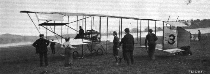
STARTING FOR THE BRIGHON RACE. - Lieut. Snowden-Smith just released for his start on his British-built Farman biplane for Brighton.
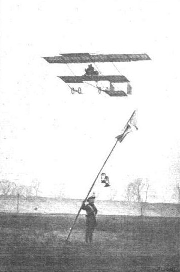
Mr. Maurice Ducrocq flying on a Henry Farman at Brooklands in an attempt upon the 100 Miles Passenger-carrying Record. Note the boy scout in charge of one of the lantern-bedecked "mark-posts" of the course.
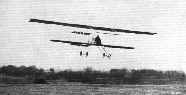
Capt. Burke in flight at Aldershot on the British Army Farman biplane during the first successful flight and before the mishap to the machine.
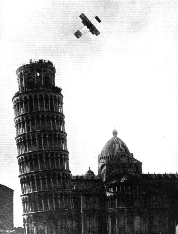
FLYING ROUND THE LEANING TOWER OF PISA. - Mario Cobianchi circling the famous tower recently. Note the cheering spectators on the two galleries at the top of the tower.
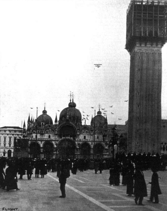
FLYING OVER VENICE. - Cagno, the chief pilot of the Italian School of Aviation at Pordenone, on his H. Farman, flying over Venice on March 2nd. Immense enthusiasm was evinced at the performance, and the band at the foot of St. Mark's Tower, which is now 78 metres high, played the Royal Italian Hymn in honour of the event. Note the agitation amongst the pigeons round the church spires occasioned by this visit.
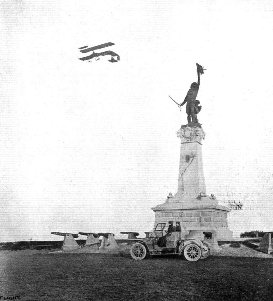
AVIATION AT THE FRENCH MILITARY MANOEUVRES ROUND ABOUT VERDUN. - Lieut. Blard and Capt. Lebeau in their Farman biplane passing over the Kellermann monument at Valmy.
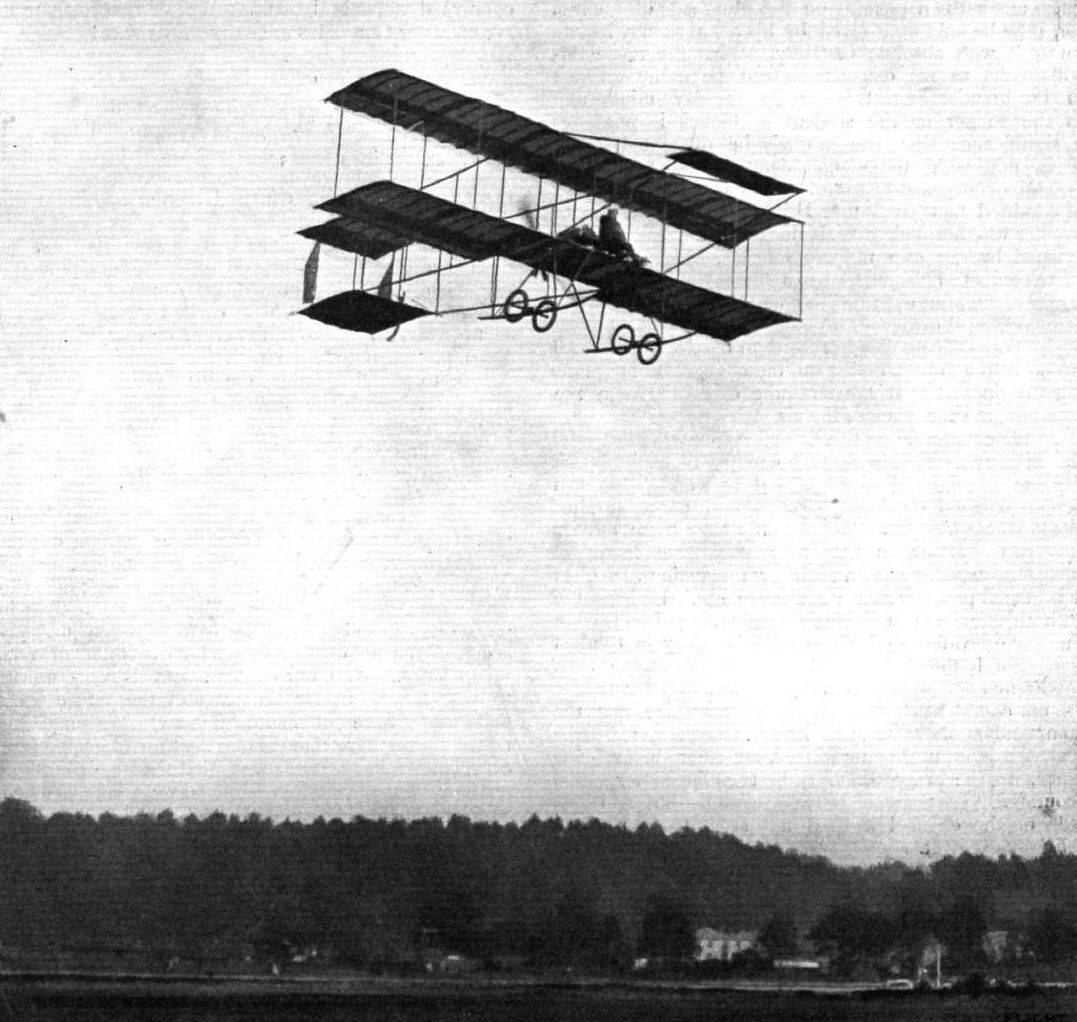
Mr. G. Blondeau, who with Mrs. Maurice Hewlett had such a very unpleasant experience at Plymouth last week, flying at Brooklands on a Farman biplane, with which he in the past has done such fine flying. As we recorded last week, Mr. Blondeau and Mrs. Hewlett in a very sportsmanlike manner returned their fees in view of the clamorous and unbecoming behaviour of the crowd who were kept waiting for a short period for the flying.

Mr. Paterson, of Freshfield, arriving, with Mr. King as passenger, on their Farman biplane at Altcar on the first day, to witness the coursing for the Waterloo Cup.
Mr. C. L. A. Hubert flying high, on his Wolseley-engined Farman, in a mist at the London Aerodrome.
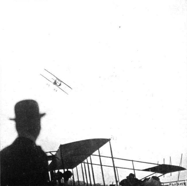
A fine banking by Grahame-White at Hendon on a Henry Farman biplane.

NO NEED TO WORRY. - This is not an aviator in the last spasms of despair "crashing down" to earth, but just Mr. Maurice Ducrocq flying at Brooklands on his Henry Farman with his hands free from all controlling gear. Yet aviation has not advanced since the Wright Bros, first flew!

"CHASSE-CROlSE" IN THE AIR. - Reminiscence of an incident - one of many similar daily - at Rouen Aviation Meeting last year. Dubonnet, on his Tellier monoplane, crossing under Capt. Dickson on his Henry Farman biplane.

AT BROOKLANDS AERODROME. - Mr. Blondeau in the air with Mrs. Hewlett in the Hewlett and Blondeau School Farman, flying over Mr. Eric England's Hanriot monoplane.
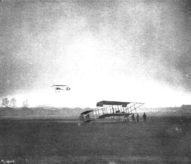
AT BROOKLANDS - FLYING AT DUSK. - Mr. Ducrocq, on the Hewlett and Blondeau Henry Farman biplane passing over Mr. Blondeau's machine at rest on the aerodrome.

Weyman, the great pilot of the Nieuport monoplane, in the earlier days was a biplane pilot. Our photograph above shows him and Tetard each on Henry Farman machines rounding a mark tower during a race meeting.
A trio in flight at the London Aerodrome, Hendon. Two Henry Famans and, in the foreground, a Type A Valkyrie.
Mr. Valentine on the Macfie biplane passing over Mr. Ducrocq's Henry Farman at Brooklands last Saturday.

Mr. Amos' flight with Mr. Compton Paterson.
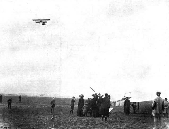
STARTING TO SEE THE OXFORD AND CAMBRIDGE BOAT RACE. - Mr. Grahame-White leaving Hendon on Saturday.
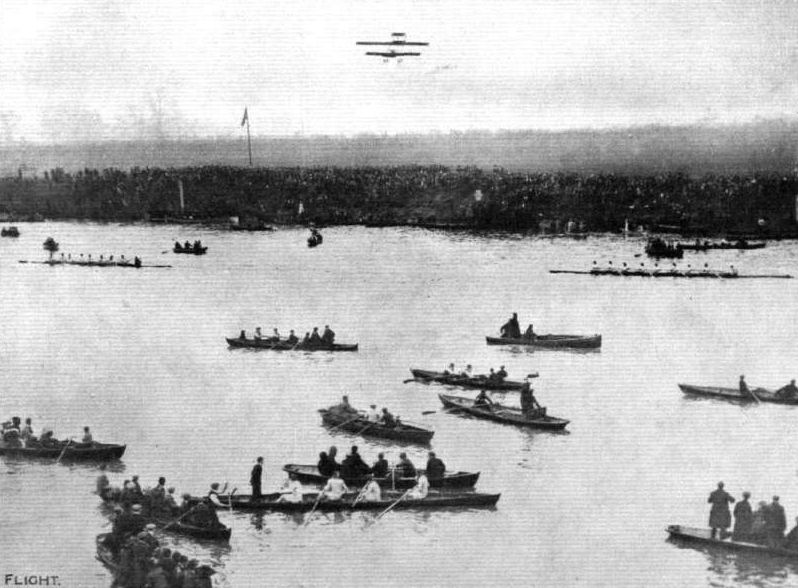
SEEING THE OXFORD AND CAMBRIDGE BOAT RACE BY AEROPLANE. - The finish at Mortlake on Saturday last, with one of the flyers, which appeared upon the scene during the contest, overhead.
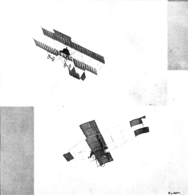
THE GREAT HENDON DEMONSTRATION. - Two snaps of Grahame-White on his Henry Farman biplane when making a sharp turn and a vol plane. These photographs were taken with the camera held perfectly horizontal, so that the machine is seen at the angles at which the evolutions were actually carried out.
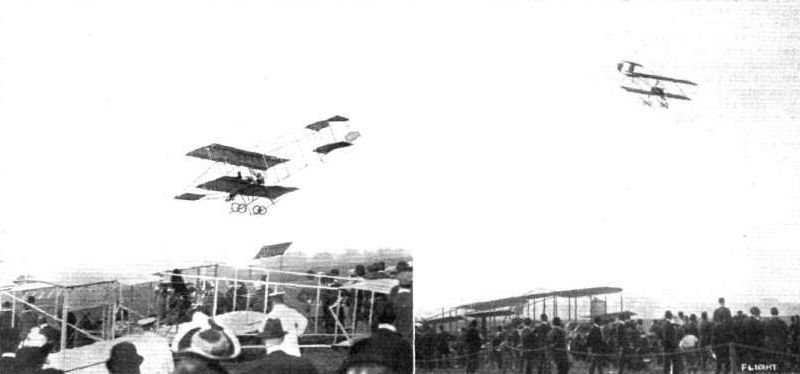
A couple of vol planes by Grahame-White on his Henry Farman at the Hendon Demonstration last week. - In the left-hand photograph Mr. McKenna is flying as passenger with Mr. Grahame-White.
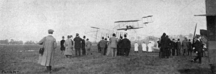
A swoop down across the enclosures and machines from over the hangars by Grahame-White at the Hendon Demonstration last week during one of his exhibition flights. From this it will be seen how close down it is possible with perfect safety to steer.
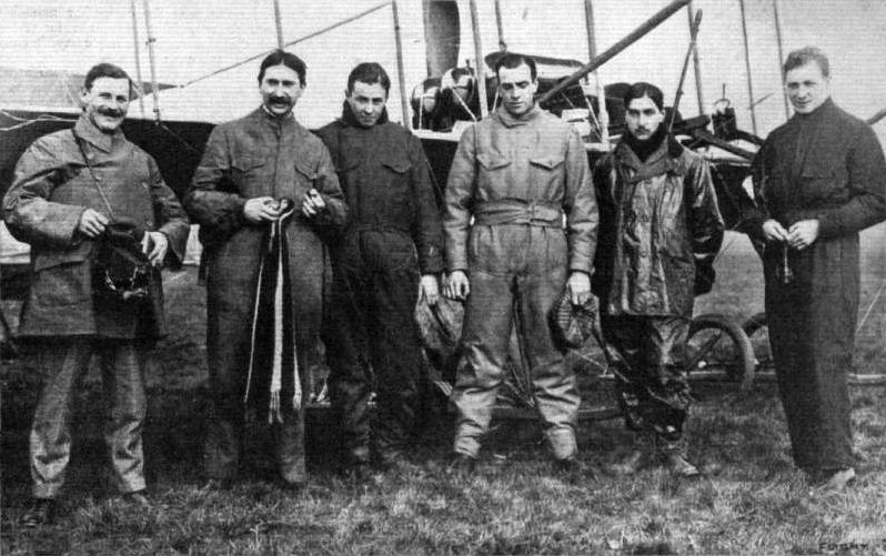
The Grahame-White-Bleriot contingent who flew from Hendon on Saturday last and witnessed the Oxford and Cambridge Boat-Race from their aeroplanes, just before their start. From left to right: Mr. Paterson, the Liverpool aviator, who accompanied Mr. Grahame-White as passenger, Messrs. Prier, C. H. Greswell, Claude Grahame-White, Hubert, and G. Hamel.
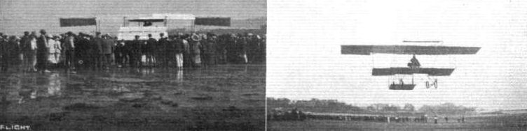
MR. R. A. KING'S FLIGHT TO COLWYN BAY FROM FRESHFIELD. - Filling up tanks before returning, and iust away.
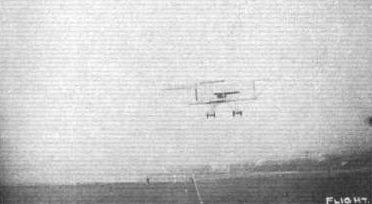
Mr. R. A. King well up on his return journey to Freshfield from Colwyn Bay.

Lieut. Cammerman, winner of the Lazare Weiller Cross-country Prize for French officers, on his Henry Farman biplane, Gnome motor. Lieut. Cammerman's flight was Bouy-Montigny-sur-Aube-Bouy, 232 kils. in 4h. 2m. 30s.
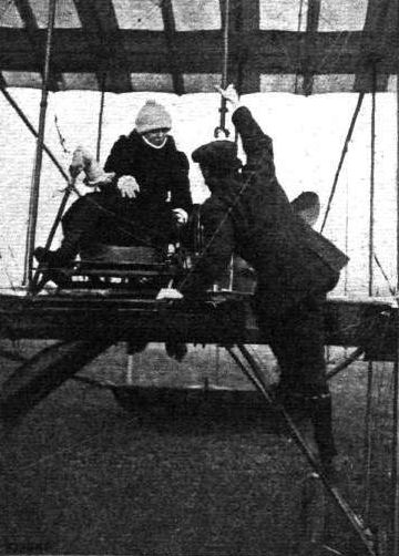
Mdlle. Helene Dutrieu, winner of the "Femina Cup" for lady flyers, in counsel with Mr. Henry Farman prior to her record flight at Etampes on her Henry Farman (Gnome motor), of 167.2 kiloms. in 2 hrs. 35 mins.
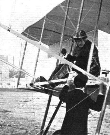
Capt. Burke ready for flying the British Army Henry Farman machine at Aldershot.
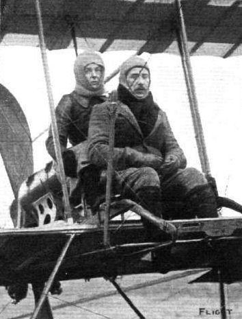
Mr. Blondeau ready to start at Brooklands with Mrs. Hewlett as passenger on their Henry Farman biplane.

Mrs. Hewlett, who is now flying one of the Henry Farmans at Brooklands attached to the Hewlett and Blondeau School. Note the sabots to the right which Mrs. Hewlett finds suitable wear this wet weather.
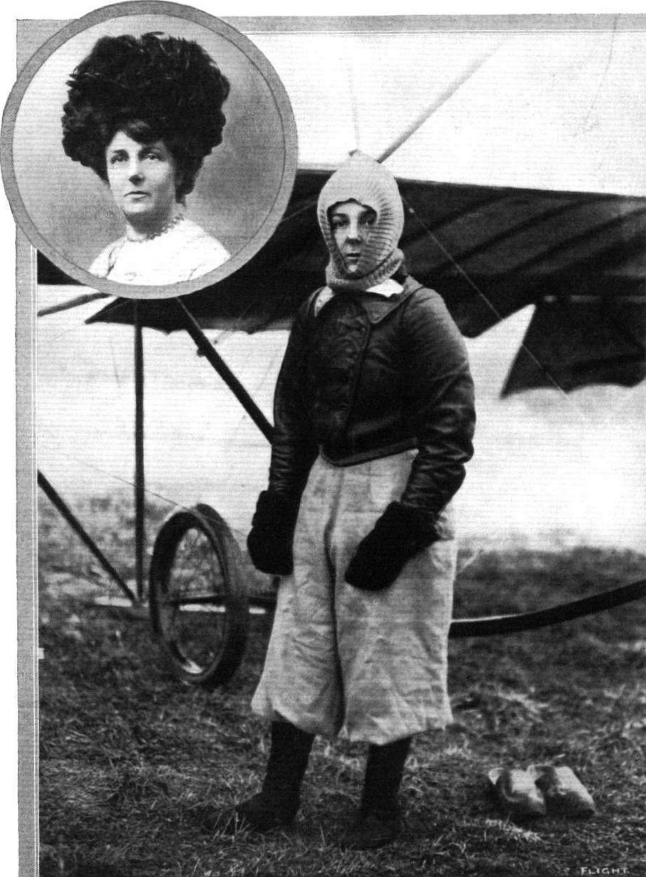
MRS. MAURICE HEWLETT. Who last week, on a Henry Farman biplane, secured her pilot's certificate from the Royal Aero Club, being the first British brevet issued to any woman. Mrs. Hewlett has received her tuition from Mr. Blondeau at Brooklands, and our picture above shows her in her aviation costume, the inset portrait being Mrs. Hewlett in ordinary life.
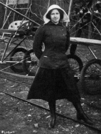
Mrs. J. V. Martin, who is flying so well at the Grahame-White School at Hendon.
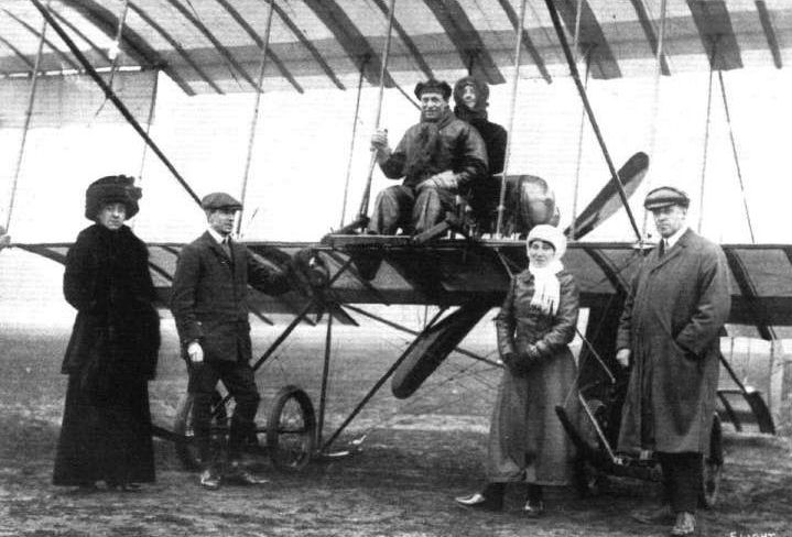
PASSENGER CARRYING AT BROOKLANDS AERODROME. - Mr. Ducrocq, who is now, with his Henry Farman, one of the most energetic passenger-carrying pilots at Brooklands, in the pilot's seat before a start with Mrs. Keith Jones as passenger. Standing in front are, from left to right, Mrs. G. Phillips, Mr. Keith Jones, Mrs. Palmer, a Ducrocq pupil, and Mr. G. Phillips, both these gentlemen being associated as Directors of Messrs. Keith Prowse and Co. with the box office iust opened by that firm on the grounds and in direct communication
w i t h London for the booking of seats for flights, long and short.
w i t h London for the booking of seats for flights, long and short.
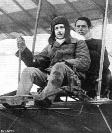
Lieut. Snowden Smith, the Army aviator, on the Hewlett and Blondeau Henry Farman, just after taking Naval Lieut. F. E. T. Hewlett for a 10-mile flight at Brooklands.
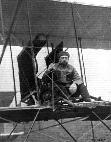
Mr. J. V. Martin, the American aviator, who has just obtained his Royal Aero Club pilot certificate, on Mr, Grabame-White's E.N.V.-engined biplane at the London Aerodrome.
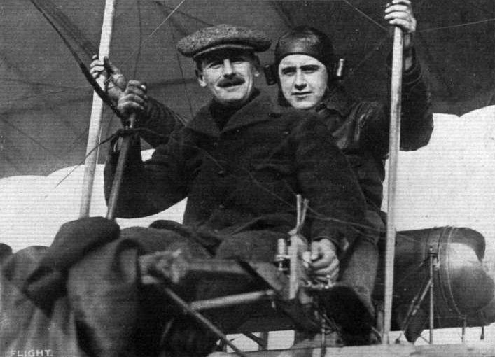
Mr. C. C. Paterson, with Mr. King as passenger, iust after their arrival at Altcar on their Farman biplane, for the Waterloo Cup.
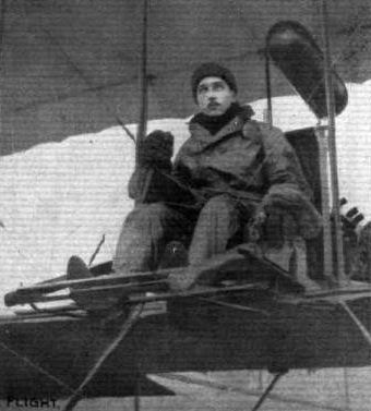
Mr. C. L. A. Hubert - a Frenchman - who has just secured his R.Ae.C. pilot's certificate at the Grahame-White School at the London Aerodrome, Hendon. Mr. Hubert has been doing a lot of very successful flying on this Farman, which is fitted with a 60-h.p. Wolseley motor.
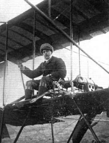
Lieut. Snowden Smith about to start on a trip from Brooklands on the Blondeau-Hewlett School biplane.
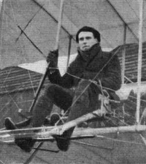
Mr. Ridley-Prentice, a pupil of the Grahame-White School at Hendon, who has made remarkably rapid progress, and has put up some good flights on the school Farman.
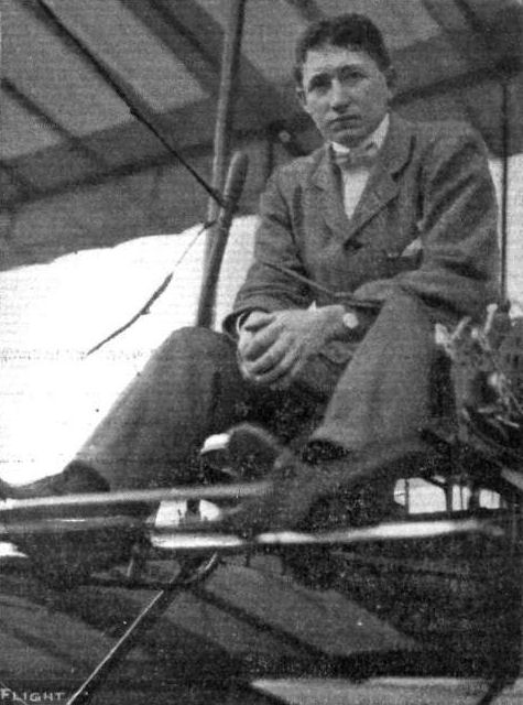
Mr. E. F. Driver, one of the recent pilots who have secured their Royal Aero Club brevet at the Grahame-Whlte School. His first cross-country flight was from Hendon to Windsor, which he reached after struggling against a strong wind for an hour and a half. He was accompanied by Capt. Vandeweyer as passenger.
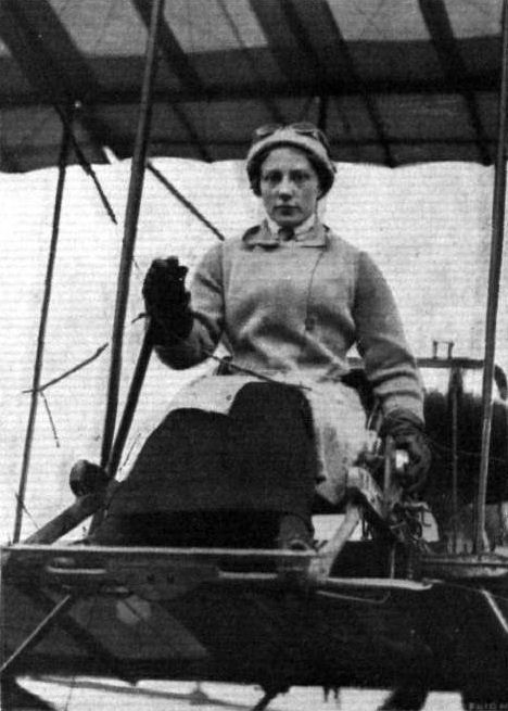
Mrs. de Beauvor Stocks, who is flying so well at the Grahame-White School at Hendon. Mrs. Stocks hoped to qualify officially for her certificate this week.

MRS. C. DE BEAUVOIR STOCKS. The second lady to secure a Royal Aero Club pilot's certificate. Mrs. Stocks graduated for her air brevet at the Grahame-White school at Hendon, becoming proficient on a Henry Farman biplane. Inset is a photograph of Mrs. Stocks as in private life, from a photograph by " Kate Pragnell."
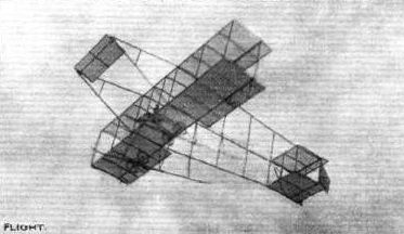
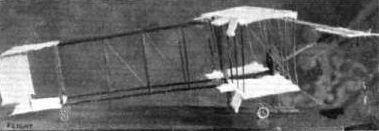
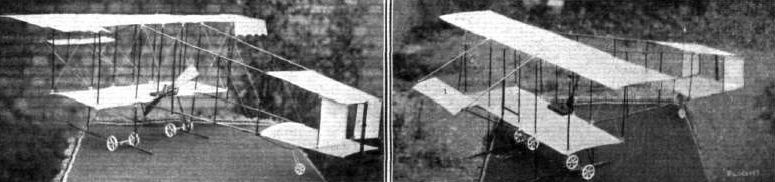
E. G. Norfield's Model Farman.
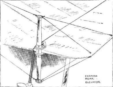
Detail sketch illustrating the rear elevating plane on the Farman biplane.
UNDERCARRIAGES AT OLYMPIA. - Comparative details in the construction of the Farman type wheel and skid combination.
Flight, May 20, 1911.
THE LATEST FARMAN BIPLANE.
THE accompanying photograph shows the latest Farman military biplane, of the successful experiments with which readers of FLIGHT have already heard. The first and most noticeable point to be observed is, of course, the absence of the front elevator. In this machine fore and aft equilibrium is obtained entirely by the use of a tail elevator, which forms a hinged extension on the horizontal tail plane. It will also be noticed that this elevating plane is of fairly high aspect ratio as also are the balancing planes in the trailing edges of the upper main planes. The tail as a whole and the tail outrigger have a light workmanlike appearance and it may also be observed that the two rudder planes are in line with the elevator so that the fixed tail plane is wholly in advance of all the movable members. This machine has the extended upper main plane characteristic of the Farman military type, and the method of trussing the upper front spar, by wires passing over steel brackets forming extensions of the outermost struts, forms an interesting minor detail relating thereto. The machine is fitted with a Gnome rotary engine. In the above photograph Mr. Farman is seen talking to Lieutenant Menard, one of the foremost biplane pilots of the French Army.
Flight, June 3, 1911.
FOREIGN AVIATION NEWS.
Lieut. Menard's Tour of France - Passenger Record Beaten.
AFTER being delayed for some days by bad weather, Lieut. Menard was able to commence his long projected 3,000 kilom. tour around France on the 25th ult. Accompanied by Lieut. Do Hu, he started on his Henry Farman from Bouy at five minutes to three, and at a quarter to six, after having covered 238 kiloms. in 2 hrs. 50 mins., he landed at Chartres at a quarter to six in order to take on board more petrol. At a quarter past seven Vendome was reached, and a landing was decided upon in order to inspect the motor, which was not working at all well. Two hours and a quarter were, as a matter of fact, spent in making adjustments, and it was not till half-past nine that the aviators were in the air again. Chatellerault was passed about midday, and at a quarter past twelve a safe landing was made at Lacueit, close by Poitiers. The journey was a record one, and the last portion beat the world's records for a flight with passenger. The total distance covered during the morning was 600 kiloms.
In consequence of some repairs being necessary, the journey was not resumed until Saturday last, when the two aerial voyagers, after fitting a new motor to the machine, left Poitiers for Rocheforte-sur-Mer, which was safely reached after about an hour and a half's flying. Lieut. Menard and his companion were to have continued their journey on Wednesday to Pau.
Flight, July 15, 1911.
FOREIGN AVIATION NEWS.
The Height Record Beaten on a Henry Farman.
FOR some considerable time no assaults have been made on the height record standing to the credit of Legagneux, but on Saturday, Loridan on one of the new racing Henry Farman biplanes succeeded in climbing during a flight of 1 hr. 23 mins. to an altitude, according to his barograph, of 3,280 metres (10,758 ft.). Stopping the motor, he came down by a vol plane in twelve minutes.
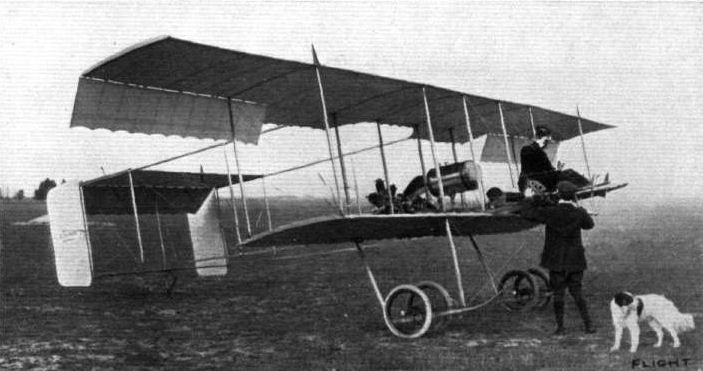
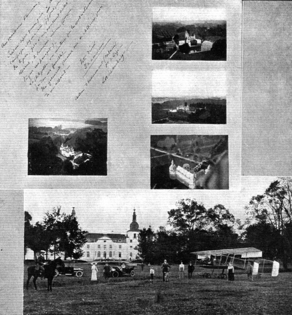
AVIATION AS A PASTIME. - Many months ago we stated that the time had arrived when flying could, under reasonable conditions, be regarded as a legitimate pastime to be indulged in by the wider circle of the public comprised in the sportsman, landed proprietor, &c. Corroboration of this comes in the above interesting photograph from Belgium, showing that well-known all-round sportsman, Chevalier Jules de Laminne, and his up-to-date sporting equipment, including a Henry Farman biplane, at the Chateau d'Oudoumont, Verlaise, near Liege. Above are snaps of the castle from different points, secured from the Farman machine by the Chevalier when flying around his estate.
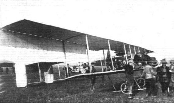
Side view of the Military Henry Farman biplane which participated in the recent French Military Competitions at Rheims.
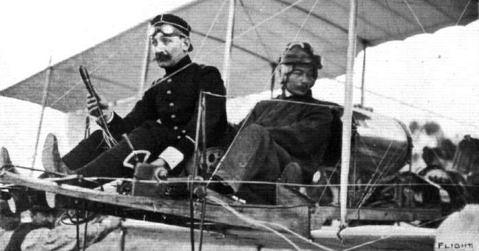
ROUND FRANCE BY MILITARY AEROPLANE. - Lieut. Menard and his passenger, Lieut. Do Hu, who, on a military Henry Farman, is making a tour round France. On his first day's flight he easily beat the world's record for passenger-carrying across country.
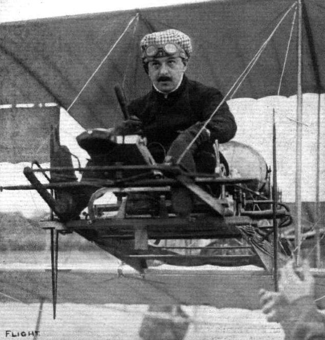
M. Loridan, who last week broke the altitude record by rising on a Henry Farman biplane to 3,280 metres. Note the position of the pilot well in advance of the motor and planes.
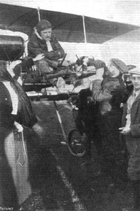
Fischer upon his completion, on the Henry Farman biplane, of the final cross-country speed test in the French Military Competition, being welcomed by his wife, and personally congratulated upon his splendid performance by Mr. Henry Farman.
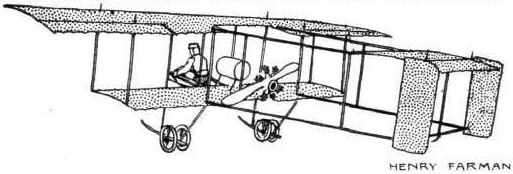
MONOPLANES AND BIPLANES IN THE DAILY MAIL CIRCUIT ROUND GREAT BRITAIN. - From these every machine can be readily identified either in flight or on the ground.
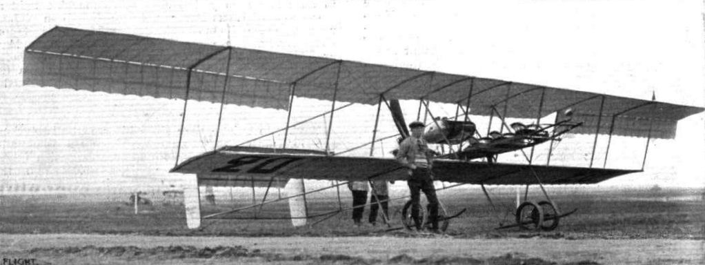
The New 3-seater Biplane that is representing Henry Farman at the Military Tests at Rheims. - This machine has a span of 16 metres, and is driven by a 70-h.p. Gnome engine. It will be noticed that Farman has changed his method of setting planes, for they are now staggered after the manner of the Goupy and the later Zodiac. The manner of seating the three occupants considerably in advance of the main plane is evidently meeting with favour in France, but it will remain to be seen how far it jeopardises the aviator's safety. The landing carriage has also undergone a modification to enable it to stand the strain of the extra weight. In flying trim the machine weighs 950 kilogs.
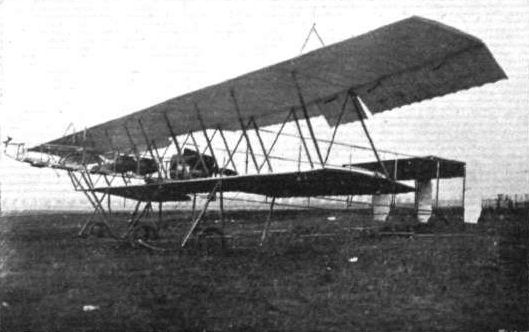
Side view of the Military Henry Farman biplane which participated in the recent French Military Competitions at Rheims.
Flight, May 20, 1911.
THE HENRY FARMAN MONOPLANE.
ALTHOUGH the name of Farman is inseparably associated with biplanes, readers of FLIGHT are aware that Mr. Farman has been for some time successfully experimenting with a monoplane of his own design. We are now able to give the accompanying photograph of the machine in question. Perhaps the most striking feature of the external appearance of the machine is the neat casing that completely encloses the 50-h.p. Gnome rotary air-cooled engine that drives the propeller. Also, as may be observed, the entire rectangular girder frame constituting the body is covered with surfacing material. At its rearmost extremity is the cruciform tail comprising an elevator and rudder. In the trailing extremities of the main wings are hinged balancing planes. The span of the machine is 9 metres (nearly 30 ft.) and the overall length 8.5 metres (28 ft.). The supporting area is 17 sq. metres (about 183 sq. ft.).
Flight, December 16, 1911.
THE HENRY FARMAN TWO-SEATER MONOPLANE.
NOT content with his reputation as a constructor of biplanes, Henry Farman has, as our readers already know, self-imposed the task of proving himself an equally good constructor of monoplanes. In certain features his new monoplane maintains many of the same characteristics as his biplanes. In the matter of lateral balance, he still retains the use of ailerons, and the control lever is essentially the same as the later type of biplane lever, being situated between the knees of the pilot. The landing chassis has undergone slight modification, the characteristic two pairs of swivelling wheels being replaced by one pair of wheels, joined by a common axle, which latter is flexibly sprung from the skids by the conventional elastic straps.
The main body is square in section, and is constructed on the usual box-girder principle. It is 25 ft. in length. At the forward end is fitted the engine - a Gnome of 50 h.p. - enclosed by a ventilated steel stamping in such a manner that it is impossible for any oil thrown off by the revolving motor to reach either pilot or passenger. At first sight one might think that this shield, almost enclosing the motor as it does, would have an adverse effect on the cooling. Such, however, is not the case, for during the trials that the machine has undergone no tendency of the motor to overheat has been evident. The seats for both pilot and passenger are arranged so that no inconvenience is caused by the propeller draught, and are placed well forward in the fuselage so that they are afforded a good view of the country over which they happen to be passing. At the rear end of the main body are attached the organs which control the monoplane in the verticle and horizontal sense.
The wings, which subtend to each other a very slight dihedral angle, have a span of 33 ft. Their internal construction is very similar to that of the doubled-surfaced planes of the later type of Farman biplanes. As no provisions are made for warping, ailerons being employed, the wings are stayed rigidly from masts above and from chassis below by means of stranded steel cables.
Eight cables - four to each wing - support the wings when the machine is at rest, and twelve cables take the weight of the monoplane in flight. The trailing edge is allowed a certain degree of flexibility. Both ailerons are interconnected, so that a downward deflection of one is accompanied by an equal and upward deflection of the other. A certain advantage of using flaps for balancing in this manner is the fact that the wings are kept rigid, and are not subject to continual deformation, as is the case when warping is used as a means of securing lateral balance.
The tail of approximately semi-circular planiform is flat, and takes no weight in flight. To the rear edge of this surface is hinged the flap, which controls the ascent and descent of the machine.
Steering to right and to left is effected by a vertical rudder, which is mounted just in advance of the elevator. When the machine is at rest the weight of the tail is taken by a short skid, which is flexibly attached to the main-body skeleton, and which is allowed to swing to right or left, in order to accommodate any sideway's movement on landing.
The landing chassis, a wheel and skid combination, needs little or no description, as a good idea of its main features can readily be gathered from the photographs appearing herewith.
Ready equipped for flight, but without pilot or passengers, the machine weighs 627 lbs., and in addition to this it can raise a useful load of 400 lbs. Its speed is from 62 to 68 miles per hour.
Flight, December 30, 1911.
PARIS AERO SHOW.
Farman Freres.
ON the Farman stand were exhibited two machines, one a Maurice Farman biplane and the other the new Henry Farman monoplane. Description of these excellent midlines would be unnecessary in the case of the former model for, apart from the staggering of the main planes and the reduced dimensions throughout, it presents no point of difference from the one exhibited at the last Aero Show at Olympia. In the case of the latter a recapitulation of its main features would be but repetition of the article that appeared in these pages only a fortnight since.
Principal dimensions, &c.
Henry Farman monoplane-
Length 25 ft. Weight 630 lbs.
Span 33 " Speed 65 m.p.h.
Area 165 sq. ft. Motor 50-h.p. Gnome.
Price L1,000.
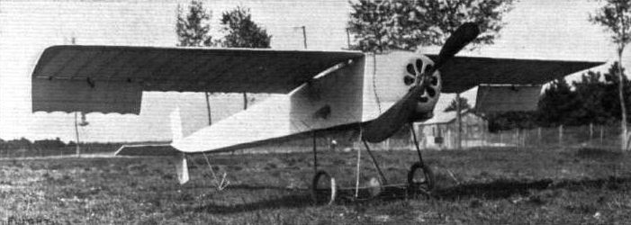

Three-quarter view from behind of the new Henry Farman two-seater monoplane, staged at the Paris Salon.
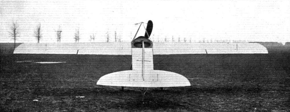
View from behind of the Henry Farman monoplane.
GENERAL VIEW OF THE THIRD PARIS AERO SALON. - The machine at the bottom of the photograph is the Bleriot 100-h.p. "Aeronef," built to the order of M. Henri Deutsch de la Meurthe. On the same side, but towards the centre of the Exhibition, may be seen the Zodiac biplane and the Borel and Deperdussin monoplanes, while opposite are the Train and H. Farman monoplanes and Savary and M. Farman biplanes.
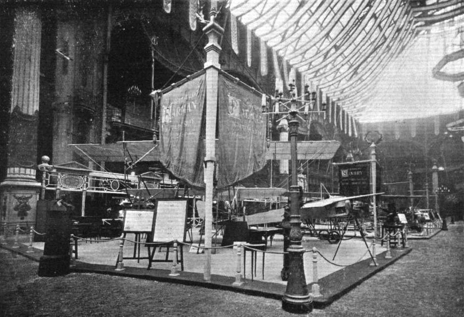
The Farman stand at the Paris Aero Salon, showing, in addition to the latest type Maurice Farman biplane, the Henry Farman monoplane, described last week in FLIGHT.
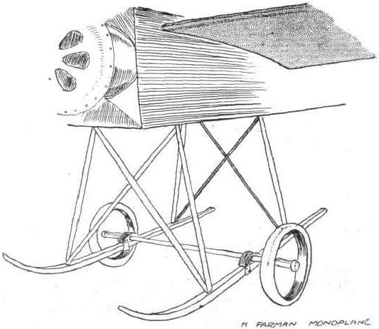
Detills of the landing chassis of the Henry Farman monoplane.

THE GASSIER MONOPLANE AT JUVISY. - A number of interesting points are embodied in the design of this machine, which has a rear elevator as well as a forward one, while the main planes are fitted with ailerons in addition. It will be noticed, too, that the spars of the main plane are very strongly trussed. The engine is a 70-h.p. Gregoire.
Flight, February 4, 1911
FOREIGN AVIATION NEWS.
Vedrine High Flying.
ON the 26th ult., at Juvisy, Vedrine was practising high flying with his Goupy machine, and during one attempt he succeeded in getting to an altitude of 1,000 metres in 10 minutes. On Sunday he was also up to a height of goo metres, flying over Juvisy and Savigny.
Juvisy to Issy and Back.
TAKING advantage of the calm weather, Vedrine, on the 24th ult, left Juvisy at 3 o'clock in the afternoon and landed at Issy-les-Moulineaux twenty-one minutes later, having circled the Eiffel Tower on his way. After a rest of three-quarters of an hour he once more mounted his machine and set out on the return journey, landing safely in front of the Goupy shed at Juvisy after a flight of 25 mins.

M. Vedrine, who has been making such fine flights at Issy on the Goupy biplane.
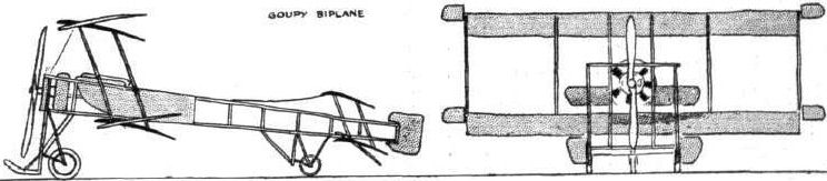
PARIS-MADRID RACE. - Diagrammatic sketches of some of the machines entered in the race.
Flight, February 18, 1911
HANRIOT WING CONSTRUCTION.
No part of the modern monoplane is of more importance or less visible than the framework of the wing, and the accompanying sketches illustrating the Hanriot wing-construction will doubtless interest many of our readers. The outstanding features of the system are the two main spars, that in front being a very substantial boxgirder, 3 ins. in depth by 1 1/2 ins. in width. It will be observed from the detail sketch that the sides of the girder are secured to the top and bottom pieces by copper rivets after being glued. The method of letting the steel shackle-plates for the tie-wires into the spar is also interesting and is clearly shown in the sketch. The rear spar of this machine is built up on the three-ply principle and is of smaller dimensions. It is, of course, obvious that the front main-spar is also fundamentally of three-ply construction, the only difference being that it has a hollow core, which thus introduces the box-girder principle. The construction of the ribs is clearly illustrated in the sketch. It will be observed that the top and bottom laths have their camber maintained by light distance-pieces at intervals, and that the fabric is supported between the ribs, which are situated about 12 ins. apart by light laths arranged parallel to the spars. The front of the plane is formed by a sheet of thin aluminium, which makes a light, smooth, and blunt entering edge. This entering edge is situated about a foot in front of the main spar, which is itself 3 ft. 4 ins. in front of the rear spar. Behind the rear spar the rib extends to a distance of about 2 ft. 7 1/2 ins. The front main-spar is attached rigidly to the body of the machine by steel straps that embrace the spar and the wedge-shaped blocks on which it rests. These wedge-shaped blocks are supported by a transverse girder in the body and give the set of the dihedral angle to the wings.
For additional security a pair of long bolts tie this support to the bottom of the body. The rear spar is merely hinged to the body, as it necessarily requires a flexible attachment to facilitate the warp. Each wing weighs complete with fabric 48 lbs.
AT BROOKLANDS AERODROME. - Mr. Blondeau in the air with Mrs. Hewlett in the Hewlett and Blondeau School Farman, flying over Mr. Eric England's Hanriot monoplane.
Mr. Low, .on his Bristol biplane, getting well into the air at Brooklands. At rest are Mr. Sopwlth's Howard Wright biplane, and in the distance the Hanriot monoplane.
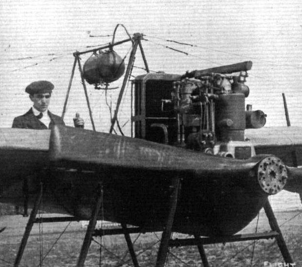
Mr. E. V. Beauchamp Fisher, one of our most skilled aviators, in the pilot's seat of his Hanriot monoplane with which he has been doing so much fine flying at Brooklands. Mr. Fisher has now joined Messrs. Vickers, Ltd.
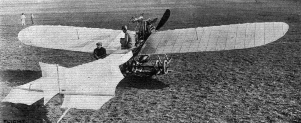
THE 100-H.P. CLERGET-ENGINED HANRIOT MONOPLANE . AT THE MILITARY TESTS AT RHEIMS. - It will be noticed that changes have been made In the landing-carriage, two pairs of wheels now being employed in place of the single pair hitherto adopted. The situation of the petrol reservoir, as mentioned in our article on aeroplane fires in last week's issue, appears to be extremely unfavourable, for if a bad landing were made - one sufficiently rough to carry away the landing-chassls - it is more than probable that the tank would
rupture and a serious fire result.
rupture and a serious fire result.
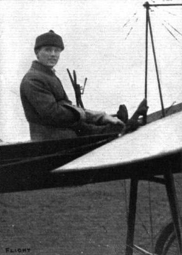
Mr. England on the Hanriot monoplane at Brooklands.
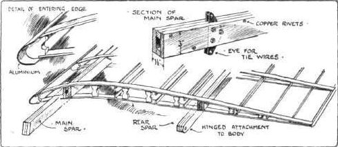

Kaufmann monoplane, type "Demoiselle," which is being successfully flown at Issy.
Six types of landing gear at the Paris Aero Salon.
Flight, January 7, 1911
FRENCH MICHELIN CUP.
JUST as was the case in England, the closing days of the competition for the International Michelin Cup in France provided quite a deal of excitement. The Cup is awarded for the longest distance flown without a stop. On the last day of the year no less than five French aviators set out to try and beat the record made on the previous day by Tabuteau, but without success, and the latter's record of 584.935 kiloms. in 7h. 48m. 31 3/5s. therefore secured to him the right to hold the Cup for the ensuing year.
Real Contest Begins.
On the 29th ult. the attempts commenced in real earnest. At Buc, Tabuteau set out to regain the world's record on his Maurice Farman machine, but after he had traversed a distance of 400 kiloms. he was compelled to come down by the thick mist. His time for 390 kiloms. was 5h. 12m. 49 1/5s. At Etampes Henry Farman also made another attempt to place the record to his credit. Starting off at eight o'clock in the morning, he was flying until half past ten, by which time a distance of about 150 kiloms. had been covered, his speed being about 63 kiloms. an hour. Then, in view of the way in which the rain, which had been falling for some time, was freezing on the upper plane of his machine, he decided that it was useless to continue, and came down. On landing, it was found that the ice which had gathered on the plane was very little short of 80 kilogs. in weight.
The Winning Flights and New Records.
As we have mentioned above, the winning flight for the Cup was made on the 30th ult. at Buc. At twenty minutes to eight Tabuteau started off in very cold but fine weather, determined to remain in the air until he had beaten all records. He had been circling round and round the course for nearly an hour when his friend Renaux also took the air. He, however, only continued for about five hours, when finding that Tabuteau had apparently got his task well in hand, he decided to come down. He did not travel quite so fast as Tabuteau, his time for 350 kiloms. being 4h. 56m. 43 1/5s. Tabuteau continued on his course until twenty minutes past three, when having ascertained that he had well beaten the distance record, he decided to descend, although he could have gone on for an hour or so more. He had then been in the air 7h. 48m. 31 3/5s., and had covered 584.935 kiloms. (365 miles), beating the previous best record by Legagneux by just on 40 miles. The flight was timed by Gaudichard, and officially observed, on behalf of the Aero Club of France, by M. Fournier. In the course of his flight, Tabuteau set up a new record for 500 kiloms. in 6h. 41m. 1 3/5 s., and also a new record for 7 hrs. of 522.935 kiloms., while his time for 550 kiloms. was 7h. 19m. 41 1/5 s.
On the same day Thomas made a fresh attempt on his Antoinette monoplane at Mourmelon. He, however, was flying very low, and after being in the air for 3h. 5m. 4s., one of the wings of his machine touched the ground in making a turn, and the official observers were obliged to count that as the termination of the flight. By that time a distance of 262 kiloms. had been covered, and the world's record for 250 kiloms. beaten.
Flight, March 11, 1911
RENAUX WINS THE MICHELIN PUY DE DOME PRIZE.
AFTER being open for just on three years, the L4,000 prize offered by M. Michelin for a passenger flight from Paris 10 the top of the Puy de Dome has been won. The conditions imposed called for considerable daring, and M. Michelin himself, as noted in recent issues of FLIGHT, seems to have come to the conclusion that they might lead to an aviator taking unnecessary risks in order to secure the prize. Fortunately, however, as it has turned out, the winning flight has been made almost without incident. For some time M. Eugene Renaux has been practising on a Maurice Farman biplane at Buc, with a view to annexing the reward. On Tuesday morning, conditions being specially favourable, he determined to take his chance. Accompanied by M. Senouque, M. Renaux made his start from Buc at five minutes to nine, making direct for St. Cloud, the official starting point. Having there crossed the imaginary starting line, he headed south, and passing over Issy continued on by way of Montargis and Cosne to Nevers, where a stop of a quarter of an hour was made at the Peuplier aerodrome for replenishment. On restarting the aviators steered for Moulins and so on to St. Pouscain and Gannat. At 2h. 23m. 20s., to be precise, the aeroplane landed on the restricted plateau at the top of the Puy de Dome, 1,600 metres (4,813 feet) high, having first circled round the Cathedral Tower at Clermont-Ferrand, in accordance with the requirements of the regulations. All traffic and business in the town was stopped as the aeroplane approached near its goal, and the spectators waited with breathless excitement until the landing had been safely effected when unrestricted enthusiasm was indulged in. The aeroplane was timed to cross the ground of the Aero Club of France at 9h. 12m. 34s., so that it will be seen that the time for the trip of 350 kiloms. was 5h. 20m. 46s., while the maximum time allowed under the regulations was 6 hours. It is interesting to note some of the times at which various points were passed. For instance, the aviators were sighted at Juvisy at 9.28, Montargis, where the machine caught up and passed an express train, at 10.18, Gien at 10.58, while Nevers was reached at 11.53.
The restart took place at 12h. 7m. 37s., and Moulins was passed at 1.20. It will be remembered that only two previous attempts have been made to win this prize, one by Weymann, who lost his way, and the other by the brothers Morane, who met with a serious accident.
Flight, May 13, 1911.
FOREIGN AVIATION NEWS.
Maurice Farman takes his Father for a Cross-country Trip.
USING one of his military type biplanes, Mr. Maurice Farman carried his father from Buc to Etampes on the 5th inst. and returned with him to Buc on the following day. The distance via Rambouillet is 80 kiloms., and on the outward journey the time occupied was one minute over the hour, while when returning an hour and a half was necessary for the trip, but then the aviators had to tight against a variable breeze which at times was blowing at 12 metres a second. On the 4th Henry Farman was carrying his brother Dick at Mourmelon.
Flight, March 25, 1911
AEROPLANES.
Farman - On the stand of the Aeroplane Supply Co., who are the English agents for Messrs. Farman Freres, will be found one of the latest military passenger type of Farman biplanes. This machine is a duplicate of that which holds the world's record for time in the air, i.e., 8 hrs. 12 mins,, when a distance of 380 miles was covered before coming to earth. The machine is beautifully finished and an interesting feature is that the pilot's seat is covered in similar to the body of a racing motor car, which shelters the pilot from the wind and lessens body resistance. The machine is fitted with a 60-h.p. Renault engine. We understand that the Aeroplane Supply Company are giving passenger flights on Farman aeroplanes at Hendon during the course of the Show.
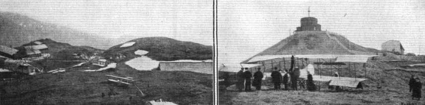
RENAUX'S PARIS-PUY DE DOME FLIGHT. - The Maurice Farman biplane is seen arriving on the left, and on the right a closer view of the machine, with the Observatory in the background.
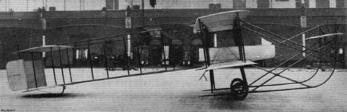
The Farman military biplane on the Aeroplane Supply Co.'s stand.
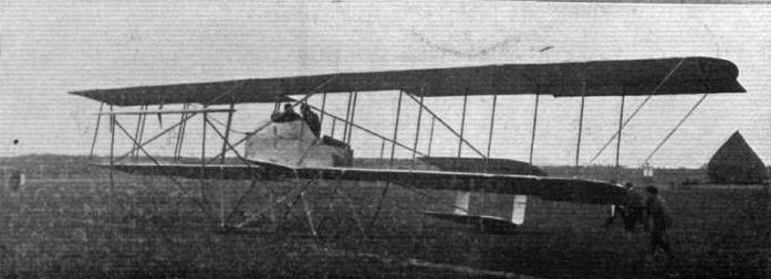
THE MILITARY TYPE MAURICE FARMAN BIPLANE. - This view shows clearly the extensions fitted to the machine, and also the arrangement of the chassis.
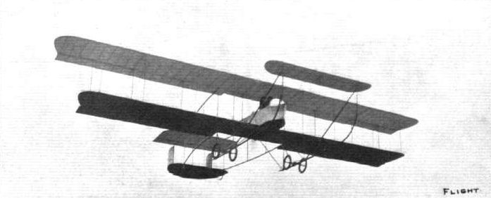
THE MILITARY TYPE MAURICE FARMAN BIPLANE. - A snapshot of the machine in full flight.

Mr. Maurice Farman and his father after the recent long flight from Buc to Etampes and back, which Farman pere indulged in recently. Mr. Farman, sen., it will be remembered is the well-known Paris correspondent of the "Standard."
UNDERCARRIAGES AT OLYMPIA. - A comparison of some girder skids.
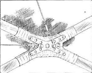
UNDERCARRIAGES AT OLYMPIA. - A crossjoint on the Maurice Farman outrigger.
UNDERCARRIAGES AT OLYMPIA. - Comparative details in the construction of the Farman type wheel and skid combination.
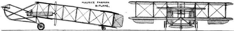
PARIS-MADRID RACE. - Diagrammatic sketches of some of the machines entered in the race.
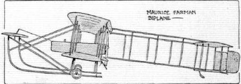
Flight, September 23, 1911.
FOREIGN AVIATION NEWS.
New Maurice Farman Military Machine.
IN the hands of Barra very good results have been obtained with the new 20-metre Maurice Farman biplane which has been built specially for the French War Office competition for aeroplanes.
Flight, December 30, 1911.
PARIS AERO SHOW.
Farman Freres.
ON the Farman stand were exhibited two machines, one a Maurice Farman biplane and the other the new Henry Farman monoplane. Description of these excellent midlines would be unnecessary in the case of the former model for, apart from the staggering of the main planes and the reduced dimensions throughout, it presents no point of difference from the one exhibited at the last Aero Show at Olympia. In the case of the latter a recapitulation of its main features would be but repetition of the article that appeared in these pages only a fortnight since.
Principal dimensions, &c.
Maurice Farman biplane-
Length 30 ft. Weight 946 lbs.
Span 36 ,, Speed 55 m.p.h.
Area 385 sq. ft. Motor 70 h. p. Renault.
Price L1,000.
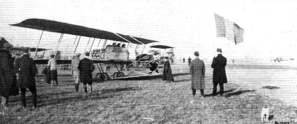
THE MILITARY AEROPLANE COMPETITION AT RHEIMS. - Barra, on his Farman, being despatched by the military officials on a long-distance test.
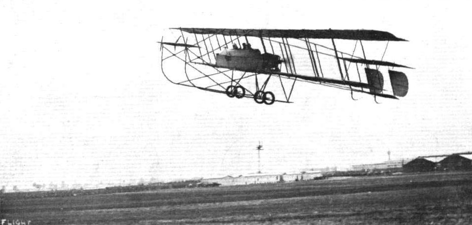
Birra on his Maurice Farman biplane in the final speed test in connection with the French Military Competition.
GENERAL VIEW OF THE THIRD PARIS AERO SALON. - The machine at the bottom of the photograph is the Bleriot 100-h.p. "Aeronef," built to the order of M. Henri Deutsch de la Meurthe. On the same side, but towards the centre of the Exhibition, may be seen the Zodiac biplane and the Borel and Deperdussin monoplanes, while opposite are the Train and H. Farman monoplanes and Savary and M. Farman biplanes.
The Farman stand at the Paris Aero Salon, showing, in addition to the latest type Maurice Farman biplane, the Henry Farman monoplane, described last week in FLIGHT.
Flight, April 8, 1911.
PARIS TO POITIERS AND BACK AT 90 M.P.H.
THE Morane monoplane has demonstrated its remarkable speed qualities on several occasions recently, but one of the most extraordinary performances was that just made by Vedrines in an attempt to fly from Paris to Pau. Leaving Issy at half-past six on the morning of the 28th ult. he flew straight through to Poitiers without a stop, landing there at thirty-five minutes past nine, having accomplished the journey of 335 kiloms. at a speed of 109 k.p.h. A large crowd of people assembled on the Chauviniere Grounds to witness the landing, and in order to avoid running into them Vedrines had to land somewhat awkwardly, damaging the chassis of his machine and also the propeller. On the following day the bad weather precluded any flying, and as the conditions had not greatly improved on the 30th, Vedrines determined to fly back to Paris and make a fresh start. On the evening of the 30th he made a flight at a height of 1,500 metres above Poitiers, while on the following day he flew back to Paris, when the remarkable speed attained during the outward trip was excelled, the time for the 335 kiloms. being returned at 2 hrs. 12 mins., giving a speed of 150.9 k.p.h. In this case the aviator was assisted by a following wind, but in spite of this the speed attained by this combination of Morane monoplane with Gnome engine and Chauviere propeller is little short of marvellous. On Sunday morning M. Vedrines left Issy on a second attempt to fly to Pau. Having lost his bearings somewhat owing to the thick fog he landed at Varennes-sur-Allier, 341 kiloms. from Paris. He then determined to go on to Bussieres, where his wife and children were staying. His flying time for the 500 kiloms. was 3 hrs. 56 mins., and he proposed completing the journey to Pau on the 3rd.
Flight, July 29, 1911.
THE MORANE MONOPLANE.
ONE of the most expert and experienced pilots that ever took his seat on the Bleriot monoplane was M. Morane, whose flights at Bournemouth last year will remain long in the memory of those who witnessed them. It is, therefore, only natural that the machine to which he has given his name should itself closely resemble the pioneer model that has now been so often copied. To the casual observer, the Morane and the Bleriot monoplanes will probably be indistinguishable at a glance, for the differences are of a kind that do not force themselves upon the eye.
One, for instance, that is more easily seen in a drawing than in the actual machine is the plan form of the wings, in which it will be observed that the rear spar is longer than the front spar, whereas in the Bleriot type the reverse is the case. Also, it will be noticed that the chassis differs materially from the Bleriot design, and embodies the wheel and skid combination originated by Karman. On the Morane monoplane, the skids are very short, we are tempted to say unduly short; but then it must be borne in mind that this machine has been built as a racer, and every effort has been made to reduce the weight. As a result, it is stated to weigh only 440 lbs. without the pilot. Under such circumstances, the presence of the skids must be regarded merely as a precaution against the complete disablement of the machine in the event of the wheels collapsing. Their use is not exactly intended to be a protection to the inexperienced pilot who brings the aeroplane to earth on its nose every now and again.
The chassis of the Morane monoplane is light but strong, and it is sufficiently evident from a glance at the accompanying sketch that there has been no wastage of material. The skids are rather close together, and their attachment to the body is carried out more or less on the principle of the A frame. The body of the machine itself is of the rectangular lattice girder type with ash spars and struts reinforced by wire diagonals. The fore part of the body is surfaced with fabric in order to give the machine something ot a keel, but the rear part is left open in order to reduce the surface against which the wind can strike to slew the machine out of its course. The rudder and the elevator are adjacent to one another at the extreme rear of the body, where they form, with the fixed plane, the tail of the machine. The fixed plane has an area of 12 sq. ft., and its two pivoted extremities, which constitute the elevator, have a total area of 11 sq. ft. The rudder, which is mostly above but also partly below the fixed tail planes, has a total area of 9 sq. ft.
The control of the machine is operated by a hand wheel that is rigidly mounted on the top of a vertical column, which is itself universally supported to the body. A to and fro movement controls the elevator and a sideways movement warps the wings. The rudder is independently operated by a pivoted cross bar under the pilot's feet. The pilot himself sits in line with the trailing edge of the wings and his weight is balanced by that of the engine, which is mounted in front under a shaded guard that protects the pilot from the oil and exhaust. The engine normally employed is a 50-h.p. Gnome rotary, which drives direct a two-bladed wooden propeller of 6 ft. 6 in. diameter.
Flight, November 11, 1911.
Model Construction.
I enclose herewith two photos I have taken of a model Morane-Borel monoplane which I hope you may consider of sufficient interest to reproduce in your excellent paper. The model was entirely made by a boy of sixteen - Robairt Dagonet - out of odd pieces of wood and wire, and cost nothing to build!
Chatham. J. C. HEWETT, Major, A.P.D.

The Morane monoplane on which M. Vedrines last week accomplished his splendid flight from Poitiers to Issy in 2 hrs. 12 mins. Note the twin skids, tip elevators, and taller rudder.
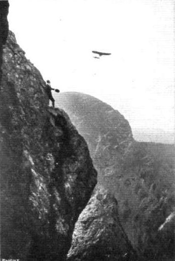
PARIS-MADRID RACE. - Vedrines' monoplane passing over the Pyrenees,
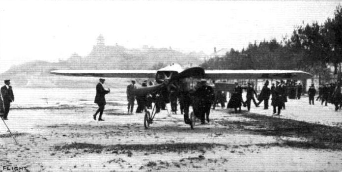
PARIS-MADRID RACE. - Vedrines' arrival at San Sebastian.
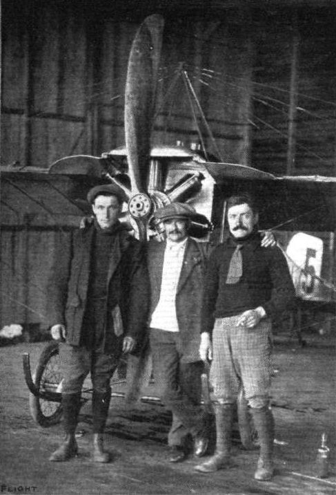
EUROPEAN AVIATION CIRCUIT. - The first man - Vedrines - to arrive at Hendon Aerodrome on Monday, he having started from Calais at 4 a.m., and after making stops at Dover and Shoreham, landed at Hendon at 8h. 34m. 53 1/5 s. To the left is Thiry, and on the right Ramondon, his two trusty assistants throughout the whole race.
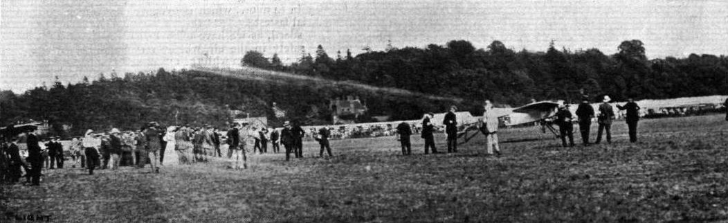
DAILY MAIL CIRCUIT OF BRITAIN. - Vedrines on his Morane-Borel just away for Hendon.
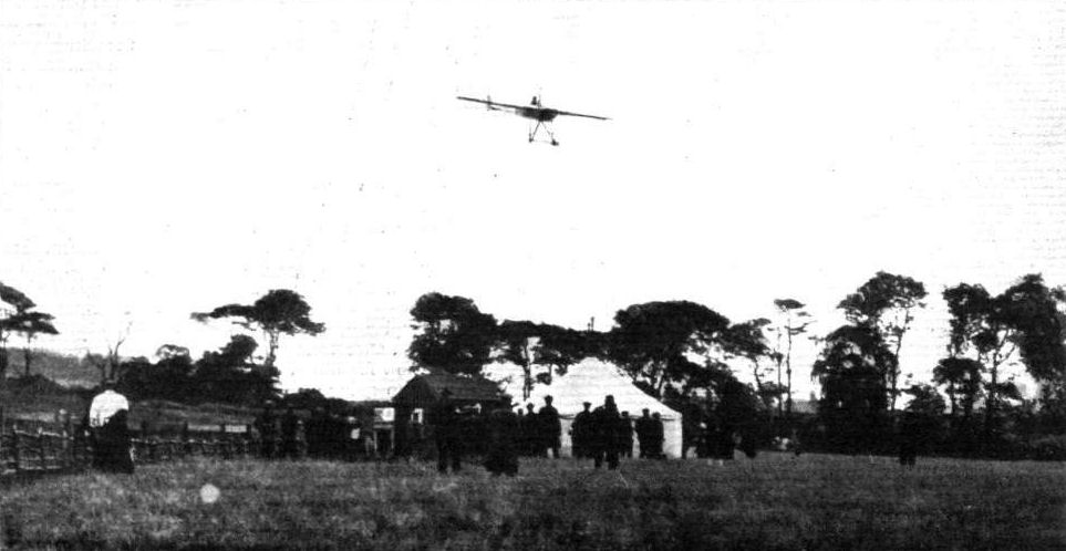
The first arrival at Edinburgh. Vedrines planing down over the Timekeeper's hut.

CIRCUIT OF BRITAIN. - Vedrines "at rest" during his compulsory stopping time at Shoreham, before the last lap to Brooklands.
GENERAL VIEW OF THE THIRD PARIS AERO SALON. - The machine at the bottom of the photograph is the Bleriot 100-h.p. "Aeronef," built to the order of M. Henri Deutsch de la Meurthe. On the same side, but towards the centre of the Exhibition, may be seen the Zodiac biplane and the Borel and Deperdussin monoplanes, while opposite are the Train and H. Farman monoplanes and Savary and M. Farman biplanes.
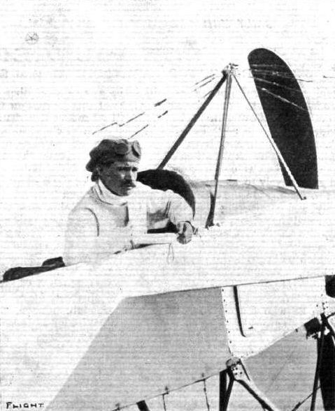
Vedrines, the second man back, on his Morane Borel.
Vedrines, the great French flyer, whose unfortunate accident on Monday has once more laid him by the heels, in a characteristic attitude when on flying bent.
Vedrines, the great French flyer, whose unfortunate accident on Monday has once more laid him by the heels, in a characteristic attitude when on flying bent.
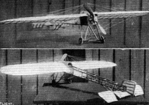

PARIS-MADRID RACE. - Diagrammatic sketches of some of the machines entered in the race.
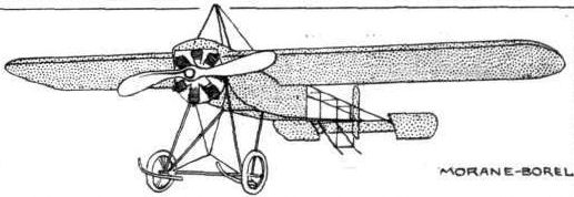
MONOPLANES AND BIPLANES IN THE DAILY MAIL CIRCUIT ROUND GREAT BRITAIN. - From these every machine can be readily identified either in flight or on the ground.
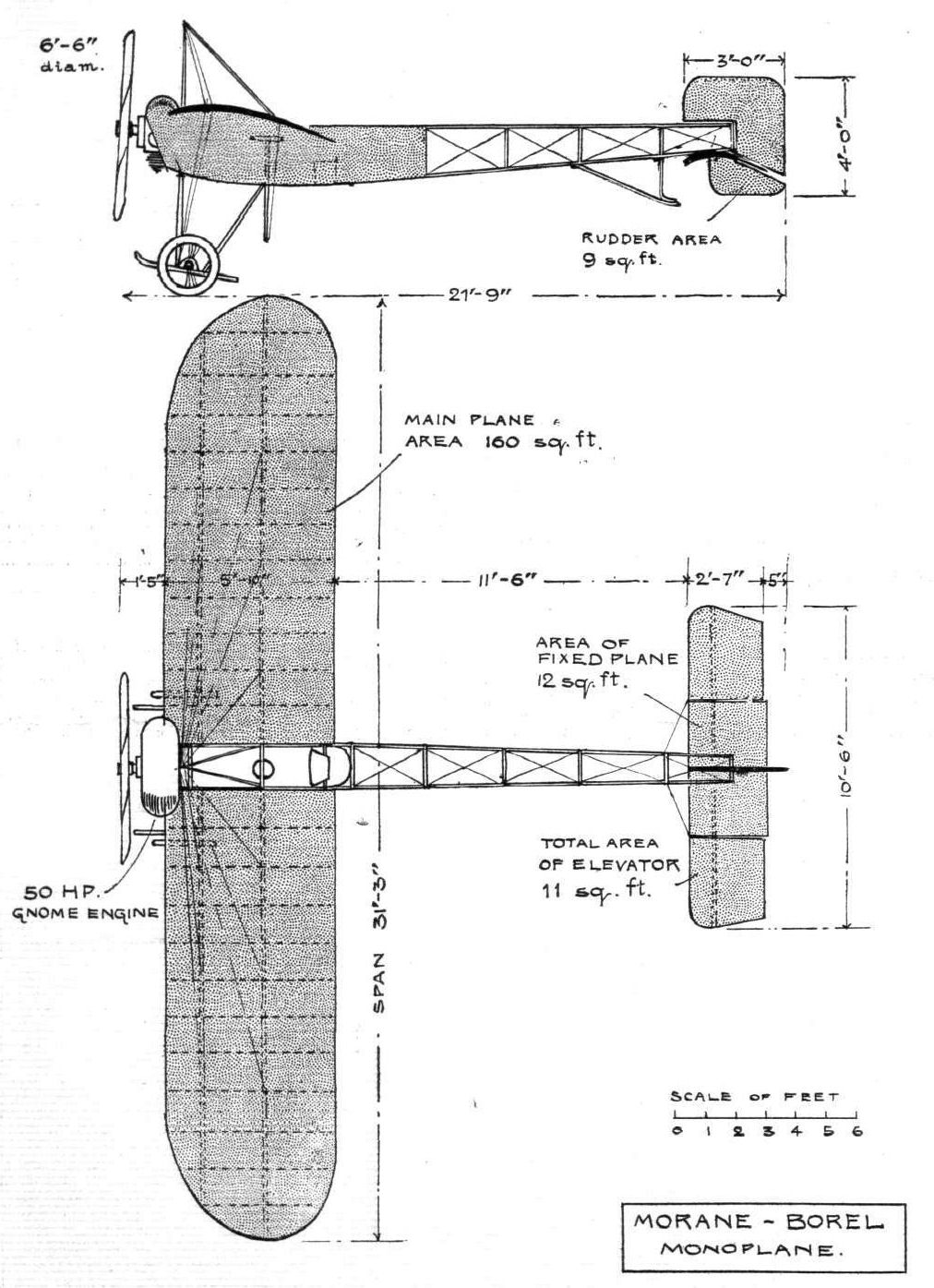
AT THE PARIS AERO SALON. - The current trend of design towards the torpedo type of body is well illustrated by these photographs: the Aero Torpedo on the left is the two-seater Breguet, with Chenu motor, and on the right is the unfinished Morane-Saulnier war monoplane; it is constructed entirely of steel, including the wing skeletons.

GORDON-BENNETT RACE A T EASTCHURCH. - Mr. Weymann. the winner on behalf of America, and his Nieuport monoplane. (1) Just before being timed away for his start; (2) getting away; (3) sharp banking round No. 1 pylone; and (4) bringing home the Nieuport after the race was won.
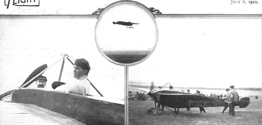
GORDON-BENNETT RACE AT EASTCHURCH. - M. Chevalier, who flew two Nieuports in the race, just before his start. Inset is M. E. Nieuport flying his Nieuport machine in the race.
GORDON-BENNETT RACE AT EASTCHURCH. - The starting line which the competitors had to cross in flight, as seen from the Press enclosure. At the other end of the line is the Judges' box, and right and left the scoring boards and public announcements. In the air above Mr. Alec Ogilvie is seen on his N.E.C.-engined "Baby" Wright, and below, Weymann, the winner, on his Nieuport monoplane.
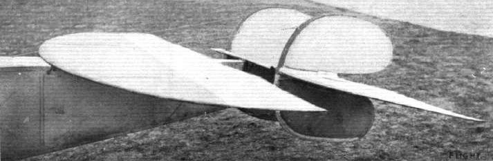
NIEUPORT MONOPLANE. - The rudder and tail of the latest model.

UNDER-CARRIAGES AT OLYMPIA. - The Nieuport inverted "A" frame.
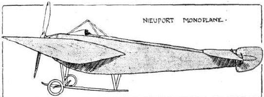
MONOPLANES AND BIPLANES IN THE DAILY MAIL CIRCUIT ROUND GREAT BRITAIN. - From these every machine can be readily identified either in flight or on the ground.
UNDER-CARRIAGES AT OLYMPIA. - A comparison of the Nieuport laminated steel spring axle and the Handley Page flexible wooden axle.
Flight, October 7, 1911.
THE NIEUPORT TWO-SEATER MONOPLANE.
IN the process of evolution of his present machine from its extremely primitive prototype, M. Edouard Nieupoit, who has for years been known to the motoring community as a manufacturer of ignition specialities, has kept the three features of simplicity, efficiency and speed as keystones of his design.
He has been eminently successful, for the Nieuport monoplane of to-day is an embodiment of all these features in a most original design. It is in fact, perhaps, the simplest-looking aeroplane that has yet been produced.
To illustrate its speediness, it is only necessary to recall Weymann's victory in the Gordon-Bennett race on a machine of this make. Its efficiency is vouched for by the fact that at one time a Nieuport held the speed record with a 30-h.p. twin-cylinder motor, the speed itself being higher than that made by Grahame White with a 100-h.p. monoplane at Belmont Park last year. As for its simplicity of construction, this can be gathered, in a measure, from the following description, but better still from a glance at the actual machine.
Nieuport's study of the reduction of head resistance has contributed largely to the efficiency of his machine. The wings are double-surfaced, of a section closely analagous to that advocated by Horatio Phillips, and they taper towards the tips.
The under surface about the entering edge has a convex curve where it passes the main spar. The trailing edge, too, is given a slightly upward turn, instead of forming a more or less tangential continuation of the cambered portion of the plane, as in the Bleriot and most other wings. The maximum camber is about 3 3/4 ins.
It is this particular wing curve, together with the fact that the machine has little head resistance, and flies with an extremely small angle of incidence, that decide its great speed.
Steel enters largely into the construction, the undercarriage, with its central skid and leaf-spring "axle," being made entirely of this material, while the tail members, all of which are perfectly flat, consist of steel tubular frames covered on both sides with fabric.
The body is of wood on the ordinary square girder principle, a few struts in the fore part, however, being steel tubes similar to those used in the undercarriage. The body is unusually deep in the region of the pilot's seat, in order that his whole body may be enclosed, while its shape is such that it can cleave through the air with a minimum of resistance.
A slight dihedral angle is given to the wings, and an interesting feature in their construction is that the I-section main spars of ash are not of even section along their entire length, but vary in thickness according to the strains imposed. Thus it has been found that the greatest strength is necessary at a point situated a few feet from the inner end of the spar, the tie wires being taken into account in this calculation. The main spars are braced well forward to the skid, and stranded-wire cables, previously subjected to a 3-ton test, are employed for this purpose. Above the planes, the tie wires are solid and, of course, much lighter, as there is not so much strain.
On the particular machine here described, which belongs to the two-seater military type, the control is unusual, in that wing-warping is accomplished by the feet, the rudder movement as well as the action of the elevating planes being under the control of a hand-lever. This application of foot-control to the wings is not new, but is decidedly uncommon, and in the opinion of Mr. Maurice Ducrocq, the well-known aviator who represents the Nieuport machines in this country, it is, perhaps, a more natural action on the part of the pilot in an emergency. It is, of course, arranged that an upward tilt of one plane is corrected by pressure on that side of the foot-lever. Exactly how this movement is transmitted can be gathered from a reference to the accompanying sketches, wherein it will be seen that a cross-bar is permanently fixed to the upper extremity of a rock-shaft which passes diagonally through the floor of the body to the skid, terminating in a small crank to which the two sets of warping-wires are attached. The movement is thus effected in a simple manner without the use of pulleys and with the minimum amount of friction.
The hand-lever is mounted by a swivel-joint on a short shaft that lies along the floor inside the body, having bearings in two tubular cross-members. A forward and backward movement of this lever operates the elevator through the agency of wires passing round pulleys at both ends of the short rock-shaft. A lateral motion of the lever actuates the rudder wires by means of a crank, which is really formed by an extension of the rear pulley sheave, and is, of course, fixed permanently to the rock-shaft.
It might easily be supposed, owing to the great depth of the body and the low portion of the seats, that the pilot's view would be somewhat restricted; but in this connection it must be remembered that the pilot's seat is very little behind the leading edge of the wings, and that the machine flies with the tail unusually high.
A 50-h.p. Gnome motor coupled to an 8 ft. 4 in. Integrale propeller is fitted, and with this power-plant the machine is capable of maintaining a speed of 63 m.p.h.
Flight, October 21, 1911.
CLAUDE GRAHAME-WHITE IN THE UNITED STATES.
To Miss B. Grahame-White, the famous aviator's sister, who has just returned from America, where she has accompanied her brother on his tour, we are indebted for the following interesting information :#
On their arrival in New York, the first four days were spent in the company of Commodore Benedict, who had invited them to join a cruising expedition on his 400-ton steam yacht. Unfortunately this pleasant interlude had to be cut short owing to the urgency of being present at the commencement of the Boston meet at Squanturn, whit her his 70-h.p. two-seater Nieuport had been shipped direct from France.
The weather during the week was so utterly impossible # there was no flying whatever for the first four days # that an extension of a further seven days was decided upon. For the reason that the arrival of Grahame-White's "Baby" biplane had been delayed by the dock strikes in Liverpool, he was unable to compete in the bomb dropping and alighting events.
However, there was not another machine that could approach his where speed and rate of ascent was concerned, so he had little difficulty in capturing those prizes. His first real flight on the Nieuport was the double trip around the Boston Light, a course for the most part above the waters of Boston Harbour. Before starting he had only made two short trips on the new machine, and so was far from being absolutely au fait with the pedal-controlled wing warping and lever-operated elevator and rudder peculiar to the Nieuport control. Probably owing to his minute attention to the new controls, and, perhaps, to the fact that in the same competition in the previous year no preliminary circuit of the aerodrome was conditioned, Grahame-White set straight off for the Light and completed two laps, each of 33 miles. He was accompanied by his engineer, Reginald Carr.
On his return to the Squanturn field, he found the alighting ground impeded by the presence of two biplanes, and to indicate the necessity of their removal he continued to circle the aerodrome, signalling the while. No one seemed to understand his signals, and he was obliged to land on unsuitable marshy ground, into which the machine promptly buried its nose, with disastrous results to the latter. In addition to this mishap, he had the misfortune of learning that, although he had made fastest time over the course, he had been disqualified for not making a preliminary circuit. Somewhat reminiscent of the Statue of Liberty trouble!
At the Boston meeting the trick "stunts" were performed by Beachey and Ely, Grahame-White leaving these items severely alone. As he wisely remarks, "It's better to be a live man than a dead hero." It is a good sign to see that the Americans are losing their desire for sensational flying, and are becoming more appreciative of that steady kind of flying work which really does further the science, for at the Nassau Boulevard meet at New York such dangerous flying was definitely forbidden.
During the meet he cabled Nieuport for speedier wings, and the latter replied in what was probably the last cablegram he ever sent, declining to make them, as their use would probably introduce some danger. Within 24 hours poor Nieuport met with his fatal accident.
Up to the present time Grahame-White has not made a feature of passenger flights, and the only flights he has yet given were to his personal friends, Mr. James Blake and Baron von Hechwaechter, and also to his engineer, Carr. As a matter of fact, the latter nearly always accompanies him, as Grahame-White finds the machine considerably steadier with two up.
The "Baby" had arrived in time for the Nassau Boulevard meeting, and it proved slightly faster than the Wrights'. This miniature biplane's quickness and latitude of control was as much admired as the Nieuport's blunt-nosed spark-like appearance and enormous speed.
Grahame-White had the misfortune to incur a second mishap while starting away to visit the scene of Sopwith's accident. The latter, accompanied by a passenger on his Wright biplane, had, while wanting to alight on the beach, misjudged his distance, with the result that he feel into the sea, happily without personal injury. As for Grahame-White, he in getting away from the aerodrome ran foul of another machine, and was obliged to make for a ditch, 10 ft. deep, at such a speed that the resultant impact did little to improve the appearance of the machine.
However, he suffered no injury beyond a bruise on the lip, for his sister had that morning sent him a thick pad to fix over the edge of the metal wind screen.
Flight, November 11, 1911.
AEROPLANES AT TRIPOLI.
MR. QUINTO POGGIOLI, who will be remembered by our readers as having taken his pilot's certificate in England under the Royal Aero Club's regulations, sends us some interesting details of the practical work being carried out in Tripoli in connection with the Italian-Turkish War. Mr. Poggioli writes :-
"On the 25th Oct. Capt. Piazza with his Bleriot, and Capt. Moizo on his Nieuport, observed three advancing columns of Turks and Arabs of about 6,000 men. The Italians, after receiving this information, could successfully calculate distances and arrange for their defence.
"On the day following, the 26th Oct., the battle of Sciara-Sciat took place, resulting in the loss to the Turkish Army of 3,000 men. During the battle two aeroplanes, Lieut. Gavotti with his Etrich and Capt. Piazza, were circling the air. The flights took place above the line of fire, so as to be able to direct the firing of the big guns from the battleship 'Carlo Alberto,' and also of the mountain artillery. The aeroplanes were often shot at by the guns of the enemy, but with no result. The only difficulty they had was caused by the currents of air caused by the firing of the big guns.
"Previously, on the 22nd Oct., Capt. Moizo when reconnoitering passed over an oasis, and, in order to observe better the movements of the enemy, descended to an altitude of about 200 metres, and in consequence the wings of his machine were pierced by bullets in six or seven places, and also a rib was broken.
"On November 1st Lieut. Gavotti (Etrich) flew over the enemy, carrying four bombs, carried in a leather bag; the detonator he had in his pocket.
"When above the Turkish camp, he took a bomb on his knees, prepared it and let it drop. He could observe the disastrous results. He returned and circled over the camp, until he had thrown the remaining three bombs. The length of his flight was altogether about 100 kiloms.
"The bombs used contained picrato of potassa, type Cipelli."
THE first official communication by one of the belligerents, in regard to the use of aeroplanes in actual warfare, has been issued by the Italian authorities, dated November 5th, from Tripoli. As a matter of historical record we reproduce the text in extenso as follows :-
"Yesterday Captains Moizo, Piazza, and De Rada carried out an aeroplane reconnaissance, De Rada successfully trying a new Farman military biplane. Moizo, after having located the position of the enemy's battery, flew over Ain Zara, and dropped two bombs into the Arab encampment. He found that the enemy were much diminished in numbers since he saw them last time. Piazza dropped two bombs on the enemy with effect. The object of the reconnaissance was to discover the headquarters of the Arabs and Turkish troops, which is at Sok-el-Djama."
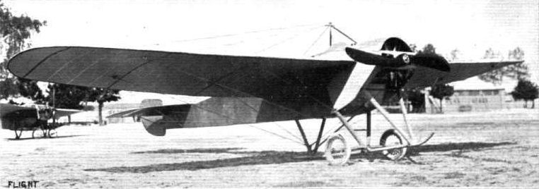
THE TWO-SEATED NIEUPORT MONOPLANE BUILT TO COMPETE IN THE PARIS-MADRID RACE. - It will be observed that the framework of this machine is entirely covered so as to present minimum resistance to the air, while the chassis is made amply strong in view of landings which might have to be made unexpectedly and on rough ground.
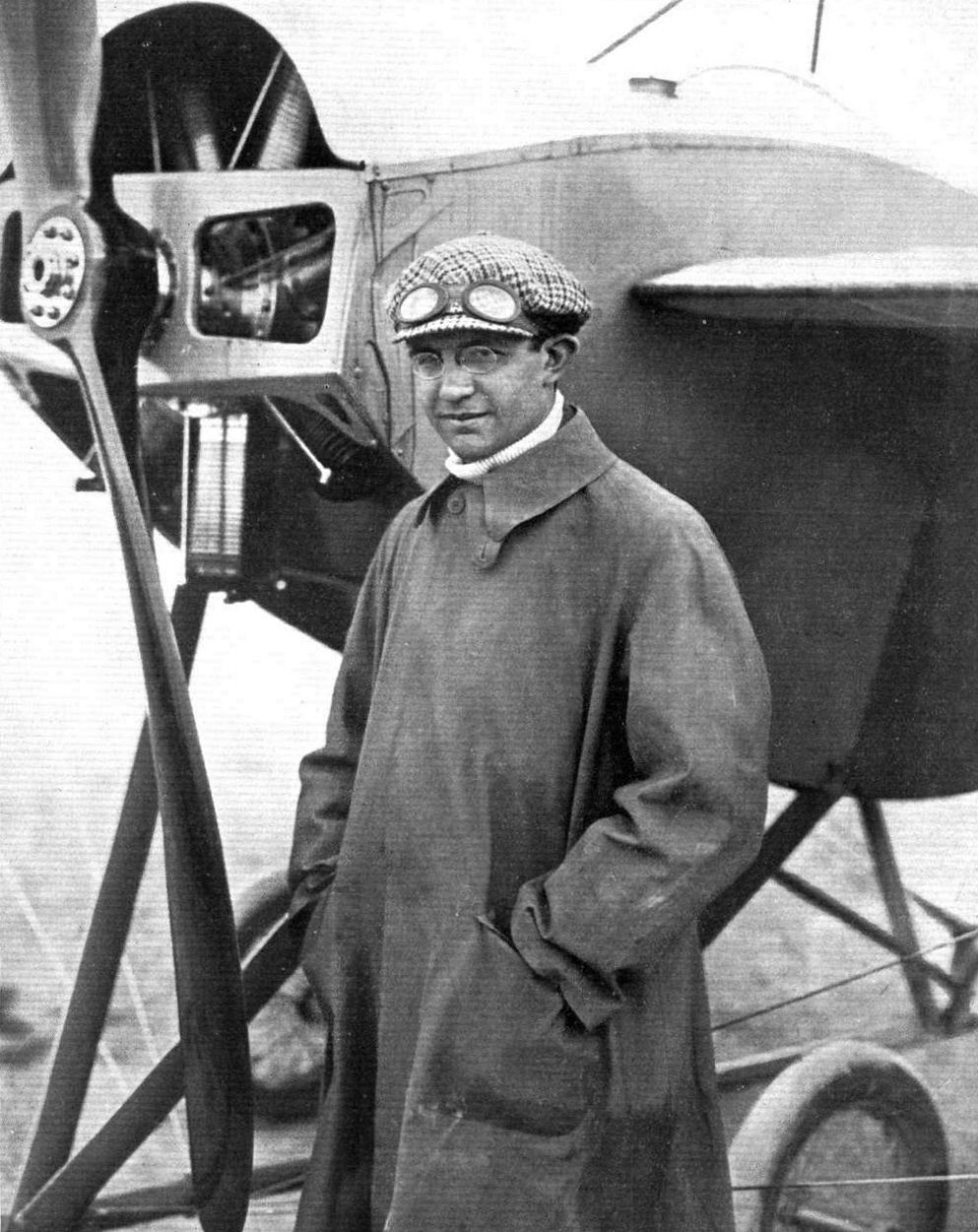
C. T. Weymann, who, on his Nieuport machine, secured the Gordon-Bennett Cup for America in last Saturday's race at the Royal Aero Club's flying grounds, Hastchurch.
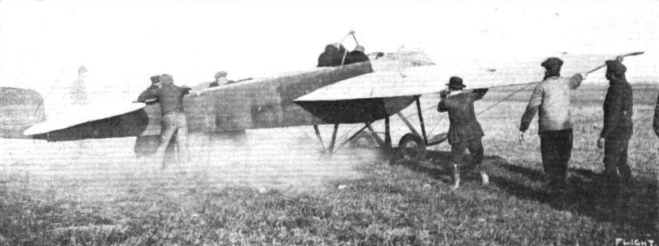
Mr. Weymann just before the signal to start from Rheims on his Nieuport monoplane for the final cross-country speed test in the Military Aviation Contest, in which he has been adjudged the premier position, he having covered the 300 kiloms. in the net time of 2 hrs. 34 mins.
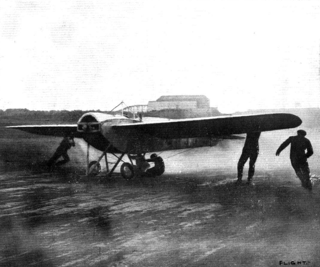
MR. CLAUDE GRAHAME-WHITE IN AMERICA. - At the moment of starting on his 70-h.p. Nieuport monoplane at Boston, U.S.A. From a photograph supplied by Miss Grahame-White.
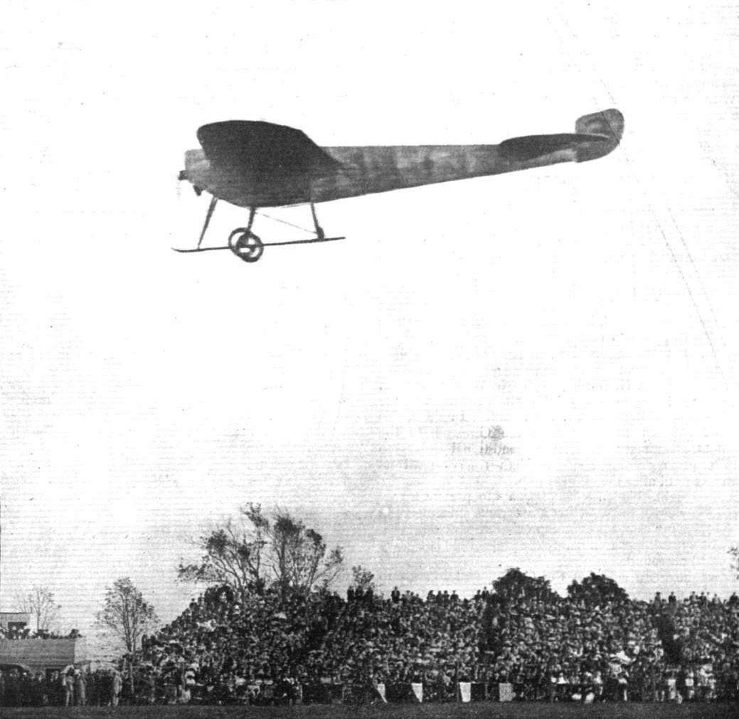
Mr. Claude Grahame-White passing some of the stands on his 70-h.p. Nieuport monoplane at the Boston Meeting, U.S.A.
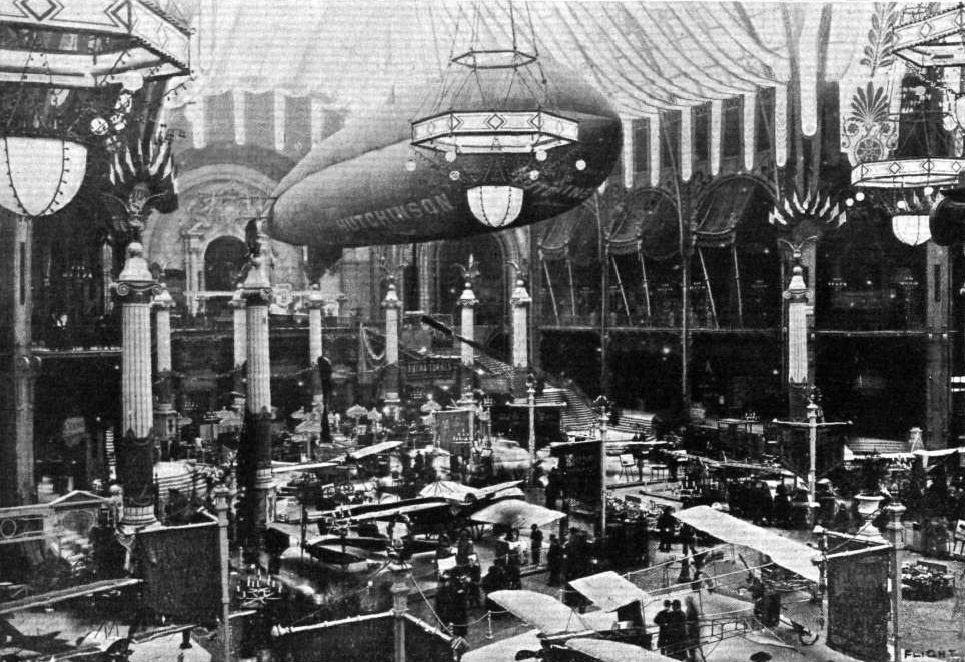
PARIS AERO SALON. - Another general view, showing the Astra-Torres dirigible. The Roger Sommer exhibit is to the front of the photograph, while behind it is the Nieuport stand.
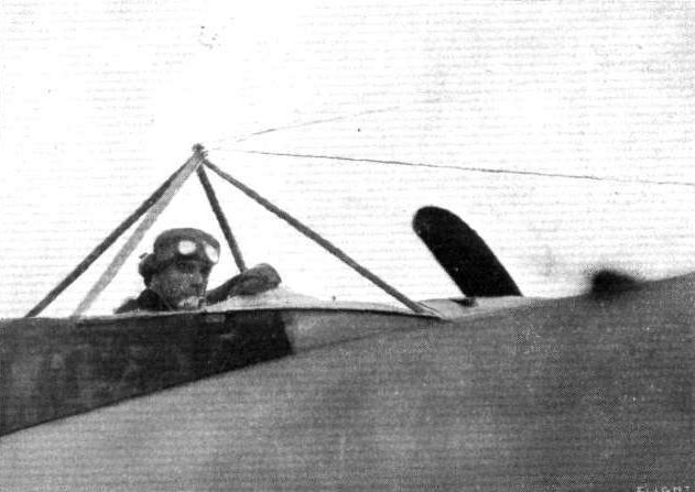
Grahame-White in his 70-h.p. Nieuport, at Boston. U.S.A., waiting to start for the race round the Boston Light.
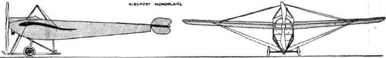
PARIS-MADRID RACE. - Diagrammatic sketches of some of the machines entered in the race.

Sketch illustrating the control system on the Nieuport monoplane.
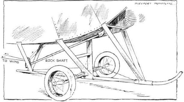
Sketch illustrating the Nieuport undercarriage.
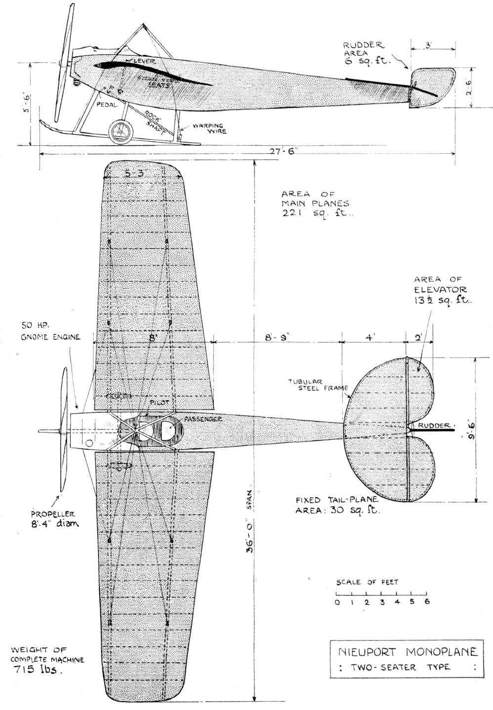
THE NIEUPORT TWO-SEATER MONOPLANE. - Plan and Elevation to Scale.
Flight, January 21, 1911
BRITISH NOTES OF THE WEEK.
British Army Paulhan Biplane.
AT BUC, on Wednesday of last week, Caille successfully put the Paulhan biplane intended for use in the British Army through a series of tests. The conditions imposed were that the machine should fly for two hours with a passenger as well as 200 kilogs. of ballast, in a wind blowing at the rate of 25 miles an hour, and make a gliding flight, with the engine stopped, from a height of 200 metres. Capt. Fulton, who represented the British Army at these tests, has, we understand, accepted delivery of the machine on behalf of the Government.
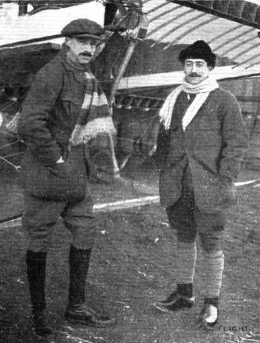
Capt. Fulton, R.A., and M. Paulhan at St. Cyr after the necessary tests of the Paulhan biplane, before delivery to the British Army, were concluded.

Capt. Fulton, R.A., in the pilot's seat of the Gnome-engined Paulhan biplane, of which he has just taken delivery in France on behalf of the British Army. This machine was fully described in FLIGHT on October 22nd last.
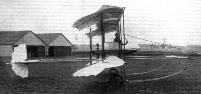
PAULHAN'S NEW MACHINE. - It will be noticed that in addition to minor changes, M. Paulhan has abandoned the fabre lattice type of construction for the main spars of his machine.

PAULHAN'S NEW MACHINE. - On the left, sketch illustrating the arrangement of the skid on the latest Pauihan biplane, and on the right is seen the rudder. This is made in two sections, which admits of the fabric being kept tight by a simple connection, and the position of the horizontal plane can be varied by adjusting the stays of the vertical rudder post.

THE LATEST PRODUCTION OF M. PAULHAN. - Side view of the triplane which was last week tested in the air.
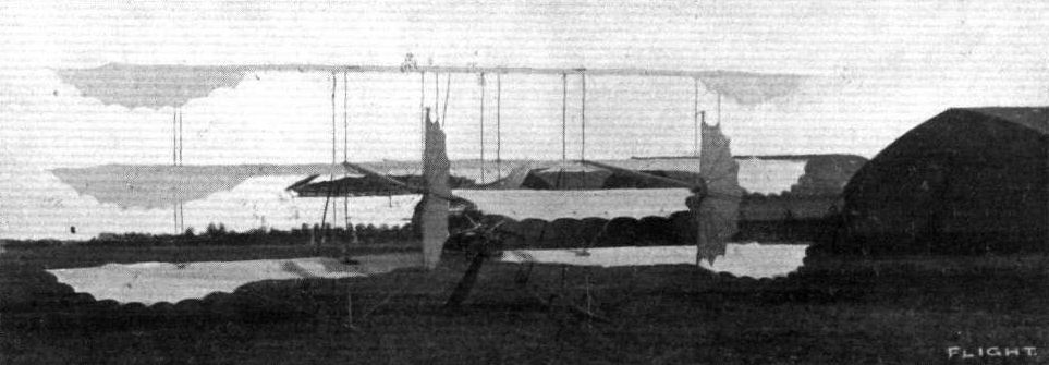
THE NEW PAULHAN TRIPLANE. - Three-quarter view from the rear.
Flight, October 7, 1911.
AIR EDDIES.
Another unique machine, a creation of that well-known pioneer, Victor Tatin, has been undergoing tests at Louis Paulhan's flying ground. "The flying porpoise," as this machine is known in the locality where these experiments are being made, has many points in common with that monoplane exhibited at the 1909 Exhibition at Olympia by the Petre brothers. The pilot sits in advance of the main wings, practically enclosed in the fusiform body. Directly behind him revolves the Gnome engine, which is coupled by means of a hollow universally-jointed shaft to the propeller at the extreme end of the tail. The wings have up-turned tips.
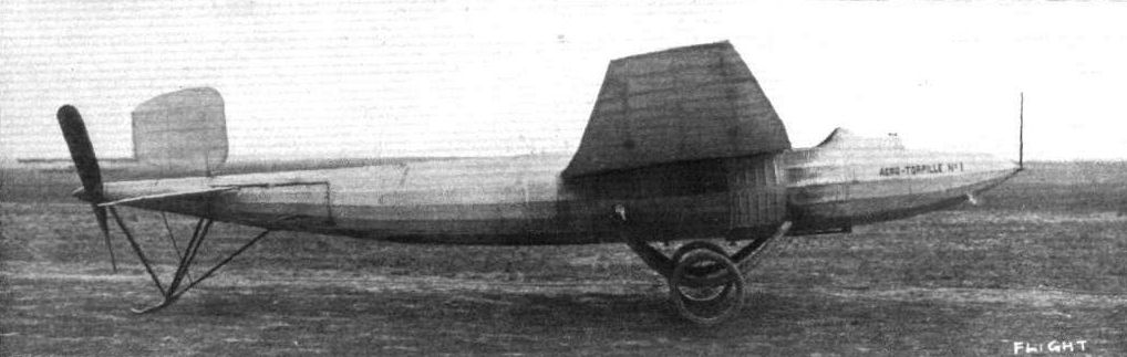
"AERO-TORPEDO NO. 1." - The result of the collaboration of Tatin and Paulhan. The photograph gives a good idea of the type of body design that is at present meeting with much favour in France. The ventilated metal shielding under the front of the wings indicates the position of the motor - a 50-h.p. Gnome - driving a propeller at the rear end of the body by means of a hollow universally-jointed shaft. Accommodation is provided for the pilot in advance of the wings.
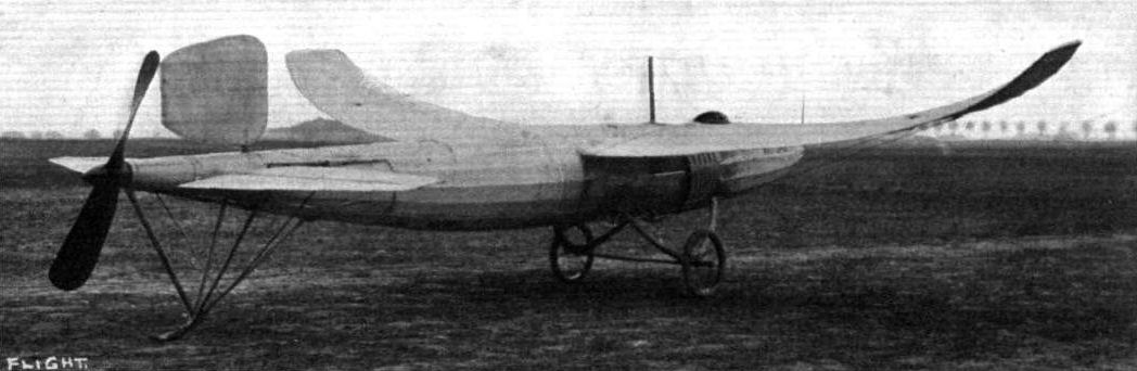
THE "AERO-TORPEDO" AS IT APPEARS FROM THE REAR. - No provision is made for wing-warping, the upturned wing-tips being expected to endow the machine with a sufficient modicum of lateral balance. It has a span of 9 metres, and its overall length is 8.60 metres. Without fuel or pilot it weighs 350 kilogs.
"Aero Torpedo No. 1," the first experimental machine of this type, with which 88 miles per hour was obtained, with Gaudart at the lever.
"Aero Torpedo No. 1," the first experimental machine of this type, with which 88 miles per hour was obtained, with Gaudart at the lever.
Six types of landing gear at the Paris Aero Salon.
Flight, April 29, 1911.
FLYING IN FRANCE.
SOME OBSERVATIONS DURING THE EASTER HOLIDAYS AT THREE FLYING CENTRES, ISSY-LES-MOULINEAUX, JUVISY, AND CHALONS CAMP.
By E. KEITH DAVIES.
Issy. - At Issy there are two dirigibles and 20 aeroplane hangars, or the most part occupied by the lesser known firms and numerous experimenters. Flying was not permitted till 4.30 in the afternoon, when several machines came out, the most interesting being the latest Pischoff, the Vinet, and an all-steel Voisin.
The Pischoff machine is certainly unique, and gives one the appearance of a small car with a monoplane attached about 4 ft. above as an afterthought. The chassis is composed of strong wood side members, attached to which are two skids and a very strong steel axle and pair of wheels. The engine is placed in front with a car radiator, starting-handle, bonnet, and scuttle dash a la Brooklands racing car, the pilot and passenger sitting side by side. The power is transmitted from the engine by a plate-clutch and cardan-shaft and then by a chain to the propeller running at half engine speed, which is fitted behind the main planes close up to the trailing edge. It is very novel to see the pilot take his clutch out, go round to the front, start up, get comfortably seated, accelerate the engine, and away. The machine flies very nicely in a straight line, but assumes some weird angles when turning. It is flown by the inventor, M. Pischoff, who in the evening left for Juvisy, arriving at the latter place safe and sound.
<...>
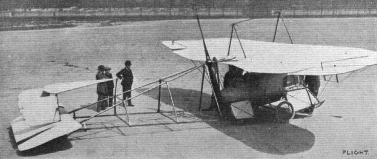
The latest Pischoff, illustrated in the above photograph, is a very good example of an underhung load in monoplane design, and also of the use of a motor car type body for the pilot and passenger. Indeed the resemblance goes even further than the arrangement of the seats, for the engine drives a propeller-shaft passing to the rear, and there is a final chain transmission to an overhead propeller-shaft situated on a level with the wings. Constructionally this machine is very interesting on account of the method of introducing a central propeller behind the main planes of a machine that has an outrigger for carrying a tail.
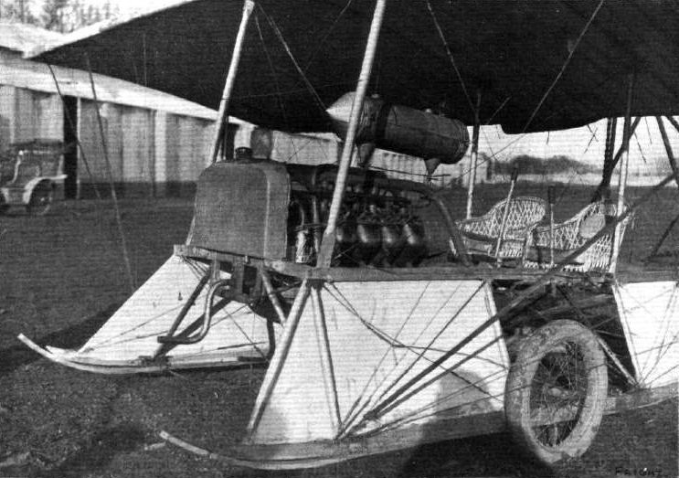
Latest Pischoff machlns, showing the carriage, E.N.V. engine, and two-seated control arrangement.
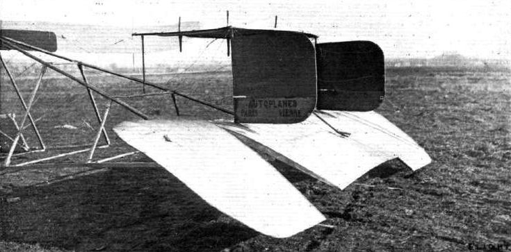
Tail of the latest Pischoff machine.
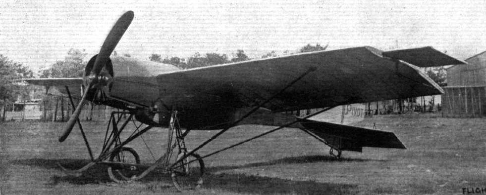
THE NEW MILITARY PIVOT MONOPLANE. - The span of this machine is 10.5 metres and the lifting surface is 16 square metres, while the weight is given as 310 kilogs. It will be seen that the use of wire stays has been entirely abandoned in favour of steel tubes. Natural stability is adjusted by the two ailerons at the tips of the main plane, and the rudders and elevators at the rear being controlled by a wheel. The motor fitted is a 45-h.p. Rossel Peugeot.
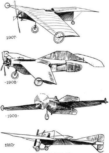
The Development of the R.E.P. monoplane. 1907. Absence of top fin, inverted Vee. 1908. Vee still inverted, partial remedy by top fin. 1909. Inverted Vee very slight and larger top fin. 1910. Stable Vee, fin above centre diminished.
Flight, January 7, 1911
FRENCH MICHELIN CUP.
The Last Day.
As we have noted above the closing day, December 31st, witnessed five aviators starting off on attempts for the prize. Henry Farman was the first in the air, and at Etampes he circled round the flying ground for 7 hrs. 11 mins., covering 487 kiloms., after which he was obliged to land owing to the breaking of a lubricating pipe.
This splendid failure was equalled by a meritorious flight made at Buc, where Pierre Marie on his R.E. P. monoplane succeeded in covering 530 kiloms. in 6h. 29m. 19 1/5s., when he was obliged to land owing to his petrol giving out. Incidentally he set up new records as follows:- 250 kilorns., 3h. 4m. 28s; 300 kiloms., 3h. 40m. 55 2/5s.; 350 kiloms., 4h. 17m. 26 1/5s.; 400 kiloms., 4h. 54m. 6 4/5s.; 450 kiloms., 5h. 30m. 35 3/5s.; 500 kiloms., 6h. 7m. 7 4/5s.
<...>
Laurens Wins the Coupe Deperdussin.
Two final attempts to better Laurens' record were made on December 31st, but neither of them was successful. At Douzy, Andre Noel started off in spite of the severe wintry conditions, but after he had covered only about 50 kiloms. in 40 mins. he was obliged to land owing to a frozen carburettor. The second attempt was made at Rheims, where Vidard was flying on the Deperdussin monoplane for 55 kiloms., and is said to have beaten the passenger speed record up to that distance, although no times are as yet available. Some difficulty was experienced apparently in obtaining the services of an official timekeeper, and by the time one arrived it was impossible to beat the record. It will be remembered that the winning flight was made on December 21st at Buc, when Laurens, accompanied by M. Hickel and mounted on his R. E.P. monoplane, completed 100 kiloms. in 1 hr. 16 mins.
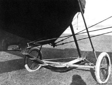
R.E.P. MONOPLANE. - Chassis and landing skid of latest model.

R.E.P. MONOPLANE. - Rudder, tail and back skid of the new model.
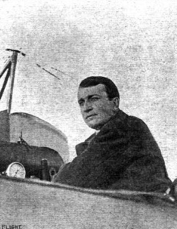
Pierre-Marie, who, at Buc on December 31st, on an R.E.P. monoplane, in an attempt to secure the French Michelin Prize, covered 530 kiloms. in 6h. 29m. 19 1/5s. Although he put up some new speed records, the cup was secured by M. Tabuteau.
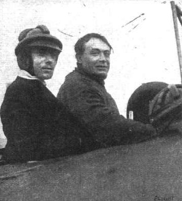
M. Laurens and his passenger on his R.E.P. monoplane, with which he won the Deperdussin Prize for monoplanes by a flight at Buc, on December 21st, of 100 kiloms. in 1 hr. 16 mins., beating all previous records.
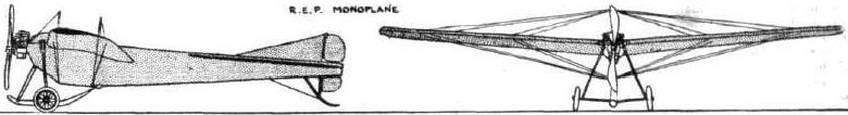
PARIS-MADRID RACE. - Diagrammatic sketches of some of the machines entered in the race.
The Development of the R.E.P. monoplane. 1907. Absence of top fin, inverted Vee. 1908. Vee still inverted, partial remedy by top fin. 1909. Inverted Vee very slight and larger top fin. 1910. Stable Vee, fin above centre diminished.
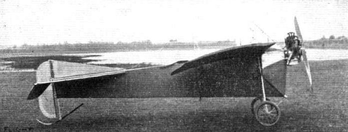
THE LATEST R.E.P. RACING MONOPLANE, "L E POUSSIN." - This small machine, under the pilotage of Amerigo, is credited with a speed of 107 kiloms. an hour.
Flight, December 30, 1911.
PARIS AERO SHOW.
Robert Esnault-Pelterie.
ON the R.E.P. stand two machines were exhibited, one completely fabric, and the other a simple fuselage, denuded of its covering of fabric in order to show the excellence of the interior workmanship. A description of these machines is unnecessary, as they do not differ in any detail from the R.E.P. monoplane which competed in the Circuit of Europe, and with which our readers are already acquainted. The new 90-h.p. R.E.P. motor, which has its seven cylinders arranged radially around the crank case, was also on exhibition on the stand.
Principal dimensions, &c. :-
Length 25 ft.
Span 40 ft.
Area 220 sq. ft.
Weight 880 lbs.
Speed 68 m.p.h.
Motor 60-h.p. R.E.P
Price L1,200.
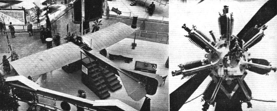
The R.E.P. stand at the Paris Aero Show, and the new 90-b.p. 7-cyl. R.E.P. motor.
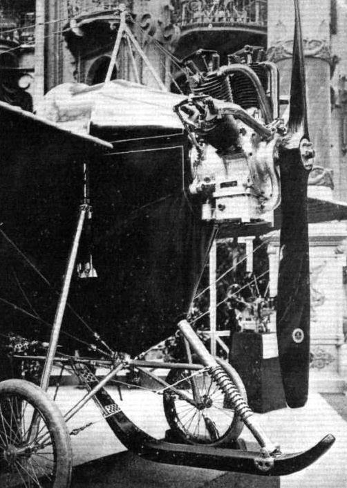
Detail view, showing the front section of the beautifully constructed R.E.P. monoplane.
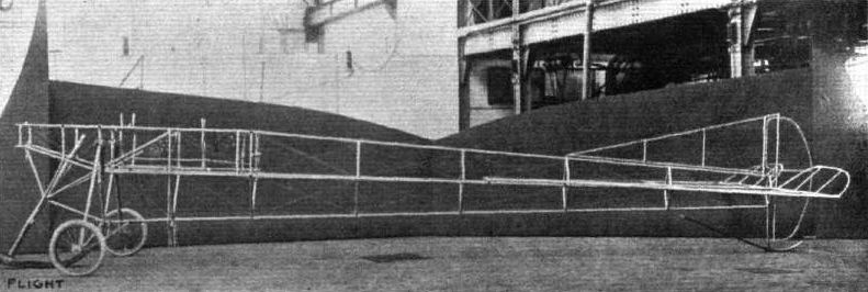
TUBULAR STEEL WORK IN AEROPLANE CONSTRUCTION. - The above photograph is an excellent example of a tubular steel frame for a monoplane body, the machine illustrated being the latest R.E.P. Forming a background to the body are the wings.
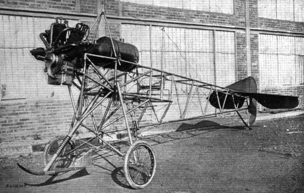
THE LATEST R.E.P. MONOPLANE. - The fuselage before the mounting of its planes, &c# showing the method of construction adopted for the framework, landing chassis, fixing of the engine, &c.

The R.E.P. monoplane.
GENERAL VIEW OF THE THIRD PARIS AERO SALON. - The machine at the bottom of the photograph is the Bleriot 100-h.p. "Aeronef," built to the order of M. Henri Deutsch de la Meurthe. On the same side, but towards the centre of the Exhibition, may be seen the Zodiac biplane and the Borel and Deperdussin monoplanes, while opposite are the Train and H. Farman monoplanes and Savary and M. Farman biplanes.
Flight, February 25, 1911
The New Sommer Machine.
VERY fair success appears to have been attained by M. Sommer with his new fast machine, the chief characteristic of which is its flat planes. Not only has a good turn of speed been obtained but the machine has shown itself capable of carrying a heavy load in the way of passengers,
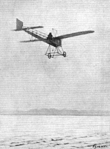
Sommer in flight at Mouzon on his new 50-h.p. Gnome-engined monoplane.
Flight, February 4, 1911
FOREIGN AVIATION NEWS.
Six in an Aeroplane.
M. ROGER SOMMER, who has for some considerable time been studying the question of passenger carrying by aeroplane, achieved a notable record on Thursday of last week, when, accompanied by five friends, he flew from Douzy to Romilly and back. Two of the passengers were accommodated on the skids of the machine and the remaining three perched themselves up behind the aviator. The lightest of the passengers weighed seven and a half stone.
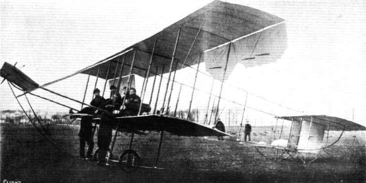
M. Sommer with his five passengers on his Sommer biplane, with whom he ilew from Douzy to Romilly and back, as recorded in our last issue.
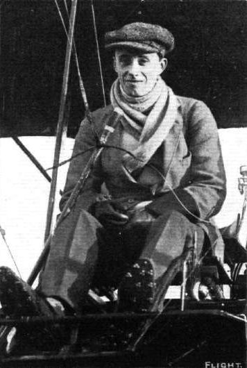
Mr. H. J. D. Astley on his Sommer biplane at Brooklands. - Mr. Astley, on this machine on Saturday, gave a remarkable display of his airmanship when he had to steer between a telegraph pole and Mr. Conway's smashed triplane, with only about 2 ft. clearance to spare.
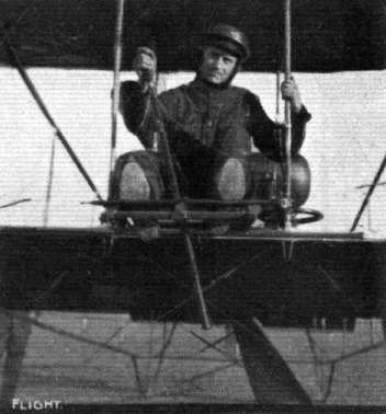
M. H. Pequet, who has recently returned from his very successful flying exhibitions at Allahabad, where he conveyed the first aerial post ever officially recognised. M. Pequet is flying for Messrs. Humber, Ltd., at Brooklands on a Humber biplane, Sommer type, the machine on which he is seen being the biplane exhibited at the last Olympia Aero Show. Early last Saturday he made two flights of a quarter of an hour's duration, and on Sunday morning he was flying for 1 hr. and 10 mins., during which he first covered several circuits of the Brooklands course, and then made a cross-country flight over Walton and Wey bridge.
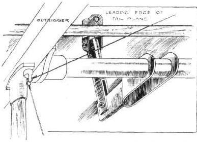
Sketch illustrating how the attitude of the tail is adjusted by a hand wheel on the Sommer-type Humber biplane.
Flight, December 30, 1911.
PARIS AERO SHOW.
Roger Sommer.
ROGER SOMMER was represented at the Salon by two machines, a monoplane and a biplane, the latter constructed throughout of steel. The biplane should really be termed a double monoplane, for the cellular method of bracing the main planes has disappeared in favour of the system originated by Breguet. Balancing laterally is effected by the rotation around the front spar, of the extensions of the top plane. Its chassis, supported by six steel tubes, is composed of a pair of wheels mounted on a common axle, which latter is flexibly attached by means of stout rubber bands to the short steel tubes uniting the steel chassis struts. One peculiarity about this landing gear, which is directly descended from the original Henry Farman conception, is that the radius rods have disappeared. Elevation and depression of the machine is controlled by a small monoplane surface, measuring about 2 ft. span by 1 ft. chord, supported on steel outriggers about 8 ft. in advance of the main plane, which surface works in conjunction with a flap hinged to the rear of the lifting tail. Its diminutive size makes one wonder if this surface is of any use at all as an elevator, and the only apparent advantage of the system is that the outriggers form a good point from which to brace the main planes against drift strains.
The main planes, which are double-surfaced with leaf-green fabric, for the purpose of rendering them invisible when close to the ground, are tested before they leave the works to withstand a strain of four times that they are ever likely to be called upon to bear in normal flight.
Principal dimensions, &c. :-
Monoplane-
Length 22 ft.
Span 29 ft.
Area 176 sq. ft.
Weight 575 lbs.
Speed 65 m.p.h.
Motor 50-h.p. Gnome
Price L640.
PARIS AERO SALON. - Another general view, showing the Astra-Torres dirigible. The Roger Sommer exhibit is to the front of the photograph, while behind it is the Nieuport stand.
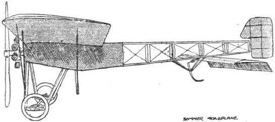
Flight, December 30, 1911.
PARIS AERO SHOW.
Roger Sommer.
ROGER SOMMER was represented at the Salon by two machines, a monoplane and a biplane, the latter constructed throughout of steel. The biplane should really be termed a double monoplane, for the cellular method of bracing the main planes has disappeared in favour of the system originated by Breguet. Balancing laterally is effected by the rotation around the front spar, of the extensions of the top plane. Its chassis, supported by six steel tubes, is composed of a pair of wheels mounted on a common axle, which latter is flexibly attached by means of stout rubber bands to the short steel tubes uniting the steel chassis struts. One peculiarity about this landing gear, which is directly descended from the original Henry Farman conception, is that the radius rods have disappeared. Elevation and depression of the machine is controlled by a small monoplane surface, measuring about 2 ft. span by 1 ft. chord, supported on steel outriggers about 8 ft. in advance of the main plane, which surface works in conjunction with a flap hinged to the rear of the lifting tail. Its diminutive size makes one wonder if this surface is of any use at all as an elevator, and the only apparent advantage of the system is that the outriggers form a good point from which to brace the main planes against drift strains.
The main planes, which are double-surfaced with leaf-green fabric, for the purpose of rendering them invisible when close to the ground, are tested before they leave the works to withstand a strain of four times that they are ever likely to be called upon to bear in normal flight.
Principal dimensions, &c. :-
Biplane-
Length 30 ft.
Span 40 ft.
Area 330 sq. ft.
Weight 640 lbs.
Speed 56 m.p.h.
Motor 50-h.p. Gnome.
Price L840
"CHASSE-CROlSE" IN THE AIR. - Reminiscence of an incident - one of many similar daily - at Rouen Aviation Meeting last year. Dubonnet, on his Tellier monoplane, crossing under Capt. Dickson on his Henry Farman biplane.
Flight, May 27, 1911.
PARIS-MADRID RACE.
WITH the same breath that everyone on Sunday expressed their horror at the national loss sustained by France in the death of M. Berteaux, the Minister of War, at the start of the Paris-Madrid race from Issy, it was universally acknowledged that in no real sense could either the pilot himself, M. Train, or aviation be blamed for the catastrophe. With every sympathy going out to all concerned in the terrible business, it must be evident from the first that no trouble would have arisen either to the aviator or any of the public had the intense excitement at the meeting not largely broken down all restraint and gradually induced the spectators and a group of leading officials to encroach very seriously upon the clear ground marked out as for the use solely of the flying men and the necessary officials controlling them. That the opening of the first great international cross-country meeting should be marred by this sad result will for a long time be as a cloak of sadness upon the whole of those associated together in sympathy with the future of aviation. But that it should be allowed to set back the steady advance of the art for even one day is not thinkable. That this is so is fully apparent from the immediate action of M. Monis, the French Premier himself. When consulted on behalf of the French Aero Club as to the cancelling of the whole race - they having temporarily suspended proceedings - he at once replied that the race was to continue as if nothing had happened. And so his commands were respected, and all the aviators who had not started on the Sunday in their turn were duly notified that they could take their place in the race on the Monday morning instead, all other conditions being left as they were originally.
It remains only to note with great thankfulness that at the time of going to press, following the death of M. Berteaux, the very greatest progress is being made towards recovery by M. Monis, the Premier, who is the next most seriously injured, as also his son, M. Antoine Monis, and M. Henri Deutsch de la Meurthe, the very generous sportsman who has so consistently supported both automobilism and aeronautics in the past ten years. The feelings of M. Train, the aviator, under all the conditions, may well be understood, and it must be a source of very great relief to him to have so speedily learned the result of the judicial inquiry which was at once set in motion into the exact causes of the accident. By this the examining magistrate has completely exonerated him from the slightest imprudence or negligence from first to last, he advising that no indictment of any kind could possibly be made against M. Train, who had undoubtedly done his best when the crisis arose. M. Train's own explanation of the accident before the judicial tribunal was as follows :-
"I started with the intention of making one or two circuits of the field, so as to be able to judge whether everything was going well, and to land in case there was anything to be done.
"As soon as I left the ground, I perceived that the motor was not working well. I was about to land, after making a turn to one side, when I saw a detachment of cuirassiers crossing the flying track. I then tried to make a short curve to avoid them, and to land in the opposite direction, but my motor at that moment failed more and more, and I was unable to undertake the curve. I raised the machine, so as to get over the troops and to land beyond them. At that very moment a group of persons, who had been hidden from my view by the cuirassiers, scattered before me in every direction. I tried to do the impossible, risking the life of my passenger to prolong my flight, and to get beyond the last persons of the group. I was about to come to land, when the apparatus, which had been raised almost vertically, dropped heavily to the ground. I got out from under the machine, with my passenger, believing that I had avoided any accident. It was only then that I learned the terrible misfortune."
M. Bonnier, the passenger who was flying with M. Train at the time, corroborated in every way the story of M. Train, and by a number of witnesses of the whole of the event not one disagreed as to what took place. As it was pointed out, M. Train was flying over the ground reserved entirely to aviators, and nobody, according to the regulations drawn up, was entitled to be on this open space during the starting. No doubt a great amount of sympathy is due to the organisers and the authorities who had charge of the keeping of the ground, as although four regiments of infantry and two squadrons of cavalry were present, besides many thousands of police, to keep order, with such a concourse of people - estimated at no less than 400,000 - it was hopeless, against the will of the public themselves, to keep them in check very long. And without question this persistence on the part of the public led to the catastrophe for which the whole world now mourns with France.
From the diagrammatic sketch of the Issy grounds, showing M. Train's course after starting, it will easily be seen how the flying section of the grounds was invaded by the public, as they had pressed forward well up behind the squadron of cavalry immediately by the side of where the tragedy took place. It was M. Berteaux himself who, but a few seconds before he was struck down, suggested that they, the official group then in the middle of the grounds, should set a good example to the rest of the crowd by retiring to their proper places behind the barriers, thereby recognising without question the danger of the over-confidence which seemed to have taken possession of both public and officials. That a national funeral is to be accorder to the Minister of War was almost a foregone conclusion, and this honour to him will finally and worthily close career of a man who has been friend to the art and progress of aviation.
One of the first to convey their sympathy to France in their bereavement was King George, through the British Ambassador in Paris. This was quickly followed by similar messages of regret and sympathy from Germany and all the leading countries of the world, as also the Royal Aero Club and other bodies so immediately associated with the industry.
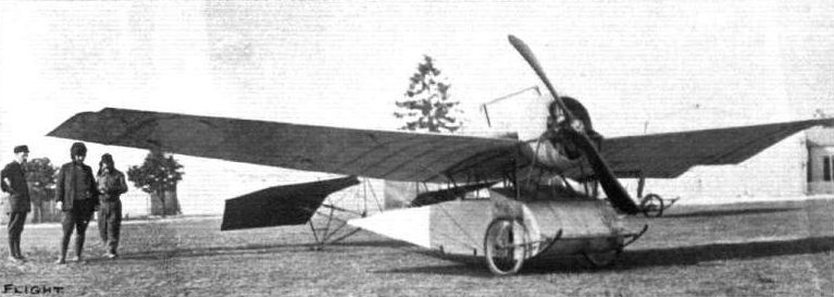
THE TRAIN MONOPLANE. - View from in front of the Train monoplane which was involved in the catastrophe at Issy at the start of the Paris-Madrid Race. M. Train has embodied in his design a system of under-carrlage somewhat similar to that evolved by M. Pischoff, the aviator being seated below the plane and protected by the covered-in body.
GENERAL VIEW OF THE THIRD PARIS AERO SALON. - The machine at the bottom of the photograph is the Bleriot 100-h.p. "Aeronef," built to the order of M. Henri Deutsch de la Meurthe. On the same side, but towards the centre of the Exhibition, may be seen the Zodiac biplane and the Borel and Deperdussin monoplanes, while opposite are the Train and H. Farman monoplanes and Savary and M. Farman biplanes.
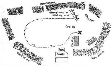
THE ISSY ACCIDENT. - Diagrammatic plan of the course, indicated by the dotted line, taken by Train on his monoplane. The X is the spot where the accident actually occurred.
Flight, December 30, 1911.
PARIS AERO SHOW.
Vinet.
Two types of monoplane were represented. The first was of a modified Bleriot type with flat stabilizing tail and wheel and skid undercarriage, the second was of the low centre of gravity type. As the first of these models presents no striking departure from accepted practice, we will confine our description to the latter of the two, of which a sketch is produced herewith.
The body of the machine is constructed on the box-girder principle and to preserve its excellent streamline form is completely covered in with fabric. Arranged above the pilot on a superstructure of wood cross-braced with steel wire are the motor and the wings. The landing gear is characteristic for its extreme simplicity, consisting merely of a pair of skids proceeding forward from the fuselage and a pair of wheels, mounted on a common axle attached thereto by means of channel steel outriggers and rubber straps. The flat stabilising tail is roughly semi-circular in shape and flies circumference foremost, the elevator, a rectangular flap, being hinged to its rear edge.
Principal dimensions, &c. :-
A-type monoplane-
Length 26 ft.
Span 30 ft.
Area 176 sq. ft.
Weight 450 lbs.
Speed 55 m.p.h.
Motor 50-h.p. Anzani.
Price L720.
Low C. G. type-
Length 22 ft.
Span 30 ft.
Area 176 sq. ft.
Weight 375 lbs.
Speed 58 m.p.h.
Motor 35-h.p. Barriquand and Marre.
Price L440.
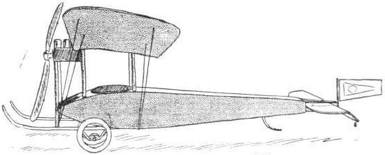
The Vinet monoplane.
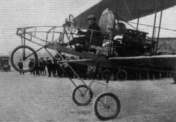
A Dansette-Gillet engine on a Voisin biplane.
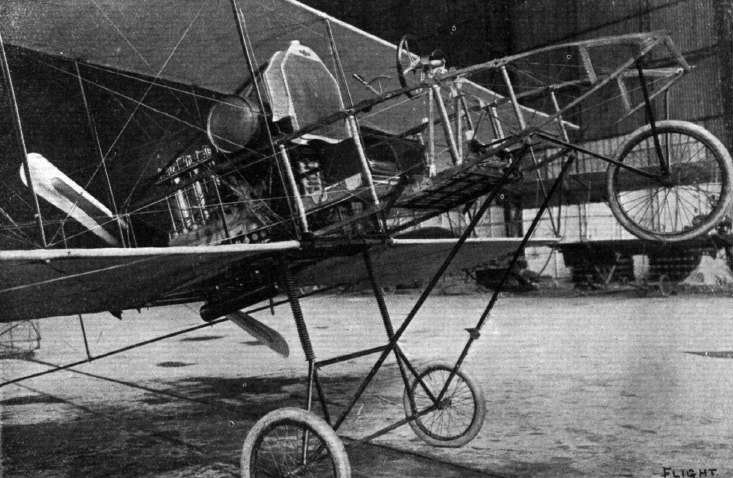
LATEST VOISIN DESIGN. - General view of the body of the two-seater, showing the arrangement of the engine and control.
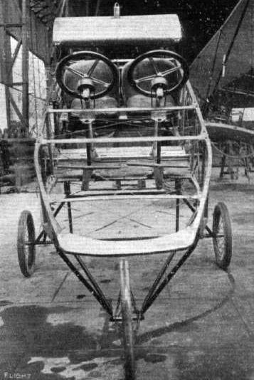
LATEST VOISIN DESIGN. - Front view of the body of a two-seater, showing the arrangement of the duplicate steering wheels.
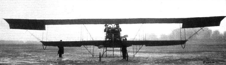
LATEST VOISIN DESIGN. - Front view of the two-seater, showing the overhanging upper plane and the lightness of the framework generally, which is built up of steel tubes. This machine, with double control gear is specially intended for the Army.

LATEST VOISIN DESIGN. - View showing the bracing of the overhung portion of the upper plane.
Flight, January 14, 1911
A New Voisin Machine.
AT the present time when most builders are abandoning the front elevator in favour of one placed at the rear, it is very interesting to notice that MM. Voisin Freres have turned out a biplane which is distinguished by the fact that it has an elevator in front, while there is an entire absence of any tail at the rear. From the accompanying photograph it will be seen that the monoplane elevator is placed a very long way in front of the main plane and that the rudder is also mounted above the elevator in front. The 50-h.p. Rossel Peugeot rotary motor and metal propeller are arranged at the rear edge of the main plane in very much the usual manner, and it will be noticed that lateral stability is maintained by means of balancing flaps at the ends of the main plane. The aviator sits some distance in advance of the main planes with the controlling levers of the usual type arranged in front of him. The position of the pilot is such that should any part of the engine break, it is extremely unlikely that it would injure him, while he is also able to get a good view of his surroundings. Needless to say the trials of this novel machine, seeing that it is the work of the Voisins, will be watched with great attention by all having any interest in aviation.
The main planes, which are placed 1.6 metres apart, have a span of 12 metres, while the chord is 2.2 metres, so that the bearing surface amounts to 26-4 square metres. The monoplane elevator measures 4 metres by 3.2 metres, and so the area is 12.8 square metres. The fuselage, which carries the elevator in front and the motor and propeller at its after end, is a long rectangular framework mounted on a modification of the usual type of Voisin landing chassis while at its forward end are arranged a supplementary pair of wheels to assist in landing. In this connection it will be remembered that Santos Dumont's first successful flight was made on a biplane with a box form elevator mounted a considerable distance in front of the main planes, which gave the machine the appearance of flying tail first. This was illustrated in the Automotor Journal of November 24th, 1906.
Flight, February 25, 1911
Things They Do Better in France.
IN order to assist aviators who intend to take part in a flight from Nice to Sartene, in Corsica, the Naval Commander at Toulon has received instructions to permit the cruiser "Polypheme" and two torpedo boats to render what assistance they can in the way of escort to the aviators. It is announced that Bregi, on a Voisin of the "Canard" type, intends to have a try shortly to win the prize. Bregi is now practising on this machine at Issy, the other day making on it a flight of over half-an-hour.
Flight, June 10, 1911.
FOREIGN AVIATION NEWS.
The Voisin Hydro-Aeroplane.
ON the 25th ult., the special Voisin biplane of the Canard type, which has been built for Prince Bibesco and equipped with floats for rising from and descending on to the surface of the water, was tried on the Seine in the neighbourhood of Billancourt. Piloted by Colliex, the machine first glided for a distance of about 100 meties, and then rising from the water flew for about 500 metres, being stopped by Colliex as it approached the Auteuil Viaduct. The trials then had to be suspended, as the ferry boats rendered it impossible to continue.
Flight, December 30, 1911.
PARIS AERO SHOW.
Voisin.
THE Canard on view on this stand is essentially the same in every detail as those which represented the Voisin firm in the Military Trials at Rheims, with the exception that, being designed to rise from and alight on water the usual landing gear is replaced by a system of floats.
Principal dimensions, &c. :-
Length 26 ft. Weight 1,210 lbs.
Span 40 ,, Speed 56 m.p.h.
Area 473 sq.ft. Motor 70-h.p. Gnome.
Price L1,200.

THE LATEST VOISIN MACHINE. - View from the side of the latest biplane constructed by MM. Voisin Freeres.
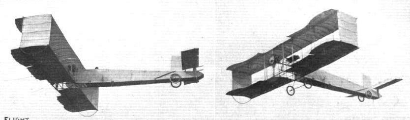
BREGI IN FULL FLIGHT ON THE NEW VOISIN, WITH ITS FUSELAGE IN FRONT. - Note in left photograph the head of the pilot just showing above the enclosed fuselage.
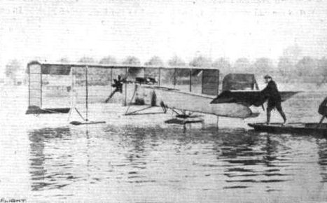
The Voisin "Canard" on the Seine, fitted with her floats.
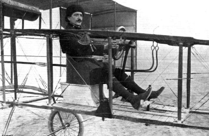
THE NEW VOISIN. - The pilot's seat - Colliex is in charge - showing the arrangement of steering gear, &c.

The Voisin "Canard" equipped with floats.
Flight, September 30, 1911.
FOREIGN AVIATION NEWS.
New Passenger Height Record.
AFTER spending a couple of days at Issy practising for the event, Mahieu, on the 22nd inst., succeeded in beating the passenger height record, carrying his friend, M. Fay, to a height of 2,460 metres in 55 mins. He then descended to about 1,500 metres, and passed over Choisy and the environs of Paris before landing again at Issy. He was flying one of the new Voisin military machines. The old record was Montalent's 2,250 metres made at Brooklands.
Mahieu Flying Home.
AFTER improving on the passenger height record, Mahieu decided to fly back on his Voisin machine to his chateau between Lille and Ypres. He left Issy on Saturday afternoon, and landed at Douai owing to the darkness at half past six, his flight having taken an hour and a quarter.

The latest Voisin biplane built for military use, with extensions on the upper plane. It is fitted with an 8-cyl. 60-h.p. Renault engine. In order that the pilot may see the ground in front of him, a large mica window is fitted in the bottom of the fuselage.
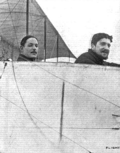
The New World's Altitude with Passenger Record. - Mahieu, the pilot who last week put up a new passenger record for height, on a Voisin biplane, with 2.460 metres. Starting from Issy at 3 o'clock, he returned to terra firma at about 6.30. With him is M, Fay, the passenger who accompanied him.

THE NEW "ZODIAC" BIPLANE. - This, the latest production of the Zodiac Society, was last week tested in the air by M. J. Labouchere at St. Cyr. In general appearance the machine reminds one of the features of the Breguet and Goupy machines, the former by the narrowness of the main planes, the boat-shaped body, and the tractor in front, and the latter by the staggered arrangements of the main planes. The question of rapid dismantling for transport along the road has also been given special attention by the designers.
GENERAL VIEW OF THE THIRD PARIS AERO SALON. - The machine at the bottom of the photograph is the Bleriot 100-h.p. "Aeronef," built to the order of M. Henri Deutsch de la Meurthe. On the same side, but towards the centre of the Exhibition, may be seen the Zodiac biplane and the Borel and Deperdussin monoplanes, while opposite are the Train and H. Farman monoplanes and Savary and M. Farman biplanes.
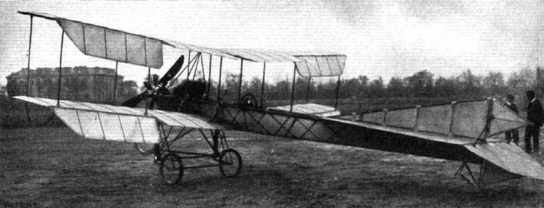
MM. Dufaux Frere's Gnome-engined Swiss biplane, which the constructors have recently taken to Issy for practice work. The surface is 44 square metres; weight 300 kilogs.