
Книги
Putnam
H.King
Armament of British Aircraft
82
H.King - Armament of British Aircraft /Putnam/
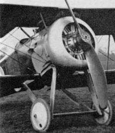
A.D. Scout (Sparrow). This aeroplane must be considered a curiosity not only in respect of design and construction but of armament and propulsion also: for if, as stated on the best authority, the intended weapon was a Davis recoilless gun, and if this was to lie on the floor of the nacelle, as indicated by drawings, then the engine and airscrew must have been of singular construction to withstand the blast of the rearward charge, even if this propelled a dose of Epsom salts, as it is known to have done on one occasion at least, in any case, the A.D. Scout is a notable machine in aeronautical history, for even if the gun was a Lewis machine-gun, as suggested by one drawing, and if this was fixed, as indicated by other evidence, the 'Admiralty Scout' (designed 1915) may well have been Britain's first fixed-gun fighter. Whether armament of any kind was actually installed is not known, but there is photographic and other proof of a sturdy pillar at the front of the nacelle, the tip of the pillar lying at the level of the pilot's eyes. This pillar may well have been associated with a sight
A.D. Type 1000. Although this very large three-engined floatplane of 1915-16 was intended to carry one or more torpedoes or a load of bombs it appears never to have been armed, and as a flying machine it was not successful. Armament must have influenced the design greatly, leading to the adoption of twin fuselages and twin independent floats beneath them. This arrangement would allow the projectiles, especially the torpedo or torpedoes, to fall freely. In terms of pilot view for sighting a torpedo, the type was probably never rivalled by any subsequent aircraft, for the frontal portion of the central structure housing the crew was glazed.
It has been stated that one intended weapon was a 12-pounder gun, for use against airships. The Navy did indeed have such a gun in their armoury, known as the '12 pdr 12 cwt'. If, then, a 12-pounder was indeed intended, it must be hoped for the crew's sake that this was to be of the Davis recoilless type.
It has been stated that one intended weapon was a 12-pounder gun, for use against airships. The Navy did indeed have such a gun in their armoury, known as the '12 pdr 12 cwt'. If, then, a 12-pounder was indeed intended, it must be hoped for the crew's sake that this was to be of the Davis recoilless type.
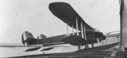
Although not itself successful, the A.D. Type 1000 was a very notable early example of how armament could influence the design of aircraft. The two floats were independently mounted, one beneath each fuselage, allowing a clear drop for the torpedo or bomb load. In this picture no engines are installed.
A.D. Navyplane. Built in 1916 for the same duties as the A.D. Flying Boat, the Navyplane twin-float seaplane had a pillar-mounted Lewis gun in the nose of the nacelle and provision for a small bomb load. In later years Maj T M. Barlow, who was well acquainted with this aircraft, with gun-mounting development generally, and with the Fairey "High-Speed" mounting in particular, said that the mounting was of 'movable, pivoted, traversing' type and was the 'forerunner of certain modern types'.
A.D. Flying Boat. A free Lewis gun pillar-mounted in the bow cockpit and a light bomb load (two 65-lb?) was the armament of this patrol and reconnaissance machine ol 1916. (See also Supermarine Channel.)
Alcock A-1. Named by 'Jack' Alcock the Sopwith Mouse (being built largely of Sopwith components), this most private of private-venture aircraft (1917) had a single fixed Vickers gun on the centre line of the fuselage, a la Pup and Triplane.
Armstrong Whitworth F.K. 3. Unlike the B.E.2c, the duties of which it shared, the 'Little Ack' of 1915 had built-in provision for armament. This was a Lewis gun attached to a spigot which moved along what was officially described as a "gun rail", in the form of a U-shaped track round the rear of what in a more conventional aircraft would have been the aft cockpit. In fact pilot and observer/gunner shared the same cockpit, as an illustration shows. In addition to its operational functions as an artillery co-operation, 'contact patrol' and bombing machine, the F.K. 3 rendered service as a trainer, and for instruction in air-gunnery was fitted with a Hythe camera gun. As a single-seat bomber the type is known to have carried bombs of 16, 100 and 112 lb weight. 'Military load' of the two-seater was given as 80 lb and 'human load' as 440 lb.
Official drawing of Armstrong Whitworth F.K.3. showing the communal cockpit with the 'gun rail' at the rear.
F.K. 12. There were Sopwith and Vickers counterparts of this 1916 three-seat escort and anti-airship fighter triplane, all three having unconventional armament layouts to give a clear field of fire. The middle wing was attached to the top of the fuselage and carried two manned nacelles, each probably intended to have a Lewis gun on a pillar mounting. The guns would have commanded a wide field of fire in the forward hemisphere, being sited forward of the airscrew. Originally the gun-nacelles were above the middle wing; later they were underslung and of different form.
F.K. 10. Several examples of this two-seat 'fighter-reconnaissance# quadruplane were built during 1916-17. The pilot's fixed Vickers gun was on the centre line, with faired breech casing, and the observer's Lewis gun was generally on a rocking-pillar mounting, though at least one specimen of the F.K. 10 had a Scarff ring-mounting.
F.K. 8. Superior to the F.K. 3 in power and armament, the F.K. 8 of 1916 was used not only for the duties named for the earlier type but for Home Defence work as a fighter. The pilot had a Vickers gun mounted under the cowling and firing through a port in the nose. This was synchronised by Constantinesco gear, a fact that was proclaimed by the 'box' type generator projecting from the cowling of late-production aircraft. The generator was bracketed to the crankcase so that a gear wheel, fastened to the generator coupling flange, could be driven at twice airscrew speed, by a gear ring bolted to the rear face of the airscrew boss. The rear Lewis gun was on a Scarff ring-mounting, set considerably below the top decking of the fuselage. A twin-gun installation has been identified. Bombs included 20-lb H.E. and 40-lb Phosphorus types.
Just as the much-maligned B.Es achieved the destruction of Zeppelins, so was the 'Big Ack' credited with bringing down a Gotha. (In the sea off the North Foreland. Crew, 2nd-Lieuts F. A. D. Grace and G. Murray.)
Just as the much-maligned B.Es achieved the destruction of Zeppelins, so was the 'Big Ack' credited with bringing down a Gotha. (In the sea off the North Foreland. Crew, 2nd-Lieuts F. A. D. Grace and G. Murray.)
Armadillo. Competitor of the Sopwith Snipe, Austin Osprey, Boulton & Paul Bobolink and Nieuport B.N.I, the Armadillo (1918) had two widely spaced synchronised Vickers guns in a remarkable installation, completely enclosed in an angular cowling and firing through tunnels. Provision was made in the early design stages for a Lewis gun on the upper-starboard wing root, but the gun was not fitted.
Ara. Designed in 1918, like its rivals the Snark, Snapper and Siskin, the Ara (completed 1919) had another unusual armament installation, the two Vickers guns (500 rpg) again being internal, but mounted very low in the fuselage. There were two holes in tandem in the fuselage sides in the area where the breech casings of the guns were probably located. Being round rather than rectangular these may have been associated with the ventilation of fumes from the guns rather than ejection.
Austin-Ball A.F.B. 1. Apparently at the suggestion of Capt Albert Ball, vc, DSO, MC, this single-seater of 1917 had a Lewis gun on a special mounting for upward tiring only (a form of attack which Ball favoured), and, of greater interest, a second Lewis gun lying between the cylinder blocks of the Hispano-Suiza engine and firing through the airscrew shaft. An existing photograph shows the external Lewis gun, which was mounted at an angle and pointed through the airscrew arc when at its lowest position, with the 'single' (47-round) drum.
Osprey. In addition to two synchronised Vickers guns on the fuselage decking forward of the cockpit, and having ejection chutes in the fuselage sides, the single-seat Osprey (1917-18) had provision, as had competitive fighters, for a Lewis gun with a limited arc of movement. The aircraft being a triplane, this was mounted on the rear spar of the 'centre centresection'. The actual installation was in dummy form only (land-service type, with 'single' drum).
Greyhound. Designed in 1918, like its competitors the Bristol Badger and Westland Weasel, this intended Bristol Fighter replacement had two close-set, internally mounted synchronised Vickers guns firing through ports in the nose and a Lewis gun on a Scarff ring-mounting almost flush with the decking atop a narrow fuselage, which allowed an extensive field of fire. Fighting effectiveness was enhanced by the closeness of pilot and gunner. The reported ammunition supply of 1.700 rounds may indicate 500 rounds per gun for the pilot and seven double drums for the gunner.
503 (Type H). There is reason to suppose that a seaplane of this type, which appeared in 1913, made a bombing attack on Zeebrugge early in the war, but the load is not known.
504. 'Each machine was fitted to carry four 20 lb T.N.T. bombs and four petrol incendiary bombs. No dummy bombs were available for testing, and the carriers were actually tested with live bombs.' So ran an Avro account of the historic and greatly daring raid on the Zeppelin installations at Lake Constance by four Avro 504s of the RNAS on 21 November, 1914. The H.E. bombs concerned were of Hales type; the incendiaries, with which the name of Wg Cdr F. A. Brock has been associated, were never carried. The bombs were hung two under each side of the fuselage on carriers devised by the Avro company. They were held in position by split-pins and were released by the pilot pulling on four wires. An elementary system of sighting by means of pins attached to the fuselage was installed. Thus armed, the 504, of enduring memory as a trainer beyond compare, and first flown in 1913 as an aeroplane with no specific application, answered its call to arms with the highest distinction. Nor was the Friedrichshafen raid the only occasion when 504s carried bombs with dramatic, if not always such telling, effect. An early raid (14 December, 1914) was made, for example, on the Bruges-Ostend railway line, on this occasion with four 16-lb bombs. In a single night (17 May, 1915) a 504 attempted to engage L.Z.38 with two grenades and two incendiary bombs, but was thwarted by the Zeppelin's rapid climb, and a similar machine dropped bombs on the stern of L.Z.39, causing damage, though the bombs passed clean through without exploding. For Home Defence some 504s carried four 20-lb bombs. A box of Ranken Darts was another anti-Zeppelin load.
As for gunnery, in early 504 two-seaters the pilot sometimes had a pistol and the observer a rifle, a frustrating scheme, for the observer sat under the centre-section. Yet, concerning Avro No.398, the following account has been rendered by 2nd-Lieut (later Lieut-Col) C. W. Wilson:
'... a Taube was seen coming from the south. Major Higgins instantly gave the order: "There you are Wilson. Go and take his number." I was off the mark at once, but Rabagliatti scrambled on board 398 before me, with a rifle and ammunition. We headed north, climbing. Rabagliatti kneeling on his seat in front and steering me till we got into position ahead and below as we had always meant to do. He then began tiring and ejecting his empties into my face, cursing at the tack of result. Suddenly his face lit up, and waving his rifle in the air he pointed to the ground... We were credited with the first German machine in the official history of the RFC.'
This feat of British marksmanship was performed on 25 August, 1914.
As for machine-gun mountings, one of the most historic of all times was associated with Avro No.383 and with the names of 2nd-Lieut L. A. Strange and Capt L. de C. Penn-Gaskell. Both these officers made contributions of note to the development of air armament. The mounting on the Avro consisted of a metal tube from a defunct Henri Farman and a length of rope to hoist the gun from the fuselage decking, the gun itself retaining a stock as on land-service guns for firing from the shoulder. This mounting was plied effectively on 22 November. 1914, when Lieut F. G. Small forced down an Aviatik after firing one full 47-round drum and 25 rounds from a second drum. Later, single-seater 504s (sub-types C.D.F and converted K) were occasionally and variously armed with Lewis guns, the C being specifically intended for anti-Zeppelin work and having to this end the gun mounted to fire upwards at 45 degrees through the centre-section. The most refined installation was probably on the K night-fighter conversion, which had a Lewis gun on a Foster mounting in association with a Hutton illuminated sight. A fixed synchronised Vickers gun, as well as a Lewis gun on a Scarff ring-mounting, is ascribed to the 504G, and a number of other 504s are known to have had synchronized guns.
Although, as might be expected, no reference to armament appears in official publications concerning the 504, the following note is to be found in Erecting and Aligning 80 h.p. Avro Biplanes Type 504, issued by A. V. Roe and Co Ltd in 1915 ('with a view to instructing our clients') and including 'classes 504, 504a, b, c and d":
'Although normally the tail is parallel to the top body-rail, peculiarities of the machine, or special requirements in the way of weight carrying, may necessitate an alteration in the angle of the tail.'
Avro 504Ks, fitted with Hythe camera guns were used at Dymchurch for training cadets.
508. This pusher biplane is given precedence over the armed 504s by reason of the fact that it was built before the outbreak of war specifically to carry a gun. To quote from the catalogue of the Aero and Marine Exhibition held at Olympia in March 1914:
'The 1914 Type Two-seater Gun-carrying Push Machine (sic) is a new model and embodies many novel features and advanced ideas . . . The observer or gunner is seated in the front of the machine, thus giving him a clear range of vision.'
'The 1914 Type Two-seater Gun-carrying Push Machine (sic) is a new model and embodies many novel features and advanced ideas . . . The observer or gunner is seated in the front of the machine, thus giving him a clear range of vision.'
510. During 1915 a few two-seater floatplanes of this type were used by the RNAS for coastal patrol, but there appears to be no record of any armament which may have been carried.
519. Though evidently intended for military use, the intended functions of this 1916 biplane two-seater cannot be determined. Defensive armament could not have been employed effectively because of fuselage form, but it may be significant that the Avro company have mentioned 'several large single-engined bombers' built by them before March 1916.
521. Designed in 1915 as a two-seat 'fighting scout#, the 521 (completed 1916) was intended to have a rear-mounted Lewis gun, though this does not appear to have materialised.
527. This Sunbeam-engined 504 development of 1915/16 was a last attempt to develop the type as a fighter. The pilot was not armed, but the gunner had a Lewis gun on a pillar mounting, apparently operating conjointly with a guide-ring.
528. A mystery aeroplane, which seems to have existed (1916), and which may well have had bomb nacelles mounted on the lower wing. If this fact could be substantiated the 528 might be considered as the Wellesley of its time.
Pike. Bearing the type number 523, the Pike was built in 1916 as a formidable fighter, stoutly armed, of long endurance, and capable of bringing heavy fire power to bear upon airships. Lights were also installed to this end. Only later does the type appear to have been developed for bombing. The nose was designed to take, and actually had installed on at least one occasion, a large-calibre quick-firing gun, apparently of Hotchkiss type. In a second Pike this gun was replaced by a Lewis gun on a ring-mounting, but in both examples the rear gunner had a Lewis gun, likewise ring-mounted. Bombs could certainly be carried on the Pike, and A.V. Roe himself is said to have designed the horizontal tier-stowage.
529 and 529A. These aeroplanes, of 1916/17, were specifically long-range bombers. Located between the lower wing spars, the bomb compartment was of three-ply and could take twenty 50-lb bombs, suspended by their noses. A bombsight and release gear were installed in the nose, and on the 529A at least the bomb-aimer appears to have assumed a prone position in a jutting structure. He communicated with the pilot by speaking tube. Scarff ring-mountings, with one Lewis gun each, were fitted at the nose and dorsal positions, but the gunner who manned the dorsal ring was also responsible for a third Lewis gun which fired through the floor. A contemporary document stated:
'A special seat is made in the floor through the rear cockpit and a long hole is arranged in the floor through which a good view downward and backward is obtained. When it is not required to use this opening it is covered by a sliding door.#
The same account listed the following weights: guns, 70 lb; ammunition, 100 lb; bombs, 1.080 lb.
530. Quite rightly this two-seater fighter of 1917 has been compared with the Bristol Fighter, but its advanced design has not, perhaps, been sufficiently stressed, especially in respect of armament provisions. Avro made reference to a 'turret-like structure' having a wing secured to it and housing a gun firing through an opening and allowing vertical adjustment. A fixed gun firing through the airscrew boss was also mentioned, and the rear gun was said to be 'raised clear of the top plane#. As it materialised, the 530 had a single synchronised Vickers gun in the pylon, or 'turret# structure, with ejection chutes projecting from the fuselage sides, and the gunner had a Lewis gun on his high-set Scarff ring-mounting.
Manchester. The Manchester twin-engined bomber of 1918 was comparable with the Boulton & Paul Bourges. Bombs up to some 880 lb in weight were stowed internally and were aimed and released from the nose position, where there was a hinged window, as on the Bourges, and a Scarff ring-mounting. There was a similar defensive gun installation in the dorsal position aft of the wings. Twin guns were apparently intended for both mountings.
Spider. Although a contemporary drawing shows two Vickers guns on this 1918 'wireless scout' (the 'wireless' signifying rigid wing bracing) only one gun was actually fitted, though this had more than the normal amount of ammunition. The gun was mounted slightly to starboard of the centre line and was largely internal. One contemporary specification listed these items: 'gun, 70 lb; mounting and ammunition box, 20 lb; belt and 800 rounds, 60 lb; Very pistol with cartridges, 8 lb.# Like the later single-gun Hawker Hornbill, the Spider carried more than the usual quantity of ammunition for a Vickers gun.
Beardmore W.B. I. Glide-bombing was the mode of attack intended for this two-seat biplane bomber (1916/17) by the RNAS. The bomb load has been given as six 110-lb, but no such bomb appears to have been used by the RNAS and it is reasonable to suppose that the bombs were of the H.E.R.L. 100-lb pattern. These bombs were intended specifically for anti-submarine work and were horizontally stowed. The observer was stationed far aft and sighted the bombs through a hatch in the floor, passing his instructions to the pilot by means of a special visual system. Provision was made for a free Lewis gun at the observer's station.
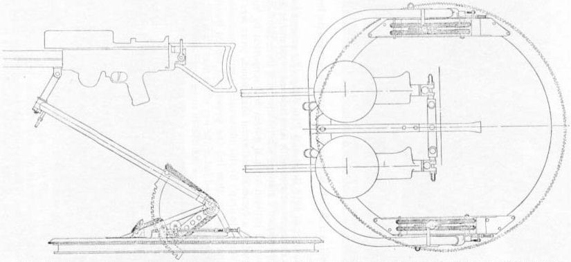
W.B. II. As was becoming to a company having Beardmore's standing in the fields of naval architecture and gunnery, the W.B. II two-seat fighter (also suitable for reconnaissance and patrol) exhibited originality in armament. The first machine (1917) had a fixed Vickers gun and a Lewis gun on a simple ring-mounting. The second was higher powered, and even more interesting than its twin-Vickers-gun installation - its Lewis gun was on a Beardmore-Richards mounting, designed by G. Tilghman-Richards and nicknamed 'The Witch's Broomstick'. The central member of this mounting was a pillar mounted on a 'universal footstep bearing' at its lower end and supported by, and guided upon, a coaxial annular guide ring round which it could be traversed. This arm carried at its upper end a gun-arm, one end of which was mounted on a pivot pin carried by the pillar, the other end being fitted with a pivoted block carrying the stem of a fork to which the gun was secured. The pillar could be locked in any position round the guide ring and the gun-arm could be locked in any position relative to the pillar. The locking was effected by spring-actuated bolts carried by the pillar and operated by levers, likewise on the pillar. The pillar was further fitted with a seat, capable of being locked at any desired height. With the pillar displaced laterally to its full extent the line of fire could extend to 15 degrees past the centre line of the aircraft.
During the course of W.B. II development the guide ring was built up from the fuselage to enhance the gun's effectiveness and the gunner's comfort.
During the course of W.B. II development the guide ring was built up from the fuselage to enhance the gun's effectiveness and the gunner's comfort.
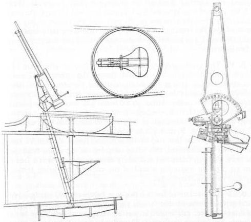
Secrets of 'The Witch's Broomstick' - the Tilghman-Richards gun mounting for the Beardmore W.B.II - seen in original makers' drawings. The detail view shows the locking arrangements for the gun arm.
W.B. III. Dating from 1916-17, this very extensively modified Sopwith Pup, for shipboard service, had a single Lewis gun, for which three ammunition drums were provided (one on the gun). Photographs show single (47-round) drums, but a contemporary account mentioned '300 rounds#, suggesting that double (97-round) drums were intended. The gun was at first carried on a tripod mounting, apparently designed at the Grain experimental station, installed forward of the cockpit, so that the gun fired through a hole in the centre-section. Later the gun was mounted slightly to starboard above the centre-section, firing a little upwards over the airscrew.
W.B. IV. Of wholly original design, this single-seat 'ship's aeroplane' of 1917 was remarkable in having the pilot in front of the wings, the Hispano-Suiza engine being mounted in the fuselage over the centre of gravity and driving the airscrew through an extension shaft (compare Westland F.7/30). A fixed synchronised Vickers gun tired out through the nose immediately behind the airscrew on the port side, the breech casing being in the fuselage. The installation was very neat and there were separate case and link chutes. Forward of the watertight cockpit was a sturdy tripod for a Lewis gun.
W.B. V. This contemporary of the W.B. IV had an armament of even greater - indeed exceptional interest, though the airframe engine layout was conventional. It was specifically designed for the French Hispano-Suiza canon Puteaux installation, of the type that became generically known as moteur canon. Although a 37-mm gun was actually installed in the first W.B. V, it found no acceptance among pilots, who were as cramped by its presence in the cockpit as they were disconcerted by the possibility of malfunctioning. French pilots using a similar installation in SPADs were said to become bemused by the explosive fumes. A fixed Vickers gun was therefore substituted, this being mounted on top of the fuselage with the breech casing faired. As secondary armament there was a free Lewis gun on a pylon mounting ahead of the cockpit and firing through an aperture in the centre-section.
Blackburn Seaplane Type L. During 1915 this aircraft is said to have been armed with a machine-gun (presumed Lewis) for service with the RNAS, and an early Blackburn document states that it was originally designed to meet the requirements of a coastal-patrol seaplane, with an observer gunner forward and the pilot behind. The same document mentions a load of two '165-lb' bombs (presumed 65-lb), though it is doubtful if these were ever carried.
T.B. Ranken Darts formed the sole recorded armament of this anti-airship seaplane of 1915. The figure of 70 lb quoted by the makers for 'military load' doubtless included the weight of the canisters and associated gear.
G.P. and S.P. These floatplane forerunners of the Kangaroo (1916/17) had nose and dorsal Scarff ring-mountings, with a Lewis gun each (one Blackburn document mentioned twin guns) installed on the top longerons, with the coaming built up fore and aft. They were designed to carry four 230-lb bombs under the wings or a 14-in torpedo under the fuselage. The bomb-sight was fixed to the starboard side of the front cockpit.
Triplane. The layout of this single-seat 'scout' of 1915-16 was much along the lines of the A.D. Scout, and concerning the supposed intended armament of a Davis recoilless gun the same remarks apply. A nacelle-mounted Lewis-gun installation was certainly schemed, this being intended (according to a Blackburn document) to give 'an exceptional arc of fire'. A makers' drawing, dated June 1916, shows this triplane armed with a single land-service Lewis gun, apparently having freedom of movement only in elevation, mounted on the nacelle with the 47-round ammunition drum and entire breech casing housed in a 'hump' fairing immediately ahead of the cockpit. 'Military load' was stated by Blackburn to be a mere 50 lb.
Kangaroo. Built in 1917 as a land-plane development of the G.P. and S.P., the Kangaroo had Scarff ring-mountings in the nose and dorsal positions and was at one time intended to have a prone position also. This was to be arranged below the fuselage in conjunction with an extended tail skid. There was also a scheme involving what Blackburn termed an 'open-ended casing', housing a gun at each end. This was dated October 1917. 'Military load' of the Kangaroo was quoted by the makers as 1.220 lb., but this was inclusive of guns and fittings, and another Blackburn document gave the bomb load as 1.040 lb (equivalent to two 520-lb bombs). The recorded four 230-lb or one 520-lb internal loads (bombs vertical, noses up) were probably not usable in addition to external carriers. A photograph shows a Kangaroo with two 230-lb flat-nosed anti-submarine bombs side by side under the lower longerons. The bombs were sighted from the nose (RNAS Mk.IIA Low Altitude sight). A 520-lb bomb was dropped to good effect on at least one occasion, falling very close to a submarine, which was despatched by depth-charges from HMS Ouse.
The Kangaroo's crew numbered three: the front gunner acted as bomb-aimer/observer and the tear gunner as wireless operator. The first machine had, in the first instance, a low-set forward gun-ring as on the S.P. and G.P., but on production aircraft the ring was carried high above the top longerons, on a higher level even than the pilot's cockpit. The field of fire was thus broadened. The rear mounting was protected in some degree by building up the coaming ahead of it, and additionally there was a windscreen for the gunner. Fields of lire benefited from the very narrow cross-section of the fuselage, but there was official criticism that the gunner was prevented from firing astern by the 'box' tail. The official general-arrangement drawing shows Lewis guns with 'land-service' cooling jackets and with "single" (47-round) drums. One Blackburn document mentioned twin guns.
The Kangaroo's crew numbered three: the front gunner acted as bomb-aimer/observer and the tear gunner as wireless operator. The first machine had, in the first instance, a low-set forward gun-ring as on the S.P. and G.P., but on production aircraft the ring was carried high above the top longerons, on a higher level even than the pilot's cockpit. The field of fire was thus broadened. The rear mounting was protected in some degree by building up the coaming ahead of it, and additionally there was a windscreen for the gunner. Fields of lire benefited from the very narrow cross-section of the fuselage, but there was official criticism that the gunner was prevented from firing astern by the 'box' tail. The official general-arrangement drawing shows Lewis guns with 'land-service' cooling jackets and with "single" (47-round) drums. One Blackburn document mentioned twin guns.
Blackburd. Like its counterpart the Short Shirl, the Blackburd was a single-seat deck-landing torpedo-carrier (not 'torpedo-bomber', for that requirement came later), designed for the 18-in Mk.VIII torpedo weighing 1.423 lb. (The 18-in Mk.IX, as carried by the Blackburn-built Sopwith Cuckoo, weighed about 1.000 lb.) A makers' description mentioned controls in the cockpit to adjust the mechanism of the torpedo in the air and the weight of the 'torpedo gear' was listed as 50 lb. The torpedo was carried parallel to the fuselage centre line; and the centre line was parallel to the top and bottom lines. 'It was like a flying box,' recalled G. E. Petty, who was responsible for several Blackburn torpedo aircraft, but he saw fit to add: 'The only excuse was that by then production was of primary importance, and Harris Booth eliminated all trimming.'
That the Blackburd was a more remarkable aeroplane than has hitherto been apparent, and not respecting armament alone, is evident from the following contemporary account, which affords a classic example of how a new form of armament and a new technique of operation could influence aircraft design:
'As the run on a ship is necessarily very limited, the machine must be capable of getting off at a comparatively low speed, or, in other words, the lift component of the reaction on the wing section must be a maximum. In the "Blackburd" aeroplane this is obtained by the use of wing flaps, which are pulled down before flight, and consequently alter the wing section to one of deep camber and high maximum lifting capacity. When once off the deck the flaps are released and automatically resume their normal position. To prevent any instability, which might be caused by a too sudden change of section, a specially-constructed oil dashpot is used, which allows the flaps to assume the neutral position gradually. In practice the time taken for this operation is about 43 seconds.
'For getting off the deck wheels arc fitted, but when once off, these, together with their axle, are dropped by means of a lever which also actuates the dashpot. By releasing the wheels, two long skeleton steel skids are left clear for use in case of landing again on the deck, and if it is inevitable that the machine should alight on the water, these skids have not the "tripping" effect that wheels possess. Once in the water, the machine is kept afloat by means of air bags fitted inside the fuselage and in the bottom of the engine cowl. Another interesting feature of this skid chassis is the arrangement of the springing gear. This consists of two vertical telescopic compression struts, which, when compressed, cause the skid to move slightly forward, with the result that when landing, the machine appears to creep forward, first on one skid and then on the other. Attached to the front tubes of the chassis arc timber hydrovanes, one above the other, and the reaction of the water on these when alighting keeps the nose of the machine up and counteracts any tripping effect.
'The torpedo is held in position by means of two sets of crutches and one adjustable tension strap round the torpedo itself. In order to prevent the torpedo from moving fore and aft, a raised stop on the top of the torpedo fits into a fixed steel block on the under side of the fuselage. The control for dropping the torpedo is very ingenious, and at the same time fool proof. A long-handled wooden lever is pulled into the rear position before flight and fixed there by means of spring plungers. Immediately after rising, the pilot pushes the lever forward and releases, by this one operation, both the wheels and axle, and the wing flaps previously mentioned. Now suppose the pilot wishes to drop the torpedo, he pulls back the lever into its original position and, by doing so, releases the two ends of the torpedo strap simultaneously, and starts the motor in the torpedo itself. When one considers that each control usually means a separate lever, and that the average torpedo-plane pilot has at least 15 different controls to operate, it is evidently a great boon to have four worked by one lever. Another advantage of this gear is that the torpedo cannot be released until the wheels and axle have been dropped clear.'
The Blackburd carried no guns.

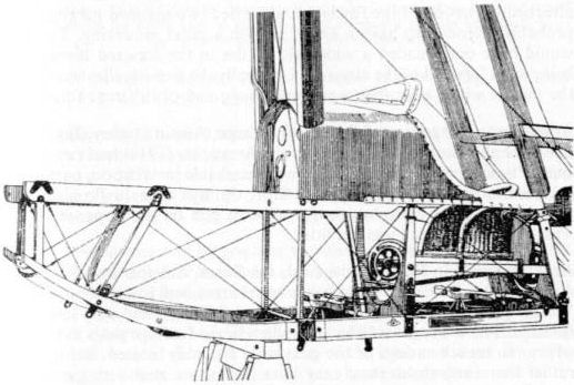
Recorded in the text are new facts concerning the remarkable Blackburn Blackburd, the frontal portion of which is shown at left and the torpedo installation at right.
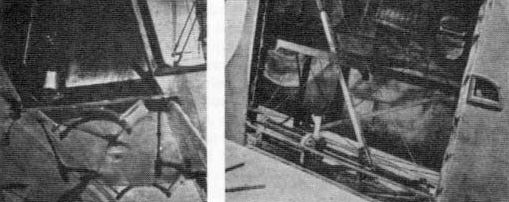
The two sets of torpedo crutches on the Blackburd are seen at left. The second picture shows the lever near the pilot's wicker seat. This singular device performed a plurality of functions, as described in the text.
Boulton & Paul (later Boulton Paul)
Bobolink. This 1918 rival (unsuccessful) of the Sopwith Snipe had its two Vickers guns mounted externally forward of the cockpit. Ejection chutes were in the fuselage flanks. Design provision was made for a pivot-mounted Lewis gun on the starboard centre-section, giving a restricted field of fire.
Bobolink. This 1918 rival (unsuccessful) of the Sopwith Snipe had its two Vickers guns mounted externally forward of the cockpit. Ejection chutes were in the fuselage flanks. Design provision was made for a pivot-mounted Lewis gun on the starboard centre-section, giving a restricted field of fire.
Fashions in fighter armament: Boulton & Paul Bobolink of 1918, with twin Vickers guns over cowling.
Boulton & Paul (later Boulton Paul)
Bourges. The Bourges twin-engined bomber of 1918/19 was not only the progenitor of a remarkable family of generally similar 'fighting bombers', which culminated in the Overstrand, but itself displayed unusual armament features. Nose and dorsal gun positions, internal bomb-stowage, and bomb-aimer's station in the nose were features retained throughout development, but one departure, made in the interests of armament, was both structural and aerodynamic. This involved the 'gulling' of the inner sections of the top wing into the fuselage to extend the fields of fire, or, as Boulton & Paul preferred to put it, to give the pilot and gunner an unrestricted view fore and aft.
In the original Bourges the two gun mountings were of the well-known Scarff ring type, with a trunnion device for twin Lewis guns. Fuselage width was almost exactly that of the gun-ring diameters; the nose ring was canted somewhat forward from the line of flight and the rear one was recessed below the top-line of the fuselage. There was transparent paneling in the rearward-sloping nose, for the bomb-aimer, and a sliding panel in the floor behind it. Bombs were stowed internally between the lower mainplane spars.
In the summer of 1918 Boulton & Paul designed a scheme for shutter-like bomb doors, associated with laths and tensioned cords, and over a year later mentioned a stowage scheme involving three bomb-supporting beams mounted between vertical guides and supported by 'quick-pitch screws geared to a common horizontal shaft which, when free to rotate, allows the bombs to drop'. By this means each bomb in succession came to the discharge position, then left the screws and moved down laterally between oblique guides and out of the way of the next beam and its bomb.
The bomb load was of the 800/900-lb order and there appear to have been three bomb cells with transverse doors or shutters.
A special bomb-loading system was also designed for the Bourges, this taking the form of a readily attachable or detachable hoisting gear. Shafts were associated with winding drums, each shaft being carried in bearings bracketed to the upper longerons. The shafts were rotated by pawl-and-ratchet or worm gear.
The 'gulling' of the Bourges' wings has been mentioned as a factor affecting fighting efficiency, but there was another, and a greater, factor, and that was the quite extraordinary manoeuvrability of the Bourges. This was to be reproduced in later bombers of the family.
It remains lo mention one other development in the story of the Bourges, appearing not only in the gull-winged variant but in the Lion-engined version, officially classified as a long-distance reconnaissance three-seater, and unofficially claimed in its day to be the fastest twin-engined aircraft in the world. On the aeroplanes mentioned, the two gun mountings were sited as previously but were of a different type. The identity and true nature of these mountings has eluded the present writer for many years, but he is now able to attribute them to Major ScarrT and to show drawings. Lightness appears to have been a primary aim in this design, which was intended for two Lewis guns but was adaptable for one. As the drawings show, the two guns were sighted with the aid of a shoulder stock and it was stated:
'The triangular frame is padded on the inner surface to prevent the operator bruising his body when pressing it against the frame to assist when turning the ring.'
Boulton & Paul Bourges with normal Scarff ring-mouniing for twin Lewis guns. The shutter-like bomb doors are just visible between the split axles of the undercarriage.
Lion-engined Bourges, showing unusual Scarff ring-mountings for twin guns in nose and dorsal positions.
Official drawings of the unusual form of Scarff ring-mounting as installed on the gull-wing and Lion-engined Bourges.
Bristol-Coanda Biplanes. Of such exceptional interest and significance were the bomb and bombsight installations, developed for the Bristol-Coanda biplane exhibited in the Paris Salon of December 1913, that they will be described at length in Volume 2 as historic departures. Original Coanda drawings will be reproduced, together with a page of calculations which influenced the design of the sight. It must be recorded here that an aircraft of similar type, but having a simple bomb-carrier, was delivered to Rumania a few weeks before the show mentioned, and that even earlier yet another Bristol-Coanda biplane was photographed at Larkhill with a mechanic holding a bomb. One RNAS machine of the type was apparently a 'gun-carrier'.
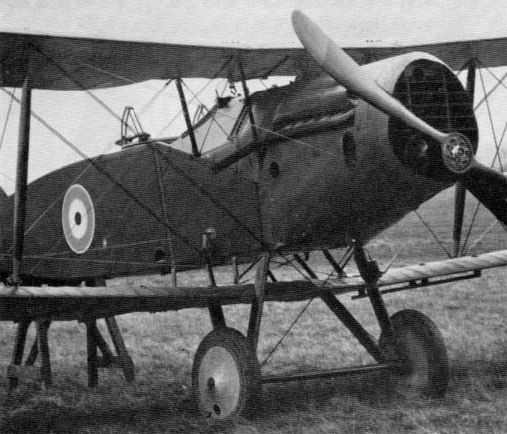
Scout. The Scout, or Bullet, originated in 1914 as an eminently appealing creation apparently suitable for no other warlike purpose than that of carrying a man swiftly on the mission its name conveyed. Two years almost to the month from the first flight of the original machine, a Scout was at the lighting from with the first operational installation of British gun-synchronising gear. This was of the Vickers type, as was the gun itself. Many and exotic were the improvisations both before and after this historic installation. Pistols were carried not only upon the pilot's person, or in his tiny cockpit, but attached to the airframe also, the classic example being the battery of three Webley-Fosbery revolvers carried in a rack affixed to the Scout of Maj W. G. Moore. Capt Vesey Molt was credited with destroying two enemy two-seaters with a pistol. Shotguns, sometimes with choke bore, were somehow shipped aboard, firing buckshot and even chain shot, and rifles were attached, with or without their stocks, and variously stripped. A 0.45-in Martini-Henry rifle was, in one instance, lashed to a centre-section strut, tiring outside the airscrew arc at an angle of 45 degrees to the line of fire. One identified load was a Short Lee-Enfield rifle without its stock, a Mauser self-loading pistol and five rifle grenades. Two rifles were fixed to the fuselage sides, firing at about 45 degrees to clear the airscrew, and a Lewis gun was mounted to lire straight ahead, and thus not to clear the airscrew, the resulting holes being filled and bound with sticky tape. (Airscrew scrapped, if holes more than three in number.) Lewis guns were also mounted for outward, upward or forward firing, in the last instance over the top wing, sometimes with a trigger extension attached to the spade grip. At least one Scout carried two Lewis guns, one on the port side and one over the top wing, pivoted at the rear and lying at its forward end in a rest carried on a pylon. In another arrangement there was one forward-firing Lewis gun on each side. Installations of the Vickers gun were not altogether crude. Attempts were made at partial fairing, and a system of channelling the empty cases and links overboard, as devised by G. H. Challenger and as will be illustrated in Volume 2, was applied. A type of cross-wire sight has been identified. In addition to the Vickers synchronizing gear, there were installations of the Scarff-Dibovsky mechanism these on RNAS Scouts. Rifle grenades were carried in external racks, and Capt G. I. Carmichael has recalled that the detonator pins 'usually had to be withdrawn by the pilot's teeth'. The rods which fitted in the rifle barrel were sawn off and streamers were attached for stability. Ranken Darts in canisters of 24 were attached to the lower longerons, and RNAS Scouts are known to have carried two such canisters. Four bombs were carried under the nose of some RNAS Scouts.
S.S.A. Although this book is mainly concerned with armament, and not passive protection, the fitting of armour to military aeroplanes inevitably has some place, and in no more fining instance than this single-seat 'scout' built to Coanda's designs in 1914. As in the later Sopwith Salamander, the whole of the forward fuselage, including the cockpit, was of sheet steel construction (in this case monocoque) and even the engine was protected. A few weeks before war came this aeroplane was sent to the Breguet works in France. It may be mentioned in this context that at the Olympia Aero and Marine Exhibition of 1914 The Integral Propeller Co Ltd showed 'an armoured propeller specially designed and built for warplanes'.
Fighter. The Bristol Fighter of 1916/17 endures in history as a preeminent example of an aeroplane designed round its armament. Not only is this quite literally true of the fixed-gun installation, but in the concentration of the crew and the studied provision of an effectively emplaced free gun - this to afford not only rear protection, but to augment the pilot's fire-power for attack. Allied with excellence of all-round performance and manoeuvrability, these qualities had their summation in an aircraft of which Oliver Stewart has declared that it 'should be spoken of in terms of the heroes of classic mythology', being 'in the fullest sense a hero after their pattern a fighter by name, inclination and aptitude'.
With this aeroplane the name of Frank Barnwell is identified, and it may have been Barnwell himself who declared: 'The fuselage is of rectangular section tapering to the rear to a horizontal knife-edge, thereby enabling the various tail members to be brought down low, out of the way of the gun. The top of the fuselage is kept flat for this purpose also.' It was further explained that, in order to bring the position of the pilot and the gunner as high as possible in relation to the top plane without increasing the depth of the fuselage, the latter was placed between the wings. In 1929 Barnwell remarked in a letter: 'I'm not sure that the happy guesses often years or so ago did not produce as efficient machines as many present-day ones. We've got performance by piling on BMP but this is not per se advance.' Yet Barnwell's masterpiece, the Bristol Fighter, was no mere happy guess. It evolved, in fact from 1916 designs for a two-seat reconnaissance aircraft along generally similar lines but armed with a synchronised Lewis gun to starboard and a second Lewis gun on a pillar-type mounting at the rear. This gun could be stowed in the fuselage decking as on much later multi-seaters. Field of fire was very carefully studied. Meanwhile Barnwell had been watching armament development and his fancy fell upon the Vickers gun for pilot use. Forthwith his assistant. L. G. Frise, was sent off on a Vickers-gun course at Hythe, and, as soon as Barnwell had learned all that he needed to know concerning the gun, he decided that it should be on the centre line of his new aeroplane with the breech casing to the pilot's hand even though this involved forming a tunnel through the petrol tank. And there it went, its presence being proclaimed only by the sights, frontal port, and low-sited ejection chute in the port side of the cowling. Proximity to the engine served to keep the lubricating oil relatively warm. The belt box was immediately behind the petrol tank and was tilled through an access panel in the top fuselage decking on the starboard side, between the centre-section struts. When the Siddeley Puma engine was installed it became necessary to move the Vickers gun to starboard, and the front of the gun was then exposed near the front centre-section strut. The gunner's Lewis gun was on a Scarff ring-mounting, attached to the upper longerons immediately behind the pilot. Six or more double drums were provided, and there were firing steps and a folding seat. Production-type Fighters had both ring-and-bead and Aldis sights, the former bracketed to the top centre-section. The Aldis sight was offset to starboard and was fixed to a special fore-and-aft tubular mounting, likewise attached to the centre-section, and earning the two circular clamps. The C.C. gear was of 'B' type and the loading handle a Hyland Type B also. An official document of 1917, relating to the F.2B, gave the empty weight, including guns and mountings, as 1,700 lb and the weight of 'ammunition' as 150 lb. This figure, however, represents a total of about 2,000 rounds of 0.303-in ammunition and corresponds to the total military load for one known condition. Other figures quoted for military load are 180, 185 and 192 lb, but in this connection it must be noted that a load of up to twelve 20-lb bombs could be carried beneath the inner lower wings and centre-section. A Negative Lens bombsight could be fitted. On production aircraft the pilot's seat was not armoured as on the two prototypes.
How the earliest F.2A Fighters met disaster, until their pilots learned to use them as single-seaters with rear cover, is a thrice-told tale, but in basic armament there was little variation. On F.2Bs two Lewis guns were sometimes fitted on the ring-mounting, and on one machine at least there was a third Lewis gun, arranged to fire upwards and forwards over the top centre-section. For this gun there was a massive 'four-poster' mounting. By far the most interesting departure from standard was made on Home Defence F.2Bs for night fighting, following a similar experimental installation on an F.2A. A Neame illuminated sight was fitted on the centre-section, pointing upward at an angle of 45 degrees from the pilot's eye. The pilot took aim, and the gunner, having aligned his gun accordingly, fired on receiving a signal from the pilot. A device enabling the pilot to rotate the gun mounting himself is said to have been fitted, though the virtue of this is not apparent.
A confirmed installation of the greatest interest was the tilting of one of the earliest Browning aircraft machine-guns (Model 1918, M1, Cal .30) on a Bristol Fighter F.2B during 1918. In general pattern this gun was similar to that which armed the Hurricane and Spitfire in the Battle of Britain, a fact which is clearly apparent in the photograph on page 93.
In post-war years the Bristol Fighter was adapted for army co-operation and general purpose duties, and during early 'A.C.' trials the guns were unshipped to make weight allowance for heavy wireless gear. In 1921 an Air Ministry order instructed that the 'C' type C.C. gear would in future be standard on all Falcon-engined Bristol Fighters, in conjunction with a new-type nose-piece for the engine in which the generator brackets were incorporated in the castings.
The last honoured years of the Bristol Fighter in RAF service have been fittingly expressed by one who shared them, thus:
'The Brisfit of North-West Frontier vintage actually carried an operational load of eight 20-lb Coopers and one 112-lb H.E. The latter was sometimes replaced by a can of 200 B.I.B. incendiaries. This was, of course, in addition to the front and rear guns, extra tropical radiator and an extra fuel tank under the rear seat. For squadron transport purposes the load was slightly different. Two bundles of bedding, complete with mosquito nets and poles (with galvanised-iron wash-bowls as nosepiece) were lashed to the wing bomb racks'.
The last variant (Mk.IV) could carry two 112-lb bombs.
Bristol Fighter F2B, showing port for Vickers gun above radiator, sight attachments on upper centre-section. Scarff ring-mounting, and bomb rails for two 20-lb carriers beneath lower wings.
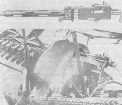
A Browning Model 1918, M1, Cal .30 aircraft machine-gun (top) is shown installed in a Bristol Fighter of the RAF. The original photographs have been somewhat "doctored", but there is no doubting the authenticity of the installation.
M.1A.B.C. Like the Bristol Fighter, this fast monoplane single-seater was in large degree designed around the Vickers gun, though not literally so, for the gun lay exposed on top of the fuselage. The A version (1916) appears never to have been armed; the B carried a Vickers gun at the port wing root, fixed to the fuselage longeron and synchronised by Sopwith-Kauper gear or C.C. gear Type B (one example had the gun centrally mounted); and on the M.IC (the production version, and the only British monoplane in service during the 1914-18 War) the central position for the gun was standardised, the padded windscreen being divided to receive the sight. For training, the type was fitted with a camera gun. Sir Miles Thomas has related how, confronted with a stoppage caused by a thick-rimmed cartridge, and finding it impossible to get his hand high enough to give the cocking handle the required blow, he had recourse to a tin of Fray Bentos corned beef. Although this split on contact with the handle it did the trick.
S.2A. This 1916 development of the Scout, designed for the Admiralty, had side-by-side seating and was intended for fighting. The proposed armament was a Lewis gun, possibly on a pillar mounting behind the cockpit.
T.T.A. This large two-seat fighter was first flown in the same month (May 1916) as the Avro Pike and there can be little doubt that it was initially intended to have been similarly armed. The 'one large gun' which was on one occasion mentioned as an alternative to the two Lewis guns with which the T.T.A. is generally associated may well have been of the Hotchkiss type, by then becoming established in French service. The pilot sat behind the wings, from which position he could sec little and probably accomplish less, for he was responsible for a rearward-firing free Lewis gun. For this he had three spare 47-round drums. The gunner, remote in the nose, had five drums for his Lewis gun.
M.R.I. Though a notable structural advance, the metal-built M.R.I of 1916 carried the same armament as the Bristol Fighter and this was similarly disposed. The fuselage was built in sections, the second embodying the cockpit. Vickers gun and ammunition box and the third the observer's seat with the Scarff ring-mounting above it.
Braemar. The Braemar four-engined triplane bomber of 1918/19 had internal cells for six 230 250-lb or twelve 112-lb - five 40-lb bombs, aimed from the nose by the front gunner, who had a Scarff ring-mounting for twin Lewis guns. For these there were six ammunition drums. Doubtless dictated by the width of the fuselage was the fitting in the dorsal position of two transversely-moving pillar mountings for one Lewis gun each. (Later large bombers, as will be seen, had laterally-sliding Scarff ring-mountings.) For this second station there were six ammunition drums. There was, additionally, a ventral position with an inverted-bow mounting for a fifth Lewis gun, and for this there were eight drums, four on each side, disposed horizontally. As the Braemar was intended for the bombing of Berlin, it is probable that the carrying of a single 3.300-lb bomb was in view, and certainly a scheme was prepared late in 1921 for fitting a torpedo-carrier under the fuselage. This installation would have placed the Braemar in the category of the Blackburn Cubaroo and Avro Ava.
A point of special note is that one contemporary document mentioned a gyro bombsight. This was said to be mounted to the rear of the pilot's seat, together with other instruments 'for bomb dropping'. In the forward compartment was a High Altitude sight.
A point of special note is that one contemporary document mentioned a gyro bombsight. This was said to be mounted to the rear of the pilot's seat, together with other instruments 'for bomb dropping'. In the forward compartment was a High Altitude sight.
Scout F. The two Vickers guns of the Scout F (1917) were mounted externally on top of the fuselage, the land-service handle blocks flanking the windscreen. There was a ring-and-bead sight, the bead being positioned just ahead of the windscreen and the ring almost level with the front of the cooling jackets. Beneath the short ejection chutes were access panels to the belt boxes. The external fitting of the guns was regrettable, if unavoidable (because of the small fuselage dimensions), for the Scout F was of unusually clean aerodynamic design.
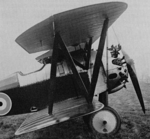
Vickers gun installation on Bristol Scout F.
Badger. Like its rivals in the contemporary (1918) two-seat fighter/reconnaissance category, the Westland Weasel and Austin Greyhound, the Badger had two fixed Vickers guns, mounted much as on the Scout F, and one Lewis gun on a Scarff ring-mounting. This mounting was over a cockpit with cutaway sides to improve the gunner's view. The scheme was later reproduced in. (e.g.), the Supermarine Seamew. Brackets for the ring-and-bead and Aldis sights were attached to the upper wing.
Makers' figures for the Jupiter-engined version, which, at one stage at least, had the full complement of guns mentioned, included 170 lb for 'ammunition, bombs etc', but this figure would easily be accounted for by the three guns with a normal supply of ammunition. Mention of two guns in another makers' document suggests that one of the Vickers guns was, or would be, deleted in the event of bombs being carried.
Makers' figures for the Jupiter-engined version, which, at one stage at least, had the full complement of guns mentioned, included 170 lb for 'ammunition, bombs etc', but this figure would easily be accounted for by the three guns with a normal supply of ammunition. Mention of two guns in another makers' document suggests that one of the Vickers guns was, or would be, deleted in the event of bombs being carried.
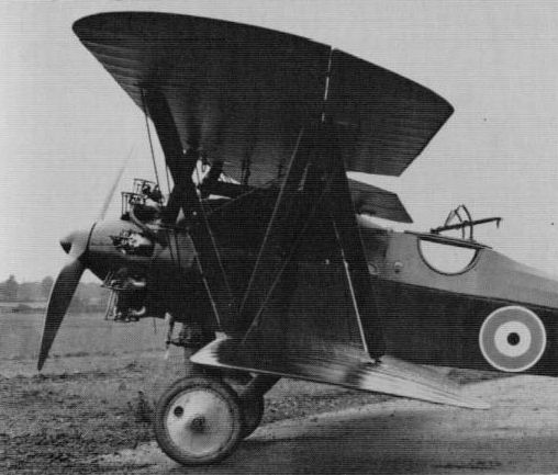
Vickers gun and Scarff ring-mouniing on Bristol Badger.
de Havilland
D.H.1. Built in 1915, the D.H.I reconnaissance lighter pusher a projection of the Farnborough-designed F.E.2 - had a pillar-mounted Lewis gun in the nose of the nacelle, the forward coaming of which was lowered on production aircraft to increase the gunner's freedom. Whether the mounting was of the type designed by Capt Geoffrey de Havilland and mentioned in connection with the D.H.2 is not known.
D.H.1. Built in 1915, the D.H.I reconnaissance lighter pusher a projection of the Farnborough-designed F.E.2 - had a pillar-mounted Lewis gun in the nose of the nacelle, the forward coaming of which was lowered on production aircraft to increase the gunner's freedom. Whether the mounting was of the type designed by Capt Geoffrey de Havilland and mentioned in connection with the D.H.2 is not known.
D.H.2. The 1915 prototype of this single-seat pusher lighter had a bracket-mounted Lewis gun on the port side of the nacelle, the swivelling bracket being attached to a vertical pillar which was faired throughout its length. Ahead of this mounting the port side of the nacelle was cut away to accommodate the gun. The mounting, or its successor, was designed by Capt de Havilland and was once described as having 'an upright pillar slidably adjusted, without turning, in a tubular socket fixed to the nacelle'. This pillar was said to have carried at its upper end 'a rotatably adjustable arm' which in turn carried at its outer end a mounting for the gun, adapted to permit of 'swinging movements in any direction'. A steel or rubber spring was provided to take up the weight of the pillar, arm and gun to facilitate height adjustment in the socket.
Production D.H.2s had a modified nacelle, and the gun was centrally positioned on a revised mounting. In its lowest position the gun rested in the specially cut-away nacelle nose. The windscreen moved with the gun, which had open sights and was sometimes stripped of its cooling jacket. So narrow was the nacelle that the spare ammunition drums had to be stowed in open-topped boxes flanking the cockpit. These were at first of the standard 47-round land-service type, but a form of 'double' drum is said to have been developed by Maj Lanoe Hawker and Air Mechanic W. L. French of No.24 Squadron. A drum of this type has also been ascribed to No.18 Squadron. There were several variant installations of the gun, and single and twin fixed guns were certainly fitted, for pilots had an aversion to what was described as a 'wobbly' mounting. They disliked also having to handle an aeroplane and a gun simultaneously, and the gun when elevated fouled the control column. Maj Hawker at first tried clamping down the muzzle of the gun to fire straight forwards, but this scheme was officially forbidden. He then made a spring clip with a catch lo hold the muzzle down but enabling it to be freed if necessary, and, though the gun was not clamped rigidly, the scheme was described as 'the best compromise possible with red tape'.
It is hoped to give considerably more information on the D.H.2 mounting in British Aircraft Weapons.
A point of interest concerning the D.H.2 on which no comment appears to have been made hitherto is the 'blister' under the nacelle, which on some machines was very prominent. This does not appear to have been associated with the base of the gun mounting and may have had the function of channelling or collecting the spent cartridge cases.
D.H.3. The intended operational functions of this 1916 pusher twin continue to be speculative, but fighting appears to have been as dominant a requirement as bombing. The original D.H.2 offset-gun scheme was followed, there being a pillar mounting for a Lewis gun on each side of the front and rear gunner's cockpits. Bombing provisions are unknown, although the type was clearly intended for raids on German cities. The second prototype is said to have been blazing on a factory dump in July 1917 when Gothas were bombing London.
D.H.4. The year 1916 saw the momentous advent of this progenitor of, and paragon among, fast bombers. Arguably the most significant of all British war machines, this was the true precursor of the Fairey Fox and - blood will out - the Mosquito also. It is, perhaps, not widely realised that the pilot did the bombing, while the observer, some feet astern of him, had a purely defensive function. The field of fire was a commanding one, and a speaking tube provided intercommunication, but sheer physical distance lent anything but enchantment, and crew co-ordination suffered.
The pilot's Vickers gun was carried externally to port ahead of him. Six hundred rounds of ammunition were provided and the gun was fitted, latterly at least, with a Cox Type D loading handle. Westland-built RNAS examples had two front guns, port and starboard. Constantinesco gear was standard; indeed the first Service application of this gear was on this aeroplane. The trigger motor was at first Type A, later type B. Gun installations varied in detail, but typically there was an ejection chute far down in the fuselage side. One or two Lewis guns were carried on the rear Scarff ring-mounting, which on early-production D.H.4s was attached to the upper longerons, below the top-line of the decking. It was later raised to improve the field of fire. The original machines had a single pillar mounting, and a few examples for the RNAS had two separate pillar-mounted Lewis guns. The twin-gun combination increased the drag and weight, decreasing in proportion the gunner's stamina, though, as will later be seen, it was sometimes preferred. Usually six, but occasionally as many as ten, double drums of ammunition were stowed in the gunner's cockpit, ahead of which there was a windscreen.
Bombs were carried under the fuselage and wings, eight or twelve 20-lb, two or four 112-lb or two 230-lb being known combinations. It will later be shown that the 40-lb Phosphorous bomb was another type carried.
Although the D.H.4 did not achieve its full potential until the Rolls-Royce Eagle VIII engine became available, it was a remarkable aircraft from the beginning; yet, bearing the heading 'Headquarters, RFC, 20th October 1916' and signed 'H. Trenchard', a letter came for Capt de Havilland to this effect:
"... on the subject of the de Havilland 4. As a reconnaissance fighter I think it will be a first rate machine, but I do not think it is entirely suitable for bomb dropping. For a large machine it is extremely handy to fly. It is quick on turns with very sensitive fore and aft controls and has a very large range of speed. The criticisms I have made have been sent home to General Brancker.'
For over-water patrol the load was typically two 230-lb bombs, adapted for anti-submarine work.
A particularly ferocious anti-aircraft installation was made in two machines, which, though they flew to France, were never to see action. Firing forward and upward, with its breech extending down almost to the bottom of the rear cockpit, was a 14-pdr Coventry Ordnance Works gun. The barrel projected through the upper centre-section, and, such was the blast, although the muzzle was well clear, that a covering of sheet metal was applied. Likewise deemed prudent was local airframe stiffening. The gun was aimed by the pilot with a bead sight mounted parallel to the gun, and the gunner fired upon the pilot's command. Some ten years were to pass before this basic concept was revived. One anti-Zeppelin aircraft had two Lewis guns on the top centre-section.
To the glory of the D.H.4 and the crews who proved worthy of it, the present writer appends this most vivid account of preparations for a daylight bombing sortie. The unknown author manned a rear seat at the turn of 1917. He recounted:
'The pilots went to their machines and got their engines running to warm up the oil, etc., while the observers went to the armoury and got out their guns and fired the usual twenty rounds into the gun-pit to see that everything was O.K. I was one of the few observers who always swore by two Lewis guns for the defence of my tail, while, of course, my pilot had his Vickers for forward work.
'Everything now being O.K., we carried our guns to our machines, where we fixed them on to the mounting and adjusted the rubber shock absorbers on the brackets. I then got out of the machine to see that the three bombs, namely a 112 lb bomb under each bottom plane and a 40 lb phosphorus bomb under the fuselage were secure. Having satisfied myself that the safely devices had been removed from the bombs, thus allowing the wind vanes to rotate immediately they were released from the rack, I got back into my cockpit.
'Our armourers meanwhile were assisting by carrying out drums of ammunition (usually six drums of 94 rounds each per observer), and as they were handed up to us we placed them on the racks provided...
'I will now describe the inside of my cockpit fixed up fur this long raid. Firstly, of course, comes my "music stool", which I sit on for taking off etc., but as I cannot see below or over the sides of my machine while seated I have a special "gadget" fixed up for a seat. This is part of a safety belt fixed on each side of my cockpit and joined in the middle by a safety device so that I can undo it when scrapping. This patent seat is fixed much higher than the "music stool" so that I can rest by sitting down and yet can see everything that is going on all around and below. When scrapping I naturally have to stand up to use my guns to advantage.
'While sitting down facing over the tail I have my maps on either side, held by a piece of shock absorber; my "L-type" camera is fixed in the fuselage under the magazines with the lens just poking through the floor... I have four of the magazines for my Lewis guns in the racks above the camera, the other two drums on the guns... On the left of the Lewis magazines is my automatic pistol with spare magazines in case of emergencies. Behind this again is my Very pistol...'
Airborne, and heading for the target:
'I fire a few rounds from both guns into space to make certain that the oil in the recoil portions is not frozen and my pilot looks round with a yell down the telephone "Huns?". I soon put him at his ease, after which I hear "rat-tat-tat-tat". He has followed suit...'
Having examined specimens of the D.H.4 a German authority reported:
'The machine is provided with complete dual control. The control lever for the observer is removable. In the observer's cockpit are placed a speed indicator, a throttle and a switch for night illumination. Observer's and pilot's cockpits are placed far apart on account of the main fuel tanks being placed between them. For communication between the occupants there is a speaking tube on the right, and on the left an endless cable passing over rollers in the two cockpits. The control of the fixed machine-gun is accomplished hydraulically by a control mechanism placed immediately behind the airscrew. For loading there is either a lever on the gun or a cable running over a roller, provided with a grip. A telescopic sight is placed in front of the rectangular windscreen.
'The bomb gear, judging from the makeshift way in which the release gear is built, appears to have been added as an afterthought. Bomb racks, either arranged for four smaller or one large bomb, are placed under the lower wings and under the body. The release is accomplished from the pilot's seat by means of Bowden cable. The cables are either joined at the right of the seat or arranged separately on the outside of the body. A sighting arrangement is built in to the body immediately behind the rudder bar. It consists of a square plane-concave glass plate, 13/16 in thick at the edges and 0.2 in thick at the centre. Underneath this are three wire rods soldered at right angles to a fourth rod lying in the direction of flight. Further down about 6 1/2 in is another longitudinal rod, and a transverse rod working in longitudinal slots, and which can be locked in place by screws.'
[This was the Negative Lens sight, the installation of which in the pilot's cockpit of the D.H.4 will be illustrated by official drawings in Volume 2.]
Armament modifications and innovations on the American-built D.H.4s are not fittingly detailed here (eight machine-guns were fitted experimentally), but there is justification for including the following items covered at a conference on 8 April. 1918:
'Wimperis bomb sight, oil lead to synchronising generator, synchronizing reservoir, cartridge chutes, magazine rack for Lewis gun, interphone box. Scarff mount, negative lens in gunner's cockpit, clothing-heating plug, gunner's seat, bomb-dropping lever, gun brackets, front and rear windshields, negative lens in pilot's cockpit, bomb-dropping rails'.
Four Marlin guns were fitted as standard to the American D.H.4s.

D.H.4, showing bomb rails under wings and fuselage, at differing angular setting, owing to wing incidence. Vickers gun and ejection chute in fuselage flank, and Scarff ring-mounting, with windscreen ahead of it.
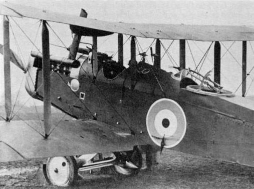
D.H.4, showing, in particular, the Scarff ring-mounting installation.
D.H.5. Back stagger, and excellence of pilot-view in consequence, combined with uncommon diving ability to make for the D.H.5 (1916) a more lustrous reputation for ground attack than for prowess in air combat. The type was effective, however, for low and medium-level lighting and all in all can be regarded as the Westland Whirlwind of its day. Respecting armament, the type holds a special interest, not only because, in prototype form, it exemplified one of the rare free installations of a Vickers gun, but because the installation itself was remarkable. Mounted immediately in front of the pilot, the gun, which was synchronised to fire through the airscrew arc, could be elevated through an arc of about 60 degrees. The synchronising gear employed was possibly of the kind devised for movable guns by G. H. Challenger, though Airco also designed a synchronizing gear. Later a Vickers gun was fixed on another solitary specimen for upward-firing at an angle of some 45 degrees. The gun was offset to port and was braced to the fuselage at the muzzle end.
The standard armament of the D.H.5 was a fixed Vickers gun firing along the line of flight, offset to port ahead of the cockpit. A Cox Type D loading handle was fitted and both ring-and-bead and Aldis sights were generally fitted. When the early A1 type of trigger motor, located at the back of the gun, was fitted, the hydraulic lead from the generator on the engine was led to the rear of the gun, but when an improved pattern of trigger motor (Type B) was fitted on top of the gun the lead was carried up from the fuselage across the gun on the port side, as shown in a photograph. Ammunition supply was 750 rounds, in a Prideaux disintegrating link belt.
Further heightening the Whirlwind ground-attack analogy, the D.H.5 saw frequent action using bombs - four of 20 lb.
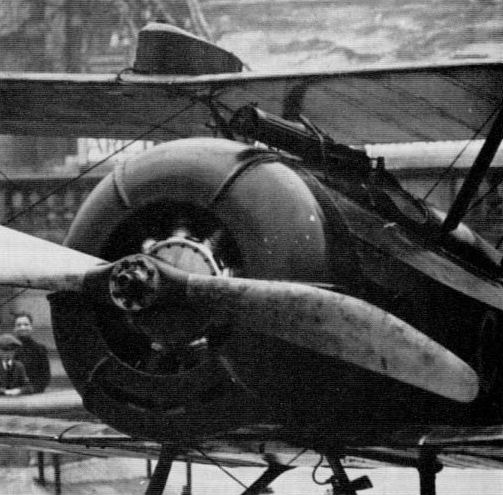
D.H.5. showing Vickers gun with hydraulic lead from engine-driven generator to trigger motor on top of gun.

Official drawing of D.H.5, showing brackets for mounting gun and hydraulic lead running to Type A1 trigger motor.
D.H.6. The analogy of the D.H.5 and Whirlwind is less remarkable than that adducible between the D.H.6 and Tiger Moth, the trainers of two wars which rendered arduous, if thankless, service on anti-submarine patrol. For this assignment the first-war 'Clutching Hand' carried a single 100-lb bomb or equivalent load and was generally manned by the pilot alone. The effectiveness of the type was not confined to keeping periscopes submerged, for on 30 May, 1918, an attack was made on UC-17, unhappily too late to prevent the torpedoing of SS Dungeness.
D.H.9. Scourged and derided though it was, the D.H.9 was more extensively employed than any aircraft of its class, both by the RFC and RAF. Such were the casualties inflicted by enemy fighters that formation flying was imperative. Being of an open kind this enabled the rear gun or guns to be worked effectively. The juxtaposition of the cockpits allowed not only better crew communication than in the D.H.4 but permitted internal bomb stowage also. Bombs could also be carried under each wing and under the fuselage.
The pilot's Vickers gun was located externally in a recess to port and with separate case and link chutes in the fuselage side. C.C. gear and a Hyland Type B loading handle were provided. The Scarff ring-mounting carried a Lewis gun, or occasionally two. Royal Air force Technical Notes for #de Havilland No.9' include these items under "Order of Erection":
'Connect all Engine Controls, Revolution Indicator, and C.C. Gear; Fit Fixed Bomb Cells and Fixed Bomb Release Gear; Fit Gun Mounting and Instrument Board; Fit Ammunition Box, Shutes, and Vickers Gun; Fit Scarff Ring Mounting; Place Movable Bomb Cells in position."
The external load of heavy bombs was typically two 230-lb or three or four 112-lb, but smaller bombs were also carried outside. With the D.H.9 the Gledhill bomb gear is mainly associated and an Air Ministry instruction dated March 1918 gave notice:
'Two sizes of this gear are being made at present. These will be issued as complete sets made up of the following units: (A) One fixed unit of two suspensions for 20 lb bombs. (This unit is a fixed part in the D.H.9.) (B) One movable unit of twelve suspensions for 20 lb bombs. (C) One movable unit of six suspensions for 50 lb bombs. (D) One operating mechanism and connection. Units B and C are interchangeable, and may be fitted in turn according to the type of bomb it is intended to carry. Units A. B. and C are placed in position immediately behind the engine and in front of the petrol tanks.
'In Units B and C the bomb rails carrying the slips, which are three in number, are mounted on the top of the bomb crates. The bomb crates are made of three ply wood and afford the lateral support needed by the bombs when stowed vertically. The crate in Unit B consists of 12 cells, made to fit the Cooper bomb, the crate in Unit C is similar in construction, with the exception that it is formed of six cells constructed to fit the 50 lb bombs.'
The bomb slips and release gear arc described thus:
'The slip is the mechanism on which the bomb is retained, and by means of which the bomb is released. It is self-locking, and consists of a lever carrying the suspension hook and a trigger lever, both of which are pivoted. The Cooper bomb is suspended from the suspension hook by a special wire loop which replaces the nut on the tail of the bomb. The 50 lb bomb is suspended by an eye bolt which forms an integral part of the nose fuse. The suspension hook receives the suspension lug of the bomb to be stowed, and is then automatically locked by a trigger lever, which projects through a slot in a sliding bar. When this bar is pulled, as is the case when operating the release, the end of this slot depresses a lever, and so allows the suspension hook to turn on its pivot and release the bomb.
'The pilot's release lever has seven positions, as follows: (1) Locked. (2) Free. (3) Release 2 Cooper bombs from fixed unit. (4) Release 3 Cooper bombs or 1-50-lb bomb. (5) Release 3 Cooper bombs or 2-50-lb bombs. (6) Release 3 Cooper bombs or 2-50-lb bombs. (7) Release 3 Cooper bombs or 1-50-lb bomb.'
The following instructions are given for loading:
'Place the release lever in "free" position and pull down the slides at the bottom of each bomb cell which hold the safety springs aside, push the suspension lug of the bomb upwards until a click is heard. The bomb will now be automatically held in position. When all the bombs are slowed, place the release handle in the locked position. The safely springs must now be adjusted by pushing up the slides which hold them aside while stowing the bombs is in progress."
The foregoing reference to one fixed unit of two suspensions for 20-lb bombs and one movable unit of twelve suspensions accords perfectly with one recorded test-load of fourteen 20-lb bombs.
Containers for Baby Incendiary Bombs were also carried internally, but the reported internal loads of two 230-lb or four 112-lb bombs must have been rare. Indeed, it is difficult to envisage the vertical stowage of 230-lb bombs which is stated to have been possible, for this type of bomb was 501 inches long, and this measurement, in addition to the length of the nose shackle and the depth of the suspension beam, would seem to be greater than the depth of the D.H.9 fuselage.
The bomb sight was of the Negative Lens type.
D.H.10. Like the D.H.9, this D.H.3 bomber development of 1918 had internal as well as external stowage. The internal vertical cells could take containers for Baby Incendiary Bombs as alternatives to high-explosive types, and the heaviest load which appears on record is six 230-lb. In postwar operations eight 112-lb was one load dropped on operations. But if, in its early forms at least, the D.H.10 was undistinguished for weight-carrying, it did possess an excellent all-round performance, and one machine was actually sent to a Home Defence station for appraisal as a fighter. The installation of a Coventry Ordnance Works gun, however, in two of the early examples (following trials of the gun in a Tellier flying-boat at the Isle of Grain) sprang rather from an offensive or defensive-escort requirement. The two experimental aircraft had their noses lengthened, strengthened and fitted with wheels, and both were sent to Orfordness for trials. The Independent Force was interested to the extent of requesting examination of the possibility of fitting a similar gun in the dorsal position also.
Normal gun armament was two (or twin-yoked) Lewis guns on nose and dorsal Scarff ring-mountings.
Normal gun armament was two (or twin-yoked) Lewis guns on nose and dorsal Scarff ring-mountings.
D.H.9A. The fine distinction in RAF nomenclature between the terms 'day bomber', 'light bomber' and 'single-engined bomber' and the generic classification 'general purpose aircraft' is to be seen most clearly in the evolution and employment of this archetype of all 'G.P.' machines - which began its career in 1918 as a strategic bomber. Of such importance and enduring memory was the 9A in RAF service that its lineage and 'general purpose' development may now be established upon the authority of a document promulgated by the Air Ministry (Directorate of Research) in April 1922. This contained the following significant passage - possibly the original instance of the term 'general purpose' appearing in a Service publication. Thus:
'Though officially classed as a two-seater fighter reconnaissance type [sic] the functions of this aircraft cover, in practice, a wider field and it could aptly be described as a general purpose two-seater. For long-distance reconnaissance, photographic work, day or night bombing or artillery observation, it is equally useful, and its high speed and strong armament render it a particularly formidable opponent."
Armament is thereafter summarised as:
'Pilot. 1 Vickers gun and 750 rounds; observer, 2 Lewis guns and six drums; bombs (under fuselage), 4-20 lb, or 2-112 lb, or 1-230 lb; bombs (under each plane), 4-20 lb, or 1-112 lb.'
In a subsequent passage no mention is made of the twin Lewis installation, but there is a reference to a performance test with two 230-lb bombs. The main account runs:
'The D.H.9A normally carries two guns, one fixed Vickers machine gun on the port side of the fuselage and a Mk.III Lewis gun mounted on a standard Scarff ring No.2, over the observer's cockpit. Bomb gear and a bomb sight, as well as wing-tip flare brackets, are also fitted.'
This information is expanded as follows:
'The Vickers gun was originally arranged parallel to the upper longerons. This position was found to be unsatisfactory, however, as, owing to the pilot's cockpit being so far back, it was impossible for the pilot to get an uninterrupted line of sight. In consequence the gun is now mounted at an angle of 3 1/2 degrees in relation to the top rail of the fuselage. The gun is bolted to two mild steel U brackets of 10 S.W.G., one front and one rear.
'The gun is synchronised with the propeller in the normal way by means of Constantinesco gear, and is fired by means of a Bowden lever and cable fitted on the control lever. At the rear of the engine, concentric with the crankshaft, a cam box with a splined shaft is fitted to engage with the hollow end of the crankshaft. A Type B synchronising gear with Type C trigger motor is fitted, but an adapter is supplied so that Type B lines may be used. The loading handle fitted to the gun is of the Cox D type.
'The magazine is constructed of sheet aluminium and takes a belt of 750 rounds. It is supported on sheet steel brackets, and the belt passes over a 3 in roller into the gun. The spent cartridges are ejected through a chute and fall clear of the aircraft. An Aldis sight is mounted on the starboard side of the fuselage cowling. In the corresponding position on the port side is fixed a standard ring-and-bead sight.
'The observer's cockpit is furnished with the standard Scarff gun ring, carrying a Lewis Mk.III gun fitted with a Norman vane 100 m.p.h. sight. Four pegs are provided for carrying the necessary ammunition drums and are accommodated in a special uncovered compartment immediately behind the cockpit. Both the Vickers and Lewis guns are fitted with the standard electric gun heater.'
Of the bomb installations:
'Two similar 18 S.W.G. mild steel ribs, each of flanged U section, are bolted lo four bottom fuselage struts, so that approximately one-third of each rib lies behind the rear spar. The ribs are parallel to the longitudinal axis of the aircraft and are 21-in apart. A similar pair of steel ribs, again 21-in apart, are fitted underneath each wing. Bomb gear comprises the standard bomb releasing toggles, working through stranded cable. The schedule provides for the fitting of one high-altitude drift sight and one negative lens bomb sight.'
It is pertinent lo include the following note on electrical equipment:
'The D.H.9As in service at the time of writing do not carry the full standard electrical equipment. Many are either not furnished electrically or only partially equipped, while others have a war-time equipment.'
On post-war aircraft of this type, arrangements were made for eight, instead of four 20-lb bombs to be carried under each wing (two tandem carriers). The Vickers gun was often of the Mk.II pattern with small perforated barrel casing and a G.3 camera gun was sometimes mounted on the port lower wing. A prone bomb-aimer's position was incorporated, as indicated by two windows in the fuselage sides near the bottom longerons.
Already the 9A was being made to carry (in the phrase which this aeroplane brought into Service currency) everything except the kitchen sink, and when geographical and climatic demands were superimposed, it became less of a war-horse and more of a beast of burden. Apart from an auxiliary radiator, oleo undercarriage (occasional), cameras, camera gun, etc. the following inventory was listed by (the writer believes) Sir Arthur Longmore: auxiliary tank, giving an endurance of seven hours; spare tyre strapped under fuselage (camel-thorn punctures); emergency rations for three days; two gallons of water; special container for beer bottles; and a gadget to work the rudder bar by hand so that the pilot could stretch.
In connection with the Handley Page O/400, mention will be made of a bomb-aiming technique involving the tying of string to the pilot's ankles, and a similar technique is known to have been employed with the D.H.9A.
Finally it may be noted that in 1921 an Air Ministry Order made allusion to modifications concerning the R.L. Launching Tube on aircraft of this type. This device had been developed by the Royal Laboratory early in the 1914-18 war with the intention of launching incendiary bombs against airships, though it was also associated with flares and markers.
D.H.9b. This designation was applied to a post-war development of the 9A, remodelled by the Aircraft Disposal Company, having an Eagle VIII engine with Lamblin radiators and augmented armament. Provision was made for three 230-lb bombs, two fixed Vickers guns, two Lewis guns on a Scarff ring-mounting and a third Lewis gun firing through the floor, for which a sliding hatch was provided.
D.H.9AJ Stag. This Jupiter-engined general purpose development of the D.H.9A appeared in 1926 and was beaten in competition by the Wapiti. War load was typically four 112-lb or two 230 250-lb bombs. Vickers gun (external port), and Scarff ring-mounting with Lewis gun. There was a prone bombing position, with wind deflector.
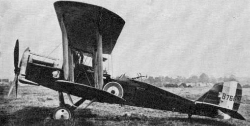
In the light of the DH 9's palpable failure, steps were initiated to replace the underpowered Siddeley Puma with something a little more powerful and tractable in the shape of the 375hp Rolls-Royce Eagle VIII, the work being given to Westland towards the end of 1917. Once flight testing got underway on the first Airco DH 9a, previously DH 9, serial no B7664, seen here, good things transpired, with the injection of extra power boosting the two seater's top level speed to 125.5mph, from the DH 9's 114mph without bomb load and from 109.5mph to 118mph with full bomb load - all at 10,000 feet. First flight of the prototype DH 9a occurred in February 1918, with initial deliveries of this reconnaissance bomber, to No 110 Squadron, RAF, following in August 1918. Sadly, at the time of the Armistice, only 885 examples of the DH 9a had been produced out of the 3,000 machines on order from Airco and five sub-contractors. Equally sadly for many DH 9 crews who were not to survive, the comparative handful of the much improved DH 9a machines that did reach the front arrived far too late.
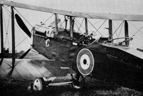
Eagle-engined D.H.9A prototype, showing details of gun installations, ring-and-bead sight to port and clamps for Aldis sight to starboard. Note how windscreen has been cut away to clear eyepiece of Aldis sight.

Liberty-engined D.H.9A. showing revised ejection chute on Vickers gun and Aldis sight in position. Although the pilot's windscreen has been perforated lo receive the eyepiece, the hole is not here used.
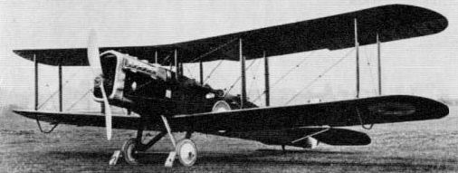
D.H.9A (first Liberty-engined example shown)
Showing how essential features of the D.H.9A were reproduced in the Stag. Note, however, that, being built to an official general purpose requirement, the Stag retains the Scarff ring-mounting and has a prone bomb-aimer's station, betokened by windows.
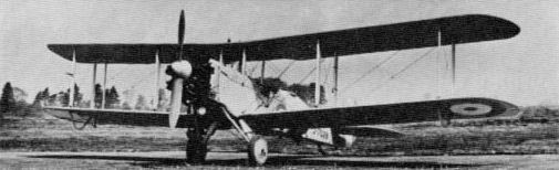
A requirement to use up spares for the D.H.9A resulted in a strong resemblance between intended replacement types. Shown is de Havilland's own submission, the Stag. The Stag carries two 250-lb bombs.
D.H.11 Oxford
Though designed in wartime, this twin-engined day bomber was only about half complete at the Armistice and did not fly for many months. It was notable respecting armament because of the commanding position of the rear gunner above the wings and the interconnecting catwalk between his station and that of the nose gunner. This was made possible by the fuselage dimensions (6 ft x 4 ft). Each position had a Scarff ring-mounting. Bomb stowage was internal, and was probably of the 800 900-lb order.
Though designed in wartime, this twin-engined day bomber was only about half complete at the Armistice and did not fly for many months. It was notable respecting armament because of the commanding position of the rear gunner above the wings and the interconnecting catwalk between his station and that of the nose gunner. This was made possible by the fuselage dimensions (6 ft x 4 ft). Each position had a Scarff ring-mounting. Bomb stowage was internal, and was probably of the 800 900-lb order.
D.H.14 Okapi
Dating from 1918-19 (and still extant in 1922) this high-performance single-engined bomber followed the now-established de Havilland practice of stowing the bombs internally. The bombs were suspended vertically by their noses, four of 112 lb in two double crates between the main spars and two of the same weight in single crates beneath the pilot’s seat. Brown paper was used to cover the openings of the bomb cells in order to exclude draughts. The pilot had a Vickers gun, set deep in a groove in the top decking, and there were twin Lewis guns on the rear Scarff ring-mounting. For these guns six double drums of ammunition were provided. Field of fire benefited from the suppression of the tailplane top-bracing wires in favour of struts beneath.
Dating from 1918-19 (and still extant in 1922) this high-performance single-engined bomber followed the now-established de Havilland practice of stowing the bombs internally. The bombs were suspended vertically by their noses, four of 112 lb in two double crates between the main spars and two of the same weight in single crates beneath the pilot’s seat. Brown paper was used to cover the openings of the bomb cells in order to exclude draughts. The pilot had a Vickers gun, set deep in a groove in the top decking, and there were twin Lewis guns on the rear Scarff ring-mounting. For these guns six double drums of ammunition were provided. Field of fire benefited from the suppression of the tailplane top-bracing wires in favour of struts beneath.
D.H.15 Gazelle
More or less contemporary with the Okapi, the Gazelle was a direct 9A development (Galloway Atlantic engine) and armament remained unchanged.
More or less contemporary with the Okapi, the Gazelle was a direct 9A development (Galloway Atlantic engine) and armament remained unchanged.
Dyott
Dyott Bomber Sometimes styled 'Dyott Twin Bomber' and sometimes 'Fighter' this adventurous aeroplane was originally intended for exploration. Undeniably advanced though it was in design, its two engines delivered no more than 240 hp, and it is difficult to imagine any useful war load additional to the astonishing array of small arms undoubtedly fitted, but possibly never fitted. The Lewis guns had land-service cooling jackets and 47-round ammunition drums. Two were on spigot mountings above the fuselage and another two were stationed at portholes in the fuselage sides. A fifth was mounted aft of the wings. These five guns alone, without ammunition or fittings, would have weighed all of 130 lb.
There were at least two versions of this aircraft. In the first a conspicuous feature was the gun-rail carried above the top decking of the fuselage and incorporating six spigot mountings, the two upper guns being interchangeable between these mountings. In the second version the decking was built up and the mounting(s) - for the gun installation may have differed from the original were no longer visible.
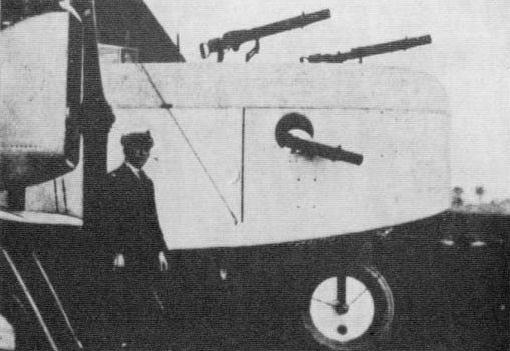
Dyott Bomber with second form of nose, showing three Lewis guns with land-service type cooling jackets, sights and ammunition drums, but with spade grip in place of stock.
Fairey
F.2. Although this twin-tractor biplane of 1916/17 has been called by the makers the Fairey Twin Bomber, it might more correctly be termed a heavy fighter, though it could doubtless carry bombs. A three-seater, it had Lewis guns in the nose and atop the fuselage aft of the wings. These were on Scarff ring-mountings, the rear one being somewhat recessed below the fuselage top-line. In the context of armament the F.2 had another association of interest, for the engines of one intended version (F.1?) were to have been products of the Brotherhood Engineering Company, which many years before had made the engines for the first Whitehead torpedoes.
F.2. Although this twin-tractor biplane of 1916/17 has been called by the makers the Fairey Twin Bomber, it might more correctly be termed a heavy fighter, though it could doubtless carry bombs. A three-seater, it had Lewis guns in the nose and atop the fuselage aft of the wings. These were on Scarff ring-mountings, the rear one being somewhat recessed below the fuselage top-line. In the context of armament the F.2 had another association of interest, for the engines of one intended version (F.1?) were to have been products of the Brotherhood Engineering Company, which many years before had made the engines for the first Whitehead torpedoes.
Hamble Baby. Although an armament of a single synchronised Lewis gun is generally ascribed to this development of the Sopwith Baby, the gun lying ahead of the cockpit, the accompanying photograph strongly suggests that there was an alternative installation of a Lewis gun, associated with a centre-section cut-out. Two 65-lb anti-submarine bombs were carried under the fuselage side by side.
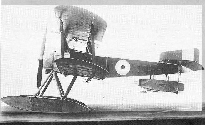
Fairey-built Hamble Baby N1452 with 110/130 hp Clerget. The full-span trailing-edge flaps can be seen as well as the differences between Falrey- and Parnall-built examples.
Fairey Hamble Baby, showing evidence of Lewis gun associated with centre section cut-out and attachment for bomb-carrier under fuselage.
Fairey Hamble Baby, showing evidence of Lewis gun associated with centre section cut-out and attachment for bomb-carrier under fuselage.
N.9. A Lewis gun on a Scarff ring-mounting appears to have been the sole armament of this 'catapultable' floatplane of 1917.
Campania. In common with other patrol and bombing floatplanes of its lime (1916/17), the Campania carried its bombs on tubular carriers suspended a considerable distance below the fuselage and had no gun for the pilot, though there was a Lewis gun for the observer, the gun in this instance being on a Scarff ring-mounting. Military load of the developed version was about 650 lb. One identified load was two 100-lb anti-submarine bombs, carried in tandem.
N.10 (Type III) and IIIA. The true begetter of the varied and versatile Fairey Series III aeroplanes, the N.10 floatplane of 1917 had a Lewis gun on a Scarff ring-mounting. The mounting was recessed considerably below the top of the fuselage, like the rear mounting on the F.2, and this type of emplacement was standardised for Fairey types to follow. No bomb load has been identified, and this also applies to the production-type Fairey IIIA, although a military load of 449 lb could be carried.
IIIB. Developed from the IIIA specifically for bombing, this seaplane had increased span and could carry a military load of up to 690 lb. The only identified bomb load is two 230-lb, the bombs being carried in tandem beneath the fuselage. The observer had a Lewis gun on a Scarff ring-mounting.
IIIC. Superior performance distinguished this higher-powered Series III development, which appeared in 1918. In addition to the rear Lewis gun, on its recessed Scarff ring-mounting, a fixed Vickers gun for the pilot has been reported, though no such installation can be identified in photographs. Bombs were certainly carried beneath the fuselage, as on the IIIB.
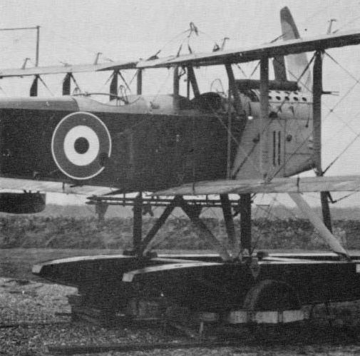
The Fairey IIIB was typical of British 1914-18 floatplanes in having tubular bomb-carriers suspended well below the fuselage. In this instance they are for two 230-lb bombs. Note also recessed Scarff ring-mounting.
F.2A. Extraordinary technical and military qualities were possessed by this most famous of the 'Felixstowe boats' and only in comparatively recent years have these qualities received full recognition. Dating from 1917, the F.2A had an armament of Lewis guns concentrated in the forward part of the hull and at the waist. Typically, there was a Scarff ring-mounting in the bow for one or twin-yoked guns. This was sometimes, perhaps generally, of the familiar No.2 pattern, though there is some evidence to suggest that in a few instances a type of Scarff ring-mounting wherein the quadrant moved with the gun-carrying 'bow', and was invisible when the bow was at its lowest position, may have been fitted. This type of mounting, which will be mentioned again in connection with the Handley Page O/400 and which will be shown in official drawings in Volume 2, was one of several mountings designed by F. W. Scarff. Sometimes the F.2A had a pillar-mounted Lewis gun on top of the pilot's cockpit canopy; there was a single Lewis gun at each waist hatch behind the wings; and atop the hull in this same area was another gun, or sometimes twin-yoked guns. In some instances at least the waist guns appear to have had the Scarff compensating sight. The pillar carrying each gun was mounted at the outer ends of two superimposed struts, braced to an inboard member and allowing the assembly to be swung outboard. There was under-wing provision for two 230-lb bombs just outboard of the attachments of the wing hull bracing struts, the carrier being staved to the wing inboard. One experimental F.2A had two 'howdah' or 'fighting-top' gun-nacelles, each with twin-yoked Lewis guns on a Scarff ring-mounting at its forward end, built on to the upper wing. These guns further broadened an already commanding field of fire; for, compared with the H.12 type of boat, the F.2 was well endowed in this regard, having a 'cocked-up' rear hull which permitted the midships beam guns to be swung outboard on their pillars so that their lines of fire could meet little more than twenty feet astern.
For comparison with the Sunderland, and with flying-boats between, this contemporary description of accommodation and battle stations is offered:
'A gunner is located immediately below the fore gun-ring, and a table for his use extends from his seat to the nose of the hull. Underneath the table is an ammunition box and trays... Abaft is the station for the pilot and assistant pilot... Their seats are well upholstered with kapok cushions, which act as lifebuoys if required. The assistant-pilot's seat is made to hinge, so that a clear passage may be obtained for walking fore and aft. A few feet behind the pilot is the wireless cabinet, with operator's seat, while at the port side of this a ration box is fitted. The engineer's accommodation is situated aft, with a ladder giving access to the top deck. Further aft is the second gun ring, with an adjustable platform to allow a gunner to have a good range of heights...'
In a photograph showing an F.2A built by the Aircraft Manufacturing Co. the sights on the beam gun are mounted on an arm on the gun's left side, with an eye-piece for the rear component. The forward gun, on its Scarff No.2 ring-mounting, does not have Norman vane-type sights, but apparently a form of ring-and-bead sight mounted laterally on the gun's axis.
F.2C. One experimental installation on this F.2A development was a compressed-air bomb-release system, eliminating the usual Bowden cable, but introducing its own problems of complexity and reliability. Only one F.2C was built. Flown by Wg Cdr J. C. Porte, to whom the greatest honour is due for developing the F-boats, this shared with two other machines of the same formation in the destruction of a submarine.
F.3 and F.5. Emphasis was placed, in the arming of these two flying-boats (1917 and 1918 respectively), upon anti-submarine operations, and the bomb load was accordingly increased to four 230-lb bombs. Machine-gun deployment was much as on the F.2 boats, the standard arrangement, as shown in an official publication on the F.5, being single Lewis guns at bow, dorsal and beam positions. No installation of a Davis gun or other heavy ordnance is known to have been made on a British F.3 or F.5, although interest in such armament was very much alive at this period and the American-built F.5 had an installation of the Davis gun. One Lion-engined F.5 for Japan is said to have had a revised bow cockpit for a '1-pounder shell-firing gun'.
F.5 (Metal Hull). Late in 1924 the upperworks of a Felixstowe F.5 flying-boat were fitted to an experimental metal hull of Short construction. Notwithstanding its experimental nature, this hull had two Scarff ring-mountings for Lewis guns. One was in the bow and the second in line with the trailing edges of the wings.

In this view of F.2A number 8677 a man is obstructing the waist hatch. Clearly, however, the mounting above the hatch is not of the Scarff No.2 type, and there is doubt, moreover, if the mounting in the bow is of this pattern. Even the Lewis guns appear non-standard. Beneath the wing is a flat-nosed 230-lb anti-submarine bomb.

F.5 (Metal Hull) with Scarff ring-mountings in bow and amidships.
Fury. The armament potential of this very large flying-boat triplane (1918) does not appear to have been fully realised; nor is it likely that this was of primary concern during development flying. Provision was made for at least four Lewis guns.
Grahame-White
1913 War Plane (Type 6). A Browning machine-gun on a British fighting aeroplane of 1913: this was but one blood-quickening feature of this pusher biplane, exhibited at Olympia early in the year mentioned. A second feature was the arrangement of the power plant to allow the free mounting of a gun. Thus The Aero:
"The engine is coupled up to a long shaft mounted on ball bearings which extends back t o behind the pilot's seat, where it carries a chain sprocket driving the propeller through a twin roller chain. The propeller is mounted so that the upper longitudinal member of the triangular-section fuselage is taken through its hub, the principal reason for this being that with this design the arrangement of the fuselage is simplified, and the engine can be carried in front without introducing the necessity for the pilot and passengers to sit immediately in the slip stream of the screw."
Almost as an afterthought there was appended to a lengthier description the simple observation:
'The machine is shown equipped with a quick-firing gun'.
Let it now be placed on record, after well over half a century, that this layout was schemed bv Horatio Barber; that the detail design was the work of John D. North, who was to adapt a Box Kite for a Lewis gun demonstration at Bisley in November of the same year (the War Plane never flew) and who in later years became a pre-eminent figure in aircraft armament development; and that the gun at Olympia, though correctly described by the commercial name Colt, was of the type called Browning Model of 1895 (or 'potato digger'). Like the later Lewis, this gun was air-cooled. The gun-pillar was associated with a quadrant fixed in a vertical plane under the gun. Elevation was said to be possible over an arc of 50 deg and traverse over 180 deg. The allusion to 'passengers', it may be noted, signified that an observer was carried in this aeroplane as well as a gunner.
Scout Type Pusher (Type 11). To J. D. North's design in 1914 Grahame-White produced this two-seater, which has a minor place here because it was seriously intended as a "gun machine", although armament never materialised. It was announced that for tests the pilot would be in front, the positions being reversed for the gun.
Type 18. For the RNAS this very large single-engined four-bay folding biplane was produced as a bomber in 1916. The observer had a ring-mounted Lewis gun and the intended bomb load probably corresponded to that of the comparable Short and Wight single-engined bombers.
Ganymede. Designed before the Armistice for long-range day bombing, and completed during 1918/19, this three-engined biplane was laid out to provide effective defensive firepower, which its intended mission would obviously demand. In the nose of the central nacelle was the bomb-aimer's station, with windows, and a gunner at a Scarff ring-mounting, and there were similar gun mountings dorsally placed on each of the two fuselages. In the bottom of each fuselage was a hatch, affording downward and rearward protection, but further details of defensive armament and bomb load are unknown.
Handley Page
Anzani Biplane. Although never intended for warlike purposes this biplane of 1913 (sometimes called Type G) serves to introduce the Handley Page military aeroplanes by reason of an anecdote beloved of 'H.P.' himself. This was simply recounted:
'When war began in 1914, this aircraft was bought by the Royal Naval Air Service and stationed for training and defence at Hendon. Its offensive and defensive potentialities were limited to one Webley revolver, worn by the pilot. During a patrol, the biplane was mistaken by London's defenders for a Taube and riddled with bullets, but without serious effect.'
O/100 and O/400. The legend of the 'bloody paralyser', requested of Mr Handley Page by Cdre Murray Sueter, is abiding testimony to the foreseen destructive powers of the RNAS 'patrol bomber' styled O/100. The original specification was dated 28/9/14 and called for pilot, 'passenger', six 100-lb bombs, bombsight, rifle, ammunition, armour and wireless. The armour was to be provided by the contractor and was described as Firth's manganese steel, of the best resistance compatible with two prescribed gauges - 10 S.W.G. underneath and 14 S.W.G. sides and engines. The radiators were to be safe from bullets nearer the vertical than 45 degrees and the petrol tanks were to be protected all over (could, in fact, be made entirely of armour plate). The bombsight was to be supplied and fitted by the Admiralty and was to weigh not more than 100 lb (sic). For the Service rifle 100 rounds of ammunition were demanded. As it materialised, the O/100 was officially described as having a machine-gun over the pilot's head, firing forward, and a cylindrical, rotating bomb gear which proved to require excessive manual effort. The crew and engine nacelles originally had armour protection, but this was later removed. In the developed aircraft up to sixteen 112-lb bombs could be carried internally. These were suspended by their noses in cells which had spring-loaded doors opened by the falling bombs. On 23 April. 1917, three O/100s, each carrying fourteen 65-lb bombs, bombed German destroyers off Ostend. The load is an interesting one because the standard 65-lb bomb was suitable for horizontal stowage only. Production aircraft (late 1916) had a Scarff ring-mounting in the nose, and in some instances at least this was of the 'disappearing-quadrant' type, apparently known as No. 3. Dorsal and ventral armament appears to have been as described in the succeeding paragraph.
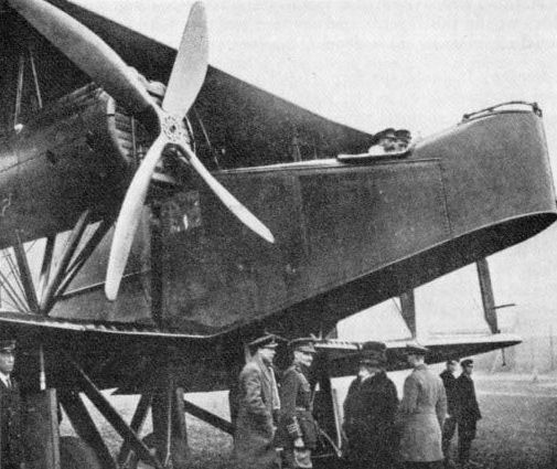
An historic picture, showing King George V in the cockpit of a Handley Page O/100. The gun-mounting on the O/100 is of the Scarff 'disappearing-quadrant' type.
O/100 and O/400.
<...>
September 1917 saw the emergence of the essentially similar O/400 with revised nacelles and tankage arrangements. This was officially slated to carry four Lewis guns and 17 double drums of ammunition. There was a Scarff ring-mounting in the nose; the two dorsal guns were carried on brackets, one on each side of the fuselage (alternatively, a single gun on a rocking pillar); and the ventral gun was officially described as being on a swivelling bar for firing under the tail. For the dorsal guns two separate firing platforms were provided. One official document gave the weight of the four Lew is guns as 66 lb, ammunition as 108 lb and mountings as 61 lb. Trial installations were made of a 6-pdr and a 2-pdr Davis recoilless gun. These guns were regarded as offensive weapons, but bombs were judged superior. The gun mounting in the nose sometimes had two Lewis guns, and in the nose position also, mounted on the cockpit rim, was a Bomb Sight, High Altitude, Mk.1A. There was at least one instance of the sight being transferred to the trapdoor position in the floor of the forward fuselage, where it was shielded from the main force of the air stream. Provision was made for the following alternative loads: sixteen 112-lb or eight 250-lb (internal), or three 520 550-lb or one 1.650-lb (external). On earlier aircraft more varied loads were carried; in one raid on Ostend in 1917 four Handley Pages dropped sixteen 112-lb, eight 100-lb and sixteen 65-lb bombs between them. There follows a contemporary account of crew and armament provisions on the O/400:
'Accommodations are made for one pilot and two or three gunners, and an observer who operates the bomb-dropping devices. Their placing is as follows: At the forward end of the fuselage is the gunner who operates a pair of Lewis guns. Bowden cables at one side of the cockpit permit the release of bombs. Behind the gunner is the pilot's cockpit from which the gunner's cockpit is reached through an opening in the bulkhead segregating the two compartments The pilot is seated at the right side of the cockpit. Beside him is the observer's seat, hinged so it may be raised to permit access. Bomb-releasing controls are placed on the left side of the observer, extending to the forward gunner's compartment and running back to the bomb racks, located in the fuselage between the wings. The forward compartments arc reached via a triangular door in the under-side of the fuselage.
'Aft of the bomb-rack compartment the rear gunners are placed. Two guns are located at the top of the fuselage and a third is arranged to fire through an opening in the underside of the fuselage. One gunner may have charge of all the rear guns, although usually two gunners man them. A platform is set half-way between the upper and lower longerons, upon which the gunner stands when operating the upper guns.'
The same account gives the dimensions of the 'bomb section' as: 3 ft 5 3/4 in x 5 ft 2 15/16 in x 4 ft 5 in.
In May 1918 the newly established Air Ministry issued an impressive document entitled Bombing Gear in Handley Page Machine. The massive, bewildering equipment installed in this true 'giant battle plane' is thus described:
'The Bomb Crates are built into the fuselage and are not detachable, the framework on which the bomb slips are supported being built into the framework of the centre section. The framework of the Bomb Crate consists at its top of two longitudinal members of 3 in x 4 in spruce 5 ft 2 in long, one on either side of the machine. On these two longitudinal members are carried four transverse members, also of spruce, termed Bomb Beams . . .
'From each of the bomb beams are suspended four metal supports or brackets; these brackets are called Adapters. The adapters extend downwards nine inches and at their ends arc carried the bomb slips, on which the bombs are hung.
'From each of these adapters is also supported a bomb cell skeleton framework constructed of four 5/8 in steel tubes. The upper ends of these tubes are shaped to the approximate outline of the nose of the bomb. These tubes are termed the Bomb Guides, and are fitted with narrow strips of ash bolted to them, the latter being named guide plates. The function of the bomb guides and guide plates is to steady the bomb when it is released, preventing it falling sideways as it slips through the bomb crate. The lower ends of the bomb guides forming each bomb cell skeleton framework are in each case secured to the centres of their corresponding squares in a series of shallow cells arranged on the floor level between the longerons immediately below the bomb beams. These enclosed cells are called the Honeycomb, their purpose being to give lateral support to the bombs as they fall through the crate when released, and also to check any tendency on the part of the bomb to rotate.
'The walls of the honeycomb cells are aluminium, reinforced with wood, and fill in the space between the bottom longerons.
'Each bomb slip is actuated by an individual control cable consisting of Bowden Standard No.51 wire of 270-lbs strength. The bombs are released in salvos of four, or separately as desired. Dropping bombs singly is not easy, and cannot be relied on, but they may be released positively in pairs, if the release handle is pulled over only one point on the ratchet on top of the control box in place of pulling it over two points, as in the release of a salvo. In either case the order of release is the same, i.e., the aft port side bomb is the first to fall, and is followed in order by the next three bombs to starboard of it; this completes the first salvo. In the second salvo the port side bombs of the second transverse row of bomb cells working forward is the first to be released, followed by the remaining three bombs of the second salvo. The third and fourth salvos are released in the same order, always from port to starboard, and always opening with the port side bomb.'
'The control cables are sixteen in number', it is explained, 'and run from port to starboard in four distinct groups of four cables each.'
There ensues a lengthy dissertation on the disposition of these, involving a set of four pulleys 'termed the Pulley Nest Block', from which the control cables ran through fairlead blocks to the salvo release gear. Devices termed Safety Springs and Tension Springs were involved.
Next followed an account of 'Salvo Release Gear. Mark IV', which the reader may be spared for the present, though a description and picture will appear in Volume 2. There could be no more dramatic illustration than this of advances in bomb-dropping technique during the First World War.
Instructions are given for 'Alterations for Stowing 250 lb Bombs' on a remaining set of eight bomb slips; and there is a concluding item headed 'Handley Page Bomb Slip' which has a particular fascination. This declares in essence:
'The bomb slip is the mechanism on which the bomb is retained, and by means of which the bomb is released. The slip has five parts: Framework; suspension hook; retaining trigger; retaining trigger spring; electro-explosive release. The electrical release is never used and need not be considered. It will not be present in the latest designs.'
Fascinating, as remarked, when Handley Page's post-war successes with electrical bomb- and torpedo-release gear is recalled; and this was not taken into RAF service until 1930. It may be added that during 1921 the Handley Page company was awarded royalties on a war-time invention which permitted 'locking of the release gear so that the bombs were held steady until the moment the release was complete'.
Official loading instructions may now be quoted for bombs. H.E.R.L., 112-lb. Mks.III, V, VI and VII (all heavy-case). The last two marks of bombs, it may be mentioned, differed considerably from the others and could be identified by their angular fins. The instructions ran:
'The total number of bombs to be carried, having been carefully fused, should be laid gently on the ground with safety pins in position at a convenient distance from the aeroplane. The release slips on the earning gear should now be tested before stowing the bombs. If the slips are found to be working satisfactorily the suspension hooks of all slips should now be placed open in readiness for stowing bombs. The bombs may then be stowed in order of the salvos, from port to starboard. The safety pin in the nose fuse of each bomb should not be removed until it is actually being handled for stowing, when, with the nose fuse safety pin removed, the bomb is pushed up into its cell from beneath the centre section by two or more men, as required. The suspension lug on the nose fuse now engages with the suspension hook of the release slip, which it automatically closes and locks, so retaining the bomb. Before allowing the weight of the bomb to fall on the release slip, the greatest care must be taken by the Officer or NCO superintending the stowing to ascertain that the arm of the suspension hook is securely locked by the locking arm of the release slip. The tail fuse arming vanes are now prevented from rotating by a locking arm, the fingers of which go over one of the arming vanes. The nose fuse arming vane is automatically held from rotating by the fact of its suspension lug being engaged in the release slip.'
As for the heavy externally carried bombs, it is known that a load of three 550-pounders was aimed at the lock gates at Zeebrugge, and Aircraftman Welland, who served with a Handles Page squadron in 1918, has recalled:
'About September a bomb was delivered to the squadron which weighed about 1,750-lb and was about twenty feel long. When it was first seen, the astonishment was great, and many doubts were expressed about a Handley ever getting off the ground with it. The armourers fitted a couple of chains under a plane and the idea was to sling it, as no proper bomb rack had been supplied...'
This reminiscence need only be qualified by noting that the weight of the bomb (nominally 1.650 lb) was almost exact, although the length was much overstated; and although it was stated that 'no proper bomb rack had been supplied' it is known that 'Carrier. Bomb. S.N.. Mk.I' was in existence or in prospect during October 1918.
For the O/400 in post-war years an electrical bombing aid was developed. The bomb-aimer was in a prone position some six feet behind the pilot, who was kept on the desired course by coloured lights on his instrument panel. How this system failed on one important occasion, and how a string was attached to the pilot's ankles with remarkable effect, will be related in Volume 2.
One of the last O/400s in RAF service was used at the Isle of Grain for gas and smoke experiments and a vastly spectacular feat of pyrotechnics was performed by such an aircraft at the RAF Pageant of 1921. It was thus described:
'The stolid Handley Page was forging slowly ahead, when, from about 100 ft below it, there was a shattering explosion, and, gradually swelling upward from the centre of the burst, a beautiful cumulus cloud appeared. From it a million rain-streams of pale fire descended in an umbrella shape. Behind the cloud the great form of the R.33 disappeared quickly from view, and was soon completely obliterated by the smoke.'
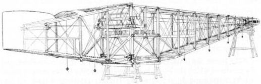
Although the wartime Handley Page bombers had internal bomb stowage, the postwar Hyderabad and Hinaidi carried their bombs externally. The four transverse bomb beams in the O/400 are seen in the drawing.
R/200. Reconnaissance was the mission of this compact single-engined biplane, built for the RNAS in 1917. A Lewis gun on a dorsal Scarff ring-mounting apparently comprised the sole armament.
V/1500. At the end of 1917 it was considered to be worth attempting to bomb Berlin from a base in England. For those days this was indeed a long-range project, entailing, it was reckoned, a point-to-point sortie of some 450 miles and a minimum endurance equivalent to 1,100 miles. Operation in daylight, as well as by night, was therefore necessary, and a heavy defensive armament was a corollary. This demanded a crew of seven. Their stations were once enumerated by Mr Frederick Handley Page, who prefaced his remarks with this most typical reflection: 'If this aeroplane did not bomb Berlin we may find consolation in the fact that perhaps the Germans knew it was coming and saw it was time to give up.' He explained:
'As in the O/400, the bomber sits in the front, and also has a gun; behind him is the pilot and the captain of the vessel, and behind them again is the mechanic, who looks after all the engine equipment. On another platform at the back there are two gunners, one who fires upwards against hostile attack and another who fires downwards. Right at the tail of the machine there is another gun position, in which a man sits and fires back to beat off attacks from the rear.'
Thus 'H.P.', speaking in 1919, the year after his V/1500 four-engined bomber had been built and flown; and Gen Trenchard, describing Independent Force operations at about the same time:
'The 27th Group was established in England under the command of Col. R. H. Mulock, DSO, for the purpose of bombing Berlin and other centres. This group only received the machines capable of carrying out this work at the end of October, and though all ranks worked day and night in order to get the machines ready for the attack on Berlin, they were only completed three days before the signing of the Armistice.'
Respecting armament, the two most remarkable features of the 'Super Handley' were the tail gun position, with a catwalk giving access, and the very heavy bomb load. Neither the tail gun nor the fuselage access were the first of their kind, for in 1916 Igor Sikorsky had applied such armament to giant aircraft of the Mouromets class. He has said:
'Finally the officers of the Squadron worked out a scheme for mounting a machine gun at the rear of the fuselage and I was given the problem of designing it. I increased the stabiliser so as to take care of the weight of a man with a machine gun and ammunition. At the end of the fuselage a cockpit was arranged for the gunner, with a sort of windshield as protection from the stream of air. It was difficult to provide means of reaching the rear gunner's nest in flight, because inside the fuselage were wire crosses... A device was invented which the flying crews called the 'trolley car'. It consisted of a pair of tight rails running along the whole fuselage and of a low couch mounted on rollers. When necessary a man could lie down on the couch and move easily below the wire crosses...'
The present writer makes a particular point of the V/1500's tail gun position, of which Handley Page were justifiably proud, because he will later be recording their arguments for not adopting such a position for the Hampden. The V/1500 tail position, it may be mentioned, proved the means of saving the life of the British flying pioneer Alec Ogilvie. He was occupying this station when one of the great bombers crashed near Golders Green and caught fire. The rest of the crew were killed.
The tail gunner in the V/1500 had a Scarff ring-mounting for a Lewis gun. There was a similar installation in the nose and on top of the fuselage aft of the wings. Alternatively, this last position had a central socket-and-pillar mounting or two such mountings, one on each side. The whole of the centre portion of the fuselage formed the bomb bay. Twenty-four 230-lb bombs was a load quoted by Handley Page, but up to thirty 250-lb bombs could be taken for short ranges.
The new 3.300-lb bomb, designed especially for the V/1500, was about 15 ft long, and one or two of these were to be carried beneath the fuselage. The bombsight was of Wimperis course-setting type.
Kennedy
Giant. No armament was ever fitted to this great biplane (142 ft span) of 1916, but mention is warranted because of the designer's earlier association with Igor Sikorsky (see under Handley Page V/1500) and the clear intention to install a tail turret, as betokened by the depth of rear fuselage. The following item in The Aeroplane of 28 February, 1923, is relevant:
'On Feb. 21 the trustee in bankruptcy of Mr Chessborough J. Mackenzie Kennedy, the author of the famous super-Sikorsky which has so long decorated or disfigured (according to taste) the landscape at Northolt, sued the Air Council in respect of the rights to use the idea of a gun-pit in the tail of an aeroplane. The Plaintiff alleged that the War Office agreed with one Hamilton Edwards to take an aeroplane designed by Mr. Kennedy, having a gun-pit in the tail and engines mounted on the wings... It was further alleged that in the autumn of 1917 the Air Board lent their designing and technical staff to Handley Page Ltd., who disclosed to that firm Kennedy's confidential reports and that the Handley Page V/1500, which had a gun-pit in the tail, was the result. Mr. Frederick Handley Page applied for a patent for the tail gun-pit on March 15, 1918, and Mr Kennedy applied for a patent on March 16.'
The action was dismissed.
The ultimate layout as planned by Kennedy was remarkably advanced. In the nose of the fuselage was a gun position, and there was an enclosed flight deck immediately behind. A second gun position was on top of the fuselage aft of the wings, and behind the tail (which had twin fins and rudders) was the controversial 'gun-pit'. The designer schemed for this position a kind of cushion, which could be arranged to act as a knee-pad or seat, according to the direction in which the gunner was firing. Two guns were planned for this station, but Kennedy was mindful of the weight problems involved and spoke of extending the nose accordingly.
Careful attention was likewise paid to the bomb installation. Each bomb was to be carried vertically, nose-down, by a pair of arms, pivoted laterally at one end and formed with interlocking cups at the other end to hold the nose of the bomb. The arms were to be controlled through selector gear, associated with an indicator, in the form of a figured drum, which showed the number of bombs dropped or still held.
Mann, Egerton
Type B. This was a seaplane of 1916, using Short 184 components and armed with one free Lewis gun (dorsal) and bombs under the fuselage.
Type B. This was a seaplane of 1916, using Short 184 components and armed with one free Lewis gun (dorsal) and bombs under the fuselage.
Type H. Answering to the same requirements as the Beardmore W.B.IV, this 'ship's fighter', or 'seaborne scout' as the makers called it, was built in 1917. It had a fixed Vickers gun mounted on the fuselage to port (250 rounds), and a Lewis gun above the centre-section (three 97-round drums).
Mann & Grimmer
M.1. The two men responsible for this imaginative single-engined twin-airscrew biplane of 1914/15 will be named in the second volume of this work because of Mr Grimmer's particular interest in military aeronautics as expressed in Flight. It was intended to arm the M.1 with a Lewis gun, installed in the cockpit behind the nose-mounted engine, under the wing leading edge.
M.1. The two men responsible for this imaginative single-engined twin-airscrew biplane of 1914/15 will be named in the second volume of this work because of Mr Grimmer's particular interest in military aeronautics as expressed in Flight. It was intended to arm the M.1 with a Lewis gun, installed in the cockpit behind the nose-mounted engine, under the wing leading edge.
Martinsyde
S.1. 'In my eyes,' recorded Capt L. A. Strange of this single-seat scout (built 1914), 'all defects were outweighed by the fact that it had a Lewis gun mounted on its top plane, which could be fired forward and upward.' The installation mentioned was made in the spring of 1915, and it was during May of that year that Capt Strange had the historic experience of saving his life in an inverted spin by hanging on to an ammunition drum which had jammed on the gun. Concerning other forms of armament, specific details are lacking, but rifles were carried, and for Home Defence the following loads have been mentioned in connection with a 'Martinsyde Scout': '6 Carcass bombs (3.45-in R.L. tube for discharge); 12 Hale Naval grenades; 150 incendiary darts; carriers for five powder bombs.' Small bombs were apparently carried for attacking ground targets, and an S.1 of No.5 Squadron (Capt G. I. Carmichael) was adapted to take a 100-lb bomb, sighted through a hole cut in the floor. Previously provision had been made for 20-lb bombs under the wings.
S.1. 'In my eyes,' recorded Capt L. A. Strange of this single-seat scout (built 1914), 'all defects were outweighed by the fact that it had a Lewis gun mounted on its top plane, which could be fired forward and upward.' The installation mentioned was made in the spring of 1915, and it was during May of that year that Capt Strange had the historic experience of saving his life in an inverted spin by hanging on to an ammunition drum which had jammed on the gun. Concerning other forms of armament, specific details are lacking, but rifles were carried, and for Home Defence the following loads have been mentioned in connection with a 'Martinsyde Scout': '6 Carcass bombs (3.45-in R.L. tube for discharge); 12 Hale Naval grenades; 150 incendiary darts; carriers for five powder bombs.' Small bombs were apparently carried for attacking ground targets, and an S.1 of No.5 Squadron (Capt G. I. Carmichael) was adapted to take a 100-lb bomb, sighted through a hole cut in the floor. Previously provision had been made for 20-lb bombs under the wings.
G.100 and G.102. Dating from 1915, these large, robust single-seaters were well suited to carry armament, and the RFC name 'Elephant' seems to have been inevitable. On early production aircraft a Lewis gun fired over the centre-section; and for rearward fire a second Lewis gun was later clamped to a cranked pillar mounting just aft of the coaming on the port side. The over-wing gun was carried above the rear spar on a massive pyramid structure, itself braced to the front spar by a fore-and-aft tube. J. M. Bruce has recorded two forms of this mounting, designated Mk.I and Mk.II, the latter having the two elements which comprised the rear attachment pivoted on the underside of the spar. The gun was fired by Bowden cable and carried a long vertical handle attached to the spade grip. By means of this handle the gun could be swung down for reloading. An experimental installation was made of a triple-gun mounting of the Eeman (or, according to one official publication, Eaman) type, which was also tested by the Army. In this instance the fuselage-mounted guns fired upwards at 45 degrees through slots in the centre-section. There was an Aldis sight at the same angle. At least one aircraft had a non-standard mounting for a single Lewis gun offset lo starboard.
As bombers, these Martinsydes were popular and successful, and in particular the more powerful G.102. Bombs were carried beneath the fuselage and wings, and among recorded loads were four 65-lb, one or two 112-lb, two 100-lb, one 230-lb, one 100-lb + four 20-lb, and twelve 20-lb. The constructors declared that the type was 'one of the few machines that could carry large 3 cwt bombs'. The bomb concerned was carried singly under the fuselage and was of the 336-lb type, designed at the Royal Aircraft Factory, Farnborough. At that establishment and also at Orfordness during the summer of 1916, tests were made with an 'Elephant' fitted with an experimental periscopic sight. The 'Bomb, H.E.. 336 lbs., Heavy Case, Mk.I' was nearly five feet long in its original form, in which it is known to have been carried by the 'Elephant'. It was later shortened to allow it to be carried on a 230-lb carrier. Mr Bruce reports that the periscopic bombsight was not developed sufficiently to see operational use in 'Elephants', but, though this may well have been so, a sight of the type was certainly made in quantity.
As bombers, these Martinsydes were popular and successful, and in particular the more powerful G.102. Bombs were carried beneath the fuselage and wings, and among recorded loads were four 65-lb, one or two 112-lb, two 100-lb, one 230-lb, one 100-lb + four 20-lb, and twelve 20-lb. The constructors declared that the type was 'one of the few machines that could carry large 3 cwt bombs'. The bomb concerned was carried singly under the fuselage and was of the 336-lb type, designed at the Royal Aircraft Factory, Farnborough. At that establishment and also at Orfordness during the summer of 1916, tests were made with an 'Elephant' fitted with an experimental periscopic sight. The 'Bomb, H.E.. 336 lbs., Heavy Case, Mk.I' was nearly five feet long in its original form, in which it is known to have been carried by the 'Elephant'. It was later shortened to allow it to be carried on a 230-lb carrier. Mr Bruce reports that the periscopic bombsight was not developed sufficiently to see operational use in 'Elephants', but, though this may well have been so, a sight of the type was certainly made in quantity.
R.G. Designed late in 1916, the R.G. was initially armed with a fixed Vickers gun to port and a Lewis gun, having a restricted field of fire, from the starboard side of the cockpit. Later two fixed Vickers guns were substituted, the guns lying exposed forward of the windscreen These guns do not appear to have had Constantinesco gear; they retained the land-service grips and firing levers at the rear and may have had a mechanical gear to allow them to fire through the airscrew arc or to have been intended for the Martinsyde electrical synchronising gear. This, however, dated from early 1916, and may have been entirely abandoned by the time the R.G. underwent official tests at Farnborough in 1917. Certainly the R.G. must have rivalled the Sopwith Camel very closely indeed for the distinction of being the first British fighter to have twin Vickers guns.
F.1. The mystery that surrounds this two-seat fighter of 1917 may be dispelled in some degree by evidence later adduced in connection with the Vickers F.B.24E, an aircraft of similar layout. The author inclines to the view that both aircraft were designed for the Vickers mounting described and illustrated in the context of the Vickers type named.
F.2. An all-round improvement on the F.1, the F.2 was more or less contemporary and had a normal armament. A fixed Vickers gun lay externally to port, and the gunner had a Lewis gun on a Scarff ring-mounting.
F.3. 'A great advance on all existing fighting scouts' was one official pronouncement on this experimental single-seater of 1917 ('Mother' in the Martinsyde family). In addition to two fixed Vickers guns, there was provision, in deference to an Air Board specification then current, for a Lewis gun on the top centre-section. This gun was apparently never fitted. Compared with the R.G., the F.3 had a deeper fuselage forward of the cockpit, and this allowed the guns to be completely cowled in and to fire through ports in the top decking. A single aperture for the ejection of cases and links was located just forward of the rear centre-section strut on each side.
F.4. The F.4, or Buzzard, was built in 1918 and had a generally similar Vickers gun installation to that of the F.3. An important feature, however, was the excellent system devised for accessibility, described and illustrated in connection with the Aircraft Disposal Company's A.D.C.1. Brackets for an Aldis sight were fitted forward of the cockpit and provision was made for a bomb-carrier (four 20-lb) under the fuselage.
A point of some interest is that on the prototype and on the production aircraft illustrated, the ejection aperture was panelled over, but whether with the object of retaining the spent cartridge cases and belt links aboard cannot be determined.
F.4a. This designation was applied to a post-war (1921) two-seater development of the F.4 having a Scarff ring-mounting for a Lewis gun.
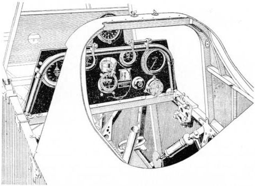
Forward of the instrument board of the Martinsyde F.4 Buzzard is a tubular frame with fittings for attachment to the rear trunnions of the two Vickers guns. The reservoir for the C.C. synchronising gear is seen at the right, but the top of the control column, with firing levers, is absent.
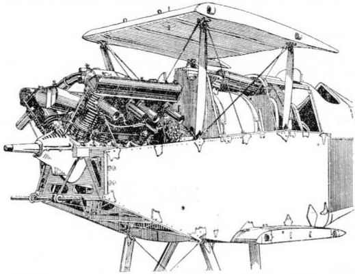
Official drawing showing Hispano-Suiza engine and gun installation of Martinsyde F.4 Buzzard.
Nieuport
B.N.I. A counterpart of the Sopwith Snipe, and resembling that type and other contemporary single-seaters in having provision for an over-wing Lewis gun as well as two Vickers guns with C .C gear, the B.N.I was designed in March 1918. The Lewis gun was actually fitted on this machine, being positioned somewhat to starboard, and the Vickers guns were semi-internally mounted, beneath a humped cowling. The makers advanced the claim that although the 'anti-airship'Lewis gun installation on the top wings of other lighters was disliked by many pilots, being too high above their heads 'to permit it to be directly sighted on a target in the best fighting attitudes', the gun on the B.N.I was 'practically in line with the pilot's eyes'.
B.N.I. A counterpart of the Sopwith Snipe, and resembling that type and other contemporary single-seaters in having provision for an over-wing Lewis gun as well as two Vickers guns with C .C gear, the B.N.I was designed in March 1918. The Lewis gun was actually fitted on this machine, being positioned somewhat to starboard, and the Vickers guns were semi-internally mounted, beneath a humped cowling. The makers advanced the claim that although the 'anti-airship'Lewis gun installation on the top wings of other lighters was disliked by many pilots, being too high above their heads 'to permit it to be directly sighted on a target in the best fighting attitudes', the gun on the B.N.I was 'practically in line with the pilot's eyes'.
Nieuport
Nighthawk. Being designed specifically for the A.B.C. Dragonfly radial engine, and having the petrol tanks flanking the pilot's cockpit and shaping the fuselage contours, the Nighthawk had a commodious fore-part. This enabled the two Vickers guns to be enclosed beneath the top decking, firing through ports located one on each side of the topmost cylinder of the Dragonfly engine. Aldis and ring-and-bead sights were bracketed to the upper centre-section. As on the contemporary Siddeley Siskin there was provision for 2.000 rounds of ammunition. It was stated that the head of the control column was of 'standard RAF type#, the ring being covered in rubber, having a magneto switch at the top and the two gun triggers at the centre. Design provision was made for four 20-lb bombs.
Nighthawk. Being designed specifically for the A.B.C. Dragonfly radial engine, and having the petrol tanks flanking the pilot's cockpit and shaping the fuselage contours, the Nighthawk had a commodious fore-part. This enabled the two Vickers guns to be enclosed beneath the top decking, firing through ports located one on each side of the topmost cylinder of the Dragonfly engine. Aldis and ring-and-bead sights were bracketed to the upper centre-section. As on the contemporary Siddeley Siskin there was provision for 2.000 rounds of ammunition. It was stated that the head of the control column was of 'standard RAF type#, the ring being covered in rubber, having a magneto switch at the top and the two gun triggers at the centre. Design provision was made for four 20-lb bombs.

Standard RAF control column with gun-firing levers, in the Nieuport Nighthawk.
Norman Thompson
N.T.4 and 4a. The first N.T.4 twin-engined pusher flying-boat (1917) had a 2-pdr Davis recoilless gun mounted above the enclosed cockpit in the nose. The mounting was braced by lateral struts running downward through the cockpit. Later a Lewis gun may have been carried by aircraft of this type. For anti-submarine work a maximum load of two 100-lb bombs appears likely.
N.1B. A two-seater, this fighter flying-boat was probably intended to carry a Lewis gun for the observer's use.
N.2C. Developed in 1918 primarily for patrol, this flying-boat probably carried a Lewis gun, and perhaps bombs also.
Parnall
Zeppelin Scout. Built in 1916 for 'Zeppelin strafing at night', this large single-seater had a gun mounted in the starboard side of the cockpit and firing forward and upward at 45 degrees. This gun appears to have been, or to have been intended to be, a Crayford rocket gun, as installed in the Vickers F.B.25 and the N.E.I built by the Royal Aircraft Factory. The makers stated in June 1916 that, in order to provide maximum field of vision, the upper wing was placed substantially in the line of forward horizontal vision of the pilot, and the lower wing was arranged substantially symmetrically below his seat. Mention was made of a cut-out in the upper trailing edge to allow downward vision, and the scat could be adjusted up and down.
Zeppelin Scout. Built in 1916 for 'Zeppelin strafing at night', this large single-seater had a gun mounted in the starboard side of the cockpit and firing forward and upward at 45 degrees. This gun appears to have been, or to have been intended to be, a Crayford rocket gun, as installed in the Vickers F.B.25 and the N.E.I built by the Royal Aircraft Factory. The makers stated in June 1916 that, in order to provide maximum field of vision, the upper wing was placed substantially in the line of forward horizontal vision of the pilot, and the lower wing was arranged substantially symmetrically below his seat. Mention was made of a cut-out in the upper trailing edge to allow downward vision, and the scat could be adjusted up and down.
Panther. Built in 1917 as a 'ship's aeroplane' for reconnaissance, the Panther was armed (according to a Ministry of Munitions publication) with a Lewis gun on a 'special pillar mounting' and supplied with 'three double trays'. This armament was supplemented on one example at least by a Vickers gun on the port side of the cockpit, with the breech casing faired in.
Pemberton-Billing
P.B.23E and P.B.25. The P.B.23E pusher 'scout' of 1915 carried a fixed Lewis gun in the nose of the nacelle and was almost certainly the first British aircraft to be armed with a fixed gun. The gun on the P.B.23E was set low in the nacelle; in the succeeding P.B.25 it was raised to the top.
P.B.23E and P.B.25. The P.B.23E pusher 'scout' of 1915 carried a fixed Lewis gun in the nose of the nacelle and was almost certainly the first British aircraft to be armed with a fixed gun. The gun on the P.B.23E was set low in the nacelle; in the succeeding P.B.25 it was raised to the top.
Pemberton-Billing
P.B.29. Designed and built in 1915 to 'stand still in the air in a 28mph breeze and lie in wait for Zeppelins' this 'patrol fighter' quadruplane appears to have been intended to carry a Lewis gun in a cockpit structure between the topmost wings.
P.B.29. Designed and built in 1915 to 'stand still in the air in a 28mph breeze and lie in wait for Zeppelins' this 'patrol fighter' quadruplane appears to have been intended to carry a Lewis gun in a cockpit structure between the topmost wings.
Supermarine
Night Hawk. Noel Pemberton-Billing's second quadruplane (the P.B.29 has already been mentioned under the designer's own name) was similarly intended for anti-Zeppelin operations and was a veritable 'giant battleplane'. It was built in 1916. The primary armament was a 2-pdr Davis recoilless gun, with ten rounds of ammunition. This gun was in a forward upper position above the topmost wing and built-in to the deep central structure, which had internal crew accommodation. The gun was on a special mounting, designed to permit traversing and described as carrying the gun on a 'double parallel sliding bed, permitting practically any arc of fire'. The target for the Davis gun was intended to be illuminated by a searchlight carried on the aircraft, gimbal-mounted in the nose, power being supplied by a separate A.B.C. engine and dynamo. The design included nine separate petrol tanks with 'quick-change' gear, enabling any number of tanks to be used or isolated in case of puncture by gunfire. In addition to the Davis gun there were two Lewis guns on Scarff ring-mountings. (The designer once claimed four guns, but two were actually fitted.) The mountings were emplaced one forward of the central structure, in the nose of the fuselage proper, and one in the rear of the central structure, behind the Davis gun. For the Lewis guns, six ammunition drums were specified. Another design feature mentioned in connection with this aeroplane was the carrying of all controls, pipes, etc. outside the fuselage in armour-plated casings and a 'special revolver' enabling 'incendiary flares' to be dropped in a stick of one every twenty feet, so that, in straddling a Zeppelin of 65-ft diameter, at least three would strike. The 'perpetual haze of escaped gas' just above the top surface of a Zeppelin was considered by Pemberton-Billing to make it very vulnerable to such attack. This same designer schemed in 1915 an 'incendiary and bomb dropper' which was manufactured by the H.M.V. Gramophone Company and which was claimed to have continued in use long after the designer's political attacks on the Government.
Night Hawk. Noel Pemberton-Billing's second quadruplane (the P.B.29 has already been mentioned under the designer's own name) was similarly intended for anti-Zeppelin operations and was a veritable 'giant battleplane'. It was built in 1916. The primary armament was a 2-pdr Davis recoilless gun, with ten rounds of ammunition. This gun was in a forward upper position above the topmost wing and built-in to the deep central structure, which had internal crew accommodation. The gun was on a special mounting, designed to permit traversing and described as carrying the gun on a 'double parallel sliding bed, permitting practically any arc of fire'. The target for the Davis gun was intended to be illuminated by a searchlight carried on the aircraft, gimbal-mounted in the nose, power being supplied by a separate A.B.C. engine and dynamo. The design included nine separate petrol tanks with 'quick-change' gear, enabling any number of tanks to be used or isolated in case of puncture by gunfire. In addition to the Davis gun there were two Lewis guns on Scarff ring-mountings. (The designer once claimed four guns, but two were actually fitted.) The mountings were emplaced one forward of the central structure, in the nose of the fuselage proper, and one in the rear of the central structure, behind the Davis gun. For the Lewis guns, six ammunition drums were specified. Another design feature mentioned in connection with this aeroplane was the carrying of all controls, pipes, etc. outside the fuselage in armour-plated casings and a 'special revolver' enabling 'incendiary flares' to be dropped in a stick of one every twenty feet, so that, in straddling a Zeppelin of 65-ft diameter, at least three would strike. The 'perpetual haze of escaped gas' just above the top surface of a Zeppelin was considered by Pemberton-Billing to make it very vulnerable to such attack. This same designer schemed in 1915 an 'incendiary and bomb dropper' which was manufactured by the H.M.V. Gramophone Company and which was claimed to have continued in use long after the designer's political attacks on the Government.
Phoenix (English Electric)
Cork. Designed to Air Board requirements for anti-submarine patrol, the Cork twin-engined flying-boat (1918) had a Scarff ring-mounting in the bows and two waist hatches aft of the wing trailing edge. The mountings appear to have carried single Lewis guns, though five guns were mentioned in a company document issued some time after the boat was built. The second machine of the type had two 'fighting top' positions at the trailing edge of the top wing in line with the second set of interplane struts from the tip. These carried Scarff ring-mountings, possibly with double-yoked guns, for the company mentioned seven Lewis guns as the armament. The gunners in the 'fighting tops' ascended to their positions by way of steps on the interplane struts. They are said to have suffered not only from a sense of isolation but from a form of airsickness also, brought on by 'unusual movements' of their emplacements. Four 250-lb or two 520 550-lb bombs could be carried under the inner wings.
Cork. Designed to Air Board requirements for anti-submarine patrol, the Cork twin-engined flying-boat (1918) had a Scarff ring-mounting in the bows and two waist hatches aft of the wing trailing edge. The mountings appear to have carried single Lewis guns, though five guns were mentioned in a company document issued some time after the boat was built. The second machine of the type had two 'fighting top' positions at the trailing edge of the top wing in line with the second set of interplane struts from the tip. These carried Scarff ring-mountings, possibly with double-yoked guns, for the company mentioned seven Lewis guns as the armament. The gunners in the 'fighting tops' ascended to their positions by way of steps on the interplane struts. They are said to have suffered not only from a sense of isolation but from a form of airsickness also, brought on by 'unusual movements' of their emplacements. Four 250-lb or two 520 550-lb bombs could be carried under the inner wings.
Port Victoria
P.V.1. This was an experimental seaplane of 1916, having a Sopwith Baby fuselage and high-lift wings with a view to improving take-off with two 65-lb bombs.
P.V.2 and P.V.2bis. In 1916 the Davis recoilless gun was still viewed hopefully as an anti-Zeppelin weapon, and the P.V.2 single-seat seaplane was designed to carry a 2-pounder gun of the type. It was to be fitted over the top wing and be accessible for loading (ten rounds provided). Before the airframe was completed, the Davis gun was abandoned, and with two Lewis guns above the raised top wing the aircraft was designated P.V.2bis.
Port Victoria
P.V.4. Another 1916 Port Victoria design, the P.V.4 pusher two-seater, did not fly until the following year. There was a Scarff ring-mounting for a Lewis gun in the nose, commanding a field of fire even over the top wing.
P.V.4. Another 1916 Port Victoria design, the P.V.4 pusher two-seater, did not fly until the following year. There was a Scarff ring-mounting for a Lewis gun in the nose, commanding a field of fire even over the top wing.
Port Victoria
P.V.5 and P.V.5a. The P.V.5 of 1917 was a fighter bomber, carrying two 65-lb bombs internally. The pilot had a Vickers gun mounted on top of the fuselage.
P.V.5 and P.V.5a. The P.V.5 of 1917 was a fighter bomber, carrying two 65-lb bombs internally. The pilot had a Vickers gun mounted on top of the fuselage.
Port Victoria
P.V.7 (Grain Kitten). Designed specially for anti-Zeppelin operations from small naval craft, this tiny single-seat biplane of 1917 had a single Lewis gun above the centre-section, the trailing edge of which was cut away for elevation. Three drums of ammunition were specified.
P.V.7 (Grain Kitten). Designed specially for anti-Zeppelin operations from small naval craft, this tiny single-seat biplane of 1917 had a single Lewis gun above the centre-section, the trailing edge of which was cut away for elevation. Three drums of ammunition were specified.
Port Victoria
P.V.8 (Eastchurch Kitten). Built to meet the same requirements as the P.V.7, the P.V.8 had its Lewis gun offset to starboard. This type likewise had a cut-away trailing edge to allow elevation, though it was officially reported that the gun would be awkward to fire because of the pilot's cramped position.
P.V.8 (Eastchurch Kitten). Built to meet the same requirements as the P.V.7, the P.V.8 had its Lewis gun offset to starboard. This type likewise had a cut-away trailing edge to allow elevation, though it was officially reported that the gun would be awkward to fire because of the pilot's cramped position.
Port Victoria
P.V.9. Intended for the escort of flying-boats, this advanced single-seat seaplane of 1917 had a synchronised Vickers gun on top of the fuselage and a Lewis gun over the top centre-section, firing upwards and forwards over the airscrew.
P.V.9. Intended for the escort of flying-boats, this advanced single-seat seaplane of 1917 had a synchronised Vickers gun on top of the fuselage and a Lewis gun over the top centre-section, firing upwards and forwards over the airscrew.
Grain Griffin. This 1918 conversion of a Sopwith Bomber as a two-seater fleet reconnaissance aircraft had a Lewis gun on a pillar-mounted swiveling bracket behind the rear cockpit.
Felixstowe
Porte Baby. The design of this three-engined flying-boat dated back to 1916, and during its existence the craft was used for some notable armament experiments. Thus, a 6-pdr Davis recoilless gun was fitted in the bows, and on another occasion two 14-in torpedoes were slung one beneath each lower wing. The effectiveness of machine-gun armament was restricted by hull-form and construction, but hatchway or window guns may well have been intended or installed behind the cockpit.
The carrying of a fighter aeroplane (Bristol Scout) on the top wing, and a successful launching in flight, is a further distinction to the credit of this early flying-boat, and one which may fairly be included under the heading of 'armament'.
B.E.2, 2a and 2b. The most famous armed exploit by an early aircraft of the B.E. series, which originated in 1912, was the dropping of a 100-lb bomb by 2nd-Lieut W. B. Rhodes-Moorhouse from a B.E.2a on Courtrai railway station on 26 April, 1915. Smaller bombs were carried, including two 20-lb, and one B.E.2a, flying without observer, was armed with one petrol bomb and 'as many grenades as the pilot could manage'. Late in 1914 the Royal Aircraft Factory produced a bomb-carrier for the B.E.2a. This held three bombs and was suspended well below the fuselage forward of the undercarriage axle. Other types of carrier were attached between the rear struts of the undercarriage. Pistols, rifles and carbines were carried, and No.50 is known to have had a rifle clamped to the side of the fuselage. One B.E.2a was used to test the Fiery Grapnel weapon, developed at the Royal Aircraft Factory for entanglement with, and explosion upon, airships. Grenades were carried on anti-airship patrols.
J. M. Bruce has recorded that at about mid-1912 it was reported that experiments were being conducted at Farnborough with a type of Vickers gun on a B.E. aircraft piloted by Geoffrey de Havilland. The gun was rumoured to weigh only 15 lb complete and to fire at the rate of 400 rounds per minute. Flight reported early in November 1912 that a biplane of B.E. type was being used at Aldershot for experiments with a Maxim gun, but whether this was a confusion with the F.E.2 (which, as a photograph shows, was definitely tilted with a Maxim gun) cannot be determined. The most diligent research gives no hint of a Vickers gun weighing 15 lb, and even the 'stripped' Lewis gun weighed 17 lb. The only aircraft machinegun known to the author which approached the reported weight was the French Darne, an experimental model of which was chambered for the British 0.303-in cartridge and which weighed 15 1/2 lb, but this gun did not exist in 1912.
J. M. Bruce has recorded that at about mid-1912 it was reported that experiments were being conducted at Farnborough with a type of Vickers gun on a B.E. aircraft piloted by Geoffrey de Havilland. The gun was rumoured to weigh only 15 lb complete and to fire at the rate of 400 rounds per minute. Flight reported early in November 1912 that a biplane of B.E. type was being used at Aldershot for experiments with a Maxim gun, but whether this was a confusion with the F.E.2 (which, as a photograph shows, was definitely tilted with a Maxim gun) cannot be determined. The most diligent research gives no hint of a Vickers gun weighing 15 lb, and even the 'stripped' Lewis gun weighed 17 lb. The only aircraft machinegun known to the author which approached the reported weight was the French Darne, an experimental model of which was chambered for the British 0.303-in cartridge and which weighed 15 1/2 lb, but this gun did not exist in 1912.
F.E.2. The genesis of the F.E.2 is of exceptional interest, especially in respect of armament. It first appeared, with 50-hp Gnome engine, in September 1911, having been rebuilt from the crashed F.E.1, which was Geoffrey de Havilland's second aeroplane (Farman Experimental No.1). By the time of the British Military trials, on Salisbury Plain in August 1912, this aircraft had been fitted with a Maxim machine-gun, as a photograph shows. The gun, which appears to have been of 0.303-in calibre, was mounted on trunnions in a fork-shaped member some distance aft from the nose of the nacelle, allowing the muzzle end of the barrel casing to rest on the tip of the nacelle. The gun was lashed in this position by two lengths of rope. As rebuilt early in 1913 with a 70-hp Renault engine the F.E.2 had a nacelle of revised form, associated with a very large gun-carrying member as seen in another photograph. That in this form the aircraft was intended to carry a heavy gun is suggested by a statement by F. W. Lanchester that the F.E.2 was designed to carry a 'gun weight' of 300 lb. This figure probably included mounting and ammunition, and the weapon concerned may well have been the Coventry Ordnance Works 1-pounder as tested in the F.E.3 during 1913.

An historic picture showing the F.E.2 with Gnome engine and Maxim gun.
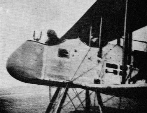
Rebuilt F.E.2 with Renault engine and mounting for large gun.
B.E.8 and 8a. A single 100-lb bomb could be carried by aircraft of this type and it is likely that the usual small arms, though not machine-guns, were also taken into the air.
F.E.3. The F.E.3 was a remarkable aeroplane, especially so as it was built as early as 1913. The tail was carried on a single boom, which passed through the hollow airscrew shaft, and the armament was a 1-pounder Coventry Ordnance Works gun. This gun was apparently never fired from the aircraft in flight but was tested in the summer of 1913 with the F.E.3 suspended by ropes from a gantry. It was established that flight stability would not be unduly affected.
F.E.6. This two-seat pusher fighter was built in 1914 as a development of the F.E.3 theme and was similarly armed with a Coventry Ordnance Works 1-pounder gun. This was (or was to be) installed on a pillar mounting in the nose.
F.E.6. This two-seat pusher fighter was built in 1914 as a development of the F.E.3 theme and was similarly armed with a Coventry Ordnance Works 1-pounder gun. This was (or was to be) installed on a pillar mounting in the nose.
S.E.2. Two rifles, one on each side of the fuselage, pointing outwards to clear the airscrew, appear to have formed the earliest armament of this single-seater. These were later discarded, and only a pistol was then carried.
B.E.2c, d and e. The B.E.2c was never intended to carry armament, but to provide a stable platform for reconnaissance. This very stability was to prove a severe handicap in combat, and even though armament schemes were quickly improvised the firing of a gun from the front (observer's) seat was a matter of great difficulty because of the adjacent wings and bracing members. Rifles, carbines and pistols were carried, and an accompanying photograph is possibly unique in showing a carbine in simulated use. This is of Lee-Metford type. Lewis guns were variously installed. In some instances four sockets were disposed round the observer's cockpit, the gun or guns being interchanged between these sockets as necessary. Sockets were also provided at the sides of the rear cockpit, or behind it, for rearward fire. Capt L. A. Strange of No. 12 Squadron mounted a Lewis gun on the side of the fuselage at such an angle that the line of fire cleared the airscrew, but whether this was the first arrangement of its kind (requiring the pilot to fly crab-fashion) cannot be determined. The common type of mounting which became known as the 'Strange mounting' was of cranked pillar type, having a toothed quadrant and illustrated in connection with the B.E.2e and B.E.12. In March 1917 the Strange mounting for the Lewis gun was improved by Sgt Hutton of No.39 Squadron by fitting a release stud which made the gun or mounting easier to manoeuvre. Other patterns of cranked pillar mounting were improvised and to these the description 'candlestick' mounting was applied. In apparent refutation of the B.E's inferior manoeuvring qualities it has been recorded: 'The Huns were a poor lot and had one violent manoeuvre not dislodged the Lewis guns from their silly candlestick mountings the B.E. might have driven them off.' Some B.E.2cs of the RNAS carried a single Lewis gun on a tall bracket mounting ahead of the cockpit, allowing the gun to be fired under the centre-section but above the airscrew arc. There was at least one instance of a hole being made in the centre-section through which the observer put his head and shoulders to use an unspecified weapon, and there was also an installation of a Lewis gun above the top wing. As many as four guns were carried at a time. One B.E.2c carried two Lewis guns and a Mauser pistol. Oliver Stewart has recalled:
'Sometimes the observer knelt or stood on his seat to use Lewis guns mounted on brackets linked by a bar between the rear pair of centre-section struts. Sometimes a Lewis gun which could be fired downwards was fitted on the left side of the fuselage alongside the pilot's seat. Another mounting, which was found in numerous forms in the B.E., had one or two Lewis guns on splayed brackets which kept the bullets clear of the disc swept by the airscrew.'
For Home Defence one or two Lewis guns were installed on Strange mountings to fire behind the centre-section, the ammunition drums being loaded with a mixture of ordinary and 'special' ammunition. Home Defence B.E.2cs and 2es also carried four, six or eight Le Prieur rockets, attached to the outer interplane struts, the launching tubes being set at an upward angle. Armament for Home Defence also included canisters of Ranken Darts, two 20-lb high-explosive bombs and two 16-lb incendiary bombs. 'Bomb boxes' were mentioned, and the R.L. Tube was used to launch incendiary bombs. The Fiery Grapnel, already mentioned in connection with the B.E.2a, was also tested on a B.E.2c. Two of these weapons were carried side by side under the fuselage. In No.6 Squadron a winch was fitted on a B.E.2c to lower a lead weight on a steel cable, the object being to foul the airscrew of an enemy aircraft.
Bombs were carried either loose in the fuselage or beneath the inner lower wings and fuselage. Some B.E.2cs of the RNAS carried three small bombs under the engine. With the heavier bomb loads the aircraft were flown as single-seaters. Identified loads are four to ten 20-lb, or one 112-lb + four 20-lb, or two 112-lb bombs, and as early as 10 March, 1915, Capt Strange dropped three French bombs weighing 25 lb on Courtrai station. B.E.2cs arc known to have been used on anti-submarine operations, and in this connection it may be noted that the standard bombs used for this work were of 65-lb, 100-lb and 230-lb weight. Loads for the B.E.2e included two 100-lb or one 100-lb + eight 20-lb.
In August 1916 a B.E.2c was used to test the first installation of the Constantinesco synchronising gear for the Vickers gun, but the only aircraft of the type to have such an installation as standard were those modified by the Belgians. The gun in this instance was mounted above the engine, and a ring-mounting of Nieuport type was fitted over the rear cockpit.
Armoured seats were developed at the Royal Aircraft Factory and during 1916 an armoured version of the B.E.2c was produced at the same establishment. The armour weighed 445 lb, and armoured B.E.2cs were operated successfully against entrenched German troops. Other applications were low-level photography and the attack of kite balloons. One single-seat B.E.2c had a repositioned and specially armoured cockpit, the armour being built up round the pilot's head and shoulders in a manner reminiscent of Ned Kelly himself. It remains to mention the now-famous installation of five Lewis guns made on a B.E.2c by Lieut C. J. Chabot. The guns were within the undercarriage structure and fired downward at a shallow angle. The installation was never, used operationally.
No aircraft of 1914-18 was fitted with a greater variety of armament than the B.E.2c, and, notwithstanding its handicaps in combat with other aeroplanes, it endures as the greatest airship-destroyer of all time. On 31 March, 1916, 2nd-Lieut A. de B. Brandon dropped Ranken Darts and an incendiary bomb on the crippled L.15, which then came down on the sea. Some months later, on 3 September, 1916, Lieut W. Leefe Robinson shot down S.L.11 in flames, using a Lewis gun installed on a Strange mounting, of the type illustrated herewith on a B.E.2e. The Lewis gun, firing special ammunition, was also the chosen instrument in the destruction of L.32 (2nd-Lieut F. Sowrey, 24 September, 1916), L.31 (2nd-Lieut W. J. Tempest, 31 October, 1916), L.34 (2nd-Lieut I. V. Pyott, 27 November, 1916) and L.21 (Flt Lieut E. Cadbury, Flt Sub-Lieut G. W. R. Fane and Flt Sub-Lieut E. L. Pulling, 28 November, 1916).
The stability which cost the B.E.2c so dearly in daylight operations in face of opposing aircraft rendered this same aeroplane a steady platform for what was to become perhaps the most famous aircraft machine-gun of all.
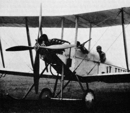
Demonstrating the use of a Lee-Metford carbine from an early B.E.2c.
F.E.2a. A single Lewis gun was the armament of this fighter/reconnaissance two-seater, first constructed in 1915. The gun was mounted on a tubular arm, pivoted to the floor of the front cockpit. The underside of the nacelle was armoured and an angular tubular framework built over the nose may have afforded protection for the aircraft structure against misdirected fire from the gun.
F.E.2b. To the single pillar-mounted Lewis gun of the F.E.2a, which had an arc of fire of about 180 degrees, there was added, as a more or less standard fitment on the F.E.2b, a second Lewis gun on a telescopic pillar mounting between the cockpits. In order to man this gun, the gunner stood on the cupboard which contained spare parts and miscellanea and fired rearwards above the pilot's head. The pilot could fly with one hand and operate the rear gun with the other. Sometimes two pillar-mounted guns were installed between the cockpits. When the pillar or pillars were fully extended, the gunner's insteps were on the upper rim of the plywood-covered nacelle. An F.E. gunner was almost as much acrobat as marksman. Arch Whitehouse recalls of one energetic occasion:
'By the time we were back opposite Arras, the empty gun drums were rattling around the bottom of my nacelle and the canvas bag bolted to the side of my gun to catch the empty cartridges was jammed to its capacity.'
In the spring of 1916 an experimental insiallation was made of a Vickers 1-pounder 'Pom-pom', of the type which had been used in the Boer War, and two aircraft having this armament were delivered about a year later to No. 100 Squadron for ground-attack work. No. 102 Squadron used the same armament. Among difficulties encountered were malfunctioning of the gun, the fierce recoil - which on one occasion at least snapped the engine holding-down bolts - and the shell cases which were blown back into the airscrew. The Pom-pom gunner sat to the pilot's right and could elevate or depress the gun in a slot formed in the nacelle. A special form of sight appears to have been fitted on a fore-and-aft tube on top of the nacelle. A few F.E.2bs used for Home Defence had a Pom-pom gun; two had a 0.45-in Maxim gun, and some had a Lewis gun on a n Anderson mounting. This type of mounting comprised a tubular inverted-U member braced to the nacelle and having a central pivoted pillar to which the gun was attached. At Farnborough early in 1917 an installation was made of two Lewis guns, one fixed to each side of a Harle searchlight for simultaneous training. There was also an installation of twin-yoked Lewis guns without the light. Some Home Defence F.E.2bs were single-seaters, either with the front cockpit faired over or with a special top decking. One or two fixed Lewis guns sometimes formed the armament and there were instances of a Lewis gun on a normal telescopic mounting. In training units a Scarff ring-mounting was tilted.
Good load-carrying ability, tractability and field of view made the F.E.2b an attractive proposition as a bomber. A single 230-lb bomb could be carried, but two of 112 lb was a commoner load. Three 112-lb bombs could be lifted. Other types of bomb carried were of 100 lb (anti-submarine F.E.2bs carried two), 40-lb Phosphorus and 20 lb, the last-named up to fourteen in number. One identified load was one 112-lb + eight 20-lb. Bomb rails were fitted under the lower inner wings and fuselage, and a C.F.S. bombsight was mounted at the starboard side of the pilot's cockpit. The F.E.2bs of No. 149 Squadron were adaptable for bombing or reconnaissance, having special carriers designed by one of the squadron mechanics to take bombs or Michelin flares without modification.
F.E.2c. In this relatively little known F.E. variant the crew positions were transposed and the shape of the nacelle was much modified. The pilot sat considerably aft of the nose, and a Lewis gun was mounted low in the nacelle ahead of him. This gun could be trained by the pilot over a limited arc in conjunction with a sighting bar forward of the windscreen. A second Lewis gun, worked by the observer, was fitted on an Anderson mounting behind the pilot's seat. Some parts of the nacelle were armoured.
One F.E.2c was fitted with an experimental gun mounting of unknown type and another was used for gyroscope tests, though whether these were in connection with bombsight development is not known.
The designation F.E.2c was also applied to a version of the F.E.2b bomber with transposed crew stations.
F.E.2d. The F.E.2d and its armament are epitomised in the following excerpts from two memorable articles by W, C. Cambray. M C , (No.20 Squadron) which appeared in Flight International during December 1968 under the title 'We Stood lo Fight':
'On joining the unit I became friendly with a Canadian observer, and we found ourselves greatly impressed by the F.E.2d biplane and its armament - 250 h.p. Rolls-Royce engine, 47 ft wing span, three Lewis guns, a camera, eight Cooper 20-lb bombs and 1.000 rounds of ammunition (one in every three of them tracer). We realised immediately that to stay alive we must become 100 per cent familiar with the machine. We spent much time in jumping from the front gun to the rear gun, standing up in the cockpit to fire over the back and then jumping down again. We practised, also, lying on the range with loaded Lewis guns by our sides, and at a shout of "Now!" seeing who could fire at the target first. This, I think, was one good reason why we both managed to survive the experiences that were to follow.
'As No.20 was mainly a fighter squadron an observer quite often went west during his first encounter. If he was lucky enough to return he was good for one more; and if he returned after three fights he was so experienced that, with luck, he would last six months and return to England for Home Establishment. But the proportion who thus returned was indeed small.
'The usual perch for the observer was on the side of the cockpit, always on the watch above and to the rear. As leader of a patrol my pilot would instruct other pilots in the formation of three, five or eight to keep close "but not too damned close, for fear of collision". I well remember a dog-fight in which another machine passed over us so close that I could have reached up and touched it; a nasty thought, for we had no parachutes.
'The enemy usually collected a formation of six, then perhaps an additional eight, and when there were about 20 of theirs to five of ours they would come close in to attack. 1 would thereupon fire a red Very light, which told our formation we were going to fight.
'We would then go round and round in a big circle, each pilot following the tail of the man in front, and always making the whole circle approach gradually closer to our own lines Should a Hun dive to attack, the observer of one machine in the circle would fire his top gun and the observer of the next machine would use his front gun, so that at any given time the attacker would have two guns firing at him.
'A close understanding between pilot and observer was essential. On one occasion I was with a new but good - pilot who had not previously been in a fight. We were flying in a formation of only three aircraft when we became engaged in a brief but rather exciting encounter. A Hun dived from our rear and I could see his tracer bullets going under us as I stood up firing over the tail. I signalled to the pilot to throw the machine about to get rid of him; but, to my surprise, he did only a simple aerodrome-style turn. The Hun climbed again and made another attack, and this time I was fortunate enough to hit him and see him going down out of control while we did a second aerodrome turn. On returning to the squadron I asked my pilot in no uncertain terms why he had not thrown the machine all over the place. "I was afraid I'd chuck you out," he answered. I replied that it was my job to slay in. A very minor incident, perhaps, but one illustrating the necessity of close cooperation.
'Our ceiling was 17.500 ft and we did our best to get there, because the anti-aircraft fire was pretty accurate; but a little drift to the left, a little to the right and an occasional about-turn kept us reasonably safe. On the odd occasion the machine would give an appreciable lift as air was displaced by a passing shell that eventually burst well above us. At this height, with no oxygen, of course, the moving from one gun to the other was quite an exertion and made one pant a good deal.
'A useful manoeuvre in dog-fights was the Immelmann turn, but it could be disconcerting when the machine hung momentarily on one wing-tip and everything, including the observer, started to fall out of it. However, the F.E.2d usually scooped everything up in the nick of time and all was in order again. Which reminds me that another pilot and I decided to try to loop one of these machines. We had arranged for it to be rigged tail-light to help it to get over, and we intended to strap ourselves well and truly in. However, the pilot was killed before we could try; and nobody else was game - which, on mature consideration, was probably just as well.
'Bombing was something of an experience, as it was necessary to fly over the target once to set the bomb sight and a second time to release the bombs. We loaded our 20-lb Cooper bombs four under each wing. They were released by pulling a Bowden cable in the pilot's cockpit; as they fell away their wind vanes would rotate, making them live before reaching the ground.
'There was the odd occasion when the bomb fell forward but was caught by its tail in the rack. The vane began to rotate, and soon the bomb was live. The observer would signal the pilot to throw the machine about, and it was then a relief to see the bomb fall clear.
'At one time we were told we would have Bristol Fighters to replace the F.E.2ds. We were not at all pleased, as the pusher's rear-mounted engine gave the Hun something to fire into and was a protection for the pilot and observer. The Bristol, being a tractor machine, made the observer feel he was rather easy meal.'
It remains to add to the foregoing stirring account that of the three Lewis guns mentioned one was fixed for the pilot's use, as shown in a photograph. Sometimes two fixed guns were fitted, and there was also an installation of twin pillar mountings in the nose of the nacelle, also illustrated. The '1.000 rounds' of ammunition mentioned would comprise ten 97-round drums.
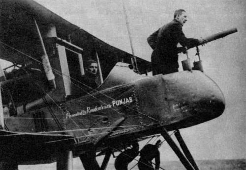
Early F.E.2d with two partially faired pillar mountings for a Lewis gun.
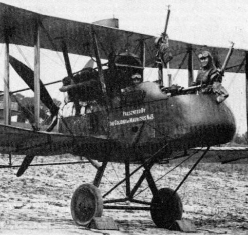
F.E.2d with two free Lewis guns and one fixed. Note also rails for bomb-carriers under wings.
R.E.5. Some of the earliest bombing raids of the 1914-18 War were made by aircraft of this type. On 30 September, 1914, an R.E.5 flown by Sqn Cdr A. M. Longmore bombed Courtrai railway station. Two or three improvised French bombs were thrown overboard by the observer. Flt Lieut Osmond. Later a load of three 20-lb Hales bombs was carried, and one R.E.5 was used to test the carrier and release gear for the 336-lb bomb developed at the Royal Aircraft Factory and associated particularly with the R.E.7 and Martinsyde 'Elephant'.
Pistols and rifles were carried as defensive armament.
Pistols and rifles were carried as defensive armament.
S.E.4a. On at least one single-seater of this type (built 1915) there were brackets for a gun, probably of Lewis type, well above the top wing on the centre line. The gun fired above the airscrew.
B.E.9. This much-modified development of the B E.2c was one of the more radical attempts to overcome the absence, in 1915, of a gear allowing a gun to be tired through the disc of a revolving airscrew. A gunner's compartment, generally resembling that of contemporary pushers, was built out in front of the airscrew, and this was officially declared to have as its object provision of a 'wide angle of fire'. Although 'The Pulpit' (as it could hardly fail to be called) went to France there is no record that a gun was actually installed.
F.E.8. It is sometimes contended that the F.E.8, which was first constructed in 1915 and remained operational until July 1917, was the last pusher fighter in British service, though that distinction appears more rightly to belong to the F.E.2d, which was serving with No.20 Squadron until the autumn of 1917. As with other pusher types, the object of the design was to obviate the use of deflector plates or synchronising gear. A single Lewis gun was initially installed low in the nose of the metal nacelle, with the barrel projecting through a circular hole. This arrangement permitted the gun to be trained over small arcs in conjunction with a sighting bar ahead of the windscreen, control being by means of a pistol grip. This position of the gun rendered difficult the clearing of stoppages and the changing of magazines, and on production aircraft the gun was raised to the level of the pilot's eyes. The form of pillar mounting has been described by Oliver Stewart as 'slightly different' from that of the D.H.2. As on the similar de Havilland fighter, the spare ammunition magazines were carried in 'panniers' at the sides of the cockpit. The magazines were four in number.
R.E.7. Official figures for 'military load plus crew' for three versions of this early 'heavy' bomber give an indication of its load-carrying ability. With the 160-hp Beardmore engine the figure was 520 lb, with the RAF 4a, 730 lb, and with the 250-hp Rolls-Royce, 802 lb. The bomb most generally associated with the type is the RAF 336-pounder, previously mentioned. This was carried with the nose distance-piece in a bracket fixed to the rear V-strut assembly of the undercarriage and with the rear of the characteristic central tube secured by an inverted pylon beneath the fuselage aft of the wings. Nevertheless, the 336-pounder does not appear to have been the heaviest bomb carried by the R.E.7, for a bomb of 500 lb has also been associated with the type, together with the periscopic bombsight developed at the Royal Aircraft Factory. Bombs of 112 lb and 20 lb are also known to have been carried.
As on the B.E.2c, the observer occupied the front cockpit, and the employment of pistol, rifle or Lewis gun must have been similarly inhibited; but there were remarkable developments in defensive armament. One of these was the addition of a third cockpit behind the pilot, this being provided with a Lewis gun on a Nieuport-type mounting. Another development was the forming of a gunner's station in the top wing above the front cockpit. Oliver Stewart, who personally flew the aircraft concerned for inspection by Gen Trenchard, mentions 'the front gunner standing up in the middle of the centre section with head and shoulders through a large hole'; and with a position of this kind a Scarff ring-mounting has been associated. This is said to have come adrift on one occasion and to have finished up in the pilot's cockpit. An installation of a Lewis gun on the fuselage ahead of the pilot has been positively identified, and mention has also been made of a synchronised Vickers gun.
The R.E.7 has yet a further interest in the context of armament, for aircraft of the type were among the earliest to tow aerial targets.
B.E.12. The earliest recorded armament tests with a B.E.12 involved the dropping of bombs and darts (Farnborough, September 1915). By March 1916 an experimental gun-mounting of indeterminate type had been installed, and in June of the same year one machine was tested with a Lewis gun and deflector plates on the airscrew. A fixed Lewis gun on the starboard side, firing through the disc swept by an airscrew having deflector plates, was to be numbered among standard installations, and Oliver Stewart records 'one or two Lewis guns mounted to clear the disc swept by the airscrew'. He comments: 'There were brackets alongside the pilot, and the guns fixed to these brackets were splayed outwards. Control of the guns was either directly by hand or by means of Bowden cables.' Not surprisingly, the complicated problems of deflection involved in the 'crab' method of attack necessitated gave poor results. In May 1916 the Central Flying School tested a B.E.12 having a fixed Vickers gun with Vickers synchronising gear, and this was to become another standard installation, together with a Lewis gun on a Strange mounting, as illustrated. Sometimes there were two Lewis guns on Strange mountings. A Lewis gun actuated by the Vickers gear is also on record. For Home Defence work the Vickers gun was fed with ordinary ball ammunition, with one round of Sparklet in five, whereas the Lewis gun fired explosive/incendiary ammunition. Some Home Defence B.E.12s had as many as four Lewis guns, and Le Prieur rockets were also fitted. Probably the most spectacular installation was that involving a six-pdr Davis recoilless gun. This gun fired upwards at 45 degrees; the muzzle was at the level of the upper wing, which was cut away accordingly as far as the front spar. For reloading the gun was lowered to the horizontal.
Bomb loads were one or two 112-lb or up to sixteen 20-lb.
B.E.12a. When used as a bomber (typically with one 112-lb bomb under the fuselage) this aircraft sometimes had a Lewis gun on a Strange mounting ahead of the cockpit. There was also an installation of a fixed Vickers gun.
B.E.12b. Although it could carry two 112-lb bombs under the lower inner wings, this single-seater was introduced in 1917 primarily for Home Defence. The armament for this duty was one or two Lewis guns, mounted over the centre-section and firing special ammunition above the airscrew arc. The Neame illuminated sight was fitted (on the starboard gun when a pair was mounted). Additionally there was a ring-and-bead sight, the two elements of which were attached to the starboard centre-section struts. The mounting for the gun(s) was one of the most elaborate of the war. Running between the rear centre-section struts was a cross-bar, and pivoted to this was a steel-tube assembly which constituted the mounting proper. A cable running over a pulley at the top of the front forward centre-section strut connected the mounting to a large lever attached outside the cockpit on the starboard side, somewhat reminiscent of the multipurpose lever in the Blackburn Blackburd. With the lever pulled to the rear the gun(s) were in a position to fire forwards above the airscrew; when the lever was moved forward the gun(s) were moved into a vertical position for reloading or upward firing.
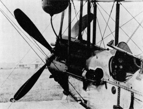
Vickers gun, with Vickers synchronising gear, on B.E.12. A Strange mounting for a Lewis gun is also seen. Note the chute for leading the webbing belt of the Vickers gun back into the fuselage.
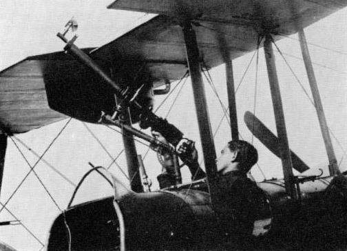
Lewis gin on Strange mounting between cockpits of B.E.2e.

Lewis gun on 'candlestick' mountong on B.E.2e.
F.E.4. The gun which was to form the primary armament of this very large three-seat fighter was a Coventry Ordnance Works product, but was of the newly introduced 1 1/2-pounder type, which continued in very restricted service with the RAF until the Second World War. This gun will be described in Volume 2. There is no indication that the gun was ever fitted, although two F.E.4s were built in 1916. The pilot sat at the front of a 'bathtub' cockpit in the fuselage nose, and, if the gun was to have been in a free installation, it is difficult to see how the gunner could have wielded it effectively. Aft of the wings was a second gun position, in this instance for a Lewis gun. On the second F.E.4 this position was deleted, but there was a gunner's station above the upper wing. This second aircraft had two Lewis guns on cranked pillar mountings at the sides of the forward gunner's cockpit. These mountings allowed the guns to be swung outboard for frontal fire.
R.E.8. The development of the pilot's fixed-gun installation on the R.E.8 two-seat reconnaissance aircraft, first flown in the summer of 1916, involved at the beginning a crude installation of deflector plates and towards the end the latest type of Constantinesco synchronising gear. As originally schemed early in 1916 there was provision for a Lewis gun inside the cockpit on the starboard side. This gun was sited low and considerably ahead of the pilot and was fired remotely by a lever on the top longeron. Five 47-round drums were specified. A Lewis gun for the pilot appears to have been actually installed on the first two R.E.s. though there is no evidence of deflector plates; but by October 1916 the first installation had been made of a Vickers gun with Vickers synchronising gear. This gun was at first internal, on the port side of the cockpit, firing through a triangular port, below which was a long casing for the actuating shaft from the engine. What it possessed in neatness, however, this installation lacked in accessibility, and the gun was quickly transferred to the outside of the fuselage. In the standard installation, the gun was carried on two triangular brackets. Constantinesco gear eventually succeeded the Vickers gear, the trigger motor being of the Type B. The loading handle was the Hyland Type C, and both a ring-and-bead and an Aldis sight were fitted, the latter being to starboard of the pilot's windscreen. By 1917 these sights had become standard in the British flying services, though late in 1916 a Le Prieur frame-type sight had been installed experimentally. This type of sight, of which more will be said in Volume 2, was considered complicated, clumsy and a source of danger to the pilot in the event of a crash, and was accordingly abandoned.
The installation of the rear Lewis gun likewise underwent considerable development. In the original design already mentioned, this was shown as being of extensible 'lazy tongs' form, allowing the gun to be fired forward over the top wing, and this is how it materialised on the first prototype. The basis of the mounting was a ring, and a ring-mounting of different form, incorporating a simple pillar, was fitted on early production R.Es. The Scarff ring-mounting was eventually standardised, and sometimes this carried twin Lewis guns. In one such installation the drums were of 'single' (47-round) type. A point to the credit of the R.E.8's designer(s), which may not previously have been made, is that, in order to secure the widest possible field of fire from the mounting, the fuselage in the immediate vicinity was contoured with extreme care and the rearmost portion was made very small in cross-section.
The bomb-carriers were attached to rails under the lower inner wings. Identified loads were two 112-lb, four 65-lb or eight 20-lb. The bombsight was of C.F.S.4B pattern. One bomb installation made by a squadron in the field has been described in these terms by one acquainted with it: 'For the R.E.8 we improvised a most effective device for bombing the enemy transport on roads. It consisted of a 48-compartment box with a chain and sprocket-operated sliding base, cut off at an angle. Each division of the box was loaded with a Hale's rifle grenade and, as the aircraft flew up the line of enemy traffic, the observer turned a bicycle crank to withdraw the base and release the grenades one by one.'
Better known than this installation was the fitting of a Davis recoilless gun on an R.E.8 of 'A' Flight, No.30 Squadron. The gun was fixed to the starboard side of the fuselage, firing forward and downward at 45 degrees, and was reloaded by the observer gunner, whose Scarff ring-mounting retained its Lewis gun. The forward muzzle of the Davis gun was roughly on the level of the undercarriage axle; the rear muzzle was above and behind the rear cockpit. The installation was considered successful, although the gun could not be sighted accurately.
R.E.9. This R.E.8 development was apparently intended to be armed as the standard version of the earlier aircraft.
S.E.5. The weight of armament (100-107 lb) carried by the standard S.E.5 and 5a single-seaters, which fought with such telling effect in harness with the Camel, approximated closely to that carried by the Sopwith fighter, but in type of armament, as in other basic respects, the Royal Aircraft Factory product differed widely.
From the beginning the S.E.5 design was associated with the Lewis gun. As will be explained in Volume 2, the idea of a fixed gun firing through the hollow airscrew shaft of an engine was an early British idea, though not, it appears, as early as Louis Bleriot's scheme for such an installation in 1911. This same arrangement was adopted in the summer of 1916 for a proposed tractor single-seat fighter designated S.E.5, an alternative design to another, designated F.E.10, which perpetuated the B.E.9 theme, but which was mercifully abandoned in favour of the S.E.5. The Lewis gun in the early S.E.5 design was to fire between the cylinder banks of the Hispano-Suiza engine and through the hollow airscrew shaft. The 47-round magazine was envisaged. This scheme was abandoned, and by December 1916 the second S.E.5 was fitted with a basic armament which set the standard pattern, namely a Lewis gun on a Foster mounting above the centre-section and a synchronised Vickers gun semi-internally to port. There is good reason for supposing that the large 'greenhouse' windshield associated with the earliest S.E.5s was adopted to facilitate the changing of ammunition drums, for the lower end of the quadrant which constituted the rear member of the Foster mounting, and down which the gun was swung for reloading or upward firing, was anchored to the top of the canopy; thus, with the gun at its lowest position, the drum was largely shielded from the slipstream. Certainly the changing of 97-round drums in later S.Es, which had ordinary windscreens, could be a difficult business, almost, on occasions, breaking a pilot's wrist. The large windshield was perforated to starboard to receive the eyepiece of the Aldis sight, the rear clamp for which was attached to the windshield framework, and the front one to a substantial pylon on the fuselage decking. The Vickers gun, which had a Type A trigger motor for the Constantinesco gear, was recessed into the main petrol tank. There was an ejection chute in the port upper cowling. When a plain windscreen was fitted it became necessary to modify the fuselage decking to enclose the breech casing of the gun.
Capt Albert Ball, whose ideas may well have influenced the adoption of the Lewis gun and Foster mounting for the S.E.5, quickly discarded the Vickers gun on his aircraft, but mounted instead a second Lewis gun, firing downwards through the bottom of the fuselage. Later this gun was discarded in turn, and the Vickers gun was reinstated, though it was now wholly external, presumably because the earlier gun-trough had been replaced by increased petrol capacity. On Ball's aircraft the lower end of the Foster mounting was braced by two wires, but a tubular structure was standardised. So that the lines of fire of the two guns could converge at a range of 50 yards, the Foster mounting was slightly raised at its rear end.
S.E.5a and b The S.E.5a had the 200-hp Hispano-Suiza engine, and the larger airscrew needed to absorb this greater power caused the Foster mounting to be raised very noticeably above the wing on two supports, over the front and rear spars. For the Lewis gun on this mounting, one ammunition drum was carried on the gun and three in the cockpit. For the Vickers gun, which, on late aircraft at least, had the Type B trigger motor on top of the gun and the Hyland Type E loading handle, there were 400 rounds. Both guns were aligned 5 degrees up from the line of flight. Fitzgerald jam-clearers have been mentioned in connection with the S.E.5a. Both Aldis and ring-and-bead sights were fitted, and provision was made under the fuselage for a four 20-lb bomb-carrier. Two 20-lb bombs are known to have been carried loose in the cockpit. Early troubles were experienced with the Constantinesco gear, but the S.E.5a proved an exemplary gun platform. Fire could thus be opened at relatively long range, and there is a reference to the guns being set for their lines of fire to converge at 200 yards. A distinctive feature of the S.E.5a was the gear wheel and the associated 'box' type generator for the Constantinesco gear, visible beneath and behind the airscrew hub.
No.41 Squadron is said to have attempted to install twin Vickers guns, and one machine had twin Lewis guns. There was, too, an experimental installation of the Eeman triple-gun mounting, wherein the three Lewis guns fired forwards and upwards through apertures in the centre-section. A report that an installation of a rearward-firing Vickers gun was made in 1917 cannot be corroborated. At least one night-flying example had a greatly lengthened pistol grip on the Lewis gun.
The S.E.5b appears to have been armed as the standard S.E.5a.
The nearest line of S.E.5as in production display a cut-out in the forward bulkhead for the Vickers gun. In the second line the Vickers gun is already installed, at least in the aircraft the Service number of which is largely visible. In the third line the Foster mounting is in place. Note access panel for Vickers gun, with built-in ejection chute, on two aircraft at top right.
F.E.9. Provision of a wide field of fire was evidently the governing consideration in the designing of the F.E.9 in the summer of 1916, for not only was this two-seater of pusher layout, but the nacelle was positioned only slightly below the top wing. Following earlier F.E. practice, Lewis guns were provided for frontal and rearward fire. The guns, one in the nose of the nacelle and one behind the gunner's cockpit, were on pillar mountings.
N.E.1. The N.E.1 was first constructed late in 1917 as a specialised night fighter. It had a counterpart in the Vickers F.B.25 and was developed from a design bearing the designation F.E. 12. In this design the pilot was in the front cockpit and was provided with a Lewis gun. The primary armament, however, was a Vickers rocket gun, manned by a gunner at the rear. For this gun two mountings were provided, one for frontal fire and one for firing rearwards above the top wing. Provision was made for two searchlights, one in the nose of the nacelle and one on the forward mounting for the rocket gun.
As first flown in 1917 the N.E.1 had no searchlight on the forward rocket-gun mounting, and later the light in the nose was discarded. This enabled the gunner to be brought forward to the front cockpit, where he was afforded a wider field of fire. The rocket gun was on a bipod mounting at the front tip of the cockpit, and on the starboard side of the fuselage was a fixed Lewis gun. Provision may also have been made, or intended, for a pillar-mounted Lewis gun for rearward fire.
Early in 1918 one N.E.1 was used for bombing experiments.
Royal Aircraft Factory
A.E.3 (Ram). Among the unusual features of this two-seat armoured ground-attack aircraft of 1918 was the use (or evident intended use) of a tubular optical sight in conjunction with the primary armament of two Lewis guns. This installation was probably devised at Farnborough, although, as will be noted in Volume 2, A. C. W. Aldis designed a gun mounting with which an Aldis sight was used. The guns were yoked together in the extreme nose of the nacelle and the sight was mounted between and above them. Vertical downward fire was possible, though field of fire was limited, and the provision of thirty-two double drums of ammunition was specified. These would be shared by a third Lewis gun on a pillar mounting, for rearward fire above the top wing. The pillar was apparently capable of transverse movement, as on the first Sopwith Buffalo.
The armoured nacelle of the A.E.3 was of structural type, as were the forward fuselage sections of the Sopwith Salamander and Buffalo. The floor and front were of double thickness (10-gauge outer, 5-gauge inner).
C.E.1. Two 230-lb anti-submarine bombs could be carried by this single-engined pusher flying-boat. There were three pillar-type mountings for Lewis guns, one in the front cockpit and two between the cockpits, one on each side of the hull.
Robey
Robey-Peters Gun Carrier. In June 1916 J. A. Peters, who designed this large three-seat three-bay tractor biplane as a Zeppelin fighter, drew up a scheme for mounting gun (or engine) nacelles under the top wing of an aeroplane. It was slated that the gun mountings were placed above the nacelles 'on the top plane, which is cut away to facilitate operation of the guns'. On the aircraft as built, the nacelles were carried close inboard on two pairs of upright V struts. There were, in fact, two cut-outs in the upper surface of the wing above each nacelle, the rear ones, apparently, for the gunners, and the forward pair for the mountings to take two Davis recoilless guns. The pilot sat far aft in the mid-mounted fuselage.
Robey-Peters Gun Carrier. In June 1916 J. A. Peters, who designed this large three-seat three-bay tractor biplane as a Zeppelin fighter, drew up a scheme for mounting gun (or engine) nacelles under the top wing of an aeroplane. It was slated that the gun mountings were placed above the nacelles 'on the top plane, which is cut away to facilitate operation of the guns'. On the aircraft as built, the nacelles were carried close inboard on two pairs of upright V struts. There were, in fact, two cut-outs in the upper surface of the wing above each nacelle, the rear ones, apparently, for the gunners, and the forward pair for the mountings to take two Davis recoilless guns. The pilot sat far aft in the mid-mounted fuselage.
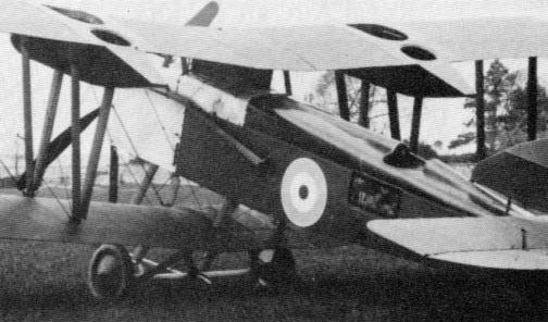
Solution to the problem of attaining a wide field of fire: Robey-Peters Gun Carrier with emplacements on top wings.
Sage
The uncompleted Sage Type I of 1916 was a twin-engined bomber with nose, upper and floor guns.
The uncompleted Sage Type I of 1916 was a twin-engined bomber with nose, upper and floor guns.
Sage
Type 2. The uncompleted Sage Type I of 1916 was a twin-engined bomber with nose, upper and floor guns; the Type 2 of the same year was a two-seat single-engined fighter, the design of which represented one of many attempts to surmount the difficulties which persisted until gun synchronizing gears became available. They were, in fact, already becoming available as the aircraft was constructed. The layout adopted resembled one that had been schemed by the Short company, the gunner standing largely in a faired superstructure between the fuselage and top wing, the upper surface of which was cut away to permit the use of a Lewis gun. The pilot, who was unarmed, sat, wholly enclosed, at the forward end of the superstructure.
Type 2. The uncompleted Sage Type I of 1916 was a twin-engined bomber with nose, upper and floor guns; the Type 2 of the same year was a two-seat single-engined fighter, the design of which represented one of many attempts to surmount the difficulties which persisted until gun synchronizing gears became available. They were, in fact, already becoming available as the aircraft was constructed. The layout adopted resembled one that had been schemed by the Short company, the gunner standing largely in a faired superstructure between the fuselage and top wing, the upper surface of which was cut away to permit the use of a Lewis gun. The pilot, who was unarmed, sat, wholly enclosed, at the forward end of the superstructure.
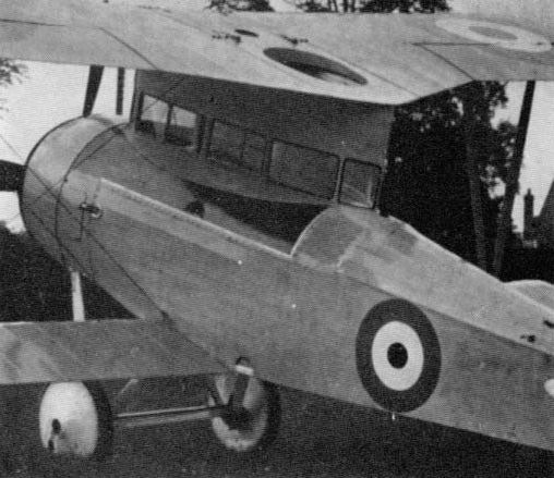
Solution to the problem of attaining a wide field of fire: Sage Type 2, in which the gunner stood to wield his gun through a hole.
Type 3. A carrier for four 20-lb bombs appears to have been fitted beneath the fuselage of this 1917 trainer, though the makers quoted the military load as 64 lb. It may be conjectured that anti-submarine operation with a 65-lb bomb was envisaged.
Type 4. There were three versions of this successor to the Type 3, the first of which was a patrol seaplane. No armament appears to have been installed.
Saunders
T.1. No photograph exists of this two-seater of 1917, but a makers' sketch suggests a fixed Lewis gun for the pilot, mounted above the decking, and a rear Lewis gun on a pillar mounting.
T.1. No photograph exists of this two-seater of 1917, but a makers' sketch suggests a fixed Lewis gun for the pilot, mounted above the decking, and a rear Lewis gun on a pillar mounting.
Short
S.38. A pioneer installation of a Maxim gun, probably of 0.45-in calibre, was made in 1913 on a Short pusher biplane of this type (No.66). This was dubbed 'Eastchurch Gun Machine' and was used for armament trials. The gun was mounted on a pillar in the nose of the nacelle. In wartime, rifles were carried aboard aircraft of the same type. No.34 was associated with early armament trials.
S.38. A pioneer installation of a Maxim gun, probably of 0.45-in calibre, was made in 1913 on a Short pusher biplane of this type (No.66). This was dubbed 'Eastchurch Gun Machine' and was used for armament trials. The gun was mounted on a pillar in the nose of the nacelle. In wartime, rifles were carried aboard aircraft of the same type. No.34 was associated with early armament trials.
A fact of the greatest interest in the present context, and one which seems to have eluded historians hitherto, is that the famous S.41 was fitted with a machine-gun and was the first British naval aircraft to be so armed. Thus, Shorts may claim yet a fourth type of pioneering armament development aircraft. In 1930 Cdr Sampson declared:
'It was in 1912 that we made our first seaplane, known first as Hydro-aeroplane H 1 and later as Short No.10.... She was an historic machine. I used her from March 1912 till the war came and never broke a piece of wood in her. I flew her in the Army manoeuvres of 1912 took her to Scotland by train for submarine experiments at Scapa Flow, used her for similar work at Harwich, and made the seaplane duration flight with her from Sheerness to Portsmouth. She was the first machine to which folding wings were fitted and the first from which a machine gun was fired'.
Samson added that the gun was a 0.45-in Maxim.
S.81 Gun-carrier. A pusher seaplane of this description (No. 126) was built in 1914 with a specially stressed nacelle for the mounting and firing of a 1 1/2-pounder Vickers gun. This development was preceded by the mounting of the gun on the Sopwith pusher seaplane No.127. It was reported in 1914 that 'excellent practice has been done in firing at targets both in the air and on the sea'. During March 1915, a 6-pounder Davis recoilless gun was tested in the same machine.
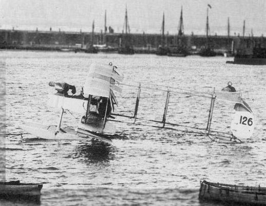
The original caption affixed to this news-agency photograph reads: 'WAR SCENES. ENGLAND MAKES READY HER AERIAL FLEET. Seaplane No. 126 all ready in Ramsgate Harbour to go off at a moment's notice, she has one of the latest machine guns fitted and only awaits the order to go.' Clearly, however, the weapon is the 1 1/2-pounder Vickers gun, inherited by Short S.81 No.126 from Sopwith No. 127.
Short Tractor Seaplanes. 'A certain 160 hp Short seaplane', identified by C. H. Barnes in Shorts Aircraft since 1900 (Putnam, 1967) as No.121, was a third type of Short aircraft to play a pioneering part in the development of aircraft armament, for it was this machine that was earmarked by Sir Arthur Longmore for the earliest British torpedo-dropping trials. These were made at Calshot in July 1914 with a 14-in torpedo. Although crutches are said to have been attached to each of two specially arched cross-bars, hastily designed by Horace Short, early drawings, which it is intended to reproduce in Volume 2, show a seaplane of Short type having cross-bracing of X form, the torpedo being carried at the apex of the lower inverted V. The release mechanism was designed by Lieut D. Hyde-Thomson, who also adapted the torpedo.
Four other Short seaplanes of the type used in the Calshot experiments are said to have been arranged for torpedo-dropping at a later date, and aircraft having the Service numbers 178 and 186 have been associated with torpedo installations, the latter being listed as 'Type B'. This designation is of particular interest having regard to the Sopwith torpedo seaplane known as the 'Type C'.
On the Short tractor seaplanes, bombs were carried loose or on carriers. One identified load was one 100-lb bomb and four of 20 lb.
The seaplanes Types 166, 827 and 830 and that which had had the 140-hp Salmson engine all carried bombs under the fuselage. The first Westland-built 166s had arched cross-bracing struts between the floats to enable them to carry a 14-in torpedo, but all later examples had a standardized installation of three 112-lb bombs. These same aircraft could have a Lewis gun in the rear cockpit, provided with six 47-round drums.
The seaplanes Types 166, 827 and 830 and that which had had the 140-hp Salmson engine all carried bombs under the fuselage. The first Westland-built 166s had arched cross-bracing struts between the floats to enable them to carry a 14-in torpedo, but all later examples had a standardized installation of three 112-lb bombs. These same aircraft could have a Lewis gun in the rear cockpit, provided with six 47-round drums. A Lewis gun on a centre-section mounting was carried by at least one Type 830, and a similar installation appears to have been made on the 140-hp Salmson type.
Bomber. Whereas it was usual for the Short seaplanes of 1915 onwards to carry their bombs on a succession of tubular carriers under the fuselage, a feature which heightened their already distinctive appearance, the type of landplane bomber developed from them in 1916 had instead under-wing carriers. In order to save weight, Short Bros developed carriers of their own design, the bombs being suspended horizontally by their nose rings, but the official Government pattern appears to have been standardized eventually. The carrier attachments were braced by cables to upper-wing strut attachments. Eight bombs of 65 lb or 112 lb, in tandem pairs under each wing were typical loads, and sometimes small bombs, e.g. live incendiaries, were carried internally; but four 230-lb bombs could be taken, and in preparation for the great raid on Zeebrugge, which materialised on St George's Day 1917, 520-lb bombs were delivered by aircraft of this type. On the first aircraft, a Lewis gun on the top wing could be manned by the observer standing exposed to the slipstream on the decking of the fuselage between the cockpits. Later machines had a Scarff ring-mounting or, it appears, a mounting of a type incorporating wheels running on rollers and associated with the name of W. K. Boyne. The Phoenix-built aircraft were slated by the makers to have had 'bullet-proof tanks', but armour-protection for the tanks was probably specified, as for the original Handley Page O/100.
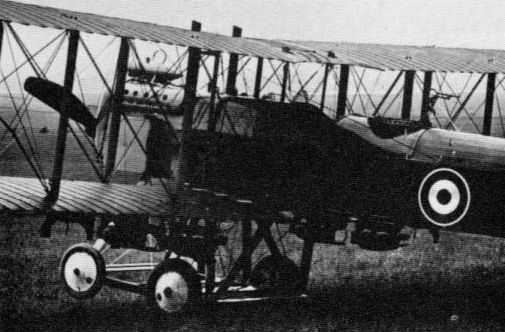
Short Bomber with four 112-lb bombs on carriers devised by the makers themselves. The ring-mounting for the Lewis gun is not of Scarff type, though a Scarff compensating sight may be fitted.
Type 184. This type - the 'Short 225', by reason of its original horsepower - was designed in 1914 specifically for operation with a 14-in torpedo, with which it achieved an early, spectacular and variously chronicled success in the Dardanelles campaign of 1915 (Flt Cdr C. H. K. Edmonds and Flt Lieut G. B. Dacre). Aircraft of the type were also employed in pioneering experiments with heavy bombs and operated with various forms of bomb installations and gun mountings.
The first examples had arched cross-bracing tubes to accommodate a torpedo, as on the early Type 166s. The release-strop was at the centre of the rear tube. One experimental Type 184 had the rear cockpit faired over, and standard RAF torpedo aircraft were to be single-seaters until the adoption of the Blackburn Ripon and Hawker Horsley.
In the early phases of the war at least, bombs were sometimes carried loose, for example, one of 16 lb plus six petrol bombs plus one incendiary bomb in addition to two bombs of 65 lb on carriers. A number of 16-lb bombs were in one instance carried loose in addition to three of 65 lb on carriers. Experiments were made with an installation of four 65-lb bombs under the wings, in line with the inner pair of interplane struts, but the carriers were normally installed in tandem on a long bomb-beam slung well below the fuselage. Identified loads include the following: four 65-lb, 100-lb or 112-lb; three 100-lb + one 112-lb; two 230-lb + one 100-lb; one 500-lb or 520-lb; and - aimed at the German cruiser Goeben when a Type 184 had failed to leave the water with a complete torpedo - an 18-in torpedo warhead. In May 1916 a 500-lb bomb was dropped experimentally at Kingsnorth, being aimed with a C.F.S. sight, and there appears to have been some intention of carrying such a bomb internally. In the Type D single-seat bomber variant, nine 65-lb bombs were slung nose-up internally, forward of the cockpit.
Mountings for a Lewis gun were improvised, but a Scarff ring-mounting was eventually standardised. A number of aircraft had a Whitehouse mounting. As in the usual installation of the Scarff mounting this was set considerably below the top line of the fuselage. It appears that the gun-arm was associated with a semi-circular bow, and, although the precise characteristics of the mounting are not known, they were apparently such that a recommendation was made that aircraft having this type of mounting should have a sliding panel in the floor to permit downward fire under the tail float. From one machine, in April 1916, tests were made with a 2-pdr Davis gun fitted with a Hamilton sight.
Type 320. On this seaplane of 1916 the placing of the massive radiator immediately ahead of the pilot's windscreen, coupled with the presence of a float-bracing cross-tie directly beneath the torpedo-carrier, might have appeared to render the aircraft wholly useless for its intended purpose of dropping an 18-in Mk.IX torpedo. But although the radiator was immovable, and the pilot was committed to making the most of his field of view on either side, the cross-tie between the floats was removable. Before an intended raid by Short 320s on Durazzo harbour, the aircraft were towed out into the Adriatic by Naval launches, and volunteers from the launches swam out to the seaplanes and unbolted the ties. On occasions when the tie was to be removed, the floats were fitted with extra struts, which braced their inner faces.
Although as torpedo-carriers these aircraft achieved no operational success, as had the Type 184, they were used for valuable trials at Calshot early in 1918.
Mostly the Short 320s were used for patrol and bombing, without provision for the torpedo but carrying bombs and a Lewis gun. The bombs were carried in the customary Short fashion under the fuselage, typical loads being two 230-lb or four 112-lb. A standard installation of a Lewis gun was made. This look the form of a Scarff ring-mounting located behind a cut-out in the top wing, the base of the ring being braced to the fuselage by two struts. The observer gunner was in the front seat, and to use the Lewis gun he stood up in his cockpit, being thus exposed to the slipstream.
310-hp Seaplane, Type B. This was the designation applied to the 'North Sea Scout' type of Short seaplane, produced in 1916 as a 'Zeppelin fighter' to carry a 6-pdr Davis recoilless gun, in addition to a Lew is gun for its own defence. The big gun was shackled to a member across the rear cockpit, and fired upward and forward. Accordingly, the centre-section of the top wing was left open, and the radiator was made in two blocks instead of one. The Lewis gun mounting was apparently developed at Grain, where the aircraft was tested.
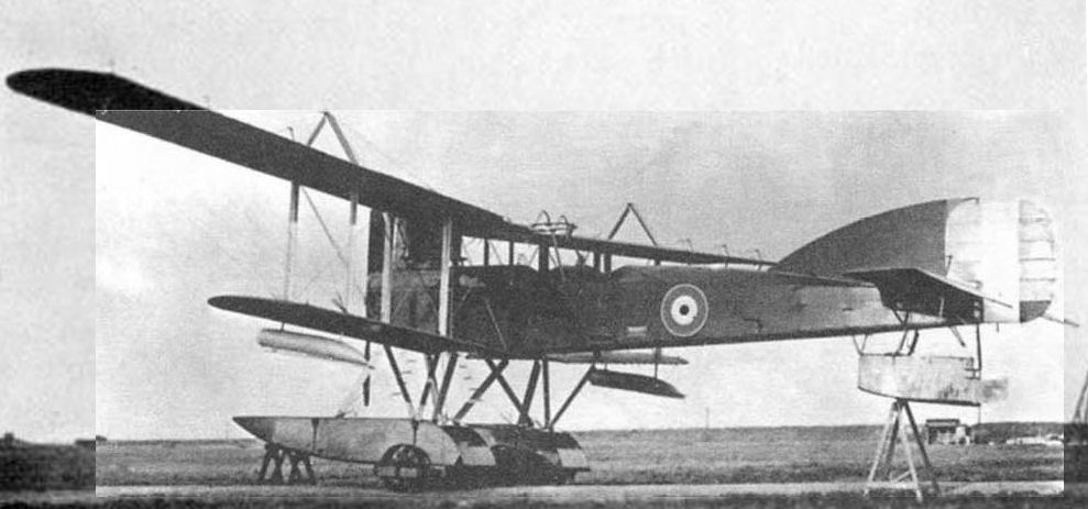
На берегу гидросамолеты перемещали на колесных тележках, крепившихся на тросах под задней частью поплавков, т.е. у центра тяжести самолета, благодаря чему удерживать хвост руками над землей было достаточно легко
Short Type 320, showing installation of Scarff ring-mounting behind cut-out in top wing.
Short Type 320, showing installation of Scarff ring-mounting behind cut-out in top wing.
N.2B. A two-seater patrol seaplane of 1917, this type carried two 230-lb bombs (or equivalent) side by side under the fuselage. The pilot had no gun, but there was a Lewis gun on a Scarff ring for the observer. An earlier experimental machine of this general type carried two 65-lb bombs.
Shirl. Like its counterpart the Blackburn Blackburd, the Shirl (1918) was a single-seat torpedo-carrier, designed specifically to operate with the 18-in Mk.VIII torpedo. Each of the two crutches was stayed by two inverted V-struts.
R.T.1. This two-seat reconnaissance machine of 1917 had one Lewis gun on a Scarff ring-mounting, the level of which was raised during development by building up the coaming of the fuselage. There was a second Lewis gun for the pilot, over the centre-section to starboard, firing above the airscrew at a slight upward angle.
Sopwith
Bat Boat. The first flying-boat of this type was bought by the Admiralty in 1913 and was used for armament experiments with which the names of Lieut A. W. Bigsworth and Sub-Lieut J. L. Travers are particularly associated. The dropping of darts and practice bombs was preceded by the discharge of potatoes. Naval ratings observed the fall of shot. Data on bomb aiming were thus accumulated.
Pusher Seaplane Gun-carrier No. 127. The identity and significance of this historic aircraft is apparently now established for the first time, the significance being that it was armed with the 1 1/2-pdr Vickers gun before that weapon was transferred to Short S.81 No. 126. First, there is the testimony of Sir Arthur Longmore that 'one of our Sopwith pusher seaplanes' (at Calshot before the 1914 war) carried a 1 1/2-pdr gun weighing 265 lb, with which Lieut R. H. Clark-Hall conducted many successful tests. Second, it was stated on the occasion of the Naval Review in July 1914 that a 'Sopwith Gun Carrier' with 200-hp Salmson (Canton-Unne) engine was unable to fly because of tail alterations. On this same occasion the Short S.81 No. 126 was present carrying a 1 1/2-pdr gun and it was remarked:
'The gun on the Short is the biggest weapon yet used in aircraft. It was first used on the Sopwith, and later was used to test the Short's ability to stand the recoil.'
Aircraft No.127 is on record as being a Sopwith with 200-hp Canton-Unne engine, and it may be supposed that this and the Short machine were ordered as a pair for trials with heavy guns. That No.127 was of the well-known Greek Gun Bus type (see below) is certainly open to question, having regard to the fact that this was a much smaller machine than the Short No. 126, the respective wing spans being 50 ft and 67 ft; and there can be little doubt that No. 127 was the Hydro Biplane Type S of 80 ft span, already associated by J. M. Bruce with a quick-firing gun. Thus No. 127 must take its place in history, not only on account of its big gun, but as the largest British aeroplane of its time.
One Sopwith seaplane with 120-hp Austro-Daimler engine has also been recorded as having a gun. This was probably No.93.
Tabloid. On 28 December, 1914, the following letter was received by the Sopwith Company from the Director of the Admiralty Air Department:
'Gentlemen, With reference to the recent attack on the German air[ship] sheds at Cologne and Dusseldorf, carried out by Sqn Cdr Spenser D. A. Grey and Fl Lieut R. L. G. Marix, you may be interested to learn that the machines used were your Sopwith Tabloid aeroplanes.'
The bombs employed in this famous raid, in which Marix destroyed Z.IX and Spenser Grey had to transfer his attack to Cologne station, were of the 20-lb Hales pattern.
The Tabloid first appeared in 1913. As early as February 1915, Tabloids of Cdr Sampson's squadron were lined with a mounting for a Lewis gun above the lop wing. This mounting was devised by Lieut T. Warner and Warrant Officer J. G. Brownridge. Other installations were made on the side of the fuselage. More primitive weapons, apart from pistols and perhaps rifles, included steel darts (as carried by Lieut N. C. Spratt when he forced an enemy aircraft to land after manoeuvring in 'an aggressive manner'), a grapnel and hand grenades. On one occasion an attempt was made by Lieut Spratt to tie a grenade to a length of control cable with the intention of fouling the enemy's airscrew. This device was never used.
Two-seater Scout. This derivative of the 'Daily Mail', or 'Circuit of Britain' type tractor two-seater (1914), was in one instance equipped for anti-Zeppelin work with a Lee-Enfield rifle firing Hales grenades and in another with a Mauser rifle firing German incendiary ammunition. A shotgun firing chain shot and a Very pistol have also been associated with the type. On specimens with lengthened undercarriage a bomb-carrier was attached beneath the fuselage immediately behind the undercarriage.
Type 807. Early in 1915 two tractor seaplanes of this type were sent to German East Africa for operations against the German cruiser Konigsberg. One was loaded with two 50-lb and four 16-lb bombs, but was unable to lift them.
Gordon Bennett Racer. Almost identical with the Tabloid, one of two machines of this type was fitted in 1915 with a fixed, stripped Lewis gun on the starboard side of the fuselage. The airscrew was provided with plates to deflect the bullets. A minute written by Winston Churchill in April 1915, calling for a single-seat Naval aircraft 'with a Lewis gun firing through the deflector propeller', may be mentioned in this context.
Gun Bus. A photograph overleaf shows the installation of a Lewis gun on one of three pusher landplanes, of a type first constructed in 1913, in RNAS service. It will be seen that the nose of the nacelle is of such a form as to allow the gunner a certain angle of downward fire. The gun, of land-service pattern, is secured to a cranked pillar by a V-shaped attachment on the cooling jacket, and a collector box is tilted to catch the spent cartridge cases. With narrow-track two-wheel undercarriage, machines of this same type were fitted to carry four bombs under the lower wings, two on each side just outboard of the second pair of interplane struts.
Schneider and Baby. The original Sopwith Schneider racing seaplane was built in 1913, and developed versions for the RNAS were in service during 1915. At least two different installations of a Lewis gun were made. The first entailed the fitting of deflector plates on the airscrew, and the second the attachment of the gun on the centre-section at an angle sufficient for the bullets to clear the airscrew disc. The rear end projected through an aperture. This second installation was for anti-airship work, and for the same purpose H.E. and incendiary bombs could be carried. One identified load was four 20-lb H.E. bombs and an incendiary bomb. The armament later standardised for the Baby was a Lewis gun. with mechanical synchronizing gear on the fuselage centre line and projecting backwards through the windscreen, or alternatively offset to starboard. For antisubmarine work there was provision for two 65-lb bombs (the Schneider carried one) in tandem under the fuselage. The gun and ammunition weighed 55 lb and only one bomb could be carried in addition. There were instances of a Lewis gun mounted on the starboard side of the fuselage and of the gun attached to the port centre-section struts, turned on its side, and firing upwards at about 45 degrees to the line of flight. In at least one instance Le Prieur rockets were attached to the interplane struts, and one batch of Blackburn-built Babies initially carried Ranken Darts to the exclusion of other armament. A photograph shows one of these aircraft later armed with a Lewis gun and having also a carrier for, apparently, four 20-lb bombs.
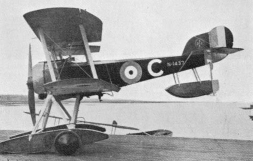
Sopwith Baby with synchronised Lewis gun and bomb-carriers.
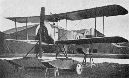
Sopwith Baby with Lewis gun through centre-section.
Type C. The first British-built aeroplane designed specifically for torpedo-dropping, the Type C tractor seaplane, was built in 1914. It arrived at Calshot shortly after Sir Arthur Longmore (then Squadron Commander) had made his first torpedo-drop from a Short, and he and his pilots made drops from the new Sopwith product. It was a four-bay biplane of very large span, with overhang, and it may be wondered if the wing cellule was similar to that of No. 127. As on the A.D. 1000 the two floats were quite independent, in order to allow the torpedo to be dropped. Each float was strut-braced to the lower longerons and to the attachment points of the inner interplane struts. This arrangement probably represented the first major influence of armament on aircraft design.
Type 860. Like its contemporary, the Short Type 184, this tractor seaplane of 1915 was designed to carry a 14-in torpedo. The crutches were attached to the two cross-ties joining the floats. There was a cut-out in the top centre-section, but whether this was associated with a gun mounting has not been established.
1 1/2 Strutter. Although justly remembered as the archetype of the classic two-seat fighter (pilot with fixed gun, gunner with free gun), this biplane of 1915/16 was also constructed as a specialised bomber and as a 'ship's aeroplane'. In all three forms the armament differed. While the fighter and bomber had a fixed Vickers gun, the third variant did not. The prototype and some production aircraft were flown without armament, the reason in part being a shortage of Vickers guns. While at least one early specimen had the gun mounted on the port upper longeron, with the breech casing lying under the built-up coaming of the cockpit, on all standard production fighters and bombers thereafter the gun was mounted on the centre line of the fuselage immediately ahead of the pilot, with the firing lever projecting from the gun above the control column. The Sopwith patented padded windscreen was fitted, and plain open or ring-and-bead sights were mounted on the gun. The ammunition was fed from the right, and a metal plate on the left, forward of the feed block, served to prevent the canvas belt from twisting in the slipstream before entering the protection of the fuselage. On some early examples the rear of the gun was partly faired. The first machines for the RFC (A and B Flights of No.70 Squadron) had gun-synchronising gear of the Vickers type, but C Flight of the same unit had aircraft intended for the RNAS and fitted with the Scarff-Dibovsky gear developed for, and standardised by, that Service. Gears of the Ross and Sopwith-Kauper types were also fitted. The advantages of the Vickers gun, with its continuous belt feed, over the drum-fed Lewis, which demanded the breaking-off of an engagement for the changing of drums, was quickly apparent.
That the Scarff No.2 ring-mounting for the Lew is gun was developed with the assistance of the Sopwith company is not generally known, and it is with this most famous of all aircraft gun mountings that the 1 1/2 Strutter is most intimately associated. Early examples, however, had either a Strange cranked pillar mounting or a ring-mounting of the French Nieuport type. The Scarff No.2 mounting was first introduced in the ex-RNAS aircraft of C Flight. No.70 Squadron, already mentioned in connection with the Scarff-Dibovsky gear. It was mourned directly on the top longerons, and thus below the fuselage top line, and its diameter was slightly greater than the fuselage width. Standard ammunition provision on the 1 1/2 Strutter two-seater was 300 rounds in a fabric belt for the Vickers gun and five double drums for the Lewis gun. On one aircraft of B Flight, No.70 Squadron, an auxiliary armament of an automatic pistol with oversize magazine was attached to the starboard undercarriage struts to fire outside the airscrew arc. On certain Home Defence aircraft, the Vickers gun was dismounted, the front cockpit was faired over, the pilot was moved to the rear and a Lewis gun was mounted over the top wing to fire above the airscrew and obviate the risk of using 'special' ammunition in the synchronized gun. One aircraft had two upward-firing Lewis guns mounted forward of the cockpit in a special installation, and another carried the same armament on a twin mounting of Foster type.
Apart from its Scarff ring-mounting and Sopwith padded screen, the 1 1/2 Strutter was notable also for its tailplane incidence-adjusting gear, a primary purpose of which was to compensate for gunners of different weights. For this aeroplane, also, Sopwith developed a special gunners seat, capable of all-round movement about an eccentric pivot on a fixed stand. Means were provided for automatically locking the seat to the stand when the seat was occupied and for unlocking the seat when it was relieved of the gunner's weight. A wooden frame carried a vertical pivot having a toothed ring which was pressed, by the weight of the gunner acting against a spring, into engagement with a toothed ring carried by a fixed socket supported by legs. The engagement between the teeth served to fix the seat in the desired position, but disengagement automatically took place under the action of the spring when the gunner raised himself, and the seat could then be freely rotated in the socket.
No fighting aeroplane ever introduced as many novel armament features as this Sopwith two-seater.
Bomb rails were sometimes fitted beneath the lower wings and/or fuselage of 1 1/2 Strutter two-seaters, and possible loads were four or eight 20-lb or two 65-lb. The potential of these aircraft as long-range bombers was quickly recognised by the RNAS; indeed the 1 1/2 Strutter had been originally designed for bombing and has a place in history as one of the first truly 'strategic' bombers. A specialised single-seat bomber type was developed, and this carried its bombs internally in a compartment which took the place of the gunner's cockpit. Official rigging notes indicate that the rear flying wires on bombers were shorter than on fighters. The standard load was four 50-lb or 65-lb bombs, horizontally stowed. The four trapdoors beneath the bomb compartment were opened by the weight of the falling bombs and were closed again by shock-absorber cord. Two small inspection and access panels were let in to each side of the bomb compartment. On the single-seat bomber, 500 rounds were provided for the Vickers gun. Occasionally a Lewis gun was fixed to fire over the top wing of bombers as auxiliary armament, but the drum for this could not be changed in flight. The 'Sopwith Bomber (Clerget)' was declared obsolete in an Air Ministry Order of 1921.
Camel F.1. The essential qualities of the Camel F.1, first constructed in 1917, were heavy firepower and compactness. These qualities are epitomized in one of the 'Points to Observe when Overhauling Machine' covered in the Technical Notes relating to the type. To quote:
'Examine cartridge drums and see that they are secure and do not foul the carburetter.'
The Camel got its hump and its name from the building up of the coaming round the breech casings of the two Vickers guns ahead of the cockpit. Allied with the qualities already named was a high performance, and it may be noted in this regard that certain of the early Camel prototypes and some production aircraft were the only known British fighters to have the front ends of their Vickers guns fitted with fairings.
On the first Camel, the top line of the 'hump' sloped upwards to meet the high-set front rim of the cockpit, but, possibly in the interests of pilot view, the rim was lowered and the top of the hump was flattened, leaving the upper surfaces of the breech casings exposed. On production aircraft, the forward coaming of the cockpit was sometimes cut away to clear these casings and the windscreen was shaped to fit the barrel jackets. At first the spent cartridge cases and links from both guns fell clear of the aircraft through a projecting chute well down on the starboard side of the cowling, and Norman Macmillan has described how 'spent cases mostly fell on the lower wing, but their drumming on the fabric was deadened by the chatter of the guns' firing'. Later, however, case and link chutes appeared on the port side also. In the standard installation, the link chutes were high in the fuselage sides, in line with the feed blocks of the guns, and the case chutes were much lower and further forward, to clear the belt boxes. They were let in to the large oval inspection panel on each side. Ring-and-bead sights were fitted to the port or starboard gun, or sometimes to both guns, with the ring at the forward end, either on a pedestal or attached directly to the barrel casing. The usual mounting for the Aldis sight was on the centre line, with the rear end projecting behind the windscreen. Hyland loading handles were fitted to the guns, and Norman Macmillan mentions 'Feroto' jam-clearers, adding that a hammer was more effective. Although the Sopwith-Kauper gun gear was installed, this was succeeded by the Constantinesco C.C. gear.
The weight of the two Vickers guns as installed in the Camel was 70 lb, and the two ammunition belts, each holding 250 rounds in Prideaux disintegrating-link belts, weighed 31 lb.
A fairly common fitting on Camels was a carrier for four 20-lb bombs attached beneath the fuselage between the rear undercarriage struts. The carrier was secured to the bottom longerons, but, as it was narrower than the fuselage, the brackets were cranked accordingly. Other identified loads were one 112-lb and two 40-lb Phosphorus bombs.
As the firing of 'special' ammunition through the airscrew was hazardous, and the muzzle flash of the guns at night temporarily blinded the pilot, a similar remedy to that used on the 1 1/2 Strutter was adopted: the Vickers guns were removed; the decking lowered; the cockpit moved aft, and two Lewis guns were fitted on parallel Foster mountings. The bottom ends of the tracks of these mountings were attached to a cross-bar carried on two rearward-sloping members fixed to the lop longerons ahead of the cockpit. A Neame illuminated sight, with a large-diameter ring, was mounted on the centre line. In one such installation the starboard gun was fixed alongside the track of the Foster mounting to fire upwards at an angle corresponding with that at which a ring sight was set on the cross-bar. On the night of 25 January, 1918, a Gotha was shot down in flames by two night fighter Camels flown by Capt G. H. Hackwill and 2nd-Lieut C.C. Banks, who thus achieved the first victory with the Neame sight.
At least one Camel F.1, greatly modified and carried on a lighter, had a single Vickers gun, mounted to port as on the 2F.1, and was fitted with two Admiralty Top Plane mountings for Lewis guns above the centre-section.

How ihe Camel's hump developed: top, first Camel with original form of fairing over breech casings of guns; lower, second Camel with revised fairings for guns.
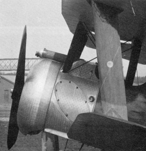
The third (tapered-wing) Camel, showing immaculate gun installation and fairings at front end of guns.
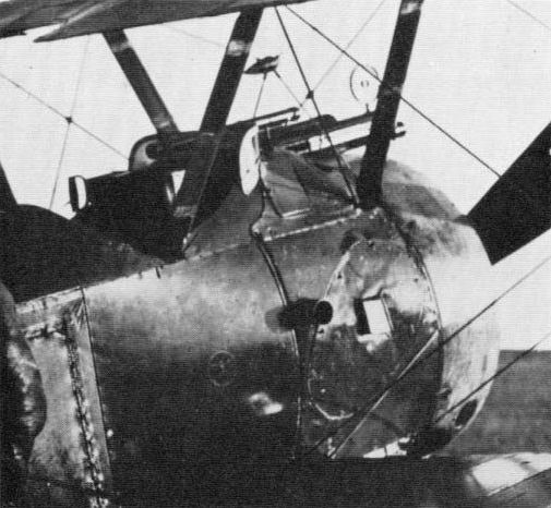
The Camel at war, with a gun installation that is hardly immaculate, since the addition of chutes, sights, screen and, in this instance, a camera gun to port.
L.R.T.Tr. This long-range, or anti-Zeppelin, fighter (1916) may be compared with the Armstrong Whitworth F.K.12. Contrasting with the ungainly masses of the airframe and undercarriage, was a carefully streamlined nacelle built into the top centre-section. Forward of the leading edge was a cockpit for a gunner, and just ahead of this was a socket for a pillar-mounted Lewis gun. The nacelle underwent at least one modification in shape. The pilot had no gun, but immediately behind him was a third cockpit for a second gunner who had a Lewis gun on a swivelling pillar mounting which carried the gun on a perforated arm.
Pup. 'Tiny little things just big enough for one man and a machine gun' was the first impression made by Pups as recorded in War Birds. In The Clouds Remember, Oliver Stewart recalled his 'perfect flying machine': 'It had the single Vickers gun, with mechanical interrupter gear, fired by a short horizontal lever or trigger which projected back from under the rear part of the gun and was pressed downwards by the pilot. Some Pups were flown by their pilots completely "stripped", without even a windscreen or an Aldis tube, the ring sight alone being used.' Concerning the standard Pup, as used by the RNAS and RFC after September 1916, it may be added that the Vickers gun was installed as on the 1 1/2 Strutter and in conjunction with the Sopwith padded screen and Sopwith-Kauper synchronising gear. Some later aircraft had the Scarff-Dibovsky or Constantinesco gear. Although the gun was generally mounted centrally, there was also an installation above the port top longeron, perhaps to protect the pilot's face. A panel on the starboard side, in line with the feed chute, gave access to the belt box. When the padded screen was discarded by some pilots, the back of the gun was occasionally padded.
The figure of 80 lb, generally quoted in official reports as the Pup's military load, would be accounted for by a Vickers gun, associated gear and 500 rounds of ammunition; the figure is, in fact, precisely half that quoted for the Westland Wagtail, with its twin Vickers guns, gear and 1.000 rounds.
There were several unofficial, and generally unsuccessful, installations of a Lewis gun above the centre-section. These were made both in France and, to obviate firing 'special' ammunition through the airscrew arc, in Home Defence units. McCudden made himself a 'rough sight of wire and rings and beads' for such an installation. The only standardised installation of a Lewis gun on a Pup appears to have been made on the Ships' Pup (Sopwith 9901), the gun in this instance being mourned on a tripod of steel tubes forward of the cockpit and firing above the airscrew at a shallow angle, with the barrel passing through a cut-out in the centre-section, and the rear of the gun accessible to the pilot. A Vickers gun was sometimes fitted in addition, and another load, additional to the Lewis gun, was eight Le Prieur rockets attached to the interplane struts. On some machines the rockets were the sole armament, and the cut-out for the Lewis gun was covered. Four 20-lb bombs were sometimes carried under the fuselage.
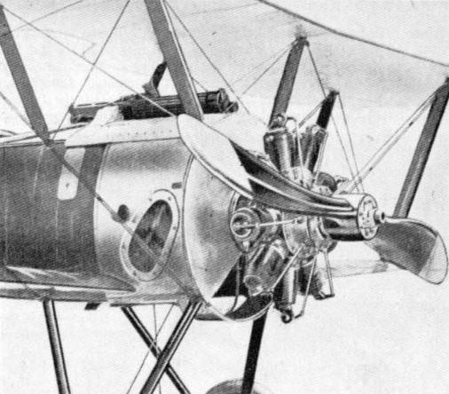
Vickers-gun installation on Sopwith Pup, showing feed chute and access panel for belt box.
Triplane. The second Sopwith fighter produced in 1916, the Triplane was armed, with only three known exceptions, in the manner of the standard Pup, the single Vickers gun lying on the centre line ahead of the cockpit and having Scarff-Dibovsky synchronising gear. Ammunition supply was 500 rounds, and the Sopwith padded screen was fitted. That the Triplane had the 'Scarff Patent Gun Mounting No.3 Made by The Sopwith Aviation Co Ltd. Kingston-on-Thames', was attested by a plate on the instrument panel. Of the three exceptions mentioned, one was the installation of two Vickers guns in a small number of aircraft; another was the fitting of a Lewis gun (additional to the standard Vickers installation) at the root of the port middle wing; and the third was the elevating of the Vickers gun to fire upward at an angle of about five degrees. This last installation entailed fitting an Aldis sight with a special graticule and was intended for stern or underneath attack at relatively long range.

Standard Sopwith Triplane, with Sopwith padded screen at rear of Vickers gun.
Triplane (Hispano-Suiza). Yet another Sopwith fighter dating from 1916, this type differed radically from the earlier rotary-engined machine. Two examples were built, one with 150-hp, the other with 200-hp engine. Both had a single Vickers gun, mounted much as on the earlier type and having Sopwith Kauper synchronising gear. The end of the gun was padded and there was a small metal screen forward of the feed block. As on the earlier Triplane, there were drag and anti-drag wires attached to the spars of the lower wing, but on the Hispano-Suiza machines there were two access panels outboard of each of the ribs to which these wires were attached. These panels somewhat resembled those on the later Sopwith triplane fighter, the Snark, and with which auxiliary outboard armament was associated. Definite conclusions, however, would not be warranted, especially so as the panels were at the anchorage points for the lower drag wires.

Triplane (Hispano-Suiza); delail showing installation of Vickers gun with Sopwith-Kauper gear and padded rear end.
Camel 2F.1. This was the "ships'" version of the Camel and normally had only one Vickers gun (port) and one Lewis gun above the centre-section. The type was a derivative of a design known as the FS.1 which may actually have been constructed as the 'Camel Seaplane' and of which a landplane version was certainly built. Like the FS.1, this aircraft had a Vickers gun to port and a Lewis gun over the centre-section. This gun was fixed and was installed in the inverted position, with the ammunition drum projecting through a trailing-edge cut-out so that it could be changed by the pilot without recourse to a movable mounting of Foster or Admiralty Top Plane type. The latter was, however, standardised. Two double drums were provided for the Lewis gun, and there were 250 rounds for the Vickers gun, which had a ring-and-bead sight mounted upon it. At least one aircraft was modified to have twin Vickers guns, and the most famous 2F.1 of all - used by Lieut S. D. Culley to shoot down Zeppelin L.53 on 10 August, 1918 - had two Lewis guns above the centre-section. An experimental installation of eight strut-mounted Le Prieur rockets was made.
It has been stated that for the raid on the Tondern Zeppelin sheds on 19 July, 1918, the bombs used by the seven Camels engaged were of 50-lb type. Marshal of the RAF Sir William Dickson, who took part in the raid, has, however, described them as 'specially made 60-lb Coopers'. He has also recorded that before the raid the pilots experimented with various forms of sight to improve their aim.
It has been stated that for the raid on the Tondern Zeppelin sheds on 19 July, 1918, the bombs used by the seven Camels engaged were of 50-lb type. Marshal of the RAF Sir William Dickson, who took part in the raid, has, however, described them as 'specially made 60-lb Coopers'. He has also recorded that before the raid the pilots experimented with various forms of sight to improve their aim.
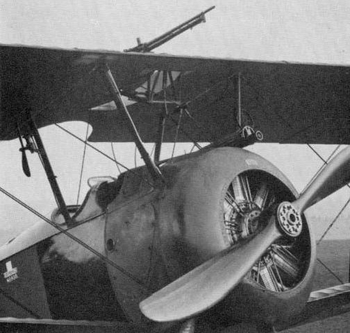
Armed to meet RNAS requirements: the Camel 2F.1 with Vickers gun to port, with ring-and-bead sight mounted on gun, and Lewis gun on Admiralty Top Plane mounting.
Bomber. Laid out along the lines of the single-seat bomber version of the 1 1/2 Strutter, with internal bomb stowage behind the pilot, this larger aircraft of 1917 was at first unarmed. While undergoing operational trials, however, it had a synchronised Lewis gun on the centre line of the fuselage ahead of the cockpit. The bomb compartment had an access panel on each side and appears to have had provision for nine 50-lb bombs, carried nose-up as in the D.H.9. J. M. Bruce records a total load of 560 lb and a test-load of twenty 28-lb Analyte bombs.
Bee. At one stage, a Vickers gun was fitted to this tiny biplane of 1916.
Cuckoo. The Cuckoo has the distinction of being the first torpedo-dropping aircraft designed to operate with a wheeled undercarriage from the deck of a ship. It was closely related to the B.1 Bomber and likewise dated from 1917. production being initiated by the Blackburn company in 1918. Distinctive features associated with the carrying of the torpedo (Mk.IX of nominal 1.000-lb weight) were the three-bay wings and split undercarriage. The torpedo gear was a Blackburn responsibility and led to developments by that company already described. The torpedo was heated either by warm air from long exhaust tail-pipes, ducted to the region of the buoyancy chamber as on the later Blackburn Swift and Dart, or by electrically heated mats. There appear to have been at least two types of torpedo installation. A photograph shows the torpedo slung by a cable which is visible between the V-struts of the undercarriage. A crutch is seen roughly in line with the wing trailing edge and there is a massive pylon structure associated with the nose of the torpedo. This appears to have the dual function of steadying the missile and of acting as a pistol stop, but in most other known photographs of Cuckoos it is absent. The same photograph shows the torpedo depth-setting gear, located to the left of the pilot's wicker seat.
Under the Blackburn heading, mention is made of the importance attached during the early days of torpedoplane development to a silent approach to the target, and it is known that silencers were fitted to some Cuckoos. During 1920 it was notified that there was a diving hazard since modifications had been made and the Viper engine installed: the Cuckoo was to be dived only with tanks half empty.
The most notable design feature of the Cuckoo to be influenced by armament was the split-axle undercarriage which allowed the torpedo to be carried and dropped. The following is a verbatim official description:
'The Chassis consists of two Undercarriages which are identical. Each Undercarriage is formed of steel tubes welded and pinned together, and consists of two portions. One portion, which is in the shape of a V, is placed parallel to the fuselage, the End Lugs being bolted to the front and rear Spars of the Centre Section Lower Plane. The other portion has one End Lug bolted to the Bottom Longeron, and is bent so as to form the Axle for one wheel, the other end resting in the apex of the V. Shock Absorbers are formed by 28 feet of 15 mms. diam elastic, which is given ten complete turns round the Axle and the apex of the V. The Steel Struts arc stream-lined by means of wood fairing attached by metal clips, the whole being wrapped with fabric and then doped.'
Dolphin. From the standpoint of armament, as from other aspects, the Dolphin of 1917 was a fighter of exceptional interest. By reason of the fact that it carried two free Lewis guns in addition to two fixed Vickers guns, it has been correctly described as the world's first multi-gun single-seat fighter. Yet the first Dolphin, with its deep car-type frontal radiator, gave scant evidence of being armed at all. The Lewis guns were not, in fact, fitted on this machine, although the Vickers guns were present beneath the cowling, as proclaimed by the breech casings visible in the cockpit, ejection chutes, and two small ports in the nose cowling. The link chutes were above the cylinder-bank fairings and the case chutes behind the exhaust pipes. When lateral radiators were adopted, the cowling was lowered accordingly and the forward portions of the Vickers guns protruded. In the Dolphin Mk.II (300-hp Hispano-Suiza engine) the guns were again submerged.
The rear ends of the Vickers guns were padded and came far back in to the sides of the cockpit at the level of the pilot's shoulders. The windscreen was far ahead of the cockpit and the centrally-mounted Aldis sight passed through it, being bracket-mounted at a point behind the screen and to the cross-tube which carried the Lewis guns. A ring-and-bead sight was mounted to starboard. C.C. gear Type B was fitted, and the guns had Hyland Type A or B loading handles. A prominent feature of the C.C. gear installation was the gear ring attached to the rear flange of the airscrew boss and the smaller gear wheel meshing with it below. Beneath the smaller gear wheel were two apertures in the cowling each exposing part of the box-type generator used with the Hispano-Suiza engine and a short length of the hydraulic pipeline leading to the trigger motor.
The two Lewis guns were swivel-mounted on brackets attached to the ends of the cross member which was officially known as the 'front spar tube'. They pointed upwards at about 45 degrees and were restrained from firing into the airscrew by two cams, which nevertheless permitted their being trained to some extent outboard. The spade grips were removed, and the guns were fired by Bowden cable. Norman vane sights were sometimes fitted. When the guns were trained parallel, they were clamped above the pistol grips by fittings attached to the upper wing roots. The Lewis gun installation was not popular among pilots by reason of the guns' intrusion into an already cramped cockpit, and inevitably they affected performance. To fly the Dolphin, keep observation, operate the radiator, and use the Lewis guns as well as the Vickers guns was a one-man-band operation that few could have mastered. One or both guns were frequently removed, although a single Lewis gun was regarded as standard. In No. 87 Squadron the guns were transferred to fixed mountings on the lower wings, somewhat inboard of the inner pairs of interplane struts, where they fired outside the airscrew arc. There were probably other schemes, and certainly a fixed Lewis gun was fitted on the upper wing. Other non-standard installations were an Aldis sight attached to the front spar tube and a Lewis gun on the cross-bar of a crash pylon above the open centre-section. For night work, Hutlon illuminated sights were fitted. Four 20-lb bombs could be carried under the fuselage.

The view of the same aircraft below left shows the 'crossbar' mounted, upward-firing Lewis guns that could prove so dangerous. The windscreen is perforated for an Aldis sight, but the sight is not installed. Note also gear ring behind propeller hub, smaller gear wheel below it and part of generator and pipeline for starboard Vickers gun.
Hippo. The Hippo two-seat fighter (1917) was a counterpart of the Salamander, in having backward stagger, and a contemporary of the Rhino, with which it was analogous in rear armament, the first machine being fitted with a pair of rocking-pillar mountings for two Lewis guns and the second having a Scarff ring-mounting for a single Lewis gun. The installation of the mounting was somewhat unusual, the ring being considerably greater in diameter than the width of the fuselage. The pilot had two Vickers guns in a remarkably neat installation and one which imperiled his frontal features less than in some other Sopwith types, the breech casings being located lower and further ahead. But although the familiar Sopwith padded windscreen was thus rendered unnecessary, the leading edge of the top centre-section was padded in the interests of head protection. There were separate case and link chutes low in the cowling and a small fitting, possibly for a sight, ahead of the windscreen. The gun gear was of Sopwith-Kauper type, and 500 rounds per gun were provided. The total ammunition weight of 260 lb, which has been recorded for the first Hippo, seems somewhat excessive, even if the four guns were included, for the guns themselves would weigh no more than 100 lb and the ammunition not much over 130 lb.
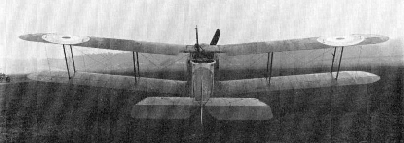
The fuselage of the Sopwith Hippo was so narrow that the Scarff ring-mounting of the second example, shown here, overhung the sides.
Rhino. A counterpart of the D.H.9, the Rhino single-engined bomber of 1917 had internal bomb stowage. This was located under the pilot's seat, and the bombs - four 112-lb or nine 50-lb or twenty 20-lb - were winched into place complete with release gear. The bombs being so placed, it was not possible to provide the pilot with a Negative Lens sight, as on the D.H.9. Between Rhinos Nos. 1 and 2, there were interesting variations in gun armament. On the first machine the pilot's Vickers gun was mounted on the centre line immediately ahead of the cockpit, with the feed block faired over, the fairing also affording some protection to the pilot. The gun retained its land-service handles. On the second example the gun was similarly mounted and was wholly forward of the windscreen (lacking on the first machine). There was a fairing ahead of the feed block. Rear armament on the first Rhino was a Lewis gun on a rocking pillar mourning at the rear of the cockpit, as on the Bulldog. The second machine had a redesigned cockpit with a Scarff ring-mounting on the top longerons, the gunner thus having a considerable depth of protective coaming ahead of him.
Buffalo. Among the several Sopwith prototypes of 1918 was the Buffalo armoured two-seater for 'contact patrol' duties. As was the case with the Rhino and Hippo, the first example had a rocking-pillar mounting for the rear Lewis gun, whereas the second had a Scarff ring-mounting. The pillar traversed in a transverse slot at the rear end of the cockpit. The pilot had a Vickers gun mounted on top of the fuselage to port and with the breech casing faired in. The link chute was by the feed block and the case chute lower down. Ring-and-bead sights were stayed to the gun, and there were brackets for a central Aldis sight. The armouring was structural, as on the Salamander, and was extended on the second machine by one bay aft.
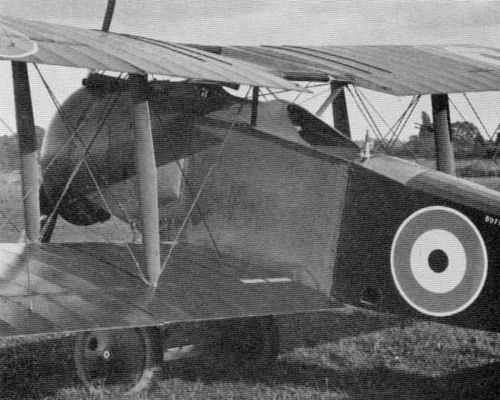
The first Sopwiih Buffalo, with rocking-pillar mounting for Lewis gun.

The second Buffalo, with Scarff ring-mounting. Note extent of armouring in this view.
Bulldog. Designed as a high-performance fighter-reconnaissance aircraft, this two-seater of 1918 had an unusual and heavy armament. For the pilot there were two synchronised Vickers guns, with 600 rounds each, mounted Snipe-fashion, with their padded breech casings all but touching the pilot's face. The windscreen was perforated for an Aldis sight, and there were separate case and link chutes in the cowling flanks. For the gunner there were two Lewis guns, one on a pillar mounting at each end of the elongated cockpit. To extend the field of fire in the forward upper hemisphere, the front pillar was extensible, and, as it was projected upwards, it raised, by means of a connecting tube, a rectangular screen hinged to the rear spar of the upper centre-section. Jointly with a small windscreen, this afforded the gunner a measure of protection. The rear pillar could be traversed from side to side. Possibly in the interests of gun handling, the ammunition drums were of single (47-round) type. In the original armament scheme, which did not materialise, two Lewis guns were to be mounted between the cockpits, capable of firing, like the single gun actually fitted, above the airscrew. The second (two-bay) version of the first Bulldog was armed as the first, but the second machine (Dragonfly engine) was unarmed, although a Scarff ring-mounting had been intended for it.
An attachment noted on the forward Lewis gun may indicate an intention that this gun could be fired also by the pilot, but this is conjectural.
An attachment noted on the forward Lewis gun may indicate an intention that this gun could be fired also by the pilot, but this is conjectural.

The Sopwith Bulldog had unusual and heavy armament. In addition to two fixed Vickers guns there were two Lewis guns on pillar mountings. The foremost pillar was extensible and operated jointly with a protective screen.
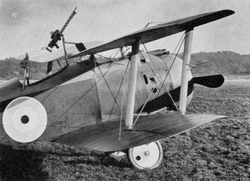
Dragon. This Snipe development of 1918 retained the same armament, and this can be said to have fitted like a glove, for the muzzles of the guns barely cleared the valve gear on the top cylinder of the Dragonfly engine.
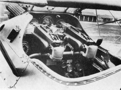
Носовая часть самолета была так плотно скомпонована, что казенники пулеметов находились в пилотской кабине, почти прижимая пилота к креслу
Installation of twin Vickers guns in a Sopwith Dragon. The trigger motors associated with the C.C. synchronising gear are not fitted to the guns, but clearly seen are the protective pads and loading handles at the rear of the guns, the feed chutes and the link chute for port gun, and the windscreen perforated for an Aldis sight.
Installation of twin Vickers guns in a Sopwith Dragon. The trigger motors associated with the C.C. synchronising gear are not fitted to the guns, but clearly seen are the protective pads and loading handles at the rear of the guns, the feed chutes and the link chute for port gun, and the windscreen perforated for an Aldis sight.
Salamander. 'The armour plating is painted in chocolate brown. On the wings is a forked-lightning camouflage design to render it comparatively invisible from above.' Thus ran an eye-witness account of a Salamander, to which it was added that the machine carried no roundels. Thus passive protection was visual as well as in the form of the armour-plate for which this 1918 'trench fighter' successor to the Camel T.F.1 is best known. The entire forward portion of the fuselage consisted of armour, and additional plating formed part of the top decking round and behind the cockpit, as well as the characteristic head-rest. The weight of all this armour (nearly 650 lb) was doubtless the cause of one officer describing the aeroplane as a 'heavily plated product of the Sopwith factories' which 'on account of its clumsiness and poor flying characteristics was found to be more lethal to its pilot than to the enemy'. This criticism may have been over-severe, although Martlesham Heath reported that lateral control was heavy and that the aircraft was tiring to fly.
The armour gave adequate protection against German armour-piercing bullets fired from short range but presented problems additional to that of weight. In January 1919 the RAF gave notice that in trueing-up the wings it was advisable first to adjust the upper wings until the dihedral was correct, and afterwards to adjust for stagger. It would then be found that any inaccuracy would be confined to the first bay from the fuselage on the lower wings. Such inaccuracy would occur at the lower-spar housings on the armour-plate, and would be due to the 'very considerable' amount of distortion inherent in these plates caused by the hardening process. The makers' order of erection was: place armoured portion on trestles and attach undercarriage vees and axle; true-up undercarriage, attach rear end of fuselage by means of four bolts 'through the joint box'; true-up fuselage; fit main petrol tank and connect piping as far as V.P. cock and first rubber joints in pipe from Weyman pump at bottom of main tank; mount engine, fit oil tank and gravity tank and connect all piping; connect engine controls, revolution counter and C.C. gear; fit magazines; mount Vickers guns and connect pipe lines to trigger motors; fit rear decking; place t op gun cowl in position; attach side cowls and front engine cowl; assemble tail unit; and connect controls. These facts may lend further interest to the details from superb manufacturers' photographs now reproduced, apparently, for the first time.
Although the Salamander was closely related to the Snipe and was similarly armed with two Vickers guns, there were many differences in the armament installation, stemming from the requirement that each gun should have 1.000 rounds o f ammunition. This led to the staggering of the guns in plan on the production type (starboard gun foremost). Case and link chutes were close together near the feed blocks. Sights were arranged as on the Snipe. Experimental installations reported, but not confirmed by photographs, were eight downward-firing guns (presumably Lewis), and two downward-firing Lewis guns and two Lewis guns over the centre-section, additional to the two standard Vickers guns. It was doubtless in connection with the Salamander that Sopwith designed a form of magazine comprising two telescopic belt boxes. This arrangement was such that when one box was completely emptied the adjacent box was moved into it with the new ammunition supply occupying the correct position relative to the gun.
Provision was made for four 20-lb bombs, as on the Snipe.

Another comparative view of the Salamander and Snipe, in production at Sopwith's Ham works in December 1918. Note staggered Vickers gun installation on Salamander (front row) and flat sides.
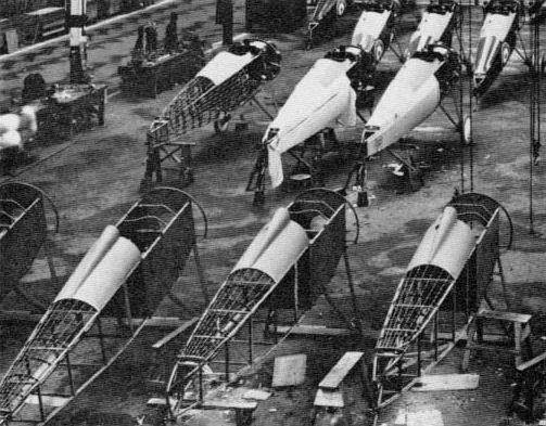
A third Salamander Snipe comparison, with the Salamanders in the foreground exhibiting not only the armoured forward fuselage but the staggered gun-mountings.
Swallow. Although the Swallow parasol monoplane fighter, which appeared just before the Armistice, had a Camel fuselage, the two Vickers guns were rearranged. The hump was no longer in evidence, and the guns were more widely spaced, lying exposed along the upper cowling and having combined large ejection chutes for cases and links immediately below them.

The fuselage of the Sopwith Swallow was that of the Camel, but the gun installation differed and the guns were more widely spaced, as seen.
Snail. The Snail Mk.II single-seat fighter, which appeared in 1918 earlier than the Mk.I version (monocoque fuselage), carried its two Vickers guns in an extremely neat installation. The relatively large fuselage diameter enabled the guns to be mounted in the sides of the cockpit, the only external evidence of their presence being the extreme muzzle ends projecting into short troughs and the separate case and link chutes in the flanks of the cockpit. A Lew is gun was mounted above the starboard edge of the centre-section cut-out, the rear end picking up a fitting seen in the photograph. In firing position, the gun was parallel with the centre line, but a pivoted arm attached to the rear face of the front spar allowed the gun to be swung inboard for reloading. This was, in effect, a reversal of the system used on the Snipe. The windscreen was perforated for an Aldis sight. The Snail Mk.I does not appear to have carried its intended armament of two Vickers guns.
Snark. Designed in 1918 and flown in 1919, the Snark was the most heavily-armed single-seat fighter of the 1914-18 war; but by the time the Gloster S.S.19 appeared in 1932 with a similar armament - two synchronized Vickers guns and four wing-mounted Lewis guns - its existence seems to have been entirely forgotten. That only one of the three specimens built appears to have been thus armed (the basic war load being the two Vickers guns) does not detract from the type's significance. The two Vickers guns were entirely 'buried' in the fuselage, almost at the level of the rudder bar, and the Lewis guns were in two close-set pairs, one pair under each bottom wing, in which were provided a pair of staggered access panels. There were brackets for an Aldis sight forward of the windscreen, offset to starboard, and a ring-and-bead sight a little further to starboard, the pedestals being canted outwards by the curved monocoque fuselage.
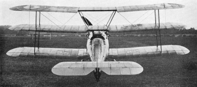
F4068, the first prototype Sopwith Snark triplane
Although it might not be supposed that a rear view of a single-seat fighter could convey much information on armament the reverse is true in this instance. The subject is the Sopwith Snark, and in a frontal view the 'buried' Vickers guns would be invisible. In addition to showing the four panels in the bottom wing, denoting the locations of the outboard Lewis guns, this picture shows brackets for the Aldis sight, slightly to starboard, and mountings for the ring-and-bead sight, the pillar for the bead being canted outboard to the right of the windscreen.
Although it might not be supposed that a rear view of a single-seat fighter could convey much information on armament the reverse is true in this instance. The subject is the Sopwith Snark, and in a frontal view the 'buried' Vickers guns would be invisible. In addition to showing the four panels in the bottom wing, denoting the locations of the outboard Lewis guns, this picture shows brackets for the Aldis sight, slightly to starboard, and mountings for the ring-and-bead sight, the pillar for the bead being canted outboard to the right of the windscreen.
Snipe. Although the Snipe's basic armament of two Vickers guns was the same as the Camel's, and was similarly disposed, there were several variations as between individual aircraft. The 'hump' fairing on the prototypes, dating from late 1917, sloped straight down from the cockpit coaming to the lip of the engine cowling, but on production aircraft the decking was asymmetrical, being carried further aft on the port side and giving a stronger impression of a hump. There were subtle differences in the location and shaping of the case and link chutes; on production aircraft the link chutes were located high in the cowling, in line with the feed blocks, and the case chutes were far lower down and further forward, in order to clear the belt boxes. Provision was made on production Snipes for both ring-and-bead and Aldis sights. The ring was stayed to the starboard gun, and the bead was immediately forward of the windscreen. As the screen was well forward of the cockpit, the sight base was very short. The Aldis sight was on the centre line and passed through an aperture in the windscreen. It was carried in brackets attached to a fore-and-aft tube running across the centre-section cut-out. Like contemporary and competitive types of fighter, the Snipe was at one time required to carry a Lewis gun as secondary armament. On the third prototype, this was mounted above the centre-section, offset to starboard. On the example called by the makers Snipe 7F.1/5, the tube on which the gun was carried above the wing was pivoted at its front end on the centre line, and built out from the front face of the rear spar was a quadrant on which the rear end of the gun could be swung to starboard. On the Snipe with the large experimental spinner and other cowling modifications, there was a fixed fining on the rear spar, not outboard of the cut-out ahead of the spar, as on the 7F.1/5, but inside, somewhat offset to starboard. It is recorded that during official trials a total of 235 lb of ammunition was carried for the three guns on one of the Snipe prototypes, but this can hardly be credited, even if the guns, which would weigh about 90 lb, were included. In any case, the position of the Lewis gun was criticised as being too near the pilot's head, and the gun was discarded.
Snipes in squadron service could carry four 20-lb bombs, the carrier brackets being of the type fitted on the Camel. A single 112-lb bomb was another load.
Snipes in squadron service could carry four 20-lb bombs, the carrier brackets being of the type fitted on the Camel. A single 112-lb bomb was another load.
Another comparative view of the Salamander and Snipe, in production at Sopwith's Ham works in December 1918. Note staggered Vickers gun installation on Salamander (front row) and flat sides.
A third Salamander Snipe comparison, with the Salamanders in the foreground exhibiting not only the armoured forward fuselage but the staggered gun-mountings.
Camel T.F.1. Camels were extensively used for low-flying attacks and one experimental 'armoured trench fighter' version was produced early in 1918. This is said to have been built originally by Boulton & Paul, although its rudder proclaimed 'Clayton & Shuttleworth Ltd'; but the experimental installations were made by Sopwith. The armament was three Lewis guns, two firing downwards, with their barrels projecting through the floor at a steep angle and one on an Admiralty Top Plane mounting as on the Camel 2F.1. Like the upper gun, the fuselage guns had their spade grips removed, and the ammunition drums were of the smaller (47-round) type. A sheet of armour-plate, slightly wider than the fuselage, extended from the firewall to the area of the petrol tank behind the cockpit.
Cobham. The Cobham triplane bomber was flown in 1920. This first and only twin-engined Sopwith carried its bombs internally in the fuselage between the roots of the main spar. A load of 750 lb has been mentioned, and this seems altogether reasonable. Two access panels were located in the side of the fuselage just below the centre wing. There was a Scarff ring-mounting for a Lewis gun in the nose and a similar installation on top of the fuselage just abaft the wings.
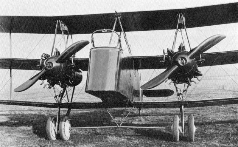
One of the finest studies of any Sopwith aeroplane (and likewise A.B.C. Dragonfly engines installed) is this close-up of the Cobham Mk.I. This was the second Cobham to fly, and the full maker's caption reads: "S.1259 - Cobham No. 2. 360 hp A.B.C. Twin Engines. Designed and built by The Sopwith Aviation & Engineering Co Ltd - March 4/1920". In this view of the Sopwith Cobham the location of the bomb compartment is seen through the inverted-pyramid tubular structure which anchors ihe undercarriage. On the Scarff ring-mounting the lever for locking and unlocking ihe mechanism is seen.
The Dragonfly was to be used to power the next generation of larger aeroplanes and was the power plant of the triplane Sopwith Cobham.
The Dragonfly was to be used to power the next generation of larger aeroplanes and was the power plant of the triplane Sopwith Cobham.
Snapper. The two Vickers guns of the Snapper single-seat fighter of 1919 were set in the top fuselage decking, widely spaced, with their breech casings in the cockpit and their barrels lying in long deep troughs. The windscreen was perforated for an Aldis sight, and there were ring-and-bead sights in addition. As on the Swallow, there were combined large ejection chutes for cases and links below the feed blocks.
Sunbeam
Bomber. This single-seat bomber of 1917 appears to have been unique among aircraft of the 1914/18 War in having a remotely-fired fixed Vickers gun. This was mounted above the engine several feet ahead of the single cockpit, where stoppages could not be cleared. In having external bomb stowage, it contrasted with the Sopwith Bomber, which it somewhat resembled. J. M. Bruce states that a bomb load of three 100-lb bombs was apparently possible. This type of bomb was a specialised anti-submarine weapon. Tandem tubular carriers suggest that a greater number of bombs was provided for, if not actually carried.
Bomber. This single-seat bomber of 1917 appears to have been unique among aircraft of the 1914/18 War in having a remotely-fired fixed Vickers gun. This was mounted above the engine several feet ahead of the single cockpit, where stoppages could not be cleared. In having external bomb stowage, it contrasted with the Sopwith Bomber, which it somewhat resembled. J. M. Bruce states that a bomb load of three 100-lb bombs was apparently possible. This type of bomb was a specialised anti-submarine weapon. Tandem tubular carriers suggest that a greater number of bombs was provided for, if not actually carried.
Baby. A makers' drawing indicates that a single Lewis gun was the armament (actual or intended) of this single-seat fighter flying-boat (1918).
Supermarine Channel. This was the name conferred by Supermarine on the A.D. Flying Boat constructed by them and offered for sale in 1919. A Scarff ring-mounting for a Lewis gun with 'single# ammunition drums was installed a short distance back from the bows as shown in a photograph herewith. This same picture suggests the presence of a four 20-lb bomb-carrier under the port wing, and the makers mentioned a possible load of two 50-lb or 100-lb bombs.

Supermarine Channel, with Lewis gun manned in bow. The gun has a 'single' (47-round) ammunition drum, and there are bomb-carriers under the wings.
Tarrant
Tabor. This immense triplane of 1918/19 was designed to carry a total armament load of 5.030 lb. Bombs and associated gear accounted for 4.650 lb (one possible load was sixteen 250-lb bombs) and the specified guns and ammunition weighed 380 lb. No armament was ever installed.
Tabor. This immense triplane of 1918/19 was designed to carry a total armament load of 5.030 lb. Bombs and associated gear accounted for 4.650 lb (one possible load was sixteen 250-lb bombs) and the specified guns and ammunition weighed 380 lb. No armament was ever installed.
Vickers
Gun Bus. Late in 1912 the Vickers drawing office was laying out a large twin-engined biplane known as No.14B, to be armed with a 1 1/2-pounder semiautomatic gun, possibly of the type later fitted to the Sopwith No.127 and Short No.126 pusher seaplanes. The Vickers machine never materialised, but an outgrowth of the technical studies made was the pusher gun-carrying aeroplane which appeared at the Olympia Aero Show in London during February 1913. This was named Destroyer, and mounted in the nose of the duralumin-covered steel-tube nacelle was a Vickers belt-fed 0.303-in machine-gun on a mounting which allowed the gun to swivel through 60 degrees in both elevation and azimuth. The ammunition box was stated to be stowed 'just over the centre of pressure of the planes', the intention being that it should be wound forward on wire rails to its action station. That this aeroplane is stated to have crashed on its first flight because of nose-heaviness occasioned by its armament is not altogether surprising.
The Destroyer, or E.F.B.1, had been built to Admiralty order, and early in 1913 a gun mounting for a machine of the type (there can be no doubt of this, by reason of the raked nacelle-struts shown in an accompanying drawing) was designed by Lieut C. J. L'Estrange Malone of the Admiralty's Air Department. With this Department other notable developments in aircraft armament, notably the Scarff ring-mounting, were later to be associated.
The Admiralty mounting appears to have been designed after the appearance of the Destroyer at Olympia and may indicate the sponsor's dissatisfaction with the original Vickers installation, for the aircraft had been built to an Admiralty order placed in November 1912. Certainly the mounting suggests a closer association between the Admiralty and the Gun Bus than has hitherto been recognised.
The Admiralty mounting consisted of a cradle or frame which could rock in a vertical plane and also rotate in azimuth. At one end of this member, the gun was carried on a universal joint; at the other end was the gunner's seat. The cradle was curved in form and was mounted on a horizontal pivot carried in a bracket which itself had a vertical swivelling pin stepped in a socket attached to the aircraft structure. A handwheel operating a worm gear was provided for traversing.
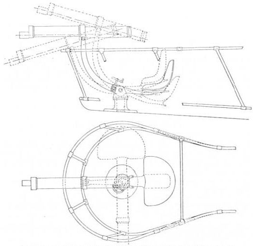
Mounting for Vickers gun designed by Lt C. J. L'Estrange Malone of the Admiralty's Air Department for the Vickers Destroyer, or E.F.B.1.
The Admiralty mounting consisted of a cradle or frame which could rock in a vertical plane and also rotate in azimuth. At one end of this member, the gun was carried on a universal joint; at the other end was the gunner's seat. The cradle was curved in form and was mounted on a horizontal pivot carried in a bracket which itself had a vertical swivelling pin stepped in a socket attached to the aircraft structure. A handwheel operating a worm gear was provided for traversing.
Whether this mounting was ever installed in an aircraft the present writer does not pretend to know; but the mounting identified with the next airframe development (E.F.B.2) was designed by Vickers themselves, and is likewise illustrated. In this installation the gun projected through the nose, somewhat as on the Destroyer, but the gap was closed by a shield of hemispherical form which moved with the gun both in elevation and traverse. This shield was primarily to protect the gunner from the airstream and to afford a good aerodynamic form for the nacelle nose, but the possibility of making it bullet-proof was considered. The mounting embodied a cross-head which carried the gun and was provided with a 'training pivot' mounted in a socket bolted to the forward portion of the fuselage. A plate having a curved slot concentric with the gun trunnions was attached to the gun and a clamp was provided by which the plate could be locked to the cross-head with the gun at any desired angle of elevation. The socket could also be fitted with a clamp for holding the cross-head rigid with the socket when the gun was not in use. Mention was made by Vickers of 'transparent sight openings in the hemispherical shield' and the form of the sight is shown in the drawing. The backsight was adjustable over a vertical scale.
The possibility of armouring has already been mentioned, and armoured Gun Buses were actually built. In this context reference may be made to a paper read early in 1913 by Maj F. H. Sykes. Commander of the Military Wing of the RFC, calling for #a two-seater fighting machine to carry a gun, ammunition, light armour and petrol for 200 miles'. Present on that occasion was Capt (later Maj) Herbert F. Wood, who was very closely connected with the development of the Gun Bus series and who remarked that, although Maj Sykes had stated that 'the armoured aeroplane could not lift as fast as the smaller machine', he was not sure that this were not possible if speed were sacrificed. 'Because such a machine would be used purely as a defensive factor against foreign flying machines.' he said. #it ought to be possible to get sufficient speed for a short time by diving.' A similar practice was enforced upon Fury, Gauntlet and Gladiator pilots when the Blenheim bomber came in.
The 'transparent sight openings# mentioned by Vickers. in connection with the hemispherical shield-type mounting described, were in evidence on the E.F.B.3 when it appeared at Olympia in 1914. It was reported:
'In the nose of the nacelle, and mounted on a universal joint resting on the tubular framework, is a Vickers Automatic Rifle Calibre gun which had a range of action of 30 degrees in any direction from the line of flight. The gun projects through a circular opening, whilst a hemispherical shield is mounted on and moves with the gun barrel. This shield is fitted with mica windows, through which the gunner obtains his sights. This arrangement enables the gunner to operate the gun without the draught of wind interfering with the sighting of it.'
The ammunition supply was stated to be 300 rounds. Another report stated that the gunner was protected not only from the wind but from the gases from the gun when in action.
That this mounting constituted the first gun turret for aircraft can hardly be denied.
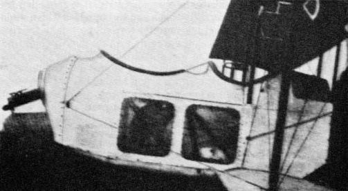
Nacelle of Vickers E.F.B.2 with Vickers mounting of the type illustrated in the accompanying drawing.

Vickers mounting for Vickers gun on E.F.B.2. a very advanced scheme which preceded far more primitive installations.
<...>
It will thus be seen that much ingenuity was applied to the earliest members of the family of aircraft which came to be known by the name 'Gun Bus' during 1914. Yet on the E.F.B.5 prototype, the gun mounting was of simple trunnion type, carried above a fairing built up from the shallow nose of the redesigned nacelle. Thereafter F.B.5s had various types of simple mounting, sometimes associated with variations in nacelle shape. The real significance of the reversion to a simple form of mounting may well have been an aerodynamic one, governed by considerations of side area rather than arcs of fire, for the pusher-type of biplane, with its tail carried on booms, must have been especially sensitive in this regard. Indeed, when the prototype E.F.B.5 arrived at Brook lands in July 1914 it was remarked that this 'latest Vickers gun-carrier, which may be regarded as the outcome of the experimental work carried out on the previous gun-carrier' embodied the modifications in side area dictated by those experiences'.
A small number of F.B.5s used by the RNAS were armed with a Vickers gun on a trunnion mounting and one machine so armed was captured intact by the Germans. Thereafter the Vickers gun was to suffer almost total eclipse as a free-mounted weapon, and the redesigned nacelle of the Gun Bus was an early factor in bringing this about, for the Lewis gun was far more easily handled in an exposed position.
Various forms of pillar or pylon mounting were fitted to Gun Buses in service, and with the four machines designated by C. F. Andrews (Vickers Aircraft since 1908, Putnam, 1969) as F.B.5A a new type of mounting was associated. This mounting was designed by G. H. Challenger, and for the first time the mounting was of ring form. The ring was rotatable and the gun was carried on a V-shaped frame, to which it was pivoted. The frame projected beyond the diameter of the ring to permit the gun to be fired vertically downward. Vickers made mention of 'counter-balancing springs', enabling the frame to be readily raised and lowered, and also of means for locking it in any desired position. The gunner could raise and lower the frame with the hand he employed for firing the gun and training it round its pivotal connection on the arm, thus leaving his other hand free to rotate the ring.
It has been said of the Scarff ring-mounting that it was the first mounting which allowed for the gun to move round the gunner, instead of vice versa. This, however, was not the case, for the Vickers-Challenger mounting dated from the early summer of 1915, whereas the Scarff ring-mounting was developed in 1916. As events turned out, a number of F.B.5 Gun Buses were later converted as gunnery trainers, fitted with the Scarff ring-mounting.
For his original ring-mounting, Challenger developed early in 1916 a quite elaborate balancing system. Movement of the gun in elevation was compensated for the resultant moment due to air resistance and the weight of the gun, and movement of the gun in traverse was compensated for the moment due to air resistance. The elevation-compensating device was a spring-controlled chain arranged between the ring and an extension of one of the arms. The chain passed round one or other of a pair of pulleys, according to the position of the gun in elevation. The spring thus increasingly opposed motion on each side of a certain central position corresponding to the angle of gun elevation at which air resistance was exactly balanced by the weight of the gun. The traverse-compensating device comprised a spring-controlled chain and pulleys, arranged to give a central position when the gun was pointed ahead and increasingly opposed movement of the gun to the right or left of this position. Later in 1916 Vickers developed the mounting by introducing a spring-controlled crank, moving synchronously with the gun.
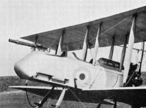
View of Vickers F.B.5 Gun Bus with Lewis gun on simple spigot mounting.
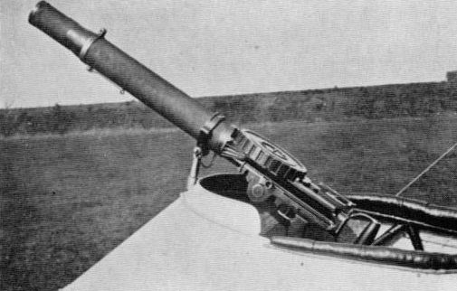
Lewis gun on spigot mounting on Vickers F.B.5. The ammunition drum held 47 rounds.
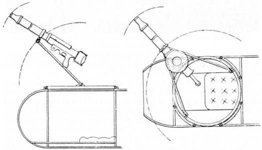
Though not to scale, this Vickers drawing shows salient features of the mounting designed for the Gun Bus by G H. Challenger.
F.B.7. To provide an all-round field of fire for its Vickers 1-pounder automatic gun, this two-seat fighter, which appeared in the summer of 1915, was given two engines. No details of the gun mounting have survived, though it is said to have been bolted to the thick duralumin floor of the cockpit and would thus have differed in principle from that later described in connection with the F.B.24E. Nevertheless, the gunner's seat is said to have traversed with the gun.
F.B.8. Late in 1915 Vickers built this two-seat fighter, laid out generally along the lines of the F.B.7 but armed only with a Lewis gun. This was emplaced in the nose at the front of a narrow cockpit and appears to have had a restricted field of fire.
F.B.8. Late in 1915 Vickers built this two-seat fighter, laid out generally along the lines of the F.B.7 but armed only with a Lewis gun. This was emplaced in the nose at the front of a narrow cockpit and appears to have had a restricted field of fire.
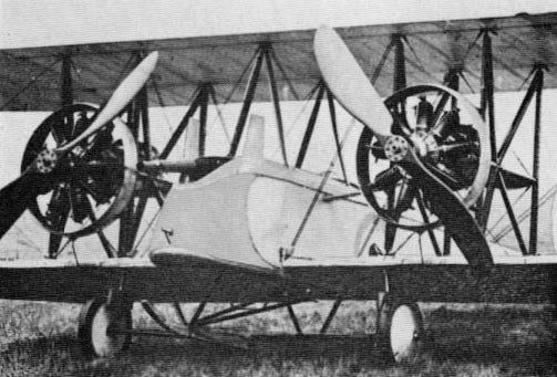
Installation of Lewis gun on Vickers F.B.8. The gun retains its land-service type cooling jacket, as on the standard Gun Buses.
E.S.1. Extremely neat installations of a single Vickers gun were made on single-seat 'scouts' of this type during 1915/16. The gun was recessed into the fuselage just inboard of the port centre-section struts, tiring, in one type of installation at least, through a hole in the front of the engine cowling. The recessing of the gun is indicated in Vickers diagrammatic drawings which will be reproduced in Volume 2 in the context of the Vickers synchronising gear, and the E.S.1 undoubtedly played a part in the development of that gear. Certain it is that one machine was used at Farnborough for gunsight experiments, the sight apparently being of frame type.
<...>
The aircraft described by C. F. Andrews as the F.B.5A had an armour-plated nose, generally of the form shown in the Vickers diagrams reproduced. This same aeroplane is illustrated in an official publication as an F.B.9, and a drawing in this same publication shows a Vickers-Challenger ring-mounting with the arms of the gun frame slightly bowed.
The aircraft described by C. F. Andrews as the F.B.5A had an armour-plated nose, generally of the form shown in the Vickers diagrams reproduced. This same aeroplane is illustrated in an official publication as an F.B.9, and a drawing in this same publication shows a Vickers-Challenger ring-mounting with the arms of the gun frame slightly bowed.
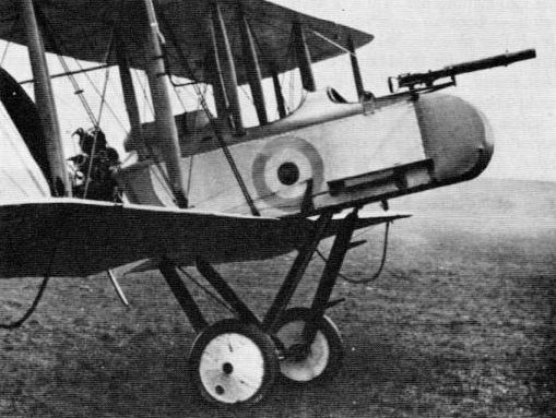
F.B.11. Apparently intended primarily for anti-airship duties, though having obvious potential as an escort fighter, this single-engined three-seater of 1916 had two Lewis guns on Scarff ring-mountings. The foremost of these installations was in the nose of a nacelle carried forward from the upper surface of the top wing; the other was immediately behind the pilot, just aft of the wing trailing edges.
F.B.12. The single Lewis gun of this pusher single-seater, which dated from mid-1916, was mounted on the centre line of the nacelle (viewed in plan) and far forward, with a short length of the barrel casing exposed. The position of the gun rendered the changing of ammunition drums difficult. Although in some installations the gun appears to have been fixed, there are strong indications in other instances of interlinking of the gun with the assembly ahead of the windscreen which carried the sights, suggesting that the gun could be elevated in conjunction with the sights. There is, too, some mystery attending the gun itself, as seen in at least two photographs, for this appears to be of neither standard Vickers nor Lewis type, Whether the 'gun' was a dummy, and whether a version of the Vickers rocket gun was fitted or intended, are matters for exciting speculation.
F.B.14. The basic armament of this two-seat fighter-reconnaissance biplane of 1916 was a fixed Vickers gun, having Vickers synchronising gear, for the pilot, and a Lewis gun on a Scarff ring-mounting for the gunner. There were variations in the installation of the Vickers gun, which was mounted ahead of the pilot, the breech casing being faired in some instances. The Scarff ring-mounting was attached to the top longerons, and in some examples the coaming was built up round it. By far the most interesting variant in respect of armament was the F.B.14D used at Orfordness for experimental work. On the occasion when this aircraft obtained an unconfirmed victory over a Gotha bomber in July 1917, the armament (according to C. F. Andrews, who adduces verification by Sir Vernon Brown, the pilot on that occasion) was a Vickers gun firing forwards and upwards at 45 degrees and two Lewis guns firing rearwards, one under the tail. The sighting arrangement had been devised by Melville Jones (later Sir), who acted as gunner. Mr Andrews records: 'The pilot laid the sight on the target for the gunner to fire the guns ... allowance had been made for relative speeds of the aircraft and for wind velocity.' J. M. Bruce has further recorded that 'the experimental gunsights with which the machine was fitted proved to be useless', and these reports are in accord with a further statement that the sight was rendered useless by sun glare.
F.B.16. The original F.B.16 single-seat fighter (built mid-1916) had one Vickers gun mounted centrally ahead of the pilot, with the coaming rising sharply to fair-in the breech casing. Ejection chutes low in the flanks of the fuselage indicate that the system devised by G. M. Challenger, which will be described and illustrated in Volume 2, was incorporated. The F.B.16A likewise had a centrally mounted Vickers gun, but in this instance the gun was enclosed in a long fairing and was supplemented by a Lewis gun mounted above the centre-section. The F.B.16D had no Vickers gun, but in addition to a Lewis gun mounted above the top wing, offset to starboard, there was a second Lewis gun mounted between the cylinder banks of the Hispano-Suiza engine and firing through the hollow airscrew shaft. Sharply contrasting in armament was the F.B.16E, with its two Vickers guns in long fairings ahead of the cockpit and a bracket for a Lewis gun on the rear spar of the top wing, offset to starboard. Armament weight was given as 176 lb, suggesting that installation of the Lewis gun was a firm intention.
F.B.19. This derivative of the E.S.1 (1916) differed from its predecessor in respect of the Vickers gun installation. The gun was recessed as formerly but was mounted much lower in the fuselage side. The Vickers synchronizing gear was retained.
F.B.24. This two-seater was built late in 1916 and was a counterpart of the Bristol Fighter. In all armed variants there was a Scarff ring-mounting for a Lewis gun, emplaced close behind the pilot under a large trailing-edge cut-out. Variants before the F.B.24D had, or were intended to have, a single fixed Vickers gun for the pilot, but the D variant had two Vickers guns, wholly cowled in and firing above the engine. This variant was perhaps the most formidably armed fighter of its time. Even greater interest attaches to the F.B.24E, which was a major redesign having the top wing attached directly to the upper longerons and flown from the rear seat. The occupant of the front seat sat high in the fuselage with his head protruding through a circular hole.
There has been speculation concerning the purpose of this aeroplane, but the present writer inclines to the belief that it was intended to carry a Vickers automatic 1-pounder gun on a Vickers mounting. There is clear evidence that during 1917 Vickers were working on the mounting illustrated in drawings herewith. This may have been a development of that installed on the F.B.7 and was certainly designed for an aeroplane and not an airship. Light weight and 'large angles of training and depression' were sought in this design. The mounting comprised a fixed ring which supported a carriage comprising two longitudinal plate girders, cross-braced, and provided with clips which, by contact with the ring, prevented the carriage from lifting when the gun was fired. The carriage was capable of all-round traverse, the training gear comprising a pinion, mounted on the carriage and driven through worm gearing through a hand wheel, meshing with rack teeth on the ring. At their forward ends the plate girders had upward extensions to receive the gun trunnions, and between one of these extensions and the gun was a worm-wheel segment gearing with a worm mounted on the carriage and driven by the elevating handwheel. The rear part of one of the girders carried a seat for the gunner, who therefore moved with the gun. It was suggested by Vickers that the ring, instead of being installed horizontally, could be disposed 'at an angle to the horizontal so that the weight of the parts moving in training can be utilised to assist in the training of the gun against the wind pressure'. The sight comprised a sight-bar pivoted to the gun carriage and moved by the elevating gear through an angle equal to that given to the gun.
The French-built F.B.24G had the lop wing mounted as on the F.B.24E, but the gunner was in the rear cockpit, which had a Scarff ring-mounting for a Lewis gun. The pilot had two 'buried' Vickers guns.
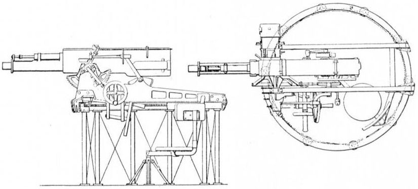
Vickers mounting for Vickers automatic 1-pounder gun. The author suggests that this mounting was intended for the Vickers F.B.24E and Martinsyde F.1.
F.B.25. Early in 1917 Vickers turned out a two-seat pusher anti-airship night fighter in the category of the Royal Aircraft Factory and similarly armed with a "Crayford rocket gun". Originally the gun was to have been supplemented by a searchlight in the nose, but this never materialised, although the gun, or a mock-up of it, was certainly installed. The two cockpits were side by side and staggered, that for the gunner being ahead and to starboard. The gun was trunnion-mounted ahead of the cockpit.
Vampire. Intended to have a single Lewis gun, the first F.B.26 (type later named Vampire) materialised in 1917 with two of these guns, set far forward in the nacelle well below the cockpit sill. As developed for Home Defence the Vampire was associated with some uncommonly interesting armament schemes. The Eeman mounting, with three Lewis guns, was fitted, at first as a fixed installation (raised higher in the nacelle on the third example) but with the intention that the mounting could eventually be elevated, in harmony with an Aldis sight, through 45 degrees. Eleven 97-round ammunition drums were specified. Adapted for ground attack, under the designation Vampire II, this aircraft had two Lewis guns set side by side in an armoured nacelle. The fitting of a BR.2 rotary aircooled engine in place of the earlier water-cooled types rendered this version less vulnerable lo ground fire. Carrying 500 lb of armour-plate, the Vampire II weighed 1.870 lb.
Vimy. That the armament of the Vimy twin-engined bomber (1917) was given high priority during development is suggested by the melancholy fact that the third prototype was blown up by its own bombs at Martlesham Heath. Several alternative loadings appear to have been possible. For the Fiat-engined aircraft, declared obsolete by an Air Ministry Order of 1921, the following stowages appear to have been planned: eight 250-lb + four 112-lb internal (bombs nose-up); two 520-lb under lower longerons; four 230-lb under lower centre-section. The most common variant had Eagle engines, and this appears to have had provision for twelve 112-lb or 250-lb bombs internally; eight 112-lb under lower centre-section; four 112-lb under fuselage; two 230-lb under lower longerons. A loading of eighteen 112-lb + two 230-lb has been recorded and consideration appears to have been given to the earning of two torpedoes.
The heaviest military' load quoted by the makers was 3.410 lb, and in this condition the Eagle-Vimy had a petrol capacity of 1.670 gal, giving a range of 550 miles at 6.000 ft. cruising at 90 mph. The military load instanced probably corresponded to a bomb load of twelve 250-lb. Four Lewis guns and ammunition would account for only about 130 lb. so the rest of the military load would presumably be made up of gun mountings, bombing gear, flares, etc.
Although a load of two 520-lb bombs has been recorded for the Fiat-powered Vimy, similar provision appears to have been made, in post-war years at least, on Eagle-powered aircraft. The sight fitted to production Vimys was the Drift Bomb Sight, High Altitude, Mk.IA, bracket-mounted on the nose. Some post-war Vimys used for training had a modified bomb-aimer's station, in a lengthened nose.
Standard defensive armament of production Vimys comprised a Scarff ring-mounting in the nose, carrying a single Lewis gun; a similar installation on top of the fuselage, roughly in line with the trailing edges (an accompanying photograph confirms twin guns in this position); and a third station in the floor, lit by side windows. A single rear gunner manned the two last-named stations. For the nose gun(s) a 4 1/2-in Neame No.1 illuminated sight was specified, together with four spare ammunition drums; for the ventral gun there was a 2-in Neame No.2 sight, and the two rear positions shared six spare drums between them. A contemporary account stated of the ventral gun:
'The gunner is able to fire through the bottom of the fuselage in a horizontal direction towards the rear. He can thus aim at a machine following at the same level without hitting the tail plane of his own machine.'
A notable experimental installation on one Vimy was made by the fixing of a trunnion-mounted 37-mm Coventry Ordnance Works gun to a pillar mounting, attached externally somewhat lo starboard on a specially modified nose section.

Vickers Vimy, showing bombsight mounted on nose forward of Scarff ring-mounting, bomb-carriers and - glimpsed through the lower blades of the port airscrew - dorsal Scarff ring-mounting for twin Lewis guns.
Westland
N.16 and N.17. In common with other naval fighter bombers of their class these single-seater floatplanes of 1918 carried an offensive load of two 65-lb bombs. These were attached to tandem tubular carriers beneath the fuselage, falling when released between the cross-ties of the floats. A fixed synchronised Vickers gun was mounted on the fuselage centre line and was entirely enclosed in a 'hump' fairing. On the top centre-section was provision for a swivel-mounted Lewis gun, and running across the centre-section near the leading edge was a cross-bar which appears to have had the dual purpose of preventing the gun from being fired through the airscrew arc and of serving as a forward anchorage for the gun, pointing either slightly to port or to starboard. When bombs were carried, this gun was not mounted. Westland gave the weight of 'bombs and gear' as 150 lb and of 'gun and 250 rounds' as 60 lb.
N.16 and N.17. In common with other naval fighter bombers of their class these single-seater floatplanes of 1918 carried an offensive load of two 65-lb bombs. These were attached to tandem tubular carriers beneath the fuselage, falling when released between the cross-ties of the floats. A fixed synchronised Vickers gun was mounted on the fuselage centre line and was entirely enclosed in a 'hump' fairing. On the top centre-section was provision for a swivel-mounted Lewis gun, and running across the centre-section near the leading edge was a cross-bar which appears to have had the dual purpose of preventing the gun from being fired through the airscrew arc and of serving as a forward anchorage for the gun, pointing either slightly to port or to starboard. When bombs were carried, this gun was not mounted. Westland gave the weight of 'bombs and gear' as 150 lb and of 'gun and 250 rounds' as 60 lb.
Wagtail. A light single-seat lighter of 1918, the Wagtail earned its two Vickers guns externally immediately forward of the cockpit sides. The case chutes were very low in the fuselage in metal panels let in to the fabric covering and were canted down at an angle of about 45 degrees to the line of flight. The windscreen had a hole on the starboard side to receive the eyepiece of the Aldis sight. On the centre line was a ring-and-bead sight, with the bead immediately ahead of the windscreen. Westland gave the weight of' 'two guns, gear and 1,000 rounds' as 160 lb.
Weasel. The Weasel was built in 1918 as a specialised two-seat fighter. It had much in common with the Wagtail, including the mounting of the two Vickers guns, though these were somewhat recessed and fired through short troughs. When a Jupiter engine was installed the guns were faired in to the fuselage and fired through longer, deeper troughs. The case chutes were some distance down the fuselage sides. There were Aldis and ring-and-bead sights. The gunner was close behind the pilot and had a Scar ff ring-mounting for twin Lewis guns. Below the ring on each side of the fuselage was a 'window', or uncovered fuselage section.

Westland Weasel two-seat fighter, showing pilot's fixed Vickers guns and installation of Scarff ring-mounting.
White & Thompson
No.3. This little flying-boat was acquired by the Admiralty in 1914 and was probably the first of its class in British service to carry armament. A Lewis gun was fitted lo a pillar mounting on the port side of the cockpit.
No.3. This little flying-boat was acquired by the Admiralty in 1914 and was probably the first of its class in British service to carry armament. A Lewis gun was fitted lo a pillar mounting on the port side of the cockpit.
Wight
Type 840. Like its counterpart the Short 184, this twin-float seaplane was designed to carry a 14-inch torpedo. On the first few machines the bracing-ties between the floats were arched accordingly, but these members were later made straight, and a bomb load of considerably less than the torpedo's weight was carried. A Wight seaplane of unspecified type was used in 1915 for bombing experiments at Calshot.
Type 840. Like its counterpart the Short 184, this twin-float seaplane was designed to carry a 14-inch torpedo. On the first few machines the bracing-ties between the floats were arched accordingly, but these members were later made straight, and a bomb load of considerably less than the torpedo's weight was carried. A Wight seaplane of unspecified type was used in 1915 for bombing experiments at Calshot.
Twin Seaplane. This type of very large torpedo-carrying seaplane appeared in 1915. Drops were actually made, and photographed. The torpedo was of the 18-in Mk.IX pattern.
Bomber. Four 112-lb bombs could be carried under the lower wings of this three-bay single-engined bomber of 1916. There was a Lewis gun on a Scarff ring-mounting over the rear cockpit.
'Converted' Seaplane. This type of twin-float seaplane was developed from the Wight Bomber in 1917. Anti-submarine operations were undertaken with 100-lb bombs (specialised anti-submarine weapons) and one machine, operating from Cherbourg on 18 August, 1917, sank UB-32 by dropping a bomb of this type just forward of the periscope. Up to four such bombs could probably be carried, and a load of two 100-lb and two 112-lb has been reported.
'Converted' Seaplane. This type of twin-float seaplane was developed from the Wight Bomber in 1917. Anti-submarine operations were undertaken with 100-lb bombs (specialised anti-submarine weapons) and one machine, operating from Cherbourg on 18 August, 1917, sank UB-32 by dropping a bomb of this type just forward of the periscope. Up to four such bombs could probably be carried, and a load of two 100-lb and two 112-lb has been reported.